9363417, Installation And Operating Manual MobiSet 3 Digital CAP 700 Mobi Set 9363417
cap700 dfd7f5cd-ccf5-4590-b883-d4572bef1fd5 Kathrein Turntable CAP 700 User Guide |
User Manual: MobiSet 3 Digital CAP 700
Open the PDF directly: View PDF ![]() .
.
Page Count: 60
- START PAGE
- CONTENTS
- FOREIGN LANGUAGE INSTALLATION MANUALS/DISPOSAL
- MOBISET 3 CAP 700 COMPONENTS/SCOPE OF DELIVERY
- PROPER USE
- SAFETY INSTRUCTIONS - IMPORTANT NOTES
- INSTALLATION AND CONNECTION
- RECEPTION RANGE/FOOTPRINT
- DISMANTLING FOR SERVICING
- POLARISATION SETTING
- MANUAL LOWERING TO PARK POSITION
- TECHNICAL DATA
- SIKAFLEX® 291 SAFETY DATA SHEET
- SIKAFLEX® 291 TECHNICAL DATA SHEET
- CAP 700 OPERATING MANUAL
- IMPORTANT INFORMATION FOR CAP 700 BEFORE SETUP
- FIRST INSTALLATION
- ALIGNMENT (SATELLITE SEARCH)
- MOVING THE ANTENNA MANUALLY
- CHANNEL (SATELLITE) SELECTION
- CHANGE OF LOCATION/TIMER PROGRAMMING
- RESET/PARKING
- SPECIAL MESSAGES FROM THE TURNTABLE
- DECLARATION OF CONFORMITY
- FOR YOUR NOTES
Installation and operating manual
MobiSet 3 digital
CAP 700

2
CONTENTS ............................................................................................................................... 2
FOREIGN LANGUAGE INSTALLATION MANUALS/DISPOSAL .................................................... 3
MOBISET 3 CAP 700 COMPONENTS/SCOPE OF DELIVERY ...................................................... 4
PROPER USE ........................................................................................................................... 5
SAFETY INSTRUCTIONS - IMPORTANT NOTES ......................................................................... 6
INSTALLATION AND CONNECTION ........................................................................................... 9
INSTALLATION OF CABLE GLAND AND MOUNTING PLATE ........................................................... 11
INSTALLATION OF TURNTABLE .............................................................................................. 14
BRIEF INSTRUCTIONS FOR INSTALLING THE TURNTABLE ......................................................... 17
INSTALLATION OF THE UFS 740SW RECEIVER ......................................................................... 19
LAYING CABLES AND CONNECTING THE TURNTABLE ............................................................... 21
CONNECTING TO THE UFS 740SW ......................................................................................... 21
FUNCTIONAL INSTRUCTIONS FOR CONNECTION TO THE ON-BOARD POWER SUPPLY .................. 22
CONNECTION EXAMPLE FOR 12 V BATTERY CONNECTION ................................................. 23
RECEPTION RANGE/FOOTPRINT ........................................................................................... 24
DISMANTLING FOR SERVICING .............................................................................................. 25
DISMANTLING ...................................................................................................................... 25
ADDRESS OF THE SERVICE CENTRE ................................................................................... 25
POLARISATION SETTING ....................................................................................................... 26
POLARISATION SETTING ...................................................................................................... 26
SAFETY NOTES .................................................................................................................... 28
SETTING OPERATIONS ......................................................................................................... 28
MANUAL LOWERING TO PARK POSITION .............................................................................. 30
SAFETY NOTES .................................................................................................................... 30
MANUAL LOWERING ............................................................................................................. 31
TECHNICAL DATA .................................................................................................................. 32
SIKAFLEX® 291 SAFETY DATA SHEET .................................................................................. 35
SIKAFLEX® 291 TECHNICAL DATA SHEET ............................................................................. 40
CAP 700 OPERATING MANUAL ............................................................................................... 42
IMPORTANT INFORMATION FOR CAP 700 BEFORE SETUP .................................................... 43
REMOTE CONTROL .............................................................................................................. 43
FIRST INSTALLATION ............................................................................................................. 44
ALIGNMENT (SATELLITE SEARCH) ........................................................................................ 48
MOVING THE ANTENNA MANUALLY ....................................................................................... 49
CHANNEL (SATELLITE) SELECTION ....................................................................................... 50
CHANNEL SELECTION FROM THE CHANNEL LIST ................................................................ 50
CHANGE OF LOCATION/TIMER PROGRAMMING .................................................................... 51
RESET/PARKING .................................................................................................................... 52
RESETTING THE TURN TABLE ANTENNA .............................................................................. 52
PARKING THE TURNTABLE ................................................................................................... 53
SPECIAL MESSAGES FROM THE TURNTABLE ....................................................................... 54
DECLARATION OF CONFORMITY ........................................................................................... 58
FOR YOUR NOTES ................................................................................................................. 59
CONTENTS
3
Dear Customer, Chère Cliente, Cher Client, Gentile cliente, Estimado cliente,
GB
You can obtain an English version of our mounting instructions from our representatives in your country
(http://www.kathrein.de/include/kontakte_groups_eng.cfm?kontinent=1&gruppe=SAT) or download one
from our homepage (http://www.kathrein.de/en/sat/products/englisch.htm).
F
Vous pouvez obtenir un manuel d‘installation en français chez notre réprésentant en votre pays
(http://www.kathrein.de/include/kontakte_groups_eng.cfm?kontinent=1&gruppe=SAT) ou le télécharger de
notre page d‘ouverture (http://www.kathrein.de/en/sat/products/franzoesisch.htm).
I
Lei puo avvere la versione italiana delle istruzioni di montaggio dalla nostra rapresentanza (http://www.
kathrein.de/include/kontakte_groups_eng.cfm?kontinent=1&gruppe=SAT) piu vicina della sua citta´, oppure
scaricarla dalla nostra hompage http://www.kathrein.de/en/sat/products/italienisch.htm)
E
Para obtener la versión española de nuestro manual de instalación, contacte nuestros representantes en
su país (http://www.kathrein.de/include/kontakte_groups_eng.cfm?kontinent=1&gruppe=SAT) o bajela de
nuestra página de Internet (http://www.kathrein.de/en/sat/products/spanisch.htm).
FOREIGN LANGUAGE INSTALLATION MANUALS/DISPOSAL
Electronic equipment is not domestic waste - in accordance with directive 2002/96/EC OF
THE EUROPEAN PARLIAMENT AND THE COUNCIL dated 27th January 2003 concerning
used electrical and electronic appliances, it must be disposed of properly.
At the end of its service life, take this unit for disposal to an appropriate offi cial collection
point.
Spent batteries are special waste!
Do not throw spent batteries into your domestic waste; take them to a collection point for
spent batteries!
DISPOSAL INSTRUCTIONS
4
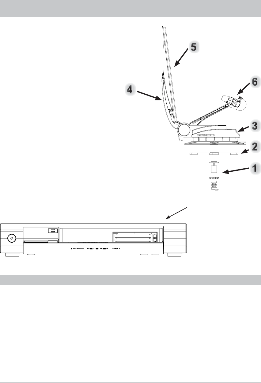
MOBISET 3 CAP 700 COMPONENTS/SCOPE OF DELIVERY
UFS 740sw
(Front view)
The MobiSet 3 digital CAP 700 consists of:
• Turntable complete with control electronics, pre-assembled parabolic refl ector with LNB
• Mounting plate
• Complete cabling set: 1 x coax cable 8 m long, and one power supply cable (10 m) for connection to
the on-board power supply
• Roof gland with sealing gasket
• Sikafl ex® 291 adhesive sealant (100 ml tube)
• UFS 740sw DVB-S receiver with connecting cables, infrared sensor and infrared remote control
• MobiSet 3 digital CAP 700 installation and operating instructions
• UFS 740sw satellite receiver operating manual
PRODUCT PACKAGE
See UFS 740sw operating
manual for a rear view of
the receiver together with
explanation of functions and
operating instructions.
1. Roof gland with retaining nut
2. Mounting plate
3. Turntable with integral controls
4. Antenna carrier
5. Parabolic refl ector
6. LNB
5
PROPER USE
The MobiSet 3 digital CAP 700 is designed to receive digital TV and radio programs via satellite.
The automatic positioner is intended to be used as a turntable for the parabolic refl ector.
The turntable can be used to receive digital TV and radio signals in the frequency range from 10.70 to
12.75 GHz; the antenna cannot receive terrestrial signals (e.g. DVB-T).
The turntable can only be used in conjunction with the UFS 740sw DVB-S receiver.
In conjunction with this receiver, the turntable provides fully automatic alignment of the parabolic refl ector
to receive digital satellite signals. The turntable is designed for use on stationary caravans or motor
homes.
Any use other than that specifi ed above will void the warranty or guarantee.
The following circumstances result in the loss of all warranty and liability claims towards
the manufacturer:
• Improper installation
• Use of non-specifi ed mounting materials, which cannot guarantee the mechanical reliability of the
antenna system
• Impermissible use, e.g. use of the satellite dish for storage
• Structural changes or interference with the components and mounting accessories in the set, which
could endanger both the mechanical and functional reliability
• Improper or forcible opening of the components
• Use of cleaners containing solvents, such as acetone, nitro-cellulose thinners, petrol etc.
• Failure to observe installation and safety instructions in this manual
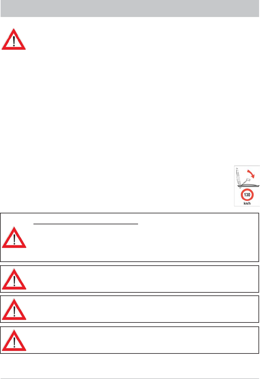
Note: The maximum permissible speed for vehicles with a CAP 700 receiver unit mounted
on the roof is 130 km/h. Before commencing a journey, the satellite dish must always be
lowered into horizontal position (park position).
The turntable may be operated in an ambient temperature range of -20 °C to +45 °C.
Operating the system outside this range may result in malfunctions or damage to
the system. When choosing the location for installation or raising the UFS 740sw,
ensure there is adequate ventilation.
PROPER USE (USE FOR THE INTENDED PURPOSE)
The system may only be installed by qualifi ed specialist
personnel!
To prevent hazards during installation, operation or when driving on public highways, the
instructions and information in this manual must be strictly adhered to. Proper installation
and connection of the system are pre-requisites for conformity with the corresponding
standards.
This is documented in advance by the CE mark and the declaration of conformity in the
appendix to this manual.
6
SAFETY INSTRUCTIONS - IMPORTANT NOTES
Safety during installation work
When carrying out installation work in locations where there is a risk of falling, take appropriate
safety precautions, e.g. use of a working platform. Make sure that the vehicle roof is
suffi ciently strong and stable to carry out the installation work (risk of damage or collapsing
of roof).
In case of doubt, contact a qualifi ed specialist dealer or the manufacturer of your vehicle to
fi nd an appropriate installation location.
Make sure that:
- The turntable and connected units are disconnected from the power supply
- The person carrying out the installation or repair does not suffer from vertigo and can move around
safely on the roof of the caravan or motor home
- The person carrying out the installation or repair is wearing sturdy and non-slip shoes
- The person carrying out the installation or repair has a secure position to stand and hold on while
working
- The roof and the climbing equipment used (e.g. ladder) are dry, clean and non-slip
- The roof can withstand the weight of the person carrying out the repairs
Attention! Risk of death or injury due to falling or the roof collapsing!
- Nobody should be inside the caravan/motor home underneath the antenna during dismantling/
installation
Attention! Risk of death or injury due to possible roof collapsing and falling parts!
Proper installation and safety
Essential information
A crucial safety factor is proper performance of installation and electrical connection work, and the
specifi ed alignment of the turntable in the direction of travel (park position), see also installation and
connection.
Comply as precisely as possible with the installation conditions and steps described.
Modifi cations to the electrical installations in the vehicle should only be carried out by a specialist in
vehicle electrics. Do not make any unauthorised changes to the turntable.
Adhesive sealant
The turntable is attached to the roof of the vehicle by adhesive and is secured by additional screws.
Note that the curing of the adhesive sealant is temperature-dependent. It reaches its full strength only
after approximately fi ve days.
During installation work, comply strictly with the processing and safety instructions
for the adhesive sealant (Sikafl ex® 291 safety data sheet and Sikafl ex® 291 technical
data sheet).
7
Road Traffi c Licensing Regulations (StVZO)
The applicable regulations of the StVZO must be observed in respect of fi xed installation of the turntable on
a vehicle which is driven on public highways.
In particular, §§ 19/2; 30 C; 32 (2) and the EC directive 74/483 EEC are applicable.
Briefl y, they state that no endorsement of the vehicle documentation is required unless the antenna
unit causes the height of the laden vehicle to exceed 2 m, or the antenna unit projects beyond the
outer lateral outline of the vehicle. The maximum permissible height of 4 m (vehicle and antenna unit)
may not be exceeded.
There is an increased risk of accidents if the normal vehicle height is increased by
extending the antenna. The driver bears sole responsibility for the condition of the
superstructure and external fi ttings!
Cables
Lay all cables such that nobody can tread on them or trip over them.
To prevent parasitic induction or interference emissions, when extending the antenna cable use 75 Ω
coaxial cable with a screening factor of at least 75 dB.
If you tied the cables together with wire or similar materials, remove this to prevent
the risk of fi re!
When connecting the power cables (receiver and turntable) to the vehicle electrical supply, make sure
that the cable polarity is not reversed.
If the cable polarity is reversed there is a risk of thermal overload and damage to
components when the equipment is powered up!
Power supply, fusing
Operate the system from your vehicle's battery (12 V) or a suitable mains power supply unit. This power
supply unit must ensure a stable output voltage of 12 V, continuous current of 11 A and 15 A (300 ms) surge
current.
The peak current consumption is up to a maximum of 12 A.
To ensure reliable functioning of the connection/control unit, the power supply cable must be connected
directly to the battery. If the supply voltage is too low, the UFS 740sw receiver indicates this with the
on-screen message “On-board voltage too low” on the television screen.
A 15 A fuse is incorporated in the power supply cable. If the fuse blows, rectify the source of the fault
and replace the blown fuse with a fuse of the same rating (15 A).
Never remove or bypass the fuse in the cable – cable fi re hazard!
Connecting the power supply cable lead marked “Ignition” activates the turntable function for automatic
lowering of the antenna. This lowering takes place as soon as the vehicle ignition circuit is turned on.
When connecting the control unit to the vehicle power supply, make sure that the “+12V”, “Earth”
and “Ignition” wires cannot be disconnected by intermediate switches, as this could deactivate the
automatic lowering function.
SAFETY INSTRUCTIONS - IMPORTANT NOTES
8
Safety precautions during operation
During operation of the turntable, make sure that no persons, in particular children,
are in the immediate vicinity of the turntable and that they cannot touch any
moving parts – crush hazard!
Always unplug the power supply during installation work.
The antenna will be lowered within 12 seconds of the ignition being switched on
(if the unit is in stand-by mode or the UFS 740sw is switched off). Otherwise the
control unit that is in use is lowered immediately.
Important: Lowering the antenna can take up to 30 seconds after the ignition is switched on!
SAFETY INSTRUCTIONS - IMPORTANT NOTES
Checks before commencing a journey
• Before commencing a journey, the antenna must always be lowered into horizontal position (park
position). If the antenna has collided with a fi xed or movable object, check that it is still securely
attached.
• As the antenna is subjected to vibration loads during driving, you should check at regular intervals,
depending on the frequency of driving, that the system is still securely attached and tighten any parts
that have worked loose.
• The maximum permissible speed for vehicles with a receiver unit mounted on the roof and the antenna
lowered is 130 km/h.
• Lower the antenna if it will not be used for a long period. This makes the securing bolts more diffi cult
to access (protection against theft).
Antenna in the park position whilst driving
The antenna must always be lowered into horizontal position (park position) while driving.
As a reminder, attach the sticker from the supplementary sheet “Lower the CAP 700
antenna while driving” where it can easily be seen by the person operating the ignition switch.
In addition the instructions in the installation and operating manuals for these
devices and for the attachments and superstructures must be complied with at
all times!
Exceeding the normal vehicle height by failing to lower the antenna increases the
risk of accidents! The driver is responsible for the condition of external fi ttings
on the vehicle!
If stormy weather is expected, the turntable must always be moved to the park
position, otherwise both the CAP 700 and the vehicle may be damaged.
9
• Circular cutter, Ø 38 mm
• Flat-bladed screwdriver for M5 screws
• Power drill
• Galvanised round head screws, depending on the roof structure (Ø: 5 mm, sheet metal screws D 7981,
depending on the roof structure) or round head screws D 7985 with washers and nuts
• Twist drill, Ø 2.5 or 5.5 mm
• Round fi le and/or emery paper
• Cleaning agent
• Open-ended or ring spanners 10 and 11 mm across fl ats
• Knife
• Cross-head screwdrivers for M3 and M5 screws
• Torque wrench capacity 6 to 11 Nm
• Hexagon socket key (5 mm)
• Two wooden beams for supporting the turntable
REQUIRED TOOLS AND EQUIPMENT
INSTALLATION AND CONNECTION
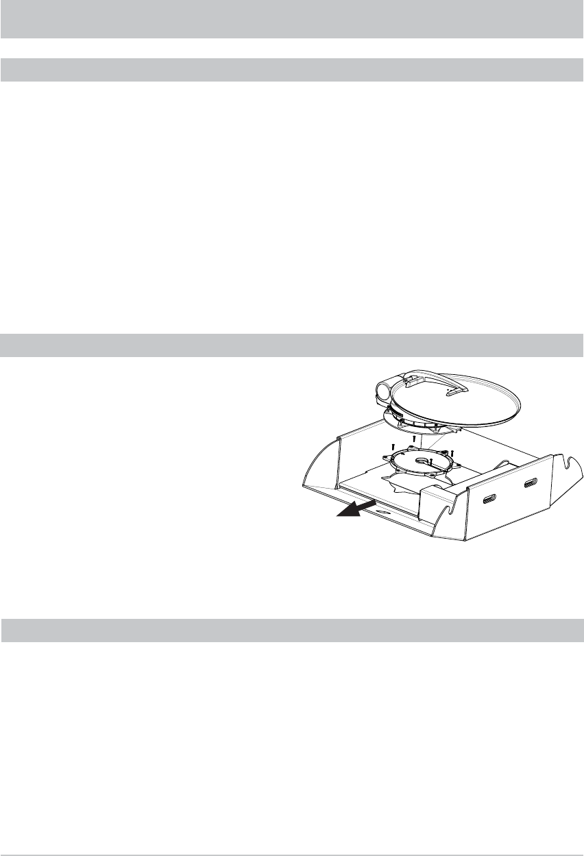
The CAP 700 must not be mounted on the satellite
dish, since this could cause it to distort. Keep the
CAP 700 in its cardboard box for transport on to the
vehicle roof.
Retain the original packaging, as if it is necessary
to send the unit for repair transport damage
cannot be ruled out and the manufacturer accepts
no liability for possible damage.
Loosen the six fastening screws (width A/F:
10 mm). Carefully lift the turntable off the mounting
plate and place it on the prepared wooden
supports. Make sure that the cables are not
crushed where they emerge from the underside of
the turntable.
UNPACKING AND PREPARATION
Essentially, the cable lengths of the MobiSet 3 CAP 700 components allow you a free choice of installation
location on your caravan or motor home.
However, you should take note of the following points:
• Before installation, you should fi nd out whether the operating manual for your vehicle permits the
fi tting of non-vehicle-specifi c parts or what requirements need to be met in order to do so.
• For direct satellite reception, there should be no obstructions between the antenna and the satellite.
Therefore, make sure that the antenna is not shadowed by roof extensions such as luggage racks,
air conditioning units, solar panels, etc. The problem of shadowing applies also to the selection of the
parking place for your vehicle. For interference-free satellite reception, the antenna needs a projected
free view to the South at an angle of between 0° and 75° (depending on location) to the horizontal.
SELECTING THE INSTALLATION LOCATION
The CAP 700 packaging can be opened along
both long sides. This allows easier access to the
fastening screws.
10
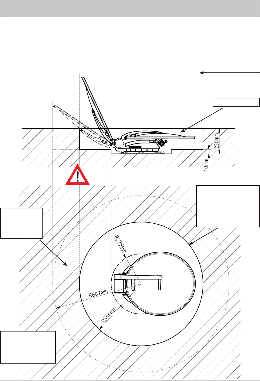
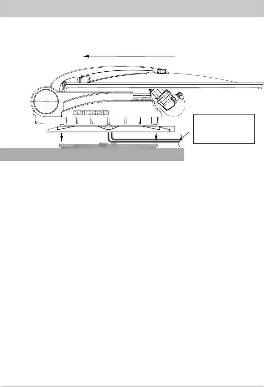
• When selecting the installation position, take into account the range of movement of the turntable
(see graphics and the “Technical Data” chapter). There must be no structures on the roof that would
obstruct this range of movement (risk of collision). For safety, keep at least the required area free
(for ease of installation and any subsequent dismantling).
INSTALLATION AND CONNECTION
Direction of travel
Park position
Recommended
clear space
(radius) min.
807 mm
Area (radius min. Ø 566
mm) within which the
device with its height
of up to 230 mm can
be attached to the
turntable
Roof attachments
may be mounted
within the hatched
area.
The height of neighbouring
attachments on the roof may
lead to shadowing!
Elevation max. 75°
Elevation 45°
11
• Choose an installation position on the roof that is as horizontal as possible or only slightly
sloping, depending on the location of the vehicle, since roof inclinations greater than 5° may lead
to problems when searching for the satellite.
• To ensure secure adhesion, the height difference of the roof curve may not be more than 1 cm
over a length of 2 m, as otherwise the gap between the roof and the mounting plate would be too
great to be fi lled by the adhesive sealant.
• As the vehicle is constantly subjected to vibration loads during travel, the roof below the antenna unit
is also subject to signifi cant loads. Please note given the nature and capacity of your vehicle roof
(see also operating manual for the vehicle) that the weight of the antenna unit is approx. 9.7 kg.
In case of doubt, consult a qualifi ed dealer or your vehicle’s manufacturer.
• The roof gland provides a watertight seal through which the two connecting cables (coax cable
and power supply cable) are fed into the interior of the vehicle directly underneath the turntable.
If you prefer a different method of laying the cables, they can be run from the rear of the turntable
via the channel provided in the mounting plate. The cables must then be run along the roof of
the vehicle in a protective cable duct (not supplied).
Note: Do not cut the cables short, as otherwise the proper functioning of the unit can no longer be
guaranteed.
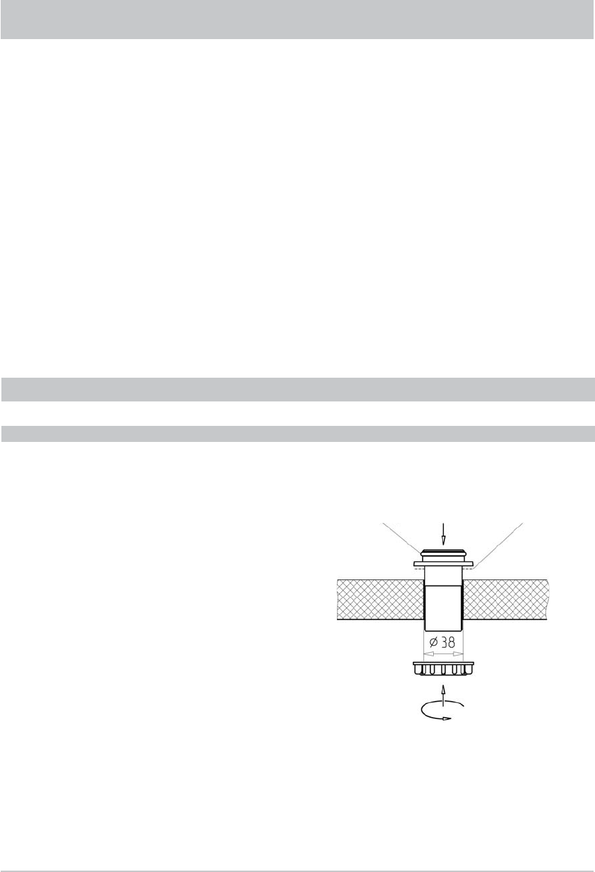
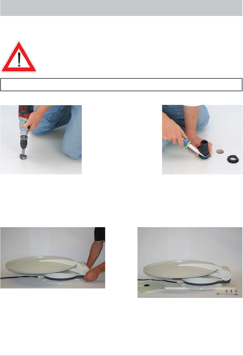
• In the centre of the intended position of the turntable, drill the opening for the cable gland with a
circular cutter (Ø: 38 mm). Deburr the hole with a round fi le or emery paper.
• Provisionally insert the roof gland into the drilled hole (Fig. A).
• Place the mounting plate on the roof of the vehicle, such that the centre hole is positioned centrally to
the cable gland. The arrow symbol must be visible from above and point forwards in the direction of
travel (Fig. B).
Figure: A
Note: If you had previously used a Kathrein HDM140/141 fl exible satellite mast or another mast
with a diameter of 34 mm, you can continue using the existing gland hole in the roof
(if space allows).
INSTALLATION STEPS
INSTALLATION OF CABLE GLAND AND MOUNTING PLATE
INSTALLATION AND CONNECTION
O Ring Adhesive

12
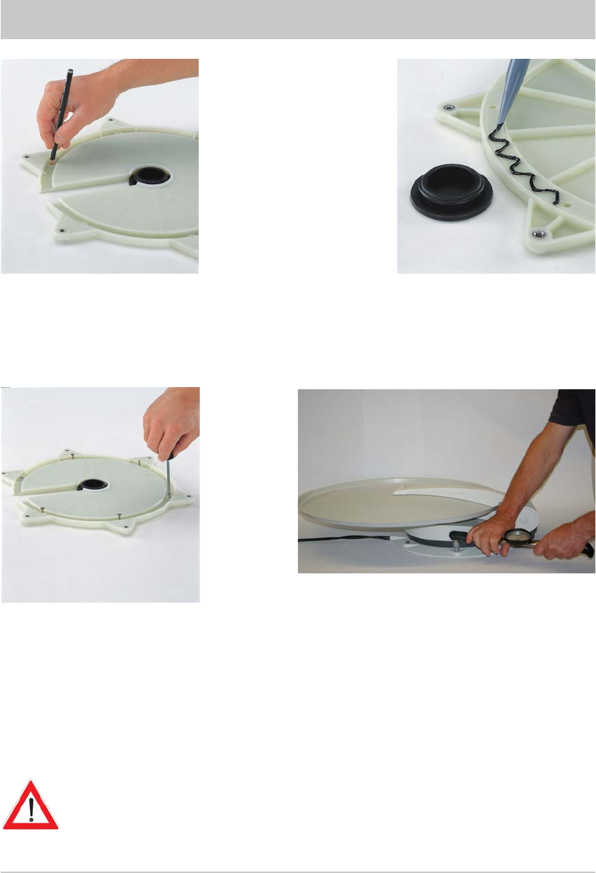
• Mark out the positions of the six fastening holes on the roof of the vehicle in a circular pattern.
Note: The size of the holes and the choice of fastening screws to be used (not supplied)
depend on the type and thickness of the materials used in the roof structure. If the roof
panelling (plastic roofs) is suffi ciently strong, it is recommended that round head screws,
plain washers and self-locking nuts are always used to secure the glued mounting plate.
Figure: B
INSTALLATION AND CONNECTION
• For very thin roof panel materials and insuffi cient support in the insulating material, through holes
(Ø: 5.5 mm) into the interior of the vehicle are necessary; galvanised M5 round head screws of
suffi cient length should then be used.
Make sure that you use a suffi ciently strong support that can accept the bolt tensile forces (large plain
washers or a complete reinforcing plate).
Figure: C
*) Not supplied
Arrow in the
direction of travel
Washer
Alternative
roof attachment
Adhesive area
between the two
grooves
13
• Create the holes necessary to secure the mounting plate (Fig. C).
• In addition to the screwed connection, the mounting plate and roof gland must be bonded to the
roof with adhesive and sealed. This is done using the Sikafl ex® 291 adhesive sealant supplied,
which is ideally suited for this purpose thanks to its broad range of adhesion.
Before starting to use Sikafl ex® 291 adhesive sealant, be sure to read the Sikafl ex® Products
safety data sheet and technical data sheet in this installation manual!
The prerequisite for good adhesive characteristics is a clean, dry and grease-free substrate. You
should therefore clean the roof surface with a suitable cleaning agent within a circumference of 35 cm
around the drilled hole and allow the surface to dry thoroughly.
If the surface is painted, ensure that the paint fi nish is suffi ciently well bonded to the substrate.
If the coat of paint is already loose or peeling, it must be removed down to a stable layer in the area
to which the adhesive will bond. If you have any doubts concerning the adhesive characteristics,
consult a paint and lacquer specialist, or the manufacturer of your vehicle.
Under certain circumstances, it may be necessary for you to improve the adhesive properties of the roof
surface by pre-treatment with a cleaning agent available from specialist dealers (e.g. Sika® Cleaner) or a
primer (e.g. Sika® Primer).
The procedure for gluing the mounting plate is as follows:
INSTALLATION AND CONNECTION
Figure: D
Recess
for cable
Adhesive areas
between the two
grooves

14
• Ensure before starting adhesive work that the temperature of materials to be glued and the
adhesive sealant is between +5 °C and +40 °C. Prepare all necessary fasteners and tools.
• Prepare the tube of adhesive sealant in accordance with the instructions enclosed with the tube.
• Remove the roof gland (Fig. A) and apply the adhesive sealant evenly to the underside of the roof gland
fl ange.
Replace the roof gland in the drilled hole and press it fi rmly against the roof of the vehicle.
• Apply the adhesive sealant evenly to the underside of the mounting plate, completely covering the
area within the circular groove (Fig. D).
This area of the vehicle roof must be completely coated with adhesive in order to achieve the
necessary bonding force.
Place the mounting plate on the roof of the vehicle, as you did previously when marking out the
drilled holes.
Make sure that the arrow on the mounting plate points forward in the direction of travel.
The fastening holes must be perfectly aligned with the prepared holes in the roof.
• Fasten the mounting plate in place with the prepared screws, evenly tightening six screws across
the diagonals.
Note: The adhesive sealant used is capable of bridging small gaps caused by the curvature of
the vehicle's roof. However, you should ensure that the mounting plate is not bent by
tightening the screws.
• Remove any adhesive sealant that leaks out at the sides with a clean cloth or if necessary with
Sikafl ex® Remover (available from specialist dealers). Do not use cleaning agents or thinners
containing solvents, as this could damage the adhesive sealant applied under the mounting plate.
Use only cleansing paste and water to clean your hands.
• Secure the cable gland from inside the vehicle by tightening the knurled nut supplied (Fig. A).
• Note that the curing of the adhesive sealant depends on the ambient temperature and the humidity.
Final strength is reached after approx. fi ve days. However, this need not restrict further installation
work, since the mounting plate is held in place by the tightened screws.
INSTALLATION AND CONNECTION
VARIANT WITH CABLE GLAND UNDERNEATH THE TURNTABLE
• Feed the ends of the cables with the connectors as far as possible through the cable gland into the
interior of the vehicle.
INSTALLATION OF TURNTABLE
15
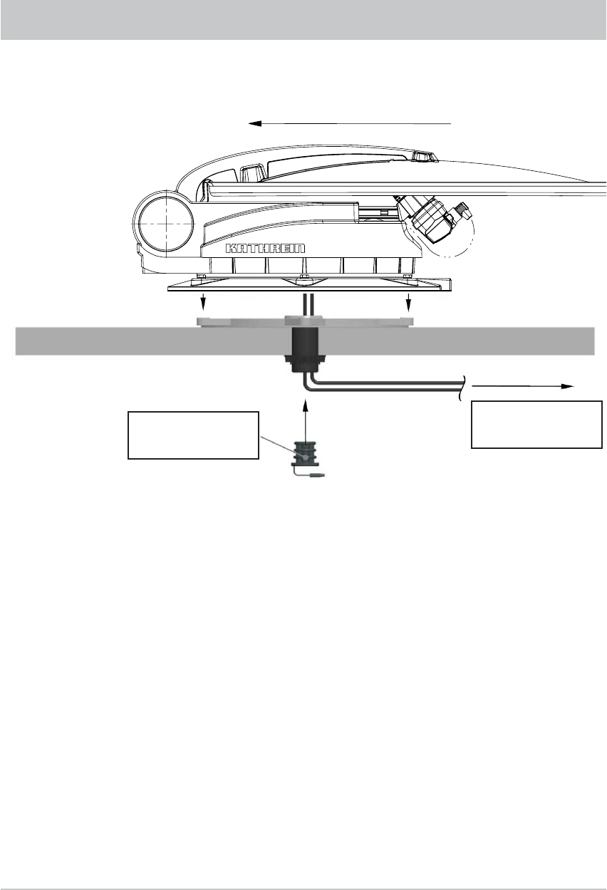
Figure: E
INSTALLATION AND CONNECTION
• Lift up the turntable and place it carefully on the mounting plate facing in the direction of travel
(see illustration Fig. E) (do not step on the plug connector and do not kink/crush the cables!)
The through holes on the turntable must be perfectly aligned with the threaded holes on the
mounting plate. When lowering, make sure that the cables are fed through the cable gland and
are not crushed.
• Apply a little adhesive sealant to the six threaded holes in the mounting plate and screw the
fastening screws into the thread. Tighten the screws to a torque of 6 Nm.
• To prevent water vapour from inside the vehicle reaching the turntable through the roof gland,
thread the two cables through the sealing gasket supplied (see Fig. E) and insert this into
the roof gland until it reaches the stop. Insert the plug into the third cable duct which is not used.
Make sure that no tensile load is acting downwards on the sealing gasket as this can cause it to
fall out in the course of time.
Gasket with plug for
the unused duct
Battery, ignition
Receivers
Direction of travel
16
INSTALLATION AND CONNECTION
VERSION WITH EXTERNAL CABLE GLAND (FIG. F)
• The external roof gland is arranged so that it forms a water-tight enclosure on the vehicle roof
around the point where the two cables projecting from the turntable are connected to the two
extension cables within the interior of the vehicle, and where if necessary they can be disconnected.
• Arrange the cables in the cable duct when placing the turntable on to the mounting plate. Make sure
that the cables are not crossed over and that they are taut so that they cannot be crushed. Do not
try to pull the cables from the unit. This could damage the cables or loosen the cable connections.
• Place the turntable carefully on the mounting plate. The through holes on the turntable must be
perfectly aligned with the threaded holes on the mounting plate.
• Apply a little adhesive sealant to the six threaded holes in the mounting plate and screw the fastening
screws into the thread. Tighten the screws to a torque of 6 Nm.
• When feeding the cables through the HDZ 100 roof gland, make sure they are not crushed, kinked
or damaged.
*) Not supplied! The HDZ 100 roof gland is available as an accessory under part number 20410032
from specialist dealers.
Cables laid in the
cable duct*) and
water-tight roof gland*)
Direction of travel
17
INSTALLATION AND CONNECTION
BRIEF INSTRUCTIONS FOR INSTALLING THE TURNTABLE
The sequence of pictures shown illustrates all the necessary installation
steps that are required to install the turntable and the BAS 60 parabolic
refl ector on the roof of the vehicle.
The other detailed instructions in this installation and operating manual must also be followed!
Determination of installation location.
Caution! System has a turning
range of 162 cm (Ø). Drill hole with
Ø 38 mm. Deburr sharp edges
of hole.
Apply Sikafl ex® 291 adhesive
to the spigot of the roof gland.
Insert the spigot into the hole
and secure it from below with the
knurled nut.
Unscrew screws (x 6, 10 AF) from
the mounting plate and remove the
mounting plate.
Place the turntable on prepared
wooden supports to protect the roof
of the vehicle.
18
Avoid skin contact! Arrow in the
direction of travel. Mark out the six
holes for securing the mounting
plate.
Apply Sikafl ex® 291 adhesive in
a sinuous line between the two
grooves and spread with spatula or
similar. Avoid skin contact!
Place mounting plate on roof gland
and secure with appropriate screws
(choose screws according to
thickness/structure of roof).
Screw turntable on to mounting plate using torque
wrench.
Caution!
Tightening torque: 6 Nm
Set up electrical connections. Connect the UFS 740 receiver. Connect the turntable to the battery.
The antenna must always be lowered into horizontal position (park position) while
driving!
Maximum driving speed of the vehicle: 130 km/h
19
INSTALLATION AND CONNECTION
The turntable is controlled by the UFS 740sw DVB-S receiver.
The cable lengths must be taken into account when choosing the installation location. For suspended
installation use the installation kit supplied with the receiver.
Note: When choosing the installation location, bear in mind that the on/off switch and the slots
for inserting common interface modules should always be accessible. The UFS 740sw
is equipped with a power saving circuit and a separate infrared transmitter, which
means that the unit does not need to be placed where it is visible. You can therefore fi t
the UFS 740sw out of sight in any location, e.g. on cupboard walls, side walls or the
base of storage compartments.
In addition, the following points should be taken into account:
• The wall thickness at the installation location must be at least 12 mm, as otherwise the screws will
break through on the other side or damage the surface
• The receiver must be placed in such a way as to allow suffi cient air circulation behind, above and
next to the unit (installation using the installation kit ensures this). Installation on carpet-covered
walls is therefore unsuitable
• Ensure that the cupboard or storage compartment in which the unit is housed is adequately
ventilated, to prevent a build up of heat
• Take care when tightening the screws not to damage any cables etc. behind or in the wall
• The receiver is designed for installation in exclusively dry, interior locations. The installation location
must be protected against moisture
• The connecting cables must be provided with strain reliefs
INSTALLATION OF THE UFS 740SW RECEIVER
The receiver must be connected to no other power supply than 12 V DC. The
receiver’s earth connection must be connected to the negative pole of the motor home
or caravan battery.
SUSPENDED INSTALLATION
20
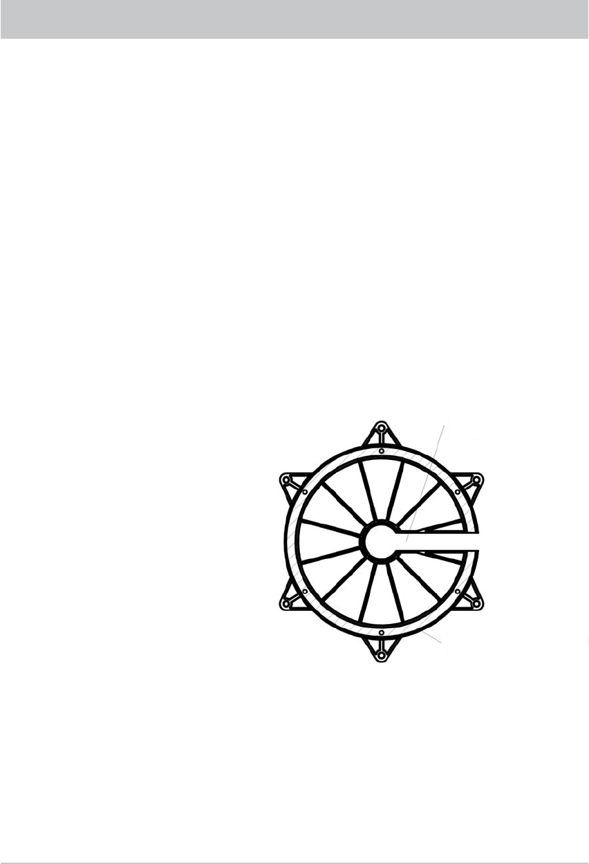
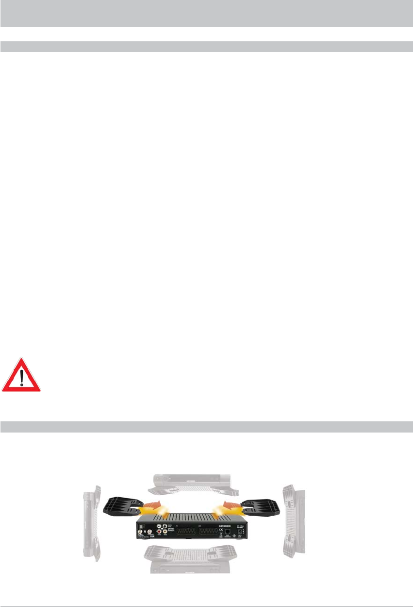
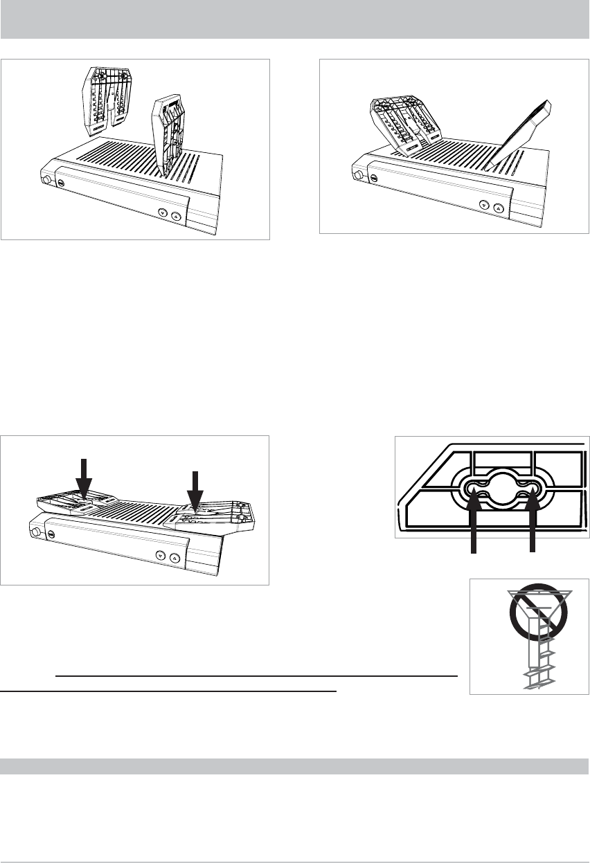
Remove the wood screws supplied from their transport attachment on the underside of the respective
mounting piece (2 pieces).
Vertically insert each mounting piece into the fi fth slot from the edge, as shown in Fig. 1.
Then push each mounting piece downwards and outwards (see Fig. 2) until they lie fl at on the receiver
casing (see Fig. 3).
Now press the mounting pieces fi rmly against the receiver casing at the points shown arrowed in Fig. 3,
until the catch audibly snaps home in the receiver casing.
Now hold the receiver, with the installation kit attached, at the installation location.
Screw in the wood screws supplied through the smaller holes in the screw
attachment area (4 x) (see Fig. 4). Wherever possible, use the wood screws
supplied. If these are unsuitable, other screws of adequate size and strength can
be used. Under no circumstances however use countersunk wood screws,
since these can damage the attachment area (see Fig. 5).
Then screw all four screws fully home, so that the installation kit is no longer
able to come free.
INSTALLATION ON A FIXED FLAT SURFACE
So as to prevent the receiver slipping or falling, the mounting kit can also be attached to the underside
of the receiver. Assembly is the same as for suspended installation, except that the installation kit
is hooked into the underside of the receiver.
INSTALLATION AND CONNECTION
or
21
INSTALLATION AND CONNECTION
• Lay the coaxial cable to the UFS 740sw.
• Lay the turntable power supply cable (3-pin plug) to the battery.
Avoid laying the cables across sharp edges and protect the cables against possible chafi ng
points.
• Connect the coaxial cable (coming from the turntable) to the “IF IN” F socket on the rear of the
UFS 740sw.
• Place the infrared sensor for the receiver close to or directly on top of the TV set and lay the
cable to the UFS 740sw. Connect the 6-pin Western connector at the rear to the socket marked
“IR REMOTE IN”.
Isolate the on-board power supply (master switch “off” or disconnect the positive pole of the on-board
power supply battery) before commencing the following work:
• Connect the power cable supplied (depending on the power supply available in your motor home or
caravan, either a 12 V supply or a 230 V supply via a power supply unit) to the “ ” socket on
the receiver.
Make sure that the “inline” integrated fuse (5 A) of the cable is fully plugged in and is intact. If the fuse
blows, the source of the fault must fi rst be eliminated. The fuse must only ever be replaced by a fuse
with the same rating (5 A).
The fuses in the cable and in the receiver may never be bridged – cable fi re hazard!
• At the connecting point for the power cable, the voltage must not fall below 10.9 V even with a load
of 12 A. Otherwise optimum functioning can no longer be guaranteed.
• Connect the power cable to the respective socket in your motor home or caravan (12 V or 230 V).
Note: Lay the AV cinch enclosed with the CAP 700 to the Scart cable. Take great care to plug the
cables into the correct sockets! The cinch connector must be assigned to the UFS 740sw and
the Scart connector to the TV set.
They must not be reversed - or the unit will not function!
LAYING CABLES AND CONNECTING THE TURNTABLE
CONNECTING TO THE UFS 740SW

22
INSTALLATION AND CONNECTION
Under certain circumstances, problems can arise when the units are connected to different connecting
sockets or circuits/earth potentials. If no others are available, it is recommended that you connect the
connecting sockets for receiver and TV set to the same cable, as shown in Figure “G”. The current rating of
the circuit used must be checked with respect to the intended application.
Further information on operating the UFS 740sw receiver can be found in the operating manual
supplied with the unit.
Only for connection in a motor home, not in a caravan!
• The green connecting cable, marked “IGNITION” allows you the option of connection to a circuit
in the vehicle that is activated when the ignition key is turned and then carries a continuous 12 V
supply. This type of connection ensures that when the engine is started the antenna is automatically
lowered into the park position (the receiver does not need to be turned on).
Note that the antenna can then be lowered only when the power supply is present in addition
to the ignition signal!
• Check the connections before you re-connect the on-board power supply.
• For commissioning and more detailed information on additional operator functions, we refer you to the
separate operating manual enclosed.
FUNCTIONAL INSTRUCTIONS FOR CONNECTION TO THE ON-BOARD POWER SUPPLY
23
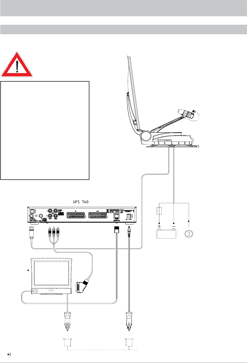
Important:
For operation with two batteries, it
must be ensured that the ignition
signal earth has the same potential
as the power supply battery earth
for the turntable.
Non-compliance means that the
automatic lowering function will not
work!
Ensure the cable polarity is correct!
Figure: G
INSTALLATION AND CONNECTION
CONNECTION EXAMPLE FOR 12 V BATTERY CONNECTION
brown white green
Battery
Ignition
6-pin
Battery
Master
TV set
External
IR sensor
not supplied
Cigarette lighter
socket or 12V
DIN ISO 4165
standard socket
10.9V–13.8V
24
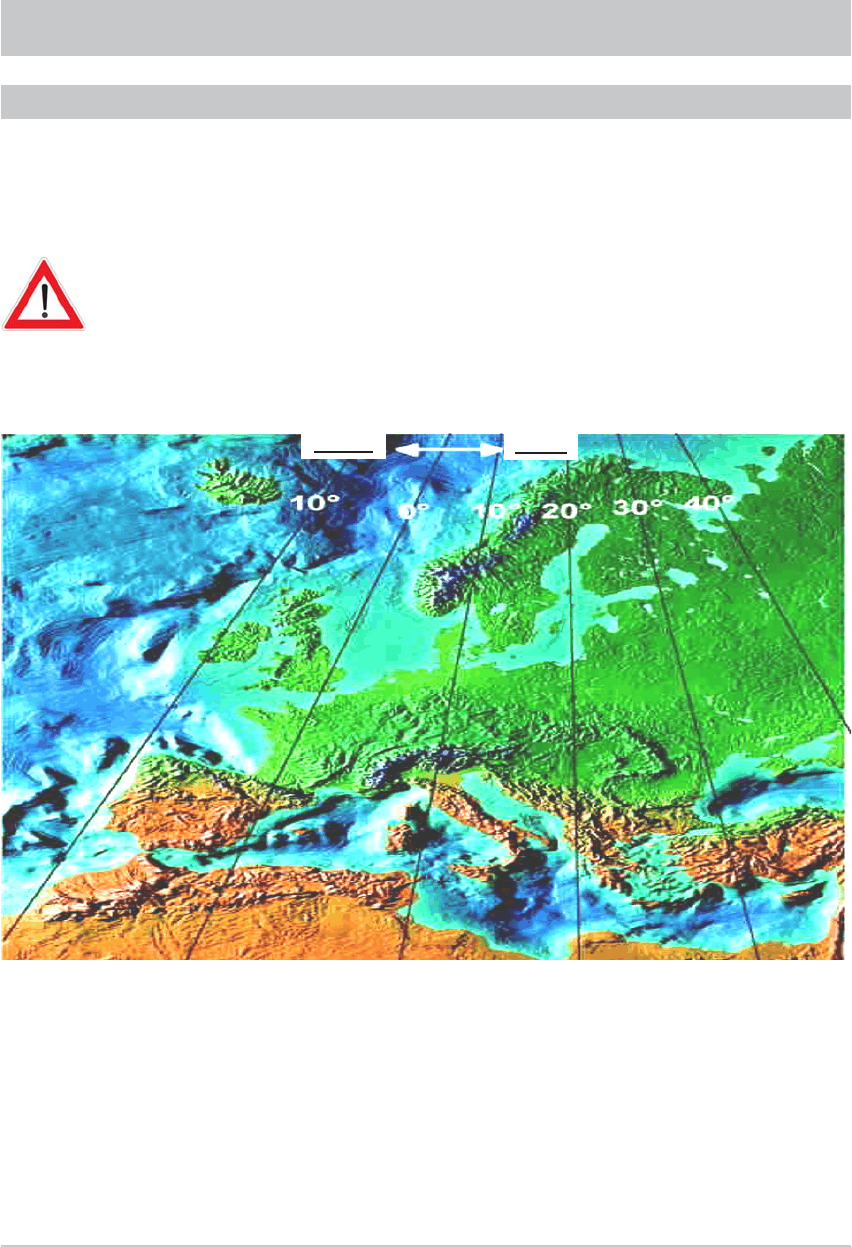
RECEPTION RANGE/FOOTPRINT
The footprint is the reception area on the earth that a satellite covers with its transmission beam (spot),
within which satellite reception is possible. The transmission power is at its greatest in the centre of
this spot – it becomes progressively weaker moving outwards.
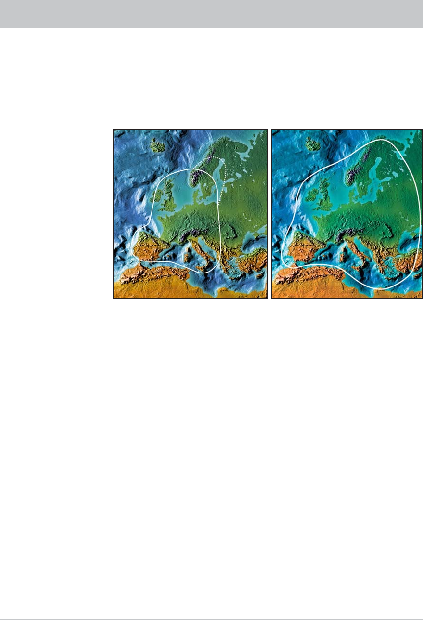
You should preferably align your antenna to the position of the ASTRA satellite 19.2° East (picture
below left), EUTELSAT/HOTBIRD 13° East (picture below right). The spots for these satellites are
shown below.
The satellites broadcast the various channel packages in different footprints.
Within these, the respective channel packages can be received with good
video and audio quality. In the marginal zones reception is possible, although
the quality of the signals received can vary considerably.
The inner line of the
footprint here shows
the area covered by the
digital signals from the
ASTRA satellite.
The outer dashed line of
the footprint displayed
here shows the area that
is covered by individual
ASTRA satellite. There-
fore not all channels
are available within this
footprint.

25
If repairs to the system or individual components are necessary, contact your specialist dealer or our
service centre (see below for address).
Never open the turntable yourself!
• Do not cut the cables! At the cable junction provided, disconnect the cables
projecting from the turntable from the two cables laid within the interior of the
vehicle (unplug the plug).
• The cables laid within the vehicle can remain there
• Unscrew the six M6 screws securing the turntable to the mounting plate
• Place two wooden supports on the vehicle roof, for protection
• Then place the turntable on the prepared wooden supports
• To ship the turntable, use the original packaging which you have saved
• Seal the opening in the vehicle roof appropriately to protect against the ingress of moisture
• If a HDZ 100 roof gland has been fi tted and the equipment is then removed, the cable channels
no longer used should be sealed with the integral plugs. The enclosure is then watertight once again.
Note: Before exchanging the UFS 740sw, fi rst move the turntable to the park position.
ESC
Electronic Service Chiemgau GmbH
Bahnhofstraße 108
83224 Grassau, Germany
Phone: +49 8641 9545-0
Fax: +49 8641 9545-35 and -36
Internet: http://www.esc-kathrein.de
e-Mail: service@esc-kathrein.de
DISMANTLING FOR SERVICING
DISMANTLING
ADDRESS OF THE SERVICE CENTRE
26
POLARISATION SETTING
The LNB for the CAP 700 is factory-set to the polarisation setting “0”. In this position
you can still receive signals from satellites with differences (between the longitude
of the desired reception area and the orbit position of the satellite) of 15° to 20°.
For differences greater than this it is best to rotate the LNB and set the necessary
polarisation angle.
However, we expressly draw attention to the fact that positioning the LNB at a
deviation of up to +45° or up to -45° from the centre position makes sense only if a
satellite to the far West or the far East is actually preferred for reception.
The respective setting angle required for the polarisation can be found in the following
table.
POLARISATION SETTING
Longitude for the reception position
West East

27
Satelliten/Satellites/Satellites
Land/Country/Pays TÜRKSAT
42° Ost
East/Est
ASTRA
(Eurobird 1)
28.2°
Ost
East/Est
ASTRA
19.2°
Ost
East/Est
EUTELSAT
W2
16°
Ost
East/Est
HOTBIRD
13°
Ost
East/Est
EUTELSAT
W1
10°
Ost
East/Est
EUTELSAT
W3A
7°
Ost
East/Est
Thor 2/3
0.8°
West
West/Ouest
Atlantic
Bird 3
5°
West
West/Ouest
Atlantic
Bird 2/
Telecom 2D
8°
West
West/Ouest
Hispasat
1C/1D
30°
West
West/Ouest
Albanien/Albania/L´Albanie -23 -2 8 5 8 11 15 22 26 28/16 41
Belgien/Belgium/La Belgique -27 -11 -5 -9 -7 -5 -2 4 8 10/-2 25
Bulgarien/Bulgaria/Bulgarie -17 4 14 10 13 16 19 25 29 31/19 41
Dänemark/Denmark/Danemark -19 -4 2 -3 -1 1 3 8 11 ´13/1 24
Deutschland/Germany/Allemagne -23 -7 0 -4 -2 0 3 9 12 14´/2 28
Frankreich/France/France -32 -16 -9 -13 -10 -7 -5 3 7 10/-2 27
Finnland/Finland/Finlande -7 6 10 5679121415´/3 21
Griechenland/Greece/Grèce -21 2 14 11 14 18 21 28 32 34/22 46
Großbritannien/Great Britain/
La Grande-Bretagne -26 -13 -8 -13 -11 -9 -7 -2 1 3/-9 17
Italien/Italy/L´Italie -29 -10 -1 -4 -1 3 6 15 19 ´22/10 37
Irland/Ireland/L´Irlande -30 -17 -12 -17 -15 -13 -11 -6 -3 0/12 15
Kroatien/Croatia/Croatie -24 -5 4147101720´23/11 36
Liechtenstein/Liechtenstein/
Liechtenstein -26 -10 -2 -6 -3 0 2 10 13 `16/4 31
Luxemburg/Luxemburg/Luxembourg -26 -11 -4 -8 -6 -3 -1 6 9 12/0 26
Monaco/Monaco/Monaco -31 -13 -5 -9 -6 -3 0 9 13 ´16/4 32
Niederlande/Netherlands/
Les Pays-Bas -25 -10 -4 -8 -6 -4 -1 5 8 10/-2 24
Norwegen/Norway/Norvège -11 2 6124591012/0 19
Österreich/Austria/L´Autriche -24 -6 2 -2 0 3 6 13 16 ´18/6 32
Polen/Poland/Pologne -17 0 725791518´20/8 31
Portugal/Portugal/Portugal -43 -28 -22 -26 -23 -20 -17 -8 -3 0/-12 24
Rumänien/Romania/Roumanie -16 4 13 9 11 14 17 23 26 28/16 38
Schweden/Sweden/Suède -12 1 61245911´13/1 21
Schweiz/Switzerland/Suisse -28 -11 -3 -7 -5 -2 1 8 12 ´15/§ 30
Serbien-Montenegro/Serbia and
Montenegro/Serbie-Monténégro -21 -1 9 5 8 11 14 21 24 26/14 39
Slowakei/Slovakia/Slovaquie -18 0 7368111720´22/10 34
Slowenien/Slovenia/Slovénie -24 -5 3 -1 2 5 8 15 18 ´21/9 34
Spanien/Spain/L´Espagne -40 -24 -17 -21 -18 -15 -11 -2 3 ´6/5 29
Tschechien/Czech Republic/
Republique Tchéque -21-440257 1316´19/7 31
Ungarn/Hungary/La Hongrie -20 -1 7369111821´23/11 35
Other countries and towns in these countries can be found on the Internet on the Kathrein Home Page under “www.kathrein.de/de/sat/index.htm” menu item
“Satellite reception equipment/Technical Information/Azimuth/Elevation and Polarisation Settings”.

28
POLARISATION SETTING
SAFETY NOTES
We strongly advise that users who are not familiar with the setting operations should not
undertake to set the LNB themselves. They should contact a technician or engineer. They may
fi nd a suitable person on the campsite.
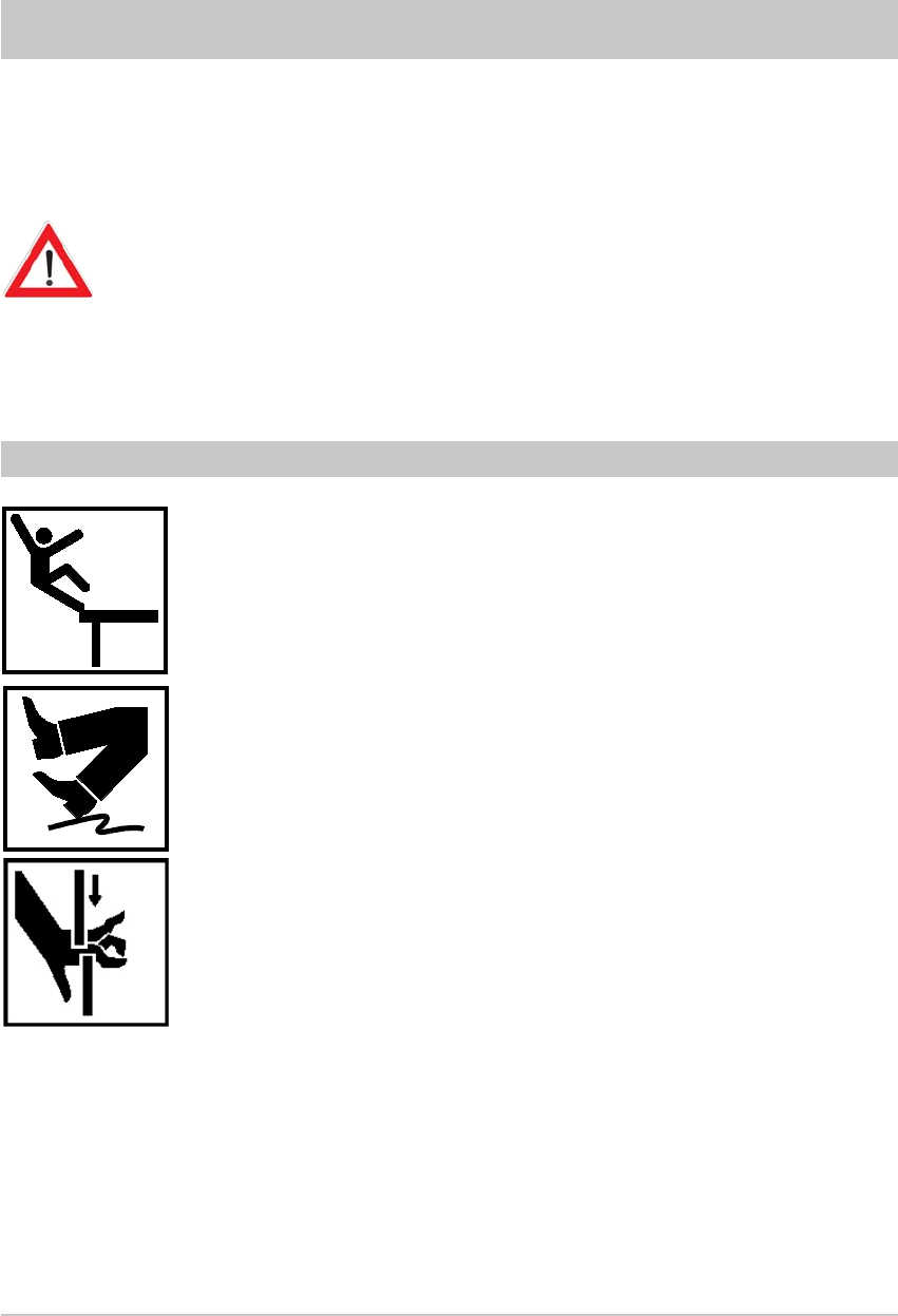
Make sure that:
- The antenna and connected units are disconnected from the power
- The person carrying out the installation does not suffer from vertigo and can move around safely on
the roof of the caravan or motor home
- The person carrying out the settings is wearing sturdy and non-slip shoes
- The person carrying out the settings has a secure position to stand and hold on while working
- The roof and the climbing equipment used (e.g. ladder) are dry, clean and non-slip
- The roof can withstand the weight of the person carrying out the settings
Attention! Risk of death or injury due to falling or roof collapsing!
- During setting operations, make sure that no persons, in particular no children, are in the immediate
vicinity of the turntable and that they cannot touch any moving parts - crush hazard! Nobody should
be below the antenna inside the caravan / motor home during setting operations
Attention! Risk of death or injury due to possible roof collapsing and falling parts on the motor
home/caravan!
Continue to refer to the “Safety instructions - important information” section!
No obstructions may be present in the turning range (see “Safety instructions and important
information”)!
The explanation for this setting procedure is based on the assumption that the entire CAP unit
has been properly put together, installed and set up, as described in this installation manual.
The safety instructions in the detailed operating manual for the UFS 740sw must also be
followed!
SETTING OPERATIONS
(The key names refer to the remote control for the UFS 740sw receiver)
1. Turn on the receiver at the main switch on the front of the unit.
2. Press any of the numeric buttons to bring the receiver into operating mode.
3. If necessary, fi rst perform a fi rst installation
4. Wait until the message “Position of Astra is not known. Start search?” is displayed – cancel this
procedure by pressing the button.
5. Next, press the button to go to the main menu and use the buttons to move to the “Settings”
menu item. Confi rm the selection by pressing the button.
6.. Use the
buttons to move to the “Antenna Confi guration” menu item. Confi rm the selection by
pressing the button.
7. Use the
buttons to select the Elevation option and use the number keys on the remote control
to enter “400”.
29
POLARISATION SETTING
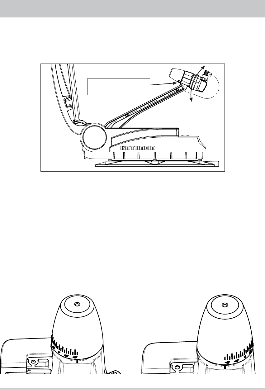
8. Press the
button and the turntable will move to the selected elevation angle.
9. Turn off the UFS 740 using the main switch on the front and disconnect it from the power.
10. Use the socket driver supplied (size 20) to slacken the securing screw of the clamp on the LNB.
11. Rotate the LNB by the required number of degrees (the scale is located on the bottom on the LNB).
Scale for polarisation
setting
12. Tighten the hexagon socket screw to a torque of 3.3-3.5 Nm.
13. Leave the installation location and reconnect the UFS 740sw to the power supply.
15. First switch the receiver on at the main switch, then press any of the numeric buttons.
16. Wait until the message “Position of Astra is not known. Start search?” is displayed – abort this
procedure using the button.
17. Next, press the button to go to the main menu and use the buttons to move to the “Settings”
menu item. Confi rm the selection by pressing the button. Use the buttons to move to the
“Antenna Confi guration” menu item. Confi rm the selection by pressing the button.
18 Use the
buttons to move to the menu item “Reset the turn table antenna”. Confi rm the selection
by pressing the button. Once the antenna has been reset, you can return to the normal TV picture
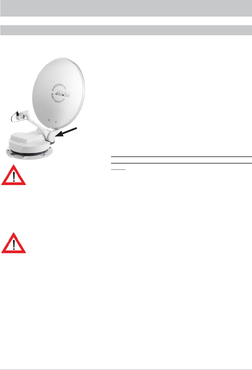
by pressing the button.
View after installation +45° View after installation -45°
30
If a defect arises in the electronic controls, after some disassembly work the
satellite dish can be returned to the park position (horizontal position) manually.
Following this however recalibration by an authorised workshop is always necessary.
Driving to the nearest workshop with the antenna extended at a moderate
speed and taking into account the increase (+ 79 cm) in the vehicle height is an
option and is preferable to manual lowering!
Users unfamiliar with the necessary repair work are urged not to attempt to
lower the antenna manually into park position themselves. They should contact
a technician or engineer. They may fi nd a suitable person on the campsite.
In any case, the safety instructions listed below must be followed.
Make sure that:
- The antenna and connected units are disconnected from the power
- The person carrying out the repairs does not suffer from vertigo and can
move around safely on the roof of the caravan or motor home
- The person carrying out the repairs is wearing sturdy and non-slip shoes
- The person carrying out the repairs has a secure position to stand and hold
on while working
- The roof and the climbing equipment used (e.g. ladder) are dry, clean and
non-slip
- The roof can withstand the weight of the person carrying out the repairs
Attention! Risk of death or injury due to falling or roof collapsing!
- Do not hold onto the antenna, as the rocker comes free without warning
during dismantling
Attention! Risk of death and injury due to falling or crushing!
- Nobody should be inside the caravan/motor home underneath the
antenna during dismantling/installation
Attention! Risk of death or injury due to possible roof collapsing and
falling parts!
MANUAL LOWERING TO PARK POSITION
SAFETY NOTES
31
MANUAL LOWERING TO PARK POSITION
MANUAL LOWERING
1. In the centre of the antenna (arrowed) there is a plastic cap.
Lever this off with a narrow slot-head screwdriver.
2. Behind the cap is an M8 hexagon head screw. Unscrew
these using a 13 mm socket wrench.
After removing the M8 screw, a further thread can be seen.
3. Attention! Secure and support the antenna to prevent it
tipping over. The connection to the rocker can suddenly
come loose during the next step (item 4). It is then no longer
connected to the turntable!
4. Screw an M10 x 40 screw into this thread (minimum length:
40 mm). Screwing in the M10 screw pushes the rocker off
the tapered shaft and releases the engagement.
Important: Screw the screw in only as far as necessary
to free the rocker from engagement on the tapered
shaft!
5. Tilt the antenna into the park position (horizontal position).
6. Unscrew the M10 screw. This allows the rocker to re-engage
on the tapered shaft.
7. Replace the M8 screw and tighten it.
8. Replace the plastic cap.
Loosening the rocker from the taper shaft causes the rocker
zero point position to be lost. When the authorised dealer
rectifi es the defect he will recalibrate the rocker!
9. Consult an authorised dealer.
32
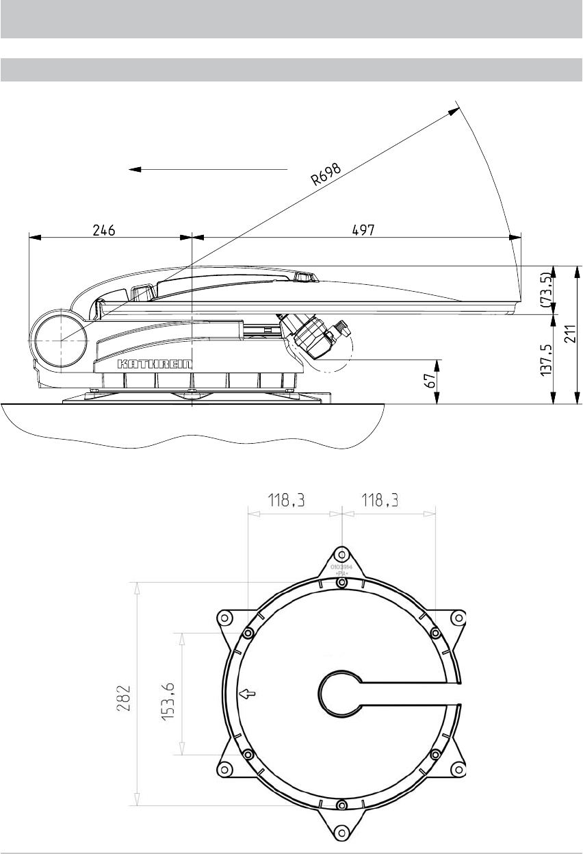
TECHNICAL DATA
DIMENSIONS (MM)
Direction of travel
Mounting plate
33
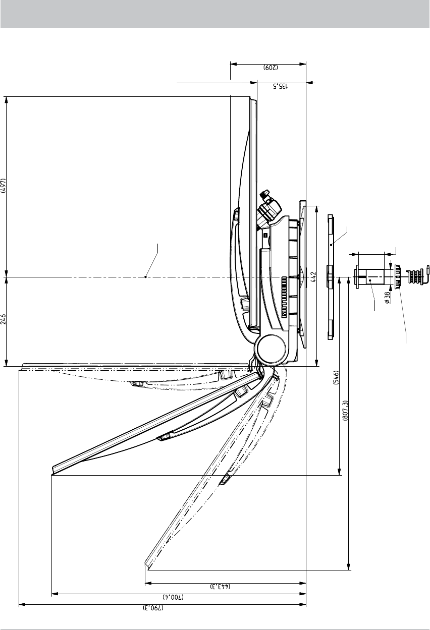
TECHNICAL DATA
Elevation max. 75°
Elevation 45°
Rotary axis
Mounting plate
Clamping range 20/50
Roof gland
Nut
137.5 including mounting plate

34
TECHNICAL DATA
Ignition signal 12…24 V
Search time for fi rst satellite (typ.) 10…120 s
Search time for further satellites (typ.) 2…30 s
LSM search time 2…15 s
(LSM = Last Satellite Memory)
Type CAP 700
Order no. 20310019
LNB 1 output switchable: V/H (14/18 V), low/high (0/22 kHz)
LNB supply voltage V vertical: 11.5-14, horizontal: 16-19
Input frequency GHz 10.70-12.75
Output frequency MHz 950-1950/1100-2150
Oscillator frequency (L.O.) GHz 9.75/10.60
System quality (G/T) 11.3/12.5 GHz dB/K 13.4/13.7
Power supply (vehicle battery) V 10.9-13.8
Power consumption from the 12 V vehicle
electrical system:
Inrush current
Satellite search
TV reception
Stand-by
A
Type 10, max. 12
Type 3
Type 1.2
Type 0.024
Current consumption from the receiver mA Type 160
Setting range:
Elevation
Azimuth
Skew
° 0-75
370
± 45
Weight of the turntable with parabolic refl ector kg 9.7
Packing unit/weight pc./kg 1/15.3

35
SIKAFLEX® 291 SAFETY DATA SHEET
1. Materials/preparation and company designation
Data on the product (trade name): Sikafl ex® 291
Data on manufacturer/suppliers
Manufacturer/suppliers: Sika Deutschland GmbH
Street/postcode: Kornwestheimer Str. 103-107
Postcode and town: Stuttgart
Country: Germany
Tel: +49 711 80090 Fax: +49 711 8009321
General information: Product safety
Emergency information hotline: +49 173 6774799 only outside offi ce hours
2. Composition/data on components
Chemical characterisation: Filled reactive PUR polymer
Hazardous contents (designation to 67/548/EEC)
CAS-No. Concentration Danger symbols R phrases EC no.
Naphtha (crude oil), hydro-desulphurised heavy
64742-82-1 1 - 2.5 % Xn,N 10,65,51/53,66,67 265-185-4
4,4‘ methylene-diphenyl-diisocyanate
101-68-8 0.1 - 1 % Xn 20,36/37/38,42/43 202-966-0
Xylol
1330-20-7 1 - 2.5 % Xn 10,20/21,38 215-535-7
3. Potential hazards
Hazard designation:
Xn Hazardous to health
Special hazard instructions for human beings and the environment
42 Sensitisation possible by breathing in.
4. First Aid measures
General instructions
In all cases show the doctor the safety data sheet.
After breathing in
In the event of trouble consult a doctor.
After contact with the skin
After contact, wash the skin with soap and water.
In the event of continuing skin irritation consult a doctor.
After contact with the eyes
In case of contact with the eyes, wash with copious water for 15 minutes.
Summon a doctor immediately.
After swallowing
Do not induce vomiting. Summon a doctor immediately.

36
5. Measures for fi re fi ghting
Suitable extinguishing media
Compatible with all extinguishing media in general use.
Special hazard from the product, its products of combustion or gases released
In case of fi re the following can be released: Carbon monoxide (CO)
Carbon dioxide (CO2)
Hydrogen chloride (HCl)
Oxides of nitrogen (NOx)
Additional instructions
Combustion residues and contaminated extinguishing media must be disposed of in
accordance with the local authority regulations. Collect contaminated extinguishing water
separately, do not allow it to run into the drains.
6. Measures if inadvertently released
Personal precautions
Ensure suffi cient ventilation.
Wear protective clothing.
Where vapours/dust/aerosols are present, wear a breathing mask.
Environmental protection measures
Do not allow to run into the drains or bodies of water.
In the event of penetration into water, ground or drains, inform the responsible
authorities!
Procedure for cleaning/clearing up
Absorb with media that bind to liquids (e.g. sand, sawdust, universal binding media.
Dispose of the material that has been cleared up in accordance with the chapter on
Disposal.
7. Handling and storage
Handling
Instructions for safe handling: Refer to Chapter 8 / Personal protective
equipment.
Instructions for fi re and explosion prevention: Not applicable
Storage
Requirements for storerooms and containers:
Containers should be dry, kept tightly sealed and stored in a cool, well ventilated place.
Storage proximity instructions
Store separately from all kinds of foodstuffs.
Additional instructions for storage
Protect against frost.
Protect against heat and direct sunlight.
Protect against atmospheric humidity and water.
* 8. Exposure limitation and personal protective equipment
Components subject to monitoring of workplace concentration limits
Designation of the component
CAS no. type Reference/country/year
Naphtha (crude oil), hydro-desulphurised heavy
64742-82-1 Permissible workplace concentration 350 mg/m3 TRGS 900/DE/2004
64742-82-1 Permissible workplace concentration 70 ml/m3 TRGS 900/DE/2004
SIKAFLEX® 291 SAFETY DATA SHEET
*) Markings (*) in the left margin indicate revisions from the previous version.

37
4,4‘ methylene-diphenyl-diisocyanate
101-68-8 Permissible workplace concentration 0.05 mg/m3 TRGS 900/DE/2004
101-68-8 Permissible workplace concentration 0.005 ml/m3 TRGS 900/DE/2004
Xylol
1330-20-7 Permissible workplace concentration 440 mg/m3 TRGS 900/DE/2004
1330-20-7 Permissible workplace concentration 100 ml/m3 TRGS 900/DE/2004
1330-20-7 EU-TWA (8h) 221 mg/m3 2000/39/EC
1330-20-7 EU-TWA (8h) 50 ml/m3 2000/39/EC
1330-20-7 EU-STEL (15‘) 442 mg/m3 2000/39/EC
1330-20-7 EU-STEL (15‘) 100 ml/m3 2000/39/EC
Personal protective equipment
General protective and hygiene measures
Ensure suffi cient ventilation at the workplace.
Avoid contact with the eyes and skin.
Apply prophylactic skin protection by protective hand cream.
Take off soiled clothing immediately.
Do not smoke, eat or drink when handling the product.
Before breaks and after completing work, wash hands well.
Breathing protection
When ventilation is poor: ABEK multi-range fi lter
The gas fi lter class is dependent on the local concentration of injurious substances.
Hand protection
Wear butyl rubber/nitrile rubber gloves
Eye protection
Safety glasses
Body protection
Work clothing
* 9. Physical and chemical characteristics
Appearance
Form: pasty
Colour: various, depends on the pigment
Smell: characteristic
Safety-relevant data, methods
Flashpoint: > 65 °C
Density at 20°C: approx. 1.26 g/cm3
Solubility in water: reacts with water
Viscosity at 20°C: not applicable
VOC (solvents): 3.47 %
VOC (CH): 3.47 %
10. Stability and reactivity
Substances to be avoided/hazardous reactions
No hazardous reactions if correctly stored and handled.
Thermal decomposition and hazardous products of decomposition
No decomposition if used correctly.
*) Markings (*) in the left margin indicate revisions from the previous version.
SIKAFLEX® 291 SAFETY DATA SHEET

38
11. Toxicology data
Sensitisation
Sensitisation/allergic reactions may occur.
Sensitive individuals may exhibit allergic reactions even at very low concentrations.
Experience of human exposure
On skin contact: May lead to irritation
On eye contact: May lead to irritation
On being breathed in: May lead to irritation
On being swallowed: May lead to health problems
12. Ecological data
Additional instructions
Do not allow to run into the drains, bodies of water or the ground.
13. Disposal instructions
Product
Recommendations
In accordance with the applicable waste labelling regulations, waste should be classifi ed by its
origin. Therefore a unique waste code number cannot be assigned.
Packaging
Recommendations
Packaging that is empty of residues should be sent for recycling. Packaging that contains residues
of hazardous substances or which is contaminated with hazardous substances, and any packaging
that is not empty of residues should be disposed of as the product, correctly and without creating
pollution.
If the last contents makes it necessary, packaging that is empty of residues must be pre-treated
for disposal (e.g. washed out, neutralised, cured, shaken out).
14. Transport data
ADR/RID
Further data
Not hazardous cargo.
IMO/IMDG
Marine pollutant: no
Further data
Not hazardous cargo.
IATA/ICAO
Further data
Not hazardous cargo.
15. Regulations
Identifi cation in accordance with EC directives
The product should be classifi ed and identifi ed in accordance with EC directives/national statute
law.
Component(s) to be labelled as hazardous content: 4.4’ methylene-diphenyl-diisocyanate
Hazard symbols
Xn Hazardous to health
SIKAFLEX® 291 SAFETY DATA SHEET

39
Risk phrases
42 Sensitisation possible by breathing in.
Safety phrases
23 Do not breathe in gas/smoke/vapour/aerosol.
45 IN the event of accident or feeling unwell summon a doctor immediately (if possible show
the doctor this label).
Special identifi cation of particular components
Contains isocyanates. Follow the manufacturer’s instructions.
National regulations
Water contamination class
WGK 1 (to VwVws of 17. May 1999)
GISCODE/PRODUCT CODE
GISCODE: PU 50
16. Other data
Markings (*) in the left margin indicate revisions from the previous version.
Intended purpose: Chemical product for building and industry
Risk phrases for the constituent substances listed in chapter 2
10 Flammable.
20 Hazardous to health if breathed in.
20/21 Hazardous to health if breathed in and if comes in contact with the skin.
36/37/38 Irritates the eyes, breathing organs and the skin.
38 Irritates the skin.
42/43 Sensitisation possible by breathing in and by contact with the skin.
51/53 Poisonous to water organisms, can have long-term polluting effects on bodies of water.
65 Hazardous to health: can cause damage to lungs if swallowed.
66 Repeated contact can lead to brittle or cracked skin.
67 Vapours can cause drowsiness and light-headedness.
The data in this safety data sheet represent our knowledge at the time of publication. They are not warranted
as a complete list of characteristics. The only warranty extended is that expressed in the technical data
sheets and the general conditions of sale. Consult the technical data sheet before use.
SIKAFLEX® 291 SAFETY DATA SHEET
40
SIKAFLEX® 291 TECHNICAL DATA SHEET
Sikaflex
®
-291 1 / 2
Technisches Merkblatt
Version 12 / 2005
Sikaflex
®-
291
Der haftstarke Marine
-
Dichtstoff
Technische Eigenschaften
Chemische Basis
1-
K Polyurethan
Farbe
weiss, schwarz, holz
Härtungsmechanismus
feuchtigkeitshärtend
Dichte vor Aushärtung (DIN 53479)
ca. 1,3
kg/l, farba
b-
hängig
Standfestigkeit
gut
Verarbeitungstemperatur
+5°C -
+40°C
Hautbildezeit
1
ca. 60 min
Durchhärtegeschwindigkeit
(siehe Diagramm 1)
Volumenänderung (DIN 52451)
ca.
-
5%
Härte Shore A (ISO 868 / DIN 53505)
ca. 40
Zugfestigkeit (ISO 52
7 / DIN 53504)
ca. 1,8 N/mm
2
Reissdehnung (ISO 527 / DIN 53504)
ca. 500%
Weiterreisswiderstand (ISO 34 / DIN 53515)
ca. 6 N/mm
Glasumwandlungstemperatur (ISO 4663 / DIN 53445)
ca.
-
45°C
Einsatztemperatur
dauerhaft
Kurzfristig
4 Stunden
1 Stunde
-40°C bis +90°C
160°C
180°C
Haltbarkeit (Lagerung unter 25°C im ungeöffneten Gebinde)
12 Monate
1)
23°C / 50% r.Lf.
Beschreibung
Sikaflex
®-291 ist ein für den Boots-
und Schiffsbau entwickelter, stand-
fe
ster 1-
Komponenten
-
Polyure
-
than
-
Dichtstoff.
Unter Einwirkung der Luft
feuch
-
tigkeit reagiert dieser zu einem
Elastomer.
Sikaflex
®-291 erfüllt die Anfor-
derungen der Internationalen Mar
i-
timen Organisation (IMO).
Sikafle
x®-291 wird nach dem Qu
a-
litätssicherungssystem ISO
9001
/ 14001 und dem Respo
n-
sible Care Pr
o
gramm hergestellt.
Produktvorteile
-1-
komponentig
-
elastisch
-
geruchsarm
-
alterungs
-
und
witterungsbestä
n
dig
-
nicht korrosiv
-
überlackierbar
-
schleifbar
-
breites Haftspektrum
-
elektrisch nicht leitfähig
-
Meerwasser
-
und Hydrolyse
-
beständig
Anwendungsbereich
Sikaflex
®-291 ist ein im Boots- und
Schiffsbau vielseitig einsetz
bares
Produkt und dient der Her
stellung
von elastischen und vibrationsb
e-
ständigen Dich
tungs
fugen im I
n-
nen
- und Aussenbereich.
Sika
-
flex
®-291 verfügt über ein grosses
Haftver
mögen auf den w
e-
sentlichen, im Schiffsbau verwe
n-
deten Materia
len.
Geeignete U
n-
tergründe sind Holz, Metalle, Grun-
die
rungen und Lackierungen (2-K-
Systeme), kera
mi
sche Mate
rialien,
Kunststoffe (UP-GFK etc.). S
i-
kaflex
®-
291
darf nicht zur Abdic
h-
tung von span
nungs
riss
ge
fähr
-
deten Kunststoffen (wie PMMA,
PC etc.) verwe
n
det werden.
Für Stabdeckverfugung emp
fehlen
wir Sikaflex®-290 DC. In erhärt
e-
tem Zustand kann Sika
flex
®-
291
probl
emlos g
e
schliffen werden.
Härtungsmechanismus
Technical data sheet
Version 12/2005
Sikafl ex®-291
The strongly bonding marine adhesive
Technical characteristics
Chemical basis 1-component polyurethane
Colour white, black, natural wood
Curing mechanism cures by absorbing moisture
Density before curing (DIN 53479) approx. 1.3 kg/l,
depending on colour
Stability good
Processing temperature
60 min.
Skin formation time 1
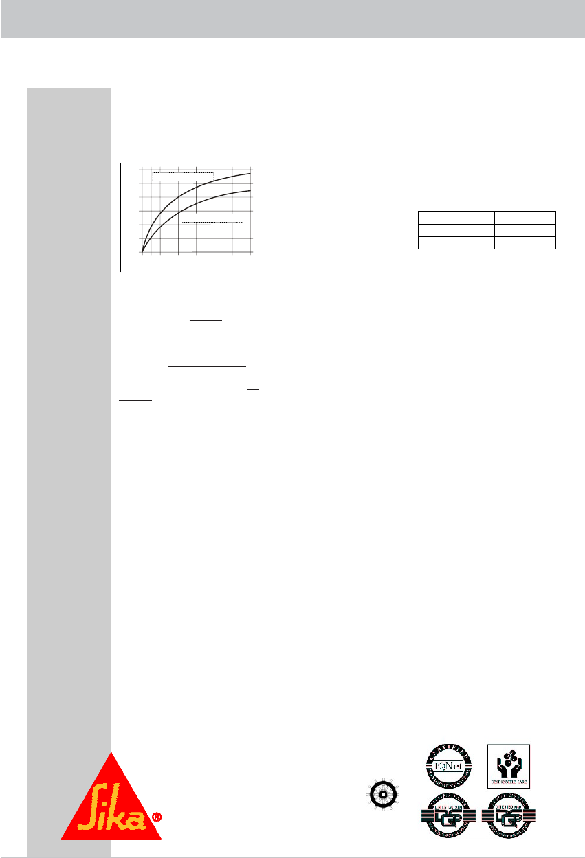
Through-curing speed (see digiagram 1)
Volume change (DIN 52451) approx. -5%
Shore A hardness (ISO 868 / DIN 53505) approx. 40
Tensile strength (ISO 527 / DIN 53504) 1.8 N/mm2
Elongation at break (ISO 527 / DIN 53504) approx. 400%
Tear propagation resistance (ISO 34 / DIN 53515) approx. 6 N/mm
Glass transition temperature (ISO 4663 / DIN 53445) approx. -45°C
Operating temperature sustained
short-term 4 hours
1 hour
-40°C to +90°C
160°C
180°C
Storage life (storage at less than 25°C in unopened containers) 12 months
1) 23°C / 50% r.Lf.
Description
Sikafl ex® 291 is a stable 1-compo-
nent polyurethane sealant developed
for boatbuilding and shipbuilding.
On exposure to atmospheric moisture
it reacts to become an elastomer.
Sikafl ex® 291 satisfi ed the require-
ments of the International Maritime
Organisation (IMO).
Sikafl ex® 291 is manufactured in ac-
cordance with the ISO 9001/14001
Quality Assurance System and the
Responsible Care Programme.
Product advantages
- 1-component
- fl exible
- low odour
- resistant to ageing and weather
- non-corrosive
- can be painted over
- can be sanded
- broad bonding spectrum
- electrically non-conductive
- resistant to seawater and hydro-
lysis
Application Range
Sikafl ex® 291 is a versatile product for
use in boatbuilding and shipbuilding to
make fl exible and vibration-resistant
seals in internal and external areas.
Sikafl ex® 291 has strong bonding pro-
perties to the principal materials used
in shipbuilding. Suitable substrates in-
clude wood, metals, primers and paint
fi nishes (2-component system), cera-
mic materials, plastics (UP-GFK etc.).
Sikafl ex® 291 should not be used for
sealing plastics that are subject to
stress cracking (such as PMMA, PC
etc.).
For timber decking we recommend Si-
kafl ex® 290 DC. In the cured condition,
Sikafl ex® 291 can be sanded without
problems.
Curing mechanism
41
SIKAFLEX® 291 TECHNICAL DATA SHEET
Sikaflex
®
-291 2 / 2
Weitere Informationen
Internet: www.sika
-
industry.de, E
-
Mail: industry@de.sika.com
www.sika.com
Sika Deutschland GmbH
Kleb
-
und Dichtstoffe Industrie
Stuttgarter Strasse 139
D-
72574 Bad Urach
Deutschland
Tel. +49 7125 940
-
761
Fax +49 7125
940
-
763
Die Vernetzungsreaktion von S
i-
ka
f
lex
®-291 erfolgt mit Luft
feuch
-
tigkeit.
Bei niedriger Temperatur ist
der Wassergehalt der Luft geringer
und die Vernet
zungs
reaktion ve
r-
läuft etwas langsamer (siehe Di
a-
gramm).
Zeit (Tage)
121086240
4
8
12
0
Schichtdicke (mm)
23°C / 50% r.Lf.
10°C / 50% r.Lf.
Diagramm 1:
Durchhärtegeschwindigkeit für
Sikaflex
®-
291
Chemische Beständigkeit
Sikaflex
®-291 ist
beständig
gegen
Süss
- und Salzwasser, Kalkwasser
und öffentliche Abwässer sowie
wässerige Tensidlösungen, ve
r-
dünnte Laugen und Sä
uren;
kur
z-
zeitig beständig gegen Treibstoffe,
Mineralöle sowie pflanzliche und
tierische Fette und Öle, nicht b
e-
ständig
gegen organische Säuren,
Alkohol, stärkere Mineralsäuren
und Laugen sowie Lösemittel.
Die Informationen sind nur A
n-
haltspunkte. Eine obj
ektbezogene
Beratung erhalten Sie auf Anfrage.
Verarbeitungshinweise
Untergrundvorbereitung
Die Haftflächen müssen sau
ber,
trocken, staub- und fettfrei sein.
Angaben zur Vorbereitung von
Werk
stoffoberflächen finden Sie in
der Primertabelle für Sika®Mari
ne
Systeme.
Verarbeitung
Kartu
schen
membrane einste
chen
und vollständig öffnen.
Beutel in die Verarbeitungs
pistole
einlegen und Clip a
b
schneiden.
Düsenspitze entsprechend der Fu-
gen
breite zuschneiden und die
Dichtmasse mit einer ge
eigneten
Hand
-,Akku-oderKolbenstange
n-
druckluftpistole luftfrei in die Fuge
einbringen.
Angebrochene Gebinde müs
sen
innerhalb weniger Tage verarbeitet
werden.
Die Verarbeitungstemperatur darf
5°C nicht unter- bzw. 40°C nicht
überschreiten.
Die optimale Te
m-
peratur von Material und Werkstoff
liegt zw
i
schen 15°C und 25°C.
Für die Beratung zur Auswahl und
Einrichtung einer geeigneten
Pumpanlage setzen Sie sich bitte
mit der Abteilung System Engine
e-
ring der Sika Industry in Verbi
n-
dung.
Abglätten
Das Abglätten muss innerhalb der
Hautbildezeit des Klebstoffes e
r-
folgen. Zum Abglätten empfehlen
wir Sika®Abglättmittel N. Andere
Abglätt
mittel müssen auf ihre Ei
g-
nung überprüft we
r
den.
Entfernung
Nicht ausgehärtetes Sikaflex®-
291
kann von Geräten und Werkze
u-
gen mit Sika®
Remover
-208 en
t-
fernt werden. Ausgehärtetes Mat
e-
rial kann nur noch mecha
nisch
entfernt werden.
Hände/Haut sollten sofort mit
Sika
®Handclean oder einer geei
g-
neten Handwaschpaste und Wa
s-
ser gereinigt werden. Keine Lös
e-
mittel verwenden!
Überlackieren
Nach erfolgter Hautbildung kann
Sikaflex
®-
291 überl
a
ckiert werden.
Die Lackverträglichkeit muss durch
Vorversuche überprüft werden.
Einbrennlacke dürfen nur auf völlig
ausgehärtetem Sikaflex®-291 au
f-
gebracht werden. Es ist zu berüc
k-
sichtigen, dass Härte und Filmd
i-
cke des Lackes den Klebstoff in
seiner Dehnung beeinträch
tigen
und zu Rissbildungen führen kö
n-
nen.
Weitere Informationen
Folgende Dokumente sind auf
Anfrage erhältlich:
-
Sicherheitsdatenblatt
-
Primertabelle für Sika Marin
e
Systeme
-
Allg. Richtlinien zur Verarbeitung
von
Sikaflex
®
Kleb
-
und Dich
t-
stoffen
-
Marine Handbuch
Gebinde
Tube
100 ml
Kartusche
310 ml
Beutel
400 ml
Wichtig
Für den Umgang mit unseren
Produkten sind die wesentlichen
physikalischen, sicherheitstechn
i-
schen, toxikologischen und ökol
o-
gischen Daten den sto
ffspezif
i-
schen Sicherheitsdatenblättern zu
entnehmen. Die einschlägigen
Vorschriften, wie z.B. die Gefah
r-
stoffverordnung, sind zu beachten.
Auf Wunsch stellen wir Ihnen u
n-
ser System-Merkblatt TM 7510
"Hinweise zum Arbeitsschutz"
beim Umgang mit Produkten d
er
Sika Deutschland GmbH zur Ve
r-
fügung.
Hinweis:
Die vorstehenden Angaben, insbeson
dere
die Vorschläge für Verarbeitung und Ve
r-
wendung unserer Produkte, beruhen auf
unseren Kenntnissen und Erfahrungen im
Normalfall, vorausgesetzt die Produkte
wurden sachgerecht gelagert und ang
e-
wandt. Wegen der unterschiedlichen Mat
e-
ri
alien, Untergründen und abweichenden
Arbeitsbedingungen kann eine Gewährlei
s-
tung eines Arbeitsergebnisses oder eine
Haftung, aus welchem Rechtsverhältnis auch
immer, weder aus diesen Hinwei
se
n, noch
aus einer mündlichen Beratung begründet
werden, es sei denn, dass uns insoweit
Vorsatz oder grobe Fahrlässigkeit zur Last
fällt. Hierbei hat der Anwender nachzuwe
i-
sen, dass er schriftlich alle Kenntnisse, die
zur sachgemäßen und erfolgversprechen
de
n
Beurteilung durch Sika erforderlich sind, Sika
rechtzeitig und vollständig übermittelt hat.
Der Anwender hat die Produkte auf ihre
Eignung für den vorgesehenen Anwe
n-
dungszweck zu prüfen. Änderungen der
Produktspez
ifikationen bleiben vorbehalten.
Schut
z
re
chte Dritter sind zu beachten. Im
übrigen gelten unsere jeweiligen Ver
kaufs
-
und Lieferbedingungen. Es gilt das jeweils
neueste Technische Merkblatt, das von uns
angefordert werden sollte.
The cross-linking reaction of Sikaf-
lex® 291 occurs in the presence of
atmospheric moisture. At lower tem-
peratures the water content of the air
is less and the cross-linking reaction
proceeds somewhat more slowly (see
diagram).
Layer thickness (mm)
Time (days)
Diagram 1: Through curing speed of
Sikafl ex® 291
Chemical Stability
Sikafl ex® 291 is resistant to fresh
water and salt water, hard water and
effl uent from public drains including
aqueous surfactants, dilute alkalis
and acids; short-term resistant to
fuels, mineral oils including vegetab-
le and animal oils and greases, not
resistant to organic acids, alcohol,
stronger mineral acids and alkalis or
solvents. This information is intended
only as a general indication. Advice
for specifi c applications is available
on request.
Processing instructions
Substrate preparation
The surfaces to be bonded must be
clean, dry, and free of dust and gre-
ase. Data on preparation of materials
surfaces can be found in the primer
table for Sikafl ex® marine systems.
Processing
Break the cartridge membrane and
fully open it. Insert the bag into the
application gun and cut off the clip.
Cut off the tip of the nozzle to suit
the crack to be fi lled, and apply the
sealant with a suitable manual, bat-
tery-powered or compressed air
piston gun into the crack, leaving no
air bubbles. Opened containers must
be used up within a few days. The
processing temperature must not be
below 5°C or above 40°C. The opti-
mum temperature both material and
sealant is beween 15°C and 25°C.
For advice on selection and arran-
gement of a suitable pump system,
please contact the System Enginee-
ring Department at Sika Industry.
Smoothing off
Smoothing off must be performed
within the skin formation time of the
adhesive. We recommend Sika® N
smoothing off agent. Other smoothing
off agents should be checked for sui-
tability before use.
Removal
Uncured Sikafl ex® 291 can be remo-
ved from equipment and tools with
Sika® Remover 208. Cured material
can only be removed machanically.
Hands/skin should be cleaned im-
mediately with Sika® Handclean or
a suitable hand cleansing paste and
water. Do not use solvents!
Painting over
After the skin has formed, Sikafl ex®
291 can be painted over. The suitab-
lility for painting over must be trialled
prior to application. Powder coating
points may be applied only to fully
cured Sikafl ex® 291. It should be
borne in mind that the hardness and
fi lm thickness of the paint fi nish may
affect the expansion of the plastic and
lead to cracking.
Additional information
The following documents are availa-
ble on request:
- Safety data sheet
- Primer table for Sika marine
systems
- General guidelines for working with
Sikafl ex® adhesives and sealants
- Marine handbook
Containers
Tube
Cartridge
Bag
Important
When handling our products, please
read the material-specifi c safety data
sheets for their essential physical,
safety, toxicological and ecological
data. The applicable regulations,
such as the hazardous substances
regulations should be complied with.
On request we will send you our sys-
tem data sheet TM 7510 „Instructions
for protection at work“ for handling
Sika Deutschland GmbH products.
Note:
The details above, especially the suggestions for
the processing and use of our products are based
on our knowledge and experience in normal cases,
providing the products are correctly stored and ap-
plied. Due to the variety of materials, surfaces and
variations in working conditions, no guarantee of a
work product or liability from any legal relationship
can be founded on these instructions or on oral
advice unless we are charged with premeditated
or gross negligence. Here the user must prove that
he brought to Sika‘s attention promptly, completely
and in writing all knowledge necessary for Sika to
make an objective assessment of expectation of
success. It is the user‘s responsibility to check the
products for suitability for the intended application.
We reserve the right to change the product specifi -
cations. The trademark rights of third parties must be
respected. In all other respects our respective sales
and delivery conditions apply. The latest version of
the technical data sheet is applicable and should be
requested from us.
Additional information
Internet: www.sika-industry.de, e-mail: industry@de.sika.com
www.sika.com
Sika Deutschland GmbH
Kleb- und Dichtstoffe Industrie
Stuttgarter Strasse 139
D-72574 Bad Urach
Germany
Tel. +49 7125 940-761
Fax +49 7125 940-763

42
CAP 700 OPERATING MANUAL
The operating manual for the
CAP 700
If, despite studying this operating manual, you still
have questions about getting started with the unit or
using it correctly, or if unexpected problems occur,
please contact your specialist dealer.
The Kathrein customer hotline is also at your disposal.
Phone: +49 8031/184-700
The automatic updating of the EPG data described in the UFS 740sw operating
manual as occurring at 03:00 in the morning is not performed automatically when
the UFS 740sw is being operated on the CAP 700! The EPG data are updated
when an individual channel is viewed. At this point however the receiver updates
all EPG data for the channels that are broadcast from the currently selected
receiving transponder.
For example: You have selected the channel “SAT.1”. At this point for instance the
EPG data will be updated for “ProSieben” and “KABEL1”.
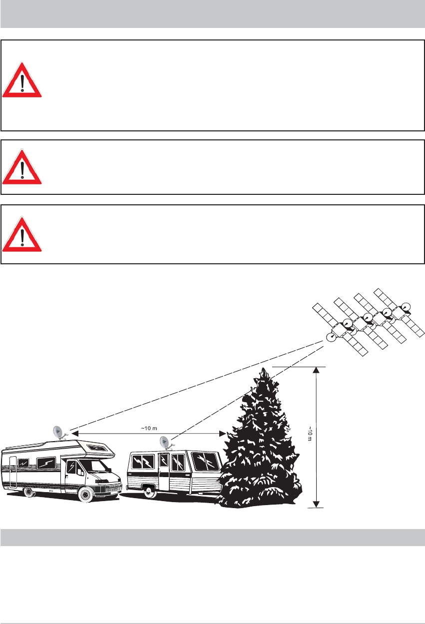
43
So as to avoid overheating the turntable motors, do not operate the motors
continuously for longer than 10 minutes.
None of the search procedures initiated by the CAP 700 will require as much
as 10 minutes operation. Only repeated unsuccessful search procedures or
manual overrides by the user can cause this limit to be exceeded.
All settings on the UFS 740 are made using the remote!
IMPORTANT INFORMATION FOR CAP 700 BEFORE SETUP
This section of the UFS 740 operating manual for the turntable assumes that
the UFS 740 and the turntable have been properly installed and connected, as
described in the installation and operating manuals!
If you have not yet done so, read the safety instructions at the beginning of the
UFS 740sw operating manual and follow them when handling the UFS 740sw
and the turntable!
REMOTE CONTROL
Before setting up your satellite system, make sure that the location allows a free
view to the satellite positions to the South and is not shadowed by trees or other
obstructions. This will save you time and effort!
Reception
No reception
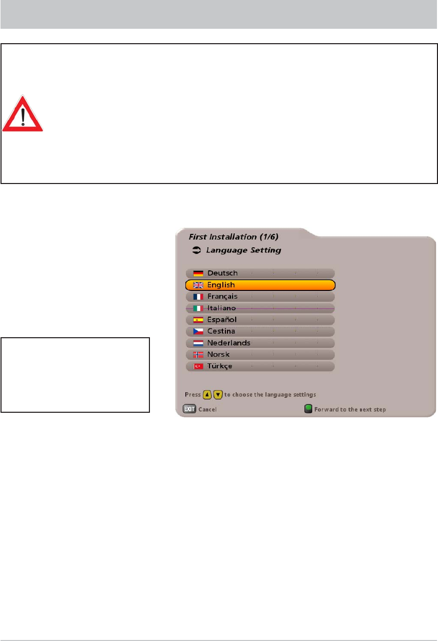
44
FIRST INSTALLATION
Before using your unit for the fi rst time, read the “Safety Instructions - Important
Information” and “Installation and Connection” sections.
You will fi nd a sample confi guration for a motor home in the Section “Installation
and Connection”, “Connection Example”.
Do not connect the receiver to the power supply until all installation work has been
properly carried out.
The guidance given in the “First Installation” section assumes that the receiver
has been properly connected, as per the “Safety Instructions - Important
Information” and “Installation and Connection” sections.
First switch your TV set on and select the AV channel slot. Switch on your receiver at the power switch
on the front of the unit. The following display appears:
Select the menu language you want using the buttons. Available options: German, English, French,
Italian, Spanish, Czech, Dutch, Norwegian and Turkish.
Press the ! (green) button to move to the next menu.
Also pay attention to the
bars at the bottom of the on-
screen display! These provide
information on what to do next.
Note: If you are unsure whether you chose the right option from a previous menu, you can go
back a step at any time during the fi rst installation process by pressing the (red) button.
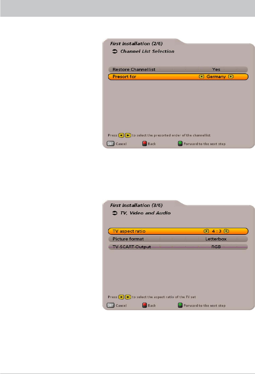
45
The following display appears:
Use the buttons to select whether to replace the default channel list with one pre-sorted
for Germany, Austria, Switzerland or Italy. If you want to use the default channel list, choose “No”
under “Restore Channellist”. Press the ! (green) button to move to the next menu.
The following display appears:
Use the buttons here to select the settings for your TV set.
When doing this, refer to the operating instructions for your TV set!
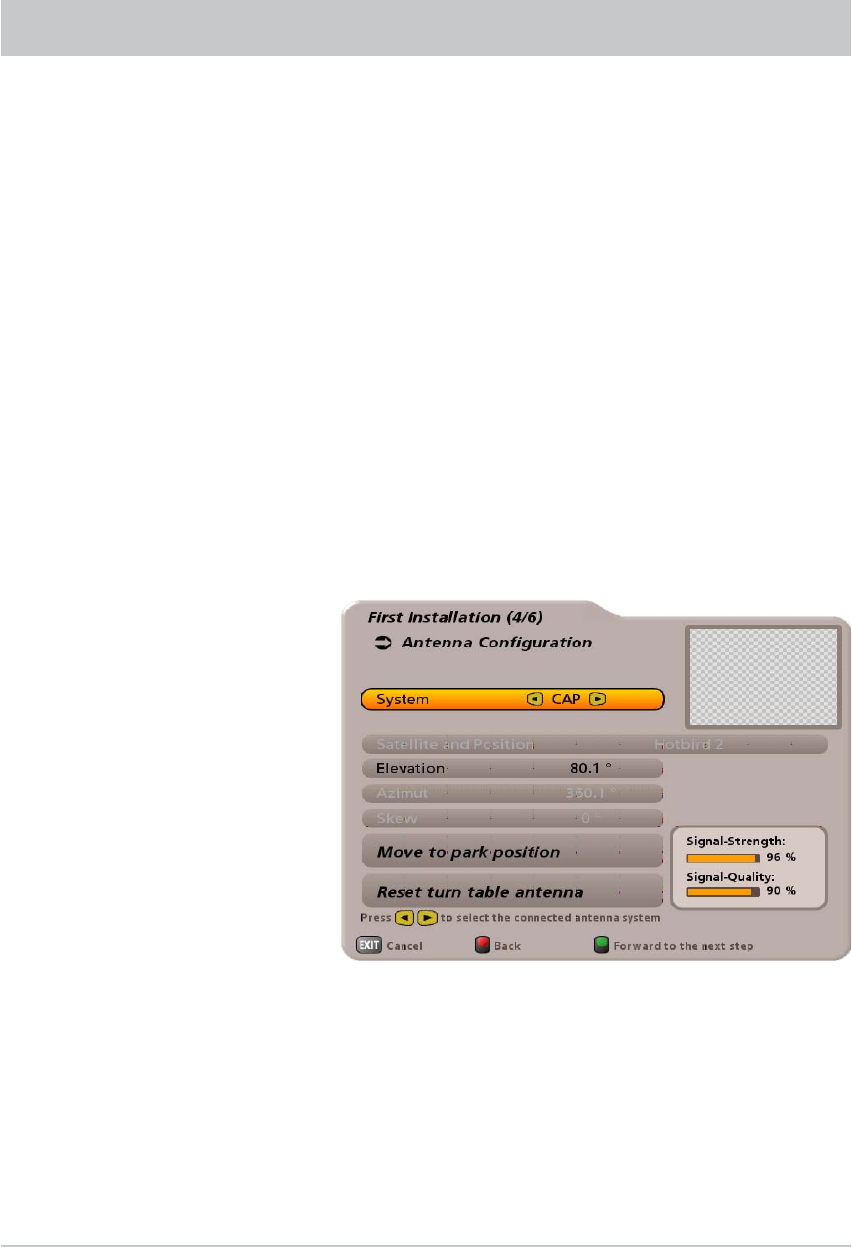
46
FIRST INSTALLATION
System
Use the buttons at “System” to select “CAP”. Then press the ! (green) button to move to the next
menu.
TV aspect ratio
Select the TV's picture format. Either
4:3 or
16:9
Picture format
Here you select the type of screen display, depending on the setting of your TV format:
- TV format “4:3”: Pan & Scan (picture is clipped) or Letterbox (black bands above and below)
- TV format “16:9”: Always 16:9 or automatic
TV Scart Output
Select the type of video signal at the TV Scart socket here. Select the signal that your TV set can process.
- FBAS – Composite Colour Baseband Signal
- RGB – Red/Green/Blue signal or
- Y/C – S-Video signal (luminance/chrominance)
Press the ! (green) button to move to the next menu.
The following display appears:
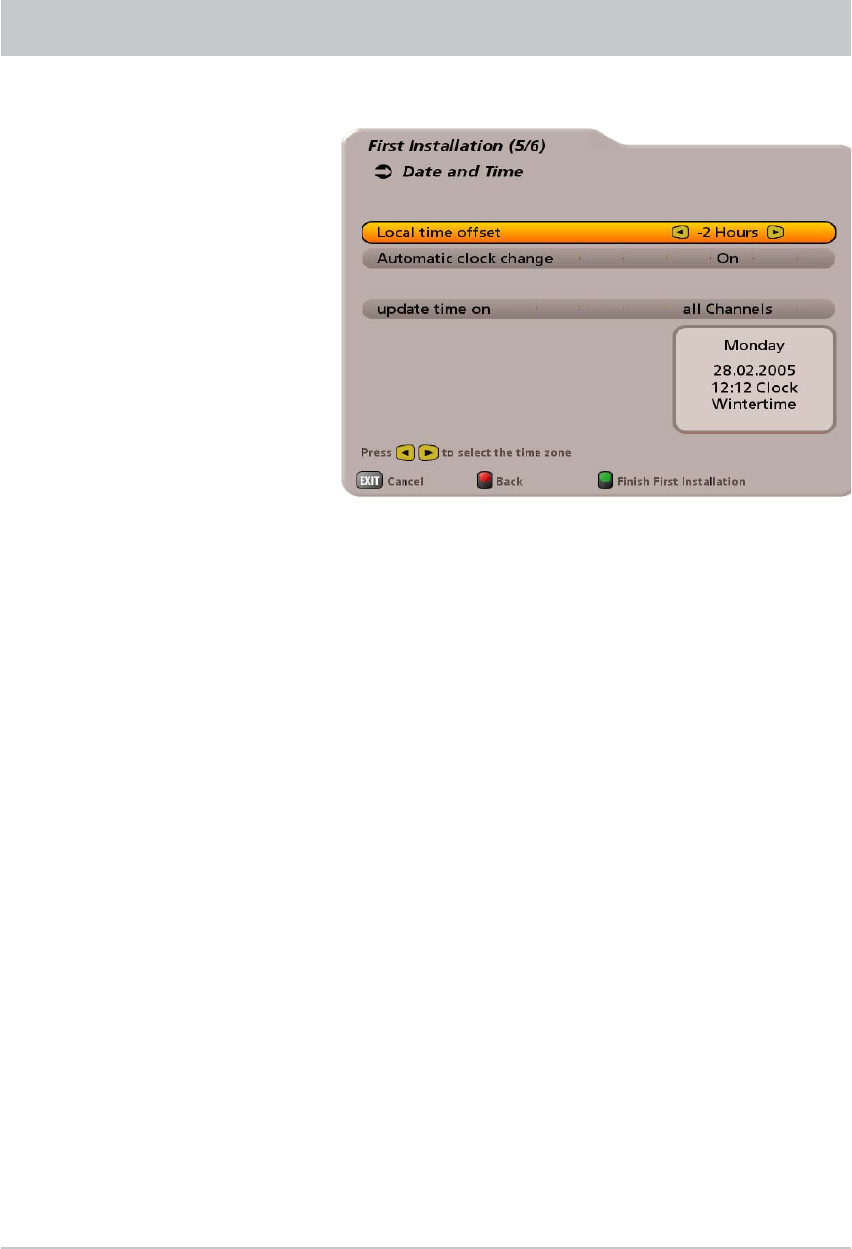
47
FIRST INSTALLATION
Local time offset
Use the buttons to set the time zone variation from UTC (formerly GMT) (e.g. for
Germany +1 hour).
Use the buttons to switch to the “Automatic clock change” fi eld. Use the
buttons to select whether the receiver should automatically change over between summer
and winter time. If “On” is selected, the receiver automatically sets itself to the right time. If
“Off” is selected, the fi eld for manual selection of summer and winter time is displayed below.
Press the buttons to perform the setting.
Press the ! (green) button to close fi rst installation and return to the main menu. Press the button
to view the TV picture.
The following display appears:
Note: Channel search “Item 6/6” is skipped if “CAP” is set, since the antenna must fi rst be
aligned to the desired satellite before a channel search can be started.
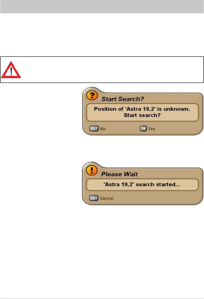
48
ALIGNMENT (SATELLITE SEARCH)
The antenna is aligned automatically. After the UFS 740 has been switched on, the turntable
automatically moves to the last channel received and the associated satellite position (e.g. ARD/ASTRA).
This works because each satellite is automatically recognised by the turntable.
The satellite search is started when you select a channel. If the turntable has not yet saved the position
of the satellite, you will see the following display when you select a channel (example):
If the vehicle is not on supports during the search process and people are mo-
ving around inside it, there is a risk that movement of the vehicle will mean that
the satellite is not found.
Press the button to start search mode.
The search may take a few minutes (generally about two minutes). You will fi rst see the following message:
As soon as the turntable has found the correct satellite, it saves this position. During this process you
receive no TV picture. The turntable will then perform an automatic fi ne adjustment (if the signal
level is suffi cient, the satellite position will be saved immediately by the turntable). During the fi ne
adjustment you will for the fi rst time receive a TV picture, this however can still “freeze” during the fi ne
adjustment process - whether it does or not is system-dependent.
The set position (of the satellite that was found) is saved and the desired channel appears on the
TV screen.
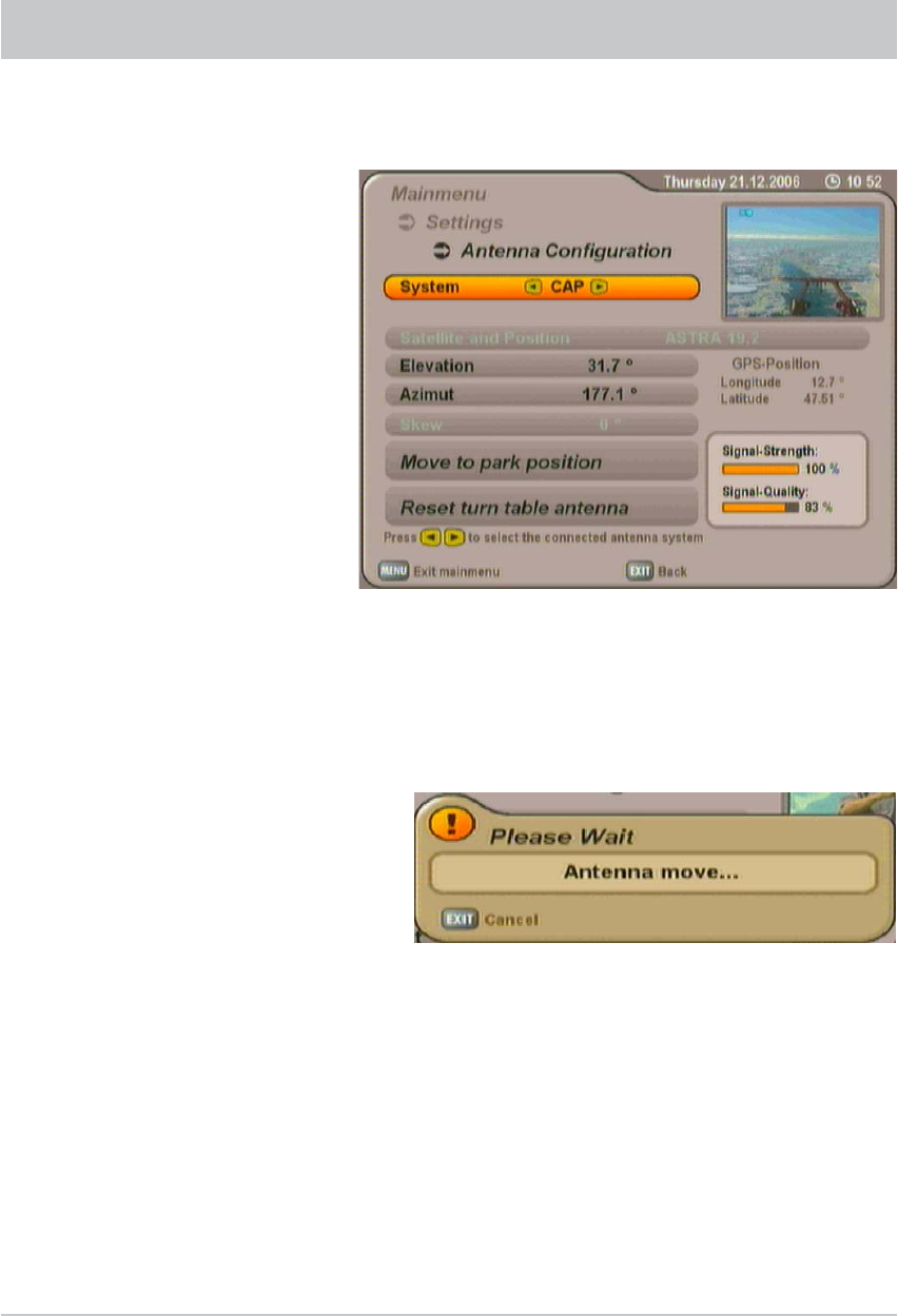
49
Press the button to return to the main menu. The buttons and button allow you to call up
the submenus (“Settings”, “Antenna Confi guration”).
You can correct the inclination and horizontal angle of the antenna using the “Elevation” and “Azimuth”
settings. To do this press the buttons or enter a numeric value using the numeric keys and
confi rm with the button. Check your settings by referring to the “Signal-Strength” and “Signal-
Quality” bars on the right-hand side. The higher the bar, the stronger and better quality the signal
received.
The new co-ordinates are not
assigned to the satellite until you
have saved the satellite position
when exiting the “Antenna
Confi guration” menu!
When you have performed the correction, press the button to exit the menu. You will be asked
whether you wish to save the changes.
Press one of the buttons (“Yes, save changes” or “No, don’t save changes”) and confi rm by
pressing the button.
MOVING THE ANTENNA MANUALLY
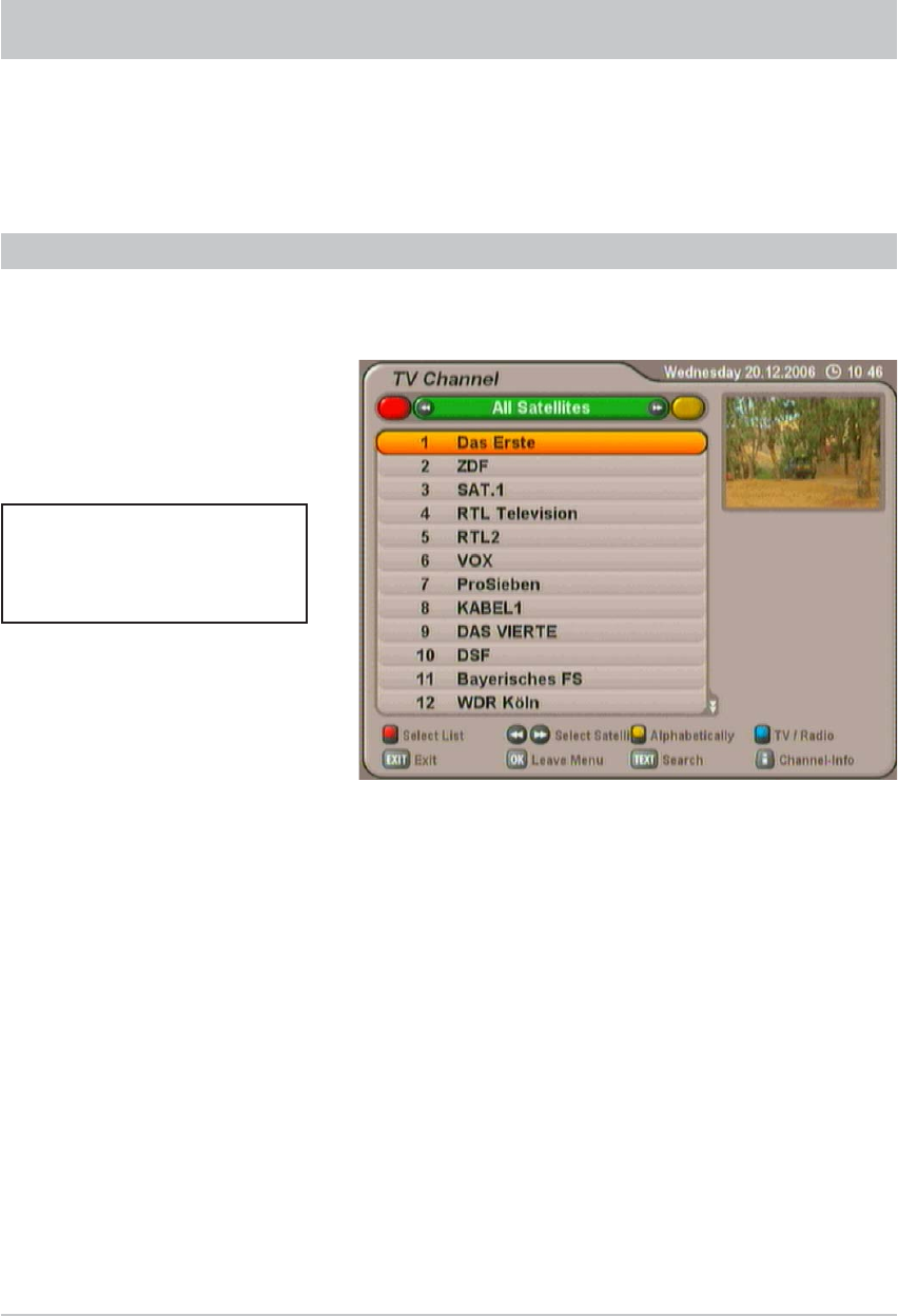
50
CHANNEL (SATELLITE) SELECTION
Providing you are not in a menu, pressing the button calls up the channel list. The following display
appears:
By pressing the & buttons all channels can be selected in the sequence that they appear in the current
channel list and its sorting. Press the # (blue) button to switch between TV and radio channels.
CHANNEL SELECTION FROM THE CHANNEL LIST
When you open this list the channel list selection/sort order is displayed from where you selected
the last channel.
At the top left you will see the selected channel list (TV Channel or Radio Channel) displayed.
Press the # (blue) button to switch between the TV and radio channel lists.
Underneath you can see the channel list with the sort order you selected.
The channel list can display channels sorted by various selection and sorting criteria. For instance you
can use the buttons to display various channel lists sorted by satellite (e.g. ASTRA 19.2° or
Hotbird 13°).
Use the cursor buttons () to select the desired channel in the various channel list views.
Confi rm the selection of the desired channel by pressing the button. As soon as the turntable has
found the satellite or has reached the known position, you will hear and view the currently selected
channel in the small window at the top right. To exit the channel list and return to the TV picture,
press the button again, or press the button.
Also pay attention to the
bars at the bottom of the on-
screen display! These provide
information on what to do next.
Note: A comprehensive explanation of the channel list with its detailed functions (e.g. the scan
and sort function) can be found in the UFS 740sw operating manual.
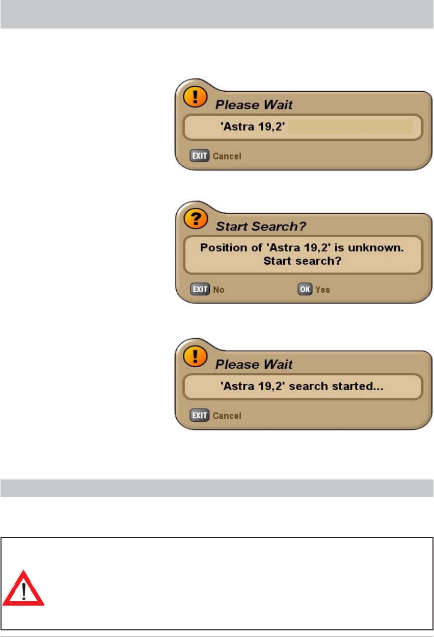
51
If you still want to aim at the satellite, press the button to start the search.
After a change of location, the antenna moves to the last position selected. After initialisation, you will
therefore see the following display (example, as it depends on the last selected position):
If a signal is found, the antenna automatically goes into fi ne tuning mode (max. 90 seconds, if signal is
adequate the position is immediately saved).
For slight changes of location, the
antenna can fi nd the satellite very
quickly.
If the search is unsuccessful, the following message appears:
CHANGE OF LOCATION/TIMER PROGRAMMING
TIMER PROGRAMMING
To prevent the turntable rotating at a time when it is unsupervised or when rotation
might be irritating (e.g. in the middle of the night), a timer can be set. During
the timer period the turntable is active only if the UFS 740sw is in operation or is
in standby mode.
If the receiver is completely switched off (switched off at the power socket) and/
or the turntable is in park position, the turntable will be inactive during the timer
period! The same applies if during the fi rst movement the satellite position is
not found.
See the UFS 740sw operating manual for details of how to program the timer. When using the
UFS 740sw on a CAP 700 please note the following additional instruction:
If the satellite is not found at the
known position, the search starts
automatically.
moving towards ...
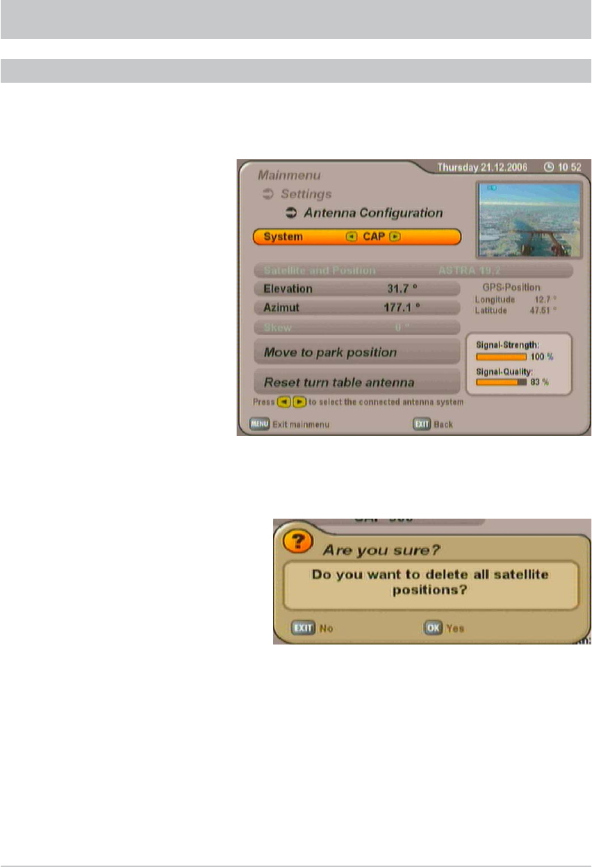
52
RESET/PARKING
Use the buttons to navigate to the sub-item “Reset the turn table antenna” and then press
the button. The following display appears:
Press the button to acknowledge the displayed message. The antenna is reset and automatically
moves to park position. A further short message “Park position reached” appears. Press the button to
exit the menu.
Note: Before exchanging any component of the system (such as the receiver) the turntable
should be moved to its park position by means of the “Reset the turn table antenna”
command. The “Reset” deletes all previously saved satellite positions. The satellite data in
the UFS 740 receiver are however retained.
Press the button to return to the main menu. The buttons and button allow you to call up
the submenus (“Settings”, “Antenna Confi guration”).
RESETTING THE TURN TABLE ANTENNA
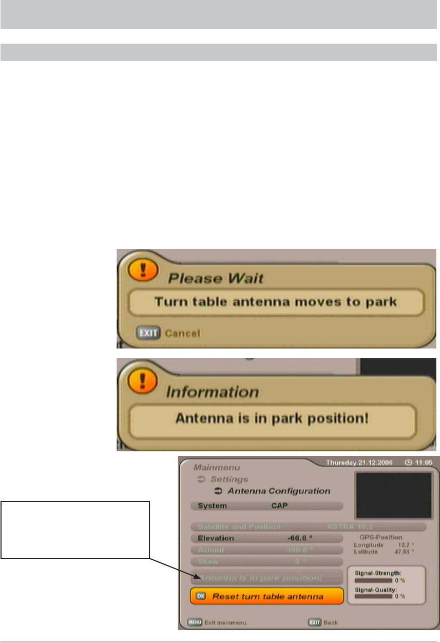
53
You have three options for “parking” the antenna.
1. The antenna can be moved to park position by pressing the button twice.
2. Press the
button to return to the main menu. The buttons and button allow you to
call up the submenus (“Settings”, “Antenna Confi guration”). Use the buttons to navigate to
the sub-item “Move to park position”. Now press to park the antenna.
3. When the ignition is operated, the antenna automatically moves to the park position! However,
for this to happen the green wire of the power supply cable must be connected to the ignition and
the turntable connected to the power supply (see “Connection Diagram”). Refer to the detailed
instructions for this in the CAP unit installation manual.
The antenna is moved to park position, and this is then confi rmed.
RESET/PARKING
PARKING THE TURNTABLE
The Antenna Confi guration menu
allows you to check whether
the antenna truly is in the park
position.
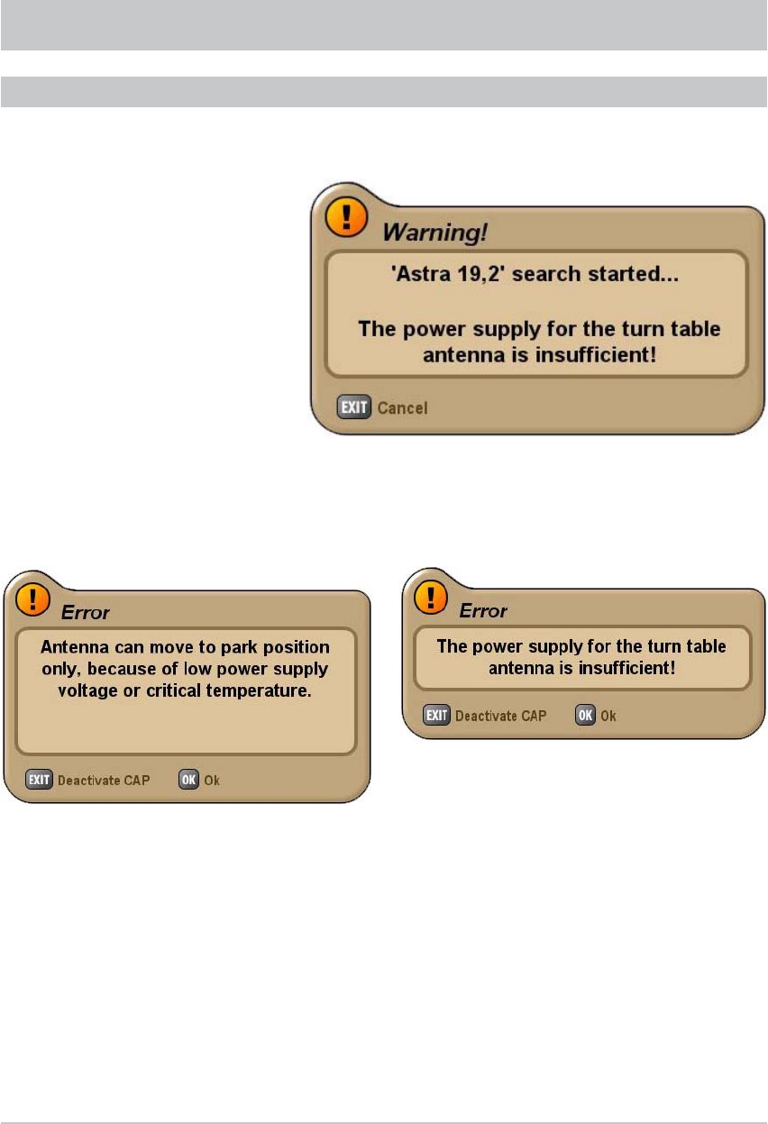
54
SPECIAL MESSAGES FROM THE TURNTABLE
The following messages are shown on the screen to protect your reception system and the on-board
power supply:
SYSTEM PROTECTION MESSAGES
The power supply to the turntable is inadequate (battery voltage below the minimum value). The turntable
can still be moved, but communication errors can occur between the UFS 740sw and the turntable
(e.g. when scanning for satellites).
If the voltage falls still further, both the following error messages are displayed:
Check the power supply to the turntable and
whether it is obstructed (e.g. by a branch). If both
causes of faults are displayed, the turntable motor
temperature is in the critical range. Allow the
turntable to stand for a few minutes in its current
position, until the turntable motor temperature has
reduced. You can also however move the turntable
to the park position and let it cool down there.
Press the button and the turntable will move
to the park position.
Press the button to acknowledge the displayed
message. The turntable cannot be moved any
more. Check the power supply to the turntable.
Note: The antenna should not be moved whilst the battery is being recharged, to prevent peak
loads when turning on.
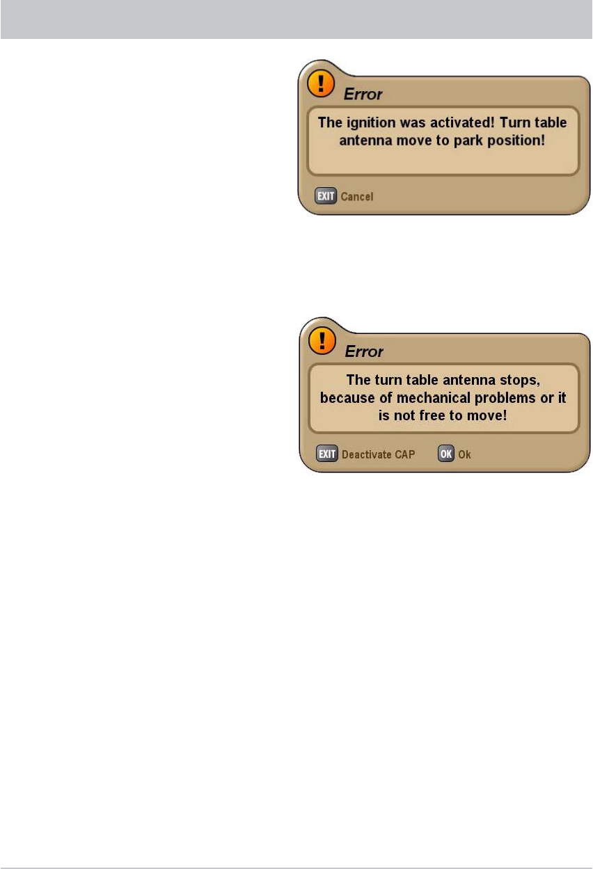
55
The vehicle ignition was switched on. For safety reasons, the turntable moves into the park position.
This operates however only if the green ignition cable for the turntable is connected to the vehicle
ignition and the turntable is connected to the power supply! As long as voltage is present at the ignition,
the connection to the CAP will remain disabled. This means the CAP cannot be operated.
SPECIAL MESSAGES FROM THE TURNTABLE
The turn table antenna has reached the mechanical stop or is jammed! Check whether the turntable
is obstructed (e.g. by a branch).
If the turntable encounters an obstruction,
the CAP reverses 10°. This allows the
obstacle to be removed more easily.
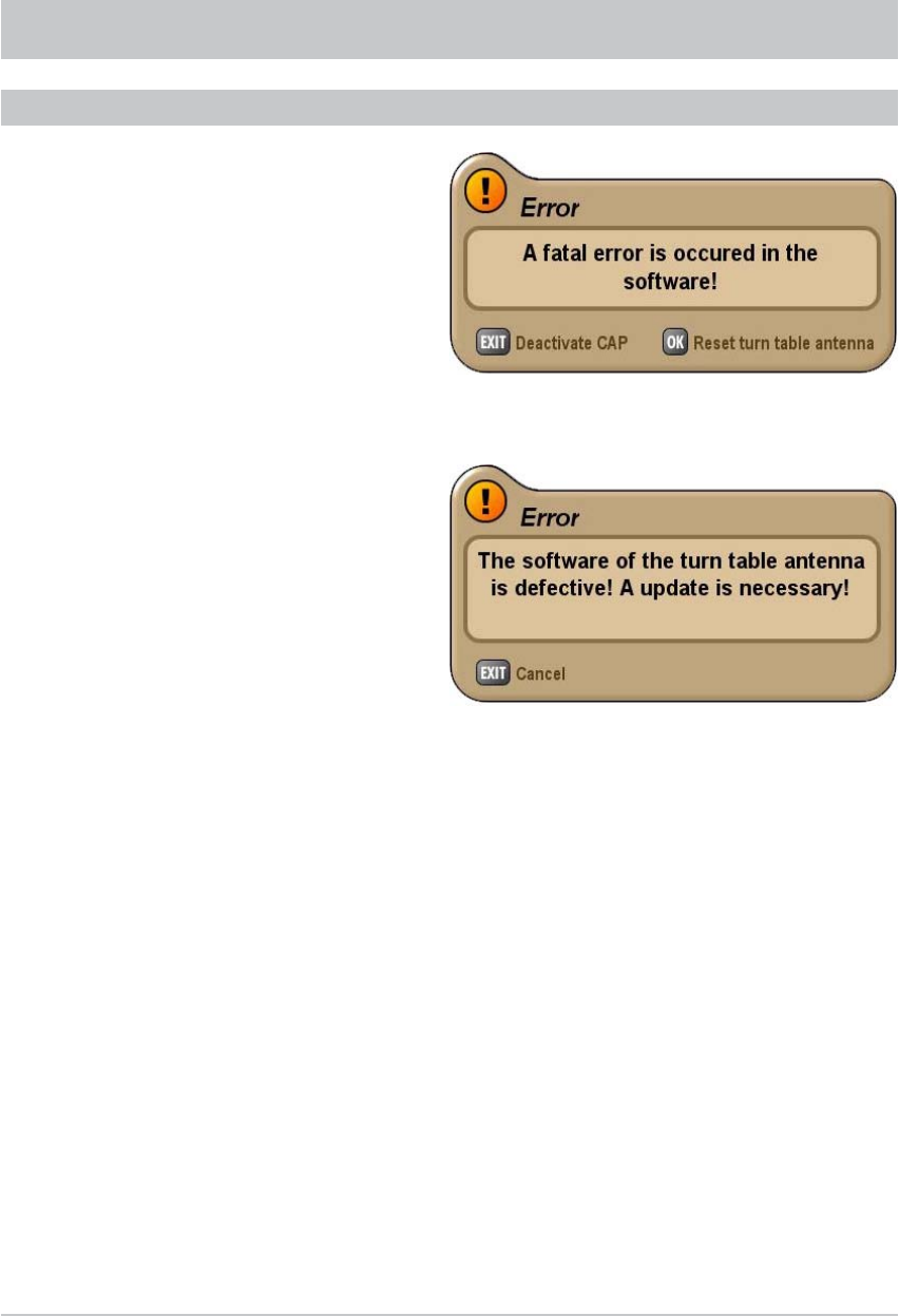
56
SPECIAL MESSAGES FROM THE TURNTABLE
A serious software error has occurred. Reset the turntable in the CAP menu, or contact our service centre.
MESSAGES ARISING FROM SOFTWARE PROBLEMS
The turn table antenna software is defective. An update is required. Contact our service centre.
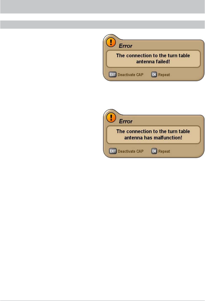
57
SPECIAL MESSAGES FROM THE TURNTABLE
The connection to the turntable is defective. Reset the turntable in the CAP menu, check the connections
between the turntable and receiver, or contact our service centre.
The receiver has lost communication with the turntable. Check the connection between the UFS 740sw
and the turntable, the power supply and whether possibly the ignition signal is present at the CAP.
FURTHER MESSAGES
This message may also appear if:
- the ignition is switched on
- voltage is present at the ignition cable
(green)
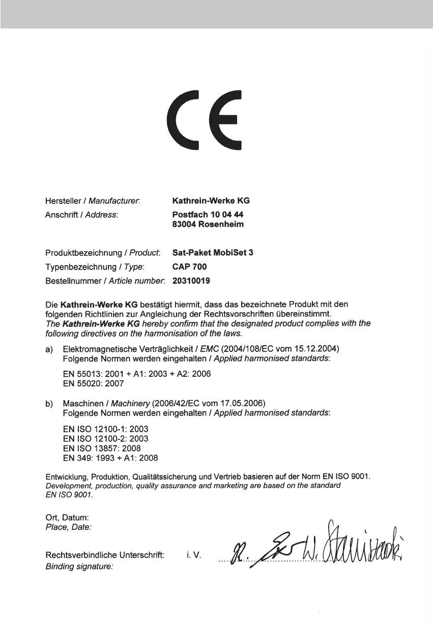
DECLARATION OF CONFORMITY
EC Declaration of Conformity
Rosenheim, 04.07.07

59
FOR YOUR NOTES

Internet: http://www.kathrein.de
KATHREIN-Werke KG • Anton-Kathrein-Straße 1 - 3
P.O. Box 100 444 • 83004 Rosenheim GERMANY
936.3417/-/0908/ZWT - Technical data subject to change.
