Tmc7285.tmp 957 0302 Onan KB KR (spec N S) Genset Operator's And Parts Manual
User Manual: 957-0302 Onan KB KR (spec N-S) Genset Operator's and Parts manual
Open the PDF directly: View PDF ![]() .
.
Page Count: 60
The following catalog
has gaps in its page
numbers, or doesn’t
have any numbers.
We have chosen to
leave the page
numbering in the
order that Acrobat
assigns it.
0I
Gimm
~iOPERATOR’S MANUAL
AND
PARTS CATALOG
FOR
KB-KR
“SERIES
I
ELECTRICGENERATING SETS
/~
.,
..
PARTSAVAfLAEHL/Ty
)LONGER GUARANTEED
I
IauE ONE
—..
INS, NS76
#me SNs, NS74)
—, PARTS CATALOG
INSTRUCTIONS FOR ORDERING
REPAIR PARTS
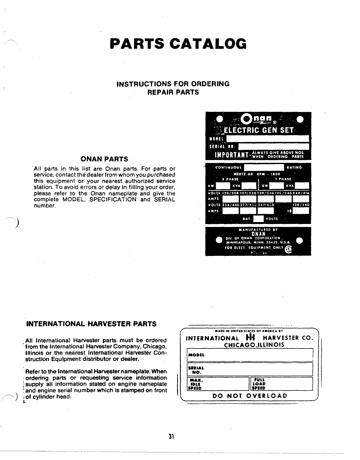
ONAN PARTS
“All parts in this list are Onan parts. For parts or
service, contact the dealer from whom you purchased
this equipment or your nearest authorized service
station. To avoid errors or delay in filling your order,
please refer to the Onan nameplate and give the
complete MODEL, SPECIFICATION and SERIAL
number.
‘““.)
~NTERNATIONAL HARVESTER PARTS
,All International Harvester park must be ordered
from the International Harvester Company, Chicago,
Illinois or the nearest International Harvester Con-
struction Equipment distributor or dealer.
Refer to the International Harvester nameplate. When
“ordering patis or requesting service information
~supply all information stated on engine namepiate
~and engine serial number which is stamped on front
~-) :of cylinder head.
L.
. . .. .
MAOi IN UNITED STA~tSof #mrRicb BY \
INTERNATIONAL ti~ HARVESTER CO.
CI+ICAGO,ILLINOIS
i1
MODEL I
11I
‘tic /
DO NOT OVERLOAD /’
~.->
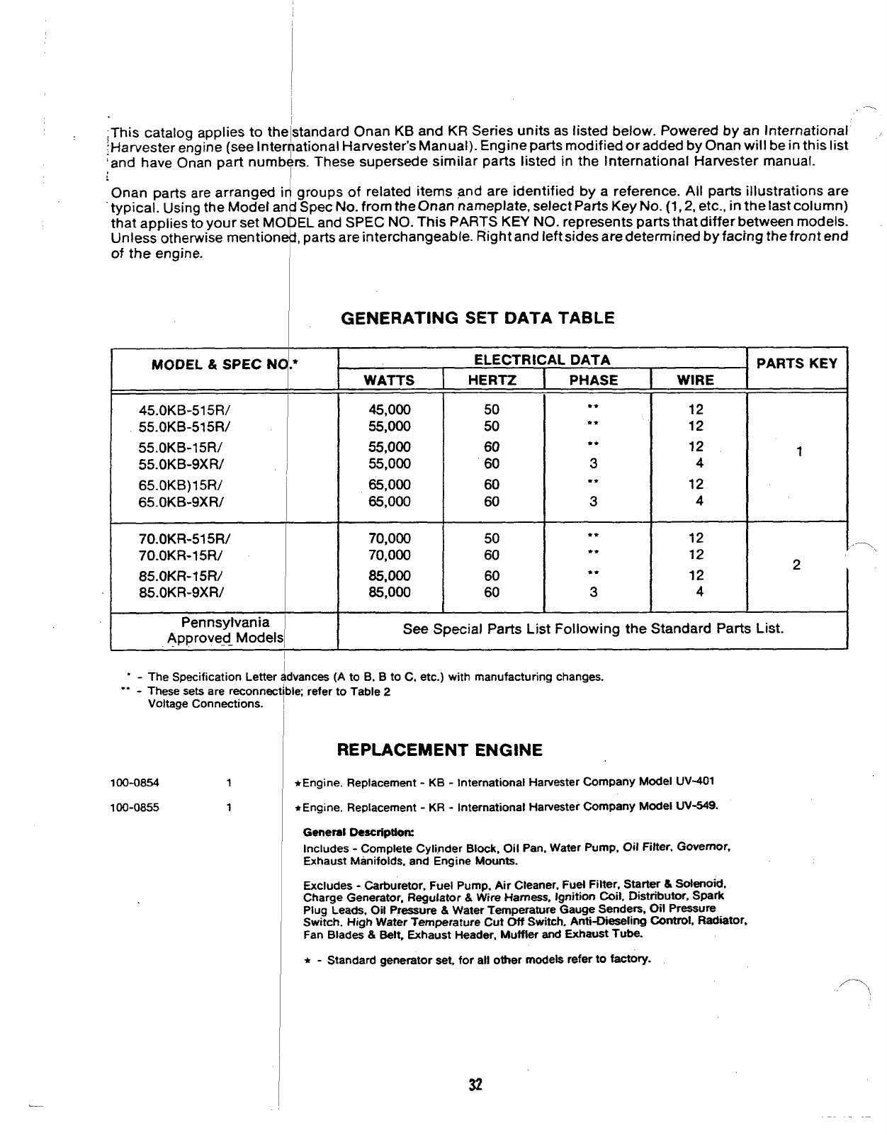
;This catalog applies to the~standard Onan KB and KR Series units as listed below. Powered by an International
!Harvester engine (see lnter~ational Harvester’s Manual)- Engine parts modified or added by Onan will be in this list
‘and have Onan part numbers. These supersede similar parts listed in the International Harvester manual.
[
Onan parts are arranged irl groups of related items and are identified by areference. All parts illustrations are
typical. Using the Model an~ Spec No. from the Onan nameplate, select Parts Key No. (1, 2, etc., in the last column)
that applies to your set MOf)EL and SPEC NO. This PARTS KEY NO. represents parts that differ between models.
Unless otherwise mentionefi, parts are interchangeable. Right and left sides are determined by facing the front end
of the engine.
45.oKB-515R/
55.oKB-515R/
55.oKB-15R/
55.oKB-9xR/
65.0KB)15R/
65. OKB-9XR/
70.OKR-515R/
70.oKR-15R/
85. OKR-15R/
85. OKR-9XR/
Pennsylvania
Approved_ Model
. .
.. -The Specification Lettel
These sets are reconner
Voltage Connections.
1oo-oa54 1
100-0855 1
GENERATING SET DATA TABLE
*
.ELECTRICAL DATA
WATTS IHERTZ IPHASE IWIRE
45,000
55,000
55,000
55,000
65,000
65,000
50
50
60
60
60
60
**
**
●☛
3
●*
3
12
12
12
4
12
4
70,000
70,000
85,000
85,000
50 ●*
60 ●*
60 ●*
60 3
12
12
12
4
PARTS KEY
1
2’
ISee Special Parts List Following the Standard Parts List.
jvances (A to B, Bto C, etc.) with manufacturing changes.
>1~ refer to Table 2
REPLACEMENT ENGINE
*Engine. Replacement -KB -International Harvester Company Model UV401
●Engine, Replacement -KR -International Harvester Company Model UV-549.
Generat Descriptiorx
Includes -Complete Cyli,nder Block, Oil Pan, Water Pump, Oil Filter. Governor,
Exhaust Manifolds. and Engine Mounts.
Excludes -Carburetor, Fuel Pump, Air Cleaner, Fuel Filter, Starter &Solenoid,
Charge Generator, Regulator &Wtre Harness, Ignition~11 ~$tributor>spark
Plug Leads, Oil Pressure &Water Temperature Gauge Sendera, Oil Pressure
Switch, High Water Temperature Cut Off Switch, Arrti-D@aeling Control, Radiator.
Fan Blades &Belt, Exhaust Header, Muffler and Exhaust Tube.
●-Standard generator set, for all other models refer to factory.
32
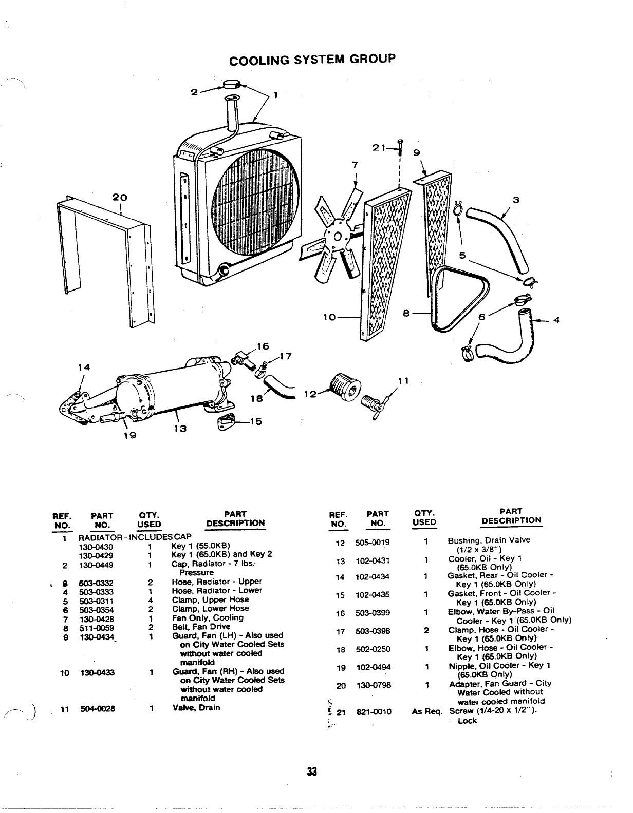
COOLING SYSTEM GROUP
-\
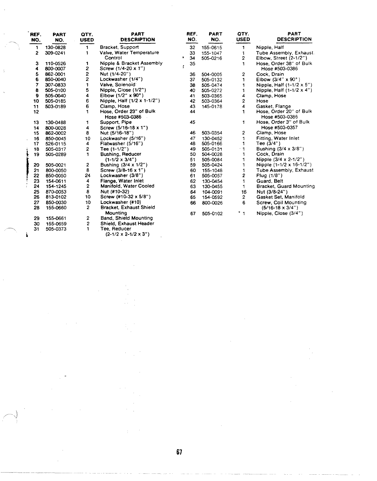
REF. PART OTY. PART
NO. NO. USED DESCRIPTION
1R-IN-ES CAP
2
iD 4
5
6
7
8
9
10
//’-. )~11
‘/
130-0430-
130-0429
130-0449
603-0332
503-0333
503-0311
130-0428
511-0059
130-0434-
Wo-0433
!5044128
1
1
1
2
1
4
2
;
1
1
1
Key 1(55.OKB)
Key 1(65.OKB) and Key 2
Cap, Radiator -7 lbs.-
Pressure
Hose, Radiator -Upper
Hose, Radiator -Lower
Clamp, Upper Hose
Clamp, Lower Hose
Fan Only, Cooling
~Fan Drive
Guard, Fan (LH) -Also used
on City Water Cooled Sets
without water cooled
manifold
Guard, Fan (RH) -Also Used
on Cw Water Cooled Sets
without water cooled
manifold
Vatve, Drain
REF. PART
NO. NO.
12 505-0019
13 102-O4W
14 102-0434
15 1024435
16 503-0399
17 503-0398
18 502-0250
19 102-0494
20 130-0798
>.
:21 821-0010
2.
QTY.
USED
1
1
1
1
1
2
1
1
1
PART
DESCRIPTION
Bushing, Drain valve
(1/2 X3/8”)
Cooler, Oil -Key 1
(65.OKB OnlY)
Gasket, Rear -Oil Cooler -
Key 1(65.OKB Only)
Gasket, Front -Oil Cooler -
Key 1(65.OKB OnlY)
Elbow, Water By-Pass -Oil
Cooler -Key I(65.OKB Onty)
Clamp, Hose -CM Cooler -
Key I(65.oKB onlY)
Elbow, Hose -Oil Cooler -
Key 1@5.OKB OnlY)
Nipple, 011 Coder -Key 1
(65.oKB Only)
Adapter, Fan Guard -City
Water Cooled without
water cooled manifold
As Req. Screw (1/4-20 x1/2”).
Lock
33
.
&–
&—
21
“o
~:
:,s
$!
<
L_____________
36
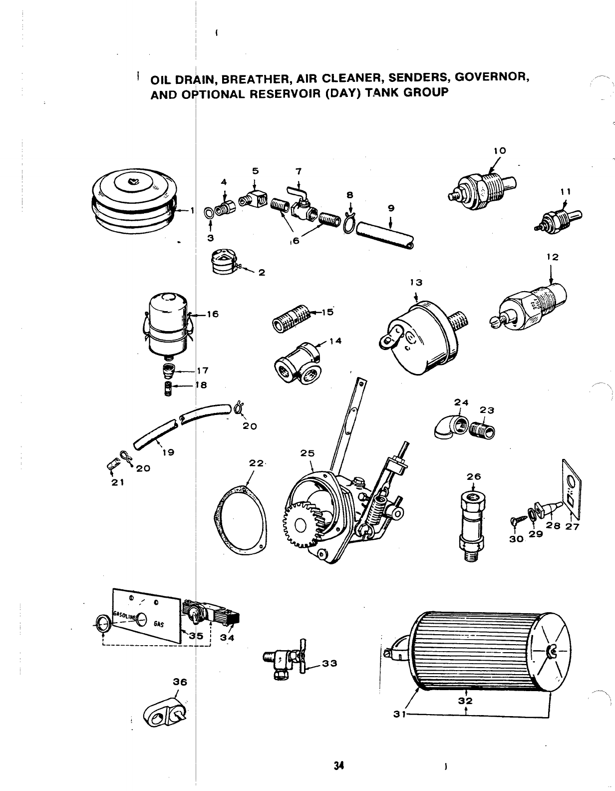
IN, BREATHER, AIR CLEANER, SENDERS,
rtONAL RESERVOIR (DAY) TANK GROUP
-16
7
8
&
12
,,- \
24 23
Lib& @
22
.- J.
33
/32
31 I
.—.
.
34
REF. PART
NO. NO.
——
22 151-0387
23 505-0099
24 505-0038
25 151-0371
26 123-0960
27 332-1281
28 870-0196
29 508-0015
30 809-0035
31 140-0851
32 140-0871
33 504-0085
34 308-0005
35 308-0150
36 309-0269
141-0640
141-0641
QTY. PART
USED DESCRIPTION
REF. PART
NO. NO.
——
1140-0524
2140-0525
3102-0034
4102-0033
5502-0133
6505-0100
7504-0011
8503-0197
9503-0098
10 193-0108
11 193-0104
QTY.
USED
1
PART
DESCRIPTION
Cleaner, Air -Gasoline
Fueled Models
Adapter, Air Cleaner
Gasket, Oil Drain Adapter
Adapter, Oil Drain
Elbow, Oil Drain (90° )
Nipple, Oil Drain (1/2”)
Valve, Shut-Off -Oil Drain
Clamp, Oil Drain Hose
Hose, Oil Drain
Sender, Oil Pressure Gauge
Sender, Water Temperature
,, ----
,-- ,
... ....
—-..<
f----
1
1
1
1
1
1
1
1
1
1
1
1
1
1
1
1
1
Gasket, Governor Flange
Nipple, Close, Breather
Hose Adapter
Elbow, Breather Hose Adapter
*Governor Assembly (lnter-
nationai Harvester Co.
#678045C91)
Vent, Crankcase
Bracket, Terminal Mounting
Nut, Insulator
Washer, Insulator
Screw, Sheet Metal
Cleaner, Air -Gaseous
Fueled Models
Element, Air Cleaner -
Gaseous Fueled Models -
Optional
Valve, Fuel Shut-Off -
Optional
Switch, Gas-Gasoline -
Optional
Bracket, Switch Mounting -
Optional
Switch, Low Engine Temperature
Repair Kit, Carburetor
Gasket Kit, Carburetor
1
1
1
1
1
1
1
1
1
12 \309-0178
r
13 309-0169
14 509-0059 1
1
1
1
1
1
1
2
1
Pressure Switch and Oil
Gauge Sender Mounting
Nipple, Close (1/8 x1-1/2”) -
oil pressure Tee to Block
Cleaner, Crankcase Breather
Coupling, Reducer (1/2 x
1/4”) -Breather Cleaner
to Mounting Nipple
Nipple, Close (1/4 x7/8”) -
Breather Cleaner to Cylinder
Head Cover Mounting
Hose, Breather
Clamp, Breather Hose
NiDDk. Half (1/4X 1“)
I15 505-0104
16 140-0518
17 505-0369
I
I18 505-0099
‘-Order Darts or components for this qovernor (International
I
I19 503-0445
20 503-0131
21 505-0010
#678045C91 )from the International Harvester Company,
401 North Michigan Avenue, Chicago, Illinois 60611.
6reather Hose Adapter
,,. .
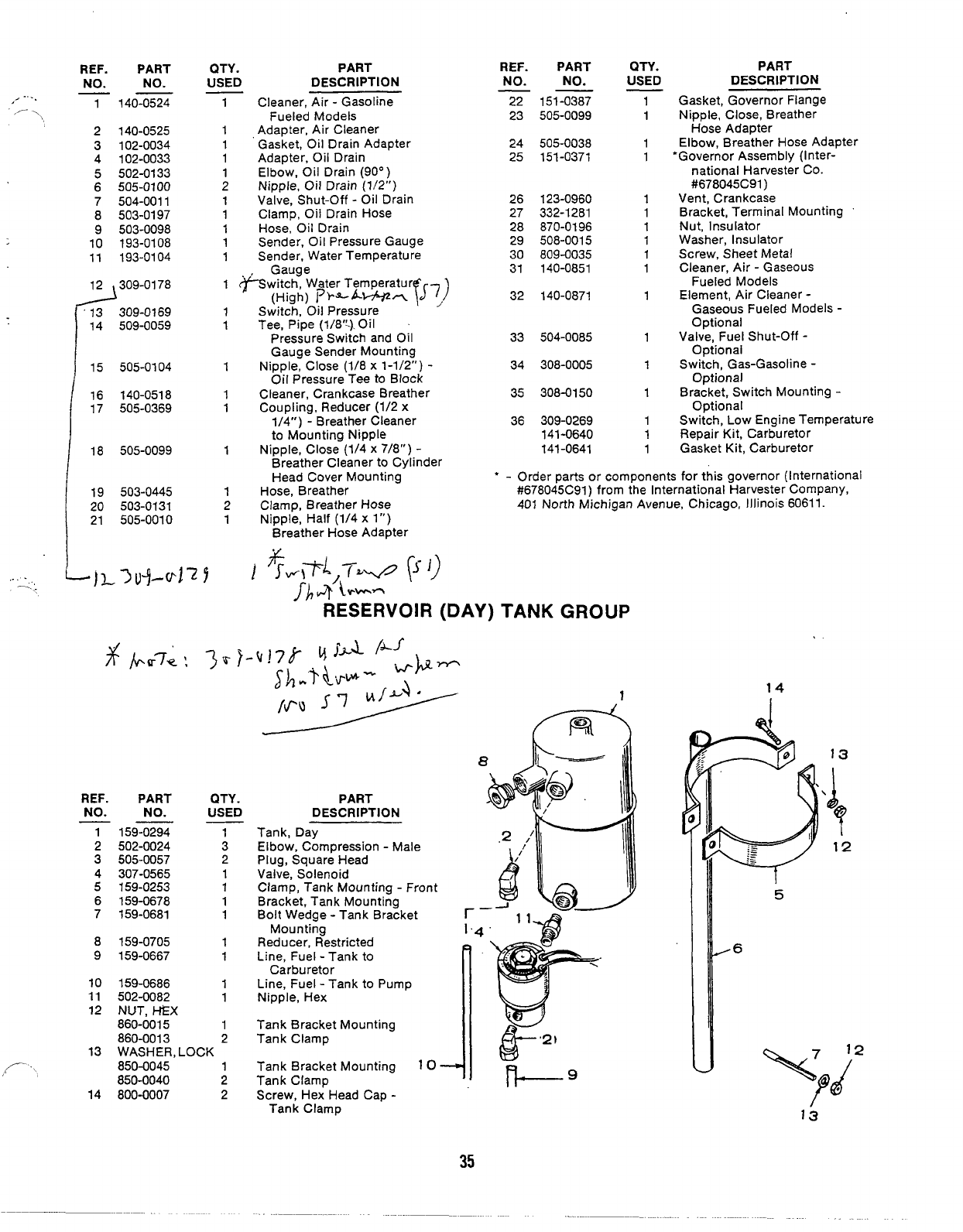
RESERVOIR (DAY) TANK GROUP
14
1
REF.
NO.
PART
NO.
QTY.
USED PART
DESCRIPTION
Tank, Day
Elbow, Compression -Male
Plug, Square Head
Valve, Solenoid
Clamp, Tank Mounting -Front
Bracket, Tank Mounting
Bolt Wedge -Tank Bracket
Mounting
Reducer, Restricted
Line, Fuel -Tank to
Carburetor
Line, Fuel -Tank to Pump
NippIe, Hex
Tank Bracket Mounting
Tank Clamp
159-0294
502-0024
505-0057
307-0565
159-0253
159-0678
159-0681
1
3
2
1
1
1
1
1
1
1
1
1
2
5
,6
8
9
159-0705
159-0667
10
11
12
159-0686
502-0082
NUT, t-&X
860-0015
860-0013
WASHER, LOCK
850-0045 1
850-0040 2
800-0007 2
13
Tank Bracket Mounting
Tank ClamD
14 Screw, Hex Head Cap -.
Tank Clamp
35
/------
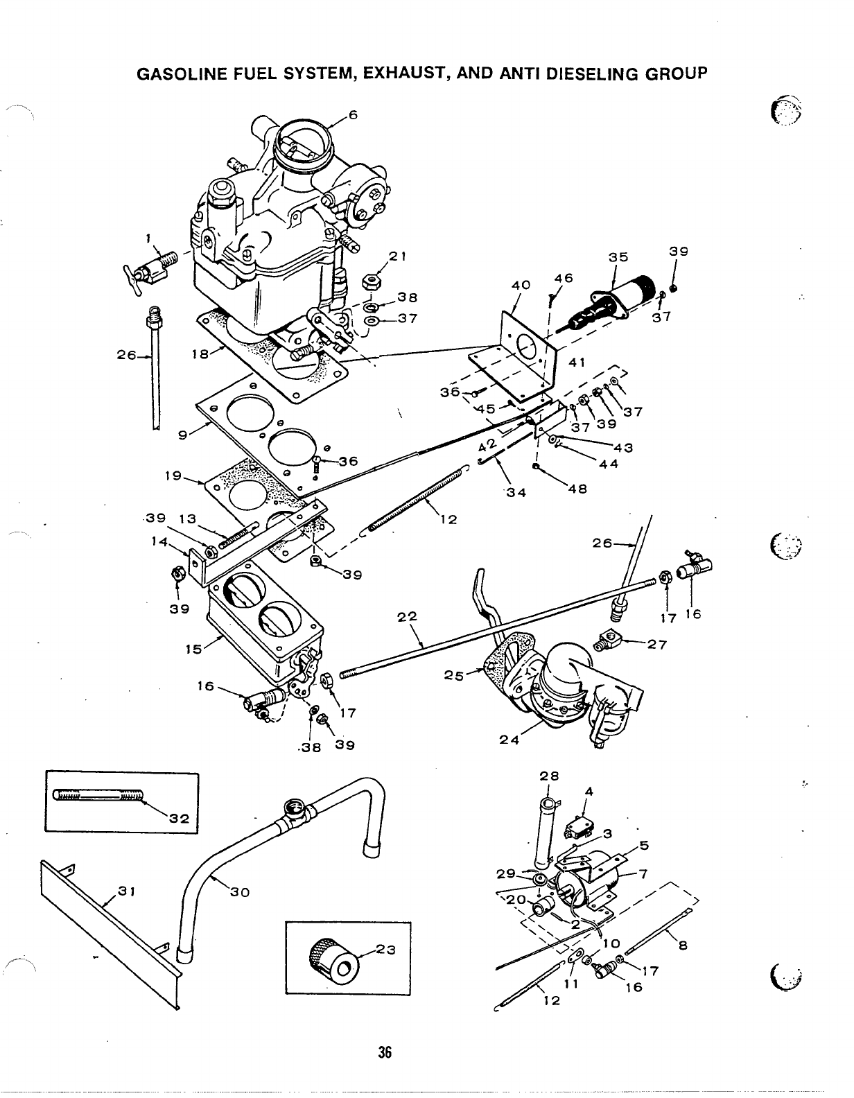
FUEL SYSTEM, EXHAUST, AND ANTI DIESELING GROUP
\\4 ~
“34
26 -J/
28 .:..
b-,
‘. ..“,,
36
—
REF. ●ART PART REF. PART OTY.
USED PART
ON. NO. NO.
——
No. No.
——
\\1504-0095
USED DESCRIPTION DESCRIPTION
1Valve, Shut-Off -Carburetor
Inlet -Key 1- Spec NOnly
Elbow, Male -Carburetor
Inlet -Key 1- Begin
Spat P
Elbow, Male -Carburetor
Inlet -Key 2
tPin, Roll (1/8x 3/4) -
Spec NOnly
Actuator, Micro Switch -
Spec NOnly
Switch, Micro -SPaC N
29 304-m15 2Washer; Resistor Centering -
Spec NOnly
Header Assembly, Exhaust
Shield, Exhaust Manifold
Heat
Stud, Exhaust Elbow
Link, Throttle Spring -
Begin Spec P
Link, Solenoid -Begin
1502-0004 130 155-0612
31 133-0157 1
2
1.502-0004
2516-0086
1
1
1
1
1
32 520-0599
33 145-0414 2
1
34 T45-W36 1
3309-0133 Spec P
35 SOLENOID, ANTI-DIESELING
307-1093 1SDec Pto Serial
4309-0155
5308-0131
Only
Bracket, Micro Switch
Mountino -Spec NOnly
“#l173734206During Spec R)
307-1356 1Begin Serial #1173734206
Durino SDec R)
6‘CARBURETOR ASSEMBLY -
141-0636
141-0635
7307-0259
36 SCREW, ROUND HEAD -‘ ‘
812-0079 4
813-0100 .2
1
1
1
1
1
1
1
1
1
1
1
2
4
1
1
1
4
1
1
1
1
1
1
1
Key 1(Zenith #28ADAl OC)
Key 2(Zenith #12411A)
Solenoid &Lead Assembly,
Anti-Dieseling -SpeC N
Only
Link, Solenoid -Spec N
Only
Bracket. Solenoid Mounting
Bushing, Throttle Spring
Link to Ball Joint
Link, Throttle Spring -
Spec NOnly
Spring. Throttle
Stud, Throttle Spring
Adjusting
Bracket, Throttle Spring
Body Assembly, Throttle
(includes Parts Marked t)
tJoint, Ball (3 Used Spec N
Only)
tNut, Hex (1/4-26) -
(2) Governor Control Stud,
(2) Ball Joint, (5 Used
Spec NOnly)
Gasket, Carburetor to
Solenoid Mounting Bracket
Gasket, Throttle Body
Cam, Micro Switch -Spec N
Only
Nut, Hex (5/16-24) -
Carburetor Retaining
tStud, Governor Control
Knob, Choke -Carburetor
Pump Assembly, Fuel
Gasket, Fuel Pump Mounting
Line, Fuel Pump to
Carburetor
Efbow, Inverted Male -
Fuel Pump Outlet
Resistor, Anti-Diaseling
(Fixed} -Spec NOnly
Solenoid Mounting
Throttle Spring Bracket
Mounting
Link Mounting -Begin
Spec P
Carburetor Mounting
Link Mounting -Begin
Spm P
Carburetor Mounting
Solenoid Mounting
tBall Joint Mounting -
Begin Spec P
Solenoid Mounting
Throttle Spring Bracket
Mounting
Throttle Adjusting Stud
Bracket, Solenoid Mounting -
Begin Serial #1 173734201
During Spec R
Bracket, Solenoid -Begin
Serial #l 173734206
During Spec R
Swivel, Solenoid -Begin Serial
#1173734206 During Spec R
Washer, Flat
Pin, Cotter
Screw, Fillister Head
(6-32 x5/16 long)
Screw, Hex Head
(1/4-20 x1/2 long)
Washer, Lock (1/4)
Nut, Hex (1/4-20)
813-0148 1
8145-0124 37 WASHER, FLAT
526-0115 4
.526-~18 2
9
10 145-0186
150-0302 38 WASHER, LOCK
650-c#5 4
650-0025 4
650-0040 2
11 145-0118
145-0158
150-0096
12
13 39 NUT, HEX 4
870-0131 2
14
15 145-0187
145-0410
16
.,- ..
17
150-0638 870-0053 2
40 307-1323 1
115-0025
41 307-1330 1
18 145-0169 42 152-0155 1
145-0185
309-0132 43 526-0006 2
44 516-0059 1
45 815-0104 121 110-0445
22
23
520-0517
141-0372
149-07WI
149-0736
159-0685
46 800-o)03 2
24
z
47 650-0040 4
48 662-ml 2
“ - For components contact your nearest Zenith Carburetor
dealer or Zenith Carburetor Division, The Bendix Corp.,
696 HaR Avenue, Detroit, Michigan.
27 S02-0004
28 304-0045
t-Included in 145-0410 Throttle Body Assembly.
.
)
/---’\,
37
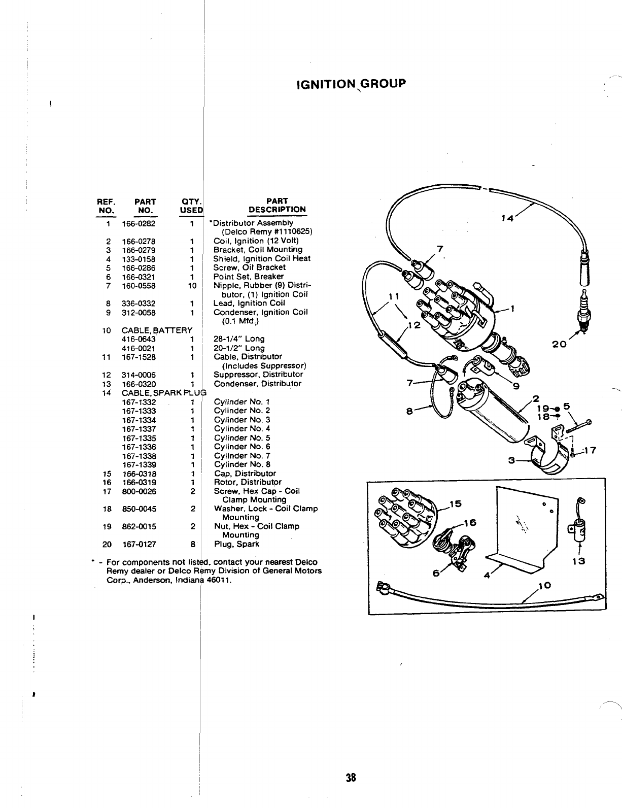
IGNITION,GROUP ,.—.
REF. PART QTY
NO. NO. USEI
—.
7166-0282 1
2166-0278 1
3166-0279 1
4133-0158 1
5166-0286 1
6166-0321 1
7160-0558 10
8336-0332 1
9312-0058 1
10 CABLE, BAITERY
416-0643 1
416-0021 1
11 167-1528 1
12 314-0006 1
13 166-0320 1
14 CABLE, SPARK PLU
167-1332 1
167-1333 1
167-1334 1
167-1337 1
167-1335 1
167-1336 1
167-1338 1
167-1339 1
15 186-0318 1
16 166-0319 1
17 800-0026 2
18 850-0045 2
19 862-0015 2
20 167-0127 8
For components not list
Remy dealer or Delco R
Corp., Anderson, Indian
I
PART
DESCRIPTION
“Distributor Assembly
(Delco Remy #l 110625)
Coil, Ignition (12 Volt)
Bracket, Coil Mounting
Shield, Ignition Coil Heat
Screw, Oil Bracket
Point Set, Breaker
Nipple, Rubber (9) Distri-
butor, (1) Ignition Coil
Lead, Ignition Coil
Condenser, Ignition Coil
(0.1 Mfdi)
28-114” Long
20-1/2” Long
Cable, Distributor
(Includes Suppressor)
Suppressor, Distributor
Condenser, Distributor
Cylinder No. 1
Cylinder No. 2
Cylinder No. 3
Cylinder No. 4
Cylinder No. 5
Cylinder No. 6
Cylinder No. 7
Cylinder No. 8
Cap, Distributor
Rotor, Distributor
Screw, Hex Cap -Coil
Clamp Mounting
Washer, Lock -Coil Clamp
Mounting
Nutr Hex -Coil Clamp
Mounting
Plug, Spark
,contact your nearest Delco
Iy Division of General Motors
$6011.
20”
,—.>
\
38
(
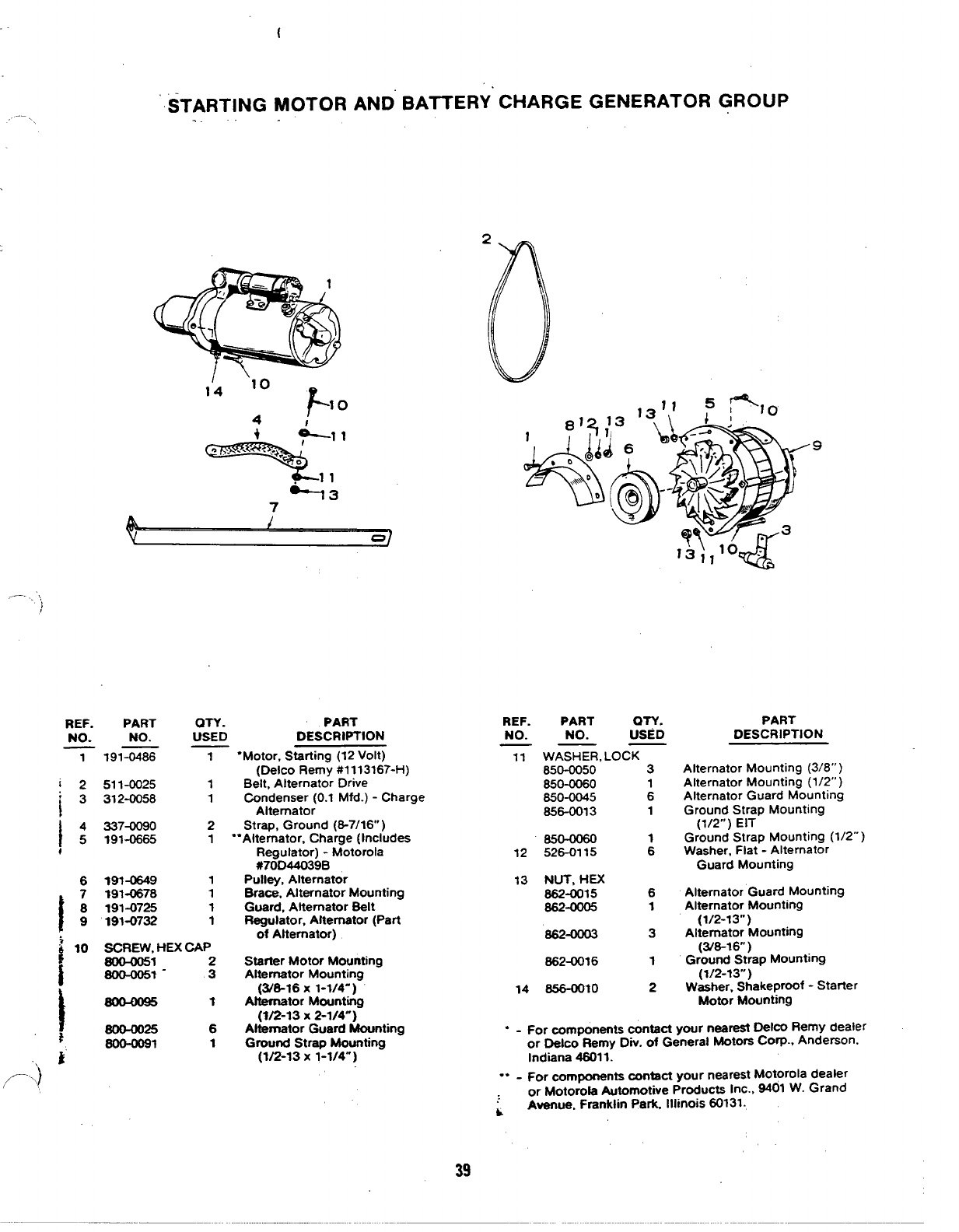
-- ‘, STARTING MOTOR AND BATTERY CHARGE GENERATOR GROUP
1‘4 ‘lo
F10
4I
*-’
,*3
-- .‘,,
)
REF.
NO.
1
PART QTY.
NO. USED
191-0486 1
511-0025 1
312-0056 1
337-0090 2
191-0665 1
191-0W9 1
191=78 1
191-0725 1
191-0732 1
SCREW, HEX CAP
6cKm151
600-0051- :
60(M025 6
600-oo91 1
PART
DESCRIPTION
“Motor, Starting (12 Volt)
(Delco Remy #1113167-H)
Belt, Alternator Drive
Condenser (O.l Mfd.) -Charge
Alternator
Strap, Ground (8-7/16” )
““Alternator, Charge (Includes
Regulator) -Motorola
#70D44039B
Pulley, Alternator
Brace, Alternator Mounting
Guard, Alternator Belt
Regulator, Alternator (Part
of Alternator)
Starter Motor Mounting
Alternator Mounting
(3/6-16 X1-1/4-)
Aftemator Mountiig
(1/213 x2-1/4”)
Altamator Guard Mounting
Ground Strap Mounting
(1/2-13 x1-1/4)
REF. PART OTY.
NO. NO. USED
——
11 WASHER, LOCK
850-0050 3
650-0060
650-0045 :
656-0013 1
65- 1
12 526-0115 6
13 NUT, HEX
662-0015 6
662-0005 1
862-0003 3
662-0016 1
14 -10 2
PART
DESCRIPTION
Alternator Mounting (3/8” )
Alternator Mounting (1/2” )
Alternator Guard Mounting
Ground Strap Mounting
(1/2”) EIT
Ground Strap Mounting (1/2” )
Washer, Flat -Alternator
Guard Mounting
Alternator Guard Mounting
Alternator Mounting
(1/2-13”)
Alternator Mounting
(3/6-16 )
Ground Strap MOuniin9
(1/2-13”’) “
Washer, Shakeproof -Starter
Motor Mounting
“-For components contact your narest OelCO Remy dealer
or Delco Remy Div. of General Motors Corp., Anderson.
Indiana 46011.
‘“ -For components contact your nearestMotorola dealer
or Motorola Automotive Products Inc., 9401 W. Grand
LAvenue. Franklin Park, Illinois 60131.
39
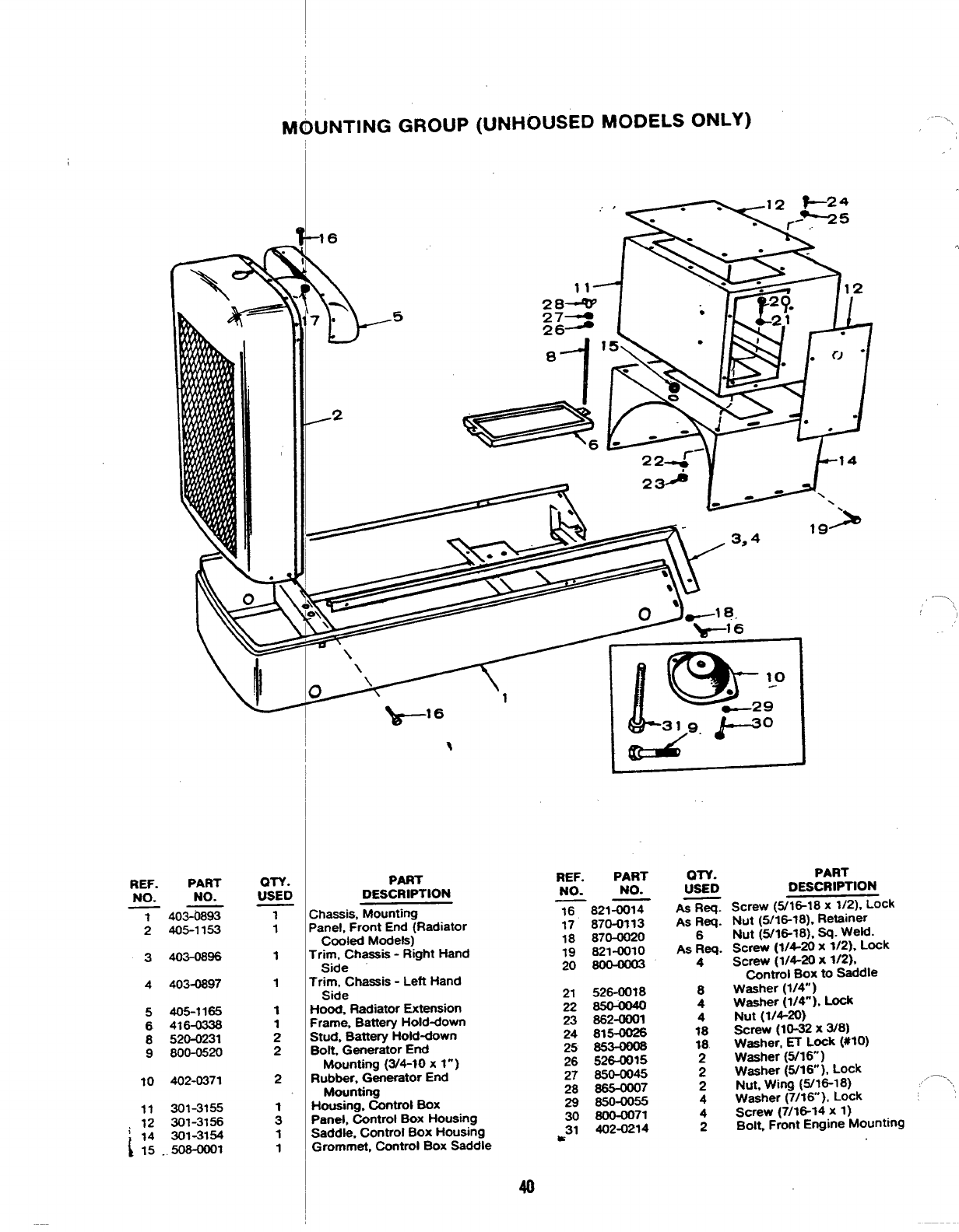
UNTING GROUP (UNHOUSED MODELS ONLY)
Y-5
-16 ,
‘1
-
/2
,,’>
1
PART
--
,, \
\1
~
QTY.
USED
T1
1
1
1
1
2
2
2
1
3
1
1
K?5-
\
OTY.
USED
REF. PART
PART
DESCRIPTION
REF.
NO.
PART
NO. NO. NO.
—— DESCRIPTION
Screw (316-18 x1/2), Lock
Nut (w18-18), Retainer
Nut (5/16-18). =i- we~.
Screw (1/4-20 x1/2), Lock
Screw (1/4-20 x1/2).
~ntrol Box to Saddle
Washer (1/4”)
Washer (1/4”). Lock
Nut (1/4-20}
Screw (10-32 xW8)
Washer, ET L~k (#to)
Washer (5/16)
Washer (5/16 ), Lock
Nut, Wing (5/16-18) .—. \
Washer (7/l&), Lock
Screw (7/lG14 x1)
BoIL Front Engine Mounting
AS Req.
As Req.
6
As Req.
4
8
4
4
18
18
2
2
2
4
4
2
16 821-0014
17 870-0113
18 870-0020
19 821-0010
20 800—OO@
21 526-0018
22 850—OWO
23 862-0001
24 815-0026
25 ~
26 526-0015
27 850-0045
28 865-0007
29 850-0055
30 8o0-oo71
31 402-0214
w
;hassis, Mounting
‘anel, Front End (Radiator
Cooled Models)
‘rim, Chassis -Right Hand
Side
‘rim, Chassis -Left Hand
Side
+ood, Radiator Extension
frame. Battery Hold-down
;tud, Battery Hold-down
30[t, Generator End
Mounting (3/4-10 x1”)
?ubber, Generator End
Mounting
-lousing, Control Box
%mel, Control Box Housing
Saddle, Control Box Housing
Grommet, Control Box Saddle
403-0893
405-1153
403-0896
3
403-0897
4
405-1165
416-0338
520-0231
800-0520
5
6
8
9
10 402-0371
301-3155
301-3156
301-31W
.508-0001
40
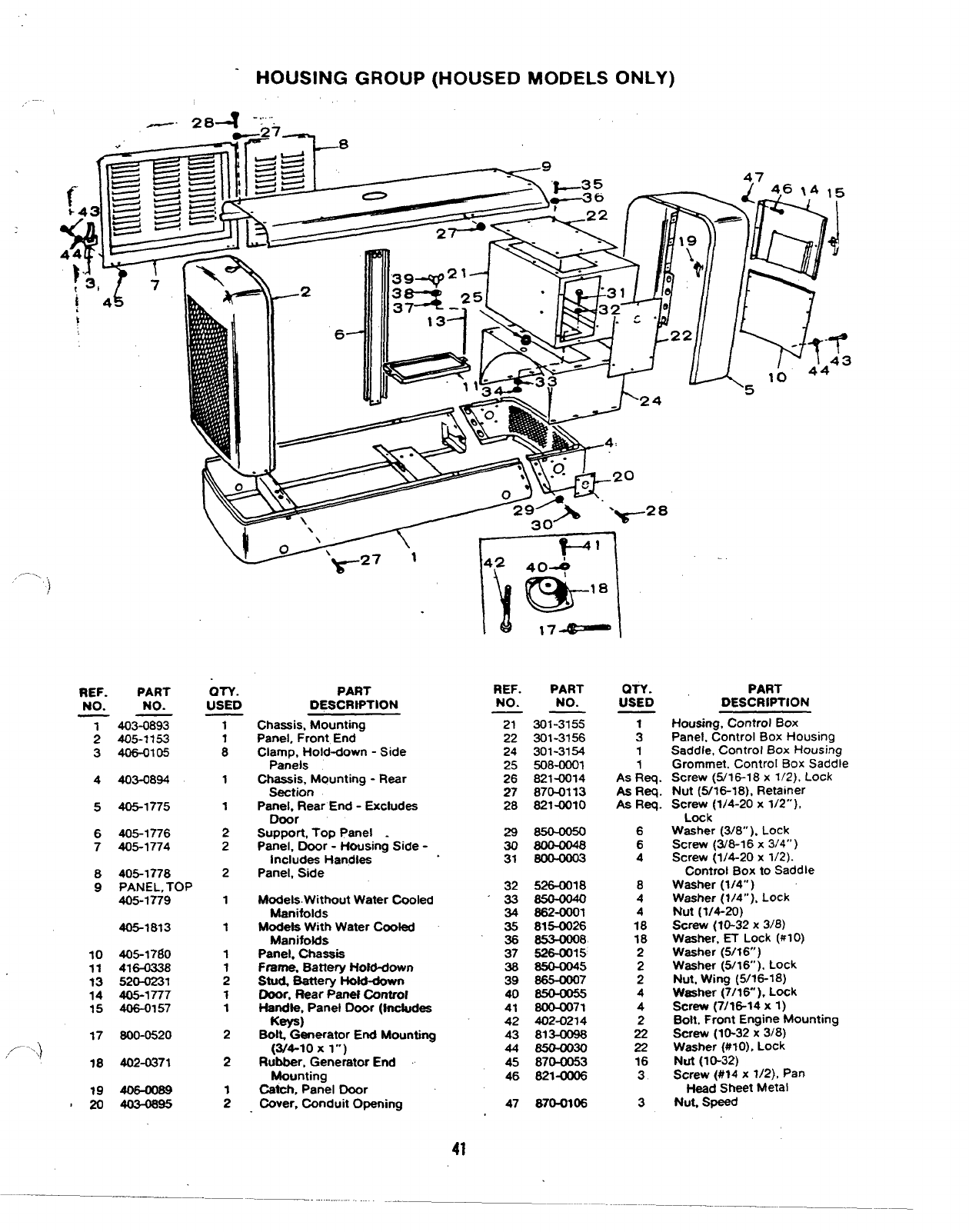
HOUSING
,,-—
—, 284 “:”-
GROUP (HOUSED MODELS ONLY)
—zf —
/2
6-
,-... )
OTY.
USED
T
:
1
1
2
2
2
1
1
1
;
1
1
2
2
;
QTY.
USED
PART
DESCRIPTION
PART REF. PART
NO. NO.
——
21 301-3155
22 301-3156
24 301-3154
25 508-0001
26 821-0014
27 870-0113
28 821-0010
298W—0050
308004048
31 80@0003
32 526-00?8
338W—0040
34 S82-oool
35 81!%0026
36 853-0008
37 526-0015
38 850-0045
39 665-ooo7
40 MO—0055
41 800-CKJ71
42 402-0214
43 813-0086
44 650-0030
45 870-0053
46 821-(M306
47 870-0106
REF.
NO. PART
NO. DESCRtPTION
Housing, Control Box
Panel. Control Box Housing
Saddle, Control Box Housing
Grommet. Control Box Saddle
Screw (5/16-18 x1/2), Lock
Nut (5/16-18), Retainer
Screw (1/4-20 x1/2”),
Lock
Washer (3/8” ). Lock
Screw (3/6-1 6x314”)
Screw (1/4-20 x1/2).
Control Box to Saddle
Washer (1/4” )
Washer (1/4”). Lock
Nut (1/4-20)
screw (10-32 x3/8)
Washer. ET Lock (#l O)
Washer (5/16”)
Washer (5/16’). Lock
Nut, Wing (5/16-18)
Washer (7/16” ), Lock
Screw (7/16-14 x1)
Boll. Front Engine Mounting
Screw (10-32 x3/8)
Washer (#IO), Lock
Nut (IO-32)
Screw (#14 x1/2), Pan
Head Sheet Metal
Nut. Speed
403-0893
405-1153
406-0105
Chassis, Mounting
Panel, Front End
Clamp, Hold-down -Side
Panels
chassis, Mounting -Rear
Section
Panel, Rear End -Excludes
Door
Support, Top Panel .
Panel, Door -Housing Side -
Includes Handles
Panel, Side
1
3
1
1
As Req.
As Req.
Aa Req.
6
6
4
8
4
4
18
16
2
2
2
4
4
2
22
22
16
3
3
;
3
403-08944
405-17755
405-1776
405-1774
6
7
8
9
405-1778
PANEL, TOP
405-1779 Models. Without Water Cooled
Manitolds
Modefa With Water Cooled
Manifolds
Panel. chassis
Frame. Battery Hold-down
Stud Battery Hold-down
Door. Rear Panel Control
Handle, Panel Door (Includes
Keys)
BoIL Generator End Mounting
(3/4-10 xl“)
Rubber, Generator End
Mounting
Catch,Panel Door
Cover, Conduit Opening
405-1813
405-1760
41-8
520-0231
405-1777
406-0157
10
11
?3
14
15
17
,<”’;}
18
800-0520
402-0371
4030695
41
c
o
Qo
a
o
.
Qo\
1
[[.
4
F
w
1..-
@c -.
5
\10 c
/’ 14
15
m“
o
0-
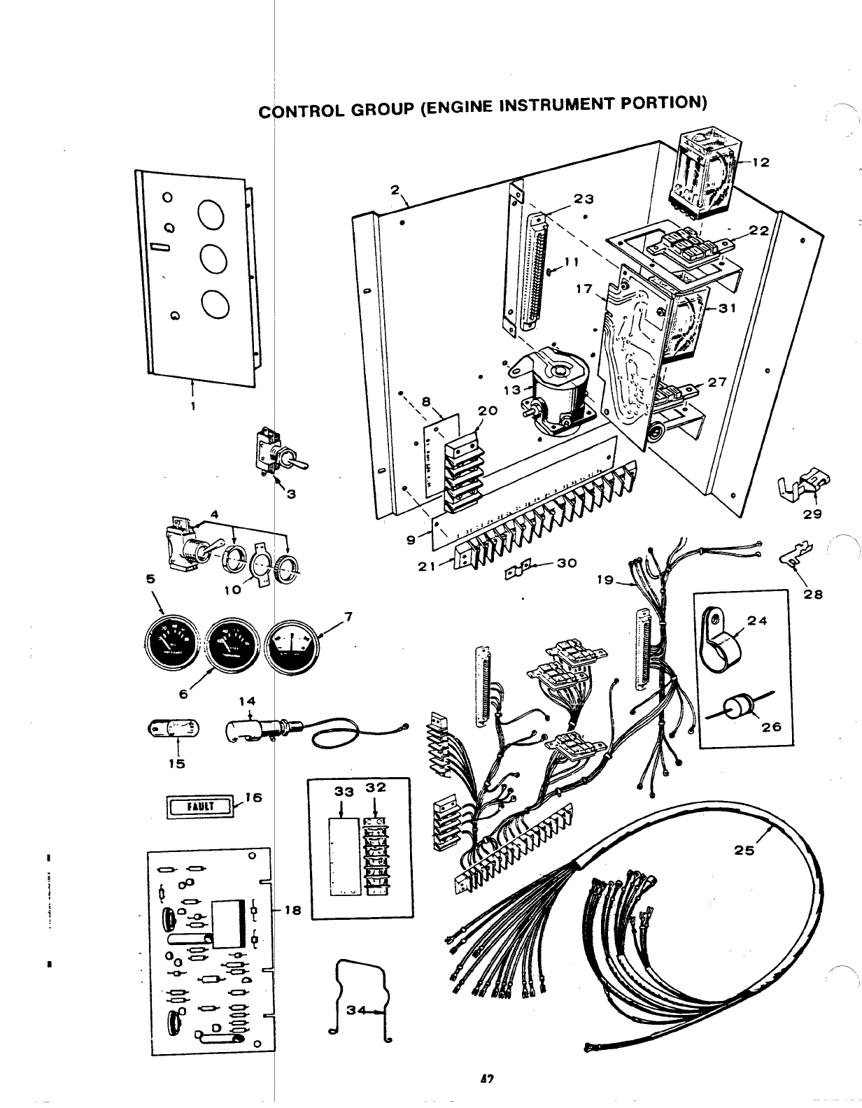
INTROL GROUP (ENGINE INSTRUMENT PORTION) “--\
18
33 32
FL
hi
.
-.
4
.“).
R
3
-.
;REF. PART (N-Y. PART
,NO. NO. USED DESCRIPTION
iTPAtiNLY. ENGINE CONTROL
2
‘3
4
9
}10
!11
12
13
14
15
16
301-3165
301-3267
301-3253
308-0138
308-0002
193-0107
193-0106
302-0061
332-1239
332-1241
308-0003
332-1276
307-1058
307-1031
322-0Q73
322-0074
LAMP, FAULT
322-0128
322-0107
322-0111
322-0108
322-0109
322-0110
1
1
1
1
1
1
1
1
1
1
;
2
1
1
1
1
1
1
1
1
1
17 CONTROL, CRANKER
300-0733
,-. .,~ 1
~, 300-0714 1
Models With One Fault Light
Models With Five Fault
Lights -Optional
Bracket, Engine Control
Switch, Selector
Switch, Panel Light
Gauge, Oil Pressure
Gauge, Water Temperature
Ammeter, Charge (30-030)
Strip, Marker (B+, Remote,
Ground, Alarm)
Strip, Marker (21 through 36)
Plate, Switch (on-off)
Plug, Keying
Relay (1) Start Disconnect,
(1) Ignition
Relay, Start Solenoid
Holder, Lamp
Lamp, Panel
Standard Sets
Overcrank (Optional)
Overspeed (Optional)
Low Oil Pressure (Optional)
High Engine Temperature
(Optional)
Low Engine Temperature
(Optional)
Standard Cranker
Cycle Cranker (Optional)
-See Separate Group for
Components
REF.
NO.
18
19
20
21
22
23
24
25
26
27
28
29
30
31
32
33
34
●-
PART QTY. PART
NO. USED DESCRIPTION
——
MONITOR. ENGINE CONTROL (See Separate Group for
Components)
300-0679 1Models With One Fault
Light -Standard
300-0681 1Models With Five Fault
Lights -Optional
HARNESS ASSEMBLY, WIRING -CQNTROL
(Includes Parts Marked”)
338-0528
338-0534
332-0537
332-0795
323-0765
332-1271
332-0051
338-0505
357-0004
323-0764
332-1269
332-1280
332-1043
307-1061
332-0699
332-1240
307-1157
1Models With One Fault
Light -Standard
1Models With Five Fault
Lights -Optional
1“Block, Terminal -4 Place
“Block, Terminal -16 Place
;Socket, Relay -11 Place
2“Housing, Printed Circuit
Board Terminal
1Clip, Tinnerman
1Harness Assembly, Wiring -
Engine to Control
1Rectifier, Diode (Part of
Standard Cranker Control)
1“Socket, Relay -8 Place
As Req. “Terminal, Printed Circuit
Board
As Req. “Terminal, Crimp
1●Jumper, Terminal Model With
One Fault Light
1Relay, Stafier Protection -
Begin Spec P
1“Block, Terminal (6 Place) -
Models With Five Fault
Lights
1●Strip, Marker (53 thru 58) -
Models With Five Fault
Lights
3Spring, Relay Hold-down
Included in Wiring Harness Assembly.
/’” ,
-.
43
.4
1“
2
r
C) ’(-’J
o.
0
.
(’y .
27 26 b
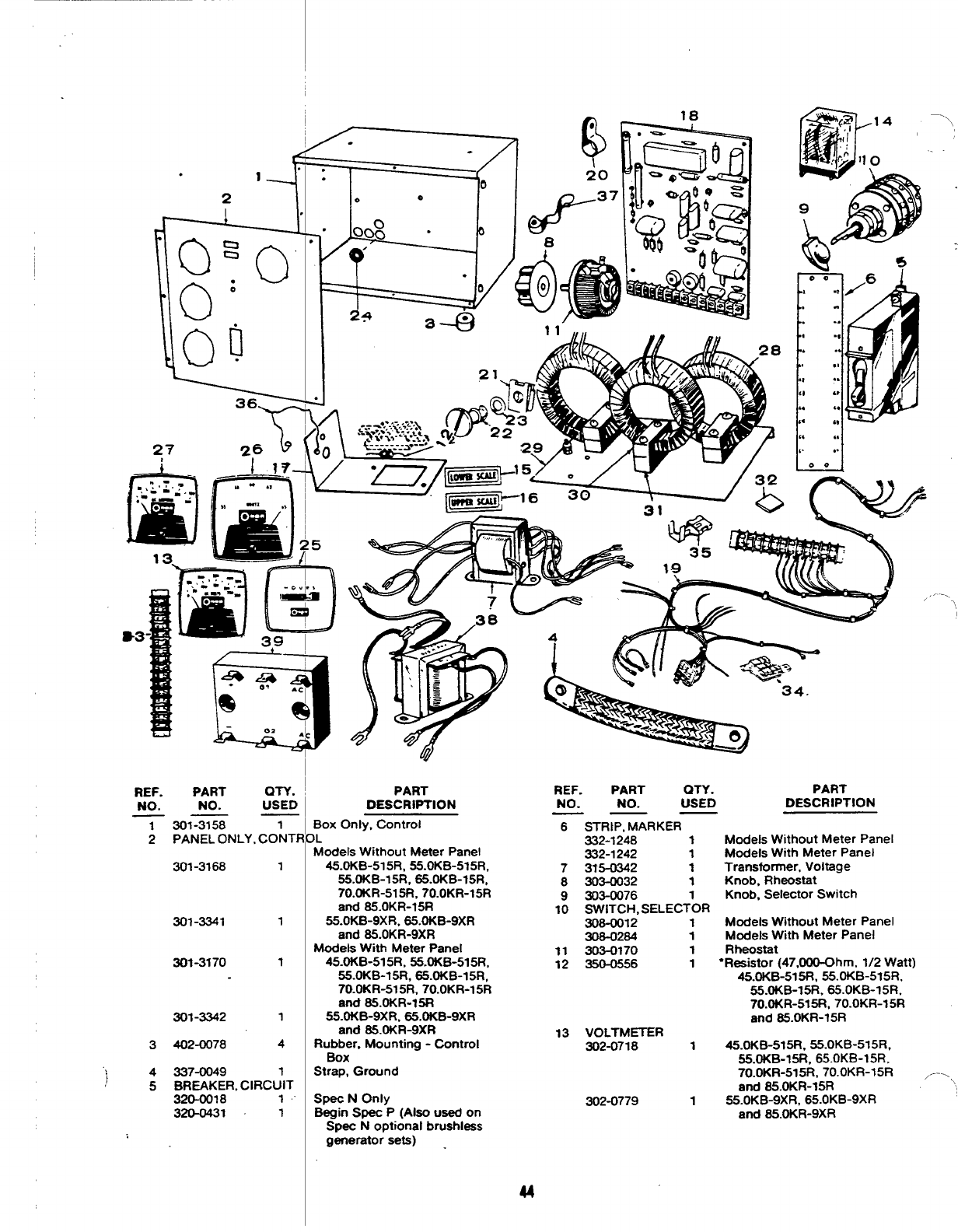
REF. PART QTY.
NO. NO. USED
7301-3158 1
2PANEL ONLY, CONTF
301-3168 1
301-3341 1
301-3170 1
301-3342 1
3402-0078 4
‘) 4337-0049 1
;5BREAKER, CIRCUIT
320-0018 1,
320-0431 1
—
I
‘-
1
i
i
PART
DESCRIPTION
Box Only, Control
IL
Modets Without Meter Panel
45.OKB-515R, 55. OKB-515R,
55.OKB-15R, 65. OKB-15R,
70.OKR-515R, 70.OKR-15R
and 85.OKR-15R
55.OKB-9XR, 85.OKB-9XR
and 85.OKR-9XR
Models Wtth Meter Panel
45.OKB-515R, 55.OKB-515R,
55.OKB-15R, 65.OKB-15R,
70.OKR-515R, 70.OKR-15R
and S5.OKR-15R
55.OKB-9XR, 65. OKB-9XR
and 85. OKR-9XR
Rubber, Mounting -Control
Box
Strap, Ground
Spec NOnly
Begin Spec P(Also used on
Spec Noptional brushless
generator sets) -
“/ u
-.,
REF. PART QTY. PART
NO. NO. USED DESCRIPTION
—— —
6STRIP, MARKER
332-1248 1
332-1242 1
7375-0342 1
8303-0032 1
9303-0076 1
10 SWITCH, SELECTOR
308-0012 1
308-0284 1
11 303-0170 1
12 350-0556 1
13 VOLTMETER
302-0718 1
302-0779 1
Models Without Meter Panel
Models With Meter Panel
Transformer, Voltage
Knob, Rheostat
Knob, Selector Switch
Models Without Meter Panel
Models With Meter Panel
Rheostat
“Resistor (47,000-Ohm, 1/2 Watt)
45.OKB-515R, 55. OKB-515R,
55.OKB-15R, 65. OKB-15R.
70.OKR-515R, 70.OKR-15R
and 85.OKR-15R
45.OKB-515R, 55.OKB-515R,
55.OKB-15R, 65.OKB-15R,
70. OKR-515R, 70. OKR-15R ,-—.
and 85.OKR-15R
55.OKB-9XR, 65.OKB-9XR
and 85.OKR-9XR
u
I
tREF. PART QTY. -PART
NO. NO. USED DESCRIPTION
——
14
15
16
17
18
19
20
21
22
23
24
25
26
27
28
307-1061 1Relay, Voltage Selector - -
45.OKB-515R,55.oKB-515R,
55. OKB-15R, 65. OKB-15R,
70.oKR-515R, 70.oKR-15R
and 85.OKR-15R
32243130 1Light. Lower Scale -
45.OKB-515R, 55. OKB-515R,
55.OKB-15R, 65. OKB-15R,
70.oKR-515R, 70.OKR-15R
and 85.OKR-15R
322-OI 31 1Light, Upper Scale -
45. OKB-515R, 58.OKB-515R,
55. OKB-15R, 65. OKB-15R,
70.OKR-515R, 70. OKR-15R
and 85. OKR-15R
301-3244 1Bracket, Relay Mounting -
45. OKB-515R, 55.OKB-515R,
55. OKB-15R, 65. OKB-15R,
70. OKR-515R, 70.OKR-15R
and 85.OKR-15R
BOARD ASSEMBLY, PRINTED CIRCUIT (See
Separate Group For Components)
332-1264 1Spec NOnly
332-1288 1Begin Spec P(Also used on
SPec Noptional brushless
generator sets
HARNESS, WIRING -AC CONTROL (lrrcludes Parts
Marked “) Models Without Meter Panel
338-0524 145.OKB-515R, 55. OKB-515R,
55. OKB-15R, 65. OKB-15R,
70.oKR-515R, 70.OKR-15R
and 85.OKR-15R
338-0570 155. OKB-9XR, 85. OKB-9XR
and 85.OKR-9XR
Models With Meter Panel
338-0525 145.OKB-515R, 55.OKB-515R,
55. OKB-15R, 65. OKB-15R,
70.OKR-515R, 70.OKR-15R
and 85.OKR-9XR
338-0571 155. OKB-9XR, 65.OKB-9XR
and 85.OKR-9XR
332-0050 2Clip, Tinnerman
406-0332 2Fastener
406-0333 2Stud, Fastener
406-0334 2Washer, Stud Fastener
508-0001 4Grommet
METER. RUNNING TIME (Models With Meter Panel)
302-0469 150 Hertz
302-0466 160 Henz
METER, FREQUENCY (Models With Meter Panel)
302-0256 150 Hertz
302-0221 1 60 Hertz
AMMETER -AC (Models With Meter Panel)
302-0720 1Key 1- 45.OKB (O-100/0-200 Amps)
302-0721 1Key 1-55.OKB (0-150/0-300 Amps)
302-0722 1Key 1- 85.OKB -AND Key 2
(0-200/0-400 Amps)
TRANSFORMER, CURRENT
302-0106 3Key 1(45.OKB)-200/5
302-0107 3Key 1(55.OKB)-300/5
302-0608 3Key 1(85.OKB)AND Key 2-
400/5
REF. PART QTY.
NO. NO. USED
—— —
29 302-0729 1
30 302-0235 3
31 302-0236 3
32 302-0253 As Req.
33 “BLOCK, TERMINAL
332-0607
332-0795
34 323-0764
35 332-1280
36 307-1157
37 302-0307
38 315-0384
39 305-0524
40 813-0110
41 854-0010
42 815-0203
43 871-0010
44 526-0049
45 856-0003
1
1
PART
DESCRIPTION
Bracket, Transformer Mounting
Clamp, Transformer Mounting -
Upper -Models With Meter
Panel
Clamp, Transformer Mounting -
Lower -Models With Meter
Panel
Shim, Transformer Mounting
Models Without Meter
Panel -12 Place
Models With Meter Panel -
16 Place
1“Socket, Relay -
45. OKB-515R, 55. OKB-515R,
55. OKB-15R, 85. OKB-15R.
70. OKR-515R, 70. OKR-15R
and 85.OKR-15R
As Req. “Terminal, Crimp -
45.OKB-515R, 55.OKB-515R,
55. OKB-15R, 65. OKB-15R,
70.OKR-515R, 70. OKR-15R
and 85.OKR-15R
and 85.OKR-15R
1Spring, Relay Hold-down
1Lock, Circuit Breaker
Handle -Penn State Models
(Optional)
1Reactor Assembly, Commutator
Begin Spec S
1Bridge, Rectifier -Begin
Spec S
6Screws, Round Head Machine
(10-32 x2“ long)
8Washer, Internal Lock (#10)
1Screw, Round Head (BM)
(10-32 x7/8” long)
3Nut, Hex (BMS) -(10-32)
2Washer, Flat
1Washer, External/Internal -
Lock
46 HARNESS, WIRING -AC CONTROL (Models Without Meter
Panel) -BEGIN SPECS
338-0764 145.OKB-515R, 50.OKB-15R (Penn
State) -55. OKB-I 5R. 55. OKB-515R,
65. OKB-15R, 70.OKR-515R,
70. OKR-15R, 75. OKR-15R
(Penn State), 85. OKR-15R
338-0766 155. OKB-9XR, 65. OKB-9XR,
70. OKR-9XR, 85.OKR-9XR
Models With Meter Panel
338-0730 145.OKB-515R, 50. OKB-15R
(Penn State), 55. OKB-15R,
55. OKB-515R, 65. OKB-15R,
70.OKR-515R, 70.OKR-15R,
75.OKR-15R (Penn State),
85. OKR-15R
338-0759 155. OKB-9XR, 65. OKB-9XR,
70. OKR-9XR, 85. OKR-9XR
“-Included in Wiring Harness Assembly.
45
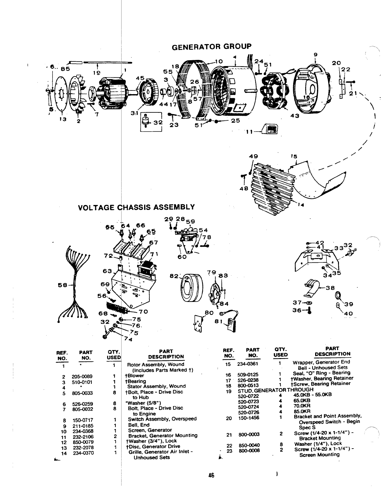
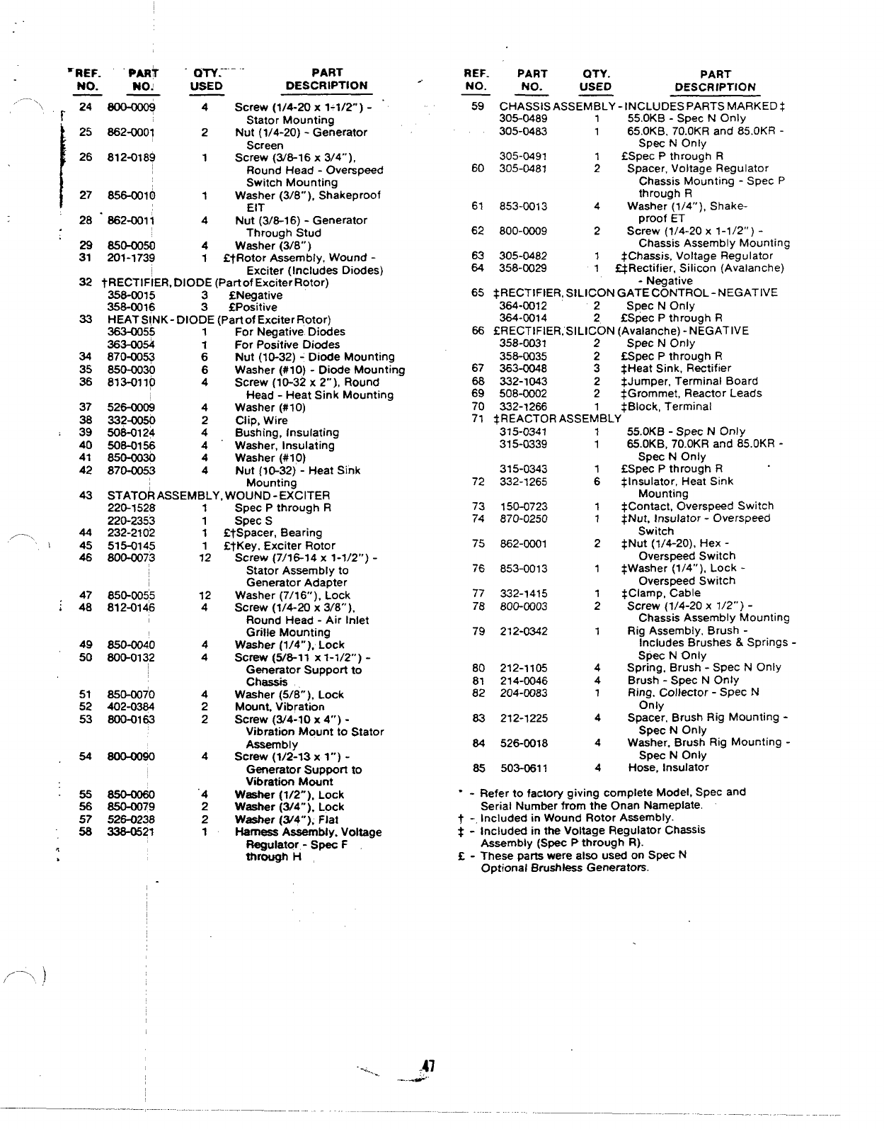
GENERATOR GROUP -\
I
I
/
IJ
VOLTAGE CHASSIS ASSEMBLY
/
/
/
?
48
,-.,,
37* >39
363 Y40
80 -
r%
“81 -.
.,
PART REF.
NO.
15
PART QTY. PART
NO. USED DESCRIPTION
——
234-0361 1Wrapper, Generator End
Bell -Unhoused Sets
REF.
NO.
PART
NO.
.
WY.
USED DESCRIPTION
Rotor Assembly, Wound
(Includes Parts Marked t)
tBlower
tBearing
Stator Assembly, Wound
tBoit, Place -Drive Disc
to Hub
“washer (5/8” )
Bolt, Place -Drive Disc
to Engrne
Switch Assembly, Overspeed
Bell, End
Screen, Generator
Bracket, Generator Mounting
tWasher (3/4’”), Lock
tDkc, Generator Drive
Grille, Generator Air Inlet -
Unhoused Sets
1 ~
1
1
1
8
8
8
1
1
1
2
1
1
1,
1
509-0125 1Seal, ‘“0 Ring -Bearing
526-0238 1tWasher, Bearing Retainer
800-0513 1W3crew, Bearing Retainer
STUD, GENERATOR THROUGH
52G0722 445.oKB -55.oKB
520-0723 465.0K6
520-0724 470.OKR
52M726 485.OKR
150-1456 1Bracket and Point Assembly,
Overspead Switch -Begin
16
17
18
19
205-0089
510-0101
.
605-0033
2
3
4
5
6
7
526-0259
805-0032
20
150-0717
211-0185
234-0368
232-2106
850-0079
232-2078
234-0370
8
9
10
11
12
13
14
L.
SDS s,-.,
21 ~2Scriw (1/4-20x 1-1/4’”) -‘‘,
Bracket Mounting
22 850-0040 8Washer (1/4”), Lock
’23~ 2screw (1/4-20 x1-1/4”) -
i. Screen Mounting
46 1
‘REF. PAR?
NO. NO!
——
,- –-X,,, r24 800+006
125 862-0001
26 812-0189
28 .862-0011
29 850-0050
31 201-1739
32
33
34
35
36
43
~w.-.-.. PART
USED DESCRIPTION
4Screw (1/4-20 x1-1/2) -
Stator Mounting
2Nut (1/4-20) -Generator
Screen
1Screw (3/6-16 x3/4”),
Round Head -Overspeed
Switch Mounting
1Washer (3/8” ), Shakeproof
EIT
4Nut (3/6-1 6) -Generator
Through Stud
4Washer (3/8”)
1!ZfRotor Assembly, Wound -
.,-.. ..
Exciter (Includes Diodes)
tRECTIFIER, DIODE (Part of Exciter Rotor)
358-0015 3SNegative
358-0016 3fPositive
HEAT SINK- DIODE (Part of Exciter Rotor)
363-C055 1For Negative Diodes
363-0054 For Positive Diodes
870410q :Nut (10-32) -Diode Mounting
850-0030 6Washer (#1 O) -Diode Mounting
813-0110 4Screw (113-32 x2“ ), Round
Head -Heat Sink Mounting
526-0008 4Washer (#1 O)
332-0350 2Clip, Wire
506-0124 4Bushing, Insulating
506-0156 4“ Washer, Insulating
850-oo3tl 4Washer (#1 O)
870-0053 4Nut (l&32) -Heat Sink
Mounting
STATOR ASSEMBLY. WOUND -EXCITER
220-1528
220-2353
/-.., 44 232-2102
45 515-0145
46 800-0073
47 850-0055
*48 812-0146
49 850-0040
50 800-0132
51 850-0070
52 402-0384
53 800-0163
54 800-0090
55850+060
56 650-0079
57 526-0238
58 336-0521
,,-’,, )
1
1
1
1
12
12
4
4
4
4
2
2
4
‘4
2
2
1
spec vmrougn I-I
Spec S
EtSpacer, Bearing
EtKey, Exciter Rotor
Screw (7/16-14 x1-1/2”) -
Stator Assembly to
Generator Adapter
Washer (7/16” ), Lock
Screw (1/4-20 x3/8”),
Round Head -Air Inlet
Grille Mounting
Washer (1/4”), Lock
screw (5/8-11 x1-1/2”) -
Generator Support to
Chassis
Washer (5/8” ), Lock
Mount Vibration
Screw (3/4-10 x4“) -
Vibration Mount to Stator
Assembly
Screw (1/2-13 x1”) -
Genemtor Support to
Vibration Mount
Washer (1/2”), Lock
Washer (3/4’. ), Lock
Washer (W4”), Flat
Harness Assembly, Voltage
Regulator -Spec F
through H
‘-.,... -
REF. PART
., QTY. PART
NO. NO. USED DESCRIPTION
—— _
59 CHASSIS ASSEMBLY -INCLUDES PARTS MARKED $
305-0489 155.OKB -Spec NOnly
305-0483 165.OKB, 70.OKR and 85.OKR -
Spec NOnly
305-0491 fSpec Pthrough R
60 305-0481 ;Spacer, Voltage Regulator
Chassis Mounting -Spec P
through R
61 853-0013 4Washer (1/4”), Shake-
proof ET
62 800-0009 2Screw (1/4-20 x1-1/2”) -
Chassis Assembly Mounting
63 305-0482 1$Chassis, Voltage Regulator
&l 358-0029 1=Rectifier, Silicon (Avalanche)
-Negative
65 *RECTIFIER, SILICON GATE CONTROL-NEGATIVE
364-0012 2Spec NOnly
364-0014 2fSpec Pthrough R
66 SRECTIFIER,’SILICON (Avalanche) -NEGATIVE
358-0031 2Spec NOnly
356-0035 2fX3pec Pthrough R
67 363-0048 3$Heat Sink, Rectifier
68 332-1043 2+Jumper, Terminal Board
69 508-0002 2$Grommet, Reactor Leads
70 332-1266 1+Block, Terminal
71 $REACTOR ASSEMBLY
315-0341 155.OKB -Spec NOnly
315-0339 165.OKB, 70.OKR and 85.OKR -
Spec NOnly
315-0343 1fSpec Pthrough R.
72 332-1265 6tlnsulator, Heat Sink
Mounting
73 150-0723 1 $Contact, Overspeed Switch
74 870-0250 1*Nut, Insulator -Overspeed
Switch
75 662-0001 2$Nut (1/4-20), Hex -
Overspeed Switch
76 853-0013 1+Washer (1/4”), Lock -
Overspeed Switch
77 332-1415 1$Clamp, Cable
78 800-0003 2Screw (1/4-20 x1/2”) -
Chassis Assembly Mounting
79 212-0342 1Rig Assembly, Brush -
Includes Brushes &Springs -
Spec NOnly
80 212-1105 4Spring, Brush -Spec NOnly
81 214-0046 4Brush -Spec NOnly
82 204-0083 1Ring. Collector -Spec N
Only
83 212-1225 4Spacer, Brush Rig Mounting -
Spec NOnly
84 526-0018 4Washer. Brush Rig Mounting -
Spec NOnly
85 503-0611 4Hose, Insulator
-Refer to factory giving complete Model, Spec and
Serial Number from the Onan Nameplate.
-. Included in Wound Rotor Assembly.
*-Included in the Voltage Regulator Chassis
Assembly (Spec Pthrough R).
Z-These parts were also used on Spec N
Optional Brushkrss Generators.
.,47
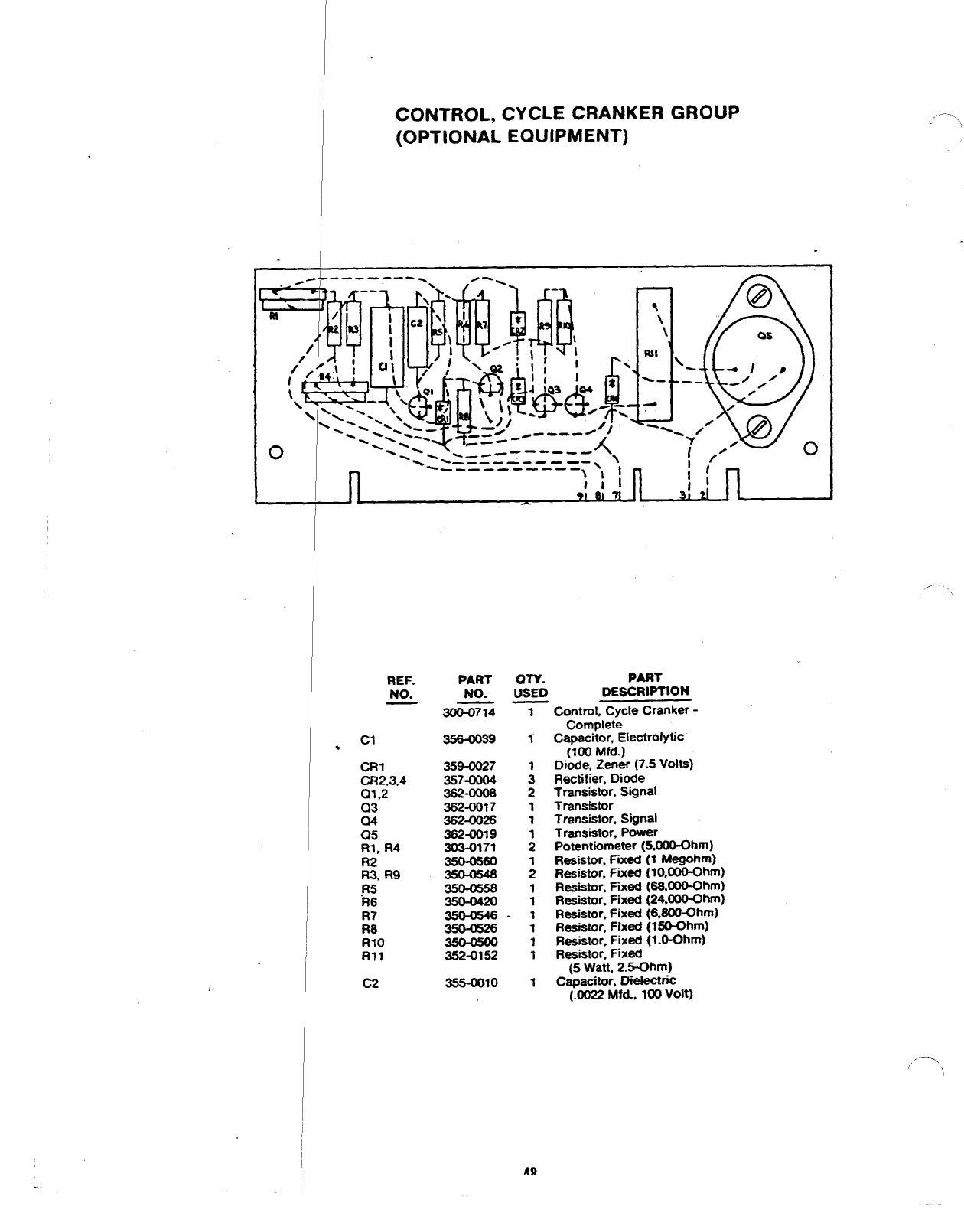
CONTROL, CYCLE CRANKER GROUP
(OPTIONAL EQUIPMENT)
-- -- —-------) ‘1 Ii’
111 1;
91 I
REF.
NO.
cl
●
CR1
CR2,3,4
01,2
C)3
04
05
RI, R4
R2
R3, R9
.R5
R6
Y8
R70
RI?
C2
PART
NO.
m74
356-0039
359-0027
357-0004
362-OOOS
362-0017
362-0026
362-0019
303-0171
35@055s
350-0420
352-0152
355-0010
--- ~,,
OTY. PART
USED DESCRIPTION
Control, Cycle Cranker -
Complete
Capacitor, Electrolytic
(100 Mfd.)
Diode. Zener (7.5 Volts)
Rectifier, Diode
Transistor, Sgnal
Transistor
Transistor, Sgnal
Transistor, Power
Potentiometer (5.000-Ohm)
Resistor, Fixed (t Megohm)
Resistor, Fixed (10.000-Ohm)
Resistor, Fixed (SWIOO-Ohm)
Resistor, Fixed (24AO0-Ohm)
Resistor. Fixad (6@0-Ohm)
Resistor, Fixed @O-Ohm)
Resistor, Fixed (1. O-Ohm)
Resistor, Ftxed
(5 Watt, 2.5-Ohm)
Capacitor, DiekttiC
(.0022 Mfd.. 100 Volt)
...
,—.,
/’
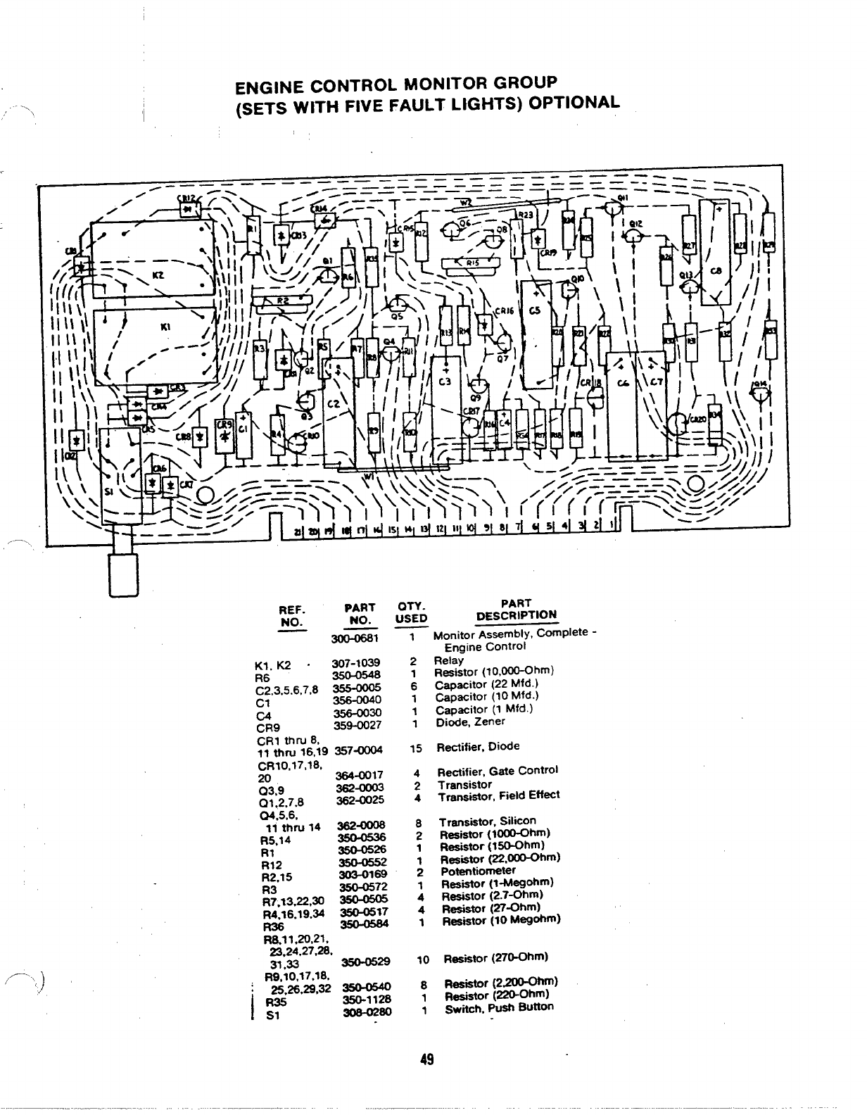
ENGINE CONTROL MONITOR GROUP
‘\ I(SETS WITH FIVE FAULT LIGHTS) OPTIONAL
DREF. PART Q~. PART
NO. NO. USED DESCRIPTION
~= —Monitor Assembly, Complete -
,/-- ,,)
Kl, K2 .307-1039
R6 350-0548
C2.3,5.6,7,8 ~
c1 356-0040
G356-0030
CR9 369-0027
CR1 thru 8,
11 ttwu 16,19 357-
CRI0,17,18.
20 364-0017
03,9 362-
01,2,7.8 362-0025
04.5.6,
11 thru Id =-
R5,14
R* 35@0526
. . .
R12 350-0552
R2.15 303-0169
R3 350-0572
R7,13,22,3r3 ~
R4.16.19.34 =17
R&l 1,20,21,
23,24,27,28.
31.33 350-05=
l%io,17,18,
:25,26.29,32 35Ct#40
IR35 -I 128
S1 308-02~
1
2
1
6
1
1
1
15
4
2
4
8
2
1
;
1
4
4
1
Engine control
Relay
Resistor (?o,oceOhrn)
C-acitor (22 Mfd.)
~pacitor (10 Mfd.)
@pacitor (1 Mfd.)
Diode, Zener
Rectifier, Diode
R~ifier, Gate Control
Transistor
Tranaiator, Field Eff~t
Transistor, SlliCOn
Resistor (looO-Ohm)
Resistor (lWhm)
RSiator @2,000-Ohm)
potentiometer
Resistor (l-Meg*m)
Resistor (2.7-Ohm)
Resistor (27-Ohm)
Resistor (10 M-*)
10 Resistor (270-Ohm)
s~r [2,200-ohm)
1~~ator @&Ohm)
1Switch, pUSh BUtton
49
—.. -.
PRltf
332-1:
z
s—----’
+“
-—
--
/---”
,/
‘/
‘,0
/’I
/
/r
+-=
REF. PART 4
NO. NO. 1
—-
TB1
,- C1
C2, C7
C3, C9
C4
C5, Ca
IC6
Clo
C13
CR4WU 11
CR12
CR13
CR*4
CR15
K1
m01, 02
Q3
RI, R23
R2. R3
R4
R5
._. —-.
332-1252
355-0018
355-0017
355-0006
355-MM6
365-0015
355-0014
357-0014
358-0035
359-0025
35WI026
359-0015
307-1063
3624XM7
361-0004
3550355’
350-0351
sto75
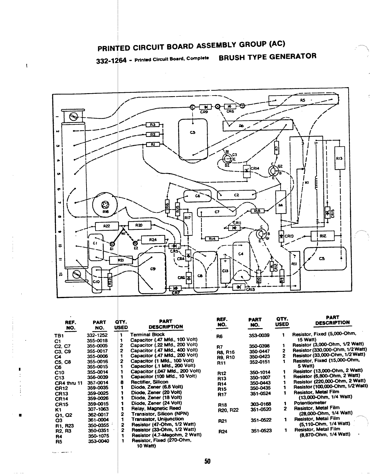
ED CIRCUIT BOARD ASSEMBLY GROUP (AC)
~-Printed Circuit Board, Cornpiete BRUSH TYPE GENERATOR
““:-ml
::---+
—,
“\
——
0--——
/
‘%,
Ez z--
u
.~-
\\
v. PART
ED DESCRIPTtON
—
REF.
NO.
I
i
2
2
I
2
I
1
1
B
1
1
1
1
:
:
2
1
1
Terminal Biocit
capacitor (.47 Mfd., 100 Volt)
Capacitor (.22 Mfd., 200 Voit)
Capacitor (.47 Mfd., 400 Volt)
Capscitor (.47 Mfd., 200 Voit)
Capacitor (1 Mfd.. 100 Voit)
Capacitor (.1 Mfd., 200 Volt)
Capacitor (.047 Mfd., 200 Vott)
Caoacitor (100 Mfd-, 10 Volt)
Rektiier. ~iicorl
Diode, Zaner (6.8 Voit)
D*, Zener (20 volt)
Diode, Zener (18 volt)
DIoda, Zener (24 volt)
Relay. Magnetic Reed
Transistor, Sitiion (NPN)
Transistor, Unyur@On
Resistor (47-Ohm, 1/2 Watt)
Resistor @3-Ohm, 1/2 Watt)
Resistor (4.7-Megohm. 2Watt)
Resistor, Freed (270-Ohm,
10watt)
R6
R7
R& R16
R9. R1O
Rll
R12
R13
Ft14
R15
R17
R18
R20. R22
R21
R24
PART on.
No. USED
——
35MM47
350-0423
352-0151
350-1014
350-1007
351-0524
m3-o166
351-0520
3514%22
351-
1
1
2
2
1
1
1
1
1
1
;
1
1
PART
DESCRtPltON
,/ ---\ \
Resistor, Fixed (5,000-Ohm,
R~~sYo;~!3,~hm, 1/2 Watt)
Resistor (330,000-Ohm, 1/2 Watt)
Resistor (33,000-Ohm, 1/2 Watt)
Resistor, Fixed (15,-hm.
5Watt)
Resistor (13,000-Ohm, 2w@
Resistor (6,_hm. 2watt]
Resistor (220,000-Ohm, 2watt)
Resistor (?OO,~m, 1/2 Watt)
Resistor,”khtat Fiim
@,000-Ohm. 1/4 wan)
POtentiirnOter
Resistor, Metai Film
(28,000-Ohm, 1/4 Watt)
Resistor, Metal Fiim —‘,,
(%ll~m, 114 Watt) ‘
R4stOr, Metal Fiim
(8.87~hm, ?/4 Watt) -
,/ —>,
.--.\
\
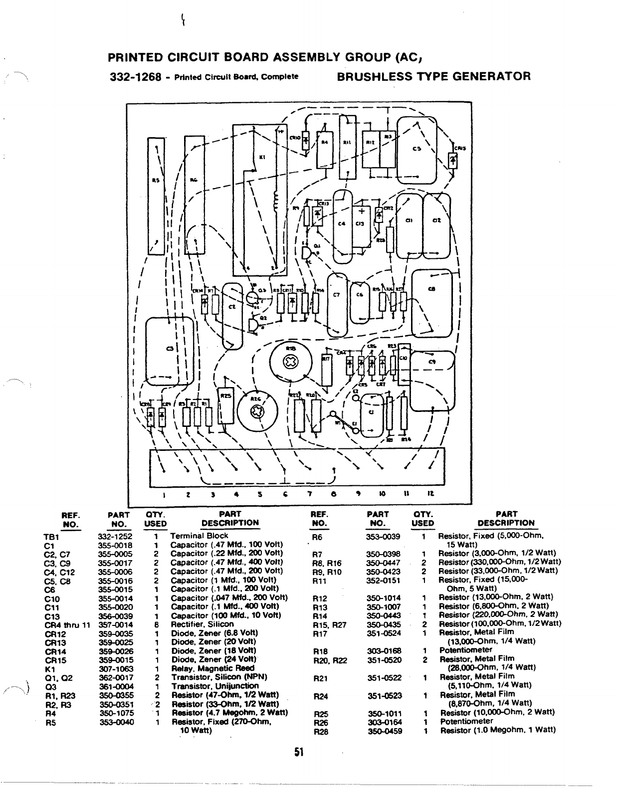
PRINTED CIRCUIT BOARD ASSEMBLY GROUP (AC,
332-1268- printed Cirwit BOa~ Complete BRUSHLESS NPE GENERATOR
s
I‘L––____i –––J I
I234 SC78 •~lllt
—.-— —
REF. PART on. PART REF. PART Q-f-Y.
NO. NO. USED DESCRIPTION NO. NO. USED
—.
TB1
%C7
C3, C9
C4, C12
C5. C8
C8’
Clo
cl 1
C13
cR4thrull
CR12
CR13
CR14
CR15
VI. 02
‘)
,. —. )03
‘\ RI, R23
R2, Ft3
R4
R5
332-1252
355-0018
355-0005
355-0017
355-a)06
355-0016
355-0015
355-0014
355-0020
356-0039
35-7-0014
359-0035
359-0025
359-0026
359-0015
307-1063
362~17
36141004
350-0351
350-1075
2
2
2
1
1
1
;
1
1
1
1
1
2
‘“2
“1
1
Terminal Block
Capacitor (.47 Mfd., 100 Volt) .
Capacitor (.22 Mfd., 200 Voft)
Capacitor (.47 Mfd., 400 Volt)
Capacitor (.47 Mfd., 200 Volt)
capacitor (I Mfd., 100 Volt)
Capacitor (.1 Mfd., 200 Volt)
Capacitor (.047 Mfd., 200 Vott)
Capacitor (.1 MM., 400 Voft)
Capacitor (100 Mfd., 10 Vott)
Rectifier, Silicon
Diode, Zener (6.6 VOft)
Diode, Zener (20 VOft)
Dtode, Zener (16 Voft)
Diode. Zener (24 Vott)
Refay, Magnetic Reed
Transistor, Silicon (NPN)
Transistor, Unijunction
Resistor (47-OhIn, 1/2 Watt)
Reektor (33-Ohm. 1/2 Watt)
Resistor (4.7 Megohrn, 2Watt)
Resistor, Fixed (270-Ohm,
10 watt)
R6
R7
R8, R16
R9, R1O
Rll
R12
R13
R14
R15, R27
R17
R18
R20. R22
R21
R24
R25
R26
353-0039 1
350-0398
350-0447 :
350-0423 2
352-0151 1
350-1014 1
350-1007 1
;
351-0524 1
351-0522 1
3514523 1
35G1011 1
303-0184 1
350-0459 1
PART
DESCRIPTION
Resistor, Fixd (5,000-Ohm,
15 Watt)
Resistor (3,000-Ohm, 1/2 Watt)
Resistor (330,000-Ohm, 1/2 Watt)
Resistor (33,000-Ohm, 1/2 Watt)
Resistor, Fixed (15,000-
Ohm, 5Watt)
Resistor (13,00CFOhm, 2Watt)
Resistor (6,800-Ohm. 2Watt)
Resistor (220.000-Ohm, 2Watt)
Resistor (100,000-Ohm, 1/2 Watt)
Resistor, Metal Film
(13,000-Ohm. 1/4 Wan)
Potentiometer
Resistor, Metal Film
(28,000-Ohm, 1/4 Wan)
Resistor, Metal Film
(5,11 O-Ohm. 1/4 Watt)
Resistor, Metal Film
(8,670-Ohm, 1/4 Watt)
Resistor (10,000-Ohm, 2wan)
potentiometer
Resistor (1.0 Megohm, 1Watt)
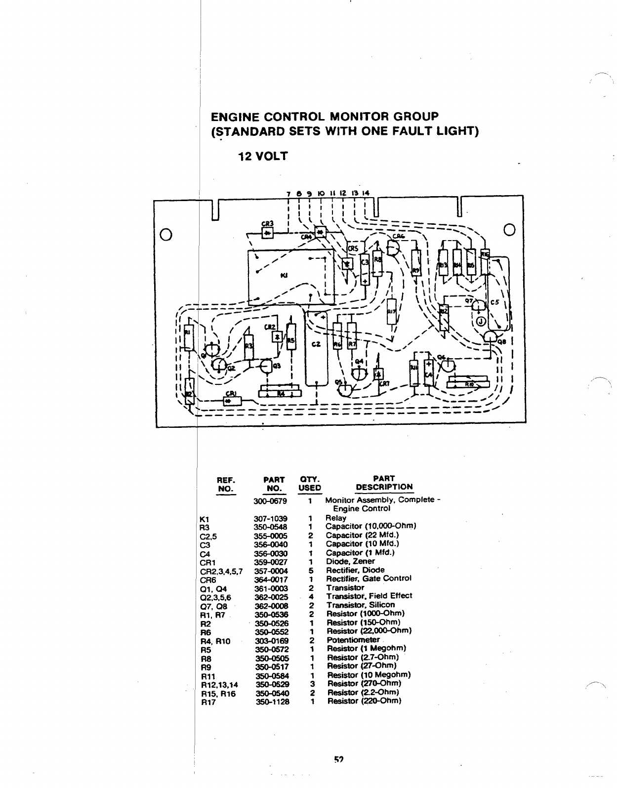
ENGINE CONTROL MONITOR GROUP
(STANDARD SETS WITH ONE FAULT LIGHT)
112 VOLT
I7Aaknll1213t4
‘{?---————-—— —--————-—— — — --- /
-+———— -- ———- ----- —--— —— -- ---
REF.
h!%
. .
R3
C2.5
C3
C4
CR1
CR2,3.4,5,7
CR6
Ql, 04
02,3,5,6
(27, 08
RI, R7
R2
Ft6
Ft4, Rio
R5
::
Rll
R12,13,14
R15, R16
R17
PART
NO.
-79
307-1039
355-0005
359-0027
357-0004
364-0017
361-00(x3
362-0025
362-0008
350-0536
350-0526
350-0552
303-0169
350-0672
350-0517
350-0564
350-1128
PART
$+6 DESCRIPTION
Monitor Assembly, Complete -
Enaine Control
Rela~
Csoacitor (10.000-Ohm)
Csbacitor ~22”Mfd.) “”
Capacitor (10 Mfd.)
Capacitor (1 Mfd.)
Dhcte, Zener
Rectif@r, Dhde
Rectifier, Gate Control
Transistor
Transistor. Fietd Effect
Transistor. SItiion
Resistor (1000-Ohm)
Resistor (150-Ohm)
Resistor (22,000-Ohm)
Potentiometer
Resistor (1 MegOhm)
Resistor (2.7-Ohm)
Resistor (27-Ohm)
Resistor (10 Megohm)
Resistor (270-Ohrn)
Resistor (22-Ohm)
Resistor (220-Ohm)
57
,,-% \
-.,,
,,.- .\
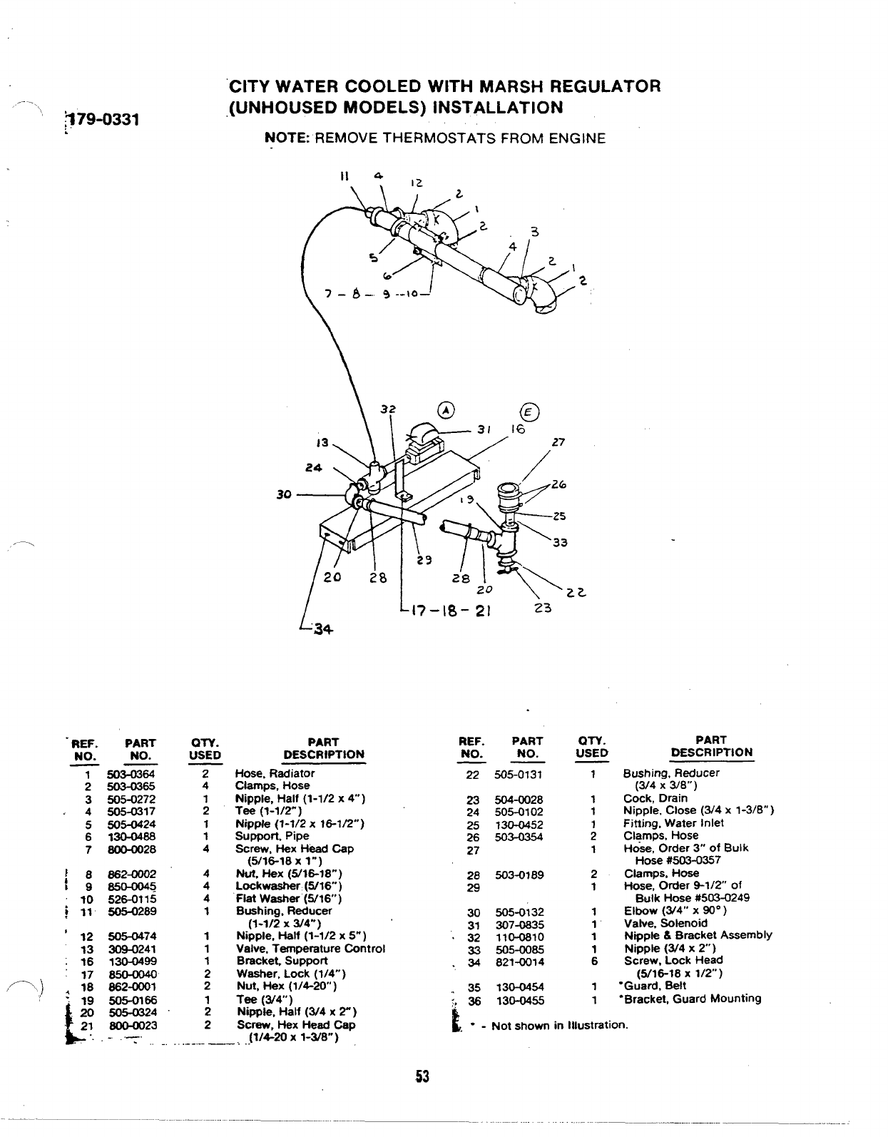
“379-0331
CITY WATER COOLED WITH MARSH REGULATOR
(UNHOUSED MODELS) INSTALLATION
NOTE: REMOVE THERMOSTATS FROM ENGINE
30
,.-
,=-’, )
-REF. PART
NO. NO.
2503-0365
3505-0272
4505-0317
5505-0424
6MJ-0488
7~28
!8862-0002
I9s50-0045
10 526-0?15
~11 505-0289
‘12 505-0474
13 309-0241
;16 130-0499
17 8504040
18 862-0001
2 19 505-0166
\
20 505a324
21 80W023
QIY.
USED
2
4
1
1
1
4
4
4
4
1
1
1
1
2
2
1
2
2
7 – b–. 9--~a— 2
LL~7-18- 2] 23
‘3+
PART
DESCRIPTION
Hose, Radiator
Clamps, Hose
Nipple, Half (1-1/2 x4)
Tee (1-1/2”]
Nipple (1-1/2 x16-1/2”)
SLJpport, Pipe
Screw, Hex Head Cap
(5/16-18x 1“)
Nut. *X (5/1618”)
Lockwaahar (6/16)
Flat Washer (5/16”)
Bushing, Reducer
(1-1/2 x3/4’”)
Nipple, Half (1-1/2 x5“ )
Valve, Temperature Control
Bracket. Suppoti
Washer, Lock (1/4” )
Nut, Hex (1/4-20” )
Tee (3/4 )
Ni~ks, Half (3/4x 2“)
Screw, Hex Head Cap
[1/4-20 X1-W8”)
~.. -.: . ...-. .———.. ..-
REF. PART
NO. NO.
——
22 505-0131
23 504-0028
24 505-0102
25 ?300452
26 503-0354
27
28 503-0189
29
30 505-0132
31 307-0835
.32 110-0810
33 505-0085
34 821-0014
“35 t30-cM54
“. 36 130-0455
QTY.
USED
1
2
1
1
1
.,
k“.Not shown in lllIJStrStiOn.
PART
DESCRIPTION
Bushing, Reducer
(3/4 x3/8”)
Cock, Drain
Nipple. Close (3/4 x1-3/8”)
Fitting. Water Inlet
Clamps, Hose
Hose, order 3“ of Bulk
Hose #503-0357
Clamps, Hose
Hose, order 9-1/2” of
Bulk Hose #503-0249
Elbow (3/4’” X90°)
Valve, Solenoid
Nipple &Bracket Assembly
Nipple (3/4 x2“)
Screw, Lock Head
(5/16-18 X1/2”)
“Guard, Belt
“Bracket, Guard Mounting
53
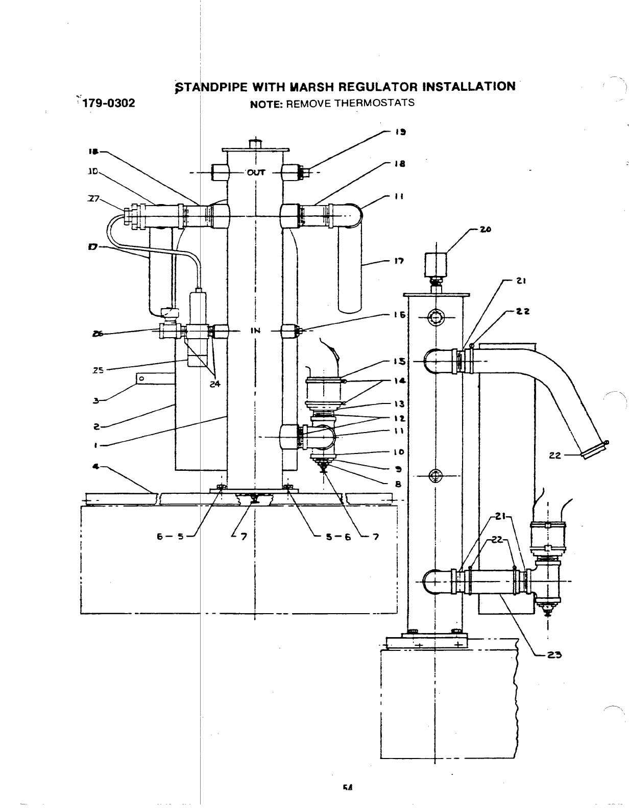
‘-179-0302
~T~NDPIPE WITH MARSH REGULATOR
NOTE REMOVE THERMOSTATS
r19
X‘R
“A‘4 ,
la
II
I
16
2+’ I I {1 11)”’/ —,*
6– 5J
i
I
.
l--
I
I
iI
~
---- _i
I
INSTALLATION
+1+
-.
I
!
1
II
i
r“
.—
..\
.
Z2
\l
.+
—--
--- 23
,,-.
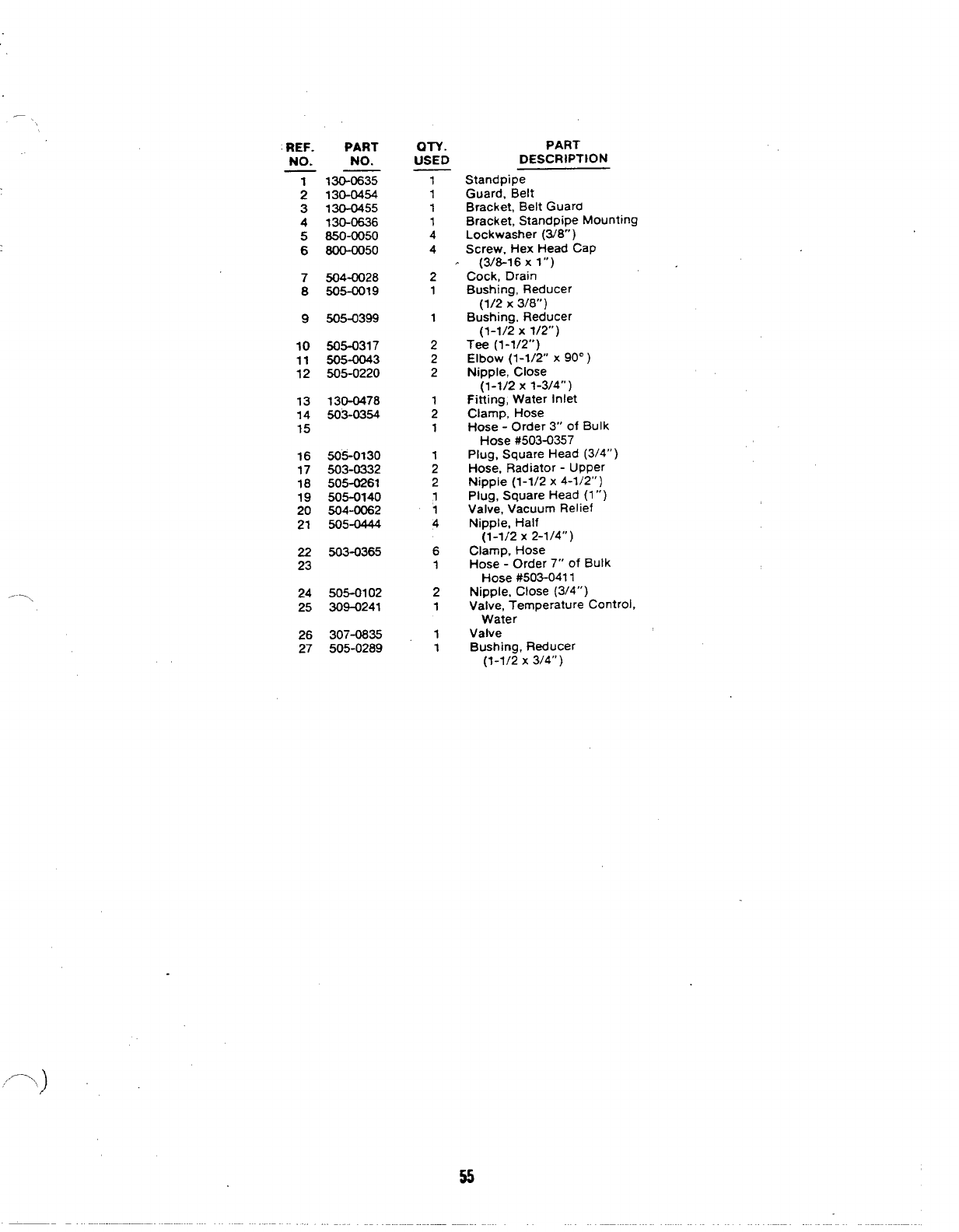
REF.
NO.
PART
NO.
;
3
4
5
6
7
8
9
10
11
12
13
14
15
16
17
18
19
20
21
22
23
24
25
26
27
130-0635
130-0454
130-0455
130-0636
850-0050
800-oo50
504-0028
505-0019
505-0399
505-0317
505-0043
505-0220
130-@478
503-0354
505-0130
503-0332
505-0261
505-0140
504-0062
505-0444
503-0365
505-0102
309-0241
307-0835
505-0289
al-v
USED
1
1
1
1
4
4
2
1
1
2
2
2
1
2
1
1
2
2
1
‘1
4
6
1
2
1
1
1
55
PART
DESCRIPTION
Standpipe
Guard, Belt
Bracket, Belt Guard
Bracket, Standpipe Mounting
Lockwasher (3/8”)
Screw. Hex Head Cap
(3/8-16 xl”)
Cock, Drain
Bushing, Reducer
(1/2 X3/8”)
Bushing, Reducer
(1-1/2 x1/2”)
Tee (1-1/2”)
Elbow (1-1/2” X90° )
Nipple, Close
(1-1/2 x1-3/4”)
Fitting, Water Inlet
Clamp, Hose
Hose -Order 3“ of Bulk
Hose #503-0357
Plug, Square Head (3/4”)
Hose, Radiator -Upper
Nippie (1-1/2 x4-1/2”)
Plug, Square Head (1”)
Valve, Vacuum Relief
Nipple, Half
(1-1/2 X2-1/4”)
Clamp, Hose
Hose -Order 7“ of Bulk
Hose #503-041 1
Nipple, Close (3/4”)
Valve, Temperature Control,
Water
Valve
Bushing, Reducer
(1-1/2 x3/4”)
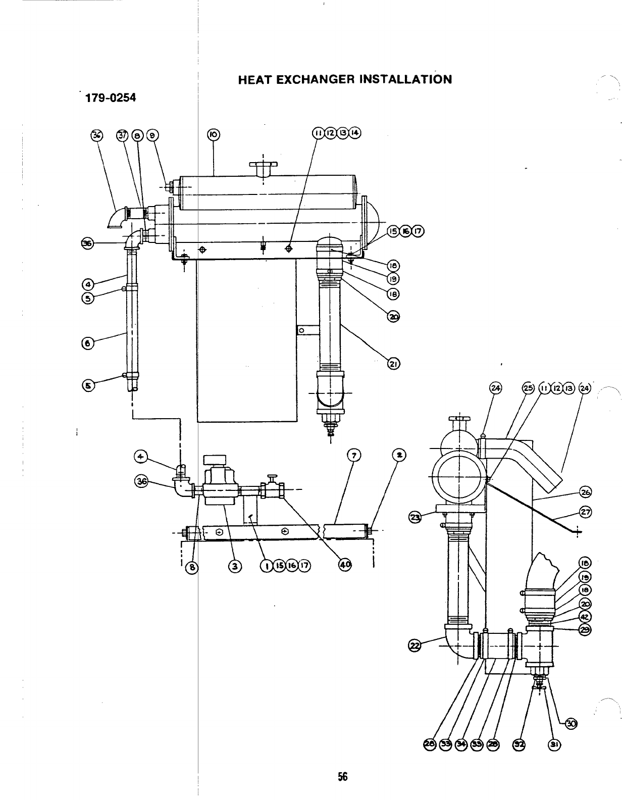
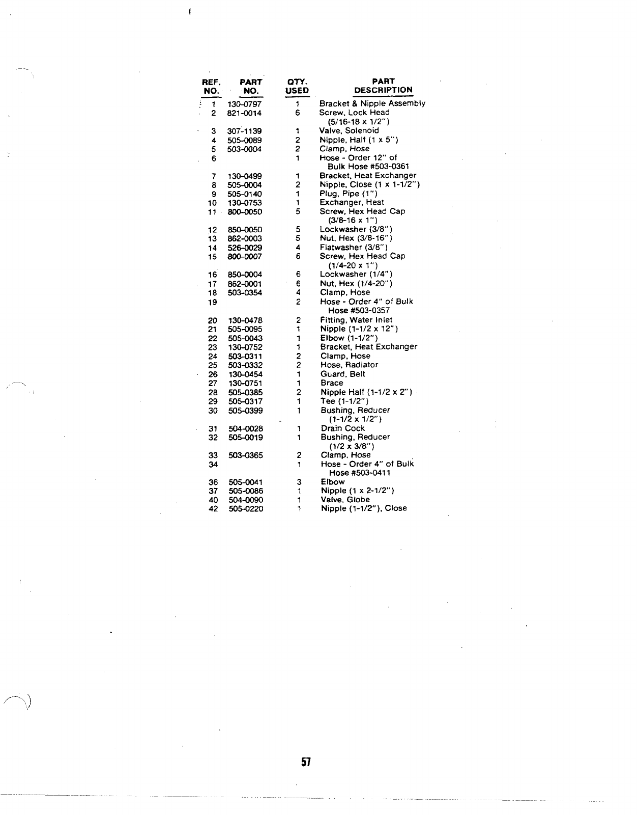
179-0254
I-1 I
%
4
36,
?
10
HEAT EXCHANGER INSTALLATION
F
II 12 13 14
I
1, , J
*/
—
/
I
““ -\
\
\
I
\
—-,.
//-.., ]
,/
REF.
NO.
PART
NO. ON.
uSED
:? 2
3
4
5
6
7
8
9
10
11
12
13
14
15
16
17
18
19
130-0797
821-0014
307-1139
505-0089
503-0004
130-0499
505-0004
505-0140
130-0753
800-oo50
850-0050
862-0003
526-0029
800-0007
862-0001
503-0354
20
21
22
23
24
25
26
27
28
29
30
31
32
33
34
36
37
40
42
130-0478
505-0095
505-0043
130-0752
503-0311
503-0332
130-0454
130-0751
505-0385
505-0317
505-0399
504-0028
505-0019
503-0365
505-0041
505-0086
504-0090
505-0220
:
1
2
2
1
;
1
1
5
5
5
4
6
6
6
4
2
2
1
1
1
2
2
1
1
2
1
1
1
1
2
1
3
1
1
1
PART
DESCRIPTION
Bracket &Nipple Assembly
Screw, Lock Head
(5/16-18 X1/2”)
Valve, Solenoid
Nipple, Half (1 x5“)
Clamp, Hose
Hose -Order 12” of
Bulk Hose #503-0361
Bracket, Heat Exchanger
Nipple, Close (1 x1-1/2”)
Plug, Pipe (1”)
Exchanger, Heat
Screw, Hex Head Cap
(3/8-16 Xl“)
Lockwasher (3/8”)
Nut, Hex (3/8-16” )
Flatwasher (3/8”)
Screw, Hex Head Cap
(1/4-20 Xl“)
Lockwasher (1/4”)
Nut, Hex (1/4-20” )
Clamp, Hose
Hose -Order 4“ of Bulk
Hose #503-0357
Fitting, Water Iniet
Nipple (1-1/2 x12”)
Elbow (1-1/2”)
Bracket, Heat Exchanger
Clamp, Hose
Hose, Radiator
Guard, Belt
Brace
Nipple Half (1-1/2 x2“ )
Tee (1-1/2”)
Bushing, Reducer
(1-1/2 x1/2”)
Drain Cock
Bushing, Reducer
(1/2 X3/8”)
Clamp, Hose
Hose -Order 4“ of Bulk
Hose #503-041 1
Elbow
Nipple (1 x2-1/2”)
Valve, Globe
Nipple (1-1/2” ), Close
57
—.-. .
i
8
m
I-IEAT EXCI
,179-0296
L
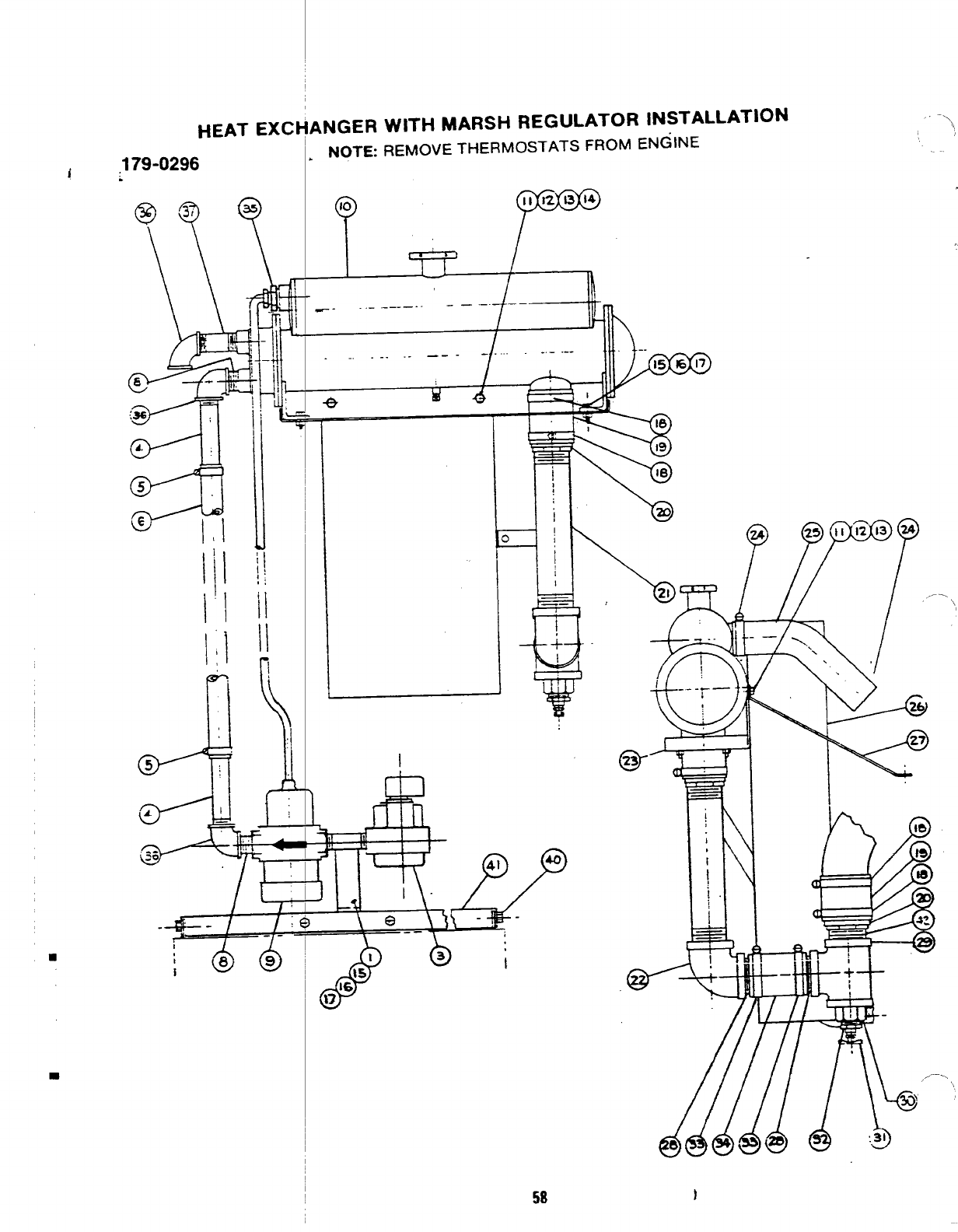
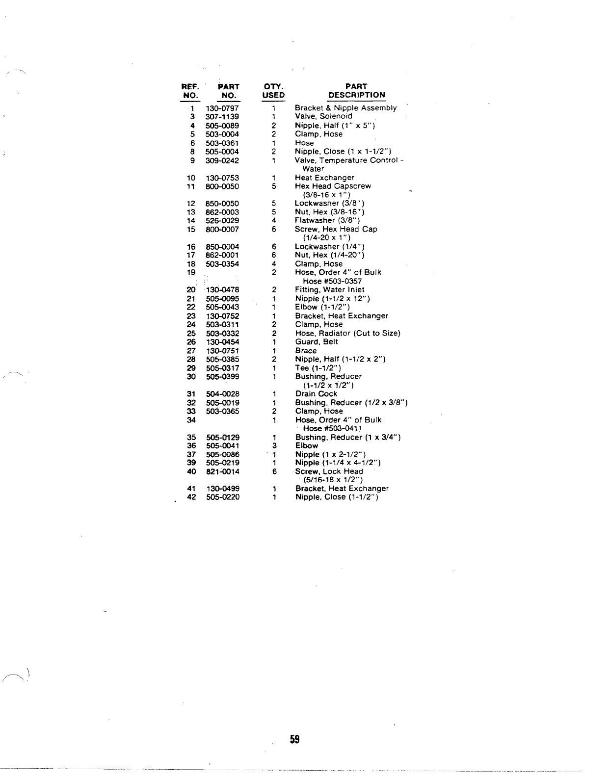
4NGERWITH MARSH REGULATOR INSTALLATION
NOTE: REMOVE THERMOSTATS FROM ENGINE
.——.—-——
--
I
%
.II
I
I\-
58
/...
REF.
NO.
:
4
5
6
8
9
10
11
12
13
14
15
16
17
18
19
20
21
22
23
24
25
26
27
28
29
30
31
32
33
34
35
36
37
39
40
41
.42
PART
NO.
130-0797
307-1139
505-0089
503-0004
503-0361
505-0004
309-0242
130-0753
800-0050
850-0050
862-0003
526-0029
800-0007
850-0004
862-0001
503-0354
130-0478
505-0095
505-0043
130-0752
503-0311
503-0332
130-0454
130-0751
505-0385
505-0317
505-0399
504-0028
505-0019
503-0365
505-0129
505-0041
505-0086
505-0219
821W14
130-0499
505-0220
QN.
USED
1
1
2
2
;
1
;
5
5
4
6
6
6
4
2
2
1
1
;
2
1
:
1
1
1
;
1
;
“1
:
1
1
PART
DESCRIPTION
Bracket&Nipple Assembly
Valve,Solenoid
Nipple, Half (1” x5“ )
Clamp, Hose
Hose
Nipple, Close (1 x1-1/2”)
Valve, Temperature Control -
Water
Heat Exchanger
Hex Head Capscrew
(3/8-16 X1“)
Lockwasher (3/8”)
Nut, Hex (3/8-1 6“ )
Flatwasher (3/8”)
Screw, Hex Head Cap
(1/4-20 X1“)
Lockwasher (1/4”)
Nut, Hex (1/4-20” )
Clamp, Hose
Hose, Order 4“ of Bulk
Hose #503-0357
Fitting, Water Inlet
Nipple (1-I/2 x12”)
Elbow (1-1/2”)
Bracket, Heat Exchanger
Clamp, Hose
Hose, Radiator (Cut to Size)
Guard, Belt
Brace
Nippler Half (1-1/2 x2“)
Tee (1-1/2” )
Bushing, Reducer
(1-1/2 x1/2”)
Drain Cock
Bushing, Reducer (1/2 x3/8”)
Clamp, Hose
Hose, Order 4“ of Bulk
Hose #503-041?
Bushing, Reducer (1 x3/4”)
Elbow
Nipple (1 x2-1/2”)
Nipple (1-1/4 x4-1/2”)
Screw, Lock Head
(5/16-18 X1/2”)
Bracket, Heat Exchanger
Nipple, Close (1-1/2” )
59
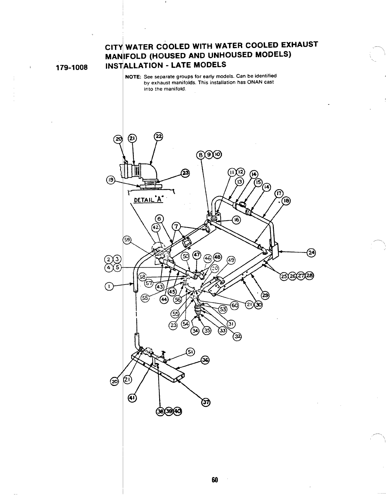
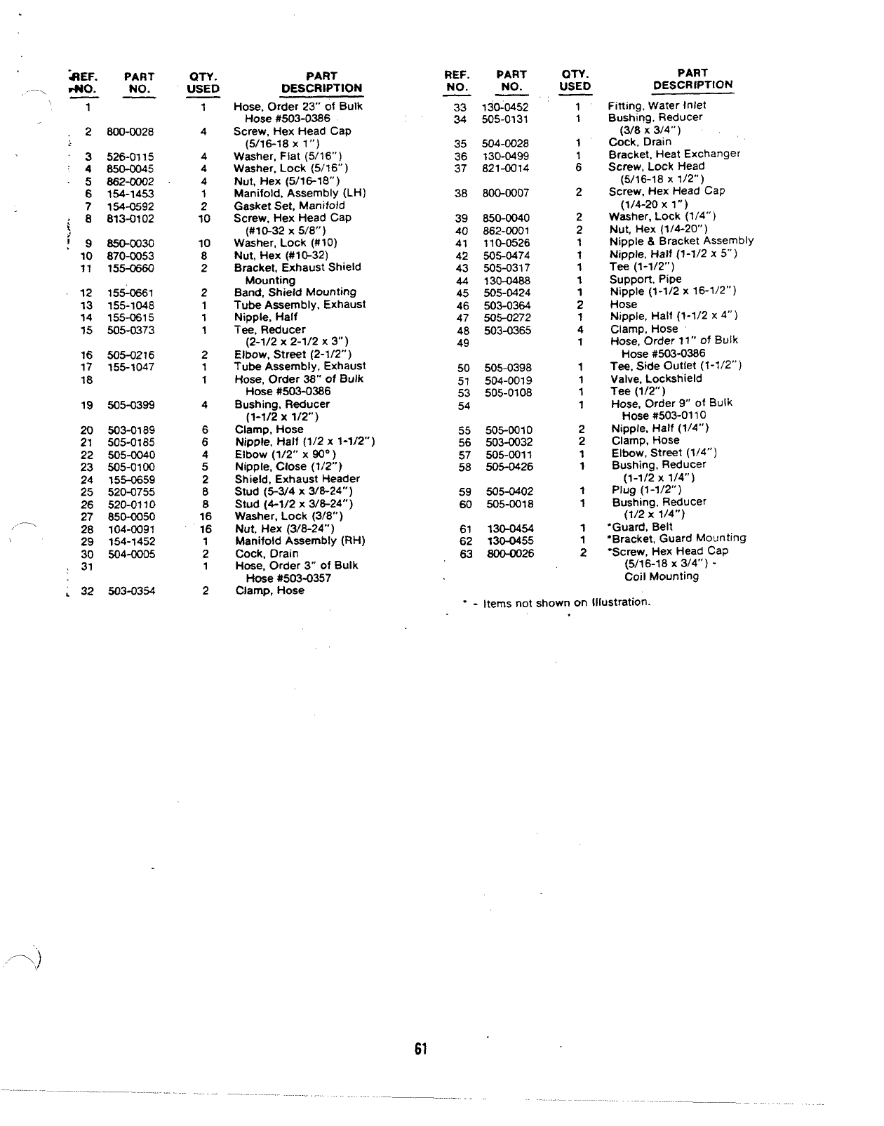
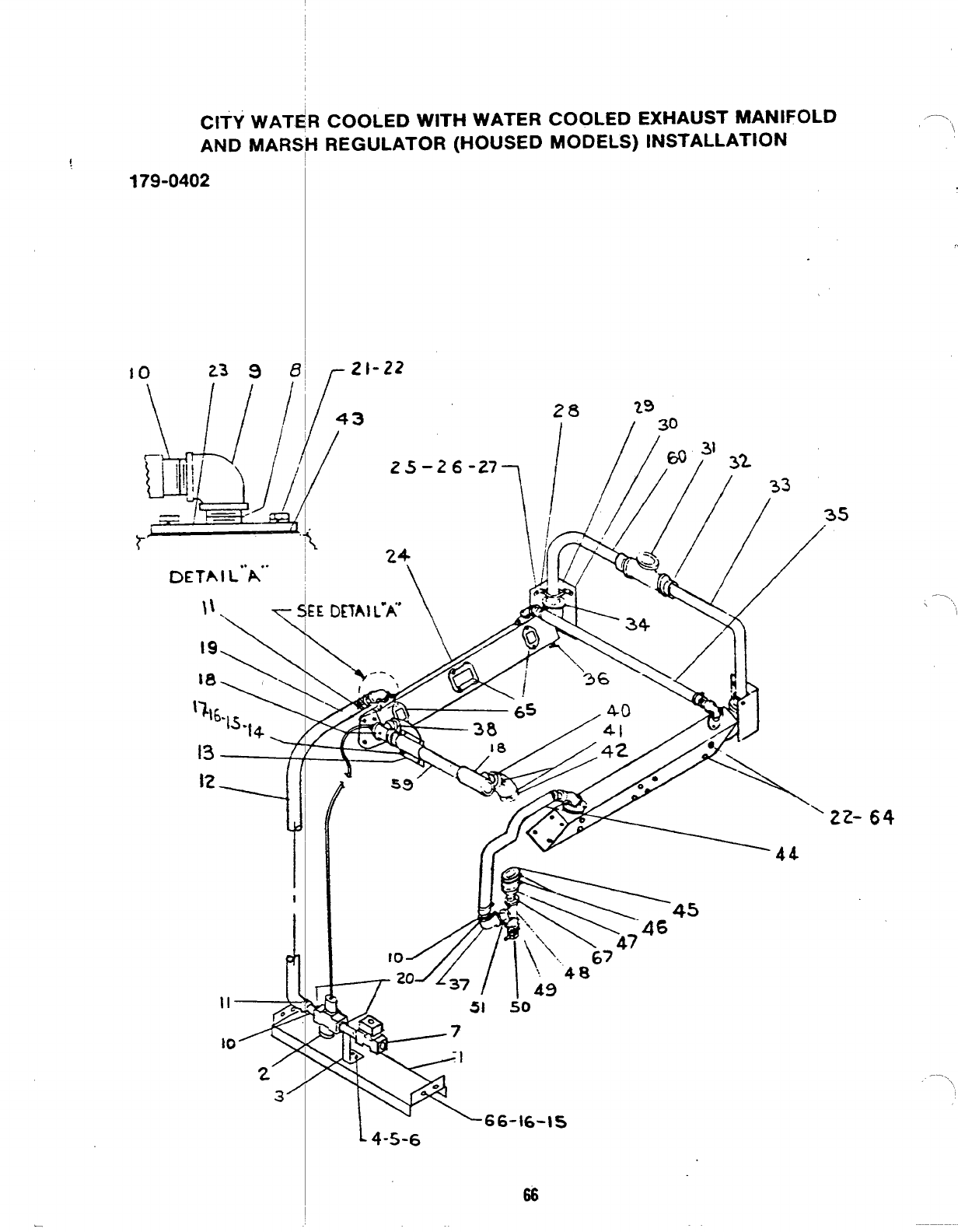
CITYI WATER COOLED WITH WATER COOLED EXHAUST
I
MAN’IFOLD (HOUSED AND UNHOUSED MODELS)
1179-1008 lNS~ALLATION -LATE MODELS
—..,
NOTE See separate groups for early models. Can be identified
by exhaust manifolds. This installation has ONAN cast
into the manifold.
,..., \
60
\
“-EF. PART
.--, +0. NO.
PART
PART REF.
NO. PART
NO. :STD
QTY.
USED DESCRIPTION
DESCRIPTION
f, n-
2800-0028
130-0452
505-0131 Fitting, Water Inlet
Bushing, Reducer
(3/8 x3/4”)
Cock, Drain
Bracket. Heat Exchanger
Screw, Lock Head
(5/16-18 X1/2”)
Screw, Hex Head Cap
(1/4-20 Xl“)
Washer, Lock (1/4”’ )
Nut, Hex (1/4-20” )
Nipple &Bracket Assembly
Nipple, Half (1-1/2 x5“ )
Tee (1-1/2”)
Support. Pipe
Nipple (1-1/2 x16-1/2”)
1
4
4
4
4
1
2
10
10
8
2
2
1
1
1
2
1
1
4
6
6
4
5
2
8
8
16
16
1
2
1
2
Hose, Order 23” of Bulk
Hose #503-0386
Screw, Hex Head Cap
(5/16-18 X1“)
Washer, Flat (5/1 6“ )
Washer, Lock (5/1 6“ )
Nut, Hex (5/l&18° )
Manifold, Assembly (LH)
Gasket Set, Manifold
Screw, Hex Head Cap
(#10-32 X5/8”)
Washer, Lock (#IO)
Nut, Hex (#10-32)
Bracket, Exhaust Shield
Mounting
Band, Shield Mounting
Tube Assembly, Exhaust
Nipple, Half
Tee, Reducer
(2-1/2 x2-1/2x 3“)
Elbow, Street (2-1/2”)
Tube Assembly, Exhaust
Hose, Order 38” of Bulk
Hose #503-0386
Bushing, Reducer
(1-1/2 x1/2”)
Clamp, Hose
Nipple, Half (1/2 x1-1/2”)
Elbow (1/2” X~“ )
Nipple, Close (1/2”)
Shield, Exhaust Header
Stud (5-3/4 X3/8-24”)
Stud (4-1/2 X3/8-24”)
Washer, Lock (3/8” )
Nut, Hex (3/8-24”)
Manifold Assembly (RH)
Cock, Drain
Hose, Order 3“ of Bulk
f-lose #503-0357
Clamp, Hose
33
34 1
1
1
:
2
2
2
1
1
1
1
1
2
1
4
1
1
1
1
1
2
2
1
1
1
1
1
1
2
35
36
37
504-0028
130-0499
821-0014
3526-0115
‘4850-0045
.5662-0002
6154-1453
7154-0592
,8813-0102
i
38 800-0007
850-0040
862-0001
110-0526
505-0474
505-0317
130-0488
505-0424
503-0364
505-0272
503-0365
39
40
41
42
43
44
45
46
47
48
49
,,
:9 10
11
850-0030
870-0053
155-0660
12
13
14
1s
155-0661
155-1048
155-0615
505-0373
Hose
Nipple, Half (1-1/2 x4“ )
Clamp, Hose
Hose, Order 11” of Bulk
Hose #503-0386
Tee, Side Outlet (1-1/2”)
Valve, Lockshield
Tee (1/2” )
Hose, Order 9“ of Bulk
Hose #503-01 10
Nipple, Half (1/4”)
Clamp, Hose
Elbow, Street (1/4”)
Bushing, Reducer
(1-1/2 x1/4”)
Plug (1-1/2”)
Bushing, Reducer
(1/2 x1/4”)
“Guard, Belt
●Bracket, Guard Mounting
“Screw, Hex Head CaP
(5/16-18 X3/4”) -
16
17
18
505-0216
155-1047 50
51
53
54
505-0398
504-0019
505-0108
19 505-0399
20
21 503-0189
505-0185
505-0040
505-0100
155-0659
520-0755
520-0110
850-CQ50
104-0091
154-1452
504-0005
55
56
57
58
505-0010
503-0032
505-0011
505-0426
22
23
24
25
26
27
/--= 28
!29
30
>31
505-0402
505-0018
59
60
61
62
63
130-0454
130-0455
800-0026
Coil Mounting
;32 503-0354
“-Items not shown on Illustration.
,
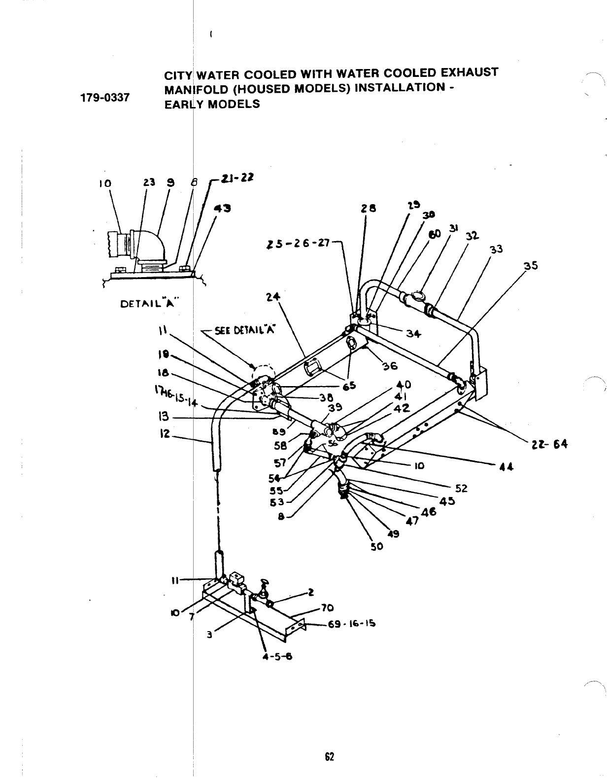
179-0337
10
\
CIT
MA
EAI
23 g
DETAI L-A””
tl-
)0”
{
fATER COOLED WITH WATER COOLED EXHAUST
OLD (HOUSED MODELS) INSTALLATION -
‘MODELS
[
ZJ-22
43
/—.
---- \/
zt- 64
I\49
50
-16-15
i-5-a
62
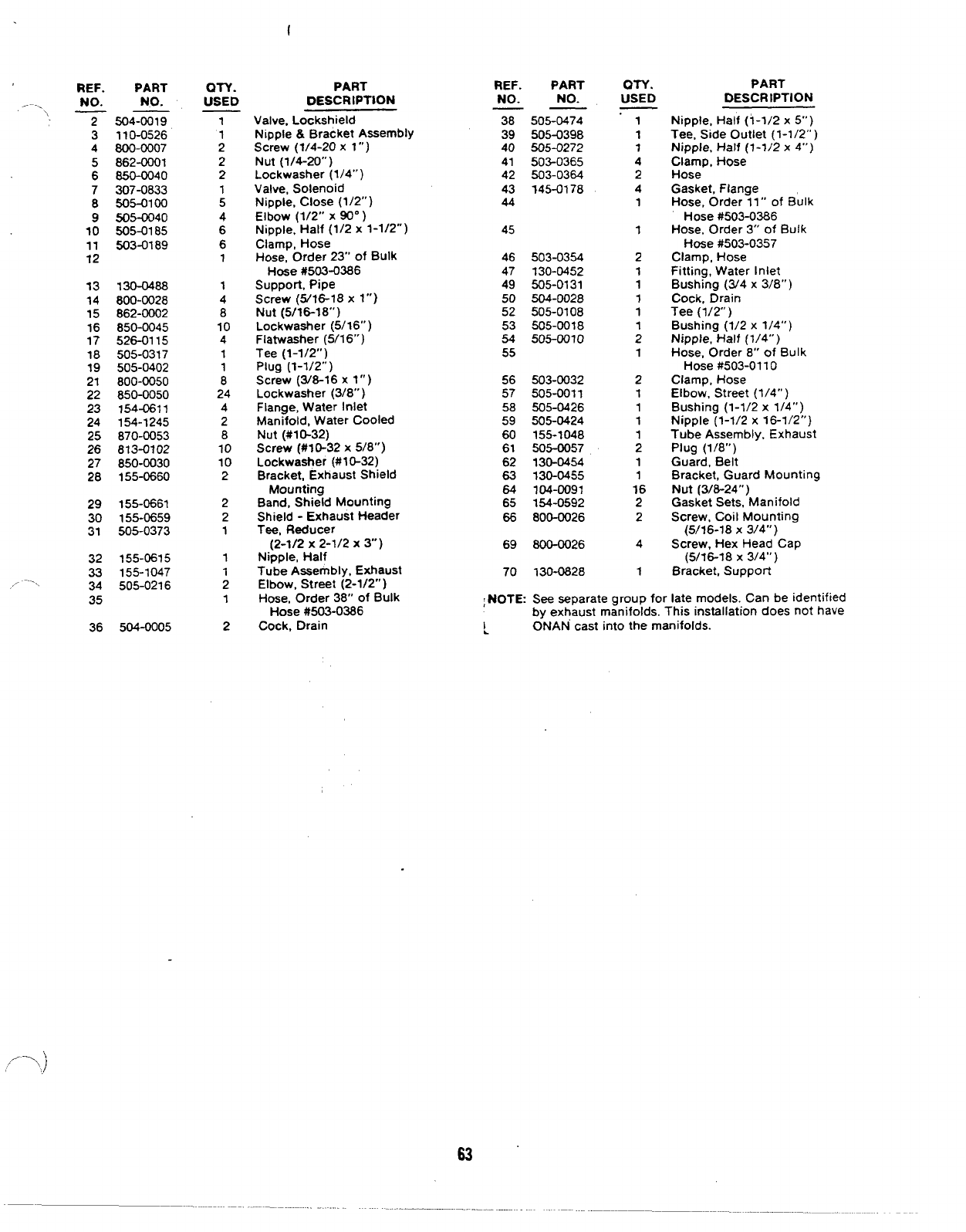
REF.
,.. . NO.
‘, -T3
4
5
6
7
8
9
10
11
12
13
14
15
16
17
18
19
21
22
23
24
25
26
27
28
29
30
31
32
33
,.- —---- 34
35
36
PART
NO.
504-0019
110-0526
800-0Q07
862-0001
850-0040
307-0833
5054100
505-0040
505-0185
503-fM89
130-0488
800-0Q28
862-0002
850-0045
526-0115
505-0317
505-0402
800-0050
850-0050
154-0611
154-1245
870-0053
813-0?02
850-0030
155-0660
155-0661
155-0659
505-0373
155-0615
155-1047
505-0216
504-0005
an.
USED
1
;
2
2
1
5
4
6
6
1
1
4
8
10
4
1
1
8
24
4
2
8
10
10
2
2
2
1
1
;
1
2
PART
DESCRIPTION
Valve, Lockshield
Nipple &Bracket Assembly
Screw (?/4-20 x1”)
Nut (1/4-20”)
Lockwasher (1/4”)
Valve, Solenoid
Nipple, Close (1/2” )
Elbow (1/2” X90”)
Nipple, Half (1/2 x1-1/2”)
Clamp, Hose
Hose, Order 23” of Bulk
Hose #503-0386
Support, Pipe
Screw (5/16-18 x1“)
Nut (5/16-18”)
Lockwaaher (5/16”)
Flatwasher (5/16”)
Tee (1-1/2”)
Plug (1-1/2” )
Screw (3/8-16 xl“)
Lockwasher (3/8”)
Flange, Water Inlet
Manifold, Water Cooled
Nut (#10-32)
Screw (#10-32 x5/8”)
Lockwasher (#10-32)
Bracket, Exhaust Shield
Mounting
Band, Shield Mounting
Shield -Exhaust Header
Tee, Reducer
(2-1/2 x2-1/2x 3“)
Nipple, Half
Tube Assembly, Exhaust
Elbow, Street (2-1/2” )
Hose, Order 38” of Bulk
Hose #503-0386
Cock, Drain
REF. PART
NO. NO.
——
38 505-0474
39 505-0398
40 505-0272
41 502-0365
42 503-0384
43 145-0178
44
45
46 503-0354
47 130-0452
49 505-0131
50 504-0028
52 505-0108
53 505-0018
54 505-0010
55
56 503-0032
57 505-0011
58 505-0426
59 505-0424
60 155-1048
61 505-0057
62 130-0454
63 130-0455
64 104-0091
65 154-0592
66 800-0026
69 800-0026
70 130-0828
ON.
USED
1
1
7
4
2
4
1
1
2
1
1
1
1
;
1
2
1
1
1
;
1
1
16
2
2
4
1
PART
DESCRIPTION
Nipple, Half (1-1/2 x5“)
Tee, Side Outlet (1-1/2” )
Nipple. Half (1-1/2 x4“)
Clamp, Hose
Hose
Gasket, Flange
Hose, Order 11” of Bulk
Hose #503-0386
Hose, Order 3“ of Bulk
Hose #503-0357
Clamp, Hose
Fitting, Water Inlet
Bushing (34 x3/8”)
Cock, Drain
Tee (1/2”)
Bushing (1/2 x1/4”)
Nipple, Half (1/4” )
Hose, Order 8“ of Bulk
Hose #503-01 10
Clamp, Hose
Elbow, Street (1/4” )
Bushing (1-1/2 x1/4”)
Nipple (1-1/2 x16-1/2”)
Tube Assembly, Exhaust
Plug (1/8”)
Guard, Belt
Bracket, Guard Mounting
Nut (3/8-24”)
Gasket Sets, Manifold
Screw, Coil Mounting
(5116-18 X3/4”)
Screw, Hex Head Cap
(5/16-18 X3/4”)
Bracket, SuppoR
;NOTE: See separate group for late models. Can be identified
by exhaust manifolds. This installation does not have
~ONAN cast into the manifolds.
/-’ 7)
63’
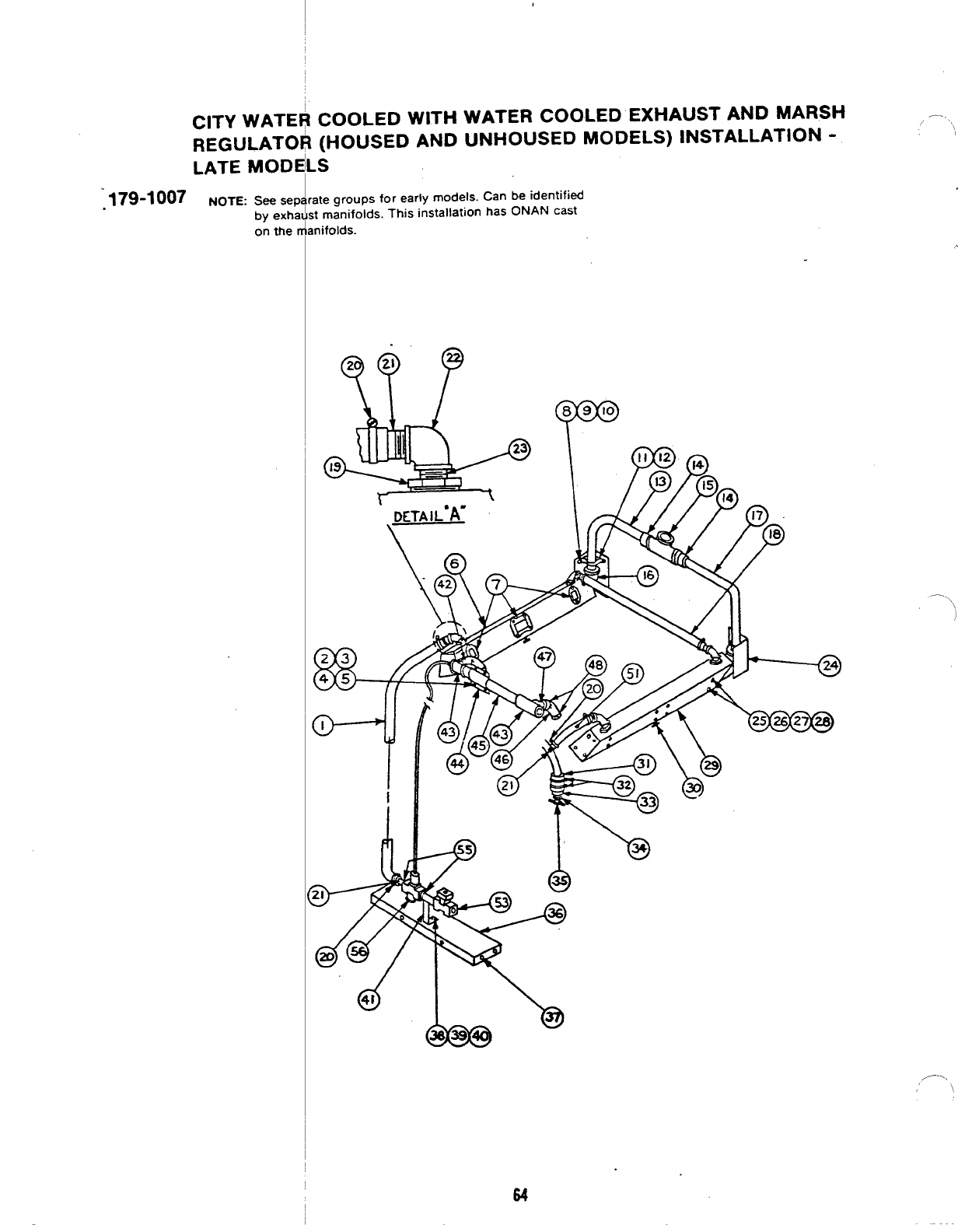
CITY WATE
REGULATO
LATE MOD[
:179-1007 NOTE: seeSep
by exha
on the I
COOLED WITH WATER COOLED EXHAUST AND MARSH
(HOUSED AND UNHOUSED MODELS) INSTALLATION -
.s
ate groups for early models. Can be identified
tmanifolds. This installation has ONAN cast
nifolds.
\
F
8910
‘o
3+
-..
,,
~,
/----
$,,
64
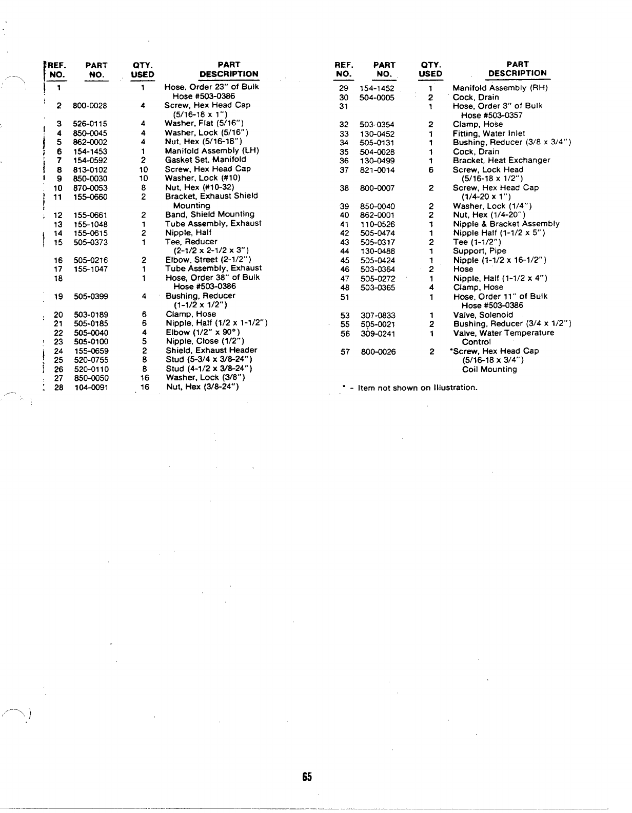
IREF.
,.-—--.\ NO.
., —
ig 10
‘11
!
;12
13
I14
!15
16
17
18
19
;20
21
22
:23
Ig
i26 27
!28
,,..—;,
PART
NO.
800-0028
526-0115
850-0045
862-0002
154-1453
154-0592
813-0102
850-0030
870-0053
155-0660
155-0661
155-1048
155-0615
505-0373
505-0216
155-1047
505-0399
503-0189
505-0185
505-0040
505-0100
155-0659
520-0755
520-0110
850-0050
104-0091
OTY.
USED
1
4
4
4
4
;
10
10
8
2
2
;
1
2
1
1
4
6
6
4
5
2
8
8
16
16
PART
DESCRIPTION
Hose. Order 23” of Bulk
Hose #503-0386
Screw, Hex Head Cap
(5/16-18 X1‘“)
Washer, Flat (5/16” )
Washer, Lock (5/1 6“ )
Nut, Hex (5/1 6-18” )
Manifold Assembly (LH)
Gasket Set, Manifold
Screw, Hex Head Cap
Washer, Lock (#1 O)
Nut, Hex (#1 O-32)
Bracket, Exhaust Shield
Mounting
Band, Shield Mounting
Tube Assembly, Exhaust
Nipple, Half
Tee, Reducer
(2-1/2 x2-1/2x 3“)
Elbow, Street (2-1/2” )
Tube Assembly, Exhaust
Hose, Order 38” of Bulk
Hose #503-0386
Bushing, Reducer
(1-1/2 x1/2”)
Clamp, Hose
Nipple, Half (1/2 x1-1/2”)
Elbow (1/2” X~“ )
Nipple, Close (1/2” )
Shield, Exhaust Header
Stud (5-3/4 X3/8-24”)
Stud (4-1/2 X3/8-24”)
Washer. Lock (3/8” )
REF. PART
NO. NO.
——
29 154-1452
30 504-0005
31
32 503-0354
33 130-0452
34 505-0131
35 504-0028
36 130-0499
37 821-0014
38 800-0007
“39 850-0040
40 862-0001
41 110-0526
42 505-0474
43 505-0317
44 130-0488
45 505-0424
46 503-0364
47 505-0272
48 503-0365
51
53 307-0833
55 505-0021
56 309-0241
57 800-0026
QTY.
USED
1
2
1
2
1
1
1
1
6
2
2
2
1
1
2
1
1
2
1
4
1
2
PART
DESCRIPTION
Manifold Assembly (RH)
Cock, Drain
Hose, Order 3“ of Bulk
Hose #503-0357
Clamp, Hose
Fitting. Water Inlet
Bushing, Reducer (3/8 x3/4”)
Cock, Drain
Bracket, Heat Exchanger
Screw, Lock Head
(5/16-18 X1/2”)
Screw, Hex Head Cap
(1/4-20 Xl“)
Washer, Lock (1/4” )
Nut, Hex (1/4-20” )
Nipple &Bracket Assembly
Nipple Half (1-1/2 x5“)
Tee (1-1/2”)
Suppoct, Pipe
Nipple (1-1/2 x16-1/2”)
Hose
Nipple, Half (1-1/2 x4“)
Clamp. Hose
Hose, Order 11” of Bulk
Hose #503-0386
Valve, Solenoid
Bushing, Reducer (3/4 x1/2”)
Valve, Water Temperature
Control
“Screw, Hex Head Cap
(5/16-18 X3/4”)
Coil Mounting
Nut, Flex (3/8-24” )“ - Item not shown on Illustration.
,’->, )
65
CITY WATI
AND MARS
!
179-0402
239t5
WI
i
/
JaLi
‘II
/
}1~ \‘
—,— -
—
r
DETAI L“”A””
\\\ Y
19 \
\
“Y
‘~16-1~-,4
13+
127I
II J
A
0
to
>
2
3’
1COOLED WITH WATER COOLED EXHAUST MANIFOLD
IREGULATOR (HOUSED MODELS) INSTALLATION
r21-22
/43
10
5} 50
1w=66-16-15
4-5-6
66
,--,
64
—.-.,,
-REF.
NO.
----- _
,, 1
2
3
4
5
6
7
8
9
10
11
12
13
14
15
16
17
i;:
I20
:;
~23
:24
25
26
27
28
29
30
-—-.. 31
i
PART
NO.
130-0628
309-0241
110-0526
600-0007
662-0001
650-0040
307-0833
505-0100
505-43040
505-0185
503-0189
130-0488
800-0028
662-0002
850-0045
526-0115
505-0317
505-0289
505-0021
800-0050
650-0050
154-0611
154-1245
870-0053
813-0102
850-0030
155-0660
155-0661
155-0659
505-0373
OTY.
USED
1
1
;
2
2
1
5
4
6
6
1
1
4
8
10
4
2
1
2
8
24
4
2
8
10
10
2
2
2
1
PART
DESCRIPTION
Bracket, Support
Valve, Water Temperature
Control
Nipple& Bracket Assembly
Screw (1/4-20 x1”)
Nut (1/4-20.’ )
Lockwasher (1/4”)
Valve, Solenoid
Nipple, Close (1/2” )
Elbow (1/2” X90° )
Nipple, Half (1/2 x1-1/2”)
Clamp, Hose
Hose, Order 23” of Bulk
Hose #503-0386
Support, Pipe
Screw (5/1 6-18 x1”)
Nut (5/16-18”)
Lockwasher (5/16”)
Flatwasher (5/16”)
Tee (1-1/2” )
Bushing. Reducer
(1-1/2 x3/4”)
Bushing (3/4 x1/2”)
Screw (3/8-16 x1”)
Lockwasher (3/8”)
Flange, Water Inlet
Manifold, Water Cooled
Nut (#10-32)
Screw (#1 O-32 x5/8”)
Lockwasher (#1 O)
Bracket, Exhaust Shield
Mounting
Band, Shield Mounting
Shield, Exhaust Header
Tee, Reducer
(2-1/2 x2-1/2x 3)
REF.
NO. PART
NO. QTY.
USED
32
33
’34
;35
36
37
36
40
41
42
43
44
45
46
47
48
49
50
51
59
60
61
62
63
64
65
66
67
155-0615
155-1047
505-0216
504-0005
505-0132
505-0474
505-0272
503-0365
503-0364
145-0178
503-0354
130-0452
505-0166
505-013?
504-0028
505-0084
505-0424
155-1048
505-0057
130-0454
130-0455
?04-0091
154-0592
800-0026
505-0102
1
;
1
2
1
1
1
4
2
4
1
1
2
1
1
‘1
1
1
1
;
1
1
16
2
6
“1
PART
DESCRIPTION
Nipple, Half
Tube Assembly, Exhaust
Elbow, Street (2-1/2”)
Hose, Order 38” of Bulk
Hose #503-0386
Cock, Drain
Elbow (3/4” X90° )
Nipple, Half (1-1/2 x5“)
Nipple, Half (1-1/2 x4“)
Clamp, Hose
Hose
Gasket, Flange
Hose, Order 20” of Bulk
Hose #503-0386
Hose. Order 3“ of Bulk
Hose #503-0357
Clamp, Hose
Fitting, Water Inlet
Tee (3/4” )
Bushing (3/4 x3/8”)
Cock, Drain
Nipple (3/4 x2-1/2”)
Nipple (1-1/2 x16-1/2”)
Tube Assembly, Exhaust
Plug (1/8” )
Guard, Belt
Bracket, Guard Mounting
Nut (3/8-24” )
Gasket Set, Manifold
Screw, Coil Mounting
(5/16-18 X3/4”)
Nipple, Close (3/4” )
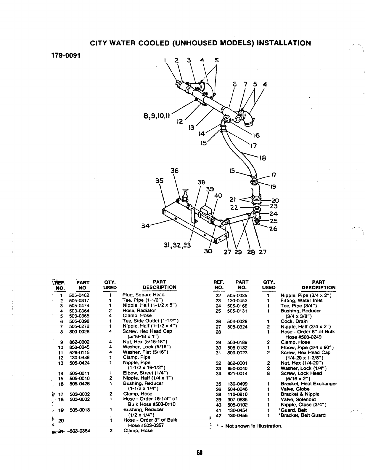
CITY VI
179-0091
NO.
1
2
3
4
5
6
7
8
9
10
11
12
:13
14
15
:16
:19
‘PART
NO.
505-0402
505-0317
505-0474
503-0364
503-0365
605-0398
505-0272
800-0028
662-0002
850-0045
526-0115
130-0488
505-0424
505-0011
505-0010
505-0426
503-0032
503-0032
505-0018
m-v
USEI
7
1
1
2
4
1
1
4
4
4
4
1
1
1
1
2
1
1
,.,
1
2
kTER COOLED (UNHOUSED MODELS) INSTAL
I23 4 5
—
8,9,~0,
34
PART
DESCRIPTION
REF.
NO.
PART
NO.
WY.
USED
Plug, Square Head
Tee, Pipe (1-1/2”)
Nipple, Half (1-1/2 x5“)
Hose, Radiator
Clamp, Hose
Tee, Side Outlet (1-1/2”)
Nipple, Half (?-1/2 x4“ )
Screw, Hex Head Cap
(5/16-18 Xl“)
Nut, Hex (5/16-18” )
Washer, Lock (5/1 6“ )
Washer, Flat (5/16” )
Clamp, Pipe
Nipple, Pipe
(1-1/2 x16-1/2”)
Elbow, Street (1/4”)
Nipple, Half (1/4 x1-)
Bushing, Reducer
(1-1/2 x1/4”)
Clamp, Hose
Hose -Order 16-1/4” of
Bulk Hose #503-01 10
Bushing, Reducer
(1/2 x1/4”)
Hose -Order 3“ of Bulk
Hose #503-0357
Clamp, Hose
26
27
28
29
30
31
32
33
34
35
36
38
z
41
~42
505-0085
130-0452
505-0166
505-0131
504-0028
505-0324
503-0189
505-0132
800-oo23
862-0001
821-0014
X30-0499
110-0810
307-
505-0102
130-W34
130-0455
1
1
1
1
1
2
1
2
:
2
2
8
1
1
1
;
1
1
.LATION
+; “-Not shown in Illustmtion.
PART
DESCRIPTION
Nipple, Pipe (3/4 x2“)
Fitting. Water tnlet
Tee, Pipe (3/4”)
Bushing, Reducer
(3/4 X3/8”)
Cock, Drain
Nipple, Half (3/4 x2“ )
Hose -Order 8“ of Bulk
Hose #503-0249
Clamp, Hose
Elbow, pipe (3/4 X90° )
Screw, Hex Head Cap
(1/4-20 X1-3/8”)
Nut, f_k?X(1/4-20”)
Washer, Lock (1/4”)
Screw, Lock Head
(6/16 X2“)
Bracket Heat Exchanger
Vafve, Globe
Bracket &Nipple
Vatve, Solenoid
Nipple, Close (3/4”)
“Guard, Belt
“Bracket Belt Guard
—.
,,,.—.
\,
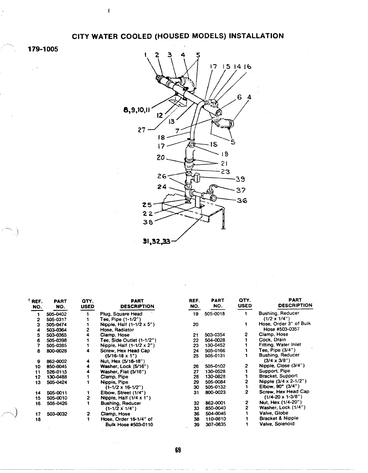
t
CITY WATER COOLED (HOUSED MODELS) INSTALLATION
—.
., 179-1005 12245
\\/l 17 1514[6
37
25 36
22A
38
,-. ”
)
‘,
REF.
!REF. PART
NO. NO.
7505-0402
2505-0317
3505-0474
4503-0364
5503-0365
6505-0398
7505-0385
880M028
9862-0002
10 850-W45
11 526-0115
12 130-0488
13 505-0424
14 505-0011
15 505-0010
16 505+$26
,’- .) 17 503-CQ32
18
OTY.
USED
PART
DESCRIPTION PART
NO.
505-0018
QTY.
USED
1
PART
DESCRIPTION
NO.
Bushing, Reducer
(1/2 x1/4”)
Hose, Order 3“ of Bulk
Hose #503-0357
Clamp, Hose
Cock, Drain
Fitting, Water Inlet
Tee, Pipe (3/4” )
Bushing, Reducer
(3/4 X3/8”)
Nipple, Close (3/4”)
Support, Pipe
Bracket, Support
Nipple (3/4 x2-1/2”)
Elbow. 90° (W4° )
Screw, Hex Head Cap
(1/4-20 X1-3/8”)
Nut, Hex (1/4-20” )
Washer, Lock (1/4” )
Valve, Globe
Bracket &Nipple
Valve, Solenoid
1
1
1
2
4
1
1
4
4
4
4
1
1
;
1
2
1
Plug, Square Head
Tee, Pipe (1-1/2”)
Nipple, Half (1-1/2 x5“)
Hose, Radiator
Clamp, Hose
Tee, Side Outlet (1-1/2” )
Nipple. Half (1-1/2 x2“)
Screw, Hex Head Cap
(5/16-18 Xl“)
Nut, Hex (5/16-18” )
Washer, Lock (5/16” )
Washer, Flat (5/16”)
Clamp, Pipe
Nipple, Pipe
(1-1/2 x18-1/2)
Elbow, Street (1/4” )
Nipple, Half (1/4 x1”)
Bushing, Reducer
(1-1/2 x“ 1/4”)
Clamp, Hose
H&e, Order lG1/4° of
Bulk Hose #503-01 10
19
20 1
21 503-0354
504-0028
130-0452
505-0?66
505-0131
2
1
1
1
1
2
1
1
2
;
2
2
1
1
1
22
23
24
25
505-0102
130-0528
130-0828
505-0084
505-0132
800-0023
26
27
28
29
30
31
862-MKN
850-0040
504-0046
110-0810
307-0835
32
33
36
38
39
69
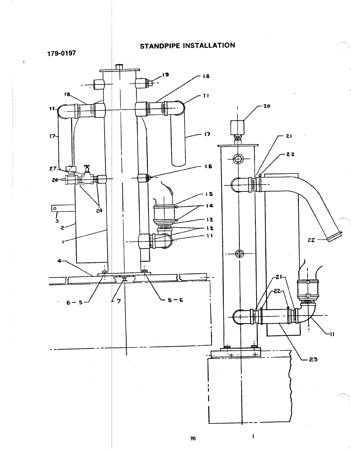
IT-
r7.
-42
r=
/
3
2’
1’
““ 6–5 1
..— --—
—
I
I
I
-—
—
INSTALLATION ...” —’. !
1-17
J
J
1
—J
—. r
I
620
‘v
.“-- --
I
1
I
I
[
21 “
y
22
\
,
2z-
i- --—
—.-—
U
.-
—
)
it
I
.
,
11
/- 23
,/—, i,
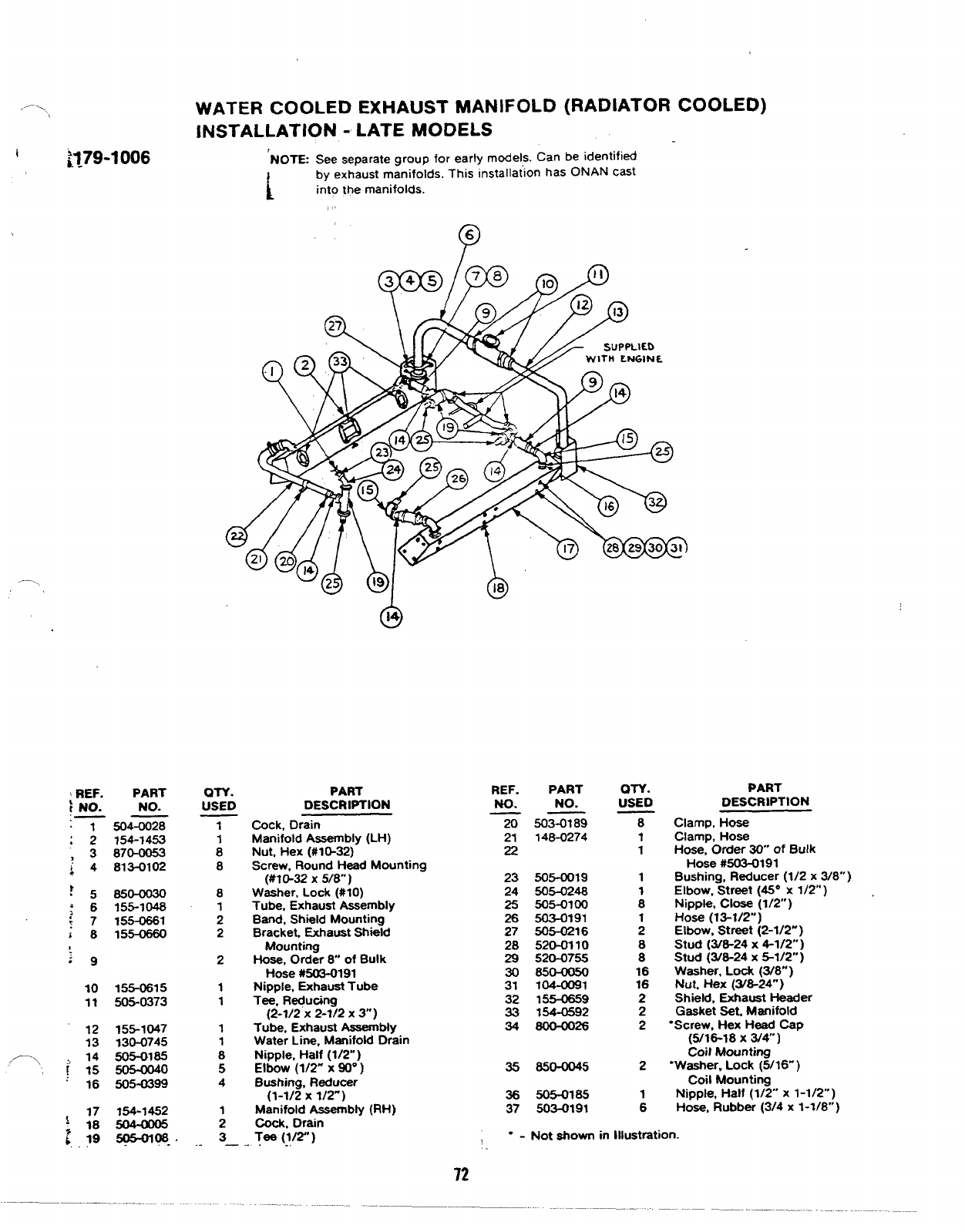
,.-—-,,
i~179-1006
WATER COOLED EXHAUST MANIFOLD (RADIATOR COOLED)
INSTALLATION -LATE MODELS
‘NOTE See separate group for early models. Can be identified
i
by exhaust manifolds. This installa~on has ONAN cast
into the manifolds.
,’
P
6
,—..
6
14
zREF. PART
iNO. NO.
.— —
1504-0028
:2154-1453
3870-0053
;4 813-0102
‘5850-0030
.
‘6155-1048
;7155-0661
i8155-0660
10
11
17
;18
b, 19
155-0815
505-0373
155-1047
130-0745
505-0185
505-4)040
505-0399
154-1452
~08. .
1
1
8
8
8
1
2
2
2
1
1
1
1
8
5
4
;
3
.—
ON.
USED
PART
DESCRIPTION
Cock, Drain
Manifold Assembly (LH)
Nut, Hex (#10-32)
Screw, Round Head Mounting
(#lM2 X5/8”)
Washer, Lock (#IO)
Tube, Exhaust Assembly
Band, Shield Mounting
Bracket, Exhaust Shield
Mounting
Hose, Order 8of Bulk
Hose #503-0191
Nipple, Exhaust Tube
Tee, Re@c@I
(2-1/2 x2-1/2x 3“)
Tube, Exhaust Assembly
Water Line, Manifold Drain
Nipple, Half (1/2”)
Elbow (1/2” X~“ )
Bushing, Reducer
(1-1/2 x1/2-)
Manifold Assembly (RH)
Cock, Drain
.Tee (1/2”)
-.
REF.
No.
x
21
22
23
24
25
28
27
28
29
30
31
32
33
34
35
38
37
PART
NO. ON.
uSED
503-0189
148-0274
505-0019
505-0248
505-0100
503-0191
505-0216
520-0110
520-0755
850-0050
104-0091
155-0859
154-0592
800-oo28
850-0045
505-0185
503-0191
--Not shown in Illustration.
DESCRIPTION
Clamp, Hose
Clamp, Hose
Hose, Order 30” of Bulk
Hose #503-0191
Bushing, R4ucer (1/2 x3/8”’)
Elbow, Street (46” X112”)
Nipple, close(1/2”)
Hose (13-1/2”)
Elbow. Street (2-1/2”)
Stud (3/8-24 X4-1/2”)
Stud (3/8-24 X5-1/2”)
Washer, Lock (3/8”)
Nut. *X (YS24”)
Shield, Exhaust Header
Gasket Set, Manifold
“Screw, Hex Head Cap
(5/18-18 XWV)
Coil Mounting
“Washer, Lock (5/16” )
Coil Mounting
Nipple, Half (1/2” x1-1/2”)
Hose, Rubber (3/4 x1-1/8”)
,.
72
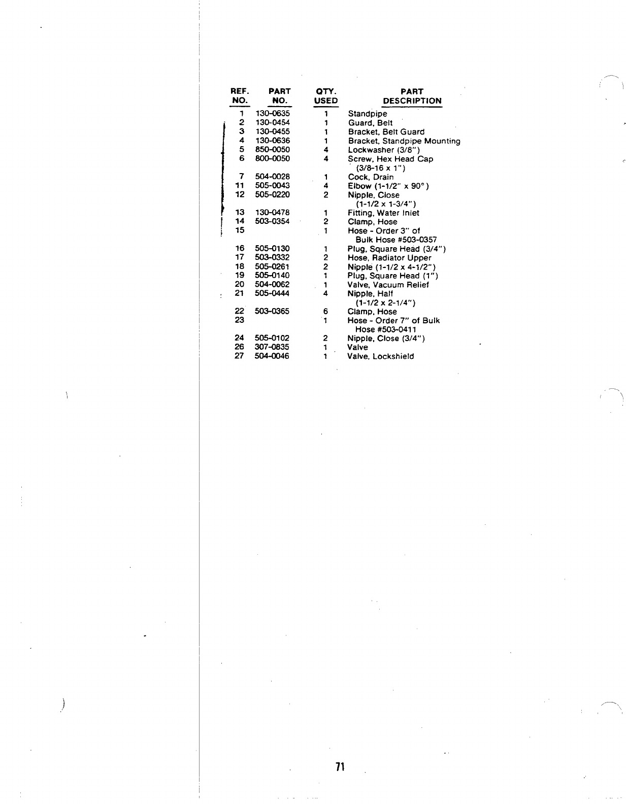
REF. PART
NO. NO.
T130-0635
I
2130-0454
3130-0455
4130-0636
5850-0050
6800-0050
1
7504-0028
11 505-0043
12 505-0220
13 130-0478
/ :: 503-0354
j
16 505-0130
17 503-0332
18 505-0261
19 505-0140
20 504-0062
21 505-0444
22 503-0365
23
24 505-0102
26 3074835
27 504-0046
ON.
USED
1
1
1
1
4
4
1
4
2
2
1
1
4
6
1
2
1
1
PART
DESCRIPTION
Standpipe
Guard, Belt
Bracket, Belt Guard
Bracket, Standpipe Mounting
Lockwasher (3/8”)
Screw, Hex Head Cap
(3/8-1 6X1“)
Cock, Drain
Elbow (1-1/2” X90° )
Nipple, Close
(1-1/2 x1-3/4”)
Fitting, Water Inlet
Clamp, Hose
Hose -Order 3“ of
Bulk Hose #503-0357
Plug, Square Head (3/4” )
Hose, Radiator Upper
Nipple (1-1/2 x4-1/2”)
Plug, Square Head (l”)
Valve, Vacuum Relief
Nipple, Half
(1-1/2 X2-1/4”)
Clamp, Hose
Hose -Order 7“ of Bulk
Hose #503-041 1
Nipple, Close (3/4” )
Valve
Valve, Lockshield
/—\ \
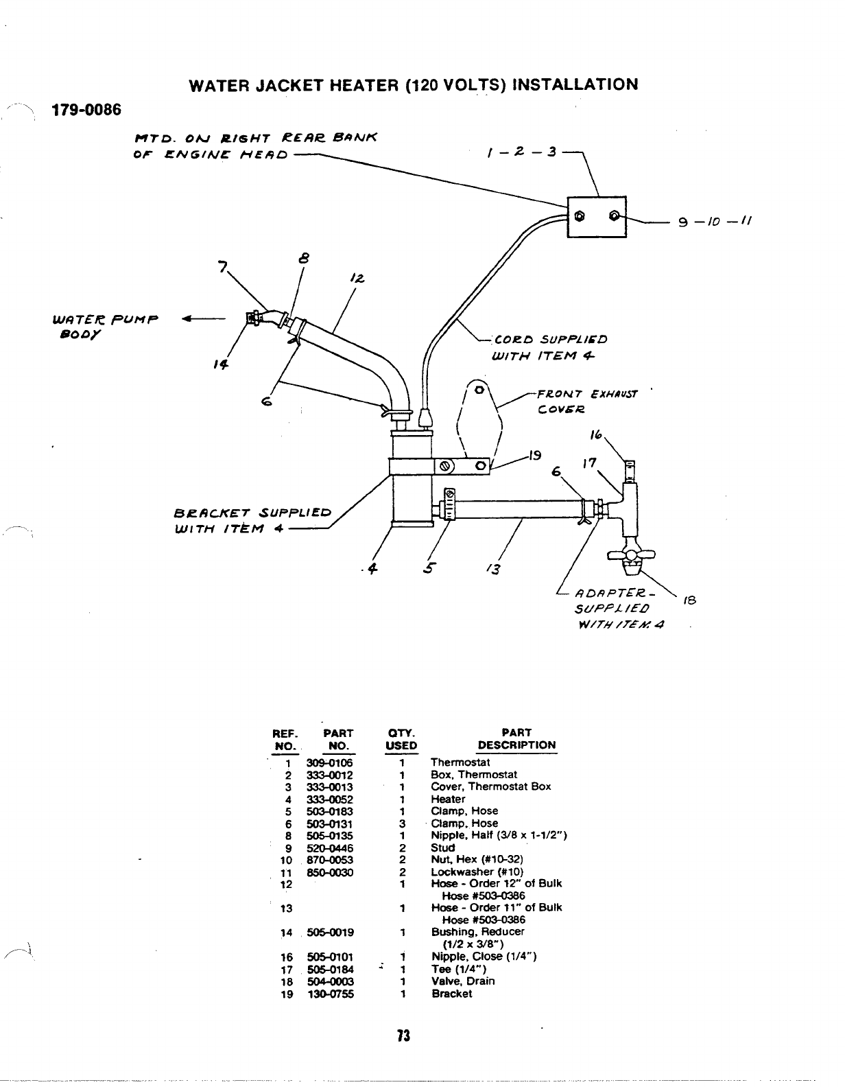
/-., ,179-0086
WATER JACKET HEATER (120 VOLTS) INSTALLATION
UTD. ON RIGHT t?ER~ 6@NK
OF ENGINE UE19D
I
,---
,,
9 –10 —11
7&
4
CORD SUPPfXD
}4 LUITH ITEM 4-
6
BRBCKET SUPPLIED
Wlri’i Irkw 4
-4 5/3
SUPPA IED
w/TH /TEAf 4
REF. PART
NO. NO.
‘T 3osi6i6
233Mm2
3333-0013
4333-0052
5503-0163
6m31
8505-OI35
952WM46
JO 87M053
11 S50a30
12
?3
14 5050019
16 505-0?01
17 606-0164
18 F04—W03
19 13WT55
QTY.
USED
1
1
1
1
1
3
1
2
2
2
1
1
1
1
+- 1
1
1
PART
DESCRIPTION
Thermostat
Box, Thermostat
Cover, Thermostat Box
H-ter
Clamp, Hose
Clamp. Hose
Nipple, Half (3/8 x1-1/2”)
Stud
Nut+ Hex (#1 fJ-32)
Lockwasher (#10)
Hose -Order 12” of Bulk
Hose #503-02S6
Hose -Order ?1” of Bulk
Hose #503-0366
Bushing, Reducer
(?/2 X3/8”)
Nipple, Close (1/4”)
Tee (1/4”’ )
Valve, Drain
Bracket
tE3
13
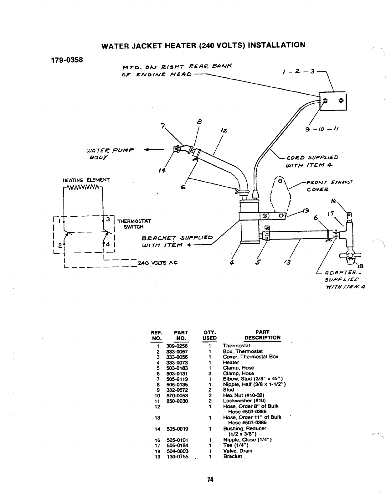
WATER JACKET HEATER (240 VOLTS) INSTALLATION \
1179-0358
WI?7ER Pi
80 Dy
HEATING ELEMENT
rl
n
_—,—
37 ~
I
I_—. I
12 I
41
~+ _—l J
Ii–_
L_—— ———
.8
-—24o .VOL= AC
-—
REF. PART
NO. NO.
7309-0256
2-57
33334056
4333-CK)73
5503-0183
6503-0131
750%3119
8606-0135
9332-0672
10 870-0053
11 650-oo30
12
13
14 505-0019
16 505-0101
17 505-0184
18 504-0003
19 130-0755
ON.
USED
1
1
1
1
:
1
;
2
2
1
1
1
1
1
1
1
74
PART
DESCRIPTION
Thermostat
Box, Thermostat
Cover, Thermostat Box
Heater
Clamp, Hose
Clamp. Hose
Elbow, Stud (3/8 X45° )
Nipple, Half (3/8 x1-1/2”)
Stud
Hex Nut (#10-32)
Lockwasher (#10)
Hose, Order 8“ of Bulk
Hose #503—03%
Hose, Order 11“ of Bulk “
Hoaa #503-0386
Bushing, Reducer
(1/2 X3/8”)
Nipple. close (1/4- )
Tee (1/4”)
Valve, Drain
Bracket
.—.
\
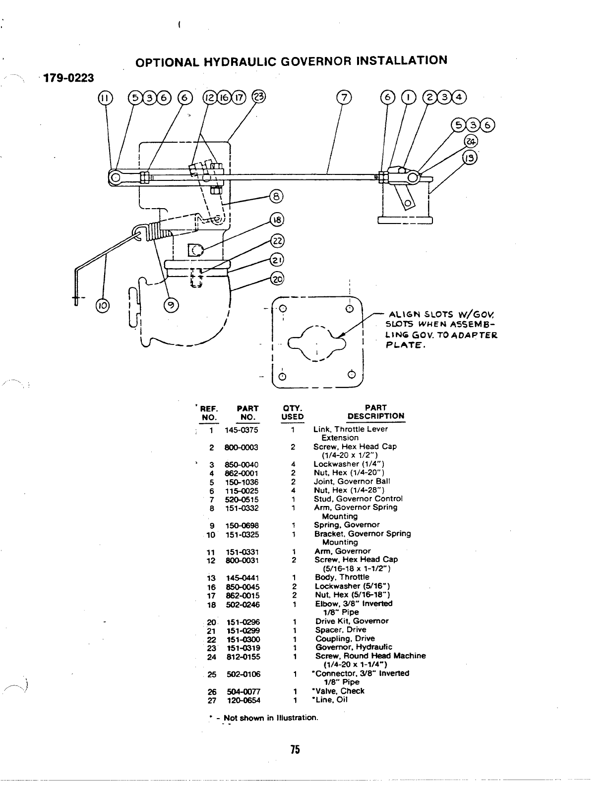
(
OPTIONAL HYDRAULIC GOVERNOR
,. .... 179-0223
/.—... ;
,.
,),/-\,
P
7
INSTALLATION
?PF
nllllh-rlin==~ /=- n
c~f~~o--iA,\GNSLOTSVW/GC)V
F‘$
<
-. smTS WHEN AS5EMB~
LIN6 GOV. TO ADAPTER
l-” PLATE.
I-. i
L)l
‘b=. J-
..
‘REF. PART
NO. NO.
T145-0375
2800—0W3
>3850-0040
4862-0001
5150-1036
6115-0025
7520-0515
8151-0332
9150-0896
10 151-0325
11 151-0331
12 800-oo31
13 145-0441
16 S50-0045
17 882-0015
18 502-0246
20 151-0296
21 151-W99
22 151-0300
23 1514319
24 812-0155
25 502-0106
26 504-0077
27 120-0854
—
L__3J
mY.
USED
1
2
4
2
2
4
1
1
1
1
1
2
1
2
2
1
1
1
1
1
1
1
1
1
PART
DESCRIPTION
Link, Throttle Lever
Extension
Screw, Hex Head Cap
(1/4-20 X1/2”)
Lockwasher (1/4”)
Nut, Hex (1/4-20” )
Joint, Governor Ball
Nut, Hex (1/4-28” )
Stud, Governor Control
Arm, Governor Spring
Mounting
Spring, Governor
Bracket, Governor Spring
Mounting
Arm. Governor
Screw, Hex Head Cap
(5/16-18 X1-1/2’. )
Body, Throttle
Lockwasher (5/16”)
Nut, Hex (5/16-18’”)
Elbow, 3/8” Inverted
1/8” Pipe
Drive Kit, Governor
Spacer, Drive
Coupling, Drive
Governor, Hydraufic
Screw, Round Head Machine
(1/4-20 X1-1/4”)
“Connector, 3/8” Inverted
1/8’. Pipe
“Valve, Check
“Line, Oil
9-Not shown in Illustration.
. .
75
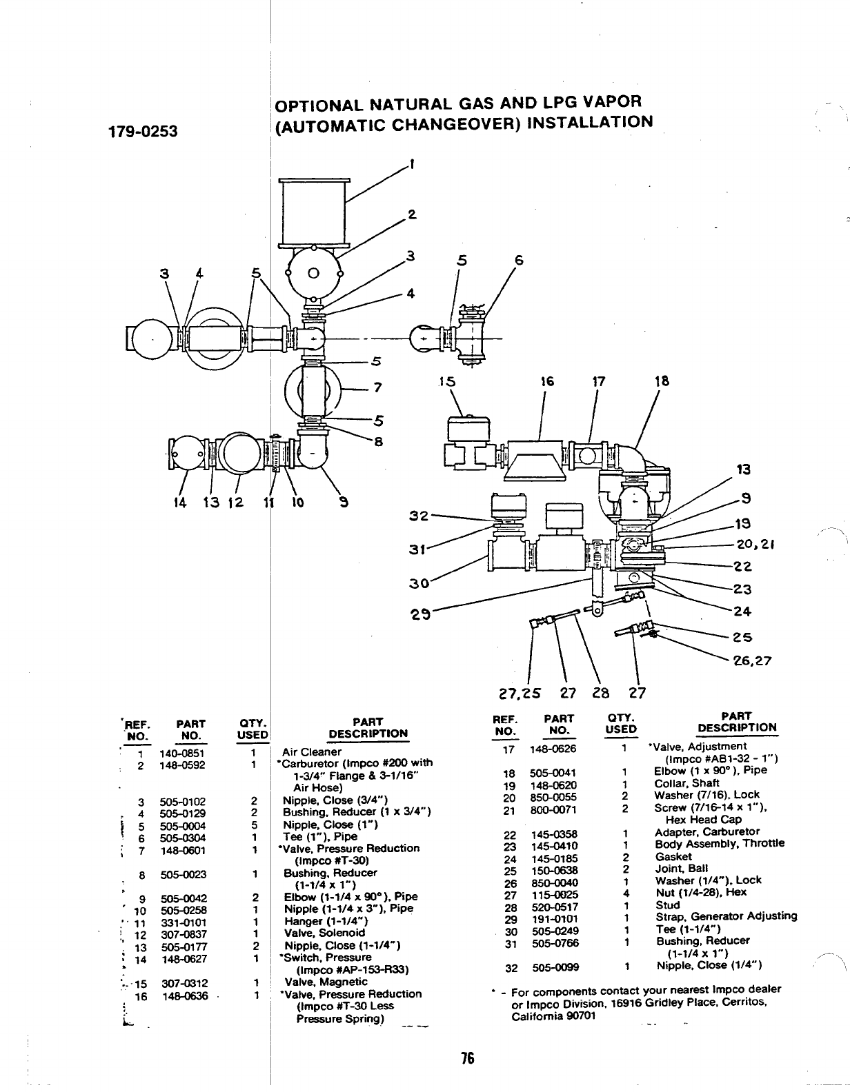
179-0253
34 5
&
\
!1 i
14 13 12 ‘
‘REF. PART
NO. NO.
,— 114CG=
2148-0592
3505-0102
~:%%%’
6 5054304
i7148-0601
-8505-0023
:9505-0042
10 505-0258
;“11 331-0101
:, 12 307-0837
;13 505-0177
:14 748-0627
:,.15 307-0312
16 148-0636
:
:.
L.
QTY.
USEt
1
1
2
2
5
1
1
1
2
1
1
1
2
1
1
OPTIONAL NATURAL GAS AND LPG VAPOR
[AUTOMATIC CHANGEOVER) INSTALLATION
t
\,
2
f35 6
0
P&
4
1’- - +
—
—5
-.
PART
DESCRIPTION
1!5 16 17 18
3,.
3,21 ‘
3
2
27
27,25 27 28 2?
Air Cleaner
‘Carburetor (Immo #200 with
1-3/4” Flange &3-1/16”
Atr Hose)
Nipple, Close (3/4” )
Bushing, Reducer (1 x3/4”)
Nipple, Close (1”)
Tee (1”), Pipe
“Valve, Pressure Reduction
(Impco #T-30)
Bushing, Reducer
(1-1/4 xl“)
Elbow (1-1/4 X~“ ), pipe
Nipple (1-1/4 x3“), Ptpe
Hanger (1-1/4”)
Valve, Solenoid
Nipple, Close (1-1/4-)
“Switch, Pressure
(Impco #AP-153-R33)
Valve, Magnetic
“Valve, Pressure Reduction
(Impco #T-30 Less
Pressure Spring) -- --
REF.
NO.
17
18
19
20
21
22
23
24
25
z
28
29
30
31
32
PART
NO.
148-0626
505-0041
148-0620
850-0055
800-0071
145-0358
145-0410
145-0185
150-0638
850-0040
1154025
S?0-0517
191-0101
505-0249
505-0766
505-0099
QTY.
uSED
1
1
1
2
2
:
1
1
1
1
1
PART
DESCRIPTION
‘Valve, Adjustment
(Impco #AB1-32 -l“)
Elbow (1 x90° ), piPe
Collar, Shaft
Washer (7/16), Lock
screw (7/lG14 x1“),
Hex Head Cap
Adapter, Carburetor
Body Assembly. Throttle
Gasket
Joint Ball
Washer (1/4”), Lock
Nut (t/4-28), HeX
Stud
Strap, Generator Adjusting
Tee (1-1/4”)
Bushing, Reducer
(1-1/4 xl“)
Nipple. Close (1/4” )
“ - For components contact your nearest Impco dealer
or Impco Division, 16916 Gridley Place, Cerritos,
California 90701 . . . ..
,—.
/...
76
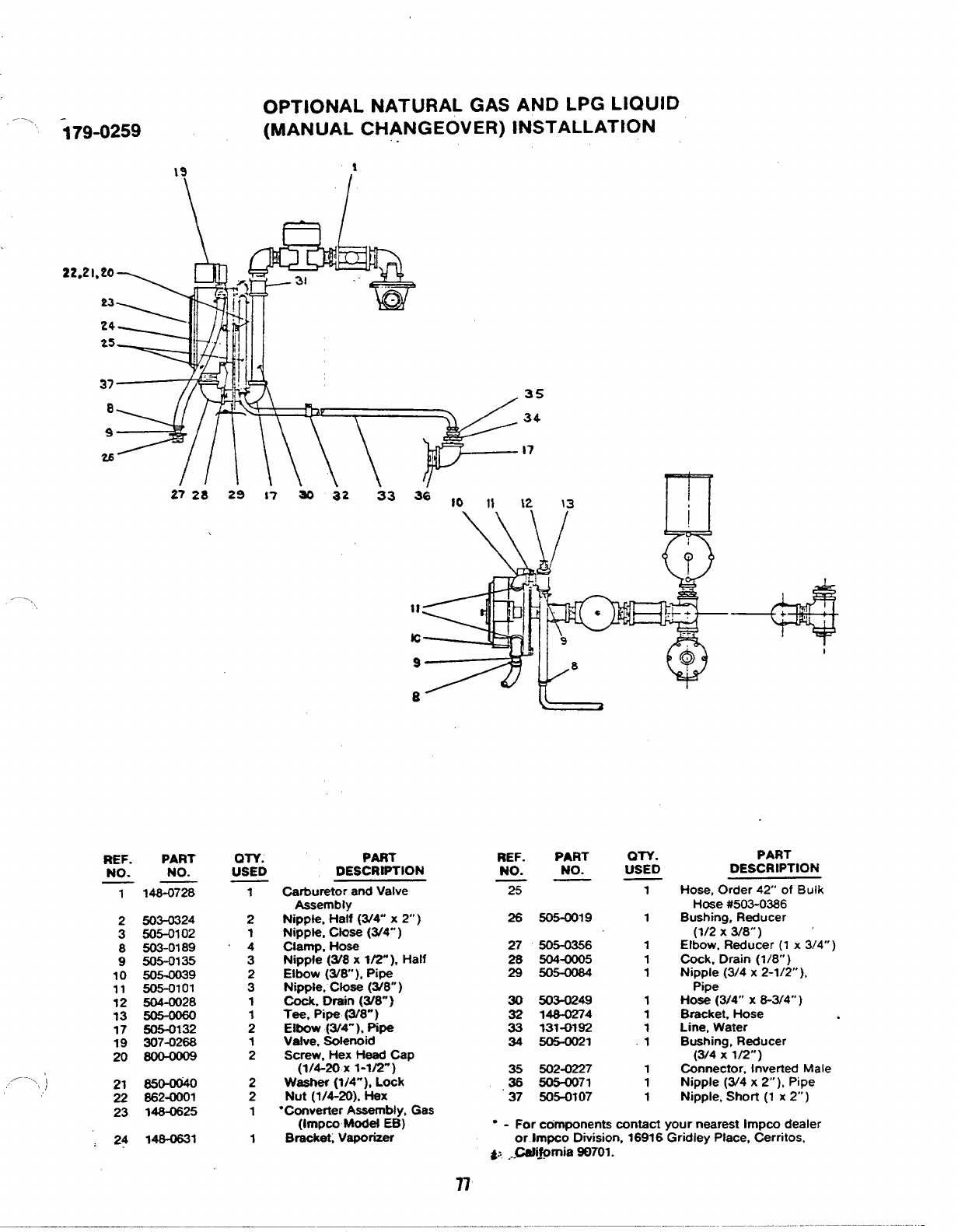
;79-0259
OPTIONAL NATURAL GAS AND LPG LIQUID
(MANUAL CHANGEOVER) INSTALLATION
19 1
\ /
22.21,20
23
24
2s
37 35
834
9
2s 17
*+
2728 29 17 w32 33 36 ,0 ,} 12 \3
\
y
‘3 i;,+
7
11 e,1 J-+
10 9
98$
e
REF. PART
NO. NO.
——
1146-0726
2503-0324
3505-0102
8503-0189
9505-0135
10 505-0039
11 505-0101
12 504-0028
13 505-0060
17 505-0132
19 307-0268
20 WO—0009
21 650-0040
22 662-0001
23 146-0625
,24 146-0631
OTV.
USED DES%%ON
1
2
1
4
3
2
3
1
1
2
1
2
2
2
1
1
Carburetor and Valve
Assembly
Nippte, Half (3/4 x2“ )
Nippte, Ctose (3/4” )
Clamp, Hose
Nipple (W8 x1/2”). Half
Elbow (W8), Pipa
Nlppie, close (3/8”)
Cock, Drain (LV8”)
Tee, Pipe (3/8”)
Elbow (3/4-), Pipe
Valve, Solenoid
Screw, Hex Heed Cap
(1/4-20 x1-1/2”)
Waatwr (?/4”), Lock
Nut (1/4-20), *X
“Converter Assembly, Gas
(Impco Modef EB)
Bracket,Vaporizer
REF.
NO.
PART
NO.
25
26
27
28
29
30
32
33
34
.Z
37
505-0019
505-0356
504-0005
503-0249
14a0274
131-0182
505-0021
502-0227
505-0071
505-0?07
+
+:
I
OTV.
USED
1
1
1
1
1
1
1
1
.1
1
1
1
PART
DESCRIPTION
Hose, Order 42” of Bulk
Hose #503-0386
Bushing, Reducer
(1/2 X3/8”’) ‘
Elbow, Reducer (1 x3/4”)
Cock. Drain (1/8 )
Nipple (3/4 x2-1/2’.),
Ptpe
Hose (314” X8-3[4”’ )
Bracket, Hose
Line, Water
Bushing, Reducer
(3/4 xlrz”)
Connector, Inverted Male
Nipple (3/4 x2“ ), Pipe
Nipple, Short (1 x2“ )
“ - For conwmnents contact your nearest lmpco dealer
or Impco Division, 16916 ‘Gridley Place, Cerritos,
~, ...@ii#mia 80701.
n
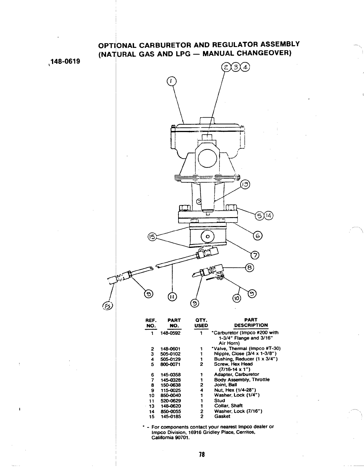
,148-0619
OPT
(NA
INAL CARBURETOR AND REGULATOR ASSEMBLY
JRAL GAS AND LPG —MANUAL CHANGEOVER)
m
/
,\
———.
s8
/“
9
10
9
REF.
NO.
T
:
4
5
6
7
8
9
10
11
73
14
15
PART
NO.
148-0592
148-0601
505-0102
505-0129
800-oo71
?45-0358
145U328
150-0638
?15-0025
520-0629
148-0620
850-0055
145-0185
QTY. PART
USED DESCRIPTION
1*Carburetor (Impco #200 with
1-3/4” Flange and 3/16”
Alr Horn)
1“Valve, Thermal (Impco #T-30)
1Nipple, Close (3/4 x1-3/8)
Bushing, Reducer (1 x3/W)
;Screw, Hex Head
(7/16-14 x1“’)
1Adapter, Carburetor
Body Assembly, Throttle
;Joint. Ball
4Nut, Hex (?/4-28” )
1Washer, Lock (1/4° )
1Stud
Collar, Shaft
;Washer, Lock (7/16” )
2Gasket
●-For components contact your neareatlmpco dealer or
Impco D’ivision, 16916 Gr;dley Place, Cerritoa,
California 90701.
78
.—
..
,.—..,
\
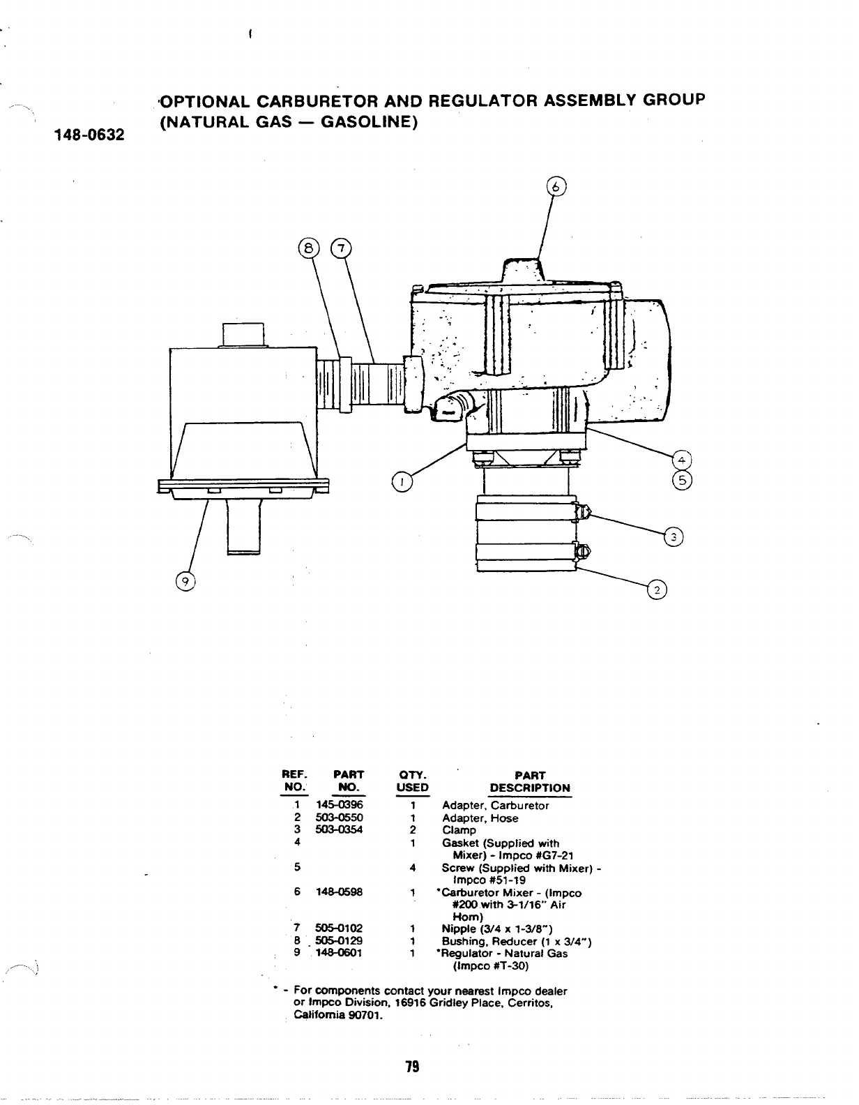
f
.IOPTIONAL CARBURETOR AND REGULATOR ASSEMBLY GROUP
148-0632 (NATURAL GAS –GASOLINE)
/’
6
..-,.
,,.—-..
..)
d
J.\
.. >..”. .
/u
REF. PART
NO. No.
T14m7
2503-0550
35034354
4
5
6146-0596
7505-0102
B.505-0129
9146-0601
WY.
USED
4
1
1
1
1
PART
DESCRIPTION
Adapter, Carburetor
Adapter, Hose
clamp
Gasket (Supplied with
Mixer) -Impco #G7-2I
SCreW (Supplied with Mixer) -
Impco #51-19
“Carburetor Mixer -(Impco
#200 with S1/16 Air
Horn)
Nipple (3/4 x1-3/8”)
Bushing, Reducer (1 x3/4”)
“Regulator -Natural Gas
(Impco #T-30)
“ - For wmponents contact your nearest Impw dealer
or lmpco Division, 16916 Gridley Place, Cerritos,
California 90701.
79
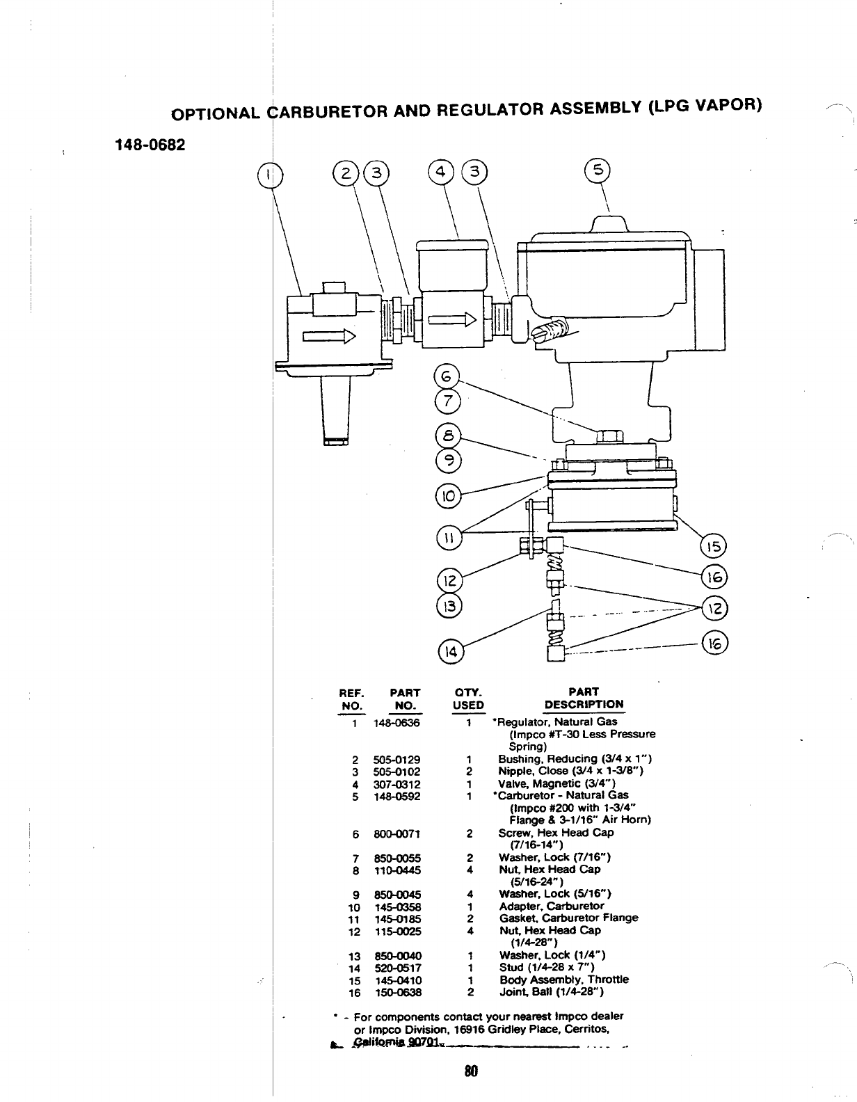
OPTIONAL CARBURETOR AND REGULATOR ASSEMBLY (LPG VAPOR)
148-0682
\
ID
u
REF. PART
No. NO.
-7 148-0636
2!505-0129
3505-0102
4307-0312
5148-0592
6800-0071
7850-0055
8110-0445
98504045
10 145-0358
11 145-0185
12 115-0025
13 850-0040
14 520-0517
15 145-0410
16 150-0638
al-v. PART
USED DESCRIPTION
1“Regulator, Natural Gas
2
2
4
4
1
2
4
fimpco #T-30 Less Pressure
Spring)
Bushing, Reducing (3/4 x1”)
Ntpple, Close (3/4x 1-3/8)
Valve, Magnetic (3/4”)
“Carburetor -Natural Gas
(Impco #200 with 1-3/4”
Flange &3-1/16 Air Horn)
Screw, Hex Head Cap
(7/16-14”)
Washer, Lock (7/16 )
Nut, Hex Head Cap
(5/16-24” )
Washer, Lock (5/16- )
Adapter, Carburetor
Gasket. Carburetor Flange
Nut Hex Head Cap
(1/4-28”)
Washer, Lock (1/4’”)
Stud (1/4-28 X7“)
Body Assembly, Throttle
Joint, Ball (1/4-28 )
“-For components contact your nearest Immo dealer
—.
,’ .,
,,—-.
.,
or Irnpco Oiviaion, 16916 ‘Gridley Place, Cerritos,
~@li&@SS97Q1. . . . . ..
80
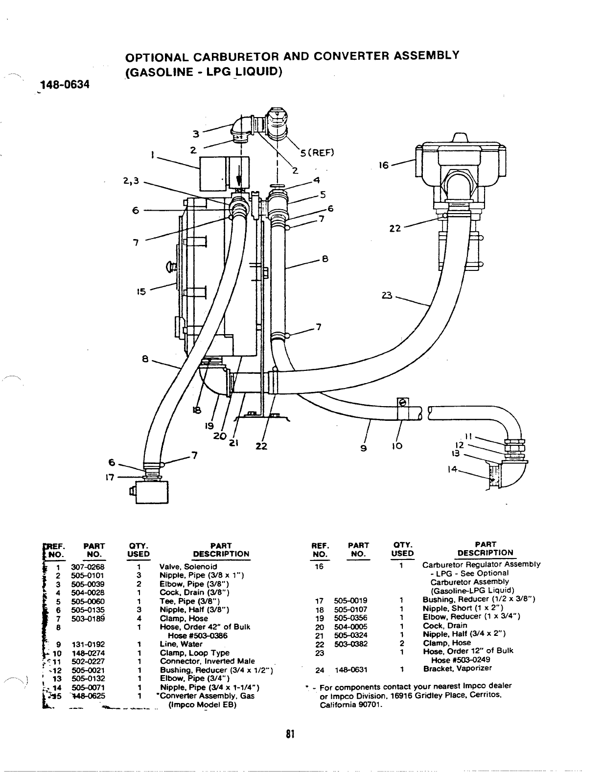
OPTIONAL CARBURETOR AND CONVERTER ASSEMBLY
.(GASOLINE -LPG LIQUID)
~48-0634
a
-.\
9
F–PART
NE~: NO.
307-0268
. ; 505-0101
t3605-0039
E:rs
1
6505-01~
7503-0189
8
9131-0192
“lo 148-0274
~:11 502-0227
-12 505-0021
,,/---- \
\/ ;13 505-0132
:,--14 505-0071
L.
.%5 “%48-0625
..- —
an. PART
USED DESCRIPTION
Valve, SoIeno id
;Nipple, Pipe (3/8 x1”)
2Elbow, Pipe (3/8” )
1Cock, Drain (W8° )
Tee, Pipe (3/8’”)
:Nipple, Half (3/80’)
4Clamp, Hose
1Hose, Order 42” of Bulk
Hose #503-0386
1Line, Water
1Clamp, Loop Type
1Connector, Inverted Male
1Bushing, Reducer (3/4 xI/2’”)”
1Elbow, Pipe (3/4” )
1Nipple, Pipe (W4 xI-1/4”)
1‘Convetier Assembly, Ges
--—. _(Impco Model EB)
REF. PART
NO. NO.
16
17 505-0019
18 505-0107
19 505-0356
20 504-0005
21 505-0324
225CS0382
23
24 148-0631
OTY.
USED
1
1
1
1
1
1
2
1
1
PART
DESCRIPTION
Carburetor Regulator Assembly
-LPG -See Optional
Carburetor Assembly
(Gasotin~LPG Liquid)
Bushing, Reducer (1/2 x3/8”)
Nipple, Short (~ x2“)
Elbow, Reducer (1 x3/4”)
Cock, Drain
N@te, Half (3/4x 2“)
Clamp, Hose
Hose, Order 12 of Bulk
Hose #503-0249
Bracket,Vaporizer
“-For components contact your nearest Impco dealer
or Impco Division, 16916 Gridley Place, Cerritos,
@lifomia 90701.
81
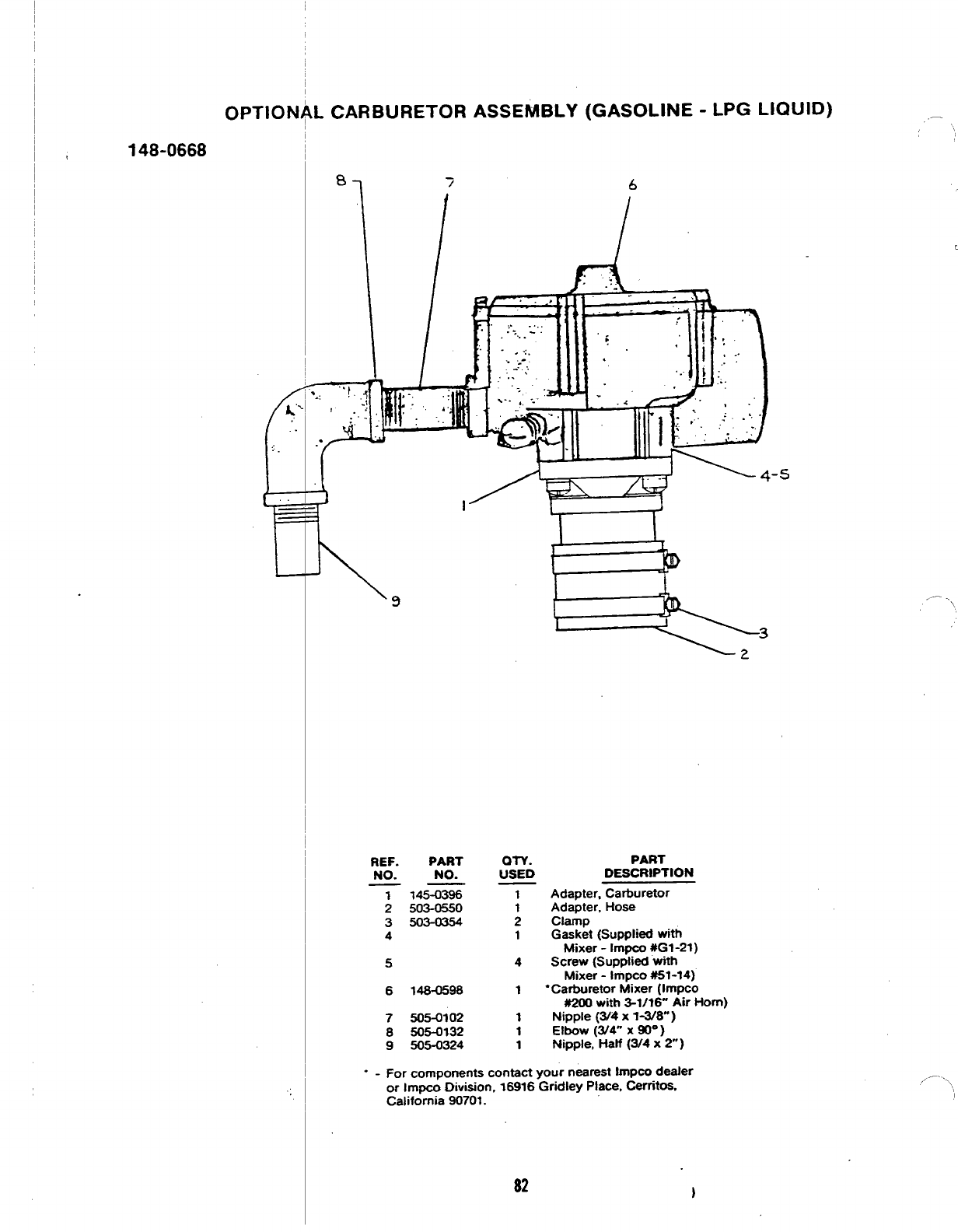
OPTIONAL CARBURETOR
7
\/
(GASOLINE -LPG LIQUID)
6
4
\4.5
Ie+’
REF.
NO.
1
3
4
5
6
7
8
9
PART
NO.
145-0396
503-0550
503-0354
146-0598
505-0102
505-0132
505-0324
OTY.
USED
PART
DESCRIPTION
4
1
1
1
1
Adapter, Carburetor
Adapter, l-lose
clamp
Gasket (Supplied with
Mixer -Irnpco #G1-21)
Screw (Suppfied with
Mixer -Impco #51-14)
“Carburetor Mixer (Impco
#2W with 3-1/? 6- Air Horn)
Nipple (3/4 x1-3/8”)
Elbow (3/4” XW“ )
Nipple, Half (3/4 x2“)
“ - For components contact your nearest Impco dealer
or Impco Division, 16916 Gridley Place, Cerritoa.
California 90701.
--
/
..,,
82 )
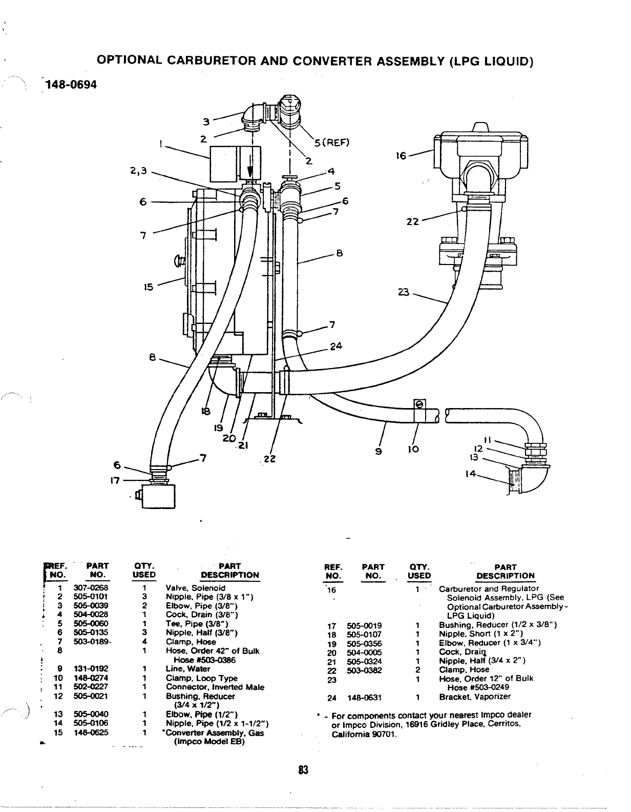
OPTIONAL CARBURETOR
\,, “148-0694
CONVERTER ASSEMBLY
--l T‘5(REF)
I2“4
&
5
--=-+ ?7
IL1
I
2,3
6
tfl /
1
r-f
7
11
11 ---8
7
8. YAE
,—.,
/,!
// 3
II
910 12
\3 .
——
14 ,!,
,1
‘S 7
—
—
2
6
17
.
“PART
NO.
307-0268
505-0101
5044028
505-0135
503-0189.
WY. .PART REF.
USED DESCRIPTION NO. QTV.
USED PART
DESCRIPTION
PART
NO.
:
2
1
;
4
1
1
1
1
1
1
1
1
. .
Valve, Solenoid “16
Nipple, Pipe (3/8 x1”)
Elbow, Pipe (3/8”)
Cock, Drain (3/8”.)
1’” Carburetor and Regulator
Solenoid Assembly, LPG (See
Optional Carburetor AsSembly -
LPG Liquid)
Bushing. Reducer (1/2 x3/8”)
Nipple, Short (1 x2“)
Elbow, Reducer (1 x3/4”)
Cock, Draiq
Nipple, Hatf (3/4 x2“ )
Clamp, Hose
Hose, Order 12” of Bulk
Hose #503-0249
Bracket, Vaporizer
Tee, Pipe (3/&”) -
Nipple, Half (3/8”) 17 505-0019
Clamp, Hose 18 505-0107
Hose, Order 42” of Bulk 19 505-0356
Hose #SB-0386 20 504-OOUi
Line, Water 21 505-0324
Clamp, Loop Type 22 503-0382
23
Connector, Inverted Mafe
1
1
1
1
;
1
131-0192
148-0274
502-0227
505-0021
10
11
12 Bushing, Reducer
(3/4 x1/2-) 24 148-0631 1
/.. ‘) *,3
... 14 SO5-O1O6
148-0625
Elbow, Pipe (1/2”)
Nipple, Pipe (1/2 x1-1/2”) ●-For components contact your nearest Impco dealer
●Converter Assembly. Gas or Impco Division, 16916 Gridley Place. Cerritos,
California 90701.
(}mpco Model EB)
15
&
83
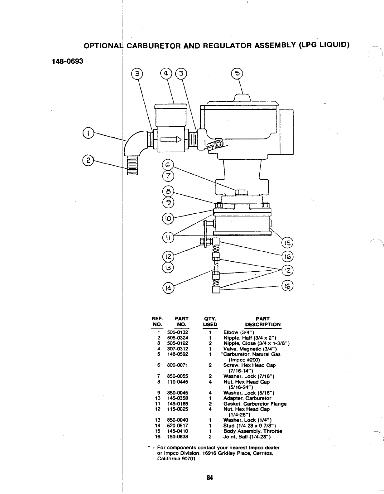
OPTIONA~ CARBURETOR AND
I
148-0693 I
REGULATOR
-2
5
ASSEMBLY (LPG LIQUID) .– !
u
REF. PART
NO. NO.
——
1505-0132
2505-0324
3505-0102
4307-0312
5148-0592
6800-0071
7850-0055
8110-0445
9850+045
10 145-0358
11 145-01s5
12 115-0025
13 850-0040
14 520-0517
15 145-0410
16 150-0638
OTY.
USED
1
;
1
1
2
2
4
4
1
2
4
1
1
1
2
PART
DESCRIPTION
Elbow (3/4”)
Nipple, Half (3/4 x2)
Nipple, Close (3/4 x1-3/8”)
Valve, Magnetic (3/4”)
“Carburetor, Natural Gas
(Impco #2CKr)
Screw, Hex Head Cap
(7/16-14”)
Washer, Lock (7/16” )
Nut, Hex Head Cap
(5/16-24”)
Washer. Lock (5/16” )
Adapter, Carburetor
Gasket, Carburetor Flange
Nut, Hex Head Cap
(1/4-28”)
Washer, Lock (1/4”)
Stud (1/4-26 X9-7/8”)
Body Assembly, Throttle
Joint, Ball (1/4-28)
,.—,\,
--..,
‘
“ - For components contact your neareat Impco dealer
or Impco Division, 16916 Gridley Place, Cerritos,
California 90701.
84
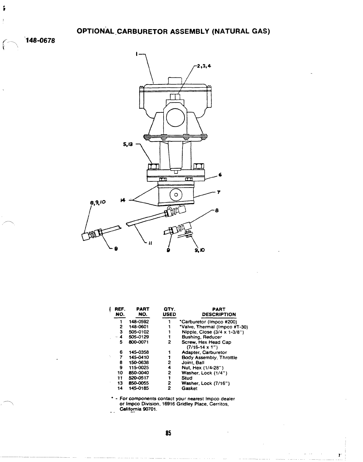
(“, . . . .. “148-0678
(’
OPTIONAL-CARBURETOR ASSEMBLY (NATURAL GAS)
S,la
‘--l
\
\
;
3
~~~4
5
6
7
8
9
10
11
13
14
PART
No.
148-0592
148-0601
505-0102
505-0129
8o0-oo71
145-0358
145-0410
150-0638
115-0025
850-0040
520-0517
145-0185
aTY.
USED
PART
DESCRIPTION
“Carburetor (Impco #200)
“Valve, Thermal (Impco #T-3o)
Nipple, Close (3/4 x1-3/8”)
Bushing, Reducer
Screw. Hex Head Cap
(7/16-14 xl“)
Adapter, Carburetor
Body Assembly, Throttle
Joint, Ball
Nut, Hex (1/4-28” )
Washer, Lock (1/4” )
Stud
Washer, Lock (7/16” )
Gasket
●-For components contact your nearest impco dealer
or Impco Division, 16916 Gridley Place, Cerritos,
. . California 90701.
-.
85
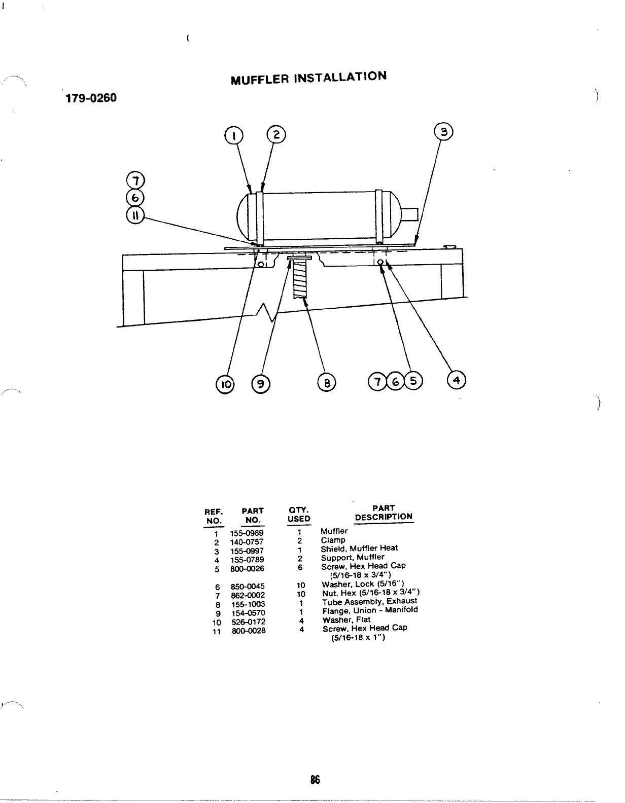
,, ....\
179-0260
MUFFLER INSTALLATION
,-.
)
REF.
NO.
PART
NO.
QTY.
USED
1
2
3
4
5
155-0989
140-0757
155-0997
155-0789
800-0026
1
2
1
2
6
6
7
8
9
10
11
650-0045
662-0002
155-1003
154-0570
526-0172
600-0028
10
10
1
1
4
4
PART
DEsCRIPTION
Muffler
Clamp
Shield, Muffler Heat
support, Muffler
Screw, Hex Head CaP
(5/16-18 X314)
Washer, Lock (5/16” )
Nut, Hex (5/16-18 x3/4”)
Tube Assembly, Exhaust
Flange, Union -Manifold
Washer, Flat
Screw, Hex Head CaP
(5/16-18 x1“)
B6
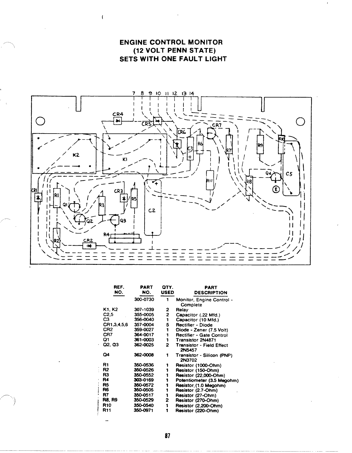
,.-.—-\\
o
/’—
,P .>‘,)
ENGINE CONTROL MONITOR
(12 VOLT PENN STATE)
SETS WITH ONE FAULT LIGHT
I\-.————————————____ ___ ___ _
--— —._ ——————___ ___ ___ ___ —
———
.“/
REF.
NO.
Kl, K2
C2.5
C3
CR1 ,3,4,5,6
CR2
PART
NO.
300-0730
307-1039
357-0004
359-0027
364-0017
361-0003
362-0025
362-0006
350-0526
350-0552
W169
350-0572
350-0517
350-0529
3!XM971
OTY. PART
USED DESCRIPTION
1
2
2
:
1
1
1
2
1
1
1
1
1
1
1
1
1
1
87
Monitor, Engine Control -
Complete
Relay
Capacitor (.22 Mfd.)
-pacitor (10 Mfd.)
Rectifier -Diode
Diode -Zener (7.s Volt)
Rectifier -Gate Control
Transistor 2N4S71
T~~7r -Field Effect
Tr~ist; -Silicon (PNP)
Resistor (KKrO-Ohm)
Resistor (lSO-Ohm)
Resistor (22,000-Ohm)
Potentiometer (3.5 Megohm)
Resistor.(1.0 Megohm)
Resistor (2.7~hm)
Resistor (27-Ohm)
Resistor (270-Ohm)
Resistor (2,200-Ohm)
Resistor (Z20-Ohm)
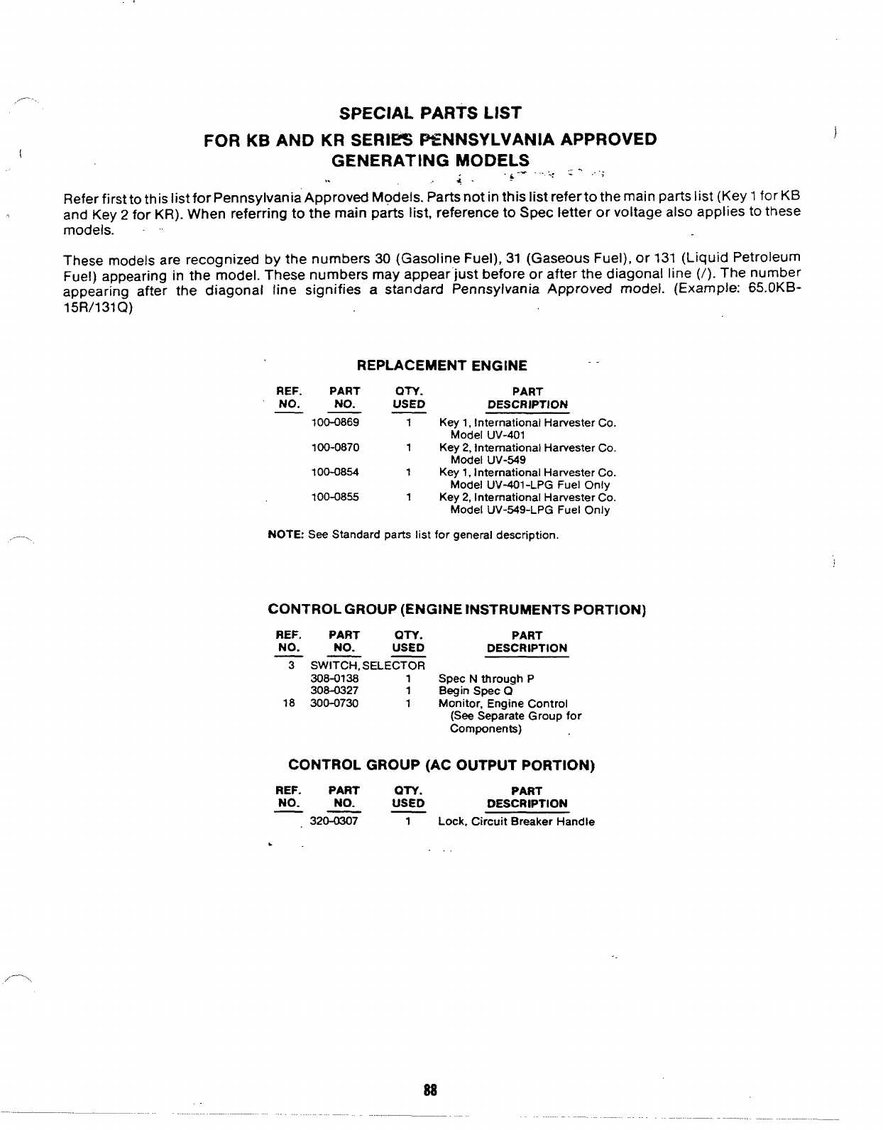
,,--- SPECIAL PARTS LIST
FOR KB AND KR SERIES PENNSYLVANIA APPROVED
(GENERATING MODELS ,. ,.;
,. &“- ““~:
g.
Refer first to this list for Pennsylvania Approved Models. Parts not in this list refer to the main parts list (Key 1for KB
,and Key 2for KR). When referring to the main parts list, reference to Spec letter or voltage also applies to these
models. ~~
These models are recognized by the numbers 30 (Gasoline Fuel), 31 (Gaseous Fuel), or 131 (Liquid Petroleum
Fuel) appearing in the model. These numbers may appear’just before or after the diagonal line (/). The number
appearing after the diagonal line signifies astandard Pennsylvania Approved model. (Example: 65.0 KB-
15 R/131Q)
REPLACEMENT ENGINE
--—-
REF. PART QTY. PART
NO. NO. USED DESCRIPTION
——
—100-0869 1Key 1, International Harvester Co.
Model UV-401
100-0870 1Key 2, International Harvester Co.
Model UV-549
1Oo-om 1Key 1, International Harvester Co.
Model UV-401 -LPG Fuel Only
100-0855 1Key 2, International Harvester Co.
Model UV-549-LPG Fuel Only
NOTE: See Standard parts list for general description.
CONTROL GROUP (ENGINE INSTRUMENTS PORTION)
REF. PART an. PART
NO. NO. USED DESCRIPTION
?SW~SELECTOR
308-0138 1Spec Nthrough P
308-0327 1Begin SpeC Q
18 300-0730 1Monitor, Engine Control
(See Separate Group for
Components)
CONTROL GROUP (AC OUTPUT PORTION)
REF. PART OTY. PART
NO. NO. USED DESCRIPTION
32&&ii? 1Lock, Circuit Breaker Handle
.
88
