95X Series Manual
User Manual: 95X
Open the PDF directly: View PDF ![]() .
.
Page Count: 151 [warning: Documents this large are best viewed by clicking the View PDF Link!]
- About this Manual
- Warranty Information
- SECTION 1 – PRODUCT INFORMATION
- Features
- Available Models and Options
- SECTION 2 – SAFETY
- Power and Grounding
- Terminals and Wiring
- User Activated Safety Abort
- Automatic Safety Abort
- SECTION 3 –INSTALLATION
- General Specifications
- Initial Inspection
- Cooling
- Mounting Position and Orientation
- Installing in a 19” Rack Enclosure
- Line Power
- Connecting Option AC-30 to the 95x
- SECTION 4 – GENERAL FRONT PANEL OPERATION
- Front Panel
- Menu Operation and Data Entry
- Adjusting the Display Contrast
- Locking and Unlocking Menus
- Displaying Build Information
- System Configuration Settings
- Returning All Configuration Settings to Factory Defaults
- SECTION 5 – TEST SEQUENCES
- Test Sequence Configuration
- Creating a New Test Sequence
- Editing an Existing Test Sequence
- Deleting an Existing Test Sequence
- Selecting and Running an Existing Test Sequence
- Reviewing Test Results after Running a Test Sequence
- Displayed Measurement Results
- Printing a Test Results Report
- Compensating for External Lead Leakage and Impedance
- SECTION 6 – TEST STEPS
- Choosing Within the Voltage Withstand and Leakage Testing Group
- AC Voltage Withstand and Leakage Testing (ACez and ACW)
- AC Voltage Resistance and Capacitance Testing (ACIR and ACCAP)
- DC Voltage Withstand and Leakage Testing (DCez, DCW and DCIR)
- High Value Capacitor DC Leakage Testing (DCCAP and IRCAP)
- Pulsed Voltage Withstand Testing (PULSE)
- DC Breakdown Voltage Device Testing (BRKDN)
- Choosing Within the Resistance Testing Group
- DC Low Resistance Testing (LowΩ)
- AC Ground Bond Testing (GBez and GB)
- Ground Leakage Testing (DCI and ACI)
- Switch Unit Control (SWITCH)
- Test Sequence Timing Control (PAUSE and HOLD)
- SECTION 7 – CONNECTING AND CONFIGURING INTERFACES
- LOCAL and REMOTE Operation
- Controlling External Switch Matrix Units
- Controlling the 95x by the RS232 Interface
- Controlling the 95x by the GPIB Interface
- Controlling the 95x by the Ethernet Interface
- Printing from the 95x using the USB Interface
- SECTION 8 – DIO INTERFACE
- Connector and Pinout
- Configuring
- Signal Levels
- Signal Isolation
- Signal Timing
- Examples
- SECTION 9 – PERIODIC MAINTENANCE
- Cleaning and Inspection
- Self Test
- SECTION 10 – PERFORMANCE VERIFICATION AND ADJUSTMENT
- Adjustment Calibration
- Verifying Calibration
- SECTION 11 – PROGRAMMING VIA AN INTERFACE
- General Command Syntax
- General Response Syntax
- Delays and Timeouts
- Multiple Interface Operation
- Front Panel Operation While Using Interfaces
- GPIB Bus Commands
- Ethernet Sessions
- Status Registers
- Commands
- Simple Programming Examples
- Programming Guidelines
95x Series Operating Manual - December 12, 2011
Page 2 of 151
About this Manual ......................................................................................................................................................... 8
Warranty Information ................................................................................................................................................... 9
SECTION 1 – PRODUCT INFORMATION........................................................................................................................ 10
Features ....................................................................................................................................................................... 10
Available Models and Options ..................................................................................................................................... 11
Interfacing Options .................................................................................................................................................. 11
DC Voltage Options .................................................................................................................................................. 11
Internal AC Voltage Options .................................................................................................................................... 12
External AC Voltage Option ..................................................................................................................................... 12
Pulse Testing Option ................................................................................................................................................ 12
Terminal Option ....................................................................................................................................................... 12
Power Input Option ................................................................................................................................................. 12
Rack Mounting Option ............................................................................................................................................. 12
Output Voltage/Current Limiting Options ............................................................................................................... 12
SECTION 2 – SAFETY..................................................................................................................................................... 13
Power and Grounding .................................................................................................................................................. 13
Terminals and Wiring ................................................................................................................................................... 13
User Activated Safety Abort ........................................................................................................................................ 14
Automatic Safety Abort ............................................................................................................................................... 14
SECTION 3 –INSTALLATION .......................................................................................................................................... 16
General Specifications ................................................................................................................................................. 16
Initial Inspection .......................................................................................................................................................... 16
Cooling ......................................................................................................................................................................... 17
Mounting Position and Orientation ............................................................................................................................. 17
Installing in a 19” Rack Enclosure ................................................................................................................................ 17
Line Power ................................................................................................................................................................... 17
Connecting Option AC-30 to the 95x ........................................................................................................................... 18
SECTION 4 – GENERAL FRONT PANEL OPERATION ...................................................................................................... 19
Front Panel .................................................................................................................................................................. 19
Menu Operation and Data Entry ................................................................................................................................. 21
Base Menu State ...................................................................................................................................................... 21
Navigating Menus .................................................................................................................................................... 22
Modifying Menu Entries .......................................................................................................................................... 22
Adjusting the Display Contrast .................................................................................................................................... 24
Locking and Unlocking Menus ..................................................................................................................................... 24
95x Series Operating Manual - December 12, 2011
Page 3 of 151
Unlocking Menus ..................................................................................................................................................... 24
Setting, Changing or Clearing a Menu Lock Password ............................................................................................. 25
Relocking Menus...................................................................................................................................................... 25
Unknown Menu Lock Password............................................................................................................................... 26
Displaying Build Information ....................................................................................................................................... 26
System Configuration Settings ..................................................................................................................................... 27
Returning All Configuration Settings to Factory Defaults ............................................................................................ 28
SECTION 5 – TEST SEQUENCES .................................................................................................................................... 29
Test Sequence Configuration ....................................................................................................................................... 29
Creating a New Test Sequence .................................................................................................................................... 31
Editing an Existing Test Sequence ............................................................................................................................... 31
Deleting an Existing Test Sequence ............................................................................................................................. 32
Selecting and Running an Existing Test Sequence ....................................................................................................... 32
Reviewing Test Results after Running a Test Sequence .............................................................................................. 34
Displayed Measurement Results ................................................................................................................................. 36
Printing a Test Results Report ..................................................................................................................................... 36
Configuring the Test Results Report ........................................................................................................................ 37
Manually Commanding a Test Results Report ......................................................................................................... 38
Compensating for External Lead Leakage and Impedance .......................................................................................... 38
SECTION 6 – TEST STEPS .............................................................................................................................................. 40
Choosing Within the Voltage Withstand and Leakage Testing Group ......................................................................... 41
Choosing AC, DC or PULSE Testing ........................................................................................................................... 41
Choosing the Limits ................................................................................................................................................. 41
Breakdown Current ................................................................................................................................................. 42
Leakage Current ....................................................................................................................................................... 43
Arc Current and Time............................................................................................................................................... 43
AC Voltage Withstand and Leakage Testing (ACez and ACW) ..................................................................................... 44
Actions While Running ............................................................................................................................................. 45
Configuring .............................................................................................................................................................. 45
Connecting to the DUT ............................................................................................................................................ 47
Lead Compensation ................................................................................................................................................. 48
Examples .................................................................................................................................................................. 48
Specifications ........................................................................................................................................................... 49
AC Voltage Resistance and Capacitance Testing (ACIR and ACCAP) ............................................................................ 52
Actions While Running ............................................................................................................................................. 53
95x Series Operating Manual - December 12, 2011
Page 4 of 151
Configuring an ACIR Test Step ................................................................................................................................. 53
Configuring an ACCAP Test Step .............................................................................................................................. 54
Connecting to the DUT ............................................................................................................................................ 55
Lead Compensation ................................................................................................................................................. 56
Examples .................................................................................................................................................................. 56
Specifications ........................................................................................................................................................... 57
DC Voltage Withstand and Leakage Testing (DCez, DCW and DCIR) ........................................................................... 58
Actions While Running ............................................................................................................................................. 58
Optimizing Performance with High Capacitance Loads (>0.1uF) ............................................................................. 59
Configuring .............................................................................................................................................................. 60
Connecting to the DUT ............................................................................................................................................ 61
Lead Compensation ................................................................................................................................................. 62
Examples .................................................................................................................................................................. 63
Specifications ........................................................................................................................................................... 65
High Value Capacitor DC Leakage Testing (DCCAP and IRCAP).................................................................................... 67
Actions While Running ............................................................................................................................................. 68
Optimizing Performance with High Capacitance Loads ........................................................................................... 68
Configuring .............................................................................................................................................................. 69
Connecting to the DUT ............................................................................................................................................ 71
Lead Compensation ................................................................................................................................................. 72
Examples .................................................................................................................................................................. 72
Specifications ........................................................................................................................................................... 73
Pulsed Voltage Withstand Testing (PULSE) ................................................................................................................. 75
Actions While Running ............................................................................................................................................. 75
Configuring .............................................................................................................................................................. 76
Connecting to the DUT ............................................................................................................................................ 77
Lead Compensation ................................................................................................................................................. 77
Examples .................................................................................................................................................................. 77
Specifications ........................................................................................................................................................... 78
DC Breakdown Voltage Device Testing (BRKDN) ......................................................................................................... 78
Actions while Running ............................................................................................................................................. 79
Configuring .............................................................................................................................................................. 79
Connecting to the DUT ............................................................................................................................................ 80
Lead Compensation ................................................................................................................................................. 80
95x Series Operating Manual - December 12, 2011
Page 5 of 151
Examples .................................................................................................................................................................. 80
Specifications ........................................................................................................................................................... 81
Choosing Within the Resistance Testing Group........................................................................................................... 81
DC Low Resistance Testing (LowΩ) .............................................................................................................................. 82
Actions while Running ............................................................................................................................................. 82
Configuring .............................................................................................................................................................. 82
Connecting to the DUT ............................................................................................................................................ 83
Lead Compensation (2-Wire) ................................................................................................................................... 84
Lead Compensation (4-Wire) ................................................................................................................................... 84
Examples .................................................................................................................................................................. 84
Specifications ........................................................................................................................................................... 85
AC Ground Bond Testing (GBez and GB)...................................................................................................................... 85
Actions While Running ............................................................................................................................................. 86
Configuring .............................................................................................................................................................. 86
Connecting to the DUT ............................................................................................................................................ 87
Lead Compensation ................................................................................................................................................. 89
Examples .................................................................................................................................................................. 89
Specifications ........................................................................................................................................................... 91
Ground Leakage Testing (DCI and ACI) ........................................................................................................................ 92
Actions While Running ............................................................................................................................................. 92
Configuring .............................................................................................................................................................. 92
Connecting to the DUT ............................................................................................................................................ 93
Lead Compensation ................................................................................................................................................. 93
Examples .................................................................................................................................................................. 93
Specifications ........................................................................................................................................................... 95
Switch Unit Control (SWITCH) ..................................................................................................................................... 95
Actions While Running ............................................................................................................................................. 95
Configuring .............................................................................................................................................................. 96
Examples .................................................................................................................................................................. 96
Specifications ........................................................................................................................................................... 97
Test Sequence Timing Control (PAUSE and HOLD) ...................................................................................................... 97
Configuring .............................................................................................................................................................. 97
Examples .................................................................................................................................................................. 98
Specifications ........................................................................................................................................................... 98
95x Series Operating Manual - December 12, 2011
Page 6 of 151
SECTION 7 – CONNECTING AND CONFIGURING INTERFACES ..................................................................................... 99
LOCAL and REMOTE Operation ................................................................................................................................... 99
Controlling External Switch Matrix Units ..................................................................................................................... 99
Configuration ........................................................................................................................................................... 99
Connections ........................................................................................................................................................... 101
Controlling the 95x by the RS232 Interface ............................................................................................................... 101
Specifications ......................................................................................................................................................... 101
Configuration ......................................................................................................................................................... 101
Connections ........................................................................................................................................................... 102
Controlling the 95x by the GPIB Interface ................................................................................................................. 102
Configuration ......................................................................................................................................................... 102
Connections ........................................................................................................................................................... 103
Controlling the 95x by the Ethernet Interface ........................................................................................................... 103
Specifications ......................................................................................................................................................... 103
Configuration ......................................................................................................................................................... 103
Connections ........................................................................................................................................................... 105
Printing from the 95x using the USB Interface .......................................................................................................... 105
Specifications ......................................................................................................................................................... 105
Connecting ............................................................................................................................................................. 105
Printing .................................................................................................................................................................. 106
SECTION 8 – DIO INTERFACE...................................................................................................................................... 107
Connector and Pinout ................................................................................................................................................ 107
Configuring ................................................................................................................................................................ 108
Signal Levels ............................................................................................................................................................... 109
Signal Isolation ........................................................................................................................................................... 110
Signal Timing .............................................................................................................................................................. 110
Examples .................................................................................................................................................................... 111
SECTION 9 – PERIODIC MAINTENANCE ..................................................................................................................... 113
Cleaning and Inspection ............................................................................................................................................ 113
Self Test ..................................................................................................................................................................... 114
SECTION 10 – PERFORMANCE VERIFICATION AND ADJUSTMENT ............................................................................ 115
Adjustment Calibration .............................................................................................................................................. 115
Equipment Required .............................................................................................................................................. 116
Procedure .............................................................................................................................................................. 116
Verifying Calibration .................................................................................................................................................. 118

95x Series Operating Manual - December 12, 2011
Page 7 of 151
Equipment Required .............................................................................................................................................. 119
Starting Verification ............................................................................................................................................... 120
DC Voltage Verification .......................................................................................................................................... 120
DC Current Scaling Verification .............................................................................................................................. 121
DC Current Zero Verification ................................................................................................................................. 121
AC Voltage Verification .......................................................................................................................................... 121
AC Current Zero Verification .................................................................................................................................. 122
Low Ohms Resistance Verification......................................................................................................................... 122
Ground Bond Verification ...................................................................................................................................... 123
SECTION 11 – PROGRAMMING VIA AN INTERFACE ................................................................................................... 124
General Command Syntax ......................................................................................................................................... 124
Field Syntax ............................................................................................................................................................ 125
Field Separator....................................................................................................................................................... 126
Command Separator .............................................................................................................................................. 126
Command Terminator ........................................................................................................................................... 126
General Response Syntax .......................................................................................................................................... 126
Delays and Timeouts ................................................................................................................................................. 127
Multiple Interface Operation ..................................................................................................................................... 127
Front Panel Operation While Using Interfaces .......................................................................................................... 128
GPIB Bus Commands ................................................................................................................................................. 128
Ethernet Sessions ...................................................................................................................................................... 128
Status Registers ......................................................................................................................................................... 129
STB and SRE Registers ............................................................................................................................................ 129
OPC Register .......................................................................................................................................................... 129
ESR Register ........................................................................................................................................................... 130
ERR Register ........................................................................................................................................................... 130
Commands ................................................................................................................................................................. 131
Simple Programming Examples ................................................................................................................................. 148
Programming Guidelines ........................................................................................................................................... 149

95x Series Operating Manual - December 12, 2011
Page 8 of 151
ABOUT THIS MANUAL
Throughout this document the instrument is referred to as the 95x, this applies to all instruments in the 95x series
having a main firmware revision of 1.59, there may be minor changes if the 95x being operated has a different
main firmware version.
Due to continuing product refinement and possible manufacturer changes to components used in this product,
ViTREK reserves the right to change any or all specifications without notice.
This manual has been created with “clickable” links. Where a reference is made to another section of the manual,
the user may click on the section name reference and the document will automatically go to that section.
The table of contents is “clickable”. The user may click on any of the entries to go to that section.
The table of contents is also made available as Bookmarks for Adobe Reader or Acrobat, allowing the user to
permanently display the table of contents alongside the document and navigate by clicking on each section
needed.

95x Series Operating Manual - December 12, 2011
Page 9 of 151
WARRANTY INFORMATION
This ViTREK instrument is warranted against defects in material and workmanship for a period of 1 year after the
date of purchase (extended up to a total of 3 years with registration and annual calibrations at ViTREK). ViTREK
agrees to repair or replace any assembly or component (except batteries) found to be defective, under normal use,
during the warranty period. ViTREKs obligation under this warranty is limited solely to repairing any such
instrument, which in ViTREKs sole opinion proves to be defective within the scope of the warranty, when returned
to the factory or to an authorized service center. Transportation to the factory or service center is to be prepaid by
the purchaser. Shipment should not be made without prior authorization by ViTREK.
This warranty does not apply to any products repaired or altered by persons not authorized by ViTREK or not in
accordance with instructions provided by ViTREK. If the instrument is defective as a result of misuse, improper
repair, improper shipment, or abnormal conditions or operations, repairs will be billed at cost.
ViTREK assumes no responsibility for its products being used in a hazardous or dangerous manner, either alone or
in conjunction with other equipment. Special disclaimers apply to this instrument. ViTREK assumes no liability for
secondary charges or consequential damages, and, in any event, ViTREKs liability for breach of warranty under any
contract or otherwise, shall not exceed the original purchase price of the specific instrument shipped and against
which a claim is made.
Any recommendations made by ViTREK or its representatives, for uses of its products are based on tests believed
to be reliable, but ViTREK makes no warranties of the results to be obtained. This warranty is in lieu of all other
warranties, expressed or implied and no representative or person is authorized to represent or assume for ViTREK
any liability in connection with the sale of our products other than set forth herein.
Document number MO-95x-GOM revision C, 12 Dec 2011.
Copyright© 2009-2011 ViTREK.
All rights reserved. No part of this publication may be reproduced, transmitted, transcribed, stored in a retrieval
system, or translated into any language in any form without prior written consent from ViTREK. This document is
copyrighted and contains proprietary information, which is subject to change without notice. The product displays
and instructional text may be used or copied only in accordance with the terms of the license agreement.
In the interest of continued product development, ViTREK reserves the right to make changes in this document
and the product it describes at any time, without notice or obligation.
ViTREK
12169 Kirkham Road,
Poway, CA 92064 USA
Telephone : 858-689-2755
Fax : 858-689-2760
Web : www.vitrek.com
Email : sales@vitrek.com

95x Series Operating Manual - December 12, 2011
Page 10 of 151
SECTION 1 – PRODUCT INFORMATION
FEATURES
The 95x is an advanced Electrical Safety Analyzer with many standard features which make it unique in this field.
• Multiple Capabilities. The 95x is capable of a very wide range of safety tests and is also capable of making
specialty measurements on components – all in the same instrument.
• Multiple Safety features. The 95x has many built-in safety features, such as ground current detection,
DUT safety ground disconnection detection, and more. The standard digital interface allows the user to
use safety interlocks and remote safety indicators with ease.
• No regrets. With all of the features shown here, the 95x is capable of so much more than the typical
users’ present requirements, the user will not regret choosing the 95x when new more stringent
requirements come up in the future.
• Wide range of voltages and currents generated. The 95x has a test voltage range from a few 10’s of volts
to several 10’s of kilovolts (for withstand testing) and a test current range from a few microamps to 10’s
of amps (for chassis ground bond testing) at DC or over a frequency range from 20 to 500Hz. The 95x is
not limited to just a few voltages, currents or frequencies, the user can specify the actual level and
frequency they desire. The 95x is not weak either – loads up to 500VA can be accommodated.
• Wide range of voltages and currents measured. The 95x does not just have a wide range of generated
voltages and currents – it can measure them too. From microvolts to 10’s of kilovolts, and from 100’s of
picoamps to 100’s of milliamps are all measured by the 95x. Using its’ DSP based technology the 95x
knows the difference between breakdown currents, leakage currents and arcing currents and gives you all
of the results.
• Advanced measurements. When it comes to AC measurements the 95x does not just measure the basics -
the 95x measures total, in phase and quadrature components all of the time and makes available more
advanced results such as in phase resistance, quadrature reactance, capacitance and dissipation factors.
• Result Analysis. The 95x does not just measure, it analyses the measurements – after a test has been run
the minimum, maximum, average and final measurements are available, a running total of the passes and
failures for each test step are also maintained across multiple runs.
• Not just “does not breakdown” but “does breakdown” too. The 95x is not only capable of testing that a
DUT does not breakdown, but it is also capable of testing that a surge suppressor type device does
breakdown at the correct voltage. Ever worried if that surge suppressor you disconnected while safety
testing was correctly reconnected, does it work, is it in specification? Not a problem for the 95x – it can
be tested after safety testing.
• The 95x adapts itself to the load automatically. The 95x does not have the load restrictions so often found
(and so often hidden in the small print) in other safety analyzers – load capacitances up to a farad during
DC withstand testing, highly inductive loads when low resistance testing, and more, are automatically
accommodated by the 95x adapting itself to the actual load during each test. Measurements on DUTs like
solar panels and computer system line filters are made by the 95x with ease.
95x Series Operating Manual - December 12, 2011
Page 11 of 151
• Stand alone operation. The 95x can be programmed by the user to perform up to 254 test steps in a
sequence. Each step is automatically performed by the 95x either with or without user intervention as
the user desires. Up to 100 such sequences can be defined and maintained in the instrument, no
computer is required. The 95x is capable of controlling switch matrix units (also available from ViTREK) –
up to 256 channels can be controlled without needing a computer or software. The 95x can even print a
test report on a printer for you when a test sequence has completed.
• System operation - Wide range of interfaces available. If the user wishes to use the 95x with a computer,
then RS232, GPIB or Ethernet interfacing can be chosen as the interfacing medium between them. Giving
the user the flexibility to use the 95x in almost any computing environment. Software (QuickTest Pro) is
available from ViTREK to provide all the control needed for any system from the simple (just the 95x) to
the most complex with the 95x terminals being multiplexed between DUTs and/or points within DUTs by
up to 1024 channels in switch matrix units (also available from ViTREK).
• High Speed. The 95x is capable of performing very quickly, up to 100 tests per second can be performed
with the test results being made available both during each test and after the entire sequence has been
run. The 95x is also capable of chaining similar tests without needing to reduce the applied voltage or
current to zero between test steps, this considerably speeds up testing when multiple test levels are
required.
• All of the measurements, all of the time. The 95x does not just measure what the user has set limits for,
all measurement results for the specific type of test being performed are made available to the user.
• Energy Efficient. The 95x uses direct line switching power supplies to provide a very energy efficient
instrument, the 95x only draws significant power from the line when needed to power the load.
AVAILABLE MODELS AND OPTIONS
Table 1 - Available Models
AC Voltage Testing
DC Voltage Testing
AC Low Resistance Testing
951i
20-6000V
10-6500V
No
951i
952i 0.1-40A @ 8V 952i
953i
20-11000V
No
953i
954i 0.1-40A @ 8V 954i
955i
40-10000V
No
955i
956i No 10-6500V No 956i
959i
No
No
0.1-40A @ 8V
959i
In addition to the above, all models have 2- and 4-wire DC Low Resistance and Ground Leakage Testing capabilities,
a RS232 interface, a Digital I/O interface and a VICL proprietary interface.
INTERFACING OPTIONS
One or none of these options may be fitted in any 95x.
Option UL-2 adds an Ethernet LAN interface and USB printer interface. NOTE – on some units this is installed as
standard, option GPIB-9 upgrades from option UL-2 to GUL-3 by adding the GPIB interface (see below).
Option GUL-3 adds an Ethernet LAN interface, GPIB interface and USB printer interface.
DC VOLTAGE OPTIONS
One or none of these options may be fitted in a 951i, 952i, 953i, 954i or 955i.

95x Series Operating Manual - December 12, 2011
Page 12 of 151
Option NEGDC changes the polarity of the DC Voltage capability to negative, but limits the minimum DC output
voltage to 200V.
Option NODC removes all DC Voltage capabilities.
INTERNAL AC VOLTAGE OPTIONS
One or none of these options may be fitted in a 951i, 952i, 953i or 954i.
Option AC2 changes the AC Voltage capability to 10-2000V, and has increased drive capability at all voltage output
levels.
Option 500VA (not available for the 952i or 954i) extends the AC voltage drive capability to 100mArms.
EXTERNAL AC VOLTAGE OPTION
This option may be fitted in a 951i, 952i, 953i, 954i or 955i.
Option AC-30 extends the maximum AC Voltage capability to 30KV by means of an external unit.
PULSE TESTING OPTION
This option may be fitted in a 951i, 952i, 953i or 954i (not available with Option 500VA).
Option PMT-1 adds pulsed voltage testing.
TERMINAL OPTION
One or none of these options may be fitted in any 95x.
Option RPO-95 adds rear panel terminals in parallel with the front panel terminals.
Option RPOO-95 replaces the front panel terminals with rear panel terminals.
POWER INPUT OPTION
This option may be fitted in any 95x.
Option LOLINE changes the standard 105-245Vrms line voltage range to 80-125Vrms.
RACK MOUNTING OPTION
This option may be fitted in any 95x.
Option RM-1 allows for standard 19” rack mounting of the 95x.
OUTPUT VOLTAGE/CURRENT LIMITING OPTIONS
The user may, at the time of order, specify that the DC and/or AC Voltage generated by the 95x may be limited to a
user specified voltage less than that normally available from the specific unit model (but must be greater than
100V). Similarly, the user may specify that the Ground Bond current generated by the 952i, 954i or 959i is limited
to a user specified current between 1 and 40Arms. The remainder of this manual assumes that these optional
limits are at the maximum for the specific model.

95x Series Operating Manual - December 12, 2011
Page 13 of 151
SECTION 2 – SAFETY
The user should be aware of these safety warnings at all times while using the 95x.
WARNING - THE 95x PRODUCES VOLTAGES AND CURRENTS WHICH MAY BE LETHAL, UNSAFE
OPERATION MAY RESULT IN SEVERE INJURY OR DEATH.
WARNING - IF THE 95x IS USED IN A MANNER NOT SPECIFIED BY VITREK, THE PROTECTION PROVIDED BY
THE EQUIPMENT MAY BE IMPAIRED AND SAFETY MAY BE COMPROMISED.
POWER AND GROUNDING
WARNING - THE 95x IS INTENDED TO BE POWERED FROM A POWER CORD HAVING A PROTECTIVE
GROUND WIRE WHICH MUST BE INSERTED INTO A POWER OUTLET HAVING A PROTECTIVE GROUND
TERMINAL. IF THE 95x IS NOT POWERED FROM A SUITABLE POWER SOURCE THEN THE CHASSIS
GROUND TERMINAL LOCATED NEAR THE POWER ENTRY CONNECTOR ON THE REAR PANEL MUST BE
PROTECTIVE GROUNDED.
WARNING - TURNING OFF OR OTHERWISE REMOVING POWER TO THE 95x WHILE IT IS GENERATING
HIGH VOLTAGES WILL NOT ENABLE THE 95x TO DISCHARGE THE DUT AND MAY DAMAGE THE 95x. THE
DUT MAY HAVE DANGEROUS VOLTAGES PRESENT FOR LONG PERIODS OF TIME AFTER THIS OCCURS.
WARNING - DO NOT REMOVE THE POWER CORD FROM THE 95x OR FROM THE SOURCE OF POWER
WHILE IT IS OPERATING AT HIGH VOLTAGES. THIS WILL REMOVE THE PROTECTIVE GROUND FROM THE
CHASSIS OF THE 95x AND THE DUT WHICH MAY RESULT IN HAZARDOUS VOLTAGES BEING ACCESSIBLE
TO THE USER.
TERMINALS AND WIRING
WARNING - THE 95x PRODUCES VOLTAGES AND CURRENTS WHICH MAY BE LETHAL, ENSURE NO
VOLTAGE OR CURRENT IS PRESENT WHEN CONNECTING TO OR DISCONNECTING FROM THE TERMINALS
OR DUT.
The HIGH VOLTAGE OR HIGH CURRENT PRESENT warning symbol on the front panel of the 95x is illuminated
whenever an unsafe voltage is present on the HV terminal or a high current is present between the SOURCE
terminals.
WARNING - THE 95x PRODUCES VOLTAGES OF UP TO 10kVrms ON THE HV TERMINAL(S). THE USER
MUST ENSURE THAT CONNECTIONS TO THESE TERMINALS HAVE SUFFICIENT INSULATION FOR THESE
VOLTAGES. EVEN WHEN SUFFICIENT INSULATION IS PRESENT, THE USER SHOULD NOT PUT ANY PART OF
THEIR BODY IN CLOSE PROXIMITY TO THE CONNECTIONS WHILE HIGH VOLTAGES ARE PRESENT.
The insulation of the wiring to the HV terminal of the 95x must be rated for at least the highest voltage expected
during the test sequence.
All terminals of the 95x other than the HV terminal are always protected to be within a safe voltage of the 95x
chassis ground, so high voltage wire is generally unnecessary for connections to them.

95x Series Operating Manual - December 12, 2011
Page 14 of 151
When using high AC voltages, even if there is sufficient insulation, there may be significant capacitive coupling
which can cause an unsafe current to flow to nearby objects and corona can occur even outside of the insulation.
This is made worse by sharp corners on grounded objects or the wiring. In severe cases this can cause interference
with the measurements of the 95x and will reduce the capabilities of the wiring insulation over time, eventually
resulting in insulation failure. The user should ensure that all personnel remain at some distance from the HV
wiring during testing. When using option AC-30, personnel should be at least 2 feet away from wiring during
testing.
When using extremely high voltages, especially when using Opt. AC-30, there will be a significant mechanical force
between the HV wiring and grounded objects. Loose wiring can move several inches and loose grounded objects
(e.g. loose screws) can be attracted to the high voltage wire.
WARNING - SOME 95x MODELS PRODUCES CURRENTS OF UP TO 40Arms ON THE SOURCE + AND -
TERMINALS. THE USER MUST ENSURE THAT CONNECTIONS TO THESE TERMINALS HAVE A SUFFICIENT
CURRENT CARRYING RATING.
The current rating of all wiring must be sufficient for at least the highest current expected from that terminal
during the test sequence.
Generally all wiring should be rated for at least 100mA, but the SOURCE+ and SOURCE- terminal wiring for a 952i,
954i or 959i performing Ground Bond testing should be rated for the highest set test current (this may be up to
40A).
USER ACTIVATED SAFETY ABORT
• The user may depress the STOP button on the 95x front panel at any time while a test sequence is being
run to remove the voltage or current as quickly as possible and abort the test sequence.
The user can configure for a digital INTERLOCK signal to be input to the DIO Interface which will abort a
high voltage or current test step if the interlock is opened. See SECTION 8 – DIO INTERFACE.
• The user can configure for a digital ABORT signal to be input to the DIO Interface which will abort any type
of test step if asserted. See SECTION 8 – DIO INTERFACE.
• There are several interface commands which can be used to abort a running test sequence. See SECTION
11 – PROGRAMMING VIA AN INTERFACE.
AUTOMATIC SAFETY ABORT
• For AC or DC voltage test steps, if the breakdown current level is set to <7mApk and the HI SAFETY setting
in the CNFG - TEST menu is enabled, the 95x will fail the test if excessive HV terminal current is detected.
This effectively reduces the drive capability of the 95x to a safer level of current (nominally 7.5mA peak)
during these test steps. See Test Sequence Configuration.
• For AC or DC voltage test steps, the RETURN terminal of the 95x provides a protective ground to the DUT.
The user may wish to take precautions to ensure its’ connection to the DUT. If the CONTINUITY SENSE
setting in the CNFG - TEST menu is enabled, and the user connects a separate wire between the SENSE+
terminal of the 95x and the portion of the DUT to which the RETURN terminal wire is connected, then if
the RETURN terminal wire becomes disconnected from the DUT the test step will be immediately aborted
and the high voltage removed, preventing a potentially unsafe condition. See Test Sequence
Configuration.
95x Series Operating Manual - December 12, 2011
Page 15 of 151
• For AC or DC voltage test steps, if the voltage present on the HV terminal is detected as being significantly
different from that expected during the execution of a test step, then the test sequence is immediately
aborted and the high voltage removed, preventing a potentially unsafe condition. This requires no
specific configuration by the user.

95x Series Operating Manual - December 12, 2011
Page 16 of 151
SECTION 3 –INSTALLATION
GENERAL SPECIFICATIONS
Nominal Dimensions 89mmH x 432mmW x 457mmD (3.5” x 17” x 18”)
Nominal Weight 951i,953i,959i : 9kg (18lb) net, 12kg (25lb) shipping
956i : 5kg (11lb) net, 8kg (18lb) shipping
951i,953i Opt. 500VA : 13kg (27lb) net, 16kg (35lb) shipping
952i, 954i, 955i : 13kg (27lb) net, 16kg (35lb) shipping
Opt. AC-30 : additional 17kg (36lb) net, 21kg (46lb) shipping
Storage Environment -20 to 75C (non-condensing)
Operating Environment 0 to 50C, <85% RH (non-condensing), Pollution Degree 2
Operating Altitude 0 to 7000ft ASL (10000ft with reduced output drive capability)
Line Power Installation Category II
Standard : 105-265Vrms, 45 to 450Hz (reduced drive below 115V), or 160-300Vdc,
having at least 500VA (750VA for Opt. 500VA) capability
Opt. LOLINE: 85 to 130Vrms, 45 to 450Hz (full specifications)
Measurement Measurement Category I
Accuracy Specifications Shown in the respective sections of this manual for each test type
Valid at the 95x terminals for 1 year at ambient temperatures within ±5C of calibration
temperature (add 5% of accuracy specification per C outside of this)
All specifications are relative to the calibration standards used
Add ½ digit to all accuracies for displayed results (results available with enhanced
resolution from interfaces)
Additional specifications (e.g. load and drive limitations) are shown in the respective sections of this manual for
each test type.
THE 95x MUST NOT BE USED IN AN ENVIRONMENT WHERE CONDUCTIVE POLLUTION CAN OCCUR, E.G. IN AN
OUTDOOR ENVIRONMENT.
IF FLUIDS OR OTHER CONDUCTIVE MATERIALS ARE ALLOWED TO ENTER THE UNIT ENCLOSURE, EVEN IF NOT
POWERED, THEN THE UNIT SHOULD BE IMMEDIATELY TAKEN OUT OF OPERATION AND SERVICED AS SAFETY MAY
HAVE BEEN COMPROMISED.
IF THE UNIT IS TRANSPORTED BETWEEN DIFFERING ENVIRONMENTS AND CONDENSATION IS SUSPECTED, THE
UNIT SHOULD REMAIN UNPOWERED FOR SUFFICIENT TIME FOR CONDENSATION TO HAVE DISSIPATED.
INITIAL INSPECTION
After the 95x has been shipped or otherwise handled in an unknown manner, the user should visually inspect the
95x for damage before attempting to operate it. Particular attention should be taken to ensure that there are no
significant dents or cracks in any outer surfaces and that all terminals are securely mounted to the unit. If any
significant dents or cracks, or any loosely mounted terminals, are noted then it is recommended that the 95x be
serviced prior to being placed into use, as safety may have been compromised.

95x Series Operating Manual - December 12, 2011
Page 17 of 151
COOLING
The 95x is cooled by means of a rear panel mounted fan and cooling vents in the top cover. Sufficient free air must
be allowed behind the rear panel and above the top cover to allow sufficient airflow for cooling purposes. At least
2” of well ventilated unrestricted space is recommended around the fan intake and above the vents.
The cooling fan has variable speed to save energy while the 95x is not in use or is not heavily loaded. The user may
notice that the fan activates shortly after initial application of line power. This is normal; the fan should stop or
slow to low speed within 1 minute of application of power. If the fan maintains high speed operation for a long
time then the airflow may be overly restricted, or the fan filter may be blocked, the user should take corrective
action.
The cooling fan has a removable filter. This is easily removed for cleaning or replacement without disassembling
the 95x, see SECTION 9 – PERIODIC MAINTENANCE
The 95x is fully specified for operation in ambient temperatures between 0 and 50C, however best accuracy and
full loading capability is obtained if the ambient temperature is maintained below 30C. For best results the user
may wish to operate the 95x in a conditioned environment.
MOUNTING POSITION AND ORIENTATION
The 95x may be installed as either a bench top instrument or installed into a standard 19” rack.
The 95x is primarily intended to be used in a horizontal, or close to horizontal position, oriented with the top cover
(with the vent holes) uppermost. There are no known issues with mounting the 95x at any angle or orientation, as
long as it is mounted in a secure and stable fashion taking into consideration its’ weight and weight distribution.
INSTALLING IN A 19” RACK ENCLOSURE
Often when installing the 95x into a rack enclosure it is desired to remove the feet from the bottom of the 95x.
This is easily achieved by simply removing the screws mounting the feet to the bottom of the unit. The user should
place the removed feet and mounting hardware into a bag for safe keeping should they be needed at a later date
for bench top usage. DO NOT INSERT THE MOUNTING HARDWARE BACK INTO THE BOTTOM OF THE 95x WITHOUT
THE FEET INSTALLED, THIS MAY DAMAGE THE UNIT.
Option RM-1 provides the rack mount ears required for mounting in a standard 19” rack enclosure.
When installing the 95x into a rack enclosure it is recommended that the unit be supported through its’ depth.
The use of a tray or angle brackets supporting the bottom edges of the unit is recommended.
LINE POWER
WARNING - THE 95x IS INTENDED TO BE POWERED FROM A POWER CORD HAVING A PROTECTIVE GROUND WIRE
WHICH MUST BE INSERTED INTO A POWER OUTLET HAVING A PROTECTIVE GROUND TERMINAL. IF THE 95x IS NOT
POWERED FROM A SUITABLE POWER SOURCE THEN THE CHASSIS GROUND TERMINAL LOCATED NEAR THE POWER
ENTRY CONNECTOR ON THE REAR PANEL MUST BE PROTECTIVE GROUNDED.
The user may connect the 95x to any source of line power within the allowable range of voltages and frequencies
(see above) without requiring any adjustment to the 95x.

95x Series Operating Manual - December 12, 2011
Page 18 of 151
The 95x line power input is fused with a 5mm x 20mm TT3.15A fuse mounted in the rear panel next to the line
power entry. If the user needs to replace this fuse it must be replaced with an exact equivalent fuse, noting the
time and current ratings. Although the 95x is fused at 3.15Arms, the unit can draw surges of up to 10Apk during
normal operation and up to 100Apk during initial application of power. The user should ensure that the power
cord is rated for at least 5Arms continuous operation.
CONNECTING OPTION AC-30 TO THE 95X
If the 95x has option AC-30 installed, the user must connect the external transformer unit to the 95x in order to be
able to use it.
The user may use the 95x without the external transformer unit if the capabilities of option AC-30 are neither
programmed nor required.
CAUTION – ENSURE THAT ALL CONNECTIONS ARE PROPERLY MADE BETWEEN THE OPTION AC-30 EXTERNAL
TRANSFORMER UNIT AND THE 95x BEFORE ATTEMPTING TO PERFORM ANY TEST USING OPTION AC-30.
EXTREMELY HIGH VOLTAGES CAN BE PRESENT WITHOUT WARNING IF MIS-WIRED.
There are two cables from the option AC-30 external transformer unit which must be correctly connected to the
95x before attempting to perform any test using option AC-30.
• A shielded coaxial cable terminated in a BNC connector. This must be connected to the BNC connector
marked EXT FB on the rear panel of the 95x. Ensure this connector is securely fastened to the rear panel
connector on the 95x, if this should become disconnected while performing a test, extremely high
voltages can exist on the output of the external transformer unit.
• A power line cord type cable terminated in three separate connections –
o A spade lug. This must be securely connected to the Ground terminal located above the power
connector on the rear panel of the 95x.
o A pair of shrouded banana plugs. These must be connected to the safety banana sockets marked
EXT DRIVE on the rear panel of the 95x. There is no polarity requirement regarding these
connections.
95x Series Operating Manual - December 12, 2011
Page 19 of 151
SECTION 4 – GENERAL FRONT PANEL OPERATION
This section gives general information regarding using the front panel and its’ menus.
FRONT PANEL
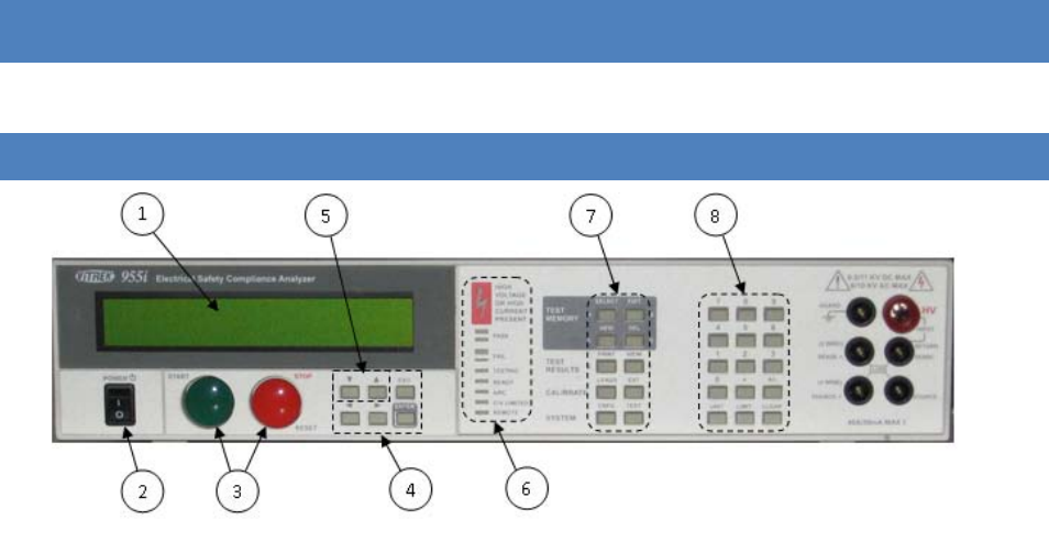
Figure 1 - Front Panel Layout
1. The display. This shows all menus during interactive data entries, all measurements during a test, and the
present date/time when not performing any other duties.
2. The POWER switch. This turns on/off the power to the 95x.
3. The START and STOP buttons.
a. The START button allows the user to start performing a previous selected test sequence, or
(while running a test sequence) select to continue a test step when it is waiting for the user to do
so.
b. The STOP button aborts any test sequence in progress (while running a test sequence), aborts
the menu activity in progress discarding any changes made (while performing a menu), or makes
no test sequence selected (otherwise).
4. The menu selection keys. During all menus, the selected element of the menu is highlighted by flashing
between the data and blocks. These keys allow the user to move the selection point within a menu.
a. The Left and Right Arrow keys are used to move the selection point within a menu.
b. The ENTER key is used to finish entry of a menu data and automatically move to the next menu
item.
c. The EXIT key (labeled EXIT/SAVE on later units) is used to save all changes made within a menu
and return to the previous menu (if any) or to the inactive display.
5. The edit keys. These allow the user to decrement or increment a selected menu items’ value. During
numeric entry these initiate “edit” mode of data entry, rather than “direct” mode of data entry (i.e. allow
the user to adjust the existing entry using the Up/Down Arrow keys, rather than overwriting the existing
value with a new value using the numeric keys). For convenience, these keys auto-repeat if the user
maintains pressure on them.
6. The indicators.
95x Series Operating Manual - December 12, 2011
Page 20 of 151
a. HIGH VOLTAGE OR HIGH CURRENT PRESENT. This is illuminated whenever the 95x has a high
voltage (>30V) or a high current (>5A) present on its’ terminals.
b. PASS. This is illuminated whenever a test sequence is passing (while running a test sequence) or
it has passed all test steps (following completion of the test sequence).
c. FAIL. This is illuminated whenever a test sequence is failing (while running a test sequence) or
the previously run test sequence has failed any test steps (following completion of the test
sequence).
d. TESTING. This is illuminated when the 95x is running a test sequence.
e. READY. This is illuminated after the user has selected a test sequence to run and the 95x is ready
to perform that test sequence.
f. ARC. This is illuminated whenever the 95x is detecting an arc current while running a test
sequence and the specific test step is enabled to detect arc current.
g. C/V LIMITED. This is illuminated when the 95x output is either current or voltage limited by the
load while running a test sequence. This is only used in certain types of test steps.
h. REMOTE. This is illuminated when the 95x is under the control of an interface (i.e. RS232,
Ethernet or GPIB). If the user wishes to return to front panel control of the 95x the CNFG key
should be pressed to achieve this.
7. The menu keys. These initiate a menu allowing the user to perform certain activities via the front panel of
the 95x. Many of these can be disabled by the user by requiring a password in order to utilize them.
a. SELECT. Initiates a menu allowing the user to select a test sequence which has already been
defined in the 95x. This never requires a password.
b. EDIT. Initiates a menu allowing the user to select an existing test sequence and then edit it.
After editing it is automatically made ready to run. This optionally requires a password.
c. NEW. Initiates a menu allowing the user to select a presently undefined test sequence number
and name, and then to create the sequence of tests to be performed. This optionally requires a
password. While editing or creating a test sequence, this key is also used to insert a new test
step into the test sequence.
d. DEL. Initiates a menu allowing the user to select an existing test sequence and delete it from the
95x. This optionally requires a password. While editing or creating a test sequence, this key is
also used to delete a test step from the test sequence.
e. PRINT. If option UL-2 or GUL-3 is fitted and a suitable printer is attached, this key causes a
printout to be generated. This never requires a password. The printout generated is dependent
on the menu (if any) which is active when the key is pressed –
i. If pressed while no menu is active, or the configuration menu is active, a configuration
printout is generated.
ii. If pressed while selecting an existing test sequence, a test sequence printout is
generated.
iii. If pressed while reviewing the results of a completed test sequence, a test results report
printout is generated. The 95x can also be configured to automatically produce this
printout if desired.
f. VIEW. Initiates a menu allowing the user to either –

95x Series Operating Manual - December 12, 2011
Page 21 of 151
i. If no test sequence is ready to run. View the pass and fail counts for any defined test
sequence, and optionally to clear them. This never requires a password except
(optionally) to clear the counts.
ii. If a test sequence has been run and is still selected. View the test results of each step
within the previously run test sequence. This is automatically performed after a test
sequence has been run. This never requires a password.
g. LEADS. Allows the user to run the presently selected test sequence in Lead Compensation mode.
This allows the 95x to store any load offsets for each step in the test sequence and to correct all
future tests using that test sequence for these load offsets. This optionally requires a password.
h. EXT. Allows the user to perform either an adjustment or verification calibration of the 95x
against external standards. This optionally requires a password (this is separate to the other
menu activity password).
i. CNFG. Initiates a menu allowing the user to configure the 95x. This uses a series of sub-menus.
This optionally requires a password.
j. TEST. Shows the present operational status of the 95x and allows the user to perform internal
operation verification (this optionally requires a password).
8. The data entry keys.
a. The numeric keys (0 through 9), decimal point and change sign keys. These are used during
numeric or character data entry. NOTE – during hexadecimal or character data entry, certain of
the menu keys can be used for entry of the A through F characters.
b. The UNIT key. This is used to change the units during numeric data entry, and is also used while
running a test, or while reviewing test results, to change the displayed test result measurement.
c. The LIMIT key. This is used during numeric data entry to set a value to the largest possible.
When setting test dwell times this sets that the dwell should be user terminated rather than
automatically terminated after the entered time. When setting a resistance type upper limit, this
allows the user to set that there is no upper limit.
d. CLEAR key. This is used to clear an entry during numeric or character data entry.
MENU OPERATION AND DATA ENTRY
Most user activities using the front panel controls are performed using menus. All menus use the same general
operating methods described in this section. The user should read this section before attempting to operate the
95x.
BASE MENU STATE
When the 95x is not performing a menu and is not performing a test sequence, the display shows the model # in
the uppermost display line and the date and time in the lower most display line, this is called the base menu state
in this document. Most menus require the 95x to be in the base menu state to be initiated, an example of the
base menu state display is -
ViTREK 951i
9-Feb-10 9:08:51am
If the 95x is not in this state and the user is unsure how to return to this state, then pressing the STOP button will
accomplish this (in some circumstances the STOP button may need to be pressed more than once).

95x Series Operating Manual - December 12, 2011
Page 22 of 151
NAVIGATING MENUS
• The present selection point in a menu is denoted by the displayed information flashing between the
information and solid blocks.
• The user can move the selection point in a menu by using the Left and/or Right Arrow keys.
o The Right Arrow key moves the selection point further down the menu. Moving the selection
point past the last selectable item in a menu selects the first selectable item in the menu (a
double beep sound is made when this occurs).
o The Left Arrow key moves the selection point further up the menu. Moving the selection point
before the first selectable item in a menu selects the last selectable item in the menu (a double
beep sound is made when this occurs).
• Although the 95x display is limited to two lines, most menus have more lines than this. The display is
automatically scrolled up and down the menu to display the menu line containing the present selection
point.
• Not all menus or menu lines may be available.
o Generally items which are not pertinent to the specific model or option content of the 95x are
not shown.
o All menus in the 95x utilize a “top down” priority. Selections or entries made may affect
subsequent entries in the menu. Entries may be limited in allowable values, or may not be
shown.
• If a menu line is an entry into a sub-menu, then the left side of the line shows descriptive text followed by
an ellipsis character (…). The descriptive text is selectable. If the user presses the ENTER key while a sub-
menu entry line is selected then the sub-menu is opened.
o When a sub-menu is terminated by pressing the EXIT key then the user is returned to the
preceding level of menu.
o If any level of sub-menu is terminated using the STOP button then all levels of menus are aborted
and any changes made at any level are discarded.
o Only when the base level menu is terminated by pressing the EXIT key are any changes made
actually saved.
• If a menu line is for informative purposes only, then the left side of the line shows descriptive text
followed by a colon character with the informative data at the right end of the line. The descriptive text is
selectable.
• If a menu line allows the user to edit its’ contents, then the left side of the line shows descriptive text
followed by a colon character with the editable data at the right end of the line. The editable data is
selectable; some menu lines may contain more than one editable data.
MODIFYING MENU ENTRIES
• In many places the available contents of entries in different menu lines are inter-related. The 95x uses a
“top down” menu approach; the topmost contents in a menu may limit the available entries in the menu
below them, but not vice versa. Generally the user cannot set a limit or an output which the specific
model and option content of the 95x is not capable of achieving.
95x Series Operating Manual - December 12, 2011
Page 23 of 151
• Changing Numeric Data. After making the numeric data the selection point in the menu, the user can
overwrite the data by using the data entry keys. While overwriting, the selection point becomes a single
character position within the numeric data.
o A numeric key places the corresponding character and moves the selection point to the right one
position.
o Certain numeric data allow the user to change the units of the data (e.g. between current and
resistance) and/or change the multiplier for the data (e.g. select an entry in microamps or
milliamps). To change the units, press the UNIT key while the entire numeric data is selected; to
change the multiplier, press the UNIT key while entering the numeric data.
o The Left Arrow key acts as a delete key, deleting the previously entered character.
o The CLR key removes all of the existing entry and places the selection point in the rightmost
character position.
o The LIMIT key sets the numeric data to the highest possible value in most cases; while entering
the lower limit in a range pair of data the LIMIT key sets the minimum value; in some other cases
the LIMIT key has a special use denoted in the description for that specific data.
o The Right Arrow or ENTER key terminates the numerical data entry and also moves the selection
point to the right or downwards, as applicable.
• Changing Multiple Choice Data. After making the multiple choice data the selection point in the menu,
the user can change the selection by repeatedly pressing the Up Arrow or Down Arrow keys until the
desired selection is displayed. The ENTER key terminates the multiple choice data entry and also moves
the selection point to the right or downwards, as applicable. The Left Arrow and Right Arrow keys
automatically terminate the multiple choice data entry prior to moving the selection point accordingly.
• Changing Character Data. After making the character data the selection point in the menu, the user can
choose to either edit the existing data, or to overwrite it with new data. While overwriting or editing the
data the selection point becomes a single character position within the character data.
o Editing Existing Character Data. If the user presses the Up Arrow or Down Arrow key while the
entire character data is selected then the edit mode of entry is initiated and the leftmost
character of the existing data is selected. Character data uses a limited character set; A through
Z, a through z, 0 through 9, the space character and most punctuation characters.
The Up Arrow and Down Arrow keys change the selected character to the next or
previous available character in the character set.
The numeric keys and the A through F keys overwrite the selected character.
The Left Arrow and Right Arrow keys move the selection point within the character data
area.
The CLR key aborts the edit, the character data is cleared, and the overwrite mode is
initiated.
The ENTER key exits the edit mode retaining the changes made.
o Overwriting Character Data. If the user presses any of the numeric keys or the CLR key then the
overwrite mode of entry is initiated, starting with the corresponding character and with the
leftmost character.

95x Series Operating Manual - December 12, 2011
Page 24 of 151
The Up Arrow and Down Arrow keys change the selected character to the next or
previous available character in the character set.
The numeric keys and the A through F keys places the corresponding character and
moves the selection point to the right one position.
The Left Arrow key acts as a delete key, deleting the previous character and moving the
selection point to the left one position.
The Right Arrow key places a space character and moves the selection point to the right
one position.
The CLR key removes all of the existing entry and places the selection point in the
leftmost character position.
The ENTER key terminates the character data entry retaining the changes made and also
moves the selection point in the menu to the right or downwards, as applicable.
• Changing Hexadecimal Data. Hexadecimal data is treated exactly the same as character data (see above)
but with the available character set restricted to 0 through 9 and A through F.
ADJUSTING THE DISPLAY CONTRAST
The user can adjust the display contrast while the 95x is in the base menu state (i.e. the display shows the model
number and the time/date). An example display when the user can adjust the display contrast is –
ViTREK 951i
9-Feb-10 9:08:51am
Using the Up and Down Arrows keys, select the display contrast which best suits the users normal viewing position.
NOTE – it may be possible to adjust the display contrast such that the display is not visible. If the display appears
to be totally blank then press and hold the Down Arrow key to return it to the visible state; if the display appears
to have all of its dots “black” then press and hold the Up Arrow key to return it to the visible state.
NOTE – it may be best to select the contrast which shows the least “blurring” when the seconds digit in the
displayed time changes. This has been found to produce the best adjustment for viewing angle as well as contrast.
LOCKING AND UNLOCKING MENUS
Many menus in the 95x can be locked by a user, preventing unauthorized changes to test sequences and
configuration settings via the front panel of the 95x. When initially delivered from the factory, this capability is
disabled.
The password is any combination of six 0 through 9 and A through F characters. The password 000000 indicates a
cleared password, disabling this capability until a non-zero password is subsequently set by the user.
If a menu lock password has been set, the 95x always powers up with the menus locked.
UNLOCKING MENUS
If the menu lock password has been set, a user must enter this password to unlock a menu. The user is prompted
to enter the password when needed; which is accomplished by using the 0 through 9 and A through F keys as
needed to match the previously set password, followed by the ENTER key. After successfully entering the
password the front panel menus remains unlocked until the menus are relocked by the user or the 95x is power
cycled. Note that the 95x display does not show the characters during unlock password entry for security reasons.

95x Series Operating Manual - December 12, 2011
Page 25 of 151
SETTING, CHANGING OR CLEARING A MENU LOCK PASSWORD
• Ensure that the display indicates that the 95x is in the base menu state, i.e. the display shows the date
and time. If necessary press the STOP button to abort a menu and return to the base menu state.
• Press the CNFG key. If a password has been already set and the menus are not already unlocked, the user
must enter the correct password to unlock the menu at this point.
• The display now shows the main configuration menu. An example of which is as follows –
TEST…
PRINTOUT…
SYSTEM…
INTERFACES…
DIGITAL I/O…
BUILD…
SET TO DEFAULTS…
LOCK PASSWORD:000000
RELOCK…
• Using the Left Arrow or Right Arrow keys as needed, change the selection point to the LOCK PASSWORD
line.
• Using the 0 through 9 keys and/or the A through F keys, enter a six character password. If the password
000000 is set then this clears the password and disables menu locking.
• Press the ENTER key.
• If a non-zero password was entered, the display now shows a message indicating that the front panel is
now locked and returns to the base menu state. Otherwise, a message is displayed indicating that the
menu lock is now disabled and the 95x stays in the main configuration menu.
RELOCKING MENUS
If the menu lock password has been set but the menus are presently unlocked (i.e. they have been previously
unlocked as described above) then the user may relock the menus as follows –
• Ensure that the display indicates that the 95x is in the base menu state, i.e. the display shows the date
and time. If necessary press the STOP button to abort a menu and return to the base menu state.
• Press the CNFG key.
• The display now shows the main configuration menu. An example of which is as follows –
TEST…
PRINTOUT…
SYSTEM…
INTERFACES…
DIGITAL I/O…
BUILD…
SET TO DEFAULTS…
LOCK PASSWORD:000000
RELOCK…
• Using the Left Arrow or Right Arrow keys as needed, change the selection point to the RELOCK line.
• Press the ENTER key.
• The display now shows a message indicating that the front panel is now locked and returns to the base
menu state.

95x Series Operating Manual - December 12, 2011
Page 26 of 151
UNKNOWN MENU LOCK PASSWORD
If the 95x menus have been locked but the password is unknown, the user should contact Vitrek for assistance.
The 95x has an internal set of “one time use” passwords for this circumstance.
DISPLAYING BUILD INFORMATION
• Ensure that the display indicates that the 95x is in the base menu state, i.e. the display shows the date
and time. If necessary press the STOP button to abort a menu and return to the base menu state.
• Press the CNFG key.
• The display now shows the main configuration menu, an example of which is –
TEST…
PRINTOUT…
SYSTEM…
INTERFACES…
DIGITAL I/O…
BUILD…
SET TO DEFAULTS…
LOCK PASSWORD:000000
RELOCK…
• Using the Left Arrow or Right Arrow keys as needed, change the selection point to the BUILD line.
• Press the ENTER key.
• The 95x now displays the build configuration menu, an example of which is –
SERIAL# 123456
FIRMWARE: v1.12
FP: v1.10
MEAS: v1.10
DRIVE: v1.10
BASE UNIT: 951i
DC OPTION: NONE
AC2 OPTION: NO
AC30 OPTION: NO
500VA OPTION: NO
PMT1 OPTION: YES
MAX DC: 6.5KV
MAX AC: 6.0KV
INTERFACE: GUL-3
UPGRADE:000000000000
• The user may navigate this menu but may not make changes to it. The information available is as follows-
o SERIAL#. This shows the serial number of this 95x.
o FIRMWARE. This shows the main firmware revision number installed in this 95x. This can be
upgraded (along with the MEAS and DRIVE firmware) by the user via the RS232, Ethernet or GPIB
interface. Contact Vitrek or your local representative for details regarding this.
o FP. This shows the front panel firmware revision number.
o MEAS. This shows the Measurement DSP firmware revision number installed in this 95x.
o DRIVE. This shows the Output Drive DSP firmware revision number installed in this 95x.
o BASE UNIT. This shows the base model number of this 95x.

95x Series Operating Manual - December 12, 2011
Page 27 of 151
o DC OPTION. This shows if option NODC or DCNEG is installed in this 95x.
o AC2 OPTION. This shows if option AC-2 is installed in this 95x.
o AC30 OPTION. This shows if option AC-30 is installed in this 95x.
o 500VA OPTION. This shows if option 500VA is installed in this 95x.
o PMT1 OPTION. This shows if option PMT-1 is installed in this 95x.
o INTERFACE. This shows if option UL-2 or GUL-3 is installed in this 95x.
o MAX DC. This shows the factory limit on the maximum DC Voltage generated by this unit.
o MAX AC. This shows the factory limit on the maximum AC Voltage generated by this unit.
o MAX GB. This shows the factory limit on the maximum Ground Bond current generated by this
unit.
o UPGRADE. This allows the user to enter a factory supplied code to upgrade their instrument to
enable additional options which were not enabled as originally purchased.
• When finished reviewing the build information, press the EXIT key to return to the main configuration
menu, and then press EXIT again (if no additional configuring is to be performed) to exit the main
configuration menu.
SYSTEM CONFIGURATION SETTINGS
There are several system configuration settings available which affect the overall operation. These can be viewed
or set as follows –
• Ensure that the display indicates that the 95x is in the base menu state, i.e. the display shows the date
and time. If necessary press the STOP button to abort a menu and return to the base menu state.
• Press the CNFG key.
• The display now shows the main configuration menu, an example of which is –
TEST…
PRINTOUT…
SYSTEM…
INTERFACES…
DIGITAL I/O…
BUILD…
SET TO DEFAULTS…
LOCK PASSWORD:000000
RELOCK…
• Using the Left Arrow or Right Arrow keys as needed, change the selection point to the SYSTEM line.
• Press the ENTER key.
• The 95x now displays the system configuration settings menu, an example of which is –
KEY BEEPS: SOFT
LINE FREQ: 60Hz
TIME FORMAT: 12hr
SET TIME: 9:18:06am
SET DATE: 9-Feb-10
• The user may navigate this sub-menu and change the displayed settings as required.

95x Series Operating Manual - December 12, 2011
Page 28 of 151
o KEY BEEPS. This allows the user to set the volume of the beep sounds made by the 95x
whenever a key is pressed.
o LINE FREQ. This allows the user to select whether the 95x is being powered from 50/400Hz line
or 60Hz line frequency. This is used by the 95x to optimize measurements of very low level DC
currents.
o TIME FORMAT. This allows the user to select whether the 95x displays time in 12hour or 24hour
format.
o SET TIME. This allows the user to adjust the presently displayed time. The hour, minute and
second are separately adjusted using the Up and Down Arrow keys.
o SET DATE. This allows the user to adjust the presently displayed date. The day, month and year
are separately adjusted using the Up and Down Arrow keys.
• When finished, press the EXIT key to exit this sub-menu, and then press EXIT again (if no additional
configuring is to be performed) to exit the main configuration menu and save the settings.
RETURNING ALL CONFIGURATION SETTINGS TO FACTORY DEFAULTS
The user may return all configuration settings to the factory default settings as follows –
• Ensure that the display indicates that the 95x is in the base menu state, i.e. the display shows the date
and time. If necessary press the STOP button to abort a menu and return to the base menu state.
• Press the CNFG key.
• The display now shows the main configuration menu, an example of which is –
TEST…
PRINTOUT…
SYSTEM…
INTERFACES…
DIGITAL I/O…
BUILD…
SET TO DEFAULTS…
LOCK PASSWORD:000000
RELOCK…
• Using the Left Arrow or Right Arrow keys as needed, change the selection point to the SET TO DEFAULTS
line.
• Press the ENTER key.
• The 95x now displays a message temporarily and remains in the main configuration menu, allowing the
user to override the factory settings as needed. If no further changes are needed, press the EXIT key to
save the changes and return to the base menu state.

95x Series Operating Manual - December 12, 2011
Page 29 of 151
SECTION 5 – TEST SEQUENCES
All usage of the 95x for testing a DUT (Device under Test) uses test sequences. Although this section is primarily
written for the front panel user, when programming the 95x via an interface the user should be conversant with
the contents of this section.
A test sequence is a series of test steps which form a series of tests to perform on a DUT. Each step in a sequence
can be configured to be one of several types of activity, including types for timing, waiting for user interaction and
controlling external switch units as well as types for performing a test on the DUT.
There are two types of test sequences which may be defined at the front panel –
• MANUAL test sequence (sequence #0).
o This always contains a single test step which may only be a step type which performs a test on
the DUT.
o During testing the user is allowed to change the applied voltage, current and/or frequency as
applicable for the specific step type being performed.
o This test sequence cannot be deleted, it can only be overwritten.
• Standard test sequences (sequence #1 through 99 inclusive).
o These may optionally have a name associated with each test sequence, and each may contain up
to 254 steps.
o All step types are available for use in this type of test sequence.
o While testing using these the user may not alter the voltages, currents or frequencies being
applied by the 95x.
o Certain step types are able to be “chained”, the DUT does not need to be discharged between
steps. This allows faster and smoother operation when testing certain types of DUT.
Test sequences defined at the front panel are automatically stored in internal non-volatile memory of the 95x. The
user does not need to take any action to ensure that a front panel defined test sequence is saved. Note that the
95x is limited to having 1000 test steps defined in total.
TEST SEQUENCE CONFIGURATION
There are settings in the 95x which apply to all test sequences. To view or change these settings perform the
following actions –
• Ensure that the display indicates that the 95x is in the base menu state, i.e. the display shows the date
and time. If necessary press the STOP button to abort a menu and return to the base menu state.
• Press the CNFG key.
• The display now shows the main configuration menu, an example of which is –
TEST…
PRINTOUT…
SYSTEM…
INTERFACES…
DIGITAL I/O…
BUILD…
SET TO DEFAULTS…
95x Series Operating Manual - December 12, 2011
Page 30 of 151
LOCK PASSWORD:000000
RELOCK…
• Using the Left Arrow or Right Arrow keys as needed, change the selection point to the TEST line.
• Press the ENTER key.
• The display now shows the test configuration menu. An example of the test configuration menu is as
follows –
START BEEP: MED
PASS BEEP: MED
FAIL BEEPS: LOUD
ARC: FAIL ON DETECT
CONTINUITY SENSE:OFF
FAST RERUN: ENABLED
USER MAX DCV: 10.0KV
USER MAX ACV: 10.0KV
HI SAFETY: ENABLED
• The user may navigate this sub-menu and change the displayed settings as required.
o START BEEP. This allows the user to set the volume of the beep sound emitted by the 95x when
a test sequence is started.
o PASS BEEP. This allows the user to set the volume of the beep sound emitted by the 95x when a
test sequence is completed with a PASS status.
o FAIL BEEP. This allows the user to set the volume of the beep sounds emitted by the 95x when a
test sequence is completed with a FAIL status.
o ARC. This allows the user to select whether all test steps configured for arc detection will either
fail the test if an arc is detected (FAIL ON DETECT) or not (DETECT ONLY). Note that arc detection
is enabled or disabled by a separate user setting in each individual test step.
o CONTINUITY SENSE. This allows the user to turn on/off the Continuity Sense feature in certain
types of test steps (see the specific test step type sections of this manual for details).
o FAST RERUN. This allows the 95x to always allow the user to rerun a test sequence without
having to terminate reviewing the results (ENABLED), or only allow it if all tests passed (IF PASS),
or never allow it (DISABLED). If fast rerun is not enabled, the user must terminate reviewing
results by using the STOP button before they can rerun the test sequence with the START button.
o USER MAX DCV. This allows the user to set a maximum DC Voltage which the 95x will produce.
This limits all test steps subsequently defined and will not allow any existing test sequence
containing a test step level outside of this limit to run.
o USER MAX ACV. This allows the user to set a maximum AC Voltage which the 95x will produce.
This limits all test steps subsequently defined and will not allow any existing test sequence
containing a test step level outside of this limit to run.
o HI SAFETY. This turns on/off the ability of the 95x to detect excessive HV terminal current in high
voltage test step types (see the specific test type sections of this manual for details).
• When finished, press the EXIT key to exit this sub-menu, and then press EXIT again (if no additional
configuring is to be performed) to exit the main configuration menu and save the settings.

95x Series Operating Manual - December 12, 2011
Page 31 of 151
CREATING A NEW TEST SEQUENCE
• Ensure that the display indicates that the 95x is in the base menu state, i.e. the display shows the date
and time. If necessary press the STOP button to abort a menu and return to the base menu state.
• Press the NEW key.
• The display now shows the lowest presently empty test sequence number and a blank name field. An
example is -
NEW TEST SEQUENCE
# 2
• Either change the test sequence number (using the numeric keys or the Up Arrow and Down Arrow keys)
or press the ENTER key. The display now selects the name field. The user can enter a name by pressing
the Up Arrow key followed using the Up, Down, Left and Right Arrow keys to change/select each
character, and the user may use the numeric keys to directly enter numeric characters.
• Press the ENTER key. The display now shows the first test step (step #1) with no test type selected (NEW
is displayed). An example is -
Seq 2 Step 1 NEW
• Using the Up or Down Arrow keys, select the desired first test step type.
• Using the information for the selected test step type shown later in this document, program the
requirements for this test step.
• If no more test steps are required, press the EXIT key. The 95x stores the test sequence and makes it
ready to be run.
• If further steps are required, then press the Up arrow key once when the previously entered step # is
selected, the next step # will be displayed with a NEW test type. Repeat as required for each test step.
Note - if the user accidently creates a NEW step after the end of the test sequence, press the DEL key to
delete it while it is being displayed.
EDITING AN EXISTING TEST SEQUENCE
Note – editing a test sequence, even if no changes are made to the test sequence, will cause any Lead
Compensation data for that sequence to be cleared. A “c” character is displayed after the test sequence# if the
test sequence contains previously obtained Lead Compensation data.
• Ensure that the display indicates that the 95x is in the base menu state, i.e. the display shows the date
and time. If necessary press the STOP button to abort a menu and return to the base menu state. A test
sequence may also be edited while the user is reviewing the results of a previously run test sequence.
• Press the EDIT key.
• The display now shows the last used test sequence number and the name associated with that test
sequence. An example is -
EDIT TEST SEQUENCE
# 2 95x LINE HYPOT
• If needed, change the test sequence number to select the desired test sequence by using the Up Arrow or
Down Arrow keys (or using the numeric keys), and then press the ENTER key. The display now selects the
name field. The user can enter a name or alter the existing name by pressing the Up Arrow key followed

95x Series Operating Manual - December 12, 2011
Page 32 of 151
using the Up, Down, Left and Right keys to change/select each character, and the user may use the
numeric keys to directly enter numeric characters.
• Press the ENTER key. The display now shows the first test step (step #1) of the existing test sequence. An
example is -
Seq 2 Step 1 ACW
LEVEL:1500.0V 60.0Hz
• To select a different test step # in the existing test sequence, as needed navigate the menu using the Left
and Right Arrow keys to select the test step #, then press the Up or Down Arrow key until the desired test
step # is shown.
• The user may edit the selected test step by navigating the menu and altering settings as needed. See
SECTION 6 – TEST STEPS.
• The user may add a test step to the end of the test sequence by pressing the Up Arrow key while the test
step # is selected until a NEW test step type is shown. Note - if the user accidently creates a NEW test
step after the end of the sequence, press the DEL key to delete it while it is being displayed.
• The user may delete an existing test step by pressing the DEL key while the undesired test step is selected.
All higher numbered test steps are automatically renumbered. The user cannot delete the only test step
in a test sequence.
• The user may insert a new test step by pressing the NEW key. A new test step is inserted before the
presently selected test step, and all higher numbered test steps are automatically renumbered. The user
cannot insert an additional test step into a test sequence which already has all 254 test steps defined.
• When no more changes are required, press the EXIT key. The 95x stores the test sequence and makes it
ready to be run.
DELETING AN EXISTING TEST SEQUENCE
CAUTION – this operation cannot be undone, ensure that the correct test sequence # is selected before pressing
the ENTER key.
• Ensure that the display indicates that the 95x is in the base menu state, i.e. the display shows the date
and time. If necessary press the STOP button to abort a menu and return to the base menu state.
• Press the DEL key.
• The display shows the last used test sequence number and the name associated with that test sequence.
An example is -
DELETE TEST SEQUENCE
# 2 95x LINE HYPOT
• As needed change the test sequence number to select the desired test sequence by using the Up Arrow or
Down Arrow keys (or using the numeric keys), then press the ENTER key. The selected test sequence is
now deleted from the 95x internal non-volatile memory.
SELECTING AND RUNNING AN EXISTING TEST SEQUENCE
• Ensure that the display indicates that the 95x is in the base menu state, i.e. the display shows the date
and time. If necessary press the STOP button to abort a menu and return to the base menu state.
• Press the SELECT key.
95x Series Operating Manual - December 12, 2011
Page 33 of 151
• The display shows the last used test sequence number and the name associated with that test sequence.
An example is -
SELECT TEST SEQUENCE
# 2 95x LINE HYPOT
• As needed change the test sequence number to select the desired test sequence by using the Up Arrow or
Down Arrow keys (or using the numeric keys), then press the ENTER key. The selected test sequence is
now made ready to be run.
NOTE - Whenever a test sequence has been selected and is ready to be run, the front panel READY indicator is
illuminated. If the READY indicator is not illuminated then either no test sequence has been selected or it is not
ready to run at that time (e.g. it is already running, or the user is viewing the results of a previous run and FAST
RERUN has been disabled). Initiating any menu activity on the front panel always makes no test sequence ready to
be run.
After an existing test sequence has been selected (either by using the SELECT or EDIT menus) the test may be run
by –
• Press the START button. The READY indicator is extinguished and the TESTING indicator is illuminated
while the selected test sequence is run.
• While the test sequence is running the PASS and FAIL indicators show the present pass/fail status after
the first test step is sufficiently completed, and throughout the test sequence the display shows the
progress. An example is -
1.01d 1500V 60.0Hz
22s PASS 5.5nArms
o The selected test sequence number and the present step # are shown in the upper left display.
Following this, the r character is shown during the ramp period or d during the dwell period of
the test step being performed. During the discharge period an informative message is displayed
in the lower line of the display.
o For most types of test step, the present output level and frequency are shown in the remainder
of the upper display line. If the MANUAL test sequence is being run (the upper left shows MAN)
then either the level or the frequency can be selected and edited using the arrow keys (start by
pressing the Up Arrow key while selected) or may be directly overwritten (enter a new value
using the numeric keys while it is selected).
o The time since the start of the present test step and test step period is shown in the lower left
display. If this is flashing between the value and blocks then the unit is waiting for the user to
press the START button to continue (e.g. if the dwell period has been programmed for user
termination), otherwise the period will automatically end when it reaches the programmed time
period.
o For most types of test step, the remainder of the lower display shows a measurement result.
During the test dwell period the displayed measurements are automatically filtered with a rolling
time constant. Initially the selected measurement is the first checked measurement, but may be
changed during the step by pressing the UNIT key which toggles between all measurement
results available for that test type. See Displayed Measurement Results.
• While the test sequence is running it may be aborted by pressing the STOP button.
• When the test sequence has been completed, the TESTING indicator extinguishes, the PASS or FAIL
indicator is illuminated, and the overall pass or failure status is temporarily displayed for approx. 2

95x Series Operating Manual - December 12, 2011
Page 34 of 151
seconds and then the measured results are reviewed, see the following section for details regarding
reviewing results. An example temporary display is -
SEQUENCE 1 PASSED
ALL TESTS
• Use the EXIT key or STOP key to return to the date/time display, or use the START button (if FAST RERUN
is enabled) to start another run of the same test sequence. The READY indicator is illuminated when the
test sequence is ready to be run again.
REVIEWING TEST RESULTS AFTER RUNNING A TEST SEQUENCE
Immediately after running a test sequence and temporarily displaying an overall pass/fail status message the 95x
automatically initiates reviewing the detailed test results. The results of a previously run test sequence can also be
manually reviewed later by pressing the VIEW key if the READY indicator is illuminated, indicating that the test
sequence is still ready to be run.
If the test sequence failed, then the review is initiated at the first failed step, otherwise it is initiated at the first
test step in the test sequence.
The following table shows example displays of reviewed results and their meanings. See the descriptions following
the table for a description of each of the fields in the display.
Table 2 - Reviewed Results Display Formats
01.01d 1500V 60.0Hz
5.0s PASS 2.10mArms The measurement being reviewed was within limits.
01.01d 1500V 60.0Hz
5.0s DET 28mAarc Arcing was detected during the test but the 95x was not configured to fail on arc
detection.
01.01d 1500V 60.0Hz
5.0s FAIL 28mAarc Arcing was detected during the test which caused the step to fail.
01.01d 1500V 60.0Hz
1.5s >MAX 2.10mArms The measurement being reviewed was above the maximum limit.
01.01d 1500V 60.0Hz
1.5s <MIN 12.3uArms The measurement being reviewed was below the minimum limit.
01.01d 1500V 60.0Hz
1.5s BRKDN 11.3mApk The breakdown current limit was exceeded.
01.01d 1012V
TIMEOUT A DCCAP or IRCAP type step failed to perform the ramp period within the
programmed ramp timeout.
01.01d 0.000A 60Hz
WIRING FAULT A wiring fault was detected during a GB, GBez or LowΩ type step.
01.01d 1500V 60.0Hz
1.5s ABORTED The user aborted the test sequence
01.01d 1500V 60.0Hz
1.5s CONTINUITY The Continuity Sense safety feature was tripped, aborting the test sequence
01.01d 1500V 60.0Hz
HV TRIP EXCEEDED The HV Trip safety feature was tripped, aborting the test sequence
01.01d 1500V 60.0Hz
INTERLOCK OPENED The INTERLOCK DIO interface signal became unasserted, aborting the test
sequence

95x Series Operating Manual - December 12, 2011
Page 35 of 151
01.01d 1500V 60.0Hz
CONTROL FAULT
The load was too unstable preventing the 95x from providing a stable test
voltage or current, or the actual test voltage or current was considerably
different from that expected, or the line voltage was too low to achieve the
programmed test voltage and load current.
01.01d SWITCH
SWITCH FAILED The 95x could not communicate with an external switch matrix unit during
execution of a SWITCH type step, aborting the test sequence
01.01d HOLD
TIMEOUT The user failed to continue the sequence within the programmed timeout period
while executing a HOLD type step, aborting the test sequence
01.01d 1500V 60.0Hz
INT FAULT
An internal fault was detected, aborting the test sequence.
The 95x may need to be power cycled to recover from this, which is often caused
by extreme interference but may be caused by an unrecoverable failure in an
internal circuit of the 95x
01.01d 1500V 60.0Hz
OVERHEATED
The 95x overheated, aborting the test sequence.
This can occur because the load current was too high for too long, or the airflow
around the 95x was restricted, or the ambient temperature is too high around
the 95x.
The user should wait at least 15 seconds to allow it to cool down properly before
either re-attempting the test or removing power from the 95x.
• The test sequence # and presently shown step # are shown in the upper left corner of the display.
Following the step #, for test step types which have a ramp and a dwell period, a single character is shown
which is either r indicating that the failure occurred during the ramp period of the step, or d indicating
that either the failure occurred in the dwell period or the test completed normally. The user can change
the step number being reviewed by selecting the step # in the display using the Left Arrow or Right Arrow
keys as needed, then using the Up Arrow or Down Arrow keys to step forwards or backwards through the
test steps in the test sequence. Note that test steps which do not have any measurements, i.e. switch
unit control steps or timing test steps, are not reviewable and are skipped unless they contain a failure.
Only test steps which have been performed can be reviewed, as an example if the test sequence was
aborted during the 2nd test step, then only the 1st and 2nd test steps are reviewable as no others were
performed.
• The remainder of the upper portion of the display shows the instantaneous applied voltage (or current)
and frequency (if applicable) at the moment of the failure (if FAIL) or at the end of the dwell period (if
PASS).
• The elapsed time in the period at the completion of the test step is shown in the lower left corner of the
display.
• The selected measurement result and the pass or fail result for that measurement is shown in the
remainder of the lower portion of the display. If the step contained a failure, other than a simple checked
measurement limit failure, then a failure message is displayed instead.
• The displayed measurement result can be changed by pressing the UNIT key. This sequentially selects
between all available results for the selected test step. When reviewing results, only those which have
limits defined are available for review. See the Displayed Measurement Results section for more details
on available results.
• By default the final measurement result is shown in the lower portion of the display. This can be changed
to the minimum (MIN), maximum (MAX) or average (AVG) value by selecting the elapsed time in the

95x Series Operating Manual - December 12, 2011
Page 36 of 151
display using the Left Arrow or Right Arrow keys as needed, then using the Up Arrow or Down Arrow keys
to change the selection.
DISPLAYED MEASUREMENT RESULTS
While running a test sequence or while reviewing the results of a test sequence the 95x allows the user to view
measurement results. Generally several different measurement results are available; the user may change
between available results by pressing the UNIT key.
So that the user can distinguish between results, the 95x displays each with different units characters following the
result as follows –
Applied test voltage (V)
Applied test frequency (Hz)
DC current (Adc)
DC resistance (Ωdc)
RMS current (Arms)
RMS Voltage (Vrms)
RMS impedance (Ωrms)
In-Phase current (Ainp)
In-Phase Voltage (Vinp)
In-Phase Resistance (Ωinp)
Quadrature current (Aqua)
Quadrature Voltage (Vqua)
Quadrature impedance (Ωqua)
Capacitance (F)
Dissipation Factor (DF)
Peak or breakdown current (Apk)
Arc current (Aarc)
• Many results are capable of having a negative polarity; a negative result is preceded by the – character. A
positive result has no preceding polarity character.
• The 95x automatically formats the displayed result to give the best meaningful resolution using a
multiplier character as needed (e.g. T, G, M, K, m, u, n or p). Displayed results may have slightly limited
resolution; full resolution is available via an interface.
• Impedance and resistance results are calculated from voltage and current measurements. For near zero
current measurements, the 95x will display the maximum meaningful resistance value preceded by the >
character. For all DC resistance results a negative current will similarly result in the maximum meaningful
resistance indication.
• A measurement may be overloaded, i.e. beyond the measurable range. In those cases the result is
displayed with a > character preceding the maximum measurable value.
PRINTING A TEST RESULTS REPORT
If the 95x has either Opt. UL-2 or GUL-3 installed, and a suitable printer is connected to the USB port of the 95x,
the user can configure the 95x to automatically print a test results report when a test sequence is completed,
and/or the user can manually command the 95x to create a test results report. See Printing from the 95x using the

95x Series Operating Manual - December 12, 2011
Page 37 of 151
USB Interface for details regarding connecting and configuring a printer and the display messages while performing
a printout.
CONFIGURING THE TEST RESULTS REPORT
Before a test report can be printed, its’ format should be configured by the user. This is achieved by using the
PRINTOUT sub-menu of the CNFG menu as follows –
• Ensure that the display indicates that the 95x is in the base menu state, i.e. the display shows the date
and time. If necessary press the STOP button to abort a menu and return to the base menu state.
• Press the CNFG key.
• The display now shows the main configuration menu, an example of which is –
TEST…
PRINTOUT…
SYSTEM…
INTERFACES…
DIGITAL I/O…
BUILD…
SET TO DEFAULTS…
LOCK PASSWORD:000000
RELOCK…
• Using the Left Arrow or Right Arrow keys as needed, change the selection point to the PRINTOUT line.
• Press the ENTER key.
• The display now shows the test report printout configuration menu. An example of the test report
printout configuration menu is as follows –
STATUS: ATTACHED
HEADING:
AUTO TEST REPORT: NO
TEST DETAIL: NORMAL
SERIAL #: NO
• The user may navigate this sub-menu and change the displayed settings as required.
o STATUS. This shows the present status of the printer interface. The information shown is not
editable and will automatically update should a change occur.
NOT FITTED. Indicates that option UL-2 or GUL-3 is not fitted, so there is no printout
capability.
DISABLED. Indicates that the user has disabled the ability to perform printouts by
setting the DISABLE USB setting in the CNFG – INTERFACES menu to YES.
NOT FOUND. Indicates that no valid printer has been detected as being connected to
the 95x USB port.
ATTACHED. Indicates that a valid printer is attached to the 95x USB port and can be
used for printouts.
o HEADING. This allows the user to enter a global 2nd heading for all printouts. This can be up to 12
characters long, and can be any alpha-numeric characters. If this is blank then the 2nd heading is
omitted from all printouts. Typically this is used to allow the user to print their company name or
department name on all printouts.

95x Series Operating Manual - December 12, 2011
Page 38 of 151
o AUTO TEST REPORT. This allows the user to set whether the 95x will automatically print a test
report when a test sequence terminates (YES) or not (NO). The user can also command a printout
by pressing the PRINT button while reviewing test results independently of this setting.
o TEST DETAIL. This sets the amount of detail to be included in the printed test report.
BRIEF. The pass/fail status, reason for failure (if any), and the level and frequency are
printed for each test step having a result.
NORMAL. The pass/fail status, reason for failure (if any), the level and frequency, the
test limits and the maximum, minimum, average and last measurements are printed for
each test step having a result.
FULL. The pass/fail status, reason for failure (if any), the level and frequency, the full
test step settings and the maximum, minimum, average and last measurements are
printed for every test step.
o SERIAL #. If set to YES the 95x will prompt the user for entry of a serial # when a test report is to
be printed (either manually or automatically). The serial number can be any alpha-numeric
characters; up to 12 characters can be included. This is included in the test report. If NO is
selected then the user will not be prompted for the serial # and it will not be included in the
printed test report.
• When finished, press the EXIT key to exit this sub-menu, and then press EXIT again (if no additional
configuring is to be performed) to exit the main configuration menu and save the settings.
MANUALLY COMMANDING A TEST RESULTS REPORT
When reviewing the results of a completed test sequence, the user can manually command a test results report by
pressing the PRINT key.
COMPENSATING FOR EXTERNAL LEAD LEAKAGE AND IMPEDANCE
Most test sequences can be run in a special mode which saves the measurement results for each test step and will
apply these saved measurements as offsets when the test sequence is subsequently run in a normal fashion in
order to provide lead error compensation. The details regarding the corrections available and the expected wiring
for each test step within the sequence are contained in the respective sections of this manual for each type of test
step.
NOTE – certain test step types are not suitable for lead compensation, see the respective sections of this manual
for each type of test step for details.
To perform a lead compensation on a test sequence perform the following –
• Ensure that the display indicates that the 95x is in the base menu state, i.e. the display shows the date
and time. If necessary press the STOP button to abort a menu and return to the base menu state.
• Press the SELECT key.
• The display shows the last used test sequence number and the name associated with that test sequence.
An example is -
SELECT TEST SEQUENCE
# 2 95x LINE HYPOT
95x Series Operating Manual - December 12, 2011
Page 39 of 151
• As needed change the test sequence number to select the desired test sequence by using the Up Arrow or
Down Arrow keys (or using the numeric keys), and then press the ENTER key. The selected test sequence
is now made ready to be run.
• Press the LEADS key. The display now shows the test sequence is ready to be run in lead compensation
mode, and the READY indicator flashes.
• Ensure that the wiring is suitable for lead compensation. See the respective sections of this manual for
each type of test step in the selected test sequence for details.
• Press the START switch on the front panel. While the sequence is running the TESTING indicator flashes
and the selected test sequence is performed in the lead compensation mode.
o Any pre-existing lead compensation data is discarded prior to the test sequence being run.
o Each test step is performed in the normal manner, only the measurement results are used
differently. See the respective sections of this manual for each type of test step in the test
sequence for details.
o Normal measurement limits are not enforced. Any programmed breakdown or arc detections
are performed and if detected aborts the test sequence with a failure.
• After the test sequence has been run in this manner –
o The display temporarily shows a message indicating that the lead compensation for this
sequence is ready to be used.
o The lead compensation measurements are saved internally in non-volatile memory and are
automatically retrieved with the test sequence when the test sequence is later selected.
o The presence of lead compensation data in a test sequence is indicated on the display during test
sequence selection by the presence of a c immediately after the test sequence number.
o Any saved lead compensation data for a test sequence is automatically discarded if the test
sequence is selected for editing by using the EDIT key.

95x Series Operating Manual - December 12, 2011
Page 40 of 151
SECTION 6 – TEST STEPS
The previous section described how to use test sequences. This section describes how to choose and configure
each step within a test sequence and the specifications and limitations for each step type.
The table below gives an overall summary of the various types of activities available for each step. After the table
are individual sections giving full details for each of these activities. The user only need be conversant with the
section for each specific activity which the user intends to perform.
Table 3 - Test Step Activities
Activity
Required
Test Step
Types
951i 952i 953i 954i 955i 956i 959i Options
Testing a DUT does not breakdown or arc, and optionally testing for max/min leakage
AC Voltage
Withstand and
Leakage Testing
ACez and
ACW
20V-
6kV, 20-
500Hz
20V-6kV,
20-
500Hz
20V-
6kV, 20-
500Hz
20V-6kV,
20-
500Hz
50V-
10kV,
40-
500Hz
No No
Extend to
30kV with
Opt. AC-30
AC Voltage
Resistance and
Capacitance
Testing
ACIR and
ACCAP
20V-
6kV, 20-
500Hz
20V-6kV,
20-
500Hz
20V-
6kV, 20-
500Hz
20V-6kV,
20-
500Hz
50V-
10kV,
40-
500Hz
No No
Extend to
30kV with
Opt. AC-30
DC Voltage
Withstand and
Leakage Testing
DCez,
DCW and
DCIR
10V-
6.5kV
10V-
6.5kV
20V-
11kV
20V-
11kV
20V-
11kV
10V-
6.5kV No Not Opt.
NODC
High Value
Capacitor DC
Leakage Testing
DCCAP
and
IRCAP
10V-
6.5kV
10V-
6.5kV
20V-
11kV
20V-
11kV
20V-
11kV
10V-
6.5kV No Not Opt.
NODC
Pulsed Voltage
Withstand
Testing
PULSE 50V-8kV 50V-8kV 50V-8kV 50V-8kV 100V-
10kV No No Opt. PMT-1
only
Testing that a DUT breaks down at a max/min voltage
DC Voltage
Breakdown
Device Testing
BRKDN 10V-
6.5kV
10V-
6.5kV
20V-
11kV
20V-
11kV
20V-
11kV
10V-
6.5kV No Not Opt.
NODC
Testing a DUT for max/min resistance at low voltage
DC Low
Resistance
Testing
LowΩ 1mΩ to
150KΩ
1mΩ to
150KΩ
1mΩ to
150KΩ
1mΩ to
150KΩ
1mΩ to
150KΩ
1mΩ to
150KΩ
1mΩ to
150KΩ
AC Ground Bond
Testing
GBez and
GB No
1uΩ-10Ω
@ 0.1-
40A
No
1uΩ-10Ω
@ 0.1-
40A
No No
1uΩ-10Ω
@ 0.1-
40A
Testing a DUT for max/min ground leakage
Ground Leakage
Testing
ACI and
DCI
0.1nA-
200mA
0.1nA-
200mA
0.1nA-
200mA
0.1nA-
200mA
0.1nA-
200mA
0.1nA-
200mA
0.1nA-
200mA
Controlling other Instruments
Switch Unit
Control
SWITCH Yes Yes Yes Yes Yes Yes Yes
Test sequence timing and user interaction control
Test Sequence
Timing Control
PAUSE
and
HOLD
Yes Yes Yes Yes Yes Yes Yes
When the user is selecting testing against the requirements of a safety standard, the information given in this
section should only be used as a guideline; the user should consult a safety testing professional for information
regarding the specific standard and application.

95x Series Operating Manual - December 12, 2011
Page 41 of 151
CHOOSING WITHIN THE VOLTAGE WITHSTAND AND LEAKAGE TESTING GROUP
When Voltage Withstand and Leakage Testing is required, the user must first decide whether to perform this using
an AC, DC or pulsed voltage, the frequency to use, the limits to use, and the actual test type(s) to perform.
The 95x makes no distinction between an insulation resistance test and any other type of Withstand and Leakage
test; the user has the choice of performing an AC or DC insulation resistance test at any test voltage within the
capability of the 95x.
Many standards require the user to remove any over-voltage suppression devices which would affect Voltage
Withstand testing. To check that such device(s) have been correctly re-installed after this test and to test that they
are functioning correctly, see DC Breakdown Voltage Device Testing (BRKDN).
CHOOSING AC, DC OR PULSE TESTING
When it is required to test a highly capacitive DUT (typically >0.1uF) the user must use DC testing, as the current
flow would be too high if AC or pulse testing were attempted (see the applicable Specifications section for details).
For some of these types of capacitive DUT the user must also carefully control the charging current and possibly
the discharging current during the test, in those applications the user should choose the High Value Capacitor DC
Leakage Testing activity.
Some standards require that testing be performed using an AC voltage waveform, others require a DC voltage, but
others allow either to be used. Also, some DUTs may need to be tested using a DC voltage for other reasons (such
as non-linearity). Generally, leakage testing is performed using a DC voltage; however the 95x is also capable of
accurately measuring resistive leakage using an AC voltage.
In some applications the DUT will not withstand the test voltage for an appreciable period of time because of the
power dissipation caused by its’ leakage. In these applications the user should choose to perform pulse testing
which can be performed in as little as a few milliseconds with the 95x. Note that this is different to “static
discharge” pulse testing.
If AC testing is to be performed it is recommended that the frequency should be the expected line power
frequency of the DUT (i.e. 50, 60 or 400Hz) unless this frequency cannot be used because of loading
considerations. The frequency is generally not specified by standards.
To summarize, selecting the type of testing is dependent on the requirement; the following guidelines should be
used -
• If there is a specific requirement for the type of testing – follow the requirement.
• If the load is capacitive >0.1uF – use DC Voltage Withstand Testing.
• If the load has power dissipation requirements which preclude DC or AC testing – use Pulse Voltage
Withstand Testing.
• If the load is highly non-linear so cannot withstand AC voltages - use DC Voltage Withstand Testing.
• Otherwise – choose either AC or DC Voltage Withstand Testing.
CHOOSING THE LIMITS
The 95x monitors three different types of DUT current - breakdown, leakage and arc current. Detailed descriptions
of these currents are given later in this section. Because the 95x monitors these currents in different ways and can
enforce different limits on each in the same test, it can be set to differentiate between a DUT which exhibits any of
the following –

95x Series Operating Manual - December 12, 2011
Page 42 of 151
• Meets all requirements
• Has excessive leakage, but withstands the applied voltage without breaking down
• Breaks down when the voltage is applied
• Exhibits arcing with any of the above
See the detailed description below for setting or disabling arc limits which are optionally enforced throughout the
step. If only arc detection is required, the user must still set a breakdown limit.
The breakdown limit is always enforced throughout the step. Leakage limits are only enforced during the dwell
period of the step. When performing DC Voltage Withstand Testing this allows the user to set different limits
during the ramp (i.e. charging) and dwell periods of the step by using the breakdown and maximum leakage limits
respectively.
A minimum leakage limit can be disabled by setting it to zero (or an unlimited resistance).
A summary of the guidelines for setting breakdown and leakage limits is –
• If Pulse Voltage Withstand Testing – set a breakdown limit (no leakage limits are available).
• If the user has both breakdown and maximum leakage limit requirements – set them both according to
the requirements. ACez or DCez types cannot be used.
• If the user has no breakdown limit requirement – set the maximum leakage limit according to the
requirement and set the breakdown limit significantly higher than this (but low enough to protect the
DUT should it breakdown). ACez or DCez types cannot be used.
• If the user wishes to detect breakdown by using the averaged leakage measurement – set the maximum
leakage limit according to the requirement (use the RMS equivalent for the AC types) and set the
breakdown limit significantly higher than this (but low enough to protect the DUT should it breakdown).
ACez or DCez types cannot be used.
• If the user has no maximum leakage current requirement –
o For the ACez or DCez types – set the maximum leakage current limit according to the breakdown
limit requirement (use the RMS equivalent for the ACez type).
o For all other types - set the breakdown limit according to the requirement and either disable the
leakage limits entirely (only for the ACW type) or set the maximum leakage limit equal to or
higher than the breakdown limit.
BREAKDOWN CURRENT
A breakdown of a DUT is a sudden, generally heavy, flow of current which does not cease without a reduction in
the applied voltage. Many standards bodies (including UL) define breakdown as the sudden uncontrolled flow of
current, this is effectively the same definition but is more ambiguous.
Often the user is testing products for compliance with safety standards which specify that the DUT “shall not
breakdown” but do not specify a particular current level at which to detect breakdown. It is the industry norm to
set a limit at some level above the normal leakage current level drawn by the DUT. Typically this is a limit of
10mApk (or 7mArms), but this may need to be increased if the DUT has significant leakage, or reduced if the DUT
has little leakage.
The 95x monitors the instantaneous current and continuously compares it against the user set breakdown current
limit. If the instantaneous current exceeds the limit then the DUT is immediately failed. The 95x applies a user set

95x Series Operating Manual - December 12, 2011
Page 43 of 151
breakdown limit at all times in all types of Voltage Withstand tests; this enables the DUT to be protected against
catastrophic failure should breakdown occur.
LEAKAGE CURRENT
This is not applicable when pulse testing.
The leakage current of a DUT is a steady flow of current caused by leakage in the DUT, generally either
intentionally by circuitry or unintentionally by inter-wiring leakage capacitance and resistances. Unlike breakdown
current, leakage current is generally fairly linear vs. the applied voltage (i.e. doubling the voltage produces
nominally twice the leakage current), but not necessarily so.
For DC there is only a single component of leakage current (the DC leakage current), whereas for AC there are two
components –
• In-phase leakage is the component of the leakage current which is in phase with the applied voltage and is
caused by the resistance of the DUT.
• Quadrature leakage is the component of the leakage current which is at 90° to the applied voltage and is
caused by the reactance of the DUT (typically capacitance).
The total RMS AC current is the scalar formed by combining the in-phase and quadrature vector currents. In-phase
and quadrature currents can be of either polarity, which is ignored when comparing against the user set limits.
The 95x measures the RMS AC current (in-phase, quadrature and total RMS values) for every cycle of the applied
voltage, or the mean DC current for every line cycle of the local power frequency. These values are compared
against the user set maximum and minimum limits for leakage current. If enabled and the leakage current is
outside the limits during the dwell period of the test then the DUT is failed. The 95x also offers two special
variations of AC Voltage Withstand testing for testing the resistance or capacitance (and Dissipation Factor) of a
DUT – these use the in-phase and quadrature measurements to internally compute the more advanced results
required for certain component testing applications.
For the ACez and DCez types the 95x uses the user set maximum leakage limit as the breakdown limit. For all other
types the 95x allows the user to independently set both breakdown and leakage limits. In all cases, setting a
minimum leakage limit of zero disables the minimum leakage limit.
ARC CURRENT AND TIME
Arcing is similar to breakdown but rapidly “self-extinguishes” without requiring a reduction in the applied voltage
(but typically rapidly re-occurs repeatedly). There are many ways in which arcing can occur and a thorough
description of arcing is beyond the scope of this document. Generally, arc currents are AC currents in the
frequency range of 1 to 2MHz and are fairly high amplitude (often tens of milliamps or more) and have no
relationship to either breakdown or leakage currents. Generally arcing can only occur at higher voltages (>300V)
and only in a gas or (in some circumstances) across a surface.
Some safety standards do not require detection of arcing, however often users decide to include arc detection
because the presence of arcing is often an indication that although the DUT passes breakdown detection at this
time, it may fail at sometime in the near future. The 95x allows the user to select either-
a) To not detect arc current.
b) If arc current is detected, the DUT is not failed; only the presence of arcing is reported.
c) If arc current is detected fail the DUT.

95x Series Operating Manual - December 12, 2011
Page 44 of 151
If enabled, the 95x continuously measures the AC (RMS) current with band-pass filtering of 50KHz to 5MHz over
consecutive 4us periods and compares each measurement with the user set arc current limit. If the limit is
exceeded for more than the user set number of consecutive 4us periods, arcing is detected.
If arc detection is required by the user, typically a limit setting of 10mA for 4us is used, a lower current limit
increases the sensitivity, increasing the current and/or time decreases the sensitivity. Although a setting as low as
1mA may be made, this setting is particularly sensitive to pickup of RF interface (e.g. local radio stations) so is not
recommended.
If arcing occurs and the DUT has significant capacitance, the DUT capacitance may provide most of the energy for
the arcing and there may be little, if any, HF current flow from the DUT. In these cases it may not be possible to
detect arcing by current flow. This is generally not the case for DUT capacitances below a few nF, and generally is
the case above a few 100nF, but this is very dependent on the DUT and wiring.
AC VOLTAGE WITHSTAND AND LEAKAGE TESTING (ACez AND ACW)
These are used to test that a DUT does not exhibit breakdown or (optionally) arcing in the presence of an applied
AC voltage, and optionally to test that the DUT leakage current or impedance is within user set limits.
Both ACez and ACW are performed in the same manner; the difference between them is in the amount of
configuration available. The ACez type is intended for basic breakdown detection; the ACW type for
comprehensive breakdown, arcing and leakage testing. The ACW type can be configured to provide the same
testing as the ACez type.
Table 4 - ACez and ACW Type Selection
ACez ACW
Separate Breakdown and Leakage Current Limits No Yes
Dual Leakage Current and/or Impedance Min/Max Limits
No
Optional
RMS Leakage Current and/or Impedance Min/Max Limits Yes Optional
In-Phase and/or Quadrature Leakage Current and/or Impedance Min/Max Limits
No
Optional
Detect Arcing
No
Optional
Timed Discharge
No
Optional
Smooth Transition to next test step if AC withstand type No Optional
For similar test step types see also AC Voltage Resistance and Capacitance Testing (ACIR and ACCAP).
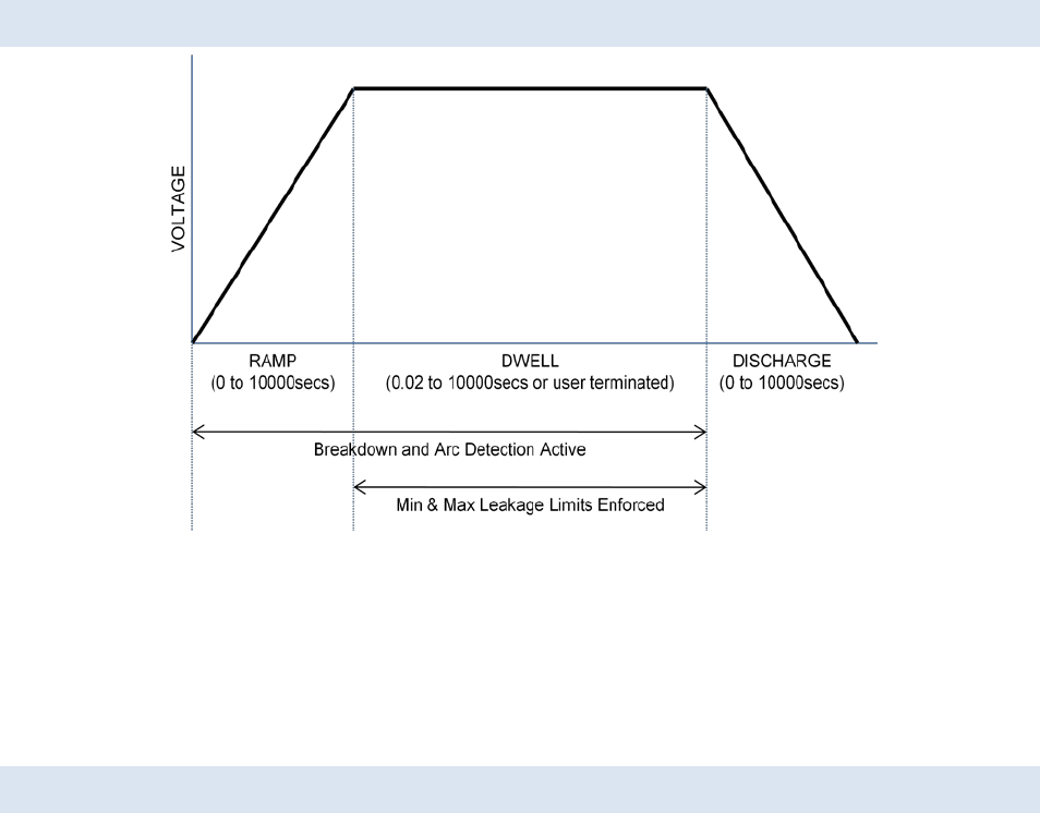
95x Series Operating Manual - December 12, 2011
Page 45 of 151
ACTIONS WHILE RUNNING
Figure 2 - ACez and ACW Type Actions
• On any failure the step is immediately aborted, and optionally the entire test sequence may be aborted.
• For the ACez type, the discharge period is of zero length, arc detection is not enabled and only RMS
leakage limits may be specified.
• For the ACW type, the discharge period can be programmed to be skipped and the next step started at
this steps’ dwell voltage level if the next step is also an ACW type.
CONFIGURING
An example ACez type menu is as follows –
Seq 1 Step 1 ACez
LEVEL:1500.0V 60.0Hz
SOURCE: INT
RAMP: 1.00sec
DWELL: 30.0sec
Lim: 0n-35.00mA
ON FAIL: ABORT SEQ
An example ACW type menu is as follows –
Seq 1 Step 1 ACW
LEVEL:1500.0V 60.0Hz
SOURCE: INT
BREAKDOWN: 49.50mApk
RAMP: 1.00sec
DWELL: 30.0sec
Test 1: RMS
Lim: 0n-35.00mA
Test 2: INPHS
Lim: 0n-5.000mA
ARC DETECT:4us 10mA
DISCHARGE: AS RAMP
ON FAIL: ABORT SEQ
95x Series Operating Manual - December 12, 2011
Page 46 of 151
• LEVEL. Allows the test voltage level and frequency to be programmed. Values cannot be set which are
beyond the range of possible output voltages and frequencies from the specific 95x or above the
maximum voltage limit set by the user in the CNFG – TEST – USER MAX ACV setting.
• SOURCE. Only available if Opt. AC-30 is installed. Allows the user to select whether to use the standard
internal source at the front panel HV terminal (INT) or the higher voltage source from the external AC-30
(EXT). This selection is automatically made and is not editable if the programmed level or frequency is
beyond the capability of the other source.
• BREAKDOWN. Only available for the ACW type. Allows breakdown detection to be programmed as a
maximum peak current level.
• RAMP. Allows the ramp time period to be programmed either as a time or rate. The UNIT key toggles the
selection between these two methods.
• DWELL. Allows the dwell time period to be programmed or set to be user terminated (with the START
button) by pressing the LIMIT key while this setting is selected.
• Test 1 and Test 2. Only available for the ACW type (the ACez type has a single leakage limit range, which is
always enabled and is always on the RMS leakage current). These allow the user to define up to 2 leakage
measurements to be checked against limits. For the test step to successfully pass when run, both the Test
1 and Test 2 measurements must pass their respective range checks or be disabled . The available
selections are –
o NONE. Disables the leakage measurement.
o RMS. Selects that the leakage check is performed on the RMS current measurement.
o INPHS. Selects that the leakage check is performed on the in-phase (i.e. resistive loading)
current measurement.
o QUAD. Selects that the leakage check is performed on the quadrature (i.e. reactive loading)
current measurement.
• Lim. Allows the user to define ranges within which each selected current measurement is considered a
PASS during the dwell period. The range can be entered in units of current or impedance, the UNIT key
toggles the selection. For the impedance selection the user may optionally disable the upper limit by
pressing the LIMIT key while the upper limit is selected. For the current selection the user may optionally
disable the lower limit by entering a zero value for it.
o For the ACez type the breakdown detection limit is automatically set to 1.414 times the
maximum RMS leakage current limit.
o If the user is concerned about testing with an accidentally disconnected DUT and the DUT
typically has a measurable leakage current, then setting a non-zero minimum RMS current limit
(or a finite maximum RMS impedance limit) will fail the test step if no DUT is connected. The
user should set this minimum limit to a value greater than the leakage current of the leads alone
but less than the lowest possible leakage current of the DUT and the leads combined.
• ARC DETECT. Only available for the ACW type. Allows the user to program arc detection during this step.
Both the time and current level can be independently programmed. Arc detection can also be disabled by
setting the leftmost (time) setting to OFF. The 95x can be configured to not fail a test step when arcing is
detected by setting the ARC setting in the CNFG – TEST sub-menu to DETECT ONLY.
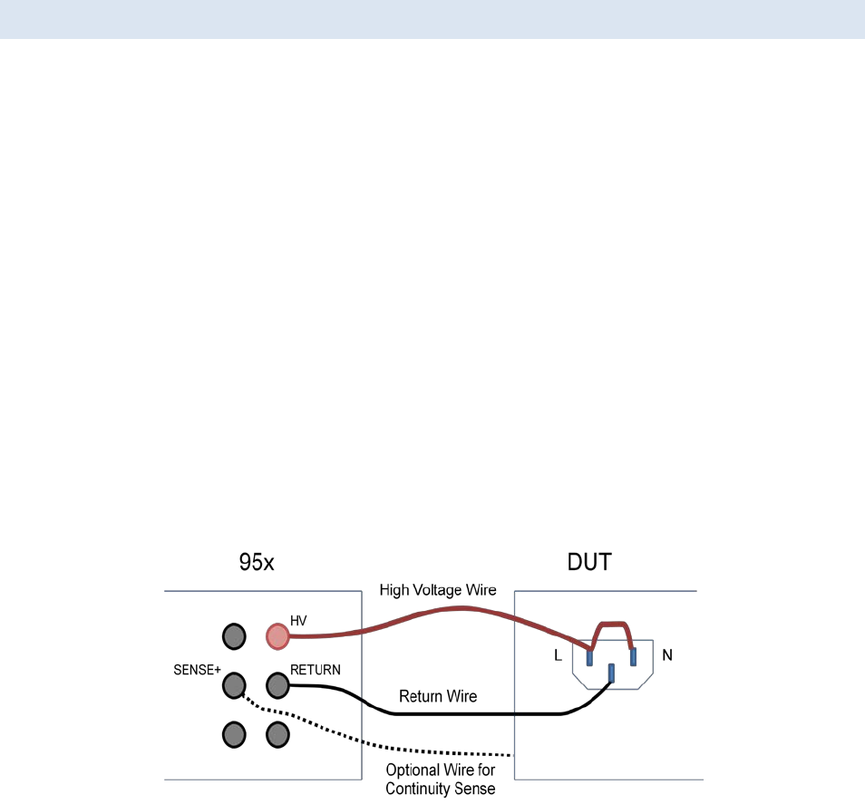
95x Series Operating Manual - December 12, 2011
Page 47 of 151
• DISCHARGE. Only available for the ACW type. Allows the user to program whether the discharge period
should use the same timing as the ramp period (AS RAMP), be as fast as possible (FAST) or skipped
(NONE). If NONE is selected but the next step is not of an AC Voltage Withstand type then the FAST
selection is used when the sequence is run. In the majority of cases, FAST should be used.
• ON FAIL. Allows the user to program the 95x to abort the entire sequence (ABORT SEQ) or only this step
(CONT SEQ) if this step fails any of its checks. A safety related failure or a user abort (STOP button) always
aborts the entire sequence.
CONNECTING TO THE DUT
The 95x requires that the DUT (at least that portion which is being measured) is floating with respect to ground.
The DUT should be wired between the HV and RETURN terminals of the 95x; if Opt. AC-30 is being used then the
DUT should be wired between the output of the external AC-30 unit and the RETURN terminal of the 95x.
The 95x provides a safety ground for the DUT during the test via its’ RETURN terminal. The Continuity Sense
feature may be used to ensure that the RETURN connection is correctly made by connecting the SENSE+ terminal
to a point on the DUT which is connected to the RETURN connection. When deciding which point on the DUT to
connect to the HV terminal and which point to connect to the RETURN terminal, the user should consider that only
the voltage on the RETURN terminal is safe at all times.
Should the DUT exhibit significant breakdown or arcing there may be high energy HF interference generated by the
surge currents. In severe cases, this can damage nearby equipment, such as computers. The wiring between the
95x terminals and the DUT should be routed as far as possible away from other equipment and cabling connected
to other equipment.
For best high impedance load performance there should be low capacitance and leakage between the wires and
for low level current measurements there should be little interference pickup in the RETURN wire. In extreme
circumstances the RETURN wire should be the inner wire of a coaxial cable, with the shield connected to the
GUARD terminal of the 95x. This will significantly reduce the capacitance and leakage between the HV and
RETURN wires. A cable such as RG174 is a suitable choice. If the Continuity Sense feature is being used then the
SENSE+ connection should similarly be a coaxial cable.
Figure 3 - Basic ACez and ACW DUT Connections
The example above shows the connections for performing AC voltage withstand testing of Line/Neutral
connections to chassis ground of a DUT. The optional wire from the DUT chassis to the SENSE+ terminal of the 95x
is used when the user wishes to use the Continuity Sense safety feature.
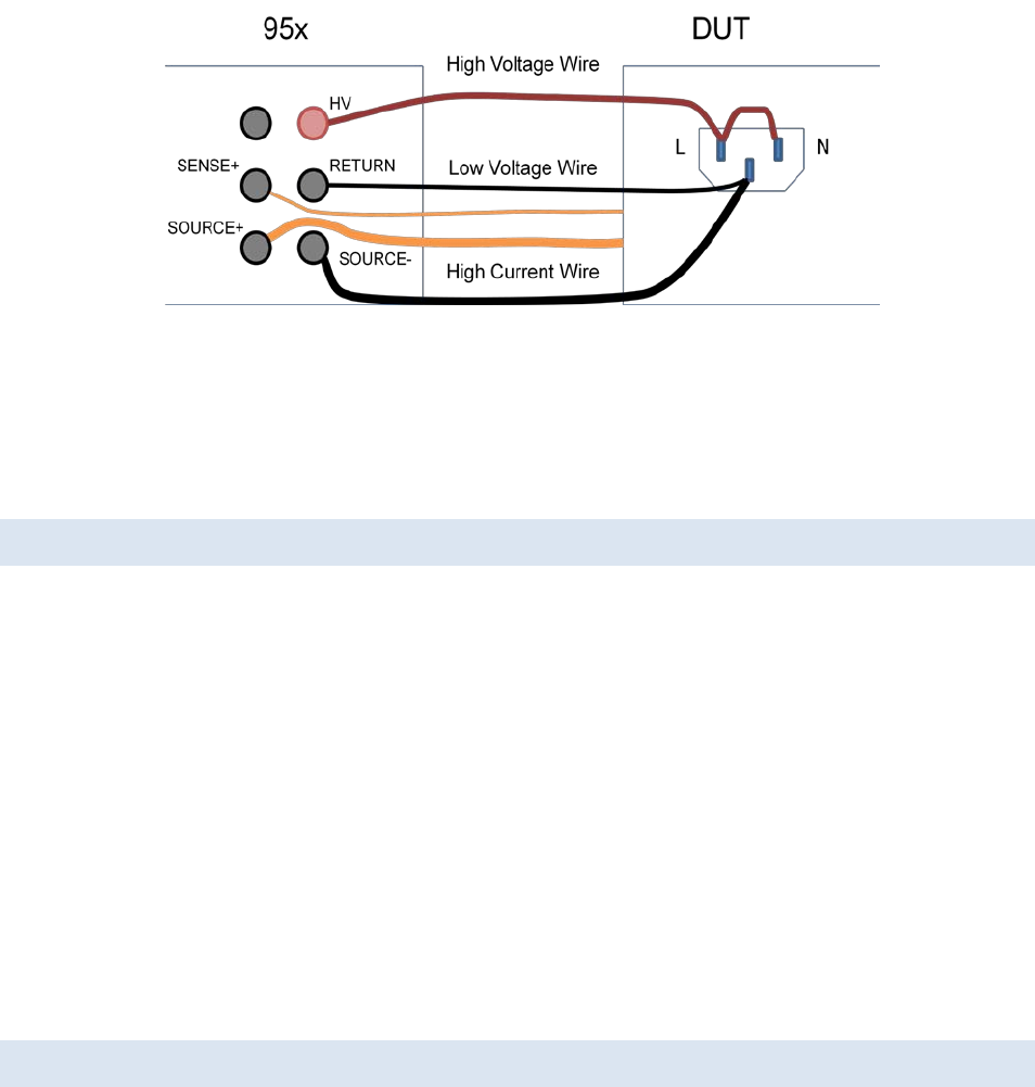
95x Series Operating Manual - December 12, 2011
Page 48 of 151
Figure 4 - ACez and ACW DUT Connections with GB also
The example above shows the connections to a DUT to perform both an AC withstand test on the Line/Neutral line
power input, and an AC Ground Bond or DC LowΩ test on the chassis of the DUT in the same sequence. If wired in
this manner, then no changes in connections are needed. This will increase the capacitive coupling between the
HV wire and the other wires, which may need to be compensated for in highly sensitive applications. The
Continuity Sense feature may also be used with this wiring configuration.
LEAD COMPENSATION
For many applications lead compensation is not necessary for these types of test steps, as the wiring leakage is
generally smaller than the DUT leakage limit and so can be ignored. However for the more sensitive requirements
(e.g. the more stringent levels of medical safety leakage testing) and/or when long lengths of wiring are required
then lead compensation may be needed.
If the capacitance of loose wiring is to be corrected for, then it is recommended to use shielding of the RETURN
wiring rather than Lead Compensation as the capacitance between loose unshielded wiring is very dependent on
the exact routing of the wires.
Performing a lead compensation compensates for the resistive and capacitive leakage currents in the wiring to the
95x in all future runs of this test step. When performing a lead compensation the normal connections to the 95x
should be in place, with the wiring positioned normally, only the DUT itself should not be connected. CAUTION
High voltages will be present on the wiring while running in lead compensation mode. Ensure that the wiring and
the (unused) DUT connections are safely positioned.
When performing a lead compensation the leakage limits are not enforced, otherwise the test step is executed
normally.
EXAMPLES
Example 1 -
A DUT is to have its’ Line/Neutral power connections tested to its’ chassis for “no breakdown” at 2000Vrms/60Hz
using a 1 second ramp and a 30 second dwell. It is known that the DUT leakage is less than 5mArms at this voltage
level and frequency (if this is not known, then start by using 5mArms as the limit and adjust it as needed).
This is accomplished in a single step as follows –
Seq 1 Step 1 ACez Only breakdown detection is needed, so use the ACez type
LEVEL:2000.0V 60.0Hz As required
RAMP: 1.00sec As required
DWELL: 30.0sec As required

95x Series Operating Manual - December 12, 2011
Page 49 of 151
Lim: 0n-5.000mA As required
ON FAIL: ABORT SEQ
Example 2 -
It is required to test a 2 conductor cable which has a specification of >100Mohm resistive leakage and <100pF
capacitance at 500Vrms, and a minimum breakdown voltage of 2000Vrms. A decision is made to test for
breakdown using a 1 second ramp and a 1 second dwell time since the requirement does not specify it.
Optionally, the Lead Compensation feature could be used to adjust for the DUT wiring capacitance, allowing
accurate measurement of the 100pF limit. Otherwise the measurement will include the capacitance of the wiring
between the 95x and the DUT.
All of these tests are accomplished by two ACW test steps in a test sequence –
Firstly test the lower voltage resistance and capacitance leakage.
Seq 1 Step 1 ACW Different breakdown and leakage limits needed, so use ACW
LEVEL: 500.0V 60.0Hz As required
BREAKDOWN: 5.000mApk Since the DUT is known to have little leakage this could be set lower
RAMP: 0.02sec No timing requirement, so set for fast testing
DWELL: 0.10sec No timing requirement, so set for fast testing
Test 1: INPHS Test the resistive leakage
Lim:100.0M-no maxΩ As required
Test 2: QUAD Test the capacitive leakage
Lim:26.50M-no maxΩ 26.5Mohm = 1/(2πFC) = the impedance of 100pF at 60Hz
ARC DETECT:4us 10mA Optional
DISCHARGE: NONE No need to discharge between this and the next step
ON FAIL: ABORT SEQ No further test steps if this step fails
Secondly test the high voltage withstand capability.
Seq 1 Step 2 ACW Could use ACez if arc detection not needed
LEVEL:2000.0V 60.0Hz As required
BREAKDOWN: 5.000mApk Since the DUT is known to have little leakage this could be set lower
RAMP: 1.00sec As required
DWELL: 1.00sec As required
Test 1: NONE No leakage testing required
Test 2: NONE No leakage testing required
ARC DETECT:4us 10mA Optional
DISCHARGE: FAST Immediately discharge as this is the last step
ON FAIL: ABORT SEQ
SPECIFICATIONS
Test Voltage, Frequency and Loading Capability
The charts below show the test voltage, frequency and loading capabilities of the 95x at ambient temperatures
≤30C and line voltage ≥115Vrms. Resistive loading is additionally limited by a maximum load power of 300W and a
maximum current of 45mArms (951-4i), 130mArms (Opt. AC-2), 50mArms (Opt. 500VA), 22.5mArms (955i) or
7.5mArms (Opt. AC-30). For ambient temperatures above 30C linearly reduce the maximum loading power and
current by 1%/C. For line voltages below 115V linearly reduce the maximum test voltage by 1%/V unless Opt.
95x Series Operating Manual - December 12, 2011
Page 50 of 151
LOLINE is fitted (there is no reduction for Opt. LOLINE). For frequencies above 100Hz other than 400Hz, the user
should linearly interpolate using the <100Hz and 400Hz capabilities shown on the applicable chart.
Figure 5 - 951-4i Test Voltage and Loading Capability (20-500Hz)
Figure 6 - 951-4i Opt. AC-2 Test Voltage and Loading Capability (20-500Hz)
Figure 7 - 951i, 953i Opt. 500VA Test Voltage and Loading Capability (40-500Hz)
0
5
10
15
20
25
30
35
40
45
50
0 1000 2000 3000 4000 5000 6000
Max Load Current (mArms)
Test Voltage 20-6000Vrms
20-100Hz
400Hz
0
20
40
60
80
100
120
140
160
180
200
0 200 400 600 800 1000 1200 1400 1600 1800 2000
Max Load Current (mArms)
Test Voltage 10-2000Vrms
20-100Hz
400Hz
0
10
20
30
40
50
60
70
80
90
100
0 1000 2000 3000 4000 5000 6000
Max Load Current (mArms)
Test Voltage 20-6000Vrms
>65mArms linearly reduce max test time to 1sec and max duty cycle to 25% at
100mArms
40-100Hz
400Hz
95x Series Operating Manual - December 12, 2011
Page 51 of 151
Figure 8 - 955i Test Voltage and Loading Capability (40-500Hz)
Figure 9 - 95x Opt. AC-30 Test Voltage and Loading Capability (40-80Hz)
Test Voltage and Frequency Accuracy
Test Voltage Accuracy <(± 0.5% ± 1.5V ± (0.01% + 0.2V) per mArms load ± 0.01% per Hz above 100Hz)
955i : Add ±0.1% above 7000Vrms
Opt. AC-30 : <(± 1.5% ± 5V ± (0.05% + 1V) per mArms load)
Test Voltage Overshoot <10% (<0.2s ramp time)
<5% (<0.5s ramp time)
<2% (>0.5s ramp time)
Settling to <±0.5% of final value in <0.1sec + 2 cycles
Test Voltage Waveform Sinewave, 1.3 – 1.5 Crest Factor
Test Frequency Accuracy <±0.1%
Surge Current Limiting & Shutdown
Impedance Limiting 951-4i (standard build): 12KΩ + 0.5H
951-4i (opt. 500VA) : 7KΩ + 0.25H
951-4i (opt. AC2): 1.4KΩ + 0.2H
955i: 25KΩ + 1.0H
Opt. AC-30 : 200KΩ
Shutdown Current Response: <40us
951-4i (standard build): 145mApk
951-4i (opt. 500VA) : 170mApk
951-4i (opt. AC2): 435mApk
0
5
10
15
20
25
30
0 1000 2000 3000 4000 5000 6000 7000 8000 9000 10000
Max Load Current (mArms)
Test Voltage 50-10000Vrms
40-100Hz
400Hz
0
2
4
6
8
10
0 5000 10000 15000 20000 25000 30000
Max Load Current
(mArms)
Test Voltage 120-30000Vrms
40-80Hz

95x Series Operating Manual - December 12, 2011
Page 52 of 151
955i: 72mApk
Opt. AC-30 : 25mApk
Current Measurements
Breakdown Current 1uA to 280mApk (DC-50kHz bandwidth)
<(± 1% ± 1uA) accuracy
<30usec detection time
<3msec response time (typically <500usec)
Leakage Current 0.0nA to 200mArms (RMS, In-phase or Quadrature)
Greater of 1 cycle or 5ms measurement period
RMS : <(± 0.5% ± 10nA ± 0.15nA per kV*Hz) accuracy
InPhs : <(± 0.5% ± 10nA ± 0.01nA per kV*Hz) accuracy
Quad : <(± 0.5% ± 10nA ± 0.15nA per kV*Hz) accuracy
Add 0.005% per Hz above 100Hz
955i : Add 50nA (RMS, InPhs and Quad) above 7000Vrms
<±0.005° per Hz phase relative to test voltage (InPhs, Quad)
Arc Current 1 to 30mArms (50KHz-5MHz bandwidth)
<(± 10% ± 1mA) accuracy at 1MHz
4us, 10us, 15us, 20us, 30us or 40us measurement period
Cable Compensation <(± 1% of error ± 0.01pF)
Test Timing
Ramp 0.00 to 9999sec
<(± 1% ± 0.1sec ± 1 cycle) accuracy
Dwell 0.02 to 9999sec or user terminated
<(± 0.05% ± 20ms ± 1 cycle) accuracy
Fast Discharge <(20ms + 1 cycle)
AC VOLTAGE RESISTANCE AND CAPACITANCE TESTING (ACIR AND ACCAP)
These are used to test that the DUT resistance or capacitance is within user set limits, and that it does not exhibit
breakdown or (optionally) arcing in the presence of an applied AC voltage.
For similar test step types see AC Voltage Withstand and Leakage Testing (ACez and ACW).
The ACIR type is often used for materials testing, providing a test of leakage resistance similar to that of the DCIR
type of DC voltage withstand test but including the effects of low frequency dielectric storage in the material by
testing at low frequency AC voltages. An example application for the ACIR type is in PCB materials testing.
Although the DC leakage resistance of a material may be high (typically >10Tohm), the 50/60Hz leakage resistance
may be much lower (often only 1 to 10Gohm) because of the presence of dielectric storage in the materials used.
Note that the ACIR type ignores the capacitive component of the leakage.
The ACCAP type is most often used for component and cable testing, providing a test of capacitance and
(optionally) dissipation factor. The 95x can resolve very small values of capacitance even when testing at low
frequencies (depending on voltage, down to 0.001pF at 60Hz). The 95x has good drive current capability and
excellent resolution so a wide range of capacitor values can be accommodated (0.1pF to 0.13uF at 1000V/60Hz
depending on model and options). This type of test can also be used to detect corona, such as between the
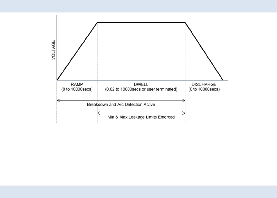
95x Series Operating Manual - December 12, 2011
Page 53 of 151
windings or between a winding and the core of a transformer. At low voltages there is no corona, so the
capacitance is set solely by the physical dimensions, at high voltages when corona is present the effective gap
between the windings becomes smaller and so the capacitance is increased. To perform this type of testing, some
processing outside the 95x is required to compare the capacitance measurements at the low and high voltages.
ACTIONS WHILE RUNNING
Figure 10 - ACIR and ACCAP Type Actions
• On any failure the step is immediately aborted, and optionally the entire test sequence may be aborted.
• For the ACIR type, the Min and Max leakage resistance measurements are checked against the user set
limits during the dwell period.
• For the ACCAP type, the Min and Max capacitance and dissipation factor measurements are checked
against the user set limits during the dwell period.
CONFIGURING AN ACIR TEST STEP
An example ACIR menu is as follows –
Seq 1 Step 1 ACIR
LEVEL:1500.0V 60.0Hz
BREAKDOWN: 49.50mApk
RAMP: 1.00sec
DWELL: 30.0sec
Lim: 45.26K-201.5KΩ
ARC DETECT:4us 10mA
DISCHARGE: AS RAMP
ON FAIL: ABORT SEQ
• LEVEL. Allows the test voltage level and frequency to be programmed. Note that values cannot be set
which are beyond the range of possible output voltages and frequencies from the specific 95x or above
the maximum voltage limit set by the user in the CNFG – TEST – USER MAX ACV setting.
• SOURCE. Only available if Opt. AC-30 is installed. Allows the user to select whether to use the standard
internal source at the front panel HV terminal (INT) or the higher voltage source from the external AC-30
(EXT). This selection is automatically made and is not editable if the programmed level or frequency is
beyond the capability of the other source.

95x Series Operating Manual - December 12, 2011
Page 54 of 151
• BREAKDOWN. Allows breakdown detection to be programmed as a maximum peak current level.
• RAMP. Allows the ramp time period to be programmed either as a time or rate. The UNIT key toggles the
selection between these two methods.
• DWELL. Allows the dwell time period to be programmed or set to be user terminated (with the START
button) by pressing the LIMIT key while this setting is selected.
• Lim. Allows the user to define the range within which the leakage resistance measurement is considered
a PASS during the dwell period. The user may optionally disable the upper limit by pressing the LIMIT key
while the upper limit is selected.
• ARC DETECT. Allows the user to program arc detection during this step. Both the time and current level
can be independently programmed. Arc detection can also be disabled by setting the leftmost (time)
setting to OFF. The 95x can be configured to not fail a test step when arcing is detected by setting the
ARC setting in the CNFG – TEST sub-menu to DETECT ONLY.
• DISCHARGE. Allows the user to program whether the discharge period should use the same timing as the
ramp period (AS RAMP), be as fast as possible (FAST) or skipped (NONE). If NONE is selected but the next
step is not of an ACez, ACW, ACIR or ACCAP type then the FAST selection is used when the sequence is
run.
• ON FAIL. Allows the user to program the 95x to abort the entire sequence (ABORT SEQ) or only this step
(CONT SEQ) if this step fails any of its checks. A safety related failure or a user abort (STOP button) always
aborts the entire sequence.
CONFIGURING AN ACCAP TEST STEP
An example ACCAP menu is as follows –
Seq 1 Step 1 ACCAP
LEVEL:1500.0V 60.0Hz
BREAKDOWN: 49.50mApk
RAMP: 1.00sec
DWELL: 30.0sec
C: 0.488p-1.512pF
DF: 0.0000-0.0005
ARC DETECT:4us 10mA
DISCHARGE: AS RAMP
ON FAIL: ABORT SEQ
• LEVEL. Allows the test voltage level and frequency to be programmed. Note that values cannot be set
which are beyond the range of possible output voltages and frequencies from the specific 95x or above
the maximum voltage limit set by the user in the CNFG – TEST – USER MAX ACV setting.
• SOURCE. Only available if Opt. AC-30 is installed. Allows the user to select whether to use the standard
internal source at the front panel HV terminal (INT) or the higher voltage source from the external AC-30
(EXT). This selection is automatically made and is not editable if the programmed level or frequency is
beyond the capability of the other source.
• BREAKDOWN. Allows breakdown detection to be programmed as a maximum peak current level.
• RAMP. Allows the ramp time period to be programmed either as a time or rate. The UNIT key toggles the
selection between these two methods.

95x Series Operating Manual - December 12, 2011
Page 55 of 151
• DWELL. Allows the dwell time period to be programmed or set to be user terminated (with the START
button) by pressing the LIMIT key while this setting is selected.
• C. Allows the user to define the range within which the capacitance measurement is considered a PASS
during the dwell period.
• DF. Allows the user to define the range within which the dissipation factor measurement is considered a
PASS during the dwell period. The limits are applied without regard to the polarity of the measured
dissipation factor.
o Setting a DF range of 0.0000->1.0000 will effectively ignore the dissipation factor measurement
as all dissipation factors lay within this range by definition.
• ARC DETECT. Allows the user to program arc detection during this step. Both the time and current level
can be independently programmed. Arc detection can also be disabled by setting the leftmost (time)
setting to OFF. The 95x can be configured to not fail a test step when arcing is detected by setting the
ARC setting in the CNFG – TEST sub-menu to DETECT ONLY.
• DISCHARGE. Allows the user to program whether the discharge period should use the same timing as the
ramp period (AS RAMP), be as fast as possible (FAST) or skipped (NONE). If NONE is selected but the next
step is not of an ACez, ACW, ACIR or ACCAP type then the FAST selection is used when the sequence is
run.
• ON FAIL. Allows the user to program the 95x to abort the entire sequence (ABORT SEQ) or only this step
(CONT SEQ) if this step fails any of its checks. A safety related failure or a user abort (STOP button) always
aborts the entire sequence.
CONNECTING TO THE DUT
The 95x requires that the DUT (at least that portion which is being measured) is floating with respect to ground.
The DUT should be wired between the HV and RETURN terminals of the 95x; if Opt. AC-30 is being used then the
DUT should be wired between the output of the external AC-30 unit and the RETURN terminal of the 95x.
The 95x provides a safety ground for the DUT during the test via its’ RETURN terminal. The Continuity Sense
feature may be used to ensure that the RETURN connection is correctly made by connecting the SENSE+ terminal
to a point on the DUT which is connected to the RETURN connection. When deciding which point on the DUT to
connect to the HV terminal and which point to connect to the RETURN terminal, the user should consider that only
the voltage on the RETURN terminal is safe at all times.
Should the DUT exhibit significant breakdown or arcing there may be high energy HF interference generated by the
surge currents. In severe cases, this can damage nearby equipment, such as computers. The wiring between the
95x terminals and the DUT should be routed as far as possible away from other equipment and cabling connected
to other equipment.
For best high impedance load performance there should be low capacitance and leakage between the wires and
for low level current measurements there should be little interference pickup in the RETURN wire. In extreme
circumstances the RETURN wire should be the inner wire of a coaxial cable, with the shield connected to the
GUARD terminal of the 95x. This will significantly reduce the capacitance and leakage between the HV and
RETURN wires. A cable such as RG174 is a suitable choice. If the Continuity Sense feature is being used then the
SENSE+ connection should similarly be a coaxial cable.
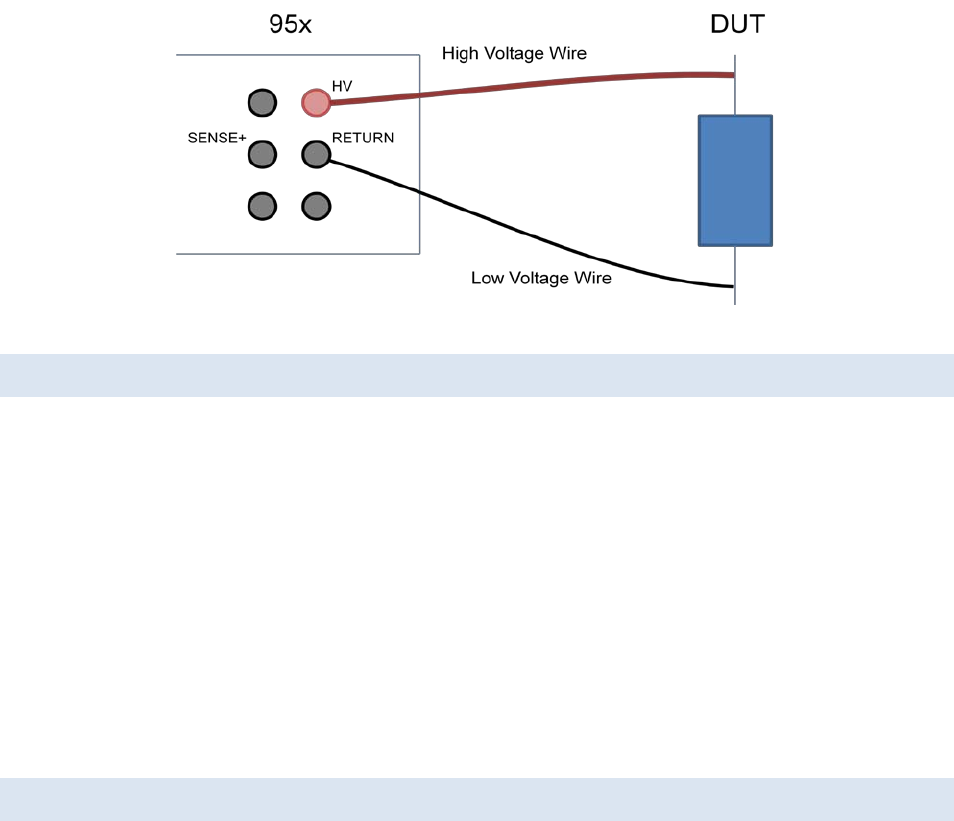
95x Series Operating Manual - December 12, 2011
Page 56 of 151
Figure 11 - ACIR and ACCAP DUT Connections
LEAD COMPENSATION
For the more sensitive requirements and/or when long lengths of connections are required, and/or when
performing ACCAP type tests on small capacitance values then lead compensation may be needed.
If the capacitance of loose wiring is to be corrected for, then it is recommended to use shielding of the RETURN
wiring rather than Lead Compensation as the capacitance between loose unshielded wiring is very dependent on
the exact routing of the wires.
Performing a lead compensation compensates for the resistive and capacitive leakage currents in the wiring to the
95x in all future runs of this test step. When performing a lead compensation the normal connections to the 95x
should be in place, with the wiring positioned normally, only the DUT itself should not be connected. CAUTION
High voltages will be present on the wiring while running in lead compensation mode. Ensure that the wiring and
the (unused) DUT connections are safely positioned.
When performing a lead compensation the leakage limits are not enforced, otherwise the test step is executed
normally.
EXAMPLES
Example 1 -
A PCB Material is to have its’ leakage resistance measured at 60Hz. The measurement will be performed using a
1000V test voltage. The resistance is to be >1Gohm.
Optionally, the user could use the Lead Compensation feature to considerably reduce the effects of the wiring
between the 95x and the PCB being tested.
This is accomplished in a single step as follows –
Seq 1 Step 1 ACIR
LEVEL:1000.0V 60.0Hz As required
BREAKDOWN: 100uApk This ensures that the energy is limited in breakdown
RAMP: 0.02sec No timing requirement, so set for fast testing
DWELL: 1.00sec No timing requirement, so set for fast testing
Lim: 1.000G-no maxΩ As required
ARC DETECT:OFF Optional
DISCHARGE: FAST
ON FAIL: ABORT SEQ

95x Series Operating Manual - December 12, 2011
Page 57 of 151
Example 2 -
A 0.033uF 1000Vac capacitor is to be tested against it tolerance (0.033uF ± 5%) and DF (<1%) specifications.
A nominal capacitor at 1000V/60Hz will draw 12.4mArms, so this is within the capabilities of all 95x models so the
capacitor can be tested at its’ maximum voltage rating.
This is accomplished in a single step as follows –
Seq 1 Step 1 ACCAP
LEVEL:1000.0V 60.0Hz As required
BREAKDOWN: 25.00mApk As required
RAMP: 1.00sec Slow ramp to better measurement a breakdown voltage
DWELL: 5.0sec Optional, could be faster
C: 31.35n-34.65nF As required
DF: 0.0000-0.0100 As required
ARC DETECT:OFF Optional
DISCHARGE: FAST
ON FAIL: ABORT SEQ
SPECIFICATIONS
Same as the AC Voltage Withstand and Leakage Testing (ACez and ACW) Specifications.
For reference, the current flowing in a capacitive load is given by 2πFCV (in Amps), where
F is the test frequency (in Hz)
C is the load capacitance (in Farads)
V is the test voltage (in Volts)
As an example, a load of 0.01uF (=10nF) at 1000V test voltage and 60Hz test frequency is a load current of
2*3.1416*60*0.00000001*1000 = 3.77mA.
Insulation Resistance Add Test Voltage and InPhs Leakage Current Accuracies as percentages
Examples at 50 or 60Hz -
100Mohm at 1000V : 0.65% + 0.61% = ±1.26%
1Gohm at 1000V : 0.65% + 1.56% = ±2.21%
10Gohm at 1000V : 0.65% + 11.1% = ±11.75%
10Gohm at 5000V : 0.53% + 3.1% = ±3.63%
Capacitance Add Test Voltage, Frequency, and Quad Leakage Current Accuracies as percentages
Examples at 1000V/60Hz -
1pF (= 377nA) : 0.65% + 0.1% + 4.73% = ±5.48%
10pF (= 3.77uA) : 0.65% + 0.1% + 0.92% = ±1.67%
100pF (= 37.7uA) : 0.65% + 0.1% + 0.54% = ±1.29%
1nF (= 377uA) : 0.65% + 0.1% + 0.5% = ±1.25%
10nF (= 3.77mA) : 0.65% + 0.1% + 0.5% = ±1.25%
100nF (= 37.7mA) : 0.65% + 0.1% + 0.5% = ±1.25%
Dissipation Factor For test voltages >100V at 60Hz and capacitive load currents >200uA, the DF
accuracy is ±0.005. For accuracy under other circumstances please contact ViTREK.
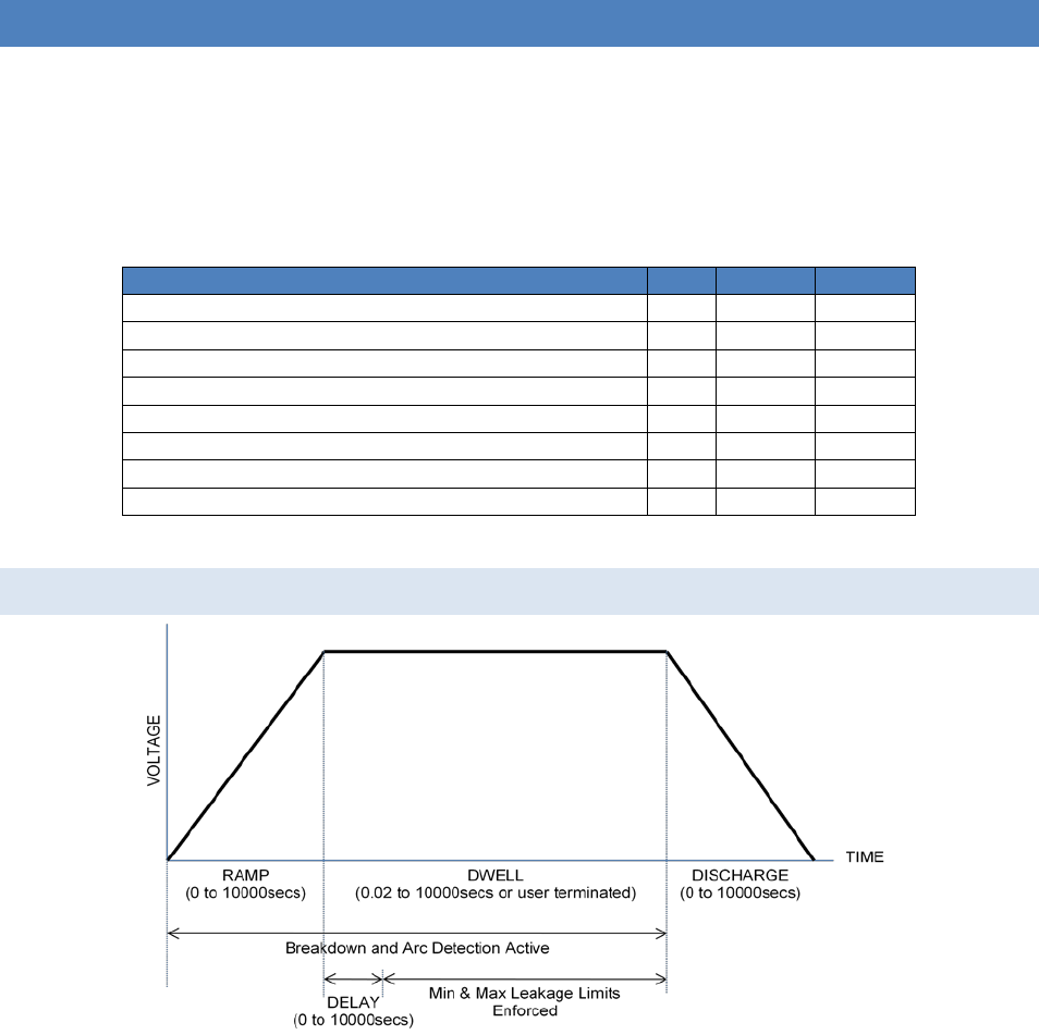
95x Series Operating Manual - December 12, 2011
Page 58 of 151
DC VOLTAGE WITHSTAND AND LEAKAGE TESTING (DCez, DCW AND DCIR)
These are used to test that a DUT does not exhibit breakdown or (optionally) arcing in the presence of an applied
DC voltage and optionally to test that the DUT leakage current or impedance is within user set limits.
All of these are performed in the same manner; the difference between them is in the amount of configuration
available. The DCez type is intended for basic breakdown detection, the DCW and DCIR types for comprehensive
breakdown, arcing and leakage testing.
Table 5 - DCez, DCW and DCIR Type Selection
DCez
DCW
DCIR
Delay after charging prior to applying leakage limits
No
Optional
Optional
Immediate Abort on Leakage Failure Yes Yes Optional
End Test on Passing Leakage current or impedance No No Optional
Separate Breakdown and Leakage Limits
No
Yes
Yes
Detect Arcing No Optional Optional
Timed Discharge No Optional Optional
High Capacitance Loads (>0.1uF)
Yes
Yes
Yes
Smooth Transition to next test step if DC Withstand type No Optional Optional
For similar test step types see High Value Capacitor DC Leakage Testing (DCCAP and IRCAP).
ACTIONS WHILE RUNNING
Figure 12 - DCez, DCW and DCIR Type Actions
• For the DCez and DCW types, on any failure the step is immediately aborted, and optionally the entire test
sequence may be aborted.
• For the DCIR type, on any failure other than leakage limit testing the step is immediately aborted. The
operation of the leakage limit test is dependent on the “End On” setting.
• For the DCez type, the delay is of zero length, the discharge period is of zero length and arc detection is
not enabled.
• For the DCW and DCIR types, the discharge period can be programmed to be skipped and the next step
started at this steps’ dwell voltage level if the next step is of the DCez, DCW or DCIR type.

95x Series Operating Manual - December 12, 2011
Page 59 of 151
• During the discharge period the voltage is reduced to zero in the programmed time or at the programmed
rate. If the actual voltage significantly lags the expected voltage during the discharge, then discharge
circuitry is automatically engaged to speed up the discharge. The test step will not fully complete until the
actual voltage is reduced to a safe level. The discharge circuitry is a combination of fixed and controlled
loading. The fixed loading is present at all times during discharge. The controlled loading has energy
limitations which may prevent it engaging until the voltage has been reduced by the fixed loading. With
very highly capacitive loads being tested at high voltages this can create lengthy discharge times. Refer to
the Specifications section for details. The HIGH VOLTAGE OR HIGH CURRENT PRESENT warning symbol on
the front panel of the 95x is illuminated whenever an unsafe voltage is present on the HV terminal. If this
is the last step in a sequence then the discharge circuitry remains engaged after the test step has fully
terminated. It is not disengaged until the user finishes reviewing the results of this sequence.
OPTIMIZING PERFORMANCE WITH HIGH CAPACITANCE LOADS (>0.1uF)
The 95x can accommodate extremely high values of capacitive loading. When testing loads having significant
capacitance the following should be noted –
• See High Value Capacitor DC Leakage Testing (DCCAP and IRCAP) if the user requires tight control of the
charging and discharging currents in the load or the user wishes to have the fastest charging rate into
highly capacitive loads.
• The user may not adjust the test voltage manually during a MANUAL sequence step.
• The test ramp time must be >0.5ec (>1sec if >1uF, >2sec if >5uF). The ramp time may need to be
extended beyond these figures to ensure the charging current is less than the desired breakdown
detection current. For reference, the charging current (in microamps) = C.(dV/dT) where C is the
capacitance in uF and (dV/dT) is the ramp rate in Volts per second (e.g. 1000V/sec ramp into a 10uF load
is 10000uA =10mA charging current).
• The test ramp rate should be >10V/sec divided by the capacitance load in uF (e.g. >10V/sec for 1uF and
>1V/sec for 10uF).
• Capacitive loads tend to have a significant dielectric storage affect. Because of this there will be
significant leakage current flowing for some time after the dwell period starts. The user should use a test
step type which supports a delay prior to applying leakage limits (i.e. not the DCez type) and to set this
delay to a long enough period. Depending on the materials, dielectric storage effects can last from a
fraction of a second to many ten’s of seconds or even longer.
• With very highly capacitive loads there may be small charging or discharging currents caused by very
slight changes in the test voltage during the dwell period of the test step. For example, for a 100uF load
being tested at 2000Vdc, if the test voltage varies by as little as ±0.01V per second (=0.0005% per second)
this will cause a ±1uA current to flow in the load. This will limit the ability to resolve very low leakage
currents or very high leakage resistances. See Specifications for details.
• The only limits to the maximum capacitance load are the ability to resolve low currents and the maximum
ramp time. The significance of the ability to resolve low currents depends on the user requirements; the
maximum ramp time of 10000 seconds combined with the standard maximum charging current of 50mA
(depends on model and option content) limits the maximum load capacitance to 1F at 500V and 0.1F at
5000V.

95x Series Operating Manual - December 12, 2011
Page 60 of 151
CONFIGURING
An example DCez menu is as follows –
Seq 1 Step 1 DCez
LEVEL: 1500.0V
RAMP: 1.00sec
DWELL: 30.0sec
Lim: 0n-15.00mA
ON FAIL: ABORT SEQ
An example DCW menu is as follows –
Seq 1 Step 1 DCW
LEVEL: 1500.0V
BREAKDOWN: 30.00mApk
RAMP: 1.00sec
DWELL: 30.0sec
Delay: 0.25sec
Lim: 0n-15.00mA
ARC DETECT:4us 10mA
DISCHARGE: AS RAMP
ON FAIL: ABORT SEQ
An example DCIR menu is as follows –
Seq 1 Step 1 DCIR
LEVEL: 1500.0V
BREAKDOWN: 30.00mApk
RAMP: 1.00sec
DWELL: 30.0sec
Delay: 0.25sec
End On: PASS
Lim: 100.0K-no maxΩ
ARC DETECT:4us 10mA
DISCHARGE: AS RAMP
ON FAIL: ABORT SEQ
• LEVEL. Allows the test voltage level to be programmed. Note that a value cannot be set which is beyond
the range of possible output voltages from the specific 95x or above the maximum voltage limit set by the
user in the CNFG – TEST – USER MAX DCV setting.
• BREAKDOWN. Only available for the DCW and DCIR types. Allows breakdown detection to be
programmed as a maximum peak current level.
• RAMP. Allows the ramp time period to be programmed either as a time or rate. The UNIT key toggles the
selection between these two methods.
• DWELL. Allows the dwell time period to be programmed or set to be user terminated (with the START
button) by pressing the LIMIT key while this setting is selected.
• Delay. Only available for the DCW and DCIR types. Allows the user to program a delay within the dwell
period before the leakage range check is to be performed.
• End On. Only available for the DCIR type. Allows the user to select when the dwell period will be ended –
o PASS. The dwell period will be immediately terminated with a PASS status if the leakage
measurement is within limits continuously for at least 2% of the dwell period. If the dwell period
ends then the test step will have a FAIL status for leakage.

95x Series Operating Manual - December 12, 2011
Page 61 of 151
o FAIL. The dwell period will be immediately terminated with a FAIL status if the leakage
measurement is outside of limits continuously for at least 2% of the dwell period. If the dwell
period ends then the test step will have a PASS status for leakage. This selection produces the
same results as the DCez and DCW types.
o TIME. The dwell period always extends for the entire programmed period. The pass/fail status
for leakage is based upon the final measurement taken at the end of the dwell period.
• Lim. Allows the user to define the range within which the leakage current is considered a PASS during the
dwell period. The range can be entered in units of current or impedance for any type of test step, the
UNIT key toggles the selection. For the impedance selection the user may optionally disable the upper
limit by pressing the LIMIT key while the upper limit is selected.
o The breakdown detection limit is automatically set to the same as the maximum leakage limit for
the DCez type.
• ARC DETECT. Allows the user to program arc detection during this step. Both the time and current level
can be independently programmed. Arc detection can also be disabled by setting the leftmost (time)
setting to OFF. The 95x can be configured to not fail a test step when arcing is detected by setting the
ARC setting in the CNFG – TEST sub-menu to DETECT ONLY.
• DISCHARGE. Allows the user to program whether the discharge period should use the same timing as the
ramp period (AS RAMP), be as fast as possible (FAST) or skipped (NONE). If NONE is selected but the next
step is not of a DCez, DCW, or DCIR type then the FAST selection is used when the sequence is run.
• ON FAIL. Allows the user to program the 95x to abort the entire sequence (ABORT SEQ) or only this step
(CONT SEQ) if this step fails any of its checks. A safety related failure or a user abort (STOP button) always
aborts the entire sequence.
CONNECTING TO THE DUT
The 95x requires that the DUT (at least that portion which is being measured) is floating with respect to ground.
The DUT should be wired between the HV and RETURN terminals of the 95x.
The 95x provides a safety ground for the DUT during the test via its’ RETURN terminal. The Continuity Sense
feature may be used to ensure that the RETURN connection is correctly made by connecting the SENSE+ terminal
to a point on the DUT which is connected to the RETURN connection. When deciding which point on the DUT to
connect to the HV terminal and which point to connect to the RETURN terminal, the user should consider that only
the voltage on the RETURN terminal is safe at all times.
Should the DUT exhibit significant breakdown or arcing there may be high energy HF interference generated by the
surge currents. In severe cases, this can damage nearby equipment, such as computers. The wiring between the
95x terminals and the DUT should be routed as far as possible away from other equipment and cabling connected
to other equipment.
For best high impedance load performance there should be low leakage between the wires and for low level
current measurements there should be little interference pickup in the RETURN wire. In extreme circumstances
the RETURN wire should be the inner wire of a coaxial cable, with the shield connected to the GUARD terminal of
the 95x. This will significantly reduce the leakage between the HV and RETURN wires. A cable such as RG174 is a
suitable choice. If the Continuity Sense feature is being used then the SENSE+ connection should similarly be a
coaxial cable.
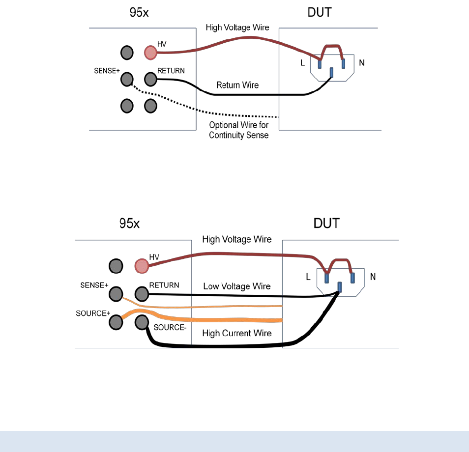
95x Series Operating Manual - December 12, 2011
Page 62 of 151
Figure 13 - Basic DCez, DCW and DCIR DUT Connections
The example shown above shows the connections for performing DC voltage withstand testing of Line/Neutral
connections to chassis ground of a DUT. The optional wire from the DUT chassis to the SENSE+ terminal of the 95x
is used when the user wishes to use the Continuity Sense safety feature.
Figure 14 - DCez, DCW and DCIR DUT Connections with GB also
The example shown above shows the connections to a DUT to perform both a DC withstand test on the
Line/Neutral line power input, and a AC Ground Bond test on the chassis of the DUT in the same sequence. If
wired in this manner, then no changes in connections are needed. The Continuity Sense feature may also be used
with this wiring configuration.
LEAD COMPENSATION
For many applications lead compensation is not necessary for these types of test steps, as the wiring leakage is
generally smaller than the DUT leakage limit and so can be ignored. However for the more sensitive requirements
lead compensation may be needed.
Performing a lead compensation compensates for any leakage currents in the wiring to the 95x in all future runs of
this test step. When performing a lead compensation the normal connections to the 95x should be in place, with
the wiring positioned normally, only the DUT itself should not be connected. CAUTION High voltages will be
present on the wiring while running in lead compensation mode. Ensure that the wiring and the (unused) DUT
connections are safely positioned.
When performing a lead compensation the leakage limits are not enforced, otherwise the test step is executed
normally.

95x Series Operating Manual - December 12, 2011
Page 63 of 151
EXAMPLES
Example 1 -
A DUT is to have its’ Line/Neutral power connections tested to its’ chassis for “no breakdown” at 2000Vdc using a 1
second ramp and a 30 second dwell. It is known that the DUT leakage is less than 5mA at this voltage level (if this
is not known, then start by using 5mA as the limit and adjust it as needed).
This is accomplished in a single step as follows –
Seq 1 Step 1 DCez Only breakdown detection is needed, so use the DCez type
LEVEL: 2000.0V As required
RAMP: 1.00sec As required
DWELL: 30.0sec As required
Lim: 0n-5.000mA As required
ON FAIL: ABORT SEQ
Example 2 –
A solar panel is to be tested for “no breakdown” at 2500Vdc using a 1 second ramp and a 5 second dwell time. The
panel is estimated to have between 1 and 4uF of capacitance. The test limit for breakdown has been decided to be
1mA and it has been decided to not test for arcing in the panel because of its’ capacitance.
This is accomplished in a single step as follows –
Seq 1 Step 1 DCW Different breakdown and leakage limits, so use DCW
LEVEL: 2500.0V As required
BREAKDOWN: 20.00mApk Must be greater than the charging current
RAMP: 1.00sec As required
DWELL: 5.00sec As required
Delay: 1.00sec Allow for dielectric storage in the panel
Lim: 0n-1.000mA As required
ARC DETECT:OFF As required
DISCHARGE: FAST
ON FAIL: ABORT SEQ
Example 3 –
The solar panel used in example 2 above is also required to be tested for insulation resistance at 500Vdc, the
specification requires the panel to have >100Mohm resistance. A ramp time of 1 second and a dwell time of 5
seconds have been chosen.
The DCIR test is performed first since if the DCIR were performed after the breakdown test then there would be
much longer settling time required because the panel is settling from 2500V to 500V, i.e. a 2000V change rather
than a 500V change prior to the very sensitive DCIR measurement.
This is accomplished in two steps as follows –
Seq 1 Step 1 DCIR This could also be a DCW test with the same results
LEVEL: 500.0V As required
BREAKDOWN: 5.000mApk Must be greater than the charging current
RAMP: 1.00sec As required
DWELL: 5.00sec As required
Delay: 2.00sec Allow for dielectric storage in the panel
End On: FAIL As required
95x Series Operating Manual - December 12, 2011
Page 64 of 151
Lim: 100.0M-no maxΩ As required
ARC DETECT:OFF As required
DISCHARGE: NONE No need to discharge before the next step, reduces test time
ON FAIL: ABORT SEQ Optional, could continue testing if fails
Seq 1 Step 2 DCW Different breakdown and leakage limits, so use DCW
LEVEL: 2500.0V As required
BREAKDOWN: 20.00mApk Must be greater than the charging current
RAMP: 1.00sec As required
DWELL: 5.00sec As required
Delay: 1.00sec Allow for dielectric storage in the panel
Lim: 0n-1.000mA As required
ARC DETECT:OFF As required
DISCHARGE: FAST
ON FAIL: ABORT SEQ
Example 4 –
In example 3 above, it is required to ensure that the panel is connected to the 95x during the tests. Since the panel
has very little DC leakage but has significant capacitance this is easily achieved by adding a low voltage AC test at
the start of the sequence. Since the load has a minimum capacitance of 1uF and a maximum of 4uF, the current at
10V/20Hz will be between 1.25 and 5mArms. This requires that Opt.AC-2 is installed.
This is accomplished in three steps as follows –
Seq 1 Step 1 ACez Simple RMS min and breakdown, so use ACez
LEVEL: 10.0V 20.0Hz As required
RAMP: 0.02sec Use a fast time to reduce test time
DWELL: 0.10sec Use a fast time to reduce test time
Lim: 1.000m-5.000mA As required
ON FAIL: ABORT SEQ No need for further tests if fails
Seq 1 Step 2 DCIR This could also be a DCW test with the same results
LEVEL: 500.0V As required
BREAKDOWN: 5.000mApk Must be greater than the charging current
RAMP: 1.00sec As required
DWELL: 5.00sec As required
Delay: 2.00sec Allow for dielectric storage in the panel
End On: FAIL As required
Lim: 100.0M-no maxΩ As required
ARC DETECT:OFF As required
DISCHARGE: NONE No need to discharge before the next step, reduces test time
ON FAIL: ABORT SEQ Optional, could continue testing if fails
Seq 1 Step 3 DCW Different breakdown and leakage limits, so use DCW
LEVEL: 2500.0V As required
BREAKDOWN: 20.00mApk Must be greater than the charging current
RAMP: 1.00sec As required
DWELL: 5.00sec As required
Delay: 1.00sec Allow for dielectric storage in the panel
Lim: 0n-1.000mA As required
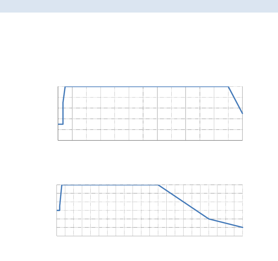
95x Series Operating Manual - December 12, 2011
Page 65 of 151
ARC DETECT:OFF As required
DISCHARGE: FAST
ON FAIL: ABORT SEQ
SPECIFICATIONS
Test Voltage and Loading Capability
The charts below show the test voltage and loading capabilities of the 95x at ambient temperatures ≤30C and line
voltage ≥115Vrms. For ambient temperatures above 30C linearly reduce the maximum loading current by 1%/C.
For line voltages below 115V linearly reduce the maximum test voltage by 1%/V unless Opt. LOLINE is fitted (there
is no reduction for Opt. LOLINE). Output powers above 200W have a limited test time (e.g. 4 seconds at 250W).
Capacitive loading is only limited by the maximum ramp time (9999.9sec) and the maximum load current, typically
this is <1F load.
Figure 15 - 951i, 952i, 956i Test Voltage and Loading Capability (DC)
Figure 16 - 953i, 954i, 955i Test Voltage and Loading Capability (DC)
Surge Current Limiting & Shutdown
Impedance Limiting 951i,952i, 956i: 6.5KΩ
953-5i : 11.5KΩ
Shutdown Current/Energy Response: <40us
951i,952i, 956i: 100mApk (1.4J max)
953-5i: 50mApk (2J max)
Test Voltage Accuracy (<1uF Loading)
Test Voltage Accuracy <(± 0.25% ± 0.5V ± (0.01% + 0.05V) per mA load)
0
10
20
30
40
50
0 1000 2000 3000 4000 5000 6000
Max Load Current (mA)
Test Voltage 10-6500V
0
5
10
15
20
25
30
0 1000 2000 3000 4000 5000 6000 7000 8000 9000 10000 11000
Max Load Current (mA)
Test Voltage 20-11000V
95x Series Operating Manual - December 12, 2011
Page 66 of 151
Test Voltage Overshoot <15% (<0.25s ramp time)
<10% (<1s ramp time)
< 5% (>1s ramp time)
Settling to <±0.25% of final value in <0.5sec
Test Voltage Accuracy (>1uF Loading)
Test Voltage Accuracy <(± 1.5% ± 5V)
Test Voltage Overshoot <3%
Typically settling to <±0.25% of final value in <1sec
Test Voltage Variation 951i,952i, 956i: <(±0.001% ± 0.02V) per second after 2 seconds
953-5i : <(±0.001% ± 0.05V) per second after 2 seconds
Load Current Measurements
Breakdown Current 1uA to 280mApk (DC-50kHz bandwidth)
<(± 1% ± 1uA) accuracy
<30usec detection time
<3msec response time (typically <500usec)
Leakage Current 0.0nA to 200mA
1 line cycle measurement period
<30uF load : <(± 0.25% ± 0.5nA ± (0.1uA per uF load)) accuracy
>30uF load : <(± 0.25% ± 3uA) accuracy
Arc Current 1 to 30mArms (50KHz-5MHz bandwidth)
<(± 10% ± 1mA) accuracy at 1MHz
4us, 10us, 15us, 20us, 30us or 40us measurement period
Cable Compensation <(± 1% of error)
Test Timing
Ramp 0.01 to 9999sec
50kV/sec max slew rate
<(± 1% ± 0.3sec) accuracy
Dwell 0.02 to 9999sec or user terminated
<(± 0.05% ± 20ms) accuracy
Delay 0.00 to 9999sec
<(± 0.05% ± 20ms) accuracy
Discharge Auto-selected combination of Fixed, Controlled and Power Discharge (see below)
Fixed Discharge Always selected
951i,952i,956i : Nominal loading 7.5MΩ
953-5i : Nominal loading 15MΩ
Controlled Discharge Selection Criteria : <400W power, <400J energy, <7500V
951i,952i,956i : Nominal loading 40KΩ
953-5i : Nominal loading 40KΩ or 240KΩ, auto-selected
Power Discharge Selection Criteria : <375V
2.5W nominal loading (<15mA)

95x Series Operating Manual - December 12, 2011
Page 67 of 151
Minimum Discharge Time <(20ms + 10ms per kV) (below 7500V)
HIGH VALUE CAPACITOR DC LEAKAGE TESTING (DCCAP AND IRCAP)
These are used to test that a DUT leakage current or impedance is within user set limits, and does not exhibit
breakdown or (optionally) arcing in the presence of an applied DC voltage. These are intended for capacitive loads
(>0.1uF) which require close control of the charging and (optionally) discharging currents. These are also useful
when it is required to charge a heavily capacitive load as fast as possible when testing for leakage.
Table 6 - DCCAP and IRCAP Type Selection
DCCAP
IRCAP
Delay after charging prior to applying leakage limits
Yes
Yes
Immediate Abort on Leakage Failure Yes Optional
End Test on Passing Leakage current or impedance No Optional
Detect Arcing
Optional
Optional
Timed Discharge Optional Optional
These test step types are very similar to the DC Voltage Withstand types described in the preceding section. The
primary differences are as follows –
• The DCCAP and IRCAP types expect the DUT to be primarily capacitive. In general, these types should only
be used with loads >0.1uF and having little DC leakage.
• For the DCCAP and IRCAP types the DC voltage drive is allowed to change to a constant current state
during the ramp period; a breakdown is detected as the output voltage ceasing to increase when in the
constant current state. For the DC Voltage Withstand types a current over the limit during ramp
immediately causes a breakdown failure and the test is aborted.
• For the DCCAP and IRCAP types the user can set a charging current limit close to the maximum current
capability of the 95x. This enables the fastest possible charging time when using very capacitive loads.
For the DC Voltage Withstand types the ramp rate cannot be set close to the breakdown current limit,
otherwise false indications of breakdown will occur if the DUT is either a) more capacitive than expected,
or b) the 95x ramps the voltage slightly faster than expected.
• For the DCCAP and IRCAP types the user can optionally select to limit the discharge circuitry in the 95x to
the same maximum current enforced during the ramp (i.e. charging) period. This is not possible using the
DC Voltage Withstand types.
95x Series Operating Manual - December 12, 2011
Page 68 of 151
ACTIONS WHILE RUNNING
Figure 17 - DCCAP and IRCAP Type Actions
• The ramp period is user defined in terms of a maximum ramp rate (V/sec), a maximum charging current
(in Amps) and a timeout value (in seconds). During the ramp period the 95x automatically limits both the
rate of change of voltage and the charging current to both be at or less than the user set limits, and will
fail the DUT if the desired test voltage is not reached within the set timeout period. The front panel C/V
LIMITED indicator is illuminated whenever the ramp is being limited by the maximum charging current.
• The breakdown detection current limit is automatically set at three times the user set maximum charging
current limit to limit the energy in a sudden breakdown of the DUT.
• For the DCCAP type, for any failure the step is immediately aborted.
• For the IRCAP type, for any failure other than leakage limit testing the step is immediately aborted. The
operation of the leakage limit test is dependent on the “End On” setting.
• During the discharge period the voltage is reduced to zero in the programmed time or with the user set
current limit. Discharge circuitry is automatically engaged to speed up the discharge as needed. The test
step will not fully complete until the actual voltage is reduced to a safe level. The discharge circuitry is a
combination of fixed and controlled loading. The fixed loading is present at all times during discharge.
The controlled loading has energy limitations which may prevent it engaging until the voltage has been
reduced by the fixed loading. With very highly capacitive loads being tested at high voltages this can
create lengthy discharge times. Refer to the Specifications section for details. The HIGH VOLTAGE OR
HIGH CURRENT PRESENT warning symbol on the front panel of the 95x is illuminated whenever an unsafe
voltage is present on the HV terminal. If this is the last step in a sequence then the discharge circuitry
remains engaged after the test step has fully terminated. It is not disengaged until the user finishes
reviewing the results of this sequence.
OPTIMIZING PERFORMANCE WITH HIGH CAPACITANCE LOADS
The 95x can accommodate extremely high values of capacitive loading when performing High Value Capacitor DC
Leakage Testing; the following should be noted for optimum performance –

95x Series Operating Manual - December 12, 2011
Page 69 of 151
• The 95x controls the ramp period using maximum ramp rate (in V/sec) and maximum charging current (in
Amps) settings. For optimum results these settings should be set according to the expected nominal
capacitive load value as follows –
o For reference, the charging (and discharging) current (in microamps) = C.(dV/dT) where C is the
capacitance in uF and (dV/dT) is the ramp rate in Volts per second (e.g. 1000V/sec ramp into a
10uF load is 10000uA =10mA charging current).
o Choose a maximum charging current according to the application and within the ability of the
specific 95x model and option content (See Figure 15 - 951i, 952i, 956i Test Voltage and Loading
Capability (DC) and Figure 16 - 953i, 954i, 955i Test Voltage and Loading Capability (DC)).
o Using the equation above with the expected nominal capacitive load value, estimate the
expected ramp time at the selected charging current. If necessary reduce the charging current to
create a nominal ramp time of greater than 1 second.
o For best results, the charging current should be 100uA or greater, only select a charging current
less than this if specifically required for the application.
o Using the estimated ramp time from above, calculate the expected ramp rate (= test voltage /
ramp time). Set the maximum ramp rate to twice this figure. This ensures that for a nominal
load the ramp period will be current limited, but restricts a low capacitance load from ramping
too fast. This also reduces charging current surges at the start of the ramp.
o Using the estimated ramp time from above, set the ramp timeout value to at least 1.5 times this
figure. If a wide range of capacitive loads may be encountered then this may need to be
extended to longer than this figure.
• Capacitive loads tend to have a significant dielectric storage affect. Because of this there will be a
significant leakage current flowing for some time after the dwell period starts. The user should set the
dwell delay to a suitably long enough period to allow the DUT to recover from charging. Depending on
the materials, dielectric storage effects can last from a fraction of a second to many ten’s of seconds or
even longer.
• With very highly capacitive loads there may be small charging or discharging currents caused by very
slight changes in the test voltage during the dwell period of the test step. For example, for a 100uF load
being tested at 2000Vdc, if the test voltage varies by as little as ±0.01V per second (=0.0005% per second)
this will cause a ±1uA current to flow in the load. This will limit the ability to resolve very low leakage
currents or very high leakage resistances. See Specifications for details.
• The only limits to the maximum capacitance load are the ability to resolve low currents and the maximum
ramp timeout. The significance of the ability to resolve low currents depends on the user requirements;
the maximum ramp timeout of 10000 seconds combined with the standard maximum charging current of
50mA (depends on model and option content) limits the maximum load capacitance to 1F at 500V and
0.1F at 5000V.
CONFIGURING
An example DCCAP menu is as follows –
Seq 1 Step 1 DCCAP
LEVEL: 1500.0V
RAMP: 100.0V/s
Limit: 1.00mA
95x Series Operating Manual - December 12, 2011
Page 70 of 151
Timeout: 30.0sec
DWELL: 60sec
Delay: 5.0sec
Lim: 0n-500.0uA
ARC DETECT:4us 10mA
DISCHARGE: AS RAMP
ON FAIL: ABORT SEQ
An example IRCAP menu is as follows –
Seq 1 Step 1 IRCAP
LEVEL: 1500.0V
RAMP: 100.0V/s
Limit: 1.00mA
Timeout: 30.0sec
DWELL: 60sec
Delay: 5.0sec
End On: PASS
Lim: 0n-500.0uA
ARC DETECT:4us 10mA
DISCHARGE: AS RAMP
ON FAIL: ABORT SEQ
• LEVEL. Allows the test voltage level to be programmed. Note that a value cannot be set which is beyond
the range of possible output voltages from the specific 95x or above the maximum voltage limit set by the
user in the CNFG – TEST – USER MAX DCV setting.
• RAMP. Allows the maximum allowable ramping rate to be specified. See the Optimizing Performance
with High Capacitance Loads section for details regarding setting this value.
• Limit. Allows the maximum charging current to be specified. The entry is limited to a minimum value of
1uA and the maximum current available from the specific 95x model and option content. See the
Optimizing Performance with High Capacitance Loads section for details regarding setting this value.
• Timeout. Allows the ramp timeout to be specified. The timeout value must be set to a sufficiently large
value to allow the highest expected capacitive load to achieve the programmed test voltage. See the
Optimizing Performance with High Capacitance Loads section for details regarding setting this value.
• DWELL. Allows the dwell time period to be programmed or set to be user terminated (with the START
button) by pressing the LIMIT key while this setting is selected. A minimum period of 5 seconds may be
defined.
• Delay. Allows the user to program a delay in the dwell period before the leakage range check is to be
performed. A minimum period of 1 second may be defined.
• End On. Only available for the IRCAP type. Allows the user to select when the dwell period will be ended –
o PASS. The dwell period will be immediately terminated with a PASS status if the leakage
measurement is within limits continuously for at least 2% of the dwell period. If the dwell period
ends then the test step will have a FAIL status for leakage.
o FAIL. The dwell period will be immediately terminated with a FAIL status if the leakage
measurement is outside of limits continuously for at least 2% of the dwell period. If the dwell
period ends then the test step will have a PASS status for leakage. This selection produces the
same results as the DCCAP test step type.
o TIME. The dwell period always extends for the entire programmed period. The pass/fail status
for leakage is based upon the final measurement taken at the end of the dwell period.

95x Series Operating Manual - December 12, 2011
Page 71 of 151
• Lim. Allows the user to define the range within which the leakage current is considered a PASS during the
dwell period. The range can be entered in units of current or impedance for any type of test step, the
UNIT key toggles the selection. For the impedance selection the user may optionally disable the upper
limit by pressing the LIMIT key while the upper limit is selected.
• ARC DETECT. Allows the user to program arc detection during this step. Both the time and current level
can be independently programmed. Arc detection can also be disabled by setting the leftmost (time)
setting to OFF. The 95x can be configured to not fail a test step when arcing is detected by setting the
ARC setting in the CNFG – TEST sub-menu to DETECT ONLY.
• DISCHARGE. Allows the user to program whether the discharge period should use the same rate and
current limits as the ramp period (AS RAMP) or to be as fast as possible (FAST).
• ON FAIL. Allows the user to program the 95x to abort the entire sequence (ABORT SEQ) or only this step
(CONT SEQ) if this step fails any of its checks. A safety related failure or a user abort (STOP button) always
aborts the entire sequence.
CONNECTING TO THE DUT
The 95x requires that the DUT (at least that portion which is being measured) is floating with respect to ground.
The DUT should be wired between the HV and RETURN terminals of the 95x.
The 95x provides a safety ground termination for the DUT during the test via its’ RETURN terminal. The Continuity
Sense feature may be used to ensure that the RETURN connection is correctly made by connecting the SENSE+
terminal to a point on the DUT which is connected to the RETURN connection. When deciding which point on the
DUT to connect to the HV terminal and which point to connect to the RETURN terminal, the user should consider
that only the voltage on the RETURN terminal is safe at all times.
Should the DUT exhibit significant breakdown or arcing there may be high energy HF interference generated by the
surge currents. In severe cases, this can damage nearby equipment, such as computers. The wiring between the
95x terminals and the DUT should be routed as far as possible away from other equipment and cabling connected
to other equipment.
For best high impedance load performance there should be low leakage between the wires and for low level
current measurements there should be little interference pickup in the RETURN wire. In extreme circumstances
the RETURN wire should be the inner wire of a coaxial cable, with the shield connected to the GUARD terminal of
the 95x. This will significantly reduce the leakage between the HV and RETURN wires. A cable such as RG174 is a
suitable choice. If the Continuity Sense feature is being used then the SENSE+ connection should similarly be a
coaxial cable.
95x Series Operating Manual - December 12, 2011
Page 72 of 151
Figure 18 - Basic DCCAP and IRCAP DUT Connections
LEAD COMPENSATION
Lead compensation is not recommended for this type.
EXAMPLES
Example 1 -
A 10uF, 2000V capacitor is to have its leakage current tested. The leakage current is to be <10uA at 2000Vdc.
There are no limitations on charging or discharging currents.
Using the methods in the Optimizing Performance with High Capacitance Loads section –
• The charging current is chosen to be 10mA.
• This yields a nominal ramp time of 2 seconds.
• This yields a nominal ramp rate of 1000V/sec, so a maximum ramp rate of 2000V/sec will be chosen.
• Since the nominal ramp time is 2 seconds and the capacitive load is fairly well known, a ramp timeout of 3
seconds is chosen.
• The load has little dielectric storage, so the minimum delay and dwell times are chosen.
This is accomplished in a single step as follows –
Seq 1 Step 1 DCCAP
LEVEL: 2000.0V As required
RAMP: 2000V/s See above
Limit: 10.00mA See above
Timeout: 3.0sec See above
DWELL: 5.0sec See above
Delay: 1.0sec See above
Lim: 0n- 10.0uA As required
ARC DETECT:OFF Arc detection cannot be performed
DISCHARGE: FAST As required
ON FAIL: ABORT SEQ
Example 2 –
The same test as in example 1 is to be performed, but the capacitor specification states “leakage current is <10uA
within 60 seconds” and the fastest possible test time is desired.

95x Series Operating Manual - December 12, 2011
Page 73 of 151
In this case the test can be terminated with a pass earlier than the 60 seconds if the leakage current drops below
10uA. This requires the IRCAP type of test step as follows -
Seq 1 Step 1 IRCAP
LEVEL: 2000.0V
RAMP: 2000V/s
Limit: 10.00mA
Timeout: 3.0sec
DWELL: 60.0sec
Delay: 1.0sec
End On: PASS
Lim: 0n- 10.0uA
ARC DETECT:OFF
DISCHARGE: FAST
ON FAIL: ABORT SEQ
The test step will terminate with a pass as early as possible, as soon as the leakage current is below 10uA
continuously for 1.2seconds (= 2% of 60 seconds). If the leakage current has not dropped below 10uA at the end
of 60 seconds, the test fails.
Example 3 –
A fragile capacitive load is to be tested for leakage current < 1uA at 3000V. The load must not have a charging
current or discharge current more than 200uA at any time otherwise it may be damaged.
The exact capacitance is not known, but estimated to be about 0.1uF.
Using the methods in the Optimizing Performance with High Capacitance Loads section –
• The charging current is chosen to be 100uA. The discharge is also set to restrict the current to 100uA.
This is chosen below the specified maximum current to ensure that 200uA will not be exceeded.
• This yields a nominal ramp time of 3 seconds.
• This yields a nominal ramp rate of 1000V/sec, so a maximum ramp rate of 2000V/sec will be chosen.
• Since the nominal ramp time is 3 seconds and the capacitive load is not well known, a ramp timeout of 15
seconds is chosen.
• The load has considerable dielectric storage, so a 10 second delay and a 15 second dwell time are chosen.
This is accomplished in a single step as follows –
Seq 1 Step 1 DCCAP
LEVEL: 3000.0V As required
RAMP: 2000V/s See above
Limit: 100uA See above
Timeout: 15.0sec See above
DWELL: 15.0sec See above
Delay: 10.0sec See above
Lim: 0n- 1.0uA As required
ARC DETECT:OFF Optional
DISCHARGE: AS RAMP
ON FAIL: ABORT SEQ
SPECIFICATIONS
Test Voltage and Loading Capability
95x Series Operating Manual - December 12, 2011
Page 74 of 151
See Figure 15 - 951i, 952i, 956i Test Voltage and Loading Capability (DC) and Figure 16 - 953i, 954i, 955i Test
Voltage and Loading Capability (DC)
Capacitive loading is only limited by the maximum ramp time (9999.9sec) and the maximum load current, typically
this is <1F load.
Surge Current Limiting & Shutdown
Impedance Limiting 951i,952i, 956i: 6.5KΩ
953-5i : 11.5KΩ
Shutdown Current/Energy Response: <40us
951i,952i, 956i: 100mApk (1.4J max)
953-5i: 50mApk (2J max)
Test Voltage Accuracy
Test Voltage Accuracy <(± 1.5% ± 5V)
Test Voltage Overshoot <3%
Typically settling to <±0.25% of final value in <1sec
Test Voltage Variation 951i,952i,956i: <(±0.001% ± 0.02V) per second after 2 seconds
953-5i : <(±0.001% ± 0.05V) per second after 2 seconds
Load Current Measurements
Breakdown Current 1uA to 280mApk (DC-50kHz bandwidth)
<(± 1% ± 1uA) accuracy
<30usec detection time
<3msec response time (typically <500usec)
Leakage Current 0.0uA to 200mA
1 line cycle measurement period
<30uF load : <(± 0.25% ± 0.1uA ± (0.1uA per uF load)) accuracy
>30uF load : <(± 0.25% ± 3uA) accuracy
Arc Current 1 to 30mArms (50KHz-5MHz bandwidth)
<(± 10% ± 1mA) accuracy at 1MHz
4us, 10us, 15us, 20us, 30us or 40us measurement period
Cable Compensation <(± 1% of error)
Test Timing
Ramp Rate User defined, 5kV/sec max slew rate
<±10% accuracy
Ramp Charging Current User defined within product limitations
<±10% accuracy
Dwell 5.0 to 9999sec or user terminated
<(± 0.05% ± 20ms) accuracy
Delay 1.0 to 9999sec
<(± 0.05% ± 20ms) accuracy
Discharge Auto-selected combination of Fixed, Controlled and Power Discharge (see below)
95x Series Operating Manual - December 12, 2011
Page 75 of 151
Fixed Discharge Always selected
951i,952i,956i : Nominal loading 7.5MΩ
953-5i : Nominal loading 15MΩ
Controlled Discharge Selection Criteria : <400W power, <400J energy, <7500V
951i,952i,956i : Nominal loading 40KΩ
953-5i : Nominal loading 40KΩ or 240KΩ, auto-selected
Power Discharge Selection Criteria : <375V
2.5W nominal loading (<15mA)
Minimum Discharge Time <(20ms + 10ms per kV) (below 7500V, unloaded)
PULSED VOLTAGE WITHSTAND TESTING (PULSE)
This type of testing is performed whenever it is required to test that a device can withstand a voltage without
breakdown or arcing, but the device will not withstand the voltage for significant periods of time. An example of
this is in the testing of the voltage withstand capability of physically small resistors, in this case the resistor may
not be able to withstand the power dissipation if the voltage is applied for lengthy periods of time, so normal AC or
DC Voltage Withstand testing cannot be performed.
ACTIONS WHILE RUNNING
Figure 19 - PULSE Type Unipolar Pulse
Figure 20 - PULSE Type Bipolar Pulse

95x Series Operating Manual - December 12, 2011
Page 76 of 151
• Breakdown and (optionally) arc detection is performed throughout the test. On any failure the pulse is
immediately aborted.
• A delay is enforced following the pulse to allow any stored energy in the 95x or the DUT caused by
asymmetry in the waveform to dissipate.
o After a unipolar pulse of either polarity or after an abnormally terminated bipolar pulse this delay is
500ms.
o After a normally terminated bipolar pulse this delay is 40ms.
CONFIGURING
An example PULSE menu is as follows –
Seq 1 Step 1 PULSE
LEVEL: 200.0V
POLARITY: UNIPOLAR+
BREAKDOWN: 150.0mApk
RAMP: 1.0msec
HOLD: 1.5msec
ARC DETECT:4us 10mA
ON FAIL: ABORT SEQ
• LEVEL. Allows the test voltage level to be programmed. For a bipolar pulse, both polarities have
nominally the same voltage amplitude.
o The amplitude of the pulse is not accurately controlled by the 95x during this type. The actual
peak voltage amplitude is displayed for review after a test step has been run, enabling the user
to adjust the peak test voltage for a specific DUT. Alternatively, the 95x can do this semi-
automatically by using the Lead Compensation feature.
• POLARITY. Allows the polarity of the pulse to be selected.
o UNIPOLAR+. A single, positive polarity, pulse of voltage is produced.
o UNIPOLAR-. A single, negative polarity, pulse of voltage is produced.
o BIPOLAR. A pair of opposite polarity pulses of voltage is produced.
• BREAKDOWN. Allows breakdown detection to be programmed as a maximum peak current level. Note
that the maximum drive current during testing is limited by the test voltage and the 95x output
impedance (see Specifications), entering a value higher than can be achieved renders this setting inactive.
• RAMP. See Figure 19 - PULSE Type Unipolar Pulse and Figure 20 - PULSE Type Bipolar Pulse. The
minimum value is 1ms (0.5ms if Opt. AC-2 if installed), and the maximum value is 20ms.
• HOLD. See Figure 19 - PULSE Type Unipolar Pulse and Figure 20 - PULSE Type Bipolar Pulse. The minimum
value is 1ms (0.5ms if Opt. AC-2 if installed), and the maximum value is 30ms.
• ARC DETECT. Allows the user to program arc detection during this step. Both the time and current level
can be independently programmed. Arc detection can also be disabled by setting the leftmost (time)
setting to OFF. The 95x can be configured to not fail a test step when arcing is detected by setting the
ARC setting in the CNFG – TEST sub-menu to DETECT ONLY.
• ON FAIL. This allows the user to program the 95x to abort the entire sequence (ABORT SEQ) or only this
step (CONT SEQ) if this step fails any of its checks. A safety related failure or a user abort (STOP button)
always aborts the entire sequence.
95x Series Operating Manual - December 12, 2011
Page 77 of 151
CONNECTING TO THE DUT
The 95x requires that the DUT (at least that portion which is being measured) is floating with respect to ground.
The DUT should be wired between the HV and RETURN terminals of the 95x.
The 95x provides a safety ground termination for the DUT during the test via its’ RETURN terminal. When deciding
which point on the DUT to connect to the HV terminal and which point to connect to the RETURN terminal, the
user should consider that only the voltage on the RETURN terminal is safe at all times.
Should the DUT exhibit significant breakdown or arcing there may be high energy HF interference generated by the
surge currents. In severe cases, this can damage nearby equipment, such as computers. The wiring between the
95x terminals and the DUT should be routed as far as possible away from other equipment and cabling connected
to other equipment.
Figure 21 - PULSE Type DUT Connections
LEAD COMPENSATION
This type of test step uses the Lead Compensation feature of the 95x in a different way to all other types as it does
not compensate for any cabling effects, but instead compensates for the loading effect on the 95x caused by the
load resistance. The output voltage level from the 95x cannot be accurately controlled for this type. The output
impedance when running this type is of significance, refer to Specifications.
The 95x reports the actual highest voltage applied across the DUT following the end of this type of test step. Using
the reported actual voltage, the user can manually adjust the programmed test voltage level to accommodate
loading effects for future runs. Alternatively the user can run a Lead Compensation with an example DUT
connected normally, in which case the 95x will save the measured highest voltage and automatically adjust the
output level in subsequent runs. Both of these methods assume that the load resistance does not vary significantly
with voltage; if the resistance does vary significantly then the user may need to manually adjust the test voltage
accordingly.
EXAMPLES
A nominally 10Kohm NTC thermistor is to be tested for breakdown at 400Vpk. The thermistor will only withstand
400V for a maximum of 100msec and will exhibit self-heating very quickly.
This is accomplished in a single step as follows –
Seq 1 Step 1 PULSE
LEVEL: 400.0V As required

95x Series Operating Manual - December 12, 2011
Page 78 of 151
POLARITY: UNIPOLAR+ As required
BREAKDOWN: 100.0mApk Must be greater than the peak load current
RAMP: 1.0msec Performed as fast as possible, the load has little capacitance
HOLD: 1.5msec Performed as fast as possible, the load has little capacitance
ARC DETECT:4us 10mA Optional
ON FAIL: ABORT SEQ
The actual test voltage may not have achieved the required test voltage with sufficient accuracy. When reviewing
the results the actual test voltage is displayed, as an example this may be 366V. The user may adjust the
programmed test voltage from the original 400V setting, to 400*(400/366) = 437V. Then the next time the step is
run the applied test voltage into this load will be closer to 400V. Alternatively, the user could run the test
sequence using the Lead Compensation feature with a nominal load connected; the 95x will then automatically
apply this in future runs of the test.
SPECIFICATIONS
Test Voltage and Loading Capability
Test Voltage 951-4i (standard build): 50V to 8000V
951-4i (opt. AC2): 20V to 2750V
Output Impedance 951-4i (standard build): 12Kohm + 0.5H nominal output impedance
951-4i (opt. AC2): 1.4Kohm + 0.2H nominal output impedance
Max Load Current Limited by the lesser of -
a) the test voltage and output impedance
b) 145mA (288mA for Opt. AC-2).
Measured Test Voltage Accuracy
Test Voltage Accuracy <(± 0.5% ± 5V ± (0.2V per mArms load))
Load Current Measurements
Breakdown Current 1uA to 280mApk (DC-50kHz bandwidth)
<(± 1% ± 1uA) accuracy
<30usec detection time
<3msec response time (typically <500usec)
Arc Current 1 to 30mArms (50KHz-5MHz bandwidth)
<(± 10% ± 1mA) accuracy at 1MHz
4us, 10us, 15us, 20us, 30us or 40us measurement period
Test Timing
The ramp and dwell times are those specified ± 100us
DC BREAKDOWN VOLTAGE DEVICE TESTING (BRKDN)
This tests that a DUT exhibits breakdown when tested with a user set DC current. The measured breakdown
voltage is checked against an allowable range.
The BRKDN type is commonly used for testing high voltage protection devices such as spark gap surge arrestors
and MOV style voltage limiters.
95x Series Operating Manual - December 12, 2011
Page 79 of 151
ACTIONS WHILE RUNNING
Figure 22 - BRKDN Type Actions
• RAMP. During this period the test voltage is ramped at the user set maximum ramp rate to an
automatically selected voltage level between 50 and 90% of the minimum breakdown voltage limit
setting. If the user set breakdown current limit occurs during this period then the DUT is failed and the
highest voltage and current are recorded and the DISCHARGE period is started (i.e. the SEARCH period is
skipped).
• SEARCH. During this period the test voltage is ramped at an automatically selected slower rate than
during the RAMP period. The search ramp rate is selected to give best accuracy within the set breakdown
voltage limits. If the user set breakdown current limit occurs during this period then the highest voltage is
recorded as the DUT breakdown voltage and the DISCHARGE period is started. If a voltage significantly
higher than the maximum breakdown voltage limit is reached before the load current achieves the user
breakdown current limit then the DUT is failed and the final voltage and current are recorded and the
DISCHARGE period is started.
• DISCHARGE. During this period the DUT is discharged as fast as possible.
NOTE – the actual reported test current in breakdown may be slightly higher than expected because of the
characteristics of the breakdown of the DUT. If this is excessive then the user should select a slower maximum
ramp rate.
CONFIGURING
An example BRKDN menu is as follows –
Seq 1 Step 1 BRKDN
CURRENT: 5.000mA
RAMP: 5.00KV/s
Lim: 800.0-850.0V
ON FAIL: ABORT SEQ
• CURRENT. Allows the DC test current to be programmed. The entry is limited to be a minimum value of
1uA.
• RAMP. Allows the maximum ramp rate to be programmed.
o The accuracy of the breakdown voltage measurement may be limited by the ramp rate at high
rates. It is not recommended to set ramp rates of more than 10 times the lowest expected
breakdown voltage per second (e.g. if the lowest expected breakdown voltage is 500V then the
highest recommended rate setting is 5000V/s).
95x Series Operating Manual - December 12, 2011
Page 80 of 151
o If the DUT and cables connected to it have any significant capacitance then a significant portion
of the test current may be consumed by the charging current. In this case the DUT will be
measured as having a considerably lower breakdown voltage than expected. The user should
consider using a lower maximum ramp rate setting in these circumstances.
• Lim. This allows the user to define the range within which the breakdown voltage measurement is
considered a PASS.
• ON FAIL. This allows the user to program the 95x to abort the entire sequence (ABORT SEQ) or only this
step (CONT SEQ) if this step fails any of its checks. A safety related failure or a user abort (STOP button)
always aborts the entire sequence.
CONNECTING TO THE DUT
The 95x requires that the DUT (at least that portion which is being measured) is floating with respect to ground.
The DUT should be wired between the HV and RETURN terminals of the 95x.
The 95x provides a safety ground termination for the DUT during the test via its’ RETURN terminal. When deciding
which point on the DUT to connect to the HV terminal and which point to connect to the RETURN terminal, the
user should consider that only the voltage on the RETURN terminal is safe at all times.
Figure 23 - BRKDN Type DUT Connections
LEAD COMPENSATION
Performing a lead compensation for this type of test step has no affect; the test step is performed normally during
lead compensation mode.
EXAMPLES
A MOV is to be tested against its’ breakdown specifications. The specifications are at a current of 10mA the
breakdown voltage shall be between 405 and 495V. The specifications state that a maximum ramp rate of
100000V/sec is to be used. The MOV has <1000pF capacitance.
This is achieved by using a single test step as follows -
Seq 1 Step 1 BRKDN
CURRENT: 10.00mA As required
RAMP: 2.00KV/s As recommended (<10*Vmin/sec)
Lim: 405.0-495.0V As required
ON FAIL: ABORT SEQ

95x Series Operating Manual - December 12, 2011
Page 81 of 151
The total test time will be less than 350ms. After the sequence is run the actual highest voltage and load current
are available for review.
SPECIFICATIONS
Test Voltage and Loading Capability
See Figure 15 - 951i, 952i, 956i Test Voltage and Loading Capability (DC) and Figure 16 - 953i, 954i, 955i Test
Voltage and Loading Capability (DC)
Surge Current Limiting & Shutdown
Impedance Limiting 951i,952i, 956i: 6.5KΩ
953-5i : 11.5KΩ
Shutdown Current/Energy Response: <40us
951i,952i, 956i: 100mApk (1.4J max)
953-5i: 50mApk (2J max)
Voltage and Current Accuracy
Breakdown Voltage Accuracy <(± 0.5% ± 1.5V)
<30usec detection time
<10msec response time
Breakdown Current Accuracy <(± 1.5% ± 3uA)
<30usec detection time
<10msec response time
Test Timing
Ramp and Search <50kV/sec , ± 15% ± 10ms accuracy
Discharge Auto-selected combination of Fixed, Controlled and Power Discharge (see below)
Fixed Discharge Always selected
951i,952i,956i : Nominal loading 7.5MΩ
953-5i : Nominal loading 15MΩ
Controlled Discharge Selection Criteria : <400W power, <400J energy, <8500V
951i,952i,956i : Nominal loading 40KΩ
953-5i : Nominal loading 40KΩ or 240KΩ, auto-selected
Power Discharge Selection Criteria : <375V
2.5W nominal loading (<15mA)
Minimum Discharge Time <(20ms + 10ms per kV) (below 8500V, unloaded)
CHOOSING WITHIN THE RESISTANCE TESTING GROUP
The user may choose for the 95x to test the resistance of a DUT using one of three activities-
• If the resistance to be tested is more than 100KΩ - use the DC Voltage Withstand capability of the 95x to
measure the resistance of the DUT. This can accommodate resistances of around 10KΩ to 1TΩ or more,
using a fixed DC Voltage across the DUT. Typical applications for this include insulation resistance and
high value resistor component testing.

95x Series Operating Manual - December 12, 2011
Page 82 of 151
• If the resistance is between 1mΩ and 100KΩ and it is allowable to measure using DC at a current of up to
50mA and voltages up to 5V - use the DC Low Resistance capability of the 95x. Typical applications for this
include component testing, cable resistance testing, and (if allowed by the safety standard) chassis ground
bond testing.
• If the resistance is between 1uΩ and 10Ω and it is allowable (or required) to measure using AC at a user
defined current between 0.1A and 40Arms and a voltage up to 8V - use the AC Ground Bond capability of
the 95x (not all models have this capability). Typical applications for this include chassis ground bond
testing and cable resistance testing at high currents. The 95x also offers the ability to independently
measure the in-phase (resistance) and quadrature (reactance) components of the DUT while maintaining
stability with inductive loads for component testing applications.
DC LOW RESISTANCE TESTING (LOWΩ)
This type is primarily for testing resistance values from a few milliohms up to 100KΩ.
For testing resistance values above 100KΩ and/or using applied voltages of over 5V the user should consider using
the DCIR type (see DC Voltage Withstand and Leakage Testing (DCez, DCW and DCIR)) or the ACIR type (see AC
Voltage Resistance and Capacitance Testing (ACIR and ACCAP)).
For testing resistance values below 8Ω using a user set AC test current between 0.1 and 40Arms the user should
consider using the GB or GBez types (see AC Ground Bond Testing (GBez and GB)).
ACTIONS WHILE RUNNING
This type of test step is performed using a single measurement period. The user may program for a delay at the
start of the test period before the resistance measurement is checked against the limits. This can be used to allow
for capacitance in parallel with the DUT.
When programmed to perform a 4-terminal measurement, the 95x continuously performs a set of checks that the
DUT is correctly wired to the 95x throughout the test period.
CONFIGURING
An example Low Ω menu is as follows –
Seq 1 Step 1 LOW Ω
2/4-WIRE: 4-WIRE
TIME: 1.00sec
Delay: 0.05sec
Lim: 0.0m-150.0KΩ
ON FAIL: ABORT SEQ
• 2/4-WIRE. Allows the user to program whether the 2-wire or 4-wire measurement technique is to be
employed.
• TIME. Allows the test time period to be programmed (in seconds) or set to be user terminated (with the
START button) by pressing the LIMIT key while this setting is selected.
• Delay. Allows the user to program a delay in the test period before the measurement range check is
performed.
• Lim. Allows the user to define the range within which the resistance measurement is considered a PASS
during the dwell period.
95x Series Operating Manual - December 12, 2011
Page 83 of 151
• ON FAIL. Allows the user to program the 95x to abort the entire sequence (ABORT SEQ) or only this step
(CONT SEQ) if this step fails any of its checks. A user abort (STOP button) always aborts the entire
sequence.
CONNECTING TO THE DUT
The 95x requires that the DUT (at least that portion which is being measured) is floating with respect to ground.
2-Wire Measurement Connections
When making 2-terminal measurements the resistance of the wires, the contact resistance to the DUT, and the
contact resistance within the 95x front panel terminals are all included in the result, use the following
recommendations to reduce these effects –
• Use heavy gage wires.
• Ensure that the connections to the DUT are clean and are solidly made.
• Ensure that the connectors on the wires to the 95x are clean and are not loose. If the connectors are left
inserted into the sockets of the 95x front panel for an extended period of time (e.g. a few weeks or more)
then they should be occasionally removed, cleaned and re-inserted into the 95x to prevent build-up of
corrosion on the connectors.
Figure 24 - 2-wire Low Resistance DUIT Connections
4-Wire Measurement Connections
When making 4-terminal measurements the resistance of the wires, the contact resistance to the DUT, and the
contact resistance within the 95x front panel terminals are not included in the result, the only recommendation is
that the SOURCE+ and SOURCE- wires be of sufficient gage to withstand the 50mA test current. When wired as
shown below, the actual resistance measured is that between the innermost connection points to the DUT (i.e.
between the SENSE+ and SENSE- connections).
If any wire has more than nominally 100Ω of resistance then the test is failed with a WIRING FAULT condition.
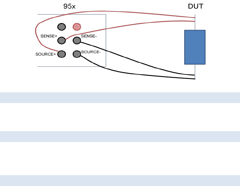
95x Series Operating Manual - December 12, 2011
Page 84 of 151
Figure 25 - 4-wire Low Resistance DUT Connections
LEAD COMPENSATION (2-WIRE)
Performing a lead compensation for this type of test step compensates for lead resistance.
During a lead compensation the SENSE+ and SENSE- wires should be solidly shorted together at the DUT end, the
95x will then measure the lead resistance and automatically subtract it from all future measurements.
LEAD COMPENSATION (4-WIRE)
Lead Compensation is not usually performed when using a 4-wire measurement since lead resistance is
automatically eliminated. If a 4-wire test is configured but the DUT is connected in a 2-wire manner (e.g. separate
wires for SOURCE and SENSE, but they are shorted together before the connection to the DUT) then a Lead
Compensation may be performed in the same manner as for the 2-wire configuration above.
EXAMPLES
Example 1 -
A DUT has a 50Ω input and it is desired to check that the input impedance is within 5% of the nominal 50Ω value.
This is accomplished in a single step as follows –
Seq 1 Step 1 LOW Ω
2/4-WIRE: 2-WIRE Lead resistance is well below 2.5ohm, so 2-wire is chosen
TIME: 0.10sec Load has very little capacitance so use a fast time
Delay: 0.00sec Load has very little capacitance so no delay needed
Lim: 47.50-52.50Ω As required
ON FAIL: ABORT SEQ
Example 2 -
It is required to test that a DUT chassis is bonded to its’ grounding terminal with no more than 0.1ohm of
resistance.
This is accomplished in a single step as follows –
Seq 1 Step 1 LOW Ω
2/4-WIRE: 4-WIRE Lead resistance is significant, so 4-wire is chosen
TIME: 0.10sec Load has very little capacitance so use a fast time
Delay: 0.00sec Load has very little capacitance so no delay needed

95x Series Operating Manual - December 12, 2011
Page 85 of 151
Lim: 0u- 100mΩ As required
ON FAIL: ABORT SEQ
SPECIFICATIONS
Test Current Source
Test Current 55mAdc max
Open Circuit Voltage 5V (nominal)
Source Resistance 130Ω (nominal)
Measurement Accuracy (2-Wire)
Measurement Period 1 cycle local line power
Accuracy <30KΩ : 0.8% + 0.02Ω
30-100KΩ : 1.5%
100-150KΩ : 5%
Lead Compensation <(±1% of error ± 0.005Ω)
Measurement Accuracy (4-Wire)
Measurement Period 1 cycle local line power
Accuracy <30KΩ : 0.8% + 0.002Ω
30-100KΩ : 1.5%
100-150KΩ : 5%
Lead Compensation <(±1% of error ± 0.0005Ω)
4-wire Compensation SOURCE <(±1% total lead impedance, 100Ω max)
SENSE <(±0.1% total lead impedance, 100Ω max)
Test Timing
Test Time 0.02 to 9999sec or user terminated
<(0.05% + 20ms) accuracy
Delay 0.00 to 9999sec
<(0.05% + 20ms) accuracy
AC GROUND BOND TESTING (GBez AND GB)
These types are primarily for testing resistance values from a few microohms up to 8Ω at a user set AC test current
between 0.1 and 40Arms, typically for ground bond testing requirements of safety standards and also for high
current connector, cabling or component testing.
Both GBez and GB are performed in the same manner; the difference between them is in the amount of
configuration available. The GBez type is intended for basic applications; the GB type for comprehensive testing.
The GB type can be configured to provide the same testing as the GBez type.
Table 7 - GBez and GB Type Selection
GBez GB
User set open circuit voltage limit
No
Yes
RMS Impedance Min/Max Limits Yes Optional
In-Phase or Quadrature Impedance Min/Max Limits No Optional
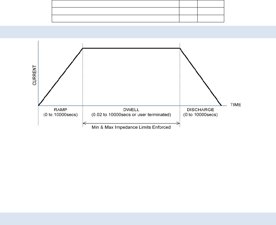
95x Series Operating Manual - December 12, 2011
Page 86 of 151
Timed Ramp
No
Optional
Timed Discharge No Optional
Smooth Transition to next test step if GB type No Optional
ACTIONS WHILE RUNNING
Figure 26 - GBez and GB Type Actions
• Throughout the entire test the actual compliance voltage is measured and the test current reduced to
maintain a constant voltage if above the user set limit – in this situation the front panel C/V LIMITED
indicator is illuminated. NOTE – if this limiting occurs during the dwell period but the impedance
measurement is within limits then the test is failed with a WIRING FAULT condition.
• On any failure the step is immediately aborted, and optionally the entire test sequence may be aborted.
• For the GBez type, the ramp and discharge periods are of zero length.
• For the GB type the discharge period can optionally be skipped if the next step is also a GB type.
CONFIGURING
An example GBez type menu is as follows –
Seq 1 Step 1 GBez
LEVEL:25.000A 60.0Hz
DWELL: 30.0sec
Lim: 0.0u-100.0mΩ
ON FAIL: ABORT SEQ
An example GB type menu is as follows –
Seq 1 Step 1 GB
LEVEL:25.000A 60.0Hz
V CLAMP: 8.0V
RAMP: 1.00sec
DWELL: 30.0sec
Test: RMS
Lim: 0.0u-100.0mΩ
DISCHARGE: FAST
ON FAIL: ABORT SEQ
• LEVEL. Allows the test current level and frequency to be programmed.
• V CLAMP. Only available for the GB type. Allows the open circuit voltage limit to be programmed as a
maximum RMS voltage level.

95x Series Operating Manual - December 12, 2011
Page 87 of 151
o The open circuit voltage limit is automatically set to 8Vrms for the GBez type.
• RAMP. Only available for the GB type. Allows the ramp time period to be programmed either as a time
or rate. The UNIT key toggles the selection between these two methods. In the majority of cases a zero
setting should be used.
• DWELL. Allows the dwell time period to be programmed or set to be user terminated (with the START
button) by pressing the LIMIT key while this setting is selected.
• Test. Only available for the GB type (the GBez type is always set to test the RMS impedance). Allows the
user to define the impedance measurements to be checked against range limits. The available selections
are –
o RMS. Selects that the impedance check is performed on the RMS impedance measurement.
o INPHS. Selects that the impedance check is performed on the in-phase (i.e. resistance)
impedance measurement.
o QUAD. Selects that the impedance check is performed on the quadrature (i.e. reactance)
impedance measurement.
• Lim. Allows the user to define ranges within which the selected impedance measurement is considered a
PASS during the dwell period. The range can be entered in units of impedance or voltage, the UNIT key
toggles the selection. The user may optionally disable the lower limit by entering a zero value for it.
o In-Phase and Quadrature measurements can be of either polarity; the limits are applied to the
measurement without regard to polarity.
• DISCHARGE. Only available for the GB type. Allows the user to program whether the discharge period
should use the same timing as the ramp period (AS RAMP), be as fast as possible (FAST) or skipped
(NONE). If NONE is selected but the next step is not of a GB type then the FAST selection is used when the
sequence is run. In the majority of cases, FAST should be used.
• ON FAIL. Allows the user to program the 95x to abort the entire sequence (ABORT SEQ) or only this step
(CONT SEQ) if this step fails any of its checks. A safety related failure or a user abort (STOP button) always
aborts the entire sequence.
CONNECTING TO THE DUT
The 95x requires that the DUT (at least that portion which is being measured) is floating with respect to ground.
When making 4-terminal measurements the resistance of the wires, the contact resistance to the DUT, and the
contact resistance within the 95x front panel terminals are not included in the result, the only recommendation is
that the SOURCE+ and SOURCE- wires be of sufficient gage to withstand the user set test current.
When wired as shown below, the actual resistance measured is that between the innermost connection points to
the DUT (i.e. between the SENSE+ and SENSE- connections).
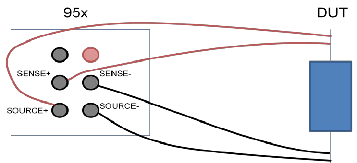
95x Series Operating Manual - December 12, 2011
Page 88 of 151
Figure 27 - GBez and GB Type DUT Connections
If there is more than nominally 1.5V peak between the respective SOURCE and SENSE terminals of the 95x then
the test is failed with a WIRING FAULT condition – the user must ensure that sufficient wire gage is used for the
SOURCE wires (there is very little current flow in the SENSE wires).
If the user needs to make optimum measurements of low impedances, particularly less than a few 10’s of mΩ,
then the following points should be considered -
• The user should be aware that inductive coupling between the current flow in the SOURCE wires and the
respective SENSE wires will cause errors in the measurement results. If the wires are longer than a few
feet and/or are tightly coupled then these errors can be 10’s of milliohms at 60Hz and significantly more
at 400Hz, particularly when high test currents are being used. This effect is not specific to the 95x, it
applies to any high current, low impedance AC measurement.
• When making very low level measurements or when using long lengths of wiring, the user is
recommended to couple (e.g. use a twisted pair) the SOURCE wires together and/or couple the SENSE
wires together for at least the majority of the wire length. Alternatively, if the user maintains at least a ¾“
spacing between each wire and all other wires then these effects are also reduced.
• Similarly, there will be some inductive coupling between the DUT and the SENSE wires if they are not
separated from the DUT sufficiently, to reduce this the SENSE wires should not rest on or close to the
DUT, but should be routed nominally 90° away from the DUT for at least several inches.
• The coupling effects described above will almost always yield a higher than expected measurement. If the
users’ test passes with the measurement within the allowable range of impedances then, even if these are
not accounted for, the DUT is guaranteed to have passed the test – the above effects may only cause a
false failure of the test.
Use caution when handling the connections to the DUT after performing a test. If high currents are being used
then the power in the contact resistance between the DUT and the SOURCE wires, particularly when using clips,
may be high, causing the contacts to become hot – at 40A the power in 1mΩ is 1.6Watts. Similarly the user should
ensure that the connections to the front panel SOURCE terminals are fully secure – the user is recommended to
use lugs and not plug-in connectors for currents above 10A.
The example below shows the connections to a DUT to perform a DC or AC withstand test on the Line/Neutral line
power input, and an AC Ground Bond test on the chassis of the DUT in the same sequence. If wired in this manner,
then no changes in connections are needed.
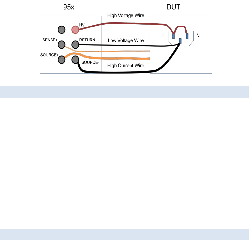
95x Series Operating Manual - December 12, 2011
Page 89 of 151
Figure 28 - DUT Connections for a Voltage Withstand and a GB Test
LEAD COMPENSATION
Lead Compensation is not usually performed when using a 4-wire measurement since lead resistance is
automatically eliminated. If the DUT is connected in a 2-wire manner (e.g. separate wires for SOURCE and SENSE,
but they are shorted together before the connection to the DUT) then a Lead Compensation may be performed to
offset the resistance of the common wiring in future runs.
Lead Compensation should be used with caution to offset errors caused by inductive coupling between the wiring;
the inductive coupling effect is not strictly an offset error as it varies with the DUT resistance and reactance and
the use of Lead Compensation could introduce significant errors.
When performing a lead compensation the impedance limits are not enforced, otherwise the test step is executed
normally.
During a lead compensation the SOURCE+, SENSE+, SOURCE- and SENSE- wires should be solidly shorted together
at the DUT end, the 95x will then measure the resistance and reactance and will automatically subtract them from
all future measurements.
For reference, a near perfect 4-terminal short circuit can be created by connecting the leads to the same short,
straight, length of heavy gage conductor in the order SOURCE+, SOURCE-, SENSE+ and then SENSE-. This creates
the situation where there is no current flow in the DUT between the SENSE terminals, so there is no measurable
impedance between them. The effective impedance of this connection is well below 1uΩ at line frequencies.
EXAMPLES
Example 1 -
It is required to test that a DUT chassis is bonded to its’ grounding terminal with no more than 2.5V drop at
25Arms when tested for at least 30 seconds.
This is accomplished in a single step as follows –
Seq 1 Step 1 GBez No ramp or discharge, RMS limits, so use GBez
LEVEL:25.000A 60.0Hz As required
DWELL: 30.0sec As required
Lim: 0u-2.5000V As required
ON FAIL: ABORT SEQ
Example 2 -
95x Series Operating Manual - December 12, 2011
Page 90 of 151
It is required to test that a DUT chassis is bonded to its’ grounding terminal with no more than 0.1Ω impedance at
40Arms when tested for at least 30 seconds. The source of the test current must be maintained below 5Vrms at all
times to avoid corrosion breakthrough.
This is accomplished in a single step as follows –
Seq 1 Step 1 GB Require a voltage limit, so use GB
LEVEL:40.000A 60.0Hz As required
V CLAMP: 5.0V As required
DWELL: 30.0sec As required
Test: RMS As required
Lim: 0.0u-100.0mΩ As required
DISCHARGE: FAST
ON FAIL: ABORT SEQ
Example 3 –
It is required to test that a line filter inductor is within ±10% of its’ 1mH nominal inductance and <10mΩ resistance
at both 1A @ 60Hz and 10Arms @ 60Hz. At 60Hz the reactance of 1mH is given by 2.π.F.L = 2*3.1416*60.0*0.001
= 0.37699Ω, which is a voltage drop of nominally 3.7699V at 10A so is within the capabilities of the 95x. It has
been decided to only test the resistance at the 10A level as that test is the most demanding. It is desired to
perform all tests within less than 0.5 second to ensure production throughput.
This is accomplished in three steps as follows –
Seq 1 Step 1 GB Not testing RMS impedance, so use GB
LEVEL: 1.000A 60.0Hz As required, perform the 1A test of inductance first
V CLAMP: 8.0V Not needed, so set to the maximum
DWELL: 0.1sec No timing requirement, so perform a fast test
Test: QUAD Test the inductance
Lim: 339.3m-414.7mΩ As required
DISCHARGE: NONE Don’t discharge before the next test, saves test time
ON FAIL: ABORT SEQ
Seq 1 Step 2 GB Not testing RMS impedance, so use GB
LEVEL:10.000A 60.0Hz As required
V CLAMP: 8.0V Not needed, so set to the maximum
DWELL: 0.1sec No timing requirement, so perform a fast test
Test: QUAD Test the inductance
Lim: 339.3m-414.7mΩ As required
DISCHARGE: NONE Don’t discharge before the next test, saves test time
ON FAIL: ABORT SEQ
Seq 1 Step 3 GB Not testing RMS impedance, so use GB
LEVEL:10.000A 60.0Hz As required
V CLAMP: 8.0V Not needed, so set to the maximum
DWELL: 0.1sec No timing requirement, so perform a fast test
Test: INPHS Test the resistance
Lim: 0.0u-10.00mΩ As required
DISCHARGE: FAST
ON FAIL: ABORT SEQ
The total test time is nominally 0.3 seconds, which could be reduced to 0.15 second with ease.

95x Series Operating Manual - December 12, 2011
Page 91 of 151
SPECIFICATIONS
Test Current Source
The following apply at the SOURCE terminals.
Test Current Range 0.100 to 40.000Arms
Test Current Accuracy <(±0.5% ± 0.005A ± 0.005% per Hz above 100Hz) accuracy
Test Current Overshoot <10% (<0.2s ramp time)
<5% (<0.5s ramp time)
<2% (>0.5s ramp time)
Settling to <±0.5% of final value in <0.1sec + 2 cycles
Test Frequency 40Hz to 500Hz
<0.1% accuracy
Test Waveform Sinewave, 1.3 – 1.5 Crest Factor
Compliance (8Vrms – 0.015V/A) max compliance at test frequencies <75Hz.
For line voltages below 115V linearly reduce the maximum compliance by 1%/V
unless Opt. LOLINE is fitted (there is no reduction for Opt. LOLINE).
Loading 10ohm max impedance (any phase, within compliance limits)
250W maximum load power
Voltage Measurements
The following apply at the SENSE terminals.
Range 0uV to 8.0000Vrms (RMS, In-phase and quadrature)
Accuracy <(±0.5% ± 30uV ± 0.5uV*A) accuracy
(add 0.005% + 0.05uV*A per Hz above 100Hz)
<±0.005° per Hz phase relative to test current
Cable Compensation <(1% of error)
Impedance Measurements
Accuracy Add Test Current and Voltage Accuracies as percentages
Examples at 50 or 60Hz -
0.1ohm at 1A : 1% + 0.53% = 1.53%
0.1ohm at 10A : 0.55% + 0.5% = 1.05%
0.1ohm at 40A : 0.51% + 0.5% = 1.01%
0.01ohm at 1A : 1% + 0.8% = 1.8%
0.01ohm at 10A : 0.55% + 0.53% = 1.08%
0.01ohm at 40A : 0.51% + 0.51% = 1.02%
0ohm at 1A : 30.5uohm
0ohm at 10A : 3.5uohm
0ohm at 40A : 1.25uohm
Test Timing
Ramp 0.00 to 9999sec
<(± 1% ± 0.1sec ± 1 cycle) accuracy

95x Series Operating Manual - December 12, 2011
Page 92 of 151
Dwell 0.02 to 9999sec or user terminated
<(± 0.05% ± 20ms ± 1 cycle) accuracy
Fast Discharge <(20ms + 1 cycle)
GROUND LEAKAGE TESTING (DCI AND ACI)
These types are intended for testing that a product does not exceed ground leakage requirements, usually of
safety standards.
Both types are similar, the difference being that the DCI type tests for DC ground leakage current while the ACI
type tests for AC ground leakage current.
ACTIONS WHILE RUNNING
During the test step the 95x measures the ground leakage current and checks that the result is within the user set
range. The 95x also measures the voltage on the HV terminal relative to ground and makes the result of this
measurement available to the user, if not required then this can be ignored.
Optionally, the user can also detecting arc currents and fail the DUT if they are found over the user set limit.
The user can set for there to be a delay at the beginning of the test step before the limits are enforced on the
ground leakage current measurement.
CONFIGURING
An example DCI menu is as follows –
Seq 1 Step 1 DCI
TIME: 25.0sec
Delay: 0.05sec
Lim: 0n-35.00mA
ARC DETECT:4us 10mA
ON FAIL: ABORT SEQ
An example ACI menu is as follows –
Seq 1 Step 1 ACI
TIME: 25.0sec
Delay: 0.05sec
Lim: 0n-35.00mA
ARC DETECT:4us 10mA
ON FAIL: ABORT SEQ
• TIME. Allows the user to program the total test time.
• Delay. Allows the user to set a delay time before which the limits are not enforced.
• Lim. Allows the user to set a minimum and maximum limit for the ground leakage current beyond which
the DUT will be failed.
• ARC DETECT. Allows the user to program arc detection during this step. Both the time and current level
can be independently programmed. ARC detection can also be disabled by setting the leftmost (time)
setting to OFF.
o The 95x can be configured to not fail a test step when arcing is detected. This is configured by
the ARC setting in the CNFG – TEST sub-menu.
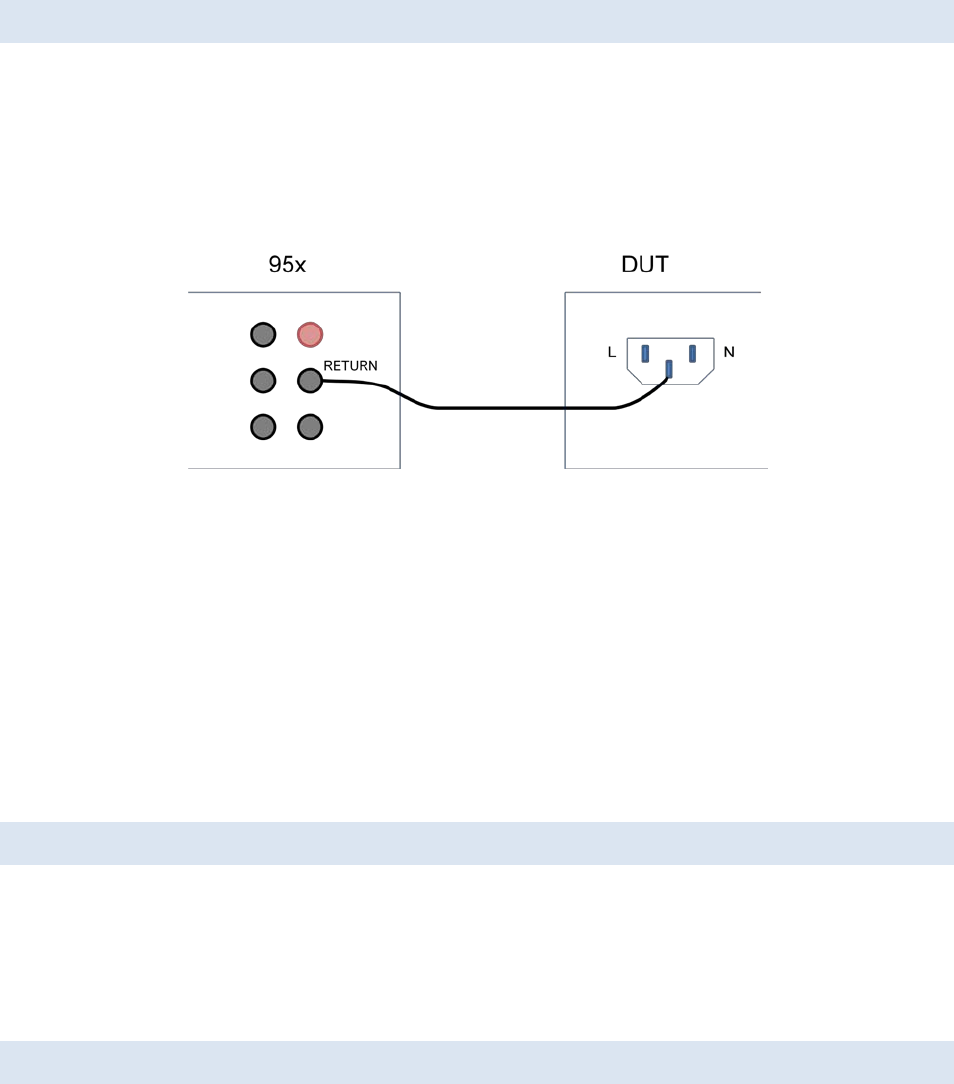
95x Series Operating Manual - December 12, 2011
Page 93 of 151
• ON FAIL. This allows the user to program the 95x to abort the entire sequence (ABORT SEQ) or only this
step (CONT SEQ) if this step fails any of its checks. A safety related failure or a user abort (STOP button)
always aborts the entire sequence.
CONNECTING TO THE DUT
Te 95x measures the current f lowing into the RETURN terminal to the 95x ground during these tests.
The RETURN terminal of the 95x provides a safety ground to the DUT during these types.
NOTE – since the 95x does not control the source of power to the DUT, there is no automatic shutdown if an
excessive current flows. The 95x contains a low voltage (<30V) MOV type protection device from the RETURN
terminal to its chassis ground if excessive current flows, but the user should take additional measures to protect
the system from high current flows in the event of a DUT failure.
Figure 29 - DUT Connections for Ground Leakage
The example above shows a typical DUT ground leakage connection between the DUT and the 95x. The DUT line
and neutral connections would normally be connected to a line and neutral line power source. The 95x is used to
check that the DUT does not have excessive ground leakage using the ACI type test step.
For this type of testing it is often also required to test the ground leakage of several exposed portions of the DUT
as well as the ground connection of the DUT. In those cases the same connection to the 95x would be used, but
the connection to the DUT would be to each required test point on the DUT.
This type of testing is often used for testing that the patient connections of a medical device meet ground leakage
safety standards. In these cases the DUT would be connected normally, either with or without its’ power ground
connection as required by the standard, and each patient connection would be tested for ground leakage by
connecting it to the 95x RETURN terminal.
LEAD COMPENSATION
Lead Compensation is not usually performed on these types. If needed, then Lead Compensation can be used to
reduce the effects of external leakage current.
When performing a lead compensation the ground leakage current limits are not enforced, otherwise the test step
is executed normally.
During a lead compensation the RETURN wire should not be connected to the DUT.
EXAMPLES
Example 1 -
It is required to test that a DUT ground leakage from its chassis is less than 5mArms when line powered. The DC
leakage current is not required to be tested.
95x Series Operating Manual - December 12, 2011
Page 94 of 151
It is assumed that the connection is made prior to the start of the test.
This is accomplished in a single step as follows –
Seq 1 Step 1 ACI AC RMS leakage required, so use ACI
TIME: 0.10sec No timing requirement, so perform quickly
Delay: 0.00sec Already connected, so no delay needed
Lim: 0n-5.000mA Per the requirement
ARC DETECT:OFF Not required so disabled
ON FAIL: ABORT SEQ
Example 2 -
The same requirement as in example 1 but both AC and DC leakage currents are to be tested.
This is accomplished in two steps as follows –
Seq 1 Step 1 ACI AC RMS leakage required, so use ACI
TIME: 0.10sec No timing requirement, so perform quickly
Delay: 0.00sec Already connected, so no delay needed
Lim: 0n-5.000mA Per the requirement
ARC DETECT:OFF Not required so disabled
ON FAIL: ABORT SEQ
Seq 1 Step 2 DCI DC leakage required, so use DCI
TIME: 0.10sec No timing requirement, so perform quickly
Delay: 0.00sec Already connected, so no delay needed
Lim: 0n-5.000mA Per the requirement
ARC DETECT:OFF Not required so disabled
ON FAIL: ABORT SEQ
Example 3 -
It is required to test that a medical device patient connection has less than 50uArms ground leakage. The test is to
be performed over a 10 second period to ensure that any periodic current is detected.
This is accomplished in a single step as follows –
Seq 1 Step 1 ACI AC RMS leakage required, so use ACI
TIME: 10.0sec Per the timing requirement
Delay: 0.00sec Already connected, so no delay needed
Lim: 0n-50.00uA Per the requirement
ARC DETECT:OFF Not required so disabled
ON FAIL: ABORT SEQ
Example 4 -
It is required to test the leakage current of material sample over a range of voltages. This is to be performed
manually, using an external source of voltage. This could be a DC or AC test, for this example DC is used.
The external voltage source is connected to one end of the material sample, with its’ common terminal grounded,
and the 95x RETURN terminal is connected to the other end of the material sample.
If the voltage being used is within the measurement capability of the 95x, then the output of the external voltage
source could also be connected to the HV terminal of the 95x, in which case the 95x display would also show the
actual applied voltage to the material sample.
A single step is used as follows –

95x Series Operating Manual - December 12, 2011
Page 95 of 151
Seq 1 Step 1 DCI DC leakage required, so use DCI
TIME: user sec Use manual timing, press the START button when finished
Delay: 0.00sec Already connected, so no delay needed
Lim: 0n-5.000mA Set wide limit, the user will manually check the results
ARC DETECT:OFF Not required so disabled
ON FAIL: ABORT SEQ
SPECIFICATIONS
HV Voltage Measurements
DC Voltage Range 951i,952i,956i : 0.0 to +/-8000V
953i,954i,955i : 0.0 to +/-11000V
AC Voltage Range 951-4i,956i : 0.0 to 6000Vrms
955i : 0.0 to 10000Vrms
DC Accuracy <(± 0.25% ± 0.5V)
AC Accuracy <(± 0.5% ± 0.5V ± 0.01% per Hz above 100Hz)
Input Impedance Nominally 100MΩ
RETURN Current Measurements
Current Range 0.0nA to 200mA (DC or ACrms)
DC Current Accuracy <(± 0.25% ± 0.5nA)
AC Current Accuracy <(± 0.5% ± 20nA ± 0.005% per Hz above 100Hz)
Input Impedance <150uA : Nominally 5KΩ
>150uA : Nominally 30Ω
Arc Current 1 to 30mArms (50KHz-5MHz bandwidth)
<(± 10% ± 1mA) accuracy at 1MHz
4us, 10us, 15us, 20us, 30us or 40us measurement period
Cable Compensation <(± 1% of error)
Test Timing
Test 0.02 to 9999sec or user terminated
<(± 0.05% ± 20ms) accuracy
Delay 0.00 to 9999sec
<(± 0.05% ± 20ms) accuracy
SWITCH UNIT CONTROL (SWITCH)
This type is used to control one or more external Switch Matrix Units (either ViTREK 948 or 964 units).
NOTE – to be able to define or edit a SWITCH test step the 95x must already be configured to control one or more
switch matrix units, see Controlling External Switch Matrix Units.
ACTIONS WHILE RUNNING
The external switch matrix units are controlled by the 95x in three periods as follows –

95x Series Operating Manual - December 12, 2011
Page 96 of 151
1. Pre-switch Period. During this period the 95x checks for the presence of each configured switch matrix
unit and also delays for at least the user set pre-switch delay period. If a configured switch matrix unit
fails to be detected then the sequence is aborted. As soon as all units have been detected and the
minimum delay has expired, the switch command period is started.
2. Switch Command Period. During this period all configured switch matrix units have their relays
commanded into the user set states. As soon as this is completed the post-switch period is started.
3. Post-switch Period. The 95x stays in this period until the user set post-switch delay has expired. This
period allows for relay and wiring settling after changing the relay states. As soon as the delay has
expired the next test step in the test sequence is started.
CONFIGURING
An example SWITCH type menu is as follows –
Seq 1 Step 1 SWITCH
PRE-DELAY: 0.00sec
POST-DELAY: 0.25sec
#1: 0000000000000000
• PRE-DELAY. Allows the pre-switch delay to be specified. Generally this should be set to zero, but may
need to be extended if external circumstances require a delay between the preceding step and the relays
being changed in this step.
• POST-DELAY. Allows the post-switch delay to be specified. When controlling a ViTREK 948 this should be
set to a minimum of 0.20sec, for a ViTREK 964 this can be set to zero if there are negligible wiring settling
requirements.
• #1. Allows the user to specify, using a hexadecimal code, the required relay states for switch matrix unit
#1. If configured for more than one switch matrix unit, there are further menu lines added for each
additional switch matrix unit. If configured for a ViTREK 948 then this menu line has 14 characters, for a
ViTREK 964 it has 16 characters. The hexadecimal code sets a binary code defining the required states of
relays #64 through 1 (for a 964) or #56 through 1 (for a 948) in left-to-right order. A ‘1’ in this code
indicates that the relay is to be in the ON state. See the relevant switch matrix manual for further details
regarding setting these codes. The user should ensure that the state of any relay which is not actually
fitted in the switch matrix unit is ‘0’.
NOTE – the 95x does not change the states of switch matrix units unless commanded to do so by a SWITCH test
step. It is recommended to finish a test sequence using switch matrix units with a SWITCH type step setting the
relays to best “quiescent” state for the users’ specific system (generally the OFF state for all relays).
EXAMPLES
Example 1 -
The user wishes to set a single ViTREK 964 to engage (ON) relays #1, 28 and 47; all other relays are to be
disengaged (OFF).
Since a ViTREK 964 is being used, no delays are needed.
The 64-bit code for the required state is (splitting the binary into groups of 8 bits for easier viewing) –
00000000 00000000 10000000 00000000 00010000 00000000 00000000 00000001
In hexadecimal this is 00 00 80 00 10 00 00 01 (keeping the same grouping as above)

95x Series Operating Manual - December 12, 2011
Page 97 of 151
The SWITCH step is configured as –
Seq 1 Step 1 SWITCH
PRE-DELAY: 0.00sec
POST-DELAY: 0.00sec
#1: 0000800010000001
Example 2 -
This is the same as example 1 above, but using a ViTREK 948.
Since a ViTREK 948 is being used, a 0.25sec post-switch delay is needed.
The 56-bit code for the required state is (splitting the binary into groups of 8 bits for easier viewing) –
00000000 10000000 00000000 00010000 00000000 00000000 00000001
In hexadecimal this is 00 80 00 10 00 00 01 (keeping the same grouping as above)
The SWITCH step is configured as –
Seq 1 Step 1 SWITCH
PRE-DELAY: 0.00sec
POST-DELAY: 0.25sec
#1: 00800010000001
SPECIFICATIONS
Pre- or Post-Switch Delay 0.00 to 9999sec
<(± 0.05% ± 20ms) accuracy
TEST SEQUENCE TIMING CONTROL (PAUSE AND HOLD)
The PAUSE type is generally used when the user needs to have a fixed delay inserted into a test sequence to allow
for wiring or DUT settling between two test steps.
The HOLD type is generally used when the user needs to have some user interaction to occur prior to continuing
the test sequence. A timeout is provided which, if it occurs, will abort the entire sequence is the user does not
provide user interaction (e.g. pressing the START button, asserting the DIO interface START signal, or sending the
interface CONT command).
CONFIGURING
An example PAUSE type menu is as follows –
Seq 1 Step 1 PAUSE
TIME: 0.00sec
• TIME. Allows the user to set the desired pause time. Any value between 0.00 and 9999 seconds may be
entered.
An example HOLD type menu is as follows –
Seq 1 Step 1 HOLD
TIMEOUT: 30.0sec
• TIMEOUT. Allows the user to set the desired hold timeout. Any value between 0.00 and 9999 seconds
may be entered. Setting a zero value disables the timeout entirely; the 95x will wait “forever” for user
interaction to occur.

95x Series Operating Manual - December 12, 2011
Page 98 of 151
EXAMPLES
Example 1 -
The user wishes to program a 1 second pause into a test sequence to allow for wiring settling between two steps.
A PAUSE step is configured as –
Seq 1 Step 28 PAUSE
TIME: 1.00sec
Example 2 -
The user wishes to program a step to have the sequence wait for user interaction before proceeding. This will be
used to allow the user to manually alter the DUT wiring. It is desired to timeout the sequence if the user does not
respond within 1 minute.
A HOLD step is configured as –
Seq 1 Step 28 HOLD
TIME: 60.0sec
SPECIFICATIONS
Delay or Timeout 0.00 to 9999sec
<(± 0.05% ± 20ms) accuracy
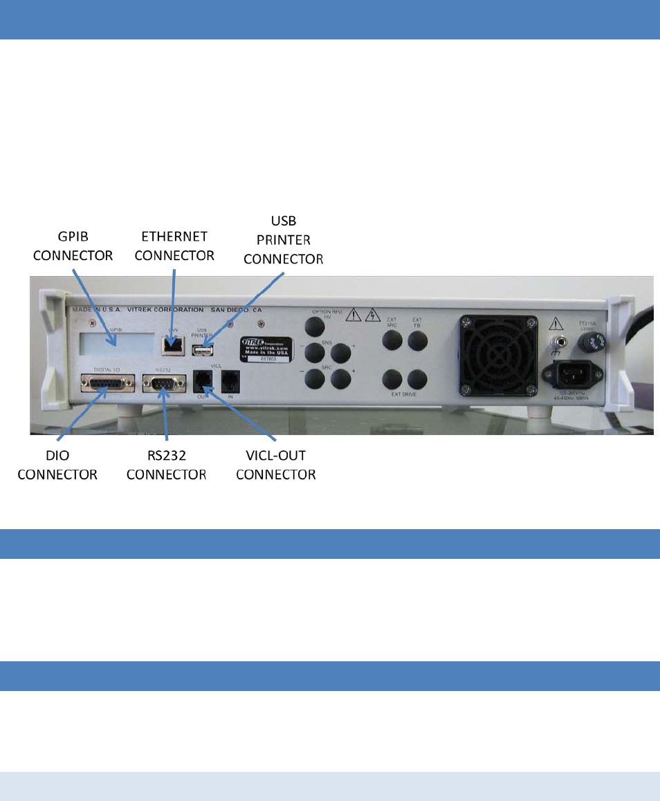
95x Series Operating Manual - December 12, 2011
Page 99 of 151
SECTION 7 – CONNECTING AND CONFIGURING INTERFACES
The 95x contains several interfaces, some of which are options. This section describes how to configure and
connect to each interface. Each description of menus only includes the settings pertinent to the section being
described.
For the DIO interface, see SECTION 8 – DIO INTERFACE
For programming information using an interface to control the 95x see SECTION 11 – PROGRAMMING VIA AN
INTERFACE.
NOTE – The user is recommended to disable all unused interfaces to avoid interference affects.
Figure 30 - Rear Panel Layout (Interface Connectors)
LOCAL AND REMOTE OPERATION
When the 95x receives a command from an enabled interface the front panel REMOTE indicator is illuminated and
the user may not use the front panel menus. To attempt to return the 95x into the local state the user should
press the CNFG key on the 95x front panel. If the 95x has been enabled to return to the local state by the
controlling interface then the REMOTE indicator will extinguish and a message is displayed on the 95x front panel.
CONTROLLING EXTERNAL SWITCH MATRIX UNITS
The 95x can be configured to control one ViTREK 948i or up to 4 ViTREK 964i Switch Matrix units.
NOTE – the 95x must be configured to control an external Switch Matrix unit before a test sequence can be
created which contains steps to control it.
CONFIGURATION
• Ensure that the display indicates that the 95x is in the base menu state, i.e. the display shows the date
and time. If necessary press the STOP button to abort a menu and return to the base menu state.
• Press the CNFG key.
95x Series Operating Manual - December 12, 2011
Page 100 of 151
• The display now shows the main configuration menu, an example of which is –
TEST…
PRINTOUT…
SYSTEM…
INTERFACES…
DIGITAL I/O…
BUILD…
SET TO DEFAULTS…
LOCK PASSWORD:000000
RELOCK…
• Using the Left Arrow or Right Arrow keys as needed, change the selection point to the INTERFACES line.
• Press the ENTER key.
• The 95x now displays the base interfaces configuration settings menu, an example of which is –
RS232 BAUD: 115200
SWITCH: NONE
DISABLE USB: NO
DISABLE GPIB: NO
DISABLE ENET: NO
ETHERNET…
GPIB ADDR: 2
• The user may navigate this sub-menu and change the displayed settings as required. The settings
affecting controlling external switch matrix units are -
o RS232 BAUD. This setting is only used when controlling an external 964i Switch Matrix unit via
the RS232 interface. Its setting should match the baud rate setting in the attached 964i.
o SWITCH. This allows the user to select the method by which external switch matrix units are
interfaced to the 95x. The available selections are –
NONE. No switch matrix units are controlled by the 95x.
948 (SERIAL). A single ViTREK 948i Switch Matrix unit is being controlled by the 95x via
the RS232 serial interface. The RS232 BAUD setting is ignored if this is selected.
964 (SERIAL). A single ViTREK 964i Switch Matrix unit is being controlled by the 95x via
the RS232 serial interface.
964 (VICLx1). A single ViTREK 964i Switch Matrix unit is being controlled by the 95x via
the VICL interface. The 964i must be configured for VICL and set to address 1.
964 (VICLx2). Two ViTREK 964i Switch Matrix units are being controlled by the 95x via
the VICL interface. All 964i’s must be configured for VICL and set to addresses 1 and 2.
964 (VICLx3). Three ViTREK 964i Switch Matrix units are being controlled by the 95x via
the VICL interface. All 964i’s must be configured for VICL and set to addresses 1, 2 and
3.
964 (VICLx4). Four ViTREK 964i Switch Matrix units are being controlled by the 95x via
the VICL interface. All 964i’s must be configured for VICL and set to addresses 1, 2, 3
and 4.
• When finished, press the EXIT key to exit this sub-menu, and then press EXIT again (if no additional
configuring is to be performed) to exit the main configuration menu and save the settings. NOTE – the
settings are not active until all menus have been exited.

95x Series Operating Manual - December 12, 2011
Page 101 of 151
CONNECTIONS
Refers to the instructions received with the specific Switch Matrix unit(s) for details regarding connecting the
terminals of the 95x to those of the Switch Matrix Units.
RS232 Interface
Using a RS232 cable supplied by ViTREK, connect the RS232 port on the 95x rear panel to the RS232 (Serial) port of
the ViTREK 948i or 964i. The user may supply their own cable, in which case it should be a 9-wire female-female
null modem cable capable of full handshake 115200baud operation.
VICL
Using a VICL cable supplied by ViTREK, connect the VICL – OUT port on the 95x to a ViTREK 964i VICL – IN port. If
using more than one 964i, then connect each additional ViTREK 964i VICL – IN port to the preceding 964i’s VICL –
OUT port. The 964i’s do not need to be wired together in any specific order when using the VICL interface.
CONTROLLING THE 95X BY THE RS232 INTERFACE
NOTE – the RS232 interface can only be used for a single purpose, it cannot be used for both controlling an
external Switch Matrix unit and controlling the 95x.
SPECIFICATIONS
Baud Rate 9600, 19200, 57600 or 115200
Handshake Bi-directional, hardware (RTS/CTS)
Data Bits 8
Parity None
Start/Stop Bits 1
Connector 9-pin Male Dsub
Interface Pinout Type DTE (same as PC computer)
Cable required 9-wire female-female null modem cable, fully wired
Cable Length <50ft (per standard)
CONFIGURATION
• Ensure that the display indicates that the 95x is in the base menu state, i.e. the display shows the date
and time. If necessary press the STOP button to abort a menu and return to the base menu state.
• Press the CNFG key.
• The display now shows the main configuration menu, an example of which is –
TEST…
PRINTOUT…
SYSTEM…
INTERFACES…
DIGITAL I/O…
BUILD…
SET TO DEFAULTS…
LOCK PASSWORD:000000
RELOCK…

95x Series Operating Manual - December 12, 2011
Page 102 of 151
• Using the Left Arrow or Right Arrow keys as needed, change the selection point to the INTERFACES line.
• Press the ENTER key.
• The 95x now displays the base interfaces configuration settings menu, an example of which is –
RS232 BAUD: 115200
SWITCH: NONE
DISABLE USB: NO
DISABLE GPIB: NO
DISABLE ENET: NO
ETHERNET…
GPIB ADDR: 2
• The user may navigate this sub-menu and change the displayed settings as required. The settings
affecting using the RS232 to control the 95x are -
o RS232 BAUD. This setting must match the baud rate setting of the attached computer.
• When finished, press the EXIT key to exit this sub-menu, and then press EXIT again (if no additional
configuring is to be performed) to exit the main configuration menu and save the settings. NOTE – the
settings are not active until all menus have been exited.
CONNECTIONS
Using a RS232 cable supplied by ViTREK, connect the RS232 port on the 95x rear panel to the RS232 (Serial) port of
a computer. The user may supply their own cable, in which case it should be a 9-wire female-female null modem
cable capable of full handshake 115200baud operation.
CONTROLLING THE 95X BY THE GPIB INTERFACE
CONFIGURATION
• Ensure that the display indicates that the 95x is in the base menu state, i.e. the display shows the date
and time. If necessary press the STOP button to abort a menu and return to the base menu state.
• Press the CNFG key.
• The display now shows the main configuration menu, an example of which is –
TEST…
PRINTOUT…
SYSTEM…
INTERFACES…
DIGITAL I/O…
BUILD…
SET TO DEFAULTS…
LOCK PASSWORD:000000
RELOCK…
• Using the Left Arrow or Right Arrow keys as needed, change the selection point to the INTERFACES line.
• Press the ENTER key.
• The 95x now displays the base interfaces configuration settings menu, an example of which is –
RS232 BAUD: 115200
SWITCH: NONE
DISABLE USB: NO
DISABLE GPIB: NO

95x Series Operating Manual - December 12, 2011
Page 103 of 151
DISABLE ENET: NO
ETHERNET…
GPIB ADDR: 2
• The user may navigate this sub-menu and change the displayed settings as required. The settings
affecting using the RS232 to control the 95x are –
o DISABLE GPIB. This must be set to NO to enable the GPIB interface in the 95x.
o GPIB ADDR. This must be set to a chosen address for the 95x on the GPIB bus. Addresses in the
range 1 through 29 may be used if there is no other device on the bus at that address. Software
in the computer will need to be set to match this address in order for it to communicate with the
95x.
• When finished, press the EXIT key to exit this sub-menu, and then press EXIT again (if no additional
configuring is to be performed) to exit the main configuration menu and save the settings.
CONNECTIONS
Using a standard GPIB cable connect the GPIB port on the 95x rear panel to the GPIB port of a computer. It is
recommended to use a high quality, shielded GPIB cable. Cables may be purchased from ViTREK.
CONTROLLING THE 95X BY THE ETHERNET INTERFACE
SPECIFICATIONS
Speed 10baseT or 100baseTX, auto-selected
Duplex Half or full-duplex, auto-selected
MDI/MDIX Auto-selected
Protocols ICMP, ARP, DHCP, TCP/IP (IPv4 only)
TCP Port 10733
Remote Connections Only one remote connection is allowed at any given time
Connector RJ45
Cable required CAT5 or CAT5e, UTP or STP
Cable Length <100m (per standard)
CONFIGURATION
Prior to configuring the 95x or connecting the 95x to a network, the user must have knowledge of certain aspects
of the network –
• The user must ascertain if the network uses DHCP or not for allocation of IP addresses.
• If the network does not use DHCP for allocation of IP addresses, then the user must choose a suitable
unused IP address within the local network subnet, the subnet mask of the local network, and the
gateway IP address to additional networks.
• Some networks which use DHCP allocation of IP addresses limit the allocation of addresses to known
devices by means of a list of known MAC addresses. In this case the user must ascertain the MAC address
of the 95x and correctly configure the DHCP server prior to connecting the 95x to the local network.
95x Series Operating Manual - December 12, 2011
Page 104 of 151
Configure the Ethernet Interface of the 95x as follows -
• Ensure that the display indicates that the 95x is in the base menu state, i.e. the display shows the date
and time. If necessary press the STOP button to abort a menu and return to the base menu state.
• Press the CNFG key.
• The display now shows the main configuration menu, an example of which is –
TEST…
PRINTOUT…
SYSTEM…
INTERFACES…
DIGITAL I/O…
BUILD…
SET TO DEFAULTS…
LOCK PASSWORD:000000
RELOCK…
• Using the Left Arrow or Right Arrow keys as needed, change the selection point to the INTERFACES line.
• Press the ENTER key.
• The 95x now displays the base interfaces configuration settings menu, an example of which is –
RS232 BAUD: 115200
SWITCH: NONE
DISABLE USB: NO
DISABLE GPIB: NO
DISABLE ENET: NO
ETHERNET…
GPIB ADDR: 2
• The user may navigate this sub-menu and change the displayed settings as required. The settings
affecting using the RS232 to control the 95x are –
o DISABLE ENET. This must be set to NO to enable the Ethernet interface in the 95x.
o ETHERNET… This selection is the entry point to the sub-menu for configuring the Ethernet
interface. The user should navigate to select this menu line and press then ENTER key.
• The Ethernet sub-menu allows the user to configure the 95x for the local network. An example of this
sub-menu is as follows –
• USE DHCP: YES
IP: 000.000.000.000
SNET:000.000.000.000
GTWY:000.000.000.000
MAC: 1234567890AB
• The user may navigate this sub-menu and change the displayed settings as required. The settings are –
o USE DHCP. Allows the user to configure the 95x to use DHCP for IP address allocation (YES) or
not (NO).
o IP. If using DHCP, this shows the IP address which the 95x has been allocated. If not using DHCP
this allows the user to enter an IP address for the 95x on the local network.
o SNET. If using DHCP, this shows the IP subnet mask which the 95x has been given. If not using
DHCP this allows the user to enter the subnet mask for the local network.

95x Series Operating Manual - December 12, 2011
Page 105 of 151
o GTWY. If using DHCP, this shows the IP of the gateway to additional networks which the 95x has
been given. If not using DHCP this allows the user to enter the IP address of the gateway.
o MAC. This is not editable and shows the MAC address of the 95x. This may be needed to
configure the local network to allow connection of the 95x to it. In most networks this is not
needed.
• When finished, press the EXIT key to exit this sub-menu, and then press EXIT again (if no additional
configuring is to be performed) to exit the main configuration menu and save the settings. NOTE – the
settings are not active until all menus have been exited.
• If using DHCP the user should re-enter the ETHERNET configuration sub-menu and note the IP address
allocated to the 95x. This will be needed to configure the TCP/IP client software used to communicate
with the 95x.
CONNECTIONS
The 95x connects to the local network using a standard CAT5 or CAT5e Ethernet cable and RJ45 connector.
When initially connected to the network the 95x display shows a message for 2 seconds detailing the actual speed
and duplex used for the connection.
PRINTING FROM THE 95X USING THE USB INTERFACE
SPECIFICATIONS
Printer Class Printer must be a “Printer” USB Class device
Printer Language PJL/PCL (HP)
USB Speed Full Speed
Hub Not supported
Many printers meet the requirements above; ViTREK has tested the 95x with the HP OfficeJet Pro 8000 Series and
the HP LaserJet 2420. The 95x is generally not compatible with multi-purpose printers (e.g. “All-in-One” types).
CONNECTING
The printer should be connected to the 95x USB Host port using a standard USB cable of any suitable length. The
printer must be directly connected to the 95x, a hub must not be used.
When the printer is initially plugged in to the 95x, or when the printer is initially powered (for some printers) the
95x displays an informative message for 2 seconds detailing the status of the printer connection.
The user may also view the status of the connection to the printer at any time by using the following procedure –
• Ensure that the display indicates that the 95x is in the base menu state, i.e. the display shows the date
and time. If necessary press the STOP button to abort a menu and return to the base menu state.
• Press the CNFG key.
• The display now shows the main configuration menu, an example of which is –
TEST…
PRINTOUT…
SYSTEM…

95x Series Operating Manual - December 12, 2011
Page 106 of 151
INTERFACES…
DIGITAL I/O…
BUILD…
SET TO DEFAULTS…
LOCK PASSWORD:000000
RELOCK…
• Using the Left Arrow or Right Arrow keys as needed, change the selection point to the PRINTOUT line.
• Press the ENTER key.
• The display now shows the test report printout configuration menu. An example of the test report
printout configuration menu is as follows –
STATUS: ATTACHED
HEADING:
AUTO TEST REPORT: NO
TEST DETAIL: NORMAL
SERIAL #: NO
• The STATUS line shows the status of the present connection to the printer. See later in this document
regarding the remainder of this menu..
• When finished, press the EXIT key to exit this sub-menu, and then press EXIT again (if no additional
configuring is to be performed) to exit the main configuration menu and save the settings.
PRINTING
While printing the display of the 95x shows the progress and any errors which occur –
• PRINTING. This is displayed while the printout is being performed. The user may press the STOP button
on the 95x front panel to abort a printout.
• PRINTER DISCONNECTED. Indicates that the USB cable became disconnected.
• PRINTER USB BUS ERROR. Indicates that an unrecoverable USB bus error occurred. The 95x automatically
reinitializes the USB bus after this, but the printout is aborted. This is typically caused by severe
interference on the USB cable.
• PRINTER TIMEOUT. This occurs after a printout is suspended by the printer for over 10 minutes.
• PRINT ABORTED. This occurs when the user aborts a printout using the front panel STOP button.
Configuration Printout
This is commanded by pressing the PRINT key while the 95x is in the base menu state (i.e. displaying the date and
time). The printout contains a complete listing of all the configuration settings and the build state of the unit.
Test Sequence Printout
This is commanded by pressing the PRINT key while the user is selecting a test sequence using the SELECT key. The
printout contains a full listing of all the settings for each defined step in the selected test sequence.
Test Results Report Printout
See Printing a Test Results Report.
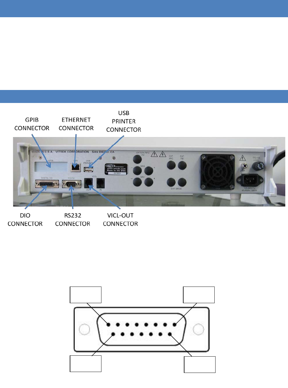
95x Series Operating Manual - December 12, 2011
Page 107 of 151
SECTION 8 – DIO INTERFACE
Using the 95x Digital Input & Output (DIO) interface the user may perform any combination of the following –
• Control the 95x using a PLC type device, starting, stopping, selecting a sequence and determining the
pass/fail status
• Control the 95x using external start and/or stop switches
• Abort a test sequence when a safety interlock is opened
• Allow the 95x to illuminate external safety indicators
CONNECTOR AND PINOUT
Figure 31 - Rear Panel Layout (DIO Connector)
The DIO signals are available at the rear panel of the 95x in the 15-pin connector identified as “DIGITAL I/O” as
shown the photograph above. The 95x connector is a standard two-row 15-pin female Dsub connector; any
suitable male mating connector may be used.
The diagram below shows the pin locations within the connector as viewed from the rear panel of the 95x.
Pin 1 Pin 8
Pin 9
Pin 15
Figure 32 - DIO Connector Pin Locations

95x Series Operating Manual - December 12, 2011
Page 108 of 151
The following table contains a description of the signal on each pin in the connector. Each input and output signal
can be configured as the active level being low or high, or each input may be disabled.
Table 8 - DIO Connector Pin out and Signals
CONFIGURING
The DIO interface may be configured from the front panel by using the DIGITAL I/O sub-menu of the CNFG menu as
follows –
• Ensure that the display indicates that the 95x is in the base menu state, i.e. the display shows the date
and time. If necessary press the STOP button to abort a menu and return to the base menu state.
• Press the CNFG key.
• The display now shows the main configuration menu, an example of which is –
TEST…
PRINTOUT…
SYSTEM…
INTERFACES…
DIGITAL I/O…
BUILD…
Pin 1 +12VDC Internal +12VDC power source, internally fused 100mA (self resetting)
Pin 2 HV PRESENT Output Active whenever an unsafe voltage or current is present on the 95x
terminals
Pin 3 COMMON Common Reference signal for all digital inputs and outputs (Digital
Ground, internally connected to the 95x chassis ground)
Pin 4 START Input
Starts a test sequence when transitions inactive to active. This may also
be used to continue a test sequence when it is waiting for user
interaction (e.g. in a HOLD step, or programmed for a user terminated
test step). If the SEQUENCE input signals are not used to select a
sequence, then a sequence must have been already manually selected at
the front panel.
If the 95x is waiting for the front panel START button to be pressed while
running a test sequence (i.e. waiting for user interaction) then an inactive
to active transition of the START signal will also continue the sequence.
Pin 5 ABORT Input Aborts a test sequence when active. This signal has priority over the
START signal; disabling it while ABORT is active.
Pin 6 INTERLOCK Input Aborts a test sequence (high voltage or current steps only) when inactive
Pin 7 PRINT Input Initiates a Test Results Printout
Pin 8 SEQUENCE 1
Input
These signals are only used at the instant of the START signals’ transition
which starts a sequence; they are ignored at all other times. Sequence #
0 through 15 is selected and run according to the state of these signals.
Pin 9 SEQUENCE 2
Pin 10 SEQUENCE 4
Pin 11 SEQUENCE 8
Pin 12 PASS Output Active after the end of a sequence if passed
Pin 13 FAIL Output Active after the end of a sequence if failed
Pin 14 TESTING Output Active while running a sequence
Pin 15 DWELL Output Active during the dwell period of a measurement type of test

95x Series Operating Manual - December 12, 2011
Page 109 of 151
SET TO DEFAULTS…
LOCK PASSWORD:000000
RELOCK…
• Using the Left Arrow or Right Arrow keys as needed, change the selection point to the DIGITAL I/O line.
• Press the ENTER key.
• The display now shows the Digital I/O configuration menu. An example of the Digital I/O configuration
menu is as follows –
START: IGNORE
ABORT: IGNORE
INTERLOCK: IGNORE
PRINT: IGNORE
SEQUENCE: IGNORE
PASS: ACTIVE LO
FAIL: ACTIVE LO
TESTING: ACTIVE HI
DWELL: ACTIVE HI
HV: ACTIVE HI
• The user may navigate this sub-menu and change the displayed settings as required.
o START, ABORT, INTERLOCK, PRINT and SEQUENCE. These allow the user to select whether the
respective digital input is to be ignored, active low or active high.
If either the INTERLOCK signal is enabled and set for active low, or the ABORT signal is
enabled and set for active high, then the 95x will be prevented from running any test
sequence if the DIO signals are removed (e.g. the cable is unplugged). If this is not
intended, then these signals should be used with the opposite polarity (i.e. active high
for INTERLOCK and active low for ABORT).
CAUTION – changing the active level of the START signal may cause the 95x to detect a
change in the START signal from the inactive to the active state (e.g. if the signal is high
and the configuration is changed from active low to active high). This may cause a
previously selected sequence to be run and high voltages to become present on the 95x
terminals. The user should ensure that no sequence is selected and that the START
signal will end up being in the inactive state when changing the polarity of the START
signal.
o PASS, FAIL, TESTING, DWELL and HV. These allow the user to select whether the respective
digital output is to be active low or active high.
• When finished, press the EXIT key to exit this sub-menu, and then press EXIT again (if no additional
configuring is to be performed) to exit the main configuration menu and save the settings. The settings
are not used until they are saved.
SIGNAL LEVELS
Each input signal has the following characteristics –
• Each is referenced to the COMMON signal, which is internally connected to the 95x chassis ground.
• The maximum input level guaranteed to be recognized as a low level is +1V, the minimum guaranteed to
be recognized as a high level is +2.3V.

95x Series Operating Manual - December 12, 2011
Page 110 of 151
• Each has an internal pull-up resistor of nominally 1.8KΩ to an internal 4V level and is protected to 5V.
• Each has a nominally 10nF capacitance to the COMMON signal.
• Each can be directly interfaced to a contact closure or a TTL, CMOS or LVCMOS logic source. If the input is
to be actively driven from a higher voltage logic signal than 5V (e.g. 12V) then one of the following should
be used –
• A suitable value series resistance should be placed in each input signal line to limit the current in the
5V protection to a maximum of 30mA (for 12V logic signals the recommended series resistance is
390Ω). The maximum series resistance value allowable is nominally 600Ω to achieve the guaranteed
low voltage level.
• A diode should be placed in series with the signal with its’ anode connected towards the 95x
connector. This will effectively change the high voltage digital signal to a contact closure type, only
being able to pull the 95x input to the low state and relying on the 95x internal pull-up resistor to
select the high state.
• A suitable logic level translation circuit should be employed between the high voltage logic and the
95x.
• An isolation circuit must be employed between the high voltage logic signal and the 95x input.
Each output signal has the following characteristics –
• Each has an open-drain drive with >12V withstand and >500mA sink capability (<1.3Ω impedance) with a
pull-up resistor of nominally 2.2KΩ to an internal 5V level.
• Each is internally clamped to nominally 16V (14V minimum) so may be used to directly drive a relay.
When using a digital output to drive a 12V relay coil or indicator the user should consider that each
output has a nominally 3.2mA current flow into the 95x when the output is in the off state at +12V. The
user must ensure that this current is insufficient to operate the relay or indicator. If this current is not
acceptable then the signal must be buffered by a suitable driver, e.g. a NPN transistor, N-channel
MOSFET, buffer IC, or an isolation device.
SIGNAL ISOLATION
When operating the 95x in adverse environments having a large amount of ground noise, or when the 95x is being
at very high test voltage levels, it is recommended to provide isolation between the 95x DIO signals and the
remote device if that is also grounded or has significant capacitance to ground. This avoids transient ground
voltages during DUT breakdown from causing improper operation of the interface. The user should consider using
relays (mechanical or solid state) or logic type optical couplers to provide the isolation. In extreme conditions, the
user may need to take steps to ensure that there is minimum capacitance across the isolation barrier formed by
these components and also that they are specified for the high voltage transients which could occur – it is
recommended that isolation devices with a capacitance of <20pF and a voltage withstand capability of >2.5KVpk
be used.
SIGNAL TIMING
In this section there are several references to signals needing to be active or inactive for minimum periods of time.
The time shown is the minimum guaranteed time for the action described to occur, times less than shown may
also function correctly but they are not guaranteed to be reliable.

95x Series Operating Manual - December 12, 2011
Page 111 of 151
Starting with the START signal
The following timing constraints on the DIO signals must be observed when starting a test sequence using the
START signal –
• The TESTING output signal from the 95x must have been inactive for >5ms before a sequence may be
started.
• If enabled, the ABORT signal must be inactive for >5ms before the inactive to active transition of the
START signal.
• The START signal must have been inactive for >5ms before attempting to start.
• The START signal must be active for >10ms, there is no maximum time.
• If enabled, the SEQUENCE signals must all be stable in the required state for >5ms before and after the
inactive to active transition of the START signal.
<(10ms + 1ms per test step in the sequence commanded by the SEQUENCE input signals if enabled) after
recognition of the inactive to active transition of the START signal the test sequence is started. At that time the
PASS, FAIL and TESTING output signals are set by the 95x to the following states with <±100us skew between
them-
• PASS and FAIL – both made inactive if the sequence is valid and started correctly, otherwise PASS is made
inactive and FAIL is made active.
• TESTING – made active if the sequence is valid and started correctly, otherwise remains inactive.
Aborting with the ABORT or INTERLOCK signals
If enabled and the ABORT signal is active for >5ms then any running test sequence is aborted.
If enabled and the INTERLOCK signal is inactive for >5ms then a test sequence is aborted if it is presently running
an ACez, ACW, ACIR, ACCAP, ACI, BRKDN, DCez, DCW, DCCAP, IRCAP, DCI, GBez, GB or PULSE type step. It has no
affect on any other type of step or if a test sequence is not being run.
PASS, FAIL and TESTING signals at the end of a Test Sequence
Within <5ms after a test has completed the PASS, FAIL and TESTING output signals are set by the 95x to the
following states with <±100us skew between them –
• PASS and FAIL – one is made active and the other remains inactive depending on the status of the
sequence.
• TESTING – made inactive.
HV PRESENT and DWELL Output Signals
These are asynchronous signals which indicate their respective conditions. They do not have any relevant timing
specifications.
EXAMPLES
Example 1 -
It is desired to drive a TESTING IN PROGRESS warning indicator, external to the 95x. The indicator is illuminated
when driven with 12Vdc and draws less than 100mA. The indicator does not illuminate at a current of 3.2mA.
In this case the indicator may be driven directly from the 95x DIO TESTING signal and the 95x internal 12V power
source from the DIO connector. The indicator is simply wired between the DIO connector pin 1 (+12V) and pin 14
95x Series Operating Manual - December 12, 2011
Page 112 of 151
(TESTING), and the TESTING output should be configured to be ACTIVE LO to cause the indicator to be illuminated
when testing.
Note – if instead the user wished to have a High Voltage warning indicator then this is similarly accomplished by
using the HV DETECT signal instead of the TESTING signal.
Example 2 -
It is desired to use an external mechanical switch to start a sequence rather than the 95x front panel START button.
The test sequence will be manually selected at the 95x front panel. The switch will be momentarily actuated to
start a sequence.
In this case the mechanical switch should be connected between DIO connector pin 3 (COMMON) and pin 4
(START). Assuming that the switch is to be closed to start a sequence, the user should configure the START input
as ACTIVE LO and the SEQUENCE inputs as IGNORE.
Example 3 -
This is the same as example 2, but the external switch will be held closed during the test sequence. If the switch is
released during the sequence then it will be aborted.
In this case the mechanical switch should be connected between DIO connector pin 3 (COMMON) and both pins 4
(START) and 5 (ABORT). The user should configure the START input as ACTIVE LO, the ABORT input as ACTIVE HI as
and the SEQUENCE inputs as IGNORE.
Example 4 -
This is the same as example 2 but the user wishes to always run sequence #3 when the external start switch is
activated. The user will not need to select a test sequence from the front panel.
In this case the mechanical switch should be connected between DIO connector pin 3 (COMMON) and pin 4
(START), and also pins 10 and 11 (SEQUENCE 4 and 8) should be connected directly to pin 3 (COMMON).
Assuming that the switch is closed to start a sequence, the user should configure the START input as ACTIVE LO
and the SEQUENCE inputs as ACTIVE HI. Note, the connections to the SEQUENCE inputs will select sequence #3
since SEQUENCE 1 and 2 are open circuit (so will be high = active) while SEQUENCE 4 and 8 are grounded (so will
be low = inactive).
Example 5 –
The user wishes to use a mechanical safety hood enclosure over the DUT, which must be maintained closed during
testing for safety reasons. A magnetic switch is mounted on the hood which is closed when the hood is in position.
In this case the magnetic switch is used with the INTERLOCK capability of the 95x and should be connected
between DIO connector pin 3 (COMMON) and pin 6 (INTERLOCK).
If the safety hood is opened while the 95x is producing high (i.e. unsafe) voltages then the test will be immediately
aborted. However, the user can still open the hood (e.g. to make wiring changes to the DUT) during the test
sequence as long as they are made while there are no unsafe voltages present (e.g. a HOLD step could be
programmed in the sequence to allow the user to make the changes and then press the START button to continue
testing).
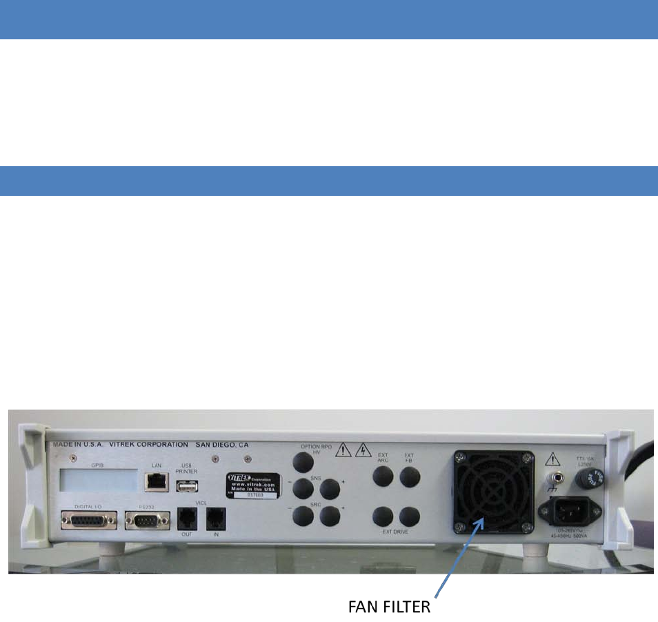
95x Series Operating Manual - December 12, 2011
Page 113 of 151
SECTION 9 – PERIODIC MAINTENANCE
THE 95x CONTAINS NO INTERNAL USER SERVICABLE PARTS AND REQUIRES NO INTERNAL PERIODIC
MAINTENANCE. THE COVERS OF THE 95x SHOULD ONLY BE REMOVED BY ViTREK OR ITS SERVICE CENTERS –
REMOVAL OF THE COVERS MAY AFFECT WARRANTY AND CALIBRATION CERTIFICATION.
The following procedures are recommended to be performed at monthly intervals. These require no special tools
or equipment and take the average user about ten minutes to perform.
CLEANING AND INSPECTION
Cable Inspection
Carefully inspect the power cord, any high voltage cabling and (if Opt. AC-30 is fitted) all cables to the external AC-
30 transformer, for breaks, abrasions or cracks in the outer insulation. Replace any cable found to be damaged.
If a high voltage cable has become excessively dirty then the user should clean it by wiping it with a wetted cloth,
with a cleaning agent if needed. If a high voltage cable is wetted ensure it is fully dried before returning it to use.
Fan Filter Cleaning
With power completely removed from the 95x, visually inspect the cleanliness of the fan filter. The fan filter is
located on the rear panel of the 95x, near the power entry socket. DO NOT REMOVE THE FOUR SCREWS
SURROUNDING THE FILTER.
Figure 33 - Rear Panel Fan Filter Location
To remove the filter, pull on one of the tabs on the filter cover to remove the cover and then remove the filter
itself. Carefully brush off or blow out any dirt which may have accumulated on the filter. Replacement filters can
be purchased from ViTREK if needed. DO NOT OPERATE THE 95x WITHOUT A FAN FILTER INSTALLED. If the filter is
damaged, e.g. is torn, then it must be replaced. When replacing the filter into the cover, take care to ensure the
filter is installed flat and does not impair operation of the fan.
Display Filter Cleaning
Visually inspect the cleanliness of the front panel display filter. If it is excessively dirty then it should be carefully
wiped with a soft, lint free cloth wetted with a weak solution of dish soap. Commercially available pre-wetted
wipes may also be used, however under no circumstances should alcohol based cleaners be used on the front
panel screen as it may damage the surface.

95x Series Operating Manual - December 12, 2011
Page 114 of 151
Terminal Inspection
Visually inspect the terminals and the area immediately around them in the front and/or rear panels and clean
them if required. IF THE INTERNAL SURFACES OF TERMINALS ARE WETTED DURING CLEANING THEN ENSURE THAT
THEY ARE FULLY DRIED BEFORE OPERATING THE 95x AT HIGH VOLTAGES, OTHERWISE SAFETY MAY BE
COMPROMISED.
Carefully visually inspect the high voltage terminal shrouds for mechanical damage. If there is any cracking in the
shroud then safety may be compromised and the terminal should be replaced. Replacement of high voltage
terminals should only be carried out at ViTREK or one of its certified repair establishments.
SELF TEST
Prior to performing a self test, the 95x must have been continuously powered and turned on for at least 5 minutes.
The user may press the STOP button at any time during the self-test procedure to abort it. The HIGH VOLTAGE OR
HIGH CURRENT PRESENT warning symbol is illuminated whenever high voltages are present on the 95x terminals
during this procedure.
Perform the following to command an automatic self-test procedure –
• Ensure that the display indicates that the 95x is in the base menu state, i.e. the display shows the date
and time. If necessary press the STOP button to abort a menu and return to the base menu state.
• Press the TEST key.
• The display now shows a series of temporary messages indicating the status of certain portions of the 95x.
If any of these indicate a failure of the 95x, then the self-test is halted at the failing test.
• The display now shows a message indicating that the user should remove all leads to the 95x. The user
must remove all connections to the terminals of the 95x before continuing with the self-test. CAUTION –
high voltages may be present on the HV terminal of the 95x during the remainder of the self-test
procedure, the user should ensure that there are no connections and that the terminals are not touched
during the procedure. When sure that all connections have been removed, the user should press the
START button to continue the procedure.
• The display now shows a series of messages indicating the progress as several active circuitry tests are
performed automatically by the 95x. If any of these indicate a failure of the 95x, then the self-test is
halted at the failing test.
• When all tests have successfully completed, a temporary message is displayed and the display is returned
to the base menu state.

95x Series Operating Manual - December 12, 2011
Page 115 of 151
SECTION 10 – PERFORMANCE VERIFICATION AND ADJUSTMENT
The 95x has been designed to give many years of service without needing calibration. However, particularly for
devices used to test for product safety, it is important to periodically ensure that the device is properly working
within its’ specifications.
There are three strategies recommended for periodic performance verification/adjustment of the 95x. Which one
is selected by the user depends on the users specific requirements regarding quality level and the availability of
equipment.
• Periodic Adjustment Calibration Only. This is the simplest of the strategies, while it gives the typical user a
reasonable degree of certainty that the 95x is performing to its specifications, it does not cross-check that
the calibration technique was performed correctly and does not account for some (rare) possible
malfunctions in the 95x.
• Periodic Adjustment followed by Verification. With this strategy the user ensures that the 95x was within
specification as received by performing the adjustment calibration and checking that the adjustments are
within the product specification, then checking that the calibration was correctly performed and checking
for the rare possible 95x malfunctions by means of the post-adjustment verification. This completely
ensures that the outgoing 95x meets its’ specifications but leaves the possibility of an error made during
the adjustment calibration leading to the incorrect indication that the incoming 95x did not meet
specifications.
• Periodic Verification – Adjustment – Verification. This is the most complete strategy, but is also the most
costly in time. The time cost can be reduced by performing the initial verification and then only
performing the Adjustment – Verification components if the initial verification indicates that it is
necessary (as an example, only perform if beyond some percentage of specification in the initial
verification).
ADJUSTMENT CALIBRATION
The 95x employs internal software calibration adjustments, there are no physical adjustments required. These
adjustments are needed to correct for manufacturing tolerances in the components used in the 95x, it is important
to note that there is no calibration of design defects allowed for, giving the end user a high degree of certainty that
the 95x maintains its’ specifications. Typically, adjustment should be rarely needed; however the user may wish to
perform it at periodic intervals to ensure optimal performance.
The adjustment calibration procedure for the 95x is an internally prompted sequence dependent on the actual
product model being calibrated.
Please take note of the following–
• The 95x should be fully powered and turned on for at least 10 minutes (1 hour is recommended) prior to
being calibrated. Initially there should be no connections to any of the 95x terminals and it is
recommended to not have any connections to the interface ports during the procedure.
• In many cases the same accuracy determining circuitry is used in several different modes of operation. As
an example, there is no difference between the DC and AC voltage modes of operation in the accuracy
determining circuitry of the 95x. Because of this the entire product can be calibrated with complete
certainty by only a few fairly simple calibrations.

95x Series Operating Manual - December 12, 2011
Page 116 of 151
• The combination of the adjustment calibration and the internal self test ensures the performance of the
95x in all but the most unusual of circumstances. Even if a formal calibration verification procedure is not
performed, the user can have a very high degree of certainty that the 95x is performing to its capabilities.
• The adjustment calibration procedure has been designed to use widely available equipment, such as the
multi-function calibrators available from Fluke. No voltages over 1000V are needed during this
procedure. This document describes the equipment needed and provides details regarding the use of the
95x during this procedure; it does not describe how to use that equipment.
• The user can press the STOP button to abort the procedure. This discards any changes which have been
made during the procedure. DO NOT REMOVE POWER FROM THE 95x DURING THE ADJUSTMENT
CALIBRATION PROCEDURE. If a failure occurs during the procedure, the 95x will automatically halt the
procedure and discard any changes made.
• In several steps the 95x display prompts the user to make connection to the GND terminal, this is also
denoted as the GUARD terminal on the 95x front panel.
• The front panel High Voltage warning light is illuminated whenever there are high voltages or currents
present on the 95x terminals. When illuminated the user should not touch the connections to the 95x.
EQUIPMENT REQUIRED
1. (All models) A shorting plug suitable for use between the SENSE+ and SENSE- terminals. This must have a
resistance of less than 5mΩ at a nominal 30mAdc current for a 4:1 accuracy ratio (the 95x specification is
20mΩ).
2. (All models) A true 4-wire short circuit having a 4-terminal resistance of less than 0.5mΩ at a nominal
30mAdc current for a 4:1 accuracy ratio (the 95x specification is 2mΩ) and (952i/4i/9i only) an impedance
of less than 1.625uΩ at 5Arms/60Hz current for a 4:1 accuracy ratio (the 952i/4i/9i specification is 6.5uΩ).
3. (All models except the 959i) A source of 100Vdc, 500Vdc and 1000Vdc capable of driving a 100MΩ load
with an accuracy of better than ±0.075% for a 4:1 accuracy ratio (the 95x specification is ±0.3%).
4. (All models) A source of 100uA, 1mA, 10mA and 50mAdc capable of driving at least 1.5V compliance with
an accuracy of better than ±0.0625% for a 4:1 accuracy ratio (the 95x specification is ±0.25%).
5. (All models) A 10KΩ resistance with an accuracy of better than ±0.2% at a nominal 0.5mAdc current (the
95x specification is ±0.8%). Preferably this resistor should be a 4-terminal device.
6. (952i/4i/9i only) A nominally 1Ω 4-wire impedance with an accuracy of better than ±0.375% at
1Arms/60Hz current for a 4:1 accuracy ratio (the 952i/4i/9i specification is ±1.5%). The actual value must
be known to within the accuracy limits and must be in the range 0.9 to 1.1Ω.
Equipments #3 through 6 are generally available in the same multi-function calibrator and can be cabled using
standard wire of heavy enough gauge for the current and with sufficient insulation for the voltage. For equipment
#2 the user may construct their own 4-wire zero resistance standard and use short lengths of heavy gauge wire
(contact ViTREK for details if uncertain on how to construct this). Equipment #1 must be a low resistance short at
the 95x terminals. Since the 95x is internally grounded, the equipment listed here must not have grounded
terminals.
PROCEDURE
Follow the prompts in the display of the 95x for the actual procedure as it varies between models and option
content.
• Press EXT.
95x Series Operating Manual - December 12, 2011
Page 117 of 151
• Press the UP arrow key to display “ADJUST CAL” on the lower display line, then press ENTER. The 95x now
prompts the user for entry of the calibration password.
o If the user has not locked the calibration previously then there is no password in the 95x, so the
user may just press ENTER again to continue.
o Otherwise the user must enter the previously defined numeric password (using the numeric keys
on the front panel) prior to pressing ENTER.
o If the calibration has previously been locked by a password, but it is no longer known to the user,
then please contact ViTREK for details regarding how to proceed.
• The user is now prompted to enter a new calibration lock password.
o If no change is required then press ENTER (all zero digits is the selection for no password
protection of calibration).
o If no password protection for calibration is desired but a password was previously defined, the
user should overwrite the password with all zero digits and then press ENTER.
o If the password is to be changed, then enter the new password using the numeric keys on the
front panel and then press ENTER.
• The user is now prompted to remove all leads. Ensure there are no connections to the front panel and (if
any) rear panel terminals then press START.
• The 95x now performs a series of internal adjustments which require no user equipment or intervention.
• When the internal adjustments have completed, the display prompts the user to provide a short between
the SENSE+ and SENSE- terminals. This is equipment #1 listed above. NOTE – this short circuit must have
less than 5uV of thermally induced voltage, the user may need to wait for some time after making
connections. Ensure that the short circuit is properly inserted into the terminals and then press START to
continue the procedure.
• The 95x now automatically performs both a voltage zero and a 2-wire resistance zero adjustment. When
the 95x has completed its 2-wire zero adjustments, the user is prompted to provide a 4-wire zero. This is
equipment #2 listed above. NOTE – this short circuit must have less than 5uV of thermally induced
voltage, the user may need to wait for some time after making connections. Ensure that the short circuit
is properly inserted into the terminals and then press START to continue the procedure.
• The 95x now automatically performs a 4-wire resistance zero adjustment. When the 95x has completed
its 4-wire zero adjustments, the user is prompted to remove the 4-wire short circuit. When it has been
removed press START to continue the procedure.
• The user is now prompted to provide a source of 1000Vdc (equipment #3 listed above) between the HV
(+) and GND/GUARD (-) terminals of the 95x. Apply the connections to the 95x terminals ensuring the
connections are to the correct terminals and with the correct polarity, and then set the source to provide
the voltage. DO NOT TOUCH TERMINALS OR CONNECTORS WHILE VOLTAGE IS APPLIED. When the
voltage is correctly applied press START to continue the procedure. The user is now shown the difference
in calibration at 1000Vdc between this calibration and the last calibration of the 95x. If the change is
acceptable then press START to accept it and continue the procedure, otherwise abort the calibration by
pressing STOP. NOTE – the 95x specification at this level is ±0.3%. The 95x display will show FAILED if the
calibration is out of range for calibration, not if the change is beyond the specification.
• The above step is repeated at levels of 500V then 100Vdc. The 95x specification is ±0.35% at 500Vdc and
±0.75% at 100Vdc.
• The user is now prompted to provide a source of 50mAdc (equipment #4 listed above) between the
SENSE- (+) and GND/GUARD (-) terminals of the 95x. Apply the connections to the 95x terminals ensuring
the connections are to the correct terminals and with the correct polarity, and then set the source to

95x Series Operating Manual - December 12, 2011
Page 118 of 151
provide the current. When the current is correctly applied press START to continue the procedure. The
user is now shown the difference in calibration at 50mAdc between this calibration and the last
calibration of the 95x. If the change is acceptable then press START to accept it and continue the
procedure, otherwise abort the calibration by pressing STOP. NOTE – the 95x specification at this level is
±0.25%. The 95x display will show FAILED if the calibration is out of range for calibration, not if the
change is beyond the specification.
• The above step is repeated at levels of 10mA, 1mA then 100uAdc.
• The user is now prompted to connect a 4-wire 10KΩ resistance (equipment #5 listed above) to the 95x
terminals. The 95x internal current source is from the SOURCE terminals, and the voltage sense uses the
SENSE terminals, ensure that the resistor is connected with the + terminals and – terminals correctly
paired for a 4-wire measurement. When the 10KΩ resistance is correctly applied press START to continue
the procedure. The user is now shown the difference in calibration at 10KΩ between this calibration and
the last calibration of the 95x. If the change is acceptable then press START to accept it and continue the
procedure, otherwise abort the calibration by pressing STOP. NOTE – the 95x specification at this level is
±0.8%. The 95x display will show FAILED if the calibration is out of range for calibration, not if the change
is beyond the specification.
• The user is now prompted to connect a 4-wire 1Ω impedance (equipment #6 listed above) to the 95x
terminals. The 95x internal current source is from the SOURCE terminals, and the voltage sense uses the
SENSE terminals, ensure that the resistor is connected with the + terminals and – terminals correctly
paired for a 4-wire measurement. The use of short leads is recommended and steps should be taken to
reduce the potential for coupling between the SOURCE and SENSE wires. Ideally, the SOURCE wires
should be a twisted pair, and the SENSE wires a separate twisted pair spaced away from the SOURCE pair.
When the 1Ω impedance is correctly applied press START to continue the procedure.
• The user is now prompted for the actual, calibrated value of the 1Ω. The user should enter the correct
value using the numeric keys and then press ENTER. The user is now shown the difference in calibration at
1Ω between this calibration and the last calibration of the 95x. If the change is acceptable then press
START to accept it and continue the procedure, otherwise abort the calibration by pressing STOP. NOTE –
the 95x specification at this level is ±1.5%. The 95x display will show FAILED if the calibration is out of
range for calibration, not if the change is beyond the specification.
• If all steps above were completed successfully then the calibration is completed and the 95x display
shows “FINISHED CALIBRATION” for a short time. The user should remove all equipment and connections
from the 95x. DO NOT REMOVE POWER FROM THE 95x OR TURN OFF THE POWER SWITCH FOR AT LEAST
5 SECONDS AFTER COMPLETING THE CALIBRATION PROCEDURE.
VERIFYING CALIBRATION
Prior to performing a Verification procedure the user should first perform the self test procedure as described in
Self Test.
The 95x has a built-in automatic verification sequence which may be followed by the user. In some circumstances
the user may wish to not use this built-in sequence, but use their own sequence. The user can use any verification
sequence which they wish by building a special “test sequence” in the 95x and then using external equipment to
monitor the voltages and/or current during the execution of the sequence. This document does not cover the
details regarding how to do this, but is limited to the steps in the internal automatically sequenced verification
procedure.
Please note the following -

95x Series Operating Manual - December 12, 2011
Page 119 of 151
• In several steps the equipment needed to perform performance verification is highly specialized and may
not be available to many users. Making very high voltage measurements with high precision require
special skills and equipment, particularly when performing high AC voltage testing. If there are any
doubts regarding the correct methods to use, consult the manufacturer of the test equipment being used.
• The 95x should be fully powered and turned on for at least 10 minutes (1 hour is recommended) prior to
being calibrated. Initially there should be no connections to any of the 95x terminals and it is
recommended to not have any connections to the interface ports during the procedure.
• In the various steps shown in this procedure, if a step is specific to certain models then it is denoted as
such. In all cases, follow the prompts in the display of the 95x for the actual procedure.
• The user can press STOP to abort the procedure.
• The front panel High Voltage warning light is illuminated whenever there are high voltages or currents
present on the 95x terminals. When illuminated the user should not touch the connections to the 95x.
• Several of the verification steps are performed at very high voltages, the user must ensure that the wiring
used has sufficient insulation for the voltages.
• Although the sequence is similar between the 95x series products and options, there are differences
depending on the voltages, currents, and modes which each model and option is capable of. The 95x
automatically accounts for the actual model and option content when guiding the user through the
sequence. Individual steps and/or entire groups of steps may not be present in the actual product being
verified. Any optional customer requested factory voltage and current generation limitations are applied
during verification and so will also affect the procedure.
• Since the 95x is internally grounded, the measurement equipment, current sources and test loads used
during verification must not be grounded.
• The user can skip verification steps by simply not connecting a measurement device during that step and
immediately continuing the step by pressing START again to proceed to the next.
EQUIPMENT REQUIRED
1. (All except the 959i). A measurement device capable of measuring DC voltages of 100V to 1000V, 6000V
or 10000V (depending on the model being verified), having an input impedance of 10MΩ or greater, and
an accuracy which yields the desired error ratio to the 95x series accuracy (see the DC Voltage Verification
portion for the accuracies). At voltages at or below 1000V there is a great range of products available
which easily achieve very high ratios (e.g. a bench-top 6 ½ digit DMM has a typical DC voltage accuracy of
±0.005%, producing more than a 50:1 error ratio). At voltages above 1000V however there are a very
limited amount of products available.
2. (All models) A source of DC currents in the range 1uA to 50mAdc capable of driving at least 1.5V
compliance with an accuracy which yields the desired error ratio to the 95x series accuracy (see the DC
Current Scaling Verification portion for the accuracies). This is achievable with most multi-function
calibration products (e.g. Fluke).
3. (All except the 956i and 959i). A measurement device capable of measuring AC RMS voltages of 100V to
1900V, 6000V or 10000V (depending on the model being verified), with a frequency range of at least 60 to
400Hz, having an input impedance of 10MΩ or greater, and an accuracy which yields the desired error
ratio to the 95x series accuracy (see the AC Voltage Verification portion for the accuracies). At all but the
100V level there is a very limited amount of products available.
4. (All models). A set of DC resistance standards of values 100KΩ, 10KΩ, 100Ω and 1Ω, capable of being
connected using a 4-wire configuration, and accuracies which yield the desired error ratio to the 95x
95x Series Operating Manual - December 12, 2011
Page 120 of 151
series accuracy (see the Low Ohms Resistance Verification portion for the accuracies). This is achievable
with most multi-function calibration products (e.g. Fluke) or Resistance Decade Boxes (e.g. ESI).
5. (All models) A shorting plug suitable for use between the SENSE+ and SENSE- terminals. This must have a
resistance of less than 5mΩ at a nominal 30mAdc current for a 4:1 accuracy ratio (the 95x series
specification is 20milliohms).
6. (All models) A true 4-wire short circuit having a 4-terminal resistance of less than 0.5mΩ at a nominal
30mAdc current for a 4:1 accuracy ratio (the 95x series specification is 2mΩ) and (952i/4i/9i only) an
impedance of less than 1.625uΩ at 5Arms/60Hz current for a 4:1 accuracy ratio (the 952i/4i/9i
specification is 6.5uOhm).
7. (952i, 954i and 959i only). A set of AC resistance standards of values 1Ω, 100mΩ and 50mΩ, calibrated for
use at 60Hz, capable of being connected using a 4-wire configuration, and accuracies which yield the
desired error ratio to the 95x series accuracy at the currents used in the 95x (see the Ground Bond
Verification portion for the accuracies and current levels). These may have to be custom built.
STARTING VERIFICATION
To start the internal verification procedure press EXT. The user prompts the user to select the VERIFY (or ADJUST)
calibration procedure. Since the VERIFY procedure is always initially selected, press ENTER to start the procedure.
The 95x then performs a few internal tests to ensure basic functionality of the product then starts the actual
verification procedure which is described in the following sub-sections in the order shown -
DC VOLTAGE VERIFICATION
The user should connect a DC Voltage measuring device (equipment #1 in the equipment list above) to the HV (+)
and the GND/GUARD (-) terminals of the 95x. While the 95x prompts whether to verify the voltage, there are no
unsafe voltages present so the user may safely make connections and configure the measurement device as
needed. In some circumstances a different measuring device may be used depending on the voltage being
measured. ENSURE THAT THE MEASURING DEVICE AND WIRING IS CAPABLE OF WITHSTANDING THE VOLTAGE
LEVEL PRIOR TO PRESSING THE START SWITCH AT EACH STEP.
The table below shows the fullest listing of the voltages requested for verification and the 95x specification at each
level. When prompted for each step the user should either –
• Press START to perform the verification (the output voltage will be present after pressing this switch).
• Press STOP to abort the entire sequence.
During each step the user should measure the actual voltage and record it, checking against the 95x specification.
When the user is satisfied that the step has been completed, the user should press START to continue or STOP to
abort the sequence.
Table 9 - DC Voltage Verification Levels
Voltage Level
95x Models
95x Accuracy
10000V 953i,954i and 955i only ±0.255% (25.5V)
6000V
All except 959i
±0.258% (15.5V)
1900V All except 959i ±0.276% (5.25V)
1000V
All except 959i
±0.3% (3V)
500V
All except 959i
±0.35% (1.75V)
100V
All except 959i
±0.75% (0.75V)

95x Series Operating Manual - December 12, 2011
Page 121 of 151
DC CURRENT SCALING VERIFICATION
The user should connect a DC current source (equipment #2 in the list above) between the SENSE- (+) and the
GND/GUARD (-) terminals of the 95x.
The table below shows the listing of the currents prompted for verification and the 95x specification at each level.
When prompted for each step the user should either –
• Press START to perform the verification (the user should ensure that the requested current is present
prior to pressing this switch).
• Press STOP to abort the entire sequence.
During each step the user should note the displayed current and record it, checking against the 95x specification.
When the user is satisfied that the step has been completed, the user should press START to continue or STOP to
abort the sequence.
Table 10 - DC Current Verification Levels
Current Level
95x Accuracy
100mA
±0.25% (0.25mA)
10mA ±0.25% (0.025mA)
1mA
±0.25% (2.5uA)
100uA ±0.25% (0.25uA)
10uA
±0.255% (0.0255uA)
1uA
±0.3% (3nA)
DC CURRENT ZERO VERIFICATION
No connections to any terminals should be present during these steps. The product prompts for the DC current
zero to be verified at a zero output voltage level and at a 5000V output level. When prompted for each step the
user should either –
• Press START to perform the verification.
• Press STOP to abort the entire sequence.
During each step the user should note the displayed current and record it, checking against the 95x specification of
±0.5nA. When the user is satisfied that the step has been completed, the user should press START to continue or
STOP to abort the sequence.
AC VOLTAGE VERIFICATION
The user should connect an AC Voltage measuring device (equipment #3 in the list above) to the HV (+) terminal
and the GND/GUARD (-) terminal of the 95x. While the 95x prompts whether to verify the voltage there is no
unsafe voltages present so the user may safely make connections and configure the measurement device as
needed. In some circumstances a different measuring device may be used depending on the voltage being
measured. ENSURE THAT THE MEASURING DEVICE AND WIRING IS CAPABLE OF WITHSTANDING THE VOLTAGE
LEVEL PRIOR TO PRESSING THE START SWITCH AT EACH STEP.
The table below shows the fullest listing of the voltages and frequencies requested for verification and the 95x
specification at each level/frequency. When prompted for each step the user should either –
• Press START to perform the verification (the output voltage will be present after pressing this switch).
• Press STOP to abort the entire sequence.
95x Series Operating Manual - December 12, 2011
Page 122 of 151
During each step the user should measure the actual voltage and record it, checking against the 95x specification.
When the user is satisfied that the step has been completed, the user should press START to continue or STOP to
abort the sequence.
Table 11 - AC Voltage Verification Levels and Frequencies
Voltage Level/Frequency
95x Models
95x Accuracy
10000V/60Hz
955i only
±0.515% (51.5V)
6000V/60Hz All except 956i, 959i and if opt.
AC2 not fitted ±0.525% (31.5V)
1900V/60Hz
All except 956i, 959i
±0.579% (11V)
1000V/60Hz All except 956i, 959i ±0.65% (6.5V)
1000V/400Hz
All except 956i, 959i
±3.65% (36.5V)
300V/60Hz All except 956i, 959i ±1% (3V)
100V/60Hz
All except 956i, 959i
±2% (2V)
AC CURRENT ZERO VERIFICATION
No connections to any terminals should be present during these steps. The 95x prompts for the AC current zero to
be verified at several different output voltage voltages and frequencies. When prompted for each step the user
should either –
• Press START to perform the verification.
• Press STOP to abort the entire sequence.
During each step the user should note the displayed current and record it, checking against the 95x specification
shown in the table below. When the user is satisfied that the step has been completed, the user should press
START to continue or STOP to abort the sequence.
Table 12 - AC Current Verification Levels and Frequencies
Voltage Level/Frequency/Parameter
95x Models
95x Accuracy
Zero/Zero/RMS All except 956i, 959i 10nA
2000V/60Hz/RMS
All except 956i, 959i
22nA
2000V/60Hz/InPhase
All except 956i, 959i
±11.2nA
5000V/60Hz/RMS All except 956i, 959i and if
opt. AC2 not fitted 40nA
9000V/60Hz/RMS 955i only 64nA
LOW OHMS RESISTANCE VERIFICATION
The user should connect the prompted value resistance standard (equipment #4, 5 and 6 in the equipment list
above) to the SENSE and SOURCE terminals of the 95x using a 4-wire connection method for all but the final step
in this part of the sequence (which should be a 2-wire connection to the SENSE terminals only). For all 4-wire
connections the 95x internal current source is from the SOURCE terminals, and the voltage sense uses the SENSE
terminals, ensure that the resistor is connected with the + terminals and – terminals correctly paired for a 4-wire
measurement.
The table below shows the listing of the resistances requested for verification and the 95x specification at each
resistance value. When prompted for each step the user should either –
• Press the START switch to perform the verification.

95x Series Operating Manual - December 12, 2011
Page 123 of 151
• Press the STOP switch to abort the entire sequence.
During each step the user should note the displayed resistance measurement on the 95x display and record it,
checking against the 95x specification shown in the table below. When the user is satisfied that the step has been
completed, the user should press START to continue or STOP to abort the sequence.
Table 13 - Low Resistance Verification Values
Resistance 95x Accuracy
100KΩ
±1.5% (1.5KΩ)
10KΩ
±0.8% (0.08KΩ)
100Ω ±0.8% (0.8Ω)
1Ω
±1% (10mΩ)
Zero Ω (4-wire) ±2mΩ
Zero Ω (2-wire)
±20mΩ
GROUND BOND VERIFICATION
This series of steps is only included in the 952i, 954i and 959i models.
The user should connect the prompted value resistance standard (equipment #7 in the equipment list above) to
the SENSE and SOURCE terminals of the 95x using a 4-wire connection method. For all 4-wire connections the 95x
internal current source is from the SOURCE terminals, and the voltage sense uses the SENSE terminals, ensure that
the resistor is connected with the + terminals and – terminals correctly paired for a 4-wire measurement. The user
should also ensure that the cabling to the SOURCE terminals of the 95x is capable of handling the measurement
current shown. To reduce cross-coupling between the SOURCE and SENSE wiring, the user is recommended to use
one twisted pair for the SOURCE connections and a separate twisted pair for the SENSE connections.
The table below shows the listing of the resistances requested for verification, the measurement current levels,
and the 95x specification at each resistance value and current level. When prompted for each step the user should
either –
• Press START to perform the verification.
• Press STOP to abort the entire sequence.
During each step the user should note the displayed resistance measurement on the 95x display and record it,
checking against the 95x specification shown in the table below. When the user is satisfied that the step has been
completed, the user should press START to continue or STOP to abort the sequence.
Table 14 - GB Verification Values and Currents
Resistance/Current
95x Accuracy
1Ω/0.1A
±6.03% (0.0603Ω)
1Ω/1A ±1.5% (0.015Ω)
100mΩ/1A ±1.53% (1.53mΩ)
100mΩ/10A ±1.05% (1.05mΩ)
50mΩ/25A
±1.02% (0.51mΩ)

95x Series Operating Manual - December 12, 2011
Page 124 of 151
SECTION 11 – PROGRAMMING VIA AN INTERFACE
The 95x may be programmed via the RS232, GPIB or Ethernet interface. All use the same general format for
commands and query responses. All data uses the standard 7-bit ASCII character set. In general all activities are
independent for each interface.
There are two types of command –
• Commands which do not have a response. These always cause the 95x to take an action.
• Commands which have a response (these are named Query commands in this document). These
generally do not cause the 95x to take an action other than sending back the response. These all have a
keyword which ends with the ? character.
Throughout this section reference is made to several special ASCII characters –
<CR> the carriage return character
<LF> the line feed character
<FF> the form feed character
<TAB> the tab character
<SPACE> the space character
Throughout this section reference is made to whitespace characters, the <SPACE> and <TAB> characters are
considered whitespace characters.
Throughout this section reference is made to data field formats, these are described in more detail later in this
section –
<EMPTY> is an empty field, containing nothing other than optional whitespace characters
<STRING> is a general string of ASCII characters
<NR1> is an integer numeric
<NR3> is a floating point numeric
<BOOL> is a boolean, indicating true or false
GENERAL COMMAND SYNTAX
Every command takes the form of a set of one or more fields; each field is separated from the next by a field
separator. The first field is always the command keyword, the remaining fields and their syntax depends on the
command keyword and in some cases the content of a preceding field in the command.
Multiple commands can be transferred as a single set of commands; each command is separated from the next by
a command separator. If there are multiple query commands in a single set then each response is given as
separate fields in the overall response, which is not transmitted until all commands in the set have been
successfully actioned. The maximum overall length of a response set is 19999 characters (except for the Ethernet
interface which is limited to 1500). Commands are always actioned in the same order as they are received.
The end of a set of commands is denoted by the inclusion of a command terminator. Sets of commands are always
actioned in the same order as they are received.

95x Series Operating Manual - December 12, 2011
Page 125 of 151
Received characters on each interface are buffered from the actual communications stream, the contents of the
buffer being decoded and actioned when a command terminator is found in the stream. The maximum length of a
set of commands is 1023 characters.
The 95x does not raise an error if an empty set of commands is received, i.e. if there are two or more consecutive
command terminators. This is effectively a “do nothing” set of commands.
The 95x does not raise an error if an empty command is received in a set of commands, i.e. there are two or more
consecutive command separators, or a command separator is immediately followed by a command terminator.
This is effectively a “do nothing” command.
If an error is found in a set of commands, then processing of the set of commands is terminated and the remainder
of the set of commands is not decoded or actioned. There is never any response from a set of commands which
contains an error, even if the erroneous command was after a query command in the set.
FIELD SYNTAX
Except for the <STRING> format data field (see below), any field may optionally start and/or end with one or more
whitespace characters.
Fields within a command are position dependent, i.e. the exact order is defined for each command. There are two
types of fields in a command -
1. COMMAND KEYWORD. Although all command keywords are shown using uppercase characters in this
document, lowercase characters may also be used if desired. Command keywords must exactly match the
defined set for the 95x. The first field in a command is always the command keyword; some commands
have a second command keyword in the second field.
2. DATA. There are several types of data, the type used is dependent on the field -
a. <EMPTY>. This is a field containing no, or only whitespace, characters between the enclosing
separators. In many commands the user may give an empty field where another format is
expected, this generally has a specific effect defined in the description for each command.
b. <BOOL>. This can be the single character “Y” or ‘1’ denoting a true state, or the single character
‘N’ or ‘0’ denoting the false state (the Y or N may be upper- or lower-case).
c. <NR1>. One of three methods may be used to define a <NR1> field-
i. Decimal value. A string of numeric (0 through 9) characters defining a decimal number
without polarity or decimal point (e.g. “123” defines the decimal number one hundred
and twenty three). A value greater than 4294967295 is a syntax error.
ii. Hexadecimal value. The user can optionally start this field with the characters “0X” or
the single character “X” (in both cases the “X” character can also be lowercase), in which
case the following data defines the number in hexadecimal format using the numeric
characters and the letters A through F (either upper- or lowercase), as an example 0x12
defines the decimal numeric value 18. A value greater than 0xffffffff is a syntax error.
iii. Binary value. The user can optionally start this field with the characters “0B” or the
single character “B” (in both cases the “B” character can also be lowercase), in which
case the following data defines the number in binary format using the “0” and “1”
characters only with the most-significant bit being defined first, as an example
0b00010010 defines the decimal numeric value 18 or hexadecimal value 0x12. In all
cases, leading digits or bits which are not defined are assumed to be zero (e.g.
0b00010010 is the same as 0b10010). A value greater than 32 bits is a syntax error.

95x Series Operating Manual - December 12, 2011
Page 126 of 151
d. <NR3>. This is a string of characters defining a floating point numeric value, optionally having a
polarity, and/or a decimal point, and/or an exponent. Within the limitations of the 95x
command input buffer, there is no limitation on the number of numeric characters before the
decimal, after the decimal or in the exponent. There may be none or one polarity character and,
if present, it must be the first character in the field. If an exponent is required then it may be
defined immediately following the mantissa in one of two ways, either a) an upper- or lowercase
‘E’ character followed by an optional exponent polarity character (+ or -) followed by the integer
exponent (in <NR1> format), or b) a single character (case sensitive) explicitly defining the
exponent which may be one of the characters T (+12), G (+9), M (+6), K (+3), k (+3), m (-3), u (-6),
n (-9) or p (-12). Examples include –
i. “12”. Defines the floating point value +12.0. A <NR1> syntax numeric can always be
used to define a <NR3> value.
ii. “-12”. Defines the floating point value -12.0.
iii. “1.2345”. Defines the floating point value +1.2345.
iv. “12.45e+1”. Defines the floating point value +124.5.
v. “12.45e+01”. Defines the floating point value +124.5.
vi. “12.45e1”. Defines the floating point value +124.5.
vii. “12.345K”. Defines the floating point value +12345.0.
e. <STRING>. This can be any combination of printable ASCII characters (including whitespace
characters). To include a separator character in a <STRING> the user must immediately precede
the character with the / character. Any character immediately following a / character is taken
“literally” and included in the <STRING> and the / character is discarded.
FIELD SEPARATOR
Fields are separated by the comma character.
COMMAND SEPARATOR
Commands are separated by the semi-colon character.
COMMAND TERMINATOR
A command (or set of commands) is terminated by any of the following-
• A line-feed character (shown in this document as <LF>).
• A carriage return character (shown in this document as <CR>).
• A form feed character (shown in this document as <FF>).
• (GPIB only) Any data byte with EOI asserted.
• (GPIB only) Reception of the GET bus command.
GENERAL RESPONSE SYNTAX
Multiple query commands may be included in the same set of commands, in which case the overall response will
include each requested response, separated by the comma character, in the order defined in the set of commands.
A response is always terminated with a <CR> character followed by a <LF> character (with EOI asserted for the
GPIB interface). If the response is over 19999 characters in total length then an error is raised and no response is

95x Series Operating Manual - December 12, 2011
Page 127 of 151
given. For the GPIB interface only, a space character is appended to the start of each set of responses (including a
blank response).
On the RS232 and Ethernet interfaces any response is transmitted as soon as the set of commands containing one
or more query commands is completely decoded.
On the GPIB interface the user must take some action to receive the response from the 95x (i.e. a READ bus
operation). If a read operation is performed when there is no data to be transmitted then a blank data is
transmitted (i.e. a single space character followed by <CR><LF>).
If another set of commands is decoded containing a query command prior to the 95x fully transmitting a prior
response then the new response is not provided and an error is raised.
The following types of responses are given-
• <BOOL>. This is a single character ‘0’ indicating the false condition or ‘1’ indicating the true condition.
This is always 1 character in length.
• <STRING>. This is one or more printable ASCII characters. This has a variable number of characters in
length, and may be of no length.
• <NR1>. This is one or more decimal characters defining a decimal numeric value. If the polarity is positive
then no polarity character is included, otherwise the data starts with the minus character. This has a
variable number of characters in length.
• <NR3>. This is always 12 characters in length, and is of the following format (in the order shown)-
o A single polarity character (either + or -).
o Six decimal characters with a decimal point character contained within them (i.e. a total of seven
characters) indicating the mantissa value.
o The single ‘E’ (always uppercase) character.
o A single polarity character (either + or -) indicating the polarity of the exponent.
o Two decimal digit characters indicating the value of the exponent. For clarity in engineering use
the exponent is always divisible by 3.
DELAYS AND TIMEOUTS
The user does not need to perform any delays between sets of commands, or between a set of commands
containing query commands and reading the response. The 95x automatically handshakes the commands as
needed. The only exception to this is following application of power to the 95x in which case a minimum delay of 3
seconds is required prior to operation of the interfaces.
The maximum length of time for which the 95x will “hold-off” a set of commands (e.g. waiting for a previous set of
commands to be decoded) is 100ms.
For all interfaces, responses to query commands are generally transmitted within a very short period of time,
however in some circumstances there may be some delay enforced by the 95x. The user should use a timeout of
no less than 100ms for responses.
MULTIPLE INTERFACE OPERATION
Generally operation of the 95x via multiple interfaces is not recommended but is possible. The 95x will decode
sets of commands in the order in which they were terminated (each interface has separate receive and transmit
buffers). Any query responses will only be transmitted via the interface over which the query command
originated.

95x Series Operating Manual - December 12, 2011
Page 128 of 151
FRONT PANEL OPERATION WHILE USING INTERFACES
It is possible to inter-mix front panel and interface operation of the 95x however the user should be aware of the
following-
• The front panel has three states associated with interface operation-
o LOCAL. The front panel operates normally. When any command from an interface is decoded,
the front panel enters either the REMOTE or REMOTE LOCK-OUT state (depending on the
interface and the commands executed) and any menu in progress is aborted.
o REMOTE. The front panel is locked out other than the STOP button (and the START button in
some circumstances) but the user can return to the LOCAL state by pressing the CNFG key.
o REMOTE LOCK-OUT. The front panel is completely locked-out except for the STOP button (and
the START button in some circumstances). The user cannot return the front panel to any other
state by front panel action.
• The GPIB interface also has a set of remote states associated with it as defined by IEEE488.1 and
IEEE488.2. The 95x does NOT decode commands while in the GPIB LOCAL or GPIB LOCAL LOCK-OUT
states (as required by IEEE488.2). Transitions between the GPIB interface states are controlled by specific
GPIB bus commands as defined by the standards.
• A LOCKOUT command is provided on the RS232 and Ethernet interfaces to allow the user to command the
front panel to the REMOTE LOCK-OUT state; this command raises an error if received via the GPIB
interface.
• A LOCAL command is provided on the RS232 and Ethernet interfaces to allow the user to remotely return
the front panel to the LOCAL state. This command must be the last command in a set of commands.
GPIB BUS COMMANDS
Most standard GPIB bus commands are implemented in the normal fashion, however some cause a special activity
in the 95x-
Device Clear (SDC and DCL)
Either of these cause the 95x to clear all interface buffers, abort any test sequence in progress, return to the no
test sequence selected state and clear all interface status registers.
Interface Clear (IFC)
This causes the 95x to clear all interface buffers and clear all interface status registers. It does NOT affect any test
sequence in progress or affect the selected test sequence.
Group Execute Trigger (GET)
This can be used as a GPIB interface command terminator.
ETHERNET SESSIONS
The Ethernet interface uses TCP/IP as its’ transport protocol which is a session based protocol. The computer is
the session client and the 95x is the session server, so each session is managed by the computer.
The 95x is only allowed to have one session active at a time. The active session is established between the 95x and
the opening combination of the client IP address and TCP port (this combination is often called a “socket”).

95x Series Operating Manual - December 12, 2011
Page 129 of 151
With most operating systems (e.g. Windows) the management of sessions is transparent to the user, being entirely
handled by the OS. The user only needs to program –
• Initiating a session (opening the connection).
• Sending and receiving ASCII data to and from the respective streams.
• Closing the session.
If the 95x is power cycled then it will power up with no active session. The user should employ timeouts to detect
that the 95x has become off-line and restart the session.
If a session is inactive for more than 1 minute then the 95x will allow a session to be initiated from a different
source, automatically closing the inactive session. This prevents a potential lockup if the user does not close an
active session properly.
STATUS REGISTERS
There are several status registers associated with the 95x interfaces.
STB AND SRE REGISTERS
These are specifically used to show the status of and control the assertion of the GPIB SRQ signal. The value of the
STB register is logically ORed with the value of the SRE register; if the result is non-zero then the GPIB SRQ line is
asserted. The STB register is read by the GPIB interface when a serial poll bus command is performed.
These are common to all interfaces. They are 8-bit registers (i.e. has values from 0 to 255). Each bit is defined as
follows –
• Bit 0, decimal value 1, binary value 00000001 – set if a high voltage is currently present on the HV
terminal. The value of this status bit is “dynamic” – i.e. its’ value can change without user interaction.
• Bit 1, decimal value 2, binary value 00000010 – set when a test step dwell period is completed, cleared
when read, when a test sequence is started, when a different test sequence is selected, or when reset.
• Bit 2, decimal value 4, binary value 00000100 – set if a test sequence is currently being performed. The
value of this status bit is “dynamic” – i.e. its’ value can change without user interaction.
• Bit 3, decimal value 8, binary value 00001000 – set when a test sequence is completed, cleared when
read, when a test sequence is started, when a different test sequence is selected, or when reset.
• Bit 4, decimal value 16, binary value 00010000 – set when a test failure has been detected, cleared when
read, when a test sequence is started, when a different test sequence is selected, or when reset.
• Bit 5, decimal value 32, binary value 00100000 – set when an ARC current over limit has been detected,
cleared when read, when a test sequence is started, when a different test sequence is selected, or when
reset.
• Bit 6, decimal value 64, binary value 01000000 – as defined by IEEE488.1, set if the 95x is asserting the
SRQ line, otherwise it is cleared. Always zero for the SRE register.
• Bit 7, decimal value 128, binary value 10000000 – not used, always 0.
OPC REGISTER
This is separate within each interface. This is an 8-bit register (i.e. has values from 0 to 255). All of the bits in this
register are cleared when read by the user. Each bit is defined as follows –
• Bit 0, decimal value 1, binary value 00000001 – set when a command set is decoded without error.

95x Series Operating Manual - December 12, 2011
Page 130 of 151
• Bit 1, decimal value 2, binary value 00000010 – set when a command is decoded with a field count error.
• Bit 2, decimal value 4, binary value 00000100 – set when a command is decoded with an internal memory
error.
• Bit 3, decimal value 8, binary value 00001000 – set when a command is decoded with a field syntax or
data range error.
• Bit 4, decimal value 16, binary value 00010000 – set when a command is decoded with a compatibility
error (e.g. this 95x variant is incapable of performing the requested operation).
• Bit 5, decimal value 32, binary value 00100000 – set when a query command is decoded but there is
insufficient room in the output buffer for the response.
• Bit 6, decimal value 64, binary value 01000000 – set when the command buffer is overflowed.
• Bit 7, decimal value 128, binary value 10000000 – set when a command is received with a command word
that is not known to the 95x, or the command cannot be processed at this time.
ESR REGISTER
This is separate within each interface. This is an 8-bit register (i.e. has values from 0 to 255). All of the bits in this
register are cleared when read by the user. Each bit is defined as follows –
• Bit 0, decimal value 1, binary value 00000001 – set when a command is decoded and an error occurred
during decode.
• Bit 1, decimal value 2, binary value 00000010 – set when a query command is decoded but the response is
too long for the response buffer.
• Bit 2, decimal value 4, binary value 00000100 – set when a test failure has been detected.
• Bit 3, decimal value 8, binary value 00001000 – set when the internal temperature of the 95x is above
limits.
• Bit 4, decimal value 16, binary value 00010000 – set when an internal fault is detected.
• Bit 5, decimal value 32, binary value 00100000 – set when an ARC current over limit has been detected.
• Bit 6, decimal value 64, binary value 01000000 – not used, always 0.
• Bit 7, decimal value 128, binary value 10000000 – not used, always 0.
ERR REGISTER
This is separate within each interface. This is a numeric value register. The value is cleared to zero when read by
the user. The value is set according to the success or failure of the last decoded command on this interface. The
possible values of this register are defined as follows –
0. The command was decoded without error.
1. The command could not be decoded at this time.
2. The command attempted to create an invalid test step number.
3. The command attempted to create or access an invalid test sequence number.
4. The command created a test step which is not compatible with this specific instruments’ capability.
5. The command contained a numeric value field which was outside of the allowable range.
6. The command contained a field which did not have the correct syntax.
7. The command did not contain an expected field.
8. The command contained additional fields than expected.

95x Series Operating Manual - December 12, 2011
Page 131 of 151
9. The command keyword was not recognized.
10. The 95x had an internal memory error while executing the command.
11. The previous response had not yet been transmitted when this query command was executed.
12. The set of commands was too long, over 1023 characters.
COMMANDS
Table 15- Interface Commands
Command Description
Register Commands
*CLS Clears the STB, SRE, OPC, ESR and ERR registers.
Resets the front panel to the LOCAL state.
*ERR?
Responds with a <NR1> field value of the ERR register then clears the
ERR register
*ESR? Responds with a <NR1> field value of the ESR register then clears the ESR
register
*OPC? Responds with a <NR1> field value of the OPC register then clears the
OPC register
*SRE,<NR1>
Sets the SRE register
*SRE?
Responds with a <NR1> field value of the SRE register
*STB? Responds with a <NR1> field value of the STB register then certain bits of
the STB register are cleared
Commands to create, edit, recall or save the Active Test Sequence
(Cannot be used while a test sequence is running)
ADD,…
Add a test step to the end of the active sequence. See –
Table 17 - ACez Configuration Fields
Table 18 - ACW Configuration Fields
Table 19 - DCez Configuration Fields
Table 20 - DCW Configuration Fields
Table 21 - DCIR Configuration Fields
Table 22 - GBez Configuration Fields
Table 23 - GB Configuration Fields
Table 24 - LowΩ Configuration Fields
Table 25 - ACIR Configuration Fields
Table 26 - ACCAP Configuration Fields
Table 27 - ACI Configuration Fields
Table 28 - DCCAP Configuration Fields
Table 29 - IRCAP Configuration Fields
Table 30 - DCI Configuration Fields
Table 31 - PULSE Configuration Fields
Table 32 - PAUSE Configuration Fields
Table 33 - HOLD Configuration Fields
Table 34 – SWITCH (948i configuration) Configuration Fields
Table 35 – SWITCH (964i configuration) Configuration Fields
CLRLEADS
Clears the lead compensation data from the active test sequence
NAME,<STRING>
Names the active test sequence
NOSEQ
Clears the active test sequence
RCL,<NR1> Recalls a test sequence from the requested store # and makes it the
active test sequence

95x Series Operating Manual - December 12, 2011
Page 132 of 151
Command
Description
SAVE,<NR1>
Saves the active test sequence into the requested store #
SET,<NR1>, …
Overwrite a step in the active sequence (see also ADD,…)
Commands to Run the Active Test Sequence
(Can only be used while a test sequence is not running)
READY Makes the active test sequence ready to be run by the START button
RUN
Runs the active test sequence
RUN,LEADS
Runs the active test sequence in Lead Compensation mode
Running Test Sequence Control Commands
(Can only be used while a test sequence is running)
ABORT Aborts a running test sequence
CONT
Continues a running test sequence
Commands changing the test level or frequency while running a MANUAL sequence
AMPS,<NR3>
Sets the current test level of a running MANUAL test sequence
FREQ,<NR3>
Sets the test frequency of a running MANUAL test sequence
VOLTS,<NR3>
Sets the voltage test level of a running MANUAL test sequence
Active Test Sequence Information Query Commands
(Can only be used while not running a test sequence)
LEADS? Responds with a <BOOL> indicating if the active test sequence contains
lead compensation data
NAME? Responds with a <STRING> which is the name of the active test sequence
Active Test Sequence Status Query Commands
RUN? Responds with a <BOOL> indicating if the active test sequence is being
run (1) or not (0)
SEQ? Responds with a <NR1> which is the active test sequence # (-1 if none,
100 if defined by an interface, otherwise 0 through 99)
STEP?
Responds with a <NR1> indicating the step # presently being actioned in
a running test sequence (0 if none, otherwise 1 through 254)
Test Result Query Commands
(While running a test sequence)
MEASRSLT?,<STRING>
Responds with a <NR3> measurement result during execution of a test
step. <STRING> is –
FREQ – frequency (in Hz)
AMPS – DC or RMS current (in Amps)
INPHSA – In-phase current (in Amps)
QUADA – quadrature current (in Amps)
VOLTS – DC or RMS voltage (in Volts)
INPHSV – In-phase voltage (in Volts)
QUADV – quadrature voltage (in Volts)
OHMS – DC or RMS impedance (in Ω)
INPHSO – In-phase impedance (in Ω)
QUADO – quadrature impedance (in Ω)
ARC – arc current (in Amps)
BRKDN – breakdown current (in Amps)
CAP – capacitance (in F)
DF – dissipation factor (unitless)
Test Result Query Commands
(After running a test sequence)

95x Series Operating Manual - December 12, 2011
Page 133 of 151
Command
Description
RSLT?
Responds with a <NR1> indicating the overall test sequence fail status
and reason. This is the logical OR of all individual step status flags. This
can also be used while running a test sequence.
See Table 36 – Test Step Status Flags
STAT?
Responds with a <STRING> indicating the pass/fail state of each test step.
This can also be used while running a test sequence. The response
contains one character for each defined test step-
P passed
F failed
- Not perfomed
? In process
STEPRSLT?,<NR1> Responds with a set of fields giving the complete set of results for the
specified test step. See Table 37 – STEPRSLT? Response Fields
Configuration Settings Commands
BEEP,START,<NR1>
Configures the start beep sounds to 0 (off) to 4 (loud)
BEEP?,START
Responds with the <NR1> setting of the start beep sound
BEEP,PASS,<NR1>
Configures the pass beep sounds to 0 (off) to 4 (loud)
BEEP?,PASS Responds with the <NR1> setting of the pass beep sound
BEEP,FAIL,<NR1> Configures the fail beep sounds to 0 (off) to 4 (loud)
BEEP?,FAIL Responds with the <NR1> setting of the fail beep sound
BEEP,KEY,<NR1> Configures the key press beep sounds to 0 (off) to 4 (loud
BEEP?,KEY Responds with the <NR1> setting of the key press beep sound
CONTSENSE,<BOOL> Configures the Continuity Sense feature
CONTSENSE? Responds with the <BOOL> Continuity Sense feature setting
DATE,<NR1>,<NR1>,<NR1> Sets the present date (month, date, year)
DHCP,<BOOL>
Configures the Ethernet DHCP setting
DHCP?
Responds with the <BOOL> Ethernet DHCP setting
DIO,START,<STRING>
Configures the START DIO input to OFF, HI or LO
DIO?,START
Responds with the <STRING> setting for the START DIO input
DIO,ABORT,<STRING> Configures the ABORT DIO input to OFF, HI or LO
DIO?,ABORT Responds with the <STRING> setting for the ABORT DIO input
DIO,INTERLOCK,<STRING> Configures the INTERLOCK DIO input to OFF, HI or LO
DIO?,INTERLOCK Responds with the <STRING> setting for the INTERLOCK DIO input
DIO,SEQUENCE,<STRING> Configures the SEQUENCE DIO inputs to OFF, HI or LO
DIO?,SEQUENCE
Responds with the <STRING> setting for the SEQUENCE DIO inputs
DIO,PASS,<STRING>
Configures the PASS DIO output to HI or LO
DIO?,PASS
Responds with the <STRING> setting for the PASS DIO output
DIO,FAIL,<STRING>
Configures the FAIL DIO output to HI or LO
DIO?,FAIL
Responds with the <STRING> setting for the FAIL DIO output
DIO,TESTING,<STRING>
Configures the TESTING DIO output to HI or LO
DIO?,TESTING
Responds with the <STRING> setting for the TESTING DIO output
DIO,DWELL,<STRING>
Configures the DWELL DIO output to HI or LO
DIO?,DWELL Responds with the <STRING> setting for the DWELL DIO output
DIO,HV,<STRING> Configures the HV PRESENT DIO output to HI or LO
DIO?,HV Responds with the <STRING> setting for the HV PRESENT DIO output
FAILARC,<BOOL> Configures if the 95x is to fail on arc detection
FAILARC? Responds with the <BOOL> fail on arc detection setting

95x Series Operating Manual - December 12, 2011
Page 134 of 151
Command
Description
FASTRERUN,<NR1>
Configures how a test sequence may be rerun from the front panel
0 – enable fast rerun
1 – enable fast rerun if pass
2 – disable fast rerun
FASTRERUN? Responds with the <NR1> fast rerun setting
GATEWAY,<NR1>,<NR1>,<NR1>,<NR1> Configures the Ethernet Gateway IP Address setting
GATEWAY? Responds with the Ethernet Gateway IP address setting as four <NR1>
GPIB,<NR1>
Configures the GPIB address setting
GPIB?
Responds with the <NR1> GPIB address setting
HVDETECT,<BOOL>
Configures the HV Detect safety feature
HVDETECT?
Responds with the <BOOL> HV Detect safety feature setting
IP,<NR1>,<NR1>,<NR1>,<NR1> Configures the Ethernet IP Address setting
IP? Responds with the Ethernet IP address setting as four <NR1>
LINE50,<BOOL>
Configures the local line frequency setting
0 or N – 60Hz
1 or Y – 50 or 400Hz
LINE50? Responds with the <BOOL> local line frequency setting
RS232,<NR1> Configures the RS232 baud rate setting
RS232? Responds with the <NR1> RS232 baud rate setting
SUBNET,<NR1>,<NR1>,<NR1>,<NR1> Configures the Ethernet IP Subnet Mask setting
SUBNET?
Responds with the Ethernet IP Subnet Mask setting as four <NR1>
SWITCHES,<STRING>
Configures the switch matrix unit control setting.
NONE – no external switch matrix units
948 – a single 948i using RS232
964SER – a single 964i using RS232
964VICL1 – a single 964i using VICL
964VICL2 – two 964i using VICL
964VICL3 – three 964i using VICL
964VICL4 – four 964i using VICL
SWITCHES?
Responds with the <STRING> switch matrix unit control setting
TIME,<NR1>,<NR1>,<NR1> Sets the present time (hours, minutes, seconds)
TIME12,<BOOL> Configures the clock 12/24hr configuration setting
TIME12? Responds with the <BOOL> clock 12/24hr configuration setting
VLIMIT,DC,<NR3> Configures the maximum DC Voltage available during future test
sequences
VLIMIT?,DC Responds with the <NR3> maximum DC Voltage setting
VLIMIT,AC,<NR3> Configures the maximum AC Voltage available during future test
sequences
VLIMIT?,AC
Responds with the <NR3> maximum AC Voltage setting
Identification Commands
*IDN? Responds with a set of fields describing the product
See Table 16 - *IDN? Response Fields
OPT?
Responds with a set of <STRING> fields indicating each installed option
SERNUM?
Responds with a <STRING> indicating the serial number of the product
Misc. Commands
DATE?
Responds with the present date as a <STRING> (mm/dd/yy)
LOCAL Sets the front panel into the LOCAL state
LOCKOUT Sets the front panel into the REMOTE LOCK-OUT state
95x Series Operating Manual - December 12, 2011
Page 135 of 151
Command
Description
*RST
Resets all interfaces
Aborts a running test sequence
Clears the active test sequence
TIME?
Responds with the present time as a <STRING> (hh:mm:ss)
This is always in 24hr format
Table 16 - *IDN? Response Fields
Field # Field Format Description
1
<STRING>
Manufacturer (e.g. VITREK)
2
<STRING>
Model (e.g. 951i).
3
<STRING>
Serial number (e.g. 123456)
4 <STRING> Main firmware version (e.g. v1.45)
5 <STRING> Front panel firmware version (e.g. v1.21)
6
<STRING>
Measurement DSP firmware version (e.g. v1.21)
7 <STRING> Drive DSP firmware version (e.g. v1.21)
Table 17 - ACez Configuration Fields
Field # Field Format Value
1 <STRING> ACEZ
2
<NR3>
Test Voltage (in Vrms)
3 <NR3> Test Frequency (in Hz)
4 <NR3> Ramp Time (in seconds)
5
<NR3>
Dwell time (in seconds)
<EMPTY> Step is to be user terminated
6
<NR3>
Minimum Leakage Limit (in Arms)
7 <NR3> Maximum Leakage Limit (in Arms)
8 <STRING> ABORT - Abort on failure
CONT - Continue on failure
Example –
ADD,ACEZ,1000.0,60.0,1.5,60.0,0.0,0.005,ABORT
Configures the following (in order) –
An ACez type test step
1000V test voltage
60Hz test frequency
1.5 second ramp time
60 second dwell time
No minimum leakage current limit
5mArms maximum leakage current limit (i.e. 7.07mApk breakdown limit)
Abort test sequence if fails
Table 18 - ACW Configuration Fields
Field #
Field Format
Value
1
<STRING>
ACW
2
<NR3>
Test Voltage (in Vrms)
3 <NR3> Test Frequency (in Hz)
4 <NR3> Breakdown Limit (in Apk)
5
<NR3>
Ramp Time (in seconds)

95x Series Operating Manual - December 12, 2011
Page 136 of 151
6
<NR3>
Dwell time (in seconds)
<EMPTY> Step is to be user terminated
7 <STRING>
NONE - No 1
st
checked leakage
RMSA - 1st checked value is RMS leakage current
INPHSA - 1st checked value is In-Phase leakage current
QUADA - 1st checked value is Quadrature leakage current
RMSO - 1st checked value is RMS leakage impedance
INPHSO - 1st checked value is In-Phase leakage impedance
QUADO - 1st checked value is Quadrature leakage impedance
8 <NR3> 1
st
Minimum Leakage Limit (in A or Ω)
<EMPTY>
Only valid if no 1st checked leakage
9 <NR3> 1
st
Maximum Leakage Limit (in A or Ω)
<EMPTY>
No 1st maximum limit (only valid for impedance or no 1st checked leakage)
10 <STRING>
NONE - No 2
nd
checked leakage
RMSA - 2nd checked value is RMS leakage current
INPHSA - 2nd checked value is In-Phase leakage current
QUADA - 2nd checked value is Quadrature leakage current
RMSO - 2nd checked value is RMS leakage impedance
INPHSO - 2nd checked value is In-Phase leakage impedance
QUADO - 2nd checked value is Quadrature leakage impedance
11
<NR3>
2nd Minimum Leakage Limit (in A or Ω)
<EMPTY> Only valid if no 2
nd
checked leakage
12
<NR3>
2nd Maximum Leakage Limit (in A or Ω)
<EMPTY>
No 2nd maximum limit (only valid for impedance or no 2nd checked leakage)
13
<NR1>
Time period for arc detection (4, 10, 15, 20, 30 or 40)
<EMPTY>
Arc detection disabled
14 <NR1> Arc detection limit (in mA)
<EMPTY>
Only valid if arc detection disabled in field 13
15 <STRING>
NONE - No discharge if next step compatible
FAST - Fast discharge
RAMP - Discharge same as ramp
16 <STRING> ABORT - Abort on failure
CONT - Continue on failure
Example –
ADD,ACW,1000.0,60.0,0.01,1.5,60.0,RMSA,0.0,0.005,NONE,,,,,FAST,ABORT
Configures the following (in order) –
An ACW type test step
1000V test voltage
60Hz test frequency
10mApk breakdown limit
1.5 second ramp time
60 second dwell time
1st checked value is rms leakage current
No minimum 1st leakage current limit
5mArms maximum 1st leakage current limit
No 2nd checked limit (so following two fields are <EMPTY>)
No arc detection (so following field is also <EMPTY>)

95x Series Operating Manual - December 12, 2011
Page 137 of 151
Fast discharge
Abort test sequence if fails
Table 19 - DCez Configuration Fields
Field # Field Format Value
1 <STRING> DCEZ
2
<NR3>
Test Voltage (in V)
3 <NR3> Ramp Time (in seconds)
4
<NR3>
Dwell time (in seconds)
<EMPTY> Step is to be user terminated
5
<NR3>
Minimum Leakage Limit (in A)
6 <NR3> Maximum Leakage Limit (in A)
7 <STRING> ABORT - Abort on failure
CONT - Continue on failure
Example –
ADD,DCEZ,1000.0,1.5,60.0,0.0,0.005,ABORT
Configures the following (in order) –
A DCez type test step
1000V test voltage
1.5 second ramp time
60 second dwell time
No minimum leakage current limit
5mA maximum leakage current limit
Abort test sequence if fails
Table 20 - DCW Configuration Fields
Field # Field Format Description
1
<STRING>
DCW
2
<NR3>
Test Voltage (in V)
3 <NR3> Breakdown Limit (in A)
4 <NR3> Ramp Time (in seconds)
5 <NR3> Dwell time (in seconds)
<EMPTY>
Step is to be user terminated
6 <NR3> Pre-check delay (in seconds)
7 <STRING>
AMPS - Leakage limits are in Amps
OHMS - Leakage limits are in Ω
8 <NR3> Minimum Leakage Limit (in A or Ω)
9
<NR3>
Maximum Leakage Limit (in A or Ω)
<EMPTY> No maximum limit (only valid for impedance)
10
<NR1>
Time period for arc detection (4, 10, 15, 20, 30 or 40)
<EMPTY>
Arc detection disabled
11
<NR1>
Arc detection limit (in mA)
<EMPTY> Only valid if arc detection disabled in field 10
12 <STRING>
NONE - No discharge if next step compatible
FAST - Fast discharge
RAMP - Discharge same as ramp

95x Series Operating Manual - December 12, 2011
Page 138 of 151
13 <STRING> ABORT - Abort on failure
CONT - Continue on failure
Example –
ADD,DCW,1000.0,0.015,1.5,60.0,0.0,AMPS,0.0,25e-6,4,10,FAST,ABORT
Configures the following (in order) –
A DCW type test step
1000V test voltage
15mA breakdown limit
1.5 second ramp time
60 second dwell time
0 second delay
Define leakage limits in Amps
No minimum leakage current limit
25uA maximum leakage current limit
4us arc detection time
10mA arc detection limit
Fast discharge
Abort test sequence if fails
Table 21 - DCIR Configuration Fields
Field # Field Format Value
1 <STRING> DCIR
2
<NR3>
Test Voltage (in V)
3 <NR3> Breakdown Limit (in A)
4
<NR3>
Ramp Time (in seconds)
5
<NR3>
Dwell time (in seconds)
<EMPTY> Step is to be user terminated
6
<NR3>
Pre-check delay (in seconds)
7 <STRING>
PASS - Test is ended as soon as passes
FAIL - Test is ended as soon as fails
TIME - Test always extends for the full time
8 <STRING> AMPS - Leakage limits are in Amps
OHMS - Leakage limits are in Ω
9 <NR3> Minimum Leakage Limit (in A or Ω)
10
<NR3>
Maximum Leakage Limit (in A or Ω)
<EMPTY> No maximum limit (only valid for impedance)
11 <NR1> Time period for arc detection (4, 10, 15, 20, 30 or 40)
<EMPTY>
Arc detection disabled
12 <NR1> Arc detection limit (in mA)
<EMPTY>
Only valid if arc detection disabled in field 11
13 <STRING>
NONE - No discharge if next step compatible
FAST - Fast discharge
RAMP - Discharge same as ramp
14 <STRING> ABORT - Abort on failure
CONT - Continue on failure
Example –
ADD,DCIR,1000.0,0.015,1.5,60.0,0.0,FAIL,AMPS,0.0,25e-6,4,10,FAST,ABORT
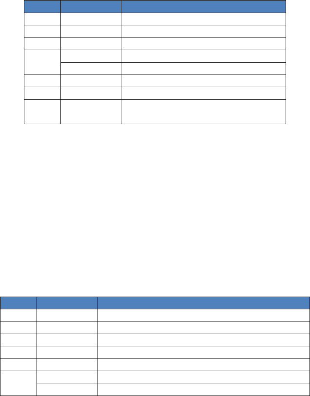
95x Series Operating Manual - December 12, 2011
Page 139 of 151
Configures the following (in order) –
A DCW type test step
1000V test voltage
15mA breakdown limit
1.5 second ramp time
60 second dwell time
0 second delay
Test is terminated as soon as a failure is detected
Define leakage limits in Amps
No minimum leakage current limit
25uA maximum leakage current limit
4us arc detection time
10mA arc detection limit
Fast discharge
Abort test sequence if fails
Table 22 - GBez Configuration Fields
Field #
Field Format
Value
1 <STRING> GBEZ
2
<NR3>
Test Current (in Arms)
3 <NR3> Test Frequency (in Hz)
4
<NR3>
Dwell time (in seconds)
<EMPTY> Step is to be user terminated
5
<NR3>
Minimum Voltage Drop Limit (in Vrms)
6
<NR3>
Maximum Voltage Drop Limit (in Vrms)
7 <STRING> ABORT - Abort on failure
CONT - Continue on failure
Example –
ADD,GBEZ,25.0,60.0,60.0,0.0,0.1,ABORT
Configures the following (in order) –
A GBez type test step
25A test current
60Hz test frequency
60 second dwell time
No minimum voltage drop
0.1V maximum voltage drop
Abort test sequence if fails
Table 23 - GB Configuration Fields
Field #
Field Format
Value
1
<STRING>
GB
2 <NR3> Test Current (in Arms)
3 <NR3> Test Frequency (in Hz)
4
<NR3>
Maximum open circuit drive (in Vrms)
5 <NR3> Ramp Time (in seconds)
6
<NR3>
Dwell time (in seconds)
<EMPTY>
Step is to be user terminated

95x Series Operating Manual - December 12, 2011
Page 140 of 151
7 <STRING>
RMSV - Checked value is RMS voltage drop
INPHSV - Checked value is In-phase voltage drop
QUADV - Checked value is quadrature voltage drop
RMSO - Checked value is RMS impedance
INPHSO - Checked value is in-phase impedance
QUADO - Checked value is quadrature impedance
8 <NR3> Minimum Limit (in V or Ω)
9
<NR3>
Maximum Limit (in V or Ω)
10 <STRING>
NONE - No discharge if next step compatible
FAST - Fast discharge
RAMP - Discharge same as ramp
11 <STRING> ABORT - Abort on failure
CONT - Continue on failure
Example –
ADD,GB,25.0,60.0,5.0,0.0,60.0,RMSO,0.0,0.1,FAST,ABORT
Configures the following (in order) –
A GB type test step
25A test current
60Hz test frequency
5V max open circuit voltage
0 second ramp time
60 second dwell time
Check RMS impedance
No minimum impedance
0.1Ω maximum impedance
Fast discharge
Abort test sequence if fails
Table 24 - LowΩ Configuration Fields
Field # Field Format Value
1
<STRING>
LOWOHM
2 <BOOL> 1 or Y - Test using 2-wire mode
0 or N - Test using 4-wire mode
3
<NR3>
Test time (in seconds)
<EMPTY> Step is to be user terminated
4
<NR3>
Check delay (in seconds)
5
<NR3>
Minimum Resistance Limit (in Ω)
6
<NR3>
Maximum Resistance Limit (in Ω)
7 <STRING> ABORT - Abort on failure
CONT - Continue on failure
Example –
ADD,LOWOHM,0,5.0,0.0,1.25,1.75,ABORT
Configures the following (in order) –
A LowΩ type test step
Use 4-wire mode
5 second test time
0 second delay

95x Series Operating Manual - December 12, 2011
Page 141 of 151
1.25Ω minimum resistance
1.75Ω maximum resistance
Abort test sequence if fails
Table 25 - ACIR Configuration Fields
Field # Field Format Value
1 <STRING> ACIR
2
<NR3>
Test Voltage (in Vrms)
3 <NR3> Test Frequency (in Hz)
4
<NR3>
Breakdown Limit (in Apk)
5 <NR3> Ramp Time (in seconds)
6
<NR3>
Dwell time (in seconds)
<EMPTY> Step is to be user terminated
7 <STRING> AMPS - Check in-phase leakage current
OHMS - Check in-phase resistance
8 <NR3> Minimum Leakage Limit (in A or Ω)
9
<NR3>
Maximum Leakage Limit (in A or Ω)
<EMPTY> No maximum limit (only valid for resistance)
10 <NR1> Time period for arc detection (4, 10, 15, 20, 30 or 40)
<EMPTY>
Arc detection disabled
11 <NR1> Arc detection limit (in mA)
<EMPTY>
Only valid if arc detection disabled in field 10
12 <STRING>
NONE - No discharge if next step compatible
FAST - Fast discharge
RAMP - Discharge same as ramp
13 <STRING> ABORT - Abort on failure
CONT - Continue on failure
Example –
ADD,ACIR,1000.0,60.0,0.01,1.5,60.0,OHMS,1e7,,,,FAST,ABORT
Configures the following (in order) –
An ACIR type test step
1000V test voltage
60Hz test frequency
10mApk breakdown limit
1.5 second ramp time
60 second dwell time
Checked value is resistance
10MΩ minimum resistance
No maximum resistance
No arc detection (so following field is also <EMPTY>)
Fast discharge
Abort test sequence if fails
Table 26 - ACCAP Configuration Fields
Field #
Field Format
Value
1 <STRING> ACCAP
2 <NR3> Test Voltage (in Vrms)

95x Series Operating Manual - December 12, 2011
Page 142 of 151
3
<NR3>
Test Frequency (in Hz)
4 <NR3> Breakdown Limit (in Apk)
5 <NR3> Ramp Time (in seconds)
6
<NR3>
Dwell time (in seconds)
<EMPTY> Step is to be user terminated
7
<NR3>
Minimum Capacitance Limit (in F)
8
<NR3>
Maximum Capacitance Limit (in F)
9 <NR3> Minimum DF Limit (no units)
10
<NR3>
Maximum DF Limit (no units)
11 <NR1> Time period for arc detection (4, 10, 15, 20, 30 or 40)
<EMPTY>
Arc detection disabled
12 <NR1> Arc detection limit (in mA)
<EMPTY>
Only valid if arc detection disabled in field 11
13 <STRING>
NONE - No discharge if next step compatible
FAST - Fast discharge
RAMP - Discharge same as ramp
14 <STRING> ABORT - Abort on failure
CONT - Continue on failure
Example –
ADD,ACCAP,1000.0,60.0,0.01,1.5,60.0,0.9e-9,1.1e-9,0.0,1.0,,,FAST,ABORT
Configures the following (in order) –
An ACCAP type test step
1000V test voltage
60Hz test frequency
10mApk breakdown limit
1.5 second ramp time
60 second dwell time
0.9nF minimum capacitance
1.1nF maximum capacitance
No minimum dissipation factor
No maximum dissipation factor (1.0 disables the maximum)
No arc detection (so following field is also <EMPTY>)
Fast discharge
Abort test sequence if fails
Table 27 - ACI Configuration Fields
Field # Field Format Value
1
<STRING>
ACI
2
<NR3>
Test time (in seconds)
<EMPTY> Step is to be user terminated
3 <NR3> Delay time (in seconds)
4
<NR3>
Minimum Leakage Current Limit (in Arms)
5 <NR3> Maximum Leakage Current Limit (in Arms)
6
<NR1>
Time period for arc detection (4, 10, 15, 20, 30 or 40)
<EMPTY>
Arc detection disabled
7
<NR1>
Arc detection limit (in mA)
<EMPTY>
Only valid if arc detection disabled in field 6

95x Series Operating Manual - December 12, 2011
Page 143 of 151
8 <STRING> ABORT - Abort on failure
CONT - Continue on failure
Example –
ADD,ACI,5.0,0.0,0.0,50e-6,,,ABORT
Configures the following (in order) –
An ACI type test step
5 second test time
0 second delay time
No minimum leakage current
50uA maximum leakage current
No arc detection (so following field is also <EMPTY>)
Abort test sequence if fails
Table 28 - DCCAP Configuration Fields
Field # Field Format Value
1
<STRING>
DCCAP
2 <NR3> Test Voltage (in V)
3
<NR3>
Maximum ramping rate (in V/sec)
4
<NR3>
Maximum Charging Current (in Amps)
5
<NR3>
Ramp timeout (in seconds)
6
<NR3>
Dwell time (in seconds)
<EMPTY> Step is to be user terminated
7
<NR3>
Pre-check delay (in seconds)
8 <STRING> AMPS - Leakage limits are in Amps
OHMS - Leakage limits are in Ω
9 <NR3> Minimum Leakage Limit (in A or Ω)
10 <NR3> Maximum Leakage Limit (in A or Ω)
<EMPTY>
No maximum limit (only valid for impedance)
11 <NR1> Time period for arc detection (4, 10, 15, 20, 30 or 40)
<EMPTY>
Arc detection disabled
12
<NR1>
Arc detection limit (in mA)
<EMPTY> Only valid if arc detection disabled in field 11
13 <STRING>
NONE - No discharge if next step compatible
FAST - Fast discharge
RAMP - Discharge same as ramp
14 <STRING> ABORT - Abort on failure
CONT - Continue on failure
Example –
ADD,DCCAP,1000.0,200.0,10e-3,75.0,60.0,5.0,AMPS,0.0,250e-6,,,FAST,ABORT
Configures the following (in order) –
A DCCAP type test step
1000V test voltage
200V/sec maximum ramp rate
10mA maximum charging current
75 second ramp timeout
60 second dwell time
5 second delay

95x Series Operating Manual - December 12, 2011
Page 144 of 151
Define leakage limits in Amps
No minimum leakage current limit
250uA maximum leakage current limit
No arc detection (so following field is also <EMPTY>)
Fast discharge
Abort test sequence if fails
Table 29 - IRCAP Configuration Fields
Field # Field Format Value
1
<STRING>
IRCAP
2 <NR3> Test Voltage (in V)
3
<NR3>
Maximum ramping rate (in V/sec)
4 <NR3> Maximum Charging Current (in Amps)
5 <NR3> Ramp timeout (in seconds)
6
<NR3>
Dwell time (in seconds)
<EMPTY> Step is to be user terminated
7
<NR3>
Pre-check delay (in seconds)
8 <STRING>
PASS - Test is ended as soon as passes
FAIL - Test is ended as soon as fails
TIME - Test always extends for the full time
9 <STRING> AMPS - Leakage limits are in Amps
OHMS - Leakage limits are in Ω
10 <NR3> Minimum Leakage Limit (in A or Ω)
11
<NR3>
Maximum Leakage Limit (in A or Ω)
<EMPTY> No maximum limit (only valid for impedance)
12 <NR1> Time period for arc detection (4, 10, 15, 20, 30 or 40)
<EMPTY>
Arc detection disabled
13 <NR1> Arc detection limit (in mA)
<EMPTY> Only valid if arc detection disabled in field 12
14 <STRING>
NONE - No discharge if next step compatible
FAST - Fast discharge
RAMP - Discharge same as ramp
15 <STRING> ABORT - Abort on failure
CONT - Continue on failure
Example –
ADD,IRCAP,1000.0,200.0,10e-3,75.0,60.0,5.0,PASS,AMPS,0.0,250e-6,,,FAST,ABORT
Configures the following (in order) –
An IRCAP type test step
1000V test voltage
200V/sec maximum ramp rate
10mA maximum charging current
75 second ramp timeout
60 second dwell time
5 second delay
End on pass
Define leakage limits in Amps
No minimum leakage current limit
250uA maximum leakage current limit
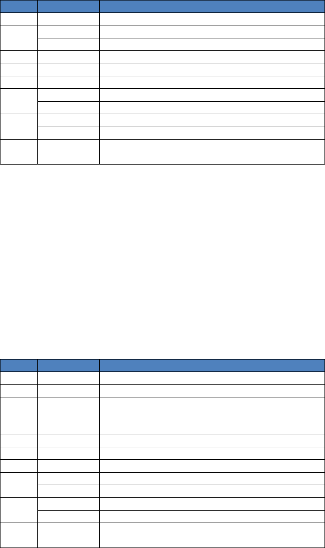
95x Series Operating Manual - December 12, 2011
Page 145 of 151
No arc detection (so following field is also <EMPTY>)
Fast discharge
Abort test sequence if fails
Table 30 - DCI Configuration Fields
Field # Field Format Value
1 <STRING> DCI
2
<NR3>
Test time (in seconds)
<EMPTY> Step is to be user terminated
3
<NR3>
Delay time (in seconds)
4
<NR3>
Minimum Leakage Current Limit (in A)
5 <NR3> Maximum Leakage Current Limit (in A)
6 <NR1> Time period for arc detection (4, 10, 15, 20, 30 or 40)
<EMPTY> Arc detection disabled
7
<NR1>
Arc detection limit (in mA)
<EMPTY> Only valid if arc detection disabled in field 6
8 <STRING>
ABORT - Abort on failure
CONT - Continue on failure
Example –
ADD,DCI,5.0,0.0,0.0,50e-6,,,ABORT
Configures the following (in order) –
A DCI type test step
5 second test time
0 second delay time
No minimum leakage current
50uA maximum leakage current
No arc detection (so following field is also <EMPTY>)
Abort test sequence if fails
Table 31 - PULSE Configuration Fields
Field #
Field Format
Value
1 <STRING> PULSE
2 <NR3> Level (in V)
3 <STRING>
POSITIVE - Unipolar +ve
NEGATIVE – Unipolar –ve
BIPOLAR - Bipolar
4
<NR3>
Ramp time (tr) (in seconds)
5 <NR3> Hold Time (th) (in seconds)
6 <NR3> Breakdown Current Limit (in A)
7 <NR1> Time period for arc detection (4, 10, 15, 20, 30 or 40)
<EMPTY>
Arc detection disabled
8 <NR1> Arc detection limit (in mA)
<EMPTY> Only valid if arc detection disabled in field 7
9 <STRING> ABORT - Abort on failure
CONT - Continue on failure
Example –
ADD,PULSE,250.0,POSITIVE,1e-3,10e-3,0.05,4,10,ABORT
95x Series Operating Manual - December 12, 2011
Page 146 of 151
Configures the following (in order) –
A PULSE type test step
A single positive pulse
1ms ramp time
10ms hold time
50mA maximum current
4us arc detection
10mA arc detection limit
Abort test sequence if fails
Table 32 - PAUSE Configuration Fields
Field # Field Format Value
1 <STRING> PAUSE
2 <NR3> Pause time (in seconds)
Example –
ADD,PAUSE,5.0
Configures the following (in order) –
A PAUSE type test step
5 second pause time
Table 33 - HOLD Configuration Fields
Field # Field Format Value
1
<STRING>
HOLD
2 <NR3> Timeout (in seconds)
Example –
ADD,HOLD,60.0
Configures the following (in order) –
A HOLD type test step
60 second timeout
Table 34 – SWITCH (948i configuration) Configuration Fields
Field # Field Format Value
1
<STRING>
SWITCH
2
<NR3>
Pre-switch delay (in seconds)
3
<NR3>
Post-switch delay (in seconds)
4-10 <NR1> Switch bank data banks 6-0 resp.
Example –
ADD,SWITCH,0.0,0.25,0x00,0x00,0x00,0x00,0x00,0x00,0x00
Configures the following (in order) –
A SWITCH type test step
0 second pre-switch delay
0.25 second post-switch delay
Bank #6 set to hexadecimal 00
Bank #5 set to hexadecimal 00
Bank #4 set to hexadecimal 00

95x Series Operating Manual - December 12, 2011
Page 147 of 151
Bank #3 set to hexadecimal 00
Bank #2 set to hexadecimal 00
Bank #1 set to hexadecimal 00
Bank #0 set to hexadecimal 00
Table 35 – SWITCH (964i configuration) Configuration Fields
Field # Field Format Value
1
<STRING>
SWITCH
2
<NR3>
Pre-switch delay (in seconds)
3 <NR3> Post-switch delay (in seconds)
4-11 <NR1> 964 #1 Switch bank data banks 7-0 resp.
12-19
<NR1>
964 #2 Switch bank data banks 7-0 resp. (only if configured for >1x964)
20-27
<NR1>
964 #3 Switch bank data banks 7-0 resp. (only if configured for >2x964)
28-35 <NR1> 964 #4 Switch bank data banks 7-0 resp. (only if configured for 4x964)
Example –
ADD,SWITCH,0.0,0.25,0x00,0x00,0x00,0x00,0x00,0x00,0x00,0x00
Configures the following (in order) –
A SWITCH type test step
0 second pre-switch delay
0.25 second post-switch delay
Bank #7 set to hexadecimal 00
Bank #6 set to hexadecimal 00
Bank #5 set to hexadecimal 00
Bank #4 set to hexadecimal 00
Bank #3 set to hexadecimal 00
Bank #2 set to hexadecimal 00
Bank #1 set to hexadecimal 00
Bank #0 set to hexadecimal 00
Table 36 – Test Step Status Flags
Bit #
Value
Description
0 1 95x Internal Fault
1
2
Failed to control the output level
2
4
Breakdown detected
3 8 Timeout exceeded
4 16 User abort
5 32 Continuity Sense failure detected
6
64
Wiring fault detected
7 128 Arc detected
8 256 1
st
check <minimum
9
512
1st check >maximum
10 1024 2
nd
check <minimum
11
2048
2nd check >maximum
12 4096 INTERLOCK failure
13
8192
HV TRIP activated
14 16384 Switch Matrix unit did not communicate
15 32768 Heavy breakdown detected
16
65536
95x Overheated

95x Series Operating Manual - December 12, 2011
Page 148 of 151
Table 37 – STEPRSLT? Response Fields
Field # Field Format Value
1 <NR1>
0 – Not executed
1 – Terminated during Ramp
2 – Terminated during Dwell (during delay)
3 – Terminated during Dwell (after delay)
Others – Terminated
2 <NR3> Elapsed time of last executed period (in seconds)
3
<NR1>
Status of this step, see Table 36 – Test Step Status Flags
4
<NR3> or <EMPTY>
Final test level (in Volts or Amps)
5
<NR3> or <EMPTY>
Final test frequency (in Hz)
6 <NR3> or <EMPTY> Highest breakdown current (in Amps)
7 <NR3> or <EMPTY> Highest voltage (in Volts), PULSE or BRKDN types only
8
<NR3> or <EMPTY>
Highest 1st check result
9 <NR3> or <EMPTY> Lowest 1
st
check result
10
<NR3> or <EMPTY>
Average 1st check result
11
<NR3> or <EMPTY>
Last 1st check result
12 <NR3> or <EMPTY> Highest 2
nd
check result
13
<NR3> or <EMPTY>
Lowest 2nd check result
14 <NR3> or <EMPTY> Average 2
nd
check result
15
<NR3> or <EMPTY>
Last 2nd check result
16 <NR3> or <EMPTY> Highest arc current (in Amps)
17 <NR3> or <EMPTY> Lowest arc current (in Amps)
18
<NR3> or <EMPTY>
Average arc current (in Amps)
19 <NR3> or <EMPTY> Last arc current (in Amps)
SIMPLE PROGRAMMING EXAMPLES
If the user wishes to simply be able to send a command to the 95x to test that the interface is active and
functioning then the following could be used –
Example 1
Send *IDN?<CR><LF> (don’t type the <CR><LF> just ensure that your application sends a carriage return and/or
line feed)
Read the response back from the 95x, it should be similar to VITREK,952i,000000,v1.45,v1.23,v1.23,v1.23
Refer to Table 16 - *IDN? Response Fields for details regarding the response.
Example 2
Ensure there are no connections to any terminals on the 95x, this example is not applicable to the 959i.
Send NOSEQ; ADD,ACEZ,1000.0,60.0,1.5,5.0,0.0,0.005,ABORT;RUN<CR><LF>
The 95x will perform an ACez test at 1000Vrms/60Hz with a 1.5sec ramp and 5sec dwell.
After completion send STEPRSLT?,1<CR><LF>
The 95x responds with the results for the step which should be similar to –
3,+5.01700E+00,0,+1.00012E+03,+60.0000E+00,+82.3600E-09,,+2.22916E-09,+2.10947E-09,+2.18633E-
09,+2.17637E-09,,,,,,,,
Refer to Table 37 – STEPRSLT? Response Fields for details regarding the response.

95x Series Operating Manual - December 12, 2011
Page 149 of 151
PROGRAMMING GUIDELINES
Avoid Interface Specific Methods
The 95x can be interfaced to with RS232, GPIB or Ethernet interfaces. It is recommended that the programmer not
use interface specific methods, e.g. serial polling over GPIB, to ease the migration between interfaces at a later
date. Similarly, it is recommended to always terminate commands with either the <CR> or <LF> characters (or
both) rather than using the GPIB specific EOI or GET methods. The command set and response formats are
identical between interfaces, so migration between interfaces is simple if this guideline is followed.
Start by Initializing the 95x
When a user application is started on the controlling computer the status of the 95x is unknown, it may have a
response waiting to be read, it may have a partial command in its’ input buffer. It is recommended that the user
always perform an interface clear when the application is started to ensure that there are no pending or partially
programmed activities in the 95x. This can be achieved by sending the *RST command.
Employ a Timeout on all Activities
On all interfaces, the 95x has full handshake capabilities, so both commands and responses can be held up for
short periods of time. The user must employ timeouts for both transmit and receive operations and take any
desired corrective action should a timeout occur.
Fully Configure the 95x
If there are any configuration settings in the 95x which are relied upon by the programmer, then these should be
explicitly set by the user application when it is first started. Commands are provided to set the 95x configuration
settings.
Checking for errors
Often the user wishes to ensure that a command was correctly received by the 95x and that the command was not
rejected by the 95x. This is easily achieved by always sending the *ERR? command after sending any non-query
command, waiting for the response and checking that it is “0”. There are other registers which could be used also,
but the ERR register provides the most information regarding the nature of the error.
For example –
BEEP,START,2<CR><LF>
*ERR?<CR><LF>
This would cause the response to be 0<CR><LF>
As another example –
BEEP,START,9;*ERR?<CR><LF>
This would not function as expected. The “9” field in the BEEP command is in error, which makes the 95x reject
the entire set of commands. This should be –
BEEP,START,9<CR><LF>
*ERR?<CR><LF>
This would cause the response to be 5<CR><LF>
Program and run a Sequence rather than Individual Steps
95x Series Operating Manual - December 12, 2011
Page 150 of 151
When setting up and running a test sequence the user is recommended to run it as a sequence in the 95x, rather
than running individual steps one at a time.
The 95x will remember the sequence, even if it is not stored, as long as power is not removed from the 95x. The
user only needs to program the sequence once; it can then be run multiple times as needed.
The 95x remembers the results of each step performed; the user can extract all of the test results as needed after
completion of the test sequence.
By running a sequence, the 95x can operate at its’ own speed, the computer does not have to “keep up” with the
95x.
The recommended flow is as follows –
• Send a NOSEQ command to ensure there is no active test sequence.
• Send ADD,… commands as needed to program the desired sequence. After each command send the
*ERR? command to check for any incompatibility between the requested test step operation and the 95x.
The 95x will append each ADD,… test step to the active sequence, so the user should send each desired
step in the correct order.
• Send the RUN command. The 95x will now run the sequence.
• Poll the 95x at intervals to detect completion of the sequence. The selection of the polling interval is up
to the user, for short test sequences this could be as fast as every millisecond, for long sequences perhaps
every 100milliseconds or longer would suffice. Either the STEP? or RUN? Commands can be used, the
STEP? command is recommended as it provides more information in the response. If needed, the user
could also program MEASRSLT? Command(s) to extract actual measurements during execution of the
sequence. If multiple measurement results are required during execution, the user should send multiple
MEASRSLT? Commands as a set of commands, the 95x responds with all of the measurement results as a
single set in the same order as requested. In this manner some interface time is saved, and it is
guaranteed that all of the measurement results are consistent in time with each other. When using
asynchronous timed polling the user should be careful as the OS may cause undesired operation –
o If the user calls for an asynchronous timed event from the OS which is handled by the user code
sending the query command(s) and fetching the response(s) then command overrun can occur if
polling is too fast. The 95x may slightly delay either the command or the response to beyond the
time interval being used for polling, also the OS itself may delay the transmission or reception. In
some OS’s calls are made regardless of the completion of the preceding call – so the second call
will cause commands to be transmitted even though the responses from the first call have not
been received yet. The user should use some sort of software interlock to prevent this if needed.
o This issue does not occur if the user uses synchronous coding – i.e. send the query command(s) –
wait for the response(s) – wait for a delay – repeat.
• Once the test sequence has completed (e.g. the response to the STEP? command is 0) the user should
request for the test results. There are various methods of achieving this, which the user chooses is
dependent on the level of detail which is needed. The following query commands are recommended –
o RSLT? – responds with the overall test status, giving overall pass/fail information.
o STEPRSLT? for each defined step – giving very detailed information regarding each step.
• If the user requires to run the sequence again (usually with a different DUT) – then simply repeat the
process starting with the RUN command – there is no need to reprogram the sequence itself unless
changes are needed.
95x Series Operating Manual - December 12, 2011
Page 151 of 151
If the user needs to synchronize the execution of the sequence to external events, the HOLD type step can be used
to cause the 95x to suspend execution of the sequence until the CONT command is received from the computer.
As an example, if the computer is controlling switching which needs to be altered during execution the user would
program the following during execution –
• Detect that the HOLD step is being performed by the response to the polled STEP? command.
• If the HOLD step is being performed, then program the required change(s) to switches and send the
command CONT to the 95x to command it on to the next step in the sequence. The user may need to
perform a slight delay after sending the CONT command as it will take the 95x about 1ms to actually
continue on to the next step – if another STEP? command is received during that time then it will still
report that the HOLD step is being executed.
