WE261 E 96022000801 442476_r1 !!
Preview ! 96022000801 Weed Eater Lawn Mower Manuals - Lawn Mower Manuals – The Best Lawn Mower Manuals Collection
User Manual: !! Weed Eater Lawn Mower Manuals - Lawn Mower Manuals – The Best Lawn Mower Manuals Collection
Open the PDF directly: View PDF ![]() .
.
Page Count: 13

02.21.11 BAD Printed in the U.S.A.
This product has been expertly en gi neered and carefully manu fac tured to rigid quality stan dards. As with all
mechanical products, some adjustments or part replacement may be necessary during the life of your unit.
For Parts and service, contact our authorized distributor: call 1-800-849-1297
• For replacement parts, have available the following information:
a. Model Number/Manufacturer's I.D. Number
b. Description of part.
For Technical Assistance: call 1-800-829-5886
For a Parts Manual, go to our website: www.weedeater.com
NOTE: HOP provides parts and service through its au thor ized dis tribu tors and dealers; there fore,
all requests for parts and service should be directed to your local dealer(s). The phi loso phy
of HOP is to con tinu ally improve all of its prod ucts. If the operating characteristics or the
appearance of your product differs from those described in this Manual, please contact
your local dealer for updated in for ma tion and as sis tance.
PARTS AND SERVICE
Operator’s Manual
532 44 24-76 Rev. 1
26" RIDING MOWER
SIDE DISCHARGE
ELECTRIC START
IMPORTANT:
Read and follow all Safety
Rules and Instructions before
op er at ing this equipment.
Catalog No.
WE261
Patents Pending
Gasoline containing up to 10% ethanol (E10) is acceptable for use in this
machine. The use of any gasoline exceeding 10% ethanol (E10) will void the
product warranty.
BAGGER = 960730027
MULCH KIT = MK26
38
1 532 43 05-88 DECAL, STEERING WHEEL
2 532 43 35-96 DECAL, V-BELT SCH 30"
3 532 42 51-13 DECAL, WARN. DEFLECT/CTFGR
4 532 44 07-79 DECAL, DECK/DEFLECTOR
6 532 43 67-55 DECAL
7 532 43 44-57 DECAL, WARNING
8 532 42 41-02 DECAL, WARNING SPARK ARRESTOR
9 532 43 73-12 DECAL, LRV STEERING BRKT.
- - 532 43 24-79 DECAL, BYPASS
- - 532 44 24-76 MANUAL OPERATOR ENGLISH
- - 532 44 24-77 MANUAL OPERATOR SPANISH
KEY PART
NO. NO. DESCRIPTION
NOTE: All component dimensions given in U.S. inches
1 inch = 25.4 mm
1
4
6
7
8
9
4
3
2
RIDING MOWER MODEL NUMBER WE261 (96022000801)
DECALS PRODUCT NUMBER 960 22 00-08
3
SAFETY RULES
DANGER: This cutting machine is ca pa ble of amputating hands and feet and throwing
objects. Failure to observe the fol low ing safety instructions could result in serious
injury or death.
I. GENERAL OPERATION
• Read, understand, and follow all instruc-
tions on the machine and in the manual
before starting.
• Do not put hands or feet near rotating
parts or under the machine. Keep clear
of the discharge opening at all times.
• Only allow responsible adults, who are
familiar with the instructions, to operate
the machine.
• Clear the area of objects such as rocks,
toys, wire, etc., which could be picked up
and thrown by the blade.
• Be sure the area is clear of bystanders
before operating. Stop machine if anyone
enters the area.
• Never carry passengers.
• Do not mow in reverse unless absolutely
necessary. Always look down and behind
before and while backing.
• Never direct discharged material toward
anyone. Avoid discharging material
against a wall or obstruction. Material may
ricochet back toward the operator. Stop the
blade when crossing gravel surfaces.
• Do not operate machine without the entire
grass catcher, discharge chute, or other
safety devices in place and working.
• Slow down before turning.
• Never leave a running machine unat-
tended. Always turn off blade, set park-
ing brake, stop engine, and remove keys
before dismounting.
• Disengage blade when not mowing. Shut
off engine and wait for all parts to come
to a complete stop before cleaning the
machine, removing the grass catcher, or
unclogging the discharge chute.
• Operate machine only in daylight or good
artificial light.
• Do not operate the machine while under
the influence of alcohol or drugs.
• Watch for traffic when operating near or
crossing roadways.
• Use extra care when loading or unloading
the machine into a trailer or truck.
• Always wear eye protection when operat-
ing machine.
• Data indicates that operators, age 60
years and above, are involved in a large
percentage of riding mower-related inju-
ries. These operators should evaluate
their ability to operate the riding mower
safely enough to protect themselves and
others from serious injury.
• Keep machine free of grass , leaves or
other debris build-up which can touch hot
exhaust / engine parts and burn. Do not
allow the mower deck to plow leaves or
other debris which can cause build-up to
occur. Clean any oil or fuel spillage before
operating or storing the machine. Allow
machine to cool before storage.
WARNING: In order to prevent ac ci den-
tal starting when setting up, trans port ing,
ad just ing or making repairs, always dis con-
nect spark plug wire and place wire where
it can not contact spark plug.
WARNING: Do not coast down a hill in
neutral, you may lose control of the riding
mower.
WARNING: Engine exhaust, some of its
constituents, and certain vehicle com po nents
contain or emit chem i cals known to the State
of Cal i for nia to cause can cer and birth defects
or oth er re pro duc tive harm.
WARNING:This unit is not intended for
towing, or use of wheel weights. Only use
attachments designed specifically for this
riding mower.
WARNING: Battery posts, terminals and
related accessories contain lead and lead
compounds, chemicals known to the State of
Cal i for nia to cause can cer and birth defects
or oth er re pro duc tive harm. Wash hands
after handling.
4
SAFETY RULES
II. SLOPE OPERATION
Slopes are a major factor related to loss of
control and tip-over accidents, which can
result in severe injury or death. Operation
on all slopes requires extra caution. If you
cannot back up the slope or if you feel uneasy
on it, do not mow it.
• Mow up and down slopes (15° Max), not
across.
• Watch for holes, ruts, bumps, rocks, or
other hidden objects. Uneven terrain could
overturn the machine. Tall grass can hide
obstacles.
• Choose a low ground speed so that you
will not have to stop or shift while on the
slope.
• Do not mow on wet grass. Tires may lose
traction.
• Always keep the machine in gear when
going down slopes. Do not shift to neutral
and coast downhill.
• If machine stops while going uphill,
disengage blade, shift into reverse and
back down slowly.
• Avoid starting, stopping, or turning on a
slope. If the tires lose traction, disengage
the blade and proceed slowly straight down
the slope.
• Keep all movement on the slopes slow and
gradual. Do not make sudden changes
in speed or direction, which could cause
the machine to roll over.
• Use extra care while operating machine
with grass catchers or other attachments;
they can affect the stability of the machine.
• Do no use on steep slopes.
• Do not try to stabilize the machine by
putting your foot on the ground.
• Do not mow near drop-offs, ditches, or
embankments. The machine could sud-
denly roll over if a wheel is over the edge
or if the edge caves in.
III. CHILDREN
Tragic accidents can occur if the operator
is not alert to the presence of children.
Children are often attracted to the machine
and the mowing activity. Never assume
that children will remain where you last
saw them.
• Keep children out of the mowing area and
in the watchful care of a responsible adult
other than the operator.
• Be alert and turn machine off if a child
enters the area.
• Before and while backing, look behind and
down for small children.
• Never carry children, even with the blade
shut off. They may fall off and be seriously
injured or interfere with safe machine
operation. Children who have been given
rides in the past may suddenly appear in
the mowing area for another ride and be run
over or backed over by the machine.
• Never allow children to operate the ma-
chine.
• Use extra care when approaching blind
corners, shrubs, trees, or other objects
that may block your view of a child.
IV. SERVICE
SAFE HANDLING OF GASOLINE
To avoid personal injury or property dam-
age, use extreme care in handling gasoline.
Gasoline is extremely flammable and the
vapors are explosive.
• Extinguish all cigarettes, cigars, pipes,
and other sources of ignition.
• Use only approved gasoline container.
• Never remove gas cap or add fuel with
the engine running. Allow engine to cool
before refueling.
• Never fuel the machine indoors.
• Never store the machine or fuel container
where there is an open flame, spark, or
pilot light such as on a water heater or
other appliances.
37
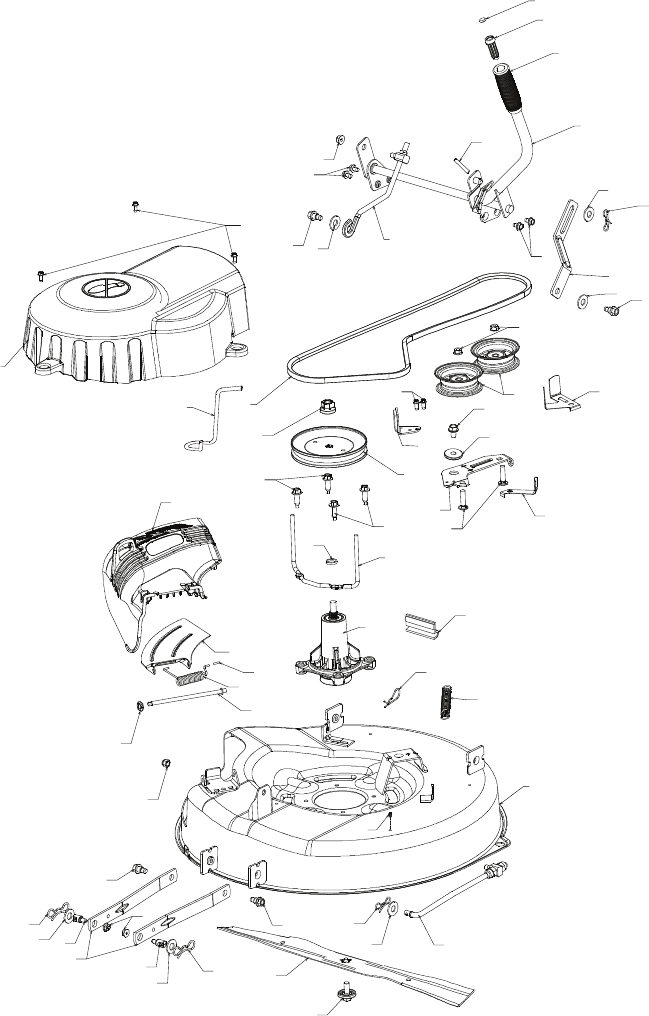
1 532 42 81-93 DECK, 26"
2 532 19 28-70 MANDREL ASM
3 532 43 25-20 KEEPER, BELT
4 532 43 25-94 PULLEY, MANDREL
5 532 42 85-78 BELT
6 532 42 82-42 COVER, MANDREL
7 532 42 93-95 LIFT ASM, DECK
8 532 42 91-95 LINK, DECK LIFT
9 532 42 93-97 LINK, ADJUSTABLE
10 532 43 89-23 DEFLECTOR
11 532 42 89-68 SUPPORT, DEFLECTOR
12 532 13 14-91 ROD, HINGE
13 532 19 70-26 SPRING, TORSION
14 532 41 88-63 ARM, MOWER SUPPORT
15 873 90 05-00 NUT, LOCK
16 532 19 51-61 STUD
17 819 19 19-12 WASHER
18 532 19 42-09 PIN
19 532 19 65-39 BOLT, SHOULDER
20 532 19 42-08 PIN
21 819 17 19-12 WASHER, 17/32 X 1 3/16
22 532 42 93-50 LINK, DECK
23 873 90 06-00 NUT, LCK 3/8-16
24 532 42 95-31 SPRING, DECK
25 532 12 47-88 PIN
26 532 18 76-90 SPACER, MANDREL
27 532 17 39-84 BOLT, MANDREL
28 532 40 02-34 NUT, LOCK
29 532 42 85-00 BLADE
30 532 19 30-03 BOLT, BLADE
31 532 19 31-97 PULLEY, IDLER
32 532 14 10-43 GUARD, IDLER
33 532 19 34-14 KEEPER, BELT IDLER
34 872 11 06-12 BOLT, 3/8-16 X 1 1/2
35 532 19 94-70 ARM, BRAKE
36 532 13 77-29 SCREW, 1/4-20 X 5/8
37 873 90 06-00 NUT, 3/8-16 FLANGE
38 532 42 84-35 ARM, IDLER
39 817 49 05-08 BOLT, 5/16-18 X 1/2
40 819 17 16-16 WASHER, 16 GA.
41 532 10 53-04 CAP, SLEEVE
42 532 11 04-52 NUT, PUSH
43 532 12 56-31 GRIP, HANDLE
44 532 42 94-01 PLUNGER
45 532 10 57-67 PIN
47 532 12 45-26 BUTTON PLUNGER
48 532 43 86-10 KEEPER BELT
49 532 19 90-92 SPACER RETAINER
50 817 00 06-16 SCREW 3/8-16 X 1
51 532 40 47-42 BUMPER
52 817 67 06-08 SCREW 3/8-16 X 1/2
KEY PART
NO. NO. DESCRIPTION
NOTE: All component dimensions given in U.S. inches
1 inch = 25.4 mm
RIDING MOWER MODEL NUMBER WE261 (96022000801)
MOWER DECK PRODUCT NUMBER 960 22 00-08
36
10
11
1
2
3
4
5
7
9
8
12
13
41
14
15
16
16
17
17
17
40
21
45
18
18 19
19
19
19
20
20
21 22
23
42
24
25
26
27
27
28
29
30
31 32
33
34
35
36
37
37
38
39
39
44
47
43
48
LRV-A_Deck_5
51
49
50
52
6
36
RIDING MOWER MODEL NUMBER WE261 (96022000801)
MOWER DECK PRODUCT NUMBER 960 22 00-08
5
SAFETY RULES
• Never fill containers inside a vehicle or
on a truck or trailer bed with plastic liner.
Always place containers on the ground
away from your vehicle when filling.
• Remove gas-powered equipment from the
truck or trailer and refuel it on the ground.
If this is not possible, then refuel such
equipment with a portable container, rather
than from a gasoline dispenser nozzle.
• Keep the nozzle in contact with the rim
of the fuel tank or container opening at
all times until fueling is complete. Do not
use a nozzle lock-open device.
• If fuel is spilled on clothing, change clothing
immediately.
• Never overfill fuel tank. Replace gas cap
and tighten securely.
GENERAL SERVICE
• Never operate machine in a closed area.
• Keep all nuts and bolts tight to be sure the
equipment is in safe working condition.
• Never tamper with safety devices. Check
their proper operation regularly.
• Keep machine free of grass, leaves, or
other debris build-up. Clean oil or fuel spill-
age and remove any fuel-soaked debris.
Allow machine to cool before storing.
• If you strike a foreign object, stop and
inspect the machine. Repair, if necessary,
before restarting.
• Never make any adjustments or repairs
with the engine running.
• Check grass catcher components and the
discharge chute frequently and replace
with manufacturer’s recommended parts,
when necessary.
• Mower blade is sharp. Wrap the blade or
wear gloves, and use extra caution when
servicing them.
• Check brake operation frequently. Adjust
and service as required.
• Maintain or replace safety and instruction
labels, as necessary.
• Be sure the area is clear of bystanders
before operating. Stop machine if anyone
enters the area.
• Never carry passengers.
• Do not mow in reverse unless absolutely
necessary. Always look down and behind
before and while backing.
6
UNASSEMBLED PARTS
PRODUCT SPECIFICATIONS
CUSTOMER RESPONSIBILITIES
• Read and observe the safety rules.
• Follow a regular schedule in main tain ing,
caring for and using your riding mower.
• Follow the instructions under “Main te-
nance” and “Stor age” sec tions of this
own er’s manual.
WARNING: This riding mower is
equipped with an internal com bus tion en-
gine and should not be used on or near any
un im proved forest-covered, brush-covered
or grass-cov ered land unless the engine’s
exhaust system is equipped with a spark
arrester meeting applicable local or state
laws (if any). If a spark arrester is used, it
should be maintained in effective working
order by the operator.
In the state of California the above is required
by law (Section 4442 of the California Public
Resources Code). Other states may have
similar laws. Federal laws apply on federal
lands. A spark arrester for the muffler is
available through your nearest authorized
service center.
Gasoline Capacity
1.2 qt.
and Type: Unleaded Regular
Oil Type SAE 30 (above 32°F)
(API-SG-SL): SAE 5W-30(below 32°F)
Oil Capacity: 20 oz.
Spark Plug: Champion RC12YC
(Gap: .030")
Ground Speed Forward: 0-4 mph
Reverse: 0-1 mph
Blade Bolt Torque: 45-55 Ft. Lbs.
3TEERINGª7HEELª)NSERT
3TEERINGª7HEEL
3EAT
3TEERINGª#OVER
3TEERINGª
3HAFTª#OVER
3TEERINGª3HAFTª
ª,ARGEª&LATª7ASHER
ªª*AMª.UT
ªª,OCKª.UT
ªªXªªª
(EXª"OLT
ª0IN
ªª&LATª7ASHER
3LOPEª3HEET
ª+NOB
ª+EY
ª7ASHER
3TEERINGª7HEELª!DAPTER
35
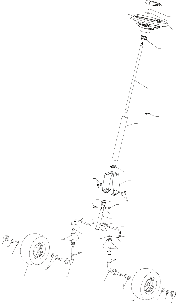
1 532 43 65-00 WHEEL ASM (FRONT)
2 812 00 00-01 E-CLIP
3 532 18 89-67 WASHER, HARDENED
4 532 12 17-49 WASHER, 1/4 X 3/4
5 532 43 53-24 SPINDLE, RH
6 532 12 49-31 WASHER, HARDENED THRUST
7 532 12 49-37 BUSHING, STEERING COLUMN
8 532 42 10-76 PIN, 5/64 X 3/4 COTTER
9 819 13 14-14 WASHER
10 532 42 80-57 WELDMENT, LWR STRG SHAFT
11 532 42 80-35 LINK, STRNG LH
12 532 42 80-36 LINK, STRNG RH
13 874 78 05-24 BOLT, 5/16-18 X 1 1/2
14 819 13 10-16 WASHER
15 873 80 05-00 NUT, 5/16-18
16 532 42 80-44 BUSHING, STEERING SNAP
17 532 42 82-52 SUPPORT, UPPER STEERING
18 532 07 67-15 BUSHING, UPPER STEERING
19 817 00 05-12 BOLT, 5/16-18 X 3/4
20 532 42 80-45 CLIP, RETAINER SPRING
21 532 42 83-47 COVER, STEERING COLUMN
22 532 42 82-13 SHAFT, STEERING
23 532 43 77-47 ADAPTER, STEERING WHEEL
24 819 18 38-12 WASHER, 9/16 X 2 3/8 12 GA.
25 873 94 08-00 NUT, JAM LOCK 1/2-20
26 532 44 16-14 WHEEL, STEERING
27 532 44 16-15 CAP, STEERING WHEEL
28 532 19 98-49 CLIP, RETAINER SPRING
29 532 43 53-23 SPINDLE, LH
30 532 43 64-99 CAP, HUB, AXLE
31 819 34 32-10 WASHER 1-1/16 X 2 X 10 GA
KEY PART
NO. NO. DESCRIPTION
NOTE: All component dimensions given in U.S. inches
1 inch = 25.4 mm
RIDING MOWER MODEL NUMBER WE261 (96022000801)
STEERING PRODUCT NUMBER 960 22 00-08
34
10
11
2
2
31
6
6
7
7
9
31
9
1
2
30
3
12
30
3
4
4
5
29
8
88
12
13
14
15
16
17
18
19
19
20
21
22
28
23
24
25
26
27
LRV-A_Steering_1_r4
RIDING MOWER MODEL NUMBER WE261 (96022000801)
STEERING PRODUCT NUMBER 960 22 00-08
7
Your new riding mower has been assembled at the factory with the exception of those
parts left unassembled for shipping purposes. To ensure safe and proper operation of your
riding mower all parts and hardware you as sem ble must be tightened securely. Use the
correct tools as nec es sary to in sure proper tightness.
ASSEMBLY/PRE-OPERATION
TOOLS REQUIRED FOR ASSEMBLY
A socket wrench set will make assembly
easier. Stan dard wrench sizes you need
are listed below.
(1) 3/4" wrench
(1) 1/2" wrench
(1) Utility knife
(1) Tire pressure gauge
When right or left hand is mentioned in
this man ual, it means when you are in the
operating po si tion (seated be hind the steer-
ing wheel).
TO REMOVE RIDING MOWER FROM
CARTON
UNPACK CARTON
1. Cut along dotted lines on all four panels
of carton. Remove carton and top frame
as one unit.
2. Remove packing materials from riding
mower.
NOTE: Only cut carton with a short blade
utility knife, a long blade or saw can puncture
tires on unit.
HOW TO SET UP YOUR RIDING
MOWER
INSTALL STEERING COLUMN
1. Insert steering shaft into mount and se-
curely fasten with bolt, washer, and nut
provided.
2. Insert pin into hole in steering shaft.
3. Slide plastic cover over steering shaft
and into position.
4. Slide steering shaft protective foam cover
over shaft.
5. Position front wheels of the riding mower
so they are pointing straight forward.
Plastic Cover
Steering
Shaft
Mount
Nut
Washer
Pin
Bolt
Steering Shaft
Foam Cover
Steering Wheel
Adapter
Insert
Washer
Nut
Steering Shaft
6. Remove steering wheel adapter from
steering wheel and slide adapter onto
steer ing shaft.
7. Press steering wheel into position on
shaft, install large washer, and tighten
nut securely.
8. Snap steering wheel insert into center of
steer ing wheel securely.
INSTALL SEAT
1. Pivot seat upward and remove from the
cardboard packing. Remove the card-
board packing and discard.
2. Place seat on seat pan so head of shoul-
der bolt is positioned over large slotted
hole in pan.
3. Push down on seat to engage shoulder
bolt in slot and pull seat towards rear of
riding mower.
02466
Seat Pan
Shoulder
Bolt
Seat
8
NOTE: You may now roll your riding
mower off the skid. Follow the ap pro pri ate
instruction below to remove the riding mower
from the skid.
CHECK TIRE PRESSURE
The tires on your riding mower were
overinflated at the factory for shipping pur-
poses. Correct tire pressure is important
for best cutting performance.
• Reduce tire pressure to PSI shown on
tires.
CHECK DECK LEVELNESS
For best cutting results, mower housing
should be properly leveled. See “TO LEVEL
MOWER HOUSING” in the Service and
Adjustments section of this manual.
CHECK FOR PROPER POSITON OF
MOWER DRIVE BELT
See the figure that is shown for replacing
the mower drive belt in the service and
adjustment section of this manual. Verify
that the belt is routed correctly.
CHECK BRAKE SYSTEM
After you learn how to operate your rid-
ing mower, check to see that the brake
is operating properly. See “TO ADJUST
BRAKE” in the Service and Adjustments
section of this manual.
02464
Adjustment Knob
Flat Washer
4. Pivot seat and pan forward and as sem ble
adjustment knob and flat washer loosely.
Do not tighten.
5. Lower seat into operating position and
sit in seat.
6. Slide seat until a comfortable position is
reached which allows you to press clutch/
brake pedal all the way down.
7. Get off seat without moving its ad just ed
position.
8. Raise seat and tighten adjustment knob
securely.
CHECK BATTERY
Make sure battery is securely fastened,
and that all wires are securely connected.
• Battery is located under the seat.
• Battery has been fully charged from the
factory, before installation.
Battery
Seat
WARNING: Before starting, read, un-
der stand and follow all in struc tions in the
Operation section of this manual. Be sure
riding mower is in a well-ventilated area.
Be sure the area in front of riding mower is
clear of other people and objects.
TO ROLL RIDING MOWER OFF
SKID (See Op er a tion section for
location and function of con trols)
1. Raise deck lift lever to its highest
position.
2. Release parking brake by depressing
clutch/brake ped al.
3. Engage freewheel control. See “TO
TRANSPORT” in the operation section
of this manual.
4. Roll riding mower forward off skid.
33
KEY PART
NO. NO. DESCRIPTION
KEY PART
NO. NO. DESCRIPTION
NOTE: All component dimensions given in U.S. inches
1 inch = 25.4 mm
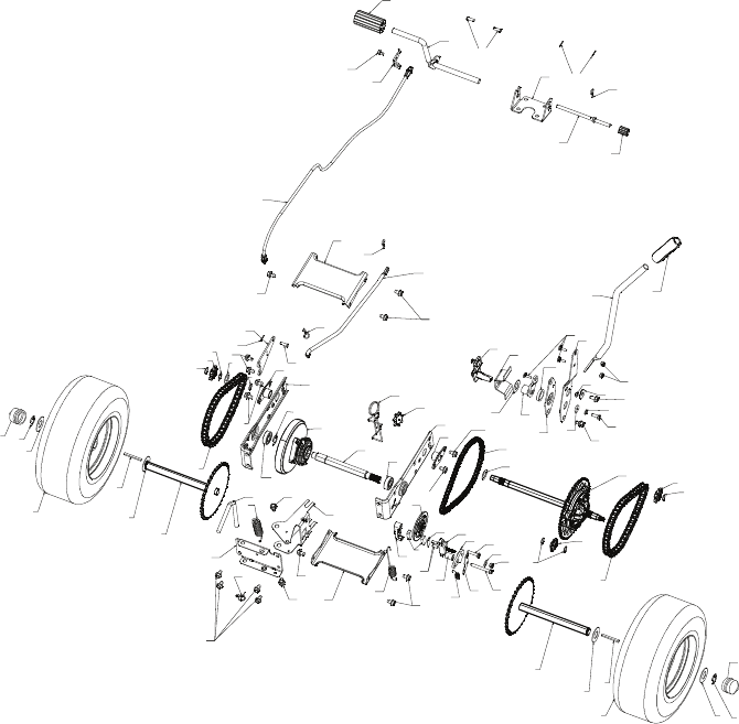
- - 532 43 61-44 SERVICE KIT, TRANSAXLE
1 532 43 64-98 WHEEL ASM (REAR)
2 532 12 17-48 WASHER, 16 GA.
3 812 00 00-01 E-CLIP
4 532 12 35-83 KEY. SQUARE
5 532 42 79-39 WELDMENT. DRIVE AXLE
6 532 42 80-69 CHAIN DRIVE
7 532 42 78-73 SPROCKET. 9 TOOTH
SPLINED
8 812 10 00-09 RING, SNAP
10 532 42 88-76 DIFFERENTIAL ASM
11 532 00 13-70 WASHER, THRUST
12 532 43 06-45 CHAIN, PRIMARY DRIVE
13 532 43 08-45 BUSHING
14 532 43 85-68 BRACKET, CARRIER
15 532 12 47-93 BEARING ASM
16 532 42 79-26 SHAFT INPUT
17 532 43 72-81 WHEEL, FRICTION A5M
18 532 42 47-59 ARM, SHIFT
19 532 43 08-70 ROD, BYPASS
20 532 42 79-97 BRACE CARRIER REAR
21 532 42 80-77 SPRING, CARRIER
22 532 42 80-76 SPRING, BRAKE
23 532 43 13-74 SPRING, BYPASS
24 532 42 79-95 BRACE CARRIER BOX
25 532 42 83-03 LINK, SHIFT
26 532 42 98-16 ARM. CLUTCH
27 532 42 90-53 WELDMENT SHIFT LEVER
28 532 42 83-02 SUPPORT, SHIFT LEVER
29 532 17 48-40 WASHER, NYLON
30 532 18 39-00 HUB SHIFT LEVER
31 532 42 90-55 SPACER, NYLON
32 532 42 84-64 MNTG BRKT. SHIFT ARM
33 532 42 84-61 BRACKET, SHIFTER FLEX
34 532 42 84-62 TUBE SHIFT ARM
35 532 41 15-55 GRIP, HANDLE
36 872 11 04-06 BOLT, CARRIAGE - 114-20 X 3/4
37 873 80 04-00 NUT NYLON LOCK 114-20
38 532 16 54-92 BOLT, SHOULDER
39 874 78 04-12 BOLT, 1/4-20 X 3/4
40 810 04 04-00 WASHER, LOCK
41 819 09 12-10 WASHER FLAT
42 532 16 60-02 WASHER, SERRATED
43 873 68 04-00 NUT, CROWN LOCK 114-20
45 817 49 04-36 SCREW 1/4-20 X 2 114
46 819 09 10-16 WASHER
47 817 49 04-20 SCREW, 1/4-20 X 1 1/2
48 532 43 02-49 PLATE BRAKE ANTI - ROTATE
49 532 43 02-45 SPRING, BRAKE RETURN
50 532 42 80-21 ARM, BRAKE
51 532 43 02-47 SPACER RETURN
52 532 42 80-78 CALIPER, BRAKE ASM
53 877 01 08-10 PIN, DOWEL 1/4
54 532 42 80-19 PLATE, BRAKE PAD
55 532 42 80-17 PUCK BRAKE
56 532 43 52-53 ROTOR, BRAKE
57 532 42 80-16 CAP, BRAKE CALIPER
58 532 12 47-88 PIN, RETAINER
59 817 49 05-08 BOLT, 5/16-16 X 112
60 532 43 55-59 CABLE, BRAKE
61 532 42 79-45 WELDMENT, PEDAL
62 532 42 96-78 ROD, PARKING BRAKE
63 877 10 08-12 PIN, .25 X .75 CLEVIS
64 876 02 02-08 PIN, 1/16 DIA. COTTER
65 532 42 93-25 BRACKET, BRAKE SUPPORT
66 532 42 96-94 COVER PEDAL
67 532 42 96-93 COVER, BRAKE PEDAL
68 817 49 04-06 SCREW, 1/4-20 X 3/8
69 532 42 80-70 BRAKE CABLE MOUNT
70 817 00 05-12 BOLT, 5/16-18 X 3/4
71 532 43 64-99 CAP HUB AXLE
72 812 00 00-02 E RING #5133-62
73 532 42 95-19 SPROCKET II TOOTH
SPLINED
74 532 43 78-41 TENSION LRV CHAIN
75 532 43 34-95 SPROCKET IDLER
RIDING MOWER MODEL NUMBER WE261 (96022000801)
DRIVE PRODUCT NUMBER 960 22 00-08
32
10
11
11
3
12
2
3
4
5
6
7
72
8
8
1
2
23
4
5
6
7
8
73
8
12
13
13
70
70
14
14
15
71
15
16
17
18
19
20
21
22
23
24
24
25
26
27
28
29 30
31
32
33
34 35
36
37
37
38
38
38
39
40
41
42
43
70
45
46
47
48
49
50
51
52
53
54
55
56
57
58
58
58
70
70
70
59
70
70
70
60
61
62
63
63
64
64
65
66
67
68
69
71
LRV-A_Drive_3
75
74
RIDING MOWER MODEL NUMBER WE261 (96022000801)
DRIVE PRODUCT NUMBER 960 22 00-08
9
✓CHECKLIST
Before you operate your new riding mower,
we wish to assure that you receive the best
performance and satisfaction from this
Quality Product.
Please review the following checklist:
✓ All assembly instructions have been
com plet ed.
✓ No remaining loose parts in carton.
✓ Battery is properly connected.
✓ Seat is adjusted comfortably and tight-
ened securely.
✓ All tires are properly inflated. (For ship-
ping purposes, the tires were overinflated
at the factory).
✓ Be sure mower deck is properly leveled
side-to-side/front-to-rear for best cutting
results. (Tires must be properly inflated
for leveling).
✓ Check mower belt. Be sure it is routed
properly around pulleys and inside all belt
keepers.
✓ Check wiring. See that all connections
are still secure and wires are properly
clamped.
✓ Before driving riding mower, be sure free-
wheel control is in “transmission engaged”
position (see “TO TRANSPORT” in the
Operation section of this man u al).
While learning how to use your riding mower,
pay extra attention to the following important
items:
✓ Engine oil is at proper level.
✓ Fuel tank is filled with fresh, clean, regular
unleaded gasoline.
✓ Become familiar with all controls, their
location and function. Operate them
before you start the engine.
✓ Be sure brake system is in safe operating
condition.
✓ Be sure Operator Presence System and
Reverse Operation System (ROS) are
working properly (See the Operation and
Maintenance sections in this manual).
10
OPERATION
These symbols may appear on your riding mower or in literature supplied with the prod-
uct. Learn and understand their meaning.
DANGER, KEEP HANDS
AND FEET AWAY
OVER TEMP
LIGHT
KEEP AREA CLEAR SLOPE HAZARDS
15
15
(SEE SAFETY RULES SECTION)
BATTERY REVERSE FORWARD
FAST SLOW
ENGINE ON
ENGINE OFF
OIL PRESSURE
FUEL
CHOKE
MOWER HEIGHT
PARKING BRAKE
LOCKED
PARKING BRAKE
UNLOCKED
REVERSE NEUTRAL HIGH LOW
ATTACHMENT
CLUTCH ENGAGED
PARKING BRAKE
ATTACHMENT
CLUTCH DISENGAGED
P
ENGINE START
MOWER LIFT
Failure to follow instructions
could result in serious injury or
death. The safety alert symbol
is used to identify safety inform-
ation about hazards which can
result in death, serious injury
and/or property damage.
DANGER indicates a hazard which, if not avoided,
will result in death or serious injury.
WARNING indicates a hazard which, if not avoided,
could result in death or serious injury.
CAUTION indicates a hazard which, if not avoided,
might result in minor or moderate injury.
CAUTION when used without the alert symbol,
indicates a situation that could result in damage
to the tractor and/or engine.
FIRE indicates a hazard which, if not avoided,
could result in death, serious injury and/or
property damage.
HOT SURFACES indicates a hazard which,
if not avoided, could result in death, serious injury
and/or property damage.
BRAKE/CLUTCH
PEDAL
FREEWHEEL CONTROL
ENGAGED
FREEWHEEL CONTROL
DISENGAGED
REVERSE
OPERATION
SYSTEM (ROS)
IGNITION SWITCH
31
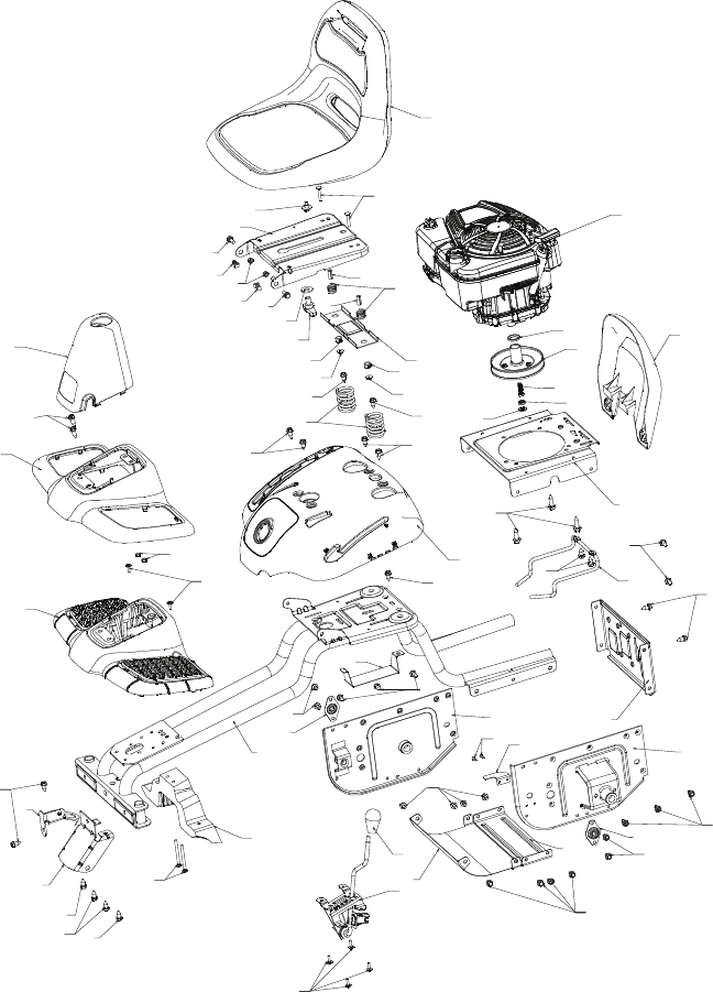
1 532 42 80-48 WELDMENT, CHASSIS
2 532 42 82-47 SUPPORT, AXEL LH
3 532 42 82-44 SUPPORT, AXEL RH
4 532 42 83-46 SHIELD, TRANSAXLE FRONT
5 532 42 81-10 BRACE, AXLE CROSS
6 532 42 81-09 COVER, FRICTION DRIVE
7 532 42 80-40 PLATE, ENGINE
8 532 42 85-76 BRACKET, CHASSIS FRONT
9 532 42 88-56 BRACKET, STEERING SUPPORT
10 532 19 55-30 PAN, SEAT
11 532 17 46-48 BRACKET, SWITCH MOUNTING
12 532 42 82-48 BOOT, DUST
13 532 43 64-96 COVER, FOOT REST
14 532 42 82-50 STRUCTURE, FOOT REST
15 532 42 82-49 SUPPORT, FOOT REST
16 532 43 64-97 FENDER, CONTROL
17 532 42 83-48 GUARD, ENGINE
18 532 43 81-54 ENGINE, (NON-CALIFORNIA) 12S907-2411-B1
19 532 42 89-86 KEEPER, BELT
20 532 42 80-46 BRACKET, BATTERY
21 532 42 98-15 LEVER, SWITCH
22 532 42 88-26 DECK CLUTCH ASM
23 532 14 98-46 KNOB
24 532 41 63-58 SCREW, NO. 10
25 872 14 04-24 BOLT, CARRIAGE 1/4-20 X 3
26 873 51 04-00 NUT, 1/4-20
27 532 43 00-87 SPACER, ENGINE
28 532 42 83-01 DISC, FRICTION ASM
29 532 43 08-17 BOLT, SCKT HD 3/8-24 X 1 .25
30 532 43 04-70 BEARING
31 532 43 73-22 SPACER, NEUTRAL
32 817 49 05-06 BOLT, HEX WSH HD 5/16-18 X 3/8
33 532 12 41-81 SPRING, SEAT
34 532 12 12-50 SPRING
35 872 05 04-12 BOLT, 1/4-20 X 1 1/2
36 532 12 70-18 BOLT, SHOULDER
37 819 17 19-12 WASHER, 17/32 X 1 3/16
38 532 16 63-69 KNOB, SEAT
39 532 13 43-00 SPACER
40 532 12 12-48 BUSHING, NYLON SNAP
41 532 12 39-76 NUT, LOCK
42 532 17 18-52 BOLT, 5/16-18 SHOULDER
43 873 80 05-00 NUT, 5/16-18
44 532 42 82-43 SEAT
45 817 00 05-12 BOLT, 5/16-18 X 3/4
46 817 49 05-08 BOLT, 5/16-18 X 1/2
47 532 08 67-77 SCREW
48 532 40 89-81 BEARING, FLANGE, BALL
49 817 06 05-16 SCREW, 5/16-18 X1
51 532 16 54-92 BOLT, SHOULDER, 5/16-18 X .561
52 532 14 50-06 CLIP PUSH-IN HINGED
KEY PART
NO. NO. DESCRIPTION
NOTE: All component dimensions given in U.S. inches
1 inch = 25.4 mm
RIDING MOWER MODEL NUMBER WE261 (96022000801)
CHASSIS PRODUCT NUMBER 960 22 00-08
30
10
11
3
4
5
7
9
8
1
2
12
13
49
14
15
16
17
18
19
20
21
22
23
24
24
25
26
27
28
29
30
31
32
33
34
35
36
37
38
39
39
40
40
41
41
42
43
44
45
45
51
51
45
45
45
45
45
45
6
46
45
45
45
46
48
46
48
46
46
47
LRV-A _Chassis_3
52
52 42
RIDING MOWER MODEL NUMBER WE261 (96022000801)
CHASSIS PRODUCT NUMBER 960 22 00-08
11
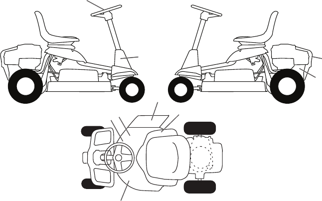
KNOW YOUR RIDING MOWER
READ THIS OWNER'S MANUAL AND SAFETY RULES BEFORE OPERATING
YOUR RIDING MOWER
Compare the illustrations with your riding mower to familiarize yourself with the locations
of various controls and ad just ments. Save this manual for future reference.
Our riding mowers conform to the applicable safety standards of the
American National Stan dards Institute.
DECK CLUTCH LEVER - Used to engage
the mower blade.
BRAKE PEDAL - Used for brak ing the rid-
ing mower and starting the engine.
HEIGHT ADJUSTMENT LEVER - Used to
adjust mower cutting height.
IGNITION SWITCH - Used for starting and
stopping the engine.
LIFT LEVER PLUNGER - Used to re lease
height adjustment lever when chang ing its
position.
PARKING BRAKE LEVER - Locks park-
ing brake into brake position.
MOTION CONTROL LEVER - Selects the
speed and direction of the riding mower.
FREEWHEEL CONTROL - Disengages
transmission for pushing or slowly towing
the riding mower with the engine off.
ROS “ON” POSITION - Allows operation
of mower deck or other powered attach-
ment while in reverse.
Ignition
Switch
ROS
"ON"
Motion
Control
Lever
Lift Lever
Plunger
Freewheel Control
Height
Adjustment
Lever
Deck Clutch
Lever
Brake Pedal
Parking
Brake
Pedal
12
The op er a tion of any riding mower can result in foreign objects thrown
into the eyes, which can result in severe eye dam age. Al ways wear
safety glass es or eye shields while op er at ing your riding mower or
per form ing any ad just ments or repairs. We rec om mend a wide vi sion
safe ty mask over spec ta cles or stan dard safety glass es.
00155
HOW TO USE YOUR RIDING
MOWER
TO SET PARKING BRAKE
Your riding mower is equipped with an opera-
tor presence sens ing switch. When engine
is running, any attempt by the op er a tor to
leave the seat without first setting the parking
brake will shut off the engine.
1. Depress brake pedal all the way down
and hold.
2. Depress parking brake lever and re lease
pres sure from brake pedal. Pedal should
re main in brake position. Make sure
parking brake will hold riding mower
secure.
TO MOVE FORWARD AND BACK WARD
The direction and speed of movement is
controlled by the motion control lever.
1. Start riding mower with clutch/brake pedal
depressed and motion control lever in
neutral (N) position.
2. Move motion control lever to desired
po si tion.
3. Slowly release clutch/brake pedal to start
movement.
IMPORTANT: Bring riding mower to a com-
plete stop before shifting or changing gears.
Failure to do so will shorten the useful life of
your transaxle.
TO ADJUST MOWER CUT TING HEIGHT
The po si tion of the mower height deck lift
le ver de ter mines the cut ting height.
• Grasp lift le ver.
• Press lift lever plunger with thumb and
move lever to desired position.
The cutting height range is ap prox i mate ly
1-1/2 to 4". The heights are measured from
the ground to the blade tip with the engine
not running. These heights are approximate
and may vary depending upon soil condi-
tions, height of grass and types of grass
being mowed.
• The average lawn should be cut to ap-
proximately 2-1/2" during the cool season
and to over 3" during hot months. For
healthier and better looking lawns, mow
often and after moderate growth.
• For best cutting performance, grass over
6" in height should be mowed twice. Make
the first cut relatively high; the second to
de sired height.
STOPPING
MOWER BLADE -
• To stop mower blade, move deck clutch
lever to disengaged po si tion.
GROUND DRIVE -
• To stop ground drive, depress brake pedal
all the way down.
ENGINE -
• Turn ignition key to “STOP” position and re-
move key. Always remove key when leaving
riding mower to prevent un au tho rized use.
IMPORTANT: Leaving the ignition switch in
any position other than "STOP" will cause
the battery to discharge and go dead.
NOTE: Under certain conditions when riding
mower is standing idle with the engine run-
ning, hot engine exhaust gases may cause
“browning” of grass. To eliminate this pos-
sibility, always stop engine when stopping
riding mower on grass areas.
CAUTION: Always stop riding mower
com plete ly, as described above, before
leav ing the operator's position.
Motion
Control
Lever
Mower Height
Adjustment
Brake Pedal
"Engaged"
Position Deck Clutch
Lever
"Engaged"
Position
Deck Clutch
Lever
"Disengaged"
Position
Brake Pedal
"Drive"
Position
Parking Brake
Pedal-Push Down
to "Engage"
29
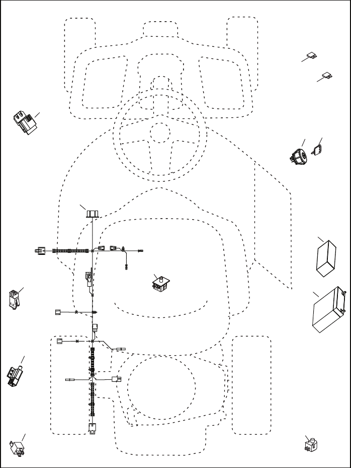
1 532 43 70-70 BATTERY
2 532 42 54-16 FOAM, POLYURETHANE
3 532 19 33-50 SWITCH, IGN, DLTA, P-IN, ROS
4 532 41 19-33 KEY/CHAIN
5 532 43 33-30 FUSE, 5A
6 532 42 59-37 FUSE, 40A
7 532 16 07-84 SWITCH, PLUNGER, NO, OLIVE
8 532 43 15-42 RELAY, 40A
9 532 10 95-53 SWITCH, INTLK,CL, MWR, GRY
10 532 17 61-38 SWITCH, INTERLOCK, NONC,GRAY
11 532 43 18-46 MODULE, STARTING, RECOIL, LRV
12 532 19 27-49 SWITCH, SEAT, DP, ROS
13 532 42 84-77 HARNESS, IGN, ELECTSTART, LRV
KEY PART
NO. NO. DESCRIPTION
NOTE: All component dimensions given in U.S. inches
1 inch = 25.4 mm
RIDING MOWER MODEL NUMBER WE261 (96022000801)
ELECTRICAL PRODUCT NUMBER 960 22 00-08
28
11
LRV1
10
9
8
12
13
7
1
2
34
6
5
RIDING MOWER MODEL NUMBER WE261 (96022000801)
ELECTRICAL PRODUCT NUMBER 960 22 00-08
13
TO OPERATE MOWER
Your riding mower is equipped with an
operator presence sensing switch. Any
attempt by the operator to leave the seat
with the engine running and the deck clutch
engaged will shut off the engine. You must
remain fully and centrally positioned in the
seat to prevent the engine from hesitating or
cutting off when operating your equipment
on rough, rolling terrain or hills.
1. Select desired height of cut.
2. Start mower blade by engaging deck
clutch lever.
TO STOP MOWER BLADE-
Disengage deck clutch lever.
CAUTION: Do not operate the mower
without either the en tire grass catcher, on
mowers so equipped, or the deflector shield
in place.
Mower Height
Adjustment High
Position
Mower Height
Adjustment
Low Position
Deck Clutch Lever
"Disengaged" Position
Deck Clutch Lever
"Engaged" Position
REVERSE OPERATION SYSTEM (ROS)
Your tractor is equipped with a Reverse
Operation System (ROS). Any attempt by
the operator to travel in the reverse direc-
tion with the deck clutch engaged will shut
off the engine unless ignition key is placed
in the ROS "ON" position.
WARNING: Backing up with the deck
clutch engaged while mowing is strongly
discouraged. Turning the ROS "ON", to al-
low reverse operation with the deck clutch
engaged, should only be done when the
operator decides it is necessary to reposi-
tion the machine with the attachment
engaged. Do not mow in reverse unless
absolutely necessary.
USING THE REVERSE OPERATION
SYSTEM -
Only use if you are certain no children or
other bystanders will enter the mowing
area.
1. Move motion control lever to neutral
(N) position.
2. With engine running, turn ignition key
counterclockwise to ROS "ON" posi-
tion.
3. Look down and behind before and
while backing.
4. Slowly move motion control lever to
reverse (R) po si tion to start movement.
5. When use of the ROS is no longer
needed, turn the ignition key clockwise
to engine "ON" position.
ROS "ON" Position Engine "ON" Position
(Normal Operating)
0
2
8
2
8
Deflector Shield
14
ADD GASOLINE
• Fill fuel tank to bottom of filler neck. Do
not overfill. Use fresh, clean, regular
un lead ed gasoline with a minimum of
87 octane. (Use of leaded gasoline will
increase carbon and lead oxide deposits
and reduce valve life). Do not mix oil with
gasoline. Purchase fuel in quan ti ties that
can be used within 30 days to assure fuel
freshness.
CAUTION: Wipe off any spilled oil or
fuel. Do not store, spill or use gasoline near
an open flame.
CAUTION: Alcohol blended fuels (called
gasohol or using ethanol or methanol) can
attract moisture which leads to separation
and for ma tion of acids during storage. Acidic
gas can damage the fuel system of an engine
while in storage. To avoid engine problems,
the fuel system should be emptied before
stor age of 30 days or longer. Drain the gas
tank, start the engine and let it run until the
fuel lines and carburetor are empty. Use fresh
fuel next season. See Storage In struc tions
for additional information. Never use engine
or carburetor cleaner products in the fuel tank
or permanent damage may occur.
TO START ENGINE
When starting the engine for the first time
or if the engine has run out of fuel, it will
take extra cranking time to move fuel from
the tank to the engine.
1. Be sure freewheel control is in the
trans mis sion en gaged position.
2. Sit on seat in operating position,
depress clutch/brake pedal and set
parking brake.
3. Place motion control lever in neutral
(N) position.
4. Move deck clutch to dis en gaged posi-
tion.
5. Insert key into ignition and turn key
clock wise to start position and release
key as soon as engine starts. Do not
run starter continuously for more than
fifteen sec onds per minute.
NOTE: If at high altitude (above 3000
feet) or in cold temperature (below 32°F)
the fuel mixture may need to be adjusted
for best performance.
TO TRANSPORT
When pushing or towing your riding mower,
be sure to disengage transmission by placing
freewheel control in freewheel position.
Freewheel control is located at the rear
drawbar of the riding mower.
• Raise mower height adjustment to its
highest position with mower height
adjustment lever.
• Push freewheel control down and over
with foot.
TO OPERATE ON HILLS
WARNING: Do not drive up or down
hills with slopes great er than 15° and do not
drive across any slope. Use the slope guide
at the back of this manual.
• Choose the slowest speed before starting
up or down hills.
• Avoid stopping or changing speed on
hills.
• If stopping is absolutely necessary, push
clutch/brake pedal quickly to brake position
and engage parking brake.
• Move motion control lever to neutral (N)
position.
• To restart movement, slowly re lease park-
ing brake and clutch/brake pedal.
• Make all turns slowly.
• To reengage transmission, reverse above
procedure, or press brake lever all the way
down.
BEFORE STARTING THE ENGINE
CHECK ENGINE OIL LEVEL
The engine in your riding mower has been
shipped, from the factory, already filled with
sum mer weight oil.
1. Check engine oil with riding mower on
level ground.
2. Remove oil fill cap/dipstick and wipe
clean, reinsert the dipstick and screw cap
tight, wait for a few seconds, remove and
read oil level. If nec es sary, add oil until
“FULL” mark on dipstick is reached. Do
not overfill.
Freewheel
Control
Disengaged
Freewheel
Control
Engaged
• For cold weather operation you should
change oil for easier starting (See the oil
viscosity chart in the Main te nance sec tion
of this man u al).
• To change engine oil, see the Main te-
nance section in this manual.
27
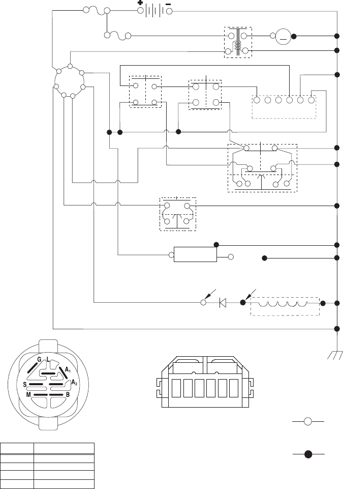
BATTERY
FUSE-40A
RED
RED
WHITE
BLACK/WHITE
RED
GREEN
YELLOW
BLACK/WHITE
BLACK
BLACK
GRAY
BLACK
RELAY
M
STARTER
CLUTCH / BRAKE
(PEDAL UP)
SEAT SWITCH
(NOT OCCUPIED)
IGNITION
UNIT
SM
B
GA1
A2
L
REVERSE SWITCH
SPARK PLUG
GAP
NOT IN REVERSE SHORTING CONNECTOR
ATTACHMENT CLUTCH
(CLUTCH OFF)
REMOVABLE
CONNECTIONS
WIRING INSULATED CLIPS
NOTE: IF WIRING INSULATED CLIPS
WERE REMOVED FOR SERVICING OF
UNIT, THEY SHOULD BE RE-INSTALLED
TO PROPERLY SECURE YOUR WIRING.
IGNITION SWITCH
CIRCUITPOSITION
OFF
B+A1
RUN/OVERRIDE
B+S+A1START
M+G+A1
B+A1RUN
“MAKE”
L+A2
NON-REMOVABLE
CONNECTIONS
STATOR
DIODE
28 VOLTS AC MIN. @ 3600 RPM
(CHARGING SYSTEM DISCONNECTED)
CHARGING SYSTEM OUTPUT
.5AMPDC@3600RPM
SCH21
STARTER
FUSE-5A
SAFETY START MODULE
ABF
DE
C
RED
RED
BLACK/WHITE
BLACK
WHITE
WHITE
BLACK
BLACK/WHITE
BLACK
A
BDC
E
F
SAFETY START MODULE
VIEWED FROM MATING SIDE
RIDING MOWER MODEL NUMBER WE261 (96022000801)
SCHEMATIC PRODUCT NUMBER 960 22 00-08
