965 0267 Onan BGM (spec A H) RV Genset Parts Manual (09 1998)
User Manual: 965-0267 Onan BGM (spec A-H) RV Genset Parts manual (09-1998)
Open the PDF directly: View PDF ![]() .
.
Page Count: 58

BGM
GenSet Parts Manual
RV

The following symbols are used in Onan manuals
to alert users to the potentially dangerous condi-
tions
relating to maintenance of equipment and re
-
placement of parts. Please read and observe.
This symbol warns of immedi-
ate hazards which will result in
severe
personal injury or death.
This symbol refers to a hazard
or
unsafe practice which can re
-
sult
in severe personal injury or
death.
This symbol refers to a hazard
or
unsafe practice which can re
-
sult
in severe personal injury or
product
or property damage.
To avoid errors or delay in filling your parts order,
always
give the MODEL, SPEC NO. and SERIAL
NO. from the Onan nameplate.
For handy reference, insert your nameplate in-
formation in the spaces below.
MODEL AND SPEC NO.
SERIAL NO.
DIGITAL CONTROL SOFTW
ARE VERSION
AND DA
TE (IF APPLICABLE)
Contact
with USED ENGINE OILS has been identified by a United States federal agency and some USA
state
agencies as causing CANCER or REPRODUCTIVE T
OXICITY
. When checking or changing engine
oils take all necessary precautions not to ingest, breathe the fumes or contact the used oil.
Contact with ASBESTOS has been identified by a United States federal agency and some USA state
agencies as causing CANCER or REPRODUCTIVE TOXICITY. When handling engine gaskets take all
necessary
precautions not to ingest, breathe or contact the dust from the gaskets! Use adequate
ven
-
tilation and wear protective gloves, masks and clothing!
Contact with BENZINE and LEAD, found in gasoline, fuel additives and solvents has been identified
by
a United States federal agency and some USA state agencies as causing CANCER or REPRODUC
-
TIVE
T
OXICITY
. When checking, draining
or adding gasoline and fuel additives or using solvents take
all
necessary precautions not to ingest,
breathe the fumes or contact the liquids. Use adequate ventila
-
tion and wear protective gloves, masks and protective clothing!
PSP-1
Service
and repair of Onan equipment must be performed by trained, experienced personnel only
. Im
-
proper
service or
repair may result in property damage, severe personal injury or death. Do not use this
catalog as a guide to servicing your equipment. Read and follow the IMPORT
ANT SAFETY INSTRUC
-
TIONS in the Service Manual appropriate for the equipment you are working on.

1
Introduction
This manual applies to the standard Recreational Vehicle Generator Set as listed in the Generator Set Data Table.
Parts
are arranged in groups of related items
and each illustrated part is identified by a reference number correspond
-
ing
to the same reference number in the parts list. Parts illustrations are typical. Using the model and specification
number
from your generator set nameplate, select parts that apply to your set. Right and left sides are determined by
facing
the engine end (front) of the set.
Generator Set Data Table
ELECTRICAL
DA
TA
MODEL** WATTS VOLTS HERTZ WIRE PHASE
5BGM–FA/* 5000 120 60 2 1
5.5BGM–FA/ 5500 120 60 2 1
* – The diagonal line (/) in the model and specification number separates generator set
characteristics from the specification number and letter. The specification number
denotes customer requested options of deviations from a standard (26105A) model.
The specification letter advances (A to B, B to C, etc.) with major manufacturing
changes.
** – See Back of Book for W/D Information.
2
Index
3
Actuator, Governor
,
17
Adapter
, Air Cleaner
,
19
Adapter
, Generator
,
27
Adapter
, Oil Drain,
26
Adapter
, Oil Fill T
ube,
25
Adapter
, Oil Filter
,
23
Adapter
, Preheater
,
19
Backplate, Air Housing,
33
Baf
fle, Breather V
alve,
7
Ball, Gearcase Bearing,
14
Ball, Governor
,
10
Base, Oil,
24
Bearing, Camshaft,
9
Bearing, Crankshaft,
7
,
9
Bearing, Generator Rotor Ball,
37
Bearing, Governor Shaft Needle,
14
Block, Cylinder
,
7
,
9
Block, Generator Brush, 37
Block, T
erminal,
39
Board, PC,
39
Bracket, Cable Adjust,
16
Bracket, Choke Mounting,
19
Bracket, Diaphragm Mounting,
19
Bracket, Fuel Pump,
31
Bracket, Fuse Holder
,
39
Bracket, Governor
,
16
Bracket, Ignition Coil,
27
Bracket, Ignition Control,
27
Bracket, Oil Fill T
ube Support,
25
Bracket, Relay
,
39
Bracket, Resistor Mounting,
22
Bracket, V
oltage Regulator
,
39
Breaker
, Circuit,
39
Brush, Generator
,
37
Bushing, Fuel T
ank Reducer
,
35
Bushing, Isolator
,
31
Cable, Governor Flexible Adjust,
16
Cable, Spark Plug,
27
Cable, Starter
,
21
Camshaft (Begin Spec B),
11
Camshaft (Spec A),
10
Cap, Air Inlet Rod V
inyl,
19
Cap, Intake/Exhaust V
alve,
7
Cap, Oil Fill,
24
Cap, Starter Drive,
21
Capacitor
,
27
Carburetor
,
19
Clip, Air Housing Moulding,
33
Clip, Choke Housing T
ube Retaining,
19
Clip, Control Rod Retaining,
16
Clip, Diaphragm Mounting ”U”,
19
Clip, Fuel Line Retainer
,
31
Clip, Fuse,
39
Clip, Preheater Hose,
19
Clip, Spark Plug Wire,
33
Clip, Throttle Rod,
17
Coil, Ignition,
27
Components, Carburetor
,
20
Connector
, Conduit,
37
Connector
, Fuel T
ank Barbed Hose,
35
Connector, Hose, 19
Control,
39
Control, Ignition,
27
Controller, Governor
,
31
Coupling, Fuel T
ank Hose, 35
Cover
, Air Housing Cylinder
,
33
Cover
, Air Housing T
op,
33
Cover
, Air Inlet,
19
Cover
, Breaker Box Opening,
7
Cover, Brush Block Access, 37
Cover
, Choke,
19
Cover
, Choke Housing,
19
Cover
, Control,
39
Cover, Governor Access, 33
Cover, Switch, 39
Cover
, T
ailpipe Access, 29
Cover
, Underfloor Housing Rear Panel,
34
Cover
, V
alve,
7
Crankshaft, 12
Cup, Governor
,
10
Cup, Oil Pickup,
24
Diaphragm, Pullof
f,
19
Diode,
43
Drain, Oil Filter
,
23
Elbow
, Carburetor
,
19
Elbow, Hose, 19
Element, Air Cleaner
,
19
Element, Thermostat,
19
Exhaust Options, 29
Extension, Oil Drain,
26
Fan, Generator
,
37
Filter
, Breather T
ube,
7
Filter
, Fuel,
19
Filter
, Oil,
23
Fitting, V
acuum,
19
Flange, Exhaust Manifold,
29
Float Package,
20
Fuse, Control Panel,
39
Fuse, Engine Harness,
41
Gasket, Air Horn, 19
Gasket, Bearing Plate,
7
Gasket, Breaker Box Opening, 7
Gasket, Carburetor Mounting,
19
Gasket, Cylinder Head, 7
Gasket, Exhaust Manifold,
28
Gasket, Gearcase (Begin Spec B), 15
Gasket, Gearcase (Spec A), 14
Gasket, Intake Manifold,
19
Gasket, Oil Base, 24
Gasket, Oil Drain Adapter
,
26
Index
4
Gasket, Oil Filter Adapter
,
23
Gasket, Side/Bottom Exhaust T
ube,
28
Gasket, Valve Cover
,
7
Gear
, Camshaft (Begin Spec B),
11
Gear
, Camshaft (Spec A),
10
Gear, Crankshaft, 12
Gearcase (Begin Spec B), 15
Gearcase (Spec A), 14
Generator
,
37
Governor (Begin Spec B),
17
Governor (Spec A), 16
Grommet, Fuel Pump,
31
Grommet, Generator Stator Housing,
37
Grommet, Underfloor Housing,
34
Guide, Valve,
7
Hanger, Exhaust, 29
Harness, AC Output, 39
Harness, Adapter
,
48
,
49
Harness, Engine (Begin Spec B),
41
Harness, Engine (Spec A),
40
Harness, Fuel Pump,
39
Harness, Generator
,
39
Harness, PC Board, 42
Harness, Remote (Begin Spec G),
48
Harness, Remote (Spec A–F), 44
Harness, Remote Panel (Switch Only) (Begin Spec G),
45
Harness, Remote Panel (Switch/Hourmeter) (Begin Spec
G), 46
Harness, Remote Panel (Switch/V
oltmeter) (Begin Spec G),
47
Harness, V
oltage Regulator
,
39
Head, Cylinder
,
7
Holder
, Control Panel Fuse,
39
Holder
, Engine Harness Fuse,
41
Hose, Fuel,
19
,
35
Hose, Oil Drain,
26
Hose, Preheater
,
19
Hose, V
acuum,
19
Housing, Air
,
33
Housing, Air Cleaner
,
19
Housing, Breather
,
7
Housing, Choke,
19
Housing, Generator Stator
,
37
Housing, Underfloor
,
34
Hub, Governor Cup,
10
Indicator
, Oil Fill T
ube,
25
Insulation, Exhaust T
ube,
28
Insulator
, PC Board,
39
Isolator
, V
ibration,
31
Jet, Idle,
20
Jet, Power
,
20
Joint, Governor Ball,
16
Key
, Blower Wheel,
13
Key
, Camshaft W
oodruf
f (Begin Spec B),
11
Key
, Camshaft W
oodruff (Spec A), 10
Key, Crankshaft Gear
,
12
Kit, Carburetor Repair
,
20
Kit, Choke Bimetal,
20
Kit, Choke Breaker
,
20
Kit, Choke Shaft,
20
Kit, Engine Gasket,
50
Kit, Oil Pump Gasket,
50
Kit, Piston Ring,
7
Kit, Remote Panel (Spec A–F),
43
Kit, Remote Panel (Switch Only) (Begin Spec G),
45
Kit, Remote Panel (Switch/Hourmeter) (Begin Spec G),
46
Kit, Remote Panel (Switch/Voltmeter) (Begin Spec G),
47
Kit, Starter Drive,
21
Kit, V
alve Grind Gasket, 50
Labels,
50
Line, Fuel,
19
Link, Governor Spring,
14
Linkage, Choke,
19
Linkage, Diaphragm Pullof
f,
19
Lock, V
alve Spring,
7
Manifold, Exhaust,
28
Manifold, Intake,
19
Meter
, Battery Condition,
43
Meter
, Hour
,
46
Meter
, T
ime T
otalizing,
43
Meter
, V
oltage,
47
Muffler
,
28
O’Ring, Generator
,
37
O’Ring, Oil Drain V
alve,
24
O’Ring, Oil Fill Cap,
24
O’Ring, Oil Fill T
ube,
25
O’Ring, Oil Fill T
ube Adapter
,
25
O’Ring, Preheater Hose,
19
Paint,
50
Pan, Drip,
31
Panel, Air Housing Front,
33
Panel, Remote (Begin Spec G),
45
,
46
,
47
Panel, Remote (Spec A–F),
43
Panel, Underfloor Housing,
34
Pin, Bearing Stop Drive,
7
Pin, Camshaft Center
,
10
Pin, Gear Cover Aignment,
9
Pin, Gearcase Alignment (Begin Spec B),
15
Pin, Gearcase Alignment (Spec A),
14
Pin, Piston,
7
Piston,
7
Plate, Bearing,
7
Plug, Air Cleaner Housing,
19
Plug, Camshaft Opening W
elch,
7
Plug, Core Hole,
9
Plug, Gearcase,
15
Plug, Governor Adjust Access, 33
Plug, Intake Manifold Hex Head,
19
Plug, Spark,
27
Index
5
Plunger, Bypass V
alve,
7
Plunger
, Camshaft,
11
Pump, Fuel,
19
Pump, Oil,
9
Rectifier
,
39
Reed, Breather V
alve,
7
Regulator
, V
oltage,
39
Relay
, Engine Harness,
41
Relay
, Start Solenoid,
39
Relay
, Stop Latch,
39
Resistor
, Battery Charger
,
37
Resistor
, Fixed,
22
Resistor
, Fuel Pump,
37
Resonator, Exhaust, 29
Retainer, Governor Push–On, 16
Ring, Camshaft Retaining,
10
Ring, Choke Housing Retaining,
19
Ring, Collector
,
37
Ring, Crankshaft Retaining,
12
Ring, Piston Pin Retaining,
7
Ring, T
olerance,
37
Rod, Air Inlet,
19
Rod, Connecting,
9
Rod, Governor Control (Spec A),
16
Rod, Throttle Control (Begin Spec B),
17
Rotor
, Generator
,
37
Rotor
, Ignition,
27
Seal, Crankshaft Oil (Begin Spec B),
15
Seal, Crankshaft Oil (Spec A),
14
Seal, Crankshaft Rear Oil,
7
Seal, Drip Pan Air Outlet,
31
Seal, Governor Shaft Oil,
14
Seal, Muf
fler Support,
28
Seal, Oil Fill T
ube,
25
Seal, V
alve,
7
Sealant, Thread,
50
Seat, V
alve,
7
Shaft, Governor
,
14
Shield, Fuel Pump,
19
Shield, Starter Lead,
21
Shim, Crankshaft,
7
Spring, Air Inlet,
19
Spring, Breather V
alve,
7
Spring, Bypass V
alve,
7
Spring, Generator Brush,
37
Spring, Governor
,
16
Spring, Plunger
,
11
Spring, Throttle Rod,
17
Spring, V
alve,
7
Starter
,
21
Stator
, Generator
,
37
Strap, Ground,
31
Support, Muf
fler
,
28
Switch, Low Oil Pressure, 23
Switch, On/Of
f,
39
Switch, On/Of
f (Remote Panel),
43
,
45
,
46
,
47
System, Exhaust (Side/Bottom),
28
System, Fuel,
19
T
ank, Fuel,
35
T
appet, V
alve,
7
T
ube, Breather
,
19
T
ube, Choke Housing,
19
T
ube, Cylinder Block Oil,
9
T
ube, Elbow Exhaust,
28
T
ube, Extended Oil Fill,
25
T
ube, Oil Fill,
25
T
ube, Straight Exhaust,
29
V
alve, Exhaust,
7
V
alve, Fuel Solenoid,
19
V
alve, Intake,
7
V
alve, Oil Base Drain/Shutof
f,
24
V
alve, Shutof
f,
35
Wheel, Blower
,
13
Y
oke, Governor Shaft (Spec A),
14

6BGM/965–0267
Cylinder Block
60
33
36
28
29
30
31
27
59
26
32
52
38
37
53
50
51
4
54
8
9
6
21
3
5
10
39
40
1
18
11
19
34
35
41
42
13
7
43 44
2
55
12
56
57
58
17
16
15
47
14
46
48
49
45
25
24
22
23
32
11
512
5
1
2
20
7BGM/965–0267
Cylinder Block
REF PART QTY PART REF PART QTY PART
NO. NO. USED DESCRIPTION NO. NO. USED DESCRIPTION
1 800–0009 1 Screw,
Hex Head Cap
(1/4–20 x 1–1/2”)
2 526–0063 2 Washer
, Copper Flat (1/4”)
3 123–1649 1
Housing, Left Side Breather
4 123–1871 1 Filter
, Breather T
ube
5 110–3709 3 Gasket, Valve Cover
6 123–1174 1
Spring, Breather V
alve
7 526–0018 1 Washer
, Flat (1/4”)
8 123–1175 1
Reed, Breather V
alve
9 123–1173 1 Baf
fle, Breather V
alve
10 T
appet, V
alve
115–0006 4 Standard
115–0006–02 4 .002” Oversize
115–0006–05 4 .005” Oversize
11 110–3511 8 Lock, V
alve Spring
12 110–3510 4
Cap, V
alve
13 110–3487 4 Washer
, V
alve Spring–Retg
14 120–0398 1 Plunger, Bypass Valve
15 120–0140 1 Spring, Bypass Valve
16 526–0066 1 Washer
, Copper Flat (3/8”)
17 801–0049 1 Screw
, Hex Head Cap
(3/8–24 x 7/8”)
18 110–3485 4
Spring, V
alve
19 509–0289 2
Seal, Intake V
alve
20
Guide, V
alve
110–3527 2 Exhaust
110–3526 2 Intake
21 110–1879–01 1 Cover
, Right Side V
alve
22 800–0004 2 Screw
, Hex Head Cap
(1/4–20 x 5/8”)
23 740–1004 2 Washer
, Flat (M6)
24 160–1345–01 1 Cover
, Breaker Box Opening –
Prime Painted
25 160–1368 1 Gasket, Breaker Box Opening
26 509–0041 1
Seal, Crankshaft Rear Oil
27 101–0439–01 1
Plate, Rear Bearing
28 Shim, Crankshaft (Use as
Required)
104–0776 1 .005”
104–0776–01 1 .003”
29
Bearing, Rear Crankshaft
(Includes Thrust Washer)
101–0804 1 Standard
101–0804–02 1
.002” Undersize
101–0804–10 1
.010” Undersize
101–0804–20 1
.020” Undersize
101–0804–30 1
.030” Undersize
30 104–0575 2 Washer
, Thrust (Special)
31 101–0809 1
Gasket, Bearing Plate
32 516–0072 2
Pin, Bearing Stop Drive
33 517–0048–01 1 Plug,
Camshaft Opening W
elch
(1–5/8”)
34 803–0071 2 Screw, Set Socket
(3/8–16 x 5/8”)
35 Washer
850–0050 5 Specs A–B – Lock (3/8”)
526–0402 5
Begin Spec C – Flat (.385”)
36 Screw
, Cap
800–0575 5
Flanged Head (Special)
(Specs A–B)
800–0051 5 Hex
Head (3/8–16 x 1–1/4”)
(Begin Spec C)
37
Seat, Intake V
alve
110–0197 2 Standard
110–0197–10 2 .010” Oversize
38
Seat, Exhaust V
alve
110–1824 2 Standard
110–1824–02 2 .002” Oversize
110–1824–05 2 .005” Oversize
110–1824–10 2 .010” Oversize
110–1824–25 2 .025” Oversize
39 110–3479 2 V
alve, Intake
40 110–3515 2 Valve, Exhaust
41 110–3181 2 Gasket, Cylinder Head
42
Head, Cylinder
110–3509 1
Right Side
110–3508 1
Left Side
43 526–0122 18 Washer
, Flat (5/16”)
44 800–0571 18 Screw
, Hex Head Cap
(Special) 2” Long
45
Kit, Piston Ring
Spec A–B
113–0314 2 Standard
113–0314–05 2 .005” Oversize
113–0314–10 2 .010” Oversize
113–0314–20 2 .020” Oversize
113–0314–30 2 .030” Oversize
Begin Spec C
113–0310 2 Standard
113–0310–05 2 .005” Oversize
113–0310–01 2 .010” Oversize
113–0310–02 2 .020” Oversize
113–0310–03 2 .030” Oversize
46
Piston (Includes Pin and
Retaining Rings)
112–0264 2 Standard
112–0264–05 2 .005” Oversize
112–0264–01 2 .010” Oversize
1
12–0264–02
2 .020” Oversize
112–0264–03 2 .030” Oversize
47 112–0229 2
Pin, Piston
48 518–0311 4
Ring, Retaining

8BGM/965–0267
Cylinder Block
60
33
36
28
29
30
31
27
59
26
32
52
38
37
53
50
51
4
54
8
9
6
21
3
5
10
39
40
1
18
11
19
34
35
41
42
13
7
43 44
2
55
12
56
57
58
17
16
15
47
14
46
48
49
45
25
24
22
23
32
11
512
5
1
2
20
9BGM/965–0267
Cylinder Block
REF PART QTY PART REF PART QTY PART
NO. NO. USED DESCRIPTION NO. NO. USED DESCRIPTION
49 Rod,
Connecting (Includes Bolt
and Nut)
114–0397 2 Standard
114–0397–10 2
.010” Undersize
114–0397–20 2
.020” Undersize
114–0397–30 2
.030” Undersize
50 114–0392 4
Bolt, Connecting Rod (Special)
51 Nut
870–0302 4
Self–Locking (5/16–24)
870–0533 4
Hex Flange
52 120–1320 1 T
ube, Cylinder Block Oil
53
Bearing, Front Crankshaft
(Flanged)
101–0805 1 Standard
101–0805–02 1
.002” Undersize
101–0805–10 1
.010” Undersize
101–0805–20 1
.020” Undersize
101–0805–30 1
.030” Undersize
54 516–0141 2
Pin, Gear Cover Alignment
55 517–0067 1
Plug, Core Hole
56 120–0491 1
Pump, Oil (Components Not
Sold Separately)
57 740–1004 2 Washer
, Flat (M6)
58 800–0007 2 Screw
, Hex Head Cap
(1/4–20 x 1”)
59 101–0405 2
Bearing, Camshaft
60
–
1
Block, Cylinder (See Short
Block Catalog #932–0109)
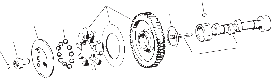
10 BGM/965–0267
Camshaft
Spec A
1
2
34
7
8
5
6
9
REF PART QTY PART REF PART QTY PART
NO. NO. USED DESCRIPTION NO. NO. USED DESCRIPTION
1 150–0078 1 Ring,
Retaining
2 150–1519 1
Hub, Governor Cup
3 150–1520 1
Cup, Governor (Includes
Bushing)
4 510–0015 10
Ball, Governor
5 105–0700 1
Gear (Includes Spacer and
Plate)
6 105–0541 1 Washer
, Thrust
7 515–0001 1 Key
, W
oodruff
8 105–0637 1 Camshaft
(Includes Center Pin)
9 150–0075 1 Pin,
Center
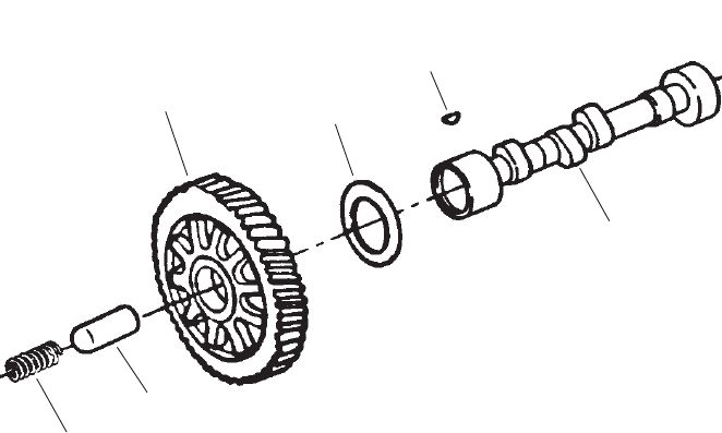
11 BGM/965–0267
Camshaft
Begin Spec B
1
23
4
5
6
REF PART QTY PART REF PART QTY PART
NO. NO. USED DESCRIPTION NO. NO. USED DESCRIPTION
1 105–0677 1 Camshaft
2 105–0700 1
Gear (Includes Spacer and
Plate)
3 105–0541 1 Washer
, Thrust
4 515–0001 1 Key
, W
oodruff
5 105–0058 1 Plunger
, Camshaft
6 105–0059 1
Spring, Plunger

12 BGM/965–0267
Crankshaft
3
4
1
2
5
REF PART QTY PART REF PART QTY PART
NO. NO. USED DESCRIPTION NO. NO. USED DESCRIPTION
1 104–1735 1 Crankshaft
2 515–0001 1 Key
, Gear
3 104–0032 1 Gear
4 104–0043 1 Washer
, Gear
5 518–0014 1
Ring, Retaining
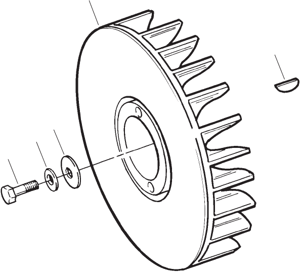
13 BGM/965–0267
Blower Wheel
5
4
1
3
2
REF PART QTY PART REF PART QTY PART
NO. NO. USED DESCRIPTION NO. NO. USED DESCRIPTION
1 134–4705 1 Wheel,
Blower
2 515–0263 1 Key
, Blower Wheel
3 526–0017 1 Washer
, Flat (7/16” x 1/4”THK)
Special
4 526–0356 1 Washer
, Flat (7/16” x 1/8”THK)
Special
5 104–0170 1 Screw (Special)

14 BGM/965–0267
Gearcase
Spec A
1
6
9
10
12
11
3
2
13
14
15
16
8
45
7
REF PART QTY PART REF PART QTY PART
NO. NO. USED DESCRIPTION NO. NO. USED DESCRIPTION
1 103–0804 1 Gearcase Assy (Includes Parts
Marked *) (Spec A)
2 815–0046 2 *Screw
, Pan Head Machine
Cross Recessed
(#8–32 x 3/8”)
3 150–1187 1 *Yoke
4 870–0328 1 *
Nut, Self–Locking (#10–32)
5 851–0031 1 *Washer, Conical Disc Spring
6 150–2002–04 1 *
Shaft, Governor
7 150–2300 1 *Screw
, Governor Adjust Guide
(Special)
8 150–1998 1 *
Link, Governor Spring
9 509–0008 1 *
Seal, Oil
10 510–0013 1 *
Bearing, Needle
11 516–0130 1 *
Pin, Alignment
12 510–0014 1 *
Ball, Bearing
13 509–0040 1 *
Seal, Crankshaft Front Oil
14 103–0810 1 Gasket, Gearcase
15 526–0065 5 Washer
, Copper Flat (5/16”)
16 Screw
, Hex Head Cap
114–0022 4
5/16–18 x 1–3/4”
800–0592 1
5/16–18 x 3–1/4”
* – Parts Included in Gearcase Assy.
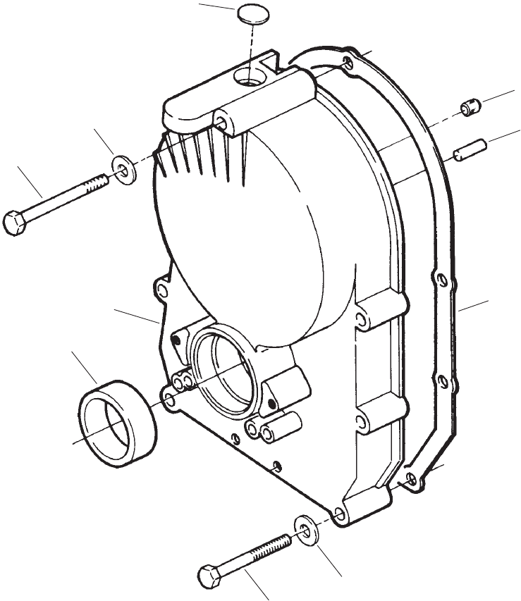
15 BGM/965–0267
Gearcase
Begin Spec B
1
2
4
8
9
6
5
7
3
6
REF PART QTY PART REF PART QTY PART
NO. NO. USED DESCRIPTION NO. NO. USED DESCRIPTION
1 103–0813 1 Gearcase Assy (Includes Seal
and Plugs)
2 509–0040 1
Seal, Crankshaft Front Oil
3 516–0051 1 Plug
4 517–0293 1
Plug, Expansion
5 800–0545 1 Screw
, Hex Head Cap
(5/16–18 x 2–3/4”)
6 526–0065 5 Washer
, Flat (5/16”)
7 516–0141 2
Pin, Alignment
8 103–0810 1 Gasket, Gearcase
9 800–0032–01 4 Screw
, Hex Head Cap
(1–3/4” Lg.)
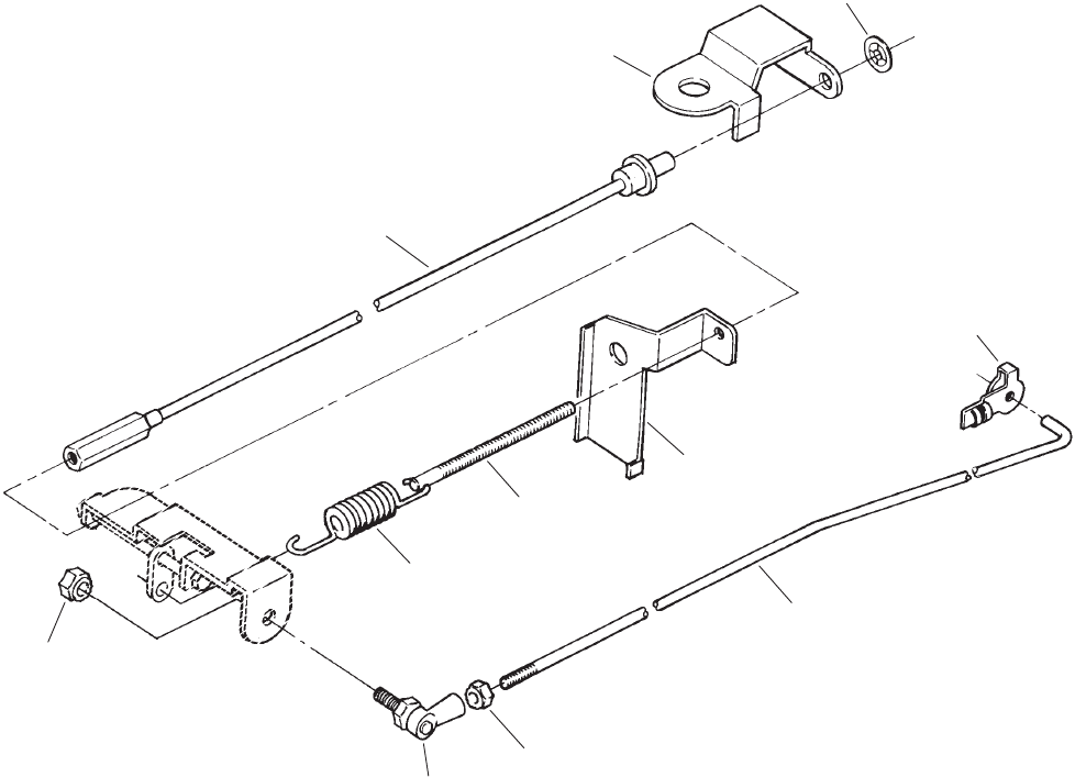
16 BGM/965–0267
Governor
Spec A
1
2
3
4
5
6
7
8
9
10
1
REF PART QTY PART REF PART QTY PART
NO. NO. USED DESCRIPTION NO. NO. USED DESCRIPTION
1 870–0131 2 Nut,
ET Hex (#10–32)
2 150–0096 1
Stud, Governor Adjusting
3 150–1612 1
Spring, Governor
4
150–2298–01 1 Bracket, Governor
5 518–0006 1
Clip, Retaining
6 150–1957 1
Rod, Governor Control
7 150–0939 1
Joint, Ball
8 150–2294 1
Cable, Flexible Adjust
9 150–2295 1
Bracket, Cable Adjust
10 518–0582 1 Retainer, Push–On

17 BGM/965–0267
Electronic Governor
Begin Spec B
1
2
3
4
5
6
REF PART QTY PART REF PART QTY PART
NO. NO. USED DESCRIPTION NO. NO. USED DESCRIPTION
1 150–2424 1 Rod,
Throttle Control
2 150–2425 1
Clip, Throttle Rod
3 150–2426 1
Spring, Throttle Rod
4 151–0701 1 Actuator, Governor (K2)
5 815–0783–01 2 Screw
, Pan Head
(#10–32 x 1–5/8”)
6
815–0783–02 2 Screw
, Pan Head
(#10–32 x 2–1/8”)
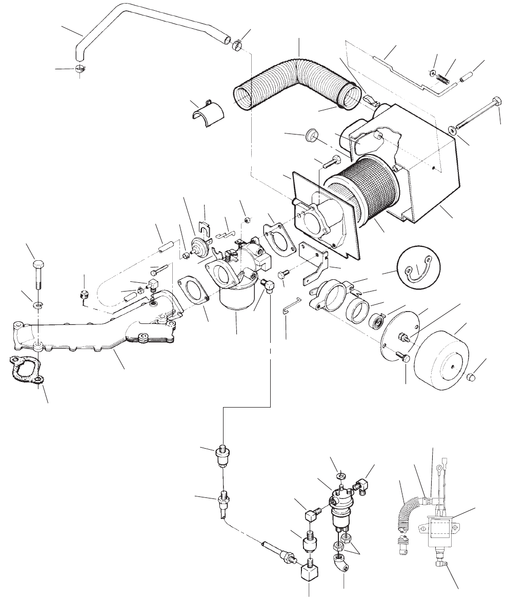
18 BGM/965–0267
Fuel System
48
55
47
61
46
45 21
62
64
16
17
57
59
6
20
15
44
11
12
14
13
43
63
60
58
56
54
27
5
25
26
18
49
51
50
53
3
2
65
4
1
7
19
10
89
42
52
22 23 24
41
35
38
40
33
36
34
39
37
67
66
,,
53
32
29
28
30
31
19 BGM/965–0267
Fuel System
REF PART QTY PART REF PART QTY PART
NO. NO. USED DESCRIPTION NO. NO. USED DESCRIPTION
1 503–1133 1 Clamp, Hose
2 123–1852 1 T
ube, Breather
3 140–1919–50 1 Adapter
, Preheater
4 503–0183 1
Clamp, Hose
5 503–1351 1
Hose, Preheater
6 518–0459 1
Clip, Preheater Hose
(Spec A–B)
7
Rod, Air Inlet
145–0707 1 Spec A–E
145–0704 1
Begin Spec F
8 526–0002 1 Washer
, Flat (#6)
9 120–0140 1
Spring, Air Inlet
10 517–0223 1
Cap, V
inyl
11 800–0017 1 Screw
, Hex Head Cap
(1/4–20 x 3–1/2”)
12 526–0021 1 Washer
, Flat (1/4”)
13
Housing, Air Cleaner
140–1894 1 Spec A–C
140–2883–01 1
Begin Spec D
14 140–2379 1
Element, Air Cleaner
15 153–0557 1
Bracket, Choke Mounting
(Spec A–C)
16 153–0556 1 Housing, Choke (Spec A–C)
(Includes Choke Shaft,
Insulating W
asher and
Retainer Ring) (H1)
17 518–0387 1
Ring, Retaining (Spec A–C)
18 518–0466 1
Clip, Choke Housing T
ube
Retaining (Spec A–C)
19 153–0578 1 T
ube, Choke Housing
(Spec A–C)
20 153–0554 1
Element, Thermostat (Spec
A–C)
21 153–0555 1 Cover, Choke (Spec A–C)
(Includes Hex Nuts, Washers,
Heater Coil Spider and Choke
Heater Element)
22 526–0047 2 Washer
, Flat (#6) (Spec A–C)
23 854–0006 2 Washer
, IT Lock (#6)
(Spec A–C)
24 871–0006 2 Nut, Brass Hex (6–32”)
(Spec A–C)
25 153–0579 1 Cover
, Choke Housing
(Spec A–C)
26 870–0421 1
Nut, Nylon Acorn Cap (#6–32)
(Spec A–C)
27 815–0592 2 Screw, Hex W
asher Head
Thread Forming (Spec A–C)
(#8–32 x 1–3/8”)
28 503–2041 1
Hose, Fuel
29 503–0731 2
Clamp, Hose
30 502–0395 1 Connector, Hose
31 149–2331–03 1 Pump,
Fuel (E3) (Begin Spec G)
32 502–0313 1 Elbow,
90
° Hose
33 502–0020 1 Elbow
, 90
°
Street – V
alve
Outlet
34 122–0345 1
Shield, Fuel Pump
35 870–0131 2
Nut, ET Hex (#10–32)
36 502–1107 1 Elbow
, 90
°
Barbed – Inlet
37 Washer
, Flat
526–0115 3
Spec A (.344)
526–0115 3
Begin Spec B (.3125)
38 149–2267 1
Pump, Fuel (E3) (Spec A–F)
39 502–0054 1 Elbow
, 90
°
Street – Outlet
40 V
alve, Fuel Solenoid (E4)
307–1279 1 Spec A
307–2756 1 Spec B,C
307–2788 1 Spec D
41 501–0550 1
Line, 30” Flexible Fuel
42 Filter
, Fuel
149–2279 1 Spec A–F
149–2341 1
Begin Spec G
43 153–0558 1
Linkage, Choke (Spec A–C)
44 815–0591 2 Screw, Hex W
asher Head Cap
Thread
Forming(1/4–10 x
3/4”)
45 502–1108 1 Elbow,
90
°
Street
46 Carburetor
(See Separate
Page
for
Components)
146–0455 1 Spec A
146–0528 1 Spec B–C
146–0664 1
Begin Spec D (Includes
Gaskets)
47
Gasket, Mounting
141–0281 1 Spec A
141–0958 1
Begin Spec B
48
Manifold, Intake
154–2447 1 Spec A–F
154–3026 1
Begin Spec G
49 154–2495 1
Gasket, Intake Manifold
50 740–1006 4 Washer
, Flat (M8)
51 800–0033 4 Screw
, Hex Head Cap
(5/16–18 x 2”)
52 502–0028 1
Plug, Hex Head Pipe (Begin
Spec D)
53 503–0813 2 Clamp, Hose (Spec A–C)
54 502–1105 1
Fitting, 90
°
Flow V
acuum
(Spec A–C)
55 815–0587 2 Screw
, Hex Flange Head Cap
(5/16–18 x 1”)
56 503–1252–01 1 Hose, V
acuum (3/16” ID x 6”)
(Spec A–C)
57 153–0561 1
Bracket, Diaphragm Mounting
(Spec A–C)
58 153–0614 1
Diaphragm, Pullof
f (Spec A–C)
59 518–0450 1
Clip, Diaphragm Mounting ”U”
(Spec A–C)
60 153–0577 1
Linkage, Diaphragm Pullof
f
(Spec A–C)
61 862–0015 1
Nut, Hex (5/16–18)
62 140–2308 1 Gasket, Air Horn
63 140–3093 1 Adapter
, Air Cleaner
64 815–0590 3 Screw
, Hex Head Machine
(#10–32 x 7/16”)
65 145–0561 1 Cover
, Air Inlet
66 517–0320 1
Plug, Button (Begin Spec D)
67 509–0313 1
O’Ring (Begin Spec C)
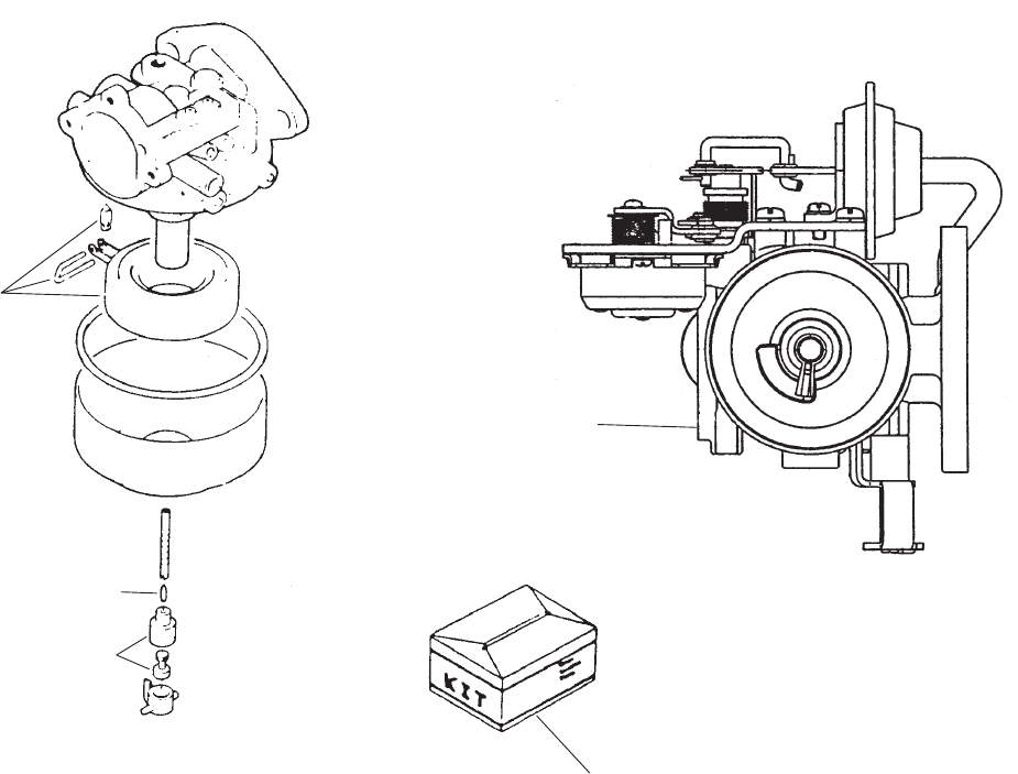
20 BGM/965–0267
Carburetor Components
,
1
7
2
3
465
,,
Spec
A–C
1
Begin Spec D
REF PART QTY PART REF PART QTY PART
NO. NO. USED DESCRIPTION NO. NO. USED DESCRIPTION
Carburetor
146–0455 1 Spec
A (Includes Mounting
Gaskets)
146–0528 1 Spec B,C
146–0664 1
Begin Spec D (Includes
Mounting Gaskets)
1 146–0453 1
Float Package (Includes Float,
Pin and V
alve)
2 146–0449 1
Jet, Idle (Spec A–C)
3 146–0450 1 Jet, Power (Spec A–C)
4 146–0588 1
Kit, Choke Bimetal (Includes
Compl. Bimetal Holder
,
Thermostat Cover Assy,
Bimetal Set Plate, Bimetal
Case Set Screw)
5 146–0589 1
Kit, Choke Breaker (Includes
Choke Piston Rod, Link
Washer
, Snap Pin, Choke
Opener Assy
6 146–0592 1
Kit, Choke Shaft (Includes
Choke Shaft Assy, Choke
Collar
, Choke Arm Return
Spring,
Choke
V
alve, V
alve Set
Screw, Choke Lever Assy)
7 146–0457 1
Kit, Repair (Includes Gasket
Package, Float V
alve, Idle
Adjust Needle and Spring,
Mounting Gaskets, Adjust
Limit Caps, Throttle Stop
Screw
and Spring) (Spec A–C)
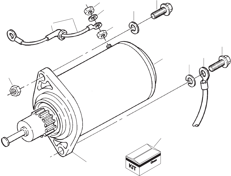
21 BGM/965–0267
Starter
1
7
8
4
9
5
6
3
2
10
11
6
2
4
REF PART QTY PART REF PART QTY PART
NO. NO. USED DESCRIPTION NO. NO. USED DESCRIPTION
1 191–2158 1 Starter (B1)
2 800–0052 2 Screw
, Hex Head Cap
(3/8–16 x 1–1/2”)
3 337–2435 1
Cable (Spec A)
4 850–0050 2 Washer
, Spring Lock (3/8”)
5 850–0040 1 Washer
, Spring Lock (1/4”)
6
862–0001 2
Nut, Hex (1/4–20)
7 226–3457–01 1
Lead, Starter (Includes Shield)
8 122–0345 1 Shield
9 862–0003 2
Nut, Hex (3/8–16)
10 191–2186 1 Cap, Drive
11 191–2187 1
Kit, Drive (Includes Retainers,
Washers, Spring, Cover
, Roll
Pin,
Pinion Gear
, Drive Clutch)
22 BGM/965–0267
Resistor
Spec A–F
1
2
3
4
5
6
7
8
9
REF PART QTY PART REF PART QTY PART
NO. NO. USED DESCRIPTION NO. NO. USED DESCRIPTION
1 870–0196 1 Nut,
Insulation (#8)
2 304–0015 1 Washer
, Centering
3 304–0818 1 Resistor
, Fixed – 1.4 Ohms
50 W
atts
4 304–0773 1
Bracket, Resistor Mounting
5 815–0583 1 Screw
, Hex Head Cap
(#8–32 x 4.75”)
6 815–0770 1 Screw, Hex W
asher Head
Thread Form (#10–32 x 1/2”)
7 304–0772 1
Bracket, Resistor Mounting
8 815–0261 1 Screw, Hex W
asher Head
Thread Cutting
(1/4–20 x 1/2”)
9 508–0321 1 Washer
, Flat (.184)

23 BGM/965–0267
Oil Filter
1
5
6
3
2
7
4
8
REF PART QTY PART REF PART QTY PART
NO. NO. USED DESCRIPTION NO. NO. USED DESCRIPTION
1 122–0814 1 Adapter,
Oil Filter (Includes
Screws)
2 815–0340 2 Screw
, Hex Head Cap
Thread Forming with ET
(#10–32 x 3/8”)
3 122–0360–55 1
Drain, Oil Filter
4 122–0645 1 Filter
, Oil
5 526–0065 2 Washer
, Copper Flat (5/16”)
6 800–0028–01 2 Screw
, Hex Head Cap
(5/16–18 x 1”)
7 122–0771 1
Gasket, Oil Filter Adapter
8 Switch, Low Oil Pressure (S2)
309–0322 1
Spec A – Open – to
Close at 5–9 PSI
309–0615 1
Begin Spec B – Close
to Open at 5–9 PSI

24 BGM/965–0267
Oil Base
1
2
3
4
5
6
7
8
9
10
REF PART QTY PART REF PART QTY PART
NO. NO. USED DESCRIPTION NO. NO. USED DESCRIPTION
1 102–1387 1 Gasket, Oil Base
2 Base, Oil
102–1359 1 Spec A–F
102–1457–01 1
Begin Spec G
3 123–1616 1 Cup, Oil Pickup
4 123–2092 1
Cap, Oil Fill
5V
alve, Drain/Shutof
f
504–0164 1 Spec A–F
504–0150 1
Begin Spec G
6 509–0246 1
O’Ring (1–1/4” ID)
7 509–0247 2
O’Ring (3/8” ID) (Spec A–F)
8 526–0251 4 Washer
, Flat (3/8”)
9 800–0052–01 4 Screw
, Hex Head Cap
(3/8–16 x 1–1/2”)
10 509–0291 1
O’Ring (1/2”ID)
(Spec A–F)
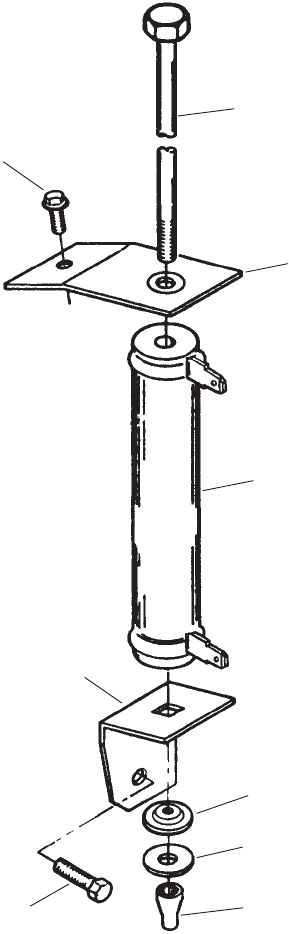
25 BGM/965–0267
Extended Oil Fill Tube
1
2
3
4
5
6
7
8
9
10 11
REF PART QTY PART REF PART QTY PART
NO. NO. USED DESCRIPTION NO. NO. USED DESCRIPTION
1 123–2041–50 1 Tube,
OIl Fill
2 332–3213 1
Clamp, Coated
3 123–2039 1 Adapter
Assy (Includes
Adapter
and
O’Ring)
4 509–0246 1
O’Ring, Adapter
5 509–0269 1
Seal, Oil FIll T
ube
6 123–2042 1 Indicator
Assy (Includes
O’Ring)
7 509–0142 1 O’Ring,
Indicator
8 155–2943–02 1 Bracket, T
ube Support
9 821–0010 1
Screw (1/4–20 x 1/2”)
10 870–0212 1
Nut (1/4 x 20)
11 526–0029 1 Washer
, Flat (3/8”)
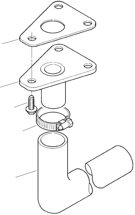
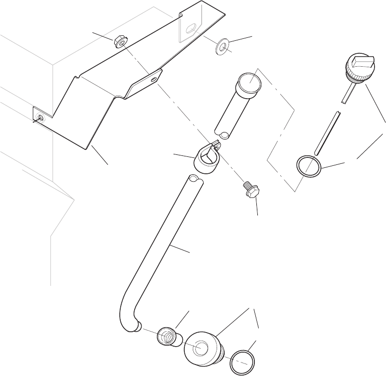
26 BGM/965–0267
Oil Drain Extension
1
2
3
4
5
REF PART QTY PART REF PART QTY PART
NO. NO. USED DESCRIPTION NO. NO. USED DESCRIPTION
1 102–1394 1 Adapter,
Oil Drain
2 503–1195 1
Hose, Oil Drain (3/4” ID x 24”)
3 503–0183 1
Clamp, Hose
4 102–1391 1
Gasket, Oil Drain Adapter
5 815–0261 3 Screw, Hex W
asher Head Cap
Thread Forming
(1/4–20 x 1/2”)
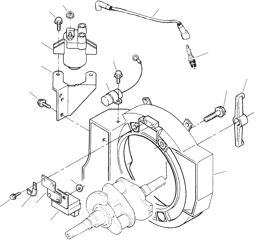
27 BGM/965–0267
Generator Adapter
16
3
4
8
12
1
9
5
6
2
10
11 14
15
13
7
6
REF PART QTY PART REF PART QTY PART
NO. NO. USED DESCRIPTION NO. NO. USED DESCRIPTION
1 Nut,
Hex Flange
166–0770 1
M4 x 0.7 – Positive T
erminal
166–0771 1 M5
x 0.8 – Negative
T
erminal
2 815–0650 2 Screw,
Self–Locking Hex
W
asher Head Thread
Forming (1/4–20 x 1”)
3
Coil, Ignition (T1)
166–0761 1 Spec A,B – Spec C
S/N G923938483 & Below
166–0820 1
Begin Spec C,
S/N G923938484 & Above
4
Bracket, Ignition Coil
166–0789–01 1 Spec A,B – Spec C
S/N G923938483 & Below
166–0747 1
Begin Spec C
S/N G923938484 & Above
5 815–0290 2 Screw
, Self–Locking Hex
W
asher Head Thread
Forming (1/4–20 x 5/8”)
6 815–0770 3 Screw
, Self–Locking Hex
W
asher Head Thread
Forming (#10–32 x 1/2”)
7 332–3198 1 Connector
8 166–0793 1
Bracket, Ignition Control
9 166–0821 1
Control, Ignition (S3)
10 870–0328 2
Nut, Self–Locking (#10–32)
11 312–0256 1 Capacitor (C4)
12
Cable, Spark Plug
167–1625–01 1 9”
167–1625–02 1 23”
13 167–0272 2
Plug, Spark
14 166–0842 1 Rotor
, Ignition
15 800–0575–01 4 Screw
, Hex Flange Head Cap
(3/8–16 x 1–1/8”)
16 231–0381–01 1 Adapter
, Generator
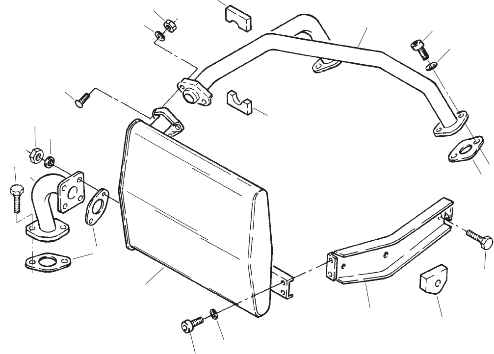
28 BGM/965–0267
Exhaust System
(Side or Bottom)
1
16
9
18
13 14
10
8
12
3
6
17
11
4
15
5
2
7
1
6
REF PART QTY PART REF PART QTY PART
NO. NO. USED DESCRIPTION NO. NO. USED DESCRIPTION
1 134–4770 2 Insulation, Exhaust Tube
2 870–0048 2
Nut, Self–Locking (5/16–18)
3 526–0122 2 Washer
, Flat (.34)
4 816–0140 2
Bolt, Carriage
(5/16–18 x 1–1/4”)
5 862–0014 2
Nut, Hex (5/16–18)
(Stainless Steel)
6 740–1006 6 Washer
, Flat (M8)
7 800–0730 2 Screw
, Hex Head Cap
(5/16–18 x 1”)
8 155–2428 1 T
ube, Exhaust
9 154–2765 2 Gasket, Exhaust Tube
10 155–2477 1 Muffler, Exhaust
11 815–0261 4 Screw, Hex W
asher Head Cap
Thread Forming
(1/4–20 x 1/2”)
12 526–0018 4 Washer
, Flat (1/4”)
13 155–2558 2
Support, Muf
fler
14 155–2415 2
Seal, Muf
fler Support
15 Screw
, Hex Flange Head
821–0029 4
Spec A–F (3/8–16 x 3/4”)
815–0890–01 4
Begin Spec G (3/8–16 x 1)
16 154–2746 2
Gasket, Exhaust Manifold
17 802–0053 4 Screw, Socket Head
(5/16–18 x 3/4”)
18 154–2784 1
Manifold, Exhaust
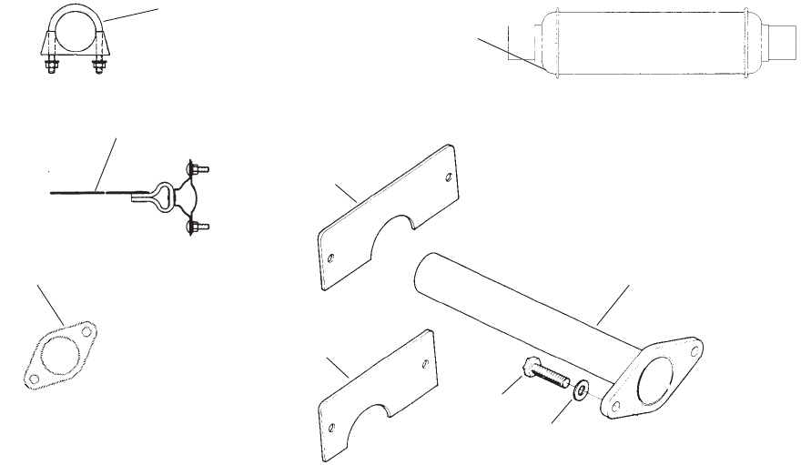
29 BGM/965–0267
Exhaust Options
1
2
7
3
4
5
8
9
6
REF PART QTY PART REF PART QTY PART
NO. NO. USED DESCRIPTION NO. NO. USED DESCRIPTION
1 Tube, Exhaust
155–2610 1 3”
155–2424 1 7”
2 154–0945 1
Flange, Exhaust Manifold
(1/4”Thk) (Steel Plate)
3 800–0730 2 Screw
, Hex Head Cap
(5/16–18 x 1”)
4 526–0115 2 Washer
, Flat (5/16”)
5 155–2402 2 Cover
, T
ailpipe Access
6 155–2174 – Hanger
, Exhaust (1–1/2”)
7 155–2401–02 2 Cover
, T
ailpipe Access
8 155–2449 1 Resonator, Exhaust
9
Clamp, Exhaust
155–1255 – 1”
155–1256 – 1–1/8”
155–1257 – 1–1/4”
155–1015 – 1–3/8”
155–1239 – 1–1/2”
155–1135 – 1–5/8”
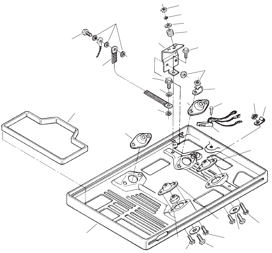
30 BGM/965–0267
Drip Pan
4
6
3
5
13
12
20
19
1
21
7
8
9
2
14
15
16
10
11
17
18
3
5
12
12
9
5
8
5
3
31 BGM/965–0267
Drip Pan
REF PART QTY PART REF PART QTY PART
NO. NO. USED DESCRIPTION NO. NO. USED DESCRIPTION
1 403–2893–02 1 Pan,
Drip
2 402–0629 1
Bushing, Isolator
3 Screw
, Self–Locking Hex
Flange Head (1/4–20 x 1/2”)
821–0010 7 Spec A–F
821–0010 9
Begin Spec G
4 815–0657 4 Screw
, Hex Head Cap
Thread Forming
(3/8–16 x 2–3/4”)
5 402–0624 4 Isolator
, V
ibration
6 526–0325 4 Washer
, Flat
(13/32” ID x 2–29/64” OD x
1/8” Thk)
7 821–0015 2 Screw
, Self–Locking Hex
Flange Head (1/4–20 x 3/4”)
8 518–0515 2
Clip, Fuel Line Retainer
9 870–0212 4
Nut, Self–Locking Hex
(1/4–20)
10 151–0752 1 Controller
, Governor (Begin
Spec B)
11 815–0783–03 1 Screw
, Pan Head T
orx
(#10–32 x 1/2”)
12 856–0008 5 Washer
, EIT Lock (5/16”)
13 Screw
821–0016 1
Self–Locking Hex Flange
Head (5/16–18 x 3/4”)
815–0236 1
Hex Head Thread Cutting
(5/16–18 x 5/8”)
14
Bracket, Fuel Pump
149–2321–02 1 Spec A–F
149–2569–02 1
Begin Spec G
15 508–0307 3
Grommet, Fuel Pump
(Neoprene) (Spec A–F)
16 526–0012 3 Washer
, Flat (#10)(Spec A–F)
17 850–0030 3 Washer,
Lock (#10) (Spec
A–F)
18 Nut,
Hex (#10–32)
867–0028 1 Spec A–F
870–0131 1
Begin Spec G
19 815–0610 1 Screw
, Hex Head Cap
Thread Forming (1/4–20 x 1”)
20 337–2434 1
Strap, Ground
21 134–4745 1
Seal, Air Outlet
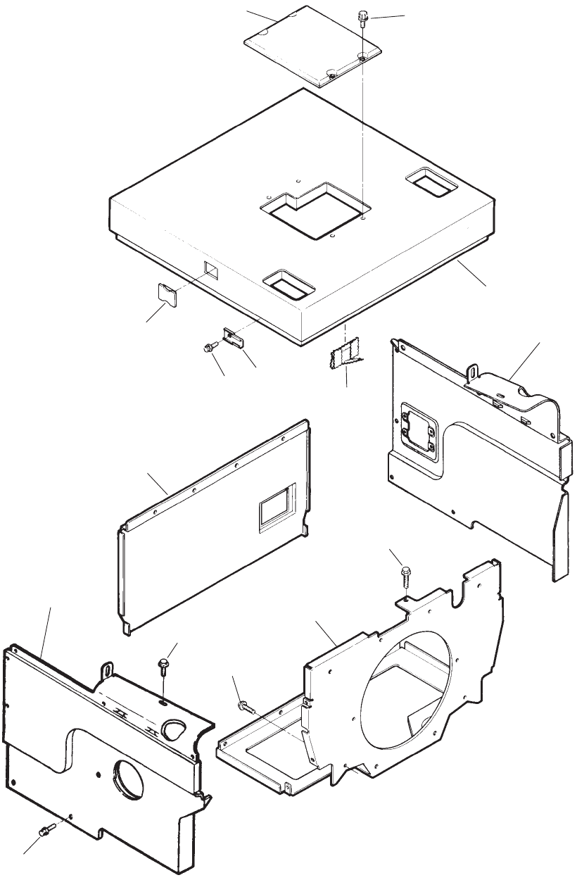
32 BGM/965–0267
Air Housing
7
9
4
3
10
11
6
2
8
1
12
5
6
2
2
33 BGM/965–0267
Air Housing
REF PART QTY PART REF PART QTY PART
NO. NO. USED DESCRIPTION NO. NO. USED DESCRIPTION
1 134–4753–02 1 Cover, Governor Access
2 815–0889 31 Screw, Hex W
asher Head
(1/4–20 x 3/4”)
3 134–5163 Cover
, Top (Includes Insulation
and Indented Nut Listed
Below)
134–5146 1
Insulation, T
op
518–0581 3 Nut, Push On
4 134–4890 1 Cover
, Left Side Cylinder
(Includes Indented Parts
Listed Below)
134–5061 1
Insulation, Cylinder Head
870–0468 1 Nut, Flex Lock
518–0581 6
Nut, Push On (Round
Shaped)
134–4771–50 1 Cover
, T
ailpipe Access
518–0574 4 Clip (1/4–20) Access Cover
815–0815 4 Screw
, T
orx Drive
(1/4–20 x 1/2”) Access
Cover
134–4837 1
Insulation, Muf
fler Box
(Lower)
134–4832 1
Insulation, Muf
fler Box
(Upper)
134–4793–50 1 Cover
, Cylinder Head Inner
5 518–0618 1
Clip, Spark Plug Wire
6 815–0261 7 Screw, Hex W
asher Head Cap
Thread Forming
(1/4–20 x 1/2”)
7 Backplate
134–4961–50 1 Spec A
134–4924–50 1
Begin Spec B
8 821–0014 2 Screw
, Self–Locking Hex
Washer
Head (5/16–18 x 1/2”)
9 134–4939 1 Cover,
Right Side Cylinder
(Includes Indented Parts
Listed Below)
134–5060 1
Insulation, Cylinder Head
870–0468 1 Nut, Flex Lock
518–0581 5 Nut, Push On
134–4791–50 1 Cover
, Cylinder Head Inner
134–4831 1
Insulation, Muf
fler Box
10 134–4888 1
Panel, Front (Includes
Insulation and Indented
Parts Listed Below)
134–4771–50 1 Cover
, T
ailpipe Access
Opening
518–0574 4 Clip (1/4–20) Access Cover
815–0815 4 Screw
, T
orx Drive – Access
Cover (1/4–20 x 1/2”)
518–0581 5 Nut, Push On
134–4997 1 Insulation
11 518–0570 9
Clip, Moulding
12 517–0278 1 Plug, Governor Adjust Access
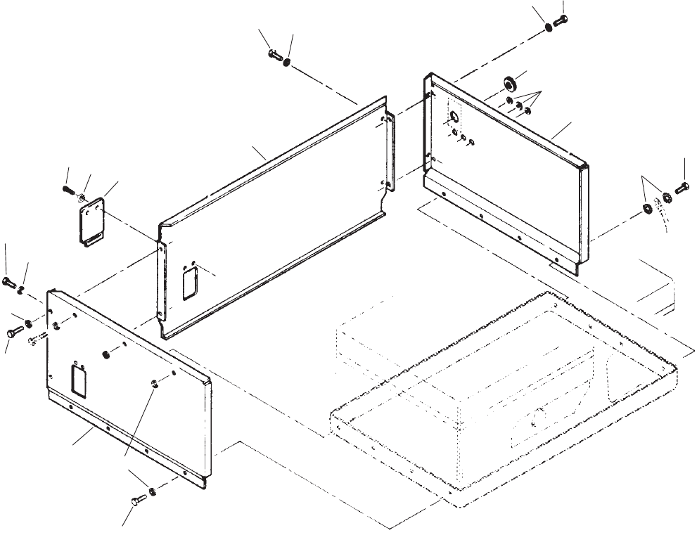
34 BGM/965–0267
Underfloor Housing
1
7
9
2
10
11
45
6
8
3
5
5
5
5
5
6
6
6
6
REF PART QTY PART REF PART QTY PART
NO. NO. USED DESCRIPTION NO. NO. USED DESCRIPTION
1 405–4662 1 Panel,
Rear (Includes
Insulation)
2 405–4668–01 1 Cover
, Panel Rear
3 850–0030 2 Washer
, Spring Lock (#10)
4 813–0098 2 Screw
, Round Head Machine
(#10–32 x 3/8”)
5 800–0026 16 Screw
, Hex Head Cap
(5/16–18 x 3/4”)
6 526–0122 22 Washer
, Flat (5/16”)
7 405–4663 1
Panel, Left Side (Includes
Insulation)
8 856–0008 2 Washer
, EIT Lock (5/16”)
9 405–4237 1
Panel, Right Side (Includes
Insulation)
10 508–0071 3
Grommet, Rubber (5/8”)
11 508–0055 1
Grommet, Rubber (1–1/2”)

35 BGM/965–0267
Fuel Tank
1
2
3
4
5
6
7
8
REF PART QTY PART REF PART QTY PART
NO. NO. USED DESCRIPTION NO. NO. USED DESCRIPTION
1 415–0511 1 Tank,
Fuel (6 Gallon)
2 505–0007 1
Bushing, Reducer (1/4” x 1/8”)
3
504–0169 1 V
alve, Shutof
f (1/8”)
4 502–0395 1 Connector
, Barbed Hose
(1/8”)
5 503–0708 1
Hose, Fuel (1/4” ID x 14”)
6 503–0731 4
Clamp, Hose
7 502–0397 1 Coupling, Quick Disconnect
Female
8 502–0398 1 Coupling, Quick Disconnect
Male

36 BGM/965–0267
Generator
1
4
5
2
3
23
24
6
7
10
22
11
12
13
15
14
9
27
25
26
29
19 18 17
28
16
8
20
21
18
37 BGM/965–0267
Generator
REF PART QTY PART REF PART QTY PART
NO. NO. USED DESCRIPTION NO. NO. USED DESCRIPTION
1 Rotor,
Generator (Includes
Parts Marked *)
201–3388–03 1 Spec A,B
201–3509–01 1
Begin Spec C
2 510–0099 1 *
Bearing, Ball
3 204–0134 1 *
Ring, Collector
4 518–0460 1 *
Ring, T
olerance
5 205–0165 1 *
Fan, Generator
6 862–0003 4
Nut, Hex (3/8–16)
7 802–1038 1 Screw, Socket Head
(7/16–14 x 10–7/32”)
8 331–0536 1 Connector
, Conduit (Begin
Spec D)
9 508–0272 2
Grommet, Nylon
10 212–1284 1 Cover, Brush Block Access
11 212–1285 1 Block, Generator Brush
(Includes Parts Marked #)
12 212–1286 1 #Block, Brush
13 214–0103 2 #
Brush, Generator
14 815–0788 2 Screw
, T
orx – Pan Head
(#10–32 x 7/8”)
15 212–1276–03 2 #
Spring, Generator Brush
16 304–0810 1 Resistor
, Fuel Pump (R7)
17 Screw
, T
orx Drive Thread
Forming
815–0660 2
Hex Head (#10–32 x 2–1/2”)
Specs A,B
815–0808–01 1
Pan Head Shakeproof
(#10–32 x 4–1/2”)
Begin Spec C
18 304–0015 4 Washer
, Centering (7/32”)
19 Resistor
, Battery Charge (R1)
(Spec A–F)
304–0794 1
25 W
atts, 5 Ohms
304–0818 1
50 W
atts, 1.2 Ohms
20 821–0030 1 Screw,
Lock Head (3/8–16 x 1”)
21 856–0010 1 Washer, EIT Lock (3/8”)
22
Housing, Generator Stator
220–4438–01 1 Spec A
220–4532–01 1
Begin Spec B–G
23 800–0052 4 Screw
, Hex Head Cap
(3/8–16 x 1–1/2”)
24 850–0050 4 Washer
, Spring Lock (3/8”)
25 232–2955–02 3
Clamp, Stator
26 815–0290 3 Screw, Hex W
asher Head
Thread Forming
(1/4–20 x 5/8”)
27 220–4135–04 1 Stator
, Generator
28 509–0196 1 O’Ring
29 332–0819 2
Housing, Push On Connector
*–
Parts Included in Generator Rotor
.
#–
Parts Included in Generator Brush Block

38 BGM/965–0267
Control
123
4
5
6
7
8
9
10
11 12 13
14
15
16
17
18
26 21
22
23
20
24
28
29
46
30
31
32
33
34
35
36
45
44
43
37
38
39
40
41
42
7
29
5
27
28
27
19
25
39 BGM/965–0267
Control
REF PART QTY PART REF PART QTY PART
NO. NO. USED DESCRIPTION NO. NO. USED DESCRIPTION
1 815–0550–01 4 Screw
, Pan Head
(#6–32 x .312”)
2 232–3265–02 1
Clamp, Conduit
3 815–0661 2 Screw
, Pan Head Thread
Forming (#10–32 x 1/2”)
4 Bracket, Fuse Holder
321–0323–02 1 Spec A–F
321–0357–02 1
Begin Spec G
5 815–0692–02 2 Screw
, Machine Pan Head
Torx Drive (1/4–20 x 1”)
6 305–0825–02 1 Bracket, V
oltage Regulator
7 815–0664 2 Screw
, T
orx Drive Thread
Forming (1/4–20 x 3/8”)
8 305–0826 1 Regulator
, V
oltage (Includes
Cap and Pins) (VR1)
9 323–1315 1 Cap,
Connector – 12 Place (P4)
10 323–1199 12 Pin,
Contact
11 815–0777–01 1 Screw,
T
orx Drive
(1/4–20 x 1/2”)
12 338–2476 1 Harness, V
oltage Regulator
(Includes Socket and Plug)
13 323–1200 7 Socket, Contact
14 323–1314 1
Plug, Connector – 12 Place
(J4)
15 815–0791 4 Screw
, Pan Head
(#6–32 x 3/8”)
16 Breaker
, AC Output Circuit
(CB1,CB2)
Spec 26105
320–1323 1 30A
320–1683 1 20A
320–1323 2
Spec 1
1578 (30A)
17 332–3075 1 Insulator
, PC Board (Begin
Spec B)
18
Board, Printed Circuit
(Includes
Parts
Marked
°
) (A1)
300–3950 1 Spec A
300–3764 1 Spec B–F
300–4902 1
Begin Spec G
19 321–0271 1 °
Clip, Fuse
20 815–0661 2 Screw
, Pan Head Thread
Forming (#10–32 x 1/2”)
21 Fuse (F1)
321–0298 1
5 Amp – Spec A
321–0146 1
10 Amp – Begin Spec B
22 321–0295 2 Holder, Fuse (For Spares)
23 308–0949 1 Cover
, Rubber Switch
24 Cover
, Control
319–0762 1 Spec A
Begin Spec B
319–1238–01 1
Spec 26105
319–1238–02 1
Spec 1
1578
25 308–0996 1 °Cover, Hard Plastic Switch
26 308–0995 1 °Switch, On/Of
f (A1S1)
27 332–2112 2 Insulator
, T
erminal
28 868–0002 2
Nut, Jam Hex (5/16–24)
29 850–0045 2 Washer
, Spring Lock (5/16”)
30 307–2570 1 Relay
, Start Solenoid (K1)
31 338–2058 1 Harness, AC Output
32 815–0803 1 Screw
, T
orx Pan Head
(#10–32 x 1”)(Spec A–F)
33 815–0691–01 1 Screw
, Pan Head T
orx Drive
Thread Forming
(#10–32 x 3/8”)
34 332–2859–02 1 Block, T
erminal (TB1)
35 813–0096 2 Screw
, Round Head Machine
(#10–32 x 1/4”)
36 307–2695 1 Bracket, Relay
37 338–2465 1 Harness, Generator (Includes
Parts Marked +)
38 323–1440 2 +
Pin, Contact
39 870–0131 1
Nut, Hex (#10–32)(Spec A–F)
40 307–1886 2 +Relay
, Stop Latch – Fuel Pump
(K5, K6)
41 305–0718 1 +Rectifier
, Bridge – Fuel Pump
Power (CR10) (Spec A–F)
42 357–0067 2 +Rectifier
, Stop Latch – Fuel
Pump (CR8, CR9)
43 813–0103 1 Screw
, Round Head Machine
(#10–32 x 3/4”)
44 338–2533 1
Harness, Fuel Pump
(F2–2, TB1–L0 to J5, R6)
45
Housing, Push On Connector
332–0819 1 Spec A–F
332–0556 1
Begin Spec G
46 323–1298 2
Connector (B1 to H1–1, J1–1
and B2 to H1–2, J1–7)
+–
Parts Included in 338–2465 Wiring Harness.
°–
Parts Included in Printed Circuit Board.
40 BGM/965–0267
Engine Harness
Spec A
1
2
3
REF PART QTY PART
NO. NO. USED DESCRIPTION
1 338–2481 1 Harness,
Wiring – Engine to
Control (Includes Housing
and Contact Pins)
2 323–1329 1 Housing (J3)
3 323–1440 2
Pin, Contact

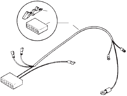
41 BGM/965–0267
Engine Harness
Begin Spec B
1
2
3
4
5
6
7
REF PART QTY PART REF PART QTY PART
NO. NO. USED DESCRIPTION NO. NO. USED DESCRIPTION
Harness,
Engine Wiring
(Includes Connector and
Wedge)
338–2585 1 Spec B
338–2585–01 1 S pec C
338–2888 1
Begin Spec D (Also Includes
Fuse Holder
, Fuse and
Relay)
1 323–1505 1 Connector
, Receptacle
2 323–1501 1 W
edge, Receptacle – Use with
323–1505 Connector
3 321–0322–01 1 Holder
, Fuse
4 321–0321–06 1
Fuse (10A)
5 307–1886 1 Relay (K4)
6 323–1500 1 W
edge, Plug – Use with
323–1505 Connector
7 323–1504 1 Connector
, Plug – Use with
323–1505 Connector
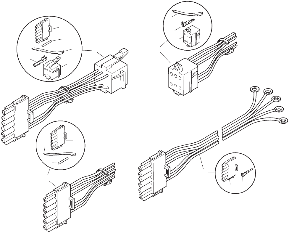
42 BGM/965–0267
PCB Harness
2
45
9
10
11
12
1
3
7
8
6
REF PART QTY PART REF PART QTY PART
NO. NO. USED DESCRIPTION NO. NO. USED DESCRIPTION
Harness, PCB
338–2040 1 Spec A (Includes Parts
Marked #)
338–2584 1 Spec B (Includes Parts
Marked +)
338–2584–01 1 Spec C (Includes Parts
Marked +)
338–2887 1 Spec D–F (Includes Parts
Marked +)
338–3478–01 1 Begin
Spec G (Includes Parts
Marked
)
1 323–1487–03 1 +
Housing, Connector –
12 Connections
2 323–1494 1 +Connector
, Receptacle
3 323–1486 8 +Socket, Contact
4 323–1491 3 +T
erminal, Pin
5 323–1502 1 +W
edge, Receptacle – Use with
323–1494 Connector
6 323–1200 1 #+Socket, Contact
7 323–1312 1 #
Housing (J1) (8 Pin)
8 323–1440 5 #
Pin, Contact
9 323–1743 1 Connector
, Plug (8 Pin)
10 323–1741 1 Housing, Lock
11 323–1708 –
Seal, Cable
12 323–1712 3 Plug, Cavity
#–
Parts Included in 338–2040 Wiring Harness.
+–
Parts Included in 338–2584, 338–2584–01, and
338–2887 Wiring Harnesses.
–
Parts Included in 338–3478–01 Wiring Harness.

43 BGM/965–0267
Remote Panel
Spec A–F
1
2
3
4
5
6
7
8
9
10
3
4
5
REF PART QTY PART REF PART QTY PART
NO. NO. USED DESCRIPTION NO. NO. USED DESCRIPTION
1 300–2313 1 Kit,
Standard Remote Starting
Control (Includes Parts
Marked *) (A3)
2 300–2314 1
Kit, Deluxe Remote Starting
Control (Includes Parts
Marked +) (A2)
3 Screw
, W
ood Oval Head
Cross Recessed (#5 x 1/2”)
815–0380 2 *
Standard Control
815–0380 4 +
Deluxe Control
4 308–0341 1 +*Switch, Rocker (S1)
5
Panel, Control
301–3566 1 *
Standard Control
301–3606 1 +
Deluxe Control
6 302–0885 1 +Meter
, T
ime T
otalizing (M2)
7 302–0888 1 +Meter
, Battery Condition (M1)
8 359–0034 1 +Diode
9 815–0385 2 +Screw
, Round Head Machine
(#6–32 x 1/2”)
10 860–0006 2 +
Nut, Hex (#6–32)
44 BGM/965–0267
Remote Harness
Spec A–F
1
2
3
4
5
6
7
8
3
3
6
9
10 11
12
13
14
REF PART QTY PART REF PART QTY PART
NO. NO. USED DESCRIPTION NO. NO. USED DESCRIPTION
1 338–1082 1 Harness,
Wiring – 6” (Includes
Parts Marked *)
2 323–0500 5 *
Pin, Contact
3 332–0941
1
+#*T
ie, Cable
4 323–0400 1 *
Housing, Connector (6 Place)
5 338–2046 1
Harness, Wiring – 6” (Includes
Parts Marked #)
6 323–1304 1 +#
Housing, Connector (6 Place)
7 323–1199 5 #
Pin, Contact
8 338–2137 1
Harness, Wiring – 6” (Includes
Parts Marked +)
9 323–1199 5 +
Pin, Contact
10 323–0488 5 +Socket, Connector
11 323–0440 1 +
Housing, Connector (6 Place)
12 Harness, Wiring (Includes)
Housing and Pins)
338–2260–01 1 T
en Foot
338–2260–02 1
Thirty Foot
13
323–1
199 5
Pin, Contact
14
323–1304
1
Housing, Connector (6 Place)
(J2)
*–
Parts Included in 338–1082 Wiring Harness
#–
Parts Included in 338–2046 Wiring Harness
+–
Parts Included in 338–2137 Wiring Harness
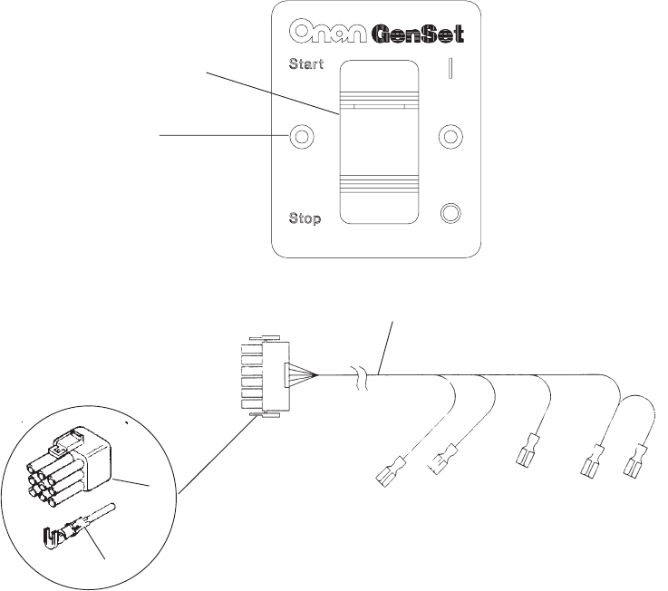
45 BGM/965–0267
Remote Switch Panel
Begin Spec G
3
4
5
1
2
REF PART QTY PART REF PART QTY PART
NO. NO. USED DESCRIPTION NO. NO. USED DESCRIPTION
300–4936 1 Kit,
Switch Only Remote Panel
1 815–0910 2 Screw,
W
ood Mounting (#6 x 1)
2 308–1062 1 Switch, Rocker
3 338–3510 1
Harness, Remote Panel
(Includes Pins and Plug)
4 323–1291 1
Plug (9 Pin)
5 323–1199 4
Pin, Contact
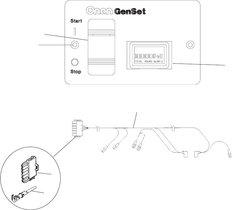
46 BGM/965–0267
Remote Switch/Hourmeter Panel
Begin Spec G
1
2
3
4
5
6
REF PART QTY PART REF PART QTY PART
NO. NO. USED DESCRIPTION NO. NO. USED DESCRIPTION
300–4937 1 Kit,
Switch/Hourmeter Remote
Panel
1 815–0910 2 Screw,
W
ood Mounting (#6 x 1)
2 308–1062 1 Switch, Rocker
3 302–2002 1 Meter
, Hour
4 338–3466 1
Harness, Remote Panel
(Includes Pins and Plug)
5 323–1304 1
Plug (6 Pin)
6 323–1199 4
Pin, Contact

47 BGM/965–0267
Remote Switch/Voltmeter Panel
Begin Spec G
10
9
8
7
1
2
3
45 6
,,,
REF PART QTY PART REF PART QTY PART
NO. NO. USED DESCRIPTION NO. NO. USED DESCRIPTION
300–4938 1 Kit, Switch/Voltmeter
1 815–0910 2 Screw,
W
ood Mounting (#6 x 1)
2 308–1062 1 Switch, Rocker
3 302–1641 1 Meter
, V
oltage
4 526–0409 2 Washer, Nylon
5 526–0049 4 Washer
, Flat
6 871–0010 4 Nut, Hex Brass Machine
(10–32)
7 850–0030 2 Washer, Lock
8 338–3507 1
Harness, Remote Panel
(Includes Pins and Plug)
9 323–1304 1
Plug (6 Pin)
10 323–1199 4
Pin, Contact

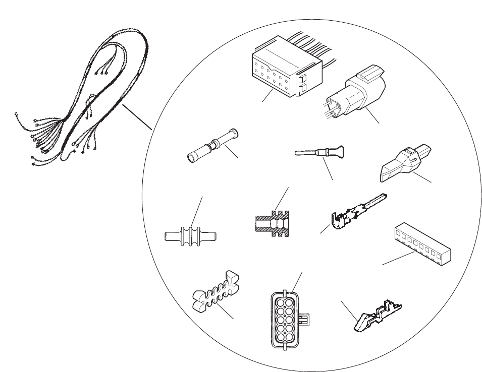
48 BGM/965–0267
Remote Harness
Begin Spec G
1
2
3
4
5
6
7
8
910
REF PART QTY PART REF PART QTY PART
NO. NO. USED DESCRIPTION NO. NO. USED DESCRIPTION
1 300–4946 1 Harness,
Remote (Includes
Parts Marked *)
2
Harness, Remote Panel
(Includes Parts Marked +)
338–3489–01 1 10’
338–3489–02 1 30’
3 338–3572 1
Harness, Adapter (Includes
Parts Marked #)
4 323–1744 1 +*Connector
, Receptacle (8 Pin)
5 323–1712 3 +*Plug, Cavity
6 323–1708 5 +*
Seal, Cable
7 323–1707 5 *
Pin, Contact
8 323–1741 1 +*Housing, Lock
9 323–1200 1 +#Socket, Contact
10 323–1342 1 +#
Cap, Connector
*–
Parts Included in Remote Harness (300–4947).
+–
Parts Included in Remote Panel Harness (338–3490).
#–
Parts Included in Adapter Harness (338–3573).
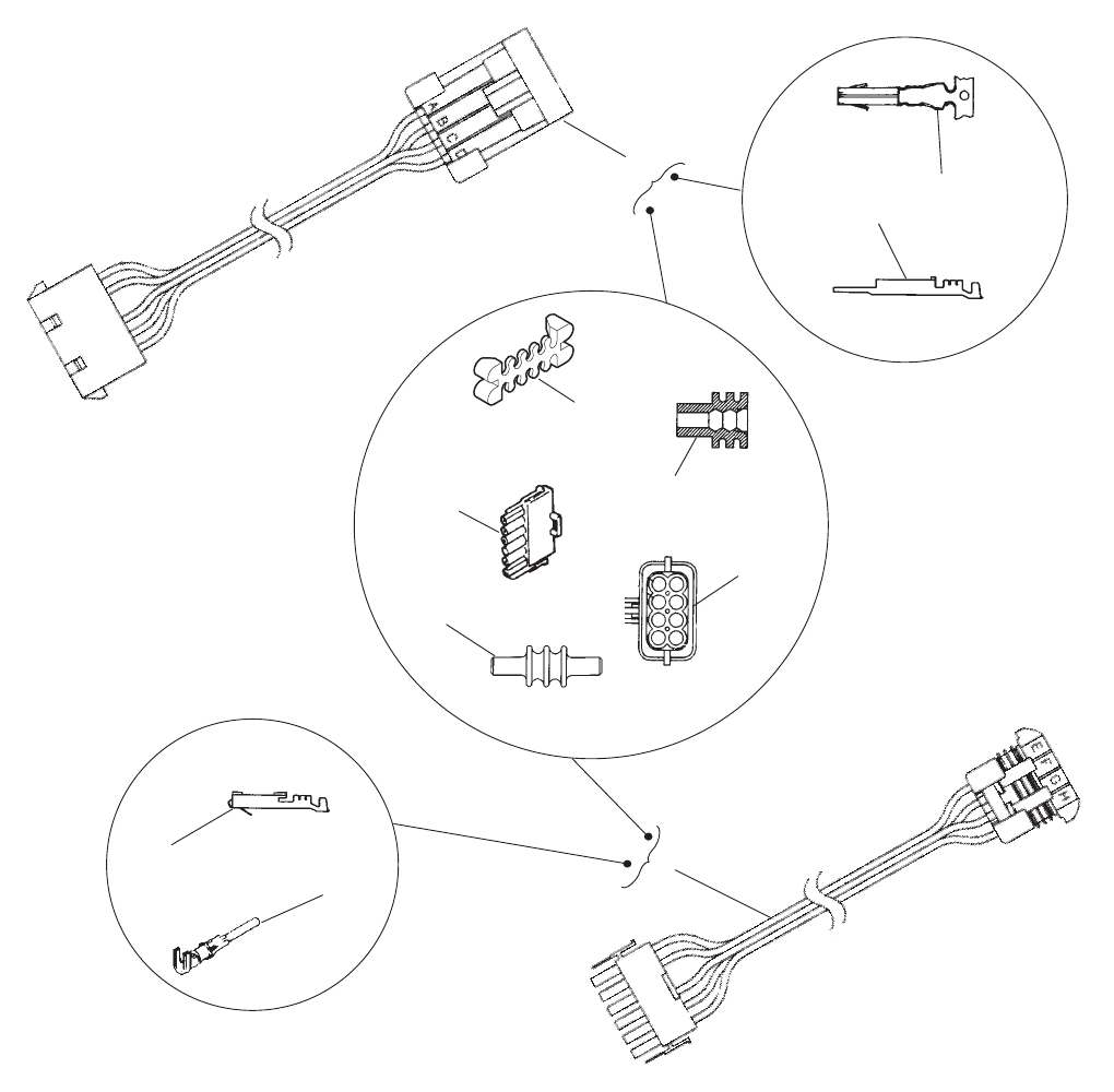
49 BGM/965–0267
Adapter Harness
1
2
4
5
6
7
8
9
10
11
12
13
3
,
,
REF PART QTY PART REF PART QTY PART
NO. NO. USED DESCRIPTION NO. NO. USED DESCRIPTION
1 338–3513 Harness,
Adapter Wiring
New Set to Old Panel
(Includes Parts Marked *)
2 338–3514
Harness, Adapter Wiring
Old Set to New Panel
(Includes Parts Marked +)
3 323–1744 1 *Connector
, Receptacle (8 Pin)
4 323–1708 5 +*
Seal, Cable
5 323–1707 5 *
Pin, Contact
6 323–1712 3 +*Plug, Cavity
7 323–1741 1 +*Housing, Lock
8 323–1342 1 *
Cap, Connector (6 Pl)
9 323–1200 1 *Socket, Contact
10 323–1743 1 +Connector
, Plug (8 Pin)
11 323–1709 5 +Socket, Terminal
12 323–1304 1 +
Cap, Connector (6 Pl)
13 323–1199 5 +
Pin, Contact
*–
Parts Included in Remote Harness (338–3513).
+–
Parts Included in Remote Panel Harness (338–3514).
50 BGM/965–0267
Labels, Kits, Paint and Thread Sealant
REF PART QTY PART REF PART QTY PART
NO. NO. USED DESCRIPTION NO. NO. USED DESCRIPTION
98–6105–02 1 Label,
Air Cleaner (Spec A)
98–6105–03 1
Label, Air Cleaner (Spec A)
98–5335 1
Label, Air Cleaner – Begin
Spec B
98–6586–02 1
Label, Battery – Negative
98–6566 1
Label, Fuse
Label, Model Identification
98–7371–01 5.0kW
98–7371–05 5.5kW
Label, Oil Fill
98–6618–01 1
White Background
98–6618–02 1 Black Background
98–6388–02 1
Label, Phone Info.
98–6402–02 1
Label, W
arning – Service/
Maintenance
98–6074–02 1
Label, W
arning – Provide
Support
98–6088 1 Label,
W
arning – Fire or Fumes
98–6041 1 Label, W
arning – Hazardous
V
oltage, Exhaust Gas
Kit, Gasket
168–0189 1 V
alve Grind
168–0192 1 Engine
120–0161 1
Kit, Oil Pump Gasket
518–0347 1
Loctite, Bottle (250cc)
525–0394 1
Paint, Black – Flat Enamel
(16 oz. Pressurized Spray
Can)
518–0452 –
Sealant, Thread (50cc Bottle)

51
Wiring Diagram Information
Spec Wiring
Diagram Number
Number A B/C D/E/F G
11578 611–1240.
. . . . . . . . . . . . . . . . . . . . . . . . . . . . . . . . . . . . . . . . . . . . . . . . . . . . . . . . . . . . .
26105 611–1196 611–1219 611–1240
. . . . . . . . . . . . . . . . . . . . . . . . . . . . . . . . . . . . . . . . . .

Numerical Index
Part
No. Page
Part No. Page Part No. Page Part No. Page
52
098–5335,
50
098–6041,
50
098–6074–02,
50
098–6088,
50
098–6105–02,
50
098–6105–03,
50
098–6388–02,
50
098–6402–02,
50
098–6566,
50
098–6586–02,
50
098–6618–01,
50
098–6618–02,
50
098–7371–01,
50
098–7371–05,
50
101–0405,
9
101–0439–01,
7
101–0804,
7
101–0804–02,
7
101–0804–10,
7
101–0804–20,
7
101–0804–30,
7
101–0805,
9
101–0805–02,
9
101–0805–10,
9
101–0805–20,
9
101–0805–30,
9
101–0809,
7
102–1359,
24
102–1387,
24
102–1391,
26
102–1394,
26
102–1457–01,
24
103–0804,
14
103–0810,
14
,
15
103–0813,
15
104–0032,
12
104–0043,
12
104–0170,
13
104–0575,
7
104–0776,
7
104–0776–01,
7
104–1735,
12
105–0058,
11
105–0059,
11
105–0541,
10
,
11
105–0637,
10
105–0677,
11
105–0700,
10
,
11
1
10–0197,
7
1
10–0197–10,
7
1
10–1824,
7
1
10–1824–02,
7
1
10–1824–05,
7
1
10–1824–10,
7
1
10–1824–25,
7
1
10–1879–01,
7
1
10–3181,
7
1
10–3479,
7
1
10–3485,
7
1
10–3487,
7
1
10–3508,
7
1
10–3509,
7
1
10–3510,
7
110–351
1,
7
1
10–3515,
7
1
10–3526,
7
1
10–3527,
7
1
10–3709,
7
1
12–0229,
7
1
12–0264,
7
1
12–0264–01,
7
1
12–0264–02,
7
1
12–0264–03,
7
1
12–0264–05,
7
1
13–0310,
7
1
13–0310–01,
7
1
13–0310–02,
7
1
13–0310–03,
7
1
13–0310–05,
7
1
13–0314,
7
1
13–0314–05,
7
1
13–0314–10,
7
1
13–0314–20,
7
1
13–0314–30,
7
1
14–0022,
14
1
14–0392,
9
1
14–0397,
9
1
14–0397–10,
9
1
14–0397–20,
9
1
14–0397–30,
9
1
15–0006,
7
1
15–0006–02,
7
1
15–0006–05,
7
120–0140,
7
,
19
120–0161,
50
120–0398,
7
120–0491,
9
120–1320,
9
122–0345,
19
,
21
122–0360–55,
23
122–0645,
23
122–0771,
23
122–0814,
23
123–1
173,
7
123–1
174,
7
123–1
175,
7
123–1616,
24
123–1649,
7
123–1852,
19
123–1871,
7
123–2039,
25
123–2041–50,
25
123–2042,
25
123–2092,
24
134–4705,
13
134–4745,
31
134–4753–02,
33
134–4770,
28
134–4771–50,
33
134–4791–50,
33
134–4793–50,
33
134–4831,
33
134–4832,
33
134–4837,
33
134–4888,
33
134–4890,
33
134–4924–50,
33
134–4939,
33
134–4961–50,
33
134–4997,
33
134–5060,
33
134–5061,
33
134–5146,
33
134–5163,
33
140–1894,
19
140–1919–50,
19
140–2308,
19
140–2379,
19
140–2883–01,
19
140–3093,
19
141–0281,
19
141–0958,
19
145–0561,
19
145–0704,
19
145–0707,
19
146–0449,
20
146–0450,
20
146–0453,
20
146–0455,
19
,
20
146–0457,
20
146–0528,
19
,
20
146–0588,
20
146–0589,
20
146–0592,
20
146–0664,
19
,
20
149–2267,
19
149–2279,
19
149–2321–02,
31
149–2331–03,
19
149–2341,
19

Numerical Index
Part No. Page
Part No. Page Part No. Page Part No. Page
53
149–2569–02,
31
150–0075,
10
150–0078,
10
150–0096,
16
150–0939,
16
150–1
187,
14
150–1519,
10
150–1520,
10
150–1612,
16
150–1957,
16
150–1998,
14
150–2002–04,
14
150–2294,
16
150–2295,
16
150–2298–01,
16
150–2300,
14
150–2424,
17
150–2425,
17
150–2426,
17
151–0701,
17
151–0752,
31
153–0554,
19
153–0555,
19
153–0556,
19
153–0557,
19
153–0558,
19
153–0561,
19
153–0577,
19
153–0578,
19
153–0579,
19
153–0614,
19
154–0945,
29
154–2447,
19
154–2495,
19
154–2746,
28
154–2765,
28
154–2784,
28
154–3026,
19
155–1015,
29
155–1
135,
29
155–1239,
29
155–1255,
29
155–1256,
29
155–1257,
29
155–2174,
29
155–2401–02,
29
155–2402,
29
155–2415,
28
155–2424,
29
155–2428,
28
155–2449,
29
155–2477,
28
155–2558,
28
155–2610,
29
155–2943–02,
25
160–1345–01,
7
160–1368,
7
166–0747,
27
166–0761,
27
166–0770,
27
166–0771,
27
166–0789–01,
27
166–0793,
27
166–0820,
27
166–0821,
27
166–0842,
27
167–0272,
27
167–1625–01,
27
167–1625–02,
27
168–0189,
50
168–0192,
50
191–2158,
21
191–2186,
21
191–2187,
21
201–3388–03,
37
201–3509–01,
37
204–0134,
37
205–0165,
37
212–1276–03,
37
212–1284,
37
212–1285,
37
212–1286,
37
214–0103,
37
220–4135–04,
37
220–4438–01,
37
220–4532–01,
37
226–3457–01,
21
231–0381–01,
27
232–2955–02,
37
232–3265–02,
39
300–2313,
43
300–2314,
43
300–3764,
39
300–3950,
39
300–4902,
39
300–4936,
45
300–4937,
46
300–4938,
47
300–4946,
48
300–4947,
48
,
49
301–3566,
43
301–3606,
43
302–0885,
43
302–0888,
43
302–1641,
47
302–2002,
46
304–0015,
22
,
37
304–0772,
22
304–0773,
22
304–0794,
37
304–0810,
37
304–0818,
22
,
37
305–0718,
39
305–0825–02,
39
305–0826,
39
307–1279,
19
307–1886,
39
,
41
307–2570,
39
307–2695,
39
307–2756,
19
307–2788,
19
308–0341,
43
308–0949,
39
308–0995,
39
308–0996,
39
308–1062,
45
,
46
,
47
309–0322,
23
309–0615,
23
312–0256,
27
319–0762,
39
319–1238–01,
39
319–1238–02,
39
320–1323,
39
320–1683,
39
321–0146,
39
321–0271,
39
321–0295,
39
321–0298,
39
321–0321–06,
41
321–0322–01,
41
321–0323–02,
39
321–0357–02,
39
323–0400,
44
323–0440,
44
323–0488,
44
323–0500,
44
323–1
199,
39
,
44
,
45
,
46,
47
,
49
323–1200,
39
,
42
,
48
,
49
323–1291,
45
323–1298,
39
323–1304,
44
,
46
,
47
,
49
323–1312,
42
323–1314,
39
323–1315,
39
323–1329,
40
323–1342,
48
,
49
323–1440,
39
,
40
,
42
323–1486,
42
323–1487–03,
42

Numerical Index
Part No. Page
Part No. Page Part No. Page Part No. Page
54
323–1491,
42
323–1494,
42
323–1500,
41
323–1501,
41
323–1502,
42
323–1504,
41
323–1505,
41
323–1707,
48
,
49
323–1708,
42
,
48
,
49
323–1709,
49
323–1712,
42
,
48
,
49
323–1741,
42
,
48
,
49
323–1743,
42
,
49
323–1744,
48
,
49
331–0536,
37
332–0556,
39
332–0819,
37
,
39
332–0941,
44
332–21
12,
39
332–2859–02,
39
332–3075,
39
332–3198,
27
332–3213,
25
337–2434,
31
337–2435,
21
338–1082,
44
338–2040,
42
338–2046,
44
338–2058,
39
338–2137,
44
338–2260–01,
44
338–2260–02,
44
338–2465,
39
338–2476,
39
338–2481,
40
338–2533,
39
338–2584,
42
338–2584–01,
42
338–2585,
41
338–2585–01,
41
338–2887,
42
338–2888,
41
338–3466,
46
338–3478–01,
42
338–3489–01,
48
338–3489–02,
48
338–3490,
48
,
49
338–3507,
47
338–3510,
45
338–3513,
49
338–3514,
49
338–3572,
48
338–3573,
48
357–0067,
39
359–0034,
43
402–0624,
31
402–0629,
31
403–2893–02,
31
405–4237,
34
405–4662,
34
405–4663,
34
405–4668–01,
34
415–051
1,
35
501–0550,
19
502–0020,
19
502–0028,
19
502–0054,
19
502–0313,
19
502–0395,
19
,
35
502–0397,
35
502–0398,
35
502–1
105,
19
502–1
107,
19
502–1
108,
19
503–0183,
19
,
26
503–0708,
35
503–0731,
19
,
35
503–0813,
19
503–1
133,
19
503–1
195,
26
503–1252–01,
19
503–1351,
19
503–2041,
19
504–0150,
24
504–0164,
24
504–0169,
35
505–0007,
35
508–0055,
34
508–0071,
34
508–0272,
37
508–0307,
31
508–0321,
22
509–0008,
14
509–0040,
14
,
15
509–0041,
7
509–0142,
25
509–0196,
37
509–0246,
24
,
25
509–0247,
24
509–0269,
25
509–0289,
7
509–0291,
24
509–0313,
19
510–0013,
14
510–0014,
14
510–0015,
10
510–0099,
37
515–0001,
10
,
11
,
12
515–0263,
13
516–0051,
15
516–0072,
7
516–0130,
14
516–0141,
9
,
15
517–0048–01,
7
517–0067,
9
517–0223,
19
517–0278,
33
517–0293,
15
517–0320,
19
518–0006,
16
518–0014,
12
518–031
1,
7
518–0347,
50
518–0387,
19
518–0450,
19
518–0452,
50
518–0459,
19
518–0460,
37
518–0466,
19
518–0515,
31
518–0570,
33
518–0574,
33
518–0581,
33
518–0582,
16
518–0618,
33
525–0394,
50
526–0002,
19
526–0012,
31
526–0017,
13
526–0018,
7
,
28
526–0021,
19
526–0029,
25
526–0047,
19
526–0049,
47
526–0063,
7
526–0065,
14
,
15
,
23
526–0066,
7
526–01
15,
19
,
29
526–0122,
7
,
28
,
34
526–0251,
24
526–0325,
31
526–0356,
13
526–0402,
7
526–0409,
47
740–1004,
7
,
9
740–1006,
19
,
28
800–0004,
7
800–0007,
9
800–0009,
7
800–0017,
19

Numerical Index
Part No. Page
Part No. Page Part No. Page Part No. Page
55
800–0026,
34
800–0028–01,
23
800–0032–01,
15
800–0033,
19
800–0051,
7
800–0052,
21
,
37
800–0052–01,
24
800–0545,
15
800–0571,
7
800–0575,
7
800–0575–01,
27
800–0592,
14
800–0730,
28
,
29
801–0049,
7
802–0053,
28
802–1038,
37
803–0071,
7
813–0096,
39
813–0098,
34
813–0103,
39
815–0046,
14
815–0236,
31
815–0261,
22
,
26
,
28
,
33
815–0290,
27
,
37
815–0340,
23
815–0380,
43
815–0385,
43
815–0550–01,
39
815–0583,
22
815–0587,
19
815–0590,
19
815–0591,
19
815–0592,
19
815–0610,
31
815–0650,
27
815–0657,
31
815–0660,
37
815–0661,
39
815–0664,
39
815–0691–01,
39
815–0692–02,
39
815–0770,
22
,
27
815–0777–01,
39
815–0783–01,
17
815–0783–02,
17
815–0783–03,
31
815–0788,
37
815–0791,
39
815–0803,
39
815–0808–01,
37
815–0815,
33
815–0889,
33
815–0890–01,
28
815–0910,
45
,
46
,
47
816–0140,
28
821–0010,
25
,
31
821–0014,
33
821–0015,
31
821–0016,
31
821–0029,
28
821–0030,
37
850–0030,
31
,
34
,
47
850–0040,
21
850–0045,
39
850–0050,
7
,
21
,
37
851–0031,
14
854–0006,
19
856–0008,
31
,
34
856–0010,
37
860–0006,
43
862–0001,
21
862–0003,
21
,
37
862–0014,
28
862–0015,
19
867–0028,
31
868–0002,
39
870–0048,
28
870–0131,
16
,
19
,
31
,
39
870–0196,
22
870–0212,
25
,
31
870–0302,
9
870–0328,
14
,
27
870–0421,
19
870–0468,
33
870–0533,
9
871–0006,
19
871–0010,
47

56
Onan Corporation
1400 73rd A
venue N.E.
Minneapolis, MN 55432
1-800-888-ONAN
612-574-5000 International Use
T
elex: 275477
Fax: 612-574-8087
Onan
is a registered trademark of Onan Corporation
