Sdjd205.tmp 968 0220 Onan MDJE (spec A AA) Marine Diesel Genset Parts Manual (07 1975)
User Manual: 968-0220 Onan MDJE (spec A-AA) Marine Diesel Genset Parts manual (07-1975)
Open the PDF directly: View PDF ![]() .
.
Page Count: 33
I
parts catalog
——.
~-for series
MDJE
marine electric
generating sets
SPEC ATHROUGH AA
I
—- —.
968-0220 7A-AA75
Printed In U.S. A
GENERAL INFORMATION
INSTRUCTIONS FOR ORDERING REPAIR PARTS
For parts or service, contact the dealer from whom you purchased this equipment or refer to your Nearest
Authorized Onan Parts and Service Center.
To avoid errors or delay in filling your parts order, please furnish all information requested.
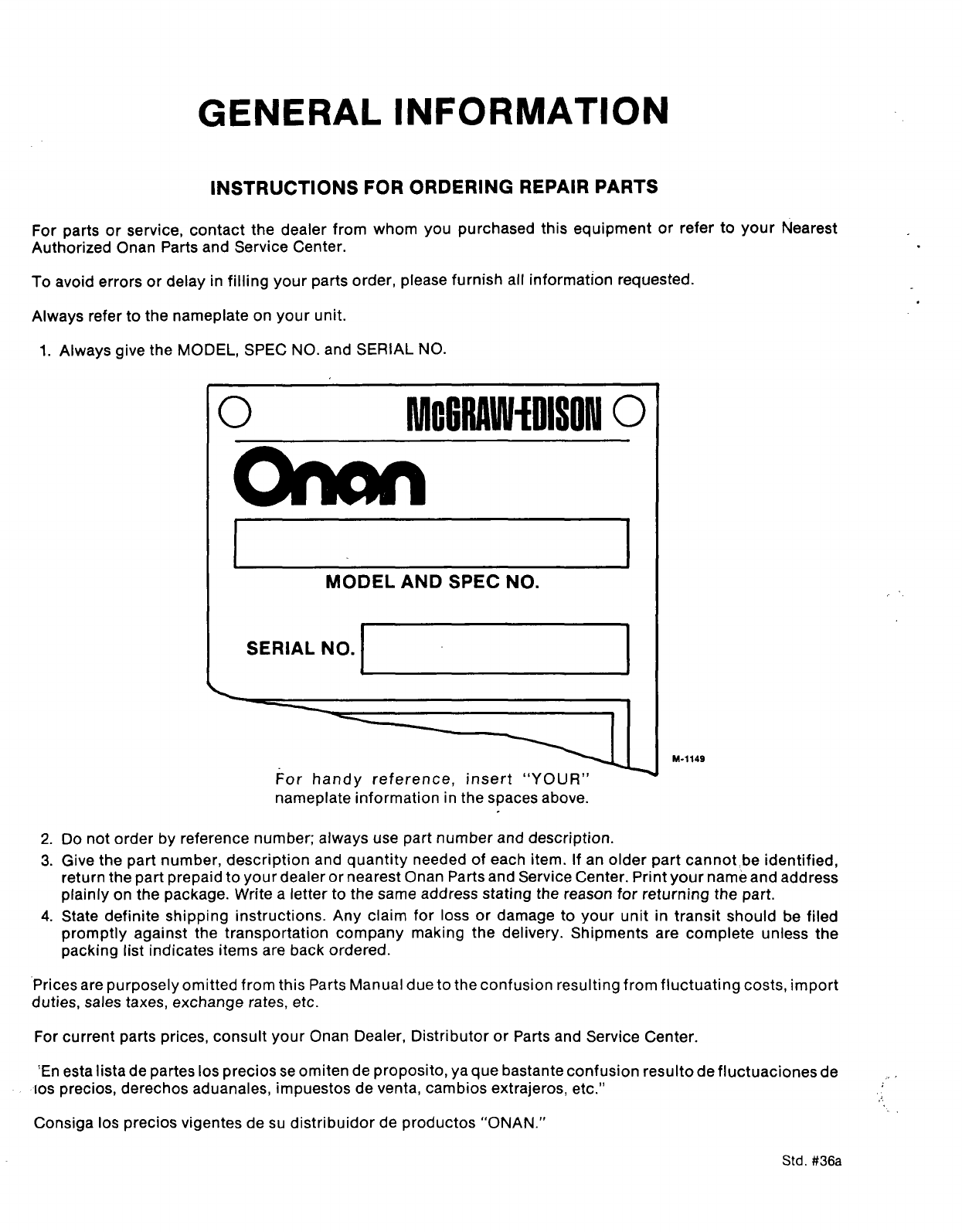
Always refer to the nameplate on your unit.
1.
2.
3.
4.
Always give the MODEL, SPEC NO. and SERIAL NO.
10 MctMllllfDISONO
II I
1I
MODEL AND SPEC NO.
ISERIAL NO.
For handy reference, insert “YOUR”
M-1149
nameplate information in the spaces above.
Do not order by reference number; always use part number and description.
Give the part number, description and quantity needed of each item. If an older part cannot be identified,
return the part prepaid to your dealer or nearest Onan Parts and Service Center. Print your name and address
plainly on the package. Write aletter to the same address stating the reason for returning the part.
State definite shipping instructions. Any claim for loss or damage to your unit in transit should be filed
promptly against” the transportation company making the delivery. Shipments are complete unless the
packing list indicates items are back ordered.
‘Prices are purposely omitted from this Parts Manual due to the confusion resulting from fluctuating costs, import
duties, sales taxes, exchange rates, etc.
For current parts prices, consult your Onan Dealer, Distributor or Parts and Service Center.
‘En esta lista de partes Ios precios se omiten de proposito, yaque bastante confusion resultode fluctuaciones de ,,,
IOS precios, derechos aduanales, impuestos de venta, cambios extrajeros, etc.” ‘,>,
Consiga Ios precios vigentes de su distribuidor de productos “ONAN.”
.,
.,
.
Std. #36a
PARTS CATALOG
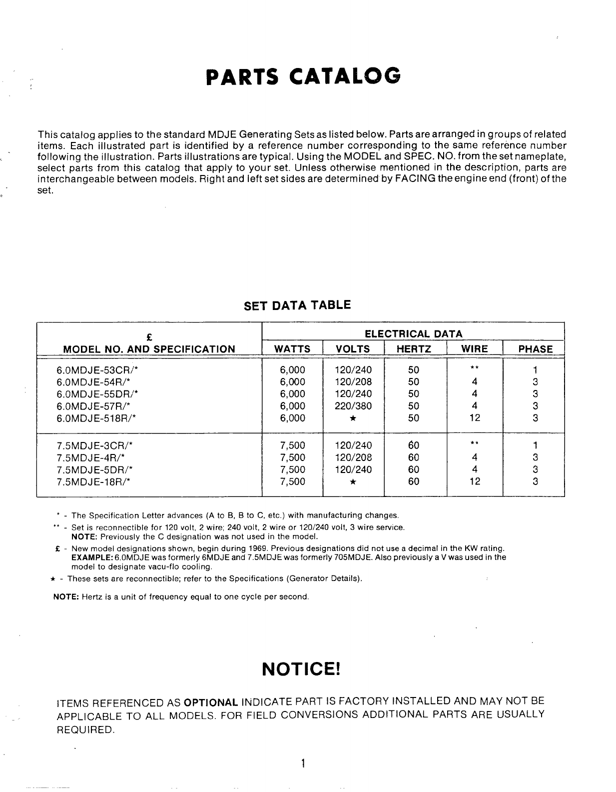
This catalog applies to the standard MDJE Generating Sets as listed below. Parts are arranged in groups of related
items. Each illustrated part is identified by areference number corresponding to the same reference number
following the illustration. Parts illustrations are typical. Using the MODEL and SPEC. NO. from the set nameplate,
select parts from this catalog that apply to your set. Unless otherwise mentioned in the description, parts are
interchangeable between models. Right and left set sides are determined by FACING the engine end (front) of the
set.
SET DATA TABLE
f
MODEL NO. AND SPECIFICATION
6. OMDJE-53CR/*
6.0 MDJE-54R/*
6.OMDJE-55DR/*
6. OMDJE-57R/*
6.OMDJE-518R/*
7.5 MDJE-3cR/*
7.5 MDJE-4R/*
7.5 MDJE-5DR/*
7.5 MDJE-18R/*
WATTS
6,000
6,000
6,000
6,000
6,000
7,500
7,500
7,500
7,500
ELECTRICAL DATA
VOLTS
120/240
120/208
120/240
220/380
*
120/240
120/208
120/240
*
HERTZ
50
50
50
50
50
60
60
60
60
WIRE
**
4
4
4
12
**
4
4
12
*-The Specification Letter advances (A to B, Bto C, etc. )with manufacturing changes.
,, -Set is reconnectable for 120 volt, 2wire; 240 volt, 2wire or 120/240 volt, 3wire service.
NOTE: Previously the Cdesignation was not used in the model.
E-New model designations shown, begin during 1969. Previous designations did not use adecimal in the KW rating.
EXAMPLE: 6. OMDJE was formerly 6MDJE and 7.5MDJE was formerly 705 MDJE. Also previously aVwas used in the
model to designate vacu-flo cooling.
*-These sets are reconnectable; refer to the Specifications (Generator Details),
NOTE: Hertz is aunit of frequency equal to one cycle per second.
NOTICE!
PHASE
—
1
3
3
3
3
1
3
3
3
ITEMS REFERENCED AS OPTIONAL INDICATE PART IS FACTORY INSTALLED AND MAY NOT BE
APPLICABLE TO ALL MODELS. FOR FIELD CONVERSIONS ADDITIONAL PARTS ARE USUALLY
REQUIRED.
1
1“3 45678
REF. PART QTY. PART ‘REF. PART
NO. NO. U5ED DESCRIPTION NO. NO.
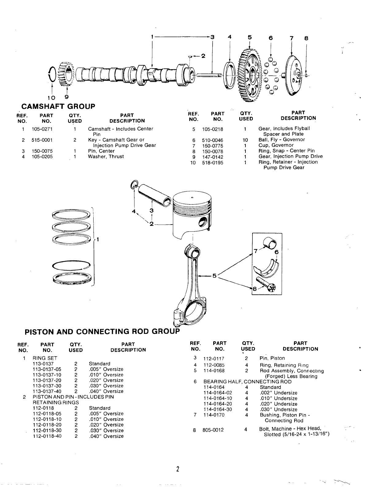
1105-0271 1Camshaft -Includes Center 5105-0218
Pin
2515-0001 2Key -Camshaft Gear or 6510-0046
Injection Pump Drive Gear 7150-0775
3150-0075 1Pin, Center
4105-0205 8150-0078
1Washer, Thrust 9147-0142
10 518-0195
PISTON AND CONNECTING ROD
REF. PART QTY. PART
NO. NO. USED DESCRIPTION
1RING SET
113-0137 2Standard
113-0137-05 2,005” Oversize
113-0137-10 2.010” Oversize
113-0137-20 2,020” Oversize
113-0137-30 2.030” Oversize
113-0137-40 2.040” Oversize
2PISTON AND PIN- INCLUDES PIN
RETAINING RINGS
112-0118 2Standard
112-0118-05 2.005” Oversize
112-0118-10 2.010” Oversize
112-0118-20 2.020” Oversize
112-0118-30 2.030” Oversize
112-0118-40 2.040” Oversize
i- I
GROUP
QTY.
USED
1
10
1
1
1
1
!
-e-
PART
DESCRIPTION
Gear, Includes Flyball
Spacer and Plate
Ball, Fly -Governor
Cup, Governor
Ring, Snap -Center Pin
Gear, Injection Pump Drive
Ring, Retainer -Injection
Pump Drive Gear
It
.,...
REF. PART QTY. PART
NO. NO. USED DESCRIPTION
,
3l12_0117 2Pin, Piston
4112-0085 4Ring, Retaining Ring
5114-0168 2Rod Assembly, Connecting
(Forged) Less Bearing
6BEARING HALF, CONNECTING ROD
114-0164 4Standard
114-0164-02 4.002” Undersize
114-0164-10 4,010” Undersize
114-0164-20 4.020” Undersize
114-0164-30 4.030” Undersize
7114-0170 4Bushing, Piston Pin -
Connecting Rod
8805-0012 4Bolt, Machine -Hex Head, .
Slotted (5/16-24 x1-13/16”)
.
. . -,. :“1,.
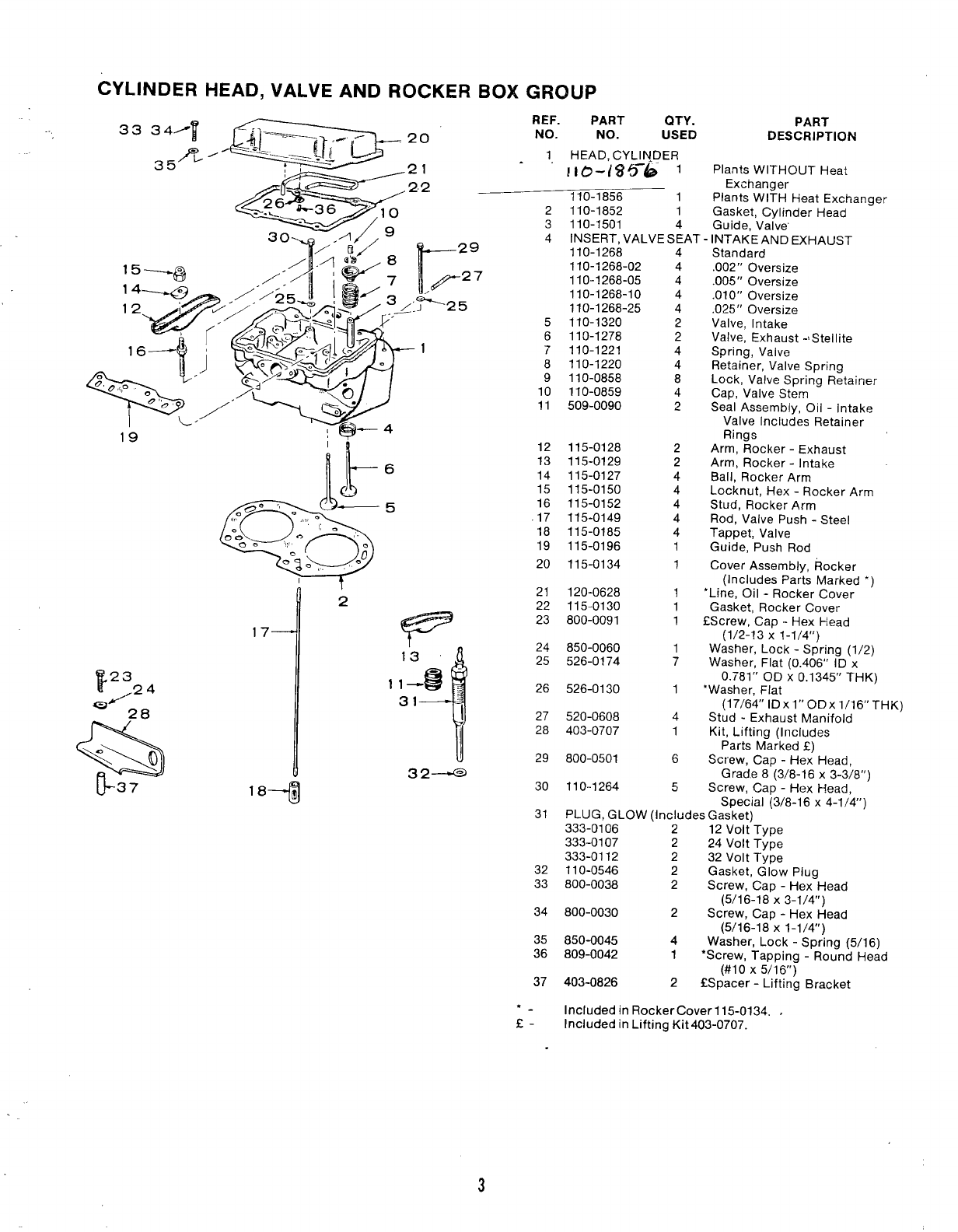
CYLINDER HEAD, VALVE AND ROCKER BOX GROUP
In
5
F
4
13
$
11—-
31 I
32~
18+
REF. PART QTY.
NO. NO. USED
1HEAD, CYL~NDER
. . [16-/$56 1
110-1856 1
2
3
4
5
6
7
8
9
10
11
12
13
14
15
16
.17
18
19
20
21
22
23
24
25
26
27
28
29
30
31
32
33
34
35
36
37
*-
E-
110-1852 1
110-1501 4
INSERT, VALVE SEAT
110-1268
110-1268-02
110-1268-05
110-1268-10
110-1268-25
110-1320
110-1278
110-1221
110-1220
110-0858
110-0859
509-0090
115-0128
115-0129
115-0127
115-0150
115-0152
115-0149
115-0185
115-0196
115-0134
120-0628
115-0130
800-0091
850-0060
526-0174
526-0130
520-0608
403-0707
800-0501
110-1264
4
4
4
4
4
2
2
4
4
8
4
2
2
2
4
4
4
4
4
1
1
1
1
1
1
7
1
4
1
6
5
PART
DESCRIPTION
Plants WITHOUT Heat
Exchanger
Plants WITH HeatExchanger
Gasket, Cylinder Head
Guide, Valve’
INTAKEANDEXHAUST
Standard
.002” Oversize
.005” Oversize
.010” Oversize
.025” Oversize
Valve, Intake
Valve, Exhaust -lStellite
Spring, Valve
Retainer, Valve Spring
Lock, Valve Spting Retainer
Cap, Valve Stem
Seal Assembly, Oil -Intake
Valve Includes Retainer
Rings
Arm, Rocker-Exhaust
Arm, Rocker-Intake
Ball, Rocker Arm
Locknut, Hex -Rocker Arm
Stud, Rocker Arm
Rod, Valve Push -Steel
Tappet, Valve
Guide, Push Rod
Cover Assembly, Rocker
(Includes Parts Marked ‘)
‘Line, Oil -Rocker Cover
Gasket, Rocker Cover
fScrew, Cap -Hex Head
(1/2-13 X1-1/4”)
Washer, Lock-Spring (1/2)
Washer, Flat (0.406” IDx
0.781” OD X0.1345” THK)
‘Washer, Flat
(17/64’’ lDxl’’ODx 16lTHK)HK)
Stud -Exhaust Manifold
Kit, Lifting (Includes
Parts Marked E)
Sct”ew, Cap -Hex Head,
Grade 8(3/8-16 x3-3/8”)
Screw, Cap -Hex Head,
Special (3/8-16 x4-1/4”)
PLUG, GLOW (Includes Gasket)
333-0106 212 Volt Type
333-0107 224 Volt Type
333-0112 232 Volt Type
110-0546 2Gasket, Glow Plug
800-0038 2Screw, Cap -Hex Head
(5/16-18 X3-1/4”)
800-0030 2Screw, Cap -Hex Head
(5/16-18 X1-1/4”)
850-0045 4Washer, Lock -Spring (5/16)
809-0042 1*Screw, Tapping -Round Head
(#10 X5/16”)
403-0826 2CSpacer -Lifting Bracket
Included in Rocker Cover 115-0134. ,
Included in Lifting Kit403-0707.
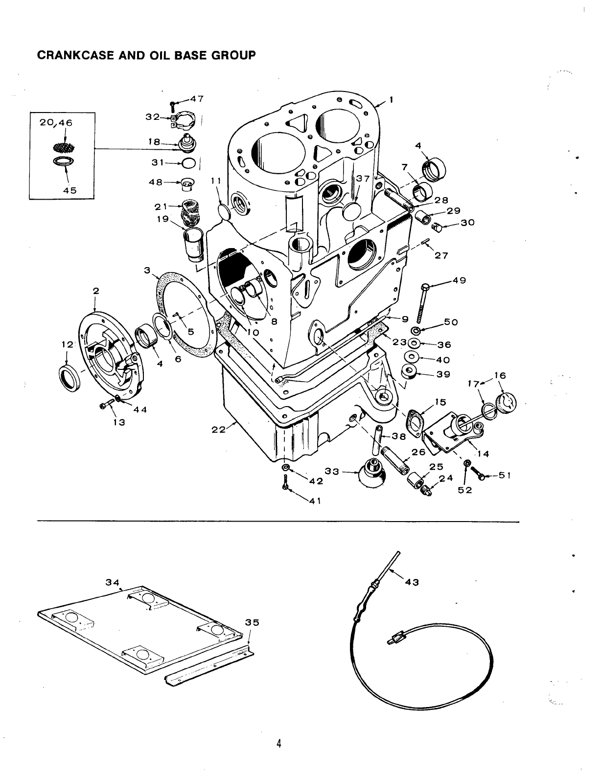
CRANKCASE AND OIL BASE GROUP
.,. -
21——
19\
3
2
\—
\41 ‘w 52
.
. .
.
.
REF. ”
NO.
3
4
5
6
“7
8
9
10
11
12
13
14
15
16
17
18
19
20
21
22
23
24
25
26
27
PART QTY. PART
NO. USED DESCRIPTION
110-1664 1Block Assembly, Cylinder
(Includes Parts Marked *)
101-0337 1‘Plate, Bearing -Less
Bearing and Pin
101-0386 1‘Gasket and Shim Kit, Rear
Bearing Plate
BEARING, PRECISION, MAIN -FRONT OR REAR
101-0359 2Standard
101-0359-02 2.002” Undersize
101-0359-10 2.010” Undersize
101-0359-20 2.020” Undersize
101-0359-30 2.030” Undersize
516-0072 4●Pin, Lock -Thrust Washer
104-0420 2*Washer, Crankshaft Thrust
101-0363 1*Bearing, Precision Cam -
Front -Standard Only
101-0365 1*Bearing, Precision Cam -
Rear -Standard Only
120-0553 1*Tube, Crankcase Oil
517-0053 1“Plug, Expansion -Rear
Camshaft Opening
517-0059 3●Plug, Expansion -Cylinder
Block (1-7/16”)
509-0086 Seal, ‘Oil -Rear Bearing
1’ Plate
805-0019 6●Bolt, Place -Rear Bearing
Plate (3/8-16 x1-1/4”)
TUBE, OIL FILL
123-0681 1Spec AOnly
123-1 0S5 1Begin Spec B
123-0667 1Gasket, Oil Fill Tube
Mounting
CAP AND INDICATOR, OIL FILL
123-0651 1Spec AOnly ,
123-1058 1Begin Spec B
123-0191 1Gasket, Oil Fill Cap
123-1203 1Cap and Valve, Breather Tube
123-0952 1Tube, Breather
123-0958 1Screen, Breather -Used on
some early Models
123-0865 1Baffle, Breather Tube
102-0540 1Base, Oil
102-0451 1Gasket, Oil Base
505-0056 1Plug, 1/2”
505-0014 1Coupling, 1/2”
505-0002 1Nipple, I/2 x3“
516-0141 2●Pin, Dowel -Gear Cover
Locating
REF. PART QTY. PART
NO. NO. USED DESCRIPTION
28 505-0449 1Nipple, 1/4 x6“
29 505-0027 1Coupling, 114”
30 502-0153 1Plug, 1/4” Hex Head
31 509-0117 1Seal, “O” Ring -Breather
Cap
32 123-0951 1,Clamp, Breather Cap
33 CUSHION, VIBRATION’- CONE SHAPED
402-0284
402-0285
34 405-1402
35 405-1265
36 526-0014
37 517-0096
38 402-0290
39 402-0282
40 526-0198
2Engine End
2Generator End
1Pan, Drip
2Clamp, Drip Pan Hold-Down
4●Washer, Mounting Rubber -
Steel
1●Plug, Expansion -Cylinder
Block (1-9/16’)
4●Bushing, Cushion Mounting
Spacer
4.. Snubber, Shock Mcunting
As Rea. ●Washer. (29/64” I.D. x
1-1/2;’ ‘O.D. X1/16”)
41
42
43
44
45
46
47
48
49
50
51
52
800-0072
850-0055
102-0558
526-0245
123-1201
123-1202
809-0035
123-1153
800-0081
850-0055
800-0026
850-0045
4
4
1
6
1
1
,1
1
4
4
3
3
Screw, Cap -Hex Head
(7/16-14 X1-1/4”)
Washer, Lock -Spring (7/16)
Heater, Oil Base -Optional
*Washer, Flat (0.391” ID x
0,625” OD X0.598” THK)
Retainer -Breather Screen
Screen -Breather Cap —
Screw, Tapping -Round Head
(#8 X3/4”)
Baffle -Breather Tube
●Screw, Cap -Hex Head
(7/16-14 X3-1/2”)
●Washer, Lock -Spring (7/16)
Screw, Cap -Hex Head
(5/16-18 X3/4”)
Washer, Lock -Spring (5/16)
●-Included in 402-0360 Mounting Hardware Set.
●-Included in 110-1664 Cylinder Block Assembly.
1Line, Oil -Injection Pump
Tee to Cylinder Head
@,* “’”’
!‘
-17
/16
&
‘% ‘
REARP::;:ING r
7
t
21
,,
L
20
,
/.
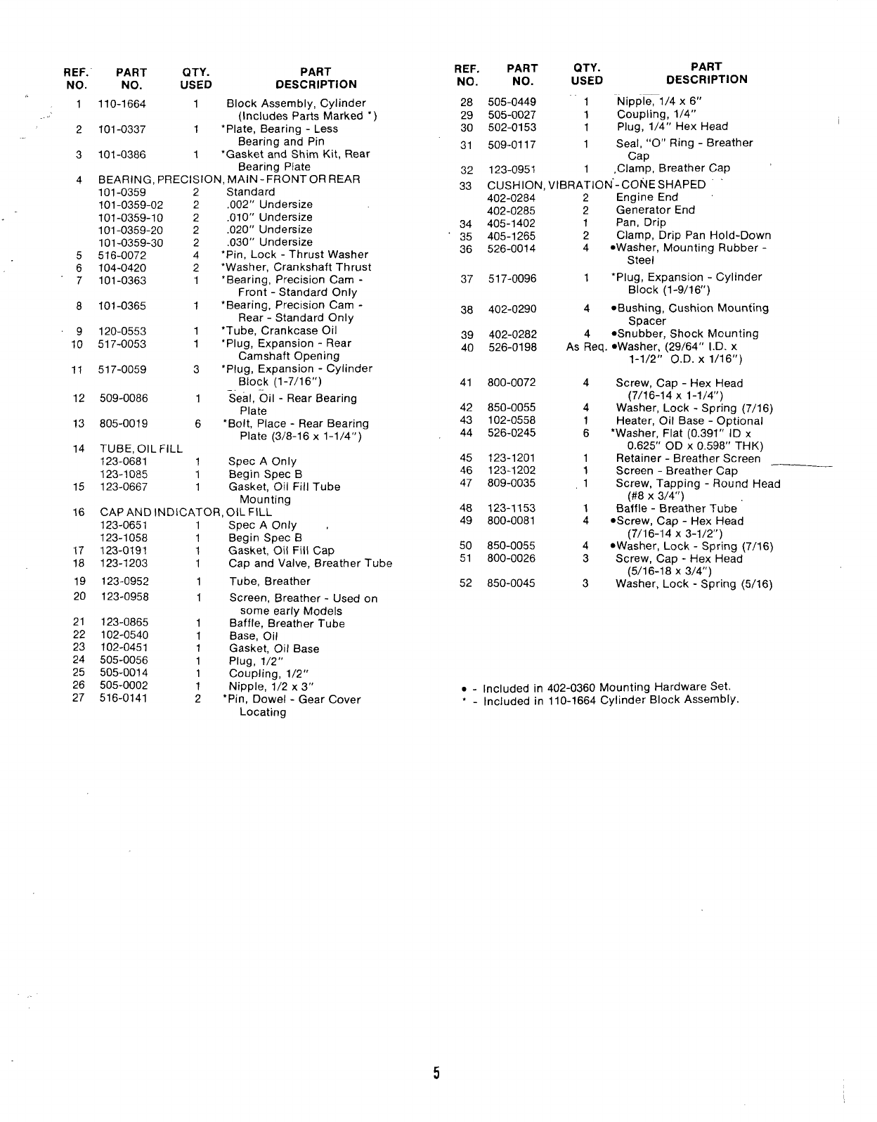
OIL SYSTEM GROUP
REF. PART
NO. NO.
1120-0547
2120-0580
3120-0551
4122-0185
5122-0188
6122-0182
7193-0006
8502-0053
9505-0057
10 502-0037
11 120-0636
12 502-0274
13 502-0242
14 12Q-0631
QTY.
USED
1
1
1
1
1
1
1
1
1
1
1
1
1-
-.
PART
DESCRIPTION
Pump Assembly, Oil
Gasket Kit, Oil Pump
Cup Assembly, Oil Pump
Intake
Filter, Oil
Gasket, Filter Adapter
Adapter Assembly, Filter
Gauge, Oil Pressure
Elbow, Street -45°
(NOTE: Quantity of 2Used
Prior to Spec B)
Plug, 1/8” -Filter Adapter
Elbow, Inverted Male -Oil
Line to Oil Filter Adapter
Line, Oil -Adapter to Tee
Connector, Restricted -
Injection Pump Tee
Tee, Restricted -Injection
PumD Lubrication
REF. PART
NO. NO.
15 502-0281
16 120-0539
17 120-0555
18 505-0274
19 309-0169
20 501-0003
21 502-0003
22 502-0058
23 800-0028
24 850-0045
25 800-0030
26 850-0045
27 502-0037
‘23
QTY. PART
USED DESCRIPTION
1
1
1
1
1
1
1
1
3
3
2
2
1
Connector, Restricted -Oil
Line to Cylinder Head
Valve, Oil By-Pass
Spring, By-Pass Valve
Plug, Oil By-Pass
Switch, LOW Oil pressure
cut-off
Line, Oil -Begin Spec B
Connector, Oil Fill Bracket
to Oil Line -Begin Spec B
Tee, Oil Fill Bracket to
Gauge and Switch -Begin
Spec B
‘“ Screw, Cap -Hex Head
(5/16-18 Xl“)
Washer, Lock -Spring (5/16)
Screw, Cap -Hex Head
(5/16-18 X1-1/4’)
Washer, Lock -Spring (5/16)
Elbow, Injection Pump to
Lubrication Tee
E
716
I
1’1 ]2
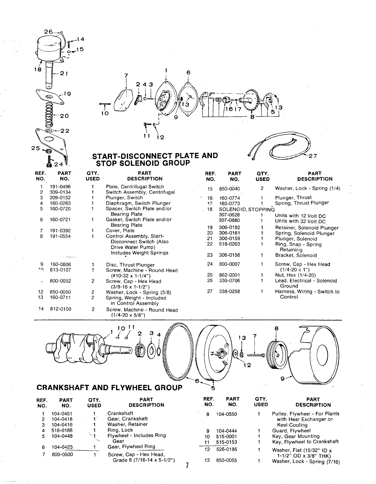
START-DISCONNECT PLATE AND
STOP SOLENOID GROUP B27
PART
DESCRIPTION
Plate, Centrifugal Switch
Switch Assembly, Centrifugal
Plunger, Switch
Diaphragm, Switch Plunger
Spacer, Switch Plate and/or
Bearing Plate
Gasket, Switch Plate and/or
Bearing Plate
Cover, Plate
Control Assembly, Start-
DisconnectSwitch (Also
Drive Water Pump)
Includes Weight Springs
.
REF. PART QTY. PART
NO. NO. USED DESCRIPTION
15 850-0040 2Washer, Lock -Spring (1/4)
‘16 160-0774 1Plunger, Thrust
17 160-0773 1Spring, Thrust Plunger
18 SOLENOID, STOPPING
307-0628 1Units with 12 Volt DC
307-0680 1Units with 32 Volt DC
19 306-0162 1Retainer, Solenoid Plunger
20 306-0161 1Spring, Solenoid Plunger
21 306-0159 1Plunger, Solenoid
22 518-0203 1Ring, Snap -Spring
Retaining
23 306-0158 1Bracket, Solenoid
24 800-0007 1Screw, Cap -Hex Head
(1/4-20 xl“)
25 862-0001 1Nut, Hex (1/4-20)
26 336-0706 1Lead, Electrical -Solenoid
Ground
27 338-0258 1Harness, Wiring -Switch to
Control
REF. PART
NO. NO.
QTY.
USED
1191-0496
2309-0134
3309-0152
4160-0263
5160-0720
1
1
1
1
1
6160-0721 1
7191-0392
8191-0554
1
1
9160-0806
‘~ 813-0107
1
1
Disc, Thrust Plunger
Screw, Machine -Round Head
(#10-32 X1-1/4”)
Screw, Cap -Hex Head
(3/8-16 X1-1/2”)
Washer, Lock -Spring (3/8)
Spring, Weight -Included
in Control Assembly
Screw, Machine -Round Head
(1/4-20 X5/8”)
800-0052 2
12 850-0050
13 160-0711
2
2
14 812-0150 2
—–( f
,jo)12
W@-’o
——w
.- —. —~
—b
0
—=,-—~
CRANKSHAFT AND FLYWHEEL GROUP ‘5
PART REF. PART QTY.
DESCRIPTION NO. NO. USED
PART
REF.
NO.
1
2
3
4
5
PART QTY.
NO. USED DESCRIPTION
Crankshaft 8104-0550 1
Gear, Crankshaft
Washer, Retainer
Ring, Lock
Flywheel -Includes Ring 9104-0444 1
10 515-0001 1
104-0451 1
104-0418 1’
104-0416 1
518-0188 1
104-0448 ‘\, ,
.,
Pulley, Flywheel -For Plants
with Heat Exchanger or
Keel Cooling
Guard, Flywheel
Key, Gear Mounting
Key, Flywheel to Crankshaft
Gear 11 515-0153 1
Gear, Flywheel Ring 12 526-0185 1
Screw, Cap -Hex Head,
Grade 8(7/16-14 x5-1/2”) 13 850-0055
71
6
7
104-0423 1
800-0500 1Washer, Flat (15/32” ID x
1-1/2” OD X3/8” THK)
Washer, Lock -Spring (7/16)
REF. PART QTY. PART -.
REF. PART QTY. PART
NO. NO. USED DESCRIPTION NO. NO. USED DESCRIPTION
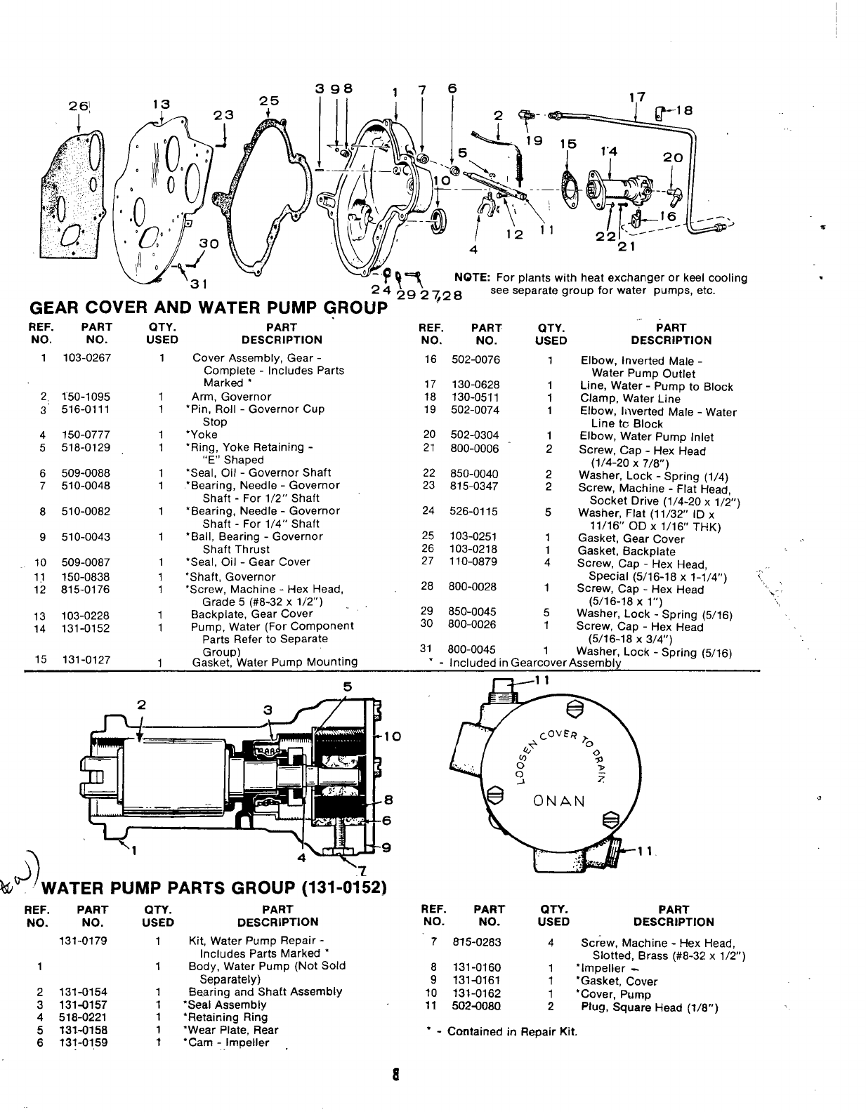
1103-0267 1Cover Assembly, Gear -
Complete -Includes Parts
Marked *
Arm, Governor
“Pin, Roll -Governor Cup
stop
*Yoke
“Ring, Yoke Retaining -
“E” Shaped
●Seal, C)il -Governor Shaft
‘Bearing, Needle -Governor
Shaft -For 1/2” Shaft
*Bearing, Needle -Governor
Shaft -For 1/4” Shaft
‘Ball, Bearing -Governor
Shaft Thrust
‘Seal, Oil -Gear Cover
16 502-0076 1Elbow, Inverted Male -
Water Pump Outlet
Line, Water -Pump to Block
Clamp, Water Line
Elbow, ll~verted Male -Water
Line tc Block
Elbow, Water Pump Inlet
Screw, Cap -Hex Head
(1/4-20 X7/8”)
Washer, Lock -Spring (1/4)
Screw, Machine -Flat Head,
Socket Drive (1/4-20 x1/2”)
Washer, Flat (1 1/32” ID x
11/16” OD X1/16” THK)
Gasket, Gear Cover ...
Gasket, Backplate
Screw, Cap -Hex Head,
Special (5/16-18 xl-I/4’1) ‘~,
Screw, Cap -Hex Head -, ‘.
(5/16-18 Xl“) ,,,
Washer, Lock -Spring (5/16)
Screw, Cap -Hex Head
(5/16-18 X3/4”)
17 130-0628
18 130-0511
19 502-0074
1
1
1
2,
3’
150-1095
516-0111
1
1
20 502-0304
21 800-0006
4
5
150-0777
518-0129
1
1
1
2
6
7
509-0088
510-0048
1
1
22 850-0040
23 815-0347 2
2
8510-0082 124 526-0115 5
9510-0043 125 103-0251
26 103-0218
27 110-0879
1
1
4
10
11
12
509-0087
150-0838
815-0176
1
1
1‘Shaft, Governor
‘Screw, Machine -Hex Head, 28 800-0028 1
Grade 5(#8-32 x1/2”) .
Backpiate, Gear COver 29 850-0045 5
Pump, Water (For Component 30 800-0026 1
Parts Refer to Separate
Group) 31 800-0045 1Washer, Lock -Spring (5/16)
Gasket, Water Pump Mounting *-Included in Gearcover Assembly
13
14
103-0228
131-0152
1
1
15 131-0127 1
5
10
8
6
9
W6J~WATER PUMP PARTS GROUP (131 -01;2)
REF.
NO.
PART
NO.
131-0179
QTY. PART
USED DESCRIPTION
1Kit, Water Pump Repair -
Includes Parts Marked ‘
1Body, Water Pump (Not Sold
Separately)
1Bearing and Shaft Assembly
1●Seal Assembly
1●Retaining Ring
1●Wear Plate, Rear
?“Cam -impeller .
REF. PART QTY.
NO. NO. USED
7W5-0283 4
8131-0160 1
9131-0161 1
10 131-0162 1
11 502-0080 2
PART
DESCRIPTION
Screw, Machine -Hex Head,
Slotted, Brass (#8-32 x1/2”)
“Impeller -
*Gasket, Cover
*Cover, Pump
plug, Square Head (?/8”)
1
2
3
4
5
6
131-0154
131-0157
518-0221
131-0158
131-0159 “ - Contained in Repair Kit.
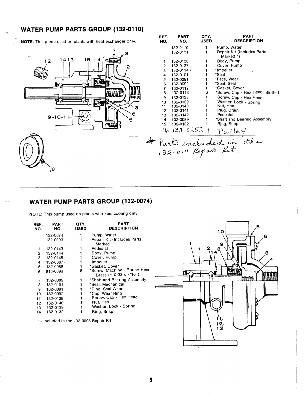
WATER PUMP PARTS GROUP (132-0110)
REF. PART
NOTE: This pump used on plants with heat exchanger only. NO. NO.
:132-0110
,8 132-0111
QTY. PART
USED DESCRIPTION
1
1
1132-0136 1
2132-0137 1
3132-0114” 1
4132-0101 1
5132-0091 1
6132-0092 1
7132-0112 1
8132-0113 6
9132-0138 1
10 132-0139 1
11 132-0140 1
12 132-0141 1
13 132-0142 1
14 132-0089 1
15 132-0132
lb 13.2-0/252 ‘1
Pump, Water
ReDair Kit (Includes’ Patis
Marked ●’)
Body, Pump
Cover, Pump
“Impeller
*Seal
“Face, Wear
“Seat, Seal
*Gasket, Cover
*Screw, Cap -Hex Head, Slotted
Screw, Cap -Hex Head
Plug, Drain
Pedestal
‘Shaft and Bearing Assembly
RJng, Snap
WATER PUMP PARTS GROUP (132-0074)
NOTE: This pump used on plants with keel cooling only.
REF.
NO.
1
2
3
4
5
6
7
8
9
10
11
12
;:
PART
NO.
132-0074
132-0093
132-0143
132-0144
132-0145
132-0087.
132-0088
810-0099
132-0089
132-0101
132-0091
132-0092
132-0138
132-0140
132-0139
132-0132
‘-Included in the
1
1
1
1
1
1
1
8
1
1
1
1
1
1
1
1
QTY. PART
USED DESCRIPTION
Pump, Water
Repair Kit (Includes Parts
Marked *)
Pedestal
Body, Pump
Cover, Pump
Impeller
‘Gasket, Cover
‘Screw, Machine -Round Head,
Brass (#1 O-32 X7/1 6“)
*Shaft and Bearing Assembly
‘Seal, Mechanical
●Ring, Seal Wear
*Cap, Wear Ring
Screw, Cap -Hex Head
Nut, Hex
Washer, Lock -SPrin9
Ring, Snap
132-0093 Repair Kit.
9
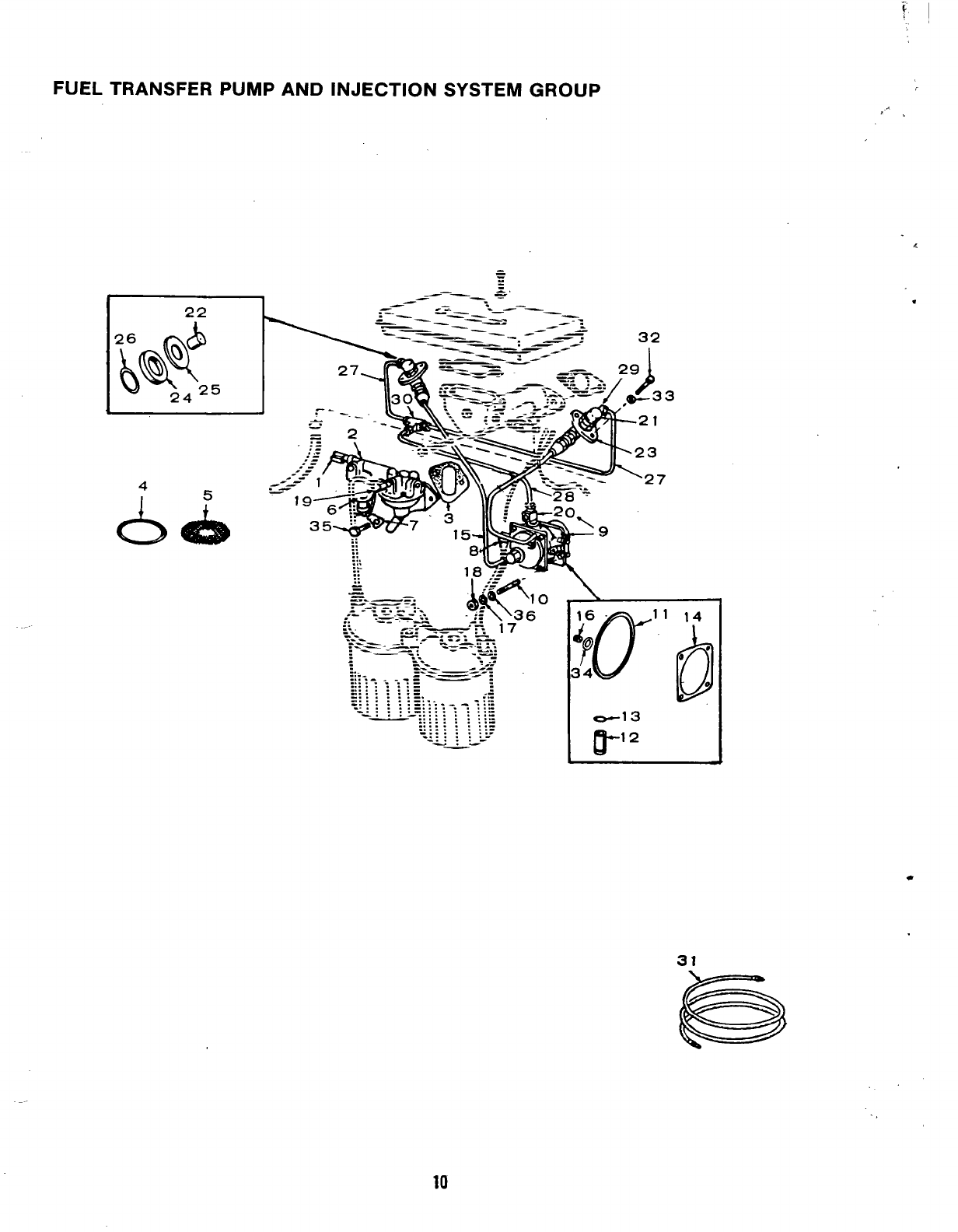
FUEL TRANSFER PUMP AND INJECTION SYSTEM GROUP
,’.
*
0
e
REF;
:\ NO.
!. -,,
1
2
3
4
-. 5
6
7
8
9
10
11
12
13
14
15
16
PART QTY. PART
NO. USED DESCRIPTION
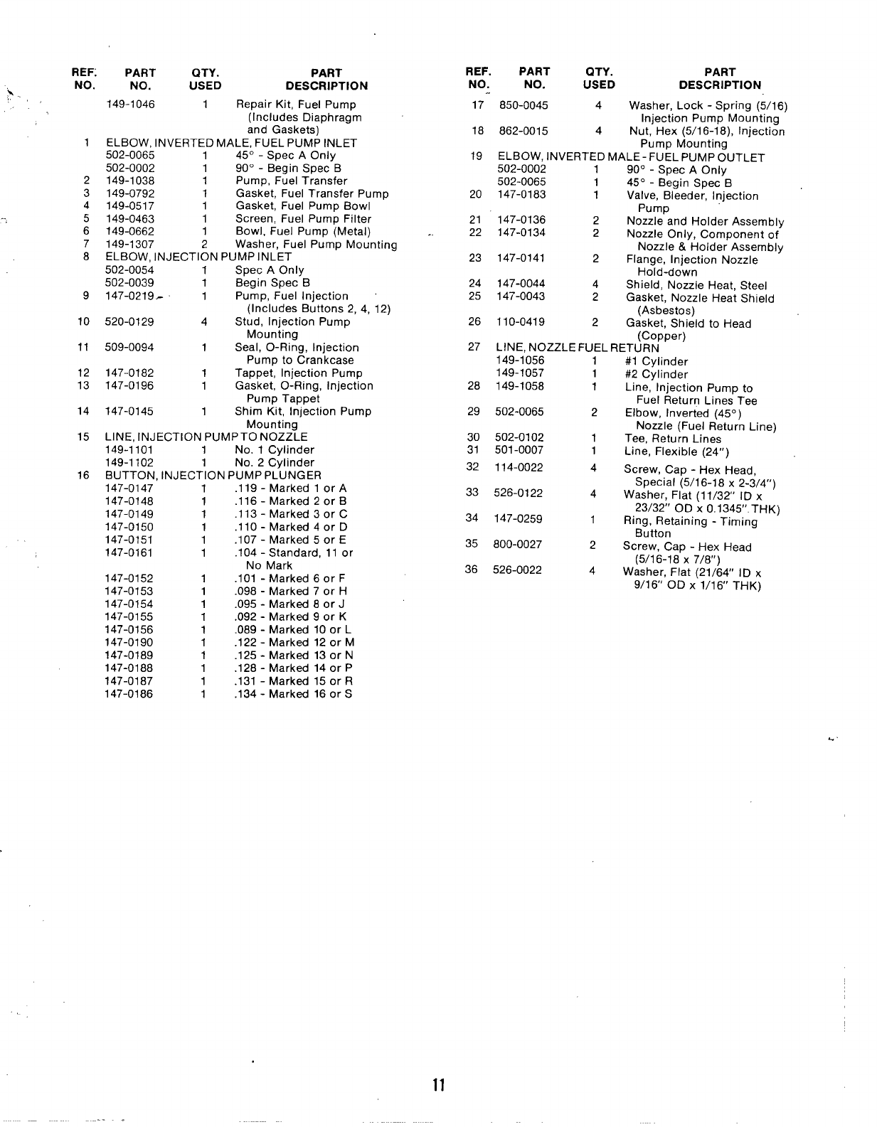
149-1046 1Repair Kit, Fuel Pump
(Includes Diaphragm
and Gaskets)
ELBOW, INVERTED MALE, FUEL PUMP INLET
502-0065 145°- Spec AOnly
502-0002 190°- Begin Spec B
149-1038 1Pump, Fuel Transfer
149-0792 1Gasket, Fuel Transfer Pump
149-0517 1Gasket, Fuel Pump Bowl
149-0463 1Screen, Fuel Pump Filter
149-0662 1Bowl, Fuel Pump (Metal)
149-1307 2Washer, Fuel Pump Mounting
ELBOW, INJECTION PUMP INLET
502-0054 1Spec AOnly
502-0039 1Begin Spec B
147-0219- 1Pump, Fuel Injection
(Includes Buttons 2,4, 12)
520-0129 4Stud, Injection Pump
Mounting
509-0094 1Seal, O-Ring, Injection
Pump to Crankcase
147-0182 1Tappet, Injection Pump
147-0196 1Gasket, O-Ring, injection
Pump Tappet
147-0145 1Shim Kit, Injection Pump
Mounting
LINE, INJECTION PUMP TO NOZZLE
149-1101 1No. 1Cylinder
149-1102 1No, 2Cylinder
BUTTON, INJECTION PUMP PLUNGER
147-0147 1.119 -Marked 1or A
147-0148 1.116 -Marked 2or B
147-0149 1.113 -Marked 3or C
147-0150 1.110 -Marked 4or D
147-0151 1.107 -Marked 5or E
147-0161 1.104 -Standard, 11 or
No Mark
147-0152 1.101 -Marked 6or F
147-0153 1.098 -Marked 7or H
147-0154 1.095 -Marked 8or J
147-0155 1.092 -Marked 9or K
147-0156 1.089 -Marked 10 or L
147-0190 1.122 -Marked 12 or M
147-0189 1.125 -Marked 13 or N
147-0188 1.128 -Marked 14 or P
147-0187 1.131 -Marked 15 or R
147-0186 1.134 -Marked 16 orS
--
REF. PART QTY. PART
NO. NO. USED DESCRIPTION
..
17 850-0045 4Washer, Lock -Spring (5/16)
Injection Pump Mounting
18 862-0015 4Nut, Hex (5/16-18), Injection
Pump Mounting
19 ELBOW, INVERTED MALE- FUEL PUMP OUTLET
502-0002 190°- Spec AOnly
502-0065 145°- Begin Spec B
20 147-0183 1Valve, Bleeder, Injection
Pump
21 147-0136 2Nozzle and Holder Assembly
22 147-0134 2Nozzle Only, Component of
Nozzle &Holder Assembly
23 147-0141 2Flange, Injection Nozzle
Hold-down
24 147-0044 4Shield, Nozzle Heat, Steel
25 14?-0043 2Gasket, Nozzle Heat Shield
(Asbestos)
26 110-0419 2Gasket, Shield to Head
(Copper)
27 LINE, NOZZLE FUEL RETURN
149-1056
149-1057
28 149-1058
29 502-0065
30 502-0102
31 501-0007
32 114-0022
33 526-0122
34 147-0259
35 800-0027
36 526-0022
1
1
1
2
1
1
4
4
1
2
4
#1 Cylinder
#2 Cylinder
Line, Injection Pump to
Fuel Return Lines Tee
Elbow, Inverted (45°)
Nozzle (Fuel Return Line)
Tee, Return Lines
Line, Flexible (24’I)
Screw, Cap -Hex Head,
Special (5/16-18 x2-3/4”)
Washer, Flat (1 1/32’ ID x
23/32” OD X0,1345”, THK)
Ring, Retaining -Timing
Button
Screw, Cap -Hex Head
(5/16-18 X7/8”)
Washer, Flat (21/64” ID x
9/16” OD X1/16’ THK)
11
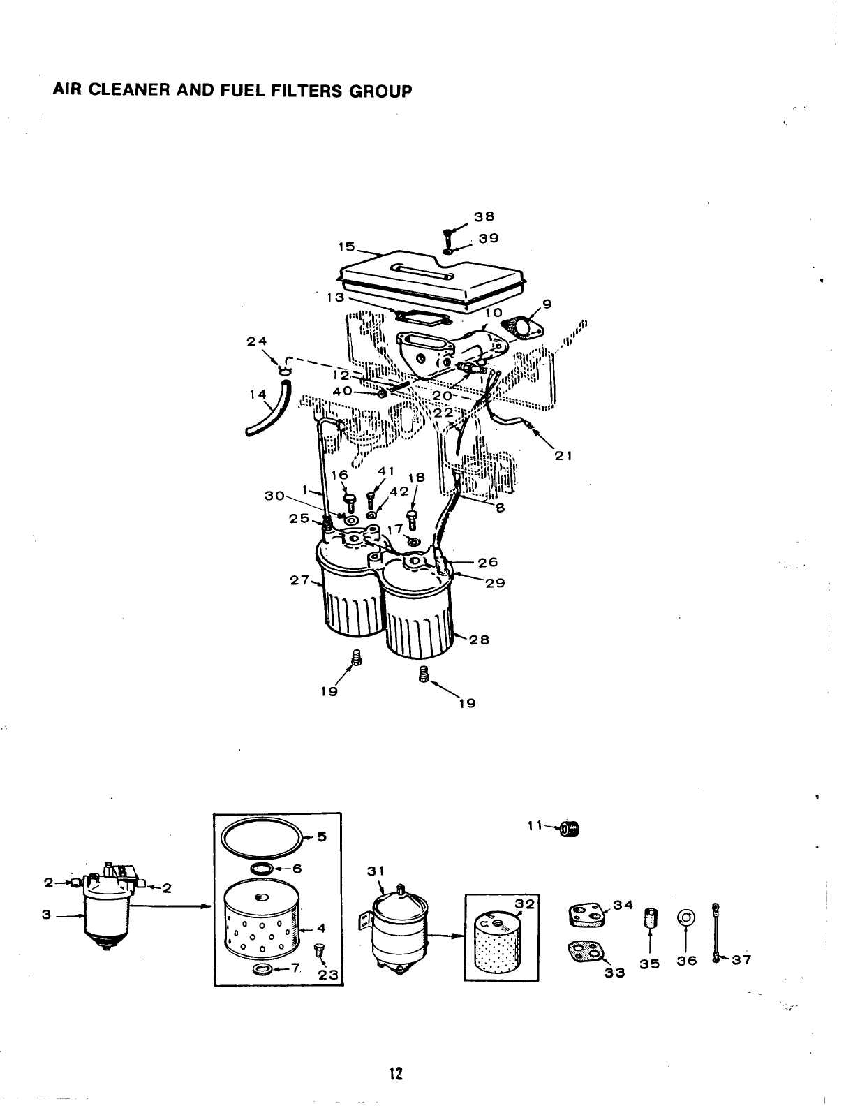
AIR CLEANER AND FUEL FILTERS GROUP
38
*
2’ , . -2
3
31
... ,
.,. .
.,
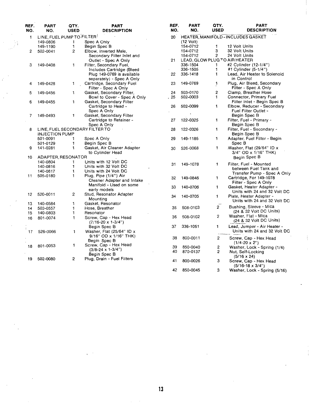
REF.
NO.
1
2
3
4
5
6
7
8
9
10
PART QTY. PART
NO. USED DESCRIPTION
LINE, FUEL PUMP TOFILTERI
149-0806 1Spec AOnly
149-1190 1Begin Spec B
502-0041 2Elbow, Inverted Male,
Secondary Filter Inlet and
Outlet -Spec AOnly
149-0408 1Filter, Secondary Fuel,
Includes Cartridge (Bleed
Plug 149-0769 is available
separately) -Spec AOnly
149-0428 1Cartridge, Secondary Fuel
Filter -Spec AOnly
149-0456 1Gasket, Secondary Filter,
Bowl to Cover -Spec AOnly
149-0455 1Gasket, Secondary Filter
Cartridge to Head -
Spec AOnly
149-0493 1Gasket, Secondary Filter
Cartridge to Retainer -
Spec AOnly
LINE, FUEL SECONDARY FILTER TO
INJECTION PUMP
501-0091 1Spec AOnly
501-0129 1Begin Spec B
141-0281 1Gasket, Air Cleaner Adapter
to Cylinder Head
ADAPTER, RESONATOR
140-0804
140-0816
140-0817
11 505-0180
12 520-0011
13 140-0584
14 503-0557
15 140-0803
16 801-0074
17 526-0066
18 801-0053
19 502-0080
1
1
1
1
2
1
1
1
1
1
1
2
Units with 12 Volt DC
Units with 32 Volt DC
Units with 24 Volt DC
Plug, Pipe (1/4”) Air
Cleaner Adapter and Intake
Manifold -Used on some
early models
Stud, Resonator Adapter
Mounting
Gasket, Resonator
Hose, Breather
Resonator
Screw, Cap -Hex Head
(7/16-20 X1-3/4’)
Begin Spec B
Washer, Flat (25/64” ID x
9/16” OD X1/16” THK)
Begin Spec B
Screw, Cap -Hex Head
(3/8-24 X1-3/4”)
Begin Spec B
Plug, Drain -Fuel Filters
REF.
NO.
20
21
22
23
24
25
26
27
28
29
30
31
32
33
34
35
36
37
38
39
40
41
42
PART QTY. PART
NO. USED DESCRIPTION
.—— —
HEATER, MANIFOLD -INCLUDES GASKET “-
(12 volt)
154-0712 112 Volt Units
154-0712 3 32 Volt Units
154-0712 2 24 Volt Units
LEAD, GLOW PLUG TO AIR HEATER
336-1504
336-1505
336-1418
149-0769
503-0170
502-0003
502-0099
122-0325
122-0326
149-1185
526-0068
149-1078
149-0846
140-0706
140-0705
508-0103
508-0102
336-1051
800-0011
850-0040
870-0137
800-0026
850-0045
1
1
1
1
2
1
1
1
1
1
1
1
1
1
1
—.
2
2
1
#2 Cylinder (12-1/4”)
#1 Cylinder (5-1/4”)
Lead, Air Heater to Solenoid
in Control
Plug, Air Bleed, Secondary
Filter -Spec AOnly
Clamp, Breather Hose
Connector, Primaty Fuel
Filter Inlet -Begin Spec B
Elbow, Reducer -Secondary
Fuel Filter Outlet -
Begin Spec B
Filter, Fuel -Primary -
Begin Spec B
Filter, Fuel -Secondary -
Begin Spec B
Adapter, Fuel Filter -Begin
Spec B
.Washer, Flat (29/64’ ID x
3/4” OD X1/16” THK)
Begin SpeC B
Filter, Fuel -Mounted
between Fuel Tank and
Transfer Pump -Spec AOnly
Cartridge, For 149-1078
Filter -Spec AOnly
Gasket, Heater Adapter -
Units with 24 and 32 Volt DC
Plate, Heater Adapter -
Units with 24 and 32 Volt DC
Bushing, Sleeve -Mica
(24 &32 Volt DC Units)
Washer, Flat -Mica
(24 &32 Volt DC Units)
Lead. JumIJer -Air Heater -
Units wi{h 24 and 32 Volt DC
. .. ... ___
2Screw, Cap -Hex Head
(1/4-20 X2“)
2Washer, Lock -Spring (1/4)
2Nut, Self-Locking
(5/16 X24)
3Screw, Cap -Hex Head
(5/16-18 X3/4)
3Washer, Lock -Spring (5/16)
13
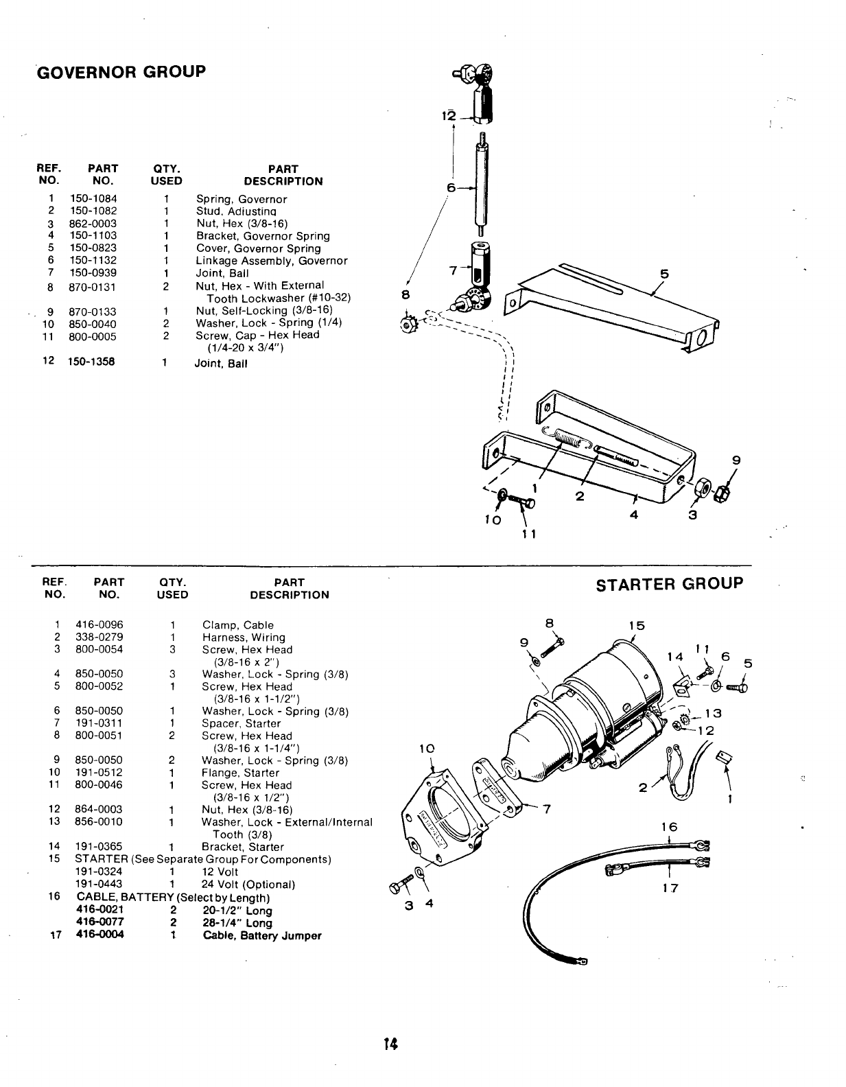
GOVERNOR GROUP
REF. PART QTY.
USED
1
1
1
1
1
1
1
2
1
2
2
1
PART
DESCRIPTION
Spring, Governor
Stud. Adiustina
Nut, Hex (3/8-16)
Bracket, Governor Spring
Cover, Governor Spring
Linkage Assembly, Governor
Joint, Ball
Nut, Hex -With External
Tooth Lockwasher (#1 O-32)
Nut, Self-Locking (3/8-16)
Washer, Lock -Spring (1/4)
Screw, Cap -Hex Head
(1/4-20 X3/4”)
NO. NO.
1150-1084
2150-1082
3862-0003
4150-1103
5150-0823
6150-1132
7150-0939
8870-0131
9870-0133
10 850-0040
11 800-0005
12 150-1358 Joi’nt, Ball ,!
l’;
11
REF. PART QTY. PART
NO. NO. USED DESCRIPTION STARTER GROUP
1
2
3
416-0096
338-0279
800-0054
1
1
3
Clamp, Cable
Harness, Wiring
Screw, Hex Head
(3/8-16 X2“)
Washer, Lock -Spring
Screw, Hex Head
(3/8-16 X1-1/2”)
Washer, Lock -Spring
Spacer, Starter
Screw, Hex Head
(3/8-16 X1-1/4”)
Washer, Lock -Spring
Flange, Starter
Screw, Hex Head
(3/8-16 X1/2”)
Nut. Hex (3/8-16)
815
4
5
850-0050
800-0052
3
1
(3/8)
(3/8)
(3/8)
6
7
8
850-0050
191-0311
800-0051
1
1
2
9
10
11
850-0050
191-0512
800-0046
2
1
1
12 864-0003 1
13 856-0010 1Washer, Lock -External/Internal
Tooth (3/8)
14 191-0365 1Bracket. Starter
15 STARTER (See Separate Group For Components)
191-0324 1 12 volt
191-0443 1 24 Volt (Optional)
16 CABLE, BATTERY (Select by Length)
416-0021 220-1/2” Long
416-0077 228-1/4” Long
17 416-0004 tCable, Battery Jumper
34
L
;
9
a
L
2
kL
16 \11
*(
10 ‘,
\
+7
12 0.
14 t
‘4
—-----8 ‘
15 &
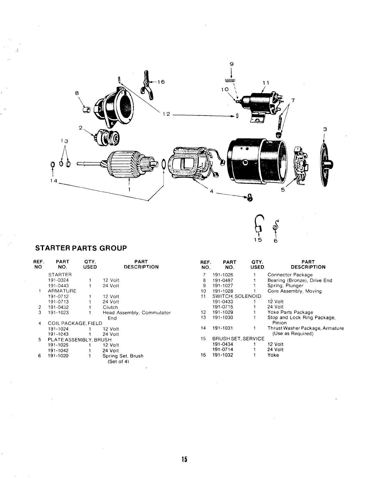
STARTER PARTS GROUP
REF. PART QTY. PART
NO NO. USED DESCRIPTION
STARTER
191-0324 112 volt
191-0443 1 24 Volt
1ARMATURE
191-0712 1 12 volt
191-0713 124 Volt
2191-0432 1Clutch
3191-1023 1Head Assembly, Commutator
End
4CO IL PACKAGE, FIELD
191-1024 1 12 volt
191-1C43 124 Volt
5PLATE ASSEMBLY, BRUSH
191-1025 1 12 volt
191-1042 1 24 Volt
6191-1020 1Spring Set, Brush
(Set of 4)
3
1
/
REF. PART QTY. PART
NO. NO. USED DESCRIPTION
7191-1026 1Connector Package
8191-0497 1Bearing (Bronze), Drive End
9191-1027 1Spring, Plunger
10 191-1028 1Core Assembly, Moving
11 SWITCH, SOLENOID
191-0433 112 volt
191-0715 1 24 Volt
12 191-1029 1Yoke Parts Package
13 191-1030 1Stop and Lock Ring Package,
Pinion
14 191-1031 1Thrust Washer Package, Armature
(Use as Required)
15 BRUSH SET, SERVICE
191-0434 112 volt
191-0714 1 24 Volt
16 191-1032 1Yoke
15
26
25
%
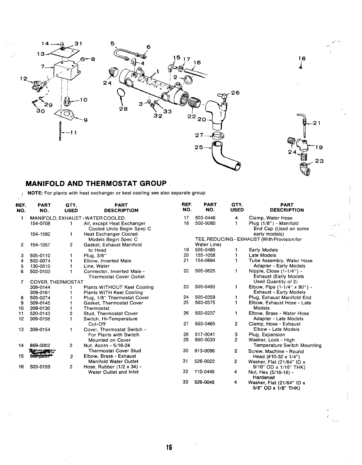
MANIFOLD AND THERMOSTAT GROUP
~NOTE: For plants with heat exchanger or keel cooling see also separate group.
REF. PART QTY. PART REF. PART QTY. PART
NO. NO. USED DESCRIPTION NO. NO. USED DESCRIPTION
1MANIFOLD, EXHAUST- WATER COOLED 17 503-0446 4Clamp, Water Hose
154-0708 1All, except Heat Exchanger 18 502-0080 1Plug (1/8”) -Manifold
Cooled Units Begin Spec C
,,,
End Cap (Used on some
154-1592 1Heat Exchanger Cooled early models)
Models Beoin S~ec CTEE, REDUCING -EXHAUST (With Provision for
2154-1057 2Gasket, Exha-ust Manifold
to Head
3505-0110 1Plug, 3/8”
4502-0074 1Elbow, Inverted Male
5130-0510 1Line, Water
6502-0103 1Connector, Inverted Male -
Thermostat Cover Outlet
7COVER, THERMOSTAT
309-0144 1Plants WITHOUT Keel Cooling
309-0161 1Plants WITH Keel Cooling
8505-0274 1Plug, 1/8” Thermostat Cover
9309-0145 1Gasket, Thermostat Cover
10 309-0130 1Thermostat
11 520-0143 2Stud, Thermostat Cover
12 309-0156 1Switch, Hi-Temperature
cut-off
13 309-0154 1Cover, Thermostat Switch -
For Plants with Switch
Mounted on Cover
14 869-0002 Nut, Acorn -5/1 6-24
15- :
Thermostat Cover Stud
Elbow, Brass -Exhaust
Manifold Water Outlet
16 503-0159 2Hose, Rubber (1/2 x34) -
Water Outlet and Inlet
Water Line)
505-0485
155-1058
154-0894
1
1
1
Early Models
Late Models
Tube Assembly, Water Hose
Adapter -Early Models
Nipple, Close (1-1/4”) -
Exhaust (Early Mocleis
Used Quantity of 2)
Elbow, Pipe (1-1/4” x90°) -
Exhaust -Early Models
Plug, Exhaust Manifold End
Elbow, Exhaust Hose -Late
Models
Elbow, Brass -Water Hose
Adapter -Late Models
Clamp, Hose -Exhaust
Elbow -Late Models
Plug, Expansion
Washer, Lock -High
Temperature Switch Mounting
Screw, Machine -Round
Head (#10-32 x1/4”)
Washer, Flat (21/64” ID x
9/16” OD X1/16 THK)
Nut, Hex (5/16-18) -
Hardened
Washer, Flat (21/64” ID x
5/8” OD X1/8” THK)
19
20
21
22 505-0625 1
23 505-0493 1
24
25
505-0359
503-0575
1
1
26
27
502-0237
503-0465
1
2
28
29
517-0041
850-0030
3
2
30
31
813-0096 2
526-0022 2
4
32 110-0445
526-004533 4
.-.
16 ‘“
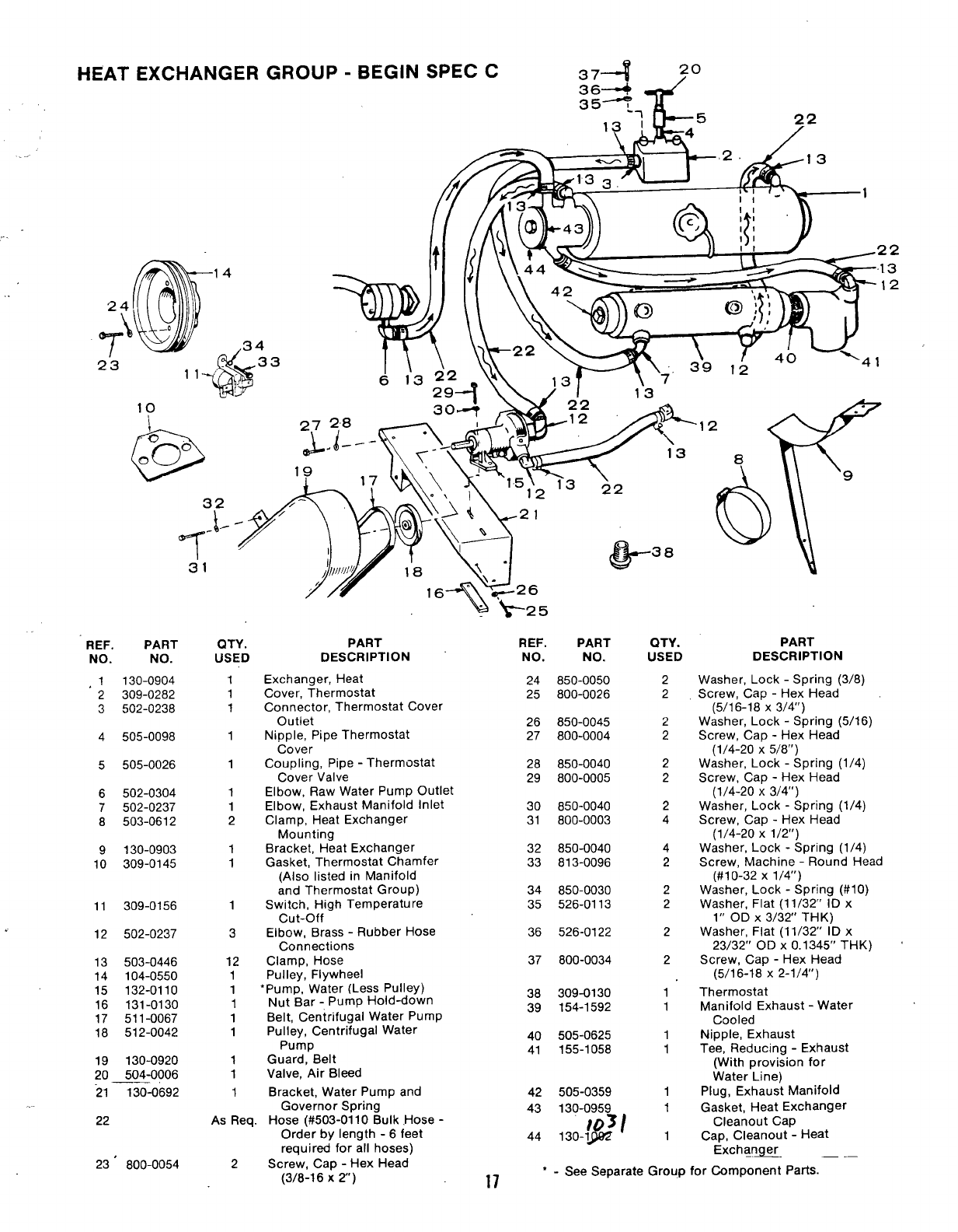
HEAT EXCHANGER GROUP -BEGIN SPEC C
,.
REF. PART
NO. NO.
,1 130-0904
2309-0282
3502-0238
4505-0098
5505-0026
6502-0304
7502-0237
8503-0612
9130-0903
10 309-0145
11
.12
13
14
15
16
17
18
19
20
21
309-0156
502-0237
503-0446
104-0550
132-0110
131-0130
511-0067
512-0042
130-0920
504-0006
130-0692
22
23’ 800-0054
31
QTY.
USED
1
1
1
1
1
1
1
2
1
1
1
3
12
1
1
1
1
1
1
1
1
22
19 ,7
PART
DESCRIPTION
Exchanger, Heat
Cover, Thermostat
Connector, Thermostat Cover
Outlet
Nipple, Pipe Thermostat
Cover
Coupling, Pipe -Thermostat
Cover Valve
Elbow, Raw Water Pump Outlet
Elbow, Exhaust Manifold Inlet
Clamp, Heat Exchanger
Mounting
Bracket, Heat Exchanger
Gasket, Thermostat Chamfer
(Also listed in Manifold
and Thermostat Group)
Switch, High Temperature
cut-off
Elbow, Brass -Rubber Hose
Connections
Clamp, Hose
Pulley, Flywheel
*Pump, Water (Less Pulley)
Nut Bar -Pump Hold-down
Belt, Centrifugal Water Pump
Pulley, Centrifugal Water
Pump
Guard, Belt
Valve, Air Bleed
Bracket, Water Pump and
Governor Spring
As Req. Hose (#503-0110 Bulk .Hose -
Order by length -6 feet
required for all hoses)
2Screw, Cap -Hex Head
(3/8-16 X2)
REF. PART
NO. NO.
24 850-0050
25 800-0026
26 850-0045
27 800-0004
28 850-0040
29 800-0005
30 850-0040
31 800-0003
32 850-0040
33 813-0096
34 850-0030
35 526-0113
36 526-0122
37 800-0034
38 309-0130
39 154-1592
40 505-0625
41 155-1058
42 505-0359
QTY.
USED
2
2
2
2
2
2
2
4
4
2
2
2
2
2
1
1
1
1
1
43 130-0959 1
&
)3/
44 130-1 1
Id‘4 1
>
.
PART
DESCRIPTION
Washer, Lock -Spring (3/8)
Screw, Cap -Hex Head
(5/16-18 X3/4”)
Washer, Lock -Spring (5/16)
Screw, Cap -Hex Head
(1/4-20 X5/8”)
Washer, Lock -Spring (1/4)
Screw, Cap -Hex Head
(1/4-20 X3/4”)
Washer, Lock -Spring (1/4)
Screw, Cap -Hex Head
(1/4-20 X1/2”)
Washer, Lock -Spring (1/4)
Screw, Machine -Round Head
(#1 O-32 X1/4”)
Washer, Lock -Spring (#IO)
Washer, Flat (11/32” ID x
1“ OD X3/32” THK)
Washer, Flat (11/32” ID x
23/32” OD X0.1345” THK) ‘
Screw, Cap -Hex Head
(5/16-18 X2-1/4”)
Thermostat
Manifold Exhaust -Water
Cooled
Nipple, Exhaust
Tee, Reducing -Exhaust
(With provision for
Water Line)
Plug, Exhaust Manifold
Gasket, Heat Exchanger
Cleanout Cap
Cap, Cleanout -Heat
Exchqn~. .—
17 ‘-See Separate Group for Component Parts.
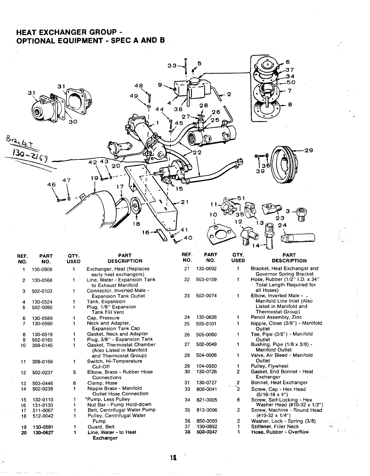
HEAT EXCHANGER GROUP -
OPTIONAL EQUIPMENT -SPEC AAND B
g-50
!\\>, \; ’15
,“
REF. PART
NO. NO.
1130-0908
QTY. PART
USED DESCRIPTION
REF. PART
NO. NO. QTY. PART
USED DESCRIPTION
Bracket, Heat Exchanger and
Governor Spring Bracket
Hose, Rubber (1/2” I.D. x34”
Total Length Required for
all Hoses)
Elbow, Inverted Male -.
Manifold Line Inlet (Also
Listed in Manifold and
Thermostat Group)
Pencil Assembly, Zinc
Nipple, Close (3/8”) -Manifold
Outlet
Exchanger, Heat (Replaces
early heat exchangers)
Line, Water -Expansion Tank
to Exhaust Manifold
Connector, Inverted Male -
Expansion Tank Outlet
Tank, Expansion
Plug, 1/8” Expansion
Tank Fill Vent
Cap, Pressure
Neck and Adapter,
Expansion Tank Cap
Gasket, Neck and Adapter
Plug, 3/8” -Expansion Tank
Gasket, Thermostat Chamber
(Also Listed in Manifold
and Thermostat Group)
Switch, Hi-Temperature
cut-off
Elbow, Brass -Rubber Hose
Connections
Clamp, Hose
Nipple Brass -Manifold
Outlet Hose Connection
*Pump, Less Pulley
Nut Bar -Pump Hold-down
Belt, Centrifugal Water Pump
Pulley, Centrifugal Water
Pump
Guard, Belt
Liner Water -to Heat
Exchanger
21 130-0692 1
1
1
1
1
1
1
1
1
2
2
-2
6
2
2
1
*
1
1
1
1
1
1
1
1
1
1
1
5
6
1
1
1
1
1
1
t
22 503-0159
2130-0568
3502-0103
23 502-0074
4130-0524
5502-0080
24
25
130-0626
505-0101
6130-0589
7130-0590
Tee, Pipe (3/8”) -Manifold
Outlet
8130-0519
9502-0155
10 309-0145
26 505-0060
502-0049 Bushing, Pipe (1/8 x3/8) -
Manifold Outlet
27
28 504-0006 Valve, Air Bleed -Manifold
Outlet11 309-0156 29
30
104-0550
130-0726
Pulley, Flywheel
Gasket, End Bonnet -Heat
Exchanger
Bonnet, Heat Exchanger
Screw, Cap -Hex Head
(5/16-18 X4“)
Screw, Self-Locking -Hex
Washer Head (#10-32 x1/2”)
Screw, Machine -Round Head
(#10-32 X1/4)
Washer, Lock -Spring (3/8)
Stiffener, Filler Neck .:
Hose. Rubber -OverflQw .. .. .
12 502-0237
503-0446
502-0238
31
33
130-0727
800-0041
13
14
132-0110
131-0130
511-0067
512-0042
15
16
17
18
34 821-0005
35 813-0096
36
37
38
850-0050
130-0892
503-0347
19
20
130-0591
130-062?
10 ‘
REF.’
NO.
39
PART
NO.
QTY.
USED
2
PART
DESCRIPTION
Screw, Cap -Hex Head
(3/8-16 X2“)
Screw, Cap -Hex Head
(5/16-18 X3/4”)
Washer, Lock -Spring (5/16)
Screw, Cap -Hex Head
(1/4-20 X5/8”)
Washer, Lock -Spring (1/4)
Screw, Cap -Hex Head
(1/4-20 X3/4)
REF.
NO.
PART
NO.
QTY .
USED
2
4
PART
DESCRIPTION
45
46
850-0040
800-0003
Washer, Lock -Spring (1/4)
Screw, Cap -Hex Head
(1/4-20 X1/2”)
Washer, Lock -Spring (1/4)
Screw, Cap -Hex Head
(1/4-20 X1/2”)
Washer, Lock -Spring (1/4)
Washer, Lock -Spring (#IO)
(Early Models Only)
Washer, Lock -Spring (#IO)
800-0054
40 800-0026 247
48
850-0040
800-0003
4
4
41
42 850-0045
800-0004
2
249
50
850-0040
850-0030
4
6
43
44
850-0040
800-0005
2
251 850-0030 2
‘-For component parts, refer to separate group.
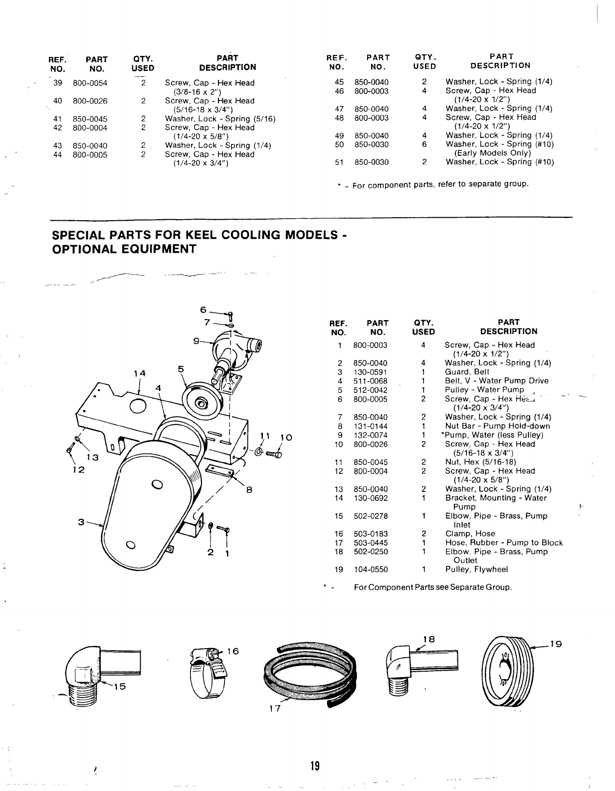
SPECIAL PARTS FOR KEEL COOLING MODELS -
OPTIONAL EQUIPMENT
,/-’ .--——--—-
:~ REF. PART QTY. PART
A% NO. NO. USED DESCRIPTION
1800-0003 4Screw, Cap -Hex Head
(1/4-20 X1/2”)
Washer, Lock -Spring (1/4)
Guard, Belt
Belt, V-Water Pump Drive
Pulley -Water Pump
Screw, Cap -Hex i-1~<~ -- ‘“-
(1/4-20 X3/4”)
Washer, Lock -Spring (1/4)
Nut Bar -Pump Hold-down
‘Pump, Water (less Pulley)
Screw, Cap -Hex Head
(5/16-18 X3/4’)
Nut, Hex (5/16-18)
Screw, Cap -Hex Head
(1/4-20 X5/8”)
Washer, Lock -Spring (1/4)
Bracket, Mounting -Water
Pump }
Elbow, Pipe -Brass, Pump
Inlet
Clamp, Hose
Hose, Rubber -Pump to Block
Elbow, Pipe -Brass, Pump
Outlet
Pulley, Flywheel
2
3
4
5
6
850-0040
130-0591
511-0068
512-0042
800-0005
4
1
1
1
2
7
8
9
10
850-0040
131-0144
132-0074
800-0026
2
1
1
2
2
2
2
1
11 850-0045
12 800-0004
13
14
850-0040
130-0692
15 502-0278 1
2
1
1
16
17
18
503-0183
503-0445
502-0250
19 104-0550 1
●✍For Component Parts see Separate Group.
..!? ‘m’ P
,
“
19 --
so
\
\
,1’-
,,..
..
‘~,\-.. -.’.1...
.-. —.- -’\.
\
7“1
Q/“’
-,
-..
.. .>. .
------
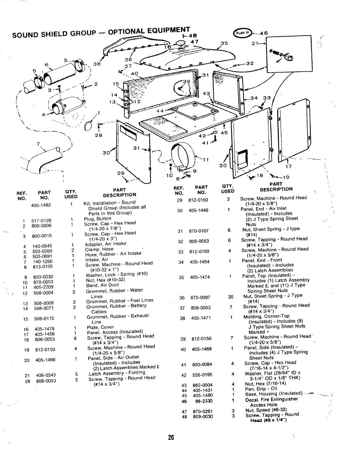
REF. PART
NO. NO.
405-1482
1517-0126
2800-0006
...
3800-0015
4140-0645
5503-0269
6503-0691
7140-1266
8813-0105
9850-0030
10 870-0053
11 405-2209
:, 12 508-0004
13 508-0008
14 508-0071
15 508-0115
16 405-1478
17 405-1456
18 808-0053
19 812-0150
20 405-1466
21 406-0343
28 808-0053
.
I
I
QTY.
USED
1
1
1
1
1
2
1
1
1
1
1
1
2
2
2
1
1
1
6
4
1
5
5
PART
DESCRIPTlON
Kit, Installation -Sound
Shield Group (Includes all
parts in this GrouP)
Plug, Button
Screw, Cap -Hex Head
(1/4-20 X718”)
Screw, Cap -Hex Head
(1/4-20 X3“)
Adapter, Air Intake
Clamp, Hose
Hose, Rubber -Air Intake
Intake, Air
Screw, Machine -Round Head
(#10-32 Xl“)
Washer, Lock -Spring (#10)
Nut. Hex (#lo-32)
.. —.,
Band, Air’Duct
Grommet, Rubber -Water
Lines
Grommet, Rubber -Fuel Lines
Grommet, Rubber -Battery
Cables
Grommet, Rubber -Exhaust
Line
Plate, Cover
Panel, Access (Insulated)
Screw, Tapping -Round Head
(#14 x3/4”)
Screw, Machine -Round Head
(1/4-20 X5/8”)
panel, Side -Air Outlet
(Insulated) -Includes
(2) Latch Assemblies Marked E
.Latch Assembly -Folding
Screw, Tapping -Round Head
(#14 x314”)
REF. PART
NO. NO.
29 812-0150
30 405-1446
31 870-0107
32 808-0053
33 812-0150
34 405-1454
35 405-1474
36 870-0097
37 808-0053
38 405-1471
39 812-0150
40 405-1468
41 800-0084
42 526-0195
43 862-0004
44 405-1431
45 405-1480
46 98-2330
QTY.
uSED
3
-1
6
6
4
1
1
20
7
1
7
1
4
4
4
1
1
1
47 870-0261
48 809-0030
3
3
PART
DESCRIPTlON i
Screw, Machine -Round Head
,,
(1/4-20 X5/8”)
panel, End -Air Inlet
(Insulated) -Includes ,,
(2) JType Spring Sheet -.
Nuts
Nut. Sheet SIJrin9-JtYPe
(#i4)
Screw, Tapping -Round Head
(#14 x3/4)
Screw, Machine -Round Head
(1/4-20 X5/8”)
panel, End -Front
(Insulated) -Includes
(2) Latch Assemblies
Panel, Top (Insulated) -
Includes (1) Latch Assembly
Marked Gand (11) JType
Spring Sheet Nuts
Nut, Sheet Spring -JType
(#14)
Screw, Tapping -Round Head
(#14 x3/4’)
Molding, Corner-Top
(Insulated) -Includes (9)
JType Spring Sheet Nuts
Marked +
Screw, Machine -Round Head
(1/4-20 X5/6”)
Panel, Side (Insulated) -
Includes (4) JType sPrin9
Sheet Nuts
Screw, Cap -Hex Head
(7/16-14 X4-1/2”)
Washer, Flat (29/64” ID x
3-I/4° OD X1/8” THK)
Nut, Hex (7/1 6-1 4)
Pan, Drip -Oil
Base, Housing (Insulated) --- -k_, i
Decal, Fire Extinguisher
Access Hole
Nut, Speed (#8-32)
Screw, Tapping -Round
Heed ($8 X1/4”)
m
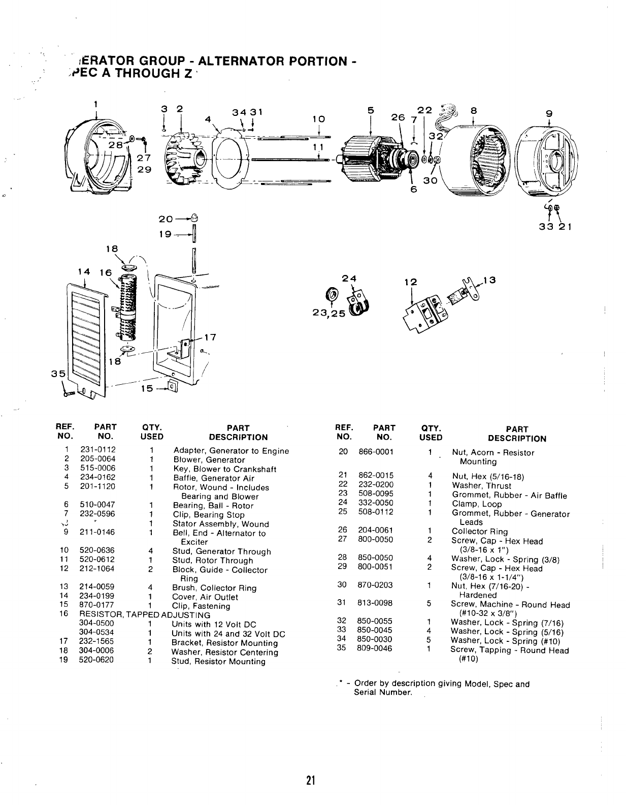
/ERATOR GROUP -ALTERNATOR PORTION -
,#EC ATHROUGH Z‘
1
7
27
29
.
204
194
REF. PART QTY.
NO. NO. USED
1231-0112 1
2205-0064 1
3515-0006 1
4234-0162 1
5201-1120 1
6510-0047 1
7232-0596 1
.
,2 1
9211-0146 1
10 520-0636 4
11 520-0612 1
12 212-1064 2
PART REF. PART
DESCRIPTION NO. NO.
Adapter, Generator to Engine
Blower, Generator
Key, Blower to Crankshaft
Baffle, Generator Air
Rotor, Wound -Includes
Bearing and Blower
Bearing, Ball -Rotor
Clip, Bearing Stop
Stator Assembly, Wound
Bell, End -Alternator to
Exciter
Stud, Generator Through
Stud, Rotor Through
Block, Guide -Collector
Ring
Brush. Collector Rino
20
21
22
23
24
25
26
27
28
29
30
13 214-0059 4
14 234-0199 1Cover, Air Outlet -
15 870-0177 1Clip, Fastening 31
16 RESISTOR, TAPPED ADJUSTING
304-0500 1Units with 12 Volt DC 32
304-0534 1Units with 24 and 32 Volt DC 33
17 232-1565 1Bracket, Resistor Mounting 34
18 304-0006 2Washer, Resistor Centering 35
19 520-0620 1Stud, Resistor Mounting
866-0001
862-0015
232-0200
508-0095
332-0050
508-0112
204-0061
800-0050
850-0050
800-0051
870-0203
813-0098
850-0055
850-0045
850-0030
809-0046
QTY. PART
USED DESCRIPTIC)N
1
4
1
1
1
1
1
2
4
2
1
5
1
4
5
1
Nut, Acorn -Resistor
Mounting
Nut, Hex (5/16-18)
Washer, Thrust
Grommet, Rubber -Air Baffle
Clamp, Loop
Grommet, Rubber -Generator
Leads
Collector Ring
Screw, Cap -Hex Head
(3/8-16 X1“)
Washer, Lock -Spring (3/8)
Screw, Cap -Hex Head
(3/8-16 X1-1/4”)
Nut, Hex (7/1 6-20) -
Hardened
Screw, Machine -Round Head
(#1 O-32 X3/8”)
Washer, Lock -Spring (7/16)
Washer, Lock -Spring (5/16)
Washer, Lock -Spring (#IO)
Screw, Tapping -Round Head
(#lo)
Order by description giving Model, Spec and
Serial Number.
●
21
......-
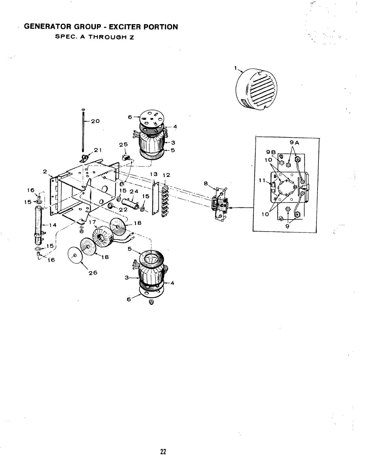
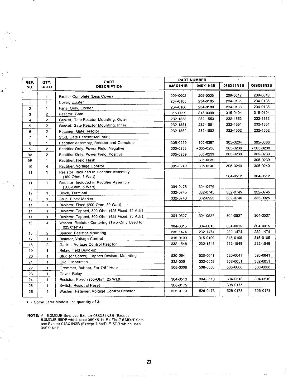
GENERATOR GROUP -EXCITER PORTION
SPEC. ATHROUGH Z
1
,, .,, -. ‘!,$
Y’
... ,
;
9A
11
1
I9
,-
?
REF. QTY. PART PART NUMBER
NO. USED DESCRIPTION 04SX1N1B 04SX1N3B 06SX51 N1 B06 SX51N3B
1Exciter Complete (Less Cover) 209-0003 209-0005 209-0012 209-0013
11Cover, Exciter 234-0185 234-0185 234-0185 234-0185
21Panel Only, Exciter 234-0188 234-0188 234-0188 234-0188
32Reactor, Gate 315-0099 315-0099 315-0104 315-0104
42Gasket, Gate Reactor Mounting, Outer 232-1553 232-1553 232-1553 232-1553
52Gasket, Gate Reactor Mounting, Inner 232-1551 232-1551 232-1551 232-1551
62Retainer, Gate Reactor 232-1552 232-1552 232-1552 232-1552
7 1 Stud, Gate Reactor Mounting
81Rectifier Assembly, Resistor and Complete 305-0259 305-0387 305-0264 305-0388
92Rectifier Only, Power Field, Negative 305-0238 *305-0238 305-0238 h305-0238
9A 2Rectifier Only, Power Field, Positive 305-0239 305-0239 305-0239 305-0239
9B 1Rectifier, Field Flash 305-0239 305-0239
10 4 Rectifier, Voltage Control 305-0240 305-0240 305-0240 305-0240
11 1Resistor, Included in Rectifier Assembly
(150-Ohm, 5Watt) 304-0512 304-0512
11 1 Resistor, Included in Rectifier Assembly
(500-Ohm, 5Watt) 804-0476 304-0476
12 1Block, Terminal 332-0745 332-0745 3~2-0745 332-0745
13 1Strip, Block Marker
14 1Resistor, Fixed (mm” ‘k- ‘n “’-’”
14 1Resistor, Tapped, 500-Ohm (425 Fixed, 75 Adj. )
14 1Resistor, Tapped, 500-Ohm (425 Fixed, 75 Adj.)
15 4Washer, Resistor Centering (Two Only Used for
02SX1 NIA)
16 2Spacer, Resistor Mounting
17 1Reactor, Voltage Control
,0 ~
I.“ I
I21 1
332-0746 I332-0925 I332-0746 I332-0925
I
(< UU-UIIIII, UU VVdl L) J[ I 1I
,“ .Gasket, Voltage Control Reactor
19 1 Relay, Field Build-up
9n 4 Stud (or Screw), Tapped Resistor Mounting
Clip, Tinnerman
22 1Grommet, Rubber, For 7/8” Hole
23 1Cover, Relay
24 1 Resistor, Fixed (250-Ohm, 25 Watt)
25 1Switch, Residual Reset
26 1Washer, Retainer, Voltage Control Reactor
A-Some Later Models use quantity of 3.
I
~04-0527 304-0527 304-0527 304-0527
I
bo4-oo15 304-0015 ‘304-0015 304-0015
~32-1474 232-1474 232-1474 232-1474
b15-oloo 315-0100 315-0105 315-0105 .
~32-1 548 I232-1548 232-1548 I232-1548
I
304-0510 304-0510 304-0510 304-0510
308-0175 308-0175
526-0173 526-0173 526-0173 526-0173
1III
NOTE: All 6.OMDJE Sets use Exciter 06SX51N3B (Except
6.OMDJE-55DR which uses 06SX51N1 B). The 7.5 MDJESets
use Exciter 04SX1N3B (Except 7.5MDJE-5DR which uses
04SX1N1B),
23
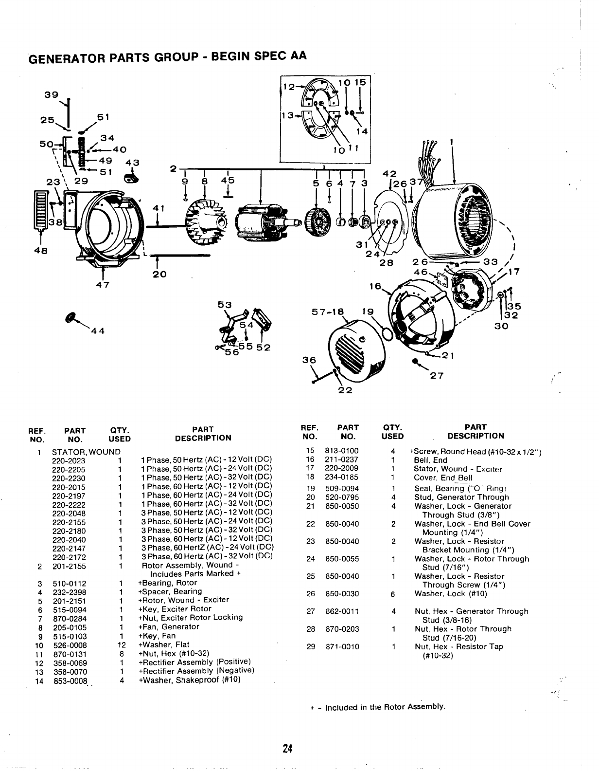
GENERATOR PARTS GROUP -BEGIN SPEC AA ,,
*49 43
‘2.3 ‘i. 29 (
47
%44
REF. PART QTY.
NO. NO. USED
1STATOR, WOUND
220-2023 1
220-2205 1
220-2230 1
220-2015 1
220-2197 1
220-2222 1
220-2048 1
220-2155 1
220-2180 1
220-2040 1
220-2147 1
220-2172 1
2201-2155 1
3510-0112 1
4232-2398 1
5201-2151 1
6515-0094 1
7870-0284 1
8205-0105 1
9515-0103 1
10 526-0008 12
11 870-0131 8
12 358-0069 1
13 358-0070 1
14 853-0008, 4
20
PART
DESCRIPTION
lPhase,50Hertz (AC)-12Volt(DC)
lPhase,50”Hertz(AC) -24Volt(DC)
lPhase,50Hertz (AC) -32Volt(DC)
lPhase,60Hertz (AC) -12Volt(DC)
lPhase,60Hertz (AC) -24Volt(DC)
lPhase,60Hertz (AC) -32Volt(DC)
3Phase,50Hertz (AC) -12Volt(DC)
3Phase,50Hertz (AC) -24Volt(DC)
3Phase,50Hertz (AC) -32Volt(DC)
3Phase,60Hertz (AC) -12Volt(DC)
3Phase,60HertZ (AC)-24Volt(DC)
3Phase,60Hertz (AC) -32Volt(DC)
Rotor Assembly, Wound -
Includes Parts Marked +
+Bearing, Rotor
+Spacer, Bearing
+Rotor, Wound -Exciter
+Key, Exciter Rotor
+Nut, Exciter Rotor Locking
+Fan, Generator
+Key, Fan
+Washer, Flat
+Nut, Hex (#10-32)
+Rectifier Assembly (Positive)
+Rectifier Assembly (Negative)
+Washer, Shakeproof (#1 O)
I
22
24
REF. PART
NO. NO.
15 813-0100
16 211-0237
17 220-2009
18 234-0185
19 509-0094
20 520-0795
21 850-0050
22 850-0040
23 850-0040
24 850-0055
25 850-0040
26 850-0030
27 862-0011
28 870-0203
29 871-0010
27
QTY.
USED
4
1
1
1
1
4
4
2
2
1
1
6
4
1
1
PART
DESCRIPTION
+. Screw, Round Head (#1 O-32x 1/2”)
Bell, End
Stator, Wound -Exciter
Cover, End Bell
SeaI, Bearing (“O’ Ring}
Stud, Generator Through
Washer, Lock -Generator
Through Stud (3/8”)
Washer, Lock -End Bell Cover
Mounting (1/4”)
Washer, Lock -Resistor
Bracket Mounting (1/4”)
Washer, Lock -Rotor Through
Stud (7/1 6“ )
Washer, Lock -Resistor
Through Screw (1/4”)
Washer, Lock (#1 O)
Nut, Hex -Generator Through
Stud (3/8-1 6)
Nut, Hex -Rotor Through
Stud (7/1 6-20)
Nut, Hex -Resistor Tap
(#10-32)
+-Included in the Rotor Assembly
,,,-
/
.,!,
. .
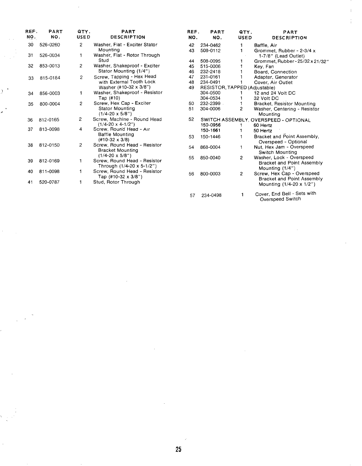
REF. PART
NO. NO.
.
30 526-0260
31 526-0034
32 853-0013
33 815-0184
)’ 34 856-0003
35 800-0004
.
36 812-0165
37 813-0098
38 812-0150
39 812-0169
40 811-0098
41 520-0787
QTY .PART
USED DESCRIPTION
2Washer, Flat -Exciter Stator
Mounting
1Washer, Flat -Rotor Through
Stud
2Washer, Shakeproof -Exciter
Stator Mounting (1/4”)
2Screw, Tapping -Hex Head
with External Tooth Lock
Washer (#10-32 x3/8”)
1Washer, Shakeproof -Resistor
Tap (#10)
2Screw, Hex Cap -Exciter
Stator Mounting
(1/4-20 X5/8”)
2Screw, Machine -Ro’und Head
(1/4-20 X4-1/2”)
4Screw, Round Head -Alr
Baffle Mounting
(#10-32 X3/8)
2Screw, Round Head -Resistor
Bracket Mounting
(1/4-20 X5/8”)
1Screw, Round Head -Resistor
Through (1/4-20 x5-1/2”)
1Screw, Round Head -Resistor
Tap (#1 O-32 x3/8”)
1Stud, Rotor Through
REF. PART QTY .PART
NO. NO, USED DESCRIPTION
42 234-0462 1Baffle, Air
43 508-0112 1Grommet, Rubber -2-3/4 x
1-7/8” (Lead Outlet)
44 508-0095 1Grommet, Rubber-25/32x21/32”
45 515-0006 1Key, Fan
46 232-2418 1Board, Connection
47 231-0161 1Adapter, Generator
48 234-0491 1Cover, Air Outlet
49 RESISTOR, TAPPED (Adjustable)
304-0500 112 and 24 Volt DC
304-0534 132 Volt DC
50 232-2399 1Bracket, Resistor Mounting
51 304-0006 2Washer, Centering -Resistor
Mounting
52 SWITCH ASSEMBLY, OVERSPEED -OPTIONAL
150-0956 160 Hertz
150-1861 150 Hertz
53 150-1446 1Bracket and Point Assembly,
Overspeed -Optional
54 868-0004 1Nut, Hex Jam -Overspeed
Switch Mounting
55 850-0040 2Washer, Lock -Overspeed
Bracket and Point Assembly
Mounting (1/4”)
56 800-0003 2Screw, Hex Cap -Overspeed
Bracket and Point Assembly
Mounting (1/4-20 x1/2”)
57 234-0498 1Cover, End Bell -Sets with
Overspeed Switch
25
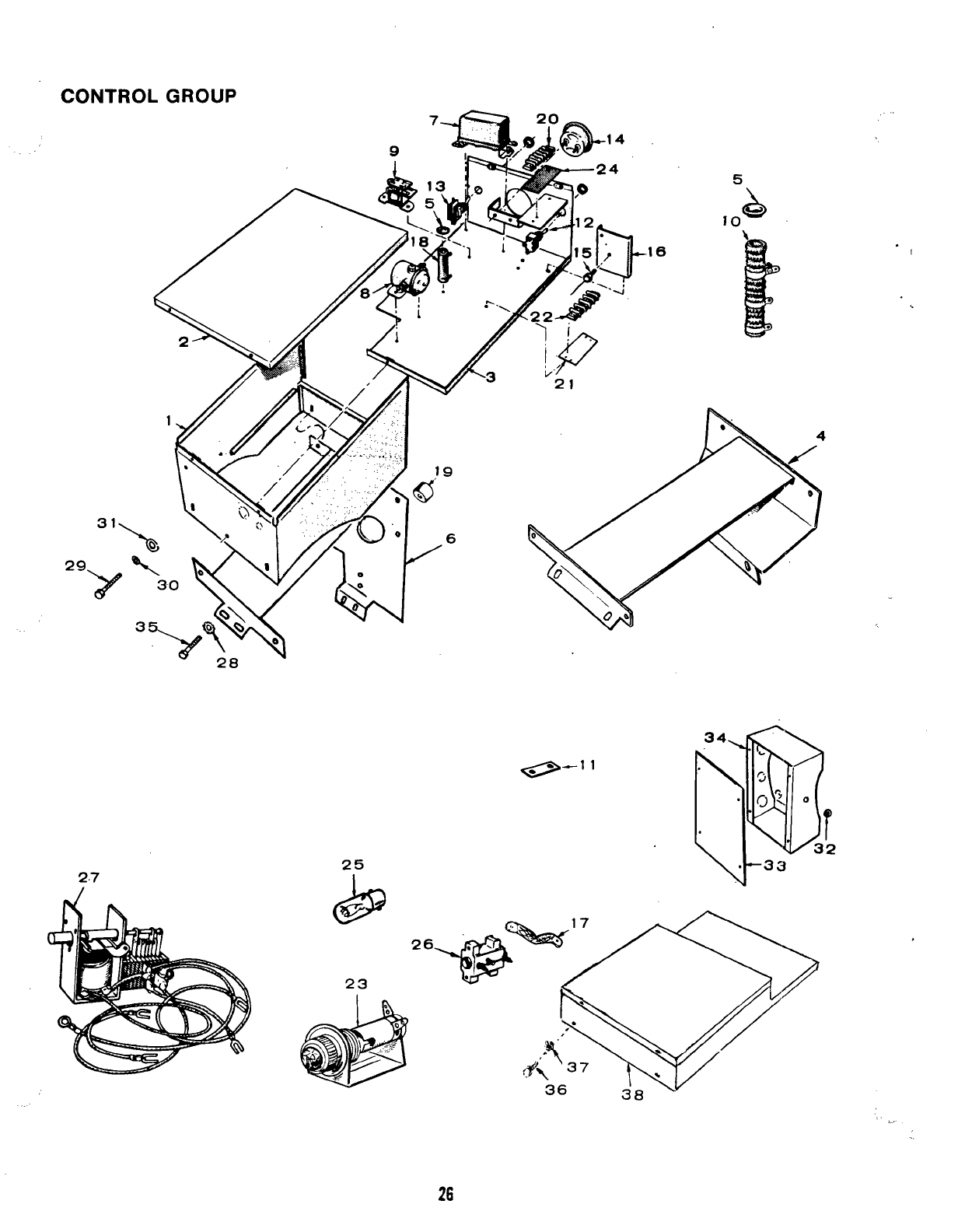
CONTROL GROUP
2.7
.16
21
e-’ ‘
25
“1
.
26
REF. PART QTY.
NO. NO. USED
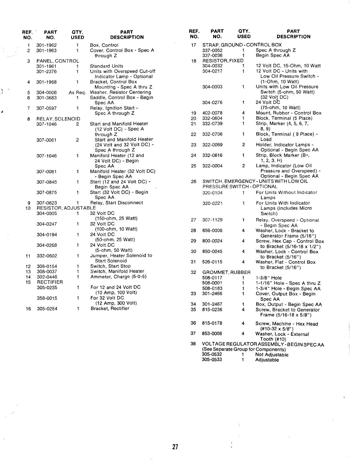
1301-1962 1
2301-1963 1
3PANEL, CONTROL
301-1961 1
301-2376 1
4301-1968 1
)
)5304-0006 As Req.
6301-3683 1
7307-0597 1
.4
8RELAY, SOLENOID
307-1046 2
307-0061 2
307-1046 1
307-0061 1
307-0845 1
307-0875 1
9307-0623 1
PART
DESCRIPTION
Box, Control
Cover, Control Box -Spec A
through Z
Standard Units
Units with Overspeed Cut-off
Indicator Lamp -Optional
Bracket, Control Box
Mounting -Spec Athru Z
Washer, Resistor Centering
Saddle, Control Box -Begin
Spec AA
Relay, Ignition Start -
Spec Athrough Z
Start and Manifold Heater
(12 Volt DC) -Spec A
through Z
Start and Manifold Heater
(24 Volt and 32 Volt DC) -
Spec Athrough Z
Manifold Heater (12 and
24 Volt DC) -Begin
Spec AA
Manifold Heater (32 Volt DC)
-Begin Spec AA
Start (12 and 24 Volt DC) -
Begin Spec AA
Start (32 Volt DC) -Begin
Spec AA
Relav, Start Disconnect
10 RESISTOR, ADJUSTABLE
304-0005
304-0247
304-0194
304-0268
11 332-0602
12 308-0154
13 308-0037
14 302-0446
15 RECTIFIER
305-0235
358-0015
16 305-0254
1
1
1
1
1
1
1
1
1
1
1
32 Volt DC
(150-ohm, 25 Watt)
32 Volt DC
(100-ohm, 10 Watt)
24 Volt DC
(50-ohm, 25 Watt)
24 Volt DC
(5-ohm, 50 Watt)
Jumper, Heater Solenoid to
Start Solenoid
Switch, Start Stop
Switch, Manifold Heater
Ammeter, Charge (5-O-5)
For 12 and 24 Volt DC
(10 Amp, 100 Volt)
For 32 Volt DC
(12 Amp, 300 Volt)
Bracket, Rectifier
REF.
NO.
17
18
19
20
21
22
23
24
25
26
27
28
29
30
31
32
33
34
35
36
37
38
PART QTY. PART
NO. USED DESCRIPTION
STRAP. GROUND -CONTROL BOX
337-0052 1
337-0036 1
RESISTOR, FIXED
304-0032 1
304-0217 1
304-0003 1
304-0276 1
402-0078 4
332-0604 1
332-0739 1
332-0706 1
322-0069 2
332-0616 1
322-0004 2
Spec Athrough Z
Begin Spec AA
12 Volt DC, 15-Ohm, 10 Watt
12 Volt DC -Units with
Low Oil Pressure Switch -
(l-Ohm, 10 Watt)
Units with Low Oil Pressure
Switch (5-ohm, 50 Watt)
(32 Volt DC)
24 Volt Dh
(75-ohm, 10 Watt)
Mount, Rubber -Control Box
Block, Terminal (5 Place)
Strip, Marker (4, 5, 6, 7,
8, 9)
Block, Terminal (8Place) -
Load
Holder, Indicator Lamps -
Optional -Begin Spec AA
Strip, Block Marker (B+,
1,2, 3,H)
Lamp, Indicator (Low Oil
Pressure and Overspeed) -
Optional -Begin Spec AP.
SWITCH, EMERGENCY-UNITS WITH LOW OIL
PRESSURE SWITCH-OPTIONAL
320-0104 1For Units Without Indicator
Lamps
320-0221 1For Units With Indicator
Lamps (Includes Micro
Switch)
307-1129 1Relay, Overspeed -Optional
-Begin Spec AA
856-0008 4Washer, Lock -Bracket to
Generator Frame (5/1 6“)
800-0024 4Screw, Hex Cap -Control Box
to Bracket (5/16-18 x1/2”)
850-0045 4Washer, Lock -Control Box
to Bracket (5/1 6“)
526-0115 4Washer, Flat -Control Box
to Bracket (5/1 6“)
GROMMET, RUBBER
508-0117 11-3/8” Hole
508-0001 11-1/16” Hole -Spec Athru Z
508-0183 11-3/4” Hole -Begin Spec AA
301-2466 1Cover, Output Box -Begin
Spec AA
301-2467 1Box, Output -Begin Spec AA
815-0236 4Screw, Bracket to Generator
Frame (5/16-18 x5/8”)
815-0178 4Screw, Machine -Hex Head
(#10-32 X5/8”)
853-0008 4Washer, Lock -External
Tooth (#1 0)
VOLTAGE REGULATOR ASSEMBLY-BEGIN SPECAA
(See Separate Group for Components)
305-0532 1Not Adjustable
305-0533 1Adjustable
27
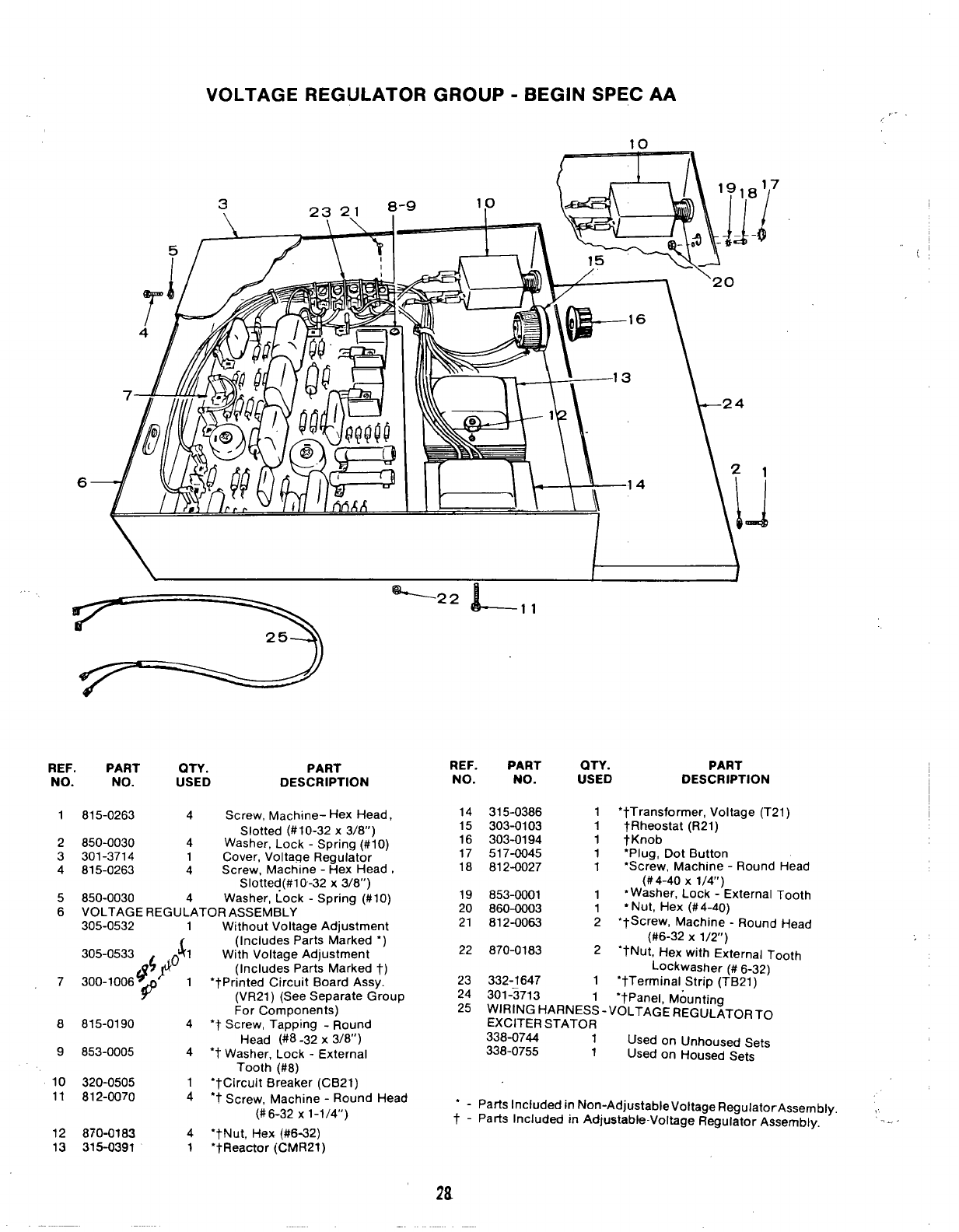
VOLTAGE REGULATOR GROUP -BEGIN SPEC AA
10
r7
/“-”
6
-22 L11
25
REF. PART QTY. PART
NO. NO. USED DESCRIPTION
1
2
3
4
5
6
7
8
9
10
11
12
13
815-0263 4Screw, Machine- Hex Head,
Slotted (#1 O-32 x3/8”)
850-0030 4Washer, Lock -Spring (#10)
301-3714 1Cover, Voltage Regulator
815-0263 4Screw, Machine -Hex Head ,
Slotted (#l 0-32 x3/8”)
850-0030 4Washer, Lock -Spring (#IO)
VOLTAGE REGULATOR ASSEMBLY
305-0532 1Without Voltage Adjustment
$1 ~;:;:;~:~;~;:;; “)
:~~$fi ,(Includes Parts Marked t)
#’
●tPrinted Circuit Board Assy.
(VR21 )(See Separate Group
For Components)
815-0190 4‘t Screw, Tapping -Round
Head (#8 -32 x3/8”)
853-0005 4“t Washer, Lock -External
Tooth (#8)
320-0505 1“tCircuit Breaker (CB21)
812-0070 4“t Screw, Machine -Round Head
(#6-32 x1-1/4”)
870-0183 4‘tNut, Hex (#6-32)
315-0391 1‘tReactor (CMR21)
1
REF. PART QTY. PART
NO. NO. USED DESCRIPTION
14 315-0386 1●tTransformer, Voltage (T21 )
15
16
17
18
19
20
21
22
23
24
25
303-0103 1
303-0194 1
517-0045 1
812-0027 1
853-0001 1
860-0003 1
812-0063 2
870-0183 2
332-1647 1
301-3713
WIRING HARNESL -
EXCITER STATOR
7Rheostat (R21) -
tKnob
“Plug, Dot Button
‘Screw, Machine -Round Head
(#4-40 x1/4”)
*Washer, Lock -External Tooth
“Nut, Hex (#4-40)
‘tScrew, Machine -Round Head
(#6-32 X1/2”)
“tNut, Hex with External Tooth
Lockwasher (# 6-32)
‘tTerminal Strip (TB21 )
‘tPanel, Mounting
VOLTAGE REGULATOR TO
338-0744 1Used on Unhoused Sets
338-0755 1Used on Housed Sets
‘-Parts Included in Non-Adjustable Voltage RegulatorAssembly. ,
t-Patis Included in Adjustable-Voltage Regulator Assembly. -
—
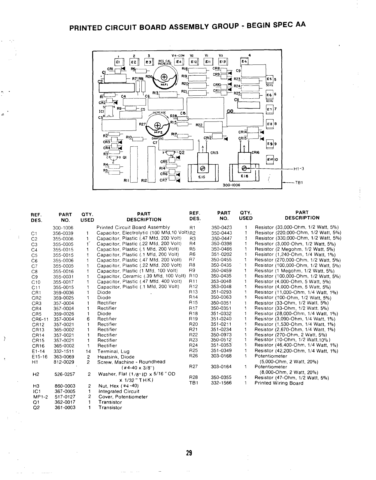
PRINTED CIRCUIT BOARD ASSEMBLY GROUP -BEGIN SPEC AA
4
—HI-3
—TB1
PART
DESCRIPTION
“E
. .
6
R12U CR7 ‘~ dui
300-[006
Rllu
QTY. PART REF.
USED DESCRIPTION DES.
PART
NO.
350-0423
350-0443
350-0447
350-0398
350-0466
351-0202
350-0455
350-0435
350-0459
350-0435
353-0048
353-0048
351-0293
350-0363
350-0351
350-0351
351-0332
351-0240
351-0211
351-0234
350-0973
350-0512
351-0353
351-0349
303-0168
303-0164
350-0355
332-1566
QTY.
USED
REF.
DES
PART
NO.
300-1006
356-0039
355-0006
355-0005
355-0015
355-0015
355-0006
355-0005
355-0016
355-0031
355-0017
355-0015
359-0036
359-0025
357-0004
357-0004
359-0026
Printed Circuit Board Assembly
Capacitor, Electrolytic (100 Mfd,10 VOlt)~~
Capacitor, Plastic (.47 Mfd, 200 Volt) R3
Capacitor, Plastic (.22 Mfd, 200 Volt) R4
Capacitor, Plastic (.1 Mfd, 200 Volt) R5
Capacitor, Plastic (.1 Mfd, 200 Volt) R6
Capacitor, Plastic (.47 Mfd, 200 Volt) R7
Capacitor, Plastic (.22 Mfd, 200 Volt) R8
Capacitor, Plastic (1 Mfd, 100 Volt) R9
Capacitor, Ceramic (.39 Mfd, 100 Volt) R1O
Capacitor, Plastic (.47 Mfd, 400 Volt) Rll
Capacitor, Plastic (.1 Mfd, 200 Volt) R12
Diode R13
Diode R14
Rectifier R15
Rectifier R17
Diode R18
Rect[fler R19
Rectifier R20
Rectifier R21
Rectifier R22
Rectifier R23
Rectifier R24
Terminal, Lug R25
Heatsink, Diode R26
Screw, Machine -Roundhead
(#4-40 X3/8”) R27
Washer, Flat (1/8i’ID x5/16 “OD R28
Xl/32’’ THK)
Nut, Hex (#4 -40) TB 1
Integrated Circuit
Cover, Potentiometer
Transistor
Transistor
1
1
1
1
1
1
1
‘1
1
1
1
1
1
1
1
1
1
1
1
1
1
1
1
1
1
Resistor (33,000-Ohm, 1/2 Watt, 50/o)
Resistor (220,000-Ohm, 1/2 Watt, 596)
Resistor (330,000-Ohm, 1/2 Watt, 50/.)
Resistor (3,000-Ohm, 1/2 watt, 5°/0)
Resistor (2 Megohm, 1/2 Watt, 50/.)
Resistor (1 ,240-Ohm, 1/4 Watt, 10/.)
Resistor (270,000-Ohm, 1/2 Watt, 5°/0)
Resistor (100,000 -C)hm, 1/2 Watt, 50/’)
Resistor (1 Megohm, 1/2 watt, 5°/0)
Resistor (1 00,000-Ohm, 1/2 Watt, So/o)
Resistor (4,000-Ohm, 5Watt, 5“/0)
Resistor (4,000-Ohm, 5watt, 50/0)
Resistor (1 1,000-Ohm, 1/4 Watt, 10/.)
Resistor (100-Ohm, 1/2 Watt, 50/0)
Resistor (33-Ohm, 1/2 Watt, 5°/0)
Resistor (33-Ohm, 1/2 Watt, 5°/0)
Resistor (28,000-Ohm, 1/4 Watt, 1°/0)
Resistor (3,090-Ohm, 1/4 Watt, 1°/0)
Resistor (1,530-Ohm, 1/4 Watt, 10/~)
Resistor (2,670-Ohm, 1/4 Watt, 10/.)
Resistor (270-Ohm, 2Watt, 5°/0)
Resistor (l O-Ohm, 1/2 Watt,loO/~)
Resistor (46,400-Ohm, 1/4 Watt, 1°/0)
Resistor (42,200-Ohm, 1/4 Watt, 1°/0)
Potentiometer
(5,000-Ohm, 2Watt, 20°/0)
Potentiometer
(8,000-Ohm, 2Watt, 20°/0)
Resistor (47-Ohm, 1/2 Watt, 50/.)
Printed Wiring Board
1
1
1
1
1
1
1
1
1
1
1
1
1
1
1
1
6
1
1
1
1
1
14
2
2
2
2
1
2
1
1
cl
C2
C3
C4
C5
C6
C7
C8
C9
Clo
cl 1
CR1
CR2
CR3
CR4
CR5
CR6-11
CR12
CR13
)CR14
CR15
CR16
E1-14
E15-16
HI
357-0004
357-0021
365-0002
357-0021
357-0021
365-0002
332-1511
363-0069
812-0029 1
H2 526-0257 1
1
H3 860-0003
367-0005
517-0127
362-0017
361-0003
ICI
MPI-2
Q1
Q2
29
SERVICE KITS AND MISCELLANEOUS
NOTE: For other kits, refer to the group for the part
in question.
REF. PART QTY. PART
NO. NO. USED DESCRIPTION
98-1807 1Decal Kit
168-0106 1Gasket Kit, Plant
155-1004 1Muffler, Aqualift (Includes
Hull Strainer)
155-0955 1Installation Package -
Aqualift Muffler
OVERHAUL KIT, ENGINE
522-0241 1Spec AOnly
522-0257 1Begin Spec B
525-0216 1Paint, Touch-up (pressurized
can) 16 ounce -Marine White
Enamel
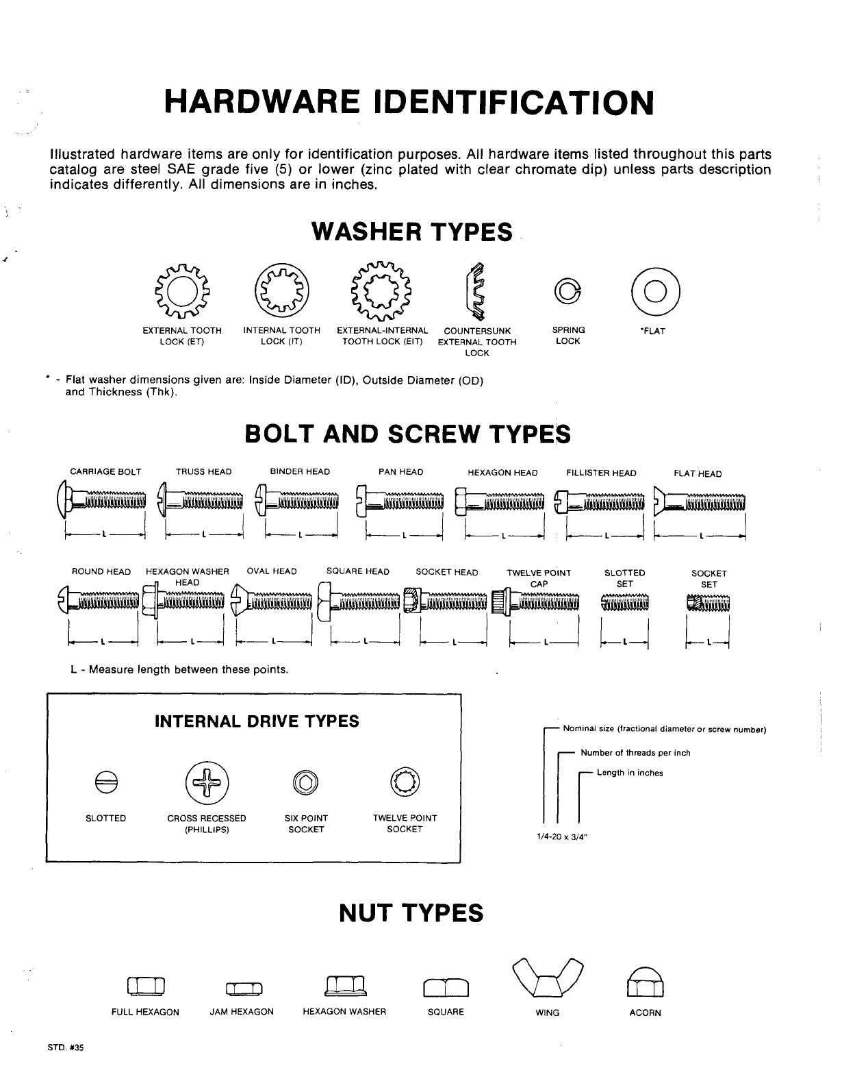
HARDWARE IDENTIFICATION
Illustrated hardware items are only for identification purposes. All hardware items listed throughout this parts
catalog are steel SAE grade five (5) or lower (zinc plated with clear chromate dip) unless parts description
indica{es differently, Al~dimensionk “are in inches.
WASHER
aQ@
EXTERNAL TOOTH INTERNAL TOOTH EXTERNAL-INTERNAL COUNTERSUNK SPRING
LOCK (ET)
“FLAT
LOCK (IT) TOOTH LOCK (EIT) EXTERNAL TOOTH LOCK
LOCK
‘-Flat washer dimensions given are: Inside Diameter (ID), Outside Diameter (OD)
and Thickness (Thk).
BOLT AND SCREW TYPES
CARRIAGE BOLT TRUSS HEAD BINDER HEAD PAN HEAD HEXAGON HEAD FILLISTER HEAD FLAT HEAD
ROUND HEAD HEXAGON WASHER OVAL HEAD SQUARE HEAD SOCKET HEAD TWELVE POINT SLOTTED SOCKET
SET SET
En
L-Measure length between these points.
INTERNAL DRIVE TYPES
@@oo
SLOTTED CROSS RECESSED SIX PoINT TWELVE POINT
(PHILLIPS) SOCKET SOCKET
NUT TYPES
rNominal size (fractional diameter or screw number)
Number of threads per inch
rr
Length in inches
1/4-20 X3/4
Dm mwfi
FULL HEXAGON JAM HEXAGON HEXAGON WASHER SQUARE WING ACORN
STD. #35
