968 0221 Onan MDJF (spec A AD) Marine Diesel Gensets Parts Manual (10 1988)
User Manual: 968-0221 Onan MDJF (spec A-AD) Marine Diesel Gensets Parts manual (10-1988)
Open the PDF directly: View PDF ![]() .
.
Page Count: 62
The following catalog
has gaps in its page
numbers, or doesn’t
have any numbers.
We have chosen to
leave the page
numbering in the
order that Acrobat
assigns it.
mm
Parts
Manual
MIDJIIF’
GenSets
a
Replaces
7-82 (Spec A-AB)
Printed In U.S.A.
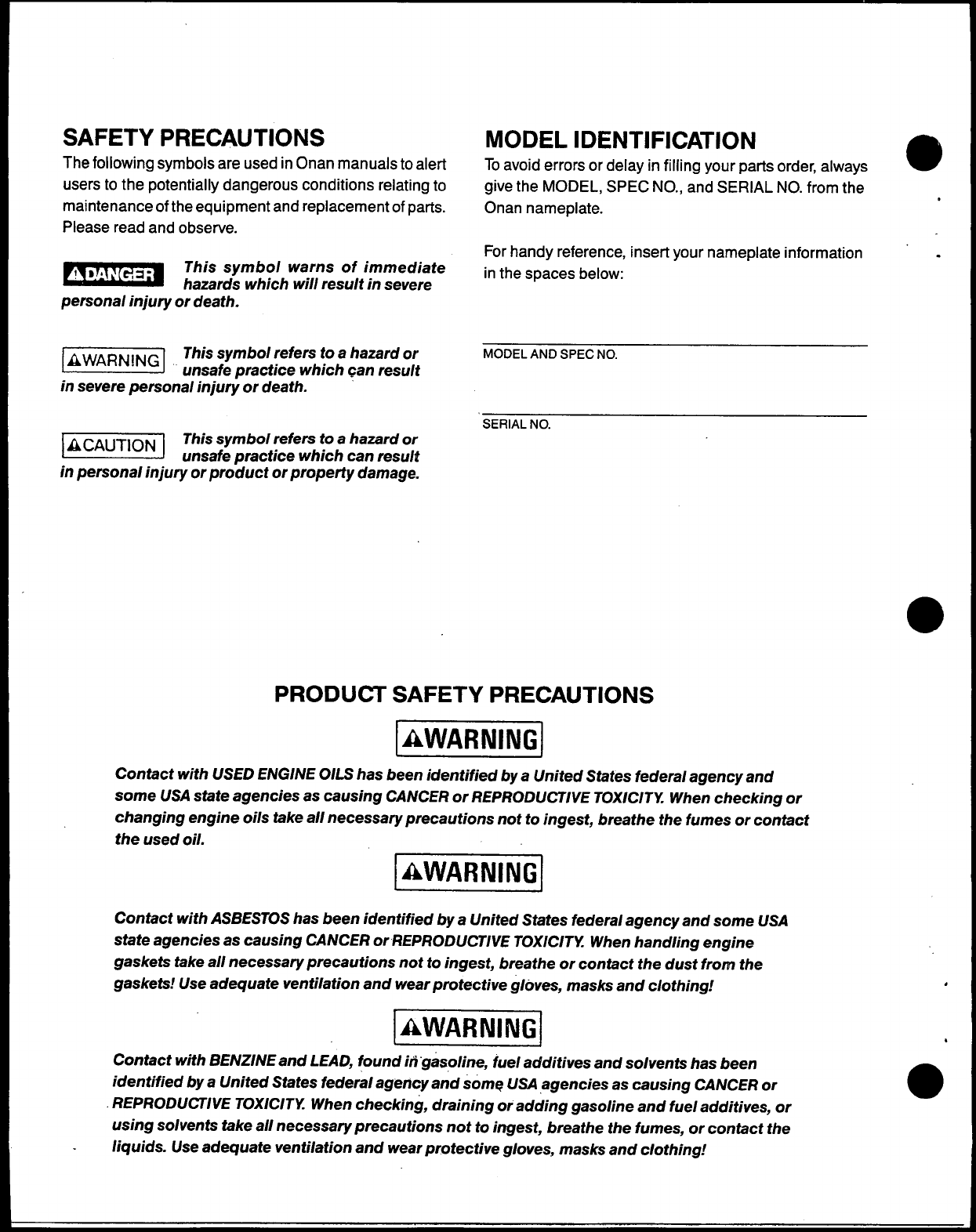
SAFETY PRECAUTIONS
The following symbols are used in Onan manuals to alert
users to the potentially dangerous conditions relating to
maintenance of the equipment and replacement of parts.
Please read and observe.
-This symbol warns of immediate
hazards which will result in severe
personal injury or death.
mThis symbol refers to ahazard or
unsafe practice which can result
in severe personal injury or death.
@@l This symbol refers to ahazard or
unsafe practice which can result
in personal injury or product or property damage.
MODEL IDENTIFICATION
To avoid errors or delay in filling your parts order, always e
give the MODEL, SPEC NO., and SERIAL NO. from the ,
Onan nameplate.
For handy reference, insert your nameplate information .
in the spaces below:
MODEL AND SPEC NO.
SERIAL NO.
PRODUCT SAFETY PRECAUTIONS
Imiiimd
Contact with USED ENGINE OILS has been identified by aUnited States federal agency and
some USA state agencies as causing CANCER or REPRODUCTIVE TOXICITY When checking or
changing engine oils take all necessary precautions not to ingest, breathe the fumes or contact
the used oil.
Pw!!w!J
Contact with ASBESTOS has been identified by aUnited States federal agency and some USA
state agencies as causing CANCER or REPRODUCTIVE TOXICITY When handling engine
gaskets take all necessary precautions not to ingest, breathe or contact the dust from the
gaskets! Use adequate ventilation and wear protective g/eves, masks and clothing.! ,
I
IAWARNINGI .
IJ
Contact with BENZINE and LEAD, found in “gasoline, fuel additives and solvents has been
identified by aUnited States federal agency and some USA agencies as causing CANCER or ●
REPRODUCTIVE TOXICITY When checking, draining or adding gasoline and fuel additives, or
using solvents take all necessary precautions not to ingest, breathe the fumes, or contact the
liquids. Use adequate ventilation and wear protective gloves, masks and clothing!
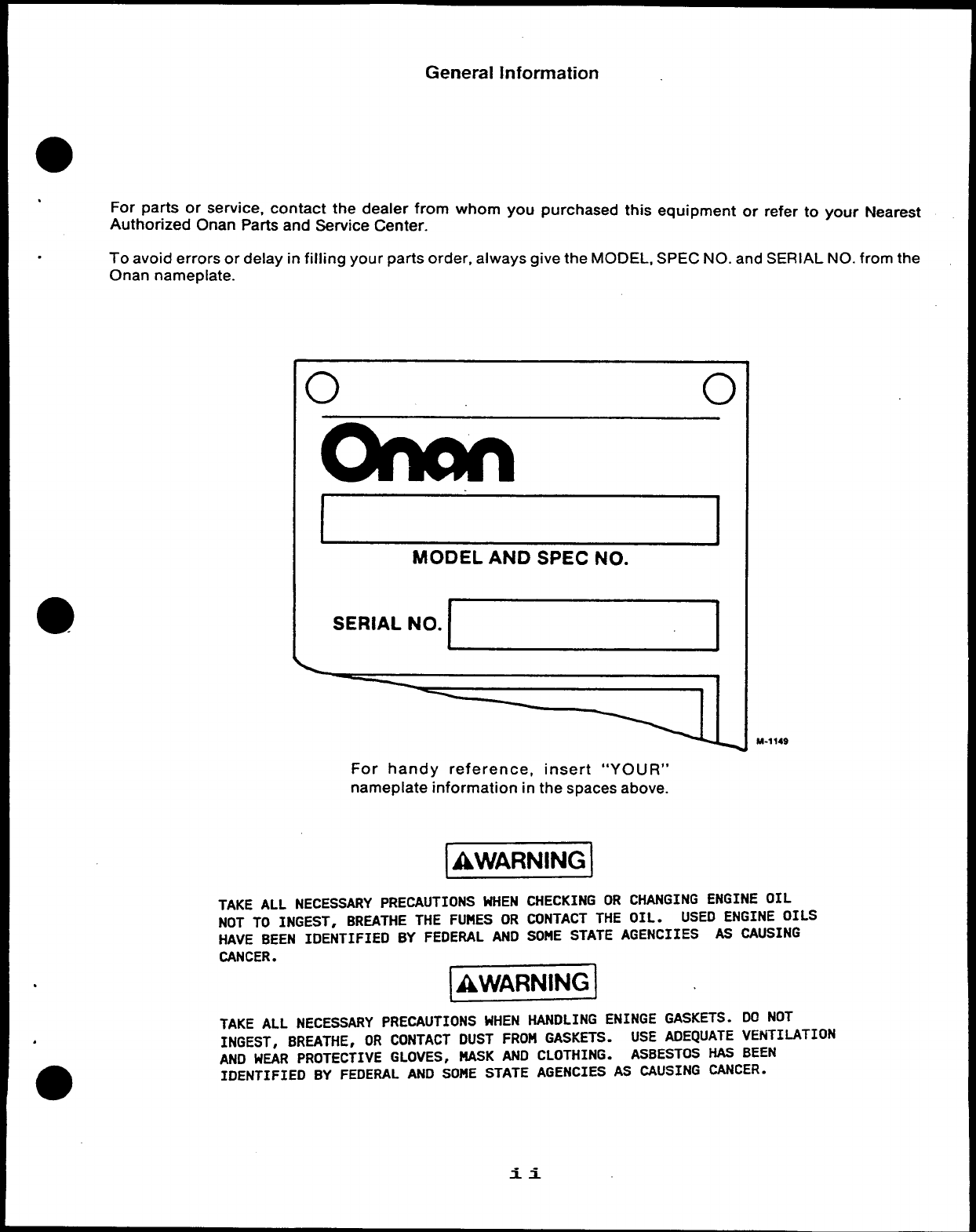
General Information
.For parts or service, contact the dealer from whom you purchased this equipment or refer to your Nearest
Authorized Onan Parts and Service Center.
.To avoid errors or delay in filling your parts order, always give the MODEL, SPEC NO. and SERIAL NO. from the
Onan nameplate.
0
BJ
MODEL AND SPEC NO.
SERIAL NO.
.
.
ii
M-1149
For handy reference, insert “YOUR”
nameplate information in the spaces above.
TAKE ALL NECESSARY PRECAUTIONS WHEN CHECKING OR CHANGING ENGINE OIL
NOT To INGEST, BREATHE THE FUMES OR CONTACT THE OIL. USED ENGINE OILS
HAVE BEEN IDENTIFIED BY FEDERAL AND SOME STATE AGENCIIES AS CAUSING
CANCER.
-
TAKE ALL NECESSARY PRECAUTIONS WHEN HANDLING ENINGE GASKETS. DO NOT
INGEST, BREATHE, OR CONTACT DUST FROM GASKETS. USE ADEQUATE VENTILATION
AND WEAR PROTECTIVE GLOVES, NASK AND CLOTHING. ASBESTOS HAS BEEN
IDENTIFIED BY FEDERAL AND SOME STATE AGENCIES AS CAUSING CANCER.
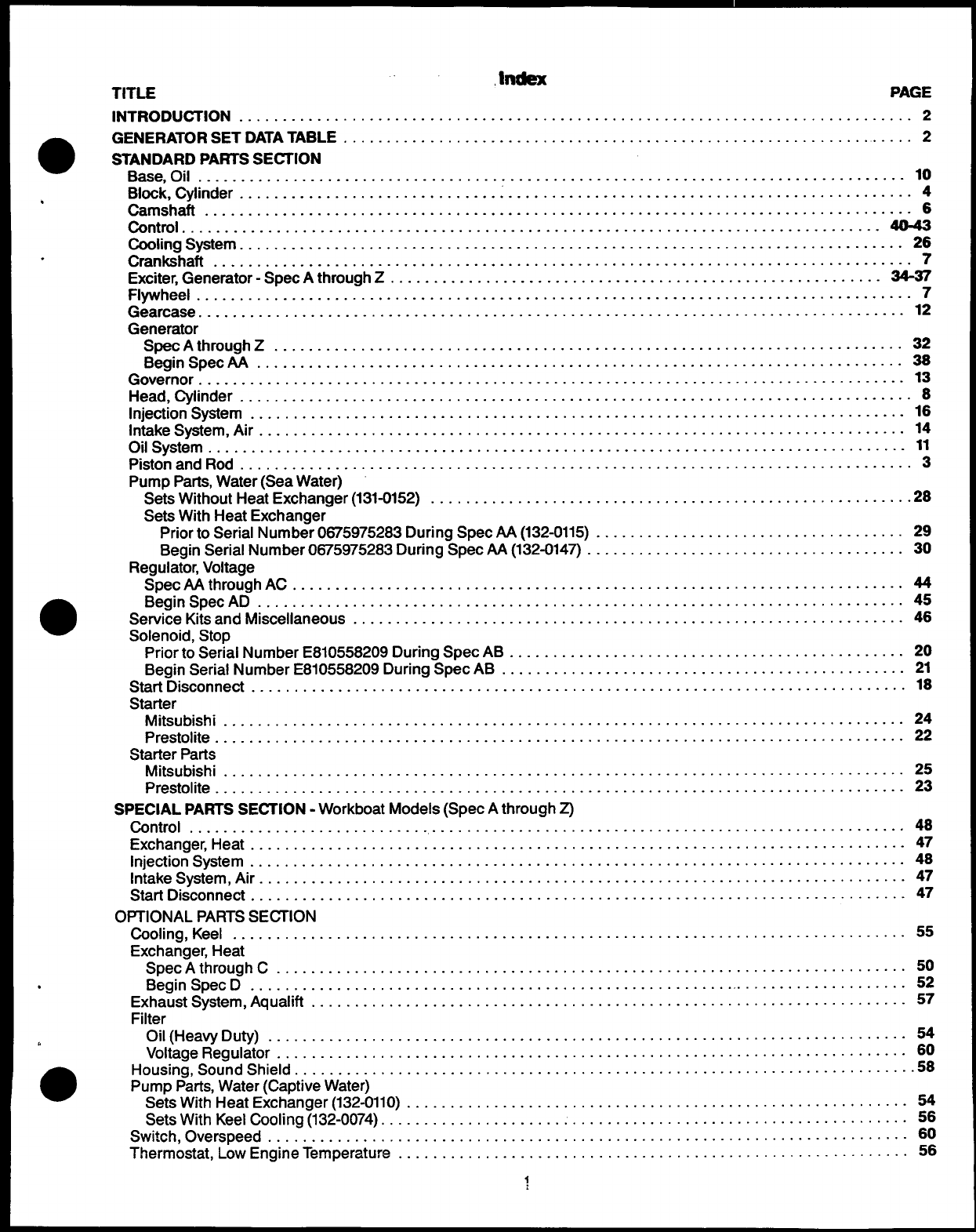
,Index
TITLE PAGE
INTRODUCTION .............................................................................-2
●GENERATORSETDATATABLE ..................................................................2
STANDARDPARTS SEHION
Base, Oil .........................................................................--..-...-10
Block, Cylinder .............................................................................-4
.Camshaft ................................................................................-- 6
Control ...........................................................................-....-40-43
Cooiing System ......................................................................... --.-26
.Crankshaft ...............................................................................-.7
Exciter, Generator-SpecAthrough Z........................................................-34-37
Flywheel .................................................................................--7
Gearcase ..........................................................................-.--.-..12
Generator
SpecAthroughZ .........................................................................32
Begin SpecAA ..........................................................................-=
Governor ........................................................................-....-..-.13
Head, Cylinder ......................................................................... -....8
injection System .......................................................................- ...-16
intake System, Air ..................................................................-.....-..14
Oil System ................................................................................-11
Piston and Rod ..............................................................................3
Pump Parts, Water(SeaWater)
SetsWithoutHeatExchanger(131-0152) ....................................................-...28
SetsWith HeatExchanger
Priorto Serial Number0875975283During SpecAA(132-0115) .................................... 29
Begin Serial Number0875975283During SpecAA(132-0147) ..................................... 30
Regulator,Voltage
SpecN4throughAC ....................................................................... 44
●Begin SpecAD ...........................................................................45
Service Kitsand Miscellaneous.. ........................................................--.-..46
Solenoid, Stop
PriortoSerial NumberE810558209 During SpecAB ..............................................20
Begin Serial NumberE810558209 During SpecAB ...............................................21
Start Disconnect ............................................................................18
Starter
Mitsubishi ...............................................................................24
Prestolite ................................................................................ 22
StarterParts
Mitsubishi ............................................................................... 25
Prestolite ................................................................................23
SPECIAL PARTSSECTION -WorkboatModels (SpecAthroughZ)
control ................................................................................... 48
Exchanger, Heat ...................................................................--.....--47
injection System ............................................................................48
[ntake System, Ah .........................................................................-.47
Start Disconnect ............................................................................47
OPTIONALPARTS SECTION
Cooling, Keel .........................................................................- ....55
Exchanger,Heat
SpecAthroughC ......................................................................... 50
.Begin Spec D............................................................................. 52
Exhaust System, Aqualift .............................................................--....--57
Filter
*Oil(HeavyDuty) .......................................................................... 54
Voltage Regulator ......................................................................... 60
●Housing, Sound Shield ......................................................................-58
PumpParts,Water (CaptiveWater)
SetsWith HeatExchanger(132-0110) ..........................................................54
SetsWith Keel Cooling (132-0074).. ........................................................... 56
Switch, Overspend ...............................................................-. . . . . . ...-60
Thermostat, Low EngineTemperature ...........................................................56
~
INTRODUCTION
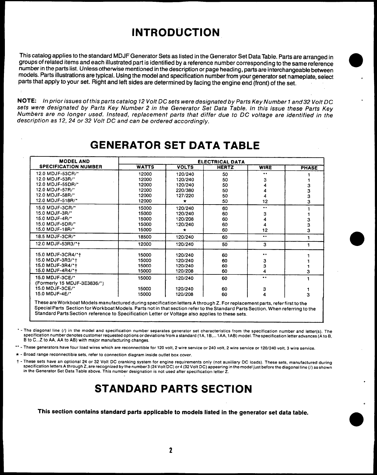
This catalog applies to the standard MDJF Generator Sets as listed in the Generator Set Data Table. Parts are arranged in
groups of related items and each illustrated part is identified by areference number corresponding to the same reference
number in the parts list. Unless otherwise mentioned in the description or page heading, parts are interchangeable between
models. Parts illustrations are typical. Using the model and specification number from your generator set nameplate, select
parts that apply to your set. Right and left sides are determined by facing the engine end (front) of the set.
NOTE: In prior issues of this parts catalog 12 Volt DC sets were designated by Parts Key Number 1arrd32 Volt DC
sets were designated by Parts Key Number 2in the Generator Set Data Table. In this issue these Parts Key
Numbers are no longer used. Instead, replacement parts that differ due to DC voltaae are identified in the
description as 12, 24 or 32 Volt DC and can be ordered accordingly.
GENERATOR SET DATA TABLE
MODEL AND ELECTRICAL DATA
SPECIFICATION NUMBER WATTS VOLTS HERTZ WIRE PHASE
12.0 MDJF-53cR/” 12000 120/240 50 . . 1
12.0 MDJF-53R/’ 12000 120/240 50 3 1
12.0 MDJF-55DR/’ 12000 120/240 50 43
12.0 MDJF-57R/’ 12000 220/380 50 43
12.0 MDJF-58R/’ 12000 127/220 50 43
12.0 MDJF-518R/” 12000 *50 12 3
15.0 MDJF-3cR/’ 15000 120/240 60 . . 1
15.0 MDJF-3R/” 15000 120/240 60 3 1
15.0 MDJF-4R/” 15000 120/208 60 4 3
15.0 MDJF-5DR/” 15000 120/240 60 4 3
15.0 MDJF-18R/” 15000 *60 12 3
18.5 MDJF-3CR/” 18500 120/240 60 . . 1
12.0 MDJF-53R3/’? 12000 120/240 50 3 1
15.0 MDJF-3CR4/”7 15000 120/240 60 . . 1
15.0 MDJF-3R3/’7 15000 120/240 60 3
15.0 MDJF-3R4/”-) 1
15000 120/240 3
15.0 MDJF-4R4/”7 15000 120/208 :4:
15.0 MDJF-3cE/” 15000 120/240 60 ., 1
(Formerly 15 MDJF-3E3836/”)
15.0 MDJF-3cE/” 15000 120/240 60 3 1
15.0 MDJF-4E/* 15000 120/208 60 4 3
These are Workboat Models manufactured during specification letters Athrough Z. For replacement parts, refer first to the
Special Parts Section for Work boat Models. Parts not in that section refer to the Standard Parts Section. When referring to the
Standard Parts Section reference to Specification Letter or Voltage also applies to these sets.
“-The diagonal line (/) in the model and specification number separates generator set characteristics from the specification number and letter(s). The
specification number denotes customer requested options or deviations from astandard (1A, 1B,... lAA, lAB) model. The specification Ietteradvances (A to B,
Bto C...Z to AA, AA to AB) with major manufacturing changes.
““ - These generators have four load wires which are reconnectable for 120 volt, 2wire service or 240 volt, 2wire service or 120/240 volt, 3wire service,
*-Broad range reconnectable sets, refer to connection diagram inside outlet box cover.
t-These sets have an optional 24 or 32 Volt DC cranking system for engine requirements only (not auxiliary DC loads). These sets, manufactured during
specification letters Athrough Z, are recognized by the number3 (24Volt DC) or4 (32 Volt DC) appearing in the model just before the diagonal line (/) as shown
in the Generator Set Data Table above. This number designation is not used after specification letter Z,
STANDARD PARTS SECTION
This section contains standard parts applicable to models listed in the generator set data table.
●✌
.
.
●
2
.
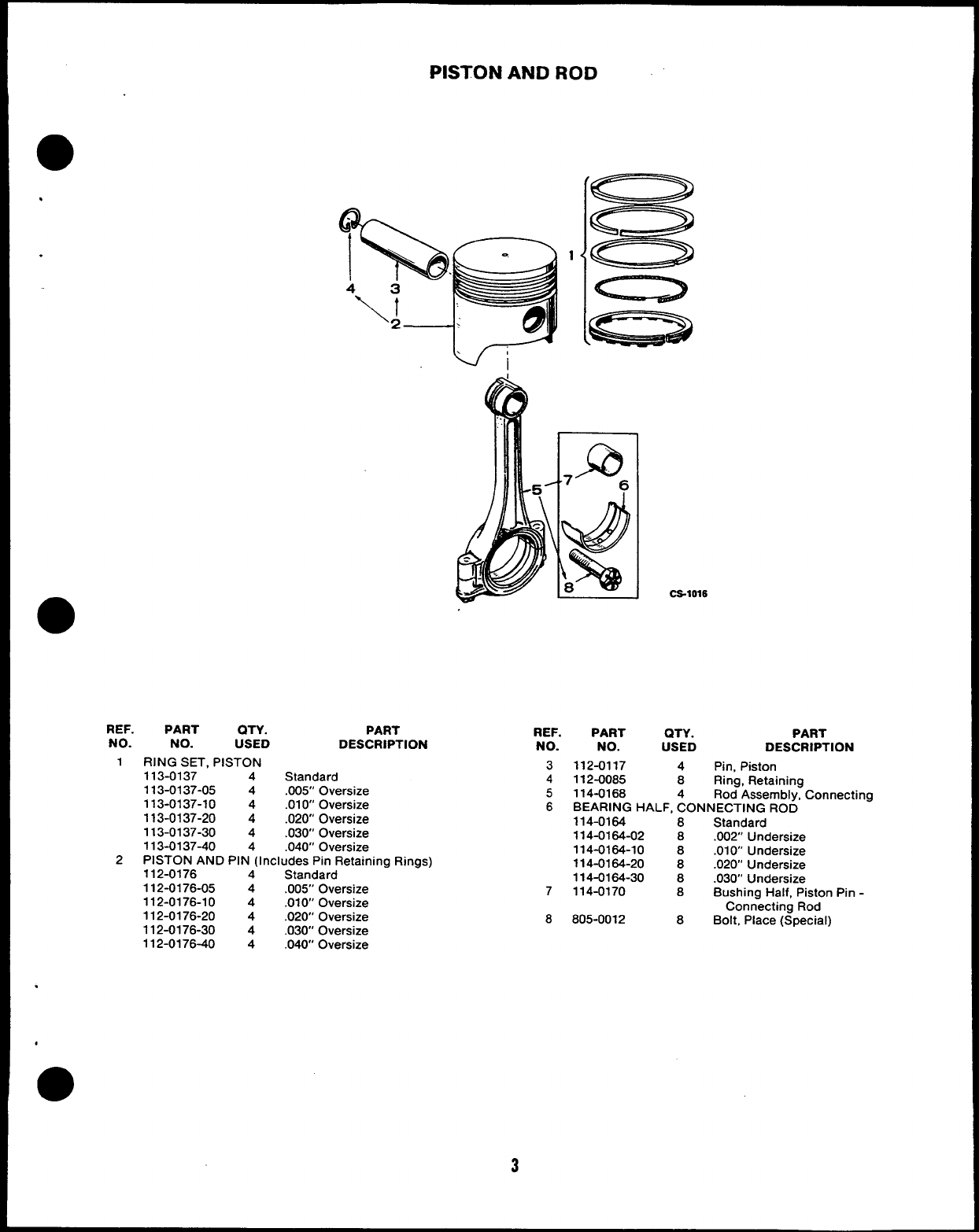
PISTON AND ROD
REF. PART QTY. PART
NO. NO. USED DESCRIPTION
1RING SET, PISTON
113-0137 4Standard
113-0137-05 4.005” Oversize
113-0137-10 4.010 Oversize
113-0137-20 4.020 Oversize
113-0137-30 4.030’ Oversize
113-0137-40 4.040” Oversize
2PISTON AND PIN (Includes Pin Retaining Rings)
112-0176 4Standard
112-0176-05 4.005” Oversize
112-0176-10 4.010’ Oversize
112-0176-20 4.020’ Oversize
112-0176-30 4.030” Oversize
112-0176-40 4.040 Oversize
.
●
3
REF. PART QTY. PART
NO. NO. USED DESCRIPTION
3112-0117 4Pin, Piston
4112-0085 8Ring, Retaining
5114-0168 Rod Assembly, Connecting
6BEARING HALF, ~ONNECTING ROD
114-0164 8Standard
114-0164-02 8.002” Undersize
114-0164-10 8.010” Undersize
114-0164-20 8.020” Undersize
114-0164-30 8.030’ Undersize
7114-0170 8Bushing Half, Piston Pin -
Connecting Rod
8805-0012 8Bolt, Place (Special)
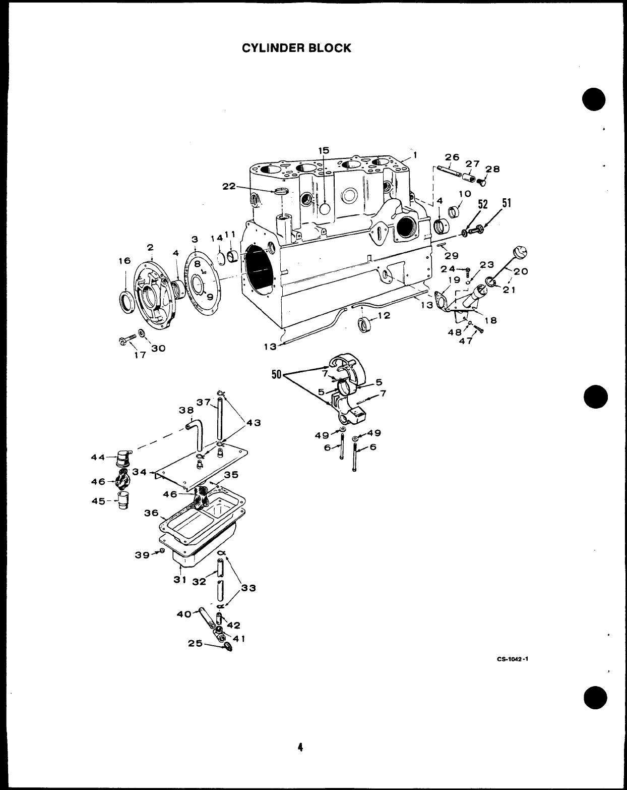
CYLINDER BLOCK
.
15
22—
0
A7
e“’.
\17 30
a?
,ST
50
*
7’
5
5
(’/’7
i) “
VI
.
.
,
●
4
C2-1W2-1
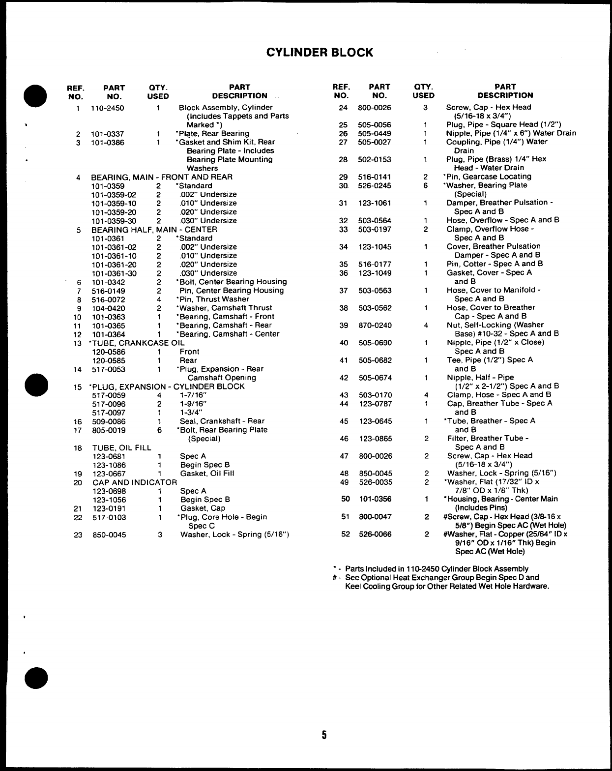
CYLINDER BLOCK
●REF.
NO.
1
i
2
3
4
5
6
7
8
9
10
11
12
13
14
●15
16
17
18
19
20
21
22
23
PART QTY. PART
NO. USED DESCRIPTION
110-2450 1Block Assembly, Cylinder
(Includes Tappets and Parts
Marked “)
101-0337 1“Pi~te, Rear Bearing
101-0386 1“Gasket and Shim Kit, Rear
Bearing Plate -Includes
Bearing Plate Mounting
Washers
BEARING, MAIN -FRONT AND REAR
101-0359 2‘Standard
101-0359-02 2.002’ Undersize
101-0359-10 2.010” Undersize
101-0359-20 2.020” Undersize
101-0359-30 2.030 Undersize
BEARING HALF, MAIN -CENTER
101-0361 2“Standard
101-0361-02 2.002’ Undersize
101-0361-10 2.010 Undersize
101-0361-20 2.020 Undersize
101-0361-30 2.030 Undersize
101-0342 2“Bolt, Center Bearing Housing
516-0149 2Pin, Center Bearing Housing
516-0072 4“Pin, Thrust Washer
104-0420 2“Washer, Camshaft Thrust
101-0363 1“Bearing, Camshaft -Front
101-0365 1“Bearing, Camshaft -Rear
101-0364 1“Bearing, Camshaft -Center
“TUBE, CRANKCASE OIL
120-0586 1Front
120-0585 1Rear
517-0053 1“Plug, Expansion -Rear
Camshaft Opening
“PLUG, EXPANSION -CYLINDER BLOCK
517-0059 41-7/16”
517-0096 21-9/16
517-0097 11-3/4’
509-0086 1Seal, Crankshaft -Rear
805-0019 6“Bolt, Rear Bearing Plate
(Special)
TUBE, OIL FILL
123-0681 1Spec A
123-1086 1Begin Spec B
123-0667 1Gasket, Oil Fill
CAP AND INDICATOR
123-0698 1Spec A
123-1056 1Begin Spec B
123-0191 1Gasket, Cap
517-0103 1“Plug, Core Hole -Begin
Spec C
850-0045 3Washer, Lock -Spring (5/1 6“)
REF. PART
NO. NO.
24 800-0026
25 505-0056
26 505-0449
27 505-0027
28 502-0153
29 516-0141
30. 526-C1245
31 123-1061
32 503-0564
33 503-0197
34 123-1045
35 516-0177
36 123-1049
37 503-0563
38 503-0562
39 870-0240
40 505-0690
41 505-0682
42 505-0674
43 503-0170
44 123-0787
45 123-0645
46 123-0865
47 800-0026
48 850-0045
49 526-0035
50 101-0356
51 800-0047
52 526-0066
QTY.
USED
3
1
1
1
1
2
6
1
1
2
1
1
1
1
1
4
1
1
1
4
1
1
2
2
2
2
1
2
2
PART
DESCRIPTION
Screw, Cap -Hex Head
(5/16-18 X3/4”)
Plug, Pipe -Square Head (1/2”)
Nipple, Pipe (1/4 x6) Water Drain
Coupling, Pipe (1/4”) Water
Drain
Plug, Pipe (Brass) 1/4” Hex
Head -Water Drain
“Pin, Gearcase Locating
“Washer, Bearing Plate
(Special)
Damper, Breather Pulsation -
Spec Aand B
Hose, Overflow -Spec Aand B
Clamp, Overflow Hose -
Spec Aand B
Cover, Breather Pulsation
Damper -Spec Aand B
Pin, Cotter -Spec Aand B
Gasket, Cover -Spec A
and B
Hose, Cover to Manifold -
Spec Aand B
Hose, Cover to Breather
Cap -Spec Aand B
Nut, Self-Locking (Washer
Base) #1 O-32 -Spec Aand B
Nipple, Pipe (1/2” xClose)
Spec Aand B
Tee, Pipe (1/2”) Spec A
and B
Nipple, Half -Pipe
(1/2” x2-1/2”) Spec Aand B
Clamp, Hose -Spec Aand B
Cap, Breather Tube -Spec A
and B
“Tube, Breather -Spec A
and B
Filter, Breather Tube -
Spec Aand B
Screw, Cap -Hex Head
(5/16-18 X3/4”)
Washer, Lock -Spring (5/16)
“Washer, Flat (17/32” ID x
7/8’ OD X1/8” Thk)
“Housing, Bearing -Center Main
(Includes Pins)
#Screw, Cap -Hex Head (3/8-1 6x
5/8”) Begin Spec AC (Wet Hole)
#Waeher, Flat- Copper (25/64” ID x
9/16” OD x1/16” Thk) Begin
Spec AC (Wet Hole)
“ - Parts Included in 110-2450 Cylinder Block Assembly
#- See Optional Heat Exchanger Group Begin Spec Dand
Keel Cooling Group for Other Related Wet Hole Hardware.
5
t
10
REF. PART
NO. NO.
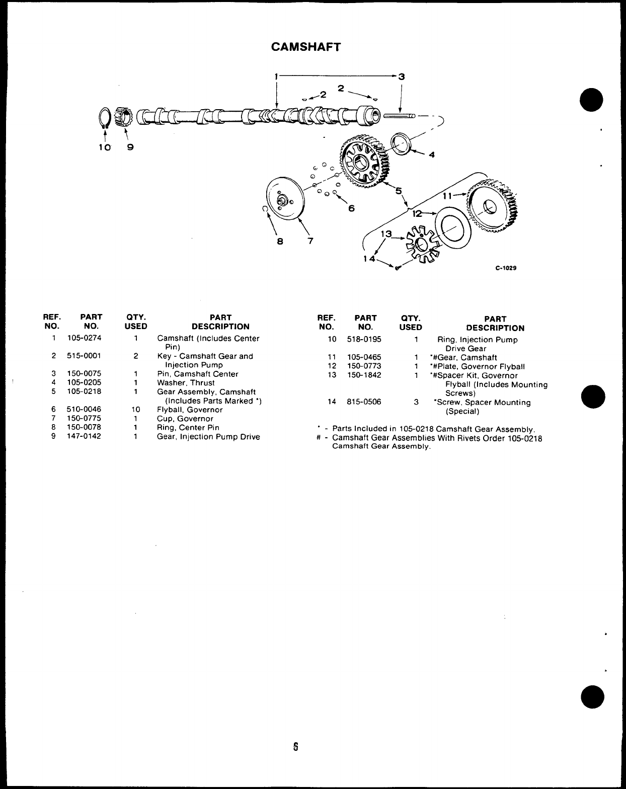
1105-0274
2515-0001
3150-0075
4105-0205
5105-0218
6510-0046
7150-0775
8150-0078
9147-0142
\
9
QTY.
USED
1
2
1
1
1
10
1
1
1
PART REF. PART QTY.
DESCRIPTION NO. NO. USED
Camshaft (Includes Center 10 518-0195 1
Pin)
Key -Camshaft Gear and 11 105-0465 1
Injection Pump 12 150-0773 1
Pin, Camshaft Center 13 150-1842 1
Washer, Thrust
Gear Assembly, Camshaft
(Includes Parts Marked “) 14 815-0506 3
Fly ball, Governor
CUD. Governor
PART
DESCRIPTION
Ring, Injection Pump
Drive Gear
“#Gear, Camshaft
“#Plate, Governor Flyball
“#Spacer Kit, Governor
Flyball (Includes Mounting
Screws)
“Screw, Spacer Mounting
(Special)
Ring, Center Pin “ - Parts Included in 105-0218 Camshaft Gear Assembly.
Gear, Injection Pump Drive #-Camshaft Gear Assemblies With Rivets Order 105-0218
Camshaft Gear Assembly.
6
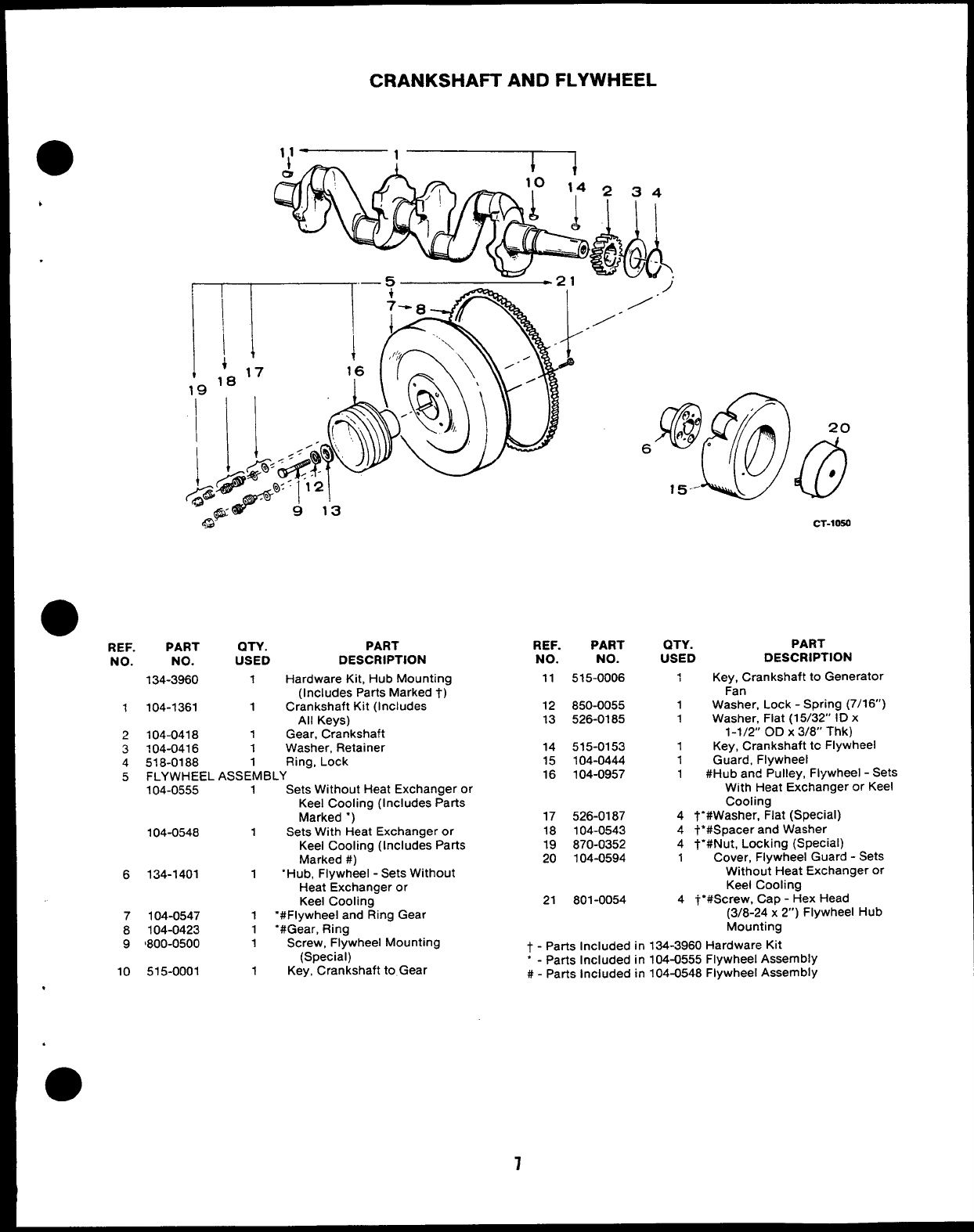
CRANKSHAFT AND FLYWHEEL
*
CT-1OSO
●REF.
NO.
PART
NO.
134-3960
QTY. PART
USED DESCRIPTION
1Hardware Kit, Hub Mounting
(Includes Parts Marked t)
1Crankshaft Kit (Includes
All Keys)
1Gear, Crankshaft
1Washer, Retainer
1Ring, Lock
ASSEMBLY
1Sets Without Heat Exchanger or
Keel Cooling (Includes Parts
Marked ‘)
1Sets With Heat Exchanger or
Keel Cooling (Includes Parts
Marked #)
1‘Hub, Flywheel -Sets Without
Heat Exchanger or
Keel Cooling
1“#Flywheel and Ring Gear
1“#Gear, Ring
REF.
NO.
11
PART
NO.
515-0006
QTY.
USED
1
PART
DESCRIPTION
Key, Crankshaft to Generator
Fan
Washer, Lock -Spring (7/16)
Washer, Flat (15/32” ID x
1-1/2” OD X3/8” Thk)
Key, Crankshaft tc Flywheel
Guard, Flywheel
#Hub and Pulley, Flywheel -Sets
104-1361 12
13
850-0055
526-0185
1
1
1
104-0418
104-0416
518-0188
FLYWHEEL
104-0555
2
3
4
5
14
15
16
515-0153
104-0444
104-0957
1
1
1With Heat Exchanger or Keel
Cooling
4T“#Washer, Flat (Special)
4t’#Spacer and Washer
4t“#Nut, Locking (Special)
1Cover, Flywheel Guard -Sets
Without Heat Exchanger or
Keel Cooling
4~’#Screw, Cap -Hex Head
(3/8-24 x2“) Flywheel Hub
Mounting
17
18
19
20
526-0187
104-0543
870-0352
104-0594
104-0548
6134-1401
21 801-0054
7
8
104-0547
104-0423
9‘800-0500 1Screw, Flywheel Mounting
(Special) t-Parts Included in 134-3960 Hardware Kit
10 515-0001 1Key, Crankshaft to Gear ‘-Parts Included in 104-0555 Flywheel Assembly
#-Parts Included in 104-0548 Flywheel Assembly
.
.
7
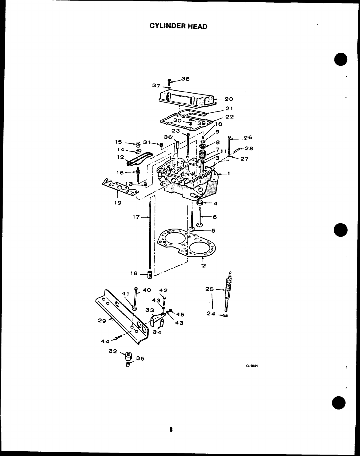
CYLINDER HEAD
37 _Y3”
23 ‘.’%5%2’
~/.
.-4
17
i
i
i
1’
!JT
6
*
0=’ ‘.
01
5
*,? “d! :,,,,,~
O*O
00
0
%,
J,,I1,,
-“i -m,, i’;
j
25
If
I
A.
8
●
.
32
-Q o 35
9-’ C-1041
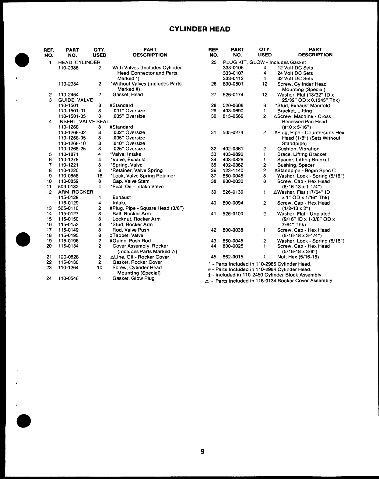
CYLINDER HEAD
REF. PART QTY. PART
●NO. NO. USED DESCRIPTION
1HEAD, CYLINDER
110-2986 2With Valves (Includes Cylinder
Head Connector and Parts
.Marked “)
110-2984 2‘Without Valves (Includes Parts
Marked #)
2110-2464 2Gasket, Head
.3GUIDE, VALVE
110-1501 8#Standard
110-1501-01 8.001” Oversize
110-1501-05 8.005” Oversize
4INSERT, VALVE SEAT
REF. PART QTY. PART
NO. NO. USED DESCRIPTION
25 PLUG KIT. GLOW -Includes Gasket
333-0106
333-0107
333-0112
800-0501
4
4
4
12
12 Volt DC Sets
24 Volt DC Sets
32 Volt DC Sets
Screw, Cylinder Head
Mounting (Special)
Washer, Flat (13/32’ ID x
25/32” OD X0.1345” Thk)
“Stud, Exhaust Manifold
Bracket, Lifting
AScrew, Machine -Cross
Recessed Pan Head
(#10 X5/16”)
#Plug, Pipe -Countersunk Hex
Head (1/8”) (Sets Without
Standpipe)
Cushion, Vibration
Brace, Lifting Bracket
Spacer, Lifting Bracket
Bushing, Spacer
#Standpipe -Begin Spec C
Washer, Lock -Spring (5/16)
Screw, Cap -Hex Head
(5/16-18 X1-1/4”)
AWasher, Flat (17/64 ID
X1“ OD X1/16” Thk)
Screw, Cap -Hex Head
(1/2-13 X2“)
Washer, Flat -Unplated
(9/16 ID X1-3/8” OD X
7/64” Thk)
Screw, Cap -Hex Head
(5/16-18 X3-1/4”)
Washer, Lock -Spring (5/16”)
Screw, Cap -Hex Head
(5/1 6-18 x3/8’)
Nut, Hex (5/16-1 8)
26
27 526-0174 12
28
29
30
520-0608
403-0690
815-0562
8
1
2
110-1268 8
110-1268-02 8
110-1268-05 8
110-1268-10 8
110-1268-25 8
110-1871 4
110-1278 4
110-1221 8
110-1220 8
110-0858 16
110-0859 8
509-0132 4
ARM, ROCKER
#Standard
.002” Oversize
.005” Oversize
.010 Oversize
.025” Oversize
●Valve, Intake
“Valve, Exhaust
“Spring, Valve
“Retainer, Valve Spring
“Lock, Valve Spring Retainer
Cap, Valve Stem
“Seal, Oil -Intake Valve
Exhaust
Intake
#Plug, Pipe -Square Head (3/8”)
Ball, Rocker Arm
Locknut, Rocker Arm
●Stud, Rocker Arm
Rod, Valve Push
4Tappet, Valve
#Guide, Push Rod
Cover Assembly, Rocker
(Includes Parts Marked A)
ALine, Oil -Rocker Cover
Gasket, Rocker .Cover
Screw, Cylinder Head
Mounting (Special)
Gasket, Glow Plug
31 505-0274 2
32
33
34
35
36
37
38
402-0361
403-0890
403-0826
402-0362
123-1140
850-0045
800-0030
2
1
1
2
2
8
8
5
6
7
8
9
10
11
12 39 526-0130 1
115-0128
115-0129
505-0110
115-0127
115-0150
115-0152
115-0149
115-0195
115-0196
115-0134
4
4
2
8
8
8
8
8
2
2
2
2
10
4
40 800-0094 2
13
14
15
16
41 526-0100 2
17
●18
:
42 800-0038 1
43
44 850-0045
800-0025
2
1
21
22
23
120-0628
115-0130
110-1264
110-0546
45 862-0015 1
‘-Parts Included in 110-2986 Cylinder Head.
#-Parts Included in 110-2964 Cylinder Head.
t-included in 110-2450 Cylinder Block Assembly.
A-Parts Included in 115-0134 Rocker Cover Assembly
24
.
9
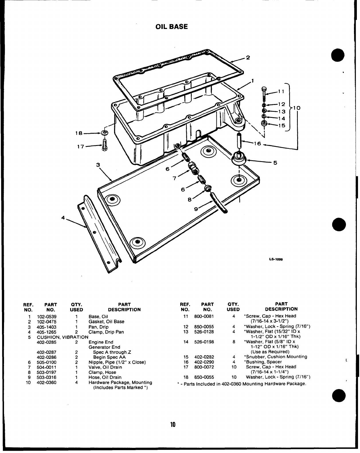
OIL BASE
.
LS-109S
.
)
REF. PART QTY. PART
NO: NO. USED DESCRIPTION
102-0539 1Base, Oil
;102-0475 1Gasket, Oil Base
3405-1403 1Pan, Drip
4405-1265 2Clamp, Drip Pan
5CUSHION, VIBRATION
402-0285 2Engine End
Generator End
402-0287 2Spec Athrough .Z
402-0286 2Begin Spec AA
6505-0100 2Nipple, Pipe (1/2 xClose) :
7504-0011 1Valve, Oil Drain
8503-0197 1Clamp, Hose
9503-0316 1Hose, Oil Drain
10 402-0360 4Hardware Package, Mounting
(Includes Parts Marked “) ●
REF. PART OTY. PART
NO. NO. USED DESCRIPTION
11 800-0081 4●Screw, Cap -Hex Head
(7/16-14 X3-1/2”)
12 850-0055 4‘Washer, Lock -Spring (7/1 6“)
13 526-0128 4“Washer, Flat (15/32’ ID x
1-1/2” OD X1/16” Thk)
14 526-0198 8“Washer, Flat (5/8” ID x
1-12” OD X1/16” Thk)
(Use as Required)
15 402-0282 4‘Snubber, Cushion Mounting
16 402-0290 4‘Bushing, Spacer
17 800-0072 10 Screw, Cap -Hex Head
(7/1 6-14 X1-1/4”)
18 850-0055 10 Washer, Lock -Spring (7/16)
“ - Parts Included in 402-0360 Mounting Hardware Package.
10
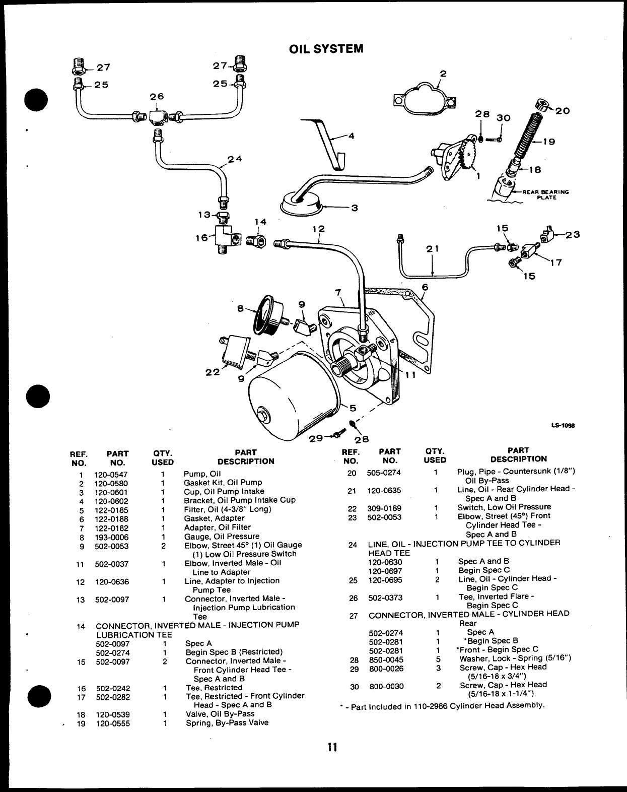
OIL SYSTEM
27 +
&27 2
fl-25
h
25
1? A
26
0
.
/w?- 18
/
“J&
%-‘
<
REARSEARING
PLATE
7’39 14
n-l, @Y--
3
15
\fib- 23
?
l’p& .4- K!
L-s-loss
PART
DESCRIPTION
Plug, Pipe -Countersunk (1/8”)
Oil By-Pass
Line, Oil -Rear Cylinder Head -
Spec Aand B
Switch, LOW Oi IPressure
Elbow, Street (45°) Front
Cylinder Head Tee -
PART REF. PART QTY.
DESCRIPTION NO. NO. USED
Pump, Oil 20 505-0274 1
Gasket Kit, Oil Pump
Cup, Oil Pump Intake 21 120-0635 1
Bracket, Oil Pump Intake Cup
Filter, Oil (4-3/8’ Long) 22 309-0169 1
Gasket, Adapter 23 502-0053 1
Adapter, Oil Filter
QTY.
USED
1
1
1
1
1
1
1
1
2
1
1
1
REF. PART
NO. NO.
1120-0547
2120-0580
3120-0601
4120-0602
5122-0185
6122-0188
7122-0182
8193-0006
9502-0053
Gauge, Oil Pressure
Elbow, Street 45° (1) Oil Gauge
(1) Low Oil Pressure Switch
Elbow, Inverted Male -Oil
Line to Adapter
Line, Adapter to Injection
Pump Tee
Connector, Inverted Male -
Injection Pump Lubrication
Tee
Spec Aand B
24 LINE, OIL -INJECTION PUMP TEE TO CYLINDER
HEAD TEE
120-0630 1Spec Aand B
120-0697 1Begin Spec C
25 120-0695 2Line, Oil -Cylinder Head -
Begin Spec C
26 502-0373 1Tee, Inverted Flare -
Begin Spec C
27 CONNECTOR, INVERTED MALE -CYLINDER HEAD
11 502-0037
12 120-0636
13 502-0097
14 CONNECTOR, INVERTED MALE -INJECTION PUMP
.LUBRICATION TEE
502-0097 1Spec A
502-0274 1Begin Spec B(Restricted)
15 502-0097 2Connector, Inverted Male -
Front Cylinder Head Tee -
Spec Aand B
Rear
502-0274 1Spec A
502-0281 1‘Begin Spec B
502-0281 1“Front -Begin Spec C
28 850-0045 5Washer, Lock -Spring (5/16”)
29 800-0026 3Screw, Cap -Hex Head
(5/16-18 X314”)
>-. .
30 600-0030 2Screw, Cap -Hex Head
(5/16-1 8X1-1/4”)
●16 502-0242 1Tee”, Restricted
17 502-0282 1Tee, Restricted -Front Cylinder
Head -SDec Aand B“ - Part Included in 110-2986 Cylinder Head Assembly
18 120-0539 1Valve, Oil By-Pass
A19 120-0555 1Spring, By-Pass Valve
11
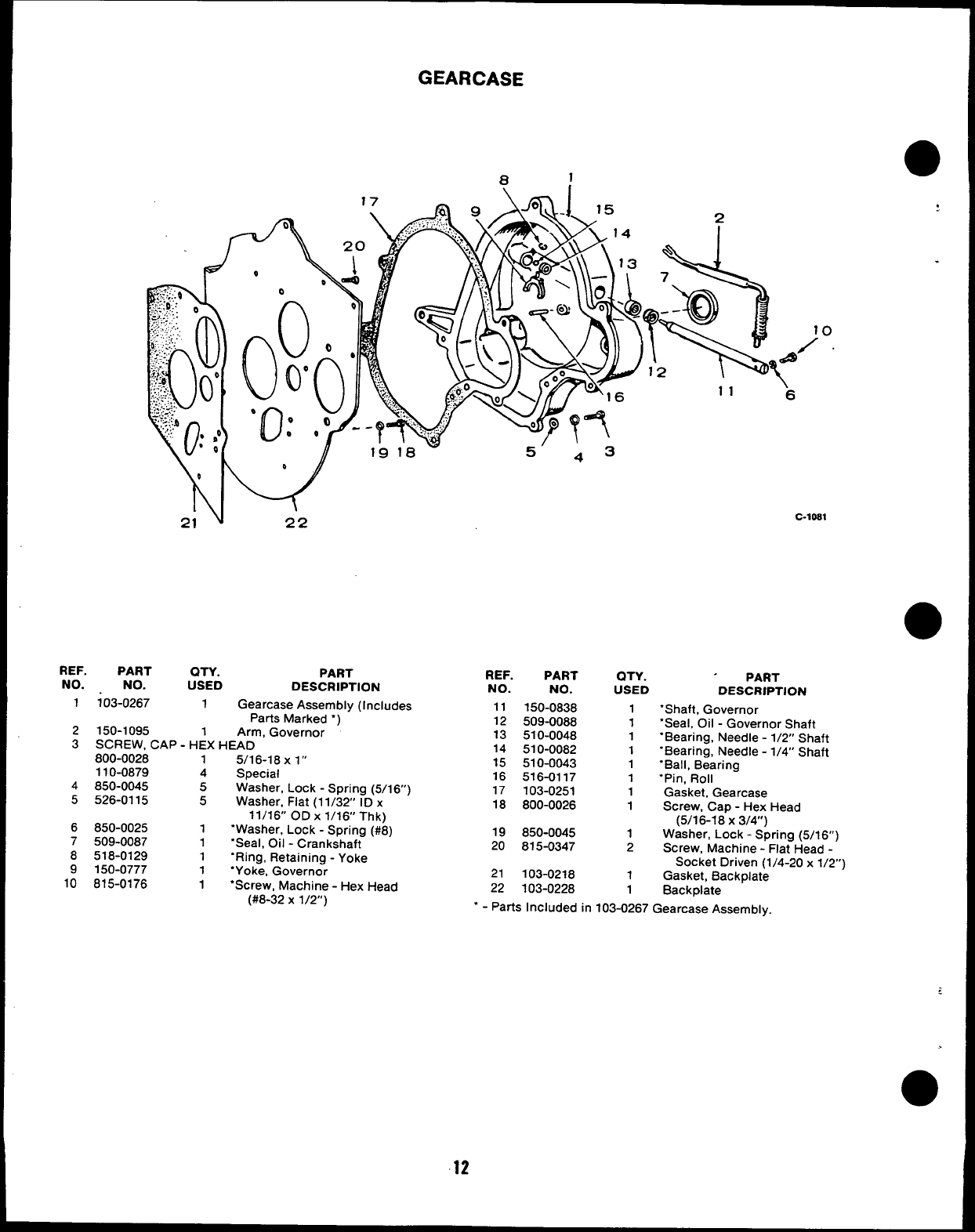
GEARCASE
o
C-losl
.
REF. PART QTY. PART
NO. NO. USED DESCRIPTION
1103-0267 1Gearcase Assembly (Includes
Parts Marked ‘~
2150-1095 1Arm, Governor ‘
3SCREW, CAP- HEX HEAD
800-0028 15/16-18 X1“
110-0879 4Special
4850-0045 5Washer, Lock -Spring (5/16”)
5526-0115 5Washer, Flat (1 1/32” ID x
11/16” OD x1/16 Thk)
6850-0025 1“Washer, Lock -Spring (#8)
7509-0087 1“Seal, oil -Crankshaft
8518-0129 1‘Ring, Retaining -Yoke
9150-0777 1‘Yoke, Governor
10 815-0176 1‘Screw, Machine -Hex Head
(#8-32 X1/2”)
REF. PART
NO. NO.
11 150-0838
12 509-0088
13 510-0048
14 510-0082
15 510-0043
18 516-0117
17 103-0251
18 800-0026
QTY. PART
USED DESCRIPTION
1
1
1
1
1
1
1
1
‘Shaft, Governor
“Seal. Oil -Governor Shaft
“Bearing, Needle -1/2” Shaft
“Bearing, Needle -1/4” Shaft
“Ball, Bearing
‘Pin, Roll
Gasket, Gearcase
Screw, Cap -Hex Head
(5/16-18 X3/4”)
19 850-0045 1Washer, Lock -Spring (5/16”)
20 815-0347 2Screw, Machine -Flat Head -
Socket Driven (1/4-20 x1/2”)
21 103-0218 1Gasket, Backplate
22 103-0228 1Back plate
‘-Parts Included in 103-0267 Gearcase Assembly.
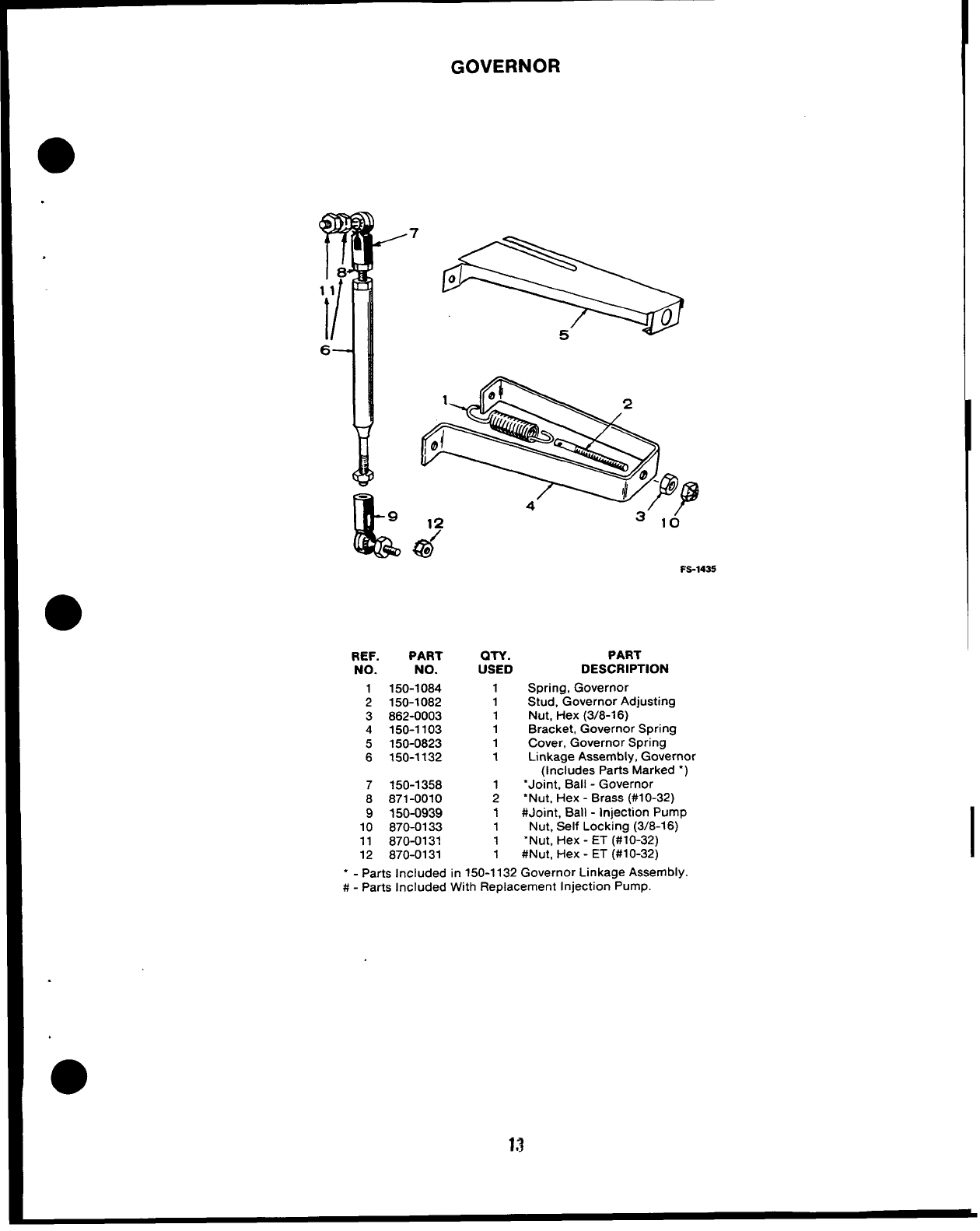
GOVERNOR
.
II
L9
T+
7
00
11
II o
5
6
Qif
Fs-1435
REF. PART QTY. PART
NO. NO. USED DESCRIPTION
1 150-1064 1Spring, Governor
2150-1082 1Stud, Governor Adjusting
3882-0003 1Nut, Hex (3/8-16)
4150-1103 1Bracket, Governor Spring
5150-0823 1Cover, Governor Spring
6150-1132 1Linkage Assembly, Governor
(Includes Parts Marked “)
7150-1358 1“Joint, Ball -Governor
8871-0010 2‘Nut, Hex -Brass (#10-32)
9150-0939 1#Joint, Ball -Injection Pump
10 870-0133 1Nut, Self Locking (3/8-16)
11 870-0131 1‘Nut, Hex -ET (#10-32)
12 870-0131 1#Nut, Hex -ET (#10-32)
“ - Parts Included in 150-1132 Governor Linkage Assembly.
#-Parts Included With Replacement Injection Pump.
13
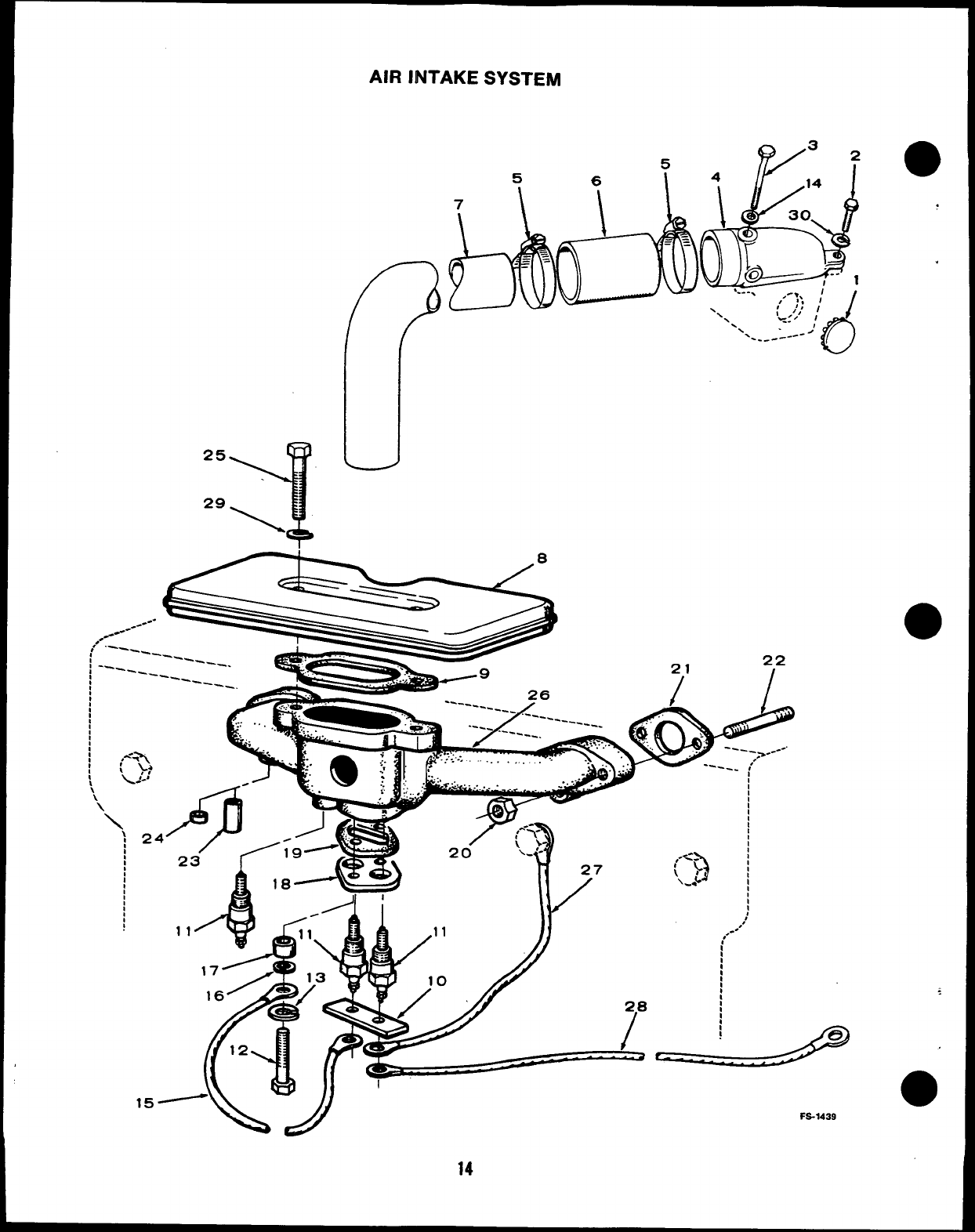
AIR INTAKE SYSTEM
25
Y
‘g\
3
5
&
2
4
\
14
30
r
d------ ;-- ,
L.-. ,-*, J
,/ ;;
‘\ i’
te:’,~ I
-,1
‘. ‘---------- >
D
0
28
/
AIR INTAKE SYSTEM
REF. PART
NO. NO.
1517-0186
2800-0006
3800-0015
4140-0645
5503-0365
6503-0691
7140-1278
8140-0803
9140-0584
10 332-0829
QTY.
USED
1
1
1
1
2
1
1
1
1
1
11 HEATER, MANIFOLD
154-0712 2
154-0712 3
12 114-0023 2
13 WASHER
850-0040 2
526-0015 1
526-0015 2
14 526-0108 1
PART
DESCRIPTION
Plug, Dot Button -Sets With
Sound Shield Housing
Screw, Cap -Hex Head
(1/4-20 x7/8’) Sets With
Sound Shield Housing
Screw, Cap -Hex Head
(1/4-20 x3“) Sets With
Sound Shield Housing
Adapter, Air Intake -Sets
With Sound Shield Housing
Clamp, Hose -Sets With
Sound Shield Housing
Hose, Rubber -Sets With
Sound Shield Housing
Tube, Intake -Sets With
Sound Shield Housing
Resonator
Gasket, Resonator
Jumper, Air Heater
12 and 24 Volt DC Sets
32 Volt DC Sets
Screw, Cap =Hex Head (Special)
Lock -Spring (1/4”)
Flat (9/32” ID x9/16” OD x
1/16” Thk)
24 Volt DC Sets
32 Volt DC Sets
Washer, Flat (17/84” ID x
7/16 OD x1/32” Thk) Sets
REF.
NO.
15
16
17
18
19
20
PART
NO.
LEAD
336-1408
338-1051
508-0102
508-0103
140-0705
140-0706
870-0137
Q-w.
USED
1
1
2
2
1
1
4
PART
DESCRIPTION
24 Volt DC Sets
32 Volt DC Sets
Washer, Insulator -24 and 32
Volt DC Sets
Bushing, Insulator
Plate, Heater
Gasket, Heater Plate
Nut, Hex -Self-Locking
(5/16-24)
21 154-0733 2Gasket, Intake Manifold
22 STUD, MANIFOLD MOUNTING
520-0011 25/1 6-24 X5/1 6-18 X1-7/16”
520-0338 25/16-1 8X5/1 6-24X 2-7/8”
23 123-1116 1“Tube, Breather -Spec Aand B
24 517-0104 1“Plug, Core Hole -Begin Spec C
25 800-0012 2Screw, Cap -Hex Head
(1/4-20 X2-1/4’)
26 MANIFOLD KIT, INTAKE (Includes Parts Marked “)
154-1376 1 12 and 24 Volt DC Sets
154-1379 1 32 Volt DC Sets
27 LEAD -Glow Plug to Air Heater
336-1504 2No. 1 and No. 4Cylinder
(12-1/4”)
336-1505 2No. 2 and No. 3Cylinder
(5-1/4”)
28 336-1331 1 Lead -Air Heater to Control
Solenoid
29 850-0040 2Washer, Lock -Spring (1/4”)
30 850-0040 1Washer, Lock -Spring (1/4”)
Sets With Sound Shield
With Sound Shield Housing Housing
“ - Parts Included in Intake Manifold Kits.
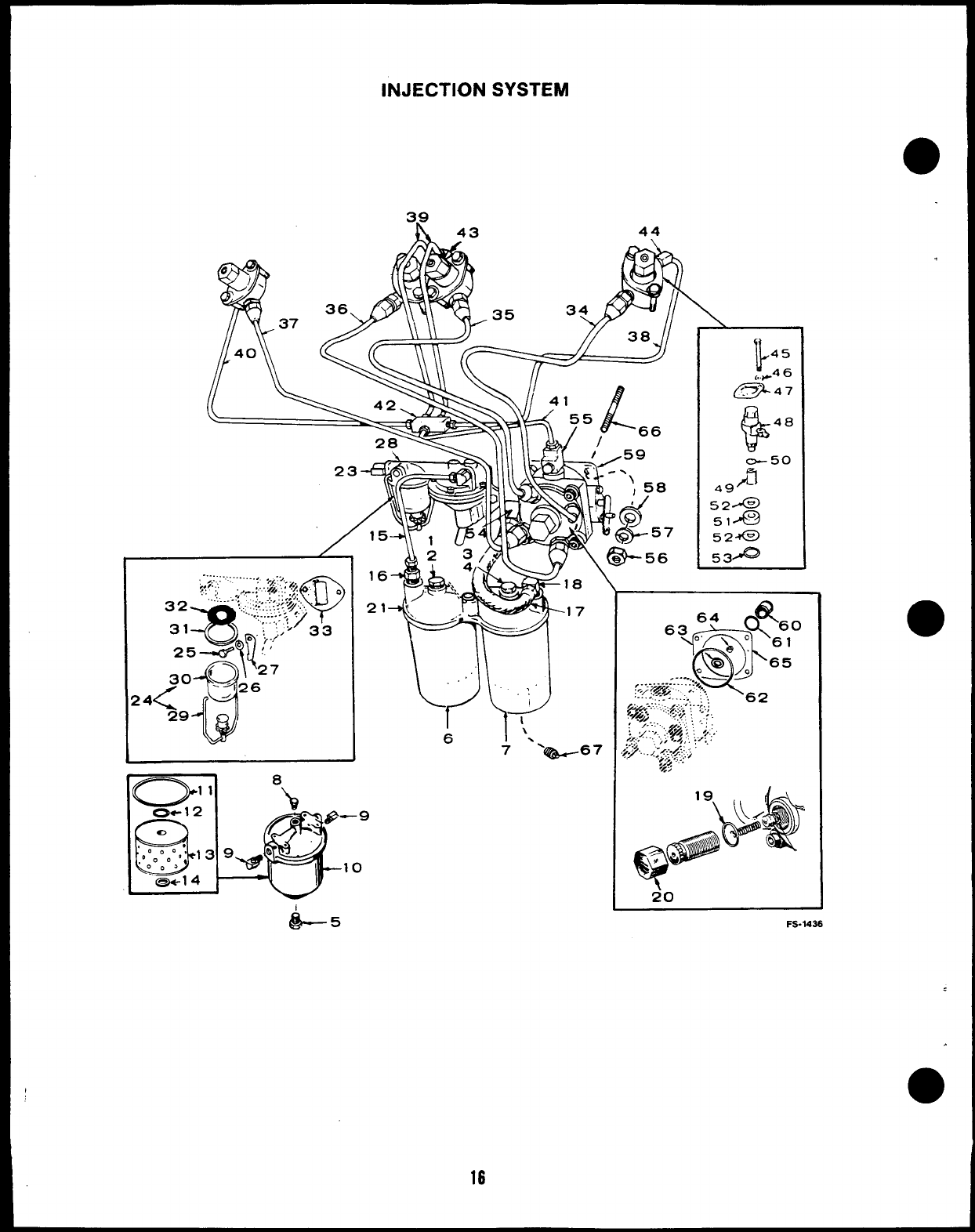
INJECTION SYSTEM
3R 43 44
R
o1,
37
40
}
45
,,,Z46
7/ . . II ~
/56 k8___
16
21
L5
20
FS-1436
16
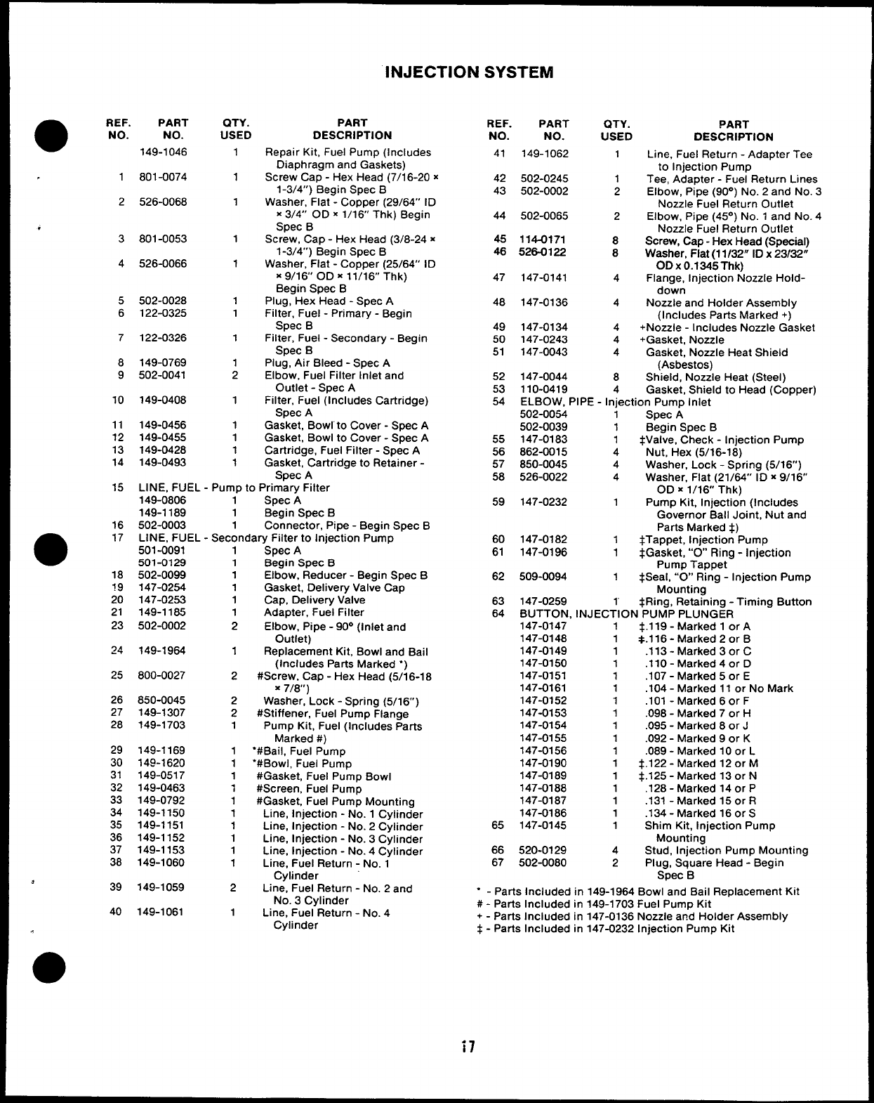
INJECTION SYSTEM
●REF. PART
NO. NO.
1
2
,
3
4
5
6
7
8
9
10
11
12
13
14
15
16
●17
18
?9
20
21
23
24
25
26
27
28
29
30
31
32
33
34
35
36
37
38
*39
40
149-1046
801-0074
526-0068
801-0053
526-0066
502-0028
122-0325
122-0326
149-0769
502-0041
149-0408
149-0456
149-0455
149-0428
149-0493
QTY.
USED
1
1
1
1
1
1
1
1
1
2
1
1
1
1
1
PART
DESCRIPTION
Repair Kit, Fuel Pump (Includes
Diaphragm and Gaskets)
Screw Cap -Hex Head (7/1 6-20 x
1-314”) Begin Spec B
Washer, Flat -Copper (29164” ID
x3/4” OD x1/16 Thk) Begin
Spec B
Screw, Cap -Hex Head (3/8-24 x
1-3/4”) Begin Spec B
Washer, Flat -Copper (25/64” ID
X9/16’ OD x11/16” Thk)
Begin Spec B
Plug, Hex Head -Spec A
Filter, Fuel -Primary -Begin
Spec B
Filter, Fuel -Secondary -Begin
Spec B
Plug, Air Bleed -Spec A
Elbow, Fuel Filter Inlet and
Outlet -Spec A
Filter, Fuel (Includes Cartridge)
Spec A
Gasket, Bowl to Cover -Spec A
Gasket, Bowl to Cover -Spec A
Cartridge, Fuel Filter -Spec A
Gasket, Cartridge to Retainer -
Spec A
LINE, FUEL -Pump to Primary Filter
149-0806 1Spec A
149-1189 1Begin Spec B
502-0003 1Connector, Pipe -Begin Spec B
LINE, FUEL -Secondary Filter to Iniection PumD
501-0091
501-0129
502-0099
147-0254
147-0253
149-1185
502-0002
149-1964
800-0027
850-0045
149-1307
149-1703
149-1169
149-1620
149-0517
149-0463
149-0792
149-1150
149-1151
149-1152
149-1153
149-1060
149-1059
149-1061
1
1
1
1
1
1
2
1
2
2
2
1
1
1
1
1
1
1
1
1
1
1
2
1
‘Spec A“
Begin Spec B
Elbow, Reducer -Begin Spec B
Gasket, Delivery Valve Cap
Cap, Delivery Valve
Adapter, Fuel Filter
Elbow, Pipe -90° (Inlet and
Outlet)
Replacement Kit, Bowl and Bail
(Includes Parts Marked “)
#Screw, Cap -Hex Head (5/16-1 8
X7/8”)
Washer, Lock -Spring (5/16”)
#Stiffener, Fuel Pump Flange
Pump Kit, Fuel (Includes Parts
Marked #)
“#Bail, Fuel Pump
“#Bowl, Fuel Pump
#Gasket, Fuel Pump Bowl
#Screen, Fuel Pump
#Gasket, Fuel Pump Mounting
Line, Injection -No. 1Cylinder
Line, Injection -No. 2Cylinder
Line, Injection -No. 3Cylinder
Line, Injection -No. 4Cylinder
Line, Fuel Return -No. 1
Cylinder
Line, Fuel Return -No. 2 and
No. 3Cylinder
Line, Fuel Return -No. 4
Cylinder
REF. PART
NO. NO.
41 149-1062
42 502-0245
43 502-0002
44 502-0065
45 114-0171
46 526-0122
47 147-0141
48 147-0136
49 147-0134
50 147-0243
51 147-0043
52 147-0044
53 110-0419
54
55
56
57
58
59
60
61
62
63
64
QTY. PART
USED DESCRIPTION
1
1
2
2
8
8
4
4
4
4
4
8
4
Line, Fuel Return -Adapter Tee
to injection Pump
Tee, Adapter -Fuel Return Lines
Elbow, Pipe (90°) No. 2 and No. 3
Nozzle Fuel Return Outlet
Elbow, Pipe (45°) No. 1 and No. 4
Nozzle Fuel Return Outlet
Screw, Cap -Hex Head (Special)
Washer, Flat (11/32” ID x23/32”
ODx O.1345Thk)
Flange, Injection Nozzle Hold-
down
Nozzle and Holder Assembly
(Includes Parts Marked +)
+Nozzle -Includes Nozzle Gasket
+Gasket, Nozzle
Gasket, Nozzle Heat Shield
(Asbestos)
Shield, Nozzle Heat (Steel)
Gasket, Shield to Head (Copper)
ELBOW, PIPE -Injection Pump Inlet
502-0054 1Spec A
502-0039 1Begin Spec B
147-0183 1tValve, Check -Injection Pump
862-0015 4Nut, Hex (5/16-18)
850-0045 4Washer, Lock -Spring (5/16”)
526-0022 4Washer, Flat (21/64” ID x9/16”
OD X 1/16 Thk)
147-0232 1Pump Kit, Injection (Includes
Governor Ball Joint, Nut and
Parts Marked t)
147-0182 1$Tappet, Injection Pump
147-0196 1$Gasket, “0” Ring -Injection
Pump Tappet
509-0094 1tSeal, “O” Ring -Injection Pump
Mounting
147-0259 ,$Ring, Retaining -Timing Button
BUTTON. INJECTION PUMP PLUNGER
147-0147
147-0148
147-0149
147-0150
147-0151
147-0161
147-0152
147-0153
147-0154
147-0155
147-0156
147-0190
147-0189
147-0186
147-0187
147-0166
65 147-0145
66 520-0129
67 502-0080
1
1
1
1
1
1
1
1
1
1
1
1
1
1
1
1
1
4
2
$.119- Marked 1orA
*.116 -Marked 2or B
.113 -Marked 3or C
.110-Marked40r D
.107 -Marked 5or E
.104 -Marked 11 or No Mark
.101 -Marked 6or F
.098 -Marked 7or H
.095 -Marked 8or J
.092 -Marked 9or K
.069 -Marked 10 or L
*.122 -Marked 12 or M
$.125- Marked 13 or N
.128 -Marked 140r P
.131 -Marked 15 or R
.134 -Marked 16 orS
Shim Kit, Injection Pump
Mounting
Stud, Injection Pump Mounting
Plug, Square Head -Begin
Spec B
“ - Parts Included in 149-1964 Bowl and Bail Replacement Kit
#-Parts Included in 149-1703 Fuel Pump Kit
+-pa~s Included in 147-0136 Nozzle and Holder Assembly
$- Parts Included in 147-0232 Injection Pump Kit
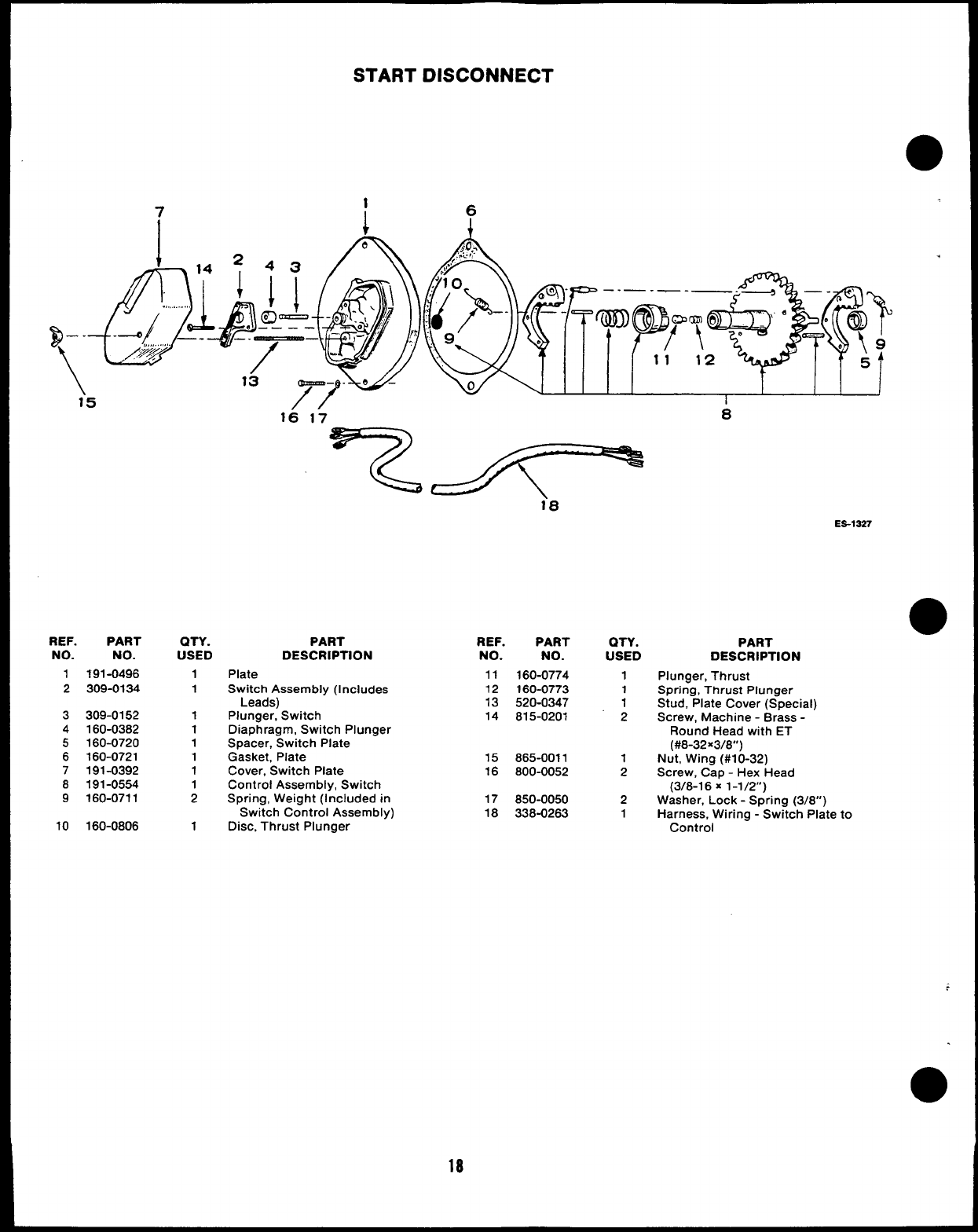
START DISCONNECT
B--
/1“5
ES-1327
REF. PART
NO. NO.
1191-0496
2309-0134
3309-0152
4160-0382
5160-0720
6160-0721
7191-0392
8191-0554
9160-0711
10 160-0806
QTY.
USED
1
1
1
1
1
1
1
1
2
1
PART
DESCRIPTION
Plate
Switch Assembly (Includes
Leads)
Plunger, Switch
Diaphragm, Switch Plunger
Spacer, Switch Plate
Gasket, Plate
Cover, Switch Plate
Control Assembly, Switch
Spring, Weight (Included in
Switch Control Assembly)
Disc, Thrust Plunger
REF. PART
NO. NO.
11 160-0774
12 160-0773
13 520-0347
14 815-0201
15 865-0011
16 800-0052
17 850-0050
18 338-0263
QTY.
USED
1
1
1
2
1
2
2
1
PART
DESCRIPTION
Plunger, Thrust
Spring, Thrust Plunger
Stud, Plate Cover (Special)
Screw, Machine -Brass -
Round Head with ET
(#8-32x3/8”)
Nut, Wing (#1 O-32)
Screw, Cap -Hex Head
(3/6-1 6X1-1/2”)
Washer, Lock -Spring (3/8”)
Harness, Wiring -Switch Plate to
Control
18
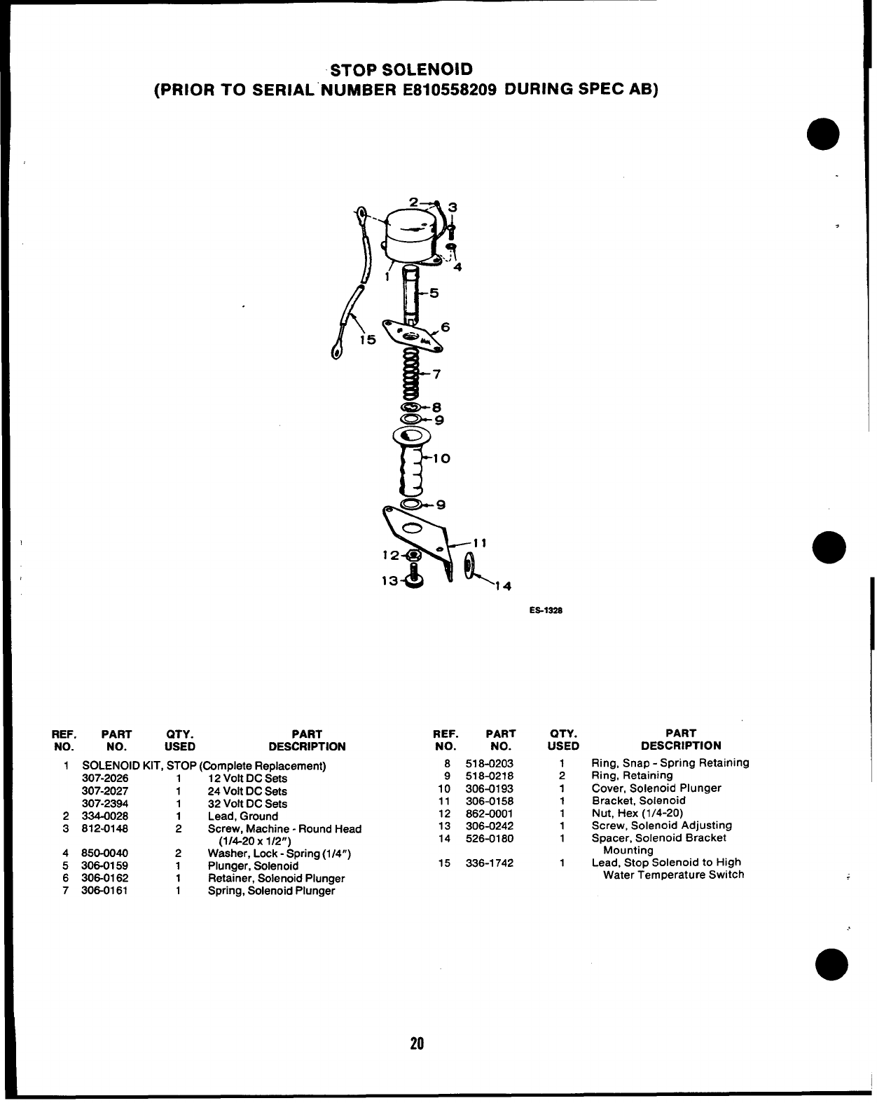
STOP SOLENOID
(PRIOR TO SERIAL NUMBER E8105582O9 DURING SPEC AB)
1
.
(f
15
b
REF. PART QTY. PART
NO. NO. USED DESCRIPTION
1SOLENOID KIT, STOP (Complete Replacement)
307-2026 1 12 Volt DC Sets
307-2027 124 Volt DC Sets
307-2394 132 Volt DC Sets
2334-0028 1Lead, Ground
3812-0148 2Screw, Machine -Round Head
(1/4-20 x1/2”)
4850-0040 2Washer, Lock -Spring (1/4”)
5306-0159 1Plunger, Solenoid
6306-0162 1Retainer, Solenoid Plunger
7306-0161 1Spring, Solenoid Plunger
‘14
ES-132S
20
REF.
NO.
8
9
10
11
12
13
14
15
PART
NO.
518-0203
518-0218
306-0193
306-0158
862-0001
306-0242
526-0180
336-1742
QTY.
USED
1
2
1
1
1
1
1
1
PART
DESCRIPTION
Ring, Snap -Spring Retaining
Ring, Retaining
Cover, Solenoid Plunger
Bracket, Solenoid
Nut, Hex (1/4-20)
Screw, Solenoid Adjusting
Spacer, Solenoid Bracket
Mounting
Lead, Stop Solenoid to High
Water Temperature Switch
,
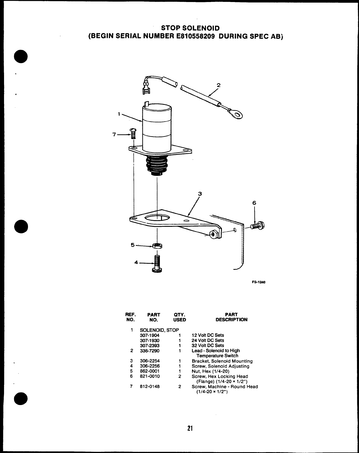
STOP SOLENOID
(BEGIN SERIAL NUMBER E8105582O9 DURING SPEC AB)
,
.
Ii
7—
3
6
J
-411@l
5
4
4
FS-1240
REF. PART QTY.
NO. NO. USED
1SOLENOID, STOP
307-1904 1
307-1930 1
307-2393 1
2336-7290 1
3306-2254 1
4306-2256 1
5862-0001 1
6821-0010 2
7812-0148 2
PART
DESCRIPTION
12 Volt DC Sets
24 Volt DC Sets
32 Volt DC Sets
Lead -Solenoid to High
Temperature Switch
Bracket, Solenoid Mounting
Screw, Solenoid Adjusting
Nut, Hex (1/4-20)
Screw, Hex Locking Head
(Flange) (1/4-20 x1/2’)
Screw, Machine -Round Head
(1/4-20 x1/2”)
21
1
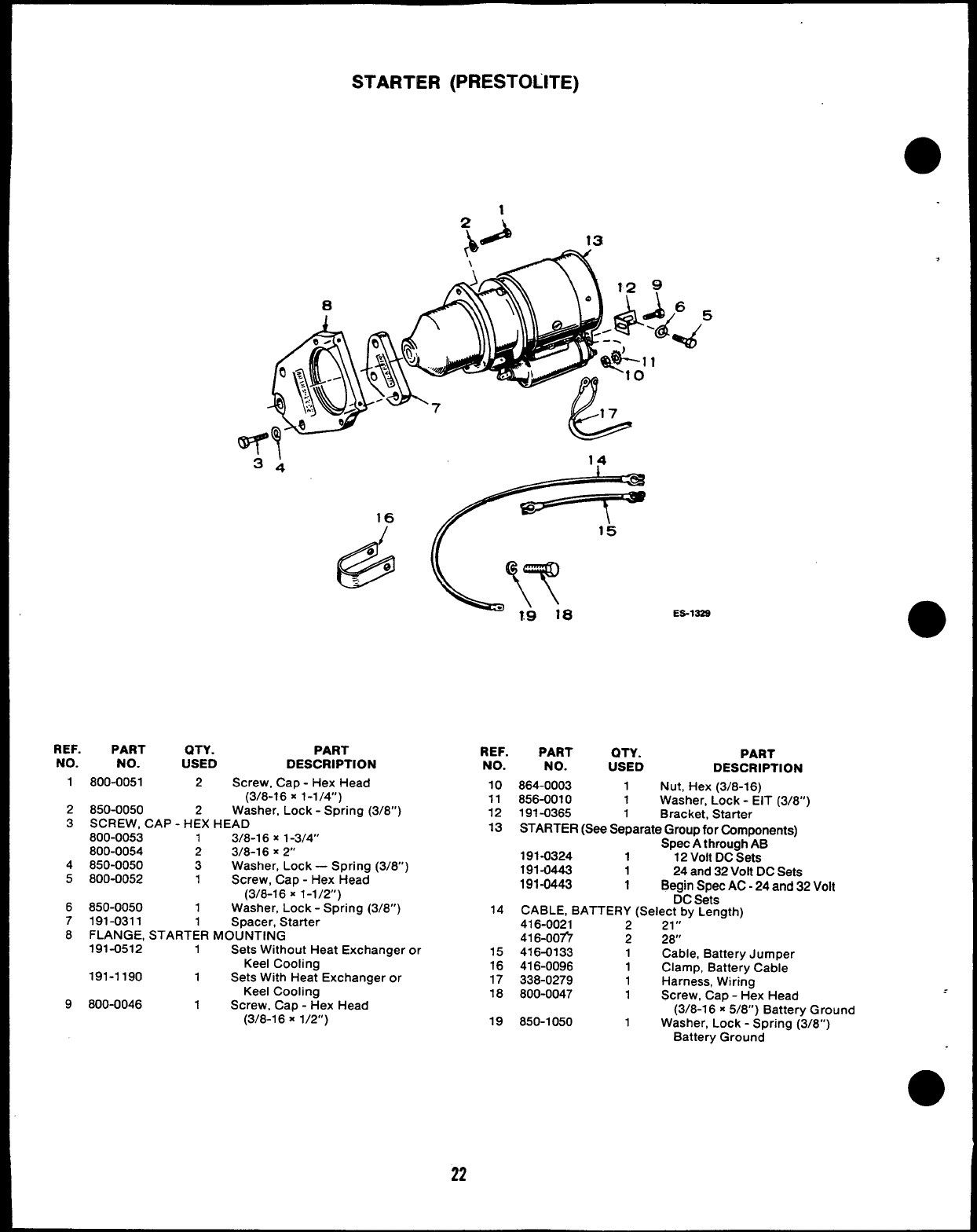
STARTER (PRESTOLITE)
3: \
16
/15
@
e
@
--
ES-1S2S
,
REF. PART QTY. PART
NO. NO. USED DESCRIPTION
1800-0051 2Screw, Cap -Hex Head
(3/8-16 X1-114”)
2850-0050 2Washer, Lock -Spring (3/8”)
3SCREW, CAP -HEX HEAD
800-0053 13f8-16 X1-314”
800-0054 2318-16 X2“
4850-0050 3Washer, Lock —Spring (3/8”)
5800-0052 1Screw, Cap -Hex Head
(3/8-16 X1-1/2”)
6850-0050 1Washer, Lock -Spring (3/8”)
7191-0311 1Spacer, Starter
8FLANGE, STARTER MOUNTING
191-0512 1Sets Without Heat Exchanger or
Keel Cooling
191-1190 1Sets With Heat Exchanger or
Keel Cooling
9800-0046 1Screw, Cap -Hex Head
(3/8-1 6X1/2”)
22
REF. PART QTY. PART
NO. NO. USED DESCRIPTION
10 864-0003 1Nut, Hex (3/8-16)
11 856-0010 1Washer, Lock -EIT (3/8”)
12 191-0365 1Bracket, Starter
13 STARTER (See Separate Group for Components)
Spec Athrough AB
191-0324 112 Volt DC Sets
191-0443 124 and 32 Volt DC Sets
191-0443 1Begin Spec AC -24 and 32 Volt
DC Sets
14 CABLE, BATTERY (Select by Length)
416-0021 221,,
416-OOfi 228
15 416-0133 1Cable, Battery Jumper
16 416-0096 1Clamp, Battery Cable
17 338-0279 1Harness, Wiring
18 800-0047 1Screw, Cap -Hex Head
(3/8-1 6x5/8”) Battery Ground
19 850-1050 1Washer, Lock -Spring (3/8”)
Battery Ground
*
REF.
NO.
1
2
3
4
5
6
7
8
13
14
I
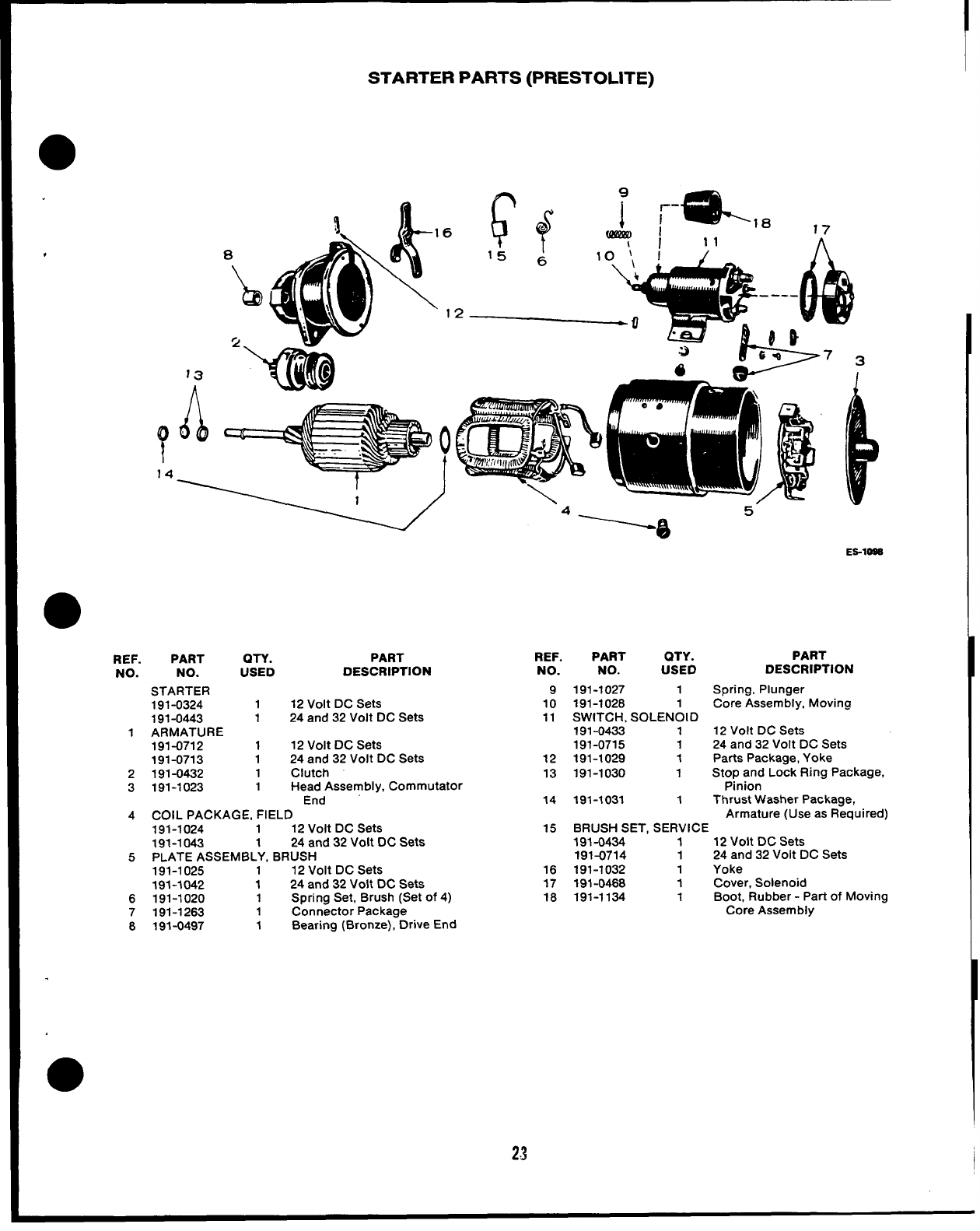
STARTER PARTS (PRESTOLITE)
6
1
7(’i o
I
PART QTY.
NO. USED
STARTER
191-0324 1
191-0443 1
ARMATURE
191-0712 1
191-0713 1
191-0432 1
191-1023 1
PART
DESCRIPTION
12 Volt DC Sets
24 and 32 Volt DC Sets
12 Volt DC Sets
24 and 32 Volt DC Sets
Clutch
Head Assembly, Commutator
End
COIL PACKAGE, FIELD
191-1024 112 Volt DC Sets
191-1043 1 24 and 32 Volt DC Sets
PLATE ASSEMBLY, BRUSH
191-1025 1 12 Volt DC Sets
191-1042 1 24 and 32 Volt DC Sets
191-1020 1Spring Set, Brush (Set of 4)
191-1263 1Connector Package
191-0497 1Bearing (Bronze), Drive End
REF.
NO.
9
10
11
12
13
14
15
16
17
18
PART QTY. PART
NO. USED DESCRIPTION
191-1027 1Spring, Plunger
191-1028 1Core Assembly, Moving
SWITCH, SOLENOID
191-0433 112 Volt DC Sets
191-0715 1 24 and 32 Volt DC Sets
191-1029 1Parts Package, Yoke
191-1030 1Stop and Lock Ring Package,
Pinion
191-1031 1Thrust Washer Package,
Armature (Use as Required)
BRUSH SET, SERVICE
191-0434 112 Volt DC Sets
191-0714 1 24 and 32 Volt DC Sets
191-1032 1Yoke
191-0468 1Cover, Solenoid
191-1134 1Boot, Rubber -Part of Moving
Core Assembly
23 I
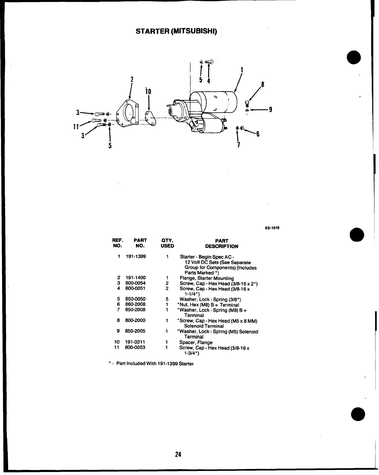
STARTER (MITSUBISHI)
2
Im
I
-@&
o
3P@- -. I_
Q=@- -—
q
**~. .e’ --
3
5
9
i
ES-1S?8
REF. PART QTY. PART
NO. NO. USED DESCRIPTION
1191-1399 1Starter -Begin Spec AC -
12 Volt DC Sets (See Separate
Group for Components) (Includes
Parts Marked ●)
2191-1400 1Flange, Starter Mounting
3800-0054 2Screw, Cap -Hex Head (3/6-1 6x2“)
4800-0051 2Screw, Cap -Hex Head (3/6-1 6x
1-1/4”)
5850-0050 5Washer, Lock -Spring (3/8”)
6860-2008 1●Nut, Hex (M8) B+Terminal
7850-2008 1●Washer, Lock -Spring (M8) B+
Terminal
8600-2000 1●Screw, Cap -Hex Head (M5 x8MM)
Solenoid Terminal
9650-2005 1●Washer, Lock -Spring (M5) Solenoid
Terminal
10 191-0311 1Spacer, Flange
11 800-0053 1Screw, Cap -Hex Head (3/6-16 x
1-3/4”)
“ - Part Included W[th 191-1399 Starter
24
I
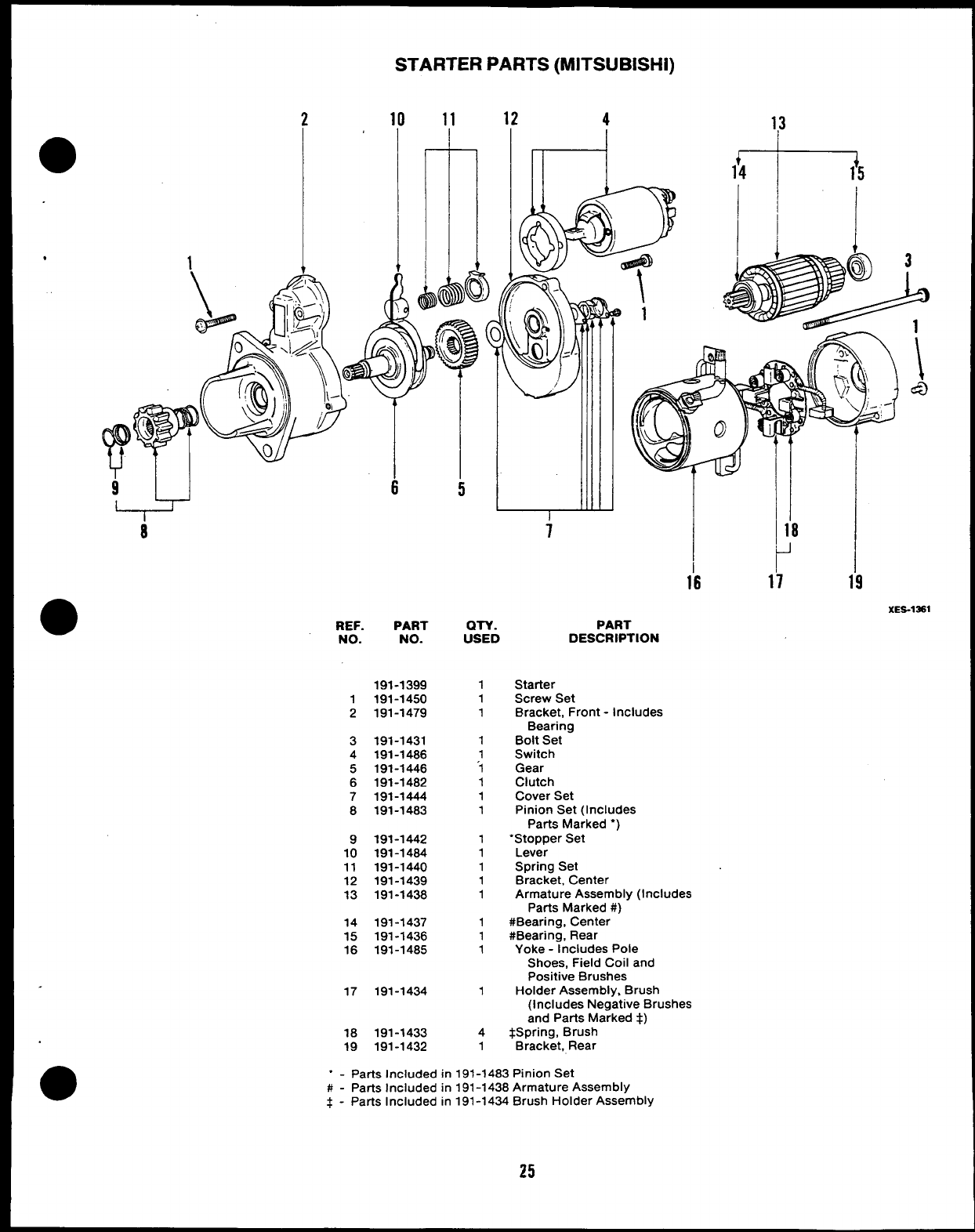
STARTER PARTS (MITSUBISHI)
210 11 12
4rtl
*
96
I
8
5
4
l-+
13
I
18
Y
1’6 17 19
XES-1*1
REF. PART QTY. PART
NO. NO. USED DESCRIPTION
191-1399
1191-1450
2191-1479
3191-1431
4191-1486
5191-1446
6191-1482
7191-1444
8191-1483
9191-1442
10 191-1464
11 191-1440
12 191-1439
13 191-1438
14 191-1437
15 191-1436
16 191-1485
1
1
1
1
1
1
1
1
1
1
1
1
1
1
1
1
1
17 191-1434 1
18 191-1433 4
19 191-1432 1
Starter
Screw Set
Bracket, Front -Includes
Bearing
Bolt Set
Switch
Gear
Clutch
Cover Set
Pinion Set (Includes
Parts Marked*)
“Stopper Set
Lever
Spring Set
Bracket, Center
Armature Assembly (Includes
Parts Marked #)
#Bearing, Center
#Bearing, Rear
Yoke -Includes Pole
Shoes, Field Coil and
Positive Brushes
Holder Assembly, Brush
(includes Negative Brushes
and Parts Marked $)
$3pring, Brush
Bracket, Rear
●✎
-Parts Included in 191-1483 Pinion Set
#-Parts Included in 191-1438 Armature Assembly
$- Parts Included in 191-1434 Brush Holder Assembly
25
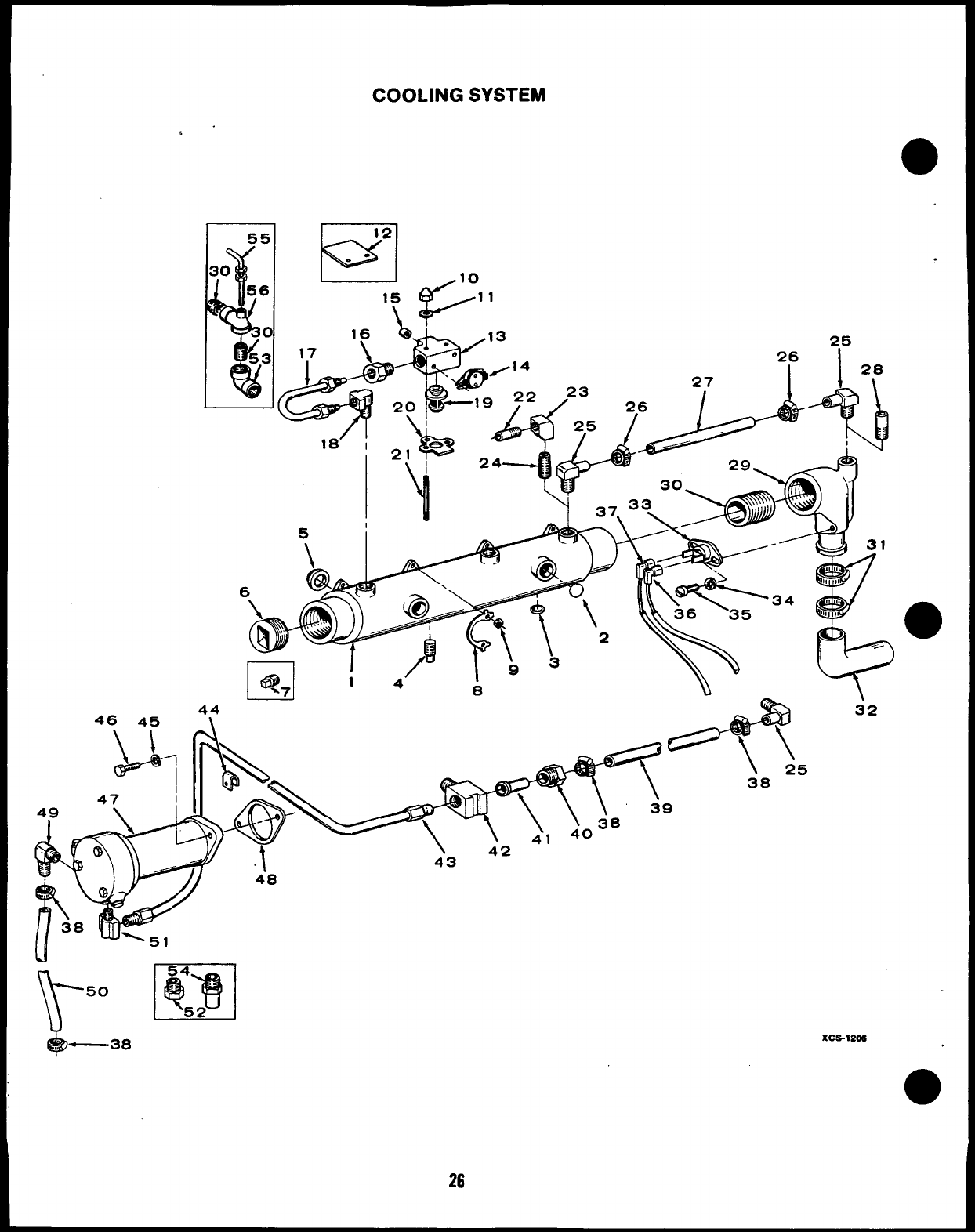
COOLING SYSTEM
25
26 I
u
I@ 14’
%7
46 45 4:
0\
54
~u
50 q~ 52
,, —38
26
●
\
XCS-1206
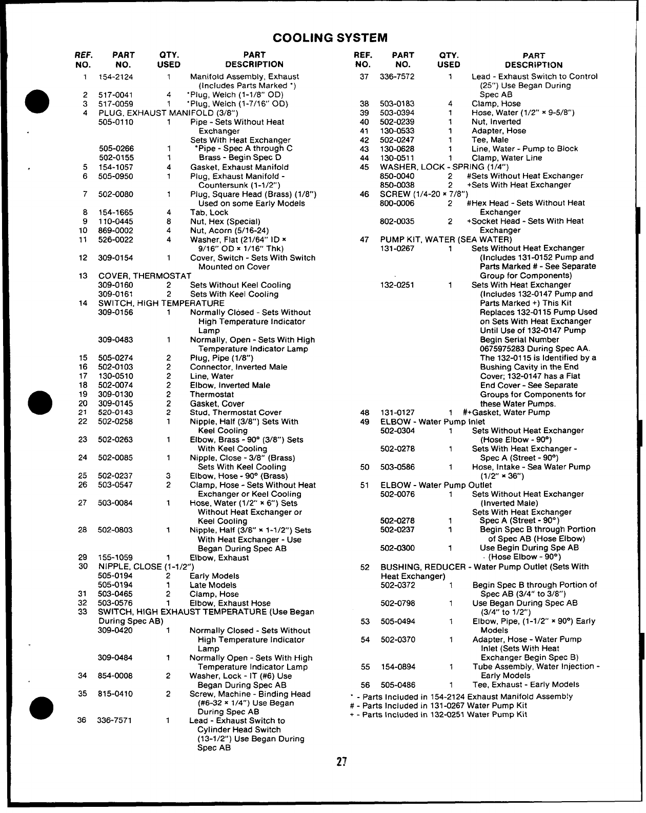
COOLING SYSTEM
REF. PART QTY. PART REF. PART QTY. PART
NO. NO. USED DESCRWT!ON
37 336-7572 1 Lead -Exhaust Switch to Control
(25”) Use Began During
Spec AB
38 503-0183 4Clamp, Hose
39 503-0394 1Hose, Water (1/2” x9-5/8”)
40 502-0239 1Nut, inverted
41 130-0533 1Adapter, Hose
42 502-0247 1Tee, Male
43 130-0628 1Line, Water -Pump to Block
44 130-0511 1Clamp, Water Line
45 WASHER. LOCK -SPRING (1/4”)
850-0040 2#Sets Without Heat Exchanger
850-0038 2+Sets With Heat Exchanger
46 SCREW (1/4-20 X7/8”)
800-0006 2#Hex Head -Sets Without Heat
Exchanger
802-0035 2+Socket Head -Sets With Heat
Exchanger
47 PUMP KIT, WATER (SEA WATER)
131-0267 1Sets Without Heat Exchanger
(Includes 131-0152 Pump and
Parts Marked #-See Separate
Group for Components)
132-0251 1Sets With Heat Exchanger
(Includes 132-0147 Pump and
Parts Marked +) This Kit
Replaces 132-0115 Pump Used
on Sets With Heat Exchanger
Until Use of 132-0147 Pump
Begin Serial Number
0675975283 During Spec AA.
The 132-0115 is Identified by a
Bushing Cavity in the End
Cover; 132-0147 has aFlat
End Cover -See Separate
Groups for Components for
these Water Pumps.
48 131-0127 1#+ Gasket, Water Pump
49 ELBOW -Water Pump Inlet
502-0304 1Sets Without Heat Exchanger
(Hose Elbow -90°)
502-0278 1Sets With Heat Exchanger -
Spec A(Street -90°)
50 503-0586 1Hose, Intake -Sea Water Pump
(1/2 x36)
51 ELBOW -Water Pump Outlet
502-0076 1Sets Without Heat Exchanger
(Inverted Male)
Sets With Heat Exchanger
502-0278 1Spec A(Street -90° )
502-0237 1Begin Spec Bthrough PoWlon
of Spec AB (Hose Elbow)
502-0300 1Use Begin During Spe AB
(Hose Elbow -90°)
52 BUSHING, REDUCER -Water Pump Outlet (Sets With
Heat Exchanger)
502-i1372 1Begin Spec Bthrough Portion of
Spec AB (3/4” to 3/8”)
502-0798 1Use Began During Spec AB
(3/4” to 1/2”)
53 505-0494 1Elbow, Pipe, (1-1/2” x90°) Early
Models
54 502-0370 1Adapter, Hose -Water Pump
Inlet (Sets With Heat
Exchanger Begin Spec B)
55 154-0894 1Tube Assembly, Water Injection -
Early Models
58 505-0486 1Tee, Exhaust -Early Models
“ - Parts Included in 154-2124 Exhaust Manifold Assemb!y
#-Parts Included in 131-0267 Water Pump Kit
+-parts Included in 132-0251 Water Pump Kit
NO. NO. USED DESCRIPTION
154-2124 1Manifold Assembly, Exhaust
(includes Parts Marked “)
517-0041 4“Plug, Welch (1-1/8” OD)
517-0059 “Plug, Welch (1-7/16’ 00)
PLUG, EXHAUSTIMANIFOLD (3/8”)
505-0110 1Pipe -Sets Without Heat
Exchanger
Sets With Heat Exchanger
505-0266 1“Pipe -Spec Athrough C
502-0155 1Brass -Begin Spec D
154-1057 4Gasket, Exhaust Manifold
505-0950 1Plug, Exhaust Manifold -
Countersunk (1-1/2’)
502-0080 1Plug, Square Head (Brass) (1/8”)
Used on some Early Models
154-1665 4Tab, Lock
110-0445 8Nut, Hex (Special)
869-0002 4Nut, Acorn (5/16-24)
526-0022 4Washer, Flat (21/64” ID x
9/16” OD X1/16” Thk)
309-0154 1Cover, Switch -Sets With Switch
Mounted on Cover
COVER, THERMOSTAT
309-0160 2Sets Without Keel Cooling
309-0161 2Sets With Keel Cooling
1
●2
3
4
.5
6
7
8
9
10
11
12
13
14 SWITCH, HIGH TEMPERATURE
309-0156 1Normally Closed -Sets Without
High Temperature Indicator
Lamp
Normally, Open -Sets With High
Temperature Indicator Lamp
Plug, Pipe (1/8)
Connector, Inverted Male
Line, Water
Elbow, Inverted Male
Thermostat
Gasket, Cover
Stud, Thermostat Cover
Nipple, Half (3/8”) Sets With
Keel Cooling
Elbow, Brass -90° (3/8) Sets
With Keel Cooling
Nipple, Close -3/8” (Brass)
Sets With Keel Cooling
Elbow, Hose -90° (Brass)
Clamp, Hose -Sets Without Heat
Exchanger or Keel Cooling
Hose, Water (1/2” x6) Sets
Without Heat Exchanger or
Keel Cooling
Nipple, Half (3/6” x1-1/2”) Sets
With Heat Exchanger -Use
Began During Spec AB
Elbow, Exhaust
309-0483 1
15
16
17
18
505-0274
502-0103
130-0510
502-0074
309-0130
309-0145
520-0143
502-0258
2
2
2
2
2
2
2
1
●19
20
21
22
23 502-0263 1
24 502-0085 1
25
26
502-0237
503-0547
3
2
27 503-0084 1
28 502-0803 1
29
30
155-1059 1
NIPPLE, CLOSE (1-1/2”)
505-0194 2Early Models
505-0194 1Late Models
503-0465 2Clamp, Hose
503-0576 1Elbow, Exhaust Hose
SWITCH, HIGH EXHAUST TEMPERATURE (Use Began
During Spec AB)
309-0420 1Normally Closed -Sets Without
High Temperature Indicator
Lamp
309-0484 1Normally Open -Sets With High
Temperature Indicator Lamp
854-0008 2Washer, Lock -IT (#6) Use
Began During Spec AB
815-0410 2Screw, Machine -Binding Head
(#6-32 x1/4”) Use Began
During Spec AB
336-7571 1Lead -Exhaust Switch to
31
32
33
34
35
●36
Cylinder Head Switch
(13-1/2”) Use Began During
Spec AB
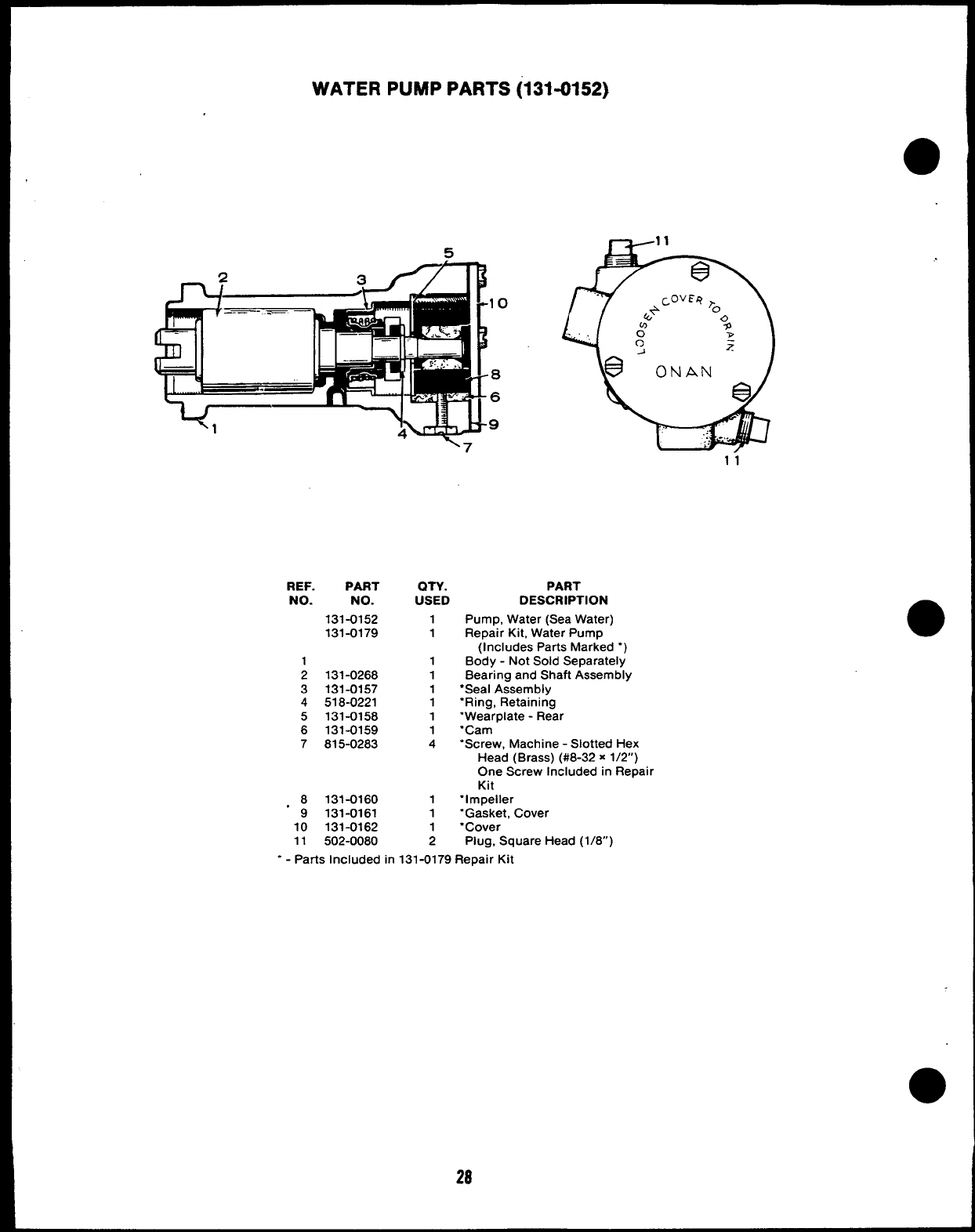
WATER PUMP PARTS (131=0152)
al 10
-? M: 9
\7
3
d
ONAN
e
.: ...
,;..
REF. PART QTY. PART
NO. NO. USED DESCRIPTION
131-0152 1Pump, Water (Sea Water)
131-0179 1Repair Kit, Water Pump
(Includes Parts Marked “)
1 1 Body -Not Sold Separately
2131-0268 1Bearing and Shaft Assembly
3131-0157 1●Seal Assembly
4518-0221 1“Ring, Retaining
5131-0158 1“Wearplate -Rear
6131-0159 1“Cam
7815-0283 4“Screw, Machine -Slotted Hex
Head (Brass) (#8-32 x1/2”)
One Screw Included in Repair
Kit
.8131-0160 1“Impeller
9131-0161 1“Gasket, Cover
10 131-0162 1“Cover
11 502-0080 2Plug, Square Head (1/8”)
.- Parts Included in 131-0179 Repair Kit
●
28
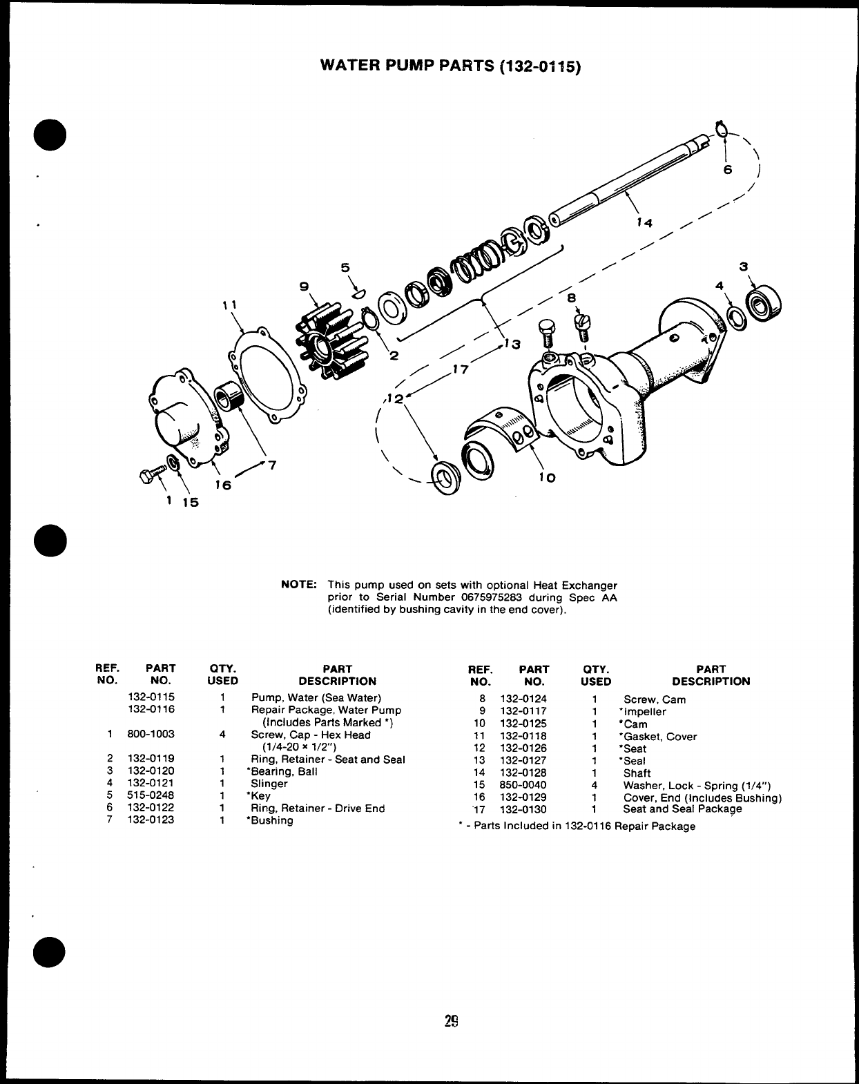
WATER PUMP PARTS (132-Of 15)
.
REF. PART
No. NO.
132-0115
132-0116
1800-1003
2132-0119
3132-0120
4132-0121
5515-0248
6132-0122
7132-0123
NOTE: This pump used on sets with optional Heat Exchanger
prior to Serial Number 0675975283 during Spec AA
(identified by bushing cavity in the end cover).
QTY. PART
USED DESCRIPTION
1
1
4
1
1
1
1
1
1
Pump, Water (Sea Water)
Repair Package, Water Pump
(Includes Parts Marked ●)
Screw, Cap -Hex Head
(1/4-20 X1/2”)
Ring, Retainer -Seat and Seal
‘Bearing, Ball
Slinger
“Key
Ring, Retainer -Drive End
“Bushing
●
REF. PART QTY. PART
NO. NO. USED DESCRIPTION
8132-0124 1Screw, Cam
9132-0117 1“Impeller
10 132-0125 1●Cam
11 132-0118 1‘Gasket, Cover
12 132-0126 1‘Seat
13 132-0127 1‘Seal
14 132-0128 1Shaft
15 850-0040 4Washer, Lock -Spring (1/4”)
16 132-0129 1Cover, End (Includes Bushing)
“17 132-0130 1Seat and Seal Package
“ - Parts Included in 132-0116 Repair Package
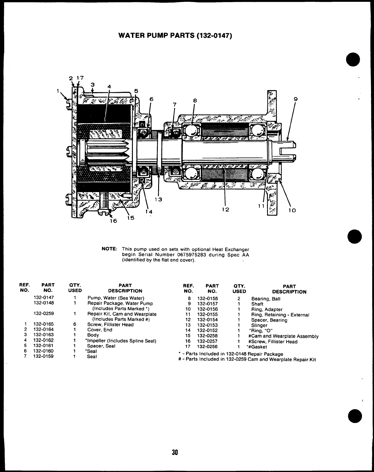
WATER PUMP PARTS (132-0147)
REF. PART
NO. NO.
132-0147
132-0148
132-0259
1132-0165
2132-0164
3132-0163
4132-0162
5132-0161
6132-0160
7132-0159
1
16
NOTE:
i5
1‘2
This pump used on sets with optional Heat Exchanger
begin Serial Number 0675975283 during Spec AA
(identified by the flat end cover).
QTY. PART REF. PART
USED QTY.
DESCRIPTION NO. NO. USED
1
1
1
6
1
1
1
1
1
1
Pump, Water (Sea Water) 8132-0158 2
Repair Package, Water Pump 9132-0157 1
(Includes Parts Marked “) 10 132-0156 1
Repair Kit, Cam and Wearplate 11 132-0155 1
(Includes Parts Marked #) 12 132-0154 1
Screw, Fillister Head 13 132-0153 1
Cover, End 14 132-0152 1.
PART
DESCRIPTION
Bearing, Ball
Shaft
Ring, Adapter
Ring, Retaining -External
Spacer, Bearing
Slinger
Ring, “0”
Body 15 132-0258 1#Cam and Wearplate Assembly
“Impeller (Includes Spline Seal) 16 132-0257 1#Screw. Fillister Head
Spacer, Seal 17 132-0256 1“#Gasket
“Seal “ - Parts Included in 132-0148 Repair Package
Seal #-Parts Included in 132-0259 Cam and Wearplate Repair Kit
30
GENERATOR -SPEC ATHROUGH Z
I t I I I 5
204
19+
32
G-IW5
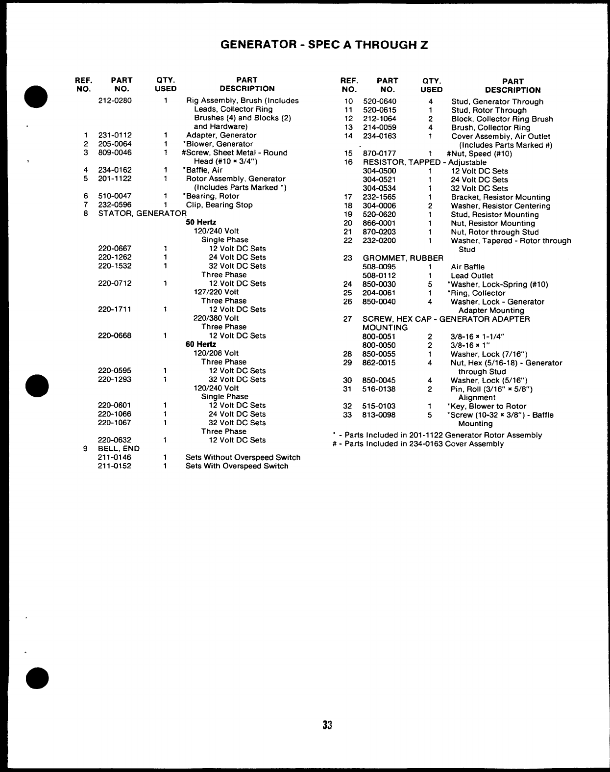
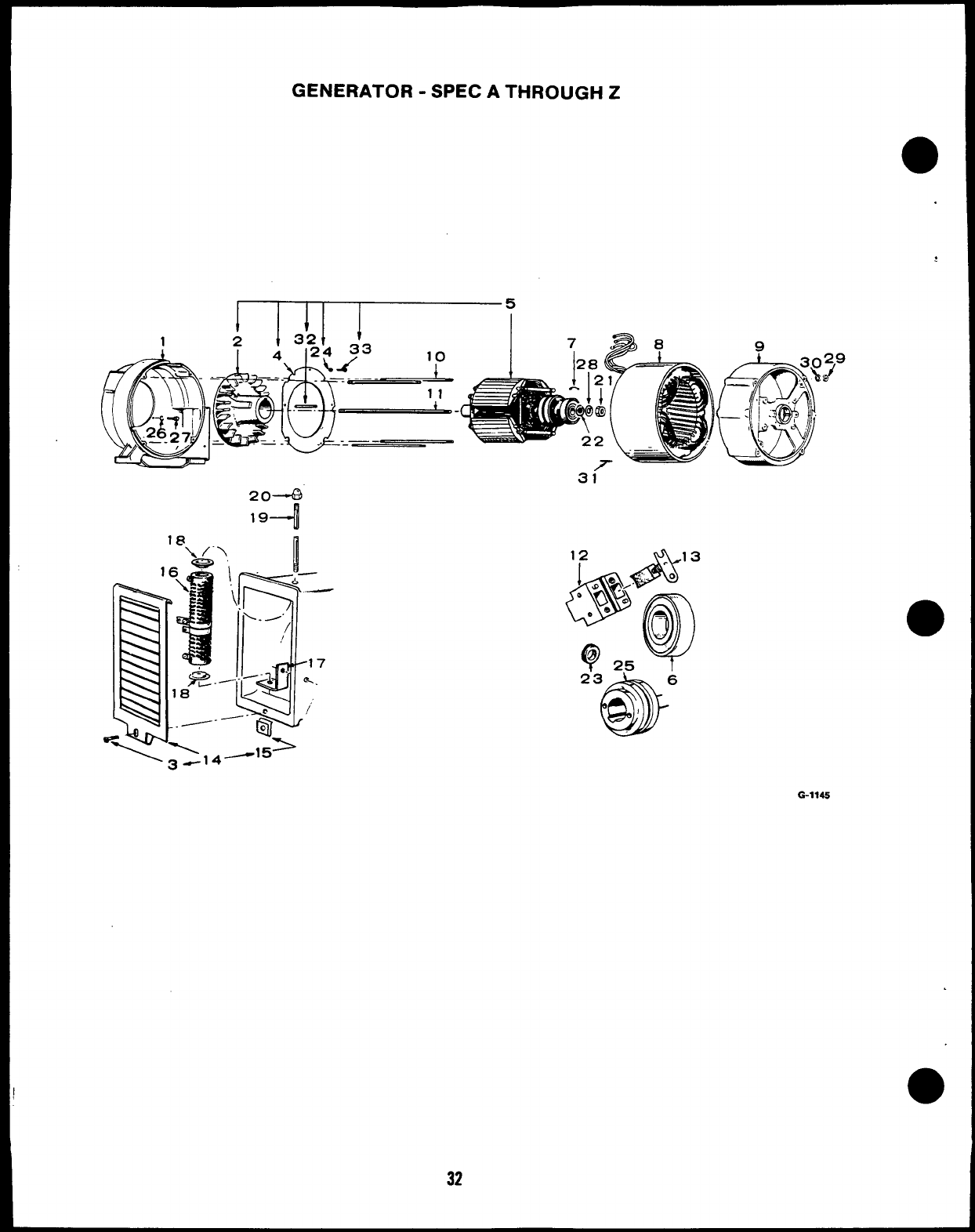
GENERATOR -SPEC ATHROUGH Z
REF.
●NO.
1
2
3
4
5
6
7
8
9
PART QTY. PART
NO. USED DESCRIPTION
212-0280 1Rig Assembly, Brush (Includes
Leads, Collector Ring
Brushes (4) and Blocks (2)
and Hardware)
231-0112 1Adapter, Generator
205-0064 1‘Blower, Generator
809-0046 1#Screw, Sheet Metal -Round
Head (#1 Ox3/4”)
234-0162 1“Baffle, Air
201-1122 1Rotor Assembly, Generator
(Includes Parts Marked “)
510-0047 1“Bearing, Rotor
232-0596 Clip, Bearing Stop
STATOR. GENER~TOR
220-0667
220-1262
220-1532
220-0712
220-1711
220-0668
220-0595
220-1293
220-0601
220-1066
220-1067
220-0632
BELL, END
211-0146
211-0152
1
1
1
1
1
1
1
1
1
1
1
1
1
1
50 Hertz
120/240 Volt
Single Phase
12 Volt DC Sets
24 Volt DC Sets
32 Volt DC Sets
Three Phase
12 Volt DC Sets
127/220 Volt
Three Phase
12 Volt DC Sets
220/380 Volt
Three Phase
12 Volt DC Sets
60 Hertz
120/208 Volt
Three Phase
12 Volt DC Sets
32 Volt DC Sets
120/240 Volt
Single Phase
12 Volt DC Sets
24 Volt DC Sets
32 Volt DC Sets
Three Phase
12 Volt DC Sets
Sets Without Overspeed Switch
Sets With Overspeed Switch
REF. PART QTY.
NO. NO. USED
10 520-0640 4
11 520-0615 1
12 212-1064 2
13 214-0059 4
14 234-0163 1
PART
DESCRIPTION
Stud, Generator Through
Stud, Rotor Through
Block, Collector Ring Brush
Brush, Collector Ring
Cover Assembly, Air Outlet
(Includes Parts Marked #)
15 870-0177 1#Nut, Speed (#10)
16 RESISTOR, TAPPED -Adjustable
304-0500 112 Volt DC Sets
304-0521 124 Volt DC Sets
304-0534 1 32 Volt DC Sets
17 232-1565 1Bracket, Resistor Mounting
18 304-0006 2Washer, Resistor Centering
19 520-0620 1Stud, Resistor Mounting
20 866-0001 1Nut, Resistor Mounting
21 870-0203 1Nut, Rotor through Stud
22 232-0200 1Washer, Tapered -Rotor through
Stud
23 GROMMET, RUBBER
508-0095 1Air Baffle
508-0112 1 Lead Outlet
24 850-0030 5“Washer, Lock-Spring (#10)
25 204-0061 1“Ring, Collector
26 850-0040 4Washer, Lock -Generator
Adapter Mounting
27 SCREW, HEX CAP -GENERATOR ADAPTER
MOUNTING
800-0051 23/8-1 6X1-1/4”
800-0050 23/8-16 X1“
28 850-0055 1Washer, Lock (7/16”)
29 862-0015 4Nut, Hex (5/16-18) -Generator
through Stud
30 850-0045 4Washer, Lock (5/16’)
31 516-0138 2Pin, Roll (3/1 6“ x5/8”)
Alignment
32 515-0103 1“Key, Blower to Rotor
33 813-0098 5“Screw (1O-32 x3/8) -Baffle
Mounting
‘-Parts Included in 201-1122 Generator Rotor Assembly
#-Parts Included in 234-0163 Cover Assembly
33
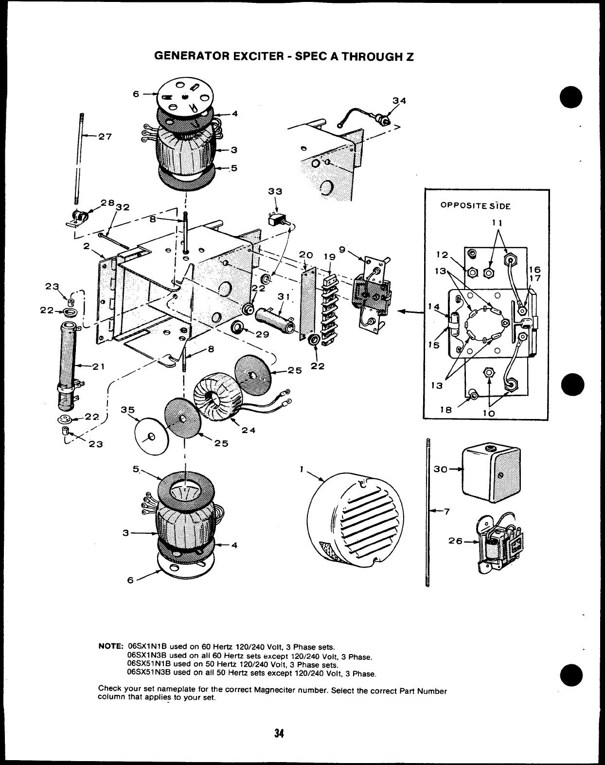
w,
OPPOSITE SiDE
11
I
I
NOTE: 06SX1 N1 Bused on 60 Hertz 120/240 Volt, 3Phase sets.
06SX1 N3B used on all 60 Hertz sets except 120/240 Volt, 3Phase.
06SX51 N1 Bused on 50 Hertz 120/240 Volt, 3Phase sets.
06SX51 N3B used on all 50 Hertz sets except 120/240 Volt, 3Phase.
Check your set nameplate for the correct Magneciter number. Select the correct Part Number
column that applies to your set.
●
●
✎
●
r
REF
No.
I
1
1
2
2
3
3
3
3
4
4
5
6
6
7
8
8
9
9
9
9
10
11
12
13
PART
NUMBER
209-0001
209-0002
209-0003
209-0005
209-0007
209-0008
209-0010
209-0011
209-0012
209-0013
234-0154
234-018S
234-0153
234-0188
315-0084
315-0099
315-0102
315-0104
232-1553
232-1608
232-1551
232-1552
234-0191
520-0211
800-0013
800-0015
305-0259
305-0387
305-0264
305-0388
305-0238
305-0239
305-0239
305-0240
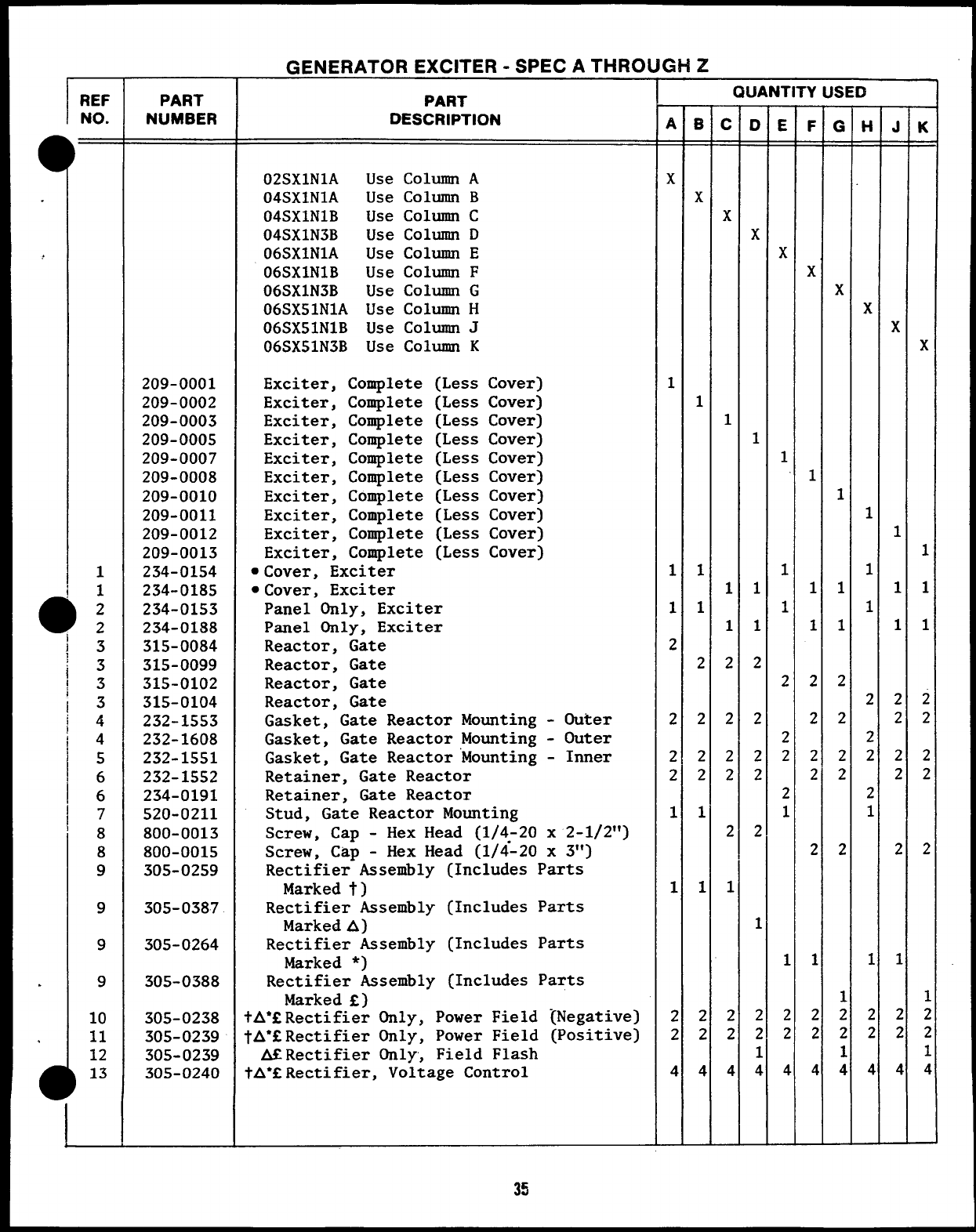
GENERATOR EXCITER -SPECATHROI
PART
DESCRIPTION
02SX1N1A
04SX1N1A
04SX1N1B
04SX1N3B
06SX1N1A
06SX1N1B
06SX1N3B
06SX51N1A
06SX51N1B
06SX51N3B
Use Column A
Use Column B
Use Column C
Use Column D
Use Column E
Use Column F
Use Column G
Use Column H
Use Column J
Use Column K
Exciter, Complete (Less Cover)
Exciter, Complete (Less Cover)
Exciter, Complete (Less Cover)
Exciter, Complete (Less Cover)
Exciter, Complete (Less Cover)
Exciter, Complete (Less Cover)
Exciter, Complete (Less Cover)
Exciter, Complete (Less Cover)
Exciter, Complete (Less Cover)
Exciter, Complete (Less Cover)
●Cover, Exciter
.Cover, Exciter
Panel Only, Exciter
Panel Only, Exciter
Reactor, Gate
Reactor, Gate
Reactor, Gate
Reactor, Gate
Gasket, Gate Reactor Mounting -Outer
Gasket, Gate Reactor Mounting -Outer
Gasket, Gate Reactor Mounting -Inner
Retainer, Gate Reactor
Retainer, Gate Reactor
Stud, Gate Reactor Mounting
Screw, Cap -Hex Head (1/4-20 x2-1/2”)
Screw, Cap -Hex Head (1/&20 x3“)
Rectifier Assembly (Includes Parts
Marked t)
Rectifier Assembly (Includes Parts
Marked A)
Rectifier Assembly (Includes Parts
Marked *)
Rectifier Assembly (Includes Parts
Marked f)
tA*fRectifier Only, Power Field {Negative)
tA*fRectifier Only, Power Field (Positive)
AfRectifier Only, Field Flash
tA*fRectifier, Voltage Control
SH Z
A
=
x
1
1
1
2
2
2
2
1
1
2
2
4
.
—
B
=
x
1
1
1
2
2
2
2
1
1
2
2
4
—
QUANTITY USED
—
D
=
x
1
1
1
2
2
2
2
2
1
2
2
1
4
—
—
E
=
x
1
1
1
2
2
2
2
1
1
2
2
4
—
—
F
=
x
1
1
1
2
2
2
2
2
1
2
2
4
—
—
G
=
x
1
1
1
2
2
2
2
2
1
2
2
1
4
—
—
H
=
x
1
1
1
2
2
2
2
1
1
2
2
4
—
—
K
=
x
1
1
1
2
2
2
2
2
1
2
2
1
4
—
35
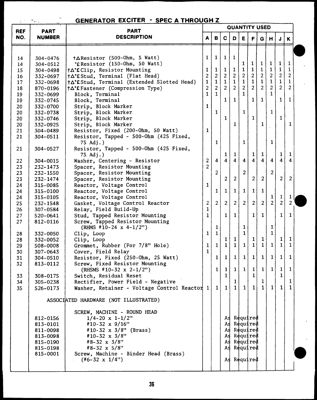
REF
NO.
14
14
15
16
17
18
19
19
20
20
20
20
21
21
21
22
23
23
23
24
24
24
25
26
27
27
28
28
29
30
31
32
33
34
35
... . ..
PART
NUMBER
304-0476
304-0512
304-0498
332-0697
332-0698
870-0196
332-0699
332-0745
332-0700
332-0738
332-0746
332-0925
304-0489
304-0511
304-0527
304-0015
232-1473
232-1550
232-1474
315-0085
315-0100
315-0105
232-1548
307-0584
520-0641
812-0116
332-0050
332-0052
508-0008
307-0643
304-0510
813-0112
308-0175
305-0238
526-0173
ASSOCI
812-0156
813-0101
811-0098
813-0098
815-0190
815-0198
815-0001
GENERATOR EXCITER -SPECATHRO[
PART
DESCRIPTION
tAResistor (SOO-Ohm, 5Watt)
●fResistor (lSO-Ohm, 50 Watt)
lA*fClip, Resistor Mounting
lA*EStud, Terminal (Flat Head)
lA*EStud, Terminal (Extended Slotted Head)
FA*fFastener (Compression Type)
Block, Terminal
Block, Terminal
Strip, Block Marker
Strip, Block Marker
Strip, Block Marker
Strip-,Block Marker
Resistor, Fixed (200-Ohm, 50 Watt)
Resistor, Tapped -500-Ohm (425 Fixed,
75 Adj.)
Resistor, Tapped -500-Ohm (425 Fixed,
75.Adj.)
Washer, Centering -Resistor
Spacer, Resistor Mounting
Spacer, Resistor Mounting
Spacer, Resistor Mounting
Reactor, Voltage Control
Reactor, Voltage Control
Reactor, Voltage Control
Gasket, Voltage Control Reactor
Relay, Field Build-Up
Stud, Tapped Resistor Mounting
Screw, Tapped ResistorMounting
(RHMS #10-24 x4-1/2”)
Clip, Loop
Clip, Loop
Grommet, Rubber (For 7/8” Hole)
Cover, Field Relay
Resistor, Fixed (250-Ohm, 25 Watt)
Screw, Fixed Resistor Mounting
(RHSMS #10-32 X2-1/2”)
Switch, Residual Reset
Rectifier, Power Field -Negative
Washer, Retainer -Voltage Control Reacto
TED HARDWARE (NOT ILLUSTRATED)
SCREW, MACHINE -ROUND HEAD
1/4-20 X1-1/2”
#10-32 X9/16”
#10-32 x3/8” (Brass)
#10-32 X3/8”
#8-32 x3/8”
#8-32 x5/8”
Screw, Machine -Binder Head (Brass)
(#6-32 X1/4”)
36
>H Z
QUANTITY USED
—
A
=
1
1
2
1
2
1
1
1
2
2
1
2
1
1
1
1
1
1
—
—
B
=
1
1
2
1
2
1
1
1
4
2
1
2
1
1
1
1
1
1
—
—
c
=
1
1
2
1
2
1
1
1
4
2
1
2
1
1
1
1
1
1
1
A:
A!
A:
A:
A:
A:
A:
—
—
D
=
1
1
2
1
2
1
1
1
4
2
1
2
1
1
1
1
1
1
1
R
R
R
R
R
R
R
—
—
F
=
1
1
2
1
2
1
1
1
4
2
1
2
1
1
1
1
1
1
1
cef
cef
cet
re(
re(
re(
ret
—
—
G
=
1
1
2
1
2
1
1
1
4
2
1
2
1
1
1
1
1
1
1
—
—
H
=
1
1’
2
1
2
1
1
1
4
2
1
2
1
1
1
1
1
1
—
—
J
=
1
1
2
1
2
1
1
1
4
2
1
2
1
1
1
1
1
1
1
—
—
K
=
1
1
2
1
2
1
1
1
4
2
1
2
1
1
1
1
1
1
1
B
●
●
-J
F?EF
NO. PART
NUMBER
526-0003
526-0048
526-0049
526-0179
850-0030
850-0040
853-0005
854-0007
854-0010
854-0014
860-0008
860-0011
862-0001
870-0053
871-0005
871-0007
871-0010
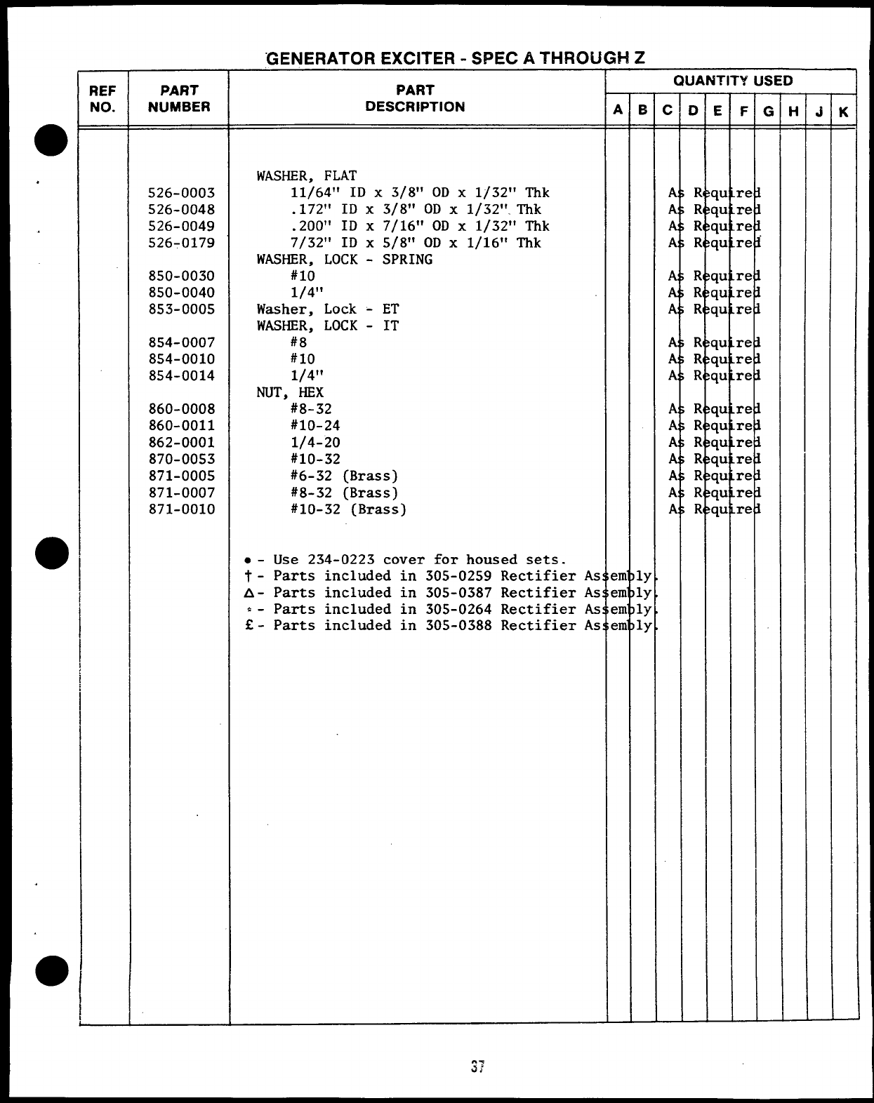
“GENERATOR EXCITER -SPECATHROU
PART
DESCRIPTION
WASHER, FLAT
11/64” ID X3/8” OD X1/32” Thk
.172” ID X3/8” OD Xl/32’’.Thk
.200” ID X7/16” OD X1/32” Thk
7/32” ID X5/8” OD X1/16” Thk
WASHER, LOCK -SPRING
#lo
1/4”
Washer, Lock -ET
WASHER, LOCK -IT
#8
#lo
1/4”
NUT, HEX
#8-32
#10-24
1/4-20
#10-32
#6-32 (Brass)
#8-32 (Brass)
#10-32 (Brass)
●-Use 234-0223 cover for housed sets.
t- Parts included in 305-0259 Rectifier As
A- Parts included in 305-0387 Rectifier As
*- Parts included in 305-0264 Rectifier As
Q- Parts included in 305-0388 Rectifier As
1!-!z
QUANTITY USED
—
B
=
ly
ly
ly
ly
—
—
c
=
A
A
A
A
A
A
A
A
A
A
A
A
A
A
A
A
A
—
—
D
=
R
R
R
R
R
R
R
R
R
R
R
R
R
R
R
R
R
—
—
F
=
re
re
re
re
re
re
re
re
re
re
re
re
Cc
re
re
re
re
.
—
G
=
—
—
H
=
—
—
J
=
—
—
K
=
—
42
&●
45
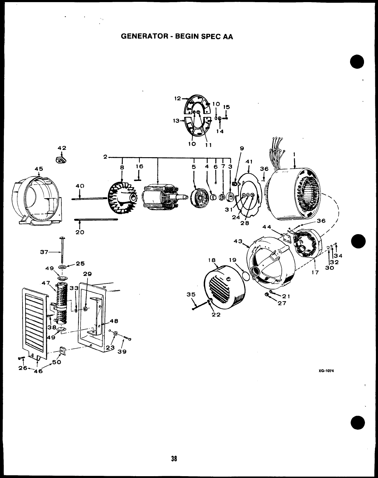
GENERATOR -BEGIN SPEC AA
●
2III1II1
816 I54673
!
20
37
4
49 w-25
xG-W74
.
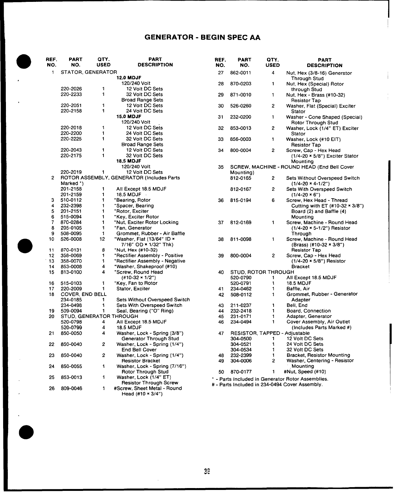
GENERATOR -BEGIN SPEC AA
●REF.
NO.
1
2
3
4
5
6
7
8
9
●10
11
12
13
14
15
16
17
18
19
20
PART QTY. PART
NO. USED DESCRIPTION
STATOR, GENERATOR 12.0 MDJF
120/240 Volt
220-2026 1 12 Volt DC Sets
220-2233 132 Volt DC Sets
Broad Range Sets
220-2051 112 Volt DC Sets
220-2158 124 Volt DC Sets
15.0 MDJF
120/240 Volt
220-2018 112 Volt DC Se~s
220-2200 124 Volt DC Sets
220-2225 132 Volt DC Sets
Broad Range Sets
220-2043 1 12 Volt DC Sets
220-2175 132 Volt DC Sets
18.5 MDJF
1201240 Volt
220-2019 1 12 Volt DC Sets
ROTOR ASSEMBLY, GENERATOR (Includes Parts
Marked “)
201-2158 1All Except 18.5 MDJF
201-2159 118.5 MDJF
510-0112 1“Bearing, Rotor
232-2398 1“Spacer, Bearing
201-2151 1“Rotor, Exciter
515-0094 1“Key, Exciter Rotor
870-0284 1“Nut, Exciter Rotor Locking
205-0105 1‘Fan, Generator
508-0095 1Grommet, Rubber -Air Baffle
526-0008 12 “Washer, Flat (13/64” ID x
7/16 OD X1/32 Thk)
870-0131 8“Nut, Hex (#10-32)
358-0069 1“Rectifier Assembly -Positive
358-0070 1“Rectifier Assembly -Negative
853-0008 4“Washer, Shakeproof (#1 O)
813-0100 4‘Screw, Round Head
(#l O-32 X1/2’)
515-0103 1“Key, Fan to Rotor
220-2009 1Stator, Exciter
COVER, END BELL
234-0185 1Sets Without Overspeed Switch
234-0498 1Sets With Overspeed Switch
509-0094 1Seal, Bearing (“0” Ring)
STUD. GENERATOR THROUGH
520-0?98
520-0799
21 850-0050
22 850-0040
23 850-0040
24 850-0055
25 853-0013
26 809-0046
4
4
4
2
2
1
1
1
Ail Except 18.5 MDJF
18.5 MDJF
Washer, Lock -Spring (3/8”)
Generator Through Stud
Washer, Lock -Spring (1/4”)
End Bell Cover
Washer, Lock -Spring (1/4”)
Resistor Bracket
Washer, Lock -Spring (7/16)
Rotor Through Stud
Washer, Lock (1/4” ET)
Resistor Through Screw
#Screw, Sheet Metal -Round
Head (#10 x3/4”)
REF. PART
NO. NO.
27 862-0011
28 870-0203
29 871-0010
30 526-0260
31 232-0200
32 853-0013
33 856-0003
34 800-0004
QTY.
USED
4
1
1
2
1
2
1
2
PART
DESCRIPTION
Nut, Hex (3/8-16) Generator
Through Stud
Nut, Hex (Special) Rotor
through Stud
Nut, Hex -Brass (#10-32)
Resistor Tap
Washer, Flat (Special) Exciter
Stator
Washer -Cone Shaped (Special)
Rotor Through Stud
Washer, Lock (1/4” ET) Exciter
Stator
Washer, Lock (#10 EIT)
Resistor Tap
Screw, Cap -Hex Head
35 SCREW, MACHINE -
Mounting)
812-0165 2
812-0167 2
36 815-0194 6
37 812-0169 1
38 811-0098 1
39 800-0004 2
(1/4-20 ~5/8”) Exciter Stator
Mounting
ROUND HEAD (End Bell Cover
Sets Without Overspeed Switch
(1/4-20 X4-1/2”)
Sets With Overspeed Switch
(1/4-20 X6’)
Screw, Hex Head -Thread
Cutting with ET (#10-32 x3/8)
Board (2) and Baffle (4)
Mounting
Screw, Machine -Round Head
(1/4-20 x5-1/2”) Resistor
Through
Screw, Machine -Round Head
(Brass) (#l O-32 x3/8)
Resistor Tap
Screw, Cap -Hex Head
(1/4-20 x5/8”) Resistor
Bracket
40 STUD, ROTOR THROUGH
520-0790 1
520-0791 1
41 234-0462 1
42 508-0112 1
43 211-0237 1
44 232-2418 1
45 231-0171 1
46 234-0494 1
47 RESISTOR, TAPPED
304-0500 1
304-0521 1
304-0534 1
48 232-2399 1
49 304-0006 2
50 870-0177 1
“ - Parts Included in Generator Rotor Assemblies.
#-Parts Included in 234-0494 Cover Assembly.
All Except 18.5 MDJF
18,5 MDJF
Baffle, Air
Grommet, Rubber -Generator
Adapter
Bell, End
Board, Connection
Adapter, Generator
Cover Assembly, Air Outlet
(Includes Parts Marked #)
Adjustable
12 Volt DC Sets
24 Volt DC Sets
32 Volt DC Sets
Bracket, Resistor Mounting
Washer, Centering -Resistor
Mounting
#Nut, Speed (#IO)
CONTROL
16 34
.
32 4,2
/4’/
46
47
,:. ”●
.’,”, .
40
I
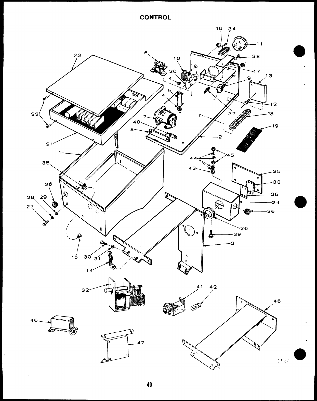
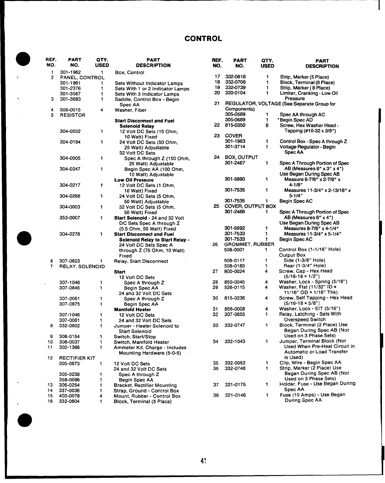
CONTROL
.
REF. PART OTY.
NO. NO. USED
1301-1962 1
2PANEL. CONTROL
301-1961
301-2376
301-3567
3301-3683
4508-0015
5RESISTOR
304-0032
304-0194
304-0005
304-0247
304-0277
304-0268
304-0003
353-0007
304-0276
6307-0623
1
1
1
1
4
1
1
1
1
1
1
1
1
1
1
7RELAY, SOLENOID
8
9“
10
11
12
13
14
15
16
307-1046
307-0845
$07-006?
307-0875
307-1046
307-0061 1
332-0602 1
306-0154 1
308-0037 1
302-1366 1
RECTIFIER KIT
305-0673 1
305-0238 1
358-0096 1
305-0254 1
337-0036 1
402-0078 4
332-0604 1
PART
DESCRIPTION
Box, Control
Sets Without Indicator Lamps
Sets Withl or21ndicator Lamps
Sets With 3Indicator Lamps
Saddle, Control Box -Begin
Spec AA
Washer, Fiber
Start Disconnect and Fuel
Solenoid Reiay
12 Volt DC Sets (15 Ohm,
10 Watt) Fixed
24 Volt DC Sets (50 Ohm,
25 Watt) Adjustable
32 Volt DC Sets
Spec Athrough Z(150 Ohm,
25 Watt) Adjustable
Begin Spec AA (100 Ohm,
10 Watt) Adjustable
Low Oii Pressure
12 Volt DC Sets (1 Ohm,
10 Watt). Fixed
24 Volt DC Sets (5 Ohm,
50 Watt) Adjustable
32 Voit DC Sets (5 Ohm,
50 Watt) Fixed
Start Solenoid -24 and 32 Volt
DC Sets Spec Athrough Z
(5.5 Ohm, 50 Watt) Fixed
Start Disconnect and Fuel
Solenoid Relay to Start Relay -
24 Volt DC Sets Spec A
through Z(75 Ohm, 10 Watt)
Fixed
Relay, Start Disconnect
Start
12Volt DC Sets
Spec Athrough Z
Begin Spec AA
24 and 32 Volt DC Sets
Spec Athrough Z
Begin Spec AA
Manifold Heater
12 Volt DC Sets
24 and 32 Volt DC Sets
Jumper -Heater Solenoid to
Start Soienoid
Switch, Start/Stop
Switch, Manifold Heater
Ammeter Kit, Charge -Includes
Mounting Hardware (5-O-5)
12 Volt DC Sets
24 and 32 Volt DC Sets
Spec Athrough Z
Begin Spec AA
Bracket, Rectifier Mounting
Strap, Ground -Control Box
Mount, Rubber -Control Box
Block, Terminal (5 Place)
REF. PART QTY. PART
NO. NO. usED DESCRIPTION
17 332-0616 1Strip, Marker (5 Place)
18 332-0706 1Block, Terminai (8 Place)
19 332-0739 1Strip, Marker (8 Piace)
20 320-0104 1Limiter, Cranking -Low Oil
Pressure
21 REGUIATOR, VOLTAGE (See Separate Group for
Components)
305-0589 1Spec AA through AC
305-0689 1“Begin Spec AD
22 815-0350 8Screw, Hex Washer Head -
23 COVER Tapping (#1 O-32 x3/8”)
301-1963 1Control Box -Spec Athrough Z
301-3714 1Voltage Regulator -Begin
Spec M
24 BOX. OUTPUT
301-2467 1Spec AThrough Portion of Spec
AB (Measures 6“ x3“ x4“)
Use Began During Spec AB
301-5990 1Measure 8-7/8” x2-718” x
4-1/8”
301-7535 1Measures 11-314° x2-13/1 6“ x
5-114”
301-7535 Begin Spec AC
25 COVER, OUTPUT :OX
301-2466 1
301-5992 1
301-7533 1
301-7533 1
26 GROMMET, RUBBER
508-0001 1
508-0117 1
508-0183 1
27 800-0024 4
28 650-0045 4
29 526-0115 4
30 815-0236 4
31 856-0008 4
32 307-0655 1
33 332-0747
34 332-1043
35 332-0052 1
36 332-0748 1
37 321-0175 1
38 321-0146 1
SPSCAThrough Portion of Spec
AB (Measures 6“ x4“)
Use Began During Spec AB
Measures 8-718” x4-114”
Measures 11-314” x5-114”
Begin Spec AC
Control Box (1-1/16” Hole)
Output Box
Side (1-3/8” Hole)
Rear (1-3/4” Hole)
Screw, Cap -Hex Head
(5/16-18 K1/2”)
Washer, Lock -Spring (5/16)
Washer, Flat (11/32” ID x
11/16 OD X1/16 Thk)
Screw, Self Tapping -Hex Head
(5/16-1 8X5/8”)
Washer, Lock -EIT (5/16”)
Relay, Latching -Sets With
Overspeed Switch
Block, Terminal (2 Place) Use
Began During Spec AB (Not
Used on 3 Phase Sets)
Jumper, Terminal Block (Not
Used When Pre-Heat Circuit in
Automatic or Load Transfer
is Used)
Clip, Wire -Begin Spec AA
Strip, Marker (2 Place) Use
Began During Spec AB (Not
Used on 3 Phase Sets)
Holder, Fuse -Use Began During
Spec AA
Fuse (10 Amps) -Use Began
Dur”ing Spec AA
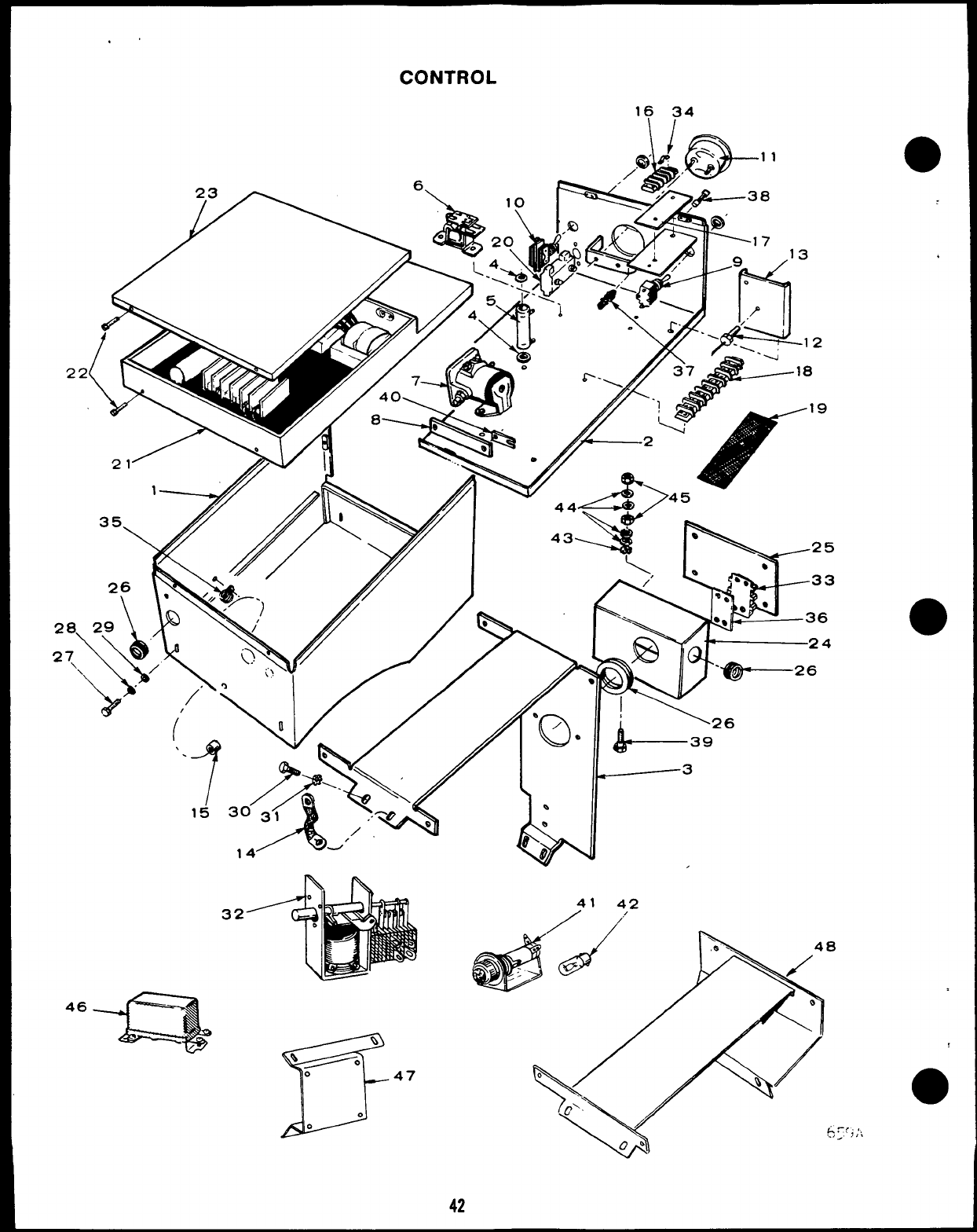
.,
CONTROL
16 34
2
2a
27
46
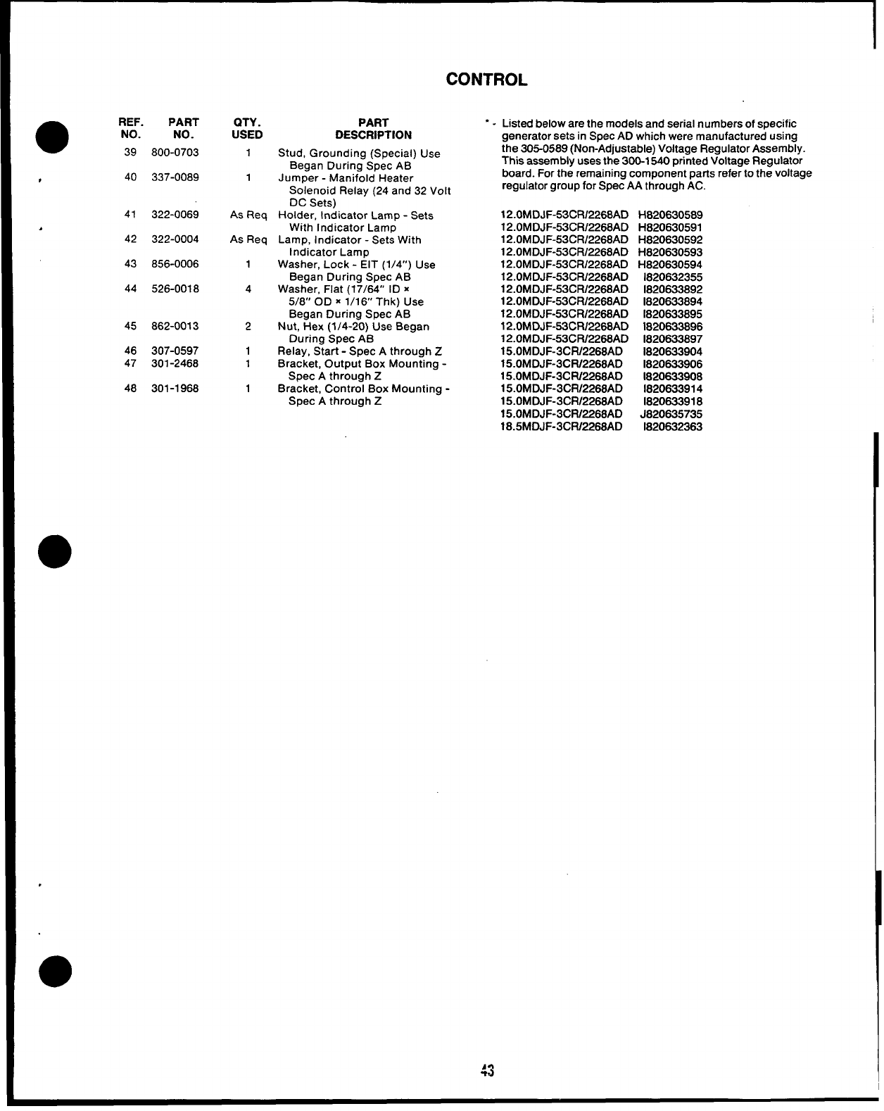
CONTROL
●REF. PART
NO. NO.
39 800-0703
#40 337-0089
41 322-0069
J
42 322-0004
43 856-0006
44 526-0018
45 862-0013
46 307-0597
47 301-2468
48 301-1968
QTY.
USED
1
1
As Req
As Req
1
4
2
1
1
1
PART
DESCRIPTION
Stud, Grounding (Special) Use
Began During Spec AB
Jumper -Manifold Heater
Solenoid Relay (24 and 32 Volt
DC Sets)
Holder, Indicator Lamp -Sets
With Indicator Lamp
Lamp, Indicator -Sets With
Indicator Lamp
Washer, Lock -EIT (1/4”) Use
Began During Spec AB
Washer, Flat (17/64” ID x
5/8” OD x1/16 Thk) USe
Began During Spec AB
Nut, Hex (1/4-20) Use Began
During Spec AB
Relay, Start -Spec Athrough Z
Bracket, Output Box Mounting -
Spec Athrough Z
Bracket, Control Box Mounting -
Spec Athrough Z
“ - Listed below are the models and serial numbers of specific
generator sets in Spec AD which were manufactured using
the 305-0589 (Non-Adjustable) Voltage Regulator Assembly.
This assembly uses the 300-1540 printed Voltage Regulator
board. For the remaining component parts refer to the voltage
regulator group for Spec AA through AC.
12.0MDJF-53CR/2268AD H820630589
12.0MDJF-53CR/2268AD H820630591
12.OMDJF-53CR12268AD H820630592
12.OMDJF-53CRL2268AD H820630593
12.OMDJF-53CR12268AD H820630594
12.0MDJF-53CR/2268AD 1820632355
12.0MDJF-53CR/2268AD 1820633892
12.0MDJF-53CFV2268AD 1820633894
12.0MDJF-53CR/2268AD 1820633895
12.0MDJF-53CR/2268AD 1820633896
12.0MDJF-53CFU2268AD 1820633897
15.0MDJF-3CFU2268AD 1820633904
15.OMDJF-3CW2268AD 1820633906
15.OMDJF-3CRR268AD 1820633908
15.0MDJF-3CR/2268AD 1820633914
15.0MDJF-3CR/2268AD 1820633918
15.OMDJF-3CW2268AD J820635735
18.5MDJF-3CR/2268AD 1820632363
43
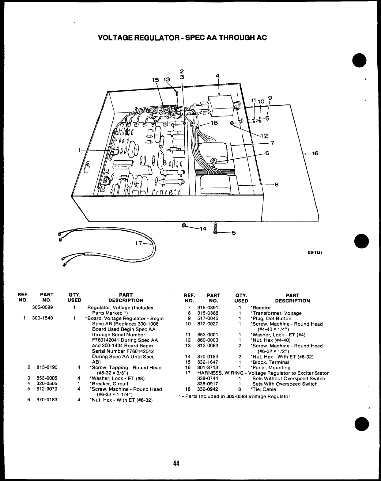
‘\
VOLTAGE REGULATOR -SPEC AA THROUGH AC
24
15 13 ?
r-—t—w———
REF. PART QTY.
NO. NO. USED
305-0589 1
1300-1540 1
2815-0190 4
3853-0005 4
4320-0505 1
5812-0070 4
6870-0183 4
I
PART
DESCRIPTION
Regulator, Voltage (Includes
Parts Marked “)
‘Board, Voltage Regulator -Begin
Spec AB (Replaces 300-1006
Board Used Begin Spec AA
through Serial Number
F760142041 During Spec AA
and 300-1404 Board Begin
Serial Number F7601 42042
During Spec AA Until Spec
AB)
“Screw, Tapping -Round Head
(#8-32 X3/8”)
“Washer, Lock -ET (#8)
“Breaker, Circuit
‘Screw, Machine -Round Head
(#6-32 X1-1/4”)
‘Nut, Hex -With ET (#6-32)
,
●
Es-1131
REF. PART QTY. PART
NO. NO. USED DESCRIPTION
73’f5-0391 1“Reactor
8315-0386 1“Transformer, Voltage
9517-0045 1“Plug, Dot Button
10 812-0027 1“Screw, Machine -Round Head
(#4-40 x1/4”)
11 853-0001 1‘Washer, Lock -ET (#4)
12 860-0003 1“Nut, Hex (#4-40)
13 812-0063 2●Screw, Machine -Round Head
(#6-32 X1/2”)
14 870-0183 2“Nut, Hex -With ET (#6-32)
15 332-1647 1‘Block, Terminal
16 301-3713 1“Panel, Mounting
17 HARNESS, WIRING -Voltage Regulator to Exciter Stator
338-0744 1Sets Without overspeed Switch
338-0917 1Sets With Overspeed Switch
18 332-0942 8●Tie, Cable
‘-Parts Included in 305-0589 Voltage Regulator
44
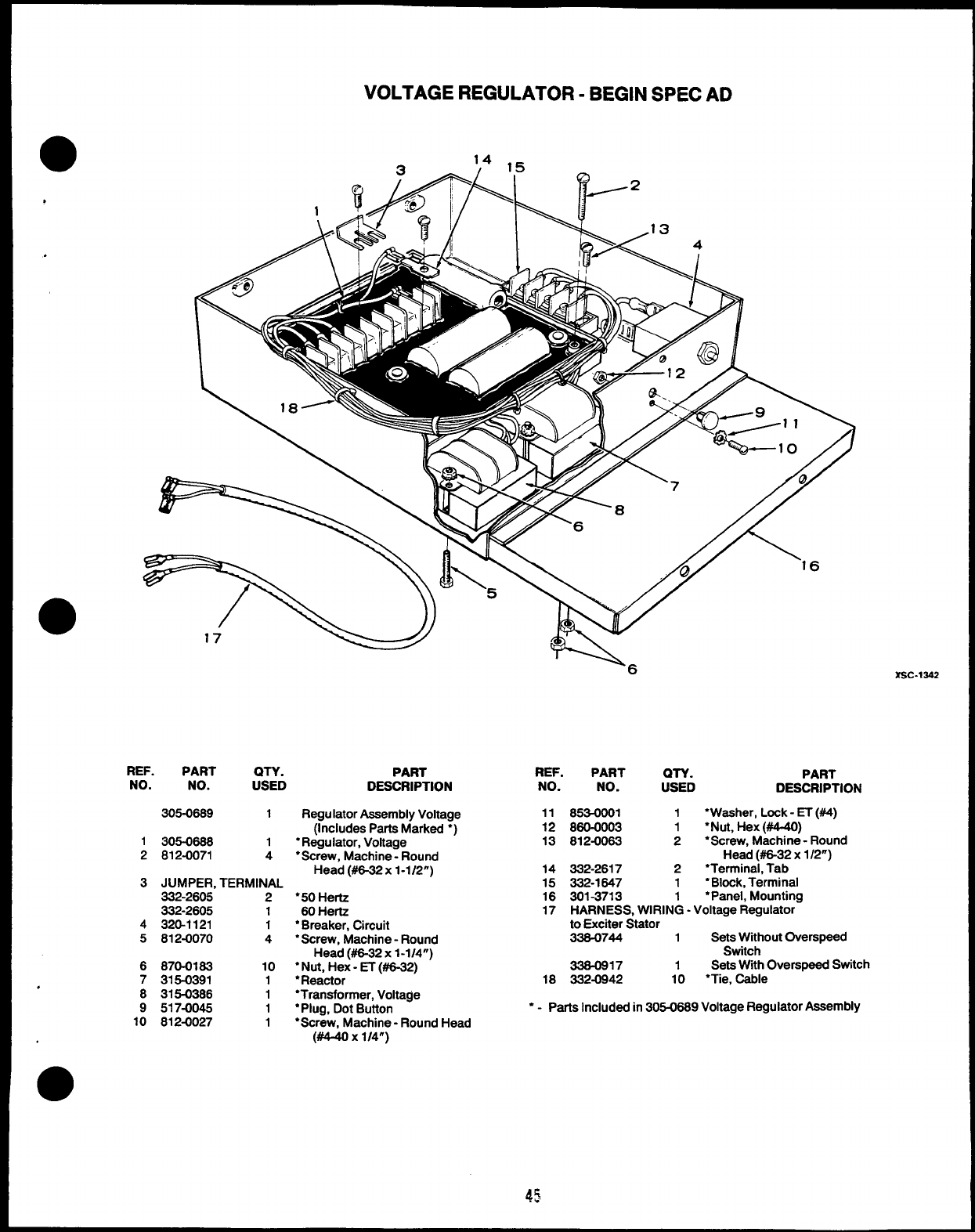
—
,
.
VOLTAGE REGULATOR -BEGIN SPEC AD
Q14 ,5
‘16
●17
REF. PART
NO. NO. &LD
305-0689 1
1305-0688 1
2812-0071 4
3JUMPER, TERMINAL
332-2605 2
332-2605 1
4320-1121 1
5812-0070 4
6870-0183 10
7315-0391 1
8315-0386 1
9517-0045 1
10 812-0027 1
PART
DESCRIPTION
Regulator Assembly Voltage
(Includes Parts Marked “)
●Regulator, Voltage
●Screw, Machine -Round
Head (#6-32 x1-1/2”)
●5O Hertz
60 Hertz
●Breaker, Chcuit
●Screw, Machine- Round
Head (#6-32 x1-1/4”)
●Nut, Hex-~ (#6-32)
●Reactor
●Transformer, Voltage
●Plug, Dot Button
●Screw, Machine -Round Head
(#4-40 x1/4”)
REF. PART
NO. NO.
11 653-0001
12 860-0003
13 812-0063
14 332-2617
15 332-1647
16 301-3713
1
1
2
2
1
1
PART
DESCRIPTION
“Washer, Lock -ET (#4)
●Nut, Hex (#4-40)
●Screw, Machine -Round
Head (=32 x1/2”)
“Terminal, Tab
“Block, Terminal
●Panel, Mounting
17 HARNESS, WIRING -Voltage Regulator-
to Exciter Stator
338-0744 1Sets Without Overspeed
Switch
338-0917 1Sets With C)verspeed Switch
18 332-0942 10 ●Tie, Cable
●-Parts Included in 305-0689 Voltage Regulator Assembly
45
SERVICE KITS AND MISCELLANEOUS
98-1807 1Label Kit
168-0107 1Gasket Kit, Engine
OVERHAUL KIT, ENGINE
Spec A
522-0242 1Sets Without Heat Exchanger
522-0243 1Sets With Heat Exchanger
Begin Spec B
522-0253 1Sets Without Heat Exchanger
522-0252 1Sets With Heat Exchanger
525-0216 —Paint, Touch-Up —White
Enamel (13 oz. Pressurized
Can)
NOTE For other kits refer to the related group
46
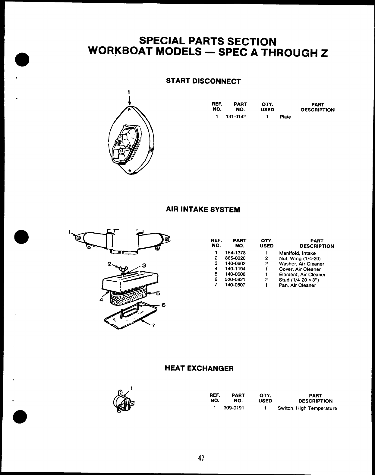
SPECIAL PARTS SECTION
WORKBOAT MODELS —SPEC ATHROUGH Z
START DISCONNECT
i.REF. PART
NO. NO.
1131-0142
QTY.
USED
1Plate
PART
DESCRIPTION
AIR INTAKE SYSTEM
‘- ‘w 3
@
~7/~”
i.
...,’,
. . .. ..$ 5
*.......4.....
4/.? .....4 .
&
.,.,.. . . 6
:,1$”
.1:, ,,, ,’!
7
REF. PART Q-I-Y. PART
NO. NO. USED DESCRIPTION
1154-1378 1Manifold, Intake
2865-0020 2Nut, Wing (1/4-20)
3140-0602 2Washer. Air Cleaner
4140-1194 iCover, Air Cleaner
5140-0606 1Element, Air Cleaner
6520-0621 2Stud (1/4-20 X3)
7140-0607 1Pan, Air Cleaner
HEAT EXCHANGER
REF. PART QTY. PART
NO. NO. USED DESCRIPTION
1309-0191 1Switch, High Temperature
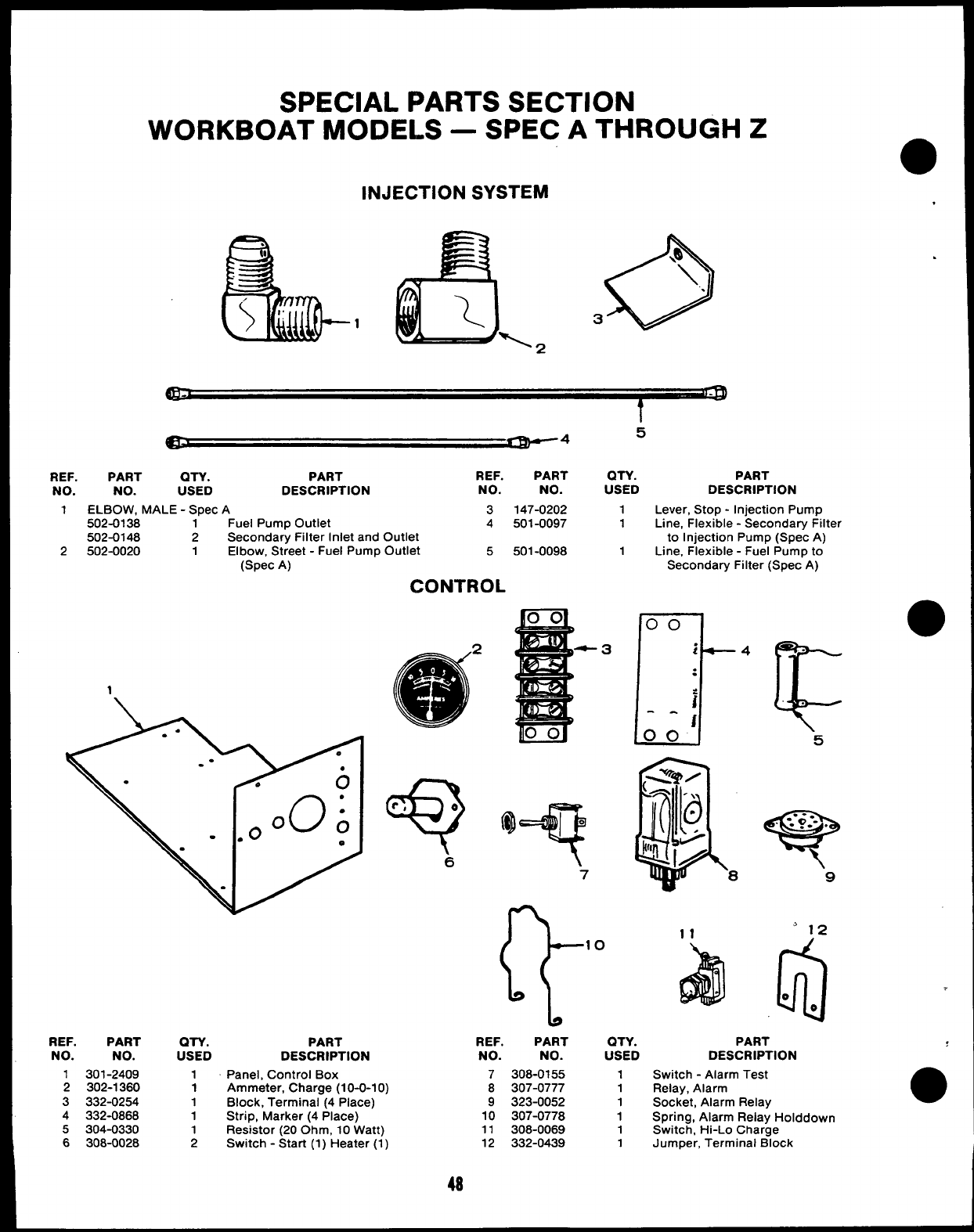
SPECIAL PARTS SECTION
WORKBOAT MODELS —SPEC ATHROUGH Z●
INJECTION SYSTEM .
o
‘Q\
..
3
5
REF. PART QTY.
NO. NO. USED
1ELBOW, MALE -Spec
502-0138 1
502-0148 2
2502-0020 1
1
PART REF. PART QTY. PART
DESCRIPTION NO. NO. USED DESCRIPTION
A3147-0202 1
Fuel Pump Outlet 4501-0097 1
Secondary Filter Inlet and Outlet
Elbow, Street -Fuel Pump Outlet 5501-0098 1
(Spec A)
CONTROL
REF. PART QTY.
NO. NO. USED
1301-2409 1
2302-1360 1
3332-0254 1
4332-0868 1
5304-0330 1
6308-0028 2
2
Lever, Stop -Injection Pump
Line, Flexible -Secondary Filter
to Injection Pump (Spec A)
Line, Flexible -Fuel Pump to
Secondary Filter (Spec A)
.
11 “12
all
.,,eo
PART REF. PART QTY.
DESCRIPTION NO. NO. USED
Panel, Control Box 7308-0155 1
Ammeter, Charge (10-0-1 O) 8307-0777 1
Block, Terminal (4 Place) 9323-0052 1
Strip, Marker (4 Place) 10 307-0778 1
Resistor (20 Ohm, 10 Watt) 11 308-0069 1
Switch -Start (1) Heater (1) 12 332-0439 1
PART
DESCRIPTION
Switch -Alarm Test
Relay, Alarm
Socket. Alarm Relav
Spring; Alarm Rela~ Holddown
Switch, Hi-Lo Charge
Jumper, Terminal Block
.
OPTIONAL PARTS SECTION
This section contains illustrated parts listing of factory installed options. Options may not be
applicable to all models; for field conversions additional parts are usuaily required.
,
.
49
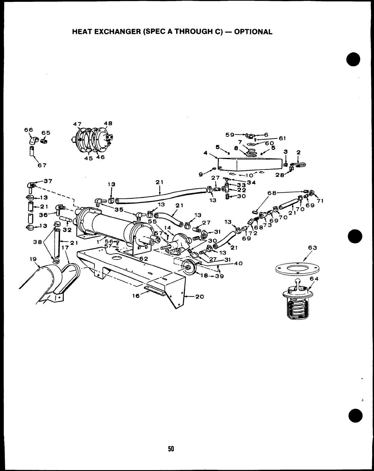
HEAT EXCHANGER (SPEC ATHROUGH C) –OPTIONAL
47 48
w13
63
/
4
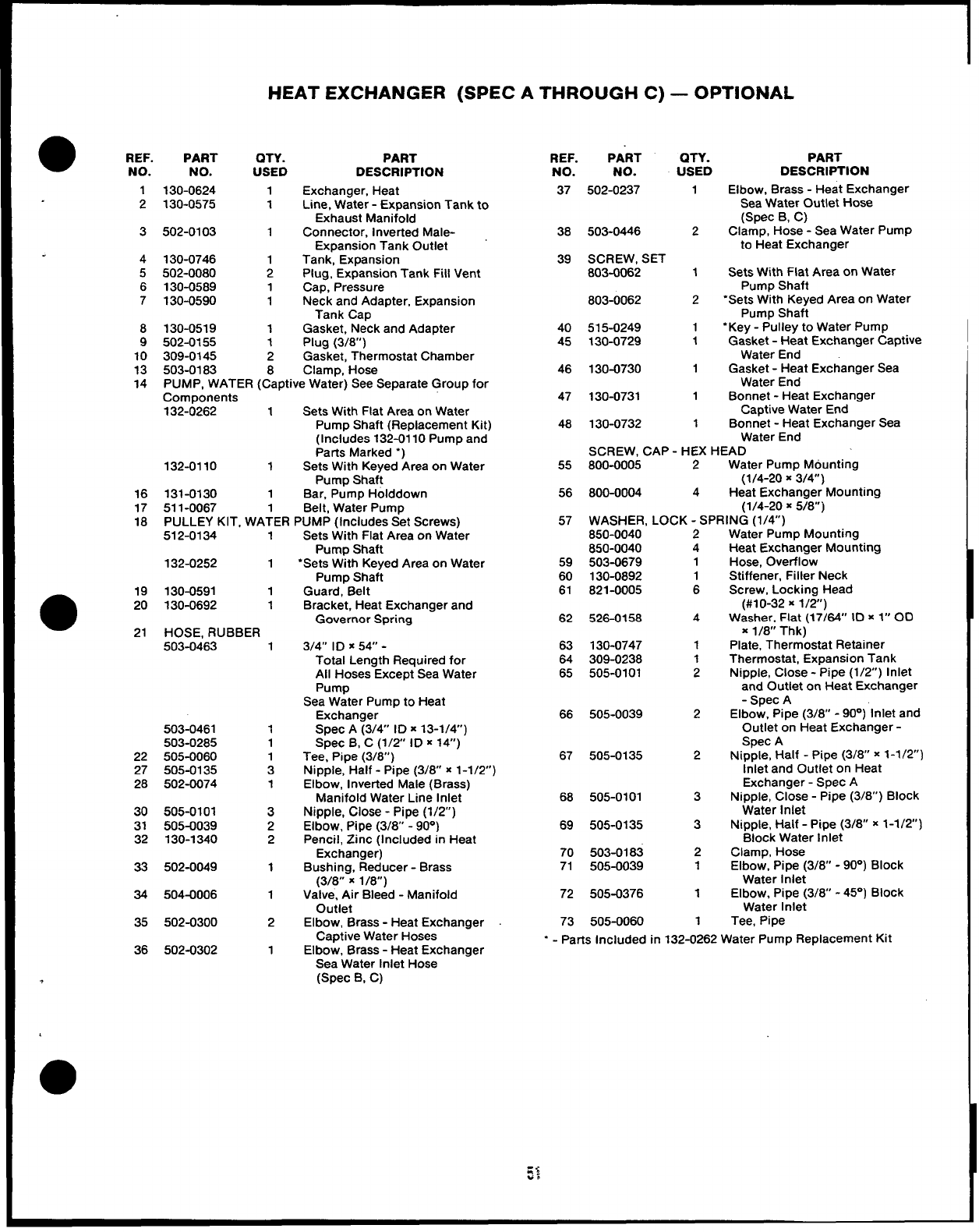
HEAT EXCHANGER (SPEC ATHROUGH C) —OPTIONAL
●REF.
NO.
PART QTY. PART
NO. USED DESCRIPTION
130-0624 1Exchanger, Heat
130-0575 1Line, Water -Expansion Tank to
Exhaust Manifold
502-0103 1Connector, Inverted Male-
Expansion Tank Outlet
130-0746 1Tank, Expansion
502-0080 2Plug, Expansion Tank Fill Vent
130-0589 1Cap, Pressure
130-0590 1Neck and Adapter, Expansion
Tank Cap
130-0519 1Gasket, Neck and Adapter
502-0155 1Plug (3/8”)
309-0145 2Gasket, Thermostat Chamber
503-0183 8Clamp, Hose
PUMP, WATER (Captive Water) See Separate Group for
Components
132-0262 1Sets With Flat Area on Water
Pump Shaft (Replacement Kit)
(Includes 132-0110 Pump and
Parts Marked “)
132-0110 1Sets With Keyed Area on Water
Pump Shaft
131-0130 1Bar, Pump Holddown
511-0067 1Belt, Water Pump
PULLEY KIT, WATER PUMP (Includes Set Screws)
REF. PART QTY. PART
NO. NO. USED DESCRIPTION
37 502-0237 Elbow, Brass -Heat Exchanger
Sea Water Outlet Hose
(Spec B, C)
Clamp, Hose -Sea Water Pump
to Heat Exchanger
Sets With Flat Area on Water
Pump Shaft
“Sets With Keyed Area on Water
Pump Shaft
“Key -Pulley to Water Pump
Gasket -Heat Exchanger Captive
Water End
Gasket -Heat Exchanger Sea
Water End
Bonnet -Heat Exchanger
Captive Water End
Bonnet -Heat Exchanger Sea
1
2
1
2
1
2
1
1
1
1
1
3 38
39
503-0446
SCREW, SET
803-0062
4
5
6
7803-0062
40
45
515-0249
130-0729
8
9
10
13
14
46 130-0730
47 130-0731
130-073248
Water End
SCREW, CAP -HEX HEAD
55 800-0005 2Water Pump Mounting
(1/4-20 X3/4”)
56 800-0004 4Heat Exchanger Mounting
(1/4-20 X5/8”)
16
17
18 57 WASHER, LOCK -SPRING (1/4”)
850-0040 2
512-0134 1Sets With Flat Area on Water Water Pump Mounting
Heat Exchanger Mounting
Hose, Overflow
Stiffener, Filler Neck
Screw, Locking Head
(#10-32 X1/2”)
Washer, Flat (17/64” ID x1“ 00
x1/8” Thk)
Plate, Thermostat Retainer
Thermostat, Expansion Tank
Nipple, Close -Pipe (1/2”) Inlet
and Outlet on Heat Exchanger
-Spec A
Elbow, Pipe (3/8 -90”) Inlet and
Outlet on Heat Exchanger -
Spec A
Nipple, Half -Pipe (3/8 x1-1/2)
Inlet and Outlet on Heat
Exchanger -Spec A
Nipple, Close -Pipe (3/8”) Block
850-0040
59 503-0679
60 130-0892
61 821-0005
4
1
1
6
Pump Shaft
‘Sets With Keyed Area on Water
Pump Shaft
Guard, Belt
Bracket, Heat Exchanger and
Governor Spring
3/4” ID X5V -
Total Length Required for
All Hoses Except Sea Water
Pump
Sea Water Pump to Heat
Exchanger
Spec A(3/P ID x13-1/4”)
Spec B, C(1/2 ID x14”)
Tee, Pipe (3/8” )
Nipple, Half -Pipe (3/8 x1-1/2)
Elbow, Inverted Male (Brass)
Manifold Water Line Inlet
Nipple, Close -Pipe (1/2”)
Elbow, Pipe (3/8” -90°)
Pencil, Zinc (Included in Heat
Exchanger)
Bushing, Reducer -Brass
(3/8 X1/8”)
Valve, Air Bleed -Manifold
Outlet
Elbow, Brass -Heat Exchanger
Captive Water Hoses
Elbow, Brass -Heat Exchanger
Sea Water Inlet Hose
(Spec B, C)
132-0252 1
●19 130-0591 1
20 130-0692 1
21 HOSE, RUBBER
62 526-0158 4
63 130-0747
64 309-0238
65 505-0101
503-0463 1
66 505-0039 2
503-0461
503-0285
22 505-0060
27 505-0135
28 502-0074
1
1
1
3
1
67 505-0135 2
68 505-0101
69 505-0135
3
30 505-0101
31 505-0039
32 130-1340
3
2
2
Water Inlet
Nipple, Half -Pipe (3/8 x1-1/2’
Block Water Inlet
Clamp, Hose
Elbow, Pipe (3/8 -90”) Block
Water Inlet
Elbow, Pipe (3/8 -45°) Block
Water Inlet
Tee, Pipe
3
70 503-0183
71 505-0039
72 505-0376
2
1
33 502-0049 1
1
34 504-0006 1
73 505-0060
35 502-0300 21
“ - Parts Included in 132-0262 Water Pump Replacement Kit
36 502-0302 1
,
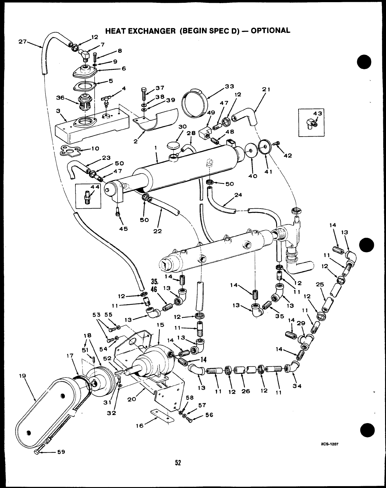
~HEAT EXCHANGER (BEGIN SPEC D) –OPTIONAL
27
F&
12
>8
6
-s. -
*“9
5
,4 21
,I. . I~\ ,~~., ))//\l $5’”0
4.
14
1\
34
612 ,1
f31 ‘-
/0
v
7. 32 /57
WY
,6>0
,56
3
&59
,
●
XCS-1207
52
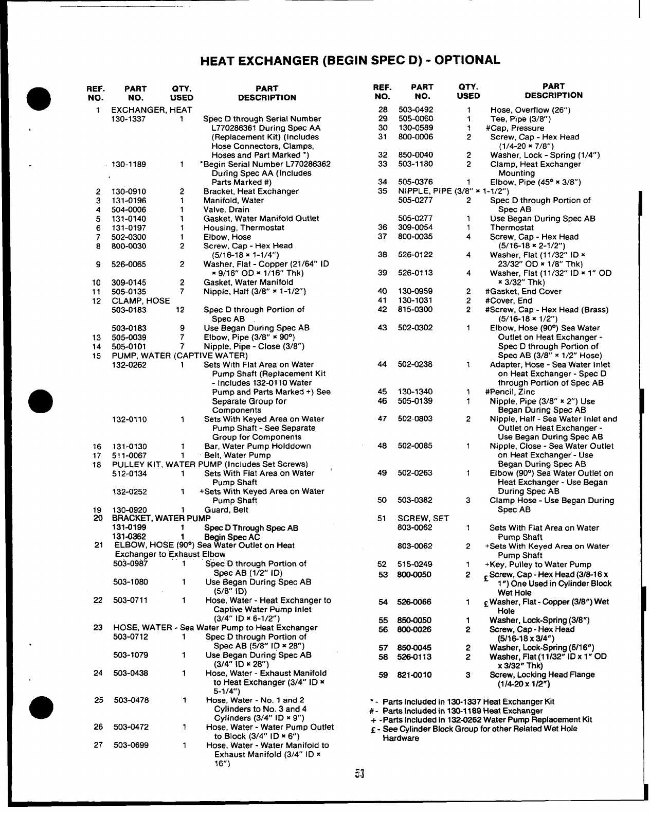
HEAT EXCHANGER (BEGIN SPEC D) -OPTIONAL
I
REF.
NO.
28
29
30
31
PART QTY. PART
NO. USED DESCRIPTION
●REF. PART QTY. PART
NO. NO. USED DESCRIPTION
1EXCHANGER, HEAT 503-0492 1Hose, Overflow (26”)
505-0060 1Tee, Pipe (3/8)
130-0589 1#Cap, Pressure
800-0006 2Screw, Cap -Hex Head
(1/4-20 X7/8”)
850-0040 2Washer, Lock -Spring (1/4”)
503-1180 2Clamp, Heat Exchanger
Mounting
505-0376 1Elbow, Pipe (45° x3/8”)
NIPPLE, PIPE (3/8” X1-1/2”)
Spec Dthrough Serial Number
L770286361 During Spec AA
(Replacement Kit) (Includes
Hose Connectors, Clamps,
Hoses and Part Marked ‘)
“Begin Serial Number L770286362
During Spec AA (Includes
Parts Marked #)
Bracket, Heat Exchanger
Manifold, Water
Valve, Drain
Gasket, Water Manifold Outlet
Housing, Thermostat
Elbow, Hose
Screw, Cap -Hex Head
(5/16-18 X1-1/4”)
Washer, Flat -Copper (21/64” ID
=9/16 OD X1/16” Thk)
Gasket, Water Manifold
Nipple, Half (3/8” x1-1/2’)
Spec Dthrough Portion of
Spec AB
Use Began During Spec AB
Elbow, Pipe (3/8” x90°)
NiDDle. PiDe -Close (3/8”)
130-1337 1
32
33
.130-1189 1
34
35
2130-0910 2
3131-0196 1
4504-0006 1
5131-0140 1
6131-0197 1
7502-0300 1
8800-0030 2
505-0277 2Spec Dthrough Portion of
Spec AB
Use Began During Spec AB
Thermostat
Screw, Cap -Hex Head
(5/16-18 X2-1/2”)
Washer, Flat (11/32 ID x
23/32 OD X1/8” Thk)
Washer, Flat (1 1/32 ID x1” OD
X3/32” Thk)
#Gasket, End Cover
#Cover, End
#Screw, Cap -Hex Head (Brass)
(5/16-1 8X1/2”)
Elbow, Hose (90°) Sea Water
Outlet on Heat Exchanger -
Spec Dthrough Portion of
Spec AB (3/8” x1/2” Hose)
Adapter, Hose -Sea Water Inlet
on Heat Exchanger -Spec D
through Portion of Spec AB
#Pencil, 21nc
Nipple, Pipe (3/8” x2“) Use
Began During Spec AB
Nipple, Half -Sea Water Inlet and
Outlet on Heat Exchanger -
Use Began During Spec AB
Nipple, Close -Sea Water Outlet
on Heat Exchanger- Use
Began During Spec AB
Elbow (90°) Sea Water Outlet on
Heat Exchanger -Use Began
During Spec AB
Clamp Hose -Use Began During
Spec AB
505-0277
309-0054
800-0035
1
1
4
36
37
38 526-0122 4
9526-0065 2
10 309-0145 2
11 505-0135 7
12 CLAMP, HOSE
503-0183 12
503-0183 9
13 505-0039 7
14 505-0101 7
39 526-0113 4
40
41
42
130-0959
130-1031
815-0300
2
2
2
43 502-0302 1
15
●
PUMP, WATER (CAPTIVE”WATEti)
132-0262 1Sets With Flat Area on Water
Pump Shaft (Replacement Kit
-Includes 132-0110 Water
Pump and Parts Marked +) See
Separate Group for
Components
132-0110 1Sets With Keyed Area on Water
Pump Shaft -See Separate
Group for Components
131-0130 1Bar, Water Pump Holddown
511-0067 1Belt, Water Pump
PULLEY KIT, wATER pLIMp (Includes Set Screws)
512-0134 1Sets With Fiat Area on Water c
Pump Shaft
132-0252 1+Sets With Keyed Area on Water
PumD Shaft
44 502-0238 1
45 130-1340
46 505-0139
47 502-0803
1
1
2
16
17
18
48 502-0085 1
49 502-0263 1
50 503-0382
51 SCREW, SET
803-0062
803-0062
52 515-0249
53 800-0050
3
19 130-0920 Guard,’ Belt
20 BRACKET, WATEi PUMP
131-0199 1Spec DThrough Spec AB
131-0362 1Begin Spec AC
ELBOW, HOSE (90°) Sea Water Outlet on Heat
Exchanger to Exhaust Elbow
503-0987 1Spec Dthrough Poti\on of
Spec AB (1/2” ID)
503-1080 1Use Began During Spec AB
(5/6” ID)
503-0711 1Hose, Water -Heat Exchanger to
CaDtive Water PumD Inlet
1Sets With Flat Area on Water
Pump Shaft
+Sets With Keyed Area on Water
Pump Shaft
+Key, Pulley to Water Pump
[Screw, Cap -Hex Head (3/6-1 6x
1”) OneUsed in Cylinder Block
Wet Hole
~Washer, Flat- Copper (3/8”) Wet
Hole
Washer, Lock-Spring (3/8”)
Screw, Cap -Hex Head
(5/16-18 X3/4”)
Washer, Lock-Spring (5/1 6“)
Washer, Flat (11 /32” ID x1” OD
X3132” Thk)
Screw. Lockina Head Flange
21 2
-1
2
22 54 526-0066
55 850-0050
56 800-0026
57 650-0045
56 526-0113
59 821-0010
1
(3/4” ID X6-1/2”)
HOSE, WATER -Sea Water Pump to Heat Exchanger
503-0712 1Spec Dthrough Portion of
1
2
23
.‘Spec AB (578” ID x28)
503-1079 1Use Began During Spec AB
(3/4” ID x28)
503-0438 1Hose, Water -Exhaust Manifold
to Heat Exchanger (3/4” ID x
5-1/w)
503-0478 1Hose, Water -No. 1 and 2
Cylinders to No. 3 and 4
Cylinders (3/4 ID x9“)
503-0472 1Hose, Water -Water Pump Outlet
to Block (3/4” ID X6)
503-0699 1Hose, Water -Water Manifold to
Exhaust Manifold (3/4” ID x
16)
2
2
24 3
(1/i20 xl/21 -
“ - Parts Included in 130-1337 Heat Exchanger Kit
#- Parts Included in 130-1169 Heat Exchanger
+-Parta Included in 132-0262 Water Pump Replacement Kit
E- See Cylinder Block Group for other Related Wet Hole
Hardware
25
26
27
53
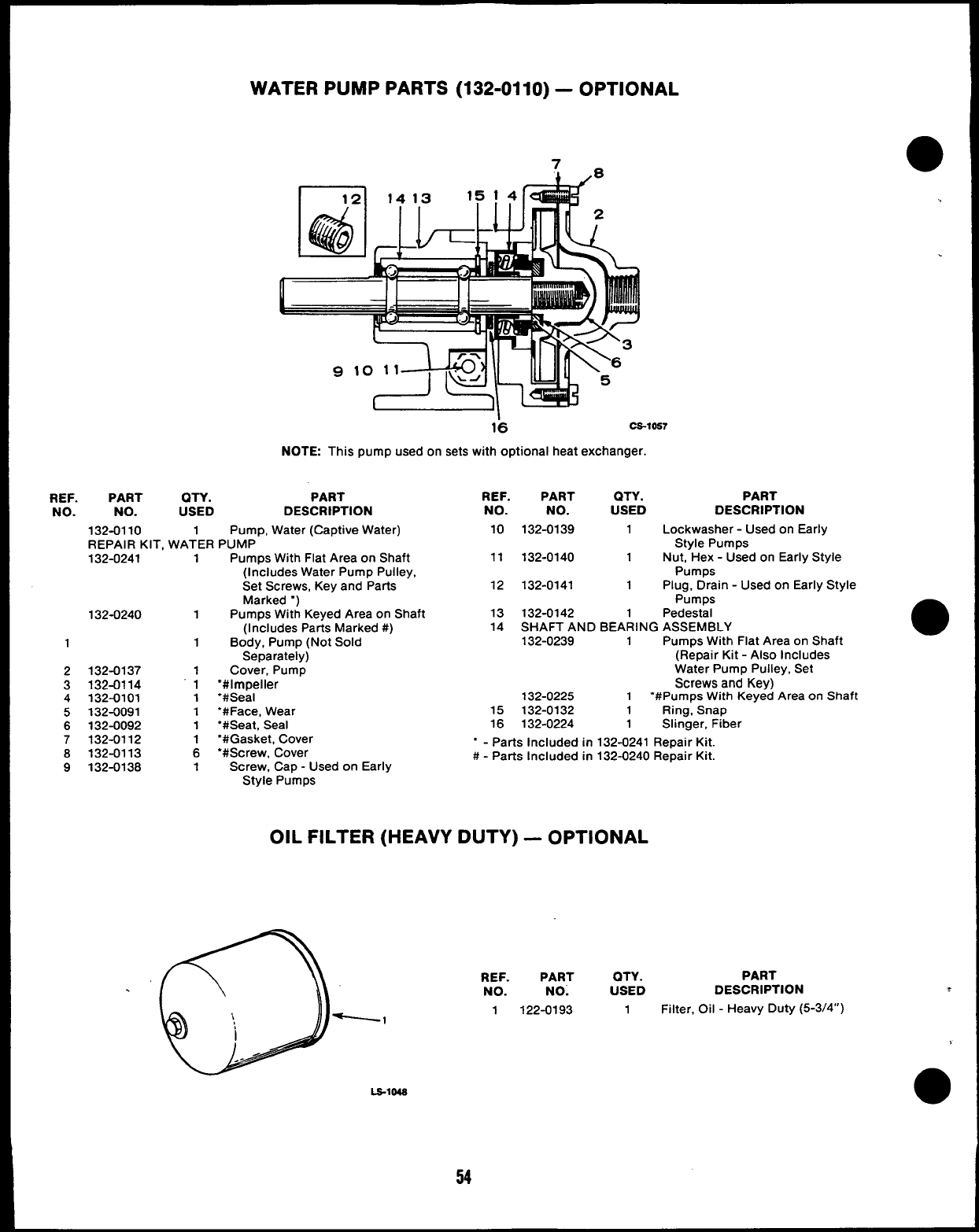
WATER PUMP PARTS (132-0110) –OPTIONAL
L’*
16 CS-1OS7
NOTE This pump used on sets with optional heat exchanger.
REF. PART QTY. PART REF. PART QTY. PART
NO. NO. USED DESCRIPTION NO. NO. USED DESCRIPTION
132-0110 1Pump, Water (Captive Water) 10 132-0139 1Lockwasher -Used on Early
REPAIR KIT. WATER PUMP Style Pumps
1
2
3
4
5
6
7
8
9
132-0241 1
132-0240 1
1
132-0137 1
132-0114 “1
132-0101 1
132-0091 1
132-0092 1
132-0112 1
132-0113 6
132-0138 1
Pumps With Flat Area on Shaft
(Includes Water Pump Pulley,
Set Screws, Key and Parts
Marked “)
Pumps With Keyed Area on Shaft
(Includes Parts Marked #)
Body, Pump (Not Sold
Separately)
Cover, Pump
“#impeller
“#Seal
“#Face, Wear
“#Seat, Seal
11 132-0140 1Nut, Hex -Used on Early Style
Pumps
12 132-0141 1Plug, Drain -Used on Early Style
Pumps
13 132-0142 1Pedestal
14 SHAFT AND BEARING ASSEMBLY
132-0239 1Pumps With Flat Area on Shaft
(Repair Kit -Also Includes
Water Pump Pulley, Set
Screws and Key)
132-0225 1“#Pumps With Keyed Area on Shaft
15 132-0132 1Ring, Snap
16 132-0224 1Slinger, Fiber
‘#Gasket, Cover
‘#Screw, Cover “ - Parts Included in 132-0241 Repair Kit.
Screw, Cap -Used on Early #-Parts Included in 132-0240 Repair Kit.
Style Pumps
OIL FILTER (HEAVY DUTY) –OPTIONAL
LS-lMS
REF. PART QTY. PART
NO. NO. USED DESCRIPTION
1-122-0193 1Filter, Oil -Heavy Duty (5-3/4”)
54
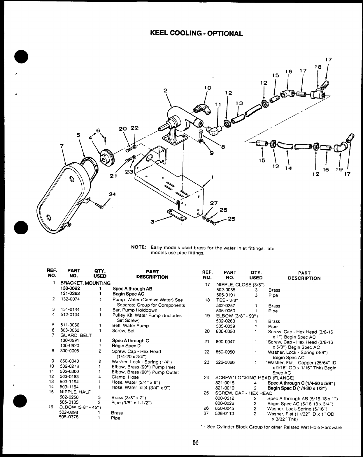
KEEL COOLING -OPTIONAL
●
✌
✎
7
17
18
1,6 17
15 I II
w124
‘Q /
●/
NOTE: Early models used brass for the water inlet fittings, late
models use pipe fittings,
REF. PART QTY.
NO. NO. PART
USED DESCRIPTION
1BRACKH, MOUNTING
130-0692 1
131-0362 1
2132-0074 1
3131-0144 1
4512-0134 1
5
6
7
8
9
.10
11
12
13
14
15
●16
511-0068 1
803-0062 1
GUARD, BELT
130-0591 1
130-0920 1
800-0005 2
850-0040 2
502-0278 1
502-0300 1
503-0183 4
503-1194 1
503-1194 1
NIPPLE. HALF
502-0258 3
505-0135 3
ELBOW (3 “8” -45°)
502-0298 1“
505-0376 1
Spec Athrough AB
Begin Spec AC
Pump, Water (Captive Water) See
Separate Group for Components
Bar. Pump Holddown
Pulley Kit, Water Pump (Includes
Set Screw)
Belt. Water Pump
Screw, Set
Spec Athrough C
Begin Spec D
Screw, Cap -Hex Head
(1/4-20 X3/4”)
Washer, Lock -Spring (1 /4”)
Elbow. Brass (90°) Pump Inlet
Elbow, Brass (90”) Pump Outlet
Clamp, Hose
Hose. Water (3/4” x9“)
Hose, Water Inlet (3/4” x9“)
Brass (3/8” x2“)
Pipe (3/8” xl-I/2”)
Brass
Pipe
REF.
NO.
17
18
19
20
21
22
23
24
25
26
27
1,:,~1
12 17
PART OTY. PART
NO. USED DESCRIPTION
NIPPLE, CLOSE (3/8”)
502-0085 3Brass
505-0101 3Pipe
TEE -3!8”
502-0257 1Brass
505-0060 1Pipe
ELBOW (3~8° -90°)
502-0263 1Brass
505-0039 iPipe
800-0050 1Screw. Cap -Hex Head (3/8-1 6
xl“) Begin Spec AC
800-0047 1.Screw, Cap -Hex Head (3/8-16
x5/8”) Begin Spec AC
850-0050 1Washer. Lock -Spring (3/8”)
Begin Spec AC
526-0066 1.Washer. Flat -Copper (25/64” ID
x9!16” OD x1/16’ Thk) Begin
Spec AC
SCREW.’ LOCKING HEAD (FLANGE)
821-0018 4Spec Athrough C(1/4-20x5/8”)
821-0010 3Begin Spec D(1/4-20 x1/2”)
SCREW. CAP -HEX HEAD -
800-0512 2Spec Athrough AB (5/16-18 xl“)
800-0026 2Begin Spec AC (5/16-18 x3/4”)
850-0045 2Washer, Lock-Spring (5/16’)
526-0113 2Washer, Flat (1 1/32” ID x1“ OD
X3/32” Thk)
.- See Cylinder Block Group for other Related Wet Hole Hardware
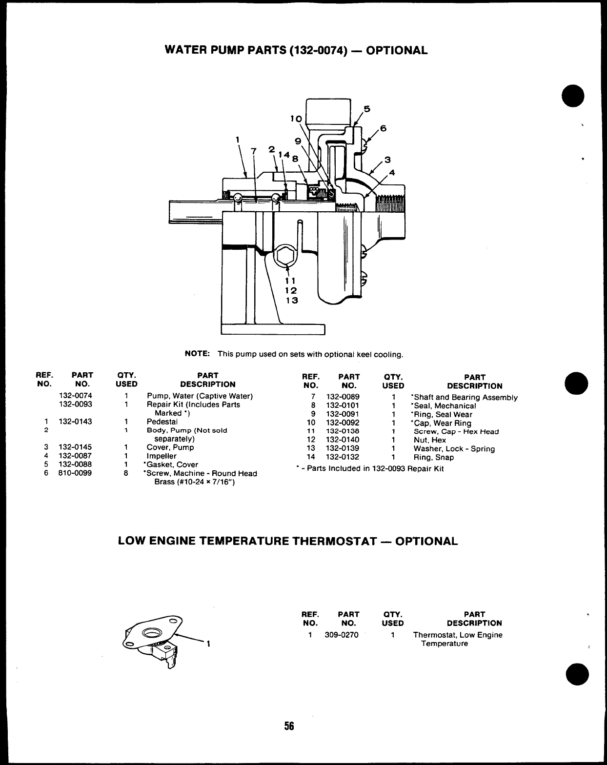
WATER PUMP PARTS (132-0074) –OPTIONAL
REF. PART
NO. NO.
132-0074
132-0093
1132-0143
2
3132-0145
4132-0087
5132-0088
6810-0099
QTY.
USED
1
1
1
1
1
1
1
I
NOTE This pump used on sets with optional keel cooling.
PART
DESCRIPTION
Pump, Water (Captive Water)
Repair Kit (Includes Parts
Marked “)
Pedestal
Body, Pump (Not sold
separately)
Cover, Pump
Impeller
‘Gasket, Cover
8“Screw, Machine -Round Head
.
.
REF.
NO.
7
8
9
10
11
12
13
14
PART
NO.
132-0089
132-0101
132-0091
132-0092
132-0138
132-0140
132-0139
132-0132
QTY. PART
USED DESCRIPTION
1‘Shaft and Bearing Assembly ●
1‘Seal, Mechanical
1“Ring, Seal Wear
1“Cap, Wear Ring
1Screw, Cap -Hex Head
1Nut, Hex
1Washer, Lock -Spring
1Ring, Snap
“ - Parts Included in 132-0093 Repair Kit
Brass (#10-24 x7/16”)
LOW ENGINE TEMPERATURE THERMOSTAT —OPTIONAL
REF. PART QTY. PART
NO. NO. USED DESCRIPTION
1309-0270 1Thermostat, Low Engine
Temperature
56
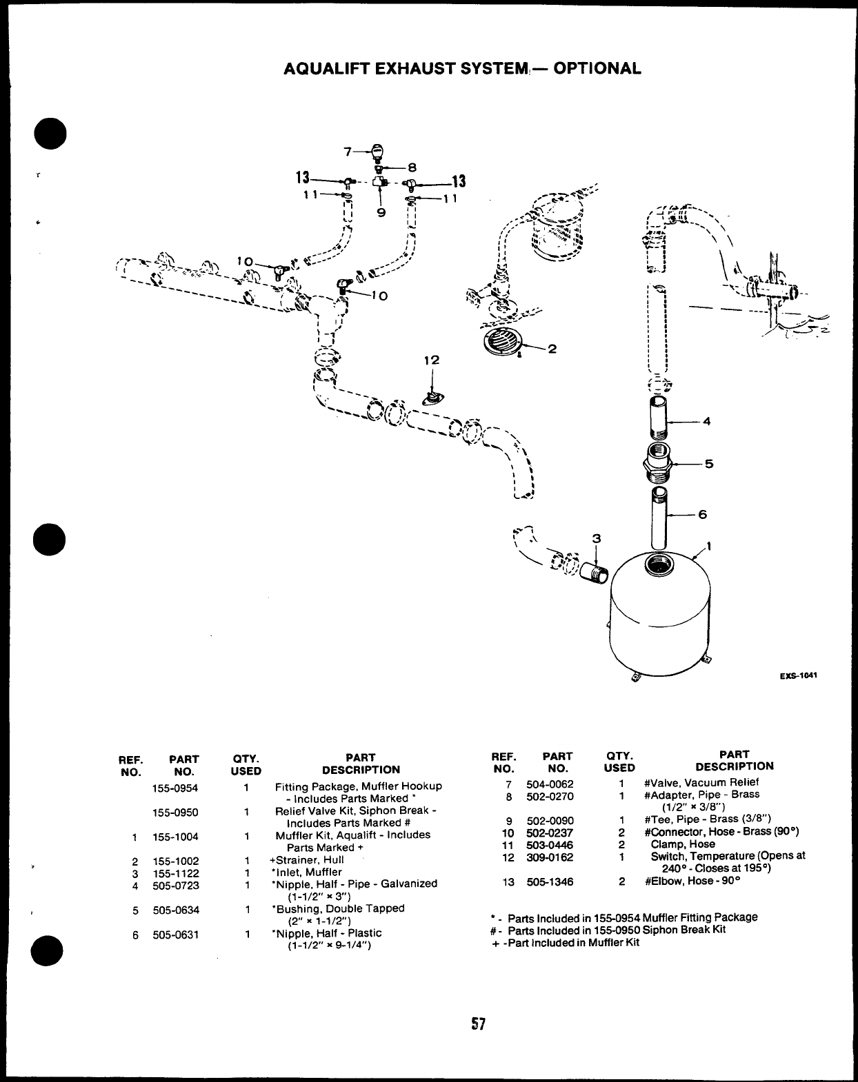
AQUALIFT EXHAUST SYSTEM- OPTIONAL
●74
REF. PART
NO. NO.
155-0954
155-0950
1155-1004
>2155-1002
3155-1122
4505-0723
5505-0634
6505-0631
i:
::
. .
QTY. PART REF. PART QTY. PART
USED DESCRIPTION NO. NO. USED DESCRIPTlON
1
1
1
1
1
1
1
1
Fitting Package, Muffler Hookup
-Includes Parts Marked “
Relief Valve Kit, Siphon Break -
Includes Parts Marked #
Muffler Kit, Aqualift -Includes
Parts Marked +
+Strainer, Hull
“Inlet, Muffler
“Nipple, Half -Pipe -Galvanized
(1-1/2” x3“)
“Bushing, Double Tapped
(2” x1-1/2”)
“Nipple, Half -Plastic
(1-1/2 x9-1/4”)
EXS-1041
7504-0062 1#valve, Vacuum Relief
8502-0270 1#Adapter, Pipe -Brass
(1/2” x3/8”)
9502-0090 1#Tee, Pipe -Brass (3/8’)
10 502-0237 2#Connector, Hose -Brass (90°)
11 503-0446 2Clamp, Hose
12 309-0162 1Switch, Temperature (Opens at
240°- Closes at 195°)
13 505-1346 2#Elbow, Hose -90°
*-Parts Included in 155-0954 Muffler Fitting Package
#- Parts Included in 155-0950 Siphon Break Kit
+-Part Included in Muffler Kit
57
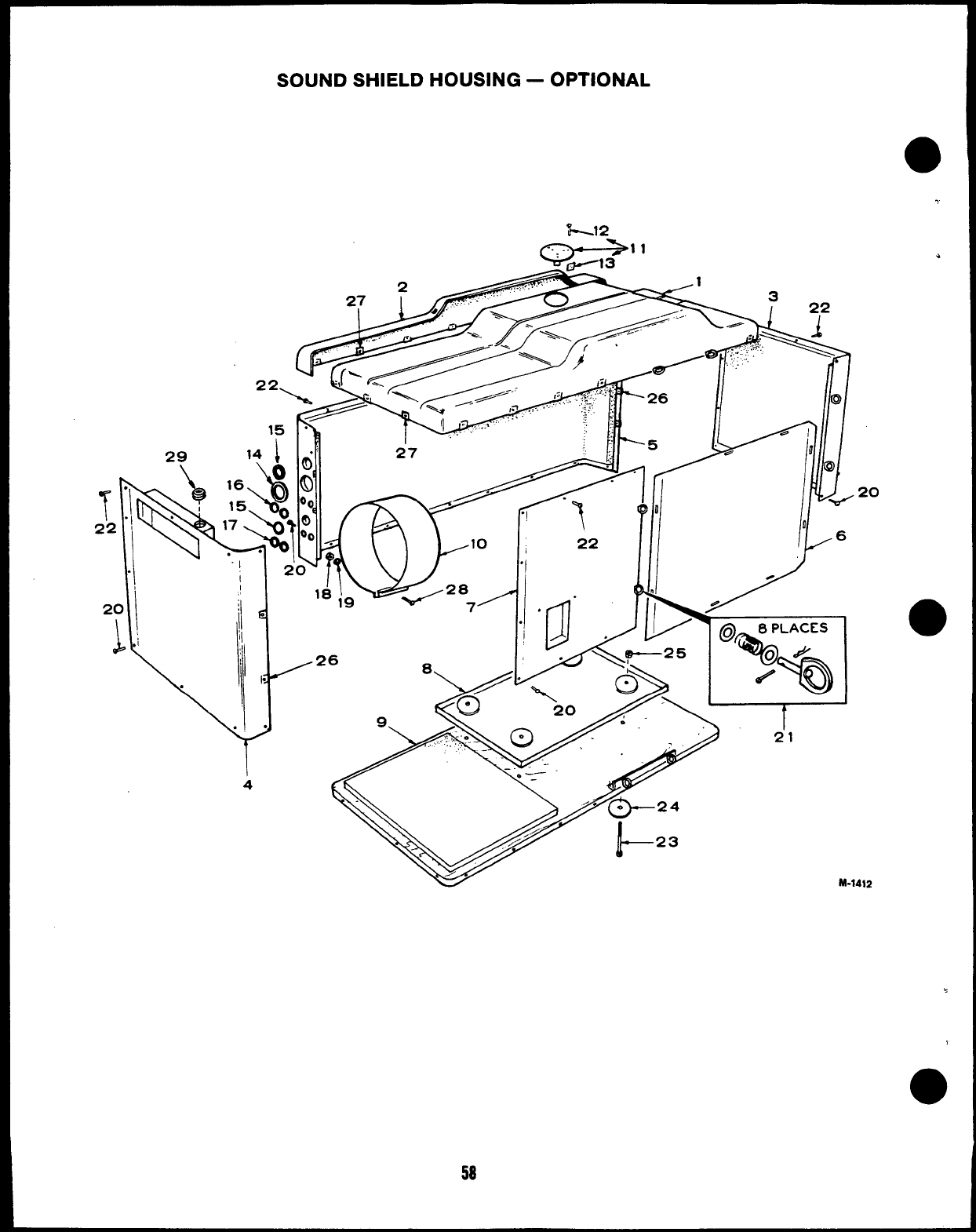
SOUND SHIELD HOUSING –OPTIONAL
-1
M-1412
58
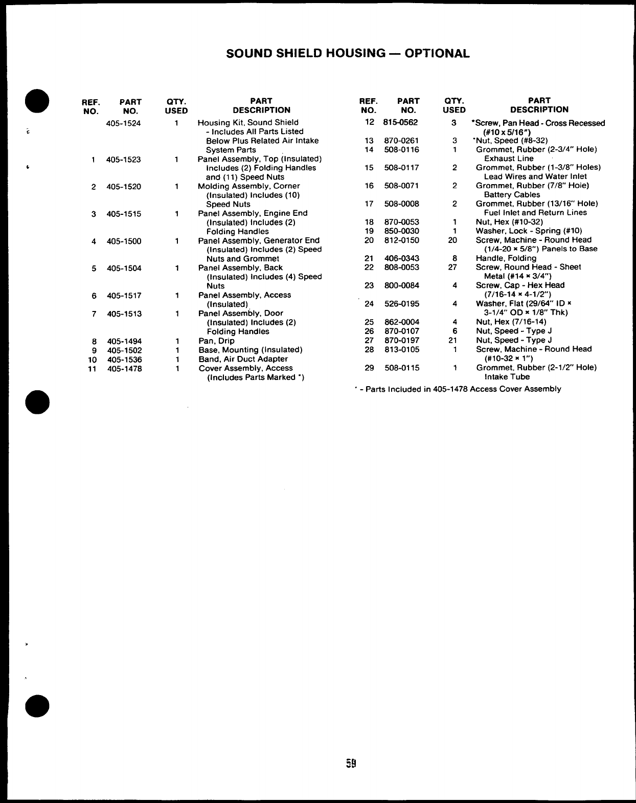
SOUND SHIELD HOUSING —OPTIONAL
REF. PART
NO. NO.
405-1524
1405-1523
&
2405-1520
3405-1515
4405-1500
5405-1504
6405-1517
7405-1513
8405-1494
9405-1502
10 405-1536
11 405-1478
WY.
USED
1
1
1
1
1
1
1
1
1
1
1
1
PART
DESCRIPTION
Housing Kit, Sound Shield
-Includes All Parts Listed
Below Plus Related Air Intake
System Parts
Panel Assembly, Top (Insulated)
Includes (2) Folding Handles
and (11 )Speed Nuts
Molding Assembly, Corner
(Insulated) Includes (10)
Speed Nuts
Panel Assembly, Engine End
(Insulated) Includes (2)
Folding Handles
Panel Assembly, Generator End
(Insulated) Includes (2) Speed
Nuts and Grommet
Panel Assembly, Back
(Insulated) Includes (4) Speed
Nuts
Panel Assembly, Access
(Insulated)
Panel Assembly, Door
(Insulated) Includes (2)
Folding Handles
Pan, Drip
Base, Mounting (Insulated)
Band, Air Duct Adapter
Cover Assembly, Access
(includes Parts Marked “)
REF. PART
NO. NO.
12 815-0562
13 870-0261
14 508-0116
15 508-0117
16 508-0071
17 508-0008
18 870-0053
19 850-0030
20 812-0150
21 406-0343
22 808-0053
23 800-0084
24 526-0195
25 862-0004
26 870-0107
27 870-0197
28 813-0105
29 508-0115
QTY. PART
USED DESCRIPTION
3
3
1
2
2
2
1
1
20
8
27
4
4
4
6
21
1
1
“Screw, Pan Head -Cross Recessed
(#10 X5/16”)
“Nut, Speed (#8-32)
Grommet, Rubber (2-3/4” Hole)
Exhaust Line
Grommet, Rubber (1-3/8’ Holes)
Lead Wires and Water Inlet
Grommet, Rubber (7/8” Hole)
Battery Cables
Grommet, Rubber (13/16’ Hole)
Fuel Inlet and Return Lines
Nut, Hex (#10-32)
Washer, Lock -Spring (#IO)
Screw, Machine -Round Head
(1/4-20 x5/8”) Panels to Base
Handle, Folding
Screw, Round Head -Sheet
Metal (#14 x3/4”)
Screw, Cap -Hex Head
(7/16-14 X4-1/2)
Washer, Flat (29/64” ID x
3-1/4 OD X1/8 Thk)
Nut, Hex (7/16-14)
Nut, Speed -Type J
Nut, Speed -Type J
Screw, Machine -Round Head
(#10-32 xl“)
Grommet, Rubber (2-1/2 Hole)
Intake Tube
>
“ - Parts Included in 405-1478 Access Cover Assembly
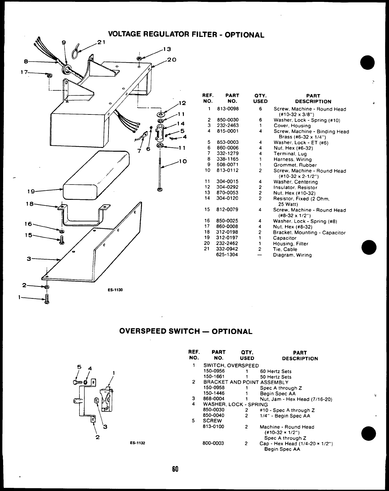
VOLTAGE REGULATOR FILTER -OPTIONAL
●
1
‘8------+
16,
3
2IES-1130
I
r10
REF. PART
NO. NO.
1813-0098
2850-0030
3232-2463
4815-0001
5853-0003
6860-0006
7332-1279
8338-1165
9508-0071
10 813-0112
11 304-0015
12 304-0292
13 870-0053
14
15
16
17
18
19
20
21
304-0120
812-0079
850-0025
860-0008
312-0198
312-0197
232-2462
332-0942
625-i304
OVERSPEED SWITCH —OPTIONAL
2ES-1132
OTY.
USED
6
6
1
4
4
4
4
1
1
2
4
2
2
2
4
4
4
2
1
1
2
.
REF. PART OTY.
NO. NO. USED
1SWITCH,OVERSPEED
PART
DESCRIPTION
Screw. Machine -Round Head
(#1 O-32 X3/8”)
Washer, Lock -Spring (#10)
Cover, Housing
Screw, Machine -Binding Head
Brass (#6-32 x1/4”)
Washer, Lock -ET (#6)
Nut, Hex (#6-32)
Terminal, Lug
Harness. Wiring
Grommet. Rubber
Screw, Machine -Round Head
(#10-32 X2-1/2”)
Washer. Centering
Insulator, Resistor
Nut. Hex (#10-32)
Resistor, Fixed [20hm,
25 Watt)
Screw, Machine -Round Head
(#8-32 X1/2”)
Washer. Lock -Spring (#8)
Nut. Hex (#8-32)
Bracket, Mounting -Capacitor
Capacitor
Housing. Filter
Tie, Cable
Diagram. Wiring
PART
DESCRIPTION
150-0956 160 Hertz Sets
150-1661 150 Hertz Sets
2BRACKET AND POINT ASSEMBLY
150-0958 1Spec Athrough Z
150-1446 1Begin Spec AA
3868-0004 1Nut, Jam -Hex Head (7/16-20)
4WASHER, LOCK -SPRING
850-0030 2 #10 -Soec Athrouah Z
850-0040 2114”- Begin Spec ~A
5SCREW
813-0100 2Machine -Round Head
(#10-32 X1/2”)
Spec Athrough Z
800-0003 2Cap -Hex Head (1/4-20 x1/2”)
Begin Spec AA
60
