981 0516 Onan 10KW HDKAG Genset Service Manual (10 1997) W 1051 Supl
User Manual: 981-0516 Onan 10KW HDKAG Genset Service manual (10-1997) w-981-1051 Supl
Open the PDF directly: View PDF ![]() .
.
Page Count: 67
Caution: This document contains mixed page sizes (8.5 x 11 or 11 x
17), which may affect printing. Please adjust your printer settings
according to the size of each page you wish to print.

Service Manual
10.0 kW HDKAG Generator Sets
Printed in U.S.A. 981-0516
10-97

Page 1 of 1
Supplement 981Ć1051
Date: 02Ć05
Insert withĆ
Title: HDKAG Service Manual
Number (Date): 981Ć0516 (10Ć97)
This Supplement transmits changes to Figure 4-5 to illustrate the location of the voltage adjustment pot on
newer voltage regulator boards. Replace Sheet 4-5/4-6 with the attached sheet.
Redistribution or publication of this document,
by any means, is strictly prohibited.
4-5
GENERATOR OPERATION
Refer to Figures 4-3 and 4-4, the generator sche-
matics, while working through the following descrip-
tion.
1. Voltage regulator VR1 (three-phase: VR21)
supplies DC to the field winding (F1 - F2 leads)
through brushes and slip rings, thereby estab-
lishing a revolving 4-pole magnetic field. The
battery is connected during startup to initiate
field excitation. Voltage regulator VR1 supplies
field current during operation. Rated output
voltage is maintained as the generator load
varies, by varying field current to maintain field
strength proportional to the load.
2. The revolving magnetic field induces AC in the
stator windings (T1 - T2 and T3 - T4) which are
connected to the load.
3. Under light load, the stator windings can supply
sufficient current for the field to maintain rated
output voltage.
4. As the load increases, load currents increase,
resulting in a proportional increase of current,
which in turn supplies the field. Rated output
voltage is thereby maintained as the load var-
ies.
ELECTRONIC VOLTAGE REGULATOR
The voltage regulator controls the output of the gen-
erator so that a constant voltage is maintained un-
der varying load conditions.
Only the basic functions of the regulator are de-
scribed (Figure 4-5). Voltage from quadrature wind-
ings Q1/Q2 supply power to the voltage regulator it-
self. The voltage regulator in turn supplies an ex-
citation voltage (F1/F2) that is directly proportionate
to the output voltage (L1/L0) it senses. Any
changes in the generator output voltage produce a
corresponding change in the excitation voltage pro-
vided by the regulator.
On the HDKAG, the voltage regulator assembly in-
cludes a potentiometer which enables a slight de-
gree of output voltage adjustment. The voltage reg-
ulator assembly contains no user-serviceable
parts. If the assembly fails, it must be replaced.
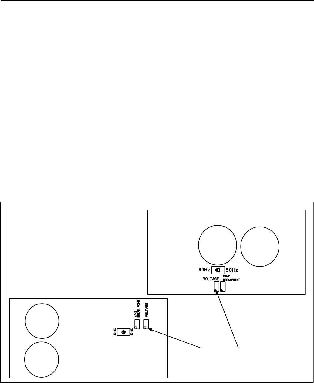
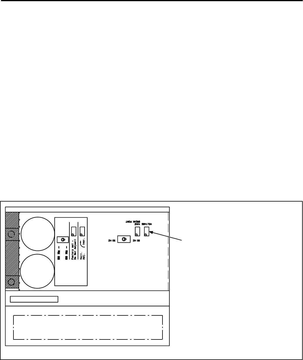
FIGURE 4-5. ADJUSTMENTS ON GENSET VOLTAGE REGULATOR BOARD
NEWER BOARDS
OLDER BOARDS
VOLTAGE ADJUST: Trim pot adjusts
output voltage level. Turn pot clockwise to
increase voltage. Turn pot counterclockwise
to decrease voltage.
CAUTION: The V/Hz Break Point Pot is
Factory Set and Sealed. DO NOT ADJUST.
Redistribution or publication of this document,
by any means, is strictly prohibited.
4-6
GENERATOR SERVICE
Always disconnect the battery cables (negative [-]
first) from the battery to prevent accidental starting
of the set while servicing the generator.
WARNING Accidental starting of the set while
working on it can cause severe injury. To pre-
vent accidental starting, disconnect the battery
cables (negative [-] first) from the battery.
The negative (-) cable is always disconnected
first, and connected last, to prevent arcing if a
tool accidentally touches the frame or other
grounded metal parts of the set while discon-
necting or connecting the positive (+) cable.
Arcing can ignite the explosive hydrogen gas
given off by the battery, and cause severe inju-
ry.
Brush Inspection/Replacement
The generator should be inspected for brush wear
and cleaning every six months.
WARNING Accidental starting of the generator
set can cause severe personal injury or death.
Stop the generator set and disable by discon-
necting the starting battery cables (negative [-]
cable first) before inspecting the generator.
1. Remove the access cover for the brush assem-
bly.
2. Check the brushes for wear with a piece of wire
marked off 1 inch (25 mm) from one end (Fig-
ure 4-6). Replace the brush and the spring if
the wire goes into the brush holder 1 inch or
more.
3. To replace brushes, remove the brush holder
by disconnecting the two leads to the holder
and removing the two mounting screws.
4. Install the new brushes and springs in the hold-
er and keep them in place during assembly by
inserting a piece of wire through the holder, as
shown in Figure 4-7.
5. Install the brush holder. After tightening the
mounting screws, pull out the brush retaining
wire.
6. Connect the F1 lead to the inner brush terminal
(nearest the rotor windings). Connect the F2
lead to the outer brush terminal (nearest the
end bell).
Slip Ring Inspection/Replacement
Inspect the slip rings for grooves, pits or other dam-
age. If dust has accumulated on any generator
components, they can be cleaned with filtered low-
pressure air.
1. Examine the slip rings while servicing the
brushes.
2. If the rings need cleaning or service, remove
the rotor from the generator and dress the rings
on a lathe.
CAUTION Dressing the slip rings on a lathe
improperly may damage the generator rotor.
Make certain that only an experienced techni-
cian performs this job.
Generator Bearing
Inspect the bearing for evidence of outer case rota-
tion every 1000 hours of use. The bearing should
be replaced every five years, because the bearing
grease gradually deteriorates due to oxidation.
Replace the O-ring if it shows evidence of wear or
deterioration. Renew grease if necessary (moly
only).
Redistribution or publication of this document,
by any means, is strictly prohibited.

California
Proposition 65 Warning
Diesel engine exhaust and some of its constituents are known
to the State of California to cause cancer, birth defects, and
other reproductive harm.
Redistribution or publication of this document,
by any means, is strictly prohibited.

i
Table of Contents
SAFETY PRECAUTIONS iii. . . . . . . . . . . . . . . . . . . . . . . . . . . . . . . . . . . . . . . . . . .
1 INTRODUCTION 1-1. . . . . . . . . . . . . . . . . . . . . . . . . . . . . . . . . . . . . . . . . . . . . . . . . .
About This Manual 1-1. . . . . . . . . . . . . . . . . . . . . . . . . . . . . . . . . . . . . . . . . . . . . . .
Assistance 1-1. . . . . . . . . . . . . . . . . . . . . . . . . . . . . . . . . . . . . . . . . . . . . . . . . . . . . .
Test Equipment 1-1. . . . . . . . . . . . . . . . . . . . . . . . . . . . . . . . . . . . . . . . . . . . . . . . . .
Safety Considerations 1-1. . . . . . . . . . . . . . . . . . . . . . . . . . . . . . . . . . . . . . . . . . . .
Set Removal 1-3. . . . . . . . . . . . . . . . . . . . . . . . . . . . . . . . . . . . . . . . . . . . . . . . . . . .
2 ENGINE CONTROLS 2-1. . . . . . . . . . . . . . . . . . . . . . . . . . . . . . . . . . . . . . . . . . . . . .
General 2-1. . . . . . . . . . . . . . . . . . . . . . . . . . . . . . . . . . . . . . . . . . . . . . . . . . . . . . . .
Start Control at Set 2-1. . . . . . . . . . . . . . . . . . . . . . . . . . . . . . . . . . . . . . . . . . . . . .
Control Troubleshooting 2-6. . . . . . . . . . . . . . . . . . . . . . . . . . . . . . . . . . . . . . . . . .
3 ENGINE CONTROL SERVICE 3-1. . . . . . . . . . . . . . . . . . . . . . . . . . . . . . . . . . . . . .
General 3-1. . . . . . . . . . . . . . . . . . . . . . . . . . . . . . . . . . . . . . . . . . . . . . . . . . . . . . . .
[A] Battery Check (BT1) 3-1. . . . . . . . . . . . . . . . . . . . . . . . . . . . . . . . . . . . . . . . . .
[B] Battery Cable Check 3-1. . . . . . . . . . . . . . . . . . . . . . . . . . . . . . . . . . . . . . . . . .
[C] Battery Charging Check 3-1. . . . . . . . . . . . . . . . . . . . . . . . . . . . . . . . . . . . . . .
[D] Start Solenoid Check (K11) 3-1. . . . . . . . . . . . . . . . . . . . . . . . . . . . . . . . . . . .
[E] Heater (Glow Plug) Relay Check (K13) 3-2. . . . . . . . . . . . . . . . . . . . . . . . . .
[F] Fuel Solenoid Check (K14) 3-2. . . . . . . . . . . . . . . . . . . . . . . . . . . . . . . . . . . .
[G] Start/Stop Switch Check (S11) 3-2. . . . . . . . . . . . . . . . . . . . . . . . . . . . . . . . .
[H] Power Relay Check (A11-K12) 3-2. . . . . . . . . . . . . . . . . . . . . . . . . . . . . . . . .
4 GENERATOR/VOLTAGE REGULATOR 4-1. . . . . . . . . . . . . . . . . . . . . . . . . . . . . .
General Description 4-1. . . . . . . . . . . . . . . . . . . . . . . . . . . . . . . . . . . . . . . . . . . . . .
Generator Operation 4-5. . . . . . . . . . . . . . . . . . . . . . . . . . . . . . . . . . . . . . . . . . . . .
Electronic Voltage Regulator 4-5. . . . . . . . . . . . . . . . . . . . . . . . . . . . . . . . . . . . . .
Generator Service 4-6. . . . . . . . . . . . . . . . . . . . . . . . . . . . . . . . . . . . . . . . . . . . . . .
Generator Disassembly/Assembly 4-8. . . . . . . . . . . . . . . . . . . . . . . . . . . . . . . . .
5 GENERATOR/REGULATOR TROUBLESHOOTING 5-1. . . . . . . . . . . . . . . . . . .
General 5-1. . . . . . . . . . . . . . . . . . . . . . . . . . . . . . . . . . . . . . . . . . . . . . . . . . . . . . . .
Troubleshooting Procedures 5-1. . . . . . . . . . . . . . . . . . . . . . . . . . . . . . . . . . . . . .
6 GENERATOR/REGULATOR TESTS 6-1. . . . . . . . . . . . . . . . . . . . . . . . . . . . . . . . .
General 6-1. . . . . . . . . . . . . . . . . . . . . . . . . . . . . . . . . . . . . . . . . . . . . . . . . . . . . . . .
[A] Testing Field Voltage 6-1. . . . . . . . . . . . . . . . . . . . . . . . . . . . . . . . . . . . . . . . . .
[B] Testing Generator Rotor 6-1. . . . . . . . . . . . . . . . . . . . . . . . . . . . . . . . . . . . . . .
[C] Testing Generator Stator 6-2. . . . . . . . . . . . . . . . . . . . . . . . . . . . . . . . . . . . . .
[D] Dynamic Rotor/Stator Test 6-3. . . . . . . . . . . . . . . . . . . . . . . . . . . . . . . . . . . . .
[E] Voltage Regulator Replacement 6-5. . . . . . . . . . . . . . . . . . . . . . . . . . . . . . . .
[F] Wiring Harness Check 6-5. . . . . . . . . . . . . . . . . . . . . . . . . . . . . . . . . . . . . . . .
[G] Voltage Adjustment 6-5. . . . . . . . . . . . . . . . . . . . . . . . . . . . . . . . . . . . . . . . . . .
[H] Reconnection 6-5. . . . . . . . . . . . . . . . . . . . . . . . . . . . . . . . . . . . . . . . . . . . . . . .
Redistribution or publication of this document,
by any means, is strictly prohibited.

ii
7 ROUTINE MAINTENANCE 7-1. . . . . . . . . . . . . . . . . . . . . . . . . . . . . . . . . . . . . . . . .
Introduction 7-1. . . . . . . . . . . . . . . . . . . . . . . . . . . . . . . . . . . . . . . . . . . . . . . . . . . . .
Maintenance Schedule 7-1. . . . . . . . . . . . . . . . . . . . . . . . . . . . . . . . . . . . . . . . . . .
Generator Set Inspection 7-2. . . . . . . . . . . . . . . . . . . . . . . . . . . . . . . . . . . . . . . . .
Oil and Filter Change 7-3. . . . . . . . . . . . . . . . . . . . . . . . . . . . . . . . . . . . . . . . . . . .
Cooling System 7-4. . . . . . . . . . . . . . . . . . . . . . . . . . . . . . . . . . . . . . . . . . . . . . . . .
Fan Belt 7-6. . . . . . . . . . . . . . . . . . . . . . . . . . . . . . . . . . . . . . . . . . . . . . . . . . . . . . . .
Fuel System 7-7. . . . . . . . . . . . . . . . . . . . . . . . . . . . . . . . . . . . . . . . . . . . . . . . . . . .
Air Cleaner 7-9. . . . . . . . . . . . . . . . . . . . . . . . . . . . . . . . . . . . . . . . . . . . . . . . . . . . .
Battery Care 7-9. . . . . . . . . . . . . . . . . . . . . . . . . . . . . . . . . . . . . . . . . . . . . . . . . . . .
AC Generator 7-10. . . . . . . . . . . . . . . . . . . . . . . . . . . . . . . . . . . . . . . . . . . . . . . . . .
Crankcase Breather 7-10. . . . . . . . . . . . . . . . . . . . . . . . . . . . . . . . . . . . . . . . . . . . .
Muffler/Spark Arrester 7-11. . . . . . . . . . . . . . . . . . . . . . . . . . . . . . . . . . . . . . . . . . .
Cleaning the Generator Set 7-11. . . . . . . . . . . . . . . . . . . . . . . . . . . . . . . . . . . . . .
Initial Starting and Checks 7-11. . . . . . . . . . . . . . . . . . . . . . . . . . . . . . . . . . . . . . .
8 WIRING DIAGRAMS 8-1. . . . . . . . . . . . . . . . . . . . . . . . . . . . . . . . . . . . . . . . . . . . . .
Redistribution or publication of this document,
by any means, is strictly prohibited.

iii
Safety Precautions
Thoroughly read the OPERATOR’S MANUAL
before operating the genset. Safe operation and
top performance can be obtained only with
proper operation and maintenance.
The following symbols in this Manual alert you to
potential hazards to the operator, service person
and equipment.
Alerts you to an immediate hazard
which will result in severe personal injury or
death.
Alerts you to a hazard or unsafe
practice which can result in severe personal in-
jury or death.
Alerts you to a hazard or unsafe
practice which can result in personal injury or
equipment damage.
Electricity, fuel, exhaust, moving parts and batteries
present hazards which can result in severe person-
al injury or death.
GENERAL PRECAUTIONS
•Keep ABC fire extinguishers handy.
•Make sure all fasteners are secure and torqued
properly.
•Keep the genset and its compartment clean.
Excess oil and oily rags can catch fire. Dirt and
gear stowed in the compartment can restrict
cooling air.
•Let the engine cool down before removing the
coolant pressure cap or opening the coolant
drain. Hot coolant under pressure can spray
out and cause severe burns.
•Before working on the genset, disconnect the
negative (-) battery cable at the battery to pre-
vent starting.
•Use caution when making adjustments while
the genset is running—hot, moving or electri-
cally live parts can cause severe personal inju-
ry or death.
•Used engine oil has been identified by some
state and federal agencies as causing cancer
or reproductive toxicity. Do not ingest, inhale,
or contact used oil or its vapors.
•Benzene and lead in some gasolines have
been identified by some state and federal
agencies as causing cancer or reproductive
toxicity. Do not to ingest, inhale or contact gas-
oline or its vapors.
•Do not work on the genset when mentally or
physically fatigued or after consuming alcohol
or drugs.
•Carefully follow all applicable local, state and
federal codes.
GENERATOR VOLTAGE IS DEADLY!
•Generator output connections must be made
by a qualified electrician in accordance with ap-
plicable codes.
•The genset must not be connected to the public
utility or any other source of electrical power.
Connection could lead to electrocution of utility
workers, damage to equipment and fire. An ap-
proved switching device must be used to pre-
vent interconnections.
•Use caution when working on live electrical
equipment. Remove jewelry, make sure cloth-
ing and shoes are dry and stand on a dry wood-
en platform on the ground or floor.
FUEL IS FLAMMABLE AND EXPLOSIVE
•Keep flames, cigarettes, sparks, pilot lights,
electrical arc-producing equipment and
switches and all other sources of ignition well
away from areas where fuel fumes are present
and areas sharing ventilation.
•Fuel lines must be secured, free of leaks and
separated or shielded from electrical wiring.
•Use approved non-conductive flexible fuel
hose for fuel connections at the genset.
Redistribution or publication of this document,
by any means, is strictly prohibited.
iv
ENGINE EXHAUST IS DEADLY!
•Learn the symptoms of carbon monoxide poi-
soning in this Manual.
•Never sleep in the vehicle while the genset is
running unless the vehicle has a working car-
bon monoxide detector.
•The exhaust system must be installed in accor-
dance with the genset Installation Manual.
•Do not use engine cooling air to heat the ve-
hicle interior.
•Make sure there is ample fresh air when oper-
ating the genset in a confined area.
MOVING PARTS CAN CAUSE SEVERE
PERSONAL INJURY OR DEATH
•Do not wear loose clothing or jewelry near mov-
ing parts such as PTO shafts, fans, belts and
pulleys.
•Keep hands away from moving parts.
•Keep guards in place over fans, belts, pulleys,
etc.
BATTERY GAS IS EXPLOSIVE
•Wear safety glasses and do not smoke while
servicing batteries.
•When disconnecting or reconnecting battery
cables, always disconnect the negative (-) bat-
tery cable first and reconnect it last to reduce
arcing.
DO NOT OPERATE IN FLAMMABLE AND
EXPLOSIVE ENVIRONMENTS
Flammable vapor can cause a diesel engine to
overspeed and become difficult to stop, resulting in
possible fire, explosion, severe personal injury and
death.
Do not operate a diesel-powered genset
where a flammable vapor environment can be
created by fuel spill, leak, etc., unless the gen-
set is equipped with an automatic safety device
to block the air intake and stop the engine.
The
owners and operators of the genset are solely re-
sponsible for operating the genset safely. Contact
your authorized Onan/Cummins dealer or distribu-
tor for more information.
Mobile-3
Redistribution or publication of this document,
by any means, is strictly prohibited.

1. Introduction
1-1
ABOUT THIS MANUAL
This manual contains troubleshooting and repair
data for these components of the HDKAG genera-
tor set:
•Control
•Generator
See the Engine Service Manual for engine informa-
tion.
Study this manual carefully. Heed all warnings and
cautions. Proper use and maintenance can result in
longer set life, better performance and safer opera-
tion.
This manual contains basic wiring diagrams and
schematics for troubleshooting. Technicians
should use the wiring diagram and schematic
shipped with each unit. Update these diagrams and
schematics when the set is modified.
PC board information is limited; in the field, it is
more efficient to replace the boards than to attempt
repair.
ASSISTANCE
When contacting an Onan distributor, supply the
complete model number and serial number shown
on the Onan nameplate on the side of the generator
control box.
TEST EQUIPMENT
•Multimeter/digital VOM
•AC voltmeter
•DC voltmeter
•Frequency meter
•Jumper leads
•Load test panel
•Megger or insulation resistance meter
•Wheatstone bridge or digital ohmmeter
WARNING
Incorrect service or replacement of
parts can result in severe personal injury,
death, and /or equipment damage. Service per-
sonnel must be qualified to perform electrical
and mechanical service.
SAFETY CONSIDERATIONS
Generator sets present safety hazards that the
technician must know about. Read the precautions
on the inside cover of this manual. Familiarize your-
self with the hazards shown in Table 1-1. When the
hazards are known, approach the job with a safety-
conscious attitude. Being safety-conscious is the
best way to avoid injury. Reduce the chance of an
accident with the following safeguards.
Safeguards To Avoid Hazards
•Use Protective Clothing. Protect your body
by wearing protective clothing such as:
•Safety shoes
•Gloves
•Safety glasses
•Hard hats
Leave rings and jewelry off. Do not wear loose
clothing that might get caught on equipment.
•Reduce Workshop Hazards.
•Keep guards and shields in place on
machinery
•Maintain equipment in good working order
•Store flammable liquids in approved
containers away from open flame, spark,
pilot light, cigarette, or other ignition source
•Keep the workshop clean and well-lighted
•Provide adequate ventilation
•Keep a fire extinguisher and safety
equipment nearby
•Be prepared to respond to an emergency
•Develop Safe Work Habits.
Unsafe actions are the source of most acci-
dents with tools and machines. Be familiar with
the equipment and know how to use it safely.
Use the right tool for the job, and check its con-
dition before starting. Observe the warnings
and cautions in this manual and take special
precautions when working around electrical
equipment. Do not work alone if possible and
do not take unnecessary risks.
Redistribution or publication of this document,
by any means, is strictly prohibited.

1-2
•Be prepared if an accident occurs.
Agencies such as the Red Cross and local police
and fire departments offer courses in first aid, CPR,
and fire control. Take advantage of this information
to be ready to respond to an accident. Learn to be
safety conscious and make safe practices a part of
your work routine. Do not work when tired or after
consuming any alcohol or drug that makes the op-
eration of equipment unsafe.
•Fire and explosions
•Leaking fuel
•Hydrogen gas from charging battery
•Oily rags improperly stored
•Flammable liquids improperly stored
•Any fire, flame, spark, pilot light, arc-
producing equipment or other ignition
sources
•Burns
•Hot exhaust pipes
•Hot engine and generator surfaces
•Hot engine oil
•Electrical short in DC wiring system
•Hot engine coolant
•Poisonous gases
•Carbon monoxide from faulty exhaust
pipes, joints or hangers
•Operating generator set where
exhaust gases can accumulate
•Electrical shock (AC)
•Improper genset load connections
•Faulty RV wiring
•Faulty electrical appliance
•Faulty genset wiring
•Working in damp conditions
•Jewelry touching electrical components
•Rotating Machinery
•Flywheel fan guard not in place
•Jewelry or loose clothing catching in
moving parts
•Slippery Surfaces
•Leaking or spilled oil
•Heavy Objects
•Removing generator set from RV
•Removing heavy components
TABLE 1-1
HAZARDS AND THEIR SOURCES
Redistribution or publication of this document,
by any means, is strictly prohibited.
1-3
SET REMOVAL
Some service procedures require removing the
generator set from the vehicle. Because of the wide
variety of installations, it is not possible to specify
exact removal procedures for each genset. If a sat-
isfactory method for removing a particular set can-
not be determined, contact the vehicle manufactur-
er or the set installer for their recommendations.
WARNING
Generator sets are heavy and they
can cause severe personal injury or death if
dropped during removal. Use adequate lifting
devices to provide sufficient support for the set.
Keep hands and feet clear while lifting the gen-
erator set. Before starting set removal, place
the transmission in park, set the emergency
brake, and remove the negative (-) cable from
the vehicle ignition system battery to avoid in-
advertent movement of the vehicle.
Disconnecting Generator Set Systems
Some installations require partial removal of the set
to gain access to the battery cable, fuel line, and
other connections. Read this entire section before
starting set removal. The following steps are a gen-
eral guideline.
WARNING
Leakage of fuel in or around the
generator set compartment presents the hazard
of fire or explosion that can cause severe per-
sonal injury or death. Do not disconnect or con-
nect battery cables if fuel vapors are present.
Ventilate the compartment thoroughly: park ve-
hicles outdoors in a well ventilated area.
1. Disconnect the generator set negative (-) bat-
tery cable at the battery terminal.
2. Disconnect the generator set positive (+) bat-
tery cable from the wire harness.
3. Disconnect the remote control plug wire from
the generator set (if applicable).
4. Disconnect the generator load wires. Tag for
identification when reconnecting.
5. Disconnect the exhaust system and support
brackets or hangers, to allow set removal.
6. Disconnect the fuel line at the genset housing.
Securely plug the end of the fuel line to prevent
fuel leakage.
7. Verify that the set is adequately supported be-
fore loosening any mounting bolts or support
members.
WARNING
Leakage of fuel presents the hazard
of fire or explosion that can cause severe per-
sonal injury or death. Make certain all fuel line
openings are plugged. Before disconnecting
the fuel line, be certain there are no ignition
sources such as flame, spark, pilot light, ciga-
rette, etc., near the generator set. Keep an ABC
type fire extinguisher nearby.
When reinstalling the set, be sure all mounting
hardware, and electrical, exhaust, and fuel system
components are connected exactly as they were
before removal. See the appropriate installation
manual during reinstallation for important safety
precautions.
Check for oil and fuel leaks. Check the exhaust sys-
tem audibly and visually with the generator set run-
ning. Repair leaks immediately. Replace worn,
damaged, or corroded exhaust and fuel line compo-
nents before leaks occur.
Redistribution or publication of this document,
by any means, is strictly prohibited.

1-4
Blank Page
Redistribution or publication of this document,
by any means, is strictly prohibited.

2. Engine Controls
2-1
GENERAL
This section describes the generator set preheat/
start/run control system. The set may be started ei-
ther at the onboard DC control box or by using a re-
motely mounted start control.
START CONTROL AT SET
The set is started with a Start/Stop/Preheat switch
on the front panel of the DC control box. Component
references are found on wiring/schematic diagrams
in the Wiring Diagrams section of this manual.
The DC control box does not contain meters and is
designed for remote mounting within limits of the
wire harness (approximately 32 inches [813 mm]).
An optional remote control panel with meters is
available in a kit from Onan.
Switches
Start-Stop/Preheat Switch S11:
Starts and stops
the unit locally. Preheat function occurs when the
switch is held in the Stop position. The unit may also
be operated from a remote switch wired to recep-
tacle J3 on the rear panel.
Circuit Breakers
DC Control Breaker CB11:
A 15 ampere DC
breaker providing protection to the control box wir-
ing and remote wiring from short circuits or over-
load. Also serves as an emergency stop switch.
Fault Breaker CB12:
A manual reset breaker that
shuts down the engine for low oil pressure and high
coolant temperatures.
Control Components
The following describes the basic engine control
components and how they function.
A11 Engine Monitor Circuit Board:
A circuit board
that monitors the engine control system functions.
This includes starting, stopping, and fault system
operation. Terminals are included for making re-
mote connections. See Figure 2-1.
Two relays soldered into the engine monitor board
are not serviceable. They function as follows:
•Power relay K12 connects battery B+ to the
control meters and fuel solenoid during opera-
tion.
•Starter protection relay K15 is AC operated.
When the Start switch is pressed, B+ is con-
nected to K11 start solenoid through the K15
NC contacts until the generator output reaches
about 90 volts AC. At this voltage K15 acti-
vates and disconnects the starter circuit.
K11 Start Solenoid:
Located over the engine moni-
tor circuit board (above K13 glow plug heater sole-
noid). It connects battery B+ to the start solenoid,
K13 heater solenoid, fuel solenoid and meters dur-
ing cranking.
K13 Glow Plug Heater Solenoid:
Located directly
above the monitor circuit board. Connects B+ to the
engine glow plugs during cranking. It is energized
by K11 start solenoid.
K14 Fuel Solenoid:
It opens the fuel control valve
when the start/stop switch is placed in the Start
position.
Redistribution or publication of this document,
by any means, is strictly prohibited.

2-2
FIGURE 2-1. HDKAG GENERATOR SET DC CONTROL BOX
300-3203
A11 ENGINE MONITOR
CIRCUIT BOARD
RELAY - START
SOLENOID
CB12 FAULT
BREAKER
DC CONTROL
BREAKER CB11
S11 START-STOP-
PREHEAT SWITCH
COVER
DC WIRING
HARNESS
CR2 RECTIFIER
ASSEMBLY
J3 REMOTE
CONNECTION
J1 AC INPUT J2 ENGINE
HARNESS
Engine Monitors
This section briefly describes the engine sensors
(switches) and optional gauge senders. The sen-
sors protect the engine from unfavorable operating
conditions; the senders are used with the operation-
al remote panel. These sealed units are not repair-
able. Do not use a substitute part if replacement is
necessary, since they are close-tolerance parts
made for a specific application.
The safety sensors (switches) close the fault circuit
to ground if abnormal operating conditions exist,
tripping the fault breaker CB12 to stop the engine.
See Figure 2-2 and the schematic in Figure 2-3.
Oil Pressure Monitors
Refer to Figure 2-2 for the location of the oil pres-
sure monitors.
Oil Pressure Sender E1:
The sender resistance
changes with oil pressure and results in a reading
on the (optional) oil pressure meter. The meter
range is 0 to 100 psi (0 to 700 kPa).
Low Oil Pressure Switch S1:
This switch closes if
oil pressure drops to 9 psi (62 kPa), activating the
fault breaker and stopping the engine.
Control Power Latch S6:
This oil pressure switch
closes at 5 psi (34 kPa) and provides a latch func-
tion for the control circuits. When closed, the switch
supplies a ground path for relay K12 on the engine
monitor board.
Redistribution or publication of this document,
by any means, is strictly prohibited.

2-3
FIGURE 2-2. HDKAG FAULT SENSOR LOCATIONS
OIL PRESSURE
SWITCH (S1)
(SHUTDOWN)
OIL PRESSURE
SENDER (M12)
COOLANT SHUTDOWN
SWITCH (S2)
OIL PRESSURE
SWITCH (S6)
(POWER LATCH)
COOLANT TEMPERATURE
SENDER (E2)
Redistribution or publication of this document,
by any means, is strictly prohibited.

2-4
Engine Temperature Monitors
Refer to Figure 2-2 for the location of the engine
temperature sensors.
Coolant Temperature Sender E2:
The resistance
of the sender unit changes with the engine coolant
temperature and causes a reading on the coolant
temperature meter (optional). The meter range is
100° to 250° F (40° to 121° C).
High Coolant Temperature Switch S2:
This
switch closes if the coolant temperature rises to
250° F (121° C), activating the fault breaker CB12
and stopping the engine.
Control Operation
To understand control operation, refer to the follow-
ing text and the schematic diagram (Figure 2-3).
Starting Sequence:
When start/stop switch S11 is
held in the
Stop
(preheat) position, battery B+ is
connected to the coil of heater relay K13. The relay
contacts close and connect B+ to heaters HR1 -
HR4.
After the preheat time interval, the operator holds
S11 in the
Start
position. This connects B+ to K14
fuel solenoid relay and through A11-K15 NC (nor-
mally closed) contacts to K11 start solenoid relay.
These relays actuate K1 fuel solenoid, B1 solenoid/
starter motor and heaters HR1 - HR4 (via K13 NC
contacts).
A11-K12 power relay is actuated after a short delay,
when the control power latch switch S6 closes. S6
is closed when oil pressure rises to 5 psi (34 kPa),
assuring engine lubrication before the set reaches
full operating speed. Normally open (NO) contacts
on A11-K12 close, supplying B+ to the other compo-
nents on the engine monitor board.
Start-Disconnect Sequence:
As the generator
gains speed and output voltage, A11-K15 starter
protection relay energizes at about 90 VAC.
A11-K15 NC contact opens and de-energizes start
solenoid relay K11. K11 then disconnects B+ from
the starter solenoid (to stop the cranking motor) and
from the glow plug heaters. If the generator fails to
develop voltage, the engine will attempt to start but
will stop as soon as the Start switch is released.
The two K15 NO (normally open) contacts close
and function as follows:
•Closes circuit for S1 and S2 (low oil pressure
and high coolant temperature switches respec-
tively)
•Provides another ground path for K12 coil
(through K11 coil) similar to S6.
Battery Charge Circuit:
Alternator G1, powered
by a belt from the engine, supplies B+ voltage to re-
charge the generator set starting battery through
circuit breaker CB13.
Stopping Sequence:
Placing S11 in the Stop posi-
tion puts B+ (through diode CR2) on the ground side
of the A11-K12 power relay. This causes K12 to de-
energize and disconnect B+ from CB12 and K1 fuel
solenoid. De-energizing K1 shuts off the fuel flow to
stop the engine.
Fault Shutdown:
Fault breaker CB12 opens to
stop the engine any time a fault sensor closes the
circuit to ground. The fault sensors as shown in Fig-
ure 2-2 are:
•S1 low oil pressure
•S2 high coolant temperature
Redistribution or publication of this document,
by any means, is strictly prohibited.

2-5
ENGINE PARTS
B1 Starter and solenoid
BT1 Battery (12V)
E1 Sender (oil pressure)
E2 Sender (coolant temperature)
HR1-4 Heater - glow plug
E5 Fuel pump - electric
K1 Fuel solenoid
S1 Switch - low oil pressure
S2 Switch - high coolant
temperature
S6 Switch - control power latch
G1 Alternator
CONTROL BOX PARTS
A11 PCB assy - engine monitor
CB11, 13 Circuit breaker (control)
CB12 Circuit breaker (fault)
K11 Relay - start solenoid
(starter) (12 V)
A11-K12 Relay - power
K13 Relay - heater
K14 Relay - fuel solenoid
A11 - K15 Relay - starter protection
K15 Relay
A11 - R1 Resistor (K12)
A11 - R2 Resistor (LOP timing)
S11 Switch - start/stop/preheat
J3 - J4 Connector - remote
FIGURE 2-3. DC CONTROL SCHEMATIC DIAGRAM
Redistribution or publication of this document,
by any means, is strictly prohibited.
2-6
Remote Control Operation (Optional):
The gen-
erator set may be operated from a remote switch
connected to the control receptacle J3. Installation
instructions are furnished with the kit available from
Onan. See Figure 2-4.
FIGURE 2-4. REMOTE CONTROL
WIRING DIAGRAM
J4 J3
START-STOP/
PREHEAT
RUN LIGHT
OIL
PRESSURE
WATER
TEMPERATURE
RUNNING TIME
METER
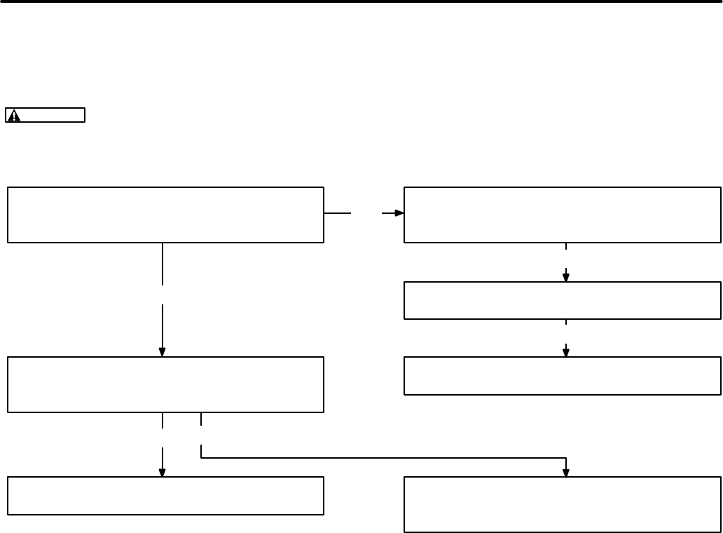
CONTROL TROUBLESHOOTING
The information in this section is divided into three
flow charts. Determine the problem and then refer
to the appropriate flow chart (A, B, or C) for the trou-
bleshooting procedures.
A. Engine does not crank.
B. Engine cranks but does not start.
C. Engine starts but stops after running
several seconds.
Before starting a troubleshooting procedure, make
a few simple checks that may expose the problem
and cut down on troubleshooting time.
•Check all modifications, repairs, and re-
placements performed since last satisfac-
tory operation of set. A loose wire connec-
tion overlooked when installing a replace-
ment part could cause problems. An in-
correct connection, an opened switch or
circuit breaker, or a loose plug-in are all po-
tential problems that can be eliminated by
a visual check.
•Unless absolutely sure that panel instru-
ments are accurate, use portable test me-
ters for troubleshooting.
To troubleshoot a problem, start at the upper-left
corner of chart and answer all questions either YES
or NO. Follow the chart until the problem is found,
performing referenced adjustments or test proce-
dures. Refer to Figures 2-1 through 2-4 for locating
control components, leads, terminals and other
check points.
Redistribution or publication of this document,
by any means, is strictly prohibited.

2-7
FLOW CHART A. ENGINE DOES NOT CRANK
Many troubleshooting procedures present hazards that can result in severe personal in-
jury or death. Only qualified service personnel with knowledge of fuels, electricity, and machinery
hazards should perform service procedures. Review Safety Precautions.
Is battery dead?
Check CB11 circuit breaker. If okay, jumper
battery cable B+ connection to B1 starter so-
lenoid terminal. Does engine crank?
With S11 in Start position, is battery voltage
present between K11 terminal S and ground?
If K11 does not energize, test per Checkout
[D] and replace if bad. Is battery voltage pres-
ent at B1 solenoid terminal with S11 in Start
position?
Check battery per Checkout [A] and recharge
or replace. Check battery charger operation
per Checkout [C].
Check battery cables for clean tight connec-
tions (ref. Checkout [B]). Check B1 starter so-
lenoid and motor: if bad, repair or replace.
Check B+ wiring to S11, and between S11 and
K11. Check NC contacts of A11-K15. Re-
place if bad.
no
yes
no
no
yes
yes
START
Check B+ wiring between K11 and B1 sole-
noid terminal. Replace if bad. Check K1
plunger travel for freedom to bottom in sole-
noid (necessary to open pull coil circuit).
no
WARNING
Redistribution or publication of this document,
by any means, is strictly prohibited.
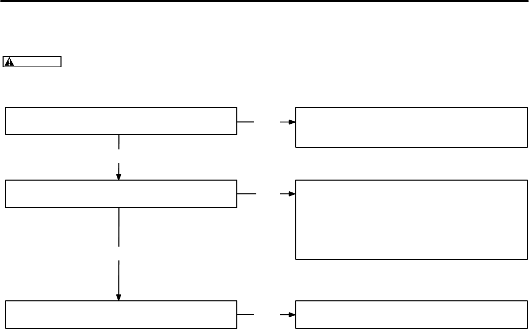
2-8
Many troubleshooting procedures present hazards that can result in severe personal in-
jury or death. Only qualified service personnel with knowledge of fuels, electricity, and machinery
hazards should perform service procedures. Review Safety Precautions.
FLOW CHART B. ENGINE CRANKS BUT DOES NOT START
Is engine getting fuel? Exhaust smoke should
be blue-white and fuel flow steady from fuel
return line.
Is battery B+ applied to glow plug heaters
when switch S11 is in Preheat and Start posi-
tions?
Incorrect fuel? See Operator’s Manual rec-
ommendations.
Check fuel system: fuel tank level, shut-off
valves, fuel lines and connections, fuel filters,
fuel pump and injection pump. Okay?
Does K14 fuel solenoid energize when S11 is
in Start position?
Check B+ circuit through S11. Test S11 per
Checkout [G]. Test K14 per Checkout [F].
Check switch S11 per Checkout [G]. Check
heater relay per Checkout [E]. Check heater
wiring.
no
no
yes
yes
yes
START
no
WARNING
Redistribution or publication of this document,
by any means, is strictly prohibited.
2-9
Many troubleshooting procedures present hazards that can result in severe personal in-
jury or death. Only qualified service personnel with knowledge of fuels, electricity, and machinery
hazards should perform service procedures. Review Safety Precautions.
FLOW CHART C. ENGINE STARTS BUT STOPS AFTER RUNNING SEVERAL SECONDS
Is a fault condition indicated by fault breaker
CB12 on control panel? Check for a possible fault condition. If none,
check fault monitors S1 through S4 and fault
breaker CB12 for improper wiring.
Check relay K12 per Checkout [H]. Is K12
good?
Does DC control breaker trip after generator
set is started?
Check for closing of S6 power latch switch. If
switch is OK, check mechanical adjustment of
K1 solenoid: is rod adjusted to correct length
to allow the hold-in coil of K1 to latch? If K1
adjustment is OK and problem remains, re-
place engine monitor PC board.
Check all B+ wiring for shorts to ground.
Check fuel solenoid adjustment.
yes
yes
no
yes
no
WARNING
Redistribution or publication of this document,
by any means, is strictly prohibited.

2-10
Blank Page
Redistribution or publication of this document,
by any means, is strictly prohibited.

3. Engine Control Service
3-1
GENERAL
The following checks are referred to in the Control
Troubleshooting flow charts. They isolate circuit
problems caused by faulty engine control compo-
nents. Disconnect leads before testing compo-
nents.
WARNING
Many troubleshooting procedures
present hazards that can result in severe per-
sonal injury or death. Only qualified service
personnel with knowledge of fuels, electricity,
and machinery hazards should perform service
procedures. Review Safety Precautions.
[A]
BATTERY CHECK (BT1)
Check the battery charge condition with a hydrome-
ter. Electrolyte specific gravity should be about
1.260 for a fully charged battery at 80°F (27°C). If
not, add distilled water to keep electrolyte at proper
level, then recharge the battery. If the battery will
not recharge, replace it.
If the battery loses excess water, the charge rate
may be too high. If the battery charge is not main-
tained, the charge rate may be too low. See proce-
dure [C].
WARNING
Ignition of explosive battery gases
can cause severe personal injury. Do not permit
any flame, spark, cigarette, or other ignition
source near the battery.
[B]
BATTERY CABLE CHECK
With the starter motor running, check these voltage
drops:
1. From the battery negative post (not the cable
clamp) to the cylinder block
2. From the battery positive post to the battery ter-
minal stud on the solenoid
Normally these should be less than 0.3 volts. If ex-
tra-long battery cables are used, slightly higher volt-
age drops may result. Thoroughly clean all connec-
tions in any part of the circuit showing excessive
voltage drop.
[C]
BATTERY CHARGING CHECK
With the engine running, check the DC voltmeter
(control option). The 12-volt system should read
13.5 to 15 volts.
The power source is a belt-driven alternator. The
charge rate/voltage is determined by a voltage reg-
ulator located inside the control box.
Improper output may be caused by a loose drive
belt, poor terminal connections, broken wires, bad
regulator or alternator. Checkout procedures for
the regulator and alternator are found in the engine
service manual. The charge circuit is protected by
circuit breaker CB13.
If the output voltage is high (over 15 volts), check for
loose or corroded voltage regulator leads. If this
does not correct the problem, the regulator is prob-
ably shorted and should be replaced.
[D]
START SOLENOID CHECK (K11)
1. Apply battery positive (B+) to the terminal
marked S.
2. Connect a ground wire to the solenoid terminal
marked I. The solenoid should activate.
3. If the contacts are good, battery voltage should
be read between terminal 1 and ground. The
voltage drop measured across the contacts
should never exceed one volt in circuit applica-
tion.
Redistribution or publication of this document,
by any means, is strictly prohibited.

3-2
[E]
HEATER (GLOW PLUG) RELAY CHECK
(K13)
1. Connect the relay coil voltage across the relay
coil terminals. The relay should activate if coil
is okay.
2. Connect a voltage source to one side of relay
contacts.
3. Connect a voltmeter to other side of relay con-
tact and voltage source. If voltage appears
when relay energizes, the contact is good. The
voltage reading appears in reverse order when
checking normally closed (NC) contacts.
[F]
FUEL SOLENOID CHECK (K14)
If there is fuel to the injection pump, but no fuel at the
injection nozzle, the fuel solenoid may be defective.
To check solenoid operation, watch for solenoid ac-
tuation when B+ is applied (start switch in start or
run position). If there is no actuation when B+ is ap-
plied, the fuel solenoid must be replaced. When B+
is removed, the solenoid must de-activate.
[G]
START/STOP SWITCH CHECK (S11)
1. Remove battery B+ cable.
2. Place ohmmeter leads across switch.
3. Open and close switch while observing the
ohmmeter. A normally open (NO) switch
should indicate infinite resistance when open
and continuity when closed. A normally closed
(NC) switch should indicate continuity when
closed and infinite resistance when open.
4. Replace switch if defective.
[H]
POWER RELAY CHECK (A11-K12)
Make certain that the genset starting battery is good
before beginning this check.
1. Unplug CB12-2A from the circuit breaker. Note
the markings on the wire to select the correct
one.
2. Locate S6 (oil pressure switch) on the genset
(see Figure 2-2). Find the grounded side of S6,
using a continuity tester.
3. Use a jumper to ground the non-grounded side
of S6.
4. Use a second jumper from the B+ terminal on
the control board to apply B+ to the SW B+
(switched B+) terminal. Fuel pump E5 should
start and run.
5. Remove the B+ jumper. If the fuel pump contin-
ues to run, K12 is good. If the fuel pump stops,
K12 has failed and the A11 control board
should be replaced.
6. Push the genset STOP button.
7. Remove the jumpers and reconnect CB12-2A.
Redistribution or publication of this document,
by any means, is strictly prohibited.

4. Generator/Voltage Regulator
4-1
GENERAL DESCRIPTION
The YK generator (Figure 4-1) is a four-pole, revolv-
ing field, brush-type design with drip-proof
construction.
The generator rotor is directly coupled to the engine
flywheel with a rigid drive disc. Engine speed deter-
mines generator output voltage and frequency. A
centrifugal blower on the drive disc circulates gen-
erator cooling air which is drawn in through the end
bell and discharged through an outlet in the blower
end.
A ball bearing in the end bell supports the outer end
of the rotor shaft. The end bell is attached with four
studs that thread into the generator adapter casting.
The genset brushes are mounted in the end bell
(see Figure 4-2).
FIGURE 4-1. YK SERIES GENERATOR
STATOR
ASSEMBLY
GENERATOR
ADAPTER
FAN
GUARD
END BELL
COVER
OUTPUT AND
CONTROL LEADS
COLLECTOR
RINGS
GENERATOR
DRIVE DISK
GENERATOR
DRIVE HUB
GENERATOR FAN
ROTOR
ASSEMBLY
END
BEARING
STATOR
WRAPPER
STATOR
ASSEMBLY
END BELL ASSEMBLY
(SEE FIGURE 4−2 FOR
BRUSH CONFIGURATION)
Redistribution or publication of this document,
by any means, is strictly prohibited.
4-2
FIGURE 4-2. GENSET END BELL WITH BRUSHES
BRUSH BLOCK
ASSEMBLY
LEAD (F2 TO
VR1−2)
LEAD (F1 TO
VR1−1)
O−RING
Redistribution or publication of this document,
by any means, is strictly prohibited.
4-3
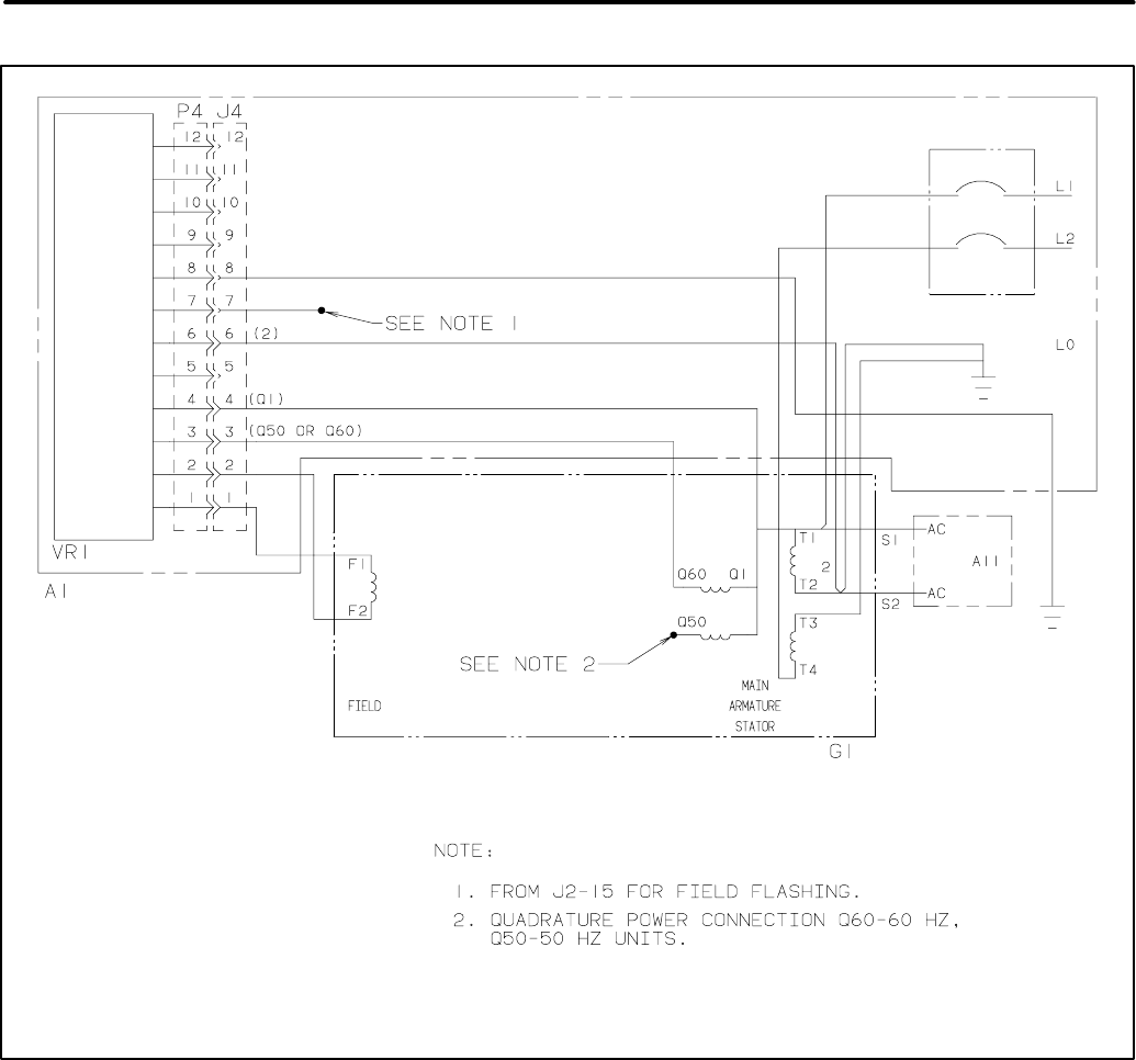
FIGURE 4-3. SINGLE-PHASE GENERATOR SCHEMATIC
Redistribution or publication of this document,
by any means, is strictly prohibited.
4-4
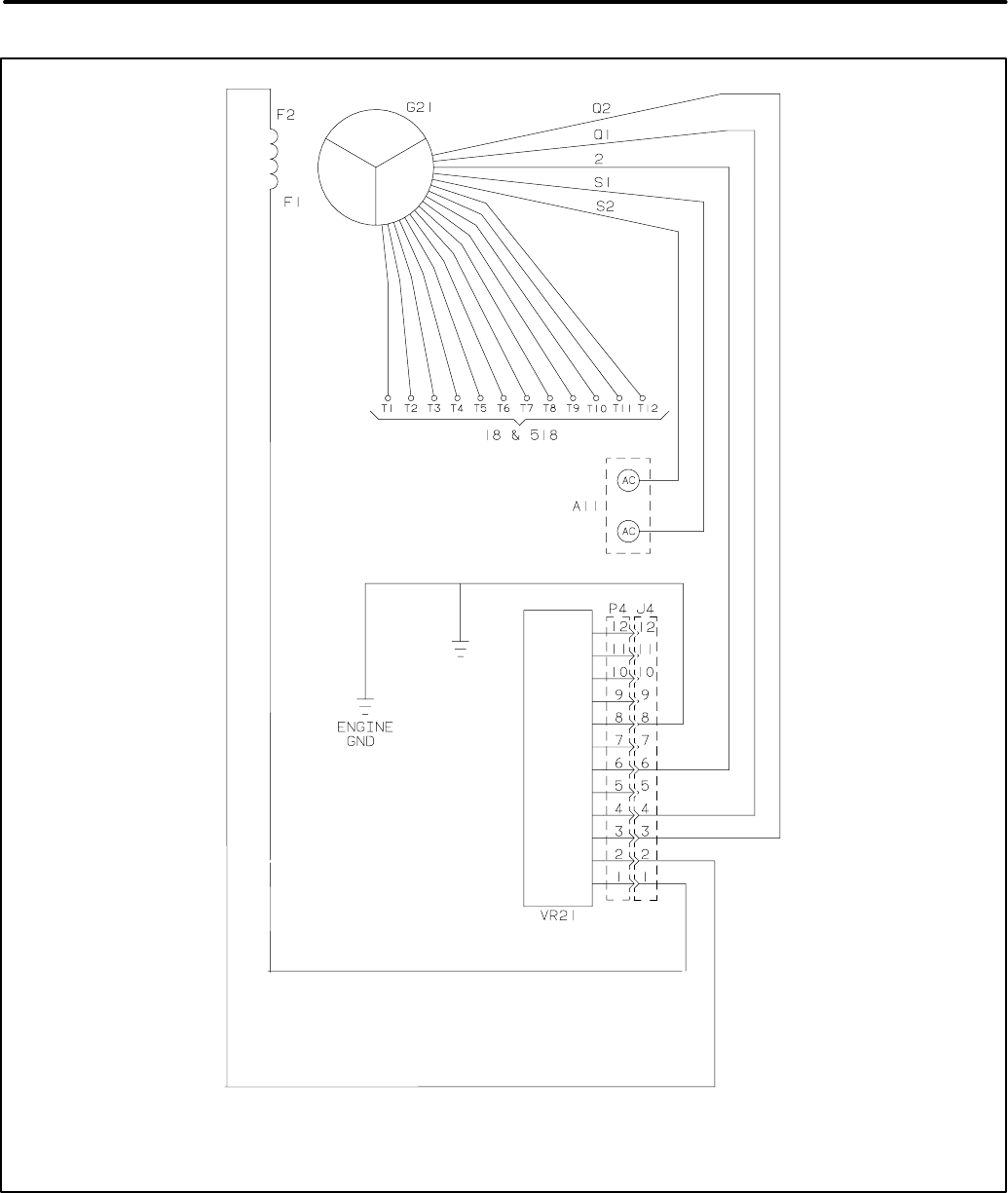
FIGURE 4-4. THREE-PHASE GENERATOR SCHEMATIC
Redistribution or publication of this document,
by any means, is strictly prohibited.
4-5
GENERATOR OPERATION
Refer to Figures 4-3 and 4-4, the generator sche-
matics, while working through the following descrip-
tion.
1. Voltage regulator VR1 (three-phase: VR21)
supplies DC to the field winding (F1 - F2 leads)
through brushes and slip rings, thereby estab-
lishing a revolving 4-pole magnetic field. The
battery is connected during startup to initiate
field excitation. Voltage regulator VR1 supplies
field current during operation. Rated output
voltage is maintained as the generator load
varies, by varying field current to maintain field
strength proportional to the load.
2. The revolving magnetic field induces AC in the
stator windings (T1 - T2 and T3 - T4) which are
connected to the load.
3. Under light load, the stator windings can supply
sufficient current for the field to maintain rated
output voltage.
4. As the load increases, load currents increase,
resulting in a proportional increase of current,
which in turn supplies the field. Rated output
voltage is thereby maintained as the load var-
ies.
ELECTRONIC VOLTAGE REGULATOR
The voltage regulator controls the output of the gen-
erator so that a constant voltage is maintained un-
der varying load conditions.
Only the basic functions of the regulator are de-
scribed (Figure 4-5). Voltage from quadrature wind-
ings Q1/Q2 supply power to the voltage regulator it-
self. The voltage regulator in turn supplies an ex-
citation voltage (F1/F2) that is directly proportionate
to the output voltage (L1/L0) it senses. Any
changes in the generator output voltage produce a
corresponding change in the excitation voltage pro-
vided by the regulator.
On the HDKAG, the voltage regulator assembly in-
cludes a potentiometer which enables a slight de-
gree of output voltage adjustment. The voltage reg-
ulator assembly contains no user-serviceable
parts. If the assembly fails, it must be replaced.
FIGURE 4-5. ADJUSTMENTS ON GENSET VOLTAGE REGULATOR BOARD
VOLTAGE ADJUST: Trim pot adjusts output
voltage level. Turn pot clockwise to increase
voltage. Turn pot counterclockwise to
decrease voltage.
BOARD SHOWN
WITHOUT COVER
Redistribution or publication of this document,
by any means, is strictly prohibited.

4-6
GENERATOR SERVICE
Always disconnect the battery cables (negative [-]
first) from the battery to prevent accidental starting
of the set while servicing the generator.
WARNING
Accidental starting of the set while
working on it can cause severe injury. To pre-
vent accidental starting, disconnect the battery
cables (negative [-] first) from the battery.
The negative (-) cable is always disconnected
first, and connected last, to prevent arcing if a
tool accidentally touches the frame or other
grounded metal parts of the set while discon-
necting or connecting the positive (+) cable.
Arcing can ignite the explosive hydrogen gas
given off by the battery, and cause severe inju-
ry.
Brush Inspection/Replacement
The generator should be inspected for brush wear
and cleaning every six months.
WARNING
Accidental starting of the generator
set can cause severe personal injury or death.
Stop the generator set and disable by discon-
necting the starting battery cables (negative [-]
cable first) before inspecting the generator.
1. Remove the access cover for the brush assem-
bly.
2. Check the brushes for wear with a piece of wire
marked off 1 inch (25 mm) from one end (Fig-
ure 4-6). Replace the brush and the spring if
the wire goes into the brush holder 1 inch or
more.
3. To replace brushes, remove the brush holder
by disconnecting the two leads to the holder
and removing the two mounting screws.
4. Install the new brushes and springs in the hold-
er and keep them in place during assembly by
inserting a piece of wire through the holder, as
shown in Figure 4-7.
5. Install the brush holder. After tightening the
mounting screws, pull out the brush retaining
wire.
6. Connect the F1 lead to the inner brush terminal
(nearest the rotor windings). Connect the F2
lead to the outer brush terminal (nearest the
end bell).
Slip Ring Inspection/Replacement
Inspect the slip rings for grooves, pits or other dam-
age. If dust has accumulated on any generator
components, they can be cleaned with filtered low-
pressure air.
1. Examine the slip rings while servicing the
brushes.
2. If the rings need cleaning or service, remove
the rotor from the generator and dress the rings
on a lathe.
CAUTION
Dressing the slip rings on a lathe
improperly may damage the generator rotor.
Make certain that only an experienced techni-
cian performs this job.
Generator Bearing
Inspect the bearing for evidence of outer case rota-
tion every 1000 hours of use. The bearing should
be replaced every five years, because the bearing
grease gradually deteriorates due to oxidation.
Replace the O-ring if it shows evidence of wear or
deterioration. Renew grease if necessary (moly
only).
Redistribution or publication of this document,
by any means, is strictly prohibited.

4-7
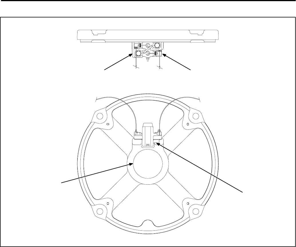
ES1676
BRUSH BLOCK
ASSEMBLY
MEASURING
WIRE
GENERATOR
BEARING
1 INCH
FIGURE 4-6. CHECKING GENERATOR BEARING
AND BRUSH BLOCK
WIRE
HOLDER
SPRING BRUSH
FIGURE 4-7. BRUSH REPLACEMENT
Redistribution or publication of this document,
by any means, is strictly prohibited.

4-8
GENERATOR DISASSEMBLY/ASSEMBLY
The following sections describe the disassembly
and reassembly procedures for the generator. Fig-
ure 4-8 illustrates generator disassembly.
WARNING
Generator components are heavy
and can cause severe personal injury if dropped
during service. Be careful, use appropriate lift-
ing techniques, keep hands and feet clear dur-
ing service, and use the recommended service
procedures.
Note that the control box and air cleaner assembly
need not be removed from the set to disassemble the
generator. These components may remain attached
to the stator housing, and will be removed with it.
Disassembly
1. Remove the generator set from the vehicle and
place it on a sturdy work bench. Refer to Sec-
tion 1 of this manual for removal guidelines.
WARNING
Accidental starting of the set
can cause severe personal injury or death.
Disconnect the battery cables, negative (-)
lead first, when repairs are made to the en-
gine, controls or generator.
2. Remove the cover from the AC control box and
disconnect all stator leads (Q1-Q50/60,
T1-T2-T3-T4, F1-F2, S1-S2). Disconnect
leads at the load circuit breaker(s). If the lead
markings do not clearly identify reconnection,
mark the leads with tape.
3. Remove the bonding strap between the stator
assembly and the drip pan.
4. Loosen and remove the two bolts that extend
through the rear genset mounts (under the sta-
tor housing).
5. Lift the rear of the set and place a wooden block
under the generator adapter to hold the stator
and housing in place. Make certain that the en-
gine-to-generator adapter (bolted to the en-
gine) is propped up high enough for the gener-
ator adapter assembly (bolted to the genera-
tor) to clear the rear genset mounts when it is
pulled off the set. A block approximately 3.5
inches wide (standard 2 x 4 lumber width) will
hold the adapter high enough. Remove the two
rubber vibration isolators whose bolts were re-
moved in the last step.
6. Remove the end bell cover and disconnect F1
(outer) and F2 (inner) lead wires from the brush
holder terminals.
7. Pull each brush away from the commutator
rings and insert a piece of stiff wire into the
small hole in the brush holder. See Figure 4-7.
Note that the brushes may be secured (as de-
scribed in the last two steps) at any convenient
point during this procedure.
8. Remove four nuts and lock washers from the
generator stud bolts. Remove the end bell cov-
er and pry the end bell free of the rotor bearing.
Be careful not to damage the brush holder.
9. Pull the stator/wrapper assembly with the con-
trol boxes off the rotor and away from the en-
gine. Set it aside.
10. Remove the four bolts that hold the generator
adapter and fan guard to the engine-to-genera-
tor adapter. Pull the adapter/guard assembly
off the adapter and set it aside.
11. Loosen the six bolts that hold the rotor drive
disk to the engine flywheel. Loosen these bolts
in an alternating pattern, so that the drive disk
does not bend from the weight of the rotor.
12. Pull the rotor, fan and drive disk assembly off
the flywheel and set them aside.
Redistribution or publication of this document,
by any means, is strictly prohibited.
4-9
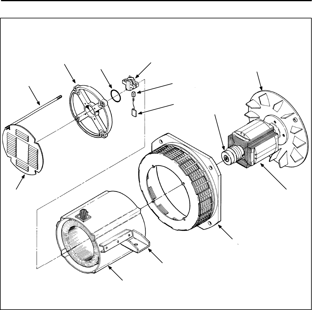
FIGURE 4-8. GENERATOR DISASSEMBLY/REASSEMBLY
STUD BOLT
(1 OF 4)
BRUSH
BLOCK
ENGINE−GENERATOR
ADAPTER
ROTOR
ASSEMBLY
STATOR
ASSEMBLY
END BELL
COVER
SPRING
BRUSH
O−RING
xES2095s
END BELL
ASSEMBLY
END
BEARING
FAN
MOUNTING
FOOT
Redistribution or publication of this document,
by any means, is strictly prohibited.

4-10
Rotor Disassembly
1. Place the rotor assembly on a wood block in the
horizontal position. The drive disc and fan
should not be resting on anything, or dis-
tortion may occur.
2. Remove the six bolts that hold the drive disk
and fan to the rotor hub. Remove the drive disk
and fan.
3. Use a gear puller to remove the end bearing
from the rotor shaft.
CAUTION
The end bearing will be dam-
aged if pulled on the outer race. If the bear-
ing must be removed, replace it; this bear-
ing should not be reused.
Rotor Bearing Replacement
1. Clean the bearing and shaft mating surfaces.
2. Apply Loctite #680 adhesive to the shaft mating
surface.
3. Apply Loctite #747 activator to the bearing mat-
ing surface.
4. Install the bearing and allow ten minutes curing
time before handling the assembly.
Rotor Reassembly
After necessary service checks and repairs are
made, the rotor and generator are reassembled us-
ing the reverse procedure of disassembly except for
the rotor as noted below. Regrease the O-ring us-
ing moly grease only. Apply required torque value
shown in Figure 4-9.
CAUTION
The drive disk will be damaged if the
bolts are tightened and it is not properly cen-
tered. Center the disk accurately before begin-
ning to tighten the drive disk.
Redistribution or publication of this document,
by any means, is strictly prohibited.
4-11
REMOVE SIX BOLTS AND
WASHERS TO REMOVE DRIVE
DISK FROM HUB: TORQUE TO
25−29 N−M WHEN REPLACING
FIGURE 4-9. ROTOR ASSEMBLY COMPONENTS
COLLECTOR
RINGS
GENERATOR
DRIVE DISK
GENERATOR
DRIVE HUB
GENERATOR
FAN
ROTOR
ASSEMBLY
END
BEARING
ROTOR
WINDINGS
Redistribution or publication of this document,
by any means, is strictly prohibited.

4-12
Blank Page
Redistribution or publication of this document,
by any means, is strictly prohibited.

5-1
GENERAL
This section contains troubleshooting information
for the HDKAG generator and voltage regulator.
Make the following visual checks before starting:
•Check any modification or repair that was done
since the last satisfactory operation of the set.
Verify that it was done properly.
•Check to see that generator leads are con-
nected correctly. Also check the voltage regu-
lator and control component connectors. A
loose, contaminated, or misplaced wire con-
nection can be detected by close inspection.
•Check for an open circuit breaker. If the break-
er is open, check for an overloaded circuit and
correct load problems before resetting the
breaker.
TROUBLESHOOTING PROCEDURES
Determine the type of problem, then refer to the cor-
responding flow chart (A, B, C, or D) for trouble-
shooting procedures.
A. NO AC OUTPUT VOLTAGE AT RATED EN-
GINE RPM
B. UNSTABLE OUTPUT VOLTAGE, ENGINE
SPEED STABLE
C. OUTPUT VOLTAGE TOO HIGH OR TOO
LOW
D. UNBALANCED OUTPUT VOLTAGE
To troubleshoot a problem, start at the upper left
corner of the chart that corresponds to the problem,
and answer all questions either YES or NO. Follow
the chart until the problem is found. Perform the ref-
erenced test or adjustment procedures in the Gen-
erator/Regulator Tests section.
Components referenced in the flow charts, tests
and adjustment procedures are found in the sche-
matics and wiring diagrams in Section 9 of this
manual.
Redistribution or publication of this document,
by any means, is strictly prohibited.

5-2
Many troubleshooting procedures present hazards that can result in severe personal
injury or death. Only qualified service personnel with knowledge of fuels, electricity, and machin-
ery hazards should perform service procedures. Review Safety Precautions.
FLOW CHART A. NO AC OUTPUT VOLTAGE AT RATED ENGINE RPM
Are load circuit breakers closed? Locate cause of overload and correct as re-
quired. Reset breaker, or replace if bad.
no
yes
START
Check continuity of circuit breakers and
replace if necessary. Is circuit open be-
tween brush block and voltage regulator?
no
yes Check for continuity and correct if circuit is
open.
Are brushes stuck in holder or not
making good contact with slip rings? yes Release brushes if jammed in holder. Clean
slip rings if dirty.
no
Test continuity of rotor, stator per Tests
[B], [C]. Are there opens or grounds? yes Replace component if defective.
Test field voltage per TEST [A]. Is
there correct field voltage?
no
yes
Examine brush block connections. Are F1
and F2 leads installed on correct terminals?
Perform TEST [D].
no Connect brush leads to correct terminals.
yes
WARNING
Redistribution or publication of this document,
by any means, is strictly prohibited.

5-3
A new voltage regulator can be dam-
aged by malfunctioning components. Do not
install a new voltage regulator until all other
problems have been located and corrected.
Many troubleshooting procedures present hazards that can result in severe personal
injury or death. Only qualified service personnel with knowledge of fuels, electricity, and machinery
hazards should perform service procedures. Review Safety Precautions.
FLOW CHART B. UNSTABLE VOLTAGE, ENGINE SPEED STABLE
Are there any broken wires or loose connec-
tions on voltage regulator assembly? yes
Check wiring harness from regulator assem-
bly to end bell per TEST [F]. Check OK?
Repair as required.
Inspect brushes per procedure in Manual
Section 4. Brushes OK?
Repair wiring or replace as required.
no
yes
no
START
Replace the voltage regulator per procedure
[E].
yes
Repair or replace as required.
no
WARNING
CAUTION
Redistribution or publication of this document,
by any means, is strictly prohibited.

5-4
Is engine running at correct RPM?
Does adjustment of Voltage Adjust con-
trol on the regulator board result in cor-
rect output voltage?
Are voltage regulator connections secure?
Set RPM per instructions in appropriate
engine manual.
Set control per Voltage Adjustment [G].
Are generator output leads properly con-
nected? See TEST [H].
Perform procedure [D]. If correctly func-
tioning rotor/stator indicates a bad volt-
age regulator, replace it per procedure
[E].
Many troubleshooting procedures present hazards that can result in severe personal
injury or death. Only qualified service personnel with knowledge of fuels, electricity, and machin-
ery hazards should perform service procedures. Review Safety Precautions.
FLOW CHART C. OUTPUT VOLTAGE TOO HIGH OR TOO LOW
A new printed circuit board can be
damaged by malfunctioning components within
the control. Do not install a new PC board until all
other problems have been located and corrected.
yes
yes
yes
yes
no
no
START
Is the set AC output overloaded? Remove part of the set load.
yes
no
CAUTION
WARNING
Redistribution or publication of this document,
by any means, is strictly prohibited.

5-5
FLOW CHART D. UNBALANCED GENERATOR OUTPUT VOLTAGE
Many troubleshooting procedures present hazards that can result in severe personal
injury or death. Only qualified service personnel with knowledge of fuels, electricity, and machinery
hazards should perform service procedures. Review Safety Precautions.
Remove load at generator terminals. Is
output still unbalanced?
Are generator leads connected and
grounded properly? See Test [C].
Is generator stator winding continuous
per TEST [C]?
Check load for ground faults and correct
as necessary.
Check for correct grounding of generator
and load.
Correct as necessary.
Replace stator assembly.
START
yes
yes
yes
no
no
no
WARNING
Redistribution or publication of this document,
by any means, is strictly prohibited.

5-6
Blank Page
Redistribution or publication of this document,
by any means, is strictly prohibited.

Section 6. Generator/Regulator Tests
6-1
GENERAL
The following tests and adjustments can be per-
formed without disassembly of the generator.
These procedures should be used for testing the
generator components and the regulator in con-
junction with the Troubleshooting Flow Charts in the
Generator/Regulator Troubleshooting section.
WARNING
Many troubleshooting procedures
present hazards that can result in severe per-
sonal injury or death. Only qualified service
personnel with knowledge of fuels, electricity,
and machinery hazards should perform service
procedures. Review safety precautions on in-
side cover page.
[A] TESTING FIELD VOLTAGE
Field voltage can be tested at the brush holder ter-
minals with a DC voltmeter. Field voltage should fall
between 18 and 60 volts. Test at no load and at full
load. See Figure 6-1.
FIGURE 6-1. FIELD VOLTAGE TEST POINTS
BRUSH
BLOCK
ASSEMBLY
LEAD (F2
TO VR1−2)
LEAD (F1
TO VR1−1)
TEST POINTS
[B] TESTING GENERATOR ROTOR
The generator circuits can be tested without having
to disassemble the generator. It is recommended
that an ohmmeter be used to check for open circuits
and an insulation resistance meter for grounded cir-
cuits. An ohmmeter can be used to check for
grounded circuits, but it may not be able to detect
marginal insulation breakdown.
FIGURE 6-2. TESTING ROTOR FOR GROUNDS
MEGGER OR
INSULATION
RESISTANCE
METER
ES2068s
CONNECT LEADS
BETWEEN EACH RING
AND ROTOR SHAFT
Testing for Grounds
Check for grounds between each slip ring and the
rotor shaft, Figure 6-2. Use a Megger or insulation
resistance meter which applies 500 VDC or more at
the test leads. Perform test as follows:
1. Isolate the rotor windings by disconnecting the
two leads to the brush holder.
2. Connect test leads between each ring and the
rotor shaft in turn. Meter should register
100,000 ohms or greater.
3. If less than 100,000 ohms, rotor is question-
able. Thoroughly dry the rotor and retest.
4. Replace a grounded rotor with a new identical
part.
Redistribution or publication of this document,
by any means, is strictly prohibited.

6-2
Testing for Open or Shorted Windings
Perform this test with an accurate meter such as a
digital ohmmeter.
1. Isolate the rotor windings by disconnecting the
two leads to the brush holder.
2. Using ohmmeter, check resistance between
F1 and F2 by connecting leads between the F1
and F2 slip rings, Figure 6-3.
Rotor resistances (measured at 25° C) are:
Standard single-phase: 17.2 ohms
Standard three-phase: 19.4 ohms
Extended-stack three-phase: 22.5 ohms
Extended-stack three-phase “husky”:
25.5 ohms
If there is a large difference, replace the defec-
tive rotor with a new, identical part.
FIGURE 6-3. TESTING ROTOR FOR AN
OPEN CIRCUIT
CONNECT LEADS BETWEEN
F1, F2 SLIP RINGS
DIGITAL
OHMMETER
ES2069s
[C] TESTING GENERATOR STATOR
Isolate the stator windings by disconnecting all six
stator leads. Test for open circuits between T1-T2,
T3-T4 and Q1-Q2, and for grounded circuits be-
tween T1, T3 and B1 and the stator laminations or
other unpainted grounding point.
Using proper test equipment, check the stator for
grounds, opens, and shorts in the windings.
Testing for Grounds
Some generators have ground connections to the
frame. Check wiring diagram. All stator leads must
be isolated for testing.
Use a megger or insulation resistance meter which
applies not more than 500 VDC to the test leads
(Figure 6-4). Test each stator winding for short to
laminations. A reading less than 100,000 ohms in-
dicates a questionable stator. Thoroughly dry the
stator and retest.
FIGURE 6-4. TESTING STATOR WINDING
FOR GROUNDS
ES2070s
CONNECT LEADS BETWEEN
EACH WINDING AND GROUND
Redistribution or publication of this document,
by any means, is strictly prohibited.

6-3
Testing for Open or Shorted Windings
Test for continuity between coil leads as shown in
Figure 6-5; all pairs should have equal resistance.
Use an accurate instrument for this test such as a
Wheatstone Bridge.
Stator resistances (measured at 25° C) are:
Standard single-phase:
T1-T2, T3-T4: 0.221 ohms
Q1-Q60: 1.997 ohms
Q1-Q50: 2.405 ohms
Standard three-phase:
T1-T4, T2-T5, T3-T6,
T7-T10, T8-T11, T9-T12: 0.505 ohms
Q2-T11: 0.252 ohms
Extended-stack three-phase:
T1-T4, T2-T5, T3-T6,
T7-T10, T8-T11, T9-T12: 0.153 ohms
Q2-T11: 0.305 ohms
Extended-stack three-phase heavy-duty:
T1-T4, T2-T5, T3-T6,
T7-T10, T8-T11, T9-T12: 0.107 ohms
Q2-T11: 0.214 ohms
If a winding is shorted, open or grounded, replace
the stator assembly. Before replacing the assem-
bly, check the leads for broken wires or insulation.
ES2071s
FIGURE 6-5. TESTING STATOR WINDING
RESISTANCE
CONNECT LEADS
BETWEEN PAIRS
OF STATOR
WINDING LEADS
[D] DYNAMIC ROTOR/STATOR TEST
The following procedure serves as a functional volt-
age regulator check, by determining if the problem
is in the voltage regulator or in the generator. The
voltage regulator is temporarily replaced with a
12-volt battery (the genset starting battery is usable
here); 12 volts applied to the F1/F2 exciter stator
should produce approximately 125 volts generator
output voltage at L1 and L2, with no load.
WARNING
Electrical shock can cause severe
personal injury or death. Do not touch electrical
wiring or components during testing. Discon-
nect electrical power by removing starting bat-
tery negative (-) cable before handling electrical
wiring or components.
Use a sharp voltage probe and touch it carefully to
the connector pins or output terminals when making
these tests.
1. Stop the generator set.
2. Unplug the voltage regulator from the wiring
harness.
CAUTION
Failure to unplug the voltage
regulator at this point in the procedure
could lead to equipment damage.
3. Using jumpers and a spare plug or other con-
nector, connect a 12-volt battery to the F1/F2
terminals as illustrated in Figure 6-6.
4. Start the generator set. Use a voltmeter to
measure the outputs at J4-4 - J4-6, L1 - L2, L1 -
L0, L2 - L0, Q60 - Q1 (50 Hz sets: Q50 - Q1),
and S1 - S2. The output voltages should read
as follows (all voltages apply to both 50 Hz and
60 Hz sets):
J4-4 - J4-6: 62 VAC ± 20 VAC
L1 - L2: 125 VAC ± 20 VAC
L1 - L0: 62 VAC ± 20 VAC
L2 - L0: 62 VAC ± 20 VAC
Q60 - Q1: 75 VAC ± 20 VAC
(50 Hz sets) Q50 - Q1: 75 VAC ± 20 VAC
S1 - S2: 62 VAC ± 20 VAC
If these voltages are measured, then the gen-
erator is operating correctly and the problem is
elsewhere.
Redistribution or publication of this document,
by any means, is strictly prohibited.

6-4
+
−
APPLY
12 VDC
MEASURE
75 VAC
MEASURE
62 VAC
MEASURE
75 VAC
MEASURE
62 VAC
MEASURE
125 VAC
MEASURE
62 VAC
MEASURE
62 VAC
FIGURE 6-6. DYNAMIC ROTOR/STATOR TEST
Redistribution or publication of this document,
by any means, is strictly prohibited.

6-5
[E] VOLTAGE REGULATOR
REPLACEMENT
Use the following procedure for replacing the AC
voltage regulator assembly.
1. Stop the generator set and disconnect the
starting battery leads, negative (-) lead first.
2. Unscrew the voltage regulator from the control
box.
3. Disconnect the regulator from the wiring har-
ness.
4. Remove the mounting screws from the old volt-
age regulator, then install the new regulator.
5. Reconnect the plug connection to the wiring
harness.
6. Set voltage as outlined in [G] Voltage Adjust-
ment.
[F]
WIRING HARNESS CHECK
Carefully check the wiring harness as follows:
1. Inspect all wires for breaks, loose connections,
and reversed connections. Refer to applicable
wiring diagram.
2. Remove wires from terminals at each end and
with an ohmmeter, check each wire end to end
for continuity or opens.
3. Using an ohmmeter, check each wire to other
wires and to ground for possible shorts or in-
sulation breaks under areas covered by wrap-
ping material.
4. Reconnect or replace wires/harness according
to applicable wiring diagram.
[G]
VOLTAGE ADJUSTMENT
This section describes adjustment of the genset
output voltage. When checking output voltage, be
sure the generator set has stabilized and is running
at the correct speed (frequency). The regulator is
adjusted with the set running.
WARNING
Accidental starting of the set can
cause severe personal injury or death. Discon-
nect both battery cables, negative (-) cable first,
when repairs are made to the engine, controls,
or generator.
WARNING
Contact with high voltage can cause
severe personal injury or death. Do not touch
any exposed wiring or components with any
part of the body, clothing, tool or jewelry. Do not
use non-insulated tools inside the control.
Stand on an insulating mat or dry wood platform
when the control doors are open.
Output voltage adjustments are found on the volt-
age regulator board under the DC control box. A re-
movable cover protects the board. See Figure 6-7.
1. Attach a voltmeter securely to the L1 and L2
leads.
2. Start the generator set and place a typical load
on its output.
3. Use a flat-blade screwdriver to set the voltage
adjust potentiometer for correct voltage.
For most 60 Hz applications, the ideal setting is 117
VAC at 60-61 hz, measured at the power input of the
application. Retighten the locking nut when com-
plete.
Note that the voltage adjustment pot on the voltage
regulator board is a 10-turn potentiometer: it may
take several turns to change the voltage noticeably.
[H]
RECONNECTION
Generator reconnection is dependent upon the
nameplate code. See Section 8 for reconnection
diagrams.
Redistribution or publication of this document,
by any means, is strictly prohibited.

6-6
FIGURE 6-7. LOCATION, OUTPUT VOLTAGE ADJUSTMENT
VOLTAGE ADJUST: Trim pot adjusts
output voltage level. Turn pot
clockwise to increase voltage. Turn pot
counterclockwise to decrease voltage.
BOARD SHOWN
WITHOUT COVER
Redistribution or publication of this document,
by any means, is strictly prohibited.
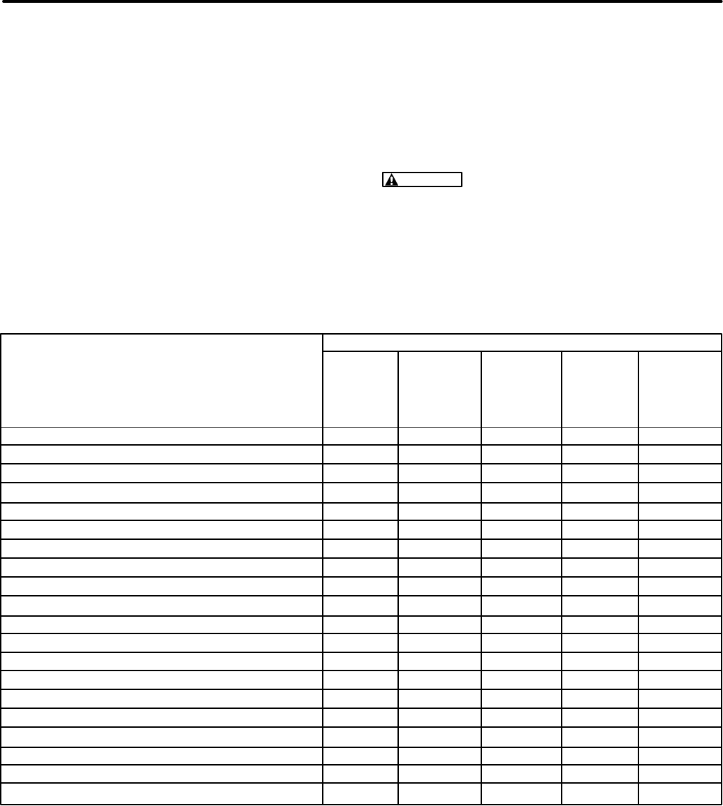
Section 7. Routine Maintenance
7-1
INTRODUCTION
This section describes routine maintenance proce-
dures to be performed on the generator set. Most of
this information is duplicated in the Operator’s
Manual, publication #981-0137.
Many of the items in this section refer to the genset
engine: for more information, refer to the Engine
Workshop Manual.
MAINTENANCE SCHEDULE
Perform each maintenance procedure at the time
period indicated or after the number of operating
hours indicated, whichever comes first. Refer to the
Maintenance Procedures
section for instructions. If
the generator set will be subjected to extremely hot
or dusty conditions, a more frequent maintenance
schedule may be necessary.
WARNING
Accidental starting of the generator
set during maintenance can cause severe per-
sonal injury or death. Disconnect both genera-
tor set starting battery cables, before perform-
ing maintenance. Remove the negative (-) cable
first to reduce the risk of arcing.
SERVICE TIME
Daily Weekly Monthly 6 Months Yearly
or or or or or
after after after after after
SERVICE THESE ITEMS 8 hours 50 hours 100 hours 250 hours 500 hours
Inspect set x1
Check oil level x
Check coolant level x
Check fuel level x
Check air cleaner dust cap (clean if required) x3x
Check battery charging system x
Check drive belt tension x4
Clean out spark arrester x
Check battery specific gravity x
Change crankcase oil and filter x2
Drain water/sediment from fuel filter x
Check antifreeze x
Clean generator assembly x
Drain sediment from fuel tank x5
Clean crankcase breather x3
Check fuel shut-off linkage x
Change fuel filter element x
Check genset brushes x
Change air cleaner element x3
Clean cooling system x
1 - Check for oil, fuel, cooling and exhaust system leaks. Check exhaust system audibly and visually
with genset running and repair any leaks immediately.
2 - Perform after first 35 hours of operation on new genset.
3 - Perform more often in extremely dusty conditions.
4 - Visually check belts for evidence of slippage.
5 - Drain one cup of fuel to remove water and sediment.
TABLE 7-1. PERIODIC MAINTENANCE SCHEDULE
Redistribution or publication of this document,
by any means, is strictly prohibited.

7-2
GENERATOR SET INSPECTION
Inspect the generator set daily or after every eight
hours of operation, whichever comes first. Check
the exhaust, fuel, and DC electrical systems as de-
scribed below. Also check the mechanical condi-
tion of the set.
Engine Gauges (Remote Installation)
Check these gauges while the set is running.
Oil Pressure Gauge:
Oil pressure should be 40 to
60 psi (276 to 414 kPa) when the engine is at oper-
ating temperature.
Coolant Temperature Gauge:
Coolant tempera-
ture should be 165° to 195° F (74° to 91° C), de-
pending on load and ambient temperature.
DC Voltmeter:
Battery voltage during operation
should be 14 to 15 volts.
Exhaust System
With the set running, inspect the entire exhaust sys-
tem including the exhaust manifold, exhaust elbow,
muffler and exhaust pipe. Visually and audibly
check for leaks at all connections, welds, gaskets,
and joints. If any leaks are detected, shut down
the genset and do not operate until corrected.
Replace corroded exhaust components before
leaks occur.
WARNING
Inhalation of exhaust gases can re-
sult in severe personal injury or death. Inspect
exhaust system audibly and visually for leaks
daily. Repair all leaks immediately.
Fuel System
With the set running, inspect the fuel supply lines,
return lines, filters, and fittings for leaks. Check flex-
ible sections for cuts, cracks and abrasions. See
that the fuel lines do not rub against anything that
could break them. Replace worn fuel line compo-
nents before leaks occur.
WARNING
Fuel leakage will create a fire hazard
which can result in severe personal injury or
death if ignited. While checking for leaks, do
not smoke or allow any spark, flame, pilot light
or other ignition source in the area. If any leaks
are detected, have them corrected immediately.
DC Electrical System
With the genset off, check the battery terminals for
clean and tight connections. Loose or corroded
connections create resistance which can impede
starting. Clean and reconnect loose battery cables.
Always disconnect the negative battery cable first
and connect it last, to reduce the possibility of arc-
ing.
WARNING
Ignition of explosive battery gases
can cause severe personal injury. Do not
smoke. Wear goggles, protective rubber gloves
and apron when servicing batteries.
Mechanical
Check for any signs of mechanical damage. Start
the set and listen for any unusual noises that may
indicate mechanical problems.
Check the mounting fasteners to make sure the set
is secure in its compartment. If an under-floor hous-
ing is used, make sure that the set is secured to the
housing. Check the condition of the housing com-
ponents and make sure they are secure to the ve-
hicle.
Make sure that the generator set air inlet and outlet
areas are not blocked with debris.
Clean the generator set whenever dust and dirt be-
gin to accumulate. Dust and dirt can usually be re-
moved with a damp cloth. Steam cleaning may be
needed to remove road contaminants. Do not clean
the genset while the engine is running. Protect the
generator, air cleaner, control panel, and electrical
connections from cleaning solvents. Cleaning sol-
vents can damage electrical connectors.
Redistribution or publication of this document,
by any means, is strictly prohibited.

7-3
OIL AND FILTER CHANGE
Change the oil and filter at the intervals listed in
Table 7-2. Use oil that meets the API classification
and SAE viscosity grade indicated in the previous
section.
Engine Oil Change
Run the engine until thoroughly warm. Stop the en-
gine, open the drain valve (Figure 7-1) and drain the
oil into a container. When completely drained, close
the valve and refill the crankcase with new oil.
WARNING
Hot crankcase oil can cause burns if
it is spilled or splashed on skin. Keep fingers
and hands clear when removing the oil drain
plug and wear protective clothing.
WARNING
State or federal agencies have de-
termined that prolonged contact with used en-
gine oil can cause cancer or reproductive toxic-
ity. When adding, changing or working with
used oil, take care not to breathe, ingest or
come into excessive contact with these sub-
stances. Wash hands after use. Wear protec-
tive clothing and equipment. Provide adequate
ventilation.
Oil Filter Change
Spin off the oil filter and discard it. Thoroughly clean
the filter mounting surface. Apply a thin film of oil to
the filter gasket, and spin the filter on until the gasket
just touches the mounting pad. Then turn an addi-
tional 3/4 turn. Do not over-tighten the filter.
With oil in the crankcase, start the set and check for
leakage around the filter gasket. Tighten the filter
only enough to eliminate leaks.
FIGURE 7-1. ENGINE OIL
OIL FILL
DRAIN
VALVE
OIL FILTER
OIL
DIPSTICK
ALTERNATE OIL FILL AT
TOP OF CYLINDER
HEAD COVER (HIDDEN)
Redistribution or publication of this document,
by any means, is strictly prohibited.
7-4
COOLING SYSTEM
The cooling system must be filled with coolant
before the genset can be operated. Cooling sys-
tem capacity is listed in the
Specifications
section.
Coolant Requirements
Engine coolant must inhibit corrosion and protect
against freezing. A 50/50 mixture of ethylene glycol
anti-freeze and water is recommended for normal
operation and storage. Use only a reliable brand of
antifreeze that contains a rust and corrosion inhibi-
tor. The antifreeze must not contain a stop-leak
additive.
Do not exceed a 50/50 mixture of ethylene glycol
and water. A higher proportion of ethylene glycol
will alter the heat transfer properties of the coolant.
A 50/50 mixture will provide freeze protection to
-34° F (-37° C).
Water used for engine coolant should be clean, low
in minerals, and free of corrosive chemicals. Use
distilled or soft water if available. Avoid the use of
well water, which may contain minerals that can
clog the heat exchanger core and reduce cooling ef-
ficiency.
Filling the Cooling System
Verify that all drain cocks are closed and all hose
clamps are secure. Remove the cooling system
pressure cap and slowly fill the cooling system with
the coolant mixture.
CAUTION
Exceeding the recommended fill
rate can cause incomplete filling of the engine
block, leading to engine damage during warm-
up. Always follow the recommended fill proce-
dure.
Add coolant to the recovery tank (or separate ex-
pansion tank if equipped) to the full-cold level.
Start the engine, then remove the pressure cap and
monitor the coolant level. As trapped air is expelled
from the system, the coolant level will drop. Add
coolant to replace it. Replace the pressure cap
when the coolant level is stable.
Coolant Level
Check the coolant level at the intervals specified in
the Periodic Maintenance Schedule. Check by ob-
serving the coolant level in the recovery tank (or
separate expansion tank if equipped) when the sys-
tem is cold. See Figure 7-2 for a typical cooling sys-
tem. Engine coolant is at the proper level when the
recovery tank level is between FULL and LOW
marks.
WARNING
Coolant in a warm engine is under
pressure and can flash to steam causing severe
burns if the radiator cap or drain cock are
opened. Let the engine cool down before open-
ing the radiator cap or drain cock.
CAUTION
The high engine temperature cutoff
will shut down the engine in an overheat condi-
tion only if the coolant level is sufficiently high
to physically contact the shutdown switch.
Loss of coolant will allow engine to overheat
without protection of shutdown device, thereby
causing severe damage to the engine. It is
therefore imperative that adequate engine cool-
ant levels be maintained for operational integri-
ty of the cooling system and engine coolant
overheat shutdown protection.
Redistribution or publication of this document,
by any means, is strictly prohibited.

7-5
FIGURE 7-2. COOLING SYSTEM COMPONENTS
HOSE IS CONNECTED AT
RADIATOR CAP
RECOVERY
TANK
BRACKET
OVERFLOW
HOSE
RADIATOR COOLANT DRAIN
(ON LOWER REAR CORNER OF
RADIATOR)
CYLINDER BLOCK COOLANT DRAIN
(REAR OF GENSET ENGINE BLOCK
SHOWN WITHOUT SHEET METAL, EX-
HAUST PARTS)
G1250s
Redistribution or publication of this document,
by any means, is strictly prohibited.

7-6
Flushing and Cleaning
Once a year, drain, flush and refill the cooling sys-
tem with new coolant. To drain the system, open the
radiator coolant drain and the cylinder block drain
on the the rear (non-service access) side of engine.
See Figure 7-2.
WARNING
Contact with hot coolant can cause
severe burns. Do not bleed hot, pressurized
coolant from a closed cooling system.
Chemical Cleaning:
Rust and scale slow heat ab-
sorption and can block coolant flow. Clean the cool-
ing system if rust and scale have collected on the
engine water jacket or in the heat exchanger. Use a
good cleaning compound and follow its instructions.
Flushing:
After cleaning, or before filling the sys-
tem with new coolant, drain the system and fill with
clean water. Run the genset for 10 minutes, then
drain the system completely. Refill with the coolant
mixture.
CAUTION
Never pour hot water into a cold en-
gine or cold water into a hot engine. Doing so
can crack the head or the cylinder block. Do not
operate the unit without water for even a few
minutes.
Thermostat
If the engine overheats or does not reach and main-
tain a minimum operating temperature, have the
thermostat removed and tested. Replace the ther-
mostat with the gasket if necessary. See the Engine
Workshop Manual for instructions on thermostat re-
moval and testing.
Pressure Cap
Closed cooling systems use a pressure cap to in-
crease the boiling point of the coolant and allow
higher operating temperatures. Replace the pres-
sure cap every two years, or sooner if it malfunc-
tions.
FAN BELT
A loose fan belt can cause the engine to overheat.
The belt tension must be correct for the set to run
well.
First, remove the generator set’s starting battery
cables (negative [-] cable first).
WARNING
Accidental starting of the set can
cause severe personal injury or death. Stop the
generator set and disable it by disconnecting
the starting battery cables (negative [-] cable
first) when maintaining or repairing the engine,
controls, or generator.
To reach the fan belt, remove the belt guard from the
front of the set. Do not operate the genset with-
out the belt guard in place.
To adjust the belt, loosen the bolt that passes
through the long slot in the alternator mounting
bracket and slide the alternator until the tension is
right. See Figure 7-3.
Belt tension is correct when a finger pressure of 22
pounds (10 kg) at the middle of the belt deflects it
about 0.4 inch (10 mm).
CS-1239
ADJUST
TENSION
HERE
ALTERNATOR
PUMP/
FAN
PULLEY
FIGURE 7-3. FAN BELT ADJUSTMENT
Redistribution or publication of this document,
by any means, is strictly prohibited.

7-7
FUEL SYSTEM
Use the best fuel available. Fuel quality is important
for dependable performance and satisfactory en-
gine life.
WARNING
Ignition of fuel can cause serious
personal injury or death by fire or explosion. Do
not permit any flame, cigarette, pilot light, spark
or other igniter near the fuel system.
Fuel Recommendation
Use ASTM 2-D (no. 2 Diesel) or ASTM 1-D (No. 1
Diesel) fuel with a minimum Cetane number of 45.
Number 2 diesel fuel gives the best economy and
performance under most conditions. Use number 1
diesel fuel when ambient temperatures are below
32° F (0° C), and during long periods of light engine
load.
Use low sulfur content fuel which has a cloud point
at least 10 degrees below the lowest expected fuel
temperature. (Cloud point is the temperature at
which wax crystals begin to form in diesel fuel.)
Fuel Handling Precautions
Prevent dirt, water or other contaminants from en-
tering the fuel system. Filter or strain the fuel as the
tank is filled.
CAUTION
Due to the precise tolerances of die-
sel injection systems, dirt or water in the system
will cause severe damage to both the injection
pump and the injection nozzles. It is extremely
important that the fuel be kept clean and water
free.
Condensation (water) can cause clogging of fuel fil-
ters as well as freezing problems. Water mixing
with the sulfur in the fuel forms acid which can cor-
rode and damage engine parts.
Low fuel in the tank promotes condensation. In
warm weather, the fuel tank cools at night quicker
than the fuel. If the fuel level is low, the upper por-
tion of the tank will cool more rapidly, forming con-
densation. In cold weather, the warm fuel returning
from the injectors heats the fuel in the supply tank. If
the fuel is low, condensation may form on the upper
part of the tank. To avoid condensation, fill the
fuel tank every time the genset is used.
Fuel Filter
The wrong fuel or dirty fuel will shorten the life of the
fuel filter. See the
Periodic Maintenance Schedule
for the filter change interval.
CAUTION
Dirt or water in the system will cause
severe damage to both the injection pump and
the injection nozzles. It is extremely important
that the fuel be kept clean and free of water.
Refer to the Periodic Maintenance Schedule for the
recommended filter change interval. However, if
the engine shows signs of fuel starvation (reduced
power or surging), the fuel filter must be changed.
This involves purging the fuel system of trapped air.
See
Priming the Fuel System
later in this section.
High Pressure Fuel System:
The injection pump,
fuel injection lines and fuel injectors are the high
pressure fuel system. See Figure 7-4. The high-
pressure system is self-priming; trapped air is
forced out through the injection nozzles.
Low Pressure Fuel System
The electric fuel pump, fuel filter and injection pump
inlet comprise the low pressure fuel system. See
Figure 7-4. These components are normally
primed (purged of trapped air) at set installation. Be
sure to check the fuel level in the tank and that the
shutoff valve is open.
Redistribution or publication of this document,
by any means, is strictly prohibited.

7-8
FUEL
INLET
FUEL
FILTER
FIGURE 7-4. FUEL SYSTEM
FUEL
PUMP
FUEL RETURN
LINE FITTING
INJECTION LINE
CONNECTING NUT
INJECTION PUMP
FUEL INLET
Redistribution or publication of this document,
by any means, is strictly prohibited.

7-9
AIR CLEANER
The air cleaner element (Figure 7-5) is a dry type
and should never have oil applied to it. Avoid touch-
ing the element except when cleaning it. Instruc-
tions for cleaning the element are on a label at-
tached to the element. Change the element yearly,
or more often in extremely dusty conditions.
FIGURE 7-5. AIR CLEANER ASSEMBLY
AIR CLEANER
BAND W/CUSHION
AIR CLEANER
ELEMENT
VALVE WING
BOLT
INLET
OUTLET
BATTERY CARE
Service the battery at the intervals shown in the
maintenance schedule. Check the electrolyte level
more frequently during hot weather.
WARNING
Batteries present the hazard of ex-
plosion that can result in severe personal inju-
ry. Do not smoke or allow any fire, flame, spark,
pilot light, arc-producing equipment or other
ignition sources around the battery area. Do
not disconnect battery cables while the genera-
tor set is cranking or running because explo-
sive battery gases could be ignited.
WARNING
Battery electrolyte can cause se-
vere eye damage and burns to the skin. Wear
goggles, rubber gloves and a protective apron
when working with batteries.
1. Keep the battery case clean and dry.
2. Make certain that the battery cable connec-
tions are clean and tight. Use a terminal puller
tool to remove the battery cables.
Remove corrosion from the battery terminal
connections. Wash the terminals with an am-
monia solution or a solution consisting of 1/4
pound (about 100 grams) of baking soda in 1
quart (about 1 liter) of water. Be sure the vent
plugs are tight to prevent cleaning solution from
entering the cells. After cleaning, flush the out-
side of the battery and the surrounding areas
with clean water.
3. Identify the cable as positive (+) or negative (-)
before making the battery connections. Al-
ways connect the negative (-) cable last, to re-
duce the risk of arcing.
4. Maintain the electrolyte level by adding distilled
water. Fill each cell to the split-level marker in
the battery. The water component of the elec-
trolyte evaporates, but the sulfuric acid compo-
nent remains. For this reason, add water, not
electrolyte to the battery.
5. Use a battery hydrometer to check the specific
gravity of the electrolyte in each battery cell
(Figure 7-6). Charge the battery if the specific
gravity measures less than 1.215. Do not over-
charge the battery. Stop charging the battery
when the electrolyte specific gravity reaches
1.260, at approximately 80° F (27° C).
FIGURE 7-6. BATTERY CHECK
SPECIFIC GRAVITY
READING SHOULD BE
1.260 AT 80° F (27° C)
Redistribution or publication of this document,
by any means, is strictly prohibited.

7-10
AC GENERATOR
Generator Brushes
The generator should be inspected for brush wear
and cleaning as required per the Periodic Mainte-
nance Schedule. Perform this procedure according
to the steps in Section 4 of this manual.
WARNING
Accidental starting of the generator
set can cause severe personal injury or death.
Stop the generator set and disable by discon-
necting the starting battery cables (negative [-]
cable first before inspecting the generator.
Generator Bearing
Inspect the bearing for evidence of outer case rota-
tion every 1000 hours of use. The bearing should
be replaced every five years, because the bearing
grease gradually deteriorates due to oxidation. See
Section 4 of this manual for information on the gen-
erator bearing.
CRANKCASE BREATHER
Clean the crankcase breather element at the
scheduled intervals, using the following procedure
(see Figure 7-7).
1. Remove the cap nuts and gaskets from the top
of the cylinder head cover. Carefully remove
the cover. Avoid damaging the gasket.
2. From inside the cover, remove two machine
screws securing the breather element, plates
and shield.
3. Clean the element in a suitable solvent. Dry the
element, then saturate with engine oil before re-
placing.
WARNING
Many cleaning solvents present
a hazard of severe personal injury or death.
Follow the manufacturer’s instructions and
proceed with care.
4. If necessary, clean other breather components
in solvent before reassembling.
CAP NUT AND
GASKET
FIGURE 7-7. CRANKCASE BREATHER
FILLER CAP
AND GASKET
ELEMENT
PLATE 1
BREATHER
ELEMENT
OIL
SHIELD
CYLINDER
HEAD COVER
GASKET
BREATHER
PIPE JOINT
BREATHER
PIPE
ELEMENT
PLATE 2
Redistribution or publication of this document,
by any means, is strictly prohibited.
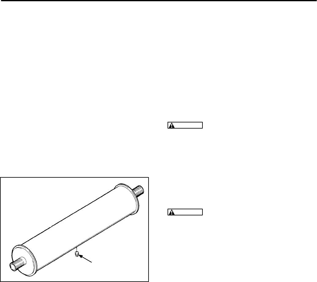
7-11
MUFFLER/SPARK ARRESTER
The exhaust spark arrester mounted inside the muf-
fler is necessary for safe operation. It must be peri-
odically cleaned out for maximum efficiency, and to
meet Forest Service requirements (RV use). See
the maintenance schedule for cleaning intervals.
To clean the spark arrester, park the vehicle on a
non-flammable, washable surface, and remove the
1/8 inch pipe plug from the bottom of the muffler.
Run the generator set with a full load for five min-
utes. Stop the generator set and allow the muffler to
cool. Replace the pipe plug in the muffler. See Fig-
ure 7-8.
FIGURE 7-8. EXHAUST MUFFLER
EXS−1190s
PIPE
PLUG
CLEANING THE GENERATOR SET
Clean the generator set at least every six months.
Dust usually can be removed with a damp cloth.
Some road contaminants may require steam clean-
ing. Do not steam clean the generator set while the
engine is running. When cleaning, protect the area
so spray is not directed into the generator, air clean-
er, control box, fuel solenoid, or electrical connec-
tions. Do not clean with solvents; they can damage
electrical connectors.
INITIAL STARTING AND CHECKS
WARNING
Exhaust gas presents the hazard of
severe personal injury or death. Do not operate
the generator set inside any room or building.
If none of the fuel line junctions have been loosened
between the electric fuel pump and the injection
pump, the fuel system should not need priming.
However, if priming is necessary, it should be done
according to the following procedure.
Priming the Fuel System
CAUTION
Priming the fuel system should only
be done by a skilled and experienced diesel
technician. Incorrect priming could lead to
equipment damage or faulty operation.
1. Turn off both DC breakers on the set control
box.
2. Disconnect the B+ lead to the fuel pump.
3. Use a clip lead to jumper B+ to the fuel pump.
Run the fuel pump for five to ten seconds until
the air is purged from the low-pressure fuel sys-
tem.
Redistribution or publication of this document,
by any means, is strictly prohibited.

7-12
Blank Page
Redistribution or publication of this document,
by any means, is strictly prohibited.

8. Wiring Diagrams
8-1
The electrical schematics and wiring diagrams that apply to the generator set covered in this manual are listed
below.
WIRING DIAGRAM DRAWING NO. PAGE
DC Control Assembly 612-6635 8-2. . . . . . . . . . . . . . . . . . . . . . . . . . . . . . . . . . . . . . . . . . . . . . . .
AC Control Assembly (single-phase) 612-6637 8-3. . . . . . . . . . . . . . . . . . . . . . . . . . . . . . . . . . .
AC Control Assembly (three-phase) 612-6732 8-4. . . . . . . . . . . . . . . . . . . . . . . . . . . . . . . . . . .
Redistribution or publication of this document,
by any means, is strictly prohibited.

8-2
612-6635
Redistribution or publication of this document,
by any means, is strictly prohibited.
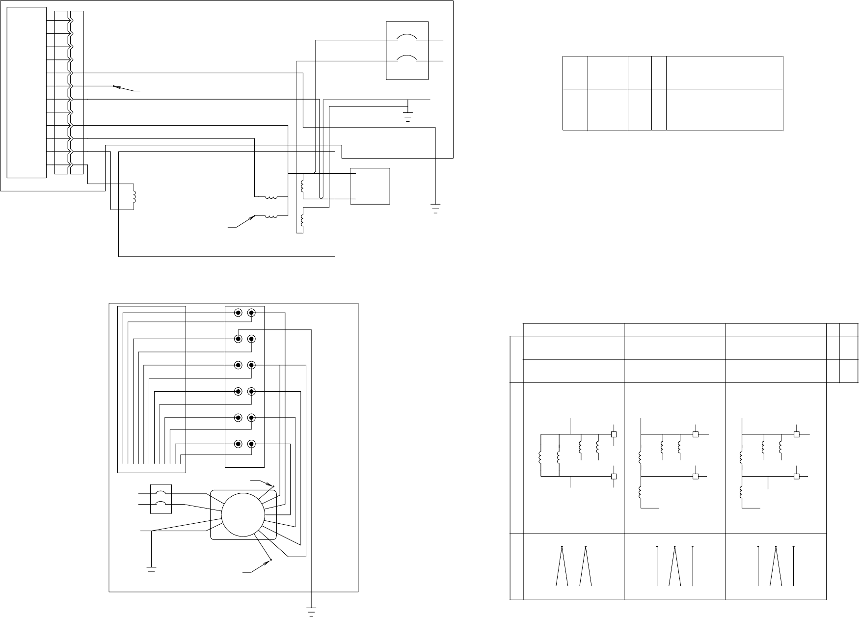
8-3
SEE NOTE 1
SEE NOTE 3
SEE NOTE 2
SEE NOTE 2
L1
L2
12
11
10
9
8
7
6
5
4
3
2
1
11
10
8
2
1
P4 J4
VR1
G1
3
4(Q1)
( Q5 0 OR Q6 0 )
MAIN
ARMATURE
STATOR
A1
L1
L2
G1
P4/J4
A1
F2
S2
GND
1
VR1
F1
F2
T1
T2
T4
T3
Q6 0 Q1
F1
S1
T3
T4
T1
T2
Q60
Q1
L0
L0
115/ 230
T4T3T2T1
L2L1 L0( N)
110/ 220
230
T4T3T2T1
L0L1
220
115
T4T2T3T1
L0L1
110
CBA HZ CODE
60
50 P
J
VOLTAGESCHEMATI CDI AGRAM
110/ 220V, 115/ 230V & 120/ 240V AS SHOWN
SEE RECONNECTI ON CHART FOR OTHER VOLTAGES
110/ 220V, 115/ 230V & 120/ 240V AS SHOWN
SEE RECONNECTI ON CHART FOR OTHER VOLTAGES
L2
12
5
2
9
GND
S1
S2 AC
AC
A11
6
2
3
4
5
6
12
11
10
9
8
7
Q50
2
7
(2)
T4
T3
L0
L1
Q50 Q60
T2
T1
S2
2
S1
Q1
T4
T3
L2
L1
Q50 Q60
T2
T1
S2
2
S1
Q1
L0(N)
L1
Q50 Q60
T2
T1
S2
2
S1
Q1
T4
T3
L0
Q5 0
120/ 240
100/ 200
240
200
120
100
FIELD
GENERATOR
RECONNECTION CHART
WIRING DIAGRAM
SCHEMATIC
NOTE:
1. FROM J2-15 FOR FIELD FLASHING.
VOLTAGEREG- CAP AVR
LEAD ( F1)
--
PART
N0
REF
DES DWG
SIZE QTY DESCRIPTION
VR1
2
1
3
G1
---
---
---
---
---
--
--
--
--
1
1
1
1
1
GENERATOR
LEAD ( F2)
WI RE HARNESS
2. QUADRATURE POWER CONNECTION Q60-60 HZ,
Q50-50 HZ UNITS.
3. AVR REFERENCE VOLTAGE.
612-6637
Redistribution or publication of this document,
by any means, is strictly prohibited.
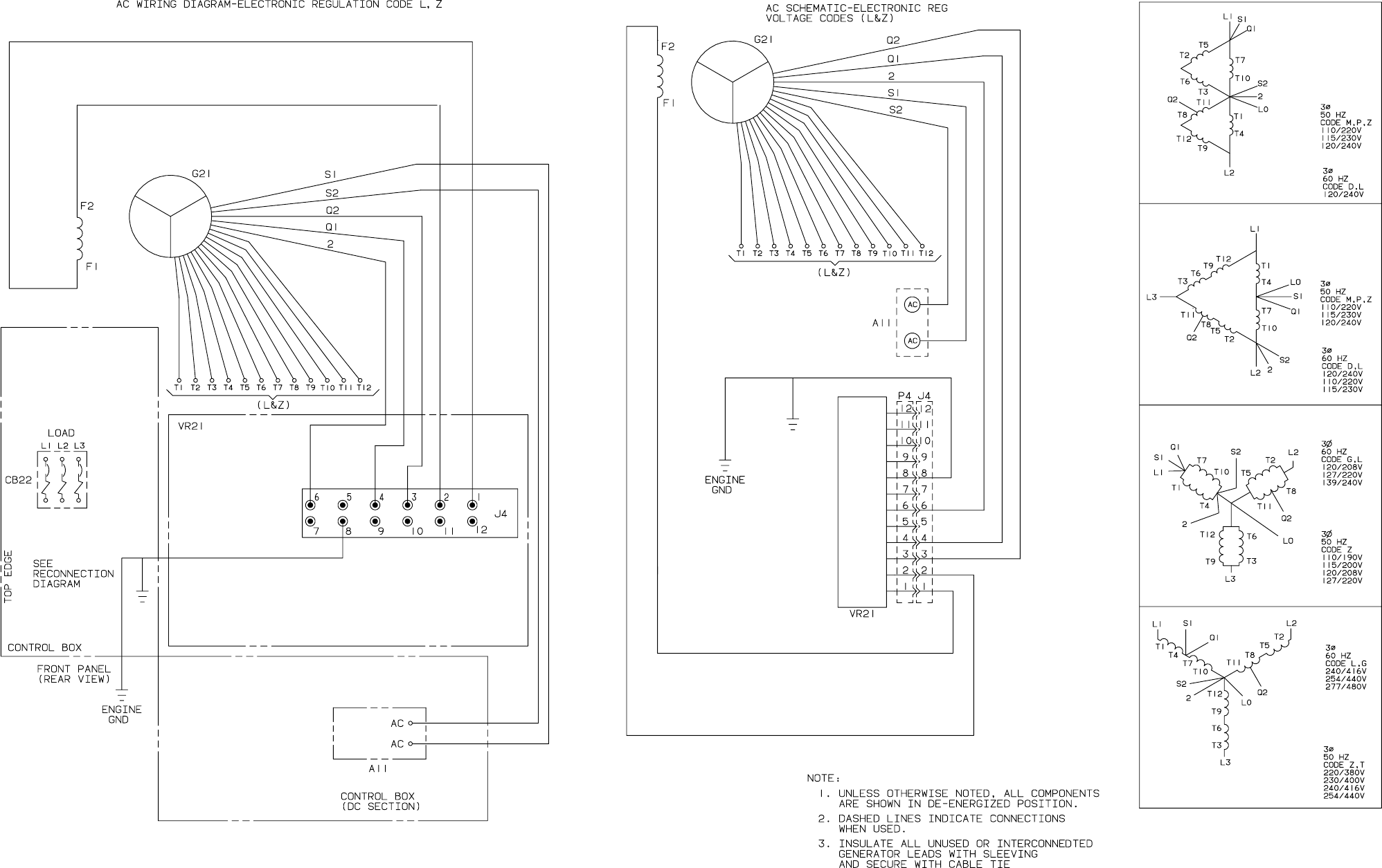
8-4
612-6732
Redistribution or publication of this document,
by any means, is strictly prohibited.

Cummins Power Generation
1400 73rd Avenue N.E.
Minneapolis, MN 55432
763-574-5000
Fax: 763-528-7229
Cummins and Onan are registered trademarks of Cummins Inc.
Redistribution or publication of this document,
by any means, is strictly prohibited.
