A_1670D A 1670D
A_1672D A_1672D
User Manual: A_1670D
Open the PDF directly: View PDF ![]() .
.
Page Count: 8

The HP 1670-Series
Benchtop Logic Analyzers
Technical Data
Identifying the cause of problems in
embedded microprocessor system
designs can be difficult. The
Hewlett-Packard 1670-series bench-
top logic analyzers have the fea-
tures to help the embedded system
design team find hardware and soft-
ware defects quickly.
With 64K of acquisition memory
(1M optional) the HP 1670-series
logic analyzers are the first bench-
top logic analyzers which display
processor mnemonics and verify
critical hardware timing relation-
ships over a long period of time.
With the standard Ethernet LAN
interface, the software designer can
now capture a real-time micropro-
cessor trace and time-correlate it to
source code in C++ or other high-
level languages on a PC or worksta-
tion. For time-correlation of source
code, order the HP B3740A
Software Analysis package.
Logic Analyzer Key Specifications and Characteristics
_______________________________________________________________________
Model Number HP 1670D HP 1671D HP 1672D
_______________________________________________________________________
State and Timing 136 102 68
Channels
_______________________________________________________________________
Timing Analysis Conventional: 125 MHz all channels, 250 MHz half channels
_______________________________________________________________________
State Analysis 100 MHz, all channels
Speed
_______________________________________________________________________
State Clocks/ 4 4 4
Qualifiers
_______________________________________________________________________
Memory Depth 64K per channel, 128K in timing half-channel mode
per Channel (1M per channel optional memory,
2M in timing half-channel mode)
_______________________________________________________________________
The combination of deep memory,
large internal disk drive, and LAN
make the HP 1670-series of bench-
top logic analyzers especially well
suited to solving your integration
problems.
• Mass storage is provided by an inter-
nal hard drive which provides quick
storage and retrieval of files.
• The 3.5-inch high-density flexible
disk drive supports both DOS and
LIF formats.
• The LAN interface enables access to
the logic analyzer files via FTP or
NFS. Use X11 windows to control or
view the logic analyzer on a PC or
workstation. The LAN interface
includes both Ethertwist (10BASE-T)
and ThinLan (10BASE 2) connectors.
• Store data as ASCII files and screen
images in TIFF, PCX, and EPS
(encapsulated PostScriptTM) formats.
• New graphical trigger macros make
trigger setup easier.
• Centronics, RS-232, HP-IB and LAN
communication ports make connect-
ing to other devices easier than ever.
All of these come standard on all
models of the HP 1670-series.
• The HP 1670-series operating system
includes System Performance
Analysis (SPA). SPA provides state
histograms, state overview, and time
interval analysis.
• The HP E2450A Symbolic Download
Utility is included with the HP 1670-
series. This utility provides the capa-
bility to extract symbolic information
from popular object module formats.
PostScriptTM is a trademark of Adobe
Systems Incorporated.
Get to the root cause of
problems quickly
This literature was published years prior to the establishment of Agilent Technologies as a company independent from Hewlett-Packard
and describes products or services now available through Agilent. It may also refer to products/services no longer supported by Agilent.
We regret any inconvenience caused by obsolete information. For the latest information on Agilent’s test and measurement products go to:
www.agilent.com/find/products
Or in the US, call Agilent Technologies at 1-800-452-4844 (8am–8pm EST)
Discontinued Product—Support Information Only

HP 1670-Series
General-Product
Information
_________________________
Human Interface
_________________________
Front Panel A knob and keypads
make up the front-
panel human interface.
Keys include control,
menu, display naviga-
tion, and alpha-numer-
ic entry functions.
_________________________
Mouse A DIN mouse is shipped
as standard equipment.
It provides full instru-
ment control. Knob
functionality is replicat-
ed by holding down the
right button and moving
the mouse left or right.
_________________________
Keyboard The logic analyzer can
also be operated using
a DIN keyboard. Order
the HP Logic Analyzer
Keyboard Kit, model
number HP E2427B.
_________________________
Input/Output, Control, and
Printing
_________________________
I/O Ports All units ship with a
Centronics parallel
printer port, RS-232,
and HP-IB as standard
equipment.
_________________________
LAN Interface An Ethernet LAN inter-
face is standard with
the HP 1670-series. The
LAN interface comes
with both Ethertwist
(10BASE-T) and
ThinLan (10BASE 2)
connectors.The LAN
supports FTP and
PC/NFS connection
protocols. It also works
with X11 window pack-
ages.
_________________________
Software The HP B3740A Soft-
Analysis ware Analyzer provides
Capability true source line refer-
encing and symbol
download capabilities.
Standard object
module formats are
supported.
_________________________
_________________________
Program- Each instrument is fully
mability programmable from a
computer via HP-IB
and RS-232 connec-
tions. This feature is
standard on all models.
_________________________
HP Printer Printers which use the
Support HP Printer Control
Language (PCL) and
have a parallel
Centronics, RS-232 or
HP-IB interface are
supported: HP
DeskJet, LaserJet,
QuietJet, PaintJet, and
ThinkJet models.
_________________________
Alternate The Epson FX80, LX80
Printer and MX80 printers
Supported with an RS-232 or
Centronics interface
supported in the Epson
8-bit graphics mode.
_________________________
Hard Copy Screen images can be
Output printed in black and
white from all menus
using the
Print
field.
State or timing listings
can be printed in full or
part (starting from
center screen) using
the
Print All
selection.
_________________________
Mass Storage Files
and Software
_________________________
Updating the The operating system
Operating resides in Flash ROM
System and can be updated
from the flexible disk
drive or the hard disk
drive.
_________________________
Mass Storage Is supported by an
internal hard disk drive
and by a 1.44 Mbyte,
3.5-inch flexible disk
drive. Supports DOS
and LIF formats.
A disk drive provides
quick storage and
retrieval of files.
_________________________
_________________________
Screen An image file of any display
Image Files screencan be stored to
disk via the display's
Print
field. Black &
white TIFF, PCX,
Encapsulated
PostScript (EPS) , and
gray-scale TIFF file for-
mats are available.
_________________________
ASCII Data State or timing listings
Files can be stored as ASCII
files on a flexible disk via
the display's
Print
field.
These files are equivalent
in character width and
line length to hardcopy
listings printed via the
Print All
selection.
_________________________
Configuration Logic analyzer files
and Data Files that include configura-
tion and data informa-
tion (if present) are
encoded in a binary
format. They can be
stored to or loaded
from the hard disk drive
or a flexible disk.
_________________________
Recording of Binary format
Acquisition configuration/data files are
and Storage stored with the time of
Times acquisition and the time of
storage.
_________________________
Acquisition Arming
_________________________
Initiation Arming is started by
Run
or the Port In
BNC.
_________________________
Cross Arming The analyzer machines
can cross-arm each
other.
_________________________
Output An output signal is
provided at the Port
Out BNC.
_________________________
2
_________________________
Port In/Out
_________________________
PORT IN Port In is a standard
Signal and BNC connection.
Connection The input operates at
TTL logic signal levels.
Rising edges are valid
input signals.
_________________________
PORT OUT Port Out is a standard
Signal and BNC connection with
Connection TTL logic signal levels.
A rising edge is assert-
ed as a valid output.
_________________________
Arming Times
_________________________
PORT IN 15 ns typical delay from
Arms Logic signal input to a
don't
Analyzer [1]
care
logic analyzer
trigger.
_________________________
Logic 120 ns typical delay
Analyzer from logic analyzer
Arms PORT trigger to signal
OUT [1] output.
_________________________
Operating Environment
_________________________
Power 115 Vac or 230 Vac, –22%
to +10%, single phase,
48-66 Hz, 320 VA max
_________________________
Temperature Instrument, 0° to 50° C
(+32° to 122° F). Disk
media, 10° to 40° C
(+50° to 104°F). Probes
and cables, 0° to 65° C
(+32° to 149° F)
_________________________
Humidity Instrument, up to 95%,
relative humidity at
+40° C (+140° F). Disk
media and hard drive,
8% to 85% relative
humidity.
_________________________
Altitude To 3,048 m (10,000 ft)
_________________________
Vibration: Random vibrations
Operating 5–500Hz,
10 minute per axis,
~ 0.3 g (rms).
_________________________
Vibration: Random vibrations
Non Operating5–500 Hz,10 minutes per
axis,~ 2.41 g (rms); and
swept sine resonant
search, 5–500 Hz,
0.75 g (0-peak),
5 minute resonant
dwell @ 4 resonances
per axis.
_________________________
_________________________
Physical Factors
_________________________
Weight 28.6 lbs. (13 kg)
_________________________
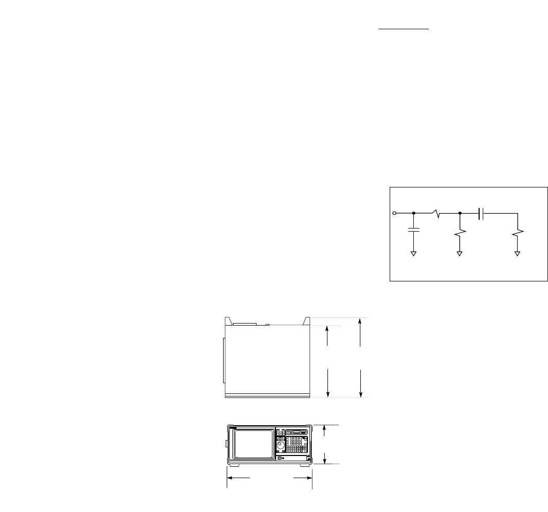
Dimensions See figure 1
_________________________
Safety IEC 348/ HD 401,
UL 1244, and
CSA Standard C22.2
No. 231 (series M-89)
_________________________
EMC
CISPR 11:1990/EN 55011 (1991):
Group 1 Class A
IEC 801-2:1991/EN 50082-1 (1992):
4kV CD, 8 kV AD
IEC 801-3:1984/EN 50082-1 (1992):3V/m
IEC 801-4:1988/EN 50082-1 (1992): 1kV
_________________________
_________________________
Logic Analyzer Probes
_________________________
Input 100 kΩ±2%
Resistance
_________________________
Input approx. 8 pF
Capacitance (see figure 2)
_________________________
_________________________
Minimum 500 mV peak-to-peak
Input Voltage
Swing
_________________________
Minimum 250 mV or 30% of input
Input amplitude, whichever is
Overdrive greater
_________________________
Threshold –6.0 V to +6.0 V in 50-mV
Range increments
_________________________
Threshold Threshold levels may be
Setting defined for pods
(17-channel groups) on
an individual basis
_________________________
Threshold ± (100 mV +3% of
Accuracy* threshold setting)
_________________________
Input ± 10 V about the
Dynamic threshold
Range
_________________________
Maximum ± 40 V peak
Input Voltage
_________________________
+5 V 1/3 amp maximum
Accessory per pod
Current
_________________________
Channel Each group of 34
Assignment channels (a pod pair)
can be assigned to
Analyzer 1, Analyzer 2
or remain unassigned.
______________________________
HP 1670-series
Logic Analyzer
Specifications and
Characteristics
[1] Time may vary depending upon the
mode of logic analyzer operation.
* Warranted Specification
3
RT= 250Ω
High Frequency Model for Probe Inputs
RIN = 100kΩCTG = 1 pF Z0=
150Ω
CCOMP = 7.5 pF
17.3 inches
(440 mm)
8.1 in.
(205 mm)
13.0 in.
(330 mm) 14.5 in.
(367 mm)
Figure 1Figure 1
Figure 2
Weight 28.6 lb. (13kg)

_________________________
State Analysis
_________________________
Maximum 100 MHz
State
Speed
_________________________
Channel HP 1670D 136/68
Count [2] HP 1671D 102/51
HP 1672D 68/34
_________________________
Memory
Depth per
Channel
Standard 64K
(65,536) samples
Time 32K
Tags On (32,768) samples)
Compare 32K
Mode On (32,768) samples)
Compare 32K
Mode and (32,768) samples)
Time Tags On
Option 030 1M
(1,032,192) samples
Time 500K
Tags On (507,904) samples
Compare 250K
Mode On (245,760) samples
Compare 120K
Mode and (114,688) samples
Time Tags On
_________________________
State Clocks HP 1670D 4 clocks
HP 1671D 4 clocks
HP 1672D 4 clocks
Clocks can be used by
either one or two state
analyzers at any time.
Clock edges can be
ORed together and
operate in single
phase, two-phase
demultiplexing, or two-
phase mixed mode.
Clock edge is
selectable as positive,
negative, or both edges
for each clock.
_________________________
_________________________
State Clock The high or low of the
Qualifier clocks can be ANDed
or ORed with the clock
specification.
_________________________
Setup/Hold [3]
one clock, 3.5/0 ns to 0/3.5 ns
one edge (in 0.5 ns increments)
one clock, 4.0/0 ns to 0/4.0 ns
both edges (in 0.5 ns increments)
multi-clock, 4.5/0 ns to 0/4.5 ns
multi-edge (in 0.5 ns increments)
_________________________
Minimum 3.5 ns
State Clock
Pulse Width [3]
_________________________
Minimum 10 ns
Master to
Master
Clock Time [3]
_________________________
Minimum 10 ns
Slave to
Slave
Clock Time [3]
_________________________
Minimum 0.0 ns
Master to
Slave
Clock Time [3]
_________________________
Minimum 4.0 ns
Slave to Master
Clock Time [3]
_________________________
Clock 4.0/0 ns (fixed)
Qualifiers
Setup/Hold [3]
_________________________
State Counts the number of
Tagging [4] qualified states
between each stored
state. Measurement
can be shown relative
to the previous state or
relative to trigger. Max.
count is 4.29 ×10⁹.
State Tag 0 to 4.29 ×10⁹
Count
State Tag 1 count
Resolution
_________________________
_________________________
Time Measures the time
Tagging [4] between stored states,
relative to either the pre-
vious state or to the trig-
ger. Max. time between
states is 34.4 sec. Min.
time between states is 8
ns.
Time Tag 8 ns to 34.4 seconds
Value ± (8 ns + 0.01% of time
tag value)
Time Tag 8 ns or 0.1%
Resolution (whichever is greater)
_________________________
Timing Analysis
_________________________
Conventional Data stored at selected
Timing sample rate across all
timing channels.
Maximum 125 MHz/250 MHz
Timing
Speed [2]
Channel HP 1670D 136/68
Count [2] HP 1671D 102/51
HP 1672D 68/34
Sample 8 ns/4 ns minimum
Period [2] 41 µs/10 µs
maximum
Memory 64K standard
Depth per 64K/128K samples
Channel [2] (65,536/131,072)
1M option
1M/2M samples
(1,032,192/2,080,768)
_________________________
Time Covered Sample period ×
by Data [2] memory depth
_________________________
4
[2] Full Channel /Half Channel Modes
[3] Specified for an input signal VH= – 0.9V, VL = – 1.7V,
slew rate = 1V/ns, and threshold = –1.3V
[4] Time or-state-tagging (Count Time or Count State) is
available in the full-channel state mode. There is no
speed penalty for tag use. Memory is halved when
time or state tags are used unless a pod pair (34-
channel group) remains unassigned in the
Configuration menu.

_________________________
Qualifier A user-specified term
that can be any state,
no state, any recogniz-
er, (pattern, ranges or
edge/glitch), any timer,
or the logical combina-
tion (NOT, AND, NAND,
OR, NOR, XOR, NXOR)
of the recognizers and
timers.
_________________________
Branching Each sequence level
has a branching qualifi-
er. When satisfied, the
analyzer will branch to
the sequence level
specified.
_________________________
Occurrence Sequence qualifier may
Counters be specified to occur
up to 1,048,575 times
before advancing to
the next level. Each
sequence level has its
own counter.
Maximum 1,048,575
Occurrence
Count
_________________________
Storage Each sequence level
Qualification has a storage qualifier
(state only) that specifies the states
that are to be stored.
_________________________
Maximum 125 MHz
Sequencer
Speed
State 12
Sequence
Levels
Timing 10
Sequence
Levels
_________________________
________________________
Time Interval Accuracy
________________________
Sample ± 0.01%
Period
Accuracy
________________________
Channel-to- 2 ns typical,
Channel 3 ns maximum
Skew
________________________
Time Interval ± (Sample Period
Accuracy + channel-to-channel
skew + 0.01% of time
interval reading)
________________________
Maximum Sample Period 4-8 ns :
Delay 8.389 ms
After Sample Period > 8 ns:
Triggering 1,048,575 ×sample
period
_______________________
Trigger Specifications
________________________
Trigger Trigger setups can be
Macros selected from a cate-
gorized list of trigger
macros. Each macro
is shown in graphical
form and has a written
description. Macros
can be chained
together to create a
custom trigger
sequence.
________________________
Pattern Each recognizer is the
Recognizers AND combination of bit
(0,1, or X) patterns in
each label.
Pattern 10
Recognizers
Pattern Width HP 1670D 136/68
(in channels) HP 1671D 102/51
[2] HP 1672D 68/34
________________________
Minimum 125 MHz and 250 MHz
Pattern Timing Modes: 13 ns
and Range + channel-to-channel
Recognizer skew
Pulse Width ≤125 MHz Timing
Modes : 1 sample
period + 1 ns + chan-
nel-to-channel skew
+ 0.01%
________________________
________________________
Range Recognize data which is
Recognizers numerically between or
on two specified pat-
terns (ANDed combina-
tion of zeros and/or
ones).
Range 2
Recognizers
Range Width 32 channels
_________________________
Edge/Glitch Trigger on glitch or
Recognizers edge on any channel.
Edge can be specified
as rising, falling or
either.
Edge/Glitch 2 (in timing mode only)
Recognizers
Edge/Glitch HP 1670D 136/68
Width (in HP 1671D 102/51
channels) [2] HP 1672D 68/34
Edge/Glitch Sample Period 4-8 ns:
Recovery 28 ns
Time Sample Period > 8 ns:
20 ns + sample period
_________________________
Greater than Sample period 4-8 ns:
Duration 8 ns to 8.389 ms.
(timing only) Accuracy is –2 ns to
+10 ns
Sample period > 8 ns:
(1 to 220) ×sample
period. Accuracy is
–2 ns + sample period
+ 2 ns ± 0.01%
_________________________
Less than Sample period 4-8 ns:
Duration 8 ns to 8.389 ms.
(timing only) Accuracy is –2 ns to
+10 ns.
Sample period > 8 ns:
(1 to 220) ×sample
period.
Accuracy is 2 ns +
sample period – 2 ns ±
0.01%
_________________________
5
[2] Full Channel /Half Channel Modes

_________________________
Timers Timers may be Started,
Paused, or Continued at
entry into any sequence
level after the first.
Timers 2
Timer Range 400 ns to 500 seconds
Timer 16 ns or 0.1% whichever
Resolution is greater
Timer ± 32 ns or ± 0.1%,
Accuracy whichever is greater
Timer 70 ns
Recovery Time
_________________________
Data In to 110 ns typical
Trigger Out
BNC Port
_________________________
Acquisition, Measurement
and Display Functions
_________________________
Arming Each analyzer can be
armed by the Run key,
the other analyzer, or
the Port In.
_________________________
Run Starts acquisition of
data in specified trace
mode.
_________________________
Stop Stop halts acquisition
and displays the cur-
rent acquisition data.
_________________________
Trace Mode Single mode acquires
data once per trace
specification; repeti-
tive mode repeats
single mode acquisi-
tions until Stop is
pressed or until pat-
tern time interval or
compare stop criteria
are met.
_________________________
Trigger Displayed as a vertical
dashed line in the
timing waveform,
state waveform and
X-Y chart displays and
as line 0 in the state
listing and state com-
pare displays.
_________________________
_________________________
Activity Provided in the
Indicators Configuration, State
Format, and Timing
Format menus for
monitoring device-
under-test activity
while setting up the
analyzer.
_________________________
Labels Channels may be
grouped together and
given a 6-character
name called a
label
. Up
to 126 labels in each
analyzer may be
assigned with up to 32
channels per label.
Trigger terms may be
given an 8-character
name.
_________________________
Measurement Functions
_________________________
Markers Two markers (x and o)
are shown as dashed
lines in the display.
_________________________
Time The x and o markers
Intervals measure the time
interval between
events occurring on
one or more wave-
forms or states.
Available in state when
time tagging is on.
_________________________
Delta States The x and o markers
measure the number
of tagged states
between any two
states (state only).
_________________________
Patterns The x or o marker can
be used to locate the
nth occurrence of a
specified pattern
before or after trigger,
or after the beginning
of data. The o marker
can also find the nth
occurrence of a pat-
tern before or after
the x marker.
_________________________
Statistics x to o marker statistics
are calculated for
repetitive acquisitions.
Patterns must be
specified for both
markers, and statistics
are kept only when
both patterns can be
found in an acquisi-
tion. Statistics are
minimum x to o time,
maximum x to o time,
average x to o time,
and ratio of valid runs
to total runs.
_________________________
Compare Performs post-process
Mode ing bit-by-bit
Functions comparison of the
acquired state data
and Compare Image
data.
Compare Created by copying a
Image state acquisition into
the compare image
buffer. Allows editing
of any bit in the
Compare Image to a 1,
X or O.
Compare Each channel (column)
Image in the compare image
Boundaries can be enabled or dis-
abled via bit masks in
the Compare Image.
Upper and lower
ranges of states (rows)
in the compare image
can be specified. Any
data bits that do not
fall within the enabled
channels and the
specified range are
not compared.
Stop Repetitive acquisitions
Measurement may be halted when
the comparison
between the current
state acquisition and
the current Compare
Image is equal or not
equal.
_________________________
Compare Reference Listing
Mode display shows the
Displays Compare Image and
bit masks; Difference
Listing display highlights
differences between
the current state acqui-
sition and the Compare
Image.
_________________________
6

_________________________
Data Entry/Display
_________________________
Display State Listing, State
Modes Waveforms, State
Chart, State Compare
Listing, Compare
Difference Listing,
Timing Waveforms,
Timing Listing, inter-
leaved time-correlat-
ed listing of two state
analyzers (time tags
on), and time-correlat-
ed State Listing with
Timing Waveforms on
the same display.
_________________________
State X-Y Plots value of a speci-
Chart Display fied label (on y-axis)
versus states or
another label (on x-
axis). Both axes can
be scaled.
Markers Correlated to State
Listing, State Compare,
and State Waveform
displays. Available as
pattern, time, or statis-
tics (with time count-
ing) and states (with
state counting on).
Accumulate Chart display is not
erased between suc-
cessive acquisitions.
_________________________
State Displays state
Waveform acquisitions
Display in waveform format.
States/div 1 to mem length/8
Delay ±memory length
Accumulate Waveform display is
not erased between
successive acquisi-
tions.
Overlay Multiple channels can
Mode be displayed on one
waveform display line.
Displayed 24 lines maximum on
Waveforms one screen. Up to 96
lines may be specified
and scrolled through.
________________________
________________________
Timing Displays timing
Waveform acquisition in wave-
Display form format.
Sec/div [2] 1 ns to 4.4 sec/div/
1 ns to 2.2 sec/div
Delay – 2,500 s to + 2,500 s
Accumulate Waveform display is
not erased between
successive acquisi-
tions.
Overlay Mode Multiple channels can
be displayed on one
waveform display line.
When waveform size
set to large, the value
represented by each
waveform is displayed
inside the waveform
in the selected base.
Displayed 24 lines maximum on
Waveforms one screen. Up to 96
lines may be specified
and scrolled through.
________________________
System SPA includes state
Performance histogram, state
Analysis overview and time
interval measure-
ments to aid in the
software optimization
process. These tools
provide a statistical
overview of your syn-
chronous design. For
additional information,
refer to HP 10390A
System Performance
Software technical
data sheet, pub no.
5091-7850E.
________________________
Bases Binary, Octal,
Decimal,
Hexadecimal, ASCII
(display only), sym-
bols, two's compli-
ment.
________________________
7
________________________
Symbols
Pattern User can define a
Symbols mnemonic for the spe-
cific bit pattern of a
label. When data dis-
play is SYMBOL,
mnemonic is displayed
where the bit pattern
occurs.
Range User can define a
Symbols mnemonic covering a
range of values. When
data display is
SYMBOL, values within
the specified range are
displayed as mnemonic
+ offset from base of
range.
Number of 1000 maximum.
Symbols
________________________
[2] Full Channel /Half Channel Modes

HP 1670D-Series Benchtop Logic Analyzers
_____________________________________________________
HP 1670D 136-Channel 100-MHz State/250-MHz Timing with 64K Memory
Depth and Ethernet LAN
________________________________________________________________
HP 1671D 102-Channel 100-MHz State/250-MHz Timing with 64K Memory
Depth and Ethernet LAN
________________________________________________________________
HP 1672D 68-Channel 100-MHz State/250-MHz Timing with 64K Memory
Depth and Ethernet LAN
________________________________________________________________
Additional HP 1660C/CS and 1670D-Series Product Options
_____________________________________________________
Opt 030 Extended Memory depth to 1M samples/channel (ordered at
the time of purchase)
________________________________________________________________
Opt 0B3 Add Service Manual
________________________________________________________________
Opt 1CM Rack Mount Kit
________________________________________________________________
Opt UK9 Front Panel Cover
________________________________________________________________
Opt W30 3-Year extended repair service
________________________________________________________________
Opt W50 5-Year extended repair service
________________________________________________________________
Opt OBF Add Programming Manual
________________________________________________________________
Accessory Software
_____________________________________________________
HP B3740A Software Analyzer
Opt AJ4 IBM, 3.5-inch Media/Documentation
Opt AAY HP 9000 Series 700 Media/Documentation
Opt AAV SUN (Solaris and SUN OS) Media/Documentation
Opt UDY IBM Single User License
Opt UBY HP 9000 Series 700 Single User License
Opt UBK SUN (Solaris and SUN 0S) Single User License
________________________________________________________________
HP 10391B Inverse Assembler Development Package
________________________________________________________________
HP 1670D-Series Upgrades
_____________________________________________________
HP E2471D Upgrade HP 1670D-Series from 64K to 1M of memory
Opt 001 Upgrades HP 1670D from 64K to 1M of acquisition memory
Opt 002 Upgrades HP 1671D from 64K to 1M of acquisition memory
Opt 003 Upgrades HP 1672D from 64K to 1M of acquisition memory
________________________________________________________________
HP E2427B Add keyboard with DIN connector (PC style)
________________________________________________________________
State/Timing Analyzer Probes & Lead Sets
_____________________________________________________
HP 5959-9333 5 Grey Probe Leads for HP 1670D-Series
________________________________________________________________
HP 5959-9334 5 Short Ground Leads for HP 1670D-Series
________________________________________________________________
HP 5959-9335 5 Long Ground Leads for All State and Timing Analyzers
________________________________________________________________
HP 01650-61608 16-Channel Probe Lead Set for State and Timing Analyzers
________________________________________________________________
HP 01650-63203 Termination Adapter for State and Timing Analyzers
________________________________________________________________
HP 1810-1278 9-Channel IC Termination DIP
________________________________________________________________
HP 1810-1588 Termination IC SIP
________________________________________________________________
HP 1251-8106 2 ×10, 0.1-inch Center Header (Similar to 3M p/n 2520-6002)
________________________________________________________________
HP 5090-4356 Surface-Mount Grabbers (package of 20)
________________________________________________________________
HP 5959-0288 Throughhole Grabbers (package of 20)
________________________________________________________________
Other Accessories for HP Logic Analyzers
_____________________________________________________
HP 1180B Testmobile for the HP 1670-Series
________________________________________________________________
HP 92199B Power Strip
________________________________________________________________
HP 5041-9456 Front Cover for HP 1670-Series
________________________________________________________________
HP 5062-7379 Rack Mount Kit for HP 1670-Series
________________________________________________________________
For more information on
Hewlett-Packard Test & Measurement
products, applications or services
please call your local Hewlett-Packard
sales offices. A current listing is avail-
able via Web through AccessHP at
http://www.hp.com. If you do not have
access to the internet, please contact
one of the HP centers listed below and
they will direct you to your nearest HP
representative.
United States:
Hewlett-Packard Company
Test and Measurement Organization
5301 Stevens Creek Blvd.
Bldg. 51L-SC
Santa Clara, CA 95052-8059
1 800 452 4844
Canada:
Hewlett-Packard Canada Ltd.
5150 Spectrum Way
Mississauga, Ontario L4W 5G1
(905) 206 4725
Europe:
Hewlett-Packard
European Marketing Centre
P.O. Box 999
1180 AZ Amstelveen
The Netherlands
Japan:
Hewlett-Packard Japan Ltd.
Measurement Assistance Center
9-1, Takakura-Cho, Hachioji-Shi,
Tokyo 192, Japan
Tel: (81-426) 56-7832
Fax: (81-426) 56-7840
Latin America:
Hewlett-Packard
Latin American Region Headquarters
5200 Blue Lagoon Drive, 9th Floor
Miami, Florida 33126, U.S.A.
(305) 267 4245/4220
Australia/New Zealand:
Hewlett-Packard Australia Ltd.
31-41 Joseph Street
Blackburn, Victoria 3130
Australia
1 800 629 485
Asia Pacific:
Hewlett-Packard Asia Pacific Ltd
17-21/F Shell Tower, Times Square,
1 Matheson Street, Causeway Bay,
Hong Kong
Fax: (852) 2506 9285
Technical information in this
document is subject to change
without notice.
5964-3666E 9/96
Printed in the U.S.A.
Copyright©
Hewlett-Packard Company 1996
Ordering Information
