A26 5988 2_2841_2302_2311_2321_2303_Component_Descriptions_Oct65 2 2841 2302 2311 2321 2303 Component Descriptions Oct65
A26-5988-2_2841_2302_2311_2321_2303_Component_Descriptions_Oct65 A26-5988-2_2841_2302_2311_2321_2303_Component_Descriptions_Oct65
A26-5988-2_2841_2302_2311_2321_2303_Component_Descriptions_Oct65 A26-5988-2_2841_2302_2311_2321_2303_Component_Descriptions_Oct65
User Manual: A26-5988-2_2841_2302_2311_2321_2303_Component_Descriptions_Oct65
Open the PDF directly: View PDF ![]() .
.
Page Count: 58
Systems
Reference Library
IBM
System/360
Component
Descriptions-
2841
Storage Control Unit
2302
Disk Storage, Models 3 and 4
2311
Disk Storage Drive
2321
Data Cell Drive, Model 1
2303
Drum Storage
This
publication
contains
reference
information
for
the
operation
and
programming
of
storage
devices
which
attach
to
the
IBM 2841
Storage
Control
Unit.
These
storage
devices
include
the
IBM 2311
Disk
Storage
Drive;
the
IBM
2302
Disk
Storage,
Models
3
and
4;
the
IBM 2321
Data
Cell
Drive,
Modell;
and
the
IBM 2303
Drum
Storage.
File
No.
S360-07
Form
A26-5988-2
This
is a
reprint
of
an
earlier
publication
(Form
A26-5988
-1).
The
following
Technical
Newsletter
is
incorporated
in
this
edition:
Form
No.
N26-0131
Pages
iii
and
blank,
1
and
2, 13
and
14,
41
and
42
Date
10/22/65
Copies
of
this
and
other
IBM
publications
can
be
obtained
through
IBM
Branch Offices.
Comments
concerning
the
contents
of
this
publication
may
be
addressed
to:
IBM,
Product
Publications
Department,
San
Jose,
Calif.
95114
ii
Page
IBM
2841
STORAGE
CONTROL
UNIT.
• • • • • • • • • • • • •
••
1
Introduction.
• • • • • • • • • • • • • • • • • • • • • • • • • • • • • • • •
IBM 2841 F1.Ulctions
•••••••••••••••••••••••••••
Data
Character
Format
•••
•••••
••••••••••••••••••
Data
Characters
•••••••••••••••••••••••••••••
Data
Checking
••••••••••••••••••••••••••••••
Data
Character
Transfer.
• • • • • • • • • • • • • • • • • • • • •
••
2
Track
Format.
• • • • • • • • • • • • • • • • • • • • • • • • • • • • •
••
2
Index
Marker.
• • • • • • • • • • • • • • • • • • • • • • • • • • • •
••
2
Gaps.
• • • • • • • • • • • • • • • • • • • • • • • • • • • • • • • • •
••
2
Home
Address.
• • • • • • • • • • • • • • • • • • • • • • • • • • •
••
3
Track
Descriptor
Record
(RO) • • • • • • • • . • • • • • • • • •
••
3
Data
Records
(Rl
-
Rn)
• • • • • • • • • • • • • • • • • • • • •
••
5
INPUT/OUTPUT
OPERATIONS.
• • • • • • • • • • • • • • • • • •
••
7
Instruc
tions
• • • • • • • • • • • • • • • • • • • • • • • • • • • • • • • • •
Start
I/O
••••••••••••.••••••••••••••••••••
Halt
I/O
••••••••••••••••••••••••••••••••••
Test
I/O
••••••••••••••••••••••••••••••••••
T
est
Channel
•••••••••••
• • • • • • • • • • • • • • • • • • •
ChaIUlel
Operation
••••••••••••••••••••••••••••
ChaIUlel
Status
Word
••••••••••••••••••••••••••
Channel
Address
Word
•••••••••••••••••••••••••
ChaIUlel
Command
Word
•••••••••••••••••••••••
Program
Status
Word
••••••••••••••••••••••••••
Channel
Program
Branching
•••••••••••••••••••••
7
8
8
8
8
8
8
10
10
11
12
Control
Commands.
• • • • • • • • • • • • • • • • • • • • • • • •
••
12
Sense
I/O
Commands
• • • • • • • • • • • • • • • • • • • • • • •
••
15
Search
Commands
• • • • • • • • • • • • • • • • • • • • • • • • •
••
18
Read
Commands
• • • • • • • • • • • • • • • • • • • • • • • • • •
••
22
Write
Commands.
• • • • • • • • • • • • • • • • • • • • • • • • •
••
22
End-of-File
••••••••••••••
• . • • • • • • • • • • • • •
••
27
Multiple
Track
Operation
• • • • • • • • • . • • • • • • • • • •
••
27
Two
-ChaIUlel
Switch
••••
• • • . • . • . • . • • • • • • • • •
.•
27
iii
CONTENTS
Page
Record
Overflow
• • • • • • • • • • • • • • • • • • • • • • • • • • •
••
28
IBM 2311
DISK
STORAGE.
• • • • • • • • • • • • • • • • • • • • • •
••
29
Introduction
• • • • • • • • • • • • • • • • • • • • • • • • • • • • • •
••
29
Device
Description.
• • • • • • • • • • • • • • • • • • • • • • • • •
••
29
Data
Storage.
• • • • • • • • • • • • • • • • • • • • • • • • • • • • •
••
31
Operator
Controls
and
Indicators
• • • • • • • • • • • • • • • • •
••
31
Operating
Procedures
••••••••••••••••••••••••••
32
IBM
2302
DISK
STORAGE,
MODELS 3
AND
4 • • • • • • • • • •
••
34
Introduction
• • • • • • • • • • • • • • • • • • • • • • • • • • • • • •
••
34
Device
Description.
• • • • • • • • • • • • • • • • • • • • • • • • •
••
34
Data
Storage.
• • • • • • • • • • • • • • • • • • • • • • • • • • • • •
••
36
Indicators
••••••••••••••••••••
IBM
2321
DATA
CELL DRIVE
••••••••
Introduction
••••••••••••••••••••••••••••••••
Device
Description
••••••••••••••••••••••••••••
Data
Storage
•••••••••••.••••••••••••••••••••
Operator
Controls
and
Indicators
•••••••••••••••••••
Operating
Procedures
•••••••••••••••••••••••••••
IBM 2303
DRUM
STORAGE
••••••••••••••••••••••••
Introduction
••••••••••••••••••••••••••••••••
Device
Description
••••••••••••••••••••••••••••
Data
Storage
•••••••••
0
••••••••••••••••••••••
APPENDIX
A.
2841/2311
PROGRAMMING
EXAMPLE
•••••••
APPENDIX
B.
HEXADECIMAL-DECIMAL
CONVERSION
APPENDIX
C.
COMMAND
SUMMARY
36
37
37
37
38
39
40
41
41
41
41
43
46
51
APPENDIX
D.
TRACK
ORIENTATION
•••••••••••.•.••
52

INTRODUCTION
The
IBM 2841
Storage
Control
Unit
provides
for
the
attachment
of
direct
access
storage
devices
to
IBM
System/360.
These
storage
devices
are:
IBM 2311
Disk
Storage
Drive
(standard
feature)
IBM 2302
Disk
Storage,
Models 3 and 4
(special
feature)
IBM 2321
Data
Cell
Drive
(special
feature)
IBM 2303
Drum
Storage
(special
feature)
A
single
2841
Storage
Control
Unit
provides
for
the
attachment
of
any
combination
of the above
stor-
age
devices
up
to
a
maximum
of
eight
access
mech-
anisms.
With
the
2841 Additional
Storage
special
feature,
up
to
eight
access
mechanisms
may
be
added,
bringing
the
total
available
access
mechanisms
to
sixteen.
A
versatile
set
of
instructions
ensures
optimum
data
processing
efficiency.
Direct
access
to
vast
quantities
of
operating
information
enables
the
user
to
locate
specific
data
records
without
sequential
ad-
dress
searching.
Voluminous
master
record
files
can
be
stored
on-line,
ready
for
immediate
reference
or
updating.
Maintenance
of
master
record
files
can
be
im-
mediate
and
direct;
the
most
current
information
can
be
entered
into
the
proper
area
of
the
master
record
file
as
transactions
occur.
Complex
account-
ing
procedures
can
be
Simplified,
because
interme-
diate
manual
operations,
necessary
to
maintain
off-
line
record
files,
are
eliminated.
IBM 2841
Functions
The
2841
performs
the
following functions:
•
Interprets
and
executes
commands
from
the
channel
attached
to
the
central
processing
unit
(CPU).
•
Provides
a
path
for
data
between
the
CPU
and
attached
storage
devices.
•
Translates
data
appropriately
as
it
is
trans-
ferred
between
the
storage
devices
and
the
CPU.
•
Furnishes
operation
status
information
to
the
CPU.
•
Performs
checks
to
ensure
accurate
transfer
of
data.
IBM 2841 STORAGE CONTROL UNIT
DATA CHARACTER FORMAT
Data
Characters
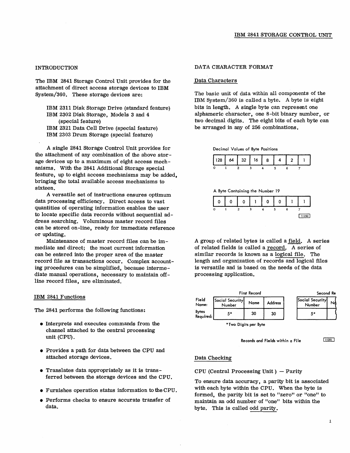
The
basic
unit of
data
within
all
components
of
the
IBM
System/360
is
called
a
byte.
A
byte
is
eight
bits
in
length.
A
single
byte
can
represent
one
alphameric
character,
one 8
-bit
binary
number,
or
two
decimal
digits.
The
eight
bits
of
each
byte
can
be
arranged
in any
of
256
combinations.
Decimal
Values
of
Byte Positions
,128
I
64
I
32
I
16
I 8 I 4 I 2
o 4
A Byte
Containing
the
Number
19
I
0 I 0 I 0 I I 0 I 0 I
0 1 2 3 4 5 6
~
A group
of
related
bytes
is
called
a
field.
A
series
of
related
fields
is
called
a
record.
A
series
of
similar
records
is
known
as
a
logical
file.
The
length and
organization
of
records
and
logical
files
is
versatile
and
is
based
on
the
needs
of
the
data
processing
application.
First Record Second
Re
Field
Name: Social Security Name Address Social Security
Bytes
Required:
Number
5*
30 30
*Two Digits
per
Byte
Records and Fields within a
Fi
Ie
Data
Checking
CPU
(Central
Processing
Unit)
-
Parity
Number
5*
To
ensure
data
accuracy,
a
parity
bit
is
associated
with
each
byte
within
the
CPU.
When
the
byte
is
formed,
the
parity
bit
is
set
to
"zero"
or
"one"
to
maintain
an odd
number
of
"one"
bits
within
the
byte.
This
is
called
odd
parity.
N(
1
1
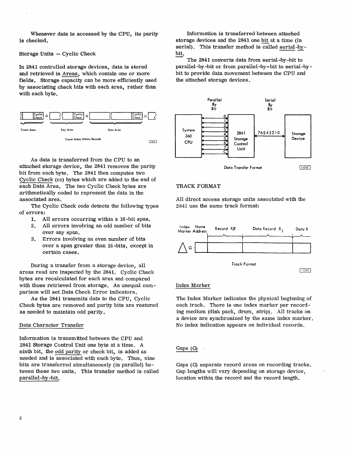
Whenever
data
is
accessed
by
the
CPU,
its
parity
is
checked.
Storage
Units
-
Cyclic
Check
In
2841
controlled
storage
devices,
data
is
stored
and
retrieved
in
Areas,
which
contain
one
or
more
fields.
Storage
capacity
can
be
more
efficiently
used
by
associating
check
bits
with
each
area,
rather
than
with
each
byte.
ov----"
Count Area Key Area
Dota
Area
Count
Areas Within Records
As
data
is
transferred
from
the
CPU
to
an
attached
storage
device,
the
2841
removes
the
parity
bit
from
each
byte.
The
2841
then
computes
two
Cyclic
Check
(cc)
bytes
which
are
added to
the
end
of
each
Data
Area.
The
two
Cyclic
Check
bytes
are
arithmetically
coded
to
represent
the
data
in
the
associated
area.
The
Cyclic
Check
code
detects
the
following
types
of
errors:
1. All
errors
occurring
within a
16-bit
span.
2. All
errors
involving
an
odd
number
of
bits
over
any
span.
3.
Errors
involving
an
even
number
of
bits
over
a
span
greater
than
16-bits,
except
in
certain
cases.
During
a
transfer
from
a
storage
device,
all
areas
read
are
inspected
by
the
2841.
Cyclic
Check
bytes
are
recalculated
for
each
area
and
compared
with
those
retrieved
from
storage.
An unequal
com-
parison
will
set
Data
Check
Error
indicators.
As
the
2841
transmits
data
to the
CPU,
Cyclic
Check
bytes
are
removed
and
parity
bits
are
restored
as
needed
to
maintain
odd
parity
.
Data
Character
Transfer
Information
is
transmitted
between
the
CPU
and
2841
Storage
Control
Unit one
byte
at
a
time.
A
ninth
bit,
the
odd
parity
or
check
bit,
is
added
as
needed
and
is
associated
with
each
byte.
Thus,
nine
bits
are
transferred
simultaneously
(in
parallel)
be-
tween
these
two
units.
This
transfer
method
is
called
parallel-by
-bit.
2
Information
is
transferred
between
attached
storage
devices
and
the
2841
one
bit
at
a
time
(in
serial).
This
transfer
method
is
called
serial-by-
bit.
---
The
2841
converts
data
from
serial-by-bit
to
parallel-by-bit
or
from
parallel-by-bit
to
serial-by-
bit
to
provide
data
movement
between
the
CPU
and
the
attached
storage
devices.
System
360
CPU
Parallel
By
Bit
TRACK FORMAT
o.
1~
2
3
4
5
6
7
C
2841
Storage
Control
Unit
Serial
By
Bit
76543210
Data
Transfer Format
Storage
Device
All
direct
access
st<.>rage
units
associated
with
the
2841
use
the
same
track
format:
Index
Home
Mar
ker Address
Record
R.0
Dato
Record
R 1
Dota
R
T
roc
k
Format
Index
Marker
The Index
Marker
indicates
the
physical
beginning
of
each
track.
There
is
one index
marker
per
record-
ing
medium
(disk
pack,
drum,
strip).
All
tracks
on
a
device
are
synchronized
by the
same
index
marker.
No index
indication
appears
on individual
records.
Gaps
(G)
Gaps
(G)
separate
record
areas
on
recording
tracks.
Gap
lengths
will
vary
depending on
storage
device,
location
within
the
record
and the
record
length.
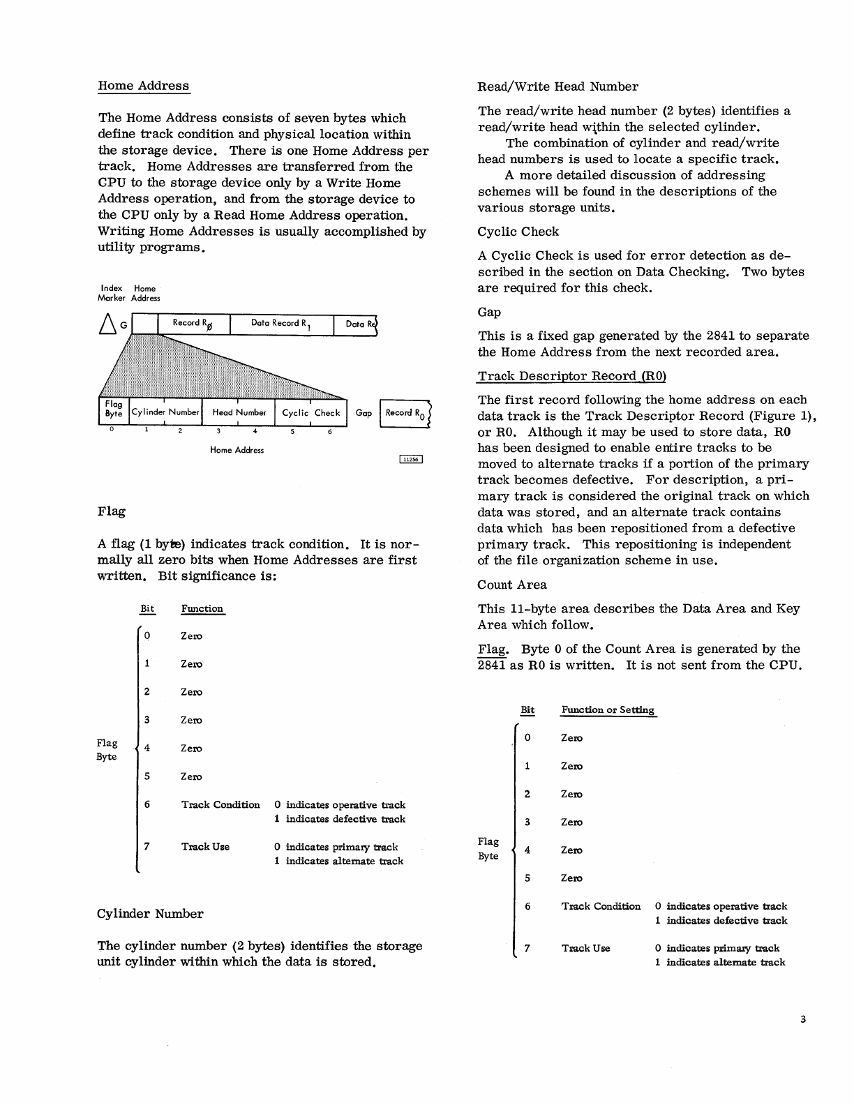
Home
Address
The
Home
Address
consists
of
seven
bytes
which
define
track
condition and
physical
location
within
the
storage
device.
There
is
one Home
Address
per
track.
Home
Addresses
are
transferred
from
the
CPU
to the
storage
device
only by a
Write
Home
Address
operation,
and
from
the
storage
device
to
the
CPU
only
by
a
Read
Home
Address
operation.
Writing
Home
Addresses
is
usually
accomplished
by
utility
programs.
Index Home
Merker
Address
Home Address
Flag
A
flag
(1 byte)
indicates
track
condition.
It
is
nor-
mally
all
zero
bits
when Home
Addresses
are
first
written.
Bit
significance
is:
Bit FWlction
0 Zero
Zero
2 Zero
3 Zero
Flag
4 Zero
Byte
5 Zero
6
Track
Condition
o indicatE:s
operative
track
1
indicates
defective
track
7
Track
Use o
indicates
primaty
track
1
indicates
alternate
track
Cylinder
Number
The
cylinder
number
(2
bytes)
identifies
the
storage
unit
cylinder
within
which
the
data
is
stored.
Read/Write
Head
Number
The
read/write
head
number
(2
bytes)
identifies
a
read/write
head
w\thin
the
selected
cylinder.
The
combination
of
cylinder
and
read/write
head
numbers
is
used
to
locate
a
specific
track.
A
more
detailed
discussion
of
addressing
schemes
will
be
found
in
the
descriptions
of
the
various
storage
units.
Cyclic
Check
A
Cyclic
Check
is
used
for
error
detection
as
de-
scribed
in
the
section
on
Data
Checking. Two
bytes
are
required
for
this
check.
Gap
This
is
a fixed
gap
generated
by
the
2841
to
separate
the Home
Address
from
the
next
recorded
area.
Track
Descriptor
Record
(RO)
The
first
record
following
the
home
address
on
each
data
track
is
the
Track
Descriptor
Record
(Figure
1),
or
RO.
Although
it
may
be
used
to
store
data,
RO
has
been
designed
to
enable
entire
tracks
to
be
moved
to
alternate
tracks
if
a
portion
of
the
primary
track
becomes
defective.
For
description,
a
pri-
mary
track
is
considered
the
original
track
on
which
data
was
stored,
and
an
alternate
track
contains
data
which
has
been
repositioned
from
a
defective
primary
track.
This
repositioning
is
independent
of
the
file
organization
scheme
in
use.
Count
Area
This
I1-byte
area
describes
the
Data
Area
and Key
Area
which follow.
Flag.
Byte
0 of
the
Count
Area
is
generated
by
the
2841
as
RO
is
written.
It
is
not
sent
from
the
CPU.
Bit
Function
or
Setting
0 Zero
Zero
2 Zero
3 Zero
Flag
4 Zero
Byte
5 Zero
6
Track
Condition
o
indicates
operative
track
1
indicates
defective
track
7
Track
Use o
indicates
primary
track
1
indicates
alternate
track
3

Index
Marker
Home
Address Record
R~
Data Record R 1 Data R
__
--------~A---------~r----------------JA~--------------~----------~
Home
Address
I
CY~liC
Check
5 6
Figure
1.
Track
Descriptor Record
Count Area
Bits
6 and 7
are
transmitted
to
the
flag
bytes
of
all
records
on
the
track
from
the
flag
byte
of
the home
address
of
that
track.
Cylinder
Number.
In a
primary
track,
bytes
1
and 2 of
RO
contain
the
cylinder
number
of
the
primary
track
on which
this
record
was
stored.
If
this
record
has
been
moved
to
an
alternate
track,
the
cylinder
number
of
the
alternate
track
appears
in
the
data
area
of
RO
of
the
defective
primary
track.
Read/Write
Head
Number.
In a
primary
track
bytes
3 and 4 of
RO
contain
the
read/write
head
number
of
the
primary
track
on which
this
record
was
stored.
If
this
area
has
been
moved
to
an
alternate
track,
the
head
number
of the
alternate
track
appears
in
the
data
area
of
RO
of
the
defective
primary
track.
Record
Number.
Byte 5
designates
the
sequential
number
of
the
record
on
the
track.
For
RO,
the
record
number
is
zero.
Key Length. Byte 6
specifies
the
number
of
bytes
in
the Key
Area
of the
record
(excluding
check
bytes).
If
the
record
has
no key,
this
byte
is
zero.
This
byte
can
indicate
a Key Length
from
0
to
255
bytes.
Because
of
its
intended
special
use
with
alternate
track
procedures,
RO
will
normally
have no Key
Area.
Data
Length.
Bytes
7 and 8
specify
the
number
of
bytes
in
the
Data
Area
of
the
record
(excluding
check
4
Key Area Data Area
bytes).
Two
bytes
(16
bits)
can
indicate
Data
Length
from
1 to
65,535
bytes.
Zero
Data
Length
indicates
the
end
of
a
logical
file.
The 2841
sends
special
indicators
to
the
CPU
when
an
End-of-File
record
is
read
or
written.
Cyclic
Check.
Bytes
9 and
10
are
used
for
error
detection
as
discussed
in
the
section
on
Data
Check-
ing.
Key
Area
Although a Key
Area
can
be
written
and
used
in
RO
by
the
commands
used
by
the
2841,
this
use
is
purely
at
the
discretion
of
the
programmer.
Standard
use
of
RO
by IBM
Programming
Systems
does
not
include
a Key
Area.
A
more
detailed
discussion
of Key
Area
may
be
found
in
the
section
of
this
manual
which
describes
Key
Area
within
Data
Records
(R1
-Rn).
Data
Area
The
design
and
use
of
this
area
is
normally
pre-
scribed
by IBM
Programming
Systems.
Because
of
this
special
use
by
the
programming
system,
it
is
recommended
that
this
area
not
be
used
for
applica-
tion
data.
If
the
Data
Length
is
zero,
indicating End
-of-
File,
the
Data
Area
contains one byte
of
zeros
in
addition to the
check
bytes.
No
data
is
transferred
to
the
channel when
this
record
is
read,
but
the
End-
of -
File
indicator
is
set.
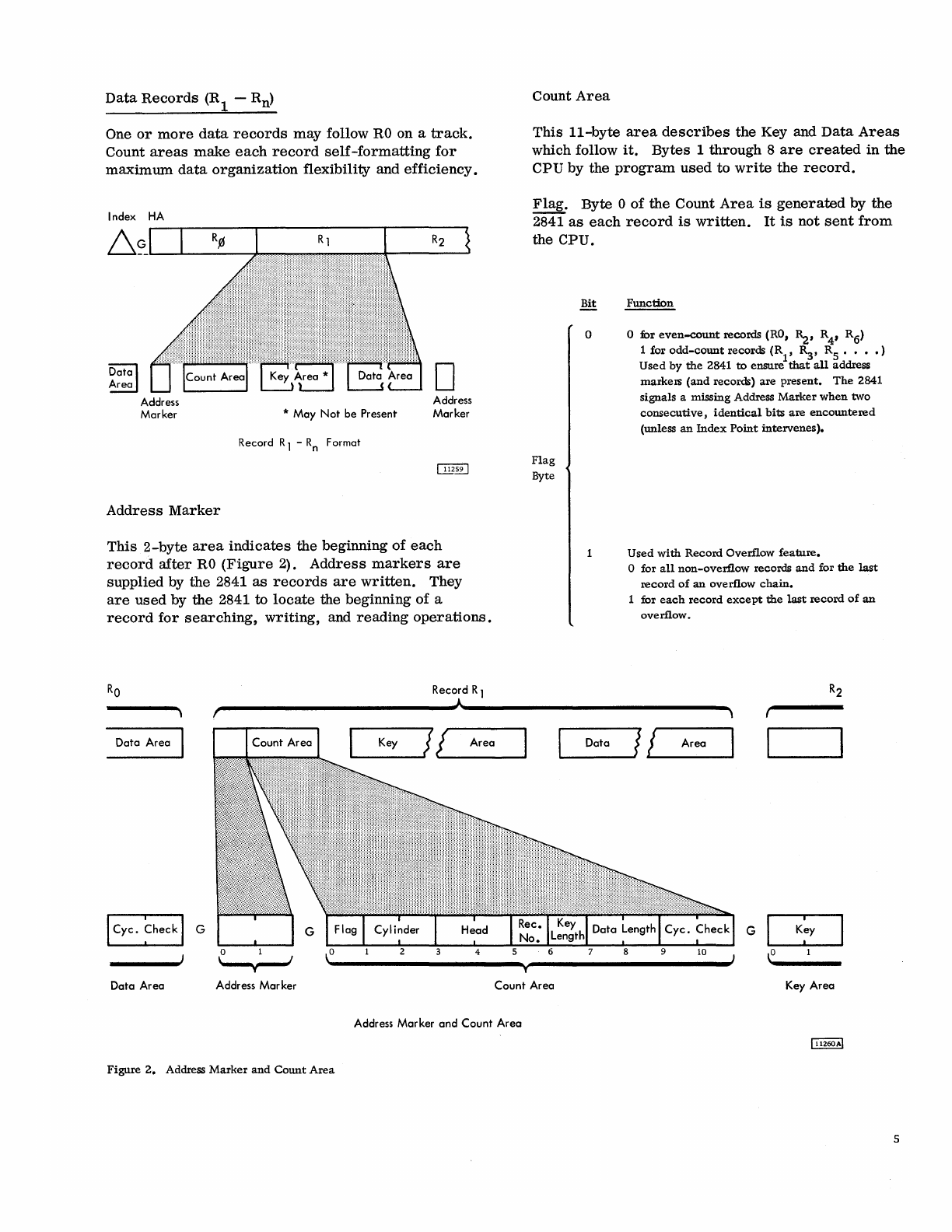
Data
Records
(R
1 -Rn)
One
or
more
data
records
may
follow
RO
on a
track.
Count
areas
make
each
record
self-formatting
for
maximum
data
organization
flexibility and
efficiency.
Index
HA
Dcrlal
~
Address
Marker
Address
Marker
* May
Not
be Present
Record R 1 -
Rn
Format
D
Address
Marker
This
2-byte
area
indicates
the
beginning
of
each
record
after
RO
(Figure
2).
Address
markers
are
supplied by
the
2841
as
records
are
written.
They
are
used
by the 2841
to
locate
the beginning of a
record
for
searching,
writing,
and
reading
operations.
Record R 1
Count
Area
This
II-byte
area
describes
the
Key and
Data
Areas
which follow
it.
Bytes
1
through
8
are
created
in
the
CPU by the
program
used
to
write
the
record.
Flag.
Byte 0
of
the
Count
Area
is
generated
by
the
2841
as
each
record
is
written.
It
is
not
sent
from
the CPU.
Flag
Byte
Bit
Function
o o for
even-count
records (RO,
~,
R4, R6)
1 for
odd-count
records
(R
1, R3,
Rs
• •
••
)
Used
by
the
2841
to
ensure
that
all
address
markers
(and
records)
are
present.
The
2841
signals a missing Address
Marker
when
two
consecutive,
identical
bits
are
encountered
(unless
an
Index
Point
intervenes).
Used
with
Record
Overflow
feature.
o for
all
non-overflow
records
and
for
the
last
record
of
an
overflow
chain.
for
each
record
except
the
last
record
of
an
overflow.
r'--------------------------~A~----------------------------~
Data Area
Data Area Address Mar ker
Figure
2.
Address
Marker
and
Count
Area
......
_K_e_Y_~J
J
Area
T
Count
Area
Address Marker
and
Count
Area
~_D_a_ta
_
_JI
~!
__
A_r_ea_~
G
Key
Area
5

~
2
3
4
5
Flag
6
Byte
7
Function
Zero
Zero
Zero
Zero
Track
Condition
0
indicates
operative
track
1
indicates
defective
track
Track
Use
o
indicates
primary
track
1
indicates
alternate
track
Bits 6
and
7
are
transmitted
to
the
flag
bytes
of
all
records
on
the
track
from
the
flag
byte
of
the
Home
Address
of
that
track
by
the
2841.
Cy
linder
Number.
Bytes
1
and
2
contain
the
cylinder
number
of
the
track
on
which
the
data
is
stored.
Read/Write
Head
Number.
Bytes
3 and 4
contain
the
read/write
head
number
of
the
track
on
which
the
data
is
stored.
Record
Number.
Byte
5
designates
the
sequential
number
of
the
record
on
the
track.
Key Length. Byte 6
specifies
the
number
of
bytes
in
the
Key
Area
of
the
record
(excluding
check
bytes).
If
the
record
has
no
key,
this
byte
is
zero.
This
byte
can
indicate
a Key Length
from
zero
to 255
bytes.
Data
Length.
Bytes
7
and
8
specify
the
number
of
bytes
in
the
Data
Area
of
the
record
(excluding
check
bytes).
Two
bytes
(16
bits)
can
indicate
Data
Length
from
1
to
65,535
bytes.
It
should
be
noted
that
maximum
data
length
is
a function
of
the
track
capacity
of
the
specific
storage
device.
See
the
description
of
the
Overflow
Feature
for
records
that
exceed
the
track
size.
6
Zero
Data
Length
indicates
the
end
of
a
logical
file.
Special
indicators
are
sent
to
the
CPU
when
an
End-of-File
record
is
read
or
written.
Cyclic
Check.
Bytes
9 and 10
are
used
for
error
detection
as
discussed
in
the
section
on
Check
Characters.
Key
Area
The Key
Area
concept
has
been
provided
in
storage
units
of the 2841
family
to allow
searching
and
data
accessing
during
a
single
disk,
drum,
or
strip
revolution.
The
Key
Area
can
contain
identifying
information
about
a
record,
such
as
serial
number,
social
security
number,
or
policy
number.
Special
commands
are
provided
to
search
Key
Areas
for
this
identifying
information.
When
the
desired
record
is
found, a
read
or
write
instruction
can
be
issued
and
the
Data
Area
read
or
written
during
the
same
revolution.
Comparison
(during
searching)
is
accomplished
within the 2841.
Thus,
use
of Key
Areas
for
search-
ing
allows
searching
and
comparing
of
keys
and
movement
of
the
desired
Data
Area
to
or
from
the
CPU
during
a
single
disk,
drum,
or
strip
revolu-
tion.
Key
Area
length
ranges
from
1
to
255
bytes.
Two
Cyclic
Check
bytes
are
added
to
the
Key
Area
by
the
2841.
If
Key Length,
in
the
Count
Area,
is
zero,
no Key
Area
will
be
written.
Data
Area
This
area
contains
the
information
identified
by
the
Count and Key
Areas.
Data
information
is
organ-
ized
and
arranged
by
the
programmer.
Two
Cyclic
Check
bytes
are
added
to
the
Data
Area
by
the
2841.
If
Data
Length
was
zero,
indica-
ting
End-of-File,
the
Data
Area
will
contain
one
byte
of
zeros
in
addition to
the
check
bytes,
however
no
data
is
transferred
to
the
channel
when
this
record
is
read.

Input/Output
(I/O)
operations
involve
the
transfer
of
information
to
or
from
CPU
storage.
Within
this
concept,
disk
and
drum
storage
drives
and
data
cell
drives
are
considered
I/O
devices.
The
CPU
program
initiates
I/O
operations
with
the
Start
I/O
instruction.
Bit
positions
24-31
of
this
instruction
identify
the
device.
Start
I/O
causes
the
channel
to
fetch
the
Channel
Address
Word
(CAW)
from
main
storage
location
72.
The
command
ad-
dress
portion
of
the
CAW
designates
the
location
in
main
storage
from
which
the
channel
subsequently
fetches
the
first
Channel
Command
Word
(CCW).
The
CCW
specifies
the
command
to
be
executed
and
the
storage
area
to
be
used.
If
the
channel
is
not
busy,
the
channel
attempts
to
select
the
device
by
sending
the
address
of
the
device
to
all
attached
control
units.
The
control
unit
specified
in
the
address
responds
to
its
selection
and
awaits
further
instructions.
The
command
code
is
sent
to
the
selected
control
unit;
the
control
unit
then
responds
with a
device
status
byte
to
the
CSW.
At
this
time,
the
start
r/o
is
terminated.
The
results
of
the
attempt
to
initiate
the
execution
of
the
command
are
indicated
by
the
condition
code
in
the
Program
Status
Word,
and,
under
certain
conditions,
by
status
bytes
in
the
Channel
Status
Word.
All
data
transfers
from
the
channel
to
the
2841
are
checked
for
parity.
If
a
parity
error
is
detected,
a
unit
check
signal
is
sent
to
the
CSW
by
the
2841
and
the
command
will
not
be
executed.
An
I/O
operation
may
involve
transfer
of
data
to
one
storage
area,
designated
by
a
single
CCW. When
data
chaining
is
specified,
data
is
transferred
to a
number
of
storage
areas.
In
each
case,
a
chain
of
CCWs
is
used,
in
which
each
CCW
designates
an
area
in
main
storage
for
a
part
of
the
operation.
The
program
can
be
notified
of
the
progress
of
chaining
by
specifying
that
the
channel
modify
the
Channel
Status
byte
upon
fetching
a new CCW. When
command
chaining
is
specified,
a
series
of
commands
is
executed.
Termination
of
an
I/O
device
operation
normally
is
indicated
by
two
CSW
conditions:
Channel
End
and
Device
End.
The
channel
end
condition
indicates
that
the
I/O
device
has
received
or
provided
all
informa-
tion
associated
with
the
operation
and no
longer
needs
channel
facilities.
The
device
end
signal
indicates
that
the
I/O
device
has
terminated
execution
of
the
operation.
The
device
end
condition
can
occur
con-
currently
with
the
channel
end
condition
or
later.
If
INPUT/OUTPUT
OPERATIONS
command
chaining
has
been
specified,
the
next
CCW
is
fetched
by
the
channel
and
the
operation
designated
is
commenced.
Unusual
conditions
and
errors
ter-
minate
the
execution
of
a
command
chain.
INSTRUCTIONS
All
I/O
instructions
use
the
following
format:
o
78
1516
1920
31
I/O
Instruction Format
Fields
in
the
instruction
are
allocated
as
follows:
Bit
Position
Field
Designation
0-7
Operation
(Op)
Code
8-15
Not
Used
16-19
20-31
Base Address
Register
Location
(B
1)
Displacement
(D 1 )
Function
Designates
the
operation
to
be
performed.
Designates
the
address
of
a
general
register
in
main
storage.
The
register
is 32
bits
in
length,
but
only
the
low
order
24
bits
are
used.
The
sum
obtained
by
the
addition
of
the
content
of
the
register
at
B1
and
content
of
the
D1
field
identifies
the
channel
and
device
addressed
by
the
instruction.
The
re-
sult
has
the
format:
2021
2324
31
7
Bit Position
Field
DesilEation
Function
0-7
Operation
(Op) Designates
the
operation
to
Code
be
perfonned.
8-20
Not
Used
21-23
Channel
Address
000
-deSignates
multiplexer
channel.
001 -110 -designates
selec-
tor
channel
1-6.
111 -
invalid
combination.
24
Shared
Channel
1
indicates
multiplex
channel
Indicator
or
sub-channel.
On
a
selec-
tor
channel,
this
bit
is
in-
cluded
in
the
control
unit
address.
25-27
Control
Unit
0-7
control
units
per
channel.
28-31
Access
Mechanism
0-7.
Bit
28
will
be
1
only
if
additional
access
feature
is
installed
(indicates
mecha-
nism
8-15).
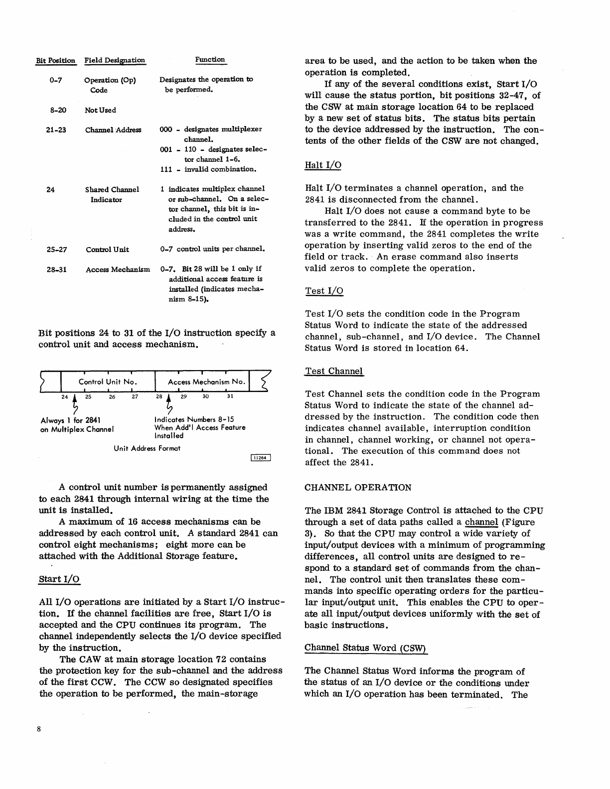
Bit
positions
24 to 31
of
the
I/O
instruction
specify
a
control
unit
and
access
mechanism.
? I
C~ntrol
~nit
N~.
24
t 2S 26
27
Always 1 for 2841
on
Multiplex
Channel
28 t 29
30
31
Indicates
Numbers
8-15
When Add'i Access
Feature
Installed
Unit
Address Format
A
control
unit
number
is
permanently
assigned
to
each
2841
through
internal
wiring
at
the
time
the
unit
is
installed.
A
maximum
of 16
access
mechanisms
can
be
addressed
by
each
control
unit. A
standard
2841
can
control
eight
mechanisms;
eight
more
can
be
attached
with
the
Additional
Storage
feature~
Start
I/O
All
I/O
operations
are
initiated
by
a
Start
I/O
instruc-
tion.
If
the
channel
facilities
are
free,
Start
I/O
is
accepted
and the CPU continues
its
program.
The
channel
independently
selects
the I/o
device
specified
by
the
instruction.
The
CAW
at
main
storage
location
72
contains
the
protection
key
for
the
sub-channel
and
the
address
of
the
first
CCW. The CCW
so
designated
specifies
the
operation
to
be
performed,
the
main-storage
8
area
to
be
used,
and the
action
to
be
taken
when
the
operation
is
completed.
If
any of the
several
conditions
exist,
Start
I/O
will
cause
the
status
portion,
bit
positions
32-47,
of
the
CSW
at
main
storage
location
64 to
be
replaced
by a new
set
of
status
bits.
The
status
bits
pertain
to the device
addressed
by
the
instruction.
The
con-
tents
of the
other
fields
of
the
CSW
are
not
changed.
Halt
I/O
Halt
I/O
terminates
a channel
operation,
and
the
2841
is
disconnected
from
the
channel.
Halt
I/O
does not
cause
a command
byte
to
be
transferred
to
the
2841.
If the
operation
in
progress
was a
write
command,
the
2841
completes
the
write
operation
by
inserting
valid
zeros
to
the end of
the
field
or
track.
An
erase
command
also
inserts
valid
zeros
to
complete
the
operation.
Test
I/O
Test
I/O
sets
the
condition code in
the
Program
Status Word to
indicate
the
state
of
the
addressed
channel,
sub-channel,
and
I/O
device.
The
Channel
Status Word
is
stored
in
location
64.
Test
Channel
Test
Channel
sets
the
condition code in
the
Program
Status Word to
indicate
the
state
of
the
channel
ad-
dressed
by
the
instruction.
The condition code
then
indicates
channel
available,
interruption
condition
in channel, channel working,
or
channel not
opera-
tional.
The execution of
this
command
does
not
affect the
2841.
CHANNEL OPERATION
The IBM 2841
Storage
Control
is
attached
to the CPU
through
a
set
of
data
paths
called
a channel
(Figure
3).
So
that
the
CPU may
control
a wide
variety
of
input/output
devices
with a
minimum
of
programming
differences,
all
control
units
are
designed
to
re-
spond to a
standard
set
of
commands
from
the
chan-
nel.
The
control
unit
then
translates
these
com-
mands
into
specific
operating
orders
for
the
particu-
1ar
input/output
unit.
This
enables
the
CPU to
oper-
ate
all
input/output
devices
uniformly
with
the
set
of
basic
instructions.
Channel Status Word
(CSW)
The Channel Status Word
informs
the
program
of
the
status
of an
I/O
device
or
the conditions
under
which an
I/O
operation
has
been
terminated.
The

System/360
CPU
Issues
I/o
Instructions
Executes Commands (CCW's)
I
NSTRUCTIO
NS
and
COMMANDS
Figure
3.
Instructions,
Commands
and
Orders
Data
Cell
Drive
CSW
is
formed,
or
parts
of
it
are
replaced,
during
I/O
interruptions
and
during
execution
of
I/O
in-
structions.
The
CSW
is
placed
in
main
storage
at
location
64.
It
is
available
to
the
program
at
this
location
until the
next
I/O
interruption
occurs
or
un-
til
another
I/O
instruction
generates
a new CSW,
whichever
occurs
first.
When the
CSW
is
stored
as
a
result
of
an
I/O
interruption,
the
I/O
device
is
identified
by
the
I/O
address
in
the
old
PSW. The
information
placed
in
the
CSW
by
an
I/O
instruction
pertains
to
the
device
addressed
by
the
instruction.
2841
Storage
Control
The
CSW
has
the
following
format:
I Key I 0000 I Command Address
0 3 4
78
I
Device
St1tus
Channel
I
Count
32
39
40
4748
I
31
I
63
Channel
Status Word
~
F.ields in the
CSW
are
allocated
for
the
following
purposes:
9
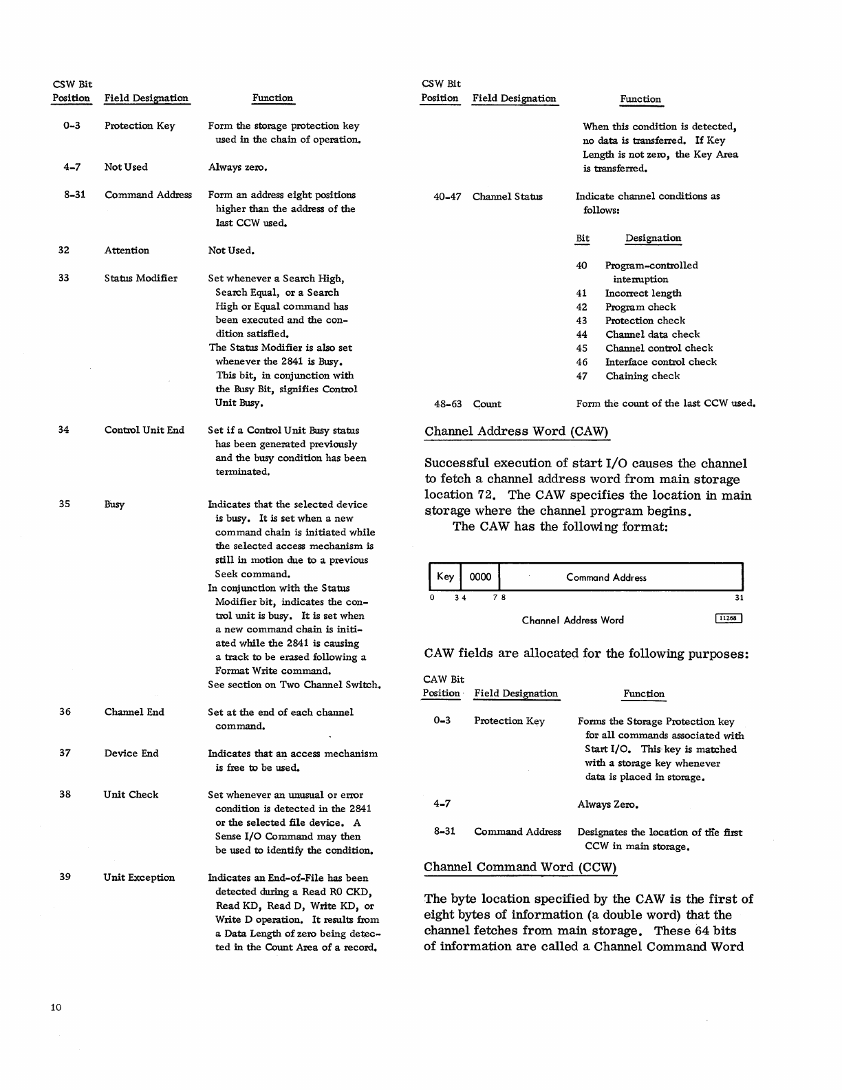
CSW
Bit
Position
Field
Designation
0-3
Protection
Key
4-7
Not
Used
Function
Form
the
storage
protection
key
used
in
the
chain
of
operation.
Always zero.
8-31
Command
Address
Form
an
address
eight
positions
32
Attention
33
Status
Modifier
34
Control
Unit
End
35
Busy
36
Channel
End
37
Device
End
38
Unit
Check
39
Unit
Exception
10
higher
than
the
address
of
the
last
CCW
used.
Not
Used.
Set
whenever
a
Search
High,
Search
Equal,
or
a
Search
High
or
Equal
command
has
been
executed
and
the
con-
dition
satisfied.
The
Status
Modifier
is
also
set
whenever
the
2841 is Busy.
This
bit,
in
conjunction
with
the
Busy Bit,
signifies
Control
Unit
Busy.
Set
if
a
Control
Unit
Busy
status
has
been
generated
previously
and
the
busy
condition
has
been
terminated.
Indicates
that
the
selected
device
is
busy.
It
is
set
when
a
new
command
chain
is
initiated
while
the
selected
access
mechanism
is
still
in
motion
due
to
a
previous
Seek
command.
In
conjunction
with
the
Status
Modifier
bit,
indicates
the
con-
trol
unit
is
busy.
It
is
set
when
a
new
command
chain
is
initi-
ated
while
the
2841 is
causing
a
track
to
be
erased
following
a
Format
Write
command.
See
section
on
Two
Channel
Switch.
Set
at
the
end
of
each
channel
command.
Indicates
that
an
access
mechanism
is
free
to
be
used.
Set
whenever
an
unusual
or
error
condition
is
detected
in
the
2841
or
the
selected
file
device.
A
Sense
1/0
Command
may
then
be
used
to
identify
the
condition.
Indicates
an
End-of-File
has
been
detected
during
a
Read
RO
CKD,
Read
KD,
Read
D,
Write
KD,
or
Write
D
operation.
It
results
from
a
Data
Length
of
zero
being
detec-
ted
in
the
Count
Area
of
a
record.
CSW
Bit
Position
Field
Designation
40-47
Channel
Status
48-63
Gount
Function
When
this
condition
is
detected,
no
data
is
transferred.
If
Key
Length
is
not
zero,
the
Key
Area
is
transferred.
Indicate
channel
conditions
as
follows:
Bit
Designation
40
Program-controlled
interruption
41 IncOlTect
length
42
Program
check
43
Protection
check
44
Channel
data
check
45
Channel
control
check
46
Interface
control
check
47
Chaining
check
Form
the
count
of
the
last
CCW
used.
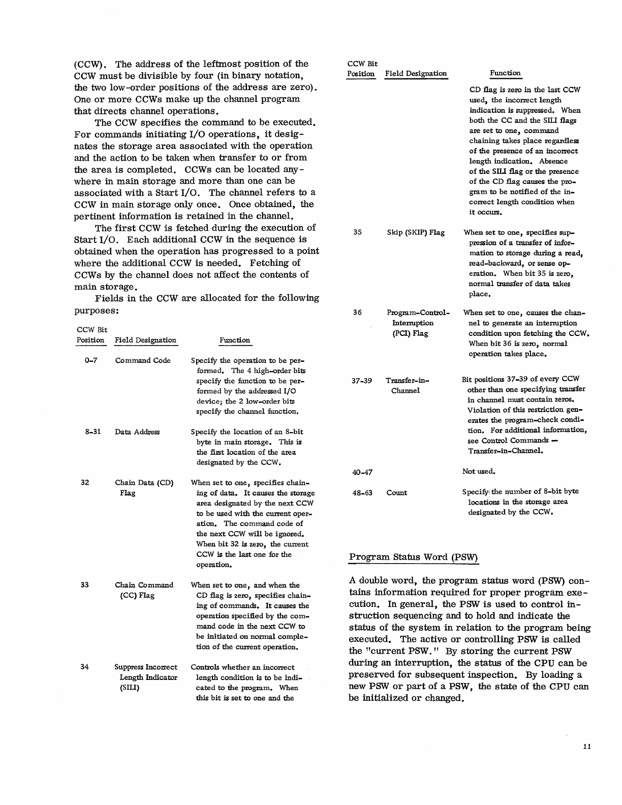
Channel
Address
Word
(CAW)
Successful
execution
of
start
I/O
causes
the
channel
to
fetch
a
channel
address
word
from
main
storage
location
72.
The
CAW
specifies
the
location
in
main
s.torage
where
the
channel
program
begins.
The
CAW
has
the
following
format:
Command Address
o
34
78
31
Channel
Address
Word
CAW
fields
are
allocated
for
the
following
purposes:
CAW Bit
Position·
Field
Designation
0-3
Protection
Key
4-7
Function
Forms
the
Storage
Protection
key
for
all
commands
associated
with
Start
1/0.
This
key
is
matched
with
a
storage
key
whenever
data
is
placed
in
storage.
Always
Zero.
8-31
Command
Address
Designates
the
lacation
of
tIie
first
CCW
in
main
storage.
Channel
Command
Word
(CCW)
The
byte
location
specified
by
the
CAW
is
the
first
of
eight
bytes
of
information
(a
double word)
that
the
channel
fetches
from
main
storage.
These
64
bits
of
information
are
called
a Channel
Command
Word
(CCW). The
address
of
the
leftmost
position
of
the
CCW
must
be
divisible
by
four
(in
binary
notation,
the two
low-order
positions
of
the
address
are
zero).
One
or
more
CCWs
make
up
the
channel
program
that
directs
channel
operations.
The CCW
specifies
the
command
to
be
executed.
For
commands
initiating
I/O
operations,
it
desig-
nates
the
storage
area
associated
with
the
operation
and
the
action
to
be
taken
when
transfer
to
or
from
the
area
is
completed.
CCWs
can
be
located
any-
where
in
main
storage
and
more
than
one
can
be
associated
with a
Start
I/O.
The channel
refers
to
a
CCW
in
main
storage
only
once.
Once obtained,
the
pertinent
information
is
retained
in
the
channel.
The
first
CCW
is
fetched
during
the execution
of
Start
I/O.
Each
additional CCW in the
sequence
is
obtained when
the
operation
has
progressed
to a
point
where
the additional CCW
is
needed.
Fetching
of
CCW
s by the channel
does
not
affect
the contents
of
main
storage.
Fields
in
the
CCW
are
allocated
for
the following
purposes:
CCW Bit
Position
Field
Designation
0-7
Command
Code
8-31
Data
Address
32
33
34
Chain
Data
(CD)
Flag
Chain
Command
(cq
Flag
Suppress
Incorrect
Length
Indicator
(SIU)
Function
Specify
the
operation
to
be
per-
formed.
The
4
high-order
bits
specify
the
function
to
be
per-
formed
by
the
addressed
I/O
device;
the
2
low-order
bits
specify
the
channel
function.
Specify
the
location
of
an
8-bit
byte
in
main
storage.
This is
the
first
location
of
the
area
designated
by
the
CCW.
When
set
to
one,
specifies
chain-
ing
of
data.
It
causes
the
storage
area
designated
by
the
next
CCW
to
be
used
with
the
current
oper-
ation.
The
command
code
of
the
next
CCW
will
be
ignored.
When
bit
32 is zero,
the
current
CCW is
the
last
one
for
the
operation.
When
set
to
one,
and
when
the
CD
flag
is
zero,
specifies
chain-
ing
of
commands.
It
causes
the
operation
specified
by
the
com-
mand
code
in
the
next
CCW
to
be
initiated
on
normal
comple-
tion
of
the
current
operation.
Controls
whether
an
incorrect
length
condition
is
to
be
indi-
cated
to
the
program.
When
this
bit
is
set
to
one
and
the
CCW Bit
Position
Field
Designation
35
Skip
(SKIP)
Flag
36
37-39
40-47
Program-Control-
Interruption
(PC!)
Flag
Transfer-in-
Channel
48-63
Count
Function
CD
flag
is zero
in
the
last
CCW
used,
the
incorrect
length
indication
is suppressed.
When
both
the
CC
and
the
SILl flags
are
set
to
one,
command
chaining
takes
place
regardless
of
the
presence
of
an
incorrect
length
indication.
Absence
of
the
SIll
flag
or
the
presence
of
the
CD
flag
causes
the
pro-
gram
to
be
notified
of
the
in-
correct
length
condition
when
it
occurs.
When
set
to
one,
specifies
sup-
pression
of
a
transfer
of
infor-
mation
to
storage
during
a
read,
read-backward,
or
sense
op-
eration.
When
bit
35 is
zero,
normal
transfer
of
data
takes
place.
When
set
to
one,
causes
the
chan-
nel
to
generate
an
interruption
condition
upon
fetching
the
CCW.
When
bit
36
is
zero,
normal
operation
takes
place.
Bit positions
37-39
of
every
CCW
other
than
one
specifying
transfer
in
channel
must
contain
zeros.
Violation
of
this
restriction
gen-
erates
the
program-check
condi-
tion.
For
additional
information,
see
Control
Commands
-
Transfer-in-Channel.
Not
used.
Specify;
the
llumber
of
8-bit
byte
locations
in
the
storage
area
designated
by
the
CCW.
Program
Status Word (PSW)
A double
word,
the
program
status
word
(PSW)
con-
tains
information
required
for
proper
program
exe-
cution.
In
general,
the
PSW
is
used
to
control
in-
struction
sequencing and to hold and
indicate
the
status
of
the
system
in
relation
to
the
program
being
executed.
The
active
or
controlling
PSW
is
called
the
"current
PSW."
By
storing
the
current
PSW
during
an
interruption,
the
status
of the CPU
can
be
preserved
for
subsequent
inspection.
By loading a
new PSW
or
part
of
a PSW, the
state
of
the
CPU
can
be
initialized
or
changed.
11
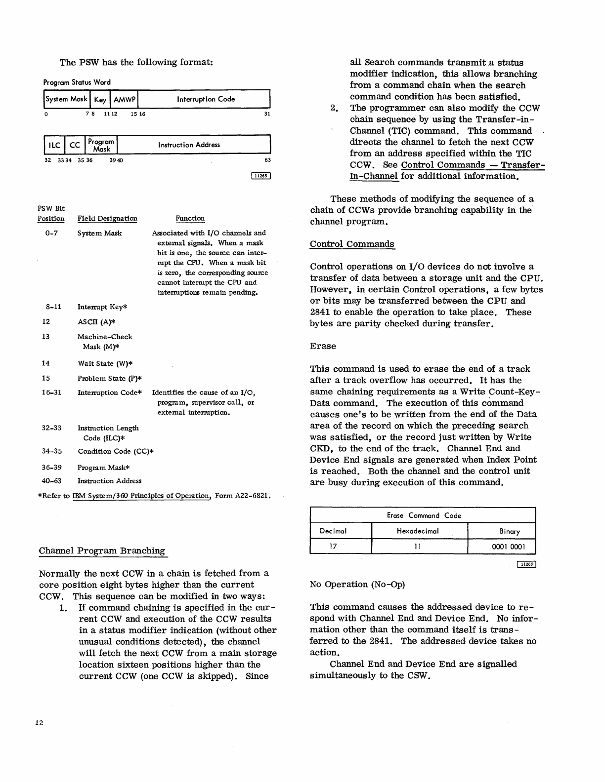
The
PSW
has
the
following
format:
Program Status Word
ISystem Mask I
Key
I AMWP\
o 7 8
1112
15
16
32.
3334
35 36
3940
PSW
Bit
Position
Field
Designation
0-7
System
Mask
8-11
Interrupt
Key*
12 ASCII (A)*
13
Machine-Check
Mask (M)*
14
Wait
State
(W)*
15
Problem
State
(P)*
16-31
Interruption
Code*
32-33
Instruction
Length
Code (ILC)*
Interruption Code
31
Instruction Address
63
Function
Associated
with
I/O
channels
and
external
signals. When a
mask
bit
is
one,
the
source
can
inter-
rupt
the
CPU. When a
mask
bit
is zero,
the
corresponding source
cannot
interrupt
the
CPU
and
interruptions
remain
pending.
Identifies
the
cause
of
an
I/O,
program,
supervisor
call,
or
external
interruption.
34-35
Condition
Code (CC)*
36-39
Program
Mask*
40-63
Instruction
Address
*Refer
to
IBM
System/360
Principles
of
Operation,
Form
A22-6821.
Channel
Program
Branching
Normally
the
next
CCW
in
a chain
is
fetched
from
a
core
position
eight
bytes
higher
than
the
current
CCW.
This
sequence
can
be
modified in two ways:
12
1.
If
command
chaining
is
specified
in
the
cur-
rent
CCW
and execution of the
CCW
results
in
a
status
modifier
indication (without
other
unusual
conditions
detected),
the channel
will
fetch
the
next
CCW
from
a
main
storage
location
sixteen
positions
higher
than
the
current
CCW
(one
CCW
is
skipped). Since
all
Search
commands
transmit.a
status
modifier
indication,
this
allows
branching
from
a command
chain
when
the
search
command condition
has
been
satisfied.
2. The
programmer
can
also
modify the
CCW
chain
sequence
by
using
the
Transfer-in-
Channel (TIC)
command.
This
command
directs
the
channel to
fetch
the
next
CCW
from
an
address
specified
within
the
TIC
CCW. See
Control
Commands
-
Transfer-
In -Channel
for
additional
information.
These
methods
of
modifying
the
sequence
of a
chain
of
CCWs
provide
branching
capability
in
the
channel
program.
Control
Commands
Control
operations
on 110
devices
do
not
involve a
transfer
of
data
between a
storage
unit
and
the
CPU.
However,
in
certain
Control
operations,
a few
bytes
or
bits
may
be
transferred
between
the CPU and
2841 to
enable
the
operation
to
take
place.
These
bytes
are
parity
checked
during
transfer.
Erase
This
command
is
used
to
erase
the
end
of a
track
after
a
track
overflow
has
occurred.
It
has
the
same
chaining
requirements
as
a
Write
Count-Key-
Data
command.
The
execution
of
this
command
causes
one's
to
be
written
from
the
end
of the
Data
area
of
the
record
on which the
preceding
search
was
satisfied,
or
the
record
just
written
by
Write
CKD, to the
end
of
the
track.
Channel End and
Device End
signals
are
generated
when Index
Point
is
reached.
Both the channel and the
control
unit
are
busy
during
execution
of
this
command.
Erase Command Code
Decimal Hexadecimal Binary
17
11
0001
0001
No
Operation
(No-Op)
This
command
causes
the
addressed
device
to
re-
spond
with
Channel End and
Device
End.
No
infor-
mation
other
than the
command
itself
is
trans-
ferred
to
the
2841. The
addressed
device
takes
no
action.
Channel
End
and Device
End
are
signalled
simultaneously
to
the
CSW.
No-Operation
Command Code
Decimal Hexadecimal Binary
03 03
00000011
Restore
This
command
is
used
with
the
2321 only,
It
causes
the
2321
to
restore
the
strip
from
the
drum
to
the
cell.
It
causes
Channel End
to
be
generated
upon
initiation
of
the
operation
by
the
Control
Unit and
Device End when
the
strip
is
fully
restored.
The
Restore
command
operates
exactly
like
a
seek
com-
mand
except
that
no
address
is
transferred
to
the
2841.
A
Restore
command
is
not
restricted
by
the
file
protect
mask.
Any
device
other
than
a 2321
performs
a No-op when a
Restore
command
is
given.
Restore Command Code
Decimal Hexadecimal Binary
23
17
00010111
Recalibrate
This
command
is
used
with
the
2311 only.
It
causes
the
2311 to
seek
to
head
zero
and
track
zero.
It
causes
Channel End
to
be
generated
immediately
and Device End to
be
generated
when
the
operation
is
complete.
Any
device
other
than
a 2311
performs
a No-op when a
Recalibrate
command
is
given. A
Recalibrate
command
works
under
the
same
File
Protect
Mask
as
a
Cylinder
Seek
command.
Reca
librate· Command Code
Decimal H exadec i
ma
I Binary
19
13
0001 0011
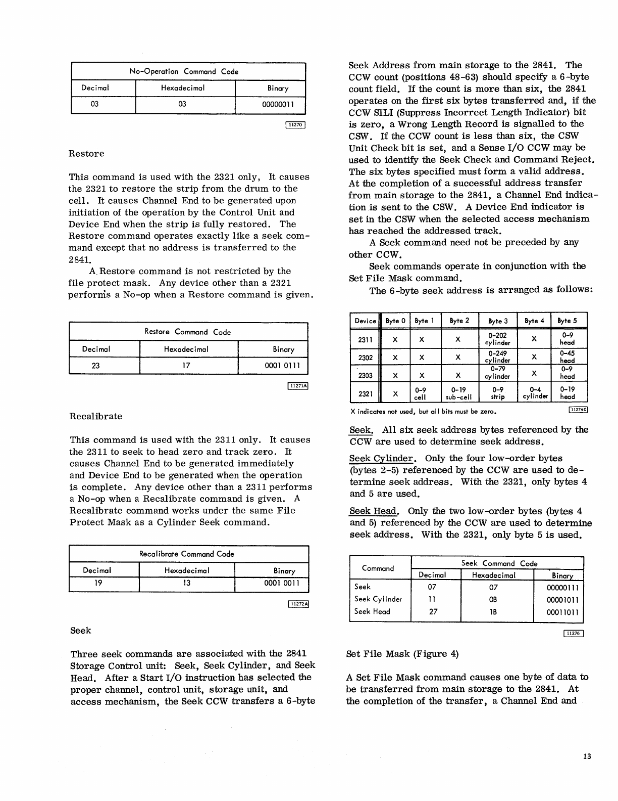
Seek
Three
seek
commands
are
associated
with
the
2841
Storage
Control
unit:
Seek,
Seek
Cylinder,
and Seek
Head.
After
a
Start
I/O
instruction
has
selected
the
proper
channel,
control
unit,
storage
unit, and
access
mechanism,
the
Seek
CCW
transfers
a
6-byte
Seek
Address
from
main
storage
to
the
2841.
The
CCW
count
(pOSitions 48-63)
should
specify
a
6-byte
count
field.
If
the
count
is
more
than
six,
the
2841
operates
on the
first
six
bytes
transferred
and,
if
the
CCW SILl
(Suppress
Incorrect
Length
Indicator)
bit
is
zero,
a
Wrong
Length
Record
is
signalled
to
the
CSW.
If
the
CCW count
is
less
than
six,
the
CSW
Unit
Check
bit
is
set,
and a
Sense
I/O
CCW
may
be
used
to identify
the
Seek
Check
and
Command
Reject.
The
six
bytes
specified
must
form
a
valid
address.
At
the
completion
of
a
successful
address
transfer
from
main
storage
to
the
2841, a Channel End
indica-
tion
is
sent
to
the
CSW. A
Device
End
indicator
is
set
in
the
CSW
when the
selected
access
mechanism
has
reached
the
addressed
track.
A Seek
command
need
not
be
preceded
by any
other
CCW.
Seek
commands
operate
in
conjunction
with
the
Set
File
Mask
command.
The
6-byte
seek
address
is
arranged
as
follows:
Device Byte 0 Byte 1 Byte 2 Byte 3
Byte
4 Byte 5
2311
X X X 0-202 X
0-9
cylinder head
2302 X X X 0-249 X 0-45
cylinder head
0-79 X
0-9
2303
X X X cylinder head
2321
X
0-9
0-19
0-9
0-4
0-19
cell sub-cell strip cylinder head
X indicates not used, but all bits
must
be
zero.
Seek.
All
six
seek
address
bytes
referenced
by
the
cCW
are
used
to
determine
seek
address.
Seek
Cylinder.
Only
the
four
low-order
bytes
(bytes 2-5)
referenced
by the CCW
are
used
to
de-
termine
seek
address.
With
the
2321, only
bytes
4
and 5
are
used.
Seek Head. Only the two
low-order
bytes
(bytes 4
and
5)
referenced
by
the
CCW
are
used
to
determine
seek
address.
With
the
2321, only
byte
5
is
used.
Command Seek Command Code
Decimal Hexadecimal Binary
Seek 07
07
00000111
Seek Cylinder
11
OB
00001011
Seek Head
27
1B
00011011
Set
File
Mask
(Figure
4)
A
Set
File
Mask
command
causes
one
byte
of
data
to
be
transferred
from
main
storage
to
the
2841.
At
the
completion
of
the
transfer,
a Channel
End
and
13
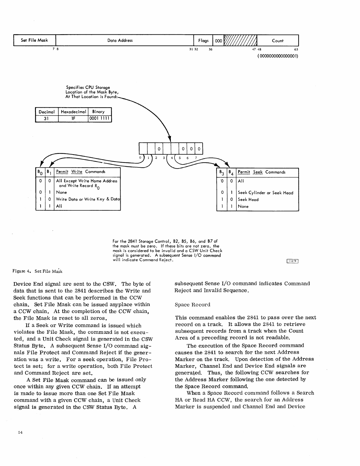
Set
File
Mask
BO
0
0
0
7 8
Data
Address
Specifies
CPU
Storage
Location
of
the
Mask
Byte,
At
That
Location
is
Found:
Permit
Write
Commands
All Except
Write
Home Address
and
Write
Record
RO
None
Write
Data
or
Write
Key
&
Data
All
31 32
Count
36
47
48 63
( 0000000000000001)
B3
B4
Permit
Seek
Commands
·0
0 All
0
Seek
Cylinder
or
Seek
Head
0
Seek
Head
None
For
the
2841
Storage
Control,
B2, B5, B6,
and
B7
of
the
mask must
be
zero.
If
these
bits
are
not
zero,
the
mask
is
considered
to
be
invalid
and
a CSW
Unit
Check
signal
is
generated.
A
subsequent
Sense
I/O
command
will
indicate
Command
Reject.
Figure
4.
Set
File
Ma;k
Device
End
signal
are
sent
to
the
CSW.
The
byte
of
data
that
is
sent
to
the
2841
describes
the
Write
and
Seek
functions
that
can
be
performed
in
the
CCW
chain.
Set
File
Mask
can
be
issued
anyplace
within
a CCW
chain.
At
the
completion
of
the
CCW
chain,
the
File
Mask
is
reset
to
all
zeros.
If
a
Seek
or
Write
command
is
issued
which
violates
the
File
Mask,
the
command
is
not
execu-
ted,
and a
Unit
Check
signal
is
generated
in
the
CSVil
Status
Byte.
A
subsequent
Sense
I/O
command
sig-
nals
File
Protect
and
Command
Reject
if
the
gener-
ation
was
a
write.
For
a
seek
operation,
File
Pro-
tect
is
set;
for
a
write
operation,
both
File
Protect
and
Command
Reject
are
set.
A
Set
File
Mask
command
can
be
issued
only
once
within
any
given
CCW
chain.
If
an
attempt
is
made
to
issue
more
than
one
Set
File
Mask
command
with
a
given
CCW
chain,
a Unit
Check
signal
is
generated
in
the
CSW
Status
Byte.
A
14
subsequent
Sense
I/O
command
indicates
Command
Reject
and
Invalid
Sequence.
Space
Record
This
command
enables
the
2841
to
pass
over
the
next
record
on
a
track.
It
allows
the
2841
to
retrieve
subsequent
records
from
a
track
when
the
Count
Area
of
a
preceding
record
is
not
readable.
The
execution
of
the
Space
Record
command
causes
the
2841
to
search
for
the
next
Address
Marker
on
the
track.
Upon
detection
of
the
Address
Marker,
Channel
End
and
Device
End
signals
are
genera~ed.
Thus,
the
following CCW
searches
for
the
Address
Marker
following
the
one
detected
by
the
Space
Record
command.
When a Space
Record
command
follows a
Search
HA
or
Read
HA
CCW
~
the
search
for
an
Address
Marker
is
suspended
and
Channel
End and
Device
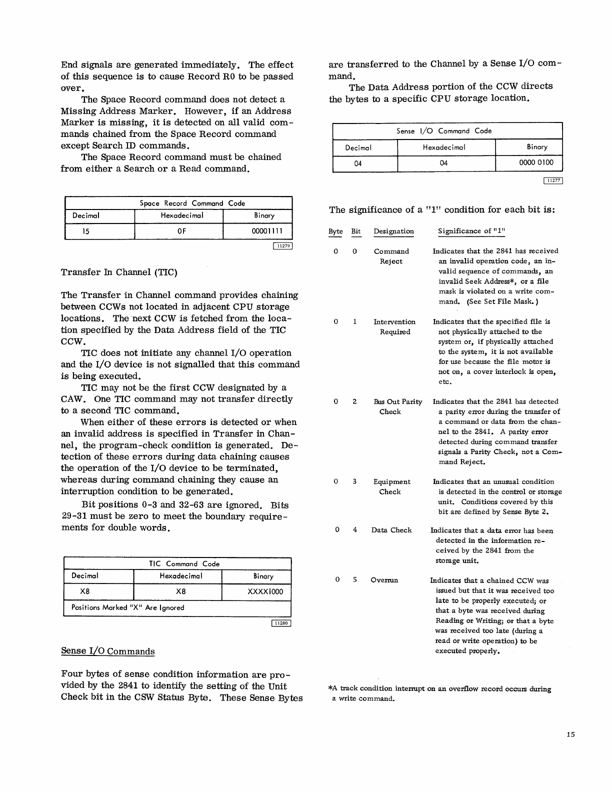
End
signals
are
generated
immediately.
The
effect
of
this
sequence
is
to
cause
Record
RO
to
be
passed
over.
The
Space
Record
command
does
not
detect
a
Missing
Address
Marker.
However,
if
an
Address
Marker
is
missing,
it
is
detected
on
all
valid
com-
mands
chained
from
the
Space
Record
command
except
Search
ID
commands.
The
Space
Record
command
must
be
chained
from
either
a
Search
or
a
Read
command.
Space Record Command Code
Decimal Hexadecimal Binary
15
OF
00001111
Transfer
In
Channel (TIC)
The
Transfer
in
Channel
command
provides
chaining
between
CCWs
not
located
in
adjacent
CPU
storage
locations.
The
next
CCW
is
fetched
from
the
loca-
tion
specified
by
the
Data
Address
field
of the TIC
CCW.
TIC
does
not
initiate
any
channel
I/O
operation
and
the
I/O
device
is
not
signalled
that
this
command
is
being
executed.
TIC
may
not
be
the
first
CCW
designated
by a
CAW. One TIC
command
may
not
transfer
directly
to
a
second
TIC
command.
When
either
of
these
errors
is
detected
or
when
an
invalid
address
is
specified
in
Transfer
in
Chan-
nel,
the
program-check
condition
is
generated.
De-
tection
of
these
errors
during
data
chaining
causes
the
operation
of
the
I/O
device
to
be
terminated,
whereas
during
command
chaining
they
cause
an
interruption
condition
to
be
generated.
Bit
positions
0-3
and 32-63
are
ignored.
Bits
29-31
must
be
zero
to
meet
the
boundary
require-
ments
for
double
words.
TIC Command Code
Decimal Hexadecimal Binary
X8
X8
XXXXIOOO
Positions
Marked
"X"
Are
Ignored
Sense
I/O
Commands
Four
bytes
of
sense
condition
information
are
pro-
vided
by
the
2841
to
identify
the
setting
of
the
Unit
Check
bit
in
the
CSW
Status
Byte.
These
Sense
Bytes
are
transferred
to
the
Channel
by
a
Sense
I/O
com-
mand.
The
Data
Address
portion
of
the
CCW
directs
the
bytes
to a
specific
CPU
storage
location.
Sense
I/o Command Code
Decimal H exadec i
ma
I Binary
04 04
0000 0100
The
significance
of
a
"1"
condition
for
each
bit
is:
Byte Bit
Designation
o o
o
0 2
0 3
0 4
0 5
Command
Reject
Intervention
Required
Bus
Out
Parity
Check
Equipment
Check
Data
Check
Overrun
Significance
of
"1"
Indicates
that
the
2841
has
received
an
invalid
operation
code,
an
in-
valid
sequence
of
commands,
an
invalid
Seek
Address*,
or
a
file
mask
is
violated
on
a
write
com-
mand.
(See
Set
File
Mask.
)
Indicates
that
the
specified
file
is
not
physically
attached
to
the
system
or,
if
physically
attached
to
the
system,
it
is
not
available
for
use
because
the
file
motor
is
not
on,
a
cover
interlock
is
open,
etc.
Indicates
that
the
2841
has
detected
a
parity
error
during
the
transfer
of
a
command
or
data
from
the
chan-
nel
to
the
2841.
A
parity
error
detected
during
command
transfer
signals
a
Parity
Check,
not
a
Com
...
mand
Rej
ect.
Indicates
that
an
unusual
condition
is
detected
in
the
control
or
storage
unit.
Conditions
covered
by
this
bit
are
defined
by
Sense
Byte
2.
Indicates
that
a
data
error
has
been
detected
in
the
information
re-
ceived
by
the
2841
from
the
storage
unit.
Indicates
that
a
chained
CCW
was
issued
but
that
it
was
received
too
late
to
be
properly
executed;
or
that
a
byte
was
received
during
Reading
or
Writing;
or
that
a
byte
was
received
too
late
(during
a
read
or
write
operation)
to
be
executed
properly.
*A
track
condition
interrupt
on
an
overflow
record
occurs
during
a
write
command.
15
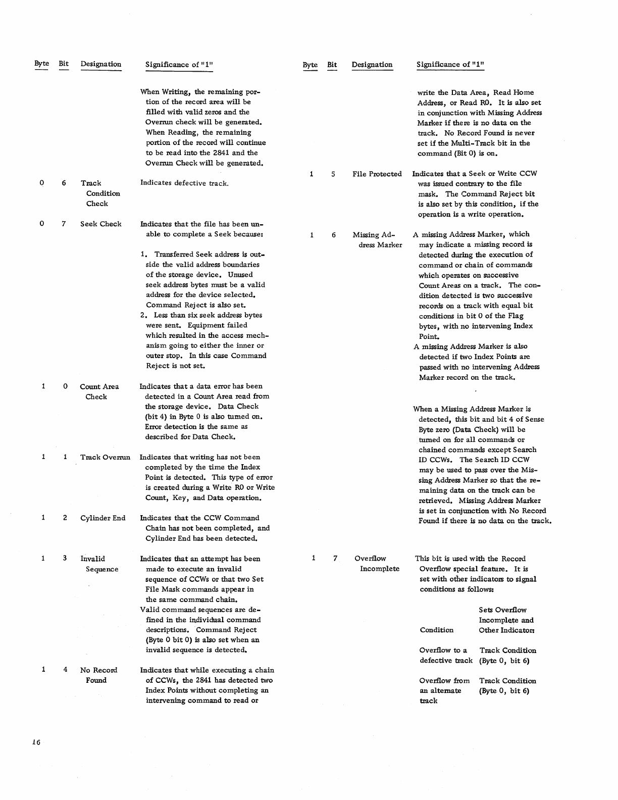
Byte Bit
Designation
Significance
of
11111
o 6
o 7
o
2
3
4
16
Track
Condition
Check
Seek
Check
Count
Area
Check
When
Writing,
the
remaining
por-
tion
of
the
record
area
will
be
filled
with
valid
zeros
and
the
Overrun
check
will
be
generated.
When
Reading,
the
remaining
portion
of
the
record
will
continue
to
be
read
into
the
2841
and
the
Overrun
Check
will
be
generated.
Indicates
defective
track.
Indicates
that
the
file
has
been
un-
able
to
complete
a
Seek
because:
1.
Transferred
Seek
address is
out-
side
the
v.!lid address
boundaries
of
the
storage
device.
Unused
seek
address bytes
must
be
a
valid
address for
the
device
selected.
Command
Rej
ect
is
also
set.
2.
Less
than
six
seek
address
bytes
were
sent.
Equipment
failed
which
resulted
in
the
access
mech-
anism
going
to
either
the
inner
or
outer
stop.
In
this
case
Command
Rej
ect
is
not
set.
Indicates
that
a
data
error
has
been
detected
in
a
Count
Area
read
from
the
storage
device.
Data
Check
(bit
4)
in
Byte 0 is
also
tumed
on.
Error
detection
is
the
same
as
described
for
Data
Check.
Track
Overrun
Indicates
that
writing
has
not
been
completed
by
the
time
the
Index
Point
is
detected.
This
type
of
error
is
created
during a
Write
RO
or
Write
Count,
Key,
and
Data
operation.
Cylinder
End
Invalid
Sequence
No
Record
Found
Indicates
that
the CCW
Command
Chain
has
not
been
completed,
and
Cylinder
End has
been
detected.
Indicates
that
an
attempt
has
been
made
to
execute
an
invalid
sequence
of
CCWs
or
that
two
Set
File
Mask
commands
appear
in
the
same
command
chain.
Valid
command
sequences
are
de-
fined
in
the
individual
command
descriptions.
Command
Rej
ect
(Byte 0
bit
0)
is
also
set
when
an
invalid
sequence
is
detected.
Indicates
that
while
executing
a
chain
of
CCWs,
the
2841
has
detected
two
Index
Points
without
completing
an
intervening
command
to
read
or
Byte Bit
Designation
Significance
of
11111
write
the
Data
Area,
Read
Home
Address,
or
Read
RO.
It
is
also
set
in
conjunction
with
Missing Address
Marker
if
there
is
no
data
on
the
track.
No
Record
Found
is
never
set
if
the
Multi-Track
bit
in
the
command
(Bit
0)
is
on.
5
File
Protected
Indicates
that
a
Seek
or
Write
CCW
6
7
was issued
contrary
to
the
file
mask.
The
Command
Reject
bit
is
also
set
by
this
condition,
if
the
operation
is a
write
operation.
Missing
Ad-
A missing Address
Marker,
which
dress
Marker
may
indicate
a missing
record
is
detected
during
the
execution
of
command
or
chain
of
commands
which
operates
on
successive
Count
Areas
on
a
track.
The
con-
dition
detected
is two
successive
records
on
a
track
with
equal
bit
conditions
in
bit
0
of
the
Flag
bytes,
with
no
intervening
Index
Point.
Overflow
Incomplete
A
missing
Address
Marker
is
also
detected
if
two
Index
Points
are
passed
with
no
intervening
Address
Marker
record
on
the
track.
When
a Missing Address
Marker
is
detected,
this
bitand
bit
4
of
Sense
Byte zero
(Data
Check)
will
be
tumed
on
for
all
commands
or
chained
commands
except
Search
ID CCWs.
The
Search
ID
CCW
may
be
used
to
pass
over
the
Mis-
sing
Address
Marker
so
that
the
re-
maining
data
on
the
track
can
be
retrieved.
Missing Address
Marker
is
set
in
conjunction
with
No
Record
Found
if
there
is
no
data
on
the
track.
This
bit
is
used
with
the
Record
Overflow
special
feature.
It
is
set
with
other
indicators
to
signal
conditions
as follows:
Condition
Sets
Overflow
Incomple.te
and
Other
Indicator:
Overflow
to
a
Track
Condition
defective
track
(Byte
0,
bit
6)
Overflow
from
an
alternate
track
Track
Condition
(Byte
0,
bit
6)
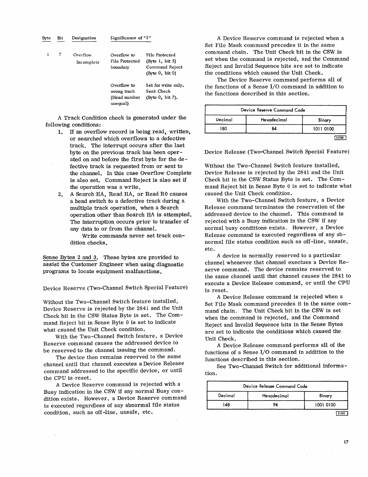
Byte Bit
Designation
Significance
of
"1
II
7 Overflow
Overflow
to
File
Protected
Incomplete
File
Protected
(Byte
1,
bit
5)
boundary
Command
Rej
ect
(Byte
0,
bit
0)
Overflow
to
Set
for
write
only.
wrong
track
Seek
Check
(Head
number
(Byte
0,
bit
7).
unequal)
A
Track
Condition
check
is
generated
under
the
following
conditions:
1.
If
an
overflow
record
is
being
read,
written,
or
searched
which
overflows
to a
defective
track.
The
interrupt
occurs
after
the
last
byte
on
the
previous
track
has
been
oper-
ated
on
and
before
the
first
byte
for
the
de-
fective
track
is
requested
from
or
sent
to
the
channel.
In
this
case
Overflow
Complete
is
also
set.
Command
Reject
is
also
set
if
the
operation
was
a
write.
2. A
Search
HA,
Read
HA,
or
Read
RO
causes
a
head
switch
to
a
defective
track
during
a
multiple
track
operation,
when
a
Search
operation
other
than
Search
HA
is
attempted.
The
interruption
occurs
prior
to
transfer
of
any
data
to
or
from
the
channel.
Write
commands
never
set
track
con-
dition
checks.
Sense
Bytes
2 and 3.
These
bytes
are
provided
to
assist
the
Customer
Engineer
when
using
diagnostic
programs
to
locate
equipment
malfunctions.
Device
Reserve
(Two-Channel Switch
Special
Feature)
Without
the
Two-Channel
Switch
feature
installed,
Device
Reserve
is
rejected
by
the
2841 and
the
Unit
Check
bit
in
the
CSW
Status
Byte
is
set.
The
Com-
mand
Reject
bit
in
Sense
Byte
0
is
set
to
indicate
what
caused
the
Unit Check
condition.
With
the
Two-Channel
Switch
feature,
a
Device
Reserve
command
causes
the
addressed
device
to
be
reserved
to
the
channel
issuing
the
command.
The
device
then
remains
reserved
to
the
same
channel
until
that
channel
executes
a
Device
Release
command
addressed
to
the
specific
device,
or
until
the
CPU
is
.reset.
A
Device
Reserve
command
is
rejected
with
a
Busy
indication
in
the
CSW
if
any
normal
Busy
con-
dition
exists.
However,
a
Device
Reserve
command
is
executed
regardless
of
any
abnormal
file
status
condition,
such
as
off-line,
unsafe,
etc.
A
Device
Reserve
command
is
rejected
when a
Set
File
Mask
command
precedes
it
in
the
same
command
chain.
The
Unit Check
bit
in
the
CSW
is
set
when
the
command
is
rejected,
and
the
Command
Reject
and
Invalid
Sequence
bits
are
set
to
indicate
the
conditions
which
caused
the
Unit
Check.
The
Device
Reserve
command
performs
all
of
the
functions of a
Sense
I/O
command
in
addition
to
the
functions
described
in
this
section.
Device
Reserve
Command Code
l>ecimal Hexadecimal Binary
180
54
1011
0100
Device
Release
(Two-Channel Switch
Special
Feature)
Without
the
Two-Channel
Switch
feature
installed,
Device
Release
is
rejected
by
the
2841
and
the
Unit
Check
bit
in
the
CSW
Status
Byte
is
set.
The
Com-
mand
Reject
bit
in
Sense
Byte
0
is
set
to
indicate
what
caused
the
Unit Check
condition.
With
the
Two-Channel
Switch
feature,
a
Device
Release
command
terminates
the
reservation
of
the
addressed
device
to
the
channel.
This
command
is
rej
ected
with
a
Busy
indication
in
the
CSW
if
any
normal
busy
conditions
exists.
However,
a
Device
Release
command
is
executed
regardless
of any
ab-
normal
file
status
condition
such
as
off-line,
unsafe,
etc.
A
device
is
normally
reserved
to
a
particular
channel
whenever
that
channel
exectues
a
Device
Re-
serve
command.
The
device
remains
reserved
to
the
same
channel
until
that
channel
causes
the
2841
to
execute
a
Device
Release
command,
or
until
the
CPU
is
reset.
A
Device
Release
command
is
rejected
when a
Set
File
Mask
command
precedes
it
in
the
same
com-
mand
chain.
The
Unit
Check
bit
in
the
CSW
is
set
when
the
command
is
rejected,
and
the
Command
Reject
and
Invalid
Sequence
bits
in
the
Sense
Bytes
are
set
to
indicate
the
conditions
which
caused
the
Unit
Check.
A
Device
Release
command
performs
all
of
the
functions of a
Sense
I/O
command
in
addition
to
the
functions
described
in
this
section.
See
Two-Channel
Switch
for
additional
informa-
tion.
Device
Release
Command Code
Decimal Hexadecimal Binary
148
94
1001
0100
17
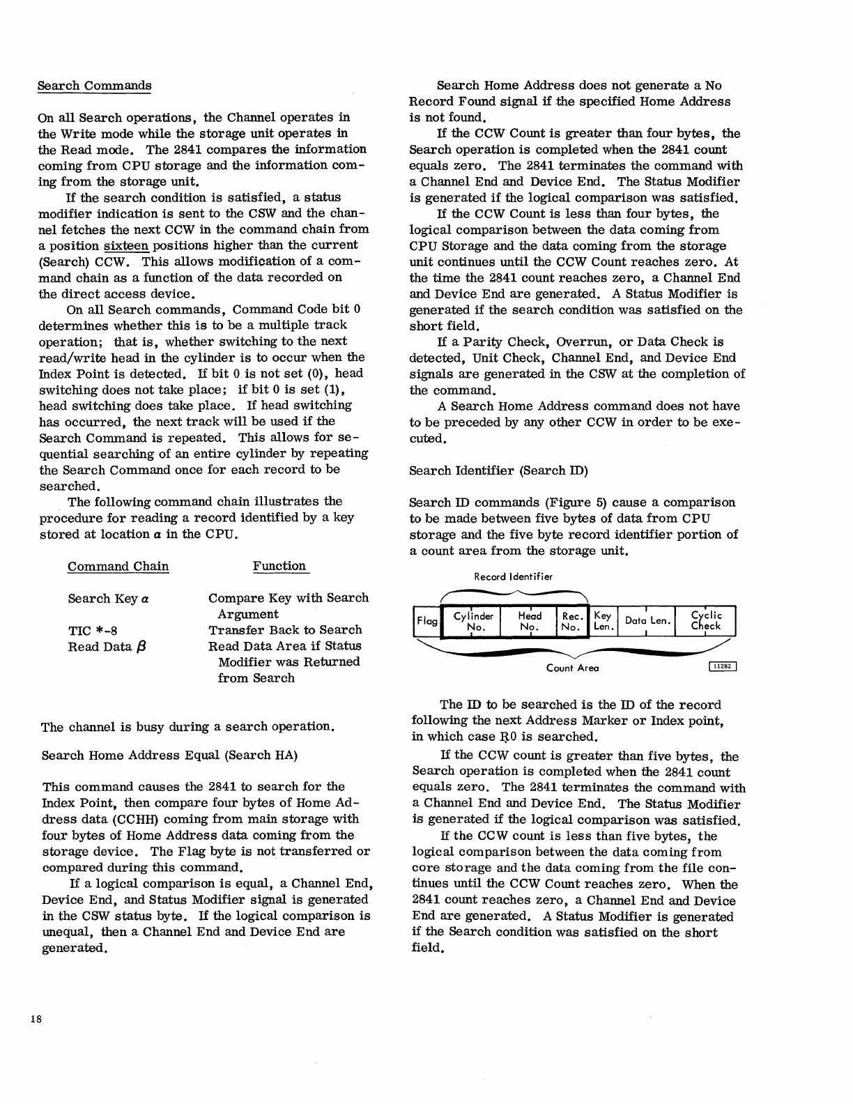
Search
Commands
On
all
Search
operations,
the
Channel
operates
in
the
Write
mode while
the
storage
unit
operates
in
the
Read
mode. The 2841
compares
the
information
coming
from
CPU
storage
and the
information
com-
ing
from
the
storage
unit.
If
the
search
condition
is
satisfied,
a
status
modifier
indication
is
sent
to
the
CSW
and
the
chan-
nel
fetches
the
next
CCW
in
the command
chain
from
a
position
sixteen
positions
higher
than
the
current
(Search) CCW.
This
allows modification
of
a
com-
mand
chain
as
a function of
the
data
recorded
on
the
direct
access
device.
On
all
Search
commands,
Command Code
bit
0
determines
whether
this
is
to
be
a multiple
track
operation;
that
is,
whether
switching
to
the
next
read/write
head
in
the
cylinder
is
to
occur
when the
Index
Point
is
detected.
If
bit
O.
is
not
set
(0),
head
switching
does
not
take
place;
if
bit
0
is
set
(1),
head
switching
does
take
place.
If
head switching
has
occurred,
the
next
track
will
be
used
if
the
Search
Command
is
repeated.
This
allows
for
se-
quential
searching
of
an
entire
cylinder
by
repeating
the
Search
Command once
for
each
record
to
be
searched.
The following command
chain
illustrates
the
procedure
for
reading
a
record
identified by a key
stored
at
location
a
in
the
CPU.
Command
Chain
Search
Key a
TIC
*-8
Read
Data
f3
Function
Compare
Key with
Search
Argument
Transfer
Back
to
Search
Read
Data
Area
if
Status
Modifier
was
Returned
from
Search
The channel
is
busy
during
a
search
operation.
18
Search
Home
Address
Equal
(Search
HA)
This
command
causes
the 2841 to
search
for
the
Index
Point,
then
compare
four
bytes
of
Home
Ad-
dress
data
(CCHH) coming
from
main
storage
with
four
bytes
of Home
Address
data
coming
from
the
storage
device.
The
Flag
byte
is
not
transferred
or
compared
during
this
command.
If
a
logical
comparison
is
equal,
a Channel End,
Device
End,
and
Status
Modifier signal
is
generated
in
the
CSW
status
byte.
If
the
logical
comparison
is
lUlequal,
then
a Channel End and Device End
are
generated.
Search
Home
Address
does
not
generate
a
No
Record
Found
signal
if
.the
specified
Home
Address
is
not
found.
If
the CCW Count
is
greater
than
four
bytes,
the
Search
operation
is
completed when the 2841 count
equals
zero.
The
2841
terminates
the
command
with
a Channel End and Device
End.
The
Status
Modifier
is
generated
if
the
logical
comparison
was
satisfied.
If
the CCW Count
is
less
than
four
bytes,
the
logical
comparison
between the
data
coming
from
CPU
Storage
and the
data
coming
from
the
storage
unit
continues
until
the CCW Count
reaches
zero.
At
the
time
the
2841 count
reaches
zero,
a Channel End
and Device End
are
generated.
A Status
Modifier
is
generated
if
the
search
condition
was
satisfied
on
the
short
field.
If
a
Parity
Check,
Overrun,
or
Data
Check
is
detected,
Unit Check, Channel End, and Device End
signals
are
generated
in the
CSW
at
the
completion of
the
command.
A
Search
Home
Address
command
does
not
have
to
be
preceded
by any
other
CCW
in
order
to
be
exe-
cuted.
Search
Identifier
(Search
ID)
Search
ID
commands
(Figure
5)
cause
a
comparison
to
be
made
between
five
bytes
of
data
from
CPU
storage
and the five byte
record
identifier
portion
of
a count
area
from
the
storage
unit.
Record
Identifier
--------~~------
----
....
---~-----------
Count
Area
~
The ID to
be
searched
is
the
ID
of
the
record
following the
next
Address
Marker
or
Index point,
in
which
case
ij.0
is
searched.
If
the
CCW count
is
greater
than
five
bytes,
the
Search
operation
is
completed when the 2841
count
equals
zero.
The
2841
terminates
the
command
with
a Channel End and Device End. The Status Modifier
is
generated
if
the
logical
comparison
was
satisfied.
If
the
CCW count
is
less
than
five
bytes,
the
logical
comparison
between
the
data
coming
from
core
storage
and
the
data
coming
from
the
file
con-
tinues
until the CCW
COlUlt
reaches
zero.
When the
2841 count
reaches
zero,
a Channel End and Device
End
are
generated.
A
Status
Modifier
is
generated
if
the
Search
condition
was
satisfied
on the
short
field.
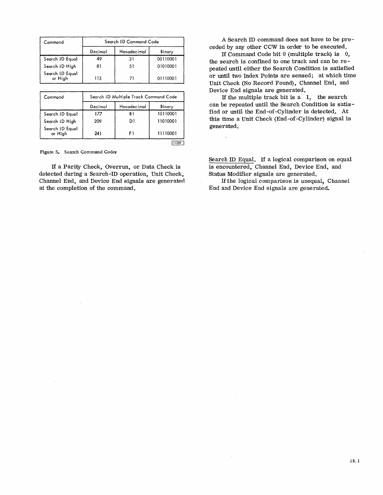
Command Search I D Command Code
Decimal Hexadecimal Binary
Search
ID
Equal 49
31
00110001
Search I D
High
81
51
01010001
Search I D Equal
or
High
113
71
01110001
Command Search ID
Multiple
Track Command Code
Decimal Hexadecimal Binary
Search I D
Equa
I
177
B1
10110001
Search
ID
High 209
D1
11010001
Search I D Equal
or
High
241
F 1 11110001
Figure
5.
Search
Command
Codes
If
a
Parity
Check,
Overrun,
or
Data
Check
is
detected
during
a
Search-ID
operation,
Unit
Check,
Channel
End,
and
Device
End
signals
are
generated
at
the
completion
of
the
command.
A
Search
ID
command
does
not
have
to
be
pre-
ceded
by
any
other
CCW
in
order
to
be
executed.
If
Command
Code
bit
°
(multiple
track)
is
0,
the
search
is
confined
to
one
track
and
can
be
re-
peated
until
either
the
Search
Condition
is
satisfied
or
until two
Index
Points
are
sensed;
at
which
time
Unit
Check
(No
Record
Found),
Channel
End,
and
Device
End
signals
are
generated.
If
the
multiple
track
bit
is
a 1,
the
search
can
be
repeated
until
the
Search
Condition
is
satis-
fi~d
or
until
the
End-of-Cylinder
is
detected.
At
this
time
a
Unit
Check
(End-of-Cylinder)
signal
is
generated.
Search
ID
Equal.
If
a
logical
comparison
on
equal
is
encountered,
Channel
End,
Device
End,
and
Status
Modifier
signals
are
generated.
If
the
logical
comparison
is
unequal,
Channel
End
and
Device
End
signals
are
generated.
18. 1
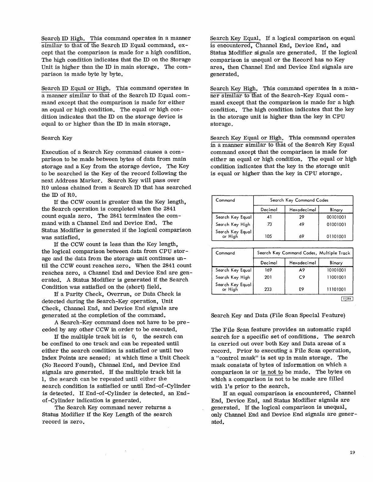
Searcl;t. ID High.
This
command
operates
in a
manner
similar
to
that
of
the
Search
ID Equal
command,
ex-
cept
that
the
comparison
is
made
for
a high condition.
The
high condition
indicates
that
the
ID
on
the
Storage
Unit
is
higher
than
the
ID
in
main
storage.
The
com-
parison
is
made
byte by
byte.
Search
ID
Equal
or
High.
This
command
operates
in
a
manner
similar
to
that
of
the
Search
ID
Equal
com-
mand
except
that
the
comparison
is
made
for
either
an
equal
or
high
condition. The
equal
or
high
con-
dition
indicates
that
the
ID
on
the
storage
device
is
equal
to
or
higher
than
the
ID
in
main
storage.
Search
Key
Execution
of
a
Search
Key
command
causes
a
com-
parison
to
be
made
between
bytes
of
data
from
main
storage
and a Key
from
the
storage
device.
The Key
to
be
searched
is
the
Key of
the
record
following
the
next
Address
Marker.
Search
Key
will
pass
over
RO
unless
chained
from
a
Search
ID
that
has
searched
the
ID
of
RO.
If
the
CCW
countis
greater
than
the
Key length,
the
Search
operation
is
completed
when
the
2841
count
equals
zero.
The
2841
terminates
the
com-
mand
with
a Channel End and Device End. The
Status
Modifier
is
generated
if
the
logical
comparison
was
satisfied.
If
the
CCW count
is
less
than
the
Key
length,
the
logical
comparison
between
data
from
CPU
stor-
age and the
data
from
the
storage
unit
continues
un-
til
the
CCW
count
reaches
zero.
When
the
2841 count
reaches
zero,
a Channel End and
Device
End
are
gen-
erated.
A
Status
Modifier
is
generated
if the
Search
Condition
was
satisfied
on
the
(short)
field.
If a
Parity
Check,
Overrun,
or
Data
Check
is
detected
during
the
Search
-Key
operation,
Unit
Check,
Channel End, and Device End
signals
are
generated
at
the
completion
of
the
command.
A
Search
-Key
command
does
not
have to
be
pre-
ceded
by any
other
CCW in
order
to
be
executed.
If
the
multiple
track
bit
is
0,
the
search
can
be
confined
to
one
track
and
can
be
repeated
until
either
the
search
condition
is
satisfied
or
until
two
Index
Points
are
sensed;
at
which
time
a Unit
Check
(No
Record
Found), Channel End, and Device End
signals
are
generated.
If
the
multiple
track
bit
is
1,
the
search
can
be
repeated
until
either
the
search
condition
is
satisfied
or
until
End-of-Cylinder
is
detected.
If
End-of-Cylinder
is
detected,
an
End-
of-Cylinder
indication
is
generated.
The
Search
Key
command
never
returns
a
Status
Modifier
if
the Key Length of
the
search
record
is
zero.
Search
Key
Equal.
If
a
logical
comparison
on
equal
is
encountered,
Channel End,
Device
End,
and
Status
Modifier
signals
are
generated.
If
the
logical
comparison
is
unequal
or
the
Record
has
no Key
area,
then
Channel End and
Device
End
signals
are
generated.
Search
Key High.
This
command
operates
in a
man-
ner
similar
to
that
of
the
Search-Key
Equal
com-
mand
except
that
the
comparison
is
made
for
a high
condition.
The
high
condition
indicates
that
the
key
in
the
storage
unit
is
higher
than
the
key
in
CPU
storage.
Search
Key
Equal
or
High.
This
command
operates
in a
manner
similar
to
that
of
the
Search
Key
Equal
command
except
that
the
comparison
is
made
for
either
an
equal
or
high condition.
The
equal
or
high
condition
indicates
that
the
key
in
the
storage
unit
is
equal
or
higher
than
the
key
in
CPU
storage.
Command Search Key Command Codes
Decimal Hexadecimal Binary
Search Key Equal
41
29 00101001
Search Key High
73
49 01001001
Search Key Equal
or High
105
69 01101001
Command Search Key Command Codes,
Multiple
Track
Decimal Hexadecimal Binary
Search Key Equal 169
A9
10101001
Search Key High
201
C9
11001001
Search Key Equal
or High 233
E9
11101001
Search
Key and
Data
(File
Scan
Special
Feature)
The
File
Scan
feature
provides
an
automatic
rapid
search
for
a
specific
set
of
conditions.
The
search
is
carried
out
over
both Key
and
Data
areas
of
a
record.
Prior
to
executing
a
File
Scan
operation,
a
"control
mask"
is
set
up
in
main
storage.
The
mask
consists
of
bytes
of
information
on
which
a
comparison
is
or
is
not
to
be
made.
The
bytes
on
which a
comparison
is
not
to
be
made
are
filled
with
l's
prior
to
the
search.
If
an
equal
comparison
is
encountered,
Channel
End,
Device
End,
and
Status
Modifier
signals
are
generated.
If
the
logical
comparison
is
unequal,
only Channel End and
Device
End
signals
are
gener-
ated.
19
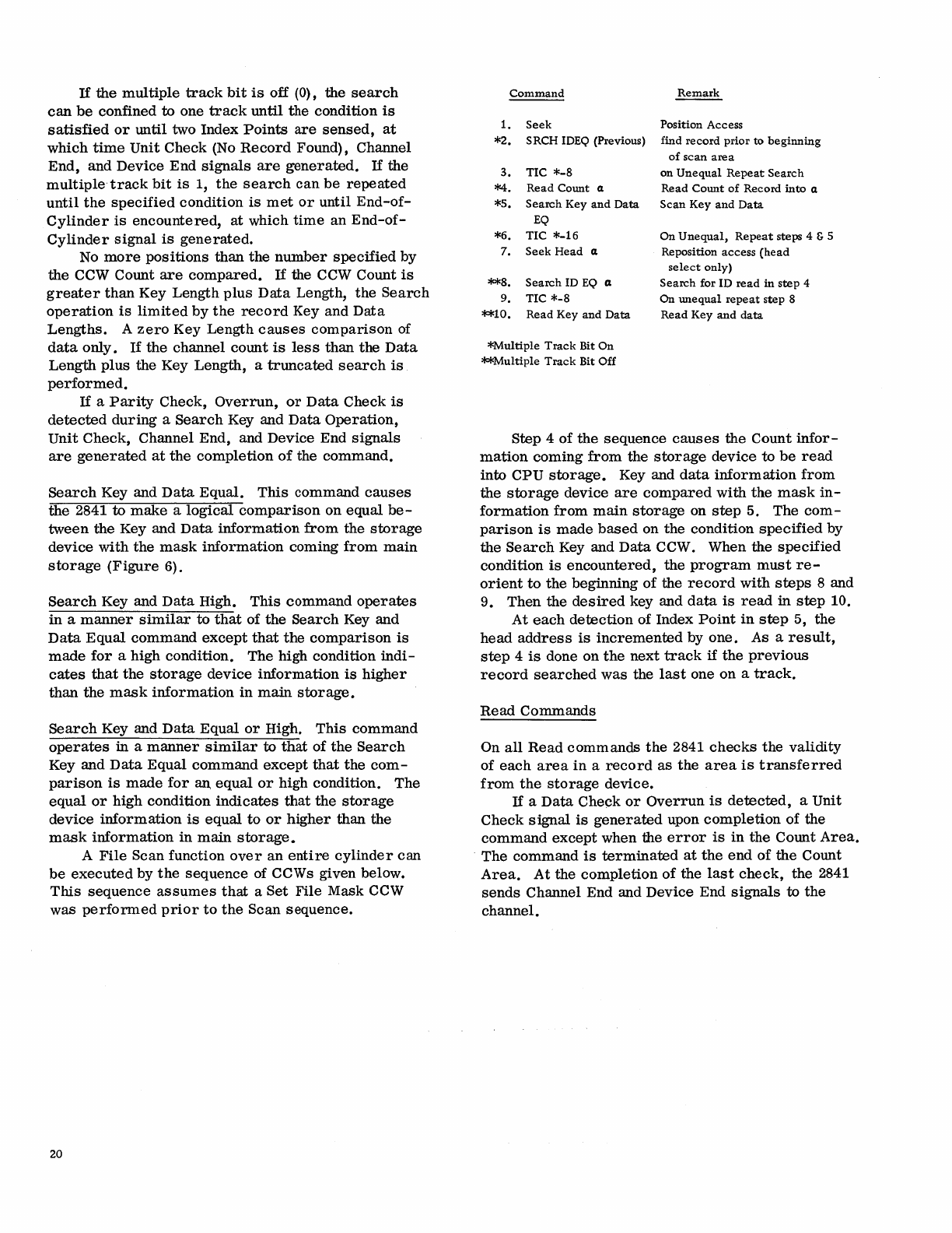
If
the
multiple
track
bit
is
off (0), the
search
can
be
confined
to
one
track
until
the condition
is
satisfied
or
until two Index
Points
are
sensed,
at
which
time
Unit
Check
(No
Record
Found), Channel
End,
and Device
End
signals
are
generated.
If
the
multiple-track
bit
is
1,
the
search
can
be
repeated
until
the
specified
condition
is
met
or
until
End-of-
Cylinder
is
encountered,
at
which
time
an
End-of-
Cylinder
signal
is
generated.
No
more
positions
than
the
number
specified
by
the
CCW Count
are
compared.
If
the CCW Count
is
greater
than
Key Length
plus
Data
Length,
the
Search
operation
is
limited
by
the
record
Key and
Data
Lengths.
A
zero
Key Length
causes
comparison
of
data
only.
If
the
channel
count
is
less
than
the
Data
Length
plus
the Key
Length,
a
truncated
search
is
performed.
If
a
Parity
Check,
Overrun,
or
Data
Check
is
detected
during
a
Search
Key and
Data
Operation,
Unit
Check,
Channel End, and Device End
signals
are
generated
at
the
completion
of
the
command.
Search
Key and
Data
Equal.
This
command
causes
the
2841
to
make
a
logical
comparison
on
equal
be-
tween
the
Key and
Data
information
from
the
storage
device
with
the
mask
information
coming
from
main
storage
(Figure
6).
Search
Key and
Data
High.
This
command
operates
in
a
manner
similar
to
that
of
the
Search
Key and
Data
Equal
command
except
that
the
comparison
is
made
for
a high condition. The high condition
indi-
cates
that
the
storage
device
information
is
higher
than
the
mask
information
in
main
storage.
Search
Key and
Data
Equal
or
High.
This
command
operates
in a
manner
similar
to
that
of
the
Search
Key and
Data
Equal
command
except
that
the
com-
parison
is
made
for
an
equal
or
high condition.
The
equal
or
high condition
indicates
that
the
storage
device
information
is
equal
to
or
higher
than
the
mask
information
in
main
storage.
A
File
Scan function
over
an
entire
cylinder
can
be
executed
by
the
sequence
of CCWs given below.
This
sequence
assumes
that
a
Set
File
Mask CCW
was
performed
prior
to
the
Scan
sequence.
20
Command
Remark
1.
Seek
Position Access
*2.
SRCH IDEQ (Previous) find
record
prior
to
beginning
3.
TIC
*-8
*4.
Read
Count
a
*5.
Search
Key
and
Data
EQ
*6.
TIC
*-16
7.
Seek
Head
a
**8.
Search
ID
EQ a
9.
TIC
*-8
**10.
Read
Key
and
Data
*Multiple
Track
Bit
On
**Multiple
Track
Bit
Off
of
scan
area
on
Unequal
Repeat
Search
Read
Count
of
Record
into
a
Scan
Key
and
Data
On
Unequal,
Repeat
steps 4 & 5
Reposition
access
(head
select
only)
Search
for ID
read
in
step
4
On
unequal
repeat
step
8
Read
Key
and
data
Step 4
of
the
sequence
causes
the
Count
infor-
mation
coming
from
the
storage
device
to
be
read
into CPU
storage.
Key and
data
information
from
the
storage
device
are
compared
with
the
mask
in-
formation
from
main
storage
on
step
5. The
com-
paris
on
is
made
based
on
the
condition
specified
by
the
Searcn
Key and
Data
CCW. When
the
specified
condition
is
encountered,
the
program
must
re-
orient
to
the
beginning
of
the
record
with
steps
8 and
9. Then the
desired
key and
data
is
read
in
step
10.
At
each
detection
of Index
Point
in
step
5,
the
head
address
is
incremented
by
one.
As a
result,
step
4
is
done on
the
next
track
if
the
previous
record
searched
was
the
last
one on a
track.
Read
Commands
On
all
Read
commands
the
2841
checks
the
validity
of
each
area
in
a
record
as
the
area
is
transferred
from
the
storage
device.
If
a
Data
Check
or
Overrun
is
detected,
a Unit
Check
signal
is
generated
upon
completion
of the
command
except
when the
error
is
in
the
Count
Area.
The
command
is
terminated
at
the
end
of
the
Count
Area.
At
the
completion
of
the
last
check,
the 2841
sends
Channel End and
Device
End
signals
to
the
channel.
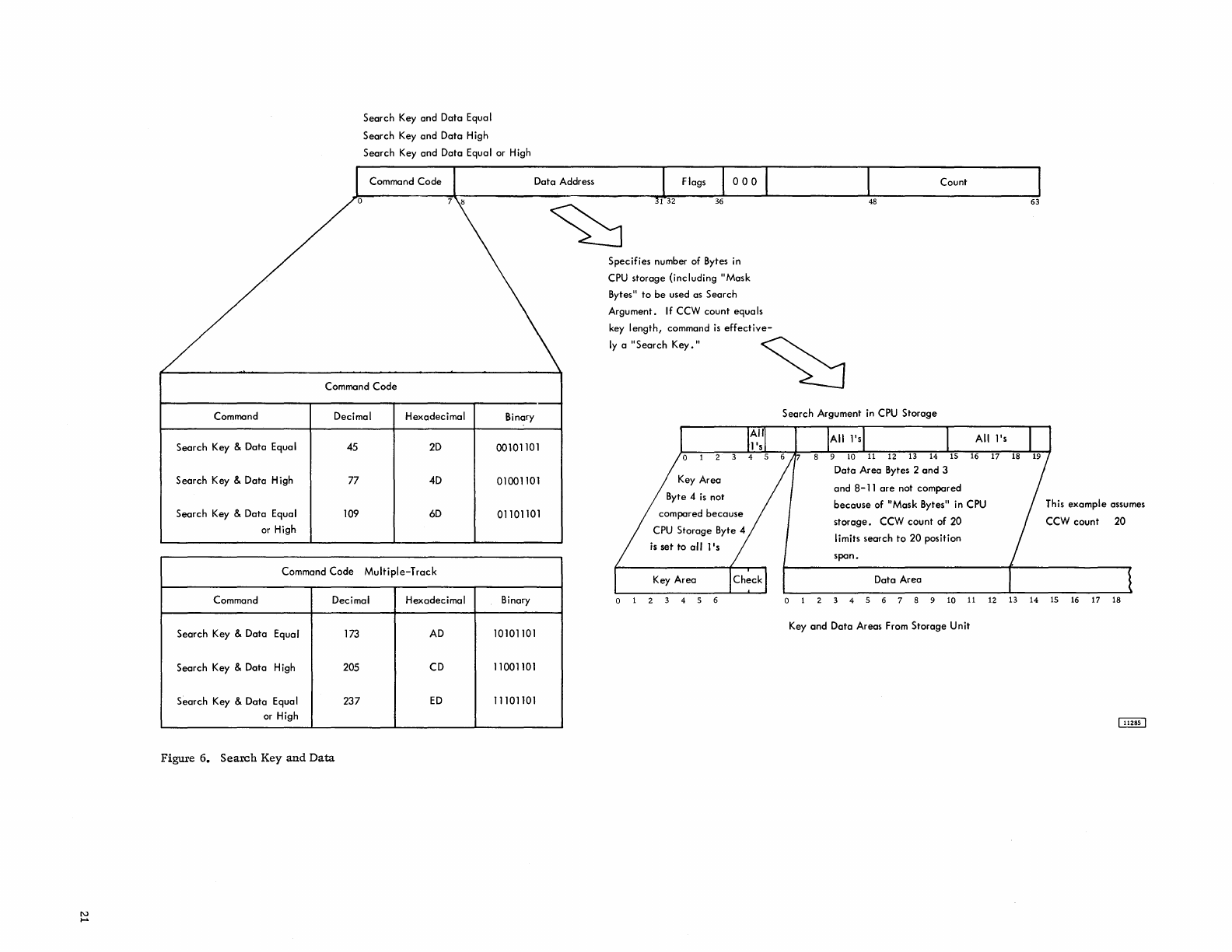
N
....
Search
Key
and
Data Equa I
Search
Key
and
Data High
Search
Key
and
Data Equal or High
Command
Code
Command
Code
Command Decimal Hexadecimal Binary
Search Key & Data Equa I
45
2D
00101101
Search Key & Data High 77 4D 01001101
Search Key & Data Equal 109
6D
01101101
or High
Command
Code
Multiple-Track
Command Decimal Hexadecimal Binary
Search Key & Data Equal 173
AD
10101101
Search Key & Data High 205 CD 11001101
Search Key & Data Equal
237
ED
11101101
or High
Figure
6.
Search
Key
and
Data
Specifies
number of Bytes in
CPU
storage
{including
"Mask
Bytes"
to
be
used as
Search
Argument. If CCW
count
equals
key
length,
command
is
effective-
Count
48
63
Iy
a
"Search
Key."
~
Byte 4
is
not
is
set
to
all
l's
Key
Area
Search
Argument in CPU
Storage
and
8-11
are
not compared
because
of "Mask Bytes" in CPU
storage.
CCW
count
of
20
I
imits search
to
20
position
span.
Data Area
This
example
assumes
CCW
count
20
4 5 6 10
11
12 13 14 15 16 17 18
Key
and
Data Areas From
Storage
Unit
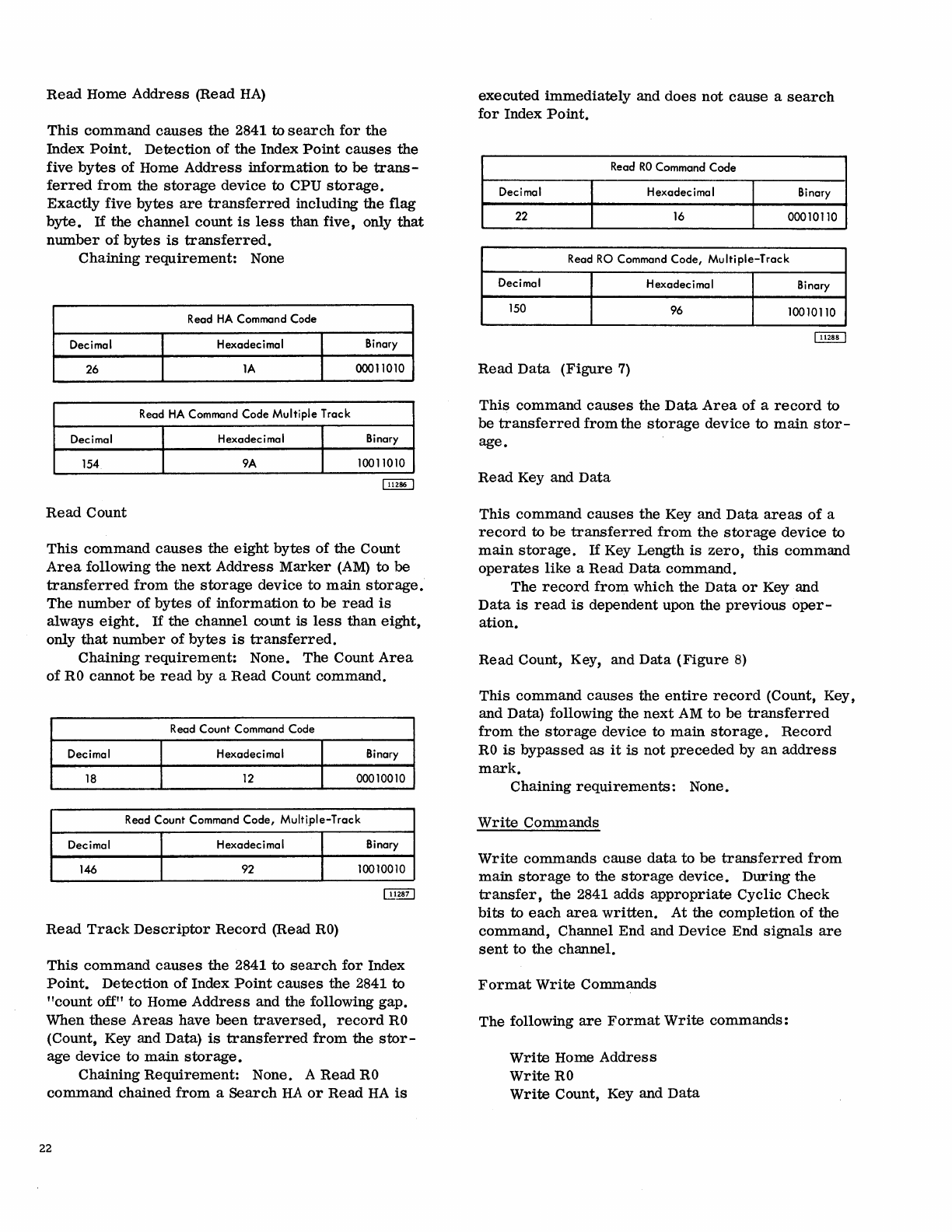
Read
Home
Address
(Read
HA)
This
command
causes
the
2841 to
search
for
the
Index
Point.
Detection
of
the
Index
Point
causes
the
five
bytes
of Home
Address
information
to
be
trans-
ferred
from
the
storage
device
to CPU
storage.
Exactly
five
bytes
are
transferred
including the flag
byte.
If
the channel
count
is
less
than five, only
that
number
of
bytes
is
transferred.
Chaining
requirement:
None
Read
HA Command Code
Decimal H exadec i
ma
I Binary
26
1A
00011010
Read
HA
Command Code
Multiple
Track
Decimal Hexadecimal Binary
154
9A
10011010
Read
Count
This
command
causes
the
eight
bytes
of
the Count
Area
following the
next
Address
Marker
(AM)
to
be
transferred
from
the
storage
device
to
main
storage.
The
number
of
bytes
of
information
to be
read
is
always
eight.
If
the channel
COlIDt
is
less
than
eight,
only
that
number
of
bytes
is
transferred.
Chaining
requirement:
None. The Count
Area
of
RO
cannot
be
read
by a
Read
Count command.
Read
Count Command Code
Decimal Hexadecimal Binary
18
12
00010010
Read
Count Command Code,
Multiple-Track
Decimal Hexadecimal Binary
146 92 10010010
Read
Track
Descriptor
Record
(Read
RO)
This
command
causes
the
2841 to
search
for
Index
Point.
Detection
of
Index
Point
causes
the
2841 to
"count
off"
to
Home
Address
and the following gap.
When
these
Areas
have
been
traversed,
record
RO
(Count, Key and Data)
is
transferred
from
the
stor-
age
device
to
main
storage.
Chaining
Requirement:
None. A
Read
RO
command
chained
from
a
Search
HA
or
Read
HA
is
22
executed
immediately
and
does
not
cause
a
search
for
Index
Point.
Read
RO
Command Code
Decimal Hexadecimal Binary
22
16
00010110
Read
RO
Command Code,
Multiple-Track
Decimal H exadec i
ma
I Binary
150 96 10010110
Read
Data
(Figure
7)
This
command
causes
the
Data
Area
of a
record
to
be
transferred
from
the
storage
device
to
main
stor-
age.
Read
Key and
Data
This
command
causes
the Key and
Data
areas
of
a
record
to
be
transferred
from
the
storage
device
to
main
storage.
If
Key Length
is
zero,
this
command
operates
like
a
Read
Data
command.
The
record
from
which the
Data
or
Key and
Data
is
read
is
dependent upon
the
previous
oper-
ation.
Read
Count, Key, and
Data
(Figure
8)
This
command
causes
the
entire
record
(Count, Key,
and Data) following the
next
AM
to
be
transferred
from
the
storage
device to
main
storage.
Record
RO
is
bypassed
as
it
is
not
preceded
by
an
address
mark.
Chaining
requirements:
None.
Write
Commands
Write
commands
cause
data
to
be
transferred
from
main
storage
to the
storage
device.
During
the
transfer,
the 2841 adds
appropriate
Cyclic Check
bits
to
each
area
written.
At the completion
of
the
command,
Channel End and Device End
signals
are
sent
to the channel.
Format
Write
Commands
The following
are
Format
Write
commands:
Write
Home
Address
Write
RO
Write
Count, Key and
Data
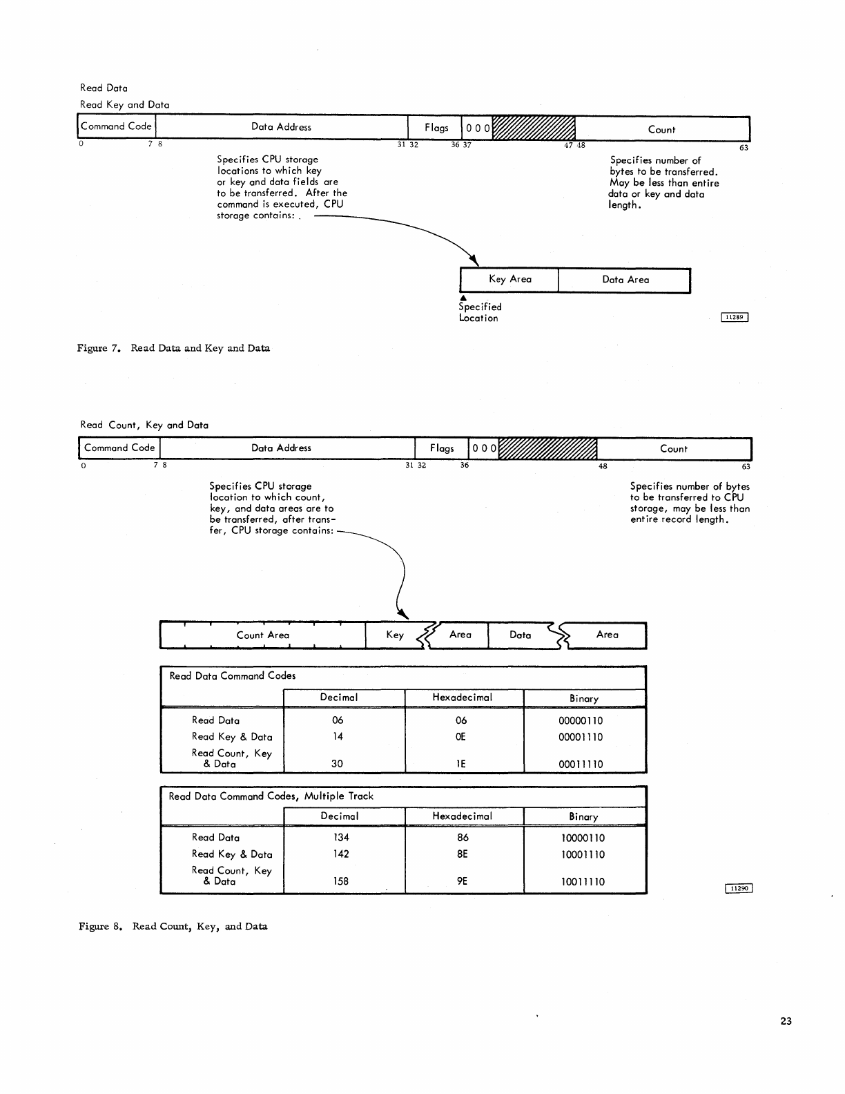
Read
Data
Read Key
and
Data
Command
Code
o 7 8
Data
Address
Specifies
CPU
storage
locations
to
which
key
or key
and
data
fields
are
to
be
transferred.
After
the
command
is
executed,
CPU
storage
contains:
.
Figure
7.
Read
Data
and
Key
and
Data
Read
Count,
Key
and
Data
Command
Code
o 7 8
Data
Address
Specifies
CPU
storage
location
to
which
count,
key,
and
data
areas
are
to
be
transferred,
after
trans-
fer,
CPU
storage
contains:
Key
Area
•
Specified
Location
Count
Specifies
number
of
bytes
to
be
transferred.
May
be
less
than
entire
data
or
key
and
data
length.
63
Data
Area
48
Count
63
Specifies
number
of
bytes
to
be
transferred
to
CPU
storage,
may
be
less
than
entire
record
length.
I
~
__
~:
__
~
___
~~o_u_n~~_A_re_~~~
__
~
__
~
__
K_e_y~~
Area
Data
~L.
__
A_re_a
__
..1
Read
Data
Command
Codes
Decimal
Hexadecimal
Binary
Read
Data
06
06
00000110
Read Key &
Data
14
OE
00001110
Read
Count,
Key
&
Data
30
IE
00011110
Read
Data
Command
Codes,
Multiple
Track
Decimal
Hexadecimal
Binary
Read
Data
134
86
10000110
Read Key &
Data
142
8E
10001110
Read
Count,
Key
&
Data
158
9E
10011110
Figure
8.
Read
COWlt, Key,
and
Data
23
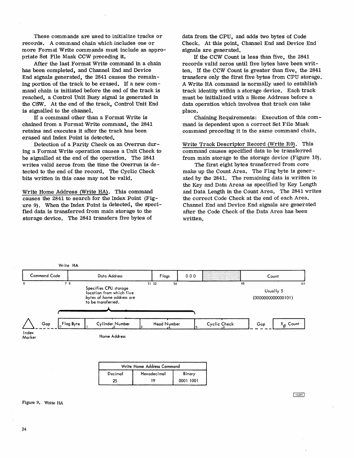
These
commands
are
used
to
initiaJize
tracks
or
records.
A
command
chain
which
includes
one
or
more
Format
Write
commands
must
include an
appro-
priate
Set
File
Mask CCW
preceding
it.
After
the
last
Format
Write
command
in
a
chain
has
been
completed,
and Channel End and Device
End
sigrials
generated,
the
2841
causes
the
remain-
ing
portion
of
the
track
to
be
erased.
If
a new
com-
mand
chain
is
initiated
before
the
end
of
the
track
is
reached,
a
Control
Unit
Busy
signal
is
generated
in
the
CSW.
At
the
end
of
the
track,
Control
Unit End
is
signalled
to
the
channel.
If
a
command
other
than
a
Format
Write
is
chained
from
a
Format
Write
command,
the
2841
retains
and
executes
it
after
the
track
has
been
erased
and Index
Point
is
detected.
Detection
of
a
Parity
Check
on
an
Overrun
dur-
ing
a
Format
Write
operation
causes
a
Unit
Check
to
be
signalled
at
the
end
of
the
operation.
The 2841
writes
valid
zeros
from
the
time
the
Overrun
is
de-
tected
to
the
end
of
the
record.
The Cyclic
Check
bits
written
in
this
case
may
not
be
valid.
Write
Home
Address
(Write HA).
This
command
causes
the 2841 to
search
for
the
Index
Point
(Fig-
ure
9). When
the
Index
Point
is
detected,
the
speci-
fied
data
is
transferred
from
main
storage
to
the
storage
device.
The
2841
transfers
five
bytes
of
Write
HA
Command
Code
o
Index
Marker
7 8
Data
Address
Specifies
CPU
storage
location
from
which
five
,bytes
of
home address
are
to
be
transferred.
Cylinder
2Number
Home Address
Head
Number
4
Write
Home Address Command
data
from
the
CPU,
and adds two
bytes
of
Code
Check. At
this
point, Channel End and Device End
signals
are
generated.
If
the
dcw Count
is
less
than
five,
the
2841
records
valid
zeros
until
five
bytes
have
been
writ-
ten.
If
the CCW Count
is
greater
than
five, the 2841
transfers
only
the
first
five
bytes
from
CPU
storage.
A
Write
HA
command
is
normally
used
to
establish
track
identity within a
storage
device.
Each
track
must
be
initialized
with
a Home
Address
before
a
data
operation
which
involves
that
track
can
take
place.
Chaining
Requirements:
Execution
of
this
com-
mand
is
dependent upon a
correct
Set
File
Mask
.
command
preceding
it
in
the
same
command
chain.
Write
Track
Descriptor
Record
(Write
RO).
This
command
causes
specified
data
to
be
transferred
from
main
storage
to
the
storage
device
(Figure
10).
The
first
eight
bytes
transferred
from
core
make
up the Count
Area.
The
Flag
byte
is
gener-
ated
by the 2841.
The
remaining
data
is
written
in
the Key and
Data
Areas
as
specified
by
Key Length
and
Data
Length
in
the
Count
Area.
The 2841
writes
the
correct
Code
Check
at
the
end
of
each
Area.
Channel End and Device
End
signals
are
generated
after
the Code
Check
of
the
Data
Area
has
been
written.
000
48
Cyclic
~heck
Count
Usually
5
(0000000000000101)
63
Decimal I
Hexadecimal
I Binary
25
19
0001
1001
Figure
9.
Write
HA
24
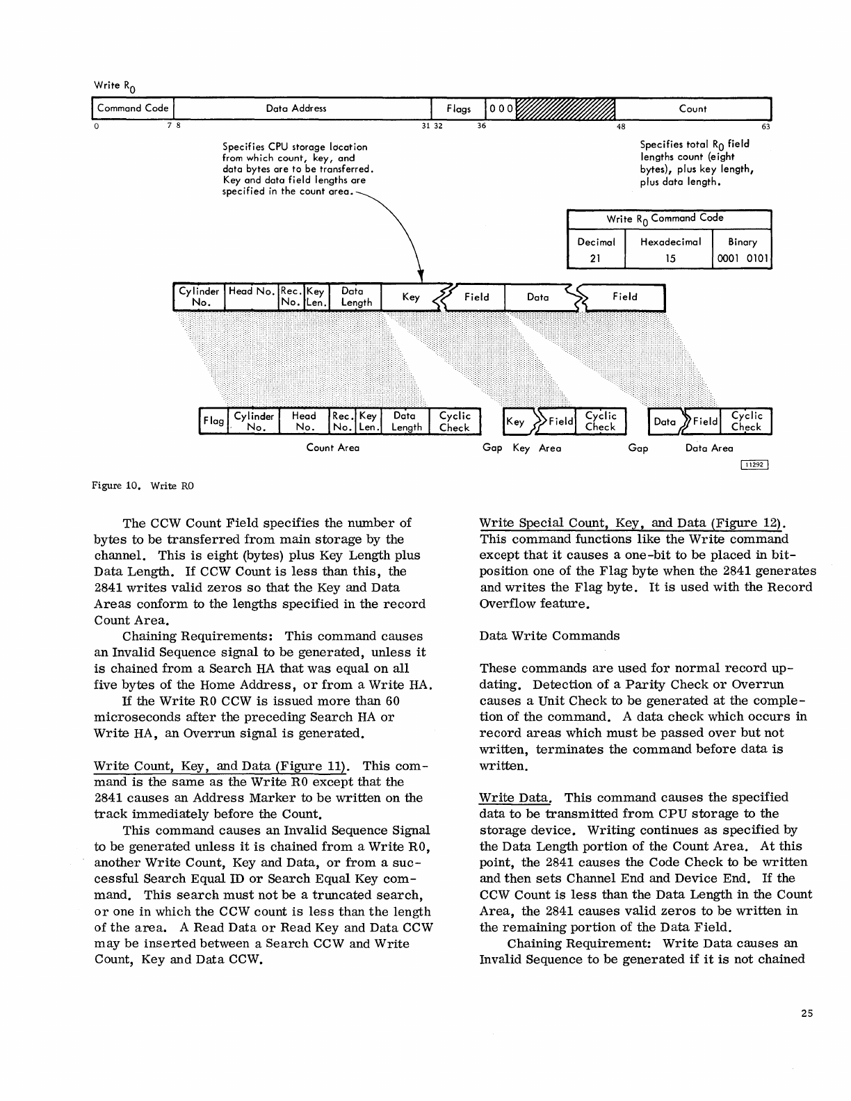
Write
RO
Command
Code
o 7 8
Figure
10.
Write
RO
Data
Address
Specifies
CPU
storage
location
from
wh
i
ch
count,
key,
and
data
bytes
are
to
be
transferred.
Key
and
data
field
lengths
are
specifi
ed
in
the
count
area.
Head
No.
Rec.
Key Dota
No.
Len. Length
Count
Area
The
CCW
Count
Field
specifies
the
number
of
bytes
to
be
transferred
from
main
storage
by
the
channel.
This
is
eight
(bytes)
plus
Key
Length
plus
Data
Length.
If
CCW
Count
is
less
than
this,
the
2841
writes
valid
zeros
so
that
the
Key
and
Data
Areas
conform
to
the
lengths
specified
in
the
record
Count
Area.
Chaining
Requirements:
This
command
causes
an
Invalid
Sequence
signal
to
be
generated,
unless
it
is
chained
from
a
Search
HA
that
was
equal
on
all
five
bytes
of the Home
Address,
or
from
a
Write
HA.
If
the
Write
RO
CCW
is
issued
more
than
60
microseconds
after
the
preceding
Search
HA
or
Write
HA,
an
Overrun
signal
is
generated.
Write
Count, Key, and
Data
(Figure
11).
This
com-
mand
is
the
same
as
the
Write
RO
except
that
the
2841
causes
an
Address
Marker
to
be
written
on
the
track
immediately
before
the Count.
This
command
causes
an
Invalid
Sequence
Signal
to
be
generated
unless
it
is
chained
from
a
Write
RO,
another
Write
Count, Key and
Data,
or
from
a
suc-
cessful
Search
Equal
ill
or
Search
Equal
Key
com-
mand.
This
search
must
not
be
a
truncated
search,
or
one
in
which
the
CCW
count
is
less
than
the
length
of
the
area.
A
Read
Data
or
Read
Key and
Data
CCW
may
be
inserted
between
a
Search
CCW and
Write
Count, Key
and
Data
CCW.
Gap
Key
Area
48
Count
Specifies
total
RO
field
lengths
count
(eight
bytes),
plus
key
length,
plus
data
length.
Write
RO
Command
Code
Hexadecimal
Binary
63
15
0001
0101
Gap
Dota
Area
Write
Special
Count,
Key,
and
Data
(Figure
12).
This
command
functions
like
the
Write
command
except
that
it
causes
a
one-bit
to
be
placed
in
bit-
position
one of
the
Flag
byte
when
the
2841
generates
and
writes
the
Flag
byte.
It
is
used
with
the
Record
Overflow
feature.
Data
Write
Commands
These
commands
are
used
for
normal
record
up-
dating.
Detection
of
a
Parity
Check
or
Overrun
causes
a
Unit
Check
to
be
generated
at
the
comple-
tion
of
the
command.
A
data
check
which
occurs
in
record
areas
which
must
be
passed
over
but
not
written,
terminates
the
command
before
data
is
written.
Write
Data.
This
command
causes
the
specified
data
to
be
transmitted
from
CPU
storage
to
the
storage
device.
Writing
continues
as
specified
by
the
Data
Length
portion
of
the
Count
Area.
At
this
point,
the
2841
causes
the
Code
Check
to be
written
and
then
sets
Channel
End
and
Device
End.
If
the
CCW
Count
is
less
than
the
Data
Length
in
the
Count
Area,
the
2841
causes
valid
zeros
to
be
written
in
the
remaining
portion
of
the
Data
Field.
Chaining
Requirement:
Write
Data
causes
an
Invalid
Sequence
to
be
generated
if
it
is
not
chained
25
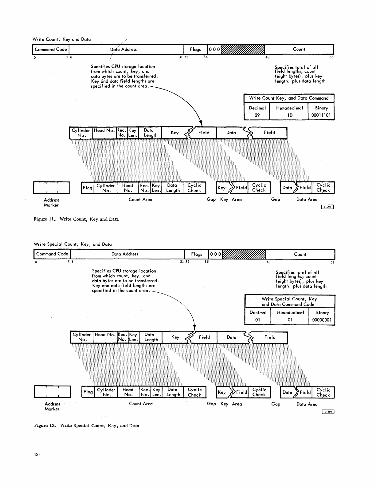
Write
Count,
Key
and
Data
Command
Code
o
Address
Marker
7 8
Address
Specifies
CPU
storage location
from
wh
iCh
count, key,
and
data
bytes
are
to
be
transferred.
Key
-cirid
data field lengths
are
specified
in the count
area.
Flag
Cylinder
No.
Head
No.
Rec. Key
No.
Len.
Count
Area
Figure
11.
Write
Count,
Key
and
Data
Write
Special
Count,
Key, and Data
Command
Code
Data Address
o 7 8
Address
Marker
(
Cylinder
No.
'III
Specifies
CPU
storage location
from
wh
ich count, key, and
data
bytes
are
to
be
transferred.
Key
and
data
field lengths
are
specified
in
the
count
area.
I
Fla
g
Cylinder
No.
Head
No.
Count
Area
Figure
12.
Write
Special
Count,
Key,
and
Data
26
Gap
Key
Area
48
Count
Specifies
total
of
all
field
lengths;
count
{eight bytes}, plus key
length,
plus
data
length
63
Write Count Key,
and
Data
Command
Decimal
29
Hexadeci
rna
I Binary
10
00011101
Gap
Data Area
Count
Specifies
total
of
all
field
lengths; count
(eight bytes), plus key
length,
plus
data
length
63
Write
Special
Count,
Key
and
Data Command
Code
Decimal
01
Hexadecimal
01
Binary
00000001

from
a
successful
Search
Equal
ID
or
from
a
Search
Equal
Key
command
which
was
not
truncated.
Write
Key and
Data.
This
command
is
the
same
as
a
Write
Data
command
except
that
the
Key
Area
is
also
written.
If
the
Key
Length
Field
of the
Count
Area
is
zero,
the
Write
Key
and
Data
command
func-
tions
just
like
the
Write
Data
command.
Write Data
Write Key
and
Data
Data Address
~--------~~~--------~
~
Specifies
CPU
storage
location'
I The CCW
count
field
specifie;
from which
data
or key
and
the
number
of
bytes to be
data
fields
are
to
be
transferred.
transferred.
Write Data Command Codes
Decimal Hexadecimal Binary
Write
Data
05
05
00000101
Write Key & Data
13
00
00001101
An
Invalid
Sequence
is
generated
if
Write
Key
and
Data
is
not
chained
from
a
successful
Search
Equal
ID
command,
which
was
not
truncated.
Write
commands
are
never
truncated.
End
of
File
The
end
of
a
logical
file
is
indicated
by
a
record
whose
Count
Area
contains
a
Data
Length
of
two
bytes
of
zeros.
This
may
be
any
record
on a
track.
This
record
is
written
by
a
Write
Count,Key
and
Data
CCW
or
a
Write
RO.
The
indicated
zero
Data
Length
causes
the
2841
to
record
a
Data
Area
of
a
single
zero
byte.
Formation
of
a Key
Area
in
an
end-of~file
record
depends
on
the
indicated
Key
Length.
If
Key
Length
is
not
zero,
the
Key
Area
is
transferred.
As
a
logical
file
is
read
or
written,
the Count
Area
of
each
record
is
examined.
Detection
of
a
zero
Data
Length
causes
Unit
Exception
to
be
sig-
nalled
in
the
Channel
Status
Word
at
the
completion
time
of
the
read
or
write
operation
that
is
performed.
No
part
of
the
Data
Area
is
transferred.
Record
Rn
Key
~
Area
I
..
oct.Q
....
1.
Area
10
End-of-File
Record
Multiple
Track
(M
-T)
Operation
The
2841
has
the
ability
to
automatically
select
the
next
sequentially
numbered
head
on
an
access
mech-
anism
under
control
of
bit
0
(BO)
of
the
Command
Byte. Head
switching
does
not
take
place
at
Index
Point
if
BO
is
a
zero.
Head
switching
takes
place
at
Index
Point
if
BO
is
a 1.
The
M
-T
bit
is
recognized
on
all
Read
and
Search
commands.
Therefore,
a
certain
amount
of
discretion
should
be
used
when
making
BO
a I
bit.
For
example,
if
during
a
Search
operation
the
M-T
bit
is
a 1
and
index
is
encountered
before
the
search
condition
is
satisfied,
the
head
automatically
switches
to
the
next
track.
The
operation
continues
until
the
End-of-Cylinder
is
detected.
This
condi-
tion
can
occur
if
the
search
was
initiated
beyond
the
point
where
the
record
was
located
on
the
track.
On
the
other
hand,
by
correctly
utilizing
the
M-T
bit,
it
is
possible
to
search
a
complete
cylinder
of
IDs
or
Keys.
Two-Channel Switch (Special
Feature)
The
Two-Channel
Switch
feature
provides
the
ability
for
the
2841
Storage
Control
to
be
shared
by
two
channels
and
also
allows
individual
devices
(access
mechanisms)
to
be
reserved
for
the
exclusive
use
of
either
of
the
channels.
The
two
channels
may
be
attached
to
the
same
CPU
or
different
CPUs.
Chan-
nel
switching
and
device
reservation
in
the
2841
are
performed
under
control
of
the
system
program.
The
Two-Channel
Switch
feature
is
limited
to
eight
access
mechanisms.
Channel
Selection
Switch
This
switch
has
three
positions:
Channel
A,
Channel
B,
and
neutral.
With
the
switch
in
the
neutral
position,
the
2841
is
selected
by
the
first
channel
to
complete
the
selection
sequence.
Once
the
2841
is
selected
by
a
channel,
it
remains
selec-
ted
to
that
channel
until
an
end
status
exists.
The
channel
selection
switch
then
returns
to
neutral
un-
less
one of
the
following
conditions
exists.
1.
The channel
indicates
command
chaining.
2.
The
last
status
byte
is
associated
with a
·channel-initiated
signal
sequence,
it
is
stacked
by
the
channel.
3.
The
last
status
byte
contains
the
unit
check
bit.
4.
No
command
other
than
an
I/O
or
a No-op
has
been
initiated
since
the
last
unit
check
condition
occurred.
27
If
Channel A (B)
attempts
to
select
the
2841
while
the
2841
is
selected
to
Channel B (A),
the
2841
responds
to
Channel A (B) with
control
unit
busy.
This,
in
turn,
causes
the
2841 to
attempt
to
present
to
Channel A (B) a
status
byte
containing
control
unit
end
after
the
channel
selection
switch
returns
to
the
neutral
position.
The
address
byte
associated
with
this
status
condition
is
the
base
address
of
the
2841
on
that
channel.
This
control
unit
busy
condition
may
occur
on
any
attempt
to
select
the
2841,
including
initial
program
load,
Test
I/O,
etc.
Device
Reservation
(See
Device
Reserve
and
Device
Release
Commands)
When a
device
is
reserved
to
Channel A (B),
any
command
from
Cha~mel
B (A)
addressed
to
that
device
is
rejected
with
a
busy
indication
in
the
initial
status
byte.
This,
in
turn,
causes
the
2841
to
attempt
to
present
to
Channel
B (A) a
status
byte
containing
Device
End
after
the
reservation
has
been
terminated.
The
address
byte
associated
with
this
status
byte
is
the
same
as
that
associated
with
the
Busy
status
byte.
Device
End
status
resulting
from
the
completion
of a 'Seek
command
is
presented
to
the
channel
that
issued
the
command.
A
device
that
generates
Device End
status
when
it
changes
from
the
not-ready
to
the
ready
state
causes
the
2841
to
present
this
type of
Device
End
status
to
both
channels.
However,
no
attempt
is
made
to
present
such
status
on one
channel
while
the
device
is
reserved
to
the
other
channel.
A
reset
can
be
initiated
by
either
channel
at
any
time.
A
reset
causes
all
reservations
and
status
conditions
stored
in
the
2841
and
related
to
the
re-
setting
channel
to
be
reset
in
the
2841.
Reservations
and
status
conditions
related
to
the
other
channel
are
not
affected.
Addressing
The
base
address
(four
high-order
bits)
of
the
2841
on
one
channel
is
independent
of
the
base
address
of
the
2841
on
the
other
channel.
However,
the
four
low-order
address
bits
for
any
attached
device
must
be
the
same
on
both
channels.
Usage
Meter
A
single
usage
meter
records
process
time
in
the
2841;
however,
a
separate
Enable
switch
is
provided
for
each
channel.
28
Power
Control
A
power
control
interface
is
provided
for
each
channel.
If
either
channel
indicates
power
"ON"
the
2841
turns
on.
The 2841
turns
off
only
if
both
chan-
nels
indicate
power
"OFF".
If
the
Emergency
Power
OFF
switch
of
either
channel
is
activated,
the
2841
power
is
turned
off.
Record
Overflow
(Special
Feature)
The
Record
Overflow
feature
is
provided
to
allow a
logical
record
to
overflow
from
one
track
to
another.
It
is
useful
in
achieving
a
greater
data
packing
efficiency
and
in
formatting
records
which
exceed
the
capacity
of
a
track.
The
cylinder
boundary
is
the
limiting
factor
to
the
size
of a
record.
Formatting
OVerflow
Records
A
portion
of
an
overflow
record
which
is
written
on
one
track
is
called
a
record
segment.
Each
record
segment
is
processed
as
a
normal
record
during
Format
Write
operations.
The
Write
Special
Count,
Key,
and
Data
CCW
is
the
command
used
for
for-
matting
all
segments
of
an
overflow
record
except
the
last
segment.
The
last
segment
is
written
by
the
normal
Write
Count,
Key,
and
Data
CCW.
The
Write
Special
CCW
causes
a
bit
to
be
writ-
ten
in
Flag
byte
one
in
bit
position
one
of
the
record
segment
being
written.
Otherwise,
the
Write
Special
CCW
functions
just
like
the
normal
Write
command.
All
overflow
segments
must
be
recorded
as
the
first
record
following
RO
on
the
overflow
track.
Overflow
segments
are
normally
recorded
with-
out
a Key
Field,
since
only
the
Key
Field
of
the
first
segment
has
significance.
All
overflow
record
seg-
ments,
except
the
last
one,
are
full
track
records.
Processing
OVerflow
Records
The
following CCWs
operate
on
an
overflow
record
as
though
it
were
a
normal
record
if
the
Overflow
Record
feature
is
installed:
Read
Data
Read
Key
and
Data
Read
Count-Key
and
Data
Write
Data
Write
Key
and
Data
The
2841
detects
that
flag
byte
bit
position
one
is
a
1-bit.
After
completing
the
read
or
write--
operation
on the
first
segment
based
on
the
count
of
the
first
segment,
the 2841
searches
for
the
Index
Point.
At
Index
Point,
the
next
sequential
Head
is
selected
and the 2841
searches
for
the
first
Address
Marker
on the
track.
Then,
under
control
of
the
Data
Length in the Count
Area,
it
processes
the
Data
Field
of
this
record
segment.
This
opera-
tion
continues until the 2841
detects
a
record
seg-
ment
which contains a
zero
bit
in
flag
byte
bit
position
one.
At
the
end of
this
record
segment,
the
operation
is
terminated.
A
CCW
chain
which
starts
operation
on a
re-
cord
segment
other
than
the
first
segment
is
proc-
essed
as
though
it
started
on
the
first
segment.
This
type
of
operation
may
make
it
desirable
to
repeat
the
Key
Field
in
all
record
segments
if
the
chain
of CCWs
is
dependent on a
Search
Key Equal.
Search
ID,
Search
Key, and
Read
Count CCWs
operate
on
each
record
segment
as
though
each
were
a
normal
record.
Unusual Conditions. In addition to
the
checks
pro-
vided
in
normal
processing
of any
record,
certain
conditions
can
occur
which
are
unique to overflow
records.
The commands
stop
immediately
on
de-
tecting
the following conditions:
1. Overflow to a Defective
Track
Overflow Incomplete and
Track
Condition
Check
sense
bits
will
be
set
if
an overflow
occurs
to a
track
which
has
been
flagged
as
defective.
2. Overflow
From
an
Alternate
Track
Overflow Incomplete and
Track
Condition
Check
sense
bits
are
set
if
an
attempt
is
made
to overflow
from
a
track
flagged
as
an
alternate.
3. Overflow Violating a
File
Mask
Attempting
to
overflow by
issuing
a
com-
mand
in
violation
of
a file
mask
sets
Over-
flow
Incomplete,
File
Protected,
and
Command
Reject
(write
command
only)
sense
bits.
4.
Overflow
to
a
Track
with
Incorrect
Head
Number
Overflow
Incomplete
and Seek Check
sense
bits
are
set
if
the
Head
number
compare
is
unequal
during
an
overflow.
This
condition
occurs
if
the
last
Seek
Address
issued
to
the 2841
is
not
the
address
of the
track
with
the overflow
record
and
an
overflow
record
is
being
read
or
written.
28.1
Introduction
The
IBM
System/360
is
used
in
many
applications
which
require
that
files
of
medium
size
be
accessible
to
the
central
processor.
These
files
may
contain
customer
account
balances,
current
inventory
status,
payroll
information,
computer
operating
programs,
or
other
information,
permanent
or
temporary,
to
which
the
central
processor'
must
refer
to
complete
the
specific
application.
If
all
files
need
not
be
directly
accessible
(on
line)
to
the
central
processor
at
all
times,
operating
and
equipment
economies
can
be
realized
if
the
file
can
be
separated
from
the
file
drive.
As
with
mag-
netic
tape,
an
unlimited
volume
of
data
can
be
stored
away
from
the
central
processor
(off-line).
Appro-
priate
data
files
can
be
placed
on-line
as
required
by
the
processing
schedule.
It
may
also
be
desirable
to
be
able
to
transfer
data
files
from
one
file
drive
to
another
(possibly
attached
to
a
second
central
processor).
This
allows
one
system
to
process
and
update
a
data
file,
and
another
(possibly
a
smaller
satellite
system),
to
print
reports
or
answer
inquiries.
This
capability
also
enables
a
second
system
to
complete
a
task
if
the
primary
system
is
not
available
because
of
other
appl
ications.
The
IBM 2311
Disk
Storage
Drive,
with
IBM 1316
Disk
Packs,
offers
processing
features
which
answer
the
needs
of
many
data
processing
applications:
Storage
capacity:
High
speed
accessibility:
Data
file
removability:
Fast
data
transfer
to
the
processor.
Multiple
unit
growth
potential:
Over
7. 2
million
bytes
per
disk
pack
85
milliseconds,
average
Disk
pack
change
time:
about
one
minute
156,000
bytes
per
second
Up
to
eight
2311's
58
million
bytes,
on
a
single
2841
control
unit
IBM 2311 DISK STORAGE
Compatibility
between
units:
Large
volume
of
data
available
at
a
single
access:
Device
Description
1316'
s
compatible
between
any
2311
's
used
on
IBM
System/360
Over
36,
000
bytes
per
cylinder
The
IBM 2311
Disk
Storage
consists
of two
main
com-
ponents:
the
2311
Disk
Storage
Drive
and
the
1316
Disk
Pack.
Storage
Medium
(1316
Disk
Pack)
Each
disk
pack
consists
of
six
14-inch
disks,
mounted
1/2
inch
apart
on a
central
hub.
Data
is
recorded
on
the
inside
ten
disk
surfaces.
The
two
outer
surfaces
are
covered
by
protective
plates.
The
entire
assembly
of
disks,
hub,
and
protective
plates
is
rotated
at
2,400
revolutions
per
minute
(25
ms
per
revolution).
Each
disk
pack
weighs
about
ten
pounds.
The
two-piece
plastic
cover
is
designed
to
protect
disks
against
damage.
A
built-in
handle
on
the
top
cover
makes
carrying
easy
and
efficient.
A
self-
locking
device
in
the
handle
permits
removal
of
the
top
cover
only
when
the
pack
is
mounted
on
the
disk
storage
drive.
Access
Mechanism
When
the
1316
Disk
Pack
is
mounted
in
the
2311
Disk
Storage
Drive,
information
is
written
on
and
read
from
the
ten
disk
surfaces
by
magnetic
read/write
heads.
These
read/write
heads
are
mounted
in
pairs
between
each
two
disks
on
a
movable
comb-like
access
mechanism.
When
in
operation,
the
read/write
heads
float
over
the
disk
surfaces
on a
thin
film
of
air.
Access
Time
Cylinder-to-cylinder
(horizontal)
access
time
varies
according
to
the
number
of
cylinders
traversed.
Ac-
cess
time
from
a
cylinder
to
an
adjacent
cylinder
is
30
ms.
Maximum
access
time
(from
cylinder
202
to
cylinder
000)
is
145
ms,
and
the
average
time
for
"random"
accesses
is
approximately
85
ms
(Figure
13)
29

~~
~
~
~
~
~~
~
~
~
~
~
~
~
140
120
tOO
/
........
~
~
~
Vl
80
~
Z
60
40
20
o
~
~
~
r
~
/
~
:(
~
~
~
, , , , , , , I
~
I I ,
o
20
40
60
Figure 13. Access
Times
...----203
Cylinders
Cylinder Concept
30
80
I I I I I I I I I , I , I I I I I I
tOO
120
140
160
180
200
NO.
TRACKS
TRAVELLED
Once
the
access
mechanism
has
reached
a
cylinder
position,
additional
time
is
required
for
disk
rotation
to
the
desired
record.
At
2,400
revolutions
per
min-
ute,
rotation
time
is
25
ms,
and
one-half
revolution
(12.5
ms)
is
the
average
rotational
delay.
Because
the
access
mechanism
includes
one
read/write
head
for
each
disk
surface,
no
vertical
access
motion
is
required.
Figure
13
shows
the
approximate
times
for
access
mechanism
movement
in
either
direction,
excluding
rotational
delay.
This
may
be
used
as
an
aid
in
pro-
gramming
for
the
most
efficient
utilization
of
the
storage
unit.
Data
Record
Addressing
As
the
access
mechanism
is
moved
horizontally,
it
may
be
stopped
at
any
of
the
203
positions.
This
provides
203
data
tracks
on
each
surface.
Since
all
ten
read/write
heads
are
moved
by
a
single
access
mechanism,
a
cylinder
of
ten
data
tracks
is
available
at
each
access
mechanism
position.
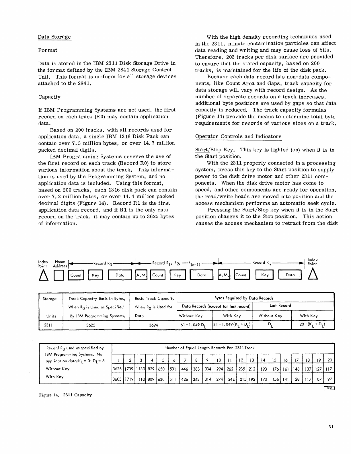
Data
Storage
Format
Data
is
stored
in
the
IBM 2311
Disk
Storage
Drive
in
the
format
defined
by
the
IBM 2841
Storage
Control
Unit.
This
format
is
uniform
for
all
storage
devices
attached
to
the
2841.
Capacity
If
IBM
Programming
Systems
are
not
used,
the
first
record
on
each
track
(RO)
may
contain
application
data.
Based
on 200
tracks,
with
all
records
used
for
application
data,
a
single
IBM 1316
Disk
Pack
can
contain
over
7.3
million
bytes,
or
over
14.7
million
packed
decimal
digits.
IBM
Programming
Systems
reserve
the
use
of
the
first
record
on
each
track
(Record
RO)
to
store
various
information
about
the
track.
This
informa-
tion
is
used
by
the
Programming
System,
and
no
application
data
is
included.
Using
this
format,
based
on 200
tracks,
each
1316
disk
pack
can
contain
over
7.2
million
bytes,
or
over
14.4
million
packed
decimal
digits
(Figure
14).
Record
R1
is
the
first
application
data
record,
and
if
R1
is
the
only
data
record
on
the
track,
it
may
contain
up
to
3625
bytes
of
information.
With
the
high
density
recording
techniques
used
in
the
2311,
minute
contamination
particles
can
affect
data
reading
and
writing
and
may
cause
loss
of
bits.
Therefore,
203
tracks
per
disk
surface
are
provided
to
ensure
that
the
stated
capacity,
based
on
200
tracks,
is
maintained
for
the
life
of
the
disk
pack.
Because
each
data
record
has
non-data
compo-
nents,
like
Count
Area
and
Gaps,
track
capacity
for
data
storage
will
vary
with
record
design.
As
the
number
of
separate
records
on a
track
increases,
additional
byte
positions
are
used
by
gaps
so
that
data
capacity
is
reduced.
The
track
capacity
formulas
(Figure
14)
provide
the
means
to
determine
total
byte
requirements
for
records
of
various
sizes
on a
track.
Operator
Controls
and
Indicators
Start/Stop
Key.
This
key
is
lighted
(on)
when
it
is
in
the
Start
position.
With
the
2311
properly
connected
in
a
processing
system,
press
this
key
to
the
Start
position
to
supply
power
to
the
disk
drive
motor
and
other
2311
com-
ponents.
When
the
disk
drive
motor
has
come
to
speed,
and
other
components
are
ready
for
operation,
the
read/write
heads
are
moved
into
position
and
the
access
mechanism
performs
an
automatic
seek
cycle.
Pressing
the
Start/Stop
key
when
it
is
in
the
Start
position
changes
it
to
the
Stop
position.
This
action
causes
the
access
mechanism
to
retract
from
the
disk
Index Home
~~'-----Record
RO
"I~
Record R1,
R2,
---R(n_l)
~1:4
Record
Rn
------
..
~I
~~~~;
Point Address
~
D B B
"""1
-Data
......
1
BB
B
r--I
Da ..........
ta
1GB
~
I
Data
I
~
Storage Track
Capacity
Basis in Bytes, Basic Track
Capacity
Bytes Requ i red by
Data
Records
When
RO
is
Used as
Specified
When
RO
is
Used for
Data
Records
(except
for last record)
Last
Record
Units
By
IBM
Programming Systems. Dato Without Key With Key Without Key With Key
2311
3625 3694
61+1.049D
L
81
+
1.049(K
L + DL
)
DL
20+(K
L + DL
}
Record
RO
used as
specified
by Number
of
Equa I Length Records Per 2311 Track
IBM
Programming Systems. No
application
data;KL
=
0;
DL
0=
8 1 2 3 4 5 6 7 8 9 10
11
12 13 14 15 16 17 18 19 20
Without Key 3625 1739 1130 829 650
531
446
383 334 294 262 235 212 193 176
161
148 137 127 117
With Key 3605 1719 1110 809 630
511
426
363 314 274 242 215 192 173 156
141
128 117 107 97
Figure
14.
2311
Capacity
31
pack
and
removes
power
from
the
disk
drive
motor.
Automatic
braking
stops
disk
pack
rotation
in
a few
seconds.
Select
Lock
Indicator.
When on,
this
indicates
a
machine
condition
which
requires
Customer
Engineer-
ing
attention.
This
condition
causes
the
disk
storage
drive
to
be
disabled
and
stops
the
usage
meter.
Enable/Disable
Switch. When
the
CPU
is
in
the
stopped
state,
this
switch
enables
or
disables
the
communication
of
the
storage
drive
with
the
CPU.
It
also
enables
or
disables
the
equipment
usage
meter.
If
the
CPU
is
running
when
the
switch
setting
is
changed,
the
storage
drive
and
usage
meter
operating
status
are
not
changed
until
the
CPU
is
placed
in
the
stopped
state.
(See
also
Select
Lock
Indicator.
)
Operating
Procedures
Disk
Pack
Handling
Each
disk
pack
is
protected
in
transit
by
special
carton
inserts
and
special
protective
material.
When
received,
examine
the
carton
closely.
If
its
condition
is
acceptable,
remove
the
disk
pack
and
store
it.
Keep
the
carton
and
inserts;
you
may
need
them
later.
If
the
carton
or
its
contents
show any
unusual
shipping
damage,
do
not
use
the
disk
pack.
Retain
the
damaged
carton
and
disk
pack
in
its
"as
received"
condition
and
notify
your
IBM
Customer
Engineer
immediately.
Disk
packs
have
been
designed
for
ease
of
trans-
port
from
location
to
location.
For
best
shipping
results:
1.
Be
sure
the
pack
is
secure
in
its
two-piece
cover.
2.
Use
only
the
specially
designed
IBM
shipping
carton
with
its
special
protective
padding
properly
inserted.
If
the
original
carton
is
worn
or
damaged,
a
new
carton
may
be
ordered
from
your
local
IBM
office.
Handle
a
disk
pack
only
with
its
cover
on.
If
the
disk
pack
is
accidentally
dropped,
or
receives
a
sharp
impact
of
any
kind,
call
an
IBM
Customer
Engineer
before
using
it.
Disk
Pack
Labeling.
For
positive
identification,
small
adhesive-backed
labels
can
be
placed
on
the
disk
pack
center
hub.
Labels
in
this
location
can
be
read
through
the
transparent
disk
pack
cover.
32
The
following
operating
procedures
should
be
followed
when
labeling
disk
packs:
1.
Use
adhesive-backed
labels
which
can
be
applied
and
removed
easily.
2.
Use
a
writing
implement,
like
a
pen
or
felt-
tip
marker,
which
does
not
produce
loose
residue.
Do
not
use
a
lead
pencil.
3.
Write
on
the
label
before
it
is
applied
to
the
disk
pack.
4.
Place
the
label
only
on
the
center
hub,
not
on
the
disk
pack
cover
or
top
disk
surface.
5.
Use
a new
label
if
changes
are
necessary.
N
ever
use
an
eraser
because
microscopic
eraser
particles
can
damage
disk
surfaces
and
read/write
heads.
Disk
Pack
Loading
and
Unloading.
The
following
procedures
should
be
followed
for
rapid,
effective
disk
pack
changing:
Loading.
1. Open
the
2311
cover.
2.
Remove
the
bottom
disk
pack
cover
by
turn-
ing
the
bottom
locking
knob.
3.
Place
the
1316
disk
pack
(still
contained
in
top
cover)
on
the
2311
spindle.
4.
Turn
the
top
cover
in
direction
of
ON
arrow
until
firm
resistance
is
met.
5.
Lift
the
top
cover
from
the
disk
pack.
6.
Close
the
2311
cover.
7.
Press
the
2311
Start
key.
8.
Reassemble
the
top
and
bottom
covers
of
the
disk
pack.
9.
Store
the
covers
in
a
clean
cabinet
or
on
a
clean
shelf.
I
CAUTION: Do
not
leave
disk
pack
top
cover
inside
Disk
Drive.
Unloading.
1.
Press
the
2311 Stop
key.
2.
Wait
for
the
disk
pack
to
stop
rotating.
3.
Separate
the
top
and
bottom
disk
pack
covers.
4.
Open
the
2311
cover.
5.
Place
the
disk
pack
top
cover
over
disk
pack.
6.
Turn
the
top
cover
in
direction
of
OFF
arrow
at
least
two
full
turns.
7.
Lift
the
top
cover,
now
containing
the
disk
pack,
from
the
spindle.
8.
Fasten
the
bottom
cover
to
disk
pack
(firmly).
9.
Close
the
2311
cover.
10.
Store
the
disk
pack
in
a
clean
cabinet
or
on a
clean
shelf.
Disk
Pack
Storage.
To
assure
maximum
disk
pack
life
and
reliability:
1.
Store
the
disk
packs
flat,
not
on
edge.
2.
Each
pack
should
rest
on a
shelf,
not on
another
disk
pack.
3.
Store
in
a
clean,
enclosed
metal
cabinet
or
a
similar
fire-resistant
container;
never
in
direct
sunlight.
4.
Store
disk
packs
in
a
machine-room
atmos-
phere
(600
to
900
F,
10%
to
80%
humidity).
5.
If
disk
packs
must
be
stored
in
a
different
environment,
allow
two
hours
for
adjust-
ment
to
machine
room
atmosphere
before
use.
33
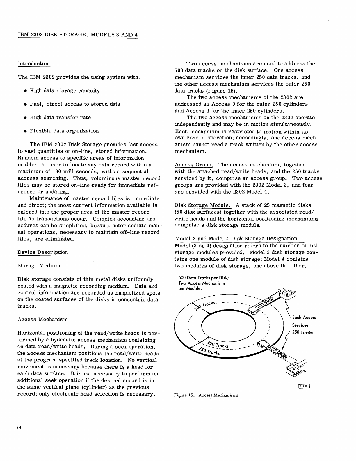
IBM 2302 DISK STORAGE, MODELS 3
AND
4
Introduction
The
IBM 2302
provides
the
using
system
with:
• High
data
storage
capacity
•
Fast,
direct
access
to
stored
data
• High
data
transfer
rate
•
Flexible
data
organization
The
IBM 2302
Disk
Storage
provides
fast
access
to
vast
quantities
of
on-line,
stored
information.
Random
access
to
specific
areas
of
information
enables
the
user
to
locate
any
data
record
within
a
maximum
of 180
milliseconds,
without
sequential
address
searching.
Thus,
voluminous
master
record
files
may
be
stored
on-line
ready
for
immediate
ref-
erence
or
updating.
Maintenance
of
master
record
files
is
immediate
and
direct;
the
most
current
information
available
is
entered
into
the
proper
area
of
the
master
record
file
as
transactions
occur.
Complex
accounting
pro-
cedures
can
be
simplified,
because
intermediate
man-
ual
operations,
necessary
to
maintain
off-line
record
files,
are
eliminated.
Device
Description
storage
Medium
Disk
storage
consists
of
thin
metal
disks
uniformly
coated
with
a
magnetic
recording
medium.
Data
and
control
information
are
r~corded
as
magnetized
spots
on
the
coated
surfaces
of
the
disks
in
concentric
data
tracks.
Access
Mechanism
Horizontal
positioning
of
the
read/write
heads
is
per-
formed
by
a
hydraulic
access
mechanism
containing
46
data
read/write
heads.
During
a
seek
operation,
the
access
mechanism
positions
the
read/write
heads
at
the
program
specified
track
location.
No
vertical
movement
is
necessary
because
there
is
a
head
for
each
data
surface.
It
is
not
necessary
to
perform
an
additional
seek
operation
if
the
desired
record
is
in
the
same
vertical
plane
(cylinder)
as
the
previous
record;
only
electronic
head
selection
is
necessary.
34
Two
access
mechanisms
are
used
to
address
the
500
data
tracks
on
the
disk
surface.
One
access
mechanism
services
the
inner
250
data
tracks,
and
the
other
access
mechanism
services
the
outer
250
data
tracks
(Figure
15).
The
two
access
mechanisms
of
the
2302
are
addressed
as
Access
0
for
the
outer
250
cylinders
and
Access
1
for
the
inner
250
cylinders.
The
two
access
mechanisms
on
the
2302
operate
independently
and
may
be
in
motion
simultaneously.
Each
mechanism
is
restricted
to
motion
within
its
own
zone of
operation;
accordingly,
one
access
mech-
anism
cannot
read
a
track
written
by
the
other
access
mechanism.
Access
Group.
The
access
mechanism,
together
with
the
attached
read/write
heads,
and
the
250
tracks
serviced
by
it,
comprise
an
access
group.
Two
access
groups
are
provided
with
the
2302 Model
3,
and
four
are
provided
with
the
2302 Model
4.
Disk
Storage
Module.
A
stack
of
25
magnetic
disks
(50
disk
surfaces)
together
with
the
associated
read/
write
heads
and
the
horizontal
positioning
mechanisms
comprise
a
disk
storage
module.
Model 3
and
Model
4
Disk
Storage
Designation.
Model
(3
or
4)
designation
refers
to
the
number
of
disk
storage
modules
provided.
Model 3
disk
storage
con-
tains
one
module
of
disk
storage;
Model 4
contains
two
modules
of
disk
storage,
one
above
the
other.
500
Data
Tracks
per
Disk;
Two
Access Mechanisms
per
Module.
Figure
15.
Access
Mechanisms
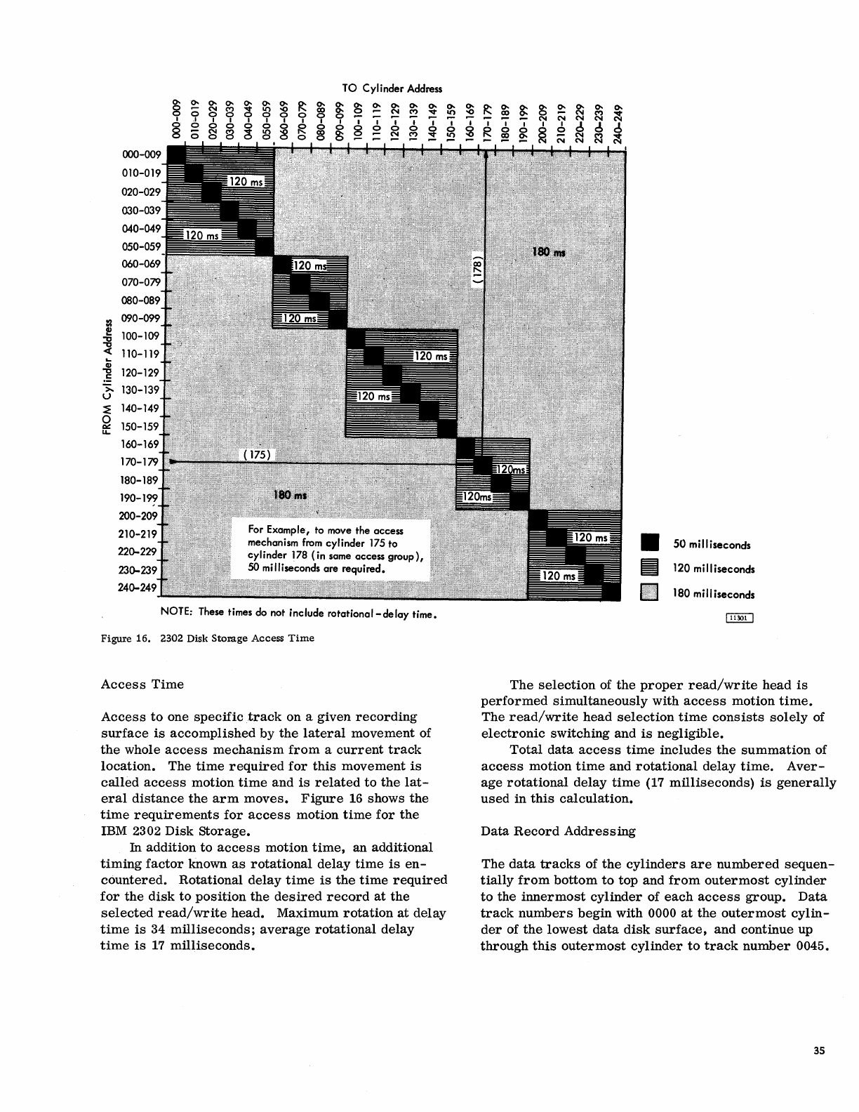
TO
Cylinder
Address
0- 0- 0- 0-
0- 0-
0-
~
0- 0- 0-
~
0-
0-
0-
0-
8 N M
~
8
-0
ex)
~
0 N
0 0 0 0 0 0
~
;!
!!?
I .I I I I I I I I
'I
I I I I I I
§ 0 0 0 0 0 0 R 0 0
~
~
0 0
~
0
;:;
N 8
C!
8 8
~
~
~
~
::I
~
~
-8
.=
>.
u
~
140-1
~
150-1
u..
160-
170-1
0 0
NOTE:
These
times
do
not include rotational-delay time.
Figure
16.
2302 Disk
Storage
Access
Time
Access
Time
Access
to
one
specific
track
on a
given
recording
surface
is
accomplished
by
the
lateral
movement
of
the
whole
access
mechanism
from
a
current
track
location.
The
time
required
for
this
movement
is
called
access
motion
time
and
is
related
to
the
lat-
eral
distance
the
arm
moves.
Figure
16
shows
the
time
requirements
for
access
motion
time
for
the
IBM 2302 Disk
Storage.
!!?
In
addition
to
access
motion
time,
an additional
timing
factor
known
as
rotational
delay
time
is
en-
countered.
Rotational
delay
time
is
the
time
required
for
the
disk
to
position
the
desired
record
at
the
selected
read/write
head.
Maximum
rotation
at
delay
time
is
34
milliseconds;
average
rotational
delay
time
is
17
milliseconds.
$
I
~
~
0-
ex)
I I
R 0
~
~
I
0
~
II
~
100ll'iI
.•.•..•.•..
'
.•.•.•.•.
'
.•...•.•.•..•.
'
....•.
~
50
milliseconds
120 milliseconds
180 milliseconds
The
selection
of
the
proper
read/write
head
is
performed
simultaneously
with
access
motion
time.
The
read/write
head
selection
time
consists
solely
of
electronic
switching and
is
negligible.
Total
data
access
time
includes
the
summation
of
access
motion
time
and
rotational
delay
time.
Aver-
age
rotational
delay
time
(17
milliseconds)
is
generally
used
in
this
calculation.
Data
Record
Addressing
The
data
tracks
of
the
cylinders
are
numbered
sequen-
tially
from
bottom
to
top
and
from
outermost
cylinder
to
the
innermost
cylinder
of
each
access
group.
Data
track
numbers
begin
with 0000
at
the
outermost
cylin-
der
of
the
lowest
data
disk
surface,
and
continue up
through
this
outermost
cylinder
to
track
number
0045.
35
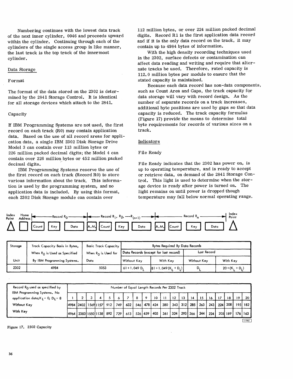
Numbering
continues
with
the
lowest
data
track
of
the
next
inner
cylinder,
0046
and
proceeds
upward
within
the
cylinder.
Continuing
through
each
of
the
cylinders
of
the
single
access
group
in
like
manner,
the
last
track
is
the
top
track
of
the
innermost
cylinder.
Data
Storage
Format
The
format
of
the
data
stored
on
the
2302
is
deter-
mined
by
the
2841
Storage
Control.
It
is
identical
for
all
storage
devices
which
attach
to
the
2841.
Capacity
If
IBM
Programming
Systems
are
not
used,
the
first
record
on
each
track
(RO)
may
contain
application
data.
Based
on
the
use
of
all
record
areas
for
appli-
cation
data,
a
single
IBM 2302
Disk
Storage
Drive
Model 3
can
contain
over
113
million
bytes
or
226
million
packed
decimal
digits
j
the
Model 4
can
contain
over
226
million
bytes
or
452
million
packed
decimal
digits.
/'
IBM
Programming
Systems
reserve
the
use
of
the
first
record
on
each
track
(Record
RO)
to
store
various
information
about
the
track.
This
informa-
tion
is
used
by
the
programming
system,
and
no
application
data
is
included.
By
using
this
format,
each
2302
Disk
Storage
module
can
contain
over
112
million
bytes,
or
over
224
million
packed
decimal
digits.
Record
R 1
is
the
first
application
data
record
and
if
it
is
the
only
data
record
on
the
track,
it
may
contain
up
to
4984
bytes
of
information.
With
the
high
density
recording
techniques
used
in
the
2302,
surface
defects
or
contamination
can
affect
data
reading
and
writing
and
require
that
alter-
nate
tracks
be
used.
Therefore,
rated
capacity
is
112.0
million
bytes
per
module
to
ensure
that
the
stated
capacity
is
maintained.
Because
each
data
record
has
non;"data
components,
such
as
Count
Area
and
Gaps,
the
track
capacity
fqr
data
storage
will
vary
with
record
design.
As
the
number
of
separate
records
on a
track
increases,
additional
byte
positions
are
used
by
gaps
so
that
data
capacity
is
reduced.
The
track
capacity
formulas
(Figure
17)
provide
the
means
to
determine
total
byte
requirements
for
records
of
various
sizes
on a
track.
Indicators
File
Ready
File
Ready
indicates
that
the
2302
has
power
on,
is
up
to
operating
temperature,
and
is
ready
to
accept
or
retrieve
data,
on
demand
of
the
2841
Storage
Con-
trol.
This
light
is
used
to
determine
when
the
stor-
age
device
is
ready
after
power
is
turned
on.
The
light
remains
on
until
power
is
dropped
though
temperature
may
fall
below
normal
operating
range.
Index
Home
I.
I I d I Index
Point Address
toI_.----Record
RO
• • Record RII
R21
---R(n-J)
...
Recor
Rn
-----I
..
~
Point
~
0 I Count I B
I-~-ata-I
B I Count I B
I-D-ata-,
~
ICount I GJ I Data I
~
Storage Track
Capacity
Basis
in
Bytes,
Basic
Track
Capacity
Bytes Required
By
Data Records
When
RO
is
Used
as
Specified
When
RO
is
Used for Data Records (except for last record)
Last
Record
Unit
By
IBM
Programming Systems. Data Without Key With Key Without Key With Key
2302 4984 5053
61
+
1.049
DL
81
+
1.049(K
L
+ DL
)
DL
20+(K
L
+ DL
)
Record
RO
used as specified by Number of Equal length Records Per 2302 Track
IBM
Programming Systems. No
application data;KL
=
0;
Dl
= 8 I 2 3 4 5 6 7 8 9
10
II
12
13 14
15
16 17 18 19 20
Without Key 4984 2402 1569 1157 912 749 632 546 478 424 380 343 312 285
263
243 224 208 195 182
With Key 4964 2383 1550 1138 892 729 613 526 459 405
361
324 293: 266 244 224 205 189 176 163
Figure
17.
2302
Capacity
36
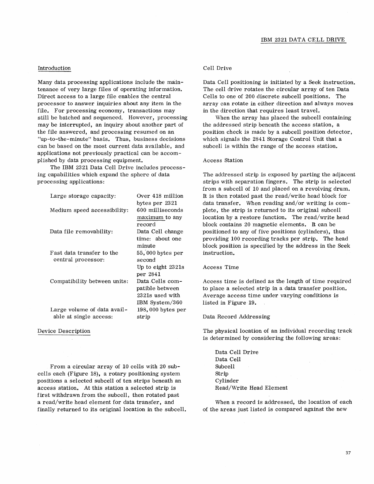
Introduction
Many
data
processing
applications
include
the
main-
tenance
of
very
large
files
of
operating
information.
Direct
access
to
a
large
file
enables
the
central
processor
to
answer
inquiries
about
any
item
in
the
file.
For
processing
economy,
transactions
may
still
be
batched
and
sequenced.
However,
processing
may
be
interrupted,
an
inquiry
about
another
part
of
the
file
answered,
and
processing
resumed
on
an
"up-to-the-minute"
basis.
Thus,
business
decisions
can
be
based
on
the
most
current
data
available,
and
applications
not
previously
practical
can
be
accom-
plished
by
data
processing
equipment.
The
IBM 2321
Data
Cell
Drive
includes
process-
ing
capabilities
which
expand
the
sphere
of
data
processing
applications:
Large
storage
capacity:
Over
418
million
bytes
per
2321
Medium
speed
accessibility:
600
milliseconds
maximum
to
any
record
Data
file
removability:
Data
Cell
change
time:
about
one
minute
Fast
data
transfer
to
the
central
processor:
Compatibility
between
units:
Large
volume
of
data
avail-
able
at
single
access:
Device
Description
55;
000
bytes
per
second
Up
to
eight
2321s
per
2841
Data
.Cells
com-
patible
between
2321s
used
with
IBM
System/360
198, 000
bytes
per
strip
From
a
circular
array
of 10
cells
with
20
sub-
cells
each
(Figure
18), a
rotary
positioning
system
positions
a
selected
subcell
of
ten
strips
beneath
an
access
station.
At
this
station
a
selected
strip
is
first
withdrawn
from
the
subcell,
then
rotated
past
a
read/write
head
element
for
data
transfer,
and
finally
returned
to
its
original
location
in
the
subcell.
IBM 2321 DATA
CELL
DRIVE
Cell
Drive
Data
Cell
positioning
is
initiated
by
a Seek
instruction.
The
cell
drive
rotates
the
circular
array
of
ten
Data
Cells
to one of 200
discrete
subcell
positions.
The
array
can
rotate
in
either
direction
and
always
moves
in
the
direction
that
requires
least
travel.
When
the
array
has
placed
the
subcell
containing
the
addressed
strip
beneath
the
access
station,
a
position
check
is
made
by
a
subcell
position
detector,
which
signals
the
2841
Storage
Control
Unit
that
a
subcell
is
within
the
range
of
the
access
station.
Access
Station
The
addressed
strip
is
exposed
by
parting
the
adjacent
strips
with
separation
fingers.
The
strip
is
selected
from
a
subcell
of 10
and
placed
on a
revolving
drum.
It
is
then
rotated
past
the
read/write
head
block
for
data
transfer.
When
reading
and/or
writing
is
com-
plete,
the
strip
is
returned
to
its
original
subcell
location
by
a
restore
function.
The
read/write
head
block
contains
20
magnetic
elements.
It
can
be
positioned
to
any
of
five
positions
(cylinders),
thus
providing
100
recording
tracks
per
strip.
The
head
block
position
is
specified
by
the
address
in
the
Seek
instruction.
Access
Time
Access
time
is
defined
as
the
length
of
time
required
to
place
a
selected
strip
in
a
data
transfer
position.
Average
access
time
under
varying
conditions
is
listed
in
Figure
19.
Data
Record
Addressing
The
physical
location
of
an
individual
recording
track
is
determined
by
considering
the
following
areas:
Data
Cell
Drive
Data
Cell
Subcell
Strip
Cylinder
Read/Write
Head
Element
When a
record
is
addressed,
the
location
of
each
of
the
areas
just
listed
is
compared
against
the
new
37
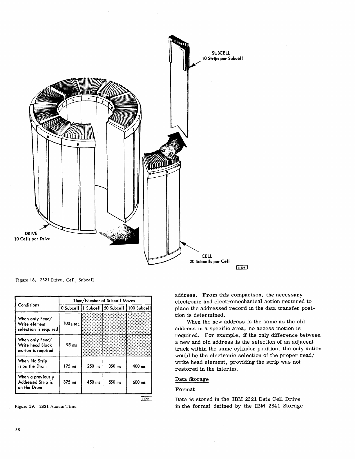
10
Ce
115
per
Drive
Figure
18.
2321
Drive,
Cell,
Subcell
Conditions
When only Read/
Write element
selection
is
required
When only Read/
Write head
Block
motion
is
required
When
No
Strip
is
on the
Drum
175
ms
When a previously
Addressed Strip
is
375
ms
on the
Drum
.
Figure
19.
2321 Access
Time
38
250
ms
350
ms
450
ms
550
ms
400
ms
600
ms
SUBCELL
10 Strips
per
Subcell
CELL
20
Subcells per Cell
address.
From
this
comparison,
the
necessary
electronic
and
electromechanical
action
required
to
place
the
addressed
record
in
the
data
transfer
posi-
tion
is
determined.
When
the
new
address
is
the
same
as
the
old
address
in
a
specific
area,
no
access
motion
is
required.
For
example,
if
the
only
difference
between
a new
and
old
address
is
the
selection
of
an
adjacent
track
within
the
same
cylinder
position,
the
only
action
would
be
the
electronic
selection
of
the
proper
read/
write
head
element,
providing
the
strip
was
not
restored
in
the
interim.
Data
Storage
Format
Data
is
stored
in
the
IBM 2321
Data
Cell
Drive
in
the
format
defined
by
the
IBM 2841
Storage
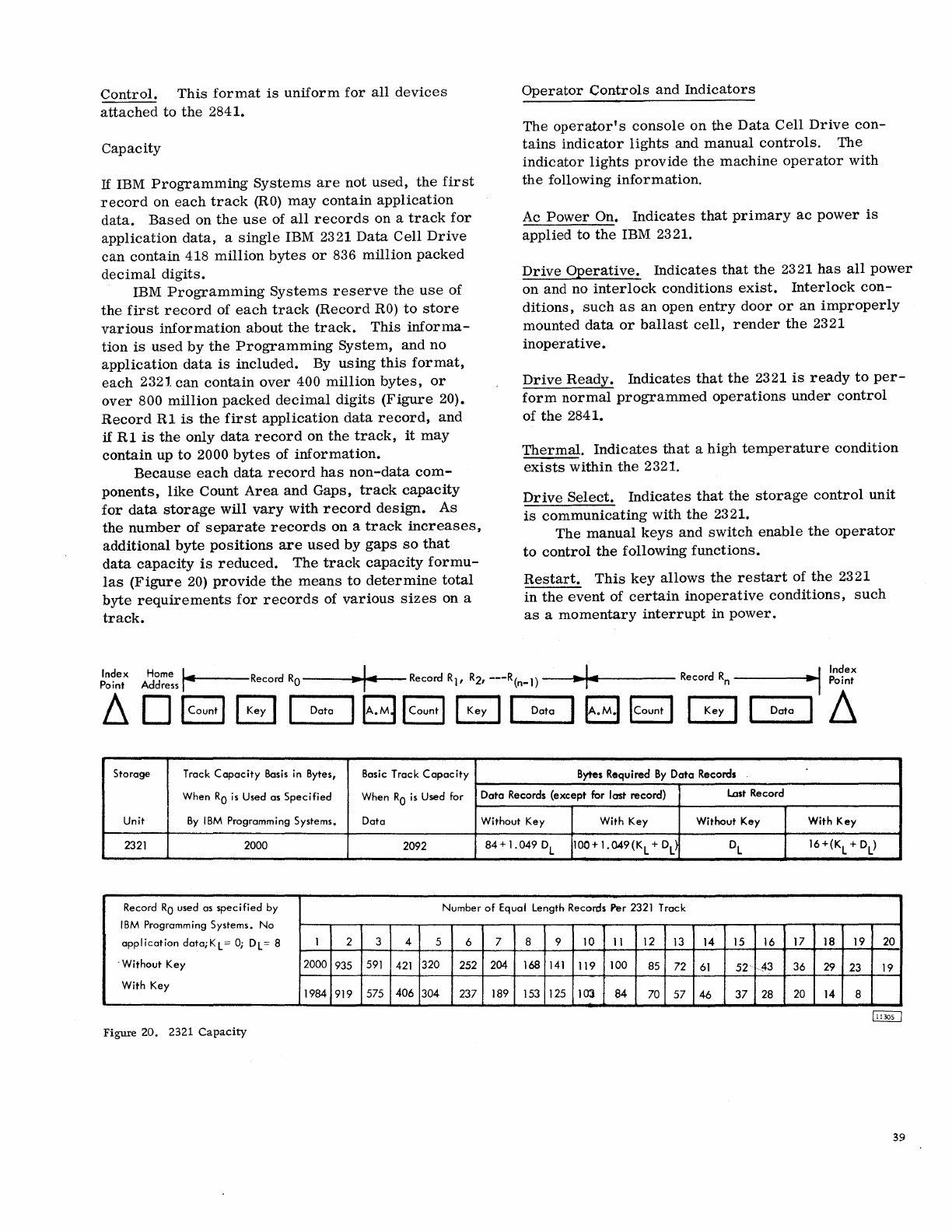
Control.
This
format
is
uniform
for
all
devices
attached
to
the
2841.
Capacity
If
IBM
Programming
Systems
are
not
used,
the
first
record
on
each
track
(RO)
may
contain
application
data.
Based
on
the
use
of
all
records
on a
track
for
application
data,
a
single
IBM 2321
Data
Cell
Drive
can
contain
418
million
bytes
or
836
million
packed
decimal
digits.
IBM
Programming
Systems
reserve
the
use
of
the
first
record
of
each
track
(Record
RO)
to
store
various
information
about
the
track.
This
informa-
tion
is
used
by
the
Programming
System,
and
no
application
data
is
included.
By
using
this
format,
each
2321
can
contain
over
400
million
bytes,
or
over
800
million
packed
decimal
digits
(Figure
20).
Record
R1
is
the
first
application
data
record,
and
if
R1
is
the
only
data
record
on
the
track,
it
may
contain
up
to
2000
bytes
of
information.
Because
each
data
record
has
non-data
com-
ponents,
like
Count
Area
and
Gaps,
track
capacity
for
data
storage
will
vary
with
record
design.
As
the
number
of
separate
records
on
a
track
increases,
additional
byte
positions
are
used
by
gaps
so
that
data
capacity
is
reduced.
The
track
capacity
formu-
las
(Figure
20)
provide
the
means
to
determine
total
byte
requirements
for
records
of
various
sizes
on a
track.
Operator
Controls
and
Indicators
The
operator's
console
on
the
Data
Cell
Drive
con-
tains
indicator
lights
and
manual
controls.
The
indicator
lights
provide
the
machine
operator
with
the
following
information.
Ac
Power
On.
Indicates
that
primary
ac
power
is
applied
to
the
IBM 2321.
Drive
Operative.
Indicates
that
the
2321
has
all
power
on
and no
interlock
conditions
exist.
Interlock
con-
ditions,
such
as
an
open
entry
door
or
an
improperly
mounted
data
or
ballast
cell,
render
the
2321
inoperative.
Drive
Ready.
Indicates
that
the
2321
is
ready
to
per-
form
normal
programmed
operations
under
control
of
the
2841.
Thermal.
Indicates
that
a
high
temperature
condition
exists
within
the
2321.
Drive
Select.
Indicates
that
the
storage
control
unit
is
communicating
with
the
2321.
The
manual
keys
and
switch
enable
the
operator
to
control
the
following
functions.
Restart.
This
key
allows
the
restart
of
the
2321
in
the
event
of
certain
inoperative
conditions,
such
as
a
momentary
interrupt
in
power.
Index
Home
,..
I
Point Address
1oI11i----Record
RO
.. ..
Record
Rl
I
R21
---R(n-D
....
Record
Rn
----
__
~-.I
Point
I I
Index
~
0 1 Count I B
"""1
D-ata--'I
B I Count
I@
I
Data
IB~
~I
Data
1/1
Storage Track
Capacity
Basis
in
Bytes, Basic Track
Capacity
Bytes Required
By
Data
Records
When
RO
is
Used as
Specified
When
RO
is
Used for Dota Records (except for last record)
Lost
Record
Unit
By
IBM
Programming Systems. Data Without Key With Key Without Key With Key
2321
2000 2092
84+
1.049
DL
100+
1.
049
(K
L
+
DL
DL
16+(K
L
+ DL
)
Record
RO
used as
specified
by Number
of
Equal Length Records Per 2321 Track
IBM
Programming Systems. No
application
data;KL =
0;
DL
= 8 1 2 3 4 5 6 7 8 9 10
11
12
13
14 15 16 17 18 19 20
. Without Key 2000 935
591
421
320 252 204 168
141
119 100 85
72
61
52
A3
36
29 23 19
With Key 1984 919 575 406 304 237 189 153 125 103
84
70
57
46
37
28 20 14 8
Figure
20.
2321
Capacity
39
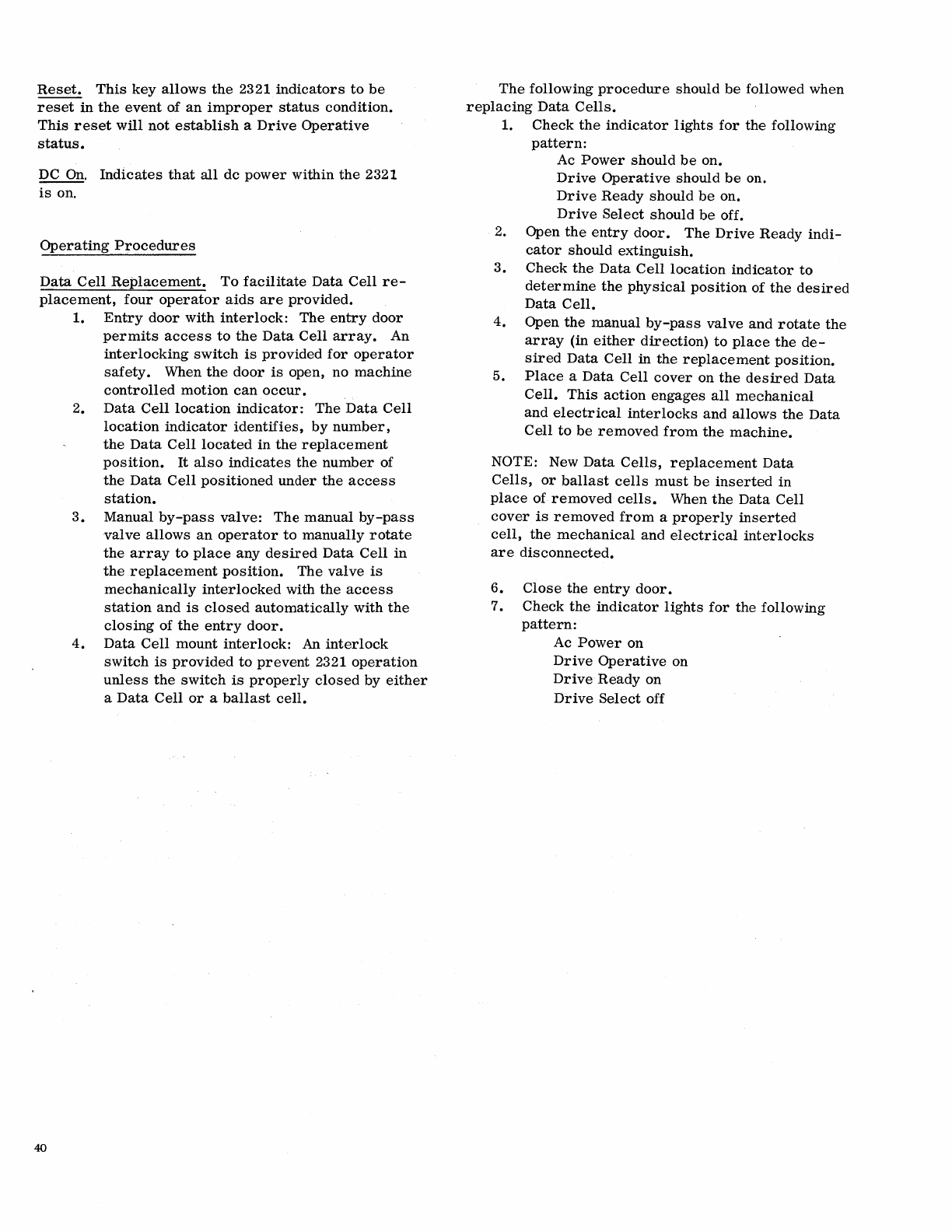
Reset.
This
key
allows
the
2321
indicators
to
be
reset
in
the
event
of
an
improper
status
condition.
This
reset
will
not
establish
a
Drive
Operative
status.
DC
On.
Indicates
that
all
dc
power
within
the
2321
is
on.
Operating
Procedures
Data
Cell
Replacement.
To
facilitate
Data
Cell
re-
placement,
four
operator
aids
are
provided.
40
1.
Entry
door
with
interlock:
The
entry
door
permits
access
to
the
Data
Cell
array.
An
interlocking
switch
is
provided
for
operator
safety.
When
the
door
is
open,
no
machine
controlled
motion
can
occur.
2.
Data
Cell
location
indicator:
The
Data
Cell
location
indicator
identifies,
by
number,
the
Data
Cell
located
in
the
replacement
position.
It
also
indicates
the
number
of
the
Data
Cell
positioned
under
the
access
station.
3.
Manual
by-pass
valve:
The
manual
by-pass
valve
allows
an
operator
to
manually
rotate
the
array
to
place
any
desired
Data
Cell
in
the
replacement
position.
The
valve
is
mechanically
interlocked
with
the
access
station
and
is
closed
automatically
with
the
closing
of
the
entry
door.
4.
Data
Cell
mount
interlock:
An
interlock
switch
is
provided
to
prevent
2321
operation
unless
the
switch
is
properly
closed
by
either
a
Data
Cell
or
a
ballast
cell.
The
following
procedure
should
be
followed
when
replacing
Data
Cells.
1.
Check
the
indicator
lights
for
the
following
pattern:
Ac
Power
should
be
on.
Drive
Operative
should
be
on.
Drive
Ready
should
be
on.
Drive
Select
should
be
off.
2. Open
the
entry
door.
The
Drive
Ready
indi-
cator
should
extinguish.
3.
Check
the
Data
Cell
location
indicator
to
determine
the
physical
position
of
the
desired
Data
Cell.
4.
Open
the
manual
by-pass
valve
and
rotate
the
array
(in
either
direction)
to
place
the
de-
sired
Data
Cell
in
the
replacement
position.
5.
Place
a
Data
Cell
cover
on
the
desired
Data
Cell.
This
action
engages
all
mechanical
and
electrical
interlocks
and
allows
the
Data
Cell
to
be
removed
from
the
machine.
NOTE: New
Data
Cells,
replacement
Data
Cells,
or
ballast
cells
must
be
inserted
in
place
of
removed
cells.
When
the
Data
Cell
cover
is
removed
from
a
properly
inserted
cell,
the
mechanical
and
electrical
interlocks
are
disconnected.
6.
Close
the
entry
door.
7.
Check
the
indicator
lights
for
the
following
pattern:
Ac
Power
on
Drive
Operative
on
Drive
Ready
on
Drive
Select
off
Introduction
The IBM 2303
Drum
Storage
provides
on-line
random
acce~s
storage
of
4.006
million
bytes
on a
magnetic
drum.
Two 2303s
may
be
attached
to
each
2841
Storage
Control
Unit
for
a
total
on-line
random
ac-
cess
storage
of
8.012
million
bytes
or
16.024
million
packed
decimal
digits.
The
drum
is
divided
into
800
data
tracks;
each
track
has
a
read/write
head
and
may
contain
up to
5,008
bytes
of
data.
The
maximum
data
transfer
rate
is
312.5
thousand
bytes
per
second.
Device
Description
The 2303
Drum
Storage
consists
of a
vertically
mounted
drum
and
its
associated
electronic
cir-
cuitry.
The
drum,
coated
with a
magnetic
record-
ing
material,
rotates
at
about
3,
500
revolutions
per
minute.
The
surface
of
the
drum
is
divided
into
tracks.
These
addressable
tracks,
extending
around
the
periphery
of
the
drum,
are
used
for
storing
data
as
follows:
800
Standard
Data
Tracks
80
Alternate
Data
Tracks
The
alternate
tracks
are
provided
to
ensure
that
each
recorded
bit
can
be
stored
in
a
magnetically
perfect
medium.
If a
defect
is
encountered
on a
track,
the
entire
track
is
disabled
and one of
the
alternate
tracks
is
substituted.
This
alternate
track
is
given
the
address
of
the
disabled
track.
Each
data
track
has
its
own
read/write
head,
used
for
both
recording
and
retrieving
data.
The
data
read/write
heads
are
fixed
in
position
on 20
vertical
racks
that
surround
the
drum.
Each
rack
contains
40
data
read/write
heads.
Access
Time
Because
of
the
assignment
of
an
individual
read/write
.
head
to
each
data
track,
data
seek
operations,
with
their
associated
access
motion
time
delay,
are
eliminated.
Therefore,
the
access
time
is
composed
of only
the
rotational
time
of
the
drum.
Maximum
rotational
time
17
. 5
ms.
Average
rotational
time
8.6
ms.
IBM 2303 DRUM STORAGE
Data
Record
Addressing
Arrangement
of
read/write
heads
on
vertical
racks
retains
the
cylinder
concept.
Cylinder
operations
with
the
2303 allow
up
to
800
tracks
to
be
written
or
read
with a
single
drum
storage
order.
Data
Storage
Format
Data
is
stored
in
the
IBM 2303
Drum
storage
in
the
format
defined
by
the
2841
Storage
Control.
This
format
is
uniform
for
all
storage
devices
which
attach
to
the
2841.
Capacity
If
IBM
Programming
Systems
are
not
used,
the
first
record
on
each
track
may
contain
application
data.
Based
on
the
use
of
all
records
on a
track
for
application
data,
a
single.IBM
2303
Drum
Storage
Unit
can
contain
over
4.006
million
bytes
or
over
8.012
million
packed
decimal
digits.
IBM
Programming
Systems
reserve
the
use
of
the
first
record
of
each
track
(Record
RO),
to
store
various
information
about
the
track.
This
informa-
tion
is
used
by
the
Programming
System,
and no
application
data
is
included.
By
using
this
format,
each
2303
can
contain
over
3.
913
million
bytes,
or
7.826
million
packed
decimal
digits
(Figure
21).
Record
Rl
is
the
first
application
data
record,
and
if
Rl
is
the
only
data
record
on
the
track,
it
may
contain up
to
4,892
bytes
of
information.
With
the
high
density
recording
techniques
used
in
the
2303
minute
contamination
particles
can
affect
data
reading
and
writing.
Therefore,
80
alternate
tracks
are
provided
to
ensure
that
the
stated
capacity,
based
on 800
tracks
is
maintained.
Because
each
data
record
has
non-data
compo-
nents,
like
Count
Area
and
Gaps,
track
capacity
for
data
storage
will
vary
with
record
design.
As
the
number
of
separate
records
on a
track
increases,
additional
byte
pOSitions
are
used
by
gaps
so
that
data
capacity
is
reduced.
The
track
capacity
formulas
(Figure
21)
provide
the
means
to
determine
total
byte
requirements
for
records
of
various
sizes
on a
track.
41
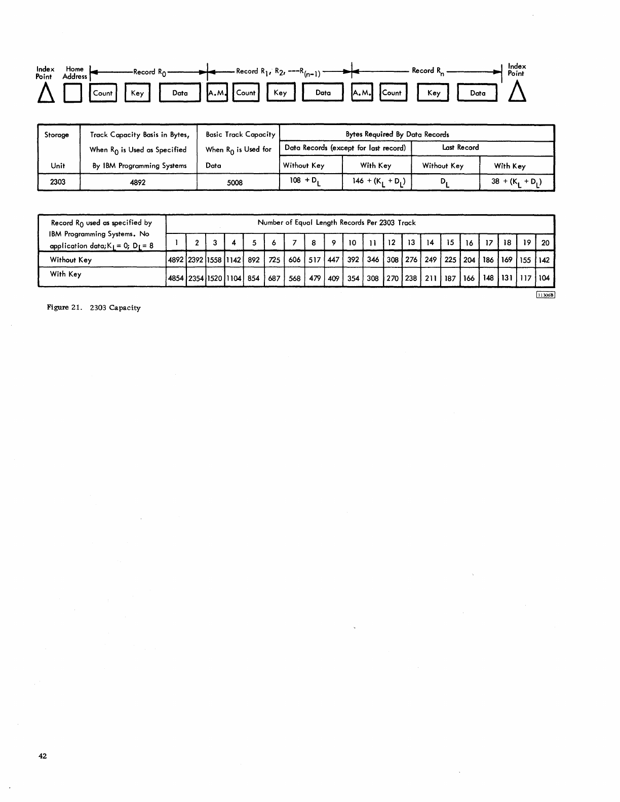
~~1~t
A~d~~s
...
14
.....
---Record
RO
~
I-
Record R1,
R2,
---R(n-l)
..
1~
Record
Rn
----
.......
..,1
~~~~:
~
0 I Count I B
-I
-Data-,
B I Count
I@
,--Data-,
~
ICount I G I Data I
~
Storage Track
Capacity
Basis
in Bytes, Basic Track
Capacity
Bytes Required
By
Data Records
When
RO
is
Used as Specified When
RO
is
Used for Data Records (except for lost record)
Last
Record
Unit
By
IBM
Programming Systems Data Without Key With Key Without Key With Key
2303 4892 5008 108 +
DL
146 +
(K
L + DL
)
DL
38 +
(K
L + DL
)
Record
RO
used as specified by Number
of
Equal Length Records Per 2303 Track
IBM
Programming Systems. No
application
data;Kl
=
0;
Dl
= 8 1 2 3 4 5 6 7 8 9 10
11
12
13
14
15
16 17 18 19 20
Without Key 4892 2392 1558 1142 892 725 606
517
447 392 346 308 276 249 225 204 186 169 155 142
With Key 4854 2354 1520 1104 854
687
568 479 409 354 308 270 238
211
187 166
148
131
117 104
Figure
21.
2303
Capacity
42
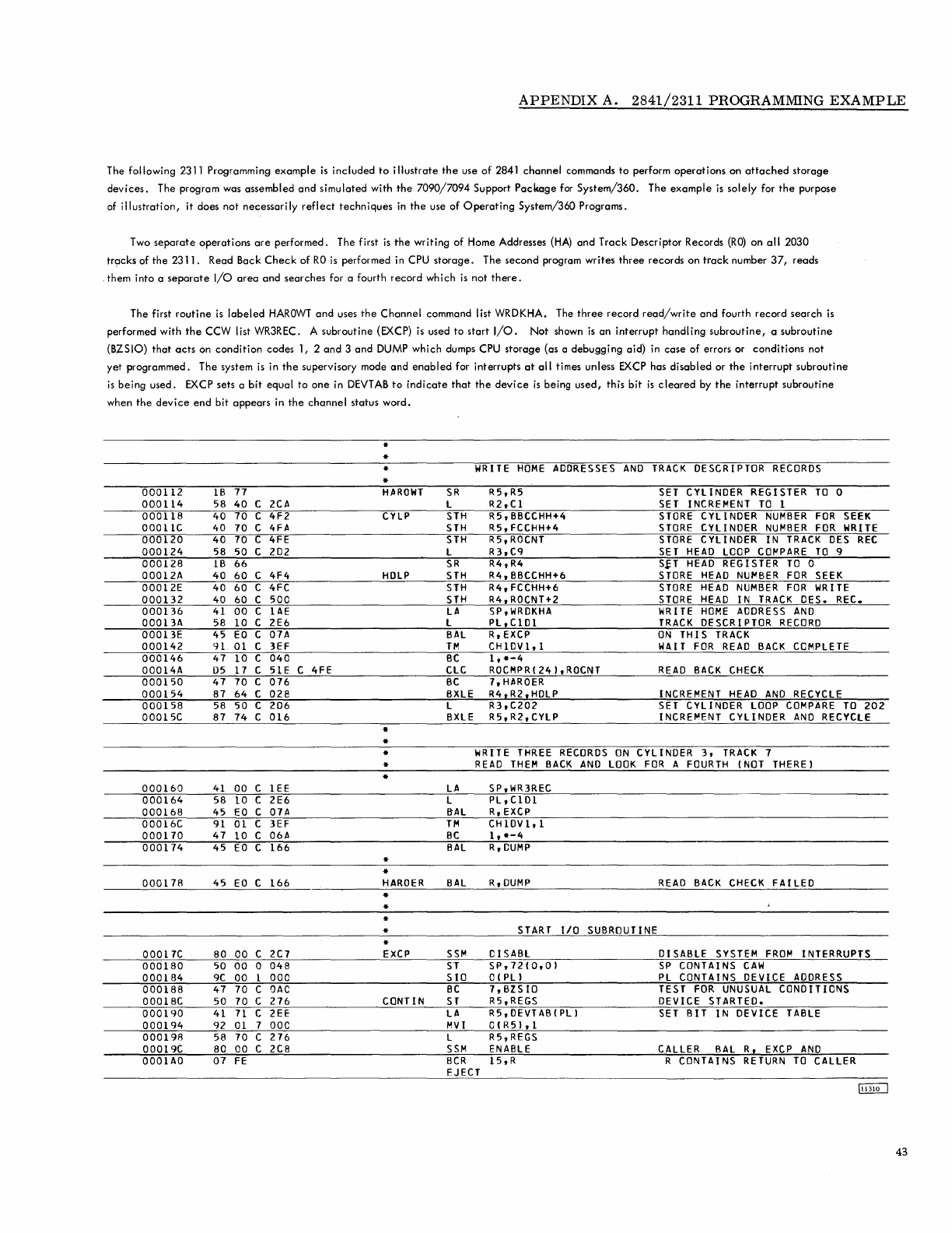
APPENDIX
A.
2841/2311
PROGRAMMING
EXAMPLE
The following 2311 Programming
example
is
included
to
illustrate
the
use
of
2841
channel
commands
to
perform
operations
on
attached
storage
devices.
The program was assembled
and
simulated with
the
7090/7094
Support
Package
for
System/360.
The
example
is
solely
for
the
purpose
of
illustration,
it
does not
necessarily
reflect
techniques
in
the
use
of
Operating
System/360 Programs.
Two
separate
operations
are
performed. The first
is
the
writing
of Home Addresses
(HA)
and
Track
Descriptor Records
(RO)
on
all
2030
trocks of
the
2311.
Read Back
Check
of
RO
is
performed in
CPU
storage.
The
second
program writes
three
records on
track
number
37,
reads
,them
into a
separate
I/O
area
and
searches for a fourth
record
which
is
not
there.
The first
routine
is
labeled
HAROWT
and
uses
the
Channel
command list WRDKHA. The
three
record
read/write
and
fourth
record
search
is
performed with
the
CCW list WR3REC. A subroutine (EXCP)
is
used
to
start
I/O.
Not
shown is
an
interrupt
handling
subroutine,
a
subroutine
(BZSIO)
that
acts
on
condition
codes 1, 2
and
3
and
DUMP which dumps
CPU
storage
(as a
debugging
aid) in
case
of
errors or
conditions
not
yet programmed. The system
is
in
the
supervisory mode
and
enabled
for interrupts
at
all
times unless
EXCP
has
disabled
or
the
interrupt
subroutine
is
being
used.
EXCP
sets a
bit
equal
to
one
in
DEVTAB
to
indicate
that
the
device
is
being
used,
this
bit
is
cleared
by
the
interrupt
subroutine
when
the
device
end
bit
appears
in
the
channel
status word.
000112
IB
71
000114
58 40
000118
40 70
00011C 40
10
000120
40
10
000124
58
50
000128
IB
66
00012A 40 60
00012E 40 60
000132
40 60
000136
41
00
00013A 58 10
00013E 45
EO
000142
91
01
000146
41 10
00014A 05 17
000150
47
10
000154
81 64
000158
58
50
00015C 87
14
000160
41
00
000164
S8
10
000168
45
EO
00016C
91
01
000170
47 10
000114
45
EO
000178
45
EO
00017C 80 00
000180
50 00
000184
9C
00
000188 47 10
00018C 50 70
000190
41
11
000194
92
01
000198
58 70
00019C 80 00
0001AO 07
FE
C 2CA
C 4F2
C
4FA
C
4FE
C
202
C 4F4
C
4FC
C 500
C
LAE
C 2E6
C
0711
C
3EF
C 040
C 51E
C 016
C 028
C 206
C 016
C
lEE
C 2E6
C
0711
C
3EF
C
06A
C 166
C 166
C
2C7
0 048
1 000
C
OAO
C 276
C
2EE
1 000
C 276
C
2C8
C4FE
*
*
*
*
HAROWT
CYLP
HDLP
*
*
*
*
•
•
*
HARDER
11:
•
•
*
EXCP
CaNTIN
WRITE
HOME
ADDRESSES
AND
TRACK
DESCRIPTOR
RECORDS
SR
L
STH
STH
STH
L
SR
STH
STH
STH
LA
L
BAL
TM
BC
CLC
BC
BXLE
L
BXLE
R5,R5
R2,C1
RS,BBCCHH+4
R5,FCCHH+4
RS,ROCNT
R3,C9
R4,R4
R4,BBCCHH+6
R4,FCCHH+6
R4,ROCNT+2
SP,WRDKHA
PL,CI01
R,EXCP
CH1DV1,1
1,*-4
ROCMPR(Z4),ROCNT
7,HAROER
R4,RZ,HDLP
R3,C202
RS,R2,CYLP
SET
CYLINDER
REGISTER
TO
0
SET
INCREMENT
TO
1
STORE
CYLINDER
NUMBER
FOR
SEEK
STORE
CYLINDER
NUMBER
FOR
WRITE
STORE
CYLINDER
IN
TRACK
OES
REC
SET
HEAD
LOOP
CO~PARE
TO
9
S&T
HEAD
REGISTER
TO
0
STORE
HEAD
NU~BER
FOR
SEEK
STORE
HEAD
NUMBER
FOR
WRITE
STORE
HEAD
IN
TRACK
DES.
REC.
WRITE
HOME
ADORESS
AND
TRACK
DESCRIPTOR
RECORD
ON
THIS
TRACK
WAIT
FOR
READ
BACK
COMPLETE
READ
BACK
CHECK
INCREMENT
HEAD
AND
RECYCLE
SET
CYLINDER
LOOP
COMPARE
TO
202
INCRE~ENT
CYLINDER
AND
RECYCLE
WRITE
THREE
RECORDS
ON
CYLINDER
3,
TRACK
7
READ
THEM
BACK
AND
LOOK
FOR
A
FOURTH
(NOT
THERE)
LA
SP,WR3REC
L PL,CID1
B'AL
R,
EXCP
TM
CHIDV1,l
BC
1,
*-4
BAL
R,DUMP
BAL
SSM
ST
SIO
BC
ST
LA
MVI
L
SSM
BCR
EJECT
R,DUMP
START
1/0
SUBROUTINE
CISABL
SP,12(0,0)
O(PL)
7,BlS10
R5,REGS
RS,OEVTAB(Pl)
O(RS),l
RS,REGS
ENABLE
15,R
READ
BACK
CHECK
FAILED
DISABLE
SYSTEM
FROM
INTERRUPTS
SP
CONTAINS
CAW
PL
CONTAINS
DEVICE
ADDRESS
TEST
FOR
UNUSUAL
CONDITIONS
DEVICE
STARTED.
SET
BIT
IN
DEVICE
TABLE
CALLER
BAL
R,
EXCP
AND
R
CONTAINS
RETURN
TO
CALLER
43
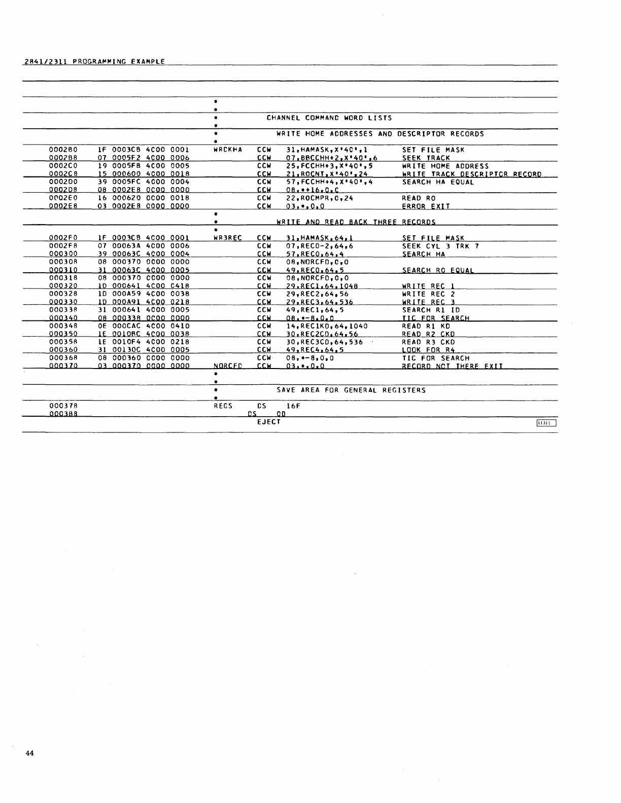
2A41/2311
PROGRA~MING
EXAMPLE
•
..
• CHANNEl
COfolMANC
WORD
1I
STS
•
..
WR
ITE
HOME
ADDRESSES
AND
DESCRIPTOR
RECORDS
..
0002BO
IF
0003eB
4COO
0001
WRCKHA
ecw
31,HAMASK,X'4C',1
SET
FILE
MASK
000288
01
0005F2
4COO
0006
ccw
01.BBCCHH+2.X'40'.6
SEEK
TRACK
0002eo
19
0005fB
4COO
0005
CCW
25,FCCHH+3,X'40',5
WR
I
TE
HofolE
ADORESS
0002e8
15
000600
4COO
001S
CCW
21.ROCNT.X'40'.24
IoiR
I
TE
TRACK
DESCRIPTCR
RECORD
000200
39
0005FC
4000
0004
CCW
57;FCCHH+4,X'40',4
SEARCH
HA
EOUAl
000208
OS
0002E8
OCOO
OOOQ
CCW
OS,.+16,O,C
O('l02EO
16
000620
OCOO
0018
ecw
22,ROCMPR,Q,24
READ
RO
0002ES
03
0002E8
COOO
0000
ccw
03,·,0.0
ERROR
EXIT
•
..
WRITE
AND
REAP
BACK
THREE
RECORPS
..
0002FO
IF
0003eB
4COO
0001
WfOREC
CCW
3l.HAMASK.64.1
SE
T
FILE
foIASK
0002ER
07
00063A
4COO
0006
CCW
07,RECO-2,64,6
SEEK
eYl
3
TRK
7
000300
39
00063C
4COO
0004
Ccw
51.RECO.64.4
SEARCH
HA
00030A
0.8
000310
0000
0000
ecw
OA,N{)RCFD,Q,O
OQ
0
31
0
31
00063e
4COO
0005
ccw
49.RECO.64.5
SEARCH
BO
EOUAl
000318
08
000370
CCOO
0000
ccw
08,NORCFD,O,0
000320
10
000641
4COO
C418
CCW
29.RECl.64.1048
WRITE
REe 1
000328
10
000A59
4COO
0038
ecw
29,REC2,64,56
WR
I
TE
REC
2
OOOUO
10
000A91
4COO
0218
ccw
29.REC3.64.536
WRITE
REC
3
000338
31
000641
4COO
0005
Ccw
49,RECl,64,5
SEARCH
Rl
10
00034
0
08
oooua
OCOO
0000
CCW
08.*-8,0,0
TIC
EQR
SEARCH
000348
OE
OOOCAC
4COO
0410
CCW
14,RECIKO,64,1040
READ
Rl
KD
000350
IE
0010Re
4COO
0038
ccw
30.REC2CD.64.S6
REAP
R2
CKO
000358
lE
0010f4
4COO
0218
CCW
30,REC3CO,64,536
READ
R3
CKD
000360
31
00130C
4COO
0005
CCW
49,REC4.64.5
LOOK
FOR
R4
000368
08
000360
CCOO
0000
CCW
08,*-8,0,0
TIC
FOR
SEARCH
OQOlIO
03
ooouo
OCOO
OQOQ
NQRCH)
COl
03
..
,0,0
RECORD
NCT
THEBE
EXIT
..
•
..
SAVE
AREA
FOR
GENERAL
REG
I STERS
..
000378
REGS
CS
16F
oooHa
os.
00
EJECT
§II]
44

2841/2311
PROGRA~MING
EXA~PlE
•
CONSTANTS
•
OOOJBA
0000000000
NICPSW
DC
Xl5'OOOOOOOOOO'
OOOlBD
0001FC
DC
Al3{INTl
0003CO
FFOOOOCO
APSW
DC
X'FFOOOOOO'
0003C4
OS
F
0003C8 00 ECFFlG
DC
X'OO'
0003Cq
00
DISA8l
DC
X'OO'
0003CA
FF
E"'~BlE
DC
X'FF'
0003C8
CO
H.6~.ASK
DC
X'CC'
FILE
MASK-ALL
WRITES-All
SEEKS
0003CC
00000001
Cl
DC
F
'1'
000100
00000C04
C4
DC
F'4'
000304
00000009
C<.l
DC
F'<.l'
000308
OOCOOCCA
C202
DC
F'202'
0003DC
00000001
COllI
DC
F I
I'
READER
SYSINI
OOOlFO
00000002
COD2
DC
F I
2'
PRINTER
SYSOU1
00031:4
00000100
CIDO
DC
F'
256'
TAPE
IN/Ol;T
SYSUT4
OOOlES
00000101
CllB
DC
F'
257'
2311
SYSCKI
0003FO
DEVTAA
OS
64C
STATUS
OF
DEVICES
0003FO
ORG
OEVTA8
ONE
ECUAlS
BUSY
0003FO
OC
CHOOVO
DC
X'OO' lERO
EQUALS
FREE.
0003Fl
00
CHCOVI
DC
X'OO'
000JF2
00
CHODV2
DC
X'OO'
0004FO
ORG
CEVTAR+256
0004FO 00
CHICVO
DC
X'OO'
0004Fl
00 CHIDVI
DC
X'OO'
0004F2
00 CHICV2
DC
X'OO'
0005FO
ORG
D EVTAB+512
•
RECORD
AREAS
0005FO
00000000
8BCCHH
DC
2F'0'
SEEK
ADDRESS
00
BB
CC
HH
0005F4
00000000
0005FA
00000000
FCCHH
DC
2F'0'
HO~E
ADDRESS
00
OF
CC
HH
0005FC
OOOOOOCO
000600
0000000000000010
ROCNT
DC
XLS
'
I0'
RO
COUNT
F I
HD
000608
000000000000000000
ROCATA
DC
Xl16'0'
RO
OATA
FIElD
00C611
OOOOOOOOOCCCOO
OC061A
OOOOOOOC
HAC~PR
DC
2F'O'
HA
COMPARE
00
OX
XX
XX
0006lC
00000000
000620
ROC~PR
OS
6F
TRACK
RO
CC~PARE
AREA
0006J8
OOOOOCOO
CC
F'O'
00C63C
0003000700
RECO
CC
X'00030007CO'
RO
10
000641
00030007011C0400
RECI
DC
X'00030007011004CO'
COUNT
00064Q
OS
Cll6
KEY
000659
OS
64Cl16
DATA
OOOA
'jQ
00030007021C0020
REC2
DC
X'OO030007C21C0020'
COUNT
000A61
OS
Cll6
KEY
OOOA
71
OS
2CL16
DA
TA
0001\
91
00030007031
C
0200
REC3
OC
X'OO030007031C0200'
COUNT
OOOA
99
09C5C3060QC440F340
DC
CL16'RECORC 3
KEYKEY
•
KEY
00OAA2
02C5E802C5E840
000AA9
OS
32CLl6
DATA
OOOC
AC
RECIKO
OS
260F
BUFFER
FOR
READ
BACK
0010t3C
REC2CC
OS
14F
0010F4
REC3CC
OS
134F
OODOC
0003000704
REC4
DC
X'0003000704'
RECORD
NOT
THERE
YET
~
4S
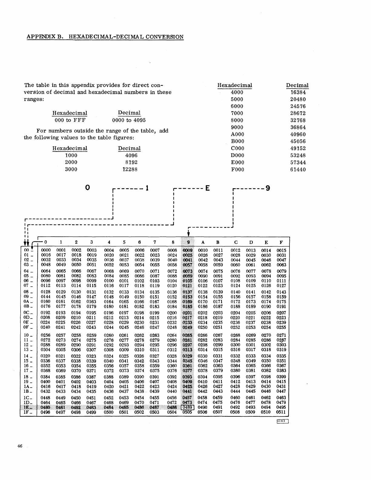
APPENDIX
B.
HEXADECIMAL-DECIMAL
CONVERSION
The
table
in
this
appendix
provides
for
direct
con-
Hexadecimal
Decimal
version
of
decimal
and
hexadecimal
numbers
in
these
4000
16384
ranges:
5000
20480
6000
24576
Hexadecimal
Decimal
7000
28672
000
to
FFF
0000
to
4095
8000
32768
For
numbers
outside
the
range
of
the
table,
add
9000
36864
AOOO
40960
the
following
values
to
the
table
figures:
BOOO
45056
Hexadecimal
Decimal
COOO
49152
1000
4096
DOOO
53248
2000
8192
EOOO
57344
3000
12288
FOOO
61440
0
r------
1
r------
E r-----
--
9
I I I
I I I
I I I
I I I
I I I
I I I
r---------------------J I I
Ir------------------------------------J
I
II
r------------'
II
II
0 2 3 4 5 6 7 8 A B C D E F
0000
0001
0002
0003 0004 0005
0006
0007
0010
0011
0012
0013 0014
0015
0016
0017
0018
0019
0020
0021
0022 0023
0026 0027 0028 0029
0030
0031
0032
0033
0034
0035
0036
0037
003S
0039 0042
0043
0044
0045
0046
0047
0048
0049 0050
0051
0052
0053 0054 0055 0058 0059 0060
0061
0062
0063
04
_
0064
0065 0066
0067
0068
0069
0070
0071
0074
0075 0076 0077
0078
0079
05
_
0080
0081
0082
0083
0084 0085
0086
0087 0090
0091
0092 0093 0094
0095
06_
0096 0097
0098 0099 0100
0101
0102
0103
0106 0107
0108 0109 0110
0111
07
_
0112 0113 0114 0115
0116
0117
0118 0119
0122
0123
0124
0125 0126
0127
08
_
0128
0129 0130
0131
0132 0133 0134
0135
0138
0139 0140
0141
0142 0143
09
_
0144 0145
0146
0147
0148
0149
0150
0151
0154 0155
0156
0157
0158
0159
OA_
0160
0161
0162 0163
0164 0165
0166
0167
0170
0171
0172
0173
0174 0175
OB_
0176
0177
0178 0179
0180
0181
0182 0183 0186
0187
0188 0189 0190
0191
OC_
0192 0193 0194
0195 0196
0197
0198
0199
0202 0203
0204
0205 0206
0207
OD_
0208 0209 0210
0211
0212
0213 0214
0215 0218 0219 0220
0221
0222
0223
OE
_
0224 0225
0226
0227
0228
0229
0230
0231
0234
0235 0236 0237
0238
0239
OF
_
0240
0241
0242
0243
0244
0245
0246 0247
0250
0251
0252
0253
0254
0255
10_
0256 0257 0258
0259 0260
0261
0262 0263 0266
0267
0268
0269 0270
0271
11_
0272 0273
0274
0275
0276
0277
0278
0279 0282 0283
0284
0285 0286
02~7
12
_
0288
0289 0290
0291
0292
0293 0294
0295
0298
0299 0300
0301
0302 0303
13
_
0304 0305
0306 0307 0308
0309
0310
0311
0314 0315
0316 0317 0318 0319
14
_
0320
0321
0322 0323
0324
0325 0326
0327
0330
0331
0332 0333
0334
0335
15
_
0336 0337
0338
0339
0340
0341
0342 0343
0346
0347 0348 0349
0350
0351
16
_
0352
0353
0354
0355
03.56
0357
0358 0359
0362
0363
0364
0365 0366
0367
17
_
0368
0369
0370
0371
0372
0373 0374
0375 0378
0379 0380
0381
0382 0383
0384
0385 0387
0388
0389
0390
0391
0394
0395
0396
0397 0398 0399
0400
0401
0403 0404
0405
0406
0407
0410
0411
0412 0413 0414
0415
0416 0417
0419
0420
0421
0422 0423 0426
0427
0428
0429 0430
0431
0432 0433 0435 0436
0437 0438
-
0439
0442
0443
0444
0445
0446 0447
0458
0459 0460
0461
0462 0463
0474
0475 0476
0477 0478 0479
0490
0491
0492
0493
0494
0495
0506
0507 0508
0509
0510
0511
~
46
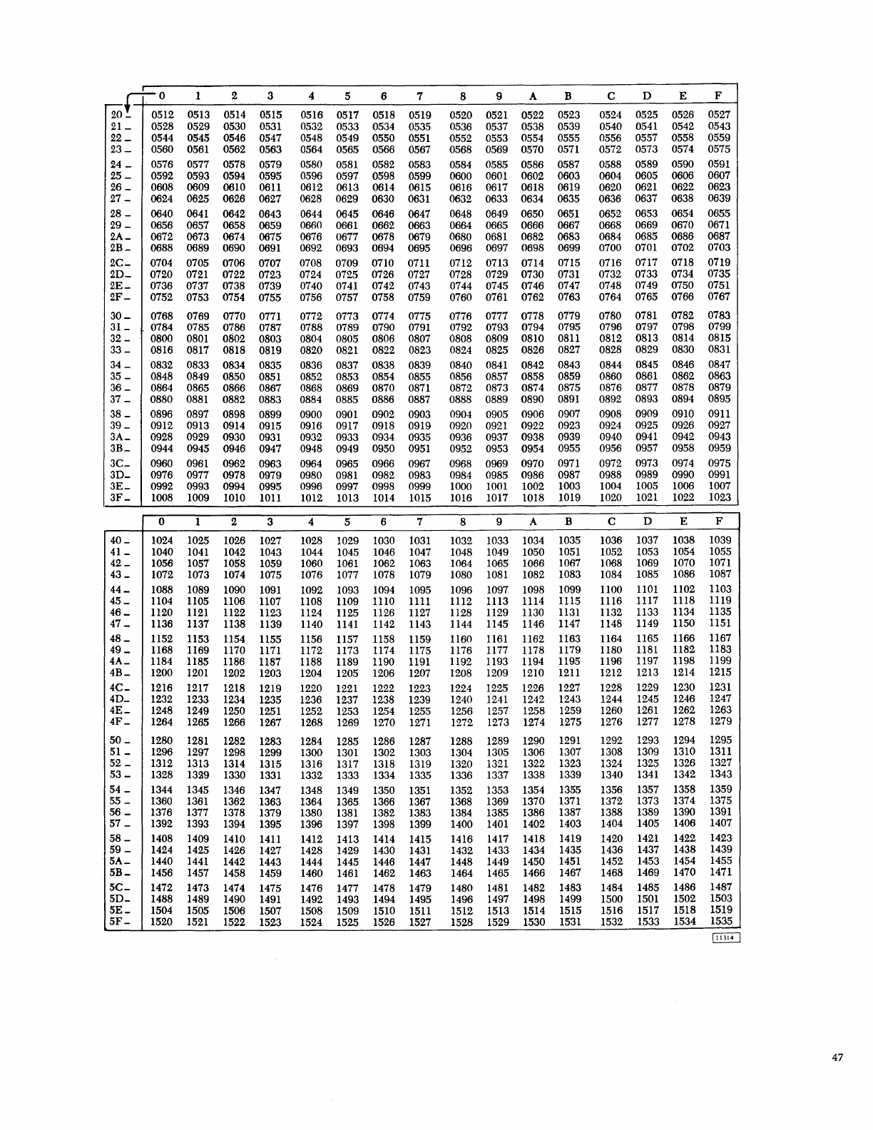
20£+0:12
1 2 3 4 5 6 7 8 9 A B C D E F
0513 0514 0515
0516 0517 0518 0519
0520
0521
0522
0523
0524 0525 0526
0527
21_
0528 0529 0530
0531
0532
0533
0534
0535 0536 0537
0538 0539 0540
0541
0542
0543
22_
0544 0545
0546 0547
0548
0549 0550
0551
0552
0553
0554
0555 0556 0557
0558 0559
23-
0560
0561
0562 0563
0564
0565
0566 0567
0568
0569
0570
0.571
0572
0573
0574
0575
24
_
0576
0577 0578
0579
0580
0581
0582
0583
0584
0585
0586
0587 0588
0589
0590
0591
25-
0592
0593
0594
0595
0596
0597
0598
0599 0600
0601
0602
0603 0604 0605
0606
0607
26
_
0608
0609
0610
0611
0612
0613
0614
0615 0616
0617
0618
0619 0620
0621
0622
0623
27
_
0624 0625
0626 0627
0628
0629
0630
0631
0632
0633
0634
0635 0636
0637 0638
0639
28
-
0640
0641
0642 0643
0644
0645 0646 0647
0648 0649
0650
0651
0652 0653
0654
065.5
29
-
0656 0657 0658
0659
0660
0661
0662
0663
0664 0665
0666
0667
0668
0669 0670
0671
2A_
0672 0673 0674 0675
0676
0677 0678 0679
0680
0681
0682 0683
0684
0685 0686
0687
2B-
0688 0689 0690
0691
0692
0693 0694
0695
0696
0697
0698
0699 0700
0701
0702
0703
2C-
0704
0705 0706
0707 0708
0709
0710 0711
0712 0713
0714
0715
0716
0717 0718
0719
2D_ 0720
0721
0722
0723
0724
0725 0726 0727 0728 0729
0730
0731
0732 0733
0734
0735
2E_
0736 0737 0738
0739
0740
0741
0742
0743
0744 0745
0746
0747 0748
0749
0750
0751
2F-
0752 0753 0754
0755
0756
0757 0758 0759 0760
0761
0762
0763 0764 0765 0766 0767
30_
0768
0769 0770
0771
0772 0773 0774 0775
0776
0777
0778
0779 0780
0781
0782 0783
31_
0784 0785 0786 0787 0788
0789
0790
0791
0792 0793 0794 0795 0796
0797
0798
0799
32
-0800
0801
0802 0803
0804
0805
0806
0807
0808 0809
0810
0811
0812
0813
0814
0815
33_
0816 0817
0818
0819 0820
0821
0822 0823
0824 0825
0826
0827
0828
0829
0830
0831
34
_
0832 0833 0834 0835 0836 0837 0838 0839 0840
0841
0842
0843 0844
0845 0846 0847
35
-
0848 0849 0850
0851 0852
0853
0854
0855
0856
0857
0858 0859 0860
0861
0862
0863
36
_
0864 0865 0866
0867 0868
0869 0870
0871
0872 0873
0874 0875
0876 0877 0878
0879
37
_ 0880
0881
0882 0883
0884
0885 0886 0887 0888 0889
0890
0891
0892 0893 0894 0895
38
_
0896
0897
0898 0899
0900
0901
0902 0903
0904 0905
0906
0907
0908
0909
0910
0911
39_
0912
0913 0914 0915
0916
0917
0918
0919
0920
0921
0922
0923
0924
0925 0926 0927
3A_ 0928
0929 0930
0931
0932
0933
0934
0935 0936 0937
0938 0939
0940
0941
0942
0943
3B_
0944
0945 0946 0947
0948
0949 0950
0951
0952
0953 0954
0955 0956 0957 0958
0959
3C_
0960
0961
0962 0963
0964
0965
0966
0967
0968
0969 0970
0971
0972
0973
0974
0975
3D-
0976 0977 0978 0979
0980
0981
0982
0983
0984
0985
0986
0987 0988
0989
0990
0991
3E_
0992 0993
0994
0995 0996 0997 0998 0999
1000
1001
1002 1003
1004
1005 1006 1007
3F _
1008 1009
1010
1011
1012
1013
1014 1015
1016 1017
1018
1019 1020
1021
1022
1023
0 1 2 3 4 5 6 7 8 9 A B C D E F
40_
1024
1025 1026
1027
1028 1029
1030
i031
1032 1033 1034 1035 1036 1037
1038
1039
41_
1040
1041
1042
1043
1044 1045 1046 1047
1048 1049
1050
1051
1052
1053
1054
1055
42_
1056 1057 1058 1059
1060
1061
1062 1063
1064
1065 1066 1067
1068
1069
1070
1071
43
_
1072
1073
1074
1075
1076
1077 1078
1079
1080
1081
1082 1083
1084
1085 1086 1087
44_
1088 1089 1090
1091
1092 1093
1094 1095
1096 1097
1098
1099
1100
1101
1102 1103
45_
1104
1105
1106
1107 1108
1109
lll0
llll
ll12 ll13
1114
lll5
1116 1117 1118
ll19
46_
1120
ll21
1122
ll23
ll24
ll25
ll26 ll27
1128
1129 1130
ll31
1132
1133
ll34
ll35
47
_
ll36
1137 1138
1139
1140
1141
ll42 ll43
1144 1145
1146
1147 1148
1149
ll50
1151
48_
1152 1153
ll54
ll55
1156
ll57 ll58
ll59
1160
ll61
ll62 ll63
ll64
ll65
1166 1167
49_
1168
ll69
1170
1171
1172
1173
ll74
1175 1176
1177
ll78
1179 1180
1181
1182
ll83
4A_
1184
ll85 ll86 ll87 ll88 ll89
1190
1191
1192
1193
1194
ll95
1196
ll97 ll98
ll99
4B_
1200
1201
1202 1203 1204
1205
1206 1207
1208
1209
1210
12ll
1212
1213 1214 1215
4C_
1216
1217
1218
1219 1220
1221
1222
1223 1224
1225
1226
1227
1228 1229 1230
1231
4D_
1232
1233
1234
1235
1236
1237
1238 1239 1240
1241
1242
1243 1244
1245 1246 1247
4E_
1248 1249 1250
1251
1252 1253
1254 1255 1256 1257
1258
1259 1260
1261
1262
1263
4F_
1264 1265
1266
1267 1268 1269 1270
1271
1272
1273
1274 1275 1276
1277
1278
1279
50
_
1280
1281
1282 1283
1284
1285 1286
1287 1288
1289
1290
1291
1292
1293
1294
1295
51
_
1296
1297
1298 1299 1300
1301
1302 1303
1304
1305 1306 1307 1308 1309 1310
1311
52
_
1312 1313
1314
1315
1316
1317 1318 1319
1320
1321
1322
1323
1324
1325 1326
1327
53-
1328
1329 1330
1331
1332 1333
1334
1335
1336 1337
1338
1339
1340
1341
1342
1343
54
_
1344
1345
1346 1347
1348 1349
1350
1351
1352 1353 1354
1355 1356
1357 1358
1359
55
-
1360
1361
1362
1363
1364
1365
1366 1367
1368 1369
1370
1371
1372
1373
1374
1375
56
_
1376
1377
1378
1379
1380
1381
1382 1383
1384
1385 1386
1387
1388
1389
1390 1391
57
_
1392
1393
1394
1395
1396 1397
1398
1399 1400
1401
1402 1403
1404
1405 1406
1407
58-
1408
1409
1410
14ll
1412
1413
1414
1415 1416
1417
1418
1419 1420
1421
1422 1423
59
-
1424 1425 1426 1427
1428 1429 1430
1431
1432 1433 1434 1435 1436
1437
1438
1439
5A_
1440
1441
1442 1443
1444
1445 1446
1447
1448 1449 1450
1451
1452 1453
1454
1455
5B-
1456 1457
1458
1459 1460
1461
1462
1463
1464 1465
1466
1467 1468
1469
1470
1471
5C_
1472 1473
1474
1475 1476
1477
1478
1479 1480
1481
1482 1483
1484
1485 1486
1487
5D_
1488 1489 1490
1491
1492
1493
1494
1495 1496 1497 1498
1499
1500
1501
1502
1503
5E_
1504
1505
1506 1507 1508 1509 1510
15ll
1512
1513 1514 1515
1516 1517
1518
1519
5F-
1520
1521
1522
1523
1524 1525 1526
1527
1528
1529 1530
1531
1532 1533
1534
1535
47
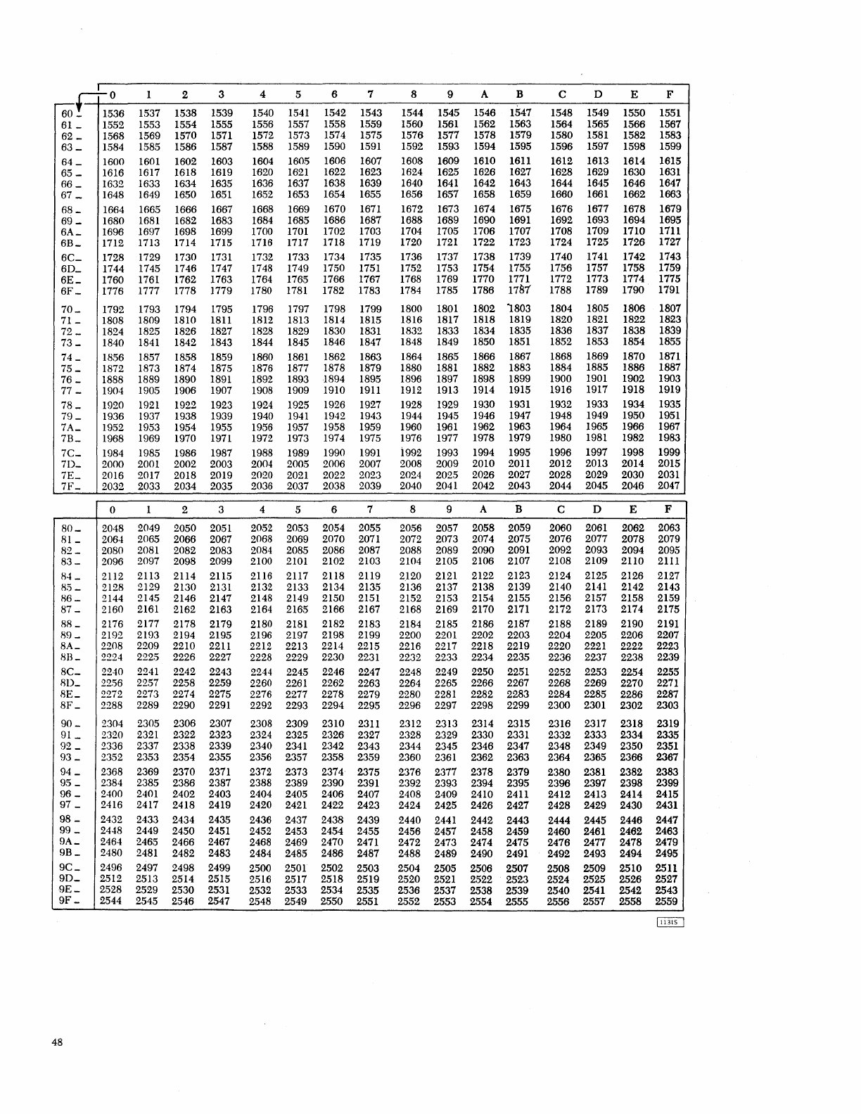
.! 0 1 2 3 4 5 6 7 8 9 A B C D E F
6of=ti536
1537 1538 1539
1540
1541
1542
1543
1544 1545
1546 1547 1548 1549 1550
1551
61
_
1552 1553
1554
1555 1556
1557
1558
1559
1560
1561
1562 1563
1564
1565
1566 1567
62
_
1568 1569
1570
1571
1572
1573
1574
1575 1576 1577 1578 1579 1580
1581
1582 1583
63_
1584
1585
1586 1587
1588
1589 1590
1591
1592 1593 1594
1595 1596 1597 1598 1599
64
_
1600
1601
1602
1603
1604
16005
1606
1607
1608
1609 1610
1611
1612 1613 1614 1615
65
_
1616
1617
1618
1619
1620
1621
1622 1623
1624
1625
1626
1627
1628 1629 1630
1631
66_
1632
1633 1634 1635 1636 1637 1638
1639
1640
1641
1642 1643
1644 1645
1646
1647
67
_
1648
1649
1650
1651 1652
1653
1654 1655 1656 1657
1658 1659 1660
1661
1662 1663
68_
1664
1665 1666
1667 1668
1669
1670
1671
1672 1673 1674 1675
1676
1677
1678 1679
69
_
1680
1681
1682 1683
1684
1685 1686 1687 1688 1689
1690
1691
1692 1693 1694 1695
6A_
1696
1697 1698
1699
1700
1701
1702
1703
1704
1705
1706
1707
1708 1709 1710
1711
6B_
1712 1713 1714
1715
1716
1717
1718 1719
1720
1721
1722 1723 1724 1725 1726 1727
6C_
1728 1729
1730
1731
1732 1733 1734
1735
1736
1737 1738
1739
1740
1741
1742 1743
6D_
1744
1745
1746
1747
1748
1749 1750
1751 1752
1753
1754 1755
1756 1757 1758 1759
6E_
1760
1761
1762 1763
1764
1765
1766 1767
1768
1769
1770
1771
1772
1773 1774
1775
6F _
1776
1777
1778
1779
1780
1781
1782 1783
1784
1785
1786 1781 1788 1789 1790
1791
70_
1792 1793 1794 1795 1796
1797
1798 1799
1800
1801
1802
1803
1804 1805 1806 1807
71_
1808 1809
1810
1811
1812
1813
1814
1815
1816 1817
1818
1819
1820
1821
1822 1823
72
_
1824 1825
1826
1827
1828
1829
1830
1831 1832
1833 1834 1835
1836 1837 1838 1839
73_
1840
1841
1842
1843
1844
1845
1846 1847
1848
1849
1850
1851
1852
1853 1854
1855
74
_
1856
1857 1858 1859
1860
1861
1862 1863
1864
1865 1866 1867 1868 1869
1870
1871
75
_
1872 1873
1874 1875
1876 1877
1878 1879
1880
1881
1882 1883 1884
1885 1886 1887
76
_
1888 1889
1890
1891 1892
1893 1894
1895
1896
1897 1898 1899
1900
1901
1902
1903
77
_
1904 1905
1906
1907
1908
1909
1910
1911
1912
1913
1914
1915
1916
1917
1918 1919
78
_
1920
1921
1922 1923
1924
1925
1926 1927
1928
1929
1930
1931
1932 1933
1934 1935
79_
1936 1937
1938 1939
1940
1941
1942
1943
1944
1945 1946 1947 1948 1949
1950
1951
7A_
1952 1953
1954 1955
1956
1957
1958 1959
1960
1961
1962 1963
1964
1965 1966 1967
7B_
1968
1969 1970
1971 1972
1973 1974 1975 1976
1977 1978
1979 1980
1981
1982
1983
7C_
1984
1985
1986
1987
1988
1989 1990
1991
1992
1993
1994
1995
1996
1997 1998 1999
7D_ 2000
2001
2002 2003
2004
200.5
2006
2007
2008
2009 2010
2011
2012 2013 2014 2015
7E_
2016
2017
2018 2019
2020
2021
2022 2023
2024
2025 2026 2027 2028 2029 2030
2031
7F_
2032 2033 2034 2035
2036
2037
2038 2039 2040
2041
2042 2043 2044 2045 2046
2047
0 1 2 3 4 5 6 7 8 9 A B C D E F
80_
2048
2049 2050
2051
2052
2053 2054 2055
20056
2057 2058 2059 2060
2061
2062
2063
81_
2064
2065
2066 2067
2068
2069 2070
2071
2072
2073 2074 2075 2076 2077 2078
2079
82
_
2080
2081
2082 2083
2084
2085 2086 2087
2088
2089 2090
2091
2092 2093 2094
2095
83_
2096
2097 2098 2099
2100
2101
2102 2103
2104
2105 2106 2107 2108 2109 2110
2111
84
_
2112
2113 2114 2115
2116
2117
2118 2119
2120
2121
2122 2123 2124 2125 2126 2127
8.'5_
2128
2129 2130
2131 2132
2133 2134
2135 2136 2137 2138 2139 2140
2141
2142 2143
86_
2144
2145
2146 2147
2148
2149
2150
2151
2152 2153
2154
2155 2156 2157 2158 2159
87
_
2160
2161
2162 2163
2164
2165 2166 2167 2168
2169 2170
2171
2172 2173 2174 2175
8tL
2176
2177
2178 2179
2180
2181
2182 2183
2184
2185 2186 2187 2188 2189 2190
2191
89_
2192
2193 2194
2195
2196
2197
2198 2199 2200
2201
2202 2203 2204 2205 2206 2207
8A_
2208
2209 2210
2211 2212
2213
2214
2215
2216 2217
2218 2219 2220
2221
2222 2223
813_
2224
222.5
2226 2227
2228
2229 2230
2231
2232
2233
2234
2235 2236 2237 2238 2239
8C_
2240
2241
2242 2243
2244
2245
2246 2247
2248
2249 2250
2251
2252 2253 2254 2255
8D_
22.56
2257
2258 2259
2260
2261
2262 2263
2264
2265 2266 2267 2268 2269 2270
2271
8E_
2272
2273
2274
2275
2276 2277
2278 2279
2280
2281
2282 2283 2284 2285 2286 2287
8F _
2288
2289 2290
2291 2292
2293
2294
2295
2296
2297 2298 2299 2300
2301
2302 2303
90_
2304
2305 2306 2307
2308
2309 2310
2311
2312 2313
2314 2315 2316 2317 2318 2319
91
_
2320
2321
2322 2323
2324
2325 2326 2327
2328 2329
2330
2331
2332 2333 2334 2335
92
_
2336
2337
2338 2339
2340
2341
2342
2343
2344 2345
2346 2347 2348 2349 2350
2351
93
_
2352
2353 2354 2355
2356
2357 2358 2359 2360
2361
2362 2363 2364 2365 2366 2367
94
_
2368
2369
2370
2371
2372
2373
2374
2375 2376 2377 2378 2379 2380
2381
2382 2383
95
_
2384
2385 2386 2387
2388
2389 2390
2391
2392 2393
2394
2395 2396 2397 2398 2399
96
_
2400
2401
2402 2403
2404
2405 2406
2407
2408 2409 2410
2411
2412 2413 2414 2415
97
_
2416
2417
2418 2419 2420
2421
2422 2423
2424
2425 2426 2427 2428 2429 2430
2431
98
-
2432
2433 2434 2435
2436 2437
2438 2439 2440
2441
2442 2443 2444 2445 2446 2447
99
_
2448
2449 2450
2451
2452
2453
2454 2455 2456
.2457
2458 2459 2460
2461
2462 2463
9A_
2464 2465
2466 2467
2468
2469 2470
2471
2472 2473 2474 2475 2476
2477
2478 2479
9B_
2480
2481
2482 2483
2484
2485
2486
2487 2488 2489 2490
2491
2492 2493 2494 2495
9C_
2496
2497
2498 2499
2.500
2501
2502 2503 2504 2505 2506 2507 2508 2509 2510 2511
90_
2512
2513 2514 2515
2516
2517 2518 2519 2520
2521
2522
2523 2524 2525 2526 2527
9E_
2528 2529 2530
2531
2532 2533
2534
2535
2536
2537 2538 2539 2540
2541
2542 2543
9F _
2544
2545 2546 2547 2548 2549 2550
2551
2552 2553 2554 2555 2556 2557 2558 2559
48
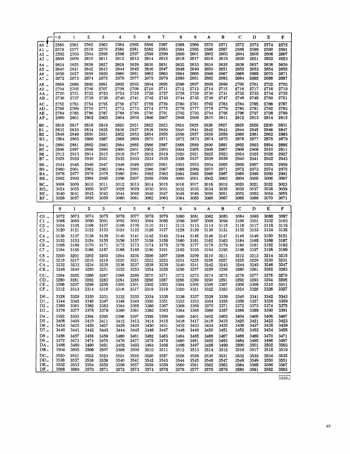
I 2 3 4 5 6 7 8 9 A B C D E
~HO
1 F
AO
_
2.560
2561
2562
2563 2564 2565 2566 2567 2568
2569
2570
2571
2572 2573 2574
2575
Al _
2576 2577 2578
2579 2580
2581
2582
2583
2584
2585 2586 2587 2588 2589
2590
2591
A2
_
2592 2593
2594
2595
2596
2597
2598
2599 2600
2601
2602
2603
2604
2605 2606
2607
A3
_
2608 2609 2610
2611
2612 2613
2614 2615
2616
2617 2618
2619 2620
2621
2622 2623
A4
_
2624
262.5
2626 2627
2628 2629 2630
2631
2632 2633
2634
2635
2636
2637
2638
2639
A5
_
2640
2641
2642 2643 2644
2645 2646
2647
2648 2649 2650
2651
2652 2653
2654 2655
A6
_
2656 2657 2658 2659
2660
2661
2662
2663
2664
2665
2666
2667 2668
2669 2670
2671
A7
_
2672
2673
2674
2675 2676
2677 2678
2679 2680
2681
2682
2683
2684 2685
2686
2687
A8
_ "
2688
2689
2690
2691
2692
2693 2694
2695
2696 2697 2698
2699 2700
2701
2702 2703
A9
_
2704
2705
2706 2707
2708
2709
2710
2711
2712
2713
2714
2715
2716 2717
2718 2719
AA_
2720
2721
2722
2723
2724 2725
2726"
2727
2728
2729 2730
2731
2732
2733 2734 2735
AB_
2736 2737 2738 2739
2740
2741
2742 2743
2744 2745 2746
2747 2748 2749 2750
2751
AC_
2752 2753
2754
2755
2756
2757
2758
2759
2760
2761
2762
2763
2764
2765 2766 2767
AD_
2768
2769 2770
2771
2772 2773
2774 2775 2776 2777
2778
2779
2780
2781
2782 2783
AE
_
2784 2785
2786 2787
2788 2789 2790
2791
2792
2793
2794
2795 2796 2797
2798
2799
AF
_
2800
2801
2802 2803
2804
2805 2806 2807
2808 2809
2810
2811
2812
2813
2814
2815
BO
_
2816 2817 2818
2819 2820
2821
2822
2823
2824
2825
2826
2827 2828
2829
2830
2831
Bl _
2832 2833
2834
2835
2836
2837
2838 2839
2840
2841
2842
2843 2844
2845 2846
2847
B2
_
2848 2849 2850
2851
2852 2853 2854
2855
2856 2857
2858
2859
2860
2861
2862 2863
B3
_
2864
2865
2866 2867
2868 2869 2870
2871
2872
2873
2874
2875 2876 2877
2878
2879
B4
_
2880
2881
2882
2883
2884
2885
2886
2887 2888 2889 2890
2891
2892 2893 2894
2895
B5
-
2896 2897 2898 2899 2900
2901
2902
2903 2904 2905 2906 2907 2908
2909 2910
2911
B6
_
2912 2913
2914
2915 2916 2917 2918
2919 2920
2921
2922
2923 2924 2925
2926 2927
B7
_
2928
2929
2930
2931
2932 2933
2934
2935
2936 2937 2938
2939 2940
2941
2942
2943
B8
_
2944
2945 2946 2947
2948
2949
2950
2951
2952 2953
2954
2955
2956
2957
2958
2959
B9
_
2960
2961
2962
2963
2964
296.5
2966
2967
2968 2969
2970
2971
2972 2973
2974
2975
BA_
2976 2977 2978 2979
2980
2981
2982
2983 2984 2985 2986
2987
2988 2989
2990
2991
BB_
2992 2993 2994
2995 2996
2997
2998
2999
3000
3001
3002
3003
3004
3005
3006
3007
BC_
3008 3009 3010
3011
3012 3013
3014
3015
3016 3017 3018
3019 3020
3021
3022 3023
BD_
3024
3025
3026
3027
3028 3029 3030
3031
3032 3033
3034
3035 3036
3037
3038 3039
BE_
3040
3041
3042
3043 3044 3045
3046
3047
3048 3049
3050
3051
3052 3053 3054 3055
BF
_
3056 3057 3058
3059 3060
3061
3062 3063
3064
3065 3066 3067 3068 3069
3070
3071
0 1 2 3 4 5 6 7 8 9 A B C D E F
CO
_
3072 3073
3074
3075 3076
3077 3078 3079 3080
3081
3082 3083 3084 3085
3086 3087
Cl
_
3088 3089 3090
3091
3092 3093 3094 3095
3096
3097
3098
3099
3100
3101
3102
3103
C2
_
3104 3105 3106 3107
3108
3109
3110
3111
3112
3113
3114
3115
3116
3117 3118 3119
C3
_
3120
3121
3122 3123 3124 3125
3126
3127
3128
3129 3130
3131
3132
3133
3134
3135
C4
_
3136 3137 3138
3139 3140
3141
3142
3143 3144 3145
3146
3147 3148 3149
3150
3151
C5
_
3152 3153
3154
3155
3156
3157
3158
3159
3160
3161
3162
3163
3164 3165
3166 3167
C6
_
3168
3169
3170
3171
3172
3173
3174
3175 3176
3177
3178
3179 3180
3181
3182 3183
C7
_
3184
3185
3186 3187
3188
3189
3190
3191
3192
3193
3194 3195
3196
3197
3198 3199
C8
-
3200
3201
3202 3203 3204 3205
3206
3207 3208
3209
3210
3211
3212 3213 3214
3215
C9
_
3216
3217
3218 3219
3220
3221
3222
3223
3224
3225 3226 3227 3228
3229 3230
3231
CA_
3232
3233 3234 3235 3236 3237
3238
3239 3240
3241
3242
3243
3244
3245 3246
3247
-CB
_
3248 3249 3250
3251
3252
3253
3254
3255
3256 3257 3258
3259
3260
3261
3262 3263
CC_
3264
3265 3266
3267
3268 3269
3270
3271
3272 3273
3274
3275
3276 3277 3278
3279
CD_
3280
3281
3282
3283 3284 3285
3286
3287 3288 3289 3290
3291
3292
3293 3294
3295
CE_
3296
3297 3298
3299 3300
3301
3302
3303 3304 3305
3306
3307
3308
3309 3310
3311
CF
_
3312 3313 3314 3315
3316
3317
3318
3319
3320
3321
3322
3323
3324 3325
3326 3327
DO_ 3328 3329
3330
3331
3332 3333
3334
3335 3336 3337 3338 3339
3340
3341
3342 3343
Dl_
3344 3345 3346 3347 3348
3349 3350
3351
3352 3353
3354
3355 3356 3357 3358
3359
D2
_ 3360
3361
3362 3363
3364
3365
3366
3367 3368
3369
3370
3371
3372 3373 3374
3375
D3_
3376 3377 3378
3379 3380
3381
3382
3383 3384 3385
3386
3387 3388 3389 3390
3391
D4
_
3392
3393
3394 3395
3396
3397
3398
3399
3400
3401
3402
3403
3404
3405 3406 3407
D5
_
3408 3409 3410
3411
3412
3413
3414
3415
3416
3417
3418
3419 3420
3421
3422 3423
06
_
3424
3425
3426 3427 3428
3429 3430
3431
3432 3433
3434
3435 3436 3437
3438 3439
D7_
3440
3441
3442 3443 3444
3445
3446
3447 3448 3449
3450
3451
3452
3453
3454
3455
D8_
3456 3457 3458 3459 3460
3461
3462
3463
3464
"3465
3466
3467 3468 3469
3470
3471
D9_
3472
3473
3474
3475 3476
3477
3478
3479
3480
3481
3482
3483 3484 3485
3486
3487
DA_
3488
3489
3490
3491
3492
3493
3494
3495
3496 3497
3498
3499
3500
3501
3502 3503
DB_
3504
3505
3506 3507
3508 3509 3510
3511
3512 3513 3514 3515 3516
3517 3518 3519
DC_ 3520
3521
3522 3523 3524
3525
3526
3527 3528
3529
3530
3531
3532 3533 3534 3535
DD_
3536 3537 3538 3539 3540
3541
3542
3543 3544 3545
3546
3547
3548
3549
3550
3551
DE_
3552
3553
3554
3555
3556 3557
3558 3559
3560
3561
3562
3563 3564 3565 3566
3567
DF_
3568
3569 3570
3571
3572 3573 3574 3575
3576
3577
3578
3579 3580
3581
3582 3583
49
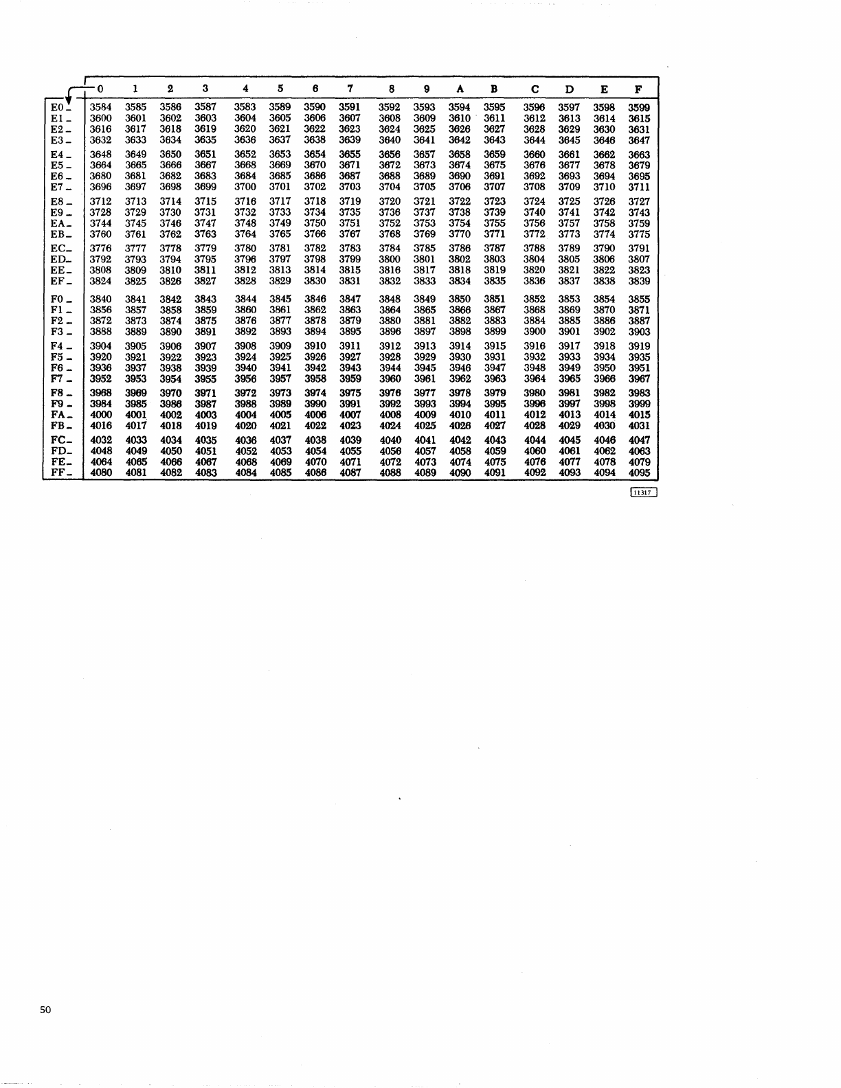
+-to
1 2 3 4 5 6 7 8 9 A B C D E F
Eo_
3584
3585 3586
3587 3583 3589 3590
3591
3592
3593
3594
3595
3596 3597 3598 3599
El_
3600
3601
3602
3603
3604 3605 3606 3607
3608
3609 3610 .
3611
3612 3613 3614
3615
E2-
3616
3617
3618
3619
3620
3621
3622
3623 3624
3625
3626
3627
3628
3629
3630
3631
E3-
3632
3633 3634
3635 3636 3637
3638
3639
3640
3641
3642
3643
3644
3645 3646
3647
E4_
3648 3649 3650
3651
3652
3653
3654
3655 3656 3657 3658 3659
3660
3661
3662
3663
E5_
3664
3665
3666
3667 3668 3669 3670
3671
3672
3673
3674 3675 3676
3677
3678 3679
E6_
3680
3681
3682
3683
3684
3685 3686 3687
3688
3689 3690
3691
3692
3693
3694
3695
E7
_
3696
3697 3698
3699 3700
3701
3702 3703
3704
3705 3706
3707
3708 3709 3710
3711
E8_
3712
3713 3714
3715 3716 3717
3718
3719 3720
3721
3722
3723 3724
3725
3726 3727
E9_
3728
3729
3730
3731
3732 3733
3734 3735 3736
3737
3738 3739
3740
3741
3742
3743
EA_
3744
3745
3746
3747 3748 3749 3750
3751
3752
3753
3754
3755
3756 3757
3758
3759
EB_
3760
3761
3762
3763
3764 3765 3766
3767
3768
3769 3770
3771
3772
3773
3774
3775
EC_
3776
3777
3778 3779 3780
3781
3782 3783
3784
3785
3786 3787
3788
3789 3790
3791
ED_
3792
3793
3794
3795
3796
3797
3798
3799 3800
3801
3802
3803 3804
3805 3806 3807
EE_
3808 3809 3810
3811
3812
3813
3814
3815 3816
3817
3818
3819 3820
3821
3822
3823
EF_
3824
3825
3826 3827 3828 3829 3830
3831
3832
3833
3834
3835 3836
3837 3838 3839
FO_
3840
3841
3842 3843
3844
3845
3846
3847 3848
3849 3850
3851
3852
3853
3854
3855
Fl_
3856
3857
3858 3859 3860
3861
3862 3863
3864
3865 3866
3867
3868
3869
3870
3871
F2 _
3872
3873 3874
3875 3876
3877 3878
3879 3880
3881
3882
3883 3884
3885
3886
3887
F3
_
3888 3889
3890
3891
3892 3893
3894
3895 3896 3897
3898
3899 3900
3901
3902
3903
F4
_
3904
3905
3906 3907
3908 3909
3910
3911
3912
3913
3914
3915
3916 3917 3918 3919
F5
_
3920
3921
3922
3923
3924
3925 3926 3927 3928
3929 3930
3931
3932
3933
3934
3935
F6_
3936
3937
3938 3939
3940
3941
3942 3943
3944
3945
3946 3947
3948 3949 3950
3951
F7_
3952
3953
3954
3955
3956
3957
3958 3959
3960
3961
3962
3963
3964
3965 3966 3967
F8_
3968
3969
3970
3971
3972 3973
3974 3975
3976
3977 3978
3979
3980
3981
3982 3983
F9_
3984 3985
3986
3987
3988 3989 3990
3991
3992 3993
3994
3995 3996
3997
3998
3999
FA_
4000
4001
4002 4003
4004 4005
4006 4007
4008
4009
4010
4011
4012 4013 4014
4015
FB_
4016
4017 4018
4019 4020
4021
4022
4023 4024 4025
4026
4027
4028
4029
4030
4031
FC-
4032 4033
4034
4035
4036 4037 4038 4039 4040
4041
4042
4043
4044
4045 4046
4047
FD_
4048
4049
4050
4051
4052 4053
4054
4055 4056 4057
4058
4059
4060
4061
4062
4063
FE_
4064 4065
4066
4067
4068 4069
4070
4071
4072 4073 4074
4075
4076 4077
4078 4079
FF_
4080
4081
4082
4083
4084
4085 4086 4087
4088
4089
4090
4091
4092
4093
4094
4095
50
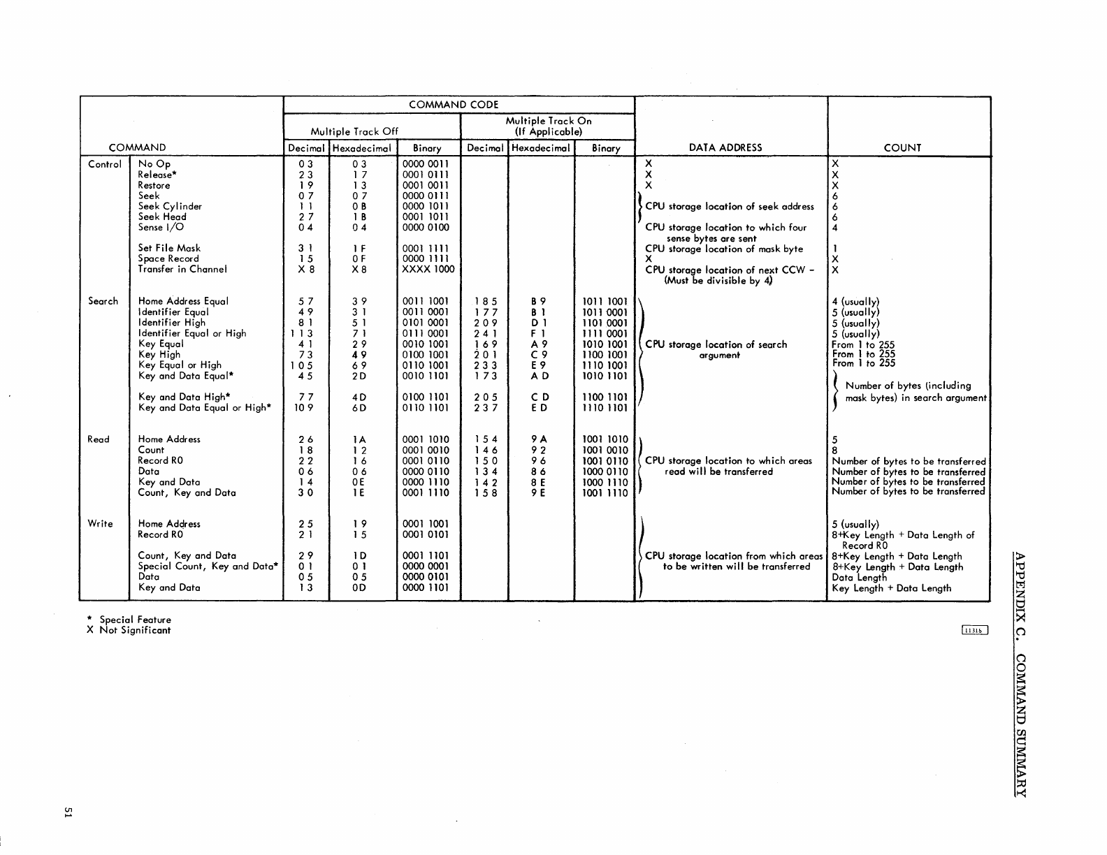
COMMAND
Control
NoOp
Release*
Restore
Seek
Seek
Cylinder
Seek Head
Sense
I/O
Set File Mask
Space
Record
Transfer
in
Channel
Search Home Address Equa I
Identifier Equal
Identifier High
Identifier Equal or High
Key Equal
Key High
Key Equal or High
Key and Data Equa
1*
Key and Data High*
Key and Data Equal or High*
Read Home Address
Count
Record
RO
Data
Key
and Data
Count,
Key
and
Data
Write
Home Address
Record
RO'
Count,
Key and Data
Special
Count,
Key and Data*
Data
Key and Data
* Special Feature
X
Not
Significant
COMMAND CODE
Multiple
Track
Off
Decimal Hexadecimal Binary Decimal
03 03
0000 0011
23
1 7 0001 0111
19
13
0001 0011
07
07
0000 0111
11
OB
0000 1011
2 7 1 B 0001 1011
04
04
0000 0100
3 1 1 F 0001 1111
15
OF 0000 1111
X8
X8
XXXX
1000
57
39
0011 1001
185
49
3 1 0011 0001
177
8 1 5 1 0101 0001
209
1 1 3
71
0111 0001
241
4 1
29
0010 1001
169
73
49
0100 1001
:2
0 1
105
69
0110 1001
233
45
20
0010 1101 1
73
77
40
0100 1101
205
109
60
0110 1101
237
26
lA
0001 1010
154
18
1 2 0001 0010
146
22
1 6 0001 0110
150
06
06
0000 0110
134
14
OE
0000 1110
142
30
1 E 0001 1110
158
25
1 9 0001 1001
2 1
15
0001 0101
29
10
0001 1101
01
a 1 0000 0001
05
05
00000101
13
00
0000 1101
Multiple
Track
On
(If
Applicable)
Hexadec i
rna
I Binary
DATA
ADDRESS
COUNT
X X
X X
X X
}
CPU
storage
location
of
seek
address 6
6
6
CPU
storage
location
to
which four 4
sense bytes
are
sent
CPU
storage
location
of mask
byte
1
X X
CPU
storage
location
of
next
CCW - X
(Must
be
divisible by 4)
B 9 1011 1001 \ 4
(usuaIlY~
8 1
10110001
) 5 (usually
o 1
11010001
5 (usually)
F 1 1111 0001 ! CPU storage
location
of
search
5 (usually)
A9
1010 1001 From 1
to
255
C9
1100 1001 ( argument
From
1 to 255
E 9 1110 1001
From
1 to 255
AD
1010 1101 ) }
Number
of
bytes lincluding
CD
11001101
mask bytes} in search argument
ED
1110 1101 I
9A
1001 1010 5
92
1001 0010 8
96
10010110
\
CPU
,to'age
10coHon
to
whkh
0'00'
Number of bytes
to
be
transferred
86
10000110
read
will
be
transferred Number
of
bytes
to
be transferred
8 E 1000 1110 Number
of
bytes
to
be transferred
9 E 1001 1110 Number
of
bytes
to
be transferred
5 {usually}
8+Key Length + Data Length of
Record
RO
i
CPU
"o'age
10coHon
f'om whkh
0'00'
8+Key Length + Data Length
to
be
written
will
be
transferred 8+Key Length +
Data
Length
Data Length
Key Length + Data Length

A26-5988-2
As
there
is
no unique physical address associated with
each
record on a given
track,
the
2841
must
have
some means of
locating
these
records. There
are
seven states of
orientation
with respect
to
a
track
in
the
2841
that
are
used
to
accomp-
lish this.
1. Index Point
State
-
Gap
between Index Point and
Home Address.
2.
Home Address
State
-
Gap
between Home Address
and
RO.
3.
Count
State
-
Gap
between
Count
and
Key
Fields.
4.
Key
State
-
Gop
between Key and Data
Field.
5.
Data
State
-
Gap
between Data Field
and
succeeding
Address Mark or Index Point if this
is
the
lost record on
the
track.
6.
Address Marker
State
-
Gop
between Address
Mark
and
Count
Field.
7.
Reset
Orientation
State
-
None
of
the
above.
The Reset
Orientation
State,
while not associated with
any
specific
area
of a
track
does not necessarily imply
that
the
2841 has lost
orientation.
Any time a
CCW
chain
is
broken or a Control Command
is
performed, the 2841
is
set
Command
Command Prerequisite
Read CKD
None
Read
KD
None
Read 0
None
Write CKD Search Equal
(also Write Count or Key
Special CKD) Write
CKD
Write
R~
Write
KD
Search Equal
Count of Key
Write 0 Search Equa I
Count or Key
Search 10
None
Search Key
None
Searc:h Home
None
Address
Read
R~
None
Write
R~
Search Equal
Home Address
Write
HA
Read
HA
None
Write
HA
None
Read
IPl
None
Read Count
None
Control
Space
Search (any)
Record Read (any)
Control Erose Write
CKD
Write
R~
Control
NOP
None
International
Business Machines Corporation
. Data Processing Division
112
East
Post Road, White Plains,
N.
Y.
10601
APPENDIX
D.
TRACK
ORIENTATION
to
this
state.
The next
data
command
(i.
e.,
read,
write or
search) further defines this
state
to
one of
the
three
sub-
states
below.
1. Reset
Orientation
to Index Point
State
(ROIP).
Orientation
state
is
set
to
Index Point
State
upon
detection
of
the
Index Point on
the
tra.ck.
2.
Reset
Orientation
to Address Marker
State
(ROAM).
Orientation
is
set
to
Address Marker
State
upon
detection
of any Address Marker.
3.
Reset
Orientation
to
Address Marker or Index Point
State
(ROAM or IP).
Orientation
is
set
to
either
Index Point
State,
upon
detection
of
the
Index
Poi
fit,
or to Address Marker
State
upon
detection
of
any Address Marker, whichever occurs first.
Read,
Write,
Search and some Control commands in
the
2841
have
two types of prerequisities
that
must
be
satisfied
to insure proper operation of
the
command.
By
considering
command
sequence
restrictions
and
orientation
requirements,
all
vol id command sequences
can
be
constructed and
the
re-
sult of
their
execution
predetermined. The following
table
illustrates these two prerequisities and
the
resulting
orientation
state
for
all
data
commands:
Valid
Orientation
Orientation
State
State
at
Beginning
at
Completion of
of
Command Command
ROAM Data
Count Data
ROAM
Count Data
Key
ROAM
Count Data
Key
Data
Count Data
ROAM
Count Data
Key
ROAM or
IP
Count
ROAM Key
Count
ROIP Home Address
Home Address Data
ROIP
Home Address Data
ROIP Home Address
ROIP Home Address
ROAM Data
ROAM Count
Count Reset
Orientation
Key
Count Reset
Orientation
Key
Data
None
Reset
Orientation
