ABS Technical Information 2011
User Manual: ABS Technical Information 2011
Open the PDF directly: View PDF ![]() .
.
Page Count: 209 [warning: Documents this large are best viewed by clicking the View PDF Link!]
ABS
Pipe, Fittings & Valves
for cooling, chilled
water, chemicals and
drinking water
Technical Information 2011

Important Note
The technical data given in this catalogue is for
preliminary information purposes only and is
published without guarantee. All pictures and
drawings are for illustrative purposes only and
should not be regarded as wholly accurate in every
detail. We reserve the right to withdraw or to alter
the specification of any product without notice.
Please consult our Terms and Conditions
www.georgefischer.co.uk
Technical Information
For technical data including operating &
control pressures, dimensions as well
as the use of accessories, please refer to
data sheets which are available in both
printed and electronic (pdf) formats from
the Coventry Sales Office (details on back
cover).
For details of our range of plastic pipe,
fittings, hand and actuated operated valves
in PVC-U, PVC-C, PP, PVDF, PFA and PE
as well as our INSTAFLEX PB and SIGNET
measurement and control range, please
request Price Lists from the Coventry Sales
Office.

Application Knowledge
GF ABS
Water, chilled water, cooling, drinking water & chemical conveyance
Fields of Application:
Water treatment
Chemical industry
Drinking water
Swimming pools
Marine industry
Food and beverage production
Building services
Product Range
Pipes
Fittings
Manual valves
Actuated valves
Jointing systems
Flow, pH, conductivity, turbidity, level, pressure, chlorine
and temperature measurement
Available in the widest standards available: BS Inch, EN/ISO metric
EN/ISO - d16 - d315mm
BS Inch - 3/8" - 8"
Application range:
Resistant to bases, weak acids and salts, suitable for
drinking water
-40°C to 60°C
Jointing system:
Tangit gap filling solvent cement
i

Worldwide Approval
GF ABS is manufactured and tested to the highest quality. Our own
compound and strict quality controls for each raw material delivery
form the basis for our high quality products.
Our own independently accredited test laboratory for components of
plastic piping systems according to EN ISO 45001 assures the highest
quality.
Quality and environmental management systems according to ISO
9001 and 14001 are the basis for the continuous improvement of our
performance.
Third party approvals for GF ABS offer peace of mind to customers
using the products.
Approved for use within public water
supplies and by the Secretary of State.
GF ABS is listed in the "List of Approved
Products" published by the DWI
ii
GF manufacture a complete range of actuators and actuated valves
which includes pneumatic as well as electric actuators. Thanks to
their modular design, the actuators can be configured specifically to
your application (eg. positioner, additional limit switches, fail-safe unit,
AS-Interface connection, etc.) Housing material is robust and resistant
PPGF. All actuators are sized specific to GF valves, resulting in an in-
creased service life. Connections to third party valves are no problem
due to EN ISO 5211 interface.
Automation
The GF Signet range of flow control and measurement equipment is
at the cutting edge of technology in this field.
Flow, pH, level, conductivity, temperature,
turbidity, chlorine, pressure and
ORP are all catered for
within the range.
SIGNET
iii
The excellent location of the Distribution Centre in Coventry offers
the latest in state of the art distribution and warehousing systems.
An enhanced delivery system and 24 hour warehousing programme
guarantees prompt delivery to GF customers nationwide.
Our Technical support staff are qualified to offer you advice and guide
you through the wealth of products GF can supply. We make sure you
feel confident that the product matches your requirements and leaving
you fully assured that GF is your preferred supplier.
Distribution, Warehousing and Technical Support
GF Fleet of delivery vehicles Tracking delivery of your order
iv
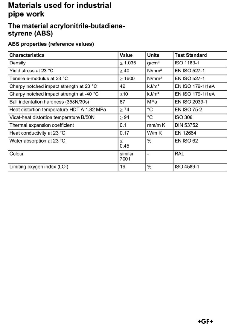
General
Acrylonitrile-Butadiene-Styrene (ABS) is a versa-
tile standard polymer. In addition to its application
in piping systems, ABS is mainly common in
automotive applications and in high-quality
household devices. The wide area of application
relates to the versatile characteristic profile of
ABS. It can be adapted to the application by
varying the composition of its three components:
acrylonitrile, styrene and polybutadiene. While
acrylonitrile provides strength to the material and
gives ABS an improved chemical resistance
relative to polystyrene, the styrenic component
provides both strength and a quality surface
finish. The chemically bound polybutadiene-
rubber particles, on the other hand, give the
material its toughness and impact strength, even
at very low temperatures. The ABS used by GF
shows a good balance between toughness and
strength, making it especially suitable for low
temperature applications. Accordingly the areas of
application are mainly refrigeration and air
conditioning systems as well as water treatment.
The advantages of ABS include:
• high impact strength even at low temperatures
• corrosion resistance
• simple installation via solvent cement joints
• low heat conductivity
• halogen free
• non-toxic
• biologically inert; no support of microbial growth
• low weight
• low pressure losses due to smooth surfaces
• good abrasion resistance
• problem-free recycling

offers considerable advantages over metal and other
plastics for many such applications. Please contact
GF if you are planning such an application. We
would be glad to advise you about the suitability of
our ABS, PE and other materials for your media.
Thermal properties
The outstanding characteristics of ABS allow its
application in a wide temperature range between
- 40 °C and +60 °C. At higher temperatures, the
tensile strength and stiffness of the material drop
and at lower temperatures, they rise. Therefore,
please consult the pressure-temperature diagram
for your maximum working temperature. As all
thermoplastics, ABS shows a higher thermal
expansion than metals. This is not a problem if the
thermal expansion is taken into account during the
planning stage of the piping system. The expansion
coefficient amounts to 0.1 mm/m K in the application
temperature range.
At 0.17 W/m K, the heat conductivity of ABS is very
low. Because of the insulation properties of the
material and the resulting savings in energy or
insulation, an ABS piping system is notably more
economical in comparison to a system made of copper
(370 W/m K) or other metals. Should there be a need
for additional insulation, e. g. in cooling applications,
GF offers COOL-FIT, a system specially dedicated to
this market. COOL-FIT it is a preinsulated ABS
system that has the advantage of quick and easy
installation.
Combustion behaviour
ABS self-ignites at temperatures exceeding 450 °C.
ABS burns when exposed to an open flame.
After removing the flame, the material continues
burning. The oxygen index amounts to 19 %.
(Materials that burn with less than 21 % of oxygen in
the air are considered to be flammable). According
to UL-94, ABS has a HB (Horizontal Burning)
flammability coefficient and falls into building
material class B2 (conventional inflammable,
non-dripping) according to DIN 4102-1. Basically,
toxic substances are released by all burning pro-
cesses. Carbon monoxide is generally the
combustion product most dangerous to humans.
When ABS burns, primarily carbon dioxide, carbon
monoxide and water are formed. Tests have shown
that the relative toxicity of the products of combustion
are similar or even lower than those of natural pro-
ducts such as wood, wool and cotton. ABS combusti-
on gases are not corrosive. Nevertheless, the burning
forms soot. Because of this, smoke develops during
combustion. Water, foam and carbon dioxide are
suitable fire-fighting agents.
Mechnical properties
In addition to the good strength and stiffness,
ABS is especially characterised by a very high
impact strength. Impact strength is a measu-
re of impact energy that the material absorbs
until it breaks. For this test, a specimen is
weakened with a sharp notch and then struck.
Without a notch, there is no breakage of the
test specimen. The exceptionally high notched
impact strength values, even at low tempera-
tures, indicate the material's high robustness
and tolerance against surface damage. GF ABS
pipes are routinely tested for their toughness
according to EN ISO 15493. In this test, a weight
falling from, a height of 2 metres hits the pipe
that has been cooled to 0 °C. The mass of the
falling weight varies, depending on the pipe
dimensions, from 0.5 (dn = 20mm) to 9 kg (dn
= 225 mm). The high load in the falling-weight
test ensures that the excellent toughness of the
material is not reduced as a result of processing
into pipe. The internal pressure resistance is
provided by the hydrostatic strength curve based
on the EN ISO 15493 standard (also see the ABS
Calculation and Long-Term Behaviour section).
The application limits for pipes and fittings, as
shown in the pressure-temperature diagram,
can be derived from these curves.
Chemical, weathering and abrasion resistance
ABS is characterised by its good resistance to
various chemicals. In general, ABS is resistant to
water, salt solutions and most dilute acids and
bases. Its resistance to alcohols, aliphatic
hydrocarbons, oils and greases is, however, to be
regarded as limited. ABS is not resistant to
concentrated mineral acids, organic acids and
solvents such as esters, ketones and chlorinated
and aromatic hydrocarbons. For detailed informa-
tion, please refer to the detailed list of chemical
resistance from GF or contact your local GF
subsidiary. If the ABS piping system is exposed to
direct sunlight over a long period, its surface loses
its shine and the colour shifts to light grey. Due to
the very high impact strength of ABS, the resulting
loss of toughness generally causes no problems
in moderate climate zones. For extreme weather
conditions or very high loads on the piping system,
we nevertheless recommend protecting the surface
from direct sunlight. In addition to the excellent
impact strength, the polybutadiene rubber particles
in ABS cause an outstanding resistance against
abrasion. Because of this, ABS piping systems
have been used for a long time to transport solids
and slurries, for example, in mining applications.
Experience has shown that ABS, as well as PE,
v

Electrical properties
ABS has good electrical insulation capacity. The
specific volume resistance is 3.5 x 10¹⁶ Ωcm and
the specific surface resistance is 1013 Ω.
These figures have to be taken into account
wherever there is a danger of fires or explosion.
vi
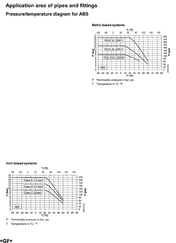
The following pressure/temperature diagram
for ABS pipes and fittings is valid for a lifetime
of 25 years.
The design factor of 2.1 for inch-based
systems and 1.8 for metric systems
recommended by GF is incorporated.
It can be used for water or media resembling
water, in other words, media which have no
derating factor regarding the chemical resi-
stance.
Remark: Please take into account the
pressure/temperature diagrams for valves and
special fittings. Because of the construction
and/or sealing material used, differences
are possible when compared with pipes and
fittings. This information can be found in the
planning fundamentals of the relevant types of
valves, respectively special fittings.
The influence of the anti-freeze compound has
to be taken into account when calculating the
allowable operating pressure. Please contact
your GF representative for further information.
Attention: According to the 10 °C curve in the
long-term diagram for ABS, the permissible
pressure in the temperature range -50 ° to
+10 °C can be
• 7.5 bar for the PN6 system.
• 11.8 bar for the PN10 system.
The maximum pressure for the PN16 system
has been limited to 16 bar.
Design of metric and inch
piping systems
vii
viii
General
Thermoplastics are subject to greater thermal
expansion and contraction than metals. Pipes
installed above ground, against walls or in
ducts, especially those exposed to tempera-
ture variations, require changes in length to be
taken up in order to prevent extra strain on
the pipes. Length changes can be taken up by:
a) flexible sections
b) compensators
Flexible sections are the most common
solution, being the simplest and the most
economical. The calculations for and the
positioning of flexible sections are therefore
described in detail.
Fundamentals
The low modulus of elasticity of thermopla-
stics allows changes in length to be taken up
by special pipe sections, where pipe supports
are positioned so that they can take advantage
of the natural flexibility of the material. The
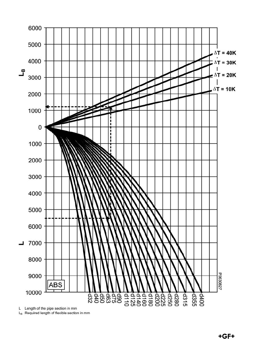
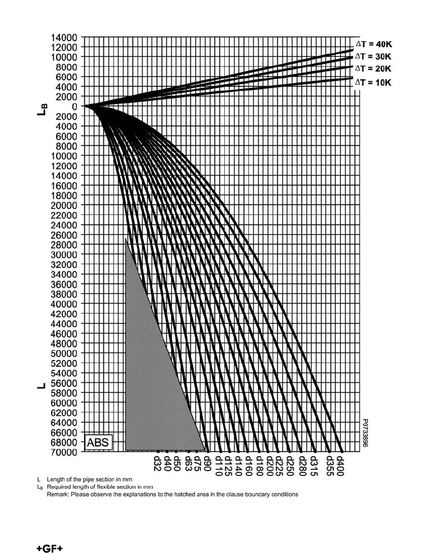
length of such sections is determined by the
diameter of the pipeline and the extent of the
thermal expansion to be compensated.
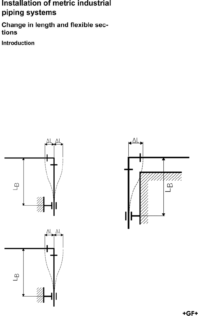
Flexible sections arise naturally at any
branching or change in direction of the
pipeline. The movement LB of the flexible
section as a result of a change ΔL in the
length must not be restrained by fixed pipe
brackets, protrusions wall, girders or the like.
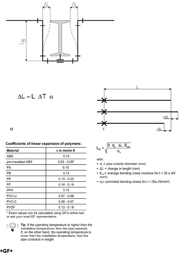
Calculation of change in length
The change in length caused by temperature can
be calculated using the following formula:
with:
• ΔL = temperature-related change in length (mm)
• L = length of the pipe section (m)
• ΔT = difference of temperature (K)
• α = coefficient of linear expansion (mm / m K)
The installation temperature must therefore
be incorporated into the calculations as well
as the maximum and minimum operating
temperatures. It is preferable to use "+"
to indicate expansion of the pipe and "-"
to indicate contraction. The larger change in
length is the one to be used for determining
the required length of the flexible section.
ix
x
xi
xii
xiii
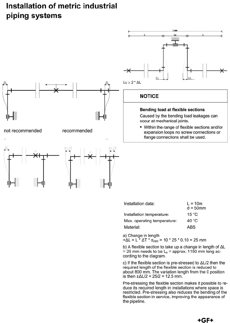
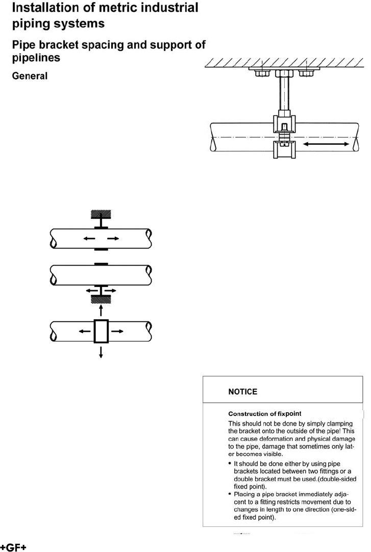
Recommendations for installation
Length changes in pipe sections should
always be accommodated through the arran-
gement of fixed brackets. The following
examples show how the changes can be
distributed in pipe sections by suitable
positioning of fixed brackets.
Expansion loops can be installed to take up
changes in length when flexible sections cannot
be included at a change in direction or branch in
the pipeline or if substantial changes in the length
of a straight section need to be taken up. In such
a case the compensation for changes in length is
distributed over two flexible sections.
Pre-stress
Length changes in pipe sections should always
be accommodated through the arrangement of
fixed brackets.
The following examples show how the changes
can be distributed in pipe sections by suitable
positioning of fixed brackets.
xiv
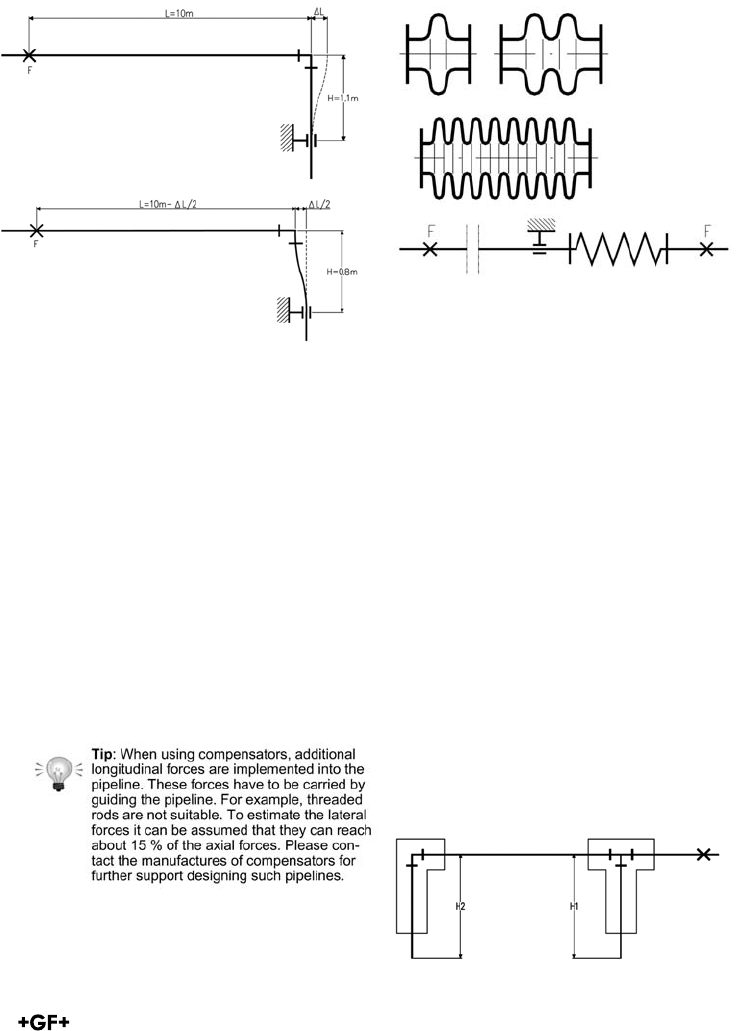
Installing compensators
The low modulus of elasticity means that the re-
action force of plastic pipes to thermal changes is
low compared to metal pipes. This makes normal
compensators designed for use with metal pipes
unsuitable because of their high inherent resi-
stance. Only freely moving compensators may be
used in plastic pipe systems, i. e. those with a low
resistance. The following compensators may be
considered: rubber compensators, PTFE
corrugated compensators or suitably selected
metal multi-disc compensators.
Carefully placed fixed points should be used when
fitting compensators for the regulation of the pipe
in order to ensure their unhindered operation.
The installation temperature provides the basis for
the calculations to ensure this.
Installing Valves
Valves should be secured as directly as possible,
so that the actuation forces are transmitted
directly and not via the pipeline. Valve brackets
or valves from GF with an integrated fastening
device are used to securely fasten plastic valves.
These valve brackets are also used to bear the
loads of the valve and filling weight of the pipe-
line. Any changes in length which arise can be
prevented with the appropriate fixed points
before or after the valve. You will find more
information under the respective valve types.
Installing pipework under plaster or
embedding it in concrete
Installing Valves
Installing pipework under plaster or embedding
it in concrete
Padded pipework
Where pipework is installed under plaster or
embedded into concrete, the flexible sections
at bends and branches must be padded for the
calculated distance H, as also must any
branches and elbows included in the affected
section. Use only flexible materials as padding,
such as glass wool, mineral wool, foam or
similar.
xv

Unpadded pipework
Unpadded pipes can also be plastered or
concreted in directly. Since the axial stress
arising from internal pressure is half as great as
the circumferential stress, pipelines can support
limited additional axial stress without becoming
overloaded. In such cases the level of stress
expected must be calculated. The same is true
of any section of pipe between two fixed points
where no allowance has been made for changes
in length. The load at the fixed points must be
calculated and considered when planning the
fixed points. The distance between pipe brackets
in such cases may have to be reduced from the
normal values in order to prevent bowing
in the pipeline.
Care must be taken to avoid creating cavities
when plastering or concreting in the pipeline,
because under unfavourable conditions these
can become areas of stress concentration.
A rich plaster mixture (1 : 3 to 1 :4) should be
used to allow the forces arising from tempera-
ture variations to be transmitted away without
causing the plaster to crack.
xvi
Pipe support for plastics pipes
Plastic pipe systems should be installed using
supports designed for use with plastics and
should then be installed taking care not to da-
mage or over stress the pipe.
Arranging Loose Brackets
What is a loose pipe bracket?
A loose pipe bracket is a bracket which allows
axial movement of the pipe, to allow stress
free compensation of temperature changes
and compensation of any other operating
condition changes
The inner diameter of the bracket should be
larger than the outside diameter of the pipe
to allow free movement of the pipe. The inner
edges of the brackets should be free from any
sharp contours which could damage the plastic.
If the brackets’ inside diameter is not larger
than the pipe then the bracket should not be
fully tightened, thus allowing the pipe to move.
Another method is to use brackets with spacers
which also avoids clamping the bracket on the
pipe.
Spacer to avoid clamping
Axial movement of the pipeline must not be
prevented by fittings placed next to pipe
brackets or by any other component affecting
the diameter of the pipe. Sliding brackets and
hanging brackets permit the pipe to move in
different directions. Attaching a sliding block
to the base of the pipe bracket permits free
movement of the pipe along a flat supporting
surface. Sliding and hanging brackets are
needed in situations where the pipeline changes
direction and free movement of the pipe must
be allowed.
Arranging fixed points
What is a fixed point?
A fixed pipe bracket is a bracket which prevents
the pipe from moving in any direction. The aim
of which is to control system stresses caused by
temperature changes.
xvii
xviii
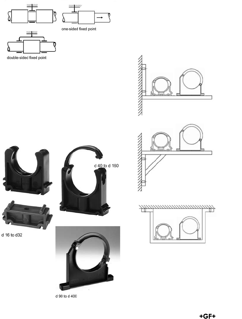
Starting from the dimension d90 the
KLIP-IT brackets must be installed
standing, like shown in the assembly
examples. The support distances given
in the following, specified for the KLIP-IT
tubing clamps, apply only to this mount-
ing method.
Information:
Pipe brackets must be robust and mounted firmly to
be able to take up the forces arising from changes in
length in the pipeline. Hanging brackets or KLIP-IT
pipe brackets are unsuitable for use as fixed points.
KLIP-IT pipe brackets
These robust plastic pipe brackets can be used not
only under rigorous operating conditions, but also
where the pipework is subject to aggressive media
or atmospheric conditions. They may be used for all
materials of pipes. Don't use KLIP-IT pipe brackets
as fixed points!
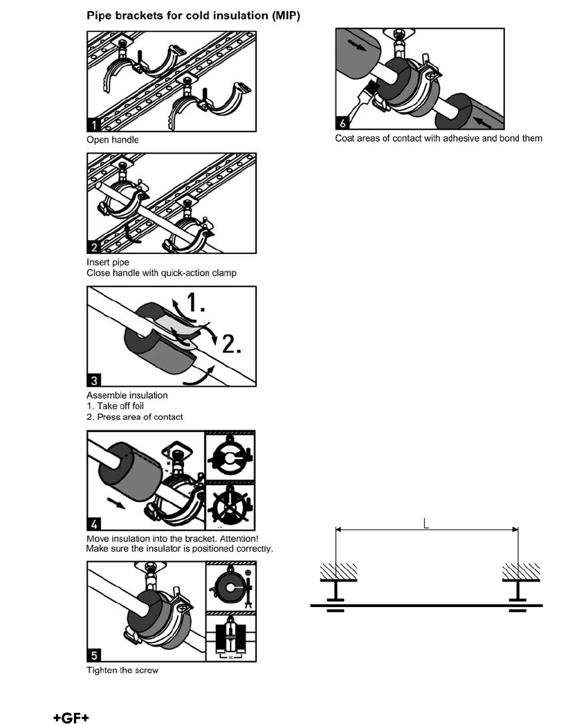
Using the tables for pipe bracket spacing
Plastic pipelines need to be supported at
certain intervals depending on several
factors: the material, the average pipe wall
temperature, the density of the medium
transported and the size and wall thickness
of the pipe. Determining the spacing between
pipe brackets is based on the permissible
deflection of the pipe between consecutive
brackets.
Information:
The values given in the tables apply only to
pipelines which are freely movable in the
axial direction.
Pipelines which are fastened tightly in the
axial direction (fixed installations) must be
checked for buckling. In most cases, this
leads to a reduction of the maximum
inner pressure and shorter distances
between the support brackets.
Furthermore, the forces that act on the fixed
points must also be taken into consideration.
For assistance, please contact your nearest
GF representative.
xiv
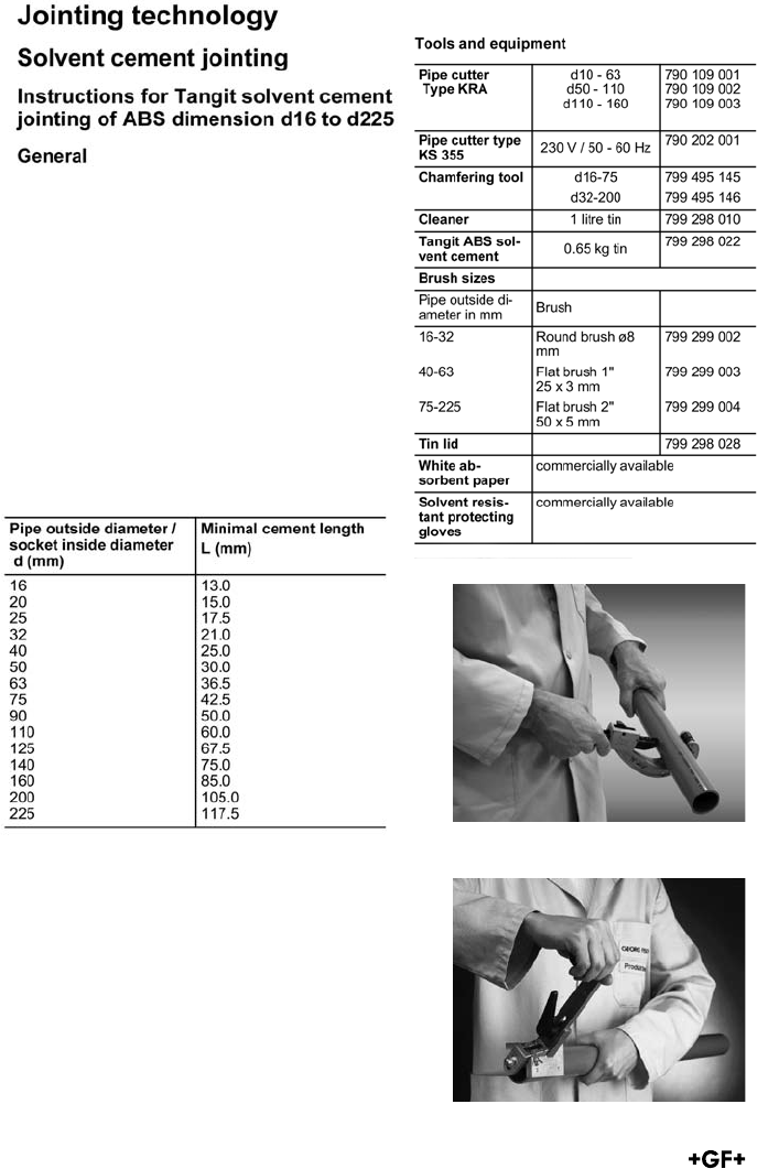
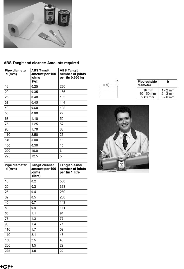
Solvent cement jointing calls for adequate
technical know-how, which can be acquired in
the appropriate training courses. Your GF
representative will gladly provide you with
information about training possibilities.
The dimensions of GF pipes, fittings and val-
ves conform generally to the various national
standards as well as to ISO 727-1 concerning
dimensions of sockets. Our fittings and valves
can be used with any ABS pipes whose outside
diameter tolerance conforms to ISO 11922-1.
According to ISO 727-1 the following minimal
cement lengths are as shown in the table:
Cutting the pipe to length
Chamfering the pipe
xx
Wipe the outside of the pipe and the inside
of the socket with a clean cloth to remove
obvious dirt. Marking the jointing length on the
pipe end makes it possible to check afterwards
whether the pipe has been inserted to the full
extent of the socket.
Note: If the outside diameter of the pipe and
the inside diameter of the socket are at
opposite extremes of their tolerances, then the
pipe cannot be inserted dry into the fitting
socket. This will only become possible once
the cement has been applied.
Solvent cementing equipment
Marking the jointing length
Note: The quantities specified above are to be
understood as practice-orientated maximum
values. In principle the quantities depend on
gap dimensions, temperatures, working
technique.
Preparations
The pipe must be cut off at right angles.
Remove the inside edges and chamfer the
outside ones as illustrated in the sketch. Only
then is an optimal solvent cemented joint
possible.
Important: Well-chamfered pipe ends prevent
the layer of cement from being removed as the
pipe is inserted into the fitting
xxi
xiii
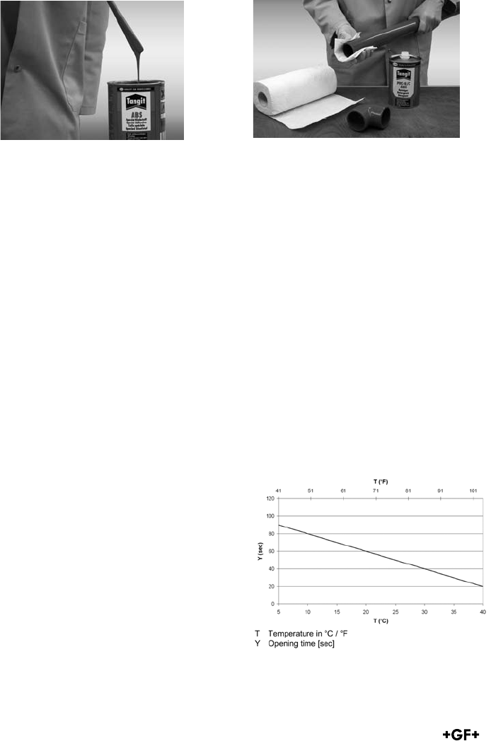
Checking the cement
The Tangit ABS cement is supplied ready for use.
Stir thoroughly before using! Cement of the
correct consistency will run evenly from a
wooden spatula held at a slant. Cement which
no longer runs smoothly is unusable.
The cement must not be thinned.
For more information please consult the safety
datasheets under the following link:
https://www.sdb.henkel.de/index.cfm
Cement and cleaner should be stored in a cool,
dry place (5–35 °C)! Under these conditions the
cement and cleaner are durable for 24 months
starting from the date of filling (imprinted on
the tin).
Cementing
Clean the outside of the pipe end and the inside
of the socket thoroughly with ABS cleaner and
absorbent paper.
Use a fresh piece of paper for each component.
If the surfaces are free from grease, cleaning
with absorbent paper and Tangit cleaner is not
absolutely necessary for ABS.
But remove any condensation which may have
formed on the parts.
Important: Pipe end and fitting socket must be
dry and free from grease and dirt and must not
be touched after cleaning.
Cleaning the pipe and socket
ABS pipes should be cemented at temperatures
between +5 °C and +40 °C. Take the following
protective measures if the temperatures deviate
from the above:
At low temperatures, condensation or ice water
which may have formed must be removed, e. g.
with warm air. Cement and cleaner should be
stored at room temperature. Please observe the
waiting times mentioned in the following until
the next cementing.
Avoid uneven overheating (->shorten the opening
time) when cementing at higher temperatures by
protecting the jointing area from direct sunlight.
The quick curing time of the cement necessi-
tates that the joint is made within the opening
time after application of the cement has started.
The opening time of the ABS cement varies with
the ambient temperature and the thickness of
the cement applied:
xxii
xiv
Begin by applying a normal layer of cement to
the fitting and then a thicker one to the pipe end
with firm brush pressure. Work in well.
The brush strokes should always be in an axial
direction. To ensure that both jointing surfaces
are completely covered with a smooth, even layer
of cement, the brush should be generously
loaded with cement.
A bead of excess solvent cement around the
complete external circumference of the joint
and a slightly smaller bead again around the
complete internal circumference show that
the joint has been performed correctly.
After use, clean the brush of excess cement
with dry absorbent paper and then clean
thoroughly using TANGIT cleaner. Brushes
must be dry before being re-used (shake out).
Applying the cement
The joints can be made single-handed for pipes
with diameters up to d63 mm.
For d75 mm and larger pipes, two people are
needed to apply the cement to the pipe end and
fitting socket simultaneously in order to avoid
exceeding the maximum opening time of the
cement.
After the cement has been applied, insert the
pipe to the full depth of the socket immediately
without twisting and bring them into the correct
alignment. Ensure that the outlet of the fitting is
in the correct position. Hold them in this position
to allow the cement to set.
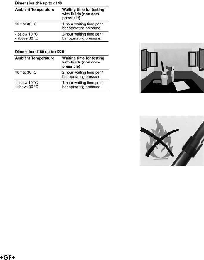
Up to the dimension d140 wait at least
10 minutes before the next joint, extend the
waiting time at temperatures under 10 °C to 15
minutes.
For the dimensions d160 to d225 wait at least 30
minutes before the next joint, extend the waiting
time at temperatures under 10 °C to 60 minutes.
In order to avoid any forces on the cemented
components by the weight of the piping system a
support of the pipeline is necessary.
Remove any surplus cement immediately, using
absorbent paper.
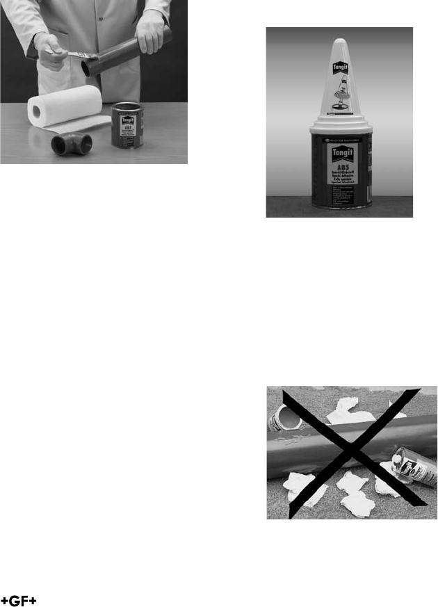
Replace the lid of the cement tin during
work breaks
Replace the lid of the cement tin after use to
prevent the solvent evaporating. Using the
conical lid allows leaving the brush in the
cement tin during breaks. Solvent cement
dissolves ABS. Pipes and fittings must
therefore not be laid on or allowed to come
into contact with spilled cement or paper
containing cement residues.
xxiii
Do not close off cement pipelines during
the drying process. This is particularly im-
portant at temperatures below + 5 °C, when
there is otherwise a danger of damaging the
material.
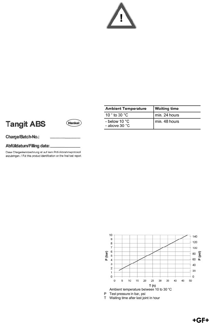
After the drying process (see waiting times
in the following table) the pipelines can be
filled. It is recommended to flush the pipe-
line before use, and leave it filled with water
if it is not directly used.
To ensure the traceability (if necessary) of
the used Tangit ABS batch, place the batch
marking on the test report. This batch
marking is attached to each dispatch unit.
If several batches are used in one project,
place one marking from each batch on the
test report.
xv
Drying period and pressure testing
of ABS piping systems d16 - d225
The length of the drying period before the
joint may be subjected to testing or operat-
ing pressure depends on the ambient tem-
perature, the dimension and the tolerances.
The following tables shows the different
waiting times.
Remark: For temperatures above 20 °C the
test pressure must be reduced according to
the requirements given in the chapter "Final
testing and commissioning".
Attention: Care should be taken, if the
medium has a large temperature difference
to the installation temperature.
Please consult your local GF Representative.
Internal pressure test with water
This pressure test shall be carried out
according to the information given in the
chapter "Internal pressure test with water or
a similar incompressible fluid". The waiting
time after the last joint until the pressure
test is shown in the following table:
Attention: Care should be taken, if the
medium has a large temperature difference
to the installation temperature.
Please consult your local GF Representative.
Internal pressure test or leak tightness test
with gas/air
Due to the risk of a pressure test with a
compressible test medium this pressure
test shall be carried out only in exceptional
cases! Please consult also the safety pre-
cautions given in the chapter "Internal pres-
sure test of ABS pipelines". The following
diagram shows the waiting time depending
on the test pressure for a ambient
temperature between 10 to 30 °C:
xxiv
xvi
Repair works
If the pipeline is only subjected to the
operating pressure with fluids, e. g. after
adaptation or repair works, the following
rule of thumb for the waiting time applies,
which is depending on the diameter:
Dimension d16 up to d140
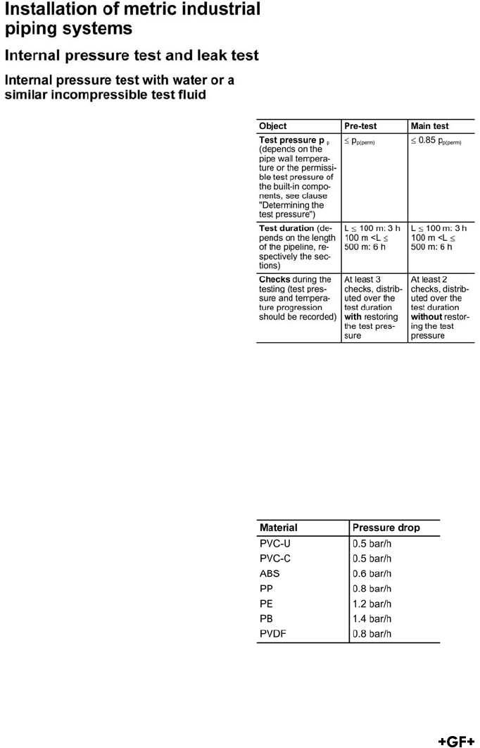
Safety precautions
Tangit cement and cleaner contain highly
volatile solvents. This makes good ventila-
tion or adequate fume extraction essential
in closed spaces. Since the solvent fumes
are heavier than air, extraction must occur
at floor level, or at least below the working
level. Place paper which has been used for
cleaning or for the removal of surplus
cement into closed containers to minimise
the amount of solvent fumes in the air.
Cement and cleaner are inflammable.
Extinguish open fires before commencing
work. Switch off unprotected electrical
apparatus, electric heaters, etc. Do not
smoke!
Discontinue any welding operations.
Furthermore, observe all instructions
issued by the solvent cement manufacturer
(e.g. label of the tin and any supplementary
documentation).
Adequate ventilation
of the workplace
Protect pipes and fittings from spilled
solvent cement, cleaner and absorbent
paper which has been used to wipe off
cement. Do not dispose of surplus solvent
cement or cleaner in drainage systems.
The use of protective gloves is recommend-
ed to avoid contact with skin. If the cement
or the cleaner get in contact with eyes,
rinse immediately with water. Consult a
doctor! Immediately change clothes that
have solvent cement on them.
Always obey the safety regulations issued
by the authorities responsible.
No open flames when cementing.
No smoking.
xxv
General
The internal pressure test is done when instal-
lation work has been completed and neces-
sitates an operational pipeline or operational
test sections. The test pressure load should
furnish experimental proof of operational
safety. The test pressure is not based on the
working pressure, but rather on the internal
pressure load capacity, derived from the pipe
wall thickness.
Supplement 2 of DVS 2210-1 forms the basis
for the following information. This replaces the
data in DVS 2210-1 entirely. The modifications
became necessary because the reference va-
lue ”nominal pressure (PN)” is being used less
and less to determine the test pressure (1.5 x
PN, or 1.3 x PN) and is being replaced by SDR,
• a short-term overload or even a reduction in
the service life can occur if in the course of the
internal pressure test based on the nominal
pressure the pipe wall temperature TR = 20 °C
is exceeded by more than 5°C.
• Test pressures are therefore determined in
relation to SDR and the pipe wall temperature.
The 100-h value from the long-term behaviour
diagram is used for the test clamping.
Test Parameters
The following table indicates recommended
methods of testing the internal pressure.
Pre-test
The pre-test serves to prepare the piping
system for the actual test (main test). In the
course of pre-testing, a tension-expansion
equilibrium in relation to an increase in
volume will develop in the piping system.
A material related drop in pressure will occur
which will require repeated pumping to restore
the test pressure and also frequently a
re-tightening of the flange connection screws.
The guidelines for an expansion-related
pressure decrease in pipes are:
xxvi
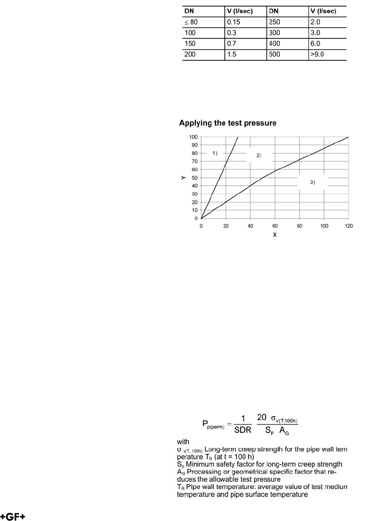
Main test
In the context of the main test, a much smaller
drop in pressure can be expected at constant
pipe wall temperatures so that it is not neces-
sary to pump again. The checks can focus pri-
marily on leak detection at the flange joints and
any position changes of the pipe.
Observe if using compensators
If the pipeline to be tested contains compensa-
tors, this has an influence on the expected axial
forces of the pipeline. Because the test pressu-
re is higher than the working pressure, the axial
forces on the fixed points become higher. This
has to be taken into account when designing
the fixed points.
Observe if using valves
When using a valve at the end of a pipeline (end
or final valve), the valve and the pipe end should
be closed by a dummy flange or cap. This pre-
vents inadvertent opening of the valve or any
pollution of the inside of the valve.
Filling the pipeline
Before starting with the internal pressure test,
the following points must be checked:
Was installation done according to the available
plans?
• All pressure relief devices and flap traps
mounted in the flow direction?
• All end valves shut?
• Valves in front of other devices are shut to
protect against pressure.
• Visual inspection of all joints, pumps,
measurement devices and tanks.
• Has the waiting period after the last fusion /
cementing been observed?
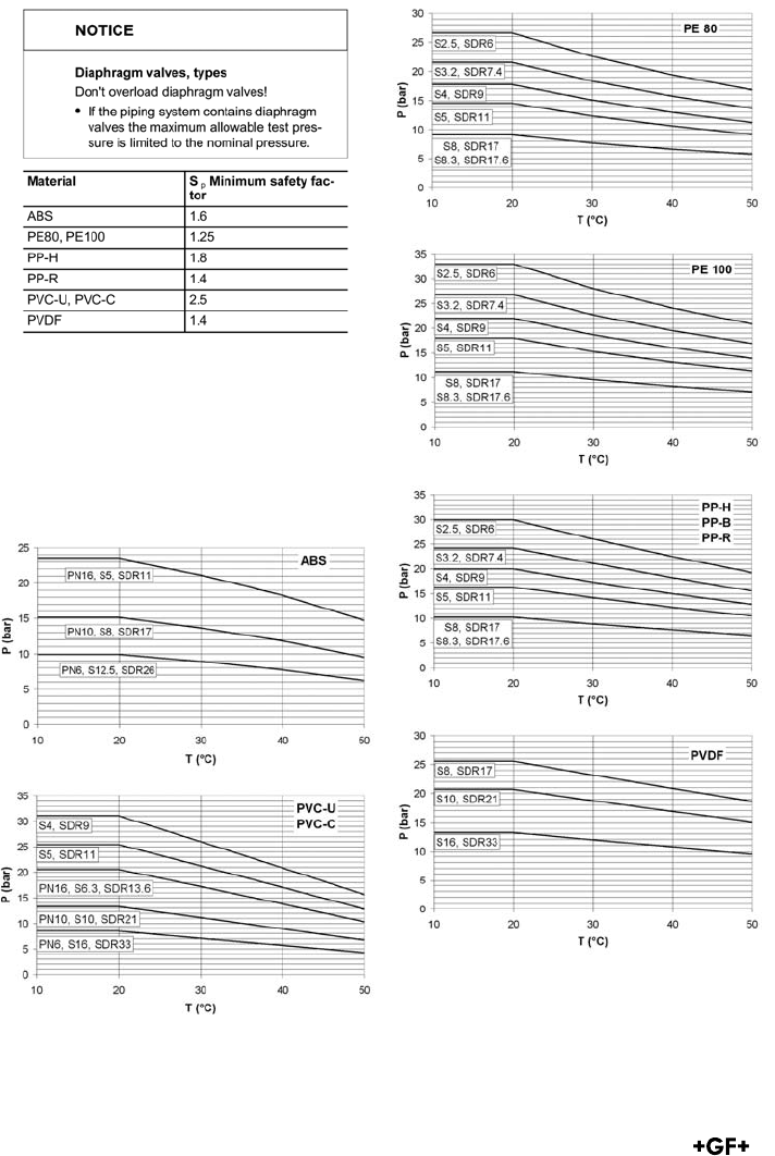
Now the pipeline can be filled from the geodetic
lowest point. Special attention should be given
to the air vent. If possible, vents should be pro-
vided at all the high points of the pipeline and
these should be open when filling the system.
Flushing velocity should be at least 1 m/sec.
Reference values for the filling volume are
given in the following table.
Adequate time should be allowed between
filling and testing the pipeline, so that the air
contained in the piping system can escape via
the vents: ca. 6 - 12 h, depending on the
nominal diameter
The test pressure is applied according to the
diagram.
Here it is important that the pressure increase
rate does not cause any water hammer!
Definitions
Y = test pressure in %
X = time for pressure increase in min
1) = pressure increase rate up to DN 100
2) = range of pressure increase rates >DN 100
- 400
3) = reference values for pressure increase
rate DN 500 and greater is: 500 / DN
[bar/10 min]
Determining the test pressure
The allowable test pressure is calculated ac-
cording to the following formula:
xxvii
General
To make things easier, the permissible test
pressures can be taken directly from the
following diagrams.
Definitions:
P = permissible test pressure in bar
T = pipe wall temperature in °C
General
• Internal pressure at the absolute low
point of the pipeline
• Medium and ambient temperature
• Water volume input
• Water volume output
• Pressure drop rates
Checks during testing
The following measurement values must be
recorded consistently during testing:
xxviii
514-519
IMPERIAL SIZES METRIC SIZES
Nominal Bore Pipe outside Nominal bore
inches diameter (mm) (mm)
1/4 12 8
3/8 16 10
1/2 20 15
3/4 25 20
1 32 25
1
1/4 40 32
1
1/2 50 40
2 63 50
2
1/2 75 65
3 90 80
4 110 100
5 140 125
6 160 150
8 225 200
10 250 250
280 250
12 315 300
ABS Pressure Pipe Systems
Standards
George Fischer metric fittings in ABS are
generally in accordance with DIN 8063 and
the pipe with DIN 16890/16891. George
Fischer’s inch range of fittings is generally
in accordance with BS 5392 and the pipe
with BS 5391.
Sizes (Metric vs Inch)
For those unfamiliar with the difference
between metric and inch sizes the
fol lowing note may be helpful. In imperial
systems, the sizes of pipe, fittings and
other components such as valves are iden-
tified by reference to the nominal size of the
bore of the pipe expressed in inches and
fractions of an inch.
In metric systems, however, sizes are iden-
tified by references to the outside diameter
of the pipe expressed in millimetres.
The table below shows the metric sizes
which are regarded for practical pur poses
as being generally equivalent to imperial
sizes up to 8 inches. It should, however, be
understood that metric sizes are not simply
inch sizes which have been converted into
millimetres and called metric; their actual
dimen sions are slightly different and they
are, with the exception of 21/2" (75 mm) and
5" (140 mm) not interchangeable.
xxix

ABS BS Inch Product Range
(for further details please contact your local George Fischer Supplier)
Pipe
Class E (15 bar, 217 lb/in2 at 20°C) 3/8"–4"
Class D (12 bar, 173 lb/in2 at 20°C) 6"
Class C ( 9 bar, 130 lb/in2 at 20°C) 1"–8"
Class T (12 bar, 173 lb/in2 at 20°C) 1/2"–2"
Fittings
Long Bends Class E 1/2"–4"
Short Pattern Bend Class C 8"
Elbows 90° Class E 3/8"–4"
Class C 6"
Tee 90° Class E 3/8"–4"
Class D 6"
Class C 8"
Tee 90° Reduced Class E 3/4"–1/2"–4"–3"
Tee 45° Class E 1/2"–5"
Elbow 45° Class E 3/8"–4"
Class D 6"
Class C 8"
Socket Class E 3/8"–4"
Class D 6"
Class C 8"
Cap Class E 3/8"–4"
Flange Adaptors Class E 1/2"–4"
(Serrated, O-ring groove, flat)
Class D 6"
Class C 8"
Full Faced Flanges Class E 1/2"–4"
(BS 10, BS 4504/ISO, ASA, undrilled)
Class D 6"
Union Class E 3/8"–2"
(EPDM and FPM)
Short Reducing Bushes Class E 3/8"–4"
Class D 6"–8"
Long Reducing Bushes Class E 3"–4"
Class D 6"
Adaptor Sockets 3/8"–2"
(Female Thread x Socket)
Adaptor 1/2"–2"
(Nipple x Female Thread)
Adaptor Bush 3/8"–2"
(Socket x Male Thread)
Adaptor Unions 3/8"–2"
(Brass, PVC, Malleable Iron)
Accessories various
(Loose Flanges, Sets, Pipe Brackets etc.)
xxx
Hand-operated and actuated valves
Ball Valve, Type 546, Class E 3/8"–4"
(EPDM and FPM, Thread Socket Versions)
Diaphragm Valve, Type 514/515/317/517, Class D 1/2"–4"
(EPDM and PTFE)
Butterfly Valves, Type 567/568 Class D 2"–8"
(EPDM and FPM)
Ball Check Valve, Type 360, Class D 3/8"–2"
Angle Seat Check Valve Type 303, Class D 1/2"–2"
Electrically Actuated Ball Valves, Type 130 and Type 107 3/8"–4"
Pneumatically Actuated Ball Valves, Type 230 3/8"–4"
Pneumatically Actuated Diaphragm Valves, Type Diastar 16,10
and 6 and Type 018 1/2"–6"
Electronically Actuated Butterfly Valves, Type 140, 141 1/2"–6"
Electronically Actuated Butterfly Valves, Type 140, 141 2"–8"
Pneumatically Actuated Butterfly Valves, Type 240, 241 2"–8"
xxxi

ABS Metric Product Range
(for further details please contact your local George Fischer Supplier)
Pipe
PN10 (10 bar at 20°C water) d16 - d225
PN6 (6 bar at 20°C water) d250 - d315
Fittings
Long Bends (10 bar at 20°C water) d16 - d225
Short Pattern Bend (10 bar at 20°C water) d16 - d225
(6 bar at 20°C water) d250 - d315
Elbows 90° (10 bar at 20°C water) d20 - d225
(6 bar at 20°C water) d250
Tee 90° (10 bar at 20°C water) d20 - d225
(6 bar at 20°C water) d250
Tee 90° Reduced (10 bar at 20°C water) d20 - d225
Tee 45° (10 bar at 20°C water) d20 - d225
(6 bar at 20°C water) d75 - d140
Elbow 45° (10 bar at 20°C water) d20 - d225
(6 bar at 20°C water) d250 - d315
Cap (10 bar at 20°C water) d16 d160
Flange Adaptors (10 bar at 20°C water) d20 - d225
(Serrated/flat) (6 bar at 20°C water) d250 - d315
Union (10 bar at 20°C water) d16 - d110
(EPDM and FPM)
Short Reducing Bushes (10 bar at 20°C water) d16 - d225
(6 bar at 20°C water) d250 - d315
Long Reducing Bushes (10 bar at 20°C water) d32 - d90
Adaptor Sockets (10 bar at 20°C water) d20 - d63
(Female Thread x Socket)
Adaptor Sockets (10 bar at 20°C water) d16 - d63
(Nipple x Female Thread)
Adaptor Bush (10 bar at 20°C water) d16 - d63
(Socket x Male Thread)
Adaptor Unions (10 bar at 20°C water) d16 - d110
(Brass, PVC-U, Malleable Iron)
Accessories various
(Loose Flanges, Sets, Pipe Brackets etc.)
xxxii
Hand-operated and actuated valves
Ball Valve, Type 546 (10 bar at 20°C water) d16 - d110
(EPDM and FPM)
3 way Ball Valve, Type 543 (10 bar at 20°C water) d16 - d63
(EPDM and FPM)
Diaphragm Valve, Type 515/514/317/517 (10 bar at 20°C water) d16 - d63
(EPDM and PTFE)
Butterfly Valve, Type 567/568/037/038 (10 bar at 20°C water) d63 - d315
(EPDM and PTFE)
Butterfly Valve, Type 037, 038 (10 bar at 20°C water) d63 - d315
Ball Check Valve, Type 360 (10 bar at 20°C water) d16 - d63
(EPDM and PTFE)
Angle Seat Check Valve Type 303 (10 bar at 20°C water) d20 - d63
Electrically Actuated Ball Valves,
Type 130 and Type 107 (10 bar at 20°C water) d16 - d110
Pneumatically Actuated Diaphragm
Valves (10 bar at 20°C water) d16 - d110
(EPDM and FPM) (6 bar at 20°C water)
Electrically Actuated Butterfly Valves
Type 140, 141 (10 bar at 20°C water) d63 - d225
Pneumatically Actuated Butterfly Valves
Type 240,241 (10 bar at 20°C water) d63 - d225
xxxiii
Abbreviations
xxxiv

1
Contents
Page
ABS BS Inch 3
ABS metric 23
Accessories 139
Index 157

2
3
ABS BS Inch
Page
Pipes 4
Solvent Cement Fittings 6
Adaptor Fittings ABS 12
Flange adaptors 16
Full Face Flange (drilled) 17
Unions 19
Adaptor Unions ABS 20
4
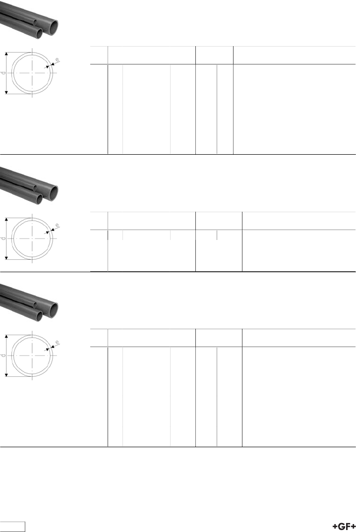
Pipes
Pipe ABS grey class E 15 bar at 20°C
•Dimensions: BS 5391
•Pipe length: 6m with plain ends
•Minimum order quantity: 1 length
d
[inch]
PN Code kg/m e
[mm]
di
[mm]
3∕815 169 018 080 0.090 1,7 6
1∕215 169 018 081 0.001 2,0 8
3∕415 169 018 082 0.210 2,5 14
1 15 169 018 083 0.330 3,1 19
1 1∕415 169 018 084 0.001 3,9 24
1 1∕215 169 018 085 0.680 4,5 29
2 15 169 018 086 1.060 5,6 39
3 15 169 018 088 2.280 8,3 59
4 15 169 018 089 0.300 10,6 80
Pipe ABS grey class C 9 bar at 20°C
•Dimensions: BS 5391
•Pipe length: 6m with plain ends
•Minimum order quantity: 1 length
d
[inch]
PN Code kg/m e
[mm]
di
[mm]
6 12 169 018 067 6.330 12.8 125.8
Pipe ABS grey class C 9 bar at 20°C
•Dimensions: BS 5391
•Pipe length: 6m with plain ends
•Minimum order quantity: 1 length
d
[inch]
PN Code kg/m e
[mm]
di
[mm]
1 9 169 018 033 0.500 2.0 21.0
1 1∕49169 018 034 0.340 2.5 27.0
1 1∕29169 018 035 0.001 2.8 33.0
2 9 169 018 036 0.001 3.6 44.0
3 9 169 018 038 1.130 5.2 66.0
2 1∕210 169 017 087 1.154 4.5 66.0
4 9 169 018 039 2.480 6.7 88.0
5 10 169 017 091 4.083 8.6 122.8
6 9 169 018 042 0.300 9.9 120.0
8 9 169 018 045 9.530 12.7 127.0
5
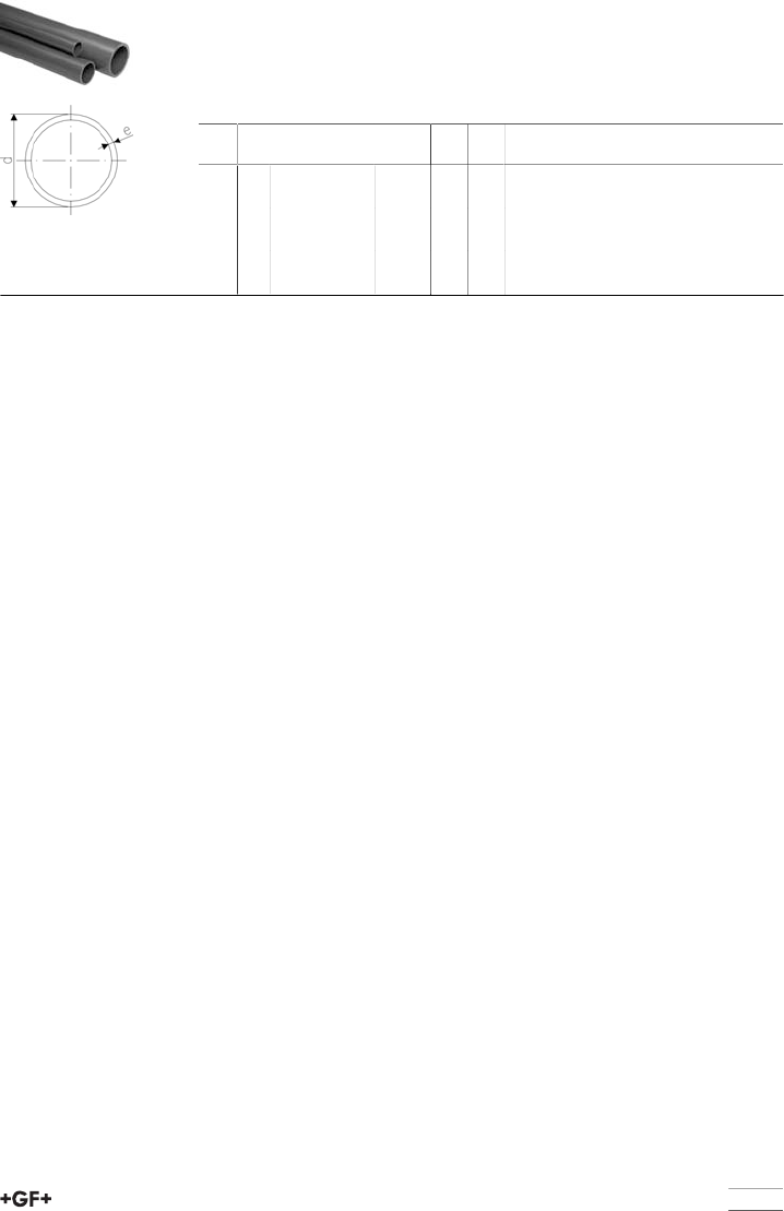
Pipe ABS grey class 7 (T) 12 bar at 20°C
•Dimensions: BS 5391
•Pipe length: 6m with plain ends
•Minimum order quantity: 1 length
•Thick wall pipe to allow for threading
d
[inch]
PN Code kg/m e
[mm]
di
[mm]
1∕212 169 018 106 0.220 3.6 5
3∕412 169 018 107 0.001 3.6 11
1 12 169 018 108 0.001 4.3 16
1 1∕412 169 018 109 0.680 5.3 21
1 1∕212 169 018 110 0.870 6.0 26
2 12 169 018 111 1.310 7.2 36
6
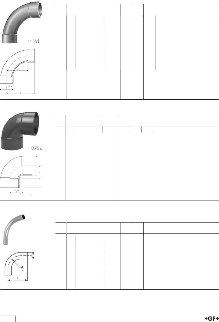
Solvent Cement Fittings
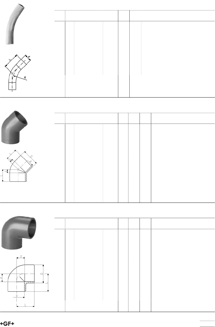
29 00 11 Bend 90° ABS Inch BS
d
[inch]
PN Code kg z
[mm]
D
[mm]
L
[mm]
1∕215 729 001 106 0.021 40 29 58
3∕415 729 001 107 0.035 50 35 71
1 15 729 001 108 0.049 64 43 88
1 1∕415 729 001 109 0.155 80 54 109
1 1∕215 729 001 110 0.262 100 64 131
2 15 729 001 111 0.388 126 76 163
2 1∕210 729 000 112 0.585 150 90 194
3 15 729 001 113 1.532 180 113 231
4 15 729 001 115 2.720 220 137 284
29 01 11 Bend 90°, short pattern, ABS BS Inch
d
[mm]
PN Code kg z
[mm]
D
[mm]
L
[mm]
8 9 729 011 120 6.800 168 256 287
29 00 16 Long Radius Bend 90°, ABS BS Inch
Other angles and sizes are available on request
d
[inch]
PN Code kg R
[mm]
L
[mm]
1∕215 729 001 656 0.017 51 71
3∕415 729 001 657 0.032 76 108
1 15 729 001 658 0.051 102 133
1 1∕415 729 001 659 0.103 127 170
1 1∕215 729 001 660 0.152 152 201
2 15 729 001 661 0.328 203 272
2 1∕215 729 001 662 1.444 255 340
3 15 729 001 663 1.125 305 402
4 15 729 001 664 2.202 406 544
7
29 15 11 Long Radius Bend 45°, ABS BS Inch
Other angles and sizes are available on request
d
[inch]
PN Code kg R
[mm]
L
[mm]
1∕215 729 151 176 0.016 51 50
3∕415 729 151 177 0.023 76 63
1 15 729 151 178 0.038 102 75
1 1∕415 729 151 179 0.077 127 100
1 1∕215 729 151 180 0.113 152 112
2 15 729 151 181 0.231 203 150
2 1∕215 729 151 182 1.444 255 200
3 15 729 151 183 0.844 305 238
4 15 729 151 184 1.694 406 301
29 15 11 Elbow 45° ABS Inch BS
d
[inch]
PN Code kg z
[mm]
D
[mm]
L
[mm]
3∕815 729 151 105 0.006 4 23 20
1∕215 729 151 106 0.011 7 28 24
3∕415 729 151 107 0.019 8 33 29
1 15 729 151 108 0.026 10 41 33
1 1∕415 729 151 109 0.046 11 51 40
1 1∕215 729 151 110 0.068 11 57 41
2 15 729 151 111 0.199 15 72 51
2 1∕210 729 150 112 0.228 17 89 61
3 15 729 151 113 0.405 21 109 72
4 15 729 151 115 0.866 26 135 89
5 10 729 150 116 1.190 32 162 108
6 15 729 151 117 1.865 38 198 129
8 9 729 151 120 3.900 49 250 168
29 10 11 Elbow 90° ABS Inch BS
d
[inch]
PN Code kg z
[mm]
D
[mm]
L
[mm]
3∕815 729 101 105 0.012 10 24 25
1∕215 729 101 106 0.016 13 28 30
3∕415 729 101 107 0.026 16 34 37
1 15 729 101 108 0.038 19 40 42
1 1∕415 729 101 109 0.058 22 52 51
1 1∕215 729 101 110 0.083 26 58 56
2 15 729 101 111 0.162 32 73 68
2 1∕210 729 100 112 0.308 40 90 84
3 15 729 101 113 0.480 46 107 97
4 15 729 101 115 0.980 59 137 122
5 10 729 100 116 1.470 70 162 146
6 15 729 101 117 2.960 86 201 176
8
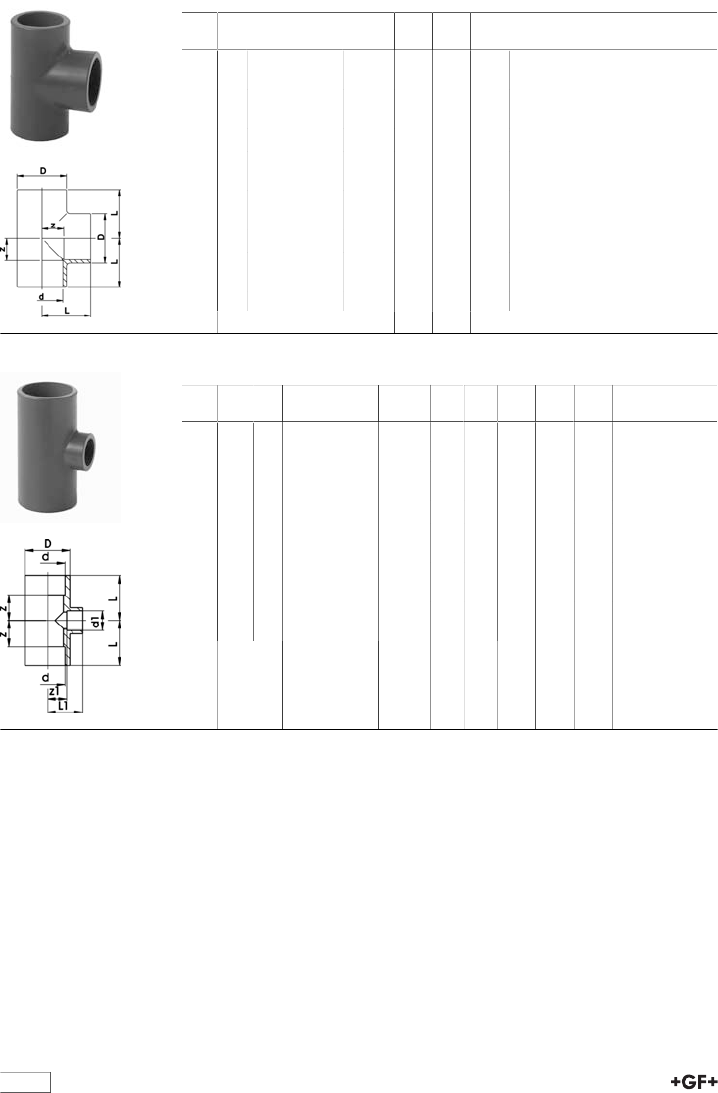
29 20 11 Tee 90° ABS Inch BS
d
[inch]
PN Code kg z
[mm]
D
[mm]
L
[mm]
3∕815 729 201 105 0.018 10 25 25
1∕215 729 201 106 0.029 13 30 30
3∕415 729 201 107 0.040 16 35 37
1 15 729 201 108 0.055 19 43 43
1 1∕415 729 201 109 0.076 22 53 51
1 1∕215 729 201 110 0.146 26 58 56
2 15 729 201 111 0.296 32 73 68
2 1∕210 729 200 112 0.421 40 90 84
3 15 729 201 113 0.700 46 107 97
4 15 729 201 115 1.181 59 138 122
5 10 729 200 116 2.500 71 169 147
6 15 729 201 117 4.470 86 202 176
8 9 729 201 120 7.680 114 256 233
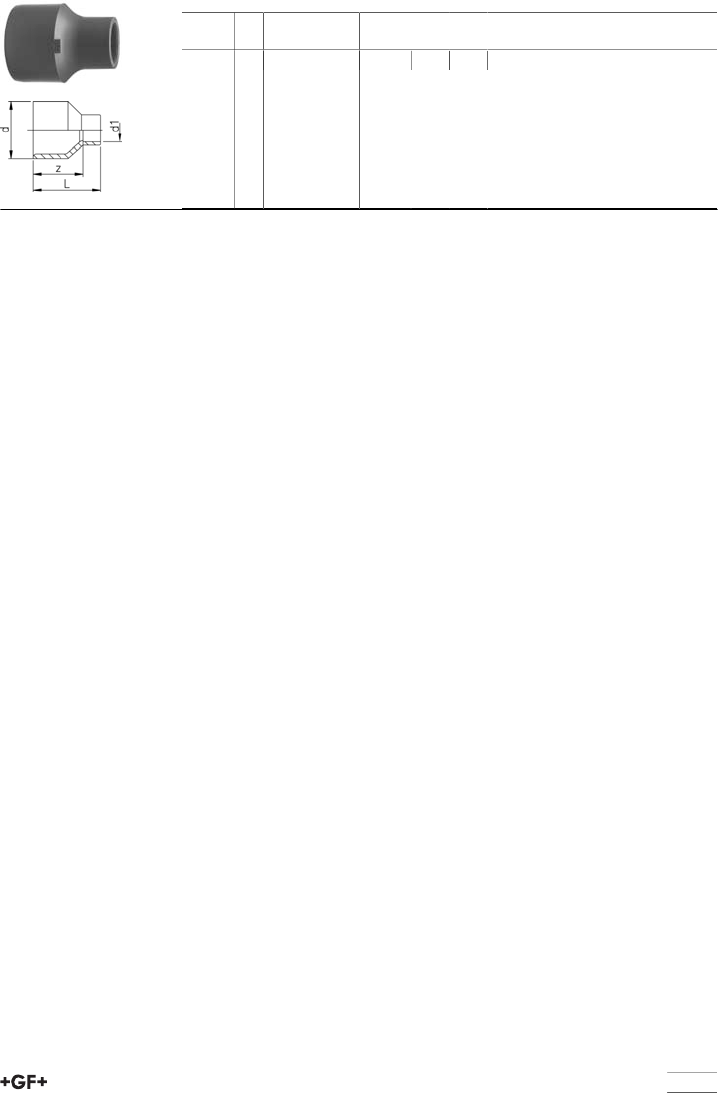
29 20 11 Tee 90° reducing ABS Inch BS
d
[inch]
d1
[inch]
PN Code kg z
[mm]
z1
[mm]
D
[mm]
L
[mm]
L1
[mm]
3∕41∕215 729 201 134 0.026 14 14 33 33 30
11∕215 729 201 141 0.042 17 17 41 39 33
13∕415 729 201 138 0.043 17 17 41 39 36
1 1∕43∕415 729 201 151 0.081 30 22 53 51 51
1 1∕41 15 729 201 147 0.085 27 22 53 51 51
1 1∕21∕215 729 201 009 0.154 29 29 62 59 44
1 1∕21 15 729 201 164 0.158 29 25 62 59 50
23∕415 729 201 011 0.246 37 31 77 73 53
2 1 15 729 201 178 0.250 37 31 77 73 56
2 1 1∕215 729 201 170 0.265 38 31 73 68 68
4 3 15 729 201 137 0.001 72 59 138 122 122
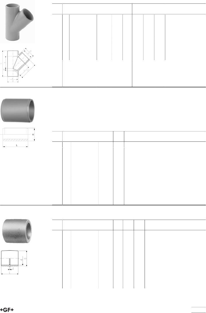
table continued next page
9
29 25 11 Tee 45° ABS Inch BS
d
[inch]
PN Code kg z
[mm]
z1
[mm]
D
[mm]
L
[mm]
L1
[mm]
1∕29729 251 106 0.026 30 6 28 68 46
3∕49729 251 107 0.039 36 9 33 83 55
1 9 729 251 108 0.068 45 10 41 99 67
1 1∕49729 251 109 0.109 55 9 50 118 82
1 1∕29729 251 110 0.207 67 13 60 140 97
2 9 729 251 111 0.372 87 16 74 175 123
2 1∕26729 250 112 0.637 101 18 91 207 145
5 6 729 250 116 4.315 190 34 168 376 266
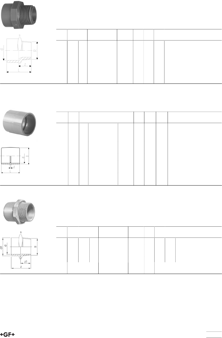
29 90 19 Barrel nipple ABS Inch BS
Model:
•With solvent cement spigots on both sides
•For quick connections between fittings
•For the shortest possible distance between fittings
•Overall length L = 2 x socket length
d
[inch]
PN Code kg L
[mm]
3∕810 729 901 905 0.002 28
1∕210 729 901 906 0.004 32
3∕410 729 901 907 0.008 38
1 10 729 901 908 0.015 44
1 1∕410 729 901 909 0.027 52
1 1∕210 729 901 910 0.050 62
2 10 729 901 911 0.098 76
2 1∕210 729 900 912 0.102 88
3 10 729 901 913 0.266 102
4 10 729 901 914 0.476 122
5 10 729 900 916 152
29 91 11 Socket ABS Inch BS
d
[inch]
PN Code kg z
[mm]
D
[mm]
L
[mm]
3∕815 729 911 105 0.006 3 23 35
1∕215 729 911 106 0.008 3 27 38
3∕415 729 911 107 0.013 3 33 45
1 15 729 911 108 0.020 3 41 51
1 1∕415 729 911 109 0.040 3 51 60
1 1∕215 729 911 110 0.048 3 58 64
2 15 729 911 111 0.090 5 72 78
2 1∕210 729 910 112 0.140 4 87 92
3 15 729 911 113 0.260 7 104 108
4 15 729 911 115 0.476 8 134 135
10
d
[inch]
PN Code kg z
[mm]
D
[mm]
L
[mm]
5 10 729 910 116 0.760 7 162 159
6 15 729 911 117 1.310 11 197 192
8 15 729 911 120 3.700 10 253 248
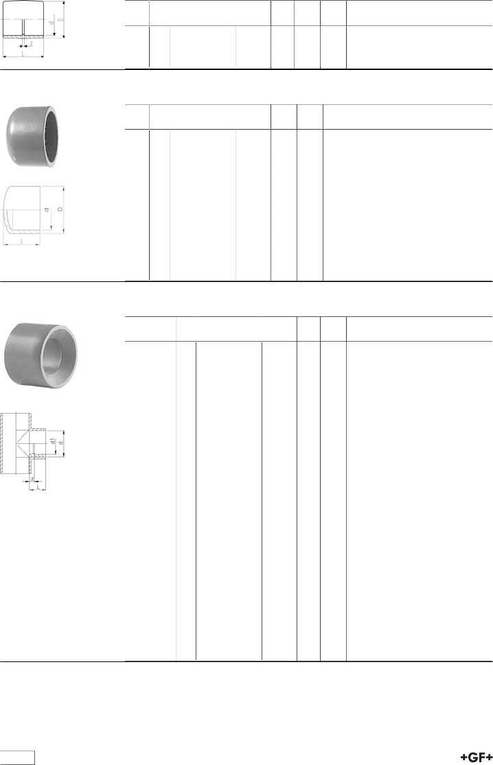
29 96 11 Cap, ABS BS Inch
d
[inch]
PN Code kg D
[mm]
l
[mm]
3∕815 729 961 105 0.004 26 33
1∕215 729 961 106 0.007 30 25
3∕415 729 961 107 0.011 37 30
1 15 729 961 108 0.019 44 34
1 1∕415 729 961 109 0.033 55 41
1 1∕215 729 961 110 0.038 62 44
2 15 729 961 111 0.097 78 54
2 1∕215 729 960 112 0.115 87 65
3 15 729 961 113 0.222 112 77
4 15 729 961 115 0.570 145 101
5 15 729 960 116 0.880 163 114
29 90 13 Reducing bush short pattern ABS Inch BS
d-d
[inch]
PN Code kg z
[mm]
l
[mm]
1∕2 - 3∕815 729 901 334 0.002 2 18
3∕4 - 1∕215 729 901 337 0.004 3 21
1 - 1∕215 729 901 342 0.015 6 24
1 - 3∕415 729 901 341 0.008 3 24
1 1∕4 - 1∕215 729 901 348 0.019 11 29
1 1∕4 - 3∕415 729 901 347 0.019 8 29
1 1∕4 - 1 15 729 901 346 0.015 5 29
1 1∕2 - 1∕215 729 901 355 0.026 13 30
1 1∕2 - 3∕415 729 901 354 0.027 10 30
1 1∕2 - 1 15 729 901 353 0.013 6 30
1 1∕2 - 1 1∕415 729 901 352 0.010 2 30
2 - 3∕415 729 901 361 0.046 16 37
2 - 1 15 729 901 360 0.060 13 37
2 - 1 1∕415 729 901 359 0.053 8 37
2 - 1 1∕215 729 901 358 0.038 6 37
2 1∕2 - 2 15 729 901 364 0.710 8 44
3 - 1 15 729 901 374 0.064 27 51
3 - 1 1∕215 729 901 372 0.133 21 51
3 - 2 15 729 901 371 0.131 14 51
3 - 2 1∕215 729 901 370 0.095 6 51
4 - 3 15 729 901 381 0.259 13 64
5 - 4 15 729 901 385 0.511 13 76
8 - 6 15 729 901 396 1.230 33 119
11
29 91 13 Reducing bush long pattern ABS Inch BS
d-d
[inch]
PN Code kg z
[mm]
l
[mm]
6 - 4 15 729 911 389 0.975 133 197

12
Adaptor Fittings ABS
29 10 12 Elbow 90°, ABS BS Inch Rp
Model:
•With solvent cement socket BS Inch and parallel female thread Rp
•Reinforcing ring stainless (A2)
•Connection to plastic or metal threads
•Do not use thread sealing pastes that are harmful to ABS
d
[inch]
Rp
[inch]
PN Code kg z1
[mm]
z2
[mm]
D
[mm]
L
[mm]
1∕21∕215 729 101 206 0.013 12 11 30 27
3∕43∕415 729 101 207 0.028 15 15 35 33
1 1 15 729 101 208 0.036 18 19 45 39
29 91 10 Socket ABS Inch BS Rp
Model:
•With solvent cement socket BS Inch and parallel female thread Rp
•Reinforcing ring stainless (A2)
•Connection to plastic or metal threads
•Do not use thread sealing pastes that are harmful to ABS
d
[inch]
Rp
[inch]
PN Code kg z
[mm]
s
[mm]
l
[mm]
3∕83∕815 729 911 005 0.010 4 27 31
1∕21∕215 729 911 006 0.015 4 32 35
3∕43∕415 729 911 007 0.020 3 36 40
1 1 15 729 911 008 0.044 3 36 45
1 1∕41 1∕415 729 911 009 0.055 3 55 51
1 1∕21 1∕215 729 911 010 0.106 8 65 69
2 2 15 729 911 011 0.138 8 8 69
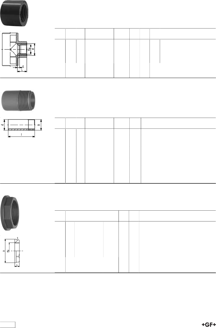
29 90 14 Adaptor ABS Inch BS Rp
Model:
•With solvent cement socket BS Inch and parallel female thread Rp
•Connection to plastic threads only
•Do not use thread sealing pastes that are harmful to ABS
d
[inch]
Rp
[inch]
PN Code kg z
[mm]
s
[mm]
l
[mm]
1∕21∕215 729 901 406 0.010 21 28 37
3∕43∕415 729 901 407 0.025 23 34 41
1 1 15 729 901 408 0.037 27 42 48
1 1∕41 1∕415 729 901 409 0.059 33 52 56
1 1∕21 1∕215 729 901 410 0.073 38 62 61
2 2 15 729 901 411 0.153 47 77 74
13
29 91 17 Adaptor Bush ABS BS Inch R
Model:
•With solvent cement socket BS Inch and taper male thread R
•Connection to plastic threads only
•Do not use thread sealing pastes that are harmful to ABS
d
[inch]
R
[inch]
PN Code kg z
[mm]
s
[mm]
l
[mm]
3∕83∕815 729 911 705 0.010 20 27 34
1∕21∕215 729 911 706 0.015 24 32 40
3∕43∕415 729 911 707 0.019 25 36 44
1 1 15 729 911 708 0.031 28 46 50
1 1∕41 1∕415 729 911 709 0.048 31 55 57
1 1∕21 1∕215 729 911 710 0.073 32 65 63
2 2 15 729 911 711 0.133 38 80 76
29 91 31 Adaptor socket ABS metric/Inch BS
Model:
•with BS Inch and metric solvent cement sockets
d
[mm]
d
[inch]
PN Code kg z
[mm]
L
[mm]
D
[mm]
16 3∕810 729 913 105 0.007 5 35 23
20 1∕210 729 913 106 0.010 5 38 27
25 3∕410 729 913 107 0.016 5 45 33
32 1 10 729 913 108 0.025 5 51 41
40 1 1∕410 729 913 109 0.045 5 60 51
50 1 1∕210 729 913 110 0.070 4 65 59
63 2 10 729 913 111 0.130 5 79 75
75 2 1∕210 729 910 112 0.140 4 92 87
90 3 10 729 913 113 0.365 6 108 104
110 4 10 729 913 115 0.630 7 135 134
29 91 15 Adaptor Socket Nipple, ABS BS Inch R
Model:
•With solvent cement spigot/reducing socket and taper male thread R
•Connection to plastic threads only
•Do not use thread sealing pastes that are harmful to ABS
d
[inch]
d1
[inch]
R
[inch]
PN Code kg z
[mm]
z1
[mm]
s
[mm]
1∕43∕83∕815 729 911 555 0.008 36 21 27
3∕81∕21∕215 729 911 556 0.012 43 28 32
1∕23∕43∕415 729 911 557 0.018 48 31 36
3∕41 1 15 729 911 558 0.031 55 35 46
14
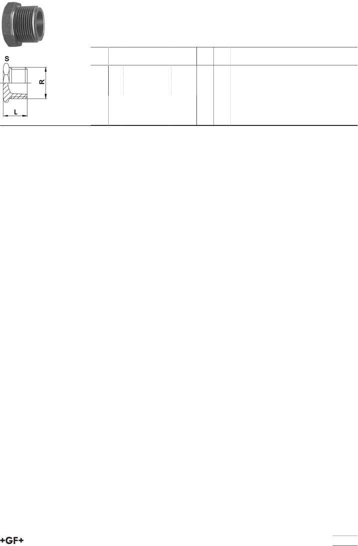
29 90 15 Reducing Bush (short), ABS BS Inch - Rp
Model:
•With solvent cement spigot BS and parallel female thread Rp
•Connection to plastic threads only
•Do not use thread sealing pastes that are harmful to ABS
d
[inch]
Rp
[inch]
PN Code kg z
[mm]
D
[mm]
L
[mm]
1∕23∕815 729 901 534 0.003 3 21 18
3∕41∕215 729 901 537 0.011 5 27 21
13∕415 729 901 541 0.011 4 33 24
11∕215 729 901 542 0.015 8 33 24
29 91 39 Adaptor nipple ABS Inch BS R
Model:
•With solvent cement spigot BS Inchand taper male thread R
•Connection to plastic threads only
•Do not use thread sealing pastes that are harmful to ABS
d
[inch]
R
[inch]
PN Code kg l
[mm]
3∕83∕815 729 913 905 0.007 43
1∕21∕215 729 913 906 0.010 50
3∕43∕415 729 913 907 0.016 56
1 1 15 729 913 908 0.025 63
1 1∕41 1∕415 729 913 909 0.045 75
1 1∕21 1∕215 729 913 910 0.070 88
2 2 15 729 913 911 0.130 88
3 3 15 729 913 913 0.365 128
4 4 15 729 913 915 0.630 153
29 28 00 Backnut ABS Inch BS
Model:
•Parallel female thread Rp
Rp
[inch]
PN Code kg D
[mm]
s
[mm]
1∕215 169 280 002 0.010 37 31
3∕415 169 280 003 0.021 42 36
1 15 169 280 004 0.024 55 46
1 1∕415 169 280 005 0.025 59 50
1 1∕215 169 280 006 0.034 70 60
2 15 169 280 007 0.065 94 79
15
29 96 19 Plug ABS R
Model:
•With taper male thread R
•Connection to plastic threads only
•Do not use thread sealing pastes that are harmful to ABS
R
[inch]
PN Code kg s
[mm]
L
[mm]
1∕210 729 961 906 0.008 27 25
3∕410 729 961 907 0.014 36 29
1 10 729 961 908 0.022 41 32
16
Flange adaptors
29 79 11 Flange adaptor ABS
Combined jointing face flat and serrated Inch BS
Model:
•Gasket: Flange Gasket EPDM No. 48 40 01, FPM No. 49 40 01
d
[inch]
PN Code kg D1
[mm]
D
[mm]
L
[mm]
L1
[mm]
z
[mm]
1∕215 729 791 106 0.007 34 27 21 6 3
3∕415 729 791 107 0.011 41 33 24 7 3
1 15 729 791 108 0.018 27 41 27 7 3
1 1∕415 729 791 109 0.027 32 50 32 8 3
1 1∕215 729 791 110 0.050 33 61 33 8 3
2 15 729 791 111 0.078 40 77 40 9 3
2 1∕210 729 790 112 0.118 106 91 47 10 3
3 15 729 791 113 0.187 56 108 56 11 5
4 15 729 791 115 0.309 69 136 69 12 5
5 10 729 790 116 0.567 188 165 81 14 5
6 12 729 791 117 0.912 96 198 96 16 5
8 9 729 791 120 1.449 122 248 122 20 6
17
Full Face Flange (drilled)
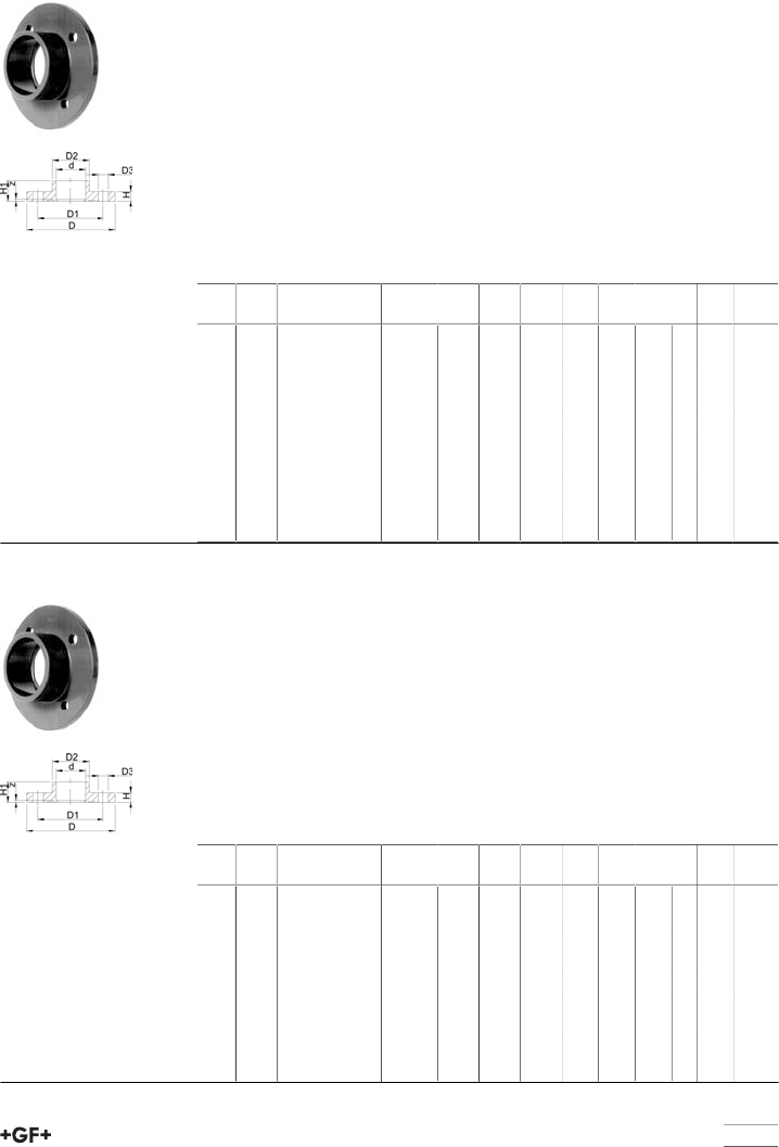
29 73 11 Full face flange ABS Inch BS
Drilled to BS 10 table D & E
Model:
•Jointing face serrated
•Solvent cement socket BS inch
•It is recommended to usebacking flangesin conjunction with all Full Face
Flanges
•For pressure ratings over 2 bar backing flanges must be used
•All Full Face Flanges are manufactured with outside diameter to BS 4504
•¹ connecting dimensions: BS 10 table E
•* connecting dimensions: BS 10 table D
AL: number of holes
d
[inch]
DN
[mm]
Code kg D
[mm]
D1
[mm]
D2
[mm]
D3
[mm]
H
[mm]
H1
[mm]
AL z
[mm]
1∕215 729 731 106 0.075 95 67 27 15 10 21 4 3
3∕420 729 731 107 0.083 105 73 33 15 10 24 4 8
1 25 729 731 108 0.097 115 83 41 15 10 27 4 3
1 1∕432 729 731 109 0.149 140 88 50 15 10 32 4 3
1 1∕240 729 731 110 0.180 150 98 61 15 10 33 4 3
2 50 729 731 111 0.231 165 115 77 18 10 40 4 3
3 80 729 731 113 0.238 200 146 108 18 12 56 4 5
¹4 100 729 731 114 0.771 220 178 136 18 17 69 8 5
*4 100 729 731 164 0.001 220 178 136 18 17 69 4 5
6 150 729 731 117 1.486 285 235 198 22 22 96 8 5
29 73 01
29 73 11 Full face flange ABS Inch BS
Drilled to BS 4504 PN10/16
Model:
•Jointing face serrated
•Solvent cement socket BS inch
•It is recommended to usebacking flangesin conjunction with all Full Face
Flanges
•For pressure ratings over 2 bar backing flanges must be used
•All Full Face Flanges are manufactured with outside diameter to BS 4504
•¹ connecting dimensions: BS 4504 and BS 10 table E
AL: number of holes
d
[inch]
DN
[mm]
Code kg D
[mm]
D1
[mm]
D2
[mm]
D3
[mm]
H
[mm]
H1
[mm]
AL z
[mm]
1∕215 729 731 106 0.075 95 67 27 15 10 21 4 3
3∕420 729 731 107 0.083 105 73 33 15 10 24 4 8
1 25 729 731 108 0.097 115 83 41 15 10 27 4 3
1 1∕432 729 730 109 0.150 140 100 50 14 10 32 4 3
1 1∕240 729 730 110 0.190 150 110 61 14 10 33 4 3
2 50 729 730 111 0.240 165 125 77 18 10 40 4 3
3 80 729 730 113 0.001 200 160 108 18 12 56 4 5
¹4 100 729 731 114 0.771 220 178 136 18 17 69 8 5
6 150 729 730 117 0.001 285 240 198 22 22 96 8 5
18
29 73 11
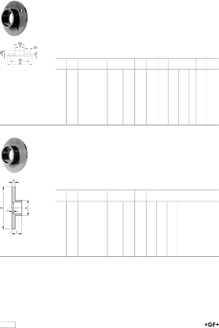
29 73 21 Full face flange ABS Inch BS
Drilled to ANSI B 16.5 class 150
Model:
•Jointing face serrated
•Solvent cement socket BS inch
•It is recommended to usebacking flangesin conjunction with all Full Face
Flanges
•For pressure ratings over 2 bar backing flanges must be used
•All Full Face Flanges are manufactured with outside diameter to BS 4504
AL: number of holes
d
[inch]
DN
[mm]
Code kg D
[mm]
D1
[mm]
D2
[mm]
D3
[mm]
H
[mm]
H1
[mm]
AL z
[mm]
1∕215 729 732 106 0.070 95 60 27 16 10 21 4 3
3∕420 729 732 107 0.090 105 70 33 16 10 24 4 8
1 25 729 732 108 0.097 115 79 41 16 10 27 4 3
1 1∕432 729 731 109 0.149 140 88 50 15 10 32 4 3
1 1∕240 729 731 110 0.180 150 98 61 15 10 33 4 3
2 50 729 731 111 0.231 165 115 77 18 10 40 4 3
3 80 729 732 113 0.238 200 152 108 19 12 56 4 5
4 100 729 732 114 0.690 220 190 136 19 17 69 8 5
6 150 729 730 117 0.001 285 240 198 22 22 96 8 5
29 73 00 Full face flange ABS Inch BS
Undrilled
Model:
•Jointing face serrated
•Solvent cement socket BS inch
•It is recommended to usebacking flangesin conjunction with all Full Face
Flanges
•For pressure ratings over 2 bar backing flanges must be used
•All Full Face Flanges are manufactured with outside diameter to BS 4504
d
[inch]
DN
[mm]
Code kg D
[mm]
b
[mm]
h
[mm]
l
[mm]
z
[mm]
1∕215 729 730 006 0.074 95 27 10 21 3
3∕420 729 730 007 0.090 105 33 10 24 8
1 25 729 730 008 0.105 115 41 10 27 3
1 1∕432 729 730 009 0.155 140 50 10 32 3
1 1∕240 729 730 010 0.187 150 61 10 33 3
2 50 729 730 011 0.238 165 77 10 40 3
3 80 729 730 013 0.426 200 108 12 56 5
4 100 729 730 014 0.656 220 136 17 69 5
6 150 729 730 017 1.832 285 198 22 96 5
19
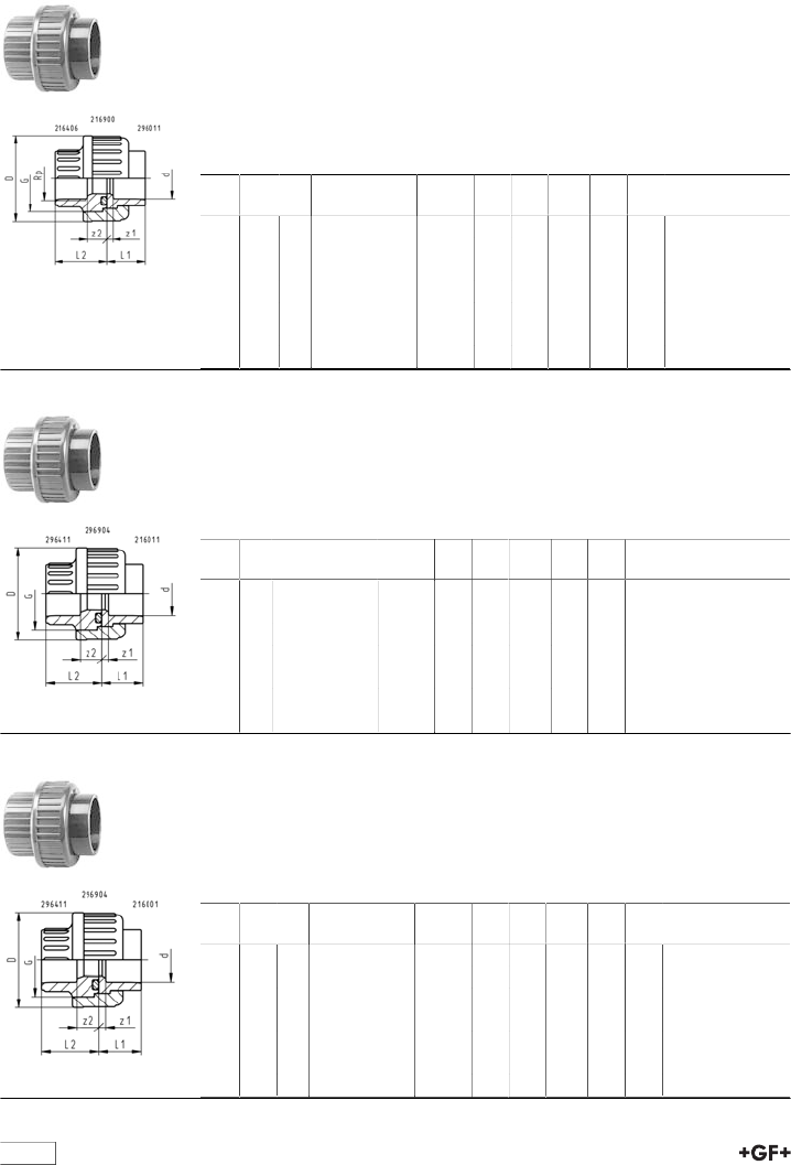
Unions
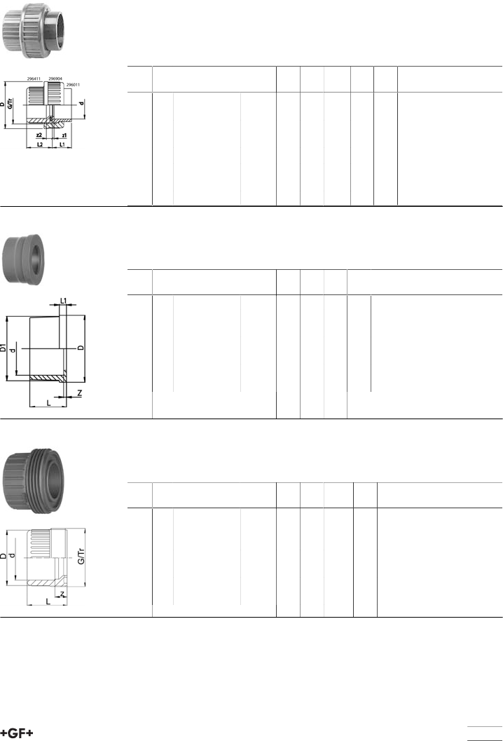
29 51 11 Union ABS Inch BS
Model:
•Union End: Solvent cement socket BS Inch
•Union Bush: Solvent cement socket BS inch
•Gasket: O-Ring EPDM No. 48 41 00, FPM No. 49 41 00
d
[inch]
PN Code kg z1
[mm]
z2
[mm]
D
[mm]
L1
[mm]
L2
[mm]
3∕815 729 511 105 0.019 3 8 35 19 24
1∕215 729 511 106 0.035 3 9 43 21 26
3∕415 729 511 107 0.049 3 9 53 24 29
1 15 729 511 108 0.070 3 9 60 27 33
1 1∕415 729 511 109 0.127 3 10 74 32 39
1 1∕215 729 511 110 0.220 3 10 83 33 41
2 15 729 511 111 0.402 3 10 103 40 48
2 1∕210 729 510 112 0.461 3 18 135 47 62
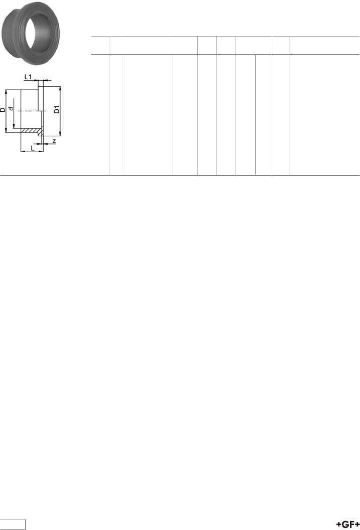
29 60 11 Union end ABS Inch BS
Model:
•Solvent cement socket BS inch
d
[inch]
PN Code kg z
[mm]
D
[mm]
D1
[mm]
L
[mm]
3∕815 729 601 105 0.004 3 24 22 19
1∕215 729 601 106 0.007 3 30 27 21
3∕415 729 601 107 0.011 3 38 36 24
1 15 729 601 108 0.015 3 44 41 27
1 1∕415 729 601 109 0.022 3 56 53 32
1 1∕215 729 601 110 0.033 3 62 59 33
2 15 729 601 111 0.060 3 78 74 40
29 64 11 Union bush ABS Inch BS
Model:
•Solvent cement socket BS inch
d
[inch]
PN Code kg z
[mm]
D
[mm]
G/Tr L
[mm]
3∕815 729 641 105 0.008 8 24 3/4 24
1∕215 729 641 106 0.009 9 28 1 26
3∕415 729 641 107 0.014 9 34 1 1/4 29
1 15 729 641 108 0.024 9 42 1 1/2 33
1 1∕415 729 641 109 0.043 10 52 2 39
1 1∕215 729 641 110 0.059 10 62 2 1/4 46
2 15 729 641 111 0.106 10 78 2 3/4 58
20
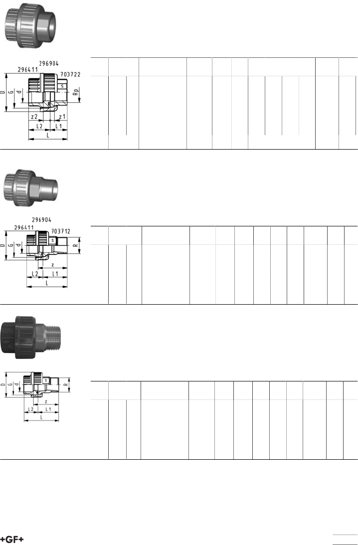
Adaptor Unions ABS
29 51 12 Adaptor Union ABS/PVC-U BS Inch - Rp
Model:
•Union Bush: PVC-U parallel female thread Rp
•Union End:Solvent cement socket ABS BS inch
•Union nut: PVC-U
•Gasket: O-Ring EPDM No. 48 41 00, FPM No. 49 41 00
•Connection to plastic threads only
•Do not use thread sealing pastes that are harmful to PVC-U
d
[inch]
Rp
[inch]
PN Code kg z1
[mm]
z2
[mm]
D
[mm]
L1
[mm]
L2
[mm]
3∕83∕815 729 511 205 0.025 3 13 35 19 24
1∕21∕215 729 511 206 0.041 3 13 43 21 26
3∕43∕415 729 511 207 0.100 3 14 53 24 29
1 1 15 729 511 208 0.172 3 15 60 27 32
1 1∕41 1∕415 729 511 209 0.200 3 19 74 32 38
1 1∕21 1∕215 729 511 210 0.277 3 26 83 33 40
2 2 15 729 511 211 0.430 3 33 103 40 46
29 52 11 Adaptor union ABS/PVC-U Inch BS
Model:
•Union End: Solvent cement socket PVC-U BS Inch
•Union Bush: Solvent cement socket ABSBS inch
•Union Nut: ABS
•Gasket: O-Ring EPDM No. 48 41 00, FPM No. 49 41 00
d
[inch]
PN Code kg z1
[mm]
z2
[mm]
D
[mm]
L1
[mm]
L2
[mm]
3∕815 729 521 105 0.025 3 8 35 19 24
1∕215 729 521 106 0.041 3 9 43 21 26
3∕415 729 521 107 0.066 3 9 53 24 29
1 15 729 521 108 0.093 3 9 60 27 32
1 1∕415 729 521 109 0.155 3 10 74 32 38
1 1∕215 729 521 110 0.209 3 10 83 33 40
2 15 729 521 111 0.368 3 10 103 40 46
29 52 31 Adaptor union ABS/PVC-U Inch BS/metric
Model:
•Union End: Solvent cement socket PVC-U metric
•Union Bush: Solvent cement socket ABSBS inch
•Union Nut: ABS
•Gasket: O-Ring EPDM No. 48 41 00, FPM No. 49 41 00
d
[inch]
d
[mm]
PN Code kg z1
[mm]
z2
[mm]
D
[mm]
L1
[mm]
L2
[mm]
3∕816 15 729 523 105 0.075 3 13 35 19 24
1∕220 15 729 523 106 0.120 3 13 43 21 26
3∕425 15 729 523 107 0.190 3 14 53 24 29
1 32 15 729 523 108 0.250 3 15 60 27 32
1 1∕440 15 729 523 109 0.400 3 19 74 32 38
1 1∕250 15 729 523 110 0.510 3 26 83 33 40
2 63 15 729 523 111 0.287 3 33 103 40 46
21
29 53 13 Adaptor union ABS/malleable iron Inch BS Rp
Model:
•Union Nut: ABS
•Union Bush: Solvent cement socket BS Inch
•Union End:malleable ironwith parallel female thread Rp
•Gasket: O-Ring EPDM No. 48 41 00
d
[inch]
Rp
[inch]
PN Code kg D
[mm]
L
[mm]
L1
[mm]
L2
[mm]
z1
[mm]
z2
[mm]
G
[inch]
s
[mm]
1∕21∕215 729 531 306 0.132 43 48 22 26 9 10 1 25
3∕43∕415 729 531 307 0.226 51 51 22 29 7 10 1 1/4 31
1 1 15 729 531 308 0.282 58 58 26 33 9 10 1 1/2 38
1 1 1∕415 729 531 309 0.476 72 69 31 39 12 12 2 48
1 1∕21 1∕215 729 531 310 0.498 83 78 33 46 14 14 2 1/4 54
2 2 15 729 531 311 0.795 100 91 35 58 11 18 2 3/4 67
29 53 18 Adaptor union ABS/malleable iron Inch BS R
Model:
•Union Nut: ABS
•Union Bush: Solvent cement socket BS Inch
•Union End: Malleable iron with taper male thread R
•Gasket: O-Ring EPDM No. 48 41 00
d
[inch]
R
[inch]
PN*
[bar]
Code kg D
[mm]
L
[mm]
L1
[mm]
L2
[mm]
z
[mm]
G
[inch]
s
[mm]
1∕21∕215 729 531 806 0.137 43 66 40 26 50 1 25
3∕43∕415 729 531 807 0.226 51 72 43 29 53 1 1/4 31
1 1 15 729 531 808 0.322 58 80 48 33 58 1 1/2 38
1 1∕41 1∕415 729 531 809 0.554 72 95 57 39 69 2 48
1 1∕21 1∕215 729 531 810 0.654 83 104 59 46 73 2 1/4 54
2 2 15 729 531 811 0.935 100 118 62 58 80 2 3/4 67
Adaptor union R ABS/brass Inch BS
Model:
•Union Nut: ABS
•Union Bush: Solvent cement socket ABSBS inch
•Union End: Brass with taper male thread R
•Gasket: O-Ring EPDM No. 48 41 00
d
[inch]
R
[inch]
PN Code kg D
[mm]
L
[mm]
L1
[mm]
L2
[mm]
z
[mm]
G
[inch]
s
[mm]
1∕21∕215 729 551 906 0.123 43 63 37 26 37 1 25
3∕43∕415 729 551 907 0.185 51 71 42 29 42 1 1/4 30
1 1 15 729 551 908 0.283 58 79 46 33 55 1 1/2 36
1 1∕41 1∕415 729 551 909 0.503 72 91 52 39 60 2 46
1 1∕21 1∕215 729 551 910 0.666 83 97 56 41 65 2 1/4 55
2 2 15 729 551 911 1.071 100 115 67 48 77 2 3/4 65
22
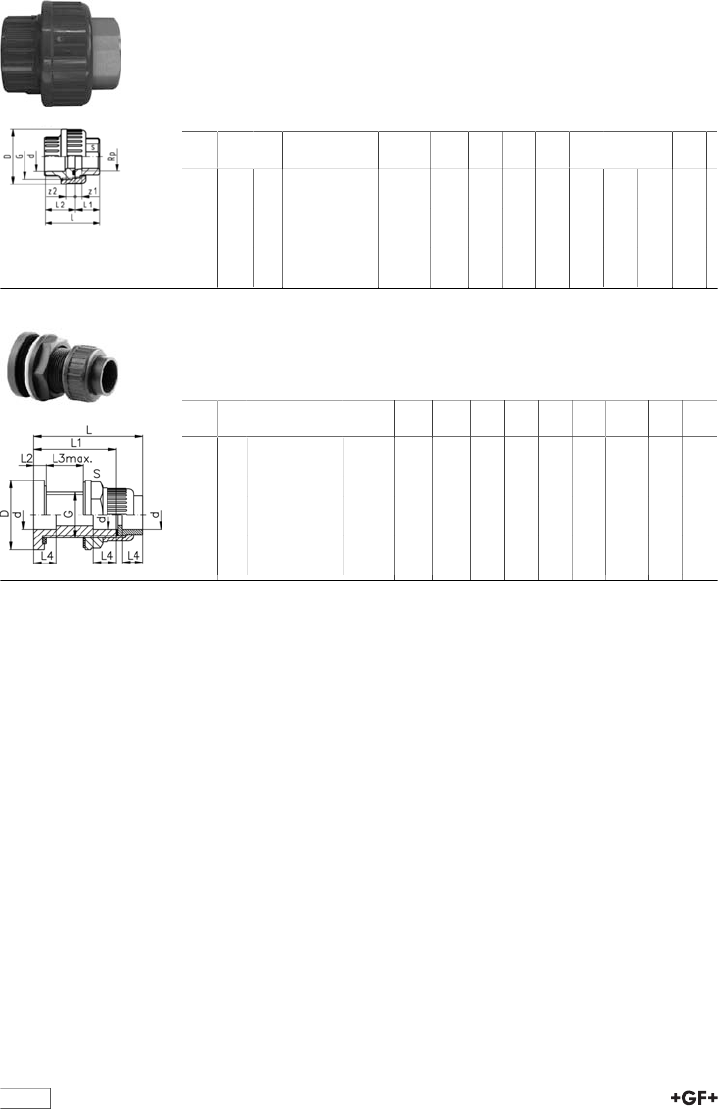
Adaptor union Rp ABS/Brass Inch BS
Model:
•Union Nut: ABS
•Union Bush: Solvent cement socket ABSBS inch
•Union End: Brass with parallel female thread Rp
•Gasket: O-Ring EPDM No. 48 41 00
d
[inch]
Rp
[inch]
PN Code kg D
[mm]
L
[mm]
L1
[mm]
L2
[mm]
z1
[mm]
z2
[mm]
G
[inch]
s
[mm]
1∕21∕215 729 551 506 0.084 43 48 22 26 7 9 1 25
3∕43∕415 729 551 507 0.134 51 54 25 29 9 8 1 1∕430
1 1 15 729 551 508 0.179 58 60 27 33 8 9 1 1∕236
1 1∕41 1∕415 729 551 509 0.327 72 70 31 39 10 11 2 46
1 1∕21 1∕215 729 551 510 0.452 83 75 35 41 13 11 2 1∕455
2 2 15 729 551 511 0.722 100 88 40 48 14 12 2 3∕465
69 25 02 Tank connector ABS Inch BS
Model:
•End connection: Union with solvent cement socket BS Inch
•Gasket: flat gasket EPDM
d
[inch]
PN Code kg d1
[mm]
L
[mm]
L1
[mm]
L2
[mm]
L3
[mm]
L4
[mm]
G
[inch]
s
[mm]
3∕815 169 250 225 0.073 44 85 65 10 32 14 3/4 33
1∕215 169 250 226 0.131 56 89 67 11 30 16 1 46
3∕415 169 250 227 0.194 65 97 72 12 32 19 11/4 50
1 15 169 250 228 0.001 70 103 75 12 33 22 11/2 60
1 1∕415 169 250 229 0.446 95 111 78 12 32 26 2 80
1 1∕215 169 250 230 0.485 95 119 82 13 32 31 21/4 80
2 15 169 250 231 0.001 115 131 87 13 33 38 23/4 83
23
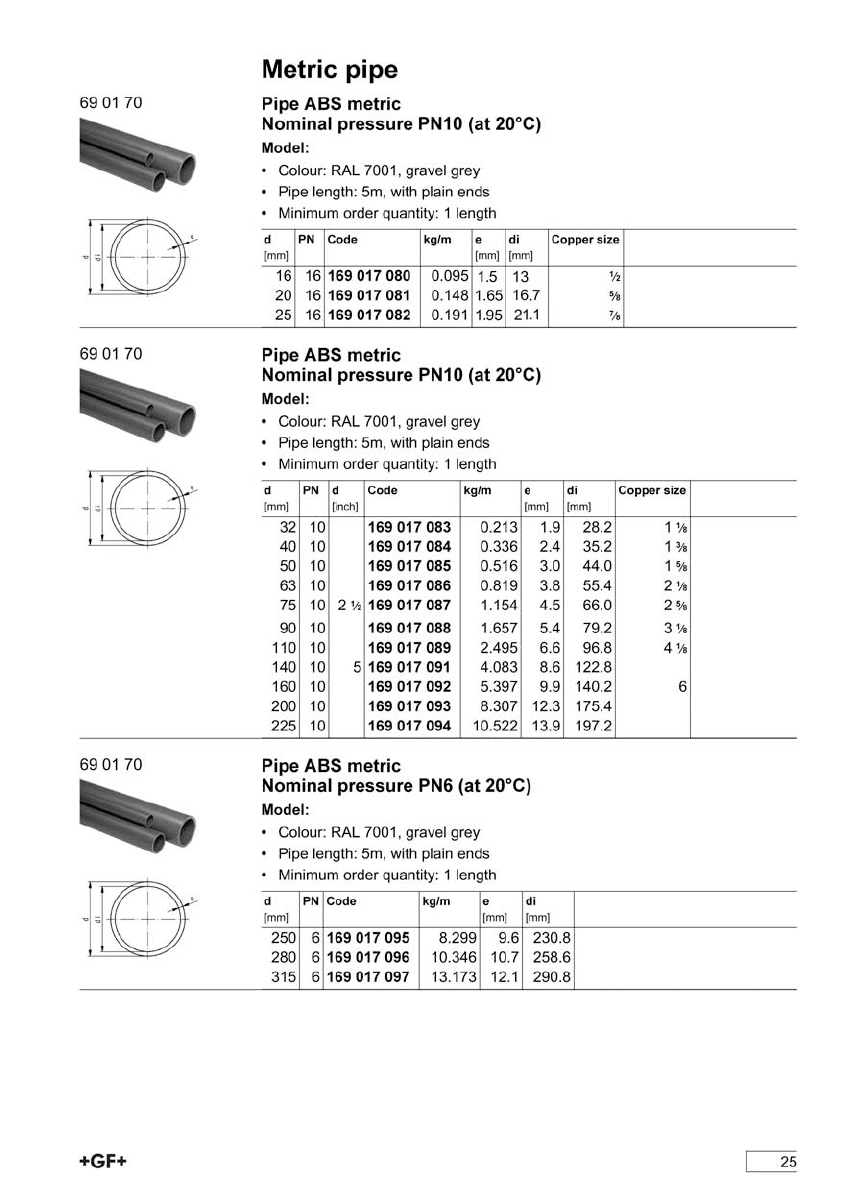
ABS metric
Page
Metric pipe 25
Pipe fittings for solvent cement jointing 26
Adaptor fittings 33
Threaded fittings 35
Flange adaptor 37
Unions 38
Adaptor Unions 39
Union spare parts 43
Branch saddles 45
Ball valves 49
Spare parts ball valves 74
Diaphragm valves 82
Spare parts diaphragm valves new generation 85
Spare parts diaphragm valves 92
Butterfly valves 94
Spare parts butterfly valves 108
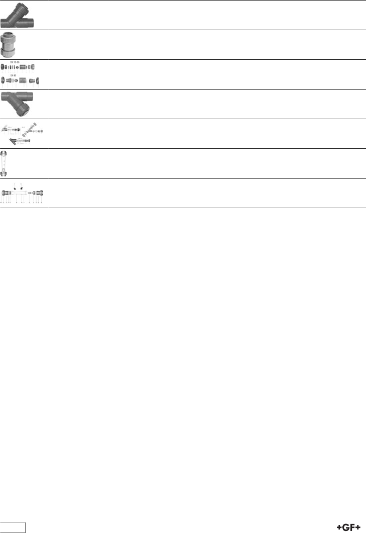
24
Page
Angle seat check valves 111
Ball check (non-return) valve 112
Spare parts ball check valves 114
Strainers 117
Spare parts line strainer 119
Variable area flow meters 123
Spare parts variable area flow meters 132
26
Pipe fittings for solvent cement jointing
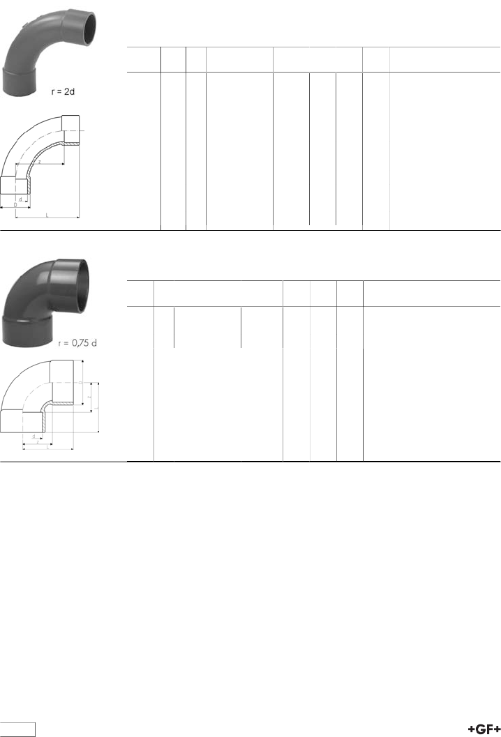
29 00 01 Bend 90° ABS metric
•Radius = 2 d
* Available as long as our stock will last
d
[mm]
d
[inch]
PN Code kg z
[mm]
D
[mm]
L
[mm]
20 16 729 000 106 0.027 40 27 58
25 16 729 000 107 0.038 50 35 69
32 10 729 000 108 0.051 64 38 86
40 10 729 000 109 0.102 80 54 109
50 10 729 000 110 0.206 100 61 131
63 10 729 000 111 0.387 126 76 164
75 2 1∕210 729 000 112 0.585 150 90 194
90 10 729 000 113 0.750 180 113 231
110 10 729 000 114 2.030 220 137 281
140 10 729 000 116 4.100 280 168 356
*160 10 729 000 117 5.600 320 191 406
29 01 01 Bend 90° short pattern ABS metric
•>d225 - maximum operating temperature: +40°C
d
[mm]
PN Code kg z
[mm]
D
[mm]
L
[mm]
225 10 729 010 120 5.650 168 256 287
280 6 729 010 122 16.000 210 318 357
315 6 729 010 123 21.000 237 356 401
27
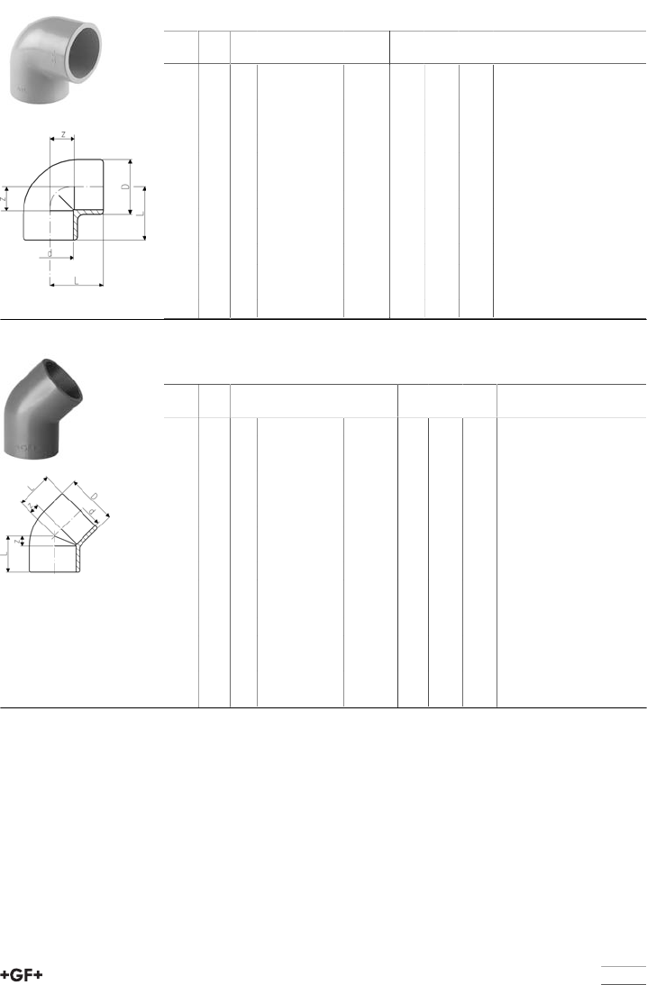
29 10 01 Elbow 90° ABS metric
•>d225 - maximum operating temperature: +40°C
d
[mm]
d
[inch]
PN Code kg z
[mm]
D
[mm]
L
[mm]
16 16 729 100 105 0.007 9 21 23
20 16 729 100 106 0.010 11 26 27
25 16 729 100 107 0.017 14 31 33
32 10 729 100 108 0.032 17 40 39
40 10 729 100 109 0.051 21 49 47
50 10 729 100 110 0.103 26 61 57
63 10 729 100 111 0.196 33 76 72
75 2 1∕210 729 100 112 0.308 40 90 84
90 10 729 100 113 0.429 46 110 97
110 10 729 100 114 0.786 55 136 116
140 5 10 729 100 116 1.470 70 162 146
160 10 729 100 117 2.150 80 185 166
200 10 729 100 119 3.372 101 225 207
250 6 729 100 121 8.200 131 282 263
29 15 01 Elbow 45° ABS metric
•>d225 - maximum operating temperature: +40°C
d
[mm]
d
[inch]
PN Code kg z
[mm]
D
[mm]
L
[mm]
20 16 729 150 106 0.008 5 25 21
25 16 729 150 107 0.013 6 31 25
32 10 729 150 108 0.046 8 40 30
40 10 729 150 109 0.082 10 49 36
50 10 729 150 110 0.121 12 61 43
63 10 729 150 111 0.144 14 76 52
75 2 1∕210 729 150 112 0.228 17 89 61
90 10 729 150 113 0.362 20 107 71
110 10 729 150 114 0.775 28 131 89
140 5 10 729 150 116 1.190 32 162 108
160 10 729 150 117 1.680 36 185 122
200 10 729 150 119 2.506 43 225 149
225 10 729 150 120 3.100 49 250 168
250 6 729 150 121 7.200 60 282 192
280 6 729 150 122 10.500 66 318 213
315 6 729 150 123 14.600 74 356 239
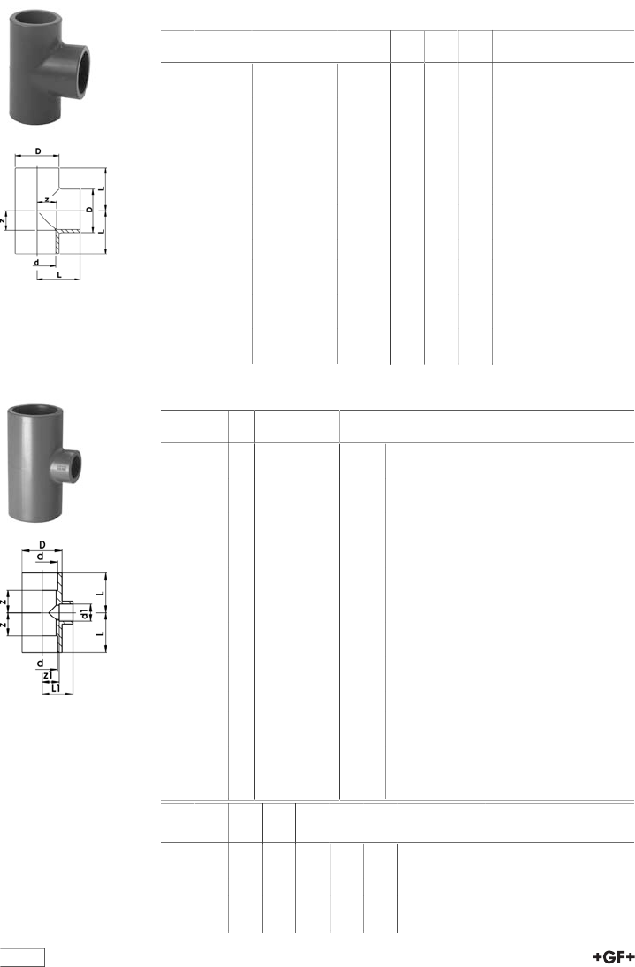
table continued next page
28
29 20 01 Tee 90° ABS metric
•>d225 - maximum operating temperature: +40°C
d
[mm]
d
[inch]
PN Code kg z
[mm]
D
[mm]
L
[mm]
16 16 729 200 105 0.010 9 21 23
20 16 729 200 106 0.014 11 25 27
25 16 729 200 107 0.024 14 31 33
32 10 729 200 108 0.042 17 40 39
40 10 729 200 109 0.074 21 49 47
50 10 729 200 110 0.131 26 61 57
63 10 729 200 111 0.250 34 76 72
75 2 1∕210 729 200 112 0.421 40 90 84
90 10 729 200 113 0.687 47 107 98
110 10 729 200 114 1.020 55 133 116
140 5 10 729 200 116 2.500 71 169 147
160 10 729 200 117 3.700 81 193 167
200 10 729 200 119 4.430 101 225 207
225 10 729 200 120 6.850 114 256 233
250 6 729 200 121 12.400 132 282 263
280 6 729 200 122 17.300 152 318 298
315 6 729 200 123 24.100 168 356 332
29 20 01 Tee 90° reducing ABS metric
d
[mm]
d1
[mm]
PN Code kg
25 20 16 729 200 134 0.029
32 25 10 729 200 138 0.048
40 25 10 729 200 151 0.081
40 32 10 729 200 147 0.085
50 25 10 729 200 010 0.135
50 32 10 729 200 164 0.200
63 25 10 729 200 011 0.245
63 32 10 729 200 178 0.249
63 50 10 729 200 170 0.265
75 40 10 729 200 182 0.500
90 32 10 729 200 143 1.000
90 63 10 729 200 146 0.900
110 32 10 729 200 144 2.000
110 50 10 729 200 136 1.900
140 50 10 729 200 148 1.899
140 75 10 729 200 149 2.500
160 90 10 729 200 158 2.800
200 110 10 729 200 153 6.110
225 110 10 729 200 156 7.500
225 160 10 729 200 157 7.900
d
[mm]
d1
[mm]
z
[mm]
z1
[mm]
D
[mm]
L
[mm]
L1
[mm]
Closest inch
run-branch-run
25 20 14 14 33 33 30 3∕4 - 1∕2 - 3∕4
32 25 17 17 41 39 36 1 - 3∕4 - 1
40 25 23 23 50 49 42 1 1∕4 - 3∕4 - 1 1∕4
40 32 23 23 50 49 45 1 1∕4 - 1 - 1 1∕4
50 25 28 28 62 59 47 1 1∕2 - 3∕4 - 1 1∕2
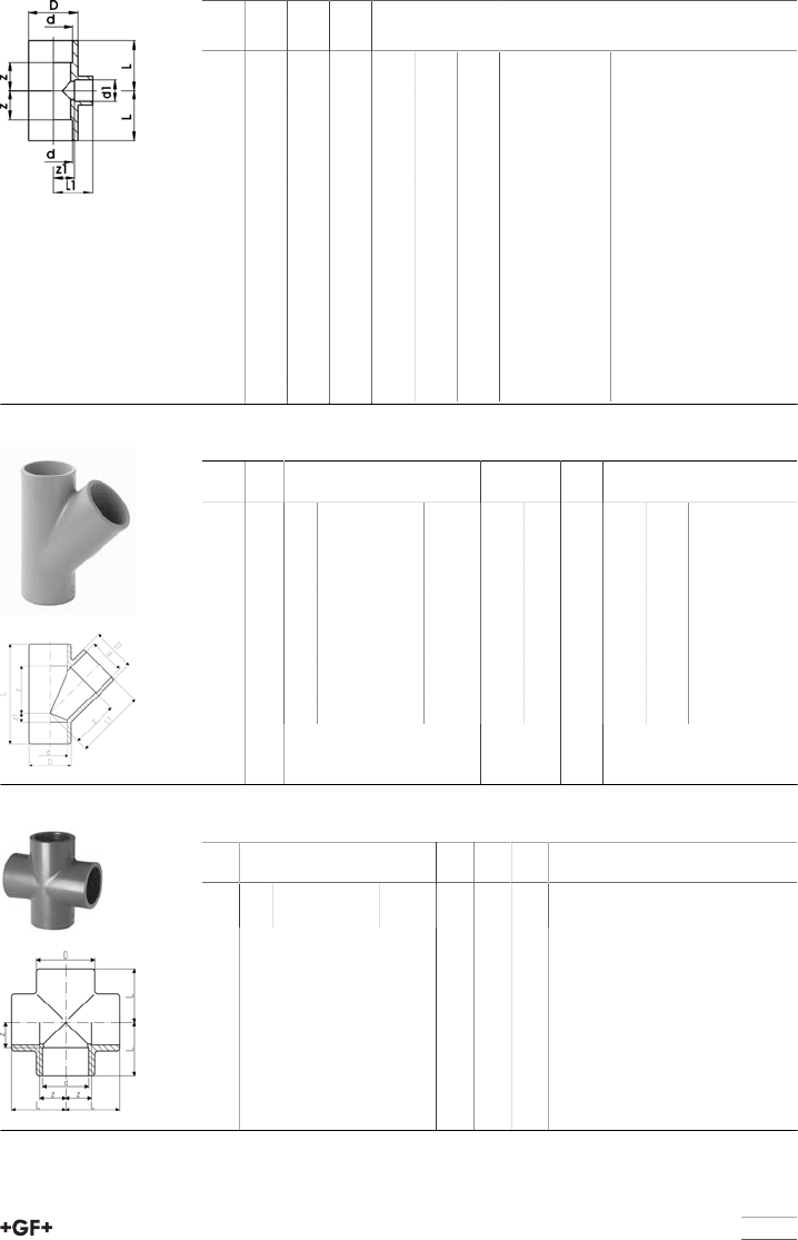
29
d
[mm]
d1
[mm]
z
[mm]
z1
[mm]
D
[mm]
L
[mm]
L1
[mm]
Closest inch
run-branch-run
50 32 28 28 62 59 50 1 1∕2 - 1 - 1 1∕2
63 25 34 34 77 73 53 2 - 3∕4 - 2
63 32 35 34 77 73 56 2 - 1 - 2
63 50 35 34 77 73 65 2 - 1 1∕2 - 2
75 40 40 41 92 84 66 2 1∕2 - 1 1∕4 - 2
1∕2
90 32 46 55 110 97 93 3 - 1 - 3
90 63 46 55 110 97 93 3 - 2 - 3
110 32 56 67 133 117 89 4 - 1 - 4
110 50 56 67 133 117 98 4 - 1 1∕2 - 4
140 50 72 82 172 148 113 5 - 1 1∕2 - 5
140 75 72 78 172 148 122 5 - 2 1∕2 - 5
160 90 81 91 192 167 142 6 - 3 - 6
200 110 106 131 232 213 192 7 - 4 - 7
225 110 119 143 257 239 204 8 - 4 - 8
225 160 119 119 257 239 205 8 - 6 - 8
29 25 01 Tee 45° ABS metric
d
[mm]
d
[inch]
PN Code kg z
[mm]
z1
[mm]
D
[mm]
L
[mm]
L1
[mm]
20 10 729 250 106 0.027 30 6 28 68 46
25 10 729 250 107 0.043 36 9 33 83 55
32 10 729 250 108 0.073 45 10 41 99 67
40 10 729 250 109 0.119 56 10 50 118 82
50 10 729 250 110 0.202 66 12 60 140 97
63 10 729 250 111 0.325 85 14 74 175 123
75 2 1∕26729 250 112 0.637 101 18 91 207 145
90 6 729 250 113 0.940 122 20 107 245 173
110 6 729 250 114 1.870 149 27 134 298 210
140 5 6 729 250 116 4.315 190 34 168 376 266
29 30 01 Cross ABS metric
d
[mm]
PN Code kg z
[mm]
D
[mm]
L
[mm]
32 10 729 300 108 0.070 17 43 39
63 10 729 300 111 0.361 34 79 72
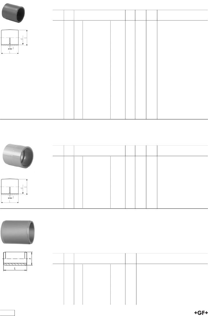
table continued next page
30
29 91 01 Socket ABS metric
•>d225 - maximum operating temperature: +40°C
d
[mm]
d
[inch]
PN Code kg z
[mm]
D
[mm]
L
[mm]
16 16 729 910 105 0.005 3 22 31
20 16 729 910 106 0.007 3 26 35
25 16 729 910 107 0.011 3 32 41
32 10 729 910 108 0.020 3 40 47
40 10 729 910 109 0.034 3 49 55
50 10 729 910 110 0.060 3 61 65
63 10 729 910 111 0.107 3 76 79
75 2 1∕210 729 910 112 0.140 4 87 92
90 10 729 910 113 0.242 5 104 107
110 10 729 910 114 0.570 5 131 132
140 5 10 729 910 116 0.760 7 162 159
160 10 729 910 117 1.176 8 183 180
200 10 729 910 119 1.480 9 221 221
225 10 729 910 120 2.500 10 253 248
250 6 729 910 121 5.400 16 284 284
280 6 729 910 122 6.600 16 321 314
315 6 729 910 123 8.100 16 356 348
29 91 31 Adaptor socket ABS metric/Inch BS
Model:
•with BS Inch and metric solvent cement sockets
d
[mm]
d
[inch]
PN Code kg z
[mm]
L
[mm]
D
[mm]
16 3∕810 729 913 105 0.007 5 35 23
20 1∕210 729 913 106 0.010 5 38 27
25 3∕410 729 913 107 0.016 5 45 33
32 1 10 729 913 108 0.025 5 51 41
40 1 1∕410 729 913 109 0.045 5 60 51
50 1 1∕210 729 913 110 0.070 4 65 59
63 2 10 729 913 111 0.130 5 79 75
90 3 10 729 913 113 0.365 6 108 104
110 4 10 729 913 115 0.630 7 135 134
29 90 09 Barrel nipple ABS metric
Model:
•With solvent cement spigots on both sides
•For quick connections between fittings
•For the shortest possible distance between fittings
•Overall length L = 2 x socket length
d
[mm]
d
[inch]
PN Code kg L
[mm]
16 16 729 900 905 0.003 28
20 16 729 900 906 0.004 32
25 16 729 900 907 0.007 38
32 10 729 900 908 0.009 44
40 10 729 900 909 0.017 52
50 10 729 900 910 0.032 62
63 10 729 900 911 0.063 76

31
d
[mm]
d
[inch]
PN Code kg L
[mm]
75 2 1∕210 729 900 912 0.102 88
90 10 729 900 913 0.173 102
110 10 729 900 914 0.309 122
29 90 03 Reducing bush ABS metric
Model:
•With solvent cement spigot and socket metric
d
[mm]
d1
[mm]
PN Code kg z
[mm]
L
[mm]
20 16 16 729 900 334 0.003 2 16
25 20 16 729 900 337 0.005 3 19
32 20 10 729 900 342 0.012 6 22
32 25 10 729 900 341 0.009 4 22
40 20 10 729 900 348 0.016 10 26
40 25 10 729 900 347 0.016 7 26
40 32 10 729 900 346 0.012 4 26
50 20 10 729 900 355 0.024 15 31
50 25 10 729 900 354 0.025 12 31
50 32 10 729 900 353 0.035 9 31
50 40 10 729 900 352 0.038 5 31
63 32 10 729 900 360 0.060 16 38
63 40 10 729 900 359 0.067 12 38
63 50 10 729 900 358 0.044 7 36
75 50 10 729 900 365 0.105 13 44
75 63 10 729 900 364 0.076 7 44
90 50 10 729 900 372 0.136 20 51
90 63 10 729 900 371 0.130 14 51
90 75 10 729 900 370 0.133 7 51
110 63 10 729 900 378 0.238 24 61
110 90 10 729 900 376 0.196 10 61
125 110 10 700 244 660 0.356 8 69
140 110 10 729 900 385 0.454 15 76
160 110 10 729 900 390 0.666 25 86
160 140 10 729 900 388 0.416 10 86
200 160 10 729 900 392 0.818 20 106
225 160 10 729 900 396 1.640 33 119
225 200 10 729 900 181 1.440 13 119
250 225 6 729 900 303 1.000 12 131
280 250 6 729 900 306 2.500 15 146
315 280 6 729 900 312 3.350 17 164
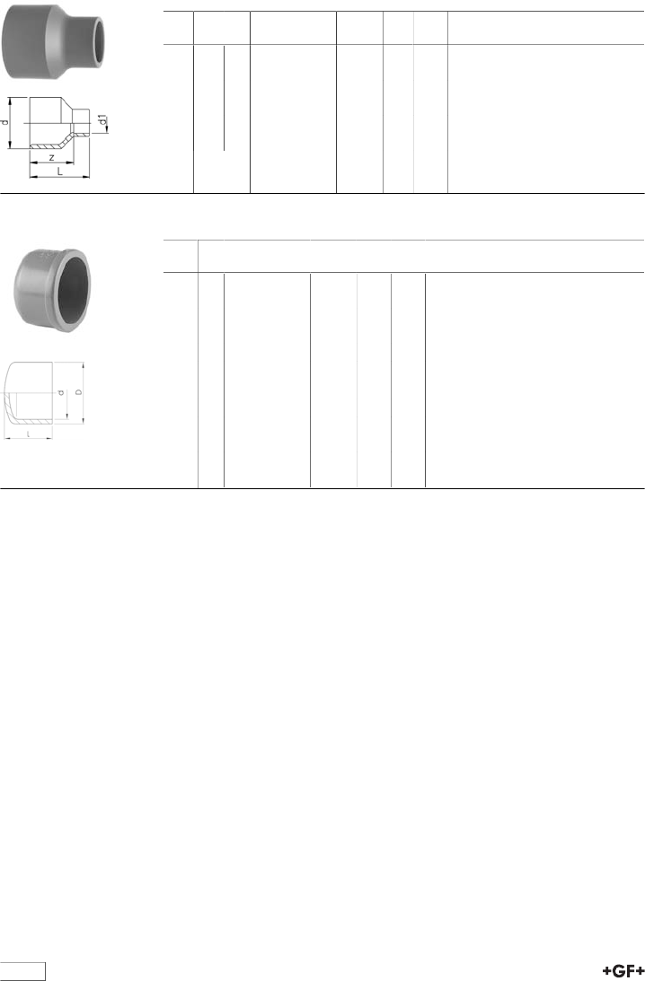
32
29 91 03 Reducing bush long ABS metric
d
[mm]
d1
[mm]
PN Code kg z
[mm]
L
[mm]
32 20 10 729 910 342 0.016 30 46
40 25 10 729 910 347 0.026 36 55
50 25 10 729 910 354 0.041 44 63
63 32 10 729 910 360 0.077 54 76
75 40 10 729 910 366 0.115 62 88
90 63 10 729 910 371 0.218 74 112
29 96 01 Cap ABS metric
d
[mm]
PN Code kg D
[mm]
L
[mm]
16 16 729 960 105 0.006 26 24
20 16 729 960 106 0.008 30 25
25 16 729 960 107 0.013 37 30
32 10 729 960 108 0.020 44 34
40 10 729 960 109 0.034 55 41
50 10 729 960 110 0.034 64 44
63 10 729 960 111 0.086 80 54
75 10 729 960 112 0.115 87 65
90 10 729 960 113 0.215 112 77
110 10 729 960 114 0.480 145 101
140 10 729 960 116 0.880 163 114
160 10 729 960 117 1.130 188 130
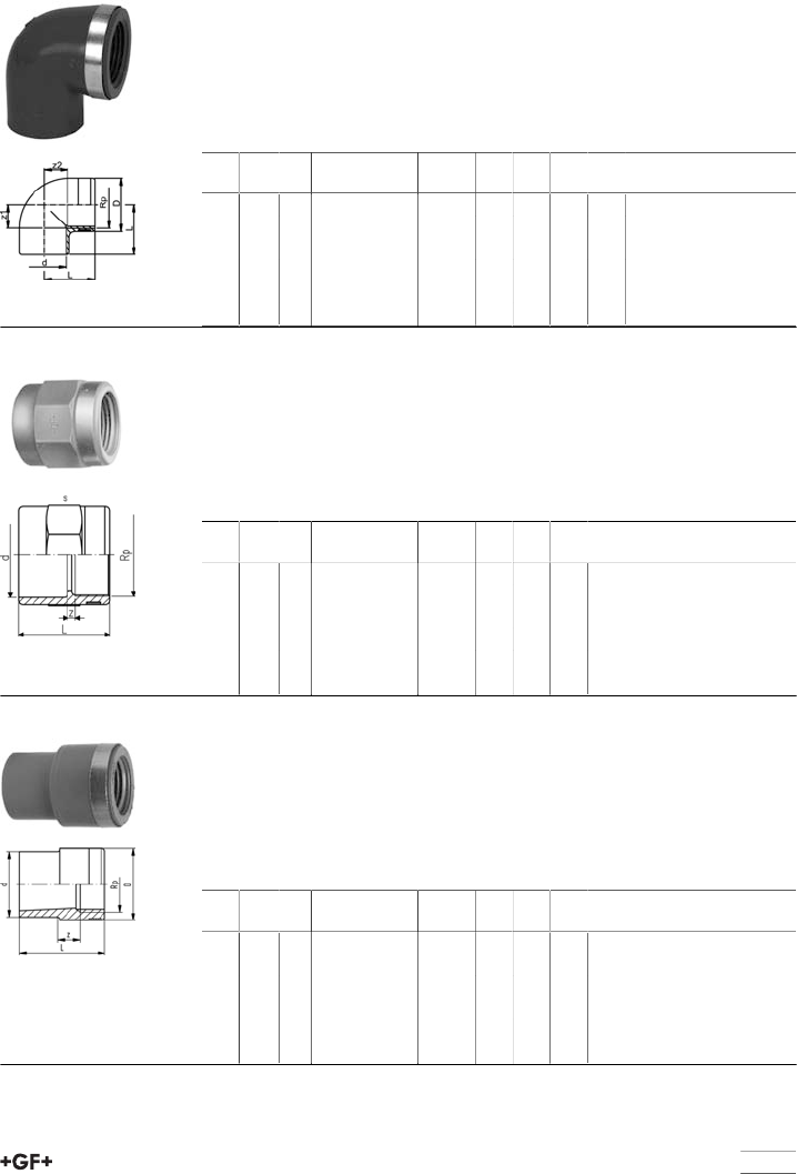
33
Adaptor fittings
29 10 02 Elbow 90° ABS metric Rp
Model:
•With solvent cement socket metric and parallel female thread Rp
•Reinforcing ring stainless (A2)
•Connection to plastic or metal threads
•Do not use thread sealing pastes that are harmful to ABS
•Install with low mechanical stress and avoid large cyclic temperature changes
d
[mm]
Rp
[inch]
PN Code kg z1
[mm]
z2
[mm]
D
[mm]
L
[mm]
20 1∕210 729 100 206 0.018 11 14 30 27
25 3∕410 729 100 207 0.028 14 17 35 33
32 1 10 729 100 208 0.047 17 22 45 39
40 1 1∕410 729 100 209 0.088 23 27 55 50
50 1 1∕210 729 100 210 0.128 27 36 62 58
63 2 10 729 100 211 0.233 33 46 75 73
29 91 02 Socket ABS metric Rp
Model:
•With solvent cement socket metric and parallel female thread Rp
•Reinforcing ring stainless (A2)
•Connection to plastic or metal threads
•Do not use thread sealing pastes that are harmful to ABS
•Install with low mechanical stress and avoid large cyclic temperature changes
d
[mm]
Rp
[inch]
PN Code kg z
[mm]
L
[mm]
s
[mm]
20 1∕210 729 910 206 0.020 4 35 32
25 3∕410 729 910 207 0.030 3 40 36
32 1 10 729 910 208 0.040 3 45 46
40 1 1∕410 729 910 209 0.069 5 51 55
50 1 1∕210 729 910 210 0.100 7 59 65
63 2 10 729 910 211 0.162 7 69 80
29 91 04 Reducing bush ABS metric Rp
Model:
•With solvent cement spigot metric and parallel female thread Rp
•Reinforcing ring stainless (A2)
•Connection to plastic or metal threads
•Do not use thread sealing pastes that are harmful to ABS
•Install with low mechanical stress and avoid large cyclic temperature changes
d
[mm]
Rp
[inch]
PN Code kg z
[mm]
D
[mm]
L
[mm]
20 3∕810 729 910 434 0.012 7 25 35
25 1∕210 729 910 437 0.018 7 30 41
32 3∕410 729 910 441 0.027 15 35 48
40 1 10 729 910 446 0.048 20 45 56
50 1 1∕410 729 910 452 0.073 20 55 66
63 1 1∕210 729 910 458 0.106 10 62 77
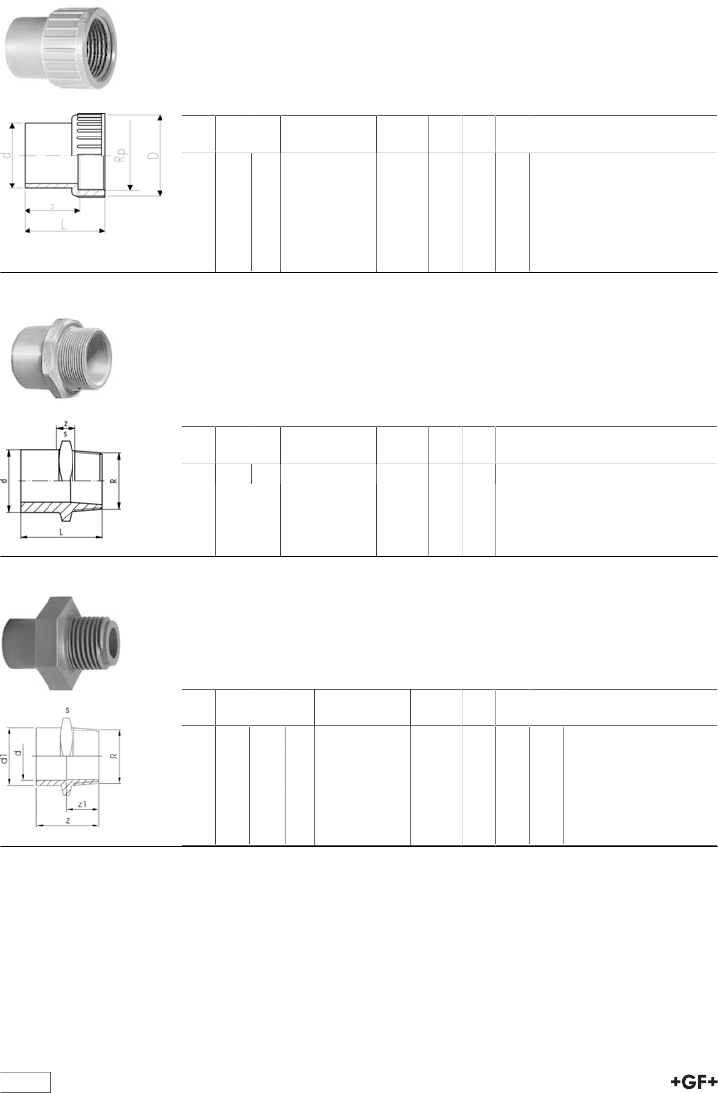
34
29 90 04 Adaptor ABS metric Rp
Model:
•With solvent cement spigot metric and parallel female thread Rp
•Connection to plastic threads only
•Do not use thread sealing pastes that are harmful to ABS
•Install with low mechanical stress and avoid large cyclic temperature changes
d
[mm]
Rp
[inch]
PN Code kg z
[mm]
L
[mm]
D
[mm]
20 1∕210 729 900 406 0.009 21 37 28
25 3∕410 729 900 407 0.014 23 41 33
32 1 10 729 900 408 0.026 27 48 42
40 1 1∕410 729 900 409 0.046 33 56 52
50 1 1∕210 729 900 410 0.073 38 61 62
63 2 10 729 900 411 0.127 47 74 77
29 91 05 Adaptor spigot nipple ABS metric R
Model:
•With solvent cement spigot metric and taper male thread R
•Connection to plastic threads only
•Do not use thread sealing pastes that are harmful to ABS
•Install with low mechanical stress and avoid large cyclic temperature changes
d
[mm]
R
[inch]
PN Code kg z
[mm]
s
[mm]
16 3∕810 729 910 505 0.009 35 27
29 91 05 Adaptor socket nipple ABS metric R
Model:
•With solvent cement spigot/socket metric and taper male thread R
•Connection for plastic threads
•Do not use thread sealing pastes that are harmful to ABS
d
[mm]
d1
[mm]
R
[inch]
PN Code kg z
[mm]
z1
[mm]
s
[mm]
16 20 1∕210 729 910 556 0.012 42 28 32
20 25 3∕410 729 910 557 0.020 47 31 36
25 32 1 10 729 910 558 0.031 54 35 46
32 40 1 1∕410 729 910 559 0.050 60 38 55
40 50 1 1∕210 729 910 560 0.070 66 40 65
50 63 2 10 729 910 561 0.123 78 47 80
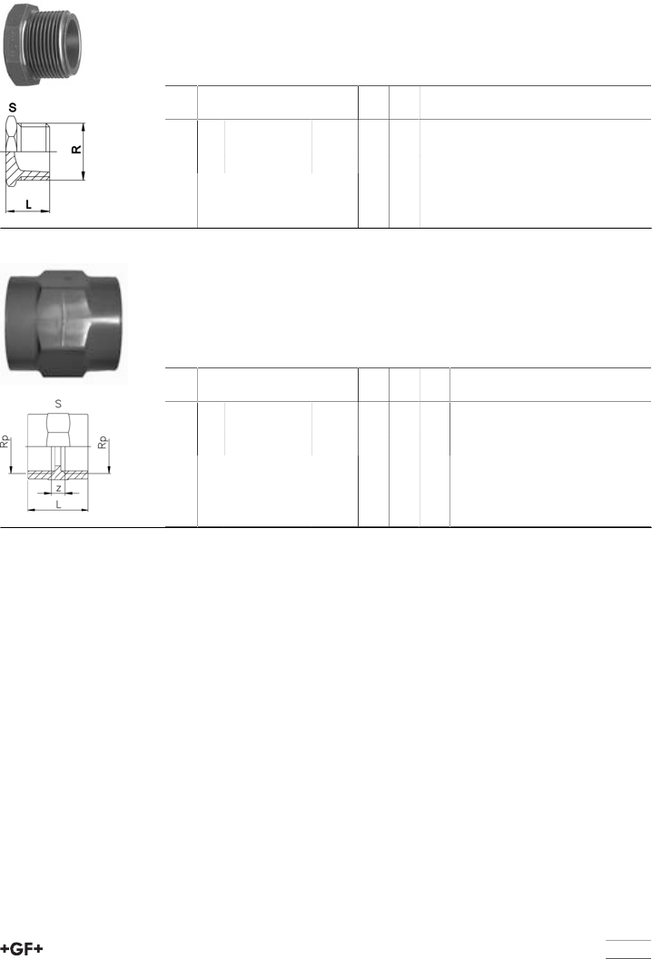
35
Threaded fittings
29 96 19 Plug ABS R
Model:
•With taper male thread R
•Connection to plastic threads only
•Do not use thread sealing pastes that are harmful to ABS
R
[inch]
PN Code kg s
[mm]
L
[mm]
1∕210 729 961 906 0.008 27 25
3∕410 729 961 907 0.014 36 29
1 10 729 961 908 0.022 41 32
29 91 06 Threaded socket ABS Rp
Model:
•With parallel female thread Rp
•Connection to plastic threads only
•Do not use thread sealing pastes that are harmful to ABS
•Install with low mechanical stress and avoid large cyclic temperature changes
Rp
[inch]
PN Code kg z
[mm]
L
[mm]
s
[mm]
1∕210 729 910 606 0.019 9 35 32
3∕410 729 910 607 0.022 9 39 36
1 10 729 910 608 0.041 11 45 46
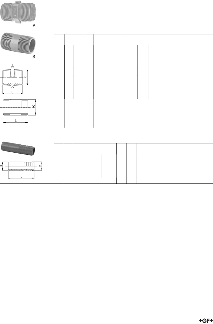
36
29 91 15 Threaded nipple R ABS
Model:
•BSP taper male threads (R)
•Connection to plastic threads only
•Do not use thread sealing pastes that are harmful to ABS
•Install with low mechanical stress and avoid large cyclic temperature changes
R
[inch]
PN Type S
[mm]
Code kg L
[mm]
3∕810 B 729 911 505 0.014 43
1∕210 A 22 729 911 906 0.009 45
3∕410 A 27 729 911 907 0.014 49
1 10 A 36 729 911 908 0.026 57
1 1∕410 B 729 911 509 0.053 75
1 1∕210 B 729 911 510 0.031 88
2 10 B 729 911 511 0.135 88
3 10 B 729 911 513 0.196 128
4 10 B 729 911 515 0.357 153
29 96 04 Hose connector ABS metric
d
[mm]
PN Code kg D
[mm]
L
[mm]
16 10 729 960 405 0.007 16 57
20 10 729 960 406 0.011 20 73
25 10 729 960 407 0.016 25 79
32 10 729 960 408 0.026 30 89
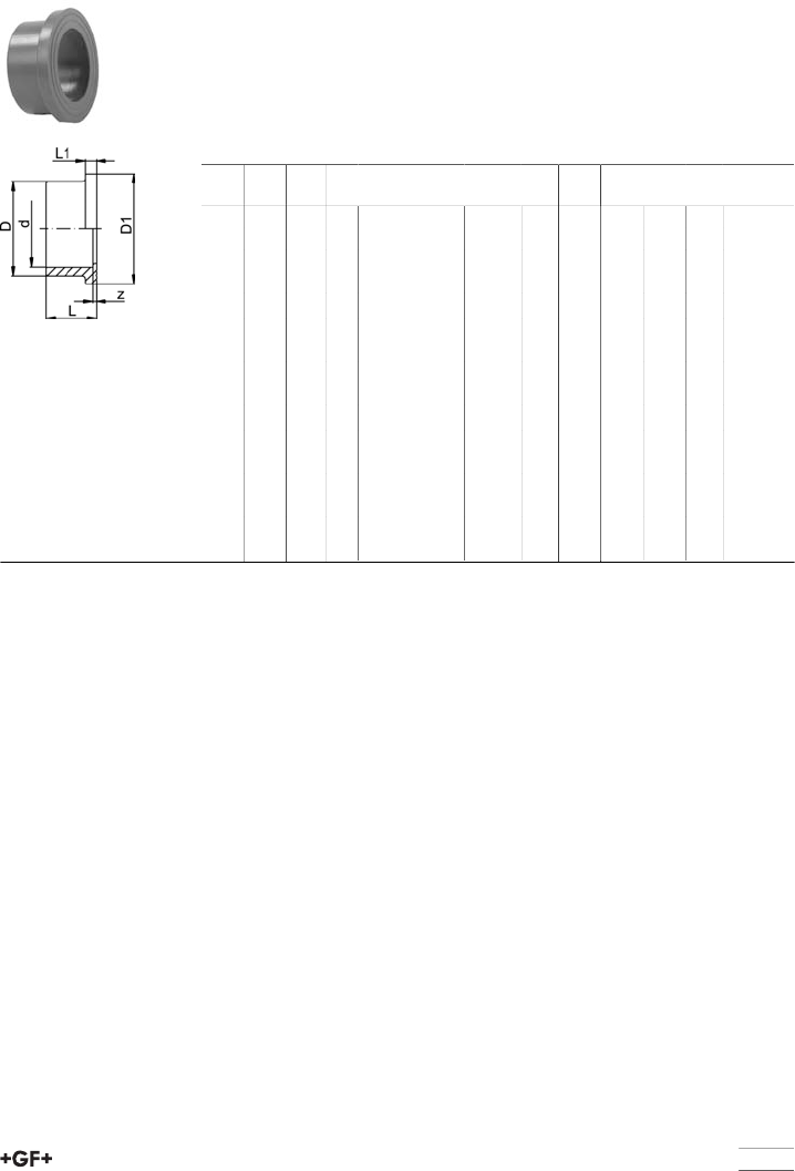
37
Flange adaptor
29 79 01 Flange adaptor ABS metric
Model:
•Flat sealing faces/serrated
•Counter part: Same flange adaptor
•Gasket: Profileflange gasket EPDM No. 48 44 07,FPM No.49 44 07
•Gasket: Flat gasket EPDM No.48 40 03
•>d225 - maximum operating temperature: +40°C
d
[mm]
DN
[mm]
d
[inch]
PN Code kg z
[mm]
D
[mm]
D1
[mm]
L
[mm]
L1
[mm]
20 15 10 729 790 106 0.008 3 27 34 21 6
25 20 10 729 790 107 0.012 3 33 41 24 7
32 25 10 729 790 108 0.020 3 41 50 27 7
40 32 10 729 790 109 0.058 3 50 61 30 8
50 40 10 729 790 110 0.058 3 61 73 34 8
63 50 10 729 790 111 0.074 3 76 90 41 9
75 65 2 1∕210 729 790 112 0.118 3 91 106 47 10
90 80 10 729 790 113 0.187 5 108 125 56 11
110 100 10 729 790 114 0.300 5 131 150 66 12
140 125 5 10 729 790 116 0.567 5 165 188 81 14
160 150 10 729 790 117 0.800 5 188 213 91 16
200 200 10 729 790 119 1.120 6 224 250 112 24
225 200 10 729 790 120 1.300 6 248 274 125 25
250 250 6 729 790 121 1.000 9 274 303 140 23
280 250 6 729 790 122 2.161 5 307 329 151 23
315 300 6 729 790 123 3.321 8 346 379 172 27
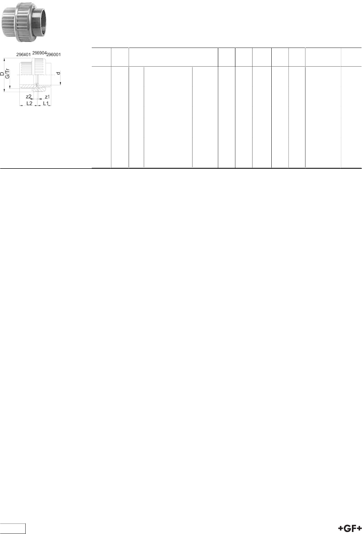
38
Unions
29 51 01 Union ABS metric
Model:
•Union End: Solvent cement socket metric
•Union bush: Solvent cement socket metric
•Gasket: O-ring EPDM No. 48 41 00
d
[mm]
d
[inch]
PN Code kg z1
[mm]
z2
[mm]
D
[mm]
L1
[mm]
L2
[mm]
G/Tr
16 10 729 510 105 0.025 5 10 35 19 24 3/4
20 10 729 510 106 0.035 4 10 43 21 26 1
25 10 729 510 107 0.050 5 10 53 24 29 1 1/4
32 10 729 510 108 0.070 5 10 60 27 33 1 1/2
40 10 729 510 109 0.130 3 12 74 31 39 2
50 10 729 510 110 0.170 3 14 83 33 46 2 1/4
63 10 729 510 111 0.340 3 18 103 40 58 2 3/4
75 2 1∕210 729 510 112 0.461 3 18 135 47 62 Tr 108x5
90 10 729 510 313 0.694 5 18 158 56 69 Tr 128x5
110 10 729 510 114 1.069 5 11 158 66 72 Tr 154x5
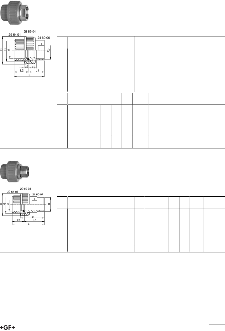
39
Adaptor Unions
29 54 02 Adaptor union ABS/stainless steel metric Rp
Model:
•Union End: Stainless Steel WN 1.4404 (316L), parallel female thread Rp
•Union Bush: Solvent cement socket ABS metric
•Union Nut: ABS
•Gasket: O-ring EPDM No. 48 41 00
d
[mm]
Rp
[inch]
PN EPDM
Code
kg
16 3∕810 729 540 205 0.053
20 1∕210 729 540 206 0.096
25 3∕410 729 540 207 0.154
32 1 10 729 540 208 0.212
40 1 1∕410 729 540 209 0.356
50 1 1∕210 729 540 210 0.455
63 2 10 729 540 211 0.721
d
[mm]
z1
[mm]
z2
[mm]
D
[mm]
L
[mm]
L1
[mm]
L2
[mm]
G
[inch]
s
[mm]
16 9 10 35 43 19 24 3/4 19
20 11 10 43 50 24 26 1 24
25 11 10 51 55 26 29 1 1/4 29
32 12 10 58 61 29 33 1 1/2 36
40 14 12 74 71 33 39 2 45
50 15 14 83 79 34 46 2 1/4 54
63 15 18 100 95 39 58 2 3/4 63
29 54 07 Adaptor union ABS/stainless steel metric R
Model:
•Union End: Stainless Steel WN 1.4404 (316L), taper male thread R
•Union Bush: Solvent cement socket ABS metric
•Union Nut: ABS
•Gasket: O-ring EPDM No. 48 41 00
d
[mm]
R
[inch]
PN EPDM
Code
kg z
[mm]
D
[mm]
L
[mm]
L1
[mm]
L2
[mm]
G
[inch]
s
[mm]
16 3∕810 729 540 705 0.073 40 35 54 30 24 3/4 19
20 1∕210 729 540 706 0.126 44 43 60 34 26 1 24
25 3∕410 729 540 707 0.174 46 51 65 36 29 11/4 32
32 1 10 729 540 708 0.262 50 58 72 40 33 11/2 37
40 1 1∕410 729 540 709 0.476 58 74 84 46 39 2 48
50 1 1∕210 729 540 710 0.535 62 83 93 48 46 21/4 54
63 2 10 729 540 711 0.931 73 100 111 55 58 23/4 69
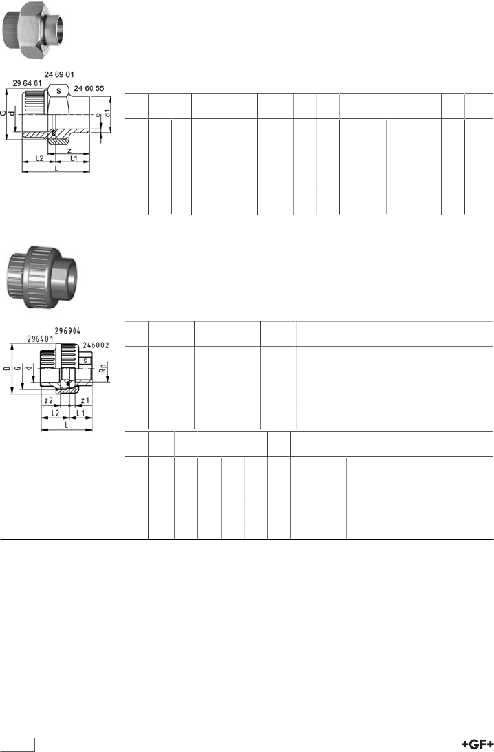
40
29 54 55 Adaptor union ABS/stainless steel metric
Welding end
Model:
•Union End: Stainless Steel WN 1.4404 (316L) with welding end
•Union Bush: Solvent cement socket ABS metric
•Union Nut: Stainless Steel WN 1.4404 (316L)
•Gasket: O-ring EPDM No. 48 41 00
d
[mm]
d1
[mm]
PN EPDM
Code
kg z
[mm]
L
[mm]
L1
[mm]
L2
[mm]
e
[mm]
G
[inch]
s
[mm]
16 17 10 729 545 505 0.101 28 42 18 24 1.6 3/4 32
20 21 10 729 545 506 0.176 32 48 22 26 2.0 1 41
25 27 10 729 545 507 0.204 33 52 23 29 2.0 1 1/4 46
32 34 10 729 545 508 0.313 36 58 26 33 2.0 1 1/2 55
40 42 10 729 545 509 0.493 38 64 26 39 2.0 2 68
50 48 10 729 545 510 0.566 42 73 28 46 2.0 2 1/4 74
63 60 10 729 545 511 0.902 50 88 32 58 2.6 2 3/4 88
29 53 03 Adaptor union ABS/malleable iron metric Rp
Model:
•Union Nut: ABS
•Union Bush: Solvent cement socket ABS metric
•Union End:malleable ironwith parallel female thread Rp
•Gasket: O-Ring EPDM No. 48 41 00
d
[mm]
Rp
[inch]
PN*
[bar]
Code kg
20 1∕210 729 530 306 0.064
25 3∕410 729 530 307 0.095
32 1 10 729 530 308 0.139
40 1 1∕410 729 530 309 0.240
50 1 1∕210 729 530 310 0.339
63 2 10 729 530 311 0.516
d
[mm]
D
[mm]
L
[mm]
L1
[mm]
L2
[mm]
z1
[mm]
z2
[mm]
G
[inch]
s
[mm]
20 43 48 22 26 9 10 1 25
25 51 51 22 29 7 10 1 1/4 31
32 58 58 26 33 9 10 1 1/2 38
40 72 69 31 39 12 12 2 48
50 83 78 33 46 14 14 2 1/4 54
63 100 91 35 58 11 18 2 3/4 67
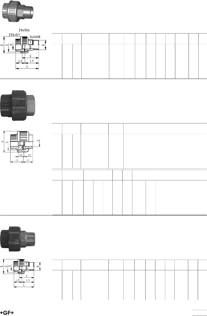
table continued next page
41
29 53 08 Adaptor union ABS/malleable iron metric R
Model:
•Union Nut: ABS
•Union Bush: Solvent cement socket ABS metric
•Union End: Malleable iron with taper male thread R
•Gasket: O-Ring EPDM No. 48 41 00
d
[mm]
R
[inch]
PN*
[bar]
Code kg D
[mm]
L
[mm]
L1
[mm]
L2
[mm]
z
[mm]
G
[inch]
s
[mm]
20 1∕210 729 530 806 0.100 43 66 40 26 50 1 25
25 3∕410 729 530 807 0.147 51 72 43 29 53 1 1/4 31
32 1 10 729 530 808 0.198 58 80 48 33 58 1 1/2 38
40 1 1∕410 729 530 809 0.400 72 95 57 39 69 2 48
50 1 1∕210 729 530 810 0.490 83 104 59 46 73 2 1/4 54
63 2 10 729 530 811 0.675 100 118 62 58 80 2 3/4 67
29 55 05 Adaptor union ABS/brass metric Rp
Model:
•Union Nut: ABS
•Union Bush: Solvent cement socket ABS metric
•Union End: Brass with parallel female thread Rp
•Gasket: O-Ring EPDM No. 48 41 00
d
[mm]
Rp
[inch]
PN Code kg
20 1∕210 729 550 506 0.084
25 3∕410 729 550 507 0.134
32 1 10 729 550 508 0.179
40 1 1∕410 729 550 509 0.327
50 1 1∕210 729 550 510 0.452
63 2 10 729 550 511 0.722
d
[mm]
Rp
[inch]
D
[mm]
L
[mm]
L1
[mm]
L2
[mm]
z1
[mm]
z2
[mm]
G
[inch]
s
[mm]
20 1∕243 48 22 26 7 10 1 25
25 3∕451 54 25 29 9 11 1 1/4 30
32 1 58 60 27 33 8 11 1 1/2 36
40 1 1∕472 70 31 39 10 13 2 48
50 1 1∕283 81 35 46 14 21 2 1/4 55
63 2 100 98 40 58 14 21 2 3/4 65
29 55 09 Adaptor union ABS/brass metric R
Model:
•Union Nut: ABS
•Union Bush: Solvent cement socket ABS metric
•Union End: Brass with taper male thread R
•Gasket: O-Ring EPDM No. 48 41 00
d
[mm]
R
[inch]
PN Code kg D
[mm]
L
[mm]
L1
[mm]
L2
[mm]
z
[mm]
G
[inch]
s
[mm]
20 1∕210 729 550 906 0.123 43 63 37 26 47 1 25
25 1∕210 729 550 957 0.185 51 66 37 29 48 1 1/4 30
25 3∕410 729 550 907 0.293 51 71 42 29 52 1 1/4 30
25 1 10 729 550 967 0.293 51 75 46 29 57 1 1/4 30
32 1∕210 729 550 958 0.283 58 70 37 33 48 1 1/2 36
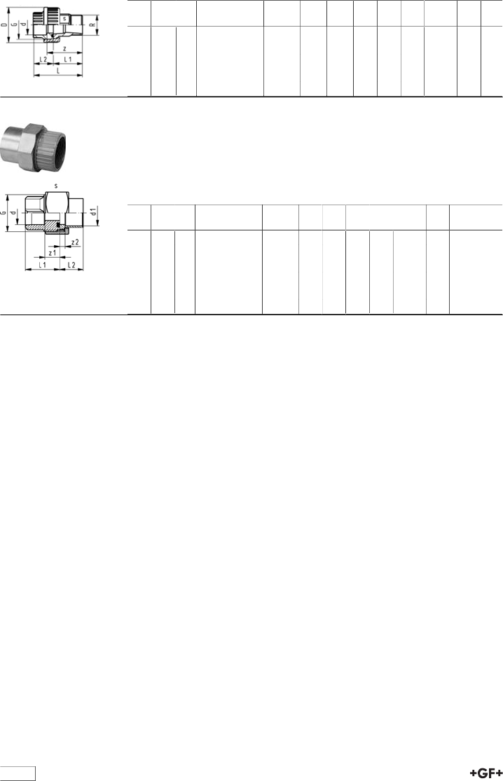
42
d
[mm]
R
[inch]
PN Code kg D
[mm]
L
[mm]
L1
[mm]
L2
[mm]
z
[mm]
G
[inch]
s
[mm]
32 3∕410 729 550 968 0.283 58 75 42 33 53 1 1/2 36
32 1 10 729 550 908 0.374 58 79 46 33 57 1 1/2 36
40 1 1∕410 729 550 909 0.503 72 91 52 39 65 2 46
50 2 1∕210 729 550 910 0.666 83 102 56 46 71 2 1/4 55
63 2 10 729 550 911 1.071 100 125 67 58 87 2 3/4 65
20 51 01 Adaptor union ABS/copper for soldering metric
Model:
•Union End: Copper
•Union Bush: Solvent cement socket ABS metric
•Union Nut: brass
•Gasket: O-ring EPDM No. 48 41 00
d
[mm]
d1
[mm]
PN Code kg L1
[mm]
L2
[mm]
z1
[mm]
z2
[mm]
G
[inch]
s
[mm]
16 18 10 720 510 105 0.079 25 17 11 4 3/4 32
20 22 10 720 510 106 0.140 26 19 9 3 1 40
25 28 10 720 510 107 0.269 29 28 9 6 1 1/4 50
32 35 10 720 510 108 0.198 33 27 10 5 1 1/2 52
40 42 10 720 510 109 0.350 39 35 12 6 2 66
50 54 10 720 510 110 0.438 46 46 14 3 2 1/4 72
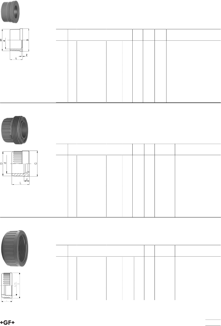
table continued next page
43
Union spare parts
29 60 01 Union end ABS metric
Model:
•Solvent cement socket metric
•For adaptor unions 29 53 02, 29 53 07, 29 55 02, 29 55 07
•For union 29 51 01
d
[mm]
PN Code kg z
[mm]
L
[mm]
D
[mm]
D1
[mm]
16 10 729 600 105 0.004 5 19 24 22
20 10 729 600 106 0.007 4 21 30 28
25 10 729 600 107 0.012 5 24 39 36
32 10 729 600 108 0.016 5 27 44 41
40 10 729 600 109 0.042 3 31 57 53
50 10 729 600 110 0.045 3 34 63 59
63 10 729 600 111 0.084 3 41 78 74
75 10 729 600 162 0.109 3 47 101 91
90 10 729 600 163 0.178 5 56 121 108
110 10 729 600 164 0.295 5 66 146 131
29 64 01 Union bush ABS metric
Model:
•Solvent cement socket metric
•For union 29 51 01
•Jointing face: With O-Ring groove
d
[mm]
PN Code kg z
[mm]
D
[mm]
L
[mm]
G/Tr
16 10 729 640 105 0.008 10 24 24 3/4
20 10 729 640 106 0.011 10 28 26 1
25 10 729 640 107 0.016 10 33 29 1 1/4
32 10 729 640 108 0.027 10 41 33 1 1/2
40 10 729 640 109 0.046 12 50 39 2
50 10 729 640 110 0.058 14 62 46 2 1/4
63 10 729 640 111 0.111 18 77 58 2 3/4
75 10 729 640 112 0.160 18 93 62 Tr108x5
90 10 729 640 123 0.274 18 110 69 Tr128x5
110 10 729 640 114 0.330 11 133 72 Tr154x6
29 69 04 Union nut ABS
Model:
•For union 23 51 01
d
[mm]
PN Code kg D
[mm]
L
[mm]
d
[mm]
G/Tr
16 10 729 690 405 0.009 35 21 3/4
20 10 729 690 406 0.014 43 23 1
25 10 729 690 407 0.018 53 25 1 1/4
32 10 729 690 408 0.024 60 27 1 1/2
40 10 729 690 409 0.049 74 30 2
50 10 729 690 410 0.070 83 34 2 1/4
63 10 729 690 411 0.101 103 38 2 3/4
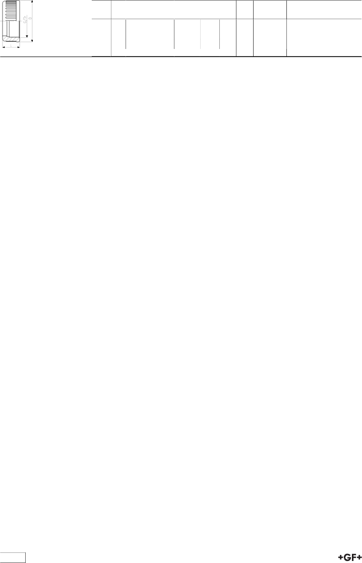
44
d
[mm]
PN Code kg D
[mm]
L
[mm]
d
[mm]
G/Tr
75 10 729 690 012 0.188 135 40 Tr108x5
90 10 729 690 013 0.267 158 43 Tr128x5
110 10 729 690 014 0.423 188 48 Tr154x6
table continued next page
45
Branch saddles
69 11 00 Branch saddle ABS metric
Model:
•For ABS-pipes
•Top saddle (ABS) for solvent cementing
•Bottom part and wedges made from PVC-U
•Outlet with solvent cement socket metric
•PN 10
d
[mm]
PN*
[bar]
Code kg d1
[mm]
d2
[mm]
Tapping-Ø
[mm]
L
[mm]
90 10 169 110 056 0.786 50 40 39 105
110 10 169 110 066 0.864 50 40 39 105
160 10 169 110 097 1.185 63 49 48 120
225 10 169 110 117 1.483 63 49 48 120
654 - Blue clamp saddles with stainless steel reinforcing ring,
flat gasket and galvanized bolts and nuts (PN16-PN10)
•water PN16-10
•suitable for PE and PVC pipes
•female thread: ISO 7 (parallel)
•material: PP
•gasket: O-ring with flat lip (NBR)
•reinforcement ring: stainless steel AISI430
•bolts and nuts : galvanized
•colour: blue
•B= N° of bolts
•M= bolt type
•(*) with O-ring gasket
d
[mm]
Rp
[inch]
PN B M Code kg
*20 1∕216 2 M8X40 158 001 041 0.119
*25 1∕216 2 M8X30 158 001 042 0.110
*25 3∕416 2 M8X30 158 001 043 0.123
*32 1∕216 2 M8X30 158 001 044 0.103
*32 3∕416 2 M8X30 158 001 045 0.115
*32 1 16 2 M8X40 158 001 046 0.162
40 1∕216 2 M8X40 158 001 047 0.135
40 3∕416 2 M8X40 158 001 048 0.146
40 1 16 2 M8X40 158 001 049 0.153
50 1∕216 4 M8X40 158 001 050 0.196
50 3∕416 4 M8X40 158 001 051 0.209
50 1 16 4 M8X40 158 001 052 0.217
50 1 1∕416 4 M8X40 158 001 053 0.221
63 1∕216 4 M8X40 158 001 054 0.212
63 3∕416 4 M8X40 158 001 055 0.222
63 1 16 4 M8X40 158 001 056 0.228
63 1 1∕416 4 M8X40 158 001 058 0.268
63 1 1∕216 4 M8X40 158 001 057 0.275
table continued next page
46
d
[mm]
Rp
[inch]
PN B M Code kg
75 1∕216 4 M8X60 158 001 059 0.364
75 3∕416 4 M8X60 158 001 060 0.376
75 1 16 4 M8X60 158 001 061 0.384
75 1 1∕416 4 M8X60 158 001 063 0.421
75 1 1∕216 4 M8X60 158 001 062 0.428
75 2 16 4 M8X60 158 001 064 0.437
90 1∕216 4 M8X60 158 001 065 0.412
90 3∕416 4 M8X60 158 001 066 0.421
90 1 16 4 M8X60 158 001 067 0.432
90 1 1∕416 4 M8X60 158 001 069 0.472
90 1 1∕216 4 M8X60 158 001 068 0.474
90 2 16 4 M8X60 158 001 070 0.481
110 1∕216 6 M8X50 158 001 071 0.511
110 3∕416 6 M8X50 158 001 072 0.523
110 1 16 6 M8X50 158 001 073 0.533
110 1 1∕416 6 M8X50 158 001 075 0.565
110 1 1∕216 6 M8X50 158 001 074 0.566
110 2 16 6 M8X50 158 001 076 0.570
*110 3 6 6 M8x70 158 001 077 1.108
125 1∕216 6 M8X50 158 001 078 0.578
125 3∕416 6 M8X50 158 001 079 0.590
125 1 16 6 M8X50 158 001 080 0.592
125 1 1∕416 6 M8X50 158 001 082 0.629
125 1 1∕216 6 M8X50 158 001 081 0.627
125 2 16 6 M8X50 158 001 083 0.640
*125 3 6 6 M8X70 158 001 084 1.009
*125 4 6 6 M8X70 158 001 085 1.051
140 1∕216 6 M8X70 158 001 086 0.830
140 3∕416 6 M8X70 158 001 087 0.843
140 1 16 6 M8X70 158 001 088 0.849
140 1 1∕416 6 M8X70 158 001 090 0.880
140 1 1∕216 6 M8X70 158 001 089 0.892
140 2 16 6 M8X70 158 001 091 0.898
*140 3 10 6 M8X70 158 001 092 1.132
*140 4 10 6 M8X70 158 001 093 1.196
160 1∕216 6 M8X70 158 001 094 0.899
160 3∕416 6 M8X70 158 001 095 0.908
160 1 16 6 M8X70 158 001 096 0.917
160 1 1∕416 6 M8X70 158 001 098 0.950
160 1 1∕216 6 M8X70 158 001 097 0.954
160 2 16 6 M8X70 158 001 099 0.956
*160 3 10 6 M8X70 158 001 100 1.185
*160 4 10 6 M8X70 158 001 101 1.262
*180 1 10 6 M10X80 158 001 102 1.980
*180 1 1∕410 6 M10X80 158 001 104 2.013
*180 1 1∕210 6 M10X80 158 001 103 2.007
*180 2 10 6 M10X80 158 001 105 2.018
*180 3 10 6 M10X80 158 001 106 2.043
*180 4 10 6 M10X80 158 001 107 2.092
*200 1 1∕210 6 M10X80 158 001 108 1.966
*200 2 10 6 M10X80 158 001 109 1.946
table continued next page
47
d
[mm]
Rp
[inch]
PN B M Code kg
*200 3 10 6 M10X80 158 001 110 1.980
*200 4 10 6 M10X80 158 001 111 2.020
*225 1 1∕210 6 M10X80 158 001 112 2.049
*225 2 10 6 M10X80 158 001 113 2.050
*225 3 10 6 M10X80 158 001 114 2.150
*225 4 10 6 M10X80 158 001 115 2.184
*250 2 10 6 M10X80 158 001 116 2.472
*250 3 10 6 M10X80 158 001 117 2.466
*250 4 10 6 M10X80 158 001 118 2.478
280 2 10 6 M10X160 158 001 119 3.440
*280 3 10 6 M10X160 158 001 120 3.543
*280 4 10 6 M10X160 158 001 121 3.585
315 2 10 6 M10X110 158 001 122 4.156
*315 3 10 6 M10X110 158 001 123 4.267
*315 4 10 6 M10X110 158 001 124 4.279
d
[mm]
Rp
[inch]
d1
[mm]
L
[mm]
L1
[mm]
H
[mm]
H1
[mm]
*20 1∕212 46 77 59 26
*25 1∕213 49 79 58 15
*25 3∕413 49 79 58 15
*32 1∕214 49 79 62 20
*32 3∕414 49 79 62 20
*32 1 14 62 87 70 20
40 1∕221 62 86 71 20
40 3∕421 62 86 71 20
40 1 21 62 86 70 19
50 1∕221 62 86 82 20
50 3∕421 62 86 82 20
50 1 21 62 86 82 20
50 1 1∕421 62 86 82 20
63 1∕218 62 101 96 21
63 3∕424 62 101 96 21
63 1 31 62 101 96 21
63 1 1∕431 62 101 96 21
63 1 1∕231 62 101 96 21
75 1∕216 79 123 102 14
75 3∕421 79 123 104 16
75 1 27 79 123 107 19
75 1 1∕435 79 123 109 21
75 1 1∕242 79 123 109 21
75 2 53 79 123 112 24
90 1∕216 87 138 116 14
90 3∕421 87 138 118 16
90 1 27 87 138 121 19
90 1 1∕435 87 138 123 21
90 1 1∕242 87 138 123 21
90 2 53 87 138 126 24
110 1∕215 99 152 150 23
110 3∕420 99 152 150 23
110 1 26 99 152 150 23
110 1 1∕435 99 152 150 23
48
d
[mm]
Rp
[inch]
d1
[mm]
L
[mm]
L1
[mm]
H
[mm]
H1
[mm]
110 1 1∕241 99 152 150 23
110 2 51 99 152 150 23
*110 3 85 99 152 150 23
125 1∕215 101 166 169 24
125 3∕420 101 166 169 24
125 1 26 101 166 169 24
125 1 1∕435 101 166 168 23
125 1 1∕241 101 166 168 23
125 2 50 101 166 168 23
*125 3 85 139 178 180 37
*125 4 90 139 178 181 38
140 1∕218 114 207 191 25
140 3∕424 114 207 191 25
140 1 30 114 207 191 25
140 1 1∕438 114 207 191 25
140 1 1∕245 114 207 191 24
140 2 50 114 207 191 24
*140 3 85 142 208 201 38
*140 4 90 142 208 201 38
160 1∕218 114 226 215 24
160 3∕424 114 226 215 24
160 1 30 114 226 215 24
160 1 1∕437 114 226 215 24
160 1 1∕245 114 226 215 24
160 2 51 114 226 215 24
*160 3 84 142 228 222 38
*160 4 90 142 228 222 38
*180 1 30 169 262 265 38
*180 1 1∕436 169 262 265 38
*180 1 1∕254 169 262 265 38
*180 2 54 169 262 265 38
*180 3 85 169 262 265 38
*180 4 103 169 262 267 40
*200 1 1∕245 169 262 265 38
*200 2 54 169 262 265 38
*200 3 85 169 262 265 38
*200 4 103 169 262 267 40
*225 1 1∕245 145 287 287 26
*225 2 51 145 287 287 26
*225 3 85 174 287 295 37
*225 4 103 174 287 295 38
*250 2 55 178 310 314 38
*250 3 85 178 310 314 38
*250 4 103 178 310 314 38
280 2 51 179 335 326 31
*280 3 78 179 335 338 41
*280 4 98 179 335 338 46
315 2 51 246 390 350 31
*315 3 78 246 390 363 41
*315 4 98 246 390 363 46
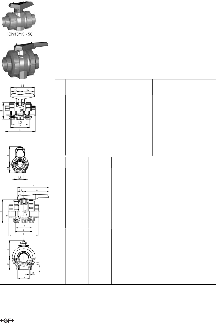
49
Ball valves
Ball valve type 546 ABS
With solvent cement sockets BS Inch
Model:
•For easy installation and removal
•z-dimension, valve end and union nut are not compatible with type 346
(DN10/15-50) resp. type 370 (DN65-100)
•Ball seals PTFE
•Without mounting inserts
Option:
•Individual configuration of the valve (see diagram)
•Multifunctional module with integrated limit switches
•Pneumatic or electric actuators from +GF+
Inch DN
[mm]
PN kv-value
(Δp=1 bar)
[l/min]
EPDM
Code
kg
3∕810 10 71 169 546 201 0.112
1∕215 10 185 169 546 202 0.114
3∕420 10 350 169 546 203 0.178
1 25 10 700 169 546 204 0.258
1 1∕432 10 1000 169 546 205 0.457
1 1∕240 10 1600 169 546 206 0.642
2 50 10 3100 169 546 207 1.175
65 10 5000 169 546 008 3.900
3 80 10 7000 169 546 209 5.700
4 100 10 11000 169 546 210 9.100
Inch D
[mm]
H
[mm]
H1
[mm]
L
[mm]
L1
[mm]
L2
[mm]
L4
[mm]
L5
[mm]
L6
[mm]
z
[mm]
3∕850 57 27 92 77 56 25 32 45 60
1∕250 57 27 95 77 56 25 32 45 60
3∕458 67 30 110 97 65 25 39 58 69
1 68 73 36 123 97 71 25 39 58 75
1 1∕484 90 44 146 128 85 45 54 74 89
1 1∕297 97 51 157 128 89 45 54 74 97
2 124 116 64 183 152 101 45 66 87 110
166 149 85 233 270 136 70 64 206 144
3 200 161 105 254 270 141 70 64 206 151
4 238 178 123 301 320 164 120 64 256 174
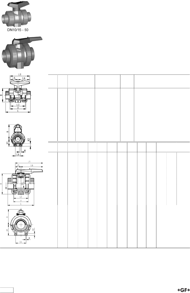
50
Ball valve type 546 ABS
With mounting inserts
With solvent cement sockets BS Inch
Model:
•For easy installation and removal
•z-dimension, valve end and union nut are not compatible with type 346
(DN10/15-50) resp. type 370 (DN65-100)
•Ball seals PTFE
•Integrated stainless steel mounting inserts
Option:
•Individual configuration of the valve (see diagram)
•Multifunctional module with integrated limit switches
•Pneumatic or electric actuators from +GF+
Inch DN
[mm]
PN kv-value
(Δp=1 bar)
[l/min]
EPDM
Code
kg
3∕810 10 71 169 546 241 0.112
1∕215 10 185 169 546 242 0.114
3∕420 10 350 169 546 243 0.178
1 25 10 700 169 546 244 0.258
1 1∕432 10 1000 169 546 245 0.457
1 1∕240 10 1600 169 546 246 0.642
2 50 10 3100 169 546 247 1.175
65 10 5000 169 546 068 3.900
3 80 10 7000 169 546 249 5.700
4 100 10 11000 169 546 250 9.100
Inch D
[mm]
H
[mm]
H1
[mm]
H2
[mm]
L
[mm]
L1
[mm]
L2
[mm]
L4
[mm]
L5
[mm]
L6
[mm]
M z
[mm]
3∕850 57 27 12 92 77 56 25 32 45 M6 60
1∕250 57 27 12 95 77 56 25 32 45 M6 60
3∕458 67 30 12 110 97 65 25 39 58 M6 69
1 68 73 36 12 123 97 71 25 39 58 M6 75
1 1∕484 90 44 15 146 128 85 45 54 74 M8 89
1 1∕297 97 51 15 157 128 89 45 54 74 M8 97
2 124 116 64 15 183 152 101 45 66 87 M8 110
166 149 85 15 233 270 136 70 64 206 M8 144
3 200 161 105 15 254 270 141 70 64 206 M8 151
4 238 178 123 22 301 320 164 120 64 256 M12 174
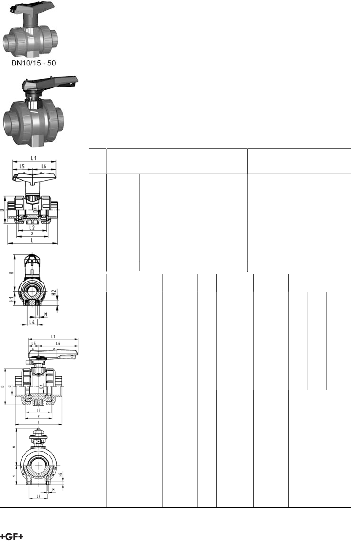
51
Ball valve type 546 ABS
With lockable handle
With solvent cement sockets BS Inch
Model:
•For easy installation and removal
•z-dimension, valve end and union nut are not compatible with type 346
(DN10/15-50) resp. type 370 (DN65-100)
•Ball seals PTFE
•Integrated stainless steel mounting inserts
•Lockable hand lever with ratchet settings
Option:
•Individual configuration of the valve (see diagram)
•Multifunctional module with integrated limit switches
•Pneumatic or electric actuators from +GF+
Inch DN
[mm]
PN kv-value
(Δp=1 bar)
[l/min]
EPDM
Code
kg
3∕810 10 71 169 546 221 0.121
1∕215 10 185 169 546 222 0.123
3∕420 10 350 169 546 223 0.193
1 25 10 700 169 546 224 0.273
1 1∕432 10 1000 169 546 225 0.480
1 1∕240 10 1600 169 546 226 0.665
2 50 10 3100 169 546 227 1.205
65 10 5000 169 546 088 4.200
3 80 10 7000 169 546 229 6.100
4 100 11000 169 546 230 9.400
Inch D
[mm]
H
[mm]
H1
[mm]
H2
[mm]
L
[mm]
L1
[mm]
L2
[mm]
L4
[mm]
L5
[mm]
L6
[mm]
M z
[mm]
3∕850 79 27 12 92 87 56 25 42 45 M6 60
1∕250 79 27 12 95 87 56 25 42 45 M6 60
3∕458 88 30 12 110 108 65 25 50 58 M6 69
1 68 94 36 12 123 108 71 25 50 58 M6 75
1 1∕484 113 44 15 146 140 85 45 66 75 M8 89
1 1∕297 119 51 15 157 140 89 45 66 75 M8 97
2 124 141 64 15 183 165 101 45 78 87 M8 110
166 224 85 15 233 270 136 70 64 206 M8 144
3 200 235 105 15 254 270 141 70 64 206 M8 151
4 238 245 123 22 301 320 164 120 64 256 M12 174
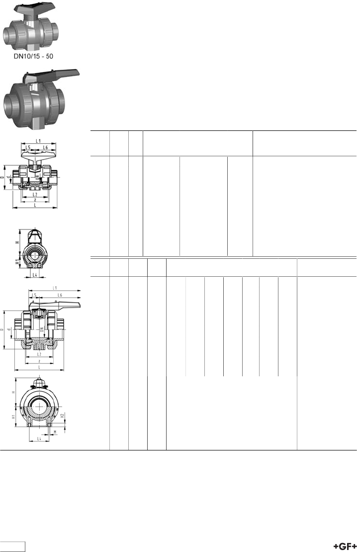
52
Ball valve type 546 ABS
With solvent cement sockets metric
Model:
•For easy installation and removal
•z-dimension, valve end and union nut are not compatible with type 346
(DN10/15-50) resp. type 370 (DN65-100)
•Ball seals PTFE
•Without mounting inserts
Option:
•Individual configuration of the valve (see diagram)
•Multifunctional module with integrated limit switches
•Pneumatic or electric actuators from +GF+
d
[mm]
DN
[mm]
PN kv-value
(Δp=1 bar)
[l/min]
EPDM
Code
kg
16 10 10 71 169 546 001 0.112
20 15 10 185 169 546 002 0.114
25 20 10 350 169 546 003 0.178
32 25 10 700 169 546 004 0.258
40 32 10 1000 169 546 005 0.457
50 40 10 1600 169 546 006 0.642
63 50 10 3100 169 546 007 1.175
75 65 10 5000 169 546 008 3.900
90 80 10 7000 169 546 009 5.700
110 100 10 11000 169 546 010 9.100
d
[mm]
D
[mm]
H
[mm]
H1
[mm]
L
[mm]
L1
[mm]
L2
[mm]
L4
[mm]
L5
[mm]
L6
[mm]
z
[mm]
16 50 57 27 92 77 56 25 32 45 64
20 50 57 27 95 77 56 25 32 45 64
25 58 67 30 110 97 65 25 39 58 72
32 68 73 36 123 97 71 25 39 58 79
40 84 90 44 146 128 85 45 54 74 94
50 97 97 51 157 128 89 45 54 74 95
63 124 116 64 183 152 101 45 66 87 107
75 166 149 85 233 270 136 70 64 206 144
90 200 161 105 254 270 141 70 64 206 151
110 238 178 123 301 320 164 120 64 256 174
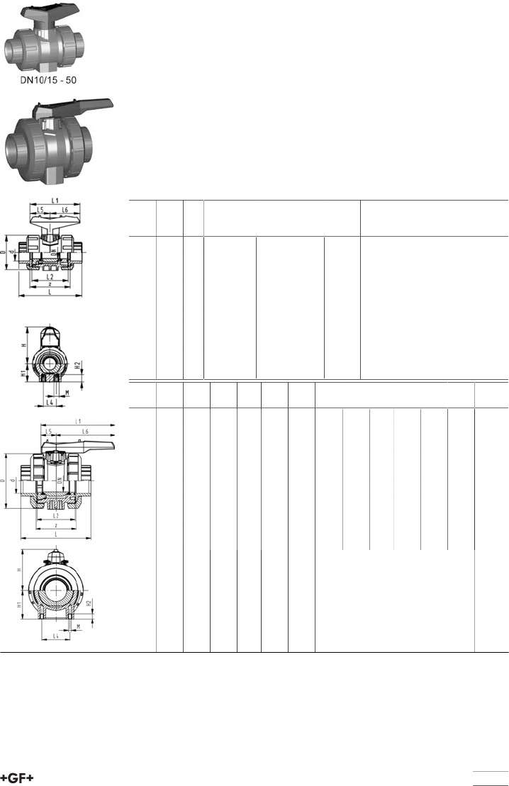
53
Ball valve type 546 ABS
With mounting inserts
With solvent cement sockets metric
Model:
•For easy installation and removal
•Ball seals PTFE
•Integrated stainless steel mounting inserts
•z-dimension, valve end and union nut are not compatible with type 346
(DN10/15-50) resp. type 370 (DN65-100)
Option:
•Individual configuration of the valve (see diagram)
•Multifunctional module with integrated limit switches
•Pneumatic or electric actuators from +GF+
d
[mm]
DN
[mm]
PN kv-value
(Δp=1 bar)
[l/min]
EPDM
Code
kg
16 10 10 71 169 546 061 0.112
20 15 10 185 169 546 062 0.114
25 20 10 350 169 546 063 0.178
32 25 10 700 169 546 064 0.258
40 32 10 1000 169 546 065 0.457
50 40 10 1600 169 546 066 0.642
63 50 10 3100 169 546 067 1.175
75 65 10 5000 169 546 068 3.900
90 80 10 7000 169 546 069 5.700
110 100 10 11000 169 546 070 9.100
d
[mm]
D
[mm]
H
[mm]
H1
[mm]
H2
[mm]
L
[mm]
L1
[mm]
L2
[mm]
L4
[mm]
L5
[mm]
L6
[mm]
M z
[mm]
16 50 57 27 12 92 77 56 25 32 45 M6 64
20 50 57 27 12 95 77 56 25 32 45 M6 64
25 58 67 30 12 110 97 65 25 39 58 M6 72
32 68 73 36 12 123 97 71 25 39 58 M6 79
40 84 90 44 15 146 128 85 45 54 74 M8 94
50 97 97 51 15 157 128 89 45 54 74 M8 95
63 124 116 64 15 183 152 101 45 66 87 M8 107
75 166 149 85 15 233 270 136 70 64 206 M8 144
90 200 161 105 15 254 270 141 70 64 206 M8 151
110 238 178 123 22 301 320 164 120 64 256 M12 174
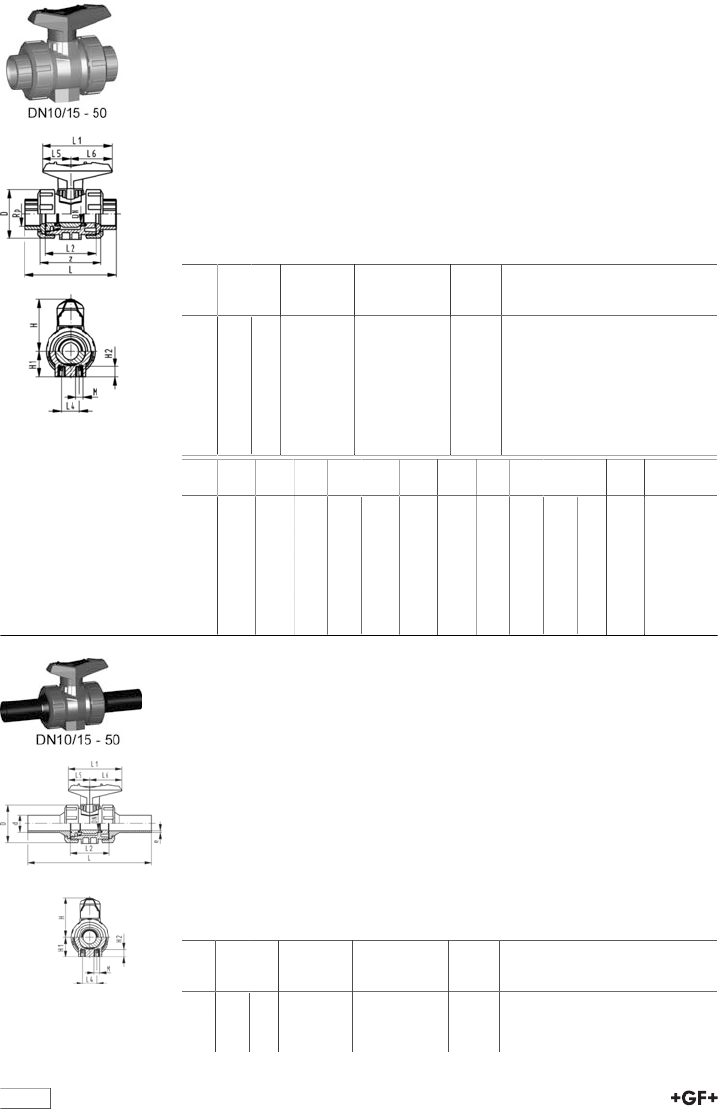
table continued next page
54
Ball valve type 546 ABS
With mounting inserts
With threaded sockets Rp
Model:
•For easy installation and removal
•Ball seals PTFE
•Integrated stainless steel mounting inserts
•z-dimension, valve end andunion nut are not compatible with type 346
Option:
•Individual configuration of the valve (see diagram)
•Multifunctional module with integrated limit switches
•Pneumatic or electric actuators from +GF+
Rp
[inch]
DN
[mm]
PN kv-value
(Δp=1 bar)
[l/min]
EPDM
Code
kg
3∕810 10 71 169 546 021 0.112
1∕215 10 185 169 546 022 0.114
3∕420 10 350 169 546 023 0.178
1 25 10 700 169 546 024 0.258
1 1∕432 10 1000 169 546 025 0.457
1 1∕240 10 1600 169 546 026 0.642
2 50 10 3100 169 546 027 1.175
Rp
[inch]
D
[mm]
H
[mm]
H1
[mm]
H2
[mm]
L
[mm]
L1
[mm]
L2
[mm]
L4
[mm]
L5
[mm]
L6
[mm]
M z
[mm]
3∕850 57 27 12 95 77 56 25 32 45 M6 69
1∕250 57 27 12 100 77 56 25 32 45 M6 67
3∕458 67 30 12 114 97 65 25 39 58 M6 78
1 68 73 36 12 127 97 71 25 39 58 M6 85
1 1∕484 90 44 15 146 128 85 45 54 74 M8 100
1 1∕297 97 51 15 152 128 89 45 54 74 M8 106
2 124 116 64 15 177 152 101 45 66 87 M8 121
Ball valve type 546 ABS
With mounting inserts
With butt fusion spigots long PE100 SDR11 metric
Model:
•For easy installation and removal
•Ball seals PTFE
•Integrated stainless steel mounting inserts
•z-dimension, valve end and union nut are not compatible with type 346
(DN10/15-50) resp. type 370 (DN65-100)
Option:
•Individual configuration of the valve (see diagram)
•Multifunctional module with integrated limit switches
•Pneumatic or electric actuators from +GF+
d
[mm]
DN
[mm]
PN kv-value
(Δp=1 bar)
[l/min]
EPDM
Code
kg
20 15 10 185 800 024 832 0.150
25 20 10 350 800 024 834 0.220
32 25 10 700 800 015 141 0.310
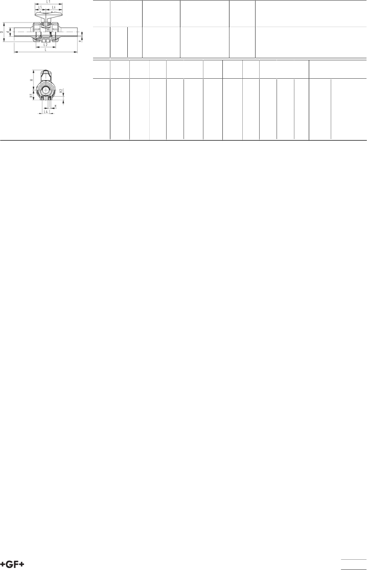
55
d
[mm]
DN
[mm]
PN kv-value
(Δp=1 bar)
[l/min]
EPDM
Code
kg
40 32 10 1000 800 015 142 0.530
50 40 10 1600 800 015 179 0.740
63 50 10 3100 800 015 143 1.370
d
[mm]
D
[mm]
H
[mm]
H1
[mm]
H2
[mm]
L
[mm]
L1
[mm]
L2
[mm]
L4
[mm]
L5
[mm]
L6
[mm]
M e
[mm]
20 50 57 27 12 193 77 56 25 32 45 M6 2,25
25 58 67 30 12 216 97 65 25 39 58 M6 2,3
32 68 73 36 12 223 97 71 25 39 58 M6 2,9
40 84 90 44 15 249 128 85 45 54 74 M8 3,7
50 97 97 51 15 271 128 89 45 54 74 M8 4,6
63 124 116 64 15 321 152 101 45 66 87 M8 5,8
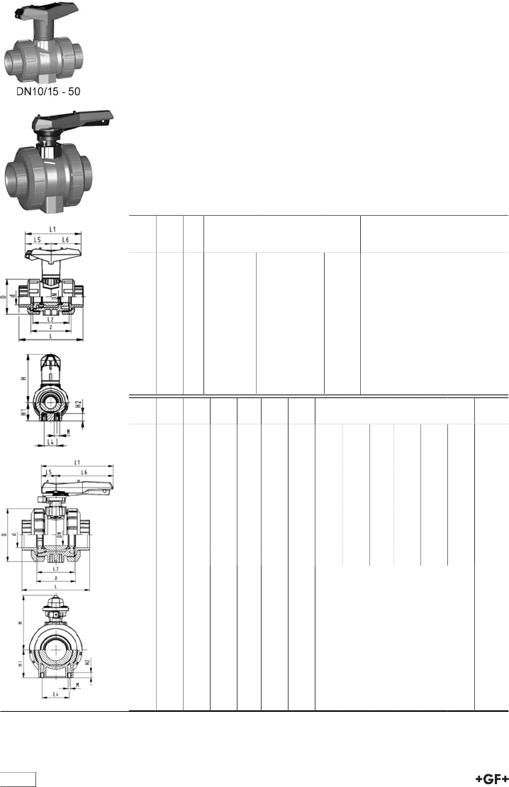
56
Ball valve type 546 ABS
With lockable handle
With solvent cement sockets metric
Model:
•For easy installation and removal
•Ball seals PTFE
•Integrated stainless steel mounting inserts
•z-dimension, valve end and union nut are not compatible with type 346
(DN10/15-50) resp. type 370 (DN65-100)
•Lockable hand lever with ratchet settings
Option:
•Individual configuration of the valve (see diagram)
•Multifunctional module with integrated limit switches
•Pneumatic or electric actuators from +GF+
d
[mm]
DN
[mm]
PN kv-value
(Δp=1 bar)
[l/min]
EPDM
Code
kg
16 10 10 71 169 546 081 0.121
20 15 10 185 169 546 082 0.123
25 20 10 350 169 546 083 0.193
32 25 10 700 169 546 084 0.273
40 32 10 1000 169 546 085 0.480
50 40 10 1600 169 546 086 0.665
63 50 10 3100 169 546 087 1.205
75 65 10 5000 169 546 088 4.200
90 80 10 7000 169 546 089 6.100
110 100 10 11000 169 546 090 9.400
d
[mm]
D
[mm]
H
[mm]
H1
[mm]
H2
[mm]
L
[mm]
L1
[mm]
L2
[mm]
L4
[mm]
L5
[mm]
L6
[mm]
M z
[mm]
16 50 79 27 12 92 87 56 25 42 45 M6 64
20 50 79 27 12 95 87 56 25 42 45 M6 64
25 58 88 30 12 110 108 65 25 50 58 M6 72
32 68 94 36 12 123 108 71 25 50 58 M6 79
40 84 113 44 15 146 140 85 45 66 75 M8 94
50 97 119 51 15 157 140 89 45 66 75 M8 95
63 124 141 64 15 183 165 101 45 78 87 M8 107
75 166 224 85 15 233 270 136 70 64 206 M8 144
90 200 235 105 15 254 270 141 70 64 206 M8 151
110 238 245 123 22 301 320 164 120 64 256 M12 174
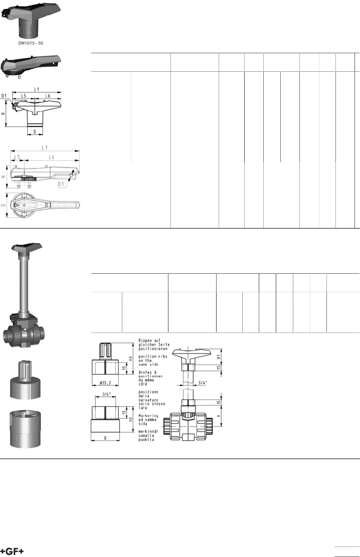
57
Multifunctional handle 546 red (K11)
With ratchet settings lockable
Note:
To retrofit the ball valve 546 with the multifunctional handle a multifunction mod-
ule is neccessary in the dimensions DN65-100
d-d
[mm]
DN-DN
[mm]
Code kg D
[mm]
D1
[mm]
H
[mm]
L1
[mm]
L5
[mm]
L6
[mm]
16 - 20 10 - 15 167 484 100 0.026 26 5 53 87 42 45
- 25 - 20 167 484 101 0.045 34 5 59 108 50 58
- 32 - 25 167 484 102 0.045 34 5 59 108 50 58
- 40 - 32 167 484 103 0.082 40 5 69 140 66 75
- 50 - 40 167 484 104 0.082 40 5 69 140 66 75
- 63 - 50 167 484 105 0.104 44 5 80 165 78 87
- 75 - 65 161 486 689 0.480 115 12 105 270 64 206
- 90 - 80 161 486 690 0.480 115 12 105 270 64 206
110 - 140 100 - 125 161 486 691 0.480 115 12 107 320 64 256
Handle extension 546 PVC-U inch BS/ASTM
Model:
•For Ball Valve Type 546
DN-DN
[mm]
Inch Code kg H
[mm]
H1
[mm]
H2
[mm]
H3
[mm]
D
[mm]
10 - 15 3/8-1/2 161 486 443 0.032 41 52 29 36 26
20 - 25 3/4-1 161 486 444 0.037 50 62 32 39 36
32 - 40 1 1/4-1 1/2 161 486 445 0.047 65 76 34 44 40
50 - 2 161 486 446 0.058 84 87 37 48 44

58
3-Way ball valve type 543 ABS
Horizontal/L-port
With solvent cement sockets metric
Model:
•For easy installation and removal (valve end andunion nut are compatible
with type 546)
•Ball seals PTFE
•Pneumatic or electric actuator available separately
•Angle of operation 360° without turn limiter
•Turn limiter 90° enclosed, in different positions usable as a clip-on ring
•Integrated stainless steel mounting inserts
•Delivery status A-C opened, see flow scheme
d
[mm]
DN
[mm]
PN kv-value
(Δp=1 bar)
[l/min]
EPDM
Code
kg
16 10 10 50 169 543 001 0.187
20 15 10 75 169 543 002 0.192
25 20 10 150 169 543 003 0.276
32 25 10 280 169 543 004 0.420
40 32 10 480 169 543 005 0.716
50 40 10 620 169 543 006 1.061
63 50 10 1230 169 543 007 2.064
d
[mm]
D
[mm]
L
[mm]
L1
[mm]
L2
[mm]
L3
[mm]
L4
[mm]
L5
[mm]
L6
[mm]
H
[mm]
H1
[mm]
H2
[mm]
M z
[mm]
z1
[mm]
16 50 109 77 73 36 25 32 45 57 28 8 6 81 40
20 50 112 77 73 36 25 32 45 57 28 8 6 81 40
25 58 131 97 86 43 25 39 58 67 32 8 6 94 47
32 68 151 97 99 50 25 39 58 73 36 8 6 107 54
40 84 181 128 120 60 45 54 74 90 45 9 8 130 65
50 97 205 128 137 69 45 54 74 97 51 9 8 143 72
63 124 261 152 179 89 45 66 87 116 65 9 8 185 92

59
3-Way ball valve type 543 ABS
Horizontal/L-port
With threaded sockets Rp
Model:
•For easy installation and removal (valve end andunion nut are compatible
with type 546)
•Ball seals PTFE
•Pneumatic or electric actuator available separately
•Angle of operation 360° without turn limiter
•Turn limiter 90° enclosed, in different positions usable as a clip-on ring
•Integrated stainless steel mounting inserts
•Delivery status A-C opened, see flow scheme
Rp
[inch]
DN
[mm]
PN kv-value
(Δp=1 bar)
[l/min]
EPDM
Code
kg
3∕810 10 50 169 543 041 0.187
1∕215 10 75 169 543 042 0.192
3∕420 10 150 169 543 043 0.276
1 25 10 280 169 543 044 0.420
1 1∕432 10 480 169 543 045 0.716
1 1∕240 10 620 169 543 046 1.061
2 50 10 1230 169 543 047 2.064
Rp
[inch]
D
[mm]
L
[mm]
L1
[mm]
L2
[mm]
L3
[mm]
L4
[mm]
L5
[mm]
L6
[mm]
H
[mm]
H1
[mm]
H2
[mm]
M z
[mm]
z1
[mm]
3∕850 113 77 73 36 25 32 45 57 28 8 6 87 43
1∕250 117 77 73 36 25 32 45 57 28 8 6 85 42
3∕458 135 97 86 43 25 39 58 67 32 8 6 100 50
1 68 155 97 99 50 25 39 58 73 36 8 6 113 57
1 1∕484 179 128 120 60 45 54 74 90 45 9 8 134 67
1 1∕297 201 128 137 69 45 54 74 97 51 9 8 155 78
2 124 255 152 179 89 45 66 87 116 65 9 8 199 99
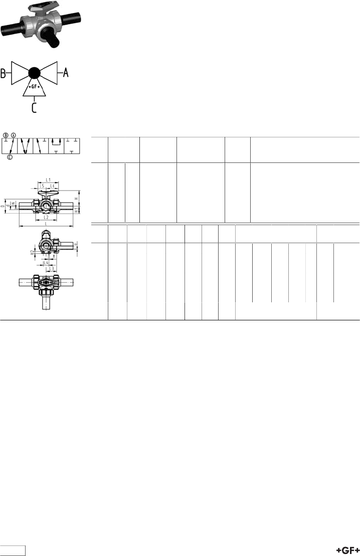
60
3-Way ball valve type 543 ABS
Horizontal/L-port
With butt fusion spigots long
PE100 SDR11 metric
Model:
•For easy installation and removal (valve end andunion nut are compatible
with type 546)
•Ball seals PTFE
•Pneumatic or electric actuator available separately
•Angle of operation 360° without turn limiter
•Turn limiter 90° enclosed, in different positions usable as a clip-on ring
•Integrated stainless steel mounting inserts
•Delivery status A-C opened, see flow scheme
d
[mm]
DN
[mm]
PN kv-value
(Δp=1 bar)
[l/min]
EPDM
Code
kg
20 15 10 75 169 543 302 0.203
25 20 10 150 169 543 303 0.296
32 25 10 280 169 543 304 0.450
40 32 10 480 169 543 305 0.762
50 40 10 620 169 543 306 1.161
63 50 10 1230 169 543 307 2.509
d
[mm]
D
[mm]
L
[mm]
L1
[mm]
L2
[mm]
L3
[mm]
L4
[mm]
L5
[mm]
L6
[mm]
H
[mm]
H1
[mm]
H2
[mm]
M e
[mm]
20 50 210 77 73 36 25 32 45 57 28 8 6 2.3
25 58 237 97 86 43 25 39 58 67 32 8 6 2.3
32 68 251 97 99 50 25 39 58 73 36 8 6 2.9
40 84 283 128 120 60 45 54 74 90 45 9 8 3.7
50 97 319 128 137 69 45 54 74 97 51 9 8 4.6
63 124 399 152 179 89 45 66 87 116 65 9 8 5.8

61
3-Way ball valve type 543 ABS
Horizontal/L-port
With solvent cement sockets BS
Model:
•For easy installation and removal (valve end andunion nut are compatible
with type 546)
•Ball seals PTFE
•Pneumatic or electric actuator available separately
•Angle of operation 360° without turn limiter
•Turn limiter 90° enclosed, in different positions usable as a clip-on ring
•Integrated stainless steel mounting inserts
•Delivery status A-C opened, see flow scheme
Inch DN
[mm]
PN kv-value
(Δp=1 bar)
[l/min]
EPDM
Code
kg
3∕810 10 50 169 543 061 0.187
1∕215 10 75 169 543 062 0.192
3∕420 10 150 169 543 063 0.276
1 25 10 280 169 543 064 0.420
1 1∕432 10 480 169 543 065 0.716
1 1∕240 10 620 169 543 066 1.061
2 50 10 1230 169 543 067 2.064
Inch D
[mm]
L
[mm]
L1
[mm]
L2
[mm]
L3
[mm]
L4
[mm]
L5
[mm]
L6
[mm]
H
[mm]
H1
[mm]
H2
[mm]
M z
[mm]
z1
[mm]
3∕850 109 77 73 36 25 32 45 57 28 8 6 77 38
1∕250 112 77 73 36 25 32 45 57 28 8 6 77 38
3∕458 131 97 86 43 25 39 58 67 32 8 6 90 45
1 68 151 97 99 50 25 39 58 73 36 8 6 103 52
1 1∕484 181 128 120 60 45 54 74 90 45 9 8 124 62
1 1∕297 205 128 137 69 45 54 74 97 51 9 8 145 73
2 124 261 152 179 89 45 66 87 116 65 9 8 189 94
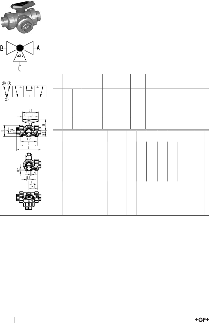
62
3-Way ball valve type 543 ABS
Horizontal/T-port
With solvent cement sockets metric
Model:
•For easy installation and removal (valve end andunion nut are compatible
with type 546)
•Ball seals PTFE
•Pneumatic or electric actuator available separately
•Angle of operation 360° without turn limiter
•Turn limiter 90° enclosed, in different positions usable as a clip-on ring
•Integrated stainless steel mounting inserts
•Delivery status A-B-C opened, see flow scheme
d
[mm]
DN
[mm]
PN kv-value
(Δp=1 bar)
[l/min]
EPDM
Code
kg
16 10 10 140 169 543 201 0.186
20 15 10 200 169 543 202 0.191
25 20 10 470 169 543 203 0.274
32 25 10 793 169 543 204 0.415
40 32 10 1290 169 543 205 0.708
50 40 10 1910 169 543 206 1.045
63 50 10 3100 169 543 207 2.030
d
[mm]
D
[mm]
L
[mm]
L1
[mm]
L2
[mm]
L3
[mm]
L4
[mm]
L5
[mm]
L6
[mm]
H
[mm]
H1
[mm]
H2
[mm]
M z
[mm]
z1
[mm]
16 50 109 77 73 36 25 32 45 57 28 8 6 81 40
20 50 112 77 73 36 25 32 45 57 28 8 6 81 40
25 58 131 97 86 43 25 39 58 67 32 8 6 94 47
32 68 151 97 99 50 25 39 58 73 36 8 6 107 54
40 84 181 128 120 60 45 54 74 90 45 9 8 130 65
50 97 205 128 137 69 45 54 74 97 51 9 8 143 72
63 124 261 152 179 89 45 66 87 116 65 9 8 185 92
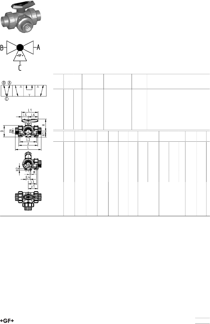
63
3-Way ball valve type 543 ABS
Horizontal/T-port
With threaded sockets Rp
Model:
•For easy installation and removal (valve end andunion nut are compatible
with type 546)
•Ball seals PTFE
•Pneumatic or electric actuator available separately
•Angle of operation 360° without turn limiter
•Turn limiter 90° enclosed, in different positions usable as a clip-on ring
•Integrated stainless steel mounting inserts
•Delivery status A-B-C opened, see flow scheme
Rp
[inch]
DN
[mm]
PN kv-value
(Δp=1 bar)
[l/min]
EPDM
Code
kg
3∕810 10 140 169 543 241 0.186
1∕215 10 200 169 543 242 0.191
3∕420 10 470 169 543 243 0.274
1 25 10 793 169 543 244 0.415
1 1∕432 10 1290 169 543 245 0.708
1 1∕240 10 1910 169 543 246 1.045
2 50 10 3100 169 543 247 2.030
Rp
[inch]
D
[mm]
L
[mm]
L1
[mm]
L2
[mm]
L3
[mm]
L4
[mm]
L5
[mm]
L6
[mm]
H
[mm]
H1
[mm]
H2
[mm]
M z
[mm]
z1
[mm]
3∕850 113 77 73 36 25 32 45 57 28 8 6 87 43
1∕250 117 77 73 36 25 32 45 57 28 8 6 85 42
3∕458 135 97 86 43 25 39 58 67 32 8 6 100 50
1 68 155 97 99 50 25 39 58 73 36 8 6 113 57
1 1∕484 179 128 120 60 45 54 74 90 45 9 8 134 67
1 1∕297 201 128 137 69 45 54 74 97 51 9 8 155 78
2 124 255 152 179 89 45 66 87 116 65 9 8 199 99

64
3-Way ball valve type 543 ABS
Horizontal/T-port
With butt fusion spigots long
PE100 SDR11 metric
Model:
•For easy installation and removal (valve end andunion nut are compatible
with type 546)
•Ball seals PTFE
•Pneumatic or electric actuator available separately
•Angle of operation 360° without turn limiter
•Turn limiter 90° enclosed, in different positions usable as a clip-on ring
•Integrated stainless steel mounting inserts
•Delivery status A-B-C opened, see flow scheme
d
[mm]
DN
[mm]
PN kv-value
(Δp=1 bar)
[l/min]
EPDM
Code
kg
20 15 10 200 169 543 322 0.203
25 20 10 470 169 543 323 0.296
32 25 10 793 169 543 324 0.450
40 32 10 1290 169 543 325 0.762
50 40 10 1910 169 543 326 1.161
63 50 10 3100 169 543 327 2.509
d
[mm]
D
[mm]
L
[mm]
L1
[mm]
L2
[mm]
L3
[mm]
L4
[mm]
L5
[mm]
L6
[mm]
H
[mm]
H1
[mm]
H2
[mm]
M e
[mm]
20 50 210 77 73 36 25 32 45 57 28 8 6 2.3
25 58 237 97 86 43 25 39 58 67 32 8 6 2.3
32 68 251 97 99 50 25 39 58 73 36 8 6 2.9
40 84 283 128 120 60 45 54 74 90 45 9 8 3.7
50 97 319 128 137 69 45 54 74 97 51 9 8 4.6
63 124 399 152 179 89 45 66 87 116 65 9 8 5.8

65
3-Way ball valve type 543 ABS
Horizontal/T-port
With solvent cement sockets BS
Model:
•For easy installation and removal (valve end andunion nut are compatible
with type 546)
•Ball seals PTFE
•Pneumatic or electric actuator available separately
•Angle of operation 360° without turn limiter
•Turn limiter 90° enclosed, in different positions usable as a clip-on ring
•Integrated stainless steel mounting inserts
•Delivery status A-B-C opened, see flow scheme
Inch DN
[mm]
PN kv-value
(Δp=1 bar)
[l/min]
EPDM
Code
kg
3∕810 10 140 169 543 261 0.186
1∕215 10 200 169 543 262 0.191
3∕420 10 470 169 543 263 0.274
1 25 10 793 169 543 264 0.415
1 1∕432 10 1290 169 543 265 0.708
1 1∕240 10 1910 169 543 266 1.045
2 50 10 3100 169 543 267 2.030
Inch D
[mm]
L
[mm]
L1
[mm]
L2
[mm]
L3
[mm]
L4
[mm]
L5
[mm]
L6
[mm]
H
[mm]
H1
[mm]
H2
[mm]
M z
[mm]
z1
[mm]
3∕850 109 77 73 36 25 32 45 57 28 8 6 77 38
1∕250 112 77 73 36 25 32 45 57 28 8 6 77 38
3∕458 131 97 86 43 25 39 58 67 32 8 6 90 45
1 68 151 97 99 50 25 39 58 73 36 8 6 103 52
1 1∕484 181 128 120 60 45 54 74 90 45 9 8 124 62
1 1∕297 205 128 137 69 45 54 74 97 51 9 8 145 73
2 124 261 152 179 89 45 66 87 116 65 9 8 189 94
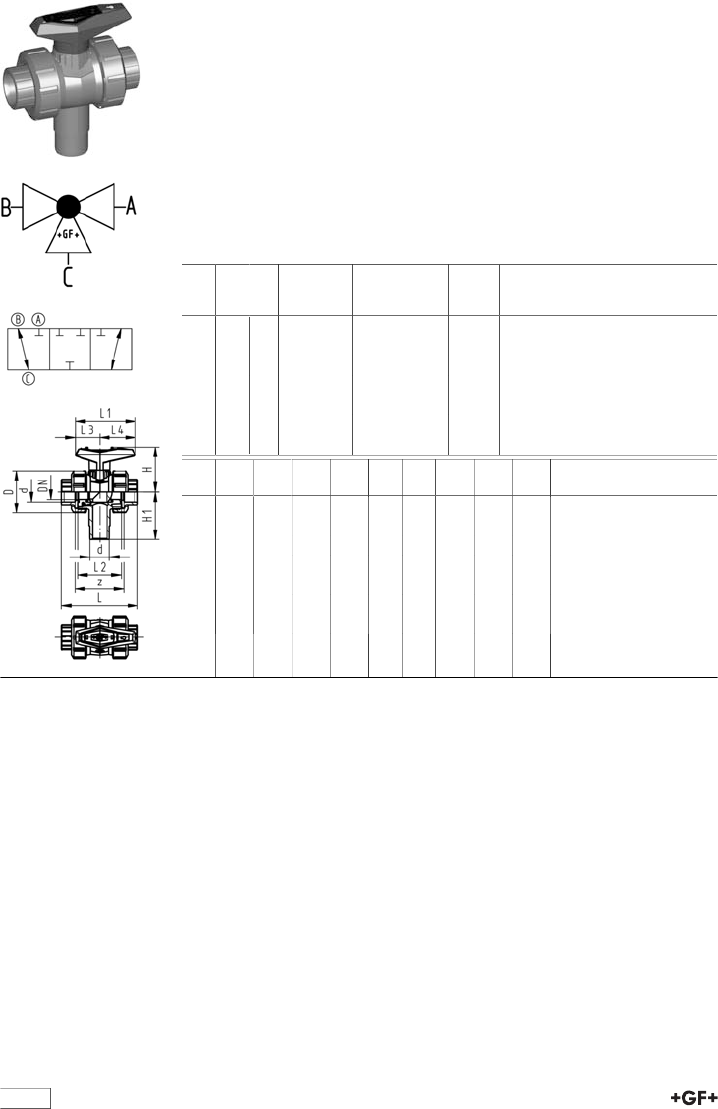
66
3-Way ball valve type 543 ABS
Vertical/L-port
With solvent cement sockets metric
Model:
•Vertical inlet solvent cement spigot metric
•Easy installation and removal using union on third outlet
•Ball seals PTFE
•Electric actuator available separately
•Angle of operation 360° without turn limiter
•Delivery status B-C opened, see flow scheme
Mode of action:
•For interconnection of two inputs
d
[mm]
DN
[mm]
PN kv-value
(Δp=1 bar)
[l/min]
EPDM
Code
kg
16 10 10 49 169 543 401 0.124
20 15 10 77 169 543 402 0.127
25 20 10 146 169 543 403 0.194
32 25 10 260 169 543 404 0.284
40 32 10 437 169 543 405 0.475
50 40 10 667 169 543 406 0.676
63 50 10 1293 169 543 407 1.234
d
[mm]
D
[mm]
L
[mm]
L1
[mm]
L2
[mm]
L3
[mm]
L4
[mm]
H
[mm]
H1
[mm]
z
[mm]
16 50 92 77 56 32 45 57 62 64
20 50 95 77 56 32 45 57 62 64
25 58 111 97 66 39 58 67 72 74
32 68 123 97 71 39 58 73 77 79
40 84 146 128 85 54 74 90 87 95
50 97 157 128 89 54 74 97 97 95
63 124 183 152 101 66 87 116 112 107
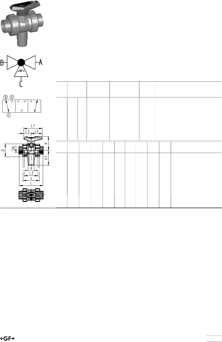
67
3-Way ball valve type 543 ABS
Vertical/L-port
With threaded sockets Rp
Model:
•Vertical inlet solvent cement spigot metric
•Easy installation and removal using union on third outlet
•Ball seals PTFE
•Electric actuator available separately
•Angle of operation 360° without turn limiter
•Delivery status B-C opened, see flow scheme
Mode of action:
•For interconnection of two inputs
Rp
[inch]
DN
[mm]
PN kv-value
(Δp=1 bar)
[l/min]
EPDM
Code
kg
3∕810 10 49 169 543 421 0.124
1∕215 10 77 169 543 422 0.127
3∕420 10 146 169 543 423 0.194
1 25 10 260 169 543 424 0.284
1 1∕432 10 437 169 543 425 0.475
1 1∕240 10 667 169 543 426 0.676
2 50 10 1293 169 543 427 1.234
Rp
[inch]
D
[mm]
L
[mm]
L1
[mm]
L2
[mm]
L3
[mm]
L4
[mm]
H
[mm]
H1
[mm]
z
[mm]
3∕850 96 77 56 32 45 57 62 69
1∕250 99 77 56 32 45 57 62 67
3∕458 115 97 66 39 58 67 72 78
1 68 127 97 71 39 58 73 77 85
1 1∕484 144 128 85 54 74 90 87 100
1 1∕297 153 128 89 54 74 97 97 106
2 124 177 152 101 66 87 116 112 121
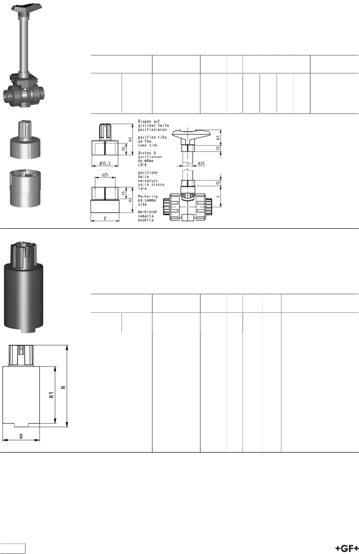
68
Handle extension 546 and 543 PVC-U metric
Model:
•For ball valve type 546 and 543
•Composed of adapter sockets for handle connection and stem connection
•PVC-U pipe in suitable length has to be obtained on site
d-d
[mm]
DN-DN
[mm]
Code kg H
[mm]
H1
[mm]
H2
[mm]
H3
[mm]
D
[mm]
16 - 20 10 - 15 161 486 435 0.032 41 52 29 36 26
25 - 32 20 - 25 161 486 436 0.037 50 62 32 39 36
40 - 50 32 - 40 161 486 437 0.047 65 76 34 44 40
- 63 - 50 161 486 438 0.058 84 87 37 48 44
Handle extension for ball valve type 546 PVC-U
DN65 - DN100
Model:
•Multiple use in succession possible
•Height variable
d-d
[mm]
DN-DN
[mm]
Code kg D
[mm]
H
[mm]
H1
[mm]
75 - 90 65 - 80 161 490 920 0.345 58 143 100
- 110 - 100 161 490 921 0.418 64 143 100
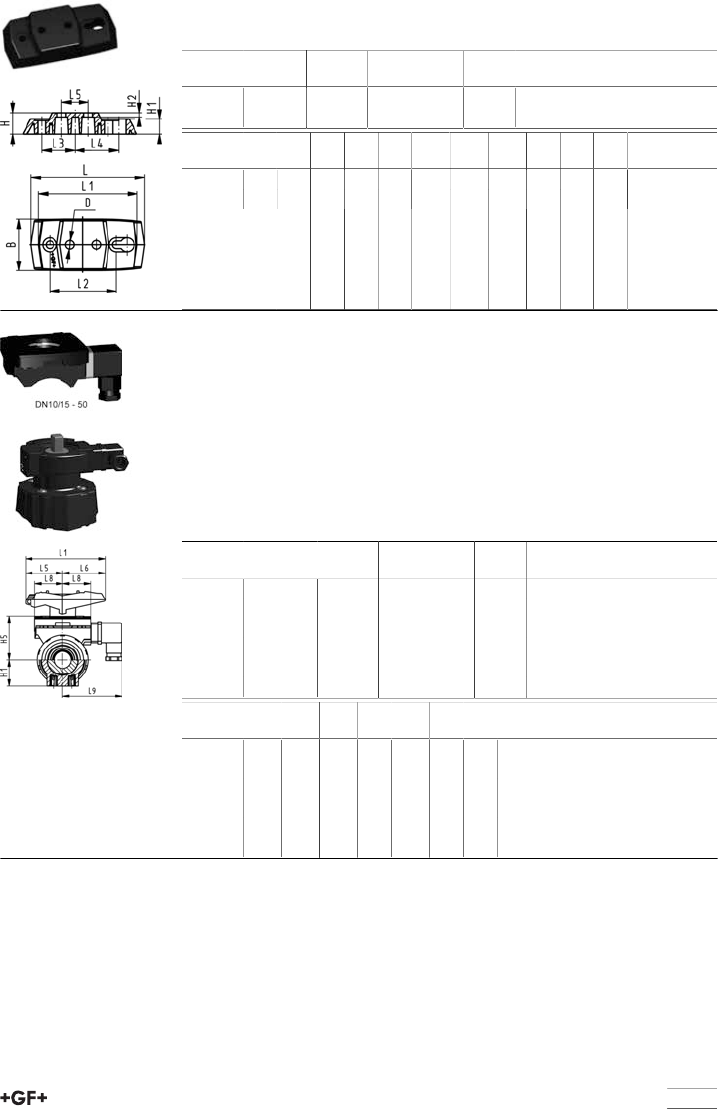
69
Mounting plate 546 and 543 PP-GF (L02)
•2 mounting screws inclusive
d-d
[mm]
Inch
[inch]
DN-DN
[mm]
Code kg
16 - 32 3∕8 - 1 10 - 25 167 484 110 0.055
40 - 63 1 1∕4 - 2 32 - 50 167 484 111 0.086
d-d
[mm]
B
[mm]
D
[mm]
H
[mm]
H1
[mm]
H2
[mm]
L
[mm]
L1
[mm]
L2
[mm]
L3
[mm]
L4
[mm]
L5
[mm]
16 - 32 48 8 20 14 4 106 92 62 31 41 25
40 - 63 54 9 20 14 4 149 134 104 52 62 45
Multifunctional module (I03) PP-GF
With mechanical limit switches Ag Ni
Model:
•Accessory to Ball Valve Type 546
•Multifunctional module acts as an intermediate element for actuators
•For operation with handle, multifunctional handle has to be ordered separate-
ly.
•Including Plug 3P+E / Protection: IP65
•Including screws to mount the module and stainless steel coupling piece
(V2A) for dimension DN65-100
d-d
[mm]
Inch
[inch]
DN-DN
[mm]
Code kg
16 - 20 3∕8 - 1∕210 - 15 167 482 626 0.110
25 - 32 3∕4 - 1 20 - 25 167 482 627 0.120
40 - 50 1 1∕4 - 1 1∕232 - 40 167 482 628 0.135
- 63 2 - 50 167 482 629 0.175
75 - 90 2 1∕2 - 3 65 - 80 167 482 630 0.460
- 110 4 - 100 167 482 631 0.480
d-d
[mm]
H1
[mm]
H5
[mm]
L1
[mm]
L5
[mm]
L6
[mm]
L8
[mm]
L9
[mm]
16 - 20 27 50 87 42 45 34 73
25 - 32 30 53 108 50 58 38 77
40 - 50 44 72 140 66 75 41 80
- 63 64 94 165 78 87 46 85
75 - 90 85 157 270 64 206
- 110 123 175 320 64 256
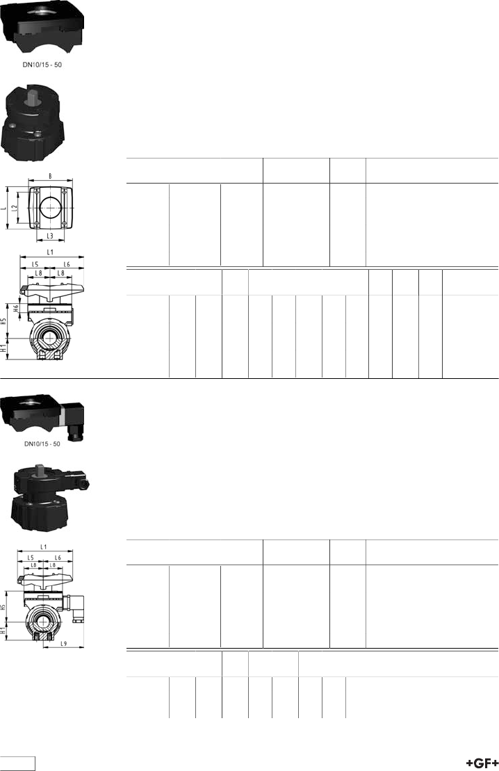
table continued next page
70
Multifunctional module (I02) PP-GF
Module empty
Model:
•Accessory to Ball Valve Type 546
•Multifunctional module acts as an intermediate element for actuators
•For operation with handle, multifunctional handle has to be ordered separate-
ly.
•Including screws to mount the module and stainless steel coupling piece
(V2A) for dimension DN65-100
•Themultifunctional modulefrom d75 - d110 has a master gauge F07 accord-
ing to EN ISO 5211.
d-d
[mm]
Inch
[inch]
DN-DN
[mm]
Code kg
16 - 20 3∕8 - 1∕210 - 15 167 482 680 0.055
25 - 32 3∕4 - 1 20 - 25 167 482 681 0.070
40 - 50 1 1∕4 - 1 1∕232 - 40 167 482 682 0.080
- 63 2 - 50 167 482 683 0.120
75 - 90 2 1∕2 - 3 65 - 80 167 482 684 0.135
- 110 4 - 100 167 482 685 0.175
d-d
[mm]
B
[mm]
H1
[mm]
H5
[mm]
H6
[mm]
L
[mm]
L1
[mm]
L2
[mm]
L3
[mm]
L5
[mm]
L6
[mm]
L8
[mm]
16 - 20 67 27 50 17 72 87 54 40 42 45 34
25 - 32 75 30 53 16 72 108 52 46 50 58 38
40 - 50 81 44 72 16 80 140 60 50 66 75 41
- 63 91 64 94 19 93 165 68 65 78 87 46
75 - 90 90 85 157 23 85 270 64 206
- 110 106 123 175 23 97 320 64 256
Multifunctional module (I04) PP-GF
With mechanical limit switches Au
Model:
•Accessory to Ball Valve Type 546
•Multifunctional module acts as an intermediate element for actuators
•For operation with handle, multifunctional handle has to be ordered separate-
ly.
•Including Plug 3P+E / Protection: IP65
•Including screws to mount the module and stainless steel coupling piece
(V2A) for dimension DN65-100
d-d
[mm]
Inch
[inch]
DN-DN
[mm]
Code kg
16 - 20 3∕8 - 1∕210 - 15 167 482 635 0.110
25 - 32 3∕4 - 1 20 - 25 167 482 636 0.120
40 - 50 1 1∕4 - 1 1∕232 - 40 167 482 637 0.135
- 63 2 - 50 167 482 638 0.175
75 - 90 2 1∕2 - 3 65 - 80 167 482 639 0.460
- 110 4 - 100 167 482 640 0.480
d-d
[mm]
H1
[mm]
H5
[mm]
L1
[mm]
L5
[mm]
L6
[mm]
L8
[mm]
L9
[mm]
16 - 20 27 50 87 42 45 34 73
25 - 32 30 53 108 50 58 38 77
40 - 50 44 72 140 66 75 41 80
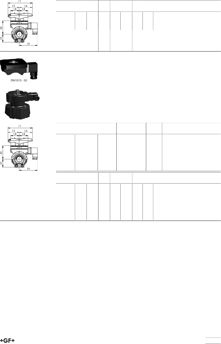
71
d-d
[mm]
H1
[mm]
H5
[mm]
L1
[mm]
L5
[mm]
L6
[mm]
L8
[mm]
L9
[mm]
- 63 64 94 165 78 87 46 85
75 - 90 85 157 270 64 206
- 110 123 175 320 64 256
Multifunctional module (I05) PP-GF
With inductive limit switches Namur
Model:
•Accessory to Ball Valve Type 546
•Multifunctional module acts as an intermediate element for actuators
•For operation with handle, multifunctional handle has to be ordered separate-
ly.
•Including Plug 3P+E / Protection: IP65
•Including screws to mount the module and stainless steel coupling piece
(V2A) for dimension DN65-100
d-d
[mm]
Inch
[inch]
DN-DN
[mm]
Code kg
16 - 20 3∕8 - 1∕210 - 15 167 482 671 0.110
25 - 32 3∕4 - 1 20 - 25 167 482 672 0.120
40 - 50 1 1∕4 - 1 1∕232 - 40 167 482 673 0.135
- 63 2 - 50 167 482 674 0.175
75 - 90 2 1∕2 - 3 65 - 80 167 482 675 0.460
- 110 4 - 100 167 482 676 0.480
d-d
[mm]
H1
[mm]
H5
[mm]
L1
[mm]
L5
[mm]
L6
[mm]
L8
[mm]
L9
[mm]
16 - 20 27 50 87 42 45 34 73
25 - 32 30 53 108 50 58 38 77
40 - 50 44 72 140 66 75 41 80
- 63 64 94 165 78 87 46 85
75 - 90 85 157 270 64 206
- 110 123 175 320 64 256
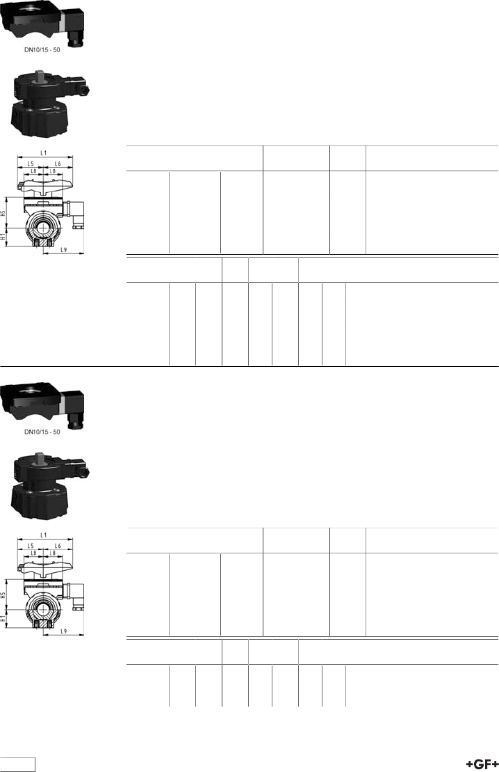
table continued next page
72
Multifunctional module (I06) PP-GF
With inductive limit switches PNP
Model:
•Accessory to Ball Valve Type 546
•Multifunctional module acts as an intermediate element for actuators
•For operation with handle, multifunctional handle has to be ordered separate-
ly.
•Including Plug 3P+E / Protection: IP65
•Including screws to mount the module and stainless steel coupling piece
(V2A) for dimension DN65-100
d-d
[mm]
Inch
[inch]
DN-DN
[mm]
Code kg
16 - 20 3∕8 - 1∕210 - 15 167 482 662 0.110
25 - 32 3∕4 - 1 20 - 25 167 482 663 0.120
40 - 50 1 1∕4 - 1 1∕232 - 40 167 482 664 0.135
- 63 2 - 50 167 482 665 0.175
75 - 90 2 1∕2 - 3 65 - 80 167 482 666 0.460
- 110 4 - 100 167 482 667 0.480
d-d
[mm]
H1
[mm]
H5
[mm]
L1
[mm]
L5
[mm]
L6
[mm]
L8
[mm]
L9
[mm]
16 - 20 27 50 87 42 45 34 73
25 - 32 30 53 108 50 58 38 77
40 - 50 44 72 140 66 75 41 80
- 63 64 94 165 78 87 46 85
75 - 90 85 157 270 64 206
- 110 123 175 320 64 256
Multifunctional module (I07) PP-GF
With inductive limit switches NPN
Model:
•Accessory to Ball Valve Type 546
•Multifunctional module acts as an intermediate element for actuators
•For operation with handle, multifunctional handle has to be ordered separate-
ly.
•Including Plug 3P+E / Protection: IP65
•Including screws to mount the module and stainless steel coupling piece
(V2A) for dimension DN65-100
d-d
[mm]
Inch
[inch]
DN-DN
[mm]
Code kg
16 - 20 3∕8 - 1∕210 - 15 167 482 653 0.110
25 - 32 3∕4 - 1 20 - 25 167 482 654 0.120
40 - 50 1 1∕4 - 1 1∕232 - 40 167 482 655 0.135
- 63 2 - 50 167 482 656 0.175
75 - 90 2 1∕2 - 3 65 - 80 167 482 657 0.460
- 110 4 - 100 167 482 658 0.480
d-d
[mm]
H1
[mm]
H5
[mm]
L1
[mm]
L5
[mm]
L6
[mm]
L8
[mm]
L9
[mm]
16 - 20 27 50 87 42 45 34 73
25 - 32 30 53 108 50 58 38 77
40 - 50 44 72 140 66 75 41 80
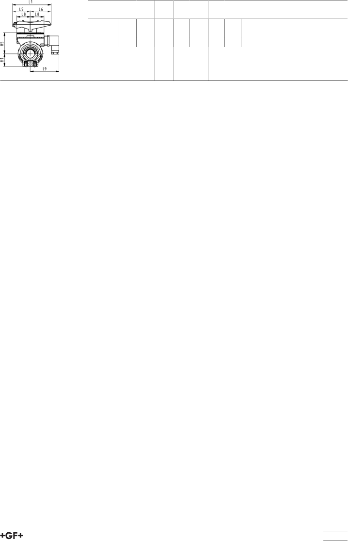
73
d-d
[mm]
H1
[mm]
H5
[mm]
L1
[mm]
L5
[mm]
L6
[mm]
L8
[mm]
L9
[mm]
- 63 64 94 165 78 87 46 85
75 - 90 85 157 270 64 206
- 110 123 175 320 64 256

table continued next page
74
Spare parts ball valves
Spare parts ball valve type 546
Central part
Model:
•Every connecting pieces and union nuts are listed on product range industry
valves
•Ball seals standard in PTFE
•Central part consisting of: body (1), union bush (2), ball (5), stem (6), ball-,
backing-, body-, face- and stem seal (7-11), standard lever (12) and threaded
inserts stainless steel (14)
d
[mm]
Inch DN
[mm]
ABS EPDM
Code
kg
16 3∕810 169 480 751 0.075
20 1∕215 169 480 751 0.075
25 3∕420 169 480 752 0.120
32 1 25 169 480 753 0.175
40 1 1∕432 169 480 754 0.310
50 1 1∕240 169 480 755 0.405
63 2 50 169 480 756 0.700
75 2 1∕265 169 480 757 2.660
90 3 80 169 480 758 3.780
110 4 100 169 480 759 5.990
Ball set
Model:
•Ball seals standard in PTFE
•Ball set consisting of: ball (5), stem (6), ball-, backing-, body- and stemseal
(7-9,11)
d
[mm]
Inch DN
[mm]
ABS EPDM
Code
kg
16 3∕810 169 480 900 0.013
20 1∕215 169 480 900 0.013
25 3∕420 169 480 901 0.020
32 1 25 169 480 902 0.035
40 1 1∕432 169 480 903 0.065
50 1 1∕240 169 480 904 0.100
63 2 50 169 480 905 0.195
table continued next page
75
d
[mm]
Inch DN
[mm]
ABS EPDM
Code
kg
75 2 1∕265 169 480 906 0.388
90 3 80 169 480 907 0.610
110 4 100 169 480 908 1.014
Lever
d
[mm]
Inch DN
[mm]
Standard lever
red
Code
Standard lever
black
Code
Multifunctional
lever
Code
kg
16 3∕810 167 484 088 167 484 076 167 484 100 0.026
20 1∕215 167 484 088 167 484 076 167 484 100 0.026
25 3∕420 167 484 089 167 484 077 167 484 101 0.045
32 1 25 167 484 090 167 484 078 167 484 102 0.045
40 1 1∕432 167 484 091 167 484 079 167 484 103 0.082
50 1 1∕240 167 484 092 167 484 080 167 484 104 0.082
63 2 50 167 484 093 167 484 081 167 484 105 0.104
75 2 1∕265 167 484 094 167 484 082 161 486 689 0.480
90 3 80 167 484 095 167 484 083 161 486 690 0.480
110 4 100 167 484 096 167 484 084 161 486 691 0.480
Face seal
Model:
•Face seal no. 10
d
[mm]
Inch DN
[mm]
EPDM
Code
kg
16 3∕810 748 410 059 0.004
20 1∕215 748 410 059 0.004
25 3∕420 748 410 106 0.002
32 1 25 748 410 151 0.002
40 1 1∕432 748 410 062 0.002
50 1 1∕240 748 410 003 0.004
63 2 50 748 410 231 0.010
75 2 1∕265 748 410 119 0.006
90 3 80 748 410 023 0.010
110 4 100 748 410 254 0.020
Seal set
Model:
•Sealset consisting of: backing-, body-, face-and stem seal (8-11)
d
[mm]
Inch DN
[mm]
EPDM
Code
kg
16 3∕810 161 486 400 0.002
20 1∕215 161 486 400 0.002
25 3∕420 161 486 401 0.002
32 1 25 161 486 402 0.003
40 1 1∕432 161 486 403 0.005
50 1 1∕240 161 486 404 0.012
63 2 50 161 486 405 0.016
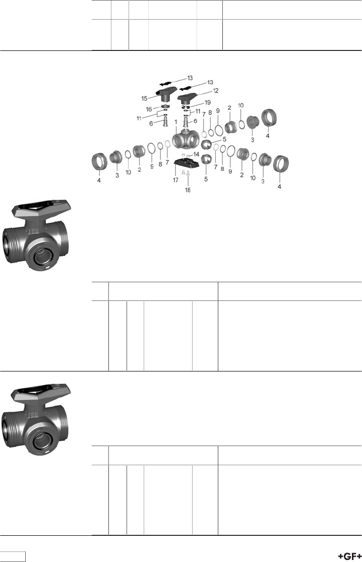
76
d
[mm]
Inch DN
[mm]
EPDM
Code
kg
75 2 1∕265 161 486 406 0.018
90 3 80 161 486 407 0.024
110 4 100 161 486 408 0.039
Spare parts ball valve type 543 horizontal
Central part L-port
Model:
•Every connecting pieces and union nuts are listed on product range industry
valves
•Ball seals standard in PTFE
•Central part consisting of: body (1), union bush (2), ball (5), stem (6), ball-,
backing-, body-, face- and stem seal (7-11), standard lever (12) and threaded
inserts stainless steel (14)
d
[mm]
Inch DN
[mm]
ABS EPDM
Code
kg
16 3∕810 169 481 202 0.120
20 1∕215 169 481 202 0.120
25 3∕420 169 481 203 0.177
32 1 25 169 481 204 0.267
40 1 1∕432 169 481 205 0.471
50 1 1∕240 169 481 206 0.699
63 2 50 169 481 207 1.340
Central part T-port
Model:
•Ball seals standard in PTFE
•Central part consisting of: body (1), union bush (2), ball (5), stem (6), ball-,
backing-, body-, face- and stem seal (7-11), standard lever (12) and threaded
inserts stainless steel (14)
d
[mm]
Inch DN
[mm]
ABS EPDM
Code
kg
16 3∕810 169 481 212 0.120
20 1∕215 169 481 212 0.120
25 3∕420 169 481 213 0.175
32 1 25 169 481 214 0.262
40 1 1∕432 169 481 215 0.462
50 1 1∕240 169 481 216 0.683
63 2 50 169 481 217 1.306
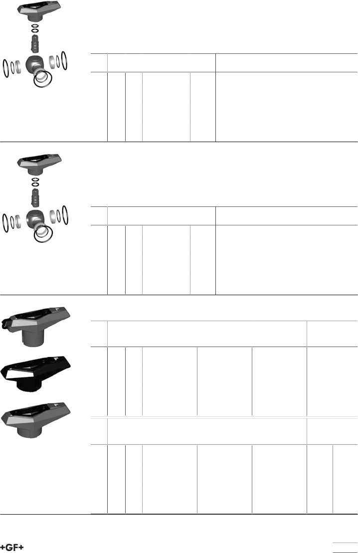
77
Ball set L-port
Model:
•Ball seals standard in PTFE
•Ball set consisting of: lever (12), ball (5), stem (6), ball-, backing-, body- and
stem seal (7-9,11)
d
[mm]
Inch DN
[mm]
ABS EPDM
Code
kg
16 3∕810 169 481 282 0.026
20 1∕215 169 481 282 0.026
25 3∕420 169 481 283 0.049
32 1 25 169 481 284 0.066
40 1 1∕432 169 481 285 0.114
50 1 1∕240 169 481 286 0.170
63 2 50 169 481 287 0.282
Ball set T-port
Model:
•Ball seals standard in PTFE
•Ball set consisting of: lever (12), ball (5), stem (6), ball-, backing-, body- and
stem seal (7-9,11)
d
[mm]
Inch DN
[mm]
ABS EPDM
Code
kg
16 3∕810 169 481 292 0.025
20 1∕215 169 481 292 0.025
25 3∕420 169 481 293 0.048
32 1 25 169 481 294 0.060
40 1 1∕432 169 481 295 0.105
50 1 1∕240 169 481 296 0.154
63 2 50 169 481 297 0.247
Lever
d
[mm]
Inch DN
[mm]
Standard lever L-
port red
Code
Standard lever L-
port black
Code
Standard lever T-
port red
Code
16 3∕810 167 484 488 167 484 376 167 484 588
20 1∕215 167 484 488 167 484 376 167 484 588
25 3∕420 167 484 489 167 484 377 167 484 589
32 1 25 167 484 490 167 484 378 167 484 590
40 1 1∕432 167 484 491 167 484 379 167 484 591
50 1 1∕240 167 484 492 167 484 380 167 484 592
63 2 50 167 484 493 167 484 381 167 484 593
d
[mm]
Inch DN
[mm]
Standard lever T-
port black
Code
Multifunctional-
lever L-port red
Code
Multifunctional-
lever T-port red
Code
kg
16 3∕810 167 484 576 167 484 442 167 484 542 0.026
20 1∕215 167 484 576 167 484 442 167 484 542 0.026
25 3∕420 167 484 577 167 484 443 167 484 543 0.045
32 1 25 167 484 578 167 484 444 167 484 544 0.045
40 1 1∕432 167 484 579 167 484 445 167 484 545 0.082
50 1 1∕240 167 484 580 167 484 446 167 484 546 0.082
63 2 50 167 484 581 167 484 447 167 484 547 0.104
78
Face seal
Model:
•Face seal no. 10
d
[mm]
Inch DN
[mm]
EPDM
Code
kg
16 3∕810 748 410 059 0.004
20 1∕215 748 410 059 0.004
25 3∕420 748 410 106 0.002
32 1 25 748 410 151 0.002
40 1 1∕432 748 410 062 0.002
50 1 1∕240 748 410 003 0.004
63 2 50 748 410 231 0.010
Seal set
Model:
•Sealset consisting of: backing-, body-, face-and stem seal (8-11)
d
[mm]
Inch DN
[mm]
EPDM
Code
kg
16 3∕810 161 488 242 0.011
20 1∕215 161 488 242 0.011
25 3∕420 161 488 243 0.011
32 1 25 161 488 244 0.014
40 1 1∕432 161 488 245 0.014
50 1 1∕240 161 488 246 0.026
63 2 50 161 488 247 0.032
Turn limiter 90°
d
[mm]
Inch DN
[mm]
Code kg
16 3∕810 167 482 479 0.001
20 1∕215 167 482 479 0.001
25 3∕420 167 482 480 0.002
32 1 25 167 482 480 0.002
40 1 1∕432 167 482 481 0.004
50 1 1∕240 167 482 481 0.004
63 2 50 167 482 482 0.004
Assembly kit
Model:
•Intermediate element for ball valve type 543 horizontaland electric or pneu-
matic actuators EA21; PA11/21
•Including screws and position indicator for actuators
d
[mm]
Inch
[inch]
DN
[mm]
Code kg
16 - 20 3∕8 - 1∕210 - 15 167 484 941 0.156
25 - 32 3∕4 - 1 20 - 25 167 484 942 0.181
40 - 50 1 1∕4 - 1 1∕232 - 40 167 484 943 0.197
63 2 50 167 484 944 0.236
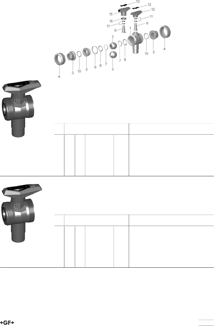
79
Spare parts ball valve type 543 vertical
Central part L-port
Model:
•Every connecting pieces and union nuts are listed on product range industry
valves
•Ball seals standard in PTFE
•Central part consisting of: body (1), union bush (2), ball (5), stem (6), ball-,
backing-, body-, face- and stem seal (7-11) and standard lever (12)
d
[mm]
Inch DN
[mm]
ABS EPDM
Code
kg
16 3∕810 169 481 221 0.079
20 3∕815 169 481 222 0.079
25 3∕420 169 481 223 0.129
32 1 25 169 481 224 0.181
40 1 1∕432 169 481 225 0.311
50 1 1∕240 169 481 226 0.435
63 2 50 169 481 227 0.751
Central part diverter ball
Model:
•Ball seals standard in PTFE
•Central part consisting of: body (1), union bush (2), ball (5), stem (6), ball-,
backing-, body-, face- and stem seal (7-11) and standard lever (12)
d
[mm]
Inch DN
[mm]
ABS EPDM
Code
kg
16 3∕810 169 481 231 0.079
20 1∕215 169 481 232 0.079
25 3∕420 169 481 233 0.127
32 1 25 169 481 234 0.176
40 1 1∕432 169 481 235 0.303
50 1 1∕240 169 481 236 0.419
63 2 50 169 481 237 0.717
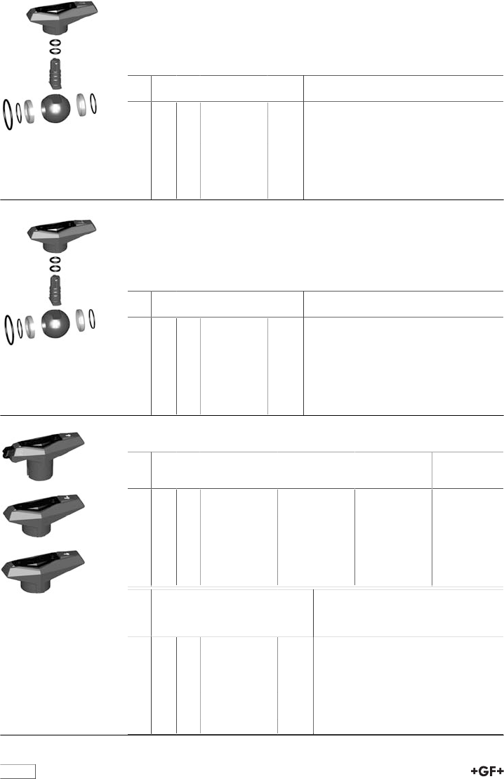
80
Ball set L-port
Model:
•Ball seals standard in PTFE
•Ball set consisting of: lever (12), ball (5), stem (6), ball-, backing-, body- and
stem seal (7-9,11)
d
[mm]
Inch DN
[mm]
ABS EPDM
Code
kg
16 3∕810 169 481 302 0.026
20 1∕215 169 481 302 0.026
25 3∕420 169 481 303 0.049
32 1 25 169 481 304 0.063
40 1 1∕432 169 481 305 0.111
50 1 1∕240 169 481 306 0.155
63 2 50 169 481 307 0.298
Ball set diverter ball
Model:
•Ball seals standard in PTFE
•Ball set consisting of: lever (12), ball (5), stem (6), ball-, backing-, body- and
stem seal (7-9,11)
d
[mm]
Inch DN
[mm]
ABS EPDM
Code
kg
16 3∕810 169 481 312 0.020
20 1∕215 169 481 312 0.020
25 3∕420 169 481 313 0.037
32 1 25 169 481 314 0.041
40 1 1∕432 169 481 315 0.070
50 1 1∕240 169 481 316 0.083
63 2 50 169 481 317 0.122
Lever
d
[mm]
Inch DN
[mm]
Standard lever L-
port red
Code
Standard lever di-
verter ball red
Code
Multifunctional-
lever L-port red
Code
16 3∕810 167 484 688 167 484 788 167 484 642
20 1∕215 167 484 688 167 484 788 167 484 642
25 3∕420 167 484 689 167 484 789 167 484 643
32 1 25 167 484 690 167 484 790 167 484 644
40 1 1∕432 167 484 691 167 484 791 167 484 645
50 1 1∕240 167 484 692 167 484 792 167 484 646
63 2 50 167 484 693 167 484 793 167 484 647
d
[mm]
Inch DN
[mm]
Multifunctional-
lever diverter ball
red
Code
kg
16 3∕810 167 484 742 0.026
20 1∕215 167 484 742 0.026
25 3∕420 167 484 743 0.045
32 1 25 167 484 744 0.045
40 1 1∕432 167 484 745 0.082
50 1 1∕240 167 484 746 0.082
63 2 50 167 484 747 0.104
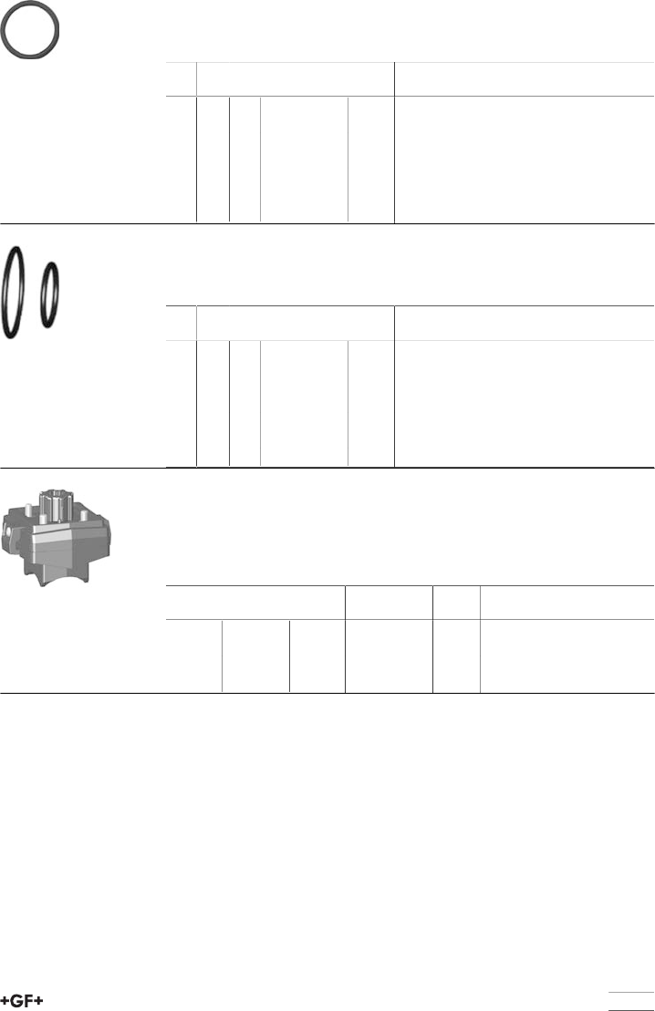
81
Face seal
Model:
•Face seal no. 10
d
[mm]
Inch DN
[mm]
EPDM
Code
kg
16 3∕810 748 410 059 0.004
20 1∕215 748 410 059 0.004
25 3∕420 748 410 106 0.002
32 1 25 748 410 151 0.002
40 1 1∕432 748 410 062 0.002
50 1 1∕240 748 410 003 0.004
63 2 50 748 410 231 0.010
Seal set
Model:
•Sealset consisting of: backing-, body-, face-and stem seal (8-11)
d
[mm]
Inch DN
[mm]
EPDM
Code
kg
16 3∕810 161 486 400 0.002
20 1∕215 161 486 400 0.002
25 3∕420 161 486 401 0.002
32 1 25 161 486 402 0.003
40 1 1∕432 161 486 403 0.005
50 1 1∕240 161 486 404 0.012
63 2 50 161 486 405 0.016
Assembly kit
Model:
•Intermediate element for ball valve type 543vertical and electric or pneumatic
actuators EA21; PA11/21
•Including screws and position indicator for actuators
d
[mm]
Inch
[inch]
DN
[mm]
Code kg
16 - 20 3∕8 - 1∕210 - 15 167 484 945 0.156
25 - 32 3∕4 - 1 20 - 25 167 484 946 0.181
40 - 50 1 1∕4 - 1 1∕232 - 40 167 484 947 0.197
63 2 50 167 484 948 0.236
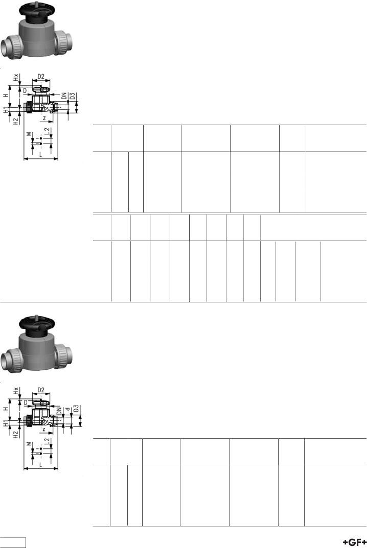
table continued next page
82
Diaphragm valves
Diaphragm valve type 514 ABS
With solvent cement sockets BS
Model:
•Double flow rate compared to predecessor
•One housing nut replaces four screws
•Handwheel with built-in locking mechanism
•For easy installation and removal
•Short overall length
Option:
•Individual configuration of the valve (see diagram)
•Self adjusting multifunctional module with integrated limit switches
Inch DN
[mm]
PN kv-value
(Δp=1 bar)
[l/min]
EPDM
Code
PTFE/EPDM
Code
kg
1∕215 10 125 169 514 512 169 514 532 0.364
3∕420 10 271 169 514 513 169 514 533 0.476
1 25 10 481 169 514 514 169 514 534 1.079
1 1∕432 10 759 169 514 515 169 514 535 1.317
1 1∕240 10 1263 169 514 516 169 514 536 2.350
2 50 10 1728 169 514 517 169 514 537 3.063
Inch D
[mm]
D2
[mm]
D3
[mm]
L
[mm]
L2
[mm]
H
[mm]
H1
[mm]
H2
[mm]
M z
[mm]
Lift =
Hx
[mm]
1∕265 65 43 128 25 73 14 12 M6 96 7
3∕480 65 51 152 25 81 18 12 M6 114 10
1 88 87 58 166 25 107 22 12 M6 122 13
1 1∕4101 87 72 192 45 115 26 15 M8 140 15
1 1∕2117 135 83 222 45 148 32 15 M8 160 19
2 144 135 100 266 45 166 39 15 M8 190 25
Diaphragm valve type 514 ABS
With solvent cement sockets metric
Model:
•Double flow rate compared to predecessor
•One housing nut replaces four screws
•Handwheel with built-in locking mechanism
•For easy installation and removal
•Short overall length
Option:
•Individual configuration of the valve (see diagram)
•Self adjusting multifunctional module with integrated limit switches
d
[mm]
DN
[mm]
PN kv-value
(Δp=1 bar)
[l/min]
EPDM
Code
PTFE/EPDM
Code
kg
20 15 10 125 169 514 012 169 514 032 0.364
25 20 10 271 169 514 013 169 514 033 0.478
32 25 10 481 169 514 014 169 514 034 1.081
40 32 10 759 169 514 015 169 514 035 1.357
50 40 10 1263 169 514 016 169 514 036 2.374
63 50 10 1728 169 514 017 169 514 037 3.111
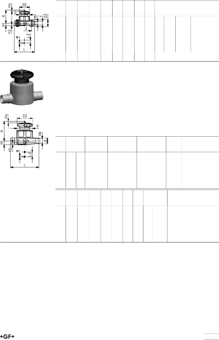
83
d
[mm]
D
[mm]
D2
[mm]
D3
[mm]
L
[mm]
L2
[mm]
H
[mm]
H1
[mm]
H2
[mm]
M z
[mm]
Lift =
Hx
[mm]
20 65 65 43 128 25 73 14 12 M6 96 7
25 80 65 51 152 25 81 18 12 M6 114 10
32 88 87 58 166 25 107 22 12 M6 122 13
40 101 87 72 192 45 115 26 15 M8 140 15
50 117 135 83 222 45 148 32 15 M8 160 19
63 144 135 100 266 45 166 39 15 M8 190 25
Diaphragm valve type 515 ABS
With solvent cement spigots metric
Model:
•Double flow rate compared to predecessor
•One housing nut replaces four screws
•Handwheel with built-in locking mechanism
•Overall length EN 558
Option:
•Individual configuration of the valve (see diagram)
•Self adjusting multifunctional module with integrated limit switches
d
[mm]
DN
[mm]
PN kv-value
(Δp=1 bar)
[l/min]
EPDM
Code
PTFE/EPDM
Code
kg
20 15 10 125 169 515 012 169 515 032 0.318
25 20 10 271 169 515 013 169 515 033 0.412
32 25 10 481 169 515 014 169 515 034 0.992
40 32 10 759 169 515 015 169 515 035 1.164
50 40 10 1263 169 515 016 169 515 036 2.141
63 50 10 1728 169 515 017 169 515 037 2.726
d
[mm]
D
[mm]
D2
[mm]
L
[mm]
L2
[mm]
H
[mm]
H1
[mm]
H2
[mm]
M Lift =
Hx
[mm]
20 65 65 124 25 73 14 12 M6 7
25 80 65 144 25 81 18 12 M6 10
32 88 87 154 25 107 22 12 M6 13
40 101 87 174 45 115 26 15 M8 15
50 117 135 194 45 148 32 15 M8 19
63 144 135 224 45 166 39 15 M8 25
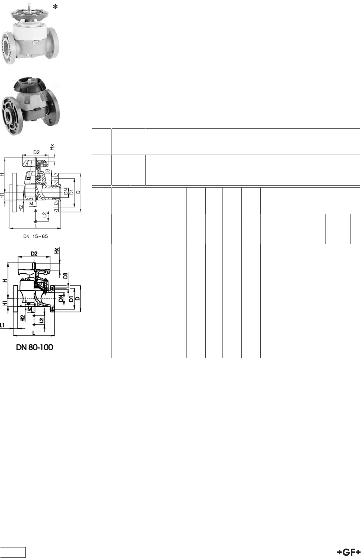
84
Diaphragm valve type 317 ABS
With flanges metric
Model:
•Overall length according to EN 558
•Flat sealing faces
•Otherdimensions available on request
•DN 80-150 with fixed flange
•Minimum temperature: - 30°C
Option:
•Handwheel lockable DN15-65 (basic version not lockable)
* DN80 and DN150 fixed flanges metric and Inch ANSI B16.5
d
[mm]
DN
[mm]
PN kv-value
(Δp=1 bar)
[l/min]
EPDM
Code
kg
75 65 10 992 169 317 423 5.000
*90 80 10 1700 169 317 024 8.350
110 100 10 2700 169 317 025 11.600
d
[mm]
D
[mm]
D1
[mm]
D2
[mm]
D3
[mm]
L
[mm]
L1
[mm]
L2
[mm]
H
[mm]
H1
[mm]
H2
[mm]
M AL Lift =
Hx
[mm]
75 185 145 152 18 290 70 201 46 15 M8 4 30
*90 200 160 270 18 310 35 120 265 57 23 M12 8 40
110 225 180 270 18 350 35 120 304 69 23 M12 8 50
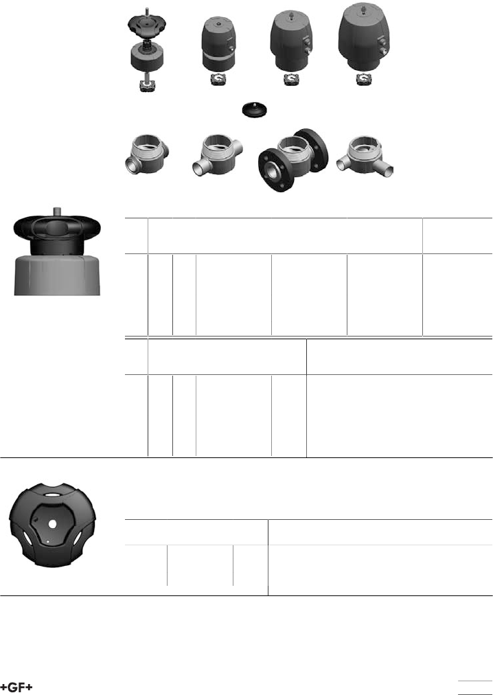
85
Spare parts diaphragm valves new genera-
tion
Spare parts for hand-operated valves
Type 514/515/517/519
Bonnet complete
d
[mm]
Inch DN
[mm]
Standard configu-
ration PN10
Code
For pressure tight
housing PN10
Code
Standard configu-
ration PN16
Code
20 1∕215 198 151 742 198 151 752 198 151 842
25 3∕420 198 151 743 198 151 753 198 151 843
32 1 25 198 151 744 198 151 754 198 151 844
40 1 1∕432 198 151 745 198 151 755 198 151 845
50 1 1∕240 198 151 746 198 151 756 198 151 846
63 2 50 198 151 747 198 151 757 198 151 847
d
[mm]
Inch DN
[mm]
For pressure tight
housing PN16
Code
kg
20 1∕215 198 151 852 0.137
25 3∕420 198 151 853 0.177
32 1 25 198 151 854 0.366
40 1 1∕432 198 151 855 0.390
50 1 1∕240 198 151 856 0.746
63 2 50 198 151 857 1.016
Hand wheel
Model:
•Without position indicator
DN
[mm]
Code kg
15 - 20 198 204 162 0.035
25 - 32 198 204 164 0.068
40 - 50 198 104 166 0.190
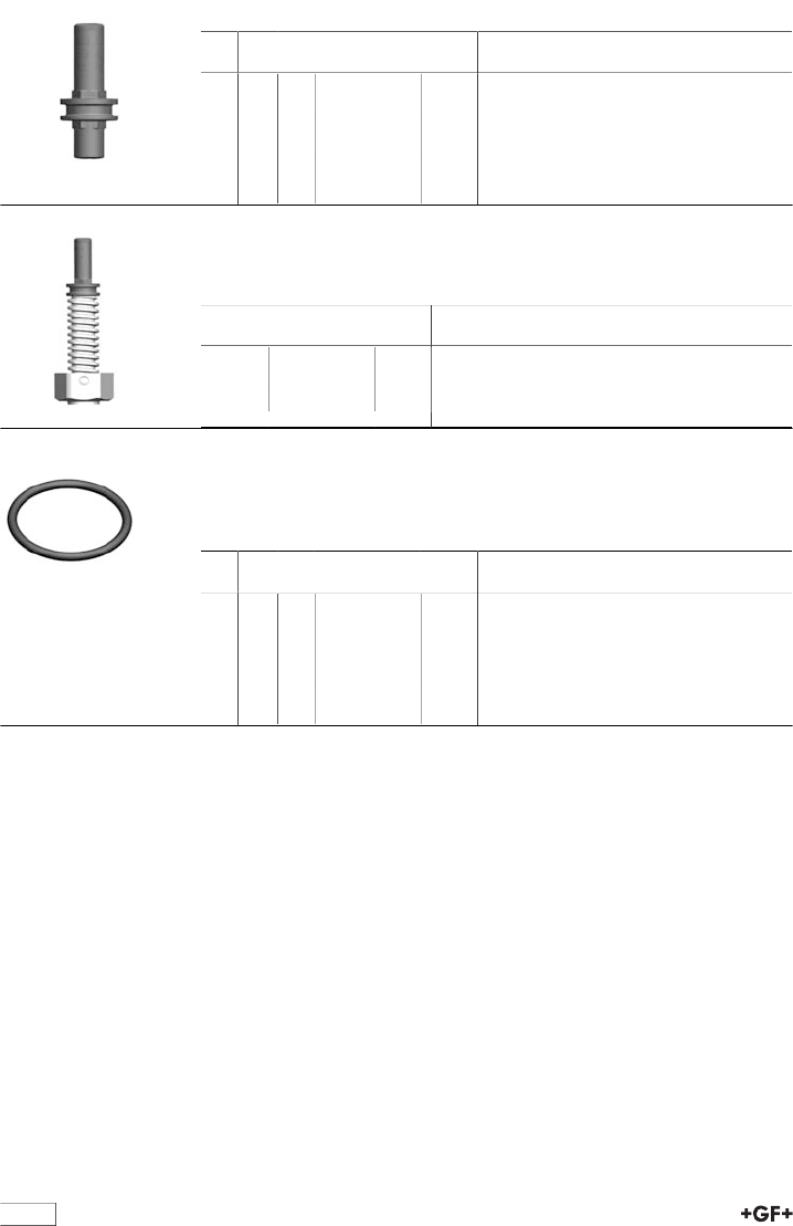
86
Position indicator
d
[mm]
Inch DN
[mm]
Code kg
20 1∕215 167 484 992 0.011
25 3∕420 167 484 993 0.011
32 1 25 167 484 994 0.013
40 1 1∕432 167 484 995 0.012
50 1 1∕240 167 484 996 0.014
63 2 50 167 484 997 0.015
Spindle assembly
Model:
•Incl. position indicator and compressor
DN-DN
[mm]
Code kg
15 - 20 198 204 327 0.049
25 - 32 198 204 328 0.135
40 - 50 198 204 329 0.251
Seal set
Model:
•For manual valve - pressure tight housing
•Incl. position indicator
d
[mm]
Inch DN
[mm]
EPDM
Code
kg
20 1∕215 198 000 892 0.004
25 3∕420 198 000 893 0.004
32 1 25 198 000 894 0.007
40 1 1∕432 198 000 895 0.006
50 1 1∕240 198 000 896 0.008
63 2 50 198 000 897 0.009
87
Spare parts for automatic valves
Diastar Six/Ten/Sixteen
Actuators
d
[mm]
Inch DN
[mm]
Diastar Six
Code
Diastar Ten
Code
Diastar Sixteen
FC
Code
Diastar Ten FO
Code
20 1∕215 198 151 762 198 151 772 198 151 782 198 151 792
25 3∕420 198 151 763 198 151 773 198 151 783 198 151 793
32 1 25 198 151 764 198 151 774 198 151 784 198 151 794
40 1 1∕432 198 151 765 198 151 775 198 151 785 198 151 795
50 1 1∕240 198 151 766 198 151 776 198 151 786 198 151 796
63 2 50 198 151 767 198 151 777 198 151 787 198 151 797
d
[mm]
Inch DN
[mm]
Diastar Ten DA
Code
kg
20 1∕215 198 151 802 0.427
25 3∕420 198 151 803 0.718
32 1 25 198 151 804 0.823
40 1 1∕432 198 151 805 1.269
50 1 1∕240 198 151 806 2.141
63 2 50 198 151 807 2.364
Indicator cap
Size Code kg
1-2 198 806 639 0.002
3-5 198 806 640 0.004
88
Compressor set
Model:
•Incl. diaphragm holder
d
[mm]
Inch DN
[mm]
Code kg
20 1/2 15 198 000 872 0.032
25 3/4 20 198 000 873 0.035
32 1 25 198 000 874 0.073
40 1 1/4 32 198 000 875 0.084
50 1 1/2 40 198 000 876 0.122
63 2 50 198 000 877 0.146
Seal set
Model:
•Spindle seal and piston seal
Size Diastar Six/Ten/
Sixteen
Code
Only for Diastar
Six DN40/DN50
Code
kg
Gr. 1 198 000 881 - 0.006
Gr. 2 198 000 882 - 0.008
Gr. 3 198 000 883 198 000 886 0.006
Gr. 4 198 000 884 - 0.010
Gr. 5 198 000 885 - 0.072
Spare parts diaphragm
For type 514/515/517/519
d
[mm]
Inch DN
[mm]
NBR
Code
EPDM
Code
FPM
Code
PTFE/EPDM
Code
20 1∕215 745 500 012 748 500 012 749 500 012 747 502 012
25 3∕420 745 500 013 748 500 013 749 500 013 747 502 013
32 1 25 745 500 014 748 500 014 749 500 014 747 502 014
40 1 1∕432 745 500 015 748 500 015 749 500 015 747 502 015
50 1 1∕240 745 500 016 748 500 016 749 500 016 747 502 016
63 2 50 745 500 017 748 500 017 749 500 017 747 502 017
d
[mm]
Inch DN
[mm]
PTFE/EPDM HP
Code
PTFE/FPM
Code
kg
20 1∕215 747 502 032 747 503 012 0.013
25 3∕420 747 502 033 747 503 013 0.021
32 1 25 747 502 034 747 503 014 0.031
40 1 1∕432 747 502 035 747 503 015 0.045
50 1 1∕240 747 502 036 747 503 016 0.069
63 2 50 747 502 037 747 503 017 0.118
89
Spare parts for valve body type 514
Valve body with true union
Model:
•Without connection parts
d
[mm]
Inch DN
[mm]
ABS
Code
kg
20 1∕215 169 481 322 0.086
25 3∕420 169 481 323 0.137
32 1 25 169 481 324 0.181
40 1 1∕432 169 481 325 0.295
50 1 1∕240 169 481 326 0.435
63 2 50 169 481 327 0.782
Union nut
d
[mm]
Inch DN
[mm]
ABS
Code
kg
20 1∕215 729 690 406 0.014
25 3∕420 729 690 407 0.018
32 1 25 729 690 408 0.024
40 1 1∕432 729 690 409 0.049
50 1 1∕240 729 690 410 0.070
63 2 50 729 690 411 0.101
O-ring
d
[mm]
Inch DN
[mm]
EPDM
Code
FPM
Code
kg
20 1∕215 748 410 006 749 410 006 0.002
25 3∕420 748 410 007 749 410 007 0.002
32 1 25 748 410 008 749 410 008 0.002
40 1 1∕432 748 410 009 749 410 009 0.006
50 1 1∕240 748 410 010 749 410 010 0.007
63 2 50 748 410 011 749 410 011 0.010
table continued next page
90
Spare parts for valve body type 515
Valve body with spigot ends
d
[mm]
Inch DN
[mm]
ABS solvent ce-
ment spigot
Code
kg
20 1∕215 169 481 862 0.089
25 3∕420 169 481 863 0.140
32 1 25 169 481 864 0.187
40 1 1∕432 169 481 865 0.287
50 1 1∕240 169 481 866 0.455
63 2 50 169 481 867 0.793
Spare parts for valve body type 517
Flange adaptor flat
d
[mm]
Inch DN
[mm]
ABS metric
Code
kg
20 1∕215 729 790 106 0.008
25 3∕420 729 790 107 0.012
32 1 25 729 790 108 0.020
40 1 1∕432 729 790 109 0.058
50 1 1∕240 729 790 110 0.058
63 2 50 729 790 111 0.074
Flange
d
[mm]
Inch DN
[mm]
PVC-U metric
Code
LVI PVC-U ASTM
Code
LVI
20 1∕215 721 700 006 721 702 206
25 3∕420 721 700 007 721 702 207
32 1 25 721 700 008 721 702 208
40 1 1∕432 721 700 009 721 702 209
50 1 1∕240 721 700 010 721 702 210
63 2 50 721 700 011 721 702 211
91
d
[mm]
Inch DN
[mm]
PP-V metric
Code
LVI PP-V ASTM
Code
LVI PP-ST metric
Code
LVI
20 1∕215 727 700 406 183 38 09 727 701 406 727 700 206
25 3∕420 727 700 407 183 38 10 727 701 407 727 700 207
32 1 25 727 700 408 183 38 11 727 701 408 727 700 208
40 1 1∕432 727 700 409 183 38 12 727 701 409 727 700 209
50 1 1∕240 727 700 410 183 38 13 727 701 410 727 700 210
63 2 50 727 700 411 183 38 14 727 701 411 727 700 211
d
[mm]
Inch DN
[mm]
PP-ST ASTM
Code
LVI kg
20 1∕215 727 701 206 0.210
25 3∕420 727 701 207 0.250
32 1 25 727 701 208 0.420
40 1 1∕432 727 701 209 0.670
50 1 1∕240 727 701 210 0.860
63 2 50 727 701 211 0.930
Flat gasket
d
[mm]
Inch DN
[mm]
EPDM
Code
kg
20 1∕215 748 400 006 0.003
25 3∕420 748 400 007 0.004
32 1 25 748 400 008 0.002
40 1 1∕432 748 400 009 0.003
50 1 1∕240 748 400 010 0.004
63 2 50 748 400 011 0.006
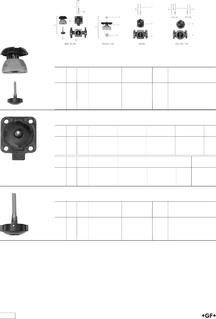
92
Spare parts diaphragm valves
Spare parts diaphragm valve type 317
Bonnet complete
Model:
•Without diaphragm (1, 3)
d
[mm]
Inch DN
[mm]
elastomer di-
aphragm
Code
PTFE diaphragm
Code
kg
75 2 1∕265 161 484 631 161 484 638 1.526
90 3 80 161 482 514 161 482 516 3.967
110 4 100 161 482 515 161 482 517 5.700
Diaphragm (2)
d
[mm]
Inch DN
[mm]
NBR
Code
EPDM
Code
FPM
Code
PTFE/EPDM
Code
75 2 1∕265 161 480 231 161 481 028 161 481 098 161 480 240
90 3 80 161 480 232 161 481 029 161 481 099 161 480 241
110 4 100 161 480 233 161 481 030 161 481 100 161 480 242
d
[mm]
Inch DN
[mm]
PTFE/FPM
Code
PTFE/EPDM HP
Code
CSM
Code
kg
75 2 1∕265 161 481 932 161 484 458 161 480 237 0.230
90 3 80 - 161 484 459 161 480 238 0.300
110 4 100 - 161 484 460 161 480 239 0.450
Pressure spindel (3)
d
[mm]
Inch DN
[mm]
elastomer di-
aphragm
Code
PTFE diaphragm
Code
kg
75 2 1∕265 161 484 694 161 484 702 0.134
90 3 80 161 483 008 161 483 020 0.335
110 4 100 161 483 009 161 483 021 0.495
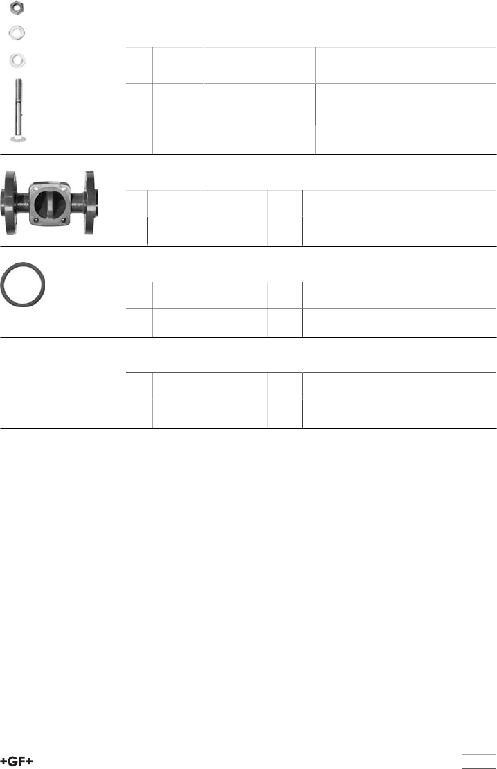
93
Fastening set (4)
Model:
•* with support plate
d
[mm]
Inch DN
[mm]
for PVC-U PVC-C
ABS
Code
kg
75 2 1∕265 161 483 032 0.679
90 3 80 161 483 033 0.845
110 4 100 161 483 034 1.440
Valve body with backing/fixed flange (5)
Inch d
[mm]
DN
[mm]
ABS ANSI
Code
kg
3 90 80 169 480 282 3.210
4 110 100 169 480 283 4.900
O-ring seal (6)
d
[mm]
Inch DN
[mm]
NBR
Code
kg
90 3 80 745 410 107 0.007
110 4 100 745 410 107 0.007
Indicator cap (7)
d
[mm]
Inch DN
[mm]
PVC-U SAN
Code
kg
90 3 80 161 481 759 0.032
110 4 100 161 481 760 0.035
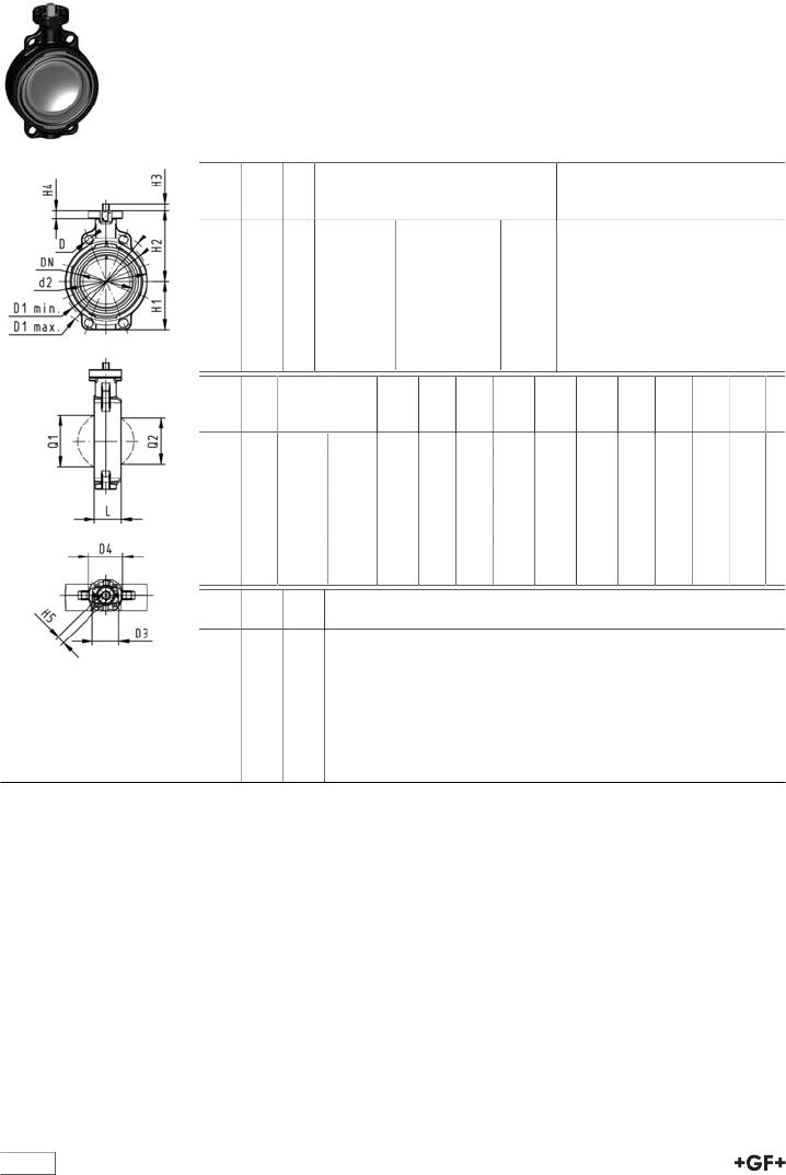
94
Butterfly valves
Butterfly valve type 567 ABS
Bare shaft
Model:
•Connecting dimension: ISO 7005 PN 10, EN 1092 PN 10, DIN 2501 PN 10,
ANSI/ASME B 16.5 Class 150, BS 1560: 1989, BS 4504, JIS B 2220
•Overall lengthaccording to EN 558, ISO 5752
•Interface F07 according to DIN/ISO 5211
d
[mm]
DN
[mm]
PN kv-value
(Δp=1 bar)
[l/min]
EPDM
Code
kg
63 50 10 1470 169 567 802 0.763
75 65 10 2200 169 567 803 0.859
90 80 10 3000 169 567 804 0.999
110 100 10 6500 169 567 805 1.535
140 125 10 11500 169 567 806 2.018
160 150 10 16600 169 567 807 2.858
225 200 10 39600 169 567 808 4.129
d
[mm]
D
[mm]
D1
min.
[mm]
D1
max.
[mm]
d2
[mm]
D3
[mm]
D4
[mm]
H
[mm]
H1
[mm]
H2
[mm]
H3
[mm]
H4
[mm]
H5
[mm]
L
[mm]
63 19 120.0 125.0 104 70 90 222 77 134 27 23 11 45
75 19 139.7 145.0 115 70 90 235 83 140 27 23 11 46
90 19 150.0 160.0 131 70 90 247 89 146 27 23 11 49
110 19 175.0 190.5 161 70 90 287 104 167 16 23 14 56
140 23 210.0 215.9 187 70 90 313 117 181 16 23 14 64
160 24 241.3 241.3 215 70 90 335 130 189 19 23 17 72
225 23 290.0 295.0 267 70 90 387 158 210 19 23 17 73
d
[mm]
Q1
[mm]
Q2
[mm]
63 40
75 54 35
90 67 50
110 88 74
140 113 97
160 139 123
225 178 169
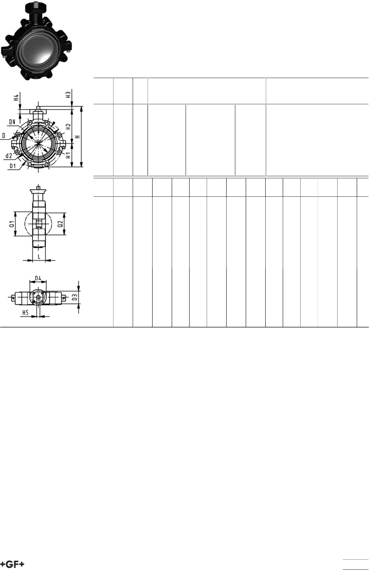
95
Lugstyle butterfly valve type 568 ABS
Bare shaft
Model:
•Outer body in GGG-40.3 epoxy-coated
•Connecting dimension: ISO 7005 PN10, EN 1092 PN10, DIN 2501 PN10
•Overall lengthaccording to EN 558, ISO 5752
•Interface F07 according to DIN/ISO 5211
d
[mm]
DN
[mm]
PN kv-value
(Δp=1 bar)
[l/min]
EPDM
Code
kg
63 50 10 1470 169 568 802 2.853
75 65 10 2200 169 568 803 3.200
90 80 10 3000 169 568 804 4.217
110 100 10 6500 169 568 805 5.633
140 125 10 11500 169 568 806 7.502
160 150 10 16600 169 568 807 9.341
225 200 10 39600 169 568 808 14.105
d
[mm]
d2
[mm]
D D1
[mm]
D3
[mm]
D4
[mm]
H
[mm]
H1
[mm]
H2
[mm]
H3
[mm]
H4
[mm]
L
[mm]
Q1
[mm]
Q2
[mm]
63 150 M16 125 70 90 222 77 134 27 23 45 40
75 170 M16 145 70 90 235 83 140 27 23 46 54 35
90 184 M16 160 70 90 247 89 146 27 23 49 67 50
110 216 M16 180 70 90 287 104 167 16 23 56 88 74
140 246 M16 210 70 90 313 117 181 16 23 64 113 97
160 273 M20 240 70 90 335 130 189 19 23 72 139 123
225 334 M20 295 70 90 387 158 210 19 23 73 178 169
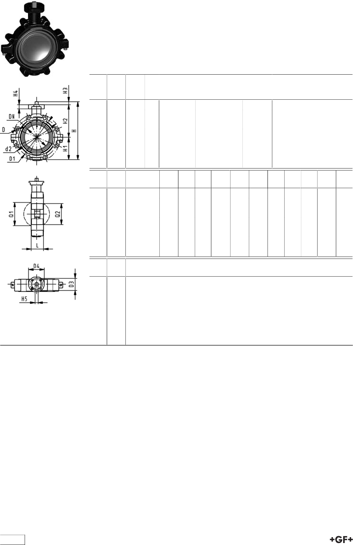
96
Lugstyle butterfly valve type 568 ABS
Bare shaft
Model:
•Outer body in GGG-40.3 epoxy-coated
•Connecting dimension ANSI/ASME B 16.5 Class 150
•Overall lengthaccording to EN 558, ISO 5752
•Interface F07 according to DIN/ISO 5211
Inch d
[mm]
DN
[mm]
PN kv-value
(Δp=1 bar)
[l/min]
EPDM
Code
kg
2 63 50 10 1470 169 568 902 2.853
2 1∕275 65 10 2200 169 568 903 3.200
3 90 80 10 3000 169 568 904 3.588
4 110 100 10 6500 169 568 905 5.633
5 140 125 10 11500 169 568 906 7.502
6 160 150 10 16600 169 568 907 9.341
8 225 200 10 39600 169 568 908 14.105
Inch d2
[mm]
D D1
[mm]
D3
[mm]
D4
[mm]
H
[mm]
H1
[mm]
H2
[mm]
H3
[mm]
H4
[mm]
L
[mm]
Q1
[mm]
2 150 UNC 5/8 121 70 90 222 77 134 27 23 45 40
2 1∕2170 UNC 5/8 138 70 90 235 83 140 27 23 46 54
3 177 UNC 5/8 152 70 90 247 89 146 27 23 49 67
4 216 UNC 5/8 191 70 90 287 104 167 16 23 56 88
5 246 UNC 3/4 216 70 90 313 117 181 16 23 64 113
6 273 UNC 3/4 241 70 90 335 130 189 19 23 72 139
8 334 UNC 3/4 298 70 90 387 158 210 19 23 73 178
Inch Q2
[mm]
2
2 1∕235
3 50
4 74
5 97
6 123
8 169
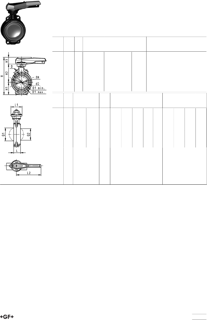
97
Butterfly valve type 567 ABS
Hand lever with ratchet settings
Model:
•Connecting dimension: ISO 7005 PN 10, EN 1092 PN 10, DIN 2501 PN 10,
ANSI/ASME B 16.5 Class 150, BS 1560: 1989, BS 4504, JIS B 2220
•Overall lengthaccording to EN 558, ISO 5752
d
[mm]
DN
[mm]
PN kv-value
(Δp=1 bar)
[l/min]
EPDM
Code
kg
63 50 10 1470 169 567 002 1.400
75 65 10 2200 169 567 003 1.150
90 80 10 3000 169 567 004 1.221
110 100 10 6500 169 567 005 1.805
140 125 10 11500 169 567 006 2.536
160 150 10 16600 169 567 007 3.128
225 200 10 39600 169 567 008 4.936
d
[mm]
D
[mm]
D1
min.
[mm]
D1
max.
[mm]
d2
[mm]
H
[mm]
H1
[mm]
H2
[mm]
H3
[mm]
L
[mm]
L1
[mm]
L2
[mm]
Q1
[mm]
Q2
[mm]
63 19 120.0 125.0 104 264 77 134 54 45 106 205 40
75 19 139.7 145.0 115 277 83 140 54 46 106 205 54 35
90 19 150.0 160.0 131 289 89 146 54 49 106 205 67 50
110 19 175.0 190.5 161 325 104 167 55 56 106 255 88 74
140 23 210.0 215.9 187 352 117 181 55 64 106 255 113 97
160 24 241.3 241.3 215 373 130 189 55 72 106 255 139 123
225 23 290.0 295.0 267 435 158 210 67 73 140 408 178 169
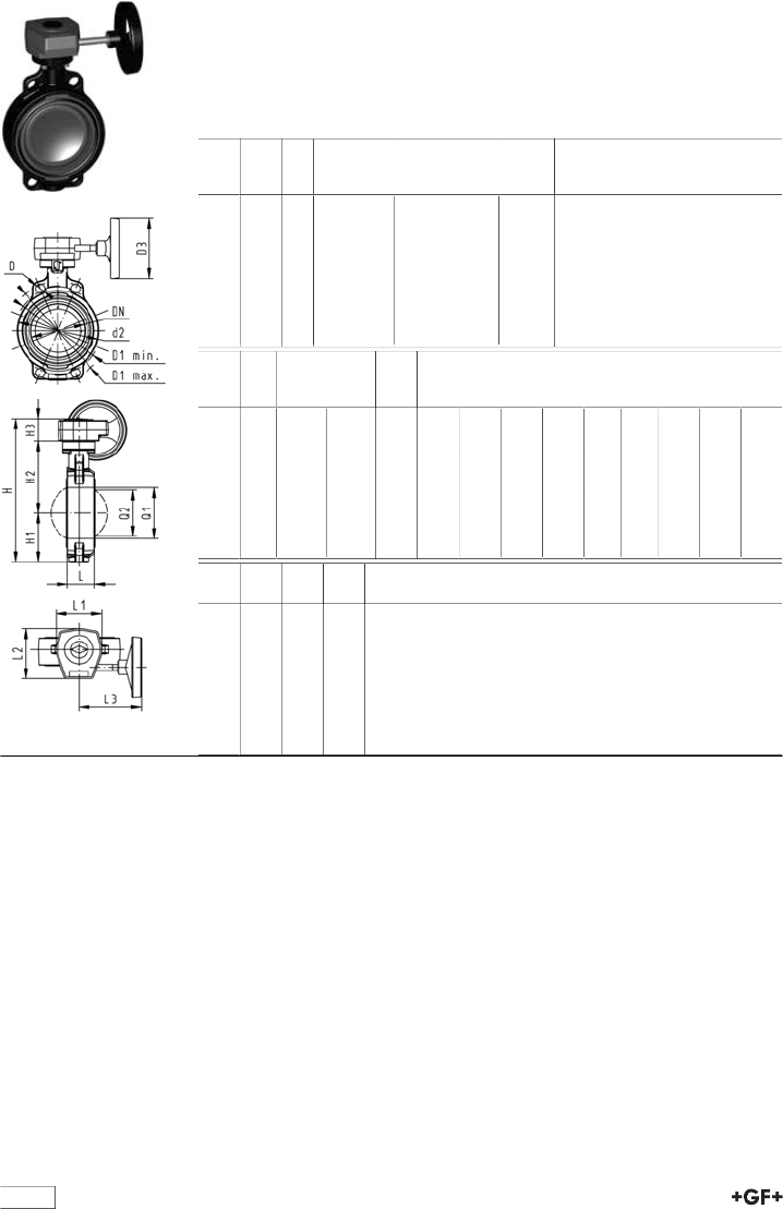
98
Butterfly valve type 567 ABS
Reduction gear with handwheel
Model:
•Connecting dimension: ISO 7005 PN 10, EN 1092 PN 10, DIN 2501 PN 10,
ANSI/ASME B 16.5 Class 150, BS 1560: 1989, BS 4504, JIS B 2220
•Overall lengthaccording to EN 558, ISO 5752
d
[mm]
DN
[mm]
PN kv-value
(Δp=1 bar)
[l/min]
EPDM
Code
kg
63 50 10 1470 169 567 022 3.078
75 65 10 2200 169 567 023 3.201
90 80 10 3000 169 567 024 3.259
110 100 10 6500 169 567 025 3.795
140 125 10 11500 169 567 026 4.526
160 150 10 16600 169 567 027 5.118
225 200 10 39600 169 567 028 6.389
d
[mm]
D
[mm]
D1
min.
[mm]
D1
max.
[mm]
d2
[mm]
D3
[mm]
H
[mm]
H1
[mm]
H2
[mm]
H3
[mm]
L
[mm]
L1
[mm]
L2
[mm]
63 19 120.0 125.0 104 150 278 77 134 50 45 110 120
75 19 139.7 145.0 115 150 291 83 140 50 46 110 120
90 19 150.0 160.0 131 150 303 89 146 50 49 110 120
110 19 175.0 190.5 160 150 339 104 167 50 56 110 120
140 23 210.0 215.9 187 150 365 117 181 50 64 110 120
160 24 241.3 241.3 215 150 387 130 189 50 72 110 120
225 23 290.0 295.0 267 150 436 158 210 50 73 110 120
d
[mm]
L3
[mm]
Q1
[mm]
Q2
[mm]
63 155 40
75 155 54 35
90 155 67 50
110 155 88 74
140 155 113 97
160 155 139 123
225 155 178 169
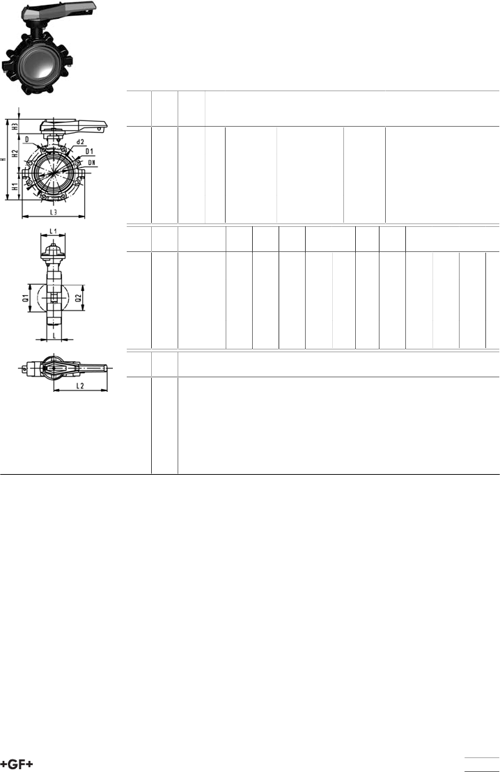
99
Lugstyle butterfly valve type 568 ABS
Hand lever with ratchet settings
Model:
•Outer body in GGG-40.3 epoxy-coated
•Connecting dimension ANSI/ASME B 16.5 Class 150
•Overall lengthaccording to EN 558, ISO 5752
Inch d
[mm]
DN
[mm]
PN kv-value
(Δp=1 bar)
[l/min]
EPDM
Code
kg
2 63 50 10 1470 169 568 102 3.075
2 1∕275 65 10 2200 169 568 103 3.422
3 90 80 10 3000 169 568 104 3.810
4 110 100 10 6500 169 568 105 5.903
5 140 125 10 11500 169 568 106 7.772
6 160 150 10 16600 169 568 107 9.611
8 225 200 10 39600 169 568 108 14.912
Inch d2
[mm]
D D1
[mm]
H
[mm]
H1
[mm]
H2
[mm]
H3
[mm]
L
[mm]
L1
[mm]
L2
[mm]
L3
[mm]
Q1
[mm]
2 150 UNC 5/8 121 265 77 134 54 45 106 205 150 40
2 1∕2170 UNC 5/8 138 277 83 140 54 46 106 205 160 54
3 177 UNC 5/8 152 289 89 146 54 49 106 205 175 67
4 216 UNC 5/8 191 326 104 167 55 56 106 255 244 88
5 246 UNC 3/4 216 353 117 181 55 64 106 255 272 113
6 273 UNC 3/4 241 374 130 189 55 72 106 255 297 139
8 334 UNC 3/4 298 435 158 210 67 73 140 408 360 178
Inch Q2
[mm]
2
2 1∕235
3 50
4 74
5 97
6 123
8 169
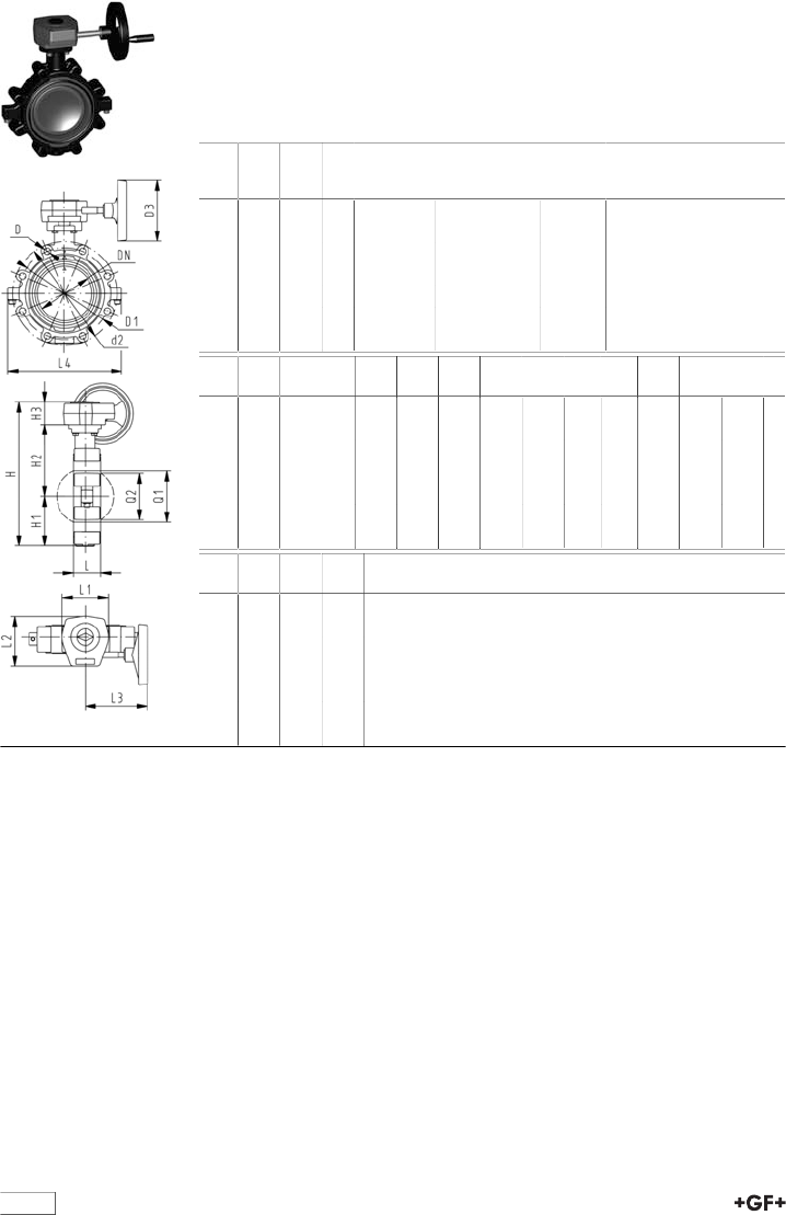
100
Lugstyle butterfly valve type 568 ABS
Reduction gear with handwheel
Model:
•Outer body in GGG-40.3 epoxy-coated
•Connecting dimension ANSI/ASME B 16.5 Class 150
•Overall lengthaccording to EN 558, ISO 5752
Inch d
[mm]
DN
[mm]
PN kv-value
(Δp=1 bar)
[l/min]
EPDM
Code
kg
2 63 50 10 1470 169 568 122 5.113
2 1∕275 65 10 2200 169 568 123 5.460
3 90 80 10 3000 169 568 124 5.848
4 110 100 10 6500 169 568 125 7.893
5 140 125 10 11500 169 568 126 9.762
6 160 150 10 16600 169 568 127 11.601
8 225 200 10 39600 169 568 128 16.365
Inch d2
[mm]
D D1
[mm]
D3
[mm]
H
[mm]
H1
[mm]
H2
[mm]
H3
[mm]
L
[mm]
L1
[mm]
L2
[mm]
L3
[mm]
2 150 UNC 5/8 121 150 279 77 134 50 45 110 120 155
2 1∕2170 UNC 5/8 138 150 291 83 140 50 46 110 120 155
3 177 UNC 5/8 152 150 303 89 146 50 49 110 120 155
4 216 UNC 5/8 191 150 339 104 167 50 56 110 120 155
5 246 UNC 3/4 216 150 366 117 181 50 64 110 120 155
6 273 UNC 3/4 241 150 387 130 189 50 72 110 120 155
8 334 UNC 3/4 298 150 436 158 210 50 73 110 120 155
Inch L4
[mm]
Q1
[mm]
Q2
[mm]
2 150 40
2 1∕2160 54 35
3 175 67 50
4 244 88 74
5 272 113 97
6 297 139 123
8 360 178 169
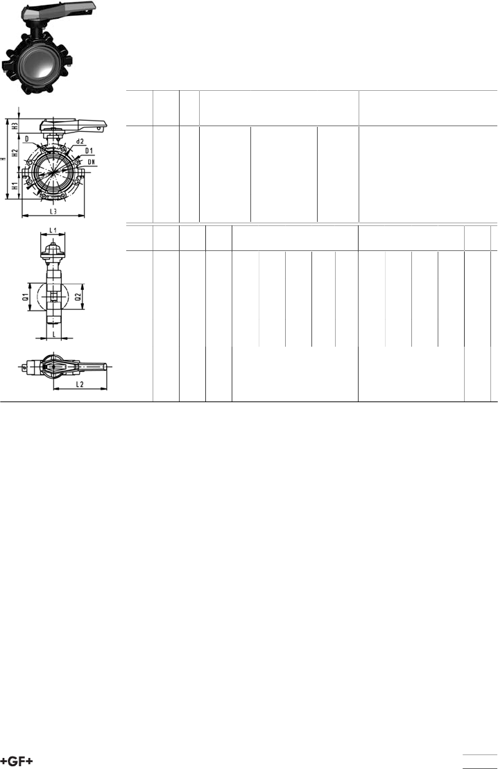
101
Lugstyle butterfly valve type 568 ABS
Hand lever with ratchet settings
Model:
•Outer body in GGG-40.3 epoxy-coated
•Connecting dimension: ISO 7005 PN10, EN 1092 PN10, DIN 2501 PN10
•Overall lengthaccording to EN 558, ISO 5752
d
[mm]
DN
[mm]
PN kv-value
(Δp=1 bar)
[l/min]
EPDM
Code
kg
63 50 10 1470 169 568 002 3.075
75 65 10 2200 169 568 003 3.422
90 80 10 3000 169 568 004 4.439
110 100 10 6500 169 568 005 5.903
140 125 10 11500 169 568 006 7.772
160 150 10 16600 169 568 007 9.611
225 200 10 39600 169 568 008 14.912
d
[mm]
d2
[mm]
D D1
[mm]
H
[mm]
H1
[mm]
H2
[mm]
H3
[mm]
L
[mm]
L1
[mm]
L2
[mm]
L3
[mm]
Q1
[mm]
Q2
[mm]
63 150 M16 125 265 77 134 54 45 106 205 150 40
75 170 M16 145 277 83 140 54 46 106 205 160 54 35
90 184 M16 160 289 89 146 54 49 106 205 205 67 50
110 216 M16 180 326 104 167 55 56 106 255 244 88 74
140 246 M16 210 353 117 181 55 64 106 255 272 113 97
160 273 M20 240 374 130 189 55 72 106 255 297 139 123
225 334 M20 295 435 158 210 67 73 140 408 360 178 169
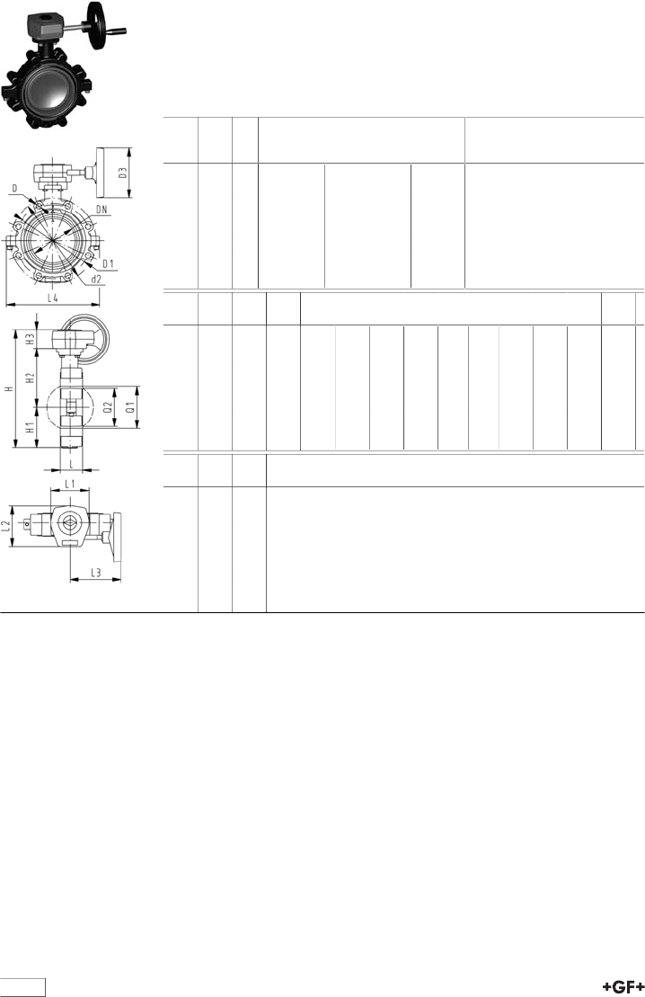
102
Lugstyle butterfly valve type 568 ABS
Reduction gear with handwheel
Model:
•Outer body in GGG-40.3 epoxy-coated
•Connecting dimension: ISO 7005 PN10, EN 1092 PN10, DIN 2501 PN10
•Overall lengthaccording to EN 558, ISO 5752
d
[mm]
DN
[mm]
PN kv-value
(Δp=1 bar)
[l/min]
EPDM
Code
kg
63 50 10 1470 169 568 022 5.113
75 65 10 2200 169 568 023 5.460
90 80 10 3000 169 568 024 6.477
110 100 10 6500 169 568 025 7.893
140 125 10 11500 169 568 026 9.762
160 150 10 16600 169 568 027 11.601
225 200 10 39600 169 568 028 16.365
d
[mm]
d2
[mm]
D D1
[mm]
D3
[mm]
H
[mm]
H1
[mm]
H2
[mm]
H3
[mm]
L
[mm]
L1
[mm]
L2
[mm]
L3
[mm]
L4
[mm]
63 150 M16 125 150 279 77 134 50 45 110 120 155 150
75 170 M16 145 150 291 83 140 50 46 110 120 155 160
90 184 M16 160 150 303 89 146 50 49 110 120 155 205
110 216 M16 180 150 339 104 167 50 56 110 120 155 244
140 246 M16 210 150 366 117 181 50 64 110 120 155 272
160 273 M20 240 150 387 130 189 50 72 110 120 155 297
225 334 M20 295 150 436 158 210 50 73 110 120 155 360
d
[mm]
Q1
[mm]
Q2
[mm]
63 40
75 54 35
90 67 50
110 88 74
140 113 97
160 139 123
225 178 169
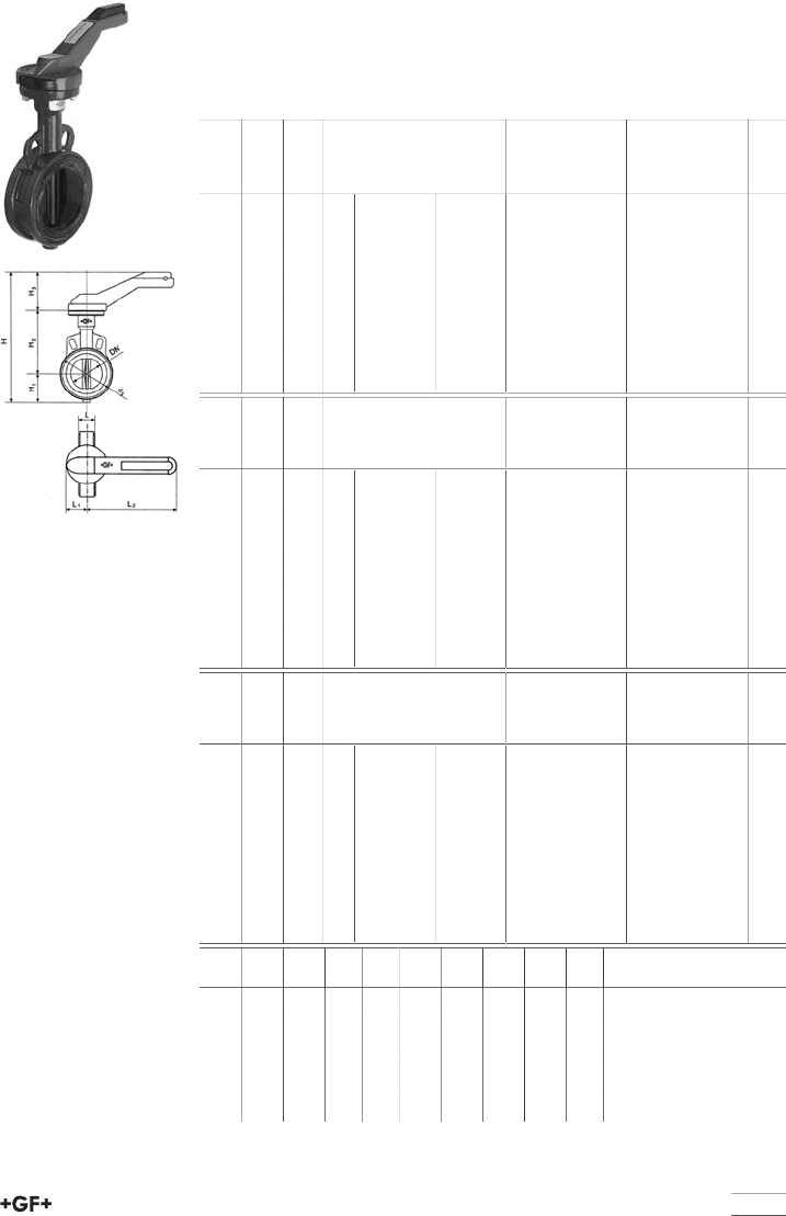
table continued next page
103
Metal - butterfly valve type 037M
With hand lever
Model:
•Housing: Aluminium ASTM S 12A, Rilsan® coated
•Seatliner available in EPDM and FPM
d
[mm]
DN
[mm]
Inch PN kv-value
(Δp=1 bar)
[l/min]
Cv value
(Δp=1 psi)
[gal (US) /
min]
Disc: ductile iron/
Rilsan® coated
EPDM
Code
Disc: ductile iron/
Rilsan® coated
FPM
Code
63 50 2 10 3140 220 199 037 000 199 037 013
75 65 2 1∕210 4570 320 199 037 001 199 037 014
90 80 3 10 7140 500 199 037 002 199 037 015
110 100 4 10 11710 800 199 037 003 199 037 016
140 125 5 10 18570 1300 199 037 004 199 037 017
160 150 6 10 27130 1900 199 037 005 199 037 018
225 200 8 10 47130 3330 199 037 006 199 037 019
280 250 10 10 77110 5400 199 037 007 199 037 020
315 300 12 10 114240 8000 199 037 008 199 037 021
d
[mm]
DN
[mm]
Inch PN kv-value
(Δp=1 bar)
[l/min]
Cv value
(Δp=1 psi)
[gal (US) /
min]
Disc: stainless
steel EPDM
Code
Disc: stainless
steel FPM
Code
63 50 2 10 3140 220 199 037 200 199 037 213
75 65 2 1∕210 4570 320 199 037 201 199 037 214
90 80 3 10 7140 500 199 037 202 199 037 215
110 100 4 10 11710 800 199 037 203 199 037 216
140 125 5 10 18570 1300 199 037 204 199 037 217
160 150 6 10 27130 1900 199 037 205 199 037 218
225 200 8 10 47130 3330 199 037 206 199 037 219
280 250 10 10 77110 5400 199 037 207 199 037 220
315 300 12 10 114240 8000 199 037 208 199 037 221
d
[mm]
DN
[mm]
Inch PN kv-value
(Δp=1 bar)
[l/min]
Cv value
(Δp=1 psi)
[gal (US) /
min]
Disc: Alu-bronze
EPDM
Code
Disc: Alu-bronze
FPM
Code
63 50 2 10 3140 220 199 037 400 199 037 413
75 65 2 1∕210 4570 320 199 037 401 199 037 414
90 80 3 10 7140 500 199 037 402 199 037 415
110 100 4 10 11710 800 199 037 403 199 037 416
140 125 5 10 18570 1300 199 037 404 199 037 417
160 150 6 10 27130 1900 199 037 405 199 037 418
225 200 8 10 47130 3330 199 037 406 199 037 419
280 250 10 10 77110 5400 199 037 407 199 037 420
315 300 12 10 114240 8000 199 037 408 199 037 421
d
[mm]
DN
[mm]
d3
[mm]
L
[mm]
L1
[mm]
L2
[mm]
H
[mm]
H1
[mm]
H2
[mm]
H3
[mm]
63 50 95 43 45 220 290 53 140 95
75 65 114 46 45 220 312 63 152 95
90 80 131 46 45 220 327 71 159 95
110 100 152 52 45 220 360 87 178 95
140 125 182 56 45 320 388 102 191 95
160 150 209 56 45 320 416 118 203 95
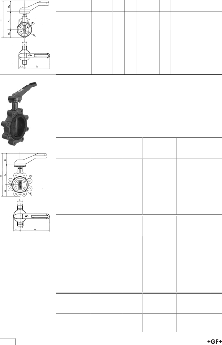
table continued next page
104
d
[mm]
DN
[mm]
d3
[mm]
L
[mm]
L1
[mm]
L2
[mm]
H
[mm]
H1
[mm]
H2
[mm]
H3
[mm]
225 200 262 60 45 320 489 149 245 95
280 250 331 68 63 560 525 200 275 50
315 300 380 78 63 560 592 227 315 50
Metal - butterfly valve type 038M
With hand lever
Model:
•Seatliner available in EPDM and FPM
•Housing: ductile iron GGG-40/ASTM A536, Rilsan® coated
•Available in ANSI standard upon request
•In case this valve is used at the end of the line, the following pressures must
not be exceeded: DN50 to DN150 5,6bar and >DN200 3,5bar
d
[mm]
DN
[mm]
Inch PN kv-value
(Δp=1 bar)
[l/min]
Cv value
(Δp=1 psi)
[gal (US) /
min]
Disc: ductile iron/
Rilsan® coated
EPDM
Code
Disc: ductile iron/
Rilsan® coated
FPM
Code
63 50 2 10 3140 220 199 038 000 199 038 013
75 65 2 1∕210 4570 320 199 038 001 199 038 014
90 80 3 10 7140 500 199 038 002 199 038 015
110 100 4 10 11710 820 199 038 003 199 038 016
140 125 5 10 18570 1300 199 038 004 199 038 017
160 150 6 10 27130 1900 199 038 005 199 038 018
225 200 8 10 47130 3330 199 038 006 199 038 019
280 250 10 10 77110 5400 199 038 007 199 038 020
315 300 12 10 114240 8000 199 038 008 199 038 021
d
[mm]
DN
[mm]
Inch PN kv-value
(Δp=1 bar)
[l/min]
Cv value
(Δp=1 psi)
[gal (US) /
min]
Disc: stainless
steel EPDM
Code
Disc: stainless
steel FPM
Code
63 50 2 10 3140 220 199 038 200 199 038 213
75 65 2 1∕210 4570 320 199 038 201 199 038 214
90 80 3 10 7140 500 199 038 202 199 038 215
110 100 4 10 11710 820 199 038 203 199 038 216
140 125 5 10 18570 1300 199 038 204 199 038 217
160 150 6 10 27130 1900 199 038 205 199 038 218
225 200 8 10 47130 3330 199 038 206 199 038 219
280 250 10 10 77110 5400 199 038 207 199 038 220
315 300 12 10 114240 8000 199 038 208 199 038 221
d
[mm]
DN
[mm]
Inch PN kv-value
(Δp=1 bar)
[l/min]
Cv value
(Δp=1 psi)
[gal (US) /
min]
Disc: Alu-bronze
EPDM
Code
63 50 2 10 3140 220 199 038 400
75 65 2 1∕210 4570 320 199 038 401
90 80 3 10 7140 500 199 038 402
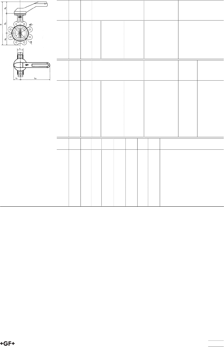
105
d
[mm]
DN
[mm]
Inch PN kv-value
(Δp=1 bar)
[l/min]
Cv value
(Δp=1 psi)
[gal (US) /
min]
Disc: Alu-bronze
EPDM
Code
110 100 4 10 11710 820 199 038 403
140 125 5 10 18570 1300 199 038 404
160 150 6 10 27130 1900 199 038 405
225 200 8 10 47130 3330 199 038 406
280 250 10 10 77110 5400 199 038 407
315 300 12 10 114240 8000 199 038 408
d
[mm]
DN
[mm]
Inch PN kv-value
(Δp=1 bar)
[l/min]
Cv value
(Δp=1 psi)
[gal (US) /
min]
Disc: Alu-bronze
FPM
Code
kg
63 50 2 10 3140 220 199 038 413 3.800
75 65 2 1∕210 4570 320 199 038 414 4.900
90 80 3 10 7140 500 199 038 415 5.400
110 100 4 10 11710 820 199 038 416 9.100
140 125 5 10 18570 1300 199 038 417 11.000
160 150 6 10 27130 1900 199 038 418 12.800
225 200 8 10 47130 3330 199 038 419 19.300
280 250 10 10 77110 5400 199 038 420 35.000
315 300 12 10 114240 8000 199 038 421 49.000
d
[mm]
d3
[mm]
L
[mm]
L1
[mm]
L2
[mm]
H
[mm]
H1
[mm]
H2
[mm]
H3
[mm]
63 95 43 45 220 298 63 95 152
75 114 46 45 220 320 73 95 178
90 131 46 45 220 335 81 95 200
110 152 52 45 220 370 97 95 229
140 182 56 45 320 398 112 95 254
160 209 56 45 320 420 122 95 280
225 262 60 45 320 489 149 95 343
280 331 68 63 560 573 203 95 406
315 380 78 63 560 651 241 95 483
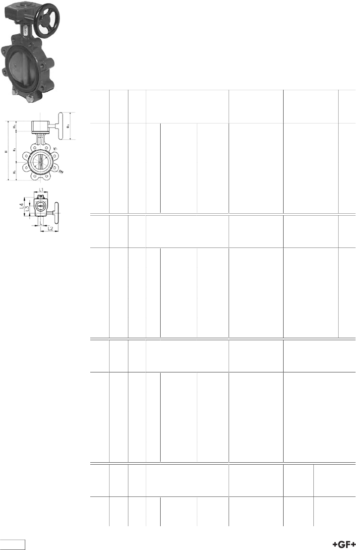
table continued next page
106
Metal - butterfly valve type 038G
Reduction gear with handwheel
Model:
•Seatliner available in EPDM and FPM
•Housing: ductile iron GGG-40/ASTM A536, Rilsan® coated
•Available in ANSI standard upon request
•In case this valve is used at the end of the line, the following pressures must
not be exceeded: DN50 to DN150 5,6bar and >DN200 3,5bar
d
[mm]
DN
[mm]
Inch PN kv-value
(Δp=1 bar)
[l/min]
Cv value
(Δp=1 psi)
[gal (US) /
min]
Disc: ductile iron/
Rilsan® coated
EPDM
Code
Disc: ductile iron/
Rilsan® coated
FPM
Code
63 50 2 10 3140 220 199 038 026 199 038 039
75 65 2 1∕210 4570 320 199 038 027 199 038 040
90 80 3 10 7140 500 199 038 028 199 038 041
110 100 4 10 11710 820 199 038 029 199 038 042
140 125 5 10 18570 1300 199 038 030 199 038 043
160 150 6 10 27130 1900 199 038 031 199 038 044
225 200 8 10 47130 3330 199 038 032 199 038 045
280 250 10 10 77110 5400 199 038 033 199 038 046
315 300 12 10 114240 8000 199 038 034 199 038 047
d
[mm]
DN
[mm]
Inch PN kv-value
(Δp=1 bar)
[l/min]
Cv value
(Δp=1 psi)
[gal (US) /
min]
Disc: stainless
steel EPDM
Code
Disc: stainless
steel FPM
Code
63 50 2 10 3140 220 199 038 226 199 038 239
75 65 2 1∕210 4570 320 199 038 227 199 038 240
90 80 3 10 7140 500 199 038 228 199 038 241
110 100 4 10 11710 820 199 038 229 199 038 242
140 125 5 10 18570 1300 199 038 230 199 038 243
160 150 6 10 27130 1900 199 038 231 199 038 244
225 200 8 10 47130 3330 199 038 232 199 038 245
280 250 10 10 77110 5400 199 038 233 199 038 246
315 300 12 10 114240 8000 199 038 234 199 038 247
d
[mm]
DN
[mm]
Inch PN kv-value
(Δp=1 bar)
[l/min]
Cv value
(Δp=1 psi)
[gal (US) /
min]
Disc: Alu-bronze
EPDM
Code
63 50 2 10 3140 220 199 038 426
75 65 2 1∕210 4570 320 199 038 427
90 80 3 10 7140 500 199 038 428
110 100 4 10 11710 820 199 038 429
140 125 5 10 18570 1300 199 038 430
160 150 6 10 27130 1900 199 038 431
225 200 8 10 47130 3330 199 038 432
280 250 10 10 77110 5400 199 038 433
315 300 12 10 114240 8000 199 038 434
d
[mm]
DN
[mm]
Inch PN kv-value
(Δp=1 bar)
[l/min]
Cv value
(Δp=1 psi)
[gal (US) /
min]
Disc: Alu-bronze
FPM
Code
kg
63 50 2 10 3140 220 199 038 439 5.300
75 65 2 1∕210 4570 320 199 038 440 6.400
90 80 3 10 7140 500 199 038 441 6.900
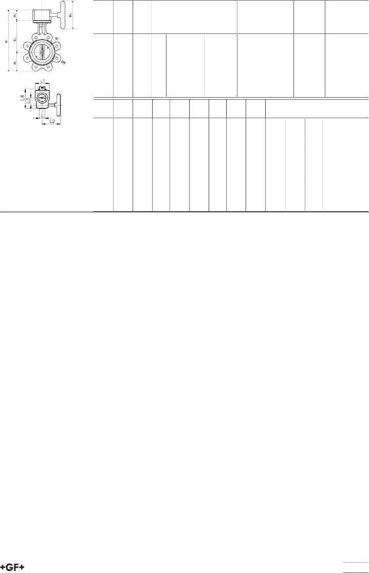
107
d
[mm]
DN
[mm]
Inch PN kv-value
(Δp=1 bar)
[l/min]
Cv value
(Δp=1 psi)
[gal (US) /
min]
Disc: Alu-bronze
FPM
Code
kg
110 100 4 10 11710 820 199 038 442 10.400
140 125 5 10 18570 1300 199 038 443 12.300
160 150 6 10 27130 1900 199 038 444 14.100
225 200 8 10 47130 3330 199 038 445 20.400
280 250 10 10 77110 5400 199 038 446 37.000
315 300 12 10 114240 8000 199 038 447 51.000
d
[mm]
d3
[mm]
D5
[mm]
L
[mm]
L1
[mm]
L2
[mm]
L3
[mm]
L4
[mm]
H
[mm]
H1
[mm]
H2
[mm]
H3
[mm]
63 95 125 43 84 152 38 107 261 63 140 58
75 114 125 46 84 152 38 107 283 73 152 58
90 131 125 46 84 152 38 107 298 81 159 58
110 152 125 52 84 152 38 107 333 97 178 58
140 182 125 56 84 152 38 107 361 112 191 58
160 209 125 56 84 152 38 107 383 122 203 58
225 262 125 60 84 152 38 107 452 149 245 58
280 331 250 68 106 152 52 141 545 203 275 67
315 380 250 78 106 152 52 141 623 241 315 67
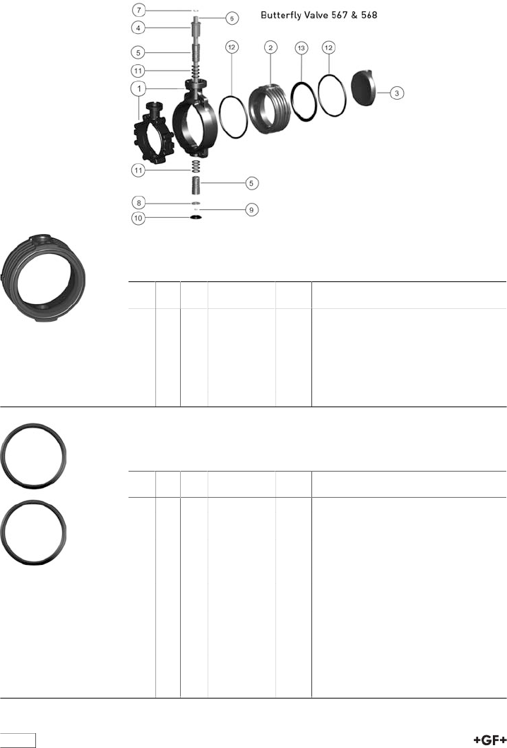
108
Spare parts butterfly valves
Spare parts butterfly valve type 567/568
Inner body
Model:
•Inner body consisting of: inner body (2) and profile seal (13)
d
[mm]
Inch DN
[mm]
ABS EPDM
Code
kg
63 2 50 169 481 067 0.113
75 2 1∕265 169 481 068 0.137
90 3 80 169 481 069 0.194
110 4 100 169 481 070 0.346
140 5 125 169 481 071 0.510
160 6 150 169 481 072 0.632
225 8 200 169 481 073 1.085
Flange seal (12)
Model:
•included in delivery 1 pcs.
d
[mm]
Inch DN
[mm]
EPDM
Code
kg
63 2 50 161 486 959 0.007
75 2 1∕265 161 486 960 0.008
90 3 80 161 486 961 0.009
110 4 100 161 486 962 0.021
125 5 125 161 486 963 0.025
160 6 150 161 486 964 0.030
225 8 200 161 486 965 0.037
280 10 250 161 486 966 0.053
315 12 300 161 486 967 0.061
355 14 350 748 410 318 0.001
400 16 400 748 410 319 0.002
450 18 450 748 410 320 0.002
500 20 500 748 410 321 0.002
630 24 600 748 410 322 0.002
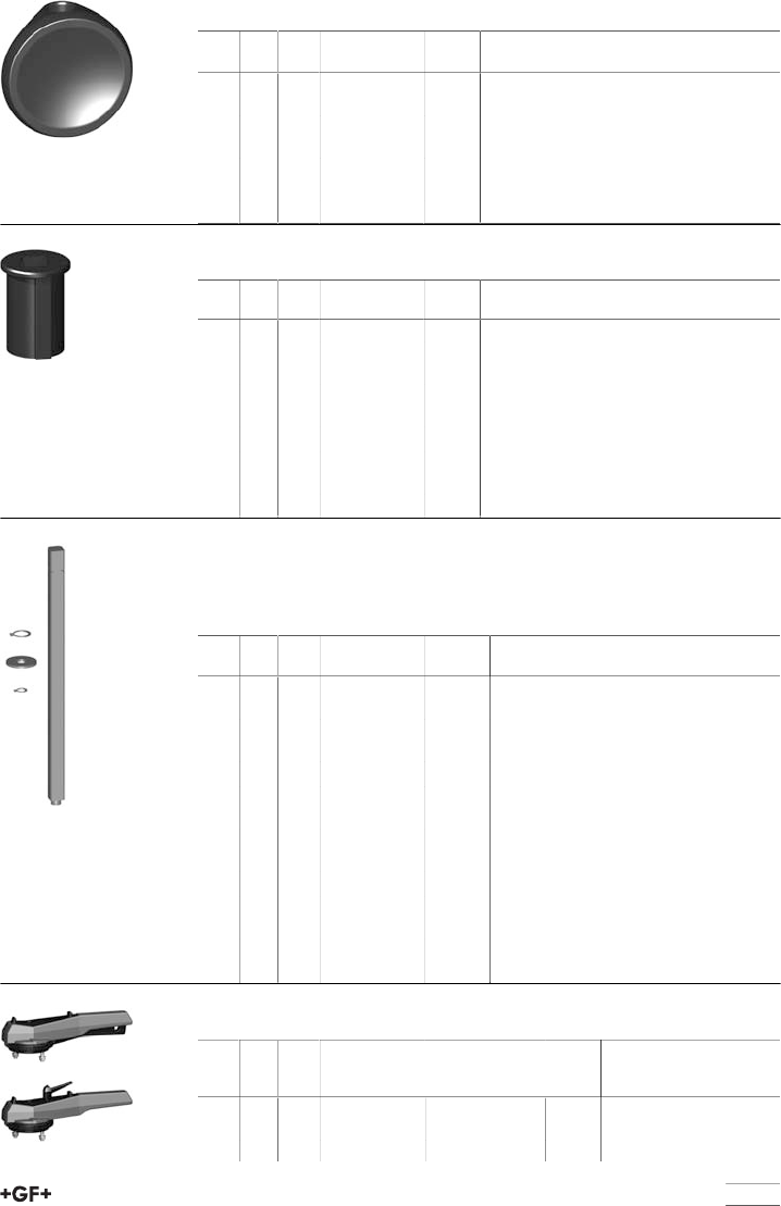
table continued next page
109
Disc (3)
d
[mm]
Inch DN
[mm]
ABS
Code
kg
63 2 50 169 480 951 0.027
75 2 1∕265 169 480 952 0.046
90 3 80 169 480 953 0.078
110 4 100 169 480 954 0.151
140 5 125 169 480 955 0.272
160 6 150 169 480 956 0.475
225 8 200 169 480 957 0.590
End stopp PP glasfiber reinforced (4)
d
[mm]
Inch DN
[mm]
Code kg
63 2 50 167 483 251 0.023
75 2 1∕265 167 483 251 0.023
90 3 80 167 483 251 0.023
110 4 100 167 483 252 0.033
140 5 125 167 483 252 0.033
160 6 150 167 483 253 0.049
225 8 200 167 483 253 0.049
280 10 250 167 483 254 0.096
315 12 300 167 483 254 0.096
Shaft set
Model:
•Shaft set consisting of: shaft chrom steel 1.4301 AISI 304 (6), retention ring
(7, 9) and washer (8)
d
[mm]
Inch DN
[mm]
Code kg
63 2 50 161 486 899 0.225
75 2 1∕265 161 486 900 0.237
90 3 80 161 486 901 0.249
110 4 100 161 486 902 0.429
140 5 125 161 486 903 0.469
160 6 150 161 486 904 0.749
225 8 200 161 486 905 0.844
280 10 250 161 486 906 2.335
315 12 300 161 486 907 2.536
355 14 350 161 486 908 7.600
400 16 400 161 486 909 8.900
450 18 450 161 486 926 11.800
500 20 500 161 486 927 14.400
630 24 600 161 486 928 26.000
Hand lever
d
[mm]
Inch DN
[mm]
with index plate
Code
with fine adjust-
ment
Code
kg
63 2 50 161 486 690 161 486 325 0.485
75 2 1∕265 161 486 690 161 486 325 0.485
90 3 80 161 486 690 161 486 325 0.485
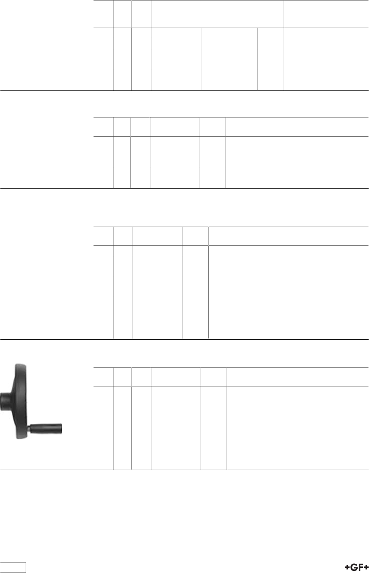
110
d
[mm]
Inch DN
[mm]
with index plate
Code
with fine adjust-
ment
Code
kg
110 4 100 161 486 691 161 486 326 0.540
140 5 125 161 486 691 161 486 326 0.540
160 6 150 161 486 694 161 486 327 0.537
225 8 200 161 486 695 161 486 328 1.375
280 10 250 161 486 697 0.330
315 12 300 161 486 697 0.330
Profile seal (13) DN350-600
d
[mm]
Inch DN
[mm]
EPDM
Code
kg
355 14 350 748 440 018 0.261
400 16 400 748 440 019 0.297
450 18 450 748 440 020 0.430
500 20 500 748 440 021 0.480
630 24 600 748 440 022 0.686
Intermediate element
Gear operated with handwheel 567 / 568
d
[mm]
DN
[mm]
Code kg
63 50 198 000 621 0.150
75 65 198 000 621 0.150
90 80 198 000 621 0.150
110 100 198 000 622 0.150
140 125 198 000 622 0.150
160 150 198 000 599 0.100
225 200 198 000 599 0.100
280 250 198 000 880 0.750
315 300 198 000 880 0.750
Reduction gear with handwheel
d
[mm]
Inch DN
[mm]
Code kg
75 2 1∕265 161 482 408 2.260
90 3 80 161 482 408 2.260
110 4 100 161 482 408 2.260
125 4 1∕2125 161 482 408 2.260
160 6 150 161 482 408 2.260
225 8 200 161 482 408 2.260
280 10 250 161 483 462 2.840
315 12 300 161 483 462 2.840
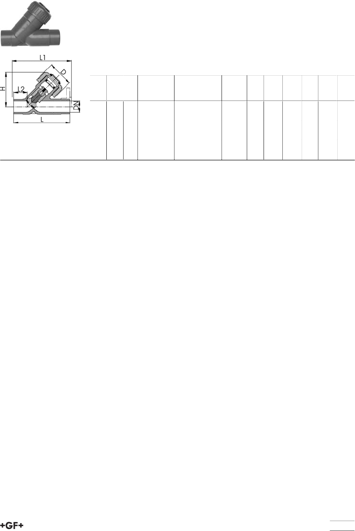
111
Angle seat check valves
Angle seat check valve type 303 ABS
With solvent cement spigots metric
Model:
•For horizontal or vertical installation
•Leakproof from: EPDM 2m, FPM 3m water column
•Specific gravity of piston approx. 2 kg/dm³
•Overall length EN 558
d
[mm]
DN
[mm]
PN kv-value
(Δp=1 bar)
[l/min]
EPDM
Code
kg D
[mm]
L
[mm]
L1
[mm]
L2
[mm]
H
[mm]
20 15 10 95 169 303 006 0.090 43 124 130 28 65
25 20 10 180 169 303 007 0.137 47 144 150 37 75
32 25 10 327 169 303 008 0.228 56 154 160 37 90
40 32 10 484 169 303 009 0.348 64 174 180 44 102
50 40 10 725 169 303 010 0.624 82 194 200 48 123
63 50 10 1130 169 303 011 1.108 95 224 230 60 144
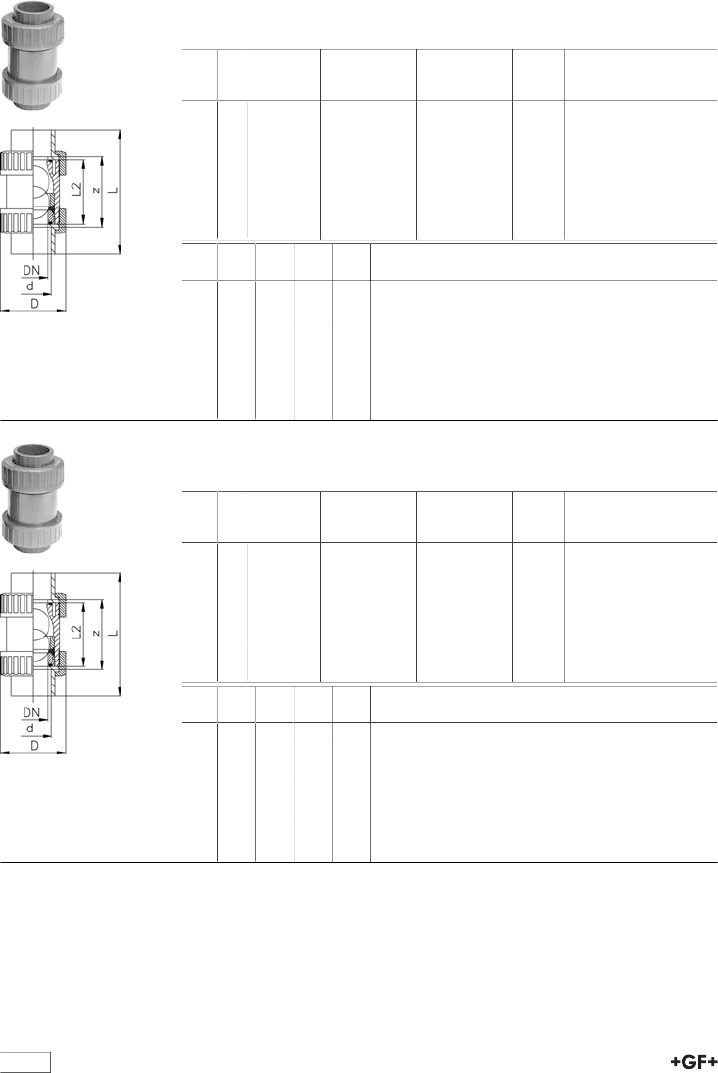
112
Ball check (non-return) valve
Ball check (non return) valve type 360 ABS
With solvent cement sockets Inch BS
Inch PN kv-value
(Δp=1 bar)
[l/min]
EPDM
Code
FPM
Code
kg
3∕816 170 169 360 521 169 360 531 0.105
1∕216 150 169 360 522 169 360 532 0.105
3∕416 330 169 360 523 169 360 533 0.174
1 16 390 169 360 524 169 360 534 0.269
1 1∕416 710 169 360 525 169 360 535 0.442
1 1∕216 900 169 360 526 169 360 536 0.727
2 16 1390 169 360 527 169 360 537 1.315
Inch z
[mm]
D
[mm]
L
[mm]
L2
[mm]
3∕871 46 99 63
1∕270 46 102 63
3∕482 56 120 75
1 87 67 131 79
1 1∕498 82 150 89
1 1∕2101 92 163 95
2 121 120 197 115
Ball check (non return) valve type 360 ABS
With threaded sockets Rp Inch
Inch PN kv-value
(Δp=1 bar)
[l/min]
EPDM
Code
FPM
Code
kg
3∕816 170 169 360 421 169 360 431 0.105
1∕216 150 169 360 422 169 360 432 0.105
3∕416 330 169 360 423 169 360 433 0.174
1 16 390 169 360 424 169 360 434 0.269
1 1∕416 710 169 360 425 169 360 435 0.442
1 1∕216 900 169 360 426 169 360 436 0.727
2 16 1390 169 360 427 169 360 437 1.315
Inch z
[mm]
D
[mm]
L
[mm]
L2
[mm]
3∕871 46 99 63
1∕270 46 102 63
3∕482 56 120 75
1 87 67 131 79
1 1∕498 82 150 89
1 1∕2101 92 163 95
2 121 120 197 115
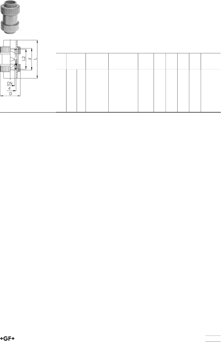
113
Ball check (non-return) valve type 360 ABS
With solvent cement sockets metric
Model:
•For easy installation and removal
•The ball seals at a minimum water column of 2 m
•Vibration free even at high flow velocity
•Minimum temperature: - 40°C
•Forhorizontal or vertical installation
d
[mm]
DN
[mm]
PN kv-value
(Δp=1 bar)
[l/min]
EPDM
Code
kg z
[mm]
D
[mm]
L
[mm]
L2
[mm]
16 10 10 170 169 360 401 0.105 71 45 99 63
20 15 10 150 169 360 402 0.105 70 45 102 63
25 20 10 330 169 360 403 0.175 82 56 120 75
32 25 10 390 169 360 404 0.271 87 67 131 79
40 32 10 710 169 360 405 0.445 98 82 150 89
50 40 10 900 169 360 406 0.715 101 92 163 95
63 50 10 1390 169 360 407 1.271 121 120 197 115
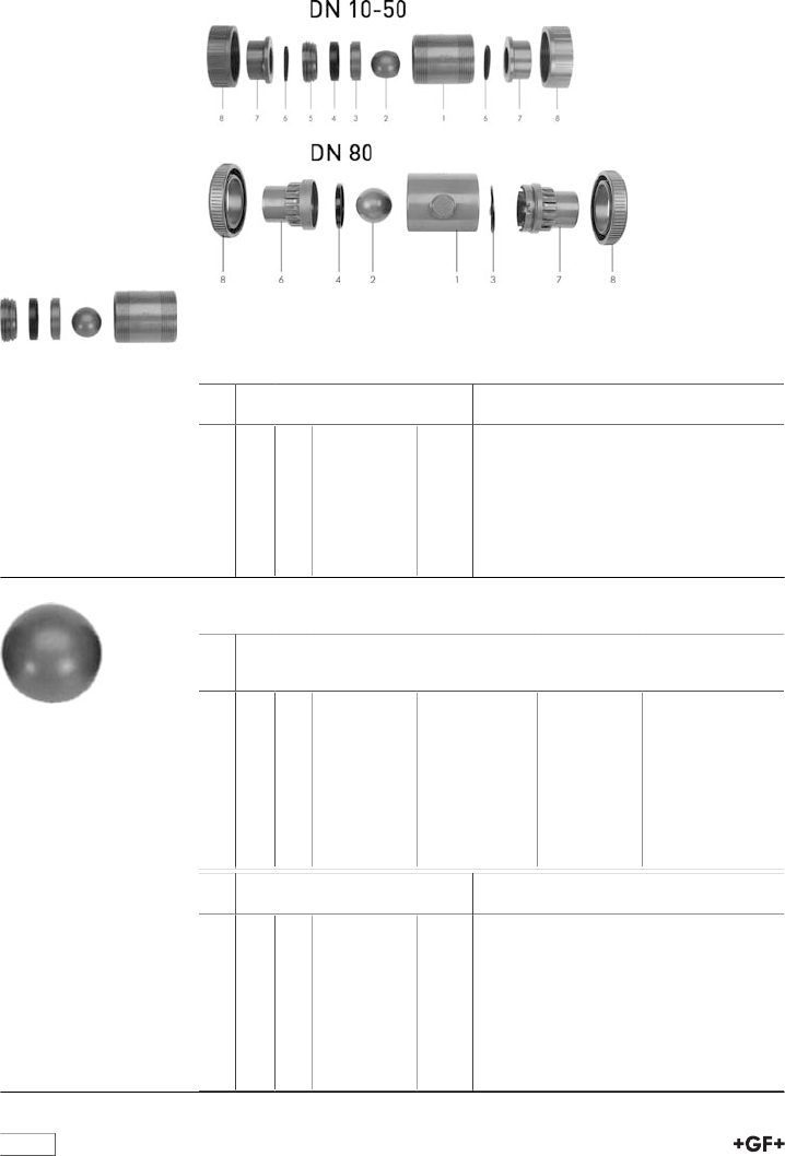
114
Spare parts ball check valves
Spare parts ball check valve type 360
Central part
Model:
•Central part consisting of: body (1), ball (2), support ring (3), sealing ring
(4)and union bush (5)
d
[mm]
Inch DN
[mm]
ABS EPDM
Code
kg
16 3∕810 169 480 250 0.063
20 1∕215 169 480 251 0.063
25 3∕420 169 480 252 0.105
32 1 25 169 480 253 0.170
40 1 1∕432 169 480 254 0.274
50 1 1∕240 169 480 255 0.422
63 2 50 169 480 256 0.799
Ball (2)
d
[mm]
Inch DN
[mm]
PVC-U
Code
PP-H with talc
density 1.24
Code
PP-H 100%
Code
16 3∕810 161 330 304 167 481 165 167 480 024
20 1∕215 161 330 304 167 481 165 167 480 024
25 3∕420 161 330 354 167 481 166 167 480 025
32 1 25 161 330 404 167 481 167 167 480 026
40 1 1∕432 161 330 454 167 481 168 167 480 027
50 1 1∕240 161 330 504 167 481 169 167 480 028
63 2 50 161 330 554 167 481 170 167 480 029
90 3 80 161 330 654
d
[mm]
Inch DN
[mm]
PVDF
Code
kg
16 3∕810 175 480 153 0.010
20 1∕215 175 480 153 0.010
25 3∕420 175 480 154 0.014
32 1 25 175 480 155 0.028
40 1 1∕432 175 480 156 0.064
50 1 1∕240 175 480 157 0.093
63 2 50 175 480 158 0.214
90 3 80 0.475
115
Sealing ring (4)
d
[mm]
Inch DN
[mm]
EPDM
Code
kg
16 3∕810 161 483 259 0.005
20 1∕215 161 483 259 0.005
25 3∕420 161 483 260 0.003
32 1 25 161 483 261 0.005
40 1 1∕432 161 483 262 0.004
50 1 1∕240 161 483 263 0.012
63 2 50 161 483 264 0.025
90 3 80 161 480 141 0.046
Face seal (6)
d
[mm]
Inch DN
[mm]
EPDM
Code
kg
16 3∕810 748 410 042 0.002
20 1∕215 748 410 042 0.002
25 3∕420 748 410 116 0.002
32 1 25 748 410 103 0.003
40 1 1∕432 748 410 027 0.005
50 1 1∕240 748 410 010 0.004
63 2 50 748 410 011 0.005
90 3 80 748 410 099 0.009
Union nut (8)
d
[mm]
Inch DN
[mm]
ABS
Code
kg
16 3∕810 169 480 101 0.013
20 1∕215 169 480 101 0.013
25 3∕420 169 480 102 0.030
32 1 25 169 480 103 0.004
40 1 1∕432 169 480 104 0.063
50 1 1∕240 169 480 105 0.085
63 2 50 169 480 106 0.160
Valve end with socket (7)
d
[mm]
Inch DN
[mm]
ABS metric
Code
kg
16 3∕810 169 480 152 0.007
20 1∕215 169 480 153 0.007
25 3∕420 169 480 154 0.010
32 1 25 169 480 155 0.016
40 1 1∕432 169 480 156 0.032
50 1 1∕240 169 480 157 0.052
63 2 50 169 480 158 0.087
116
Seal set (4, 6)
d
[mm]
Inch DN
[mm]
EPDM
Code
kg
16 3∕810 161 482 910 0.003
20 1∕215 161 482 910 0.003
25 3∕420 161 482 911 0.007
32 1 25 161 482 912 0.011
40 1 1∕432 161 482 913 0.016
50 1 1∕240 161 482 914 0.032
63 2 50 161 482 915 0.065
Body (1)
d
[mm]
Inch DN
[mm]
PVC-U
Code
kg
90 3 80 161 480 158 1.790
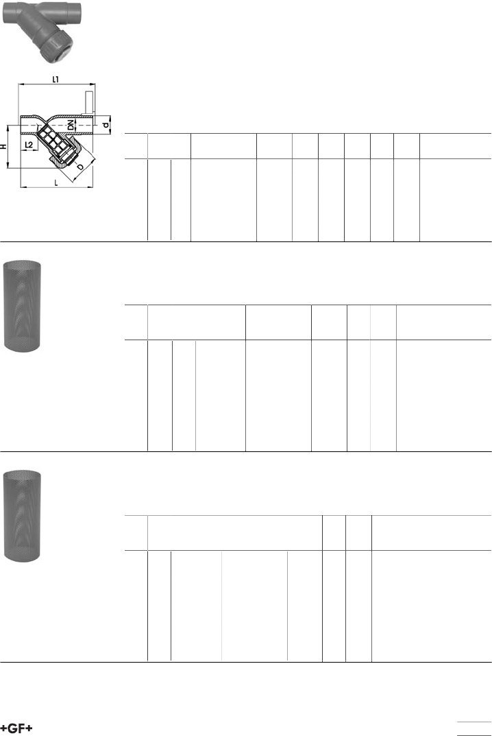
117
Strainers
Line strainer type 305 ABS
With solvent cement spigots metric
Model:
•Protects valves, pumps, etc. from becoming soiled
•Easy dismantling for cleaning the screens
•Cylindrical screen must be ordered separately
•Overall length EN 558
•Screen in stainless steel operable temperature range up -40°C to +60°C
•Screen in PVC-U operable temperature range up 0°C to +60°C
d
[mm]
DN
[mm]
PN EPDM
Code
kg D
[mm]
L
[mm]
L1
[mm]
L2
[mm]
H
[mm]
20 15 10 169 305 302 0.080 48 124 130 28 65
25 20 10 169 305 303 0.120 54 144 150 37 76
32 25 10 169 305 304 0.180 62 154 160 37 90
40 32 10 169 305 305 0.280 71 174 180 44 104
50 40 10 169 305 306 0.470 88 194 200 48 124
63 50 10 169 305 307 0.780 103 224 230 60 148
Cylindrical screen type 305 PVC-U
Screen perforations 0.5 mm
•For line strainers Type 305
d
[mm]
Inch DN
[mm]
kv-value
(Δp=1 bar)
[l/min]
Code kg D
[mm]
L
[mm]
20 1∕215 35 161 305 339 0.005 14 39
25 3∕420 65 161 305 389 0.007 18 48
32 1 25 90 161 305 439 0.003 24 60
40 1 1∕432 155 161 305 489 0.004 30 71
50 1 1∕240 225 161 305 539 0.007 38 87
63 2 50 370 161 305 589 0.010 48 106
75 2 1∕265 575 161 305 639 0.012 61 100
90 3 80 955 161 305 689 0.017 73 118
Cylindrical screen type 305 PVC-U
Screen perforations 0.8 mm
•For line strainers Type 305
d
[mm]
DN
[mm]
kv-value
(Δp=1 bar)
[l/min]
Code kg D
[mm]
L
[mm]
20 15 35 161 305 338 0.005 14 39
25 20 65 161 305 388 0.007 18 48
32 25 90 161 305 438 0.003 24 60
40 32 155 161 305 488 0.004 30 71
50 40 225 161 305 538 0.006 38 87
63 50 370 161 305 588 0.009 48 106
75 65 575 161 305 638 0.012 61 100
90 80 955 161 305 688 0.010 73 118
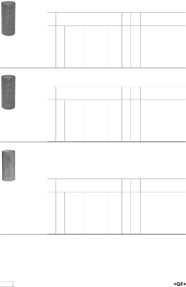
118
Cylindrical screen type 305 PVC-U
Screen perforations 1.4 mm
d
[mm]
DN
[mm]
kv-value
(Δp=1 bar)
[l/min]
Code kg D
[mm]
L
[mm]
20 15 35 161 305 337 0.005 14 39
25 20 65 161 305 387 0.003 18 48
32 25 90 161 305 437 0.003 24 60
40 32 155 161 305 487 0.004 30 71
50 40 225 161 305 537 0.006 38 87
63 50 370 161 305 587 0.008 48 106
75 65 575 161 305 637 0.011 61 100
90 80 955 161 305 687 0.015 73 118
Cylindrical screen type 305 PVC-U
Screen perforations 2.2 mm
d
[mm]
DN
[mm]
kv-value
(Δp=1 bar)
[l/min]
Code kg D
[mm]
L
[mm]
20 15 35 161 305 336 0.005 14 39
25 20 65 161 305 386 0.003 18 48
32 25 90 161 305 436 0.003 24 60
40 32 155 161 305 486 0.003 30 71
50 40 225 161 305 536 0.005 38 87
63 50 370 161 305 586 0.008 48 106
75 65 575 161 305 636 0.010 61 100
90 80 955 161 305 686 0.013 73 118
Screen stainless steel
Screen perforation 0.5 mm
Model:
•Stainless Steel A4 Quality (AISI 316)
•For line strainers Type 305
d
[mm]
DN
[mm]
kv-value
(Δp=1 bar)
[l/min]
Code kg D
[mm]
L
[mm]
20 15 35 161 486 100 0.002 14 39
25 20 60 161 486 101 0.004 18 48
32 25 85 161 486 102 0.006 24 60
40 32 130 161 486 103 0.009 30 71
50 40 200 161 486 104 0.014 38 87
63 50 330 161 486 105 0.022 48 106
75 65 460 161 486 106 0.026 61 100
90 80 665 161 486 107 0.036 73 118
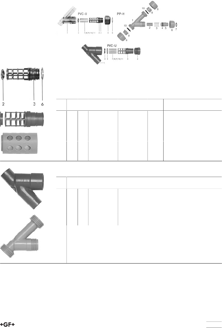
119
Spare parts line strainer
Spare parts line strainer type 305/306
Screen set
Model:
•Screen set PVC-U DN10-DN50 consisting of: screen (3), screen support ring
(2) and circlip (6), PVC-U DN65-DN80: screen (3) and screen support ring (2).
PP-H DN15-DN50: screen basket compl. without screen (2) and circlip (7)
d
[mm]
Inch DN
[mm]
PVC-U
Code
PP-H
Code
kg
20 1∕215 161 483 126 167 305 001 0.110
25 3∕420 161 483 127 167 305 002 0.070
32 1 25 161 483 128 167 305 003 0.255
40 1 1∕432 161 483 129 167 305 004 0.135
50 1 1∕240 161 483 130 167 305 005 0.140
63 2 50 161 483 131 167 305 006 0.140
75 2 1∕265 161 483 132 0.490
90 3 80 161 483 133 0.390
Body (1)
d
[mm]
Inch DN
[mm]
ABS
Code
20 1∕215 169 480 600
25 3∕420 169 480 601
32 1 25 169 480 602
40 1 1∕432 169 480 603
50 1 1∕240 169 480 604
63 2 50 169 480 605
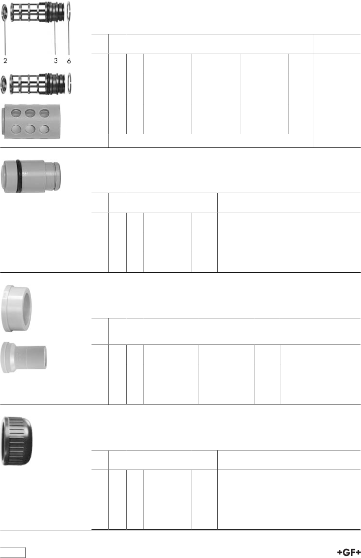
120
Screen cage
Model:
•Screen cage in PVC-U (3) and PP-H (2)
d
[mm]
Inch DN
[mm]
PVC-U
Code
PVC-C
Code
PP-H
Code
kg
20 1∕215 161 305 303 163 481 102 167 305 020 0.005
25 3∕420 161 305 353 163 481 103 167 305 021 0.007
32 1 25 161 305 403 163 481 104 167 305 022 0.003
40 1 1∕432 161 305 453 163 481 105 167 305 023 0.004
50 1 1∕240 161 305 503 163 481 106 167 305 024 0.005
63 2 50 161 305 553 163 481 107 167 305 025 0.010
75 2 1∕265 161 305 603 0.309
90 3 80 161 305 653 0.372
Screen cage bracket
Model:
•Only for the version in PP-H available
d
[mm]
Inch DN
[mm]
PP-H
Code
kg
20 1∕215 167 305 040 0.018
25 3∕420 167 305 041 0.024
32 1 25 167 305 042 0.035
40 1 1∕432 167 305 043 0.055
50 1 1∕240 167 305 044 0.088
63 2 50 167 305 045 0.132
Valve end metric
Model:
•Only for the version in PP-H available
d
[mm]
Inch DN
[mm]
fusion socket PP-
H
Code
butt fusion spigot
IR PP-H SDR11
Code
kg
20 1∕215 727 600 106 727 608 506 0.010
25 3∕420 727 600 107 727 608 507 0.017
32 1 25 727 600 108 727 608 508 0.024
40 1 1∕432 727 600 109 727 608 509 0.041
50 1 1∕240 727 600 110 727 608 510 0.054
63 2 50 727 600 111 727 608 511 0.092
Valve nut
Model:
•Union nut PVC-U DN10-DN50 (4), PP-H (6, 8)
d
[mm]
Inch DN
[mm]
Cap nut ABS
Code
kg
20 1∕215 169 480 609 0.025
25 3∕420 169 480 610 0.018
32 1 25 169 480 611 0.030
40 1 1∕432 169 480 612 0.035
50 1 1∕240 169 480 613 0.064
63 2 50 169 480 614 0.110
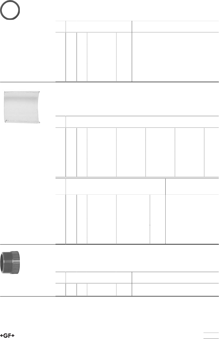
121
Body seal
Model:
•Body seal vor PVC-U (5), PP-H (10)
d
[mm]
Inch DN
[mm]
EPDM
Code
kg
20 1∕215 748 410 006 0.001
25 3∕420 748 410 001 0.002
32 1 25 748 410 007 0.002
40 1 1∕432 748 410 002 0.003
50 1 1∕240 748 410 003 0.004
63 2 50 748 410 012 0.004
75 2 1∕265 748 410 013 0.006
90 3 80 748 410 014 0.007
Screen perforation
Model:
•For PVC-U (7), PP-H (3)
•Stainless Steel A4 Quality (AISI 316)
d
[mm]
Inch DN
[mm]
PVC-U 0.5mm
Code
PVC-U 0.8mm
Code
PVC-U 1.4mm
Code
PVC-U 2.2mm
Code
20 1∕215 161 305 339 161 305 338 161 305 337 161 305 336
25 3∕420 161 305 389 161 305 388 161 305 387 161 305 386
32 1 25 161 305 439 161 305 438 161 305 437 161 305 436
40 1 1∕432 161 305 489 161 305 488 161 305 487 161 305 486
50 1 1∕240 161 305 539 161 305 538 161 305 537 161 305 536
63 2 50 161 305 589 161 305 588 161 305 587 161 305 586
75 2 1∕265 161 305 639 161 305 638 161 305 637 161 305 636
90 3 80 161 305 689 161 305 688 161 305 687 161 305 686
d
[mm]
Inch DN
[mm]
PP-H
Code
stainless steel
0.5mm
Code
kg
20 1∕215 167 305 030 161 486 100 0.002
25 3∕420 167 305 031 161 486 101 0.004
32 1 25 167 305 032 161 486 102 0.006
40 1 1∕432 167 305 033 161 486 103 0.009
50 1 1∕240 167 305 034 161 486 104 0.014
63 2 50 167 305 035 161 486 105 0.022
75 2 1∕265 161 486 106 0.026
90 3 80 161 486 107 0.036
Plug (4)
Model:
•Only for PVC-U DN65-DN80
d
[mm]
Inch DN
[mm]
PVC-U
Code
kg
75 2 1∕265 161 305 604 0.200
90 3 80 161 305 654 0.265

122
Circlip (7)
Model:
•Only for the version in PP-H available
d
[mm]
Inch DN
[mm]
PP-H
Code
kg
20 1∕215 161 482 017 0.003
25 3∕420 161 482 018 0.003
32 1 25 161 482 019 0.005
40 1 1∕432 161 482 020 0.003
50 1 1∕240 161 482 021 0.003
63 2 50 161 482 022 0.004
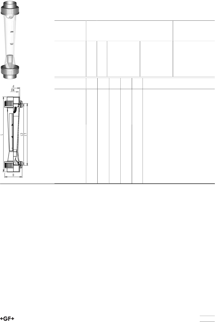
123
Variable area flow meters
Variable area flow meters
Float in PVDF without magnet
With solvent cement sockets ABS BS Inch
Scale range
[l/h]
d
[inch]
DN
[mm]
Taper tube in
Polyamid O-rings
in EPDM
Code
Taper tube in
Polysulfone O-
rings in EPDM
Code
50 - 500 1 25 198 802 814 198 802 815
100 - 1000 1 25 198 802 816 198 802 817
300 - 3000 1 1∕240 198 802 818 198 802 819
600 - 6000 1 1∕240 198 802 820 198 802 821
1000 - 10000 2 50 198 802 822 198 802 823
1500 - 15000 2 50 198 802 824 198 802 825
Scale range
[l/h]
D
[mm]
L
[mm]
L1
[mm]
L2
[mm]
G
[inch]
50 - 500 58 385 341 335 1 1∕2
100 - 1000 58 385 341 335 1 1∕2
300 - 3000 83 403 341 335 2 1∕4
600 - 6000 83 403 341 335 2 1∕4
1000 - 10000 101 417 341 335 2 3∕4
1500 - 15000 101 417 341 335 2 3∕4

124
Variable area flow meters
Float in PVDF with magnet
With solvent cement sockets ABS BS Inch
Model:
•Suitablelimit switches see accessories for variable area flow meters
Scale range
[l/h]
d
[inch]
DN
[mm]
Taper tube in
Polyamid O-rings
in EPDM
Code
Taper tube in
Polysulfone O-
rings in EPDM
Code
50 - 500 1 25 198 802 826 198 802 827
100 - 1000 1 25 198 802 828 198 802 829
300 - 3000 1 1∕240 198 802 830 198 802 831
600 - 6000 1 1∕240 198 802 832 198 802 833
1000 - 10000 2 50 198 802 834 198 802 835
1500 - 15000 2 50 198 802 836 198 802 837
Scale range
[l/h]
D
[mm]
L
[mm]
L1
[mm]
L2
[mm]
G
[inch]
50 - 500 58 385 341 335 1 1∕2
100 - 1000 58 385 341 335 1 1∕2
300 - 3000 83 403 341 335 2 1∕4
600 - 6000 83 403 341 335 2 1∕4
1000 - 10000 101 417 341 335 2 3∕4
1500 - 15000 101 417 341 335 2 3∕4
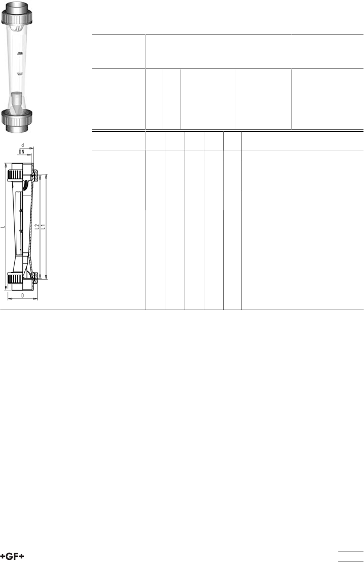
125
Variable area flow meters
Float in PVDF without magnet
With solvent cement sockets ABS metric
Scale range
[l/h]
d
[mm]
DN
[mm]
Taper tube in
Polyamid O-rings
in EPDM
Code
Taper tube in
Polysulfone O-
rings in EPDM
Code
50 - 500 32 25 198 807 120 198 807 126
100 - 1000 32 25 198 807 121 198 807 127
300 - 3000 50 40 198 807 122 198 807 128
600 - 6000 50 40 198 807 123 198 807 129
1000 - 10000 63 50 198 807 124 198 807 130
1500 - 15000 63 50 198 807 125 198 807 131
Scale range
[l/h]
D
[mm]
L
[mm]
L1
[mm]
L2
[mm]
G
[inch]
50 - 500 58 385 341 335 1 1∕2
100 - 1000 58 385 341 335 1 1∕2
300 - 3000 83 403 341 335 2 1∕4
600 - 6000 83 403 341 335 2 1∕4
1000 - 10000 101 417 341 335 2 3∕4
1500 - 15000 101 417 341 335 2 3∕4
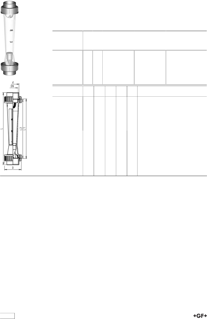
126
Variable area flow meters
Float in PVDF with magnet
With solvent cement sockets ABS metric
Model:
•Suitablelimit switches see accessories for variable area flow meters
Scale range
[l/h]
d
[mm]
DN
[mm]
Taper tube in
Polyamid O-rings
in EPDM
Code
Taper tube in
Polysulfone O-
rings in EPDM
Code
50 - 500 32 25 198 807 132 198 807 138
100 - 1000 32 25 198 807 133 198 807 139
300 - 3000 50 40 198 807 134 198 807 140
600 - 6000 50 40 198 807 135 198 807 141
1000 - 10000 63 50 198 807 136 198 807 142
1500 - 15000 63 50 198 807 137 198 807 143
Scale range
[l/h]
D
[mm]
L
[mm]
L1
[mm]
L2
[mm]
G
[inch]
50 - 500 58 385 341 335 1 1∕2
100 - 1000 58 385 341 335 1 1∕2
300 - 3000 83 403 341 335 2 1∕4
600 - 6000 83 403 341 335 2 1∕4
1000 - 10000 101 417 341 335 2 3∕4
1500 - 15000 101 417 341 335 2 3∕4
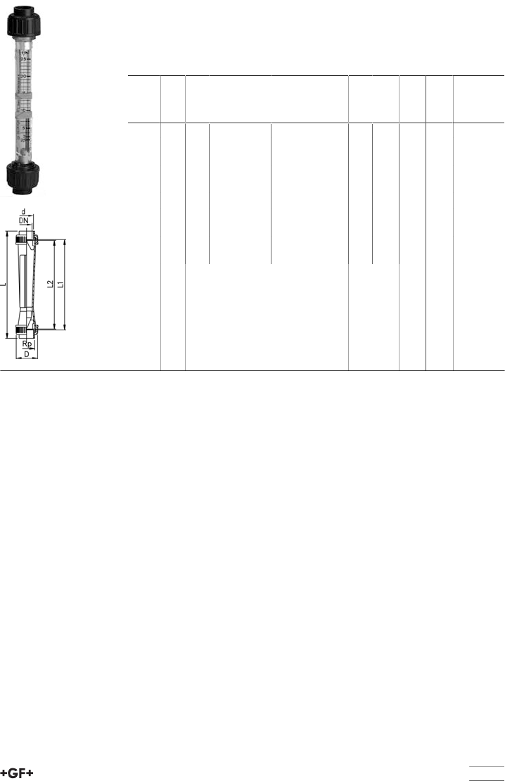
127
Short Version
Float in PVDF without magnet
With solvent cement sockets ABS BS Inch
Model:
•Union nuts and valve ends in other materials on request
Type d
[inch]
DN
[mm]
Scale range
[l/h]
Taper tube in
Polysulfone O-
rings in EPDM
Code
D
[mm]
L
[mm]
L1
[mm]
L2
[mm]
SK50 3∕810 2.5 - 25 198 807 040 35 199 171 165
SK51 3∕810 5 - 50 198 807 041 35 199 171 165
SK52 3∕810 10 - 100 198 807 042 35 199 171 165
SK60 1∕215 8 - 80 198 807 043 43 223 191 185
SK61 1∕215 15 - 150 198 807 044 43 223 191 185
SK62 1∕215 20 - 200 198 807 045 43 223 191 185
SK70 1 25 15 - 150 198 807 046 60 250 206 200
SK71 1 25 30 - 300 198 807 047 60 250 206 200
SK72 1 25 50 - 500 198 807 048 60 250 206 200
SK73 1 25 100 - 1000 198 807 049 60 250 206 200
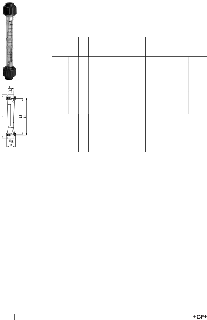
128
Short Version
Float in PVDF with magnet
With solvent cement sockets ABS BS Inch
Model:
•Suitablelimit switches see accessories for variable area flow meters
•Union nuts and valve ends in other materials on request
Type d
[inch]
DN
[mm]
Scale range
[l/h]
Taper tube in
Polysulfone O-
rings in EPDM
Code
D
[mm]
L
[mm]
L1
[mm]
L2
[mm]
SK500 3∕810 2.5 - 25 198 807 050 35 199 171 165
SK510 3∕810 5 - 50 198 807 051 35 199 171 165
SK520 3∕810 10 - 100 198 807 052 35 199 171 165
SK600 1∕215 8 - 80 198 807 053 43 223 191 185
SK610 1∕215 15 - 150 198 807 054 43 223 191 185
SK620 1∕215 20 - 200 198 807 055 43 223 191 185
SK700 1 25 15 - 150 198 807 056 60 250 206 200
SK710 1 25 30 - 300 198 807 057 60 250 206 200
SK720 1 25 50 - 500 198 807 058 60 250 206 200
SK730 1 25 100 - 1000 198 807 059 60 250 206 200

129
Short Version
Float in PVDF without magnet
With solvent cement sockets ABS metric
Model:
•Union nuts and valve ends in other materials on request
Type d
[mm]
DN
[mm]
Scale range
[l/h]
Taper tube in
Polysulfone O-
rings in EPDM
Code
D
[mm]
L
[mm]
L1
[mm]
L2
[mm]
SK50 16 10 2.5 - 25 198 807 144 35 199 171 165
SK51 16 10 5 - 50 198 807 145 35 199 171 165
SK52 16 10 10 - 100 198 807 146 35 199 171 165
SK60 20 15 8 - 80 198 807 147 43 223 191 185
SK61 20 15 15 - 150 198 807 148 43 223 191 185
SK62 20 15 20 - 200 198 807 149 43 223 191 185
SK70 32 25 15 - 150 198 807 150 60 250 206 200
SK71 32 25 30 - 300 198 807 151 60 250 206 200
SK72 32 25 50 - 500 198 807 152 60 250 206 200
SK73 32 25 100 - 1000 198 807 153 60 250 206 200
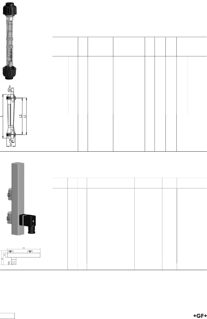
130
Short Version
Float in PVDF with magnet
With solvent cement sockets ABS metric
Model:
•Suitablelimit switches see accessories for variable area flow meters
•Union nuts and valve ends in other materials on request
Type d
[mm]
DN
[mm]
Scale range
[l/h]
Taper tube in
Polysulfone O-
rings in EPDM
Code
D
[mm]
L
[mm]
L1
[mm]
L2
[mm]
SK500 16 10 2.5 - 25 198 807 154 35 199 171 165
SK510 16 10 5 - 50 198 807 155 35 199 171 165
SK520 16 10 10 - 100 198 807 156 35 199 171 165
SK600 20 15 8 - 80 198 807 157 43 223 191 185
SK610 20 15 15 - 150 198 807 158 43 223 191 185
SK620 20 15 20 - 200 198 807 159 43 223 191 185
SK700 32 25 15 - 150 198 807 160 60 250 206 200
SK710 32 25 30 - 300 198 807 161 60 250 206 200
SK720 32 25 50 - 500 198 807 162 60 250 206 200
SK730 32 25 100 - 1000 198 807 163 60 250 206 200
Accessories
4-20 mA sensor
For type 335 and type 350
Type d
[mm]
DN
[mm]
Corresponds to water scale
[l/h]
Code kg
GK 15 32 25 50-500 198 335 962 0.150
GK 15 32 25 100-1000 198 335 963 0.150
GK 15 40 32 150-1500 198 335 964 0.150
GK 15 40 32 250-2500 198 335 965 0.150
GK 15 50 40 200-2000 198 335 966 0.150
GK 15 50 40 300-3000 198 335 967 0.150
GK 15 50 40 600-6000 198 335 968 0.150
GK 15 63 50 600-6000 198 335 969 0.150
GK 15 63 50 1000-10000 198 335 991 0.150
GK 15 63 50 1500-15000 198 335 992 0.150
GK 15 75 65 2000-20000 198 335 993 0.150
GK 15 75 65 3000-30000 198 335 994 0.150
GK 15 75 65 8000-60000 198 335 995 0.150
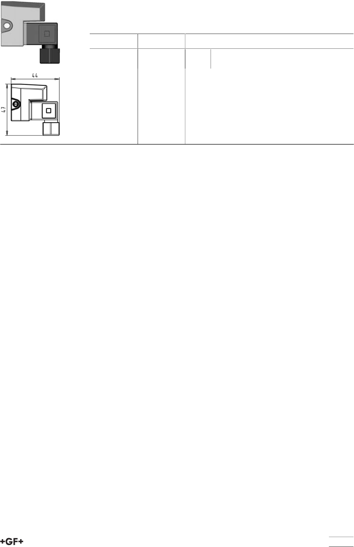
131
Accessories
Limit contacts GK10/GK11
For type 335/350 and short version
Type Code kg
GK10 (min.) 198 335 960 0.033
GK11 (max.) 198 335 961 0.033
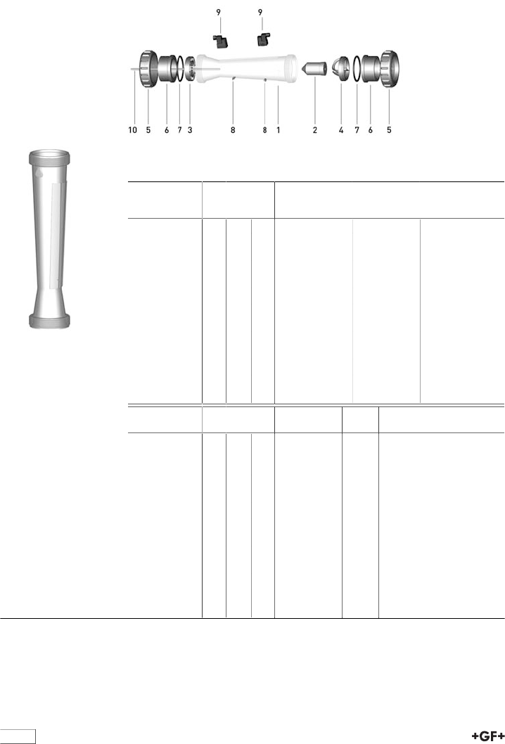
132
Spare parts variable area flow meters
Variable area flow meter type 335
Taper tube with water scale (1)
•PVC-U transparent
Scale range
[l/h]
d
[mm]
Inch DN
[mm]
PVC-U transpar-
ent
Code
Polyamid
Code
50 - 500 32 1 25 198 335 055 198 335 070
100 - 1000 32 1 25 198 335 056 198 335 071
150 - 1500 40 1 1∕432 198 335 057 198 335 072
250 - 2500 40 1 1∕432 198 335 058 198 335 073
200 - 2000 50 1 1∕240 198 335 059 198 335 074
300 - 3000 50 1 1∕240 198 335 060 198 335 075
600 - 6000 50 1 1∕240 198 335 061 198 335 076
600 - 6000 63 2 50 198335062* 198 335 077
1000 - 10000 63 2 50 198335063* 198 335 078
1500 - 15000 63 2 50 198335064* 198 335 079
2000 - 20000 75 2 1∕265 198335065* 198 335 080
3000 - 30000 75 2 1∕265 198335066* 198 335 081
8000 - 60000 75 2 1∕265 198335067* 198 335 082
Scale range
[l/h]
d
[mm]
Inch DN
[mm]
Polysulfon
Code
kg
50 - 500 32 1 25 198 335 085 0.214
100 - 1000 32 1 25 198 335 086 0.214
150 - 1500 40 1 1∕432 198 335 087 0.290
250 - 2500 40 1 1∕432 198 335 088 0.290
200 - 2000 50 1 1∕240 198 335 089 0.350
300 - 3000 50 1 1∕240 198 335 090 0.350
600 - 6000 50 1 1∕240 198 335 091 0.350
600 - 6000 63 2 50 198 335 092 0.453
1000 - 10000 63 2 50 198 335 093 0.453
1500 - 15000 63 2 50 198 335 094 0.453
2000 - 20000 75 2 1∕265 198 335 095 0.622
3000 - 30000 75 2 1∕265 198 335 096 0.622
8000 - 60000 75 2 1∕265 198 335 097 0.622
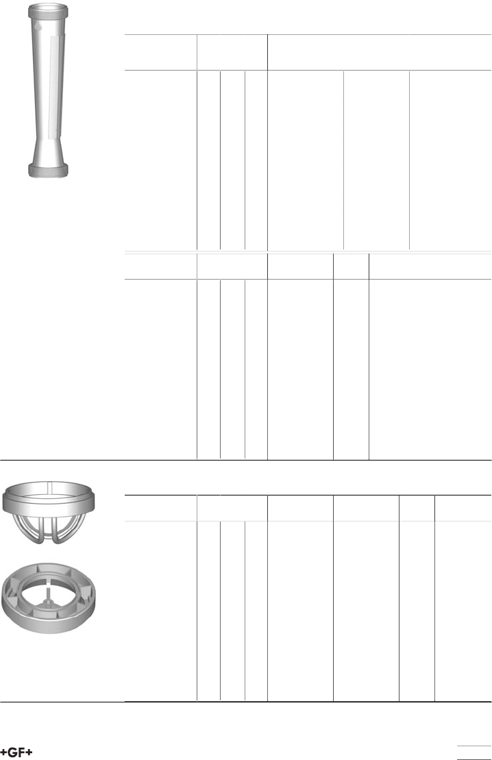
133
Taper tube without scale (1)
•PVC-U transparent
Scale range
[l/h]
d
[mm]
Inch DN
[mm]
PVC-U transpar-
ent
Code
Polyamid
Code
50 - 500 32 1 25 198 335 255 198 335 270
100 - 1000 32 1 25 198 335 256 198 335 271
150 - 1500 40 1 1∕432 198 335 257 198 335 272
250 - 2500 40 1 1∕432 198 335 258 198 335 273
200 - 2000 50 1 1∕240 198 335 259 198 335 274
300 - 3000 50 1 1∕240 198 335 260 198 335 275
600 - 6000 50 1 1∕240 198 335 261 198 335 276
600 - 6000 63 2 50 198335262* 198 335 277
1000 - 10000 63 2 50 198335263* 198 335 278
1500 - 15000 63 2 50 198335264* 198 335 279
2000 - 20000 75 2 1∕265 198335265* 198 335 280
3000 - 30000 75 2 1∕265 198335266* 198 335 281
8000 - 60000 75 2 1∕265 198335267* 198 335 282
Scale range
[l/h]
d
[mm]
Inch DN
[mm]
Polysulfon
Code
kg
50 - 500 32 1 25 198 335 285 0.214
100 - 1000 32 1 25 198 335 286 0.214
150 - 1500 40 1 1∕432 198 335 287 0.290
250 - 2500 40 1 1∕432 198 335 288 0.290
200 - 2000 50 1 1∕240 198 335 289 0.350
300 - 3000 50 1 1∕240 198 335 290 0.350
600 - 6000 50 1 1∕240 198 335 291 0.350
600 - 6000 63 2 50 198 335 292 0.453
1000 - 10000 63 2 50 198 335 293 0.453
1500 - 15000 63 2 50 198 335 294 0.453
2000 - 20000 75 2 1∕265 198 335 295 0.622
3000 - 30000 75 2 1∕265 198 335 296 0.622
8000 - 60000 75 2 1∕265 198 335 297 0.622
Insert PVDF (3,4)
Scale range
[l/h]
d
[mm]
Inch DN
[mm]
top (4)
Code
bottom (3)
Code
kg
50 - 500 32 1 25 198 335 970 198 335 977 0.012
100 - 1000 32 1 25 198 335 970 198 335 977 0.012
150 - 1500 40 1 1∕432 198 335 971 198 335 978 0.019
250 - 2500 40 1 1∕432 198 335 971 198 335 978 0.019
200 - 2000 50 1 1∕240 198 335 972 198 335 979 0.024
300 - 3000 50 1 1∕240 198 335 972 198 335 979 0.024
600 - 6000 50 1 1∕240 198 335 972 198 335 979 0.024
600 - 6000 63 2 50 198 335 973 198 335 980 0.042
1000 - 10000 63 2 50 198 335 973 198 335 980 0.042
1500 - 15000 63 2 50 198 335 974 198 335 982 0.042
2000 - 20000 75 2 1∕265 198 335 975 198 335 981 0.059
3000 - 30000 75 2 1∕265 198 335 975 198 335 981 0.059
8000 - 60000 75 2 1∕265 198 335 975 198 335 981 0.059
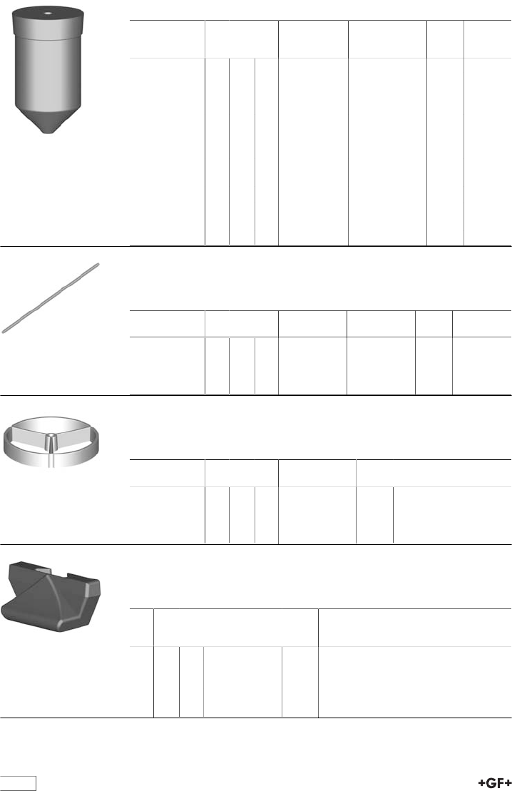
134
Float PVDF (2)
Scale range
[l/h]
d
[mm]
Inch DN
[mm]
Without magnet
Code
With magnet
(bistabil)
Code
kg
50 - 500 32 1 25 198 335 455 198 335 470 0.150
100 - 1000 32 1 25 198 335 455 198 335 470 0.150
150 - 1500 40 1 1∕432 198 335 455 198 335 470 0.150
250 - 2500 40 1 1∕432 198 335 455 198 335 470 0.150
200 - 2000 50 1 1∕240 198 335 456 198 335 471 0.328
300 - 3000 50 1 1∕240 198 335 457 198 335 471 0.328
600 - 6000 50 1 1∕240 198 335 457 198 335 471 0.328
600 - 6000 63 2 50 198 335 457 198 335 471 0.328
1000 - 10000 63 2 50 198 335 457 198 335 471 0.328
1500 - 15000 63 2 50 198 335 458 198 335 472 0.328
2000 - 20000 75 2 1∕265 198 335 459 198 335 473 0.920
3000 - 30000 75 2 1∕265 198 335 459 198 335 473 0.920
8000 - 60000 75 2 1∕265 198 335 460 198 335 474 0.746
Guiding rod (10)
Model:
•Only for DN50 (1'500 - 15'000 l/h) and DN65 (all metering ranges)
Scale range
[l/h]
d
[mm]
Inch DN
[mm]
Peek
Code
Stainless steel
Code
kg
1500 - 15000 63 2 50 198 335 985 198 335 098 0.013
2000 - 20000 75 2 1∕265 198 335 985 198 335 098 0.013
3000 - 30000 75 2 1∕265 198 335 985 198 335 098 0.013
8000 - 80000 75 2 1∕265 198 335 985 198 335 098 0.013
Insert guiding rod PVDF (for 10)
Model:
•Only for DN50 (1'500 - 15'000 l/h) and DN65 (all metering ranges)
Scale range
[l/h]
d
[mm]
Inch DN
[mm]
Insert guiding rod
Code
kg
1500 - 15000 63 2 50 198 335 986 0.020
2000 - 20000 75 2 1∕265 198 335 987 0.020
3000 - 30000 75 2 1∕265 198 335 987 0.020
8000 - 80000 75 2 1∕265 198 335 987 0.020
Flow value indicator PS (8)
Model:
•For all dimensions type 335/350
d
[mm]
Inch DN
[mm]
Flow value indica-
tor
Code
kg
32 1 25 198 335 990 0.001
40 1 1∕432 198 335 990 0.001
50 1 1∕240 198 335 990 0.001
63 2 50 198 335 990 0.001
75 2 1∕265 198 335 990 0.001
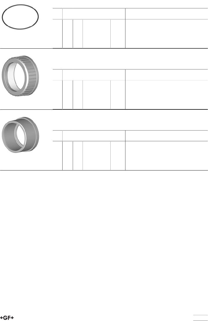
135
O-rings (7)
d
[mm]
Inch DN
[mm]
EPDM
Code
kg
32 1 25 748 410 008 0.001
40 1 1∕432 748 410 009 0.003
50 1 1∕240 748 410 010 0.004
63 2 50 748 410 011 0.005
75 2 1∕265 748 410 014 0.007
Union nut (5)
Unionnut not useable for the special version with taper tube in PVDF
d
[mm]
Inch DN
[mm]
ABS
Code
kg
32 1 25 729 690 408 0.024
40 1 1∕432 729 690 409 0.049
50 1 1∕240 729 690 410 0.070
63 2 50 729 690 411 0.101
75 2 1∕265 -
Union end / Socket (6)
For DN65 PVDF only spigot
d
[mm]
Inch DN
[mm]
ABS
Code
kg
32 1 25 729 600 108 0.016
40 1 1∕432 729 600 109 0.042
50 1 1∕240 729 600 110 0.045
63 2 50 729 600 111 0.084
75 2 1∕265 700 246 112 0.155
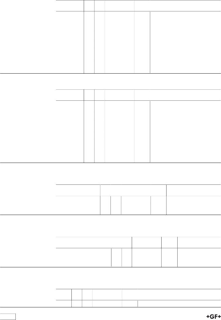
136
Spare part for variable area flow meter
SK50-SK73/SK500-SK730
Short version taper tube Polysulfone
Type d
[mm]
DN
[mm]
Code kg
SK 50 / 500 16 10 198 801 341 0.150
SK 51 / 510 16 10 198 801 342 0.150
SK 52 / 520 16 10 198 801 343 0.150
SK 60 / 600 20 15 198 801 449 0.150
SK 61 / 610 20 15 198 801 450 0.150
SK 62 / 620 20 15 198 801 451 0.150
SK 70 / 700 32 25 198 801 445 0.150
SK 71 / 710 32 25 198 801 338 0.150
SK 72 / 720 32 25 198 801 339 0.150
SK 73 / 730 32 25 198 801 340 0.150
Short version taper tube PVC-U transparent
Type d
[mm]
DN
[mm]
Code kg
SK 50 / 500 16 10 198 803 790 0.040
SK 51 / 510 16 10 198 803 791 0.150
SK 52 / 520 16 10 198 803 792 0.150
SK 60 / 600 20 15 198 803 793 0.060
SK 61 / 610 20 15 198 803 794 0.060
SK 62 / 620 20 15 198 803 795 0.300
SK 70 / 700 32 25 198 803 796 0.127
SK 71 / 710 32 25 198 803 797 0.150
SK 72 / 720 32 25 198 803 798 0.120
SK 73 / 730 32 25 198 803 799 0.120
Short version float PVDF
Without magnet
Type d
[mm]
DN
[mm]
Code kg
SK 50 / 51 / 52 16 10 198 806 219 0.005
SK 60 / 61 / 62 20 15 198 806 220 0.010
SK 70 / 71 / 72 / 73 32 25 198 806 221 0.032
Short version float PVDF
With magnet bistable
Type d
[mm]
DN
[mm]
Code kg
SK 500 / 510 / 520 16 10 198 806 222 0.005
SK 600 / 610 / 620 20 15 198 806 223 0.010
SK 700 / 710 / 720 / 730 32 25 198 806 224 0.032
Short version float PTFE
Without magnet
Type d
[mm]
DN
[mm]
Code kg
SK 73 32 25 198 807 166 0.019

137
Short version top insert PVDF
Type d
[mm]
DN
[mm]
Code kg
SK 50 / 500; 51 / 510; 52 / 520 16 10 198 807 188 0.010
SK 60 / 600; 61 / 610; 62 / 620 20 15 198 807 187 0.010
SK 70 / 700; 71 / 710; 72 / 720; 73 / 730 32 25 198 807 182 0.010

138

139
Accessories
Page
Brackets 140
Solvent and Tools 144
Backing Flanges & Gaskets 145
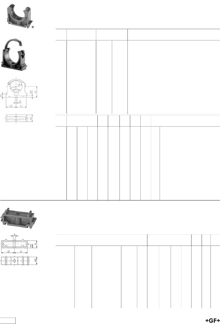
table continued next page
140
Brackets
670610 KLIP-IT pipe clip type 061 PP BS
Model:
•3/8" - 2": height designed for Ball Valve Type 546 and 543
•Material: Clip and safety clip PP black, UV resistant, bolts galvanized
• Minimum order quantity: standard packaging SP
d
[inch]
Code kg kg/m
1∕4167 061 054 0.003 0.003
3∕8167 061 055 0.007 0.007
1∕2167 061 056 0.007 0.007
3∕4167 061 057 0.008 0.008
1167 061 058 0.009 0.009
1167 061 059 0.012 0.012
1 1∕2167 061 060 0.022 0.022
2167 061 061 0.030 0.030
2 1∕2167 061 012 0.058 0.058
3167 061 013 0.090 0.090
4167 061 114 0.114 0.114
5167 061 016 0.217 0.217
d
[inch]
D
[mm]
D1
[mm]
L1
[mm]
L2
[mm]
H
[mm]
H1
[mm]
H2
[mm]
H3
[mm]
SC
1∕45 8 11 14 21 10 6 12 M5
3∕86 10 14 17 23 10 6 16 M5
1∕26 10 17 19 25 10 6 16 M5
3∕46 10 19 22 28 10 6 16 M5
1 6 10 24 27 31 10 6 16 M5
1 7 14 34 34 35 10 7 22 M6
1 1∕27 14 37 37 40 10 7 22 M6
2 9 17 45 45 52 10 10 25 M8
2 1∕29 17 52 52 58 10 10 25 M8
3 9 17 65 65 65 10 10 28 M8
4 9 17 79 79 81 10 10 28 M8
5 9 17 98 98 110 10 10 32 M8
KLIP-IT spacer type 061 PP
Model:
•For pipe clips Type 061/061H, PP black, UV resistant
• Minimum order quantity: standard packaging SP
d
[mm]
Inch
[inch]
Code kg D
[mm]
L1
[mm]
L2
[mm]
H
[mm]
H1
[mm]
H2
[mm]
SC
10 - 12 1∕8 - 1∕4167 061 153 0.003 5 11 14 20 10 12 M4
16 3∕8167 061 155 0.006 6 14 17 20 10 16 M5
20 1∕2167 061 156 0.006 6 17 19 20 10 16 M5
25 3∕4167 061 157 0.007 6 19 22 20 10 16 M5
32 1 167 061 158 0.008 6 24 27 20 10 16 M5
40 1 1∕4167 061 159 0.016 7 34 34 20 10 22 M6
50 1 1∕2167 061 160 0.017 7 37 37 20 10 22 M6
63 2 167 061 161 0.024 9 45 45 20 10 25 M8
75 2 1∕2167 061 162 0.027 9 52 52 20 10 25 M8
90 3 167 061 163 0.040 9 65 65 20 10 28 M8
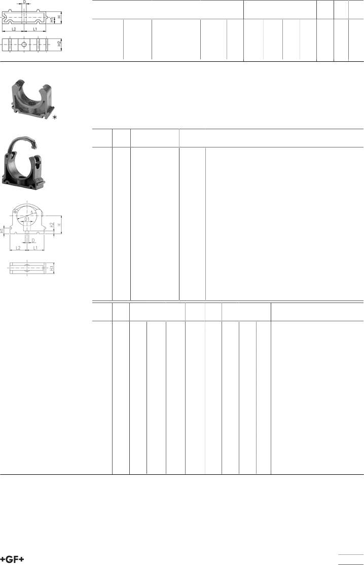
141
d
[mm]
Inch
[inch]
Code kg D
[mm]
L1
[mm]
L2
[mm]
H
[mm]
H1
[mm]
H2
[mm]
SC
110 4 167 061 164 0.048 9 79 79 20 10 28 M8
125 4 1∕2167 061 165 0.059 9 88 88 20 10 32 M8
140 5 167 061 166 0.065 9 98 98 20 10 32 M8
160 6 167 061 167 0.074 9 109 109 20 10 32 M8
KLIP-IT pipe clip type 061 PP metric
Model:
•Material: Clip and safety clip PP black, UV resistant, bolts galvanized
•d16 - d63: Height designed for Ball Valve Type 546 and 543
• Minimum order quantity: standard packagings SP
d
[mm]
d
[inch]
Code kg
*10 167 061 003 0.003
*12 167 061 004 0.003
*16 167 061 035 0.006
*20 167 061 036 0.008
*25 167 061 037 0.009
*32 167 061 038 0.012
40 167 061 039 0.027
50 167 061 040 0.031
63 167 061 041 0.054
75 2 1∕2167 061 012 0.058
90 3 167 061 013 0.090
110 4 167 061 014 0.114
125 167 061 015 0.174
140 5 167 061 016 0.217
160 167 061 017 0.237
d
[mm]
D
[mm]
D1
[mm]
L1
[mm]
L2
[mm]
H
[mm]
H1
[mm]
H2
[mm]
H3
[mm]
SC
*10 5 8 11 14 20 10 6 12 M4
*12 5 8 11 14 21 10 6 12 M5
*16 6 11 14 17 27 10 6 16 M5
*20 6 11 17 19 27 10 6 16 M5
*25 6 11 19 22 30 10 6 16 M5
*32 6 11 24 27 36 10 6 16 M5
40 7 14 34 34 44 10 7 22 M6
50 7 14 37 37 51 10 7 22 M6
63 9 17 45 45 64 10 10 25 M8
75 9 17 52 52 58 10 10 25 M8
90 9 17 65 65 65 10 10 28 M8
110 9 17 79 79 75 10 10 28 M8
125 9 17 88 88 90 10 10 32 M8
140 9 17 98 98 110 10 10 32 M8
160 9 17 109 109 108 10 10 32 M8
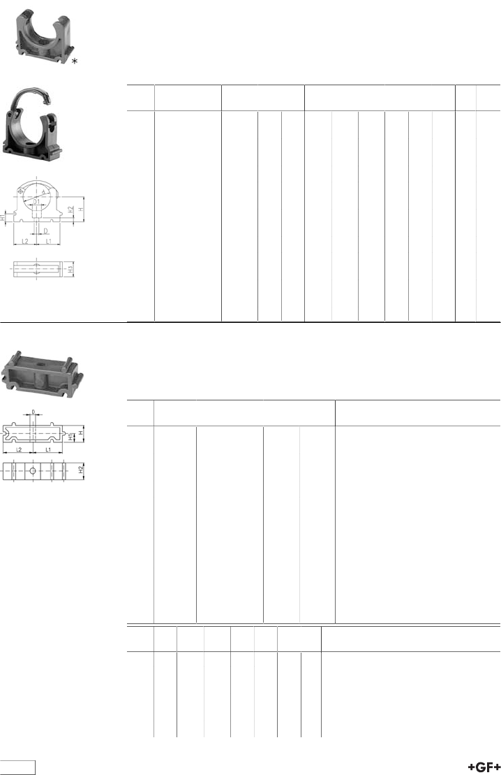
table continued next page
142
KLIP-IT pipe clip type 061 PE metric
Model:
•Material: Clip PE and safety clip PP black, bolts galvanized
• Minimum order quantity: standard packaging SP
•Height not designed for ball valve 546 and 543. Please use spacer 73 06 11.
d
[mm]
Code kg D
[mm]
D1
[mm]
L1
[mm]
L2
[mm]
H
[mm]
H1
[mm]
H2
[mm]
H3
[mm]
SC
*10 173 061 003 0.003 5 8 11 14 20 10 6 12 M4
*12 173 061 004 0.006 5 8 11 14 21 10 6 12 M5
*16 173 061 005 0.007 6 11 14 17 23 10 6 16 M5
*20 173 061 006 0.008 6 11 17 19 25 10 6 16 M5
*25 173 061 007 0.009 6 11 19 22 28 10 6 16 M5
*32 173 061 008 0.012 6 11 24 27 31 10 6 16 M5
40 173 061 009 0.022 7 14 34 34 35 10 7 22 M6
50 173 061 010 0.030 7 14 37 37 40 10 7 22 M6
63 173 061 011 0.044 9 17 45 45 52 10 10 25 M8
75 173 061 012 0.062 9 17 52 52 58 10 10 25 M8
90 173 061 013 0.090 9 17 65 65 65 10 10 28 M8
110 173 061 014 0.114 9 17 79 79 75 10 10 28 M8
125 173 061 015 0.174 9 17 88 88 90 10 10 32 M8
140 173 061 016 0.217 9 17 98 98 110 10 10 32 M8
160 173 061 017 0.237 9 17 109 109 108 10 10 32 M8
73 06 11 KLIP-IT spacer type 061 PE
Model:
•For pipe clips Type 061, PE black, UV resistant
• Minimum order quantity: standard packaging SP
d
[mm]
Inch Code kg kg/m
1/8-1/4 173 061 153 0.003 0.003
16 3/8 173 061 155 0.005 0.005
20 1/2 173 061 156 0.006 0.006
25 3/4 173 061 157 0.007 0.007
32 1 173 061 158 0.008 0.008
40 11/4 173 061 159 0.016 0.016
50 11/2 173 061 160 0.017 0.017
63 2 173 061 161 0.025 0.025
75 21/2 173 061 162 0.027 0.027
90 3 173 061 163 0.040 0.040
110 4 173 061 164 0.048 0.048
125 41/2 173 061 165 0.059 0.059
140 5 173 061 166 0.065 0.065
160 6 173 061 167 0.074 0.074
d
[mm]
D
[mm]
L1
[mm]
L2
[mm]
H
[mm]
H1
[mm]
H2
[mm]
SC
5 11 14 20 10 12 M4
16 6 14 17 20 10 16 M5
20 6 17 19 20 10 16 M5
25 6 19 22 20 10 16 M5
32 6 24 27 20 10 16 M5
40 7 34 34 20 10 22 M6
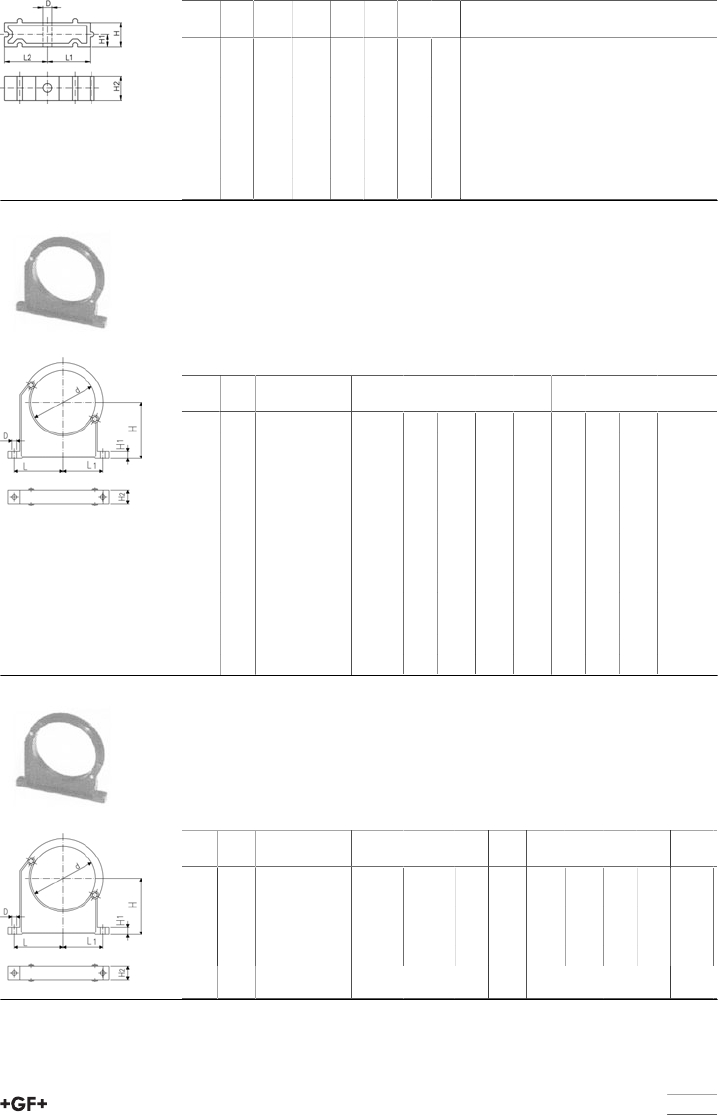
143
d
[mm]
D
[mm]
L1
[mm]
L2
[mm]
H
[mm]
H1
[mm]
H2
[mm]
SC
50 7 37 37 20 10 22 M6
63 9 45 45 20 10 25 M8
75 9 52 52 20 10 25 M8
90 9 65 65 20 10 28 M8
110 9 79 79 20 10 28 M8
125 9 88 88 20 10 32 M8
140 9 98 98 20 10 32 M8
160 9 109 109 20 10 32 M8
Pipe clip type 060 PP metric
Model:
•Material: Clip and safety clip PP black, UV resistant, bolts galvanized
•Accidental opening of the safety clip is not possible
• Minimum order quantity: standard packaging SP or gross packaging GP
•Clip and safety clip are not assembled in the packaging.
•Pipes with flanges can be installed directly
d
[mm]
d
[inch]
Code kg D
[mm]
L
[mm]
L1
[mm]
H
[mm]
H1
[mm]
H2
[mm]
SC
90 3 167 060 038 0.163 9 89 71 105 15 33 M 8
110 167 060 039 0.179 9 94 80 115 15 33 M 8
125 167 060 040 0.300 11 116 91 130 20 35 M10
140 5 167 060 041 0.309 11 121 98 130 20 35 M10
160 167 060 042 0.348 11 131 107 148 20 35 M10
180 167 060 043 0.378 11 143 115 163 20 35 M10
200 167 060 019 0.582 13 152 120 175 25 39 M12
225 167 060 020 0.612 13 165 132 175 25 39 M12
250 167 060 021 0.698 13 183 143 200 25 39 M12
280 167 060 022 0.722 13 198 156 200 25 39 M12
315 167 060 023 0.842 13 219 172 225 25 39 M12
355 167 060 024 1.250 17 275 209 258 30 50 M16
400 167 060 025 1.450 17 300 228 288 30 50 M16
Pipe clip type 060 PP BS
Model:
•Material: Clip and safety clip PP black, UV resistant, bolts galvanized
•Accidental opening of the safety clip is not possible
• Minimum order quantity: standard packaging SP or gross packaging GP
•Clip and safety clip are not assembled in the packaging.
d
[inch]
d
[mm]
Code kg kg/m D
[mm]
L
[mm]
L1
[mm]
H
[mm]
H1
[mm]
H2
[mm]
SC
3 90 167 060 038 0.163 0.163 9 89 71 105 15 33 M 8
4167 060 064 0.179 0.179 9 100 82 120 15 33 M 8
5 140 167 060 041 0.309 0.309 11 121 98 130 20 35 M10
6167 060 067 0.348 0.348 11 136 111 148 25 35 M 10
8167 060 070 0.612 0.612 13 165 132 175 25 39 M 12
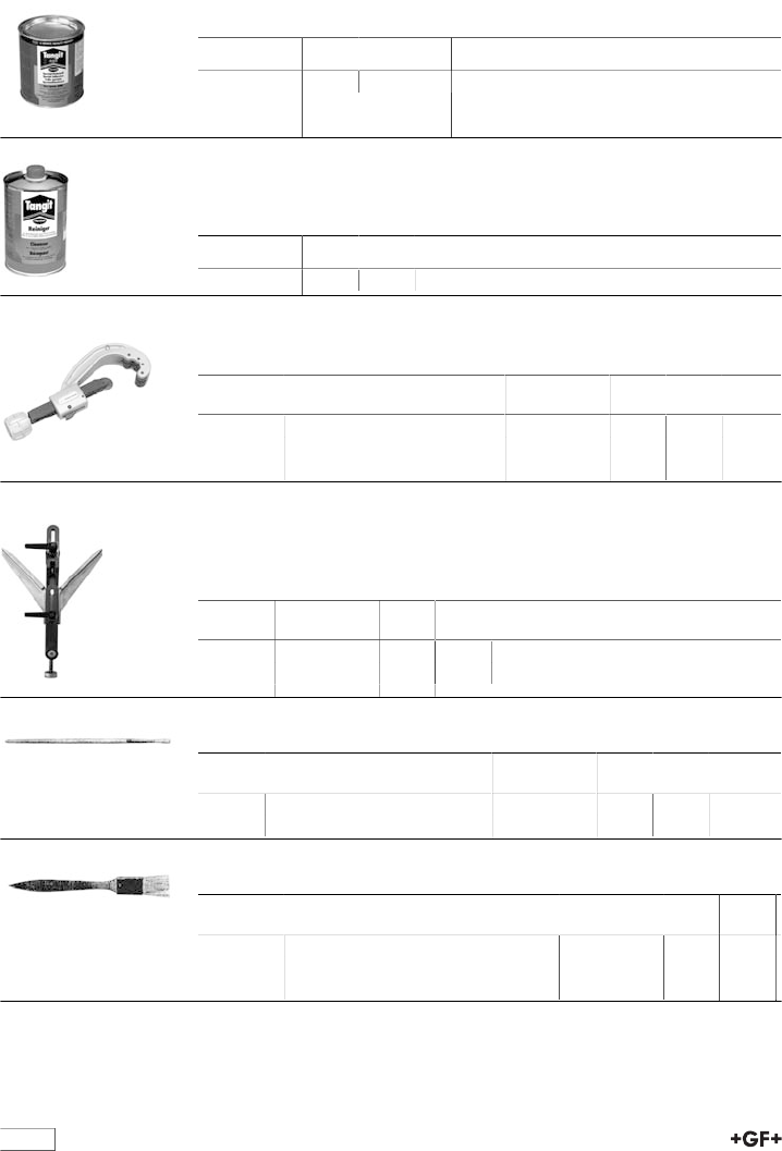
144
Solvent and Tools
99 29 80 Tangit ABS solvent cement
•0,65 kg can (net)
Code kg Description
799 298 022 0.751 tin: 0.65 kg
Tangit cleaner
Model:
•1 litre tin
Code kg kg/m
799 298 010 0.868 0.868
90 10 90 PPC Plastic pipe cutter
•For cutting plastic pipes d10 - d160
d-d
[mm]
Article Code kg kg/m
10 - 63 PPC 63, s max. = 7.2mm 790 109 001 0.710 0.710
50 - 110 PPC 110, s max. = 12.7mm 790 109 002 1.400 1.400
110 - 160 PPC 160, s max. = 19.0mm 790 109 003 1.880 1.880
90 30 90 Chamfering tools
•Chamfering tool (15° bevel) for plastic pipes (PVC, ABS, PB, PP, PE). Coat-
ed prism surface suitable for clean room applications. Fast and reliable adjust-
ment to the different pipe diameters and wall thickness.
d-d
[mm]
Code kg kg/m
16 - 200 790 309 003 1.100 1.100
63 - 400 790 309 004 2.500 2.500
Round brush
d-d
[mm]
Code kg kg/m
6 - 10 4 mm (for Fittings 6-10mm) 799 299 001 0.005 0.005
12 - 32 8 mm (for Fittings 12-32mm) 799 299 002 0.009 0.009
Flat brush
d-d
[mm]
Code kg kg/m
40 - 63 25x3 mm (for Fittings 40-63mm) 799 299 003 0.015 0.015
75 - 225 50x5 mm (for Fittings 75-225mm) 799 299 004 0.026 0.026
250 - 400 75x6 mm (for Fittings 250-400mm) 799 299 005 0.045 0.045
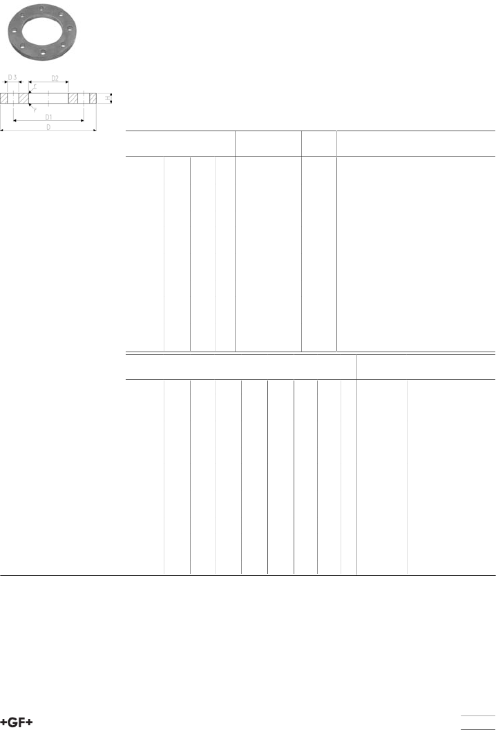
145
Backing Flanges & Gaskets
24 70 14 Backing Flange, Galvanised Steel
for Socket Systems
Model:
•Galvanised steel, suitable for laying underground
•Connecting dimensions: BS10:1962
•Bolt circle Table D &E
AL: number of holes
* Table D
** Table E
d
[mm]
DN
[mm]
d
[inch]
PN Code kg
20 15 1∕216 724 701 406 0.220
25 20 3∕416 724 701 407 0.320
32 25 1 16 724 701 408 0.410
40 32 1 1∕416 724 701 409 0.820
50 40 1 1∕216 724 701 410 1.040
63 50 2 16 724 701 411 1.220
75 65 2 1∕216 724 701 412 1.200
90 80 3 16 724 701 413 1.530
**110 100 16 724 703 414 1.840
* 100 4 16 724 701 414 1.840
** 100 4 16 724 701 415 1.840
140 125 5 16 724 701 416 2.070
160 6 16 724 701 417 2.330
225 200 8 6 724 701 419 2.750
d
[mm]
DN
[mm]
d
[inch]
D
[mm]
D1
[mm]
D2
[mm]
D3
[mm]
H
[mm]
AL SC
20 15 1∕296 67 28 15 7 4 M12x55
25 20 3∕4102 73 34 15 7 4 M12x60
32 25 1 115 83 42 15 7 4 M12x60
40 32 1 1∕4121 88 51 15 8 4 M12x70
50 40 1 1∕2134 99 62 15 8 4 M12x75
63 50 2 153 115 78 18 8 4 M16x80
75 65 2 1∕2165 127 92 18 8 4 M16x85
90 80 3 184 146 110 18 8 4 M16x90
**110 100 216 178 133 18 8 8 M16x95
* 100 4 216 178 138 18 8 4 M16x95
** 100 4 216 178 138 18 8 8 M16x95
140 125 5 254 210 167 18 8 8 M16x110
160 6 280 235 200 22 8 8 M20x120
225 200 8 337 292 250 22 8 8 M20x150
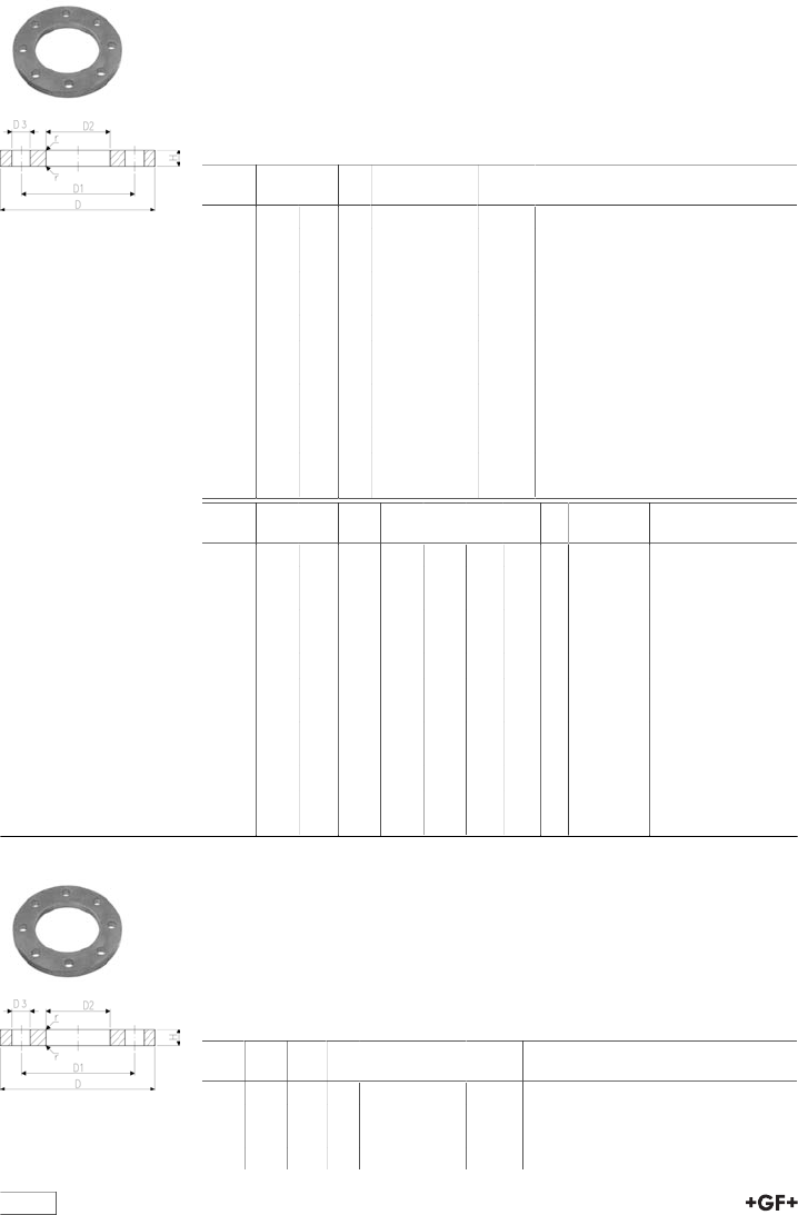
table continued next page
146
24 70 16 Backing Flanges for socket sysems - all materials
Model:
•Galvanised steel, suitable for laying underground
•Connecting dimension: ISO 7005, EN 1092, BS 4504, DIN 2501
•Bolt circle PN10/16
AL: number of holes
*Bolt circle PN16
d
[mm]
DN
[mm]
d
[inch]
PN Code kg
20 15 1∕216 724 701 606 0.220
25 20 3∕416 724 701 607 0.320
32 25 1 16 724 701 608 0.410
40 32 1 1∕416 724 701 609 0.820
50 40 1 1∕216 724 701 610 1.040
63 50 2 16 724 701 611 1.220
75 65 2 1∕216 724 701 612 1.440
90 80 3 16 724 701 613 1.530
110 100 16 724 700 014 1.840
100 4 16 724 701 615 1.620
140 125 5 16 724 701 616 2.250
150 6 16 724 701 617 2.510
*225 200 8 6 724 701 720 3.000
d
[mm]
DN
[mm]
d
[inch]
D
[mm]
D1
[mm]
D2
[mm]
D3
[mm]
H
[mm]
AL SC
20 15 1∕295 65 28 14 7 4 M12x55
25 20 3∕4105 75 34 14 7 4 M12x60
32 25 1 115 85 42 14 7 4 M12x60
40 32 1 1∕4140 100 51 18 8 4 M16x70
50 40 1 1∕2150 110 62 18 8 4 M16x75
63 50 2 165 125 78 18 8 4 M16x80
75 65 2 1∕2185 145 92 18 8 4 M16x85
90 80 3 200 160 110 18 8 4 M16x90
110 100 220 180 133 18 8 8 M16x95
100 4 220 180 138 18 8 8 M16x95
140 125 5 250 210 167 18 8 8 M16x110
150 6 285 240 200 22 8 8 M20x120
*225 200 8 340 295 250 22 8 12 M20x150
24 70 18 Backing Flanges for socket systems - all materials
Model:
•Galvanised steel, suitable for laying underground
•Connecting dimension: ANSI/ASME B 16.5 class 150, ASTM D 4024, BS
1560, BS EN 1759
•Bolt circle Class 150
AL: number of holes
d
[mm]
DN
[mm]
d
[inch]
PN Code kg
20 15 1∕216 724 701 806 0.230
25 20 3∕416 724 701 807 0.300
32 25 1 16 724 701 808 0.350
40 32 1 1∕416 724 701 809 0.480
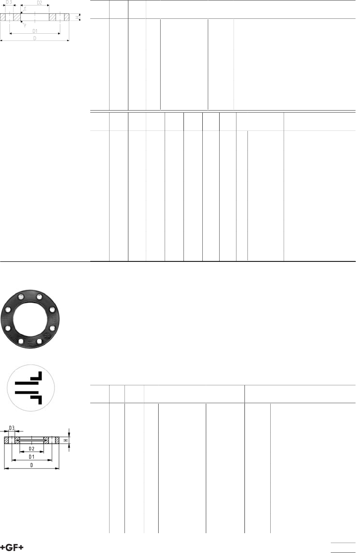
table continued next page
147
d
[mm]
DN
[mm]
d
[inch]
PN Code kg
50 40 1 1∕216 724 701 810 0.650
63 50 2 16 724 701 811 0.990
75 65 2 1∕216 724 701 812 1.200
90 80 3 16 724 701 813 1.310
110 100 16 724 703 814 2.011
100 4 16 724 701 815 1.890
140 125 5 16 724 701 816 2.000
150 6 16 724 701 817 1.950
225 200 8 6 724 701 820 3.160
d
[mm]
DN
[mm]
d
[inch]
D
[mm]
D1
[mm]
D2
[mm]
D3
[mm]
H
[mm]
AL SC
20 15 1∕289 60 28 16 7 4 M12x55
25 20 3∕498 70 34 16 7 4 M12x60
32 25 1 108 79 42 16 7 4 M12x60
40 32 1 1∕4117 89 51 16 8 4 M12x70
50 40 1 1∕2127 98 62 16 8 4 M12x75
63 50 2 152 121 78 19 8 4 M16x80
75 65 2 1∕2178 140 92 19 8 4 M16x85
90 80 3 190 152 110 19 8 4 M16x90
110 100 229 190 133 19 8 8 M16x95
100 4 229 190 138 19 8 8 M16x95
140 125 5 254 216 167 22 8 8 M20x120
150 6 279 241 200 22 8 8 M20x120
225 200 8 343 298 250 22 8 8 M20x150
27 70 04
27 70 05 Backing Flanges, PP-V
For socket systems metric
Model:
•Modern full-plastic flange PP-GF (30 % glass-fibre reinforced)
•With V-groove which applies force evenly on collar
•With integrated bolt retainers as an assembly aid
•UV-resistant. Applicable for outside applications
•Connecting dimension: ISO 7005, EN 1092, BS 4504, DIN 2501
• Bolt circle PN 10
AL: number of holes
d
[mm]
Inch DN
[mm]
PN Code LVI kg
20 15 16 727 700 406 183 38 09 0.080
25 20 16 727 700 407 183 38 10 0.100
32 25 16 727 700 408 183 38 11 0.140
40 32 16 727 700 409 183 38 12 0.220
50 40 16 727 700 410 183 38 13 0.210
63 50 16 727 700 411 183 38 14 0.380
75 65 16 727 700 412 183 38 15 0.480
90 80 16 727 700 413 183 38 16 0.520
110 100 16 727 700 414 183 38 17 0.680
140 125 16 727 700 416 183 38 18 0.800
160 6 150 16 727 700 417 183 38 19 1.200
200 200 16 727 700 419 183 38 20 1.500
225 8 200 16 727 700 420 183 38 21 1.400
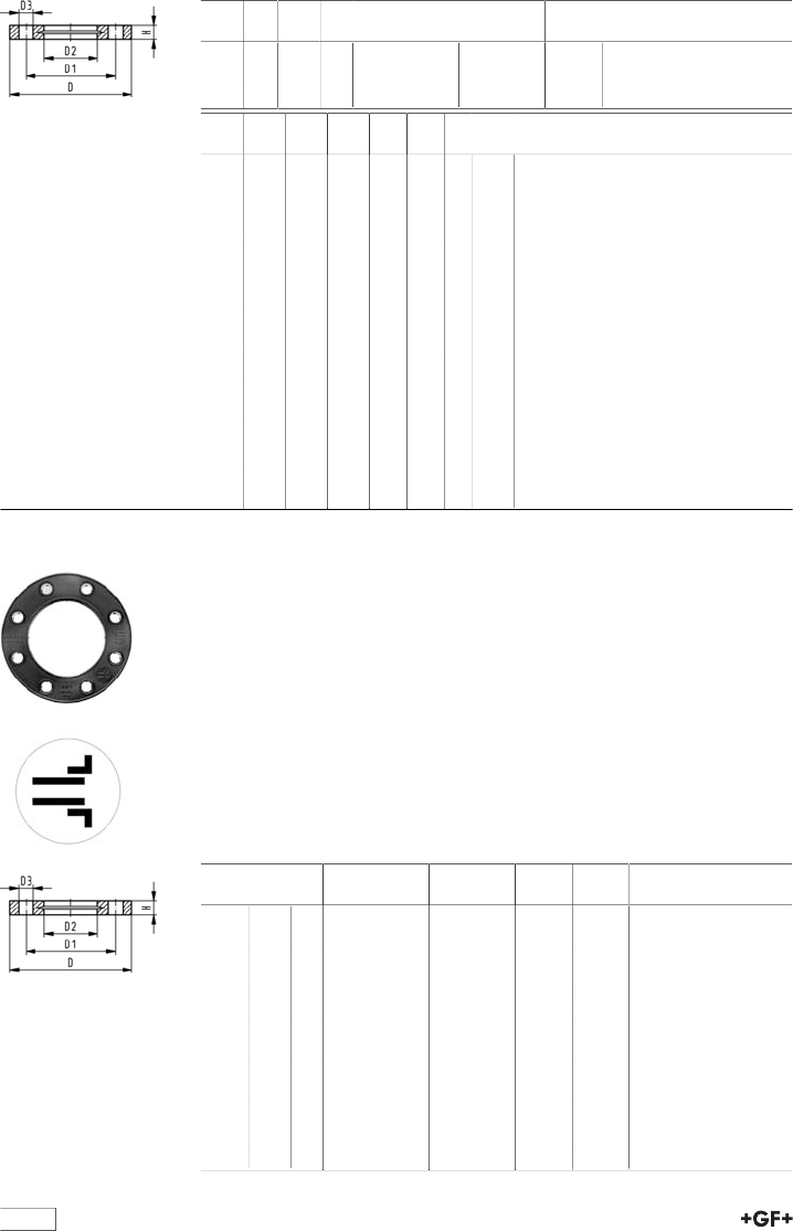
table continued next page
148
d
[mm]
Inch DN
[mm]
PN Code LVI kg
250 250 16 727 700 421 183 38 22 1.700
280 250 16 727 700 422 183 38 23 1.700
315 300 16 727 700 423 183 38 24 2.400
d
[mm]
D
[mm]
D1
[mm]
D2
[mm]
D3
[mm]
H
[mm]
AL SC
20 95 65 28 14 16 4 M12
25 105 75 34 14 17 4 M12
32 115 85 42 14 18 4 M12
40 140 100 51 18 20 4 M16
50 150 110 62 18 22 4 M16
63 165 125 78 18 24 4 M16
75 185 145 92 18 26 4 M16
90 200 160 110 18 27 8 M16
110 220 180 133 18 28 8 M16
140 250 210 167 18 30 8 M16
160 285 241 190 22 32 8 M20
200 340 296 226 22 34 8 M20
225 340 295 250 22 34 8 M20
250 395 350 277 22 38 12 M20
280 395 350 310 22 38 12 M20
315 445 400 348 22 42 12 M20
27 70 14
27 70 15 Backing Flanges, PP-V
For socket systems Inch ANSI
Model:
•Modern full-plastic flange PP-GF (30 % glass-fibre reinforced)
•With V-groove which applies force evenly on collar
•With integrated bolt-fixing as an assembly aid
•UV-resistant. Applicable for outside applications
•Connecting dimension: ANSI/ASME B 16.5 class 150, ASTM D 4024, BS
1560, BS EN 1759
• Bolt circle class 150
•DN100 and DN150: only for use with original metric flange adaptors
¹) Suitable for socket- and butt fusion systems (no pictograph on flange)
AL: number of holes
Inch DN
[mm]
PN Code LVI kg kg/m
¹1∕215 16 727 701 406 0.080 0.080
¹3∕420 16 727 701 407 0.100 0.100
¹1 25 16 727 701 408 0.140 0.140
¹1 1∕432 16 727 701 409 0.220 0.220
¹1 1∕240 16 727 701 410 0.210 0.210
¹2 50 16 727 701 411 0.380 0.380
¹2 1∕265 16 727 701 412 0.480 0.480
3 80 16 727 701 413 0.520 0.520
4 100 16 727 701 414 0.680 0.680
6 150 16 727 700 417 183 38 19 1.200 1.200
10 250 16 727 701 422 1.700 1.700
12 300 16 727 701 423 2.400 2.400
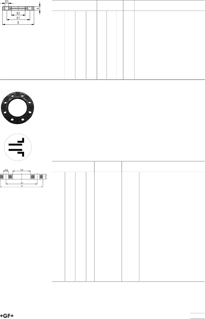
table continued next page
149
Inch D
[mm]
D1
[mm]
D2
[mm]
D3
[mm]
H
[mm]
AL SC
¹1∕295 60 28 16 16 4 M12
¹3∕4105 70 34 16 17 4 M12
¹1 115 79 42 16 18 4 M12
¹1 1∕4140 89 51 16 20 4 M16
¹1 1∕2150 98 62 16 22 4 M16
¹2 165 121 78 19 24 4 M16
¹2 1∕2185 140 92 19 26 4 M16
3 200 152 110 19 27 4 M16
4 229 190 133 19 28 8 M16
6 285 241 190 22 32 8 M20
10 406 362 310 26 38 12 M20
12 483 432 348 26 42 12 M20
27 70 02 Backing flange PP-Steel
For socket systems metric
Model:
•PP-GF (30% glass-fibre reinforced) with steel ring
•UV-resistant. Applicable for outside applications
•Connecting dimension: ISO 7005, EN 1092, BS 4504, DIN 2501
• Bolt circle PN 10
¹ Connecting dimension: ISO 2536, bolt circle acc.DN125, suitable for flange
adaptor d125/DN100
² Connecting dimension: ISO 2536, bolt circle acc. DN225, suitable for flange
adaptor d250/DN250
AL: number of holes
d
[mm]
d
[inch]
DN
[mm]
PN Code kg
20 15 16 727 700 206 0.220
25 20 16 727 700 207 0.260
32 25 16 727 700 208 0.430
40 32 16 727 700 209 0.650
50 40 16 727 700 210 0.820
63 50 16 727 700 211 0.940
75 65 16 727 700 212 1.300
90 80 16 727 700 213 1.400
110 100 16 727 700 214 1.560
¹125 125 16 727 700 215 2.590
140 125 16 727 700 216 2.120
160 6 150 16 727 700 217 3.390
200 200 16 727 700 219 5.850
225 200 16 727 700 220 4.410
²250 225 16 727 700 221 8.340
280 250 16 727 700 222 5.520
315 300 16 727 700 223 7.600
355 350 16 727 700 224 13.960
400 400 16 727 700 225 17.380
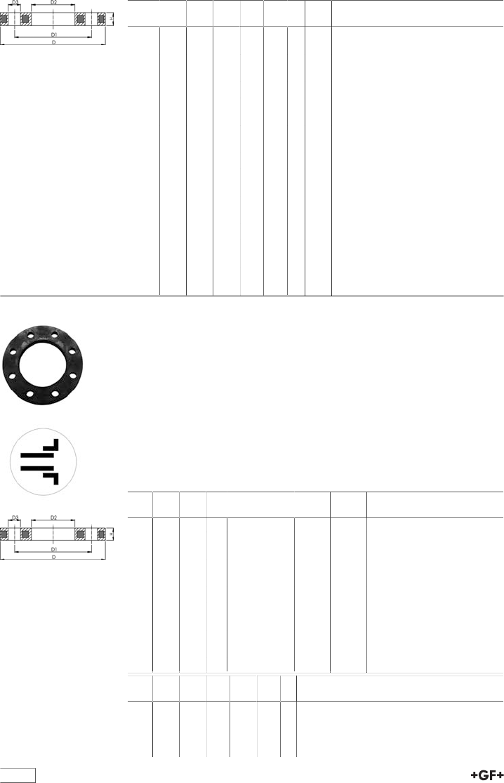
table continued next page
150
d
[mm]
D
[mm]
D1
[mm]
D2
[mm]
D3
[mm]
H
[mm]
AL SC
20 95 65 28 14 12 4 M12
25 105 75 34 14 12 4 M12
32 115 85 42 14 16 4 M12
40 140 100 51 18 16 4 M16
50 150 110 62 18 20 4 M16
63 165 125 78 18 20 4 M16
75 185 145 92 18 20 4 M16
90 200 160 110 18 20 8 M16
110 220 180 133 18 20 8 M16
¹125 250 210 150 18 24 8 M16
140 250 210 167 18 24 8 M16
160 285 240 190 22 24 8 M20
200 340 295 226 22 27 8 M20
225 340 295 250 22 27 8 M20
²250 395 325 277 22 30 8 M20
280 395 350 310 22 30 12 M20
315 445 400 348 22 34 12 M20
355 515 460 388 23 40 16 M20
400 574 515 442 26 40 16 M24
27 70 12 Backing flange PP-Steel
For socket systems Inch/ANSI
Model:
•For Flange Adaptors BS/ANSI
•Material: PP (30 % glass-fibre reinforced) with steel ring
•UV-resistant. Applicable for outside applications
•Connecting dimension: ANSI/ASME B 16.5 class 150, ASTM D 4024, BS
1560, BS EN 1759
• Bolt circle class 150
•DN100 and DN150: only for use with original metric flange adaptors
AL: number of holes
d
[inch]
DN
[mm]
d
[mm]
PN Code kg kg/m
1∕215 20 16 727 701 206 0.210 0.210
3∕420 25 16 727 701 207 0.250 0.250
1 25 32 16 727 701 208 0.420 0.420
1 1∕432 40 16 727 701 209 0.670 0.670
1 1∕240 50 16 727 701 210 0.860 0.860
2 50 63 16 727 701 211 0.930 0.930
2 1∕265 75 16 727 701 212 1.340 1.340
3 80 90 16 727 701 213 1.550 1.550
4 100 110 16 727 701 214 1.810 1.810
6 150 160 16 727 700 217 3.390 3.390
8 200 200 16 727 701 220 4.410 4.410
d
[inch]
D1
[mm]
D2
[mm]
D3
[mm]
D
[mm]
H
[mm]
AL
1∕260 28 16 95 12 4
3∕470 34 16 105 12 4
1 79 42 16 115 16 4
1 1∕489 51 16 140 16 4
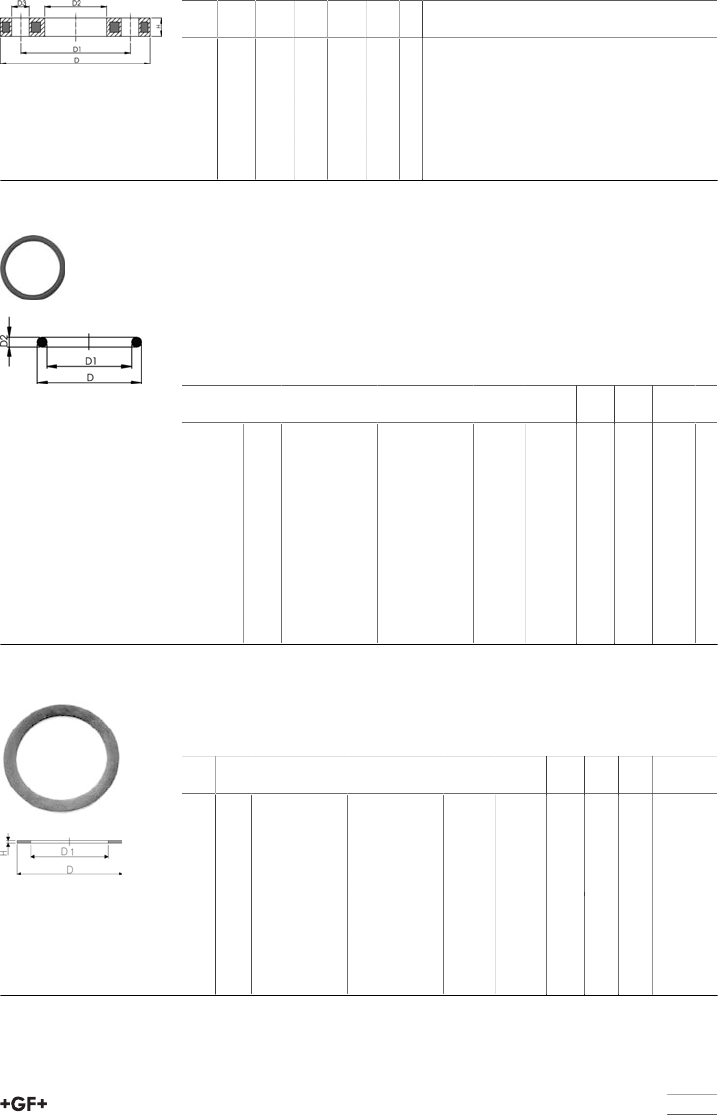
151
d
[inch]
D1
[mm]
D2
[mm]
D3
[mm]
D
[mm]
H
[mm]
AL
1 1∕298 62 16 150 18 4
2 121 78 19 165 18 4
2 1∕2140 92 19 185 18 4
3 152 110 19 200 20 4
4 190 133 19 229 20 8
6 240 190 22 285 24 8
8 298 250 22 340 27 8
EPDM 48 41 00
FPM 49 41 00 O-Ring gasket
Model:
•For unions and adaptor unions
•Hardness approx. 65° Shore
•EPDM minimum temperature -40°C
•FPM minimum temperature -15°C
* for unionsPVC-U, PVC-C and ABS: 21 51 01, 21 51 11,21 53 03, 21 53 08,
21 55 04, 21 55 13, 21 55 18, 23 51 01 and 29 51 01 only
d
[mm]
DN
[mm]
EPDM
Code
FPM
Code
kg kg/m D
[mm]
D1
[mm]
D2
[mm]
10 - 12 8 748 410 004 749 410 004 0.002 0.002 18 12 2.62
16 10 748 410 005 749 410 005 0.002 0.002 21 16 2.62
20 15 748 410 006 749 410 006 0.002 0.002 27 20 3.53
25 20 748 410 007 749 410 007 0.002 0.002 35 28 3.53
32 25 748 410 008 749 410 008 0.002 0.002 40 33 3.53
40 32 748 410 009 749 410 009 0.006 0.006 51 41 5.34
50 40 748 410 010 749 410 010 0.007 0.007 58 47 5.34
63 50 748 410 011 749 410 011 0.010 0.010 70 60 5.34
75 65 748 410 014 749 410 014 0.012 0.012 93 82 5.34
90 80 748 410 015 749 410 015 0.015 0.015 112 101 5.34
110 100 748 410 016 749 410 016 0.031 0.031 134 120 6.99
EPDM 48 40 00
FPM 49 40 00 Flat gasket
Model:
•Hardness approx. 65° Shore
•For adaptor unions
d
[mm]
Inch EPDM
Code
FPM
Code
kg kg/m D
[mm]
D1
[mm]
H
[mm]
12 1∕4748 400 004 - 0.002 0.002 20 13 2
16 3∕8748 400 005 749 400 005 0.002 0.002 24 17 2
20 1∕2748 400 006 749 400 006 0.003 0.003 30 21 3
25 3∕4748 400 007 749 400 007 0.004 0.004 38 27 3
32 1 748 400 008 749 400 008 0.002 0.002 44 32 3
40 1 1∕4748 400 009 749 400 009 0.003 0.003 55 42 3
50 1 1∕2748 400 010 749 400 010 0.004 0.004 62 46 3
63 2 748 400 011 749 400 011 0.006 0.006 78 60 3
75 2 1∕2748 400 012 749 400 012 0.009 0.009 97 75 3
90 3 748 400 013 749 400 013 0.011 0.011 109 88 3
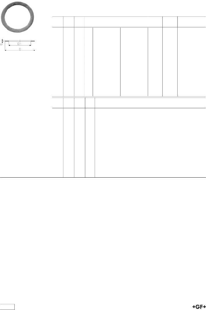
152
EPDM 48 40 00
FPM 49 40 00 Flat Gaskets
Model:
•For Flange Adaptors 21 79 01/21 80 01
•Hardness: 70° Shore EPDM, 75° Shore FPM
d
[mm]
DN
[mm]
Inch PN EPDM
Code
FPM
Code
kg kg/m
16 10 3∕810 748 400 014 0.002 0.002
20 15 1∕210 748 400 015 749 400 015 0.003 0.003
25 20 3∕410 748 400 016 749 400 016 0.003 0.003
32 25 1 10 748 400 017 749 400 017 0.004 0.004
40 32 1 1∕410 748 400 018 749 400 018 0.008 0.008
63 50 2 10 748 400 020 749 400 020 0.017 0.017
75 65 2 1∕210 748 400 021 749 400 021 0.024 0.024
90 80 3 10 748 400 022 749 400 022 0.032 0.032
110 100 4 10 748 400 023 0.015 0.048
140 125 5 10 748 400 025 749 400 025 0.058 0.058
160 150 6 10 748 400 026 749 400 026 0.063 0.063
225 200 8 6 748 400 027 749 400 027 0.103 0.103
d
[mm]
D
[mm]
D1
[mm]
H
[mm]
16 27 16 2
20 32 20 2
25 39 25 2
32 48 32 2
40 59 40 3
63 88 63 3
75 104 75 3
90 123 90 3
110 148 110 4
140 186 140 4
160 211 160 4
225 272 220 5
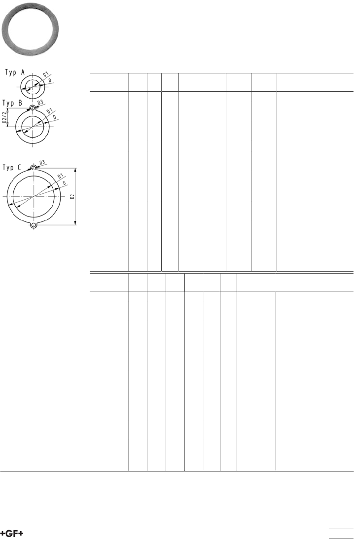
153
EPDM 48 40 03 Flat gasket
Model:
•For all metric GF Flange Adaptors
•Hardness approx. 65° Shore
•Integrated fixation aids from d110
•Centering on the inner diameter of the screw crown
di FAare the suitable inner diametersof flange adaptors
d
[mm]
DN
[mm]
PN Type EPDM
Code
kg kg/m
16 10 10 A 748 400 305 0.005 0.005
20 15 10 A 748 400 306 0.010 0.010
25 20 10 A 748 400 307 0.020 0.020
32 25 10 A 748 400 308 0.025 0.025
40 32 10 A 748 400 309 0.030 0.030
50 40 10 A 748 400 310 0.035 0.035
63 50 10 A 748 400 311 0.040 0.040
75 65 10 A 748 400 312 0.045 0.045
90 80 10 A 748 400 313 0.050 0.050
110 100 10 B 748 400 314 0.032 0.032
125 100 10 B 748 400 315 0.058 0.058
140 125 10 B 748 400 316 0.062 0.062
160 / 180 150 10 B 748 400 317 0.068 0.068
200 200 6 C 748 400 319 0.075 0.075
225 200 6 C 748 400 320 0.079 0.079
250 250 6 C 748 400 321 0.103 0.103
280 250 6 C 748 400 322 0.150 0.150
315 300 6 C 748 400 323 0.230 0.230
d
[mm]
DN
[mm]
D
[mm]
D1
[mm]
D2
[mm]
D3
[mm]
H
[mm]
di FA
[mm]
16 10 46 16 2 6 - 26
20 15 51 20 2 10 - 30
25 20 61 25 2 15 - 35
32 25 71 32 2 22 - 42
40 32 82 40 3 30 - 50
50 40 92 50 3 40 - 60
63 50 107 63 3 53 - 73
75 65 127 71 3 61 - 81
90 80 142 84 3 74 - 94
110 100 162 104 180 18 4 94 - 114
125 100 162 119 180 18 4 109 - 129
140 125 192 134 210 18 4 124 - 144
160 / 180 150 218 155 241 22 4 145 - 165
200 200 273 195 295 22 5 185 - 205
225 200 273 216 295 22 5 206 - 226
250 250 328 250 350 22 5 240 - 260
280 250 328 273 350 22 5 263 - 283
315 300 378 305 400 22 5 295 - 315
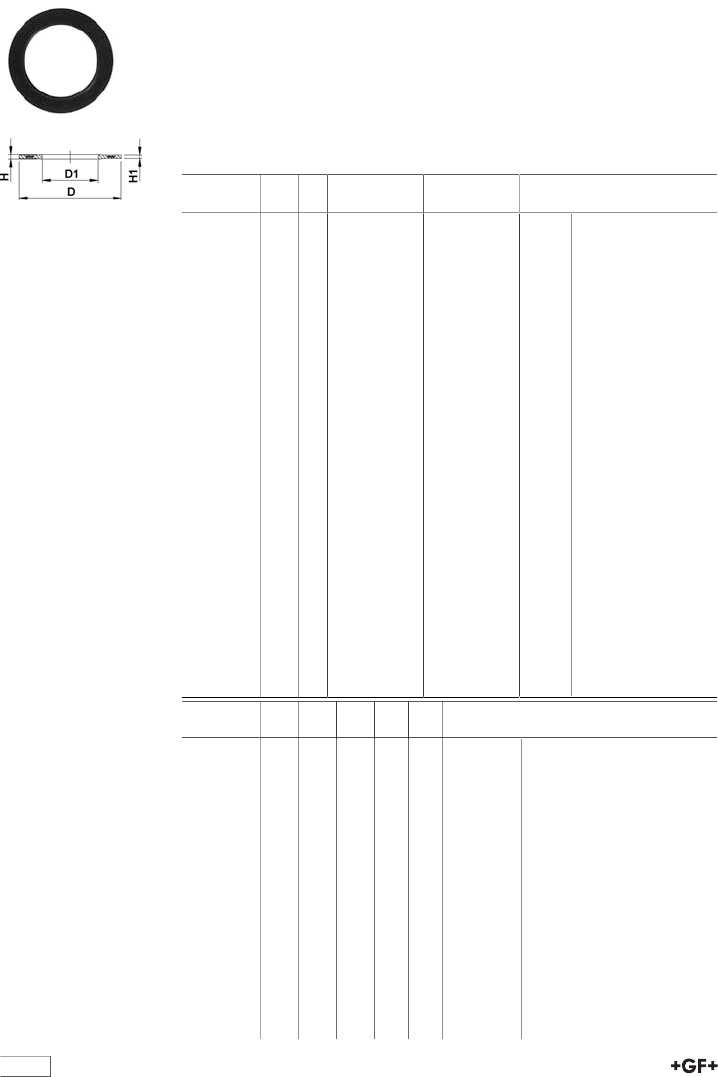
table continued next page
154
EPDM 48 44 07
FPM 49 44 07 Profile flange gasket metric
Model:
•For all metric GF Flange Adaptors
•Profile Gasket with steel insert (type G-ST-P/K)
•Hardness: 70° Shore EPDM, 75° Shore FPM
• EPDM: approved acc. to DVGW W 270, KTW recommendation
•Centering on the inner diameter of the screw crown
•material steel insert: carbon steel
di FAare the suitable inner diametersof flange adaptors
d
[mm]
DN
[mm]
PN EPDM
Code
FPM
Code
kg
16 10 16 748 440 705 749 440 705 0.007
20 15 16 748 440 706 749 440 706 0.008
25 20 16 748 440 707 749 440 707 0.011
32 25 16 748 440 708 749 440 708 0.014
40 32 16 748 440 709 749 440 709 0.021
50 40 16 748 440 710 749 440 710 0.022
63 50 16 748 440 711 749 440 711 0.041
75 65 16 748 440 712 749 440 712 0.055
90 80 16 748 440 713 749 440 713 0.062
110 100 16 748 440 714 749 440 714 0.085
125 100 16 748 440 715 749 440 715 0.158
140 125 16 748 440 716 749 440 716 0.118
160 / 180 150 16 748 440 717 749 440 717 0.153
200 200 16 748 440 719 749 440 719 0.263
225 200 16 748 440 720 749 440 720 0.181
250 250 16 748 440 721 749 440 721 0.410
280 250 16 748 440 722 749 440 722 0.226
315 300 16 748 440 723 749 440 723 0.334
355 350 16 748 440 724 749 440 724 0.410
400 400 16 748 440 725 749 440 725 0.513
450 500 16 748 440 726 749 440 726 0.718
500 500 16 748 440 727 749 440 727 0.718
560 600 16 748 440 728 749 440 728 0.923
630 600 16 748 440 729 749 440 729 0.923
d
[mm]
DN
[mm]
D
[mm]
D1
[mm]
H
[mm]
H1
[mm]
di FA
[mm]
16 10 46 16 4 3 6 - 16
20 15 51 20 4 3 10 - 20
25 20 61 22 4 3 12 - 22
32 25 71 28 4 3 18 - 28
40 32 82 40 4 3 30 - 40
50 40 92 46 4 3 36 - 46
63 50 107 58 5 4 48 - 58
75 65 127 69 5 4 59 - 69
90 80 142 84 5 4 73 - 84
110 100 162 104 6 5 94 - 104
125 100 162 123 6 5 113 - 123
140 125 192 137 6 5 127 - 137
160 / 180 150 218 160 8 6 150 - 160
200 200 273 203 8 6 192 - 203
225 200 273 220 8 6 207 - 220
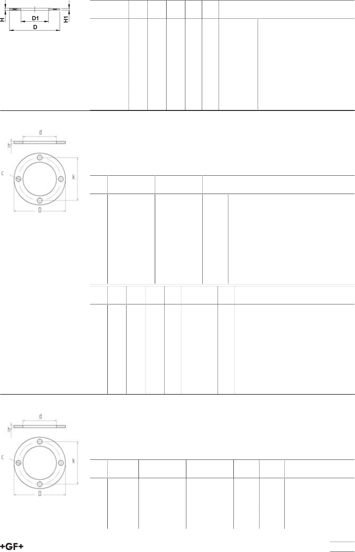
table continued next page
155
d
[mm]
DN
[mm]
D
[mm]
D1
[mm]
H
[mm]
H1
[mm]
di FA
[mm]
250 250 328 252 8 6 238 - 252
280 250 328 274 8 6 264 - 274
315 300 378 306 8 6 296 - 306
355 350 438 355 10 7 340 - 355
400 400 489 400 10 7 385 - 400
450 500 594 403 10 7 393 - 403
500 500 594 447 10 7 437 - 447
560 600 695 494 10 7 484 - 494
630 600 695 555 10 7 545 - 555
48 40 10 Flat Gaskets for Full Face Flanges
Drilled to BS4504 PN10/16
Model:
•For Flange Adaptors
•Hardness approx. 65° Shore
Inch EPDM
Code
FPM
Code
kg
1∕2748 401 006 0.031
3∕4748 401 007 0.037
1748 401 008 0.037
1 1∕4748 401 109 749 401 109
1 1∕2748 401 110 749 401 110
2748 401 111 749 401 111
3748 401 113 749 401 113
4748 401 014 0.112
6748 401 117 749 401 117
Inch D
[mm]
d
[mm]
k
[mm]
c
[mm]
no. of holes h
[mm]
1∕295 17 67 15 4 3
3∕4105 22 73 15 4 3
1 115 28 83 15 4 3
1 1∕4140 36 100 18 4 3
1 1∕2150 45 110 18 4 3
2 165 58 125 18 4 3
3 200 83 160 18 8 3
4 220 109 178 18 8 3
6 285 161 240 22 8 3
48 40 10 Flat Gaskets for Full Face Flanges
Drilled to BS10 tables D and E
Model:
•For Flange Adaptors
•Hardness approx. 65° Shore
Inch EPDM
Code
FPM
Code
kg kg/m
1∕2748 401 006 749 401 006 0.003 0.003
3∕4748 401 007 749 401 007 0.004 0.004
1748 401 008 749 401 008 0.004 0.004
1 1∕4748 401 009 749 401 009 0.003 0.003
1 1∕2748 401 010 749 401 010 0.004 0.004
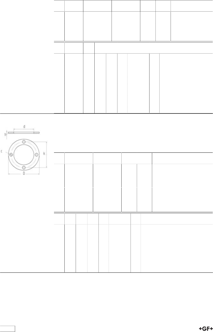
156
Inch EPDM
Code
FPM
Code
kg kg/m
2748 401 011 749 401 011 0.105 0.105
3748 401 013 749 401 013 0.011 0.011
4 Table E 748 401 014 749 401 014 0.015 0.015
*4 Table D 748 401 064 749 401 064 0.112
6748 401 017 749 401 017 0.020 0.020
Inch D
[mm]
d
[mm]
k
[mm]
c
[mm]
no. of holes h
[mm]
1∕295 17 67 15 4 3
3∕4105 22 73 15 4 3
1 115 28 83 15 4 3
1 1∕4140 36 88 15 4 3
1 1∕2150 45 98 15 4 3
2 165 58 115 18 4 3
3 200 83 146 18 4 3
4 Table E 220 109 178 18 8 3
*4 Table D 220 109 178 18 4 3
6 285 161 235 22 8 3
48 40 10 Flat Gaskets for Full Face Flanges
Drilled to ANSI B16.5 Class 150
Model:
•For Flange Adaptors
•Hardness approx. 65° Shore
Inch EPDM
Code
FPM
Code
kg kg/m
1∕2748 401 206 749 401 206
3∕4748 401 207 749 401 207
1748 401 208 749 401 208
1 1∕4748 401 009 0.041
1 1∕2748 401 010 0.055
2748 401 211 749 401 211
3748 401 213 749 401 213
4748 401 214 749 401 214 0.112 0.112
Inch D
[mm]
d
[mm]
k
[mm]
c
[mm]
no. of holes h
[mm]
1∕295 17 60 16 4 3
3∕4105 22 70 16 4 3
1 115 28 79 16 4 3
1 1∕4140 36 88 15 4 3
1 1∕2150 45 98 15 4 3
2 165 58 121 19 4 3
3 200 83 152 19 4 3
4 220 109 190 19 8 3

Index
157
Code Page
- 88
158 001 041 45
158 001 042 45
158 001 043 45
158 001 044 45
158 001 045 45
158 001 046 45
158 001 047 45
158 001 048 45
158 001 049 45
158 001 050 45
158 001 051 45
158 001 052 45
158 001 053 45
158 001 054 45
158 001 055 45
158 001 056 45
158 001 057 45
158 001 058 45
158 001 059 46
158 001 060 46
158 001 061 46
158 001 062 46
158 001 063 46
158 001 064 46
158 001 065 46
158 001 066 46
158 001 067 46
158 001 068 46
158 001 069 46
158 001 070 46
158 001 071 46
158 001 072 46
158 001 073 46
158 001 074 46
158 001 075 46
158 001 076 46
158 001 077 46
158 001 078 46
158 001 079 46
158 001 080 46
158 001 081 46
158 001 082 46
158 001 083 46
158 001 084 46
158 001 085 46
158 001 086 46
158 001 087 46
158 001 088 46
158 001 089 46
158 001 090 46
158 001 091 46
Code Page
158 001 092 46
158 001 093 46
158 001 094 46
158 001 095 46
158 001 096 46
158 001 097 46
158 001 098 46
158 001 099 46
158 001 100 46
158 001 101 46
158 001 102 46
158 001 103 46
158 001 104 46
158 001 105 46
158 001 106 46
158 001 107 46
158 001 108 46
158 001 109 46
158 001 110 47
158 001 111 47
158 001 112 47
158 001 113 47
158 001 114 47
158 001 115 47
158 001 116 47
158 001 117 47
158 001 118 47
158 001 119 47
158 001 120 47
158 001 121 47
158 001 122 47
158 001 123 47
158 001 124 47
161 305 303 120
161 305 336 118
161 305 337 118
161 305 338 117
161 305 339 117
161 305 353 120
161 305 386 118
161 305 387 118
161 305 388 117
161 305 389 117
161 305 403 120
161 305 436 118
161 305 437 118
161 305 438 117
161 305 439 117
161 305 453 120
161 305 486 118
161 305 487 118
161 305 488 117
Code Page
161 305 489 117
161 305 503 120
161 305 536 118
161 305 537 118
161 305 538 117
161 305 539 117
161 305 553 120
161 305 586 118
161 305 587 118
161 305 588 117
161 305 589 117
161 305 603 120
161 305 604 121
161 305 636 118
161 305 637 118
161 305 638 117
161 305 639 117
161 305 653 120
161 305 654 121
161 305 686 118
161 305 687 118
161 305 688 117
161 305 689 117
161 330 304 114
161 330 354 114
161 330 404 114
161 330 454 114
161 330 504 114
161 330 554 114
161 330 654 114
161 480 141 115
161 480 158 116
161 480 231 92
161 480 232 92
161 480 233 92
161 480 237 92
161 480 238 92
161 480 239 92
161 480 240 92
161 480 241 92
161 480 242 92
161 481 028 92
161 481 029 92
161 481 030 92
161 481 098 92
161 481 099 92
161 481 100 92
161 481 759 93
161 481 760 93
161 481 932 92
161 482 017 122
161 482 018 122

Index
158
Code Page
161 482 019 122
161 482 020 122
161 482 021 122
161 482 022 122
161 482 408 110
161 482 514 92
161 482 515 92
161 482 516 92
161 482 517 92
161 482 910 116
161 482 911 116
161 482 912 116
161 482 913 116
161 482 914 116
161 482 915 116
161 483 008 92
161 483 009 92
161 483 020 92
161 483 021 92
161 483 032 93
161 483 033 93
161 483 034 93
161 483 126 119
161 483 127 119
161 483 128 119
161 483 129 119
161 483 130 119
161 483 131 119
161 483 132 119
161 483 133 119
161 483 259 115
161 483 260 115
161 483 261 115
161 483 262 115
161 483 263 115
161 483 264 115
161 483 462 110
161 484 458 92
161 484 459 92
161 484 460 92
161 484 631 92
161 484 638 92
161 484 694 92
161 484 702 92
161 486 100 118
161 486 101 118
161 486 102 118
161 486 103 118
161 486 104 118
161 486 105 118
161 486 106 118
161 486 107 118
Code Page
161 486 325 109
161 486 326 110
161 486 327 110
161 486 328 110
161 486 400 75
161 486 401 75
161 486 402 75
161 486 403 75
161 486 404 75
161 486 405 75
161 486 406 76
161 486 407 76
161 486 408 76
161 486 435 68
161 486 436 68
161 486 437 68
161 486 438 68
161 486 443 57
161 486 444 57
161 486 445 57
161 486 446 57
161 486 689 57
161 486 690 57
161 486 691 57
161 486 694 110
161 486 695 110
161 486 697 110
161 486 899 109
161 486 900 109
161 486 901 109
161 486 902 109
161 486 903 109
161 486 904 109
161 486 905 109
161 486 906 109
161 486 907 109
161 486 908 109
161 486 909 109
161 486 926 109
161 486 927 109
161 486 928 109
161 486 959 108
161 486 960 108
161 486 961 108
161 486 962 108
161 486 963 108
161 486 964 108
161 486 965 108
161 486 966 108
161 486 967 108
161 488 242 78
161 488 243 78
Code Page
161 488 244 78
161 488 245 78
161 488 246 78
161 488 247 78
161 490 920 68
161 490 921 68
163 481 102 120
163 481 103 120
163 481 104 120
163 481 105 120
163 481 106 120
163 481 107 120
167 060 019 143
167 060 020 143
167 060 021 143
167 060 022 143
167 060 023 143
167 060 024 143
167 060 025 143
167 060 038 143
167 060 039 143
167 060 040 143
167 060 041 143
167 060 042 143
167 060 043 143
167 060 064 143
167 060 067 143
167 060 070 143
167 061 003 141
167 061 004 141
167 061 012 140
167 061 013 140
167 061 014 141
167 061 015 141
167 061 016 140
167 061 017 141
167 061 035 141
167 061 036 141
167 061 037 141
167 061 038 141
167 061 039 141
167 061 040 141
167 061 041 141
167 061 054 140
167 061 055 140
167 061 056 140
167 061 057 140
167 061 058 140
167 061 059 140
167 061 060 140
167 061 061 140
167 061 114 140

Index
159
Code Page
167 061 153 140
167 061 155 140
167 061 156 140
167 061 157 140
167 061 158 140
167 061 159 140
167 061 160 140
167 061 161 140
167 061 162 140
167 061 163 140
167 061 164 141
167 061 165 141
167 061 166 141
167 061 167 141
167 305 001 119
167 305 002 119
167 305 003 119
167 305 004 119
167 305 005 119
167 305 006 119
167 305 020 120
167 305 021 120
167 305 022 120
167 305 023 120
167 305 024 120
167 305 025 120
167 305 030 121
167 305 031 121
167 305 032 121
167 305 033 121
167 305 034 121
167 305 035 121
167 305 040 120
167 305 041 120
167 305 042 120
167 305 043 120
167 305 044 120
167 305 045 120
167 480 024 114
167 480 025 114
167 480 026 114
167 480 027 114
167 480 028 114
167 480 029 114
167 481 165 114
167 481 166 114
167 481 167 114
167 481 168 114
167 481 169 114
167 481 170 114
167 482 479 78
167 482 480 78
Code Page
167 482 481 78
167 482 482 78
167 482 626 69
167 482 627 69
167 482 628 69
167 482 629 69
167 482 630 69
167 482 631 69
167 482 635 70
167 482 636 70
167 482 637 70
167 482 638 70
167 482 639 70
167 482 640 70
167 482 653 72
167 482 654 72
167 482 655 72
167 482 656 72
167 482 657 72
167 482 658 72
167 482 662 72
167 482 663 72
167 482 664 72
167 482 665 72
167 482 666 72
167 482 667 72
167 482 671 71
167 482 672 71
167 482 673 71
167 482 674 71
167 482 675 71
167 482 676 71
167 482 680 70
167 482 681 70
167 482 682 70
167 482 683 70
167 482 684 70
167 482 685 70
167 483 251 109
167 483 252 109
167 483 253 109
167 483 254 109
167 484 076 75
167 484 077 75
167 484 078 75
167 484 079 75
167 484 080 75
167 484 081 75
167 484 082 75
167 484 083 75
167 484 084 75
167 484 088 75
Code Page
167 484 089 75
167 484 090 75
167 484 091 75
167 484 092 75
167 484 093 75
167 484 094 75
167 484 095 75
167 484 096 75
167 484 100 57
167 484 101 57
167 484 102 57
167 484 103 57
167 484 104 57
167 484 105 57
167 484 110 69
167 484 111 69
167 484 376 77
167 484 377 77
167 484 378 77
167 484 379 77
167 484 380 77
167 484 381 77
167 484 442 77
167 484 443 77
167 484 444 77
167 484 445 77
167 484 446 77
167 484 447 77
167 484 488 77
167 484 489 77
167 484 490 77
167 484 491 77
167 484 492 77
167 484 493 77
167 484 542 77
167 484 543 77
167 484 544 77
167 484 545 77
167 484 546 77
167 484 547 77
167 484 576 77
167 484 577 77
167 484 578 77
167 484 579 77
167 484 580 77
167 484 581 77
167 484 588 77
167 484 589 77
167 484 590 77
167 484 591 77
167 484 592 77
167 484 593 77

Index
160
Code Page
167 484 642 80
167 484 643 80
167 484 644 80
167 484 645 80
167 484 646 80
167 484 647 80
167 484 688 80
167 484 689 80
167 484 690 80
167 484 691 80
167 484 692 80
167 484 693 80
167 484 742 80
167 484 743 80
167 484 744 80
167 484 745 80
167 484 746 80
167 484 747 80
167 484 788 80
167 484 789 80
167 484 790 80
167 484 791 80
167 484 792 80
167 484 793 80
167 484 941 78
167 484 942 78
167 484 943 78
167 484 944 78
167 484 945 81
167 484 946 81
167 484 947 81
167 484 948 81
167 484 992 86
167 484 993 86
167 484 994 86
167 484 995 86
167 484 996 86
167 484 997 86
169 017 080 25
169 017 081 25
169 017 082 25
169 017 083 25
169 017 084 25
169 017 085 25
169 017 086 25
169 017 087 4
169 017 088 25
169 017 089 25
169 017 091 4
169 017 092 25
169 017 093 25
169 017 094 25
Code Page
169 017 095 25
169 017 096 25
169 017 097 25
169 018 033 4
169 018 034 4
169 018 035 4
169 018 036 4
169 018 038 4
169 018 039 4
169 018 042 4
169 018 045 4
169 018 067 4
169 018 080 4
169 018 081 4
169 018 082 4
169 018 083 4
169 018 084 4
169 018 085 4
169 018 086 4
169 018 088 4
169 018 089 4
169 018 106 5
169 018 107 5
169 018 108 5
169 018 109 5
169 018 110 5
169 018 111 5
169 110 056 45
169 110 066 45
169 110 097 45
169 110 117 45
169 250 225 22
169 250 226 22
169 250 227 22
169 250 228 22
169 250 229 22
169 250 230 22
169 250 231 22
169 280 002 14
169 280 003 14
169 280 004 14
169 280 005 14
169 280 006 14
169 280 007 14
169 303 006 111
169 303 007 111
169 303 008 111
169 303 009 111
169 303 010 111
169 303 011 111
169 305 302 117
169 305 303 117
Code Page
169 305 304 117
169 305 305 117
169 305 306 117
169 305 307 117
169 317 024 84
169 317 025 84
169 317 423 84
169 360 401 113
169 360 402 113
169 360 403 113
169 360 404 113
169 360 405 113
169 360 406 113
169 360 407 113
169 360 421 112
169 360 422 112
169 360 423 112
169 360 424 112
169 360 425 112
169 360 426 112
169 360 427 112
169 360 431 112
169 360 432 112
169 360 433 112
169 360 434 112
169 360 435 112
169 360 436 112
169 360 437 112
169 360 521 112
169 360 522 112
169 360 523 112
169 360 524 112
169 360 525 112
169 360 526 112
169 360 527 112
169 360 531 112
169 360 532 112
169 360 533 112
169 360 534 112
169 360 535 112
169 360 536 112
169 360 537 112
169 480 101 115
169 480 102 115
169 480 103 115
169 480 104 115
169 480 105 115
169 480 106 115
169 480 152 115
169 480 153 115
169 480 154 115
169 480 155 115

Index
161
Code Page
169 480 156 115
169 480 157 115
169 480 158 115
169 480 250 114
169 480 251 114
169 480 252 114
169 480 253 114
169 480 254 114
169 480 255 114
169 480 256 114
169 480 282 93
169 480 283 93
169 480 600 119
169 480 601 119
169 480 602 119
169 480 603 119
169 480 604 119
169 480 605 119
169 480 609 120
169 480 610 120
169 480 611 120
169 480 612 120
169 480 613 120
169 480 614 120
169 480 751 74
169 480 752 74
169 480 753 74
169 480 754 74
169 480 755 74
169 480 756 74
169 480 757 74
169 480 758 74
169 480 759 74
169 480 900 74
169 480 901 74
169 480 902 74
169 480 903 74
169 480 904 74
169 480 905 74
169 480 906 75
169 480 907 75
169 480 908 75
169 480 951 109
169 480 952 109
169 480 953 109
169 480 954 109
169 480 955 109
169 480 956 109
169 480 957 109
169 481 067 108
169 481 068 108
169 481 069 108
Code Page
169 481 070 108
169 481 071 108
169 481 072 108
169 481 073 108
169 481 202 76
169 481 203 76
169 481 204 76
169 481 205 76
169 481 206 76
169 481 207 76
169 481 212 76
169 481 213 76
169 481 214 76
169 481 215 76
169 481 216 76
169 481 217 76
169 481 221 79
169 481 222 79
169 481 223 79
169 481 224 79
169 481 225 79
169 481 226 79
169 481 227 79
169 481 231 79
169 481 232 79
169 481 233 79
169 481 234 79
169 481 235 79
169 481 236 79
169 481 237 79
169 481 282 77
169 481 283 77
169 481 284 77
169 481 285 77
169 481 286 77
169 481 287 77
169 481 292 77
169 481 293 77
169 481 294 77
169 481 295 77
169 481 296 77
169 481 297 77
169 481 302 80
169 481 303 80
169 481 304 80
169 481 305 80
169 481 306 80
169 481 307 80
169 481 312 80
169 481 313 80
169 481 314 80
169 481 315 80
Code Page
169 481 316 80
169 481 317 80
169 481 862 90
169 481 863 90
169 481 864 90
169 481 865 90
169 481 866 90
169 481 867 90
169 514 012 82
169 514 013 82
169 514 014 82
169 514 015 82
169 514 016 82
169 514 017 82
169 514 032 82
169 514 033 82
169 514 034 82
169 514 035 82
169 514 036 82
169 514 037 82
169 514 512 82
169 514 513 82
169 514 514 82
169 514 515 82
169 514 516 82
169 514 517 82
169 514 532 82
169 514 533 82
169 514 534 82
169 514 535 82
169 514 536 82
169 514 537 82
169 515 012 83
169 515 013 83
169 515 014 83
169 515 015 83
169 515 016 83
169 515 017 83
169 515 032 83
169 515 033 83
169 515 034 83
169 515 035 83
169 515 036 83
169 515 037 83
169 543 001 58
169 543 002 58
169 543 003 58
169 543 004 58
169 543 005 58
169 543 006 58
169 543 007 58
169 543 041 59

Index
162
Code Page
169 543 042 59
169 543 043 59
169 543 044 59
169 543 045 59
169 543 046 59
169 543 047 59
169 543 061 61
169 543 062 61
169 543 063 61
169 543 064 61
169 543 065 61
169 543 066 61
169 543 067 61
169 543 201 62
169 543 202 62
169 543 203 62
169 543 204 62
169 543 205 62
169 543 206 62
169 543 207 62
169 543 241 63
169 543 242 63
169 543 243 63
169 543 244 63
169 543 245 63
169 543 246 63
169 543 247 63
169 543 261 65
169 543 262 65
169 543 263 65
169 543 264 65
169 543 265 65
169 543 266 65
169 543 267 65
169 543 302 60
169 543 303 60
169 543 304 60
169 543 305 60
169 543 306 60
169 543 307 60
169 543 322 64
169 543 323 64
169 543 324 64
169 543 325 64
169 543 326 64
169 543 327 64
169 543 401 66
169 543 402 66
169 543 403 66
169 543 404 66
169 543 405 66
169 543 406 66
Code Page
169 543 407 66
169 543 421 67
169 543 422 67
169 543 423 67
169 543 424 67
169 543 425 67
169 543 426 67
169 543 427 67
169 546 001 52
169 546 002 52
169 546 003 52
169 546 004 52
169 546 005 52
169 546 006 52
169 546 007 52
169 546 008 49
169 546 009 52
169 546 010 52
169 546 021 54
169 546 022 54
169 546 023 54
169 546 024 54
169 546 025 54
169 546 026 54
169 546 027 54
169 546 061 53
169 546 062 53
169 546 063 53
169 546 064 53
169 546 065 53
169 546 066 53
169 546 067 53
169 546 068 50
169 546 069 53
169 546 070 53
169 546 081 56
169 546 082 56
169 546 083 56
169 546 084 56
169 546 085 56
169 546 086 56
169 546 087 56
169 546 088 51
169 546 089 56
169 546 090 56
169 546 201 49
169 546 202 49
169 546 203 49
169 546 204 49
169 546 205 49
169 546 206 49
169 546 207 49
Code Page
169 546 209 49
169 546 210 49
169 546 221 51
169 546 222 51
169 546 223 51
169 546 224 51
169 546 225 51
169 546 226 51
169 546 227 51
169 546 229 51
169 546 230 51
169 546 241 50
169 546 242 50
169 546 243 50
169 546 244 50
169 546 245 50
169 546 246 50
169 546 247 50
169 546 249 50
169 546 250 50
169 567 002 97
169 567 003 97
169 567 004 97
169 567 005 97
169 567 006 97
169 567 007 97
169 567 008 97
169 567 022 98
169 567 023 98
169 567 024 98
169 567 025 98
169 567 026 98
169 567 027 98
169 567 028 98
169 567 802 94
169 567 803 94
169 567 804 94
169 567 805 94
169 567 806 94
169 567 807 94
169 567 808 94
169 568 002 101
169 568 003 101
169 568 004 101
169 568 005 101
169 568 006 101
169 568 007 101
169 568 008 101
169 568 022 102
169 568 023 102
169 568 024 102
169 568 025 102

Index
163
Code Page
169 568 026 102
169 568 027 102
169 568 028 102
169 568 102 99
169 568 103 99
169 568 104 99
169 568 105 99
169 568 106 99
169 568 107 99
169 568 108 99
169 568 122 100
169 568 123 100
169 568 124 100
169 568 125 100
169 568 126 100
169 568 127 100
169 568 128 100
169 568 802 95
169 568 803 95
169 568 804 95
169 568 805 95
169 568 806 95
169 568 807 95
169 568 808 95
169 568 902 96
169 568 903 96
169 568 904 96
169 568 905 96
169 568 906 96
169 568 907 96
169 568 908 96
173 061 003 142
173 061 004 142
173 061 005 142
173 061 006 142
173 061 007 142
173 061 008 142
173 061 009 142
173 061 010 142
173 061 011 142
173 061 012 142
173 061 013 142
173 061 014 142
173 061 015 142
173 061 016 142
173 061 017 142
173 061 153 142
173 061 155 142
173 061 156 142
173 061 157 142
173 061 158 142
173 061 159 142
Code Page
173 061 160 142
173 061 161 142
173 061 162 142
173 061 163 142
173 061 164 142
173 061 165 142
173 061 166 142
173 061 167 142
175 480 153 114
175 480 154 114
175 480 155 114
175 480 156 114
175 480 157 114
175 480 158 114
198 000 599 110
198 000 621 110
198 000 622 110
198 000 872 88
198 000 873 88
198 000 874 88
198 000 875 88
198 000 876 88
198 000 877 88
198 000 880 110
198 000 881 88
198 000 882 88
198 000 883 88
198 000 884 88
198 000 885 88
198 000 886 88
198 000 892 86
198 000 893 86
198 000 894 86
198 000 895 86
198 000 896 86
198 000 897 86
198 104 166 85
198 151 742 85
198 151 743 85
198 151 744 85
198 151 745 85
198 151 746 85
198 151 747 85
198 151 752 85
198 151 753 85
198 151 754 85
198 151 755 85
198 151 756 85
198 151 757 85
198 151 762 87
198 151 763 87
198 151 764 87
Code Page
198 151 765 87
198 151 766 87
198 151 767 87
198 151 772 87
198 151 773 87
198 151 774 87
198 151 775 87
198 151 776 87
198 151 777 87
198 151 782 87
198 151 783 87
198 151 784 87
198 151 785 87
198 151 786 87
198 151 787 87
198 151 792 87
198 151 793 87
198 151 794 87
198 151 795 87
198 151 796 87
198 151 797 87
198 151 802 87
198 151 803 87
198 151 804 87
198 151 805 87
198 151 806 87
198 151 807 87
198 151 842 85
198 151 843 85
198 151 844 85
198 151 845 85
198 151 846 85
198 151 847 85
198 151 852 85
198 151 853 85
198 151 854 85
198 151 855 85
198 151 856 85
198 151 857 85
198 204 162 85
198 204 164 85
198 204 327 86
198 204 328 86
198 204 329 86
198 335 055 132
198 335 056 132
198 335 057 132
198 335 058 132
198 335 059 132
198 335 060 132
198 335 061 132
198 335 070 132

Index
164
Code Page
198 335 071 132
198 335 072 132
198 335 073 132
198 335 074 132
198 335 075 132
198 335 076 132
198 335 077 132
198 335 078 132
198 335 079 132
198 335 080 132
198 335 081 132
198 335 082 132
198 335 085 132
198 335 086 132
198 335 087 132
198 335 088 132
198 335 089 132
198 335 090 132
198 335 091 132
198 335 092 132
198 335 093 132
198 335 094 132
198 335 095 132
198 335 096 132
198 335 097 132
198 335 098 134
198 335 255 133
198 335 256 133
198 335 257 133
198 335 258 133
198 335 259 133
198 335 260 133
198 335 261 133
198 335 270 133
198 335 271 133
198 335 272 133
198 335 273 133
198 335 274 133
198 335 275 133
198 335 276 133
198 335 277 133
198 335 278 133
198 335 279 133
198 335 280 133
198 335 281 133
198 335 282 133
198 335 285 133
198 335 286 133
198 335 287 133
198 335 288 133
198 335 289 133
198 335 290 133
Code Page
198 335 291 133
198 335 292 133
198 335 293 133
198 335 294 133
198 335 295 133
198 335 296 133
198 335 297 133
198 335 455 134
198 335 456 134
198 335 457 134
198 335 458 134
198 335 459 134
198 335 460 134
198 335 470 134
198 335 471 134
198 335 472 134
198 335 473 134
198 335 474 134
198 335 960 131
198 335 961 131
198 335 962 130
198 335 963 130
198 335 964 130
198 335 965 130
198 335 966 130
198 335 967 130
198 335 968 130
198 335 969 130
198 335 970 133
198 335 971 133
198 335 972 133
198 335 973 133
198 335 974 133
198 335 975 133
198 335 977 133
198 335 978 133
198 335 979 133
198 335 980 133
198 335 981 133
198 335 982 133
198 335 985 134
198 335 986 134
198 335 987 134
198 335 990 134
198 335 991 130
198 335 992 130
198 335 993 130
198 335 994 130
198 335 995 130
198 801 338 136
198 801 339 136
198 801 340 136
Code Page
198 801 341 136
198 801 342 136
198 801 343 136
198 801 445 136
198 801 449 136
198 801 450 136
198 801 451 136
198 802 814 123
198 802 815 123
198 802 816 123
198 802 817 123
198 802 818 123
198 802 819 123
198 802 820 123
198 802 821 123
198 802 822 123
198 802 823 123
198 802 824 123
198 802 825 123
198 802 826 124
198 802 827 124
198 802 828 124
198 802 829 124
198 802 830 124
198 802 831 124
198 802 832 124
198 802 833 124
198 802 834 124
198 802 835 124
198 802 836 124
198 802 837 124
198 803 790 136
198 803 791 136
198 803 792 136
198 803 793 136
198 803 794 136
198 803 795 136
198 803 796 136
198 803 797 136
198 803 798 136
198 803 799 136
198 806 219 136
198 806 220 136
198 806 221 136
198 806 222 136
198 806 223 136
198 806 224 136
198 806 639 87
198 806 640 87
198 807 040 127
198 807 041 127
198 807 042 127

Index
165
Code Page
198 807 043 127
198 807 044 127
198 807 045 127
198 807 046 127
198 807 047 127
198 807 048 127
198 807 049 127
198 807 050 128
198 807 051 128
198 807 052 128
198 807 053 128
198 807 054 128
198 807 055 128
198 807 056 128
198 807 057 128
198 807 058 128
198 807 059 128
198 807 120 125
198 807 121 125
198 807 122 125
198 807 123 125
198 807 124 125
198 807 125 125
198 807 126 125
198 807 127 125
198 807 128 125
198 807 129 125
198 807 130 125
198 807 131 125
198 807 132 126
198 807 133 126
198 807 134 126
198 807 135 126
198 807 136 126
198 807 137 126
198 807 138 126
198 807 139 126
198 807 140 126
198 807 141 126
198 807 142 126
198 807 143 126
198 807 144 129
198 807 145 129
198 807 146 129
198 807 147 129
198 807 148 129
198 807 149 129
198 807 150 129
198 807 151 129
198 807 152 129
198 807 153 129
198 807 154 130
Code Page
198 807 155 130
198 807 156 130
198 807 157 130
198 807 158 130
198 807 159 130
198 807 160 130
198 807 161 130
198 807 162 130
198 807 163 130
198 807 166 136
198 807 182 137
198 807 187 137
198 807 188 137
198335062* 132
198335063* 132
198335064* 132
198335065* 132
198335066* 132
198335067* 132
198335262* 133
198335263* 133
198335264* 133
198335265* 133
198335266* 133
198335267* 133
199 037 000 103
199 037 001 103
199 037 002 103
199 037 003 103
199 037 004 103
199 037 005 103
199 037 006 103
199 037 007 103
199 037 008 103
199 037 013 103
199 037 014 103
199 037 015 103
199 037 016 103
199 037 017 103
199 037 018 103
199 037 019 103
199 037 020 103
199 037 021 103
199 037 200 103
199 037 201 103
199 037 202 103
199 037 203 103
199 037 204 103
199 037 205 103
199 037 206 103
199 037 207 103
199 037 208 103
Code Page
199 037 213 103
199 037 214 103
199 037 215 103
199 037 216 103
199 037 217 103
199 037 218 103
199 037 219 103
199 037 220 103
199 037 221 103
199 037 400 103
199 037 401 103
199 037 402 103
199 037 403 103
199 037 404 103
199 037 405 103
199 037 406 103
199 037 407 103
199 037 408 103
199 037 413 103
199 037 414 103
199 037 415 103
199 037 416 103
199 037 417 103
199 037 418 103
199 037 419 103
199 037 420 103
199 037 421 103
199 038 000 104
199 038 001 104
199 038 002 104
199 038 003 104
199 038 004 104
199 038 005 104
199 038 006 104
199 038 007 104
199 038 008 104
199 038 013 104
199 038 014 104
199 038 015 104
199 038 016 104
199 038 017 104
199 038 018 104
199 038 019 104
199 038 020 104
199 038 021 104
199 038 026 106
199 038 027 106
199 038 028 106
199 038 029 106
199 038 030 106
199 038 031 106
199 038 032 106

Index
166
Code Page
199 038 033 106
199 038 034 106
199 038 039 106
199 038 040 106
199 038 041 106
199 038 042 106
199 038 043 106
199 038 044 106
199 038 045 106
199 038 046 106
199 038 047 106
199 038 200 104
199 038 201 104
199 038 202 104
199 038 203 104
199 038 204 104
199 038 205 104
199 038 206 104
199 038 207 104
199 038 208 104
199 038 213 104
199 038 214 104
199 038 215 104
199 038 216 104
199 038 217 104
199 038 218 104
199 038 219 104
199 038 220 104
199 038 221 104
199 038 226 106
199 038 227 106
199 038 228 106
199 038 229 106
199 038 230 106
199 038 231 106
199 038 232 106
199 038 233 106
199 038 234 106
199 038 239 106
199 038 240 106
199 038 241 106
199 038 242 106
199 038 243 106
199 038 244 106
199 038 245 106
199 038 246 106
199 038 247 106
199 038 400 104
199 038 401 104
199 038 402 104
199 038 403 105
199 038 404 105
Code Page
199 038 405 105
199 038 406 105
199 038 407 105
199 038 408 105
199 038 413 105
199 038 414 105
199 038 415 105
199 038 416 105
199 038 417 105
199 038 418 105
199 038 419 105
199 038 420 105
199 038 421 105
199 038 426 106
199 038 427 106
199 038 428 106
199 038 429 106
199 038 430 106
199 038 431 106
199 038 432 106
199 038 433 106
199 038 434 106
199 038 439 106
199 038 440 106
199 038 441 106
199 038 442 107
199 038 443 107
199 038 444 107
199 038 445 107
199 038 446 107
199 038 447 107
700 244 660 31
700 246 112 135
720 510 105 42
720 510 106 42
720 510 107 42
720 510 108 42
720 510 109 42
720 510 110 42
721 700 006 90
721 700 007 90
721 700 008 90
721 700 009 90
721 700 010 90
721 700 011 90
721 702 206 90
721 702 207 90
721 702 208 90
721 702 209 90
721 702 210 90
721 702 211 90
724 700 014 146
Code Page
724 701 406 145
724 701 407 145
724 701 408 145
724 701 409 145
724 701 410 145
724 701 411 145
724 701 412 145
724 701 413 145
724 701 414 145
724 701 415 145
724 701 416 145
724 701 417 145
724 701 419 145
724 701 606 146
724 701 607 146
724 701 608 146
724 701 609 146
724 701 610 146
724 701 611 146
724 701 612 146
724 701 613 146
724 701 615 146
724 701 616 146
724 701 617 146
724 701 720 146
724 701 806 146
724 701 807 146
724 701 808 146
724 701 809 146
724 701 810 147
724 701 811 147
724 701 812 147
724 701 813 147
724 701 815 147
724 701 816 147
724 701 817 147
724 701 820 147
724 703 414 145
724 703 814 147
727 600 106 120
727 600 107 120
727 600 108 120
727 600 109 120
727 600 110 120
727 600 111 120
727 608 506 120
727 608 507 120
727 608 508 120
727 608 509 120
727 608 510 120
727 608 511 120
727 700 206 91

Index
167
Code Page
727 700 207 91
727 700 208 91
727 700 209 91
727 700 210 91
727 700 211 91
727 700 212 149
727 700 213 149
727 700 214 149
727 700 215 149
727 700 216 149
727 700 217 149
727 700 219 149
727 700 220 149
727 700 221 149
727 700 222 149
727 700 223 149
727 700 224 149
727 700 225 149
727 700 406 91
727 700 407 91
727 700 408 91
727 700 409 91
727 700 410 91
727 700 411 91
727 700 412 147
727 700 413 147
727 700 414 147
727 700 416 147
727 700 417 147
727 700 419 147
727 700 420 147
727 700 421 148
727 700 422 148
727 700 423 148
727 701 206 91
727 701 207 91
727 701 208 91
727 701 209 91
727 701 210 91
727 701 211 91
727 701 212 150
727 701 213 150
727 701 214 150
727 701 220 150
727 701 406 91
727 701 407 91
727 701 408 91
727 701 409 91
727 701 410 91
727 701 411 91
727 701 412 148
727 701 413 148
Code Page
727 701 414 148
727 701 422 148
727 701 423 148
729 000 106 26
729 000 107 26
729 000 108 26
729 000 109 26
729 000 110 26
729 000 111 26
729 000 112 6
729 000 113 26
729 000 114 26
729 000 116 26
729 000 117 26
729 001 106 6
729 001 107 6
729 001 108 6
729 001 109 6
729 001 110 6
729 001 111 6
729 001 113 6
729 001 115 6
729 001 656 6
729 001 657 6
729 001 658 6
729 001 659 6
729 001 660 6
729 001 661 6
729 001 662 6
729 001 663 6
729 001 664 6
729 010 120 26
729 010 122 26
729 010 123 26
729 011 120 6
729 100 105 27
729 100 106 27
729 100 107 27
729 100 108 27
729 100 109 27
729 100 110 27
729 100 111 27
729 100 112 7
729 100 113 27
729 100 114 27
729 100 116 7
729 100 117 27
729 100 119 27
729 100 121 27
729 100 206 33
729 100 207 33
729 100 208 33
Code Page
729 100 209 33
729 100 210 33
729 100 211 33
729 101 105 7
729 101 106 7
729 101 107 7
729 101 108 7
729 101 109 7
729 101 110 7
729 101 111 7
729 101 113 7
729 101 115 7
729 101 117 7
729 101 206 12
729 101 207 12
729 101 208 12
729 150 106 27
729 150 107 27
729 150 108 27
729 150 109 27
729 150 110 27
729 150 111 27
729 150 112 7
729 150 113 27
729 150 114 27
729 150 116 7
729 150 117 27
729 150 119 27
729 150 120 27
729 150 121 27
729 150 122 27
729 150 123 27
729 151 105 7
729 151 106 7
729 151 107 7
729 151 108 7
729 151 109 7
729 151 110 7
729 151 111 7
729 151 113 7
729 151 115 7
729 151 117 7
729 151 120 7
729 151 176 7
729 151 177 7
729 151 178 7
729 151 179 7
729 151 180 7
729 151 181 7
729 151 182 7
729 151 183 7
729 151 184 7

Index
168
Code Page
729 200 010 28
729 200 011 28
729 200 105 28
729 200 106 28
729 200 107 28
729 200 108 28
729 200 109 28
729 200 110 28
729 200 111 28
729 200 112 8
729 200 113 28
729 200 114 28
729 200 116 8
729 200 117 28
729 200 119 28
729 200 120 28
729 200 121 28
729 200 122 28
729 200 123 28
729 200 134 28
729 200 136 28
729 200 138 28
729 200 143 28
729 200 144 28
729 200 146 28
729 200 147 28
729 200 148 28
729 200 149 28
729 200 151 28
729 200 153 28
729 200 156 28
729 200 157 28
729 200 158 28
729 200 164 28
729 200 170 28
729 200 178 28
729 200 182 28
729 201 009 8
729 201 011 8
729 201 105 8
729 201 106 8
729 201 107 8
729 201 108 8
729 201 109 8
729 201 110 8
729 201 111 8
729 201 113 8
729 201 115 8
729 201 117 8
729 201 120 8
729 201 134 8
729 201 137 8
Code Page
729 201 138 8
729 201 141 8
729 201 147 8
729 201 151 8
729 201 164 8
729 201 170 8
729 201 178 8
729 250 106 29
729 250 107 29
729 250 108 29
729 250 109 29
729 250 110 29
729 250 111 29
729 250 112 9
729 250 113 29
729 250 114 29
729 250 116 9
729 251 106 9
729 251 107 9
729 251 108 9
729 251 109 9
729 251 110 9
729 251 111 9
729 300 108 29
729 300 111 29
729 510 105 38
729 510 106 38
729 510 107 38
729 510 108 38
729 510 109 38
729 510 110 38
729 510 111 38
729 510 112 19
729 510 114 38
729 510 313 38
729 511 105 19
729 511 106 19
729 511 107 19
729 511 108 19
729 511 109 19
729 511 110 19
729 511 111 19
729 511 205 20
729 511 206 20
729 511 207 20
729 511 208 20
729 511 209 20
729 511 210 20
729 511 211 20
729 521 105 20
729 521 106 20
729 521 107 20
Code Page
729 521 108 20
729 521 109 20
729 521 110 20
729 521 111 20
729 523 105 20
729 523 106 20
729 523 107 20
729 523 108 20
729 523 109 20
729 523 110 20
729 523 111 20
729 530 306 40
729 530 307 40
729 530 308 40
729 530 309 40
729 530 310 40
729 530 311 40
729 530 806 41
729 530 807 41
729 530 808 41
729 530 809 41
729 530 810 41
729 530 811 41
729 531 306 21
729 531 307 21
729 531 308 21
729 531 309 21
729 531 310 21
729 531 311 21
729 531 806 21
729 531 807 21
729 531 808 21
729 531 809 21
729 531 810 21
729 531 811 21
729 540 205 39
729 540 206 39
729 540 207 39
729 540 208 39
729 540 209 39
729 540 210 39
729 540 211 39
729 540 705 39
729 540 706 39
729 540 707 39
729 540 708 39
729 540 709 39
729 540 710 39
729 540 711 39
729 545 505 40
729 545 506 40
729 545 507 40

Index
169
Code Page
729 545 508 40
729 545 509 40
729 545 510 40
729 545 511 40
729 550 506 41
729 550 507 41
729 550 508 41
729 550 509 41
729 550 510 41
729 550 511 41
729 550 906 41
729 550 907 41
729 550 908 42
729 550 909 42
729 550 910 42
729 550 911 42
729 550 957 41
729 550 958 41
729 550 967 41
729 550 968 42
729 551 506 22
729 551 507 22
729 551 508 22
729 551 509 22
729 551 510 22
729 551 511 22
729 551 906 21
729 551 907 21
729 551 908 21
729 551 909 21
729 551 910 21
729 551 911 21
729 600 105 43
729 600 106 43
729 600 107 43
729 600 108 43
729 600 109 43
729 600 110 43
729 600 111 43
729 600 162 43
729 600 163 43
729 600 164 43
729 601 105 19
729 601 106 19
729 601 107 19
729 601 108 19
729 601 109 19
729 601 110 19
729 601 111 19
729 640 105 43
729 640 106 43
729 640 107 43
Code Page
729 640 108 43
729 640 109 43
729 640 110 43
729 640 111 43
729 640 112 43
729 640 114 43
729 640 123 43
729 641 105 19
729 641 106 19
729 641 107 19
729 641 108 19
729 641 109 19
729 641 110 19
729 641 111 19
729 690 012 44
729 690 013 44
729 690 014 44
729 690 405 43
729 690 406 43
729 690 407 43
729 690 408 43
729 690 409 43
729 690 410 43
729 690 411 43
729 730 006 18
729 730 007 18
729 730 008 18
729 730 009 18
729 730 010 18
729 730 011 18
729 730 013 18
729 730 014 18
729 730 017 18
729 730 109 17
729 730 110 17
729 730 111 17
729 730 113 17
729 730 117 17
729 731 106 17
729 731 107 17
729 731 108 17
729 731 109 17
729 731 110 17
729 731 111 17
729 731 113 17
729 731 114 17
729 731 117 17
729 731 164 17
729 732 106 18
729 732 107 18
729 732 108 18
729 732 113 18
Code Page
729 732 114 18
729 790 106 37
729 790 107 37
729 790 108 37
729 790 109 37
729 790 110 37
729 790 111 37
729 790 112 16
729 790 113 37
729 790 114 37
729 790 116 16
729 790 117 37
729 790 119 37
729 790 120 37
729 790 121 37
729 790 122 37
729 790 123 37
729 791 106 16
729 791 107 16
729 791 108 16
729 791 109 16
729 791 110 16
729 791 111 16
729 791 113 16
729 791 115 16
729 791 117 16
729 791 120 16
729 900 181 31
729 900 303 31
729 900 306 31
729 900 312 31
729 900 334 31
729 900 337 31
729 900 341 31
729 900 342 31
729 900 346 31
729 900 347 31
729 900 348 31
729 900 352 31
729 900 353 31
729 900 354 31
729 900 355 31
729 900 358 31
729 900 359 31
729 900 360 31
729 900 364 31
729 900 365 31
729 900 370 31
729 900 371 31
729 900 372 31
729 900 376 31
729 900 378 31

Index
170
Code Page
729 900 385 31
729 900 388 31
729 900 390 31
729 900 392 31
729 900 396 31
729 900 406 34
729 900 407 34
729 900 408 34
729 900 409 34
729 900 410 34
729 900 411 34
729 900 905 30
729 900 906 30
729 900 907 30
729 900 908 30
729 900 909 30
729 900 910 30
729 900 911 30
729 900 912 9
729 900 913 31
729 900 914 31
729 900 916 9
729 901 334 10
729 901 337 10
729 901 341 10
729 901 342 10
729 901 346 10
729 901 347 10
729 901 348 10
729 901 352 10
729 901 353 10
729 901 354 10
729 901 355 10
729 901 358 10
729 901 359 10
729 901 360 10
729 901 361 10
729 901 364 10
729 901 370 10
729 901 371 10
729 901 372 10
729 901 374 10
729 901 381 10
729 901 385 10
729 901 396 10
729 901 406 12
729 901 407 12
729 901 408 12
729 901 409 12
729 901 410 12
729 901 411 12
729 901 534 14
Code Page
729 901 537 14
729 901 541 14
729 901 542 14
729 901 905 9
729 901 906 9
729 901 907 9
729 901 908 9
729 901 909 9
729 901 910 9
729 901 911 9
729 901 913 9
729 901 914 9
729 910 105 30
729 910 106 30
729 910 107 30
729 910 108 30
729 910 109 30
729 910 110 30
729 910 111 30
729 910 112 9
729 910 113 30
729 910 114 30
729 910 116 10
729 910 117 30
729 910 119 30
729 910 120 30
729 910 121 30
729 910 122 30
729 910 123 30
729 910 206 33
729 910 207 33
729 910 208 33
729 910 209 33
729 910 210 33
729 910 211 33
729 910 342 32
729 910 347 32
729 910 354 32
729 910 360 32
729 910 366 32
729 910 371 32
729 910 434 33
729 910 437 33
729 910 441 33
729 910 446 33
729 910 452 33
729 910 458 33
729 910 505 34
729 910 556 34
729 910 557 34
729 910 558 34
729 910 559 34
Code Page
729 910 560 34
729 910 561 34
729 910 606 35
729 910 607 35
729 910 608 35
729 911 005 12
729 911 006 12
729 911 007 12
729 911 008 12
729 911 009 12
729 911 010 12
729 911 011 12
729 911 105 9
729 911 106 9
729 911 107 9
729 911 108 9
729 911 109 9
729 911 110 9
729 911 111 9
729 911 113 9
729 911 115 9
729 911 117 10
729 911 120 10
729 911 389 11
729 911 505 36
729 911 509 36
729 911 510 36
729 911 511 36
729 911 513 36
729 911 515 36
729 911 555 13
729 911 556 13
729 911 557 13
729 911 558 13
729 911 705 13
729 911 706 13
729 911 707 13
729 911 708 13
729 911 709 13
729 911 710 13
729 911 711 13
729 911 906 36
729 911 907 36
729 911 908 36
729 913 105 13
729 913 106 13
729 913 107 13
729 913 108 13
729 913 109 13
729 913 110 13
729 913 111 13
729 913 113 13

Index
171
Code Page
729 913 115 13
729 913 905 14
729 913 906 14
729 913 907 14
729 913 908 14
729 913 909 14
729 913 910 14
729 913 911 14
729 913 913 14
729 913 915 14
729 960 105 32
729 960 106 32
729 960 107 32
729 960 108 32
729 960 109 32
729 960 110 32
729 960 111 32
729 960 112 10
729 960 113 32
729 960 114 32
729 960 116 10
729 960 117 32
729 960 405 36
729 960 406 36
729 960 407 36
729 960 408 36
729 961 105 10
729 961 106 10
729 961 107 10
729 961 108 10
729 961 109 10
729 961 110 10
729 961 111 10
729 961 113 10
729 961 115 10
729 961 906 15
729 961 907 15
729 961 908 15
745 410 107 93
745 500 012 88
745 500 013 88
745 500 014 88
745 500 015 88
745 500 016 88
745 500 017 88
747 502 012 88
747 502 013 88
747 502 014 88
747 502 015 88
747 502 016 88
747 502 017 88
747 502 032 88
Code Page
747 502 033 88
747 502 034 88
747 502 035 88
747 502 036 88
747 502 037 88
747 503 012 88
747 503 013 88
747 503 014 88
747 503 015 88
747 503 016 88
747 503 017 88
748 400 004 151
748 400 005 151
748 400 006 91
748 400 007 91
748 400 008 91
748 400 009 91
748 400 010 91
748 400 011 91
748 400 012 151
748 400 013 151
748 400 014 152
748 400 015 152
748 400 016 152
748 400 017 152
748 400 018 152
748 400 020 152
748 400 021 152
748 400 022 152
748 400 023 152
748 400 025 152
748 400 026 152
748 400 027 152
748 400 305 153
748 400 306 153
748 400 307 153
748 400 308 153
748 400 309 153
748 400 310 153
748 400 311 153
748 400 312 153
748 400 313 153
748 400 314 153
748 400 315 153
748 400 316 153
748 400 317 153
748 400 319 153
748 400 320 153
748 400 321 153
748 400 322 153
748 400 323 153
748 401 006 155
Code Page
748 401 007 155
748 401 008 155
748 401 009 155
748 401 010 155
748 401 011 156
748 401 013 156
748 401 014 155
748 401 017 156
748 401 064 156
748 401 109 155
748 401 110 155
748 401 111 155
748 401 113 155
748 401 117 155
748 401 206 156
748 401 207 156
748 401 208 156
748 401 211 156
748 401 213 156
748 401 214 156
748 410 001 121
748 410 002 121
748 410 003 75
748 410 004 151
748 410 005 151
748 410 006 89
748 410 007 89
748 410 008 89
748 410 009 89
748 410 010 89
748 410 011 89
748 410 012 121
748 410 013 121
748 410 014 121
748 410 015 151
748 410 016 151
748 410 023 75
748 410 027 115
748 410 042 115
748 410 059 75
748 410 062 75
748 410 099 115
748 410 103 115
748 410 106 75
748 410 116 115
748 410 119 75
748 410 151 75
748 410 231 75
748 410 254 75
748 410 318 108
748 410 319 108
748 410 320 108
Index
172
Code Page
748 410 321 108
748 410 322 108
748 440 018 110
748 440 019 110
748 440 020 110
748 440 021 110
748 440 022 110
748 440 705 154
748 440 706 154
748 440 707 154
748 440 708 154
748 440 709 154
748 440 710 154
748 440 711 154
748 440 712 154
748 440 713 154
748 440 714 154
748 440 715 154
748 440 716 154
748 440 717 154
748 440 719 154
748 440 720 154
748 440 721 154
748 440 722 154
748 440 723 154
748 440 724 154
748 440 725 154
748 440 726 154
748 440 727 154
748 440 728 154
748 440 729 154
748 500 012 88
748 500 013 88
748 500 014 88
748 500 015 88
748 500 016 88
748 500 017 88
749 400 005 151
749 400 006 151
749 400 007 151
749 400 008 151
749 400 009 151
749 400 010 151
749 400 011 151
749 400 012 151
749 400 013 151
749 400 015 152
749 400 016 152
749 400 017 152
749 400 018 152
749 400 020 152
749 400 021 152
Code Page
749 400 022 152
749 400 025 152
749 400 026 152
749 400 027 152
749 401 006 155
749 401 007 155
749 401 008 155
749 401 009 155
749 401 010 155
749 401 011 156
749 401 013 156
749 401 014 156
749 401 017 156
749 401 064 156
749 401 109 155
749 401 110 155
749 401 111 155
749 401 113 155
749 401 117 155
749 401 206 156
749 401 207 156
749 401 208 156
749 401 211 156
749 401 213 156
749 401 214 156
749 410 004 151
749 410 005 151
749 410 006 89
749 410 007 89
749 410 008 89
749 410 009 89
749 410 010 89
749 410 011 89
749 410 014 151
749 410 015 151
749 410 016 151
749 440 705 154
749 440 706 154
749 440 707 154
749 440 708 154
749 440 709 154
749 440 710 154
749 440 711 154
749 440 712 154
749 440 713 154
749 440 714 154
749 440 715 154
749 440 716 154
749 440 717 154
749 440 719 154
749 440 720 154
749 440 721 154
Code Page
749 440 722 154
749 440 723 154
749 440 724 154
749 440 725 154
749 440 726 154
749 440 727 154
749 440 728 154
749 440 729 154
749 500 012 88
749 500 013 88
749 500 014 88
749 500 015 88
749 500 016 88
749 500 017 88
790 109 001 144
790 109 002 144
790 109 003 144
790 309 003 144
790 309 004 144
799 298 010 144
799 298 022 144
799 299 001 144
799 299 002 144
799 299 003 144
799 299 004 144
799 299 005 144
800 015 141 54
800 015 142 55
800 015 143 55
800 015 179 55
800 024 832 54
800 024 834 54

LITGF0743 (01.11)
© George Fischer Sales Ltd.
Stockist
George Fischer Sales Limited
Paradise Way, Coventry CV2 2ST
Tel. 024 7653 5535, Fax. 024 7653 0450
email uk.ps@georgfischer.com
website www.georgefischer.co.uk
