5990 7580_pxi Dm_2 17 12_d3a A_M9183A A M9183A
User Manual: A_M9183A
Open the PDF directly: View PDF ![]() .
.
Page Count: 14
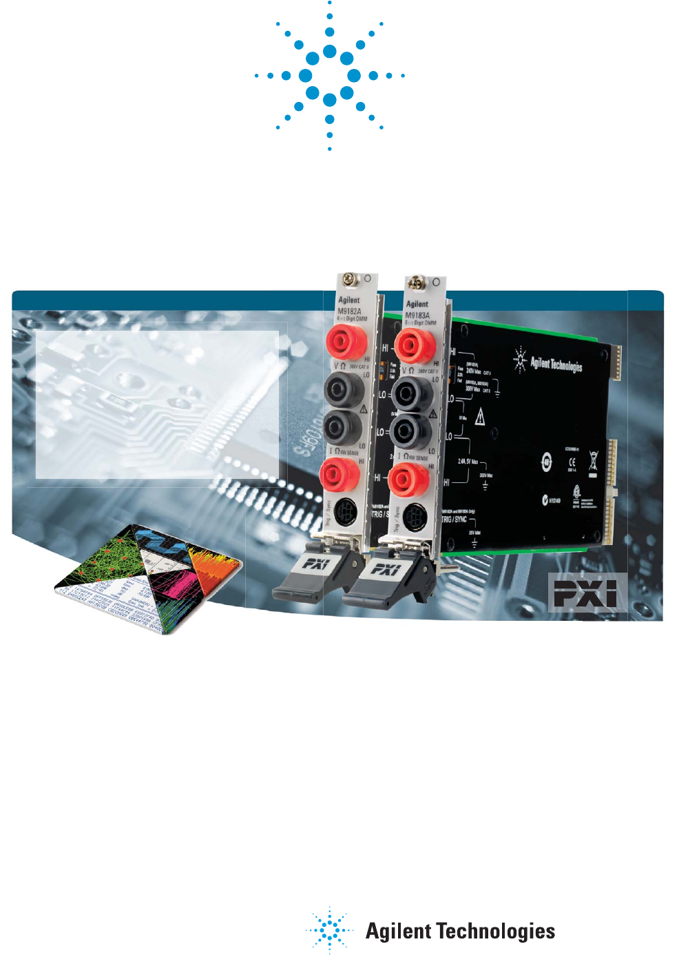
Agilent PXI Digital
Multimeters
6½ Digit, High Performance
M9182A
M9183A
Data Sheet
Discover the Alternatives...
... Agilent Modular Products
• 6½ digit resolution
• High throughput: up to 15,000 rdgs/sec,
66 µs single reading interval
• DCV basic one year accuracy: 40 ppm
• Ten standard measurements: DCV,
ACV, DCI, ACI, 2- and 4-wire resistance,
frequency, period, capacitance, and
temperature
• Floating isolation (CAT II) up to 300 V
TM
TM
2
OVERVIEW
Agilent’s M9182A and M9183A 6½ digit high performance
PXI digital multimeters (DMMs) offer fast throughput, flex-
ible measurements, and trustworthy results. The M9182A
provides ten built-in measurement types with all the accu-
racy and stability you would expect from an Agilent 6½
digit DMM. The M9183A provides the same capabilities as
the M9182A, with market-leading measurement speed of
up to 15,000 readings per second, additional ranges, and a
DC source.
Industries and Applications
• Aerospace and defense
• Automotive electronics test
• Industrial electronics test
• Medical device test
• Semiconductor and component test
Features
• 6½ digit resolution
• Up to 15,000 readings per second, 66 µs single reading
interval time (M9183A)
• Up to 4,500 readings per second, 222 µs single reading
interval time (M9182A)
• Basic 1 year DCV accuracy of 40 ppm
• DCV, ACV, DCI, ACI, 2- and 4-wire resistance, frequency,
period, capacitance, and temperature
• Pulse width, duty cycle, and totalizer/event counter
(M9183A)
• DC voltage and current source (M9183A)
• External trigger in and DMM out, to synchronize with
external multiplexers and instruments
• Analog threshold trigger with pre- and post- levels for
measuring the correct signal
• Floating isolation (CAT II) to 300 V
• Software drivers to support most common programming
environments
• Chassis connector compatibility: PXI-1 (J-1 only), PXIe
hybrid slot
Customer Values
• Measurements you can trust
• Higher test throughput due to the lowest latency
• Application development in the environment of your
choice reduces development time
• Customer supportable calibration procedures as well as
calibration services available from Agilent
PXI-DMM M918xA Feature Summary
All three products are 6½ digit PXI DMMs that take DCV, ACV, DCI, ACI, 2- and 4-wire resistance measurements.
DMM Description DCV basic
1 year
accuracy
Maximum
reading rate at
4½ digits
Other
measurements
Triggering DC source
M9181A* Basic features
PXI DMM
90 ppm 150 rdgs/sec None Immediate n/a
M9182A High
performance
PXI DMM
40 ppm 4,500 rdgs/sec Temperature,
capacitance,
frequency, period
Immediate, analog
threshold, PXI trigger
bus, external
n/a
M9183A Enhanced
performance
PXI DMM
40 ppm 15,000 rdgs/sec Temperature,
capacitance,
frequency, period,
offset compensated
Ω, pulse width, duty
cycle, totalizer/
event counter
Immediate, analog
threshold, PXI trigger
bus, external
± 10 V
± (1.2 µA to 12 mA)
*This table and more information about the M9181A can be found in the M9181A data sheet, literature number 5990-9035EN.
3
EASY SETUP… TEST… AND MAINTENANCE
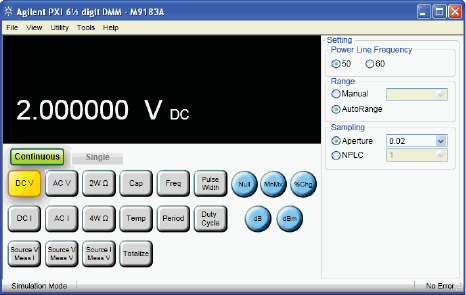
Figure 1. M9183A soft front panel
Compliance
The M9182A and M9183A 6½ digit DMMs are PXI
compliant, using either a cPCI (J1), PXI-1 (J1) or PXIe
Hybrid slot. Designed to benefit from fast data interfaces,
an M9182A or M9183A DMM can be integrated with other
test and automation modules in a PXI, CompactPCI, or
Hybrid chassis. The PXI format offers high performance
in a small, rugged package. It is an ideal deployment
platform for many automated test systems. A wide array
of complementary PXI products are currently available.
Products from Agilent include switches, multiplexers,
digitizers, waveform generators, and local oscillators.
Hardware Platform
Software Platform
IO Libraries Suite
Agilent IO Libraries Suite offers fast and easy instrument
connections. IO Libraries Suite 16.1 supports PXI, helping
you display all of the modules in your system, view
information about installed software and allows you to
more easily find the right driver and start module soft front
panels directly with Agilent Connection Expert.
National Instruments IO libraries are also supported, and
may be used along with Agilent IO libraries.
Drivers
Agilent’s digital multimeters come complete with software
drivers for Windows® XP, Windows Vista, and
Windows 7 (32 and 64 bit). These software drivers work
in the most popular test and measurement development
environments including: LabVIEW, Visual Studio® (C, C++,
C#, Visual Basic), MATLAB, and VEE.
Easy software integration
Application code examples are included for LabVIEW,
Visual Basic, C/C++, C#, and MATLAB – demonstrating
DMM set up and basic functionality. These application
code examples can be used to help you integrate the DMM
module into your measurement system.
Soft front panel
The soft front panel provides easy to use instrument
control. The M9182A and M9183A graphical user interface
guides developers through module setup so users can
quickly configure the DMM.
One notable feature of the soft front panel is the Driver Call
Log which allows the user to see the driver calls for each
button pushed. The user can then incorporate the driver
calls into the their application program – enabling fast and
easy program development.
Calibration
Each M9182A and M9183A DMM is factory calibrated
and shipped with an ISO-9002, NIST-traceable calibration
certificate.
Calibration is required once per year. A documented
calibration process allows you to do in-rack calibration
using standard calibration sources. Alternatively, Agilent
and 3rd party calibration labs offer calibration services for
the M9182A and M9183A DMMs.

4
M9182A and M9183A: Accuracy specifications ±(% of reading + % of range) 1,2
Function Range
3Frequency 24 hour
23 °C ± 1 °C
90 day
23 °C ± 5 °C
1 year
23 °C ± 5 °C
DC voltage 200.0000 mV
2.000000 V
20.00000 V
200.0000 V
300.0000 V
0.0030 + 0.0005
0.0020 + 0.0002
0.0040 + 0.0006
0.0030 + 0.0002
0.0130 + 0.0002
0.0040 + 0.0008
0.0030 + 0.0002
0.0050 + 0.0007
0.0040 + 0.0001
0.0230 + 0.0003
0.0050 + 0.0010
0.0040 + 0.0003
0.0070 + 0.0008
0.0050 + 0.0003
0.0250 + 0.0003
True RMS,
AC voltage 4,5
(Fast RMS off)
200.0000 mV610 Hz - 20 Hz
20 Hz - 47 Hz
47 Hz - 10 kHz
10 kHz - 50 kHz
50 kHz - 100 kHz
3.00 + 0.18
0.37 + 0.08
0.13 + 0.05
0.25 + 0.08
1.90 + 0.18
3.10 + 0.19
0.38 + 0.09
0.14 + 0.06
0.26 + 0.10
1.95 + 0.19
3.20 + 0.22
0.40 + 0.10
0.15 + 0.06
0.27 + 0.12
2.00 + 0.20
2.000000 V 10 Hz - 20 Hz
20 Hz - 47 Hz
47 Hz - 10 kHz
10 kHz - 50 kHz
50 kHz - 100 kHz
3.00 + 0.10
0.37 + 0.07
0.05 + 0.05
0.32 + 0.06
1.90 + 0.08
3.10 + 0.11
0.38 + 0.08
0.06 + 0.06
0.33 + 0.07
2.00 + 0.09
3.20 + 0.13
0.40 + 0.09
0.07 + 0.06
0.35 + 0.08
2.10 + 0.10
20.00000 V 10 Hz - 20 Hz
20 Hz - 47 Hz
47 Hz - 10 kHz
10 kHz - 50 kHz
50 kHz - 100 kHz
3.00 + 0.07
0.37 + 0.06
0.06 + 0.05
0.18 + 0.09
1.30 + 0.15
3.10 + 0.08
0.38 + 0.07
0.07 + 0.06
0.20 + 0.11
1.40 + 0.18
3.30 + 0.10
0.40 + 0.08
0.07 + 0.07
0.22 + 0.13
1.50 + 0.20
200.0000 V
& 300.0000 V
10 Hz - 20 Hz
20 Hz - 47 Hz
47 Hz - 10 kHz
10 kHz - 50 kHz
50 kHz - 100 kHz
3.00 + 0.07
0.43 + 0.06
0.07 + 0.05
0.28 + 0.07
1.30 + 0.09
3.10 + 0.08
0.44 + 0.07
0.08 + 0.07
0.30 + 0.08
1.60 + 0.12
3.30 + 0.08
0.45 + 0.08
0.09 + 0.08
0.32 + 0.10
2.40 + 0.13
True RMS,
AC voltage4,5
(Fast RMS on)
200.0000 mV6350 Hz - 800 Hz
800 Hz - 10 kHz
10 kHz - 50 kHz
50 kHz - 100 kHz
0.60 + 0.08
0.13 + 0.05
0.55 + 0.08
5.30 + 0.18
0.65 + 0.09
0.14 + 0.06
0.60 + 0.10
5.40 + 0.19
0.70 + 0.10
0.15 + 0.06
0.63 + 0.12
5.60 + 0.20
2.000000 V 350 Hz - 800 Hz
800 Hz - 10 kHz
10 kHz - 50 kHz
50 kHz - 100 kHz
0.93 + 0.07
0.07 + 0.05
0.62 + 0.06
5.10 + 0.08
0.96 + 0.08
0.08 + 0.06
0.65 + 0.07
5.20 + 0.09
1.00 + 0.09
0.08 + 0.06
0.70 + 0.08
5.30 + 0.10
20.00000 V 350 Hz - 800 Hz
800 Hz - 10 kHz
10 kHz - 50 kHz
50 kHz - 100 kHz
0.93 + 0.06
0.07 + 0.05
0.31 + 0.09
2.00 + 0.15
0.96 + 0.07
0.07 + 0.06
0.33 + 0.11
2.20 + 0.18
1.00 + 0.08
0.07 + 0.07
0.35 + 0.13
2.40 + 0.20
200.0000 V
& 300.0000 V
350 Hz - 800 Hz
800 Hz - 10 kHz
10 kHz - 50 kHz
50 kHz - 100 kHz
1.00 + 0.06
0.07 + 0.05
0.34 + 0.07
2.50 + 0.09
1.10 + 0.07
0.07 + 0.07
0.45 + 0.08
2.80 + 0.12
1.10 + 0.08
0.08 + 0.08
0.50 + 0.10
3.20 + 0.13
TECHNICAL SPECIFICATIONS AND CHARACTERISTICS

5
TECHNICAL SPECIFICATIONS AND CHARACTERISTICS
M9182A and M9183A: Accuracy specifications ±(% of reading + % of range) 1,2
Function Range
3Frequency,
test current or
burden voltage
24 hour
23 °C ± 1 °C
90 day
23 °C ± 5 °C
1 year
23 °C ± 5 °C
Resistance 720.00000 Ω
(M9183A only)
200.0000 Ω
2.000000 kΩ
20.00000 kΩ
200.0000 kΩ
2.000000 MΩ
20.00000 MΩ
200.0000 MΩ
(M9183A , 2-wire only)
10 mA
1 mA
1 mA
100 µA
10 µA
1 µA
100 nA
4 nA
0.004 + 0.004
0.004 + 0.002
0.003 + 0.002
0.003 + 0.002
0.006 + 0.002
0.018 + 0.002
0.120 + 0.002
0.800 + 0.013
0.009 + 0.004
0.010 + 0.002
0.008 + 0.002
0.008 + 0.002
0.010 + 0.002
0.030 + 0.003
0.130 + 0.003
1.000 + 0.015
0.014 + 0.005
0.013 + 0.003
0.012 + 0.002
0.012 + 0.002
0.016 + 0.003
0.040 + 0.004
0.200 + 0.003
1.300 + 0.025
DC current 200.0000 nA
(M9183A only)
2.000000 µA
(M9183A only)
20.00000 µA
(M9183A only)
200.0000 µA
(M9183A only)
2.000000 mA
20.00000 mA
200.0000 mA
2.000000 A
< 100 µV
< 100 µV
< 100 µV
< 2.5 mV
< 25 mV
< 250 mV
< 55 mV
< 520 mV
0.130 + 0.020
0.050 + 0.004
0.050 + 0.002
0.052 + 0.100
0.020 + 0.015
0.020 + 0.002
0.020 + 0.025
0.100 + 0.003
0.160 + 0.023
0.080 + 0.003
0.080 + 0.003
0.070 + 0.150
0.030 + 0.020
0.035 + 0.003
0.030 + 0.030
0.150 + 0.004
0.170 + 0.030
0.210 + 0.008
0.130 + 0.004
0.100 + 0.200
0.040 + 0.028
0.045 + 0.003
0.040 + 0.040
0.200 + 0.005
True RMS,
AC current 8
2.000000 mA 910 Hz - 20 Hz
20 Hz - 47 Hz
47 Hz - 1 kHz
1 kHz - 10 kHz
2.70 + 0.20
0.90 + 0.20
0.04 + 0.08
0.12 + 0.20
2.90 + 0.20
0.90 + 0.20
0.08 + 0.15
0.14 + 0.20
2.90 + 0.20
1.00 + 0.20
0.12 + 0.20
0.22 + 0.20
20.00000 mA 10 Hz - 20 Hz
20 Hz - 47 Hz
47 Hz - 1 kHz
1 kHz - 10 kHz
1.80 + 0.15
0.60 + 0.15
0.07 + 0.05
0.21 + 0.15
2.60 + 0.15
0.90 + 0.15
0.15 + 0.10
0.30 + 0.20
2.80 + 0.15
1.00 + 0.15
0.16 + 0.15
0.40 + 0.20
200.0000 mA 10 Hz - 20 Hz
20 Hz - 47 Hz
47 Hz - 1 kHz
1 kHz - 10 kHz
1.80 + 0.20
0.60 + 0.20
0.15 + 0.08
0.30 + 0.15
2.70 + 0.20
0.90 + 0.20
0.17 + 0.09
0.35 + 0.18
2.80 + 0.20
1.00 + 0.20
0.20 + 0.11
0.40 + 0.20
2.000000 A 10 Hz - 20 Hz
20 Hz - 47 Hz
47 Hz - 1 kHz
1 kHz - 10 kHz
1.80 + 0.20
0.66 + 0.30
0.30 + 0.19
0.40 + 0.20
2.50 + 0.23
0.80 + 0.30
0.33 + 0.19
0.45 + 0.23
2.70 + 0.25
0.90 + 0.30
0.35 + 0.20
0.50 + 0.25
Frequency or
period 10, 14
200 mV to 300 V 1Hz - 20 Hz
20 Hz - 130 Hz
130 Hz - 640 Hz
640 Hz - 2.5 kHz
2.5 kHz - 40 kHz
40 kHz - 200 kHz
200 kHz - 300 kHz
0.08 + 0.01
0.03 + 0.01
0.03 + 0.01
0.03 + 0.01
0.03 + 0.01
0.05 + 0.01
0.07 + 0.01
0.08 + 0.01
0.03 + 0.01
0.03 + 0.01
0.03 + 0.01
0.03 + 0.01
0.05 + 0.01
0.07 + 0.01
0.08 + 0.01
0.03 + 0.01
0.03 + 0.01
0.03 + 0.01
0.03 + 0.01
0.05 + 0.01
0.07 + 0.01

6
TECHNICAL SPECIFICATIONS AND CHARACTERISTICS
M9182A and M9183A: Accuracy specifications ±(% of reading + % of range) 1,2
Function Range Full scale reading
or resolution
24 hour
23 °C ± 1 °C
90 day
23 °C ± 5 °C
1 year
23 °C ± 5 °C
Single shot
duty cycle 11
[M9183A only]
2 - 100 Hz
100 Hz - 1 kHz
1 - 10 kHz
0.02 %
0.20 %
2.00 %
0.03 ± 0.03
0.03 ± 0.30
0.03 ± 3.00
0.03 ± 0.03
0.03 ± 0.30
0.03 ± 3.00
0.03 ± 0.03
0.03 ± 0.30
0.03 ± 3.00
Single shot
pulse width 12, 14
[M9183A only]
14 μs - 62.5 ms 1 µs .01 ± 4 µs 01 ± 4 µs 01 ± 4 µs
Capacitance 13
[M9183A and
M9182A]
1000.0 pF
10.000 nF
100.00 nF
1.0000 µF
10.000 µF
100.00 µF
1.0000 mF
10.000 mF
1199.9 pF
11.999 nF
119.99 nF
1.1999 µF
11.999 µF
119.99 µF
1.1999 mF
11.999 mF
1.00 + 0.10
1.20 + 0.05
1.00 + 0.10
1.00 + 0.10
1.00 + 0.10
1.00 + 0.10
1.20 + 0.10
2.00 + 0.10
1.00 + 0.10
1.20 + 0.05
1.00 + 0.10
1.00 + 0.10
1.00 + 0.10
1.00 + 0.10
1.20 + 0.10
2.00 + 0.10
1.00 + 0.10
1.20 + 0.05
1.00 + 0.10
1.00 + 0.10
1.00 + 0.10
1.00 + 0.10
1.20 + 0.10
2.00 + 0.10
1. Specifications are for 1 hour warm up, within 1 hour self-cal, aperture ≥ 0.5 sec. Slow AC filter for AC measurements only.
2. For temperatures outside the range of 23 °C ± 5 °C, but within 0 °C to 50 °C, add 0.1 × accuracy specification per °C.
3. 20% over range on all ranges except 300 V range, 10% over range for 300 V range.
4. Minimum input specified: 5 mV or 1% of range, whichever is larger.
5. Signal is limited to 8x10⁶ Volt Hz product. For example, at 32 kHz, the highest input is 250 V.
6. For inputs from 5 mV to 15 mV, add 100 µV to the specification.
7. Specifications are for 4-wire resistance measurements, for 2-wire, add 1 mΩ additional error to the specification; for offset
compensated ohms (M9183A only), add 0.02% of range.
8. Minimum input specified: 60 µA or 1.5% of range, whichever is larger; for inputs < 5% of full scale, add 0.02% of range.
9. For inputs from 60 to 120 µA, add 10 µA to the specification; for inputs < 5% of full scale, add 0.1% of range.
10. Minimum amplitude greater of: 100 mV, or 5 % of range for 1 Hz to 2.5 kHz, or 25 % of range for 2.5 kHz to 200 kHz , or 40% of range
for 200 kHz to 300 kHz..
11. Specifications are % of reading (0.03) ± adder.
12. Specifications are % of reading + time.
13. Specifications apply to input signals ≥ 5% of range.
14. Maximum wait time for duty cycle and period is 5 seconds.
Definitions for specifications
Specification (spec): Represents warranted performance of a calibrated instrument that has been stored for a minimum
of two hours within the operating temperature range of 0 to 55 °C, unless otherwise stated, and after a one hour warm-up
period. The specifications include measurement uncertainty. Data represented in this document are specifications unless
otherwise noted.
Typical (typ): Represents characteristic performance, which 80% of the instruments manufactured will meet. This data is
not warranted, does not include measurement uncertainty, and is valid only at room temperature (approximately 25 °C).
Nominal (nom): The expected mean or average performance, or an attribute whose performance is by design, such as the
50 Ω connector. This data is not warranted and is measured at room temperature (approximately 25 °C).
Measured (meas): An attribute measured during the design phase for purposes of communicating expected performance,
such as amplitude drift vs. time. This data is not warranted and is measured at room temperature (approximately 25 °C).
Note: All graphs contain measured data from several units at room temperature unless otherwise noted.
7
TECHNICAL SPECIFICATIONS AND CHARACTERISTICS
M9182A and M9183A temperature accuracy (spec) 1
Temperature
function
Type R0 (Ω) Sensitivity Range/max
temperature
1 year
23 °C ± 5 °C
RTD temperature
measurement 2,3
pt385 100 Ω, 200 Ω 0.01 °C -150 to 650 °C ± 0.06 °C
500 Ω, 1 kΩ 0.01 °C -150 to 650 °C ± 0.03 °C
Cu (Copper) Less than 12 Ω 0.01 °C -100 to 200 °C ± 0.18 °C at ≤ 20 °C
± 0.05 °C otherwise
Higher than 90 Ω 0.01 °C -100 to 200 °C ± 0.10 °C at ≤ 20 °C
± 0.05 °C otherwise
Thermocouple
temperature
measurement 4,5
B NA 0.01 °C 2200 °C ± 0.38 °C
E NA 0.01 °C 1200 °C ± 0.035 °C
J NA 0.01 °C 2000 °C ± 0.06 °C
K NA 0.01 °C 3000 °C ± 0.07 °C
N NA 0.01 °C 3000 °C ± 0.10 °C
R NA 0.01 °C 2700 °C ± 0.25 °C
S NA 0.01 °C 3500 °C ± 0.35 °C
T NA 0.01 °C 550 °C ± 0.06 °C
Thermistor 32.25 kΩ NA 0.01 °C -80 to 150 °C ± 0.1 °C
5 kΩ NA 0.01 °C -80 to 150 °C ± 0.1 °C
10 kΩ NA 0.01 °C -80 to 150 °C ± 0.1 °C
M9182A and M9183A Sensitivity (nom)
Function Lowest Range Sensitivity
DCV 200.0000 mV 0.1 µV
ACV 200.0000 mV 0.1 µV
Resistance (M9183A) 20.00000 Ω 10 µΩ
Resistance (M9182A) 200.0000 Ω 100 µΩ
DCI (M9183A) 200.0000 nA 0.1 pA
DCI (M9182A) 2.000000 mA 10 nA
ACI 2.000000 mA 1 nA
Capacitance 1000.0 pF 0.1 pF
1. Specifications are for one hour warm up, within one hour self-cal, aperture ≥ 0.5 sec.
2. 4-wire RTD measurement, R0 variable 1 Ω to 7 k Ω.
3. For total measurement accuracy, add temperature probe error.
4. For total measurement accuracy, add thermocouple error and cold junction compensation.
5. DMM linearization temperature range may be greater than that of the thermocouple device.
8
TECHNICAL SPECIFICATIONS AND CHARACTERISTICS
M9183A source DC voltage, measure DC voltage
Parameter Closed Loop Open Loop
DC voltage source (output) range +10 to -10 V +10 to -10 V
DC source sink current at 5 V output 5 mA 5 mA
DAC resolution (nom) 18 bits /12 bits 12 bits
DC voltage source accuracy 1 Year, 23°± 5° C 0.01% ± 0.001% 0.5% ± 0.2%
Settling time (typ) 100 ms/1 ms 1 ms
Source resistance (nom) 200 ohms 200 ohms
Source-Measure [(spec) unless otherwise stated)]
M9183A source DC voltage, measure DC current
DC voltage source (output) range -10.000 to +10.000 V
DC current measurement range 0 to ± 20 mA
Voltage resolution (nom) 5 mV
Voltage source accuracy 1 Year, (23 °C ± 5 °C) 1,2,3,4 2.0% ± 0.4%
Settling time (typ) 100 ms
DC current measurement accuracy 0.1% + 0.005%
M9183A source DC current, measure DC voltage
DC voltage measurement range 0 to ± 2.0 V
Current output Compliance voltage Minimum Level Source Accuracy
1 year, (23 °C ± 5 °C) 1,2,3
< 1.25 µA 4.2 V 10 nA 1% + 1%
< 12.5 µA 4.2 V 50 nA 1% + 1%
< 125 µA 4.2 V 100 nA 1% + 0.5%
< 1.25 mA 4.2 V 1 µA 1% + 0.5%
< 12.5 mA 1.2 V 10 µA 1% + 0.5%
1. Specifications are for one hour warm up, within one hour self-cal, slow AC filter.
2. For temperatures outside the range of 23 °C ± 5 °C, but within 0 °C to 50 °C, add 0.1 × accuracy specification per °C.
3. Repetitive reading at an aperture of 133 ms or higher.
4. If DCV source > 6 V, then add current * 4 ohms; if DCV source > 8 V, then add current * 30 ohms.
9
TECHNICAL SPECIFICATIONS AND CHARACTERISTICS
Triggering Characteristics
The M9182A and M9183A have advanced triggering capabilities that exceed those found on other digital
multimeters. Advanced triggering enables you to obtain the signal you need and accurately measure it, in a variety
of applications.
External hardware trigger
Trigger input voltage level range (at DIN 7 connector) +3 to +15 V activates the trigger
Minimum trigger pulse width Aperture + 50 µs
Trigger input impedance 3 kΩ
Edge Selectable positive or negative edge
PXI bus trigger inputs
Trigger input voltage level range (via PXI backplane) CMOS level (see PXI standard)
Minimum trigger pulse width Aperture + 50 µs
Edge Selectable positive or negative edge
Trigger features
Trigger sources Immediate, PXI trigger , external DIN
connector, analog threshold trigger
source
Trigger delay
[Auto delay (default delay) ensures 1st
reading accuracy in most configurations)
Measurement delay 50 µs to 15 s
Resolution 1 µs to 65 ms and 16 µs above 65 ms
Reading storage Circular buffer - 80 readings
Multi Sample Mode Aperture range 2.5 µs to 160 ms (M9183A)
(DCV and DCI functions only) 130 µs to 160 ms (M9182A)
Maximum read interval range 1sec for aperatures ≥ 625 µs, else 65 ms
Reading per trigger Up to 80 readings (maximum of 78
pre-triggers or a maximum of 80 post
triggers)
Trigger sources PXI trigger, external DIN connector, and
analog threshold (accuracy within 5% of
range)

10
MEASUREMENT CHARACTERISTICS
Resolution vs. Aperture and Reading Rate for DCV, DCI, Ω
Measurement
aperture Maximum
readings per
second
Resolution
10 ms 98 6½ digits (22 bits)
625 µs 1,200 5½ digits (18 bits)
130 µs 4,500 4½ digits (14 bits)
2.5 µs 15,000
(M9183A only) 1 4½ digits (14 bits)
Transaction Speed
Transactional I/O speed is a single reading measurement.
This is important when you are taking many single
measurements with the DMM. The M9183A delivers the
highest transactional measurement speed in its class.
These fast readings, up to 15,000 readings per second with
a read interval rate of 66 µs, provides the lowest latency,
translating into higher test-system throughput and lower
cost of test per unit tested.
Variable delay can be programmed to allow fully settled
readings in most configurations.
Time frame of a single measurement
Minimum read interval = 66 µs (M9183A)
Minimum read interval = 222 μs (M9182A)
System Reading and Throughput Rates
Switching
ranges within
a function
Aperture (A) Range change
time (ms)
DCV A ≤ 20 ms (A × 0.2) + 15
A > 20 ms A + 15.6
Resistance (2-
wire or 4-wire)
A < 33 ms (A × 0.05) + 15.5
A ≥ 33 ms A + 13
DCI (200 mA or
2 A to any other
range)
A ≤ 40 ms 4.2
A > 40 ms 15.7
DCI (all other
ranges)
All apertures 1
Capacitance All apertures 12
Switch
between
functions
Aperture (A) Function
change time
(ms)
DCV A < 16 ms 15.6
A ≥ 16 ms A + 25
Resistance to
DCI
A < 16.66 ms 7.8
16.66 ms ≤ A < 40 ms A × 0.65
40 ms < A < 66.66 ms 7.8
A ≥ 66.66 ms (A × 0.51) + 45
DCV to
capacitance
A < 33.33 ms 23.4
A ≥ 33.33 ms (A × 0.65) + 50
Resistance to
capacitance
A ≤ 33.33 ms 23.4
33.33 ms < A < 80 ms (A × 2) + 35
80 ms ≤ A < 160 ms 23.4
A ≥ 160 ms 160
1. 15,000 readings/second represent a typical maximum with a
measurement aperture of 2.5 µs. Results will vary, depending on
what PC hardware, PXI hardware, and driver are used.
-
2,000
4,000
6,000
8,000
10,000
12,000
14,000
16,000
10 mS 625 µS 130 µS 2.5 µS
Aperture reading rate
(< 1 NPLC)
M9182A M9183A
11
MEASUREMENT CHARACTERISTICS
DC voltage
Measurement method Delta-sigma A/D conversion
Input resistance 200 mV, 2.0 V ranges: >10 GΩ with typical leakage of < 50 pA;
20 V, 200 V, 300 V ranges: 10.0 MΩ
Input isolation 330 VDC, 250 VAC from Earth ground
Input overvoltage protection 330 VDC all ranges
DCV noise rejection Normal mode rejection at 50, 60, or 400 Hz ± 0.5%; > 95 dB (apertures ≥
0.160 s); CMRR (1 kΩ lead imbalance) ≥ 120 dB
True RMS AC voltage
Measurement method AC coupled (10 Hz to 100 kHz) true RMS — measures the AC component of
an input waveform that consists of AC and DC components.
Crest factor Maximum crest factor of 4 at full scale, 7 at 10% of range
Input impedance 1 MΩ, in parallel with < 300 pF
Settling time < 0.5 sec to within 0.1% of final value
Fast RMS: < 0.05 sec to within 0.1% of final value
Peak input 8 x 10⁶ volt Hz product (example: 250 V @ 32 kHz)
Input overvoltage protection 330 VAC all ranges
ACV noise rejection Common mode rejection at 50 Hz or 60 Hz; 1 kΩ imbalance in either lead
> 60 dB
Resistance
Measurement method Selectable 2-wire or 4-wire. Current source referenced to LO output
Offset compensation (M9183A only) All ranges, use with apertures > 5 ms
Voffset + (I*R) < 2.2 V for ranges ≥ 2 kΩ
Voffset + (I*R) < 0.22 V for ranges < 2 kΩ
Maximum test voltage 240 mV for 20 Ω and 200 Ω ranges; 2.4 V for 20 kΩ to 20 MΩ ranges;
1.0 V for 200 MΩ range (M9183A only)
Maximum lead resistance (4-wire) 50 kΩ for 200 kΩ, 2.0 MΩ, and 20 MΩ ranges; 5 kΩ for 20 kΩ range
500 Ω for 200 Ω and 2 kΩ ranges; 50 Ω for 20 Ω range
Input protection 330 V on all ranges
DC current
Shunt resistance 10 Ω for 2 mA and 20 mA, 0.1 Ω for 200 mΩ and 2 A;
Virtual zero shunt for 200 μA, 20 μA, 2 μA, and 200 nA range (M9183A only)
Input protection Protected with 2.5 A, 250 V fast blow fuse
True RMS AC current
Measurement method AC coupled true RMS measurement (measures the AC component only.)
analog RMS DC converter.
Shunt resistance 10 Ω for 2 mA and 20 mA, 0.1 Ω for 200 mA and 2 A
Input protection Protected with 2.5 A, 250 V fast blow fuse
12
MEASUREMENT CHARACTERISTICS
Frequency and period
Measurement method Direct (conventional) counting
Input impedance 1 MΩ with < 300 pF
Sensitivity (130 Hz) .001 Hz
Totalizer (M9183A only)
Active edge polarity Positive or negative transition
Maximum count 10,000,000,000
Allowed rate 1 to 30,000 events per second
Threshold Set threshold DAC
Accuracy ±2 counts
Capacitance
Measurement method Differential charge balance: variable currents used to stimulate dV/dt
response.
Connection type 2-wire
Environmental and physical characteristics
Temperature range Operating -10° to 55 °C
Non-operating -40 ° to +85 °C
Relative humidity Operating to 80% at 40 °C
Storage to 95% at 40 °C
Connectors V HI*, 2-wire Ω IN, DCV OUT Sheathed banana jack
V LO*, 2-wire Ω IN, DCV OUT Sheathed banana jack
I HI*, 4-wire Ω IN Sheathed banana jack
I LO*, 4-wire Ω IN Sheathed banana jack
Sync OUT DIN 7, pin 2
External Trigger IN DIN 7, pin 7
Trigger and Sync common DIN 7, pin 4
Safety Complies with IEC 61010-1, CAT II 300 V, pollution degree 2
EMC Complies with EN61326-1 Industrial Environment
Warm-up time 1 hour
Physical characteristics
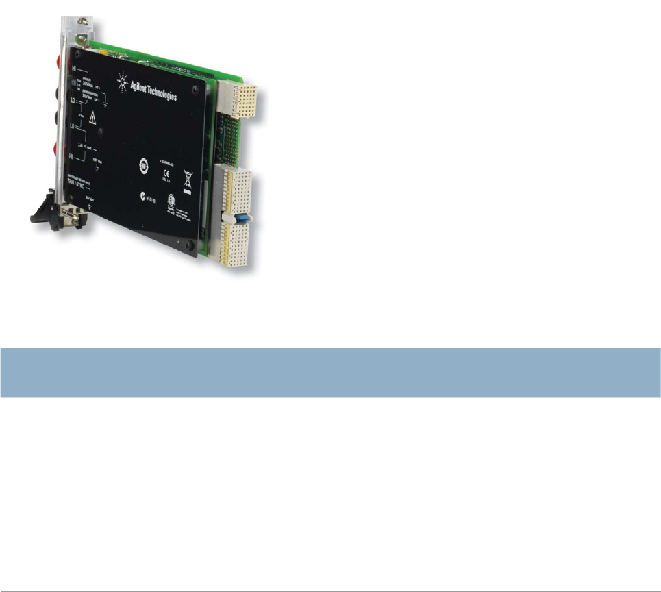
Dimensions 3U/1-slot PXI/CompactPCI standard
Weight 0.5 kg (1 lb.)
Power dissipation:
+5 V Total power
300 mA 1.5 W max
* Do not connect the V HI and V LO or I HI and I LO connectors to anything when the measurement function does not utilize those
connectors.
13
CONFIGURATION
Model Description
M9182A PXI 6½ digit multimeter, high performance
M9183A PXI 6½ digit multimeter, enhanced
performance
DMM units
include:
Getting started guide, software drivers,
user and service documentation (on CD
ROM), Agilent I/O libraries
Hardware
Model Description
Supported
Operating
Systems
Microsoft Windows XP (32-bit),
Microsoft Windows Vista (32/64-bit)
Microsoft Windows 7 (32/64-bit)
Standard
Compliant
Drivers
IVI-C, IVI-COM, LabVIEW
Supported
Application
Development
Environments
(ADE)
VisualStudio (VB.NET, C#, C/C++)®,
LabVIEW, MATLAB, VEE
Agilent IO
Libraries
Includes: VISA Libraries, Agilent
Connection Expert, IO Monitor
Software
Calibration and Warranty
Advantage services: calibration and warranty
Agilent Advantage Services is committed to your
success throughout your equipment’s lifetime.
Calibration
R-50C-011-3 Yearly calibration, for 3 years
R-50C-011-5 Yearly calibration, for 5 years
R-50C-021-3 Yearly ANSI Z540-1-1994 calibration,
for 3 years
R-50C-021-5 Yearly ANSI Z540-1-1994 calibration,
for 5 years
Warranty
Standard warranty is 1 year
R-51B-001-3C 1 year return-to-Agilent warranty
extended to 3 years
R-51B-001-5C 1 year return-to-Agilent warranty
extended to 5 years
Model Description
34138A Test lead set
Accessories
Related products
Model Description
M9018A 18-slot PXIe chassis
M9021A PCIe cable interface to an external
system controller
M9036A Embedded controller
M9101A PXI high-density multiplexer,
64 channels, reed relays
M9103A PXI high-density multiplexer,
99 channels, armature relays
M9120A PXI high-density matrix switch, 4x32,
armature relays
M9121A PXI high-density matrix switch, 4x64,
reed relays
M9181A PXI digital multimeter, 6½ digit, basic
features
Agilent Advantage Services is committed to your
success throughout your equipment’s lifetime. We share
measurement and service expertise to help you create the
products that change our world. To keep you competitive,
we continually invest in tools and processes that speed up
calibration and repair, reduce your cost of ownership, and
move us ahead of your development curve.
www.agilent.com/find/advantageservices
www.agilent.com/quality
For more information on Agilent Technologies’ products, applications
or services, please contact your local Agilent office. The complete list
is available at: www.agilent.com/find/contactus
Americas
Canada (877) 894 4414
Brazil (11) 4197 3600
Mexico 01800 5064 800
United States (800) 829 4444
Asia Pacific
Australia 1 800 629 485
China 800 810 0189
Hong Kong 800 938 693
India 1 800 112 929
Japan 0120 (421) 345
Korea 080 769 0800
Malaysia 1 800 888 848
Singapore 1 800 375 8100
Taiwan 0800 047 866
Thailand 1 800 226 008
Europe & Middle East
Austria 43 (0) 1 360 277 1571
Belgium 32 (0) 2 404 93 40
Denmark 45 45 80 12 15
Finland 358 (0) 10 855 2100
France 0825 010 700*
*0.125 €/minute
Germany 49 (0) 7031 464 6333
Ireland 1890 924 204
Israel 972-3-9288-504/544
Italy 39 02 92 60 8484
Netherlands 31 (0) 20 547 2111
Spain 34 (91) 631 3300
Sweden 0200-88 22 55
Switzerland 0800 80 53 53
United Kingdom 44 (0) 118 927 6201
For other unlisted Countries: www.agilent.com/find/contactus
Revised: January 6, 2012
www.agilent.com
www.agilent.com/find/modular
www.agilent.com/find/pxi-switch
Product specifications and descriptions in this document subject to change
without notice.
© Agilent Technologies, Inc. 2012 Printed in USA, February 17, 2012
5990-7580EN
The Modular Tangram
The four-sided geometric symbol that appears throughout this
document is called a tangram. This seven-piece puzzle originated
in China a few centuries ago. The goal is to create shapes—from
simple to complex—that form an identifiable silhouette. As with
a tangram, the possibilities may seem infinite as you begin to
create a new test system. With a set of clearly defined elements—
architecture, hardware, software—Agilent can help you create the
system you need, from simple to complex.
Discover the Alternatives …
... Agilent Modular Products
PXI is a registered US trademark of PXI Systems Alliance. Visual Studio,
Visual C, C++, and C#, and Visual Basic are registered trademarks of
Microsoft Corporation. Windows and MS Windows are U.S. registered
trademarks of Microsoft Corporation. MATLAB is a U.S. registered
trademark of The Math Works, Inc.
