N6700 Series Specifications Guide A_N6705A A N6705A
N6700-900011 N6700-900011
User Manual: A_N6705A
Open the PDF directly: View PDF ![]() .
.
Page Count: 51
- Legal Notices
- Where to Find More Information
- Contents
- Power Module Differences
- Agilent N673xB, N674xB, N677xA DC Power Modules
- Agilent N675xA High Performance Power Modules
- Agilent N676xA PrecisionPower Modules
- Agilent N6781A, N6782A, N6784ASource/Measure Units
- Agilent N6783A-BAT, N6783A-MFG Application-Specific Power Modules
- Agilent N6700 Modular Power System Mainframes
- Manual Updates
Agilent N6700
Modular
Power System Family
N6731B
-N6784A DC Power Modules
N6700B
-N6705B Mainframes
Specifications Guide

2 N6731B-N6784A DC Power Modules
N6700B-N6705B Mainframes
Specifications Guide
Legal Notices
© Agilent Technologies, Inc. 2010 - 2012
No part of this document may be
photocopied, reproduced, or translated to
another language without the prior
agreement and written consent of Agilent
Technologies, Inc. as governed by United
States and international copyright laws.
Warranty
The material contained in this document
is provided “as is,” and is subject to
being changed, without notice, in future
editions. Further, to the maximum extent
permitted by applicable law, Agilent
disclaims all warranties, either express or
implied, with regard to this manual and
any information contained herein,
including but not limited to the implied
warranties of merchantability and fitness
for a particular purpose. Agilent shall not
be liable for errors or for incidental or
consequential damages in connection
with the furnishing, use, or performance
of this document or of any information
contained herein. Should Agilent and the
user have a separate written agreement
with warranty terms covering the material
in this document that conflict with these
terms, the warranty terms in the separate
agreement shall control.
Manual Editions
Manual Part Number: N6700-90001
Sixth Edition, February 2012
Available in electronic format only.
Updates of this manual containing minor
corrections may have the same edition
date. Revised editions are identified by a
new edition date.
Certification
Agilent Technologies certifies that this
product met its published specifications
at time of shipment from the factory.
Agilent Technologies further certifies that
its calibration measurements are
traceable to the United States National
Institute of Standards and Technology, to
the extent allowed by the Institute's
calibration facility, and to the calibration
facilities of other International Standards
Organization members.
Technologies Licenses
The hardware and or software described
in this document are furnished under a
license and may be used or copied only in
accordance with the terms of such
license.
U.S. Government Restricted
Rights
Software and technical data rights
granted to the federal government include
only those rights customarily provided to
end user customers. Agilent provides this
customary commercial license in
Software and technical data pursuant to
FAR 12.211 (Technical Data) and 12.212
(Computer Software) and, for the
Department of Defense, DFARS 252.227-
7015 (Technical Data – Commercial
Items) and DFARS 227.7202-3 (Rights in
Commercial Computer Software or
Computer Software Documentation).
Declaration of Conformity
Declarations of Conformity for this
product and for other Agilent products
may be downloaded from the Web. Go to
http://regulations.corporate.agilent.com
and click on “Declarations of Conformity.”
You can then search by product number
to find the latest Declaration of
Conformity.
Regulatory Symbols
The CE mark shows
that the product
complies with all
applicable European
Directives.
The C-Tick mark is a
registered trademark
of the Australian
Communications
Authority.
This ISM device
complies with
Canadian ICES-001.
Cet appareil ISM est
conforme à la norme
NMB-001 du Canada.
This is the symbol for
an Industrial,
Scientific and
Medical, Group 1
Class A product.
The CSA mark is a
registered trademark
of Intertek-etlsemko
Inc.
This is the RoHS
(Restriction of
Hazardous
Substances) symbol
for electrical and
electronic equipment.
This symbol indicates
separate collection for
electrical and
electronic equipment
mandated under EU
law as of August 13,
2005. All electric and
electronic equipment
are required to be
separated from
normal waste for
disposal (Reference
WEEE Directive
2002/96/EC).

N6731B-N6784A DC Power Modules
N6700B-N6705B Mainframes
Specifications Guide 3
Where to Find More Information
This document provides specification and supplemental
characteristic information for the following instruments:
• Agilent N6731B through N6784A Power Modules
• Agilent N6700B through N6705B Mainframes
For additional technical details and ordering information for the
Agilent N6700 Modular Power System Family, refer to the following:
Document
Description
Agilent N6700 Modular Power
System Family: Low-Profile MPS
Mainframe for Automated Test
Environments
The Agilent N6700 Low-Profile Modular Power System (MPS) is a 1U (rack unit) high,
multiple-output programmable DC power supply system that enables test system
integrators to optimize performance, power and price to match test needs.
Go to: http://cp.literature.agilent.com/litweb/pdf/5989-1411EN.pdf
Agilent N6700 Modular Power
System Family: DC Power Analyzer
Mainframe for R&D
The Agilent N6705 DC Power Analyzer represents an entirely new instrument category
for R&D engineers. It provides unrivaled productivity gains when sourcing and
measuring DC voltage and current into a DUT. Using the Agilent N6705 DC Power
Analyzer, R&D engineers can gain insights into the DUT’s power consumption in
minutes, with all sourcing and measuring functions available from the front panel.
Go to: http://cp.literature.agilent.com/litweb/pdf/5989-6319EN.pdf
Agilent N6700 Modular Power
System Family: N6780 Series
Source/Measure Units
The Agilent N6781A and N6782A 2-quadrant SMUs offer advanced sourcing and
measurement capabilities required to overcome test challenges associated with
optimizing power consumption and maximizing battery life of battery-powered devices
and their components. The Agilent N6784A 4-quadrant SMU offers advanced sourcing
and measurement capabilities in four quadrants for general purpose applications.
Go to: http://cp.literature.agilent.com/litweb/pdf/5990-5829EN.pdf
Agilent N6700 Modular Power
System Family: Battery
Charge/Discharge Module
The Agilent N6783A-BAT battery charge/discharge module is a basic, 2-quadrant DC
power module designed to be used by mobile device designers. Its 2-quadrant operation
allows it to act as a programmable power supply to charge the battery or as a
programmable electronic load to discharge the battery, all in one instrument.
Go to: http://cp.literature.agilent.com/litweb/pdf/5990-8662EN.pdf
Agilent N6700 Modular Power
System Family: Mobile
Communications DC Power Module
The Agilent N6783A-MFG mobile communications DC power module offers advanced
features specifically for testing battery-powered (mobile) devices in manufacturing or
automated test environments.
Go to: http://cp.literature.agilent.com/litweb/pdf/5990-8643EN.pdf
NOTE You can contact Agilent Technologies at one of the following telephone
numbers for warranty, service, or technical support information.
In the United States: (800) 829-4444
In Europe: 31 20 547 2111
In Japan: 0120-421-345
Or use our Web link for information on contacting Agilent in your country or
specific location: www.agilent.com/find/assist
Or contact your Agilent Technologies Representative.
The web contains the most up to date version of this manual.
Go to http://cp.literature.agilent.com/litweb/pdf/N6700-90001.pdf.
4 N6731B-N6784A DC Power Modules
N6700B-N6705B Mainframes
Specifications Guide
Contents
1 - Power Module Differences ...................................................................................................... 5
Power Module Differences–for Agilent N6700 Modular Power Systems . 6
Power Module Differences–for Agilent N6705 DC Power Analyzers ........ 8
Power Module Option Characteristics .......................................................... 10
2 - Agilent N673xB, N674xB, N677xA DC Power Modules ................................................... 11
Performance Specifications ............................................................................ 12
Supplemental Characteristics ......................................................................... 14
Output Quadrant Characteristic ...................................................................... 16
Arbitrary Waveform Generator Maximum Bandwidth ................................ 16
3 - Agilent N675xA High Performance Power Modules ......................................................... 19
Performance Specifications ............................................................................ 20
Supplemental Characteristics ......................................................................... 21
Autoranging Characteristic.............................................................................. 23
Output Impedance Graphs ............................................................................... 23
Arbitrary Waveform Generator Maximum Bandwidth ................................ 26
4 - Agilent N676xA Precision Power Modules ......................................................................... 27
Performance Specifications ............................................................................ 28
Supplemental Characteristics ......................................................................... 29
Autoranging Characteristic.............................................................................. 31
Output Impedance Graphs ............................................................................... 31
Arbitrary Waveform Generator Maximum Bandwidth ................................ 34
5 - Agilent N6781A, N6782A, N6784A Source/Measure Units .............................................. 35
Performance Specifications ............................................................................ 36
Supplemental Characteristics ......................................................................... 37
Output Quadrant Characteristic ...................................................................... 42
Output Impedance Graphs ............................................................................... 42
6 - Agilent N6783A-BAT, N6783A-MFG Application-Specific Power Modules ................... 43
Performance Specifications ............................................................................ 44
Supplemental Characteristics ......................................................................... 45
Output Quadrant Characteristic ...................................................................... 46
7 - Agilent N6700 Modular Power System Mainframes ......................................................... 47
Supplemental Characteristics ......................................................................... 48
Outline Diagrams ............................................................................................... 50

N6731B-N6784A DC Power Modules
N6700B-N6705B Mainframes
Specifications Guide 5
Chapter 1
Power Module Differences
Power Module Differences–for Agilent N6700 Modular Power Systems . 6
Power Module Differences–for Agilent N6705 DC Power Analyzers ........ 8
Power Module Option Characteristics .......................................................... 10
This chapter provides a brief overview of the basic differences
between the Agilent N6700 series DC Power Modules. Note that the
basic capabilities of a power module depend not only on its hardware
capabilities, but also the on the hardware and firmware capabilities
of the mainframe in which it is installed.
In addition to their primary output and measurement capabilities,
power modules installed in an Agilent N6705 DC Power Analyzer
have expanded capabilities such as front panel scope view, arbitrary
waveform generation, and internal and external data logging.
Refer to the Agilent N6700 or N6705 User’s Guide for more
information about the power module capabilities.

6 N6731B-N6784A DC Power Modules
N6700B-N6705B Mainframes
Specifications Guide
Power Module Differences–for Agilent N6700 Modular Power Systems
Agilent N6731B–N6777A Differences
Feature DC Power High-Performance Precision
(● = available) N673xB, N674xB, N677xA N675xA N676xA
50 W output rating N6731B – N6736B N6751A N6761A
100 W output rating
N6741B – N6746B
N6752A
N6762A
300 W output rating N6773A – N6777A N6753A, N6754A N6763A, N6764A
500 W output rating N6755A, N6756A N6765A, N6766A
Output disconnect relays Option 761 Option 761 Option 761
Output disconnect/polarity reversal relays NOTE 1 Option 760 Option 760 Option 760
Autoranging output capability ● ●
Voltage or current turn-on priority N6761A, N6762A
Precision voltage and current measurements ●
Low voltage and current output ranges N6761A, N6762A
Low voltage and current measurement ranges
●
200 microampere measurement range NOTE 2 Option 2UA
Simultaneous voltage and current measurements
●
SCPI command output list capability NOTE 3 Option 054 Option 054 ●
SCPI command array readback NOTE 3 Option 054 Option 054 ●
SCPI command programmable sample rate NOTE 3 Option 054 Option 054 ●
SCPI command external data logging NOTE 3 Option 054 Option 054 ●
Double-wide (occupies 2 channel locations) N6753A – N6756A N6763A – N6766A
1 Option 760 limits the output current to 10A maximum on Models N6742B and N6773A.
Option 760 is not available on Models N6741B, N6751A, N6752A, N6761A, and N6762A.
2 Option 2UA.is only available on Models N6761A and N6762A. It includes Option 761.
3 Only available when using the remote interfaces; not from the front panel.

N6731B-N6784A DC Power Modules
N6700B-N6705B Mainframes
Specifications Guide 7
Agilent N6781A–N6784A Differences
Feature Source/Measure Units (SMU) Application-Specific
(● = available) N6781A N6782A N6784A N6783A-BAT N6783A-MFG
Output rating 20 W 20 W 20 W 24 W 18 W
2-quadrant operation ● ● ● ●
4-quadrant operation ●
Auxiliary voltage measurement input ●
Output disconnect relays ● ● ● Option 761 Option 761
Negative voltage protection
●
●
●
●
●
Voltage or current priority mode ● ● ●
Programmable output resistance ●
600 mV output range ● ● ●
300 mA output range ● ●
100 mA, 10 mA output ranges ●
1 V, 100 mV measurement ranges
●
●
●
100 mA, 1 mA, 10 μA measurement ranges ● ● ●
150 mA measurement range ● ●
Simultaneous voltage and current measurements ● ● ●
Seamless measurement autoranging ● ●
SCPI command output list capability NOTE 1, 2 ● ● ● ● ●
SCPI command array readback NOTE 2 ● ● ● ● ●
SCPI command programmable sample rate NOTE 2 ● ● ● ● ●
SCPI command external data logging NOTE 2 ● ● ● ● ●
1 List capability is not available on the negative current output on Model N6783A.
2 Only available when using the remote interfaces; not the front panel.

8 N6731B-N6784A DC Power Modules
N6700B-N6705B Mainframes
Specifications Guide
Power Module Differences–for Agilent N6705 DC Power Analyzers
Agilent N6731B–N6777A Differences
Feature DC Power High-Performance Precision
(● = available) N673xB, N674xB, N677xA N675xA N676xA
50 W output rating N6731B – N6736B N6751A N6761A
100 W output rating
N6741B – N6746B
N6752A
N6762A
300 W output rating N6773A – N6777A N6753A, N6754A N6763A, N6764A
500 W output rating N6755A, N6756A N6765A, N6766A
Output disconnect relays Option 761 Option 761 Option 761
Output disconnect/polarity reversal relays NOTE 1 Option 760 Option 760 Option 760
Arbitrary waveform generation ● ● ●
Autoranging output capability ● ●
Voltage or current turn-on priority N6761A, N6762A
Precision voltage and current measurements ●
Low voltage and current output ranges
N6761A, N6762A
Low voltage and current measurement ranges ●
200 microampere measurement range
NOTE 2
Option 2UA
Voltage or current scope traces ● ● ●
Simultaneous voltage and current scope traces ●
Simultaneous voltage and current data logging NOTE 3
●
Interleaved voltage and current data logging NOTE 3 ● ●
Dynamic current correction ● N6751A, N6752A N6761A, N6762A
SCPI command output list capability NOTE 4 ● ● ●
SCPI command array readback
NOTE 4
●
●
●
SCPI command programmable sample rate NOTE 4 ● ● ●
SCPI command external data logging
NOTE 4
●
●
●
Double-wide (occupies 2 channel locations) N6753A – N6756A N6763A – N6766A
1 Option 760 limits the output current to 10A maximum on Models N6742B and N6773A.
Option 760 is not available on Models N6741B, N6751A, N6752A, N6761A, and N6762A.
2 Option 2UA is only available on Models N6761A and N6762A. It includes Option 761.
3 Option 055 deletes the Data Logger function on Model N6705.
4 Only available when using the remote interfaces; not from the front panel.

N6731B-N6784A DC Power Modules
N6700B-N6705B Mainframes
Specifications Guide 9
Agilent N6781A–N6784A Differences
Feature Source/Measure Units (SMU) Application-Specific
(● = available) N6781A N6782A N6784A N6783A-BAT N6783A-MFG
Output rating 20 W 20 W 20 W 24 W 18 W
2-quadrant operation ● ● ● ●
4-quadrant operation ●
Auxiliary voltage measurement input ●
Output disconnect relays ● ● ● Option 761 Option 761
Arbitrary waveform generation
NOTE 1
●
●
●
●
●
Negative voltage protection ● ● ● ● ●
Voltage or current priority mode ● ● ●
CC load/CV load ● ● ●
Battery emulator/charger ● ● ●
Voltage/current measurement only ● ● ●
Programmable output resistance
●
600 mV output range ● ● ●
300 mA output range ● ●
100 mA, 10 mA output ranges ●
1 V, 100 mV measurement ranges ● ● ●
100 mA, 1 mA, 10 μA measurement ranges ● ● ●
150 mA measurement range ● ●
Voltage or current scope traces ● ● ● ● ●
Simultaneous voltage and current scope traces ● ● ●
Simultaneous voltage and current data logging NOTE 2
● ● ●
Interleaved voltage and current data logging NOTE 2 ● ●
Seamless measurement autoranging ● ●
SCPI command output list capability NOTE 1, 3 ● ● ● ● ●
SCPI command array readback NOTE 3 ● ● ● ● ●
SCPI command programmable sample rate NOTE 3 ● ● ● ● ●
SCPI command external data logging NOTE 3 ● ● ● ● ●
SCPI command histogram measurements NOTE 3 ● ●
1 Arbitrary waveform generation and list capability are not available on the negative current output on Model N6783A.
2 Option 055 deletes the Data Logger function on Model N6705.
3 Only available when using the remote interfaces; not the front panel.
10 N6731B-N6784A DC Power Modules
N6700B-N6705B Mainframes
Specifications Guide
Power Module Option Characteristics
Option 760 & 761
Option 761 provides output and sense disconnect relays. Option 760
provides polarity reversal in addition to output and sense disconnect.
Note that models N678xA SMU have output and sense disconnect
relays built in.
• Option 760 limits the output current to 10 A on Models N6742B
and N6773A.
• Option 760 is not available on Models N6741B, N6751A, N6752A,
N6761A, N6762A, and N6781A – N6784A
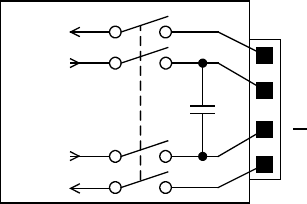
Although the plus and minus rail of the output power mesh are
physically disconnected from the output terminals with options 760
and 761, a small AC network is still connected across the plus and
minus output terminals (see figure).
Option 054
Option 054 (High-speed Test Extensions) include output list and
digitized measurement capability. This option is separately orderable
for Models N673xB, N674xB, N677xA, and N675xA when installed in
an N6700 MPS mainframes. All other power modules as well as the
N6705 DC Power Analyzer mainframes have output list and digitized
measurement capability built in.
Output list:
•
Maximum number
of
steps
= 512
•
Maximum dwell time in seconds
= 262
•
Maximum list repetitions
= 256 or infinite
Digitized measurement:
•
Maximum measurement points
= 4026
•
Maximum sample rate
= 50 kHz
Option 2UA
Option 2UA is a 200 microampere measurement range available on
Models N6761A and N6762A only. It includes Option 761 relay
capability.
+S
+
-S
Option 761
+ rail
+ sense
- rail
- sense

N6731B-N6784A DC Power Modules
N6700B-N6705B Mainframes
Specifications Guide 11
Chapter 2
Agilent N673xB, N674xB, N677xA
DC Power Modules
Performance Specifications ............................................................................ 12
Supplemental Characteristics ......................................................................... 14
Output Quadrant Characteristic ...................................................................... 16
Arbitrary Waveform Generator Maximum Bandwidth ................................ 16
Unless otherwise noted, specifications are warranted over the
ambient temperature range of 0 to 40°C after a 30-minute warm-up
period. Specifications apply at the output terminals, with each
module's sense terminals internally connected to its output terminals
(local sensing).
Refer to the Agilent N6700 or N6705 Service Guide for the setup
conditions for all performance specifications.
Supplemental characteristics are not warranted but are descriptions
of performance determined either by design or by type testing. All
supplemental characteristics are typical unless otherwise noted.

12 N6731B-N6784A DC Power Modules
N6700B-N6705B Mainframes
Specifications Guide
Performance Specifications
N6731B/
N6741B
N6732B/
N6742B
N6733B/
N6743B
N6734B/
N6744B
N6735B/
N6745B
N6736B/
N6746B
DC Output Ratings:
Voltage 0 - 5 V 0 - 8 V 0 - 20 V 0 - 35 V 0 - 60 V 0 - 100 V
Current NOTE 1
0-10 A/ 0-20 A
NOTE 2
0-6.25 A/0-12.5 A
0-2.5 A / 0-5 A
0-1.5 A / 0-3 A
0-0.8 A / 0-1.6 A
0-0.5 A / 0-1 A
Power
50 W / 100 W
50 W / 100 W
50 W / 100 W
52.5W / 105W
50 W / 100 W
50 W / 100 W
Output Ripple and Noise (PARD):
(from 20 Hz – 20 MHz)
CV peak-to- peak 10 mV / 20 mV 12 mV 14 mV 15 mV 25 mV 30 mV
CV rms 2 mV 2 mV 3 mV 5 mV 9 mV 18 mV
Load Effect (Regulation):
(Applies for any output load change, with a maximum load-lead drop of 1V/lead.
The load lead drop reduces the maximum available voltage at the load.)
Voltage 5 mV 6 mV 9 mV 11 mV 13 mV / 16 mV 20 mV / 30 mV
Current 2 mA 2 mA 2 mA 2 mA 2 mA 2 mA
Source Effect (Regulation):
Voltage 1 mV 2 mV 2 mV 4 mV 6 mV 10 mV
Current 1 mA 1 mA 1 mA 1 mA 1 mA 1 mA
Programming Accuracy:
(@ 23 °C ±5 °C after a 30 minute warm-up. Applies from minimum to maximum programming range at any load.)
Voltage 0.1% + 19 mV 0.1% + 19 mV 0.1% + 20 mV 0.1% + 35 mV 0.1% + 60 mV 0.1% +100 mV
Current
0.15% + 20 mA
0.15% + 20 mA
0.15% + 20 mA
0.15% + 20 mA
0.15% + 20 mA
0.15% + 10mA
Voltmeter/Ammeter Measurement Accuracy:
(@ 23 °C ±5 °C. Applies when measuring the default value of 1024 data points with a 20.48 μs time interval.)
Voltage 0.1% + 20 mV 0.1% + 20 mV 0.1% + 20 mV 0.1% + 35 mV 0.1% + 60 mV 0.1% +100 mV
Current 0.15% + 20 mA 0.15% + 10 mA 0.15% + 5 mA 0.15% + 4 mA 0.15% + 4 mA 0.15% + 2 mA
Load Transient Recovery Time:
(Time to recover to within the settling band following a load change from 50% to 100% and from 100% to 50% of full load.)
Voltage settling band
NOTE 3
±0.08 V / 0.1 V
NOTE 3
±0.08 V / 0.1 V
± 0.2 V / 0.3 V
± 0.2 V / 0.3 V
± 0.4 V / 0.5 V
± 0.5 V / 1.0 V
Time < 200 µs < 200 µs < 200 µs < 200 µs < 200 µs < 200 µs

N6731B-N6784A DC Power Modules
N6700B-N6705B Mainframes
Specifications Guide 13
Performance Specifications (continued)
N6773A N6774A N6775A N6776A N6777A
DC Output Ratings:
Voltage 0 - 20 V 0 - 35 V 0 - 60 V 0 - 100 V 0 - 150 V
Current NOTE 1 0 - 15 A NOTE 2 0 - 8.5 A 0 - 5 A 0 - 3 A 0 - 2 A
Power 300 W 300 W 300 W 300 W 300 W
Output Ripple and Noise (PARD):
(from 20 Hz – 20 MHz)
CV peak-to- peak 20 mV 22 mV 35 mV 45 mV 68 mV
CV rms
3 mV
5 mV
9 mV
18 mV
27 mV
Load Effect (Regulation):
(Applies for any output load change, with a maximum load-lead drop of 1V/lead.
The load lead drop reduces the maximum available voltage at the load.)
Voltage 13 mV 16 mV 24 mV 45 mV 68 mV
Current 6 mA 6 mA 6 mA 6 mA 6 mA
Source Effect (Regulation):
Voltage 2 mV 4 mV 6 mV 10 mV 15 mV
Current 1 mA 1 mA 1 mA 1 mA 1 mA
Programming Accuracy:
(@ 23 °C ±5 °C after 30 minute warm-up. Applies from minimum to maximum programming range at any load.)
Voltage 0.1% + 20 mV 0.1% + 35 mV 0.1% + 60 mV 0.1% +100 mV 0.1% +150 mV
Current 0.15% + 60 mA 0.15% + 60 mA 0.15% + 60 mA 0.15% + 30 mA 0.15% + 30 mA
Voltmeter/Ammeter Measurement Accuracy:
(@ 23 °C ±5 °C. Applies when measuring the default value of 1024 data points with a 20.48 μs time interval.)
Voltage 0.1% + 20 mV 0.1% + 35 mV 0.1% + 60 mV 0.1% +100 mV 0.1% +150 mV
Current 0.15% + 15 mA 0.15% + 12 mA 0.15% + 12 mA 0.15% + 6 mA 0.15% + 6 mA
Load Transient Recovery Time:
(Time to recover to within the settling band following a load change from 50% to 100% and from 100% to 50% of full load.)
Voltage settling band ± 0.3 V NOTE 4 ± 0.3 V NOTE 4 ± 0.5 V ± 1.0 V ± 2.0 V
Time < 250 µs < 250 µs < 250 µs < 250 µs < 250 µs
1 Output current is derated 1% per °C above 40°C.
2 When relay option 760 is installed on Models N6742B and N6773A, the output current is limited to 10 A.
3 When relay option 760 or 761 is installed, the settling band is ±0.10V/0.125 V.
Option 760 is not available on Model N6741B.
4 When relay option 760 or 761 is installed, the settling band is ±0.35 V.

14 N6731B-N6784A DC Power Modules
N6700B-N6705B Mainframes
Specifications Guide
Supplemental Characteristics
N6731B/
N6741B
N6732B/
N6742B
N6733B/
N6743B
N6734B/
N6744B
N6735B/
N6745B
N6736B/
N6746B
Programming Ranges:
Voltage
15 mV – 5 .1 V
15 mV – 8 .16 V
30 mV – 20.4 V
40 mV – 35.7 V
70 mV – 61.2 V
100 mV – 102 V
Current 60 mA – 10.2 A/
60 mA – 20.4 A
40 mA –6.375 A/
40 mA – 12.75 A
10 mA – 2.55 A/
10 mA – 5.1 A
5 mA – 1.53 A/
5 mA – 3.06 A
2.5 mA – 0.85 A/
2.5 m A – 1.7 A
1.5 mA – 0.51A/
1.5 mA – 1.02 A
Programming Resolution:
Voltage
3.5 mV
4 mV
7 mV
10 mV
18 mV
28 mV
Current
7 mA
4 mA
3 mA
2 mA
1 mA
0.5 mA
Measurement Resolution:
Voltage
3 mV
4 mV
10 mV
18 mV
30 mV
50 mV
Current
10 mA
7 mA
3 mA
2 mA
1 mA
0.5 mA
Programming Temperature Coefficient per °C:
Voltage
0.005% + 0.1mV
0.005% + 0.1 mV
0.005% + 0.2 mV
0.005% + 0.5 mV
0.005% + 0.5 mV
0.005% + 1 mV
Current
0.005% + 1 mA
0.005% + 0.5 mA
0.005% + 0.1 mA
0.005% + 0.05 mA
0.005% + 0.02 mA
0.005% + 0.02 mA
Measurement Temperature Coefficient per °C:
Voltage
0.01% + 0.1mV
0.01% + 0.1 mV
0.01% + 0.2 mV
0.01% + 0.2 mV
0.01% + 0.5 mV
0.01% + 0.5 mV
Current
0.01% + 1 mA
0.01% + 0.5 mA
0.01% + 0.1 mA
0.01% + 0.05 mA
0.01% + 0.02 mA
0.01% + 0.02 mA
N6705 Mainframe Oscilloscope Measurement Accuracy:
(@t 23 °C ±5 °C; accuracy of
any individual point in the trace)
Voltage
0.1% + 25 mV
0.1% + 30 mV
0.1% + 45 mV
0.1% + 75 mV
0.1% + 130 mV
0.1% + 190 mV
Current–Correction On
NOTE 1
0.15% + 50 mA
0.15% + 30 mA
0.15% + 15 mA
0.15% + 10 mA
0.15% + 9 mA
0.15% + 5 mA
Current
0.15% + 70 mA
0.15% + 40 mA
0.15% + 20 mA
0.15% + 14 mA
0.15% + 12 mA
0.15% + 7 mA
Up-programming and Down-programming Time with full resistive load:
(Time from 10% to 90% of total voltage excursion; for voltage setting from 0V to full scale and full scale to 0V)
20 ms
20 ms
20 ms
20 ms
20 ms
20 ms
Up-programming and Down-programming Settling Time with full resistive load:
(Time from start of voltage change to 0.1% of full-scale value; for voltage setting from 0V to full scale and full scale to 0V)
100 ms
100 ms
100 ms
100 ms
100 ms
100 ms
Over-voltage Protection:
Accuracy
0.25% + 50mV
0.25% + 50 mV
0.25% + 75 mV
0.25% + 100 mV
0.25% + 200 mV
0.25% + 250 mV
Accuracy with Opt. 760
0.25%+600mV
0.25% + 600 mV
0.25% + 350 mV
0.25% + 250 mV
0.25% + 300 mV
0.25% + 300 mV
Accuracy with Opt. 761
0.25%+600mV
0.25% + 600 mV
0.25% + 350 mV
0.25% + 250 mV
0.25% + 300 mV
0.25% + 300 mV
Maximum setting
7.5 V
10 V
22 V
38.5 V
66 V
110 V
Response time
50 µs from occurrence of over-voltage condition to start of output shutdown
Output Ripple and Noise (PARD):
CC rms
8 mA
4 mA
2 mA
2 mA
2 mA
2 mA
Common Mode Noise: (from
20 Hz – 20 MHz;
from either output to chassis)
Rms
1 mA
1 mA
1 mA
1 mA
1 mA
1 mA
Peak-to- peak
< 15 mA
< 10 mA
< 10 mA
< 10 mA
< 10 mA
< 10 mA
Remote Sense
Capability:
Outputs can maintain specifications with up to a 1-volt drop per load lead.
The load lead drop reduces the maximum available voltage at the load.
Series and
Parallel Operation:
Identically rated outputs can be operated directly in parallel or can be connected for straight series operation.
Auto-series and auto-parallel operation is not available.
Minimum Output Turn-On Delay:
(Time from when any Output On command is received until the output starts turning on)
Without relay option
32 ms
32 ms
32 ms
32 ms
32 ms
32 ms
With relay Option 760
58 ms
58 ms
58 ms
58 ms
58 ms
58 ms

N6731B-N6784A DC Power Modules
N6700B-N6705B Mainframes
Specifications Guide 15
Supplemental Characteristics (continued)
N6773A N6774A N6775A N6776A N6777A
Programming Ranges:
Voltage
30 mV – 20.4 V
40 mV – 35.7 V
70 mV – 61.2 V
100 mV – 102 V
145 mV – 153 V
Current
30 mA – 15.3 A
15 mA – 8.67 A
7.5 mA – 5.1 A
4.5 mA – 3.06 A
2.75 mA – 2.04 A
Programming Resolution:
Voltage
7 mV
10 mV
18 mV
28 mV
43 mV
Current 9 mA 6 mA 3 mA 1.5 mA 1 mA
Measurement Resolution:
Voltage
10 mV
18 mV
30 mV
50 mV
77 mV
Current
9 mA
6 mA
3 mA
1.5 mA
1 mA
Programming Temperature Coefficient per °C:
Voltage
0.01% + 0.2 mV
0.01% + 0.5 mV
0.01% + 0.5 mV
0.01% + 1 mV
0.01% + 1 mV
Current
0.01% + 0.5 mA
0.01% + 0.5 mA
0.01% + 0.1 mA
0.01% + 0.1 mA
0.01% + 0.1 mA
Measurement Temperature Coefficient per °C:
Voltage
0.01% + 0.2 mV
0.01% + 0.2 mV
0.01% + 0.5 mV
0.01% + 0.5 mV
0.01% + 0.5 mV
Current
0.01% + 0.5 mA
0.01% + 0.5 mA
0.01% + 0.05 mA
0.01% + 0.05 mA
0.01% + 0.05 mA
N6705 Mainframe Oscilloscope Measurement Accuracy:
(@ 23 °C ±5 °C; accuracy of
any individual point in the trace)
Voltage
0.1% + 45 mV
0.1% + 75 mV
0.1% + 120 mV
0.1% + 160 mV
0.1% + 175 mV
Current – Correction On
NOTE 1
0.15% + 35 mA
0.15% + 22 mA
0.15% + 19 mA
0.15% + 9 mA
0.15% + 9 mA
Current
0.15% + 45 mA
0.15% + 27 mA
0.15% + 22 mA
0.15% + 12 mA
0.15% + 12 mA
Up-programming and Down-programming Time with full resistive load:
(Time from 10% to 90% of total voltage excursion; for voltage setting from 0V to full scale and full scale to 0V)
20 ms
20 ms
20 ms
20 ms
20 ms
Maximum Up-programming and Down-programming Settling Time with full resistive load:
(Time from start of voltage change to 0.1% of full-scale value; for voltage setting from 0V to full scale and full scale to 0V)
100 ms
100 ms
100 ms
100 ms
100 ms
Over-voltage Protection:
Accuracy
0.25% +100 mV
0.25% + 130 mV
0.25% + 260 mV
0.25% + 650 mV
0.25% + 650 mV
Accuracy with Opt. 761
0.25% + 500 mV
0.25% + 350 mV
0.25% + 350 mV
0.25% + 650 mV
0.25% + 650 mV
Accuracy with Opt. 760
0.25% + 700 mV
0.25% + 700 mV
0.25% + 400 mV
0.25% + 650 mV
0.25% + 650 mV
Maximum setting
22 V
38.5 V
66 V
110 V
165 V
Response time
50
µ
s from occurrence of over-voltage condition to start of output shutdown
Output Ripple and Noise (PARD):
CC rms
6 mA
6 mA
6 mA
6 mA
6 mA
Common Mode Noise:
(from 20 Hz – 20 MHz; from either output to chassis)
Rms
2 mA
2 mA
2 mA
2 mA
2 mA
Peak-to- peak
< 20 mA
< 20 mA
< 20 mA
< 20 mA
< 20 mA
Remote Sense
Capability:
Outputs can maintain specifications with up to a 1-volt drop per load lead.
The load lead drop reduces the maximum available voltage at the load.
Series and
Parallel Operation:
Identically rated outputs can be operated directly in parallel or can be connected for straight series operation.
Auto-series and auto-parallel operation is not available.
Minimum Output Turn-On Delay:
(Time from when any Output On command is received until the output starts turning on)
Without relay option
32 ms
32 ms
32 ms
32 ms
32 ms
With relay Option 760
58 ms
58 ms
58 ms
58 ms
58 ms
1 Correction On compensates for current flowing into the output capacitor during voltage transients.

16 N6731B-N6784A DC Power Modules
N6700B-N6705B Mainframes
Specifications Guide
Output Quadrant Characteristic
Arbitrary Waveform Generator Maximum Bandwidth
NOTE The information in this section only applies when the power modules are
installed in an Agilent N6705 DC Power Analyzer.
The following tables characterize the maximum bandwidth of the
arbitrary waveform generator. The maximum bandwidth is based on
a sine wave into a resistive load and apples to any output current.
The following definitions apply in the frequency tables:
V p-p =
Voltage peak-to-peak
3 dB max. =
Max. frequency where the voltage drops to 3 dB below its setting
6 dB max. =
Max. frequency where the voltage drops to 6 dB below its setting
THD 3 dB =
The total harmonic distortion at 3 dB max. frequency
THD 6 dB =
The total harmonic distortion at 6 dB max. frequency
Voltage 3 dB max THD 3 dB 6 dB max THD 6 dB
N6731B & N6741B
0.1 Vp-p 175 Hz 1.0% 260 Hz 3.0%
0.1 Vp-p 125 Hz 1.0% 175 Hz 3.0%
0.3 Vp-p 75 Hz 6.0% 100 Hz 6.0%
0.5 Vp-p 40 Hz 9.0% 55 Hz 9.0%
5.0 Vp-p 20 Hz 10% 37 Hz 10%
N6732B & N6742B
0.1 Vp-p 125 Hz 1.0% 200 Hz 3.0%
0.2 Vp-p 125 Hz 1.0% 180 Hz 3.0%
0.4 Vp-p 75 Hz 6.0% 100 Hz 6.0%
0.8 Vp-p 40 Hz 8.5% 60 Hz 8.5%
8.0 Vp-p 20 Hz 10% 37 Hz 10%
Current
+ rated
current
0
Voltage
+ rated
voltage
maximum
power

N6731B-N6784A DC Power Modules
N6700B-N6705B Mainframes
Specifications Guide 17
Arbitrary Waveform Generator Maximum Bandwidth (continued)
Voltage 3 dB max THD 3 dB 6 dB max THD 6 dB 3 dB max THD 3 dB 6 dB max THD 6 dB
N6733B & N6743B N6773A
0.2 Vp-p 110 Hz 1.0% 190 Hz 3.0% 125 Hz 1.5% 210 Hz 4.0%
0.4 Vp-p 110 Hz 1.0% 160 Hz 3.0% 125 Hz 1.5% 180 Hz 4.0%
1.0 Vp-p 72 Hz 6.0% 95 Hz 6.0% 75 Hz 6.0% 95 Hz 6.0%
2.0 Vp-p 40 Hz 8.0% 55 Hz 8.5% 42 Hz 9.0% 60 Hz 9.0%
20 Vp-p 20 Hz 10% 37 Hz 10% 20 Hz 10% 37 Hz 10%
N6734B & N6744B N6774A
0.4 Vp-p 125 Hz 1.0% 200 Hz 1.0% 125 Hz 1.0% 200 Hz 1.0%
0.7 Vp-p 125 Hz 1.0% 175 Hz 3.5% 125 Hz 1.0% 160 Hz 3.0%
1.8 Vp-p 72 Hz 6.0% 100 Hz 6.0% 75 Hz 6.0% 95 Hz 6.0%
3.5 Vp-p 40 Hz 8.0% 55 Hz 8.5% 40 Hz 8.5% 55 Hz 8.5%
35 Vp-p 20 Hz 8.0% 37 Hz 8.5% 20 Hz 10% 37 Hz 10%
N6735B & N6745B N6775A
0.6 Vp-p 100 Hz 1.0% 180 Hz 1.0% 120 Hz 1.0% 200 Hz 1.0%
1.2 Vp-p 100 Hz 1.0% 160 Hz 3.0% 120 Hz 1.0% 160 Hz 3.0%
3.0 Vp-p 70 Hz 5.5% 92 Hz 5.5% 70 Hz 5.0% 95 Hz 6.0%
6.0 Vp-p 40 Hz 8.0% 55 Hz 8.0% 40 Hz 8.5% 55 Hz 8.5%
60 Vp-p 20 Hz 8.0% 37 Hz 8.0% 20 Hz 10% 35 Hz 10%
N6736B & N6746B N6776A
1.0 Vp-p 90 Hz 1.0% 160 Hz 1.5% 75 Hz 1.0% 160 Hz 1.0%
2.0 Vp-p 90 Hz 1.0% 150 Hz 3.0% 75 Hz 1.0% 150 Hz 3.0%
5.0 Vp-p 62 Hz 4.5% 85 Hz 6.0% 55 Hz 4.0% 75 Hz 6.0%
10 Vp-p 37 Hz 8.0% 50 Hz 8.0% 35 Hz 8.0% 45 Hz 8.0%
100 Vp-p 20 Hz 8.0% 35 Hz 8.0% N/A N/A 35 Hz 8.0%
N6777A
1.5 Vp-p 70 Hz 1.0% 150 Hz 1.0%
3.0 Vp-p 55 Hz 5.0% 120 Hz 2.0%
7.5 Vp-p 55 Hz 5.0% 70 Hz 6.0%
15 Vp-p 35 Hz 7.0% 55 Hz 7.0%
150 Vp-p N/A N/A 30 Hz 1.0%

N6731B-N6784A DC Power Modules
N6700B-N6705B Mainframes
Specifications Guide 19
Chapter 3
Agilent N675xA High Performance
Power Modules
Performance Specifications ............................................................................ 20
Supplemental Characteristics ......................................................................... 21
Autoranging Characteristic.............................................................................. 23
Output Impedance Graphs ............................................................................... 23
Arbitrary Waveform Generator Maximum Bandwidth ................................ 26
Unless otherwise noted, specifications are warranted over the
ambient temperature range of 0 to 40°C after a 30-minute warm-up
period. Specifications apply at the output terminals, with each
module's sense terminals internally connected to its output terminals
(local sensing).
Refer to the Agilent N6700 or N6705 Service Guide for the setup
conditions for all performance specifications.
Supplemental characteristics are not warranted but are descriptions
of performance determined either by design or by type testing. All
supplemental characteristics are typical unless otherwise noted.

20 N6731B-N6784A DC Power Modules
N6700B-N6705B Mainframes
Specifications Guide
Performance Specifications
N6751A/N6752A N6753A/N6755A N6754A/N6756A
DC Output Ratings:
Voltage 0 - 50 V 0 - 20 V 0 - 60 V
Current NOTE 1 0 - 5 A / 0 - 10 A 0 - 50 A 0 - 20 A / 0 - 17A
Power 50 W / 100 W 300 W / 500 W 300 W / 500 W
Output Ripple and Noise (PARD):
(from 20 Hz – 20 MHz)
CV peak-to-peak 4.5 mV 5 mV 6 mV
CV rms 0.35 mV 1 mV 1 mV
Load Effect (Regulation):
(Applies for any output load change, with a maximum load-lead drop of 1V/lead.
The load lead drop reduces the maximum available voltage at the load.)
Voltage 2 mV 2 mV 2 mV
Current 2 mA 12 mA 5 mA
Source Effect (Regulation):
Voltage 1 mV 0.5 mV 1.2 mV
Current 1 mA 5 mA 2 mA
Programming Accuracy:
(@ 23 °C ±5 °C after 30 minute warm-up. Applies from minimum to maximum programming range at any load.)
Voltage 0.06% + 19 mV 0.06% + 10 mV 0.06% + 25 mV
Current 0.1% + 20 mA 0.1% + 30 mA 0.1% + 12 mA
Voltmeter/Ammeter Measurement Accuracy:
(@ 23 °C ±5 °C. Applies when measuring the default value of 1024 data points with a 20.48 μs time interval.)
Voltage
0.05% + 20 mV
0.05% + 10 mV
0.05% + 25 mV
Current 0.1% + 4 mA 0.1% + 30 mA 0.1% + 8 mA
Load Transient Recovery Time:
(Time to recover to within the settling band following a load change
- from 60% to 100% and from 100% to 60% of full load for model N6751A
- from 50% to 100% and from 100% to 50% of full load for models N6752A through N6756A.)
Voltage settling band ± 75 mV NOTE 2 ± 30 mV NOTE 3 ± 90 mV NOTE 4
Time < 100 µs < 100 µs < 100 µs
1 Output current is derated 1% per °C above 40°C.
2 When relay option 761 is installed on Model N6752A, the settling band is ±125 mV.
3 When relay option 760 or 761 is installed on Model N6753A and N6755A, the settling band is ±200 mV.
4 When relay option 760 or 761 is installed on Model N6754A and N6756A, the settling band is ±350 mV.

N6731B-N6784A DC Power Modules
N6700B-N6705B Mainframes
Specifications Guide 21
Supplemental Characteristics
N6751A / N6752A N6753A / N6755A N6754A / N6756A
Programming Ranges:
Voltage
20 mV – 51 V
10 mV – 20.4 V
25 mV- 61.2 V
Current
10 mA – 5.1A/10 mA – 10.2A
50 mA – 51 A
20 mA – 20.4 A/20 mA – 17.3A
Programming Resolution:
Voltage
3.5 mV
1.5 mV
4.2 mV
Current
3.25 mA
16.3 mA
6.5 mA
Measurement Resolution:
Voltage
1.8 mV
0.8 mV
2.2 mV
Current
410
µ
A
2.05 mA
0.82 mA
Programming Temperature Coefficient per °C:
Voltage
18 ppm + 160
µ
V
35 ppm + 100
µ
V
35 ppm + 170
µ
V
Current
100 ppm + 45
µ
A
60 ppm + 500
µ
A
60 ppm + 200
µ
A
Measurement Temperature Coefficient per °C:
Voltage
25 ppm + 35
µ
V
50 ppm + 85
µ
V
50 ppm + 100
µ
V
Current
60 ppm + 3
µ
A
60 ppm + 30
µ
A
60 ppm + 12
µ
A
N6705 Mainframe Oscilloscope Measurement Accuracy: (@ 23 °C ±5 °C, accuracy of any individual point in the trace)
Voltage
0.05% + 32 mV
0.05% + 15 mV
0.05% + 37 mV
Current– with Correction On
NOTE 1
0.1% + 14 mA N/A N/A
Current
0.1% + 8 mA
0.1% + 52 mA
0.1% + 17 mA
Up-programming Time with full resistive load: (Time from 10% to 90% of total voltage excursion)
Small voltage step
0 V to 10 V
0 V to 6 V/0 V to 10 V
0 V to 15 V/0 V to 29 V
Time
0.2 ms
0.4 ms/0.5 ms
0.35 ms/0.7 ms
Large voltage step
0 V to 50 V
0 V to 20 V
0 V to 60 V
Time
1.5 ms
1.5 ms
2 ms
Up-programming Settling Time with full resistive load:
(Time from start of voltage change to 0.1% of full scale value)
Small voltage step
0 V to 10 V
0 V to 6 V/0 V to 10 V
0 V to 15 V/0 V to 29 V
Time
0.5 ms
0.8 ms/1.0 ms
0.8 ms/1.4 ms
Large voltage step
0 V to 50 V
0 V to 20 V
0 V to 60 V
Time
4 ms
3 ms
4.2 ms
Down-programming Time with no load: (Time from start of voltage change to output voltage < 0.5 V)
Small voltage step
10 V to 0 V
6 V to 0 V/10 V to 0 V
15 V to 0 V/29 V to 0 V
Time
0.3 ms
0.55 ms/1.0 ms
0.6 ms/1.2 ms
Large voltage step
50 V to 0 V
20 V to 0 V
60 V to 0 V
Time
1.3 ms
1.8 ms
2.2 ms
Down-programming Settling Time with no load: (Time from start of voltage change to 0.1% of full scale value)
Small voltage step
10 V to 0 V
6 V to 0 V/10 V to 0 V
15 V to 0 V/29 V to 0 V
Time
0.45 ms
0.8 ms/1.3 ms
0.8 ms/1.5 ms
Large voltage step
50 V to 0 V
20 V to 0 V
60 V to 0 V
Time
1.4 ms
2 ms
2.3 ms

22 N6731B-N6784A DC Power Modules
N6700B-N6705B Mainframes
Specifications Guide
Supplemental Characteristics (continued)
N6751A / N6752A N6753A / N6755A N6754A / N6756A
Down-programming Time with Capacitive load: (Time from start of voltage change to output voltage < 0.5 V)
Small voltage step
10 V to 0 V
6 V to 0 V/10 V to 0 V
15 V to 0 V/29 V to 0 V
Time
2.1 ms
2.2 ms/4.5 ms
2.3 ms/5.5 ms
Large voltage step
50 V to 0 V
20 V to 0 V
60 V to 0 V
Time
11 ms
8.5 ms
10 ms
Capacitive load
NOTE 2
1000 µF 4700 µF 680 µF
Down-programming Capability:
Continuous power
7 W
12.5 W
12.5 W
Peak current
7 A
15 A
6 A
Over-voltage Protection:
Accuracy
0.25% + 0.25 V
0.25% + 0.15V
0.25% + 0.3V
Accuracy with Option 761
0.25% + 0.25 V
0.25% + 0.45V
0.25% + 0.6V
Accuracy with Option 760
N/A
0.25% + 0.45V
0.25% + 0.6V
Maximum setting
55 V
22 V
66 V
Response time
50
µ
s from occurrence of over-voltage condition to start of output shutdown
Output Ripple and Noise: (PARD)
CC rms:
2 mA
10 mA
4 mA
Common Mode Noise: (from 20 Hz – 20 MHz; from either output to chassis)
rms 500 µA 500 µA 750 µA
peak-to-peak
< 2 mA
< 2 mA
< 3 mA
Remote Sense Capability:
Outputs can maintain specifications with up to a 1-volt drop per load lead.
The load lead drop reduces the maximum available voltage at the load.
Series and Parallel Operation:
Identically rated outputs can be operated directly in parallel or be connected for
straight series operation. Auto-series and auto-parallel operation is not available.
Minimum Output Turn-On Delay: (Time from when any Output On command is received until the output starts turning on)
Without relay option 25 ms 18 ms 18 ms
With relay Option 760 51 ms 44 ms 44 ms
1 Correction On compensates for current flowing into the output capacitor during voltage transients.
2 Modules can discharge the specified capacitive load from full scale to 0V at a rate of 4 times/second.
N6731B-N6784A DC Power Modules
N6700B-N6705B Mainframes
Specifications Guide 23
Autoranging Characteristic
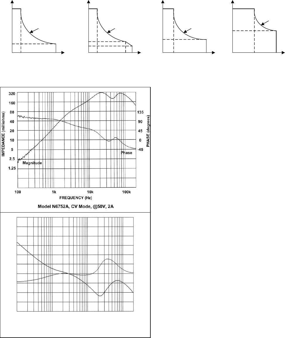
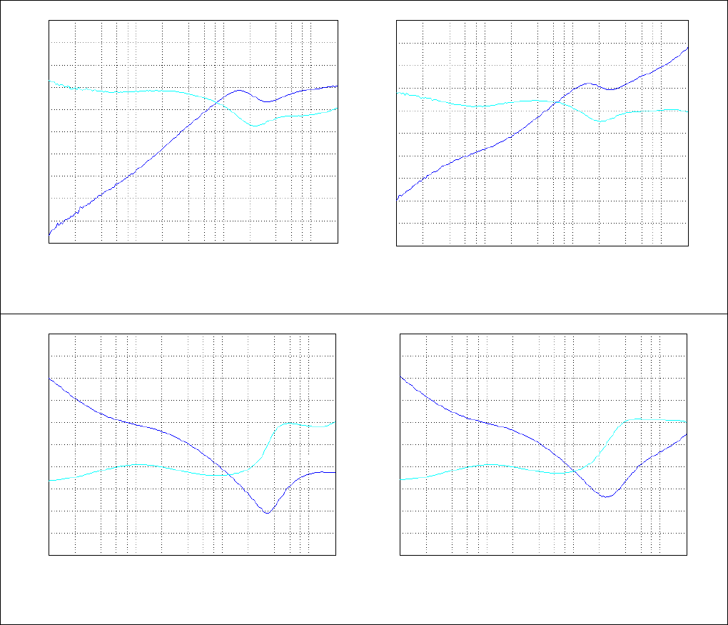
Output Impedance Graphs
1k
90
45
0
-45
-90
FREQUENCY (Hz)
10k 100k
Model N6752A, CC Mode, @50V, 2A
PHASE (degrees)
Phase
100
Magnitude
8
4
2
1
0.5
0.25
0.125
IMPEDANCE (ohms)
0
50 V
10 V
1 A
Voltage
Current
N6751A
50 W Output
50 W curve
5 A0
50 V
12 V
2 A
Voltage
Current
N6752A
100 W Output
100 W curve
10 A
8.5 V
8.33 A0
20 V
60 V
6 V
15 V
Voltage
Current
N6753A / N6754A
300 W Output
300 W curve
50 A
20 A
15 A
5 A
0
20 V
60 V
10 V
29 V
Voltage
Current
500 W curve
50 A
17 A
25 A
8.33 A
N6755A / N6756A
500 W Output

24 N6731B-N6784A DC Power Modules
N6700B-N6705B Mainframes
Specifications Guide
1k
80
40
20
10
5
2.5
1.25
0.62
90
45
0
-45
-90
FREQUENCY (Hz)
10k 100k
Phase
IMPEDANCE (milliohms)
100
Magnitude
1k
80
40
20
10
5
2.5
1.25
0.62
135
90
45
0
-45
FREQUENCY (Hz)
10k 100k
PHASE (degrees)
Phase
100
Magnitude
Model N6753A and N6755A, CV Mode, @20 V, 15A
Model N6753A and N6755A, Option 760, CV Mode, @20 V, 15A
1k
45
0
-45
-90
-135
FREQUENCY (Hz)
10k 100k
Phase
IMPEDANCE (ohms)
100
Magnitude
0.8
0.4
0.2
0.1
0.05
0.025
0.0125
0.0062
1k
90
45
0
-45
-90
FREQUENCY (Hz)
10k 100k
PHASE (degrees)
Phase
100
Magnitude
0.8
0.4
0.2
0.1
0.05
0.025
0.0125
0.0062
Model N6753A and N6755A, CC Mode, @20 V, 15A
Model N6753A and N6755A, Option 760, CC Mode, @20 V, 15A

N6731B-N6784A DC Power Modules
N6700B-N6705B Mainframes
Specifications Guide 25
1k
0.8
0.4
0.2
0.1
0.05
0.025
0.0125
0.0062
90
45
0
-45
-90
FREQUENCY (Hz)
10k 100k
Phase
IMPEDANCE (ohms)
100
Magnitude
1k
0.8
0.4
0.2
0.1
0.05
0.025
0.0125
0.0062
90
45
0
-45
-90
FREQUENCY (Hz)
10k 100k
PHASE (degrees)
Phase
100
Magnitude
Model N6754A and N6756A, CV Mode, @60 V, 5A
Model N6754A and N6756A, Option 760, CV Mode, @60 V, 5A
1k
8
4
2
1
0.5
0.25
0.125
0.062
45
0
-45
-90
-135
FREQUENCY (Hz)
10k 100k
Phase
IMPEDANCE (ohms)
100
Magnitude
1k
45
0
-45
-90
-135
FREQUENCY (Hz)
10k 100k
PHASE (degrees)
Phase
100
Magnitude
8
4
2
1
0.5
0.25
0.125
0.062
Model N6754A and N6756A, CC Mode, @60 V, 5A
Model N6754A and N6756A, Option 760, CC Mode, @60 V, 5A

26 N6731B-N6784A DC Power Modules
N6700B-N6705B Mainframes
Specifications Guide
Arbitrary Waveform Generator Maximum Bandwidth
NOTE The information in this section only applies when the power modules are
installed in an Agilent N6705 DC Power Analyzer.
The following tables characterize the maximum bandwidth of the
arbitrary waveform generator. The maximum bandwidth is based on
a sine wave into a resistive load and apples to any output current.
The following definitions apply in the frequency tables:
V p-p =
Voltage peak-to-peak
3 dB max. =
Max. frequency where the voltage drops to 3 dB below its setting
THD 3 dB =
The total harmonic distortion at 3 dB max. frequency
THD < 1.5% =
The frequency below which the THD is less than 1.5%.
Voltage 3 dB max THD 3 dB THD < 1.5%
N6751A & N6752A
0.5 Vp-p 4000 Hz 12% 440 Hz
1.0 Vp-p 2200 Hz 21% 440 Hz
2.5 Vp-p 900 Hz 25% 265 Hz
5.0 Vp-p 500 Hz 27% 160 Hz
50.0 Vp-p 340 Hz 22% 25 Hz
N6753A & N6755A
0.2 Vp-p 2300 Hz 10% 1300 Hz
0.4 Vp-p 1500 Hz 15% 800 Hz
1.0 Vp-p 980 Hz 19% 480 Hz
2.0 Vp-p 580 Hz 21% 300 Hz
20.0 Vp-p 400 Hz 12% 32 Hz
N6754A & N6756A
0.6 Vp-p 2800 Hz 8.0% 1600 Hz
1.2 Vp-p 1400 Hz 15% 800 Hz
3.0 Vp-p 600 Hz 17% 300 Hz
6.0 Vp-p 400 Hz 20% 200 Hz
60.0 Vp-p 344 Hz 12% 30 Hz

N6731B-N6784A DC Power Modules
N6700B-N6705B Mainframes
Specifications Guide 27
Chapter 4
Agilent N676xA Precision
Power Modules
Performance Specifications ............................................................................ 28
Supplemental Characteristics ......................................................................... 29
Autoranging Characteristic.............................................................................. 31
Output Impedance Graphs ............................................................................... 31
Arbitrary Waveform Generator Maximum Bandwidth ................................ 34
Unless otherwise noted, specifications are warranted over the
ambient temperature range of 0 to 40°C after a 30-minute warm-up
period. Specifications apply at the output terminals, with each
module's sense terminals internally connected to its output terminals
(local sensing).
Refer to the Agilent N6700 or N6705 Service Guide for the setup
conditions for all performance specifications.
Supplemental characteristics are not warranted but are descriptions
of performance determined either by design or by type testing. All
supplemental characteristics are typical unless otherwise noted.

28 N6731B-N6784A DC Power Modules
N6700B-N6705B Mainframes
Specifications Guide
Performance Specifications
N6761A/N6762A
N6763A/N6765A
N6764A/N6766A
DC Ratings:
Voltage
0 - 50 V
0 - 20 V
0 - 60 V
Current
NOTE 1
0 - 1.5 A / 0 - 3 A
0 - 50 A
0 - 20 A / 0 - 17 A
Power
50 W / 100 W
300 W / 500 W
300 W / 500 W
Low programming ranges (V & I)
5.5 V; 100 mA
N/A
N/A
Low measurement ranges (V & I)
5.5 V; 100 mA
2 V; 1.5 A
6 V; 0.5 A
Output Ripple and Noise (PARD):
(from 20 Hz – 20 MHz)
CV peak-to-peak
4.5 mV
5 mV
6 mV
CV rms
0.35 mV
1 mV
1 mV
Load Effect (Regulation):
(Applies for any output load change, with a maximum load-lead drop of 1V/lead.
The load lead drop reduces the maximum available voltage at the load.)
Voltage
0.5 mV
2 mV
2 mV
Current
30 µA (@ 0 –7 V)
65 µA (@ 7 – 50V)
12 mA
5 mA
Source Effect (Regulation):
Voltage
0.5 mV
0.5 mV
1.2 mV
Current
30
µ
A
5 mA
2 mA
Programming Accuracy:
(@ 23 °C
±
5 °C after 30 minute warm-up. Applies from minimum to maximum programming range at any load.)
Voltage, high range
0.016% + 6 mV
0.03% + 5 mV
0.03% + 12 mV
Voltage, low range
0.016% + 1.5 mV
N/A
N/A
Current, high range
0.04% + 200
µ
A
0.1% + 15 mA
0.075% + 4 mA
Current, low range
0.04% + 30 µA (@ 0 –7 V)
0.04% + 55
µ
A (@ 7 –50 V)
N/A
N/A
Voltmeter/Ammeter Measurement Accuracy:
(@ 23 °C
±
5 °C. Applies when measuring 4096 data points with a 20.48 μs time interval.)
Voltage, high range
0.016% + 6 mV
0.03% + 10 mV
0.03% + 25 mV
Voltage, low range
0.016% + 1.5 mV
0.03% + 1.5 mV
0.03% + 5 mV
Current, high range
0.04% + 160 µA
0.1% + 10 mA
0.1% + 5 mA
Current, low range
0.03% + 15 µA (@ 0 – 7 V)
0.03% + 55
µ
A (@ 7 – 50 V)
0.05% + 1.1 mA
NOTE 2
0.05% + 0.75 mA
NOTE 2
200 µA current range (Option 2UA)
0.5% + 100 nA
N/A
N/A
Load Transient Recovery Time:
(time to recover to within the settling band following a load change
- from 60% to 100% and from 100% to 60% of full load for model N6761A
- from 50% to 100% and from 100% to 50% of full load for model N6762A through N6766A)
Voltage settling band
± 75 mV
± 30 mV
NOTE 3
± 90 mV
NOTE 4
Time
< 100
µ
s
< 100
µ
s
< 100
µ
s
1 Output current is derated 1% per °C above 40°C.
2 Applies when measuring currents that remain within the low range. Due to thermal settling, when transitioning
from measuring full-rated output current (the worst case), to measuring the current within the low range, the low
range accuracy specification is typically met within 5 seconds after the current has transitioned into the low
range. Accuracies within this 5 second settling period are typically 2X the specified accuracy or better.
3 When relay option 760 or 761 is installed on Models N6763Aand N6765A, the settling band is ±200 mV.
4 When relay option 760 or 761 is installed on Models N6764Aand N6766A, the settling band is ±350 mV.

N6731B-N6784A DC Power Modules
N6700B-N6705B Mainframes
Specifications Guide 29
Supplemental Characteristics
N6761A / N6762A N6763A / N6765A N6764A / N6766A
Programming Ranges:
Voltage, high range
15 mV – 51 V
10 mV – 20.4 V
25 mV- 61.2 V
Voltage, low range
12 mV – 5.5 V
N/A
N/A
Current, high range
1 mA – 1.53 A/1 mA – 3.06 A
50 mA – 51 A
20 mA – 20.4A/20 mA – 17.3A
Current, low range
0.1 mA – 0.1 A
NOTE 1
N/A
N/A
Programming Resolution:
Voltage, high range
880
µ
V
1.5 mV
4.2 mV
Voltage, low range
90
µ
V
N/A
N/A
Current, high range
60
µ
A
16.3 mA
6.5 mA
Current, low range
2
µ
A
N/A N/A
Measurement Resolution:
Voltage, high range
440
µ
V
250
µ
V
600
µ
V
Voltage, low range
44
µ
V
25
µ
V
60
µ
V
Current, high range
30
µ
A
500
µ
A
250
µ
A
Current, low range
1
µ
A
20
µ
A
10
µ
A
200
µ
A current range (Option 2UA)
4 nA
N/A
N/A
Programming Temperature Coefficient per °C:
Voltage, high range
18 ppm + 140
µ
V
23 ppm + 95
µ
V
23 ppm + 218
µ
V
Voltage, low range
40 ppm + 70
µ
V
N/A
N/A
Current, high range
33 ppm + 10
µ
A
25ppm + 129
µ
A
25ppm + 52
µ
A
Current, low range
60 ppm + 1.5
µ
A
N/A N/A
Measurement Temperature Coefficient per °C:
Voltage, high range
23 ppm + 40
µ
V
23 ppm + 53
µ
V
23 ppm + 73
µ
V
Voltage, low range
30 ppm + 40
µ
V
25 ppm + 53
µ
V
25 ppm + 73
µ
V
Current, high range
40 ppm + 0.3
µ
A
25 ppm + 21
µ
A
25 ppm + 7
µ
A
Current, low range
50 ppm + 0.3
µ
A
27 ppm + 21
µ
A
27 ppm + 7
µ
A
Current, 200 µA range (Option 2UA)
100 ppm + 3 nA/°C
N/A
N/A
N6705 Mainframe Oscilloscope Measurement Accuracy: (@ 23 °C ±5 °C, accuracy of any individual point in the trace)
Voltage
0.016% + 16 mV
0.03% + 13 mV
0.03% + 32 mV
Current, high range
–
with Correction On
NOTE 2
0.04% + 10 mA
N/A
N/A
Current, high range
0.04% + 1 mA
0.1% + 16 mA
0.1% + 8.4 mA
Current, low range
0.03% + 0.175 mA
0.05% + 6.6 mA
0.05% + 2.6 mA
Up-programming Time with full resistive load: (Time from 10% to 90% of total voltage excursion)
Small voltage step
0 V to 10 V
0 V to 6 V/0 V to 10 V
0 V to 15 V/0 V to 29 V
Time
0.6 ms
0.4 ms/0.5 ms
0.35 ms/0.7 ms
Large voltage step
0 V to 50 V
0 V to 20 V
0 V to 60 V
Time
2.2 ms
1.5 ms
2 ms
Up-programming Settling Time with full resistive load:
(Time from start of voltage change to 0.1% of full scale value)
Small voltage step
0 V to 10 V
0 V to 6 V/0 V to 10 V
0 V to 15 V/0 V to 29 V
Time
0.9 ms
0.8 ms/1.0 ms
0.8 ms/1.4 ms
Large voltage step
0 V to 50 V
0 V to 20 V
0 V to 60 V
Time
4 ms
3 ms
4.2 ms

30 N6731B-N6784A DC Power Modules
N6700B-N6705B Mainframes
Specifications Guide
Supplemental Characteristics (continued)
N6761A / N6762A N6763A / N6765A N6764A / N6766A
Down-programming Time with no load: (time from start of voltage change to output voltage < 0.5 V)
Small voltage step
10 V to 0 V
6 V to 0 V/10 V to 0 V
15 V to 0 V/29 V to 0 V
Time
0.3 ms
0.55 ms/1.0 ms
0.6 ms/1.2 ms
Large voltage step
50 V to 0 V
20 V to 0 V
60 V to 0 V
Time
1.3 ms
1.8 ms
2.2 ms
Down-programming Settling Time with no load: (time from start of voltage change to 0.1% of full scale value)
Small voltage step
10 V to 0 V
6 V to 0 V/10 V to 0 V
15 V to 0 V/29 V to 0 V
Time
0.45 ms
0.8 ms/1.3 ms
0.8 ms/1.5 ms
Large voltage step
50 V to 0 V
20 V to 0 V
60 V to 0 V
Time
1.4 ms
2 ms
2.3 ms
Down-programming Time with Capacitive load: (time from start of voltage change to output voltage < 0.5 V)
Small voltage step
10 V to 0 V
6 V to 0 V/10 V to 0 V
15 V to 0 V/29 V to 0 V
Time
4.5 ms
2.2 ms/4.5 ms
2.3 ms/5.5 ms
Large voltage step
50 V to 0 V
20 V to 0 V
60 V to 0 V
Time
23 ms
8.5 ms
10 ms
Capacitive load
NOTE 3
1000 µF 4700 µF 680 µF
Down-programming Capability:
Continuous power
7 W
12.5 W
12.5 W
Peak current
3.8 A
15 A
6 A
Over-voltage Protection:
Accuracy
0.25% + 0.25 V
0.25% + 0.15 V
0.25% + 0.3 V
Accuracy with Option 761
0.25% + 0.25 V
0.25% + 0.45 V
0.25% + 0.6 V
Accuracy with Option 760
N/A
0.25% + 0.45 V
0.25% + 0.6 V
Maximum setting
55 V
22 V
66 V
Response time
50 µs from occurrence of over-voltage condition to start of output shutdown
Output Ripple and Noise: (PARD)
CC rms:
2 mA
10 mA
4 mA
Common Mode Noise: (from 20 Hz – 20 MHz; from either output to chassis)
rms 500 µA 500 µA 750 µA
peak-to-peak
< 2 mA
< 2 mA
< 3 mA
Remote Sense Capability:
Outputs can maintain specifications with up to a 1-volt drop per load lead.
The load lead drop reduces the maximum available voltage at the load.
Series and Parallel Operation:
Identically rated outputs can be operated directly in parallel or be connected for
straight series operation. Auto-series and auto-parallel operation is not available.
Minimum Output Turn-On Delay: (Time from when any Output On command is received until the output starts turning on)
Without relay option
32 ms
NOTE 4
18 ms 18 ms
With relay Option 760
58 ms
NOTE 4
44 ms 44 ms
1 If you are operating the unit below 255 µA in constant current mode, the output may become unregulated with the
following load conditions: The load resistance is <175 mΩ and the load inductance is >20 µH. If this occurs, an
UNRegulated flag will be generated and the output current may rise above the programmed value but will remain
less than 255 µA.
2 Correction On compensates for current flowing into the output capacitor during voltage transients
3 Modules can discharge the specified capacitive load from full scale to 0V at a rate of 4 times/second.
4 In Current priority mode, minimum delay is 23 ms without relays and 45 ms with relay Option 760.
N6731B-N6784A DC Power Modules
N6700B-N6705B Mainframes
Specifications Guide 31
Autoranging Characteristic
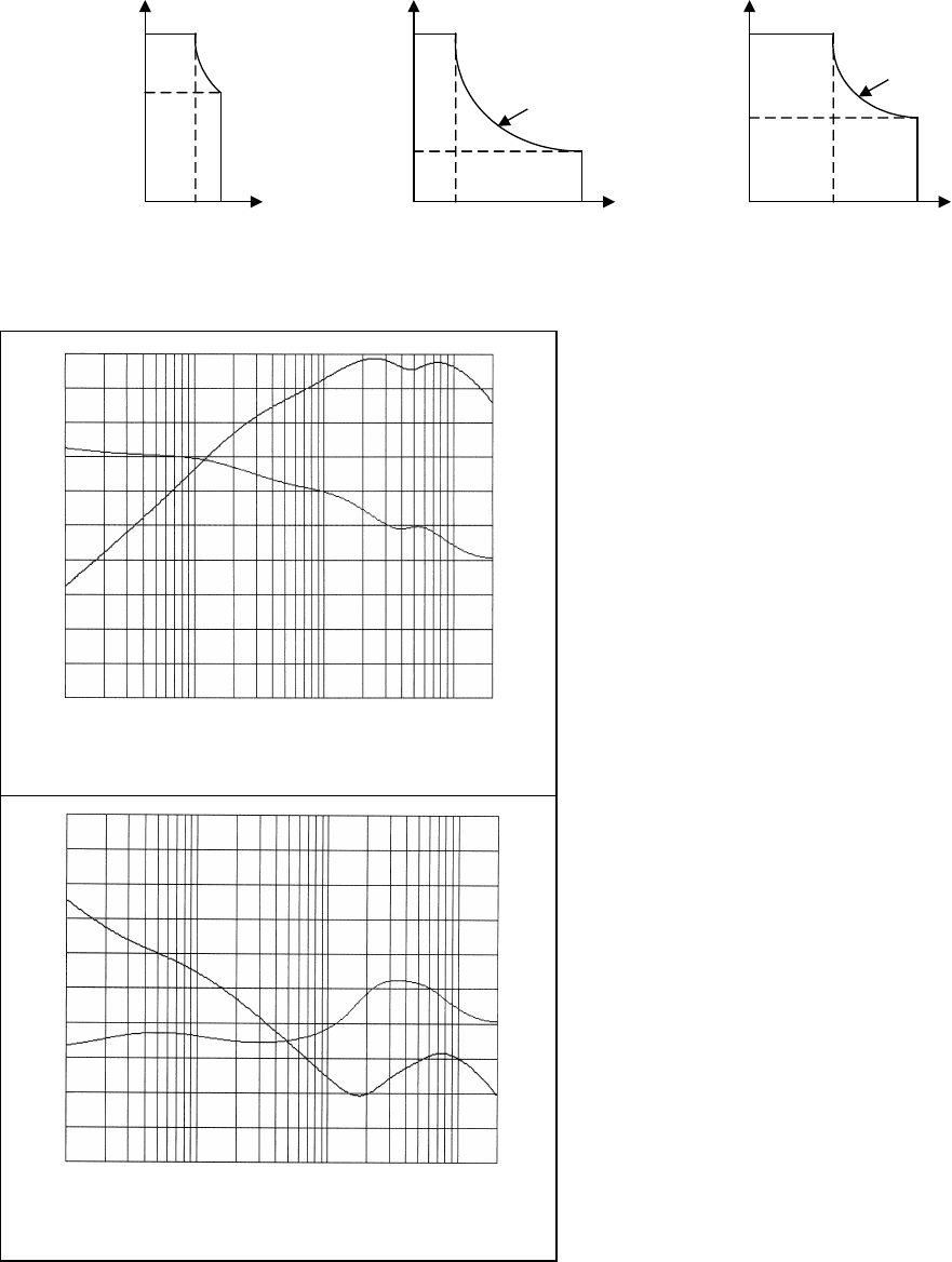
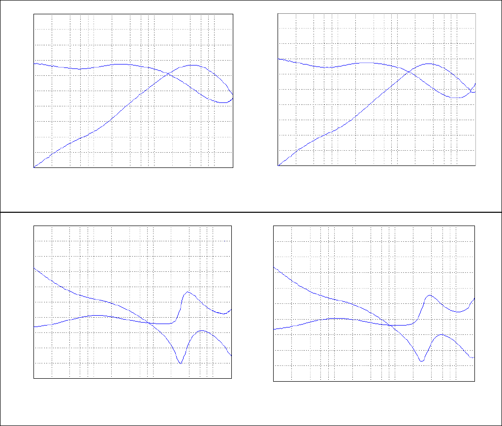
Output Impedance Graphs
1k
320
160
80
40
20
10
5
2.5
135
90
45
0
-45
FREQUENCY (Hz)
10k 100k
Model N6762A, CV Mode, @50V, 2A
Phase
IMPEDANCE (milliohms)
100
Magnitude
PHASE (degrees)
1k
90
45
0
-45
-90
FREQUENCY (Hz)
10k 100k
Model N6762A, CC Mode, @50V, 2A
PHASE (degrees)
Phase
100
Magnitude
8
4
2
1
0.5
0.25
0.125
IMPEDANCE (ohms)
0
50 V
33 V
Voltage
1 A
2 A1.5 A
3 A
Current
- 50 W
- 100 W
N6761A / N6762A
50 W / 100 W Output
0
20 V
60 V
6 V
15 V
Voltage
Current
N6763A / N6764A
300 W Output
300 W curve
50 A
20 A
15 A
5 A
0
20 V
60 V
10 V
29 V
Voltage
Current
500 W curve
50 A
17 A
25 A
8.33 A
N6765A / N6766A
500 W Output
32 N6731B-N6784A DC Power Modules
N6700B-N6705B Mainframes
Specifications Guide
1k
80
40
20
10
5
2.5
1.25
0.62
90
45
0
-45
-90
FREQUENCY (Hz)
10k 100k
Phase
IMPEDANCE (milliohms)
100
Magnitude
1k
80
40
20
10
5
2.5
1.25
0.62
135
90
45
0
-45
FREQUENCY (Hz)
10k 100k
PHASE (degrees)
Phase
100
Magnitude
Model N6763A and N6765A, CV Mode, @20 V, 15A
Model N6763A and N6765A, Option 760, CV Mode, @20 V, 15A
1k
45
0
-45
-90
-135
FREQUENCY (Hz)
10k 100k
Phase
IMPEDANCE (ohms)
100
Magnitude
0.8
0.4
0.2
0.1
0.05
0.025
0.0125
0.0062
1k
90
45
0
-45
-90
FREQUENCY (Hz)
10k 100k
PHASE (degrees)
Phase
100
Magnitude
0.8
0.4
0.2
0.1
0.05
0.025
0.0125
0.0062
Model N6763A and N6765A, CC Mode, @20 V, 15A
Model N6763A and N6765A, Option 760, CC Mode, @20 V, 15A
N6731B-N6784A DC Power Modules
N6700B-N6705B Mainframes
Specifications Guide 33
1k
0.8
0.4
0.2
0.1
0.05
0.025
0.0125
0.0062
90
45
0
-45
-90
FREQUENCY (Hz)
10k 100k
Phase
IMPEDANCE (ohms)
100
Magnitude
1k
0.8
0.4
0.2
0.1
0.05
0.025
0.0125
0.0062
90
45
0
-45
-90
FREQUENCY (Hz)
10k 100k
PHASE (degrees)
Phase
100
Magnitude
Model N6764A and N6766A, CV Mode, @60 V, 5A
Model N6764A and N6766A, Option 760, CV Mode, @60 V, 5A
1k
8
4
2
1
0.5
0.25
0.125
0.062
45
0
-45
-90
-135
FREQUENCY (Hz)
10k 100k
Phase
IMPEDANCE (ohms)
100
Magnitude
1k
45
0
-45
-90
-135
FREQUENCY (Hz)
10k 100k
PHASE (degrees)
Phase
100
Magnitude
8
4
2
1
0.5
0.25
0.125
0.062
Model N6764A and N6766A, CC Mode, @60 V, 5A
Model N6764A and N6766A, Option 760, CC Mode, @60 V, 5A

34 N6731B-N6784A DC Power Modules
N6700B-N6705B Mainframes
Specifications Guide
Arbitrary Waveform Generator Maximum Bandwidth
NOTE The information in this section only applies when the power modules are
installed in an Agilent N6705 DC Power Analyzer.
The following tables characterize the maximum bandwidth of the
arbitrary waveform generator. The maximum bandwidth is based on
a sine wave into a resistive load and apples to any output current.
The following definitions apply in the frequency tables:
V p-p =
Voltage peak-to-peak
3 dB max. =
Max. frequency where the voltage drops to 3 dB below its setting
THD 3 dB =
The total harmonic distortion at 3 dB max. frequency
THD < 1.5% =
The frequency below which the THD is less than 1.5%.
Voltage 3 dB max THD 3 dB THD < 1.5%
N6761A & N6762A
0.5 Vp-p 4500 Hz 14% 450 Hz
1.0 Vp-p 3600 Hz 14% 450 Hz
2.5 Vp-p 1300 Hz 25% 340 Hz
5.0 Vp-p 600 Hz 25% 250 Hz
50.0 Vp-p 350 Hz 22% 30 Hz
N6763A & N6765A
0.2 Vp-p 2300 Hz 10% 1300 Hz
0.4 Vp-p 1500 Hz 15% 800 Hz
1.0 Vp-p 980 Hz 19% 480 Hz
2.0 Vp-p 580 Hz 21% 300 Hz
20.0 Vp-p 400 Hz 12% 32 Hz
N6764A & N6766A
0.6 Vp-p 2800 Hz 8.0% 1600 Hz
1.2 Vp-p 1400 Hz 15% 800 Hz
3.0 Vp-p 600 Hz 17% 300 Hz
6.0 Vp-p 400 Hz 20% 200 Hz
60.0 Vp-p 344 Hz 12% 30 Hz

N6731B-N6784A DC Power Modules
N6700B-N6705B Mainframes
Specifications Guide 35
Chapter 5
Agilent N6781A, N6782A, N6784A
Source/Measure Units
Performance Specifications ............................................................................ 36
Supplemental Characteristics ......................................................................... 37
Output Quadrant Characteristic ...................................................................... 42
Output Impedance Graphs ............................................................................... 42
Unless otherwise noted, specifications are warranted over the
ambient temperature range of 0 to 30°C after a 30-minute warm-up
period. Unless otherwise noted, specifications apply at the
mainframe output terminals, with each module's sense terminals
internally connected to its output terminals (local sensing).
Refer to the Agilent N6700 or N6705 Service Guide for the setup
conditions for all performance specifications.
Supplemental characteristics are not warranted but are descriptions
of performance determined either by design or by type testing. All
supplemental characteristics are typical unless otherwise noted.

36 N6731B-N6784A DC Power Modules
N6700B-N6705B Mainframes
Specifications Guide
Performance Specifications
N6781A
N6782A
N6784A
DC Ratings:
Voltage
20 V / 6 V
20 V / 6 V
± 20 V / ± 6 V
Current
NOTE 1
± 1 A / ± 3 A
± 1 A / ± 3 A
± 1 A / ± 3 A
Power
20 W
20 W
20 W
Auxiliary Voltage Measurement Input:
± 20 V
N/A
N/A
Output Voltage Ripple & Noise (PARD) from 20 Hz – 20 MHz:
(Measured at front panel terminals, with full load, in Voltage Priority mode. Output Bandwidth setting = Low)
CV peak-to-peak
12 mV
12 mV
12 mV
CV rms
1.2 mV
1.2 mV
1.2 mV
Load Effect (Load regulation):
(For any load change, based on a load lead drop 1.0 V. The load lead drop reduces the maximum available voltage at the load.)
Voltage, 20 V range
700 μV
700 μV
700 μV
Voltage, 6 V range
400 μV
400 μV
400 μV
Current, 3 A range
100 μA
100 μA
100 μA
Current, 1 A range
50 μA
50 μA
50 μA
Current 300 mA range
50 μA
50 μA
N/A
Current 100 mA & 10 mA range
NOTE 2
N/A
N/A
1 μA
Source Effect (Line regulation):
Voltage, all ranges
300 μV
300 μV
300 μV
Current, all ranges
60 μA
60 μA
60 μA
Programming Accuracy @ 23 °C ±5 °C:
(After a 30 minute warm-up. Applies from minimum to maximum programming range at any load.)
Voltage, 20 V range
0.025% + 1.8 mV
0.025% + 1.8 mV
0.025% + 1.8 mV
Voltage, 6V range
0.025% + 600 μV
0.025% + 600 μV
0.025% + 600 μV
Voltage 600 mV range
NOTE 2
0.025% + 200 μV
0.025% + 200 μV
0.025% + 200 μV
Current 3 A & 1 A range
0.04% + 300 μA
0.04% + 300 μA
0.04% + 300 μA
Current 300 mA range
NOTE 2
0.03% + 150 μA
0.03% + 150 μA
N/A
Current 100 mA range
NOTE 2
N/A
N/A
0.03% + 12 μA
Current 10 mA range
NOTE 2
N/A
N/A
0.025% + 5 μA
Resistance for 20 V, 1 A output range
0.1% + 3 mΩ
N/A
N/A
Resistance for 6 V, 3 A output range
0.1% + 1.5 mΩ
N/A
N/A
Measurement Accuracy @ 23 °C ±5 °C:
(Applies when measuring the default value of 4883 data points with a 20.48 μs time interval.)
Voltage 20 V range
0.025% + 1.2 mV
0.025% + 1.2 mV
0.025% + 1.2 mV
Voltage 1 V range
0.025% + 75 μV
0.025% + 75 μV
0.025% + 75 μV
Voltage 100 mV range
0.025% + 50 μV
0.025% + 50 μV
0.025% + 50 μV
Current 3 A range
0.03% + 250 μA
0.03% + 250 μA
0.03% + 250 μA
Current 100 mA range
0.025% + 10 μA
0.025% + 10 μA
0.025% + 10 μA
Current 1 mA range
NOTE 3
0.025% + 100 nA (110 nA)
0.025% + 100 nA (110 nA)
0.025% + 100 nA (110 nA)
Current 10 μA range
NOTE 3
0.025% + 8 nA (20 nA)
0.025% + 8 nA (20 nA)
0.025% + 8 nA (20 nA)
Auxiliary Voltage Measurement Input
0.025% + 5 mV
N/A
N/A
Load Transient Response Time in Voltage Priority mode:
(Time to recover to within settling band for a load change from 0.1 A to 0.9 A in the 20 V range; from 0.1 A to 1.5 A in the 6 V range.)
Settling band for 20 V, 1 A output range
± 10 mV
± 10 mV
± 10 mV
Settling band for 6 V, 3 A output range
± 20 mV
± 20 mV
± 20 mV
Recovery time
≤ 35 μs
≤ 35 μs
≤ 35 μs
1 Output current is derated 1% per °C above 30°C.
2 600 mV range is only available in Voltage Priority mode;
300 mA, 100 mA, 10 mA ranges are only available in Current Priority mode.
3 Values in parentheses apply when power modules are installed in Agilent N6705A mainframes.

N6731B-N6784A DC Power Modules
N6700B-N6705B Mainframes
Specifications Guide 37
Supplemental Characteristics
N6781A, N6782A
N6784A
Minimum Current and Voltage Compliance limits:
Minimum current limit for 20 V range in Voltage Priority mode
10 mA
10 mA
Minimum current limit for 6 V range in Voltage Priority mode
20 mA
20 mA
Minimum voltage limit for 3 A range in Current Priority mode
10 mV
10 mV
Minimum voltage limit for 1 A range in Current Priority mode
20 mV
20 mV
Programming Range & Resolution:
Voltage, 20 V range
0 to 20.4 V; 200 μV
-20.4 V to 20.4 V; 200 μV
Voltage, 6 V range
0 to 6.12 V; 60 μV
-6.12 V to 6.12 V; 60 μV
Voltage, 600 mV range
0 to 612 mV; 6 μV
-612 mV to 612 mV; 6 μV
Current, 3 A range
-3.06 A to 3.06 A; 50 μA
-3.06 A to 3.06 A; 50 μA
Current, 1 A range
-1.02 A to 1.02 A; 50 μA
-1.02 A to 1.02 A; 50 μA
Current, 300 mA range
-306 mA to 306 mA; 3 μA
N/A
Current, 100 mA range
N/A
-102 mA to 102 mA; 1 μA
Current, 10 mA range
N/A
-10.2 mA to 10.2 mA; 0.1 μA
Resistance, for 20 V / 1 A range (N6781A only)
-40mΩ to +1Ω; 0.5mΩ
Resistance, for 6 V / 3 A range (N6781A only)
-40mΩ to +1Ω; 0.25mΩ
Programming Accuracy Temperature Coefficient (per °C):
Voltage, 20 V range
0.002% +120uV
0.002% +120uV
Voltage, 6 V range
0.0015% +40uV
0.0015% +40uV
Voltage, 600 mV range
0.0015% +10uV
0.0015% +10uV
Current, 3 A range
0.0025% +22uA
0.0025% +22uA
Current, 1 A range
0.0025% +22uA
0.0025% +22uA
Current, 300 mA range
0.0025% +14uA
N/A
Current, 100 mA range
N/A
0.0025% +1uA
Current, 10 mA range
N/A
0.0025% +0.5 μA
Measurement Resolution:
Voltage, 20 V range
200 μV
200 μV
Voltage, 1 V range
10 μV
10 μV
Voltage, 100 mV range
1 μV
1 μV
Current, 3 A range
50 μA
50 μA
Current, 100 mA range
1 μA
1 μA
Current, 1 mA range
10 nA
10 nA
Current, 10 μA range
0.1 nA
0.1 nA
Auxiliary Voltage Measurement Input (N6781A only)
800 μV
N/A
Measurement Accuracy Temperature Coefficient (per °C):
Voltage, 20 V range
0.0025% +25 uV
0.0025% +25 uV
Voltage, 1 V range
0.002% +2.5 uV
0.002% +2.5 uV
Voltage, 100 mV range
0.0025% +2.5 uV
0.0025% +2.5 uV

38 N6731B-N6784A DC Power Modules
N6700B-N6705B Mainframes
Specifications Guide
Supplemental Characteristics (continued)
N6781A, N6782A
N6784A
Measurement Accuracy Temperature Coefficient (continued)
Current, 3 A range
Current, 100 mA range
Current, 1 mA range
Current, 10 μA range
Auxiliary Voltage Measurement Input (N6781A only)
0.0025% +14 uA
0.0025% +0.4 uA
0.002% +5 nA
0.002% +0.55 nA
0.0007% +200 uV
0.0025% +14 uA
0.0025% +0.4 uA
0.002% +5 nA
0.002% +0.55 nA
N/A
Voltage Programming Speed & Settling Time:
At the specified Bandwidth setting.
Low
High1
High2
High3
Low
High1
High2
High3
Rise Time (from 10% to 90% of step)
20 V range with a 0-10 V step
6 V range with a 0-4 V step
600mV range with a 0-500 mV step
300 μs
300 μs
400 μs
15 μs
20 μs
75 μs
20 μs
22 μs
30 μs
120 μs
50 μs
50 μs
300 μs
300 μs
400 μs
15 μs
20 μs
75 μs
20 μs
22 μs
30 μs
120 μs
50 μs
50 μs
Settling Time (to 0.1% of step)
20 V range with a 0-10 V step
6 V range with a 0-4 V step
600mV range with a 0-500 mV step
850 μs
850 μs
1.2 ms
45 μs
55 μs
220 μs
65 μs
65 μs
85 μs
240 μs
160 μs
170 μs
850 μs
850 μs
1.2 ms
45 μs
55 μs
220 μs
65 μs
65 μs
85 μs
240 μs
160 μs
170 μs
High Frequency Output Voltage Noise:
At the specified Bandwidth setting.
Low
High1
High2
High3
Low
High1
High2
High3
CV peak-to-peak (from 20 Hz – 20 MHz;)
20 V range with no load
6 V & 600 mV range with no load
12 mV
12 mV
12 mV
12 mV
4 mV
4 mV
4 mV
3 mV
12 mV
12 mV
12 mV
12 mV
4 mV
4 mV
4 mV
3 mV
CV rms (from 20 Hz – 20 MHz;)
20 V range with no load
6 V & 600 mV range with no load
1.2 mV
1 mV
1.2 mV
1 mV
0.5 mV
0.3 mV
0.5 mV
0.3 mV
1.2 mV
1 mV
1.2 mV
1 mV
0.5 mV
0.3 mV
0.5 mV
0.3 mV
Low Frequency Output Voltage Noise:
CV peak to peak (from 0.1 Hz – 10 Hz)
20 V range
6 V range
600 mV range
N/A
N/A
N/A
100 μV
50 μV
20 μV
CV rms (from 0.1 Hz – 10 Hz)
20 V range
6 V range
600 mV range
N/A
N/A
N/A
20 μV
10 μV
5 μV
Voltage Programming Small Signal Bandwidth: (All ranges)
At the specified Bandwidth setting.
Low
High1
High2
High3
Low
High1
High2
High3
3 dB typical
with no load cap DC to
with 1μF load cap DC to
with 6.8μF load cap DC to
with 150μF load cap DC to
1.4 kHz
N/A
N/A
2.9 kHz
29 kHz
60 kHz
N/A
N/A
N/A
21 kHz
40 kHz
N/A
N/A
N/A
8.6 kHz
14 kHz
1.4 kHz
N/A
N/A
2.9 kHz
29 kHz
60 kHz
N/A
N/A
N/A
21 kHz
40 kHz
N/A
N/A
N/A
8.6 kHz
14 kHz
1 dB typical
with no load cap DC to
with 1μF load cap DC to
with 6.8μF load cap DC to
with 150μF load cap DC to
700 Hz
N/A
N/A
1 kHz
15 kHz
22 kHz
N/A
N/A
N/A
11 kHz
14 kHz
N/A
N/A
N/A
4.3 kHz
6 kHz
700 Hz
N/A
N/A
1 kHz
15 kHz
22 kHz
N/A
N/A
N/A
11 kHz
14 kHz
N/A
N/A
N/A
4.3 kHz
6 kHz

N6731B-N6784A DC Power Modules
N6700B-N6705B Mainframes
Specifications Guide 39
Supplemental Characteristics (continued)
N6781A, N6782A
N6784A
Voltage Measurement Noise:
Peak value
20 V range
1 V range
100 mV range
3 mV
250 μV
50 μV
3 mV
250 μV
50 μV
Voltage Measurement Settling Time: (All ranges)
Settling Time with no range change
40 μs
40 μs
Voltage Measurement Small Signal Bandwidth: (All ranges)
3 db typical with seamless ranging Off
with seamless ranging On
DC to 30 kHz
DC to 27 kHz
DC to 30 kHz
N/A
1 db typical with seamless ranging Off
with Seamless ranging On
DC to 17 kHz
DC to 15 kHz
DC to 17 kHz
N/A
Auxiliary Voltage Measurement Input: (N6781A only)
Differential input resistance
Maximum continuous differential input without damage
Maximum voltage from chassis common
Maximum conversion rate
10 MΩ
± 60 V
± 240 VDC
100k samples/second
N/A
N/A
N/A
N/A
Voltage Priority Transient Characteristic: (6 V range only)
At the specified Bandwidth setting.
Low
High1
High2
High3
Low
High1
High2
High3
At the specified Settling band.
40 mV
50 mV
30 mV
20 mV
40 mV
50 mV
30 mV
20 mV
Recovery time
with no load cap
with 1μF load cap
with 6.8μF load cap
with 150μF load cap
30 μs
N/A
N/A
140 μs
10 μs
20 μs
N/A
N/A
N/A
10 μs
25 μs
N/A
N/A
N/A
15 μs
35 μs
30 μs
N/A
N/A
140 μs
10 μs
20 μs
N/A
N/A
N/A
10 μs
25 μs
N/A
N/A
N/A
15 μs
35 μs
Current Programming Speed & Settling Time:
Rise Time (from 10% to 90% of step)
3 A range with a 0-3 A step
1 A range with a 0-1 A step
300 mA range with a 0-300mA step
100 mA range with a 0-100mA step
10 mA range with a 0-10mA step
2.8 μs
3.2 μs
3.5 μs
N/A
N/A
2.8 μs
3.2 μs
N/A
4 μs
5 μs
Settling Time (to 0.1% of step)
3 A range with a 0-3 A step
1 A range with a 0-1 A step
300 mA range with a 0-300mA step
100 mA range with a 0-100mA step
10 mA range with a 0-10mA step
30 μs
30 μs
40 μs
N/A
N/A
30 μs
30 μs
N/A
30 μs
30 μs
High Frequency Output Current Noise: (All ranges)
CC rms (from 20 Hz – 20 MHz;)
200 μA 200 μA
Low Frequency Output Current Noise:
CC rms (from 0.1 Hz – 10 Hz)
3 A & 1 A ranges
100 mA range
N/A
N/A
2 μA
50 nA

40 N6731B-N6784A DC Power Modules
N6700B-N6705B Mainframes
Specifications Guide
Supplemental Characteristics (continued)
N6781A, N6782A
N6784A
Current Programming Small Signal Bandwidth: (All ranges)
3 dB - for all except 100 mA & 10 mA ranges
- for 100 mA & 10 mA ranges
DC to 120 kHz
N/A
DC to 120 kHz
DC to 100 kHz
1 dB - for all except 100 mA & 10 mA ranges
- for 100 mA & 10 mA ranges
DC to 75 kHz
N/A
DC to 75 kHz
DC to 50 kHz
Current Measurement Noise:
Peak value
3 A range
100 mA
1 mA
10 μAl
400 μA
20 μA
2 μA
20 nA
400 μA
20 μA
2 μA
20 nA
Current Measurement Settling Time:
Settling Time with no range change or when up-ranging
3 A range
100 mA range
1 mA range
10 μA range (up- ranging N/A)
45 μs
45 μs
0.5 ms
1.5 ms
45 μs
45 μs
0.5 ms
1.5 ms
Settling Time when down-ranging
down-ranging to 100 mA range
down-ranging to 1 mA range
down-ranging to 10 μA range
45 μs
200 μs
3.5 ms
45 μs
200 μs
3.5 ms
Current Measurement Small Signal Bandwidth: NOTE 1
3 dB typical with seamless ranging Off
3 A range
100 mA range
1 mA range
10 μA range
DC to 29 kHz
DC to 29 kHz
DC to 10 kHz
DC to 750 Hz
DC to 27 kHz
DC to 27 kHz
DC to 10 kHz
DC to 750 Hz
3 dB typical with seamless ranging On
3 A range
100 mA range
1 mA range
10 μA range
DC to 26 kHz
DC to 26 kHz
DC to 10 kHz
N/A
N/A
N/A
N/A
N/A
1 dB typical with seamless ranging Off
3 A range
100 mA range
1 mA range
10 μA range
DC to 16 kHz
DC to 16 kHz
DC to 6 kHz
DC to 400 Hz
DC to 16 kHz
DC to 16 kHz
DC to 6.5 kHz
DC to 400 Hz
1 dB typical with seamless ranging On
3 A range
100 mA range
1 mA range
10 μA range
DC to 14 kHz
DC to 14 kHz
DC to 6 kHz
N/A
N/A
N/A
N/A
N/A
Common Mode Current from 20 Hz – 20 MHz: (With −output connected to chassis)
CC peak-to-peak
< 1 mA
< 1 mA
CC rms
<100 μA
<100 μA

N6731B-N6784A DC Power Modules
N6700B-N6705B Mainframes
Specifications Guide 41
Supplemental Characteristics (continued)
N6781A, N6782A N6784A
Over-voltage Protection:
Accuracy 0.05% + 20 mV 0.05% + 20 mV
Maximum setting 24 V 24 V
Response time (From occurrence of over-voltage to start of shutdown) <30 s <30 s
Current Priority Transient Characteristic: (3 A range)
Voltage step 1 V to 4 V 1 V to 4 V
Current settling band 5 mA 5 mA
Recovery time NOTE 2 12 μs (24 μs) 2 12 μs (24 μs)
Current Priority Transient Characteristic: (1 A range)
Voltage step 0.5 V to 20 V 0.5 V to 20 V
Current settling band 10 mA 10 mA
Recovery time NOTE 2 12 μs (24 μs) 12 μs (24 μs)
Remote Sense Capability: Outputs can maintain specifications with up to a 1-volt drop per load lead.
The load lead drop reduces the maximum available voltage at the load.
Series and Parallel Operation: Not supported
Minimum Output Turn-on Delay: (Time from when any Output On command is received until the output starts turning on.)
With output turn-off mode set to Low impedance 25.6 ms 25.6 ms
With output turn-off mode set to High impedance 24.7 ms 24.7 ms
1 When using an Agilent N6705A mainframe and connecting through the front panel binding posts, additional
output capacitance causes large measurement peaking/overshoots when the load impedance is greater than
~1 kΩ. This does not apply to Agilent N6705B mainframes. When using an N6705A or N6705B mainframe and
connecting directly to the module connector, there are slight measurement peaking/overshoots when the load
impedance is greater than ~10 kΩ.
2 Values in parentheses apply when power modules are installed in Agilent N6705A mainframes.
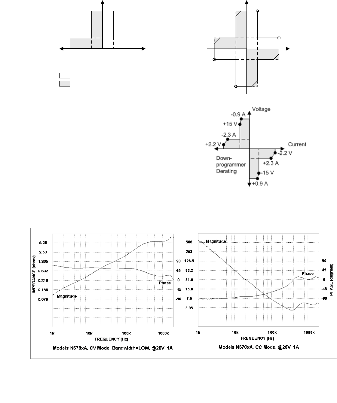
42 N6731B-N6784A DC Power Modules
N6700B-N6705B Mainframes
Specifications Guide
Output Quadrant Characteristic
+20 V
+6 V
Voltage
Current
N6781A,
N8782A,
20 W
+3 A
+1 A-3 A -1 A 0
Key Sourcing power
Sinking power
0
+6 V
Current
N6784A,
20 W
+3 A
-3 A
-6 V
+20 V
Voltage
+1 A
-20 V
-1 A
Note 1
Note 1. When sinking power, Agilent Model N6784A
can operate at the maximum rated output power for
only a limited amount of time. The unit monitors the
temperature of the internal power devices and
latches the output off if the output power causes
the temperature to exceed its safe limit. A protect
clear is required to resume normal operation. The
condition is annunciated by the OT status bit. Refer
to the downprogrammer derating figure for the
values of the safe limit boundaries.
Output Impedance Graphs

N6731B-N6784A DC Power Modules
N6700B-N6705B Mainframes
Specifications Guide 43
Chapter 6
Agilent N6783A-BAT, N6783A-MFG
Application-Specific Power Modules
Performance Specifications ............................................................................ 44
Supplemental Characteristics ......................................................................... 45
Output Quadrant Characteristic ...................................................................... 46
Unless otherwise noted, specifications are warranted over the
ambient temperature range of 0 to 40°C after a 30-minute warm-up
period. Specifications apply at the output terminals, with each
module's sense terminals internally connected to its output terminals
(local sensing).
Refer to the Agilent N6700 or N6705 Service Guide for the setup
conditions for all performance specifications.
Supplemental characteristics are not warranted but are descriptions
of performance determined either by design or by type testing. All
supplemental characteristics are typical unless otherwise noted.

44 N6731B-N6784A DC Power Modules
N6700B-N6705B Mainframes
Specifications Guide
Performance Specifications
N6783A-BAT N6783A-MFG
DC Ratings:
Voltage 0 - 8 V 0 - 6 V
Current NOTE 1 – 2 to +3 A – 2; 0 to +3 A
Power 24 W 18 W
Low current measurement range 150 mA 150 mA
Output Ripple and Noise (PARD):
(from 20 Hz – 20 MHz)
CV peak-to-peak 8 mV 8 mV
CV rms 1.5 mV 1.5 mV
Load Effect (Regulation):
(For any output load change, with a maximum load-lead drop of 0.5V/lead.
The load lead drop reduces the maximum available voltage at the load.)
Voltage 6 mV 6 mV
Current 2 mA 2 mA
Source Effect (Regulation):
Voltage 2 mV 2 mV
Current 1 mA 1 mA
Programming Accuracy:
(@ 23 °C ±5 °C after a 30 minute warm-up. Applies from minimum to maximum programming range at any load.)
Voltage 0.1% + 10 mV 0.1% + 10 mV
Positive Current 0.1% + 1.8 mA 0.1% + 1.8 mA
Negative Current @ –2 A 0.2% + 1.8 mA N/A
Measurement Accuracy:
(@ 23 °C ±5 °C. Applies when measuring the default value of 1024 data points with a 20.48 μs time interval.)
Voltage
0.05% + 5 mV
0.05% + 5 mV
Current high range
0.1% + 600
µ
A
0.1% + 600
µ
A
Current low range 0.1% + 75 µA 0.1% + 75 µA
Load Transient Recovery
(Time to recover to within settling band for a load change from 0.15 A to 1.5 A and from 1.5 A to 0.15 A at 6 V output)
Voltage settling band NOTE 2 ± 75 mV ± 75 mV
Time NOTE 2 < 45 µs < 45 µs
1 Output current is derated 1% per °C above 40°C.
2 When relay Option 761 is installed, the settling band is ± 90 mV. The time is < 75 µs.

N6731B-N6784A DC Power Modules
N6700B-N6705B Mainframes
Specifications Guide 45
Supplemental Characteristics
N6783A-BAT N6783A-MFG
Programming Ranges:
Voltage
15 mV to 8.16 V
15 mV to 6.12 V
Positive Current
5 mA to 3.06 A
5 mA to 3.06 A
Negative Current
– 5 mA to – 2 A
Fixed at – 2 A
Programming Resolution:
Voltage
2.5 mV
2.5 mV
Positive Current
1 mA
1 mA
Negative Current
10 mA
N/A
Measurement Resolution:
Voltage
300
µ
V
300
µ
V
Current high range
100
µ
A
100
µ
A
Current low range (
≤
0.150 A)
5
µ
A
5
µ
A
Programming Temperature Coefficient per °C:
Voltage
25 ppm + 50
µ
V
25 ppm + 50
µ
V
Current
25 ppm + 10
µ
A
25 ppm + 10
µ
A
Measurement Temperature Coefficient per °C:
Voltage
25 ppm + 40
µ
V
25 ppm + 40
µ
V
Current high range
25 ppm + 2.5
µ
A
25 ppm + 2.5
µ
A
Current low range (
≤
0.150 A)
25 ppm + 1.5
µ
A
25 ppm + 1.5
µ
A
Maximum Up-Programming and Down-Programming Time with Full Resistive Load
(Time from 10% to 90% of total voltage excursion)
Voltage Settling from 0V to Full Scale 4.0 ms 4.0 ms
Voltage Settling from Full Scale to 0V 4.0 ms 4.0 ms
Maximum Up-Programming and Down-Programming Settling Time with Full Resistive Load
(Time from start of voltage change until voltage settles within 0.1% of the full-scale voltage of its final value)
Voltage Settling from 0V to Full Scale 20 ms 20 ms
Voltage Settling from Full Scale to 0V 20 ms 20 ms
Over-voltage Protection:
Accuracy without disconnect relays
0.25% + 75 mV
0.25% + 75 mV
Accuracy with disconnect relays
0.25% + 275 mV
0.25% + 275 mV
Nominal range
0 – 10 V
0 – 10 V
Programmable delay time
60
µ
s – 5 ms
60
µ
s – 5 ms
Over-Current Protection:
Programmable delay time
0 – 255 ms
0 – 255 ms
Nominal Range
5 mA – 3.06 A
5 mA – 3.06 A
Output Ripple and Noise: (PARD)
CC rms:
4 mA
4 mA
Common Mode Noise:
(From 20 Hz – 20 MHz; from either output to chassis)
Rms 1 mA 1 mA
Peak-to-peak
6 mA
6 mA
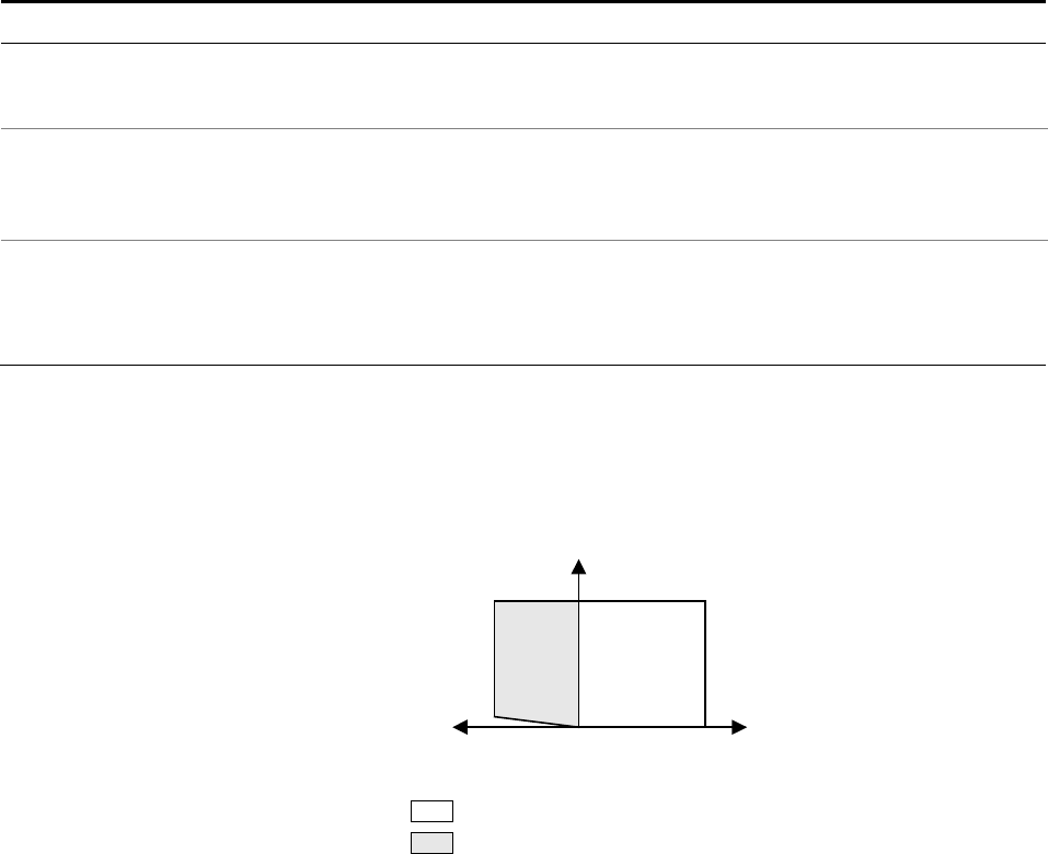
46 N6731B-N6784A DC Power Modules
N6700B-N6705B Mainframes
Specifications Guide
Supplemental Characteristics (continued)
N6783A-BAT N6783A-MFG
Remote Sense Capability:
Outputs can maintain DC specifications with up to a 0.5-volt drop per load lead.
Maximum sense lead resistance is limited to 300mΩ/lead.
Series and Parallel Operation:
Identically rated outputs can be operated directly in parallel.
N6783A modules cannot be used in series with other N6783A modules or any
other N67xx module. Auto-series and auto-parallel operation is not available.
Down-programming Capability:
(Current down-programming capability is reduced at output voltages below 0.5 V)
Continuous power 12 W 12 W
Continuous current 2 A 2 A
Output Quadrant Characteristic
Key Sourcing power
Sinking power
+8 V (BAT)
Current
+3 A
-2 A 0
N6783A-BAT
N6783A-MFG
+6 V (MFG)
Negative current
not programmable
on N6783A-MFG
Voltage

N6731B-N6784A DC Power Modules
N6700B-N6705B Mainframes
Specifications Guide 47
Chapter 7
Agilent N6700 Modular Power System
Mainframes
Supplemental Characteristics ......................................................................... 48
Outline Diagrams ............................................................................................... 50
Supplemental characteristics are not warranted but are descriptions
of performance determined either by design or by type testing. All
supplemental characteristics are typical unless otherwise noted.
NOTE Refer to the following documents for information about using and servicing the
Agilent N6700 Modular Power System Mainframes
Agilent Model N6705 DC Power Analyzer User’s Guide
Go to http://cp.literature.agilent.com/litweb/pdf/N6705-90001.pdf.
Agilent Model N6705 DC Power Analyzer Service Guide
Go to http://cp.literature.agilent.com/litweb/pdf/N6705-90010.pdf.
Agilent Series N6700 Low-Profile Modular Power System User’s Guide
Go to http://cp.literature.agilent.com/litweb/pdf/5969-2937.pdf.
Agilent Series N6700 Low-Profile Modular Power System Service Guide
Go to http://cp.literature.agilent.com/litweb/pdf/5969-2938.pdf.

48 N6731B-N6784A DC Power Modules
N6700B-N6705B Mainframes
Specifications Guide
Supplemental Characteristics
N6700B, N6701A, N6702A
N6705A, N6705B
Maximum Power Available for Modules:
Values represent combined power rating
of all modules installed per mainframe.
400 W (for N6700B mainframes)
600 W (for N6701A mainframes)
1200 W (for N6702A mainframes)
600 W
Front Panel Output Terminals:
Maximum current rating
N/A
20 A
BNC Trigger Connectors:
I/O
Maximum voltage
N/A
N/A
Digital TTL level compatible
5 V
USB Current Ratings:
Front panel USB connector
Rear panel USB connector
N/A
N/A
200 mA
300 mA
Data Storage:
Internal flash memory 8 Mbyte 4 Gbyte
(Earlier N6705 models have less memory)
Protection Response Characteristic:
INH input
Fault on coupled outputs
5 µs from receipt of inhibit to start of shutdown
< 10 µs from receipt of fault to start of shutdown
Command Processing Time:
≤ 1 ms from receipt of command to start of output change
Digital Port Characteristics:
Maximum voltage ratings
Pins 1 and 2 as FLT output
Pins 1 - 7 as digital/trigger outputs
(pin 8 = common)
Pins 1 - 7 as digital/trigger inputs
and pin 3 as INH input
(pin 8 = common)
+16.5 VDC/− 5 VDC between pins
(pin 8 is internally connected to chassis ground).
Maximum low-level output voltage = 0.5 V @ 4 mA
Maximum low-level sink current = 4 mA
Typical high-level leakage current = 1 mA @ 16.5 VDC
Maximum low-level output voltage = 0.5 V @ 4 mA;
1 V @ 50 mA; 1.75 V @ 100 mA
Maximum low-level sink current = 100 mA
Typical high-level leakage current = 0.8 mA @ 16.5 VDC
Maximum low-level input voltage = 0.8 V
Minimum high-level input voltage = 2 V
Typical low-level current = 2 mA @ 0 V (internal 2.2k pull-up)
Typical high-level leakage current = 0.12 mA @ 16.5 VDC
Interface Capabilities:
GPIB
LXI Compliance
USB 2.0
10/100 LAN
Built-in Web server
SCPI - 1993, IEEE 488.2 compliant interface
Class C (only applies to units with LXI label on front panel)
Requires Agilent IO Library version M.01.01 or 14.0 and up
Requires Agilent IO Library version L.01.01 or 14.0 and up
Requires Internet Explorer 7+ or Firefox 2+

N6731B-N6784A DC Power Modules
N6700B-N6705B Mainframes
Specifications Guide 49
Supplemental Characteristics (continued)
N6700B, N6701A, N6702A
N6705A, N6705B
Regulatory Compliance:
EMC
Safety
Complies with European EMC Directive for test and measurement products.
● IEC/EN 61326-1
● CISPR 11, Group 1, class A
● AS/NZS CISPR 11
● ICES/NMB-001
Complies with Australian standard and carries C-Tick mark.
This ISM device complies with Canadian ICES-001.
Cet appareil ISM est conforme à la norme NMB-001 du Canada.
Complies with European Low Voltage Directive and carries the CE-marking.
Conforms to UL 61010-1 and CSA C22.2 61010-1.
Environmental Conditions
Operating environment
Temperature range
Relative humidity
Altitude
Storage temperature
Indoor use, installation category II (for AC input), pollution degree 2
0°C to 55°C (output current is derated 1% per °C above 40°C ambient temperature)
Up to 95%
Up to 2000 meters
-30°C to 70°C
Acoustic Noise Declaration:
This statement is provided to comply
with the requirements of the German
Sound Emission Directive, from 18
January 1991.
Sound Pressure Lp <70 dB(A), At Operator Position,
Normal Operation, According to EN 27779 (Type Test).
Schalldruckpegel Lp <70 dB(A), Am Arbeitsplatz,
Normaler Betrieb, Nach EN 27779 (Typprüfung).
Output Terminal Isolation:
Maximum rating
No output terminal may be more than ±240 VDC from any other terminal or chassis ground.
N6781A Note When using the AUX measurement input terminals on Model N6781A, no output or input
terminal may be more than ±60 VDC from any other terminal and chassis ground.
AC Input:
Input Ratings
Power Consumption
Power Factor
Fuse
~ 100 VAC – 240 VAC; 50/60/400Hz
1000 VA (N6700B)
1440 VA (N6701A)
1440 VA (N6702A @ < 180 VAC input)
2200 VA (N6702A @ > 180 VAC input)
0.99 @ nominal input and rated power
Internal fuse - not customer accessible.
~ 100 VAC – 240 VAC; 50/60/400Hz
1440 VA
0.99 @ nominal input and rated power
Internal fuse - not customer accessible.
N6702A Note
AC mains circuits rated at 100-180 VAC cannot supply enough current to power the
N6702A mainframe when operated at its full rated power. When connected to a 100-180
VAC mains, internal circuits will limit the power available to modules to 600 W maximum.
Net Weight:
Mainframe with 4 modules (typical)
Single-wide power module (typical)
N6700B 12.73 kg / 28 lbs
N6701A 11.82 kg / 26 lbs
N6702A 14.09 kg / 31 lbs
1.23 kg / 2.71 lbs
16 kg / 35 lbs
1.23 kg / 2.71 lbs
Dimensions:
Refer to the outline diagrams on the following page.
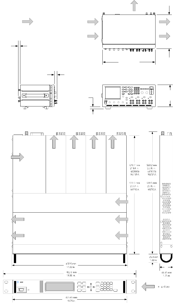
50 N6731B-N6784A DC Power Modules
N6700B-N6705B Mainframes
Specifications Guide
Outline Diagrams
272.6 mm
10.733 in.
425.6 mm
16.756 in.
177.0 mm
6.968 in.
17.7 mm
0.697 in.
16.9 mm
0.663 in.
23.5 mm
0.923 in.
= airflow

Manual Updates
The following updates have been made to this manual since its
edition date.
03/20/12
The description of the Voltmeter/Ammeter Measurement Accuracy
specification has been updated throughout.
The description of the Voltage Measurement Noise and Current Meas-
urement Noise characteristic has been updated on pages 39 and 40.
The downprogrammer derating information has been updated on
page 42.
06/15/12
External datalogging has been added as a feature on pages 6 and 7.
Applies to N6705 firmware revision D.01.08 and up, and N6700
firmware revision. D.01.09 and up.
The CC mode graphs have been updated on pages 23 and 31.
The N6781A Auxiliary Voltage Measurement input characteristics
have been updated on pages 38 and 39.
The dc output ratings have been edited to match the instrument
labels.
