Web Addendum.pm6 APC AP9221 Master Switch Power Strip Manual
APC-Masterswitch-AP9221-Rack-PDU-Manual APC-Masterswitch-AP9221-Rack-PDU-Manual Igor's of metalworking and electrical manuals
User Manual: APC-AP9221-MasterSwitch-Power-Strip-Manual Igor's of metalworking and electrical manuals
Open the PDF directly: View PDF ![]() .
.
Page Count: 2
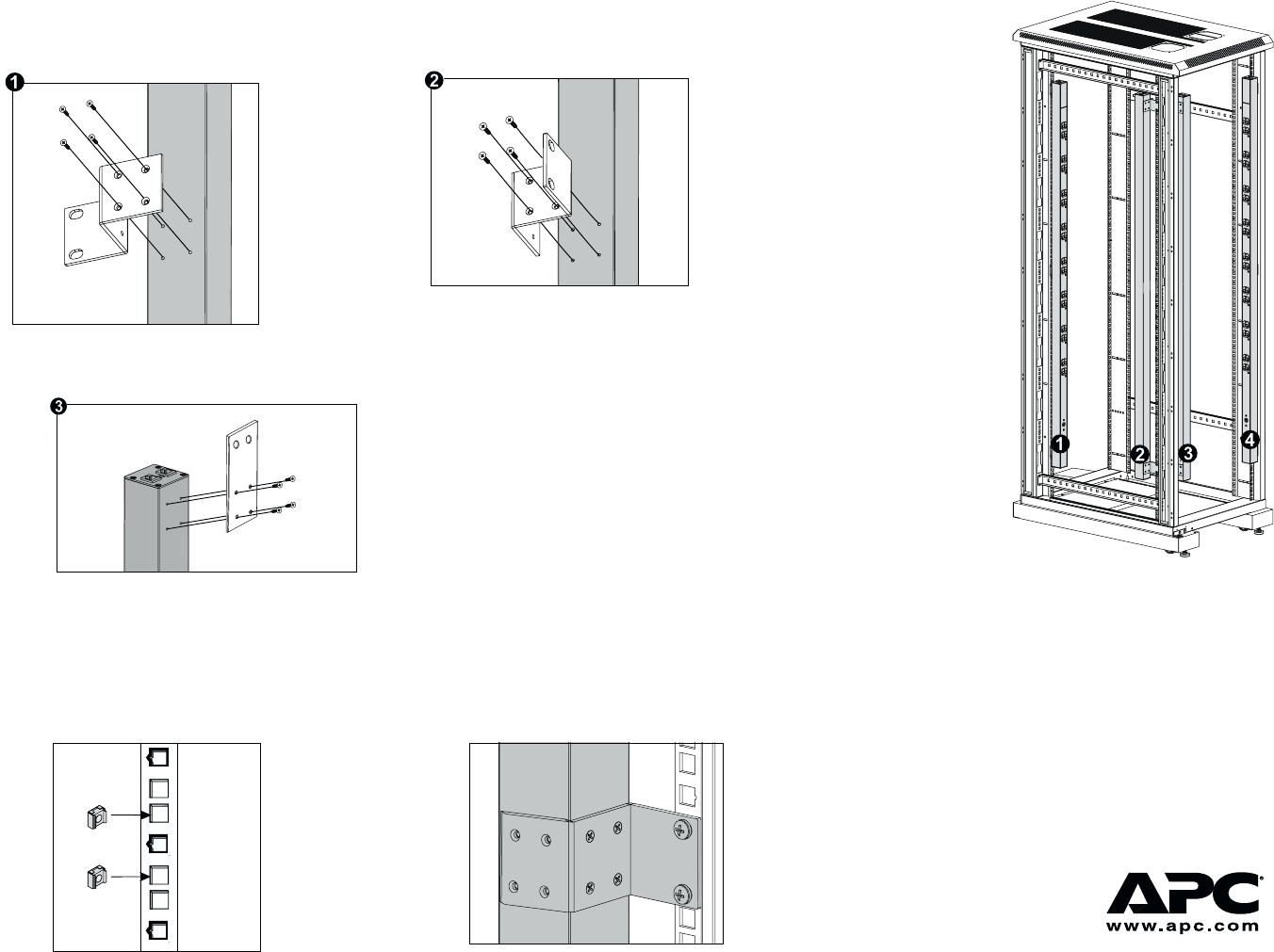
2. Choose a suitable
location for the
strip. The figure at
right shows the
strip mounted in
four different
locations in the
enclosure. To
avoid interfering
with shelves or
equipment, install
the strip so that it
hangs on the
outside edge of the
vertical rail.
How to Mount MasterSwitch VM in a NetShelter Enclosure
3. Insert a caged nut (provided with the enclosure)
above and below a notched hole on a vertical
mounting rail at the highest point in your chosen
location.
4. Align the mounting holes on the top bracket with the
caged nuts you installed in Step 3, and insert two
mounting screws (provided with the enclosure) to
secure the top bracket.
1. Attach the brackets to the rear of the strip, using 4 screws (provided) for each bracket. Choose the bracket
and position that best suits your needs.
5. Repeat Step 4 for the bottom bracket to secure the
strip to the enclosure.
Note: The bracket in ! (at left) is for two-post racks.
Using this bracket may require you to drill holes
in the rack.
990-6066A 08-01
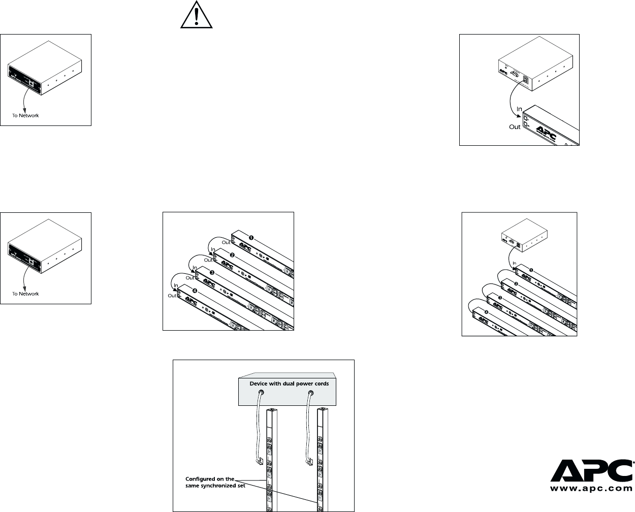
How to Set Up MasterSwitch VM
Setting up a single strip You must perform Step 2 last!
2. Connect the To PDU port on the controller to the In
port on the strip, using one of the provided gray
communication cables.
1. Plug the strip into a protected power source
and use the appropriate cable to connect to the
network port on the controller.
Setting up multiple strips (cascading) You must perform Step 3 last!
1. Plug each strip into a protected power source and
use the appropriate cable to connect to the network
port on the controller.
2. Connect the strips using the 10-foot gray commu-
nication cable (607-0035A): strip 4 In to strip 3 Out;
strip 3 In to strip 2 Out; strip 2 In to strip 1 Out.
3. Connect the RJ-11 port labeled To PDU on the
controller to the RJ-11 port labeled In on strip 1, using
one of the provided gray communication cables.
Use the following procedure when cascading
strips that are connected to devices (servers)
with dual power cords.
1. Follow the procedure for setting up multiple
strips. (Attach dual cords to separate strips for
redundancy.)
2. Use the MasterSwitch VM network interface to
configure the redundant strips on the same
synchronized set. Failure to configure syn-
chronized sets will not guarantee “power off”
to both strips at the same time.
Note: You can also
connect AP9222
strips to
AP9221EXPX166
units in a cascade
configuration.
Note: See the MasterSwitch VM User’s Guide on
the provided CD or on the Web site for
more information on configuring synchro-
nized sets.
Caution: APC does not recommend plugging
the strip directly into any unpro-
tected power source, such as a wall
outlet.
How to set up PDUs for dual power cord devices
990-6066A 08-01
