API 1000 13kgf 10 20 05 Rev_0 S 75408 KG3 13
User Manual: S 75408 KG3
Open the PDF directly: View PDF ![]() .
.
Page Count: 3
Engineering Standards Manual - Welding Standards Manual - Volume 3 Welding Procedure Specifications
API WELDING PROCEDURE SPECIFICATION
WPS: API 1000-13 REV. NO.: 0 PROCESS: SMAW DATE: 10/11/2005
API-1104 QUALIFIED RANGES
Diameter: 2.375” od. thru 12.75” od. Filler Metal Group: API Group 3
Thickness: .154” thru .750” Joint Type: Sleeve/fillet/butt full penetration
Material: Yield less than 42 Kpi
Position’s: Fixed:
All Rolled: Progression: V/Up & Down
NOTE: This WPS shall be used in conjunction with the applicable sections of the Los Alamos National
Laboratories Welding Standards Manual (GWS)
WELD JOINT: Type: Sleeve/fillet/butt ~371/2° Class: Full & Partial Penetration
Joint Description: Sleeve weld for In-service hot-tap (per 1104 App. B) (Mueller stop/plug fitting)
Sketch Number: See pg. 2 for typical sketch and bead sequence.
FILLER MATERIALS: API Group No.: 3 AWS Class: E-6010 & E-7018
SFA Class: 5.1/5.5 F No.: 3/4 Sizes (s): 1/8 5/32 5/32
Number of Beads: See pg. 2 for typical number and of beads
BASE MATERIALS: Spec: ASTM A-53 or A-106 Gr. B to Spec: ASTM A-53 or A-106 Gr. B
Thickness Welded: .154” - .750” to .154” - .750”
Pipe Diameter: 2.375” OD. thru 12.75” OD. pipe to Pipe Diameter Less than 12.75” OD.
ASME P No.: 1 Group: 1 to P No.: 1 Group: 1
POSITIONS: Fixed: All positions PWHT: Time @ º F Temp.: N/A
Progression: V/Up/Dn (E-7018 & E-6010) Temperature Range º F: N/A
PREHEAT: X Minimum Temp º F: ~≥70°F GAS: Shielding: N/A Backing: N/A
NOTE: See time between passes. Composition: N/A
INTERPASS TEMP.: ≥~70°F Flow Rate: CFH N/A
ELECTRICAL CHARACTERISTICS:
Current: DC Polarity: EP Ranges Amps: 65 - 140
Transfer Mode: N/A WFS/IPM: N/A Volts: 22 - 30
Electrode size and Type 3/32 – 1//8 – 5/32 E70xx –E-6010 Travel/IPM 5 - 13
MAX. TIME BETWEEN PASSES: 5 minutes between root pass and second (hot) pass.
Engineering Standards Manual - Welding Standards Manual - Volume 3 Welding Procedure Specifications
WPS No.: API-1000-13 Rev. No.: 0 Date: 10/11/2005
WELDING TECHNIQUE:
Line-Up Clamp: Fit-up dogs – removed after tack welding by grinding.
Stringer or Weave Bead: (S) S (W) Single Pass Multi Pass M
Cleaning and/or Grinding: Stiff wire brush or power grinder
PROCEDURE QUALIFIED FOR: Charpy V Notch N/A NDTT N/A DT N/A
Maximum K/J Heat Input: N/A
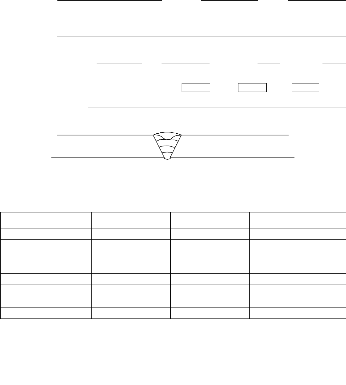
JOINT SKETCH AND BEAD NUMBER AND SEQUENCE
NOTE: Weld layers are representative only ⎯ actual number of passes and layer sequence may vary
due to variation in joint design, thickness and fit-up.
TYPICAL WELDING PARAMETERS
Pass
Number Filler/ Electrode
Size
Amps
Volts Travel
Speed
Other
1 E-6010 1/8 70 -115 24 - 29 5 – 10”
2 E-6010 5/32 80 -130 24 - 30 6 – 12
3 E-7018 3/32 125 – 135 24 - 30 6 – 10
4 E-7018 1/8 125 – 150 24 - 30 6 – 13
5 E-7018 5/32 125 – 180 26 - 32 8 – 13
6 Rem. >>>>>> >>>>> >>>>> >>>>> >>>>>
7 Rem. >>>>>> >>>>> >>>>> >>>>> >>>>>
8 Rem. >>>>>> >>>>> >>>>> >>>>> >>>>>
PREPARED BY: KG Fellers DATE: 10/03/2005
Signature on file
APPROVED BY: Tobin Oruch DATE: 10/25/2005
Signature on file
QA REVIEW BY: Larry Souza DATE: 10/26/2005
Signature on file
0
–
3/32” lan
d
~
1/18”-5/32”
g
a
p
t thickness varies
Engineering Standards Manual - Welding Standards Manual - Volume 3 Welding Procedure Specifications
API-1000-13 REV.: 0 PAGE 3 OF 3 DATE: 06/02/2005
API WELDING SPECIFICATION PROCEDURE
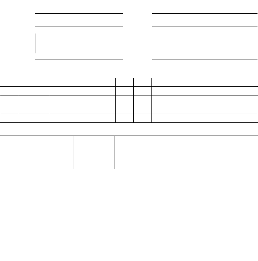
TEST PARAMETERS
Full Pene. Butt/Fillets 10”
Joint Type:
Diameter:
.365 wall (3/8in.) 1/8 & 5/32 E-6010 1/8 & 5/32 E-7018
Thickness:
Filler:
ASTM A-106/53 Gr B ~70°F IPT ~73°F
Material:
Preheat:
6F Girth welds and 2G Fixed (Modified
to 45° angle)
DCEP Amps: 70-125
Position:
Current:
E-7018 V/Up E-6010 V/Up/Dn. root 22-26
Progression:
Volts:
GUIDED BEND TESTS
No. Type Result No. Type Result
1. Side Acc. 5. Side Acc.
2. Side Acc. 6. Side Acc.
3. Side Acc. 7. Side Acc.
4. Side Acc. 8. Side Acc.
TENSILE TESTS
No. Specimen
Type Area
Sq./ in Applied
Load Ultimate
Tensile Character of failure and location
1. Figure 4 0.3721 28057.62 75408.51 BM
2. Figure 4 0.3684 27372.56 74297.56 BM
NICK-BREAK TESTS
No. Type Remarks on Nick-Break tests
1. Figure 5 Clean (Minor atomic H) Cup & Cone
2. Figure 5 Clean (Minor atomic H) Cup & Cone
Welders Name: Brett McNeil Z No.: 09815 Stamp: ________
Procedure developed and conducted by: By: KG Fellers _________________Date:_10/20/2005_____________
Signature on File
We certify that the statements herein are correct and that the tests were conducted in accordance with API-
1104 – App. B and LANL Welding Program Chapter 13 Engineering Standards Manual
Authorized by: Kelly Bingham ______________________________________ Date: 10/20/2005
Signature on File
