DB98_20429A_1 AS09HPBN AS 09 12 HPBN Service Manual
User Manual: AS09HPBN
Open the PDF directly: View PDF ![]() .
.
Page Count: 54
INDOOR UNIT
AS09HPBN
AS12HPBN
OUTDOOR UNIT
AS09HPBX
AS12HPBX
SERVICE Manual
CONTENTSAIR CONDITIONER
1. Product Specifications
2. Operating Instructions & Installation
3. Disassembly and Reassembly
4. Refrigerating Cycle Diagram
5. Set Up the Model Option
6. Troubleshooting
7. Exploded Views and Parts List
8. Block Diagram
9. Wiring Diagram
ROOM AIR CONDITIONER
DB98_20429A(1)_CO 12/24/04 10:54 AM Page 3
1Samsung Electronics
1. Product Specifications
1-1 Table
Perfor-
mance
Power
Size
Model
Item
Type
Cooling kW
Heating kW
Dehumidifying |/h
Air Volume Cooling m3/min
Heating (H/M/L)
Noise Cooling dB
Heating (H/M/L)
Energy Efficiency Ratio Cooling W/W
Heating
Power ph-V-Hz
Power Consumption Cooling W
Heating
Operating Current Cooling A
Heating
Power Factor Cooling %
Heating
Starting Current A
Length m
Power Cord Number of Core Wire
Capacity A
Outer Dimension Width x Height mm
x Depth inch
Weight(Net) kg
Refrigerant Pipe Liquid mm x L(m)
Gas mm x L(m)
Drain Hose D x L(mm)
Type
Compressor Motor Type
Rated Output
Oil Type
Type
Blower Motor Type
Rated Output W
Heat Exchanger
Refrigerant Control Unit
Freezer Oil Capacity cc
Refrigerant to Change(R410A) g
Protection Device(OLP)
Cooling Test Condition
Maximum Operation Condition
AS09HPBN AS12HPBN
INDOOR UNIT : DB27˚C WB19˚C OUTDOOR UNIT : DB35˚C WB24˚C
INDOOR UNIT : DB32˚C WB23˚C OUTDOOR UNIT : DB43˚C WB26˚C
Indoor unit Outdoor unit
Wall-mounted
2.70
2.90
1.0
7.5/6.9/6.3 25
8.0/7.4/6.8 25
40/36/32 51/51
40/36/32 51/51
3.21
3.41
1-220/240-50
840
850
3.9
3.7
93.6
99.9
21
2.1
5G
250V-10A
950 x 268 x 165 790 x 548 x 285
37.4 x 10.6 x 6.5 31.1 x 21.6 x 11.2
9.0 33.8
ø6.35 x 7.5
ø9.52 x 7.5
ø18 x 550
Rotary, G4A091JU
Induction Motor(PSC)
930
DAPHNE FV68S(PVE)
Cross-flow Propeller
Resin / steel steel
15 50
2ROW 12STEP 1ROW 24STEP
CAPILLARY TUBE
280
730
RBC12054-12500
Indoor unit Outdoor unit
Wall-mounted
3.50
3.80
1.4
8.3/7.0/5.7 25
9.5/8.9/8.3 25
43/38/34 53/53
43/38/34 53/53
3.21
3.22
1-220/240-50
1,090
1,180
5.0
5.4
94.8
95.0
28
2.1
5G
250V-10A
950 x 268 x 165 790 x 548 x 285
37.4 x 10.6 x 6.5 31.1 x 21.6 x 11.2
9.0 36.0
ø6.35 x 7.5
ø9.52 x 7.5
ø18 x 550
Rotary, G8C124JU
Induction Motor(PSC)
1,267
DAPHNE FV68S(PVE)
Cross-flow Propeller
Resin / steel steel
15 50
2ROW 12STEP 2ROW 24STEP
CAPILLARY TUBE
500
950
RBC12128-12500
DB98_20429A(1)_1 12/24/04 10:55 AM Page 1
Samsung Electronics2
2. Operating Instructions & Installation
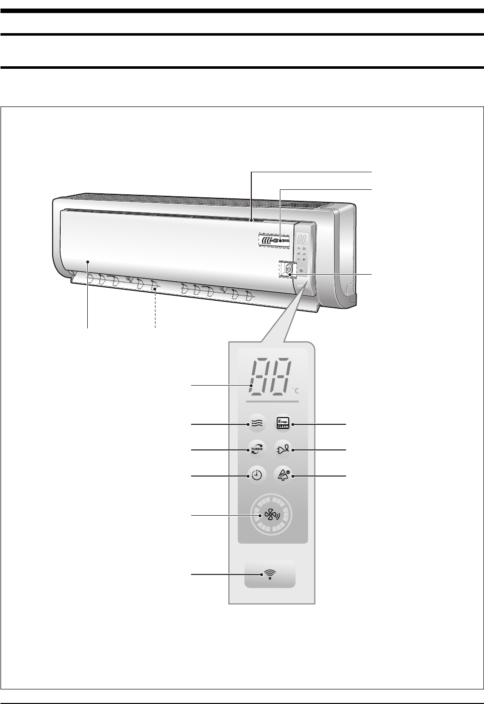
2-1 View of the Unit
2-1-1 Indoor Unit
Air filter
(under the grille)
Airflow blades
(outlet)
Power(On/Off) button
Set temperature &
room temperature
Operation indicator
(Auto-Cool, Cool, Dry, Fan : Blue
Auto-Heat, Heat : Orange)
Auto cleaning indicator
(Blue)
Energy saving indicator
(Blue)
Anion indicator
(Blue)
Turbo function indicator
(Blue)
Timer indicator
(Orange)
Fan speed indicator
(Blue)
Remote control sensor
Room Temperature sensor
Air Inlet
DB98_20429A(1)_1 12/24/04 10:55 AM Page 2
3Samsung Electronics
Operating Instructions & Installation
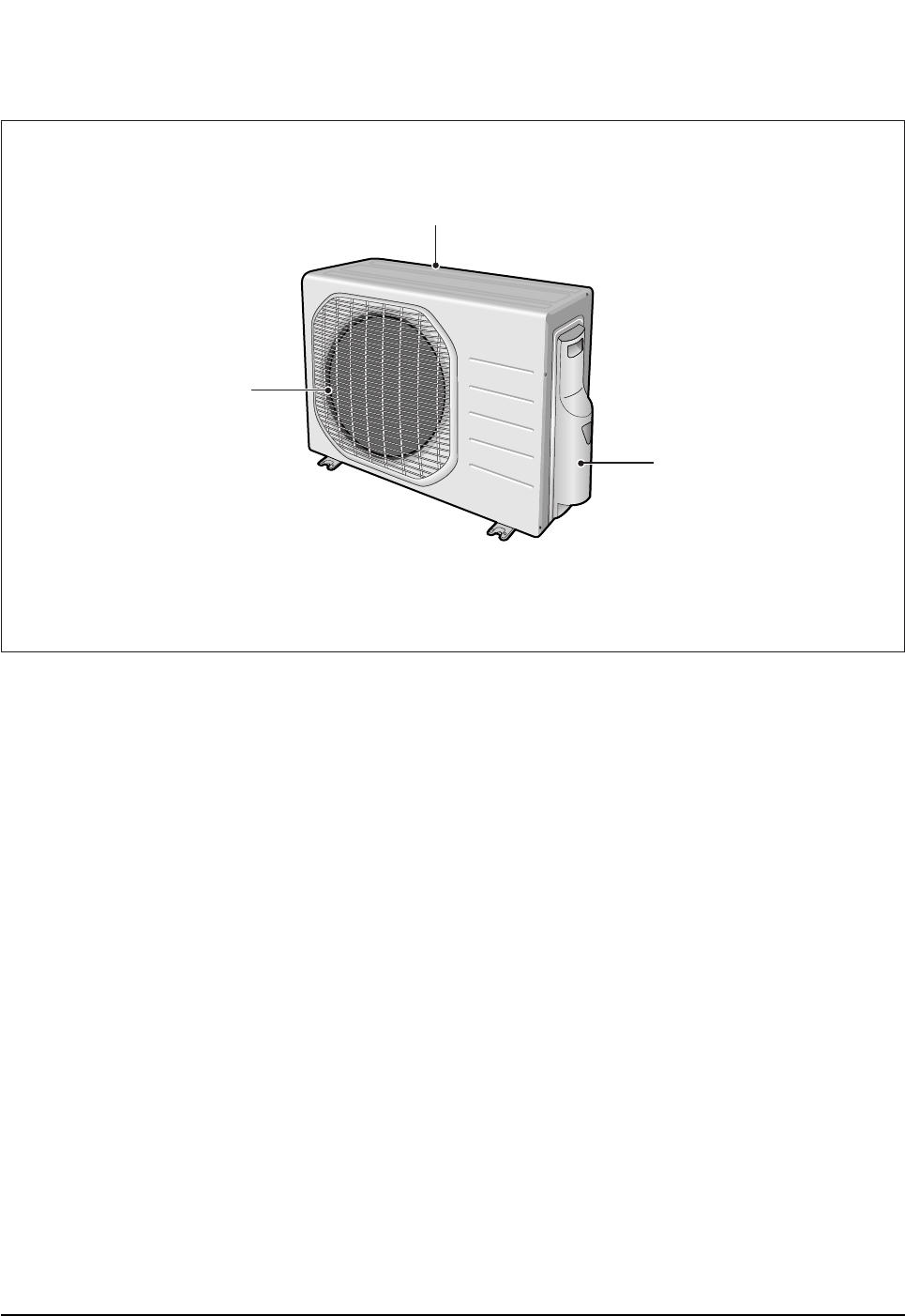
2-1-2 Outdoor Unit
Air Inlet(Rear)
Air Outlet
Connection Valve
(inside)
DB98_20429A(1)_1 12/24/04 10:55 AM Page 3
Samsung Electronics4
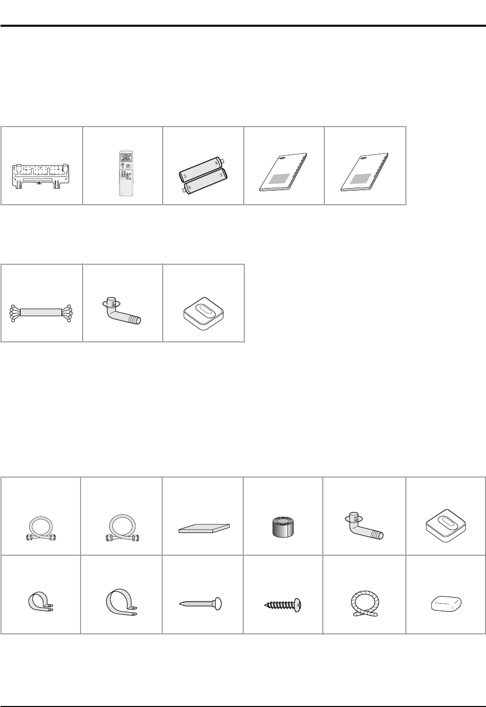
2-2 Air Conditioner and Accessories
The following accessories are supplied with the air conditioner.
- The number of each accessory is indicated in parentheses.
2-2-1 Accessories in the Indoor Unit Case
2-2-2 Accessories in the Outdoor Unit Case
- The flare nuts are attached to the end of each pipe of an evaporator or a service port.
Use the nuts when connecting the pipes.
- The 5-wire assembly cable is optional. If it is not supplied, use the standard cable.
- The drain plug and rubber leg are only included when the air conditioner is supplied without the assembly pipe as seen in the
picture below.
The following connection accessories are optional.
If they are not supplied, you should prepare them before installing the air conditioner.
- If these accessories are supplied, you can find them in the accessory box.
Assembly Pipe, ø6.35mm
by 7.5m (1)
Assembly Pipe, ø9.52mm
by 7.5m (1)
PE T3 Foam Tube
Insulation (1)
Vinyl Tape,
Width 50mm (1)
Drain Plug (1) Rubber Leg (4)
Pipe Clamps A (3) Pipe Clamps B (3) Cement Nail (6) M4 x 16 Tapping
Screws (10)
Drain Hose,
length 2m (1)
Putty 100g (1)
Installation Plate (1) Remote Control (1) Batteries for
Remote Control (2)
User’s Manual (1) Installation Manual (1)
OWNER’S INSTRUCTIONS
MANUAL DE INSTRUCCIONES
ISTRUZIONI PER L’USO
MANUAL DE INSTRU˝ES
MANUEL D’UTILISATION
GEBRAUCHSANWEISUNG
Splut-type Room Air Conditioner
Aire acondicionado domstico sistema Split
Condizionatore d’aria per ambienti ad unit Separate
Aparelho de ar condicionado tipo Split
Climatiseur de type spar
Geteilte raumklimaanlage
5-wire
Assembly Cable (1)
Drain Plug (1) Rubber Leg (4)
DB98_20429A(1)_1 12/24/04 10:55 AM Page 4
5Samsung Electronics
2-3 Installation
2-3-1 Before Installation
Keep the air conditioner outlet and inlet free from its surroundings.
In case of installation, keep the symmetry and fix it to prevent vibration.
The pipe length shall meet the standard as far as possible.
2-3-2 Installation Procedure
■Location
Install the product in an area to guarantee the best cooling effect, convenience of piping and electric work, and inexistence of
vibration or wind.
■Wall Drilling
Drill the wall downward in a diameter of 60 to 65mm.
■Fixing Indoor Unit & Outdoor Unit
Fix the air conditioner indoor unit securely to the wall. Secure the outdoor unit in a suitable position.
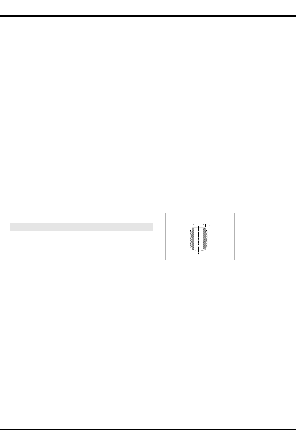
■Pipe Spooling & Connecting
You shall cut the pipe with a pipe cutter and grind all the burrs of the cut surface.
Pipe expansion may continue until the pipe surface becomes uneven or torn apart.
Be sure to use a torque wrench to tighten pipes or flare nuts.
■Leak Test
Put an inert gas like nitrogen in the outdoor unit pipe and put soap bubbles or other test liquids on the pipe surface for the leak test.
■Drain Hose Connecting
Install the drain hose downward to drain water naturally. Be sure to pour water into the hose to check if it drains well.
■Electric & Earth Work
Electric and earth work shall meet the "Electric Facility Technology Standard" and the "Internal Wire Regulation" of the Electric
Business Laws.
■Inspection & Trial Run
Upon completion of the tests, you shall make a trial run while you explain the main functions of the air conditioner to finish the
installation.
Outer Diameter(D)
6.35mm(1/4")
9.52mm(3/8")
Torque(kgf.cm)
140~170
250~280
Depth(A)
1.3mm
1.8mm
D
A
<Torque & Depth>
DB98_20429A(1)_1 12/24/04 10:55 AM Page 5
Samsung Electronics6
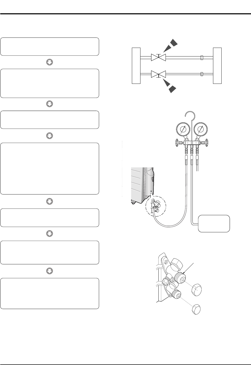
2-4 Installation Diagram of Indoor Unit and Outdoor Unit
2-4-1 Air-Purge Procedure
1) Connect each assembly pipe to the appropriate
valve on the outdoor unit and tighten the flare nut.
3) Open the valve of the low pressure side of
manifold gauge counter-clockwise.
4) Purge the air from the system using vacuum
pump for about 30 minutes.
- After that, please recheck that pressure is
stabilized.
- Close the valve of the low pressure side of
manifold gauge clockwise.
- Remove the hose of the low pressure side
of manifold gauge.
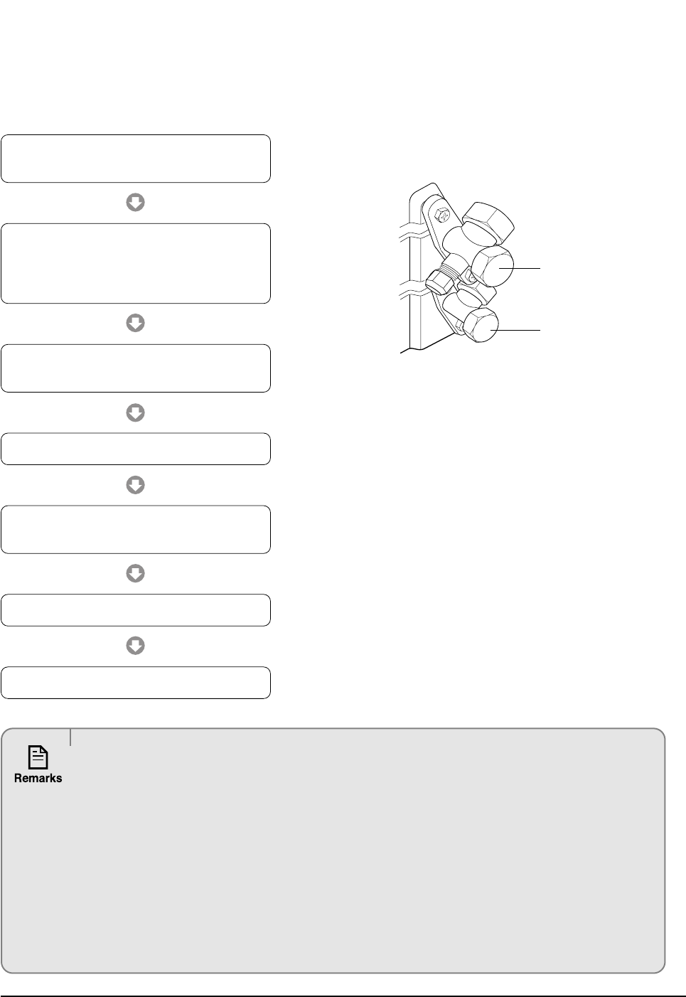
7) Check for gas leakage.
- At this time, especially check for gas
leakage from the 3-Way valve’s stem nuts,
and from the service port cap.
2) Connect the charging hose of low pressure side
of manifold gauge to the packed valve having a
service port (3/8" Packed valve) as shown at the
figure.
5) Set valve cork of both liquid side and gas side of
packed valve to the open position.
6) Mount the valve stem nuts to the 2-Way and
3-Way valve. And mount the service port cap to
3-Way valve.
A
B
C
D
Outdoor unit Indoor unit
Gas pipe side
Liquid pipe side
Vacuum Pump
A
(gas)
B
(liquid)
Valve stem
Stem cap
DB98_20429A(1)_1 12/24/04 10:55 AM Page 6
7Samsung Electronics
Operating Instructions & Installation
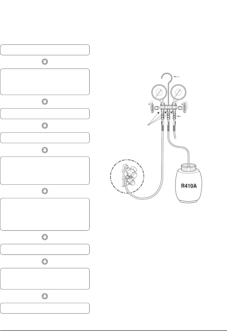
2-4-2 Refrigerant Refill(R410A)
Refill an air conditioner with refrigerant when refrigerant has been leaked at installing or using.
Suspension hook
High
pressure
gauge
Hand
wheel
Finger tight
fittings
Connected to
high pressure
side
Charging line
For mounting
other and of
hose when
not in use
Compound
gauge
1) Purge air(for new installation only).
3) Connect the tank to refill with refrigerant.
4) Set the unit to cool operation mode.
7) Stop operation of the air conditioner.
9) Close the cap of each valve.
2) Turn the 3-Way valve clockwise to close,
connect the pressure gauge (low pressure side) to
the service valve, and open the 3-Way valve
again.
5) Check the pressure indicated by the pressure
gauge(low pressure side).
* Standard pressure is should be 9.0~10.0kg/cm2
in a regular, high operation mode.
6) Open the refrigerant tank and fill with refrigerant
until the rated pressure is reached.
* It is recommended not to pour the refrigerant
in too quickly, but gradually while operating a
pressure valve.
8) Close the 3-Way valve, disconnect the
pressure gauge, and open the 3-Way valve
again.
DB98_20429A(1)_1 12/24/04 10:55 AM Page 7
Samsung Electronics8
Operating Instructions & Installation
2-4-3 "Pump down" Procedure
Pump down will be carried out when an evaporator is replaced or when the unit is relocated in another area.
3-Way Valve
2-Way Valve
1) Remove the caps from the 3-Way valve and the
3-Way valve.
3) Set the unit to cool operation mode.
(Check if the compressor is operating.)
4) Turn the 3-Way valve clockwise to close.
7) Close the cap of each valve.
2) Turn the 3-Way valve clockwise to close and
connect a pressure gauge (low pressure side)
to the service valve, and open the 3-Way valve
again.
5) When the pressure gauge indicates "0" turn the
3-Way valve clockwise to close.
6) Stop operation of the air conditioner.
Relocation of the air conditioner
• Refer to this procedure when the unit is relocated.
• Carry out the pump down procedure (refer to the details of 'pump down').
• Remove the power cord.
• Disconnect the assembly cable from the indoor and outdoor units.
• Remove the flare nut connecting the indoor unit and the pipe.
• At this time, cover the pipe of the indoor unit and the other pipe using a cap or vinyl plug to avoid foreign
material entering.
• Disconnect the pipe connected to the outdoor unit.
At this time, cover the valve of the outdoor unit and the other pipe using a cap or vinyl plug to avoid foreign
material entering.
• Make sure you do not bend the connection pipes in the middle and store together with the cables.
• Move the indoor and outdoor units to a new location.
• Remove the mounting plate for the indoor unit and move it to a new location.
DB98_20429A(1)_1 12/24/04 10:55 AM Page 8
9Samsung Electronics
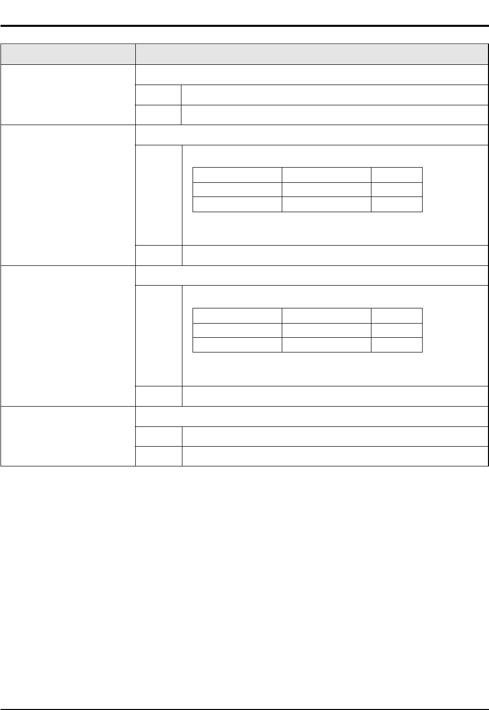
3. Disassembly and Reassembly
3-1 Indoor Unit
Stop operation of the air conditioner and remove the power cord before repairing the unit.
No Parts Procedure Remark
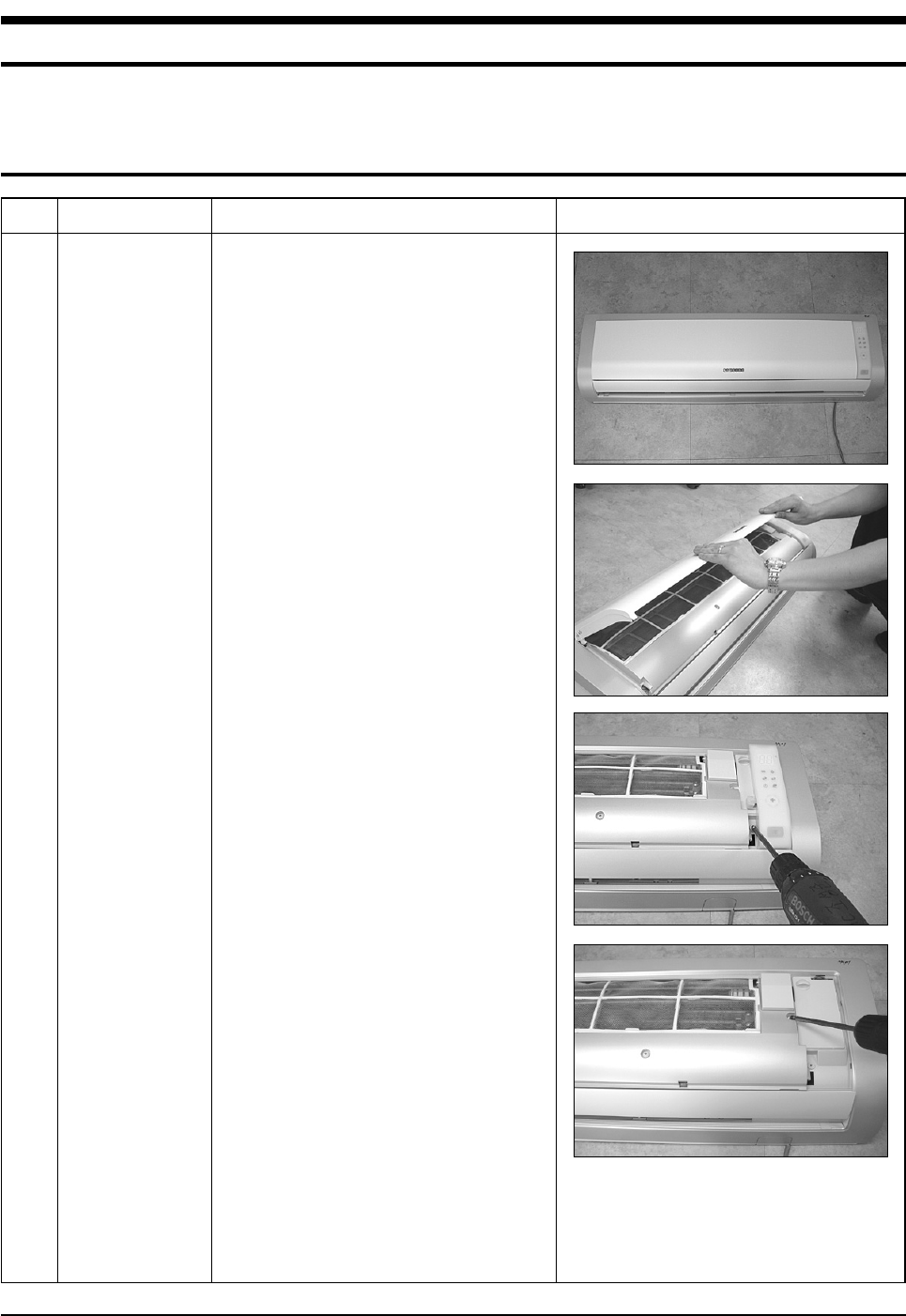
1 Panel Front 1) Stop the air conditioner operation and
shut off the main power.
2) Detach the Front Grille after pushing out it.
3) Loosen 1 of the right screw and detach
the Ass'y display.
4) Loosen 1 of the right screw and detach the
Terminal Cover.
5) Detach the cover PCB-DVM and thermistor
from the Panel Front.
DB98_20429A(1)_1 12/24/04 10:55 AM Page 9
Samsung Electronics10
Disassembly and Reassembly
No Parts Procedure Remark
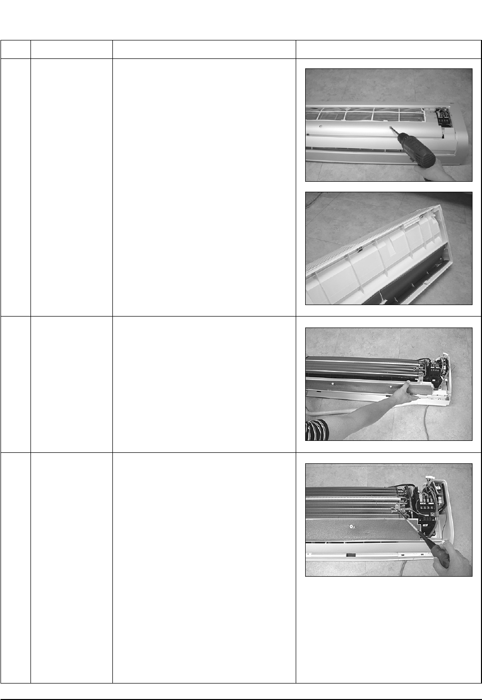
2
3
Tray Drain
Heat Exchanger
6) Loosen 5 fixing screws of Panel Front.
7) Unlock 2 hooks to fix Panel Front and
Tray Drain.
8) Unlock 2 hooks to fix Panel Front and
Back Body.
1) Detach the connected wire of Stepping
Motor.
2) Pull Tray Drain out from the Back Body.
1) Loosen 1 fixing earth screw of right side.
DB98_20429A(1)_1 12/24/04 10:55 AM Page 10
11Samsung Electronics
Disassembly and Reassembly
No Parts Procedure Remark
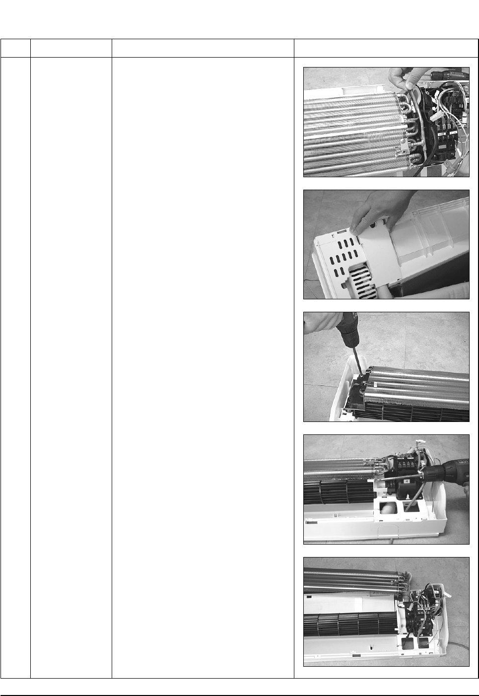
2) Detach the Room Sensor.
3) Detach the Holder Pipe at the rear side
of the unit.
4) Loosen 3 fixing screws of left Holder Evap.
5) Loosen 1 fixing screw of right Holder
Motor.
6) Detach the Heat Exchanger from the
indoor unit.
DB98_20429A(1)_1 12/24/04 10:55 AM Page 11
Samsung Electronics12
Disassembly and Reassembly
No Parts Procedure Remark
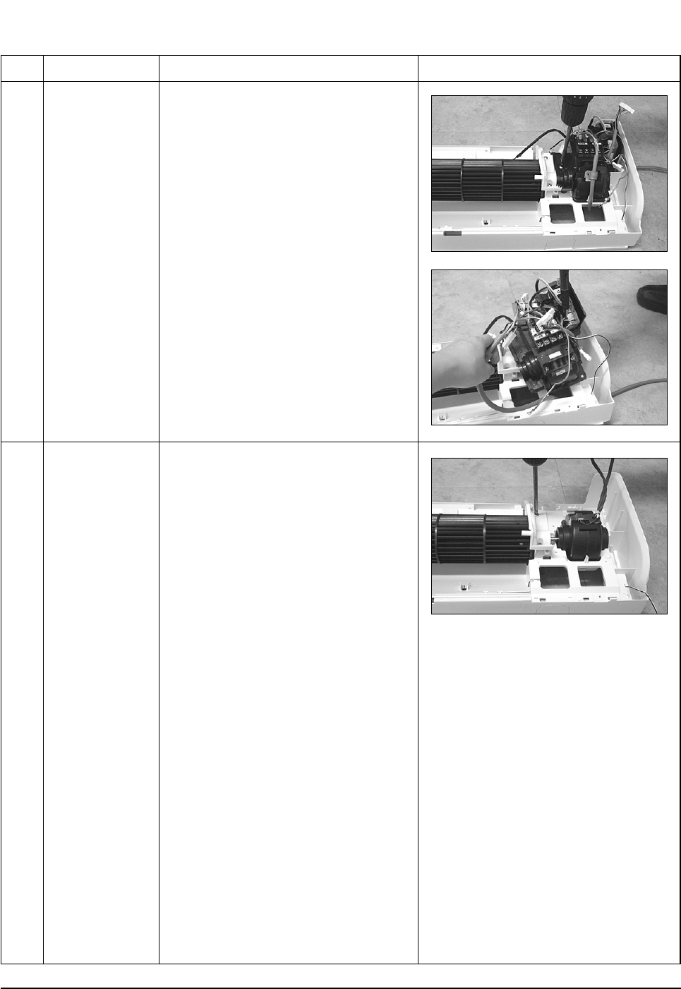
4
5
Electrical Parts
(Main PCB)
Fan Motor
&
Cross Fan
1) Loosen 4 fixing screws of right Holder
control.
2) Take all the connector of PCB upper side
out.(Including Power Cord)
3) Detach the outdoor unit connection wire
from the Terminal Block.
4) Pull the PCB up to detach.
1) Loosen 2 fixing screws and detach the
Motor Holder.
2) Loosen 1 fixing screw of Fan Motor.
3) Detach the Fan Motor from the Fan.
4) Detach the Fan from the left Holder
Bearing.
DB98_20429A(1)_1 12/24/04 10:55 AM Page 12
13Samsung Electronics
3-2 Outdoor Unit
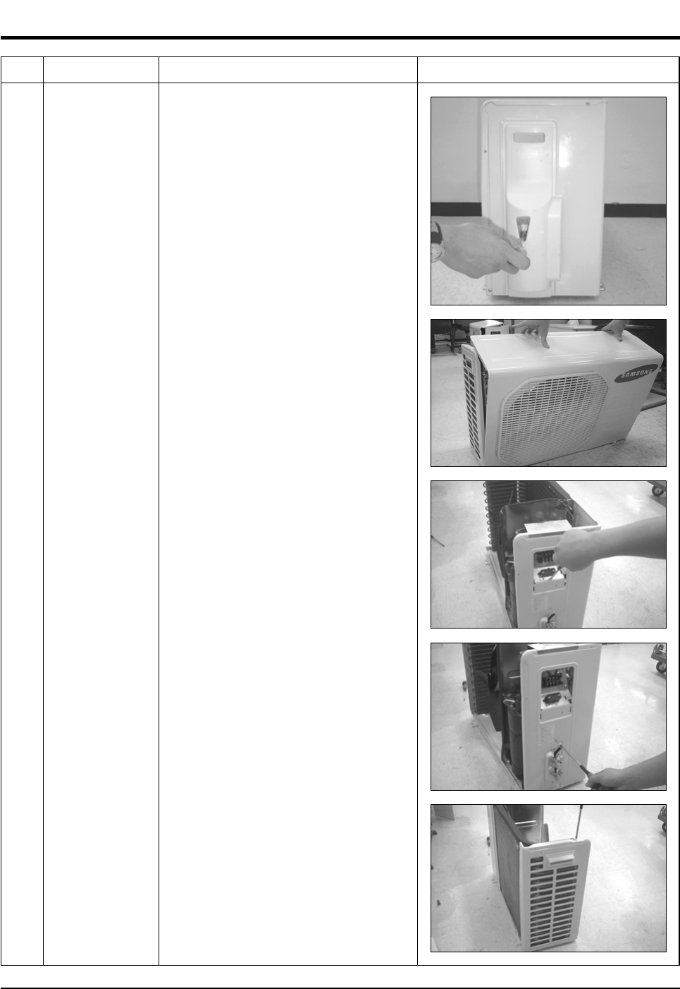
No Parts Procedure Remark
1 Common Work 1) Loosen 1 fixing screw of the Cover-Side.
2) Loosen each 3 fixing screws on both right
and left Cabinet-Side edge and a fixing
screw on the Cabinet-Front lower to detach
the Cabinet-Front.
3) Loosen 6 fixing screws of the Cabinet-Side
RH.
4) Loosen 2 fixing screws of the Cabinet-Side
LF.
DB98_20429A(1)_1 12/24/04 10:55 AM Page 13
Samsung Electronics14
Disassembly and Reassembly
No Parts Procedure Remark
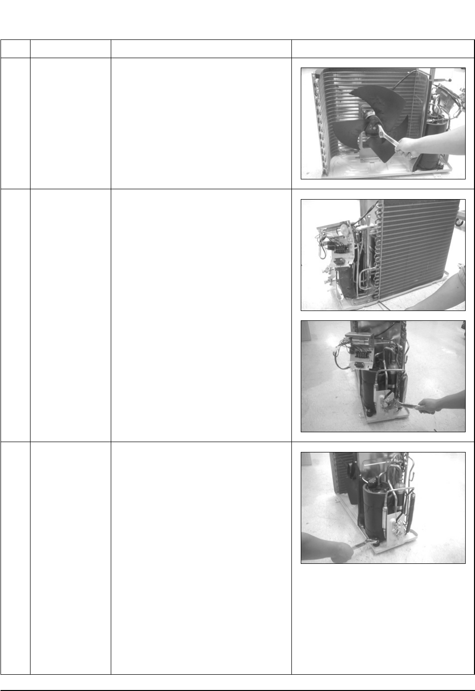
2
3
4
Fan & Motor
Heat Exchanger
Compressor
1) Detach the Nut Flange.(Turn counterclock-
wise because the screw is right-handed)
2) Detach the Fan.
3) Loosen 4 fixing screws to detach
the Motor.
1) Loosen 2 fixing screws on both sides.
2) Disassemble the pipe in both inlet and
outlet with welding torch.
3) Detach the Heat Exchanger.
1) Loosen the Terminal Cover nut to open the
Terminal Cover.
2) Disassemble the cloth sound felt.
3) Disassemble the pipe in both inlet and
outlet of the Compressor with welding
torch.
4) Disassemble the pipe in both inlet and
outlet of the Condenser with welding torch.
5) Loosen the 3 bolts at the bottom.
6) Detach the Compressor.
DB98_20429A(1)_1 12/24/04 10:55 AM Page 14
15Samsung Electronics
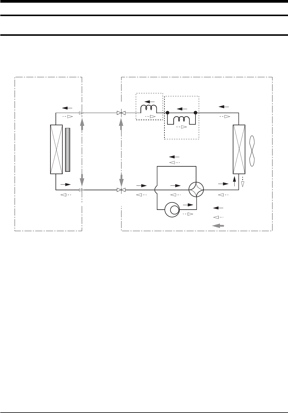
4. Refrigerating Cycle Diagram
4-1 Refrigerating Cycle Diagram
Cooling
Heating
Gas Leak Check Polnt
Indoor Unit Outdoor Unit
T1
T2
Heat
Exchanger
(Evaporator)
Heat
Exchanger
(Condenser)
Propeller fan
Cross fan
2-Way valve
Capillary tube
Capillary tube
Check valve
✳Note
3-Way valve 4-Way valve
Gas side
Liquid side
Compressor
DB98_20429A(1)_1 12/24/04 10:55 AM Page 15
Samsung Electronics16
4-2 Refrigerant Cycle Characteristic
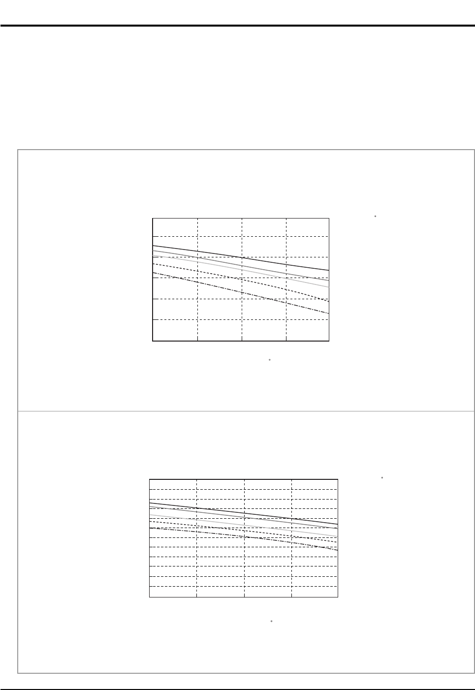
4-2-1 Capacity Distributions
Capacity Distributions according to indoor and outdoor temperature variation.
■COOLING MODE
- Indoor Temp. Variation : 21.0˚C ~ 32.4˚C
- Outdoor Temp. Variation : 25.0˚C ~ 45.0˚C
DB32.4 / WB24.0
DB30.6 / WB22.5
DB27.0 / WB19.0
DB24.0 / WB17.0
DB21.0 / WB15.0
Cooling Capacity(kW)
Cooling Capacity Distribution
4.0
3.0
2.0
1.0
25.0 35.0 45.0
Outdoor Temp.(DB C)
Indoor Temp.( C)
■ AS09HPBN
DB32.4/WB24.0
DB30.6/WB22.5
DB27.0/WB19.0
DB24.0/WB17.0
DB21.0/WB15.0
Cooling Capacity(kW)
Cooling Capacity Distribution
6.0
5.0
4.0
3.0
2.0
1.0
0.0
25 35 45
Outdoor Temp.(DB C)
Indoor Temp.( C)
■ AS12HPBN
DB98_20429A(1)_1 12/24/04 10:55 AM Page 16
17Samsung Electronics
Refrigerating Cycle Diagram
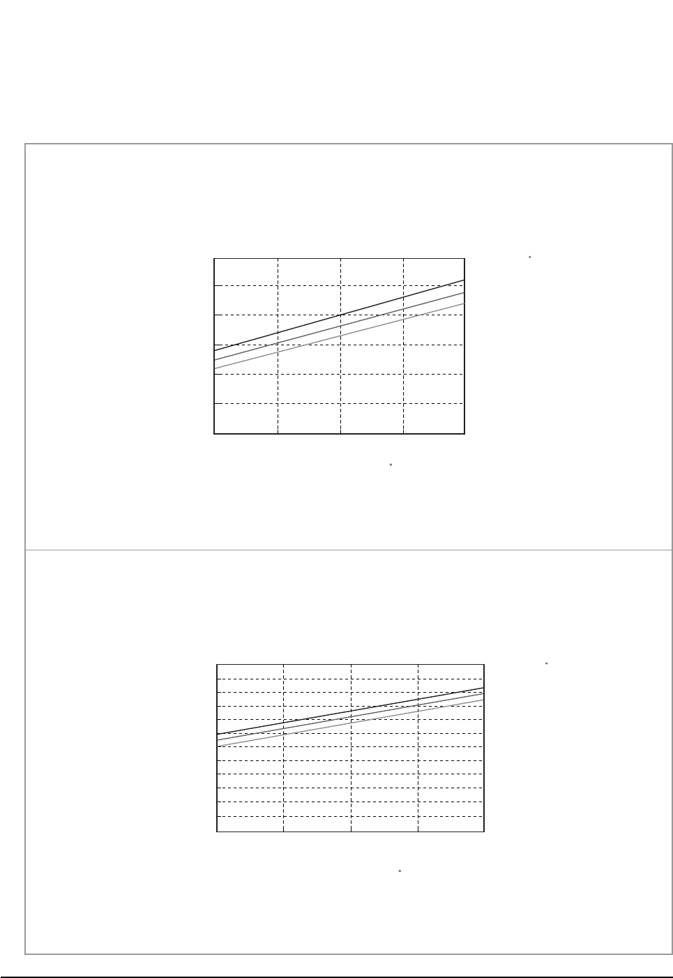
■HEATING MODE
- Indoor Temp. Variation : 15.0˚C ~ 25.0˚C
- Outdoor Temp. Variation : 1.0˚C ~ 20.0˚C
DB15.0
DB20.0
DB25.0
Heating Capacity(kW)
Heating Capacity Distribution
4.00
3.00
2.00
1.00
1.0/0.0 7.0/6.0 20.0/15.0
Indoor Temp.( C)
Outdoor Temp.(DB/WB C)
■ AS09HPBN
DB15.0
DB20.0
DB25.0
Heating Capacity
Heating Capacity Distribution
6.00
5.00
4.00
3.00
2.00
1.00
0.00
1.0/0.0 7.0/6.0 20.0/15.0
Indoor Temp.( C)
Outdoor Temp.(DB/WB C)
■ AS12HPBN
DB98_20429A(1)_1 12/24/04 10:55 AM Page 17
Samsung Electronics18
Refrigerating Cycle Diagram
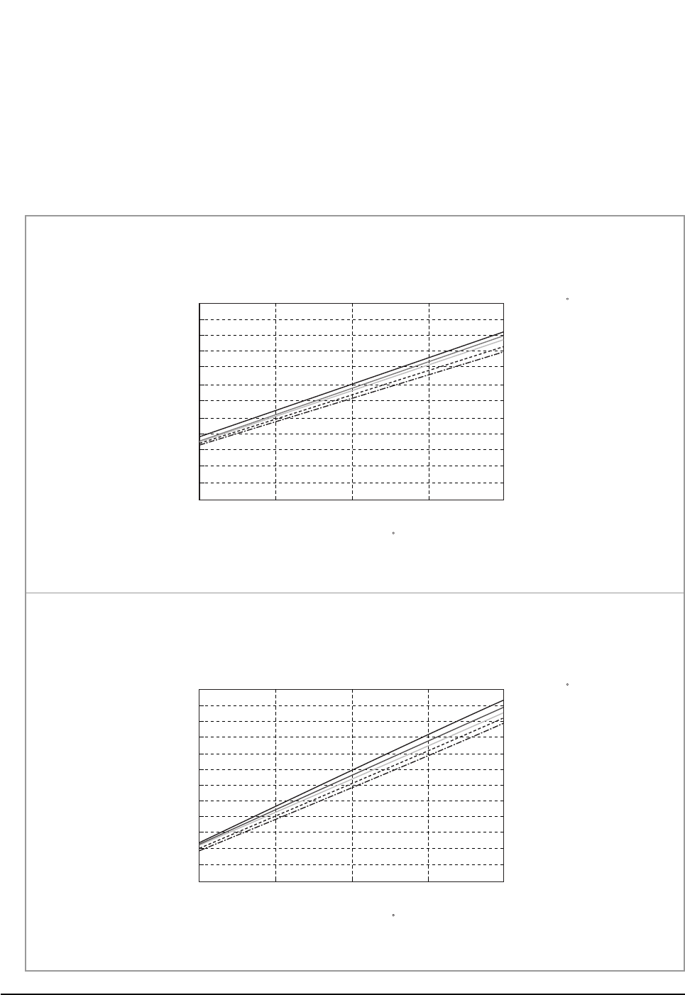
4-2-2 Power Consumption Distributions
Power Consumption Distributions according to indoor and outdoor temperature variation.
■COOLING MODE
- Indoor Temp. Variation : 21.0˚C ~ 32.4˚C
- Outdoor Temp. Variation : 25.0˚C ~ 45.0˚C
DB32.4 / WB24.0
DB30.6 / WB22.5
DB27.0 / WB19.0
DB24.0 / WB19.0
DB21.5 / WB15.0
Power consumption(W)
Power consumption Distribution(Cooling mode)
1,100
1,000
900
800
700
600
500 25 35 45
Indoor Temp.( C)
Outdoor Temp.(DB C)
■ AS09HPBN
Power consumption(W)
Power consumption Distribution(Cooling mode)
1,400
1,300
1,200
1,100
1,000
900
800
25 35 45
DB32.4 / WB24.0
DB30.6 / WB22.5
DB27.0 / WB19.0
DB24.0 / WB19.0
DB21.5 / WB15.0
Indoor Temp.( C)
Outdoor Temp.(DB C)
■ AS12HPBN
DB98_20429A(1)_1 12/24/04 10:55 AM Page 18
19Samsung Electronics
Refrigerating Cycle Diagram
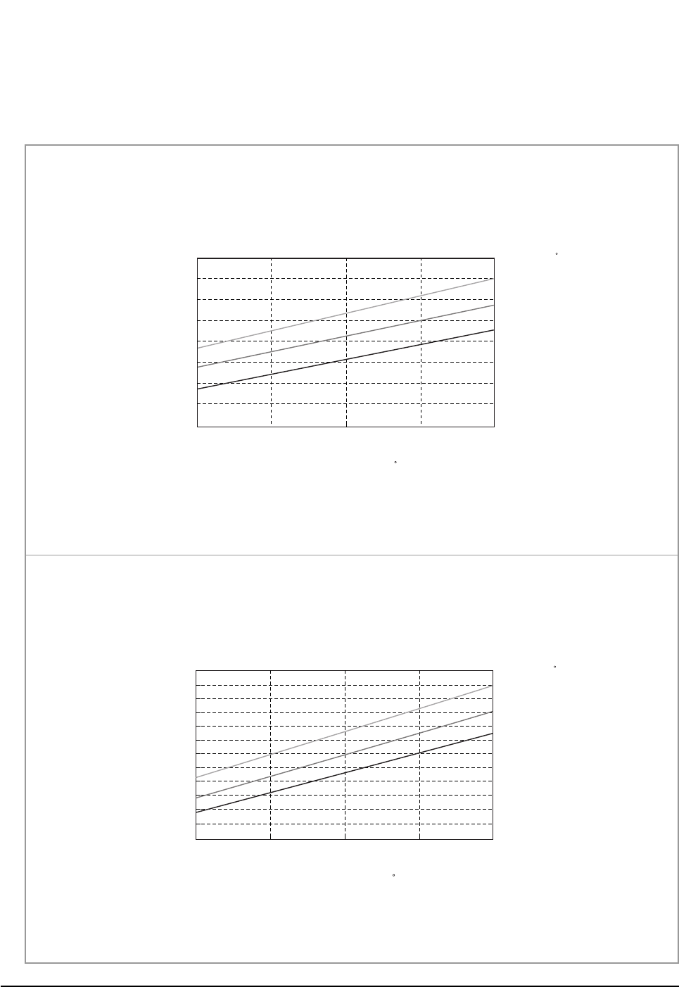
■HEATING MODE
- Indoor Temp. Variation : 15.0˚C ~ 25.0˚C
- Outdoor Temp. Variation : 1.0˚C ~ 20.0˚C
1.0/0.0 7.0/6.0 20.0/15.0
DB25.0
DB20.0
DB15.0
Power consumption(W)
Power consumption Distribution(Heating mode)
1,050
950
850
750
650
Indoor Temp.( C)
Outdoor Temp.(DB/WB C)
■ AS09HPBN
Power consumption(W)
Power consumption Distribution(Heating mode)
1,500
1,400
1,300
1,200
1,100
1,000
900
25 35 45
DB25.0
DB20.0
DB15.0
Indoor Temp.( C)
Outdoor Temp.(DB/WB C)
■ AS12HPBN
DB98_20429A(1)_1 12/24/04 10:55 AM Page 19
Samsung Electronics20
Refrigerating Cycle Diagram
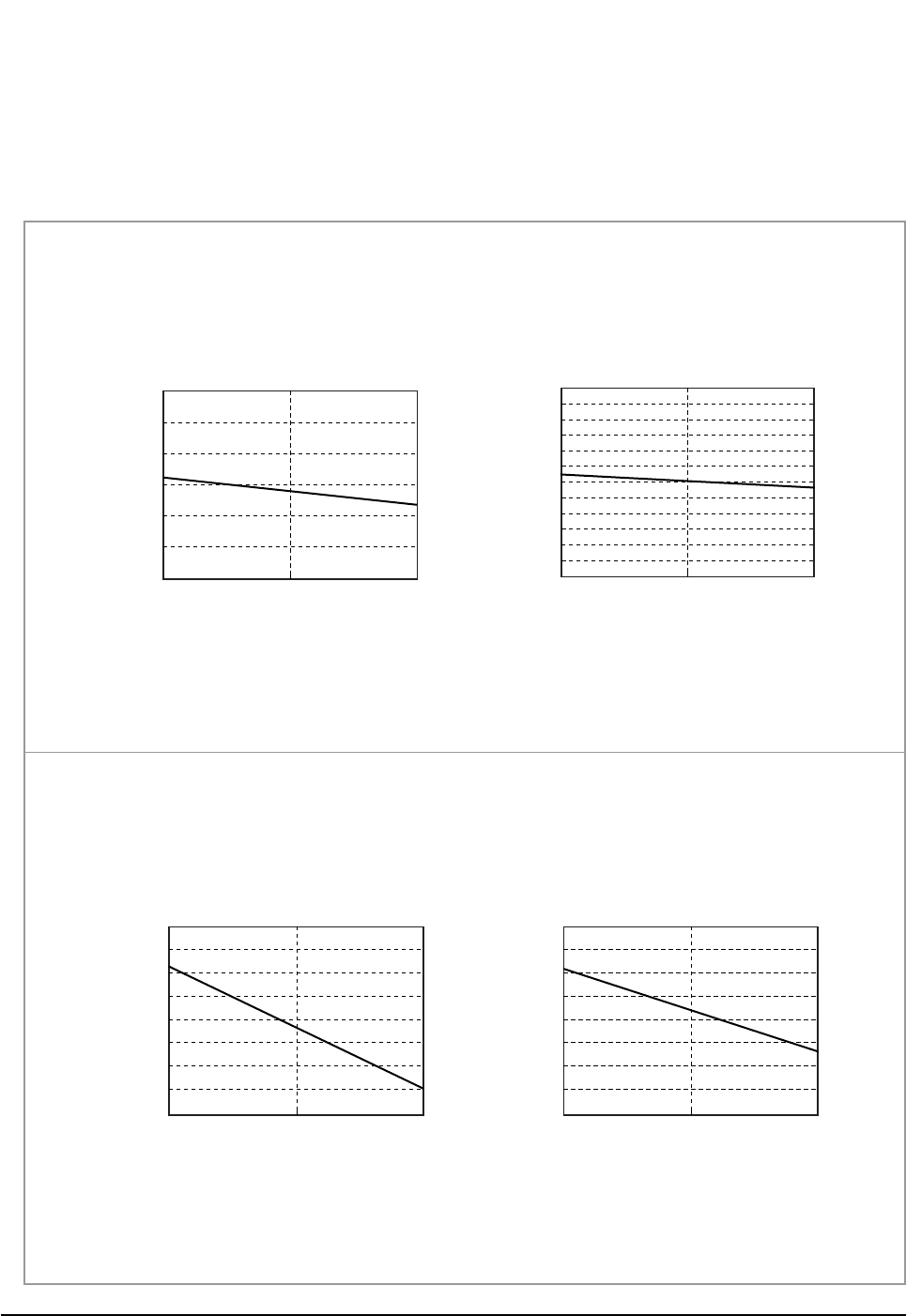
4-2-3 Capacity and Power Consumption Distributions
Capacity and power Consumption distributions according to the length of connecting Pipe between indoor unit and outdoor unit.
■COOLING MODE
Power consumption(W)
Length of Connecting Pipe(m)
Power consumption(Cooling)
1,100
1,000
900
800
700
600
500 7.5 15.0
Coooling Capacity(kW)
Length of Connecting Pipe(m)
Cooling Capacity
4
3
2
1
7.5 15.0
Cooling Capacity(kW)
Length of Connecting Pipe(m)
Cooling Capacity
3.70
3.50
3.30
3.10
2.90
7.5 15.0
Power consumption(W)
Length of Connecting Pipe(m)
Power consumption(Cooling)
1,300
1,200
1,100
1,000
900
7.5 15.0
■ AS09HPBN
■ AS12HPBN
DB98_20429A(1)_1 12/24/04 10:55 AM Page 20
21Samsung Electronics
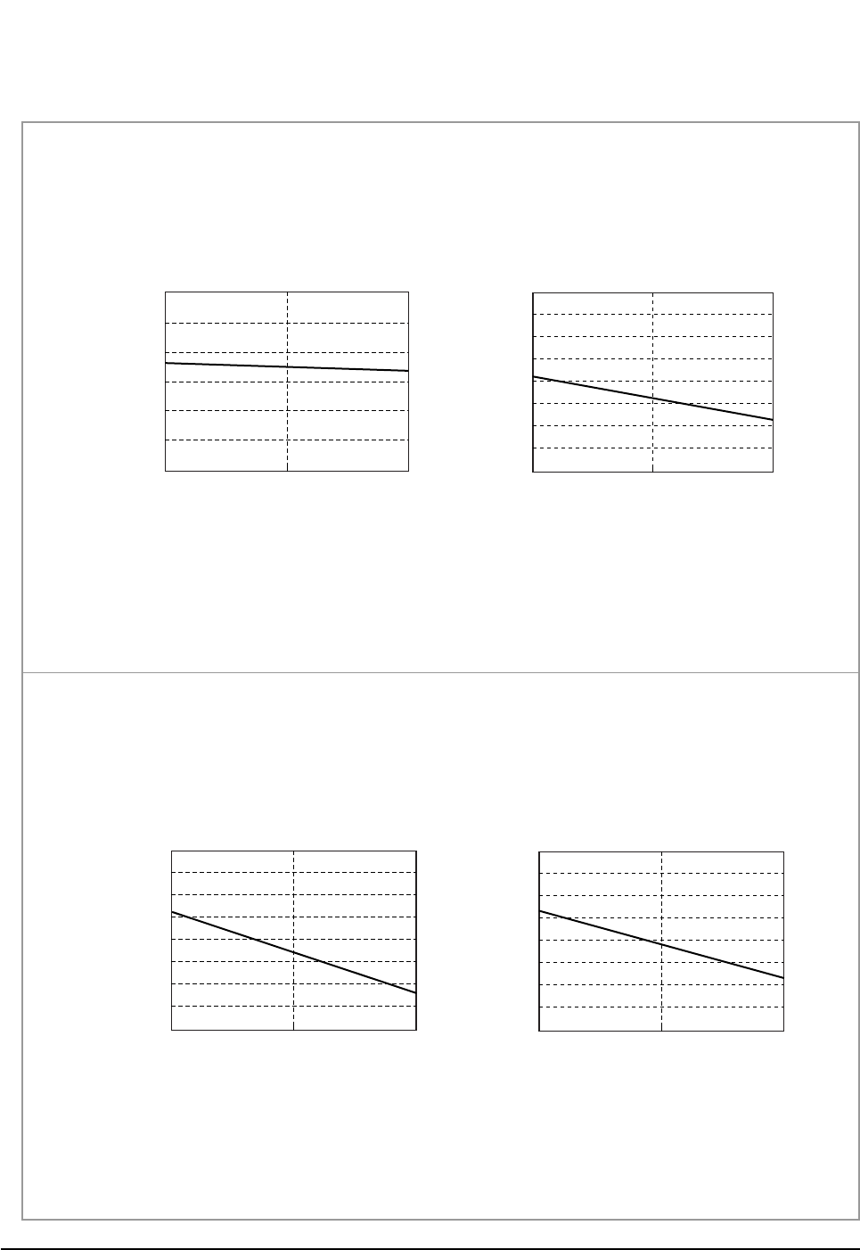
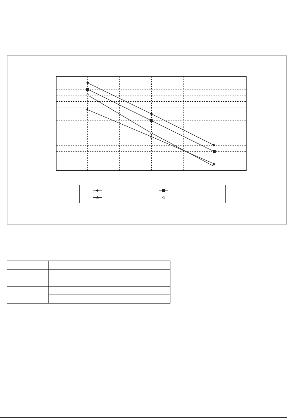
Refrigerating Cycle Diagram
■HEATING MODE
Power consumption(W)
Length of Connecting Pipe(m)
Power consumption(Heating)
1,050
950
850
750
650
7.5 15.0
Heating Capacity(kW)
Length of Connecting Pipe(m)
Heating Capacity
4.00
3.00
2.00
1.00
7.5 15.0
Heating Capacity(kW)
Length of Connecting Pipe(m)
Heating Capacity
4.30
4.10
3.90
3.70
3.50
7.5 15.0
Power consumption(W)
Length of Connecting Pipe(m)
Power consumption(Heating)
1,350
1,250
1,150
1,050
950
7.5 15.0
■ AS09HPBN
■ AS12HPBN
DB98_20429A(1)_1 12/24/04 10:55 AM Page 21
Samsung Electronics22
Refrigerating Cycle Diagram
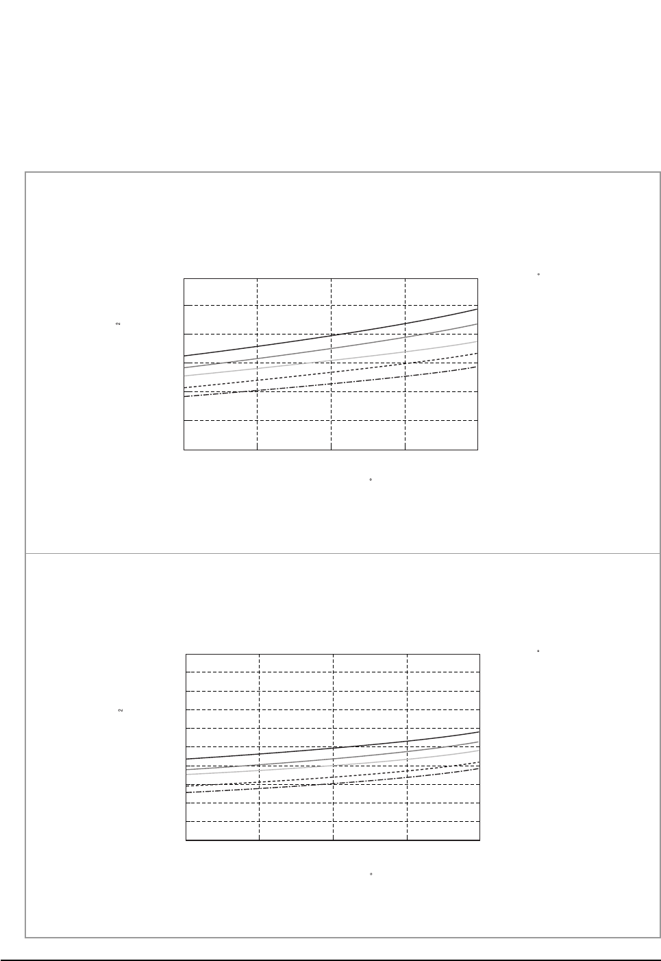
4-2-4 Low Pressure Distributions
■COOLING MODE
- Indoor Temp. Variation : 21.0˚C ~ 32.4˚C
- Outdoor Temp. Variation : 25.0˚C ~ 45.0˚C
DB32.4 / WB24.0
DB30.6 / WB22.5
DB27.0 / WB19.0
DB24.0 / WB17.0
DB21.0 / WB15.0
Low pressure(kg/cm G)
Low Pressure Distribution(Cooling mode)
12.0
10.0
8.0
6.0 25 35 45
Outdoor Temp.(DB C)
Indoor Temp.( C)
■ AS09HPBN
DB32.4 / WB24.0
DB30.6 / WB22.5
DB27.0 / WB19.0
DB24.0 / WB19.0
DB21.5 / WB15.0
Low pressure(kg/cm G)
Low Pressure Distribution(Cooling mode)
15.0
13.0
11.0
9.0
7.0
5.0 25 35 45
Outdoor Temp.(DB C)
Indoor Temp.( C)
■ AS12HPBN
DB98_20429A(1)_1 12/24/04 10:55 AM Page 22
23Samsung Electronics
Refrigerating Cycle Diagram
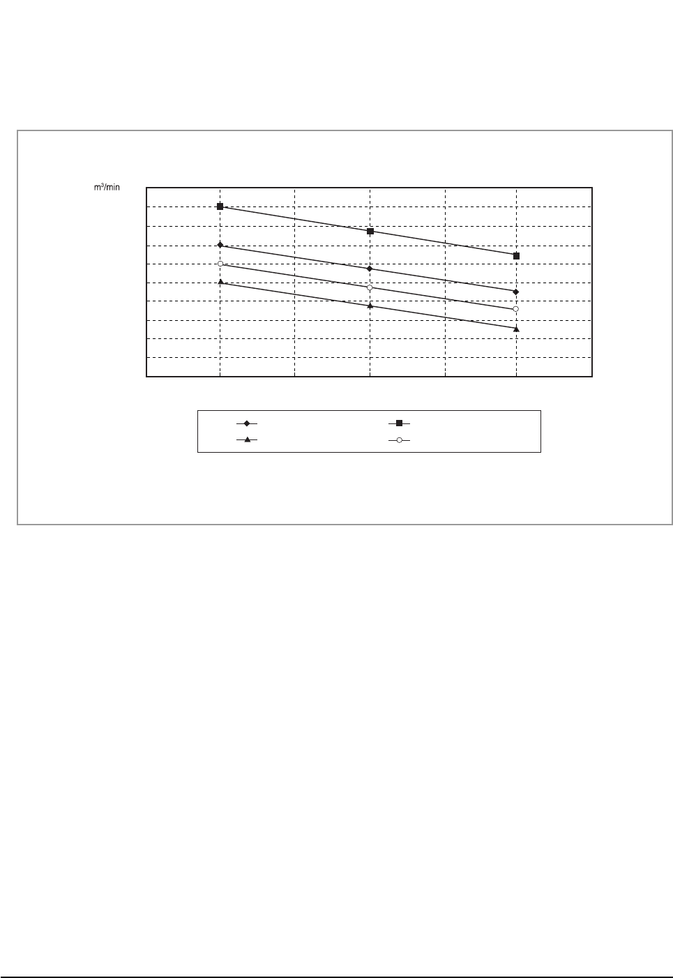
4-2-5 Air Volume according to the RPM variation(High/Mid/Low)
■Indoor Unit
■Outdoor Unit
The air volume is 25m3/min regardless of model.
8
7.5
9.5
9
8.5
10
7
6.5
6
5.5
5
High Mid RPM
Low
12,000BTU-Cooling-Vol.
19,000BTU-Cooling-Vol.
12,000BTU-Heating-Vol.
19,000BTU-Heating-Vol.
DB98_20429A(1)_1 12/24/04 10:55 AM Page 23
Samsung Electronics24
Refrigerating Cycle Diagram
4-2-6 Noise Level according to the RPM variation(High/Mid/Low)
■Indoor Unit
■Outdoor Unit
41
39
37
35
33
31
29
27
High Mid RPM
Low
12,000BTU-Cooling-Noise
dB
19,000BTU-Cooling-Noise
12,000BTU-Heating-Noise
19,000BTU-Heating-Noise
Section Operation Noise(dB) Remark
AS09HPBN Cooling 51
Heating 51
AS12HPBN Cooling 53
Heating 53
DB98_20429A(1)_1 12/24/04 10:55 AM Page 24

25Samsung Electronics
■HFCs
1. When installing or removing or servicing an air conditioner, do not allow air or moisture to remain in the refrigeration cycle.
2. When evacuating an air conditioner, always use the vacuum pump to sufficiently evacuate an air conditioner.
3. You must use the specified lubricant(Polyol ester oil), valve and dryer.
■Lubricants
1. Synthetic Oils : POE, PVE, PAG, AB
2. POE is made from Acid and Alcohol
3. Hydrolysis causes Metallic Soap
4-3 Cautions Of using R410A
DB98_20429A(1)_1 12/24/04 10:55 AM Page 25
Samsung Electronics26
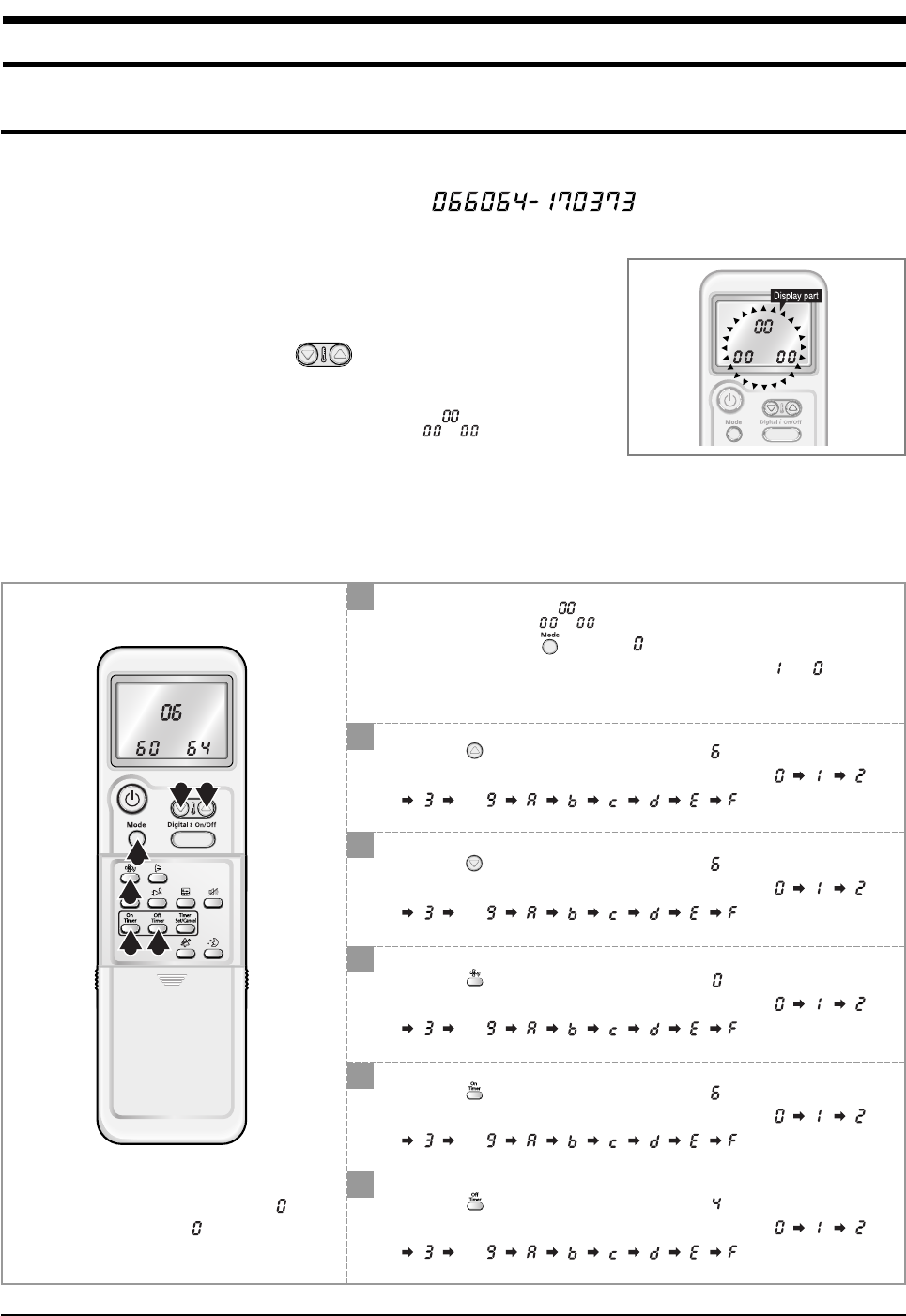
5. Set Up the Model Option
5-1 Setting Option Setup Method
ex) Option No. :
Step 1 :Enter the Option Setup mode.
1st Take out the batteries of remote control.
2nd Press the temperature button simultaneously and
insert the battery again.
3rd Make sure the remocon display shown as .
Step 2 :Enter the Option Setup mode and select your option according to the following procedure.
3 2
1
4
5 6
1
2
The default value is .
Otherwise, push the button to .
Every time you push the button, the display panel reads or
repeatedly.
✳Setting is not required if you must
a value which has a default.
Push the button to set the display panel to .
Every time you push the button, the display panel reads
... repeatedly.
3
Push the button to set the display panel to .
Every time you push the button, the display panel reads
... repeatedly.
4
Push the button to set the display panel to .
Every time you push the button, the display panel reads
... repeatedly.
5
Push the button to set the display panel to .
Every time you push the button, the display panel reads
... repeatedly.
6
Push the button to set the display panel to .
Every time you push the button, the display panel reads
... repeatedly.
DB98_20429A(1)_1 12/24/04 10:55 AM Page 26
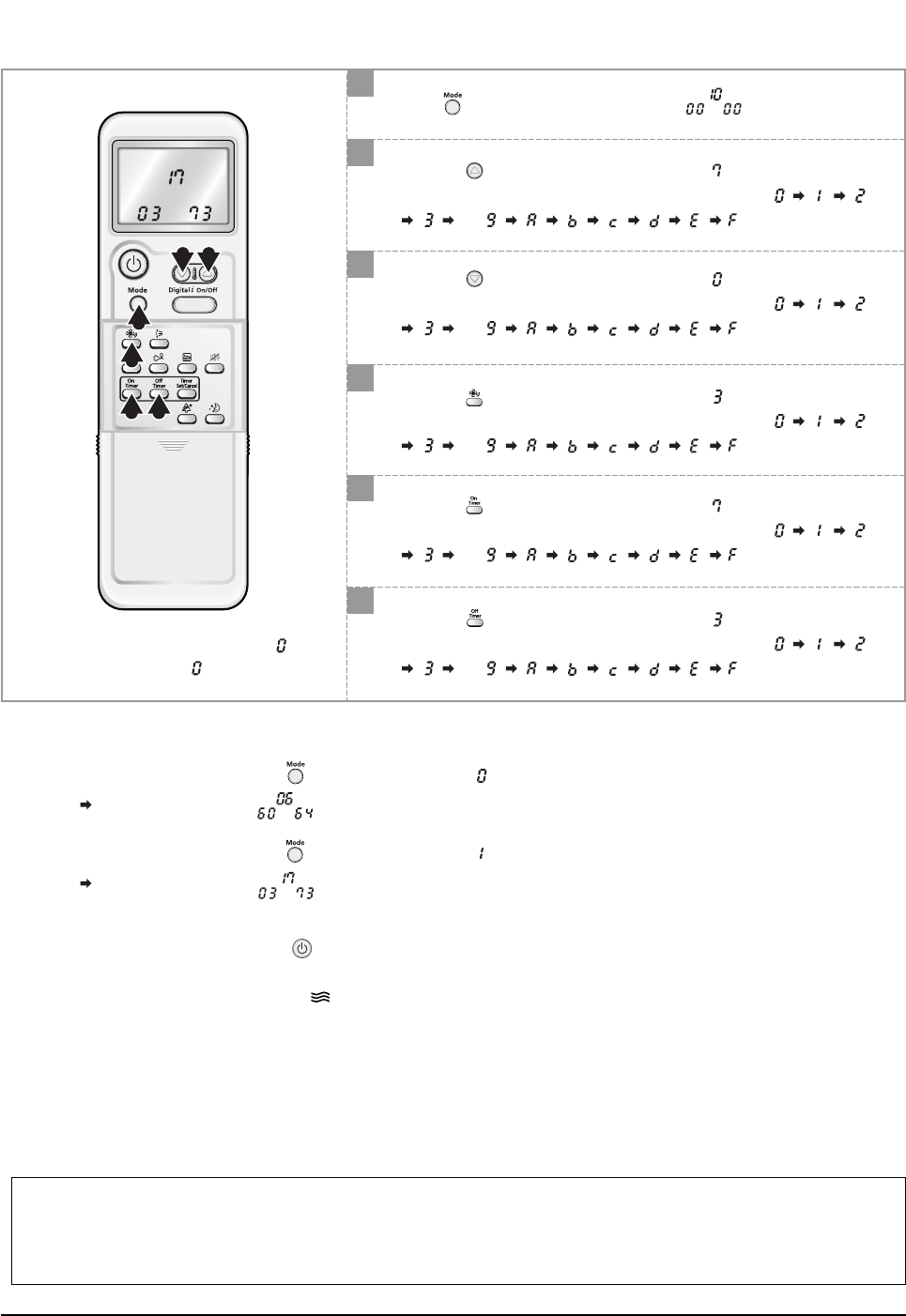
27Samsung Electronics
Set Up the Model Option
7
8
Press button, then the default value is .
Push the button to set the display panel to .
Every time you push the button, the display panel reads
... repeatedly.
10
Push the button to set the display panel to .
Every time you push the button, the display panel reads
... repeatedly.
9
Push the button to set the display panel to .
Every time you push the button, the display panel reads
... repeatedly.
11
Push the button to set the display panel to .
Every time you push the button, the display panel reads
... repeatedly.
12
Push the button to set the display panel to .
Every time you push the button, the display panel reads
... repeatedly.
9 8
7
10
11 12
✳Setting is not required if you must
a value which has a default.
Step 3 : Upon completion of the selection, check you made right selections.
Press the Mode Selection key, to set the display part to and check the display part.
The display part shows .
Press the Mode Selection key, to set the display part to and check the display part.
The display part shows .
Step 4 : Pressing the ON/OFF button ( )
When pressing the operation ON/OFF key with the direction of remote control for unit, the sound ''Ding'' or ''Diriring'' is
heard and the OPERATION ICON( ) lamp of the display is flickering at the same time, then the input of option is com-
pleted. (If the diriring sound isn't heard, try again pressing the ON/OFF button.)
Step 5 : Unit operation test-run
First, Remove the battery from the remote control.
Second, Re-insert the battery into the remote control.
Third, Press ON/OFF key with the direction of remote control for set.
• Error Mode
1st If all lamps of indoor unit are flickering, plug out, plug in power plug again and press the ON/OFF key to retry.
2nd If the unit is not working properly or all lamps are continuously flickering after setting the option code, see if the correct option code is
set up for its model.
DB98_20429A(1)_1 12/24/04 10:55 AM Page 27

Samsung Electronics28
Set Up the Model Option
■OPTION ITEMS
REMOCON
MODEL
SEG1 SEG2 SEG3 SEG4 SEG5 SEG6 SEG7 SEG8 SEG9 SEG10 SEG11 SEG12
AS09HPBN
AS12HPBN
028025170208
02732717026c
DB98_20429A(1)_1 12/24/04 10:55 AM Page 28
29Samsung Electronics
1. The input voltage should be rating voltage ±10% range.
The airconditioner may not operate properly if the voltage is out of this range.
2. Is the link cable linking the indoor unit and the outdoor unit linked properly?
The indoor unit and the outdoor unit shall be linked by 5 cables.
Check the terminals if the indoor unit and outdoor unit are properly linked by the same number of cables.
Otherwise the airconditioner may not operate properly.
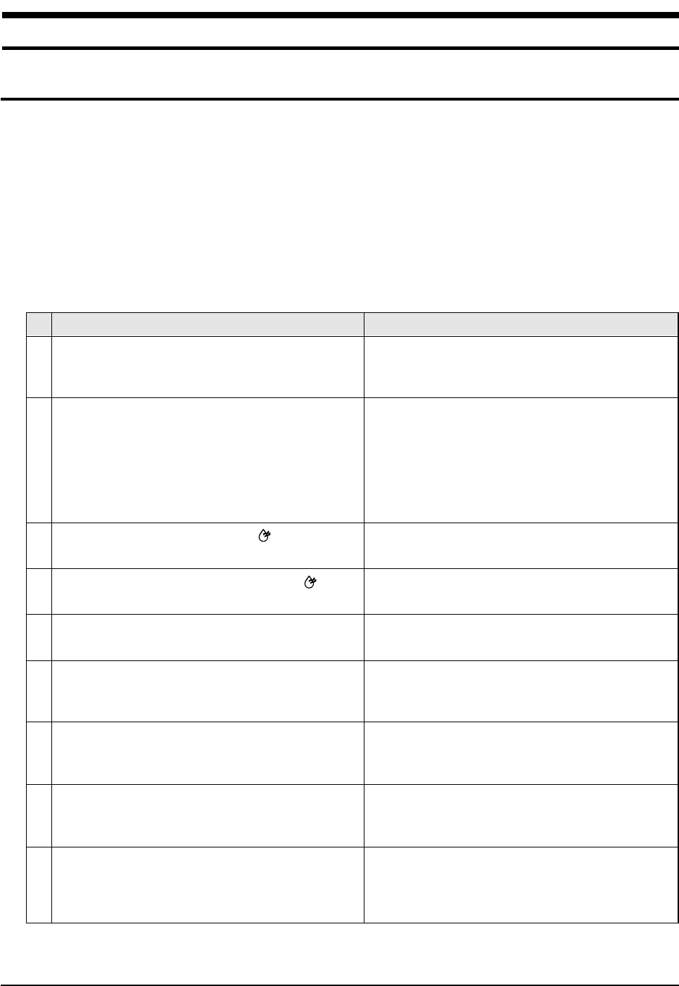
3. When a problem occurs due to the contents illustrated in the table below it is a symptom not related to the malfunction of the
airconditioner.
The OPERATION indication LED(BLUE) blinks when a
power plug of the indoor unit is plugged in for the first
time.
In a COOL operation mode, the compressor does not
operate at a room temperature higher than the setting
temperature that the INDOOR FAN should operate.
[In case of heat pump model]
In a HEAT operation mode, the compressor does not
operate at a room temperature lower than the setting
temperature that indoor fan should operate.
Fan speed setting is not allowed in DRY( ) mode.
Compressor stops operation intermittently in DRY( )
mode.
Timer LED(YELLOW) of the indoor unit lights up and the
air conditioner does not operate.
The compressor stops intermittently in a COOL mode or
DRY mode, and fan speed of the indoor unit decreases.
[In case of heat pump model]
Compressor of the outdoor unit is operating although it is
turned off in a HEAT mode.
[In case of heat pump model]
The compressor and indoor fan stop intermittently in
HEAT mode.
[In case of heat pump model]
Indoor fan and outdoor fan stop operation intermittently
in a HEAT mode.
1
2
3
4
5
6
7
8
9
Operation of air conditioner Explanation
It indicates power is on. The LED stops blinking if the opera-
tion ON/OFF button on the remote control unit is pushed.
In happens after a delay of 3 minutes when the compressor
is reoperated. The same phenomenon occurs when a power
is on.
As a phenomenon that the compressor is reoperated after a
delay of 3 minutes, the indoor fan is adjusted automatically
with reference to a temperature of the air blew.
The speed of the indoor fan is set to LL in DRY mode.
Fan speed is selected automatically in AUTO mode.
Compressor operation is controlled automatically in DRY
mode depending on the room temperature and humidity.
Timer is being activated and the unit is in ready mode.
The unit operates normally if the timer operation is cancelled.
The compressor stops intermittently or the fan speed of the
indoor unit decreases to prevent inside/outside air frozen
depending on the inside/outside air temperature.
When the unit is turned off while de-ice is activated,
the compressor continues operation for up to 9 minutes
(maximum) until the deice is completed.
The compressor and indoor fan stop intermittently if room
temperature exceeds a setting temperature in order to protect
the compressor from overheated air in a HEAT mode.
The compressor operates in a reverse cycle to remove
exterior ice in a HEAT mode, and indoor fan and outdoor fan
do not operate intermittently for within 20% of the total heater
operation
No
6. Troubleshooting
6-1 Items to be checked first
DB98_20429A(1)_1 12/24/04 10:55 AM Page 29
Samsung Electronics30
Troubleshooting
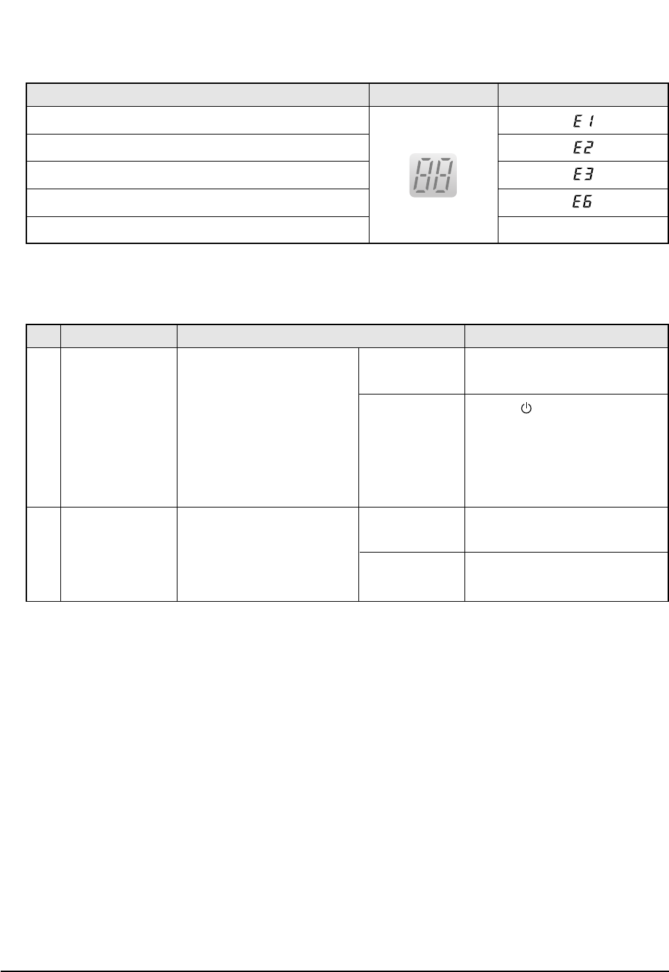
4. Indoor unit observes operation condition of the air conditioner, and displays self diagnosis details on the display panel.
5. Operation with abnormal motion
Error Mode LAMP 7-segment Display
No response from
the remote control
operation signal.
Unable to operate the
outdoor unit
• Plug out and plug in 5 seconds
later.
• Press the TURBO button with the
remote control.
• In 3 minutes, check the voltage
between the indoor unit terminal
block N(1) and 1.
Able to operate the
remote control.
Unable to operate
the remote control.
AC198V ~ AC242V
No power source
displayed.
OK
Press the (ON/OFF) button in the
indoor unit.
• If it operates, the remote control and
indoor unit receiver are in trouble.
• If not, the indoor unit is in trouble.
Problem with the outdoor unit or PCB
Problem with the relay (RY71) or PCB
No Abnormal condition Inspection Initial Diagnosis
1
2
Indoor unit room temperature sensor error (open or short)
Indoor unit heat exchanger temperature sensor error (open or short)
Indoor fan motor malfunction
EEPROM error
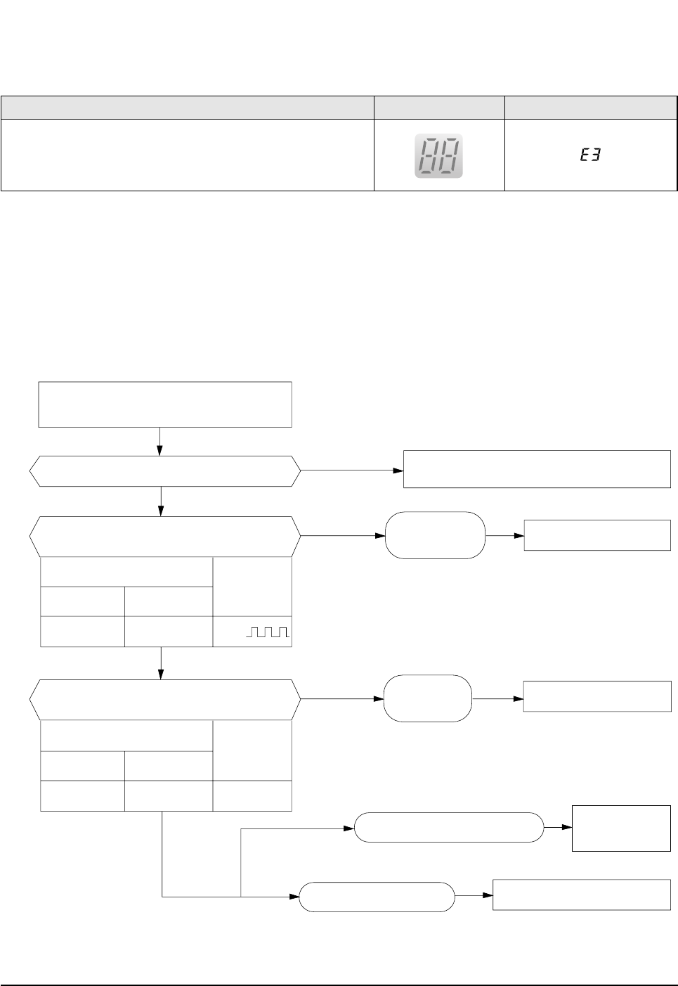
Option error (option wasn't set up or option data error) Display Flickering
DB98_20429A(1)_1 12/24/04 10:55 AM Page 30
31Samsung Electronics
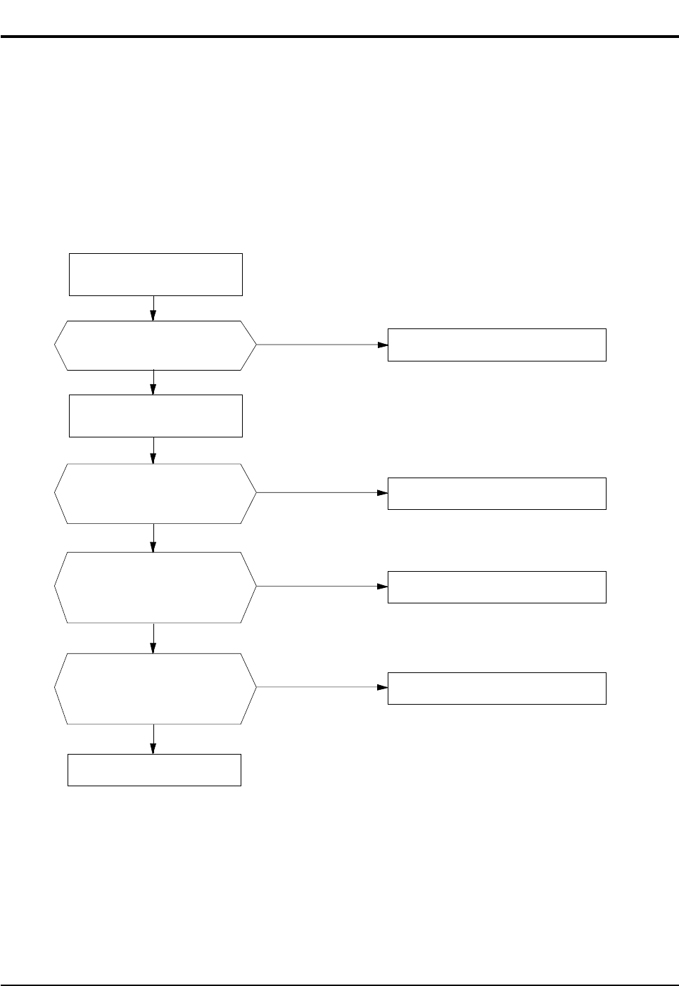
1. Checklist :
1) Is input voltage normal?
2) Is AC power linked correctly?
3) Is input voltage of DC regulator IC KA7805 (IC02) normal? (11VDC-12.5VDC)
4) Is output voltage of DC regulator IC KA7805 (IC02) normal? (4.5VDC-5.5VDC)
2. Troubleshooting procedure
Unplug the power cord and
plug it after 5 seconds
Press the Power Button on the
remote control unit to
operate the air conditioner
Check whether 2 wires
of power cord are
connected correctly to the
terminal block and control board.
Check whether the fuse on the
control board is normal.
FUSE: 3.15[A]/250[V]
Check the output of SMPS
on the control board.
Input power: AC230±15%[V]
IC02 Input: DC12[V]
IC02 output: DC5[V]
◆Check the setting temperature
◆Check the indoor unit
control board
◆Check the display board
Reconnect wires correctly
Replace fuse
PCB should be replaced
operate
does not operate
Ye s
Ye s
Ye s
No
No
No
6-2 Fault Diagnosis by Symptom
6-2-1 No Power (completely dead)-Initial diagnosis
DB98_20429A(1)_1 12/24/04 10:55 AM Page 31
Samsung Electronics32
Troubleshooting
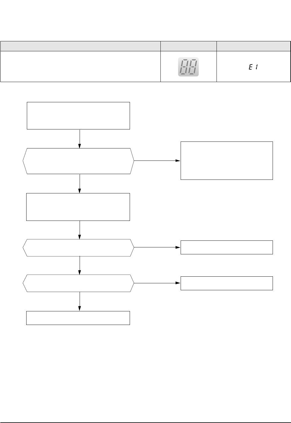
6-2-2 Room temperature sensor failure
No
ASS'Y Sensor Replace
SENSOR Resistance Value : 20˚C-12.09kΩ
SENSOR Resistance Value : 30˚C-8.31kΩ
SENSOR Resistance Value : 35˚C-6.94kΩ
SENSOR Resistance Value : 40˚C-5.83kΩ
Ye s
No
No
Detach the assembly sensor from the
ASS'Y PCB CN43 connector and measure
the sensor resistance with an ohmmeter (tester).
Connect the sensor to CN43,
supply power, and measure the voltage of
#1 and #2 of the CN43 connector.
MICOM Error or Connector(CN43) check
Is the sensor resistance value
10KΩ±3% at the room temperature
of 25˚C?
Ye s Poor ASS'Y PCB Replace
Below 0.5V?
Ye s Poor ASS'Y PCB Replace
Over 4.9V?
Error Mode LAMP 7-segment Display
Indoor unit room temperature sensor error(open or short)
DB98_20429A(1)_1 12/24/04 10:55 AM Page 32
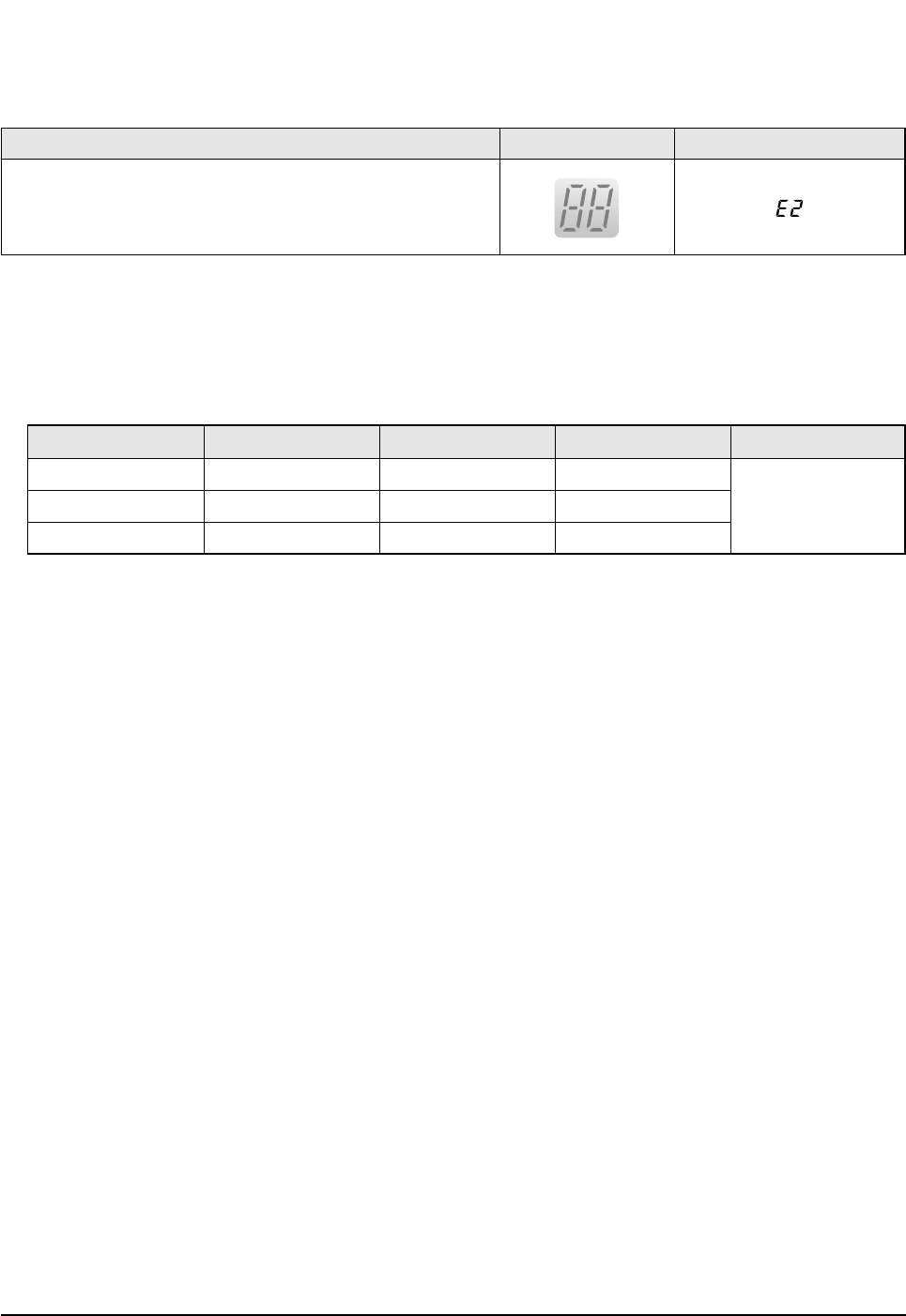
33Samsung Electronics
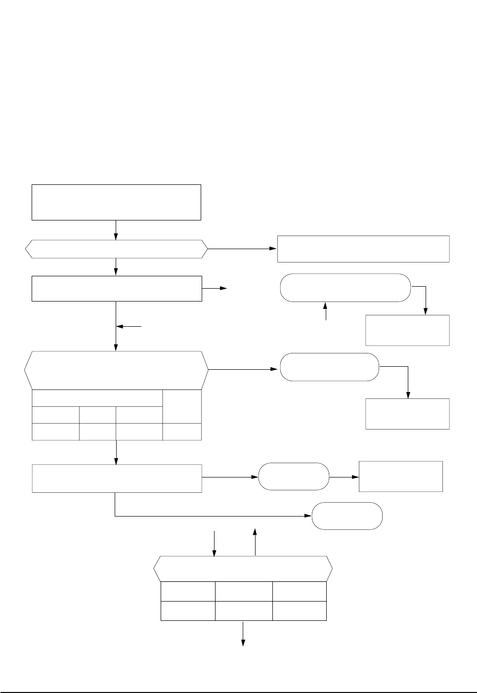
Troubleshooting
1. Check the assembly condition of the sensor connector(CN43) on the indoor unit Main PCB and if not assembled, reassemble the
connector accurately.
2. Detach the room pipe sensor connector(CN43) and check the resistance between connector 3 and 4.
If the above data is not met, replace the room pipe sensor.
3. Assemble the room pipe sensor to PCB, plug in, and check the voltage of connector 3 and 4. If the resistance is below 0.5V or
over 4.9V, replace the indoor Main PCB. (short or disconnected in the PCB board)
Temperature(˚C)
15
20
25
Temperature(˚C)
30
35
40
Resistance Value(Kohm)
8.31
6.94
5.83
Resistance Value(Kohm)
14.68
12.09
10
Others
The data tolerance
is ±3%.
6-2-3 Room Pipe sensor failure
Error Mode LAMP 7-segment Display
Indoor unit heat exchanger temperature sensor error(open or short)
DB98_20429A(1)_1 12/24/04 10:55 AM Page 33
Samsung Electronics34
Troubleshooting
6-2-4 When the Indoor Unit Fan Does Not Operate. (Initial Diagnosis)
1. Checklist :
1) Is the indoor unit fan motor properly connected with the connector (CN72)?
2) Is the AC voltage correct?
3) Is HALL IC in indoor fan motor properly connected with the connector (CN44)?
4) Is the running capacitor (CR71) properly connected with PCB board?
2. Troubleshooting procedure
After unplugging out the power cord should
be reconnected within 5 seconds.
Does the OPERATION lamp blink?
Does the Solid State Relay(SS71) work properly?
Is the supply voltage of the fan motor sufficient?
Test rod location
PCB CN72 Condition
About AC180V
Normal
voltage
pin #3 and #5 Fan operating
Ye s
Ye s
Ye s
Ye s
No
No
No Check as in the procedure "No power".
PCB is
out of order. PCB should be replaced.
Replace Motor
Fan-Capacitor
Fan motor should be replaced.
Fan motor is out of order.
Motor Fan-Capacitor is out of order
Test rod location
+-
SS71-SS71- 12V
Normal
Voltage
Micom is
out of order. Micom should be replaced
Error Mode LAMP 7-segment Display
Indoor unit heat exchanger temperature sensor error(open or short)
DB98_20429A(1)_1 12/24/04 10:55 AM Page 34
35Samsung Electronics
Troubleshooting
6-2-5 When the Outdoor Unit Does Not Operate. (Initial Diagnosis)
1. Checklist :
1) Is input voltage normal?
2) Is the set temperature of the remote control higher than room temperature in COOL mode?
3) Is the set temperature of the remote control lower than room temperature in HEAT mode?
4) Is the POWER IN connector (CN71) linked correctly?
5) Is the outdoor unit properly connected with the TERMINAL BLOCK connector(N(1), 1, 2, 3)?
2. Troubleshooting procedure
After unplugging out the power cord should be
reconnected within 5 seconds.
Does the OPERATION lamp blink?
Ye s
No
Ye s
No
No
No
Ye s
Ye s
Outdoor unit is
out of order.
Power relay is
out of order
Power relay should be
replaced.
PCB should be
checked.
Micom is
out of order.
Sensor Should be
replaced
Room temperature sensor is
out of order
Check as in the procedure "No Power".
Is the room sensor normal resistor?
10°C20°C30°C
17.96kΩ12.09kΩ8.3kΩ
Does the timer lamp blink during operation?
Is the power relay RY71 operated by adjusting the
room temperature?
Is rating voltage ±10% range applied relay between
Terminal block No. N(1) and No. 1
Test rod location Normal
+ - Condition Voltage
IC4 Pin No.38 GND RY71 ON DC4.8V
#
!
!
@
#
@
No
Ye s
DB98_20429A(1)_1 12/24/04 10:55 AM Page 35

Samsung Electronics36
Troubleshooting
6-2-6 When the Up/Down Louver Motor Does Not Operate. (Initial Diagnosis)
1. Checklist :
1) Is input voltage normal?
2) Is the Up/Down louver motor properly connected with the connector (CN61)?
2. Troubleshooting procedure
6-2-7 In the HEAT mode, When there is no warm air current. Check this first;
1. Is the set temperature of Remote Control lower than room temperature in Heat mode?
2. Is the Indoor PCB properly connected with the CN71 connector?
Remove power cord and plug in again in approx. 5 seconds.
Is STD lamp blinking?
Does operation start when swing button of the
remote control unit pushed?
Voltage at pin #57~#60 of micom (IC04) change?(Squarewave)
Voltage at pin #2 ~ #3 of CN61(motor connector)
change?(Squarewave)
Up/Down louver motor is faulty.
Driver IC05/06 (ULN2003A) is faulty.
Micom (IC04) is faulty.
Normal
Check as in the procedure
"No Power".
After training on, the heating operation
should start in 5 minutes.
Is the number #38 of Micom (IC04) DC5.0V?
Is the number checking #11 of IC05 (ULN2003A) LOW?
Is the voltage between CN71 #1 and CN71 #5 rating voltage ±10% range
Abnormal 4-Way valve of Outdoor Unit.
or connecting Cable
4-Way valve should be replaced
or connecting Cable Check.
No
Ye s
Ye s
Ye s
No
No
No
Ye s Normal
Abnormal Micom
Abnormal IC05
Abnormal RY73
PCB should be replaced.
Ye s
No
No
Ye s
No
No
Ye s
Ye s
DB98_20429A(1)_1 12/24/04 10:55 AM Page 36

37Samsung Electronics
Troubleshooting
6-2-8 When the remote control is not receiving
1. Check if the connector was normally assembled.
2. Put the set in operation and check the voltage of No. 15(+) and No. 16(-) of the main PCB CN91 while operating the
remote control. When the voltage descends below 3V, the assembly module PCB is normal and the main PCB is poor.
Then replace the main PCB.
3. Replace the assembly display PCB because the module PCB is poor if the voltage between No. 15~16 of CN91
maintains 5V after the remote control starts operation.
DB98_20429A(1)_1 12/24/04 10:55 AM Page 37
Samsung Electronics38
6-3 PCB Inspection Method
6-3-1 Pre-inspection Notices
1. Check if you pulled out the AC power plug when you eliminate the PCB or front panel.
2. Don't hold the PCB side not impose excessive force on it to eliminate the PCB.
3. Don't pull the lead wire but hold the whole housing to connect or disconnect a connector to the PCB.
6-3-2 Inspection Procedure
1. Check connector connection and peeling of PCB or bronze coating pattern when you think the PCB is broken.
2. The PCB is composed of the 3 parts.
1. ●Main PCB Part : MICOM and surrounding circuit, relay, room fan motor driving circuit and control circuit,
sensor driving circuit, power circuit of DC12V and DC5V, and buzzer driving circuit.
1. ●Display part : LED lamp
1. ●Switch part : Switch
6-3-3 Detailed Inspection Procedure
Plug out and pull the PCB
out of the electronic box.
Check the PCB fuse.
Supply power.
If the operating lamp
twinkles at this time,
the above 1)~3) have
no relation.
Press the ON/OFF button
and operate TURBO
mode.
But, exclude the
RESERVE operation.
Press the ON/OFF button.
1. FAN Speed [High]
2. Continuous Operation
1) Is the fuse disconnected? (F701)
Checking the power voltage.
1) Is the DB71input voltage AC200V~AC240V?
2) Is the voltage between both terminals of the
C103 on the 2
nd
side of the transformer DC12V
±0.5V?
3) Is the voltage between both terminals of OUT
and GND of IC02(KA78L05) DC5V ±0.5V?
Checking the power voltage.
1) Check the voltage of the relay(RY71) coil(IC05 PIN
#11 and GND : 0V, PIN#6 and GND : 5V) during
operation(3 minutes after TURBO operation).
2) Check the voltage of both terminals of
terminal block 1 and N(1) after 3 minute
operation.: AC220V
1) Is the voltage over AC180V being imposed
on terminal #3 and #5 of the fan motor
connector(CN72)?
2) The fan motor of the indoor unit doesn't run.
3) The power voltage between terminal #3 and #5
of the connector(CN72) is 0V.
• Overcurrent
• Indoor Fan Motor Short
• AC Part Pattern Short of the MAIN PCB
• Power Cord is fault, Fuse open. Wrong
Power Cable Wiring, AC Part is faulty.
• Switching Trans or Power Circuit is faulty
• Power Circuit is faulty, Load Short
• Relay(RY71) Coil Disconnection, IC05 is
faulty
• Relay(RY71) Contact is faulty
• Fan Motor of the indoor is faulty
• Fan Motor Connector(CN72) is faulty
• ASS'Y Main PCB is faulty
• Connection is faulty
No Procedure Inspection Method Cause
1
2
3
4
DB98_20429A(1)_1 12/24/04 10:55 AM Page 38
39Samsung Electronics
Troubleshooting
Temperature
[˚C]
Sensor Resistance
[Kohm]
Temperature
[˚C]
Sensor Resistance
[Kohm]
Temperature
[˚C]
Sensor Resistance
[Kohm]
Temperature
[˚C]
Sensor Resistance
[Kohm]
70
69
68
67
66
65
64
63
62
61
60
59
58
57
56
55
54
53
52
51
50
2.229
2.296
2.365
2.437
2.512
2.589
2.669
2.752
2.838
2.928
3.021
3.116
3.216
3.319
3.426
3.537
3.652
3.772
3.897
4.026
4.161
49
48
47
46
45
44
43
42
41
40
39
38
37
36
35
34
33
32
31
30
29
28
27
26
25
24
23
22
21
20
19
18
17
16
15
14
13
12
11
10
9
8
7
6
5
4
3
2
1
0
-1
-2
-3
-4
-5
-6
-7
-8
-9
4.300
4.444
4.594
4.749
4.912
5.080
5.256
5.439
5.630
5.828
6.033
6.246
6.468
6.699
6.941
7.192
7.455
7.729
8.015
8.313
8.622
8.944
9.281
9.632
10
10.380
10.780
11.200
11.630
12.090
12.560
13.060
13.570
14.120
14.680
15.280
15.900
16.550
17.240
17.960
18.700
19.480
20.290
21.150
22.050
22.990
23.900
25.030
26.130
27.280
28.470
29.720
31.040
32.430
33.890
35.430
37.050
38.760
40.560
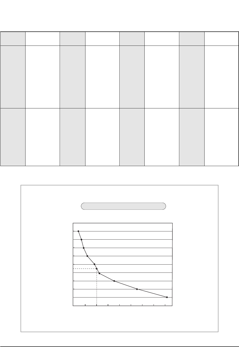
6-3-4 Temperature Sensor Feature Conversion Table(Room Temperature Sensor); 103AT
70
60
50
40
30
20
10
0
-10
-9
510152025303540
Temperature
(˚C)
Resistance Value (Kohm)
At the temperature of 25˚C(10KΩ)
Temperature Sensor Characteristic Curve
DB98_20429A(1)_1 12/24/04 10:55 AM Page 39
Samsung Electronics40
6-4 Main Part Inspection Method
Room Temperature Sensor
Room Fan Motor
Outdoor Fan Motor
Stepping Motor
Measure resistance with a tester
Normal At the normal temperature 37kΩ~ 8.3kΩ(-7˚C~+30˚C) *Refer to Table 6-3-4.
Abnormal ∞, 0Ω...Open or Short
Measure the resistance between terminals of the connector (CN72) with a tester.
Normal At the normal temperature (10˚C ~ 30˚C)
Abnormal ∞, 0Ω...Open or Short
Measure the resistance between motor wires with a tester.
Normal At the normal temperature (10˚C ~ 30˚C)
Abnormal ∞, 0Ω...Open or Short
Measure the resistance between the red wire and each terminal wire with a tester.
Normal About 300Ωat the normal temperature (20˚C ~ 30˚C)
Abnormal ∞, 0Ω...Open or Short
Breakdown Inspection MethodPart
Compare terminal Resistance Remark
Yellow, Blue 404.4Ω± 10% Main
Yellow, Red 340Ω± 10% Sub
Compare terminal Resistance Remark
Yellow, Red 360Ω± 10% Main
Black, Yellow 328Ω± 10% Sub
DB98_20429A(1)_1 12/24/04 10:55 AM Page 40

MEMO
41Samsung Electronics
DB98_20429A(1)_1 12/24/04 10:55 AM Page 41
Samsung Electronics42
10
12
16
11
5
13 19
21
22
15
7
23
23-1
3
6
17
14
1
18
9
4
8
24
14-6
14-1
1-1
1-3
9-2
9-3
2-5
23-2
3-2
3-4
3-1
3-3
2-1
2-6
2-5-1
2-4
2-2
2-3
9-1
1-2
14-5
14-2
14-3
14-4
20
2
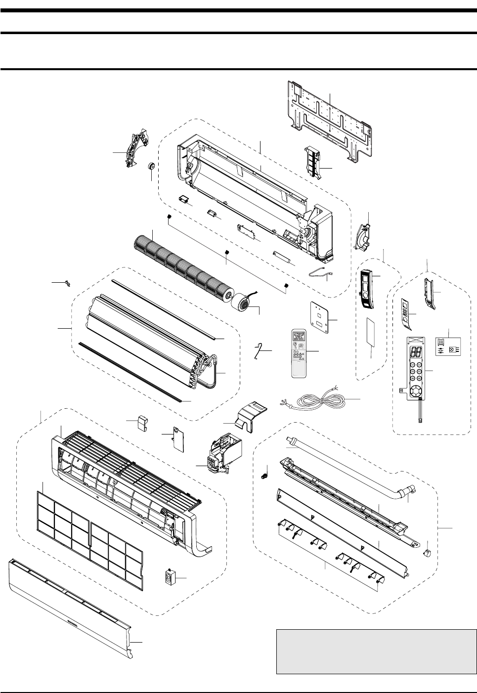
You can search for the updated part code
number through the ITSELF.
URL : http://itself.sec.samsung.co.kr
7. Exploded Views and Parts List
7-1 Indoor Unit
DB98_20429A(1)_1 12/24/04 10:55 AM Page 42
43Samsung Electronics
Exploded Views and Parts List
■
Parts List
Q'TY
No. Code No. Description Specification
1 DB92-00633A ASS'Y PANEL FRONT ASS'Y 1 1
1-1 DB64-01210A PANEL FRONT HIPS 1 1
1-2 DB93-02831A ASS'Y SPEAKER UNIT ASS'Y 1 1
1-3 DB63-01103A FILTER-PRE PP 1 1
2 DB94-00629A ASS'Y TRAY DRAIN ASS'Y 1 1
2-1 DB63-01104A TRAY DRAIN ABS 1 1
2-2 DB61-02049A BLADE-H ABS 1 1
2-3 DB61-02053A BLADE-V PP 2 2
2-4 DB73-00234A RUBBER-CAP DRAIN CR 1 1
2-5 DB94-00062L ASS'Y DRAIN-HOSE ASS'Y 1 1
2-5-1 DB67-00510A DRAIN-CUFF ABS 1 1
2-6 DB95-20138A ASS'Y MOTOR-STEPPING 24BYJ48 1 1
3 DB93-02960A ASS'Y DISPLAY ASS'Y 1 1
3-1 DB61-02056A HOLDER DISPLAY HIPS 1 1
3-2 DB64-01211A WINDOW DISPLAY HIPS 1 1
3-3 DB93-02806A ASS'Y PCB DISPLAY ASS'Y 1 1
3-4 DB93-01369A ASS'Y MODULE PCB ASS'Y 1 1
4 DB63-01106A COVER TERMINAL HIPS V0 1 1
5 DB63-01107A COVER PCB-DVM HIPS 1 1
6 DB61-02050A HOLDER EVAP ABS 1 1
7 DB61-02052A HOLDER MOTOR PP 1 1
8 DB93-02804A ASS'Y CONTROL IN ASS'Y 1 1
9 DB96-03835A ASS'Y EVAP TOTAL ASS'Y - 1
DB96-03835B ASS'Y EVAP TOTAL ASS'Y 1 -
9-1 DB60-00198A SPACER-EVAP MID PVC 1 1
9-2 DB60-00203B SPACER-EVAP UP PVC 1 1
9-3 DB96-03834A ASS'Y EVAP FP1.3, H-FIN, 2x12 - 1
DB96-03834B ASS'Y EVAP FP1.5, H-FIN, 2x12 1 -
10 DB67-60030A SPRING-SENSOR STS 301 1 1
11 DB94-00674A ASS'Y BEARING-RUBBER ASS’Y, CR 45 1 1
12 DB94-00627A ASS'Y-CROSS FAN ø83 x 719 1 1
13 DB31-00270A MOTOR FAN-IN YDK-20S4D8C-1 1 1
14 DB94-00626A ASS'Y BACK BODY ASS'Y 1 1
14-1 DB61-02057A BODY BACK HIPS 1 1
14-2 DB61-02047A BUSH BODY LF HIPS 1 1
14-3 DB61-02048A BUSH BODY RH HIPS 1 1
14-4 DB63-01105A COVER-IONIZER HIPS 1 1
14-5 DB91-00287A ASS'Y ELECTRIC-IONIZER ASS'Y 1 1
14-6 DB93-01383G ASS'Y C/W ION ASS'Y 1 1
15 DB61-02051A HOLDER-PIPE HIPS 1 1
16 DB67-00508A CAP SCREW HIPS 3 3
17 DB70-00514A PLATE-HANGER SGCC-M, T0.8 1 1
18 DB70-00515A PLATE CONTACT SUS 304 1 1
19 DB70-00516A PLATE-CONTROL IN SGCC-M 1 1
20 DB93-01549B ASS'Y-CONNECTOR POWER ASS'Y 1 1
21 DB93-03016R ASS'Y REMOCON ARH-1315 1 1
22 DB92-00643A ASS'Y GRILLE ASS'Y 1 1
23 DB90-01829A ASS'Y COVER DISPLAY ASS'Y 1 1
23-1 DB63-01108A COVER DISPLAY PC 1 1
23-2 DB64-01276A INLAY DISPLAY ACRYL 1 1
24 DB63-01253A COVER CONTROL SGCC-M 1 1
AS09HPBN AS12HPBN
DB98_20429A(1)_1 12/24/04 10:55 AM Page 43
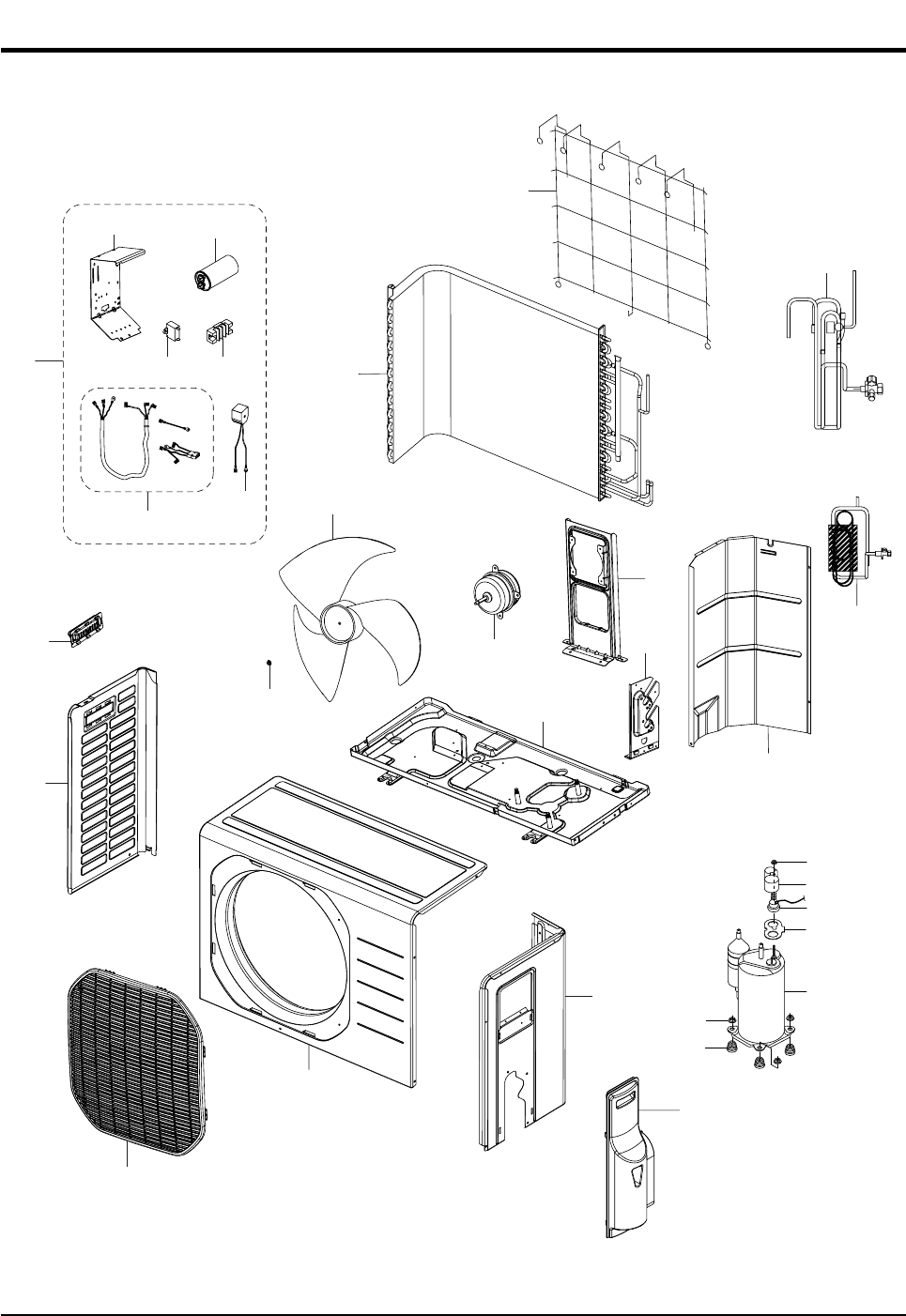
Samsung Electronics44
7-2 Outdoor Unit
22
6
15
21
14
3
2
22-1 22-6
22-2
22-5
1
10
4
12
8
11
24
5
22-422-7
19
13
20
18
22-3
17
16
23
7
9
DB98_20429A(1)_1 12/24/04 10:55 AM Page 44

45Samsung Electronics
Exploded Views and Parts List
■
Parts List
Q'TY
No. Code No. Description Specification
1 6021-000281 NUT-HEXAGON M6, ZPC, STS410 1 1
2 DB67-50063A FAN-PROPELLER AS+G/F 20%, ø405 1 1
3 DB31-10058C MOTOR FAN OUT 220/240V, 50/60Hz 1 1
4 DB90-01524B ASS'Y CABINET-FRONT ASS'Y 1 1
5 DB63-00847A GUARD FAN PP 1 1
6 DB64-00982A CABINET-SIDE LF SECC-P 1 1
7 DB64-00992A HANDLE-LF PP 1 1
8 DB90-01525C ASS'Y-CABI SIDE RH ASS'Y 1 1
9 DB63-00843A COVER-SIDE ABS 1 1
10 DB90-01295C ASS'Y-BASE OUT ASS'Y - 1
DB90-01295E ASS'Y-BASE OUT ASS'Y 1 -
11 DB61-02065A BRACKET MOTOR SGCC-M 1 1
12 DB61-02066A BRACKET-VALVE GALVANIZED STEEL 1 1
13 DB73-00067A GROMMET-ISOLATOR NR - 3
DB73-00070A GROMMET-ISOLATOR NR 3 -
14 DB94-00631A ASS'Y PARTITION ASS'Y 1 1
15 DB96-03836A ASS'Y COND ø7 FP1.5, LOUVER, 2x24 - 1
DB96-03837A ASS'Y COND ø7 FP1.4, LOUVER, 1x24 1 -
16 G8C124JU1EL COMPRESSOR G8C124 - 1
G4A091JU1EP COMPRESSOR G4A091 1 -
17 DB63-20002A GASKET EPDM 1 1
18 DB63-10165D COVER TERMINAL PBT 1 1
19 DB60-30028A NUT-WASHER HEX2C M8 ZPC 3 3
20 DB60-30018A NUT-FLANGE M5, SM20C 1 1
21 DB71-00093A BAR-STEEL HSWR 1 1
22 DB93-02916A ASS'Y CONTROL OUT ASS'Y - 1
DB93-02916B ASS'Y CONTROL OUT ASS'Y 1 -
22-1 DB70-00523A PLATE-CONTROL OUT SGCC-M 1 1
22-2 DB33-00049B SOLENOID-ASS'Y ASS'Y 1 1
22-3 DB35-00028B RELAY PROTECTOR O/L RBC12128-12500 - 1
DB35-00028A RELAY PROTECTOR O/L RBC12054-12500 1 -
22-4 DB65-00166A TERMINAL BLOCK 4P 1 1
22-5 DB93-01547F ASS'Y LEAD WIRE ASS'Y 1 1
22-6 2501-001237 CAPACITOR-COMP 35uF/450VAC - 1
2501-001238 CAPACITOR-COMP 40uF/450VAC 1 -
22-7 2301-001375 CAPACITOR-MOTOR 1.5uF/450VAC 1 1
23 DB96-03828A ASS'Y VALVE 4WAY ASS'Y - 1
DB96-03840A ASS'Y VALVE 4WAY ASS'Y 1 -
24 DB96-03829A ASS'Y TUBE CAPILLARY ASS'Y - 1
DB96-03829B ASS'Y TUBE CAPILLARY ASS'Y 1 -
AS09HPBX AS12HPBX
DB98_20429A(1)_1 12/24/04 10:55 AM Page 45
Samsung Electronics46
N(1) 1 2 3
DB61-02054A
DB65-00103C
DB93-02808A
DB93-02809A
DB70-00516A
DB61-00171A
6001-000929
6001-001054
DB93-02827A
DB39-00643N
DB32-00020K
DB93-02881A
DB93-02828A
DB65-10088D
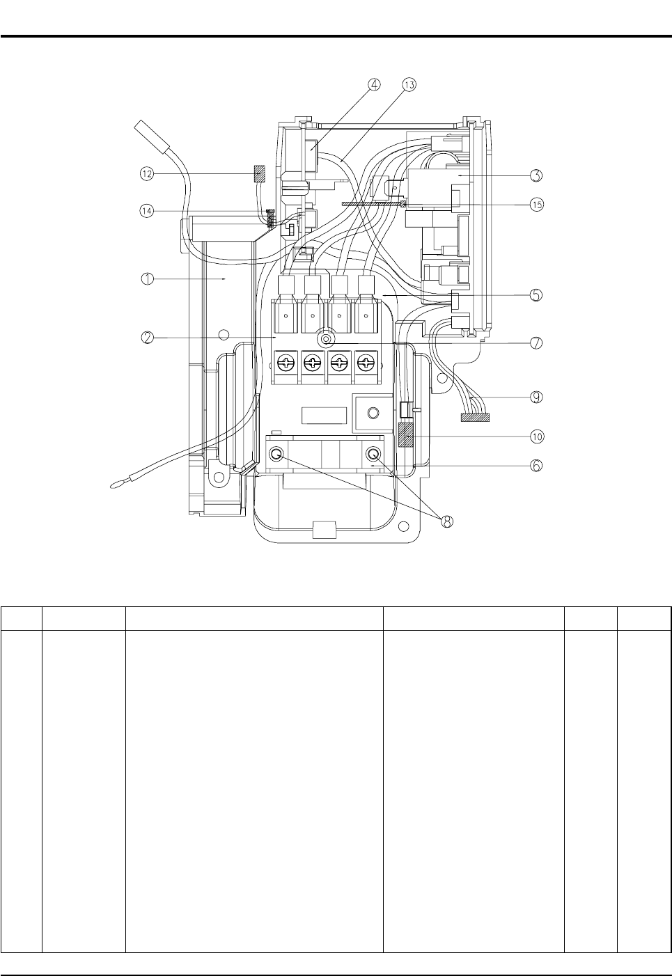
7-3 Ass'y-Control In : DB93-02804A
■
Parts List
No. Code No.
1
2
3
4
5
6
7
8
9
10
11
12
13
14
CASE-CONTROL
ASS'Y-TERMINAL BLOCK
ASS'Y-MAIN PCB
ASS'Y-MELODY PCB
PLATE-TERMINAL LOW
HOLDER-WIRE CLAMP
SCREW-MACHINE
SCREW-MACHINE
C/W MAIN TO DISPLAY
C/W STEP MOTOR UP/DOWN
ASS'Y-THERMISTOR
C/W MELODY TO SPEAKER
C/W MELODY TO MAIN
SPEAKER WIRE TIE
ABS
ASS'Y
ASS'Y
ASS'Y
SGCC-M T1.2
ABS
PH M3 x L22
TH M4 x L10
ASS'Y
ASS'Y
4P(103AT)
ASS'Y
ASS'Y
-
1
1
1
1
1
1
1
2
1
1
1
1
1
1
SpecificationDescription RemarkQ'TY
DB98_20429A(1)_1 12/24/04 10:55 AM Page 46
47Samsung Electronics
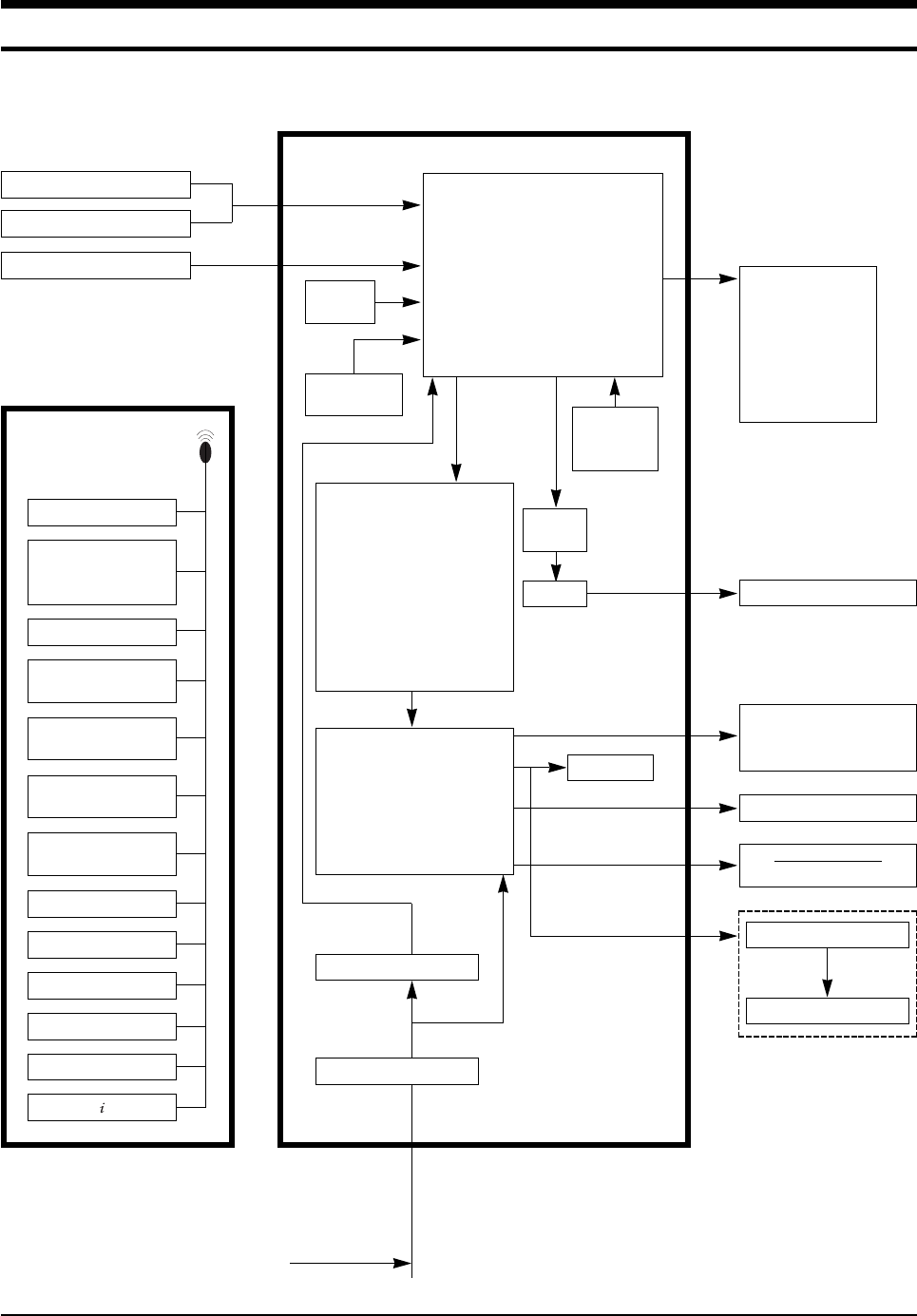
8. Block Diagram
HEAT EXCHANGER SENSOR
TEMPERATURE
OPERATION
AUTO CLEAN
TURBO
ENERGY SAVING
TIMER
ANION
FAN SPEED
INDOOR FAN MOTOR
BUZZER
COMPRESSOR
OUTDOOR FAN MOTOR
4-WAY VALVE
STEPPING MOTOR
: BLADE UP/DOWN
DISPLAY PART
IC-MCU
ROOM TEMPERATURE SENSOR
CONTROLLER
REMOTE CONTROL
ANION
INFRARED SIGNAL
RESET
CIRCUIT
OSCILLATION
CIRCUIT
POWER ON/OFF
TURBO OPERATION
ANION SELECT
AUTO CLEAN SELECT
SLEEP OPERATION
MODE
(AUTO, COOL, DRY, FAN,
HEAT)
FAN SPEED SELECT
(H/M/L/AUTO)
BLADE-H
MOVING SELECT
ON, OFF TIMER
SELECT/CANCEL
ENERGY SAVING SELECT
SOUND ON/OFF SELECT
DIGITAL ON/OFF
TEMPERATURE
SELECT(UP/DOWN)
ZERO
VOLTAGE
DETECT
• BLADE CONTROL
• INDOOR FAN MOTOR CONTROL
• COMPRESSOR CONTROL
• OUTDOOR FAN MOTOR CONTROL
SIGNAL
• 4-WAY VALVE CONTROL SIGNAL
• TEMPERATURE CONTROL
• TIMER
• BUZZER CONTROL
• ANION CONTROL
TRIGGER
SIGNAL
SSR
• COMPRESSOR DRIVE
• OUTDOOR FAN MOTOR
DRIVE
• 4-WAY VALVE DRIVE
• STEPPING MOTOR DRIVE
• BUZZER DRIVE
• ANION DRIVE
• COMPRESSOR CONTROL
SIGNAL
• OUTDOOR FAN MOTOR
CONTROL SIGNAL
• 4-WAY VALVE CONTROL
SIGNAL
• STEPPING MOTOR
CONTROL SIGNAL
• BUZZER CONTROL SIGNAL
• ANION CONTROL SIGNAL*
DC5V
DC12V
AC INPUT
SMPS POWER BLOCK
VOLTAGE REGULATOR
* : OPTION
BUZZER CONTROL PART
SPEA KER
OPTION
DB98_20429A(1)_1 12/24/04 10:55 AM Page 47
Samsung Electronics48
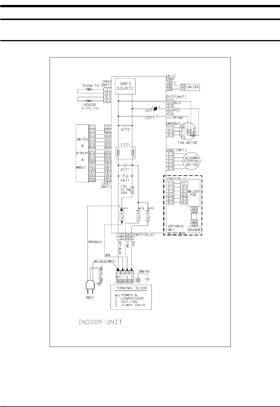
9. Wiring Diagram
9-1 Indoor Unit
This Document can not be used without Samsung's authorization.
Code No : DB98-20360A
DB98_20429A(1)_1 12/24/04 10:55 AM Page 48
49Samsung Electronics
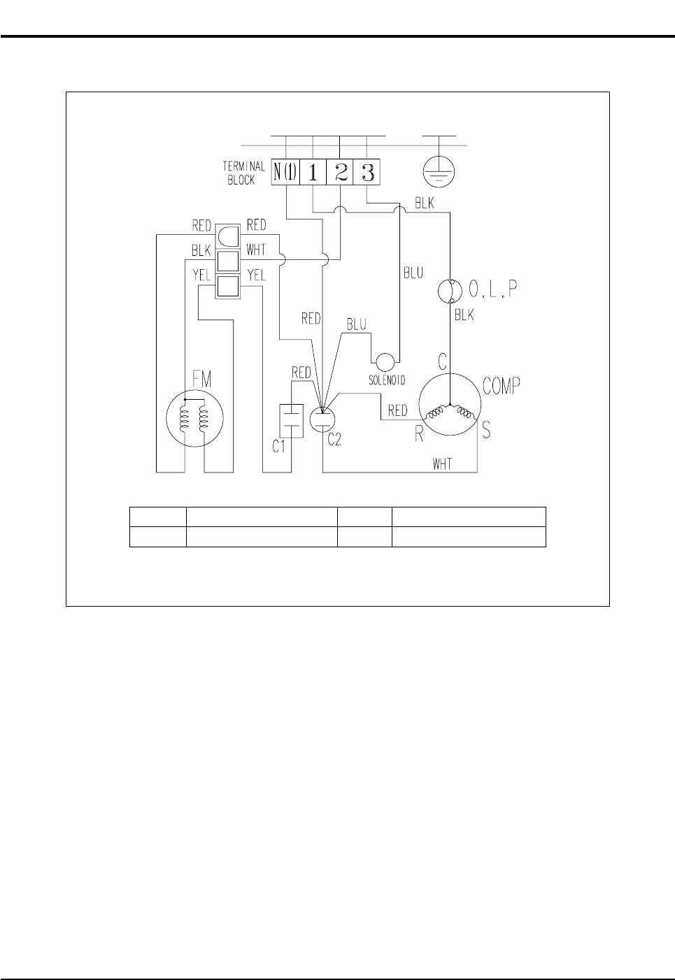
This Document can not be used without Samsung's authorization.
9-2 Outdoor Unit
C1 MOTOR CAPACITOR FM1 FAN MOTOR
C2 COMP CAPACITOR O.L.P OVER LOAD PROTECTOR
Code No : DB98-21095A
DB98_20429A(1)_1 12/24/04 10:55 AM Page 49

MEMO
Samsung Electronics50
DB98_20429A(1)_1 12/24/04 10:55 AM Page 50

MEMO
51Samsung Electronics
DB98_20429A(1)_1 12/24/04 10:55 AM Page 51

MEMO
Samsung Electronics52
DB98_20429A(1)_1 12/24/04 10:55 AM Page 52

ELECTRONICS
This Service Manual is a property of Samsung Electronics Co., Ltd.
Any unauthorized use of Manual can be punished under applicable
International and/or domestic law.
© Samsung Electronics Co., Ltd. Dec. 2004.
Printed in Korea.
Code No. DB98-20429A(1)
DB98_20429A(1)_CO 12/24/04 10:54 AM Page 2
