Alwac_III 3_Manual_of_Operation_1957 Alwac III 3 Manual Of Operation 1957
Alwac_III-3_Manual_of_Operation_1957 manual pdf -FilePursuit
Alwac_III-3_Manual_of_Operation_1957 Alwac_III-3_Manual_of_Operation_1957
User Manual: Alwac_III-3_Manual_of_Operation_1957
Open the PDF directly: View PDF ![]() .
.
Page Count: 68
alwac
corporation
manual
of
operation
alwac
ill-E
Copyright
1957
by
ALWAC
CORPORATION
13040
South
Cerise
Avenue
Hawthorne,
California
Form
10-0001-0
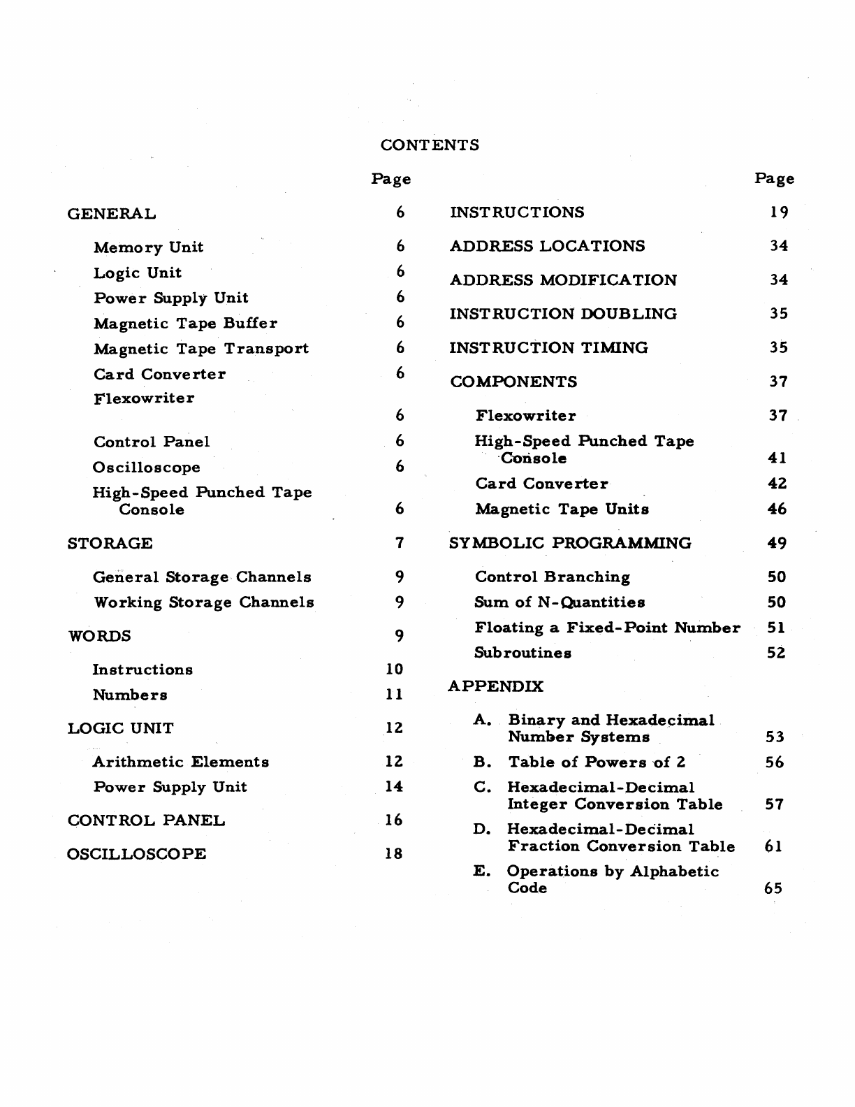
CONTENTS
Page
Page
GENERAL
6
INSTRUCTIONS
19
Memory
Unit
6
ADDRESS
LOCATIONS
34
Logic
Unit
6
ADDRESS
MODIFICATION
34
Power
Supply
Unit
6
Magnetic
Tape
Buffer
6
INSTRUCTION
DOUBLING
35
Magnetic
Tape
Transport
6
INSTRUCTION
TIMING
35
Card
Converter
6
COMPONENTS
37
Flexowriter
6
Flexowrite
r
37
Control
Panel
6
High-Speed
Punched
Tape
Oscilloscope
6 . C--onso
Ie
41
High-Speed
Punched
Tape
Card
Converter
42
Console
6
Magnetic
Tape
Units
46
STORAGE
7
SYMBOLIC
PROGRAMMING
49
General
Storage
Channels
9
Control
Branching
50
Working
Storage
Channels
9
Sum
of
N -
Quantities
50
WORDS
9
Floating
a
Fixed-Point
Number
51
Subroutines
52
Instructions
10
Numbers
11
APPENDIX
LOGIC
UNIT
12
A.
Binary
and
Hexadecimal
Number
Systems
53
Arithmetic
Elements
12
B.
Table
of
Powers
'of
2
56
Power
Supply
Unit
14
C.
Hexadecimal-Decimal
Integer
Conversion
Table
57
CONTROL
PANEL
16
D.
Hexadecimal-
Decimal
OSCILLOSCOPE
18
Fraction
Conversion
Table
61
E.
Operations
by
Alphabetic
Code
65
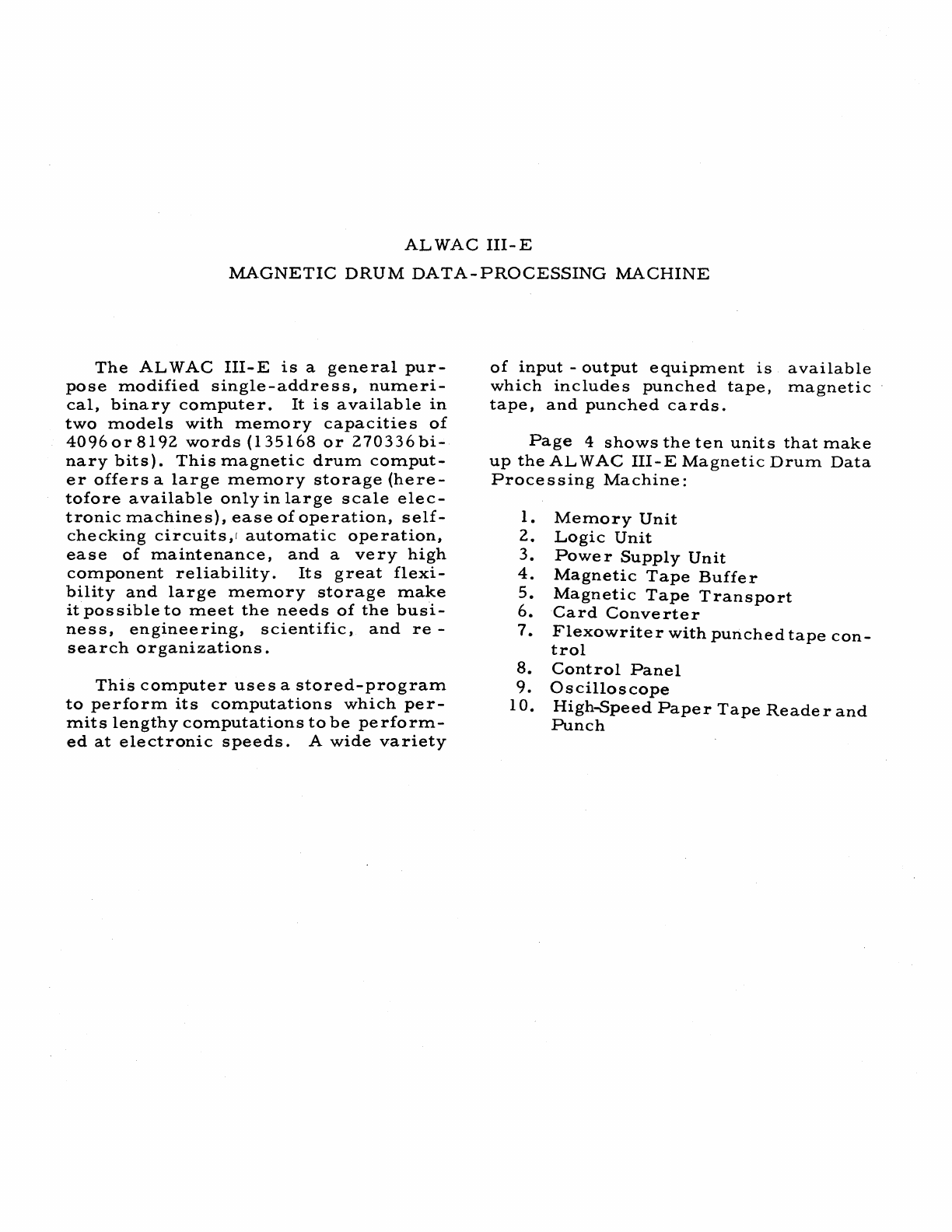
ALWAC
III-E
MAGNETIC
DRUM
DATA-PROCESSING
MACHINE
The
ALWAC
III-E
is
a
general
pur-
pose
modified
single-address,
numeri-
cal,
binary
computer.
It
is
available
in
two
models
with
memory
capacities
of
4096or8192
words
(135168
or
270336bi-
nary
bits).
This
magnetic
drum
comput-
er
offers
a
large
memory
storage
(here-
tofore
available
only
in
large
scale
elec-
tronic
machines),
ease
of
operation,
self-
checking
circuits,1
automatic
operation,
ease
of
maintenance,
and
a
very
high
component
reliability.
Its
great
flexi-
bility
and
large
memory
storage
make
it
possible
to
meet
the
needs
of
the
busi-
ness,
engineering,
scientific,
and
re-
search
organizations.
This
computer
uses
a
stored-program
to
perform
its
computations
which
per-
mits
lengthy
computations
to
be
perform-
ed
at
electronic
speeds.
A
wide
variety
of
input
-
output
equipment
is
available
which
includes
punched
tape,
magnetic
tape,
and
punched
cards.
Page
4
shows
the
ten
units
that
make
up
the
AL
WAC
III-E
Magnetic
Drum
Data
Processing
Machine:
1.
Memory
Unit
2.
Logic
Unit
3.
Power
Supply
Unit
4.
Magnetic
Tape
Buffer
5.
Magnetic
Tape
Transport
6.
Card
Converter
7.
Flexowriter
with
punched
tape
con-
trol
8.
Control
Panel
9.
Oscilloscope
10.
High-Speed
Paper
Tape
Reader
and
Punch
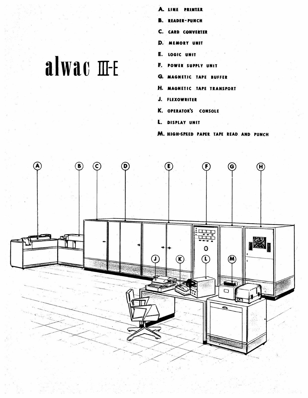
alwac
III-E
--~-
-'--.:......----
-~,--~
.-;
..
-
A-
U.1.
.a.M:1U.
8. IIADEI-.PU;NCH
C.
CAID
C,oIlYElt
II
D.
MEMOIY UNIT
E.
LOGIC
UNIT
F.
'OWEI
SUPPLY
UNIT
G.
MAGNEUC
TAPE
BUFFER
H.
MAGNETIC
TA.PE
T.IAJUP.O.RT
J.
FLEXOWR·ITER
K.
O'liATOR'S
CONSO.LE
L
DISPLAY
UNIT
M..
HJG:H.-5'1ID
PA'E~
tAPE
READ
AND
PUNCH
---.":"'--~-.-
6
ALWAC
III-E
Memory
Unit
The
Magnetic
Drum
and
its
associ-
ated
control
circuits
are
contained
in
this
cabinet.
The
drum
rotates
at
a
speed
of
3500
revolutions
per
minute.
Both
data
and
instructions
are
stored
in
serial
man-
ner
by
means
of
magnetized
spots
on
the
surface
of
the
drum.
Logic
Unit
The
control
logic
and
certain
parts
of
the
arithmetic
registers
are
located
in
this
cabinet.
All
electronic
parts
are
mounted
on
removable
plug-in
units
to
permit
maximum
ease
of
maintenance.
Power
Supply
Unit
This
cabinet
contains
the
power
supply
for
all
units
which
comprise
the
basic
ALWAC
III-E.
Voltmeters
for
each
of
the
various
supplies
are
mounted
on
the
front
ofthe
cabinet
with
rheostat
controls
to
permit
manual
adjustment
of
voltages.
Magnetic
Tape
Buffer
Control
for
the
magnetic
tape
trans-
ports
is
contained
in
this
cabinet.
A
maxi-
mum
of
16
magnetic
tape
transports
may
be
controlled
from
this
unit.
Magnetic
Tape
Transport
Magnetic
tape
is
used
to
extend
the
memory
capacity
of
the
basic
ALWAC
III-Efor
rapid-access,
intermediate
stor-
age
of
information
and
to
provide
a
most
efficient
means
for
input
and
output
of
large
data
files.
Card
Converter
Control
of
punched
card
reading
and
punching
equipment
and
the
automatic
conversion
of
decimal,
hexadecimal,
and
alphabetic
information
is
accomplished
with
the
electronic
equipment
contained
in
this
.
cabinet.
Flexowriter
Input
and
output
are
accomplished
through
the
Flexowriter
unit
by
means
of
the
typewriter
keyboard
or
punched
paper
tape.
A
maximum
input
or
output
rate
of
10
characters
per
second
is
possible.
Control
Panel
The
Control
Panel
contains
control
switches
and
banks
of
lites
which
display
to
the
operator
the
contents
of
the
loca-
tion,
instruction,
and
address
registers
and
the
status
of
the
overflow
indicator.
By
means
of
this
the
operator
may
con-
trol
any
ofthe
various
machine
functions
and
observe
the
contents
of
arithmetic
registers
or
word
locations.
Oscilloscope
The
contents
of
the
A,
B,
D,
and
E
Registers,
orthe
contents
ofa
word
from
one
of
the
Working
Channels,
or
General
Storage
Channels
may
be
viewed
on
the
face
of
an
oscilloscope
when
the
proper
switches
are
set
on
the
Control
Panel.
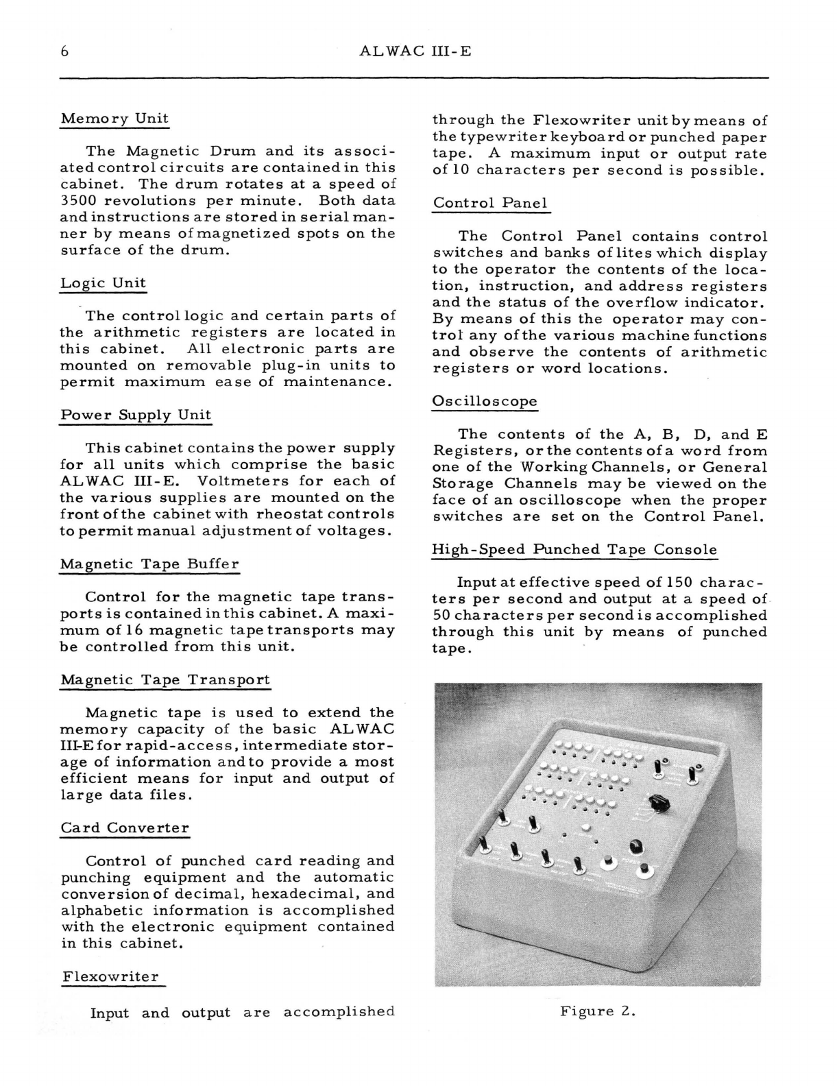
High-Speed
Punched
Tape
Console
Input
at
effective
speed
of
150
charac-
ters
per
second
and
output
at
a
speed
of
50
characters
per
second
is
accomplished
through
this
unit
by
means
of
punched
tape.
Figure
2.
STORAGE
7
Figure
3.
Magnetic
Drum
and
Read-
Write
Head
STORAGE
The
arithmetic
registers,
the
4
work-
ing
channels,
the
256
channels
of
General
Storage,
and
several
channels
used
for
internal
timing
are
stored
on
the
surface
of
the
magnetic
drum
in
the
form
of
mag-
netic
spots.
Information
stored
on
the
drum
will
remain
permanently,
or
until
erased
by
recording
another
spot
in
the
same
location.
This
memory
is
extremely
stable
and
no
danger
exists
from
loss
of
information
when
the
power
is
turned
off
completely.
Recorded
information
is
arranged
on
separate
bands
on
the
drum
which
are
known
as
channels.
By
the
geometric
location
of
the
read
and
write
heads
a-
round
the
surface
of
the
drum,
storage
line
s
of
various
lengths
are
obtained.
Placing
the
read-write
heads
closer
to:-
gethe
r
provide
s
"sho
rt"
line
s
of
rapid
access
for
use
as
arithmetic
registers.
Information
stored
in
these
rapid
access
lines
is
retained
only
as
long
as
power
is
supplied,
the
information
being
lost
when
the
power
is
turned
off.
Such
lines
are
used
for
the
A,
B,
D,
and
E
Registers
and
.
for
the
four
Working
Storage
Channels.
As
information
is
processed
in
groups
of
33
binary
digits
at
a
time,
the
basic
unit
of
storage
contains
32
bits
and
an
algebraic
sign.
Each
such
group
of
32
bits
and
a
sign
is
known
as
a
word.
Each
of
the
General
Storage
Channels
contain
32
words.
Magnetic
drums
are
provided
with
a
capacity
for
either
4096
or
8192
words
(135168
or
270336
binary
digits).
corresponding
to
128
or
256
channels.
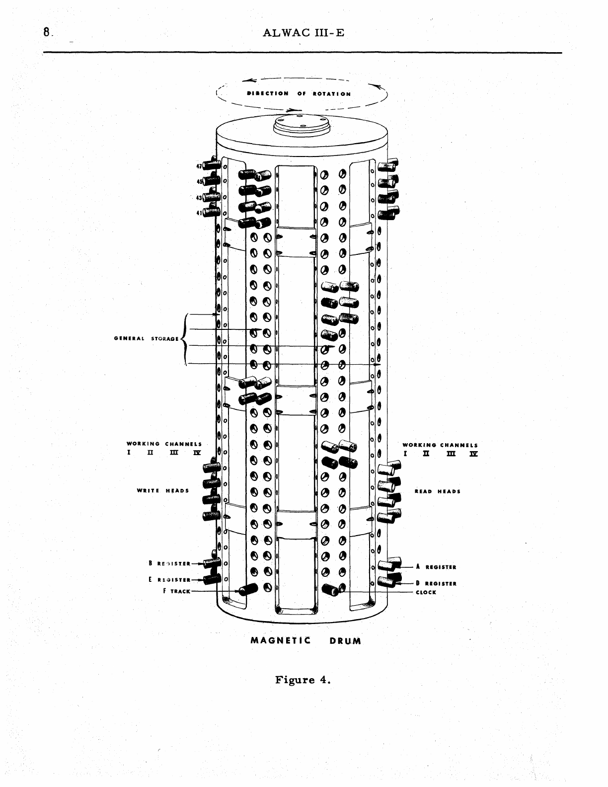
8.
WORKING
CHANNELS
I
II
m
:Dr
WltlTE
H,ADS
B
R~·'ioI
ST.ER.
E
REGISTER
r
TRACK
-
ALWAC
III-E
o.al
CT
ION
OF
-
-.;;;.--
ROTATION
---
.--
~
~
(J
If~_'"
IF==::::::!;I
~
GJ
IT-------;JI
0
~
~O
@)
.f:) 0
~f:}
0
~~·O
e~
e~
e···~
MAGNET
Ie.
DRUM
Figure
4.
~
)
---
WORKI.NG
CHANNE
LS
II
m
Dr
READ
HEADS
A
RIGISTER
D
REGISTER
CLOCK
STORAGE
9
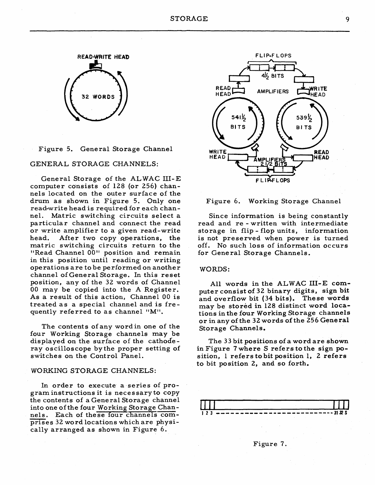
Figure
5.
General
Storage
Channel
GENERAL
STORAGE
CHANNELS:
General
Storage
of
the
ALWAC
III-E
computer
consists
of
128
(or
256)
chan-
nels
located
on
the
outer
surface
of
the
drum
as
shown
in
Figure
5.
Only
one
read-write
head
is
required
for
each
chan-
nel.
Matric
switching
circuits
select
a
particular
channel
and
connect
the
read
or
write
amplifier
to
a
given
read-write
head.
After
two
copy
operations,
the
mat
ric
switching
circuits
return
to
the
"Read
Channel
00"
position
and
remain
in
this
position
until
reading
or
writing
operations
are
to
be
performed
on
another
channel
of
General
Storage.
In
this
reset
position,
any
of
the
32
words
of
Channel
00
may
be
copied
into
the
A
Register.
As
a
result
of
this
action,
Channel
00
is
treated
as
a
special
channel
and
is
fre-
quently
referred
to
as
channel
"M".
The
contents
of
any
word
in
one
of
the
four
Working
Storage
channels
may
be
displayed
on
the
surface
of
the
cathocfe-
ray
oscilloscope
by
the
proper
setting
of
switches
on
the
Control
Panel.
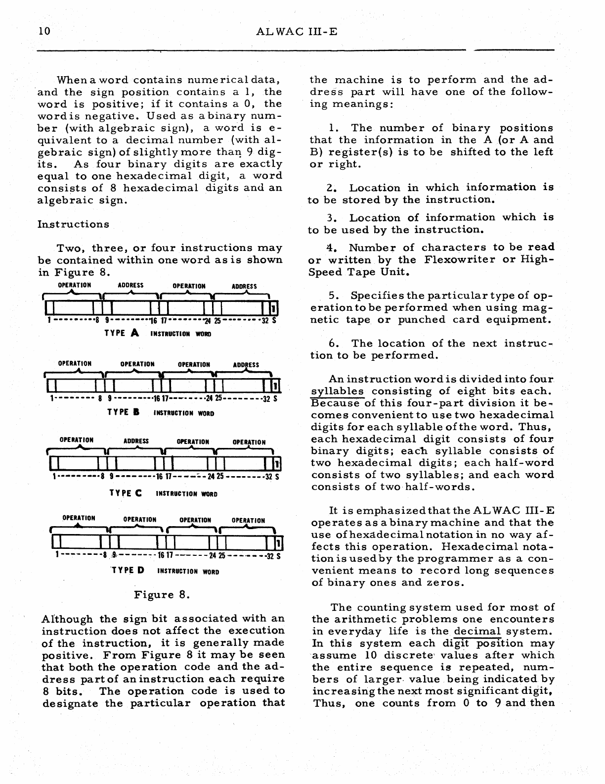
WORKING
STORAGE
CHANNELS:
In
order
to
execute'
a'series
of
pro-
gram
instructions
it
is
necessary
to
copy
the
contents
of
a
General
Storage
channel
into
one
of
the
four
Working
Storage
Chan-
nels.
Each
of
these
four
channels
com-
prises
32
word
locations
which
are
physi-
cally
arranged
as
shown
in
Figure
6.
FLI
P-F
LOPS
\/I
F L
IP-FLOi=»S
Figure
6.
Working
Storage
Channel
Since
information
is
being
constantly
read
and
re
-
written
with
inte
rmediate
storage
in
flip-
flop
units,
information
is
not
preserved
when
power
is
turned
off.
No
such
loss
of
information
occurs
for
Gene
ral
Storage
Channels.
WORDS:
All
words
in
the
ALWAC
III-E
com-
puter
consist
of
32
binary
digits,
sign
bit
and
overflow
bit
(34
bits).
These
words
may
be
stored
in
128
distinct
word
loca-
tions
in
the
four
Working
Storage
channels
or
in
any
of
the
32
words
of
the
256
General
Storage
Channels.
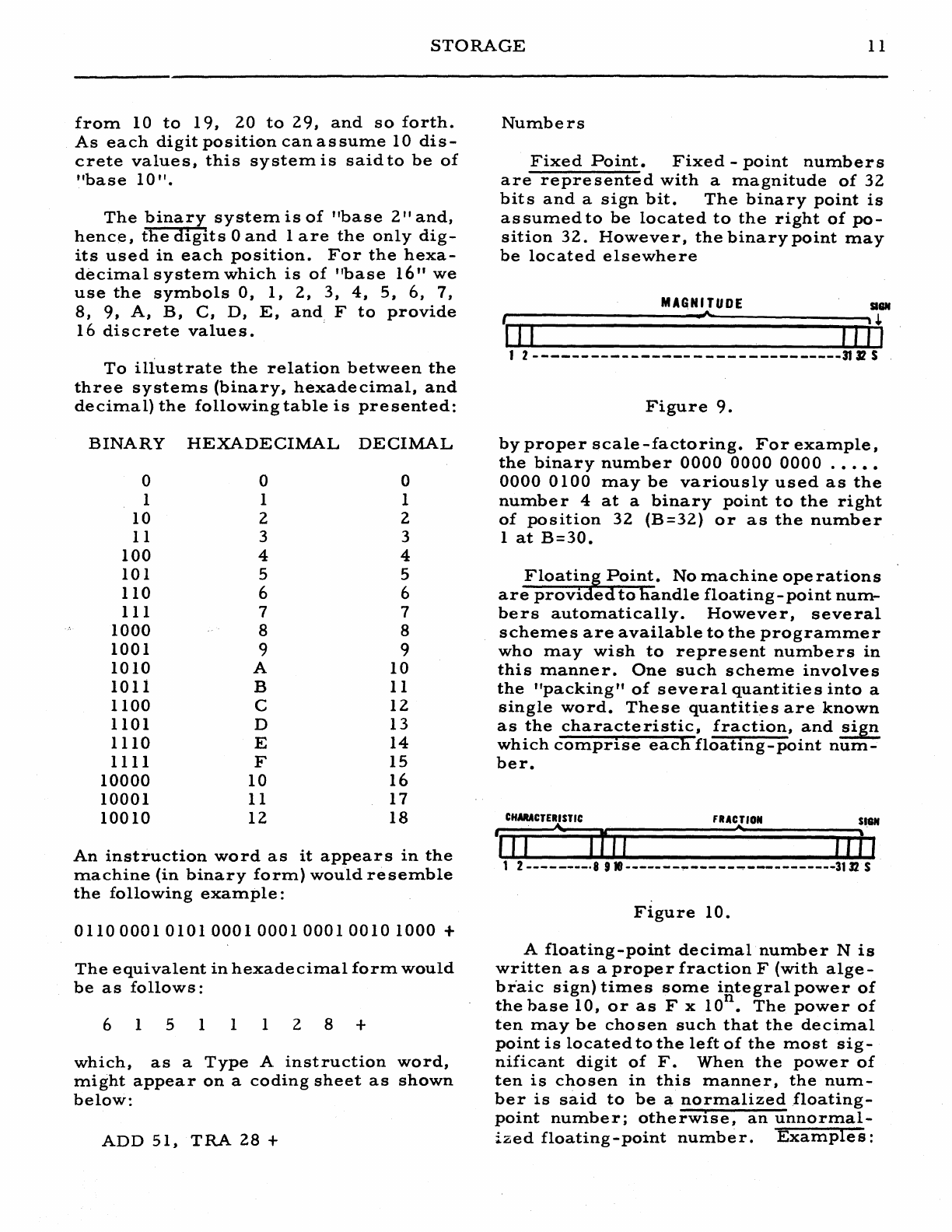
The
33
bit
positions
of
a
word
are
shown
in
Figure
7
where
S
refers
to
the
sign
po-
sition,
1
refers
to
bit
position
1, 2
refers
to
bit
position
2,
and
so
forth.
IIII
IIJI
123
_-------------------------311JS
Figure
7.
10
ALWAC
III-E
When
aword
contains
numerical
data,
'and
the
sign
position
contains
a
1,
the
word
is
positive;
if
it
contains
a
0,
the
word
is
negative.
Used
as
a
binary
num-
ber
(with
algebraic
sign),
a
word
is
e-
quivalent
to
a
decimal
number
(with
al-
gebraic
sign)
of
slightly
more
thaT! 9
dig-
its.
As
four
binary
digits
are
exactly
equal
to
one
hexadecimal
digit,
a
word
consists
of
8
hexadecimal
digits
and
an
algebraic
sign.
In.structions
Two,
three,
or
four
instructions
may
be
contained
within
one
word
as
is
shown
in
Figure
8.
OPERATION
ADDRESS
OPERATION
ADDRESS
~~i-·~
II
I 1 I I I I
111
1---····-·S
9---·---·16
'17----·--"24
25------·
-32
S
Y Y
PEA
I
NSTRUCTI
ON
WOIID
OPERATION
OPERATION
OPERATION
r
.......
u
"'"
• 1
I~I--~I~II~~I~I~I--~I~II--~I~ht
1-----
--·-s
9----
·-~-16
17--
--~-
24 25
-------
-32
S
y Y
PE
C
INSTRUCTION
WORD
OPERATION
OPERATION
OPERATION
OPERATION
( •
II
..
'.
..."
'I
...
\
I
II
I I I I I I I I I
111
1----
---
-8 ,:91--
---~
-1"611--- - - -
2425
--
-.-
---32 S
'Y
Y
PE
D
INSTRUCTION
WORD
Figure
8.
Although
the
sign
bit
associated
with
an
instruction
does
not
affect
the
execution
of
the
instruction,
it
is
generally
made
positive.
From
Figure
8
it
may
be
seen
that
both
the
operation
code
and
the
ad-
dress
part
of
an
instruction
each
re'quire
8
bits.
The
operation
code
is
used
to
de
signate
the
particular
ope
ration
that
the
machine
is
to
perform
and
the
ad-
dress
part
will
have
one
of
the
follow-
ing
meaning
s :
1.
The
number
of
binary
positions
that
the
information
in
the
A
(or
A
and
B)
register(s)
is
to
be
shifted
to
the
left
or
right.
2.
Location
in
which
information
is
to
be
stored
by
the
instruction.
3.
Location
of
information
which
is
to
be
used
by
the
instruction.
4.
Number
of
characters
to
be
read
or
written
by
the
Flexowrite
r
or
High-
Speed
Tape
Unit.
5.
Specifies
the
particular
type
of
op-
eration
to
be
performed
when
using
mag-
netic
tape
or
punched
card
equipment.
6.
The
location
of
the
next
instruc-
tion
to
be
performed.
An
instruction
wordis
divided
into
four
syllables
consisting
of
eight
bits
each.
Because
of
this
four-part
division
it
be
..
comes
convenient
to
use
two
hexadecimal
digits
for
each
syllable
of
the
word.
Thus,
each
hexadecimal
digit
consists
of
four
binary
digits;
each
syllable
consists
of
two
hexadecimal
digits;
each
half-word
consists
of
two
syllables;
and
each
word
consists
of
two-half-words.
It
is
emphasized
that
the
ALWAC
III-E
operates
asa
binary
machine
and
that
the
use
of
hexadecimal
notation
in
no
way
af-
fects
this
operation.
Hexadecimal
nota-
tion
is
us·ed
by
the
programmer
as
a
con-
venient
means
to
record
long
sequence
s
of
binary
ones
and
zeros.
The
counting
system
used
for
most
of
the
arithmetic
problems
one
encounte
r s
in
everyday
life
is
the
decimal
system.
In
this
system
each
digit
position
may
assume
10
discrete'
values
after
which
the
entire
sequence
is
repeated,
num-
bers
of
larger.
value
being
indicated
by
increasing
the
next
most
significant
digit,
Thus,
one
counts
from
0
to
9
and
then
STORAGE
11
from
10
to
19,
20
to
29,
and
so
forth.
As
each
digit
position
can
assume
10
dis-
crete
values,
this
system
is
said
to
be
of
"base
10".
The
binary
system
is
of
"base
2"
and,
hence,
the
digits
a
and
1
are
the
only
dig-
its
used
in
each
position.
For
the
hexa-
decimal
system
which
is
of
"base
16"
we
use
the
symbols
0,
1,
2,
3,
4,
5,
6,
7,
8,
9,
A,
B,
C,
D,
E,
and
F
to
provide
16
discrete
values.
.
To
illustrate
the
relation
between
the
three
systems
(binary,
hexadecimal,
and
decimal)
the
following
table
is
presented:
BINARY
a
1
10
11
100
101
110
III
1000
1001
1010
1011
1100
1101
1110
1111
10000
10001
10010
HEXADECIMAL
DECIMAL
a 0
1 1
2 2
3 3
4 4
5 5
6 6
7 7
8 8
9 9
A
10
B 11
C
12
D
13
E
14
F
15
10
16
11
17
12 18
An
instruction
word
as
it
appears
in
the
machine
(in
binary
form)
would
resemble
the
following
example:
0110
0001010100010001000100101000
+
The
equivalent
in
hexadecimal
form
would
be
as
follows:
615
1 1 1
28+
which,
as
a
Type
A
instruction
word,
might
appear
on
a
coding
sheet
as
shown
below:
ADD
51,
TRA
28
+
Numbers
Fixed
Point.
Fixed
-
point
numbers
are
represented
with
a
magnitude
of
32
bits
and
a
sign
bit.
The
binary
point
is
as
surned
to
he
located
to
the
right
of
po-
sition
32.
Howeve
r,
the
binary
point
may
be
located
elsewhere
MAGNITUDE
au
t .
~
.~
I I I , , , I
1 2 -------------------------------3132 S
Figure
9.
by
proper
scale
-factoring.
For
example,
the
binary
number
0000
0000
0000
.••••
0000
0100
may
be
variously
used
as
the
numbe
r 4
at
a
binary
point
to
the
right
of
position
32
(B=32)
or
as
the
number
1
at
B=30.
Floating
Point.
No
machine
ope
rations
are
provided
to
handle
floating
-
point
num-
bers
automatically.
However,
several
schemes
are
available
to
the
programmer
who
may
wish
to
represent
numbers
in
this
manner.
One
such
scheme
involves
the
"packing"
of
several
quantities
into
a
single
word.
These
quantities
are
known
as
the
characteristic,
fraction,
and
sign
which
comprise
each
floating-point
num~
her.
CHARACTER
I
STIC
)11
=nIl
fRACTION
...,
SI8N
J J 1 ,
2
--------·8
910
-------'!'"-----
...
-----------3132
$
Figure
10.
A
floating-point
decimal
number
N
is
written
as
a
proper
fraction
F
(with
alge-
braic
sign)
times
some
integral
power
of
n
the
base
10,
or
as
F x
10
•
The
power
of
ten
may
be
chosen
such
that
the
decimal
point
is
located
to
the
left
of
the
most
sig-
nificant
digit
of
F.
When
the
power
of
ten
is
chosen
in
this
manner,
the
num-
ber
is
said
to
be
a
normalized
floating-
point
number;
otherwise,
an
unnormal-
ized
floating-point
number.
Examples:
12
ALWAC
III-E
+ •
124
.012
+
5.120
=
=
=
+
+
•
124
x
10
0
•
120
x
10
-1
.512
x
10+
1
A
floating-point
binary
number
N
is
written
in
a
similar
manner
with
a
prop-
er
fraction
F
(with
algebraic
sign)
times
some
integral
power
of
the
base
2,
or
as
n
F x
2.
Examples:
+ .
ioo
= + •
100
x 20
.010
= -· lOO x
2-
1
+
1.
100
= + •
110
x
2+1
10.100
=
.101
x
2+
2
In
the
AL
WAC
llI-
E,
floating
-
point
binary
numbers
are
stored
as
shown
in
Figure
10.
1.
Bit
positions
9 -
32
contain
the
mag-
nitude
of
the
fraction
F
with
the
binary
point
located
to
the
left
of
position
9.
A
normalized
floating-binary
number
will
have
a 1
in
position
9.
Thus,
the
range
for
values
of
F
is"s~en_to
be:
2.
The
sign
of
the
fraction
F
is
placed
in
the
S
position
of
the
word.
3.
Since
signed
exponents
will
occur
and
since
the
S
position
contains
the
al-
gebraic
sign
of
the
fraction,
the
chara:c-
teristic,
C,
of
the
number
is
stored
in
positions
1 - 8
instead
of
the
exponent.
This
characteris,tic
is
formed
by
adding
+
128
to
the
exponent.
Thus,
the
range
of
the
exponent
is:
-
l28.(n
~
+
127
whereas
the
range
of
the
characteristic
is:
o
~
C "
255
An
exponent
of
+
12
would
use
a
charac-
teristic
of
+
12
+
128
=
140
while
an
ex-
ponent
of
-
12
would
use
a
characteristic
of
-
12
+
128
=
116.
LOGIC
UNIT
Arithmetic
and
control
functions
are
performed
by
electronic
components
lo-
cated
in
the
Logic
Unit.
Information
pass-
e s
between
the
Memory
Unit
and
the
Logic
Unit
for
processing.
Each
machine
in-
struction
may
be
d~vided
into
three
mi-
cro-programming
operations
which
are
known
as
interpretation,
search
and
ex-
ecution
times.
During
the
interpretation
time,
the
machine
locates
the
next
in-
struction
to
be
executed
and
fills
the
Operation
andAddress
registers.
The
Op-
eration
register
is
then
examined
to
de-
termine
whether
or
not
the
given
instruc-
.
tion
requires
reference
to
the
contents
of
another
word
in
memory
and
whether
or
not
the
Address
register
is
to
be
modi-
fied.
During
search
time,
if
required,
the
machine
obtains
the
content
s
of
the
desired
word
from
memory.
(Since
some
operations
do
not
require
such
refer-
,
ence,
these
operations
do
not
have
search
times).
During
execution
time,
the
given
operation
is
performed.
The
time
re-
quired
to
complete
each
of
these
three
micro-programming
operations
is
an
in-
tegral
multiple
of
one
word-time
(0.
523
ms.
)
and
is
variable
depending
upon
the
given
instruction,
wh~the
r
or
not
a
search
is
to
be
made,
and
the
time
required
to
locate
the
given
word
in
memory.
Arithmetic
Elements
The
A
Register.
The
A
Register
is
an
accumulator
register
consisting
of
32
bits,
an
overflow
position,
and
a
sign.
See
Figure.
11.
0111
liP
Z 1 2
--
....
------------------------
3132
Figure
11.
ARITHMETIC
ELEMENTS
13
Almost
all
arithmetic
operations
make
use
of
the
A
Register.
With
some
instruc-
tions
(for
example,
addition,
subtraction)
the
content's
of
the
A.
Register
may
over-
flow
from
position
1.
When
an
overflow
occurs,
with
the
exception
of
shifting
in-
structions,
the
OVERFLOW
INDICATOR
lite
on
the
operator's
Contro-l
Panel
is
turned
on
and
will
remain
Qn
until
turned
off
by
manually
depressing
the
ALARM
SWITCH
No.
2
to
the
RESTORE
position
or
by
executing
one
of
the
instructions
COM,
COV,
or
,TOV.
It
should
be
noted
that
an
overflow
from
bit
position
1
does
not
always
result
in
causing
a 1
to
be
placed
in
the
Z
position
of
the
A
Register
(for
example,
ADB'
and
SBB)
and,that
th~
status
of
the
OVERFLOW
INDICATOR
lite
is
not
affected
by
any
subsequent
op-
eration
which
causes
a
change
in
the
Z
position.
It
must
be
borne
in
mind
that
the
OVERFLOW
INDICATOR
lite
ma'y
be
turned
on
by
both
arithmetic
and
control
instructions
and
that
any
attempt
to
exe-
cute
an"arithmetic
operation
when
the
lite
is
on
will
result
in
the
sounding
of
the
ALARM
No.2
buzzer
which
'will
prevent
the
completion
of
the
operation
until
the
OVERFLOW
INDICATOR
lite
is
turned
off.
The
B
Register.
The
B
Register
con-
sists
of
32
hits
and
a
sign
and
has
three
major
uses:
1.
The
multiplier
must'
be
placed
in
the
B
Register
prior
to
execution
of
a
multiplication
instruction.
2.
After
the
execution
of
a
division.
instruction,
the
quotient
appears
in
the
B
Register
(the
remainde
r
is
located
in
the
A
Register).
3.
After
executing
a
multiplication
instruction,
the
B
Register
contains
the
les
s
significant
part
of
the
product
and,
in
this
respect,
may
be
considered
as
an
extension
of
the
A
Register.
III
1\
P
1 2
_______________________________
·313:2.
Figure
12.
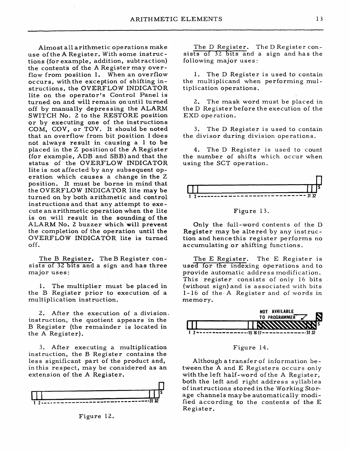
The
D
Register.
The
D
Register
con-
sists
of
32
hits
and
a
sign
and
has
the
following
major
uses:
1.
The
D
Register
is
used
to
contain
the
multiplicand
when
performing
mul-
tiplication
operations.
2.
The
mask
word
must
be
placed
in
the
D
Register
before
the
execution
of
the
EXD
ope
ration.
3.
The
D
Register
is
used
to
contain
the
divisor
during
division
operations.
4.
The
D
Register
is
used
to
count
the
number
of
shifts
which
occur
when
using
the
seT
operation.
Figure
13.
Only
the
full-word
contents
of
the
D
Register
may
be
altered
by
any
instrp.c-
tion
and
hence
this
register
performs
no
accumulating
or
shifting
fun<:tions.
The
E
Register.
The
E
Register
is
used
for
the
indexing
operations
and
to
provide
automatic
addre
s s
modification.
This
register
consists
of
only
16
bits
(without
sign)
and
is
associated
with
bits
1-16
of
the'
A
Register
and
of
words
In
memory.
NOT
AVAILABLE
TO
PROGRAMMER? S
III
II~
1 2
----·-----------·151617------------·31-32
Figure
14.
Although
a
transfer
of
information
be-
tween
the
A
and
E
Registers
occurs
only
with
the
left
half-word
of
the
A
Register,
both
the
left
and
right
address
syllables
of
instructions
stored
in
the
Working
Stor-
age
channels
maybe
automatically
modi-
fied
according
to
the
contents
of
the
E
Register.
14
ALWAC
III-E
Although
the
storage
line
on
the
drum
which
is
used
to
store
the
E
Register
con-
tains
32
bits
and
a
sign,
the
right
half
of
this
line
is
not
available
for
use
by
the
programmer
and
will,
therefore,
rarely
concern
him.
All
arithmetic
registers
are
stored
on
the
drum
as
one-word
recirculating
lines
as
shown
in
Figure
15.
WRITE
'---v----:I
FLI
P-FLOPS
Figure
15.
Since
information
is
being
constantly
read
and
re-written
and
requires
inter-
mediate
stoTage
in
flip
-
flop
units,
in-
formation
is
not
preserved
when
power
is
turned
off.
By
the
proper
setting
~f
switches
on
the
Control
Panel,
the
contents
of
any
arithmetic
register
may
be
displayed
on
the
surface
of
the
cathode-ray
oscillo-
scope.
When
two
numbe
r s
having
the
same
magnitude,
but
opposite
signs
are
added
algebraically
in
theA
(or
A
and
B)
regis-
ter(s),
the
result
maybe
either
+0
or
-0.
The
signof
the
zero
result
may
be
de-
termined
from
the
following
tabulation:
ADD
and
SCS
- -
same
as
sign
of
C (W)
SUB
and
ACS
- -
opposite
to
sign
of
C(W)
ADB
and
SBB
--
same
as
sign
of
C(B)
before
execution
of
instruction
POWER
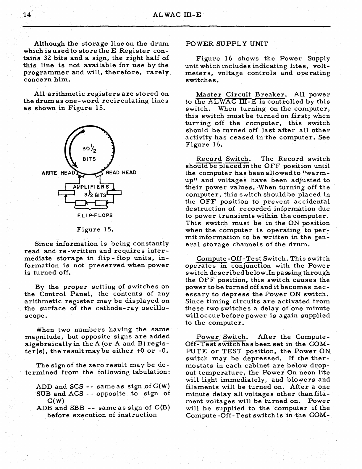
SUPPLY
UNIT
Figure
16·
shows
the
Power
Supply
unit
which
includes
indicating
lites,
volt-
meters,
voltage
controls
and
operating
switches.
Master
Circuit
Breaker.
All
power
to
the
AL
WAC
Ill-E
is
controlled
by
this
switch.
When
turning
on
the
computer,
this
switch
mustbe
turned
on
first;
when
turning
off
the
computer,
this
switch
should
be
turned
off
last
after
all
other
activity
has
ceased
in
the
computer.
See
Figure
16.
Record
Switch.
The
Record
switch
shouldbe
placed
in
the
OFF
position
until
the
computer
has
been
allowed
to
"warm-
up"
and
voltages
have
been
adjusted
to
their
power
values.
·When
turning
off
the
computer,
this
switch
should
be.
placed
in
the
OFF
position
to
prevent
accidental
destruction
of
recorded
information
due
to
power
transients
within
the
computer.
This
switch
must
be
in
the
ON
position
when
the
computer
is
operating
to
per-
mit
information
to
be
written
in
the
gen-
eral
storage
channels
of
the
drum.
Compute-Off-Test
Switch.
This
switch
ope
rate
s
In
COrijunction
with
the
Powe
r
switch
described
below.Inpassing
through
the
OFF
position,
this
switch
causes
the
power
to
be
turned
off
and
it
becomes
nec-
essary
to
depress
the
Power
ON
switch.
Since
timing
circuits
are
activated
from
these
two
switches
a
delay
of
one
minute
will
occur
before
power
is
again
supplied
to
the
computer.
Power.
Switch.
After
the
Compute-
Off-Test
switch
has
been
set
in
the
COM-
PUTE
or
TEST
position,
the
Power
ON
switch-
may
be
depressed.
If
the
ther-
mostats
in
each
cahinet
are
below
drop-
out
temperature,
the
Power
On
neon
lite
will
light
immediately,
and
blo~ers
and
filaments
will
be
turned
on.
After
a
one
minute
delay
all
voltages
other
than
fila-
ment
voltages
will
be
turned
on.
Power
will
be
supplierl:
to
the
computer
if
the
Compute-Off-Test
switch
is
in
the
COM-
POWER
SUPPLY
UNIT
15
Figure
16.
PUTE
position,
but
will
only
be
supplied
to
the
cable
connection
for
the
tester
unit
when
this
switch
is
in
the
TEST
position.
The
Power
switch
is
also
located
on
the
operator
I s
Control
Panel
and
is
operated
in
a
similar
manner.
Operating
Procedure.
To
prepare
the
computer
for
operation
the
follow-
ing
steps
should
be
observed:
1.
The
Record
switch
should
be
turned
to
the
OFF
position.
2.
The
Master
Circuit
Breaker
should
be
turned
to
the
ON
position.
The
line
voltage
meter
will
then
rise
to
120
volts
and
return
to
zero
after
a
period
of
one
minute.
3.
The
Compute
-
Off
-
Test
switch
should
then
be
turned
to
the
COMPUTE
position.
4.
The
Power
ON
switch
should
be
depressed.
5.
The
voltage
regulators
beneath
each
voltmeter
should
be
adjusted
to
cause
the
prope
r
reading
to
be
dis
played.
The
proper
voltage
readings
are
given
beneath
each
meter.
6.
As
soon
as
voltages
are
indicated
on
the
meters
and
are
adjusted
to
the
val-
ues,
the
Record
switch
should
be
turned
to
the
ON
position.
7.
The
computer
shouldnowbe
opera-
tive.
At
this
time
a
standard
test
pro-
gram
is
usually
executed
to
insure
cor-
rect
operation
before
useful
computing
is
begun.
This
test
may
be
some
standard
production
problem
which
provide
s
an
adequate
check
of
machine
operations.
16
ALWAC
llI-E
When
turning
off
the
computer
the
follo~ing
steps
should
be
observed:
1.
The
RecQrd
switch
should
be
turn-·
ed
to
the
OFF
position.
z.
The
Power
OFF
switch
should
be
depressed.
3.
After
the
line
voltage
meter
has
dropped
to
zero,
the
Master
Circuit
Breaker
tnay
be
turned
to
the
OFF
posi-
tion.
CONTROL
PANEL
Figure
17
shows
the
operator's
Con-
trol
Panel·which
includes'indlcating
lites
and
operating
switches.
Under
normal
operating
conditions
this
console
unit
is
used
for
control
of
-all
functions
of
the
computer.
Power
Switch.
The
operation
of
this
switch
is
identical
with
the
Power
switch
locatedonthe
Power
Supply
unit
which
is
described
on
page
14.
Normal
-Test
-Clear
Switch.
When
this··
.Wltch
rs1ii
tne
NoRMAL
position,
the
computer
is
under
the
control
of
the
FlexOVlriter
and
will
not
operate
unless
the
Flexowriter
is
turned
ON
and
the
Flexowriter-Computer
switch.
is
turned
to
the
COM.PUTER
position.
In
the
TEST
position,
the
computer
will
execute
instructions
whether
or
not
the
Flexowriter
is·
turned
ON.
Upon
release
from
the
CLEAR
posi-
tion,the
contents
of
General
Storage
chan-
nel
01
replaces
the
contents
of
Working
Storage
channel
I
and
control
is
trans-
ferred
to
word
00.
.A
similar
switch
is
located
on
the·
Flexowriter.
A
program
known
as
the
Start
Routine
is
located
in
General
Storage
channel
Oland
is
u,Sed
to
cause
input
and
output
of
programs
and
to
transfer
control.to
a
given
location
in
one
of
the
Four
Working
Storage
channels.
Normal
..
Hold
-
Select
Switch.
When
this
switch
is
in
the
NORMAL
position,
the
computer
will
execute
instructions
in
their
normal
sequence.
If
in
the
HOLD
position,
the
computer.
inhibits
the
normal
sequence
and
thus
this
position
maybe
used
to
cause
the
comput-
er
to
repeat
a
giveninstructionanynum-
ber
of
times.
If
in
the
SELECT
position,
the
General
Storage
selection
relays
will
select
the
channel
which
is
indicated
by
the.
neon
display
lites
of
the
Address
register.
A
given
word
in
this
channel
may
then
be
displayed
on
the
cathode-ray
oscilloscope
by
setting
the
Instruction
Address
lites
to
the
address'
of
the
desired
word
and
setting
the
A B
DEW
M
switch
to
the
M
position.
Normal
-
Stop
-
One
Step
Switch.
.
In
the
NORMAL
position,
tliecomputer
will
execute
instructions
in
their
normal
se-
quence
at
high~speed.
In
the
STOP
position,
all
com.putation
is
suspended.
Byalternatelymoving
this
switch
from
the
ONE
STEP
to
the
STOP
position,
the
computer
can
be
made
to
execute
single
instructions
in
their
nor-
mal
sequence.
JuhP
Switches.
Two
switches
pro-
vide
t e
operator
with
manual
control
over
the
program
while
it
is
being
exe-
cuted.
At
various
points
in
the
program,
the
status
of
these
switches
maybe
test-
ed
by
the
program,
which
will
cause
the
computer
to
execute
one
of
two
branches
of
the
program.
Overflow
Indicator
Lite.
Arithmetic
operations
and
certain
control
operations
may
cause
this
lite
to
be
turned
on
and
off.
If
the
lite
is
ON,
any
attempt
to
exe-
cute
arithmetic
operations
will
result
in
the
sounding
of
ALARM
No.
2
and
will
inhibit
the
execution
of
the
operation
un-
til
corrected
manually
by
depressing
the
Overflow
OFF
button
or
by
turning
Alarm
Switch
No.
2
to
the
RESTORE
position
and
then
to
the
NORMAL
position.
CONTROL
PANEL
17
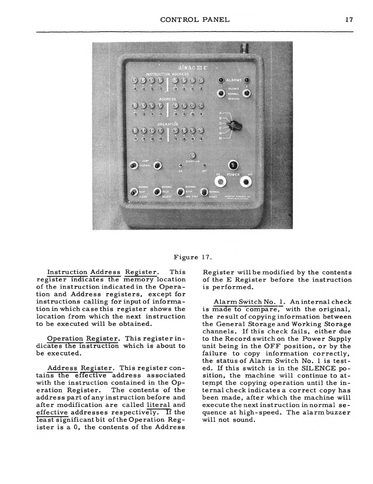
Figure
17.
Instruction
Address
Register.
This
register
indicates
the
memory
location
of
the
instruction
indicated
in
the
Opera-
tion
and
Address
registers,
except
for
instructions
calling
for
input
of
informa-
tion
in
which
case
this
register
shows
the
location
from
which
the
next
instruction
to
be
executed
will
be
obtained.
Operation
Register.
This
register
in-
dicate
s
the
instruction
which
is
about
to
be
executed.
Address
Register.
This
register
con-
tains
the
effective
address
associated
with
the
instruction
contained
in
the
Op-
eration
Register.
The
contents
of
the
addre
s s
part
of
any
instruction
before
and
after
modification
are
called
literal
and
effective
addresses
respectively.
1£
the
least
significant
bit
of
the
Operation
Reg-
ister
is
a
0,
the
contents
of
the
Address
Register
will
be
modified
by
the
contents
of
the
E
Register
before
the
instruction
is
performed.
Alarm
Switch
No.
1.
An
internal
check
is
made
to
compare,
with
the
original,
the
re
sult
of
copying
information
between
the
General
Storage
and
Working
Storage
channels.
If
this
check
fails,
either
due
to
the
Record
switch
on
the
Power
Supply
unit
being
in
the
OFF
position,
or
by
the
failure
to
copy
information
correctly,
the
status
of
Alarm
Switch
No.
1
is
test-
ed.
If
this
switch
is
in
the
SILENCE
po-
sition,
the
machine
will
continue
to
at-
te
.
mpt
the
copying
operation
until
the
in-
ternal
check
indicates
a
correct
copy
has
been
made,
after
which
the
machine
will
execute
the
next
instruction
in
normal
se-
quence
at
high-
speed.
The
alarm
buzzer
will
not
sound.
18
If
in
the
NORMAL
position,
the
buzzer
.
will
sound
and
the
machine
will
stop
until
this'
switch
is
placed
in
the
SILENCE
or
RESTORE
position.
If
in
the
RESTORE
position,
the
buz-
zer
will
not
sound,
the
internal
check
is
over-ruled
and
the
machine
continues
at
high
speed
permitting
whatever
informa-
tion
was
copied
to
remain.
~s
errone-
ous
information
could
result
under
this
condition,.
it
is
recommended
that
this
switch
not
be
permitted
to
remain
in
the
RESTORE
position.
Since
General
Storage
channel
No.
01
is
used
to
contain
the
Start
Routine
and
since
the
contents
of
this
channel
are
to
be
preservedfornormal
machine
use,
it
is
desirable
to
prevent
accidental
record-
ing
of
information
in
this
channel.
Hence,
if
an
attempt
is
made
to
record
in
Gen-
eral
Storage
channel
No.
01,
the
status
of
Alarm
Switch
No.
1
is
te
sted
and
the
machine
will
then
operate
as
described
above.
The
operator
will
seldom
have
occasion
to
place
this
switch
in
the
RE-
STORE
position.
A
special
program
to
fill
General
Storage
channel
No.
01
is
provided
and
is
known
as
the
Load
Start
Routine.
This
program
require
s
Alarm
Switch
No.
1
to
be
placed
in
the
RESTORE
position
in
orderto
copy
the
Start
Routine
into
'General
Storage
channel
No.
01.
Alarm
Switch
No.2.
If
in
the
NOR-
MAL
position,
when
arithmetic
opera-
tions
are
attempted
while
the
Ove
rflow
Indicator
Lite
is
ON,
the
buzzer
will
sound
and
the
exe
cut
ion
of
the
operation
will
be
inhibited
until
corrected
manually
by
turning
Alarm
Switch
No.
2
to
the
RE-
STORE
position
and
then
to
,the
NORMAL
position
or
by
depressing
the
Overflow
.'
OFF
button.
This
action
will
cause
the
Overflow
Indicator
Lite
and
the
buzzer
to
be
turned
OFF.
In
the
SILENCE
po
sition,
the
machine
will
pe·rform
as
for
the
NORMAL
position
except
that
the
buzze
r
will
not
sound.
If
this
switch
is
allowed
to
remain
in
the
RESTORE
position,
the
Overflow
In-
dicator
Lite
and
the
buzzer
will
be
turned
OFF
once
with
the
machine
returning
to
high-speed
operation.
However,
if
an~
other
attempt
is
made
to
execute
an
arith-
metic
operation
when
the
Overflow
Indi-
cator
Lite
is
ON,
the
machine
will
again
stop
and
the
buzzer
will
sound.
This
switch
may
then
be
returned
to
the
NOR-
MAL
position
and
the
sequence
repeated.
ABDEWM
Switch.
This
rotary
switch
controls.
the
selection
of
information
to
be
displayed
on
the
cathode-ray
oscillo-
scope.
The
A,
B,
D,
and
E
postiions
select
the
A,
B,
D,
and
E
registers
re-
spectively.
To
inspect
the
contents
of
a
word
in
one
of
the
four
Working
Storage
channels,
this
switch
is
placed
in
the
W
position,
the
Normal
-
Hold
-
Select
switch
to
the
HOLD
position,
the
Normal-
Stop
-
One
Step
switch
to
the
STOP
position,
and
the
location
of
the
desired
full-word
seton
the
Address
Register
in
neon
lites.
The
contents
of
the
desire.d
word
will
then
be
displayed
on
the
cathode-ray
oscilloscope.
To
inspect
the
contents
of
a
word
in
one
of
the
General
Storage
channels,
this
switch
is
placed
in
the
M
position,
the
Normal-
Hold
-
Select
switch
to
the
SE-
LECT
position,
the
Normal-Stop-One
Step
switch
to
the
STOP
position,
the
desired
channel
set
on
the
Address
Register
neon
lites,
and
the
desired
full-word
set
on
the
Instruction
Address
neon
lites.
The
con-
tents
of
the
desired
word
will
then
be
dis-
played
on
the
cathode-ray
oscilloscope.
OSCILLOSCOPE
Figure
18
shows
a
cathode-rayoscillo-
s
cope
on
which
the
content
s
of
a
full-word
maybe
displayed
by
setting
the
appropri-.
ate
switches
on
the
operator's
Control
Panel.
Note
that
the
scope
has
been
set
by
AL
WAC
Corporation
to
sweep
from
right
to
left.
Sweep
should
be
adjusted
to
start
at
the
far
right
of
the
scope.
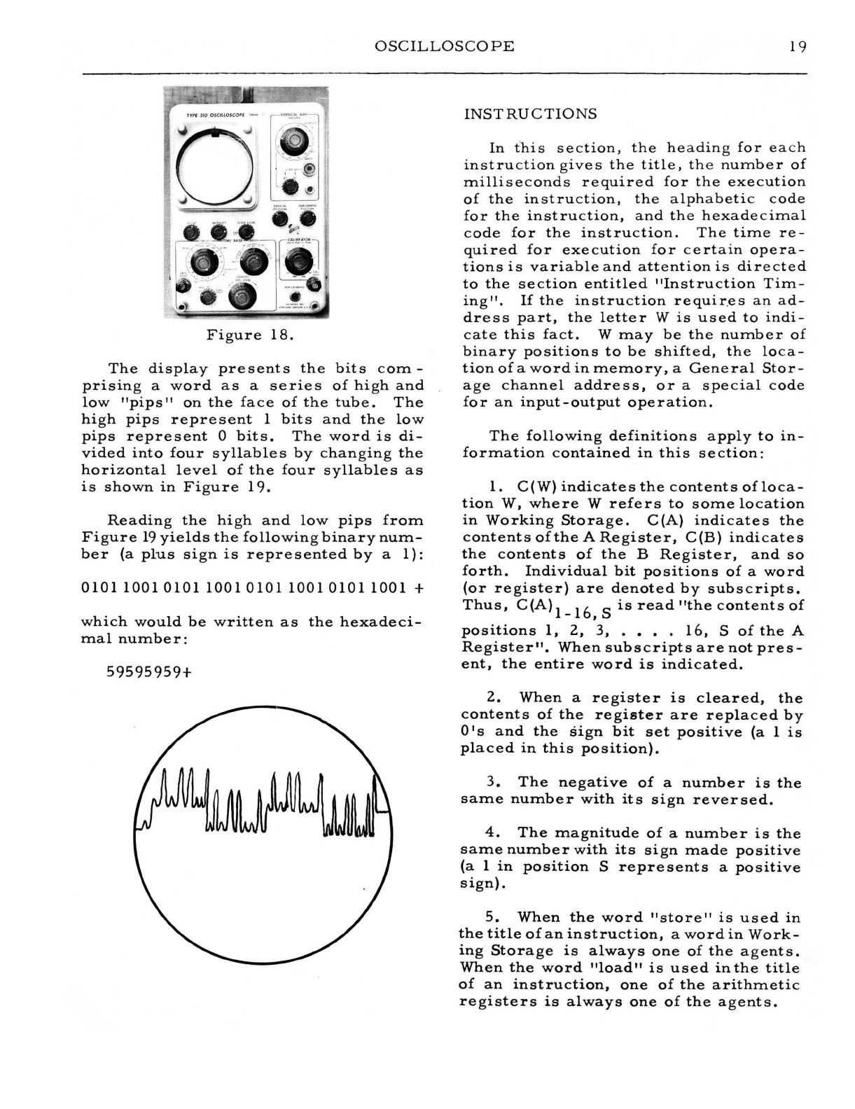
OSCILLOSCO
PE
19
Figure
18.
The
display
presents
the
bits
com-
pnsmg
a
word
as
a
series
of
high
and
low
"pips"
on
the
face
of
the
tube.
The
high
pips
represent
1
bits
and
the
low
pips
represent
a
bits.
The
word
is
di-
vided
into
four
syllables
by
changing
the
horizontal
level
of
the
four
syllables
as
is
shown
in
Figure
19.
Reading
the
high
and
low
pips
from
Figure
19
yields
the
following
binary
num-
ber
(a
plus
sign
is
represented
by
a
1):
0101
10010101
10010101
10010101
1001
+
which
would
be
written
as
the
hexadeci-
mal
number:
59595959+
INSTRUCTIONS
In
this
section,
the
headin
g
for
ea
ch
instruction
gives
the
title,
th
e
number
of
milliseconds
required
for
the
execution
of
the
instruction,
the
alphabetic
code
for
the
instruction,
and
the
hexadecimal
code
for
the
instruction.
The
time
re-
quired
for
execution
for
certain
opera-
tions
is
variable
and
attention
is
directed
to
the
section
entitled
"Instruction
Tim-
ing".
If
the
instruction
requir.es
an
ad-
dress
part,
the
letter
W
is
used
to
indi-
cate
this
fact.
W
may
be
the
number
of
binary
positions
to
be
shifted,
the
loca-
tionofawordinmemory,
a
General
Stor-
age
channel
address,
or
a
special
code
for
an
input-output
operation.
The
following
definitions
apply
to
In-
formation
contained
in
this
section:
1.
C(W)
indicates
the
contents
ofloca-
tion
W,
where
W
refers
to
some
location
in
Working
Storage.
C(A)
indicates
the
contents
ofthe
A
Register,
C(B)
indicates
the
contents
of
the
B
Register,
and
so
forth.
Individual
bit
positions
of
a
word
(or
register)
are
denoted
by
subscripts.
Thus,
C(A)1_16,S
is
read
"the
contents
of
positions
1,
2,
3,
.••.
16,
S
of
the
A
Register".
When
subscripts
are
not
pres-
ent,
the
entire
word
is
indicated.
2.
When
a
register
is
cleared,
the
contents
of
the
register
are
replaced
by
a I s
and
the
sign
bit
set
positive
(a
1
is
placed
in
this
position).
3.
The
negative
of
a
number
is
the
same
number
with
its
sign
reversed.
4.
The
magnitude
of
a
number
is
the
same
number
with
its
sign
made
positive
(a
1
in
position
S
represents
a
positive
sign)
.
5.
When
the
word
"store"
is
used
in
the
title
of
an
instruction,
a
word
in
Work-
ing
Storage
is
always
one
of
the
agents.
When
the
word
"load"
is
used
in
the
title
of
an
instruction,
one
of
the
arithmetic
registers
is
always
one
of
the
agents.
zo
ALWAC
nl-E
With
both
Itstore
II
and
"load"
instruc-
tions.,
the
agent
from
which
the
informa-
tion
is
obtained
is
unaltered.
6.
In
the
three
-letter
operation
code:
a.
The
first
letter
of
all
load
in-
structions
is
L.
b.
The
first
letter
of
all
transfer
instructions
is
T.
c.
The
first
letter
of
all
exchange
instructions
is
X.
d.
The
first
letter
of
all
add,
sub-
tract,
multiply,
and
divide
operations
is
respectively,
A,
S,
M,
and
D.
Other
com-
mands,
however,
may
start
with
these
letters.
ARITHMETIC
OPERATIONS
Add
r.o
ADD
W
61
The
status
of
the
Overflow
Indicator
is
tested:
If
ON,
this
instruction
is
not
executed
and
the
machine
sounds
the
a-
larm
2
buzzer;
if
OFF,
this
operation
re-
places
the
contents
of
the
Z
position
with
a
0,
adds
algebraically
theC(W)
to
the
C(A),
and
replaces
the
C(A)
with
this
sum.
The
C(W)
are
unchanged.
Overflow
indi-
cation
is
possible
and
a
carry
from
posi-
tion.l
in
the
A
Register
will
be
placed
in
the
Z
position.
Add
and
Change
Sign
1.0
ACS W 63
The
status
of
the
Overflow
Indicator
is
tested:
If
ON,
this
instruction
is
not
executed
and
the
machine
sounds
the
a-
larm
2
buzzer;
if
OFF,
this
operation
re-
places
the
contents
of
the
Z
position
with
a
0,
adds
algebraically
the
C(W)
to
the
C(A),
reverses
the
sign
of
this
sum,
and
replace
s
the
C (A)
with
the
re
sult.
The
. C (W)
are
unchanged.
Ove
rflow
indication
is
possible
and
a
carry
from
position
1
in
the
A
Register
will
be
placed
in
the
Z
position.
Add
to
B
1. 0
ADB
W
BD
The
status
of
the
Overflow
Indicator
is
tested:
If
ON,
this
instruction
is
not
executed
and
the
machine
sounds
the
a-
larm
2
buzzer;
if
OFF,
this
operation
treats
the
C(A)1_32
and
the
C(B)1_32,
S
as
a
64-bit
augend
(with
the
sign
of
B),
replace
s
the
content
s
of
the
Z
pas
ition
with
a
0,
adds
algebraically
the
C
(W)
to
form
a
65
-
bit
sum,
and
replaces
the
C(A)Z,
1-32
and
the
C(B)1_32,
S
with
the
result.
The
sign
of
A
is
replaced
by
the
sign
.of
B.
The
C(W)
are
unchanged.
The
Overflow
Indicator
is
'not
turned
on
if
a
carry
from
position
1
in
the
A
Register
occurs
but
said
carry
does
enter
the
Z
position.
Subtract
1. 0 SUB W 67
The
status
of
the
Overflow
Indicator
is
tested:
If
ON,
this
instruction
is
not
executed
and
the
machine
sounds
the
a-
larm
2
buzzer;
if
OFF,
this
operation
re-
places
the
contents
of
the
Z
position
with
a
0,
subtracts
algebraically
the
C(W)
from
the
C(A),
and
replaces
the
C(A)
with
this
difference.
The
C(W)
are
un-
changed.
Overflow
indication
is
possi-
ble
and
a
carry
from
position
1
in
the
A
Register
will
be
placed
in
the
Z
position.
Subtract
and
Change
Sign
1. 0 SCS W 65
The
status
of
the
Overflow
Indicator
is
tested:
If
ON,
this
instruction
is
not
executed
~nd
the
machine
sounds
the
a-
larm
2
buzzer;
if
OFF,
the
operation
re-
places
the
contents
of
the
Z
position
with
a
0,
subtracts
algebraically
the
C(W)
from
the
C(A),
reverses
the
sign
of
the
difference,
and
replaces
C(A)
with
the
re-
sult.
Overflow
indication
is
possible
and
a
carry
from
position
1
in
the
A
Register
will
be
placed
in
the
Z
position.
~NSTRUCTIONS
21
Subtract
fromB
1.
" .
SSBW
·BJ'
The
status
of
the
Overflow
Indicator
is
tested:
If
ON.,
this
instruction'isnot
executed
and
the
machine
sounds
the
a-
.
larm2
buzzer;
if
OFF,
the
operation
treats
the
C(A)1~32andthe
C(~)1_32,
S
as
~
64-bit
mip.uend
(with
the
sign
of
B),
replaces
the
contents
of
the
Z
position
witha
0,
subtracts
algebraically
the
C(W)
to
forma
65
...
bit
remainder,
and
replaces
the
C(A)'Z, 1
..
32
and
theC(B)
1-32~
S
with
the
result.
The
sIgn
of
A
is
replaced
by
the
sign
of
B.
TheC(W)
are
unchanged.
The
Overflow
Indicator
is
not
turned
on
iJ' a
carry
from
position
1
in
the
A
Reg-
ister
occurs
but
said
carr·y
does
enter
the
Z
position.
MultiPil
I'.
0
PW
W
E7
The
status
of
the
Overflow
Indicator
is
tested:
If
ON,
this
inst~ction
is
not
executed
and
the
machine
Bounds
the
a-
larm
2
buzzer;
if
OFF,
the
C(D)
are
re-
placed
with
the
C(W)
and
the
C(A)
are
re-
placed
~ith
zeros.
Then,
the
C(B)
are
multiplied
by
the
C(D)
and
the
64-bit
prod-
uct
placed
in
the'
A
and
B
Registers
'with
the
most
significant
part
in
the
A
Regis-
tel".
The,
algebraic
sign
of
the
product
is
placed
in
both
the
A
and
B
Registers.
Overflow
indication
is
not
possible
on
this
instruction
and
the
Zposition
will
contain
a
zero.
MultiP~~
D
17. 0 P E5
The
status
of
the
Overflow
Indicator
is
tested:
If
ON,
this
instruction
is
;not
exe
cuted
and
the
machine
sounds
the
a-
larm
2
buzzer;
if
OFF,
the
C(A)
are
re-
placed
with
zeros,
the
C(B)
are
multi-
plied
by
the
C(D)
and
the
64-bit
product
placed
in
the
A
'and
B
Registers
with
the
most
significant
part
in
the
A
Register.
The
algebraic
sign
of
the
product
is
placed
in
both
th.e A
and
B
Registers.
Overflow
indication
is
not
possible
on
this
instruc-
tionand
the
Z
position
will
contain
a
zero.
The
address
part
of
this
instruction
is
not
examined;
thus,
this
instruction
may
be
doubled
if
de
sired.
MultiP~
and
Add
17. o
PAW
E3
The
status
of
the
Ove
rflow
Indicator
is
tested:
If
ON,
this
instruction
is.not
executed
and
the
machine
sounds
the
a-
larm
2
buzzer;
if
OFF,
the
C(D)
are
re-
placed
with
the
C(W),
the
C(B)'
are
mul-
tiplied
by
the
C(D)
~
the
sign
of
A
is
re-
placed
by
the
sign
of
the
product,
and
the
C(A)
added
algebraically
to
the
least
sig-
nificant
half
of
the
64-
bit
product.
The
result
replaces
the
C(A)
and
C(B}
with
the
most·
significant
part
in
the
A
Register.
The
algeb
raic
sign
of
the
re
suIt
is
placed
in
both
the
A
and
B
Registers.
Overflow
indication
is
not
possible
on
this
instruc-
tion
and
the
Z
position
will
contain
a
zero
.•
MultiPifri>y
D
and
Add
17.
oX
E1
The
status
of
the
Overflow
Indicator
is
tested:
If
ON,
this
instruction
is
not
executed
and
the
machine
sounds
the
a-
larm
2
buzzer;
if
OFF,
the
C(B)
are
mul-
.
tiplied
by
the
C(D),
the
sign
of
A
is
're-
placed
by
the
sign
of
the
product,
and
the
C(A)
added
algebraically
to
the
least
sig-
nificant
half
of
the
64-bit
product.
The
result
replaces
the
C(A)
and
the
C(B)
with
the
most
significant
part
in
the
A
Register.
The
algebraic
sign
'of
the
result
is
placed
in
both
the
A
and
B
.Registers.
Overflow
indication
is
not
possible
on
this'
instruc-
tion
and
the
Z
position
will
contain
a
zero.
The
address
part
of
this
instruction
is
'
not
examined;
thus,
this
instruction
may
be
doubled
if
desired.
RQund
1.0
RND
22
The
status
of
the
Overflow
Indicator
is
tested:
If
ON,
this
instruction
is
not
executed
and
the
machine
sounds
the
a-
larm
buzzer
2;
if
OFF,
position
1
of
the
22
ALWAC
III-E
B
Register
is
tested
for
a.
1.
If
it
con-
tains
aI,
the
magnitude
of
the
C(A)
is
increased
by
1
in
position
32.
If
position
1
of
the
BRegiste
r
contains
a
zero,
the
C(A)
are
not
altered.
Overflow
indication
is
possible
and
a
carry
from
position
1
of
the
A
Register
enters
the
Z
position.
The
contents
of
the
B
Register
are
not
altered.
Divide
17.0
DVW
W
EF
The
status
of
the
Ove
rflow
Indicator
is
tested:
If
ON,
this
instruction
is
not
executed
and
the
machine
sounds
the
a-
larm
2
buzzer;
if
OFF,
the
C-(A)
are
re-
placed
with
zeros,
the
C(D)
are
replaced
with
the
C(W),
and
the
contents
of
the
A
and
B
Registers
are
treated
as
a
64-bit
dividend(Z
position.
excluded)
with
the
sign
of
the
B
Register.
The
new
C(D)
are
examined
for
a
zero
divisor.
If
zero,
the
Overflow
Indicator
is
turned
ON
and
the
division
is
not
performed.
If
non-
zero,
the
contents
of
the
Z
position
are
replaced
with
a
0,
the
dividend
in
the
A
and
B
Registers
is
divided
algebraically
by
the
C(D),
the
quotient
(with
its
alge-
braic
sign)
placed
in
the
B
Register,
and
the
remainder
with
the
sign
of
the
divi-
dend
is
'placed
in
the
A
Register.
Over-
flow
indication
is
possible
only
if
the
D
Register
contains
a
zero
divisor.
whether
or
not
the
division
is
perform.ed,
the
di-
visor
is
left
in
the
D
Register.
Divide
by
D
17. 0
DVD
ED
The
status
of
the
Overflow
Indicator
is
tested:
If
ON,
this
instruction
is
not
executed
and
the
machine
sounds
the
a-
larm2
buzzer;
if
OFF,
the
C(A)
are
re-
placed
with
zeros,
and
the
contents
of
the
AandB
Registers
are
treated
as
a
64-bit
.
dividend
(Z
position
excluded)
with
the
sign
of
the
B
Register.
The
C{D)
are
ex-
am.ined
for
a
zero
divisor.
If
zero,
the
Overflow
Indicator
is
turned
ON
and
the
division
is
not
performed.
If
non-zero,
the
contents
of
the
Z
position
are
re-
placed
with
a
0,
the
dividend
in
the
A
and
B
Registers
is
divided
algebraically
by
the
C(D),
the
quotient
(with
its
algebraic
sign)
placed
in
the
B
Register,
and
the
remainder
with
the
sign
of
the
dividend
placed
in
the
A
Register.
Overflow
in-
dication
is
possible
only
if
the
D
Regis-
ter
contains
a
zero
divisor.
Whether
or
not
the
division
is
performed,
the
divisor
is
left
in
the
D
Register.
The
address
part
of
this
instruction
is
not
examined;
thus,
this
instruction
may
be
doubled
if
desired.
Di
vide
Doub
le
Length
17.0
nDW
W
EB
The
status
of
the
Overflow
Indicator
is
tested:
If
ON,
this
instruction
is
not
exe-
cuted
and
the
machine
sounds
the
alarm
2
buzzer;
if
OFF,
the
C(D)
are
replaced
with
the
C(W),
and
the
contents
of
the
A
and
B
Registers
are
treated
as
a
64-bit
dividend
(Z
position
excluded)
with
the
sign
of
the
B
Register.
If
I
C(A)l_
321
~
IC(D)
I
or
if
the
D
Register
contains
a
zero
divisor,
the
Overflow
Indicator
is
turned
ON
and
the
division
is
not
performed.
If
none
of
the
above
error
conditions
occur,
the
content
of
the
Z
position
is
re-
placed
with
a 0
and
the
division
is
per-
form.ed.
The
quotient
(with
its
algebra-
ic
sign)
is
placed
in
the
B
Register
and
the
remainder
with
the
sign
of
the
divi-
dend
is
placed
in
the
A
Register.
Over-
flow
indication
is
possible
under
the
con-
ditions
described
above.
Whether
or
not
the
divisioIl;
is
performed,
the
divisor
is
left
in
the
D
Register.
Divide
Double
Length
by
D
17. 0
DDD
--
E9
The
status
of
the
Overflow
Indicator
is
tested:
If
ON,
this
instruction
is
not
exe-
cuted
and
the
machine
sounds
the
alarm
2
buzzer;
if
OFF,
the
contents
of
the
A
and
B
Registers
are
treated
as
a
64-bit
divi-
dend
(Z
position
excluded)
with
the
sign
of
the
B
Register.
If
IC(A)
1-321:~
IC(D)
1-321
INSTRUCTIONS
23
or~
if
the
D
Register
contains
a
zero
divi-
sor,
the
Overflow
Indicator
is
turned
ON
and
the
division
is
not
performed.
If
none
of
the
above
error
conditions
occur,
the
content
of
the
Z
position
is
re-
placed
with
a
0,
and
the
division
is
per-
formed.
The
quotient
(with
its
algebraic
sign)
is
placed
in
the
B
Register
and
the
remainde
r
with
the,
sign
of
the
dividend
is
placed
in
the
A
Register.
Overflowindi-
cation
is
'possible
under
the
conditions
described
above.
Whether
or
not
the
di-
vision
is
performed,
the
divisor
is
left
in
the
D
Register.
The
address
part
of
this
instruction
is
not
examined;
thus,
this
instruction
may
be
doubled
if
desired.
Load
A
from
W
1. 0 LAW W
79
The
C(W)
replace
the
C(A)
and
a
zero
is
placed
in
the
Z
position.
The
C(W)
remain
unchanged.
Load
A
from
M
9.0
LAM
M
BS
The
C'(M)mod
32
replaces
the
C(A)
and
a
zero
is
placed
in
the
Z
position.
The
C(M)
remain
unchanged.
At
least
34
mil-
liseconds
(2
drum
revolutions)
must
be
allowed
between
this
instruction
and
any
preceding
Copy
instruction
except
one
which
copie
s
information
into
channel
M
(Channel
No.
00).
--
Load
A
from
B
1. 0 LAB
--
32
The
C(A)
are,
replaced
with
the
C(B)
and
a
zero
is
placed
in
the
Z
position.
The
C(B)
remain
unchanged.
The
ad-
dre
s s
part
of
this
instruction
is
not
ex-
amined,
thus,
this
instruction
may
be
doubled
if
de·sired.
Load
A
from
D
1. 0
LAD
--
38
The
C(A).
are
r'eplaced
with
the
C(D)
and
a
zero
is
placed
in
the
Z
position.
The
C (D)
remain
unchanged.
The
ad-
dress
part
of
this
instruction
is
not
ex-
amined,
thus,
this
instruction
may
be
doubled
if
desired.
Load
A
from
E
1.
0
LAE
- -
34
The
C(A)
1-16
are
replaced
with
the
C(E)
1-16.
The
C(A)
17
_
32,
S
are
left
un-
changed,
and
the
Z
position
is
filled
with
a
zero.
The
address
part
of
this
instruc-
tion
is
not
examined;
thus,
this
instruc-
tion
may
be
doubled
if
desired.
Exchange
A
and
B
1. 0 XAB
--
30
The
C(A)
and
the
C(B)
are
exchanged
and
a
zero
is
placed
in
the
Z
position.
The
address
part
of
this
instruction
is
not
examined;
thus,
this
instruction
may
be
doubled
if
desired.
ExchXll
A
and
D
1. 0 D
--
3A
The
C(A)
and
the
C(D)
are
exchanged
and
a
ze
ro
is
placed
in
the
Z
position.
,The
address
part
of
this
instruction
is
not
examined;
thus,
this
instruction
may
be
doubled
if
desired.
ExchjGle
A
and
E
1. 0 E
--
36
The
C(A)1_16
and
the
C(E)
1-16
are
exchanged.
The
C(A)
17
-32
are
left
un-
changed,
the
Z
position
is
filled
with
a
zero,
and
the
sign
of
the
A
Register
made
positive.
The
address
part
of
this
in-
struction
is
not
examined;
thus,
this
in-
struction
may
be
doubled
if
desired.
Exchange
A
and
W
1. 0
XAW
w
69
Th'e
C (A)
and
C (W)
are
exchanged
and
a
zero
is
placed
in
the
Z
position.
24
ALWAC
Ill-E
Store
A
1.0
SAW
W
49
The
G(W)
1-
32,
S
are
replaced
with
the
C(A)I_32,
S.
The
C(A)
remain
unchanged.
Place
Address
in
A
1.0
pAA
W 6D
IfW~
(7F)16'
the
C(A)9_l6are
re-
placed
with
the
C(W)9_l6;
if
W
'Q
(80)
16'
the
C
(A)
25
_
32
are
replaced
with
the
C(W)25_32.
The
remaining
bits
of
C(W)
and
G(A)
including
the
sign
-and
Z
posi-
tions
are
not
affected.
Place
Half-
Word
in
A
1.0
PHA W bF
If
W
~
(7F)
16'
the
C(A)
1-16
are
re-
placed
with
the
C(W)1_16;
ifW)
(80)16'
the
C
(A
) 1 7 _
32
are
replaced
with
the
C(W)17_32.
The
C(W)
and
the
remain-
ing
bits
of
C(A)
including
the
sign
and
Z
positions
are
not
affected.
Store
Address
from
A
1.0
SAA W
4D
If
w.(
(7F)
16'
the
C(W)9_16
are
re-
placed
with
the
C(A)9_l6;
if
W
~
(80)
16'
the
C (
W)
25
_
32
are
replaced
with
the
C(A)25_32.
The
C(A)
including
the
sign
and
Z
positions
and
the
remainlng
bits
of
C(W)
are
not
changed.
Store
Half-
Word
from
A
1.0
SHA
W
4F
If
W
~
(7F)
16'
the
C(W)
1-16
are
re-
placed
with
the
C(A)
1-16;
if
W
~
(80)
16'
the
C
(W)
1 7 _
32
are
replaced
with
the
C(A)
17
-32.
The
C(A)
including
the
sign
and
Z
positions
and
the
remaining
bits
of
Ware
not
affected.
Load
B
1. 0
LBW
41
The
G(B)
are
replaced
with
the
C(W).
The
C(W)
are
not
affected.
Store
B
1.0
SBW
C5
The
C(W)
are
replaced
with
the
C(B).
The
C(B)
are
not
affected.
Load
D
1. 0
LDW
W
5B
The
C(D)
are
replaced
with
the
C(W).
The
C(W)
are
not
affected.
Store
D
1.0
SDW
W
C7
The
C (W)
are
replaced
by
the
C
(D).
The
C(D)
are
not
affected.
Load
E
1.0
LEW
W
57
The
C
(E)
1-
16
are
replaced
with
the
C(W)I_16.
The
C(W)
are
not
affected.
Store
E
1. 0
SEW
W
C3
The
C(W)I_16
are
replaced
with
the
G(E)
1,-16.
The
remaining
bits
of
C(W)
and
the
C(E)
are
not
affected.
Clear
A
1. 0
CLA
28
The
C(A)I_32
and
the
Z
position
are
replaced
with
zeros
and
the
sign
of
the
A
Register
made
positive.
The
address
part
of
this
instruction
is
not
examined;
thus,
this
instruction
may
be
doubled
if
desired.
Chan~e
Sign
1. 0
HS
--
2E
If
the
sign
bit
of
the
A
Register
is
posi-
tive,
it
is
made
negative,
and
vice
versa.
INSTRUCTIONS
25
The
addre
s s
part
of
this
instruction
is
not
examined;
thus,
this
instruction
may
be
doubled
if
de
sired.
Set
Si~n
Plus
1. 0 S p - -
2C
The
sign
bit
of
the
A
Register
is
made
positive.
The
address
part
of
this
in-
struction
is
not
examined;
thus,
this
in-
struction
may
be
doubled
if
desired.
Complement
A
1.0
CpL
--
3E
All
zeros
are
replaced
by
ones
and
vice
versa
in
the
C(A)
1-
32,
S.
The
Z
po-
sition
is
filled
with
a
ze
ro.
The
addre
s s
p~rt
of
this
instruction
is
not
examined;
thus,
this
instruction
may
be
doubled
if
desired.
LOGICAL
AND
CONTROL
OPERATIONS
Extract
1.
0
EXT
W
75
Each
bit
of
the
C(A)
1-32,
S
is
compared
with
the
corresponding
bit
of
C(W)
1-
32,S.
When
both
bits
are
ones,
the
correspond-
ing
bit
in
the
A
Register
is
left
unaltered
(remains
a
one)~
However,
when
either
of
the
bits
compared
is
zero,
the
correa-
ponding
bit
in
the
A
Register
is
replaced
with
a
zero.
The
Z
position
is
filled
with·
a
zero.
The
C(W)
are
not
affected.
Extract
with
D
Mask
1. 0 EXD W
71
Each
bit
of
the
C(A)I_32,
S
is
compared
with
the
correspondingbit
of
C(D)
1-32,
S.
When
the
bit
in
the
D
Register
is
a
one,
the
corresponding
bit
in
the
A
Register
is
replaced
by
the
bit
in
W;
when
the
bit
in
the
D
Register
is
a
zero,
the
corres-
pondingbit
in
the
A
Register
is
not
chang-
ed.
The
Z
position
is
filled
with
a
zero.
The
C(D)
and
C(W)
are
not
affected.
Change
Overflow
Indicator
1.
OCOV
--
02
If
the
Overflow
Indicator
is
ON,
turn
it
OFF
and
vice
versa.
The
address
part
of
this
instruction
is
not
examined;
thus,
this
instruction
maybe
doubled
if
desired.
Compare
Magnitude
1. 0
COM
--
51
The
status
of
the
Overflow
Indicator
is
tested;
if
ON,
this
instruction
causes
the
machine
to
stop;
if
OFF,
the
C{A)
and
C(W)
are
compared:
If
(C(A)
1-321
< IC(W)
1-
321,
this
instruc-
tion
causes
the
Overflow
Indicator
to
be
turned
ON.
If
I
C(A)
1-
321
~IC(W)
1-
321
'
the
Overflow
Indicator
remains
OFF.
No
Operation
1. 0 NOP
--
00
The
machine
takes
the
next
instruc-
tion
in
sequence
•.
(Although
no
opera-
tion
is
performed,
the
Address
Regis-
ter
will
contain
the
effective
address;
i.
e.,
after
address
modificatIon
by
the
E
Register
has
been
performed.)
Halt
and
Transfer
1. 0
HTR
W IB
If
the
START-NORMAL
switch
on
the
Control
Panel
is
in
the
NORMAL
position,
the
machine
will
stop
until
this
switch
is
thrown
to
the
START
position,
after
which
the
machine
will
obtain
the
next
instruc-
tion
from
location
Wand
proceed
from
there.
If
this
switch
is
in
the
START
po-
sition,
the
machine
will
not
stop
but,
in-
stead,
will
obtain
the
next
instruction
from
location
Wand
proceed
from
there.
Transfer
1.0
TRA
W 11
The
machine
takes
the
next
instruction
from
location
Wandproceeds
from
there.
26
ALWAC
III-E
Transfer
on
Overflow
1.0
foV
W
IF
If
the
Overflow
Indicator
is
ON
as
the
result
of
a
previous
operation,
the
indi-
cator
is
turned
OFF
and
the
rna-chine
take
s
the
next
inst.ruction
from
location
Wand
proceeds
from
there.
If
the
indicator
is
OFF,
the
machine
takes
the
next
instruc-
tion
in-
sequence.
Transfer
on
Non-Zero
1. 0
TNZ
W
19
If
the
C(A)
1-
32
are
non-
zero,
the
ma-
chine
takes
the
next
instruction
from
lo-
cation
Wand
proceeds
from
there.
If
the
CJA)1_32
are
zero,
the
machine
takes
the
next
instruction
in
sequence.
Note
that
the
Z
and
sign
positions
are
not
ex-
amined.
Transfer
on
Less
than
Zero
1.0
TLZ
W ID
1£
the
C (A)
1-
32.,
S·
are
non
-
zero
and
negative,
the
machine
takes
the
next
in-
struction
from
location
Wand
proceeds
from
there·.
If
the
C(A)
1-~2,
S
are
zero
or
positive,
the
machine
takes
the
next
instruction
in
sequence.
Note
the
Z
po-
sition
is
not
examined.
Transfer
on
Index
1.
0 TIX W
17
The
C(E)
are
decreased
by
1
in
the
least
significant
position
and
the
result
placed
in
the
E
Register,
after
which
the
contents
of
this
register
are
tested
for
the
presence
of
a
zero
result.
If
non-
zerQ,
the
machine
takes
its
next
instruc-
tion
from
location
Wand
proceeds
from
there;
if
zero,
the
machine
takes
the
next
instructi()n
in
the
normal
sequence.
The
contents
of
the
other
arithmetic
registers
are
not
affected.
Therefore,
the
E
Regis-
ter
may
be
used
as
an
index
register.
Transfer
on
Switch
One
1. 0 TSA W 13
The
status
of
jump
switch
one
is
ex-
amined.
If
in
the
JUMP
position,
the
ma-
chine
obtains
the
next
instruction
from
lo-
cation
Wand
proceeds
from
there;
if
in
the
NORMAL
position,
the
machine
takes
the
next
instruction
in
sequence.
Transfer
on
Switch
Two
1.
O.
TSB W
15
The
status
of
jump
switch
two
is
ex-
amined.
If
in
the
JUMP
position,
the
ma-
chine
obtains
the
next
instruction
from
lo-
cation
Wand
proceeds
from
there;
if
in
the
NORMAL
position,
the
machine
takes
the
next
instruction
in
sequence.
Shifting
Instructions
Shift
instructions
are
used
to
move
the
contents
of
the
A
(or
A
and
B)
Register(s)
to
the
left
or
rightof
their
original
posi-
tions.
The
address
syllable
is
'Used
to
in-
dicate
the
number
of
positions
to
be
shift-
ed.
When
a
shift
i
ruction
is
executed,
the
positions
left
cant
in
the
registers
are
automatically
ilIed
with
zeros.
When
a
shift
instruction
is
interpreted,
the
ex-
tent
of
the
shift
is
determined
from
the
six
least
significant
bits
of
the
address
syllable.
Thesebits,
are,
therefore,in-
terpretedmodulo
64.
Multiples
of
(40)16
used
in
the
a.ddress
syllable
of
a
shift
in-
struction
produce
no
shift,
as
the
address
is
interpreted
as
zero.
Thus,
addresses
greater
than
(40)
16
will
produce
shifts
ranging
between
hexadecimal
91
and
3F.
Hence,
the
maximum
number
of
shifts
is
63
(hexadecimal
3F)
bits.
Example
1.
8
modulo
64
= 8
because
8 =
0(64)+8
Example
2.
63
modulo
64
=
63
63
=
0(64)+63
Example
3.
128
modulo
64
= 0
128
=
2(64)+0
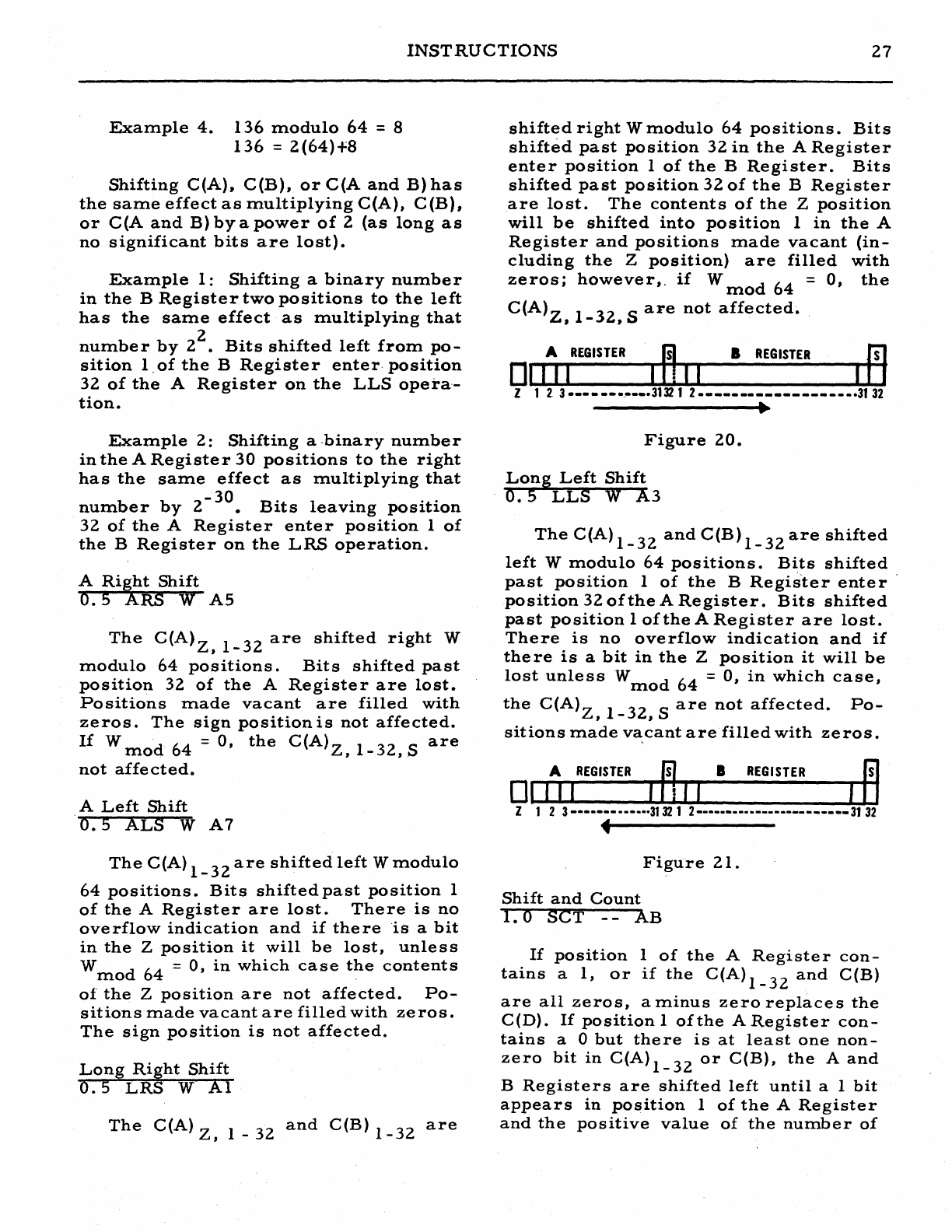
INSTRUCTIONS
27
Example
4.
136
modulo
64
= 8
136
=
2(64)+8
Shifting
C(A),
C(B),
or
C(A
and
B)
has
the
same
effect
as
multiplying
C(A),
C(B),
or
C(A
and
B)
by
a
power
of
2
(as
long
as
no
significant
bits
are
lost).
Example
1:
Shifting
a
binary
number
in
the
B
Register
two
positions
to
the
left
has
the
same
effect
as
multiplying
that
number
by
22.
Bits
shifted
left
from
po-
sition
1.
of
the
B
Register
enter·
position
32
of
the
A
Register
on
the
LLS
opera-
tion.
Example
2:
Shifting
a
.binary
number
in
the
A
Register
30
positions
to
the
right
has
the
same
effect
as
multiplying
that
b b 2
-30
B·
I·
..
num
er
y •
Its
eavIng
POSItIon
32
of
the
A
Register
enter
position
1
of
the
B
Register
on
the
LRS
operation.
A
Ri5tt
Shift
o.
5
RS
W
AS
The
C(A)Z,
1-32
ar'e
shifted
right
W
modulo
64
positions.
Bits
shifted
past
position
32
of
the
A
Register
are
lost.
Positions
made
vacant
are
filled
with
zeros.
The
sign
position
is
not
affected.
If
W
mod
64
=
0,
the
C(A)Z,
1-32,
S
are
not
affected.
A
Left
Shift
'0.5
ALS W
A7
The
C(A)
1-32
are
shifted
left
Wmodulo
64
positions.
Bits
shifted
past
position
1
of
the
A
Register
are
lost.
There
is
no
overflow
indication
and
if
there
is
a
bit
in
the
Z
position
it
will
be
lost,
unless
W
mod
64
=
0,
in
which
case
the
contents
of
the
Z
position
are
not
affected.
Po-
sitions
made
vacant
are
filled
with
zeros.
The
sign
position
is
not
affected.
Long
Right
Shift
o.
5LRS
W
Al
The
C(A)
z,
1 _
32
and
C(B)
1-32
are
shifted
right
W
modulo
64
positions.
Bits
shifted
past
position
32
in
the
A
Register
enter
position
1
of
the
B
Register.
Bits
shifted
past
position
32
of
the
B
Register
are
lost.
The
contents
of
the
Z
position
will
be
shifted
into
position
1
in
the
A
Register
and
positions
made
vacant
(in-
cluding
the
Z
position)
are
filled
with
zeros;
however,.
if
W
mod
64
=
0,
the
C(A)Z,
1-32,
S
are
not
affected~
.
It.
REGISTER
~
•
REGISTER
P1
01
III
I
~
II
I
Z 1
2.
3
-------.---.31321
2
------------------.3132
Figure
20.
Long
Left
Shift
o.
5
LLS
W A3
•
The
C(A)
1-32
and
C(B)
1-32
are
shifted
left
W
modulo
64
positions.
Bits
shifted
past
position
1
of
the
B
Regis"ter
enter
position
32
of
the
A
Register.
Bits
shifted
past
position
1
of
the
A
Register
are
lost.
There
is
no
overflow
indication
and
if
there
is
a
bit
in
the
Z
position
it
will
be
lost
unlessW
mod
64
=
0,
in
which
case,
the
C(A)Z,
1-32,
S
are
not
affected.
Po-
sitions
made
vacant
are
filled
with
zeros.
It.
REGISTER
B •
REGISTER
M
01
1
II
,
~
I I , _
Z 1 2 3
-------
-----·3132 1 2
------------------------
31
32
•
Figure
21.
Shift
and
Count
1.
0 SeT
--
AB
If
position
1
of
the
A
Register
con-
tains
a
1,
or
if
the
C(A)I_32
and
C(B)
are
all
zeros,
a
minus
zero
replaces
the
C(D).
If
position
1
of
the
A
Register
con-
tains
a 0
but
there
is
at
least
one
non-
zero
bit
in
C(A)I_32
or
C(B),
the
A
and
B
Registers
are
shifted
left
until
a 1
bit
appears
in
position
1
of
the
A
Register
and
the
positive
value
of
the
number
of
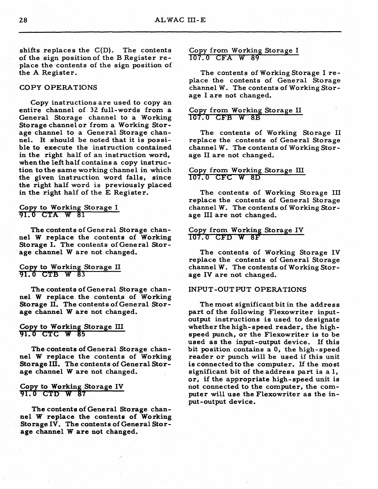
28
ALWAC
III-E
shifts
replaces
the
C(D).
The
contents
of
the
sign
position
of
the
B
Register
re-
place
the
'contents
of
the
sign
position
of
the
A
Register.
COpy
OPERATIONS
Copy
instructions
are
used
to
copy
an
entire
channel
of
32
full~word'5
from
a
General
Sto.rage
channel
to
a
WorlP-ng
Storage
channel
or
from
a
Working
Stor-
age
channel
to
a
General
Storage
chan-
nel.
It
should
be
noted
that
it
is
possi-
ble
to
execute
the
instruction
contained
in
the
right
half
of
an
instruction
word,
when
the
left
half
contains
a
copy
instruc-
tion
to
the
same
working
channel
in
which
the
given
instruction
word
falls,
since
the
right
half
word
is
previously
placed
in
the
right
half
of
the
E
Register.
Copy
to
Workint
Storage
I
91. 0
eTA
W 1
The
contents
of
General
Storage
chan-
nel
W
replace
the
contents
of
Working
Storage
I.
The
contents
ofGeneralStor-
.
age
channel
Ware
not
changed.
Copy
to
Workinl
Storage
II
91.0
eTB
W
~
The
contents
of
General
Storage
chan-
nel
W
replace
the
content.s
of
Working
Storage
II.
The
contents
of
General
Stor-
age
channel
Ware
not
changed.
CoPl
to
workinl
Storage
III
91.·
eTC
W 5
The
contents
of
General
Storage
chan-
nel
W
replace
the
contents
of
Working
Storage
Ill.
The
contents
of
General
Stor'-
age
channel
Ware
not
changed.
Copy
to
wo.rkinl
Storage
IV
91.0
CTn
W 7
The
contents
of
General
Storage
chan-
nel
W
replace
th~
contents
of
Working
.
Storage
IV.
The
contents
of
General
Stor-
age
channel
.W
are
not
changed.
Copy
from
Working
Storage
I
107. 0
CFA
W 89
The
contents
of
Working
Storage
I
re-
place
the
contents
of
General
Storage
channel
W.
The
contents
of
Working
Stor-
age
I
are
not
changed.
CoPY
from
workill
Storage
II
107.0
CFB W 8
The
contents
of
Working
Storage
II
replace
the
contents
of
General
Storage
channel
W.
The
contents
of
Working
Stor-
age
II
are
not
changed.
Copy
from
worki~
Storage
III
107.0
eFC
W 8
The
contents
of
Working
Storage
III
replace
the
contents
of
.General
Storage
channel
W.
The
contents
of
Working
Stor-
age
III
are
not
changed.
Copy
from
workiif
Storage
IV
107. 0 CFD W 8 .
The
contents
of
Working
Storage
IV
replace
the
contents
of
General
Storage
channel
W.
The
contents
of
Working
Stor-
age
IV
are
not
changed.
INPUT-OUTPUT
OPERATIONS
The
most
significant
bit
in
the
address
part
of
the
following
Flexowrite
r
input-
output
instructions
is
used
to
designate
whether
the
high-speed
reader,
the
high-
speed
puncR,
or
the
Flexowriter
is
to
be
used
as
the
input-output
device.
If
this
bit
position
contains
a
0,
the
high-speed
reade
r
or
punch
will
be
used
if
this
unit
is
connected
to
the
computer.
If
the
most
significant
bit
of
the
address
part
is
a
1,
or,
if
the
appropriate
high-speed
unit
is
not
connected
to
the
computer,
the
com-
puter
will
use
the
Flexowriter
as
the
in-
put-output
device.
INSTRUCTIONS
Z9
Hexadecimal
(or
Decim~l)
Input
--
HXI
W
Fl
Hexadecimal
input
is
indicated
by
plac-
ing
a 0
in
the
second
most
significant
bit
position
of
the
address
part
of
this
in-
struction;
decimal
input
is
indicated
by
placing
a I
in
the
second
most
significant
bit
po
sition.This
instruction
causes
the
contents
of
the
A
Register
to
be
shifted
left
4
binary
positions
and
the
C(A)Z9_3Z
to
be
replaced
with
one
hexadecimal
char-
acter
(4
bits)
for
h'exadecimal
input;
or
to
-multiply
the
contents
of
the
A
Register
by
10
arid
to
add
the
4
least
significant
bits
of
the
character
read
to
this
prod-
uct
w)lich
then
replaces
the
contents
of
"the A
Register,
for
decimal
input.
For
both
types
of
input,
this
operation
is
re-
peateduntl1
nW-l)mod
8
+~
inputshave
been
supplied
after
which
the
Select
Lite
is
turned
OFF
and
the
machine
resumes
high-
speed
operations.
The
sign
and
Z
po-
sitions
in
the
A
Register
are
not
changed~
Hexadecimal
(or
Decimal)
Output.
--
HXO
W F5
Hexadecimal
output
is
indicated
by
placing
a 0
in
the
second
I:lost
significant
bit
position
of
the
address
part
of
this
instruction;
decimal
output
-
is
indicated
by
placing
a 1
in
the
second
most
sig-
nificant
bit
position.
This
instruction
causes
the
Flexowriter
to
print
(or
punch)
the
hexadecimal
character
located
in
the
C(A)1_4
and
to
shift
the
A
~egister
left-
4
positions
for
hexadecimal
output;
or
to
multiply
the
C(A)
1-
32
by
10,
to
print
(or
punch)
a
decimal
character
form.ed
from
the
integral
part
of
the
product,
and
to
re-
place
the
C(A)
1-
32
with
the
fractional
part
of
the
product.
For
both
types
of
output,
this
operation
is
repeated
[(W-l)mod
8
+9
times.
The
sign
and
Z
positions
in
the
A
Register
are
not
changed.
Number
Output-
NMO
--
DD
This
_instruction
causes
the
Flexo-
writer
to
print
(or
punch)
the
hexadeci-
mal
character
located
in
the
C(A)29_3Z.
The
C(A)
including
sign
and
Z
positions
are
not
changed.
The
address
part
of
this
word
is
not
examined,
and,
since
the
operation
code
is
odd,
this
instruc-
tion
may
be
doubled
only
when
used
as
the
address
part
of
a
doubled
instruction.
Sign
Input
--
SNI
--
F9
This
instruction
r~places
the
C(.A)
1-
3Z
with
zeros
and
replaces
the
sign
position
with
a 0
or
I
(minus
or
plus)
accordiJlg
to
the
character
received
from
the
Flexo--
writer.
The
space
bar
is
used
for
plus
and
the
minus
key
for
minus
indications;
however,
any
Flexowriter
character
code
which
has
a
punch
in
position
4
m~y
be
used
in
place
of
the
minus
key.
Thiif!
in-
clude.
the
characters:
abcdefjyzABCDEFJYZ89L,( -I
$.,
*6~;
abd
the
stop,lower
case,color
sh1ft,code
delete,tabulate,
carriage
return,and
back spi,ce
codes.
Any
Flexowriter
character
code
which
has
no
-
punch
in
position
4
may
be
used
in
place
of
the
space
bar.
This
includes
the
characters:
ghiklmnopqrstuvwx
GHIKIMNOPQRS'IUVWX
12345670°"+=%11)
The
Select
Lite
'on
the
Flexowriter
is
turned
ON
by
this
instruction
and
the
ma-
chine
waits
until
an
input
has
been
sup-
plied,
after
which
the
Select
Lite
is
turned
OFF
and
the
machine
resumes
high-speed
ope
rations.
Note
that
the
Z
position
of
the
A
Re
gister
is
not
changed.
Sign
Output
---SNO--
D5
If
the
sign
of
the
A
Register
is
po.itive,
a
space
code
is
transmitted
to
the
Flexo-
writeor;
if
the
sign
of
the
A
Register
is
negative,
a
minus
code
is
transmitted
to
30
ALWAC
III-E
the
Flexowriter.
The
C (A)
including
the
sign
·and
Z
positions
are
not
changed.
Alphabetic
Input
ALI W F3
This
instruction
causes
the
C(A)2_32
to
be
shifted
left
6
binary
positions
and
replaces
the
C(A)26~31
with
one
alpha-
betic
character
(6
bits),
and
causes
this
9perationtobe
repeated
RW-l)mod
8
+~
times.
Note
that
if
this
instruction
is
repeated
more
than
5
times,
all
but
the
last
5
alphabetic
characters
will
be
lost.
The
Select
Lite
on
the
Flexowriter
is
turnedONby
this
instruction
and
the
ma-
chine
waits
until
trw
-l)mod
8
+~
inputs
have
been
supplied,
after
which
the
Select
Lite
is
turned
OFF
and
the
machine
re-
sume
s
high-
speed
operation.
The
sign
and
Z
positions
are
not
changed
but
the
C(A)32
is
replaced
with
the
C(A)31
after
the
last
alphabetic
character
has
been
read.
Alphabetic
Output
ALa
W F7
This
instruction
replaces
C(A)32
with
a
zero,
causes
the
Flexowriter
to
print
(or
punch)
the
alphabetic
characte
r
lo-
cated
in
the
C(A)2
-7'
the
contents
of
the
A
Register
to
be
shifted
left
6
positions,
and
causes
this
operation
to
be
repeated
U
W
-1
)mod
8
+~
time
s.
The
bit
positions
made
vacant
are
filled
with
zeros.
The
C(A)Z,
1,
S
are
not
changed.
The
following
instructions
are
used
to
control
punching
and
typing
functions
on
the
Flexowriter
according
to
the
setting
of
the
two
switche
s
on
the
Flexowrite
r
which
are
labeled
IITYPE"
and
"PUNCH".
Two
flip-flops,
which
are
known
as
the
Type
and
Punch
flip-flops,
operate
in
conjunction
with
these
switches.
The
status
of
these
flip-flops
may
be
affected
by
executing
one
of
the
instruc-
.tions
TYP,
PNH,
BTP,
or
NTP
(9B,
9D,
9F,
or
99)
or
by
depressing
the
Clear
switch
on
the
Flexowriter
or
by
placing
the
Normal
-
Test
-
Clear
switch
on
the
Control
Panel
in
the
CLEAR
position.
Operating
either
of
these
switches
causes
the
Type
flip-flop
to
be
turned
ON,
and
the
Punch
flip-flop
to
be
turned
OFF.
Placing
the
Type
and
Punch
switches
on
the
Flexowriter
in
the
COMPUTE
po-
sition
permits
the
computer
to
select
the
desired
output
according
to
the
setting
of
the
Type
and
Punch
flip-flops
which
are
controlled
by
the
instructions
TYP,
PNH,
BTP,
and
NTP
(9B,
9D,
9F,
and
99)
which
are
described
below.
Placing
the
Type
arid
Punch
switches
on
the
Flexowriter
in
the
OFF
position
will
result
in
the
loss
of
printed
or
punched
in-
formation
transmitted
to
the
Flexowriter.
Placing
the
Type
and
Punch
switche
s
on
the
Flexowriter
in
the
TYPE
or
PUNCH
positions
will
cause
all
information
trans-
mitted
to
the
Flexowriter
to
be
typed
or
punched,
accordingly,
without
regard
to
the
setting
of
the
Type
and
Punch
flip-
flops.
Type
24. 0
TYP
--
9B
This
instruction
causes
the
Type
flip-
flop
to
be
turned
ON
and
the
Punch
flip-
flop
to
be
turned
OFF.
Punch
24. 0
PNH
--
9D
This
instruction
causes
the
Punch
flip-
flop
to
be
turned
ON
and
the
Type
flip-
flop
to
be
turned
OFF.
Both
Type
and
Punch
24.0
BTP
--
9F
This
instruction
causes
both
the
Type
and
the
Punch
flip-flops
to
be
turned
ON.
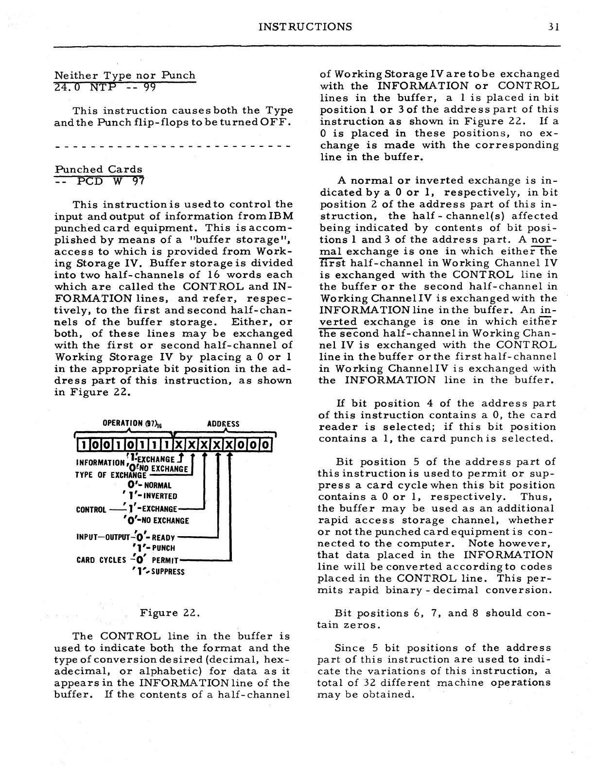
INSTRUCTIONS
31
Neither
Type
nor
Punch
24.
a
NTP
--
99
This
instruction
causes
both
the
Type
and
the
Punch
flip-flops
to
be
turned
OFF.
Punched
Cards
PCD
W
97
This
instruction
is
used
to
control
the
input
and
output
of
information
from
IBM
punched
card
equipment.
This
is
accom-
plished
by
means
of
a
"buffer
storage",
access
to
which
is
provided
from
Work-
ing
Storage
IV.
Buffer
storage
is
divided
into
two
half-
channels
of
16
words
each
which
are
called
the
CONTROL
and
IN-
FORMATION
lines,
and
refer,
respec-
tively,
to
the
first
and
second
half-chan-
nels
of
the
buffer
storage.
Either,
or
both,
of
these
lines
may
be
exchanged
with
the
first
or
second
half-
channel
of
Working
Storage
IV
by
placing
a 0
or
1
in
the
appropriate
bit
position
in
the
ad-
dress
part
of
this
instruction,
as
shown
in
Figure
22.
OPERATION
(97~6
INFORMATION
q!E~CHANGE:J
'O!NO
EXCHANGE
TYPE
OF
EXCHANGE
0'0-
NORMAL
, 1
'-INVERTED
, , 0
CONTROL
-J -
EXCHANGE
, O'-NO
EXCHANGE
ADDRESS
, ,
INPUT-OUTPUT-:O
-
READY
----I
'1'-
PUNCH
CARD
CYCLES
.!O'
PERMIT----.&
,
1'
...
SUPPRESS
Figure
22.
The
CONTROL
line
in
the
buffer
is
used
to
indicate
both
the
format
and
the
type
of
conversion
desired
(decimal,
hex-
adecimal,
or
alphabetic)
for
data
as
it
appears
in
the
INFORMATION
line
of
the
buffer.
If
the
contents
of
a
half-channel
of
Working
Storage
IV
are
to
be
exchanged
with
the
INFORMATION
or
CONTROL
lines
in
the
buffer,
a I
is
placed
in
bit
position
1
or
3
of
the
addre
s s
part
of
this
instruction
as
shown
in
Figure
22.
If
a
o
is
placed
in
these
positions,
no
ex-
change
is
made
with
the
corresponding
line
in
the
buffe
r.
A
normal
or
inverted
exchange
is
In-
dicated
by
a 0
or
1,
respectively,
in
bit
position
2
of
the
address
part
of
this
in-
struction,
the
half
-
channel(s)
affected
being
indicated
by
contents
of
bit
posi-
tions
1
and
3
of
the
address
part.
A
nor-
mal
exchange
is
one
in
which
eitherttle
first
half-channel
in
Working
Channel
IV
is
exchanged
with
the
CONT
ROL
line
in
the
buffer
or
the
second
half-channel
in
Working
Channel
IV
is
exchanged
with
the
INFORMATION
line
in
the
buffer.
An
in-
verted
exchange
is
one
in
which
either
the
second
half-channel
in
Working
Chan-
nel
IV
is
exchanged
with
the
CaNT
ROL
line
in
the
buffer
or
the
first
half-
channel
in
Working
ChannelIV
is
exchanged
with
the
INFORMATION
line
in
the
buffe
r.
If
bit
position
4
of
the
addre
s s
part
of
this
instruction
contains
a
0)
the
card
reader
is
selected;
if
this
bit
position
contains
a
1,
the
card
punch
is
selected.
Bit
position
5
of
the
addre
s s
part
of
this
instruction
is
used
to
permit
or
sup-
press
a
card
cycle
when
this
bit
position
contains
a 0
or
1,
respectively.
Thus,
the
buffer
may
be
used
as
an
additional
rapid
access
storage
channel,
whether
or
not
the
punched
card
equipment
is
con-
nected
to
the
computer.
Note
however,
that
data
placed
in
the
INFORMATION
line
will
be
converted
according
to
codes
placed
in
the
CONTROL
line.
This
per-
mits
rapid
binary
-
decimal
conversion.
Bit
positions
6, 7,
and
8
should
con-
tain
zeros.
Since
5
bit
positions
of
the
address
part
of
this
instruction
are
used
to
indi-
cate
the
variations
of
this
instruction,
a
total
of
32
different
machine
operations
rna
y
be
obtained.
32
ALWAC
III-E
It
should
be
noted
that
the
contents
of
the
indicated
half-channels
are
exchanged
before
conversion
or
card
cycles
occur.
Hence,
inforrnation
from
either
Working
Channel
IV
or
the
buffer
may
be
punched
on
the
same
card
cycle;
however,
infor-
mation
read
into
the
buffer
on
the
previ-
ous
card
cycle
appears
in
Working
Chan-
nel
IV
after
the
exchange.
In
order
to
operate
the
punched
card
equipment
at
maximum
speed,
proce
s
s-
ing
of
the·
information
placed
in
Working
Channel
IV
is
accomplished
during
the
conversion
cycle
before
the
card
reaches
the
"9-time"
position.
Since
a
change
in
format
require
s
exchange
with
the
CON-
TRoL
line,
a
blank
card
is
usually
placed
at
the
end
of
each
file
of
cards.
MAGNETIC
TAPE
OPERATIONS
The
following
instructions
are
used
for
control
of
the
magnetic
tape
buffer
and
of
individual
tape
units.
Bit
posi-
tions
1-4
of
the
address
part
of
these
in-
structions
are
used
to
indicate
the
de-
sired
sub-operation
in
accordance
with
the
hexadecimal
codes
given
in
the
de-
scription
of
the
instruction.
See
Figure
23.
When
it
is
necessary
to
specify
an
individual
tape
unit,
bit
positions
5-8
are
used
for
this
purpose.
Thus,
as
m.any
as
16
tape
units
may
be
used
which
are
num.bered,
hexadecirnally,
from.
0
to
F.
ADDRESS
t
_----------~A~--------
__
-,
_I
-,----r-I
--r-I-'r----r-I
---rl---"I
1 2 3 4
J\
5 6 7 8
v V
SUB-OPERATION
TAPE
UNIT
Figure
23.
Each
individual
tape
unit
contains
a
Comparing
Register
which
is
used
for
searching
operations.
The
C (
A)
re-
place
the
contents
of
this
register
before
searching
operations
are
started.
In
the
explanation
of
instructions
which
follows,
the
first
word
in
each
tape
record
is
in-
dicated
by
the
symbol
WI.
The
contents
of
this
word
are
com.pared
with,
the
con-
tents
of
the
Comparing
Register
during
searching
operations.
Magnetic
Tape
Status
1.
0
MTS
W
91
This
instruction
is
used
to
prepare
the
unit
to
read
or
to
write,
to
select
the
searching
mode
and
cause
searching
op-
erations
to
be
started,
to
test
for
com-
pletion
of
searching
operations,
or
to
re-
wind
a
tape
to
the
load
point.
Searching
operations
cause
the
con-
tents
of
the
A
Register
to
be
stored
in
the
CR
(Com.paring
Register)
of
the
des~
ignated
tape
unit,
after
which
the
com-'
puter
interlocks
are
released.
While
the
computer
continues
to
execute
instru:c-
tions
in
their
normal
sequence,
the
tape
m.oves
in
a
forward
direction
until
the
desired
tape
record
is
located.
In
the
following
explanation,
the
symbol
W 1
is
used
to
represent
the
first
word
in
a
given
tape
record.
Two
searching
modes
are
available:
Mode
1.
The
tape
unit
searches
for
the
tape
record
until
C(W
1)1_32:9C(CR)1_32.
Note
that
the
sign
positions
are
not
com-
pared.
Mode
2.
'Ihe
tape
unit
searches
for
the
tape
record
until
C(W
1
)29_32=C(CR)29_32.
The-
address
part
of
this
instruction
contains
the
designated
tape
unit
and
the
desired
operation
as
shown
in
Figure
23.
Bit
positions
-5-8
of
the
address
part
of
this
instruction
are
used
to
indicate
the
desired
tape
unit.
Bit
positions
1-4
of
the
address
part
of
this
instruction
are
used
to
indicate
the
_
de
sired
sub
-opera-
tion,
according
to
the
following
hexadeci-
mal
code:
INSTRUCTIONS
33
"0"
R~wind.
"1"
Set
unit
to
read
status.
"2"
Search
in
mode
1
and
set
to
read
status.
"3"
--
Search
in
mode
2
and
set
to
read
statu
s .
"4"
Test
for
completion
of
search-
ing
operation.
The
status
of
the
Ove
rflow
Indicator
lite
is
tested:
If
ON,
the
computer
sounds
the
alarm
2
buzzer;
if
OFF,
the
status
of
the
tape
unit
is
tested:
If
the
tape
unit
is
still
searching,
the
Overflow
Indicator
lite
is
turned
ON
and
the
computer
takes
the
next
in-
struction
in
sequence.
"5"
Set
unit
to
write
status.
"6"
Search
in
mode
1
and
set
to
write
status.
"7"
- -
Search
in
mode
2
and
set
to
write
status.
It
should
be
carefully
noted
that
all
the
above
codes
except
4
are
executed
im-
mediately
by
the
individual
tape
unit
and
overrule
any
previous
MTS
instruction
which
the
unit
maybe
in
proce
s s
of
exe-
cuting.
However,
this
overrule
action
will
not
interrupt
read-write
operations
being
executed;
instead,
the
computer
will
wait
until
completion
of
the
MTC
instruc-
tion
before
execution
of
a
MTS
instruc-:-
tion.
Magnetic
Tape
Copy
1.0
MTC W
93
This
instruction
causes
information
to
be
read
from
a
tape
and
copi~.d
into
the
magnetic
tape
buffer,
or
to
be
copied
from
the
buffer
and
written
on
the
tape.
Before
this
instruction
is
executed,
the
status
of
the
tape
unit
is
tested
and
com-
pared
with
the
operation
specified
in
the
address
part
of
this
instruction.
Thus,
when
reading
operations
are
attempted,
the
tape
unit
should
be
in
READ
status,
and
for
writing
operations,
the
tape
unit
should
be
in
WRITE
status.
If
the
tape
unit
is
in
the
wrong
status
for
the
given
operation,
the
given
MTC
inst.ruction
can-
not
be
executed,
the
machine
sounds
the
alarm
2
buzzer
and
stops.
If
the
alarm
switch
2
is
placed
in
the
RESTORE
po-
sition,
the
machine
will
execute
the
next
instruction
in
the
normal
sequence.
.It
should
be
noted
that
the
tape
unit
is
set
to
READ
status
after
a
rewind
operation.
This
rewind
operation
may
be
caused
by
execution
of
the
MTS
operation,
by
the
automatic
rewinding
of
the
tape
when
reaching
the
physical
end
of
the
tape,
or
by
the
manual
operation
of
the
control
switches
located
on
the
tape
transport.
Bit
positions
5-8
of
the
address
part
of
this
instruction
are
used
to
indicate
the
desired
tape
unit.
See
Figure
23.
Bit
positions
1-4
of.Jh~
..
address
part
of
this
instruction
are
used
to
indicate
the
desired
sub-operation,
according
to
the
following
hexadecimal
code:
"I"
--
Read
previous
record
into
the
buffer.
"2" - -
Read
next
record
into
the
buff-
er.
"3"
--
Read
same
record
into
the
buff-
er.
"5"
Write
previous
record
from
buffer.
Write
next
record
from
the
buffer.
"7"
Write
same
record
from
the
buffer.
Magnetic
Tape
Exchange
16. 0 MTX W 95
This
instruction
causes
the
contents
of
Working
Storage
IV
to
be
copied
into
the
magneti
c
tape
buffe
r,
0 r
the
content
s
34
ALWAC
In-E
of
the
buffer
to
be
copied
into
Working
Storage
IV,
or
causes
the
contents
of
the
buffer
and
Working
Storage
IV
to
be
ex-
changed.
Bit
positions
5-8
of
the
address
part
of
this
instruction
are
not
examined.
Bit
po
sitions
1-4
of
the
addre
s s
part
are
used
to
indicate
the
de
sired
sub
-op-
eration,
accordingto
the
following
hexa-
decimal
codes:
It
111
- -
The
content
s
of
the
buffe
r
re-
place
the
contents
of
Working
Storage
IV.
The
contents
of
the
buffer
are
not
changed.
"2
t1
--
The
contents
of
Working
Stor-
age
IV
replace
the
contents
of
the
buffer.
The
contents
of
Working
Storage
IV
are
not
changed.
113"
--
The
contents
of
Working
Stor-
age
IV
and
the
buf~er
are
ex-
changed.
ADDRESS
LOCATIONS
Each
half-word
in
the
four
Working··
.
Storage
channels
is
addressable,
the
ad-
dresses
00
to
7Fbeingused
for
left
half.:..
word
locations
and
80
to
FF
used
for
right
half-word
locations.
The
address
loca-
tions
contained
in
each
of
the
Working
Storage
channels
are
as
follows:
00
to
IF
and
80
to
9F
Working
Storage
I
20
to
3F
and
AO
to
BF
--
Working
Storage
II
40
to
5F
and
CO
to
DF
--
Working
Storage
III
60
to
7F
and
EO
to
FF
--
Working
Stoxeage
IV
Normal
sequencing
of
instructions
is
in
half-word
increments
from
the
left
to
the
right
half
of
an
instruction
word
and,
then,
to
the
left
half
of
the
next
instruc--:
tion
word.
in
sequence
as
shown
in
Figure
24
which
illustrates
the
normal
sequence
for
Working
Channel
I.
.
Note
that
the
in-
struction
which
follows
80
is
04
(not
0
I),
that
a I
follows
9C,
and
.
that
00
follows
9F.
Normal
address
sequencing
in
the
re-
maining
.
Working
Storage
channels
is
similar.
ADDRESS
MODIFICATION
Automatic
address
modification
maybe
achieved
when
using
instructions
whose
hexadeci:mal
instruction
codes
are
odd
numbers.
This
is
accomplishedby
using
a
code
obtained
by
subtracting
1
from
the
instruction
code.
When
the
instruction
is
executed,
the
literal
address
is
added
to
the
21s
complement
of
the
contents
of
theE
Register
to
determine
an
effective
address
which
is
placed
in
the
Address
Register
and
is
used
for
the
execution
of
the
instruction.
For
example,
assume
that
the
ADD
instruction
is
to
be
use.d
and
that
the
E
Register
contains
the
hexadecimal
num-
ber
0001.
The
he1adecimal
instruction
code
for
the
ADD
instruction
is
61
which
would
be
written
as
60
together
with
an
address.
Thus,
the
instruction
6024
with
the
literal
address
24
would
be
added
to
the
21s
complement
9f
the
E
Register
(which,
in
this
example,
is
FFFF),
there-
by
obtaining
the
effective.
address
23.
Hence,
when
the
E
Register
contains
0001,
the
instruction
6024
is
executed
in
the
same
manner
as
if
the
instruction
6123
had
been
given.
The
distinct
advantage
to
such"
indexing
operations
is
the
manner
in
which
ad.dre
s s
modification
rna
y
be
used
to
select
one
quantity
from
a
set,
the
elements
of
which
are
stored
in
suc-
cessive
word
locations.
An
example
of
such
usage
is
given
in
the
section
titled
"Symbolic
Programming".
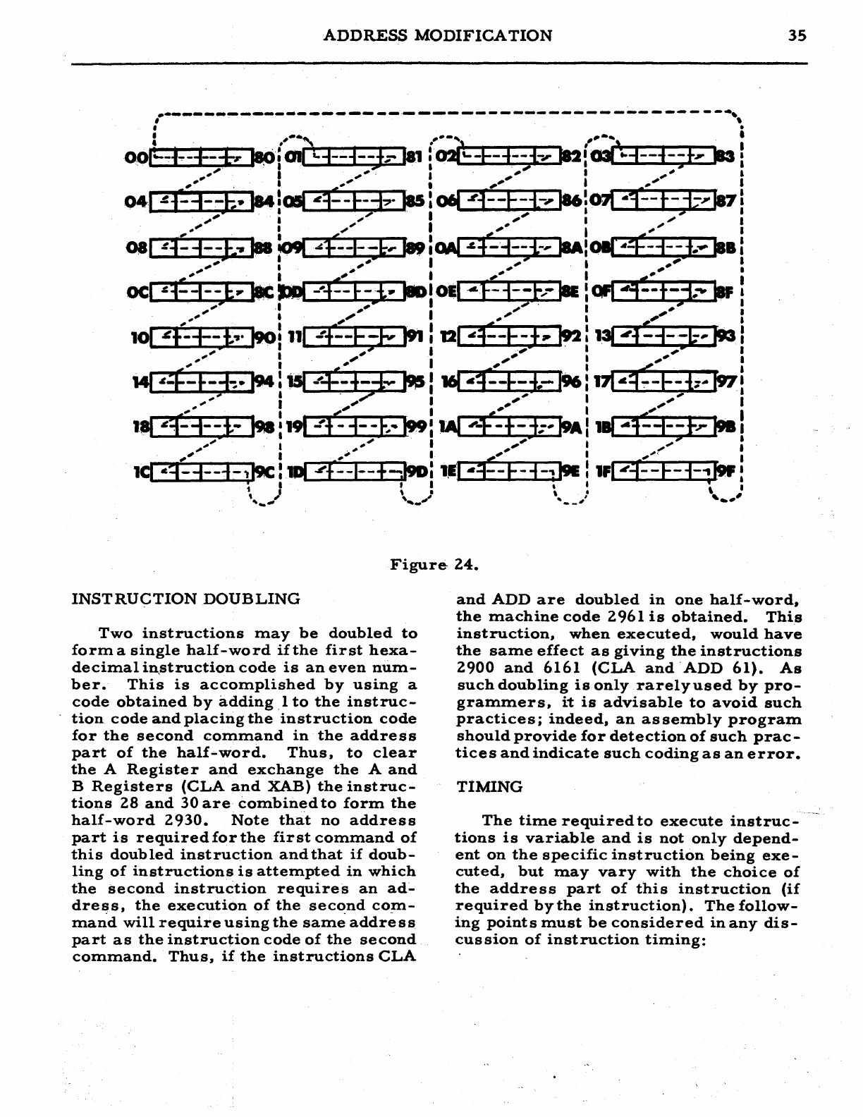
ADDRESS
MODIFICATION
35
Figure-
24.
INSTRUCTION
DOUBLING
Two
instructions
may
be
doubled
to
forma
single
half-word
if
the
first
hexa-
decimal
in,struction
code
is
an
even
num-
ber.
This
is
accomplished
by
using
a
code
obtained
by
adding
1
to
the
instruc-
tion
code
and
placing
the
instruction
code
for
the
second
command
in
the
address
part
of
the
half-word.
Thus,
to
clear
the
A
Register
and
exchange
the
A
and
B
Registers
(CLA
and
XAB)
the
instruc-
tions
28
and
30
are
combined
to
form
the
half-word
2930.
Note
that
no
address
part
is
requiredforthe
first
command
of
this
doubled
instruction
and
that
if
doub-
ling
of
instructions
is
attempted
in
which
the
second
instruction
requires
an
ad~
dress,
the
execution
of
the
second
co~
mand
will
require
using
the
same
address
part
as
the
instruction
code
of
the
second
command.
Thus,
if
the
instructions
CLA
and
ADD
are
doubled
in
one
half-word,
the
machine
code
2961
is
obtained.
This
instruction,
when
executed,
would
have
the
same
effect
as
giving
the
instructions
2900
and
6161
(CLA
and
'ADD
61).
As
such
doubling
is
only
rarelyused
by
pro-
grammers,
it
is
advisable
to
avoid
such
practices;
indeed,
an
as
sembly
program
should
provide
for
detection
of
such
prac-
tices
and
indicate
such
coding
as
an
error.
TIMING
The
time
required
to
execute
instruc-
tions
is
variable
and
is
not
only
depend-
ent
on
the
specific
instruction
being
exe-
cuted,
but
may
vary
with
the
choice
of
the
address
part
of
this
instruction
(if
required
by
the
instruction).
The
follow-
ing
points
must
be
considered
in
any
dis-
cussion
of
instruction
timing:
36
ALWAC
III-E
1.
The
word
location
at
~..vhich
the
drum
is
positioned
at
the'
time
of
com-
pletion
of
the
last
instruction.
If
the
cur-
rent
instruction
is
in
the
left
side
of
an
instruction
word,
the
drum
must
turn
until
it
is
positioned
to
read
this
instruc-
tion
word.
If
the
current
instruction
is
in
the
right
side
of
an
instructio~
word,
and
such
word.is
acce
s
sible
from
the
right
side
of
the
E
Register
(as
the
result
of
execution
of
the
left
instruction
in
the
same
instruction
word),
only
one
word-
time
is
required
to
tra.nsfer
the
contents
to
the
instruction
and
address
registers.
If
the
current
instruction
is
a
right
ad-
dress
and
such
word
is
not
accessible
from
the
right
side
of
the
E
Register
(as
the
result
of
a
transfer
instruction
from
some
othe
r
word
location),
the
drum
must
turn
until
it
is
positioned
to
read
this
in-
struction
word.
In
all
of
the
above
cases,
the
mini-
,mum
access
time
will
be
O.
5
milliseconds
(one
word-time)
and
the
maxim.um,.
8.0
milliseconds
(16
word-times).
2.
If
the
instruction
requires
refer-
ence
to
the
contents
of
a
word
location
specified
in
the
address
part
of
the
in-
struction,
a
search
is
required.
This
search
starts
immediately,
and,
there-
fore,
timing
considerations
:glust
involve
the
positions
of
the
drum
at
the
time
this
action
starts
and
at
the
time
when
it
is
positioned
to
read
the
word
specified
in
the
address
part
of
the
instruction.
In
all
cases,
however,
access
time
will
vary
between
0.0
and
8.0
milliseconds.
3.
The
execution
time
required
for
an
instruction,
after
the
contents
of
the
oper-
and
address
have
been
obtained,
is
given
in
the
Description
of
Instructions.
See
pages
19
to
34.
4.
The
shifting.
instructions
require
O.
5
milliseconds
for
each
shift
(modulo
64)
specified
in
the
address
part
of
the
instruction.
The
transfer
instructions
require
vary-
ing
amounts
of
time
depending
upon
the
re-
sult
of
various
testing
operations.
Maxi-
mum
time
for
such
instruction~
is
8.0
milliseconds.
5.
Input-output
instruction
times
are'
dependent
upon
typing
skills
or
upon
the
status
of
punched
tape'
and
certain
switch-
es
and,
therefore,
only
minimum
times
may
be
specified
for
these
types
of
in-
structions.
Hence,
the
dete
rmination
of
the
amount
of
time
required
for
the
execution
of
a
set
of
instructions,
although
computable,
is
sOnlewhat
complex.
Such
computations
may
be
included
in
Symbolic
Assembly
Programs
or
similar
executive
programs
without
significant
reductions
in
the
a-
mount
of
time
required
for
other
opera-
tions
performed
by
such
programs.
How-
ever,
certain
programming
rules
·are
re
commended
'to
pe
rmit
reduction
in
the
time
required
for
the
execution
of
instruc-
tions.
These
rules
produce
near-optimum
times
for
execution
of
instructions.
1.
If
an
instruction
appears
in
the
left-
half,
of
an
in
struction
word,
the
optinlum
address
is
one
whose
last
hexadecimal
digit
is
one
greater
thaii'tlie
location
ad-
dress
of
either
the
left
or
right
half
of
the
instruction
wora..
Thus,
for
loca-
tion
05,
the
optimum
addresses
are
06,
86,
16,
96,
26,
A6,
36,
B6,
46,
C6,
56,
D6,
66,
E6,
76,
and
F6.
2.
If
an
optimum
address
is
used
for
the
left
half
instruction,
the
optimum
ad,..
dress
for
the
right
half
instruction
is
one
whose
last
hexadecima1
digit
is
three
greate
r
than
the
loca.tion
addre
s s
of
eithe
r
the
left
or
right
half
of
the
instruction
word.
3.
If
a
non-optimum
address
is
used
for
the
left
half
instruction,
the
optimum
address
for
the
right
half
instruction
is
one
whose
last
hexadecimal
digit
is
at
least
two
greater
than
the
effective~
and
address
contained
in
the
left
instruc-
tion
or
a
word
location
whose
last
hexa-
decimal
digit
is
the
same
as
this
sum.
4.
Transfer
instructions
are
excep-
tions
to
the
above
rules.
For
left
half,
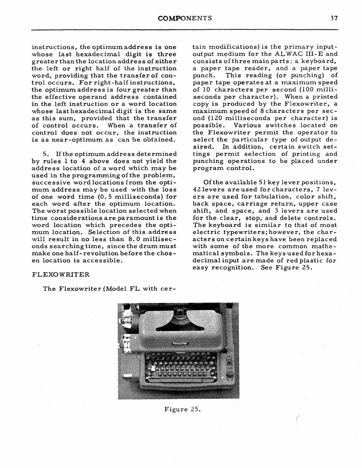
COMPONENTS
37
instructions,
the
optimum
addre
s s
is
one
whose
last
hexadecimal
digit
is
three
greater
than
the
location
address
of
either
the~
left
or
right
half
of
the
instruction
word,
providing
that
the
transfer
of
con-
troloccurs.
For
right-half
instructions,
the
optimum
address
is
four
greater
than
the
effective
operand
address
contained
in
the
left
instruction
or
a
word
location
whose
last
hexadecimal
digit
is
the
same
as
this
sum,
provided
that
the
transfer
of
control
occurs.
'When
a
transfer
of
control
does
not
occur,
the
instruction
is
as
near-optimum
as
can
be
obtained.
5.
If
the
optimum
addre
s s
dete
rmined
by
rule
s 1
to
4
above
doe
s
not
yield
the
address
location
of
a
word
which
may
be
used
in
the
programming
of
the
problem,
successive
word
locations
from
the
opti-
mum
address,
may
be
used
with
the
loss
of
one
word
time
(0.
5
milliseconds)
for
each
word
after
the
optimum
location.
The
worst
possible
location
s.elected
when
time
considerations
are
paramount
is
the
word
location
which
precede
s
the
opti-
mum
location.
Selection
of
this
address
will
result
in
no
less
than
8.0
millisec-
onds
searching
time,
since
the
drum
must
make
one
half-
revolution
before
the
chos-
en
location
is
acce
s
sible.
FLEXOWRITER
The
F1exowriter
(Model
FL
with
cer-
tain
modifications)
is
the
primary
input-
output
medium
for
the
ALWAC
III-E
and
consists
of
three
main
parts:
a
keyboard,
a
paper
tape
reader,
and
a
paper
tape
punch.
This
reading
(or
punching)
of
paper
tape
operates
at
a
maximum
speed
of
10
characters
per
second
(100
milli-
seconds
per
character).
When
a
printed
copy
is
produced
by
the
Flexowriter,
a
maximum
speed
of
8
characters
per
sec-
ond
(120
milliseconds
per
character)
is
possible.
Various
switches
located
on
the
Flexowriter
permit
the
operator
to
select
the
particular
type
of
output
de-
sired.
In
addition,
certain
switch
set-
tings
permit
selection
of
printing
and
punching
operations
to
be
placed
under
program
control.
Of
the
available
51
key
lever
positions,
42
levers
are
used
for
characters,
7
lev-
ers
are
used
for
tabulation,
color
shift,
back
space,
carriage
return,
upper
case
shift,
and
space,
and
3
levers
are
used
for
the
clear,
stop,
and
delete
controls.
The
keyboard
is
similar
to
that
of
most
electric
typewriters;
however,
the
char-
acters
on
certain
keys
have
been
replaced
with
some
of
the
more
common
mathe-
matical
symbols.
The
keys
used
for
hexa-
decimal
input
are
made
of
red
plastic
for
easy
recognition.
See
Figure
25.
Figure
25.
/
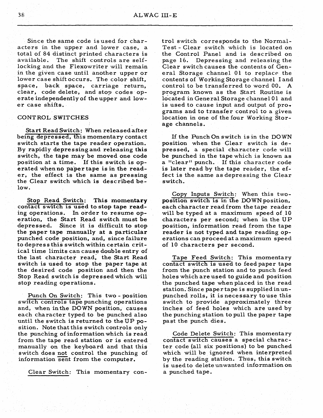
38
ALWAC
III-E
Since
the
same
code
is
used
for
char-
acters
in
the
upper
and
lower
case,
a
total
of
84
distinct
printed
characters
is
available.
The
shift
controls
are
self-
locking
and
the
Flexowrite
r
will
remain
in
the
given
case
until
another
upper
or
lower
case
shift
occurs.
The
color
shift,
space,
back
space,
carriage'
return,
clear,
code
delete,
and
stop
codes
op-
erate
independently
of
the
upper
and
low-
er
case
shifts.
CONTROL
SWITCHES
Start
Read
Switch:
When
releasedafter
being
depressed,
this
momentary
contact
switch
starts
the
tape
reader
operation.
By
rapidly
depressing
and
releasing
th.is
switch,
the
tape
may
be
moved
one
code
position
at
a
time.
If
this
switch
is
op-
erated
when
no
paper
tape
is
in
the
read-
er,
the
effect
is
the
sa:me
as
pressing
the
Clear
switch
which
is
described
be-
low.
Stop
Read
Switch:
This
:momentary
contact
switch
IS
used
to
stop
tape
read-
ing
operations.
In
order
to
resume
op-
eration,
the
Start
Read
switch
must
be
depressed.
Since
it
is
difficult
to
stop
the
paper
tape
m.anually
at
a
particular
punched
code
position,
and,
since
failure
to
depress
this
switch
within
certain
crit-
ical
time
limits
can
cause
double
entry
of
the
last
character
read;
the
Start
Read
switch
is
used
to
stop
the
paper
tape
at
the
desired
code
position
and
then
the
Stop
Read
switch
is
depre
s
sed
which
will
stop
reading
operations.
Punch
On
Switch:
This
two
-
position
sWItch
controls
tape
punching
operations
and,
when
in
the
DOWN
position,
causes
each
character
typed
to
be
punched
also
until
the
switch
is
returned
to
the
UP
po-
sition.
Note
that
this
switch
controls
only
the
punching
of
information
which
is
read
from.
the
tape
read
station
or
is
entered
m.anually
on
the
keyboard
and
that
this
switch
does
not
control
the
punching
of
information
sent
from.
the
com.puter.
Clear
Switch:
This
momentary
con-
trol
switch
corre
sponds
to
the
Normal-
Test
-
Clear
switch
which
is
located
on
the
Control
Panel
and
is
described
on
page
16.
Depressing
and
releasing
the
Clear
switch
causes
the
c.ontents
of
Gen-
eral
Storage
channel
01
to
replace-
the
contents
of
Working
Storage
channel
I
and
control
to
be
transferred
to
word
00.
A
p~ogram
known
as
the
Start
Routine
is
located
in
General
Storage
channel
Oland
is
used
to
cause
input
and
output
of
pro
...
grams
and
to
transfer
control
to
a
given
location
in
one
of
the
four
Working
Stor-
age
channels.
If
the
Punch
On
switch
is
in
the
DOWN
position
when
the
Clear
switch
is.
de-
pressed,
a
special
character
code
will
be
punched
in
the
tape
which
is
known
as
a
"clear
11
punch.
If
this
character
code
is
later
read
by
the
tape
reader,
the
ef-
fect
is
the
same
as
depressing
the
Clear
switch.
Copy
Inputs
Switch:
When
this
two-
position
switch
is
in
the
DOWN
position,
each
character
read
from
the
tape
reader
will
be
typed
at
a
maximum
speed
of
.10
characters
per
second;
when
in
the
UP
position,
information
read
from
the
tape
reader
is
not
typed
and
tape
reading
o.P-
erations
can
proceed
at
a
maximum
speed
of
10
characters
per
second.
Tape
Feed
Switch:
This
momentary
contact
switch
is
used
to
feed
paper
tape
from
the
punch
station
and
to
punch
feed
holes
which
are
used
to
guide
and
position
the
punched
tape
when
placed
in
the
read
station;
Since
paper
tape
is
supplied
in
un-
punched
rolls,
it
is
necessary
to
use
this
switch
to
provide
approximately
three
inches
of
feed
holes
which
are
used
by
the
punching
station
to
pull
the
paper
tape
pa
st
the
punch
die
s.
Code
Delete
Switch:
Thism.omentary
contact
switch
cause
s a
special
charac-
ter
code
(all
six
positions)
to
be
punched
which
will
be
ignored
when
inte
rpreted
by
the
reading
station.
Thus,
this
switch
is
used
to
delete
unwanted
information
on
a
punched
tape.
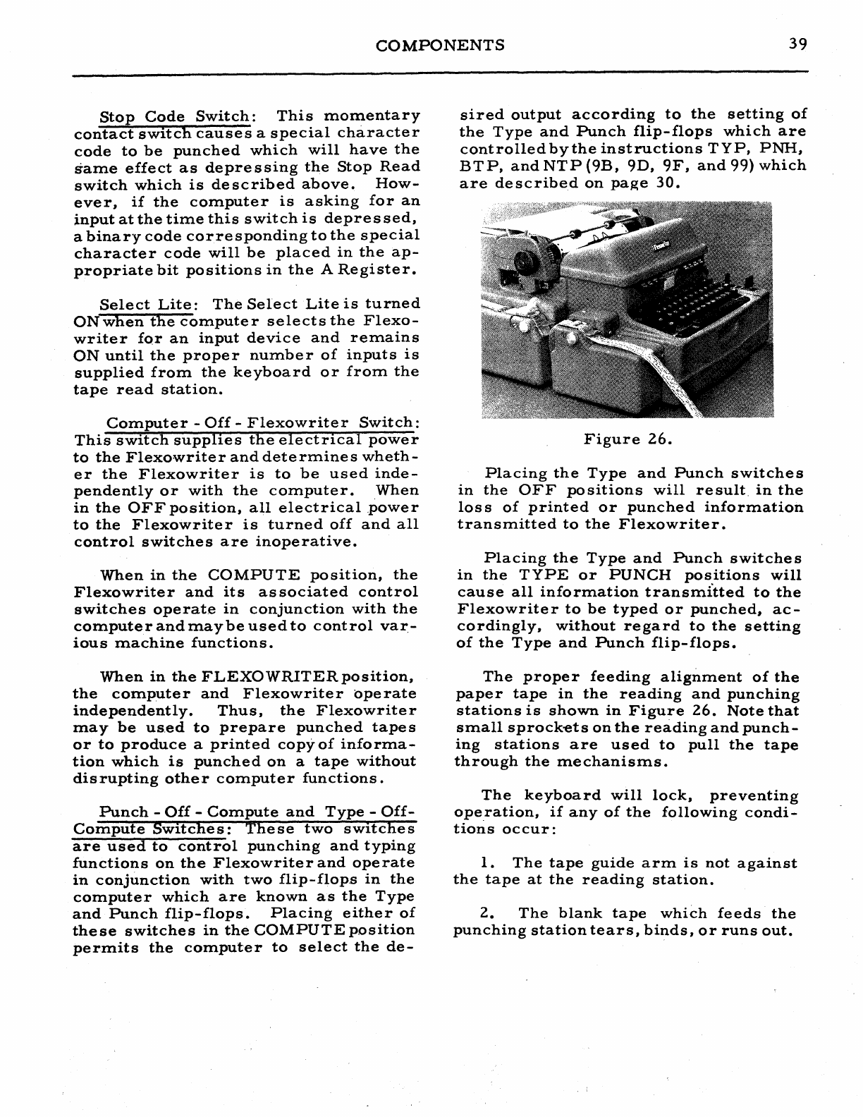
COMPONENTS
39
Stop
Code
Switch:
This
momentary
contact
switch
causes
a
special
character
code
to
be
punched
which
will
have
the
same
effect
as
depressing
the
Stop
Read
switch
which
is
described
above.
How-
ever,
if
the
computer
is
asking
for
an
input
at
the
time
this
switch
is
depressed,
a
binary
code
corresponding
to
the
special
character
code
will
be
placed
in
the
ap-
propriate
bit
positions
in
the
A
Register.
Select
Lite:
The
Select
Lite
is
turned
ONwhen
the
computer
selects
the
Flexo-
writer
for
an
input
device
and
remains
ON
until
the
proper
number
of
inputs
is
supplied
from
the
keyboard
or
from
the
tape
read
station.
Computer
-
Off
-
Flexowriter
Switch:
This
switch
supplies
the
electrical
power
to
the
Flexowriter
and
determines
wheth-
er
the
Flexowriter
is
to
be
used
inde-
pendently
or
with
the
computer.
When
in
the
OFF
position,
all
electrical
.power
to
the
Flexowriter
is
turned
off
and
all
control
switches
are
inoperative.
When
in
the
COMPUTE
position,
the
Flexowriter
and
its
as
sociated
control
switches
operate
in
conjunction
with
the
computer
and
may
be
used
to
control
var-
ious
machine
functions.
When
in
the
FLEXOWRITERposition,
the
computer
and
Flexowriter
operate
independently.
Thus,
the
Flexowriter
rna
y
be
uS.ed
to
prepare
punched
tape
s
or
to
produce
a
printed
copy-of
informa-
tion
which
is
punched
on
a
tape
without
disrupting
other
computer
functions.
Punch
-
Off
-
Compute
and
Type
-
Off-
Compute
Switches:
These
two
switches
are
used
to
control
punching
and
typing
functions
on
the
Flexowriter
and
operate
in
conjunction
with
two
flip-flop.s
in
the
computer
which
are
known
as
the
Type
and
Punch
flip-flops.
Placing
either
of
these
switches
in
the
COMPUTE
position
permits
the
computer
to
select
the
de-
sired
output
according
to
the
setting
of
the
Type
and
Punch
flip-flops
which
are
controlled
by
the
instructions
TYP,
PNH,
BTP,
and
NTP
(9B,
9D,
9F,
and
99)
which
are
described
on
page
30.
Figure
26.
Placing
the
Type
and
Punch
switches
in
the
OFF
positions
will
result.
in
the
los
s
of
printed
or
punched
information
transmitted
to
the
Flexowriter.
Placing
the
Type
and
Punch
switches
in
the
TYPE
or
PUNCH
positions
will
cause
all
information
transmi'tted
to
the
Flexowrite
r
to
be
typed
or
punched,
ac-
cordingly'
without
regard
to
the
setting
of
the
Type
and
Punch
fIi
p-
flo
ps.
The
proper
feeding
alignment
of
the
paper
tape
in
the
reading
and
punching
stations
is
shown
in
Figure
26.
Note
that
small
sprock-ets
on
the
reading
and
punch-
ing
stations
are
used
to
pull
the
tape
through
the
mechanisms.
The
keyboard
will
lock,
preventing
operation,
if
any
of
the
following
condi-
tions
occur:
1.
The
tape
guide
arm
is
not
against
the
tape
at
the
reading
station.
2.
The
blank
tape
which
feeds
the
punching
station
tears,
binds,
or
runs
out.
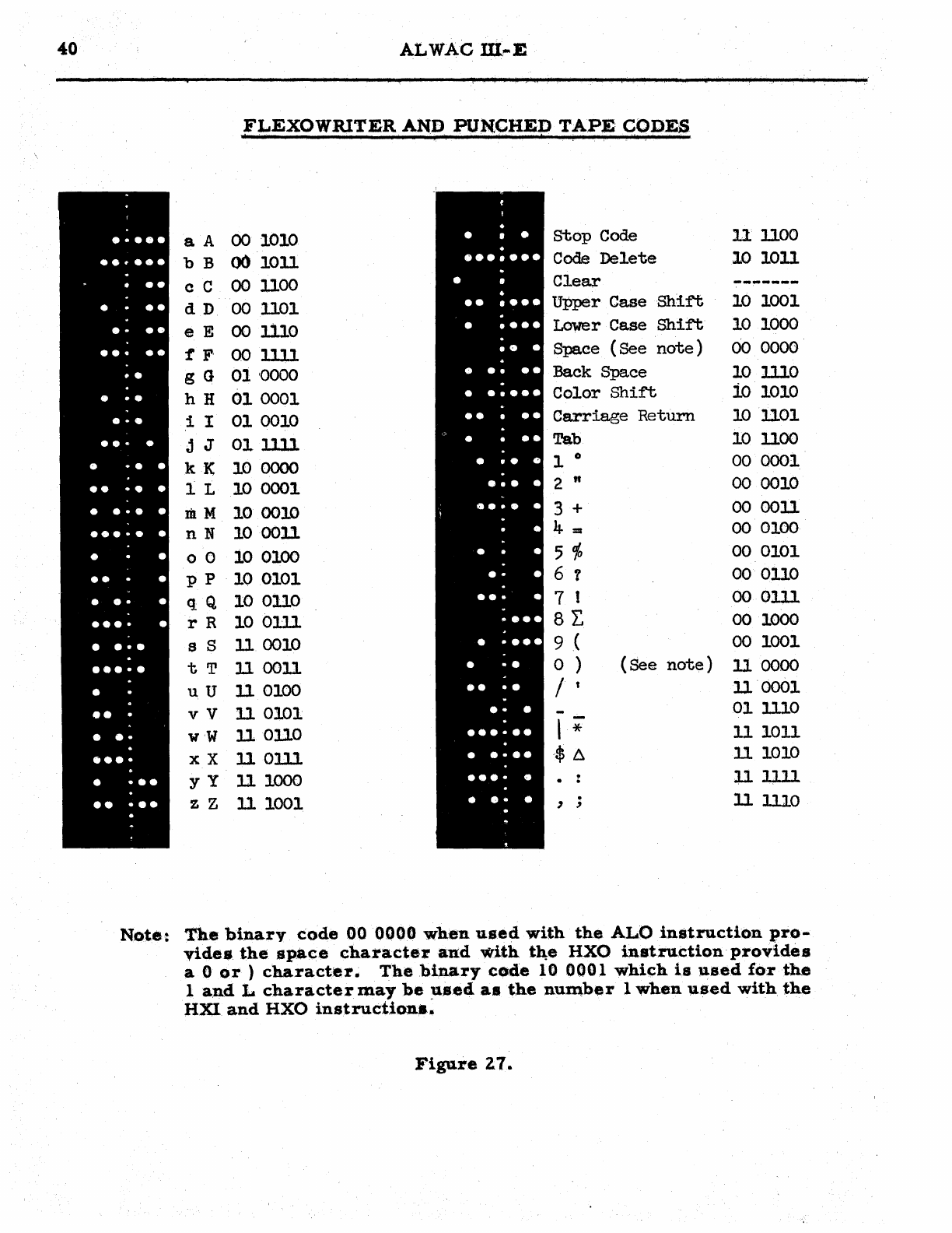
40
ALWAcm""E
FLEXOWRlTER
AND
PUNCHED
TAPE
CODES
•••••
aA
00
1010
stop
Code
11
1100
.......
bB
00
1011
Code
Delete
10
1011
••
c C
00
1100
Clear
-------
• • •
dD
00
1101
Upper
Case
Shift
10
1001
• •
••
e E
00
1110
Lower
Case
Shift
10
1000
•••
••
t
F'
00
llll
Space
(See
note)
00
0000
• •
• -.
gG
01
'0000
Back
Space
10
1110
hH
01
0001
Color
Shift
io
1010
•••
i I
01
0010
Carriage
Return
10
1101
••• •
• • • • j J
01ll1l
Tab
10
1100
kK
10
0000
1 0
00
0001
•• • • • 1 L
10
0001
2
It
00
0010
•
•••
• mM
10
0010
3 +
00
0011
•••••
•
nN
100011
4 =
00
0100
• • o 0
10
0100
5
10
00
0101
•• •
pP
100101
6 1
00
0110
•
.-
•
•••• •
qQ
10
0110
7 t
00
0111
rR
100111
8L.
00
1000
• ••• s S
11
0010
9 (
00
1001
••••• t T
11
0011
0 )
(See
note)
11
0000
•
uU
11
0100
/t
11'0001
••
•
••
vV
II
0101
--
01
1110
wW
110110
,
*
II
1011
••••
xX
11
Olll
~$
6
II
1010
• •••
yY
11
1000
. •
111lll
.
•• ••• z Z
11
1001
, ;
11
1110
Note:
The
binary
code
000000
when
used
with
the
ALO
instruction
pro-
videa
the
space
character
and
with
t1l:e
HXO
in
stru.ction
'
provides
a 0
or
)
character.
The
binary
code
10
0001
which
is
used
for
the
land
L
character
may
be
:a.sed
as
the
nw:nber
1
when
"sed
with
the
HXl
and
HXO
instruction
••
Figure
2.1
•
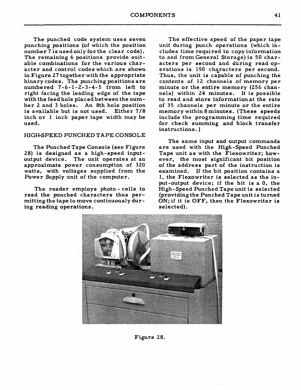
COMPONENTS
41
The
punched
code
system
use
s
seven
punching
positions
(of
which
the
position
number
7
is
used
only
for
the
clear
code).
The
remaining
6
positions
provide
suit-
able
combinations
for
the
various
char-
acter
and
control
codes
which
are
shown
in
Figure
27
together
with
the
appropriate
binary
codes.
The
punching
positions
are
numbered
7-6-1-2-3-4-5
from
left
to
right
facing
the
leading
edge
of
the
tape
with
the
feed
hole
placed
between
the
num-
ber
2
and
3
holes.
An
8th
hole
position
is
available
but
is
not
used.
Either
7/8
inch
or
'I
inch
paper
tape
width
may
be
used.
HIGH-SPEED
PUNCHED
TAPE
CONSOLE
The
Punched
Tape
Console
(see
Figure
28)
is
designed
as
a
high-
speed
input-
output
device.
The
unit
operate
s
at
an
approximate
power
consumption
of
320
watts,
with
voltages
supplied
from
the
Power
Supply
unit
of
the
computer.
The
reader
employs
photo
-
cells
to
read
the
punched
characters
thus
per-
mitting
the
tape
to
move
continuously
dur-
ing
reading
operations.
The
effective
speed
of
the
paper
tape
unit
during
punch
operations
(which
in-
cludes
time
required
to
copy
information
to
and
from
General
Storage)
is
50
char-
acters
per
second
and
during
read
op-
erations
is
150
cha.racters
per
second.
Thus,
the
unit
is
capable
of
punching
the
contents
of
12
channels
of
memory
per
minute
or
the
entire
memory
(256
chan-
nels)
within
24
minutes.
It
is
possible
to
read
and
store
information
at
the
rate
of
35
channels
per
minute
or
the
entire
memory
within
8
minutes.
(These
speeds
include
the
programming
time
required
for
check
summing
and
block
transfer
instructions.
)
The
same
input
and
output
commands
are
used
with
the
High-Speed
Punched
Tape
unit
as
with
the
Flexowriter;
how-
ever,
the
most
significant
bit
position
of
the
address
part
of
the
instruction
is
examined.
If
the
bit
position
contains
a
I,
the
Flexowriter
is
selected
as
the
in-
put-output
device;
if
the
bit
is
a
0,
the
High-Speed
Punched
Tape
unit
is
selected
(providing
the
Punched
Tape
unit
is
turned
ONi
if
it
is
OFF,
then
the
Flexowriter
is
selected)
.
Figure
28.
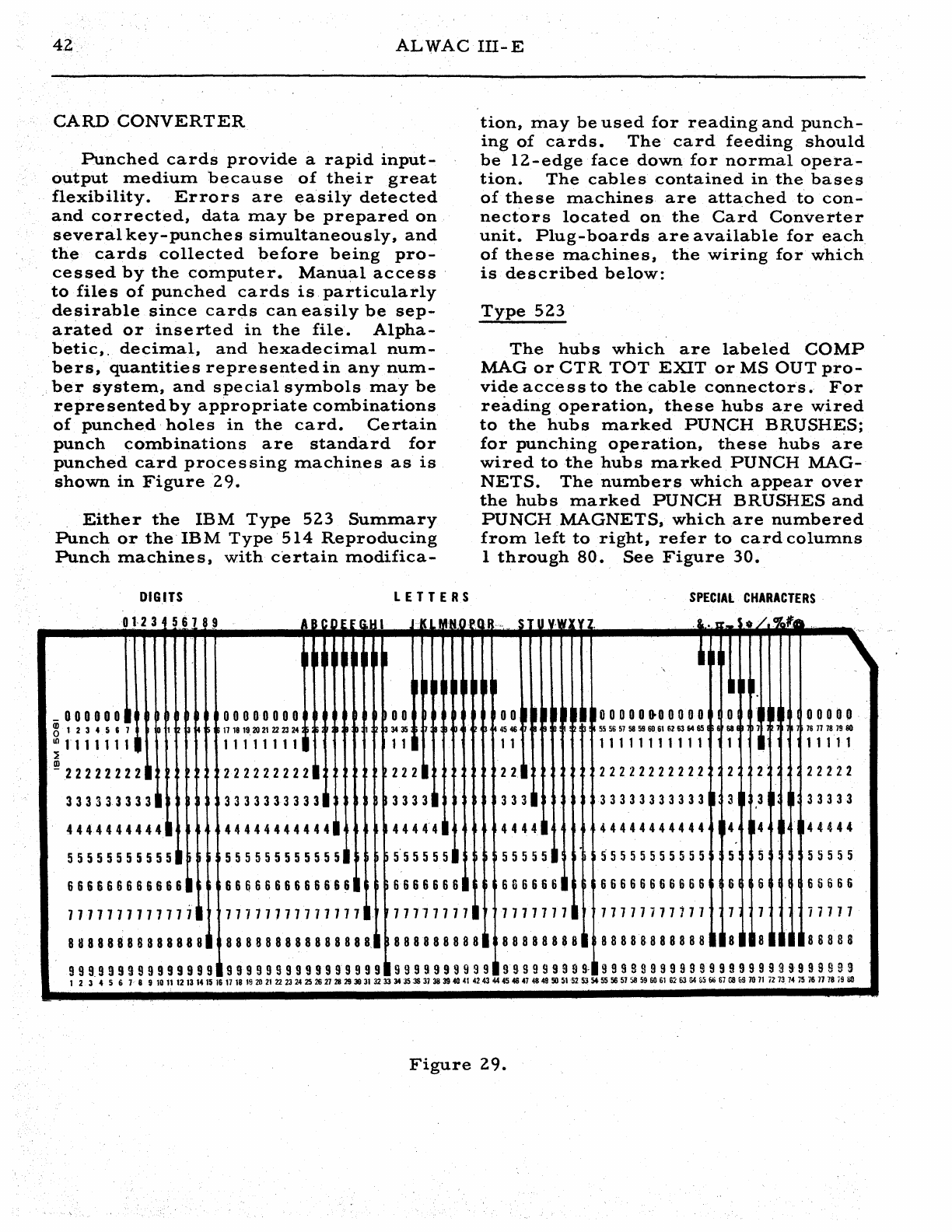
4.2
ALWAC
III-E
CARD
CONVERTER
Punched
cards
provide
a
rapid
input-
output
:mediu:m
because
of
their
great
flexibility.
Errors
are
easily
detected
and
corrected,
data:ma
y
be
prepared
on
several
key-punches
si:multaneously,
and
the
cards
collected
before
being
pro-
cessed
by
the
computer.
Manual
access
to
files
of
punched
cards
is
particularly
desirable
since
carcis
can
easily
be
sep-
arated
or
inserted
in
the
file.
Alpha-
betic,.
deci:mal,
and
hexadeci:mal
num-
bers,
quantities
representedin
any
nu:m-
,ber
syste:m,
and
special
sy:mbols
may
be
represented
by
appropriate
co:mbinations
of
punched
holes
in
the
card.
Certain
punch
co:mbinations
are
standard
for
punched
card
processing
:machines
as
is
shown
in
Figure
29.
Either
the
IBM
Type
523
Summary
Punch
or
the
IBM
Type
514
Reproducing
Punch
machines,
with
c'ertain
modifica-
DIGITS
LETTERS
tion,
:may
be
used
for
reading
and
punch-
ing
of
cards.
The
card
feeding
should
be
12-edge
face
down
for
normal
opera-
tion.
The
cables
contained
in
the
bases
of
these
machines
are
attached
to
con-
nectors
located
on
the
Card
Converter
unit.
Plug-boards
are
available
for
each
of
these
:machines,
the
wiring
for
which
is
described
below:
Type
523
The
hubs
which
are
labeled
CaMP
MAG
or
CTR
TOT
EXIT
or
MS
OUT
pro-
vide
acce
s s
to
the
cable
connectors.
For
reading
operation,
these
hubs
are
wired
to
the
hubs
:marked
PUNCH
BRUSHES;
for
punching
operation,
these
hubs
are
wired
to
the
hubs
:marked
PUNCH
MAG-
NETS.
The
nu:mbers
which
appear
over
the
hubs
marked
PUNCH
BRUSHES
and
PUNCH
MAGNETS,
which
are
numbered
fro:m
left
to
right,
refer
to
card
columns
1
through
80.,
See
Figure
30.
SPECIAL
CHARACTERS
0,·23
561
9 , I I
"'~
.I~,
l_~
!,CI",
I
U.
• t • .
<!a'e"
,
~
II
I
~
~
,
II
I
~
~ ~
I
III.
_000000
~
~
00000000
00
00
I
~
!
~
II
I
~
0 0 00 0
.0
0 0 0 0 0
II
~I
00000
~1234567
~
1
~ ~
4 5
17
18
19
20
21
22 23 24
~
33435
~ ~
4546
~
55565758
59
60
61
6263
64
651
,16U
1 1 167118
19
80
10
11111111
11111111
~
1 1 1 1
11111111111
1 I 1 1 1 1 1
~
~2
2 2 2
2222
I
222222222~
222
I 2 2
~
22222222222
: 2 2
~
22222
3333333331
33333333331
~3333~
333
I
33333333333
1 3 3 I I
33333
4 4 4 4 4 4 4 4 4 4 .•
44444444444~
4444' 4
~
4444
I
44444444444
~4
~4
~
~
44444
55555555555
h
555555555555
)555555~
555551
55555555555
5 5 5
555
5
666666666666.
666666666&666
I
66666661
66666Sn
66666666666
6 6 6 S 6 6 6
7711111111711
~
177777717111111
117777111
7177111
~
11117711177
1 7 i 7 7 7 7
888888888888881
888888888888888~
888888888.
88888888.
8 8 8 8 8 8 8 8 8 8 8
1118
lila
I~
I
II
88888
Figure
29.

CARD
CONVERTER
43
Type
514
The
hubs
which
are
labeled
SELEC-
TOR
1
and
SELECTOR
2
provide
con-
nections
to
the
cable
connectors
and
are
wired
to
the
hubs
which
are
labeled
RE-
PRODUCING
BRUSHES
for
reading
op-
erations.
COMP
MAG
or
CTR
TOT
EXIT
or
MS
OUT
provide
access
to
the
cable
connectors
and
are
wired
to
the
hubs
which
al"e
labeled
PUNCH
MAGNETS
for
punching
operations.
The
numbers
which
appear
over
the
hubs
marked
PUNCH
BRUSHES,
REPRODUCING
BRUSHES
which
are
numbered
from
left
to
right,
refe
r
to
the
columns
1
through
80
on
the
card.
See
Figure
30.
Types
523
and
514
The
80
hubs
which
connect
to
the
cable
connectors
are
numbered
from
rip~t
to
left
and
correspond
to
80
hub
posltions
within
the
ca
rdconve
rte
r
which
are
called
columns
of
the
card
image
in
the
de
s-
cription
which
follows.
Two
half-channels
which
comprise
16
words
each
are
used
to
form
this
card
image.
These
half-channels
are
called
the
CONTROL
and
the
INFORMATION
lines
in
the
Card
Converter
unit.
The
CONT ROL
line
.is
used
to
indicate
both
the
card
format
and
the
type
of
conversion
desiredand
the
INFORMATION
line
con-
tains
the
data
read
from
the
card
or
to
be
punched
on
the
card.
These
half-chan-
nels
may
be
exchanged
with
either
of
the
half-channels
which
comprise
Working
Storage
IV
by
the
execution
of
the
PCD
instruction.
(See
page
31).
Upon
exe-
cution
of
this
instruction,
the
Card
Con-
verter
unit
examines
the
contents
of
the
.
CONTROL
line
and
causes
data
read
from
a
card
to
replace
the
contents
of
the
IN-
FORMATION
line,
or
data
contained
in
the
INFORMATION
line
to
be
punched
on
a
card,
according
to
the
contents
of
the
address
part
of
the
PCD
instruction.
Since
the
INFORMATION
line
may
con-
tain
binary
codes
which
represent
deci-
mal,
hexadecimal,
alphabetic,
or
special
characters,
it
is
necessary
to
specify
which
of
these
types
of
data
is
contained
in
each
of
the
16
~ords
of
the
INFORMA-
TION
line.
This
is
indicated
by
the
bi-
nary
positions
1-
2
of
the
Control
Word.
See
Figure
31.
The
number
of
columns
of
the
card
image
(not
to
exceed
8)
asso-
ciated
with
each
word
is
indicated
by
the
binary
positions
5 -
32
and
the
sign
bit
of
the
Control
Word.
Binary
position
4
of
the
Control
Word
is
used
to
indicate
a
special
timing
marker.
.5"23
~
UPlOD'U'Ci'N"G
hUSHES
15
20
OOOOOc.ooooooooooooo
o
2S
30
U
.0
o 0
'0
0 0 0 0 0 0 0 0 0 0 0 0 0 0 0
O'
0
AS
SO
"
'0
o 0 0 0
,~
0 0 0 0
~
0 0 0 0
~
0 0 0 0
:0
00000000000000000000
~
-0
0.
~
a
!L.
~OL~
DE~CT~ON;-!FO
C~.
LU:N-;-~~:~l;;-;SP~ITS~
00000000000000000000
'-'-GoOP.
EMITTEl-I-O
I , 3 ..
COM
7 • ,
10
00000000000000000000
~
10
2~E":oX
:~.7ol~x
~
flEPlODuCING
IItUSHU
15
:-~1C:
~r..x-~-~-:,o
~:
::
,:
::
'ute::,
MAGNETS"
:'\
I
___
~~~~~-=---~~II
(':
..
(F.A
:-:
..
,-:-->
'1::
1I,..........--------~~~~------'I1II
,r
" " "
.~"
II
..
III
111~~:-;::::~;z;*~~=~==-:iJIIII
::0 0
P~X.
~R.-~~~--;-
0 0 0
:.
So
IR~SH~-~
0 0 0
~:::
I~
5~PUHCH
UUSHES-,15
:::::
I\~;::::---
"
'-~'-COMP,t,RING
8RUSH~S-'~
SO
00000000000000000000
25
30
3~
~o
00000000000000000000
.5
50 55
40
00000000000000000000
45
70
n
80
o 0
o.
0 0 0 0 0 0 0 0 0 0 0 0 0 0 0 0 0
'-~'-COMP,t,RING
BRUSHES-IS
0000000000000000000
25
30
3)
0000000000000000000
~5
SO
~5
o 0 0
o·
0 0 0 0 0 0 0 0 0 0 0 0 0 0 0
45
70
1$
o 0 0 0 0 0 0 0 0 0 0 0 0 0 0 0 0 0 0
Figure
30.
To
explain
the
use
of
these
codes
a
relation
between
words
in
the
Control
and
Information
lines
must
be
defined:
A
CONTROL
word
and
an
INFORMATION
word
are
said
to
correspond
if
the
4
least
significant
binary
positions
of
the
address
location
of
the
words
are
the
same.
See
Figure
24.
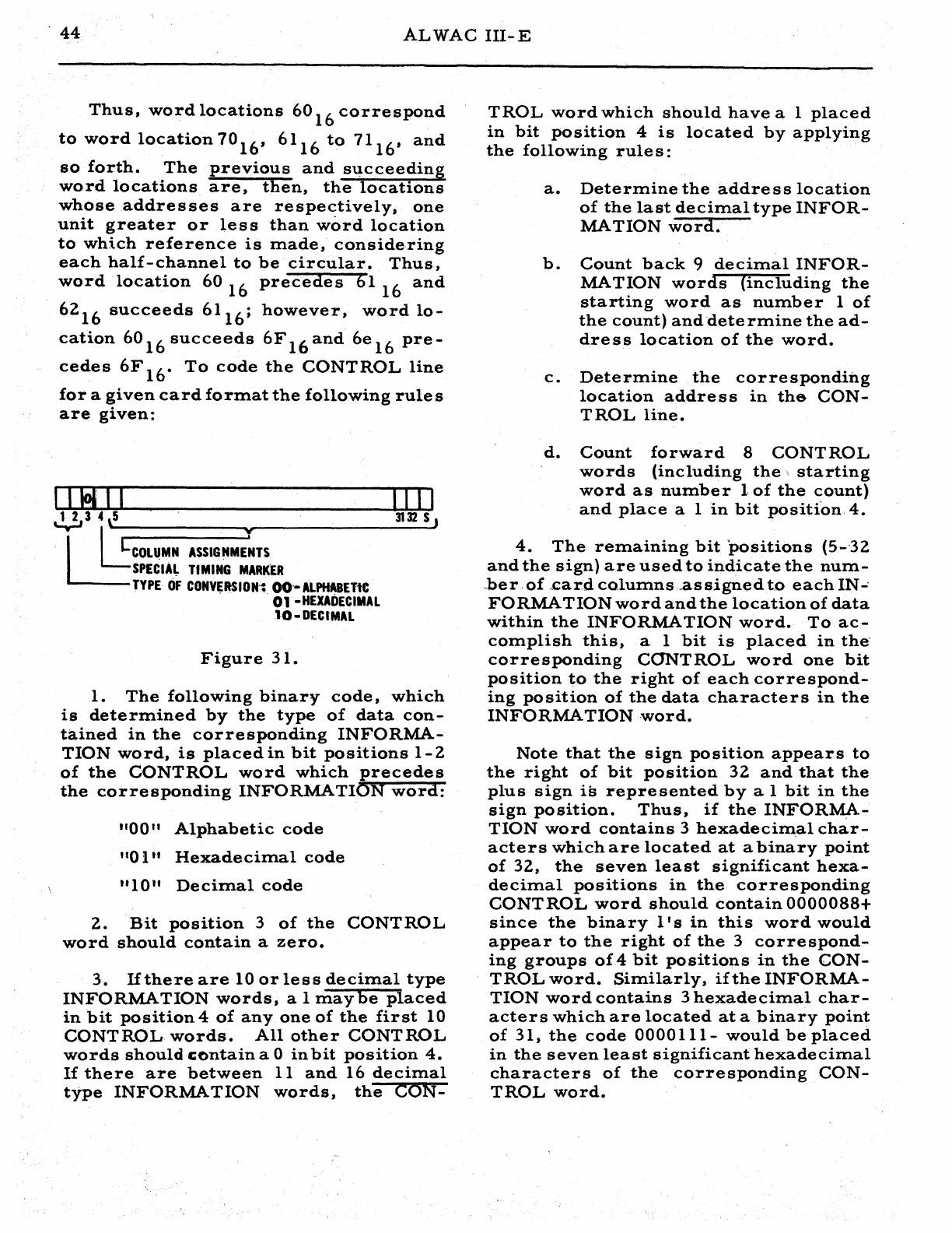
.
44
ALWAC
III-E
Thus,
word
locations
60
16
correspond
to
word
location
70
16
, 61
16
to
71
16
,
and
so
forth.
The
previous
and
succeeding
word
locations
are,
then,
the
locations
whose
addresses
are
respectively,
one
unit
greater
or
less
than
word
location
to
which
reference
is
made,
considering
each
half-channel
to
be
circular.
Thus,
word
location
60
16
precedes
61
16
and
62
16
succeeds
61
16
;
however,
word
lo-
cation
60
16
succeeds
6F
16
and
6e
16
pre-
cedes
6F
16.
To
code
the
CONTROL
line
for
a
given
card
format
the
following
rule
s
are
given:
11!l11
IIII
~3
4 ,5 '
3132
S J
I I
L:CO:L:~:M:N:A:S:S:IG:N:M~E:'T-S------------------~
SPECIAL
TIMING
MARKEl
TYPE
OF
CONVERSION';
00'·
ALPHABET1e
. . 01
-HEXADECIMAL
10-DECIMAL
Figure
31.
1.
The
following
binary
code,
which
is
determined
by
the
type
of
data
con-
tained
in
the
corresponding
INFORMA-
TION
word,
is
placed
in
bit
positions
1-2
of
the
CONTROL
word
which
precedes
the
corresponding
INFORMATION
word:
"00"
Alphabetic
code
itO
1 U
Hexadecimal
code
"10"
De
cimal
code
2.
Bit
position
3
of
the
CONTROL
word
should
contain
a
zero.
3.
If
there
are
10
or
less
decimal
type
INFORMATION
words,
a 1
maybe
placed
in
bit
position
4
of
anyone
of
the
first
10
CONTROL
words.
All
other
CONTROL
words
should
contain
a 0
in
bit
position
4.
If
there
are
between
11
and
16
decimal
type
INFORMATION
words,
the
CON-
TROL
word
which
should
have
a 1
placed
in
bit
position
4
is
located
by
applying
the
following
rule
s :
a.
Determine
the
addre
s s
location
of
the
last
decimal
type
INFOR-
MATION
word.
b.
Count
back
9
decimal
INFOR-
MATION
words
(including
the
starting
word
as
number
1
of
the
count)
and
determine
the
ad-
dress
location
of
the
word.
c.
Determine
the
corresponding
location
address
in
the
CON-
TROL
line.
d.
Count
forward
8
CONTROL
words
(including
the
starting
word
as
number
10f
the
count)
and
place
a 1
in
bit
positi'on.4.
4.
The
remaining
bit
positions
(5--32
and
the
sign)
are
used
to
indicate
the
num-
,be
r,
of
,card
columns,.as
signed
to
each
IN-'
FORMA
TION
word
and
the
location
of
data
within
the
INFORMATION
word.
To
ac-
complish
this,
a 1
bit
is
placed
in
the'
corresponding
CONTROL
word
one
bit
position
to
the
right
of
each
correspond-
ing
position
of
the
data
characters
in
the
INFORMATION
word.
Note
that
the
sign
position
appears
to
the
right
of
bit
position
32
and
that
the
plus
sign
is
represented
by
a 1
bit
in
the
sign
position.
Thus,
if
the
INFORMA-
TION
word
contains
3
hexadecim,al
char-
acters
which
are
located
at
a
binary
point
of
32,
the
seven
least
significant
hexa-
decimal
positions
in
the
corresponding
CONTROL
word
should
contain
0000088+
since
the
binary
l'
s
in
this
word
would
appear
to
the
right
of
the
3
correspond-
ing
groups
of
4
bit
positions
in
the
CON-
TROL
word.
Similarly,
if
the
INFORMA-
TION
word
contains
3
hexadecimal
char-
acters
which
are
located
at
a
binary
point
of
31,
the
code
0000
111-
would
be
placed
in
the
seven
least
significant
hexadecimal
characters
of
the
corresponding
CON-
TROL
word.
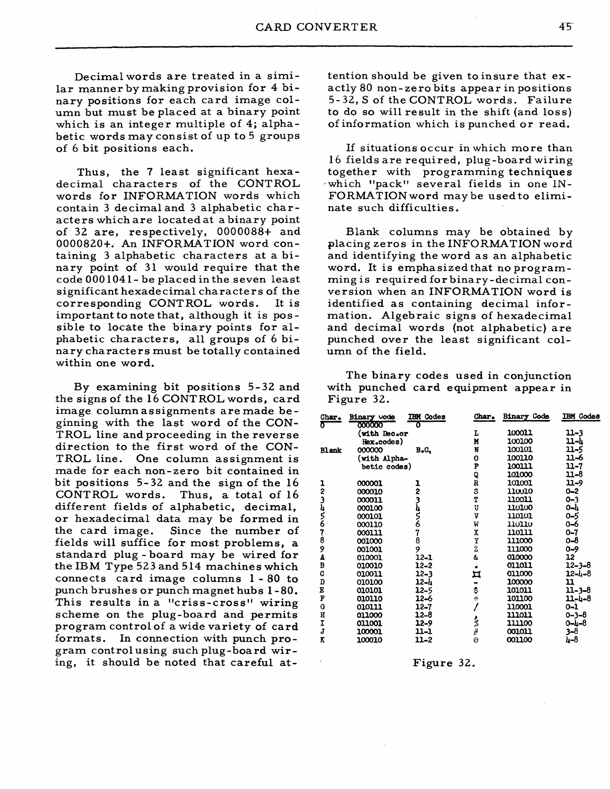
CARD
CONVERTER
Decimal
words
are
treated
in
a
simi-
lar
manner
by
making
provision
for
4
bi-
nary
positions
for
each
card
image
col-
umn
but
must
be
placed
at
a
binary
point
which
is
an
integer
multiple
of
4;
alpha-
betic
words
may
consist
of
up
to
5
groups
of
6
bit
positions
each.
Thus,
the
7
least
significant
hexa-
decimal
characte
rs
of
the
CONT
ROL
words
for
INFORMATION
words
which
contain
3
decimal
and
3
alphabetic
char-
acters
which
are
located
at
a
binary
point
of
32
are,
respectively,
0000088+
and
0000820+.
An
INFORMATION
word
con-
taining
3
alphabetic
characters
at
a
bi-
nary
point
of
31
would
require
that
the
code
000
1
041-
be
placed
in
the
seven
least
significant
hexadecimal
characters
of
the
corresponding
CONTROL
words.
It
is
important
to
note
that,
although
it
is
pos-
sible
to
locate
the
binary
points
for
al-
phabetic
characters,
all
groups
of
6
bi-
nary
characters
must
be
totally
contained
within
one
word.
By
examining
bit
positions
5 -
32
and
the
signs
of
the
16
CONTROL
words,
card
image
column
assignments
are
made
be-
ginning
with
the
last
word
of
the
CON-
TRoL
line
and
proceeding
in
the
reverse
direction
to
the
first
word
of
the
CON-
TRoL
line.
One
column
assignment
is
made
for
each
non-zero
bit
contained
in
bit
positions
5-32
and
the
sign
of
the
16
CONTROL
words.
Thus,
a
total
of
16
different
fields
of
alphabetic,
decimal,
or
hexadecimal
data
may
be
formed
in
the
card
image.
Since
the
number
of
fields
will
suffice
for
most
problems,
a
standard
plug
-
board
may
be
wired
for
the
IB
M
Type
523
and
514
machine
s
which
connects
card
image
columns
1 -
80
to
punch
brushes
or
punch
magnet
hubs
1-80.
This
results
in
a
"criss-cross"
wiring
scheme
on
the
plug-board
and
permits
program
control
of
a
wide
variety
of
card
formats.
In
connection
with
punch
pro-
gram
control
using
such
plug-board
wir-
ing,
it
should
be
noted
that
careful
at-
tention
should
be
given
to
insure
that
ex-
actly
80
non-zero
bits
appear
in
positions
5-32,
S
of
the
CONTROL
words.
Failure
to
do
so
will
re
sult
in
the
shift
(and
los
s)
of
information
which
is
punched
or
read.
If
situations
occur
in
which
more
than
16
fields
are
required,
plug-board
wiring
togethe
r
with
programming
technique
s
'which
"pack"
several
fields
in
one
IN-
FORMATION
word
maybe
usedto
elimi-
nate
such
difficulties.
Blank
columns
may
be
obtained
by
placing
zeros
in
the
INFORMATION
word
and
identifying
the
word
as
an
alphabetic
word.
It
is
emphasized
that
no
program-
ming
is
required
for
binary-decimal
con-
version
when
an
INFORMATION
word
is
identified
as
containing
decimal
infor-
mation.
Algebraic
signs
of
hexadecimal
and
decimal
words
(not
alphabetic)
are
punched
over
the
least
significant
col-
umn
of
the
field.
The
binary
code
s
used
in
conjunction
with
punched
card
equipm.ent
appear
in
Figure
32.
Char.
B~\,iOde
IBM
Codes
~
Binary
Code
IBM
Codes
0-
000
0
(with
Dec.or
L 100011
ll
.. 3
Hex.codes) M 100100
ll-4
B1ank
00000o
B.C,
N 100101
ll-$
(with
Alpha-
0 100110
ll-6
betic
codes) P 100111 11-7
Q 101000
ll-B
1
000001
1 R 101001
ll
.. 9
2
000010
2 S 110010 0..2
3
000011
3 T
1100ll
0-3
4
000100
4 U Uo100 0..4
$
000101
$ V
110101
0-$
6
000110
6 W 110110 0-6
7
000111
7 X 110111 0-7
8
001000
8 y 111000 0-8
9
001001
9 Z 111000 0 .. 9
A
010001
12-1 &
010000
12
B 010010 12-2 .
011011
12-3-8
C 010011 12-3 1:( 011000 12-4-8
D 010100 12-4 100000
II
E
010101
12-5 $ 101011 11-3-8
F
010110
12-6
-r.
..
101100 11\"4-8
G 010111 12-7 /
lloool
0-1
H
011000
12-8 ,
lUOll
0-3-8
I
011001
12-9 % 1111oo 0-4-8
J 100001 11-1 #
0010ll
3-8
K 100010 11-2
€:I
001100 4-8
Figure
32.
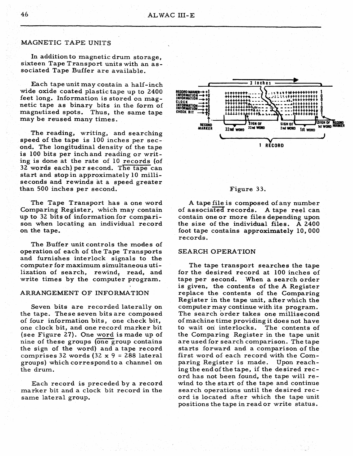
46
ALWAC
III-E
MAGNETIC
TAPE
UNITS
In
addition
to
magnetic
drum
storage,
sixteen
Tape
Transport
units
with
an
as-
sociated
Tape
Buffer
are
available.
Each
tape
unit
may
contain
a
half-inch
wide
oxide
coated
plastic
tape
up
to
2400
feet
long.
Information
is
stored
on
m.ag-
netic
tape
as
binary
bits
in
the
form
of
magnetized
spots.
Thus,
the
same
tape
may
be
reused
many
times.
The
reading,
writing,
and
searching
speed
of
the
tape
is
100
inches
per
sec-
ond.
The
longitudinal
density
of
the
tape
is
100
bits
per
inch
and
reading
or
writ-
ing
is
done
at
the
rate
of
10
records
(of
32
words
each)
per
second.
The
tape
can
start
and
stop
in
approximately
10
milli-
seconds
and
rewinds
at
a
speed
greater
than
500
inches
per
second.
The
Tape,
Transport
has
a
one
word
Comparing
Register,
which
may
contain
up
to
32
bits
of
information
for
compari-
son
when
locating
an
individual
record
on
the
tape.
The
Buffer
unit
controls
the
mode
s
of
operation
of
each
of
the
Tape
Transports
and
furnishes
interlock
signals
to
the
computer
for
maximum
simultaneous
uti-
lization
of
search,
rewind,
read,
and
write
times
by
the
computer
program.
ARRANGEMENT
OF
INFORMATION
Seven
bits
are
recorded
laterally
on
the
tape.
These
seven
bits
are
composed
of
four
information
bits,
one
check
bit,
one
clock
bit,
and
one
record
marker
bit
(see
Figure
27).
One
word
is
made
up
of
nine
of
these
groups
(one
group
contains
the
sign
of
the
word)
and
a
tape
record
comprises
32
words
(32
x 9 =
288
lateral
groups)
which
correspond
to
a
channel
on
the
drum.
Each
record
is
preceded
by
a
record
marker
bit
and
a
clock
bit
record
in
the
same
lateral
group.
r----------3
inch~e~s-======.='======3-
__
R£CORD
MA1UCER-+
+ 1
INFORMATION
-+
+0'
INFORMATION
-+H'
CLOCK
•
INFORMATION=:
INFORMATlON--+
tl
CHECK
BIT
--+"1:1
H1'+-ti+t+
.••
_ • . ! to't
tt
tM++++
...
H ..... t 1
++++++tt"'...
_,..·!:'~Htt+tH-ti'ttH
8
H+++<++++t:
_ _ _ _
._.
__
sS;'++-+++++++
+
ti'tt"tt't1f!~.,.___
...
___
..
H++++++++
1
H"4~".u+~
__ .. . ..
__
.+Utittttt
~
+++-I+t+++++:&
L:.....
,..
......
++t+++H-it
U.~.U.H'"
++-J+",,~..
__
.W,.HH
........
t
-.-.....f--
.......
~--~
-
......
--""'*=~~.---
REcotm
MAllKER
32l1li
WORD
l
Figure
33.
V
RECOR'D
A
tape
file
is
composed
of
any
number
of
associated
records.
A
tape
reel
can
contain
one
or
more
file
s
depending
upon
the
size
of
the
individual
files.
A
2400
foot
tape
contains
approximately
10,000
records.
SEARCH
OPERATION
The
tape
transport
searches
the
tape
for
the
desired
record
at
100
inches
of
tape
per
second.
When
a
search
order
is
given,
the
contents
of
the
A
Register
replace
the
contents
of
the
Cornparing
Register
in
the
tape
unit,
after
which
the
computer
rnay
continue
with
its
program.
The
search
order
takes
one
rnillisecond
of
machine
time
providing
it
doe
s
not
have
to
wait
ori
inte
rlocks.
The'
contents
of
the
Comparing
Register
in
the
tape
unit
are
used
for
search
comparison.
The
tape
starts
forward
and
a
comparison
of
the
first
word
of.
each
record
with
the
Com-
paring
Register
is
made.
Upon
reach-
ingthe
end
of
the
tape,
if
the
desired
rec-
ord
has
not
been
found,
the
tape
will
re-
wind
to
the
start
of
the
tape
and
continue
search
operations
until
the
de
sired
rec-
0rd
is
located
after
which
the
tape
unit
positions
the
tape
in
read
or
write
status.
SEARCH
MODES
The
tape
transport
is
able
to
search
in
two
different
modes
of
operation.
The
search
mode
desired
is
indicated
by
the
configuration
of
the
address
part
of
the
word.
During
search
mode
I
operations,
the
tape
transport
unit
will
choose
the
first
record
whose
first
word
is
greater
than
or
equal
to
the
Comparing
Register.
During
search
mode
II
operation,
the
tape
transport
unit
will
choose
the
first
rec-
0rd
which
has
the
least
significant
eight
bits
of
t.he
first
word
equal
to
the
least
significant
eight
bits
of
the
Comparing
Register.
READING
The
programming
required
to
read
a
record
from
tape
is
the
command
Mag-
netic
Tape
Copy
(MTC).
The
configura-
tion
of
the
address
part
indicates
which
one
of
three
available
records
to
read
from,
the
preceding,
the
current,
or
the
succeeding
record.
If
the
tape
unit
is
in
the
WRIT
E
status
when
the
command
is
given
to
read,.
the
computer
will
stop
and
alarm
number
2
buzze
r
.will
sound.
If
a
command
to
read
is
given
while
the
tape
unit
is
engagecrTn
a
search
and
prepare
to
read
operation
or
another
read
operation,
tli'e
command
to
read
is
lleld
up
by
interlocks·
until
the
completion
of
the
previous
instruction.
At
this
time,
the
interlocks
release
and
the
computer
takes
the
next
command
in
sequence
while
the
tape
unit
performs
the
read
operation.
If
the
tape
unit
is
engaged
in
a
write
operation
or
search
and
prepare
to
write
and
a
command
to
read
is
given,
the
com-
mand
to
read
is
heTCI"li'j)
by
interlocks
until
the
previous
command
is
completed.
At
this
time,
the
machine
will
stop
and
the
alarm
number
2
buzzer
will
sound,
indi-
cating
the
tape
unit
is
not
in
the
correct
47
status
for
the
read
operation.
WRITING
The
programming
required
to
write
a
record
onto
tape
is
the
command
Mag-
netic
Tape
Copy
(MTC).
The
configura-
tion
of
the
addre
s s
portion
indicate
s
which
one
of
three
available
records
is
to
be
written:
the
preceding,
the
current,
or
the
succeeding
record.
If
the
tape
unit
is
in
the
READ
status
when
the
command
is
given
to
WRITE,
the
computer
will
stop
and
alarm
number
2
buzze
r
will
sound.
If
a
command
to
write
is
given
whIle
the
tape
unit
is
engaged
in
a
search
and
prepare
to
write
operation
or
another
write
ope
ration,
the
command
to
write
is
held
up
by
interlocks
until
the
com-
pletion
of
the
previous
instruction.
At
this
time,
the
interlocks
release
and
the
computer
takes
the
next
command
in
se-
quence
while
the
tape
unit
performs
the
write
operation.
If
the
tape
unit
is
engaged
in
a
search
and
prepare
to
read
or
a
read
ope
ration
and
a
command
iSgIVen
to
wnre,
the
sec-
0nd
command
is
held
in
the
tape
unit
until
the
completion
of
the
first
command.
At
this
time,
the
machine
will
stop
and
the
alarm
number
2
buzzer
will
sound
indi-
cating
the
tape
unit
is
not
in
the
correct
status
to
carry
out
a
write
instruction.
If
the
tape
unit
is
engaged
in
a
rewind
operation
and
a
command
is
given
to
write,
the
write
command
is
held
in
the
tape
unit
until
the
completion
of
the
re-
wind
operation.
At
this
time
the
tape
unit
is
automatically
set
to
READ
status
and
the
command
to
write
is
released
by
the
interlocks.
The
computer
stops
and
a-
larm
number
2
buzzer
sounds
indicating
the
unit
is
not
in
the
correct
status
to
per-
form
the
write
operation.
48
ALWAC
III-E
MANUAL
OPERATION
During
normal
operation
the
compute
r
controls
the
tape
transport
through
the
buffer.
The
controls
on
the
front
panel
of
the
tape
unit
are
for
manual
operation
of
the
unit.
The
door
of
the
tpae
transport
must
be
closed
to
actuate
an
interlock
which
permits
the
unit
to
operate
from
any
con-
trol.
The
Interlock
Lite
on
the
Control
Panel
'signifies
the
door
is
open.
To
operate
the
tape
unit
manually
the
Test
Switch
must
be
ON.
The
Test
Lite
will
be
turned
ON
and
remains
ON
until
the
Te
st
Switch
is
turned
0
FF
•
With
the
Test
Switch
ON,
the
unit
may
be
run
forward,
reversed,
or
rewound
with
the
appropriate
switch.
The
Ready
Lite
is
ON
at
any
time
the
unit
has
found
a
record
commanded
by
a
search
operation
or
when
the
machine
is
reading
or
writing
under
normal
condi-
tions.
The
Stop
Lite
is
turned
ONat
anytime
the
Stop
Switch
is
ON.
The
Stop
Switch
m.ay
be
utilized
at
anytime
of
normal
op-
eration
or
manual
operation.
CALIBRATE
OPERATION
The
calibration
switch
is
for
the
pur-
pose
of
calibrating
a
new
tape
or
a
tape
that
is
suspected
of
having
bad
spots
on
it.
To
calibrate
a
tape,
load
tape
reel
and
thread
tape
to
the
start
position.
De-
press
the
Calibrate
Switch.
No
further
manual
operation
is
needed
as
the
cali-
bration
takes
place
automatic,ally.
The
tape
will
start
in
a
forward
di-
rection
and
traverse
the
entire
length
of
the
tape,
saturating
it
on
all
seven
tracks.
Upon
reaching
the
effective
end
of
the
tape,
the
unit
reverse
s
tape
direction
and
after
inspection
of
the
tape
it
records
a
record
marker
bit
and
'a
clock
bit
as
an
indicationthat
it
has
scanned
enough
con-
secutive
good
tpae
to
hold
one
record.
This
process
is
continued
to
the
beginning
of
the
tape
at
a
speed
of
125
inches
per
second.
At
this
time,
the
operation
is
complete
and
control
of
the
tape
unit
is
again
transferred
tn
the
computer.
LOAD
OPERATION
Loading
is
accomplished
by
the
follow-
ing
list
of
operations:
1.
Place
LOAD
Switch
in
ON
position.
2.
Place
loaded
tape
reel
on
lower
spindle.
End
of
tape
should
hang
from
left
side
of
reel.
,Place
empty
reel
on
upper
spindle.
Place
reel
retainer
caps
on
both
spindles.
3.
Thread
end
of
tape
over
right
hand
guide
and
through
right
vacuum
well
guide.
(Drop
c;loor
at
top
of
well
to
provide
access
to
guides).
Tape
should
loop
to
half
length
of
well.
4.
Thread
tape
over
right
capstan
and
through
read-write
mechanism.
5.
Thread
tape
through
left
vacuum
well
guides.
Tape
should
form
loop
half
the
length
of
the
well.
6.
Thread
tape
over
left
capstan.
7.
Thread
<tape
over
upper
guide
and
to
upper
reel.
Manually
turn
the
top
reel
to
take
up
loose
tape,
but
maintaining
the
tape
loops
to
approximately
one
half
the
length
of
the
vacuum
wells.
8.
Close
cover
on
read-write
mechanism
and
access
doors
on
vacuum
wells.
9.
Turn
LOAD
Switch
to
OFF
position.
10.
Close
and
secure
the
"main
door
on
the
tape
unit.
11.
With
all
switches
on
the
tape
unit
in
the
NORMAL
position,
the
unit
is
loaded
and
under
the
control
of
the
computer.
SYMBOLIC
PROGRAMMING
The
AL
WAC
III-E
can
execute
only
absolute
programs.
In
such
programs,
both
instruction
and
data
words
have
defi-
nite
storage
locations
assigned,
and
all
Rrogram
functions
which
depend
on
such
assignments
have
been
given
definite
numerical
values.
Because
intelligent
assignment
of
storage
locations
cannot
be
made
until
after
the
program
is
writ-
ten,
it
becomes
difficult
to
prepare
pro-
grams
in
this
form.
Therefore,
some
system
of
program
writing
is
used
which
permits
the
use
of
non-absolute
or
rela-
tive
locations.
The
programming
sys-
teiil
which
incorporates
this
technique
is
called
symbolic
programming.
The
program
is
first
written
in
a
sym-
bolic
form
after
which
the
prograzii'iiier
can
make
storage
assignments
of
certain
quantities.
Mter
such
assignments
are
made,
the
symbolic
quantities
can
be
translated
into
the
machine
language
and
an
ab
solute
program
prepared.
To
ac-
compllsh
this
conversion,
a
general
pro-
gram
is
written
and
is
known
as
the
As-
sembly
Program
1
(AP
1).
This
pro-
gram
accepts
either
cards
or
tape
on
which
the
symbolic
program
has
been
punched
from
information
contained
on
the
coding
form,
together
with
additional
information
regarding
storage
specifica-
tions,
and
produces
the
absolute
program
in
a
form
suitable
for
subsequent
loading
procedures,
together
with
a
printed
list-
ing
of
the
assembled
program.
The
pre-
pared
listing
may
also
contain
notations
which
indicate
detection
(by
AP
1)
of
er-
rors
in
the
symbolic
program.
Such
no-
tations
assist
the
programmer
in
the
de-
tection
and
correction
of
coding
errors.
The
AP
1
writeup
should
be
consulted
for
details.
The
following
programming
examples
appear
as
they
would
be
written
in
sym-
bolic
code
on
the
coding
form
for
assem-
bly
by
AP
1.
To
provide
a
convenient
method
fo
r
location
addre
s
sing,
two
num-
bering
schemes
are
used
to
refer
to
spe-
cific
word
locations
within
a
channel.
Thus,
each
word
location
may
be
speci-
fied
by
either
of
two
decimal
numbers
49
which
are
called
the
drum
or
instruction
locations.
The
first
two
columns
on
the
coding
form
provide
conversion
between
the
two
scheme
s .
These
columns,
which
are
labeled
DRUM
and
INSTR,
are
decimal
locations
of
half-words
within
a
channel
and
are
used,
respectively,
in
conjunction
with
the
codes
1-4
and
5-9,
in
the
column
la-
beled
REG
(Regio~).
Note
that
the
half-
words
are
numbered
sequentially
from
00
to
63
for
instructions
and
that
this
numbering
conforms
to
the
normal
se-
quence
for
execution
of
instructions;
how-
ever,
the
data
locations
are
numbered
in
such
a
manner
as
to
indicate
their
actual
sequence
in
storage.
It
is
necessary
to
specify
which
numbering
scheme
is
being
referenced
when
specifying
the
ADDRESS
part
of
an
operation
and
it
isfor
this
pur~
pose
that
the
region
column
is
provided.
The
following
code
is
used
in
this
col-
umn:
"0
"
Absolute
addresses
(e.
g.
shifting)
"1"
--
Drum
locations
Working
Storage
I
tt2"
--
Drum
locations
Working
Storage
II
"3"
--
Drum
locations
Working
Storage
III
"4"
--
Dr:um
locations
Working
Storage
IV
115"
-_
Instruction
locations
in
the
same
channel
"6"
--
Instruction
locations
Working
Storage
I
"7"
--
Instruction
locations
Working
Storage
II
"8"
--
Instruction
locations
Working
Storage
III
"9"
--
Instruction
locations
Working
Storage
IV
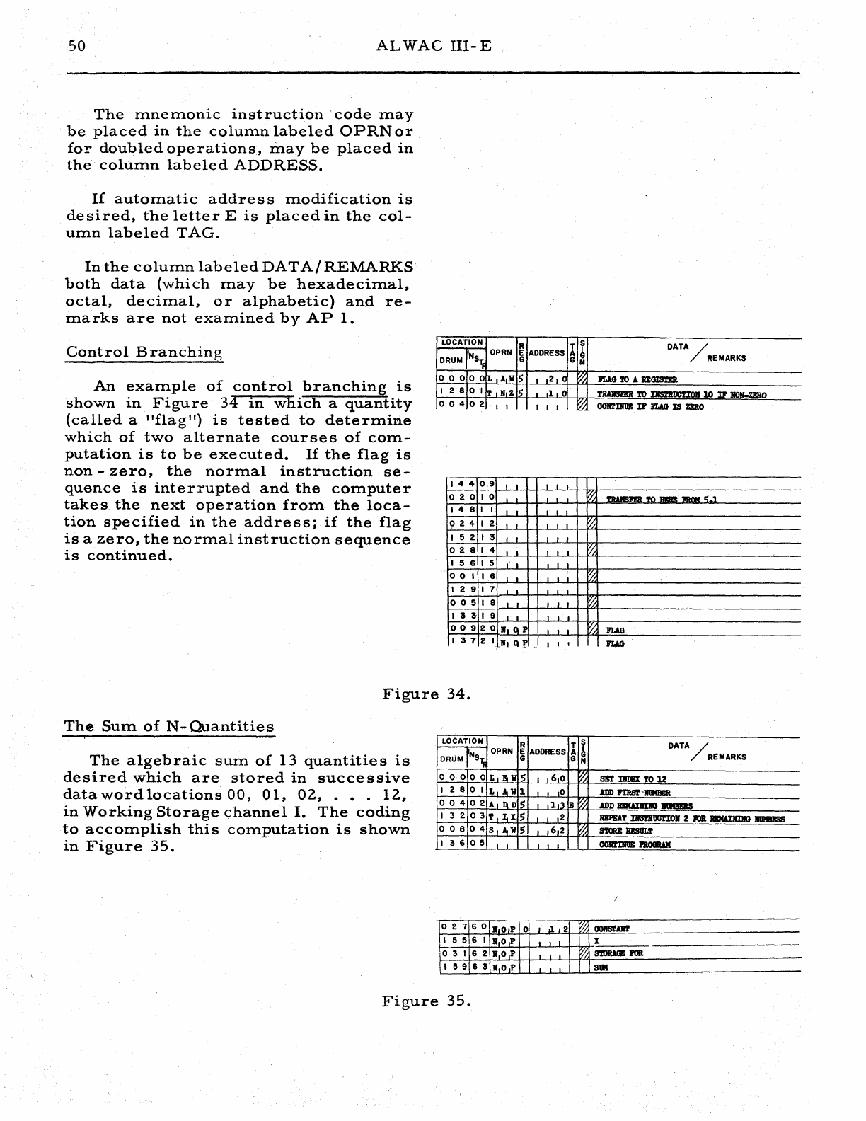
50
ALWAC
IlI-E
The
mnemonic
instruction'
code
may
be
placed
in
the
column
labeled
OPRN
or
fo!"
doubled
operations,
may
be
placed
in
the
column
labeled
ADDRESS.
If
automatic
addre
s s
modification
is
desired,
the
letter
E
is
placed
in
the
col-
utnn
labeled
TAG.
In
the
column
labeled
DAT
AI
REMARKS
both
data
(which
may
be
hexadecimal,
octal,
decimal,
or
alphabetic)
and
re-
marks
are
not
exatnined
by
AP
1.
Control
Branching
LOCATION
DRUM
Ns,;
_'F
000
00
R
OPRN
E
ADDRESS
G
L
A,W
S ,
,2,
(
T S
DATA~
A
~
REMARKS
G N
~
lUG
'l'O
A RlGIS'fBR
An
example
of
control
branching
is
shown
in
Figure
34
in
which
a
quantity
(called
a
"flag
ll
)
is
tested
to
determine
which
of
two
alternate
courses
of
com-
putation
is
to
be
executed.
If
the
flag
is
non
-
zero,
the
normal
instruction
se-
quence
is
interrupted
and
the
computer
takes
the
next
operation
from
the
loca-
tion
specified
in
the
address;
if
the
flag
is
a
zero,
the
normal
instruction
sequence
is
continued.
128
01
T
'I,zl~
••
1,
l '
l'lWISJBR
'l'O
I1IS1'ROOTIOlf
10
]]I'
HOlI-ZIRO
004
02
, , I , J
,~
COIl'lDflll
IF
FLlO
IS
ZIIlO
144
0,9
, , , , ,
020
I 0 , , , , ,
~
TIWISJ'Im
TO
RIm!
JRm(
'>-1
14
8 I I , I I , •
024
I 2 , I I I I
~
152
I 3 I I , , ,
02
8 I 4 I , , ,
~
I 5 6 I 5 " I I , I
001
16
I , , ,
~
I 2 9
17
, I , . ,
005
I 8 , , , , ,
~
I 3 3 I 9 ,
009
20
I,
Q P , , ,
~
PUG
I
372
I
.,
Q'f
, I , ,
FLAG
Figure
34.
The
Sum
of
N-Quantities
LOCATION R I
~
DATA~
DRUM
NS
1f
OPRN
E
ADDRESS
REMARKS
G G N
000
00
L,.W
S ,
,6,0
~
SBT
IIIIBI
TO
12
I 2 8
01
L,AW'l
, ,
,0
ADD
PIBSr-1I1IIIBR
The
algebraic
sum
of
13
quantities
is
desired
which
are
stored
in
successive
data
word
locations
00,
01,
02,
••.
12,
in
Working
Storage
channel
I.
The
coding
to
accomplish
this
computation
is
shown
in
Figure
35.
004
02
A,
QDI~
,
,1,1
B~
ADD
B!IUI1tOI.I lItIIBIRS
132
03
T,I,XS
I I
12
RlPDT
IIS!JlOOfIOlI 2 _ BI!KAIIIIIO
IlIIBIIIS
008
04
S,AtwS
,
,6,2
~
S'l'CilB
BBS'OU
I 3 6
05
, COll'lIlUE
I'IlOOIWI
021
eo
.o,P
o
,'.1.
,2
~
CO_AlIT
I 5 5 6 I If,O,P I " X
o 3 I 6 2
I,O,P
I • I
~
S'l'OlWB
JOIl
I
59
6 3
.,O,P
I "
SlII
Figure
35.

SYMBOLIC
PROGRAMMING
Floating
a
Fixed-
Point
Numbe
r
To
convert
a
fixed
-
point
number,
whose
binary
point
is
located
16
places
from
the
left
end
of
a
word,
into
a
nor-
malized
floating-point
number,
the
cod-
ing
shown
in
Figure
36
is
used.
LOCATION
R T s
. I OPRN E ADDRESS A b
DRUM
NS
T
,;
G G N
DATA/
000
o 0 L
is
I W
, J 1
S,O
~
CLEAR
B
REGISTER
REMARKS
I 2 8 0 I
L,1.
W
~
I ".2
FIXED-POINT
WORD
TO
A
REGISTER
004
o 2 S,C
IT
0 1
.1.0
VI
SHIn
LEFT
TO
NORMALIZE
51
1 3 2 o 3 X
rA
I B X
~
ID,
NORM
IlAGNITUIlE
TO
B
AND
COUNT
TO
A
REGISTER
..
_--,---_.'-,-------
,.'-'-
~
008
o 4 8
IC
• S S 1 ",4
PCRH
128-D
--~-
...
--,--.---
...
-
..
-~
....
-
I 3 6 o 5 A
aD
• D , I .S,6
ADD
BINARY
POINT
LOa.
---.--------...
..
--
..
--
.•.
-----..~-....--
0 I 2 o 6
t,R
18
0 I I
.8
~
PACK
WORD
III
B
REGISTER
,---"
..
-.-
...
----.~.-
..
-
..
-
I 4 0
07
S
~,'W
, I
1,.8
STORE
FLOATING-PCDr!'
1UMBFl!
~
-----
----
0 I 6 o 8
TIN.
Z , I
.3,2
TRANSFER
TO
ERROR
HALT
IF
OVERFLOW
.------
.~-.-
..
-.
14
4 o 9 • • 1 1 •
CONTIBUE
PROGRAH
--
007
5 0
B.o
I P 0 I I
,0
~
ZlCRO
._--_
..
_._-
1 3 5 5 I
ltO.P
0 J 1
.0
X
_.
0 I I
!5
2 •
to
I P I I •
~
S'lORJ.(JE
FOR
FIIED-POIIfl
I 3 9 5 3
If
PIP
J J I
lUMBER
015
5 4
"1
0 • P J I
,0
~
128
AT
A
BINARY
POIlI'l
I 4 3 5 5
If
,0 1 p
[1.2
18
OF
32
0 I 9 5 6
Il
PIP
J I
1°
~
-------
16
AT
B
I 4 7 5 7
Wp
,P
I
.1,6
OF
32
o 2 3 5 8
IfP.P
I I
,0
~
STORAGE
FOR
FLOATING-PODT
I
!5
I 5 9
.1'
,P
J I
.0
lfUHBER
Figure
36.
!
;
52
ALWAC
llI-E
Sub
routine
s
.
Many
routines,
such
as
square
root,
trigonometric
functions,
exponential
and
logarithmic
functions,
data
input-output,
interpolation,
and
integration,
are
used
repeatedly
in
the
execution
of
a
single
problem
or
in
different
problems.
Such
routines
are
called
subroutines
since
their
use
is
subordinate
to
the
control
of
the
main
problem
of
which
they
are
a
part.
A
set
of
such
subroutine
s
is
called
a
libr.ary
and
each
computing
installation
maintains
such
a
basic
programming
tool.
Subroutines
are
classified
as
being
an
open
or
closed
type,
accordingly,
by
the
manner
in
which
they
are
used
with
re-
gard
to
the
flow
of
control:
An
open
sub-
routine
is
incorporated
in
a
pr~graiii1)y
inserting
the
subroutine
directly
into
the
ma~n
flow
of
control.
It
is
therefore
nec-
essary
to
insert
the
subroutine
at
each
point
in
the
main
program
at
which
it
is
required.
A
closed
subroutine
is
one
which
may
be
executed
Illany
tiIlles
in
a
program,
but
the
subroutine
instructions
need
ap-
pear
only
once
in
the
prograIll.
To
trans-
fer
control
from
the
main
program
to
the
subroutine,
a
set
of
instructions
(known
as
a
calling
sequence)
is
given.
The
sub-
routine
obtains
sufficient
information
from
this
sequence
to
perform.
its
vari-
ous
functions
and
to
determine
the
re-
turn
address
to
which
control
istrans·-
ferred
after
completion
of
the
subroutine
.
co.mputations.
Calling
sequences
are
necessarily
unique
for
each
special
sub-
routine;
hence,
each
computing
installa-
tion
maintains
a'
set
of
such
calling
se-
quences
for
subroutines
in
their
library,
which
set,
together
with
selected
notes
pertinent
to
programming
standards
used
by
the
installation,
constitute
s a
text
known
as
a
coding
manual.
APPENDIX
A
BINARY
AND
HEXADECIMAL
NUMBER
SYSTEMS
In
all
systems
for
representing
num-
bers,
a
number
may
be
expressed
as
a
~um
of
terms.
Each
term
appears
as
the
product
of
an
inte
ge
r
and
some
powe
r
of
a
base
number.
Thus,
in
the'
decimal
number
system,
the
base
is
10
and
the
'integers
of
the
set
0,
1,
Z,
...
9,
are
used.
For
example:
3Z1 =
(3xlOZ)
+
(2xI01)
+
(lxlO
O)
5.93
=
(5xl0
0) +
(9xlO-
I) +
(3xl0-Z)
and,
in
the
binary
number
system:
32
1 = Z 5 6 +
64
+ 1
=
(lxZ
8) + (OxZ 7) + (
lx2
6)
+ (OxZ5) + (OxZ4) +
(OxZ
3)
+ (Ox2Z) +
(OxZl)
+
(lx2
0)
If
the
base
used
is
evident
from
the
discussion
in
which
such
numbers
appear,
it
is
unnece
s
sary
.
to
write
more
than
the
coefficients
of
the
above
series.
Thus,
3Z1
and
101'000'001
are
respectively
the
decimal
and
binary
representations
of
the
same
numerical
value.
If
confusion
may
occur
when
the
base
is
omitted,
a
con-
venient
symbol
- a
subscript
-
may
be
used
to
indicate
the
base.
In
the
above
ex-
ample,
the
numbers
32
10
and
101000001
Z
indicate
decimal
and
binary
representa-
tions
by
the
subscripts
10
and
2.
It
is
important
to
note
that
the
integers
0,
1,
Z,
..•
(n-l)
comprise
a
set
of
n
quantities
and
that
each
coefficient
of
the
series
must
consist
of
an
integer
from
this
set.
Thus,
the
integers
0,
1,
2,
3,
. • . 9
are
used
for
each
decimal
posi-
tion,
the
integers
0
and
1
each
for
bi-
nary
position,
and
the
integers
0,
1,-Z,
:-:-:
8,
9,
A,
B,
C,
..•
F,
for
each
hexadecimal
(base
16)
position.
53
There
are
but
three
rules
for
binary
addition;
the
se
are:
0+0
= 0
0+1
= 1
1 + 1 =
10
(a
0
witha
"carry"
of
1)
The
following
e~ample
illustrates
these
rules
for
the
addition
of
the
numbers
1011001
and
10111101:
carries:
11111
10111101
1011001
100010110
Four
rules
exist
for
bi~ary
subtrac-
tion
which
are:
o - 0 = 0
1-0
= 1
1 - 1 = 0
o - 1 = 1
(with
a 1
borrowed
from
the
next
rno
st
significant
position)
For'
example:
1011001
is
subtracted
from
10111101
as
follows:
borrows:
1
10111101
-1011001
1100100
For
binary
multiplication,
the
follow-
ing
four
rules
apply:
OxO=O
Ox
1 = 0
1 x 0 = 0
1 x 1 = 1
54
ALWAC
III-E
To
multiply
1011
by
1001
proceed
as
follows:
1011
1001
1011
0000
00000
1011
11.00011
To
convert
a
number
from
one
nUIn-
ber
system
to
another,
the
number
is
divided'
by
the
base
of
the
new
system
and
the
remainder
is
noted.
The
quo-
tient
obtained
is
2.
gain.
di
vided
by
the
base
and
the
remainder
again
noted;
this
pro-
cess
is
repeated
with
each
successive
quotient
until
a
zero
quotient
is
obtained.
The
sequence
of
remainder
terms
ob-
tained
provide
s
the·
coefficient
s
of
the
number
expressed
in
the
number
system
of
the
chosen
base
and
these
are
written
from
left
to
right
in
the
reverse.sequence
from
that
in.
which
.
they
are_
obtained.
Thus,
to
convert
the
decimal
number
321
to
its
binary
representation
the
following
computations
are
made:
321
-:-
2 =
160
+
remainder
of
1
160
-:-
2 =
80
+
remainder
of
0
80
-:-
2 =
40
+
remainder
of
0
40
..;.
-2
=
20
+
remainder
of
0
20
-:-
2::t
10
+
remainder
of
0
10
-:-
2 = 5 +
remainder
of
0
5
-:-
2 = 2 +
remainder
of
1
2
+2
= 1 +
remainder
of
0
1
~
2 = 0 +
remainder
of
1
..
and,
the
number
is
written
as:
(321)10
=
(101000001)2
To
convert
a
binary
number
to
its
decimal
representation
successive
divi-
sions
by
1010
(=decimal
10).
For
example:
101000001-:-1010
=
100000
with
remain-
der
of
1
100000
1010
= 11
with
remainder
of
10
11
1010
= 0
with
remainder
of
11
The
remainders
obtained
are
the
bi-
nary
numbers
11,
10,
and
1
which
repre-
sent
the
decimal
integers
3,
2,
and
1.
Hence,
(101000001)2
=
(321)10.
To
express
decimal
fractions
in
their
equivalent
binary
representations
suc-
cessive
multiplication
by
2
is
used
to
generate
the
coefficients.
The
integer
generated
(a
0
or
1)
represents
the
cor-
respondingbinary
digits.
Using
only
the
.
resulting
decimal
fraction
the
process
is
continued
to
the
number
of
positions
re-
quired
or
until
a
zero
fractional
part
is
obtained
which
indicate
s
all
furthe
r
bi-
nary
digits
should
be
zero.
Thus,
to
con-
vert
the
decimal
fraction
.
875
to
its
bi-
nary
representation,
the
following
com-
putations
a're'
performed:
.
875
x 2 =
1.
75
•
75
x 2 =
1.
5
.5
x2=1.0
and,
hence,
the
binary
representation
of
the
number
(.
875)
10
is
(.
11100
· · •
)2'
or
more
simply;
(.
111)2.
It
~aybe
necessary
to
round
the
binary
fractIon
to
the
amount
of
accuracy
desired
s.ince
not
all
terminating
decimal
frac-
tl.ons
can
b~
represented
by
terminating
bInary
fractions
..
He~Cl.de
c-ima
1
If
the
'base
sixteen
is
chosen
for
rep-
resentation
of
a
number,
it
is
said
to
be
expres'::sed
in
the
hexadecimal
number
system.
The
number
set
used
is
0,
1,
2,
:
..
9,
A,
B,
..•
F.
Thus,
the
dig-
Its
0,
1,
. • • 9,
correspond
directly
with
the
decimal
system
while
the
alpha-
betic
characters
A
through
F
correspond
with
the
decimal
characters
10
through
15
respectively.

APPENDIX
55
Thedcecimal
to
hexadecimal
conver-
sion
of
an
integral
number
can
be
effected
by
dividing
successivelyby
16
(in
the
dec
-
~imal
system)
until
a
quotient
of
0
is
ob-
tained.
The
remaInders,
expressed
in
hexadecimal
notation
and
written
in
the
r.everse
sequence
from
that
obtained,
produce
the
desired
hexadecimal
repre-
sentation.
For
example,
the
decimal
736
conversion
would
be:
736+
16 =
46
with
a
remainder
of
0
(decimal)
46";':'
16
= 2
with
a
remainder
of
14
(decimal)
2 -:-
16
= 0
with
a
remainder
of
2
(decimal)
The
remainders
when
expressed
in
hexadecimal
notation
and
arranged
in
proper
sequence
yield,
2,
E,
and
O.
Thus,
(736)
I 0 =
(2EO)
16·
The
conversion
from
hexadecimal-
to
-
binary
is
particularly
simple.
Since
(10)16
equals
24,
the
conversion
is
carried
out·
simply
by
replacing
the
hexadecimal
digits
with
their
binary
equivalents
ex-
pressed
as
four-digit
binary
numbers.
For
example,
to
convert
the
hexadeci-
mal
2EO,
replace
the
0
with
0000,
E
with
1110,
and
2
with
0010
and
obtain
101110
0000,
omitting
the
zeros
at
the
extreme
left.
Conversely,
to
convert
from
binary
to
hexadecimal,
arrange
the
binary
digits
irito
groups
of
four,
begin-
ning
at
the
binary
point.
Fill
in
any
zeros
necessary
at
the
left.
Then
replace
each
group
of
binary
digits
with
the
appropriate
hexadecimal
character.
Thus,
the
hexadecimal
numbering
sys-
tem
furnishes
a
convenient
form
for
hand-
ling
a
large
binary
representation.
Moduli
In
certain
sections
of
this
Manual
of
Operations,
reference
is
made
to
num-
bers
reduced
to
various
moduli.
To
re-
duce
a
negative
number
to
a
given
modu-
lus,
the
number
is
first
made
positive
by
successive
additions
of
the
modulus
un-
til
a
positive
integer
is
obtained,
after
which
the
computation
proceeds
as
that
for
a
positive
number.
To
reduce
a
positive
number
to
a
given
modulus,
the
number
is
divided
by
the
modulus
and
a
remainder
term
obtained.
The
number
at
the
given
modulus
is
equal
to
this
remainder.
Thus,
12
modulo
o
modulo
17
modulo
-1
modulo
10
= 2
2 = 0
16
= 1
16
=
15
modulo
16
=
15
10
or
F
16
When
evaluating
algebraic
expression
involving
moduli
reductions,
the
quanti-
ties
inside
the
parenthesis
should
be
re-
duced
to
the
indicated
modulus
before
be-
ing
combined
with
the
remaining
terms.
Thus,
the
expression
[(W
-1)mod
B + 9
which
occurs
in
several
instruction
des-
criptions
has
the
following
evaluations:
W
o
1
2
3
4
5
6
7
B
9
fW-l)mod
B +
~
B
1
2
3
4
5
6
7
B
1

TABLE
OF
POWERS
OF
2
2n n 2-n
1 0
1.0
2-
1
005
4 2 0.25
8 3 0.125
16
4 0.062
.5
32
5-
0.031
25
64
6 0.015
625
128 7 00007812 5
256
8
017003
906
25
512
9 0.001
953
125
1
024
10
0.000
976
562
.5
2
048
11
0.000
488
281
~5
4
096
l2
00
000
244
140
625
8
192
13
0.000
122
070
312
5
16
384
14
00
000 061 035
156
25
32
768
-15
0.000
030
517 578
125
65
536
16 00
000
01'5
258
789
0625
131
072
17
0.000
00.7
629
394
531
25
262
144
18
00000003
814
697
265
625
524
288
19
OoDOO
001"
907
348
632
812
5
1 048576
20
0.000 000
953
674316
406
25
2
097
152
21 0.000
000
476
837
158
203
125
4
194
304
22
OeOOO
000
238
418
579
101
562
5
8
388
608
23
00
000 000
119
209
289
550
781
25
16
777
216
24
00
000
000059
604
644
775
390
625
3.3
554
432
25
00000 000
029
802
322
387
695
312
5
67
108
864
26
0.000
000
014
901
161
193
847
656
25
134
217
728
27
0.000
000
007
450
580
596
923
828
125
268
435456
28
0.000
000
003
725
290 298
461
914
062
5
536
870
912
29
OcOOO
000
001
862
645
149
230
957
031
25
1
073
741
824
30
00
000
000 000
931
322
574
615
478
515
625
2
147
483
648
31
00
000
000 000
465
661
287
307
739
257
812
5
4
294
967
296
32
0.000
000
006
232830
643 653
869
628
906
25
8
589
934
592
33
OcOOO
000
000
116415
321
826
934
814
453
125
l7
179
869
184
34
00
000
000
000
058
207
660
913
467
401
226
562
5
34
359
738
368
35
00000
000
000
029
103
830
456
733
703
613
281
25
68
719
476
736
36
00
000
000
000
014
551
915
228
366
851
806
640
625
137
438
953
472
37
0.,000
000
000 007
275
957
614
183
425
903
320
312
5
274
877
906
944
38
00000
000
000
003
637
978
807
091
712
951
660-156
25
549
755
813
888
39
00000000
000
001
818
989403
545
856
475
830
078125
56

APPENDIX
C
HEXADECIMAL-DECIMAL
INTEGER
CONVERSION
TABLE
0 1 2 3 4 5 6
'(
8 9 A B C D E F
000
0000
0001
0002
0003
0004
0005 0006
000'7
0008 0009
0010
0011
0012
OQ13
0014
0015
010
0016 0017
0018
0019
0020
0021
0022 0023
0024
0025
0026
0027
0028 0029
0030
0031
02:0
0032 0033
0034
0035
0036 0037
0038
0039
0040 0041
0042
0043 0044
00
45
0046
0047
030
0048 0049
0050
0051
0052 0053
0054
0055
0056
0057
0058 0059 0060
0061
0062
0063
040
0064
0065
0066 0067 0068
0069
0070
0071
00r(2
0073
0074
0075
0076·
0077
0078
0079
050
0080
0081
0082 0083
0084
0085
0086
'0087
0088
'0089
0090
0091
0092
0093
0094
0095
060
0096
0097 0098 0099 0100
0101
0102
0103
0104
0105
0106
0107 0108
q
10
9
0110 0111
070
0112
0113
0114
0115:
0116 0117 0118
0119
0120
0121 0122 0123
0124
0125
012(i
0127
080
0128 0129 0130 0131
0132
0133
0134
0135
0136
0137 0138 0139 0140
0141
0142
0143
090
0144
0145
0146 0147
0148
0149 0150
0151
0152
0153
015
4
0155
0156
0157
0158
0159
CAO
0160
0161
0162
0163
0164
0165 0166
0167
0168
0169 0170 0171
0172
0173
0174
01'75
OBO
0176
01T{
0178
0179 0180
0181
0182
0183
0184 0185
018
0181'
0188
0189
0190 0191
OCO
0192
0193
019
4
0195
0196 0197 0198 0199 0200 0201
0202
0203
0204
0205
0206
0207
ODO
0208
0209
02io
Q211
0212
0213
0214
0215
0216 0217 0218
6219
0220
0221
0222
0223
OEO
0224
'0225
0226
022'7
0228
0229
0230
0231
0232
0233
0234
0235
0236
0237
0238
0239
OFO
0240 0241
0242
0243
0244
0245
0246
0247
0248
0249
0250 0251
02,52
0253
0254
0255
100
0256
025'7
0258
0259
0260
0261
0262
0263
0264
0265
0266
0267
0268
0269
0270
02'71
110
0272 0273
0274
0275
0276 0277 0278
0279
0280
0281
0282
0283
0284
0285
0286
0287
120
0288
0289 0290
0291
0292
0293
0294
0295 0296
0297
0298
0299
0300 0301
0302
0303
130
0304
0305 0306 0307 0308
0309
0310
0311
0312
0313
0314
0315
0316
0317
0318
0319
140
0320 0321
0322
0323
0324 0325 0326 0327
0328 0329
0330
0331
0332
0333
0334
0335
150
0336
03J7
0338
0339
0340 0341
0342 0343
0344 0345
0346
034'7
0348
0349
0350 0351
160
0352 0353
.
0354
0355
0356
0357
0358 0359
0360
0361
0362
0363
0364
0365
0366
036"{
170
0368 0369
03'70
0371
0372
03'73
0374
0375
0376
037'7
0378
0379
0380 0381
0382
0383
180
0384
0385
0386
0387
0388
0389
0390
0391
0392
0393
0394
0395
0396 0397
0398
0399
190
0400
0401
0402
0403
0404
0405
0406
0407
0408 0409
0410
0411
0412
0413 0414
041.5
lAO
0416
0417
0418 0419
0420 0421
0422 0423
0424
0425
0426
0427
0428
0429
0430
0431
lEO
0432 0433
0434
0435
0436
0437.
0438,
0439
0440 0441
0442
0443
0444
0445
0446
0447
lCO
0448 0449
0450 0451
0452
0453-
0454
0455
0456
0457
0458 0459
0460
0461
0462
0463
IDO
0464
0465
0466
0467
0468
0469
0470
0471
0472
0473
0474
0475
0476
0477 0478 0479
lEO
0480
0481
0482
0483
0484
0485
0486
0487
0488 0489
0490
04
91
0492
0493
0494
0495
.1FO
0496
0497
0498 0499
0500
.0501
0502 0503
0504
0505
0506
0507
0508 0509
0510
0511
200
0512'
0513
0514
0515
0516 0517
0518
0519
0520
0521
0522 0523
0524
0525
0526
052r(
210
0528 0529
0530
0531
0532
0533
0534
0535
0536
0537 0538
0539
0540
05
41
0542
0543
22'0
0544
0545
0546
0547 0548
0549 0550
0551
0552
0553
0554
0555
0556
0557
9558
0559
230
0560 0561
0562
0563
0564
0565
0566
0567
0568
0569
0570
0571
0572
05
r
(3
0574
05''(5
240
0576
05'1'7
05'(8
0519 0580
0581
0582
0583
0584
0585
0586 0587 0588 0589 0590 0591
250
0592
0593
0594
0595
0596 0597
0598 0599
0600 0601
0602
0603
0604
0605
0606
0607
260
0608 0609
0610 0611 0612
0613
0614
0615
0616
0617
0618
0619
0620 0621
0622
0623
2,(0
0624
0625 0626
0627
0628
0629
'0630
0631
,0632
0633
0634
0635'
0636 0637 0638
0639
280
0640
0641
0642 0643
0644
0645 0646
0647 0648
0649
0650
0651
0652
0653
0654
0655
290
0656
0657
0658
0659 0660
0661
0662 0663
0664
0665
0666
0667 0668
0669
0670
0671
2A0
0672
0673
0674
0675
0676
0677 0678
0619
0680.
0681
0682 0683
0684
0685
0686
0687
2BO
0688 0689
0690
0691
0692
0693
0694
0695
0696 0697
0698
0699
0700
0'701
0702
0703
2CO
0704
0705
0706
0,(07
0708
0709
0710 0711
0712
0713
0714
0715
0716 0717
0718
0719
2DO
0720
0721
0722
0723
0724
0125
0726
072'7
0,(28
0729
0730
0731
0'732
0733
0734
0735
2EO
0736
0'(37
0738
0739·
0740
0'/41
0'742
0743
0744
0745
0~(46
0747
0748
0749
0750
0751
2FO
0752
0753
0754
or{55
0756
0757
0758
0'(59
0'(60
0761
0762
0763
0764 0765
0766
0767
300
0'(68
0769
OTTO
01'71
OT(2
0,{73
0774
0775
0'l'{6
0777'
OT(8
0779
0780
0781
0782
0783
310
0784
0'(85
0786
0787
0'(88
0'(89 0'(90
0791
0'(92
0'793
0'794
0795
0796
0797-
0798
0'799
320
0800
0801
0802 0803
0804
0805
0806
080'(
0808 0809
0810 0811
0812
0813
0814
0815
330
08olo
081,(
0818
0819 0820
0821
0822
0823
0824
0825
0826
0827
0828 0829 0830
0831
340
0832 0833
0834
0835
0836
083'1
0838
0839 0840
0841
0842 0843
0844
08
45
0846
0847
350
0848
084
9
0850
0851
0852
0853
0854
0855
0856 0857
0858
0859
0860
0861
0862 0863
360
0864
0805 0866
0867
0868 0869
0870
0871
0872
0873
0874
0875
0876
0877
0878
08(9
370
0880
0881
0882 0883
0884
0885
0886
088'(
0888
0889
0890 0891
08S2
0893
0894
0895
380
0896
08::17
0898 0899
0900
0901
0902 0903
0904
0905
0906
0907
0908
0909
0910 0911
390
0:112
0913
0914
0915
0916
091'(
0918
0919
0920
0921
0922 0923
0924
0925
0926
0927
JAO
0928
0929
0930
0931
0932
0933
0934
0935
0936
0937 0938
0939·
0940
09
41
0942
0943
3BO
09
44
0945
09
46
0947
0948
09
49
0950
05151
0952
0953'
0954
0955
0950
0957
0958
0959
3eo
os6u
0961
0962
0963
0964
0965
0966 0967
0968
0969
0970
09'71
0972
0973
0974
0975
3DO
0976 0977
osn8
0919
0980
0981
0982
0983
0984
0985
0986
0987
0988
098~
0990 0991
3EO
0992
0993
0994
.
0995
0996 0997
0998
0999
1000 1001
1002 1003
1004
1005
1006
100'(
31,"0
loob 100)
10.l.0
1011
.L012
1013
1014
1015
1016
1()I7
1018
1019
1020 1021
1022
1023
57
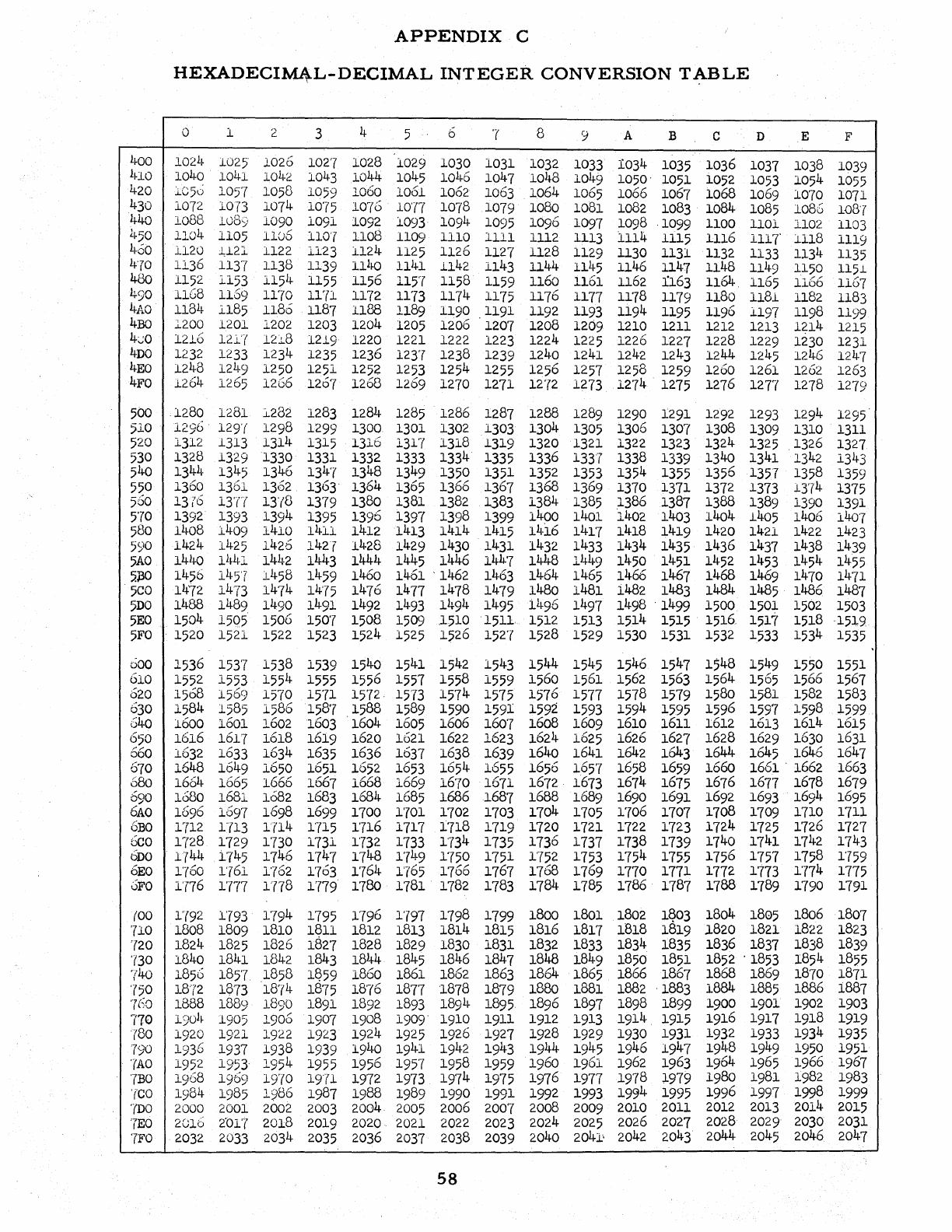
APPENDIX
C
HEXADECIM4-L-DECIMAL
INTEGER
CONVERSION
T~BLE
0 1 2 3 4 5 b
'7
8 9 A B C D E F
1~00
1021~
1025
1026
1027
1028
1029
1030
1031
1032
1033
1034
1035
1036
1037
1038
1039
lno
1040
1041
1042
1043
1044
1045
1046
1047 1048
10
49 1050'
1051
1052 1053
105
4
1055
420
lC5u
1057
1058
1059 1060
1061
1062
1063
1064
1065
1066
1067
1068
1069 1070
1071
430
1072
1073
1074
1075
1076
10T(
1078
1079 1080
1081
1082
1083
1084
1085
1086
108'7
440
1086
1089
1090
1091
1092 1093
1094
1095
1096
1097
1098 1099
1100
1101
1102
1103
1~50
1104
1105
11Ub
110'7
1108
1109
1110
1111
1112 1113
1114
1115
1116
I11T
i118
1119
460
1120
1,121
1122
1123
1124
1125
1126
1127 1128 1129 1130 1131
1132
1133
1134
1135
4'70
1136
1137
1138 1139
I1ho
llla
1142
1143 1144
1145
1146
1147
1148
1149 1150
115.1
480
1152
l153
1154
1155
1156
1157
1158
1159
1160
1161
1162
:L163
1164,
1165
1166
1167
490
I1G8
1169
1170
1171 1172
11'73
1174
1175
1176
1177
11'78
1179 1180
1181
1182
1183
4AO
1184
l1S5
1186
1187
1188
1189
1190
1191
1192 1193
1194
1195
ll96
1197
1198
1199
4BO
1.200
1201
1202 1203
1204
1205
1206
1207
1208 1209
1210
1211
1212
1213
1~14
1215
4~0
1216
12l'( 121.8
1219
1220 1221
1222
1223
1224
1225
1226
1227
1228
1229
1230 1231
4DO
1232
1233
1234
1235
1236
1237
1238 1239 1240
1241
1242
12
43
1244
1245
1246 1247
4EO
1248 1249
1250
1251
1252
1253
125
4
1255
1256
1257
1258 1259 1260
1261
1262
1263
4FO
1264
1265
1266
1267
1268
1269 1270
1271
1272
1273
1274
1275
1276
121'7
1278 1279
500
1280
1281
1..232
1283
1284
1285
1286
1287
1288
1289
1290 1291
1292
1293
129
4
1295
510
1296
129'(
1298
1299 1300 1301
1302
1303 1304
1305
1306
1307 1308 1309 1310 1311
520
1312
1313
1314
1315
1310
1317
1318
1319
1320
1321
1322
1323
1324
1325 1326
1327
530
1328 1329
1330
1331
1332
1333
1334
1335
1336
133'1
1338
1339 1340
1341
1342
1343
540
1344
1345
1346
134'(
1348
13
49
1350
1351
1352
1353
1354
1355
1356
1357
1358 1359
550
1360
1361
1362
1363'
1364
1365
1366
1367 1368 1369 1370 1371
1372
1373
1374
1375
560
13i'6
13T{
Ij'{8
1379 1380
1381 1382 1383
1384
1385
1386 1387
1388
1389
1390
1391
5'70
1392
1393
139
4
1395
1396
1397
1398
1399
1400
1401
1402 1403
1404
1405 1406 1407
580
1408
1409 1410
1411
1412
1413
1414
1415
14i6
1417 1418
1419 1420
1421
1422
1423
590
1424
1425
1426
142l
1428
1429
1430 1431
1432
1433
1434
1435
1436
1437 1438
1439
5AO
14)+0
Ih~-1
1442 1443
1444
1445
1446
144'7
1448
1449
1450
14
51
1452 1453
14
54
14
55
5.J30
1456
14
5'1'
J.
h
58
14
59
1460
1461
'1462
1463
1464
1465
1466
1467
1468
1469 1470
1471
5CO
I1H2
1473
1474
14'75
1476
1477
14'78
1479
1480 1481
i482
1483
1484
1485
1486 1487
5DO
1488
1489
1490
14
91
1492
1493
149
4
1495
i4
96
14
97
1498
'
1499
1500
1501
1502
1503
5EO
1504
1505
1506
150'7
1508
1509
1510
. 151l.
1512
1513 1514
1515
1516
1517
1518
·15:1,9
5FO
·1520
1521
1522
1523
1524
1525
15
26
152'(
1528
1529
1530
1531
1532 1533 1534 1535
DOo
1536
1537
1538
1539
1540
1541
1542
1543
1544
1545
1546
1547
1548
15
49
1550 1551
610
1552
1553
1554
1555 1556
1557
1558
1559
1560
1561
1562
1563
1564
1565 1566
1567
620
1568
1569
15'70
15'(1
1572,
15'73
1574
1575
1576
1577 1578
1579
1580
1581
1582
1583
630
1584
1585
1586
1587
1588
1589
1590
1591
1592 1593
1594
1595
1596
1597
159
8
1599
540
1600
1601
1602 1603
1604
1605
1606 1607
1608
1609
1610
1611
1612
1613
1614
1615
650
1616
161'7
1618 1619
1620
1621 1622
1623
1624
1625 1626 1627
1628
1629
1630 1631
660
l632
1633
1634
1635
1636
1637
1638 1639 1640 1641
1642
1643
1644
1645 1646 1647
670
1648
1649
1650 1651
1652
1653
1654
1655
1656
1657
1658 1659
1660
1661
.
1662
1663
680
1664
1665
1666 1667
1668
1669
1670
1671
1672 1673
1674
1675
1676
1677
1678
16'79
690
1680 1681
1682 1683
1684
1685
1686 1687 1688
1689
1690
1691
1692
1693
1694
1695
bAO
1696
1697
1698
1699 1700
1'701
1702
1703
1704
1705
1706
1707
1708
1709 1710
1711
cBO
1712
1,(13
1114
1715
1'716
1717
1718 1719
1720
1721
1722
1723
1724
1725
1726
1727
Geo
1728
1729 1730
1731
1'732 1'733
1734
1735
1736
1737
1738 1739
1740
1741
1742
1743
ODO
1744
i745
1746
1747
1748
171~9
1750
1751
1752 1753
1754
175-5
1756
1757
1758
1759
6EO
1'760
1'{61
1'762
1763
1764
1'765
1766
1767
1768
1769 1770 1771
1772 1773
1774
1775
0FO
1776
177'7
In8
1779
1780 1781
1782
1783
1784
1785 1786
1787
1788
1789 1790
1791
(00
1'{92
1'793
179
4
1795
1796
1797
1798
1799
1800
1801
1802
1~03
1804
1805
1806 1807
'710
1808
1809
1810
1811
1812
1813
1814
1815
1816
1817
1818
1819
1820
1821
1822
1823
'(20
1824 1825
1826
1827
1828
1829 1830
1831
1832
1833
1834
1835
1836
1837
1838
1839
730
1840
1841
1842
1843
1844
1845
1846
1847
1848 1849
1850
1851
1852
'1853
185
4
1855
,(40
1856
1857
1858
1!?59
1860
1861 1862
1863
1864
1865
1866 1867
1868
1869
1870 1871
750
1872
1873
18,{4
1875
1876
1877
'1878
1879
1880 1881
1882
'1883
1884
1885
1886
1887
760
1888 1889
1890
1891
1892
1893
189
4
18
95
1896
18
97
1898 1899 1900 1901
1902
1903
770
190
h
1905
1906
1907
1908
1909-
1910
1911
1912 1913
1914
1915
1916
1917
1918
1919
r80
1920 1921
1922
1923
1924
19
25
1926
1927 1928 1929
1930
1931
1932
1933
1934
1935
790
1936
1937
1938
1939 1940
19
41
1942
1943
1944
1945 1946
19
47
1948
1949 1950
1951
'fAO
1952
1953
195
4
1955
1956
1957
1958 1959 1960
1961
1962
1963
1964
1965
1966
1967
7BO
19
68
1969
19,(0
1971
1972 1973
1974
1975
1976
1977
1978
:1979
1980
1981
1982
1983
'(CO
1984
1985
19
86
1987
1988
1989
1990
1991
1992
1993
199
4
1995
1996
1997 1998
1999
'(DO
2000
2001
2002
2003
2004
2005
2006
200,"(
2008
2009
2010
2011
2012 2013
2014
2015
'TEO
2010
2'017
2018
2019
2020 2021
2022
2023 2024
2025
2026
2027
2028
2029 2030
2031
T£I'O
2032
2033 2034
2035
2036
2037
2038
2039
2040
2041-
2042
2043
2044
2045
2046 2047
58
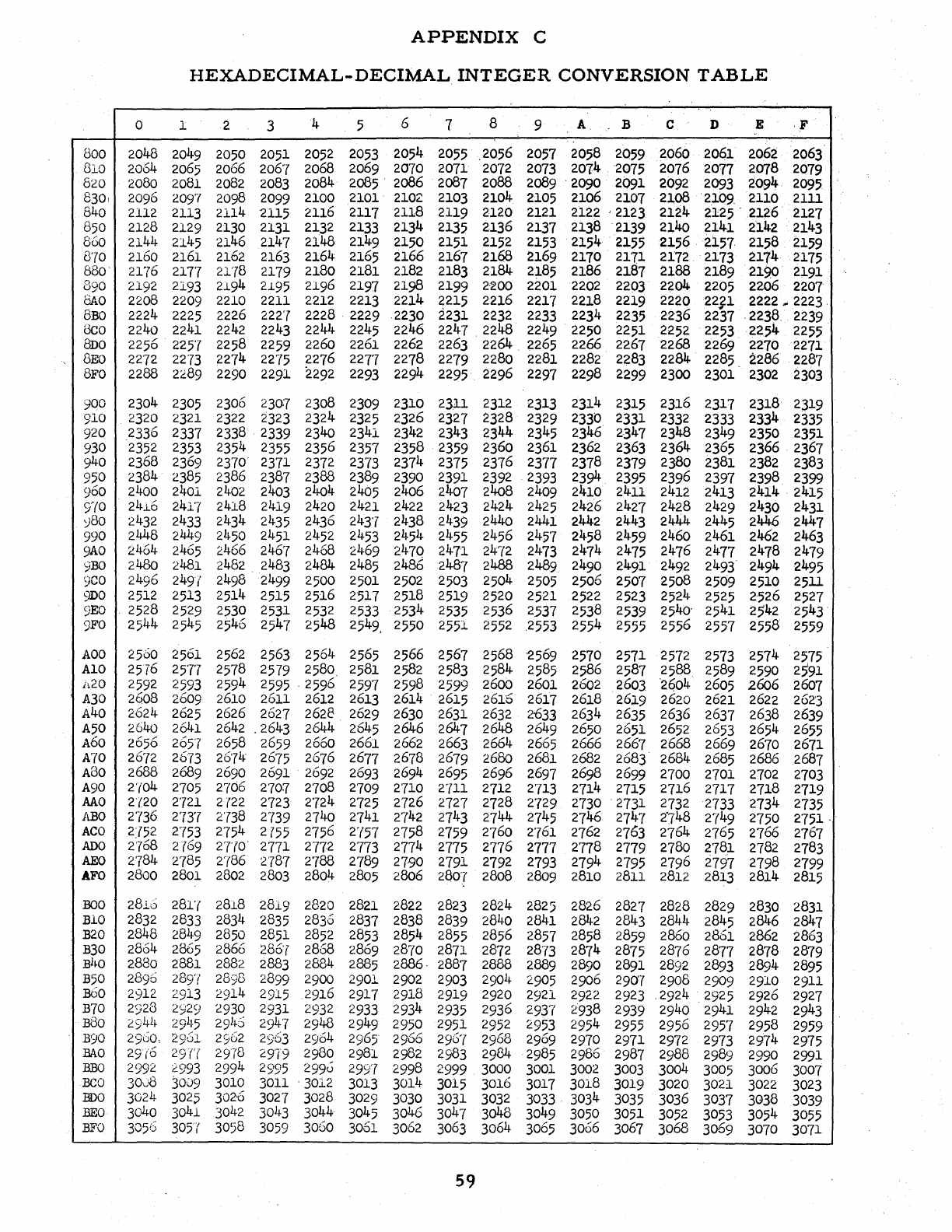
APPENDIX
C
HEXADECIMAL-DECIMAL
INTEGER
CONVERSION
TABLE
0 1 2 3 4 5 6 7 8 9
A,
B C D E
,F
800
2048
2049
2050 2051
2052 2053
2054
2055
.2056
2057 2058 2059
2060 2061
2062
2063
SlO
2064
2065
2066
2067
2068
2069
2070 2071
2072
2073
2014
2075
2076
2077
2078
2079
620
2080 2081
2082
2083
2084
2085
.
2086
2081
2088
2089
'2090
2091
2092
2093
2094,
2095
8301
2096
2097 2098
2099
2100
2101'
2102
2103
2104
2105
2106 2107
2108
'2109.
2110
2111
S40
2112
2113
2114
2115
2116 2111 2118 2119
2120
2121
2122
'2123
2124
2125
.
2126 2127
850
2128 2129 2130
2131
2132
2133
2134
2135
2136
2137
2138
'2139
2140 2141
2142
2143
860
2144
2145
2146
2141
2148
21
49
2150
2151
2152
2153
2154
'
2155
2156
2157,
2158
2159
870
2160 2161
2102
2163
2164
2165
2166
2161
2168 2169 2110
2111
2112
2113
2174
2175
880'
2176
217'7
21,{8
2119
2180
2181
2182
2183
2184
2;185
2186
2181
2188
2189
219.0
2191
890
2192
2193
2194
2.195
2196
2191
2198 2199
2·200
2201
2202
2203
2204
2205
2206
2201
SAo
2208
2209
2210 2211
2212
2213
2214
2215
2216
2217
2218 2219
2220
22,f1
2222
...
2223,
SBO
2224
2225
2226
222'7
2228
'
2229
.2230
2231
2232
2233
2234
2235
2236 2231
,2238,
2239
oeo
2240
2241
2242
2243
2244
2245
2246
2247
2248
22
49
2250 2251
2252 2253
2254
2255
SDO
2256
2257
2258
2259
2260 2261
2262 2263
2264
2265
2266 2261
2268 2269 2270
2271
SEO
22'72
2273
2214
2275
2216
2217
2278
2219
2280 2281
2282
2283
2284
2285.
2286
2281
8:F'0
2288
2~89
2290
2291
2292 2293
2294
2295
2296
2291 2298
2299 2300 2301
2302
2303
900
2304
2305
2306
230:7
2308 2309
2310
2311
2312
2313
2314 2315
2316
2311
2318
2319
910
2320
2321
2322
2323
2324
2325
2326
2321
2328
2329
2330
2331
2332
2333
2334
2335
920
2336
2337
2338
2339
2340 2341
2342
2343
2344
2345 2346
2-341
2348
2349 2350
2351
930
2352 2353
2354 2355
2356
2351
2358
2359
2360
2361
2362
2363
2364
2365
2366
2361
940
2368
2369
2310'
2311
2312
2313
2314
2315
2376
2311 2318 2319
2380
2381
2382
2383
950
2384
2385
2386 2381
2388
2389
2390 2391
2392 2393
2394
2395
2396 2391
2398
2399
960
2400
2401
2402
2403
2404
2405
2406 2407
2408
2409
2410 2411
2412
2413
2414
2415
c:/{O
24l.6
2417
2418 2419 2420 2421
2422
2423
2424
2425
2426
2427
2428
2429
2430 2431
~80
2432
2433
2434 2435 2436
243'7
2438
2439
2440
2441
2442
2443
2444
24
45
2446
2447
990
2448
2449
2450
2451
2452
2453
2454
2455
2456
2457
2458 2459 2460 2461
2462
2463
9AO
2464
2465
2466
246'7
2468
2469
247Q
241'1
2472
2473
2474 2475
2476
2471
2478
2419
9BO
2480
2481
2482
2483
2484
2485
2486
2487
2488
2489
2490
24
91
2492
2493
2494
2495
9CO
24
96
2491
2498
24
99
2500
2501 2502 2503
2504
2505
2506 2507
2508 2509
2510 2511
9DO
2512 2513
2514
2515
2516
2'517
2518
2519
2520
2521
2522
2523 2524
2525
2'526
2521
9EO
'
2528
2529
2530
2531
2532 2533
2534
2535
2536
2537
2538 2539
2540'
2541
25'42
2543'
9FO
2544
2545
25
46
2547
2548
25
4
9,
2550
2551
2552
,2553
2554 2555
2556
2557
2558
2559
AOO
2500
2561
2562
2563
2564
2565
2566
2567
2568
'2569
2510
2571
2572
2573
2574
2575
AI0
2576
25'1'7
2578 2579
2580
2581
2582
2583 2584
2585
2586
2587
2588.
2589 2590
2591
il.20
2592
2593
2594
2595
,2596
2597
2598 2599
2600 2601
2602
2603
'2604
2605
2606
2607
A30
2608
2609 2610
2611
2612
2613 2614 2615
2616
2617
2618
2619
2620 2621
2622
262'3
A40
2624
2625
2626 2627
2628
2629
2630 2631
2632
2'633
2634
2635
2636
2637
2638 2639
A50
2640
2641
2642
.2643
2644
2645
2646
2647
2648
26
49
2650
2651
2652
2653 2654
2655
A60
2656
2657 2658
2659
2660 2661
2662
2663
2664
2665
2666 2667
2668
2669
2670 2671
A70
26'(2
2673
26'7L~
26'75
2676 2677
2678
2679 2680
2681
2682
2683'
2684
2685
2686 2687
ABo
2688
2689 2690 2691
2692
2693
2694
2695
2696
2697
2698
2699
2700
2701
2702
2703
A90
2'l04
2705
2706
2'70':(
2'708
2709
2'710
2711
2712
2713
2714
2715
2716
2717
2718
2719
MO
2'{20
2721
2
(22
2723
2'724
2725
2726
2127
2728
2'129
2730
·2731
2732
2733
2734
2735
ABO
2736 2737
2738
2739 2740 2741
2742
2743
2744
2745
2746
2747
2"748
2749 2750
2751· '
ACO
2J52
2'(53
2'754
2755 2756
2'(57
2758
2759
2760
2'761
2762
2763
2764
2165
2766
2167
ADO
2768
2{69
2T70'
2771
277,2
2173
2174
2175
2776
2777
2178
2779
2780
2781
2782
2783
AEO
2784
2'785
2,(86
2787
2'788
2789
2790
2791
2792
2193
279
4
2795
2796 2197
2798
2799
AFO
2800
2801
2802
2803
2804
2805
2806 2807
2808
2809 2810 2811
2812 2813
2814
2815
BOO
2810
281'(
2818
2819
2820
2821
2822
2823
2824
2.825
2826
2827 2828
2829 2830 2831
BIO
2832
2833 2834 2835
2836
2837
2838
2839 2840
2841
2842
2843 2844
28
45
2846
2847
B20
2848
2849
2850
2851
2852
2853
2854
2855
2856
2857
2858
2859 2860
2861
2862
2863
B30
2864
2865
2866
286'(
2868
2869
28'(0
2871
2872 2813
2874
2875 2876 2877
2818
2879
Bho
2880
2881
2882
2883
2884
2885
2886·
2887 2888
2889
2890 2891
2892
2893
2894
2895
B50
2896
2897
2890
2899 2900
2901
2902
2903
2904
2905
2906
290'7
2908
2909 2910 2911
1360
2912
2913
2914
2915 2916
29r(
2918
2919
2920
2921
2922
2923
,2924
2925
2926
2927
B10
2:;28
2ji29
2930
2931
2932
2933 2934 2935
2936
2937
2938
2939
2940
2941
2942 2943
B80
2941J.
291~5
2914.6
2~~7
2948
2949 2950 2951
2952 2953
295
4
2955
2956
2957
2958 2959
B90
2960,
2961
2962
2::;03
2964
2965
2966
296'(
2968
2969 2970
2971
2972
2973
2974
2975
BAa
29(6 29Tr
2978
2979
2980
2981
2982
2983 2984
2985
2986 2987
2988
2989 2990
2991
BBO
2992
2.993
299
4
2995
299u
2991 2998
2999
3000
3001
3002
3003
3004 3005 3006
3007
BeO
30,.)8
3009
3010 3011
.
3012
3013
3014 3015
3016
3017
3018
3019
3020
3021
3022
3023
BOO
3024
3025
302'0
3027
3028
3029
3030
3031
3032
3033,
3034 3035
3036
3037 3038
3039
BEO
3040
3041
3042
30!}3
3044
3045
3046
3047 3048
3049
3050
3051
3052
3053
3054
3055
BFO
3056
305"(
3058
3059
3060
3061
3062
3063
3064
3065
3066
3067
3068 3069
30'70
3071
59
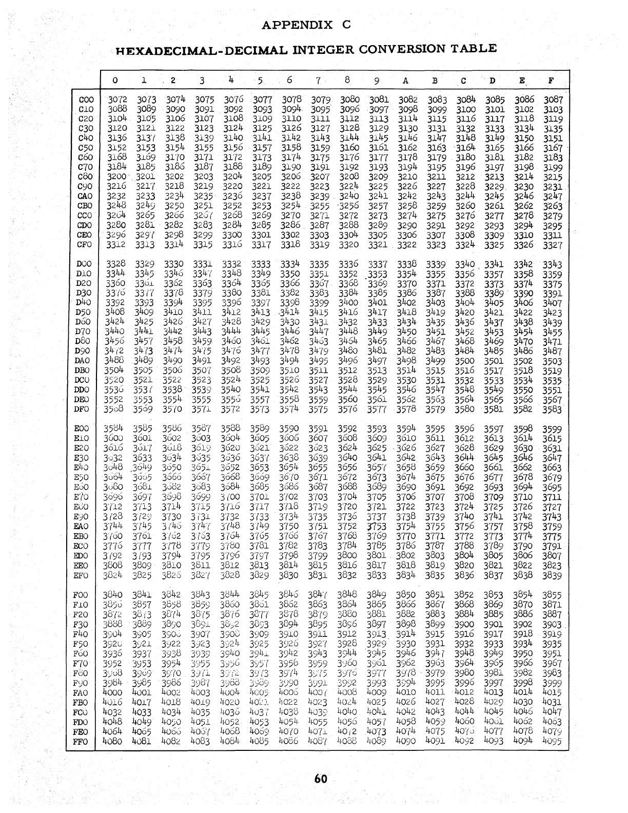
COO
Cl0
C20
C30
C40
C50
c60
c70
c80
C90
CAO
CBO
cco
CDO
CEO
CFO
DOO
D10
D20
D30
,
D40
D50
DoO
D70
D80
D90
DAO
DBO
DCO
DDO
DEO
DFO
EOO
E10
E20
E30
E!~O
E50
EoO
K(O
EGO
E')O
EAO
EBO
EGO
EDO
EEO
EFO
):0"00
FLO
F20
F30
F40
F50
FoO
F70
FSO
F';JO
FAO
FEO
Fca
FDa
FEO
FFO
APPENDIX
C
HEXADECIMAL-DECIMAL
INTEGER
CONVERSION
TABLE
0 1 2 3 4 5 6 7 8 9 A B C
'D
30,{2
3073
3074
3075
30,,(6
3077
30"(8
3079
3080
3081
3082
3083
3084
3085
3088 3089 3090
3091
3092
3093
3094
3095
3096
,3097
3098
3099
3100
3101
3104
3105
3106
3107
3108 3109
3110 3111
3112 3113
3114
3115
3116
3117
3120 3121
3122 3123
3124
3125
3J.26
3127
3128
3129
3130
3131
3132
3133
3136
31J(
3138
3139
3140
3141 3142
3143
3144
3145 3146
3147
3148
3149
3152
3153
3154
3155
3156
'3157
3158
3159 3160
3161
3162 3163
'3164
3165
3168 3109
31,{0
3171
3172 3173
3174
3175
31~(6
31T7
3178
3179
3180 3181
3184
3185
3186
3187
3188
3189
3190
3191
3192
3193
3194
3195
3196
3197
3200
,3201
3202
3203
3204
3205
3206
320'(
3208 3209 3210
3211
3212
3213
3216
3217 3218
3219 3220
3221 3222 3223
3224
3225
3226
3227
3228
3229,
3232
3233 3234
3235
3236
3237
3238
3239
'
3240
3241
3242 3243
3244
3245
3248 3249 3250 3251
3252
3253
3254
3255
'3256
3257
3258
3259 3260
3261
3204
3265
3266
32S(
3268
3269 3270
3271
3272
3273
3274
3275
3276
3277
3280 3281
3282
3283
3284
3285
3286,
3287
3288
3289
3290
3291
3292
3293
3296
329'(
3298 3299
330b 3301
3302
3303
3304
3305
3306
3307
3308 3309
3312
3313 3314 3315
3316
331'7
3318 3319
3320
3321
3322 3323
3324
3325
3328 3329
3330
3331
3332
3333
3334
3335
3336
3331
3338
3339
3340
,
3341
3344
3345
3346
334'(
3348
3349
3350
3351
3352
3353
3354
3355
3356 3357
3360
33O.L
3362
3363
3364
3365
3366
3367
3368 3369
3370
3371
3372
3373
3J(o
33(T
33'(8
3379
3380
3381
3382
3383
3384
3385
3386 3387
3388 3389
'
3392 3393
3394
3395
339
6
3397
3398
3399
31~00
3401
3402
3403
3404
3405
3408
34
09
3410 3411
3412 3413
,3
4
14
3415
3416 3417 3418
3419
3420 3421
3424
3425
3426 3427 3428
3429
3430
3431
3432
3433
3434
3435
3436
3437
3440 3441
3442
3443
3444
3411-5
3446
3447
3448
3449
34
50
34
51
34
52
3453
3450
3457
3458
3h59
3460
3461
3462
3463
3464 3465
3466
3467
3468 3469
34(2 34(3
34'('4
34'l5
3476
3l~Tr
3478
3479
3480 3481
3J.~82
3483
3484
3485
31~88
3489
3h90
34
91
3492
3!~93
3494
34
95
3496
34
97
3498
34
99
3500
3501
3504
3505
3506
350'(
3508 3509
3510
3511
3512
3513
3514
3515
3516
3517
3520
3521
3522
3523
3521~
3525
3526 3527
3528
3529 3530
3531 3532
3533
3536
353
('
3538
3539
3540 3541
3542
3543
35
44
3545
3546
3547
3548
3549
3552 3553
355
4
3555
355,-5
3557
3558
3559
3560 3561
3562
3563
3564 3565
3508
3569
35'(0
3571
3572
35'{3
3574
3575
3576 3577
3578
3579
3580
3581
3504
3585
35U6
3587
3588
3589
3590
3591
3592
3593
3594
3595
3596
3597
3600
3601
3602
3603
36Q4
3605
3606 3607
3608
3609 3610
3611
3612
3613
3616
301'{
301<3
361)
3620 3621
3622
3623
3624
3625
,3626
3627 3628
3629
3u32
3633
3034
3035
3036
363'(
3638
3639
3640 3641
3642
3643
3644
36
45
30
1
1-8
,36
49
3050
365.;.
3052
3653
3654
3655
3656
365'(
3658
3659 3660
3661
3u64
35~)5
3566
366'(
3668
3669
36(0
36,(1
3672
3673
3674
3675
3676
3677
3uGo
3681
3002
3083
3684
3685
3686
3687
3688
3689
3690
3691
3692
3693
3696
3691 3698 3699
3(00
3701
3702
3,,(03
3704
3705 3706
3707
3708 3709
3'(12
3'(13
3'714
3'(15
3{lG 3'(17
3'(18
3719 3720 3721
3722
3723
3724 3725
3(23
3{2S)
3730
3i'31
3732
3{33
3734
3735
3736
3737
3738
3739 3740
3741
3741~
3T
45 3(46 3(4'(
3'(1+8
3(49
3750
3(51
3752
1753
3754 3755 3756 3757
3(00
3761
3'(02
3753
3764
Jy65
3766 3767 3768
3769
3770
3771
3772
3773
3776
37'77
3'(78
3779 3780
3(31
3782
3783
3784
3785
3786 3787
3788 3789
3(92 3(93
3794 3795
3796
3797 3798
3799
3800
3801,
3802
3803
3804
3805
3808
3809
3810
3811
3812
3B13
3814
3815
3816
3817
3818
3819
3820 3821
3824
3825
3826
382'(
3828
3829
3830 3831 3832
3833
3834
3835
3836
3837
3840
3841
3842
38J~3
3844
3845
3846
384'(
3848
38
49
3850
3851 3852 3853
3850
3857
3858
385>
3860
3861
3862
3863
3864
3865
3866
3867
3868
3869
38'(2
38
(3
30'(4
30'(5
38'(6
33't(
3B78
38'rS)
3880
3881
3882
3883
3884 3885
3888
3889
3890
389J.
38;;2
3893
3394
3[\95
38:;6
3897
3898
3899
3900 3901
3904
3905
3900
390'(
3908
3909 3910 3911
3912
3913
3914
3915
3916
3917
392c
3921
3)22
3923
3)~~
l~
3S!25
3926
392'(
3928 3929
3930
3931
3932
3933
3936
393
r
(
3938 3939
3940
391~i.
3942
39L~3
3944
39
45
3946
3941
3948
3949
3952
3:;53
3954
3955 3;ijG
3S!5'(
3956
3959
3:)60
3901
3962 3963
3964,
3965
3')u8
3909
39'(0
3)(1 3/(2
3"1?
;;1,)
39'(11-
J";;:-
;;1,)
3)'76
3Strf
39'(8
'
3979
3980
3981
39b4
3985
3986
39D'(
3980
3;;0S;
31
)90
3;)91
39~)2
3993
3S:9
4
3995
3996
3997
4000
4()01
4002
L~003
l~()Ol1-
1~U05
l~oo6
l~OD(
4008 4009
4010
LI-Ol1
4012 4013
4016
4017
4018
40i9
1~020
40',-':i,
11022
1~0;~3
~,()<::4,
4025
4026
4027
4028
1~a29
4032 4033
4034
4035
11-036
4-u3i'
4038
4039
L~O!~O
404i
4042
4043
4044
4045
40
1
1-8
4049
LI-O)O
4051
1~052
4053
405
L1
-
h055
11-056
4057
4058
4059 4060 4061
4064
4065
4066
406'(
1
t
068
4009
1.~0(0
407i
4o{2
40'73
40,{4
4075
40'l~)
4,07'7
4080
4081
4082
4083
408
1
+
4005
1.~066
408'(
h008
11-029
h090
4091
4092
4,093
E F
3086
3087
3102 3103
3118
3119
3134
3135
3150 3151
3166
3167
'
3182
3183
3198
3199
3214
3215
3230
3231
3246
3247
3262
3263
3278
3279
3294
3295
3310
3311
3326
3327
3342
3343
3358
3359
3374
3375
3390
3391
3406
3407
3422
3423
3438
3439
3454
3455
3470 3471
3486
3487
3502
3503
3518 3519
3534
3535
3550
3551
3566
3567
3582
3583
3598 3599
3614
3615
3630
3631
.3646
3647
3662
3663
3678
3679
3694
3695
3710
3711
3726
3727
3742 3743
3758
3759
3774
3775
3790
3791
3806
3807
3822 3823
3838
3839
3854
3855
3870
3871
3886
3887
3902
3903,
3918
3919
3934
3935
3950
3951
3966 3967
3982 3983
3998
3999
4014
4015
4030
4031
4046
4047
4062
4063
40'78
40'79
4091~
4095
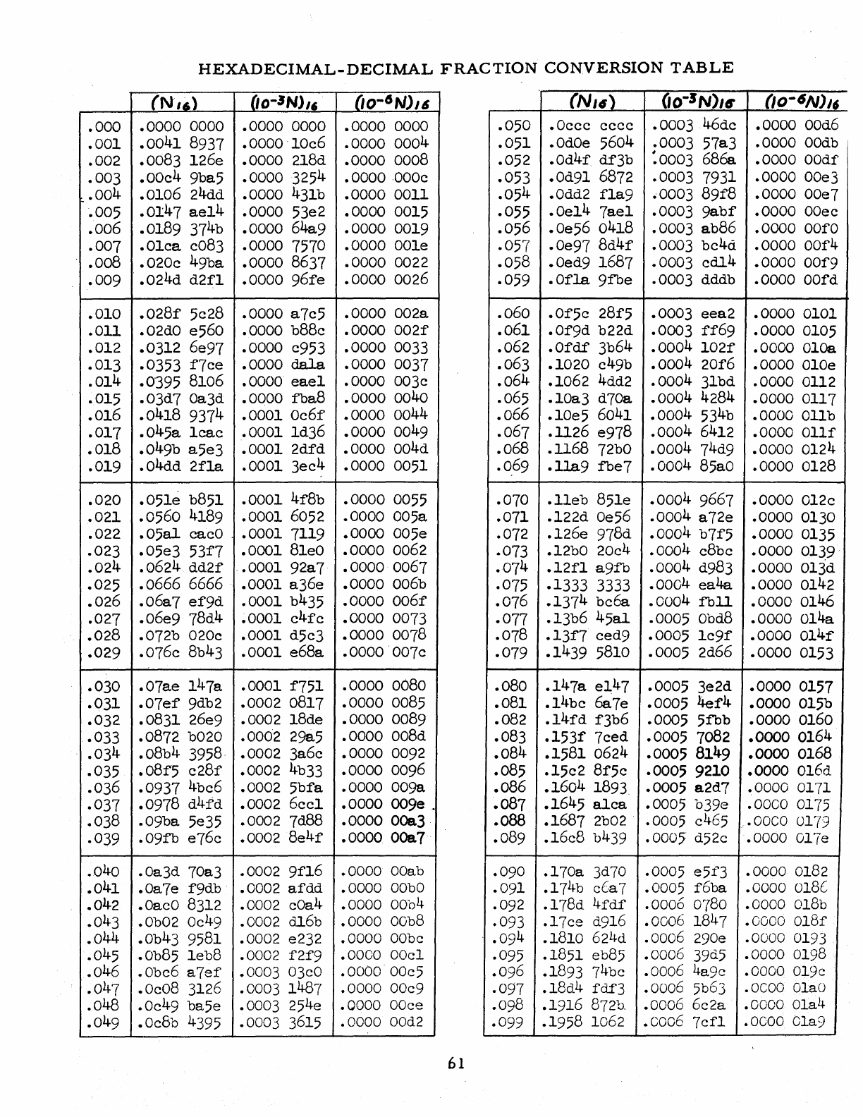
HEXADECIMAL-DECIMAL
FRACTION
CONVERSION
TABLE
(N'16)
(lo~3N)"
00-41\1)16
(N,.)
(io-3N)ur
(lo-6N)lf
.000
.0000
0000
.0000
0000
.0000
0000
.050
.Occc
cccc
.0003
46dc
.0000
00d6
.001
.0041
8937
.0000'10c6
.0000
0004
.002
.0083 126e
.0000
218d
.0000
0008
.051
.0dOe 5604
.0003
57a3
.0000
OOdb
.052
.od4r
df3b
:0003
6800
.0000
OOdf
.003
.00c4
9ba5
.0000
3254
.0000
,000c
.053
.Od91 6872
.0003
7931
.0000
00e3
.004
.0106
24dd
.0000
431b
.0000
0011
.054
.Odd2
fla9
.0003
89f8
.0000
00e7
~005
.0147
ae14
.0000 53e2
.0000
0015
.055
.Oe14
7ael
.0003
9abf
.0000
OOee
.006
.0189
374b
.0000
64a9
.0000
0019
.056
.Oe56 0418
.0003
ab86
.0000
Oaf a
.007
.Olca
c083
.0000
7570 .0000 001e
.057
.Oe97
8d4f
.0003
bc4d
.0000
00r4
.008
.020c
49ba
.0000
8637
.0000
0022
.058
.Oed9
1687
.0003
cdl4
.0000
001'9
.009
'
.024d
d2fl
.0000
96fe
.0000
0026
.059
.Ofla
9fbe
.0003
dddb
.0000
oord
.010
.028f
5c28
.0000
a7c5
.0000
002a
.060
.Of5e
28f5
.0003
eea2
.0000
0101
.011
.02dO e560
.0000
b88c
.0000
002f
.061
.Of9d
b22d
.0003
ff69
.0000
0105
.012
.0312 6e97
.0000
c953
.0000
0033
.062
.Ofdf
3b64
.0004
102f
.0000
OlGa
.013
.0353
f7ce
.0000
dala
.0000
0037
.063
.1020
c49b
.0004
20f6
.0000
alOe
.014
.0395
8106
.0000
eael
.0000
003c
.064
.1062
4dd2
.0004
31bd
.0000
0112
.015
.03d7
Oa3d
.0000
fba8
.0000
0040
.065
.10a3
d70a
.0004
4284
.0000
0117
.016
.0418
9374
.0001
Oc6f
.0000
0044
.066
.10e5 6041
.0004
534b
.0000
Olib
.017
.045a
lcac
.0001
1d36
.0000
0049
.067
.1l26
e978
.0004
6412
.0000
011f
.018
.049b
a5e3
.0001
2dfd
.0000
004d
.068
.1168
72bO
.0004
74d9
.0000
0124
.019
.04dd
2fla
.0001
3ec4
.0000
0051
.0.
69
.lla9
fbe7
.0004
85aO
.0000
0128
.020
.051e
b851
.0001
4f8b
.0000
0055
.070
.11eb
851e
.0004
9667
.0000
012c
.021
.0560
4189
.0001
6052
.0000
005a
.071
.122d
Oe56
.0004
a72e
.0000
0130
.022
.05al
cacO '
.0001
7119
.0000
005e
.072
.126e 978d
.0004
b7f5
.0000
0135
.023
.05e3
53f7
.0001
81eO
.0000
0062
.073
.12bO 20c4
.0004
c8bc
.0000
0139
.024
.0624
dd2f
.0001
92a7
.0000
0067
.074
.12fla9fb
.0004
d983
.0000
013d
.025
.0666
6666
.0001
a36e
.0000
006b
.075
.1333
3333
.0004
ea4a
.0000
0142
.026
.06a7
ef9d
.0001
b435
.0000
006f
.076
.137
4
be6a
.0004
fbll
.0000
0146
.027
.06e9 78d4
.0001
c4fc
.0000
0073
.077
.13b6
45al
.0005
Obd8
.0000
014a
.028
.072b
020c
.0001
d5c3
.0000
0078
.078
.13f7
ced9
.0005
1c9f
.0000
014r
.029
.076c
8b43
.0001
e68a
.0000'007c
.079
.1439
5810
.0005
2d66
.0000
0153
.030
.07ae
147a
.0001
f751
.0000
0080
.080
.147a
e147
.0005
3e2d
.0000
0157
.031
.07ef
9db2
.0002
0817
.0000
0085
.081
.14bc
6a7e
.0005
4er4
.0000
015b
.032
.0831 26e9
.0002
18de
.0000
0089
.082
.14fd
f3b6
.0005
5fbb
.0000
0160
.033
.0872
b020
.0002
298.5
.0000
008d
.083
.153f
7ced
.0005
7082
.0000
0164
.034
.08b4
3958,
.0002
3a6c
.0000
0092
.084
.1581
0624
.0005
8149
.0000
0168
.035
.08f'5
c28f
.0002
4b33
.0000
0096
.085
.15c2
Bf5c
.0005
9210
.0000
016d
.036
.0937
4bc6
.0002
5bfa
.0000
009a
.oB6
.1604
1893
.0005
a2d7
.0000
0171
.037
.0978
d4fd
.0002
6cc1
.0000
00ge.
.087
.1645
alca
.0005
b3ge
.0000
0175
.038
.09ba
5e35
.0002
7d88
.0000
00a3
.088
.1687
2b02 .0005 c465
.OOCO
0179
.039
.09fb
e76c
.0002
8e4f
.0000
00a7'
.089
.16c8
b439 •
0005:
d52c
.0000
017e
.040
.Oa3d 70a3
.0002
9f16
.0000
OOab
.090
.170a
3d70 .0005
e5f3
.0000
0182
.041
.Oa7e
f9db
.0002
afdd
.0000
OObO
.091
.174b
eCa7 .0005
f6ba
.0000
olBt::
.042
.0acO 8312 .0002 cOa4
.0000
0004
.092
.178d
4fdf
.0006 0780
.0000
018b
.043
.Ob02 Oc49 .0002
dl6b
.0000
oOb8
.093
.17ee
d916
.0006
1847
.0000
01Sf
.044
.ob43
9581
.0002
e232
.0000
OObe
,
.094
.1810
62L~d
.0006
290e
.0000 0193
.045
.ob85
1eb8
.0002
f2f9
.0000
OOe1
.095
.1851
eb85
.0006
39d5
.0000
0198
.046
.obc6
a7ef
.0003
03eO
.OOOOOOc5
.096
.1893 74be
.0006
4age
.0000
01ge
.047
.Oc08 3126
.0003
1487
.0000
00e9
.097
.18d4
fdf3
.0006
5b63
.oeoo
01aO
.048
.Oc49
ba5e
.0003
254e
.0000
OOce
.098
.1916
8720.
.0006
6e2a
.0000
01a4
.049
.Oc8b 4395
.0003
3615
.0000
00d2
.099
.1958
1062
.co06
7ef1
.oeoo
01a9
61
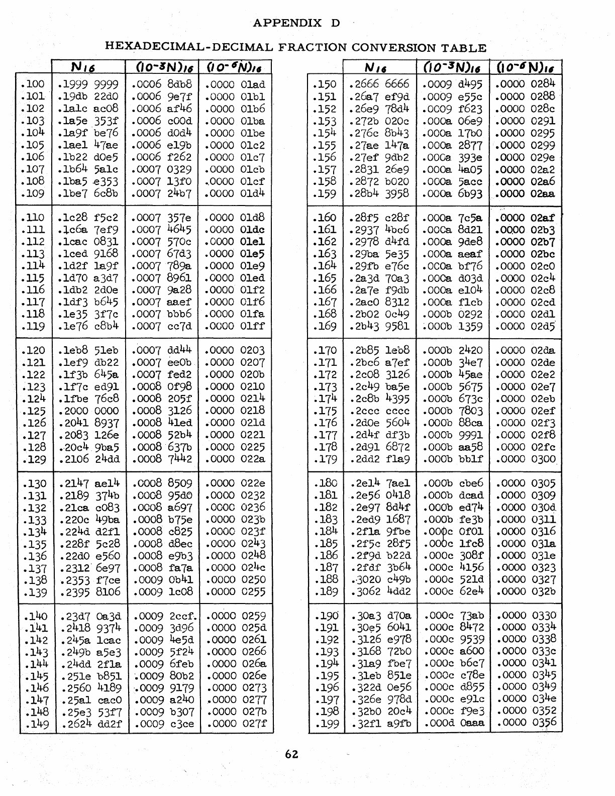
.100
.101
.
.102
.103
.104
.105
.106
.107
.108
.109
.110
.111
.112
.113
.114
.115
.116
.117
.118
.119
.120
.121
.122
.123
.124
.125
.126
.127
.128
.129
.130
.131
.132
.133
.134
.135
.136
.137
.138
.139
.140
.141
.142
.143
.144
.145
.146
.147
.148
.149
APPENDIX
D
HEXADECIMAL-DECIMAL
FRACTION
CONVERSION
TABLE
N'6
(IO-~N)/6
(lo-6N),.
NJf
(IO-3N)16
.1999
9999
.0006
8db8 .0000 01ad
.150
.2666
6666
.0009
d495
• 19db
22dO
.0006
ge7f
.0000
01b1
.151
• 2007
ef9d
.0009
e55e
.lale
ac08
.0006
af46
.0000 01b6
.152
.26e9
78d4
.0009
f623
.la5e
353f
.0006
eOOd
.0000
01ba
.153
.272b 020e
.000a
06e9
.la9f·be76
.0006
dOd4
.0000
01be
.154
.276e
8b43
.000a
17b0
.1ael
41ae
.0006
e19b .0000 01e2
.155
.27ae
147a
.00Da 2877
.lb22
dOe5
.0006
f262
.0000
01e7
.156
.27ef
9db2
.000a
393e
.lb64
5ale
.0007
0329
.0000
01eb
.157
.2831
26e9 .00Da 4a05
.lba5
.e353
.0007
13fO
•.
0000
01ef
.158
.2872
b020
.ooca
5aee
.lbe7
6e8b
.0007
24b7
.0000
01d4
.159
.28b4
3958
.ooaa
6b93
.lc28
f5e2
.0007
357e
.0000
01d8
.160
.28f5
e28f
.000a
7e5a
.le6a
7ef9
.0007
4645 .0000 Ol.dc
.161
.2937
4be6 .00Ca 8d21
.1eae
0831
.0007
570e
.0000
01e1
.162
.2978
d4fd
.00Da 9de8
.1ced
9168 • 0007 67d3
.0000
01e5
.163
.29ba; 5e35 .00Ga
aeaf
.ld2f
la9f
.0007
789a
.0000
01e9
.164
.29fb
e76e .0COa
bf76
.ld70
a3d7
.0007
8961
.0000
01ed
.165
.2a3d
70a3 .00Ca d03d
.ldb2
2dOe
.0007
9a28
.0000
01f2
.166
.2a7e
f9db .00Ga e104
.lM3
b645
.0007
aaef
.0000
011'6
.167
.2acO 8312 .0oCa
fleb
.le35
3f7e
.0007
bbb6
.0000
01fa
.168
.2b02
Oc49
.000b
0292
.le76 e8b4
.0007
ce7d
.0000
01ff
.169
.2b43
9581
~OOOb
1359
.leb8
51eb
.0007
o.d44
.0000
0203
.170
.2b85
leb8
.000b
2420
.lef9
db22
.0007
eeOb .0000 0207
.171
.2be6
a7ef
.000b
34
e7
.lf3b
645a
.0007
fed2
.0000 020b
.172
.2e08
3126
.000b
45ae
.lf7e
ed91
.0008
Of98
.0000
0210
.173
.2e49
ba5e
.000b
5675
.1fbe
76e8
.0008
205f
.0000
0214
.17
4
.2e8b
4395
.000b
673e
.2000
0000
.0008
3126 .0000 0218
.175
.2eee
ecce
.000b
7803
.2041
8937
.0008
41ed
..
0000 021d
.176
.2dOe 5604
.000b
88ea
.2083
126e
.0008
52b4
.0000
0221
.177
.2d4f
df'3b
.000b
9991
.·20e4.9ba5
.0008
637b
.0000
0225
.178
.•
2d91 6872
.000b
aa58
.2106
24dd
.0008
7442
.0000
022a
.179
.2dd2
fla9
.000b
bblf
.2147
ae14
.0008 8509
.0000
022e
.180
.2e14
7ael
.000b ebe6
.2189
374b
.0008
95d<J
.0000
0232
.181
.2e56
0418
.000b
dead
.21ea
c083
.0008
a697
.0000
0236
.182
.2e97
8d4f
.000b
ed74
.220e
49ba
.0008
b75e
.0000
023b
.183
.2ed9
1687
.000b
fe3b
.224d
d2f'1
.0008
c825
.0000
023f
.228f
5e28
.0008
d8ee
.0000
0243
.184
.2f1a
9fbe
.oo~e
Of 01
.185
.2f5c
28f5
.00
e
Ife8
.22dO e560
.0008
e9b3
.0000
0248
.186
.2f9d
b22d
.000e
308f
.2312'6e97
.0008
fa7a
.0000
024e
.187
.2fdf
3b64
.000e
4156
.2353
f7ee
.0009
0041
.0000
0250
.188
.-3020 e49b
.000e
521d
.2395 8106 .0009
le08
.0000
0255
.189
.3062 4dd2
.OOOe
62e4
• 23d7 Ga3d
.0009
2cef' •
.0000
0259
.190
.30a3
d70a
.000e
73ab
.2418
9374 .0009
30.96
.0000 025d
.191
.30~5
6041
.000e
8472
.245a
leae
.0009 4e5d
.0000
0261
.192
.3126 e978
.000e
9539
.249b
a5e3
.0009
5f24
.0000
0266
.193
.3168
72bO
.000e
a600
.24dd
2fla
.0009
6feb
.0000
026a
.19
4
.3la9
fbe7
.000e
b6e7
•
25le
b851 -.0009 80b2
.0000
026e
.195
.31eb
851e
.000c
e78e
.2560
4189 '.0009 9179
.0000
0273
.196
.322d
Oe56
.000e
d855
.25a1
eaeO
.0009
a240
.0000
0277
.25e3
53f7
.0009
b307 .0000 027b
.197
.326e
978d
.000e
e91e
.198
.32bO 20e4
.000e
fge3
.2624
dd2f
.0009
e3ee
.0000
027f
.199
.32f1
a9fb
.000d
Oa.aa.
62
CI
0-4N)'6
.0000
0284
.0000
0288 .
.0000
028e
.0000
0291
.0000
0295
.0000
0299
.0000
02ge
.0000
02a2
.0000
02a6
.0000
02a.a
.0000
02af
.0000
02b3
.0000
02b7 .
.0000
02be
.0000
02eO
.0000
02e4
.0000
02e8
.0000
02cd
.0000
02dl
.0000
02d5'
.0000
02da
.0000 02de
.0000
02e2
.0000
02e7
.0000
02eb
.0000
02ef
.0000
02f3
.0000
02f8
.0000
02fe
.0000
0300.
.0000 0305
.0000
0309
.0000
030d.
.0000
0311
.0000
0316
.0000
03la
.0000
031e
.0000 0323
.0000 0327
.0000
032b
.0000
0330
.0000 0334
.0000
0338
.0000
033e
.0000 0341
.0000 0345
.0000
0349
.0000
034e
.00000352
.0000
03~6
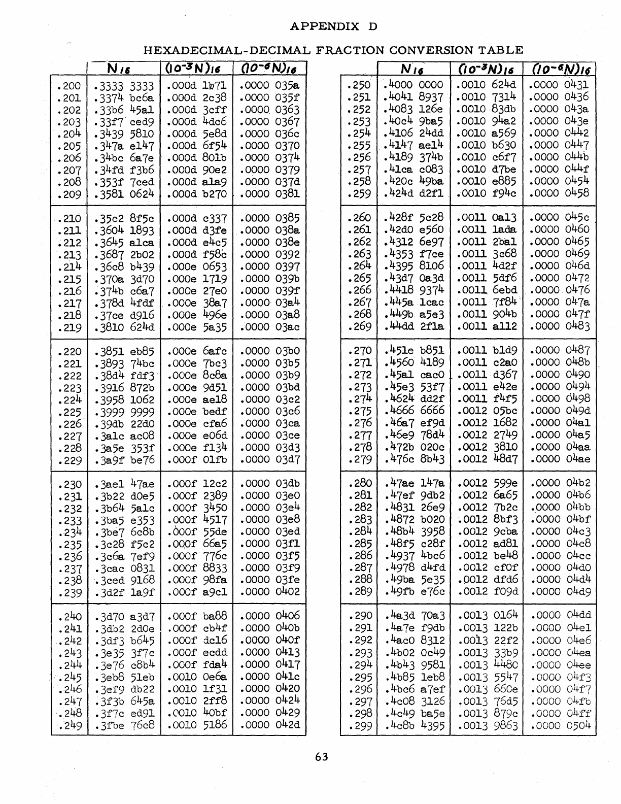
.200
.201
.202
.203
.204
.205
.206
.207
.208
.209
.210
.211
.212
.213
.214
.215
.216
.217
.218
.219
.220
.221
.222
.223
.224
.225
.226
.227
.228
.229
.230
.231
.232
.233
."234
.235
.236
.237
.238
.239
.240
.241
.242
.243
.244
.245
.246
.247
.248
."249
APPENDIX
D
HEXADECIMAL-DECIMAL
FRACTION
CONVERSION
TABLE
-
Nil
(IO-:JN)"
(10-"~N)'6
N'"
(io-6N)"
.3333 3333 .000d
1~71
.0000 035a
.3374
bc6a
.0GOd
2c38 .0000
035f
.250 .4000 0000 .0010 624d
.251
.4041 8937 .0010 7314
.33b6 45a1
.000d
3cff
.0000. 0363
.33f7" ced9 .000d 4dc6 .0000 0367 .252 .4083 126e
.0010
83db
.253
.40c4
9ba5 .0010 94a2
.3439 5810
.000d
5e8d .0000 036c
.347a
e147 .000d
61'54
.0000 0370
.34bc 6a7e " .000d 801b .0000 0374
.254
.4106 24dd .0010 a569
.255 .4147
ae14
.0010 b630
.256 .4189 374b .0010
c6f7
.341'd f3b6 .000d 90e2
.090
0 0379
.353f
7ced .000d
ala9
.0000 037d
.3581 0624
.000d
b270 ' .0000 0381
.257
.41ca
c083 .0010 d?be
.258 .420c 49ba .0010 e885
.259 .424d
d21'1
" .0010 f94c
.35c2
8f5c
.000d c337 .0000 0385
.3604 1893
.000d
d31'e
.0000 038a
.3645 a.1ca
.000d
e4c5 .0000 038e
.3687 2b02 .000d 1'58c .0000 0392
.36c8
b439
.000e
0653 .0000 0397
.370a
3d70 .000e 1719 .0000 039b
~374b
c6a7 .000e
27eO
.0000
039f
.378d
4fdf
" .000e 38a7 .0000, 03a4
.37ce
d916 .000e 496e .0000 03a8
.3810 624d .000e 5a35 .0000 03ac
.260
.428f
5c28 .0011
Oa13
.261
.42dO e560 .0011
1ada
.262 .4312 6e97
.001l2ba1
.263 .4353 1'7ce .0011 3c68
.264
.4395 8106 .0011
4d2f
.265 .43d7 0a3d .0011 5df6
.266 .4418 9374
.001l6ebd
.267
.445a
1cac
.001171'84'
.268
.449b a5e3 .0011 904b
.269 .44dd
2fla
.0011 a112
.3851 eb85 .000e
6afc
.0000
03bO
.3893 74bc .000e ?bc3 .0000 03b5
.38d4
fdf3
.000e 8c8a .0000 03b9
.3916 872b .Oooe 9d51 .0000 03bd
.3958 1062 .000e ae18 .0000 03c2
.3999 9999 .000e
bedf
.0000 03c6
.39db
22dO
.000e
cfa6
.0000 03ca
.3a1c
ac08 .000e e06d .0000 03ce
.38.5e 353f .000e f134 .0000 03d3
.3a9f" be76
.000f
01fb .0000 03d7
.270 .451e b851 .0011 b1d9
.271
.4560
4189 .0011
c2aO
.272
.45al
cacO .0011 d367
.273
.45e3
53f7
.0011
e42e
.274
.4624
dd21'
.0011 f4f'5
.275 .4666 6666 .0012 05bc
.276
.46a7
e1'9d .0012 1682
.277
.46e9
78d4 .0012 2749
.278 .472b 020c .0012 3810
.279 .476c 8b43 .0012 48d7
.3ae1
47ae
.000f
12c2 .0000 03db .280
.47ae
147a .0012 59ge
.3b22
dOe5
.000f
2389 .0000
03eO
.281
.47e1' 9db2 .0012 0065
.3b64 5a1c
.000f
3450 .0000 03e4
.3ba5 e353
.000f
4517 .0000 03e8
.3be7
6c8b
.OOOf
55de .0000 03ed
.282 .4831 26e9 .0012 7b2c
.283 .4872 b020 .0012
8b1'3
.284
.48b4 3958 .0012 9cba
.3c28
f5'c2 .0o.Of 66a5 .0000
03f1
.285 .481'5
c28f
.0012 ad81
.3c6a
7ef9
.000f
776c .0000
031'5
.286 .4937 4bc6 .0012 be48
.3cac
0831
.000f
8833 .0000
031'9
.3ced
9168
.000f
98fa
.0000
03fe
.3d2f
1a91'
.000f
a9c1 .0000 0402
.287 .4978
d41'd
.0012 ef01'
.288
.49ba
5e35 .0012
dfd6
.289
.49fb
e76c .0012
f09d
.3d70 a3d7
.000f
ba88 .0000 0406 .290
.4a3d
70a3 .0013 0164
.3db2
2dOe
.000f
cb4f
.0000 040b
.291
.4a7e
f9db .0013 122b
.3df3
b645
.000f
dc16 .0000
040f
.292 .4acO 8312 .0013
221'2
.3e35 3f7c
.000f
ecdd .0000 0413 .293 .4b02
Oc49
.0013 33b9
• 3e76
c8bl~
.000f
fda4
.0000 0417
.29
4
.4b
43 9581 .0013 4480
.3eb8 51eb .0010 Oe6a .0000 041c
.3ef9
db22 .0010 11'31 .0000 0420 .295 .4b85
leb8
.0013 5547
.296 .4bc6 a7e1' .0013 660e
.3f3b
645a .0010
21'1'8
.0000 0424
.297
.4c08 3126 .0013 76d5
.3f7c
ed91
.0010
40bf .0000 0429 .298
.4c
49 ba5e .0013 879c
.3fbe
76c8 .0010 5186 .0000 042d •
299
.4e8b 4395 .0013 9863
63
(JO-«/V)/f
.0000 0431
.0000 0436
.0000 043a
.0000 043e
.0000 0442
.0000 0447
.0000 044b
.0000
044f
.0000 0454
.0000 0458
.0000 045e
.0000 0460
.0000 0465
.0000 0469
.0000 046d
.0000 0472
.0000 0476
.0000 047a
.0000
047f
.0000 0483
.0000 0487
.0000 048b
.0000 0490
.0000 0494
.0000 6498
.0000 049d
.0000
04al
.0000 04a5
.0000 04aa
.0000 04ae
.0000 04b2
.0000 04b6
.0000 04bb
.-0000
04bf
.0000 04c3
.0000 04c8
.0000 04ce
.0000
04dO
.0000 04d4
.0000 04d9
.0000 04dd
.0000 04e1
.0000 04e6
.0000 04ea
.0000 04ee
.0000
04f3
.0000
Ol~1'7
.0000
04£'b
.0000
04ff
• 0000
0501~"
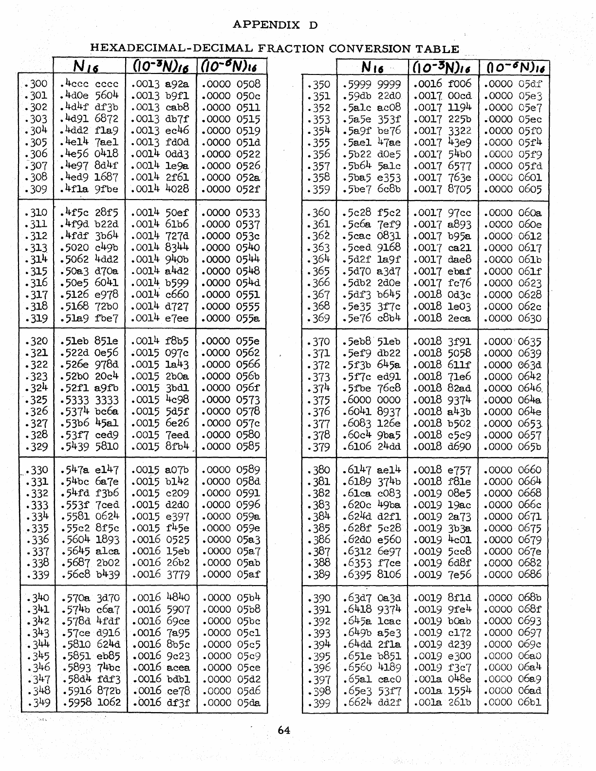
·300
·301
.302
·303
.304
.305
.306
~-307
.308
·309
·310
.311
·312
.313.
.314
-315
.316
.317
.318
.319
.320
.32J.
.322
·323
.324
.325
.326
.327
.328
.329
..•
330
.331
.332
.333
.334
.335
.336
.337
.338
.339
.340
.341
.342
.343
.344
.345
.346
.347
.348
.349
APPENDIX
D
HEXADECIMAL-DECIMAL
FRACTION
CONVERSION
TABLE
NI6
(IO-JN)/6
0O-6N)"
Nt6
"
(IO-3NJ"
.4cee
ecce .0013 a92a .0000 0508 .350 .5999
9999
.0016 fo06
.4dOe5604 .0013 b9f1 .0000 050c .351 .59db
22dO
.0017
OOcd
.4d4f
df3b .0013 cab8 .0000 0511 .352
.5ale
ac08 .0017 1194
.4d91
6872
.0013 db7f .0000
0515
.353 .5a5e 353f .0017
2250
.4dd2 f1a9 .0013 ee46 .0000 0519 .354
.5a9f
be76 .0017
3322
.4e14 7ae1 .0013
rdOd
.0000 051d .355 .5ae1 47ae .0017 43e9
.4e56 0418 .0014
Odd]
.0000 0522 .356 .5b22
dOe5
.0017
54bO
.4e97 8d4r .0014
le9a
.0000 0526 .357 .5b64
5alc
.0017
6577
.4ed9 1687 .0014 2f61 .0000 052a .358 .5ba5 e353 .0017 763e
.4r1a
9fbe .0014
4028
.0000 052f .359 .5be? 6c8b .0017
8705
.4f5c
28f5 .0014 50ef .0000 0533 .360 .5e28 f5c2 .0017 97ec
.4f9d
b22d .0014
61b6
.0000 0537 .361
.5cOO
7ef9 .0017 a893
.4fd.f
3b64
.0014 727d .0000 053c .362 .5cae 6831 .0017 b95a
.5020 c49b .0014
83
44 .0000 0540 .363
.5ced
9168
.0017 ea21
.5062
4dd2
.0014
94,Ob
.0000 0544 .364
.5d2f
la9f
.0017 dae8
.50a3 d70a .0014
a4d.2
.0000
0548
.365 .5d70 a3d7 .0017
ebaf
.50e5 6041
.001~
b599
.0000
05
4d .366 .5db2
2dOe
.0017 fc76
.5126 e978 .0014 c660 .0000 0551 .367 .5di'3 b645 .0018
Od3c
.5168
72bO
.0014
d727
.0000
0555
.368 .5e35 3f7e .0018 le03
.5la9
fbe7 .0014 e7ee .0000 055a .369 .5e76 e8b4 .0018 2eca
.51eb 851e .0014
f8b-5
.0000 055e .370 .5eb8"
51eb
.0018 3f91
.522d
Oe56
.0015 097c .0000
0562
.371
.5ef9
db22
.0018
5058
.526e 978d .0015
la43
.0000 0566 .372 .5f3b 645a .0018 611f
.52bO
20c4 .0015
2bOa
.0000
056b
.373
.5f7c
ed91 .0018 71e6
• 52f1
a9:f'b
•
0015
3bdl .0000 056f .374
.5fbe
76c8 .0018 82ad
·5333
3333
.0015 4c98 .0000 0573 •
375
•
6000
0000
.0018 9374
.5374 bc6a .0015 5d5f .0000 0578 .376 .6041 8937 .0018 a43b
.53b6
45B.l
.0015 6e26 .0000 057c .377 .6083 126e .0018 b502
.53f7
ced9 .0015 7eed .0000 0580 .378 .60c4 9ba5 .0018 c5e9
.5439
5810
.0015 8fb4_ .0000
0585
·379 .6106
24dd
.0018
d690
.547a e147 .0015 a07b .0000
0589
.54bc 6a7e .00i5
b142
.0000 058d .380
.61
47 ae14 .0018 e757
.381 .6189
374b
.0018 f81e
.54fd
f3b6 .0015
c209
.0000 0591 .382 .61ca co83 .0019 08e5
.553f
7ced .0015
d2dO
.00000596
.383 .620c 49ba .0019 19ae
.5581 0624 .0015 e397 .0000 059a .384 .624d
d2fl
.0019
2a73
.55c2 8f5e .0015 f45e .0000 05ge .385
.628f
5c28 .0019 3b3a
.5604 1893 .0016
0525
.0000 05a3 .386
.62dO
e560 .0019 4cOl
.5645 a1ea .0016 15eb .0000 05a7 .387 .6312
6e97
.0019 5cc8
.56872b02
.0016
26b2
.0000 05ab .388 " .6353 f7ce .0019 6d8f
.56c8 b439 .0016
3779
.0000 05af .389 .6395 8106 .0019 7e56
.570a
3d.70
.0016
4840
.0000 05b4 .390 .63d7 0a3d .0019
8fld
.574b c6a7 .0016
5907
.0000
0508
.391 .6418 9374 .0019 9fe4
.578d
4fdf
.0016 69ce .0000 05bc .392 .645a 1cac .0019 bGab
.57ce
d916
" .0016 7a95 .0000 05c1 .393 .649b a5e3 .0019
e172
.5810 624d .0016 8b5c .0000 05e5 .394 .64dd
2fla
.0019
d239
.5851 eb85 .0016 9c23 .0000 05c9 .395 .651e
b8.51
.0019 e300
.589374bc
.0016 acea .0000 05ce .396 .6560
4189
.0019 fJe7
.58d4
fdf3
.0016 bdbl .0000
05d2
.397
.65al
cacO
.OOla
048e
.5916
872b
.0016ce78
.0000
05d6
.398 .65e3 53f7 .OOla 1554
.5958 1062 .0016
df3f
.0000
0500
.399 .6624 dd2f .OOla
Z61b
64
o
0-6N)"
.0000
05d1'
.0000 05e3
.0000 05e7
.0000 05ee
.0000
05fO
.0000 05f4
.0000 05f9
.0000 05fd
.0000
0601
.0000
0605
.0000 060a
.0000 060e
.0000
0612
.0000
0617
.0000
061b
.0000 061f
.0000
0623
.0000
0628
.0000 062c
.0000
0630
.0000:0635
.0000
0639
.0000 063d
.0000
0642
.0000
0646
.
.0000
0648
.
.0000 064e
.0000
0653-
.0000
0657
.0000
065b
.0000
0660
.0000
0664
.0000
0668
.0000 066c
.0000
0671
.0000
0675
.0000
0679
.0000
067e
.0000
0682
.0000
0686
.0000
o6Bb
.0000
o68f
.0000
0693
.0000
0697
.0000 06ge
.0000
06aO
.0000
06a4
.0000
06a9
.0000 06ad
.0000
06bl
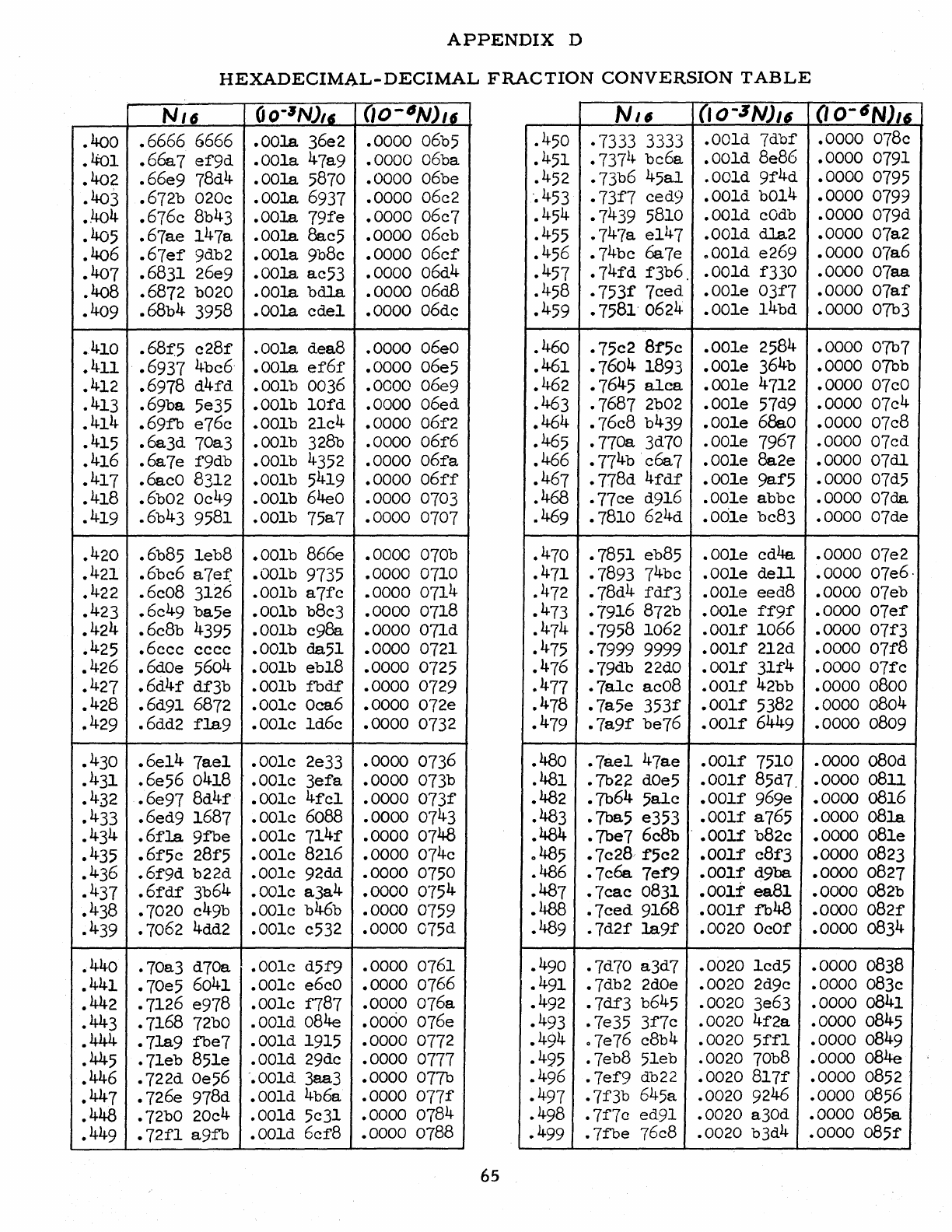
APPENDIX
D
HEXADECIMAL-DECIMAL
FRACTION
CONVERSION
TABLE
NI6
OO-~N)/(i
(JO-tSNJ'f
Nil
(lo-SNJ'6 (lo-6NJ'6
.400
.6666 6666
.00la
36e2 .0000 06b5 .450 .7333 3333
.00ld
7dbf .0000 078e
.4:01
.66a7
ef9d
.OOla 47a9 .0000 06ba
.402
.66e9
78d4
.00la
5870 .0000 06be
.403 .672b 020e
.00la
6937 .0000 06e2
.451
•
7371~
be6a
.001d
8e8G
.0000 0791
.452 .73b6
45al
.00ld
9f4d
.0000 0795
·.453
.73f7
eed9
.001d
b014 .0000 0799
•.
404
.676e
Bb
43 .00la.
79fe
.0000
06e7
.405
.67ae
147a
.00la
8ae5 .0000 06eb
.406
.67ef
9db2
.001a
9bBe
.0000
06ef
.454
.7439
5BlO
.001d
eOdb
.0000 079d
.455
.747a
e147
.001d
dla2
.0000 07a2
.456
.74be
6a7e
..
OOld
e269 .0000 07a6
• 407 .6831 26e9
.00la
ae53 .0000 06d4
.457
.74fd
f3b6 .
.001d
f330 .0000 07aa
.408
.6872 b020
.00la
bdla
.0000 06d8 .458
.753f
7eed .001e
03f7
.0000
07af
.409
.68b4
3958
.00la
cdel
.0000 06de
.459
.7581· 0624
.001e
l4bd
.0000 07b3
.410
.68:f5
e28f
.00la
dea8 .0000
06eO
.411
.6937 4bc6· .00la.
ef6f
.0000 06e5 .460
.75e2
Bf5c .001e 2584 .0000 07b7
.461
.1604
1893
.001e
364b .0000 07bb
.412 .6978
d4fd
.001b 0036 .0000 06e9
.462
.1645
alea
.001e
4712 .0000
07cO
.413
.69ba
5e35 .001b
10fd
.0000 06ed .463 .7687 2b02
.001e
57d9 .0000 07e4
.414
.69fb
e76c .001b 21c4 .0000 06f2
.464
.76cB b439
.001e
68e.0
.0000
01cB
.415
.6a3d
70a3 .001b 328b .0000
06f6
.465
.770a
3d70 .001e 7967 .0000 07cd
.416
.6a7e
f9db .001b 4352 .0000
06fa
.466
.77
4
b·coo7
.001e 8a2e .0000
07dl
.417
.6aeO 8312 .001b 5419 .0000
06ff
.467
.778d
4fdf
.001e
9af5
.0000 07d5
.418
.6b02
Oe
49 .001b 64e0 .0000 0703 .468
.77ce
d9l6
.001e abbe .0000 0700
.419
.6b43 9581 .001b 75a7 .0000 0707 .469 .7810 624d
.00le
be83 .0000 07de
.420
.6b85
leb8
.001b 866e .0000 070b .470 .7851 eb85
.001e
ed4a .0000 07e2
.421
.6be6
a7ef
.OOlb 9735 .0000 0710
.471
.7893 74be .001e
dell
.0000 07e6·
.422
.6c08
3126 .001b
a7fe
.0000
0714 .472
.78d4
fdf3
.001e eed8 .0000 07eb
.423
.6c49
ba5e .001b b8c3 .0000 0718 .473 .7916 872b
.001e
ff9f
.0000
07ef
.424
.6eBb 4395
.00lb
e98a .0000
07ld
.474
.7958 1062
.001f
1066 .0000 07f3
.425
.6eee
ecce
.001b 0051 .0000 0721 .475 ·7999 9999
.001f
2l2d
.0000
07f8
.426
.6dOe 5604 .001b eb18 .0000 0725 .476 .79db
22dO
.001f
3lf4
.0000
07fc
.427
.6d4f
df3b .001b
ibdf
.0000 0729
.477
.7ale
acoB
.001f
42bb .0000 0800
.428
.6d91 6872 .001c
Oca6
.0000 072e .478
.7a5e
353f
.001f
5382 .0000 0804
.429
.6dd2
fla9
.001e
ld6e
.0000 0732 .479
.7a9f
be76
.001f
6449 .0000 0809
.430
.6e14
7ael
.001e
2e33
.0000 0736 .480
.7ael
47ae
.001f
7510 .0000
aBOd
.431
.6e56
0418 • 001e
3efa
.0000 073b .481 .7b22
dOe5
.001f
85d7 . .0000
08ll
.432
.6e97
Bd4f .001e
4fcl
.0000
073f
.482 .7b64
5ale
.001f
96ge .0000 0816
.433
.6ed9
1687 .001c
60BB
.0000 0743 .483 • 7ba5 e353
.001f
a765 .0000
08la
.43
4
.6fla
9fbe
.001e
7l4f
.0000 0748 .484
.7be7
6e8b
.•
001f
b82e .0000
08le
.435
.6f5c
28f5 .001e 8216 .0000 074c
0485
.7e28,
f5c2
.001f
e8f3
.0000 0823
.436
.6f9d
b22d .001c 92dd .0000 0750 .486
.7c6a
7ef9
.001f
d9ba .0000 0827
.437
.6fdf
3b64 .001c
a3a
4 .0000 0754
.487
.7cae
0831 .001f' ea81 .0000
aB2b
.438
.7020 e49b .001e b46b .0000 0759
.488
.7eed
9168
.001f
fb48 .0000
082f
.439
.7062 4dd2 .001e e532 .0000 075d .489
.7d2f
la9f
.0020
OeOf
.0000 0834
.440 .70a3 d70a .001c d5f9 .0000 0761 .490 .7d70 a3d7 .0020
led5
.0000 0838
.441
.70e5
6041 .001c
e6eO
.0000 0766
.491
.7db2
2dOe
.0020 2d9c .0000 083c
.442 .7126 e978 .001e f787 .0000 076a
.443 .7168
72bO
.001d 084e .0000 076e
.444
.7la9fbe7
.001d 1915 .0000 0772
.445
.7leb
851e .001d 29de .0000 0777
.492
.7df3
b645 .0020 3e63 .0000 0841
.493 .7e35
3f7e
.0020
4f2a
.0000 0845
.494
o 7e76 c8b4 .0020
5ffl
.0000 0849
.495
.7eb8
5leb
.0020 70b8 .0000 084e
.446 .722d
Oe56
".OOld
3aa3 .0000 077b
.496
.7ef9
db22 • 0020
8l7f
.0000 0852 .
.447
.726e
978d .001d 4b6a .0000
077f
.497
.7f3b
645a .0020 9246 .0000 0856
.448 .72bO 20c4 .001d
5c3l
.0000 0784
.449
.72fl
a9fb
.001d
6cf8
.0000 0788 .498
.7f7c
ed91 .0020 a30d .0000 085a
.499
.7fbe
76c8 .0020 b3d4 .0000
085f
65
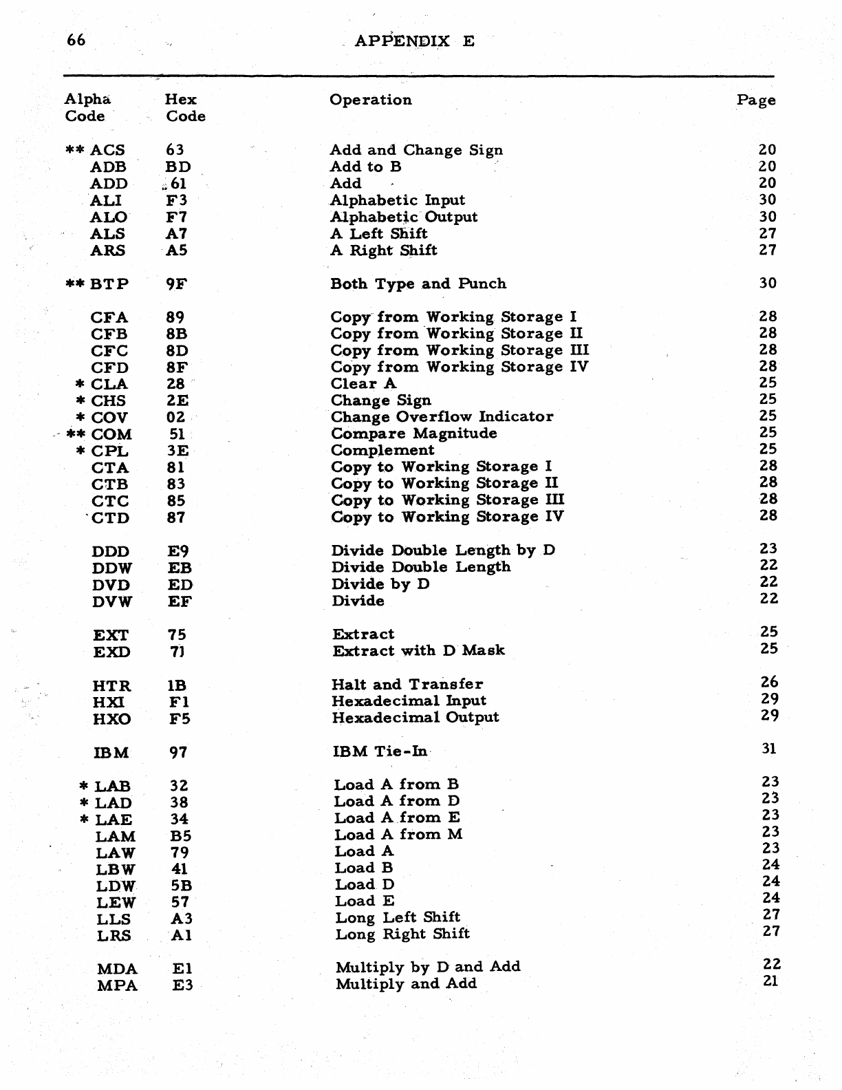
66
APPENDIX
E
Alpha
Hex
Operation
Page
Code'
Code
**ACS
63
Add
and
Change
Sign
20
ADB
BD
Add
to
B
20
ADD
~6l
Add
20
,'ALI
F3
Alphabetic
Input
30
ALO'
F7
Alphabetic"
Output
30
ALS
A7
A
Left
Sliift
27
ARS
A5
A
Right
SPift
27
**BTP
9F
Both
Type
and
Punch
30
CFA
89
Copy'
from
Working
Storage
I
28
CFB
8B
Copy
from
'Working
Storage
n
28
CFC
8D
Copy
from
Working
Storage
III
28
CFD
8F
Co'py
from
Working
Storage
IV
28
*CLA
28'
Clear
A
25
*CHS
ZE
Change
Sign
25
*COV
OZ
Change
Overflow
Indicator
25
"**
COM
51
Compare
Magnitude
25
*
CPt,
3E
Complement
25
CTA
81
Copy
t,o
Working
Storage
I
28
CTB
83
Copy
to
Working
Storage
II
28
CTC
85
Copy
to
Working
Storage
m
28
'CTD
87
Copy
to
Working
Storage
IV
28
DDD
E9
Divide
Double
Length
byD
23
DDW
EB
Divide
Double
Length
22
DVD
ED
Divide
by
D
22
DVW
EF
Divide
22
EXT
75
Extract
25
EXD
7J
Extract
with
D
Mask
25
HTR
lB
Halt
and
Transfer
26
HXI
Fl
Hexadecimal
Input
29
HXO
F5
Hexadecimal
Output
29
mM
97
IBM
Tie-In,
31
*
LAB
32
Load
A
from
B
23
*
LAD
38
Load
A
from
D
23
*LAE
34
Load
A_from
E 23
LAM
B5
Load
A
from
M 23
LAW
79
Load
A 23
LBW
41
Load
B
24
LD-W
5B
LoadD
24
LEW
57
Load
E
24
LLS
A3
Long
Left
Shift
27
LRS
Al
Long
Right
Shift
27
MDA
El
Multiply
by
D'
and
Add
22
MPA
E3
Multiply
and
Add
21
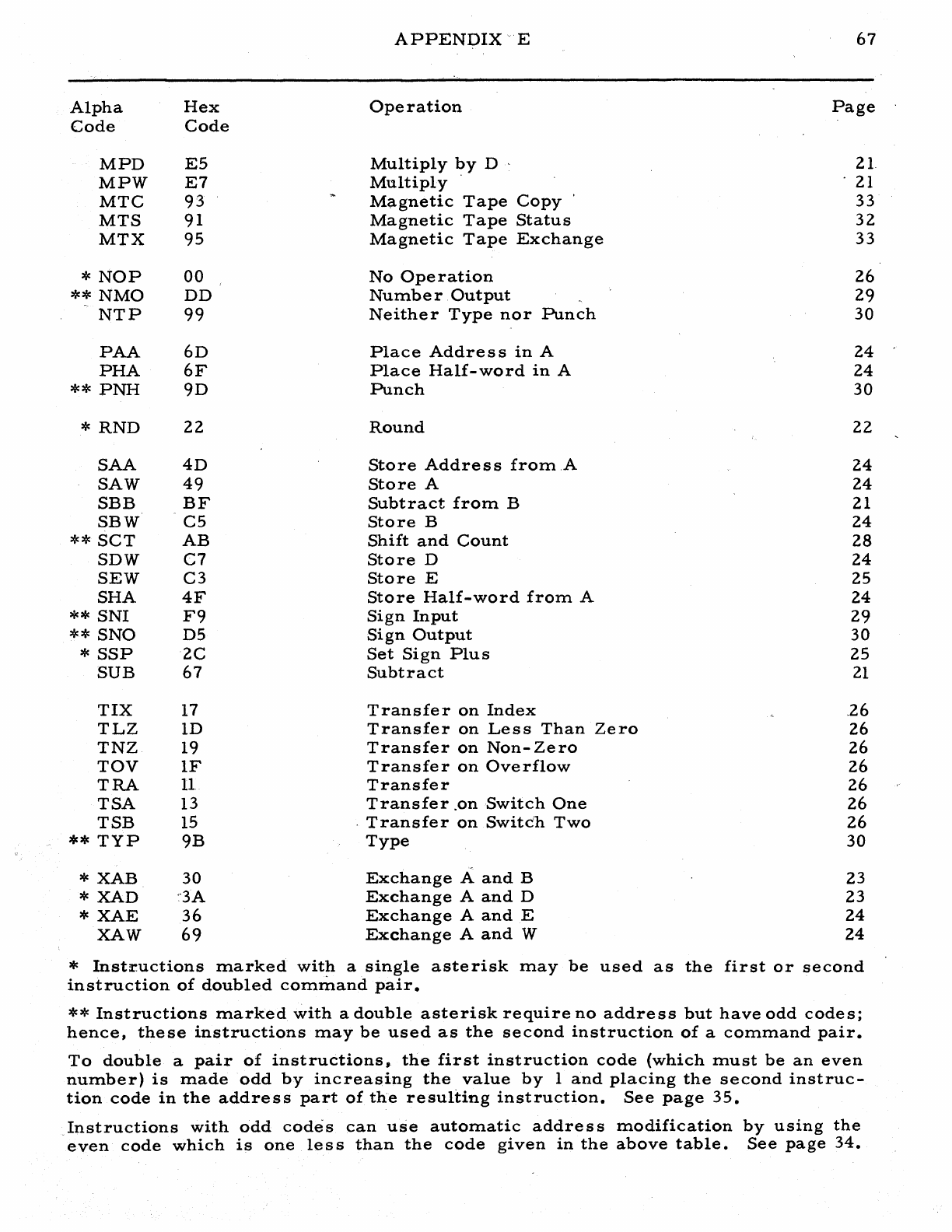
APPENDIX"
E
67
Alpha
Hex
Operation
Page
Code Code
MPD
E5
Multiply
l?y D ' 21
MPW
E7
Multiply
21
MTC
93
Ma.gnetic
Tape
Copy
33
MTS
91
Magnetic
Tape
Status
32
MTX
95
Magnetic
Tape
Exchange
33
*
NOP
00
No
Operation
26
**
NMO
DD
Number
Output
29
NTP
99
Neither
Type
nor
Punch
30
PAA
6D
Place
Address
in
A
24
PHA
6F
Place
Half-word
in
A
24
**
PNH
9D
Punch
30
*
RND
22
Round
22
SAA
4D
Store
Address
from
A
24
SAW
49
Store
A
24
SBB
BF
Subtract
from
B 21
SBW
C5
Store
B
24
**
SCT
AB
Shift
and
Count
28
SDW
C7
Store
D
24
SEW
C3
Store
E
25
SHA
4F
Store
Half-word
from
A
24
**
SNI
F9
Sign
Input
29
**
SNO
D5
Sign
Output
30
*
SSP
2C
Set
Sign
Plus
25
SUB
67
Subtract
21
TIX
17
Transfer
on
Index
.26
TLZ
lD
Transfer
on
Less
Than
Zero
26
TNZ
19
Transfer
on
Non-Zero
26
TOV
IF
Transfer
on
Overflow
26
TRA
11
Transfer
26
TSA
13
Transfer
.on
Switch
One
26
TSB
15 .
Transfer
on
Switc'h
Two
26
**
TYP
9B
Type
30
*
XAB
30
Exchange
A
and
B 23
*
XAD
~'3A
Exchange
A
and
D
23
*
XAE
36
Exchange
A
and
E
24
XAW
69
Exchange
A
and
'W
24
*
Instructions
marked
with
a
single
asterisk
may
be
used
as
the
first
or
second
instruction
of
doubled
command
pair.
**
Instructions
marked
with
a
double
asterisk
require
no
address
but
have
odd
codes;
hence,
these
instructions
may
be
used
as
the
second
instruction
of
a
command
pair.
To
double
a
pair
of
instructions,
the
first
instruction
code
(which
must
be
an
even
number)
is
made
odd
by
increasing
the
value
by
1
and
placing
the
second
instruc-
tion
code
in
the
address
part
of
the
resulting
instruction.
See
page
35.
Instructions
with
odd
codes
can
use
automatic
address
modification
by
using
the
.
even
code
which
is
one
less
than
the
code
given
in
the
above
table.
See
page
34.
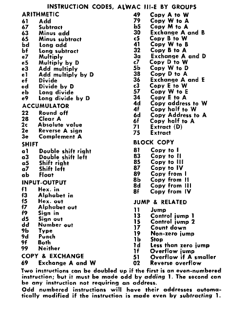
INSTRUCTION CODES,
MWAC
III-E
BY
GROUPS
ARITHMETIC
49
COpy A
to
W
61
Add
79
Copy
W
to
A
67
Subtract
bS
Copy
M
to
A
63
Minus
add
30
Exchange
A
and
B
65
Minus.
subtract
c5
Copy
B
to
W
bd
Long
add
41
Copy
W
to
B
bf
Long
subtract
32
Copy
B
to
A
e7
Multiply
30
Exchange
A
and
0
es
Multiply
by
0 c7
Copy
D
to
W
e3
Add
multiply
Sb
Copy
W
to
0
el
Add
multiply
by
0
38
Copy
0
to
A
ef
Divide
36
Exchange
A
and
E
ed
Divide
by
0 c3 COpy E
to
W
eb
Long
divide
57
Copy
W
to
E
e9
Long
divide
by
D
!:
~~:~
:Jdr~ss
to
W
ACCUMULATOR
4f
Copy
half
to
W
2228
Round
off
6d
Copy
Address
to
A
2c
Clear
A
6f
Copy
half
to
A
2e
Absolute
value
7751
EExxttrraacctt
(D)
Reverse A
sign
3e
Complement
A
SHIFT BLOCK COPY
al
Double
shift
right
81
Copy
to
I
a3
Double
shift
left
83
Copy
to
II
as
Shift
right
85
Copy
to
III
a7
Shift
left
87
COpy
to
IV
ab
Float
89
COpy
from
I
INPUT-OUTPUT
8b
Copy
from
II
8d
Copy
from
III
f1
Hex. in
8f
Copy
from
IV
f3
Alphabet
in
fs
Hex.
out
JUMP &
RELATED
f7
Alphabet
out
11
Jump
f9
Sign
in 13
Control
jump
1
ds
Sign
out
IS
Control
jump
2
dd
Number
out
17
Count
down
9b
Type
19
Non-zero
jump
9d
Punch
lb
Stop
9f
Both
99
Neither
ld
Less
than
zero
jump
If
Overflow
jump
COPY & EXCHANGE
51
Overflow
if A
smaller
69
Exchange
A
and
W
02
Reverse
overflow
Two instructions can
be
doubled
up
if
the
first is an
even-numbered
instruction; but
it
must
be
made
odd
by
adding
1.
The
second
can
be
any
instruction
not
requiring
an
address.
Odd
numbered instructions will
have
their
addresses
autorna
..
tically
modified
if
the
instruction
is
made
even
by
subtracting
1.
