Ammunition And Explosive Safety
Ammunition and Explosive Safety The Eye | File Listing
User Manual: Ammunition and Explosive Safety
Open the PDF directly: View PDF ![]() .
.
Page Count: 194 [warning: Documents this large are best viewed by clicking the View PDF Link!]
Department of the Army
Pamphlet 385–64
Safety
Ammunition
and Explosives
Safety
Standards
Headquarters
Department of the Army
Washington, DC
28 November 1997
Unclassified
SUMMARY of CHANGE
DA PAM 385–64
Ammunition and Explosives Safety Standards
This new Department of the Army pamphlet--
o Implements and amplifies the explosives safety criteria depicted in DOD
6055.9-STD, DOD Ammunition and Explosives Safety Standards (chap 1).
o Defines general safety standards for Army operations involving ammunition
and/or explosives (chap 2).
o Establishes management controls for fire prevention, suppression and
protection as applicable to Army ammunition and explosives (chap 3).
o Provides an overview of the Joint Hazard Classification System (JHCS) and
establishes storage principles for the various compatibility groupings of
ammunition and explosives (chap 4).
o Establishes quantities of explosives material and distance separation
requirements that provide defined levels of protection (chap 5).
o Establishes requirements for the installation and use of electrical service
and equipment in Army explosives facilities (chap 6).
o Defines regulations and guidance regarding shipment of Army explosives and
other dangerous articles (chap 7).
o Establishes requirements and provides definitive material on the preparation
and submittal of explosives and toxic chemical site plans (chap 8).
o Explains the purpose, denotes minimum requirements and defines
responsibilities of the Army explosives licensing program (chap 9).
o Provides guidance on the appropriate usage of material handling equipment
(MHE) for ammunition and/or explosives operations (chap 10).
o Establishes requirements for the movement of Army units to ports during times
of war, peace, or national emergency (chap 11).
o Provides the minimum technical criteria for lightning protection of
explosives areas and facilities (chap 12).
o Sets forth requirements for storage of ammunition and explosives within the
Army (chap 13).
o Establishes peacetime operational requirements concerning CONUS and OCONUS
ammunition and explosives activities, training operations, contingency force
operations and airfields used by military aircraft in the theater of
operations (chap 14).
o Provides guidance for the safe handling, transportation, and storage of
ammunition during wartime and contingency operations (chap 15).
o Defines the Army criteria pertaining to the storage and handling of
commercial explosives (chap 16).
o Provides guidance on the requirements and procedures for the disposal of
ammunition, explosives and propellants (chap 17).
o Establishes requirements and criteria relative to operations involving
maintenance and/or the restoration of ammunition and explosives to a
serviceable condition (chap 18).

Headquarters
Department of the Army
Washington, DC
28 November 1997
Safety
Ammunition and Explosives Safety Standards
Department of the Army
Pamphlet 385–64
History. The electronic version of DA Pam
3 8 5 – 6 4 , d a t e d 2 8 N o v e m b e r 1 9 9 7 , d i f f e r s
f r o m t h e p a p e r v e r s i o n . T h e e l e c t r o n i c t e x t
contains corrected data in tables 5–12, 5–27,
5 – 2 8 , 5 – 2 9 , a n d 5 – 3 6 . T h i s i s a n e w
Department of the Army publication.
S u m m a r y . T h i s p a m p h l e t p r o v i d e s f o r c e
protection guidance for commanders with an
a m m u n i t i o n o r e x p l o s i v e s m i s s i o n . I t
provides procedures to protect military and
civilian Army employees, the public, and the
environment. It also sets forth procedures for
use when transporting ammunition or explo-
sives over the public highway.
Applicability. The provisions of this pam-
phlet apply to all Army installations and ac-
tivities, the Army National Guard (ARNG),
t h e U . S . A r m y R e s e r v e ( U S A R ) , G o v e r n -
ment-owned, contractor-operated (GOCO) fa-
c i l i t i e s , a n d c o n t r a c t o r o p e r a t i o n s o n
Government property. Ammunition and ex-
plosives under U.S. title, even though stored
in a host country, remain the responsibility of
the U.S. commander. Storage must conform
with Army standards for explosives safety
unless the use of other criteria (such as North
Atlantic Treaty Organization (NATO) or host
nation has been agreed to or is mandatory. A
copy of all agreement documents will be pro-
v i d e d m a j o r A r m y c o m m a n d s ( M A C O M s )
involved and two will be sent to the Director,
U.S. Army Technical Center for Explosives
S a f e t y ( U S A T C E S ) . A c o p y o f a l l a g r e e -
ments will also be made a permanent part of
the real property records. Provisions of this
pamphlet apply in wartime, peacetime, and in
contingency situations.
P r o p o n e n t a n d e x c e p t i o n a u t h o r i t y .
The proponent of this pamphlet is the Under
Secretary of the Army. The Under Secretary
of the Army has the authority to approve
exceptions to this pamphlet that are consis-
tent with controlling law and regulation. The
p r o p o n e n t m a y d e l e g a t e t h i s a u t h o r i t y , i n
writing, to a division under his or her super-
vision or to a division chief within the propo-
nent office who holds the grade of colonel or
the civilian equivalent.
Supplementation. Supplementation of this
pamphlet is prohibited without prior approval
from the proponent of this pamphlet.
Suggested Improvements. Users are in-
vited to send comments and suggested im-
p r o v e m e n t s o n D A F o r m 2 0 2 8
(Recommended Changes to Publications and
Blank Forms) directly to Director, U.S. Army
Technical Center for Explosives Safety.
Distribution. Distribution of this publica-
tion is made in accorance with initial distri-
bution number (IDN) 095466, for command
levels D and E for the Active Army, the
Army National Guard, and the U.S. Army
Reserve.
Contents (Listed by paragraph and page number)
Chapter 1
Introduction, page 1
Purpose • 1–1, page 1
References • 1–2, page 1
Explanation of abbreviations and terms • 1–3, page 1
Implementation • 1–4, page 1
Policy on existing explosives facilities • 1–5, page 1
Chapter 2
General Safety Precautions, page 1
Hazard analysis and risk assessment • 2–1, page 1
Personnel qualifications • 2–2, page 1
Use of written standards • 2–3, page 1
Personnel and explosives limits • 2–4, page 1
Handling and movement precautions • 2–5, page 2
Housekeeping • 2–6, page 2
Testing, disassembly, and modification of explosives items • 2–7,
page 2
Explosive ordnance disposal training aids • 2–8, page 2
Field safety • 2–9, page 3
Accident reporting • 2–10, page 3
Rod and gun clubs • 2–11, page 3
Public demonstrations, exhibitions, and celebrations • 2–12,
page 3
Static or public display • 2–13, page 3
Explosives training aids for military working dogs • 2–14, page 3
Hunting • 2–15, page 4
Chapter 3
Fire Prevention, Protection, and Suppression, page 7
Fire prevention management • 3–1, page 7
Smoking • 3–2, page 7
Training • 3–3, page 7
Fire drills • 3–4, page 7
Fire exit drills • 3–5, page 7
Alarms • 3–6, page 7
Fire prevention requirements • 3–7, page 7
Auxiliary firefighting equipment • 3–8, page 9
Storage of water for firefighting • 3–9, page 9
Access to fire hose • 3–10, page 9
Limitation of fire areas • 3–11, page 9
Reciprocal agreements for fire fighting support • 3–12, page 9
Public withdrawal distances • 3–13, page 9
Firefighting guidance symbols • 3–14, page 10
Posting fire symbols • 3–15, page 10
Exceptions on posting fire symbols • 3–16, page 10
Posting chemical hazard symbols • 3–17, page 10
DA PAM 385–64 • 28 November 1997 i
Unclassified
Contents—Continued
Procedures for chemical agents and other toxic substances • 3–18,
page 10
Firefighting at railheads • 3–19, page 10
Automatic sprinkler systems • 3–20, page 11
Deluge systems for explosives operations • 3–21, page 11
Instructions for fighting fires involving ammunition or explosives
• 3–22, page 12
Chapter 4
Hazard Classification and Compatibility Groups, page 23
Explosives hazard classification procedures • 4–1, page 23
EIDS and EIDS ammunition • 4–2, page 23
Storage principles • 4–3, page 23
Mixed storage • 4–4, page 23
Storage compatibility groups • 4–5, page 23
Class 1 or 6 chemical agent hazards or combined chemical agent
and explosives hazards • 4–6, page 24
Chapter 5
Quantity-Distance, page 25
Explosives quantity-distance • 5–1, page 25
Quantity of explosives • 5–2, page 26
Measuring distance • 5–3, page 26
Q-D computations and determinations • 5–4, page 26
Fragments • 5–5, page 27
Quantity-distance: expected effects and permissible exposures
• 5–6, page 27
Facilities siting criteria • 5–7, page 30
Magazine orientation • 5–8, page 39
Quantity-distance tables • 5–9, page 40
Airfields, heliports, and seadromes • 5–10, page 41
Pier and wharf facilities • 5–11, page 41
Liquid propellants • 5–12, page 41
Underground storage • 5–13, page 43
Military working dog (MWD) explosives search training • 5–14,
page 45
Chapter 6
Electrical Hazards, page 75
Section I
Electrical Service and Equipment, page 75
Overview • 6–1, page 75
Hazardous locations • 6–2, page 75
Approved equipment • 6–3, page 76
Maintenance of electrical equipment • 6–4, page 76
Electrical service lines in explosives areas • 6–5, page 76
Electrical motors for hazardous locations • 6–6, page 76
Portable lighting systems • 6–7, page 76
Permanent lighting for storage magazines • 6–8, page 76
Flexible cords • 6–9, page 76
Section II
Static electricity, page 76
Static electricity charge dissipation subsystem • 6–10, page 76
Ordnance grounds (static grounds) • 6–11, page 79
Instrument grounds • 6–12, page 79
Section III
Grounding, page 79
Explosives facility grounding • 6–13, page 79
Earth electrode subsystem • 6–14, page 79
Section IV
Electromagnetic Radiation, page 80
Hazards of electromagnetic radiation to electro-explosive devices
(EEDs) • 6–15, page 80
Chapter 7
Transportation, page 89
Section I
General requirements, page 89
General information • 7–1, page 89
Certification of personnel involved with transportation • 7–2,
page 89
Hazard classification • 7–3, page 89
Preparation for shipment • 7–4, page 89
Compatibility of explosives in transportation • 7–5, page 90
Section II
Motor Vehicles, page 90
Vehicle general safety requirements • 7–6, page 90
Inbound motor shipment of ammunition and explosives • 7–7,
page 90
Outbound motor vehicle shipments of explosives • 7–8, page 90
Safe haven for explosive shipments • 7–9, page 91
On-post explosive movements • 7–10, page 91
Passengers in or on Government vehicles transporting explosives
• 7–11, page 91
Section III
Rail, Air, and Water Transport, page 91
Railroad transportation • 7–12, page 91
Air transportation • 7–13, page 92
Water transportation • 7–14, page 93
Chapter 8
Safety Site Planning, Construction, and Utilities, page 93
Section I
Explosives/Toxic Chemical Safety Site Plans, page 93
Explosives/Toxic Chemical Safety Site Plan Submittals • 8–1,
page 93
Explosives safety site plan contents • 8–2, page 94
Review and approval of explosives safety site plans • 8–3,
page 94
Section II
Construction Considerations, page 94
Construction considerations • 8–4, page 94
Buildings • 8–5, page 94
Interior finishes and floors • 8–6, page 95
Firewalls • 8–7, page 95
Substantial dividing walls • 8–8, page 95
Building exits • 8–9, page 95
Safety chutes • 8–10, page 95
Emergency exits and fire escapes • 8–11, page 95
Stairways • 8–12, page 95
Fixed ladders • 8–13, page 95
Platforms, runways, and railings • 8–14, page 95
Passageways • 8–15, page 95
Roads, walks, and gates • 8–16, page 96
Windows and skylights • 8–17, page 96
Drains and sumps • 8–18, page 96
Hardware • 8–19, page 96
Tunnels • 8–20, page 96
Powerhouse equipment • 8–21, page 96
Refrigeration • 8–22, page 96
Laundries • 8–23, page 96
Steam for processing and heating • 8–24, page 96
Ventilation • 8–25, page 96
Electrical equipment • 8–26, page 96
Collection of explosives dusts • 8–27, page 96
Automatic sprinkler systems • 8–28, page 97
ii DA PAM 385–64 • 28 November 1997
Contents—Continued
Section III
Open Storage Modules, Barricades, and Protective Construction,
page 97
Barricaded open storage modules • 8–29, page 97
Barricades and earth cover for magazines • 8–30, page 98
Policy on protective construction • 8–31, page 98
Strengthening (hardening of buildings) • 8–32, page 98
Chapter 9
Explosives Licensing, page 104
Procedures • 9–1, page 104
Required information • 9–2, page 104
Chapter 10
Materials Handling Equipment (MHE), page 104
General requirements • 10–1, page 104
Battery-powered materials handling equipment • 10–2, page 104
Gasoline and diesel powered equipment • 10–3, page 104
LP-gas-powered equipment • 10–4, page 104
Gasoline, diesel-powered and LP-gas-powered equipment for
handling explosives materials • 10–5, page 104
Storage • 10–6, page 105
Chapter 11
Port Operations, page 105
Background information • 11–1, page 105
Loading of vehicles • 11–2, page 105
Vehicle holding site • 11–3, page 105
Railhead operations • 11–4, page 105
Road movement • 11–5, page 105
Port safety • 11–6, page 106
Chapter 12
Lightning Protection, page 110
General information • 12–1, page 110
Fundamental principles of lightning protection • 12–2, page 110
Locations requiring an LPS • 12–3, page 111
Locations not requiring lightning protection • 12–4, page 111
Requirements for lightning protection systems • 12–5, page 111
Types of lightning protection systems • 12–6, page 112
General prohibitions • 12–7, page 112
Bonding • 12–8, page 112
Lightning warning systems • 12–9, page 112
Structural grounds • 12–10, page 112
Grounding • 12–11, page 113
Surge protection • 12–12, page 113
Visual inspection requirements • 12–13, page 113
Electrical testing requirements • 12–14, page 113
Records • 12–15, page 113
Truck holding areas • 12–16, page 113
Lightning protection for empty facilities • 12–17, page 113
Chapter 13
Explosives Storage Requirements, page 115
General requirements • 13–1, page 115
Magazine storage of explosives and ammunition • 13–2, page 116
Outdoor storage • 13–3, page 117
Holding yard • 13–4, page 117
Storage of specific types of ammunition and explosives • 13–5,
page 117
Inert ammunition • 13–6, page 119
Unserviceable ammunition • 13–7, page 119
Storage of captured enemy ammunition • 13–8, page 119
Chemical munitions • 13–9, page 119
Chemical Group B agents • 13–10, page 120
Storage of Chemical Group B agent munitions • 13–11, page 120
Special protective equipment for Chemical Group B agent
munitions • 13–12, page 120
First aid for Group B chemical agents • 13–13, page 121
Leaking Chemical Group B agent munitions • 13–14, page 121
Removal of spilled Chemical Group B fillers • 13–15, page 121
Fire in Chemical Group B agent munitions magazines • 13–16,
page 121
Chemical Group C agents • 13–17, page 121
Storage for Chemical Group C munitions • 13–18, page 121
First aid and special equipment for Chemical Group C munitions
• 13–19, page 121
Leaking Group C chemical munitions • 13–20, page 121
Removal of Chemical Group C contamination • 13–21, page 122
Fire in Chemical Group C munitions magazines • 13–22,
page 122
Chemical Group D fillers • 13–23, page 122
Storage of Chemical Group D munitions • 13–24, page 122
Special protective equipment for Chemical Group D munitions
• 13–25, page 122
First aid for Chemical Group D munitions • 13–26, page 122
Leaking Chemical Group D munitions • 13–27, page 122
Fire in Chemical Group D munitions magazines • 13–28,
page 122
Chapter 14
Peacetime Operations, page 122
Applicability of provisions outside the United States • 14–1,
page 122
Basic load ammunition holding areas • 14–2, page 123
Basic load storage in other than BLAHAs • 14–3, page 123
Vehicle and equipment maintenance • 14–4, page 123
Fire prevention • 14–5, page 123
Surveillance • 14–6, page 124
Storage • 14–7, page 124
Basic load storage ammunition holding areas in the United States
• 14–8, page 124
General requirements for training operations • 14–9, page 124
Upload exercises • 14–10, page 124
Combat configured loads • 14–11, page 124
Aviation operations at BLAHAs • 14–12, page 125
Forward area rearm/refuel points (FARP) • 14–13, page 125
General requirements or airfields used only by military aircraft in
the theater of operations • 14–14, page 125
Quantity distance • 14–15, page 125
Chapter 15
Wartime Operations, page 133
General requirements • 15–1, page 133
Theater and corps ammunition storage areas • 15–2, page 134
Storage at the ASP and ATP • 15–3, page 134
Short-term ATP storage • 15–4, page 134
Field storage units • 15–5, page 134
Transportation within the theater of operations • 15–6, page 135
Modular storage • 15–7, page 135
Ammunition turn-in at the cessation of hostilities • 15–8,
page 135
Chapter 16
Storage and handling of commercial explosives, page 137
Background • 16–1, page 137
Use • 16–2, page 137
Procedures • 16–3, page 137
Commercial dynamite • 16–4, page 138
Chapter 17
Demilitarization, page 138
Demilitarization • 17–1, page 138
Methods • 17–2, page 138
Safety precautions • 17–3, page 138
Site selection for burning or demolition grounds • 17–4, page 139
Burning sites • 17–5, page 139
iiiDA PAM 385–64 • 28 November 1997
Contents—Continued
New demilitarization technologies • 17–6, page 139
Chapter 18
Maintenance, page 139
General information • 18–1, page 139
Safety requirements • 18–2, page 139
Operational shields • 18–3, page 140
Equipment for shielded operations • 18–4, page 141
Tools, equipment and supplies • 18–5, page 141
Protection of primers • 18–6, page 141
Cleaning ammunition • 18–7, page 141
Spray painting • 18–8, page 141
Electrostatic paint spraying and detearing of inert items in non-
hazardous locations • 18–9, page 142
Infrared ray drying • 18–10, page 142
Drying freshly painted loaded ammunition • 18–11, page 142
Heat sealing equipment • 18–12, page 143
Soldering containers • 18–13, page 143
Thread cleaning • 18–14, page 143
Inert scrap components and packaging materials • 18–15,
page 143
Sand or shotblasting operations • 18–16, page 143
Location of sand or shotblasting operations in explosives storage
areas • 18–17, page 143
Sand or shotblasting operations within a building in an operating
line • 18–18, page 144
Electrical testing of ammunition and ammunition components
• 18–19, page 144
Profile and alignment gaging operations • 18–20, page 144
Collection of explosives dusts • 18–21, page 144
Location of collection chambers • 18–22, page 144
Design and operation of collection systems • 18–23, page 145
Solid propellant collection • 18–24, page 145
Destruction of solid wastes • 18–25, page 145
Assembly and crimping of complete rounds • 18–26, page 145
Rotational speeds for equipment used in field ammunition
operations • 18–27, page 145
Machining of explosives • 18–28, page 146
Operational shields for munitions loading • 18–29, page 146
Appendixes
A. References, page 147
B. Earth Electrode Subsystem Test and Inspection, page 149
C. Inspection and Test of Static Electricity Charge Dissipation
Subsystem, page 155
D. Inspection and Test of Lightning Protection Subsystems,
page 156
E. Field Expedient Grounding Techniques, page 158
F. Safe Conveyor Separation for Ammunition/Explosives,
page 159
G. Standard designs for explosives facilities, page 164
H. The 100–Foot Zone of Protection, page 165
Table List
Table 3–1: Extinguishing agents for fires, page 12
Table 3–2: Fire symbol hazards and actions, page 13
Table 3–3: Chemical hazard symbols and actions, page 13
Table 3–4: Emergency withdrawal distances for nonessential
personnel, page 14
Table 3–5: Fire divisions hazards, page 14
Table 3–6: Fire division symbols, page 15
Table 3–7: Chemical agents and fillers contained in ammunition
and the chemical hazard symbols required in storage, page 15
Table 4–1: EIDS and EIDS ammunition hazard divisions, page 24
Table 4–2: QD criteria for configuration of HD 1.6 components
and assemblies with other HD components, page 25
Table 4–3: Storage Compatibility Mixing Chart, page 25
Table 5–1: HD 1.1 inhabited building and public traffic route
distances, page 31
Table 5–2: Minimum primary fragment protection distance
expressed in feet for selected HD 1.1 Items, page 33
Table 5–3: HC/D 1.1 intraline distances in feet from PESs other
than earth-covered magazines3, page 34
Table 5–4: HD 1.1 intraline distances from earth-covered
magazines (type of distance protection to be provided to ES),
page 34
Table 5–5: HC/D 1.1 intermagazine hazard factors and distances,
page 35
Table 5–6: HC/D 1.1 guide for intermagazine distance table5,
page 37
Table 5–7: Personnel protection distances from aboveground
detonations, page 38
Table 5–8: Required blast overpressure protection distance in feet
for nonessential personnel at ranges used for detonating
ammunition for demilitarization, demonstration, or explosives
ordnance disposal, page 38
Table 5–9: Thermal flux calculations, page 38
Table 5–10: Impulse noise protection decision table, page 45
Table 5–11: Impulse noise zones measured in feet from intentional
detonations, page 46
Table 5–12: Impulse noise B-duration (estimated for various NEWs
and distances), page 47
Table 5–13: Impulse noise zones and required protections with
maximum permissable number of detonations per day, page 49
Table 5–14: Q-D for unprotected aboveground service tanks
supporting explosives storage or operating complexes, page 50
Table 5–15: HD 1.2 distances, page 50
Table 5–16: HD 1.3 QD, page 50
Table 5–17: HC/D 1.4 quantity-distance, page 53
Table 5–18: QD criteria for HD 1.6 ammunition, page 53
Table 5–19: HD 1.1.QD for military aircraft parking areas,
page 54
Table 5–20: Application of ammunition and explosives safety
distances between various types of facilities, page 55
Table 5–21: Liquid propellant HE (TNT) equivalents2,3,4,5,6,7,
page 56
Table 5–22: Factors for converting gallons of propellant into
pounds1, page 56
Table 5–23: Liquid propellants hazard and compatibility groups,
page 57
Table 5–24 (PAGE 1): QD for propellants, page 58
Table 5–24 (PAGE 2): QD for propellants—Continued, page 59
Table 5–24 (PAGE 3): QD for propellants—Continued, page 60
Table 5–25: Hazard group IV separation distances, page 60
Table 5–26: Chamber separation, page 62
Table 5–27: Distance to protect against ground shock, page 62
Table 5–28: Distance to protect against hard rock debris, page 63
Table 5–29: Distance to protect against soft rock debris, page 64
Table 5–30: Functions of loading density, page 64
Table 5–31: IBD for airblast traveling through earth cover,
page 65
Table 5–32: Distance versus overpressure along the centerline,
page 66
Table 5–33: Distance versus overpressure along the centerline,
page 67
Table 5–34: Effective overpressure at the opening, page 67
Table 5–35: Allowable overpressure at IBD, page 67
Table 5–36: IBD distances to protect against airblast, page 68
Table 6–1: Grounding system inspection and test requirements,
page 82
Table 6–2: Ground rod quantity requirements, page 82
iv DA PAM 385–64 • 28 November 1997
Contents—Continued
Table 6–3: Minimum safe distance from transmitter antennas,
page 83
Table 6–4 (PAGE 1): Safe separation distance equations, page 85
Table 6–4 (PAGE 2): Safe separation distance equations, page 85
Table 8–1: Intermagazine separation for barricaded storage modules
for mass detonating explosives, page 99
Table 11–1: Mixed class/division for QD computations, page 109
Table 11–2 (PAGE 1): Quantity-distance separations for pier and
wharf facilities, page 110
Table 11–2 (PAGE 2): Quantity-distance separations for pier and
wharf facilities--Continued, page 110
Table 12–1: Lightning protection systems, page 113
Table 14–1: Quantity-distance table for basic load ammunition
holding areas, page 128
Table 14–2: HD 1.1 Quantity-distance for airfields used only by
military aircraft in theaters of operation, page 128
Table 14–3: Quantity-distance for propagation prevention at
airfields, page 130
Table 14–4: Quantity-distance for assets preservation at airfields,
page 130
Table 15–1: Wartime compatibility chart, page 136
Table 15–2: Q-D for field storage units, page 137
Table 16–1: Turning of commercial dynamite, page 138
Table B–1: Test probe C and P distances, page 151
Table F–1: Safe conveyor spacing, page 159
Figure List
Figure 2–1 (PAGE 1): Risk management, page 5
Figure 2–1 (PAGE 2): Risk management, page 6
Figure 3–1: Fire symbol 1 — mass detonation, page 16
Figure 3–2: Fire symbol 2 — explosion with fragments, page 17
Figure 3–3: Fire symbol 3 — mass fire, page 18
Figure 3–4: Fire symbol 4 — moderate fire, page 19
Figure 3–5: Chemical hazard symbol 1, page 20
Figure 3–6: Chemical hazard symbol 2, page 21
Figure 3–7: Chemical hazard symbol 3, page 22
Figure 5–1: Impulse noise zones for various B-durations and peak
sound pressures, page 69
Figure 5–2: Impulse noise zones from intentional detonations,
page 70
Figure 5–3: Intermagazine hazard factors, page 71
Figure 5–4: Intermagazine hazard factors, page 71
Figure 5–5: Intermagazine hazard factors, page 72
Figure 5–6: Intermagazine hazard factors, page 72
Figure 5–7: Intermagazine hazard factors, page 73
Figure 5–8: Intermagazine hazard factors, page 73
Figure 5–9: Intermagazine hazard factors, page 74
Figure 6–1: Typical Ground Rod Installation, page 85
Figure 6–2: Typical multiple ground rod installation, page 86
Figure 6–3: Typical ground loop installation, page 86
Figure 6–4: U.S. Navy designed earth electrode subsystem,
page 87
Figure 6–5: Typical grid installation, page 87
Figure 6–6: Typical radial installation, page 88
Figure 6–7: Typical buried plates or cones installation, page 89
Figure 8–1: Typical 8–cell module, page 100
Figure 8–2: Determination of barricade height, page 101
Figure 8–3: Determination of barrricade length, page 102
Figure 8–4: Barricade locations, page 103
Figure 14–1: Hardened aircraft shelter an as exposed site,
page 131
Figure 14–2: Hardened aircraft shelter as a PES, page 132
Figure 14–3: Igloo Q-D angles, page 133
Figure B–1: Measurement of soil resistivity, page 152
Figure B–2: Resistivity determination of a small site, page 153
Figure B–3: Fall of potential method for measuring the resistance
of earth electrodes, page 154
Figure B–4: Fall of potential resistance to earth test, page 155
Figure D–1: Testing lightning protection system, page 158
Figure H–1: Zone of protection test, page 166
Figure H–2: Zone of protection for integral systems, page 167
Figure H–3: Illustrated zone of protection, page 168
Figure H–4: Zone of protection geometric concept, page 169
Figure H–5: Adequate protection not penetrating earth cover,
page 170
Figure H–6: Adequate protection penetrating earth cover, page 171
Figure H–7: Inadequate protection penetrating earth cover,
page 171
Glossary
Index
vDA PAM 385–64 • 28 November 1997
RESERVED
vi DA PAM 385–64 • 28 November 1997
Chapter 1
Introduction
1–1. Purpose
This pamphlet explains the Army’s safety criteria and standards for
operations involving ammunition and explosives prescribed by AR
385–64, for the United States Army, GOCO facilities, and contrac-
tor operations on Government property.
1–2. References
Required and related publications are listed in appendix A.
1–3. Explanation of abbreviations and terms
Abbreviations and special terms used in this pamphlet are explained
in the glossary.
1–4. Implementation
a . T h i s p a m p h l e t p r o v i d e s t h e g u i d a n c e t o i m p l e m e n t A R
385–64. Adhering to its procedures will ensure safe and proper
storage and handling of ammunition and explosives. Mandatory
requirements are those in which the term “shall,”“will,” or “must” is
used and no deviation is permitted without specific written authority
in the form of a waiver or exemption as detailed in AR 385–64.
Advisory provisions are those in which the term “may” or “should”
is used, and no deviation is permitted unless local waivers are
authorized in writing by local commander or his or her designee. In
new construction or building modification, advisory standards be
come mandatory.
b. Some of the procedures used in carrying out the U.S. Army
Explosives Safety Program are outlined in publications that are not
published by the Army and are not available through standard sup-
ply channels. For example, several are published by the National
Fire Protection Association (NFPA) and some by the American
National Standards Institute (ANSI).
1–5. Policy on existing explosives facilities
A program should be locally developed to correct deficiencies if
such deficiencies exist where previously constructed explosives fa-
cilities do not comply with current safety standards. The program
priority items should be based on a hazard analysis and risk assess-
ment of each violation.
Chapter 2
General Safety Precautions
2–1. Hazard analysis and risk assessment
All operations involving ammunition and explosives will be re-
viewed to identify and manage the risk associated with the operation
(see fig 2–1).
a. A risk assessment shall be performed on all new or modified
industrial operations and facilities involving ammunition and explo-
sives. Based upon this assessment, engineering design criteria for
the facility and/or operation will be developed to select appropriate
equipment, shielding, engineering controls, and protective clothing
for personnel. The assessment will review such factors as—
(1) Initiation sensitivity;
(2) Quantity of materials;
(3) Heat output;
(4) Rate of burning;
(5) Potential ignition and initiation sources;
(6) Protection capabilities of shields, various types of clothing,
and fire protection systems; and,
(7) The acute and chronic health hazards of hot vapors and com-
bustion products on exposed personnel.
b. Ammunition and explosives operations will require an opera-
tional or task hazard analysis prior to writing a new standing operat-
ing procedure (SOP) for an ammunition or explosives operation or
before the biannual review of an existing ammunition or explosives
operation.
c . P e r s o n n e l c o n d u c t i n g t h e h a z a r d a n a l y s i s w i l l b e
knowledgeable—
(1) In ammunition and explosives safety;
(2) In the task to be performed; and ,
(3) In the methods used to conduct a hazard analysis.
2–2. Personnel qualifications
Personnel working with explosives will be trained in the tasks to be
performed. They must understand the hazards, standards, proce-
dures, and precautions that apply to their work.
2–3. Use of written standards
Written standards must be developed and used for each explosives
operation. These standards may be based on standards found in
Army publications such as regulations or technical manuals, or in
higher headquarters standard publications.
a. SOPs for all explosives operations ensure workers have the
information necessary to perform their tasks safely. Each worker
will read the SOP or have the SOP read aloud before starting the
operation. SOPs must be readily available at the work site. Applica-
ble parts of the SOP will be clearly posted at all workstations in the
operation, such as bays within a building. When posting within the
work site is not practical, the SOP will be posted at the entrance to
the site.
b. All SOPs for explosives operations will identify potentially
hazardous items or conditions. Explosives workers observing haz-
ardous or potentially hazardous conditions will notify their supervi-
sor immediately. Supervisors will correct the operations or practices
which, if allowed to continue, could reasonably be expected to cause
death or serious physical harm to personnel or major system dam-
a g e , o r e n d a n g e r t h e i n s t a l l a t i o n ’ s c a p a c i t y t o a c c o m p l i s h i t s
mission.
c. Procedures will be written in English and in the language
workers understand if they do not understand English.
d. Written procedures are not required for explosives ordnance
disposal (EOD) emergency operations in connection with an ap-
proved render-safe procedure.
2–4. Personnel and explosives limits
Operations must be conducted in a manner which exposes the mini-
mum number of people to the smallest quantity of explosives for the
shortest period of time consistent with conducting the operation.
Examples are as follows:
a. Tasks not necessary to the operation will be prohibited within
the immediate area of the hazard produced by the operation.
b. Personnel limits must be clearly posted for each operation and
must not be exceeded during the operation. Limits for explosives
operations will be included in the SOP.
c. Where concurrent operations must be performed in a single
building, the layout will be planned to protect from blast overpres-
sure and to provide separation of dissimilar explosives hazards by
using substantial dividing walls, barricades, or other means to en-
sure maximum personnel protection.
d. Personnel not needed for the operation will be prohibited from
visiting. This does not prohibit official visits by safety, quality
control (QC), management, or inspection personnel, up to estab-
lished personnel limits.
e. Each worker will ensure explosives limits for the work area
are not exceeded. Limits will be expressed in total net explosive
weight (NEW), number of units, or the number of trays, boxes,
pallets, or other units which are more easily controlled.
f. Explosives limits will be based on the minimum quantity of
explosives sufficient for the operation. Limits will not exceed the
quantity used during half a work shift, and will be consistent with
quantity-distance (Q-D) separation criteria.
g. The maximum amount of explosives of each hazard division
(HD) allowed will be clearly posted in each room, cubicle, maga-
zine, or building used for storing explosives. For operating loca-
tions, post the explosives limits for the operation being conducted.
Material limits need only be posted in storage magazines if the limit
is not the same as that for other magazines in the block or if the
1DA PAM 385–64 • 28 November 1997
l i m i t w o u l d n o t b e r e a d i l y a p p a r e n t d u e t o s o m e u n u s u a l
circumstances.
2–5. Handling and movement precautions
Munitions and/or explosives will be handled only by trained person-
nel who understand the hazards and risks involved in the operation.
Supervisors will be trained to recognize and abate hazards associ-
ated with their operations.
a. Detonators, initiators, squibs, blasting caps (electrical and non-
electrical), and other initiating devices will be carried in protective
containers. The containers must prevent item-to-item contact and be
marked to identify the contents.
b. Bale hooks will not be used to handle explosives.
c. Nails may be used to secure covers or repair explosives con-
t a i n e r s o n l y i f t h e r e i s n o h a z a r d t o t h e e x p l o s i v e i t e m o r o f
penetrating protective coverings.
d. Nails and other packing materials will comply with technical
packing orders, military specifications, or Department of Transporta-
tion (DOT) specifications applicable to the item.
e . M u n i t i o n s w i l l n o t b e t u m b l e d , d r a g g e d , d r o p p e d , t h r o w n ,
rolled, or walked. Containers designed with skids may be pushed or
pulled for positioning, unless otherwise marked on the container.
f. Conveyors, chutes, hand trucks, and forklifts may be used in
atmospheres and locations where they will not create hazards.
g. Sectionalized roller conveyors moving munitions or explosives
will be supported and the sections interlocked or secured. Boxes of
explosives will not be used to support conveyors.
h. Safety handtools will be constructed of wood or other non-
sparking or spark-resistant materials such as bronze which, under
normal conditions of use, will not produce sparks. Only properly
maintained safety handtools will be used for locations having haz-
ardous concentrations of flammable dusts, gases, vapors, or exposed
explosives.
(1) Handtools or other implements used near hazardous materials
must be handled carefully and kept clean. All tools will be checked
for damage at the start and on completion of work.
(2) If it is necessary to use ferrous metal handtools because of
their strength, the immediate area should be free from exposed
explosives and other highly combustible materials except in specific
operations approved by the installation safety officer.
(3) Safety handtools containing copper or zinc, such as brass or
bronze, will not be used in proximity to lead azide or residuals from
the treatment of lead azide.
2–6. Housekeeping
a. Waste materials.
(1) Waste materials, such as oily rags, hazardous materials, such
as explosives scrap, and wood, paper, and combustible packing
materials, will not be mixed. Each of these categories of waste will
be carefully controlled and placed in separate approved, properly
marked containers. The containers will be placed outside the facili-
ties, except for containers required at the work location during
operations. Working location containers will be emptied as needed
but at least once each shift.
(2) Containers for explosives waste will have covers, preferably
self-closing. Explosives hazardous waste includes scrap powder, ini-
t i a t i n g o r s e n s i t i v e e x p l o s i v e s , s w e e p i n g s f r o m o p e n e x p l o s i v e s
areas, and rags contaminated with these explosives.
(a) Receptacles should have enough liquid, normally water or oil,
to cover the scraps or rags if this does not add to the hazard.
(b) No. 10 mineral oil is useful for covering white phosphorous
(WP), pyrotechnic, tracer, flare, and similar mixtures. If water is
used to cover such materials, scrap should be put in so it is immedi-
ately immersed to reduce any production of dangerous gases.
(3) Hazardous waste material will be removed from operating
buildings to the disposal area (or an isolated, temporary collection
point) at frequent intervals and before leaving at the end of the duty
day or shift. When isolated collection points are used, time and
quantity limits, which comply with environmental regulations, will
be set up to ensure timely movement of the material to the disposal
area. Hazardous material should not be “stored” in the disposal area
but disposed of as soon as possible after arrival.
(4) Hazardous wastes will be disposed of in authorized facilities.
Disposal operations will be covered by an SOP. The organization
responsible for hazardous waste disposal will include disposal facili-
ties on waste disposal permits, as required by the Environmental
Protection Agency (EPA).
b. Cleaning. A regular cleaning program will be established. To
e n s u r e s a f e t y , f r e q u e n c y , e s p e c i a l l y i n o p e r a t i n g b u i l d i n g s , w i l l
depend on local conditions.
(1) General cleaning will not be done during an explosives opera-
tion or while explosives are in operating buildings.
(2) Where there are exposed explosives or a risk from accumulat-
ing explosives, structural members, radiators, heating coils, pipes,
and electrical fixtures will be kept clean.
c. Sweeping compounds.
(1) Sweeping compounds containing wax or oil will not be used
on conductive floors.
(2) Cleaning agents that include caustic alkalies must not be used
in locations containing exposed explosives because sensitive explo-
sive compounds may form.
(3) Where there may be exposed explosives on the floor, hot
water or steam is the preferred cleaning method. When sweeping
compounds must be used, they will be nonabrasive.
(4) Sweeping compounds may be combustible but will not be
volatile (closed cup flashpoint will not be less than 230 degrees
Fahrenheit).
d. Explosives recovery and re-use. All loose explosives recovered
as sweepings will be destroyed.
2–7. Testing, disassembly, and modification of explosives
items
This paragraph gives precautions to take during testing, disassemb-
ly, and modification of explosives items.
a. All testing, disassembly, and modification operations will be
done by qualified technicians according to approved SOPs. The
supervisor will provide any necessary drawings and sketches.
b. Modification, testing, or disassembly of explosives items is
permitted for any one of the following circumstances:
(1) When authorized by approved publications.
(2) When approval has been granted by the MACOM and the
item manager or system program office.
(3) When EOD personnel require disassembly for technical intel-
ligence or emergency render-safe operations.
(4) When conducted as part of an approved organization mission
that includes research, development, or test of explosives items or
explosive equipment.
c. Operational shields, remote controlled devices, fire protection
systems, and ventilator systems will be used where needed to pro-
tect personnel and property.
(1) Operations such as continuity checks of electrically actuated
explosives devices, propellant cutting, explosives component assem-
bly, modification, or disassembly and demilitarization will require
proven operator protection.
(2) Operational shields and remote control systems will be de-
signed and tested to protect completely against all potential hazards.
These hazards may include explosion, fragments, fire, heat, radia-
tion, high-intensity light, or toxic vapors, dependent on the explo-
sive material involved.
(3) When protective devices of a specific design are required by
a technical manual (TM), the TM managing agency must ensure that
the devices have been tested and are safe.
(4) When a using command establishes a requirement for protec-
tive devices, that command must ensure that the devices are of a
safe design.
2–8. Explosive ordnance disposal training aids
a. EOD training aids are unique in their requirements for realism.
The EOD requirements listed below are required for ensuring that
EOD training aids are properly maintained. The Commander of each
EOD unit having training aids, will—
2 DA PAM 385–64 • 28 November 1997
(1) Ensure that no live explosive or ammunition is mixed with
the training aids.
(2) Ensure that each training aid larger than .50 caliber is marked
as being inert. Small arms ammunition which is .50 caliber or less
may be marked by marking the container and the number of rounds
contained in the box.
(3) Ensure that each training aid is marked with a serial number.
Small arms ammunition containers may be marked instead of each
item.
b. The accountability program for controlling EOD training aids
will include the following:
(1) A 100 percent serial number inventory conducted yearly.
(2) A formal report of the results of the inventory.
(3) A file on record at EOD headquarters which shows by serial
number and type where EOD training aids are located.
c. When an EOD training aid is released from EOD control, it
will comply with the requirements of paragraph 13–6 for marking of
inert ammunition.
2–9. Field safety
Using units must keep ammunition and explosives properly packed
to the maximum extent possible. This practice is critical to safety
and quality.
a. Ammunition and explosives must remain packed until immedi-
ately prior to use. Unpack only the quantity expected to be immedi-
ately fired. Save all packing material until exercise is complete for
possible use in repack.
b. Properly repack ammunition before transporting on motor ve-
hicles, aircraft, or watercraft.
c. It is especially important to replace safety devices before repa-
cking; for example, shorting clips on 2.75–inch rockets, electrical
shunts on Hoffman devices, and pads protecting primers on gun and
mortar ammunition.
d. Ammunition which has misfired or has been classified as un-
serviceable must be indelibly marked and segregated from servicea-
ble ammunition.
2–10. Accident reporting
Ammunition and explosives accidents shall be reported and investi-
gated in accordance with AR 385–40. Malfunctions must be repor-
ted in accordance with AR 75–1.
2–11. Rod and gun clubs
Each club that handloads ammunition on Army property must oper-
ate according to written explosives safety standards. A qualified
member will be designated to ensure explosives safety criteria are
developed and enforced.
a. Retail stores. Where only retail sales are made, paragraph
5–1b of this pamphlet will apply.
(1) As determined by the installation commander, compliance
with Q-D standards will not be required for reasonable quantities of
small arms ammunition, such as 100 pounds of propellant, and 25,
000 primers packed in their shipping containers.
(2) HD 1.3 propellant will not be placed in other containers if it
would result in extreme confinement if ignited.
(3) When complying with (1) and (2) above, an exception to Q-D
and fire symbol requirements for HD 1.1 primers will apply. Fire
symbol 3 may be used to designate the presence of propellant and
primers. The symbol need not be changed during temporary periods
when the propellant has been sold out, but primers are still in stock.
b. Handloading. Handloading operations will be done in a room
or building solely used for this purpose. The safety requirements
outlined above for a retail store apply, as well as the following:
(1) A written procedure approved by the installation safety office
will be developed and posted.
( 2 ) O n l y a u t h o r i z e d p e r s o n n e l , t r a i n e d i n u s i n g h a n d l o a d i n g
equipment and knowledgeable about safety provisions and hazards
involved, will be allowed loading privileges. Reloaders will wear
safety goggles or face shields. Trainees must be strictly supervised.
(3) Smoking, matches, or flame-producing devices will not be
allowed in any loading or storage location.
(4) No more than 10 pounds of propellants; 10,000 primers, and
5,000 assembled rounds will be allowed in the handloading room at
one time.
(5) Storage lockers will be provided for the explosives. Only
quantities required to sustain a continuous operation will be trans-
ferred to the loading point. Only one packing tray at a time will be
removed from primer storage. Unused components will be repacked
in their original containers and returned to the storage locker at the
end of each loading operation. Lockers will be locked when not in
use.
(6) Floors and walls must be free of cracks that could accumulate
explosives dust and foreign materials. Good housekeeping practices
will be observed at all times.
(7) In case of a spill, all operations will stop until the explosives
are cleaned up. Place all salvaged propellant in a metal container
with water. All damaged components, or damaged complete rounds
will be placed in a separate, properly marked container. Salvaged
propellant, damaged rounds or components, and empty explosives
containers will be disposed of by qualified personnel.
( 8 ) O n l y c o m m e r c i a l - t y p e l o a d i n g t o o l s , d i e s , s c a l e s , p o w d e r
measures, and other equipment will be used during handloading
operations.
(9) Bullet molding will be done outside the handloading room.
2–12. Public demonstrations, exhibitions, and
celebrations
a. Participation of Army personnel (military of civilian) in pubic
demonstrations, exhibitions, and celebrations involving the use of
military or commercial explosives and pyrotechnics is not advisable,
except in rare instances.
b. Requests for participation of Army personnel in such demon-
strations, exhibitions, an celebrations, either in an official or semiof-
f i c i a l c a p a c i t y , w i l l b e d i s c o u r a g e d . I n t h e e v e n t s u c h o f f i c i a l
participation is considered advisable, detailed plans for demonstra-
tions, exhibitions, or celebrations involving Army personnel, activi-
t i e s , e q u i p m e n t , o r m a t e r i a l s w i l l b e s u b m i t t e d t h r o u g h s a f e t y
channel to the MACOM commander for approval.
c. Commercial fireworks used in holiday celebrations on the in-
stallation will be transported, set up, and fired on the same day only
by commercial firms or licensed pyrotechnic technicians in accord-
ance with local laws and NFPA Standard 1123. Commercial fire-
works confiscated or found on an installation will be placed in
isolated storage until qualified EOD personnel destroy them.
2–13. Static or public display
Live explosives items will not be used for display or loaded, or
installed on display vehicles or aircraft. Explosives items will not be
rendered inert for this purpose unless authorized by the specific item
manager or the system program office.
a. Live or expended ammunition must be removed from vehicle
or aircraft gun system, if feasible. If not feasible, gun systems must
be rendered mechanically and electrically safe before the aircraft or
vehicle is placed on display.
b. Operational vehicles and aircraft may be displayed without
removing explosives components from egress or life support sys-
tems. Appropriate safety precautions in accordance with technical
manuals will be taken, and visitors will not be allowed near actuat-
ing controls.
c. When feasible, ejection cartridges will be removed from exter-
nal release systems. If not, ensure that safety pins or devices cannot
be easily removed and firing circuits are isolated (for example,
circuit breakers pulled).
d. Procedures for static display of vehicles and aircraft are con-
tained in specific vehicle or aircraft technical manuals.
2–14. Explosives training aids for military working dogs
The use of explosives training aids for training military working
3DA PAM 385–64 • 28 November 1997
dogs is addressed in paragraph 5–14 and AR 190–12 and DA Pam
190–12.
2–15. Hunting
Written permits authorizing hunting within an explosives area may
be issued by the installation commander if hunting conditions can be
controlled to ensure life and property are not endangered.
a. Hunting will not be allowed in surety “limited” storage and
operating areas.
b. Where hunting is allowed, maps will clearly define the “hun-
t i n g ” a n d “ n o h u n t i n g ” a r e a s . E a c h h u n t e r m u s t b e t h o r o u g h l y
briefed on the respective areas and local arrangements.
c. All hunting will conform to applicable State, Federal, or host
nation regulations.
d. Hunting in dedicated impact areas (real property contaminated
with explosives and ammunition) is not authorized.
4 DA PAM 385–64 • 28 November 1997
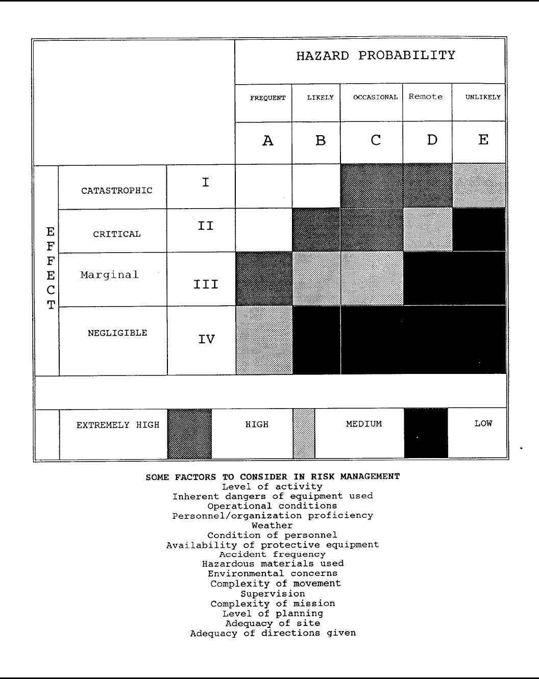
Figure 2-1 (PAGE 1). Risk management
5DA PAM 385–64 • 28 November 1997
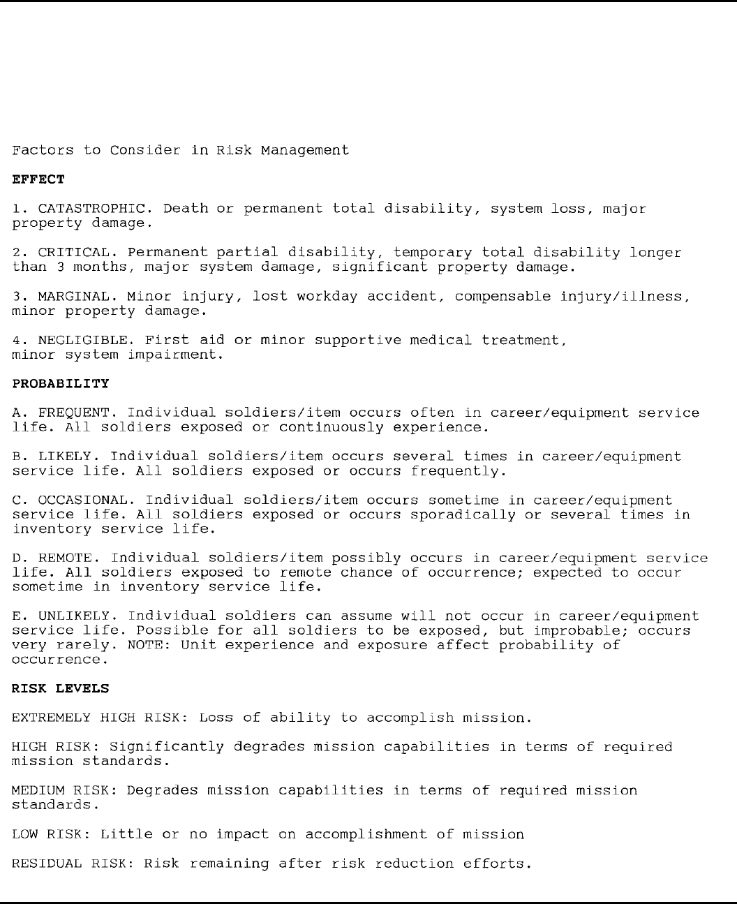
Figure 2-1 (PAGE 2). Risk management
6 DA PAM 385–64 • 28 November 1997
Chapter 3
Fire Prevention, Protection, and Suppression
3–1. Fire prevention management
a. Fire and excessive heat are two of the greatest hazards to
explosives. This chapter gives procedures for dealing with these
hazards.
b. Fires which may occur in buildings or magazines containing
ammunition or explosives will vary in intensity and effect, depend-
ing on the material involved in the fire. Certain explosives will
ignite immediately on contact with a spark or flame or when sub-
jected to frictional heat or concussion. Some explosive substances
may burn freely while others will be subject to explosion while
burning or will develop such intense heat, as in the case of solid and
liquid propellants, that firefighting efforts will be practically impos-
sible. Firefighting forces will be well acquainted with the hazards
involved in each fire hazard group and the best methods of fighting
fires of all kinds of materials under their protection. They should
also know how to use personnel protective devices required for the
various types of fires.
c . E a c h i n s t a l l a t i o n i n v o l v e d i n e x p l o s i v e s o p e r a t i o n s w i l l
develop prefire plans in accordance with AR 420–90. Plans will
cover all explosives areas and possible exposures of explosives to
fire. In addition to the requirements of AR 420–90, the overall plan
will specify responsible individuals and alternates, their organiza-
tions and training, and include a description of the emergency func-
tion of each department or outside agency. Duties of personnel
spelled out in the plan will include the following:
(1) Reporting the fire.
(2) Directing orderly evacuation of personnel.
( 3 ) N o t i f y i n g p e r s o n n e l i n n e a r b y l o c a t i o n s o f i m p e n d i n g
dangers.
(4) Activating means of extinguishing or controlling the fire.
(5) Meeting and advising the firefighters on the details of the fire
up to the time of their arrival.
d. Each Army fire station central communications center will
have an area map showing all explosives areas or locations. Loca-
tions with less than 1,000 rounds of HD 1.4 small arms ammunition
(.50 caliber or less) are exempt.
e. Personnel in charge of explosive operations will notify the fire
department when there is a change in the type of explosives being
worked which would require a change of fire or chemical hazard
symbols.
f. Where explosives, highly flammable, or energetic materials are
i n v o l v e d , a w r i t t e n p e r m i t i s r e q u i r e d f o r u s i n g h e a t - p r o d u c i n g
equipment capable of reaching a temperature higher than 228 de-
grees Fahrenheit (F) (109 degrees Celsius (C)). (See para 3–7a and
AR 420–90 for additional guidance.)
g. Matches or other flame or spark producing devices will not be
permitted in any magazine area or explosives area unless the com-
manding officer or his or her designated representative provides
written authority. When such authority has been received, a carrying
device, too large to fit into the pockets, will be used for matches,
lighters, and similar materials.
h. Carrying and using “strike anywhere” (kitchen) matches are
prohibited.
i. All flashlight or storage-battery lamps used in buildings con-
taining hazardous quantities of exposed explosives or flammable
vapors will be certified for the hazardous environment by the United
States Bureau of Mines or by a similarly recognized testing labora-
tory for that specific type of exposure.
3–2. Smoking
a. Smoking is prohibited in any explosives storage or operating
area or location, except as permitted below.
(1) Smoking may be allowed within an explosives area or loca-
tion in specially designated and posted “authorized smoking areas.”
A certification of approval by the installation commander or his or
her designated representative (fire chief, fire marshal, or fire war-
den), in coordination with the safety office, will be displayed in
each designated smoking location.
(2) In “Authorized Smoking Areas,” the following minimum pre-
cautions will be taken:
(a) Suitable receptacles for cigarette and cigar butts and pipe
heels will be provided. (Smoking residue will not be placed in trash
receptacles until it has been determined that no flammable or com-
bustible risk exists.)
(b) If electric power is available, push-button electric lighters that
cut off when pressure is released will be used. Lighters will be
permanently installed to prevent removal and use outside the desig-
nated area.
(c) Where intervening noncombustible walls are not available to
separate a potential smoking area from an area where ammunition
and explosives are present, the smoking area shall be separated by a
distance of at least 50 feet from the ammunition or explosives.
(d) At least one portable fire extinguisher with a 1A or greater
rating will be provided at each designated smoking area.
(e) Personnel whose clothing is contaminated with explosives or
other hazardous materials will not be allowed in smoking areas.
(f) Personnel working with hazardous chemicals or material must
wash their hands before smoking.
(g) A “No Smoking” sign will be posted at each entrance to an
explosives storage area. Where applicable, include a notice that
flame-producing devices must be turned over to the entry controller
or placed in the container provided.
b. Smoking is prohibited in, on, or within 50 feet of any motor
vehicle, trailer, railcar, or material handling equipment loaded with
explosives items.
c. Smoking is prohibited in any explosives-laden compartment of
an aircraft.
3–3. Training
All operating personnel and firefighting forces involved with explo-
sives must be trained in the precautions to be taken and how to fight
fires. This training will include the application and meaning of each
type fire hazard symbol, reporting fires, sounding alarms, area evac-
uations, and type and use of appropriate firefighting equipment. See
tables at the end of this chapter.
3–4. Fire drills
Fire drills will be held within the explosives areas at intervals of 6
months or less. See table 3–4 for withdrawal distances.
a. Drills are conducted to train firefighting forces and ensure
other personnel involved understand their duties and to evaluate fire
alarm systems and firefighting equipment.
b. Fire drills involving a fire department response will be coordi-
nated with the fire chief. This does not preclude unannounced tests
of a fire department’s response capabilities, provided adequate prior
coordination with the fire chief is accomplished. Personnel who
conduct these tests will make sure all personnel in the area are
aware that an exercise, and not a real fire, is in progress.
3–5. Fire exit drills
a. Frequent fire exit drills should be held when warranted by the
size of the building and the number of occupants. If emergency exits
other than the usual doors and stairways are provided, these drills
will cover their use.
b. All emergency exits will have exit signs which are clearly
visible. Signs will be marked in accordance with AR 385-30.
3–6. Alarms
In addition to any automatic alarm systems required by AR 420–90
or other applicable directives, an audible, manually operated fire
evacuation alarm system should be installed in each explosives
operating building. All alarm systems will be clearly labeled.
3–7. Fire prevention requirements
a. Heat-producing devices. The use of devices which produce
7DA PAM 385–64 • 28 November 1997
temperatures higher than 228 degrees F (109 degrees C) in any
explosives area should be confined to essential, temporary use.
Written instructions and a DA Form 5383–R (Hot-Work Permit),
are required before beginning work. They should cover the location,
purpose, duration, and details of general and explosives safety pre-
cautions to be used. Approved furnaces, electrical space heaters, and
electrical cigarette lighters which are properly installed in an operat-
ing building are exempt. Bilingual instructions are required in for-
eign countries where local employees are included in the work
force.
b. Control on wax pots.
(1) All wax pots regardless of size will be equipped with a power
indicator light, lids with fusible link, and placed on noncombustible
surfaces.
(2) Wax pots with a capacity in excess of one gallon must be
equipped with dual temperature controls.
c. Vegetation control. Vegetation control measures within explo-
sives areas and adjacent areas will be determined by the local
commander. The following items should be considered in a vegeta-
tion control program:
(1) The primary purpose of vegetation control is to limit the
probability of combustible vegetation causing an unacceptable risk
to munitions in storage. Control of combustible materials, such as
long dry grass or brush, heavy clippings, or dead wood, is designed
to slow the spread of vegetation fires.
(2) Except for firebreaks, those grounds in or near explosives
areas or locations should be maintained as unimproved grounds.
Maintenance should be limited to prevent waste of natural resources
(for example, erosion) and to prevent or suppress fires. Intensive
maintenance should not be performed.
(3) Vegetation control requirements must be balanced with other
operational factors such as cost to control, security, erosion preven-
tion, and passive defense (camouflage). Each of these factors must
be weighed in determining the level of vegetation control in and
around a particular explosives area.
(4) Varieties of vegetation that are resistant to burning should be
used wherever feasible. If removal of vegetation will cause soil
erosion, soil sterilants will not be used. Shrubs and trees planted on
earth cover of magazines should be selected so that their weight or
root system will not damage the structure. Dead or cut vegetation
must not be allowed to accumulate.
(5) When animals are used for vegetation control, overgrazing of
barricade surfaces and magazine earth cover must be avoided to
prevent erosion.
(6) Where vegetation growth is ineffective in preventing erosion,
a layer of approximately 2 inches of pressure-applied (Gunite) con-
crete or asphalt mixture may be used.
d. Firebreaks. Firebreaks will be kept clear of all readily com-
bustible material, such as dry grass, dead wood, or brush. The level
of live vegetation to be permitted in firebreaks (except those around
earth-covered magazine ventilators) will be determined as outlined
in c above.
( 1 ) A 5 0 – f o o t f i r e b r e a k w i l l b e m a i n t a i n e d a r o u n d e a c h
aboveground magazine, operating building or location, outdoor stor-
age site, and ready explosives facility.
(2) A 5-foot firebreak will be maintained around earth-covered
magazine ventilators.
(3) A 5-foot firebreak will be maintained on both sides of fences.
e. Separation criteria for burning vegetation. Intentional burning
will not be allowed within 200 feet of any explosives location.
When wind velocity exceeds 5 miles per hour or is forecasted to
exceed 5 miles per hour, burning operations will not take place.
(1) The windows, doors, and ventilators of magazines and/or
buildings within 600 feet of burning operations will be closed.
( 2 ) D u r i n g b u r n i n g o p e r a t i o n s , f i r e b r a n d s , s p a r k s , a n d / o r h o t
ashes must be controlled.
(3) Firefighting personnel and equipment determined necessary
by the fire chief will be present during burning operations.
f. Flammable liquids for cleaning. Flammable liquids will not be
used for cleaning within an explosives area or near explosives,
except as authorized by approved SOPs. Flammable liquids will be
used in explosive areas only when authorized by approved SOPs.
In-use stocks will—
(1) Not exceed one workday’s supply;
(2) Be kept in approved safety containers or dispensers; and,
(3) Be removed at the end of each workday.
g. Petroleum, oils, and lubricants (POL) fire separation distances
(1) POL storage location requirements. Fire clearance criteria
from POL locations are specified by the NFPA Standard 30. If
required fire clearances are greater than those required by this regu-
lation, use the greater required separation.
(a) Antisiphon systems will be used where applicable.
(b) Any aboveground petroleum storage tank which has a capac-
ity of 2,000 gallons or more must be enclosed within a dike area as
prescribed in 29 Code of Federal Regulation (CFR) 1910.106 and
NFPA Standard 30. The capacity of this diked area must equal the
capacity of the largest tank within the diked area.
(2) Quantities of 500 gallons or less.
(a) Where tanks serve equipment (such as oil heaters or diesel
generators) located in explosives buildings, antisiphoning devices
will be used. They are not needed if the level of the tank installation
is such that siphoning is impossible.
(b) Above ground petroleum facilities (such as tanks, pumps, or
pumphouses) will be located a minimum of 50 feet from explosives
locations.
(3) Parking fuel service trucks. Parking areas for fuel service
t r u c k s w i l l b e l o c a t e d a m i n i m u m o f 5 0 f e e t f r o m e x p l o s i v e s
locations.
(4) Mobile dispensing units. There must be at least 100 feet
between explosives and any mobile petroleum dispensing unit oper-
ating in an explosives area, unless a shorter distance is needed
during transfer operations to an underground tank (as allowed under
(2) above).
(5) Liquid petroleum (LP) gas facilities. LP gas facilities will
meet the requirements of this section.
(6) Vehicle refueling. Gasoline and diesel-powered vehicles and
equipment will not be refueled inside any structure in the explosives
storage area or in any facility, site, revetment, or other building
containing explosives, regardless of location. When being refueled,
vehicles will be at least 100 feet from structures or sites containing
explosives. When refueling is completed, the refueling vehicle must
be removed promptly from the storage area.
(a) Use the smallest available size refueling unit consistent with
the mission.
(b) When refueling explosives-loaded vehicles, maintain an elec-
trically continuous bonding path between the vehicle being filled
and the tank being emptied. The entire system will be grounded.
(c) Do not allow smoking or open flame devices within 50 feet
of gasoline or diesel refueling. At least one person must be present
during the entire operation. During the refueling, stop the motor of
both the vehicle being refueled and the refueling truck (unless the
refueling truck motor drives the pump).
(d) If a fuel spill occurs, immediately notify the installation fire
department. Do not start the motors of the refueling truck or unit
being refueled until the area is rendered safe by the fire department.
(e) Refueling will not be done within 20 feet of a inert ammuni-
tion storage building or loading dock.
( 7 ) E x c e p t i o n s . T h e f o l l o w i n g a r e e x c e p t e d f r o m t h e a b o v e
requirements:
(a) Separation of POL facilities and aircraft during combat or
simulated combat operations.
(b) Separation between POL hydrants set on the flight line flush
with the pavement and explosives loaded aircraft or explosives load-
ing or unloading operations.
(c) Diesel-powered generators may be equipped with an opera-
tional “day-tank” of the smallest size needed to operate the motor
properly. Supply tanks will be separated by the applicable under-
ground or aboveground criteria.
8 DA PAM 385–64 • 28 November 1997
h. Paint and other flammable materials. Small stocks of flamma-
ble materials, such as paints and solvents required to support explo-
s i v e s m a i n t e n a n c e o p e r a t i o n s , m a y b e s t o r e d i n a n e x p l o s i v e s
storage area. The 29 CFR 1910.106 and AR 420–90, apply.
(1) Combustible materials, such as wood, paper, and rags, will
not be stored with flammables. Containers of flammable materials
will be closed, except when in use.
( 2 ) F l a m m a b l e m a t e r i a l s i n a p p r o v e d w e a t h e r p r o o f c o n t a i n e r s
maystored outdoors. Grounding and bonding are required when con-
tents are being dispensed.
(3) Flammable storage will be located at least 50 feet from explo-
sives locations.
(4) A limited supply of paint, not to exceed a one day require-
ment, may be stored in explosives operating facilities if the require-
ments of AR 420–90 are met.
( 5 ) A t l e a s t o n e f i r e e x t i n g u i s h e r , s u i t a b l e f o r t h e t y p e o f
materials involved, will be readily available for use (table 3–1).
i. Vehicle parking. Vehicles, except during loading or unloading,
will not be parked closer than 100 feet to any explosives facility.
j. Operating support equipment. The following applies to all sup-
port equipment powered by internal combustion engines used with
explosives and not otherwise regulated under chapter 10.
(1) This equipment should be located 50 feet or more from ex-
plosives but never less than 25 feet.
(2) Only qualified personnel will use the equipment.
(3) The equipment will be inspected for cleanliness and visual
defects before each use. Defects will be documented in the applica-
ble forms. Equipment that is malfunctioning or has defects that
present a hazard will be removed from the operational site for
repairs.
(4) Two fire extinguishers rated 10BC or higher for flammable or
combustible liquid fires (Class B fire) and electrical fires (Class C
fire) will be readily available.
(5) Equipment will not be refueled within 100 feet of explosives.
k. Stacking combustible material. Containers, dunnage, lumber,
and other material will be stacked in an orderly manner. Stacks
should be limited to an area of no more than 1,500 square feet. Bulk
stacks of combustible materials should not be closer than intraline
distance from locations containing explosives (use chap 5 to estab-
lish minimum separations). Working quantities may be stacked in
the vicinity of explosives. Portable fire extinguishers or water bar-
rels should be provided in these areas.
l. Exceptions on stacking combustible material. When needed to
prepare for combat operations, empty containers, dunnage, and lum-
ber which cannot be removed while the work is in progress may be
t e m p o r a r i l y s t a c k e d i n o r n e a r t h e e x p l o s i v e s s t o r a g e s i t e ,
provided—
(1) The stacks are stable and are separated from the operations as
far as practical.
(2) All of the materials are removed upon completion of the
operation or once each day (24 hours).
3–8. Auxiliary firefighting equipment
a. Fire extinguishers. A minimum of two fire extinguishers suita-
ble for the hazards involved, will be available for immediate use
when explosives are being handled. Extinguishers need not be per-
manently located at the site. Each extinguisher will be placed in a
conspicuous and readily accessible location. Each fire extinguisher
will be kept in a full, or fully charged, operable condition. Table
3–1 lists agents for fighting fires.
b. Water barrels. Water barrels and pails are suitable for fighting
Class A fires. Water barrels will be covered to prevent insect breed-
ing and evaporation. The installation fire chief will decide if they
are required and where to put them at explosives locations. At least
two metal pails will be available for each barrel. Water barrels
should be winterized as needed. Water barrels may not be needed in
an explosives storage area if—
(1) Vegetation control measures are adequate and the area is
regularly monitored.
(2) Each crew working in the area has two fire extinguishers
readily available. If more than one crew are working at the same
location, only two fire extinguishers are required.
(3) The installation has an organized firefighting force able to
combat grass and brush fires in a timely manner.
3–9. Storage of water for firefighting
a. Adequate water to fight fires must be available at permanent
explosives facilities. The required amount of water will be calcu-
lated in accordance with Mil Handbook 1008.
b. The minimum water supply will not be less than 3,000 gallons.
c. The following will be used as guidelines in separating water
supplies from explosives:
(1) Water tanks shall be separated from explosives per chapter 5.
(2) Sectional control valves will protect the water distribution
system so that damaged sections of the main can be cut off without
impairing the operation of the remainder of the system. Water mains
will not be located under railroads or roads used for conveying large
quantities of ammunition or explosives, as a detonation may cause a
main to break.
3–10. Access to fire hose
The fire chief may choose to have a standard hose prepositioned and
connected to fire hydrants. Hose and accessories will be protected
from deterioration by approved hose houses and other protection as
determined by the fire chief.
3–11. Limitation of fire areas
Openings in fire walls will be provided with approved automatic fire
doors. They will be installed and maintained per NFPA Standard 80.
3–12. Reciprocal agreements for fire fighting support
Mutual aid agreements will be established where civilian fire depart-
ments support major firefighting efforts or when the host nation
provides fire protection.
a. The Army fire department will provide adapters if there is any
difference in the thread size of equipment connections the cooperat-
ing departments use.
b. The Army fire department will give familiarization training to
s e n i o r f i r e o f f i c i a l s o f c o o p e r a t i n g d e p a r t m e n t s f o r t h e s p e c i a l
firefighting problems in the territory served by their departments.
This will ensure better integration of their forces in an emergency.
c. Non-Department of Defense (DOD) firefighters who support
Army units will not be used to fight fire involving chemicals or
explosives. These firefighters will be informed during training of the
hazards of a fire involving chemicals or explosives. A mutual aid
agreement according to AR 420–90 will specify the base agency
which will provide this training.
3–13. Public withdrawal distances
a. Emergency withdrawal distances for nonessential personnel are
intended to apply in emergency situations only and are not to be
used for facility siting. Emergency withdrawal distances depend on
fire involvement and on whether or not the hazard classification, fire
division, and quantity of explosives are known. The withdrawal
distance for essential personnel at accidents shall be determined by
emergency authorities on site. Emergency authorities shall deter-
mine who are essential personnel.
b. If a fire involves explosives or involvement is imminent, then
the initial withdrawal distance applied will be at least inhabited
building distance. When emergency authorities determine that the
fire is or may become uncontrollable and may result in deflagration
and/or detonation of nearby ammunition or explosive material, all
nonessential personnel will be withdrawn to the appropriate emer-
gency withdrawal distance listed in table 3–4. If fire is not affecting
explosives or involvement is not imminent, then emergency authori-
ties shall determine the withdrawal distance based on the situation at
hand.
c. Structures or protected locations offering equivalent protection
for the distances listed in table 3–4 may be used instead of relocat-
ing personnel from the structure and/or location to the specified
emergency withdrawal distance.
9DA PAM 385–64 • 28 November 1997
d. Commanders will develop evacuation plans for their installa-
tions that reference the appropriate withdrawal distances as part of
the disaster response plan. The commander must alert civilian au-
thorities of any explosive accident on the installation that may affect
the local community and provide these authorities with the appropri-
ate emergency withdrawal distances.
3–14. Firefighting guidance symbols
There are two types of symbols which give guidance for firefighting
forces and other personnel, fire and chemical hazard symbols.
a. Fire divisions. There are six explosives divisions. Fire division
1 indicates the greatest hazard. The hazard decreases as the fire
division numbers increase, as shown in table 3–5.
b. Fire division symbols.
(1) Each of the six fire divisions is indicated by one of four
distinctive symbols recognizable to the firefighting personnel ap-
proaching the fire scene. The applicable fire division number is
shown on each symbol. For easy identification from long range, the
symbols differ in shape as shown in table 3–6. (Also, see figs 3–1
through 3–4.)
(2) The hazard and firefighting precautions for each symbol are
summarized in table 3–3.
c. Chemical hazard symbols. These symbols are used to identify
operating buildings and storage facilities which contain pyrotechnic
and chemical munitions or agents and other hazardous material.
(1) Hazard symbols vary with the type of agent. These symbols
are described in figures 3–5 through 3–7.
(2) The hazard each symbol represents and the firefighting pre-
cautions are summarized in table 3–3.
(3) The APPLY NO WATER sign is intended for use with haz-
ardous materials where use of water may intensify the fire, cause an
explosion, or spread the fire.
(4) The chemical agents most used in ammunition and the combi-
nations of chemical hazard symbols required in storage are specified
in table 3–7.
d. Posting symbols. Symbols will be removed, covered, or re-
versed if the explosives or chemical agents are removed from a
facility or location. The person in charge of the operation will post
or change the symbols. The fire department will be notified each
time fire or hazard symbols are changed.
e . S y m b o l d i m e n s i o n s . T h e d i m e n s i o n s s h o w n i n f i g u r e s 3 – 1
through 3–7 are the normal minimum sizes. Half-size symbols may
be used where appropriate, for example, on doors and lockers inside
buildings.
f. Obtaining symbol decals. Decals for fire and chemical hazard
symbols may be obtained through normal supply channels. National
stock numbers of standard and half-size decals are listed in figures
3–1 through 3–7.
g. Storing toxic chemical and ammunition items. Toxic chemicals
without explosive components may be received as Class 6, Division
1 poisons (6.1). Items which contain chemical substances of another
commodity class and which do not contain explosive components,
may be stored with ammunition items containing explosives and the
same chemical substance.
3–15. Posting fire symbols
The fire symbol that applies to the most hazardous material present
will be posted on or near all nonnuclear explosives locations. It will
be visible from all approach roads. One symbol posted on or near
the door end of an earth-covered magazine is normally enough. One
or more symbols may be needed on other buildings. When all
munitions within a storage area are covered by one fire symbol, it
may be posted at the entry control point. Backing material for fire
symbol decals should be the shape of the decal and should be
noncombustible.
a. When different HDs of explosives are stored in individual
multi-cubicle bays or module cells, they may be further identified
by posting the proper fire symbol on each bay or cell.
b. Where facilities containing explosives are located in a row on
one service road and require the same fire symbol, only one fire
symbol at the entrance of the row is required.
c. Fire symbols will be placed on entrances to arms rooms con-
taining ammunition. Where explosives are stored in a locker or
similar container, the container will also be marked with the appro-
priate fire symbol. Symbols are not required on the exterior of the
building, providing the building is exempt from Q-D according to
paragraph 5–1b.
3–16. Exceptions on posting fire symbols
a. Fire symbols need not be posted on locations having 1,000
rounds or less of HD 1.4 small arms ammunition (.50 caliber or
less).
b. Use the symbols in this regulation unless host nation symbols
differ and, by agreement, host nation symbols are required.
c. The responsible commander may, for security purposes, re-
move symbols. In such situations the commander will emphasize
giving prompt and exact information to the fire department about
changes in the status of explosives.
d. Fire symbols are not required on individual structures used to
store, maintain, or handle nuclear weapons or components. Howev-
er, fire symbols are required to mark individual structures used to
store, maintain, or handle conventional ammunition. The following
procedures will be used in these situations:
(1) Maintain a storage area facility map or listing as applicable
showing the proper TM 39–20–11 line number for nuclear weapons
and components.
(a) Provide the information on this map or listing to the fire
department and update it as changes occur.
(b) The entry controller will keep a map or listing similar to the
one in (1) above. This information will be given to firefighters
responding to an emergency.
(2) If explosives are stored overnight in the maintenance and
assembly building, advise the entry controller (when required) and
fire department of the TM 39–20–11 line number for the building.
e. If vehicles or aircraft are in a designated explosives parking
area, fire symbols need not be posted if such areas are described in
a local publication, such as the vehicles and aircraft parking plan,
which includes the following:
(1) The HD involved.
(2) The governing fire symbol for the parking area.
(3) Procedures to be followed during an emergency.
(4) The requirement to notify the fire department.
f. Do not post fire symbols near vehicle or aircraft loaded with
nuclear weapons. Do not post fire symbols near vehicles loaded
with nonnuclear munitions parked within the same designated area
as nuclear weapons-loaded vehicles or aircraft. In these cases, use
the procedures described in e above.
3–17. Posting chemical hazard symbols
If chemical or pyrotechnic munitions are assembled with explosive
components, then chemical hazard symbols must be used together
with fire division symbols. Chemical munitions which do not have
explosive components will be identified by the chemical hazard
symbol only. Requirements for posting hazard symbols are the same
as for fire symbols.
3–18. Procedures for chemical agents and other toxic
substances
These procedures vary according to the type of agent involved and
are summarized in table 3–3.
3–19. Firefighting at railheads
a. Fires are most likely to occur in the under-structure of railcars.
Often they can be extinguished if found in the early stages. Every
effort should be made to separate and promptly remove undamaged
cars from yards where a fire has broken out.
b. Where explosives operations are conducted at railheads, Gov-
ernment railroad personnel should be trained to use fire equipment.
10 DA PAM 385–64 • 28 November 1997
3–20. Automatic sprinkler systems
a. Properly installed and maintained automatic sprinkler protec-
tion is important in reducing fire losses and is justified in certain
buildings. In addition to requirements of the National Fire Codes,
published by the NFPA, the following are examples of locations
where sprinklers will be installed when required by AR 420–90:
(1) In certain buildings, in load lines, explosives manufacturing,
r e c e i v i n g , s h i p p i n g , i n s p e c t i o n , a m m u n i t i o n w o r k s h o p , a n d
demilitarization areas after a risk assessment.
(2) Where a potential loss of life exists.
(3) When value of buildings and/or contents warrants.
b. Automatic sprinkler systems will not be deactivated unless
repairs or modification to the system are required. When interrup-
tion is required or deactivation of a system is necessary, the criteria
and precautions outlined in TM 5–695 will be followed. Where
heating is a problem, wet systems should be converted to automatic
dry systems. Valve rooms will be heated during the winter.
c. Inspection and maintenance of automatic sprinkler systems
will conform with requirements of TM 5–695.
d. Local water flow alarm facilities are required for automatic
sprinkler systems installed in explosives operating buildings; howev-
er, transmitted waterflow alarms may not be required.
3–21. Deluge systems for explosives operations
a. In addition to sprinklers, deluge systems will be provided to
protect operating personnel in high hazard occupations and locations
where a process fire hazard exists. An ultra high speed deluge
system will be considered when the following conditions exist—
(1) A risk assessment indicates that an accidental deflagration or
explosion is unacceptable.
(2) An area or operation will expose personnel to thermal flux in
excess of 0.3 calories per square centimeter per second if an ac-
cidental deflagration or explosion should occur.
(3) The system must be capable of preventing propagation be-
tween bays and preventing significant injury to employees. Quick-
acting sensors such as ultraviolet (UV) or infrared (IR) detectors
will be used. The MACOM may approve using new technology
which offers comparable or better protection than UV or IR detec-
tors. The deluge valve will be arranged for automatic and/or manual
activation.
b. An ultra high speed deluge system is an instantaneous re-
sponse (milliseconds) system. It is used primarily to protect person-
nel, process equipment, and buildings from the fire and thermal
hazard presented by energetic material involved in high hazard ex-
plosive operations, such as, melting, mixing, blending, screening,
sawing, granulating, drying, pressing, extrusion, and pouring. Del-
uge systems with heat actuated devices (HAD) are not ultra high
speed deluge systems and will not be used for personnel protection.
c. Due to the speed of water coming from all the nozzles, ultra
high speed deluge systems depend on the detection system, piping
network, nozzles and water supply characteristics. Only experienced
designers, engineers, and installers who understand the system’s
limitations and capabilities should provide the design, specification,
and installation of the deluge system.
d. All munitions production, maintenance, renovation, quality as-
surance and demilitarization operations will receive a risk assess-
ment to identify potential fire and thermal threats and to assess the
level of risk. The hazard must be accurately defined. A potential fire
and or thermal hazard whose level of risk is high or extremely high
is unacceptable. The risk assessment will consider factors such as:
(1) Initiation sensitivity
(2) Quantity of material
(3) Heat output
(4) Burning rate
(5) Potential ignition and initiation sources
(6) Protection capabilities
(7) Personnel exposure
(8) Munitions configuration
(9) Process equipment
(10) Process layout
(11) The building layout.
e. The diameter, length, number of bends, and friction coefficient
limits the effective flow rate of the water that the system can
transport at an effective pressure. Pipe runs will be kept to a mini-
mum. Horizontal runs will be sloped at least 1/4 inch per 10 feet of
run, with air bleeders at all high points. The looping of deluge
piping systems may improve response time by improving pressure
and effective flow rate.
f. The design of the nozzle orifice determines the dispersion pat-
tern, water droplets, and turbulence of the water flow which in turn,
directly affects the water velocity. Nozzles will be installed with
priming water being held back at the nozzle with blowoff caps,
rupture disc, or the poppet valve when utilizing pilot operated noz-
zles. Nozzle discharge rates and spray patterns will be selected to
meet the hazard condition being protected.
g. The nozzles will be located as close to the exposed surface of
the explosives as possible to ensure immediate drenching of all parts
of the machine or operation under extreme conditions. The dis-
charge pattern of the nozzle can be used in determining the required
distance. When explosives are located inside machines under tight
hoods or covers, distributing outlets will be located inside the en-
closed space.
h. Where explosive vapors, gases, or dusts may enter outlets and
interfere with their operation, nonmetallic internally spring- held
caps will be placed on the outlets. The design must provide immedi-
ate release of the cap when pressure is exerted within the outlet.
Caps will be attached to outlets with small nonferrous chains to
prevent their loss when the deluge system is activated.
i. Install a device on the supply side of the system so that the
system will actuate an audible warning device in affected operating
areas when the pressure falls.
j. Deluge systems will be charged with water or chemicals. This
depends on the character of the fire to be controlled, as determined
by engineering studies of the hazards and the hazard analysis.
k. Operations protected by a deluge system will be stopped im-
mediately if the system fails and will not be resumed without ade-
quate protection.
l. An estimate of the required maximum flow rate and pressure
will be made. The capabilities of the existing water supply and
distribution system to meet these requirements will be evaluated. If
the required flow rate and pressure is not adequate, arrangements
must be made to provide the required flow and pressure. The water
pressure necessary for proper functioning of a deluge system must
be available instantaneously. The water supply will have a duration
of at least 15 minutes. If there are two or more deluge systems in
the same fire area, supply mains and the arrangements and size of
the system rise will provide each system with the required quantities
of water per head. No allowance is required for hose lines. All valve
on water lines between the water main and the deluge systems will
be supervised to ensure the valves are not accidently closed.
m. The deluge valve will be arranged for automatic or manual
activation or both. Manual activation devices will, as a minimum, be
located at exits.
n. The deluge system must able to prevent fire spreading from
one cell or bay to another. Together with personal protective equip-
ment required for workers at the operation, the deluge system will
prevent significant injury to the worker. The workers will not re-
ceive more than first-degree burns from any thermal threat. The
effectiveness of the deluge system will be demonstrated by test
against actual or equivalent threat. These tests will be conducted
with the maximum quantity of energetic material expected to be in
the cell or bay. Testing is unnecessary if a small deluge (design
flow of 500 gallons per minute or less) has a response time of 100
milliseconds. Testing is unnecessary for a large deluge system (de-
sign flow of more than 500 gallons per minute) with a response time
of 200 milliseconds or less, provided a hazard analysis indicates that
a faster response time is not required. For the life of the system, the
installation will retain on file the results of the tests or the use of the
100 or 200 milliseconds or less response time.
o. Response time is the time in milliseconds from the presenta-
tion of an energy source to the detection system, to the beginning of
11DA PAM 385–64 • 28 November 1997

water flow from the critical nozzle under test. The critical nozzle is
usually located closest to the hazard or as a hazard analysis deter-
mines best.
p. Two methods are commonly used to measure response time—
(1) A millisecond digital time is started by saturated UV source
(IR for IR detectors) held directly in front of the detector and is
stopped by the actuation of a water flow switch at the critical
nozzle. This method does not measure the time lag of and water
travel time from the nozzle to the target. It is normally used for
routine testing.
(2) A high-speed video camera and recorder (at least 120 frames
per second) can be used for very accurate measurement. The time
from ignition to detection and water travel time from nozzle to
target can also be measured. The video recording system can be
used for contract compliance or when measurement of total response
time is required.
q. Deluge systems will be tested and maintained per the criteria
of TM 5–695 and this pamphlet. A good preventive maintenance
program is required to reduce the number of false alarms and other
system problems. Systems in laid-away or inactive facilities are
exempt from testing. Laid-away systems will be tested when they
are put back into service. Records of tests will be kept on file at the
installation. The following tests will be conducted—
(1) A full operational flow test will be conducted at intervals not
to exceed 1 year, including measurement of response time. The
installation will retain the results of tests on file for the life of the
system.
(2) Detectors will be tested and inspected for physical damage
and accumulation of deposits on the lenses at least monthly.
(3) Controllers will be checked at the start of each shift for any
faults.
(4) Valves on the water supply line shall be checked at the start
of each shift to ensure that they are open. Checking is unnecessary
if the valve is secured in the “open” position with a locking device
or is monitored by a signaling device that will sound a trouble
signal at the deluge system control panel or other central location.
r. The melt kettle and closed containers of molten explosive will
normally not be equipped with internal flame detectors or deluge
nozzles. The exterior of the kettles and closed containers will be
protected by ultra-high-speed deluge systems. This is especially
i m p o r t a n t f o r c o n t a i n e r o r k e t t l e o p e n i n g s w h e r e m a t e r i a l s a r e
placed.
s. A portable deluge may be used in lieu of a permanently in-
stalled deluge system provided it meets the following—
(1) A portable ultra-high-speed deluge system may be used to
protect short-run ammunition operations involving production, main-
tenance, renovation, demilitarization, and surveillance. It is not a
permanent solution for long-term runs or high usage locations.
(2) The portable deluge systems, as a minimum, will consist of—
(a) Two detectors,
(b) Two nozzles,
(c) A pressurized tank with at least 100 gallons of water.
(3) The portable deluge system must be tested and timed each
time it is set up for each new operation. This time must not exceed
100 milliseconds as outlined above.
(4) The portable deluge system must be located so that no per-
sonnel are working directly opposite it.
(5) The portable deluge system should be tied into a backup
water supply. It will also set off the building fire alarm.
t. The required density will depend upon the type of energetic
material involved, process layout, and whether the aim is to extin-
guish the fire, prevent its propagation, or prevent serious injury, or a
combination of these. A commonly used density for preventing
propagation and structural damage is 0.5 GPM/SQ FT. To protect
p e r s o n n e l a n d p r o c e s s e q u i p m e n t o r e x t i n g u i s h p y r o t e c h n i c
materials, significantly higher density rates may be necessary. These
may be as high as 3.0 GPM/SQ FT for area coverage or 200 GPM
for point-of-operation coverage.
3–22. Instructions for fighting fires involving ammunition
or explosives
a. When a guard, watchman, or other person discovers smoke
coming from a closed magazine, or sees any evidence that a maga-
zine is afire, he or she will give the alarm as quickly as possible and
evacuate to a safe distance. He or she will not enter a burning
building or magazine, nor open the building or magazine door if a
fire is suspected.
b. If a fire is discovered in grass or other combustible material
surrounding a magazine, the alarm should be given immediately and
the guard should do all that is possible, using available firefighting
tools to extinguish or control the fire until firefighting forces arrive.
It is important to extinguish grass fires especially when they are
close to magazines. If a fire has actually started inside a magazine,
firefighting forces should either combat the fire or seek the nearest
suitable protection, depending on the type of ammunition or explo-
sives with the magazine.
c. When a workman or other person discovers a fire in a building
where people are working and explosives are present, a suitable fire
signal will be given and all personnel present will be evacuted. At
least one responsible manager will be dispatched in the direction
from which the fire department is expected to come, to inform
firemen of the location, nature, and extent of the fire. The officer in
charge of firefights will not permit personnel to advance until ac-
cruate information is available about the existing hazard and an
dconcludes that the advance is justified.
Table 3–1
Extinguishing agents for fires
Type of Fire Extinguishing Agent
Class A - Combustible (materials Water
such as wood, paper, rubbish, or
grass)
Class B - Volatile flammables Carbon dioxide, halon, foam,
(materials such as oil, gasoline or dry chemical
grease, or paint)
Class C - Electrical (electrical equip- Carbon dioxide, halon, or dry
ment) chemical
Class D - Combustible metals (mag- Dry powder
nesium, potassium, and so forth)
Notes:
1This is general guidance. For more specific guidance, see MSDS, NFPA publi-
cations, or consult a fire protection specialist.
12 DA PAM 385–64 • 28 November 1997

Table 3–2
Fire symbol hazards and actions
Fire Materials Hazard Action/remarks
sym-
bol
1 1.1 explosives, ammunition, and
liquid propellants Mass detonation 1. Will not be fought unless a rescue attempt is being made.
2. If there is suitable separation between nonexplosive and symbol 1
materials, and if approved by the fire chief, fire fighting forces may at-
tempt to extinguish the fire.
3. If personal safety is in doubt, take suitable cover.
2 1.2 ammunition and explosives Explosion with fragments 1. Give the alarm and attempt to extinguish the fire if in an early stage.
2. Firefighting forces should fight the fire, until the explosive material be-
comes involved in the fire or the fire chief determines the risk is too great.
If not possible, prevent the spreading of the fire.
3. Detonations of items could occur. Provide protection from fragments.
3 1.3 ammunition and explosives Mass fire 1. May be fought if explosives not directly involved.
2. If WP munitions are involved, smoke is liberated. WP munitions may
explode. WP should be immersed in water or sprayed with water con-
tinuously.
3. For fire involving HC and incendiaries, water should not be used unless
large quantities are available. Use dry and/or dry powder agent in the
early stage.
4. For fires involving pyrotechnics and magnesium incendiaries, protect
adjacent facilities and equipment. Do not use CO2or halon extinguishers
or water on or near the munitions. Allow magnesium to cool unless upon
flammable material. In this case, use a 2-inch layer of dry sand or powder
on the floor and rake the burning material onto this layer and resmother.
4 1.4 ammunition and explosives Moderate fire 1.Fight these fires.
2. Expect minor explosions and hot fragments.
Table 3–3
Chemical hazard symbols and actions
Chemical symbol Materials (SCG) Hazard Action/Remarks
Full protective clothing—
set 1 (Red) Nerve or blister agents (K) Highly toxic as aerosol/va-
por 1. Evacuate public 2 miles downwind or 1 mile upwind or
to the sides. These are initial evacuation distances which
can and should be modified using an approved evacuation
plot program.
2. Use munitions decontamination procedures.
3. If explosion does not occur, approach from upwind and
extinguish fire.
Full protective clothing—set
2 (Yellow) Riot control/smokes (G) In-
capacitating agents (K) Toxic as aerosol/vapor 1. Approach from upwind and extinguish fire.
2. Decontamination may be required.
Full protective clothing—set
3 (white) TEA smoke (L) Spontaneously flammable
when exposed to air 1. Do no look at burning material.
2. Do not use water.
White Phosphorous (H),
Red Phosphorous Spontaneously flammable
when exposed to air 1. Post fire guard until leaking phosphorus has been re-
moved.
2. After removal of agents, post fire guard for 2 days for
possible reignition.
3. Use putty knife to remove small amounts, then use
blowtorch to burn off remainder.
13DA PAM 385–64 • 28 November 1997

Table 3–3
Chemical hazard symbols and actions—Continued
Chemical symbol Materials (SCG) Hazard Action/Remarks
Wear breathing apparatus HC smoke (G) Smoke Do not use water.
Incendiary (G) Burns with extremely high
temperatures 1. Do not use water.
2. Do not look at burning material.
Napalm (J) Mass fire Fight as a POL fire.
Apply no water HC smoke (G) Smoke Do not use water.
Incendiary (G) Burns with extremely high
temperature 1. Do not use water.
2. Do not look at burning material.
TEA smoke (L) Spontaneously combustible 1. Do not use water.
2. Do not look at burning material.
Table 3–4
Emergency withdrawal distances for nonessential personnel
Hazard Class/Division Unknown quantity NEW Known quantity NEW
Unknown facility, truck and/or tractor
trailer 4000 feet (approximately .75 mile) 4000 feet (approximately .75 mile)
Unknown railcar 5000 feet (approximately 1 mile) 5000 feet (approximately 1 mile)
HC/D 1.1 (see note 1) Same as unknown HC/D For transportation:
(a) Use 2500 feet minimum distance for 500 lbs NEW and
below.
(b) Use 5000 feet minimum distance for railcars above 500
lbs,
(c) Otherwise use 4,000 feet minimum distance.
(d) Use 4000 feet minimum distance for bombs and projec-
tiles with caliber 5 inch (127mm) and greater.
For facilities:
(a) Use 2500 feet minimum distance for 15000 lbs and be-
low.
(b) Use 4000 feet minimum distance for above 15000 lbs
and less than 50,000 lbs.
(c) Above 50,000 lbs, use D = 105W1/3.
HC/D 1.2 (See note 1.) 2500 feet 2500 feet
HC/D 1.3 (See note 2.) 600 feet Twice the IBD distance with a 600 feet minimum distance.
HC/D 1.4 300 feet 300 feet
Notes:
1For HC/D 1.1 and 1.2 items, if known, the maximum range fragments and debris will be thrown (including the interaction effects of stacks of items, but excluding lugs,
strongbacks, and/or nose and tail plates) may be used to replace the minimum range shown above.
2For accidents involving propulsion units, it is unnecessary to specify emergency withdrawal distances based upon the potential flight ranges of these items.
Table 3–5
Fire divisions hazards
Fire division Hazard involved
1 Mass detonation
2 Explosion with fragments
3 Mass fire
4 Moderate fire
14 DA PAM 385–64 • 28 November 1997

Table 3–6
Fire division symbols
Fire symbol Shape National Stock Number
1 Octagon 7690-01-082-0290
7690-01-081-9581
2 X 7690-01-082-0289
7690-01-087-7340
3 Inverted triangle 7690-01-081-9583
7690-01-081-9582
4 Diamond 7690-01-082-6709
7690-01-081-9584
Table 3–7
Chemical agents and fillers contained in ammunition and the chemical hazard symbols required in storage
Chemical agents and fillers Full protective clothing Breathing ap- Apply no water G VX BZ H L
paratus
Set 1 Set 2 Set 3
GB X X
VX X X
H, HD, HT X X
LX X
CL, CG, CK, CN, CNS, CS, BBC, DA, DC, DM, FS, FM X
HC XX
BZ X X
WP, PWP, RP X
TH, PT XX
IM, NP X
TEA, TPA X X
Colored smokes X
15DA PAM 385–64 • 28 November 1997
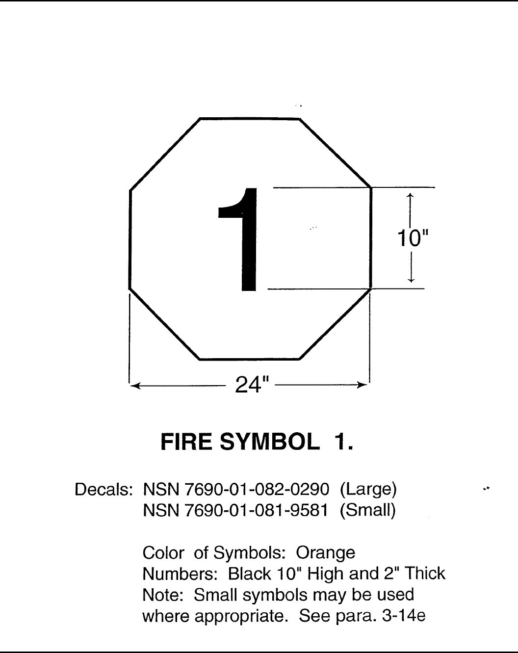
Figure 3-1. Fire symbol 1 — mass detonation
16 DA PAM 385–64 • 28 November 1997
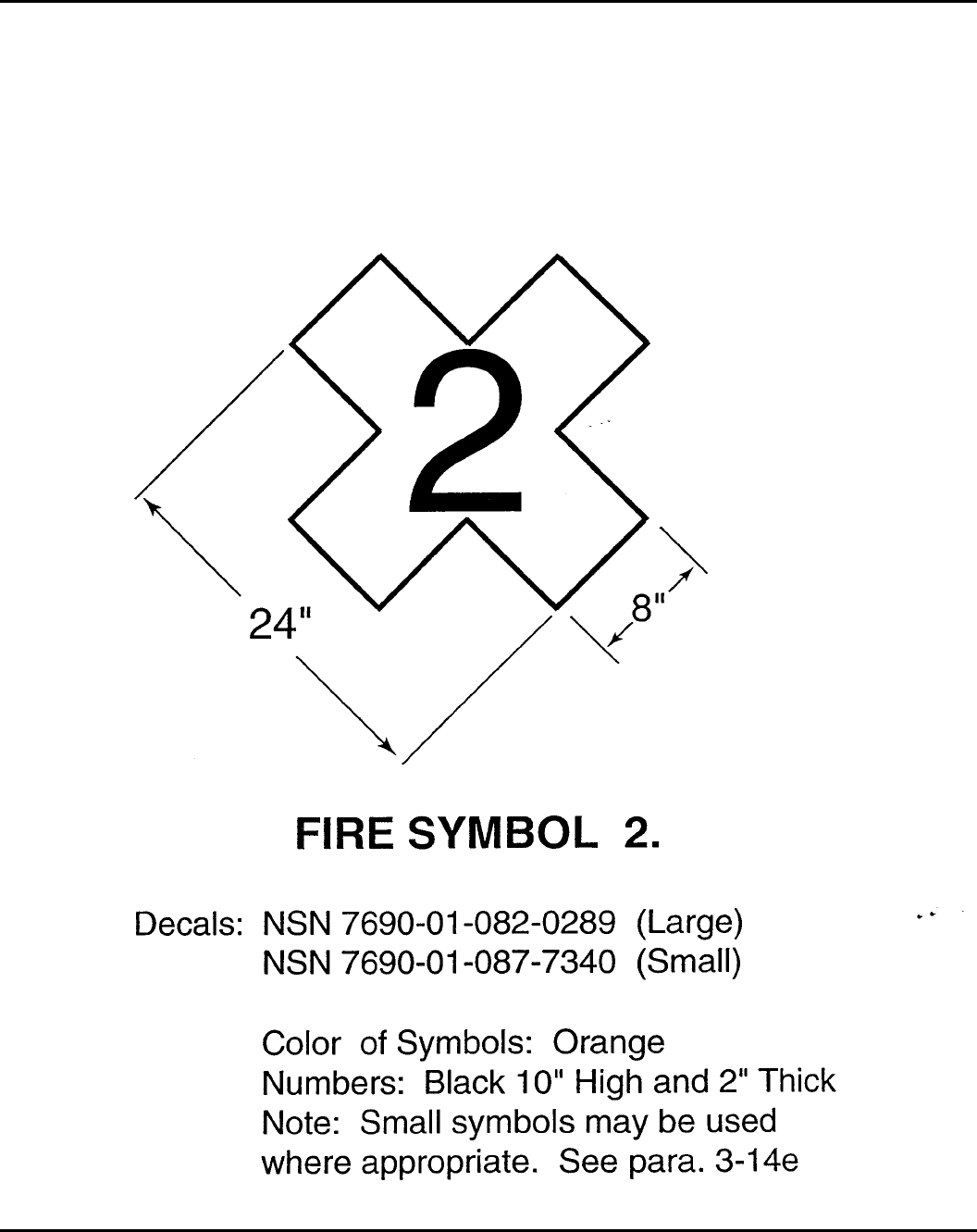
Figure 3-2. Fire symbol 2 — explosion with fragments
17DA PAM 385–64 • 28 November 1997
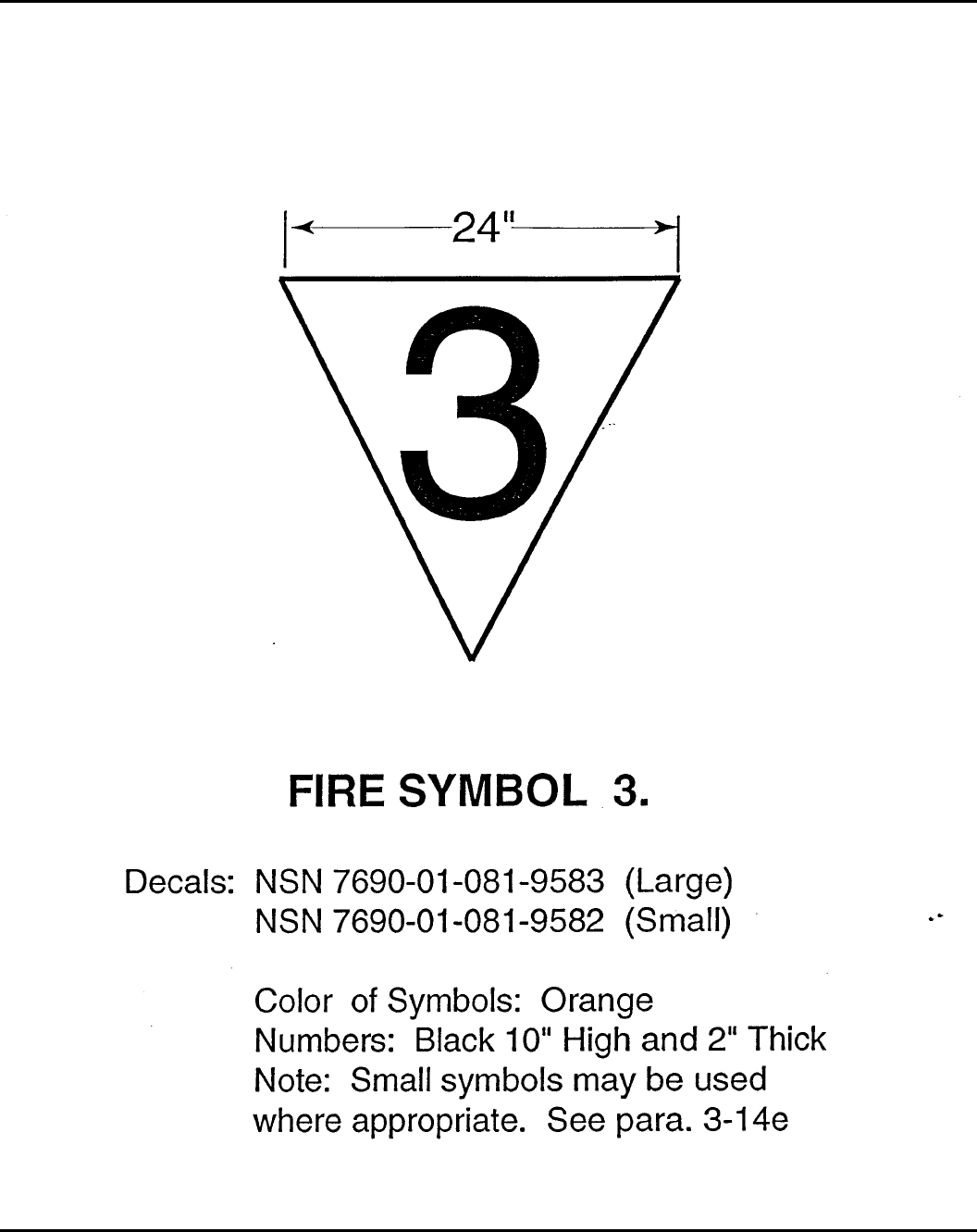
Figure 3-3. Fire symbol 3 — mass fire
18 DA PAM 385–64 • 28 November 1997
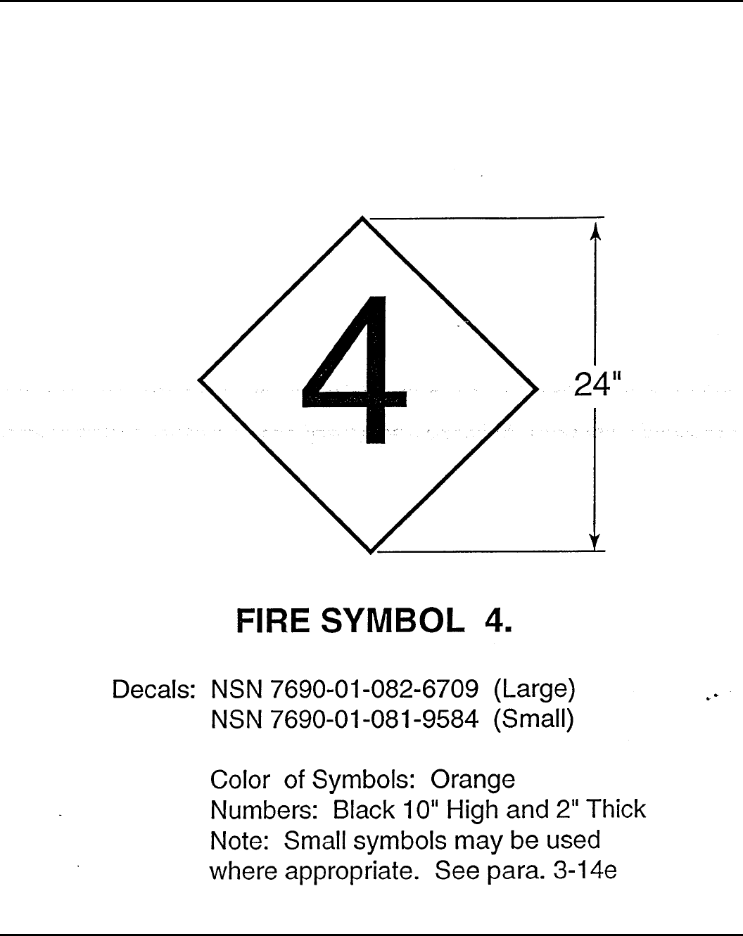
Figure 3-4. Fire symbol 4 — moderate fire
19DA PAM 385–64 • 28 November 1997
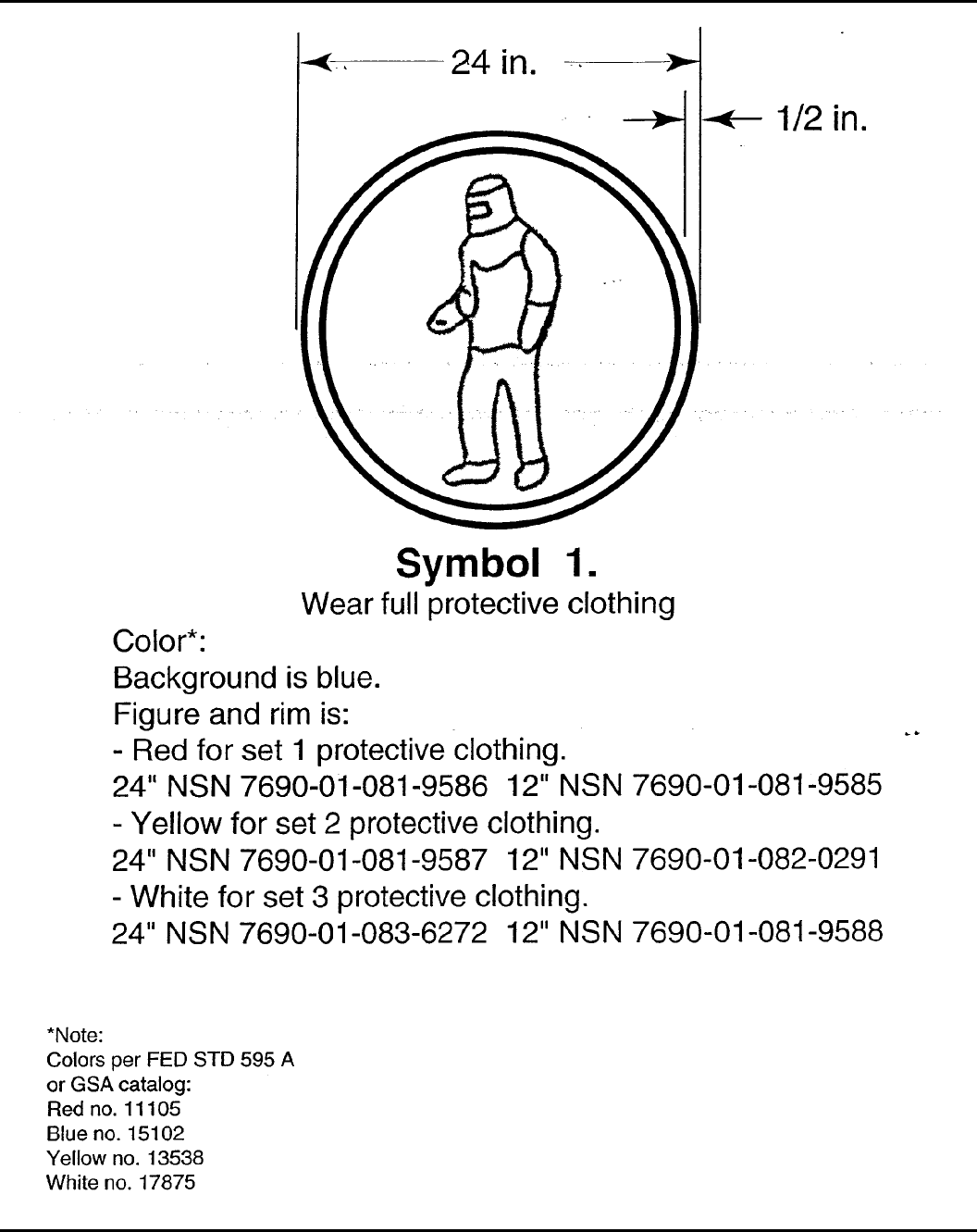
Figure 3-5. Chemical hazard symbol 1
20 DA PAM 385–64 • 28 November 1997
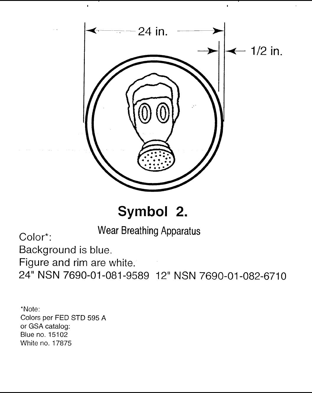
Figure 3-6. Chemical hazard symbol 2
21DA PAM 385–64 • 28 November 1997
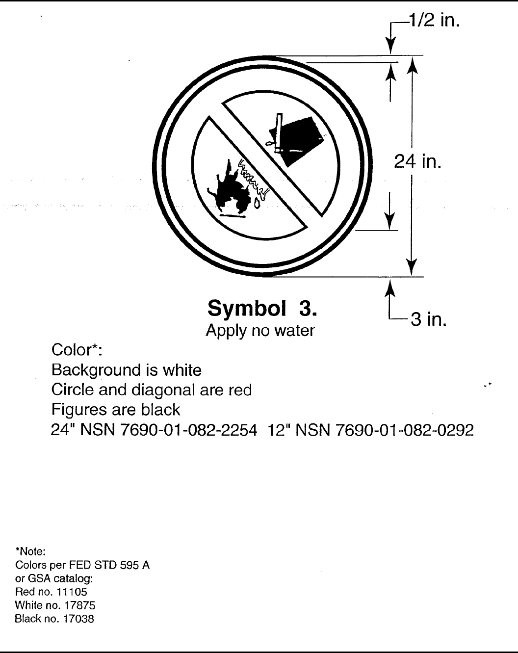
Figure 3-7. Chemical hazard symbol 3
22 DA PAM 385–64 • 28 November 1997
Chapter 4
Hazard Classification and Compatibility Groups
4–1. Explosives hazard classification procedures
a. To make identifying hazard characteristics easier and thus pro-
mote safe storage and transport of ammunition and explosives, DOD
uses the international system of classification devised by the United
Nations (UN) for transport of dangerous goods. Ammunition and
explosives are also assigned DOT class and marking in accordance
with 49 CFR 173.
b . T h e U . S . A r m y T e c h n i c a l C e n t e r f o r E x p l o s i v e S a f e t y
(USATCES) assigns proper hazard classifications. Inquiries for in-
formation about existing munitions or required data regarding newly
developed systems will be addressed to U.S. Army Technical Center
for Explosives Safety.
c. The UN classification system consists of nine hazard classes,
two of which contain most ammunition and explosives as defined in
this publication (Classes 1 and 6). Ammunition is now being classi-
fied by predominant hazard. This means that if an ammunition item
contains something which presents a greater hazard in transportation
than the hazard class 1 material, it will be placed in that hazard
class. For example, if a rocket motor contains a quantity of fuel and
a small igniter, then the proper hazard class may be class 3, rather
than HD 1.3.
d. Class 1 is divided into divisions that indicate the character and
predominance of associated hazards:
(1) Mass detonating (Division 1)
(2) Nonmass-detonating fragment producing (Division 2)
(3) Mass fire (Division 3)
(4) Moderate fire - no blast (Division 4)
(5) Extremely insensitive detonating substances (EIDS) (Division
5) (6) Extremely insensitive ammunition (Division 6).
e. For further refinement of this hazard identification system, a
numerical figure (in parentheses) is used to indicate the minimum
separation distance (in hundreds of feet) for protection from debris,
fragments, and firebrands when distance alone is relied on for such
protection. This number is placed to the left of the HD designators
1.1 through 1.3, such as (18)1.1, (08)1.2, and (06)1.3 (see para 5–5
for more information).
f. Articles that contain riot control substances without explosives
components are classified as Class 6, Division 1, in the U.N. Rec-
o m m e n d a t i o n s f o r T r a n s p o r t o f D a n g e r o u s G o o d s . B u l k l e t h a l
chemical agents and munitions without explosives are HD 6.1 in the
U.N. recommendations.
g. Technical Bulletin (TB) 700–2 is used to assign an HD to all
ammunition and explosives except those that are candidates for
designation as EIDS and EIDS ammunition. The EIDS and EIDS
ammunition shall be assigned to HD as indicated in table 4–1 with
prior Department of Defense Explosives Safety Board (DDESB)
approval.
h. Final hazard classifications for ammunition and explosives are
listed in the Joint Hazard Classification System (JHCS). The JHCS
is the DOD authority for hazard classifications. The JHCS is availa-
ble through File Transfer Protocol (FTP), on-line as the Joint Haz-
ard Automated Retrieval System (JHARS), microfiche, or printout.
Requests for copies of the JHCS shall be addressed to U.S. Army
Technical Center for Explosives Safety. DOD contractors have to
submit their requests through their Contracting Officer’s Representa-
tive (COR) who will validate the contractor’s need.
4–2. EIDS and EIDS ammunition
a. EIDS is comprised of substances which have a mass explosion
hazard but are so insensitive that there is very little probability of
initiation or of transistion from burning to detonation under normal
conditions of transport. These materials are assigned to HD 1.5 for
transportation purposes only. For storage, these materials are as-
signed to HD 1.1 (see para 5–2 also).
b. The EIDS ammunition consists of extremely insensitive arti-
cles which do not have a mass explosive hazard. The articles con-
tain only EIDS and demonstrate (through test results) a negligible
probability of accidental initiation or propagation. These materials
are assigned HD 1.6.
c. Quantity-distance application:
(1) Quantity-distance separations for HD 1.6 ammunition and
explosives will be based on table 5–18. This information is detailed
in table 4–2.
(2) Inhabited building distance (IBD) for bulk HD 1.6 explosives
will be based on chapter 5.
4–3. Storage principles
a. The highest degree of safety in ammunition and explosives
storage could be assured if each item were stored separately. How-
ever, such ideal storage generally is not feasible. A proper balance
of safety and other factors frequently requires mixing of several
types of ammunition and explosives in storage.
b. Ammunition and explosives may not be stored together with
dissimilar materials or items that present additional hazards. Exam-
ples are mixed storage of ammunition and explosives with flamma-
ble or combustible materials, acids, or corrosives.
c. All ammunition and explosives items are assigned to one of 13
storage compatibility groups (SCGs), based on the similarity of
characteristics, properties, and accident effects potential. Items in
each individual SCG can be stored together without increasing sig-
nificantly either the probability of an accident or, for a given quanti-
ty, the magnitude of the effects of such an accident. Considerations
used in assigning SCGs include but are not limited to the following:
(1) Chemical and physical properties.
(2) Design characteristics.
(3) Inner and outer packing configurations.
(4) Quantity-distance division.
(5) Net explosive weight.
(6) Rate of deterioration.
(7) Sensitivity to initiation.
(8) Effects of deflagration, explosion, or detonation.
d. When such mixed storage will facilitate safe operations and
promote overall storage efficiency, ammunition and explosives may
be mixed in storage, provided they are compatible. Assignment of
items of SCGs requiring separate storage will be minimized consis-
tent with actual hazards presented and not based on administrative
considerations or end use.
e. Ammunition and explosives in substandard or damaged pack-
aging, in a suspect condition, or with characteristics that increase the
risk in storage will be stored separately.
4–4. Mixed storage
a. Table 4–3 shows how different SCGs of ammunition and ex-
plosives can be mixed in storage. Exceptions are listed in b, below.
b. Certain locations within the United States, its territories, and
possessions designated by the Army and with site approval from the
DDESB to store ammunition in rapid response configurations and
B a s i c L o a d A m m u n i t i o n H o l d i n g A r e a s ( B L A H A ) o u t s i d e t h e
United States are authorized to store ammunition without regard to
compatibility. The maximum net explosive quantity (NEQ) at any of
these locations storing mixed compatibility ammunition must not
exceed 4000 kg (8820 pounds NEW) calculated in accordance with
paragraph 14–2d of this pamphlet.
4–5. Storage compatibility groups
a. Assignment. Ammunition and explosives are assigned to one
of 13 SCGs as follows:
(1) Group A. Bulk initiating explosives that have the necessary
sensitivity to heat, friction, or percussion to make them suitable for
use as initiating elements in an explosives train. Examples are wet
l e a d a z i d e , w e t l e a d s t y p h n a t e , w e t m e r c u r y f u l m i n a t e , w e t
tetracene, dry cyclonite (RDX), and dry pentaerythritol tetranitrate
(PETN).
23DA PAM 385–64 • 28 November 1997

(2) Group B. Detonators and similar initiating devices not con-
taining two or more independent safety features. Items containing
initiating explosives that are designed to initiate or continue the
functioning of an explosives train. Examples are detonators, blasting
caps, small arms primers, and fuzes.
(3) Group C. Bulk propellants, propelling charges, and devices
containing propellant with or without their own means of ignition.
Items that, upon initiation, will deflagrate, explode, or detonate.
Examples are single-, double-, triple-base and composite propel-
lants, rocket motors (solid propellant), and ammunition with inert
projectiles.
(4) Group D. Black powder, high explosives (HE), and ammuni-
tion containing HE without its own means of initiation and without
propelling charge, or a device containing an initiating explosives
and containing two or more independent safety features. Ammuni-
tion and explosives that can be expected to explode or detonate
when any given item or component thereof is initiated except for
devices containing initiating explosives with independent safety fea-
tures. Examples are bulk trinitrotoluene (TNT), Composition B,
black powder, wet RDX or PETN, bombs, projectiles, cluster bomb
units (CBUs), depth charges, and torpedo warheads.
(5) Group E. Ammunition containing HE without its own means
of initiation and with propelling charge (other than one containing a
flammable or hypergolic liquid). Ammunition or devices containing
HE and containing propelling charges. Examples are artillery ammu-
nition, rockets, or guided missiles.
(6) Group F. Ammunition containing HE with its own means of
initiation and with propelling charge (other than one containing a
flammable or hypergolic liquid) or without a propelling charge.
Examples are grenades, sounding devices, and similar items having
an in-line explosives train in the initiator.
(7) Group G. Fireworks, illuminating, incendiary, and smoke,
including hexachloroethane (HC) or tear-producing munitions other
than those munitions that are water activated or which contain white
phosphorous (WP) or flammable liquid or gel. Ammunition that,
u p o n f u n c t i o n i n g , r e s u l t s i n a n i n c e n d i a r y , i l l u m i n a t i o n ,
lachrymatory, smoke, or sound effect. Examples are flares, signals,
incendiary or illuminating ammunition, and other smoke or tear-
producing devices.
(8) Group H. Ammunition containing both explosives and WP or
other pyrophoric material. Ammunition in this group contains fillers
which are spontaneously flammable when exposed to the atmos-
phere. Examples are WP, plasticized white phosphorous (PWP), or
other ammunition containing pyrophoric material.
(9) Group J. Ammunition containing both explosives and flam-
mable liquids or gels. Ammunition in this group contains flammable
liquids or gels other than those which are spontaneously flammable
when exposed to water or the atmosphere. Examples are liquid- or
gel-filled incendiary ammunition, fuel-air explosives (FAE) devices,
flammable liquid-fueled missiles, and torpedoes.
(10) Group K. Ammunition containing both explosives and toxic
chemical agents. Ammunition in this group contains chemicals spe-
c i f i c a l l y d e s i g n e d f o r i n c a p a c i t a t i n g e f f e c t s m o r e s e v e r e t h a n
lachrymation. Examples are artillery or mortar ammunition (fuzed or
unfuzed), grenades, and rockets or bombs filled with a lethal or
incapacitating chemical agent. (See note 5, fig. 4–1.)
(11) Group L. Ammunition not included in other compatibility
groups. Ammunition having characteristics that do not permit stor-
age with dissimilar ammunition belong in this group. Examples are
water-activated devices, prepackaged hypergolic liquid-fueled rocket
engines, certain FAE devices, triethylaluminum (TEA), and dam-
aged or suspect ammunition of any group. Types presenting similar
hazards may be stored together but not mixed with other groups.
(12) Group N. Ammunition containing only EIDS. Examples are
bombs and warheads.
(13) Group S. Ammunition presenting no significant hazard. Am-
munition so packaged or designed that any hazardous effects arising
from accidental functioning are confined within the package unless
the package has been degraded by fire, in which case all blast or
projection effects are limited to the extent that they do not hinder
firefighting significantly. Examples are thermal batteries, explosives
switches or valves, and other ammunition items packaged to meet
the criteria of this group.
b. Means of initiation. As used in this standard, the phrase “with
its own means of initiation” indicates that the ammunition has its
normal initiating device assembled to it, and this device would
present a significant risk during storage. However, the phrase does
not apply when the initiating device is packaged in a manner that
eliminates the risk of causing detonation of the ammunition if the
initiating device functioned accidentally, or when fuzed end items
are configured and packaged to prevent arming of the fuzed end
items. The initiating device may be assembled to the ammunition
provided its safety features preclude initiation or detonation of the
explosives filler of the end item during an accidental functioning of
the initiating device.
4–6. Class 1 or 6 chemical agent hazards or combined
chemical agent and explosives hazards
a. Items in these classes are chemical agent-filled ammunition,
chemical agents, and chemical agent-filled components. Depending
upon the type of agent, its persistency, toxicity, or other characteris-
tics, the primary safety considerations may be the area of agent
dispersal rather than blast or fragment considerations.
b. Items that contain only toxic chemical components are as-
signed to HD 6.1. Items that contain both explosives and toxic
chemical components are included in UN Class 1, ammunition and
explosives, as appropriate. HD 6.1 requirements also shall be ap-
plied so that the explosives and toxic chemical hazards both are
considered.
Table 4–1
EIDS and EIDS ammunition hazard divisions
Type QD HD
SCG
EIDS bulk 1.5D
EIDS loaded projectiles and/or warheads w/o fuzes or with 1.6N
EIDS fuzes 1,2
EIDS fuzes11.4D
EIDS loaded projectiles and/or warheads w/1.3 propelling 1.3C/1.2C
charges and without fuzes or with EIDS fuzes1,2
EIDS loaded projectiles and/or warheads with non-EIDS 1.2D3,4
fuzed and without 1.3 propelling charges
EIDS loaded projectiles and/or warheads 1.2E3,4
with non-EIDS2,4fuzes and with 1.3 propelling charges
Notes:
1EIDS fuzed means that the fuze has an EIDS booster with an out-of-line non-
EIDS explosive and two or more independent safety features. The fuze must be
certified as invulnerable to accidental detonation of the warhead.
2Fuzed configuration must be tested for propagation.
3Unit risk may be justified on a case-by-case basis.
4Fuze must have two or more independent safety features and be indepen-
dently classified group D.
24 DA PAM 385–64 • 28 November 1997

Table 4–2
QD criteria for configuration of HD 1.6 components and assemblies with other HD components
Location Explosives Ammunition
Bulk Non-EIDS fuzed2Unfuzed or with EIDS fuze2,4
With or without 1.3 propel-
ling charge With 1.3 propelling charge Without 1.3 propelling charge
Earth covered magazine Div 1.3 Div 1.23Div 1.3 Div 1.3/1.45
All others Div 1.3 Div 1.23Div 1.31Div 1.31
Notes:
1Unit risk minimum fragment distance applies, unless excepted on a case-by-case basis by the DDESB.
2Fuzed configuration must be tested for propagation.
3Unit risk may be justified on a case-by-case basis.
4EIDS fuzed means that the fuze has an EIDS booster with an out-of-line non-EIDS explosive and two or more independent safety features.
5Hazard class/division 1.4 applies for items packed in nonflammable pallets or packing, stored in earth covered steel, or concrete arch magazines when accepted by
USATCES.
Table 4–3
Storage Compatibility Mixing Chart
Group A B C D E F G H J K L N S
AXZ
B Z XZZZZZ XX
C ZXXXZZ XX
D ZXXXZZ XX
E ZXXXZZ XX
F ZZZZXZ ZX
G ZZZZZX ZX
HXX
JXX
K Z
L
N XXXXZZ XX
S XXXXXXXX XX
Notes:
1"X" indicates that these groups may be combined in storage, otherwise, mixing is either prohibited or restricted according to note #2.
2"Z" indicates that, when warranted by operational considerations or magazine nonavailability and when safety is not sacrificed, logical mixed storage of limited quanti-
ties of some items of different groups may be approved. These relaxations involving mixed storage shall be approved by the MACOM and are not considered waivers.
However, DA shall determine which items within Group K may be stored together and which must be stored separately. Group K requires not only separate storage from
other groups but may also require separate storage within the group.
3Compliance with compatibility criteria is not required for mission essential or operationally necessary quantities of explosives in class/division 1.4 or 6.1 (excluding toxic
chemical munitions); up to 100 lbs. NEW class/division 1.3; and up to 50 lbs. NEW Class/Division (04)1.2. See paragraph 5-5g for Q-D requirements and additional infor-
mation concerning small quantities of explosives.
4Equal numbers of separately packaged components of complete rounds of any single type of ammunition may be stored together. When so stored, compatibility is that
of the assembled round; for example, WP filler in Group H, HE filler in Groups D, E, or F, as appropriate.
5Ammunition items without explosives that contain substances properly belonging to another U.N. hazard class may be assigned to the same compatibility group as
items containing explosives and the same substance, and be stored with them.
6DA may authorize ammunition designated "practice" by National Stock Number (NSN) and nomenclature to be stored with the fully loaded ammunition it simulates.
7The MACOM may authorize the mixing of compatibility groups, except items in Groups A, K, and L, in quantities not exceeding 1,000 lbs. NEW per storage site. This is
independent of note #2 and the exception found in paragraph 4-4b.
8For purposes of mixing, all items must be packaged in approved storage/shipping containers. Items shall not be opened for purposes of issuing unpackaged munitions
in storage locations. Outer containers may be opened in storage locations for inventorying; for removing munitions still inside an approved inner package in limited
amounts, and for magazines storing only hazard division 1.4 items, unpacking, inspecting, and repacking the hazard division 1.4 ammunition.
9Articles of compatibility Groups B and F shall each be segregated in storage from articles of other compatibility groups by means which are effective in preventing prop-
agation of those articles.
10 If dissimilar HD 1.6, SCG N munitions are mixed together and have not been tested to ensure nonpropagation; the mixed munitions are considered to be HD 1.2, SCG
D for purposes of transportation and storage. When mixing SCG N munitions with SCGs B through G, see chapter 5, paragraph 5-2f through 5-2i about changing quanti-
ty-distance (QD) class/divisions.
11 For storage purposes, fuzes assigned to SCG D are also compatibile with fuzes assigned to SCG B.
Chapter 5
Quantity-Distance
5–1. Explosives quantity-distance
a. The damage or injury potential of an explosion normally is
determined by the distance between the potential explosion site
(PES) and the exposed site (ES); the ability of the PES to suppress
blast overpressure, fragments and debris; and the ability of the ES to
withstand explosion effects. This chapter sets minimum standards
for separating a PES from an ES taking these factors into account.
These standards represent minimum acceptable levels of protection.
Greater levels of protection should be applied where possible.
b. Compliance with Q-D and compatibility criteria is not required
for mission essential or operationally necessary quantities of ammu-
nition and explosives in HD 1.4 or 6.1 (excluding toxic chemical
munitions). In addition, up to 100 pounds NEW HD 1.3 and up to
50 pounds NEW HD (04)1.2 may be stored in this manner.
(1) For document destroyers of HD 1.3, quantities in excess of
25DA PAM 385–64 • 28 November 1997
100 pounds may be stored without complying with Q-D and com-
patibility if the MACOM finds this necessary for security reasons.
(2) When HD (04)1.2 is stored inside or at less than IBD from
inhabited buildings such as barracks, fragment barriers will be pro-
vided. Minimum acceptable fragment barriers are: 1/4 inch of mild
steel plate, or one layer of sand bags, or 12 inches of loose sand or
dirt, or equivalent protection.
(3) Quantities in excess of the above must comply with all Q-D
requirements of this chapter.
5–2. Quantity of explosives
For Q-D purposes, the total quantity of explosives at a site shall be
calculated using the JHCS listing, or other similar listing approved
by the MACOM. The JHCS is the preferred source and the recog-
nized authority when data varies between sources.
a. When HDs 1.1 and 1.2 are located in the same site, determine
the distances for the total quantity considered first as 1.1 and then as
1.2. The required distance is the greater of the two. Unless testing or
analysis has shown otherwise, unpackaged 1.2 is treated as 1.1,
regardless of the presence of 1.1. This unpackaging provision does
not apply to 1.2 chemical munitions in facilities sited and approved
to process 1.2 chemical munitions as 1.2 material.
b. When HDs 1.1 and 1.3 are located in the same site, determine
the distances for the total quantity as 1.1. However, when the HE
equivalence of the 1.3 is known, the HE equivalent weight of the
1.3 items may be added to the total explosive weight of 1.1 items to
determine the NEW for 1.1 distance determinations.
c. When HDs 1.2 and 1.3 are located in the same site, determine
the required distance for each separately. The required distance is
the greater of the two. The two quantities do not need to be added
together for Q-D purposes.
d. When HDs 1.1, 1.2, and 1.3 are located in the same site,
determine the distances for the total quantity considered first as 1.1,
next as 1.2, and finally as 1.3. The required distance is the greatest
of the three.
e. When HD 1.2 and/or 1.3 are stored with 1.1, and when re-
quirements are controlling, the HE equivalence of the 1.2 and/or 1.3
may be used to compute the total NEW. The DDESB must approve
HE equivalence data.
f. Explosives designated as HD 1.5 for transportation are consid-
ered to be HD 1.1 for storage or Q-D purposes.
g. When HD 1.6 is located with HD 1.1 or 1.5, HD 1.6 is
considered HD 1.1 for Q-D purposes. When HD 1.6 is located with
HD 1.2, HD 1.6 is considered HD 1.2 for Q-D purposes.
h. When HD 1.6 is located with HD 1.3, add the explosives
weight of the HD 1.6 to the weight of the HD 1.3 and consider the
total weight as HD 1.3 for Q-D purposes.
i. The Q-Ds for HD 1.1, 1.2, 1.3, 1.5 or 1.6 individually or in
combination, are not affected by the presence of HD 1.4.
j. If DDESB approved buffered configurations are provided, the
NEW for Q-D purposes is the explosives weight of the largest stack
plus the explosives weight for the buffer material.
5–3. Measuring distance
a. Measure the distance to or from the outside of the nearest wall
of the structure or room containing explosives. When a structure is
s u b d i v i d e d t o p r e v e n t m a s s d e t o n a t i o n b e t w e e n c o m p a r t m e n t s ,
measure from the outside of the nearest wall of the compartment
containing the greatest explosives hazard. Measurements for open
storage, such as modules and revetments, are made from stack face
to stack face.
b. Where explosives are outdoors or on a vehicle parked in the
open, distances are measured to the explosives. In protective shel-
ters, distances are measured from the external wall of the shelter or
stall containing the explosives or explosives-loaded vehicle. Dis-
tances are measured from the center of large missiles, launchers, or
launch pads.
c. Measure to the nearest point of a nonexplosive location, build-
ing, vehicle, aircraft, or taxiway.
d. Measure to the centerline of the runway.
e. Measure to the nearest edge of open recreational areas. For
golf courses, measure to the nearest edge of the tee or green or to
the centerline of the fairway.
f. Measure to the nearest edge of the ship’s channel.
g. Distances are expressed in feet or meters (as applicable) and
measured along a straight line. For large intervening topographical
features such as hills, measure over or around the feature, whichever
is the shorter.
h. When railroad cars or motor vehicles containing ammunition
and explosives are not separated from operating buildings, maga-
zines, or open storage sites containing ammunition and explosives
so as to prevent their mass-detonation, the total quantity of explo-
sives will be considered as a unit. The separation distance will be
measured from the nearest outside wall of the building, railcar,
vehicle, or edge of open stack, as appropriate, to an ES. If the
explosives are separated into smaller units so that propagation of the
explosion between the explosives in the railcars, motor vehicles, or
other units will not occur, the separation distance will be measured
from the nearest controlling explosives unit, railcar, or vehicle to a
target.
5–4. Q-D computations and determinations
a. For blast protection from 1.1 materials, required distances lis-
ted in this standard have been calculated using formulas of the type
D = KW1/3 where D is the distance in feet, K is a factor depending
upon the risk assumed or permitted, and W is the NEW in pounds.
When metric units are used in the formula D = KQ1/3, the symbol Q
denotes NEQ in kilograms and the distance D is expressed in meters
(m). The value of K in English units is approximately 2.5 times its
value in metric units. For example, if D(m) = 6Q1/3, then D(feet) =
15W1/3. Distance requirements determined by the formula with Eng-
lish units are sometimes expressed by the value of K, using the
terminology “K9,”“K11,”“K18,” to mean K = 9, K = 11, and K =
18.
b. Interpolation and extrapolation of Q-D in specified tables is
authorized in the table footnotes.
c. In some cases, it may be advantageous for Q-D computations
to subdivide a total quantity of mass-detonating explosives into
smaller units. Simultaneous detonation will be prevented either by
constructing a suitable barrier to provide “Category Four” protection
or by adequately separating stacks. Intervening barriers designed to
provide “Category Four” protection (prevents simultaneous detona-
tion) in accordance with the principles contained in TM 5–1300 will
satisfy this requirement. If this requirement is met, the NEW of the
subdivision requiring the greatest distance will govern. If this re-
quirement is not met, Q-D computations must be based upon the
s u m m a t i o n o f t h e m a s s - d e t o n a t i n g e x p l o s i v e s i n a l l o f t h e
subdivisions.
d. Substantial dividing walls (SDWs) are designed to prevent
b a y - t o - b a y s i m u l t a n e o u s d e t o n a t i o n o f 1 . 1 m a t e r i a l s . E x i s t i n g
12–inch reinforced concrete SDWs are approved for quantities no
greater than 425 pounds per bay provided explosives are no closer
than 3 feet from the SDW. Construction of new SDWs shall be in
accordance with TM 5–1300.
e. In many operations, not only 1.1 but also 1.2, 1.3, and 1.4 are
found in the various bays of an operating building. The following
rules apply for Q-D determinations in these situations:
(1) If any bay containing 1.1 has a quantity greater than the limit
of its walls, determine the distance based upon the total building
quantity of all 1.1, 1.2, and 1.3 materials. Consider the total quantity
first as 1.1, next as 1.2, and finally as 1.3. The required distance is
the greatest of the three.
( 2 ) I f n o b a y c o n t a i n i n g 1 . 1 e x c e e d s i t s l i m i t s , p r o c e e d a s
follows:
(a) Total all 1.3 in the building and determine the 1.3 distance.
(b) Total all 1.2 in the building and determine the 1.2 distance.
(c) Consider each bay containing 1.1 as a separate PES and
determine the 1.1 distance from each of these bays.
(d) The greatest distance as computed by (a) through (c) above
will govern.
f. The quantity of explosives to be permitted in each of two or
26 DA PAM 385–64 • 28 November 1997
more locations will be determined by considering each location as a
PES. The quantity of explosives to be permitted in each of these
locations shall be the amount permitted by the distance specified in
the appropriate Q-D tables considering each as an ES in turn, except
for service magazines. For service magazines that are part of operat-
ing lines, the distances are based on the quantity and type of ammu-
nition and explosives in the service magazine or magazines, not the
operating line.
g. It is impractical to specify Q-D separations allowing for the
designed flight range of propulsive units (rockets, missile motors,
and catapults) that properly belong in HD 1.1, 1.2, or 1.3. Therefore,
maximum designed flight ranges for units in a propulsive state will
be disregarded.
5–5. Fragments
a. An important consideration in analyzing the hazard associated
with an accidental explosion is the effect of the fragments generated
by the explosion.
(1) A hazardous fragment is defined as one having an impact
energy of 58 foot-pounds or greater. For 1.1 materials, hazardous
fragment density is defined as one or more hazardous fragments per
600 square feet. This equates to a hit probability of 1 percent on a
man with a face-on surface area of 6 square feet. For 1.2 and 1.3
materials, maximum fragment throw range (not density) is the basis
for fragment distance. For further information, see TB 700–2.
(2) Fragments are classified as primary or secondary, depending
on their origin. The minimum distance for protection from hazard-
ous fragments is the greater of the primary or secondary fragment
distance.
(3) Public traffic route (PTR) distance for fragment protection is
60 percent of the IBD for fragment protection.
(4) Fragment distances are not considered for intraline or inter-
magazine distance.
b. Primary fragments. Primary fragments are formed from the
shattering of the explosives container.
(1) The container may be the casing of conventional munitions,
the kettles, hoppers, and other metal containers used in manufactur-
ing explosives, the metal housing of rocket engines, or similar
items.
(2) These fragments are usually small and travel initially at ve-
locities on the order of thousands of feet per second (fps).
( 3 ) F o r H D 1 . 1 , p r i m a r y f r a g m e n t d i s t a n c e s a r e a s s i g n e d a s
follows:
(a) Items without metal casings and items with thin metal casings
do not produce primary fragments. No primary fragment distances
apply. Examples of thin cased items are M15 land mines and demo-
lition shaped charges with sheet metal bodies.
(b) All other metal cased items are considered primary fragment
producers. IBD and PTR for fragment protection applies.
(c) For some 1.1 metal cased items, the IBD and PTR for pri-
mary fragment protection is given by a numerical figure (in paren-
thesis). This number will be placed to the left of the division
designators, such as (18)1.1. An (18)1.1 item has a primary frag-
ment IBD of 1800 feet and a primary fragment PTR of 60 percent
of 1800 or 1080 feet.
(d) Most 1.1 items with metal casings do not have a fragment
distance given in parenthesis. For these, a primary fragment IBD of
1250 feet and PTR of 750 feet applies unless the item is listed in
table5–2, which provides primary fragment distance for selected 1.1
items for which detailed studies have been done.
(4) For HD 1.2 items, a parenthetically indicated primary frag-
ment distance is always provided.
(5) For HD 1.3 items, a parenthetically indicated fragment dis-
tance is provided only for those 1.3 items capable of producing
fragments. Unlike 1.1, a fragment distance is not applied to those
1.3 items with metal casings which lack a parenthetically indicated
distance. Consider 1.3 fragments as firebrands, burning 1.3 items
projected from the 1.3 fire.
(6) For HD 1.4 items, fragment distance does not apply.
c. Secondary fragments include debris such as that from struc-
tural elements of the facility and from non-confining process equip-
ment likely to break into enough pieces to significantly contribute to
the total number of expected fragments. These fragments are gener-
ally larger in size than primary fragments and travel initially at
velocities in the order of hundreds of fps. Secondary fragment dis-
tances are provided below.
( 1 ) S e c o n d a r y f r a g m e n t h a z a r d s a r e c o n s i d e r e d o n l y f o r 1 . 1
materials.
(2) PTR is 60 percent of IBD.
(3) For 100 pounds NEW or less of demolition explosives, thin-
cased ammunition items, bulk high explosives, pyrotechnics of HD
1.1, and other inprocess explosives of HD 1.1, IBD is 670 feet.
Exception: Table 5–1 allows lesser distances for storage in earth-
covered magazines.
(4) For all types of 1.1 in quantities over 100 lbs, IBD is 1250
feet. Exceptions are—
(a) Table 5–1 allows lesser distances for storage in earth-covered
magazines for quantities up to 500 lbs
(b) Facilities sited at 1235 or 1245 feet in accordance with past
standards shall be considered in compliance.
(c) Alternative distances based upon analysis or test may be used
if DDESB approves them. DDESB Technical Paper No. 13 provides
an approved alternative method.
d. Fragment hazards must be considered along with the principal
hazard of the HD in determining distance.
(1) For 1.1, determine both the fragment distance (if any) and the
blast distance. Use the greater distance.
(2) For 1.2, (primary) fragment distance is the only consideration.
(3) For 1.3, consider both the fragment distance (if any) and the
mass fire distance. Use the greater distance.
(4) For 1.4, fragment hazards are not considered. Consider only
the moderate fire distance.
e. The following relaxations apply to the consideration of frag-
ment hazards in determining IBD and PTR.
(1) For 1.1 and 1.3, fragment distance does not apply to an ES
requiring IBD or PTR when the ES is inside the ammunition area
and is exclusively supporting ammunition operations. For example,
IBD is often applied between operating lines to ensure continued
production. Each line is an IBD ES of the other. If the material in
the lines were 1.1, then the IBD between them is based only on the
blast hazard. Fragment hazards are not considered.
(2) For IBD to sparsely populated locations, the minimum 1250
feet may be reduced to 900 feet if both of the following conditions
are met:
(a) No more than 25 persons are located in any sector bounded
by the sides of a 45 degree angle (whose vertex is at the PES) and
by the 900 feet and 1250 feet arcs (from the PES).
(b) The NEW does not exceed 11,400 pounds.
f. For 1.1 materials, Q-D to public highways depends on traffic
density. Traffic density will be determined for a 24–hour period on
days that reflect normal busy periods.
(1) For 5,000 or more vehicles per day, use IBD.
(2) For 200 or more but less than 5,000 vehicles per day, use
PTR.
(3) For less than 200 vehicles per day, use PTR based only on
the blast hazard. Fragment distance does not apply.
5–6. Quantity-distance: expected effects and permissible
exposures
a. Inhabited building distance. The inhabited building distance is
40W1/3 - 50W1/3 feet; 1.2 - 0.90 psi incident overpressure.
(1) Expected effects.
(a) Unstrengthened buildings are likely to sustain damage up to
about 5 percent of the replacement cost.
(b) Personnel are provided a high degree of protection from death
or serious injury, with likely injuries principally being caused by
broken glass and building debris.
(c) Personnel in the open are not expected to be injured seriously
directly by the blast. Some personnel injuries may be caused by
27DA PAM 385–64 • 28 November 1997
fragments and debris, depending largely upon the PES structure and
the amount of ammunition and its fragmentation characteristics.
(2) Control at IBD. Broken glass and structural damage can be
reduced by orientation and by keeping the surface area of exposed
glass panels to a minimum or by using blast resistant windows.
(3) Permissible exposures at IBD
(a) Inhabited buildings, administrative, and housing areas.
(b) Installation boundaries, with two exceptions. First, if restric-
tive easements (“buffer zones”) prohibiting inhabited buildings or
other occupied areas are established beyond the installation bounda-
ry, then IBD applies to the edge of the restrictive easement and not
t o t h e b o u n d a r y . S e c o n d , i f m a n i f e s t l y u n i n h a b i t a b l e l a n d ( u n -
suitable terrain, Government land not open to the public, and so
forth) forms a buffer zone beyond the installation boundary, then
IBD applies to the nearest inhabited building.
Note. For locations where installation boundary lines are penetrated by in-
habited building Q-D arcs, the installation shall certify that conditions do not
require inhabited building protection for the encumbered area and shall
establish procedures to monitor the area for any change in that status.
(c) Training and recreation areas when structures are present. For
an exception, see paragraph 5–6b(5)(d).
(d) Flight line passenger service involving structures.
(e) Main power houses providing vital utilities to a major portion
of an installation.
(f) Storehouses and shops that, because of their vital, strategic
nature or the high intrinsic value of their contents, should not be
placed at risk.
(g) Functions that, if momentarily put out of action, would cause
an immediate secondary hazard by their failure to function.
(h) Public highways with 5,000 or more vehicles per 24–hour
period.
(i) Certain types of power lines (see para 5–7n).
b. PTR distance. The PTR distance is 24W1/3 - 30W1/3 feet; 2.3 -
1.7 psi incident overpressure.
(1) Expected effects (under 100,000 pounds HE): 24W1/3 feet; 2.3
psi.
(a) Unstrengthened buildings are likely to sustain damage ap-
proximating 20 percent of the replacement cost.
(b) Occupants of exposed structures may suffer temporary hear-
ing loss or injury from secondary blast effects such as building
debris and the tertiary effect of displacement.
( c ) P e r s o n n e l i n t h e o p e n a r e n o t e x p e c t e d t o b e k i l l e d o r
seriously injured directly by blast. There may be some personnel
injuries caused by fragments and debris, depending largely upon the
PES structure and the amount of ammunition and its fragmentation
characteristics.
(d) Vehicles on the road should suffer little damage unless hit by
a fragment or unless the blast wave causes momentary loss of
control.
(e) Aircraft should suffer some damage to appendages and sheet
metal skin from blast and possible fragment penetration; however,
the aircraft should be operational with minor repair.
(f) Cargo ships should suffer minor damage to deck structure and
exposed electronic gear from blast and possible fragment penetra-
tion, but such damage should be readily repairable.
(2) Control at PTR - 24W1/3. The risk of injury or damage due to
fragments from limited quantities of explosives at the PES can be
reduced by barricading. Also, many situations arise when control of
pressure by suitably designed suppressive construction at the PES or
protective construction at the ES are practical.
(3) Expected effects (over 250,000 pounds HE): 30W1/3 feet; 1.7
psi.
(a) Unstrengthened buildings are likely to sustain damage ap-
proximating 10 percent of the replacement cost.
(b) Occupants of exposed unstrengthened structures may suffer
injury from secondary effects such as building debris.
(c) Aircraft in landing and takeoff status may lose control and
crash.
(d) Parked military and commercial aircraft will likely sustain
minor damage due to blast but should remain airworthy.
( e ) P e r s o n n e l i n t h e o p e n a r e n o t e x p e c t e d t o b e k i l l e d o r
seriously injured directly by blast. There may be some personnel
injuries caused by fragments and debris, depending largely upon the
PES structure and the amount of ammunition and its fragmentation
characteristics.
(4) Control at PTR - 30W1/3. The risk of injury or damage due to
fragments from limited quantities of explosives at the PES may be
reduced by barricading or applying minimum fragment distance
requirements.
(5) Permissible exposures at PTR distance.
(a) PTRs (see para 5–5f for QDs to public highways).
( b ) P e r s o n n e l e x p o s e d t o r e m o t e l y c o n t r o l l e d o p e r a t i o n s w h o
have blast-attenuating and fragment-defeating shields, such as for
those at control stations, need not be at PTR from the operation, but
the shield must ensure no exposure to overpressures exceeding 2.3
psi incident. See paragraph 5–7k for more information.
(c) Open air recreation facilities (such as ball diamonds and vol-
leyball courts) when structures are not involved. When these recrea-
tion facilities are solely for off-duty recreation of military personnel
at their posts of duty, Q-D requirements do not apply. This total
relaxation of Q-D requirements applies only when the PES and the
ES are related closely. Examples are a security alert force and the
explosives facilities which they control and crews for quick reaction
force armored vehicles and the explosives-loaded vehicles that these
crews man during military action. It is not intended that these
relaxations be used to encourage the building of elaborate installa-
tions that substitute for properly located rest and recreation (R&R)
facilities or that they encourage collocation of essentially unrelated
military functions.
(d) Training areas for unprotected military personnel including
observation points and instruction areas for small arms and artillery
f i r i n g r a n g e s a n d s i m i l a r f i x e d f a c i l i t i e s ( i n c l u d i n g s m a l l c l a s s -
rooms) designed for occasional use coincident with use by groups or
classes using the range. Separation or other protection from perma-
nent magazines and ammunition supply points is required, but not
from ammunition and explosives needed for any particular exercise
to achieve realism in training, nor from explosives in necessary on-
the-job training operations for explosives workers.
(e) Aircraft passenger loading and unloading areas that do not
include any structures.
(f) Certain types of power lines (see para 5–7n).
(g) Combat aircraft parking areas exposed to ammunition and
explosives storage and operating facilities.
(h) Construction personnel who must, on a temporary basis, be
near PESs to perform their jobs. If distances are less than PTR, the
minimum distance shall be determined through risk management as
approved by the installation commander. The risk assessment will
address the probability and effects of an accidental explosion on the
construction personnel and also will address any hazards the con-
struction activity poses to the ammunition. Control measures, such
as limiting activity at PESs to reduce the probability of explosion,
will be devised as appropriate. Documentation of the risk assess-
ment and control measures taken will be maintained until operations
have been completed and personnel have permanently vacated the
work site.
c. Barricaded intraline distance (IL(B)). The barricaded intraline
distance is 9W1/3 feet; 12 psi incident overpressure.
(1) Expected effects.
(a) Unstrengthened buildings will suffer severe structural damage
approaching total destruction.
(b) Severe injuries or death to occupants of the ES may be
expected from direct blast, building collapse, or translation.
(c) Aircraft will be damaged beyond economical repair both by
blast and fragments. If the aircraft are loaded with explosives, de-
layed explosions are likely from subsequent fires.
(d) Transport vehicles will be damaged heavily, probably to the
extent of total loss.
(e) Immediate spread of the fire between two explosives loca-
tions is unlikely when barricades are interposed between them to
intercept high-velocity low-angle fragments. Delayed propagation is
possible from lobbed munitions and burning materials.
28 DA PAM 385–64 • 28 November 1997
(f) Improperly designed barricades or structures may increase the
hazard from flying debris, or may collapse increasing the risk to
personnel and equipment.
(2) Control at IL(B). Barricading is required. Exposed structures
containing equipment of high monetary value or critical mission
importance or where personnel exposure is significant may require
hardening to protect personnel and equipment.
(3) Permissible exposures at IL(B) distance.
(a) Operating buildings housing successive steps of a single pro-
duction, renovation, or maintenance operation.
(b) Security alert force buildings.
(c) Facilities of a tactical missile site where greater distances
from the PES cannot be provided for technical reasons.
(d) Breakrooms and change houses, if they are part of an operat-
ing line and are used exclusively by personnel employed in opera-
tions of the line.
(e) Temporary holding areas for trucks or railcars containing ex-
plosives to service production or maintenance facilities.
(f) Field operations in magazine areas when performing minor
maintenance, preservation, packaging, or surveillance inspection.
( g ) U n m a n n e d a u x i l i a r y p o w e r f a c i l i t i e s , t r a n s f o r m e r s t a t i o n s ,
water treatment and pollution abatement facilities, and other utility
installations that serve the PES and are not an integral function in
the PES, if their loss would not create an immediate secondary
hazard. These applications need not be barricaded. An exception is
unmanned auxiliary power generation or conversion facilities sup-
plying power exclusively to the explosives storage area and security
fence lighting may be located at fire protection distance from explo-
sives facilities (50 feet for fire-resistant structures, 100 feet for
nonfire-resistant structures).
(h) Dunnage preparation and similar support structures housing
nonexplosives operations if used only by personnel employed at the
PES.
(i) Service magazines that are part of operating lines. Distance
between an explosives operating building and its service magazines
is determined by the quantity of explosives in the service magazines
irrespective of the quantity in the operating building. Magazines
serving the same line may be separated by magazine distance.
(j) Exposures as indicated in paragraph 5–6d(3) below if blast
suppression and structure hardening provide comparable protection
for personnel and equipment involved.
d. Unbarricaded intraline distance (IL(U)) 18W1/3 feet; 3.5 psi
incident overpressure.
(1) Expected effects.
(a) Direct propagation of explosion is not likely.
(b) Delayed communication of an explosion may occur from fires
or equipment failure at the ES.
(c) Damage to unstrengthened buildings will be serious and ap-
proximate 50 percent or more of the total replacement cost.
(d) There is a 1 percent chance of eardrum damage to personnel.
(e) Serious personnel injuries are likely from fragments, debris,
firebrands, or other objects.
(f) Cargo ships would suffer damage to decks and superstructure
from being struck by fragments and having doors and bulkheads on
the weather deck buckled by overpressure.
( g ) A i r c r a f t c a n b e e x p e c t e d t o s u f f e r c o n s i d e r a b l e s t r u c t u r a l
damage from blast. Fragments and debris are likely to cause severe
damage to aircraft at distances calculated from the formula 18W1/3
when NEWs under 9,000 pounds are involved.
(h) Transport vehicles will incur extensive, but not severe, body
and glass damage consisting mainly of dishing of body panels and
cracks in shatter-resistant window glass.
(2) Control at IL(U). Many situations arise in which control of
pressure by suitably designed suppressive construction at the PES or
protective construction at the ES are practical. Using such construc-
tion to withstand blast overpressure is encouraged if it is more
economical than distance alone, or if sufficient distance is not avail-
able to prevent the overpressure from exceeding this level.
(3) Permissible exposures at IL(B) distance.
(a) Operating buildings housing successive steps in a single pro-
duction, maintenance, or renovation operation.
(b) Surveillance buildings, laboratories in exclusive support of
ammunition operations, field offices, and other labor intensive oper-
ations closely related to the ammunition mission. The minimum
level of protection for these types of operations will be IL(B),
regardless of whether a barricade is provided.
( c ) O c c u p i e d c o m f o r t , s a f e t y , a n d c o n v e n i e n c e b u i l d i n g s e x -
clusively in support of the PES (such as lunchrooms, motor pools,
area offices, auxiliary fire stations, transportation dispatch points,
and shipping and receiving buildings (not magazine area loading
docks).
(d) Parallel operating lines from one another, whether or not
barricaded, provided the ammunition and explosives involved in
each line present similar hazards. Operations with similar hazards
may be conducted within a single operating building provided a
hazards analysis verifies 3.5 psi (IL(U)) protection from one opera-
tion to the other.
(e) Operations and training functions that are manned or attended
exclusively by personnel of the unit operating the PES. This in-
cludes day rooms and similar functions for units such as individual
missile firing batteries or ammunition supply companies. Training
functions permitted this level of exposure include organized class-
room and field training of personnel who must perform explosives
work at the PES. Maneuver areas, proving ground tracks, and simi-
lar facilities for armored vehicles also may be permitted this level of
exposure since the vehicle should adequately protect the operators
from fragments and debris.
(f) Maintenance of military vehicles and equipment when the
PES is basic load or ready storage located outside the United States
(para 14–4). The maximum credible event is limited to 4,000 kg or
less NEQ, and the work is performed exclusively by and for military
personnel of the unit for which the basic load of ammunition is
stored.
( g ) M i n i m u m d i s t a n c e b e t w e e n s e p a r a t e g r o u p s o f e x p l o s i v e s
loaded combat-configured aircraft or between aircraft and a pre-load
or quick-turn site that serves to arm the aircraft. Barricades are
required to reduce further communication and fragment damage, and
to eliminate the necessity for totaling NEW. Loading ammunition
and explosives aboard aircraft can be accomplished within each
group of aircraft without additional protection.
(h) Service magazines that are part of operating lines. Distance
between the service magazine and buildings in the operating line is
based on the quantity of explosives in the service magazine irrespec-
tive of the quantity in the operating building. Magazines serving the
same line may be separated by magazine distance.
(i) Container stuffing and unstuffing operations that are routine
support of PES. This applies only to main support functions set
aside for support of ship loading or manufacturing operations. When
the activity involves ship loading and unloading and the ES is an
ammunition ship, the quantity at the container site will govern.
(Container stuffing and unstuffing in a magazine area are permitted
at intermagazine distances.)
(j) Ammunition and explosives being transported on conveyors
within an operating building or from one operating building to
another unless test data support reduced spacing.
(k) Parking lots for employees’ privately owned automobiles at
multiple PESs will be sited at intraline distance from each PES.
When a parking lot supports a single PES, it may be separated at
less than intraline only from its associated facility. A minimum
distance of 100 feet to the associated facility is required to protect it
from vehicle fires. Access for emergency vehicles must be provided.
Parking lots for administrative areas will be located at PTR distance
from all PESs (minimum fragment distances apply).
e . A b o v e g r o u n d m a g a z i n e d i s t a n c e . A b o v e g r o u n d m a g a z i n e
(MAG) distance is barricaded - 6W1/3 feet, 27 psi incident overpres-
sure and unbarricaded - 11W1/3 feet, 8 psi incident overpressure.
(1) Expected effects - barricaded magazine distance.
(a) Unstrengthened buildings will be destroyed completely.
(b) Personnel will be killed by direct action of blast, by being
struck by building debris, or by impact against hard surfaces.
29DA PAM 385–64 • 28 November 1997
(c) Transport vehicles will be overturned and crushed by blast.
(d) Explosives vessels will be damaged severely, with propaga-
tion of explosion likely.
( e ) A i r c r a f t w i l l b e d e s t r o y e d b y b l a s t , t h e r m a l , a n d d e b r i s
effects.
(2) Control at MAG. Barricades will prevent immediate propaga-
tion of explosion, but provide only limited protection against de-
layed propagation.
(3) Expected effects - unbarricaded magazine distance.
( a ) D a m a g e t o u n s t r e n g t h e n e d b u i l d i n g s w i l l a p p r o a c h t o t a l
destruction.
(b) Personnel are likely to be injured seriously by the blast,
fragments, debris, and translation.
(c) There is a 20 percent risk of eardrum rupture.
(d) Explosives vessels are likely to be damaged extensively and
delayed propagation of explosion may occur.
(e) Aircraft will be damaged heavily by blast and fragments;
ensuing fire will likely destroy them.
(f) Transport vehicles will sustain severe body damage, minor
engine damage, and total glass breakage.
(4) Control at unbarricaded magazine distance. Barricading will
reduce significantly the risk of propagation of explosion and person-
nel injuries from fragments.
(5) Permissible exposures at magazine distance. Magazines for
HD 1.1 will be separated one from another in accordance with
tables 5–5 and 5–6. Paragraph 5–8 below explains how to use table
5–6.
5–7. Facilities siting criteria
This paragraph establishes criteria for siting explosives and nonex-
plosive facilities with respect to PESs.
a. Administrative and industrial areas.
(1) Administrative and industrial areas will be separated from
PESs by IBD.
(2) Auxiliary facilities such as heating plants, line offices, break
rooms, briefing rooms for daily work schedules or on-site safety
matters, joiner shops, security posts, and similar locations may be at
explosives operations servicing only one building or operation. They
will be located and constructed to provide prudent fire protection.
b. Classification yard.
(1) To protect the classification yard from external explosions,
s e p a r a t i o n d i s t a n c e s w i l l b e a t l e a s t t h e a p p l i c a b l e m a g a z i n e
distance.
(2) Specific Q-D separation is not required from the classification
yard to ESs other than explosives locations when the classification
yard is used exclusively for the following:
(a) Receiving, dispatching, classifying, and switching of cars.
(b) When a classification yard is used solely as an interchange
yard, see paragraph 5–7e below.
(c) Conducting external inspection of motor vehicles and railcars,
or opening of free rolling doors of railcars to remove documents and
make a visual inspection of the cargo.
(3) If the yard is used at any time for any purpose other than
listed in (2) above such as placing or removing dunnage or explo-
sive items into or from cars, then Q-D must apply to nonexplosives
locations as well as explosives locations.
c. Ranges used to detonate ammunition for demilitarization, dem-
onstration, and explosives ordnance disposal. The minimum dis-
tances to essential and nonessential personnel on these ranges are as
follows:
(1) Essential personnel. Competent authorities on site determine
t h e m i n i m u m s e p a r a t i o n d i s t a n c e f o r e s s e n t i a l r a n g e p e r s o n n e l .
These authorities will also determine who is essential.
(2) Nonessential personnel. This paragraph provides the primary
criteria for protection of nonessential personnel. If this criteria can-
not be met, then the criteria in paragraph 5–7k may be used as an
alternate.
(a) Nonessential personnel shall be separated from demolition
range operations by a distance sufficient to protect from both blast
and fragments or debris. This distance is determined by first finding
the blast distance, then the fragment or debris distance, then choos-
ing the greater distance.
(b) For aboveground (unburied) detonations, use table 5–7 to
determine blast and fragment or debris distance. Instead of the
formula D = 328W1/3, the 0 foot column of table 5–8 may be used.
(c) For buried detonations, the distances in table 5–7 may be
reduced as follows:
(d) Use table 5–8 to determine reduced blast distance for buried
detonations.
(e) Use the following procedure to determine reduced fragment
or debris distance for buried detonations: For existing detonation
o p e r a t i o n s f o r w h i c h a p p r o v e d l o c a l S O P s p r e s c r i b e p r o c e d u r e s
which experience has shown adequate to contain fragments within
the controlled access area, existing distances will be considered
adequate. For new detonation operations such as those involving a
greater quantity or different type of munitions, applicable on-site
authorities may determine earth cover depth and safe separation
distance by conducting thorough reconnaissance of adjoining lands
during trials to observe debris and fragment throw ranges, and then
adding 20 percent to the maximum observed throw range as an
appropriate safety factor.
(f) In addition to burial, protective structures for non-essential
personnel may also allow use of distances less than those required
in table 5–7. The protective structures must limit blast overpressure
to occupants to no more than 0.065 psi, and must protect completely
from all fragments and debris.
( g ) W h e r e d e m o n s t r a t i o n s i n v o l v e l i v e f i r e ( t h a t i s , c a n n o n ,
rocket launchers, and so forth), competent local authorities will
determine safe viewing range from the impact area using surface
danger zone data found in range safety regulations. The distances in
table 5–7 do not apply.
d. Inert storage area. The MACOM will determine the accepta-
ble protection for such areas after consideration of the value and
importance of material in relation to the mission of the installation,
the operational conditions, and the availability of space.
e. Interchange yards. Truck, trailer, or railcar interchange yards
are not subject to Q-D regulations when they are used exclusively—
(1) For the interchange of vehicles or railcars containing ammu-
nition and explosives between the commercial carrier and Army
activities.
(2) To conduct external inspection of the trucks, trailers, railcars,
or military demountable containers (MILVANs) containing ammuni-
tion and explosives.
(3) To conduct visual inspection of the external condition of the
cargo in vehicles (such as trucks, trailers, railcars, and MILVANS)
that passed the external inspection. If the yards are used at any time
for any purpose other than above, applicable Q-D tables apply.
f. Interservice support and tactical facilities. Q-D between inter-
service support facilities and for interservice tactical facilities is as
follows:
(1) Common requirements.
(a) Appropriate safety distances provided herein will be applied
between Army facilities and facilities of another military service
regardless of the boundary between the Army and other service
installations.
(b) Safety criteria based on toxicity, noise, thermal radiation,
flight trajectory, incendiary, or other hazards may be greater than
explosives safety distance criteria. In these cases, the criteria based
on the predominant hazard will be considered.
(2) Q-D relationships. The following Q-D relationships will ap-
ply to the separation of facilities of two services, neither of which is
a tenant of the other:
(a) Explosives storage facilities of the Army will be separated
from explosives storage facilities of another military service, as a
minimum, by appropriate intermagazine distance.
(b) IBD will be provided from explosives storage or operating
locations of the Army to explosives operating locations of another
service. When operations in each facility present a similar degree of
hazard or for joint or support operations, this separation may be
reduced to the appropriate intraline distance.
(c) IBD will be provided from explosives storage and operating
30 DA PAM 385–64 • 28 November 1997

locations of the Army to explosives tactical facilities of another
service. For joint or support operations, use the appropriate separa-
tion distance as though both facilities belonged to a single military
service.
g. Loading docks. Separate loading docks will be sited on the
basis of use. When servicing magazines, they must be separated
from the magazines by intermagazine distances. When servicing
o p e r a t i n g b u i l d i n g s , t h e y m u s t b e s e p a r a t e d f r o m t h e o p e r a t i n g
buildings by intraline distances. When servicing firing ranges, they
must be separated from firing points having either unarmored vehi-
cles or unprotected personnel by intraline distance. For firing points
with armored vehicles when personnel are in the vehicles with the
hatches closed, no Q-D applies, but a 100 feet fire protection dis-
tance must be maintained from the firing point to the loading dock.
h. Rail and truck holding yards.
(1) Generally, rail holding yards will be laid out on a unit car-
g r o u p b a s i s w i t h e a c h c a r - g r o u p s e p a r a t e d b y t h e a p p l i c a b l e
aboveground magazine distance.
(2) If the rail holding yard is formed by two parallel ladder tracks
connected by diagonal spurs, the parallel tracks and the diagonal
spurs will be separated by applicable aboveground magazine dis-
tance for the unit-group quantities of HE.
(3) If the rail holding yard is a “Christmas tree” arrangement
consisting of a ladder track with diagonal dead-end spurs projecting
from each side at alternate intervals, the spurs will be separated by
the applicable aboveground magazine distance for the net quantity
of HE in the cars on the spurs.
(4) Generally, truck holding yards will be laid out on a unit
t r u c k - g r o u p b a s i s w i t h e a c h g r o u p s e p a r a t e d b y t h e a p p l i c a b l e
aboveground magazine distances.
(5) Both rail and truck holding yards will be separated from other
facilities by the applicable Q-D criteria.
(6) In addition to the temporary parking of railcars, trucks, trail-
ers, or MILVANS containing ammunition and explosives, holding
yards also may be used to interchange truck trailers or railcars
between the commercial carrier and the Army activity and to con-
duct visual inspections.
i. Railcar and truck inspection stations.
(1) Specific Q-D separations are not required for inspection sta-
tions; however, they should be as remote as practical from hazard-
ous or populated areas. Activities that may be performed at the
inspection station after railcars or motor vehicles containing ammu-
nition and explosives are received from the delivering carrier and
before further routing within the installation are as follows:
(a) External visual inspection of the railcars or motor vehicles.
(b) Visual inspection of the external condition of the cargo pack-
aging in vehicles (such as trucks, trailers, railcars) that have passed
the external inspection indicated above.
(c) Interchange of trucks, trailers, railcars, or MILVANS between
the common carrier and the Army activity.
(2) If any activities other than the above are conducted at the
inspection station, Q-D applies.
(3) Any cars or trucks which appear hazardous will be isolated
consistent with standard Q-D separation for the hazard class and
explosives quantity involved. This will be done before any other
action.
j. Recreational and training facilities. Open areas between explo-
sive storage and handling sites and between these sites and nonex-
p l o s i v e b u i l d i n g s a n d s t r u c t u r e s s h a l l b e c o n t r o l l e d c a r e f u l l y
regarding use for recreation or training facilities. As a general rule,
the fragment hazard will be severe from the explosion site out to
approximately the PTR distances. Accordingly, recreation and train-
ing facilities, where people are in the open, will be sited at not less
than PTR distances and preferably as near IBDs as practical. When
structures, including bleachers, are included as part of these facili-
ties, they will be sited at not less than IBD. For an exception, see
paragraph 5–6b(5)(d).
k. Remote operations (see glossary).
(1) Accidental ignition or initiation of explosives at remotely con-
trolled and/or shielded operations.
(a) Personnel shall be protected from potential blast overpres-
sures, hazardous fragments, and thermal effects with attendant respi-
ratory and circulatory hazards, when risk assessments indicate the
probability of an accidental explosion with attendant overpressures
and hazardous fragments, or an accidental flash fire with attendant
thermal hazards is above an acceptable risk level as the MACOM
determines on a case-by-case basis. The risk assessment shall in-
clude such factors as initiation sensitivity; quantity of materials; heat
output; rate of burning; potential initiation sources; protective capa-
bilities of shields, clothing, and fire protection systems; and person-
nel exposure to respiratory and circulatory hazards from inhalation
of hot vapors and combustion products.
(b) When required by (a) above, protection for all personnel must
be capable of limiting incident blast overpressure to 2.3 psi, frag-
ments to energies of less than 58 ft-lb, and thermal fluxes to 0.3
calories per square centimeter per second. These protection levels
shall be certified through analysis for cases where personnel are
exposed at distances less than K24 or for situations where personnel
exposure criteria are obviously exceeded. Shields complying with
Military Standard (MIL STD) 398 are acceptable protection.
(2) Intentional ignition or initiation of explosives.
(a) At operations where intentional ignition or initiation of explo-
sives is conducted (such as function, proof, lot acceptance testing,
and so forth), and where remote operation and/or shielding is re-
quired as determined on a case-by-case basis by the MACOM con-
cerned, protection for all personnel will meet the requirements of
(1)(a) above, and must also be capable of limiting overpressure
levels in personnel-occupied areas to satisfy MIL STD 1474, con-
taining all fragments, and limiting thermal flux as expressed in table
5 – 9 . S h i e l d s c o m p l y i n g w i t h M I L S T D 3 9 8 a r e a c c e p t a b l e
protection.
Table 5–1
HD 1.1 inhabited building and public traffic route distances
Distance in ft to inhabited building distance from: Distance in ft to public traffic route from:
earth-covered magazine other PES earth covered-magazine other PES
NEW in lbs Front side rear Front side rear
col 1 col 21,8 col 3 1,8 col 42,8 col 53col 64,8 col 7 5,8 col 86,8 col 97
1 500 250 250 1250 300 150 150 750
2 500 250 250 1250 300 150 150 750
5 500 250 250 1250 300 150 150 750
10 500 250 250 1250 300 150 150 750
20 500 250 250 1250 300 150 150 750
30 500 250 250 1250 300 150 150 750
40 500 250 250 1250 300 150 150 750
50 500 250 250 1250 300 150 150 750
100 500 250 250 1250 300 150 150 750
150 500 250 250 1250 300 150 150 750
31DA PAM 385–64 • 28 November 1997

Table 5–1
HD 1.1 inhabited building and public traffic route distances—Continued
Distance in ft to inhabited building distance from: Distance in ft to public traffic route from:
earth-covered magazine other PES earth covered-magazine other PES
NEW in lbs Front side rear Front side rear
col 1 col 21,8 col 3 1,8 col 42,8 col 53col 64,8 col 7 5,8 col 86,8 col 97
200 700 250 250 1250 420 150 150 750
250 700 250 250 1250 420 150 150 750
300 700 250 250 1250 420 150 150 750
350 700 250 250 1250 420 150 150 750
400 700 250 250 1250 420 150 150 750
450 700 250 250 1250 420 150 150 750
500 1250 1250 1250 1250 750 750 750 750
600 1250 1250 1250 1250 750 750 750 750
700 1250 1250 1250 1250 750 750 750 750
800 1250 1250 1250 1250 750 750 750 750
900 1250 1250 1250 1250 750 750 750 750
1000 1250 1250 1250 1250 750 750 750 750
1500 1250 1250 1250 1250 750 750 750 750
2000 1250 1250 1250 1250 750 750 750 750
3000 1250 1250 1250 1250 750 750 750 750
4000 1250 1250 1250 1250 750 750 750 750
5000 1250 1250 1250 1250 750 750 750 750
6000 1250 1250 1250 1250 750 750 750 750
7000 1250 1250 1250 1250 750 750 750 750
8000 1250 1250 1250 1250 750 750 750 750
9000 1250 1250 1250 1250 750 750 750 750
10000 1250 1250 1250 1250 750 750 750 750
15000 1250 1250 1250 1250 750 750 750 750
20000 1250 1250 1250 1250 750 750 750 750
25000 1250 1250 1250 1250 750 750 750 750
30000 1250 1250 1250 1250 750 750 750 750
35000 1250 1250 1250 1310 750 750 750 785
40000 1250 1250 1250 1370 750 750 750 820
45000 1250 1250 1250 1425 750 750 750 855
50000 1290 1290 1250 1475 775 775 750 885
55000 1330 1330 1250 1520 800 800 750 910
60000 1370 1370 1250 1565 820 820 750 940
65000 1405 1405 1250 1610 845 845 750 965
70000 1440 1440 1250 1650 865 865 750 990
75000 1475 1475 1250 1685 885 885 750 1010
80000 1510 1510 1250 1725 905 905 750 1035
85000 1540 1540 1250 1760 925 925 750 1055
90000 1570 1570 1250 1795 940 940 750 1075
95000 1595 1595 1250 1825 960 960 750 1095
100000 1625 1625 1250 1855 975 975 750 1115
110000 1740 1740 1290 1960 1045 1045 770 1175
120000 1855 1855 1415 2065 1110 1110 850 1240
125000 1910 1910 1480 2115 1165 1165 890 1270
130000 1965 1965 1545 2165 1180 1180 925 1300
140000 2070 2070 1675 2255 1245 1245 1005 1355
150000 2175 2175 1805 2350 1305 1305 1085 1410
160000 2280 2280 1935 2435 1370 1370 1160 1460
170000 2385 2385 2070 2520 1430 1430 1240 1515
175000 2435 2435 2135 2565 1460 1460 1280 1540
180000 2485 2485 2200 2605 1490 1490 1320 1565
190000 2585 2585 2335 2690 1550 1550 1400 1615
200000 1680 1680 2470 2770 1610 1610 1480 1660
225000 2920 2920 2810 2965 1750 1750 1685 1780
250000 3150 3150 3150 3150 1890 1890 1890 1890
275000 3250 3250 3250 3250 1950 1950 1950 1950
300000 3345 3345 3345 3345 2005 2005 2005 2005
325000 3440 3440 3440 3440 2065 2065 2065 2065
350000 3525 3525 3525 3525 2115 2115 2115 2115
375000 3605 3605 3605 3605 2165 2165 2165 2165
400000 3685 3685 3685 3685 2210 2210 2210 2210
425000 3760 3760 3760 3760 2250 2250 2250 2250
450000 3830 3830 3830 3830 2300 2300 2300 2300
475000 3900 3900 3900 3900 2340 2340 2340 2340
32 DA PAM 385–64 • 28 November 1997
Table 5–1
HD 1.1 inhabited building and public traffic route distances—Continued
Distance in ft to inhabited building distance from: Distance in ft to public traffic route from:
earth-covered magazine other PES earth covered-magazine other PES
NEW in lbs Front side rear Front side rear
col 1 col 21,8 col 3 1,8 col 42,8 col 53col 64,8 col 7 5,8 col 86,8 col 97
500000 3970 3970 3970 3970 2380 2380 2380 2338
Notes:
1
Basis for columns 2 and 3 distances:
1–45,000 lbs of debris hazard. Lesser distances permitted if proved sufficient to limit hazardous debris to 1 per 600 square feet.
Formula D = 35W1/3 (blast overpressure) may be used if fragments and debris are absent.
45,000–100,000 lbs - blast overpressure hazard. Computed by formula D = 35W3, W = (d/35)3.
100,000–250,000 lbs - blast overpressure hazard. Computed by formula D = 0.3955W0.7227, W = (d/.3955)1.384.
250,000 lbs and above - blast overpressure hazard. Computed by formula D = 50W1/3, W = (d/50)3.
2
Basis for column 4 distances:
1–100,000 Ibs - debris hazard. Lesser distances are permitted if proved sufficient to limit hazardous debris to 1 per 600 square feet. The formula D = 25W1/3 (blast over-
pressure) may be used if fragments and debris are absent. W = (d/25)3.
100,000–250,000 lbs - blast overpressure hazard. Computed by the formula D = 0.004125W1.0898, W = 0.004125W1.0898, W = (d/.004125).9176.
250,000 lbs and above - blast overpressure hazard. Computed by the formula D = 50W1/3, W = (d/50)3.
3
Basis for column 5 distances:
1–30,000 lbs - fragments and debris hazard. Lesser distances permited as follows:
a.
Thin-cased ammunition and bulk explosives with NEW to 100 lbs - 670 feet.
b.
For bare explosives in the open, distances are computed by the formula D = 40W1/3. Distances greater than 1,250 feet are to be used when the 1.1 item in question
has a parenthetically assigned fragment distance greater than 1,250 feet, or is listed in table 5–2 with a fragment distance greater than 1,250 feet.
30,000–100,000 lbs - blast overpressure hazard. Computed by the formula D = 40W3, W = (d/40)3.
100,000–250,000 lbs - blast overpressure hazard. Computed by the formula D = 2.42W0.5777, W = (d/2.42)1.7331.
250,000 lbs and above - blast overpressure hazard. Computed by the formula D = 50W1/3, W = (d/50)3
4Column 6 distances have the same hazard basis and are equal to 60 percent of column 2 distances.
5Column 7 distances have the same hazard basis and are equal to 60 percent of column 3 distances.
6Column 8 distances have the same hazard basis and are equal to 60 percent of column 4 distances.
7Column 9 distances have the same hazard basis and are equal to 60 percent of column 5 distances.
8The earth-covered magazine columns (columns 2–4 and 6–8) apply as follows:
a.
For standard magazines, 26 feet by 60 feet or larger, the front, side, and rear columns may be used.
b.
For nonstandard magazines, 26 feet by 60 feet or larger, only the side and rear columns may be used. For front exposures use the ’other PES’ column.
c.
For standard or nonstandard magazines, smaller than 26 feet by 60 feet, the following applies: if the magazine loading density is less than or equal to 0.028 lb of
NEW per cubic foot of the magazine’s internal volume, the front, side, and rear columns may be used. If the loading density is greater than this, use the ’other PES’
column for all exposures.
Table 5–2
Minimum primary fragment protection distance expressed in feet for selected HD 1.1 Items
Nomenclature 1 Unit52 Units 5 Units 10 Units2
AGM 65/A 400 500 500 500
AIM 7, MK38 Warhead 700 700 700 700
AIM 9 400 400 400 400
ASROC 500 5004
Bomb, 750 lb, M117A2 690 820 1020 1470
Bomb, 500 lb, MK82 670 860 1080 1240
Chapparral 400 400 400 400
Harpoon 500
Improved Hawk 900 900 900 900
Nike Hercules 900 1150 1150 1150
Penquin 500 5004
Projectile, 175mm, M437A2 450 580 830 2070
Projectile,155mm, M107 400 510 720 1490
Projectile, 105mm, M11270 350 500 1000
Projectile, 8-inch, MK25 520 750 960 1240
Projecitle, 5-inch, MK49 280 430 660 1000
Tomahawk 500
33DA PAM 385–64 • 28 November 1997

Table 5–2
Minimum primary fragment protection distance expressed in feet for selected HD 1.1 Items—Continued
Nomenclature 1 Unit52 Units 5 Units 10 Units2
Torpedoes not over 1500 NEW 5003500350035003
Notes:
1Applies only to HE 105mm M1 cartridges and projectiles not in standard shipping and storage containers. These are HD 1.1.
2Ten units or more, until this distance is exceeded by table 5–1 distance.
3Distance applies to torpedoes with explosive hazard analogous to those tested (for example, MK16 war shot).
4This distance applies for a maximum of 3 units.
5A unit is one article for unpackaged items such as bombs, or one outer package of articles for items such as fuzes. If an operation involves palletized articles, the unit
shall be considered as a pallet load.
Table 5–3
HC/D 1.1 intraline distances in feet from PESs other than earth-covered magazines3
NEW in lbs Barricaded Unbarricaded NEW in lbs Barricaded Unbarricaded
D = 9W1/3 D = 18W1/3 D = 9W1/3 D = 18W1/3
50133 66 70,000 371 742
100 42 84 75,000 380 759
200 53 105 80,000 388 776
300 60 120 85,000 396 791
400 66 133 90,000 403 807
500 71 143 95,000 411 821
600 76 152 100,000 418 835
700 80 160 125,000 450 900
800 84 167 150,000 478 956
900 87 174 175,000 503 1,007
1,000 90 180 200,000 526 1,053
1,500 103 206 225,000 547 1,134
2,000 113 227 250,000 567 1,134
3,000 130 260 275,000 585 1,171
4,000 143 286 300,000 602 1,205
5,000 154 308 325,000 619 1,238
6,000 164 327 350,000 634 1,269
7,000 172 344 375,000 649 1,298
8,000 180 360 400,000 663 1,326
9,000 187 374 500,0002714 1,429
10,000 194 388 600,000 759 1,518
15,000 222 444 700,000 799 1,598
20,000 244 489 800,000 835 1,671
25,000 263 526 900,000 869 1,738
30,000 280 559 1,000,000 900 1,800
35,000 294 589 1,500,000 1,030 2,060
40,000 308 616 2,000,000 1,134 2,268
45,000 320 640 2,500,000 1,221 2,443
50,000 332 663 3,000,000 1,298 2,596
55,000 342 685 3,500,000 1,366 2,733
60,000 352 705 4,000,000 1,429 2,857
65,000 362 724 5,000,000 1,539 3,078
Notes:
1For less than 50 pounds, lesser distances may be used when structures, blast mats, or equipment will completely contain fragments and debris. Determine distances
using the formula shown.
2Quantities above 500,000 pounds are authorized only for group IV liquid propellants.
3This table is not applicable when blast, fragments, and debris are completely contained as in certain test firing barricades.
Table 5–4
HD 1.1 intraline distances from earth-covered magazines (type of distance protection to be provided to ES)
NEW in pounds Barricaded intraline explosion coming from: Unbarricaded intraline explosion coming from:
Front1Side Rear Front Side Rear
50 35 25 20 60 60 45
l00 45 30 30 80 75 55
200 60 40 35 100 95 70
300 65 45 40 120 105 80
400 75 50 45 130 120 90
500 80 55 50 140 125 95
600 85 60 50 150 135 100
34 DA PAM 385–64 • 28 November 1997

Table 5–4
HD 1.1 intraline distances from earth-covered magazines (type of distance protection to be provided to ES)—Continued
NEW in pounds Barricaded intraline explosion coming from: Unbarricaded intraline explosion coming from:
Front1Side Rear Front Side Rear
700 90 60 55 160 140 105
800 90 65 55 170 150 110
900 95 70 60 175 155 115
1,000 100 70 60 180 160 120
1,500 115 80 70 210 185 135
2,000 125 90 75 230 200 150
3,000 145 100 85 260 230 175
4,000 160 110 95 290 255 190
5,000 170 120 100 310 275 205
6,000 180 125 110 330 290 220
7,000 190 135 115 340 305 230
8,000 200 140 120 360 320 240
9,000 210 145 125 370 330 250
10,000 215 150 130 390 345 260
15,000 245 175 150 450 395 295
20,000 270 190 165 490 435 325
25,000 290 205 175 530 470 350
30,000 310 220 185 560 500 370
35,000 325 230 195 590 525 390
40,000 340 240 205 620 545 410
45,000 355 250 215 640 570 425
50,000 370 260 220 660 590 440
55,000 380 265 230 680 610 455
60,000 390 275 235 700 625 470
65,000 400 280 240 720 645 480
70,000 410 290 245 740 660 495
75,000 420 295 255 760 675 505
80,000 430 300 260 780 690 520
85,000 440 310 265 790 705 530
90,000 450 315 270 810 715 540
95,000 455 320 275 820 730 545
100,000 465 325 280 840 745 555
125,000 500 350 300 900 800 605
150,000 530 370 320 960 850 650
175,000 560 390 335 1,010 895 700
200,000 585 410 350 1,055 935 745
225,000 610 425 365 1,090 975 795
250,000 630 440 380 1,135 1,005 840
275,000 650 455 390 1,170 1,040 890
300,000 670 470 400 1,200 1,070 935
325,000 675 520 465 1,240 1,135 1,035
350,000 680 570 530 1,270 1,200 1,130
375,000 685 615 600 1,300 1,265 1,230
400,000 690 665 665 1,330 1,330 1,330
500,000 715 715 715 1,430 1,430 1,430
Notes:
1A separate intervening barricade is required between the front of the earth-covered magazine and the ES.
Table 5–5
HC/D 1.1 intermagazine hazard factors and distances
Col 1 Col 2 Col 3 Col 4 Col 5 Col 6 Col 7 Col 8 Col 9 Col 10 Col 11
Net Expl. K1.1 K1.25 K2 K2.75 K4 K4.5 K5 K6 K8 K11
Wt.(lbs)
100 7 7 9 13 19 21 23 28 37 51
110 7 7 10 13 19 22 24 29 38 53
120 7 7 10 14 20 22 25 30 39 54
140 7 7 10 14 21 23 26 31 42 57
150 7 7 11 15 21 24 27 32 43 58
170 7 7 11 15 22 25 28 33 44 61
190 7 7 11 16 23 26 29 34 46 63
220 7 8 12 17 24 27 30 36 48 66
250 7 8 13 17 25 28 31 38 50 69
280 7 8 13 18 26 29 33 39 52 72
310 7 8 14 19 27 30 34 41 54 74
350 8 9 14 19 28 32 35 42 56 78
390 8 9 15 20 29 33 37 44 58 80
440 8 10 15 21 30 34 38 46 61 84
35DA PAM 385–64 • 28 November 1997

Table 5–5
HC/D 1.1 intermagazine hazard factors and distances—Continued
Col 1 Col 2 Col 3 Col 4 Col 5 Col 6 Col 7 Col 8 Col 9 Col 10 Col 11
Net Expl. K1.1 K1.25 K2 K2.75 K4 K4.5 K5 K6 K8 K11
Wt.(lbs)
500 9 10 16 22 32 36 40 48 63 87
560 9 10 16 23 33 37 41 49 66 91
630 9 11 17 24 34 39 43 51 69 94
700 10 11 18 24 36 40 44 53 71 98
790 10 12 18 25 37 42 46 55 74 102
890 11 12 19 26 38 43 48 58 77 106
1000 11 13 20 28 40 45 50 60 80 110
1100 11 13 21 28 41 46 52 62 83 114
1200 12 13 21 29 43 48 53 64 85 117
1400 12 14 22 31 45 50 56 67 89 123
1500 13 14 23 31 46 52 57 69 92 126
1700 13 15 24 33 48 54 60 72 95 131
1900 14 15 25 34 50 56 52 74 99 136
2200 14 16 26 36 52 59 65 78 104 143
2500 15 17 27 37 54 61 68 81 109 149
2800 16 18 28 39 56 63 70 85 113 155
3100 16 18 29 40 58 66 73 87 117 160
3500 17 19 30 42 61 68 76 91 121 167
3900 17 20 31 43 63 71 79 94 126 173
4400 18 20 33 45 66 74 82 98 131 180
5,000 19 21 34 47 68 77 85 103 137 188
5,600 20 22 36 49 71 80 89 107 142 195
6,300 20 23 37 51 74 83 92 111 148 203
7,000 21 24 38 53 77 86 96 115 153 210
7,900 22 25 40 55 80 90 100 119 159 219
8,900 23 26 41 57 83 93 104 124 166 228
10,000 24 27 43 59 86 97 108 129 172 237
11,000 24 28 44 61 89 100 111 133 178 245
12,000 25 29 46 63 92 103 114 137 183 252
14,000 27 30 48 66 96 108 121 145 193 265
15,000 27 31 49 68 99 111 123 148 197 271
17,000 28 32 51 71 103 116 129 154 206 283
19,000 29 33 53 73 107 120 133 160 213 294
22,000 31 35 56 77 112 126 140 168 224 308
25,000 32 37 58 80 117 132 146 175 234 322
28,000 33 38 61 84 121 137 152 182 243 334
31,000 35 39 63 86 126 141 157 188 251 346
35,000 36 41 65 90 131 147 164 196 262 360
39,000 37 42 68 93 136 153 170 203 271 373
44,000 39 44 71 97 141 159 177 212 282 388
50,000 41 46 74 101 147 166 184 221 295 405
56,000 42 48 77 105 153 172 191 230 306 421
63,000 44 50 80 109 159 179 199 239 318 438
70,000 45 52 82 113 165 185 206 247 330 453
79,000 47 54 86 118 172 193 215 257 343 472
89,000 49 56 89 123 179 201 223 268 357 491
100,000 51 58 93 128 186 209 232 278 371 511
110,000 53 60 96 132 192 216 240 287 383 527
120,000 54 62 99 136 197 222 247 296 395 543
140,000 57 65 104 143 208 234 260 312 415 571
150,000 58 66 106 146 213 239 266 319 425 584
170,000 61 69 111 152 222 249 277 332 443 609
190,000 63 72 115 158 230 259 287 345 460 632
220,000 66 75 121 166 241 272 302 362 483 664
250,000 69 79 126 173 252 283 315 378 504 693
280,000 72 82 131 180 262 294 327 393 523 720
310,000 74 85 135 186 271 305 338 406 541 744
350,000 78 88 141 194 282 317 352 423 564 775
390,000 80 91 146 201 292 329 365 438 584 804
440,000 84 95 152 209 304 342 380 456 608 837
500,000 87 99 159 218 317 357 397 476 635 873
560,000 91 103 165 227 330 371 412 495 659 907
630,000 94 107 171 236 343 386 429 514 686 943
700,000 98 111 178 244 355 400 444 533 710 977
790,000 102 116 185 254 370 416 462 555 740 1,017
890,000 106 120 192 265 385 433 481 577 770 1,058
1,000,000 110 125 200 275 400 450 500 600 800 1,100
1,100,000 114 129 206 284 413 465 516 619 826 1,136
1,200,000 117 133 213 292 425 478 531 638 850 1,169
1,400,000 123 140 224 308 447 503 559 671 895 1,231
1,500,000 126 143 229 315 458 515 572 687 916 1,259
1,700,000 131 149 239 328 477 537 597 716 955 1,313
36 DA PAM 385–64 • 28 November 1997

Table 5–5
HC/D 1.1 intermagazine hazard factors and distances—Continued
Col 1 Col 2 Col 3 Col 4 Col 5 Col 6 Col 7 Col 8 Col 9 Col 10 Col 11
Net Expl. K1.1 K1.25 K2 K2.75 K4 K4.5 K5 K6 K8 K11
Wt.(lbs)
1,900,000 136 155 248 341 495 557 619 743 991 1,362
2,200,000 143 163 260 358 520 585 650 780 1,040 1,431
2,500,000 149 170 271 373 543 611 679 814 1,086 1,431
2,800,000 155 176 282 388 564 634 705 846 1,128 1,550
3,100,000 160 182 262 401 583 656 729 875 1,166 1,604
3,500,000 167 190 304 418 607 683 759 911 1,215 1,670
3,900,000 173 197 315 433 630 708 787 944 1,259 1,731
4,400,000 180 205 328 451 655 737 819 983 1,311 1,803
5,000,000 188 214 342 470 684 769 855 1,026 1,368 1,881
5,600,000 195 222 355 488 710 799 888 1,065 1,421 1,953
6,300,000 203 231 369 508 739 831 923 1,108 1,478 2,032
7,000,000 210 239 383 526 765 861 956 1,148 1,530 2,104
7,900,000 219 249 398 548 797 896 996 1,195 1,593 2,191
8,900,000 228 259 414 570 829 933 1,036 1,243 1,658 2,280
10,000,000 237 269 431 592 862 69 1,077 1,293 1,724 2,370
11,000,000 245 278 445 612 890 1,001 1,112 1,334 1,779 2,446
12,000,000 252 286 458 630 916 1,030 1,145 1,374 1,832 2,518
14,000,000 265 301 482 663 964 1,085 1,205 1,446 1,928 2,651
15,000,000 271 308 493 378 986 1,110 1,233 1,480 1,973 2,713
Table 5–6
HC/D 1.1 guide for intermagazine distance table5
To Standard earth-covered magazine1,4 Nonstandard earth-covered magazine2,4 Aboveground Modules
magazine3
Module Cell
From S R F(U) F(B) S R F(U) F(B) (U) (B) (B) (B)
Standard earth-covered
magazine 1,4 S33553399973 3
R33443399973 3
F(U) 5 4 11 9 5 4 11 9 11 9 9 9
F(B)549954999 9 9
Nonstandard earth-covered
magazine2,4 S33553399993 3
R33443399993 3
F(U) 9 9 11 9 9 9 11 9 11 9 9 9
F(B)99999999999 9
Aboveground magazine3(U) 6 6 11 9 6 6 11 9 11 9 9 9
(B)66996699999 9
Module (B) 3 3 9 9 3 3 9 9 9 9 2 2
Notes:
1Standard earth-covered magazines consist of all magazines equal or greater in strength to those enumerated in paragraph 8–5.
2Nonstandard earth-covered magazines except those in note 1 with earth cover equal to or greater than required by standard earth-covered magazines.
3Aboveground magazines are all types above grade (not earth covered), storage pads, loading docks, or any other facility which provides no blast attenuation.
4Reference paragraph 5–8 and figures 5–1 through 5–7 to determine what constitutes the front, side, and rear of earth-covered magazines.
5Abbreviations used: F - front; S - side; R - rear; (U) -unbarricaded; (B) - barricaded.
6Numbers at the intersections identify the column to be used in table 5–5.
37DA PAM 385–64 • 28 November 1997
Table 5–7
Personnel protection distances from aboveground detonations
Blast distance (feet) Fragment/debris distance
Nonfragmenting explosive material D = 328W1/3 1,250 feet
Bombs and projectiles with a diameter less than 5 inches (127mm) D = 328W1/3 2,500 feet
Bombs and projectiles with a diameter of 5 inches (127mm) or more D = 328W1/3 4,000 feet
All other ammunition D = 328W1/3 2,500 feet
Notes:
1The distance required is the greater of the blast distance or fragment/debris distance.
Table 5–8
Required blast overpressure protection distance in feet for nonessential personnel at ranges used for detonating
ammunition for demilitarization, demonstration, or explosives ordnance disposal
NEW (lbs) Burial depth in feet
0123451015
1328 79 16 16 16 16 16 16
5 561 261 104 41 28 28 28 28
10 707 398 191 92 44 35 35 35
20 890 464 326 182 102 57 45 45
30 1019 566 368 260 157 94 51 51
40 1122 650 439 329 208 131 56 56
50 1208 721 501 349 255 165 60 60
100 1522 984 737 553 414 326 76 76
150 1743 1171 911 708 550 428 105 87
200 1918 1322 1052 837 665 529 151 96
250 2066 1450 1172 948 767 620 198 103
300 2196 1562 1279 1047 858 702 243 110
350 2312 1663 1375 1137 941 778 288 116
400 2417 1755 1463 1220 1018 849 332 121
450 2514 1839 1545 1297 1089 915 375 134
500 2603 1918 1620 1369 1157 977 417 154
1000 3280 2515 2200 1924 1683 1472 754 360
1500 3755 2936 2612 2324 2067 1839 1025 556
2000 4133 3273 2943 2646 2380 2140 1258 739
2500 4452 3558 3224 2921 2647 2398 1465 894
3000 4731 3808 3471 3163 2883 2627 1652 1039
4000 5207 4236 3893 3578 3289 3023 1983 1301
5000 5609 4598 4251 3931 3635 3362 2273 1537
6000 5960 4915 4566 4241 3940 3660 2533 1752
7000 6274 5199 4847 4520 4214 3929 2769 1952
8000 6560 5457 5104 4773 4464 4175 2988 2138
9000 6823 5695 5340 5007 4695 4402 3191 2313
10000 7067 5916 5560 5225 4910 4614 3382 2479
Notes:
1This table provides distances for protection from blast overpressure only. Fragment distances are given in table 5–7 and may be reduced per paragraph 5–7
c
.
2The 0 foot column distances are for above ground or open pit detonations and are based on the formula: D = 328W3/8.
3The columns 1 foot through 15 feet are for buried detonations and are generated from the program EARTHEX. These distances assume the use of alluvium soil, a silty
material which is the lightest soil type. They also assume ’base weather conditions,’ meaning low winds and high clouds. In lieu of this table, EARTHEX may be used for
soil types other than alluvium (heavier soils may allow smaller distances), for atmospheric conditions such as low, stable clouds (which may increase distances), and for
interpolation between table values. EARTHEX, an IBM compatible program, is available from the U.S. Army Technical Center for Explosives Safety.
Table 5–9
Thermal flux calculations
Q = 0.62t–0.7423 Where:
Q is the calories/square centimeter/sec-
ond
t is the time in seconds
Notes:
Shields complying with MIL STD 398 are acceptable protection.
(b) To determine overpressure protection requirements in accord-
ance with MIL STD 1474, use tables 5–10 through 5–12, and figure
5–1. They provide separation distances and hearing protection re-
quirements to protect against both blast injury to the body and
hearing loss. There are three methods for using the tables and
figure, depending on what type of equipment is available to measure
sound (See table 5–13).
(3) For both accidental and intentional detonations, personnel
hazards from broken glass can be minimized by building orientation
and/or keeping the number of exposed glass panels and panel size to
a minimum. When window panels are necessary and risk assessment
determines a glass hazard will be present, blast resistant windows
must be used. The framing and/or sash of such panels must be
strong enough to retain the panel in the structure.
l. Storage tanks.
( 1 ) A b o v e g r o u n d t a n k s . T o p r e v e n t r u p t u r e a n d c o l l a p s e , u n -
protected aboveground storage tanks for hazardous materials (such
as petroleum, oils, lubricants, industrial chemicals) will be separated
from all PESs by IBD. Exceptions are as follows—
(a) Large permanent bulk storage facilities are of primary con-
cern when applying IBD to storage tanks. For smaller tanks, it may
38 DA PAM 385–64 • 28 November 1997
be best to weigh the cost of distance and protective construction
against the strategic value of the stored material, the ease of replace-
ment after an accident, and the potential environmental impact. The
MACOM may approve distances less than IBD without formal
waiver through such a risk management process, but only if spill
containment is provided to safeguard adjacent facilities.
(b) Distances less than IBD may be used when an engineered
design protects against rupture and collapse from fragments and
blast.
(c) Small quantities of POL and other hazardous materials used
for operational purposes require no specific Q-D separation distance
for explosives safety.
(d) A service tank supporting a single PES shall be separated
from the PES by the appropriate NFPA distance (see NFPA, parts
30 and 31). The distance from the service tank to other PESs shall
be the NFPA distance or the Q-D distance between the PESs,
whichever is greater. Consider the following example: An explo-
sives operating line consists of two buildings, A and B. For Q-D
purposes, A and B are separated by 200 feet intraline distance. A
service tank supports A. The NFPA requires 25 feet from the tank
to A. The distance between the tank and the other PES (Building B)
is the greater of the NFPA distance (25 feet) or the Q-D distance
between A and B (200 feet). Therefore, the distance required be-
tween the tank and B is 200 feet.
(e) Q-D from underground ammunition storage to aboveground
storage tanks must be determined on a site specific basis taking
account of crater, blast, ground shock, debris hazards, and potential
adverse environmental impacts.
(2) Unprotected service tanks. Unprotected service tanks which
support aboveground explosives storage or operating complexes, but
not inhabited buildings (such as those in administrative, supply,
industrial, and housing areas) may be sited in accordance with table
5–14 provided the following conditions are met—
(a) The MACOM must accept the possible loss of the tanks and
any collateral damage that a fire might cause if the tanks were
punctured by fragments.
(b) A dike system must be installed meeting the requirements of
NFPA, part 30 to provide spill containment.
(c) If the tank is supplied by a pipe system as opposed to a tank
truck, then the supply pipe must be protected from blast and frag-
ments to prevent a spill larger than the contents of the tank. If the
supply pipe is underground, it will be located from PESs in accord-
ance with paragraph 5–7m. If it is aboveground, use IBD or design
protection in accordance with paragraph 5–7l(1)(b).
(3) Storage tanks for water. A key Q-D consideration is whether
loss of the water tank is acceptable. If a water tank is used for
firefighting and no adequate alternate water supplies exist, the tank
is essential and its loss is unacceptable. If adequate alternate water
supplies do exist, loss of the tank may be acceptable. However,
consider other factors, such as the replacement cost of the tank and
the effect of its loss on the installation mission, before making a
final determination.
(a) If the loss of the water tank is acceptable, Q-D does not
apply.
(b) If the loss of the water tank is unacceptable, IBD applies to
aboveground water tanks in this category. Buried tanks and associ-
ated components of like value shall meet the siting requirements of
paragraph 5–7m.
(c) The MACOM shall designate the approval authority level for
the siting of aboveground water tanks within IBD of PESs, and for
buried tanks or pipelines sited at less than the distances required by
paragraph 5–7m.
m. Underground tanks or pipelines. These shall be separated
from buildings or stacks containing ammunition and explosives of
HDs 1.2 through 1.4 by a minimum distance of 80 feet. The separa-
tion for HD 1.1 shall correspond to the formula D = 3.0W1/3 with a
minimum distance of 80 feet.
n. Electrical supply lines. These lines are classified by purpose as
transmission, distribution, or service. The following separation re-
quirements apply:
(1) Transmission lines. Transmission lines are those lines supply-
ing locations outside the installation uniquely, or in common with
the installation. Any line carrying 69 KV or more shall be classified
as a transmission line for Q-D purposes. The following separations
apply from PESs to transmission lines and to the towers or poles
supporting them:
(a) IBD, based on blast only (Use formulas in notes to table
5–1.), if the line in question is part of a grid system serving a large
offpost area.
(b) PTR, based on blast only (Use formulas in notes to table
5–1.), if loss of the line will not create a serious social or economic
hardship.
(c) A minimum distance equal to the length of the lines between
the supporting poles or towers, if loss of the line does not cause loss
of power (that is, power is rerouted through other existing lines and/
or networks). This distance may be further reduced if an effective
means is provided to ensure that energized lines, upon breaking,
cannot come into contact with the PES.
(2) Distribution lines. These are normally lines solely supplying
multiple installation locations. Distribution lines, the poles or towers
supporting them, and electrical substations directly connected to
distribution lines will be separated from PESs by PTR, based on
blast only. (Use formulas contained in notes to table 5–1.)
(3) Service lines. Service lines are those lines supplying individ-
ual installation locations. When a service line provides power to an
explosives facility, the line must be run underground for the last 50
feet to the facility. Service lines not serving a particular explosives
facility but running near it, will normally be no closer to the facility
than the distance between the supporting poles or towers. If an
effective means is provided to ensure that energized lines on break-
ing cannot come into contact with the explosives facility or its
appurtenances, then they may be closer than the distance between
poles. Examples of effective means include messenger lines, cable
trays, and ground fault circuit interrupters. Before implementing any
of these means, a safety submission must be approved per chapter 8.
o . T r a n s p o r t a t i o n m o d e c h a n g e l o c a t i o n s . T r a n s f e r p o i n t s f o r
roll-on, roll-off transportation operations involving ammunition and
explosives do not require Q-D application when the ammunition is
moved in compliance with national, international, or host country
specific transportation regulations.
p. Burning areas. Sites for burning ammunition and explosives
shall be separated from other facilities as specified below.
(1) To protect burning area essential personnel (those conducting
the burning operation) and non-essential personnel (those conduct-
ing other ammunition operations not directly related to the burning
ground operation) in ammunition facilities or areas will be located at
a minimum of K24, based on the quantity at the burning grounds.
(2) All other personnel in administrative, housing, industrial, and
other operations not related to ammunition will be located at a
minimum of K40 with a 1250 feet minimum (670 feet for quantities
o f 1 0 0 p o u n d s o r l e s s ) , b a s e d o n t h e q u a n t i t y a t t h e b u r n i n g
grounds.
(3) Burning grounds will be sited at intraline distance from other
potential explosions sites.
5–8. Magazine orientation
a. When standard earth-covered magazines containing HD 1.1
ammunition are sited so that any one is in the forward sector 60
degrees either side of the centerline of another, the two must be
separated by distances greater than the minimum permitted for side-
to-side orientations. The greater distances are required primarily to
protect door and headwall structures against blast from a PES for-
ward of the exposed magazine and, to a lesser extent, due to the
directionality of effects from the source.
b. Permitting some significant (but oblique) unbarricaded head-
wall-to-headwall exposure at reduced intermagazine distances is a
relaxation of conditions that have been proven safe by test. Some
examples of the application of the rules, with references to columns
in table 5–5, are as follows:
(1) Figures 5–3 and 5–4. If the headwalls of both A and B are
39DA PAM 385–64 • 28 November 1997
outside the 120 degree sector (60 degrees either side of the center-
line), they may be separated by column 3 (1.25W1 3) distances
based on the largest quantity of HD 1.1 stored in either. Figures 5–3
and 5–4 are considered the equivalent of standard side-to-side sepa-
ration with the optimum orientation, that is, all earth-covered maga-
zines facing the same direction and axes parallel.
(2) Figure 5–5. If the headwall of A is outside the 120 degree
sector of B but the headwall of B is inside the 120 degree sector of
A, separation distance between these two earth-covered magazines
(column 5, 2.75W1/3) is based on the largest quantity of HD 1.1 in
either magazine.
(3) Figure 5–6. If headwalls of A and B are within the 120
degree sector of each other and are not provided with a separate
door barricade, column 11 (11W1/3) distances must be used to sepa-
rate them. If one or more separate door barricades are present
meeting requirements of chapter 8, such as A to C, then column 9
(6W1/3) distances may be used to determine separation distances.
Although no separate barricade is shown between A and B, more
detailed analysis of a specific storage condition of this type may
show that the distribution of explosives within A and B is such that
the earth fill of one or the other or both meets the specifications of
an effective barricade according to paragraph 8–31b. In such case,
column 9 (6W1/3) distances would apply between A and B.
(4) Figures 5–7 and 5–8. In the arrangement shown, earth-cov-
ered magazines A and B are either of significantly different length
or canted so that one of them is within the 120 degree sector off the
headwall of the other, even though a straight line between headwall
A and magazine B does pass through the earth cover of B. The
limits for both A and shall be determined using column 5 (2.75W1/
3).(5) Figure 5–9. Separation distances between earth-covered mag-
azines and ESs other than earth-covered magazines are depicted in
figure 5–9.
c. When nonstandard earth-covered magazines are so oriented
that all straight lines between the sides and rear walls of the two
magazines pass through an earth-covered surface of each, column 3
(1.25W1/3) separation distances apply. Similarly, column 9 (6W1/3)
distances apply to all orientations in which every straight line be-
tween two magazines passes through the earth cover of one and
only one of them. If the above conditions cannot be met, column 11
(11W1/3) distances apply. The earth cover of nonstandard magazines
must be equal to or greater than that required for standard earth-
covered, arch-type magazines.
d. Other factors limiting earth-covered magazine storage are as
follows:
(1) Earth-covered magazines that are as strong as those classed as
standard in paragraph 8–5a(1) are limited to 500,000 pounds of 1.1
materials. Earth-covered magazines not meeting these strength re-
quirements are classed as nonstandard and are limited to 250,000
pounds of 1.1 materials. Exceptions are—
(a) Quantities above 500,000 pounds (for standard magazines) or
above 250,000 pounds (for nonstandard magazines) are authorized
for liquid propellants.
(b) Quantities above 500,000 pounds (for standard magazines) or
above 250,000 pounds (for nonstandard magazines) are authorized
for any 1.1 material in any earth-covered magazine provided the
magazine is Q-D sited as an aboveground magazine, not as an earth-
covered magazine. When siting an earth-covered magazine as an
aboveground magazine, the magazine earth cover shall be consid-
ered a barricade.
(2) The distance given for up to 100 pounds NEW constitutes the
minimum magazine spacing permitted.
( 3 ) E a r t h - c o v e r e d m a g a z i n e s w i t h l e s s t h a n t h e r e q u i r e d 2 4
i n c h e s , b u t 1 2 i n c h e s o r m o r e o f c o v e r s h a l l b e c o n s i d e r e d
aboveground magazines, barricaded on the sides and rear. If earth
c o v e r i s l e s s t h a n 1 2 i n c h e s , t h e m a g a z i n e w i l l b e c o n s i d e r e d
aboveground, unbarricaded. These earth cover depth criteria do not
apply to USAREUR Types II, IIA, III and IV earth-covered maga-
zines, which have unique earth cover requirements.
(4) The use of Ammunition Peculiar Equipment 1983 to measure
earth cover depth is encouraged. It is a nonintrusive measurement
method which will preserve magazine waterproofing membranes.
e. Siting requirements specified above apply only to the storage
of HD 1.1 ammunition and explosives. Existing earth-covered mag-
azines, regardless of orientation, standard or nonstandard (and sited
one from another for at least 100 pounds HD 1.1), may be used to
their physical capacity for the storage of HD 1.2, 1.3, and 1.4,
provided distances to other exposures comply with applicable Q-D
tables.
5–9. Quantity-distance tables
a. HD 1.1 Q-D tables (tables 5–1 through 5–6).
(1) HD 1.1 includes items which mass-detonate. The principal
hazards are blast and fragments.
(2) Separation distances required from earth-covered magazines
and other types of PESs to exposures requiring inhabited building
and PTR protection (see paras 5–6a and b) are listed for various
quantities of HD 1.1 in table 5–1. Specified separations from earth
covered magazines take into account reductions in blast overpres-
sure, structural debris, and primary fragments attributable to the
earth cover of the magazines. The PTR distances are 60 percent of
IBDs because of the transient nature of exposure.
(3) Separation distances required between PESs and those ESs
requiring intraline distance protection (see paras 5–6c and 5–6d) are
listed for various quantities of HD 1.1 in tables 5–3 and 5–4.
Testing has shown some attenuation of the airblast overpressure
from the sides and rear of earth-covered magazines relative to the
unconfined surface burst configuration. If the PES is an earth-cov-
ered magazine, use table 5–4. If not, use table 5–3. The distance
required between an explosives operating building and its service
magazine is determined by the quantity of explosives in the service
magazine irrespective of the quantity in the operating building.
(4) Magazines for HD 1.1 shall be separated one from another
per tables 5–5 and 5–6.
b. HD 1.2 Q-D table (table 5–15).
(1) HD 1.2 presents a fragment hazard. HD 1.2 includes items
configured for storage and transportation that do not mass detonate
when a single item or package in a stack ignites. Explosions cause
these items to burn and explode progressively, a few at a time,
projecting fragments, firebrands, and unexploded items from the
explosion site. Blast effects are limited to the immediate vicinity.
Heavy confinement, such as that in underground storage, may alter
1.2 explosion behavior significantly so that large aggregates of the
1.2 quantity may detonate en masse.
(a) Fragment distances are assigned to 1.2 items in 100 foot
increments, starting at 200 feet. Currently, the maximum 1.2 frag-
ment distance is 1,800 feet.
(b) Separate barricades and magazine earthcover do not reduce
IBD and PTR. Long-range, high-angle fragments fly over the barri-
cade. In earth-covered magazines, high angle fragments may eventu-
ally escape from the top and the front of the magazine due to
breaching of the arch after a prolonged 1.2 event.
(c) There is a 500,000 pounds (lbs) NEW storage limit for all
aboveground storage structures for items of this HD with an IBD
requirement greater than 800 feet.
(2) Public traffic route distances give consideration to the tran-
sient nature of the exposure in the same manner as for HD 1.1.
Public traffic route distance is computed as 60 percent of the IBD
for items of this HD.
(3) Intraline distances take account of the progressive nature of
explosions involving these items (normally from spreading fire) and
the ability to evacuate personnel from endangered areas before this
progression involves large numbers of items.
(a) Exposed structures may be extensively damaged by projec-
tiles and delayed propagation of the explosion may occur projec-
tions ignite combustibles.
(b) Intraline distance is computed as 50 percent of the IBD for
items of this HD. However, if the HE at an operating line PES is
limited to 5,000 pounds for items of this HD with an IBD require-
ment of 500 feet to 1,200 feet, then the intraline distance may be
reduced to 200 feet.
40 DA PAM 385–64 • 28 November 1997
(4) Aboveground magazine distances provide strong protection
against any propagation of explosion. However, there is some risk
of delayed propagation when the ES contains combustible dunnage
or packing materials that may be ignited by projected firebrands.
(a) Items of this HD with IBD requirements of 1,200 feet or
greater risk propagation to adjacent aboveground magazines, partic-
ularly when packed in combustible containers. Storage in earth-
covered magazines is therefore preferred.
(b) The aboveground magazine distance requirement is 50 per-
cent of the IBD for items in this HD with an IBD of less than 400
feet. The aboveground magazine distance requirement for HD 1.2
with an IBD between 400 and 700 feet is 200, and for HD 1.2 with
an IBD of 800 feet and greater, it is 300 feet.
c . H D 1 . 3 ( t a b l e 5 – 1 6 ) . H D 1 . 3 i n c l u d e s i t e m s t h a t b u r n
vigorously and cannot usually be extinguished in storage situations.
Explosions normally will be confined to pressure ruptures of con-
tainers and will not produce propagating shock waves or damaging
blast overpressure beyond the magazine distance specified in table
5–16. Tossing about of burning container materials, propellant, or
other flaming debris may cause a severe hazard of spreading fire.
d. HD 1.4 (table 5–17).
(1) HD 1.4 items present a moderate fire hazard with no blast
hazard and virtually no fragmentation hazard. Q-Ds in table 5–17
are based on fire hazard clearance.
(2) Articles classified as 1.4S based on testing (as opposed to
analogy) may be considered as inert for storage purposes and can be
stored in any general purpose warehouse which provides adequate
security. Questions about whether a given 1.4S item was classified
by test or analogy shall be directed to USATCES.
e. HD 1.6. Quantity-distance separations for HD 1.6 ammunition
will be based on the storage location and configuration. This infor-
mation is detailed in table 5–18. A maximum of 500,000 pounds
NEW will be permitted at any one location. Any special storage
configuration and siting approved for HD 1.1 ammunition or explo-
sives may be used to store like explosive weights of HD 1.6.
f. HD 6.1
(1) HD 6.1 includes items that contain only toxic or incapacitat-
ing chemical agents. Items containing both explosives and chemical
agents are included in United Nation Organization Class 1, ammuni-
tion and explosives. The specific division (that is, 1.1, 1.2, and so
forth) is based on testing in accordance with TB 700–2.
(2) Hazard zones for toxic chemical agents are determined by the
relative toxicity of the agents, the amount released to the atmos-
phere and the rate at which they are released (that is, evaporation,
pressure, or explosives dispersal), terrain features, and meteorologi-
cal conditions. Hazard zone calculations are based on maximum
credible events (MCEs), using DDESB Technical Paper No. 10,
June 1980.
(3) Items containing both explosives and toxic chemical agents
require application of both the appropriate HDs 1.1 through 1.4 Q-D
and the HD 6.1 hazard zone distances.
5–10. Airfields, heliports, and seadromes
a. Scope and application.
(1) This section applies to airfields, heliports, and seadromes
located within the United States, its territories, and its possessions
used by the Army at which ammunition and explosives are under
the control and custody of DOD military or civilian personnel.
Chapter 14 applies where these requirements cannot be met in a
foreign nation. Its provisions do not apply to explosives items in-
stalled on aircraft or contained in survival and rescue kits such as
flares, signals, egress systems components, squibs, and detonators
for jettisoning external stores, engine-starter cartridges, fire extin-
guisher cartridges, destructors in electronic equipment, explosives
c o m p o n e n t s o f e m e r g e n c y e q u i p m e n t , a n d o t h e r s u c h i t e m s o f
materials necessary for safe flight operations.
(2) Combat aircraft loaded only with the munitions shown below
are exempt from the intraline quantity distance requirements to
related facilities.
(a) Gun ammunition 30mm or less of HD (04)1.2.
(b) HD 1.3 tactical missiles or pyrotechnics.
(c) HD 1.4 munitions.
(3) These Q-Ds will be applied together with airfield clearance
criteria as prescribed by the Army and Federal Aviation Regulations
(14 CFR 77) as follows:
(a) Combat aircraft parking areas, ammunition and explosives
cargo areas, alert hangers, and shelters may be located within the
airfield clearance zone insofar as these Q-D standards are concerned
at airfields, heliports, and seadromes used exclusively by the Army,
other services, and allied nations’ military components. They must
never be located in the ammunition and prohibited areas described
in c below.
(b) For airfields, heliports, and seadromes not used exclusively
by the Army, other services, or allied nations’ military components,
combat aircraft parking areas, ammunition and explosives cargo
areas, alert hangars, and shelters shall be located as prescribed in
tables 5–19 and 5–20.
b. Measurement of separation distances. In applying tables 5–19
and 5–20, distances will be measured as follows:
(1) Loaded aircraft to loaded aircraft. Measure the shortest dis-
tance between explosives on one aircraft to explosives on the adja-
cent aircraft.
(2) Ammunition and explosives location to taxiways and runways.
Measure from the nearest point of the ammunition and explosives
location to the nearest point of the taxiway and to the centerline of
the runway.
c. Ammunition and prohibited areas (APAs). No ammunition,
explosives, or explosives facilities may be located in APAs as de-
fined below.
(1) The APA for fixed-wing visual flight rules (VFR) runways,
fixed-wing instrument flight rules (IFR) runways, and rotary-wing
IFR heliports are the ground areas under the normal fixed-wing
VFR approach/departure (A/D) zones as described in TM 5–803–4
unless local conditions make a larger zone prudent.
(2) The APA for rotary-wing VFR heliports is the ground area
under the VFR A/D zone for this type of facility as described in TM
5–803–4.
(3) APAs and A/D zones begin at the edge of the “landing area”
(TM 5–803–4) for runways and heliport pads.
5–11. Pier and wharf facilities
See paragraph 11–6 for Q-D rules on pier and wharf facilities.
5–12. Liquid propellants
a. General requirements.
(1) These criteria are minimum requirements for all Army instal-
lations where liquid propellants are present. This includes liquid and
gaseous substances used to propel rockets and missiles, and multi-
compartment tanks in which both liquid fuels and liquid oxidizers
are stored.
(2) These criteria do not apply to—
(a) Liquid propellant manufacturing facilities.
(b) Prepackaged liquid propellant units when installed as compo-
nents of weapon systems having assigned storage compatibility and
explosives classifications.
( c ) A s i n g l e , m i n i m u m - s i z e s t a n d a r d s h i p p i n g c o n t a i n e r o f a
given propellant. This container may be one 55–gallon drum or one
500–pound net weight cylinder. Such containers will be stored in
the normal manner prescribed for flammable liquids.
(d) The storage and handling of hydrocarbon fuels used to oper-
ate ships, aircraft, and vehicles. However, when hydrocarbon fuels
serve the dual purpose of both fuel and liquid propellant, they will
be treated as liquid propellants when the fuel is actually charged
into the missile, rocket, ammunition item, or its component. Other-
wise, store and handle them as flammable liquids in accordance
with fire protection regulations.
( e ) O n e n o n s t a n d a r d c o n t a i n e r w i t h l e s s e r q u a n t i t i e s t h a n ( c )
above.
(f) Liquid propellants developed for guns, howitzers, and other
field cannon and hazard classified 1.1, 1.2, 1.3, 1.4 or 1.5.
(3) When storage involves other explosives (solid) or explosives
41DA PAM 385–64 • 28 November 1997
items, use the Q-D criteria for those hazards together with the
criteria for the liquid propellant.
(4) These criteria do not consider toxic hazards. If the toxic
hazard is the controlling factor in siting and storing a liquid propel-
lant, refer to the directive on toxic hazards, together with explosives
criteria. When a site plan is submitted, it will consider both explo-
sives and toxic hazards.
(5) Q-D tables below do not apply to propellants contaminated to
a degree that would increase the hazards involved. Send a request
through channels to the U.S. Army Technical Center for Explosives
Safety for assistance in determining the following:
(a) Q-D criteria for conditions other than those shown here; or,
either of the following:
(b) Explosives equivalents for propellants
(c) Combinations other than those in table 5–21.
b. Determining the propellant quantity to consider in Q-D calcu-
lations.
(1) The NEW of a propellant is the total quantity of the propel-
lant in a tank, drum, cylinder, or other container. When storage
containers are not separated from each other by required distances,
calculate the quantity of propellant on the basis of the total contents
of all such storage containers. Propellant in related piping must be
included where positive means have been provided for interrupting
the flow during a mishap.
(2) Where incompatible propellants are not separated by the re-
quired distances, or there are no provisions to prevent their mixing,
the combined quantity of the two will be used.
(3) When quantities of propellants are given in gallons, use table
5–22 to find the quantity in pounds.
c. Measuring separation distances to exposures.
(1) Measure the distance to the ES from the closest point of all
hazard sources (containers, buildings, or positive cutoff points in
piping).
( 2 ) W h e n t h e b u i l d i n g s c o n t a i n i n g p r o p e l l a n t i n c y l i n d e r s o r
d r u m s a r e e f f e c t i v e l y s u b d i v i d e d , m e a s u r e d i s t a n c e s f r o m t h e
nearest container or the separate subdivision of containers requiring
the greatest separation.
d. Hazard and compatibility storage grouping. Liquid propellants
may present hazards of various types and degrees (see table 5–23).
The following groups are based on these hazards:
(1) Group I—relatively low fire hazard. These materials are the
least hazardous. They have, or may develop, a fire hazard potential
requiring some separation.
(2) Group II—fire hazard. These materials are strong oxidizers
subject to rapid combustion. When they come in contact with cer-
tain materials, such as organic matter, they may present a serious
fire hazard. Therefore, storage facilities are prescribed on the basis
of quantities involved to minimize property loss.
(3) Group III—fragment and deflagration hazard. Storage con-
tainers of these materials may rupture in a fire or deflagration, or
there may be a vapor phase explosion. Either the pressure rupture or
vapor phase explosion can cause a fragment hazard from the con-
tainer, its protective structure, or adjacent material.
(4) Group IV—detonation hazard. These materials present the
same hazard as mass-detonating explosives. They create air blast
overpressures as well as severe fragment hazards from containers
and surrounding equipment and material.
e. Location factor. Since the hazards differ in each of the above
groups, the predominant hazard of a propellant can vary with the
storage location and the operation involved. In determining safety
criteria and separation distances, consider the following conditions:
(1) Range launch pads. Range launch pads involve research, de-
velopment, test, and space exploration launches. Proximity of fuel
a n d o x i d i z e r t o e a c h o t h e r m a k e s t h e s e o p e r a t i o n s h a z a r d o u s .
Launch vehicle tanks are also involved. HE equivalents must be
used.
( 2 ) O p e r a t i o n a l l a u n c h p a d s . A c t i v i t i e s a t o p e r a t i o n a l l a u n c h
pads are similar to those at range launch pads. Launch vehicle tanks
are involved at these locations. HE equivalents must be used for all
quantities of incompatible propellants that could possibly become
mixed during a mishap. When an operational launch pad is used for
training launches, it will be considered a range launch pad.
(3) Static test stands. These units remain static and are subject to
better control than obtainable in (1) and (2) above. To reduce the
hazard, tanks should be separated (except fuel and oxidizer tanks
that are mounted one above the other). HE equivalents must be used
for all quantities of incompatible propellant that could possibly
become mixed during a mishap.
(4) Ready storage. This storage is close to launch and static test
stands, but it is not actually directly involved in feeding the engine.
If the facility is designed to prevent mixing fuels and oxidizers or
initiation of a detonation, it presents Group I through III hazards.
However, if positive measures cannot be taken to prevent mixing of
fuel and oxidizer or to prevent the propagation of a detonation, use
HE equivalents.
(5) Cold-flow test operations. These present only fire and frag-
ment hazards if the system is closed except for approved venting, is
completely airtight, fuels and oxidizers are never employed concur-
rently, each commodity has a completely separate isolated system
and fittings to positively prevent intermixing, and the propellants are
of required purity. Otherwise, use HE equivalents.
(6) Bulk storage. This is the most remote storage. It is never
directly connected to any launch or test operation. It consists of the
area, tanks, and other containers used to hold propellant for supply-
ing ready storage and, indirectly, run tanks where no ready storage
is available. Fire and fragment hazards govern storage requirements.
However, if positive measures cannot be taken to prevent mixing of
fuel and oxidizer or to prevent propagation of a detonation, use HE
equivalents.
(7) Rest storage. This resembles bulk storage. It is temporary
holding at parking locations for barges, trailers, tank cars, and porta-
ble tanks used for topping operations (when the storing vehicle is
not directly engaged in the operation). It includes parking locations
f o r s u c h v e h i c l e s w h e n t h e y a r e u n a b l e t o e m p t y t h e i r c a r g o
promptly into proper storage containers. Fire and fragment hazards
govern. A transporting vehicle becomes a part of the storage con-
tainer to which it is attached during propellant transfer.
(8) Transfer pipelines. These present minimum hazards when
used to transfer Group I through III propellants between unloading
points and storage areas or between storage areas and points of use.
Group IV material is generally too hazardous to be moved any
significant distance through such lines. Short fill, drain, or feeder
lines that are part of a system are not considered transfer pipelines
within the meaning of this paragraph. The following applies to
transfer pipelines:
(a) Group I. No minimum Q-D has been set up. Give normal fire
protection for each pipeline site.
(b) Groups II and III. Keep at least 25 feet between the pipeline
and inhabited buildings of any type. Give normal fire protection for
each pipeline site.
(c) Group IV. Generally considered too hazardous to transport by
pipeline. However, if the line is designed to carry the material,
apply the criteria in table 5–25.
f. Tables of distance.
(1) Group I—relatively low fire hazard. Table 5–24 applies.
(2) Group II—fire hazard. Table 5–24 applies.
(3) Group III—fragment and deflagration hazard. Table 5–24
applies.
( 4 ) C o m b i n e d h a z a r d g r o u p s . W h e n G r o u p s I , I I , a n d I I I
materials are stored with Group IV under conditions described in
paragraph 5–12e, tables 5–21 and 5–25 apply as appropriate.
(5) Group IV—detonation hazard (100-percent HE equivalent).
Table 5–25 applies.
g. Compatible storage. Compatible storages of different propel-
lants will be separated by the intragroup storage distances required
by the more hazardous groups.
h. Incompatible storage. Separation distance between propellants
of different SCGs will be the inhabited building distance for the
propellent quantity and the group that requires the greater distance.
There is an exception for propellants subdivided by barriers or by
42 DA PAM 385–64 • 28 November 1997
other means to prevent mixing during a mishap. For them intragroup
separation applies.
5–13. Underground storage
a. Background.
(1) This section details Q-D standards for the underground stor-
age of military ammunition and explosives. Underground storage
includes natural caverns and below grade, excavated chambers, but
criteria of this section also apply to any storage facility providing
the overpressure confinement effects typically encountered in under-
ground storage. Use criteria of this section when the minimum
distance from the perimeter of a storage area to an exterior surface
exceeds 0.25W1/3. This minimum distance most often, but not al-
ways, equals the thickness of the earth cover. This section addresses
explosives safety criteria both with and without rupture of the earth
cover. Figure 5–10 illustrates a facility layout and shows key param-
eters to be used in these criteria.
(2) Expected ground shock, debris, and airblast hazards from an
accidental explosion in an underground storage facility depend on
several variables, including the local geology and site specific pa-
rameters. These parameters vary significantly from facility to facili-
ty, so criteria listed here will likely be safety conservative for some
geologies and configurations. Siting distances other than those listed
may be used when validated by approved experimental or analytical
results showing equal protection to that required.
(3) Q-D siting requirements of this section may be determined
from applicable equations or by interpolating between table and
figure entries.
(4) The provisions of this section do not apply to storage in
earth-covered magazines.
b. Types of underground storage sites.
(1) The chamber type of underground facility may be a single
chamber or a series of connected chambers. The chamber type
usually has rectangular chambers excavated at sufficient depth to
provide the required cover thickness without having to construct a
descent for access.
(2) The cavern type of underground facility, usually a large area
of irregular shape, is often divided into smaller areas by natural
formations.
c. Explosion effects in underground storage sites.
(1) An accidential explosion confined in the very limited space in
underground storage will cause very high pressures for a prolonged
duration. Blast waves and dynamic flow fields will travel at high
velocity throughout the underground facility, causing ground shocks
and potential break-up of the cover with attendant debris throw.
(2) Under conditions of heavy confinement and high loading den-
sity, HD 1.3 material may, while either detonating or burning, pro-
duce intense gas pressures sufficient to rupture the cover and create
a significant debris hazard.
(3) An accidental explosion involving only HD 1.2 material will
likely start a fire that is sustained by burning packages and other
ammunition. This may cause further explosions that become more
frequent as the fires build and multiply until everything in the site is
destroyed. Results of these repeated explosions will depend on the
type and quantity of munitions, the type of explosion produced, and
the layout of the facility. Hazards created outside the underground
facility will likely not be as severe as those produced by HD 1.1 or
1.3 material.
d. Layout.
(1) Underground storage sites should, where possible, be op-
t i m a l l y d e s i g n e d t o c o n t a i n o r c o n t r o l e f f e c t s o f a n a c c i d e n t a l
explosion.
(2) Underground storage sites should be excavated in sound rock.
Faults and fissures in the walls should be filled with concrete to
prevent the escape of blast and hot gases.
(3) Exits from underground storage sites should be located and
oriented to minimize blast, flame, and debris hazards to exposed
sites.
( 4 ) C o n n e c t e d c h a m b e r s t o r a g e s i t e s w i t h a s i n g l e e n t r a n c e
s h o u l d b e a v o i d e d b e c a u s e o f t h e r i s k o f b l o c k a g e f r o m a n
explosion.
(5) Branch passageways that connect chambers on opposite sides
of the main passageway shall be separated as far apart as possible.
(6) Connected chamber storage sites should be provided with
positive means, such as blast doors and blast valves, to prevent the
propagation of an explosion between chambers.
(7) A properly designed blast door may be used to protect the
contents of a chamber from the blast wave originating in another
chamber. Design per TM 5–1300 is an acceptable method. The blast
door and its mounting must be carefully designed to withstand the
expected blast wave.
(8) Blast traps may be used to reduce the amount of blast and
fragments leaving or entering a passageway. Since the effect of a
blast trap will depend on its geometrical design and details of the
incident blast wave, fixed reductions must be developed on a site
specific basis.
(9) High pressure closures (seals) may be used to contain or
mitigate the effects of an explosion. High pressure closures can
include specially designed blast doors or blocks that automatically
close when loaded by blast from an accidental explosion. Since
many variables influence the function of a closing device, their
design must be developed on a site specific basis.
(10) Lightning protection for underground storage sites will meet
the requirements of chapter 12.
e. Protection provided. Quantity-distance criteria listed here pro-
vide separation distances from stored ammunition and explosives to
mitigate the hazards of ground shock, debris, or air blast. The
required distance for a given quantity and storage condition corre-
sponds to the dominant (farthest-reaching) hazard that is applicable
to the exposure under consideration. It is therefore the widest dis-
tance necessary to protect against the individual effects considered
in turn.
f. Storage limitations. Ammunition and explosives of different
kinds may be mixed in underground storage only to the extent
permitted by the compatibility rules (chap 4). In addition, ammuni-
tion containing incendiary or smoke-producing fillers, flammable
liquids or gels, or toxic agents, when stored underground, must be in
single-chamber sites.
g. Chamber interval separation requirements.
(1) Chamber separations should prevent or control the communi-
cation of explosions or fires between donor and acceptor chambers.
Consider all credible modes which could spread an explosion or
fire. Credible modes for communicating fires or explosions to an
acceptor include blast pressure, induced motion and subsequent im-
pact, spall or collapse of structural elements within an acceptor
chamber, hot gases, and directly applied flame.
(2) The separation distance between storage chambers for HD
1.1, 1.2, and 1.3 materials must always equal or exceed 15 feet. For
HD 1.4 material, use structural considerations to determine spacing
between chambers without regard to the content of ammunition.
(3) The chamber interval is the shortest distance between the
natural walls of two adjacent chambers. The interval between cham-
bers formed by subdivision of a cavern is the thickness of a compe-
tent barrier constructed between them.
(4) Prevention of rock spall for HD 1.1 and 1.3 can be assured by
providing an acceptor chamber with reinforced concrete (or equiva-
lent) walls, roof, and floor, adequately constructed to prevent spall
or collapse.
(5) When no special protective construction is used, the chamber
separation, Dcd, which prevents damage from HD 1.1 and 1.3 to
stored ammunition by spalled rock is, with Dcd in feet and W in
pounds:
(a) Dcd = 3.5W1/3 (sandstone)
(b) Dcd = 4.3W1/3 (limestone)
(c) Dcd = 5.0W1/3 (granite)
(6) Propagation by rock spall (HD 1.1 and 1.3) is considered
immediate because time separations between donor and acceptor
explosions may not be enough to prevent coalescence of blastwaves.
U n l e s s a n a l y s e s o r e x p e r i m e n t s i n d i c a t e o t h e r w i s e , e x p l o s i v e s
weights subject to this mode must be added to other donor weights
43DA PAM 385–64 • 28 November 1997
to determine NEW. When no special protective construction is used,
the separation distance, Dcp, to prevent explosion communication
by spalled rock is Dcp = 1.5W1/3. When the acceptor chamber has
protective construction to prevent spall and collapse (into the accep-
tor chamber) the separation distance to prevent propagation by im-
pact of spalled rock is (Dcp)/2. Dcp is in feet and W is the weight
in pounds of HD 1.1 and 1.3 material in the donor chamber, ad-
justed for significant differences in energy release from that of TNT.
(7) Separation distances, Dcp and Dcd, are listed in table 5–26.
These distances are based on an explosive loading density of about
17 lb/ft3. The distances will likely be safety conservative for lower
loading densities, but the effects have not been quantified.
(8) Propagation by flame and hot gas (HD 1.1 and 1.3) is gener-
ally considered a delayed mode of propagation. Time separations
between the original donor event and the potential explosions of this
mode will likely be enough to prevent coalescence of blastwaves.
Consequently, for Q-D siting, only the maximum credible explo-
sives weight need be used to determine NEW. To protect assets,
precautions should be used to determine NEW. Even when direct
paths are eliminated, it is still possible for high pressure gases to
form rock crevices so that the hot gases can flow into an acceptor
chamber and initiate acceptor ammunition. Significant factors for
this mode of propagation include the strength of rock, the prior
existence of cracks, the type of barriers in cavern storage sites, the
cover, and the loading density in the chamber. Often communication
of an explosion or fire by thermal effects will dictate necessary
chamber separations. When direct paths for flames and hot gases are
eliminated, explosions or fires are not likely to spread when cham-
ber separations equal or exceed 5W1/3. Evaluations for required
chamber separations for this communication mode should be made
on a site specific basis.
( 9 ) F o r H D 1 . 1 a n d 1 . 3 m a t e r i a l s , c h a m b e r e n t r a n c e s a t t h e
ground surface, or entrances to branch tunnels off the same side of a
main passageway, shall be separated by at least the chamber interval
determined above. Entrances to branch tunnels off opposite sides of
a main passageway shall be separated by at least twice the width of
the main passageway.
(10) Chambers, containing only HD 1.2 and 1.4 material and
separated by the appropriate distance listed above, may be used to
the limits of their physical capacities unless there are any items with
special stacking and NEW restrictions. However, when HD 1.2 or
1.4 material is stored in the same chamber with HD 1.1 or 1.3
material, the propellant and explosive content of all H/CD material
shall be added to obtain NEW.
h. External Q-D determinations.
(1) HD material dependence.
(a) HD 1.1 and 1.3 materials. Distances shall be determined
from the total quantity of explosives, propellants, pyrotechnics, and
incendiary materials in the individual chambers, unless the total
quantity is subdivided to prevent rapid communication of an inci-
dent from one subdivision to another. All HD 1.1 and 1.3 material
likely to be consumed in a single incident shall be assumed to
contribute to the explosion yield as would an equal weight of TNT.
Any significant and validated differences in energy release per unit
mass of the compositions involved from that of TNT may be con-
sidered. A connected chamber or cavern storage site containing HD
1.1 or 1.3 material shall be treated as a single-chamber site, unless
a d e q u a t e s u b d i v i s i o n o r c h a m b e r s e p a r a t i o n p r e v e n t s e x p l o s i o n
communication.
(b) HD 1.2 materials. Except for primary fragments from open-
ings to underground storage, external explosives safety hazards are
not normally significant for HD 1.2 materials. Accordingly, except
for credible primary fragments that might be hurled from openings,
external Q-D criteria do not apply for HD 1.2 materials. The safe
distance for both IBD and PTR is the IBD distance in table 5–15 for
locations within 20 degrees of the centerline of a tunnel opening.
Primary fragments exiting from underground storage facilities will
be so highly dependent on site specific parameters, that default
criteria, intended to conservatively cover all situations, will likely be
overly conservative in many situations. Site specific evaluations that
take into account significant parameters are encouraged.
(c) HD 1.4 materials. External explosives safety hazards are not
normally significant for 1.4 materials. Accordingly, external Q-D
criteria do not apply for 1.4 materials.
(2) External distance measurement.
(a) Distances determined by blast or debris issuing from open-
ings will be the minimum distances measured from the openings to
the nearest wall or point of the location to be protected. Use ex-
tended centerlines of the openings as reference lines for directional
effects.
(b) Distances determined for blast traveling through the earth
cover and for surface ejecta shall be the minimum distance from an
exterior point above the storage chamber to the nearest wall or point
of the location to be protected.
(c) Distance determined for ground shock will be minimum dis-
tance measured from a wall of a storage chamber to the nearest wall
or point of the location to be protected.
(3) Inhabited building distance (HD 1.1 and 1.3 materials). IBDs
will be the largest of those distances required to protect against
ground shock, debris, and airblast as defined below.
(a) Ground shock. To protect residential buildings against signifi-
cant structural damage by ground shock, the maximum particle
velocity induced in the ground at the building site may not exceed
2.4 inches-per-second (ips) in sand, gravel, or moist clay, 4.5 ips in
soft rock, or 9.0 ips in hard rock. Unless site-specific data are
available for ground shock attenuation in the earth materials be-
tween the PES and ES, find the IBD by using these formulas: Dig =
2.1fgW4/9 for sand, gravel, and moist clay; Dig = 11.1fgW4/9 for
soft rock; and Dig = 12.5fgW4/9 for hard rock. (Dig is in feet and
W is the explosive quantity in pounds.) Values of Dig/fg are shown
in table 5–27. The dimensionless, decoupling factor, fg depends on
loading density, w and is fg = (4/15)w0.3. The loading density is the
NEW divided by the volume of the storage chamber (Vc).
(b) Debris. A minimum IBD distance of 2,200 feet for debris
throw from an opening shall apply within 20 degrees of either side
of the centerline axis of that opening unless positive means are used
to prevent or control the debris throw. Distances required to protect
inhabited areas against the effects of surface debris depend on the
depth of overburden, or earth cover, over the storage chamber. The
minimum depth (Cc) at which debris throw from ruptures becomes
negligible is 2.5W1/3 for both soft rock and hard rock. If the depth
of overburden is less than Cc, the distance, Did, required to protect
inhabited areas against such debris will be calculated from Did =
fdfcW0.41, where fd= (3/5)w0.18, and fcdepends on the type of rock
around the storage chamber. Values of Did/fd, for hard rock (granite
or limestone) and for soft rock (sandstone), are listed in tables 5–28
and 5–29. Values of fcare shown graphically in figure 5–10. Values
for the decoupling factors fgand fdare listed in table 5–30.
(c) Airblast. For uncontained explosions the external airblast dis-
tribution will result from shock waves traveling through the earth
cover (C expressed in feet) and those issuing from designed open-
ings. Required IBDs are to be independently determined for each of
these airblast sources, with the maximum IBD used for siting. Use
t h e p r o c e d u r e i n t a b l e 5 – 3 1 t o f i n d I B D f o r a i r b l a s t t r a v e l i n g
t h r o u g h t h e e a r t h c o v e r . A n y o p e n i n g w i t h c r o s s - s e c t i o n a l a r e a
greater than 5 percent of the largest opening (normally the main
passageway) must be considered for its contribution to the airblast
distribution. (Debris hazards must be considered for all openings.)
To obtain the overpressure at a point due to several openings,
linearly add the predicted maximum overpressure values from each
opening. This linear addition of maximum values will most likely
yield safety conservative values of overpressure. If required for a
given site, experiments or computations for actual site specific inter-
actions and additions of blast from more than one opening should be
considered. Exceptions to this procedure of linear addition must be
based on validated experiment or analysis. The distance versus the
overpressure along the centerline can be determined by using the
formula in table 5–32. The distance versus the overpressure off the
centerline can be determined by using the formula in table 5–33.
The equations in tables 5–32 and 5–33 show that the distance
44 DA PAM 385–64 • 28 November 1997

providing protection from an overpressure exceeding PSO depends
on the hydraulic diameter, the effective pressure at the exit, and the
angle from centerline axis for the location of interest. Figure 5–11
shows the ratio of off-axis to on-axis distances. To find the required
distances for air blast using the appropriate equations from the
above tables, the incident pressure at IBD shall not exceed the
pressures shown in table 5–35.
(4) PTR distance (HD 1.1 and 1.3 materials).
(a) Ground shock. Q-D criteria for PTR is 5W1/3.
(b) Debris. Use appropriate criteria from chapter 5.
(c) Airblast. Q-D is 60 percent of IBD for airblast.
(5) Intraline distance (HD 1.1 and 1.3 materials).
(a) Ground shock. Q-D criteria for ground shock do not apply.
(b) Debris. For locations within 20 degrees of the centerline of a
tunnel opening, site intraline facilities at IBD for debris issuing from
the opening unless experiment or analysis shows that the debris is
mitigated to that accepted at IBD. Q-D criteria for debris are not
applicable for locations greater than 20 degrees from the centerline
axis of an opening.
(c) Airblast. Overpressure at barricaded and IL(U) distances shall
not exceed 12 and 3.5 psi, respectively.
( 6 ) D i s t a n c e t o a b o v e g r o u n d m a g a z i n e s ( H D 1 . 1 a n d 1 . 3
materials).
(a) Ground shock. Q-D criteria for ground shock do not apply.
(b) Debris. Q-D criteria for surface debris do not apply. For
locations within 20 degrees of the centerline of an opening, site
aboveground magazines at IBD for debris issuing from the opening
(not less than 2200 feet), unless experiment or analysis shows that
the debris is mitigated sufficiently to prevent the propagation of
explosions.
( c ) A i r b l a s t . O v e r p r e s s u r e a t b a r r i c a d e d a n d u n b a r r i c a d e d
aboveground magazine distance shall not exceed 27 and 8 psi,
respectively.
(7) Distance to earth-covered magazines (HD for 1.1 and 1.3
materials).
(a) Ground Shock. Q-D criteria for ground shock do not apply.
(b) Debris. Q-D criteria for surface debris do not apply. Q-D
criteria for debris issuing from an opening do not apply if the
magazine is oriented for side-on or rear-on exposures to the debris
but the criteria do apply for frontal exposures. Site earth-covered
magazines that are located within 20 degrees of the centerline of an
opening and oriented for a frontal debris exposure, at IBD for that
debris hazard (not less than 2,200 feet) unless experiment or analy-
sis shows that the debris is mitigated sufficiently to prevent the
propagation of explosions.
(c) Airblast. Use tables 5–5 and 5–6, treating the underground
facility as a standard earth-covered magazine, for this application.
Although an underground facility may contain several storage cham-
bers, distances are measured only from those chambers and their
associated tunnels that contribute to the MCE.
5–14. Military working dog (MWD) explosives search
training
a. Background. Realistic and effective training of MWDs to de-
tect explosives requires simulated searches using real explosives
samples in areas that are normally inhabited. Training will be con-
ducted so that all persons unrelated to the training of the dogs are
not exposed to the hazards associated with an accidental explosion
of a training sample.
b. Operations on explosives used for training. Only qualified
personnel will operate on training explosives. Such activities as
unpacking, handling, cutting, dividing, and repacking will be con-
ducted in facilities that meet the Q-D and other requirements of this
pamphlet.
c. Storage of explosives used for training. Explosives must be
stored in facilities that meet the Q-D and other requirements of this
pamphlet.
d. Training safety procedures. Persons unrelated to the training
of the dogs must not be exposed to the hazards associated with an
accidental explosion of a training sample. Therefore, at the training
site—
(1) The number of samples and the quantity of explosives will be
the minimum to conduct the exercise. When deployed, adjacent
samples should be separated to preclude propagation from one to
another. The distance for nonpropagation is D = 11W1/3.
(2) For quantities of explosives of 15 lbs NEW or less, all unre-
lated personnel must be evacuated from the training area to at least
100 feet from the explosives. For quantities over 15 pounds, the
evacuation distance is D = 40W1/3.
(3) Blasting caps, squibs, explosive detonators, or any initiating
explosives must not be used for any type of explosives detection
training.
(4) Samples must not be placed near any heat or spark producing
items such as bare electrical wiring, radiators, electric heaters, heat-
ing vents, or any other source of potential initiation.
Table 5–10
Impulse noise protection decision table
Type of equipment available Applicable tables and figures
No equipment available Use table 5–11, then table 5–13.
Equipment (such as a sound meter) is available to measure peak noise pressure. Peak
noise pressure is expressed in decibels (db) but may be measured in any unit (psi,
pascals, and so forth) and converted to db (see MIL STD 1474).
Use table 5–12, then figure 5–1, then table 5–13.
Equipment is available to measure both peak noise pressure and the B-duration of the
pressure. Use figure 5–1, then table 5–13.
Notes:
Of the three methods above, the last method is best because it is the most precise and least conservative.
45DA PAM 385–64 • 28 November 1997

Table 5–11
Impulse noise zones measured in feet from intentional detonations
NEW Prohibited zone Z zone Y zone X zone W zone
1 oz 0 14 25 42 230
2 oz 0 18 31 53 290
3 oz 0 20 35 61 332
4 oz 0 22 39 67 365
5 oz 0 24 42 72 394
6 oz 0 25 45 76 418
7 oz 0 27 47 80 440
8 oz 0 28 49 84 460
9 oz 0 29 51 88 479
10 oz 0 30 53 91 496
11 oz 0 31 55 94 512
12 oz 0 32 56 96 527
13 oz 0 33 58 99 541
14 oz 0 33 59 101 555
15 oz 0 34 61 104 568
1 lb 0 35 62 106 580
2 lb 0 44 78 134 731
3 lb 0 50 89 153 837
4 lb 0 56 98 168 921
5 lb 0 60 106 181 992
6 lb 0 64 113 193 1054
7 lb 0 67 119 203 1110
8 lb 0 70 124 212 1160
9 lb 0 73 129 220 1206
10 lb 0 75 134 228 1250
15 lb 0 89 153 261 1430
20 lb 0 95 168 288 1570
25 lb 0 102 181 310 1696
30 lb 0 109 193 329 1802
35 lb 0 114 203 347 1897
40 lb 0 120 212 363 1984
45 lb 0 124 221 377 2063
50 lb 0 129 228 391 2137
60 lb 0 137 243 415 2271
70 lb 0 144 256 437 2390
80 lb 0 151 267 457 2499
90 lb 0 157 278 475 2599
100 lb 0 162 288 492 2692
150 lb 0 186 329 563 3082
200 lb 0 205 363 620 3392
250 lb 0 220 391 668 3654
300 lb 0 234 415 710 3883
350 lb 0 247 437 747 4087
400 lb 0 258 457 781 4273
450 lb 0 268 475 812 4445
500 lb 0 278 492 841 5603
600 lb 0 295 523 894 4892
700 lb 0 311 551 941 5150
800 lb 0 325 576 984 5384
900 lb 0 338 599 1023 5600
1000 lb 0 350 620 1060 5800
2000 lb 0 441 781 1336 7308
3000 lb 0 505 894 1529 8365
4000 lb 0 556 984 1683 9207
5000 lb 0 598 1060 1813 9918
6000 lb 0 639 2217 1926 10539
7000 lb 0 670 1186 2028 11095
8000 lb 0 700 1240 2120 11600
9000 lb 0 728 1290 2205 12064
10000 lb 0 754 1336 2284 12496
Notes:
1This table provides impulse noise zones for use with table 5–13.
2Use this table only if unable to measure the actual noise pressure (in db) from the intentional detonation. This table is very conservative. It does not consider the effects
of terrain, earth cover, buildings, trees, and so forth in reducing noise and overpressure. This table also assumes a ’worst case’ impulse noise B-duration, the effect of
which is to further increase required distances. For this reason, actual measurement of noise pressure is preferred.
3To read the table, using a NEW of 1 oz as an example, assume the Prohibited Zone is from 0 ft up to (but not including) 14 ft. Unless protected from blast, personnel
are not allowed here due to possibile non-auditory injury. The Z zone is from 14 ft up to (but not including) 25 ft. The Y zone is from 25 ft up to (but not including) 42 ft.
The X zone is from 42 ft up to (but not including) 230 ft. The W zone is from 230 ft and beyond. After reading this table, go to table 5–13 to determine protection.
46 DA PAM 385–64 • 28 November 1997

Table 5–12
Impulse noise B-duration (estimated for various NEWs and distances)
NEW Distance (feet) B-duration Distance (feet) B-duration Distance (feet) B-duration Distance (feet) B duration
(msec) (msec) (msec) (msec)
1 oz 4 3 8 4 12 4 16 4
2 oz 5 4 10 5 15 5 20 6
3 oz 6 4 11 5 17 6 23 6
4 oz 6 4 13 6 19 6 25 7
5 oz 7 5 14 6 20 7 27 8
6 oz 7 5 14 6 22 7 29 8
7 oz 8 5 15 7 23 8 30 8
8 oz 8 6 16 7 24 8 32 9
9 oz 8 6 17 7 25 8 33 9
10 oz 9 6 17 8 26 9 34 9
11 oz 9 6 18 8 26 9 35 10
12 oz 9 6 18 8 27 9 36 10
13 oz 9 7 19 8 28 10 37 10
14 oz 10 7 19 9 29 10 38 11
15 oz 10 7 20 9 29 10 39 11
1 lb 10 7 20 9 30 10 40 11
2 lb 13 9 25 11 38 13 50 14
3 lb 14 10 29 13 43 15 58 16
4 lb 16 11 32 14 48 16 63 18
5 lb 17 12 34 15 51 17 68 19
6 lb 18 13 36 16 55 19 73 20
7 lb 19 13 38 17 57 20 77 21
8 lb 20 14 40 18 60 20 80 22
9 lb 21 15 42 19 62 21 83 23
10 lb 22 15 43 19 65 22 86 24
15 lb 25 17 49 22 74 25 99 27
20 lb 27 19 54 24 81 28 109 30
25 lb 29 21 58 26 88 30 117 32
30 lb 31 22 62 28 93 32 124 34
35 lb 33 23 65 29 98 33 131 36
40 lb 34 24 68 31 103 35 137 38
45 lb 36 25 71 32 107 36 142 39
50 lb 37 26 74 33 111 38 147 41
60 lb 39 28 78 35 117 40 157 43
70 lb 41 29 82 37 124 42 165 46
80 lb 43 30 86 39 129 44 172 48
90 lb 45 32 90 40 134 46 179 50
100 lb 46 33 93 42 139 47 186 51
150 lb 53 37 106 48 159 54 212 59
200 lb 58 41 117 53 175 60 234 65
250 lb 63 44 126 57 189 64 252 70
300 lb 67 47 134 60 201 68 268 74
350 lb 70 50 141 63 211 72 282 78
400 lb 74 52 147 66 221 75 295 82
450 lb 77 54 153 69 230 78 306 85
500 lb 79 56 159 71 238 81 317 88
600 lb 84 59 169 76 253 86 337 94
700 lb 89 63 178 80 266 91 355 98
800 lb 93 65 186 84 278 95 371 103
900 lb 97 68 193 87 290 98 386 107
1000 lb 100 70 200 90 300 102 400 111
2000 lb 126 89 252 113 378 128 504 140
3000 lb 144 102 288 130 433 147 577 160
4000 lb 159 112 317 143 476 162 635 176
5000 lb 171 120 342 154 513 174 684 190
6000 lb 182 128 363 164 545 184 727 201
7000 lb 191 135 382 172 574 195 765 212
8000 lb 200 141 400 180 600 204 800 222
9000 lb 208 146 416 187 624 212 832 231
1000 lb 215 152 431 194 646 220 862 239
1 oz 20 5 24 5 28 5 32 5
2 oz 25 6 30 6 35 6 40 7
3 oz 29 7 34 7 40 7 46 8
4 oz 31 7 38 8 44 8 50 8
5 oz 34 8 41 8 48 9 54 9
6 oz 36 9 43 9 50 9 58 10
7 oz 38 9 46 9 53 10 61 10
8 oz 40 9 48 10 56 10 63 11
9 oz 41 10 50 10 58 11 66 11
47DA PAM 385–64 • 28 November 1997

Table 5–12
Impulse noise B-duration (estimated for various NEWs and distances)—Continued
NEW Distance (feet) B-duration Distance (feet) B-duration Distance (feet) B-duration Distance (feet) B duration
(msec) (msec) (msec) (msec)
10 oz 43 10 5l 11 60 11 68 11
11 oz 44 10 53 11 62 11 71 12
12 oz 45 11 55 11 64 12 73 12
13 oz 47 11 56 12 65 12 75 12
14 oz 48 11 57 12 67 12 77 13
15 oz 49 12 59 12 69 13 78 13
1 lb 50 12 60 12 70 13 80 13
2 lb 63 15 76 16 88 16 101 17
3 lb 72 17 87 18 101 19 115 19
4 lb 79 19 95 20 111 21 127 21
5 lb 85 20 103 21 120 22 137 23
6 lb 91 21 109 23 127 24 145 24
7 lb 96 23 115 24 134 25 153 26
8 lb 100 24 120 25 140 26 160 27
9 lb 104 25 125 26 146 27 166 28
10 lb 108 25 129 27 151 28 172 29
15 lb 123 29 148 31 173 32 197 33
20 lb 136 32 163 34 190 35 217 36
25 lb 146 35 175 46 205 38 234 39
30 lb 155 37 186 39 217 40 249 42
35 lb 164 39 196 41 229 42 62 44
40 lb 171 40 205 43 239 44 274 46
45 lb 178 42 213 44 249 46 285 48
50 lb 184 44 221 46 258 48 295 49
60 lb 196 46 235 49 274 51 313 52
70 lb 206 49 247 51 288 53 330 55
80 lb 215 5l 258 54 302 56 345 58
90 lb 224 53 269 56 314 58 358 60
100 lb 232 55 278 58 325 60 371 62
150 lb 266 63 319 66 572 69 425 71
200 lb 292 69 351 73 409 76 468 78
250 lb 315 74 378 78 441 82 504 84
300 lb 335 79 402 83 469 87 535 90
350 lb 352 83 423 88 493 91 564 94
400 lb 268 87 442 92 516 95 589 99
450 lb 383 91 460 95 536 99 613 103
500 lb 397 94 476 99 555 103 635 106
600 lb 422 100 506 105 590 109 75 113
700 lb 444 105 533 110 621 115 710 119
800 lb 464 110 557 115 650 120 742 124
900 lb 483 114 579 120 676 123 772 129
1000 lb 500 118 600 124 700 130 800 134
2000 lb 630 149 756 157 882 163 1008 169
3000 lb 721 171 865 179 1009 187 1153 93
4000 lb 793 188 952 197 1111 206 1270 213
5000 lb 855 202 1026 213 1197 221 1368 229
6000 lb 908 215 1090 226 1272 235 1453 243
7000 lb 956 226 1147 238 1339 248 1530 256
8000 lb 1000 236 1200 249 1400 259 1600 268
9000 lb 1040 246 124S 259 1456 269 1664 279
10000 1077 255 1292 268 1508 279 1723 288
1 oz 36 5 40 6 44 6
2 oz 45 7 50 7 55 7
3 oz 52 8 57 8 63 8
4 oz 57 9 63 9 69 9
5 oz 61 9 68 10 75 10
6 oz 65 10 72 10 79 10
7 oz 68 10 76 11 84 11
8 oz 71 11 79 11 87 12
9 oz 74 11 83 12 91 12
10 oz 77 12 86 12 94 12
11 oz 79 12 88 13 97 13
12 oz 82 13 91 13 100 13
13 oz 84 13 93 13 103 14
14 oz 86 13 96 14 105 14
15 oz 88 13 98 14 108 14
1 lb 90 14 100 14 110 I5
2 lb 113 17 126 18 139 18
3 lb 130 20 144 20 159 21
4 lb 143 22 159 23 175 23
5 lb 154 24 171 24 188 25
6 lb 164 25 192 26 200 26
48 DA PAM 385–64 • 28 November 1997

Table 5–12
Impulse noise B-duration (estimated for various NEWs and distances)—Continued
NEW Distance (feet) B-duration Distance (feet) B-duration Distance (feet) B-duration Distance (feet) B duration
(msec) (msec) (msec) (msec)
7 lb 172 26 191 27 210 28
8 lb 180 28 200 28 220 29
9 lb 187 29 208 29 229 30
10 lb 194 30 215 31 237 31
15 lb 222 34 247 35 271 36
20 lb 244 37 271 38 299 39
25 lb 263 40 292 41 322 43
30 lb 280 43 311 44 342 45
35 lb 294 45 327 46 360 48
40 lb 308 47 342 48 376 50
45 lb 320 49 356 50 391 52
50 lb 332 5l 368 52 405 54
60 lb 352 54 391 55 431 57
70 lb 371 57 412 58 453 60
80 lb 388 59 431 61 474 63
90 lb 403 62 448 64 493 65
100 lb 418 64 464 66 510 68
150 lb 478 73 531 75 584 77
200 lb 526 81 585 83 643 85
250 lb 567 87 630 89 693 92
300 lb 602 92 669 95 736 97
350 lb 634 97 705 100 775 103
400 lb 663 102 737 104 810 107
450 lb 690 106 766 109 843 111
500 lb 714 109 794 113 873 115
600 lb 759 116 843 120 928 123
700 lb 799 122 888 126 976 129
800 lb 835 128 928 132 1021 135
900 lb 869 133 965 137 1062 140
1000 lb 900 138 1000 142 1100 145
2000 lb 1134 174 1260 179 1386 183
3000 lb 1298 199 1442 204 1586 210
4000 lb 1428 219 1587 225 1746 231
5000 lb 1539 236 1709 242 1880 249
6000 lb 1635 250 1817 258 1998 264
7000 lb 1721 264 1912 271 2104 278
8000 lb 1799 276 1999 283 2199 291
9000 lb 1872 287 2079 295 2287 303
10000 lb 1938 297 2154 305 2369 313
Notes:
1Use table 5–12 to measure the peak impulse noise in decibels (a sound meter is all that is required). After measuring the peak impulse noise, estimate the impulse
noise B-duration using this table. Then go to figure 5–2 and find the impulse noise zone. From there, go to table 5–13 to determine the protection required.
2To read table 5–12, if the NEW is 1 oz and personnel are 4 feet away, what is the B-duration? Answer: The B-duration is 3 milliseconds (msec). If the NEW is 1 oz and
personnel are 167 feet away, what is the B-duration? Answer: 17 feet lies between 167 feet (4 msec) and 20 feet (5 msec). To be conservative, choose the larger value:
5 msec. Linear interpolation between table values is not permitted. The answer, then, is 5 msec.
3“B-duration” is defined as the total time in milliseconds for the noise pressure to rise to a peak and then fall back. Any significant fluctuations after the initial rise and fall
are also included in B-duration. To the human ear, all one hears is a single sound; specialized equipment is required to measure the sound wave to determine its Indura-
tion. Procedures to calculate impulse noise s-duration from measured sound waves are in MIL STD 1474.
4It is best to determine B-duration from measured sound waves in accordance with MIL STD 1474 instead of estimating it using this table. This table conservatively esti-
mates B-duration to account for unknown conditions, such as reflecting surfaces, which can lengthen B duration.
5The B-duration values in this table were derived by computing the duration of the positive portion of the overpressure wave per TM 5–1300. This duration was then
tripled to conservatively account for follow-on fluctuations caused by reflections from walls, roofs, etc.
Table 5–13
Impulse noise zones and required protections with maximum permissable number of detonations per day
Impulse noise zone No protection Either ear plugs or ear muffs Both ear plugs and ear muffs
W zone1Unlimited exposures Unlimited exposures Unlimited exposures
X zone 0 2000 40000
Y zone 0 100 2000
Z zone 0 5 100
Prohibited zone2No personnel allowed No personnel allowed No personnel allowed
Notes:
1The W zone is the zone where noise levels are 140 decibels (db) or lower. One hundred forty decibels is the maximum impulse noise level allowed by Mil Std 1474 for
personnel not wearing hearing protection. It should be noted that 140 db presents a high risk of complaints from the public. One hundred fifteen decibels is the generally
accepted threshold for noise complaints.
2Unless protected from blast so that pressure levels are reduced to the W, X, Y, or Z zones, no personnel are allowed in the prohibited zone because of possible non-
auditory injury.
49DA PAM 385–64 • 28 November 1997

Table 5–14
Q-D for unprotected aboveground service tanks supporting explosives storage or operating complexes
NEW Distance
Over Not over
0 1,000 D = 400 feet
1,000 30,000 D = 40W1/3
30,000 100,000 D = 40W1/3 or use table 5–1, column 5
100,000 250,000 D = 2.42W0.577 or use table 5–1, column 5
250,000 500,000 D = 50W1/3 or use table 5–1, column 5
Table 5–15
HD 1.2 distances
Category IBD Public traffic route IL distance Above ground mag Magazine limit2
distance distance3
(02)1.2 200 ft4120 ft 100 ft 100 ft No limit
(03)1.2 300 ft4180 ft 150 ft 150 ft No limit
(04)1.2 400 ft4240 ft 200 ft 200 ft No limit
(05)1.2 500 ft 300 ft 250 ft1200 ft No limit
(06)1.2 600 ft 360 ft 300 ft1200 ft No limit
(07)1.2 700 ft 420 ft 350 ft1200 ft No limit
(08)1.2 800 ft 480 ft 400 ft1300 ft No limit
(09)1.2 900 ft 540 ft 450 ft1300 ft 500,0002
(10)1.2 1000 ft 600 ft 500 ft1300 ft 500,0002
(11)1.2 1100 ft 660 ft 550 ft1300 ft 500,0002
(12)1.2 1200 ft 720 ft 600 ft1300 ft 500,0002
(13)1.2 1300 ft 780 ft 650 ft1300 ft 500,0002
(14)1.2 1400 ft 840 ft 700 ft1300 ft 500,0002
(15)1.2 1500 ft 900 ft 750 ft1300 ft 500,0002
(16)1.2 1600 ft 960 ft 800 ft1300 ft 500,0002
(17)1.2 1700 ft 1020 ft 850 ft1300 ft 500,0002
(18)1.2 1800 ft 1080 ft 900 ft1300 ft 500,0002
Notes:
1If the HE in the items at an operating line PES is limited to 5,000 pounds, intraline distance may be reduced to 200 feet.
2The 500,000 pound limit applies only to aboveground magazines. See note 3 below for earth-covered magazine limits.
3This column provides magazine distances between above ground magazines. Other distances are as follows:
Between earth-covered magazines: Earth-covered magazines of any size, of standard or non-standard construction, and mutually sited on the basis of at least 100 lb
of HD 1.1 may be used to physical capacity.
From the earth-covered magazines containing HD 1.2 to an above ground magazine, above ground magazine distance separation is required. If this minimum distance
is met, the earth-covered magazine may be used to physical capacity.
From an above ground magazine containing HD 1.2 to an earth-covered magazine, a 50-foot minimum separation is required. If this minimum distance is met, the
above ground magazine may be loaded to the limit shown in the table.
4See paragraph 5–1
b
information on storage of limited quantities of these HDs without regard to QD.
Table 5–16
HD 1.3 QD
New in pounds IBD/PTR5in feet Above-ground mag7/IL6
1,000175 50
2,000 86 57
3,000 96 63
4,000 106 69
5,000 115 75
6,000 123 81
7,000 130 86
8,000 137 91
9,000 144 96
10 000 150 100
12,000 159 105
14,000 168 111
16,000 176 116
18,000 183 120
20,000 190 125
50 DA PAM 385–64 • 28 November 1997

Table 5–16
HD 1.3 QD—Continued
New in pounds IBD/PTR5in feet Above-ground mag7/IL6
22,000 195 130
24,000 201 134
26,000 206 138
28,000 210 142
30,000 215 145
32,000 219 147
34,000 224 149
36,000 228 151
38,000 231 153
40,000 235 155
42,000 238 157
44,000 242 159
46,000 245 161
48,000 247 163
50,000 250 165
52,000 252 167
54,000 254 169
60,000 260 175
62,000 262 177
64,000 264 180
66,000 266 182
68,000 268 183
70,000 270 185
72,000 272 186
74,000 274 187
76,000 276 188
78,000 278 189
80,000 280 190
82,000 284 191
84,000 287 192
86,000 290 193
88,000 293 194
90,000 295 195
92,000 296 196
94,000 297 197
96,000 298 198
98,000 299 199
100,000 300 200
110,000 307 205
120,000 315 210
130,000 322 215
140,000 330 220
150,000 337 225
160,000 345 230
170,000 352 235
180,000 360 240
190,000 367 245
200,000 375 250
210,000 383 255
220,000 390 260
230,000 398 265
240,000 405 270
250,000 413 275
260,000 420 280
270,000 428 285
280,000 435 290
290,000 443 295
300,000 450 300
310,000 458 305
320,000 465 310
330,000 473 315
340,000 480 320
51DA PAM 385–64 • 28 November 1997

Table 5–16
HD 1.3 QD—Continued
New in pounds IBD/PTR5in feet Above-ground mag7/IL6
350,000 488 325
360,000 495 330
370,000 503 335
380,000 510 340
390,000 518 345
400,000 525 350
410,000 533 355
420,000 541 361
430,000 549 366
440,000 556 371
450,000 564 376
460,000 571 381
470,000 579 385
480,000 586 391
490,000 593 395
500,000 600 400
510,000 605 402
520,000 609 404
530,000 614 407
540,000 618 409
550,000 623 411
560,000 627 413
570,000 632 415
580,000 636 418
590,000 641 420
600,000 645 422
610,000 649 424
620,000 654 426
630,000 658 428
640,000 662 430
650,000 667 432
660,000 671 435
670,000 675 437
680,000 679 439
690,000 684 441
700,000 688 443
710,000 692 445
720,000 696 447
730,000 700 449
740,000 704 451
750,000 708 453
760,000 712 455
770,000 716 457
780,000 720 459
790,000 724 461
800,000 728 463
810,000 732 465
820,000 735 467
830,000 739 469
840,000 743 471
850,000 747 472
860,000 750 474
870,000 754 476
880,000 75S 47S
890,000 761 480
900,000 765 482
910,000 769 484
920,000 772 486
930,000 776 487
940,000 779 489
950,000 783 491
960,000 786 493
52 DA PAM 385–64 • 28 November 1997

Table 5–16
HD 1.3 QD—Continued
New in pounds IBD/PTR5in feet Above-ground mag7/IL6
970,000 790 495
980,000 793 496
990,000 797 498
1,000,000 800 500
Notes:
1For quantities less than 1,000 pounds the required distances are those specified for 1,000 pounds. The use of lesser distance may be approved when supported by test
data and/or analysis.
2Linear interpolation of NEW quantities between table entries is permitted.
3For quantities above 1,000,000 pounds, the values given above will be extrapolated by means of the formulas:
a.
For IBD/PTR: D = 8W1/3.
b.
For aboveground mag/IL: D = 5W1/3.
4See para 5–1b for storage of limited quantities of items in this class without regard to QD and compatibility.
5The same distances are used for IBD and PTR.
6The same distances are used for aboveground magazines and intraline distance.
7This column provides magazine distances between aboveground magazines. Other distances are as follows:
Between earth-covered magazines: Earth-covered magazines of any size, of standard or non-standard construction, and mutually sited on the basis of at least 100 lb
of HD 1.1 may be used to physical capacity.
From the earth-covered magazines containing HD 1.3 to an aboveground magazine: Aboveground magazine distance separation is required.
From an aboveground magazine containing HD 1.3 to an earth-covered magazine: A 50 ft minimum separation is required. If this minimum distance is met, the
aboveground magazine may be loaded to physical capacity.
Table 5–17
HC/D 1.4 quantity-distance
Magazine distance 1,3
NEW Inhabited building dis- Public traffic route dis- Intraline Aboveground Earthcovered
tance tance
Limited quantities2
Larger quantities: no
limit specifically required
for safety reasons
100 100 50
(100 if combustible
construction)
50
(100 if combustible
construction)
No specified separation
requirement
Notes:
1With reasonable care in storage, HC/D 1.4 items may be stored in any weatherproof warehouse in warehouse area for general supplies provided such warehouse is
separated from all other warehouses by at least the aboveground magazine separation distance specified.
2See paragraph 5–1 for storage of mission essential or operationally necessary quantities without regard to Q-D.
3Magazines storing only Class/Division 1.4 items may be located 50 feet (100 feet if combustible construction) from all other magazines or explosives operation locations
regardless of the class/division or quantity of explosives authorized in these adjacent structures. Because loss of the Class/Division 1.4 stocks is expected if an the adja-
cent structure explodes, application of this provision must be accepted by the MACOM on a case-by-case basis. Consideration shall be given to the impact of loss on
stockage levels, readiness, and sustainment.
Table 5–18
QD criteria for HD 1.6 ammunition
NEW (lbs) IBD or PTR (ft)3,4 Above ground IMD or New (lbs) IBD or PTR (ft)3,4 Above ground IMD or
ILD (ft)1,3,4 ILD (ft)1,3,4
100237 23 180000 452 282
200 47 29 190000 460 287
300 54 33 200000 468 292
400 59 37 225000 487 304
500 64 40 250000 504 315
600 67 42 275000 520 325
700 71 44 300000 536 334
800 74 46 325000 550 344
900 77 48 350000 564 352
1000 80 50 375000 577 361
2000 101 63 400000 589 368
3000 115 72 425000 601 376
4000 127 79 450000 613 383
5000 137 86 475000 624 390
6000 145 91 500000 635 397
7000 153 96
8000 160 100
9000 166 104
10000 172 108
53DA PAM 385–64 • 28 November 1997

Table 5–18
QD criteria for HD 1.6 ammunition—Continued
NEW (lbs) IBD or PTR (ft)3,4 Above ground IMD or New (lbs) IBD or PTR (ft)3,4 Above ground IMD or
ILD (ft)1,3,4 ILD (ft)1,3,4
15000 197 123
20000 217 136
25000 234 146
30000 249 155
35000 262 164
40000 274 171
45000 285 176
50000 295 184
55000 304 190
60000 313 196
65000 322 201
70000 330 206
75000 337 211
80000 345 215
85000 352 220
90000 359 224
95000 365 228
100000 371 232
110000 383 240
120000 395 247
125000 400 250
130000 405 253
140000 415 260
150000 425 266
160000 434 271
170000 443 277
175000 447 280
Notes:
1The same distances are used for aboveground intermagazine distances (IMD) and intraline distances (ILD). Earthcovered magazines may be used to their physical
capacity for this division, provided they comply with the construction and siting requirements of chapters 5 and 8 for HD 1.1.
2For quantities less than 100 lbs, the required distances are those specified for 100 lbs. The use of lesser distances may be approved when supported by test data and/
or analysis.
3Interpolation is permitted. For IBD and PTR, use D = 8W1/3. For aboveground IMD and ILD, use D = 5W1/3.
4For IBD and PTR, a minimum distance of K40 applies or fragment distance, whichever is greater. Distances will be based on a single round of 1.6 ammunition. For
aboveground IMD and ILD, a minimum distance of K18 applies, based on a single round of 1.6 ammunition.
5For HD 1.6 items packed in nonflammable pallets or packing stored in earthcovered steel or concrete arch magazines, the following Q-D criteria apply, unless table 5–7
permits a lesser distance; IBD and PTR - 100 feet; aboveground IMD and ILD - 50 feet; earthcovered IMD - no specified requirements.
Table 5–19
HD 1.1.QD for military aircraft parking areas
NEW in pounds Distance in feet for targets listed in table NEW in pounds Distance in feet for targets listed in table
5–2015–201
50 110 50,000 1,105
100 140 55,000 1,140
200 175 60,000 1,175
300 200 65,000 1,205
400 220 70,000 1,235
500 240 75,000 1,265
600 255 80,000 1,295
700 265 85,000 1,320
800 280 90,000 1,345
900 290 95,000 1,370
1,000 300 100,000 1,390
1,500 345 125,000 1,500
2,000 380 150,000 1,595
3,000 435 175,000 1,675
4,000 480 200,000 1,755
5,000 515 225,000 1,825
6,000 545 250,000 1,890
7,000 575 275,000 1,950
8,000 600 300,000 2,005
9,000 625 325,000 2,065
10,000 645 350,000 2,115
15,000 740 375,000 2,165
20,000 815 400,000 2,210
25,000 875 425,000 2,250
30,000 935 450,000 2,300
35,000 980 475,000 2,340
54 DA PAM 385–64 • 28 November 1997

Table 5–19
HD 1.1.QD for military aircraft parking areas—Continued
NEW in pounds Distance in feet for targets listed in table NEW in pounds Distance in feet for targets listed in table
5–2015–201
40,000 1,025 500,000 2,380
45,000 1,070
Notes:
1To protect against low angle, high speed fragments, barricades will be provided; however, these distances will not be reduced.
2The distance given for 0 to 50 pounds of NEW constitutes the minimum spacing permitted.
3The minimum distance of 1,250 feet for HC/D 1.1 does not apply to targets for which this table is used.
Table 5–20
Application of ammunition and explosives safety distances between various types of facilities
To
From Combat Aircraft
Parking Area Ammo/Explo-
sives Cargo
Area
Ammo/Explo-
sives Storage Ammunition/Ex-
plosives Opera-
tions
Ready Ammo
Storage Facility Inhabited Build-
ing
Combat Aircraft Parking Area 3 3 3 4 3 1
Ammunition/Explosives Cargo
Area 333431
Ammunition/Explosives Stor-
age 533431
Ammunition/Explosives Opera-
tions 533431
Ready Ammunition Storage 3 3 3 4 3 1
From Ptr and taxiway
for DOD and
Non-DOD use
Runway DOD
and Non-DOD
use
Runway/taxiway
for DOD only Aircraft parking Aircraft
passenger area Recreation area
Combat aircraft parking area 2 1 None 10 7 8
Ammo/explosives cargo area 2 1 None 10 7 9
Ammo/explosives storage 2 1 11 6 7 9
Ammo/explosives operations 2 1 2 6 7 9
Ready ammo storage 2 1 None 10 7 8
Notes:
1Use appropriate IBD. A joint DOD/Non-DOD use runway/taxiway is defined as a runway/taxiway serving both DOD and commercial aircraft. A runway/taxiway serving
solely DOD, DOD chartered, or non-DOD aircraft on DOD authorized business (for example, a contractor on business) is not joint use.
2Use appropriate PTR distance. A joint DOD/Non-DOD use runway/taxiway is defined as a runway/taxiway serving both DOD and commercial aircraft. A runway/taxiway
serving solely DOD, DOD chartered, or non-DOD aircraft on DOD authorized business (for example, a contractor on business) is not joint use.
3Use appropriate intermagazine distance. This protects against simultaneous detonation but does not prevent serious damage to aircraft and possible propagation of
detonation due to fragments, debris, or fire.
4Use appropriate intraline distance.
5Use table 5–19 distances for mass detonating and appropriate PTR distances for non-mass detonating items.
6Use table 5–19 distances for Army or other service aircraft parking areas and appropriate IBD for non-DOD aircraft parking areas. A joint DOD/Non-DOD use runway/
taxiway is defined as a runway/taxiway serving both DOD and commercial aircraft. A runway/taxiway serving solely DOD, DOD chartered, or non-DOD aircraft on DOD
authorized business (for example, a contractor on business) is not joint use.
7Use appropriate PTR distances for locations in the open where passengers board and leave the plane; use appropriate IBD if a structure is included where passengers
assemble, such as a passenger terminal building.
8No distance is required to recreational areas that are used exclusively for alert personnel manning the combat loaded aircraft. Other recreational areas where people
are in the open shall be at appropriate PTR distance. When structures, including bleacher stands, are a part of such an area, appropriate IBD shall be used.
9Recreational areas, where people are in the open, shall be at appropriate distance. When structures, including bleacher stands, are part of such areas, appropriate IBD
shall be used.
10 Within the areas of airfields, heliports, and seadromes used exclusively by the Army or other services, the separation of aircraft parking areas from combat aircraft
parking areas and their ready ammunition storage facilities and ammunition and explosives cargo areas are considered to be a MACOM function. At joint DOD/non-DOD
use airfields, heliports, and seadromes, the combat aircraft parking area and its ready ammunition storage facilities and ammunition and explosives cargo area shall be
separated from non-DOD aircraft by IBD.
11 Use 18W1/3distances from side or rear of standard earthcovered magazine containing mass detonating items to the taxiway; use appropriate PTR distance from the
side or rear of standard earthcovered magazines containing non-mass detonating items to the taxiway; use appropriate PTR distance from the front of standard
earthcovered magazines, and from any other storage location containing mass detonating or non-mass detonating items to the runway.
55DA PAM 385–64 • 28 November 1997

Table 5–21
Liquid propellant HE (TNT) equivalents2,3,4,5,6,7
Propellant combinations Static test stands Range launch
LO2LH2or B5H9an oxidizer 60% 60%
LO2/LH2and LO2/RP–1 Sum of 60% for
LO2/LH2plus 10% for
LO2/RP–1
Sum of 60% for
LO2/LH2plus 20% for
LO2/RP–1
LO2/RP–1, LO2/NH3or
B5H9and a fuel 10% 20% up to 500,000 pounds plus 10% over 500,
000 pounds
IRFNA/Aniline110% 10%
IRFNA/UDMH110% 10%
IRFNA/UDMH plus JP–4110% 10%
N2O4/UDMH plus N2H415% 10%
N2O4UDMH plus N2H41plus solid propellants 5% plus the NEW of the solid propellants 10% plus the NEW of the solid propellant
Tetranitromethane (alone or in combinations) 100% 100%
Nitromethane (alone or in combinations) 100% 100%
Notes:
1These propellant combinations are hypergolic.
2The percentage factors given in the table are to be used to determine the equivalences of propellant mixtures at static test stands and range launch pads when such
propellants are located aboveground and are unconfined except for their tankage. Other configurations shall be considered on an individual basis to determine the equiv-
alents.
3The explosive equivalent weight calculated using this table shall be added to any non-nuclear explosives weight aboard before distances can be determined from tables
5–1 and 5–3.
4The equivalences apply also when the following substitutions are made: Alcohols or other hydrocarbons may be substituted for PR–1; BrF5, C1F3, F2, H2, H2O2, OF2,
or O2F2may be substituted for LO2; MMH may be substituted for N2H4or UDMH; C2H4O may be substituted for any propellant; or NH3may be substituted for any fuel if
a hypergolic combination results.
5Use LO2/rp–1 distances for pentaborane plus a fuel and LO2LH2distances for pentaborane plus and oxidizer.
6For quantities of propellant up to, but not over, the equivalent of 100 pounds of explosives, the distance shall be determined on an individual basis by the controlling
MACOM with USATCES approval. All personnel and facilities, whether involved in the operation or not, shall be protected adequately by proper operating procedures,
equipment design, shielding, barricading, or other suitable means.
7Distances less than intraline are not specified. When a number of prepackaged liquid propellant units are stored together, separation distance to other storage facilities
shall be determined on an individual basis, taking into consideration normal hazard classification procedures.
Table 5–22
Factors for converting gallons of propellant into pounds1
Propellant Density (pounds per gallon) At temperature (degrees F.)
Anhydrous ammonia 5.1 68
Aniline 8.5 68
Bromine pentafluoride 20.7 68
Chlorine trifluoride 15.3 68
Ethyl alcohol 6.6 68
Ethylene oxide 7.3 68
Fluorine 12.6 -306
Furfuryl alcohol 9.4 68
Hydrogen peroxide (90%) 11.6 68
Hydrazine 8.4 68
Isopropyl alcohol 6.6 68
Liquid hydrogen 0.59 -423
Liquid oxygen 9.5 -297
Methyl alcohol 6.6 68
Monomethyl hydrazine 7.3 68
Nitromethane 9.5 68
Nitrogen tetroxide 12.1 68
Oxygen difluoride 12.7 -229
Otto fuel 10.5 77
Ozone difluoride 14.6 -297
Pentaborane 5.2 68
Perchloryl fluoride 12.0 68
Red fuming nitric acid 12.5 68
RP–1 6.8 68
Tetranitromethane 13.6 78
UDMH 6.6 68
UDMH/hydrazine 7.5 68
Notes:
1To convert quantities of propellants from gallons to pounds: pounds of propellant equals gallons of propellant times density in pounds per gallon.
56 DA PAM 385–64 • 28 November 1997

Table 5–23
Liquid propellants hazard and compatibility groups
Propellant Hazard group1Storage group2
Alcohols, CH3OH, C2H5OH, (CH3)2,CHOH I C
Anhydrous Ammonia NH3IC
Aniline C6H5NH2IC
Hydrocarbon fuels JP–4, JP–5, RP–1 I C
Monopropellant NOS–58–6 I C
Nitrogen Tetroxide N2O4IA
Otto fuel II I G
Red fuming nitric acid HNO3IA
Bromine pentafluoride BrF5II A
Chlorine trifluoride C1F3II A
Hydrogen peroxide greater than 52% H2O2II3A
Liquid fluorine LF2II A
Liquid oxygen LO2II A
Perchloryl fluoride CLO3FII A
Oxygen fluoride OF2II A
Ozone difluoride O3F2II A
Ethylene oxide C2H4O III D
Hydrazine N2H4III C
Hydrazine-UDMH mixtures III C
Liquid hydrogen LH2III C
Mixed amine fuels III C
Monomethylhydraizine CH3NHNH3III C
Propellant III D
Pentaborane B5H9ID
Triethyl Boron B(C2H5)3III C
UDMH (CH3)2NNH2IV5F4
Nitromethane CH3NO2IV F
Tetranitromethane C(NO24 IV F
Notes:
1For some of the materials listed, the toxic hazard may be an overriding consideration. Consult applicable regulations and, if necessary, other authorities or publications
for determination of toxic siting criteria.
2All propellants in a compatibility group are considered compatible. Groupings are not to be confused with ammunition and explosives compatibility groupings with like
letters.
3Under certain conditions, this propellant can detonate. However, its sensitivity to detonation is not greater than that of a standard energetic double base solid propellant
under the same conditions.
4Nitromethane is chemically compatible with compatibility storage group C liquid propellants, but due to differences in hazards should be stored separately.
5Technical grade nitromethane in unit quantities of 55 gallons or less in DOT 17E or C drums may be stored as hazard group II provided the following conditions apply:
drums are stored only one tier high; drums are protected from direct rays of sun; and maximum storage life is 2 years, unless storage life tests indicate product continues
to meet purchase specification. Such tests are to be repeated at 1 year intervals thereafter.
57DA PAM 385–64 • 28 November 1997
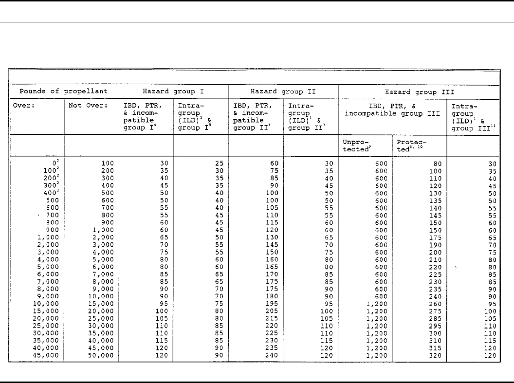
Table 5–24 (PAGE 1)
QD for propellants
58 DA PAM 385–64 • 28 November 1997
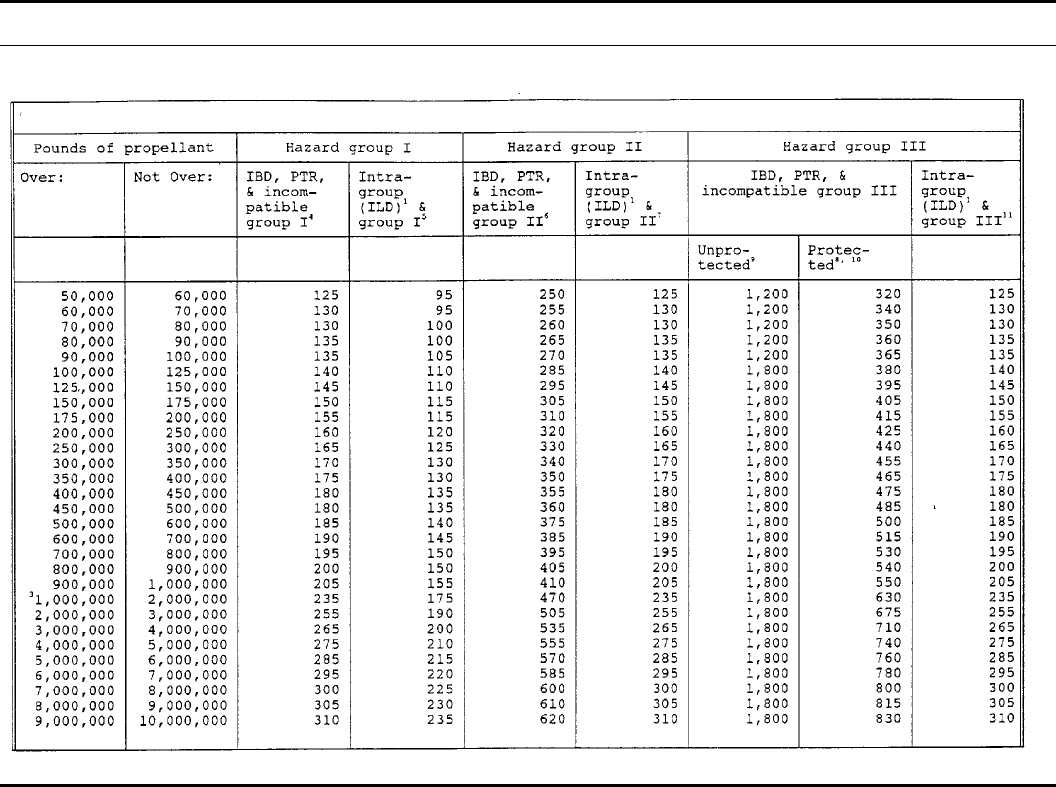
Table 5–24 (PAGE 2)
QD for propellants—Continued
59DA PAM 385–64 • 28 November 1997
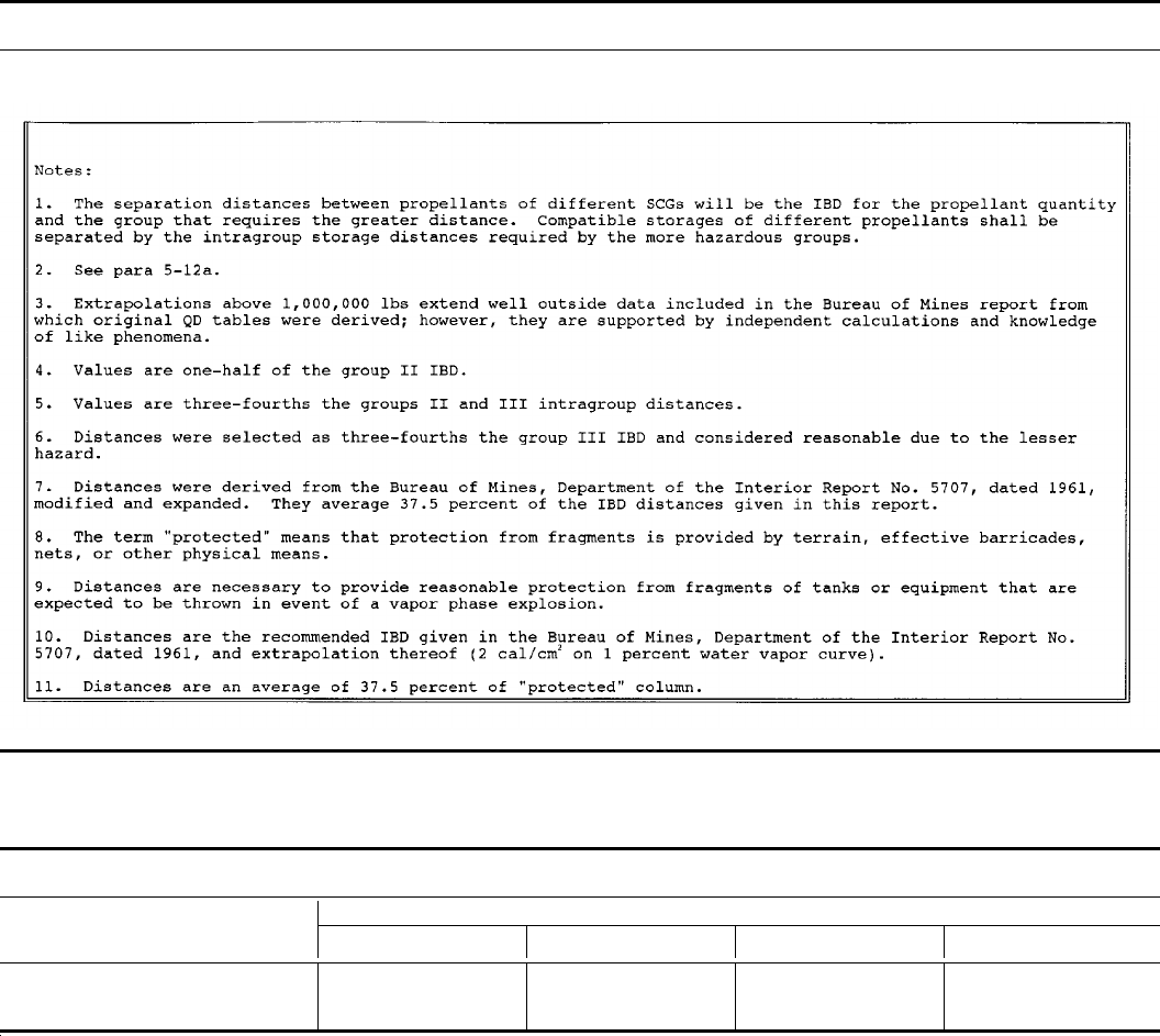
Table 5–24 (PAGE 3)
QD for propellants—Continued
Table 5–25
Hazard group IV separation distances
Quantity of propellant/explosives Distances from propellant/explosives
To inhabited buildings To public traffic routes Intraline Magazine
Total Weight group IV propellant or HE
equivalents for other propellants/ex-
plosives (see table 5–21.)
Use table 5–1. Use table 5–1. Use table 5–3 or 5–4. Use tables 5–5 and 5–6.
60 DA PAM 385–64 • 28 November 1997
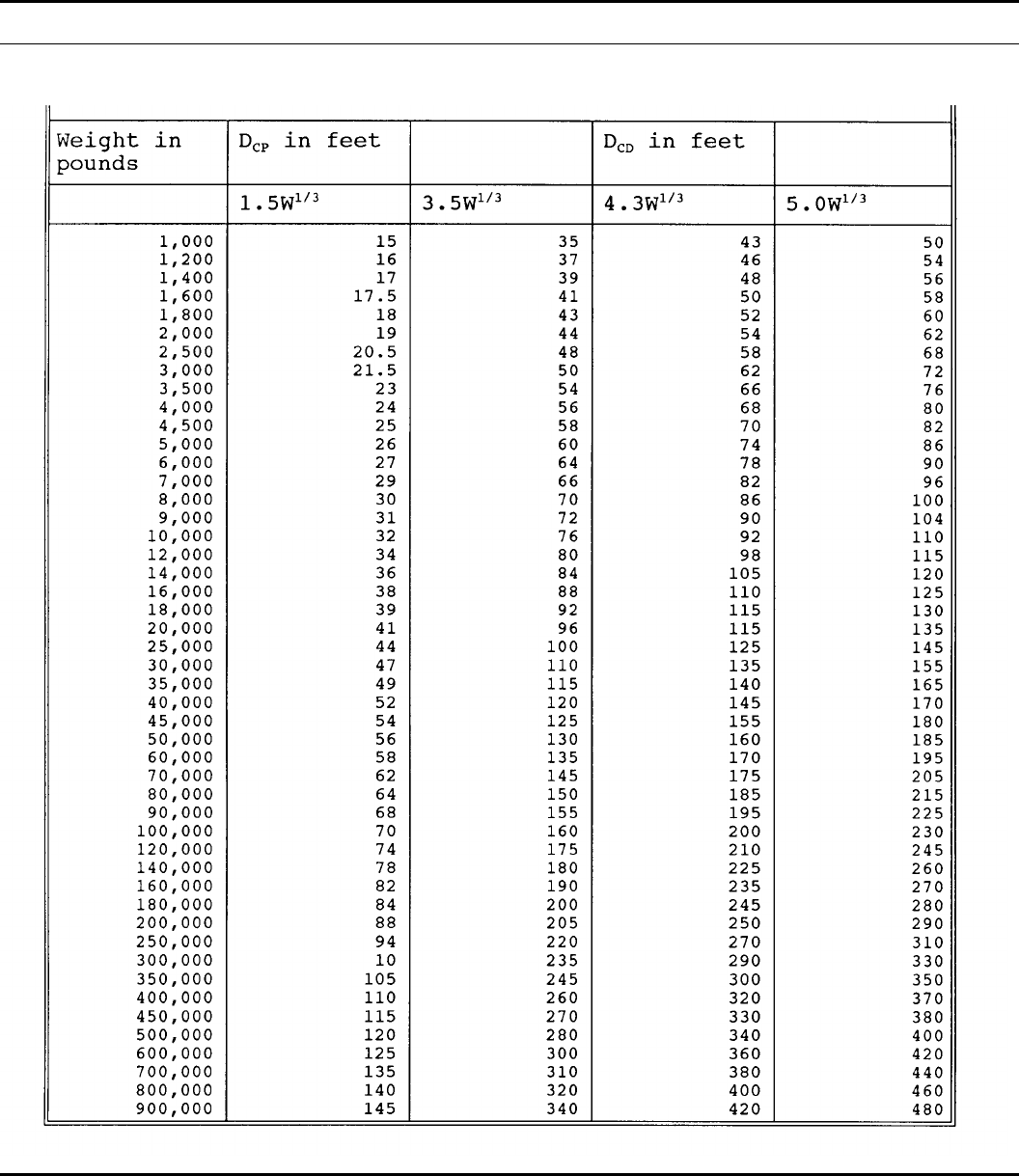
Table 5–26
Chamber separation
61DA PAM 385–64 • 28 November 1997

Table 5–27
Distance to protect against ground shock
NEW in pounds Dig/fg
2.1W4/9 11.1W4/9 12.5W4/9
1,000
1,200
1,400
1,600
1,800
2,000
2,500
3,000
3,500
4,000
4,500
5,000
6,000
7,000
8,000
9,000
10,000
12,000
14,000
16,000
18,000
20,000
25,000
30,000
35,000
40,000
45,000
50,000
60,000
70,000
80,000
90,000
100,000
120,000
140,000
160,000
180,000
200,000
250,000
300,000
350,000
400,000
450,000
500,000
600,000
700,000
800,000
45
49
52
56
58
62
68
74
78
84
88
92
100
105
115
120
125
135
145
155
165
170
190
205
220
235
245
260
280
300
320
330
350
380
410
430
450
480
520
579
620
640
680
720
780
840
880
240
260
280
290
310
330
360
390
420
440
470
490
540
560
600
640
660
720
780
820
860
900
1,000
1,100
1,150
1,250
1,300
1,350
1,500
1,600
1,700
1,750
1,850
2,000
2,150
2,300
2,400
2,500
2,800
3,000
3,200
3,400
3,600
3,800
4,100
4,400
4,700
270
290
310
330
350
370
400
440
470
500
520
560
600
640
680
720
740
820
880
920
980
1,000
1,150
1,200
1,300
1,400
1,450
1,550
1,650
1,800
1,900
2,000
2,100
2,250
2,400
2,600
2,700
2,800
3,100
3,400
3,600
3,900
4,100
4,300
4,600
5,000
5,200
62 DA PAM 385–64 • 28 November 1997

Table 5–28
Distance to protect against hard rock debris
C/W1/3 (FT/LB1/3)
Weight (lbs) .30 .50 .70 .90 1.10 1.60 2.10 2.50
Did/fd(ft)
1000
1200
1400
1600
1800
2000
2500
3000
3500
4000
4500
5000
6000
7000
8000
9000
10000
12000
14000
16000
18000
20000
25000
30000
35000
40000
45000
50000
60000
70000
80000
90000
100000
120000
140000
160000
180000
200000
250000
300000
350000
400000
450000
500000
600000
700000
800000
900000
160
170
185
195
205
210
230
250
270
280
300
310
330
350
370
390
410
440
470
500
520
540
600
640
680
720
760
800
860
920
960
1000
1050
1150
1200
1300
1350
1400
1550
1650
1750
1850
1950
2050
2200
2350
2450
2600
180
195
210
220
230
240
260
290
300
320
340
350
380
400
430
450
470
500
540
560
600
620
680
740
780
820
860
900
980
1050
1100
1150
1200
1300
1400
1450
1550
1600
1750
1900
2000
2100
2200
2300
2500
2700
2800
3000
200
215
230
240
250
260
290
310
330
350
370
380
410
440
470
490
520
560
580
620
640
680
740
800
860
900
940
980
1050
1150
1200
1250
1300
1400
1500
1600
1650
1750
1900
2050
2200
2300
2450
2500
2700
2900
3100
3200
205
220
235
250
260
270
300
320
340
360
380
400
430
460
480
500
520
560
600
640
680
700
760
820
880
940
980
1000
1100
1150
1250
1300
1350
1450
1550
1650
1750
1800
2000
2150
2250
2400
2500
2600
2800
3000
3200
3300
195
210
225
240
250
260
290
310
330
350
360
380
410
440
460
480
500
540
580
620
640
680
740
800
840
900
940
980
1050
1100
1150
1250
1300
1400
1500
1600
1650
1750
1900
2100
2200
2300
2400
2500
2700
2900
3100
3200
145
155
165
175
180
190
210
225
240
250
260
280
300
320
330
350
370
400
420
440
470
490
540
580
620
640
680
700
760
820
860
900
940
1000
1100
1150
1200
1250
1350
1500
1600
1650
1750
1800
1950
2100
2200
2300
92
98
105
110
115
120
135
145
155
160
170
175
190
205
215
225
235
250
270
290
300
310
340
370
390
420
440
460
490
520
560
580
600
660
700
740
780
800
880
960
1000
1050
1100
1150
1250
1350
1400
1500
62
67
72
76
79
83
91
98
105
110
115
120
130
140
145
155
160
175
185
195
205
215
235
250
270
285
295
310
335
355
375
395
410
445
475
500
525
550
600
645
690
725
765
800
860
915
965
1015
63DA PAM 385–64 • 28 November 1997

Table 5–29
Distance to protect against soft rock debris
C/W1/3 (FT/LB1/3)
Weight (lbs) .20 .60 .75 .90 1.00 1.50 1.75 2.50
Did/fd(ft)
1000
1200
1400
1600
1800
2000
2500
3000
3500
4000
4500
5000
6000
7000
8000
9000
10000
12000
14000
16000
18000
20000
25000
30000
35000
40000
45000
50000
60000
70000
80000
90000
100000
120000
140000
160000
180000
200000
250000
300000
350000
400000
450000
500000
600000
700000
800000
900000
155
165
175
185
195
205
225
240
260
270
290
300
320
340
360
380
400
430
460
480
500
520
560
600
620
660
680
740
800
860
900
960
1000
1050
1150
1200
1250
1300
1500
1600
1700
1800
1900
2000
2150
2250
2400
2500
200
215
230
245
260
270
290
310
330
350
370
390
420
450
470
490
520
560
600
620
660
680
740
800
860
900
960
1000
1050
1150
1250
1300
1450
1500
1600
1700
1750
1800
1950
2100
2200
2350
2450
2600
2800
2900
3100
3300
205
220
235
250
260
270
300
320
340
360
380
400
430
460
480
500
520
560
600
640
680
700
760
820
880
940
980
1000
1050
1150
1250
1300
1350
1450
1550
1650
1750
1800
2000
2150
2250
2400
2500
2600
2800
3000
3200
3300
200
215
230
245
260
270
290
310
330
350
370
390
420
450
470
490
520
560
600
620
660
680
740
800
860
900
980
1000
1050
1150
1250
1300
1450
1500
1600
1700
1750
1800
1950
2100
2200
2350
2450
2600
2800
2900
3100
3300
188
200
215
225
240
250
270
290
310
330
350
360
390
410
440
460
480
520
560
580
620
640
700
760
800
840
880
920
1000
1050
1150
1200
1250
1350
1400
1500
1550
1650
1800
1950
2050
2200
2300
2400
2600
2700
2900
3000
92
98
105
110
115
120
135
145
155
160
170
175
190
205
215
225
235
250
270
290
300
310
340
370
390
420
440
460
490
520
560
580
600
660
700
740
780
800
880
960
1000
1050
1100
1150
1250
1350
1400
1500
64
70
74
78
82
86
94
100
110
115
120
125
135
145
150
160
165
180
190
200
210
220
240
260
280
290
310
320
350
370
390
410
430
460
490
520
550
560
620
660
720
760
780
820
880
940
1000
1050
25
27
29
31
32
34
37
40
43
45
47
49
53
57
60
63
65
71
75
79
83
87
95
100
110
115
120
125
135
145
155
160
170
180
195
205
215
225
245
265
280
300
310
325
350
375
390
415
Table 5–30
Functions of loading density
Loading density Ground shock Debris
wf
gf
d
(lbs/ft1/3) (0.267w0.30) (0.600w0.18)
1.0 0.27 0.60
1.2 0.28 0.62
1.4 0.29 0.64
1.6 0.31 0.65
1.8 0.32 0.67
2.0 0.33 0.68
2.5 0.35 0.71
3.0 0.37 0.73
3.5 0.39 0.75
4.0 0.40 0.77
4.5 0.42 0.79
5.0 0.43 0.80
6.0 0.46 0.83
7.0 0.48 0.85
64 DA PAM 385–64 • 28 November 1997
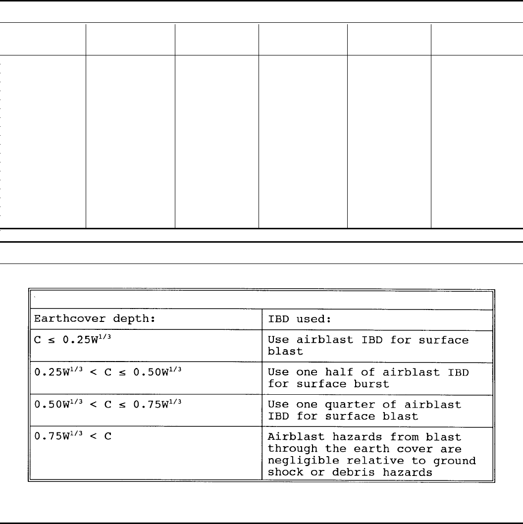
Table 5–30
Functions of loading density—Continued
Loading density Ground shock Debris
wf
gf
d
(lbs/ft1/3) (0.267w0.30) (0.600w0.18)
8.0 0.50 0.87
9.0 0.52 0.89
10.0 0.53 0.91
12.0 0.56 0.94
14.0 0.59 0.96
16.0 0.61 0.96
18.0 0.63 1.01
20.0 0.66 1.03
25.0 0.70 1.07
30.0 0.74 1.11
35.0 0.77 1.14
40.0 0.81 1.17
45.0 0.84 1.19
50.0 0.86 1.21
60.0 0.91 1.25
70.0 0.95 1.29
80.0 0.99 1.32
90.0 1.03 1.35
100.0 1.06 1.37
Table 5–31
IBD for airblast traveling through earth cover
65DA PAM 385–64 • 28 November 1997
Table 5–32
Distance versus overpressure along the centerline
Table 5–33
Distance versus overpressure along the centerline
66 DA PAM 385–64 • 28 November 1997
Table 5–34
Effective overpressure at the opening
Table 5–35
Allowable overpressure at IBD
67DA PAM 385–64 • 28 November 1997

Table 5–36
IBD distances to protect against airblast
W R/[D/VT1/3] (ft) at selected off-axis angles (deg)
lbs 0 deg 30 deg 60 deg 90 deg 120 deg 180 deg
1000
1200
1400
1600
1800
2000
2500
3000
3500
4000
4500
5000
6000
7000
8000
9000
10000
12000
14000
16000
18000
20000
25000
30000
35000
40000
45000
50000
60000
70000
80000
90000
100000
120000
140000
160000
180000
200000
250000
300000
350000
400000
450000
500000
600000
700000
800000
900000
1340
1420
1500
1570
1630
1690
1820
1930
2030
2130
2210
2290
2430
2560
2680
2790
2890
3070
3230
3380
3510
3640
3920
4160
4380
4580
4770
4940
5250
5520
5770
6010
6220
6910
7540
8130
8690
9220
10460
11110
11700
12230
12720
13180
14000
14740
15410
16030
1110
1180
1240
1300
1350
1400
1510
1600
1690
1760
1840
1900
2020
2130
2220
2310
2400
2550
2680
2800
2910
3020
3250
3450
3640
3800
3950
4100
4350
4580
4790
4980
5160
5730
6250
6740
7210
7650
8680
9220
9710
10150
10550
10930
11620
12230
12790
13300
760
810
850
890
930
960
1030
1100
1160
1210
1260
1300
1380
1460
1520
1580
1640
1740
1830
1920
1990
2070
2230
2360
2490
2600
2710
2800
2980
3140
3280
3410
3530
3920
4280
4620
4930
5240
5940
6310
6640
6950
7220
7480
7950
8370
8750
9100
520
550
580
610
630
660
710
750
790
830
860
890
950
1000
1040
1080
1120
1190
1260
1310
1370
1410
1520
1620
1700
1780
1850
1920
2040
2150
2250
2340
2420
2690
2930
3160
3380
3590
4070
4320
4550
4760
4950
5120
5450
5730
5990
6230
370
400
420
440
460
470
510
540
570
600
620
640
680
720
750
780
810
860
900
940
980
1020
1100
1160
1230
1280
1330
1380
1470
1550
1620
1680
1740
1930
2110
2270
2430
2580
2930
3110
3270
3420
3560
3690
3920
4120
4310
4480
220
240
250
260
270
280
300
320
340
350
370
380
400
430
440
460
480
510
540
560
580
600
650
690
730
760
790
820
870
920
960
1000
1030
1150
1250
1350
1440
1530
1730
1840
1940
2030
2110
2190
2320
2450
2560
2660
68 DA PAM 385–64 • 28 November 1997

Figure 5-1. Impulse noise zones for various B-durations and peak sound pressures
69DA PAM 385–64 • 28 November 1997
Figure 5-2. Impulse noise zones from intentional detonations
70 DA PAM 385–64 • 28 November 1997
Figure 5-3. Intermagazine hazard factors
Figure 5-4. Intermagazine hazard factors
71DA PAM 385–64 • 28 November 1997

Figure 5-5. Intermagazine hazard factors
Figure 5-6. Intermagazine hazard factors
72 DA PAM 385–64 • 28 November 1997
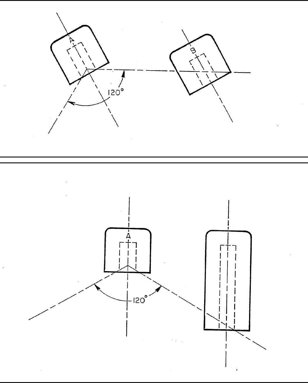
Figure 5-7. Intermagazine hazard factors
Figure 5-8. Intermagazine hazard factors
73DA PAM 385–64 • 28 November 1997
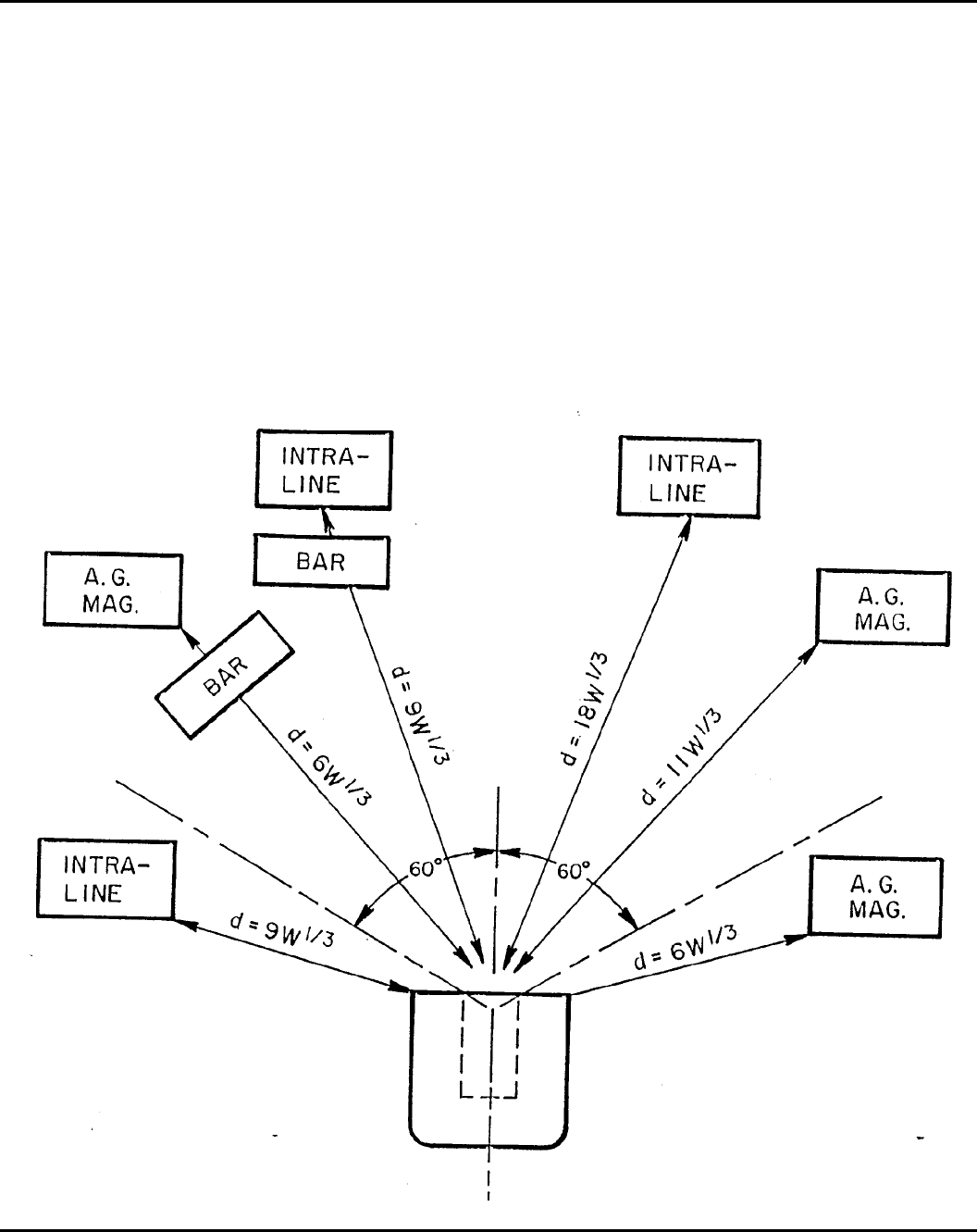
Figure 5-9. Intermagazine hazard factors
74 DA PAM 385–64 • 28 November 1997
Chapter 6
Electrical Hazards
Section I
Electrical Service and Equipment
6–1. Overview
The installation and use of electrical equipment within buildings,
magazines, operating locations, shelters, and so forth, containing
explosives will comply with the latest edition of the NFPA, Stand-
ard 70, unless stated otherwise in this chapter.
6–2. Hazardous locations
Locations are classified depending on the properties of the flamma-
ble vapors, liquids or gases, or combustible dusts or fibers which
may be present and the likelihood that a flammable or combustible
c o n c e n t r a t i o n o r q u a n t i t y i s p r e s e n t . W h e r e p y r o p h o r i c ( s p o n -
taneously igniting in air) materials are used or handled, these loca-
tions will not be classified. Each room, section, or area will be
considered individually in determining its classification. To qualify
as a hazardous location, conditions listed in paragraph 6–2a through
c should either exist or be probable in the location. Hazardous
locations are divided into three classes. Each class consists of two
division: Division 1 (more hazardous) and division 2. Hazardous
locations require either explosives dusts, flammable vapors, or ignit-
able flyings (or fibers) to be present in a proper mixture with air.
Ammunition storage structures will not normally have the proper
mixture and would not be considered a hazardous location within
the context of this definition. Additional information can be found
in NFPA 70, article 500.
a. Class I. Class I locations are those in which flammable gases
or vapors are or may be present in the air in quantities sufficient to
produce explosive or ignitable mixtures. Rooms or buildings con-
taining vapors from explosives which may condense will be consid-
ered Class I, Division 1 locations. Electrical equipment must have
been tested and listed by a recognized testing agency as suitable for
installation and use in Class I hazardous locations for safety of
operation in the presence of flammable mixtures of specific vapors
or gases in the air.
(1) Class I, Division 1. Class I, Division 1 locations are those in
which—
(a) Hazardous concentrations of flammable gases or vapors exist
continuously, intermittently, or periodically under normal operating
conditions.
(b) Hazardous concentrations of flammable gases or vapors may
exist frequently because of repair or maintenance operations or
because of leakage.
(c) Breakdown or faulty operation of equipment or processes
which might release hazardous concentrations of flammable gases or
v a p o r s m i g h t a l s o c a u s e s i m u l t a n e o u s f a i l u r e o f e l e c t r i c a l
equipment.
(d) Explosives may sublime and outgas.
(e) Equipment operating temperatures will not have an external
temperature capable of igniting the flammable mixture of the spe-
cific gas or vapor in its location.
(2) Class I, Division 2. Class I, Division 2 locations are those in
which—
(a) Volatile flammable liquids or flammable gases are handled,
processed, or used. In these areas the hazardous liquids, vapors, or
gases normally are confined within closed containers or systems
from which they can escape only in an accidental rupture or break-
down of such containers or systems or during abnormal operation of
equipment.
(b) Positive mechanical ventilation normally prevents hazardous
concentrations of gases or vapors from accumulating, but concentra-
tions might become hazardous if the ventilating equipment fails or
malfunctions.
( c ) H a z a r d o u s c o n c e n t r a t i o n s o f g a s e s o r v a p o r s o c c a s i o n a l l y
might accumulate if they spread from adjacent Class I, Division 1
locations unless prevented by adequate positive-pressure ventilation
from a source of clean air, and effective safeguards against ventila-
tion failure are provided.
b. Class II. Class II locations are those locations which are haz-
ardous because of the presence of combustible dust. Rooms or
buildings that contain explosive dusts or explosives having a chemi-
cal composition or physical size such that particles of explosives
may become disassociated from the whole and disperse in the sur-
rounding atmosphere, will be considered Class II hazardous loca-
tions. Equipment installed in Class II locations will be able to
function at full rating without developing surface temperatures high
enough to cause excessive dehydration or gradual carbonization of
any organic dust deposits that may be present. Dust that is carbon-
ized or excessively dry is highly susceptible to spontaneous ignition.
Operating temperatures of electrical equipment will not be high
enough to ignite expected dusts in its location if equipment, such as
m o t o r s , p o w e r t r a n s f o r m e r s , a n d s o f o r t h , b e c o m e s o v e r l o a d e d .
Equipment and wiring defined as explosion-proof is not required in
Class II locations, and may not be acceptable unless it meets all the
requirements of NFPA 70, Article 500 for Class II locations.
(1) Class II, Division 1. Class II, Division 1 locations are those in
which—
(a) Combustible dust is or may be suspended in the air con-
t i n u o u s l y , i n t e r m i t t e n t l y , o r p e r i o d i c a l l y u n d e r n o r m a l o p e r a t i n g
c o n d i t i o n s i n q u a n t i t i e s s u f f i c i e n t t o p r o d u c e a n e x p l o s i o n o r
ignition.
(b) Mechanical failure or malfunctioning machinery or equipment
may cause explosive or ignitable mixtures to be produced, or be-
come a source of ignition through simultaneous failure of electrical
equipment and protection devices or other causes.
(c) Combustible dusts which are electrically conductive may be
present.
(d) Explosives or explosive dusts may, during handling, produce
dust capable of being dispersed in the atmosphere.
(e) Explosives may outgas.
(2) Class II, Division 2. Class II, Division 2 locations are those in
which—
(a) Combustible dust will not normally be suspended in the air,
or thrown into suspension, by the normal operation of equipment or
apparatus in quantities sufficient to produce explosive or ignitable
mixtures.
(b) Deposits or accumulations of dust may be sufficient to inter-
fere with the safe dissipation of heat from electrical equipment or
apparatus.
(c) Deposits or accumulations of combustible dust on, in, or in
the vicinity of, electrical equipment may be ignited by arcs, sparks,
or burning material from electrical equipment.
c. Class III. Class III locations are those that could be hazardous
because of the presence of easily ignitable fibers or flyings, but
where these fibers or flyings are not likely to be in suspension in the
air in quantities sufficient to produce ignitable mixtures. These loca-
t i o n s i n c l u d e c o m b u s t i b l e f i b e r m a n u f a c t u r i n g p r e s s i n g p l a n t s ,
woodworking plants, and establishments involving similar hazardous
processes or conditions. Easily ignitable fibers and flyings include
rayon, cotton, hemp, oakum, excelsior, and other materials of simi-
lar nature.
(1) Class III, Division 1. Class III, Division 1 locations are those
in which easily ignitable fibers or materials that produce combusti-
ble flyings are handled, manufactured, or used.
(2) Class III, Division 2. Class III, Division 2 locations are those
in which easily ignitable fibers are stored or handled, excluding
l o c a t i o n s w h e r e i g n i t a b l e f i b e r s a r e s t o r e d o r h a n d l e d d u r i n g
manufacturing.
d. Change of classification. Operating buildings and magazines
are constructed to perform a specific function which dictates the
requirements for electrical equipment installation. If the functions
performed in the facility change or are rearranged, the safety offi-
cers must inspect, approve, or reclassify the hazardous locations.
Multiple classifications are discussed in the following paragraph.
e . M u l t i p l e c l a s s i f i c a t i o n s . I n s o m e a r e a s o f A r m y o p e r a t i n g
75DA PAM 385–64 • 28 November 1997
buildings or magazines there may be hazards from both dust and
flammable vapors. If so, these areas will have a dual or multiple
classification. Electrical equipment used in these areas must be lis-
ted by a recognized testing agency as suitable for use in all hazard-
ous locations to which it will be subjected.
f. Special requirements.
(1) Electrical equipment and installations in Class I, II, or III
hazardous locations involving explosives will comply with the re-
quirements of the code for Division 1 of the appropriate hazardous
location class. Equipment and installations in locations which could
be used as either a Class I or II hazardous location will meet the
requirements of both classes.
(2) An alternate source of power must be available for explosives
operations where the lack of a continuous power supply may cause
a fire or explosion.
(3) Low power, solid state devices which are intrinsically safe
under the NFPA, Standard 70, Article 504, may be used in any
hazardous location, provided they do not introduce a physical or
electromagnetic radiation (EMR) hazard. See section III of this
chapter for more information on EMR.
g. Maintenance. More than ordinary care will be taken to main-
tain equipment and electrical installations in hazardous locations.
The equipment must be periodically inspected and maintained by
qualified personnel, with a written record kept of the inspections
and maintenance. Where inspection frequency is not prescribed in a
TM or other directive, the inspection period will be fixed by local
authority on the basis of the existing situation.
h. Photographic lighting. Magnesium flashlights or photoflash
bulbs are not allowed in hazardous locations. Only lighting equip-
ment bearing the Underwriter’s Laboratory (UL) listed label for the
hazard involved will be used in photography.
6–3. Approved equipment
a. Listed equipment. Electrical equipment listed by a recognized
testing agency, is acceptable only when used under the recom-
mended environmental and operational conditions. Equipment will
be approved not only for the class of location but also for the
explosive properties of the specific gas, vapor, or dust that will be
present. For additional details, see NFPA 70.
b. Unlisted equipment. Electrical equipment not specifically listed
by a recognized testing agency for the purpose or operating condi-
tion present may be certified for use by a qualified safety or system
safety engineer (GS–803). This certification will be based on the
following:
(1) Listed equipment is not available from any source;
(2) Hazard analysis has determined that no additional hazards
would be created by using this equipment. Unlisted equipment certi-
fication and justification thereof, must be maintained at the installa-
tion until the equipment is withdrawn from service.
6–4. Maintenance of electrical equipment
Only qualified personnel authorized to do such work will perform
maintenance. Where equipment may have been contaminated by
explosives, the explosives will be removed or neutralized before
maintenance is started.
6–5. Electrical service lines in explosives areas
Each service line will be run underground from a point at least 50
feet away from the building. The exterior line side of the main
disconnecting switch or circuit breaker must have suitable lightning
arrestors. See paragraph 5–7o for separation distance for electrical
lines.
a. Surge (lightning) arresters will be required and installed as
specified in NFPA 70, Article 280.
b. Local telephone service and similar low voltage intercom or
alarm systems must also comply with the same underground routing
for the last 50 feet. Surge protection, even for lines that run under-
ground, will be provided to shield against any severe electrical
surges from a nearby lightning strike or from excessive power
through the line from other outside sources, such as broken power
lines.
c. Ground fault interrupters virtually eliminate electrical shock
hazards presented by line-to-ground fault currents and leakage cur-
rents by removing power from the faulty circuit. When building or
renovating facilities, all 120 volts alternating current (VAC) single-
phase receptacle outlets installed outdoors will have ground fault
circuit protection. Ground fault protection will be provided in other
areas where conditions creating a high-level electrical hazard exist.
Ground fault circuit interrupters can often be activated by spurious
electrical impulses. Therefore, these devices will not be used on
circuits that serve critical equipment and processes; for example,
lighting in an explosives building, or lighting required for a safe exit
from any building.
6–6. Electrical motors for hazardous locations
Electrical motors should not be installed in a room or building
which is a Class I or II hazardous location. They should have no
connection to the building except through glands or apertures ade-
quately sealed against entrance of hazardous materials either into the
location or into the motor itself. If an electrical motor must be
located in a hazardous location, paragraph 6–3 applies.
6–7. Portable lighting systems
a. Floodlight systems, which are listed by an recognized testing
agency, may be used where required. These will be mounted on
heavy portable stands and placed outside the magazine door or the
outside working area. Service cords must be placed or protected so
that they cannot be walked on or run over by equipment.
b. Flashlights and hand lanterns powered by low voltage dry cell
batteries and miners’ cap lamps, each approved as permissible by
the U.S. Bureau of Mines and by a recognized testing agency for
Class I hazardous locations, are considered satisfactory for both
Class I and II hazardous locations. In Class III hazardous locations
and nonhazardous explosives locations, any type dry cell flashlight
is acceptable. Devices which provide cold light through chemical
action are acceptable for any hazardous location.
6–8. Permanent lighting for storage magazines
If permanent lighting is essential, an approved type of disconnect
switch must be used. The switch will be placed outside the maga-
zine and arranged so that it can be locked in the open position. The
power will be on only when personnel are working in the magazine.
The magazine doors will be opened and the magazine interior will
be visually inspected before actuating the switch. As a minimum,
sparkproof or industrial rated electrical systems in rigid metal con-
duits, enclosed junction boxes, and closure plates without opening
and protective covers for lighting fixtures will be used. Explosion
proof lighting is required only for the hazardous locations listed in
paragraph 6–2.
6–9. Flexible cords
Flexible cords should be type “S” hard service cords approved for
extra hard usage in damp areas as defined in the National Electric
Code (NEC). Splices are not allowed. All flexible cords with plugs
must be equipped with a ground. Flexible cords will not be used in
place of fixed or installed electrical wiring. Place or protect each
electrical cord so that it cannot be walked on or run over by
equipment.
Section II
Static electricity
6–10. Static electricity charge dissipation subsystem
a. General information.
(1) Static electricity. Static electricity is produced when two un-
like materials are brought into contact and then separated. During
contact, there is a redistribution of the charge across the area of
contact and an attractive force is established. When the materials are
separated, work is done in overcoming these attractive forces. This
work is stored as an electrostatic field which is set up between the
76 DA PAM 385–64 • 28 November 1997
two surfaces when they are separated. If no conducting path is
available to allow the charges to bleed off the surfaces, the voltage
between the surfaces can easily reach several thousand volts as they
are separated. Static electricity is an annoyance to many individuals.
Static shock may cause discomfort and even injury to a worker due
to involuntary reaction. A far more dangerous aspect of static elec-
tricity is the fire and explosion hazard. This hazard can occur in
situations where a vapor-air, gas-air, dust-air, or combination of
these mixtures exist in the proper ratio. For static to cause ignition,
four conditions must exist:
(a) An effective means of static generation.
(b) A means of accumulating the charges and maintaining a dif-
ference of electrical potential.
(c) A spark discharge of adequate energy.
(d) The spark must occur in an ignitable mixture.
(2) Sources. The most common sources of static electricity are:
(a) Steam, air, or gas flowing from any opening in a pipe or
hose, particularly when the stream is wet or when the air or gas
stream contains particulate matter.
(b) Pulverized materials passing through chutes and pneumatic
conveyors.
(c) Nonconductive power or conveyor belts in motion.
(d) Moving vehicles.
(e) All motion involving changes in relative position of contact-
ing surfaces (usually of dissimilar substances), of which one or both
must be a poor conductor of electricity. The following paragraph
provides information and procedures on how to control static elec-
tricity charge dissipation.
(3) Materials sensitive to static spark discharge. Practically all
finely divided combustible materials, especially explosives, when
suspended in the proper concentration in air or deposited in finely
divided layers, can be ignited by an electro-static spark.
(a) Explosives. The explosives or explosive mixtures that are
sensitive to static discharge (electro-static sensitivity of 0.1 joule or
less) when exposed are generally primer, initiator, detonator, igniter,
tracer, incendiary, and pyrotechnic mixtures. Ammonium picrate,
tetryl, RDX compositions, and tetrytol are sensitive to static dis-
charge when present in dust-air mixtures. The following are some of
the explosives that can be ignited by a static electricity spark dis-
charged from a person: black powder; diazodinitrophenol; igniter
compositions; lead azide; lead styphnate; aluminum, magnesium,
titanium, uranium, or zirconium powder exposed in layers; mercury
fulminate; mixtures of flammable vapors; potassium chlorate mixed
with flammable dusts; pyrotechnic mixtures; smokeless powder dust
when present; and tetrazene.
(b) Electro-explosive devices. Static electricity on insulated con-
ductive objects, such as metal stands with rubber casters, or on a
person, can discharge through the air to other objects which are at a
sufficiently different potential. Such a discharge or spark, even
though too small to be felt, may contain enough energy to cause an
electro-explosive device, such as a primer or a detonator, to fire.
Static discharges may also be strong enough to break down the
insulation within the electro-explosive device and cause it to fire.
(c) Solvents. Flammable mixtures of solvents and air can be ig-
nited by the static charge that can be accumulated on a person.
Typical flammable solvents are ethyl ether, ethyl alcohol, ethyl
acetate, acetone, benzene, and naphtha.
(4) Static generating materials. Personnel who work in a hazard-
ous location or who handle or install unpackaged electro-explosive
devices and ammunition must avoid using rags and wearing outer
garments made of materials which have high static generating char-
acteristics. Materials of 100 percent polyester, nylon, rayon, silk, or
wool are highly static-producing. Wool socks, glove inserts, and
caps, as well as undergarments of synthetic fabrics or silk are less of
a hazard. Nylon field jacket liners should not be worn as an outer
garment. Cotton or cotton-synthetic blend materials are preferred.
(5) Static electrical potential discharge or equalization. Person-
nel, regardless of the type of clothing worn, can collect a charge of
static electricity by being in contact with moving nonconductive
s u b s t a n c e s o r c o m i n g i n c o n t a c t w i t h a m a s s t h a t h a s b e e n
previously charged. Therefore, personnel must be particularly care-
ful to discharge their static electrical potential or equalize it to that
of the explosives item before the item is handled.
(6) Garment removal. Garments will not be put on or removed
while engaged in explosives operations. This reduces the generation
of static charges caused by physical separation of materials. If outer
garments need to be removed, personnel will step out of the imme-
diate area of operation, remove the garment, ground themselves,
then reenter. Workers shall not unfasten Velcro fasteners while
present in an explosives operation.
b. Static electricity dissipation.
(1) The grounding method generally used to eliminate or reduce
the hazard from static electricity is to provide an electrically contin-
uous path to the earth electrode subsystem.
(a) When all of the objects are conductive, they can be grounded
by electrically connecting all parts to a common ground conductor.
(b) When deemed necessary, effective grounding must include
the exterior and the contents of a container.
(c) Electrical continuity may be broken by oil on bearings, paint,
or rust at any contact point. To get a continuous circuit, grounding
straps should be used to bridge such locations. Equipment in contact
with conductive floors or table tops is not adequately grounded.
(d) Static grounds will not be made to telephone grounds; electri-
cal conduit systems; gas, steam, water, or air lines; sprinkler sys-
t e m s ; o r a i r t e r m i n a l s o f l i g h t n i n g p r o t e c t i o n s y s t e m ( L P S )
(connection to the down conductor of the system at the ground level
is authorized).
(2) Static electricity accumulations and subsequent discharges are
usually impossible if the relative humidity is above 60 percent.
Where humidification techniques are used to prevent static electric-
ity accumulations, perform a daily preoperational check of the hu-
midity levels before starting work. However, certain materials such
as metallic powders and some of the pyrotechnic mixtures cannot be
exposed to air with 60 percent or higher relative humidity because
of the possibility of spontaneous ignition.
(3) Ionization is electrical neutralization and serves as an effec-
tive method of removing static charges from certain processes and/
or operation. Methods of application can be found in NFPA Recom-
mended Practice 77. Ionization methods of removing static charges
must not be used in hazardous locations as defined in the National
Electrical Code, NFPA 70, and paragraph 6–2 of this pamphlet.
Unless the MACOM commander gives approval, do not use radio-
active ionization sources due to the potential for radioactive material
contamination during an explosives accident or pyrotechnic fire.
c. Conductive floors, mats, and runners. The combination of con-
ductive floors and shoes provides the static electricity charge a
dissipation path to the earth electrode subsystem.
(1) General requirements.
(a) Conductive floors, plates, mats, and runners will be used
together with conductive footwear to protect personnel at operations
involving items and materials having an electrostatic sensitivity of
0.1 joule or less. A list of items and materials that are sensitive to
this level are listed in paragraph 6–10a(3)(a) through 6–10a(3)(c).
Operations involving such items as loosely unpacked ammunition
with electric primers, exposed electro-explosives devices, electri-
cally initiated items with exposed electric circuitry, and other haz-
a r d o u s m a t e r i a l s w i l l b e a n a l y z e d o n a c a s e - b y - c a s e b a s i s t o
determine if conductive floors, plates, mats, runners, and footwear
a r e r e q u i r e d . T h i s a n a l y s i s w i l l i n c l u d e a n a s s e s s m e n t o f t h e
electrostatic sensitivity of the item and the compensatory measures
to be employed.
(b) Conductive floors are not required throughout a building or
room if the hazard is localized. In these cases, conductive mats or
runners may be used where appropriate. These mats or runners will
be subject to all the specifications and tests that apply to conductive
floors.
( 2 ) N e w i n s t a l l a t i o n o r r e n o v a t i o n r e q u i r e m e n t s C o n d u c t i v e
floors must be constructed of nonsparking material such as lead,
conductive rubber, or conductive flooring composition and must
meet the following requirements:
(a) The surface of the installed floor must be free from cracks
77DA PAM 385–64 • 28 November 1997
and reasonably smooth. The surface material must not slough off,
wrinkle, or buckle under operating conditions. Conductive tiles are
not recommended in areas where explosives dust can cause contami-
nation. The large number of joints and the tendency of tiles to
loosen can allow explosives dust to become lodged. The tiles are not
easy to clean using normal cleanup procedures.
(b) The conductive floors must be compatible with the materials
to be processed.
(3) Conductive floor bonding requirements.
(a) Conductive floors will be bonded to the earth electrode sub-
system. The bonding material will be selected in accordance with
paragraph 6–13d below.
(b) On former Naval installations conductive floors will be bon-
ded to the secondary girdle. The bonding material will be selected in
accordance with paragraph 6–13d.
(4) Visual inspection requirements.
( a ) V i s u a l i n s p e c t i o n i n t e r v a l . C o n d u c t i v e f l o o r s w i l l b e i n -
spected daily during operations.
(b) Visual inspection procedures. (See para C–2 and table 6–1 for
inspection procedures.)
(5) Electrical test requirements.
(a) Electrical test intervals. Conductive floors will be tested at
the completion of installation, at the completion of renovation, and
at least semi-annually thereafter.
(b) Electrical test procedures. Electrical tests will be conducted
only when the room or area is free of exposed explosives and/or
flammable gas mixtures. (See para C–3 and table 6–1 for testing
procedures.)
(6) Maintenance of conductive floors. Conductive floors will be
kept clean, dry, and free of nonconductive material. Soaps, deter-
gents, and solvents that leave a residue will not be used to clean
conductive floors.
d. Conductive footwear.
(1) General requirements. Personnel who work upon conductive
flooring, conductive mats, or conductive runners where the require-
ments in c(1)(a) above apply, must wear nonsparking conductive
footwear. Personnel from other departments or visitors who enter
these areas and who walk on conductive flooring materials also
must wear nonsparking conductive footwear (conductive overshoes
with ankle straps may be used). Legstats are acceptable for visitors
or transients only, as long as their basic footwear is of nonsparking
construction. Under no circumstances will personnel working on
electrical equipment or facilities wear conductive-sole safety shoes
or other conductive footwear.
(2) Conductive footwear requirements.
( a ) C o n d u c t i v e s h o e s w i t h c o n d u c t i v e c o m p o s i t i o n s o l e s w i l l
meet ANSI Safety Standard for Safety-Toe Footwear, Z41.1 and
MIL-S–3794.
(b) Conductive footwear requires care to retain its conductive
properties. When conductive footwear is not in use, it should be
stored in lockers close to the room where it will be worn. Employ-
ees who have been issued conductive footwear will not wear it from
the workplace to their homes and return. A thin layer of dust or wax
may insulate conductive footwear from the floor.
(c) Only conductive materials will be used to repair conductive
soled shoes. Conductive shoes will be thoroughly cleaned before
being repaired.
(3) Visual inspection requirements.
(a) Inspection intervals. Conductive footwear will be inspected
every day before use.
(b) Inspection procedures and criteria. (See para C–2 and table
6–1.)
(4) Electrical test requirements.
(a) Test intervals. Conductive footwear will be tested at the time
issued and daily before use.
(b) Test procedures. (See para C–4 and table 6–1.)
e. Conductive tables and table tops. The requirements for con-
ductive floors will apply to conductive tables and table tops.
f. Conductive belts.
(1) New installation, renovation, and general requirements.
(a) Conductive conveyor belts will meet the requirements of In-
ternational Standard Organization (ISO) 284, Conveyor Belts, Elec-
tric Conductive, Specifications and Method of Test.
( b ) C o n d u c t i v e V - b e l t s w i l l m e e t t h e r e q u i r e m e n t s o f I S O
1 8 1 3 – A n t i s t a t i c V - B e l t s E l e c t r i c C o n d u c t i v e — S p e c i f i c a t i o n s a n d
Method of Test at initial installation.
(2) Bonding requirements.
(a) The belt must be electrically continuous.
(b) The combination of the belt tension and the weight on the
belt provides the bonding of the belt to the pulleys and rollers.
(c) The static electricity charge dissipation from the belt to the
pulley or roller will also dissipate through the bearings to the equip-
ment. The equipment in turn must be bonded to the earth electrode
subsystem. Static combs or sliding contacts may be used between
pulleys and roller to the equipment housing. Bonding straps can be
used on the equipment housing. Braided straps will be required on
equipment that vibrates.
(d) On former Naval installations this subsystem must be bonded
to the secondary girdle.
(3) Visual inspection requirements.
(a) Inspection intervals. Conveyer belt and v-belt systems will be
i n s p e c t e d a t i n s t a l l a t i o n o r r e n o v a t i o n a n d d a i l y b e f o r e u s e
thereafter.
(b) Inspection procedures and criteria. (See para C–2 and table
6–1.)
(4) Electrical test requirements.
(a) Test intervals. All conveyor belt systems will be tested at the
time of installation or renovation and at least semi-annually. Con-
ductive v-belts will be tested at time of installation (para C–6), but
need not be tested after installation.
(b) Test methods. (See para C–5 and table 6–1.)
g. Conductive legstats.
(1) General requirements. Legstats will not be used in place of
conductive shoes. Only transients will use legstats when they re-
quire conductive footwear. Legstats will be used in pairs (one on
each leg) when they are required.
(2) Visual inspection requirements.
(a) Inspection intervals. Legstats will be inspected upon receipt
and daily before use.
(b) Inspection procedures and criteria. (See para C–2d and table
6–1.)
(3) Electrical testing requirements.
(a) Test intervals. Legstats will be tested upon receipt and daily
before use.
(b) Test criteria. (See para C–7 and table 6–1.)
h. Conductive wriststats.
(1) General requirements. As a general rule, wriststats should not
serve as the primary method of dissipating electrostatic charges
from the human body. Wriststats may be a supplemental method
w h e n o p e r a t i o n s r e q u i r e m o r e t h a n n o r m a l p r e c a u t i o n s a g a i n s t
e l e c t r o s t a t i c d i s c h a r g e . W r i s t s t a t s m a y b e u s e d a s t h e p r i m a r y
method of electrostatic control when directed by Army publications.
(2) Visual inspection requirements.
(a) Inspection intervals. Wriststats will be inspected upon receipt
and daily before use.
(b) Inspection procedures and criteria. (See para C–2d and table
6–1.)
(3) Electrical testing requirements.
(a) Test intervals. Wriststats will be tested upon receipt and daily
before use.
(b) Test criteria. The resistance value will be provided in the
publication that requires the use of wriststats. (See table 6–1 and
C–8.)
i. Forklift trucks. Requirements, inspection, and test procedures
are in TB 43–0142.
j. Machinery and equipment
(1) General requirements. All machinery and equipment such as
m i x e r s f o r p y r o t e c h n i c , p r o p e l l a n t , a n d e x p l o s i v e c o m p o s i t i o n s ,
screening and sifting devices, assembly and disassembly machines,
elevators, defuzing machines, presses, hoppers, and all associated
78 DA PAM 385–64 • 28 November 1997
equipment involved in loading or processing explosives or explo-
sives materials will be bonded to the earth electrode subsystem.
(2) Visual inspection requirements.
(a) Inspection intervals. Machinery and equipment will be in-
spected upon receipt and daily before use.
(b) Inspection procedures and criteria. (See para C–2e and table
6–1.)
(3) Electrical testing requirements.
(a) Test intervals. Machinery and equipment will be tested upon
receipt and as specified in table 6–1.
(b) Test criteria. The resistance value between the machinery and
equipment and the earth electrode subsystem will be as specified in
paragraph C–9 and table 6–1.
k. Spray painting operations. During paint spraying operations,
static electricity dissipation will be accomplished as required in
NFPA 33 and/or NFPA 77. Electrostatic paint systems will not be
used or installed in explosives areas.
l. Aircraft loading and unloading operations. Aircraft, both ro-
tary and fixed wing, will be grounded when loading or unloading
ammunition or explosives. The resistance value between the aircraft
and the earth electrode subsystem will be as specified in table 6–1.
For sling loading ammunition and explosives, see FM 55–450–1.
m. Ground grab bars. Ground grab bars may be installed just
outside the entrance doors to operating buildings or other buildings
or structures where special hazards exist. A ground grab bar consists
of a length of noncorroding conductive pipe fitted in brackets and
connected to ground. All persons entering structures equipped with
grab bars will momentarily grasp the bar to dissipate any possible
accumulation of static electricity. To prevent reaccumulation of a
static charge, conductive floors, tables, footwear, and so forth, must
be used.
n. Field expedient grounding. There will be times when, due to
o p e r a t i o n a l n e c e s s i t y , i t e m s s u c h a s c o n d u c t i v e f o o t w e a r a n d / o r
flooring will not be available. Appendix E provides methods that
may be used in these situations.
6–11. Ordnance grounds (static grounds)
Ordnance grounds are used to ensure that electric currents do not
flow between ordnance components when they come in contact or
are assembled. These currents can be produced by common mode
voltages induced in ground loops, electrostatic discharge of one
component into another, and potential differences created in the
f a c i l i t i e s g r o u n d s y s t e m d u e t o d i r e c t l i g h t n i n g s t r i k e s o r n e a r
misses.
a. Ordnance grounds are electrically separated from all other
ground systems (and objects connected to them). At former Navy
installations, ordnance grounds will be connected to the secondary
ground girdle at a single point. Each ordnance ground subsystem
will be connected to the secondary ground girdle at a single point.
b. Where they exist, ordnance grounds will be maintained.
6–12. Instrument grounds
Instrument grounds are used to provide error-free operation of sensi-
tive electronic instruments.
a. Instrument grounds are electrically separated from all other
ground systems (and objects connected to them). At former Navy
installations, instrument grounds will be connected to the secondary
ground girdle at a single point.
b. Instrument grounds at those installations having them will be
maintained.
Section III
Grounding
6–13. Explosives facility grounding
a. Explosives facilities will be provided with a ground system to
p r o v i d e p e r s o n n e l , e q u i p m e n t , a n d f a c i l i t y p r o t e c t i o n . P e r s o n n e l
safety is provided by low impedance grounding and bonding for
personnel, equipment, metallic objects, and piping so as to prevent
voltages sufficient to cause a shock hazard or initiate explosives
within the facility.
b. A facility ground system is composed of the earth electrode
subsystem and one or more of the following subsystems:
(1) Static electricity charge dissipation subsystem.
(2) Ordnance ground subsystem.
(3) Instrument ground subsystem.
(4) Lightning protection subsystem.
(5) Structural ground subsystem.
(6) Fault protection subsystem.
(7) Power service grounds subsystem.
c. The explosives facility grounding system at all Army installa-
tions will be visually inspected and electrically tested at the required
intervals for values specified in table 6–1.
(1) General requirements are as follows:
(a) The installation safety officer, unless an alternate officer is
specifically designated by the installation commander, will maintain
the inspection and test reports and/or records for a period of 30
years.
(b) Visual inspections and electrical tests should be performed by
properly trained personnel. Personnel classified as electrical engi-
neers/technicians or who have successfully completed the Army
Electrical Explosives Safety for Army Facilities Course (or equiva-
lent) are considered properly trained to perform both visual inspec-
tions and electrical tests. Visual inspections may be performed by
individuals who have been formally trained by personnel who have
completed the above course.
(2) All required maintenance will be performed on all grounding
systems.
(3) Results of all electrical tests will be recorded and reported to
the appropriate office for resolution.
d. Grounding system material will be in accordance with NFPA
7 0 , A r t i c l e 2 5 0 , P a r t J , p a r a g r a p h s 2 5 0 – 9 1 t h r o u g h 2 5 0 – 9 9 ,
inclusively.
6–14. Earth electrode subsystem
The earth electrode subsystem establishes the electrical connection
between the facility and earth. This connection is necessary for
static electricity dissipation, useful in power fault protection, and
aids in minimizing electronic noise from communications and in-
strumentation. It is a network of electrically interconnected rods
and/or cables installed to establish a low resistance contact with
earth. Electrodes are usually buried or driven beneath the earth’s
surface. Older installations may also find that buried metal plates,
cones, pipes, grids, wells, and/or grounded railroad tracks are used
as the earth electrode subsystem. Only ground rods, ground loops,
combinations, and variations thereof and salt water grounds are
authorized for new construction or major renovation projects.
a. Earth electrode subsystem general requirement. Earth elec-
trodes will be placed at uniform intervals about the protected facility
as required; grouping of earth electrodes on one side of a facility is
prohibited. Earth electrodes will be set not less than 3 feet or more
than 8 feet from the structure. The type and size of the earth
electrode subsystem will depend on local soil conditions. Test bor-
ings and/or soil resistivity tests performed in the areas before con-
struction will be used for deciding on an adequate earth electrode
system. All connections will be tested for electrical resistance, and
the entire earth electrode subsystem will be tested to assure that
resistance to earth meets the requirements of table 6–1.
b. Designing or renovating earth electrode subsystems. The sub-
system must be tailored to reflect the characteristics of the site and
requirements of the facility. It must be properly installed and steps
must be taken to assure that it continues to provide a low resistance
connection to earth throughout the life of the facility. To achieve
these objectives—
(1) Before beginning the design, conduct a survey of the site
where the earth electrode subsystem is to be installed. Through this
survey, determine the resistivity of the soil, identify significant
geological features, gather information on architectural and land-
scape features which may influence the design of the subsystem,
and review local climate effects. (If possible, conduct this survey in
79DA PAM 385–64 • 28 November 1997
advance of the final site selection to avoid particularly troublesome
locations.)
(2) As the first step of the site survey, measure the resistivity of
the soil at several points over the area of the planned facility. Even
the smallest facility, in so far as the earth electrode subsystem is
concerned, will affect an area at least 15 meters by 15 meters (50
feet by 50 feet). For larger facilities, the area is assumed to extend
at least 6 meters (20 feet) beyond the basic building or structural
outline; that is, the ground floor plan. The soil resistivity must be
known over the area encircled or covered by the earth electrode
subsystem.
(3) Design an earth electrode subsystem appropriate for the site.
(4) Install the subsystem in accordance with the recommended
procedures.
(5) Finally, measure the resistance to earth of the subsystem to
verify that it meets the goals or design specifications.
c. Selection of earth electrode type. Only ground rods, ground
loops, combinations and variations thereof, and salt water grounds
are authorized for new or renovation projects.
(1) Acceptable resistance to earth values are easiest to achieve
when ground rods are driven to the depth determined by the soil
resistivity test.
(2) A ground loop (counterpoise) subsystem will be installed if
one of the following conditions are met:
(a) General requirements. The minimum number of ground rods
are driven to the depth determined by the soil resistivity test and the
required resistance to earth value is not achieved.
(b) Grounding system other than lightning protection. Drive, as a
minimum, two additional ground rods (see table 6–2 for minimum
ground rod requirements) to the depth determined by the soil resis-
t i v i t y t e s t . A c c e p t a b l e r e s i s t a n c e t o e a r t h v a l u e s a r e s t i l l n o t
achieved on two of three driven rods.
(c) Grounding systems for LPS. Drive, as a minimum, one addi-
tional ground rod (see table 6–2 for minimum ground rod require-
m e n t s ) t o t h e d e p t h d e t e r m i n e d b y t h e s o i l r e s i s t i v i t y t e s t .
Acceptable resistance to earth values are still not achieved on two of
three driven rods.
(d) Excessively long ground rods. The results of the soil resis-
tivity test and cost analysis may indicate that installing ground rods
would not be cost effective due to the need for excessively long
ground rods. The results of the soil resistivity test and cost analysis
must be kept on file.
(3) Grounding wells. Access to the earth electrode subsystem will
be provided by installing one or more grounding wells at each new
facility or at facilities undergoing major renovation. Acceptable
types of grounding wells are shown in figure 6–1.
d. Bonding requirements
(1) Compression clamps are the only permissible bonding method
in grounding wells.
(2) All earth electrode subsystems protecting a facility will be
bonded together. However, the following criteria applies where an
earth electrode subsystem is installed and bonded to the existing
earth electrode subsystem:
(a) All earth electrode subsystems will meet the most stringent
resistance to earth value required for that facility.
(b) All earth electrode subsystems will be bonded together when
maintenance is performed on the facility’s grounding system.
(c) When a facility is renovated, all earth electrode subsystems
will be bonded together.
e. Visual inspection requirement. (See para B–2 and table 6–1.)
f. Electrical test requirements. (See para B–4 and table 6–1.).
g. Ground rods. (figs 6–2 and 6–3.) Ground rods are any vertical
rods or pipes driven into the ground. Ground rods are normally used
where bedrock is more than 10 feet below grade. Ground rods are
manufactured in one-half inch to one inch diameters and in lengths
of 5 to 40 feet.
(1) New installation or renovation requirements
(a) Ground rods will meet the requirements of NFPA 70 except
when bonded to a lightning protection subsystem. They then will
not be less than three-quarters of an inch in diameter and 10 feet in
length. Rods will be copper-clad steel, solid copper, or stainless
steel. Ground rods will be free of paint or other nonconductive
coating. Ground rods will be located clear of paved surfaces, walk-
ways, and roadways. Rods will be driven so that the tops are at least
12 inches below finished grade, and located 3 to 8 feet beyond the
perimeter of the building foundation. Shallow topsoil over bedrock
or dense coral may make it impractical to bury ground rods or a
counterpoise to the required level below grade. In these instances,
using extended down conductors or buried open plates as described
in chapter 3 of NFPA 780 provides an acceptable alternative to
vertical burial of 10’ long rods. Drive stud bolts protect threaded
area of rods when driving the rods into the ground. Threaded cou-
plings will be used when it is necessary to drive multiple lengths of
ground rods into the earth.
(b) Ground rod quantity requirements. (See table 6–2.)
(2) Visual inspection requirements. (See para B–2 and table 6–1.)
(3) Electrical test requirements. (See para B–4 and table 6–1.)
h. Ground loop (counterpoise). (See figs 6–4 and 6–5.) Ground
loops consist of one or more buried cables (primary and secondary
girdles) that completely encircle a facility.
(1) New installation or renovation requirements. Ground loop
cable will not be less than 1/0 American Wire Gage (AWG) stran-
ded copper or copper clad steel cable. The size of any strand will
not be less than 17 AWG. In areas where the soil is highly corro-
sive, larger cable will be used. The cable will be buried not less
than 30 inches below grade and not less than 3 feet or more than 8
feet from the building foundation or footing. All bends in the cable
will not be less than 90 degrees. A minimum of two ground rods are
required with a ground loop. One ground rod will be installed at
each diagonal corner of the ground loop. (Existing ground loop
systems built under Navy specifications may have separate masts at
each of the four corners of the ground loop with two each ground
rods at each mast. This configuration meets Army standards.)
(2) Visual inspection requirements. (See para B–2 and table 6–1.)
(3) Electrical test requirements. (See para B–4 and table 6–1.)
i. Grid. A grid (fig 6–5) is a system of buried interconnecting
ground wires (cables) forming uniform rectangles either around or
under a protected facility or group of facilities.
(1) New installation or renovation requirements. A grid system
will not be used when buildinging new explosives facilities. Exist-
ing grid systems will be maintained using the same criteria defined
for new installation or renovation of ground loop subsystems.
(2) Visual inspection requirements. (See para B–2 and table 6–1.)
(3) Electrical test requirements. (See para B–4 and table 6–1.)
j. Radial systems. A radial system (fig 6–6) is a buried cable at
each down conductor that extends radially from the facility.
(1) New installation or renovation requirements. Radial system
will not be used in building new facilities. Existing radial systems
will be maintained using the same criteria defined for new installa-
tion or renovation of ground loop subsystems.
(2) Visual inspection requirements. (See para B–2 and table 6–1.)
(3) Electrical test requirements. (See para B–4 and table 6–1.)
k. Plate, cone, water pipe, and railroad track systems (fig 6-8).
The plate or cone system consists of a series of buried plates or
cones attached to each down conductor at a facility. Water pipe or
grounded railroad tracks systems also exist at some installations.
( 1 ) N e w i n s t a l l a t i o n o r r e n o v a t i o n r e q u i r e m e n t s . P l a t e , c o n e ,
water pipe, and railroad track systems will not be used in the
construction of new facilities. When plate, cone, water pipe, and
railroad systems become unserviceable, they will be replaced using
ground rods or ground loop systems as appropriate.
(2) Visual inspection requirements. (See para B–2 and table 6–1.)
(3) Electrical test requirements. (See para B–4 and table 6–1.)
Section IV
Electromagnetic Radiation
6–15. Hazards of electromagnetic radiation to electro-
explosive devices (EEDs)
a. General requirements
80 DA PAM 385–64 • 28 November 1997
(1) Unless a specific and valid exception has been authorized for
the given hazard, use the criteria in this paragraph.
(2) If technically qualified personnel at the local level can not
solve an electromagnetic hazard to EEDs, obtain consultation and
m e a s u r e m e n t s u r v e y a s s i s t a n c e f r o m t h e h i g h e r h e a d q u a r t e r s
through command safety channels.
b. Electromagnetic radiation hazards
(1) EEDs are initiated electrically. One aspect of possible hazards
is the accidental firing of EEDs by stray electromagnetic energy. A
large number of these devices are initiated by low levels of electri-
cal energy and are susceptible to unintentional ignition by many
forms of direct or induced stray electrical energy, such as lightning
discharges, static electricity, or triboelectric (friction-generated) ef-
fects, the operation of electrical and electronic subsystems onboard
weapon systems, and radio frequency (RF) energy from ground
portable and airborne emitters (transmitters).
(2) Hazards from lightning discharges are covered in chapter 12.
Lightning protection systems and requirements normally preclude
the inadvertent initiation of EEDs by direct lightning strikes.
(3) Stray energy, such as transients and other forms of induced
energy, can be imposed upon circuits affecting EEDs from other
subsystems by various methods. Examples are inductive or capaci-
tive coupling from other cabling; sneak ground circuits; defective
c o m p o n e n t s o r w i r i n g ; a n d e r r o r s i n d e s i g n , m o d i f i c a t i o n , o r
maintenance.
(4) EEDs are susceptible to initiation by exposure to the radiated
fields of RF emitters. The degree of susceptibility depends on many
variables. These variables are the threshold firing level of the EED;
the ability of the leads, circuit, or installation to capture RF energy;
the type and characteristics of RF energy; and methods of coupling
which can introduce this energy into the EED.
c. Safe separation distance criteria. The separations given in
table 6–3 should be used as a guide in setting up safe separation
distances between EEDs and the transmitting antenna of all RF
emitters. (More accurate distance calculations can be made using the
procedures in table 6–4 and g below.) These criteria apply generally
to critical areas involving explosives assembly, disassembly, testing,
loading, and unloading operations. The distances are based on a
worst case situation; that is, most sensitive EEDs presently in the
inventory, unshielded, having leads or circuitry which could inad-
vertently be formed into a resonant dipole, loop, or other antenna.
Where EEDs are in less hazardous configurations, use the proce-
dures outlined in d below.
d. Shorter distance considerations. A lesser safe separation dis-
tance may be allowed when EEDs are not in an exposed condition.
Before the safe separation distance is reduced, there must be an
analysis of local conditions, type of operations, and the inherent RF
protection afforded EEDs in a given situation. Use the formulas in
table 6–4 for calculating safe separation distances from EEDs in
specific configurations. Other possible configurations are:
(1) For unknown worst case situations or exposed EEDs, use
table 6–4, column A.
(2) EEDs may be stored or transported in metal containers with
their leads twisted (shorted) together. Such items normally would be
safe in almost any military electromagnetic environment; however,
due to discontinuities, thickness of metal, or nonconducting gaskets
the inherent shielding effectiveness of the container may be de-
graded. Use table 6–4, column C, to calculate recommended safe
separations and power densities.
(3) For EEDs stored or transported in nonmetallic containers with
their leads twisted (shorted), use table 6–4, column B, to calculate
recommended safe separations and power densities.
e. Precautionary procedures. Leave EEDs in their containers un-
til ready for use. Be careful not to untwist leads into the form of a
resonant dipole, loop, or other effective antenna. Do not remove
shorting clips until the EED is actually ready to be installed.
f. Power density criteria. When electrical characteristics of the
EEDs in question are not known or when the minimum safe separa-
tion distances cannot be complied with because of lack of real estate
or other limitations, a power density/field intensity survey should be
made. These measurements are more exacting methods of determin-
ing a hazard, since actual conditions are involved rather than worst
case conditions which are assumed for distances in table 6–3.
g. Minimum safe distance. When using the data from tables 6–3
and 6–4, the following minimum safe distance information is to be
used:
(1) A minimum safe distance of 1.5 meters (5 feet) is allowed for
citizens band radios (walkie-talkies) (26.96 to 27.23 Mhz) which
have less than 5 watts in power.
(2) A minimum safe distance of 21 meters (69 feet) is allowed
for 2–way mobile units in VHF (150.8 to 161.6 Mhz) and 13 meters
(43 feet) for 2–way mobile and fixed station units in UHF (450 to
460 Mhz), which have less than 180 watts in power.
(3) A minimum safe distance of 88 meters (290 feet) is allowed
for major VHF 2–way mobile and fixed station units in 35 to 44
Mhz range which have less than 500 watts in power.
(4) A minimum safe distance of 35 meters (115 feet) is allowed
for VHF 2–way fixed units in 150.8 to 161.6 Mhz range which have
less than 600 watts in power.
h. Necessary information. When using the data from tables 6–3
and 6–4, the following information is to be used:
( 1 ) M a x i m u m p o w e r t o a m a t e u r r a d i o m o b i l e u n i t s i s 1 , 0 0 0
watts.
(2) The maximum power for some base stations in 42 to 44 Mhz
band and 1.6 to 1.8 Mhz band is 10,000 watts.
(3) The present maximum power for channels 2 to 6 and FM is
100,000 watts.
(4) The present maximum power for channels 7 to 13 is 316,000
watts.
(5) The present maximum power for channels 14 to 83 is 5,000,
000 watts.
81DA PAM 385–64 • 28 November 1997

Table 6–1
Grounding system inspection and test requirements
Grounding system component Visual inspection interval Electrical test
Interval Required resistance
Earth electrode subsystem2,3,4
ground rods, ground loop, grid, ra-
dial, plate, cones, railroad track,
water pipes
6 months 24 months 25 ohms
Static electricity charge dissipation
subsystem
Conductive floors, mats, table,
tops, plates, runners9
Metal mats8,9
Daily before use 6 months 25K to 1 Megohm
Conductive footwear, in use (on
wearer)9Series connection Daily before use 6 months 25K to 1 Megohm, 1 Megohm
Max
Conductive belts, Conveyer belts Daily before use 6 months 5 Megohms max
V belts Daily before use At installation 600K ohms max at initial installa-
tion
Conductive hoses Daily before use 6 months 250K ohms max
Legstats9Daily before use Daily before use 40K to 250K
Wristats5,9 Daily before use Daily before use 25K to 1 megohm
Forklifts6, Aircraft loading pads 12 months 12 months 10K ohms
Equipment & machinery10 Daily before use 6 months 2 ohms
Ordnance ground subsystem 6 months 24 months 25 ohms
Instrument ground subsystem 6 months 24 months 25 ohms
Lightning protection subsystem
(bonding check) 6 months 24 months 1 ohms
Notes:
Notes:
1Only visible/accessible portions of the earth electrode subsystems will be inspected.
2In addition to the regular inspection/test interval, earth subsystems will be tested after initial installation, maintenance or renovation.
3The required resistance value is determined by what the earth electrode subsystem is bonded to. When more than one subsystem is bonded together, the most strin-
gent requirement applies.
4Ground loop systems are required to exhibit a resistance to earth less than or equal to 25 ohms. When a higher resistance is measured, the test crew will perform a full
three-point fall-of-potential test to determine if optimum probe locations will lower the result to an acceptable level. If the result is still above 25 ohms, the test crew will
perform a four-point earth resistivity test to determine if the high reading is due to soil conditions. If high soil resistivity is the reason for the high initial reading, record this
fact in the test record, and use this soil resistivity reading for a new baseline value for future tests to detect any system deterioration. If the soil resistivity is not the reason
for the high resistance to earth, perform system maintenance.
5Testing of wristats shall be conducted with a wrist strap tester or an appropriate digital readout ohmmeter. Wrist strap testers shall be used in accordance with the man-
ufacturer’s instructions.
6Forklift inspection and test procedures are in TB 43–0142, Safety Inspection and Testing of Lifting Devices. (MIL-T–21869 provides procedures for testing forklift dis-
charge straps.)
7The inspection and test procedures are found in the following appendixes: a. Appendix B, earth electrode subsystems; Appendix C, static electricity dissipation subsys-
tems; c. Appendix D, lightning protection subsystems (bonding tests).
8Test from one point on the metal mat to ground. It may be necessary to install a resistor between the metal mat and ground to achieve the required resistance.
9When utilizing electrically energized tools/equipment (110V or 220V), ground fault interruptors (GFIs) must be installed in the electrical circuits for personnel protection.
10 Equipment bonds will be visually inspected together with scheduled or unscheduled maintenance entries into the bay area for operations that are continuous (three
shifts, 24 hours per day), remotely controlled, conducted in separate bays, and can potentially create toxic atmospheres within the operating bay.
Table 6–2
Ground rod quantity requirements
Type of system Minimum number of ground rods
Power 1
Fault 1
Instrument 1
Ordnance 1
Static 1
Communication 1
Lightning protection 2
Structure 2
82 DA PAM 385–64 • 28 November 1997

Table 6–3
Minimum safe distance from transmitter antennas
Average or peak transmitter power in watts Minimum distance to transmitter in meters/feet
0 30 30/98.4
31 50 50/164.1
51 100 110/360
101 250 160/525
251 500 230/755
501 -1,000 305/1,000
1,001 -3,000 480/1,575
3,001 5,000 610/2,001
5,001 20,000 915/3,002
20,001 -50,000 1,530/5,020
50,001 -100,000 3,050/10,007
100,001-400,000 6,100/20,014
400,001-1,600,001 12,200/40,028
1,600,000-6,400,000 24,400/80,056
Notes:
*When the transmission is a pulsed or pulsed continuous wave type and its pulse width is less than 10 microseconds, the power column indicates average power. For all
other transmissions, including those with pulse widths greater than 10 microseconds, the power column indicates peak power.
83DA PAM 385–64 • 28 November 1997
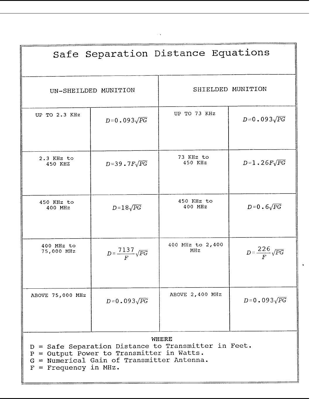
Table 6–4 (PAGE 1)
Safe separation distance equations
84 DA PAM 385–64 • 28 November 1997
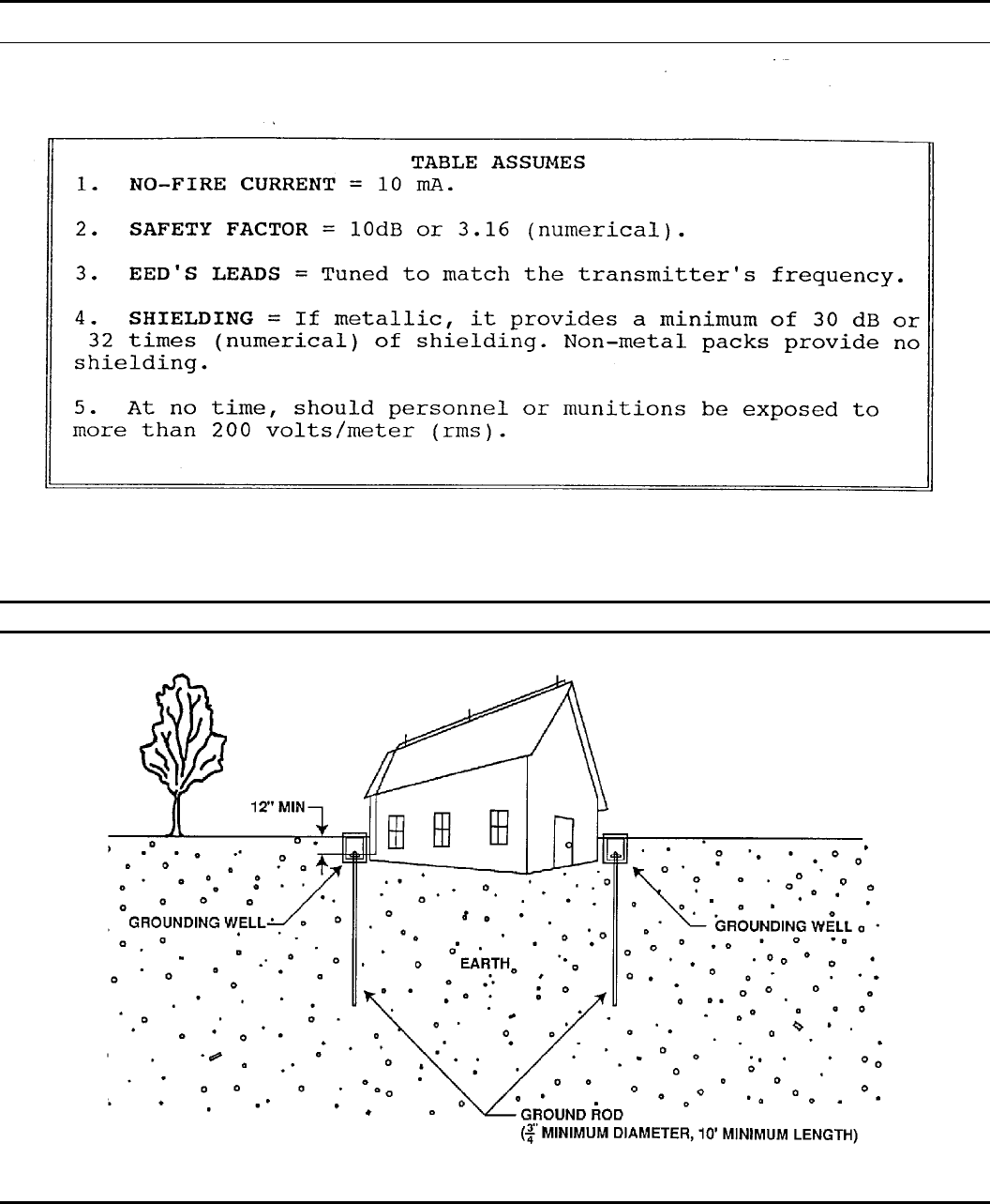
Table 6–4 (PAGE 2)
Safe separation distance equations
Figure 6-1. Typical Ground Rod Installation
85DA PAM 385–64 • 28 November 1997
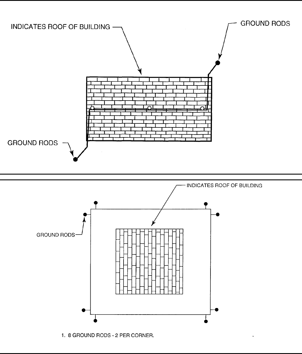
Figure 6-2. Typical multiple ground rod installation
Figure 6-3. Typical ground loop installation
86 DA PAM 385–64 • 28 November 1997
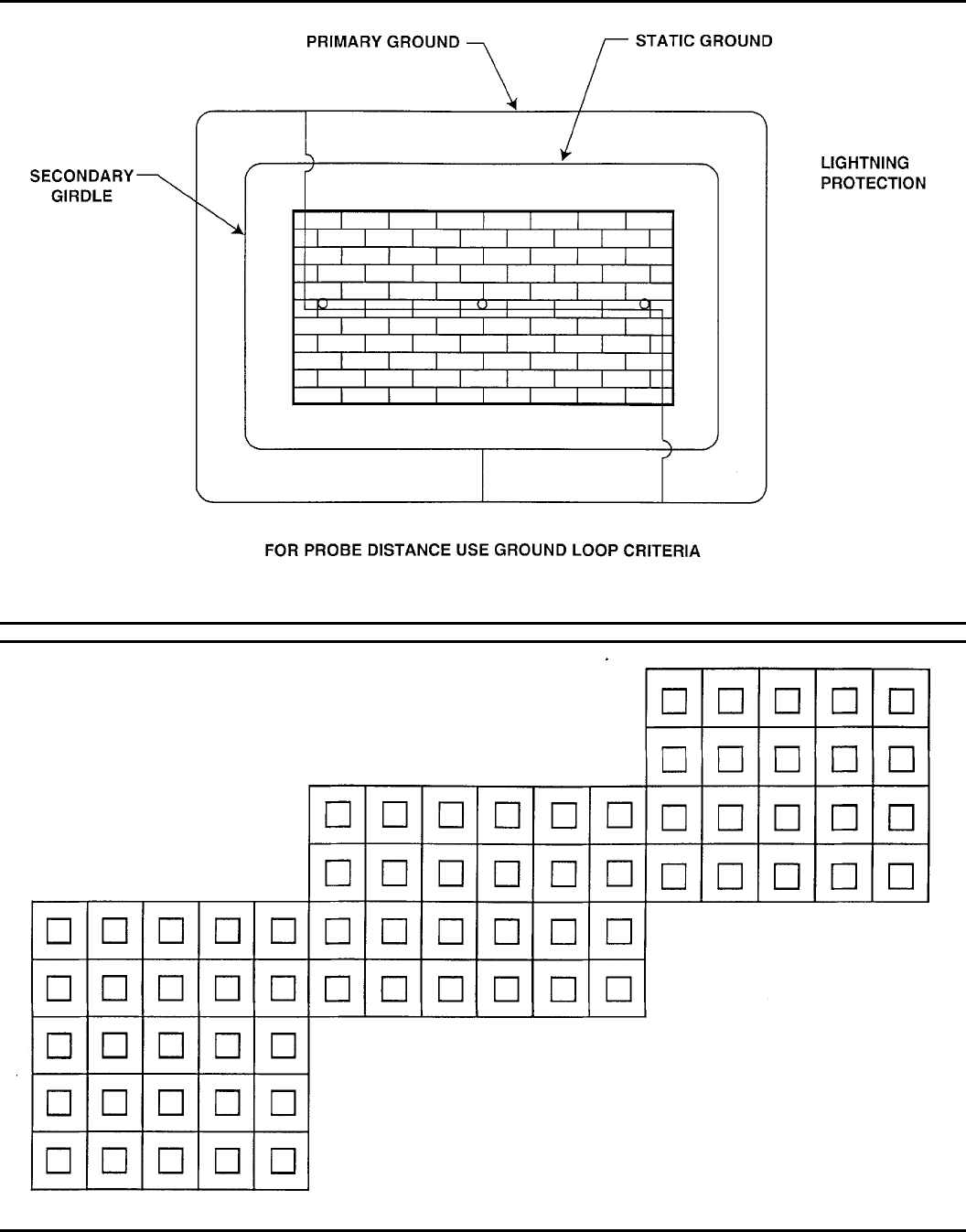
Figure 6-4. U.S. Navy designed earth electrode subsystem
Figure 6-5. Typical grid installation
87DA PAM 385–64 • 28 November 1997
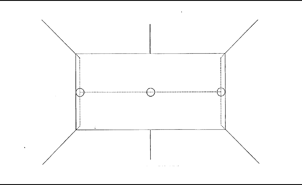
Figure 6-6. Typical radial installation
88 DA PAM 385–64 • 28 November 1997
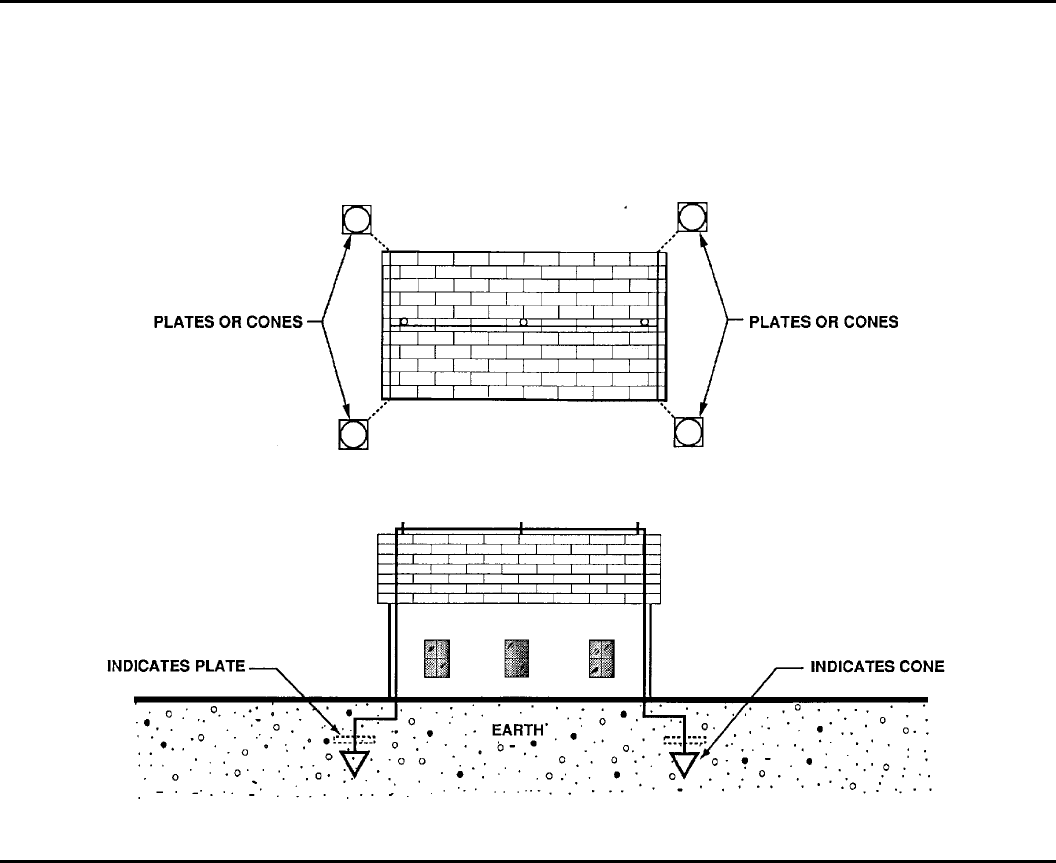
Figure 6-7. Typical buried plates or cones installation
Chapter 7
Transportation
Section I
General requirements
7–1. General information
Shipments of Army explosives and other dangerous articles by mili-
tary conveyances are governed by AR 385–64, this pamphlet, other
referenced military publications, and, outside the United States, host
country regulations. Shipments of military explosives and other dan-
gerous articles are governed by DOT regulations and AR 55–355 in
the United States and by host country regulations outside the United
States. In the absence of host country hazardous materials transpor-
tation regulations, AR 385–64 and this pamphlet apply to move-
ments of ammunition and explosives.
7–2. Certification of personnel involved with
transportation
All personnel involved with the classification, preparation of items
and/or bills of lading, inspection of vehicles and/or shipments, load-
ing or unloading of carriers, driving, or other duties that directly
involve the transportation of ammunition or explosives require train-
i n g a n d c e r t i f i c a t i o n i n a c c o r d a n c e w i t h A R 5 5 – 3 5 5 a n d D O T
regulations.
7–3. Hazard classification
a. All ammunition or explosive items require a final or interim
hazard classification before shipment. The Joint Hazard Classifica-
tion System (JHCS) shall be used as the source for all DOD final
hazard classified items.
b. Items without a final hazard classification must have an in-
terim hazard classification assigned before shipment. The develop-
ing major command normally issues an interim classification for
that item. The interim classification can be signed only by personnel
delegated that authority. It may also be issued by USATCES as
necessary. A copy of all interim hazard classifications must be
forwarded to the DDESB. The following is a list of items requiring
an interim hazard classification before shipment:
(1) Developmental or test items.
(2) Standard items that have been modified.
(3) Ammunition items of foreign manufacture. (See chap 15 for
rules governing captured ammunition.)
7–4. Preparation for shipment
a. Once a requirement for an ammunition shipment is identified,
a p e r s o n t r a i n e d a n d c e r t i f i e d i n a c c o r d a n c e w i t h A R 5 5 – 3 5 5
verifies the hazard classification of the explosives item. This person
89DA PAM 385–64 • 28 November 1997
then provides the following minimum information to the transporta-
tion officer:
(1) Proper shipping name.
(2) DOT hazard class.
(3) DOT labels required.
(4) DOT markings.
(5) DOD hazard class and division.
(6) DOD storage compatibility group.
(7) UNO number.
b. TB 9–1300–385 will be checked for suspensions/restrictions
before offering an ammunition/explosive item for shipment.
7–5. Compatibility of explosives in transportation
a. The Army storage chart, (Table 4–3), and DOT transportation
compatibility chart of CFR 49 differ. For example the Army storage
compatibility chart allows more combinations by using the ’Z’ stor-
age criteria in Table 4–3. The DOT Highway, Rail and Sea compati-
bility tables do not have ’Z’ compatibility. Additionally, the Army
compatibility chart allows group ’N’ to be stored with groups ’B,’
’F,’ and ’G.’ These combinations are not authorized for transporta-
tion by the DOT.
b. When ammunition, in either commercial or military convey-
ance, is to be transported along or across roads accessible to the
public, DOT compatibility rules shall apply.
c. When ammunition is transported along or across roads that are
not accessible to the public or roads that are clearly posted as
prohibited to the public, ammunition may be transported according
to the Army storage compatibility chart (Table 4–3). Blasting caps
or detonators will not be transported with high explosives unless
they are packed in an MK 663 MOD 0 container or equivalent
container. Additionally, note 7 to Table 4–3 is not authorized for
transportation.
d. When ammunition is transported in the training area on the
installation, by troops on a training exercise using tactical vehicles,
the vehicles may transport a mix of ammunition similar to that the
vehicles would carry in combat, provided the vehicles do not cross
or move along a route accessible to the general public. See section
IV of chapter 14 for additional details.
e. Incompatible loads may be transported on public roads during
times of war, contingency operations (not contingency exercises) or
declared national emergencies when DOT Exemption 3498 has been
i n v o k e d a n d t h e s h i p p e r c o m p l i e s w i t h a l l p r o v i s i o n s o f t h a t
exemption.
Section II
Motor Vehicles
7–6. Vehicle general safety requirements
a. Government-owned motor vehicles used to transport hazardous
materials must be inspected frequently by a qualified person to see
that mechanical condition and safety devices are in good working
order. Periodic inspections of such vehicles will be documented
using a DD Form 626, Motor Vehicle Inspection, or a similar local
form.
b. Operators must conduct a daily inspection to determine that—
(1) Fire extinguishers are serviceable and of proper (10–BC or
greater) rating. Extinguishers must have an intact inspection seal or
a gage to verify that the extinguisher is full.
(2) Electric wiring is in good condition and properly attached.
(3) Fuel tank and piping are secure and not leaking.
(4) Brakes, steering, and other equipment are in good condition.
( 5 ) T h e e x h a u s t s y s t e m i s n o t e x p o s e d t o a c c u m u l a t i o n s o f
grease, oil, gasoline, or other fuels and has ample clearance from
fuel lines and other combustible materials.
c. All lifting devices on vehicles used in explosives operations
will have a serviceable mechanism designed to prevent the sudden
dropping of the load if power fails.
d. All ammunition or explosives loaded on vehicles will be se-
cure and stable before movement. Additionally, ammunition or ex-
plosives will be blocked and braced in accordance with approved
drawings.
e. Placarding of explosives-laden vehicles gives firefighters an
idea of the hazards that a vehicle contains. All vehicles hauling
ammunition and/or explosives for the Army within the United States
require proper DOT placards for offpost movement. Host country
requirements for placarding will be followed outside the United
States. Ammunition or explosives shipments that remain onpost may
be placarded with the DOT placards, host country bilingual placards
(outside the United States) or fire symbols detailed in this pamphlet,
chapter 3. If the Army installation is an open post, DOT placards
will be used in the United States.
7–7. Inbound motor shipment of ammunition and
explosives
a. Inbound motor vehicles loaded with explosives, ammunition,
or other hazardous material will be inspected by a competent person
at a designated inspection station in accordance with AR 55–355
using DD Form 626 (DD Form 626 is not required for HD 1.4
shipments). The inspection station will be far from hazardous and
populated areas.
b. When inspection reveals that an incoming tractor or trailer is
in an unsatisfactory condition, the risk associated with the defect
will be assessed.
(1) Under no circumstances will a tractor or trailer be allowed in
the ammunition area with a defect which could endanger the area or
the load.
(2) When a commercial truck is not allowed to enter the ammuni-
tion area, consider unloading it at the truck inspection station. If no
other option is available, the tractor will be disconnected from the
trailer and the tractor will be sent off-post for repairs. In this case,
the installation will provide security for the trailer.
(3) The drivers or repairmen hired by the drivers will repair the
trailer. No repairs which use a flame or spark producing device will
be made to an explosives-laden trailer.
(4) In all cases, defective equipment on inbound shipments will
be noted on the DD Form 626 and a copy provided to the transpor-
tation officer.
(5) At no time will an explosives-laden truck known to be defec-
tive be allowed to leave an Army installation.
(6) Seals on an inbound shipment will be checked against the
numbers on the shipment paperwork. If the seal numbers do not
agree or are missing, the shipment may be considered a suspect
shipment. Suspect shipments will be taken to a remote location and
thoroughly inspected for suspicious wires or packages on the exte-
rior of the vehicle before opening the cargo compartment. If such
wires or packages are found, no one will attempt to open the cargo
compartment and the commander, security, and safety organizations
will be notified immediately.
c. When explosives-laden vehicles cannot be dispatched to un-
loading points immediately, they must be moved to a holding yard
or area. The holding yard or area must be sited in accord with the
provisions of chapter 8.
7–8. Outbound motor vehicle shipments of explosives
a. All motor vehicles which will be carrying DOT Class 1.1, 1.2
or 1.3 explosives must be inspected using a DD Form 626. Deficient
equipment will not be used.
b. When a commercial vehicle fails an inspection using a DD
Form 626, a copy of the inspection will be provided to the transpor-
tation officer and the procedures in AR 55–355 will be followed.
c. Shipments of only DOT Class 1.4, 1.5, or 1.6 explosives do
not require an inspection using a DD Form 626.
d . L o a d i n g m e t h o d s p r e s c r i b e d b y A r m y M a t e r i a l C o m m a n d
(AMC) drawings will be followed for the loading and bracing of
motor vehicle shipments of military explosives and ammunition.
The packages will be placed in position without excessive or violent
force.
90 DA PAM 385–64 • 28 November 1997
e. All Government trucks transporting any DOT class of explo-
sives (both onpost and offpost) will be equipped with two portable
fire extinguishers rated class 10BC or greater. It is recommended
that these two fire extinguishers be rated 2A:10B:C to enable users
to fight a class “A” fire. One must be CO2 or dry chemical, if
c h e m i c a l m u n i t i o n s a r e b e i n g t r a n s p o r t e d . C o m m e r c i a l t r u c k s
transporting explosives for the Army are required to have only one
10BC or greater rated fire extinguisher. Crews loading and unload-
ing vehicles carrying or about to carry ammunition or explosives
must have two 10BC or greater fire extinguishers available as re-
quired by paragraph 3–7j(4) of this pamphlet.
f. Before motor vehicles loaded with ammunition and/or explo-
sives leave an installation, drivers will be given hazardous materials
response information. Commercial drivers will have the bills of
lading annotated with the appropriate guide number from DOT
Emergency Response Guidebook (ERG). Military drivers will use
t h e D D F o r m 8 3 6 f o r h a z a r d o u s m a t e r i a l s i n f o r m a t i o n
dissemination.
g. See AR 190–11 for instructions on security of vehicles carry-
ing ammunition and/or explosives.
7–9. Safe haven for explosive shipments
I n s t a l l a t i o n s w i t h a s a f e h a v e n c a p a b i l i t y a s i d e n t i f i e d i n A R
55–355, Volume 2, may grant safe haven to explosive shipments
w h e n r e q u e s t e d b y M i l i t a r y T r a f f i c M a n a g e m e n t C o m m a n d
(MTMC) through the installation commander. Drivers who request
safe haven from the guard at the installation gate will be advised to
contact their company and have the company request safe haven
through MTMC. If safe haven is granted, the driver is still accounta-
ble for the security of the load. Installations may grant safe haven in
other situations at the discretion of the installation commander. If
safe haven is not granted, installations will consider allowing an
explosives-laden truck to rest at a secure area that meets Q-D crite-
ria, but installations will not assume security responsibility for the
shipment unless directed to do so by the installation commander.
7–10. On-post explosive movements
a. Cargo-type trucks and truck-tractor drawn semitrailer vans are
best for transporting ammunition or explosives.
b. Equipment used for transporting ammunition or explosives
must meet the following minimum requirements:
(1) Special precautions must be taken to avoid automotive ex-
hausts igniting material.
(2) The lighting system must be in good working condition. Bat-
teries and wiring will be located so that they will not come into
contact with containers of explosives, ammunition, or other hazard-
ous material. If exposed explosives or flammable vapors are encoun-
tered in a vehicle, only approved portable lights are permitted (listed
by a nationally recognized organization for the specific hazardous
locations defined by NFPA 500).
(3) The interior of the cargo body will have all exposed ferrous
metal covered with nonsparking material when transporting ammu-
nition or explosives not packaged for shipment in accordance with
DOT specifications.
(4) Open-body vehicles, other than flatbed trailer-types used to
transport large items such as rockets or missiles must have sides that
are strongly constructed and securely fastened so that the items are
safely retained.
(5) When a top is required, it will be of a noncombustible or
flame-proof material. Tarpaulins used for covering explosives will
be secured by rope or tiedowns. Nails will not be used to fasten
protective tarpaulins.
c. Ammunition will be blocked and braced or secured with suita-
ble tie-down straps to prevent movement.
7–11. Passengers in or on Government vehicles
transporting explosives
a. Except as noted below, passengers may not ride in a vehicle
transporting ammunition or explosives.
b. Under certain conditions, as approved in a standard operating
procedure, the minimum essential personnel and limited quantities
of HDs (04)1.2, 1.3 and 1.4 ammunition and/or explosives may be
transported together in the cargo portion of vehicles. Examples are
vehicles used by the military police (MP) in providing security or
by EOD personnel performing their mission. These conditions are as
follows:
(1) Explosives are packed separately from other items and pa-
cked in closed, clearly identified metal or wooden containers prop-
e r l y s e c u r e d o r s a n d b a g g e d i n t h e v e h i c l e b o d y t o p r e v e n t
movement.
(2) Seats are provided for all passengers.
(3) Smoking is not allowed in the vehicle.
(4) The vehicle cannot be left unattended.
c. Troops and ammunition may be transported in the same vehi-
cle during training exercises when the vehicle is the prime mover
for a weapon system engaged in the tactical portion of the exercise,
troops being transported are assigned to the weapon system being
moved, and the vehicle is organic to the unit.
d. Mission essential passengers may ride in the passenger com-
partments of vehicles transporting explosives if they can be safely
seated.
e. Explosives will not be transported in a passenger compartment
of a vehicle except in cases involving limited quantities (no more
than two full outerpacks of small arms ammunition with nonex-
plosive bullets). The small arms ammunition must be in closed
containers which are properly secured in the vehicle, and seats must
be available for all personnel. Using privately owned vehicles for
such purposes is prohibited, except for the Reserve Officer Training
Corps (ROTC) and Marksmanship Programs when a Government-
owned vehicle is not available. It is permissible to transport limited
quantities of HD 1.4 small arms ammunition in the trunk of sedan-
type Government-owned vehicles or in cargo compartments of Gov-
ernment-owned van-type vehicles.
Section III
Rail, Air, and Water Transport
7–12. Railroad transportation
a. Railcar inspection
(1) A car must not be loaded with any DOT Class 1.1 or 1.2
explosives unless it has been thoroughly inspected by a qualified
individual, employed by the railroad. This individual must certify
that the railcar conforms to the requirements established in AR
55–355.
(2) Shipments of DOT Class 1.3 explosives may be loaded in a
closed car or container car which is in good condition and which
sparks cannot enter.
(3) Selections of cars for shipment of DOT classes 1.4, 1.5, or
1.6 will be done in accordance with 49 CFR selection criteria for
1.4 (Sec 174.115).
b. Transportation of hazardous materials. In addition to the re-
quirements of other parts of this section, the following rules will be
followed:
(1) When cars containing explosives or other hazardous materials
are received at the installation or held in yards, precautions must be
taken to prevent accidents, particularly at night. These precautions
must include provisions for quickly removing and isolating the cars
in case of fire.
( 2 ) C a r s l o a d e d w i t h h a z a r d o u s m a t e r i a l s m u s t b e p r o p e r l y
loaded and placarded before being offered for transportion. The
carrying of hazardous materials on locomotives or other self-pro-
pelled rail vehicles is prohibited.
(3) Before cars are moved by a locomotive, the air brake hose
must be coupled and tested to assure that the air brakes are in
proper working condition and the car doors will be closed.
(4) Empty cars will not be removed from warehouses, magazines,
building, or loading docks until all warning placards have been
removed.
(5) Special care must be taken to avoid rough handling of cars.
Cars must not be cut off while in motion and must be coupled
carefully to avoid unnecessary shocks. Other cars must not be cut
91DA PAM 385–64 • 28 November 1997
off and allowed to strike a car containing explosives. Cars must be
so placed in yards or on sidings that they will be subject to a
minimum of handling and can be readily removed from danger of
fire. Such cars must not be placed under bridges; in or alongside
passenger sheds of a station; and, where avoidable, engines on
parallel tracks will not be allowed to stand opposite or near them.
(6) “Dropping,” “humping,” “kicking,” or the use of the flying
switch is prohibited.
(7) Adequate measures such as guarding, patrolling, and safety
inspecting must be provided at all times. All such activities will be
under positive administrative controls.
(8) Fire symbols or DOT placards will be placed on each railroad
car while transporting explosives or ammunition within an installa-
tion to provide quick identification of the potential hazard if fire
breaks out.
c. Car inspection. Car inspections will be conducted in accord-
ance with AR 55–355.
d. Car certificates. Car certificates will be used in accordance
with AR 55–355.
e. Leaking packages. Constant alertness must be maintained to
detect hazardous materials leaking from faulty packages either by
sight or through characteristic odors. Leaking packages will be re-
moved from cases and repaired. If artificial light is necessary, only
electric lights approved for the hazard involved will be used. All
unnecessary movement of a leaking package discovered in transit
must cease until the unsafe condition is remedied.
f. Car loading of items containing ammunition and explosives.
Loading methods prescribed by AMC drawings (DA Pam 75–5
contains a list of AMC drawings and ordering instructions.) will be
followed for the loading and bracing of railway car shipments of
military explosives and ammunition. If no drawing is available or
yet developed, Bureau of Explosives (BOE) Pamphlets 6 and 6C
will be used. The packages will be placed in position without exces-
sive or violent force.
g. Tools for loading and unloading railcars. With reasonable
care, steel tools may be used inside cars if explosives likely to ignite
are not exposed. When explosives subject to initiation are exposed,
sparkproof-tools will be used.
h. Sealing cars containing explosives and ammunition. In addi-
tion to any other seals which may be used, cars containing explo-
sives or ammunition will be secured. A cable seal lock plus an
upper rail lock will be used to secure car doors . Serial numbers of
seals will be placed on the Government bill of lading (GBL).
i. Inspection of cars before unloading.
(1) A qualified person must inspect railcars containing explosives
and ammunition entering an installation. This inspection includes
examining the outside and underside of each car for damage, to
detect unauthorized and suspicious items, and to check the correct-
ness of individual car numbers and seal numbers against bills of
lading. When the probability of sabotage is remote, such inspections
may be accomplished from ground level without using an inspection
pit to discover unsafe structural mechanical deficiencies of the car.
During periods of emergency when sabotage may be attempted, and
also to aid in the rapid inspection and movement of cars, an inspec-
tion pit will be provided.
(2) Cars of ammunition or explosives on which foreign and sus-
picious articles have been secreted or attached outside or underneath
the car, or cars which show a defect that might affect the installation
or contents of the car, will be removed to the suspect siding for
additional inspection.
(3) Cars which satisfactorily pass the inspection outlined above
may be considered reasonably safe, but care must be exercised in
breaking car seals and opening car doors because of possible dam-
age or shifting lading, leaking containers, and so forth. When the Q-
D standards for classification yards are met, cars may be opened for
inspection in the classification yard. Otherwise, interior inspection
will be accomplished after the cars have been spotted at the unload-
ing point.
j. Inspection of cars after unloading. Cars in which explosives or
ammunition are received will be inspected after unloading to see
that they are clean and free from loose explosives or other flamma-
ble materials and that the placards and car certificates are removed.
Explosives sweepings must be destroyed.
k. Damaged shipment. Any shipment received in a damaged con-
dition because of inadequate or improper blocking and bracing or
failure to load in accordance with appropriate AMC drawings will
be reported on SF 361 in accordance with AR 55–38. If the damage
was due to improper preservation, packaging, or packing, SF 364
will be prepared in accordance with AR 735–11–2.
l. Marking railcars with blue flags or signals. Blue flags or
signals will be placed at both ends of a car or group of cars when
personnel are working in, on, or under the cars. Cars marked in this
manner will not be coupled to or moved. The supervisor or foreman
in charge of the personnel loading or unloading the cars will place
and remove the blue flag or signal. Train crews will be informed of
the use of blue flags or signals. Exceptions are as follows:
(1) Flags are not required when flat cars are involved and the
presence of a working party is clearly evident.
(2) Flags or signals may be omitted from the end of a car located
against or toward a dead end spur. This also applies to a loading
ramp where no other railcars can approach from that direction.
m . L o o p i n g r a i l r o a d l i n e s . R a i l r o a d s l i n e s s e r v i n g e x p l o s i v e s
areas will be looped to give at least two ways to exit. Looping of
railroad lines may not be required if a local hazard analysis indi-
cates operations can be conducted safely.
n. Right-of-way fire hazard. Grass and brush along railroad right-
of-way which present a fire hazard will be controlled.
7–13. Air transportation
Carrying ammunition, explosives, and other hazardous materials on
civil aircraft is regulated by the DOT. Criteria for preparing and
carrying hazardous materials on military aircraft is contained in TM
38–250, DOT regulations, and AR 95–27.
a. Military aircraft operating regulations.
(1) If an aircraft carrying hazardous materials makes a landing,
forced or otherwise, and only minor repairs or refueling are neces-
sary, the cargo need not be unloaded. Repairs or refueling will be
accomplished at a location separated from dissimilar exposives and
other aircraft by the appropriate IBD for the cargo aboard. For
major repairs, the plane will be unloaded and the cargo stored in
accordance with Q-D requirements. Appropriate protection will be
afforded the cargo during inclement weather.
(2) When an explosive laden aircraft is parked in a designated,
restricted, and posted explosives parking or loading and unloading
area, fire symbols will be posted at all normal approaches to the
designated area. Otherwise, fire symbols will be placed at the nose,
tail, and each side of the aircraft. Where the height of the aircraft
does not readily permit attaching the fire symbols to the aircraft, the
fire symbols may be mounted on stands approximately 1.5 meters (5
feet) in height, positioned adjacent to the aircraft where they are
visible at long range. At other DOD installations and at non-DOD
installations, placarding will be in accordance with the requirements
of TM 38–250 and the requirements of the host installation.
b. Permissible air shipments. Ammunition and/or explosives that
may be shipped by civil air are identified in 49 CFR. Ammunition
and/or explosives that may be shipped by military aircraft are identi-
fied in TM 38–250.
c. Loading and unloading aircraft.
(1) Before an aircraft can be loaded or unloaded with ammuni-
tion and/or explosives, it must be electrically grounded so that the
resistance to ground does not exceed 10,000 ohms.
(2) When loading or unloading aircraft containing ammunition or
explosives, work crews will display placards and fire symbols.
(3) Loading and unloading will be done in accordance with the
Q-D requirements of chapter 5.
(4) All ignition switches must be in the OFF position.
(5) Front and rear wheel will be chocked.
(6) The loadmaster will direct the loading of military aircraft.
N o n m i l i t a r y a i r c r a f t w i l l b e l o a d e d t o c o m p l y w i t h c i v i l a i r
regulations.
(7) At nonmilitary airfields used by U.S. Army flight activities,
92 DA PAM 385–64 • 28 November 1997
the host normally provides aircraft rescue and fire protection. If this
protection does not meet the standards established in AR 420–90,
Army fire department personnel and/or auxiliary firefighters will be
used during Army flight activities, including loading and unloading
of explosives.
(8) As a minimum, four portable fire extinguishers will be availa-
ble for firefighting during all loading and unloading of explosives.
Recommended extinguishers are as follows:
(a) Two each pressurized water-type extinguishers using Aque-
ous Film-Forming Foam (AFFF) liquid concentrate, 6 percent (MIL-
F–24385); and,
(b) Two each Potassium Bicarbonate Base Dry chemical extin-
guishers, 13.6 kilograms (30 pounds) capacity.
d. Damaged shipments. Air shipments of explosives or ammuni-
tion received in a damaged condition or not loaded in accordance
with applicable requirements will be reported on SF 361 in accord-
ance with AR 55–38.
e. Containers. Containers of explosives in aircraft will not be
opened or repaired.
7–14. Water transportation
a. Transporting explosives and/or ammunition on waters under
U.S. jurisdiction and in vessels engaged in commercial service is
regulated by the U.S. Coast Guard (USCG). Shipments overseas
will be made in accordance with the regulations of the carrier, the
USCG, International Maritime Dangerous Goods Code, or the De-
partment of the Army (See TM 55–607.). If the travel route requires
passing under any bridges, obtain prior authorization from the re-
sponsible agency.
b. Damaged shipments or shipments not stowed in accordance
with regulations when received will be reported on SF 361 in ac-
cordance with AR 55–38. If damage was due to improper preserva-
tion, packaging, or packing, SF 364 will be prepared in accordance
with AR 735–11–2.
c. Containers of explosives and ammunition will not be opened
or repaired on board a vessel.
d. Vessels in which explosives or ammunition are received will
be inspected after unloading to see that they are clean and free from
loose explosives or other flammable materials and that warning
placards, and so forth are removed. Explosives sweepings will be
destroyed.
Chapter 8
Safety Site Planning, Construction, and Utilities
Section I
Explosives/Toxic Chemical Safety Site Plans
8–1. Explosives/Toxic Chemical Safety Site Plan
Submittals
An explosives/toxic chemical safety site plan describes in text and
graphics the relationship among proposed PES/toxic chemical sites,
related facilities, and unrelated personnel and facilities. It also con-
tains a description of the construction specifications for the facilities
and the specifications and placement of required auxiliary equip-
ment such as dividing walls, lightning protection systems, or utility
service lines or conduits. It is submitted for DDESB approval of the
particulars of the plan from an explosives safety perspective as
required in DOD regulations.
a. DDESB approval of these safety site plans is required when-
ever an Army element:
( 1 ) E s t a b l i s h e s a n e w p o t e n t i a l e x p l o s i v e s o r t o x i c c h e m i c a l
agent site which does or does not require construction. Examples of
facilities which require submittals are those locations where ammu-
nition, explosives, or toxic chemicals are developed, manufactured,
tested, stored, repaired, modified, or destroyed.
(2) Modifies an existing sited facility by either increasing the
hazard present or changing the facility’s use to effect adversely its
quantity distance or chemical interrelationships. Examples of this
criteria are changes to the hazard classification of items present,
initiation of dissimilar activities, increased net explosives weight,
increased toxic chemical agent hazard, or introduction of explosives
into a previously exclusively toxic chemical site.
(3) Plans major modification of the construction features of an
existing PES.
(4) Establishes a nonammunition ES in the vicinity of a PES
which requires a specified separation from the existing or planned
PES.
(5) Determines that no DDESB approved explosives safety site
plan exists for an existing ammunition, explosives, or toxic chemical
site.
(6) Redesignates a formerly temporary site as a permanent am-
munition or toxic chemical site.
(7) Establishes a site which will be used repeatedly, although not
continuously as an ammunition or toxic chemical site (other than as
designated in b(1) below on training ranges).
(8) Removes restrictions on ammunition or toxic chemical opera-
tions which cause new exposure of previously unexposed sites to
blast, fire, fragment, or toxic hazards.
b. An explosives safety site plan is not required for facilities or
unimproved locations as follows:
(1) On training ranges where ammunition is present only for
distribution to soldiers, crews, or vehicles in training. Storing am-
munition or explosives on the range requires an explosives safety
site plan submittal.
(2) Where ammunition or explosives will not be present and the
location is beyond the inhabited building distance of existing or
planned PESs.
(3) Where the proposed location is beyond the 1 percent lethality
distance of a toxic chemical site. See DA PAM 385–61.
(4) Where the proposed site is beyond the greater of the explo-
sive and the toxic chemical criteria above if both explosives and
toxic chemicals are present.
(5) Where this pamphlet states that the proposed facility may be
located without regard to quantity distance considerations.
(6) Where the proposed siting does not comply with all Army/
DOD siting criteria. See AR 385–64, Chapter 7, for criteria for
obtaining a Certificate of Compelling Reasons in this situation.
c. These provisions for submitting plans and specifications do not
apply to the following:
(1) Temporary and emergency facilities to be located in areas in
which the U.S. Army is engaged in:
(a) Combat operations.
(b) Contingency operations (hostilities may be imminent).
(c) Temporary (not to exceed 6 months) support of a foreign
government; for example, Joint Chiefs of Staff exercise or DA
exercise.
(2) Minor modifications to or rehabilitation of existing facilities
necessary to:
(a) Support an emergency requirement for a limited time, not to
exceed 30 days.
(b) Provide operating or maintenance line modifications due to
manufacturing process changes or adapting a line to other end items
where modifications do not introduce additional hazards or increase
the net explosives capacity or chemical agent hazard for which the
facility was designed or sited.
d. When the Army element is uncertain if an explosives or toxic
chemical safety site plan is required, the MACOM of the host
installation will make the determination.
e. Net explosives weight limits listed in explosives safety site
plans will be determined based on the activity to take place at the
site and the separation distances available.
(1) Normally locate storage PESs to achieve the maximum net
explosives weight of each hazard class/division (1.1, 1.2, 1.3,1.4,
and so forth), material which may be present at the proposed site,
based on the separations available.
(2) NEW limitations at operating sites should consider the quan-
tities and types of ammunition or explosives required to conduct the
intended operations and the separations available.
93DA PAM 385–64 • 28 November 1997
(3) Locations reserved for future sites should be considered when
determining or reviewing proposed site locations.
(4) MACOM approval authorities may provide further limitations
through correspondence conveying DDESB approvals to the submit-
ter or through the licensing process.
8–2. Explosives safety site plan contents
a. Explosives safety site plans normally consist of two time-
phased submissions.
(1) The intended user organization submits a preliminary site
plan package before funds are committed to the project. It provides
intended uses of the facility, its location, and the spatial relationship
of PESs and ESs and as many other details as are known about the
siting. It approves the physical location of the projected facility with
respect to quantity distance criteria. Furnish a statement that the
proposed siting has been reconciled with installation master plans by
the facility engineering activity and the Installation Planning Board
as required by AR 210–20, AR 415–20, and AR 415–15. This
provision does not preclude contracting-out the preparation of the
preliminary site plan package.
(2) A request for final safety approval is also submitted by the
intended user organization. It gains approval of the construction
techniques and the specifications of installed and auxiliary equip-
ment and verifies that the location has not been changed. It should
be submitted for DDESB approval when the design phase of the
project is approximately 60 percent complete. Actual construction of
a new facility, modification of an existing facility, or use of an
unimproved site cannot occur until DDESB final safety approval is
received at the installation.
(3) Explosives safety site plans for simple situations and for pre-
existing sites which do not appear to have an explosives safety site
plan approval may be accomplished in only one submission so long
as all information requirements for a final safety submission are
met. Submission time frames of (2) above still apply to simple
submissions.
b. Each submission consists of two parts.
(1) A cover memorandum describing the projected activities and
associated material most easily covered by text.
(2) A series of enclosures providing the spatial layout of the
project and other site planning requirements more easily stated in
drawings, maps, or tables.
8–3. Review and approval of explosives safety site plans
a. Explosives safety site plan submissions (both preliminary and
final safety submissions) for DDESB review and approval will be
submitted through command safety channels of the host MACOM
approval authority to the Director, U.S. Army Technical Center for
Explosives Safety. USATCES will perform Army level review and
approval functions. MACOMS will formally designate the internal
review headquarters/agencies within their commands. Two copies of
the entire submission must be provided to USATCES.
(1) When a tenant organization is proposing action which re-
quires explosives safety site plan review and approval, the tenant
organization’s review and approval chain, through MACOM ap-
proval level, will approve the explosives safety site plan before
submitting the plan to the host installation’s explosives safety site
plan review and approval chain and subsequently to USATCES and
DDESB. Alternate review paths, proposed, and concurred in by
concerned MACOMs and approved by USATCES before implemen-
tation, may be used.
(2) When a proposed Army PES risks other-service equipment or
the appropriate explosives safety arcs encumber other-service real
estate, the effected service originator/reviewer level concurrence/
nonconcurrence will be obtained and attached to the submission for
review at the remaining Army review levels. MACOMS will estab-
lish procedures to obtain concurrences at each review level below
the military service level. USATCES will accomplish final Army
coordination with military service level safety offices of the other
services.
b. Each level of review will review the submission with regard to
the technical aspects of explosives safety requirements and provide,
in the form of an endorsement of the submission, a command
recommendation for approval at the next level of review. If the
MACOM approval authority does not recommend approval, the
submission should not be forwarded for Army approval. Any addi-
tional conditions or implementing restrictions attached during the
review phase become part of the original submission.
c. Normally, DDESB makes its decision on properly prepared
and submitted routine submissions within 90 days. MACOM ap-
proval authority must provide the following information when requ-
esting expedited review or approval:
(1) Date reply is required.
(2) Proposed contract award date.
(3) Reason expedited review is required.
(4) Reasons for not forwarding the submission in time for routine
processing.
d. DDESB approvals will be returned to originators through com-
mand channels. The addition of conditions or implementing restric-
t i o n s a t a n y l e v e l w i l l b e c o n s i d e r e d a d i t i o n a l c o n d i t i o n s o f
approval. These may be more restrictive than the DDESB conditions
of approval but may not relax them.
e. Copies of DDESB final decisions and the complete submittals
on which they are based will be maintained at the USATCES and,
in the case of approvals, also at the MACOM approval authority and
the installation. These files will be retained permanently. Upon
c l o s u r e o f i n s t a l l a t i o n s , t h e s e f i l e s w i l l b e f o r w a r d e d t o t h e
USATCES with an explanation of circumstances for historical re-
cords. The USATCES will maintain an inventory of Army active
potential explosion sites and historical files of former Army poten-
tial explosion sites.
f. DDESB approval of the final safety submission is required
before inclusion of the project in the proposed budget year authori-
zation or before NATO or host nation approval. MACOMs will
indicate in all DD Forms 1391 (FY, Military Construction Project
DATA (LRS)) submitted to HQDA that either the project is not
subject to these standards or complies with them and indicate the
date and currency of the DDESB approval.
g. Each installation with any potential explosion sites will main-
tain a consolidated map or drawing of all DDESB approved explo-
sives or toxic chemical sites indicating the real estate encumbered
(within the generated inhabited building arcs) by the sitings as well
as the controlling ammunition/explosive/toxic siting generating the
encumbrance. Future uses of these encumbered areas for construc-
tion or personnel presence must conform to the exposures allowed
by AR 385–64 and this pamphlet.
Section II
Construction Considerations
8–4. Construction considerations
The primary objective of this section is to ensure design procedures
and construction techniques used in siting explosives facilities will
provide the desired margin of protection for personnel and valuable
material. The secondary objective is to ensure that explosives facili-
ties and other related facilities are constructed in a way that will
maximize cost-effectiveness in both planning and facility utilization.
a . U s e T M 5 – 1 3 0 0 i n s e l e c t i n g a n d d e s i g n i n g e x p l o s i v e s
facilities.
b. By using the standards and guidelines provided in the TM
5–1300, organizations can ensure that both of the above objectives
are met. Managers must carefully evaluate their need for explosives
facilities and ensure that construction techniques match mission
requirements.
8–5. Buildings
a. Earth covered magazines are preferred for storing explosives.
Army construction should follow standard definitive drawings un-
less operational requirements dictate special structures. A list of
currently approved drawings is in Appendix G.
(1) Standard earth covered magazines. These magazines are ap-
proved for all quantities of explosives up to 500,000 pounds (227,
94 DA PAM 385–64 • 28 November 1997
273 kg) net explosive weight (NEW). The following paragraphs list
approved magazines which are still acceptable for use as standard
magazines.
(a) Reinforced concrete, arch-type, earth covered magazines con-
structed with strength equivalent to or more than the requirements of
the Office of Chief of Engineers (OCE), drawings Nos. 652–686
through 652–693, 27 December 1941, as revised 14 March 1942,
3 3 – 1 5 – 0 6 , 3 3 – 1 5 – 5 8 ( a t o m i c b l a s t r e s i s t a n t ) , 3 3 – 1 5 – 6 1 , a n d
33–15–74. For new construction, use drawing No. 33–15–74.
( b ) M a g a z i n e s c o n s t r u c t e d a c c o r d i n g t o N a v y d r a w i n g N o s .
357428 through 347430, 9 August 1944, and modified in accord-
ance with naval facility (NAVFAC) drawing No. 626739, 19 March
1954; and NAVFAC drawing Nos. 627954 through 627957, 764597,
658384 through 658388; 724368, 751861, 764596, 793746, and
793747.
(c) Box-type A magazines constructed according to NAVFAC
drawing Nos. 1404000 through 1404007 and box-type B magazines
constructed according to NAVFAC drawing Nos. 1404018 through
1404025. Box-type C magazines constructed according to NAVFAC
drawing Nos. 1404430 through 1404440, dated 20 September 1985.
Box-type D magazines constructed according to NAVFAC drawings
1404464 through 1404478, dated 20 September 1985. Box-type E
m a g a z i n e s c o n s t r u c t e d a c c o r d i n g t o N A V F A C d r a w i n g N o s .
1404523 through 1404535, dated 23 April 1987. Box-type F maga-
zines constructed according to NAVFAC drawing Nos. 1404541
through 1404555, dated 23 April 1987.
(d) Earth covered, corrugated steel, arch-type magazines at least
equivalent in strength to those shown on Army OCE drawing Nos.
A W 3 3 – 1 5 – 6 3 , 5 M a r c h 1 9 6 3 ; A W 3 3 – 1 5 – 6 4 , 1 0 M a y 1 9 6 3 ;
3 3 – 1 5 – 6 5 , 1 0 J a n u a r y 1 9 6 3 ; a n d N A V F A C d r a w i n g N o s .
1059128–30, 1059132, 1069906, and 1355460–61. OCE drawing
No. 33–15–73 has been rescinded and will not be used for new
construction, however, existing magazines are considered standard.
For new construction of large magazines of this type, use the earth
covered steel, semicircular-arch magazine design shown on Army
OCE drawing No. 421–80–01 and for new construction of smaller
magazines of this type, use OCE drawing No. AW 33–15–65.
(e) Earth covered circular composite arch magazine described in
NAVFAC drawing Nos. 1404375 through 1404389, dated 31 Octo-
ber 1985, and the earth covered oval composite arch magazine
described in NAVFAC drawing Nos. 1404390 through 1404398,
dated 31 October 1985.
(2) Nonstandard, earth covered magazines. These magazines are
approved for all quantities of explosives up to 250,000 pounds (113,
636 kg) NEW. They include:
(a) Earth covered magazines constructed with less strength than
the requirements of those described in (1) above.
(b) Magazines constructed in accordance with NAVFAC draw-
ings Nos. 649602 through 649605, 793748, and 803060.
b. Exterior walls and roof coverings should be constructed of
noncombustible materials.
c. Roofs and walls, except for specific containment and protec-
tion purposes, should be as light in weight (weak) as practical. They
should be constructed and supported to allow venting of an internal
explosion with the minimum number of large fragments. Exceptions
are made where design requirements such as the following must be
met:
(1) Fire walls
(2) Substantial dividing walls
(3) Special roof loadings
(4) External overpressure protection
(5) Specialized manufacturing facilities.
d. Each magazine will have an appropriate means of air circula-
tion or dehumidification.
e. Each magazine will be provided with appropriate means of
lightning protection in accordance with Chapter 12.
8–6. Interior finishes and floors
a. Noncombustible material will be used for interior surfaces of
buildings.
(1) Where hazardous locations (para 6–2) exist, interior surfaces
should also be smooth, free from cracks and crevices, and with
joints taped or sealed.
(2) If painted, the surfaces should be covered with a hard gloss
paint that is easily cleaned. Horizontal ledges which might hold dust
will be avoided or beveled. Cove bases at the junction of the walls
and floor are recommended.
(3) If combustion-supporting materials are necessary in the inte-
rior of an operating building, treat or cover all exposed surfaces
with fire retardant material.
b. Conductive nonsparking floors are required where certain ex-
posed explosives and materials, sensitive (easily detonated or ig-
nited) to the uncontrolled discharge of static electricity, are present.
c. Where washing is required, floors must be able to withstand
repeated applications of hot water or other compatible cleaners.
8–7. Firewalls
Firewalls are designed to limit the spread of fire. They should
extend through the roof and walls of the buildings. If openings are
required, they must be protected as described in the NFPA 80.
8–8. Substantial dividing walls
a. These walls are one way of separating explosives into smaller
groups to minimize the results of an explosion and allow a reduction
in Q-D separation. See Chapter 5 for criteria for the levels of
protection offered by these walls based upon the quantity of explo-
sives present and the design characteristics of the wall.
b. Blast doors which separate explosives working spaces or stor-
age spaces in existing buildings will meet design-definitive drawing
specifications. Such doors should be at least as strong as adjacent
walls (see TM 5–1300 for design factors for new structures). These
doors are not to be installed as a matter of convenience. Blast doors
should be avoided when a continuous reinforced wall would not
interfere unnecessarily with operations.
8–9. Building exits
Exits and doors will conform with Occupational Safety Health Ad-
ministration (OSHA), NFPA 101 and NFPA 80, requirements.
8–10. Safety chutes
Safety chutes will be provided as exits from multistoried, hazardous
locations where rapid egress is vital and not otherwise possible.
8–11. Emergency exits and fire escapes
Use the ANSI Safety Code A156.3, NFPA 101, and NFPA 80 as a
guide in constructing emergency exits and fire escapes. All openings
will be protected as required by NFPA 101.
8–12. Stairways
S t a i r w a y s w i l l c o n f o r m w i t h O S H A r e q u i r e m e n t s . O p e n r i s e r s
should be avoided.
8–13. Fixed ladders
Fixed ladders should conform to the ANSI Safety Code A14.3 and
OSHA Std. 1910.27.
8–14. Platforms, runways, and railings
P l a t f o r m s , r u n w a y s , a n d r a i l i n g s w i l l c o n f o r m w i t h O S H A a n d
NFPA requirements.
8–15. Passageways
If weather-protected passageways (ramps) for communication be-
tween buildings or magazines are constructed, these passageways
should be of noncombustible construction and should be provided
with suitable fire doors to interrupt a fire in its progress through the
passage; these provisions will be applied in new construction. To
prevent funneling of explosion forces, weak sections, openings, and
abrupt changes in direction should be incorporated in design and
construction of passageways between explosives buildings.
95DA PAM 385–64 • 28 November 1997
8–16. Roads, walks, and gates
a. Good all-weather roads should be provided to and within the
explosives areas.
b. There is no mandatory safety requirement for more than one
gate in the fence around an explosives area. Planners determine how
many gates are needed after considering all elements of the situation
(physical security, operations, explosives safety, fire protection, and
so forth). Consideration should be given to providing an alternate
personnel gate for emergency evacuation.
c . R o a d s y s t e m s s e r v i n g g r o u p s o f m a g a z i n e s o r e x p l o s i v e s
buildings will be arranged without dead ends so that motor vehicles
carrying explosives cannot be isolated. To prevent dead ending,
interconnecting roads for magazine service roads need only be pass-
able trails adequate to accommodate the typical vehicles used at the
installation.
d . R o a d s s e r v i n g a s i n g l e m a g a z i n e o r e x p l o s i v e s p r o c e s s i n g
building (including its service facilities) may dead end at the maga-
zine or building. The road system should be designed to eliminate
the need for passing through an intermediate explosives area in
traveling from one area to another.
e. Walkways and roads at the entrances to or between adjacent
operating buildings containing explosives will be hard surfaced or
boardwalks. These walkways and roads should be kept free from
foreign material. Foot brushes, door mats, or scrapers should be
provided at the entrance of each building, except magazines. Special
attention will be given to passageways, walkways, and stairs which
have been subjected to the effects of inclement weather.
8–17. Windows and skylights
a. IBDs do not protect against the hazards of flying glass. Trans-
p a r e n t , n o n s h a t t e r a b l e , s l o w - b u r n i n g p l a s t i c w h i c h i s p r a c t i c a l l y
smokeless may be used as glazing if an explosion could cause injury
from falling or projected glass. For windows glazed with conven-
tional glass, the hazard from falling and projected glass may be
reduced by covering the inside with wire mesh screening.
b. Skylights will not be used in buildings where explosives or
ammunition are processed and should not be used in any buildings
in an explosives area.
8–18. Drains and sumps
When drain lines are used for fluids containing explosives waste,
they must have sumps or basins so that the waste explosives can be
removed.
8–19. Hardware
a. To reduce the risk of accidental ignition by spark, the opera-
tional conditions in any hazardous location must be considered in
the choice and installation of hardware. Certain hazards may be
great enough to warrant using materials that will reduce the possibil-
ity of sparking. Therefore, special precautions must be taken for
hardware having metal components which is used around exposed
explosives.
b. Hardware must be secured firmly in place with locking de-
vices if it might become loose and enter into an explosives mix.
This precaution is especially important in manufacturing and reno-
vation operations.
c. Avoid installing hardware (including pipes and ducts) on light
blowout-type walls and roofs. If it is necessary, select materials or
items that will not yield heavy fragments in an explosion.
8–20. Tunnels
Tunnels must be drained, ventilated, well-lighted, and have at least
two exits. Water and steam service lines in tunnels will be lagged
with suitable insulation. Tunnels between buildings that contain
explosives will be built to resist the shock wave and blast of an
explosion. Only authorized personnel will enter the tunnels.
8–21. Powerhouse equipment
Powerhouse equipment, boilers, engines, and auxiliary equipment
will be installed in compliance with the American Society of Me-
chanical Engineers (ASME), Boiler Code (includes Code for Un-
fired Pressure Vessels), the NEC, and other codes, regulations, or
standards accepted as standard good practice.
8–22. Refrigeration
Refrigeration equipment (including air conditioning) must be in-
stalled as required by the ANSI Safety Code B9.1.
8–23. Laundries
Laundries should have facilities for washing and flameproofing uni-
forms if such clothing is used.
a. The facilities will include a safe place to store uniforms and
rags that are contaminated with explosives before washing. Sumps
will also be provided to remove explosives from waste water. There
should be facilities available to test whether the contaminant (partic-
ularly any insoluble toxic substance) has been removed.
b . C o m m e r c i a l c o n c e r n s l a u n d e r i n g s u c h a r t i c l e s w i l l b e i n -
formed of the nature of the explosives contamination and possible
dangerous chemical reactions. These concerns should also have the
facilities listed in a above.
8–24. Steam for processing and heating
Steam used to heat operating buildings that contain explosives must
never be hotter than 228 degrees Fahrenheit (F) (108.9 degrees
Celsius (C). Process steam may exceed this if necessary but will not
exceed 249.5 degrees F (120.8 degrees C).
a. The exterior of steam or hot water pipes in contact with wood,
paper, or other combustible materials must never be hotter than 160
degrees F (71 degrees C). If the steam is hotter than this, the steam
lines must be covered and painted with an impervious material or
otherwise protected against contact with explosives.
b. Where electrical resistance to ground is high, steam or hot
water lines should be grounded where they enter buildings. See
c h a p t e r 6 f o r f u r t h e r g u i d a n c e o n b o n d i n g a n d g r o u n d i n g
requirements.
8–25. Ventilation
Buildings where dust, fumes, or vapor are formed will be adequately
ventilated, preferably at the source of the hazard. Air should not be
recirculated through these ventilation systems.
a. Exhaust fans through which combustible dust or flammable
vapor pass will be equipped with nonferrous blades (or casting lined
with nonferrous material) and suitable motors. Exhaust systems will
be cleaned thoroughly and serviced on a regular schedule. These
actions will be noted in a log. The entire ventilating system will be
bonded electrically and grounded properly. The NFPA Standard 91
may be used in the installation of such systems.
b. For buildings in which explosives dust is present, an air bal-
ance that gives a slight negative pressure within the building is
required.
c. If using air-conditioning equipment, it should be installed as
directed in the NFPA Standard 90A and Standard 90B.
8–26. Electrical equipment
The installation of electrical equipment within an explosives area
(building, magazine, shelter, and so forth) will comply with the
NFPA 70 as a minimum, unless specified otherwise (chap 6).
8–27. Collection of explosives dusts
The high explosives dusts, which may be removed by a vacuum
system, are TNT, tetryl, Explosive D, Composition B, and pentolite.
a. A wet collector which moistens the dust close to the point of
origin and keeps it wet until it is removed for disposal is preferred.
Explosive D should be collected in a dry system. More sensitive
explosives (such as black powder, lead azide, mercury fulminate,
tracer, igniter, incendiary compositions, and pyrotechnic materials)
may be kept wet, with a compatible wetting agent close to the point
of intake.
(1) Vacuum (aspirator) systems must be arranged so that each
type of explosive is collected separately or so dissimilar hazards (for
96 DA PAM 385–64 • 28 November 1997
example, black powder with lead azide) are not mixed. Gases that
may form must be properly liberated.
( 2 ) V a c u u m s y s t e m s u s e d t o c o l l e c t t h e s e m o r e s e n s i t i v e
materials should be used only for operations with fuzes, detonators,
small arms ammunition, and black powder igniters.
b. Dry explosives dust collection chambers, except as specifically
provided for portable units, should be located outside operating
buildings, in the open, or in buildings exclusively for the purpose.
(1) There must be a protective barrier between the operating
building and the outside location or separate building containing the
collection chamber.
(a) If the chamber contains 25 pounds of explosives or less, this
barrier may be a substantial dividing wall located at least 8 feet
from the operating building.
(b) If the chamber contains more than 25 pounds of explosives
and is separated from the operating building by a 12–inch reinforced
concrete wall (RCW), the wall must be separated from the operating
building by a minimum of intraline distance.
(c) If the barrier meets the requirements for operational shields or
barricades (for the quantity of explosives in the collection chamber),
it will be at a minimum of IL(B) distance from the operating
building.
(2) When it is not practical to locate dry collection chambers
outside the operating building, a separate room within the building
may be set aside for the purpose. This room must not contain other
operations and may never be used as a communicating corridor or
passageway between other operating locations within the building
when explosives are being collected. If more than one collection
chamber is to be placed in the room, the room will be subdivided
into cubicles. Not more than one collection chamber will be in a
single cubicle.
(3) Dry portable vacuum collectors will not be placed in a bay or
cubicle where explosives are present. If they do not contain more
than 5 pounds of explosives, they may be placed outside the build-
ing or in a separate cubicle having substantial dividing walls. If they
contain more than 5 pounds, the requirement for stationary collec-
tors will be met.
c. If stationary and portable wet-type collectors do not contain
more than 5 pounds of explosives, they may be placed in operating
bays or cubicles. If placed in separate cubicles, the limits for each
one may be 15 pounds. If they contain more than 15 pounds, the
location requirements for dry collectors will apply.
d. Collection systems and chambers will be designed so that
metal parts do not pinch explosives or explosive dusts. Pipes or
tubes through which the dust travels should have flanged, welded, or
rubber connections. Threaded connections are not allowed. The sys-
tem will be designed to reduce accumulation of explosives dust in
parts other than the collection chamber.
(1) Long-radius turns (centerline radius at least four times the
diameter of the duct) will be used in the duct work. Short-radius
bends may be used in systems for propellant powder provided they
are stainless steel with polished interiors. The number of points of
application of vacuum should be kept to a minimum. Each room
requiring vacuum collection should have a separate exhaust line to
the primary collection chamber. Not more than two bays will be
serviced by a common leader to the primary collection chamber.
Wet primary collectors are preferred.
(2) The vacuum line should be as short as possible from points of
application of vacuum to the wet collectors. The number of wet
primary collectors serviced by a single secondary collector should
be kept to a minimum. Not more than two dry primary collectors
should be connected to a single secondary collector (wet- or dry-
type). If an operation does not create an airborne concentration of
dust, a manually operated suction hose to remove explosives dust is
preferred. A permanent attachment increases the risk of propagation
through the collection system should a detonation occur at the dust-
producing machine.
(3) Manually operated hoses should not be connected to explo-
sives dust-producing machines. In dry vacuum collection systems,
two collection chambers should be installed in series ahead of the
pump or exhauster. Wet collectors must provide immersion of ex-
plosives to break up air bubbles, release airborne particles, and
remove airborne moisture before it leaves the collector. This will
keep moistened particles of explosives from entering the small pip-
ing between the collector and the exhauster or pump.
(4) Explosives dust will be removed from the collection chamber
at least once each shift to eliminate unnecessary and hazardous
concentrations of explosives. The entire system should be cleaned
weekly, dismantling the parts if necessary.
(5) The entire explosives dust collection system will be electri-
cally grounded and the grounds tested semiannually.
(6) Wet collection systems subject to freezing may be protected
with antifreeze provided the antifreeze formula has been certified as
compatible chemically with the propellant or explosives dust in use.
8–28. Automatic sprinkler systems
Certain buildings in explosives manufacturing, surveillance, and in-
spection or ammunition workshop areas (for example, the receiving
building in a load line) may require automatic sprinkler systems.
The proper system should be determined by engineering studies of
the hazards involved. Each system must be equipped with an audi-
ble warning device to alert personnel. Sprinkler systems in each
building must be connected to the central alarm location. Sprinkler
systems will be installed as prescribed in AR 420–90, NFPA 13,
and NFPA 16.
Section III
Open Storage Modules, Barricades, and Protective
Construction
8–29. Barricaded open storage modules
a. As depicted in Figure 8–1, a module is a barricaded area
comprised of a series of connected cells with hard surface storage
pads separated from each other by barricades. A light metal shed or
other lightweight fire-retardant cover may be used to protect indi-
vidual cells from weather. Heavy structures (reinforced concrete,
dense masonry units) or flammable material will not be used.
b. Module storage (open storage) may be used as determined
necessary by the Army. However, from the standpoint of explosives
safety as well as reliability, covered storage (earth covered maga-
zines) is preferred for items requiring protection from the elements.
Module storage is considered a temporary expedient and may not be
employed in place of standard methods for long-term storage.
c. The maximum NEW permitted to be stored within each cell is
250,000 pounds (113,636 kg).
d. Authorized storage will be—
(1) Limited to HE bombs (fuzed or unfuzed, with or without
fins), similarly cased HD 1.1 ammunition, and the following con-
tained in nonflammable or metal shipping containers: 30mm and
smaller ammunition, cluster bomb units, inert munitions compo-
nents, and hazard division 1.4 munitions.
(2) Stocks in each module normally will be limited to one type of
item in the standard shipping configuration unless the controlling
authority permits mixed storage.
(3) Module storage of ammunition in flammable outer-pack con-
figurations will be minimized.
(4) When fire retardant tarpaulins are used as a cover, there must
be a minimum of 18 inches between the tarpaulins and the stored
ammunition.
e. Barricade requirements are as follows:
(1) All barricades used in forming the module and its cells will
meet the requirements specified in paragraph 8–30. Minimum re-
quired barricade height above the top of the stack is influenced by
the width or length of the stack (storage pad size) and the distance
between the stack and the top of the barricade. Heights in Table 8–1
represent the minimum requirements for barricade locations based
upon storage pad sizes and separations shown. When feasible, barri-
cade heights will be increased by using a 5-degree angle above the
horizontal instead of the 2-degree angle shown in Figure 8–2.
(2) The centerlines of barricades between cells of the module will
be located at a point halfway between adjacent munitions storage
97DA PAM 385–64 • 28 November 1997
pads. Back and end (outside) barricades will be located at the same
distance from the pads as those between the cells.
(3) Maximum advantage will be taken of natural barriers existing
in the topography in siting these modules. If natural barriers are
substituted for a portion of the module barricades, the protection
provided will be at least equivalent to that of the barricade.
f. Cell storage pad size may be as required to accommodate
stocks. Table 8–1 gives minimum pad sizes necessary to handle
most items in the explosives quantities given. Storage pads will be
hard-surfaced, if possible, to lessen the effects of earth shock from
an accidental explosion. No restrictions are imposed upon the ar-
rangements of cells within a module or upon the arrangements of
groups of modules, except that cell openings may not face toward
each other unless they are barricaded or meet the standard Q-D
criteria for unbarricaded aboveground magazines.
g. Siting criteria—
(1) Distance between the nearest edges of stacks of munitions in
adjacent cells and modules will be as shown for appropriate explo-
sives weights in Table 8–1. When cell explosives loadings are estab-
l i s h e d f o r w e i g h t s o t h e r t h a n t h o s e s h o w n , m i n i m u m d i s t a n c e s
between stacks will be determined by the formula D = 1.1W1/3.
(2) The distance between a module and other magazines will be
determined by applying the intermagazine distances specified in
Tables 5–5 and 5–6. The distances between the explosives in the
cells of a module, and all other targets will be determined between
the nearest edge of the munitions stack in the controlling cell and
the nearest point of the target concerned (chap 5).
8–30. Barricades and earth cover for magazines
a. Barricading. Properly constructed barricades or undisturbed
natural earth are effective in protecting ammunition or explosives,
structures, or operations against high-velocity, low-angle fragments
although the barricades may be destroyed in the process. Since such
fragments move along ballistic trajectories rather than straight lines,
reasonable margins in barricade height and length must be provided
beyond the minimum dimensions that block lines of sight. Barri-
cades also provide limited protection against blast in the immediate
vicinity. They do not protect against high-angle fragments and are
ineffective in reducing the blast pressure in the far field (IBD or
PTR distance).
b . B a r r i c a d e r e q u i r e m e n t s . P r o t e c t i o n i s c o n s i d e r e d e f f e c t i v e
when barricades meet the following minimum requirements:
(1) The slope of a barricade may not be steeper than 1.5 horizon-
tal to 1 vertical to meet explosives safety requirements. Facilities
constructed after 1 April 1994 should have a slope of 2 horizontal to
1 vertical to reduce erosion and facilitate maintenance operations.
(2) Determine the height and length of barricades as follows:
(a) Height. Establish a reference point at the top of the far edge
of one of the two stacks between which the barricade is to be
constructed. This reference point, if the top of the stacks are not at
the same elevation, will be on the stack whose top is at the lower
elevation. Draw a line from the reference point to the highest point
of the other stack. Draw a second line from the reference point
forming an angle of 2 degrees above the line. To preclude building
excessively high barricades, the barricade should be located as close
as possible to the stack on which the reference point was estab-
lished. When the stacks are of equal height, the reference point may
be established on either stack. (See fig 8–2.)
(b) Length. The length of the barricade will be determined as
shown in Figure 8–3.
(3) Earth barricades that meet the above requirements may be
modified by substituting a retaining wall, preferably of concrete, for
the slope on one side. The remaining side will be of sufficient slope
and thickness to ensure that the width of earth required for the top is
held firmly in place.
(4) Other intervening barriers meeting the above requirements or
proven effective by test also may be used; for example, earth-filled
steel bin barricades for explosives-loaded aircraft.
c. Location of barricades.
(1) The distance between the foot of the barricade and the stack
of ammunition or explosives or buildings containing explosives is
necessarily a compromise. The smaller the distance, the less the
height and length of the barricade required to secure proper geome-
try for intercepting projections. On the other hand, it may be essen-
t i a l t o m a k e t h e d i s t a n c e g r e a t e n o u g h t o p r o v i d e a c c e s s f o r
maintenance and vehicles.
(2) If it is impractical to locate the barricades as described in (1)
above, they may be located adjacent to the facility to be protected.
(See fig 8–4.)
d. Earth cover for magazines and barricades.
(1) Material for earth cover over magazines and for barricades
will be reasonably cohesive (solid or wet clay or similar types of
soil may not be used as they are too cohesive), free from deleterious
organic matter, trash, debris, and stones heavier than 10 pounds or
larger than 6 inches in diameter. The larger stones will be limited to
the lower center of fills and will not be used for earth cover over
magazines. The surface will be compacted and prepared to maintain
structural integrity and avoid erosion. When it is impossible to use a
cohesive material, for example, in sandy soil, the barricade or the
earth cover over magazines will be finished with a suitable material
to ensure structural integrity.
(2) The earth fill or earth cover between earth covered magazines
may be either solid or sloped to meet the requirements of other
construction features. However, a minimum of 2 feet of earth must
b e m a i n t a i n e d o v e r t h e t o p o f e a c h m a g a z i n e . S e e p a r a g r a p h
5–8d(3) for Q-D requirements for magazines with less than 2 feet of
earth cover. A minimum slope of 1.5 horizontal to 1 vertical starting
directly above the spring line of each arch will be maintained to
meet explosives safety requirements. Facilities constructed after 1
April 1994 will have a slope of 2 horizontal to 1 vertical to reduce
erosion and ease maintenance operations.
8–31. Policy on protective construction
Advances in protective construction allow a calculated degree of
protection explosion communication between adjacent bays or build-
ings. They also protect personnel in adjacent bays or buildings
against death or serious injury from incidents, and protect vital and
expensive equipment installations. Therefore, the major objectives in
facility planning will be as follows:
a . P r o t e c t i o n a g a i n s t e x p l o s i o n p r o p a g a t i o n b e t w e e n a d j a c e n t
bays or buildings and protection of personnel against death or seri-
ous injury from incidents in adjacent bays or buildings (chap 5).
b. If personnel and facilities would be better protected or costs
reduced significantly by having separate buildings to limit explosion
propagation rather than using protective construction and separation
of explosive units within one building, planning will reflect this fact.
c. Protection for vital and expensive equipment if the additional
cost is warranted.
8–32. Strengthening (hardening of buildings)
When sufficient protection can be provided either by hardening a
target building or by constructing a source building to suppress
explosion effects, these factors may be taken into account, and the
distance required by the standard Q-D tables may be reduced. Site
and general construction plans for ammunition and explosives facili-
ties that propose reduced distances based upon protective construc-
tion will be accompanied by the rationale or test results. These must
justify the reduction when they are submitted for DDESB approval.
98 DA PAM 385–64 • 28 November 1997
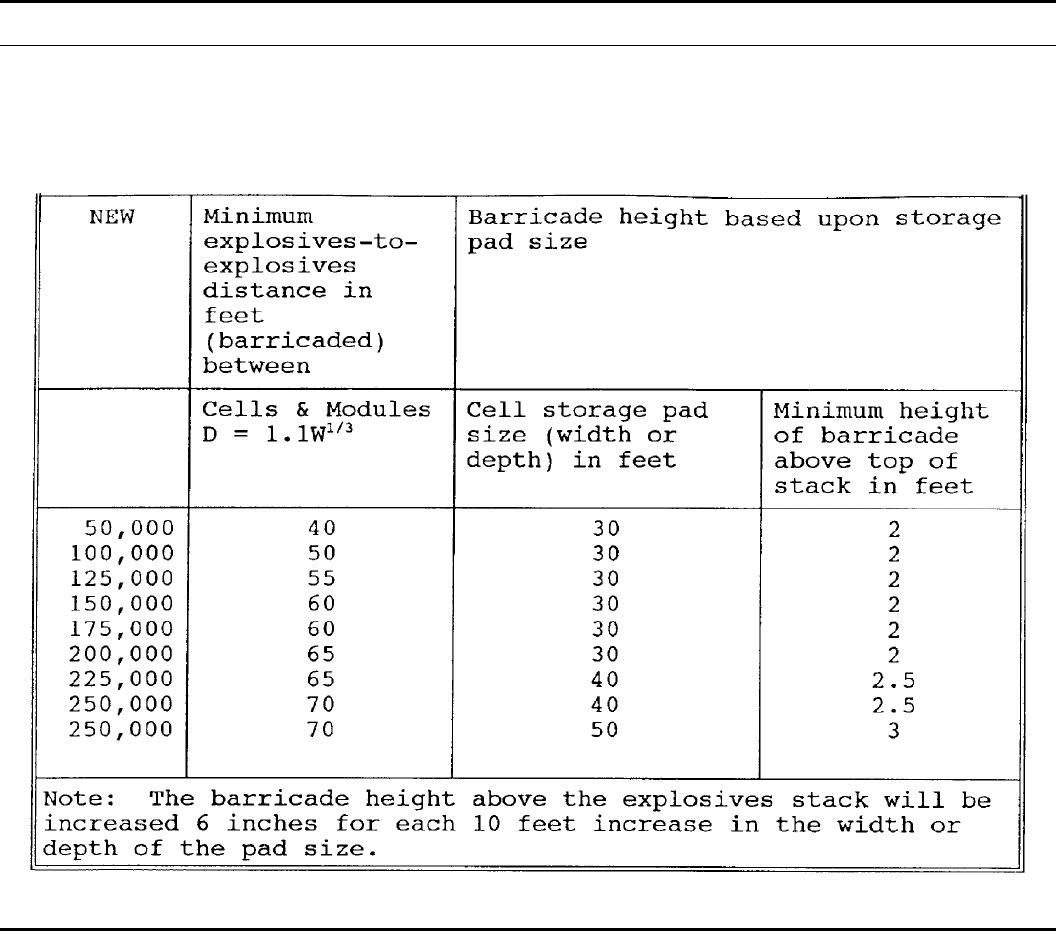
Table 8–1
Intermagazine separation for barricaded storage modules for mass detonating explosives
99DA PAM 385–64 • 28 November 1997
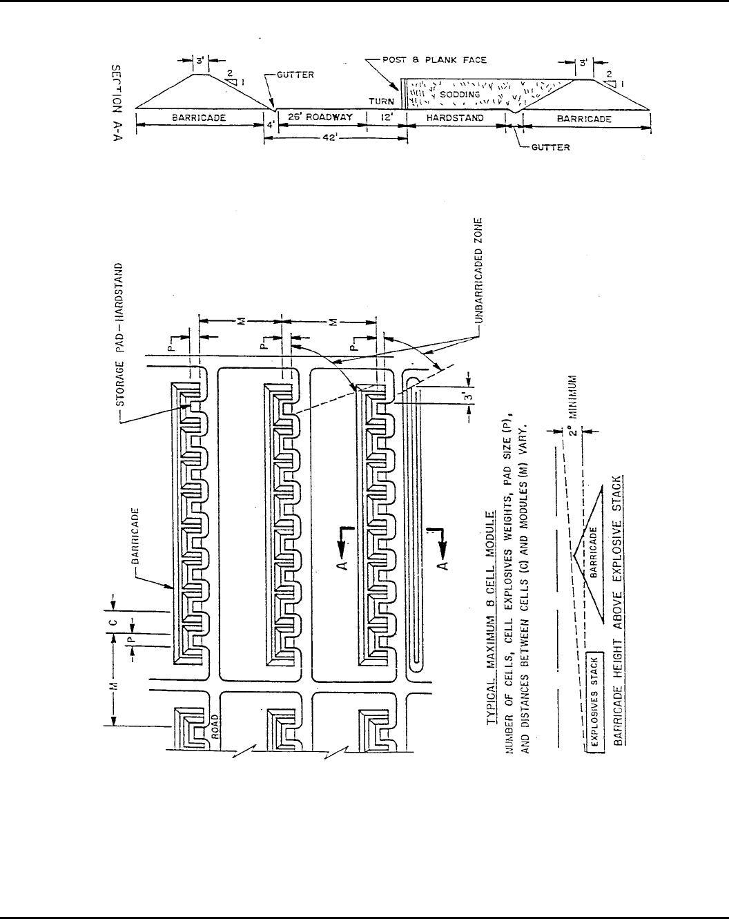
Figure 8-1. Typical 8–cell module
100 DA PAM 385–64 • 28 November 1997
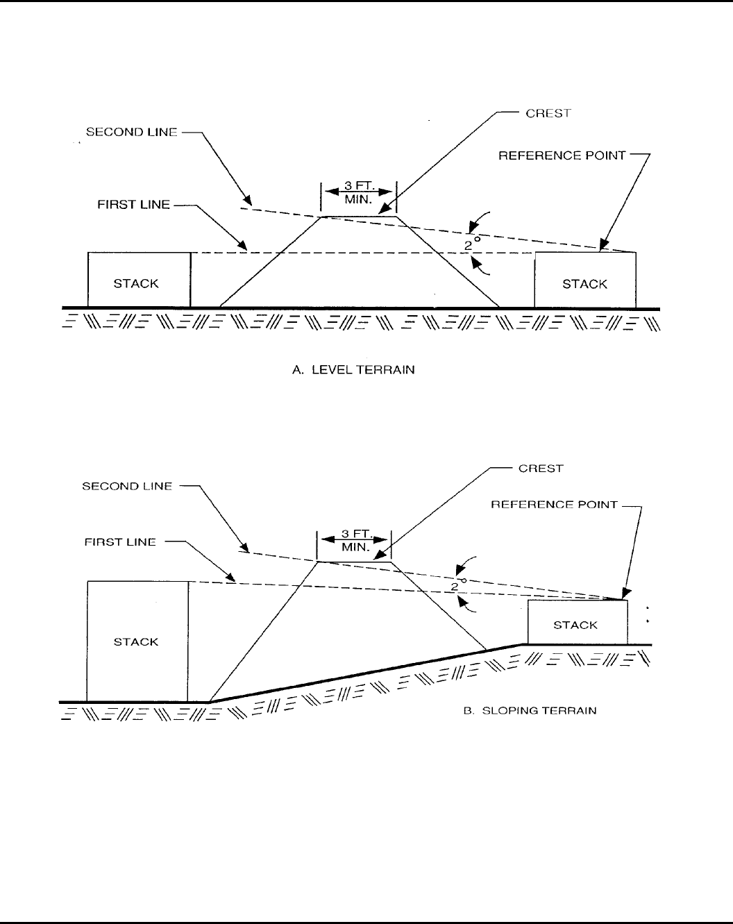
Figure 8-2. Determination of barricade height
101DA PAM 385–64 • 28 November 1997
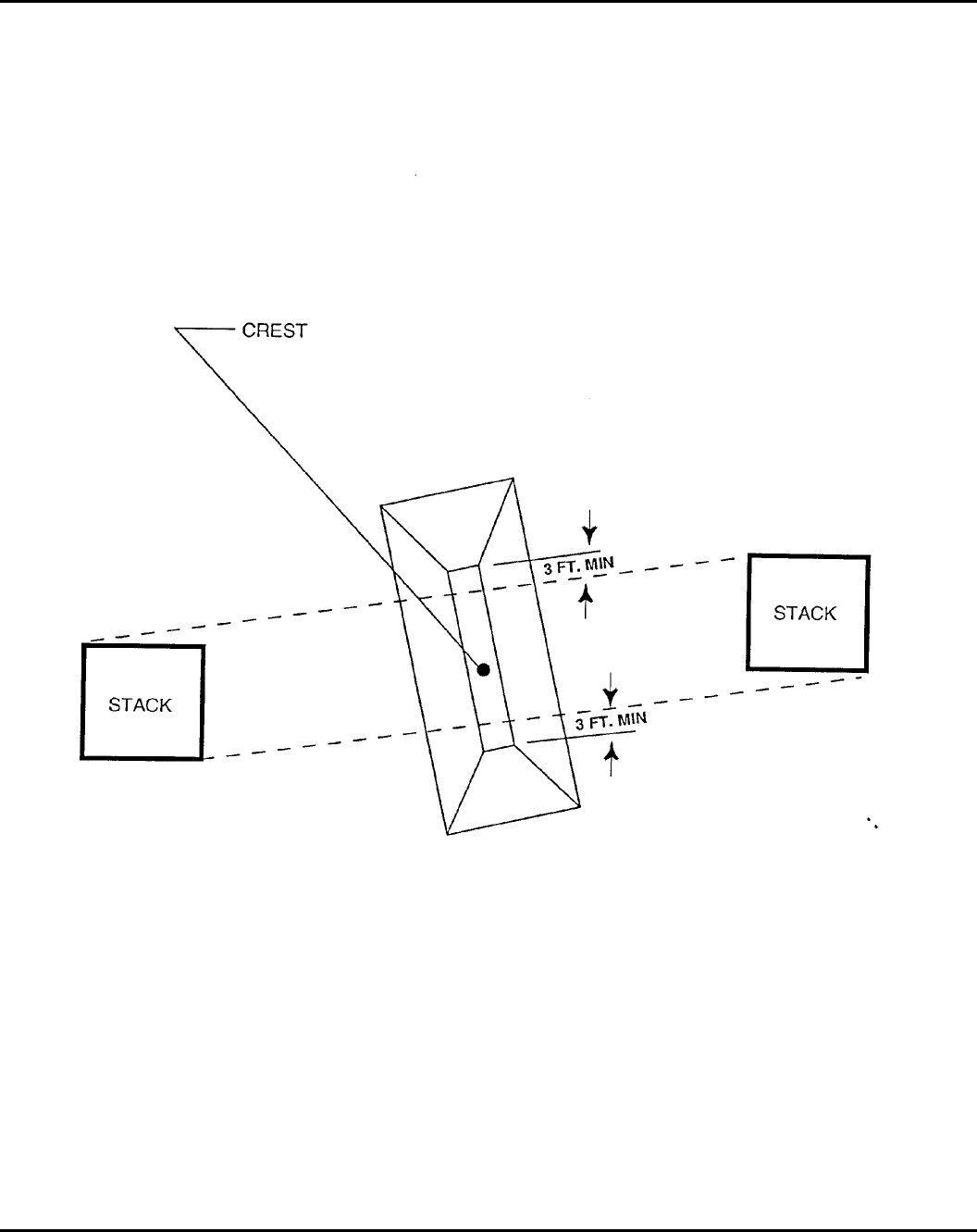
Figure 8-3. Determination of barrricade length
102 DA PAM 385–64 • 28 November 1997
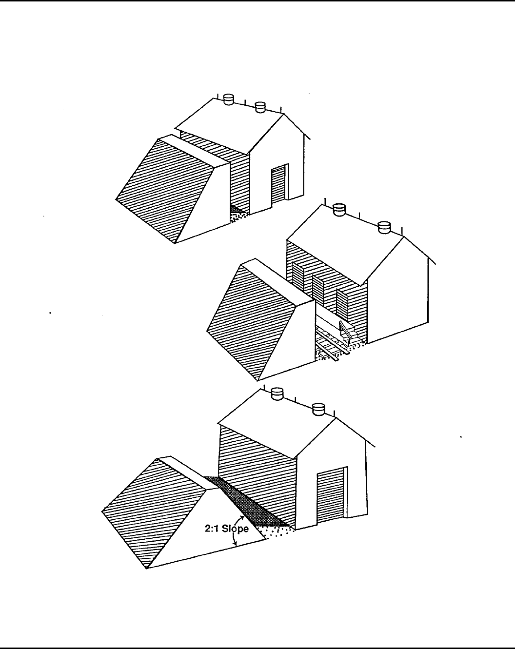
Figure 8-4. Barricade locations
103DA PAM 385–64 • 28 November 1997
Chapter 9
Explosives Licensing
9–1. Procedures
a. Explosives licenses are permanent documents with no expira-
tion date. However, a new license will be issued, and the old license
c a n c e l e d , i f e n c r o a c h m e n t c h a n g e s t h e d e t e r m i n i n g f a c t o r o r
changes in Q-D standards require license alterations.
b. The safety manager or director servicing the explosives loca-
tion will certify and date the explosives license.
c. Explosives licenses will be reviewed annually by the responsi-
ble safety manager or director for compliance and encroachment.
This review will include an on-site inspection of the area and a
recomputation of the license.
d. The explosives license, together with maps of the explosives
location and surrounding area, will be available at the servicing
safety office. If the explosives location is not at the same installation
as the servicing safety office, copies of the explosives license and
maps will also be available at the explosives location. The maps will
include structure numbers and accurate distances. A distance scale
will be part of the map.
9–2. Required information
The explosives license form will, as a minimum, contain the follow-
ing information:
a. Ammunition or explosives area location.
b. Ammunition or explosives facility location.
c. Type of facility.
d. The HD authorized.
e. Allowable limits of each HD (expressed in pounds (NEW) or
kilograms (NEQ).
f. Determining factor or object which limits the amount of am-
munition or explosives in e above.
g . A c t u a l s e p a r a t i o n d i s t a n c e b e t w e e n t h e f a c i l i t y , c i t e d i n
babove, and the determining factor, cited in f. above.
Chapter 10
Materials Handling Equipment (MHE)
10–1. General requirements
The materials handling equipment (MHE) (such as forklift trucks,
tow motors, powered pallet jacks, electric hand trucks) will be used
in a safe and efficient manner.
a. The operator will inspect MHE before use. Unsafe equipment
will not be used until repairs are made. Safety devices; for example,
dead-man switches, will not be defeated or circumvented.
b. All forklifts will have overhead guards meeting the require-
ments of applicable DOD and OSHA standards. The installation
commander may grant exceptions to the overhead guard requirement
only when the height of the overhead guard would keep the forklift
out of work locations or the overhead guard would be lower than
the top of the operator’s head.
c. Operators will not use equipment to move loads that exceed
the rated capacity of the MHE at the prescribed load-center.
d. The MHE will be used only for its intended purpose (for
example, forklifts will not be used as towing tractors).
e. Containers or pallets will be lifted only in an authorized man-
ner. Items will be lifted using forklift pockets, if present. Items will
b e s l u n g f r o m l i f t i n g l u g s / e y e b o l t s , i f p r e s e n t . D e v i a t i o n s f r o m
standard lifting procedures must be approved in writing.
f. If multiple skids or pallets are to be lifted together, the items
must be secured together to ensure the integrity of the lift.
10–2. Battery-powered materials handling equipment
a. Battery-powered equipment is the preferred MHE for handling
ammunition and explosives inside a building or a poorly ventilated
area.
b. Battery-powered equipment used within an explosives area
will have all electrical cables mounted to prevent catching on sta-
tionary objects or damage by cutting or abrasion. Cables will be
protected to prevent short-circuiting in as far as is practical.
c. Batteries will be securely fastened. Battery boxes will provide
ample ventilation, with ventilation openings that prevent access to
the cell terminals from the outside.
d. Battery-powered equipment must be equipped with a dead-
man switch and a main service switch which can be activated from
the driving position.
e. Battery charging stations should be separated from explosives
facilities by the applicable distance required in chapter 5.
f. The rated equipment defined in NFPA 505, types E, EE, ES,
and EX, are satisfactory for handling all classes of ammunition and
explosives packed in accordance with DOT regulations. Types EE
and ES battery-powered equipment may be used for handling in-
process ammunition (for example, sub-assemblies, explosives loaded
components, and so forth) in corridors or ramps connecting hazard-
ous operations. Types EE and ES equipment will not be used in
areas containing explosive dusts or with explosives that, through
handling, may produce explosive dusts.
g. Type EX equipment is the only equipment approved for use in
areas with explosive dusts (NFPA 505). EX equipment does not
carry a dual rating and can be used only in hazardous areas for
which it is specifically designed.
10–3. Gasoline and diesel powered equipment
a . G a s o l i n e a n d d i e s e l p o w e r e d e q u i p m e n t f o r h a n d l i n g i n e r t
materials will be equipped with backfire deflectors securely attached
on the throat of the carburetor. These deflectors will be of the oil-
bath or screen type. Certain types of air cleaners can serve as
backfire deflectors. A tight fitting cap, properly vented, will be in
place on the fuel fill pipe at all times except during refueling. A
flame arrester will be installed in the fill pipe. If necessary, a
deflector plate will be installed to prevent any overflow from the
fuel tank from reaching the motor or the exhaust pipe. On gravity
feed systems or on pump systems, where siphoning might occur, a
shut-off valve will be installed at the fuel tank or in the feed line to
permit shutting off the flow of fuel during an emergency or break in
t h e f u e l l i n e o r c a r b u r e t o r . P r o v i s i o n s w i l l b e m a d e t o p r o t e c t
against vibrational rupture of the fuel lines.
b. All MHE will be provided with a fire extinguisher having a
minimum rating of 5BC.
c. Gasoline and diesel-powered equipment should be checked
before being put into operation to ensure sufficient fuel is available
to minimize refueling requirements. Fueling of MHE in the ammu-
nition area will be done in accordance with paragraph 3–7g(6).
10–4. LP-gas-powered equipment
a. LP-gas-powered equipment for handling inert material will be
type LPS. All fuel lines, fittings, and containers will be designed
and installed in accordance with NFPA Standard 58 to provide
maximum protection against damage to the system by vibration,
shock, or objects striking against it and against failures from other
causes.
b. All LP-gas-powered equipment will be provided with a fire
extinguisher having a minimum rating of 5BC.
c. LP-gas-powered equipment should be checked before opera-
tion to ensure all fuel lines, fittings, and containers are secure and
that sufficient gas is available to reduce refueling or replacement of
fuel containers.
10–5. Gasoline, diesel-powered and LP-gas-powered
equipment for handling explosives materials
a. Gasoline, diesel-powered and LP-gas-powered equipment with
the precautionary measures and devices described in paragraphs
10–3 and 10–4 are appropriate for handling all classes of ammuni-
tion and bulk explosives packed in accordance with DOT regula-
tions. Included are closed ammunition items containing explosives
104 DA PAM 385–64 • 28 November 1997
(for example, artillery projectiles or bombs), including fuzes if ap-
proved for shipment in this manner, and provided the material is not
located in a hazardous location as defined by the NFPA. The exte-
rior of the cartons, projectiles, bombs, boxes, and so forth, must not
be visibly contaminated with explosives or have any explosives
exposed.
b. Due to the inherent hazards of operation, gasoline-powered or
LP-gas-powered MHE will not be used in Richmond or earth cov-
ered magazines.
c. Clean burning diesel equipment meeting the criteria of MIL-
T–52932 and electric powered forklifts are permitted in Richmond
and earth covered magazines provided—
(1) Material in a hazardous location as defined by the NFPA 70;
for example, explosive dusts or vapors, must be handled by equip-
ment which is rated according to the NFPA 505 for use in these
areas.
(2) Concentrations of combustion products and noise emitted by
the MHE must be monitored by the using installation to ensure
compliance with OSHA and The Surgeon General’s standards.
10–6. Storage
a. Battery, gasoline, or diesel-powered equipment may be stored
in a magazine, storehouse, or other suitable location that contains
only inert materials.
b. The equipment should be at least 10 feet from any combustible
material.
c. Aisles will be kept clear at all times, and individual pieces of
stored equipment should be spaced to minimize the spread of fire
from one unit to another.
d. Equipment may be parked in fire-resistant buildings containing
explosives, providing such equipment is essential for day-to-day
operations. However, the following minimum requirements must be
met:
(1) Equipment must be stored in an area that is suitably and
completely separated (by firewalls and closed doors) from the bays,
rooms, or cubicles that contain the explosives.
(2) Designed fire-resistant ratings for the enclosures containing
explosives are not degraded.
e. When necessary for efficient operation, battery-powered MHE
is permitted to be used in buildings or magazines containing explo-
sives or other hazardous materials may be temporarily stored in
magazines containing packaged ammunition and explosives and in-
ert warehouses provided the following conditions (designed to pre-
vent fires or other trouble from occurring during unattended periods)
are met:
(1) Periods of idle storage shall not exceed 4 days.
(2) After each workday, MHE will be inspected for hot brakes,
leaking oil, or fluid. If these are found, the MHE will be removed
from the building.
(3) MHE will be made inoperative by removing ignition keys,
activating shut-off switches, or seat control disconnects, and so
forth. Battery cables will not be disconnected in explosives storage
locations due to the possible arcing when terminals separate.
(4) MHE will be parked and secured at the maximum distance
from the explosives or ammunition.
(5) MHE will not be stored in an operating building containing
explosives because of the increased hazards of loose or exposed
explosives.
Chapter 11
Port Operations
11–1. Background information
a. Successful port operations require preparation at the home
station. This preparation includes the proper blocking and bracing of
ammunition and explosives as well as planning the best movement
routes and times. This chapter provides guidelines to best accom-
plish these operations.
b. This chapter applies to movement of units to ports in times of
war or national emergency. It also applies to the operations at ports
in times of peace, war, or national emergency.
11–2. Loading of vehicles
a. Before loading vehicles for movement, commanders will con-
sider the conditions expected at the point of embarkation and disem-
barkation. Ammunition should be loaded only on or in vehicles with
load restraint systems designed for ammunition. Additional quanti-
ties of ammunition should not be placed, for example into the cabs
of vehicles or banded to the exteriors of mounted generators, com-
munications shelters, and so forth.
b. Before loading ammunition and explosives (A&E), a suitable
site must be selected for this operation. This site will be licensed
and have an approved site plan in accordance with chapters 8 and 9.
This site will be equipped with lightning protection in accordance
with chapter 12. This site will not be in the ammunition supply
point (ASP) because of the increased risk involved.
c. The loading operation will be conducted during daylight hours
or under strong illumination at night. At no time will loading opera-
tions be conducted under conditions of darkness.
d. Vehicles will be loaded in accordance with vehicle load draw-
ings. These drawings can be obtained from Director, DAC.
e. A person certified to release shipments will inspect and ap-
prove all vehicles containing shipments of hazardous materials. This
inspection will be as close as possible to the inspection required for
trucks carrying A&E. Vehicles which fail to pass the inspection will
be repaired and required to pass the inspection before being loaded.
f. Vehicles which are waiting to be loaded will be kept at IBD
from the loading site before the beginning of the loading operation.
Once a vehicle is loaded and properly blocked and braced, it will be
moved to the vehicle holding site.
g. The loading site will not have more vehicles in it at one time
than it can safely handle.
11–3. Vehicle holding site
a. A vehicle holding site will be selected prior to movement. This
site will have lightning protection, in accordance with chapter 12,
and be approved by the DDESB.
b. Unless vehicles or groups of vehicles can be sited at magazine
distance, the whole vehicle holding site will be counted as one site
for QD purposes. Magazine distance will prevent immediate propa-
gation from one vehicle or group of vehicles to another, but will not
prevent delayed propagation caused by firebrands or prevent de-
struction of vehicles.
11–4. Railhead operations
a. Vehicles loaded with A&E will not be brought to the railhead
until time for loading them on the railcars. A loadmaster with a
written appointment will control the arrival of vehicles for loading.
b. As each car or cut of cars is loaded, it will be moved to a rail
holding yard or sent to the port. Loaded cars will not be kept at the
railhead longer than necessary.
c. Vehicles will be secured to the railcar to prevent movement
before moving the car.
d. Railheads and rail holding yards will be properly sited and
have lightning protection in accordance with chapter 12.
11–5. Road movement
a. Vehicles moving over the road to port will have as a minimum
two 10BC fire extinguishers. Vehicle occupants will have ready
access to the fire extinguishers. Fire extinguishers will not be locked
up during movement.
b. Rest stops will be planned to allow parking vehicles with A&E
as far away as possible from public gathering places, such as, rest
rooms, picnic areas, and so forth.
(1) Vehicles will not be left unattended at rest stops.
(2) People unrelated to the movement will be kept as far away as
possible from vehicles loaded with A&E.
(3) During prolonged rest stops (over 2 hours), fire extinguishers
will be placed at 100 feet intervals between vehicles. These fire
105DA PAM 385–64 • 28 November 1997
extinguishers will be at least 50BC in size and have at least a 5A
rating.
c. Vehicle occupants will not smoke within 100 feet of loaded
vehicles. During rest stops people who are smoking will be kept at
least 100 feet from vehicles carrying A&E.
d. Vehicles which break down during movement will not be left
unattended.
(1) If repairs cannot be made where the vehicle broke down, the
A&E will be removed and placed on another vehicle before towing
the broken down vehicle.
(2) Using flame producing devices on loaded vehicles is prohib-
ited. If a flame producing device is needed to repair the vehicle, the
A&E will be unloaded and moved at least 100 feet from the vehicle
before beginning repairs. The A&E will not be left unattended while
it is off the vehicle.
(3) Repairs which increase the risk of fire, for example, battery
removal, removal of fuel, and so forth, require the removal of A&E
as noted in (2).
e. If an accident happens, any fires which occur will be fought
until they are in among the A&E.
(1) Injured personnel will not be moved unless their lives are
threatened. Medical personnel will be called to treat and remove
injured personnel as soon as possible.
(2) Immediate action will be taken to keep other vehicles and
personnel at least 4,000 feet from the scene of the accident.
(3) If the damaged vehicle cannot be moved, the A&E will be
loaded onto another vehicle for continued transportation. At least
two 50BC fire extinguishers will be kept immediately ready for use
during the transfer operation.
(4) If the damaged vehicle is not leaking fluids and can move on
its own power, it can continue with its load. It will be checked for
leaks at each stop. If it begins to leak, the A&E will be transferred
to another vehicle.
f. Vehicles will be grounded before beginning refueling opera-
tions. Vehicles will be grounded together to equalize the potential
between the fuel truck and the vehicle being fueled.
g. Vehicles will be staged so that A&E loaded vehicles do not
accumulate at any one location in large numbers. This is especially
important at the port. Normal QD requirements will be difficult, if
not impossible, to observe at most contingency ports. The arrival of
vehicles will be timed, if at all possible, to prevent the accumulation
of vehicles on the docks at the port.
11–6. Port safety
a . G e n e r a l r e q u i r e m e n t s . T h i s s e c t i o n a p p l i e s t o p i e r s a n d
wharves and associated facilities at which ammunition and explo-
sives may be handled or be present in ships’ holds or service
conveyances. These provisions apply to loading, offloading, stow-
ing, and shifting of ammunition and explosives. Q-Ds herein are for
HD 1.1. If only ammunition and explosives of other HDs are in-
volved, the Q-Ds for such hazards will be applied as appropriate.
Separation distances are listed in Table 11–2.
b. Determination of quantity of explosives in a ship.
(1) On board ship, the various types of ammunition and explo-
sives are stored relatively close to each other in partial confinement,
and a detonation in the HE part of the cargo may receive considera-
ble support from items that are normally considered to be only
fragment or fire hazards; therefore, the total quantity of explosives
on board a ship will be determined in accordance with Table 11–1.
(2) When ship units are separated by column 3 (K11) distances
or greater, (Table 11–2), Q-D will be based individually on the
quantity of each ship unit. Lesser separation distances require that
the explosives in both ship units be totaled for Q-D purposes.
(3) Separation of a wharf yard from the pier which it serves by a
distance clearly sufficient to prevent immediate propagation of an
explosion (column 3) will be impractical in many cases. In such
cases, the wharf yard will be considered as part of the ship or barge
unit and added to it to compute the total amount of explosives for
Q-D purposes. The outer limit of the wharf yard then will be
considered as the ship unit boundary for computing applicable Q-D
requirements.
c. Measurement of separation distance.
(1) Ships at a pier. Measurement of separation distances between
ships will be from the nearest point of one unit to the nearest point
of the other. Cars passing through the clear space are an operational
risk. It will generally be impractical to separate berths at a single
pier by enough distance to prevent mass-detonation of ships contain-
ing complete cargoes of HD 1.1 ammunition. To the extent opera-
tionally feasible, therefore, scheduling shall reduce the number of
such exposures and total time that they are required.
(2) Piers. The separation distances between piers shall be meas-
ured from the nearest point of the ship unit at one pier to the nearest
point of the ship unit under consideration at the other pier.
(3) Anchorages and scuttling sites. Measurements generally will
be from the boundary of the area designated for the scuttling site or
the explosives anchorage. In the case of the explosives anchorage,
t h e s e p a r a t i o n d i s t a n c e t o o u t s i d e t a r g e t s s h a l l d e p e n d u p o n
whether—
(a) The ship units that are loading or unloading within the explo-
sives anchorage are separated properly, taking into consideration
location and the amount of explosives in each ship unit. The ship
unit equivalent for an explosives anchorage is a circle, the radius of
which is the distance from the mooring buoy or the ship’s anchor to
the stern of the ship or of the ammunition lighters alongside when
riding to the full length of the chain. To maintain proper separation
distance between loading or unloading ship units in the explosives
anchorage, the ships will moor or anchor so that at no time will they
have a separation distance less than column 3 (K11) if quantities are
not to be totaled.
(b) The ships being loaded or unloaded at one area are separated
properly from the loaded ships in another area and whether the
loaded ships within the loaded ship area are separated properly from
each other. If the latter conditions do not apply, the quantity for
entering on the table will be the total quantity rather than the unit
quantity.
(4) Dolphins or interrupted quays. Measurement of separation
distance between ships moored to dolphins or interrupted quays will
be from the nearest point of one unit to the nearest point of the
other.
(5) Fixed targets. The measurement of separation distance from
moored ships to fixed targets on land will be from the nearest
boundary of the ship or barge unit to the nearest fixed target.
d. Siting criteria and application of Q-D separation standards.
(1) Scuttling site.
(a) A properly located scuttling site will be provided, if practical,
for positioning a ship for its flooding or sinking if the vessel catches
fire and must be moved to avert damage to other ships or piers. It
will have sufficient sea room and depth of water to permit the
sinking of the largest vessel that may be handled at the installation
so that the holds will be flooded completely at low water.
(b) Since an explosion may occur during movement, the scuttling
site will provide the best available protection to other ships, piers,
and shore installations.
(c) The location of the scuttling site will depend on the greatest
net quantity of mass-detonating explosives that may be in a single
ship at any one time. The Q-D tables to be used will depend on the
particular types of targets.
(2) Explosives anchorage. An explosives anchorage will be sepa-
rated from the main ship’s channel or from normally traversed
routes of ships entering or leaving the harbor by both column 2
(PTR), distances, and by turning circles and stopping distances of
the ships. Assuming that the diameter of the turning circle of a ship
is 3,000 feet, an explosives anchorage will be located so that a ship
in the channel with a jammed rudder will clear an anchored explo-
sives-laden ship. From the turning circle standpoint, the separation
distance will be not less than 3,000 feet.
(a) When explosives anchorages are used for loading and unload-
ing ships, as well as for fully loaded vessels anchored at their
berths, ships that are being loaded or unloaded will be separated
from fully loaded ships by column 5 (K40) distances.
106 DA PAM 385–64 • 28 November 1997
(b) When the explosives anchorage is used only for loading and
unloading ships, to prevent mass-detonation, ships in the explosives
anchorage will be separated by at least column 3 distances. When-
ever possible, these separation distances will be increased to column
4 (K18) distances to reduce the loss potential of any incident.
(c) Loaded ships will be separated one from another by at least
column 4 (K18) distances.
( d ) E x p l o s i v e s a n c h o r a g e s w i l l b e s e p a r a t e d f r o m e x p l o s i v e s
piers by column 5 (K40) distances unless the anchorage is used only
for the loading and unloading of vessels. In such cases, column 4
(K18) distances will be used.
(3) Separation of piers. Ammunition piers at a port facility will
normally be separated by column 4 (K18) distances to prevent
explosive propagation (Table 11–2).
(4) Ships in tandem. Separation distances of ship units in tandem
at the same pier.
(a) When multiple ships must be handled at one pier, tandem
berthing is recommended. A detonation of one ship would expose
others to a heavy fragment density, possibly producing fires and
delayed explosion propagation. A direct hit by a fragment on ammu-
nition alongside the ship or in an open hold could cause a mass-
detonation. Separation distances based on blast damage alone may
not be enough to withstand such fragment hazards. Berthing of the
two ships in tandem will help to decrease the fragment hazard to the
explosives cargo of the second ship because of the additional protec-
tion afforded by the bow or stern.
(b) When two ships cannot be separated by column 3 (K11)
distances and are being loaded through all hatches, the spotting of
cars and the loading of hatches in both ships will be planned so as
to put the greatest possible distance between open hatches of both
ships, and between the trucks and freight cars serving the two ships.
When possible, the loading of the ships will be staggered.
(5) Separation of explosives ships from other ships. Explosives
s h i p s b e i n g l o a d e d o r u n l o a d e d w i l l b e s e p a r a t e d f r o m n o n e x -
plosives-carrying ships and from loaded explosives ships that are
not underway by column 5 (K40) distances. Column 2 (PTR) dis-
tances will be used to protect ships that are underway.
(6) Occasional watercraft. Occasional watercraft passing through
the arcs while outside both the main ship channel and normally
traversed routes of ships entering and leaving the harbor, are not
subject to Q-D requirements.
e. Quantity-distance tables.
(1) For Q-D between ammunition and explosives-laden ships or
barges, use Table 11–1 together with Table 11–2.
(2) For Q-D between ammunition and explosives-laden ships or
barges and other locations, the following applies:
(a) When considering the ship or barge as a PES, magazine
distance applies to explosives storage locations. Use Table 5–6 and
the columnar formulas given in Table 5–5. IBD applies to adminis-
trative and industrial areas, explosives operating facilities, and the
terminal boundary. Use Table 11–2, column 6 (IBD). PTR applies
to the main shipping channel and other PTRs; use Table 11–2,
column 2 (PTR). Because Table 11–2’s NEWs are listed in large
i n c r e m e n t s , T a b l e 5 – 1 m a y b e u s e d f o r N E W s b e t w e e n T a b l e
11–2’s listed values. For IBD, use column 5 (Table 5–1) or the
formulas given in note 3. For PTR, use column 9 (Table 5–1) or the
formulas given in note 7.
(b) When considering the ship or barge as an ES, IBD applies
from on shore explosives storage locations and operating facilities to
the ship or barge. Use the same distance sources for IBD as listed in
(a) above.
f. Wartime or national emergency. During wartime or national
emergencies when contingency ports are being used, the QD re-
quired above may be impossible to follow. When the QD above
cannot be followed—
(1) Vehicles will be brought up to the dock as close to their
loading time as possible. Vehicles will not be allowed to congregate
at the dock.
(2) Firefighting equipment will be ready at the dock. Either a fire
boat, fire engine, or 50BC fire extinguishers with at least a 5A
capability will be stationed every 100 feet along the dock and in the
holding area.
(3) RORO ships are not subject to the requirements of QD.
107DA PAM 385–64 • 28 November 1997
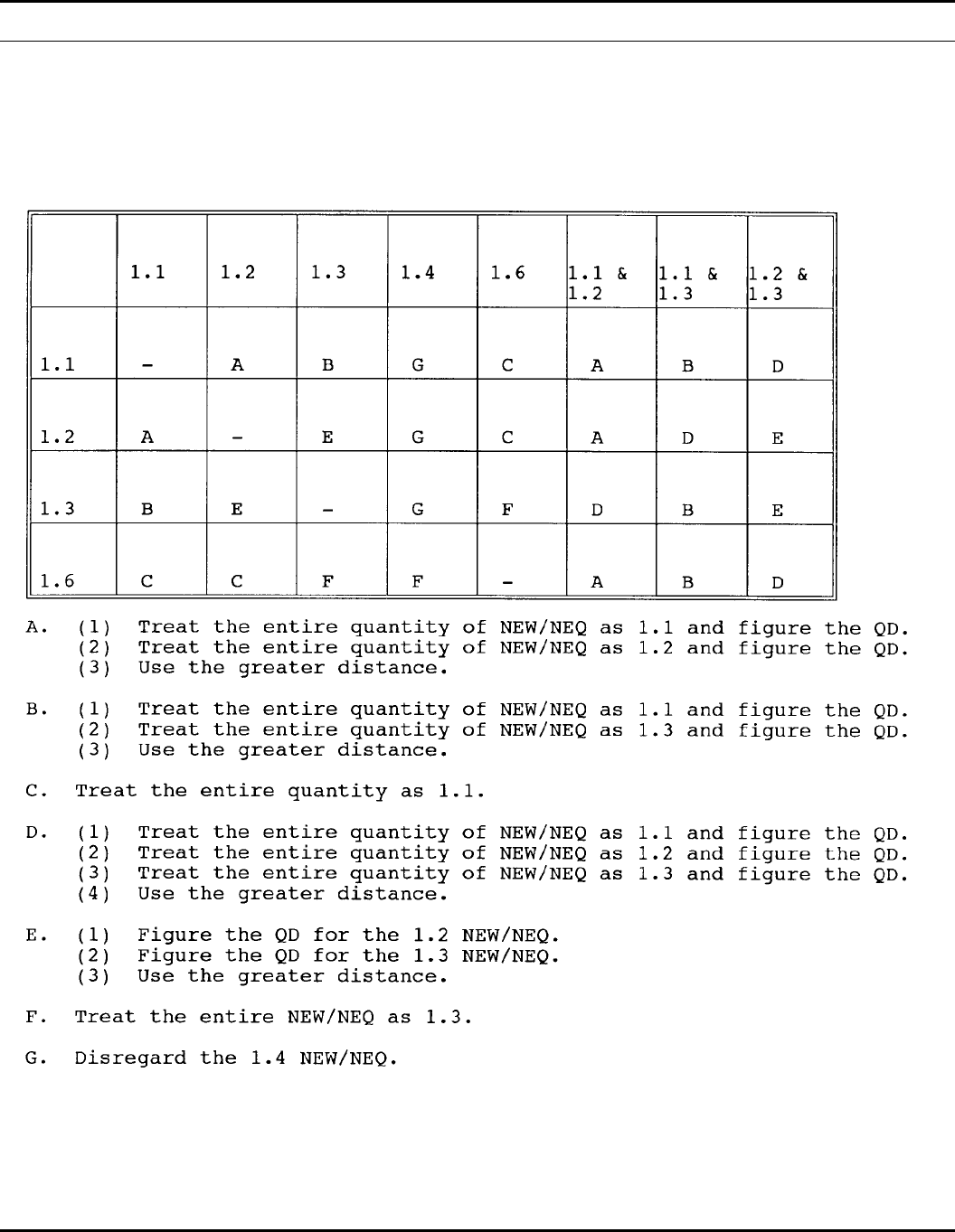
Table 11–1
Mixed class/division for QD computations
108 DA PAM 385–64 • 28 November 1997
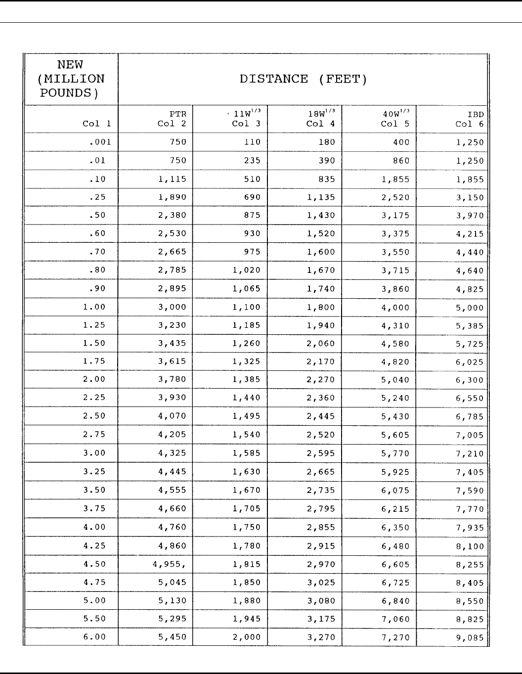
Table 11–2 (PAGE 1)
Quantity-distance separations for pier and wharf facilities
109DA PAM 385–64 • 28 November 1997
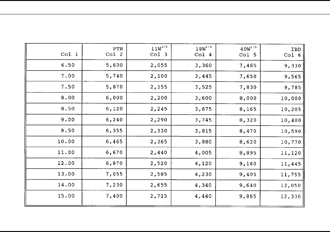
Table 11–2 (PAGE 2)
Quantity-distance separations for pier and wharf facilities--Continued
Chapter 12
Lightning Protection
12–1. General information
a. This chapter provides the minimum technical requirements for
lightning protection of structures and areas containing explosive
materials. An LPS is required on all structures and areas containing,
storing, or holding ammunition and explosives except in situations
described in paragraph 12–4.
b. All LPS must provide protection that as a minimum meets the
requirements of the 100–foot zone of protection (app H).
c. Lightning protection is designed to provide a conductive path
to ground for a lightning strike. This chapter describes what is
required for a lightning protection system, the materials to use
(Table 12–1), and how to maintain the system in good working
order.
d. Lightning normally starts in a cloud with the accumulation of
separate negative and positive charge areas. The negative charge
induces a positive region in the ground below. As the static electric-
ity builds, a dim spark, called a step leader, emerges. This step
leader jumps in 50–yard lengths. About 50 yards above the ground,
it meets a rising positive spark. These two sparks form a path for
the visible lightning stroke. As the stroke ends, in-cloud discharges
r e a c h t o w a r d t h e p a t h . S o m e t i m e s a n o t h e r s p a r k , c a l l e d a d a r t
leader, moves down the path and initiates a second visible lightning
stroke. The peak temperature in the path lasts a few millionths of a
second and reaches approximately 55,000 degrees F. The stroke
produces more electricity in its brief life than all the electrical
generators in the U.S. could produce in the same time. Yet the flash
is so brief that the electric energy where it strikes would power a
light bulb for only a month or so. Virtually all its energy is con-
verted into light, thunder, radio waves, and heat.
12–2. Fundamental principles of lightning protection
a . T h e f u n d a m e n t a l p r i n c i p l e f o r p r o t e c t i n g l i f e a n d p r o p e r t y
against lightning is to allow a lightning discharge to enter or leave
the earth without resulting damage or loss. A low impedance path
should be offered, which the discharge current will follow in prefer-
ence to all alternative high impedance paths offered by building
materials such as wood, brick, tile, stone, or concrete. When light-
ning follows the higher impedance paths, damage may be caused by
the heat and mechanical forces generated during the passage of the
discharge. Most metals, being good electrical conductors, are virtu-
ally unaffected by either heat or the mechanical forces if they are
large enough to carry the current that can be expected. The metal
path must be continuous from the earth electrode system to the air
terminal. Care should be exercised in selecting metal conductors
(Table 12–1) to ensure the integrity of the lightning conductor for
an extended period. A nonferrous metal such as copper or aluminum
will provide, in most atmospheres, a lasting conductor free of the
effects of rust or corrosion.
b. Parts of structures most likely to be struck by lightning are
those that project above surrounding parts such as chimneys, venti-
lators, flagpoles, towers, water tanks, spires, steeples, deck railings,
shafthouses, gables, skylights, dormers, ridges, and parapets. The
edge of the roof is the part most likely to be struck on flat-roofed
buildings.
c. An LPS consists of three basic parts that provide the low
impedance metal path required:
(1) A system of air terminals or overhead wires on the roof and
other elevated locations,
110 DA PAM 385–64 • 28 November 1997
(2) A system of earth electrodes, and,
(3) A conductor system (down conductor) connecting the air ter-
minals to the earth electrode system.
d. Properly located and installed, these basic components de-
scribed in c, above, improve the probability that the lightning dis-
charge will be conducted harmlessly between the air terminals and
the ground terminals.
12–3. Locations requiring an LPS
a. Lightning protection systems will be installed on all facilities.
Facilities are structures or locations used for development, manufac-
turing, testing, handling, storage, inspection, holding, or mainte-
nance of ammunition or explosives.
b. An LPS will be required at a demilitarization or disposal site
only if—
(1) Personnel are required to work or remain at the site during
the approach of or during a lightning storm; and,
(2) The installation commander determines an LPS is necessary
to protect personnel or equipment.
c. Underground storage (para 5–13) with metal or structural parts
that have less than 2 feet of earth cover will be protected as an
aboveground site.
12–4. Locations not requiring lightning protection
Under conditions specified in the following subparagraphs, lightning
protection may be omitted from certain ammunition or explosives
facilities. However, if lightning protection is present on an active
facility, it will be inspected, tested, and maintained as prescribed in
this pamphlet.
a. An LPS may be omitted from earth covered magazines where
the expected damage due to a lightning strike will not seriously
affect the installation mission; and where the following conditions
are met—
(1) Ammunition and explosives are stored in their approved ship-
ping configuration.
(2) The steel arch and/or reinforcing bars are electrically con-
nected with conductor cables to the earth electrode subsystem.
(3) Ventilator metal is at least 3/16 inch thick and electrically
connected to the earth electrode subsystem and magazine contents
are protected from molten metal fragments of the ventilator if it is
hit by lightning.
(4) Bonding, surge suppression, and ground requirements of this
chapter are met.
b. Primary lightning protection (air terminals/external down con-
ductors) may be omitted on earth covered magazines (ECMs) which
have ground girdle subsystems constructed under Navy specifica-
tions provided the following conditions are met—
(1) The ECMs are used only to store ammunition and explosives
in closed containers or in their approved shipping configurations.
(2) Bonding and surge suppression requirements are applied.
(3) Ventilators are made of a nonconducting material or of sheet
steel greater than 3/16 inch thickness.
c. An LPS may be omitted on facilities other than earth covered
magazines equipped with an adequate lightning warning system
(para 12–9) when all the following conditions can be met—
(1) Operations can be terminated before the storm strikes;
(2) All personnel can be evacuated to IBD; and,
( 3 ) T h e e x p e c t e d d a m a g e d u e t o a l i g h t n i n g s t r i k e w i l l n o t
seriously affect the installation mission.
d. An LPS may be omitted on facilities without a lightning warn-
ing system other than earth covered magazines where—
(1) Personnel are not expected to sustain injury; and,
(2) The resulting economic loss of or to the facility, it contents,
or surrounding facilities is minimal.
e. Lightning protection may be omitted on facilities that contain
only noninitiable material where there is no fire hazard.
12–5. Requirements for lightning protection systems
a. This paragraph provides the minimum technical requirements
for lightning protection of structures and areas containing explosive
materials.
b. All LPSs designed to protect structures or areas containing
explosives and energetic materials must provide a 100– foot zone of
protection (see app H). This works on the principle that a sphere
with a radius of 100 feet when it is placed on an LPS, will not touch
the structure or object being protected as the sphere is rolled from
protective point-to-point. It also will not touch the structure or
object being protected before the sphere touches the ground.
c. All LPSs will have at least two conductive paths to ground. If
the structure has a perimeter exceeding 250 feet, there will be a
down conductor for every 100 feet of the perimeter or fraction
thereof.
d. All LPSs will be bonded into the earth electrode subsystem of
the facility being protected.
e. Down conductors may be coursed through the air without
support for a distance of 3 feet or less. Down conductors that must
be coursed through air for longer distances will be provided with a
positive means of support that will prevent damage to or displace-
ment of the conductor.
f. All new and renovated LPSs will be designed and constructed
in accordance with TM 5–811–1, TM 5–811–3, and TM 5– 811–7.
g. The following subparagraphs contain guidance regarding loca-
tions and heights of air terminals that may be used to achieve the
required 100–foot zone of protection on concrete or steel arch earth
covered magazines. Other configurations are also considered to pro-
vide the 100–foot zone of protection if they were reflected in safety
submissions or standard drawings approved by the Department of
Defense Explosives Safety Board after 1984. Installations must de-
termine if alternative configurations on older magazines afford the
100–foot zone of protection. Where an LPS installed before 1984
does not meet that criterion, it must be programmed for repair. The
LPS repair program must prioritize corrective actions based on a
hazard analysis of each violation consistent with AR 385–10. First
priority will go to correcting deficiencies on facilities storing chemi-
cal ammunition (chemical surety material as defined in AR 385–61,
exclusive of ton containers). Assistance in evaluating existing alter-
native arrangements or air terminals may be obtained through com-
mand safety channels. Alternative configurations for new magazines
m u s t b e a p p r o v e d b y s i t e p l a n s o r s a f e t y s u b m i s s i o n s b e f o r e
construction.
(1) An earth covered magazine up to 40 feet in length can be
protected by a system with two air terminals. For this configuration,
one air terminal must be placed on the top center of the headwall.
The front air terminal must extend at least 24 inches above the
headwall. The other air terminal must be placed at the rear of the
magazine on or close to the rear ventilator stack. If the rear air
terminal is mounted on the ventilator stack (either the ventilator cap
or concrete stack), it must extend at least 24 inches above the top of
the ventilator cap. If the rear air terminal is not mounted on the
ventilator stack, add one additional inch in height to the terminal
over and above the minimal 24–inch extension above the ventilator
for every inch it is mounted away from the stack. The metal ventila-
tor cap must be bonded to the lightning protection system. An air
terminal less than 24 inches in height above the ventilator is accept-
able provided protection consistent with the 100–foot striking arc
can be demonstrated. However, the rear air terminal may never be
less than 10 inches above any metal ventilator.
(2) An earth covered magazine more than 40 feet, but not more
than 80 feet, in length can be protected by three air terminals. For
this configuration, a front and rear air terminal must be mounted as
described for 40–foot magazines in the preceding subparagraph. A
third air terminal is required on the top center of the magazine. The
center air terminal must be at least 24 inches in length.
(3) An earth covered concrete or steel arch magazine more than
80 feet in length could be protected by a front and rear air terminal
as described for 40–foot magazines, and multiple air terminals be-
tween the front and rear that extend 24 inches above the headwall
top surface. In this configuration, the air terminals must be equally
spaced (but not more than 40 feet apart) along the crest of the arch.
111DA PAM 385–64 • 28 November 1997
h. Ammunition facilities, other than ECMs, with integral systems
have the following minimal requirements—
(1) Air terminals will be at least 24 inches high.
(2) Air terminals are required on or close to ventilator stacks and
caps. Those terminals must be at least 24 inches high and extend at
least 10 inches above the ventilators they protect.
(3) Air terminals will be spaced not to exceed 25 feet apart on
ridges, parapets, and around the perimeter of roofs. Where it has
been necessary to exceed this spacing, the terminals shall be in-
creased by 2 inches for each foot of increase over the 25 feet
spacing between terminals. For large roof areas, additional air termi-
nals may be required on the roof surface to achieve the 100–foot
zone of protection. A grid of 24–inch air terminals on 25 foot
centers (approximately 35 feet between terminals diagonally) will
protect a horizontal roof surface.
i. Special requirements for integral systems are as follows:
(1) Air terminals will be at least 5 feet high above open or
hooded vents emitting explosives dusts or vapors under natural
draft.
(2) Air terminals will be at least 15 feet above open or hooded
vents when explosives dusts or gases are emitted under forced draft.
12–6. Types of lightning protection systems
The following LPSs are listed in the NFPA and are the only ones
currently approved for use—
a. Integral system (lightning rods). An integral system consists of
air terminals mounted directly on the structure to be protected, down
conductors, and a grounding system. This system is used to protect
structures. Air terminal spacing will meet the requirements of the
100–foot zone of protection (app H).
b. Catenary system (overhead wire). A catenary system consists
of a wire strung between posts. The wire is the equivalent of an air
terminal and may or may not run directly into the earth electrode
subsystem. The earth electrode subsystem will normally consist of
ground rods at both ends of the system and be attached either
directly to the wire or have an intermediary down conductor. Each
pole will have an air terminal which extends at least 10 inches
above the pole. This system is normally used to protect large open
areas, such as a truck holding yard, but may also be used to protect
structures.
c. Mast system. A mast system consists of an air terminal (light-
ning rod) on a mast, down conductors, and a earth electrode subsys-
tem. This system can be used to protect either structures or areas.
Masts will be separated by a minimum of 6 feet from the building
or stack of munitions being protected.
12–7. General prohibitions
a. When aluminum is used, the following applies—
(1) Aluminum lightning protection equipment will not be in-
stalled on copper roofing materials or other copper surfaces or
where exposed to runoff from copper surfaces.
(2) Aluminum materials will not be used where they come into
direct contact with the earth. Fittings used to connect aluminum
down conductors to copper or copper-clad grounding equipment will
be bimetallic. Bimetallic connectors will be installed at 18 inches or
higher above the earth level.
(3) Connectors and fittings will be suitable for use with the
conductor and the surfaces on which they are installed. Bimetallic
connectors and fittings shall be used for splicing or bonding dissimi-
lar metals.
(4) An aluminum conductor will not be attached to a surface
coated with alkaline-base paint, embedded in concrete or masonry,
or installed in a location subject to excessive moisture.
b. Copper lightning protection materials will not be installed on
aluminum roofing, siding, or other aluminum surfaces.
c. Galvanized steel will not be used in areas where atmospheric
conditions are destructive to galvanized steel. Where galvanized
steel conductors are used, the individual wires of the cable will have
a protective coating of zinc (hot-dipped process). This treated cable
must be capable of withstanding four 1–minute immersions in a
standard copper sulfate solution without showing a fixed deposit of
copper.
d. Where copper-clad steel is used, the copper covering will be
permanently and effectively welded to the steel core. The portion of
copper will be such that the conductance is not less than 30 percent
of the conductance of an equivalent cross-section of solid copper.
e. Stainless steel is very susceptible to corrosion in many soil
conditions. Extreme caution will be used along with a proper soil
analysis when this material is used. Records of the soil analysis will
be kept as a permanent part of the lightning protection records.
12–8. Bonding
a. It is critical that the bonding requirements in this chapter be
enforced to protect structures and areas containing, storing, or hold-
ing explosives or other energetic materials. The material used to
bond the LPS to the grounding loop conductor will meet the re-
quirements set forth in Table 12–1. The resistance of any object
bonded to the lightning protection system will not exceed one ohm.
Exceptions are noted in Table 6– 1.
b. Fences which come within 6 feet of an explosives structure
will be bonded to the structure’s LPS or its grounding system.
c. Railroad tracks which run within 6 feet of an explosives struc-
ture will be bonded to the structure’s LPS or its grounding system.
If the tracks are used to carry electrical signals, they will have
insulated joints immediately external to bond the LPS’s ground loop
conductor. If these tracks enter a facility, they will also be bonded
to the frame of the structure or equivalent.
d. Large masses of metal (400 square inches or larger surface
area) located on the exterior of structures or within facilities, such as
radiators, tanks, permanent machinery, and so forth, do not have to
be bonded into the LPS unless the mass of metal is within 6 feet of
any part of the exposed LPS.
e. Fire symbols and signs attached to ECM headwalls, need not
be bonded to the structure’s lightning protection systems provided
mounting hardware does not penetrate to the structure interior.
12–9. Lightning warning systems
a. Lightning warning systems provide a positive, reliable means
o f c o n t i n u o u s l y m o n i t o r i n g a n d r e c o r d i n g a t m o s p h e r i c v o l t a g e
gradient. They can detect atmospheric conditions that may produce
lightning in the vicinity. Lightning warning systems that are in-
stalled and properly maintained can detect thunderstorms up to 200
miles away and indicate the direction of approach.
b. Installations with lightning warning systems will establish a
specific criteria for terminating ammunition and explosives opera-
tions at the approach of a thunderstorm. This criteria will be based
on the sensitivity of the operation involved and the amount of time
required to terminate operations safely.
c. Installations without lightning warning systems will also be
required to develop criteria for evacuating ammunition facilities at
the approach of a storm. The decision to terminate an operation and/
or evacuate must be determined on a case-by-case basis pending an
evaluation of the hazards to operations and support personnel. Pro-
cedures should identify a responsible individual who can decide
when evacuation is necessary. Following are some examples of
facilities that should be evacuated in the event of a probable electri-
cal storm—
(1) All operations involving EEDs and exposed explosives or
propellants.
(2) Buildings containing explosives dusts or vapors, whether or
not equipped with approved LPSs and locations within IL distance
of these facilities.
(3) Outdoor operations with unpackaged munitions or ammuni-
tion operations being conducted without lightning protection.
12–10. Structural grounds
On all new construction and extensive renovation, the structural
steel in all explosives facilities will be bonded to the facility groun-
ding system. No greater than 1 ohm resistance will exist between
112 DA PAM 385–64 • 28 November 1997

the structural steel and the grounding system. Testing will be in
accordance with paragraph D–3.
12–11. Grounding
For details on grounding, use Table 12–1 and paragraph 6–13.
12–12. Surge protection
a. An LPS for ammunition and explosives structures will use
surge protection for incoming conductors. One or more of the fol-
lowing will be provided on all incoming metallic power, communi-
cation, and instrumentation lines to reduce transient voltage to a
harmless level—
(1) Lightning arresters,
(2) Surge arresters,
(3) Surge protectors,
(4) Surge suppressors,
(5) Transient power suppressors, and
(6) Isolation transformers.
b. These power and communication lines will enter the facility in
underground shielded cables or in metallic conduits which enter the
ground at least 50 feet from the facility. In addition, intrusion
detection systems and other metallic lines will run underground for
at least the last 50 feet up to the structure. The use of low-pass
filters will be considered for added protection on specific critical
electronic loads as determined by the user.
c. Fiber optic cables do not need to run underground before
entering the building.
d. Steam, water, and air conditioning lines may run above ground
as long as they are bonded to the structure’s LPS before entering the
structure. If these lines are not bonded to the LPS, they will run the
last 50 feet to the building underground.
12–13. Visual inspection requirements
a. Components of the LPS will be visually inspected at intervals
specified in Table 6–1.
b. Components of the LPS will be inspected in accordance with
paragraph D–2.
12–14. Electrical testing requirements
a. The LPS will be tested at intervals specified in Table 6– 1.
b. The LPS will be tested per paragraph D–3.
c. The resistance of any component of the LPS will not exceed
the value specified in Table 6–1.
d. The resistance of any metal object bonded to the LPS will not
exceed the values specified in Table 6–1.
e. Any standard ohm meter that is capable of reading 1 ohm with
a manufacturer’s certified accuracy of 0.1 ohm and capable of meas-
uring bond connections for large facilities can be used. Analog
meters can continue to be used but all newly procured meters must
have a resolution of 0.1 ohm as well as the 1 ohm capability with an
accuracy of 0.1 ohm.
f. Some installations have LPSs that are unique to their particular
location. Compliance with all testing details as stated in this chapter
may not be practical or possible due to variations in building fea-
tures, nonavailability of as-built drawings, or even terrain features
(rock or concrete-covered ground near structures to be tested). When
strict compliance for test and inspection of a facility cannot be
accommodated, installations must make maximum use of expertise
available; that is, electrical engineers, at their command and develop
a reasonable and well-documented LPS test and inspection plan
within the guidance of this chapter. This plan will be forwarded to
the installations next higher headquarters for review and, once ap-
proved, retained with the installation’s permanent LPS records.
12–15. Records
The inspection and test reports and/or records will be maintained in
the installation safety office, unless an alternate office is specifically
designated by the installation commander. Records of tests and
inspections will be kept on file for the last 30 years. These records
will be reviewed for deficiencies and trend analysis. Significant
variances will be analyzed to determine the cause and indicated
repairs must be made.
12–16. Truck holding areas
For designated established truck holding areas, lightning protection
must be applied. For undesignated truck holding sites used in sup-
port of field training exercises, lightning protection is not necessary
if the following requirements are met—
a. Explosives quantity distance limits and vehicle separations are
strictly enforced.
b. Onsite security personnel are kept to a minimum.
c . T h e s i t e s a r e l o c a t e d a w a y f r o m l i g h t n i n g c o n d u c t o r s a n d
attractors.
12–17. Lightning protection for empty facilities
E m p t y a m m u n i t i o n a n d e x p l o s i v e s f a c i l i t i e s t h a t h a v e b e e n i n -
spected, certified empty, and sealed (with numbered and recorded
seals) will be considered as no longer used for development, manu-
facturing, testing, handling, storage, maintenance, demilitarization,
and/or disposal of explosives or ammunition. These facilities will no
longer require either a visual inspection or electrical test of the LPS
as described in this chapter. All visual inspections and electrical
tests required by this chapter will, however, be performed before
reactivating the ammunition and explosives facilities. This require-
ment is applicable to empty facilities at active installations as well
as facilities at installations on the Base Closure List.
Table 12–1
Lightning protection systems
Item Material Size Requirements Restrictions
Ground rod 1. Copper
2. Copper-clad steel
3. Stainless steel2
4. Galvanized steel3
0.75 inch in diameter or larger; not
less than 10 ft long 1. The top of the rod must be at
least 12 inches below the fin-
ished grade.
2. Must be located 3 to 8 ft be-
yond the perimeter of the build-
ing foundation.
3. Must be free of paint or other
nonconductive coatings.
Ground loop (counterpoise) 1. Stranded copper
2. Copper-clad steel cable Must be at least 1/0 AWG with no
single strand less than 17 AWG
(0.045 inch) in size
1. Must be at least 30 inches be-
low the finished grade.
2. Must be located at least 3 ft,
but not more than 8 ft from the
building foundation or footing.
3. All bends in the cable must be
not less than 90 o.
113DA PAM 385–64 • 28 November 1997

Table 12–1
Lightning protection systems—Continued
Item Material Size Requirements Restrictions
Air terminal 1. Solid copper
2. Copper-clad steel
3. Hot-dipped galvanized steel3
Must be at least 24 inches high
and extend at least 10 inches
above the structure to be pro-
tected. Must be 3/8 inch in diame-
ter (Class I)4or 1/2 inch (Class
II)5in diameter below the taper
1. Air terminals will be either ta-
pered to a sharp or blunt point.
2. Separate points are not re-
quired on top of air terminals;
but, if they are used, they shall
be substantial and securely at-
tached by screw or slip joints.
Air terminal 1. Solid aluminum1Must be at least 24 inches high
and extend at least 10 inches
above the structure to be pro-
tected.
Must be 1/2 inch in diameter
(Class I)4or 5/8 inch (Class II)5in
diameter below the taper.
1. Air terminals will be either ta-
pered to a sharp or blunt point.
2. Separate points are not re-
quired on top of air terminals;
but, if they are used, they shall
be substantial and securely at-
tached by screw or slipjoints.
Catenary (overhead wire) system 1. Copper
2. Copper-clad steel
3. Aluminum1
4. Stainless steel 2
A continuous run of wire not less
than 1/0 AWG 1. Overhead cable must be sup-
ported by masts to ensure a
separation of at least 6 ft from
the protected structure.
2. If the wire parallels a structure
for more than 50 ft, this distance
(6 ft) must be increased 1 ft for
every 10 ft above 50 ft.
3. The minimum separation in ei-
ther 1 or 2 apply to the distance
that the supporting masts must
be from the structure also.
4. An air terminal must be
placed on the top of each mast
(See air terminal).
Air terminals 1. Tubular aluminum1
2. Tubular copper Must be at least 24 inches high
and extend at least 10 inches
above the structure to be pro-
tected.
Must have an outer diameter of at
least 5/8 inch below the taper.
Minimum wall thickeness will be
0.033 inch for copper and 0.064
inch for aluminum.
1. Air terminals will be either ta-
pered to a sharp or blunt point.
2. Separate points are not re-
quired on top of air terminals;
but, if they are used, they shall
be substantial and securely at-
tached by screw or slip joints.
Main conductor, cable 1. Copper Minimum strand size is 17 AWG
(0.045 inch) (Class I)4 or 15 AWG
(0.057 inch) (Class II)5.
The weight of the wire will be at
least 187 lbs per 1,000 ft (0.187
lbs per foot) (Class I) 4and 375
lbs per 1,000 ft (0.375 lbs per
foot) (Class II)5.
1. The down conductor will be as
nearly vertical as possible.
2. Bends will not be less than
90° with minimum radius of 8
inches.
Main conductor, cable 1. Aluminum1Minimum wire size is 14 AWG
(0.064 inch ) (Class I)4or 13
AWG (0.072 inch)(Class II)5.
The weight of the wire will be at
least 95 lbs per 1,000 feet (0.095
lbs per foot) (Class I)4or 190 lbs
per 1,000 feet (0.190 lbs per foot
(Class II)5.
1. The down conductor will be as
nearly vertical as possible.
2. Bends will not be less than
90o- minimum radius of 8
inches.
Main conductor, solid strip 1. Copper The outside diameter will be at
least 0.5 inch.
Minimum thickness will be 0.051
inch. Minimum width will be 1
inch.
1. The down conductor will be as
nearly vertical as possible.
2. Bends will not be less than
90owith minimum radius of 8
inches.
Main conductor, solid strip 1. Aluminum1Minimum thickness will be 0.064
inch.
Minimum width will be 1 inch.
1. The down conductor will be as
nearly vertical as possible.
2. Bends will not be less tha 90 o
with minimum radius of 8 inches.
114 DA PAM 385–64 • 28 November 1997

Table 12–1
Lightning protection systems—Continued
Item Material Size Requirements Restrictions
Bonding strap (solid or stranded) Copper The strap will not be less than
26,240 CM in cross section. Each
wire will be at least 17 AWG
(0.045 inch)
None
Bonding strap (solid or stranded) Aluminum1The strap will not be less than
41,100 CM in cross section. Each
wire will be at least 14 AWG
(0.064 inch)
None
Bonding strip Copper The strip will be at least 0.051 inch
thick and 0.5 inch wide. None
Bonding strip Aluminum1The strip will be at least 0.064 inch
thick and 0.5 inch wide. None
Notes:
1. Where aluminum is used, care shall be taken not to use it in contact with the ground or elsewhere where it will rapidly deteriorate. Conductors will be electrical grade
aluminum.
2. Research has been presented that warns that stainless steel is very susceptible to corrosion in many soil conditions. A proper soil analysis will be conducted before
using this type of rod.
3. Galvanized steel will not be used in atmospheric conditions which are destructive to it.
4. Class I specifications apply to buildings or structures 75 feet or less in height.
5. Class II specifications apply to buildings or structures which exceed 75 feet in height.
6. Unless otherwise noted, specifications in this chapter apply to Class I structures.
Chapter 13
Explosives Storage Requirements
13–1. General requirements
This chapter sets forth the requirements for storage of ammunition
and explosives within the U.S. Army. Explosives and ammunition
should be stored in buildings designed, designated, and isolated for
this purpose.
a. When standard magazines are not available, the buildings used
must afford protection against moisture and excessive changes in
temperature and have means for adequate ventilation. The floors
will not be wood or of a material that would produce dust. In
structures where heat is permissible, only authorized heating equip-
ment, as specified by the building safety submission will be used
(chap 8). Open fires or heating by stoves is not permitted. The
buildings are not to be used for any other purpose when ammunition
is present. Ammunition (except limited quantities of small arms)
and explosives will not normally be stored in basements, attics, or
other portions of barracks, company supply rooms, general store-
houses, or any buildings being used for other purposes.
b. Ammunition will be stacked by lot number in stacks and
arranged so that air may circulate freely beneath and throughout the
stack. When multiple lots are stored, all items or containers of a
single lot should be stored together and the line of separation be-
tween lots must be clearly indicated with a DA Form 3020–R
(Magazine Data Card), equivalent marking, or physical separation.
Lots of ammunition must never be mixed randomly. Except in earth
covered magazines, tops of ammunition stacks will be below the
level of the eaves but no closer than 18 inches to the roof to avoid
the heated space directly below the roof. In earth covered maga-
zines, ammunition will not touch the ceiling or sides of the earth
covered magazine. In heated warehouses or other buildings, ammu-
nition stacks will not be closer than 18 inches to radiators or heat-
ers. The bottom layer should be raised from the floor about 3
i n c h e s . S t a c k s m u s t b e l e v e l ; i f n e c e s s a r y , d u n n a g e , s h i m s , o r
wedges will be used to prevent the stacks from tipping. Stacks will
not be so high that ammunition or its containers in the lower layers
will be crushed or deformed.
c. Boxes, cases, and other containers of ammunition should be
clean and dry before being stored. Ammunition containers will not
be opened in a magazine (except as detailed in para 13–2i and chap
14). They should not be stored after having been opened unless they
are securely closed, except that ammunition and explosives in dam-
aged containers in the process of being repaired may be stored
overnight in magazines. When it is necessary to store ammunition
and explosives overnight in damaged containers, they should be
separated from serviceable ammunition. Repair or change of con-
tainer can be accomplished at intraline distance (minimum distance
of 100 feet from combustible storage structures or 50 feet from
noncombustible structures) from the magazine based on the quantity
of explosives at the repair or change site. Magazine doors will be
kept closed during such work.
d. Unpackaged rounds or components will not be kept loose in a
magazine containing other ammunition packed in accordance with
a p p r o v e d d r a w i n g s . E m p t y c o n t a i n e r s , e x c e s s d u n n a g e , o r t o o l s
should be permitted to remain in a magazine only during the period
of time required to complete the job for which they are being used.
No oily rags, paint, and other flammable materials will be present in
a magazine containing ammunition or explosives.
e. Liquid propellants, flammable liquids, and gases, corrosives,
and oxidizers will not be stored with ammunition. Nonflammable
gas; for example, argon, can be stored in the same storage structure
with the ammunition it supports. When the nonflammable gas is
stored with the ammunition, valves must be protected from inadver-
tent impact or packed in approved DOT containers.
f. Lethal and incapacitating chemical ammunition must be stored
separately from conventional ammunition and other types of chemi-
cal ammunition. Storage of chemical ammunition should be planned
so the containers can be inspected for leaks and easily removed.
This includes bulk agents as well as assembled munitions.
g. Ammunition containing explosives or combustibles such as
black powder, tracer composition, or pyrotechnic mixtures which
d e t e r i o r a t e r a p i d l y i n d a m p o r h i g h t e m p e r a t u r e e n v i r o n m e n t s
should be stored under the best cover available. Buildings which
p r o t e c t a g a i n s t d a m p n e s s a n d h a v e a d e q u a t e v e n t i l a t i o n a r e
preferable.
h. The amount of necessary combustible materials (dunnage, pal-
lets) used in magazines will be kept to the minimum essential.
i. When a magazine becomes empty, the following procedures
will be followed—
(1) When the last item is removed from a magazine, the maga-
zine will be inspected. An empty magazine need not be reinspected
before being reused for storage provided that:
(a) It was inspected after it was emptied.
115DA PAM 385–64 • 28 November 1997
(b) Magazines and storage formerly used to store chemical surety
material have been certified free of toxic hazard.
(c) All defects noted during the inspection have been verified as
being corrected.
(2) Empty magazines must be sealed with a numbered seal to
ensure that ammunition is not stored without proper notification of
the ammunition, security, and surveillance organizations. Local pro-
cedures must ensure notification. Integrity of the seals will be as-
sured at least every 7 months.
(3) Empty magazines at installations on the base closure list will
be considered as no longer used for storage of explosives or ammu-
nition. Once these empty facilities are inspected, certified empty,
and sealed with a numbered seal, they no longer require either the
visual inspection or electrical testing for the lightning protection and
grounding system. All required inspections and electrical tests must
be performed before reuse.
13–2. Magazine storage of explosives and ammunition
a. Magazines and magazine areas. A segregated area will be set
aside to store only ammunition and explosives. Magazines or open
revetted sites in the magazine area may be used for storing ammuni-
tion-related inert items.
b. New storage magazines. New storage magazines should be of
the standard earth covered type. Plans and specifications for these
structures may be obtained from the U.S. Army Corps of Engineers
(USACE), Huntsville Division.
c. Magazines.
( 1 ) E a r t h c o v e r e d m a g a z i n e s . T h i s g r o u p i n c l u d e s r e i n f o r c e d
concrete-oval arch, Stradley igloo, steel semicircular-arch type, hill-
side, and subsurface-type magazines. Earth covered magazines are
preferred for the storage of all items of ammunition and explosives
which require special protection for safety and/or security.
(2) Standard ammunition magazines (commonly called standard
magazines), classed as aboveground magazines. These magazines
were designed to store fixed rounds or separate loading projectiles.
For future use, they should be restricted to storing Classes/Divisions
(04)1.2, (08)1.2, (12)1.2, 1.3, and 1.4 materials (excluding rockets
and rocket motors). The storage capacity of the magazines is not
stated in definite figures since the number of items which can be
stored is regulated by the appropriate Q-D tables.
( 3 ) H i g h e x p l o s i v e s a n d b l a c k p o w d e r m a g a z i n e s , c l a s s e d a s
aboveground magazines. These magazines were designed to store
bulk explosives, such as black powder, TNT, Tetryl, and Explosive
D and may be used for this purpose if more desirable storage space
cannot be obtained.
( 4 ) P r i m e r a n d f u z e - t y p e m a g a z i n e s , c l a s s e d a s a b o v e g r o u n d
magazines. These magazines were designated for storing primers,
primer detonators, adapters and boosters, and fuzes of all types.
When it is necessary to use magazines of this type, they should be
restricted to storing Classes/Divisions (04) 1.2, 1.3 (except rockets
and rocket motors), and 1.4 ammunition and explosives.
( 5 ) S e r v i c e m a g a z i n e s a n d s e r v i c e s t o r a g e b u i l d i n g s . T h e s e
buildings are used for temporary storage of the minimum amount of
explosives necessary for safe and efficient processing operations at
an associated explosives operation. Construction details of such
m a g a z i n e s v a r y , d e p e n d i n g u p o n l o c a l c i r c u m s t a n c e s . H o w e v e r ,
consideration should be given to using fire-resistant materials and/or
fire-resistive construction.
d. Preferred magazine usage for explosives and ammunition stor-
age. Ammunition and explosives stored in earth covered magazines
are better protected from external sources of initiation than items in
aboveground magazines. Earth covered magazines also provide bet-
ter temperature control than aboveground magazines and are partic-
ularly desirable for storing solid propellants and pyrotechnics.
e. Temperature control.
(1) Sudden changes in temperature may damage airtight contain-
ers or may result in excessive condensation. If the ambient tempera-
ture in an aboveground magazine exceeds 100 degrees F for a
period of more than 24 hours, the magazine should be cooled by
wetting the exterior of the building with water and by opening the
doors and ventilators after sunset and closing them in the morning.
If these methods do not effectively lower the temperature, the com-
mander will decide whether the materials should be removed to
some other magazine.
(2) Storage magazines in general should not be heated. An excep-
tion is made in the case of magazines where heating may be neces-
s a r y t o p r e v e n t c o n d e n s a t i o n o f m o i s t u r e , t o m a i n t a i n c o n s t a n t
temperature, or other reasons. Where a suitable heating apparatus is
used to heat a magazine, it must be arranged so that explosive
materials are kept at least 18 inches from the heating element.
f . M a g a z i n e o p e r a t i o n a l r e q u i r e m e n t s . T h e f o l l o w i n g r e q u i r e -
ments will be met wherever ammunition and explosives are stored:
(1) Loose components of ammunition, packing materials, convey-
ors, forklifts, skids, dunnage, empty boxes, and other similar mate-
rial will not be stored in a magazine containing ammunition or
explosives.
(2) Vegetation around all ammunition and explosives storage lo-
cations will be controlled as specified in chapter 3.
(3) Every worker must have an unimpeded path to an exit. The
number of crews will not exceed the number of exits. Two or more
doors must be unlocked and ajar when personnel work in magazines
having more than one door. In the case of a structure with one
entrance with double doors, both doors must be ajar. In storage
magazines that have two jack-up style doors, only one must be
open.
g. Stacking.
(1) Ammunition and explosives will be stored in containers as
prescribed by approved drawings and specifications and should be
stacked and arranged in a magazine in accordance with approved
drawings listed in DA Pam 75–5. Explosives or ammunition in
stacks will be grouped and identified according to lots. General
rules set forth in (2) and (3) below should be followed in the
absence of, or when operational necessity prevents adherence to,
applicable storage drawings.
(2) Methods used for stacking must provide good ventilation to
all parts of the stack. Adequate dunnage will be used when neces-
sary for this purpose.
(3) Aisles will be maintained so that munitions in each stack may
be inspected, inventoried, and removed for shipment or surveillance
test. The aisles will not be obstructed so that personnel may escape
quickly in emergency situations.
(4) Ammunition that is returned from users without proper pack-
aging should be repackaged in accordance with approved drawings
and specifications prior to storage.
h. Loose rounds, damaged containers, and so forth. Loose rounds
of ammunition or single fiber containers with rounds therein will not
be stored in magazines containing ammunition items which are
packed in accordance with approved drawings; however, they may
be stored in magazines set aside exclusively for them. Incomplete
boxes of ammunition and explosives may be stored in magazines
containing items which are packed in accordance with approved
drawings. The boxes must be marked conspicuously to identify the
contents and quantities and placed in designated locations. Explo-
sives and ammunition in damaged containers will not be stored in a
m a g a z i n e w i t h a m m u n i t i o n i n s e r v i c e a b l e c o n t a i n e r s . ( S e e p a r a
13–1c for exceptions.) Such containers will be repaired or the con-
tents transferred to new or serviceable containers. Open containers
and containers with covers not securely fastened must not be al-
lowed in magazines except, consistent with security requirements,
material in service magazines in which hazard analysis has verified
that the storage configuration does not decrease safety. (See chap 14
for exception for basic load ammunition.)
i. Operations permitted in magazines containing explosives and
ammunition. If the space available for operations inside the maga-
zine is inadequate to prevent crowding or ensure rapid egress, the
following operations incident to storage, inspection, inventory, and
shipping are permissible outside the magazine. Use of an adjacent
apron is permissible for the following operations—
(1) Repalletization and replacement of defective banding.
(2) Removal and replacement of shipping bands on bombs.
116 DA PAM 385–64 • 28 November 1997
(3) Removal and replacement of grommets on separate loading
projectiles.
(4) Removal of bomb and projectile plugs for inspection of fuze
cavities, cavity liners, and threads.
(a) Prior to removing a plug, the exterior surface of the projectile
or bomb must receive a thorough (360 degrees) visual inspection for
signs of contamination. Loosening or removal of plugs is not per-
mitted where there is evidence of exposed explosives in the threads
or cavities in the form of dust, spillage, or explosives contaminated
exudate. When such contamination is encountered, plug removal
must be done in a designated maintenance area in accordance with a
local SOP. When there are no exposed explosives in the threads
and/or cavities, the item may be cleaned and preservatives applied if
power driven tools, highly flammable or toxic solvents, or ferrous
brushes are not used. Plugs will be removed from the magazine for
cleaning.
(b) Do not apply undue force during any phase of the operation;
the only acceptable plug removal tool is a torque wrench designed
to break away at excessive torque levels.
(5) Marking of containers
(a) No open containers of flammable liquids are permitted.
(b) Use of minimum essential quantities of flammable liquids is
allowed outside of the magazine.
(6) Operations incident to the inspection of separately packed
propelling charges and bulk solid propellants.
(7) Air test of propelling charge containers. (See para 13–5.)
(8) Preservation and packaging of small arms ammunition, unpa-
cking, linking, and repacking provided there is sufficient room in
the magazine and normal precautions are taken.
( 9 ) O p e r a t i o n s i n c i d e n t t o l i q u i d l e v e l d e t e r m i n a t i o n u s i n g a
probe sensor.
(10) Operations incident to visual inspection and/or inventory of
unit basic load ammunition.
j. Operations permitted outside of magazines. Except as enumer-
ated above, containers of explosives and ammunition will not be
opened or repaired in any magazine containing explosives or ammu-
nition. If special facilities are not available, inspection and repair
may be done in the open if the following distances are kept:
(1) At least 100 feet or intermagazine distance, whichever is
greater, from aboveground magazines and the unbarricaded door end
of earth-covered magazines. This distance will be based on the
quantity of explosives at the operation.
( 2 ) A t l e a s t 5 0 f e e t o r i n t e r m a g a z i n e d i s t a n c e , w h i c h e v e r i s
greater from the sides and rear of earth covered magazines. This
distance will be based on the quantity of explosives at the operation.
k. Protection from moisture or excessive heat. Ammunition, py-
rotechnics, solid propellants, and propelling charges are adversely
affected by dampness and extreme heat. Storage drawings in DA
Pam 75–5 provide stacking schemes that should provide adequate
ventilation.
l. Repairs to magazines.
(1) Magazines must not be repaired until prevailing conditions
have been evaluated and it has been decided whether the contents
are first to be removed. Under no circumstances will repairs be
made to the interior of magazines containing bulk explosives. Under
normal conditions roofs, ventilators, lightning rods, doors, and other
parts of or appendages to the exteriors of magazines containing bulk
explosives may be repaired without first removing the explosives. In
addition to repairs of this type, minor repairs may be made to the
interior of magazines containing finished ammunition or ammuni-
tion components.
(2) When magazines are repaired, the general safety requirements
set forth in this pamphlet are mandatory, particularly those relating
to eliminating fire hazards. The following special requirements are
also applicable:
(a) All work will be done by competent workmen under compe-
tent supervision.
(b) The floor in the immediate vicinity of the repair must be
thoroughly cleaned.
(c) No work requiring soldering, the melting of asphalt, or using
flame or any heat-producing equipment will be done inside a maga-
zine containing explosives or ammunition. To do this type of work,
the magazine must be emptied and a hot work permit obtained in
accordance with paragraph 3–7 of this pamphlet.
(d) Magazines in which repair work has been done will be in-
spected by competent authorized personnel (for example, facilities
engineers) after completion of the work.
(3) When melting pots or any other heat-producing apparatus are
authorized by the commander for use in any ammunition and explo-
sives storage area, the equipment must be kept at least 90 feet from
the ammunition or explosives location. When necessary, baffles and
screens should be used to confine sparks and flames to heating
apparatus.
m . T e l e p h o n e s i n m a g a z i n e a r e a s . T e l e p h o n e c o m m u n i c a t i o n
should be provided in ammunition and explosives magazine storage
areas. All telephones that are located outdoors should be protected
from the weather.
13–3. Outdoor storage
a. Outdoor storage of ammunition is neither desirable nor recom-
mended and should be used only as an emergency expedient. Com-
m a n d e r s w i l l t a k e s t e p s n e c e s s a r y t o p r o v i d e a d e q u a t e s t o r a g e
structures. When magazine storage is not available, every effort
should be made to provide covered storage.
b. Sites for outdoor storage will be separated from magazines,
other facilities, and each other in accordance with the Q-D require-
ments of chapter 5.
c. The storage sites will be level, well-drained, and free from
readily ignitable and flammable materials. The supporting timbers or
platform upon which the ammunition is stored will be well con-
structed to prevent falling, sagging, and shifting of the ammunition.
Steel dunnage should be used where practicable. In order to assure
stack stability and free circulation of air, not less than 3 inches of
dunnage should be used between the bottom of the stack and the
earth floor. Fire-resistant, waterproof overhead covers should be
provided for all ammunition. An air space of not less than 18 inches
should be maintained between the top of the stack and the cover.
Sides of covered stacks also may be protected by non-flammable or
fire-resistant covers provided a minimum of three inches clearance
is maintained on all sides of stacks for ventilation.
d. Frequent inspections will be made to detect unstable stacks
and accumulations of trash between or under stacks.
e. Excess dunnage should not be stored between outdoor sites
and magazines nor between magazines. Excess dunnage storage
sites should comply with applicable Q-D requirements, except that
during outdoor storage operations, service supplies of dunnage may
be located not closer than 50 feet from the stack being processed.
f. Suitable types of firefighting equipment and symbols should be
provided. Fire Department personnel should be used to assist in the
determining of type, size, and placement of equipment.
13–4. Holding yard
A holding yard provides a temporary safe location to park vehicles
that are loaded with ammunition and/or explosives for training,
convoy formation, or transporter pickup. The holding yard is an area
designated to allow the loading of a vehicle which will be picked up
b e f o r e t h e a m m u n i t i o n s u p p l y p o i n t ( A S P ) w o u l d n o r m a l l y b e
opened. Areas designated for this purpose will be properly sited in
accordance with chapter 5 of this pamphlet.
13–5. Storage of specific types of ammunition and
explosives
a. Improved conventional munitions. The submunitions in im-
proved conventional munitions (ICM) may become armed and sen-
sitive to initiation if the cargo is ejected from its container or
carrier. Emphasis must be given to blast, unit ejection, and fragment
potentials in layout plans, process equipment and operations, stor-
a g e , d i s p o s a l , a n d o t h e r a s s o c i a t e d a c c i d e n t p r e v e n t i o n
considerations.
b. Black powder. Black powder in bulk, saluting, practice-bomb,
and smoke-puff charges should be stored in dry magazines. Black
117DA PAM 385–64 • 28 November 1997
powder will never be handled or stored in a barracks, general supply
room, inhabited building, or any building heated by stoves or open
f i r e s . M a g a z i n e s s t o r i n g b l a c k p o w d e r s h o u l d h a v e c o n d u c t i v e
floors. Safety conductive (nonsparking) shoes will be worn in a
magazine containing black powder. No work will be done other than
storage operations and the clean up of spilled grains of black pow-
der. Conductive nonferrous nonmetallic mats will be used at loca-
t i o n s w h e r e o p e r a t i o n s s u c h a s r e p a c k i n g b l a c k p o w d e r a r e
performed. Containers of saluting practice and smoke-puff charges
will be stored with tops up. Containers of black powder will be
carefully examined at the time of receipt for weak spots and holes,
with special attention to looking for small holes, such as nail punc-
tures, which are not immediately evident. Damaged black powder
containers must not be repaired; their contents will be transferred to
serviceable containers. If any black powder is spilled, work will stop
until the spillage is carefully taken up and the spot washed with
water. The powder taken up will be destroyed by dumping in water
and later disposal by appropriate methods.
c. Military dynamite. Military dynamite, M1, is for general use as
medium velocity blasting explosive to replace 60 percent commer-
cial dynamite in military construction, quarrying, and demolition
work. Dynamite, M1, unlike commercial dynamite, contains no ni-
troglycerin and will not freeze in cold or exude in hot weather. The
composition does not absorb or retain moisture. Shipping containers
do not require turning in storage. Safety in transportation, storage,
and handling is better than that of 60 percent commercial dynamite,
a n d s h o u l d b e u s e d i n l i e u o f c o m m e r c i a l d y n a m i t e w h e n e v e r
possible.
d. Storage of bulk initiating explosives. Bulk initiating explosives
must be stored alone or with similar compatible compounds. They
must not be stored dry and will not be exposed to the direct rays of
the sun. If long-term storage in shipping containers is contemplated,
the container must be equipped with a cover having a port for
observation of the level of liquid therein. The viewing port must be
covered with a transparent plastic which is known to be compatible
with the initiating explosive being stored. As an expedient only,
bulk-initiating explosives may be stored in shipping containers that
are not so equipped, provided they are stored in frostproof, earth
covered magazines with containers on end, only one tier high, and
with passageways for inspection and handling. Bags of initiating
explosives in storage containers must be under distilled water. Alco-
hol may be added to the distilled water to prevent freezing.
e. Bulk solid propellant and separate loading propelling charges.
(1) Propellant should be stored in magazines which are well
ventilated and dry.
(2) Containers should be stored so the cover can be readily in-
spected or removed so that containers may be air-tested in storage.
(3) Bulk solid propellant and separate-loading charges are packed
in airtight containers for storage. It is important that containers
remain airtight until the propellant is used. When damaged or leak-
ing containers are discovered, an examination of the contents will be
made for the nitrous/nitric odor of decomposing propellant. If any
such conditions are observed, the propellant will be segregated,
reported, and disposed of in accordance with Industrial Operations
Command (IOC) instructions. Propellants and propelling charges in
containers should be stored so that they can be readily inspected.
Only the minimum number of containers will be opened and then,
only for the shortest period of time consistent with safe and efficient
operations. They will not be exposed to the direct rays of the sun.
When a shipment is received, every pallet load is given a visual
inspection to see that it is not damaged.
(4) Metal containers for propelling charges are fitted with a test
hole in the cover so that they can be tested for air tightness after the
containers have been opened and closed. However, a motor-driven
air compressor will not be taken into a magazine in which explo-
sives or ammunition are stored. If the compressor is driven by a
gasoline motor, the motor should be placed no closer than 50 feet to
the magazine or to any explosive material. An electrically continu-
ous path to ground will be maintained between the supply tank and
container being tested. The entire system will be grounded prior to
testing.
(5) The normal odor in a solid propellant magazine is a faint
odor of alcohol-ether. If this odor is strong, it probably indicates a
leaky container. Every leaking container will be repaired or the
contents transferred to an airtight container. If the contents of any
container show evidence of dampness or moisture, it should be
segregated and reported. Leaks due to defective covers or gaskets
may be repaired without removing the charge from the container or
the container from the magazine, provided care is taken to guard
against sparks. Repair of leaks in other parts of the container will be
undertaken only after the the charge is removed from the container
and the container from the magazine. Containers found unservice-
able should have the charge removed and placed into an appropri-
a t e l y m a r k e d s e r v i c e a b l e c o n t a i n e r . T h e e m p t y , u n s e r v i c e a b l e
container must be tagged and may be left in the stack until time of
the shipment or restorage. No other repair operations on solid pro-
pellants or propelling charge containers will be permitted in a maga-
zine containing explosives or ammunition.
(6) Personnel engaged in air-testing must become familiar with
the odor and appearance of decomposing propellant. They should
examine each container opened for air test for the characteristic
odor. One of the first evidences of dangerous deterioration is the
presence of the acrid odor of nitrous/nitric fumes in place of the
normally present odor of alcohol-ether. The odor of decomposing
propellant is so characteristic that it cannot be mistaken for the
normally present odor.
(7) Some fine grain solid propellants having high percentages of
nitroglycerin are almost as sensitive as black powder, and the same
precautions will be observed. Inspection schedules must be main-
tained to ensure that deterioration will be detected in the early
stages.
f. Separate-loading projectiles.
(1) Steel dunnage is preferred to wood; and, for storage in other
than earth covered magazines, steel dunnage should be connected by
electrical conductors and grounded. If it is necessary to use wood
for dunnage, the amount should be kept to an absolute minimum.
Unfuzed projectiles will be fitted with eyebolt lifting plugs. If it is
necessary to move a fuzed projectile, it will not be rolled.
(2) Palletized projectiles will be stacked in accordance with ap-
proved drawings.
(3) Projectiles containing ICMs will have a fusible lifting plug.
g. Pyrotechnics. Pyrotechnics require protection against moisture,
dampness, and high temperature. Pyrotechnic items must be given
high priority for the best available protection because of their sensi-
tivity. Pyrotechnic material that has been wet is hazardous to store;
consequently, any boxes that show signs of dampness will be re-
moved from a storage site and inspected. If the pyrotechnic material
is wet, it will be destroyed. Certain kinds of this material deteriorate
with age and have an expiration date on the containers. Loose
pyrotechnic tracer composition, flare composition, and similar mix-
tures that have spilled from broken containers should be carefully
taken up and covered completely with SAE 10 (EO–10) engine oil
and removed for appropriate disposal.
h. Shaped charges. Shaped charges focus blast effect into a direc-
tional jet, resulting in greater penetrating ability than an equivalent
sized unfocused charge. Because of this directional effect, special
storage considerations apply.
(1) When packaging and storage criteria allow, shaped charges
will be pointed toward the floor. When this is not possible, shaped
charges should be pointed toward an exterior wall. In an earth-
covered magazine, shaped charges which face walls should face the
side or rear walls.
(2) Shaped charges should not be pointed at any wall when
explosives are stored on the opposite side of that wall, such as in a
multicubicle magazine.
i. Rockets, rocket motors, and missiles.
(1) Rockets should be stored in a dry cool magazine out of the
direct rays of the sun. They should not be stored in locations where
temperatures exceed 120 degrees F. Prolonged exposure of rocket
ammunition to either high or low temperatures may increase the
118 DA PAM 385–64 • 28 November 1997
normal rate of deterioration or render the motors more susceptible to
ignition if subsequently handled improperly.
(2) Specific storage requirements apply when rockets are stored
in a propulsive state.
(a) Earth covered magazines. This is the preferred mode of stor-
age. Refer to the approved storage drawing (DA Pam 75–5) for
orientation of items. Small rockets and missiles may be stored with-
out regard to direction in which they are pointed except that they
will not be pointed upward or toward the door or headwall.
(b) Aboveground storage structures. This is an allowable sub-
stitute storage mode when earth covered structures are not available.
Orient items in the direction which presents the least exposure to
personnel and property or toward strong artificial or natural barriers.
(c) All storage. If allowed by approved storage drawings (DA
Pam 75–5), propulsive items should be stored pointed down.
(3) Any rocket, rocket motor, or missile, if not in a propulsive
state, may be stored in any magazine without regard to the direction
in which it is pointed.
(4) Care must be exercised to protect electrically initiated rockets
or rocket motors from being ignited by stray electrical currents such
as might arise from contact with extension cords, lights, or electrical
tools or close proximity to radio transmissions.
13–6. Inert ammunition
a. Storage. Dummy or inert ammunition should not be stored in
magazines with live or practice ammunition if other storage space is
available. If it is necessary to store such items with live or practice
ammunition, it will be segregated and identified clearly.
b. Inert items and components. These include those practice and
service items manufactured or made empty or inert for use in train-
ing, on desk nameplates or stands, on display boards, in demonstra-
tions or public functions, and in offices or work areas of engineers
or other personnel. Ammunition and explosive items will not be
rendered inert except by technically qualified personnel in accord-
ance with established procedures. Activity or installation command-
ers will ensure that inert or empty ammunition and components
under their control are properly identified.
c. Identifying inert or empty ammunition and components. Sten-
ciling, painting, applying decals, or labeling inert or empty ammuni-
tion and components alone is not sufficient for identifying them as
b e i n g i n e r t o r e m p t y . T h e r e f o r e , m o r e p o s i t i v e i d e n t i f i c a t i o n i s
needed. The following procedures apply:
(1) Four holes no smaller than one-fourth inch will be drilled
through each complete item. This includes fuze, body section, and
cartridge case. The holes will be 90 degrees apart. When compo-
nents such as detonators are too small for the one-fourth inch holes,
fewer holes of smaller diameter can be drilled. Exceptions are as
follows:
(a) Inert or empty projectiles used in target practice, practice
bombs, drill bombs, or other empty or inert items whose designed
use would be impaired by drilled holes.
(b) Items listed in supply manuals as standard for issue.
(c) Items on permanent display in Army museums if drilling
would diminish their historical value. These excepted items are
s u i t a b l y i d e n t i f i e d w h e n m a r k e d “ I N E R T , ” “ E M P T Y , ” o r
“DUMMY.”
(2) In addition to being drilled, all empty or inert ammunition or
c o m p o n e n t s w i l l b e s t a m p e d o r s t e n c i l e d w i t h t h e m a r k i n g
“EMPTY” or “INERT.” Markings must be clear and obvious.
(3) Inert, cloth-covered components such as bagged propelling
charges will be marked “INERT.” Markings will be in durable,
waterproof, fadeproof ink.
(4) Inert mortar sheet propellants will have the word “INERT”
cut through each propellant increment.
(5) Small arms ammunition or small objects mounted on wall
plaques or display boards, in display cases, or permanent museum
exhibits will have the word “INERT” on an attached plate. The plate
could be of metal, wood, or plastic permanently affixed to the
display.
d. Inspections. Each item of ammunition or component that is
part of a permanent museum display will be inspected by EOD
personnel or other persons familiar with explosives. Museum cura-
tors will use DA Form 2609 (Historical Property Catalog) to record
the date of inspection and inspecting unit. The museum curator will
note in the remarks section of DA Form 2609 that the item was
found to be or made inert.
e. Rendering ammunition inert. The conversion of a live ammu-
nition or explosive item to an inert condition for display, training, or
similar purposes will not be done unless the MACOM commander
and the item manager approves. The conversion is an explosives
operation and will be performed at a properly sited location (chap
5).
13–7. Unserviceable ammunition
a. Sources. Unserviceable ammunition generates from normal de-
terioration, improper storage, handling, improper packaging, and
transporting, and from defects inherent in manufacture. Ammunition
shipments received from other supply installations should be che-
cked to detect unserviceable items. Ammunition handlers must be
trained to recognize indications of unserviceability and report them
for inspection.
b. Storage. Unserviceable or hazardous ammunition must not be
stored with serviceable ammunition. Suspect and hazardous muni-
tion items will be segregated and stored separately from serviceable
a m m u n i t i o n . S u s p e n d e d s t o c k s o f a m m u n i t i o n w i l l b e c l e a r l y
marked and lot-locator and magazine data cards posted to preclude
issue.
c. Disposition.
(1) Unserviceable ammunition will be disposed of as rapidly as
possible to preclude further deterioration and potential unsafe condi-
tions. The DA Pam 738–750 provides guidance in disposing of
unservicable ammunition.
(2) Whenever the commander of an ammunition supply installa-
tion becomes aware of ammunition in such a condition that he or
she considers it to be dangerous, the commander will immediately
order the destruction of the ammunition and will report this action
to the next higher headquarters.
(3) Ammunition that has been abandoned by using units will be
treated as unserviceable until it has been inspected by ammunition
surveillance, and determined to be safe for storage, transportation,
and use.
13–8. Storage of captured enemy ammunition
Captured enemy ammunition must be inspected as soon as possible
after acquisition to determine the condition, type, and caliber. Any
special or unusual characteristics which may be of interest to techni-
cal intelligence personnel should be noted and reported through
appropriate channels. Ammunition that has been determined to be
hazardous should be separated from serviceable stocks and disposed
of as soon as possible. Serviceable enemy ammunition must not be
stored with serviceable U.S. ammunition. It will be stored in a
separate area from U.S. ammunition and, if possible, IBD from
other ammunition. Information on the NEW of foreign ammunition
can be obtained from military intelligence elements.
13–9. Chemical munitions
Chemical fillers include lethal, riot control, incapacitating agents,
smoke producing agents, incendiaries, and pyrotechnic compounds
related to the dissemination of these fillers. Chemical munitions
include a variety of items, the effects of which depend primarily
upon the chemical filler employed rather than explosion or fragmen-
t a t i o n , e v e n t h o u g h t h e y m a y c o n t a i n e x p l o s i v e e l e m e n t s o r
pyrotechnic materials to activate them.
a. Chemical groups. For purposes of storing and handling, chem-
ical fillers have been divided into groups, as defined below, based
on the action of the filler, the degree and type of hazard, and the
type of protection required.
(1) Chemical Group A. Chemical Group A (toxic agents) is not
in the purview of this DA pamphlet. Safety requirements for Chemi-
cal Group A agents are contained in AR 385–61.
(2) Chemical Group B. Group B (for example, CG, CN, CN-DM,
119DA PAM 385–64 • 28 November 1997
CS, HC, RP). This group consists of choking agents, blood agents,
riot control agents, and screening smokes. Wearing a suitable pro-
tective mask is required to protect personnel against inhalation of
vapors, particles, or smoke from burning agents. Since these agents
will cause varying degrees of skin irritation, approved types of
protective clothing (such as coveralls, protective masks, gloves, and
so forth) will be provided and worn. They can be toxic or incapaci-
tating by inhalation, ingestion, or by absorption through the skin.
(3) Chemical Group C. This group includes materials which are
spontaneously combustible WP and PWP and for which special fire
fighting techniques and materials are required. Personnel protection
will be of the type that will protect against fire and heat. Toxic
fumes are an associated hazard. At the present time, WP and PWP
are the only two fillers in this group.
(4) Chemical Group D. This group consists of signaling smokes
and incendiary and flammable munitions (for example, TH, IM, NP,
PT) material for which conventional fire fighting methods except
use of water, may be used. Protection from inhalation of smoke
from burning incendiary mixtures is required.
b. Chemical munitions. The same group designations as used for
fillers will be used for chemical munitions.
c. Structural requirements. Chemical munitions or agents will not
be stored in magazines with floors which are made of wood or other
porous material in which the agent may be absorbed, making decon-
tamination difficult.
d . H a n d l i n g . C h e m i c a l m u n i t i o n s m u s t b e h a n d l e d c a r e f u l l y .
They should not be dropped or jarred. The same equipment used for
h a n d l i n g H E f i l l e d i t e m s m a y b e u s e d f o r h a n d l i n g c h e m i c a l
munitions.
e. Outdoor storage. When it is necessary to temporarily store
Chemical Group B and C munitions outdoors, prior approval must
be obtained from the MACOM on a case-by-case basis. The muni-
tions should be covered with tarpaulins to protect them from the
direct rays of the sun and from exposure to the elements unless the
container itself affords reasonable protection. Munitions will be sta-
cked to permit free circulation of air. Covering tarpaulins should be
supported so as to permit free flow of air under the tarpaulins.
f. Handling of unserviceable chemical munitions.
(1) Reporting of leaking or unserviceable items. A report of any
leaking or damaged chemical item will be made immediately to the
supervisor of the storage area who will initiate procedures to process
t h e m a t e r i a l t o w a r d d i s p o s i t i o n o r c o r r e c t i o n a n d a c c o m p l i s h
MACOM directed reporting procedures.
(2) Processing of unserviceable items. When damaged, leaking,
or otherwise unserviceable items are discovered, they should be
marked immediately for identification. These items will be removed
from the storage structure promptly, if practical. If immediate dispo-
sition is not practical, then leaking munitions should be contained
and segregated in a structure or area reserved for storage of such
defective items.
(3) Disposal. Chemical fillers in bulk form and munitions con-
taining chemical fillers, with or without explosives, will not be
disposed of by burial or dumping into waterways. Production equip-
ment, munitions, munition residue, and other items which have been
contaminated with Chemical Group B, C, or D fillers will not be
disposed of or released for sale as scrap until they have been
thoroughly decontaminated in accordance with AR 385–61 and cer-
tified as being free of agents and/or explosives. Specific decon-
tamination procedures contained in applicable publications for these
items will take precedence over AR 385–61.
g. Personal protective equipment.
(1) Protective masks. Where respiratory protection is required, a
program will be implemented for selection, use, inspection, testing,
and maintenance that complies with TB MED 502. Individuals in-
volved in these operations will be checked for a proper fit using DA
Pam 385–61 and AR 11–34.
(2) Protective clothing and equipment. Other personal protective
equipment such as coveralls, gloves, aprons, and boots will be
issued according to the hazards presented by the chemical group
being processed.
(3) Storage and inspection of protective equipment. Personal pro-
tective equipment will be placed where it will be immediately acces-
sible for use. A list showing the quantity and type of equipment
required to be on hand will be posted in the SOP. Centrally located
protective equipment will be inspected prior to and after each use,
and on a regularly scheduled basis thereafter. Equipment that be-
comes unserviceable will be replaced promptly.
h. First aid. Appropriate first aid and decontamination equipment
will be readily available at each work site. Each employee involved
in these operations will receive—
(1) Annual first aid training on signs and symptoms of exposure
to these fillers.
(2) Whatever is appropriate first aid/self aid/buddy aid for each
filler.
(3) How to use the appropriate first aid supplies and equipment.
i . D i s p o s i t i o n o f d e f e c t i v e m u n i t i o n s . D e s t r u c t i o n o f c h e m i c a l
fillers will be accomplished in accordance with requirements out-
lined in regulations for the specific type of agent involved. As a
matter of policy, open pit burning of incapacitating chemical filler
or chemical-filled munitions in any quantity is prohibited. Further
information on methods for destroying large quantities of chemical
fillers and munitions will be obtained, through channels, from the
Commander, U.S. Army Chemical Biological Defense Command
( C B D C O M ) , A b e r d e e n P r o v i n g G r o u n d , A b e r d e e n , M D
21010–5423.
j. Packing, marking, and shipping. Chemical fillers, munitions,
and components will be packed, marked, and prepared for shipment
in accordance with current drawings and specifications for the item
involved (DA Pam 75–5). In addition, all applicable DOT regula-
tions governing the shipment of chemical fillers and munitions will
be observed.
13–10. Chemical Group B agents
Fillers in this group (choking agents, blood agents, riot control, and
smokes) require protective masks be worn when fumes or smokes
are present.
13–11. Storage of Chemical Group B agent munitions
a. Storage requirements. Chemical Group B munitions should be
stored in earth covered magazines. Concrete floors treated with
sodium silicate should be used. Rubberoid or other floor coverings
should not be used.
b. Surveillance. Periodic pressure testing and, in some instances,
sampling of containers is required to detect increases in internal
pressure before they become dangerously high. Surveillance also
includes inspection to detect leaks, breaks, or other defects in con-
tainers and valves.
c. Inspections. Specific entry procedures will be incorporated into
the movement and storage SOPs. If munitions are leaking, protec-
tive masks will be worn and doors and ventilators will be opened.
The leaking projectile or container will be located and disposed of
(see para 13–14).
d. Safety. Protective masks must be readily available to all per-
sons working in these magazines. Unboxed projectiles and contain-
ers may be handled without protective gloves unless contamination
is noted, except for corrosive fillers (FM, FS, and RP). At least one
person should be carrying a protective mask in case of an incident.
He or she would be able to summon help if needed.
13–12. Special protective equipment for Chemical Group
B agent munitions
a . E q u i p m e n t a v a i l a b i l i t y . T h e s p e c i a l p r o t e c t i v e e q u i p m e n t ,
identified in b through d below, must be readily available to person-
nel working where Chemical Group B munitions are stored.
b. Personal protective equipment. Personal protective equipment
consisting of protective masks, coveralls, and appropriate protective
gloves, sufficient in number to equip all personnel required to work
with Chemical Group B munitions, will be centrally stored and
maintained under close supervision. Personnel will be issued only
120 DA PAM 385–64 • 28 November 1997
serviceable protective masks, coveralls, and protective gloves. Per-
sonnel handling liquid corrosive chemical fillers will be issued and
will wear eye protection, rubber boots, aprons, and gloves.
c. First aid equipment. The following first aid equipment will be
centrally stored and issued to the person in charge of a group of
personnel required to work with Chemical Group B munitions:
(1) Gas casualty first aid kit and individual first aid kits.
(2) Stretchers or litters.
(3) Woolen blankets.
d. Decontaminating material. The appropriate decontamination
material and equipment as identified in the chemical’s material
safety data statement (MSDS) will be immediately available for
responding to an accident or detection of a leaking munitions or
container. Personnel will wear the minimum personal protective
clothing and equipment as described in the MSDS unless otherwise
directed by the local medical support organization.
13–13. First aid for Group B chemical agents
When performing operations involving group B chemical agents, all
operations will be conducted with not less than two persons (buddy-
system) with each person visible to the other at all times. Employees
will be trained to recognize early symptoms in other personnel and
be fully capable of administering first aid promptly and efficiently.
After first aid treatment is completed, the victim will be evacuated
for medical treatment (FM 8–285).
13–14. Leaking Chemical Group B agent munitions
Leaking Chemical Group B munitions must be disposed of in ac-
c o r d a n c e w i t h a p p r o v e d p r o c e d u r e s . P e r s o n n e l h a n d l i n g l e a k i n g
items containing corrosive Chemical Group B agents will wear
appropriate rubber boots, rubber aprons, and rubber gloves in addi-
tion to protective masks normally worn. No leaking agent should be
allowed to come into contact with skin or clothing. Pending final
disposal, leaking munitions will be removed from the magazine and
temporarily stored in accordance with directions in the SOP.
13–15. Removal of spilled Chemical Group B fillers
If Chemical Group B fillers have leaked from ammunition or con-
tainers and have contaminated the floor or other containers, one of
the treatments outlined in TM 3–250 will be used, depending upon
the type of chemical agent involved. Protective masks, appropriate
gloves, and boots will be worn during the procedure; if a corrosive
agent is involved, adequate rubber boots and aprons will be worn.
13–16. Fire in Chemical Group B agent munitions
magazines
If a fire involves or threatens buildings in which Chemical Group B
munitions are stored, all persons within three-quarters of a mile will
be notified to evacuate the area until all danger is passed. Members
of the fire department and all others fighting the fire who may be
exposed must wear a protective mask and coveralls. Danger to
personnel downwind from a fire involving Chemical Group B filled
munitions is not great, unless noncombustible toxic fillers such as
phosgene are involved. Any projectile or container that has been
exposed to fire will be considered dangerous and will be inspected
by qualified EOD personnel to determine its condition after the fire.
A report of the fire will be prepared in accordance with the provi-
sions of AR 420–90 and AR 385–40.
13–17. Chemical Group C agents
a. White phosphorous. The WP is a yellowish, wax-like sub-
stance, which melts at 110 degrees F. Its most characteristic prop-
erty is that it spontaneously ignites when exposed to air, burning
with a yellow flame and giving off a large volume of white smoke.
Smoke in field concentrations is usually harmless. Dense concentra-
tions may cause irritation of the eyes, nose, and throat. The WP is
intensely poisonous when taken internally.
b. PWP. The PWP is finely divided WP suspended in a gel of
rubber and xylene. Like WP, PWP is spontaneously combustible
when exposed to air.
13–18. Storage for Chemical Group C munitions
Chemical Group C munitions should be stored in fire-resistive mag-
azines with crack-free concrete floors. Storage in earth covered
magazines is preferred. Chemical Group C munitions will be stored
i n a c c o r d a n c e w i t h c u r r e n t d r a w i n g s ( D A P a m 7 5 – 5 ) a n d / o r
directives.
13–19. First aid and special equipment for Chemical
Group C munitions
a. Personal protective equipment. Personal protective equipment
consisting of fire resistant gloves and coveralls, and safety face
shields, sufficient in number to equip all personnel required to work
with Chemical Group C munitions, will be centrally stored and
maintained under close supervision. These items will be issued to
personnel working with WP or PWP filled items and will be worn
whenever leaks develop or are suspected. The M9 or M17 series or
other approved protective masks will be immediately available at all
times.
b. Self-aid. Self-aid comprises those aid measures which the indi-
vidual can apply in helping himself or herself.
(1) If burning particles strike and stick to clothing, take off the
contaminated clothing quickly before the phosphorous burns through
to the skin. The immediate supervisor must decide whether to allow
the contaminated clothing to burn itself out or to extinguish it based
upon the job situation as specified in the SOP.
(2) If burning particles strike the skin, smother the flame with
water, wet cloth, or wet sand. Keep the phosphorous covered with
wet material to exclude air until the particles can be removed. WP
and PWP continues to burn unless deprived of oxygen.
(3) Try to remove the particles with a knife, stick, or other
available object. It may be possible to remove some particles with a
wet cloth.
(4) If the eyes become contaminated, flush the eyes immediately
with water. Tilt the head to one side, pull the eyelids apart with the
fingers and pour water slowly into the eye so that it will run off the
side of the face to avoid the spreading of the contamination.
(5) Report to the medical services as soon as possible.
c. First aid.
(1) First aid comprises the emergency actions undertaken to re-
store or to maintain vital body functions in a casualty. Detailed
procedures will be developed by local medical officials and docu-
mented in operations SOPs.
(2) Whenever a casualty in a chemically contaminated area is
unable to put on his or her protective mask, that must be done for
him or her immediately by the nearest person able to do so, to
prevent further exposure.
(3) Every individual must perform personal decontamination if
physically able to do so. If he or she is incapacitated, decontamina-
tion must be done for that person as soon as possible by any one
present who can be spared from emergency duties long enough to
do so.
(4) If WP and PWP particles are burning flesh, immediately
plunge the affected portions of the body burned by WP particles
under water; this stops WP and PWP from burning. If WP or PWP
particles are in the victim’s face or eyes apply a continuous, gentle
stream of water to the afflicted area or apply wet compresses until
medical help is obtained.
d. Disposal of contaminates. Once the WP or PWP particles are
removed, they must be placed in water filled containers pending
subsequent disposal to prevent further injury to personnel in the
surrounding area and eliminate the fire potential.
e. Fire fighting equipment. Water filled tubs, barrels, or tanks
large enough to contain the items of WP filled munitions will be
located adjacent to magazines, outdoor stacks, or other work area
when actually working with such items.
13–20. Leaking Group C chemical munitions
a. Detection. Leaks in WP munitions can be detected immedi-
ately by the white smoke arising from the leak. As air contacts the
WP, spontaneous ignition occurs. With leaking munitions of this
group, the great risk is fire.
121DA PAM 385–64 • 28 November 1997
b. Immediate action upon discovering leaking munitions. During
operations, the person discovering the leaking munitions will, where
practical, submerge the leaker in one of the tubs provided. (Rubber
protective equipment will not give adequate protection when ex-
posed to high temperatures such as burning phosphorus. When burn-
ing phosphorus adheres to gloves, the gloved hand should be dipped
into water.)
c. Disposal of leaking munitions. When a single leaking item has
been discovered and has been immersed in water, it should be
disposed of in an area where fragmentation will not be a hazard,
where smoke will not create a nuisance, and where there is no dry
vegetation which may be ignited, and in accordance with locally
developed procedures.
13–21. Removal of Chemical Group C contamination
a. Precautions. If phosphorus has leaked on the floor or other
parts of a magazine and has been extinguished, a fire guard must be
stationed at the building until the spilled phosphorus has been com-
pletely removed. The water used in fire fighting will evaporate and
permit the phosphorus to reignite. Phosphorus may remain on the
floor for some time before it reignites. Phosphorus which has extin-
guished itself by forming a crust can be reignited if the crust is
broken.
b. Removal procedures. Small amounts of phosphorus can be
removed best by first scraping off as much as possible and then
removing the rest by burning with a blowtorch or similar appliance.
This method of removing phosphorus must not be attempted until
all loaded munitions in the vicinity have been removed.
c. Surveillance. The magazine will be kept under surveillance for
at least 2 weeks, as fire may break out again. Any deep cracks or
crevices in the floor will be cleaned and filled up with cement
mortar before munitions are restored in the magazine.
13–22. Fire in Chemical Group C munitions magazines
a. General requirements. In the event of a fire in a magazine
c o n t a i n i n g C h e m i c a l G r o u p C a m m u n i t i o n f i t t e d w i t h f u z e o r
burster and packed in containers, the magazine will be evacuated if
the fire cannot be rapidly controlled. (Fires in earth covered maga-
zines will not be fought.) Firefighting efforts will be confined to
saving adjacent magazines. In all other fires involving Chemical
Group C munitions which are stored without fuzes or bursters, the
precautions in b through c below will be observed in fighting the
fire.
b. Control of flames.
(1) Phosphorus, once extinguished, will either be immersed in
water or continually sprayed to prevent the flames breaking out
anew.
(2) The lowest pressure streams consistent with possibility of
approach should be used; a high velocity stream of water tends to
spread the fire.
c. Safety. Fire fighters will be closely supervised when fighting
fire in WP munitions magazines because components becoming
highly heated in a fire will explode with moderate violence, throw-
ing burning containers and WP for some distance. Fire fighters must
be withdrawn to safe distances when this danger becomes apparent.
13–23. Chemical Group D fillers
a. Thermite (TH). TH, a mixture of iron oxide, aluminum, and
other substances, is a dark gray granular mass that requires an
igniter to start burning; it burns with great rapidity at a temperature
of 4300 degress F, with the iron oxide being reduced to molten iron.
Thermate is a mixture of TH aluminum, barium nitrate, sulfur, and
lubricating oil.
b. Incendiary bombs. Incendiary bombs may consist of a com-
bustible body of magnesium metal alloy; inside is an igniter compo-
sition such as thermate. When ignited, the body of the bomb burns
at a temperature of about 3700 degrees F. Other types (such as IM,
NP, or PT filled bombs) have steel cases filled with thickened fuel.
These operate by ejecting the burning thickened fuel over a wide
area. The mixture is very difficult to extinguish.
c. Colored smoke mixtures. These mixtures contain a dye for the
color of smoke desired and certain types of fuels. They do not
contain HC.
d. Triethylaluminum (TEA). TEA is a pyrophoric colorless liquid
which burns with a bright flame reaching temperatures approaching
2300 degrees F. The TEA reacts violently with water. Thickened
pyrophoric agent (TPA) is a thickened version of TEA.
13–24. Storage of Chemical Group D munitions
Chemical munitions containing Chemical Group D fillers may be
stored in any dry fire-resistive magazine.
13–25. Special protective equipment for Chemical Group
D munitions
Boxed and unboxed munitions containing Chemical Group D agents
may be handled without special protective equipment, but it is
a d v i s a b l e t o h a v e p r o t e c t i v e m a s k s a v a i l a b l e w h e r e i n c e n d i a r y
materials or munitions items are involved. Protective masks will be
worn when exposed to burning munitions or bulk chemical.
13–26. First aid for Chemical Group D munitions
No unusual first aid treatment is required for personal injuries oc-
curring in handling Chemical Group D munitions. Burns should be
treated in the same manner as those caused by flame. Persons
severely affected from high concentrations of smoke should be eval-
uated by medical personnel.
13–27. Leaking Chemical Group D munitions
Any leaking munitions containing Chemical Group D fillers will be
segregated. Instructions for disposing of large quantities of such
munitions will be requested from Headquarters, U.S. Army Material
Command, ATTN: AMCSF, 5001 Eisenhower Ave., Alexandria,
VA 22333–0001. If necessary to destroy small quantities of leaking
munitions of this group, they should be burned in a standard burning
pit. Leaking bombs may be fired statically in a pit of a demolition
ground where the fire risk is negligible. Where barricade protection
for personnel is not available, a distance of 300 yards will be
maintained if the bombs do not contain an explosive charge. Use
criteria outlined in chapter 5, if the bombs contain an explosive
charge.
13–28. Fire in Chemical Group D munitions magazines
a. The primary efforts of the fire fighters will be confined to
preventing the spread of the fire in magazines containing Chemical
Group D munitions (fires in earth covered magazines will not be
fought). Normally, water is not used to fight fires of TH or mixtures
containing fine metallic powders such as magnesium or aluminum.
Incipient fires may be smothered by spraying the dry chemical from
first aid extinguishers or covering with sand. Fire in a magazine
containing Chemical Group D munitions will not be fought with
water except where large quantities are used in proportion to rela-
tively small quantities of these type munitions.
b. Triethylaluminum is explosive in water. Inert materials (for
example, sand or dirt) are the best means to extinguish a TEA fire.
Chapter 14
Peacetime Operations
14–1. Applicability of provisions outside the United States
a. The provisions in paragraphs 14-2 through 14-7 apply to DA
ammunition and explosives activities outside the United States, its
territories, and its possessions when full compliance with other
chapters of AR 385–64 and DA Pam 385–64 is not practical. These
provisions apply only if permitted by host nation laws and/or Status
of Forces Agreements and authorized by the MACOM commander.
Army units stationed at other service installations will follow this
c h a p t e r t o t h e e x t e n t t h e i n s t a l l a t i o n c o m m a n d e r a l l o w s a t t h e
installation.
122 DA PAM 385–64 • 28 November 1997
b. The provisions of paragraph 14-8 apply to contingency force
operations when specifically approved by the MACOM commander.
c. The provisions of paragraphs 14-9 through 14-13 apply to
Army training exercises.
d. The provisions of paragraphs 14-14 and 14-15 apply to Army
airfields in the Theater of Operations used only by military aircraft.
14–2. Basic load ammunition holding areas
a. Mission requirement. To fulfill their missions, certain units
must keep their basic load ammunition in readiness within the im-
mediate vicinity of their barracks (in armored vehicles, trucks, trail-
ers, structures or on pads). These storage areas, known as basic load
ammunition holding areas (BLAHAs), are comprised of one or more
licensed storage sites and involve acceptance of risks to personnel,
facilities, and equipment that are greater than permitted by other
chapters of this pamphlet.
b. Minimum fragment distance. The minimum fragment distance
requirements of chapter 5 apply for exposures involving nonmilitary
personnel, family housing, health and morale facilities.
c. Mixing of basic load ammunition. Storage compatibility re-
quirements of chapter 4 do not apply to any licensed site in a
BLAHA storing 4,000 kg NEQ/8,820 pounds NEW or less of mixed
compatibility basic load ammunition.
d. Net explosives quantity/net explosives weight. For Q-D compu-
tations, the following explosives will be excluded in determining the
NEQ/NEW in a BLAHA:
(1) Propelling charges in HD 1.2 fixed, semifixed, mortar, and
rocket ammunition.
(2) The quantity of explosives in HD 1.3 items, unless the site
contains only HD 1.3, in which case the Q-D of chapter 5 applies.
e. Explosives limits. The maximum NEQ/NEW at any licensed
site in a BLAHA storing mixed compatibility basic load ammunition
must not exceed 4,000 kg/8,820 lb. If the NEQ/NEW exceeds this
amount, then the Q-D of chapter 5 applies and mixed compatibility
is not authorized.
f. Quantity-distance computations (Table 14–1)
(1) The total NEQ/NEW of ammunition in each single armored
vehicle will be used for computation of Q-D.
(2) The total NEQ/NEW of ammunition in each truck or trailer
will be used for the computation of Q-D provided the trucks and
trailers are separated from each other by at least the D1 distances in
Table 14–1, if barricaded, or D3 distances if unbarricaded. In this
case, each truck or trailer will be considered a separate storage site.
(3) The total NEQ/NEW of ammunition in all trucks or trailers
within a truck or trailer park will be used for Q-D computations if
the trucks or trailers within a park occupy one storage site and are
not separated from each other by Q-D specified in (2) above.
( 4 ) I n t e r m a g a z i n e s e p a r a t i o n r e q u i r e m e n t s o f c h a p t e r 5 a p p l y
when basic load ammunition is stored in standard magazines. When
earth covered shelters of light construction; for example, a MIL-
VAN covered with dirt, are used, the D1 distances in Table 14–1
apply to side-to-side configurations provided the earth cover com-
plies with paragraph 5–8, and the explosives are stored at least 1
meter from the end of the shelter. If end-to-end sitings are involved,
the D2 distances apply provided there is a barricade. D3 distances
apply if there is no barricade.
(5) The D6 distances of Table 14–1 are used both as PTR dis-
tances and IBDs from uploaded heavy armor vehicles, since the
heavy armor is expected to contain fragments. The D6 distances are
based on blast impulse only and each vehicle is considered a sepa-
rate storage site. (The Bradley Fighting Vehicle is expected to con-
tain fragments from its HD 1.2, 25mm ammunition.)
(6) D4 and D5 distances are used as PTR distances and IBDs,
respectively, from the storage of uploaded basic load ammunition
not in heavy armored vehicles.
(7) Barracks, headquarters, and maintenance facilities within a
military installation will be separated from mixed compatibility,
basic load ammunition of less than 4,000 kg NEQ/8,820 pounds
NEW by D5 distances in Table 14–1.
(8) If the NEQ/NEW exceeds 4,000 kg/8,820 pounds at any site
in a BLAHA, chapter 5 Q-D criteria apply. For compatible storage
of basic load ammunition (BLA) in a BLAHA, the use of “Z”
compatibility, (Table 4-3) may be authorized by the MACOM pro-
vided all items are stored in approved packing.
(9) Blasting caps, when stored with basic load ammunition, will
be separated from other types of explosives by the installation of
sandbags. The sandbag barrier must be stable and provide line-of-
sight protection to the other explosives.
14–3. Basic load storage in other than BLAHAs
a. Individual magazines, sheds, pads, or other licensed storage
sites within a depot, pre-stock point (PSP) or ASP may be desig-
nated as basic load storage sites.
b. Each designated basic load storage site containing mixed com-
patibility basic load ammunition will not contain prepositioned war
reserves (PPWR) ammunition, training ammunition or, other ammu-
nition stock. In overseas areas where storage space is limited, basic
load ammunition and training ammunition may be stored together
for short periods not to exceed 30 days.
c. Each designated basic load storage site must comply with all
provisions of paragraph 14–2.
d. Compatible basic load ammunition may be stored with com-
patible PPWR in accordance with chapter 5.
14–4. Vehicle and equipment maintenance
a. Maintenance of military vehicles and equipment, when the
maintenance work is performed exclusively by and for the military
personnel of the unit or units storing ammunition at the BLAHA,
must be separated from the PES by IL(U) distance.
b. Crew-level maintenance may be performed on an uploaded
vehicle without downloading ammunition. However, ammunition-
laden vehicles undergoing authorized minor maintenance must be
separated from fire and spark or flame producing devices by at least
50 feet.
c . A m m u n i t i o n w i l l b e r e m o v e d f r o m v e h i c l e s s c h e d u l e d f o r
repair or maintenance requiring welding or torch cutting, disassem-
bling fuel or electrical systems, or removing power packs.
d . A m m u n i t i o n m u s t b e d o w n l o a d e d b e f o r e v e h i c l e s a r e
delivered to contact teams or shop areas.
e. Ammunition downloaded from vehicles undergoing mainte-
nance or repair must be removed to a licensed ammunition storage
area, stored in a licensed ammunition download rack, or loaded in
an extra or standby vehicle. Ammunition may not be stored, even
temporarily, in a BLAHA unless it meets all the provisions of
paragraph 14–2.
f. Ammunition may be downloaded from vehicles in a BLAHA
or vehicle park provided the ammunition is immediately removed in
accordance with e above.
14–5. Fire prevention
a. Vehicles and trailers loaded with explosives should be parked
250 feet or more from vehicles and trailers transporting flammable
liquids or cargo vehicles loaded with packaged gasoline, diesel fuel,
and similar flammable liquids. Safety clearance may be reduced
below 250 feet, but not less than 50 feet, when compliance is not
possible because of area constraints.
b. Vehicles and trailers loaded with explosives will not be parked
in military facilities where vegetation fires may ignite them. Vehi-
cles and trailers will be parked and maintained in a way allowing
rapid evacuation if a fire occurs. (This parking procedure will be
followed to the maximum practical extent during field exercises.)
c. A fire plan will be posted for evacuation of combat loaded
vehicles in a BLAHA. The fire plan for uploaded armored vehicles
will include provisions for a quarterly fire drill for armored vehicle
crews.
d. When tactical situations permit, refueling operations for vehi-
cles carrying ammunition should be delayed until the engine has
cooled for at least 10 minutes to lessen the danger of automatic
ignition from spills or overflows.
123DA PAM 385–64 • 28 November 1997
14–6. Surveillance
a. Ammunition surveillance inspections of basic load ammuni-
tion, will be separated from each PES in accordance with paragraph
13–2j.
b. In the case of uploaded tank parks, where drastically reduced
distances separate uploaded tanks from inhabited buildings, no more
than three tanks at a time may be downloaded for surveillance
inspections. Whenever possible, ammunition should be removed to a
licensed storage facility for surveillance operations.
14–7. Storage
Certain static storage provisions of this pamphlet do not apply to the
m i s s i o n - o r i e n t e d s t o r a g e o f b a s i c l o a d a m m u n i t i o n i n B L A H A
facilities.
a. Nonpowered MHE may be stored with basic load ammunition
if the MHE is used exclusively for the transfer of the ammunition
from the structure where it is stored.
b. Separation of ammunition lots is not required for basic load
combat configured load (CCL). As one lot of ammunition may exist
in several locations within one storage structure, lot will be identi-
fied with a placard attached to each load, listing, by Department of
Defense identification code (DODIC), all lot numbers and quantities
in the load.
c. Fire and chemical hazard symbols are required only on the
m a i n g a t e ( a n d o t h e r g a t e s u s e d b y f i r e f i g h t i n g f o r c e s ) o f a
BLAHA if both of the following provisions are met:
(1) All storage sites within the BLAHA are visible from the main
gate.
(2) All storage sites within the BLAHA store 4000 kg NEQ/8820
pounds NEW or less mixed compatibility basic load ammunition.
d. Artillery projectiles and associated propelling charge may be
stored in a loose, unbanded configuration when the upload proce-
dures do not include using powered or power-assisted material han-
dling equipment. When stored loose, these items must be secured so
that they will remain secure and stable. Projectiles should be stored
with the original pallet top and base with the cut banding removed.
e. To decrease response times, ammunition to be immediately
uploaded during an alert or contingency may be stored in containers
that can be easily opened. When consistent with security require-
ments, banding may be removed and nailed covers loosened to the
extent that further use of tools is not required.
f. Dunnage between uncleated boxes of unpalletized basic load
ammunition is not required.
14–8. Basic load storage ammunition holding areas in the
United States
a. In accordance with paragraph 4–4b, certain U.S. locations,
designated by the Army, and site approved by the DDESB, to store
ammunition and explosives packages in configuration for rapid re-
sponse, for example, Rapid Deployment Force, are authorized to
mix compatibility groups as required to achieve the optimum load
required by the using units. The maximum NEQ/NEW at any of
these locations must not exceed 4000 kg/8820 pounds calculated in
accordance with paragraph 14–2d.
b. All the provisions of paragraphs 14-2 through 14-7 apply to
BLAHA storage in the U.S. except that the Q-D requirements of
chapter 5 of this pamphlet apply. Use of the relaxed Q-D provisions
of Table 14–1 are not authorized.
14–9. General requirements for training operations
Realistic training with ammunition and explosives in peacetime is
an inherently hazardous operation involving constant risk assess-
ment, a greater degree of risk acceptance, and a heightened aware-
ness of explosives safety. (Explosives safety criteria for training
operations on firing ranges is contained in AR 385–63.)
14–10. Upload exercises
The live ammunition upload exercise, testing reaction times, load
times, and trafficability plans are the most common Army go-to-war
exercise performed by forward-deployed troops. These exercises are
authorized, without regard to Q-D criteria at upload sites, with the
following restrictions:
a. There will be no relaxation in standards governing vehicle
safety, fire prevention, ammunition handling safety or transportation
safety required by other portions of this pamphlet.
(1) Vehicles must be inspected in accordance with paragraph
7–6a before entering the ammunition storage area. Vehicles which
do not pass the inspection will not participate further in the upload
portion of the exercise unless deficiencies are corrected.
(2) Fire or spark producing devices, including matches and ciga-
rette lighters, will not be permitted in the ammunition storage area.
Smoking will not be permitted except in authorized areas. Two
hand-held fire extinguishers (para 3–8a) must be present and ready
for immediate use at each pad, building, and so forth, when ammu-
nition is handled.
(3) Ammunition must be handled carefully. Containers must not
be tumbled, dropped, thrown, or rolled. Only containers designed
for dragging may be dragged.
(4) Loaded weapons will not be allowed in storage structures
containing ammunition.
(5) During the loading or unloading of vehicles, the parking
brakes must be set, the engine turned off, and at least one wheel
chocked. Vehicles uploaded with ammunition must have the weight
properly distributed and the load secured to prevent movement. The
unit commander must ensure the load is checked and complies with
governing transportation requirements before the load is moved.
Palletized loads of ammunition on vehicles with load bearing side-
boards must not have over one-third the height of the pallet extend-
ing above the sides or tailgates, and unpalletized loads must not
extend above the sides or tailgates. All vehicles must be uploaded in
accordance with the loading and tiedown procedures contained in
approved drawings.
b. Exposure of units to their ammunition will be limited to the
minimum number of persons, for a minimum amount of time and
the minimum amount of ammunition consistent with safe and effi-
cient operations.
(1) Only personnel essential to the uploading or downloading of
ammunition will be permitted at the loading site.
(2) Nonessential personnel or those waiting for access to maga-
zines will be kept at the maximum practical distance from the
loading site.
(3) Upon completion of the upload portion of the exercise, the
unit will immediately download unless:
(a) The uploaded vehicle is blocking the access of another unit or
vehicle to its ammunition.
(b) The exercise involves moving the ammunition to a local dis-
persal area.
(c) Safety considerations, such as darkness or weather conditions,
intervene.
c. Local dispersal areas, or other collection points for uploaded
vehicles, will meet the Q-D requirements of chapter 5.
d. Uploaded vehicles awaiting download will be directed to loca-
tions within the installation which do not compromise external Q-D
restrictions and which present the least internal hazard.
(1) Where space on the installation permits, uploaded vehicles
will be parked a minimum of 10 meters from other uploaded vehi-
cles to facilitate isolating a burning vehicle.
(2) Where space on an installation does not permit 10 meters
separation between uploaded vehicles, collection points may be es-
tablished. These collection points will be treated as aboveground
magazines provided the NEQ/NEW does not exceed 4000 kg/8820
pounds as computed in paragraph 14–2d. If these weights are ex-
ceeded, the collection point will be treated as a holding yard and
sited in accordance with chapter 5.
(3) Under no circumstances should vehicles be forced off a stor-
age site or installation onto public roads for the sole purpose of
meeting Q-D restrictions.
14–11. Combat configured loads
a. CCLs are authorized to use “Z” compatibility (fig 4–1) and are
124 DA PAM 385–64 • 28 November 1997
an exception to lot separation requirements in accordance with para-
graph 14–7b.
b. Sites for exercises designed to practice the construction of
CCLs will be separated from each storage PES by at least IL(U)
distance.
c . E x e r c i s e s d e s i g n e d t o p r a c t i c e t h e u p l o a d o f a m m u n i t i o n
before the assembly and construction of CCLs will be conducted in
accordance with paragraph 14–10.
14–12. Aviation operations at BLAHAs
a. Helicopter landing areas for loading and unloading ammuni-
tion within storage sites and quick reaction alert sites will be consid-
ered aboveground magazines and may be sited at appropriate Q-Ds
based only upon explosives on board the helicopters. Intermagazine
distances will apply to magazines and maintenance buildings subject
to the following requirements:
(1) Flight clearance criteria are met.
(2) Landing and take-off approaches will not be over magazines.
(3) Helicopter operations will be limited to ammunition support
of the magazines concerned. Carrying passengers is not permitted.
Troops and ammunition may be transported by the same helicopter
when—
(a) The soldiers are members of a weapon crew.
(b) The helicopter is servicing their weapons.
(4) Safety precautions normal to other modes of transportation
are to be observed.
(a) Explosives operations will not be conducted in magazines or
maintenance buildings located within IBD from the helicopter land-
ing area during take-off, landing or loading/off-loading of the heli-
copters. These magazines and buildings will be closed.
(b) Ammunition upload exercises involving ground vehicles will
not take place during helicopter upload exercises unless the two
exercises are separated by at least IL(U) distance.
b . D u r i n g s l i n g - l o a d e x e r c i s e s , d u m m y l o a d s s h o u l d b e c o n -
structed to simulate the size, weight, and shape of the ammunition.
If live ammunition is used, all of the provisions of a above must be
followed.
14–13. Forward area rearm/refuel points (FARP)
a. FARPs will be separated by at least IBD from all inhabited
sites. In the United States, its territories, and possessions this dis-
tance will be computed in accordance with chapter 5. In locations
outside the United States where use of paragraphs 14-2 through 14-7
is authorized, D5 distances of Table 14–1 apply.
b. Ammunition placement sites will be a prudent fire distance
away from fuel storage sites, but in no case less than 100 feet.
c. Armament pads will contain the minimum amount of muni-
tions to conduct efficient operations. In no case will the amount of
munitions exceed the amount required to arm the maximum number
of helicopters that can be refueled at one time.
d. Ammunition brought to the helicopter for rearming will not be
placed on a fuel spill. Ammunition should be kept at least 100 feet
away from waste fuel pans.
e. Rearming will not begin until the aircrew has signaled that all
weapons systems have been safed and the aircraft engine has been
reduced to flight idle. Rearming will begin with the turret weapon
system and the wing stores opposite the fueling port during the
refueling operations.
f. When loading electrically initiated missiles or rockets, stray
voltage must be eliminated before loading. The aircraft will be
grounded during rearming.
g. Ammunition loading crew members splashed with fuel must
immediately leave the load area.
h. Excess and empty packaging material must be kept clear of the
refueling point.
14–14. General requirements or airfields used only by
military aircraft in the theater of operations
Army aircraft operate in war from the same locations that they
occupy in peacetime. Consequently, it may be necessary to store or
hold weapons and ammunition as close to the aircraft as possible
without exposing personnel or facilities to unacceptable risk from an
accidental explosion or the detonation of weapons or ammunition as
a result of enemy actions in war. The following provide the mini-
mum levels of protection deemed necessary.
a. The Q-Ds specified herein apply essentially to PESs that exist
in peacetime. Commanders will decide the Q-Ds to be applied to
sites that only become PESs in emergencies or wartime and such
distances will be accounted for in the airfield’s peacetime layout. In
reaching his or her decision, the commander will consider that, in
the event of an explosion at the PES, a reduction in specified
distances to nonoperationally essential facilities may increase dam-
age and casualties, while a similar reduction for operationally essen-
tial facilities may mean that the facility ceases to function.
b . M o r e e s s e n t i a l m i l i t a r y r e s o u r c e s m a y r e q u i r e a d d i t i o n a l
protection.
c. Aircraft that contain only installed explosives and safety de-
vices such as authorized signals in survival kits, egress systems
components, engine-starter cartridges, fire extinguisher cartridges
and other such items (chap 5) necessary to flight operations are not
regarded as PESs under the provisions of this chapter.
14–15. Quantity distance
The following Q-Ds which assumes HD 1.1 loads may be used for
all HDs. When other chapters permit, lesser distances may be used
for HDs other than 1.1.
a. Q-Ds between aircraft loaded with explosives (Table 14–2).
(1) Unbarricaded individual aircraft or groups of aircraft loaded
with explosives must be separated from each other by D11 distances
unless space limitations or operational considerations dictate other-
wise. At these distances, adjacent individual aircraft or groups of
aircraft may sustain damage due to fragments but should, in most
cases, remain operable. When complete protection against fragments
is deemed necessary, a separation distance of 270 meters will be
provided. Individual or groups of aircraft will be separated by D10
distances to protect against propagation of detonation. If the aircraft
carry ammunition of comparable resistance to propagation as robust
shells, D9 distances may be used to protect against simultaneous
detonation.
(2) Barricades between adjacent aircraft will prevent simultane-
ous propagation due to high velocity-low angle fragments. It should
be noted, however, that a barricade does not necessarily prevent
subsequent propagation or damage caused by blast, lobbed items,
debris, or secondary fires.
b. Q-Ds between hardened aircraft shelters (HASs) and associ-
ated storage facilities.
(1) As a minimum, HAS and associated storage facilities will be
separated one from another according to Table 14–3. At these dis-
tances there will be a high degree of protection against propagation
of explosion; however, the exposed shelter may be damaged heavily
and aircraft and ammunition therein may be rendered unserviceable.
(2) HAS and associated storage facilities spaced according to
Table 14–4 will prevent propagation between such facilities. An
explosion in one shelter or ready storage facility may destroy it and
its contents, but aircraft within adjacent shelters will be undamaged
provided the doors are closed. These aircraft may not be immedi-
ately removable due to debris.
(3) Areas of hazard to front, side, or rear of HAS or igloos as
PES or ES lie in the arcs shown in figures 14–1, 14–2, and 14–3. A
particular face of an ES is deemed to be threatened by a PES face
when both of these faces lie within the arc of threat or hazard of the
other.
c. Q-Ds to runways and taxiways. When real estate constraints
and operational necessity dictate and the transient risk to military
aircraft movement is accepted, PESs may be separated from run-
ways and taxiways by not less than D4 distances, Table 14–2. If the
transient risk is not accepted, D11 distances will be used to provide
protection to the aircraft.
d. Q-Ds to facilities and activities in direct support of flightline
and aircraft servicing. When explosives are present on a long-term
125DA PAM 385–64 • 28 November 1997
basis, the PES will be separated from the squadron operations build-
ing, flightline maintenance functions, flightline fire and rescue sta-
tions, and other activities in direct support of flightline and aircraft
servicing (such as alert crew, POL, and LOX facilities) by D10
distances, Table 14–2, unless the facilities are hardened to provide
comparable protection at lesser distances.
e. Q-Ds to military aircraft not loaded with explosives. Military
aircraft not loaded with explosives (such as, tankers and transports)
will be separated from PESs by at least D11 distances (Table 14–2).
At these distances, the aircraft may be damaged by fragments but
should remain operable.
f. Q-Ds to open stacks of ammunition. Barricaded open storage of
ammunition is not permitted at less than D11 distances, Table 14–2,
from unsheltered parked aircraft.
g. Q-Ds to general public and central airfield support facilities
(Table 14–2).
(1) Use D12 distances from the rear and D14 distances from the
sides and front of ready service igloos containing up to 10,000 kg
NEQ. Apply minimum fragment distances of 270m to central air-
field support facilities and PTRs having traffic densities not exceed-
ing 60 vehicles per hour, and 400m to general public facilities and
PTRs having traffic densities exceeding 60 vehicles per hour.
(2) When the PES is a U.S. third-generation HAS containing up
to 5,000 kg NEQ, D15 distances from the front, D17 distances from
the sides, and D13 distances from the rear will be used to protect an
unhardened ES against debris and blast. With an NEQ 50 kg or less
in a HAS, minimum fragment distances of 80m to the front and
none to the side and rear are acceptable.
(3) Use D16 distances for other PES when explosives are present
on a long-term basis and apply minimum fragment and debris dis-
tances of 270m or 400m depending on the nature of the PES (open-
stack or lightweight structure versus igloo or heavy-walled struc-
ture) and the population density at the ES (25 or fewer persons
versus more than 25 persons).
(4) Where ES are hardened, lesser distance may be used, depend-
ing on the degree of hardening provided.
126 DA PAM 385–64 • 28 November 1997
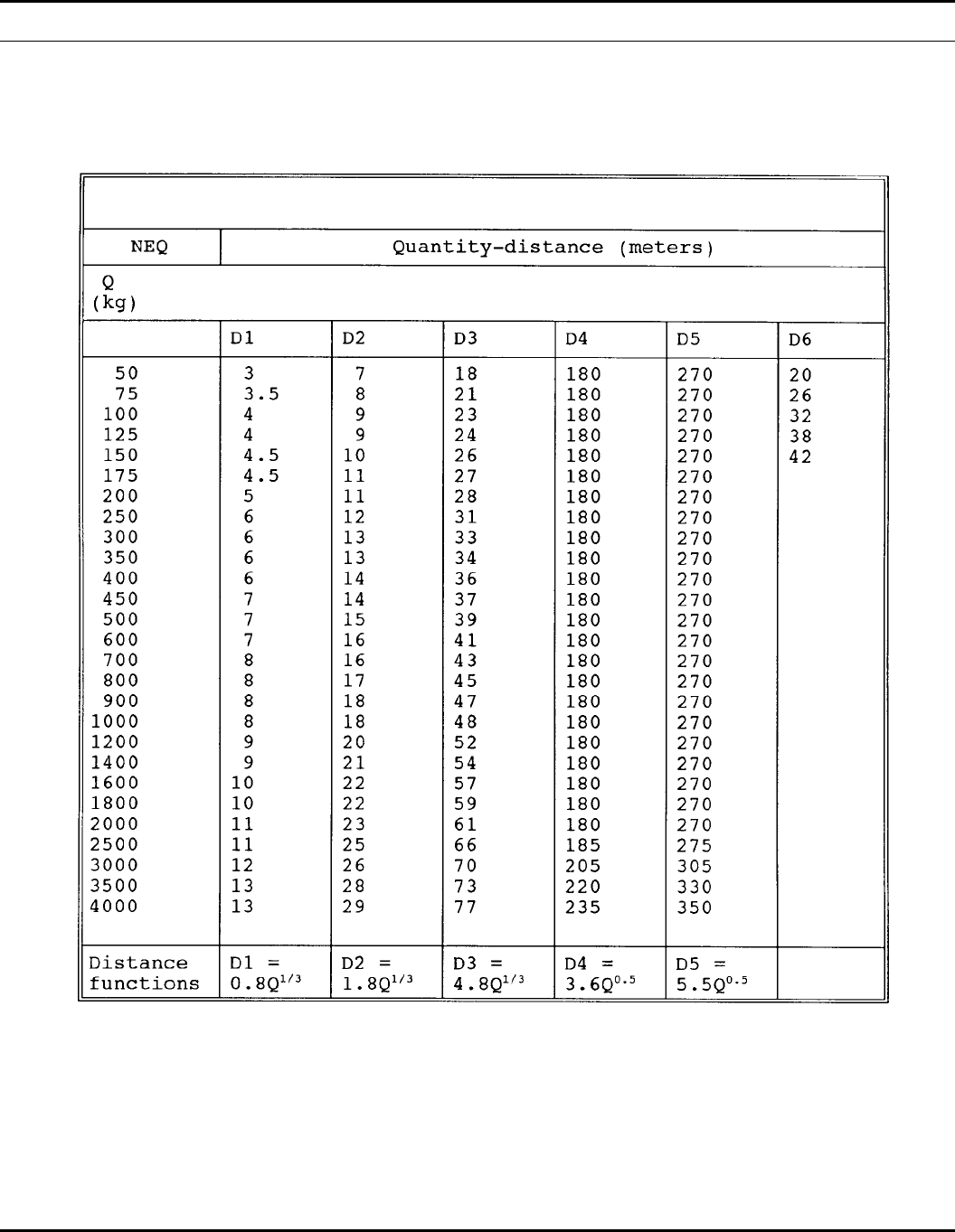
Table 14–1
Quantity-distance table for basic load ammunition holding areas
127DA PAM 385–64 • 28 November 1997
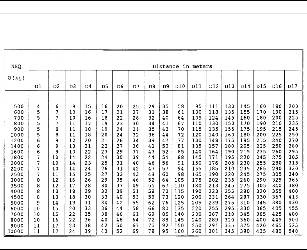
Table 14–2
HD 1.1 Quantity-distance for airfields used only by military aircraft in theaters of operation
128 DA PAM 385–64 • 28 November 1997
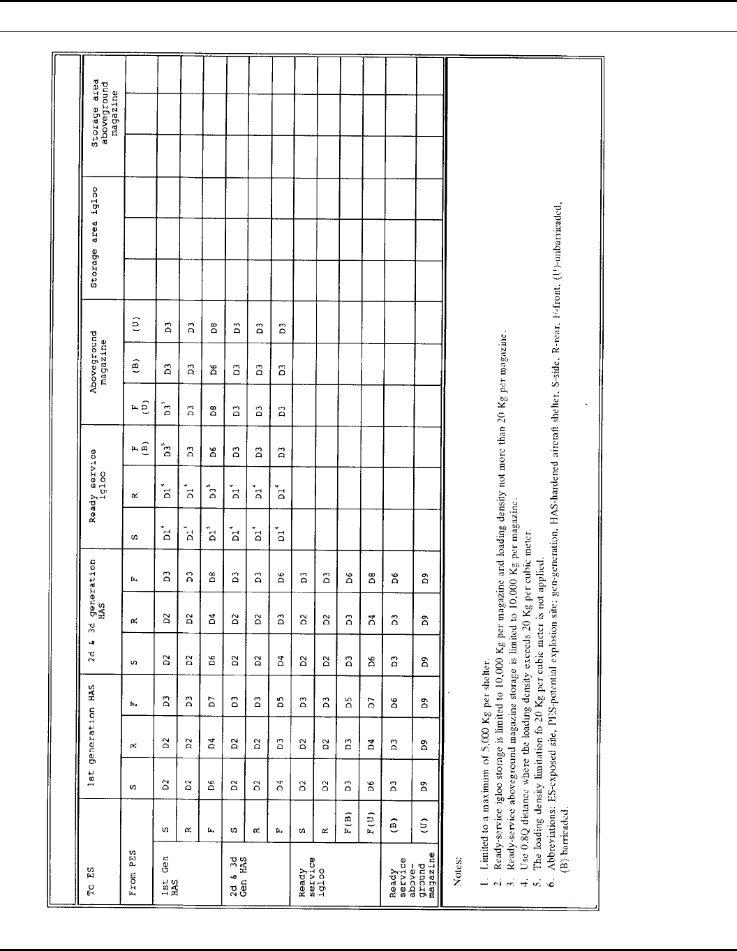
Table 14–3
Quantity-distance for propagation prevention at airfields
129DA PAM 385–64 • 28 November 1997
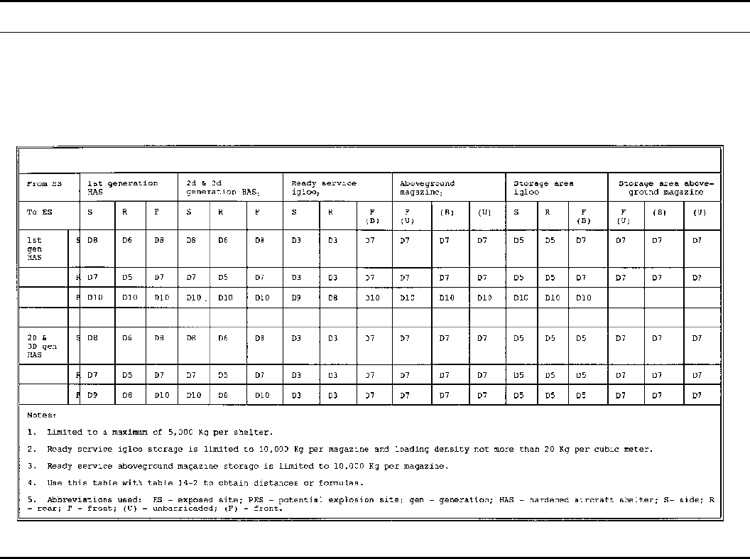
Table 14–4
Quantity-distance for assets preservation at airfields
130 DA PAM 385–64 • 28 November 1997
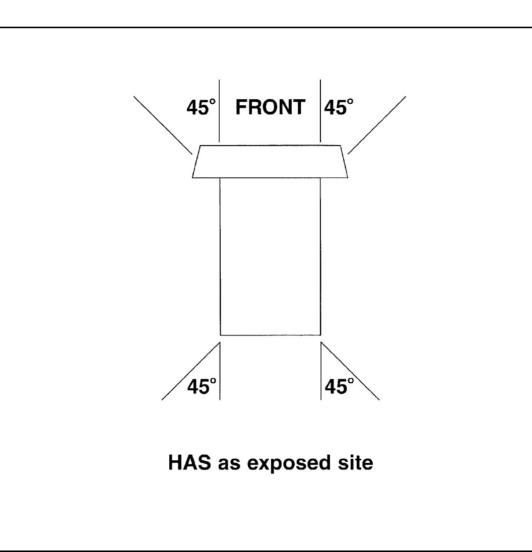
Figure 14-1. Hardened aircraft shelter an as exposed site
131DA PAM 385–64 • 28 November 1997
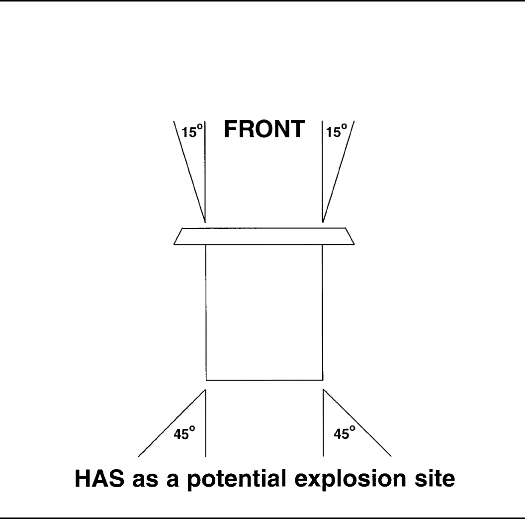
Figure 14-2. Hardened aircraft shelter as a PES
132 DA PAM 385–64 • 28 November 1997
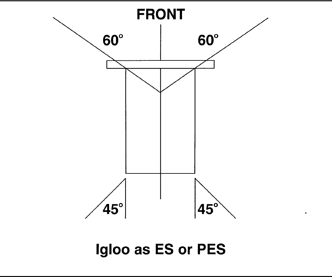
Figure 14-3. Igloo Q-D angles
Chapter 15
Wartime Operations
15–1. General requirements
a. This chapter provides guidance for the safe handling, transpor-
tation, and storage of ammunition during wartime and contingency
operations. This guidance provides options, based on the acceptance
of ever increasing degrees of risk, to the commander faced with
v a r i o u s a n d f l u c t u a t i n g b a t t l e f i e l d h a z a r d s . I t m a y b e u s e d i n
developing battle doctrine and integrated into contingency and com-
bat operations planning.
b. The provisions of this chapter apply in:
(1) A recognized war zone.
(2) A recognized contingency operations area.
(3) An area where hostilities are imminent and approval to imple-
ment this chapter has been given by the MACOM.
c. Several fundamental concepts govern the relaxation of peace-
time explosives safety standards during combat and contingency
operations and the acceptance of added risks:
(1) Whenever and wherever possible, the peacetime explosives
safety standards enumerated in chapters 1 though 14 of this pam-
phlet should be followed. Only after assessing the risks of relaxation
against the mission-imposed parameters should the less restrictive
guidance of this chapter be implemented.
(2) Where Q-D considerations must be relaxed, preventing propa-
gation and preserving personnel, military equipment, and ammuni-
tion should be paramount.
(3) The third factor in Q-D explosives safety calculations is time.
The degree to which standards are relaxed should be directly related
to the duration of the exposure. Relaxation of standards for 24 hours
involves less risk than relaxation for 48 hours.
(4) The acceptance of a high degree of explosives safety risk
depends on the competing hazards of the battlefield. The risk of an
explosives accident may be far outbalanced by more imminent bat-
tlefield hazards as ammunition approaches the forward line of own
troops (FLOT).
(5) Ammunition logistical considerations and warfighting require-
ments should take precedence over compatibility in the mixing and
grouping of ammunition items.
(6) Hazard Class/Division 1.2 ammunition should be treated as
HD 1.1. When it becomes impractical to manage ammunition by
hazard class, all ammunition, except identifiable HD 1.4, should be
treated as HD 1.1. All captured ammunition, mixed ammunition,
and unserviceable or unknown ammunition will be treated as HD
1.1.
(7) When it becomes impractical to manage ammunition separa-
tion distances by NEW, short tons may be used. Short tons will be
calculated based on gross package weight.
133DA PAM 385–64 • 28 November 1997
d. When handling ammunition in the field, the following general
principles apply:
(1) Soldiers controlling or supervising the handling of ammuni-
tion must observe safety precautions. Every effort will be made to
ensure that skilled and knowledgeable personnel are in charge of
ammunition operations.
(2) In field storage, ammunition should be distributed in such a
way that an incident will not cause the total stock of any one type of
ammunition to be lost.
(3) Ammunition should be dispersed to minimize loss in the
event of fire, accidental explosion, or enemy action.
( 4 ) F i r e f i g h t i n g p r e c a u t i o n s m u s t b e t a k e n a n d f i r e f i g h t i n g
equipment must be serviceable. All fires will be fought immediately
without special order (para 15–2e).
(5) Ammunition of unknown origin and captured ammunition
will be examined, evaluated, and classified by qualified personnel
and stored in a designated collection point (para 15– 2d).
(6) The existing infrastructure and terrain features (for example,
buildings, barns, forests, barriers, and so forth) will be used to
prevent propagation and to protect personnel and material from the
effects of an explosion. Dry water courses will not be used during
anticipated periods of heavy rain.
(7) Ammunition containing WP will be stored and transported in
an upright position if ammunition surface temperatures are expected
to exceed 111 degrees F.
(8) In any given field situation, all measures must be taken, to
minimize the risk to personnel, material, and ammunition.
(9) Provisions must be made to evaluate and, if necessary, segre-
gate damaged ammunition.
(10) Provisions should be made, particularly for contingency op-
erations of expected short duration, to save and segregate packing
m a t e r i a l t o b e r e u s e d t o t u r n i n s a f e l y a n d t r a n s p o r t u n u s e d
ammunition.
15–2. Theater and corps ammunition storage areas
a. Quantity-distance.
(1) Where the local situation allows, the peacetime Q-D specified
in chapters 5 and 14 should be followed. This level of protection
limits the risk to the civilian and unrelated military population from
death or serious injury from blast overpressure and fragments due to
a n e x p l o s i o n , p r o t e c t s v i t a l f a c i l i t i e s f r o m s e r i o u s d a m a g e , a n d
protects ammunition from propagation.
(2) Where the local situation does not allow for this level of
external protection, the internal protection should be maintained.
Any reduction in either internal or external distances increases the
risk to adjacent facilities and other ammunition locations. Stacks of
ammunition should be stored at the magazine distances specified in
chapters 5 and 14. This level provides reasonable protection against
propagation but risks the total destruction of exposed buildings and
aircraft as well as death or serious injury to exposed personnel.
(Every effort should be made to identify and protect facilities with
dense population, such as hospitals, military facilities, headquarters,
and POL storage, vital to the accomplishment of the mission.)
(3) Where existing ammunition storage sites are to be converted
to wartime use, the ammunition storage license (chap 9) lists the
maximum NEW for which these sites will provide the level of
protection described in (2) above.
(4) Where specific unimproved locations have been identified for
use as wartime/contingency ammunition storage sites, MACOMs
may wish to develop ammunition storage licenses, providing the
levels of protection described in (1) and (2) above, and integrate
these licenses into warplans.
(5) Permanent or contingency facilities with a designated wartime
ammunition mission, such as ports, must integrate explosive safety
Q-D guidance into warplans.
(6) For Q-D purposes, ammunition of HD 1.2 will be treated as
1.1.
b . C o m p a t i b i l i t y . I f a t a l l p r a c t i c a l , a m m u n i t i o n c o m p a t i b i l i t y
(Table 15–1) should be maintained during bulk storage.
(1) Compatibility does not apply to CCLs.
(2) Components of complete rounds may be stored together, for
example, fuzes, projectiles, propelling charges, and primers.
(3) Blasting caps which are not in original packing configuration
present a unique hazard and should be separated from other ammu-
nition by sandbags or other suitable material.
(4) Logistical considerations and combat requirements take prec-
edence over compatibility considerations.
c. Storage by short tons. When storing ammunition by short tons
rather than NEW, the guidance in paragraph 15–5 applies. Since this
guidance involves more risk and less predictable protection than the
guidance in a and b above, it should be used only when the above
criteria can no longer be met.
d. Foreign, captured, and unserviceable ammunition.
(1) Serviceable NATO standard ammunition, which has an as-
signed HD and SCG will be stored in the same manner as U.S.
ammunition.
(2) Unserviceable ammunition, regardless of the nation of origin,
will be segregated from serviceable war reserve ammunition and
appropriately tagged to prevent unintentional use.
(3) Captured ammunition, regardless of nation of origin, will be
segregated in a designated collection point and separated from war
reserve ammunition using HD 1.1 distances. Following examination,
evaluation, and classification by qualified personnel, it may be as-
signed a temporary HD and SCG, if necessary, by analogy to U.S.
ammunition items.
e. Firefighting. All fires in the vicinity of ammunition should be
fought until the stacks of explosives or ammunition become in-
volved in the fire. Because evacuation to IBD will not always be
practical, seek protection from an imminent explosion in trenches
and behind natural earthen barricades.
15–3. Storage at the ASP and ATP
a. The same principles of explosives safety in ammunition stor-
age and handling apply at ASPs and ammunition transfer points
(ATPs) as at theater and corps ammunition storage areas.
b. The principal explosives safety objectives should be the pre-
vention of propagation and the dispersion of ammunition to mini-
mize loss in case of fire, accidental explosion, or enemy action.
c. Since more risk is assumed at an ASP or ATP, storage by field
storage unit (FSU) (para 15–5) should be considered a routine stor-
age option. Ammunition may be stored, according to logistical con-
siderations and combat requirements, using either paragraph 15–2 or
paragraph 15–5.
d. Where real estate constraints do not permit the separation
distances specified in Table 15–2, modular storage (para 8–29)
should be constructed.
15–4. Short-term ATP storage
a. At ATPs where ammunition is stored for periods of 3 days or
less, ammunition will be positioned to fulfill logistical and adminis-
trative requirements.
b. Wherever possible, FSUs (para 15–5) or modular storage (para
8–29) should be used.
c. All explosives safety requirements, except for Q-D and storage
compatibility criteria, must be observed.
15–5. Field storage units
a. Field storage of ammunition consisting of one or more stacks
of ammunition, either roadside or area storage, is considered an
FSU. The FSU concept permits the storage of ammunition by the
short ton (2,000 pounds) without regard to NEW.
b. The principal objective of the FSU concept is to disperse
ammunition to minimize the loss in case of fire, accidental explo-
sion, or enemy action. Each type of ammunition should be stored in
at least two widely separated FSUs to prevent the loss of the con-
tents of any one FSU from seriously handicapping military opera-
tions by the loss of the entire supply of any item.
c. Short tons should be considered gross weight to include the
weight of both ammunition and packing material.
d. Each FSU is limited to a maximum of 400 short tons.
134 DA PAM 385–64 • 28 November 1997
e. Each stack within an FSU is limited to a maximum of 20 short
tons.
f. To inhibit the spread of fire, stacks must be separated by a
minimum distance of 50 feet. This distance does not provide com-
plete protection from propagation of detonation by blast overpres-
sure or fragments. Anytime the distance between stacks is reduced,
there is an increased risk of damage to adjacent stacks.
(1) The greater the distance between stacks, the less the probabil-
ity of fire spreading from stack to stack.
(2) Aggressive fire fighting can prevent the spread of fire from
one stack to another.
(3) Where these distances cannot be attained, extraordinary care
must be taken in establishing and maintaining fire protection, fire
guards and fire fighting measures.
g. Normally only one type of ammunition is stored in a stack. If
more than one type is stored in a stack, the ammunition should be
arranged to facilitate inventory and inspection. Whenever desirable,
components of complete rounds may be stored within the same
FSU.
h. Ammunition stacks should be accessible to MHE.
i. Ammunition may be stored in an FSU either in bulk storage
configuration or CCLs.
(1) In bulk storage configuration compatibility group K ammuni-
tion, items containing toxic chemical agents must be stored in sepa-
rate FSUs. This is to minimize the potential for the contamination of
other stocks if an accident occurs.
(2) Logistical considerations and combat requirements take prec-
edence over compatibility considerations. However, if at all possi-
ble, compatibility groups J and L should be stored in separate FSUs;
that is separate from other groups and separate from each other.
These groups contain ammunition items which react violently to
water and could prevent aggressive firefighting.
(3) Compatibility does not apply to CCLs.
j. The existing infrastructure (for example, office buildings, fac-
tories, barns, and so forth) may be used for FSUs provided that—
(1) The allowable load of structural parts per unit area is not
exceeded.
(2) A stacking height of approximately 16 feet is not exceeded.
Stacks will not come closer to the ceiling than 18 inches.
(3) Each FSU is accessible from the outside.
(4) Each FSU does not exceed 10 short tons.
(5) Electrical installations inside the buildings are deenergized
unless they are known to be in compliance with the regulations for
electrical installations in magazines.
k . C l i m a t i c c o n d i t i o n s m u s t b e c o n s i d e r e d w h e n e s t a b l i s h i n g
FSUs.
(1) When ammunition is stored in desert or tropical environ-
ments, care must be taken to shield the ammunition from the direct
rays of the sun, if at all possible. If tarps are used, allow at least 18
inches between the tarp and the top of the boxes.
(2) Where freezing and thawing conditions exist, dunnage must
be used to prevent the ammunition from freezing to the ground or,
during a thaw, sinking into the ground.
(3) Some types of ammunition should be protected from rain and
water damage. Care should be taken not to site an FSU in a dry
river bed or other area subject to flooding.
l. Vehicles or groups of vehicles loaded with ammunition will be
regarded as FSUs.
m. Aircraft being uploaded or downloaded with ammunition will
be regarded as FSUs. Ammunition must be situated so that it will
not be endangered by the exhaust gas stream of the aircraft.
n. The following ammunition must not be stored with other am-
munition at the same FSU:
(1) Captured ammunition
(2) Suspended ammunition
(3) Unserviceable ammunition
(4) Ammunition requiring maintenance or destruction
(5) Ammunition of unknown origin
(6) Ammunition returned from the field awaiting examination.
15–6. Transportation within the theater of operations
a. When selecting vehicles to transport ammunition, if vehicles
m e e t i n g p e a c e t i m e s t a n d a r d s a r e n o t a v a i l a b l e , c h o o s e v e h i c l e s
which do not present a fire hazard. That is, vehicles with leaks,
sticking brakes, holes in the floor of the cargo area, or exhaust
problems should be avoided.
b. Ammunition loads must be secured to prevent shifting and loss
of the load during transport.
c. Vehicles should be equipped with two fire extinguishers to
allow for fighting vehicle fires enroute.
d. Considerations of compatibility will not apply to the transport
of CCLs or other configurations being transported in the direction of
the FLOT. However, when mission permits, consideration should be
g i v e n t o t r a n s p o r t i n g S C G s “ H , ” “ J , ” “ K , ” a n d “ L ” o n s e p a r a t e
vehicles.
15–7. Modular storage
a. In a combat zone where insufficient real estate, limited secu-
rity or operational requirements are determining factors, the modular
system of storage may be employed. This system does not provide
the degree of protection to personnel or ammunition stocks afforded
by the Q-D requirements previously described in this chapter and
should be implemented only as a last resort.
b. The decision to use the modular system must be made with
full realization of its advantages and disadvantages over other field
storage systems.
(1) The advantages include—
(a) Greatly reduced real estate requirements.
(b) Greatly improved security with comparable forces.
(c) Reduced transportation requirements within the ammunition
area.
(d) Greatly reduced road net requirements.
(e) Reduced vulnerability to direct fire on ammunition stocks
because of the smaller area and use of barricades.
(2) The disadvantages include—
(a) The possibility of explosion or fire in one cell starting fire in
o t h e r c e l l s b e c a u s e o f h e a t g e n e r a t i o n o r i n d i r e c t f r a g m e n t
dispersion
(b) Increased vulnerability to enemy indirect fire and air-dropped
bombs because of concentration of stocks
(c) Additional engineer support required for initial construction
o f m o d u l e s a s o p p o s e d t o t h a t r e q u i r e d f o r u n b a r r i c a d e d o p e n
storage.
c. A module is a barricaded area composed of a series of con-
nected cells separated from each other by barricades. Construction
requirements and siting criteria for modular storage are described in
para 8–29 of this pamphlet. However, in wartime operations the
following exceptions apply:
(1) There is no restriction on the type of ammunition authorized
for modular storage.
(2) Mixing ammunition stocks in modular storage is authorized.
15–8. Ammunition turn-in at the cessation of hostilities
a. At the cessation of hostilities the Army will commence transi-
tion to the peacetime provisions of this pamphlet.
b. Ammunition will be collected and stored at selected storage
areas and turn-in points meeting the Q-D requirements of chapter 5.
Where this is not practical, the guidance of this chapter may be used
temporarily.
c . S e g r e g a t i o n , i n s p e c t i o n , f i e l d m a i n t e n a n c e , d e s t r u c t i o n , a n d
repackaging of turn-in ammunition will be accomplished in accord-
ance with established logistics procedures. However, because of the
increased hazards associated with turn-in ammunition, these activi-
ties will take place in strict compliance with the separation distances
specified in chapter 5.
d. Ammunition will not be offered for shipment to CONUS loca-
tions until a qualified military or civilian expert has certified in
writing that the ammunition meets peacetime safety standards or
equivalent for transport.
135DA PAM 385–64 • 28 November 1997
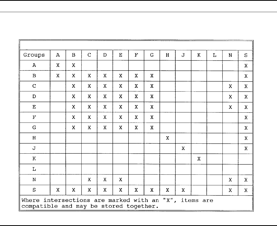
Table 15–1
Wartime compatibility chart
136 DA PAM 385–64 • 28 November 1997
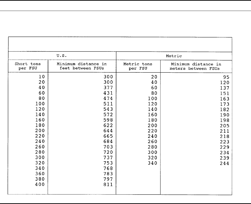
Table 15–2
Q-D for field storage units
Chapter 16
Storage and handling of commercial explosives
16–1. Background
This chapter provides guidance on the storage and handling of
commercial explosives on Army installations.
16–2. Use
Using commercial explosives, other than for production and RDTE,
is prohibited unless commercial explosives are mission essential and
specifically authorized by the installation’s MACOM commander
(see para 16–3e and f below).
16–3. Procedures
a. Obtain approval to use commercial explosives before purchase.
b. The HD and SCG information will be requested and should be
received before purchase.
c. When commercial explosives are received before USATCES
assigning HD and SCG information, commercial explosives will be
stored as HD 1.1, SCG L. Small arms ammunition will be stored as
HD 1.4, SCG S.
d. The net explosive weight (NEW) will be calculated based on
the weight of the explosive.
e. Approval request will be sent through command channels to
the installation’s MACOM approving authority.
f. When the requesting unit is a tenant activity, the request will
be sent through the unit’s command channels and the host installa-
tion’s MACOM approving authority must concur with the approval.
g. The HD and SCG will be obtained by providing the following
information to Director, U.S. Army Technical Center for Explosives
Safety.
(1) Documentation of an HD assignment by a competent authori-
ty; that is, DOT, BOE, Bureau of Mines (BOM), or foreign govern-
ment; or reports of HD testing or function testing accomplished by a
competent authority; or results of small scale laboratory tests con-
ducted by a competent authority.
(2) Complete item nomenclature.
(3) Part number, drawing number, or something that uniquely
identifies the item in its storage configuration.
(4) Explosves composition and weight. A chart or listing of haz-
ardous materials with their weights is preferred.
(5) Packaging data.
(6) Number of independent safety features if the item is a fuze,
contains a fuze, or has features similar to a fuze.
(7) Any other available information that may reflect the function
or the effects of the explosive.
(8) A point of contact and telephone number for the responsible
Army organization.
h. To receive inspection interval codes and inspection procedures,
137DA PAM 385–64 • 28 November 1997
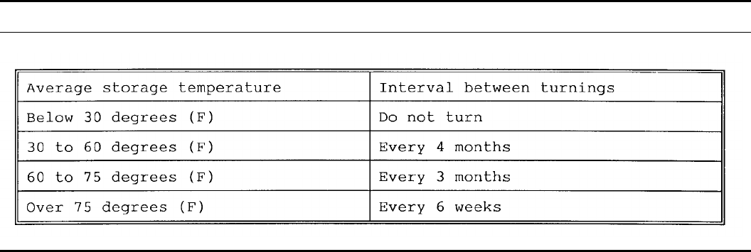
forward information in f above, to Commander, Industrial Opera-
tions Command.
16–4. Commercial dynamite
a. Dynamite is sensitive to heat and shock. Containers suspected
of containing sticks of dynamite that may exhibit signs of exudation
or crystallization (generally, these boxes have an oily appearance)
will be removed from the magazine and inspected. Individual sticks
having exudation or crystallization will be demilitarized immediate-
ly. The remainder can be repacked and returned to storage. Empty
containers that have been used for dynamite will be destroyed by
burning. Oily stains of nitroglycerin on magazine floors will be
scrubbed up with a mixture of solution A (Sodium sulfide - 9 parts
by weight and water - 30 parts by weight.) and Solution B (Dena-
tured ethyl alcohol - 70 parts by weight and acetone - 20 parts by
w e i g h t ) . I m m e d i a t e l y b e f o r e d e c o n t a m i n a t i n g t h e n i t r o g l y c e r i n ,
combine the solutions. If the solutions are mixed and then stored,
the potency diminishes in storage. Limit the use of this mixture to
very small quantities such as the oily film that adheres to surfaces
after the nitroglycerin has been removed with sponges or absorbed
in wood pulp or sawdust. Operators using this solution should wear
rubber gloves.
b. Store cases of commercial dynamite initially right side up, so
cartridges will lie flat. However, to reduce the possibility of exuda-
tion of nitroglycerin from the cartridges of straight dynamite 60
percent or over in strength, it will be necessary to turn the cases,
based on average storage temperature (Table 16–1).
c. The first turning will leave the cases bottom side up, with the
cartridges still in a horizontal position. The second turn of the boxes
will place the boxes right-side-up. Each turn of the boxes will be
180 degrees. Frozen dynamite will not be turned. With the exception
of straight dynamite, 60 percent and over in nitroglycerin strength,
o t h e r t y p e s o f d y n a m i t e - a m m o n i a , a m m o n i a - g e l a t i n , a n d g e l a t i n
need not be turned in storage. However, yearly, at the conclusion of
the year’s warmest season, a representative sample will be selected
and the containers examined for evidence of nitroglycerin on the
exterior of the cartridge and/or packing materials.
Table 16–1
Turning of commercial dynamite
Chapter 17
Demilitarization
17–1. Demilitarization
This chapter covers demilitarization operations to include demolition
and burning operations done as a separate operation. It does not
cover EOD operations. It does not cover demolition and burning
operations done as part of a training exercise providing that—
a. The item to be destroyed was generated during training.
b. The item would normally be destroyed as part of the wartime
mission.
c. The item has not been returned to storage.
17–2. Methods
Disposition of ammunition, explosives, and propellants will be ac-
complished by reclamation, open detonation, open burning, incinera-
tion, or other approved methods. Unless emergency disposition is
required, resource recovery and recycling efforts will be the primary
m e a n s o f d i s p o s i n g o f u n w a n t e d a m m u n i t i o n a n d e x p l o s i v e
materials. The burying or dumping of ammunition, explosives, or
propellants is not an approved method of disposal.
17–3. Safety precautions
a. General precautions. No demilitarization operation will take
place without an approved SOP. SOPs used for these type of opera-
tions will be reviewed at the local level at least annually for compli-
a n c e w i t h l o c a l l a w s a n d r e g u l a t i o n s i n v o l v i n g d e m i l i t a r i z a t i o n .
SOPs which are not in continuous use and have not been used
within the past 6 months will be reviewed and updated before the
beginning of an operation.
b. Burning/detonation operations.
(1) A red range flag will be flown or a red light will be lit at the
entrance to the range when operations are in progress. A red light
will be used during any operations occurring after sunset.
(a) The flag will be a minimum of 3 feet wide by 5 feet long.
This flag will continue flying until the range has been cleared and
all operations have ceased.
(b) The light will be of sufficient size and clarity to be seen from
at least 100 feet under all weather conditions in which operations
take place. This light will continue to burn until the range has been
cleared and all operations have ceased.
(2) A sign will be placed on the access road to the range explain-
ing the meaning of the red light and red flag. This sign will be
located at least 100 feet from the gate and will be lighted during
night operations. This sign will be in English and foreign languages
required by the area.
(3) A first aid kit will be present during all operations. It will
contain, as a minimum, items to treat burns and puncture wounds.
The first aid kit used will be approved by local medical authorities
based on the hazards involved. Personnel will be trained in using the
first aid kit and its limitations. They will be instructed that if there is
any doubt as to its use, that they will seek professional medical care
for the injured person.
(4) A means of communications between personnel on the demo-
lition range or burning area and base facilities will be maintained in
working order. A further means of communications will be main-
tained between personnel preparing items for demolition or burning
138 DA PAM 385–64 • 28 November 1997
operation and the control center on the range. Operations will not be
conducted if one or both of these means of communications is not
working. Radios will not be used when electrically initiated explo-
sives are being used, unless in compliance with Table 6–3.
(5) Firefighting equipment will be present at the scene to combat
fires which may start due to operations. The amount and type of
equipment will vary with local conditions and will be approved by
the installation fire marshal.
(6) After each demolition or burning operation, trained and com-
p e t e n t p e r s o n n e l w i l l s e a r c h t h e a r e a f o r h a z a r d o u s i t e m s . T h e
search will begin after an appropriate waiting period as specified in
the SOP for the operation. Personnel will be instructed in the type
and shape of the items being destroyed as well as what to do upon
finding an item. In the event of a misfire, a waiting period of 30
minutes will be observed prior to investigation of the misfire.
(7) In areas where the demolition ranges or burning grounds are
not under constant control of U.S. military, the following require-
ments will be strictly adhered to:
(a) Before the start of operations, the range will be searched for
unauthorized personnel.
(b) Guards will be posted to prevent entry into the range area.
Guards will be protected from fragments.
( 8 ) A l l p e r s o n n e l s h e l t e r s w i l l p r o t e c t a g a i n s t o v e r p r e s s u r e s
greater than 2.3 psi and against noise louder than 140 decibels if the
noise level exceeds 140 decibels. Personnel will wear hearing pro-
tection in accordance with DA Pam 40–501. If the noise level is
greater than 165 decibels, then earplugs must be worn in combina-
tion with a noise muff or a noise attenuating helmet.
(9) All burning and demolition operations will be initiated re-
motely or by using a delay device. If a delay device is used, it must
allow for a delay that is 50 percent longer than the time that would
normally be required to retire to the shelter.
17–4. Site selection for burning or demolition grounds
a. Open Burning (OB) Areas. Sites for burning of ammunition
and explosives shall be separated from other facilities as specified in
paragraph 5–7p.
b. Open Demolition (OD) Areas. OD operations will be sited
according to the requirements for paragraph 5–7c.
c. Burning and demolition sites. All disposal sites permitted as
hazardous waste treatment facilities under 40 CFR must be sited in
accordance with 40 CFR 265.382.
17–5. Burning sites
a. Burning pans or trays will be of locally approved construction.
b. Burning pads constructed of concrete will be covered with a
minimum of a 4–inch bed sand to protect the concrete. When the
user intends to dispose of the sand, tests for hazardous waste charac-
teristics will be conducted.
c. All burning sites will have a means of collecting remnants and
e v e n t u a l l y d i s p o s i n g o f a n y h a z a r d o u s w a s t e s p r o d u c e d b y t h e
operation.
d. Burning sites will—
(1) Ensure that the items to be burned are spread evenly over the
burning pan or pad, so that the depth of the material does not
exceed 3 inches. Items which exceed 3 inches in diameter may be
burned, provided they are stacked only one item high.
(2) Be sited so that the distance between each active burning site
will be sufficient to prevent a burning ember from landing on
adjoining sites.
e . I n s t a l l a t i o n s m u s t e s t a b l i s h w r i t t e n p r o c e d u r e s t o p r e v e n t
materials to be burned from igniting from heat or residue remaining
in pan trays or on pads.
17–6. New demilitarization technologies
a. The Army encourages the development of new technologies
for reclamation which will—
(1) Result in less hazardous waste.
(2) Be economically feasible. (The sale of residue will be in-
cluded in making the determination of whether a technology is
economically feasible.)
(3) Be environmentally safe.
(4) Meet the requirements of AR 385–16.
b. Coordinate the development of new technologies with the Di-
rector, USADACS.
c. In developing new technologies or testing them before final
approval for use is given, the following procedures will be followed:
(1) A hazard analysis will be conducted to determine the level of
risk involved and the required safety measures needed.
(2) Based on (1), a written procedure will be developed before
running a test.
(3) A dry run will be conducted before using live explosives to
verify the mechanics of the procedure.
(4) Only the minimum number of personnel using the minimum
a m o u n t o f e x p l o s i v e s w i l l b e u s e d t o v e r i f y t h e p r o p o s e d
technology.
Chapter 18
Maintenance
18–1. General information
a. Maintenance is maintaining explosives and ammunition in a
serviceable condition or restoring them to that condition. It includes
s u c h o p e r a t i o n s a s r e n o v a t i o n , m o d i f i c a t i o n , p r e s e r v a t i o n , a n d
packing.
b. Maintenance includes all operations from the time of delivery
of the ammunition to the maintenance building to the time it is
ready for shipment to storage or issue. Maintenance operations in-
volve the following: line layout, establishing barricades as appropri-
a t e , s e t t i n g u p e q u i p m e n t , p a r t i a l o r c o m p l e t e d i s a s s e m b l y o f
ammunition items, cleaning parts or subassemblies, repair or re-
placement of mechanical parts, replacement of explosive compo-
nents, reassembly, repainting and remarking, and the repacking and
r e m a r k i n g f o r s h i p m e n t a n d d e l i v e r y t o a n a m m u n i t i o n i s s u i n g
point.
c. Renovation or modification of conventional ammunition, mis-
siles, ammunition or missile components and explosives will be
accomplished only with specific authority from Industrial Operation
Command (IOC), Aviation and Missile Command (AMCOM), or
other authority as appropriate.
d. The necessary preservation and packing (P&P) may be per-
formed on unserviceable ammunition and components when a re-
quirement exists.
18–2. Safety requirements
a. Renovation.
(1) Renovation will be performed in an isolated area or building
specifically designed for that purpose. These operations will be
carried out in conformity with the quantity-distance requirements of
Chapter 5. The number of persons permitted at or near the operation
will be kept to a minimum. The area or buildings will be kept free
of loose explosives, waste paper, and other combustible material.
All work will be performed under the direct supervision of experi-
enced personnel.
(2) Renovation operations can be hazardous. They require a thor-
o u g h k n o w l e d g e o f t h e a c t i v i t i e s i n v o l v e d , t h e h a z a r d s t o b e
g u a r d e d a g a i n s t , a n d t h e p r e c a u t i o n a r y m e t h o d s n e c e s s a r y f o r
greatest protection to personnel and property. Before starting any
operation involving ammunition or explosives, an adequate SOP
will be developed and approved—
(a) By the commander of the establishment, or,
(b) By a qualified member of his or her staff who has been
delegated authority to review and approve the SOP.
(3) Controlled tests may be necessary to establish SOPs for cer-
tain operations. The SOPs will include, as a minimum, such items as
safety requirements, personnel and explosives limits, equipment des-
ignation, and location and sequence of operations. A dry run will be
139DA PAM 385–64 • 28 November 1997
done using inert components to ensure that the SOP includes all
necessary operations, equipment and, procedures. No deviation from
this procedure will be permitted unless the commander or his desig-
nated representative approves.
b. Allowable limits. The quantity of explosives or ammunition at
an operating location will be the minimum necessary to carry out
the operation. This quantity will be subdivided to the maximum
extent possible into smaller amounts, adequately separated to pre-
vent propagation. Personnel exposure will be minimum consistent
with safe, efficient, and continuous operation.
c. Internal movement of explosives. Items or groups of items of
ammunition and explosives that are transported from bay to bay
within an operating building, will be separated to preclude creating
a path for the propagation of an explosion or fire between bays. For
this purpose, the minimum spacing between items or groups of
items in transport will be intraline distance unless reduced distances
have been approved. Suitable shields or barricades may be used to
interrupt the propagation path between items on a conveyor when
approved. Appendix F shows the approved safe separation distances
of conveyor spacing for specified items based on configuration of
the item, position on the conveyor, distance between items and, if
needed, the shield or barricade.
d. Concurrent operations.
(1) Unless a building is specifically designed and approved for
concurrent operation, permissible concurrent operations will be ac-
complished in separate buildings located at the appropriate intraline
distance from other operating buildings in the area.
(2) When necessary to conduct concurrent operations in the same
building, they must be arranged in a manner to segregate the items
so that dissimilar hazards are separated by a reinforced concrete
dividing wall. Unrelated personnel involved in concurrent operations
in a single building must be afforded protection equivalent to IL
distance (K18).
(3) Operations involving nuclear weapons and associated major
assemblies will be separated from conventional ammunition opera-
tions by not less than the applicable inhabited building distance
based on the quantity of explosives at the conventional ammunition
operation. In such instances, explosives limits for the nuclear weap-
ons facility may be determined by applying intraline quantity-dis-
tance requirements.
(4) The quantities of explosives and number of personnel ex-
posed at each concurrent operation will be held to the minimum
consistent with safe and efficient operating procedures.
e. Operations within a magazine area.
(1) Explosives and ammunition will not be renovated, modified,
or demilitarized within a magazine. These operations will not be
carried on within the magazine area unless the site, empty magazine,
buildings, or rail cars in which the work is done are assigned
exclusively to such work. Temporary operations outside of the mag-
azine may be carried out as permitted in (2) below. Permanent
structures involving labor intensive operations must be properly
sited with an approved site plan.
(2) The performance of P&P operations in the magazine area
may be approved by the installation commander as field operations
and separated from the PES by intraline distance based on the larger
quantity of NEW at either the PES or ES. Such operations will be
limited to derusting and painting of bombs and separate loading
projectiles, opening and repacking boxes and metal containers of
ammunition (including chemical ammunition), repacking of ammu-
nition into serviceable boxes and fiber containers, spot painting
projectiles, maintenance of fuze cavities and base covers of separate
loading projectiles, and other relatively safe operations of the same
general type.
f. Division of explosive quantities. The division of large quanti-
ties of explosives material into a number of smaller quantities, using
dividing walls, is intended to prevent the simultaneous explosion of
the total quantity involved. If the explosives on both sides of a
dividing wall are prevented from exploding simultaneously, the wall
achieves its purpose. If this requirement is met, then, for the purpose
of quantity-distance computations, the quantities separated by divid-
ing walls need not be added together. Design of intervening barriers
in accordance with the principles contained in TM 5–1300 will
satisfy this requirement. Information on barricaded open storage
modules meeting this criteria are given in paragraph 8–29 of this
pamphlet.
18–3. Operational shields
a. Shields required. Operational shields are required when the
operation to be performed provides an unacceptable risk of exposure
as defined by paragraph 5–7k of this pamphlet.
(1) Operational shields prevent operator exposure to blast over-
pressure in excess of 2.3 psi, fragments to energies of less than 59
ft-lb, and thermal fluxes to 0.3 calories per square centimeter per
second. For operations involving intentional initiation or detonation,
operational shields shall be capable of limiting overpressure levels
(decibels) in personnel-occupied areas to satisfy the requirements of
MIL STD 1474. (MIL STD 1474 overpressures are expressed as
decibels. The conversion factor is: dB = 20(log (144/4.2 x 107))
(2) Shields complying with MIL STD 398 are acceptable protec-
tion. Shields which have not been tested in accordance with the
requirements of MIL STD 398 shall be evaluated by competent
personnel before beng used in ammunition operations.
( 3 ) D e t e r m i n a t i o n o f t h e m a x i m u m c r e d i b l e e v e n t f o r t h e
materials and operational scenario involved is an essential part of
the evaluation of the operator protection requirements.
b. Unacceptable risk. In addition to those operations where a risk
assessment per paragraph 5–7k shows an unacceptable risk, opera-
tional shields will be provided to separate the operator from the item
being processed for the following operations:
(1) Disassembly of loaded boosters, fuzes, primers, and blank
ammunition.
(2) Removal of base plugs from loaded projectiles where the
design of the projectile is such that explosive contamination of the
base plug is not positively precluded.
(3) Removal of fuzes from pentolite loaded projectiles.
(4) Disassembly of loaded bombs and warheads, except for re-
moval of shipping bands, nose and tail closing plugs, fin locknuts,
and washout of high explosives bursting charge.
(5) Removal of fuzes from hand grenades loaded with high ex-
plosives except as noted in c(6) below.
(6) Pull-apart of fixed ammunition, 20mm and larger. In the pull-
apart of rounds containing self-destroying tracer, the dimensions of
the shield will anticipate initiation of the propellant and the projec-
tile. Pull-apart of ammunition with inert projectiles will use initia-
tion of the propellant as the maximum credible event. Pull-apart of
a m m u n i t i o n w i t h e x p l o s i v e s l o a d e d p r o j e c t i l e , b u t w i t h o u t s e l f -
destroying tracer, will use initiation of the propellant as the maxi-
mum credible event.
(7) Disassembly of foreign ammunition or other ammunition of
uncertain design and condition.
(8) Electrical testing of igniter circuitry of rockets, missiles, or
any other electrically initiated explosives item. Electrical testing of
igniter circuitry in missile and rocket motors and other propulsion
systems shall use initiation of the propellant as the maximum credi-
ble event. Electrical testing of initiating components of warheads,
projectiles, and similar items shall use initiation of the warhead or
projectile and propellant as the maximum credible event unless
hazards analysis shows negligible probability that test-energized cir-
cuitry could cause explosives functioning.
c. Shields not required. The operations (1) through (6) (below)
and similar operations do not require operational shields to protect
operators if the assembly has been normal, and if regular equipment,
tools, and methods used in the assembly are sufficient to accomplish
the disassembly without the application of undue force. Undue force
is considered to be any force greater than the maximum allowable
disassembly torque specified on the current drawings for the item
u n d e r c o n s i d e r a t i o n . T o o l s u s e d f o r d i s a s s e m b l y w i l l n o t h a v e
greater lever advantage than those required for the assembly. In
these cases, care will be taken to ascertain that the assembly has
been normal and the surfaces to be separated are not corroded and
140 DA PAM 385–64 • 28 November 1997
have not been sealed with metallic caulking, laminac, or epoxy resin
whose strength exceeds the adhesive properties of Pettman Cement
or NRC compound.
(1) Removal of loaded fuzes and fuze well cups from loaded
projectiles.
(2) Removal of primers from mortar ammunition.
(3) Removal of ignition cartridges from mortar ammunition.
(4) Removal of boosters or bursters from loaded projectiles.
(5) Removal of setscrew from loaded projectiles. When drilling
equipment is used to remove stake-punch marks and back out set-
screws, positive stops on the drill must be provided to prevent the
contact of the drill with the component parts of the fuze or booster
which contain explosives or with the explosives in the projectile.
Drills will be changed and positive stop set only by competent
mechanics. Only fully trained personnel will be used for such opera-
tions. Before the operation is begun, the projectile must be exam-
ined for the presence of exudate or other abnormal conditions.
(6) Removal of detonating fuzes from hand grenades designed
with metal fuze well liners provided:
(a) The operation is performed immediately in front of a suitable
protective tank having effective baffles for delay type fuzes into
which the grenade can be deposited should it ignite prematurely.
Baffle type tanks will not be used for grenades having impact fuzes.
(b) Shielded trays are employed to receive fuzes removed from
the grenades. The maximum number of fuzes allowed at each disas-
sembly station may not exceed fifty.
(c) Fuzes which will not readily disassemble from the grenade
with the equipment adjusted to the appropriate torque are immedi-
ately removed from the holding fixture and transferred to adequately
shielded locations where they may be removed in accordance with
the requirements contained in b above. Fuzes in this category will
be inspected for any defects which would render the item unsafe for
handling or further processing.
d. Disassembly operations.
(1) Each disassembly operation will be separated from adjacent
similar or dissimilar operations by operational shields designed to
protect the operator at any operation from the blast and fragments
arising from a possible explosion at any adjacent operation. Compo-
nents will be protected from a possible explosion occurring at the
disassembly operation.
(2) When disassembly of ammunition or components not gener-
ally included in paragraph 18–3 is contemplated, specific approval
of the proposed methods and locations for the operations must be
obtained in accordance with the procedures outlined in chapter 11.
(3) When disassembly is required to be performed with the oper-
ator protected by any operational shield (disassembly means com-
plete separation (threads or other connections) of component parts)),
the operator must not loosen the components while shielded and
then complete the disassembly without protection.
e. Containers for waste explosives. Explosives destined for the
burning ground will be in the original closed packages or in contain-
ers of fire-retardant materials which will not contribute to the exist-
ing hazard by readily producing sparks when contacting rocks, steel,
or other containers. Bags or containers made from easily ignited
material will not be used. Containers will have closures that will
prevent spilling or leakage of contents when handled or if overtur-
ned. Closures will be of a type that will not pinch or rub explosives
during closing and opening. The closures and surfaces of container
openings will be thoroughly cleaned of explosive contamination to
minimize the hazard during closing or opening.
18–4. Equipment for shielded operations
As used in this paragraph, the word “suitable” refers to a certified or
tested item. Normally, the equipment required for shielded opera-
tions consists of a suitable shield, holding devices, operating device,
means of observing the operation, and means of safely transmitting
power required for the operation.
a . A s u i t a b l e h o l d i n g d e v i c e , l o c a t e d b e h i n d t h e o p e r a t i o n a l
shield may consist of some form of a vise or jig on either a fixed or
an adjustable base, placed in such a manner as to hold the item in a
position to apply the operating device.
b. A suitable operating device may be a wrench, screwdriver, or
other tool designed to accomplish the work to be performed.
c. A suitable means for observation may be an indirect viewing
system of mirrors or a television camera located so that personnel
may operate at a safe distance. (A safe distance provides 2.3 pounds
per square inch (PSI) protection to the operator.)
d. A suitable means of transmitting power to the operating device
normally consists of a shaft extending through the shield. The shaft
will have a positive stop in front of the shield to prevent the shaft
from being blown through the shield toward the operator in the
event of an explosion. Personnel will not be in a direct line with a
shaft.
18–5. Tools, equipment and supplies
a. Tools. The basic tools and equipment for Ammunition Reno-
vation and Field Maintenance are listed in SC 4925–95–CL-A03.
Specific tools for ammunition operations are listed in the applicable
TM.
b. Equipment
(1) Equipment that is designed specifically for ammunition is
listed in TM 43–0001–47 and described in the operational and parts
manual for each piece of equipment. Additional lists may be found
in TM 9–1300–250.
(2) Other tools and equipment that have to be specially designed
will meet strength requirements and guard against the introduction
of chemical, mechanical, or electrical hazards over and above the
normal hazard of the explosives and ammunition involved. Special
tools and equipment, designed and fabricated locally, will require
prior approval by the appropriate commodity command before use.
18–6. Protection of primers
Preventative measures must be taken in the design of equipment,
transportation, and operations to protect not only loose primers but
also primers in rounds or in components from accidental impact or
pressure. Where feasible a protecting cap will be placed over the
p r i m e r . B o d i e s o f h a n d t r u c k s a n d o t h e r c o n v e y a n c e s u s e d f o r
transporting the primed items must be free from stones, protruding
nails, and other projections and debris which might cause the primer
to function. When primed items are transported on their bases, the
containers or truck bed will be recessed at the point primers would
otherwise make contact.
18–7. Cleaning ammunition
Power tools with nonferrous brushes may be used on ammunition or
ammunition components only when there are no exposed explosives
or thin walled casings where brushing would create heat or friction
sufficient to initiate the item involved.
18–8. Spray painting
a. All spray painting operations involving flammable liquids will
comply with 29 CFR and/or NFPA 77 whichever is more restrictive.
b. Water wash or dry filter-type spray booths will be used ex-
clusively for loaded ammunition and inert items. Filters for dry type
booths must not support combustion when clean and must be capa-
ble of effectively arresting paint overspray. They must be replaced
whenever the type of paint being sprayed is changed, and as di-
rected to maintain required airflow measures. Paint encrusted filters
will be disposed of promptly when found.
c. Electrical equipment, devices, apparatus and wiring will com-
ply with the requirements of Article 516, Spray Applications, Dip-
ping, and Coating Processes, of the NEC. Equipment will also be
listed for the appropriate hazardous location as determined by use of
Article 500, Hazardous (Classified) Locations, of the NEC.
d. Automatic sprinkler protection will be provided as follows:
(1) Above each paint booth and 20 feet horizontally beyond the
perimeter of the paint booth.
(2) Installed in exhaust ducts, 6 feet or more in length. If the
ducts pass through combustible walls, ceilings, or roof structures,
141DA PAM 385–64 • 28 November 1997
the sprinkler heads inside the ducts, will be no more than 12 feet
apart.
(3) For dry-type paint booths, automatic sprinklers will be in-
stalled behind the filters.
e. Controls for paint spray booth ventilating fan motors will be
interlocked with the controls for the paint sprayer. With this ar-
rangement, failure of the ventilating system will shut off power to
the paint sprayer.
f. For additional paint booth and flammable storage requirements,
see NFPA 33.
g. Where it is necessary to set up field operations and the re-
quirements of a above, cannot be met, spray painting of sizable
quantities of loaded ammunition or inert items is permissible if:
(1) Paint booths are constructed of noncombustible material.
(2) An exhaust system with fan is installed to remove paint
fumes from the booth (the fan may be powered by an air motor).
( 3 ) A t l e a s t t w o 1 0 B C ( o r l a r g e r ) C O 2 o r f o a m - t y p e e x t i n -
guishers are installed within the booth with rate-of-rise actuated
nozzle attachments. Two manual type CO2 or foam-type portable
fire extinguishers must also be provided at the paint spray booth or
operation.
(4) Special precautions are taken to keep the booth clean and
prevent the accumulation of paint on the surface of the booth or fire
extinguisher nozzles.
(5) The number of items in the booth at any one time are re-
stricted to the minimum number required for efficient and continu-
ous operation.
(6) The area within 50 feet of the paint booth is kept free of
combustible material, such as dry vegetation, wooden pallets, com-
bustible crating, or packing materials.
(7) Paint and chemical mixing operations, supplies, and air com-
pressors are located at least 50 feet from the booth.
(8) Personnel limits are maintained at the minimum consistent
with efficient safe operation.
h. If the quantity of loaded ammunition or inert items to be spray
painted in an outside location does not warrant providing a paint
booth, the operation may be performed in the open provided:
(1) The area within 50 feet of the spray paint operation is kept
clean and free from extraneous combustible material, air compres-
sors, and paint mixing operations.
(2) At least two class 10BC (or larger) portable fire extinguishers
are provided at the spray painting operation.
(3) Personnel are protected from toxic materials by respirators,
approved for the amount and type of exposure involved.
(4) Personnel limits are maintained at the minimum required for
efficient safe operation.
18–9. Electrostatic paint spraying and detearing of inert
items in non-hazardous locations
a. Electrostatic paint spraying and detearing operations will meet
the requirements of NFPA Standards or OSHA requirements which-
ever are more restrictive.
b. Loaded ammunition items will not be electrostatically paint
sprayed or deteared.
18–10. Infrared ray drying
a. Infrared drying processes will not be used in the same room in
which exposed explosives are present. Special precautions will be
taken to ensure that all items from which explosives have been
removed by processes such as “steam out” are free of explosives
contamination before subjecting them to this process.
b. If sealed items containing explosives are to be subjected to
infrared drying processes, prior tests to determine maximum internal
temperatures to which explosives will be raised by such rays will be
conducted on duplicate sealed containers with inert filler having a
thermal conductivity and specific heat similar to that of the explo-
sives. Conveyer speed, time of exposure, and intensity of exposure
to infrared rays will be adjusted so that the maximum internal
temperatures to which explosives are subjected to do not exceed 170
degrees F. (76.7 degrees C.) during entire period of exposure.
c. Before freshly dipped or painted items (inert or explosive
loaded) are processed in infrared drying equipment, they will pass
through a predryer. This predryer will be provided with positive
mechanical ventilation, constructed of non-combustible materials,
and will be provided with automatic sprinkler protection. The air
exhausted from the predryer will be discharged to the outside at a
point where possibility of re-entry into the building is at a mini-
mum. The predryer need not be heated. The time the article must
remain therein will be determined by actual test when using the
normal paint mixture. Freshly dipped or painted articles will be
predried until at least 85 percent of the volatile flammable vapors
are removed. (In most instances, less than 2 minutes are required
when air velocity past the article in the predryer is 300 feet per
minute (fpm) and the circulated air temperature is 70 degrees F.)
d. Within 20 feet of the predryer, paint spray booth or dip tank,
the electrical equipment will be installed in accordance with NFPA
Standard 33.
e. Interlock the drying equipment with the exhaust fan so that the
drying equipment cannot function unless the fan and conveyor are
operating.
f. Infrared drying equipment will be installed in a large room at
least six times as large in unobstructed area as the area of the
infrared drying equipment.
g . A d e q u a t e v e n t i l a t i o n , p r e f e r a b l y e x h a u s t v e n t i l a t i o n o f t h e
predryer will be provided for the room to keep vapor air mixtures at
least 25 percent below the lower explosive limit, and also below the
health hazard threshold limit values. Periodic tests in the vicinity of
the infrared drying equipment will be made with a flammable vapor
indicator to ensure low vapor concentrations.
h. The construction of infrared drying equipment will be such
that paint dripping from articles will not strike the lamps, reflectors
or wiring.
i. The construction and position of the infrared drying equipment
and conveyor equipment will be such that contact between articles
and bulbs is not possible.
j. Provisions will be made so that items being processed cannot
drop off the hooks and lodge in the dryer unnoticed. If the drying
equipment is constructed so that falling articles will not pass com-
pletely through it, arrangements will be made to automatically stop
the conveyor and extinguish the lights concurrently using suitable
protective devices.
k. The infrared drying equipment will be screened, or the source
of infrared radiation shielded so as to protect workers from pro-
longed or close exposure to radiation. If screening or shielding is
not adequate to protect employees’ eyes while working in the vicin-
ity of the drying equipment, safety goggles with Nos. 1–1/2 to 3
shade lens will be worn by those so exposed.
18–11. Drying freshly painted loaded ammunition
a. Ovens in which freshly painted loaded ammunition is dried
will comply with the requirements of 29 CFR or NFPA Standard 33,
whichever is more restrictive.
b. In addition, the following requirements will be met:
(1) Automatic thermostatic controls will be arranged to stop the
application of heat upon reaching a predetermined maximum tem-
perature which will not exceed 170 degrees F. (76.7 degrees C.).
(2) The oven will be equipped with an automatic sprinkler sys-
tem installed in conformity with the requirements of NFPA Standard
13. Automatic operation of the system may be accomplished by
electrical heat-actuated devices provided they are approved for, and
are installed in accordance with the requirements of Class I, Divi-
sion 1, Group D hazardous locations as defined in the NEC.
(3) Heating may be by hot air or other means as long as ammuni-
tion or explosives do not come in contact with coils, radiators, or
heating elements.
(4) If a conveyor system is employed, provision will be made to
shut off the heat supply automatically in the event of power failure
to the conveyor.
(5) Electric drying units that are not approved for use in Class I
hazardous locations as defined in the NEC will be designed so that
142 DA PAM 385–64 • 28 November 1997
the atmosphere in the oven is kept below 25 percent of the lower
explosive limit of the mixture of solvent vapors and air.
18–12. Heat sealing equipment
Electric heat sealing machines, used for sealing packages of uncased
or exposed explosives, will be separated from all similar or dissimi-
lar operations by an operational shield large enough to limit the
effect of an incident originating at the sealing operation to the
immediate vicinity. This does not apply for sealing outer packages
of cased or unexposed ammunition and explosives. Temperature
limits for heat-sealing equipment will be established with a safety
factor below the ignition temperature of the explosive, propellants,
or pyrotechnics involved. Such sealing equipment will be limited to
one machine per operating room, bay, or cubicle.
18–13. Soldering containers
Containers to be soldered will be free from explosives, explosive
dust, and flammable vapors. This does not prohibit soldering covers
to metal liners containing completely closed ammunition.
18–14. Thread cleaning
a. When thread cleaning is necessary, it will be accomplished by
the judicious use of nonferrous “picks.” Stainless steel brushes may
be used to clean threads of explosive-loaded projectiles providing a
fuze seat liner separates the thread cleaning operation from the
explosive charge. The operators need not be protected by operation
shields; however, thread cleaning operation will be separated from
unrelated operations.
b. Power actuated “thread-chasing” tools may be used to clean
loaded projectiles when threads are imperfect because of previously
applied Pettman cement or other sealers, provided the operation is
performed within a separate cubicle and by remote control. Hand
operated “thread-chasing” tools may be utilized provided no explo-
sives are present in the threads.
c. Thread cutting or correcting crossthreads will not be performed
on projectiles containing explosives. Straightening of crossthreads is
considered thread cutting.
18–15. Inert scrap components and packaging materials
a . A l l s c r a p c o m p o n e n t s a n d p a c k a g i n g m a t e r i a l s , o t h e r t h a n
fired small arms cartridge cases, derived from ammunition and haz-
ardous chemical renovation, P&P, modification and demilitarization
operations will be inspected by the activity generating the scrap to
detect contamination. All packaging materials will be opened to
ensure that no hazardous chemicals or ammunition items are pres-
ent. Qualified responsible personnel will certify such material to be
inert and free of hazardous chemicals and explosives prior to reuse
or transfer to the Defense Property Disposal Officer (DPDO) or to
an inert storage area.
b. For those items transferred to DPDO, the qualified responsible
personnel conducting the inspection of material will submit a certifi-
cate of inertness as part of the turn-in document in accordance with
the provision of DOD 4160.21–M–1, Chapter II, paragraph D2.
Materials generated from ammunition or other hazardous items,
even though properly inspected and certified inert, will not be min-
gled with other types of material, including scrap. The separation of
inert projectiles, dummy ammunition rounds and other types of
material will be maintained.
18–16. Sand or shotblasting operations
a. Because of possible hazards (resulting from hidden explosives,
thin or eroded cases, and certain characteristics of explosive filler),
sandblasting or shotblasting is prohibited for items such as thin-
cased land mines, shoulder-fired rocket ammunition, fixed rounds of
a r t i l l e r y a m m u n i t i o n , a n d c a r t r i d g e c a s e s c o n t a i n i n g p r o p e l l a n t .
Blast cleaning of solid propellant rocket motors may be accom-
plished only if the item manager approves in advance.
b. Explosive-filled or chemical-filled ammunition items assem-
b l e d w i t h t r a c e r s , f u z e s , o r o t h e r e x p l o s i v e - l o a d e d c o m p o n e n t s ,
which are not or cannot be adequately protected from direct contact
with the abrasive, will have such components removed prior to blast
cleaning. Where explosive-filled and chemical-filled items contain-
ing explosives-loaded components such as fuzes are, or can be,
p r o t e c t e d i n a m a n n e r t o p e r m i t b l a s t c l e a n i n g , s a t i s f a c t o r y
safeguards must be installed to prevent rotational velocities and
accelerations that will harm or otherwise affect the component parts.
c. In instances where items of ammunition are contained within a
structurally suitable outer container, the container, if necessary, may
be cleaned by sandblasting or shotblasting.
d. Each explosives or chemical-filled item must be carefully in-
spected for the presence of exuding explosives, chemical, and/or
inert seal material prior to sand or shot blasting. If exudation can be
properly removed with the application of approved solvents, such as
acetone, the unit may then be returned for sandblast or shot blast
cleaning. Solvents shall only be used in well ventilated areas.
e. All metal processing equipment used at the sand or shot blast-
ing operations will be electrically grounded and tested.
f. All operators directly engaged in sand or shot blasting opera-
tions will wear personal protective equipment.
g. Approved automatic or semi-automatic sand or shotblasting
e q u i p m e n t w i l l b e i n s t a l l e d w h e r e p r a c t i c a l . R e m o t e c o n t r o l o f
equipment, from behind an adequate barrier, is preferred.
h. The quantity of loaded items being sand or shot blasted at one
time will be maintained at the minimum consistent with safety and
efficiency. The sand or shotblasting equipment location will be
separated from the remainder of the operations and personnel by an
adequate barrier, dividing wall, or appropriate quantity-distance in a
manner to effectively limit the forces of an explosion during the
process to the immediate area.
i. Steel wool will not be used for cleaning where possible contact
with exposed explosives exists; nonferrous wool will be substituted
in these instances.
j. Operations involving the processing of related inert compo-
nents will not be performed in close proximity to the sand or
shotblasting operation involving explosives-filled items. These oper-
ations will be accomplished at a location where safety from an
explosion can be reasonably ensured. Wherever practical, the inde-
pendent processing on inert components such as cleaning metal
grommets and the like will be accomplished at not less than the
appropriate IL separation from the explosive hazard.
18–17. Location of sand or shotblasting operations in
explosives storage areas
a. Inhabited building distance will be maintained from an earth
covered magazine or open storage site to the point of operation,
when the point of operation is other than a permanent or semi-
permanent structure. Permanent or semi-permanent structures for
such operations will be located at a minimum of IBD from explo-
sives storage locations, based on the larger quantity of explosives
involved. Operations located at less than 100 feet from an earth
covered magazine or open storage site containing ammunition or
explosives are prohibited under any circumstances. Where loading
docks or other outdoor areas are used for sand and shot blast
cleaning activity, unrelated concurrent operations will not be con-
ducted in magazines or outdoor storage sites located closer than IL
distance.
b. A temporary earth barricade or other suitable protective barrier
will be erected around sand or shot blasting operations conducted in
the open within an ammunition storage area to protect adjacent
personnel and the source of supply of explosive-filled items.
c. Air compressors and motor generator sets used at the operation
are not to be located closer than 50 feet from the operational site
and from the nearest earth covered magazine or outdoor storage site.
If they are gasoline-powered and are to be used for a period long
enough to require refueling, they will be located 90 feet away, or
midway between earth covered magazines which are separated by
185 feet. Care must be exercised in the selection of the location to
preclude exposure of the entrance to the operation or to the earth
covered magazine.
d. When it is necessary to use loading docks as operating sites
143DA PAM 385–64 • 28 November 1997
for sand or shot blast cleaning operations, the docks will not be used
for normal shipping and receiving activities.
18–18. Sand or shotblasting operations within a building
in an operating line
When sand and shot blasting operations are carried on within a
building in an operating line, the following safety measures are
required in addition to the applicable precautions listed in para-
graphs 18–16 and 18–17:
a. The actual sand or shot blasting operation must be separated
from all other operations in the building by walls or barriers that are
designed to protect all other personnel if an unusual incident occurrs
at this location. Opening in these walls or barriers will be limited to
the minimum sizes required to facilitate the handling of items to and
from the operation. These openings will be arranged in a manner to
effectively baffle fragments and prevent projection into adjoining
rooms. Openings of the size to allow entry and exit of MHE will not
be permitted within the protective walls or barriers unless specially
designed to provide resistance to potential explosions equivalent to
that provided by the wall. A door opening of sufficient size for use
of personnel only may be provided in the protective wall if required.
In existing buildings where protection is provided by 12–inch rein-
forced concrete dividing walls, the walls must extend to the exterior
walls of the building. In no event will the height of the concrete
wall be lower than the lower rafters of the roof truss. Any opening
remaining between the top of the concrete wall and the underside of
the roof will be closed on both faces with rigid fire-resistant mate-
rial securely fastened to the wall and the underside of the roof.
b. Equipment for sand or shot blasting operations will be of the
type not requiring operators in the immediate vicinity of the ma-
chine to control it. It will be automatically controlled and provided
with interlocking switches that will stop the machine if any of its
parts fail. Manually controlled stop switches also will be provided at
proper intervals to permit prompt stopping of the equipment in event
of an accident. When manually operated abrasive equipment is used,
“dead man” controls will be provided on the blast nozzle.
18–19. Electrical testing of ammunition and ammunition
components
a. Type of test equipment. Electrical (including electronics) test
equipment will use the weakest possible power source. Battery-
powered equipment will be used in lieu of that with an AC source.
The power source will not be capable of initiating the explosive
item under test. Where greater power must be used, positive means
must be provided to prevent delivery of power to the explosive item,
in quantities sufficient to initiate the item. The possibility of error
on the part of operators and other personnel must be recognized and
safeguards provided.
b. Layout of test equipment. Test equipment will not be placed in
hazardous atmospheres unless absolutely necessary. When the test
equipment or parts thereof must be placed in hazardous atmos-
pheres, its suitability must be attested by an approved testing facili-
t y ’ s a p p r o v a l o r s p e c i f i c a p p r o v a l m u s t b e o b t a i n e d f r o m t h e
commander. Unless the test equipment is incapable of initiating the
item being tested, operational shields are required to protect person-
nel. The most reliable means for attaining and retaining this initia-
tion incapability is to protect the test equipment, including leads,
from electromagnetic (induction and radiation fields) and electros-
tatic energy and to provide the test equipment with a weak power
source. Where reliance is placed on resistors and other devices for
limiting power delivered to the item being tested, operational shields
will be provided.
c. Use of test equipment. Test equipment will be used only in the
manner and for the purpose for which approval was granted. The
equipment will be maintained in good working order by qualified
personnel. Operator adjustments must be limited to those required
by design of the equipment.
d. Equipment selection. The Army Equipment Data Sheets, Am-
munition Peculiar Equipment, TM 43–0001–47, may be used as a
guide in selecting equipment for specific operations.
18–20. Profile and alignment gaging operations
a. Each profile and alignment gaging operation, excluding small
arms ammunition, will be so enclosed that adjacent operations are
protected by operational shields complying with the requirements of
paragraph 18–3. The layout of the equipment and operational proce-
dure will be developed with a view toward minimizing personnel
injury and property damage in the event of an incident.
b. During chamber gaging of major caliber fixed ammunition, the
gate will be pointed toward a dividing wall or other barrier and the
round inserted into the gage and removed by the same operator. In
no case will the round be left in the gage. Rounds of mortar
ammunition will be gaged prior to attaching propellant increments,
and, unless prohibited by design characteristics, prior to assembly of
ignition cartridge.
18–21. Collection of explosives dusts
a. Dust collecting systems may be used to aid cleaning, to lessen
explosion hazards, and to minimize industrial job incurred poisoning
and dermatitis.
b. Examples of high explosives dusts which may be removed by
a vacuum system are TNT, tetryl, Explosive D, Composition B and
pentolite. A wet collector which moistens the dust close to the point
of origin and keeps it wet until the dust is removed for disposal is
preferred except for Explosive D which will only be collected in a
dry system.
c. More sensitive explosives such as black powder, lead azide,
m e r c u r y f u l m i n a t e , t r a c e r , i g n i t e r , i n c e n d i a r y c o m p o s i t i o n s , a n d
pyrotechnic materials may be collected by vacuum, provided they
are maintained wet with the wetting agent, close to the point of
intake. The vacuum (aspirator) systems must be so arranged that the
various types of explosives are collected separately or in a manner
to avoid mixture of dissimilar hazards; for example, black powder
with lead azide. Provision will be made for the proper liberation of
gases that may be formed. The use of vacuum systems for collecting
these more sensitive materials will be confined to operations involv-
ing small quantities of explosives; for example, in operations in-
v o l v i n g f u z e s , d e t o n a t o r s , s m a l l a r m s a m m u n i t i o n , a n d b l a c k
powder igniters. Potential fire and explosion hazards can be mini-
mized by collecting scrap pyrotechnic, tracer, flare and similar mix-
t u r e s i n n u m b e r 1 0 m i n e r a l o i l . S a t i s f a c t o r y t e c h n i q u e s i n c l u d e
placing the oil in catch pans and scrap transporting containers at the
various operations throughout the plant, and by having individual oil
containers serve as collection points for multiple operations. In the
latter case, nominal quantities of dry scrap may accumulate at oper-
ating locations before they are delivered to collection points and
placed in containers of oil. The level of oil will be kept at least 1
inch above the level of any pyrotechnic mixture in the containers.
C o n t a i n e r s i n w h i c h s c r a p e x p l o s i v e s a n d p y r o t e c h n i c m a t e r i a l s
have been collected will be removed from the operating buildings
for burning at least once per shift. Where oil is used, fire-fighting
equipment satisfactory for class B fires will be available. Carbon
dioxide or foam extinguishers are recommended.
18–22. Location of collection chambers
a. Wherever practical, dry type explosives dust collection cham-
bers, except portable units as specifically provided for in paragraph
18–23, will be located outside operating buildings, in the open, or in
buildings exclusively set aside for the purpose. To protect operating
personnel from an incident involving the collection chamber, a pro-
tective barrier must be provided between the operating building and
the outside location or separate building where the collection cham-
ber is placed. If the collection chamber contains 25 pounds of
explosives or less, the protective barrier may be a 12–inch rein-
forced concrete wall located a minimum of 8 feet away from the
operating building. The collection chamber must be separated from
cubicle walls by at least 3 feet. If the collection chamber contains
144 DA PAM 385–64 • 28 November 1997
more than 25 pounds of explosives and is separated from the operat-
ing building by a 12–inch reinforced concrete wall, the wall must be
separated from the operating building by a minimum of IL(U) dis-
tance. If the protective barrier meets the requirements of paragraph
18–3 for operational shields (including the required 3–foot distance
between the barrier and explosives), for the quantity of explosive in
the collection chamber, or if they comply with the requirements of
paragraph 18–29 for barricades, the cubicle may be placed at a
minimum of IL(B) distance from the operating building. Barricaded
and unbarricaded intraline distances will be based on the quantity of
explosives in the collection chamber.
b. When it is not practical to locate dry type collection chambers
outside the operating building, a separate room within the building
may be set aside for the purpose. This room will not contain other
operations nor will it be used as a communicating corridor or pas-
sageway between other operating locations within the building when
explosives are being collected. Walls separating the room from
other portions of the operating buildings must meet the requirements
of paragraph 18–3 and not more than one collection chamber will be
in a single cubicle.
c. Stationary and portable wet type collectors may be placed in
the explosives operating bays or cubicles provided the quantity of
explosives in the collectors does not exceed 5 pounds. If placed in
separate cubicles, the explosives limits for the collectors may be
increased to the amount reflecting the capabilities of the cubicle
walls as operational shields. For greater quantities, the location
requirements set forth in this paragraph are applicable.
18–23. Design and operation of collection systems
a. Collection systems and chambers will be designed to prevent
pinching explosives (especially dust or thin layers) between metal
parts. Pipes or tubes through which dusts are conveyed will have
flanged, welded, or rubber connections. Threaded connections are
prohibited. The systems will be designed to minimize accumulation
of explosives dusts in parts other than the collection chamber. Ac-
cordingly, pipes or ducts through which high explosives are con-
veyed will have long radius bends with a center line radius at least
four times the diameter of ducts or pipes. Short radius bends may be
used in systems for propellant powder provided they are stainless
steel, with polished interiors. The number of points of application of
vacuum will be kept to a minimum. As far as practical, each collec-
tion system serving one bay will require a single header leading
directly to the collector. A common header serving more than two
bays is prohibited. No part of a collection system servicing an
operation within a bay or cubicle will expose personnel outside that
bay or cubicle. Wet primary collectors are preferred. Not more than
two primary collectors (wet or dry) will be connected to a single
secondary collector. If an operation does not create a dust concen-
tration which may produce a severe health hazard, manual operation
of the suction hose to remove explosives dusts is preferred to a
permanent attachment to the explosive dust producing machine. A
p e r m a n e n t a t t a c h m e n t i n c r e a s e s t h e l i k e l i h o o d o f p r o p a g a t i o n
through a collection system of a detonation occurring at the ma-
chine. Interconnection of manually operated hose connections to
explosives dust- producing machines will be avoided.
b. Two collection chambers will be installed in series ahead of
the pump or exhauster to prevent explosives from entering the
vacuum producer in dry vacuum collection systems.
c. Dry portable vacuum collectors will not be located in a bay or
cubicle where explosives are present, or in enclosed ramps, but may
be positioned outside the buildings or in a separate cubicle having
substantial dividing walls for quantities of explosives not exceeding
5 pounds. Wet portable vacuum collectors may be placed in explo-
sives operating bays or cubicles provided the quantity of explosives
in the collector is limited in accordance with the requirements of
paragraph 18–22. For dry collection of quantities in excess of 5
pounds, or wet collection of quantities in excess of 15 pounds, the
further provisions of paragraph 18–22 will apply.
d. The design of wet collectors will provide for proper immersion
of explosives, breaking up air bubbles to release airborne particles
and removal of moisture from the air before it leaves the collector to
prevent moistened particles of explosives from entering the small
piping between the collector and the exhauster or pump.
e. Explosives dust will be removed periodically from the collec-
tor chamber to eliminate unnecessary and hazardous concentrations
of explosives but not less frequently than once every shift. The
entire system will be cleaned, dismantling the parts if necessary.
f . S l i d e v a l v e s f o r v a c u u m c o l l e c t i o n s y s t e m s a r e p e r m i t t e d .
There will be no metal-to-metal contacts with the metal slide. An
aluminum slide operating between two ebonite space bars will not
constitute a hazard.
18–24. Solid propellant collection
a. Solid propellant being recovered from the fixed rounds that are
being pulled apart will be removed from the pull-apart machine as
soon as practical. This removal is best accomplished by a properly
designed vacuum-type collecting system. Regardless of which type
collection system is used, the operations and equipment will be
arranged so that the operators and the pull- apart machine are not
exposed to more than 15 pounds of solid propellants at any one
time. If a vacuum collection system is not used, requirements of e
below must be enforced.
b. Vacuum collecting systems for solid propellants will be de-
signed, located, and operated in accordance with the requirements of
paragraphs 18–22 and 18–23 and where practical will include wet
collection features.
c. The common header connected to a primary collector will not
serve, nor be connected to, more than three pull-apart machines. Not
more than one header connected to a collector will be operated
simultaneously. Additional collecting units will be installed com-
plete for any additional pull-apart machines, limiting each additional
collecting system to not more than three machines.
d. Pull-apart machines will be electrically interconnected with
vacuum collection systems (piping and collectors) and grounded.
e. When vacuum collecting systems are not installed, the collec-
tion of solid propellants may be accomplished by means of a closed
tube or chute leading from the pull-apart machine to a collection
point located in a separate room or enclosure. This system depends
on unimpeded gravity flow. Each tube or chute will be equipped
with a properly designed flashback damper to prevent exposure of
personnel to flame, toxic gas, and heat in the event of an incident
within the collection station. The tubes, troughs, and containers at
the collection station will be of nonsparking metal properly cross
bonded and electrically grounded. The collection station enclosure
or room will be vented directly to the outside (preferably through
the roof) to prevent the rupture of the room or enclosures. The total
poundage of solid propellants at the collection station will be limited
to a minimum amount necessary to fill one container (not over 200
pounds).
18–25. Destruction of solid wastes
Contaminated solid waste material will be taken in closed contain-
ers, as soon as practical, to buildings set apart for its treatment or to
the burning ground to be destroyed in an appropriate manner.
18–26. Assembly and crimping of complete rounds
Each assembly and crimping machine will be separated from other
similar or dissimilar operations by walls or operational shields that
are sufficiently strong to retain any fragment that may be produced.
18–27. Rotational speeds for equipment used in field
ammunition operations
a. The following rotational speeds will be the maximum permit-
ted for equipment used in ammunition field operations:
(1) Drilling exposed explosives, 75 revolutions per minute.
(2) Cleaning metal parts seated in explosives, such as fuze seat
liners in projectiles and bombs, 125 revolutions per minute.
b. The speeds cited above are applied speeds of light feed. Rota-
tional speeds for equipment used in explosives loading are set forth
in paragraph 18–28. Higher speeds and rates of feed are permitted
for these because of their mechanical tool alignment and speed and
145DA PAM 385–64 • 28 November 1997
feed control features. Stainless steel brushes may be used for clean-
ing small deposits of explosives from nose threads of separate load-
i n g p r o j e c t i l e s p r o v i d e d b r u s h e s h a v e b e e n p r o v e n t o b e n o n -
sparking and have speeds and feed in accordance with the standards
above.
c. Rotational speeds and other safety factors for equipment used
in machining explosives in workshops or line operations are con-
tained in paragraph 18–28.
18–28. Machining of explosives
a. Items containing explosives may be drilled either while in a
vertical or horizontal position. Vertical drilling is preferred since
withdrawal of explosive chips and dust is facilitated and proper drill
alignment is more easily attained and maintained.
b. To protect adjacent operators, high explosives will be drilled,
faced, milled, sawed, or otherwise machined within rooms or cubi-
cles having reinforced concrete walls except as permitted by para-
graph 18–28.
(1) The following high explosives, cased or uncased, may be
machined without protection for the operator and without coolant if
there is no metal-to-metal contact: Amatol, Octol, TNT, Composi-
tion B, Explosive D, and RDX/TNT compositions containing 60
percent or less RDX.
(2) The following high explosives, cased or uncased, may be
machined without protection being afforded the operator provided a
suitable noncombustible, nontoxic coolant is directed on the tool
and explosives at their point of contact: baratols, pentolite (50–50
and 10–90), tetrytol, and cyclotols (Composition B less than 60–40;
that is 70–30).
(3) When essential, any other high explosives may be machined
by remote control, with the operator projected by a suitable opera-
tional shield (para 18–29). Initiating explosives will not be ma-
chined if other means (for example, forming) may be used to obtain
desired shapes or sizes. If a coolant is used when machining explo-
sives containing aluminum, it must be of a waterless, noncombus-
tible, and nontoxic type.
c. If drilling is being accomplished without protection for the
operator, only a single drill will be used and the drill must have a
diameter greater than one-fourth inch. Operations involving the use
of multiple drills or drills one-fourth inch or less in diameter must
be performed by remote control, with the operator protected by an
operational shield.
d. Machining of cased explosives is permitted, if the operation
requires the tool to remove metal prior to or after contact with the
explosives filler, provided it is performed by remote control with the
operators protected by operational shields complying with the re-
quirements of paragraph 18–29.
e. Where wet machining is to be performed, positive automatic
interlocking devices will be provided to ensure that machining can-
not be started until coolant is flowing. These controls also must be
capable of stopping the machining if the flow of coolant is inter-
rupted. When it is essential to cut off the flow of coolant to adjust
machining tools, positive means must be devised to ensure that,
when adjusted, the flow of coolant is restored and all automatic
control devices are in operation before machining is permitted to
continue. The manipulation of the manual means employed for mak-
ing the automatic control devices temporarily inoperative will be
under the direct control of some assigned, responsible person other
than the operator.
f. The lineal and rotational speeds of tools used for the machining
of cased or uncased explosives will be maintained at the minimum
necessary to safely and efficiently perform the operation. Speeds
will not exceed 210 linear fpm or 525 revolutions per minute. So far
as practical, machining equipment will be used that is capable of
accurately controlling the rate of feed. The above rotational and feed
speed rates are for high explosive charge machining. For propellant
manufacture, machining rates and methods will be established for
individual operations by accepted hazard analysis methods. The rate
of feed used will be the lowest consistent with safe and efficient
operations, dependent upon the explosive materials being machined.
When equipment provided with feed control mechanisms are used
for machining high explosives, the rate of feed used will not exceed
.035 inch per revolution. Cavities required in explosives preferably
will be made with forming tools rather than drills.
g. Pneumatic or hydraulic driven machine tools are preferred for
all machining operations on high explosives. Electric tools may be
used if the motors, switches, and wiring are of types suitable for the
specific hazardous exposure being produced. Control mechanisms
for hydraulic or pneumatic equipment will provide positive control
of speed selected to prevent tampering by unauthorized personnel.
Pressure relief devices will be installed where necessary.
h. Wherever practical, and when forming tools cannot be used,
“fly-cutter” type tools and forming cutters will be used for produc-
ing cavities in high explosives. When fluted drills must be used, the
flutes will extend from the tip of the drill to a point beyond the
entry of the drill into the cased or uncased explosives. High explo-
sives will not be drilled to a greater depth than 4 inches unless
operation is remotely controlled or the drill is stopped at increments
of depth not greater than 4 inches, withdrawn, and loose explosives
removed from the cavity and drill before continuing. When produc-
ing cavities in high explosives with a “fly-cutter” type drill, a flow
of air will be directed at or near the interior bottom of the cavity to
a i d i n c l e a r i n g e x p l o s i v e s c h i p s a n d d u s t t h r o u g h t h e e x h a u s t
systems.
i. In all machining operations on cased or uncased high explo-
sives, tool adjustments will be controlled by positive means to
ensure proper depth, diameter and contour of the cut. The positive
control measures will include guides, bushings or other alignment
aids to prevent contact between moving parts of the machining
equipment and metallic parts of the case or holding fixtures. Minor
adjustments of machining tools may be made while operations are in
progress; however, the total personnel exposure must not exceed
that permitted for normal operation. Major repairs, modification, or
adjustment of machine equipment will not be undertaken while
machining of explosives is in progress.
j. Dull or damaged tools will not be used for machining high
explosives. Tools will be made of material which will take and
retain a satisfactory cutting edge and be compatible with the explo-
sives being processed.
k. The explosives products resulting from drilling and other ma-
chining operations will be removed by an approved exhaust system
or by immersion in a stream of water flowing away from the
operation. The waste products will be collected at a point outside
the operating room or cubicle. Collected waste products will be
removed from the operating area at intervals frequent enough to
prevent hazardous accumulations. The use of large capacity sumps
i m m e d i a t e l y a d j a c e n t t o t h e o p e r a t i n g r o o m o r c u b i c l e w i l l b e
discouraged.
l. The quantity of cased or uncased explosives being machined
will be the minimum necessary for safe and efficient operation.
When the explosives intended for processing are on trays or transfer
dollies, the unit being processed must be located as far as is practi-
cal from the remaining units awaiting processing.
m. Unless an operational shield is provided to protect operators,
not more than two persons will be permitted in a room or cubicle
when dry machining of explosives is being accomplished. Where
wet machining of explosives is being performed and the work is of
a special nature which requires the presence of more than two
persons, the number of personnel exposed will not exceed five.
18–29. Operational shields for munitions loading
a. Operational shield for munition loading operations will comply
with the requirements of paragraph 18–3.
b. On any equipment used for explosives processing, equipped
with doors which function as operational shields, interlocking de-
vices will be installed which will prevent the operator from opening
such doors while the equipment is in operation.
146 DA PAM 385–64 • 28 November 1997
Appendix A
References
Section I
Required Publications
American National Standard Institute (ANSI) Safety Code
A156.3
Building Exits (This publication may be obtained from the
American National Standard Institute, 1430 Broadway, ATTN: Sales
Dept, New York, NY 10018.) (Cited in para 8–11.)
ANSI Safety Code B9.1
Mechanical Refrigeration (This publication may be obtained from
the American National Standard Institute, 1430 Broadway, ATTN:
Sales Dept, New York, NY 10018.) (Cited in para 8–22.)
ANSI Safety Standard Z41.1
Men’s Safety-Toe Footwear (This publication may be obtained from
the American National Standard Institute, 1430 Broadway, ATTN:
Sales Dept, New York, NY 10018.) (Cited in para 6–10.)
American Society of Mechanical Engineers (ASME)
Boiler Code (This publication may be obtained from McGraw Hill
Book Company, 1221 Avenue of the Americas, New York, NY
10020.)(Cited in para 8–21.)
AR 11–34
The Army Respiratory Protection Program (Cited in para 13–9.)
AR 55–38
Reporting of Transportation Discrepancies in Shipments (Cited in
paras 7–12, 7–13, and 7–14.)
AR 55–355
Defense Traffic Management Regulations (Cited in paras 7–1, 7–2,
7–4, 7–7, 7–8, 7–9, and 7–12.)
AR 95–27
Operational Procedures for Aircraft Carrying Hazardous Materials
(Cited in para 7–13.)
AR 210–20
Master Planning for Army Installations (Cited in para 8–2.)
AR 385–10
The Army Safety Program (Cited in paras 12–5a and D–1c.)
AR 385–40
Accident Reporting and Records (Cited in paras 2–10 and 13–16.)
AR 385–63
Policies and Procedures for Firing Ammunition forTraining, Target
Practice, and Combat (Cited in 14–9.)
AR 385–64
U.S. Army Explosives Safety Program (Cited in paras 1–1, 1–3,
1–4, 8–1, 8–3, and 14–1.)
AR 415–15
Military Construction, Army (MCA) (Cited in para 8–2.)
AR 415–20
Project Development and Design Approval (Cited in para 8–2.)
AR 420–90
Fire Protection (Cited in paras 3–1, 3–6, 3–12, 3–20, 7–13, 8–28,
and 13–16.)
AR 735–11–2
Reporting of Item and Packaging Discrepancies (Cited in paras 7–12
and 7–14.)
Bureau of Explosives (BOE) Pamphlet 6
Approved Methods for Loading and Bracing Trailers and Less than
Carload Shipments of Explosives and other Hazardous Materials
(This publication may be obtained from the Association of
American Railroads, Bureau of Explosives, 50 F Street, N.W.,
Washington, DC 20001.) (Cited in paras 7–12 and 16–3.)
BOE Pamphlet 6C
Approved Methods for Loading and Bracing Trailers and Less than
Trailerload Shipments of Explosives and Other hazardous materials
via Trailer-On-Flat-Car (TOFC) or Container-On-Flat-Car (COFC)
(This publication may be obtained from the Association of
American Railroads, Bureau of Explosives, 50 F Street, N.W.,
Washington, DC 20001.) (Cited in paras 7–12 and 16–3.)
DA Pamphlet 75–5
Index of Storage and Outloading Drawings (Cited in paras 7–12,
13–2, 13–5, 13–9, and 13–18.)
DA Pamphlet 385–61
Morning Report (Cited in paras 8–1b(3) and 12–5g.)
FM 55–450–1
Army Helicopter External Load Operations (Cited in para 6–10.)
International Standards Organization (ISO) 284
Conveyor Belts, Electric Conductive, Specifications and method of
Test (This publication may be obtained from the American National
Standard Institute, 1430 Broadway, ATTN: Sales Dept, New York,
NY 10018.) (Cited in para 6–10.)
ISO 1813
Antistatic V-Belts Electric Conductive--Specifications and Method
of Test (This publication may be obtained from the American
National Standard Institute, 1430 Broadway, ATTN: Sales Dept,
New York, NY 10018.) (Cited in para 6–10.)
Mil Handbook 419
Grounding, Bonding, and Shielding for Electronic Equipment and
Facilities (This publication may be obtained from the Commanding
Officer, Naval Publications and Forms Center, 5801 Tabor Avenue,
Philadelphia, PA 19120.) (Cited in para B–4.)
Mil Std 1474
Noise Limits for Military Material This publication may be obtained
from the Naval Publications and Forms Center, Standardization
Documents Order Desk, Bldg 4D, 700 Robins Avenue, Philadelphia,
PA 19111–5094.) (Cited in paras 5–7 and 18–3.)
Mil–T–52932
Truck, Lift, Fork, Internal Combustion Engine, 4000 - 6000 Pound
Capacity, General Specification (Cited in para 10–5.)
National Fire Protection Association (NFPA) Standard 13
Installation of Sprinkler System (This publication may be obtained
from the National Fire Protection Association, 1 Batterymarch Park,
Quincy, MA 02269–9101.) (Cited in paras 3–20, 8–28, and 18–11.)
NFPA Recommended Practice 13A
Inspection, Testing, and maintenance of Sprinkler Systems (This
publication may be obtained from the National Fire Protection
Association, 1 Batterymarch Park, Quincy, MA 02269–9101.) (Cited
in para 3–20.)
NFPA Recommended Practice 33
Spray Application Using Flammable and Combustible Materials
(Cited in paras 1–4, 6–10, 18–8, 18–10, and 18–11.)
147DA PAM 385–64 • 28 November 1997
NFAP Recommended Practice 77
Static Electricity (Cited in paras 1–4, 6–10, and 18–8.)
NFPA Standard 16
Deluge Foam-Water Sprinkler and Foam-Water Spray Systems
(This publication may be obtained from the National Fire Protection
Association, 1 Batterymarch Park, Quincy, MA 02269–9101.) (Cited
in paras 3–20 and 8–28.)
NFPA Standard 30
Flammable and Combustible Liquids (This publication may be
obtained from the National Fire Protection Association, 1
Batterymarch Park, Quincy, MA 02269–9101.) (Cited in paras 3–7
and 5–7.)
NFPA Standard 58
Storage and Handling of Liquefied Petroleum Gases (This
publication may be obtained from the National Fire Protection
Association, 1 Batterymarch Park, Quincy, MA 02269–9101.) (Cited
in para 10–4.)
NFPA Standard 70
National Electrical Code (This publication may be obtained from the
National Fire Protection Association, 1 Batterymarch Park, Quincy,
MA 02269–9101.) (Cited in para 3–21, 6–1, 6–2, 6–3, 6–5, 6–10,
6–13, 6–14, 8–26, and 10–5.)
NFPA Standard 80
Fire Doors and Windows (This publication may be obtained from
the National Fire Protection Association, 1 Batterymarch Park,
Quincy, MA 02269–9101.) (Cited in paras 3–11, 8–7, and 8–9.)
NFPA Standard 101
Life Safety Code (This publication may be obtained from the
National Fire Protection Association, 1 Batterymarch Park, Quincy,
MA 02269–9101.) (Cited in paras 8–9 and 8–11.)
NFPA Standard 505
Powered Industrial Trucks (This publication may be obtained from
the National Fire Protection Association, 1 Batterymarch Park,
Quincy, MA 02269–9101.) (Cited in paras 10–2 and 10–5.)
NFPA Standard 780
Lightning Protection Code (Cited in paras 1–4, 6–14, 12–6, and
D–2.)
NFPA Standard 1123
Outdoor Display of Fire Works (This publication may be obtained
from the National Fire Protection Association, 1 Batterymarch Park,
Quincy, MA 02269–9101.) (Cited in para 2–12.)
TB Med 502
Occupational and Environmental Health Respiratory Protection
Program (Cited in para 13–9.)
TB 9–1300–385
Munitions Restricted of Suspended (Cited in para 7–4.)
TB 43–0142
Safety Inspection of Testing of Lifting Devices (Cited in para 6–10.)
TB 700–4
Decontamination of Facilities and Equipment (Cited in para 13–9.)
Title 29, Code of Federal Regulation
Labor (This publication may be obtained from the Superintendent of
Documents, Government Printing Office, Washington, DC 20402.)
Cited in paras 3–7, 18–8, and 18–11.)
TM 3–250
Storage, Shipment, Handling, and Disposal of Chemical Agents and
Hazardous Chemicals (Cited in para 3–15.)
TM 5–695
Maintenance of Fire Protection Systems (Cited in para 3–20.)
TM 5–803–4
Planning of Army Aviation Facilities (Cited in para 5–10.)
TM 5–811–1
Electric Power Supply and Distribution (Cited in para 12–5.)
TM 5–811–3
Electric Design, Lightning and Static Electricity (Cited in para
12–5.)
TM 5–811–7
Electrical Design, Cathodic Protection (Cited in para 12–5.)
TM 5–1300
Structures to Resist the Effects of Accidental Explosions (Cited in
paras 5–4, 5–13, 8–4, 8–8, and 18–2.)
TM 38–250
Preparing Hazardous Material for Military Air Shipment (Cited in
para 7–13.)
TM 39–20–11
(C) General Firefighting Guide (U) (Cited in para 3–16.)
Section II
Related Publications
A related publication is a source of additional information. The user
d o e s n o t h a v e t o r e a d a r e l a t e d p u b l i c a t i o n t o u n d e r s t a n d t h i s
regulation.
ANSI Safety Code A14.3
Construction, Care and Use of Ladders
AR 55–355, Volume 2
Transportation Facility Guide (TGF) Records, U.S. Army Volume 2
AR 75–1
Malfunctions Involving Ammunition and Explosives
AR 75–15
Responsibilities and Procedures for Explosive Ordnance Disposal
AR 190–11
Physical Security of Arms, Ammunition, and Explosives
AR 190–12
Military Police Working Dogs
AR 385–30
Safety Color Code Markings and Signs
AR 385–61
Safety Studies and Reviews of Chemical Agents and Associated
Weapon Systems
AR 385–63
Policies and Procedures for Firing Ammunition for Training, Target
Practice and Combat
DA Pamphlet 190–12
Military Working Dogs
DA Pamphlet 738–750
Functional Users’ Manual for the Army Maintenance Management
System
148 DA PAM 385–64 • 28 November 1997
DDESB Technical Paper Number 13
Prediction of Building Debris for Quantity-Distance Siting
DDESB TR 76–1
Detection of Unexploded Ordnance
FM 8–285
Treatment of Chemical Agent Casualties and Conventional Military
Chemical Injuries
Mil–F–24385
Fire Extinguishing Agent, Aqueous Film-Forming Foam, (AFFF)
Liquid Concentrate, for Fresh and Seawater
Mil Std 398
Shields, Operational for Ammunition Operations, Criteria for Design
and Tests for Acceptance
NFPA Standard 90a
Air Conditioning and Ventilating Systems
NFPA Standard 90b
Warm Air Heating and Air Conditioning
NFPA Standard 91
Blower and Exhaust Systems
NFPA 1231
Suburban and Rural Fire Fighting
TB 700–2
Department of Defense Explosives Hazard Classification Procedures
TM 55–607
Loading and Stowage of Military Ammunition and Explosives
Aboard Breakbulk Merchant Ships, UNO Recommendations for
Transport of Dangerous Goods
U.S Army Corps of Engineers Pamphlet EP 1110–345–2
Index of Design Drawings for Military Construction
Section III
Prescribed Forms
This section contains no entries.
Section IV
Referenced Forms
DA Form 3020–R
Magazine Data Card
DA Form 5383–R
Hot Work Permit
DD Form 626
Motor Vehicle Inspection
DD Form 836
Special Instructions for Motor Vehicle Drivers
DD Form 1391
Military Construction Project Data (LRA)
SF 361
Transportation Discrepancy Report
SF 364
Report of Discrepancy
Appendix B
Earth Electrode Subsystem Test and Inspection
B–1. Introduction
This appendix provides criteria and procedures for conducting both
visual inspection and electrical testing of earth electrode subsystems.
B–2. Visual inspection criteria
The earth electrode subsystem will be visually inspected only when
or where the subsystem is visible. The earth cover will not be
removed from the earth electrode subsystem for the sole purpose of
inspection.
a. Components will be in good repair.
b . C o m p o n e n t s w i l l b e f r e e o f p a i n t o r o t h e r n o n c o n d u c t i v e
coating.
c . C o m p o n e n t s w i l l b e f r e e o f c o r r o s i o n . D i s c o l o r a t i o n o f
materials is not considered corrosion.
d. Components will be free of breaks, cuts, and damage that will
affect equipment integrity.
e. All permanent (welded) and semi-permanent (bolted) bonds
are in good condition.
f. Components will be securely fastened to their mounting sur-
faces and protected against movement and damage.
g. There have not been additions or alterations to the protected
facility which would require additional protection or testing.
h. Compression clamps are tight.
B–3. Earth resistivity testing
The resistivity of the earth surrounding the facility should be meas-
ured using a four terminal fall-of-potential meter. The reading ob-
tained indicates the average resistivity of the soil in the immediate
vicinity of the test area. A resistivity profile of the site requires that
the test be repeated at many sample locations over the region being
mapped.
a. For small sites, up to 2,500 square feet (232 square meters),
make at least one measurement at the center of the site and at each
of the four corners of a 50–foot (15 meters) square as shown in
Figures B–1 and B–2. Drive a stake or marker at the locations
shown. Position the potential and current probes in a straight line
with the stake or marker centered between the probes. Make a
resistance measurement at each location and calculate the resistivity.
Record the resistivity. Take the average of the five readings as the
resistivity for the soil at the site. If possible, soil measurements
should be made during average or normal weather conditions. Meas-
urements should never be made immediately after a rain or storm.
b. For larger sites, make measurements every 100 to 150 feet (31
to 46 meters), over the site area. Include in the site area the loca-
tions of support elements such as transformer banks, towers, engine-
generator buildings, and so forth. Choose a sufficient number of test
points to indicate the relative uniformity of the soil composition
throughout the area. Be particularly alert for the presence of local-
ized areas of very high or very low resistivity soils.
c. A single soil resistivity measurement is made using the four-
probe method in the following manner:
(1) At a location near the center of the site, insert the four short
probes supplied with the earth resistance test set into the soil in a
straight line as illustrated in Figure B–2. A convenient probe spac-
ing of 6 to 9 meters (20 to 30 feet) is recommended as a start. If
probes are not supplied with the test set or if they have been lost or
misplaced, four metal (steel, copper, or aluminum) rods, 1/4 to 3/8
inch in diameter and 12 to 18 inches in length, may be used. Drill
and tap the rod for Nos. 6–32, 8–32, or 10–24 screws, according to
rod size and securely fasten the test set leads to the rods. Clamps
may also be used for connecting the leads to the probes.
149DA PAM 385–64 • 28 November 1997
(2) Following the manufacturer’s instruction, obtain a resistance
reading, R, with the test set.
(3) Convert the probe spacing, A, to centimeters.
(4) Compute resistivity from p = 6.28RA (in ohm-cm). Example:
Assume that a resistance of 2 ohms is measured with probe spacings
of 20 feet. Convert 20 feet to centimeters: 20 ft. x 30.5 cm/ft. = 610
cm. Calculate resistivity: p = 6.28 x 2 (ohm) x 610 (cm) = 7662
ohm-cm.
B–4. Resistance to earth testing
The calculated resistance of a given earth electrode subsystem is
based on a variety of assumptions and approximations that may or
may not be met in the final installation. Because of unexpected and
uncontrolled conditions which may arise during construction, or
develop afterward, the resistance to earth of the installed earth
electrode subsystem must be measured to see if the design criteria
are met. In an existing facility, the resistance to earth of the earth
electrode subsystem must be measured to see if modifications or
upgrading is necessary. There is only one test method (the 3–point
f a l l o f p o t e n t i a l m e t h o d ) t h a t i s r e c o g n i z e d b y t h e A r m y . T h e
3–point fall of potential method involves the passing of a known
current between the electrode under test and a current probe as
shown in Figure B–3. The drop in voltage between the earth elec-
trode and the potential electrode located between the current elec-
trodes is then measured. The ratio of the voltage drop to the known
current gives a measure of resistance.
a. Probe spacing. Current flow into the earth surrounding an
electrode produces shells of equipotential around the electrode. A
family of equipotential shells exists around both the electrode under
test and the current reference probe. The sphere of influence of
these shells is proportional to the size of each respective electrode.
The potential probe in Figure B–3 provides an indication of the net
voltage developed at the earth’s surface by the combined effect of
these two families of shells. If the electrode under test and the
current reference probe are so close that their equipotential shells
overlap, the surface voltage variation as measured by the potential
probe will vary as shown in Figure B–4. Since the current flowing
between the electrodes is constant for each voltage measurement,
the resistance curve will have the same shape as the voltage curve.
For close electrode spacings, the continuously varying resistance
curve does not permit an accurate determination of resistance to be
made. By locating the current reference probe far enough away from
the electrode under test to ensure that the families of equipotential
shells do not overlap, a voltage curve like that shown in Figure B–4
will be obtained to produce the type of resistance curve shown in
Figure B–3. When the distance (D) between the electrode under test
and the current reference probe is very large compared to the di-
mensions of the earth electrode subsystem under test, the latter can
be approximated as a hemisphere, and interaction between the two
electrodes is negligible. Thus the true value of resistance to earth
corresponds to the ratio of the potential difference to the measured
current when X is 62 percent of the distance (D) from the electrode
under test to the current probe. It is important to remember that (D)
is measured from the center of the electrode under test to the center
of the current probe and that (D) is large relative to the radius of the
electrode under test. Figure B–4 shows an example of data taken
with the fall-of-potential method. The correct resistance of 13 ohms
corresponds to the potential probe location of 27.4 meters (90 feet)
which is 62 percent of the distance to the current probe. For a
complete explanation of probe spacing see Military Handbook 419.
b. Meters. Meters for this type of test are manufactured with
either three or four terminals. With a four-terminal meter, the P1
and C1 terminals must be interconnected and connected to the earth
electrode to be tested. With a three-terminal instrument, connect
terminal X to the earth electrode being tested. The earth electrode
subsystem will be disconnected when practical. If the earth electrode
is directly accessible, connect the C1 P1 terminals or the X terminal
of the test meter directly to the earth electrode or interconnecting
cable. If the earth electrode is not directly accessible, connect the
C1 P1 terminal or X terminal to the lowest portion of the LPS down
conductor or a structural ground connection. The driven reference
probe C should be driven at the distance (D) from the electrode
under test as specified in Table B–1. Potential reference probe P is
then driven at a point between the earth electrode under test and
probe C as specified in Table B–1. The test leads should then be
connected as shown in Figure B–4. Reference probes should be
driven to a three-foot depth unless an acceptable reading can be
achieved with the reference probes driven to a lesser depth. Operate
the test meter in accordance with manufacturer’s instructions to
obtain the resistance to earth reading. Record the reading.
150 DA PAM 385–64 • 28 November 1997
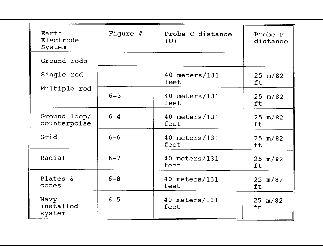
Table B–1
Test probe C and P distances
151DA PAM 385–64 • 28 November 1997
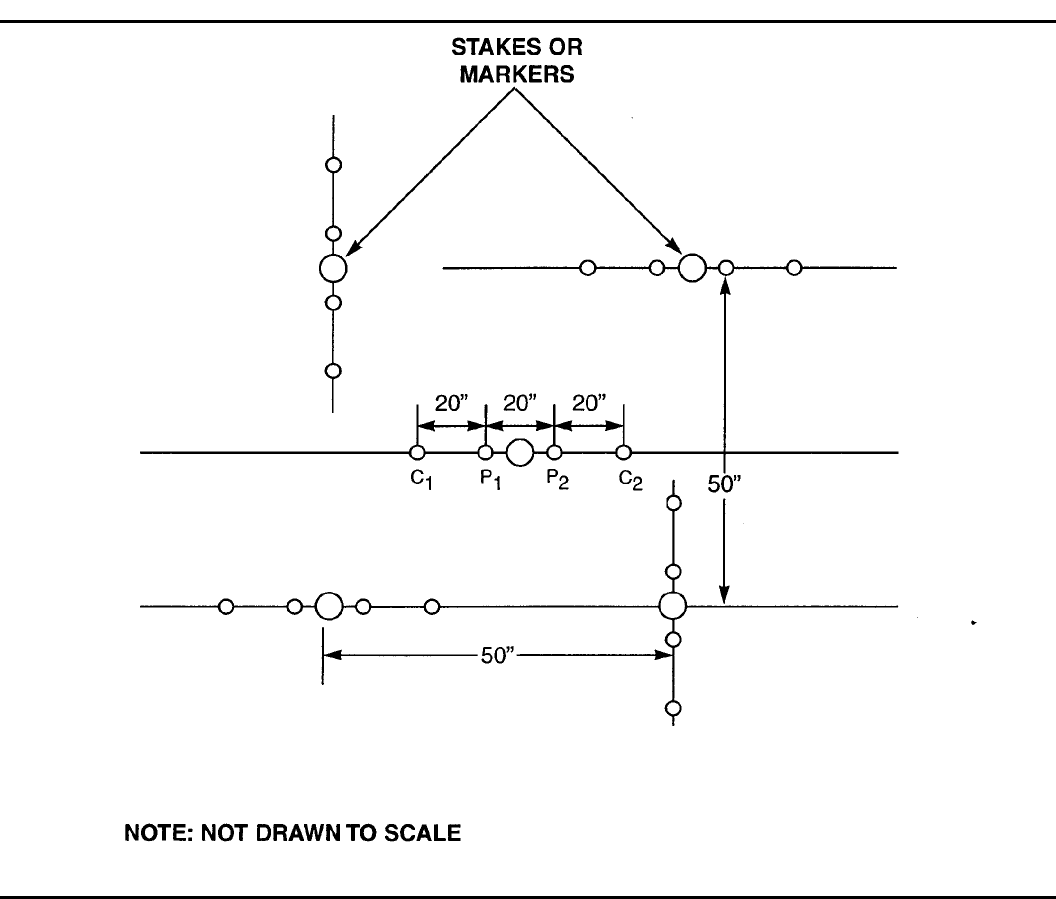
Figure B–1. Measurement of soil resistivity
152 DA PAM 385–64 • 28 November 1997
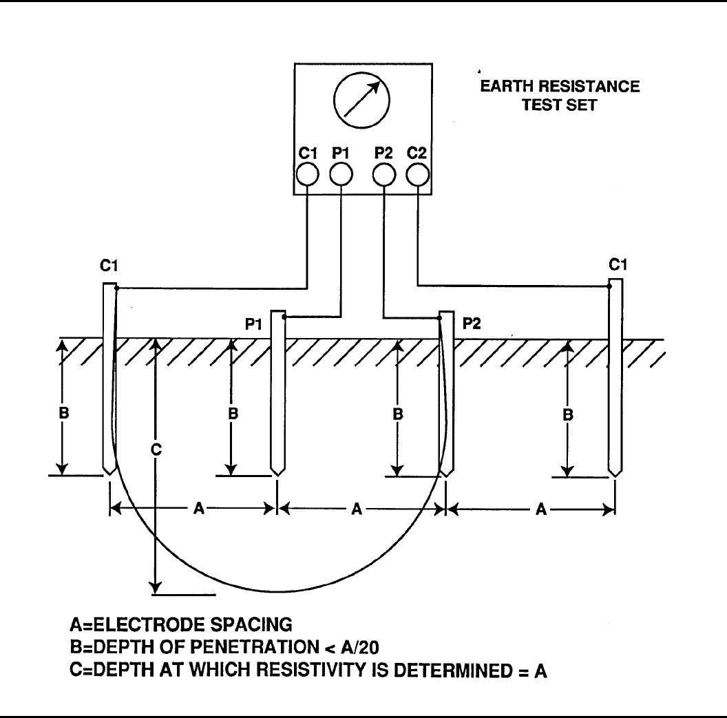
Figure B–2. Resistivity determination of a small site
153DA PAM 385–64 • 28 November 1997
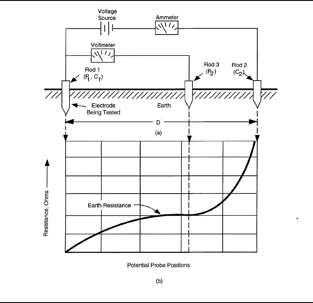
Figure B–3. Fall of potential method for measuring the resistance of earth electrodes
154 DA PAM 385–64 • 28 November 1997
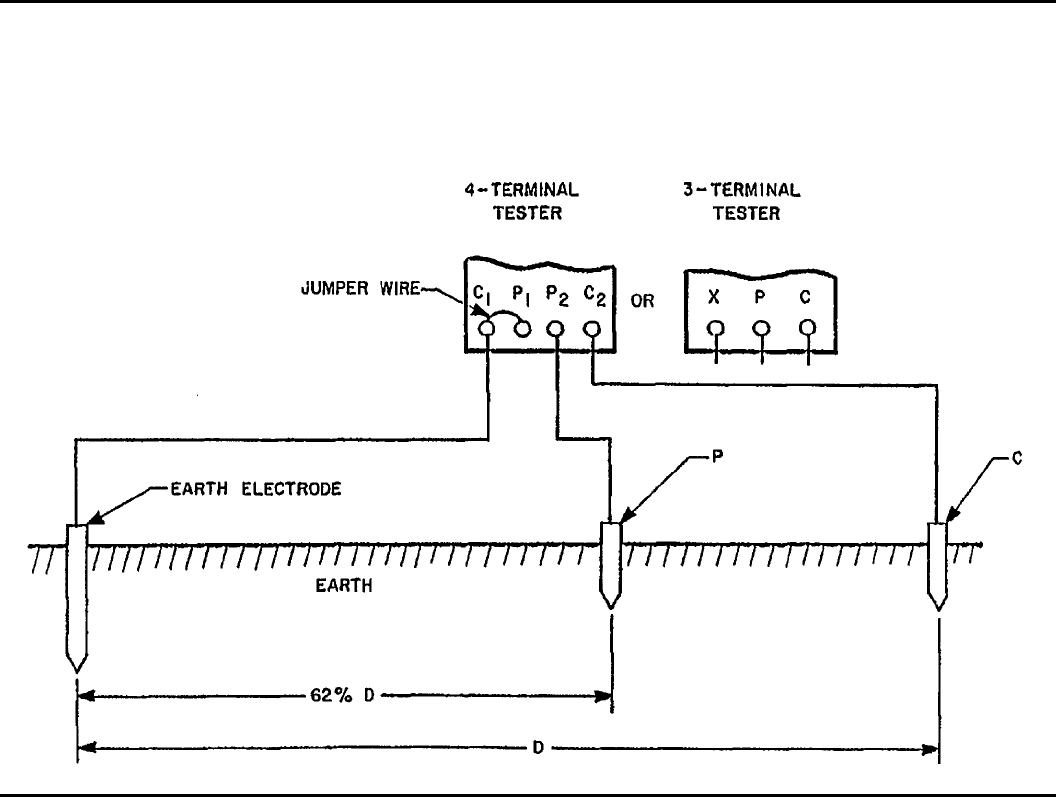
Figure B–4. Fall of potential resistance to earth test
Appendix C
Inspection and Test of Static Electricity Charge
Dissipation Subsystem
C–1. Introduction
This appendix provides criteria and procedures for conducting both
visual inspection and electrical testing of static electricity charge
dissipation systems.
C–2. Visual inspection procedures and criteria
a . V i s u a l i n s p e c t i o n p r o c e d u r e s a n d c r i t e r i a f o r c o n d u c t i v e
floors, mats, and runners.
(1) Floors mats and runners will be clean, dry, and free of paint
or other nonconductive coating.
(2) Related equipment (metal parts) will be free of corrosion.
Discoloration of materials is not considered corrosion.
(3) Floors, mats, and runners will be free of breaks, cuts, and
damage that will affect equipment integrity.
(4) Bonding straps will not have more than 50 percent of the
wire strands broken.
(5) Components will be in good repair.
(6) Components will not be weakened by vibration.
(7) Components will be securely fastened to their mounting sur-
faces and protected against movement and damage.
(8) There have not been additions or alterations to the protected
equipment which would require additional protection or testing.
b. Visual inspection procedures and criteria for conductive shoes.
(1) Conductive sock liners not separated or removed from con-
ductive plug.
(2) Conductive plugs not depressed below the insole surface.
(3) Conductive soles clean and free of nonconductive materials.
(4) No additions or alterations to the footwear which would ne-
gate protective properties of the footwear.
c. Visual inspection procedures and criteria for belt system.
(1) Belts and related equipment will be free of paint or other
nonconductive coating.
(2) Related equipment (metal parts) will be free of corrosion.
Discoloration of materials is not considered corrosion.
(3) Belts and related equipment will be free of breaks, cuts, and
damage that could affect equipment integrity.
(4) Bonding straps will not have more than 50 percent of the
wire strands broken.
(5) Components will be in good repair.
(6) Components will not be weakened by vibration.
(7) Components will be securely fastened to their mounting sur-
faces and protected against movement and damage.
(8) There are no additions or alterations to the protected equip-
ment which would require additional protection or testing.
d . V i s u a l i n s p e c t i o n p r o c e d u r e s a n d c r i t e r i a f o r l e g s t a t s a n d
wriststats.
(1) Legstats or wriststats will be free of paint or other noncon-
ductive coating.
(2) Legstats or wriststats will be free of corrosion. Discoloration
of materials not considered corrosion.
155DA PAM 385–64 • 28 November 1997
(3) Legstats or wriststats will be free of breaks, cuts, and damage
that shall affect their integrity.
(4) Wriststat bonding straps will not have more than 50 percent
of the wire strands broken.
(5) Components of legstats or wriststats will be in good repair.
(6) There are no been additions or alterations to the protected
equipment which would require additional protection or testing.
e. Visual inspection procedures and criteria for machinery and
equipment.
(1) Mating surfaces of machinery and equipment will be free of
paint or other nonconductive coatings.
(2) Machinery and equipment will be free of corrosion. Discolor-
ation of materials is not considered corrosion.
(3) Bonding straps will not have more than 50 percent of the
wire strands broken.
(4) Machinery and equipment will be in good repair.
(5) Components of machinery and equipment will be securely
fastened to their mounting surfaces and protected against movement
and damage.
(6) There are no additions or alterations made to the protected
machinery or equipment which would require additional protection
or testing.
C–3. Electrical testing of conductive floors and mats
a. Equipment requirements.
(1) Conductive surface resistance will be measured with a cali-
brated ohmmeter which operates on nominal open circuit output
voltage of 500 V dc with short circuit current of 2.5 mA to 5 mA.
Nominal internal resistance must not be less than 100,000 ohms.
(2) Accessories required for these tests shall include 2 weighted
electrodes. Each electrode shall weigh 5 lbs and have a flat circular
contact area 2 1/2 inches in diameter. The contact surface shall be
comprised of aluminum or tin foil .0005 inches to .001 inches thick
with a backing layer of rubber 1/4 inches thick. The rubber should
measure between 40 and 60 durometer hardness as determined with
a Shore Type A durometer.
b. Testing procedures (two electrode).
(1) Obtain resistance readings from five different locations on the
conductive surface.
(2) When conducting this test, two electrodes are placed 3 feet
apart at each of the 5 test points.
(3) Record the readings and compute the average of the five
locations.
(4) The average resistance must be more than 25,000 ohms and
less than 1,000,000 ohms.
(5) No individual reading shall be less than 10,000 ohms or more
than 5,000,000 ohms.
Note. When obtaining resistance measurements, it is recommended that ap-
proximately 5 seconds be allowed for meter stabilization before recording
reading.
c. Test procedures (one electrode to ground).
(1) Obtain 5 resistance readings to ground. For this test only 1
electrode is placed at each test location on the conductive surface.
The meter leads are connected to the electrode and to the ground
point.
(2) The average of the 5 values must be greater than 25,000
ohms with no individual reading less than 10,000 ohms. There is no
upper limit of resistance when conducting this test.
C–4. Electrical testing of conductive shoes
a. The testing instrument should consist of conductive plates ar-
ranged so that the employee stands with only one foot on each plate
to complete the circuit. When tests are so made the maximum
allowable resistance is 1 million ohms. The test voltage will be no
greater than 500 volts. The short circuit current across the electrodes
(plates) will not exceed 2.5 milliamperes to 5 milliamperes (0.5
milliamperes is required when the instrument is used with person-
nel). Positive safeguards must be incorporated into the design of the
instruments to eliminate the chance of electric shock to the subject
undergoing test. Tests must not be performed in rooms where ex-
posed explosives are present.
b. Shoes will be tested first without cleaning the soles and heels
and if the resistance does not exceed required limits, the shoes may
be put in service. If resistance exceeds 450,000 ohms per shoe when
testing, they will be cleaned and retested. If readings are then suffi-
ciently low, the shoes may be returned to service. Those with exces-
sive readings will be destroyed. Sandpaper, solvents, or other agents
affecting the structure or conductivity of the sole materials will be
avoided. Separation or removal of the conductive sock liners from
the conductive plug or depression of the conductive plugs below the
surface of the insole of the shoe may cause high resistance.
C–5. Electrical testing of conductive conveyor belts
a. The building will be clean and dry. The room will be free of
flammable gas mixtures, explosive dust, and explosives.
b. Electrodes will comply with paragraph C–3a.
c. Resistance will be measured with a calibrated ohm meter. The
meter will operate on a nominal open circuit voltage of 500 volts
DC, or a short circuit current of 2.5 to 5 milliamperes, and have an
effective internal resistance of 100,000 ohms.
d . B o t h e l e c t r o d e - t o - e l e c t r o d e a n d e l e c t r o d e - t o - e a r t h e l e c t r o d e
subsystem measurements will be made at five or more locations on
the belt and the results averaged. The average will be below the
value specified in table 6–1. When the resistance to the earth elec-
trode subsystem is measured, two measurements will be taken at
each of the five test points. The test leads will be interchanged
between each of the measurements and the two readings shall be
averaged. Electrodes will not be placed closer than three feet from
any down conductor or bonding strap (except when space is not
available). All readings will be made after the voltage has been
allowed to stabilize for 5 seconds. Record the readings.
C–6. Electrical testing of conductive V-belts
a. Requirements of paragraph C–5a apply.
b. Requirements of International Standards (ISO) 1813 will be
used to test conductive V-belts prior to installation.
c. Requirements of para C–5c apply.
C–7. Electrical testing of legstats
a. Legstats will be tested using any meter capable of measuring
resistance in the 40,000 to 250,000 ohms range.
b. Each legstat will be tested both off and on the wearer. Use
paragraph C–4 for testing procedures.
C–8. Electrical testing of wriststats (see table 6–1)
Wriststats shall be tested in accordance with the publication requir-
ing use of the wriststats.
C–9. Electrical testing of equipment and machinery
a. The requirements in paragraph C–5a apply.
b. The meter will be capable of reading 2 ohms.
c. Measurements will be made, as a minimum, at a location
closest to the earth electrode subsystem, at a location farthest from
the earth electrode subsystem, and at all locations requiring bonding
straps. Test electrodes shall not be placed closer than 3 feet from
any LPS down conductor or bonding strap that are attached to down
c o n d u c t o r s ( e x c e p t w h e n s p a c e i s n o t a v a i l a b l e ) . R e c o r d t h e
readings.
C–10. Electrical testing of airfield loading pads
Use appropriate procedures contained in Appendix B.
Appendix D
Inspection and Test of Lightning Protection
Subsystems
D–1. General requirements
Lightning protection systems will be visually inspected and tested as
156 DA PAM 385–64 • 28 November 1997

specified in table 6–1 for electrical resistance and adequacy of
grounding. Any system will be considered deficient if the required
resistance value cannot be met. Any system found to be deficient
will be repaired. If the deficiency can not be corrected immediately,
the lightning protection system test/maintenance/ace personnel shall
record the deficiency on the test record and initiate the following
actions:
a. Notify the installation safety office. The installation safety
office will ensure the following actions are taken.
b. If the deficient system protects an ammunition or explosives
storage structure, the custodian of the contents shall be notified.
c. Interim control measures will be developed based on a risk
assessment in accordance with AR 385–10. The risk assessment
must include consideration of ceasing operations in and around the
building and, for storage facilities, rewarehousing the contents. A
decision not to rewarehouse the contents of a storage magazine is
justified only when the risk of rewarehousing exceeds the risk asso-
ciated with the deficient lightning protection system. When use of
the facility will continue, maintenance to achieve the required resist-
ance must be accomplished as soon as possible.
D–2. Visual inspection of lightning protection subsystem
Components of the subsystem will be inspected for the following:
a. Subsystem will meet the requirements specified in NFPA 780.
b. Components will not be broken.
c. Components will be in good repair
d . C o m p o n e n t s w i l l b e f r e e o f c o r r o s i o n . D i s c o l o r a t i o n o f
materials is not considered corrosion.
e. Components will be free of breaks, cuts, and damage that will
affect equipment integrity.
f. Bonding straps will not have more than 50 percent of the wire
strands broken and the remaining portion of the strap will meet the
minimum strap thickness and width/cross section requirements of
table 12–1.
g. Components will not be weakened by vibration.
h. Components will be securely fastened to their mounting sur-
faces and are protected against accidental mechanical displacement
as required.
i. There have not been additions or alterations to the protected
facility which would required additional protection or testing.
j . A i r t e r m i n a l s w i l l b e i n s p e c t e d f o r e v i d e n c e o f l i g h t n i n g
strikes; for example, slight bend, appear melted, or the point may be
blunted. In cases where the above evidence is apparent, notify U.S.
Army Technical Center for Explosives Safety.
D–3. Electrical testing of lightning protection subsystems
a. Test instruments. Electrical tests consist of measuring the bon-
ding resistance of the lightning protection subsystem components.
The instrument must be capable of measuring resistance up to 1
ohm +10 percent. The manufacturer’s instruction manual will be
followed to assure proper use of the instrument.
b. The bonding test.
(1) The bonding test (fig D–1) consists of firmly attaching one
lead of the ohmmeter to the down conductor where it enters the
earth. The earth electrode system will be disconnected when practi-
cal. The other lead will then be firmly attached to:
(a) The other down conductor where it enters the earth (Fig
D–1).
(b) Each component of the lightning protection subsystem.
(c) Each component of all other subsystems on the facility.
(d) All large metal bodies (a surface area equal or greater than
4 0 0 s q u a r e i n c h e s ) t h a t a r e b o n d e d t o t h e l i g h t n i n g p r o t e c t i o n
subsystem.
(2) Read the meter. If the meter reading is one (1) ohm or less
the lightning protection subsystem is acceptable. Record the reading.
If the meter reading exceeds one ohm, the lightning protection
subsystem is not acceptable.
(3) If lightning protection down conductors are not accessible,
the air terminal base may be used as an alternate reference test point
for the meter test lead. The air terminal selected should be the same
one used to do the 3–point fall of potential test which validates the
systems’s resistance to earth.
157DA PAM 385–64 • 28 November 1997
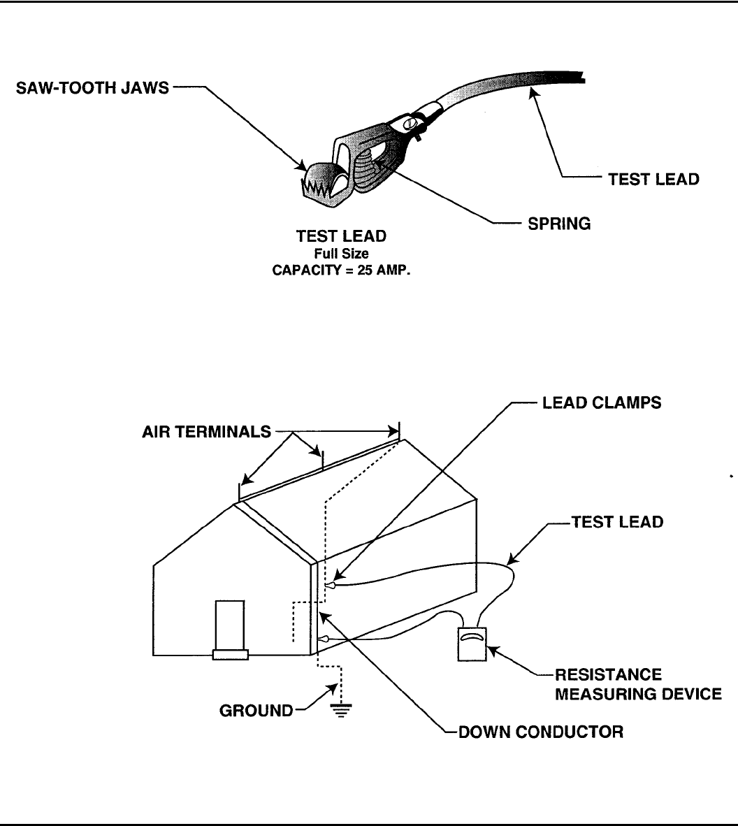
Figure D–1. Testing lightning protection system
Appendix E
Field Expedient Grounding Techniques
E–1. Introduction
This appendix provides field expedient grounding techniques.
E–2. Ground rod technique
a. Drive a 3–foot ground rod into moist earth to a depth of
approximately 30 inches.
b. Attach a length of cable (having a resistance value of less than
1 ohm) to the item being worked and the driven ground rod. (Exam-
ple: When working on propelling charges in the field. Drive the
ground rod. Attach one end of the lead to the charge container and
the other end to the driven ground rod.)
c. The ground rod will meet the requirements of chapter 6 of this
pamphlet.
158 DA PAM 385–64 • 28 November 1997

E–3. The equalization of potential method
This method equalizes the static electricity charge potential between
the item and the operator. For this reason the equalization of poten-
tial method will be used only when no other method is available.
This method consists of the operator touching a mass of bare metal
before touching the item being worked. Note: CAUTION: The oper-
ator will not touch exposed propellant, electrically sensitive explo-
sives or EEDs.
Appendix F
Safe Conveyor Separation for Ammunition/
Explosives
F–1. Safe separation distances.
Safe separation distances are meant for use on conveyor systems at
maintenance lines. The distances and precautions given in Table
F–1 are sufficient to prevent sympathetic detonation.
F–2. Items Not Listed in Table F–1.
For information on items not listed in Table F–1, consult Command-
er, Industrial Operations Command.
Table F–1
Safe conveyor spacing
Nomenclature Model Distance Shield/barrier Notes
Projectile, 155mm M107 18 inches, center-to-center Intervening shield of 0.5
inches steel, or 1-inch alu-
minum
This does not apply to
ICM projectiles or the
M795
Projectile, 155mm, HERA M549 5 feet, center-to-center, ori-
ented vertically, side-to-side None Loaded projectiles w/o
fuze, with lifting plugs
Projectile, 155mm, HERA M549 3.5 inches, outside edge to
outside edge 3-inch diameter aluminum
bar with a minimum length
equal to the height of the
projectiles placed halfway
between projectiles, ori-
ented vertically
Loaded projectiles w/o
fuze, w/o lifting plugs
Projectile, HE, 8-inch M509 5 feet center-to-center ori-
ented vertically V shield Projectile w/o fuze or
expulsion charge, at
any stage of grenade
loading
Loading rings for grenade,
GP (for M483 projectile) M42/ M46 12 inches, outside edge to
edge None 8 grenade ring pack,
Loading rings consist
of grenades and metal
parts constituting one
layer in a projectile
Loading rings for grenade,
GP (for M509 projectile) M42/ M46 12 inches, outside edge to
edge None 15 grenade ring pack,
Loading rings consist
of grenades and metal
parts constituting one
layer in a projectile
Projectile, 155mm, HE M795 15 feet center-to-center, ori-
ented side-to-side, vertically None Single projectiles with
loading funnels, filled
with cast explosives
Projectile, 30mm, HEDP M789 One inch side-to-side None Stacks of 2 each PBXN
pellets, type 2, 13.5
grams
Projectile, 30mm, HEDP M789 One inch between assem-
blies (outside edge to out-
side edge) oriented side-to-
side, vertically
None Shell body with 2 each,
loose PBXN-5 pellets,
27 grams total explo-
sive weight
Projectile, 30mm HEDP M789 One inch between assem-
blies (outside edge to out-
side edge) oriented side-to-
side, vertically
None Loaded body assembly
with liner, 0.08 gram
PBXN-5 relay charge
and steel spacer, at
ambient temperature
Projectile, 30 mm, HEDP M789 3 inches between projectiles
(outside edge to outside
edge) oriented side-to-side,
vertically
None Heated loaded body
assembly with cone
temperature of 205
degrees F
Projectile, 30mm, HEDP M789 3 inches between projectiles
(outside edge to outside
edge) oriented side-to-side,
vertically
None Fuzed projectile
159DA PAM 385–64 • 28 November 1997

Table F–1
Safe conveyor spacing—Continued
Nomenclature Model Distance Shield/barrier Notes
Cluster tray for grenade, GP M42/ M46 Zero spacing between trays Tray is a component for con-
tinuous feed conveyor sys-
tems used in the load, as-
sembly, and pack of M483
and M509 projectiles.
Tray configuration and
material of construc-
tion must be identical
to that depicted in the
4th Ind DRXOS-
ESSP, 29 Sep 81, to
letter, DRDARLCM-
SP, 7 May 81, sub-
ject: Test Results
Safe Separation Dis-
tance Testing of M42/
M46 GP Cluster Tray
Cartridge , 25mm, HEI-T M792 One inch, center-to-center,
between stacks None Stack of 3 HEI mix pel-
lets, type I, totaling
10.11 grams: 97/3%
RDX/wax (64%), alu-
minum powder (35%),
and graphite and/or
calcium sterate (1%)
Cartridge, 25 mm, HEI-T M792 One half inch, center-to-cen-
ter None HEI mix pellet, type II,
containing 1.94
grams: 97/3% RDX/
wax (64%), aluminum
power (35%), and
graphite and /or cal-
cium sterate (1%).
Cartridge, 25mm, HEI-T M792 2.5 inches, center-to-center,
oriented vertically None Loaded body assem-
bly, w/o fuze
Cartridge, 25mm, HEI-T M792 2.5 inches, center-to-center,
oriented vertically None Fuzed projectile only
Cartridge , 25mm, HEI-T M792 2.5 inches, center-to-center,
oriented vertically None Completed round
Cartridge, 105mm, HEAT-T M456 23 inches, center-to-center,
oriented vertically, w/alumi-
num bar placed halfway be-
tween cartridges; or 15
inches, center-to center, ori-
ented horizontally, side-to-
side, w/aluminum bar
placed halfway between
cartridges
Barrier bars are aluminum,
6061-T6, 3 inch diameter,
and of aluminum length
equal to that of the car-
tridges
Complete round
Cartridge , 105mm, HEAT-T M456 23 inches, center-to-center,
oriented vertically, w/
aluminu m bar placed half-
way between projectiles
Barrier bars are aluminum,
6061-T6, 3-inch diameter,
and of aluminum length
equal to that of the car-
tridges.
Projectile only
Cartridge , 105mm, HEAT-T M456 23 inches, center-to-center,
oriented vertically, w/alumi-
num bar placed halfway be-
tween cartridge cases, and
with protective caps on
cases or rapid response
deluge protection over car-
tridge cases
Barrier bars are aluminum,
6061-T6, 3-inch diameter,
and of aluminum length
equal to that of the cartridge
case. Protective caps must
be fire resistant, and must
protect propellant charge
from fire brands and radiant
thermal effects.
Primed, loaded car-
tridge cases.
Cartridge , 105mm, HEAT-T M456 Empty cases may be placed
in contact None Empty cartridge cases
w/M83 primers
Cartridge , 105mm, HE M1 15 inches nose-to-tail w/
rounds oriented nose-to-tail None Fuzed or unfuzed
rounds
Rocket, 2.75 inch M229 15 inches nose-to-tail None Complete round using
M423 fuzed and
MK40 mod 3 motors
Warhead loaded with
4.8 lbs of Comp B-4
Rocket, 2.75 inch M151 15 inches nose-to-tail None Complete round using
M423 fuze and MK40
motor. Warhead
loaded with 2.3 lbs of
Comp B-4
160 DA PAM 385–64 • 28 November 1997

Table F–1
Safe conveyor spacing—Continued
Nomenclature Model Distance Shield/barrier Notes
Mine, AP M74 Zero spacing edge-to-edge
w/shield described below
loaded on the center line
and between each mine, 3-
inch diameter, 6061-T6 alu-
minum rod, height of the
rod equal to the full height
of the mine.
3-inch diamenter, 6061-T6
aluminum rod, height of the
road equal to the full height
of the mine.
Complete assembly
with 1.3 lbs of RDX,
two conical shaped
charge plates, two
cover plates, and cen-
ter loaded booster
Mine, AP M74 Zero spacing (edge-to-edge)
between the mines and the
shield
A rod with a minimum height
of 2.6 inches (mine height),
3-inches thick, and a width
equal to the conveyor belt.
Complete assembly
with 1.3 lbs of RDX,
two conical shaped
charge plates, two
cover plates, and a
center loaded booster.
Mine, AT-AV M75 Zero spaced (edge-to-edge)
between the mines and the
sheild
A rod with a minimum height
of 2.6 inches (mine height),
3 inches thick thick, and a
width equal to the conveyor
belt
Complete assembly
with 1.3 lbs of RDX,
two conical shaped
charge plates, two
cover plates, and a
center loaded booster.
Cartridge, 81mm, w/alloy
steel projectile M374 6 inches between items ori-
ented nose-to-tail None With or without fuze,
and with or without
propellant.
Cloud detonator for M130
SLUFAE rocket 4 feet between items center-
to-center oriented vertically None Steel outer body con-
taining a detonator/de-
lay element, safety
and arming mecha-
nism, and two booster
pellets loaded with
PBXN-5.
Hand grenade, Fragmenta-
tion M67 12 inches, outside edge to
outside edge w/o regard to
orientation
None With or without M213
fuze
Rocket, 66mm, HEAT M72 10 inches between items,
placed horizontally at a 20
degree angle to the direc-
tion of movement
None Complete round
Rocket, 66mm, HEAT M72 10 inches between items,
placed horizontally at a 20
degree angle to the direc-
tion of movement
None Warhead only, fuzed or
unfuzed
Rocket, 3.5 inch, HEAT M28A2 14 inches between items,
placed horizontally at a 20
degree angle to the direc-
tion of movement
None All up round
Rocket, 3.5 inch, HEAT M28A2 14 inches between items,
placed horizontally at a 20
degree angle to the direc-
tion of movement
None Warhead only, fuzed or
unfuzed
Projectile for cartridge,
105mm M1 22 inches between items, ori-
ented horizontally, nose-to-
tail
None Comp B loaded, with-
out fuze or nose
Projectile for cartridge,
105mm M1 15 inches between items, ori-
ented horizontally, nose-to-
tail
None Comp B loaded, with-
out fuze, with lifting
plug
Cartridge , HEAT-T, 152mm M409 series 15 feet between projectiles,
center-to-center, in a nose
down, vertical orientation
None Complete round
Composition B 20 feet, side-to-side; or 12
feet, side-to-side, when ef-
fective means are provided
to prevent spread of a fire
between buildings via the
conveyor
None 60-lb box
TNT 20 feet, side-to-side; or 12
feet, side-to-side, when ef-
fective means exist to pre-
vent spread of a fire be-
tween buildings via the con-
veyor
None 55-pound box, carton,
or fiber container
Explosive D 15 feet, side-to-side None 50-pound box or fiber
container
Tetryl (bulk) 25 feet, side-to-side None 50-pound box or fiber
container
161DA PAM 385–64 • 28 November 1997

Table F–1
Safe conveyor spacing—Continued
Nomenclature Model Distance Shield/barrier Notes
Pentolite (bulk) 35 feet, side-to-side None 50-pound box or fiber
container
40mm (TNT) May be placed in contact None Projectile only or com-
plete round
57mm (TNT) 6 inches between items None Projectile only or com-
plete round
60mm (TNT) 4 inches between items None Projectile only or com-
plete round
75mm (TNT) 5 inches between items None Projectile only or com-
plete round
76mm (TNT) 5 inches between items None Projectile only or com-
plete round
81mm (TNT) M56 7 inches between items None Projectile only or com-
plete round
81mm (Comp B) M374 8 inches between items, for
pearlitic malleable iron
(PMI) cartridges. 8 inches
between items, oriented
vertically, with intervening
shield, for steel cartridges
For the steel cartridges, the
intervening shields must be
2-inch diameter bars with
minimum length equal to
the length of the cartridges,
and may be of steel or alu-
minum.
Projectile only or com-
plete round
90mm (TNT) 7 inches between items None Projectile only or com-
plete round
Projectile, 105mm (Comp B) M1 30 feet between pallets,
rounds in vertical orienta-
tion, 1-inch apart
None Pallets of projectiles
only, without funnels,
16 projectiles per pal-
let
Projectile, 105mm (Comp B) M1 20 feet between pallets,
rounds in vertical orienta-
tion, 1-inch apart
Intervening shield of 21
inches by 24 inches, by
0.75 SAE 1020 steel
Pallets of projectiles
only, without funnels,
16 projectiles per pal-
let
Cartridge , 106mm, HEAT M344 6 inches between items None Complete (nose-to-
base)
Projectile, 106mm, HEP-T M346 9 feet between items None Projectile
Cartridge , 4.2 inch mortar,
HE M329 21 inches between items None Cartridge
Projectile, 175mm (Comp B) 15 feet between items None Projectile only
Mine, AT, HE, heavy M15 25 feet between mines None Mine only
Mine, AT, HE, Heavy M15 25 feet between trays None Mine only, 4 mines per
tray
Mine, AP, (TNT) M16 12 inches between mines None Mine only
Grenade, hand, fragmenta-
tion M26 12 inches between grenades None Fuzed grenade only
Fuze, point detonating M48A3. M51A5, & M557 3 inches between cans 5/16-inch thick paper non-
propagation tubes (NSN
8140-01082-9678; dwg
#9328329) will replace the
normal plastic bottom sup-
port for the fuzes
8 fuzes per M2A1 am-
munition can with
non-propagation
tubes, without can
covers, and without
nose supports for the
fuzes
Fuze, point detonating M48A3, M51A5, & M557 6 inches, edge-to-edge, in a
nose up orientation None Fuze only
Burster for 4.2 inch M2A1
cartridge M14 64 inches between items, ori-
ented end-to-end None Bursters from chemical
munition projectiles
Burster for projectile,
155mm, M104, M110 M6 8 inches between items, ori-
ented end-to-end None Bursters from chemical
munition projectiles
Burster for projectile,
105mm, M60 M5 8 inches between items, ori-
ented end-to-end None Bursters from chemical
munition projectiles
Burster for projectile,
105mm, M360 M40A1 48 inches between items, ori-
ented end-to-end None Bursters from chemical
munition projectiles
Burster for projectile,
155mm, M121A1 M71 16 feet between items, ori-
ented end-to-end None Bursters from chemical
munition projectiles
Burster for projectile, 8 inch,
M426 M83 24 feet between items, ori-
ented end-to-end None Bursters from chemical
munition projectiles
Submunition BLU-97/B 5 feet between pallets with
barrier placed halfway be-
tween
Airflow barrier Pallet of 16 submuni-
tions with airflow bar-
rier
Submunition BLU-97/B 4 feet between pallets with
barrier placed halfway be-
tween
Solid barrier, 0.5 inch thick
by 8 inches high by 16
inches wide, 6061-T6 alumi-
num plate
Pallet of 16 submuni-
tions with solid barrier
162 DA PAM 385–64 • 28 November 1997

Table F–1
Safe conveyor spacing—Continued
Nomenclature Model Distance Shield/barrier Notes
Submunition BLU-97/B 9 inches, center line-to-cen-
ter line, with partial height
barrier placed between sub-
munitions
Partial barrier, 1.0 inch thick
by 6 inches wide by 3.75
inches high, 6061-T6 alumi-
num plate
Single submunition
Submunition BLU-97/B 9 inches center line-to-center
line, with full height barrier
placed between submuni-
tions
Full barrier, 1.0 inch thick by
6 inches wide by 5.1 inches
high, 6061-T6 aluminum
plate
Single submunition
Grenade, hand, fragmenta-
tion, delay M61 12 inches between grenades
regardless of orientation None Grenade body is a 2.25
inch diameter consist-
ing of 2 pieces of thin
wall sheet steel con-
taining a total of 5.5
oz of Comp B & .3 oz
of tetryl pellets
Cartridge , 90mm, APERS-T M580 7 inches between items, ori-
ented nose-to-tail None Complete round
Grenade, hand, fragmenta-
tion, delay M33 12 inches between grenades
regardless of orientation None Grenade body is a 2.5-
inch diameter steel
sphere, containing 5.5
ounces of Comp B
high explosive . Its
M213 fuze is
equipped with a steel
safety pin, but not a
safety clip
Grenade, hand, fragmenta-
tion, delay M61 12 inches between grenades
regardless of orientation None Grenade body is a 2.25
inch diameter consist-
ing of two pieces of
thin wall sheet steel
and containing a total
of 5.5 ounces of
Comp B and .3
ounces of tetryl pel-
lets. Its M20A1/
M204A2 incorporates
a safety clip
Cartridge , 105mm, HE M1 15 inches between items ori-
ented nose-to-tail None Complete cartridge with
primer protected
Cartridge , 105mm, HE M1 15 inches between items ori-
ented nose-to-tail None Cartridge without fuze,
primer protected
Projectile, 8 inch, HE M404 42 inches positioned horizon-
tally (nose-to-tail or side-by-
side); 48 inches positioned
vertically
None Projectile with lifting
plug and loaded with
expulsion charge and
M43 grenades
Projectile, 155mm, HE M449 42 inches positioned horizon-
tally (nose-to-tail or side-by-
side); 54 inches positioned
vertically
None Projectile with lifting
plug and loaded with
expulsion charge and
M43 grenades
90mm, HEAT (Comp B) M371A1 7 inches between items, ori-
ented horizontally, nose-to-
tail
None Composition loaded
complete cartridge
90mm, HEAT (Comp B) M371A1 7 inches between items, ori-
ented horizontally, 20 de-
grees oblique
None Composition B loaded
projectile with
M530A1 PIBD fuze
90mm, HEAT (Comp B) M371A1 7 inches between items, ori-
ented horizontally, 20 de-
grees oblique
None Composition B loaded
projectile without fuze
90mm HEAT (Comp B) M431A1 7 inches between items, ori-
ented horizontally, nose-to-
tail
None Composition B loaded
complete cartridge
90mm, HEAT (Comp B) M431A1 7 inches between items, ori-
ented horizontally, 20 de-
grees oblique
None Composition B loaded
projectile with
M509A1 PIBD fuze
90mm, HEAT (Comp B) M431A1 7 inches between items, ori-
ented horizontally, 20 de-
grees oblique
None Composition B loaded
projectile without fuze
Projectile, 105mm, HE M444 24 inches tail-to-tail None Horizontal oblique,
without fuze, 45 de-
gree angle
Projectile, 105mm, HE M444 36 inches tail-to-tail None Horizontal oblique,
without fuze, 45 de-
gree angle
163DA PAM 385–64 • 28 November 1997

Table F–1
Safe conveyor spacing—Continued
Nomenclature Model Distance Shield/barrier Notes
Projectile, 105mm, HE M444 72 inches tail-to-tail None Vertical, without fuze,
overhead monorail
Projectile, 155mm, smoke M116 No separation required be-
tween projectiles None Horizontal, 30 degree
oblique
Projectile, 105mm, illuminat-
ing M314 No separation required be-
tween projectiles None Horizontal, 45 degree
oblique with fuze
Projectile, 105mm, illuminat-
ing M314 No separation required be-
tween projectiles None Horizontal, 45 degree
oblique without fuze
Grenade, smoke M18 6 inches between grenades,
fuze-to-base None Horizontal, in line with
fuze
Grenade, smoke M18 6 inches between grenades None Horizontal, side-by-side
without fuze
Warhead, rocket, 5 inch 36 inches tail-to-tail None Horizontal, 30 degree
oblique, without fuze
Charge, propelling, 155mm M4 84 inches tail-to-tail None Horizontal oblique, 30
degree angle
Projectile, 8 inch, HE M106 One foot between outside
edges with aluminum bar
placed halfway between
projectiles, oriented verti-
cally
None Loaded projectile with-
out fuze, lifting plug,
supplementary charge
and liner
Projectile, 155mm, (Comp B
or TNT) M107 18 inches, center-to-center,
placed horizontally with a
shield located halfway be-
tween projectiles
Intervening shield of 0.5
inches thick steel, or 1 inch
thick aluminum. A minimum
of 9 inches by 25 inches in
frontal diameter
Projectile only M107
type. This does not
apply to ICM projec-
tiles or the M795
Warhead BLU 108/B 17.5 feet from nearest edge
of munition on tray to
nearest edge of munition on
the next tray with a shield
between trays
Intervening shield of 1-inch
thick aluminum (AL 6061T6
plate). A minimum frontal di-
mension of 12 inches by 12
inches. Shield may be lo-
cated as close as 2 feet, 8.5
inches from nearest tray.
4 per tray, vertical,
without fuze, with or
without funnel
Grenade, 40mm cartridge M406 6 inches, edge-to-edge None Edge-to-edge in the
horizontal perpendicu-
lar position
Projectile, 8 inch, HE M106 8 feet edge-to-edge in the
vertical in-line orientation None
Cartridge , 81mm, illuminat-
ing M301 No separation required in the
horizontal coaxial orienta-
tion
None
Cartridge , 4.2 inch illuminat-
ing M335 No separation required in the
horizontal coaxial orienta-
tion
None
Cartridge , 81mm M821 No separation required in the
nose-to-tail horizontal coax-
ial orientation
None
Cartridge , 81mm M889 No separation required in the
nose-to-tail horizontal coax-
ial orientation
None
Cartridge , 90mm, AP-T M318 No separation required in the
horizontal coaxial orienta-
tion. The point of the
windscreen must not be in
contact with the primer of
the cartridge in front.
None
Cartridge, 30mm, TP M788 Zero (in contact) None Horizontal and perpen-
dicular to the con-
veyor travel.
Cartridge, 90mm, Canister M336 Zero (in contact) None Horizontal coaxial
(nose-to-tail)
Cartridge , 20mm, HEI-T-SD M246 3/4 inch (edge-to-edge) None Horizontal and perpen-
dicular
Mine, AP M18A1 12 1/2 inches (edge-to-edge) None Horizontal, front of
mine facing up, and
side-by-side to each
other
Appendix G
Standard designs for explosives facilities
G–1. Drawings approved for new construction
The following drawings are approved for new construction:
a. Earth covered magazines
(1) Reinforced concrete arch - 33–15–74
(2) Semicircular large steel arch - 421–80–01
164 DA PAM 385–64 • 28 November 1997
(3) Semicircular small steel arch - 33–15–65
(4) Steel oval arch - 421–80–03.
b. Other structures
(1) Six bay surveillance facility - 216–12–01
(2) Twelve bay surveillance facility - 216–12–02
(3) Concrete cubicle - 422–15–01
(4) Barricades - 149–30–01
(5) Ammo maintenance building 33–69–09
G–2. Drawings not approved for new construction
Existing buildings constructed using the following drawings are
considered to be standard magazines for QD purposes. They are no
longer approved for new construction.
a. Earth covered magazines
(1) Mounded concrete - 35–15–06
(2) Stradley - 33–15–61
(3) Steel arch - AW33–15–64
(4) Steel arch - AW33–15–63
(5) Steel arch - 33–15–71
(6) Steel oval arch - 33–15–73
(7) Atomic blast resistant - 33–15–58
(8) Concrete box
( a ) U S A R E U R t y p e s I , I I , I I I ( 3 3 0 , 0 0 0 l b s N E W o n l y ) -
EUR33–15–15
(b) USAREUR types I, II, III - 33–15–16
(9) Camp Darby magazine - 33–15–13
(10) Reinforced concrete arch-type, earth covered magazines -
OCE dwg Nos. 652–686 through 652–693
G–3. Navy magazines
The following magazines were constructed according to Navy draw-
ings and are considered standard magazines. They are not approved
for new construction.
a. Drawing Nos. 357428 through 347430, 9 August 1944, and
modified in accordance with NAVFAC drawing No. 626739, 19
March 1954
b . N A V F A C d r a w i n g N o s . 6 2 7 9 5 4 t h r o u g h 6 2 7 9 5 7 , 7 6 4 5 9 7 ,
658384 through 658388; 724368, 751861, 764596, 793746, and
793747.
c . B o x - t y p e A m a g a z i n e s c o n s t r u c t e d a c c o r d i n g t o N A V F A C
drawing Nos. 1404000 through 1404007
d . B o x - t y p e B m a g a z i n e s c o n s t r u c t e d a c c o r d i n g t o N A V F A C
drawing Nos. 1404018 through 1404025.
e . B o x - t y p e C m a g a z i n e s c o n s t r u c t e d a c c o r d i n g t o N A V F A C
drawing Nos. 1404430 through 1404440, dated 20 September 1985.
f . B o x - t y p e D m a g a z i n e s c o n s t r u c t e d a c c o r d i n g t o N A V F A C
drawings 1404464 through 1404478, dated 20 September 1985.
g . B o x - t y p e E m a g a z i n e s c o n s t r u c t e d a c c o r d i n g t o N A V F A C
drawing Nos. 1404523 through 1404535, dated 23 April 1987.
h . B o x - t y p e F m a g a z i n e s c o n s t r u c t e d a c c o r d i n g t o N A V F A C
drawing Nos. 1404541 through 1404555, dated 23 April 1987.
i. Earth-covered, corrugated steel, arch-type magazines at least
equivalent in strength to those shown in NAVFAC drawing Nos.
1059128–30, 1059132, 1069906, and 1355460–61.
j. Earth-covered circular composite arch magazine described in
NAVFAC drawing Nos. 1404375 through 1404389, dated 31 Octo-
ber 1985
k . E a r t h - c o v e r e d o v a l c o m p o s i t e a r c h m a g a z i n e d e s c r i b e d i n
NAVFAC drawing Nos. 1404390 through 1404398, dated 31 Octo-
ber 1985.
G–4. Nonstandard magazines
The following magazines are considered nonstandard and are lim-
ited to 250,000 lbs NEW.
a. Earth-covered magazines if the construction is not equivalent
in strength to the requirements of paragraphs G–1 through G–3.
b. Magazines constructed in accordance with NAVFAC drawings
Nos. 649602 through 649605, 793748, and 803060.
Appendix H
The 100–Foot Zone of Protection
H–1. Introduction
This appendix provides the theory and criteria for applying the
100–foot striking arc applicable to LPS requirements for explosives
facilities.
H–2. Zone of protection
The zone of protection includes the space not intruded upon by an
arc having a radius of 100 feet. This zone is the area beneath the
point where the arc contacts earth and rests against an air terminal
of an LPS. A zone of protection is also created when the arc rests
on the tips of two properly spaced air terminals. All possible place-
ments of the arc must be considered when determining the zone of
protection using the 100–foot concept. Figures H–1 through H–4
illustrate these areas of protection.
H–3. Zone of protection for earth covered magazines
When determining the zone of protection for earth covered maga-
zines, the actual earth cover should be considered as part of the
structure that requires lightning protection. Figures H–5 through
H–7 demonstrate the application of the 100–foot striking zone arc
for earth covered magazines.
a. The depicted earth covered magazines have ventilators which
extend approximately 3 feet above the earth cover and headwalls
which extend approximately 1 foot. The air terminals extend 2 feet
above the ventilator and the headwall.
b. Magazines that project above the earth cover may require
additional air terminals to provide an adequate zone of protection.
165DA PAM 385–64 • 28 November 1997
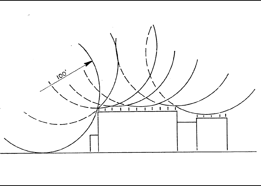
Figure H-1. Zone of protection test
166 DA PAM 385–64 • 28 November 1997
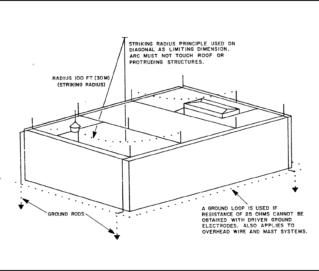
Figure H-2. Zone of protection for integral systems
167DA PAM 385–64 • 28 November 1997
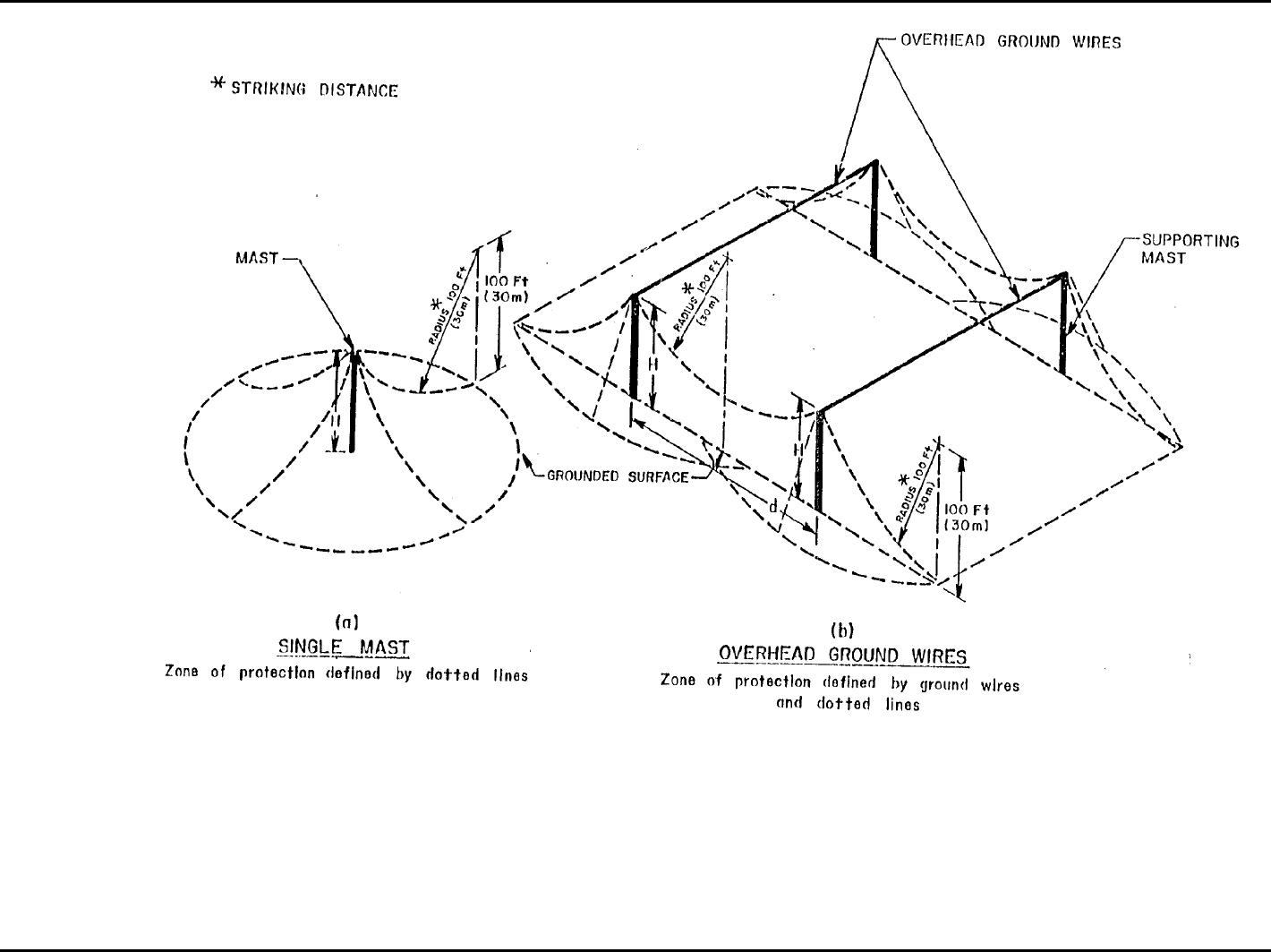
Figure H-3. Illustrated zone of protection
168 DA PAM 385–64 • 28 November 1997
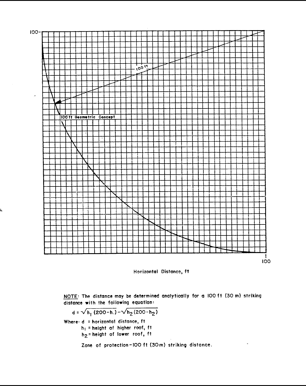
Figure H-4. Zone of protection geometric concept
169DA PAM 385–64 • 28 November 1997
Figure H-5. Adequate protection not penetrating earth cover
170 DA PAM 385–64 • 28 November 1997
Figure H-6. Adequate protection penetrating earth cover
Figure H-7. Inadequate protection penetrating earth cover
171DA PAM 385–64 • 28 November 1997
Glossary
Section I
Abbreviations
AC
active component
A&E
ammunition and explosives
AFFF
aqueous film-forming foam
AMC
U.S. Army Material Command
AMCCOM
U.S. Army Armament, Munitions and Chem-
ical Command
ANSI
American National Standards Institute
APA
ammunition and prohibited area
AR
Army regulation
ARNG
Army National Guard
ASA(IL&E)
Assistant Secretary of the Army(Installations,
Logistics & Environment)
ASME
American Society of Mechanical Engineer
ASP
ammunition supply point
ATP
ammunition transfer point
AWG
American wire gauge
A/D
approach/departure
BLA
basic load ammunition
BLAHA
basic load ammunition holding area
BOE
Bureau of Explosives
BOM
Bureau of Mines
C
Celsius
CBU
cluster bomb unit
CBDCOM
Chemical Biological Defense Command
CCL
combat configured load
CFR
Code of Federal Regulations
DA
Department of Army
DA PAM
Department of Army pamphlet
DDESB
D e p a r t m e n t o f D e f e n s e E x p l o s i v e s S a f e t y
Board
DPDO
Defense Property Disposal Office
DOD
Department of Defense
DODIC
Department of Defense identification code
DOT
Department of Transportation
DSN
Defense switched network
ECM
earth covered magazine
EED
electro-explosive device
EIDS
extremely insensitive detonating substance
EMR
electromagnetic radiation
EOD
explosives ordnance disposal
EP
Engineers Pamphlet
EPA
Environmental Protection Agency
ES
exposed site
F
Fahrenheit
FAE
fuel-air explosive
FARP
forward area rearm/refuel point
FLOT
forward line of own troops
FORSCOM
United States Army Forces Command
fpm
feet per minute
fps
feet per second
FSU
field storage unit
GBL
Government bill of lading
HAS
hardened aircraft shelter
HC
hexachloroethane
HD
hazard class/division
HE
high explosive
HQDA
Headquarters, Department of Army
IBD
inhabited building distance
ICM
improved conventional munition
ID
identification
IFR
instrument flight rules
IL(B)
intraline, barricaded
ILD
intraline distances
IL(U)
intraline, unbarricaded
ISO
International Standards Organization
JHCS
Joint Hazard Classification System
LP
liquid petroleum
LPS
lightning protection system
MACOM
major Army command
MAG
magazine
MCA
military construction, Army
172 DA PAM 385–64 • 28 November 1997
MCE
maximum credible event
MHE
material handling equipment
MICOM
United States Army Missile Command
MILVAN
military demountable container
MIL STD
military standard
MSDS
material safety data statement
MTMC
Military Traffic Management Command
MWD
military working dog
NATO
North Atlantic Treaty Organization
NAVFAC
naval facility
NEC
National Electrical Code
NEQ
net explosives quantity
NEW
net explosives weight
NEWQD
net explosives weight for QD
NFPA
National Fire Prevention Association
OB
open burning
OCE
Office of Chief Engineers
OD
open demolition
OSHA
O c c u p a t i o n a l S a f e t y a n d H e a l t h
Administration
P&P
packaging and preservation
PES
potential explosion site
POL
petroleum, oils, and lubricants
PPWR
prepositioned war reserve
PSI
pounds per square inch
PSP
pre-stock point
PTR
public traffic route
PWP
plasticized white phosphorous
QC
quality control
Q-D
quantity-distance
RC
reserve component
RCW
reinforced concrete wall
RF
radio frequency
RORO
roll on, roll off
ROTC
Reserve Officer Training Corps
SAE
Society of American Engineers
SCG
storage compatibility group
SDW
substantial dividing wall
SF
standard form
SOP
standing operating procedure
TB
technical bulletin
TEA
triethylaluminum
TH
thermite
TM
technical manual
TO
transportation officer
TOFC
trailer-on-flat car
TPA
thickened pyrophoric agent
UL
Underwriter’s Laboratory
UNO
United Nations Organization
USACE
United States Army Corps of Engineers
USATCES
United States Army Technical Center for Ex-
plosives Safety
USCG
United States Coast Guard
VAC
volts alternating current
VFR
visual flight rules
WP
white phosphorous
Section II
Terms
Aboveground magazines
Any type of magazine abovegrade other than
standard or nonstandard earth covered types
of magazines.
Administration area
The area in which administrative buildings
that function for the installation as a whole,
e x c l u d i n g t h o s e o f f i c e s l o c a t e d n e a r a n d
d i r e c t l y s e r v i n g c o m p o n e n t s o f e x p l o s i v e s
storage and operating areas, are located.
Aircraft parking area
Any area set aside for parking aircraft not
containing explosives.
Aircraft passenger transport operations
Passenger transport traffic involving military
dependents and civilians other than those em-
p l o y e d b y o r w o r k i n g d i r e c t l y f o r D O D
components.
Ammunition and explosives
Includes (but is not limited to) all items of
a m m u n i t i o n ; p r o p e l l a n t s , l i q u i d a n d s o l i d ;
h i g h a n d l o w e x p l o s i v e s ; g u i d e d m i s s i l e s ;
w a r h e a d s ; d e v i c e s ; p y r o t e c h n i c s ; c h e m i c a l
agents; and components and substances asso-
ciated therewith, presenting real or potential
hazards to life and property.
Ammunition and explosives aircraft cargo
area
An area designated for the temporary storage
of transportation configured loads of ammu-
nition and explosives. These loads may or
may not be loaded on the aircraft.
Ammunition and explosives area
An area specifically designated and set aside
from other portions of an installation for the
d e v e l o p m e n t , m a n u f a c t u r e , t e s t i n g , m a i n t e -
nance, storage, disposal, or handling of am-
munition and explosives.
Army accident
An unplanned event or series of events that
173DA PAM 385–64 • 28 November 1997
results in damage to Army property, occupa-
tional illness to Army military or civilian per-
s o n n e l , i n j u r y o r d e a t h t o A r m y m i l i t a r y
personnel on- or off-duty, injury to on-duty
civilian personnel, damage to public and pri-
vate property, or injury or illness to non-
A r m y p e r s o n n e l a s a r e s u l t o f A r m y
operations.
Auxiliary building
Any building accessory to, or maintained and
operated to serve, an operating building, line,
plant, or pier area.
B-duration
The total time in milliseconds for the noise
pressure to rise to peak and then fall back.
T o t h e h u m a n e a r t h e r e i s o n l y a s i n g l e
sound. Specialized equipment is required to
measure the sound wave to determine its B-
d u r a t i o n . P r o c e d u r e s t o c a l c u l a t e i m p u l s e
noise B-duration from measured sound waves
are in Mil Std 1474.
Barricade
An intervening barrier, natural or artificial, of
such type, size, and construction as to limit
in a prescribed manner the effect of an explo-
sion on nearby buildings or exposures.
Blast overpressure
The pressure, exceeding the ambient pres-
sure, manifested in the shock wave of an
explosion.
Burning grounds
The area dedicated to burning of energetic
materials. This includes actual burning sites
a n d f a c i l i t i e s d e d i c a t e d t o t h e b u r n i n g
operation.
Burning site
The actual location where energetic materials
are burned, for example, a burning pan.
Change house
A building provided with facilities for em-
ployees to change to and from work clothes.
Chemical agent
A substance that is intended for military use
with lethal or incapacitating effects upon hu-
m a n s t h r o u g h i t s c h e m i c a l p r o p e r t i e s . E x -
cluded from chemical agents for purposes of
this standard are riot control agents, chemical
h e r b i c i d e s , s m o k e - a n d f l a m e - p r o d u c i n g
items, and individual dissociated components
of chemical agent ammunition.
Chemical ammunition
Ammunition, the filler of which has the basic
function of producing a toxic or irritant effect
on the body, a screening or signaling smoke,
or an incendiary action.
Classification yard
A railroad yard used for receiving, dispatch-
ing, classifying, and switching of cars.
Combat aircraft parking area
Any area specifically designated for aircraft
loading or unloading or of combat-configured
m u n i t i o n s a n d / o r t h e p a r k i n g o f a i r c r a f t
loaded with combat-configured munitions.
Combat configured load
A mixed ammunition package designed to
provide for the complete round concept, type
o f u n i t , t y p e o f v e h i c l e , c a p a c i t y o f
transporter, and weapons system. Contents of
the package is predetermined and provides
optimum quality and mix to support a partic-
ular weapons system or unit.
Compatibility
A m m u n i t i o n o r e x p l o s i v e s a r e c o n s i d e r e d
compatible if they may be stored or trans-
p o r t e d t o g e t h e r w i t h o u t i n c r e a s i n g s i g -
nificantly either the probability of an accident
or, for a given quantity, the magnitude of the
effects of such an accident.
Component
Any part of a complete item whether loaded
with explosives, inert (not containing explo-
sives), or empty (not filled with explosives).
Deflagration
A rapid chemical reaction in which the out-
put of heat is enough to enable the reaction
to proceed and be accelerated without input
of heat from another source. Deflagration is a
surface phenomenon with the reaction travel-
ing along the surface at subsonic velocity.
Demilitarize
To mutilate, disarm, neutralize, and accom-
plish any other action required to render am-
m u n i t i o n , e x p l o s i v e s , a n d c h e m i c a l a g e n t s
innocuous or ineffectual for military use.
Detonation
A violent chemical reaction within a chemi-
cal compound or mechanical mixture involv-
i n g h e a t a n d p r e s s u r e . A d e t o n a t i o n i s a
reaction which proceeds through the reacted
material toward the unreacted material at a
supersonic velocity. A detonation, when the
material is located on or near the surface of
the ground, is normally characterized by a
crater.
Distribution lines
Electrical lines supplying multiple installation
locations.
Dividing wall
A wall designed to prevent, control, or delay
propagation of an explosion between quanti-
ties of explosives on opposite sides of the
wall.
Dolphin
A mooring post or posts on a wharf or quay.
Dud
Explosive munition which has not armed as
intended or which has failed to function after
being armed. (See misfire.)
Dummy ammunition
Ammunition or ammunition components hav-
ing the appearance of actual items and not
having any explosives components.
Electrical lines
See transmission lines, distribution lines, or
service lines.
Empty ammunition
Ammunition or ammunition components void
of any type of filler.
Engineering controls
Regulation of facility operations through the
use of prudent engineering principles, such as
facility design, operation sequencing, equip-
ment selection, and process limitations.
Exemption
A w r i t t e n a u t h o r i t y t h a t p e r m i t s l o n g - t e r m
noncompliance with mandatory requirement
o f U . S . A r m y a m m u n i t i o n a n d e x p l o s i v e s
safety standards.
Explosion
A chemical reaction of any chemical com-
pound or mechanical mixture that, when initi-
ated, undergoes a very rapid combustion or
d e c o m p o s i t i o n , r e l e a s i n g l a r g e v o l u m e s o f
highly heated gases that exert pressure on the
surrounding medium. Depending on the rate
of energy release, an explosion can be cate-
gorized as a deflagration or a detonation.
Explosives anchorage
An area of water specifically designated for
loading and unloading and anchoring vessels
c a r r y i n g a c a r g o o f a m m u n i t i o n a n d
explosives.
Explosives area
A restricted area specifically designated and
set aside from other portions of an installa-
tion for the manufacturing, processing, stor-
i n g , a n d h a n d l i n g o f e x p l o s i v e s a n d
ammunition.
Explosives facility
Any structure or location containing ammuni-
tion and explosives, excluding combat air-
c r a f t p a r k i n g a r e a s o r a m m u n i t i o n a n d
explosives aircraft cargo areas.
Exposed site
A location exposed to the potential hazardous
e f f e c t s ( b l a s t , f r a g m e n t s , d e b r i s , a n d h e a t
flux) from an explosion at a PES.
Field office
An office required by operational supervi-
sion; for example, foremen and line supervi-
s o r s , i n d i r e c t s u p p o r t o f a m m u n i t i o n a n d
explosives operations.
Firebrand
A projected burning or hot fragment whose
thermal energy is transferred to a receptor.
174 DA PAM 385–64 • 28 November 1997
Fire hazard area
A location in which the primary, but not nec-
essarily the only, hazard is that of fire, in-
cluding “explosions” of gas or vapor and air
mixtures.
Fire-resistive
A term used to indicate the property of struc-
tures or materials to resist a fire to which
they might be subjected, without themselves
becoming weakened to the point of failure.
Fire-retardant
A term used to designate generally combusti-
ble materials or structures which have been
treated or have surface coverings designed to
retard ignition or fire spread.
Fire wall
A wall of fire-resistive construction designed
to prevent the spread of fire from one side to
the other. A fire wall may also be termed a
“fire division wall.”
Fixed ammunition
Ammunition, except small arms and rocket
ammunition, consisting of a cartridge case
loaded with propellant and a projectile which
are loaded in one operation into the weapon,
the cartridge case being firmly attached to the
projectile.
Flame-resistant
A t e r m a p p l i e d t o c o m b u s t i b l e m a t e r i a l s ,
such as clothing, which have been treated or
c o a t e d t o d e c r e a s e t h e i r b u r n i n g
characteristics.
Flammable
A material which has the characteristic of
being easily ignited and burning readily.
Fragment
A piece of an exploding or exploded muni-
tion. Fragments may be complete items, sub-
a s s e m b l i e s , p i e c e s t h e r e o f , o r p i e c e s o f
equipment or buildings containing the items.
Hangfire
Temporary failure or delay in the action of a
primer, igniter, or propelling charge.
Hazard
Any real or potential condition that can cause
injury, illness, or death of personnel, or dam-
age to or loss of equipment or property.
Hazard analysis
T h e l o g i c a l , s y s t e m a t i c e x a m i n a t i o n o f a n
item, process, condition, facility, or system to
identify and analyze the probability, causes,
a n d c o n s e q u e n c e s o f p o t e n t i a l o r r e a l
hazards.
Hazardous fragment
A fragment having an impact energy of 58 ft-
lb or greater and/or a weight greater than 2,
700 grains (6.17 ounces or 175.5 grams).
Hazardous fragment density
A density of hazardous fragments exceeding
one per 600 square feet.
Hazardous material
Any compound, mixture, element, or assem-
blage of material which, because of its inher-
e n t c h a r a c t e r i s t i c s , i s d a n g e r o u s t o
manufacture, process, store, or handle.
High explosive equivalent or explosive
equivalent
T h e a m o u n t o f a s t a n d a r d e x p l o s i v e t h a t ,
when detonated, will produce a blast effect
comparable to that which results in the same
distances from the detonation or explosion of
a given amount of the material for which
performance is being evaluated. For the pur-
p o s e o f t h e s e s t a n d a r d s , T N T i s u s e d f o r
comparison.
Holding yard
A location for groups of railcars, trucks, or
trailers used to hold ammunition, explosives,
and dangerous materials for interim periods
before storage or shipment.
Hygroscopic
A tendency of material to absorb moisture
from its surroundings.
Hypergolic
A property of various combinations of chem-
icals to self-ignite upon contact with each
o t h e r w i t h o u t a s p a r k o r o t h e r e x t e r n a l
initiation.
Inert ammunition
A m m u n i t i o n c o n t a i n i n g n o e x p l o s i v e s o r
chemical agents.
Inert area
Any area other than an explosives or ammu-
nition area within an establishment.
Inert components
The parts of ammunition which do not con-
tain explosives or chemical agents.
Inhabited buildings
Buildings or structures, other than operating
buildings occupied in whole or in part by
human beings, both within and outside DOD
establishments.
Inspection station
A designated location at which trucks and
r a i l c a r s c o n t a i n i n g a m m u n i t i o n a n d e x p l o -
sives are inspected.
Interchange yard
An area set aside for the exchange of railroad
cars or vehicles between the common carrier
and DOD activities.
Intraline distance
The distance to be maintained between any
two operating buildings and sites within an
operating line, of which at least one contains
or is designed to contain explosives, except
that the distance from a service magazine for
the line to the nearest operating building may
b e n o t l e s s t h a n t h e i n t r a l i n e d i s t a n c e r e -
quired for the quantity of explosives con-
tained in the service magazine.
Joint DOD non-DOD use runway/taxiway
A r u n w a y / t a x i w a y s e r v i n g b o t h D O D a n d
commercial aircraft. A runway/taxiway serv-
ing solely DOD, DOD chartered, or Non-
DOD aircraft on DOD authorized business is
not joint use.
Launch pads
T h e l o a d - b e a r i n g b a s e , a p r o n , o r p l a t f o r m
upon which a rocket, missile, or space vehi-
cle and its launcher rest during launching.
Liquid propellants
Substances in fluid form (including cryogen-
ics) used for propulsion or operating power
for missiles, rockets, ammunition, and other
related devices (See table 5–16.). Hydrocar-
bon fuels used in the operation of ships, air-
craft and other vehicles are not considered
l i q u i d p r o p e l l a n t s f o r t h e p u r p o s e o f t h i s
pamphlet. Those dual purpose hydrocarbon
fuels which are used in both missiles/rockets/
ammunition and in ships/aircraft/vehicles are
considered liquid propellants only when the
fuel is actually charged into the missile/rock-
et/ammunition.
Loading docks
Facilities, structures, or paved areas, designed
and installed for transferring ammunition and
e x p l o s i v e s b e t w e e n a n y t w o m o d e s o f
transportation.
Lunchroom
Facilities where food is prepared or brought
for distribution by food service personnel. It
may serve more than one PES. A breakroom
in an operating building may be used by per-
sonnel assigned to the PES to eat meals.
Magazine
Any building or structure, except an operat-
ing building, used for the storage of ammuni-
tion and explosives.
Magazine, earth-covered, nonstandard
All earth-covered magazines which are not
constructed in accordance with DDESB ap-
proved drawings.
Mass-detonating ammunition/explosives
A m m u n i t i o n o r e x p l o s i v e s , a l m o s t a l l o f
which can be expected to explode virtually
instantaneously when a small portion is sub-
jected to fire, to severe concussion or impact,
to the impulse of an initiating agent, or to the
effect of a considerable discharge of energy.
Maximum credible event
In hazards evaluation, the maximum credible
event from a hypothesized accidental explo-
sion, fire, or agent release is the worst single
event that is likely to occur from a given
quantity and disposition of ammunition and
explosives. The event must be realistic, with
175DA PAM 385–64 • 28 November 1997
a reasonable probability of occurrence con-
sidering the explosion propagation, burning
rate characteristics, and physical protection
given to the items involved.
Military pyrotechnics
A m m u n i t i o n m a n u f a c t u r e d s p e c i f i c a l l y f o r
use as signals, illuminants, and like items.
Misfire
Failure of a component to fire or explode
following an intentional attempt to cause an
item to do so. (See dud.)
Navigable streams
Those parts of streams, channels, or canals
capable of being used in their ordinary or
maintained condition as highways of com-
merce over which trade and travel are or may
be conducted in the customary modes, not
including streams that are not capable of nav-
igation by barges, tugboats, and other large
vessels unless they are used extensively and
regularly for the operation of pleasure boats.
NEQ
N e t e x p l o s i v e q u a n t i t y e x p r e s s e d i n
kilograms.
NEW
Net explosive weight expressed in pounds.
Noncombustible
Not burnable in the ordinary sense of the
word.
Non-DOD component
Any entity (government, private, or corpo-
rate) that is not a part of the Department of
Defense.
Normal maintenance
Work performed on ammunition to prevent
deterioration and to correct minor defects not
r e q u i r i n g r e n o v a t i o n o r m a j o r m o d i f i c a t i o n
operations.
Process steam
Steam that is in direct contact with explo-
sives or which, in case of equipment failure,
would exhaust directly into contact with ex-
plosives or explosives vapors.
Operating building
Any structure, except a magazine, in which
o p e r a t i o n s p e r t a i n i n g t o m a n u f a c t u r i n g ,
processing, handling, loading, or assembling
of ammunition and explosives are performed.
Operating line
A group of buildings, facilities, or related
work stations so arranged as to permit per-
f o r m a n c e o f t h e c o n s e c u t i v e s t e p s i n t h e
manufacture of an explosive or in the load-
ing, assembly, modification, and maintenance
of ammunition.
Operational shield
A barrier constructed at a particular location
or around a particular machine or operating
s t a t i o n t o p r o t e c t p e r s o n n e l , m a t e r i a l , o r
equipment from the effects of a possible lo-
calized fire or explosion.
Operator
A person assigned to perform a specific, gen-
erally continuing function on a production,
maintenance, renovation, or disposal line or
operation. Typically the functions are per-
formed at workstations or areas defined in an
SOP.
Operator workstation
A specific location within a line or produc-
tion area where an operator is assigned on a
continuing basis to perform operations de-
scribed in the relevant SOP.
Outdoor storage sites
Locations selected within the magazine area
for the storage of ammunition and, in excep-
tion cases, inert items.
Passenger railroad
Any steam, diesel, electric, or other railroad
which carries passengers for hire.
Personnel protection
Protection afforded to personnel at all opera-
tions and operational facilities where person-
n e l a r e e x p o s e d t o a m m u n i t i o n a n d
explosives hazards during industrial, process-
ing, manufacturing, maintenance, renovation,
demilitarization and similar operations. This
protection must be capable of limiting inci-
dent blast overpressure to 2.3 psi, fragments
to energies of less than 58 ft-lb, and thermal
fluxes to 0.3 calories per square centimeter
p e r s e c o n d . P e r s o n n e l p r o t e c t i o n r e q u i r e -
ments may be achieved in one or more of the
following ways:
(1) Elimination or positive control of igni-
tion and initiation stimuli.
(2) Sufficient distance or barricades to pro-
tect from blast or fragments.
( 3 ) I n t h o s e a r e a s o f f a c i l i t i e s w h e r e
e x p o s e d t h e r m a l l y e n e r g e t i c m a t e r i a l s a r e
handled that have a high probability of igni-
tion and a large thermal output as indicated
by hazard assessments, a fire detection and
extinguishing system that is sufficiently qui-
ck-acting and of adequate capacity to extin-
guish potential flash fires in their incipient
state will protect both personnel and proper-
ty. Design and installation of the system must
maximize speed of detection and application
of the extinguishing agent.
(4) In ammunition operational areas where
it is essential for personnel to be present, and
the hazard assessment indicates that an in-
process thermal hazard exists, use of thermal
s h i e l d i n g b e t w e e n t h e t h e r m a l s o u r c e a n d
personnel is an acceptable means of protec-
tion. If shields are used, they shall comply
with MIL STD 398. If shielding is not possi-
ble, or if that provided is inadequate for pro-
tection of exposed personnel, including their
respiratory and circulatory systems, augmen-
tation with improved facility engineering de-
s i g n , p e r s o n n e l p r o t e c t i v e c l o t h i n g a n d
equipment may be necessary.
(5) Thermal protective clothing must be
capable of limiting bodily injury to first de-
gree burns (0.3 calories per square centimeter
per second with personnel taking turning-eva-
sive action) when the maximum quantity of
combustible material used in the operation is
ignited.
(6) Protective clothing selected must be ca-
p a b l e o f p r o v i d i n g r e s p i r a t o r y p r o t e c t i o n
f r o m t h e i n h a l a t i o n o f h o t v a p o r s a n d
toxicological effects when the hazard assess-
ment indicates adverse effects would be en-
countered from the inhalation of combustion
products.
(7) Personnel hazards from glass breakage
can be minimized by means such as building
orientation and/or keeping the number of ex-
posed glass panels and panel size to a mini-
m u m . W h e n w i n d o w p a n e l s a r e n e c e s s a r y
and risk assessment determines a glass haz-
ard will be present, blast resistant windows
must be used. The framing and/or sash of
such panels must be of sufficient strength to
retain the panel in the structure.
Pier
A landing place or platform built into the
water, perpendicular or oblique to the shore,
for the berthing of vessels.
Positive control
At a burning site, this is a means to prevent
items, energetic material, or embers from be-
ing ejected to a place where they could cause
injury or damage.
Potential explosion site
The location of a quantity of explosives that
will create a blast, fragment, thermal, or de-
bris hazard in the event of an accidental ex-
plosion of its contents.
Practice ammunition
Ammunition or ammunition components used
for training. Practice ammunition simulates a
service item in weight, design, and ballistic
properties. A practice round may be inert or
have a small quantity of explosive filler, such
as black powder, used as a spotting charge.
Primary girdle
A ground loop (counterpoise) earth electrode
subsystem which is connected to the light-
n i n g p r o t e c t i o n s u b s y s t e m a t f o r m e r U . S .
Navy installations.
Prohibited area
A s p e c i f i c a l l y d e s i g n e d a r e a a t a i r f i e l d s ,
seadromes, or heliports in which all ammuni-
tion and explosives facilities are prohibited.
Propellant, solid
Explosives compositions used for propelling
projectiles and rockets and to generate gases
for powering auxiliary devices.
Public traffic route
Any public street, road, highway, navigable
stream, or passenger railroad (includes roads
o n a m i l i t a r y r e s e r v a t i o n t h a t a r e u s e d
176 DA PAM 385–64 • 28 November 1997
routinely by the general public for through
traffic).
Pyrotechnic material
The explosive or chemical ingredients, in-
cluding powdered metals, used in the manu-
facture of military pyrotechnics.
Quality assurance specialist (ammunition
surveillance)
Department of the Army civilians that func-
tion in the ammunition surveillance program
a t D O D i n s t a l l a t i o n s , a c t i v i t i e s , a n d c o m -
m a n d s t h a t r e c e i v e , s t o r e , m a i n t a i n , i s s u e ,
use, and dispose of ammunition.
Quantity-distance
The quantity of explosives material and dis-
tance separation relationships that provide de-
fined types of protection.
Quay
A marginal wharf or solid fill.
Remote operation
An operation sufficiently hazardous such that
special protection to personnel is required.
Protection is provided by distance, protective
c o n s t r u c t i o n ( s h i e l d i n g , b a r r i c a d e s , e t c . ) o r
both.
Renovation
That work performed on ammunition, mis-
siles, or rockets to restore them to a com-
p l e t e l y s e r v i c e a b l e c o n d i t i o n ; u s u a l l y
involves the replacement of unserviceable or
outmoded parts.
Restricted area
Any area, usually fenced, at an establishment
where the entrance and egress of personnel
a n d v e h i c u l a r t r a f f i c a r e c o n t r o l l e d f o r
reasons of safety.
Risk
Chance of hazard or bad consequence; expo-
sure to chance injury, illness, or death of
personnel, or damage or loss of equipment or
property
Risk decision
The decision to accept or not accept the risks
associated with an action made by an individ-
ual responsible for performing that action.
Risk management
T h e p r o c e s s o f i d e n t i f y i n g a n d c o n t r o l l n g
hazards to protect the force.
Rocket
A motor which derives its thrust from ejec-
tion of hot gases generated from propellants
carried within the motor casing.
Rocket motor
That portion of the complete rocket which is
loaded with propellant.
Runway
Any surface on land designated for aircraft
takeoff and landing operations, or a desig-
nated lane of water for takeoff and landing
operations of seaplanes.
Safety shoes
Specifically designed footwear of four gen-
eral types identified as—
a. Industrial safety shoes with hard toes or
other resistive physical characteristics which
met the requirements of ANSI Standard Z41.
1–1967.
b . S p a r k p r o o f s a f e t y s h o e s ( w i t h h a r d
toes) containing no exposed metal, for use in
locations where friction sparks are hazardous
and which comply with MIL-S–41821F.
c. Conductive sole safety shoes (with hard
toes) used where static electricity would be
h a z a r d o u s a n d w h i c h c o m p l y w i t h M I L -
S–3794D.
d. Electrical hazard shoes (with hard toes)
d e s i g n e d f o r p r o t e c t i o n a g a i n s t e l e c t r i c a l
shock and which comply with MIL-S–3794D
and ANSI Z41.1–1983.
Scuttling site
An area of water specifically designated for
positioning a ship for its flooding or sinking
under emergency conditions.
Secondary girdle
A ground loop (counterpoise) earth electrode
subsystem which is connected to all ground-
ing subsystems except the lightning protec-
t i o n s u b s y s t e m a t f o r m e r U . S . N a v y
installations.
Semifixed ammunition
Ammunition loaded into a weapon in one
o p e r a t i o n a n d w h o s e c a r t r i d g e c a s e i s n o t
firmly attached to the projectile so that the
propelling charge may be adjusted for zone
firing.
Service line
E l e c t r i c a l l i n e s s u p p l y i n g i n d i v i d u a l o r
unique installation locations.
Service magazine
A building of an operating line used for the
intermediate storage of explosives materials.
Ship or barge units
All explosives within a line encompassing
the ship or barge being loaded, the space on
the pier for spotting of freight cars and tru-
cks, and the space in the water for barges
which may be working the ship or barge.
Simultaneous detonation
Detonation of separated quantities of explo-
sives of ammunition occurring so nearly at
the same time that the effect on the surround-
ings is the same as if the several quantities
were not separated and were detonated en
masse.
Small arms ammunition
Ammunition for small arms; for example, all
ammunition up to and including 20mm.
Standard igloo magazine
An earth-covered, arch-type magazine with
or without a separate door barricade, con-
structed according to an approved standard
drawing identified in chapter 8.
Static test stand
Locations on which liquid propellant engines
or solid propellant motors are tested in place.
Storage compatibility
A relationship between different items of am-
m u n i t i o n , e x p l o s i v e s , a n d o t h e r d a n g e r o u s
materials whose characteristics are such that
a quantity of two or more of the items stored
or transported together is no more hazardous
than a comparable quantity of any one of the
items stored alone.
Substantial dividing wall
An interior wall designed to prevent simulta-
neous detonation of quantities of explosives
on opposite sides of the wall.
Support facilities
Ammunition and explosives storage or opera-
tions that support solely the functions of tac-
t i c a l o r u s i n g u n i t s a s d i s t i n g u i s h e d f r o m
storage depots or manufacturing facilities.
Surveillance
T h e o b s e r v a t i o n , i n s p e c t i o n , i n v e s t i g a t i o n ,
test, study, and classification of ammunition,
ammunition components, and explosives in
movement, storage, and use with respect to
d e g r e e o f s e r v i c e a b i l i t y a n d r a t e o f
deterioration.
Surveillance workshop
A special building equipped to permit all nor-
mal ammunition surveillance inspections.
Suspect truck and car site
A designated location for placing trucks and
railcars containing ammunition or explosives
that are suspected of being in hazardous con-
ditions. These sites are also used for trucks
and railcars that may be in a condition that is
hazardous to their contents.
Tactical facilities
Prepared locations with an assigned combat
m i s s i o n , s u c h a s m i s s i l e l a u n c h f a c i l i t i e s ,
a l e r t a i r c r a f t p a r k i n g a r e a s , o r f i x e d g u n
positions.
Taxiway or taxilane
Any surface designated as such in the basic
airfield clearance criteria specified by a DOD
component publication or Federal Aviation
Regulation.
Transient
A person with official business on a produc-
tion line or operation but who is not routinely
assigned to a specific limited location.
Transmission lines
E l e c t r i c a l l i n e s s u p p l y i n g l o c a t i o n s o u t s i d e
the installation uniquely, or in common with
installation locations.
177DA PAM 385–64 • 28 November 1997
Unconfined burning
The burning of energetic material which have
a m e a n s o f v e n t i n g w i t h o u t a p p r e c i a b l e
movement.
Utilities
T h o s e s e r v i c e s s u c h a s w a t e r , a i r , s t e a m ,
sewage, telephone, and electricity necessary
to the operation of an establishment.
Waiver
A written authority that permits a temporary
deviation from a short term (5 years or less)
mandatory requirement of U.S. Army Ammu-
nition and Explosives Safety Standards.
Warhead
That portion of a rocket or guided missile
c o n t a i n i n g t h e h i g h e x p l o s i v e s c h a r g e o r
other destructive agent.
Wharf
A landing place or platform built into the
water or along the shore for the berthing of
vessels.
Wharf yard
A yard that is close to piers or wharves in
which railcars or trucks are held for short
periods of time before delivery to the piers or
wharves.
Section III
Special Abbreviations and Terms
This section contains no entries.
178 DA PAM 385–64 • 28 November 1997
Index
T h i s i n d e x i s o r g a n i z e d a l p h a b e t i c a l l y b y
topic and by subtopic within a topic. Topics
a n d s u b t o p i c s a r e i d e n t i f i e d b y p a r a g r a p h
number.
5 foot firebreak, 3–7d
50 foot firebreak, 3–7d
Accident reporting, 2–10
Air terminals
as part of a LPS, 12–2c
locations and heights, 12–5g
specifications and restrictions, Table 12–1
inspection, D–2
testing, D–3
Aircraft
damage at PTR, 5–6b
damage at IL (barricaded), 5–6c
damage at IL (unbarricaded), 5–6d
aircraft grounding, 6–10l, 7–13c
grounding inspection and test, Table 6–1
transport of ammunition by, 7–13
QD between, 14–15
Aisles
storage of MHE, 10–6
in munitions areas, 13–2g(3)
Ammunition
hazard and risk assessment requirements,
2–1
field safety, 2–9
accident reporting, 2–10
rod and gun clubs, 2–11
public displays, 2–13
hunting, 2–15
fire prevention, 3–1
posting fire symbols, 3–15
fire fighting instruction, 3–22
hazard class procedures, 4–1
storage principals, 4–3
mixed storage, 4–4
QD mixing rules, 5–2
underground storage, 5–13
preparation for shipment, 7–4
licensing, 9–1
LPS, 12–1a
storage, 13–1
stacking, 13–2g
loose rounds, 13–2h
damaged containers, 13–2h
outdoor storage, 13–3
inert ammunition, 13–6
unserviceable, 13–7
c a p t u r e d a m m u n i t i o n , w a r t i m e , 1 3 – 8 ,
15–2d
basic load holding area, 14–2
demilitarization, 17–1
maintenance, 18–1
electrical testing, 18–19
gaging, 18–20
Area map, 3–1d
Bale hooks, 2–5b
Barricades
for personnel protection, 2–4c
barricaded intraline, 5–6c
barricaded magazine distance, 5–6e
effectiveness at magazines, 5–6e(3)
door barricades, 5–8b(3)
open storage modules, 8–29
barricading and earth cover for magazines,
8–30b
location of, 8–30c
Basic load ammunition
storage compatibility, 4–4b
storage requirements, 14–7
overseas locations, 14–2
inspection, 14–6a
Black powder
storage compatibility, 4–5a(4)
sensitivity to static electricity, 6–10a(3)(a),
13–5e(7), 18–21c
collection methods, 8–27a
deterioration of, 13–1g
magazine storage, 13–2c(3), 13–5b
BLAHA
storage compatibility, 14–2c
exclusions, 14–2d
explosives limits, 14–2e
fire and chemical symbols, 14–7c
aviation operations, 14–12
Blast doors
underground storage, 5–13d(6)
as a substantial dividing wall, 8–8b
Blasting caps
protective container, 2–5a
storage compatibility, 4–5a(2)
training safety, 5–14d(3)
transportation, 7–5c
when stored with basic load, 14–2f(9)
theater storage, 15–2b(3)
Blocking and bracing
inadequate or improper, 7–12k
port operations, 11–1a
Blue flags
marking railcars, 7–12l
Bonding, electrical
when refueling vehicles, 3–7g(6)(b)
dispensing flammable material from a con-
tainer, 3–7h(2)
conductive floors, 6–10c(3)
conductive belts, 6–10f(2)
at explosives facilities, 6–13a, 6–13d
inspection and test intervals, Table 6–1
steam and water lines, 8–24b
of dissimilar metals, 12–7a(3)
b o n d i n g s t r a p s i z e a n d m a t e r i a l r e q u i r e -
ments, Table 12–1
test instruments, D–3
Captured ammunition
hazard classification, 7–3b(3), 15–1c(6)
segregation requirements, 15–1d(5)
field storage, 15–5n(1)
Celebrations
participation of Army personnel, 2–12a
commercial fireworks, 2–12b
Chutes
a c c u m u l a t i o n o f s t a t i c e l e c t r i c i t y ,
6–10a(2)(b)
personnel safety, 8–10
Clean burning
diesel equipment, 10–5c
Cleaning
regular cleaning program, 2–6b
preferred method, 2–6c(3)
with flammable liquids, 3–7f
plugs removed from bombs or projectiles,
13–2i(4)(a)
ammunition items, 18–7
threads, 18–14
with dust collection systems, 18–21a
p e r m i s s i b l e r o t a t i o n a l s p e e d s f o r e q u i p -
ment, 18–27a(2)
shoes, C–4b
Cold light
devices, 6–7b
Collection systems, explosives
design and operation, 8–27d, 18–23
dry vacuum, 8–27d(3), 18–23b
wet systems, 8–27d(6)
propagation risk, 18–23a, 8–27d(2)
Colored smoke mixtures
composition, 13–23c
Combat configured load (CCL)
separation of lots, 14–7b
compatibility, 14–11a
Combustible vegetation
risk to munitions, 3–7c(1)
Commercial explosives
storage and handling, 16–1
use of, 16–2
Commercial fireworks on Army installa-
tions, 2–12b
Commercial-type loading tool 2–11b(8)
C o m p a t i b l e s t o r a g e o f b a s i c l o a d
ammunition 14–2c
Compliance with Q-D standard
previously constructed facilities, 1–5
rod and gun clubs, 2–11
general requirements, 5–1
prior to new construction, 8–3f
licensing, 9–1c
at OCONUS locations, 14–1a
Concurrent operations
in the same structure, 2–4c
during renovation operations, 18–2d
d u r i n g s a n d o r s h o t b l a s t i n g o p e r a t i o n s ,
18–17a
Construction personnel, permissible expo-
sure, 5–6b(5)(h)
Contingency operations
transport of incompatible loads, 7–5c
site plan exemption, 8–1c(1)(b)
wartime operations, 15–1a, 15–1b, 15–1c,
15–1d(10)
C o n t i n u i t y c h e c k s o f e x p l o s i v e s i t e m s ,
2–7c(1)
Conveyors
belt specifications, 6–10f(1)(a), C–5
separation of explosive items, App F
Counterpoise
when to install, 6–14c(2)
description of, 6–14h
Daily inspection of vehicle, 7–6b
Damaged shipment
rail shipment, 7–12k
air shipment, 7–13d
water shipment, 7–14b
DD Form 626
vehicle inspection, general, 7–6a
inbound vehicles, 7–7a
outbound vehicles, 7–8
Dead ends in magazine areas, 8–16c
D e c o n t a m i n a t i n g m a t e r i a l f o r c h e m i c a l
group B agent, 13–12d
Decontamination method
group B agent, 13–15
group C agent, 13–21
D e f l e c t o r p l a t e f o r g a s o l i n e a n d d i e s e l
powered equipment, 10–3
Deluge system
179DA PAM 385–64 • 28 November 1997
for explosives operations, 3–21
testing, 13–21q
portable system, 13–21s
Demilitarization
operator protection, 2–7c(1)
risk assessment, 3–21a(1)
required blast overpressure protection, Ta-
ble 5–8
LPS requirement, 12–3b
general precautions, 17–3a
new technologies, 17–6
Diesel powered required safety equipment,
10–3
Dissimilar hazards
collection of explosives dusts, 8–27
concurrent operations, 18–2d(2)
D i s t r i b u t i o n l i n e s i n e x p l o s i v e s a r e a s ,
5–7n(2)
Door mats at the entrance of explosives
operating buildings, 8– 16e
Drilling
of permanent display items, 13–6c(1)(c)
r e m o v a l o f s t a k e - p u n c h m a r k s a n d s e t -
screws, 18–3c(5)
rotational speed limitations, 18–27a
during machining of explosives, 18–28a
removal of drilling residue, 18–28k
Drivers
operation of vehicles loaded with explo-
sives, 7–8f
commercial drivers, 7–8f
military drivers, 7–8f
request for safe haven, 7–9
Dynamite
military, 13–5c
commercial, 16–4
turning of commercial, 16–4c
turning of frozen, 16–4c
Earth cover
planting of trees and/or shrubs, 3–7c(4)
overgrazing by animals, 3–7c(5)
use for buried detonations, 5–7c(e)
when considered as a barricade, 5–8d(1)(b)
minimum depth, 5–8d(3)
composition, 8–30d(1)
Earth electrode subsystem
for elimination of static electricity, 6–10b
conductive floor bonding, 6–10c(3)(a)
as part of facility ground system, 6–13b
purpose of, 6–14
requirements for, 6–14a
design, 6–14b
grounding wells, 6–14c(3)
bonding requirements, 6–14d
inspection and test intervals, Table 6–1
LPS bonding, 12–5d
test and inspection procedures, Appendix B
EIDS ammunition
hazard classification, 4–1g, Table 4–1
characteristics, 4–2
E l e c t r i c l i g h t e r s i n e x p l o s i v e s a r e a s ,
3–2a(2)(b)
Electrical
transportation of electric detonators, 2–5a
fixtures in explosives areas, 2–6b(2)
heat producing devices in explosives areas,
3–7a
fires, 3–7j(4)
types of supply lines, 5–7n
in hazardous locations, 6–2f(1)
approved equipment, 6–3
service lines in explosives areas, 6–5
ground fault interrupter, 6–5c
electric motors in hazardous locations, 6–6
static electricity, 6–10
installation of electrical equipment, 8–26
electrical testing of ammunition, 18–19
Electromagnetic radiation (EMR)
low power solid state devices, 6–2f(3)
hazards, 6–15
Encroachment licensing, 9–1a
Exemptions for site planning, Table 8–1
Exhibitions for the public, 2–12
Existing infrastructure
h a n d l i n g a m m u n i t i o n d u r i n g w a r t i m e ,
15–1d(6)
use as field storage units, 15–5j
Expiration date
explosives licensing, 9–1a
pyrotechnics, 13–5g
Explosion proof lighting in storage maga-
zines, 6–8
Explosives
hazard analysis and risk assessment, 2–1
personnel training requirements, 2–2
standing operating procedures, 2–3
handling, 2–5
housekeeping, 2–6
testing, disassembly and modification, 2–7
field safety, 2–9
accident reporting, 2–10
static and public displays, 2–13
hunting, 2–15
fire prevention, 3–1
fire symbols, 3–15
fire fighting, 3–22
hazard classification, 4–1
compatibility groups, 4–5
quantity distance, 5–1b
transportation, 7–1
licensing 9–1
storage, 13–1
commercial explosives, 16–3
demilitarization, 17–1
maintenance, 18–1
Fences
firebreaks, 3–7d
within 6 feet of an explosives structure,
12–8b
Field safety for packaged and unpackaged
ammunition, 2–9
Fire
risk assessment factor, 2–1a(6)
fire protection management, 3–1
personnel training, 3–3
drills, 3–4
exits, 3–5
alarms, 3–6
firebreaks, 3–7d
extinguishing agents, Table 3–1
extinguisher requirements, 3–8a
fire division symbols, 3–14b
posting fire symbols, 3–15
exceptions to posting fire symbols, 3–16
automatic sprinkler systems, 3–20
deluge systems, 3–21
f i r e f i g h t i n g p r o c e d u r e s i n v o l v i n g e x p l o -
sives, 3–22
firewalls, 8–5c(1), 8–7
fire escapes, 8–11
in chemical group “B” magazines, 13–16
i n c h e m i c a l g r o u p “ C ” m a g a z i n e s ,
13–9a(3), 13–22
i n c h e m i c a l g r o u p “ D ” m a g a z i n e s ,
13–9a(4), 13–28
Firebreaks, requirements for, 3–7d
Firefighting
meeting and advising firefighters, 3–1c(5)
personnel training, 3–3
non DOD firefighters, 3–12c
guidance symbols, 3–14
procedures for chemical and toxic, 3–18
Flame arrester, use in refueling vehicles,
10–3a
Flame or spark producing devices
in magazine or explosives areas, 3–1g
separation for gasoline or diesel refueling,
3–7g(6)(c)
r e p a i r s o n t r a i l e r s , 7 – 7 b ( 3 ) , 1 1 – 5 d ( 2 ) ,
14–4b
Flammable liquids
for cleaning, 3–7f
present in ammunition, 4–5a(9)
hydrocarbon fuels, 5–12a(2)(d)
in hazardous locations, 6–2a(2)(a)
open containers, 13–2i(5)(a)
use outside magazines, 13–2i(5)(b)
separation from explosive loaded vehicles,
14–5a
spray painting, 18–8a
Flammable storage
s e p a r a t i o n f r o m e x p l o s i v e s l o c a t i o n s ,
3–7h(3)
storage for flammables and paint, 18–8f
Flashlights and lanterns
use in buildings containing explosive, 3–1i
in hazardous locations, 6–7b
Flexible cords, 6–9
Floodlight systems 6–7a
Floors
cleaning with sweeping compound, 2–6c(1)
conductive floors, 6–10c
in explosives facilities, 8–6
visual inspection, C–2
electrical inspection, C–3
Forklifts
used for handling explosives, 2–5f
requirements for overhead guards, 10–1b
for use in earth covered magazines, 10–5c
storage in magazines, 13–2f(1)
Freezing and thawing
wet collection systems, 8–27d(6)
s t o r a g e o f b u l k e x p l o s i v e s i n d i s t i l l e d
water, 13–5d
ammunition stored on the ground, 15–5k(2)
Fuel
parking fuel service truck, 3–7g(3)
refueling vehicles, 3–7g(6)
bonding during refueling, 3–7g(6)(b)
grounding vehicles, 11–5f
Gates
in fence around explosives areas, 8–16b
fire symbols on gates, 14–7c
spills, 3–7g(6)(d)
Grass fires 3–22b
Grid
electrical, 5–7n(1)(a)
buried metal, 6–14
180 DA PAM 385–64 • 28 November 1997
use in new construction, 6–14i(1)
air terminals, 12–4h(3)
G r o u n d f a u l t i n t e r r u p t e r s , r e q u i r e m e n t s
for new construction or renovation, 6–5c
Ground rods
for new construction or renovation, 6–14
requirements for LPS, 6–14g(1)(a)
inspection and test requirements, Table 6–1
minimum number, Table 6–2
Hand trucks
used to handle ammunition, 2–5f
electric, 10–1
transportation of primed items, 18–6
Handling explosives and munitions
precautions, 2–5
handling equipment, 10–1
of chemical munitions, 13–9d
during wartime, 15–1
commercial explosives, 16–1
Handloading
facility requirements, 2–11b
procedures, 2–11b(1)
Hazard analysis/Risk assessment
policy on existing facilities, 1–5
requirements, 2–1a
p e r s o n n e l q u a l i f i c a t i o n s f o r c o n d u c t o f ,
2–1c
for deluge systems, 3–21j
unlisted equipment, 6–3b(2)
prioritization of LPS repair, 12–5g
material in service magazines, 13–2h
new demilitarization technologies, 17–6c
machining of explosives, 18–28f
Hazard zones for toxic chemical agents,
5–9e(2)
Hazardous locations
classes, 6–2
special requirements, 6–2f
maintenance of equipment in hazardous lo-
cations, 6–2g
photographic lighting, 6–2h
listed equipment, 6–3a
unlisted equipment, 6–3b
electric motors, 6–6
permanent lighting, 6–8
static electricity dissipation, 6–10b
buildings, 8–6a(1)
Helicopter operations
landing areas, 14–12a
limitations, 14–12a(3)
H i g h p r e s s u r e c l o s u r e s f o r u n d e r g r o u n d
storage, 5–13d(9)
H o s t n a t i o n s y m b o l s , w h e n a p p l i c a b l e ,
3–16b
Hot work permit for heat-producing equip-
ment in magazines, 13– 2l(2)(c)
H u m i d i f i c a t i o n f o r p r e v e n t i o n o f s t a t i c
electricity, 6–10b(2)
Inert or empty ammunition
storage, 13–6a
identification, 13–6b, 13–6c
used for practice, 13–6c(1)(a)
I m p r o v e d c o n v e n t i o n a l m u n i t i o n s ( I C M )
storage requirements, 13–5a
Incendiary
storage compatibility group “G”, 4–5a(7)
storage compatibility group “J”, 4–5a(9)
QD safety criteria, 5–7f(1)(b)
underground storage limitations, 5–13f
sensitivity to static electricity, 6–10a(3)(a)
dust collection, 8–27a, 18–21c
bombs, 13–23b
special protective equipment, 13–25
Inhabited building distance (IBD)
fire involving explosives, 3–13b
for HD 1. 6 material, 4–2c(2)
expected effects, 5–6a(1)
liquid propellant, 5–12h
underground storage, 5–13h(3)
sandblasting in explosive areas, 18–17a
Inspection
o f a u t o m a t i c s p r i n k l e r s y s t e m s , 3 – 2 0 c ,
8–28
f a c i l i t y g r o u n d s y s t e m a n d L P S c o m p o -
nents, 6–13c, 12–13
Government vehicles, 7–6a
inbound vehicles, 7–7a
outbound vehicles, 7–8
railcars, 7–12(1)
inert ammunition, 13–6d
personal protective equipment, 13–9g(3)
inert scrap components, 18–15b
Interim hazard classification 7–3
I n t r i n s i c s a f e t y i n h a z a r d o u s l o c a t i o n s ,
6–2f(3)
Ionization for prevention of static electrici-
ty, 6–10b(3)
Leaking packages in railcars, 7–12e
Lighting system
security fences, 5–6c(3)g
photographic, 6–2h
portable, 6–7
permanent, 6–8
Lightning protection
arrestors, 6–5, 12–12a
LPS subsystem, 6–13b(4), 6–14g(1)(a)
loading of vehicles, 11–2b
vehicle holding area, 11–3a, 12–16
railheads, 11–4d
at demilitarization/disposal sites, 12–3b
integral system, 12–6a
catenary system, 12–6b
mast system, 12–6c
warning systems, 12–9
for empty facilities, 12–17
100 foot zone of protection, 12–1b, 12–5b,
12–5g, 12–6a
Liquid propellant
general requirements, 5–12
storage, 13–1e
Load protection lifting devices, 7–6c
Load stability
explosives loaded vehicles, 7–6d
blocking and bracing, 7–6d
Local telephone service
underground routing, 6–5b
surge protection, 6–5b
Magazines
fire fighting, 3–22b
s e r v i c e m a g a z i n e s , 5 – 4 f , 5 – 6 c ( 3 ) ( i ) ,
5–6d(3)(h), 13–2c(5)
orientation, 5–8
intermagazine distance, Table 5–6
electrical equipment, 6–1
barricades and earthcover, 8–30
empty magazines, 13–1i
storage of ammunition, 13–2
temperature control, 13–2e
preferred type, 13–2d
operations in magazines, 13–2i
operations outside magazines, 13–2j
repairs, 13–2l
storage of inert ammunition, 13–6a
approved for new construction, appendix G
M a i n s e r v i c e s w i t c h o n b a t t e r y - p o w e r e d
equipment, 10–2d
Maintenance involving welding on explo-
sives loaded vehicles, 14– 4c
Matches
at handloading operations, 2–11b(3)
in explosives areas, 3–1g, 14–10a(2)
“strike anywhere” matches, 3–1h
Maximum amount of explosives, posting of
limits, 2–4g
Military aircraft
parking areas, Table 5–19
operating regulation, 7–13a
permissible air shipments, 7–13b
non-military aircraft, 7–13c(6)
Mineral oil
for use in covering pyrotechnic mixtures,
2–6a(2)(b)
collection of scrap pyrotechnics, 18–21c
M i n i m u m w a t e r s u p p l y , s t o r a g e f o r
firefighting, 3–9
Minor modifications required on existing
facilities, 8–1c(2)
Mixed storage
s t o r a g e o f a m m u n i t i o n w i t h o t h e r
materials, 4–3b
storage of compatible ammunition, 4–3d,
4–4
storage in modules, 8–29d(2)
Modification of explosives items, precau-
tions, 2–7
Module storage
definition, 8–29b
limitations, 8–29b
a m m u n i t i o n i n f l a m m a b l e o u t e r p a c k ,
8–29d(3)
Motor vehicle
transportation of ammunition, 2–9b
Government owned, 7–6a
inspection, 7–6a
inbound, 7–7a
outbound, 7–8
New construction
type of earth grounds authorized, 6–14
a p p r o v e d d e s i g n s f o r n e w c o n s t r u c t i o n ,
8–5, appendix G
structural grounds, 12–10
new storage magazines, 13–2b
Openings in fire walls, fire doors, 3–11
Operating support equipment powered by
internal combustion engines, 3–7j
Operational shields
f o r u s e d u r i n g t e s t i n g , d i s a s s e m b l y a n d
modification, 2–7c
requirements, 18–3
when not applicable, 18–3c
at profile and alignment gaging operations,
18–20a
a t a s s e m b l y a n d c r i m p i n g o p e r a t i o n s ,
18–26
machining of cased explosives, 18–28d
munitions loading, 18–29
d o o r s w h i c h f u n c t i o n a s o p e r a t i o n a l
shields, 18–29b
181DA PAM 385–64 • 28 November 1997
Operations permitted in magazines, 13–2i
O p e r a t i o n s p e r m i t t e d o u t s i d e m a g a z i n e s ,
13–2j
Overhead guard
for forklifts, 10–1b
exceptions, 10–1b
Packing material
specifications, 2–5d
retention of, 2–9a, 15–1(10)
risk in aboveground magazines, 5–9b(4)
storage with explosives, 13–2f(1)
calculating weight, 15–5c
Paint and other flammable material, stor-
age in explosives area, 3–7h
Permissible air shipment
by civil air, 7–13b
by military air, 7–13b
damaged shipment, 7–13d
Personal protective equipment
protective masks, 13–9g(1)
p r o t e c t i v e c l o t h i n g a n d e q u i p m e n t ,
13–9g(2)
storage and inspection, 13–9g(3)
for group “B” chemical munitions, 13–12b
for group “C” chemical munitions, 13–19a
sand or shotblasting operations, 18–16f
Personnel exposure
risk assessment factor, 3–21d(7)
d u r i n g r e m o t e e x p l o s i v e s o p e r a t i o n s ,
5–7k(1)(a)
b l a s t o v e r p r e s s u r e a n d f r a g m e n t s ,
5–7k(1)(b)
allowable explosives limits at operating lo-
cations, 18–2b
d u r i n g e x p l o s i v e s m a c h i n i n g o p e r a t i o n s ,
18–28i
P h o t o g r a p h i c l i g h t i n g i n h a z a r d o u s l o c a -
tions, 6–2h
Placarding
explosives loaded vehicles, 7–6e
host country requirements, 7–6e, 7–13a(2)
P o r t a b l e d e l u g e s y s t e m c o m p o n e n t s ,
3–21s(2)
Portable lighting systems
floodlight systems, 6–7a
flashlights, 6–7b
lantern, 6–7b
miners cap lamps, 6–7b
Prepositioned war reserve (PWR)
storage at basic load site, 14–3b, 14–3d
at overseas locations, 14–3b
Prefire plans, development of, 3–1c
Protection from moisture
wet collectors, 8–27d(3)
w h e n u s i n g a l u m i n u m L P S c o n d u c t o r s ,
12–7a(4)
when standard storage magazines are not
available, 13–1a
use of heating in magazines, 13–2e(2)
ventilation, 13–2k
Public demonstrations, 2–12
Pyrotechnics
preferred storage facilities, 13–5g
ventilation in storage, 13–2k
storage environment, 13–5g
use of heat sealing equipment, 18–12
Quantity-Distance (Q-D)
administrative areas, 5–7a
airfields, 5–10a
between loaded aircraft, 14–15a
burning areas, 5–7p
calculating mixed hazard/divisions, 5–2
classification yard, 5–7b
computations, 5–4
demolition ranges, 5–7c
electrical supply lines, 5–7n
heliports, 5–10
inert storage areas, 5–7d
interchange yards, 5–7e
loading docks, 5–7g
magazine orientation, 5–8
piers and wharf, 5–11
rail and truck holding areas, 5–7h
rail and truck inspection areas, 5–7i
recreational and training facilities, 5–7j
remote operations, 5–7k
storage tanks, 5–7l
transportation mode change location, 5–7o
underground storage layout, 5–13d
underground tanks and pipelines, 5–7m
Railcars
fires, 3–19a
propagation of explosives loaded, 5–3h
at interchange yards, 5–7e
inspection stations, 5–7i
inspection prior to unloading, 7–12i
railhead operations, 11–4
Railroad track
as earth electrode subsystems, 6–14, 6–14k
w i t h i n 6 f e e t o f a n e x p l o s i v e s f a c i l i t y ,
12–8c
Refueling
within explosives areas, 3–7g(6)
within an inert storage building, 3–7g(6)(e)
explosives loaded vehicles, 3–7g(6)(b)
loaded aircraft, 7–13a(1)
grounding during refueling, 11–5f
during tactical situations, 14–5d
sand and shotblasting equipment, 18–17c
Remote controlled devices
for protection of personnel and property,
2–7c
design and testing, 2–7c(2)
Repairs to magazines
removal of building contents, 13–2l(1)
special requirements, 13–2l(2)
Repair by welding, 14–4c
Rockets, rockets motors, and missiles
safety devices, 2–9c
liquid propellants, 5–12a
on-post transport requirements, 7–10b(4)
storage facilities, 13–5i, 13–5i(2)(a)
loading on aircraft, 14–13f
electrical testing, 18–3b(8)
Roofs
construction requirements, 8–5c
installing hardware, 8–19c
repair, 13–2l(1)
Safe haven
requesting, 7–9
responsibility for cargo, 7–9
Safe separation distance
buried detonations, 5–7c(2)(e)
between EEDs and RF emitters, 6–15c
calculating, Table 6–4
reducing distance, 6–15d
conveyor spacing, 18–2c, appendix F
S a l v a g e d p r o p e l l a n t , s p i l l c l e a n u p ,
2–11b(7)
Storage compatibility group (SCG)
SCG assignment, 4–3c, 4–5a
separate storage, 4–3d
mixed storage, 4–4a
s t o r a g e o f N A T O s t a n d a r d a m m u n i t i o n ,
15–2d(1)
commercial explosives, 16–3
requesting a SCG, 16–3g
Scuttling site
measuring distances, 11–6c(3)
location considerations, 11–6d(1)
Separate-loading projectiles
storage facilities, 13–2c(2)
r e m o v i n g / r e p l a c i n g g r o m m e t s o n a p r o n ,
13–2i(3)
storage requirements, 13–5f
performing maintenance, 18–2e(2)
r o t a t i o n a l s p e e d s d u r i n g m a i n t e n a n c e ,
18–27b
Shaped charges
fragment distances, 5–5b(3)(a)
special storage considerations, 13–5h
Site plans
when required, 8–1a
when not required, 8–1b
preliminary submission, 8–2a(1)
final safety submission, 8–2a(2)
review and approval, 8–3a
Skylights
protection at IBD, 8–17a
in explosive operating buildings, 8–17b
Soil erosion
use of vegetation, 3–7c(4)
use of sterilants, 3–7c(4)
Standing operating procedure (SOP)
hazard analysis, 2–1b
basic requirements, 2–3a, 2–3b
hazardous waste disposal, 2–6a(4)
testing, disassembly and modification, 2–7a
flammable liquids for cleaning, 3–7f
buried detonation, 5–7c(2)(e)
transportation of explosives, 17–3a
renovation operations, 18–2a(2)
Stacking
combustible material, 3–7k
exceptions on combustible material, 3–7l
i n u n d e r g r o u n d s t o r a g e c h a m b e r s ,
5–13g(10)
in magazines, 13–2g
ventilation, 13–2k
permissible height, 15–5j(2)
Stacks
limited area for combustible material, 3–7k
of explosives, 5–4c
ammunition by lot number, 13–1b
height, 13–1b, 13–2g(1), 15–5j(2)
ventilation, 13–3c
QD to open stacks, 14–15f
firefighting, 15–2e
field storage unit (FSU), 15–5a
separation at FSUs, 15–5f
accessibility by MHE, 15–5h
Static electricity
generation of, 6–10a(1)
common sources, 6–10a(2), 6–10a(4)
sensitivity of explosives, 6–10a(3)(a)
garment removal, 6–10a(6)
dissipation, 6–10b
static grounds, 6–10b(1)(d)
182 DA PAM 385–64 • 28 November 1997
humidification, 6–10b(2)
ionization, 6–10b(3)
conductive floors, 6–10c
footwear, 6–10d
spray painting, 6–10k
ordnance grounds, 6–11
instrument grounds, 6–12
Storage
general requirement, 13–1
lockers, 2–11b(5)
commercial fireworks, 2–12b
vegetation control, 3–7c(1)
POL storage, 3–7g(1), 15–2a(2)
flammable materials, 3–7h
firefighting water, 3–9
posting fire symbols, 3–15
principles, 4–3
mixed with dissimilar materials, 4–3b
storage compatibility groups, 4–3c, 4–5
mixed SCGs, 4–3d, 4–4, 4–5
inert storage, 5–7d, 13–6a
tanks, 5–7l
liquid propellant, 5–12a(1)
underground storage, 5–13, 12–3c
at hazardous locations, 6–2
preferred type, 8–5a, 13–2d, 13–5i(2)(a)
open storage, 8–29
storage of MHE, 10–6
chemical munitions, 13–1f
magazine storage, 13–2
temperature control, 13–2e
outdoor, 13–3, 13–9e
unserviceable ammunition, 13–7b
at BLAHAs, 14–2a, 14–7c(2)
basic load storage, 14–3, 14–8
field storage unit (FSU), 15–5
commercial explosives, 16–3c
Substantial dividing walls (SDWs)
concurrent operations, 2–4c
for quantities up to 425 lbs, 5–4d
design, 8–5c
purpose, 8–8
use for vacuum collector, 8–27b(3), 18–23c
S y m b o l d i m e n s i o n s , h a l f s i z e d s y m b o l s ,
3–14e
Telephones
in explosives storage areas, 13–2m
Tie-down straps for securing ammunition,
7–10c
Training ammunition
mixing with basic load, 14–3b
Transportation of hazardous materials
shipment by military conveyance, 7–1
inspection of government vehicles, 7–6a,
11–2e
inspection of inbound motor vehicles, 7–7a
driver response information, 7–8f
shipment by rail, 7–12b
leaking packages, 7–12e
air transportation, 7–13, 7–13a
Vegetation control
within explosives areas, 3–7c
purpose, 3–7c(1)
determining level of control, 3–7c(3)
use of animals, 3–7c(5)
Vehicle inspection
documentation, 7–6a
certification of inspection personnel, 7–2
Government vehicles, 7–6a
inbound motor vehicles, 7–7a
outbound motor vehicles, 7–8a
shipment of hazardous materials, 11–2e
p r i o r t o e n t e r i n g a n e x p l o s i v e s a r e a ,
14–10a(1)
Vehicle parking
distance to explosives facilities, 3–7i
fuel service trucks, 3–7g(3)
designated areas, 3–16e
combat aircraft, 5–6b(5)(g), 5–10a(3)(a)
privately owned, 5–6d(3)(k)
temporary parking of railcars, 5–7h(6)
fire symbols, 7–13a(2)
during road movement, 11–5b
Vehicle refueling
in proximity to explosives areas, 3–7g(6)
electrical bonding, 3–7g(6)(b)
fuel spill, 3–7g(6)(d)
exceptions, 3–7g(7)
grounding, 11–5f
tactical situations, 14–5d
a i r c o m p r e s s o r s a n d m o t o r g e n e r a t o r s ,
18–17c
War zone, 15–1b
Waste materials
mixing, 2–6a
container, 2–6a(2), 18–3h
disposal, 2–6a(4), 18–25
183DA PAM 385–64 • 28 November 1997
Unclassified PIN 074126–000

USAPA
ELECTRONIC PUBLISHING SYSTEM
TEXT FORMATTER ... Version 2.45
PIN: 074126–000
DATE: 05-06-98
TIME: 06:43:18
PAGES SET: 188
DATA FILE: p385x64.fil
DOCUMENT: DA PAM 385–64
DOC STATUS: NEW PUBLICATION
