S5 Digital Audio System User Guide Ampac Firefinder Manual
User Manual: Ampac Firefinder User Manual
Open the PDF directly: View PDF ![]() .
.
Page Count: 113 [warning: Documents this large are best viewed by clicking the View PDF Link!]

FIREFINDER SP SERIES FIRE BRIGADE RESPONSE
GUIDE
FireFinderTM
FireFinderTM SP Series
Fire Alarm Control Panel
(AS4428)
Installation, Commissioning &
Operation
MAN 2744-20
FIREFINDER SP SERIES FIRE BRIGADE RESPONSE
GUIDE
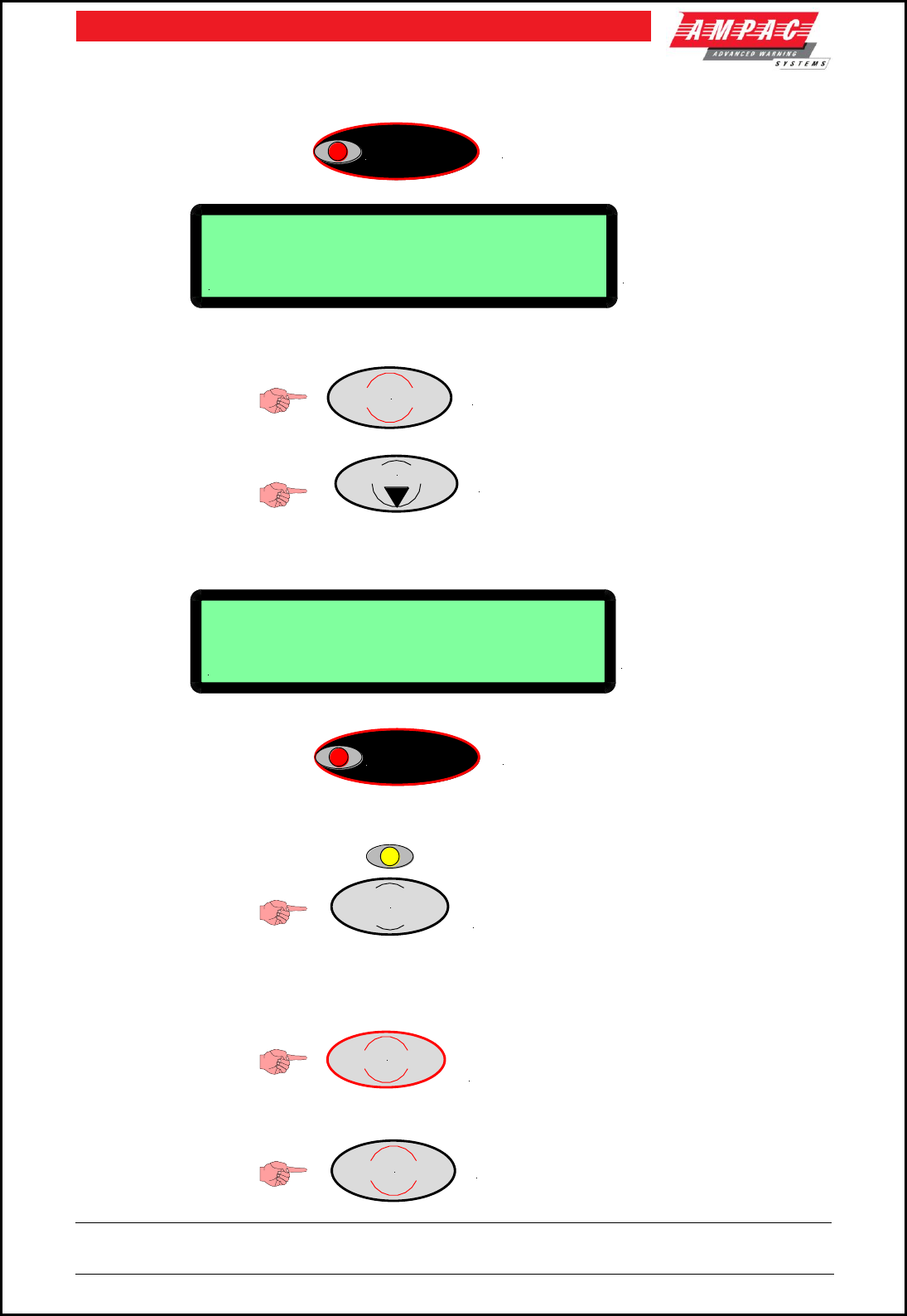
1. INDICATION ( INCOMING FIRE ALARM CONDITION )
2. ACKNOWLEDGE ALARM
3. REPEAT THE ABOVE STEPS TO ACKNOWLEDGE ALL ALARMS
4. ISOLATE BELL
5. RESET ALARMS
6. ACKNOWLEDGE RESET
ALARM
ALARM LED FLASHING
Loop X sensor X TYPE
LX SX ZX STAT: ALARM
DATE & TIME
ZONE ALARMS X OF XX
LCD DISPLAY OF DESCRIPTION
TYPE, ADDRESS, DATE & TIME
AND NUMBER OF
UNACKNOWLEDGED ALARMS
ACKNOWLEDGE
PRESS ACKNOWLEDGE KEY
PRESS NEXT TO SCROLL TO NEXT ALARM
NEXT
Loop X sensor X TYPE
LX SX ZX STAT: ALARM
DATE & TIME
ACKED ZONE ALARMS X OF XX
LCD DISPLAY OF DESCRIPTION
TYPE, ADDRESS, DATE & TIME
AND NUMBER OF
ACKNOWLEDGED ALARMS
ALARM
ALARM LED STEADY
PRESS TO ISOLATE BELLS
INDICATOR WILL TURN ON
EXTERNAL BELL
ISOLATE
RESET PRESS TO RESET ALL
ACKNOWLEDGED ALARMS
ACKNOWLEDGE
PRESS ACKNOWLEDGE KEY

Table Of Contents Page No
1 Non Disclosure Agreement..................................................................................................... 1
2 About This Manual .................................................................................................................. 2
2.1 Introduction .............................................................................................................. 2
2.2 General Requirements ............................................................................................. 2
2.3 References ................................................................................................................ 2
2.4 Symbols .................................................................................................................... 2
3 System Overview .................................................................................................................... 3
4 FireFinderTM Description ......................................................................................................... 5
5 Placing The Basic System Into Operation ............................................................................. 7
5.1 Unpacking ................................................................................................................. 7
5.2 Anti-Static Precautions ............................................................................................ 7
5.3 Working On The System .......................................................................................... 7
5.4 The Cabinet............................................................................................................... 7
5.5 Mounting The Cabinet .............................................................................................. 7
5.6 Operational Parameters ........................................................................................... 8
5.7 Cabling Recommendations ...................................................................................... 8
5.8 Power Supplies and AC Mains Installation ............................................................. 9
5.9 Current Limiter, Fuse Board .................................................................................. 11
5.10 Brigade / PSU Monitor Board 302 - 6730 ............................................................... 12
5.11 Brigade / PSU Monitor Board & Battery Connections .......................................... 14
5.12 Brigade / PSU Monitor Board Auxiliary 27 Volt Power ......................................... 14
5.13 Brigade / PSU Monitor Board DBA / MCP & Door Switch Connections ............... 14
5.14 Brigade PSU Monitor Board ASE Fault Brigade Box Connection ........................ 14
5.15 Connecting a Bell / Sounder to the Brigade / PSU Monitor Board ....................... 15
5.16 Warning System Connections ............................................................................... 15
5.17 Brigade / PSU Monitor Board Relay Output Connections .................................... 15
5.18 Main Board BRD85MBA ........................................................................................ 16
5.19 Front Panel Board 302 -690 .................................................................................... 17
5.20 Main CPU BRD85CPU ............................................................................................ 19
5.21 Slave CPU 302-669 ................................................................................................ 20
5.22 RS232 Modem / Programming / Debug Interfacing ............................................... 21
5.23 Ancillary Services .................................................................................................. 21
5.24 Conventional Zone Board 302 - 6710..................................................................... 22
5.25 Addressable Loop Termination Board 302 - 7350 ................................................. 23
6 Expanding the FACP with Compatible FireFinderTM Boards ............................................... 24
6.1 16/16 Input / Output Board 302 - 6720 ................................................................... 26
6.2 8 Way Relay Board 302 – 6760 / 1 .......................................................................... 26
6.3 16 Way Input Board 302 - 6770 .............................................................................. 27
6.4 Serial Relay Board 302 - 7320 ................................................................................ 27
6.5 Fire Fan Module BRD25FCB .................................................................................. 28
6.6 Fan Termination Board BRD25FTB ....................................................................... 28
6.7 Zone & General Indicator Card .............................................................................. 29
6.8 8 Way Sounder Monitor Board 302 – 7420 / 1 ....................................................... 30
6.9 Printer ..................................................................................................................... 31
6.9.1 Indicators and Buttons ............................................................................ 31
6.9.2 Maintenance ............................................................................................. 32
6.9.3 Printer Connections and Jumpering ....................................................... 33
6.9.4 Printer 5 Volt Power Supply ( 302-713 ) .................................................. 33
7 Expanding the System Through Networking ....................................................................... 34

7.1 Communications: Controller Interface Card 302 - 725.......................................... 34
7.2 Communications: Network Interface Card 302 - 724 ............................................ 34
7.3 Expansion Board ( 302-688 ) .................................................................................. 35
7.4 Expansion Controller ............................................................................................. 35
7.5 Networking ............................................................................................................. 36
7.6 Liquid Crystal Display Repeater Panel 302 - 7200 ................................................ 38
8 SmartTerminal ....................................................................................................................... 39
8.1 Operation ................................................................................................................ 39
8.2 Access levels .......................................................................................................... 39
8.3 Specifications ......................................................................................................... 40
8.4 Overview ................................................................................................................. 40
8.5 Operational & Key Features ................................................................................... 41
8.6 Mechanical .............................................................................................................. 41
8.7 Installation & Cabling ............................................................................................. 42
8.8 Setting the Address................................................................................................ 43
8.9 Setting the SmartTerminal Controller Configuration in ConfigManager................... 44
8.10 Setting the SmartTerminal Reporting Parameters in ConfigManager....................... 44
8.11 SmartTerminal Controls ......................................................................................... 45
8.12 SmartTerminal Indicators....................................................................................... 47
9 LCD Screen Format ............................................................................................................... 49
9.1 Trouble Shooting Chart .......................................................................................... 50
10 Agent Release Control .......................................................................................................... 51
10.1 Operation ................................................................................................................ 51
10.2 Agent Release Module BRD25ARB –A .................................................................. 53
10.3 Controlled Access .................................................................................................. 54
10.4 Local Control Station ............................................................................................. 55
10.5 Agent Release Termination Board BRD25ATB ..................................................... 58
10.6 Interface Wiring ...................................................................................................... 59
10.7 Warning Signs ........................................................................................................ 61
11 Occupant Warning Systems ................................................................................................. 63
11.1 EV60 / 120 ............................................................................................................... 67
11.2 EV3000 .................................................................................................................... 67
12 Brigade Devices .................................................................................................................... 68
12.1 ASE ( Vic Metro ) Brigade Box ............................................................................... 68
12.2 Brigade Box ( Deltec WA, SA, TAS,QLD ) .............................................................. 68
13 FireFinderTM Operation.......................................................................................................... 69
13.1 The Control Panel ................................................................................................... 69
Function And Menu......................................................................................................................... 72
13.2 The Default LCD Display ........................................................................................ 72
13.3 Accessing Functions and Menus .......................................................................... 72
13.4 Function Menu and Access Levels ........................................................................ 72
13.4.1 Forgotten Passwords .............................................................................. 72
14 The Main Menu ...................................................................................................................... 73
14.1 Status Menu ............................................................................................................ 73
14.2 Testing Menu .......................................................................................................... 75
14.2.1 Alarm Test ................................................................................................ 75
14.2.2 Fault Test ................................................................................................. 75
14.2.3 Lamp Test ................................................................................................ 75
15 Main Functions ...................................................................................................................... 76
15.1 Setting the Function Date Facility ......................................................................... 76

15.2 Setting the Function Time Facility ......................................................................... 76
15.3 Setting the Function Daynight Facility .................................................................. 76
15.4 Function Logs Facility............................................................................................ 76
15.5 The Function Test Facility...................................................................................... 77
15.6 Function Manual I/O Control .................................................................................. 78
15.7 Function Access ( Level II ) / Passwords ( Level III ) ............................................ 78
15.8 Function Programming .......................................................................................... 79
15.8.1 Conventional Zone Programming ........................................................... 79
15.8.2 Device Programming ............................................................................... 80
15.8.3 Input Programming .................................................................................. 80
15.8.4 Output Programming ............................................................................... 80
15.8.5 Manual Control Point ( MCP ) .................................................................. 81
15.8.6 Sub Address ............................................................................................ 81
15.8.7 Watchdog ................................................................................................. 81
15.9 Self Learn ................................................................................................................ 81
15.9.1 Extra Devices Detected ........................................................................... 81
15.9.2 Mismatch Detected .................................................................................. 82
16 Incoming Fire Alarm Signal .................................................................................................. 82
17 Accessing a Loop, Sensor or Zone ...................................................................................... 84
18 List of Compatible Devices ................................................................................................... 84
18.1 Short Circuit Isolation ............................................................................................ 84
18.2 Compatible Devices ............................................................................................... 85
19 Certification Information ....................................................................................................... 87
20 Statement of Compliance ..................................................................................................... 88
20.1 Installation Details .................................................................................................. 90
21 Commissioning Test Report ................................................................................................. 91
21.1 Procedure ............................................................................................................... 92
21.2 System Information ................................................................................................ 92
22 Troubleshooting Chart .......................................................................................................... 96
23 Address Setting..................................................................................................................... 97
24 Battery Capacity Calculation ................................................................................................ 98
25 Glossary of Terms ............................................................................................................... 104
26 Definitions ........................................................................................................................... 105
27 Quick Reference Guides ..................................................................................................... 106

Page 1
FIREFINDERTM INSTALLATION COMMISSIONING & OPERATION
1 Non Disclosure Agreement
This contract has been entered into by the person or company user of this document (hereafter called the
Trader) and AMPAC Technologies (hereafter called AMPAC) of 7 Ledgar rd, Balcatta, WA 6021, Western
Australia 6017. Under terms and conditions as specified here under.
Whereas AMPAC and the Trader for their mutual benefit and pursuant to a working relationship which may
be established, anticipate that AMPAC will disclose in the form of this document, information of a secret, or
confidential or proprietary nature (hereinafter collectively referred to as Proprietary Information).
Whereas AMPAC desires to ensure that the confidentiality of any Proprietary Information is maintained in
accordance with the terms of this Agreement;
NOW, THEREFORE, in consideration of the foregoing premises, and the mutual covenants contained
herein, the Trader hereby agrees as follows:
1. The Trader shall hold in trust and confidence, and not disclose to any person outside its organisation,
any Proprietary information which is disclosed to the Trader by AMPAC under this Agreement.
Proprietary Information disclosed under this Agreement may be used by the Trader only for the
purpose of carrying out work on or with AMPAC supplied equipment and may not be used for any other
purpose whatsoever.
2. The Trader shall disclose Proprietary Information received by AMPAC under this Agreement to
persons within its organisation only if such persons are legally bound in writing to protect the
confidentiality of such Proprietary Information.
3. The undertakings and obligations of the Trader under this Agreement shall not apply to any Proprietary
Information which :
1. Is disclosed in a printed publication available to the public, is described in patent anywhere in the
world, or is otherwise in the public domain at the time of disclosure;
2. Is generally disclosed to third parties by AMPAC without restriction on such third parties;
3. Is shown by the Trader to have been in its possession prior to the receipt thereof from AMPAC;
4. Is approved for release by written authorisation of AMPAC; or
5. Is not designated by AMPAC in writing or by appropriate stamp or legend to be of a secret,
confidential or proprietary nature.
4. This Agreement will be binding upon and inure to the benefit of the parties hereto, and their respective
successors and assigns.
5. This Agreement, and all rights and obligations hereunder, shall expire on the 10th anniversary of the
date of issue of this document.
These terms are accepted by the Trader on receipt and retention of this document.

Page 2
FIREFINDERTM INSTALLATION COMMISSIONING & OPERATION
2 About This Manual
2.1 Introduction
This manual contains all the information required to install, commission and operate the FireFinder™ SP
series Fire Alarm Control Panel (FACP) fitted with Version 6 software and is only available to and for the
use of personnel engaged in its installation, commissioning and operation.
2.2 General Requirements
The FireFinder SP series FACP has been designed and manufactured from high quality commercial
components so as to comply with major world standards. To ensure these standards are not compromised
in any way installation staff and operators should;
1. be qualified and trained for the task they undertake;
2. be familiar with the contents of this manual prior to the installation, commissioning or
operation of a FireFinder control system;
3. observe anti-static pre-cautions at all times; and
4. be aware that if a problem is encountered or there is any doubt with respect to the
operational parameters of the installation the supplier should be contacted.
2.3 References
FireFinder™ Technical Manual
ConfigManager ( V6 )
FireFinder™ Detector Manual
Australian Standards: AS1670 - Automatic Fire Detection and Alarm Systems, system design,
installation, and commissioning, Part 1 & Part 4
AS1851 - Maintenance of Fire Protection Systems and equipment - Fire
Detection and Alarm Systems.
AS4428 - Fire Detection, Warning, Control and Intercom Systems – Control and
Indicating Equipment. Part 1 and Part 4
2.4 Symbols
Important operational information
Note: Configuration considerations
Observe antistatic precautions
Mains supply earth
DANGER mains supply present
Page 3
FIREFINDERTM INSTALLATION COMMISSIONING & OPERATION
3 System Overview
The FireFinder™ SP series is an Intelligent Analogue / Addressable and / or Conventional Fire Alarm
Control Panel capable of supporting:
Apollo Discovery and XP95 Intelligent Detectors, Multisensor, Photoelectric, Ionisation,
Thermal (heat) and CO detectors.
Addressable Initiating Devices: Modules that monitor any conventional normally open contact
such as supervisory switches and flow switches.
Conventional two wire zone detector circuits
Multiple input/outputs
High Level Interfaces
Graphical Interfaces
Remote LCD Annunciators
Remote LCD Repeaters
Remote LED mimics
Peer to Peer networking
Master Slave (Main - Sub) networking
Main panel plus Data Gathering Panels networking
and; is built to comply with the following standards:
Australian Standard: AS 4428.1
New Zealand Standard: NZ4512
European Standard: EN54
Malaysian Standard: MS1404
Singapore Standard: CP10
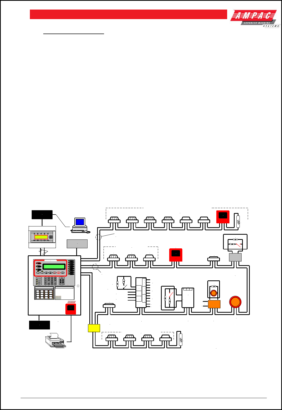
E.O.L
3K3
CONVENTIONAL ZONE
USING CONVENTIONAL DETECTORS
AND BASES
CONVENTIONAL ZONE
CIRCUIT
ADDRESSABLE
LOOP
ISOLATOR
ION OPTICAL HEAT
ANALOGUE DETECTORS
MANUAL CALL
POINT ( MCP )
ISOLATOR
E.O.L
6K2
FIR E
ALARM
PRES S HER E
TO BR EAK
EXTERNAL
COMMUNICATION
LOOP
4K7
4K7
FIRE
ALARM
PRESS HER E
TO BREAK
FIRE
ALARM
PRESS HER E
TO BREAK
HIGH LEVEL
INTERFACE
HIGH LEVEL
INTERFACE
ANCILLARY
SERVICES
EAR TH FAULT
TE ST M ODE
SYST EM F AULT
SUPP LY FAULT
POW ER ON
PRE- ALAR M
AUX A LARM
WAR NIN G
SYS FAU LT
Finder
TM
Fire
WARNING SYS
ISOLATE
EXTERNAL BELL
ISOLATE
PREVIOUS NEXT
ACKNOWLED GE
ISOLATERESET
ISO LATED
ALA RM
FAULT
AUXILIARY
FAULT / ISOLATE
FAULT
OUTP UT ISOL ATE
AIF
ACTIVE
DE-ISOLATE LOOP 1
ABC
2
DEF GHI
3
SENSOR
JKL
4
MNO
5
PQRS
6
ZONE
TUV
7 8
WXYZ
9
SYMB
TO
0
SPACE
ENTERDISPLAY
FUNCTION
MENU
CANCEL ENTRY
FIR EFIGHTE R FACIL ITY
FIREFIND ER 15/1/2003 14:00:00
AMPAC
PH: 0 8 9242 3333
SYS TEM IS NORMA L
AS PER INPUT 1
AS PER INPUT 1
20K
EOL
4K7
N/O INPUT
SWITCH
RELAY
O/P 1
IN-1
IN-2
IN-3
C1
NC
NO
C2
NC
NO
C3
NC
NO
RELAY
O/P 2
RELAY
O/P 3
FIREFINDER
FACP
SINGLE INPUT
DEVICE
FLOW SWITCH
E.O.L 20K
LOOP SOUNDER
L1
L2
E.O.L 10K
SOUNDER
SOUNDER
CONTROL
+
-
+24V DC
N/O C N/C
RELAY
OUTPUT
AUX OUTPUTS
INPUT/OUTPUT
UNIT
CONVENTIONAL DETECTORS
MAXIMUM OF 20
ZONE MONITOR
OUT
IN
SPECIFICATIONS:
MAX LENGTH = 2KM
MAX RESISTANCE = 50ohms
MIN CABLE SIZE = 1.5mm²
MONITORED
INPUT
+
-
+24V DC
THREE INPUT / OUTPUT
DEVICE
E.O.L 20K
MENU
PREVIOUS
NEXT BUZZER
MUTE
PRE-A LARMISOLAT EDEFECTALARMNORMAL
DEC2580-T1
Figure 1: Typical Application
Page 4
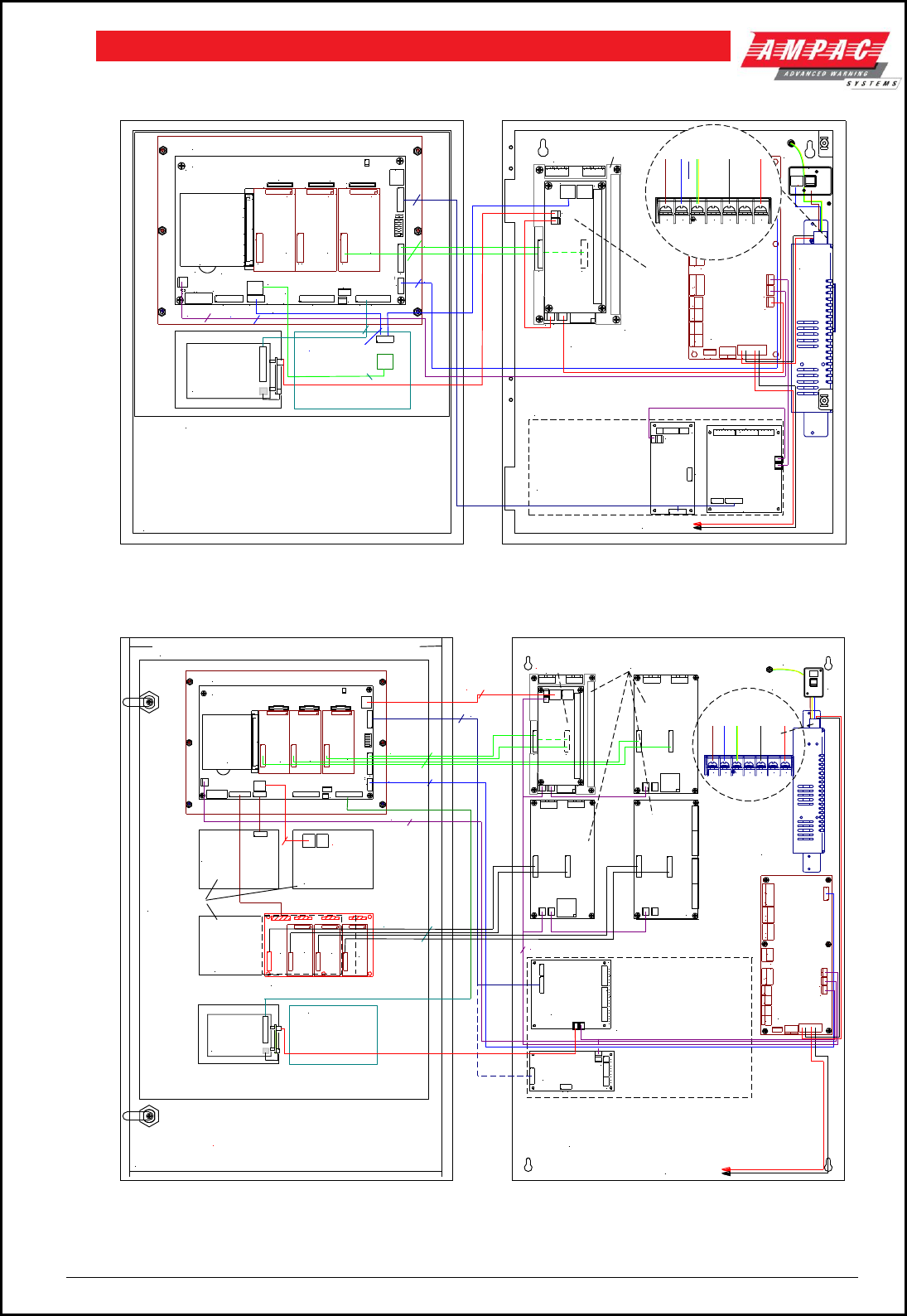
FIREFINDERTM INSTALLATION COMMISSIONING & OPERATION
FACP Configuration Examples
TYPICAL FRONT DOOR LAYOUT FOR A FULLY POPULATED PANEL
NOTE: PANEL LAYOUT MAY VARY DEPENDING ON CLIENT CONFIGURATION
X- MAF (341-0015) CONSISTS OF:
1- CONTROL PANEL BOARD (302-6906)
1- MAIN BOARD (BRD85MBA"X"-A)
1- CPU (BRD85CPU"X"-D)
X-SLAVE CPU (302-6692)
MAIN CONTROL BOARD (BRD85MBA)
20 WAY
10 WAY
FRONT PANEL CONTROL (302-6906)
CN3
CN21
CN20
TH1 CN8
CN1
CN6
D13
D14
CN3
C12
BZ1
CN5
CN2
CN7
CN11
CH16
CH15
CH6 CH8
CH2
CH1
CN16
CN14
CN18
R17
TP3
RN17
RN20
CN4
CN10
CN15
CN13
CN17
c
ba
4 3 2
BRIG ADE I/F
FRON T PA NELEXPAN SION LED S
EXPAN SION PANE L
MODE M
27V IN
PRIN TER
PSU MON ITOR
LOOP COM MS
1
+
3 WAY
CN1
CN2
1
SLAVE CPU
(302-6692)
CH8
CN1
CN2
1
CH8
CN1
CN2
1
16 WAY
SLAVE CPU
(302-6692)
SLAVE CPU
(302-6692)
U15
CN2
a b c
U11
U10
U14
U13
CPU BOARD
(BRD85CPU)
PRINTER PSU (302-7130)
C/W CAB2153
26 WAY
CN3
10 WAY
+ -+ -
+ - AUXILIARY
+ BAT -+ IN -DBA/MCP
DOOR SW
BELL2BELL1
FAULTVALVE MON
BATT FAIL NO C NC NO C NC NO C NC NO C NC NO C NC+ - + - NO C NC + - + -
ALARM ISOLATE
C
SGD II
WARN SYSAUX POW ER O/P
TB10
CN3
TB4
CN2
CN1
TB6
TB5
CN6
TB3
CN5
TB2
BRIGADE
O/P TERM
BOARD
(302-6732)
EARTH
STUD
MAINS
SWITCH
POWER
SUPPLY
UNIT
CABINET BACKPAN VIEW
SHOWING MODULES FITTED
TO THE BACKPAN
AND WIRING DETAILS
TO BATTERIES
TB1
TB2
CN2
CN1
TB3
CTS
RTS
RXD
TXD
COM
D ABCS-+ D ABCS-+
COMMS OUTCOMMS IN
OUT
CTS
RTS
RXD
TXD
COM
SCRN
TRX-
TRX+
0V
+27V
TB3
CN1
TB2
TB1
CN3
OPTIONAL NETWORKING BOARDS
302-7240 NETWORK INTERFACE CARD
302-7250 CONTROLLER INTERFACE CARD.
NOTE: POSITION MAY VARY AS SHOWN
AND IS FOR INDICATION ONLY.
302-7240
302-7250
X- PRINTER
(OEM1447)
C/W MOUNTING
PLATE.
(KIT = 159-0093)
GENERAL INDICATOR, OR
L(AC) N(AC)
-V -V +V +V
(AC)
ACTIVE
NEUTRAL
GROUND
-VE
+VE
DANGER
240V
FAN CONTROL OR
AGENT RELEASE
CN1CN3
2 LOOP TERMINATION BOARD
(302-7350) OR
16Z CONVENTIONAL BOARD
(302-671B)
L2+ L1-
B
L2+ L1-
AEXT
+35V EXT
+35V
L2+ L1-
B
L2+ L1-
AEXT
+35V EXT
+35V
SERIAL RELAY
BRD (302-7320) OR
AGENT TERM BRD
(BRD25ATB) OR
FAN TERM
BRD (BRD25FTB)
POWER
CN4
CN2 TX1
POWER
ZD7
CN2
CN1
CN3
MOUNTED ON CONVENTIONAL
OR LOOP TERMINATION BRD
Figure 2: Typical Example of an SP1X Layout
FRONT DOOR AND FRONT INNER DOOR REAR VIEW SHOWING
INSTALLED BOARDS ON FRONT INNER DOOR AND WIRING DETAILS
+ -+ -
+ - AUXILIARY
+ BAT -+ IN -DBA/MCP
DOOR SW
BELL2BELL1
FAULTVALVE MON
BATT FAIL NO C NC NO C NC NO C NC NO C NC NO C NC+ - + - NO C NC + - + -
ALARM ISOLATE
C
SGD II
WARN SYSAUX POWER O/P
TB10
CN3
TB4
CN2
CN1
TB6
TB5
CN6
TB3
CN5
TB2
CABINET BACKPAN VIEW
SHOWING MODULES FITTED TO THE BACKPAN
AND WIRING DETAILS
BRIGADE
PSU MON.
BOARD
MAIN CONTROL BOARD
20 WAY
10 WAY
FRONT PANEL CONTROL
TO BATTERIES
2 LOOP TERMINATION BOARD
OR
16Z CONVENTIONAL BOARD
CN8
CN1
CN6
CN5
CN7
CH15
CH2
CN10
BRIGADE I/F
PRINTER
PSU MONITOR
BLANK
3 WAY
3 WAY
SLAVE CPU 4
20 WAY
EARTH
STUD
302-6880 EXPANSION BOARD
TB1
TB2
CN2
CN1
TB3
CTS
RTS
RXD
TXD
COM
D ABCS-+ D ABCS-+
COMMS OUTCOMMS IN
OUT
CTS
RTS
RXD
TXD
COM
SCRN
TRX-
TRX+
0V
+27V
TB3
CN1
TB2
TB1
CN3
OPTIONAL NETWORKING BOARDS
NETWORK INTERFACE CARD
CONTROLLER INTERFACE CARD.
NOTE: POSITION MAY VARY AS SHOWN
AND IS FOR INDICATION ONLY.
16 WAY
NETWORK
I/F CARD
SLAVE CPU 3
SLAVE CPU 2
SLAVE CPU
6
NOTE: WIRING MAY VARY DUE TO
CLIENT PANEL CONFIGURATION
CH15
CONTROLLER
I/F CARD
CPU BOARD
SLAVE CPU
7
SLAVE CPU
8
MAINS
INPUT
16Z CONVENTIONAL BOARD
CABINET (291-0076)
L(AC) N(AC)
-V -V +V +V
(AC)
POWER
SUPPLY
UNIT
ACTIVE
NEUTRAL
GROUND
-VE
+VE
ANCILLARIES or
HOUSING BLANKS
AGENT RELEASE
MODULE OR
FIRE FAN CONTROL
MODULE
CN1CN3
AGENT TERM
BRD OR
FAN TERM
BRD
ZD7
CN2
RJ45/8 PIN
RJ45/8 PIN
MAINS
SWITCH
DAN GER
240 V
GENERAL
INDICATOR
CARD
X- PRINTER
(OEM1447)
C/W MOUNTING
PLATE.
(KIT = 159-0093)
BLANK
SLAVE CPU
5
Figure 3: Typical Example of an SP8X Layout

Page 5
FIREFINDERTM INSTALLATION COMMISSIONING & OPERATION
4 FireFinderTM Description
The following description does not relate to specific cabinets as the size of each cabinet will vary with the
amount of hardware fitted.
The heart of the FireFinder™ consists of two boards collectively known as the Controller. These boards
are the Main Board (BRD85MBA) and the CPU board (BRD85CPU). Combining these two boards with a
front panel (302-690) forms the basis for a FireFinder™ FACP. A single FireFinder™ Controller without an
expansion board has the capacity to interface to four (4) FireFinder™ Slave CPU’s modules. Each of these
Slave CPU’s can interface to 16 Zone Conventional Termination Boards, Loop Termination Boards or
Input/Output Boards as well as communicate with the Brigade / PSU Monitor Board (302-673).
The Main Board (BRD85MBA) has the Slave CPU Board for the first Loop Termination Board and the
provision for mounting of up to three additional FireFinder™ Slave CPU’s. The FireFinder™ Slave CPU’s all
have the same software installed and the manner in which they operate is automatically determined by the
type of termination or interface board onto which they connect.
If the system is to be expanded to have more than four Slave CPU’s an Expansion Board (302-688) is
required. This board contains FireFinder™ Slave CPU No. 5 and expansion sockets for three more. This
configuration allows for a maximum number of 8 Slave CPU’s that any one Controller can accommodate.
If a system is required to be expanded beyond eight Slave CPU’s then either local networking using up to a
total of four controllers (max 32 Slave CPU’s) within the one cabinet may be fitted or external networking
must be used.
The FireFinder™ has an internal ASPI ( Ampac Serial Peripheral Interface ) serial bus. This serial bus
provides interfacing to the Brigade /PSU Monitor Board and if required up to eight (8) Sounder Board/s
(302-7420/1).
FireFinder™ has a second serial interface that connects to ancillary boards that can be designed into a
system to control / monitor field plant / equipment and agent release .
Where the system design exceeds the capability of one FireFinder™ then other FireFinder™ panels can be
networked together to provide an expanded system containing multiple boards in a variety of applications.
Some of these applications include:
A Master / Slave (Main Sub) FACP arrangement (MFACP / SFACP)
A Peer to Peer System
Use of Data Gathering Panels (DGP’s)
LCD Annunciators
LCD Repeater Panels (LCDR)
SmartGraphics
A Network FireFinder™ System supports a combination or all these options on a single network. Each
panel on the network is regarded as a “node”. The NETWORK BUS can be accessed using either a
Network Interface Card (NIC 302-724) and/or Controller Interface Card (CIC 302-725). Modules that are
supported on the network are Remote LED Mimic Board (302-715), Remote Liquid Crystal Display
Repeater (302-720, 302-721), remote FireFinder™ main panels and other FireFinder™ remote data
gathering panels. The network configuration determines whether a NIC or a CIC or a combination of both
is required.
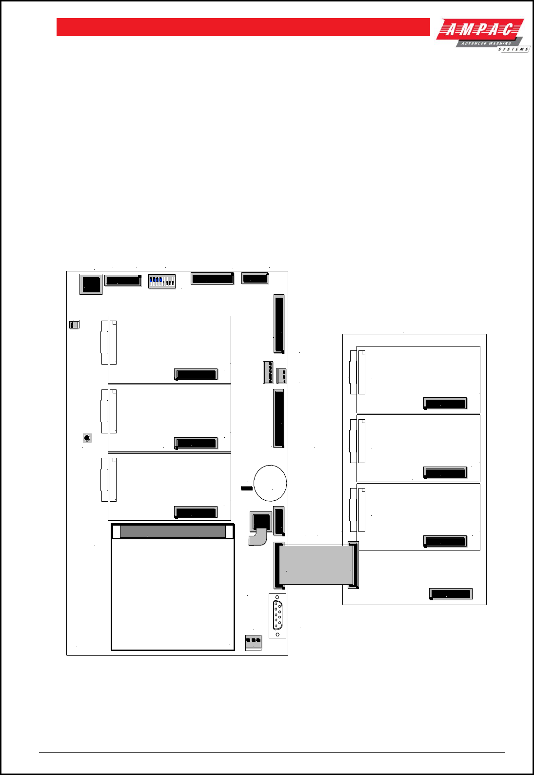
Page 6
FIREFINDERTM INSTALLATION COMMISSIONING & OPERATION
Master / Sub FACP : Where there are one or more FACP’s configured as local panels
then each report the status of their associated zones/devices to a MFACP. There is no control between
local panels as the MFACP is structured to have full control of the entire system.
Peer to Peer : Each FACP is regarded as a Master FACP and therefore a user can take control of the
entire fire system from any FACP.
Data Gathering Panel : The use of this type of panel may be installed where there is a need to have field
terminations only at one location and all control is performed by an FACP that is remotely located.
LCD Repeater Panel : The LCDR’s are network compatible and provide the user with the ability to monitor
the status of designated areas or an entire site as well as execute specific interrogation tasks.
SmartGraphics: Is an active graphics system connected to the FireFinder™.
MAIN CPU
27VDC
(CN16)
IN
302-6692 302-6692 302-6692
EXTERNAL LOOP
COMMUNICATION
CONNECTS TO
NIC OR CIC
#2 UP TO 3 ADDITIONAL
SLAVE CPU's (302-6692)
CAN BE SLOTTED ONTO
THE MAIN BOARD.
TO CN5 OF THE
BRIGADE BOARD
OR SOUNDER
CONTROL BRD
IN CN1
INTERNAL PRINTER
OUTPUT
TO FRONT KEYPAD
(NOT USED IF THE
PANEL IS A DGP OR
SLAVE CONTROLLER)
INTERNAL SERIAL
COMMUNICATION
PORT
MODEM
I/O PORT
THE MAIN BOARD
CARRIES
SLAVE CPU 1.
CN10 CABLES VIA
A 20 WAY CABLE
TO THE PANEL
BOARDS
AN EXPANSION BOARD (302-6880) CAN BE CONNECTED
TO FACILITATE UP TO 4 ADDITIONAL MODULES IF REQUIRED
302-6692 302-6692 302-6692
UP TO 3 ADDITIONAL
SLAVE CPU's ( 6, 7 & 8 )
CAN BE SLOTTED INTO
THE EXP BOARD.
CN2
CN2
CN2
CN2 CN2
CN2
MAIN BOARD
LOOP COMMS
CN11
302-6880 JUN 98
CN1 CN2 CN3 CN4
SW3
CN17
CN16
CN7
CN2 CN1
CN8
NODE ADDRESS
PRINTER
BACKLIGHT
EXPANSION
PANEL
EXPANSION
LEDS
FRONT PANEL CN6
#1 PANEL BOARDS
ARE CONNECTED
VIA A 20 WAY
RIBBON TO CN1
ON A SLAVE CPU
SLAVE CPU 2
SLAVE CPU 3
SLAVE CPU 4
SLAVE CPU 6 SLAVE CPU 7 SLAVE CPU 8
PANEL BOARDS ARE
CONNECTED BY A 20
WAY RIBBON TO CN1
ON A SLAVE CPU
CN1
CN1
CN1
CN1
CN1
CN1
CN4
CN3
CN5
CN2
CN1
+ -
+-
CN5
CN10 CN7
CN18
RESET
SW1
BZ1
LK2
BUZZER
ENABLE
KEY
SW
O O O
O O O
O O O
O O O
O O O
O O O
O O O
O O O
O O O
O O O
O O O
O O O
O O O
O O O
O O O
O O O
O O O
O O O
O O O
O O O
O O O
O O O
O O O
O O O
O O O
O O O
O O O
O O O
O O O
O O O
O O O
O O O
a b c
ON
1 2 3 4 5 6 7 8
CN21
CN20
RS485 COMMS TO
BACKPAN BORADS
RS485 COMMS TO
FRONT PANEL MODULES
Figure 4: Single Controller Board with Expansion Board

Page 7
FIREFINDERTM INSTALLATION COMMISSIONING & OPERATION
5 Placing The Basic System Into Operation
5.1 Unpacking
Carefully unpack the FireFinder™.
The package should include:
FireFinder™ Fire Alarm Control Panel
An Operators manual
003 keys
5.2 Anti-Static Precautions
To prevent damage to components, modules and boards, anti-static precautions MUST
be observed while performing any task within the FACP. The same applies to those
situated in the field
5.3 Working On The System
Prior to unplugging any connector, connecting or disconnecting any wiring, removing or replacing any
module or board ensure that both the Mains and Batteries have been isolated to prevent damage to panel
components.
5.4 The Cabinet
Features:
The cabinet is available in three different styles. Each style has the capability of being
either surface or flush mounted. With flush mounting though a surround is required.
Normally painted Arch White Ripple. Other colors are available on request.
The inner and outer door hinges are mounted on the left-hand side of the cabinet which
allow the doors open to an angle of 100º. Locking is normally keyless though keyed entry
is available on request.
Knockouts are positioned at the top and rear of the cabinet to simplify cable entry.
5.5 Mounting The Cabinet
Note: It is recommended the cabinet should be installed in a clean, dry, vibration-free area.
Open the front door. Use the keyhole mounting holes in the top corners and in the lower middle of the unit to
mount it on the wall. Cables to connect the system to its external actuating devices are brought in through the
knockouts on the top or bottom of the cabinet.
R 6mm.
12 mm
Tap lightly around the
rim of the knockout
Figure 5: Example SP1X Back Pan Mounting Hole & Removing Knockouts

Page 8
FIREFINDERTM INSTALLATION COMMISSIONING & OPERATION
5.6 Operational Parameters
Temperature: -5ºC to + 55ºC
Humidity: 25% to 75%
IP Rating IP51
Maximum Number of Devices per Loop: 126
Maximum Number of Devices per Conventional Zone: 40
Cable Loop Characteristics: 2 core. 1.5 to 2.5mm²
Power Supply Output Voltage: 27V ( Set to 27.2V )
Power Supply Output Current: 2Amp, 5.6Amp or 18Amp
Power Supply Input: 85 - 240V AC
Panel Current Draw: 450 mA (min)
Battery Type and Capacity: 2 x 12V sealed lead-acid
batteries (capacity is determined
by the installation configuration
and supplementary
documentation Power Supply
and Battery Calculation ).
Minimum Operating Voltage: 19.2 V
5.7 Cabling Recommendations
Conventional Zones
Cabled in red Twin Plastic Sheath ( TPS ) or fire rated Radox or approved equivalent.
Analogue Loop
Two core cable. The minimum cable size is 0.75mm2, the maximum loop resistance is 50 ohms and the
maximum loop distance is 2km.
RS 422 Loop
Two twisted pair screened ( 4 core ) cable originating from FACP extending through the protected areas
and returning to the FACP.
Cable Specifications
Capacitance of 100 picofarads per metre or less
Resistance of 100 milliohms per metre or less
Impedance of loop typical 100 to 120 ohms
Maximum distances between modules 1.2km providing cable meets above specifications.
Recommended cable type
Belden 8132 or 9842 (non fire rated)
Radox FR Communication 0.75mm 1 pair (fire rated) x 2
LCD Repeater
Two by two twisted pair shielded cable (4 core) plus 2 core power, or local supply.
Maximum distance between LCD mimic panel and FACP. is 1.2km.
Note: If the LCD operates in a redundant path mode the total cores including power is 10. The preferred
cabling method in this case is 1 X 2 pair twisted shielded cable ( 4 core ) and 1 X two pair twisted
shielded cable (4 core) plus 2 core power
LED Mimic ( RS485 )
Two core twisted shielded cable (No return loop) plus 2 core power or local supply.
Maximum distance between each LED repeater card and FACP. is 1.2km.
Recommended Cable Type
Hartland HC2335
Belden 9841
Radox FR Communication
Page 9
FIREFINDERTM INSTALLATION COMMISSIONING & OPERATION
Fire Alarm Bell Connection
Two core 1.5mm2 PVC sheathed MIMS ( Mineral Insulated Metal Sheathed ) to the bell location.
Brigade Connection Via Telecom
Two core 1.5mm² PVC sheathed MIMS from the FACP to the Telecom MDF.
RJ45 Multi-drop Serial Port
5.8 Power Supplies and AC Mains Installation
AC Mains will be connected to either a 2 Amp, 5 Amp or 18Amp 27 volt supply. These supplies will be
either mounted in the upper or lower right hand corner of the cabinet with the Brigade Board mounted
above or below. The wiring should enter the cabinet through the nearest knockout entry hole on that side.
See the following diagrams for the actual wiring and fusing details for each supply.
Common Power Supply Features & Specifications
High efficiency, low working temp.
High efficiency; low ripple noise
Universal AC input/ full range
Soft start with limiting AC surge current
Short circuit/ over load
100% full load burn-in test
Built in EMI Filter and PFC Circuit
Remote control on/off (option)
Over voltage protection
Over temp. protection (option)
Input Voltage:
85 to 264 VAC
Tolerance at 27V
+/- 1%
Input Freq
47 to 63Hz.
Load Regulation
+/- 0.5%
PFC
0.95~230VAC
Line Regulation
+/- 0.5%
Power Supply Specifications
Type No
Output
Tolerance
R & N
Efficiency
S-60-27
27V @ 2.2A
1%
150mV
79%
SP-150-27
27V @ 5.6A
1%
150mV
84%
SP-500-27
27VDC @ 18A
1%
200mV
86%
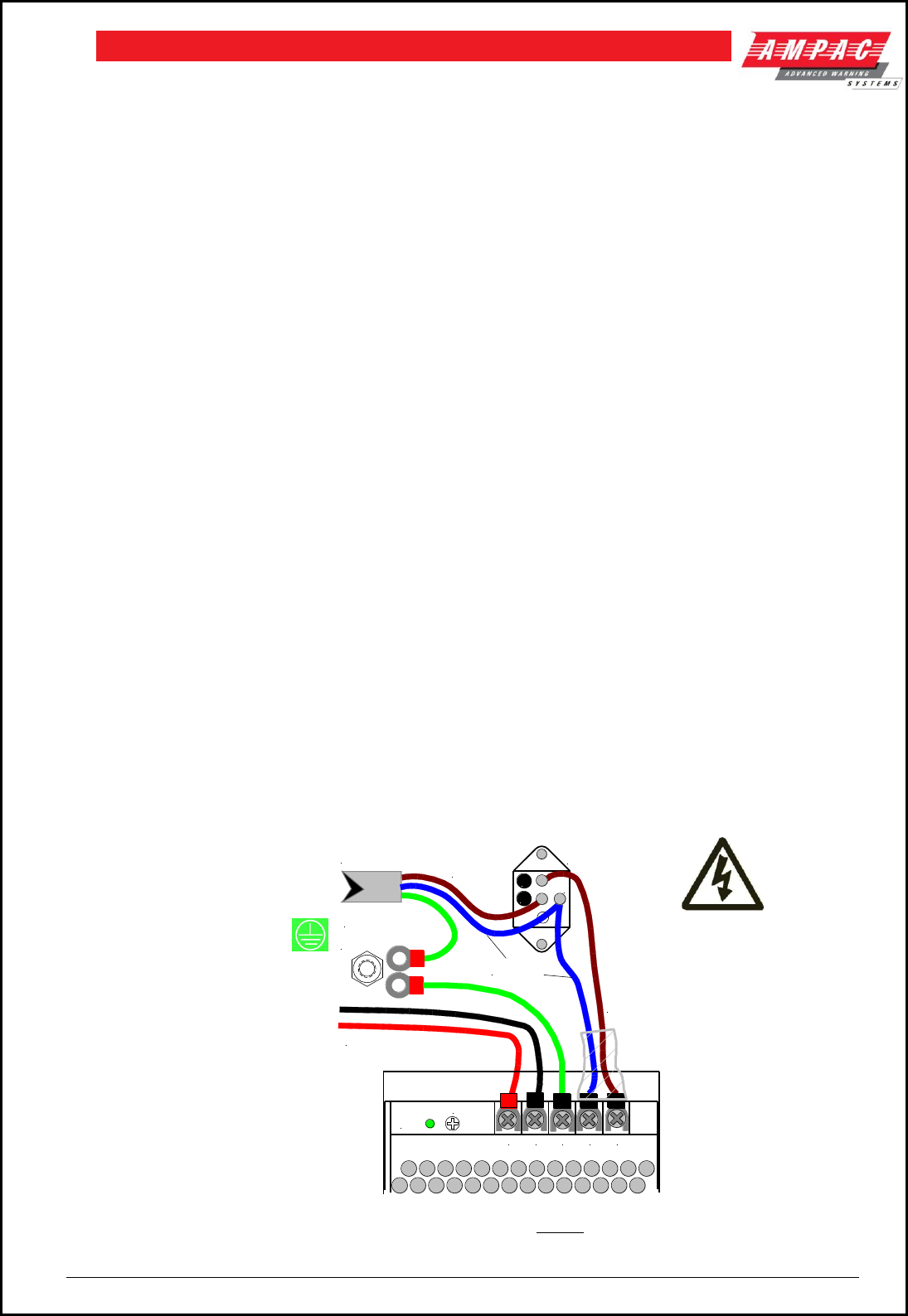
Connecting the Mains Power to the Power Supply
Terminate the mains power to the 240 VAC switch terminal block as shown below.
Figure 6: Mains Power Connection to the 2 Amp Power Supply
POWER SWITCH
(LOOKING AT REAR)
MAINS CORD BROWN
(ACTIVE)
BLUE
(NEUTRAL)
BROWN
(ACTIVE)
LED
TO CHASIS EARTH
TERMINAL
DC 27V TO PANEL
EARTH (GREEN)
L(AC)N(AC)GNDV-V+
V ADJ
C
1
LOO P
NOTE:
Output Voltage is Set to
27.4Volts.
FUSE Rating
1 Amp 3AG Slow Blow
Mains cable should be no
less than 0.75mm
Page 10
FIREFINDERTM INSTALLATION COMMISSIONING & OPERATION
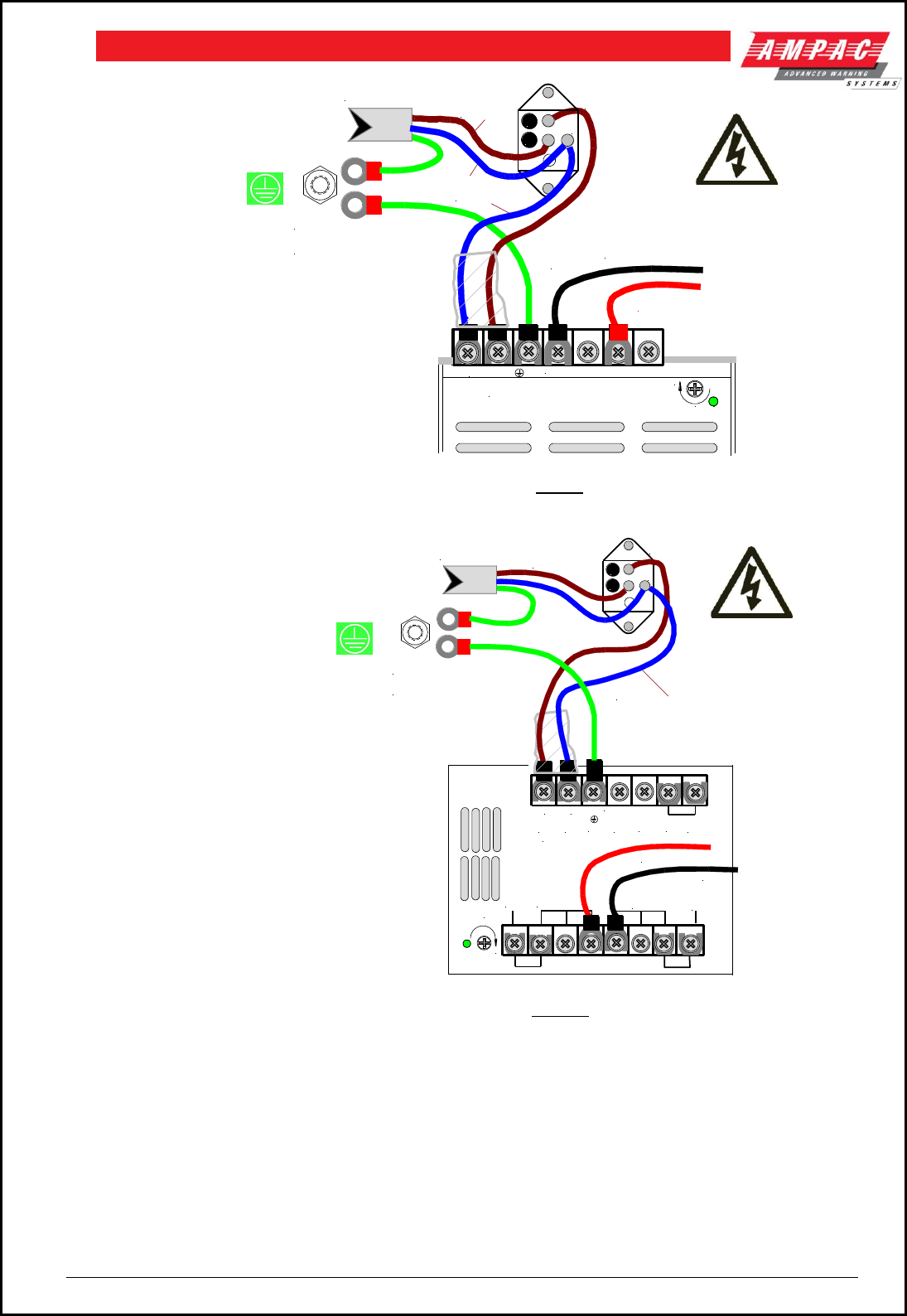
Figure 7: Mains Power Connection to the 5 Amp Power Supply
LOO P
BROWN
(ACTIVE)
DC 27V TO PANEL
V ADJ
(AC) (AC)
+
(AC)
BLACK
RED
+27V 18A+S -V -S
L N
( AC ) FG NC NC GRC
TO CHASSIS EARTH
TERMINAL
EARTH (GREEN)
MAINS CORD
BLUE
(NEUTRAL)
POWER SWITCH
(LOOKING AT REAR)
1
C
Figure 8: Mains Power Connection to the 18 Amp Power Supply
TO CHASSIS EARTH
TERMINAL 27VDC TO BRIGADE
PSU MONITOR BOARD
EARTH (GREEN)
V ADJ
L(AC) N(AC) -V -V +V +V
+
(AC)
BLACK
RED
MAINS CORD BROWN
(ACTIVE)
BLUE
(NEUTRAL)
Fuse is under this cover
POWER SWITCH
(LOOKING AT REAR)
C
1
LOOP
NOTE:
Output Voltage is Set to 27.4
Volts.
FUSE Rating
2 Amp 3AG Slow Blow
Mains cable should be no
less than 0.75mm
NOTE:
Output Voltage is Set to 27.4
Volts.
FUSE Rating
5 Amp 3AG Slow Blow
Mains cable should be no
less than 0.75mm
Page 11
FIREFINDERTM INSTALLATION COMMISSIONING & OPERATION
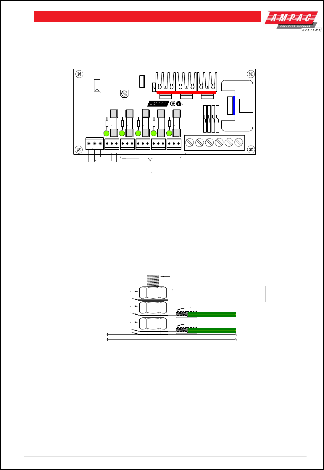
5.9 Current Limiter, Fuse Board
The Current Limiter, Fuse Board provides protection for the boards, cards and other 27VDC distribution
within the FACP when the 18Amp power supply is used. The four LED’s associated with the board indicate
that 27VDC is available at each of the outputs CN1 – 5.
F5
F4F3
F2F1
CN5
CN4
CN3
CN2CN1
HS1
TB1
TB4
Q3
Q1 Q2
RV1
U2
U1
N1236
BRD85CLFB1-A
1A 1A 1A 1A 1A
+ OUTPUT - + BATT - + PSU I/P -
TO
302-6730
TB1
+27V
0V
+BATT V
CN1-5 PINOUT = 0V, +27V, 0V
0V+27V 0V
+27V 0V
TO
302-6730
CN1
MAF, FRONT DOOR
AND BACKPAN
DISTRIBUTION
DISTRIBUTION
EV60 / 120 TONE GEN
Figure 9: Current Limiter Fuse Board
Connecting the Mains Earth
1. All earth cabling shall be terminated to the panel Chassis Earth Terminal in a star configuration.
2. The earth cable closest to the cabinet body shall have an M4 SPW beneath the lug then an M4 SPW
and M4 nut.
3. Each additional earth cable shall be terminated with an M4 SPW and M4 nut.
4. An additional M4 nut and M4 SPW are fitted to the Chassis Earth Terminal for installers to connect
their Mains Earth.
Figure 10: Panel Earthing
M4 Shake Proof Washer
M4 Shake Proof Washer
CHASSIS EARTH TERMINAL
M4 Nut
Earth Cable
Earth Cable
M4 Nut
M4 Shake Proof Washer *
M4 Nut *
Note:
* Extra M4 Nut and M4 SPW are
provided finger tight on the Earth bolt.

Page 12
FIREFINDERTM INSTALLATION COMMISSIONING & OPERATION
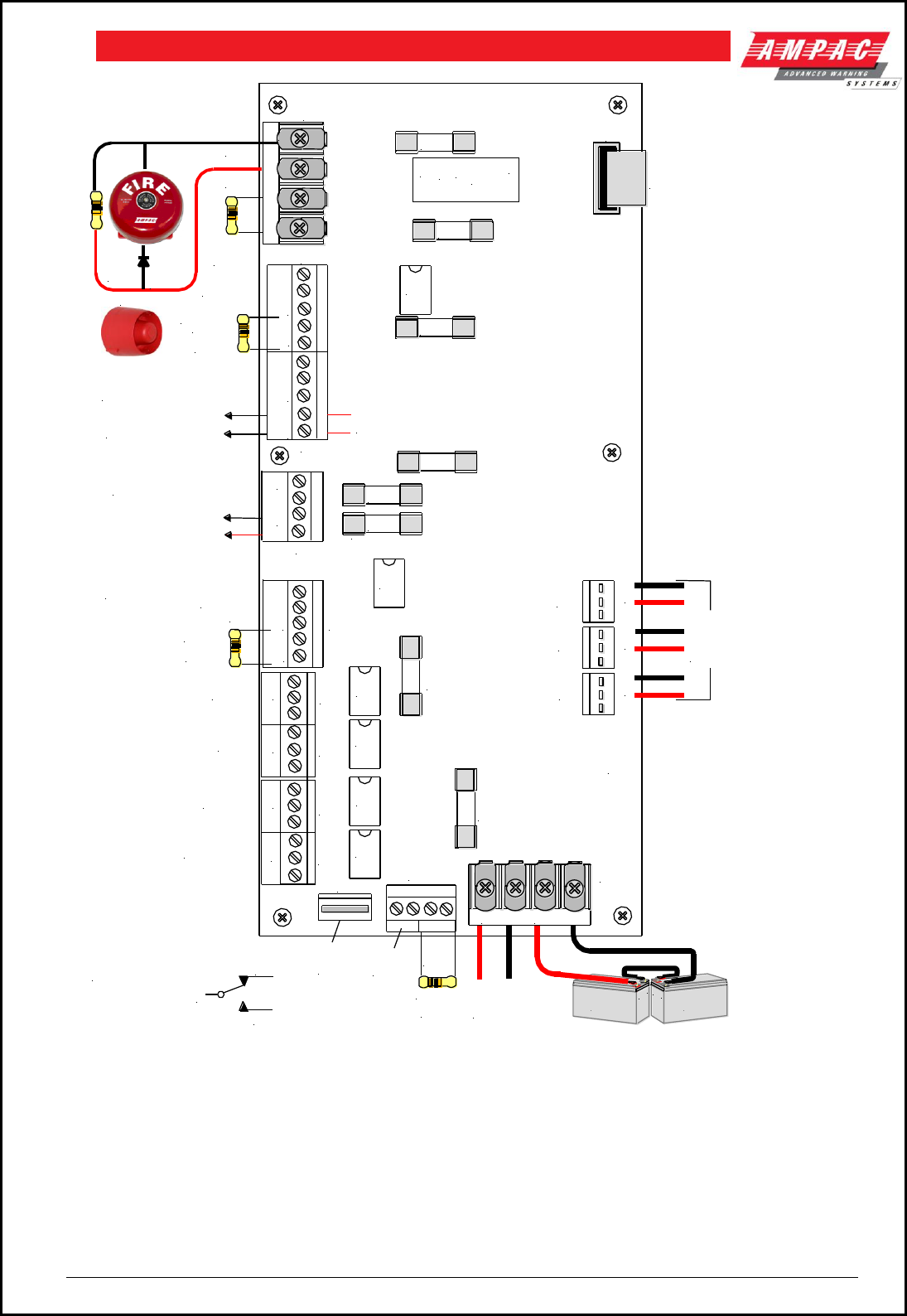
5.10 Brigade / PSU Monitor Board 302 - 6730
The Brigade / PSU Monitor Board monitors and controls the power supply, battery charging, monitored /
un-monitored inputs, outputs and the 7 relay outputs.
Providing the Power supply has adequate capacity monitored Bell/Sounder O/P’s are capable of driving 2
X 2Amp circuits. Each circuit, terminated in a bell/sounder or not, requires a 10K EOL resistor to give a
system normal indication. If either circuit is open or shorted, the panel buzzer will sound and a Sounder
Fault will be indicated on the Panel. Monitoring is achieved using a small reverse polarity current. For this
reason it is necessary to ensure that all alarm devices are fitted with a series diode (1N4004
recommended) and correct polarity is observed for both the output and the sounders they are connected
to.
Relay outputs marked NO, C and NC are voltage free relay contacts. Outputs marked +ve and -ve are
fitted with resistors (10k) to allow the circuit to be monitored. If these outputs are un-used they must be
terminated at the terminal block or turned off in ConfigManger.
For all outputs combined, total output current is 2A ( if 2.5A power supply is being used ).
Once all the field devices are installed and the wiring has been correctly terminated the FireFinder™ is
ready to turn on. Turn the Mains power on, and connect the batteries observing correct polarity. The green
power on LED should be illuminated.
OUTPUT RATINGS
TB
Function
Type of Output
Fuse
Relay
3
Bell 1
2 Amp Fused
F2
RL 1
Bell 2
2 Amp Fused
F3
RL 1
4
Plant (Aux) Monitored
1 Amp Fused
F4
Plant (Aux) Non-Monitored
1 Amp Voltage Free Contacts
RL2
5
Warn Sys (Evac) Monitored
1 Amp Fused
F5
Warn Sys (Evac) Un-Monitored
1 Amp Voltage Free Contacts
RL3
6
Fault Monitored
1 Amp Fused
F6
Fault Non-Monitored
1 Amp Voltage Free Contacts
RL 4
7
Isolate
1 Amp Voltage Free Contacts
RL6
8
Alarm
1 Amp Voltage Free Contacts
RL 5
9
Valve Monitor
1 Amp Voltage Free Contacts
RL 8
10
Batt Fail
( Relay Normally Energised )
1 Amp Voltage Free Contacts
RL 7
1
Battery Output
Thermistor Protected
2
Aux Power Output 1
1 Amp Fused Not Monitored
F7
Aux Power Output 1 – EV40 use
3 Amp Fused Not Monitored
F7
Aux Power Output 2
1 Amp Fused Not Monitored
F8
Fuse Information
1. All fuses are of the Glass M205 style.
2. F1 is 6.3A
3. Voltage Free contacts are rated at 1A @ 30V
Back EMF Protection
Inductive loads fitted to the Brigade PSU Monitor Board MUST be fitted with “Flyback”
diodes at the load for back EMF protection.
Transient Protection
Recognised transient line protection methodologies at the FACP and the load MUST also be
considered when connecting any control devices to the outputs be they in close or remote
proximity to the FACP.
Page 13
FIREFINDERTM INSTALLATION COMMISSIONING & OPERATION
Isolate Relay
Alarm Relay
NO C NC
+ -
+ -
NO C NC
Batt Fail Relay
( Normally Energised )
Valve Mon Relay
+ IN - + BAT -
302-6730
+ -
F2 2A
F6
1A
RL4
F7 1A
F8 1A
TB2
CN5
TB1
RL7
RL5
RL6
CN6
TB6
CN1
CN2
RL8
TB11
F1
6.3A
F4 1A
F3 2A
CN3
TB8
TB7
TB10
TB9
///
NO
NC
C
RL1
F5 1A
RL2
+ -
Fault
NO C NC
+ -
NO C NCNO C NCNO C NC
To CN7 of the Main
Controller Board
- + -- + -- + -
CN1, 2, 3 Supplies
Regulated +27VDC
to Internal Boards
+27VDC
from PSU
Note: NC C NO
Denotes Voltage
Free Contacts
NC = Normally Closed
C = Common
NO = Normally Open
TB4
TB5
Monitored
Un-monitored
Monitored
EOL
Required
EOL
Required
Monitored
EOL
Required
Monitored
EOL
Required
C
NC
NO
NO C NC
Un-monitored
ASE
Fault
Bell 1
Bell 2
++
-
TB3
EOL
10K
Ohms
Warning System
Alarm
Auxiliary
Door
Switch
DBA
MCP
Battery 2
12Volts
Battery 1
12 Volts
+--
+
-
Warning System
27VDC
* NOTE: When used
for the EV40 F7
MUST be changed
to 3 Amps
Bell
or Sounder
Aux 2 27VDC Supply
Note: Wired as for a Bell TB5 1, 2
could be used as a Sounder O/P
Note: If a diode is NOT fitted
internally to a bell / sounder a
diode MUST be fitted as
shown - fit 1N4004 or similar
*
Figure 11: Brigade / PSU Monitor Board Layout
Note: When connecting to the Brigade PSU Monitor board transient and “Flyback” (Back EMF) protection
methodologies MUST be applied.
Page 14
FIREFINDERTM INSTALLATION COMMISSIONING & OPERATION
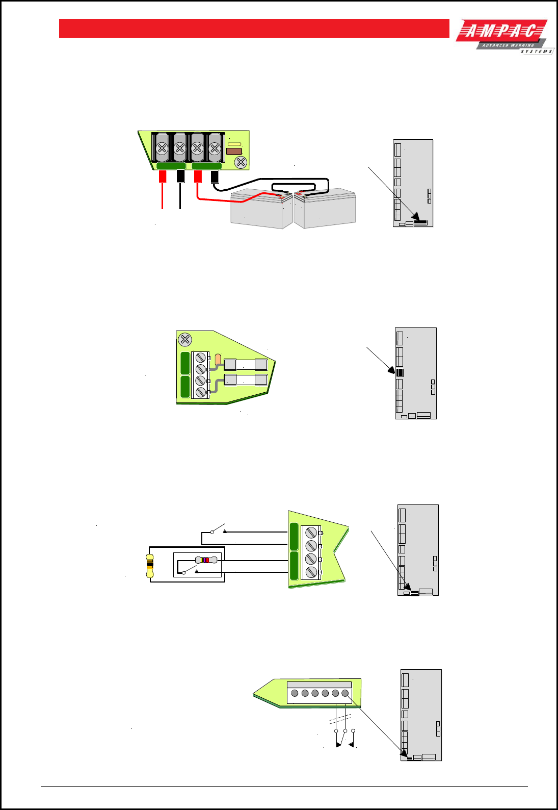
5.11 Brigade / PSU Monitor Board & Battery Connections
A FireFinder can be supplied with two ( 2 ) 12 volt batteries. The batteries should be placed into the
bottom right hand side of the cabinet. A red and black lead coming from TB1 on the Brigade Board will be
clearly seen in the same area, this lead is to be connected to the batteries red to positive and black to
negative once the system is operating on Mains supply.
+27VDC
FROM PSU
TB1 is located on the bottom
right hand side of the board
Brigade/PSU
Monitor Board
Battery 2
12Volts
Battery 1
12 Volts
+--
+
TB1
C14
M20
+ BAT -+ IN -
Figure 12: Battery Connection To The Brigade Board
5.12 Brigade / PSU Monitor Board Auxiliary 27 Volt Power
Two ( 2 ) 1 Amp outputs are available from TB2 terminals 1+ ( plus ) and 2- ( minus ) or 3+ and 4- on the
Brigade Board. It is important to note these outputs are not monitored.
2 X LIMITED 1A
AUX POWER
OUTPUTS
TB2 is located in the middle of the
left hand side of the board
Brigade/PSU
Monitor Board
C27
TB2
+ -
1A
1A
+ -
F7
F8
NOTE: If TB2 1/2 are used to power an
EV40 F7 MUST be changed to 3AMPS
*
*
Figure 13: Auxiliary 27v Power Output
5.13 Brigade / PSU Monitor Board DBA / MCP & Door Switch Connections
If used the DBA / MCP & Door Switch Connections are shown below.
Door Switch
TB11
EOL
10K
Ohms
DBA / MCP
4K7
Note: Door Switch is Open for
Normal Operation and not Monitored
DOOR SW
DBA/MCP
TB11
Brigade/PSU
Monitor Board
TB11 is located in the
middle bottom
of the board
Figure 14: DBA /MCP and Door Switch Wiring
5.14 Brigade PSU Monitor Board ASE Fault Brigade Box Connection
If an ASE Brigade Box is included in a system CN6 is used to convey a fault in the box to the FACP.
Brigade/PSU
Monitor Board
1 2 3 4 5 6
CN6
NC NO
C
RL/1
NOTE: In New Zealand
CN6 is Used to Connect
the Brigade Board
to a Signal Generating
Device (SGD)
Figure 15: ASE Fault Switching
Page 15
FIREFINDERTM INSTALLATION COMMISSIONING & OPERATION
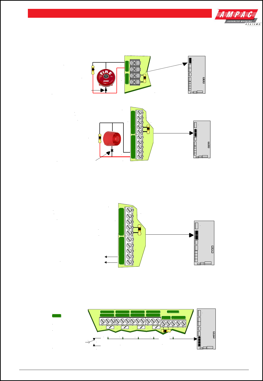
5.15 Connecting a Bell / Sounder to the Brigade / PSU Monitor
Board
Sounders are connected to the Brigade / PSU Monitor Board as shown below. If more sounders are
required, the Sounder / Bell Control Board ( 302-7420 ) must be used.
Bell 1
Bell 2
TB3
Brigade/PSU
Monitor Board
EOL
10K
Ohms
Un-used O/P's must
be terminated in
10K Ohms EOL
+ - + -
TB3 is located on the top
left hand side of the board
Note: If a diode is NOT fitted
internally to a bell / sounder a
diode MUST be fitted as
shown - fit 1N4004 or similar
Note:
Outputs are fused
@ 2Amps ( F2, F3 )
Figure 16: Sounder / Bell Wiring ( Diagram 1 )
Auxiliary
Sounder
TB5
TB4
Brigade/PSU
Monitor Board
EOL
10K
Ohms
Warning
System
EOL
10K
Ohms
NO C NC
+ -
NO C NC
+ -
TB4 & 5 are located on the top
left hand side of the board
Note:
1. NO C NC are 1A voltage free contacts
2. + / - are monitored / fused 1A outputs
Un-used O/P's must be terminated in
10K Ohms EOL
Note: If a diode is NOT fitted
internally to a bell / sounder a
diode MUST be fitted as
shown - fit 1N4004 or similar
Figure 17: Use of Warning System Control for Sounder / Bell Wiring ( Diagram 2 )
5.16 Warning System Connections
Warning systems such as the EV20 and EV40 are connected to the Brigade / PSU Monitor Board as
shown below.
Monitored
EOL
Required
Auxiliary
TB4
Brigade/PSU
Monitor Board
EOL
10K
Ohms
NO C NC
+ -
NO C NC
+ -
TB4 & 5 are located on the top
left hand side of the board
Note:
1. NO C NC are 1A voltage free contacts
2. + / - are monitored / fused 1A outputs
Un-used O/P's must be terminated in
10K Ohms EOL
TB5
Warning System Alarm
Figure 18: EV20 / EV40 Warning System Cabling ( Alternate to Sounder / Bell Wiring )
5.17 Brigade / PSU Monitor Board Relay Output Connections
The relay contacts are connected as shown below.
Brigade/PSU
Monitor Board
TB10 TB9 TB8 TB7 TB6
TB10 to TB6 are located on the
lower left hand side of the board
CNC
NO
1A Un-monitored
Voltage Free Conacts:
NO: Normally Open
NC: Normally Closed
C: Common
NO C NC
NO C NC
NO C NCNO C NC
NO C NC NO C NC NO C NC NO C NC NO C NC
+ -
FAULT
ISOLATE
ALARM
VALVE MON
BATT FAIL
M23 M27 M26 M24
+ -
= 1A monitored output and
must be terminated in EOL
EOL
10K
Ohms
Note 1:
Note 2:
Figure 19: Relay Outputs

Page 16
FIREFINDERTM INSTALLATION COMMISSIONING & OPERATION
5.18 Main Board BRD85MBA
The Main Board is the " heart " of the FACP and carries the devices for interconnecting to all the other
Boards, a buzzer for auditory indication, the backlight power supply for the LCD and CPU Reset.
The Main CPU is mounted on this board and connected to it by CN11. The main connection board then
provides interfacing to
Up to 4 Slave CPU’s
A printer
A Modem/Graphics Output
An Expansion Panel
An Internal serial bus
An External communication bus.
CN8 provides a serial data (RS232) port for interfacing to the outside world eg modems. This facility is
implemented via U15.
U21 provides the real time clock for the panel.
U19 provides non volatile memory in the form of an EEPROM.
The board also provides a data bus for the BRD85CPU processor.
RV1 – LCD contrast adjust
Supply and Current = 27VDc @ 120mA
Connections
CONNECTOR CONNECTS TO
CN1 Keyswitch Input
CN2 Expansion Panel
CN3 Serial Communication Port
CN4 Front Keypad
CN5 Printer
CN6 Misc
CN7 Brigade Output
CN8 Modem
CN10 Slave CPU output 1
CN11 Main CPU
CN12 LCD Expansion Lead
CN13 Slave CPU connection
CN14 Slave CPU connection
CN15 Slave CPU connection
CN16 27VDC in
CN17 To LCD Backlight supply
CN18 External Loop Communication
CN19 LCD Characters
CN20 RS485 Communications Port 1
CN21 RS485 Communications Port 2
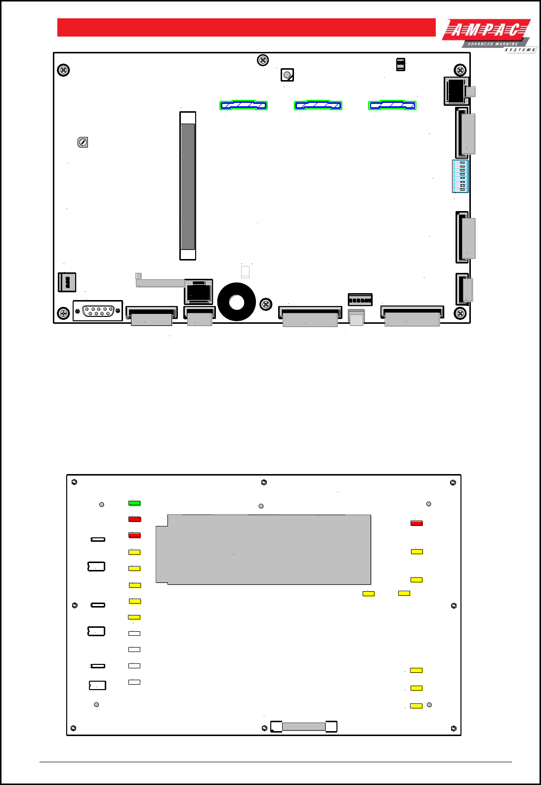
Page 17
FIREFINDERTM INSTALLATION COMMISSIONING & OPERATION
RV1
CN8 CN6
SW1
CN11
CN16
CN9
CN14
SW3
CN15
CN13
CN17
LC
BACKLIGHT
SLAVE CPU2
FRONT PANEL
EXPANSION LEDS
MODEM
DEBUG
I/O PORT
27V IN
RESET
INTERNAL PRINTER
TO BRIGADE
PSU MONITOR
BOARD OR
SOUNDER BOARD
302-674E
NODE
ADDRESS
1
+
BRD85MBA TOP OVERLAY
CONTROL INDICATOR CARD
CN21
CN20
+ -
SLAVE CPU3SLAVE CPU4
CN2 CN3 CN4
BZ1
NOT USED
CN5
C
N
7
C
N
1
0
ON BOARD
SLAVE CPU
CABLES TO
LOOP
TERMINATION
BOARD
RS485
COMMS
EXPANSION BOARD
FOR 4 SLAVE CPU's
RS485 COMMS
CN1
O O O
O O O
O O O
O O O
O O O
O O O
O O O
O O O
O O O
O O O
O O O
O O O
O O O
O O O
O O O
O O O
O O O
O O O
O O O
O O O
O O O
O O O
O O O
O O O
O O O
O O O
O O O
O O O
O O O
O O O
O O O
O O O
a b c
ON
1 2 3 4 5 6 7 8
C
N
1
8
NETWORKING
LCD CONTRAST
ADJUST
NOT FITTED
Figure 20: Main Board Layout with no Main CPU or Slave CPU’s
5.19 Front Panel Board 302 -690
The Front Panel Board provides the buttons used to control the FACP as well as all LED indications. All
LED’s are surface mounted and the buttons are embedded within the board. The LCD is viewed / protected
by a clear perspex screen.
D15
D1
D16
U4
D21
U2
D8
D9
D11
D12
D13
D14
D10
D2
D3
D4
D6
D7
D5
CN1 Cables to CN4
on the Main Board
U5
U3
U6
D22
D23
D24
U1
API 690 JAN 2002
LCD Cut - out

Page 18
FIREFINDERTM INSTALLATION COMMISSIONING & OPERATION
Figure 21: Front Panel Board
Page 19
FIREFINDERTM INSTALLATION COMMISSIONING & OPERATION
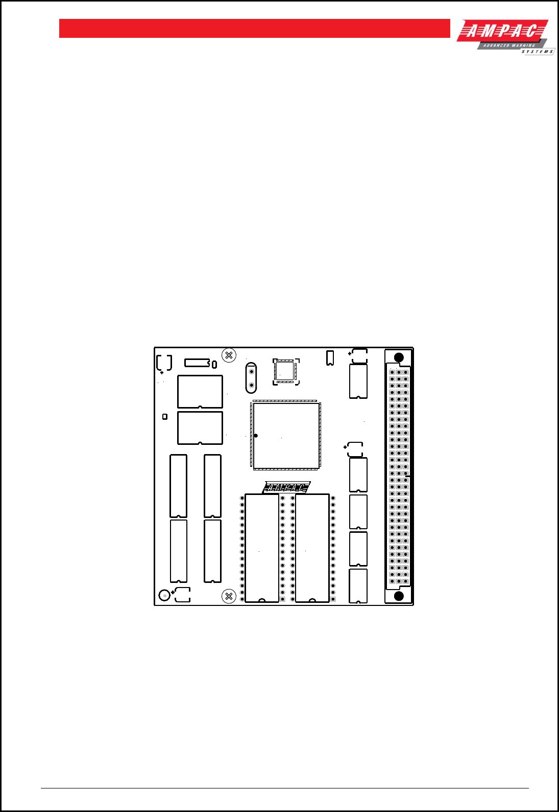
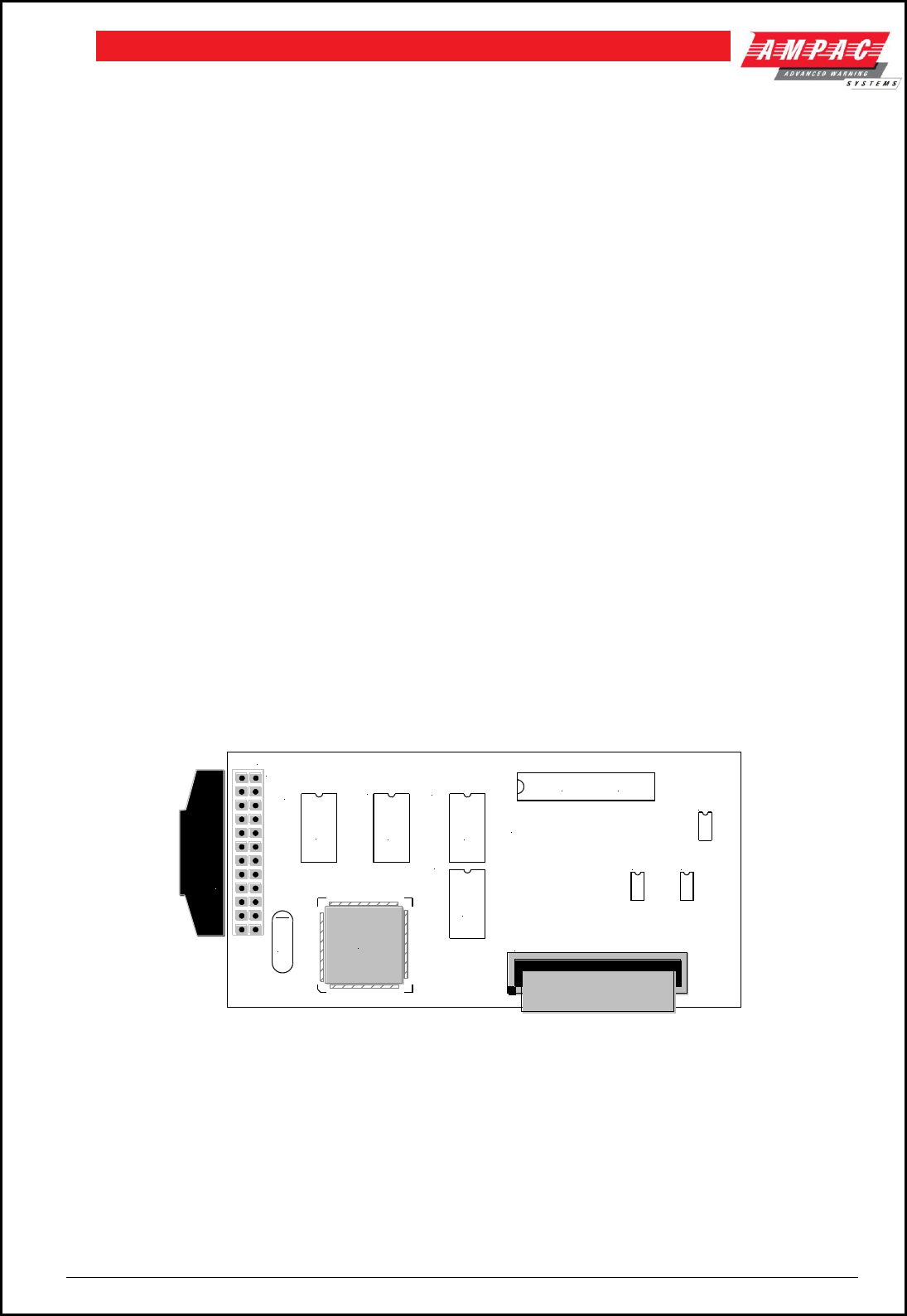
5.20 Main CPU BRD85CPU
The Main CPU holds the main central processing unit for the FACP.
BRD85CPU is a 4-layer surface mount board
The processor (U1) is a Motorola MC68302, running at 20MHz.
The external data bus is 16 bits wide.
The board has 256 Kbytes (128K x 16) of EPROM (U2,U3).
2Mbytes ( 1M x 16 ) of FLASH (U6,U9).
2Mbytes ( 2M x 16 ) of static RAM (U4,U5,U16,U17).
U8 is a programmable logic device which implements control signal timing and decoding.
External address, data and control lines are buffered by U10, U11, U13, U14 and U15.
U7 is a watchdog control and will reset the processor if there as an error in software
execution.
Two sockets (U2 and U3) are provided for 27C010 EPROMS.
U2 provides the even bytes. (D0 toD7) and U3 the odd bytes (D8 to D15
Connections
CONNECTOR CONNECTS TO
CN2 The Main Board BRDMBA CN11
Board Overlay
U1
U8
U6
1
XL1
CN2
a b c
U9
U2 U3
BRD85CPU3-
06/01/2004
Figure 22: The Main CPU Board PCB Layout
Page 20
FIREFINDERTM INSTALLATION COMMISSIONING & OPERATION
5.21 Slave CPU 302-669
The Slave CPU (Central Processing Unit) provides the interfacing signals and I/O’s required to allow the
FACP to connect / communicate to a variety of termination boards.
A single chip micro controller U1 controls all operations of the FACP Slave CPU. This device contains the
control program within Read Only Memory (ROM).
Communication to the main system is via an eight bit bi-directional bus (CN1). Integrated circuits U5, U3
and U7 provide buffering and data latches that allow data flow between the Main and Slave CPU’s. The
buffers hold one output byte and two input bytes.
CN1 provides the interconnection to the Termination Board. Within CN1 are ten analogue input lines, two
input/output lines, two current loop outputs (RS422) and one current loop input (RS422).
All analogue inputs are de-coupled then fed to an eight-bit analogue to digital converter (ADC) U4. The
data from the ADC is sent via a serial peripheral interface to the micro controller U8.
The current loop inputs and outputs are used to provide various signals according to the board connected.
The signals provided can be serial peripheral interface clock and data signals or full duplex asynchronous
data and a timing output. U6 provides the signal multiplexing and buffering required to switch between
different functions.
Automatic Termination Board Sensing
A unique feature of the Slave CPU is its ability to automatically sense the type of board it is connected to
without the user having to configure the board to suit. Board sensing is done by measuring the voltage on
analogue input ten (CN1-10), denoted Type Voltage. Each termination board provides a unique predefined
voltage. After the Slave CPU has determined the board type the Slave CPU will set the appropriate
operating conditions, signal the Main CPU of the installed type and wait for the Main CPU to inform the
Slave to begin executing the program.
Connections
Connector Connects to
CN1 302-735, 302-671 and 302-672
U9
TLC542
U4
U3
U8
U2
U6 U7
U5
X1
CN2
1
11
1
1
302-696
CN1
U1
Main Board
CN2
Main Connection Board (BRD85MBA)
Figure 23: Slave CPU Board
Page 21
FIREFINDERTM INSTALLATION COMMISSIONING & OPERATION
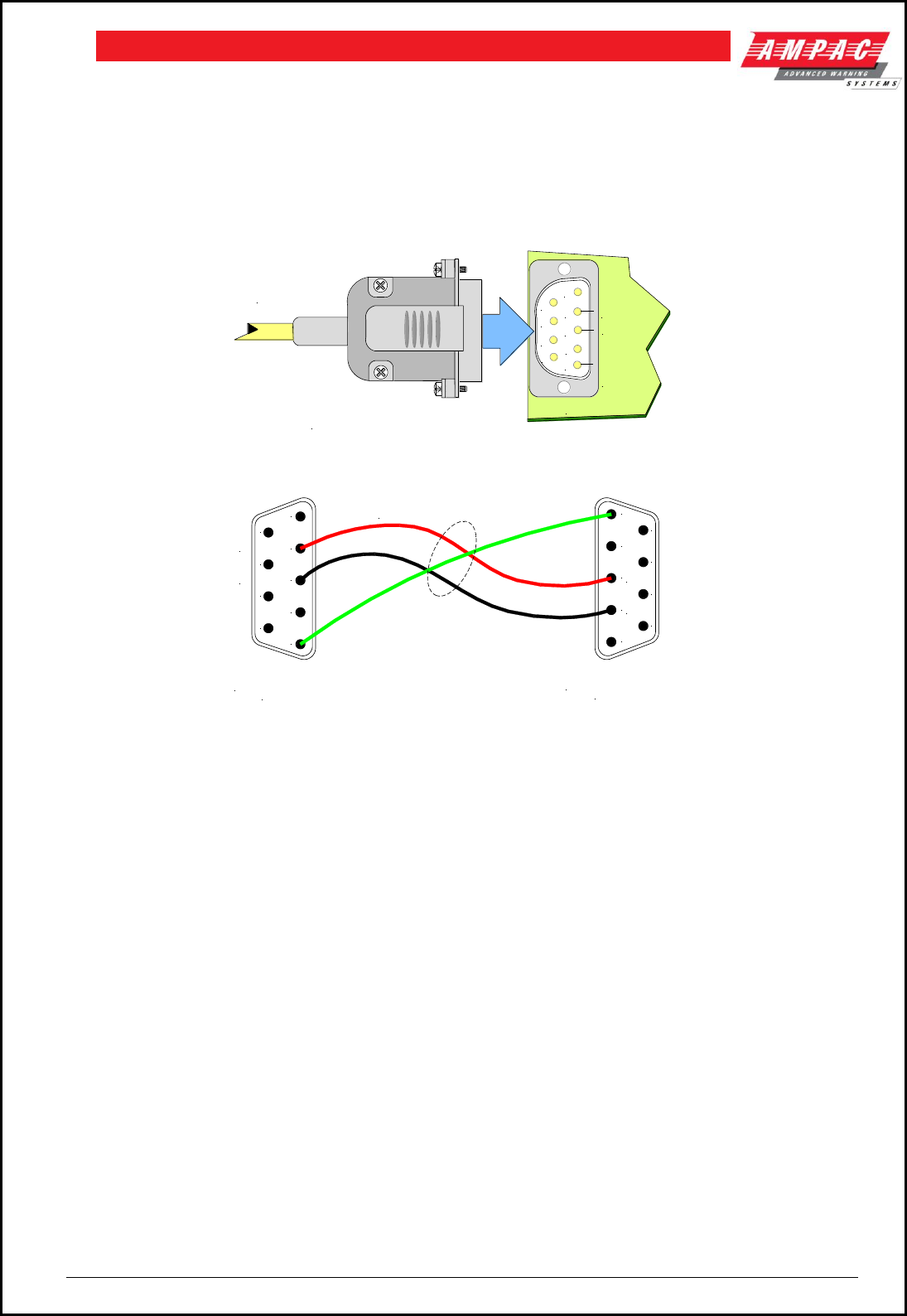
5.22 RS232 Modem / Programming / Debug Interfacing
The modem I/O port is a DB9 connector ( CN8 situated on the lower left hand corner of the Main Board
BRD85MBA ) that is normally used for programming of the FACP via the serial port of a PC or Laptop. The
Controller also has the required hand shaking to support connection to a Modem, thus allowing the FACP
to be programmed from a remote site that has an established telephone connection. This allows the
system software to be upgraded by simply transmitting a file via the serial port of the PC or Modem
external to the FACP. Diagnostic facilities are also available via the same connection.
1
62
3
4
5
7
8
9
Tx Data
Rx Data
Signal
Ground
CN8
Plug in DB9
Connector
Note: CN8 is located on the lower
left hand side of the Main Board
Figure 24: DB9 Connector CN8 as Mounted on the Main Board
Figure 25: Modem / Programming / Debug Cabling
5.23 Ancillary Services
The FACP has been designed such that detectors and/or call points, in addition to giving an alarm and
calling the fire brigade, will close or open circuits of ancillary services by means of relays or similar
devices.
Examples of these services are:
(a) actuation of fixed fire-extinguishing systems;
(b) closing of windows, smoke and fire doors,
(c) control of ventilating systems;
(d) covering of tanks containing flammable liquids and controlling their valves to isolate
the contents from direct contact with the fire, etc.
To facilitate safe maintenance of these services an option is available that allows for the isolation and
visual indication of the disablement of ancillary services that does not affect the normal operation of the fire
alarm system.
To ensure power to the fire alarm system is not prejudiced in any way, power for the ancillary services
must be included in the calculation of the power supply and battery capacity.
1
2
3
4
5
6
7
8
9
DB9F CONNECTOR
( Female Rear View )
2 CORE SHIELDED CABLE
DB9F CONNECTOR
( Female Rear View )
1
2
3
4
5
6
7
8
9
Rx Data
Tx Data
Rx Data
Tx Data
Plugs into FACP
To Modem or PC
Page 22
FIREFINDERTM INSTALLATION COMMISSIONING & OPERATION
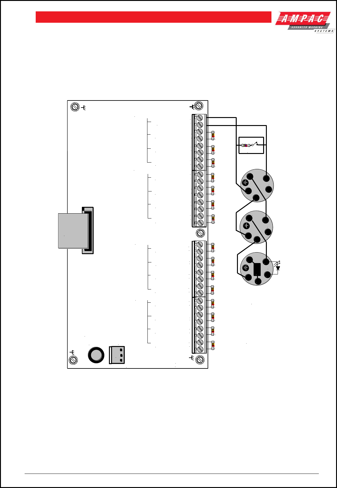
5.24 Conventional Zone Board 302 - 6710
Under the control of a Slave CPU the 302-6710 Conventional Zone Board provides the interface between it
and the external conventional devices.
16 Conventional zones can be connected to TB4 to TB1. All un-used zone connections MUST be
terminated in an EOL resistor of 3K3 as shown below.
Figure 26: Conventional Board Layout
Alarm Zone Facilities ( AZF ) Parameters
Maximum Line Voltage: The maximum line voltage is limited to the system voltage. With a nominal
battery voltage of 27V, system voltage and therefore open circuit voltage would be approximately 26.4V.
TB4
TB3
TB2
POWER
302-671B
27/2/01
3K3
EOL
3K3
EOL
3K3
EOL
3K3
EOL
3K3
EOL
3K3
EOL
3K3
EOL
3K3
EOL
3K3
EOL
3K3
EOL
3K3
EOL
3K3
EOL
3K3
EOL
3K3
EOL
3K3
EOL
3K3
EOL
To 27VDC Regulated
Output of the Brigade /
PSU Monitor Board
MCP
The Above
Shows a
Series 60
Monitored
Detector
Circuit
4K7
TB1
-
+
C1 CN1
To Slave
CPU
302-6692
Zone 1
_
+
Zone 2
Zone 4
Zone 5
Zone 3
_
+
_
+
_
+
Zone 8
Zone 9
Zone 10
Zone 7
Zone 6
_
+
_
+
_
+
_
+
_
+
_
+
_
+
_
+
_
+
_
+
_
+
_
+
Zone 11
Zone 12
Zone 13
Zone 14
Zone 15
Zone 16
L1
L1
L2
-R
IN
OUT
L1
L1
L2
-R
IN
OUT
L1
L1
L2
-R
IN
OUT
E
O
L
L2
L2
L2
Page 23
FIREFINDERTM INSTALLATION COMMISSIONING & OPERATION
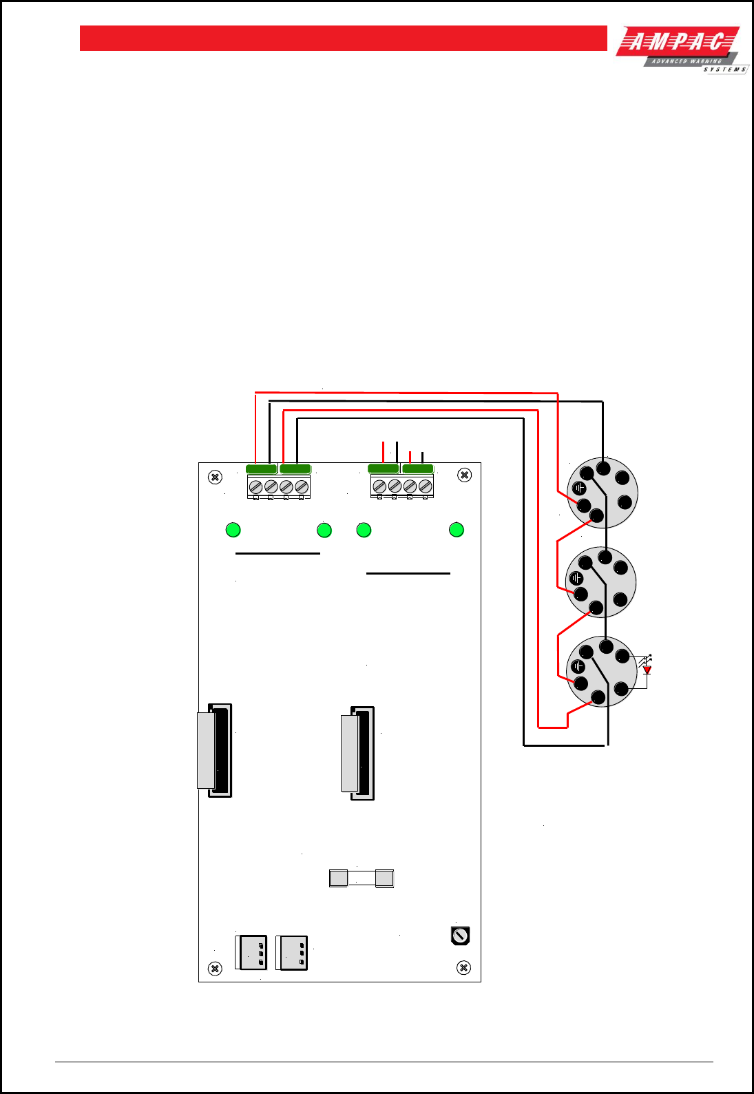
5.25 Addressable Loop Termination Board 302 - 7350
The Addressable Loop Termination Board acts as the interface between the external addressable devices
and the control and monitoring functions of the FireFinder™. Each board provides terminations for two
loops. One slave CPU is required per loop. The 2 Addressable loops are connected to TB1 and TB2.
Note: Apollo devices L2 is +ve (positive), L1 is -ve (negative)
Connect the XP-95 / DISCOVERY loop to the panel as shown below.
AMPAC strongly recommend that the LoopManager test set is used to check that the Apollo loop has been
correctly installed and commissioned before connecting it to the FireFinder™.
Loop Parameters
126 Apollo Devices
250mA Current Max
S/C protection circuitry activates at approximately 300mA
ABAB
CN2
TB1
RV1
CN4
F1
26V ADJ
POWER
3A
REGULATED
27VDC In / Out
T0 SLAVE CPU
302-6692 CN1
T0 SLAVE CPU
302-6692 CN1
LOOP 1 ADDRESSABLE DEVICES
LOOP 2 ADDRESSABLE
DEVICES
LOOP NORMAL
LED A monitoring
each Loop is ON LED A & B ON
indicates a fault
on the Loop
( S/C, O/C ) and
the Loop is being
monitored in
both directions
LOOP IN FAULT
F1: 3AMP M205 27V INTO
DC TO DC CONVERTOR
ABB
A
C
N
1
C
N
3
-
+
-
+
TB2
R+
L1
L2
-R
L1
L2 -R
L1
L2 -R
R+
R+
Wiring Shown
Above is for a
XP95 Circuit
with one Detector
Having LED
Monitoring
L2+ L1- L2+ L1-
L2+ L1- L2+ L1-
L1
L1
L1
L2
L2
L2
IN
OUT
IN
OUT
Figure 27: Loop Termination Board

Page 24
FIREFINDERTM INSTALLATION COMMISSIONING & OPERATION
6 Expanding the FACP with Compatible FireFinderTM
Boards
Numbers in Italic are Panel Add On Order Codes
Module / Function............................................... Order Codes Max Number Off
16/16 Input / Output Board .......................................... (302-6720) 8 per Slave CPU
( SP1X: 159-0113, SP8X: 159-0051, SP16X: 159-0009 )
8 Way Relay Board ..................................................... (302-6760) 16 per Slave CPU
( SP1X: 159-0013, SP8X: 159-0013, SPX16X: 159-0015 )
16 Way Input Board .................................................... (302-6770) 8 per Slave CPU
( SP1X: 159-114, SP8X: 159-0010, SP16X: 159-0011 )
Serial Relay Board ...................................................... (302-7320) 16 per Controller
( SP1X: 159-0079, SP8X: 159-0072, SP16X: 159-0072)
Fire Fan Module / Fire Fan Termination Board ............. (159-0103 H/W) 15 per Controller
( SP1X: 159-0103, SP8X:159-0104, SP16X: 159-0119 )
Fire Fan Module ( Loop Driven ) .................................. (159-0105)
General Indicator Card [ 32 Zone Alarm ] ..................... (85BRDGIBB) * 16
( SP1X: 159-0106 ) * Configuration dependant
( SP8X: 159-0089, SP16X: 159-0120 )
General Indicator Card [ 16/16 Zone Alarm / Fault ] ..... (85BRDGIBB) * 16
( SP1X: 159-0107) * Configuration dependant
( SP8X: 159-0108, SP16X: 159-0121 )
General Indicator Card ( Amber LED’s ) ....................... SP1X: 159-0123, SP8X &16: 159-0124
Printer ......................................................................... (TPUP-AT) 1 per Controller
( SP1X: 159-0084, SP8X: 159-0110 )
Sounder/Bell Controller Board 8 X 1A per Circuit ......... (302-7420) 8 per Controller
( SP1X, SP8X: 159-0071 )
Sounder/Bell Controller Board 4Volt free, 4x1Amp ....... (302-7421) 8 per Controller
( SP1X, SP8X: 150-0069 )
Agent Release Module / Agent Termination Board ....... (BRD25ARB-A) 8 per Controller
( SP1X:159-0099, SP8X: 159-0100, SP16X: 159-0117 )
Local Control Station (IP40) ......................................... (BRD25ARB-B) 4 per Termination Board
(N/A)
Expansion Board ........................................................ (302-6880) 1 per Controller
( SP8X: 159-0112, SP16X: 159-0022 )
Expansion Controller ................................................... (SP16X: 159-0077) 3 per Node
( Rack: 159-0067 )
Occupant Warning System – EV20 .............................. Factory fit
Occupant Warning System – EV40 / 60 / 120............... Factory fit
Occupant Warning System – EV3000 .......................... Factory fit
Brigade Devices .......................................................... Factory fit
Compatible Networking Devices
Network Interface Card ............................................... (302-7240) 1 per Controller
( SP1: 159-0053, SP8X: 159-116, SP16X: 159-0053 )
Controller Interface Card ............................................. (302-7250) 1 per Controller
( SP1X: 159-0054, SP8X: 159-0115, SP16X: 159-0054 )
LCD Repeater ( Supplied Complete ) ........................... (302-7200) Note # 2
( 159-0044 )
Note # 1 : This comprises 4 on the Main Controller and 4 on the Expansion Board.

Page 25
FIREFINDERTM INSTALLATION COMMISSIONING & OPERATION
Note # 2 : Depends on the configuration and the number of Panels in the
System.
Page 26
FIREFINDERTM INSTALLATION COMMISSIONING & OPERATION
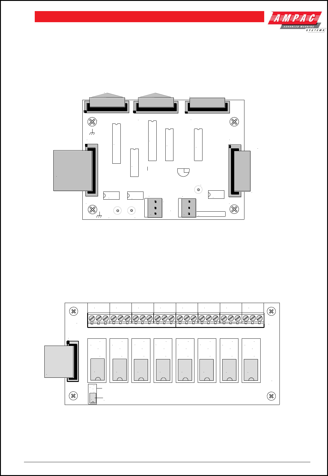
6.1 16/16 Input / Output Board 302 - 6720
The Input / Output Board is connected to the slave CPU via CN1 and acts as the interface between the
Slave CPU, 8 Way Relay Board and the 16 Way Opto Input Board.
Dependant on the panel configuration a maximum of 8 Input / Output boards can be daisy chained
together.
Figure 28: 16 / 16 Input / Output Board
6.2 8 Way Relay Board 302 – 6760 / 1
Relay Outputs: Each 8 Way Relay Board 302-676 is fitted with either eight 1A, RL1 to 8, (302-6760) or
5A, RL9 to 16, (302-6761) relays with voltage free contacts which can be used for control ( eg. releasing
doors ) or monitoring ( eg. driving indicators, door open / closed ) purposes.
Figure 29: 8 Way Relay Board With 1A Relays Fitted ( 302-6760 )
TO 8 WAY RELAY BOARDS TO 16 WAY OPTO
INPUT BOARD
TO CONTROL IN OF
NEXT
INPUT / OUTPUT BOARD
OR
FAN CONTROL BOARD
MAXIMUM OF 8
BOARDS PER
SLAVE CPU
+27V
IN
OUT
CN2
CONTROL OUT
302-6720 1/98
POWER
CTRL
CN3 I/P 1-16
CN4 O/P 9-16
IN
CN5 O/P 1-8
CTRL
OUT
U2 U7
CN7
CN6
0V +V
CN2
+5V
CN1
U8
U1
U4
U3 U5
U6
+
-+
-
1 2
U9
TO CN1 OF THE
SLAVE CPU
(302-6690)
CN1
TB2
TB1
RL9
N/O
C
N/C
RL10
N/O
C
N/C
RL16
N/O
C
N/C
RL15
N/O
C
N/C
RL14
N/O
C
N/C
RL13
N/O
C
N/C
RL12
N/O
C
N/C
RL11
N/O
C
N/C
O/P 1
N/CCN/0
302-676x
O/P 2
N/0 C N/C
O/P 3
N/0 C N/C
O/P 4
N/0 C N/C
O/P 5
N/0 CN/C
O/P 6
N/0 C N/C
O/P 7
N/0 C N/C
O/P 8
N/0 C N/C
TO CN4
OR CN5
OR THE
1/0 BOARD
302-6720
RL1 RL2 RL3 RL4 RL5 RL6 RL7 RL8
5 Amp Version
Legend
1 Amp Version
RL9
N/O
C
N/C
RL1
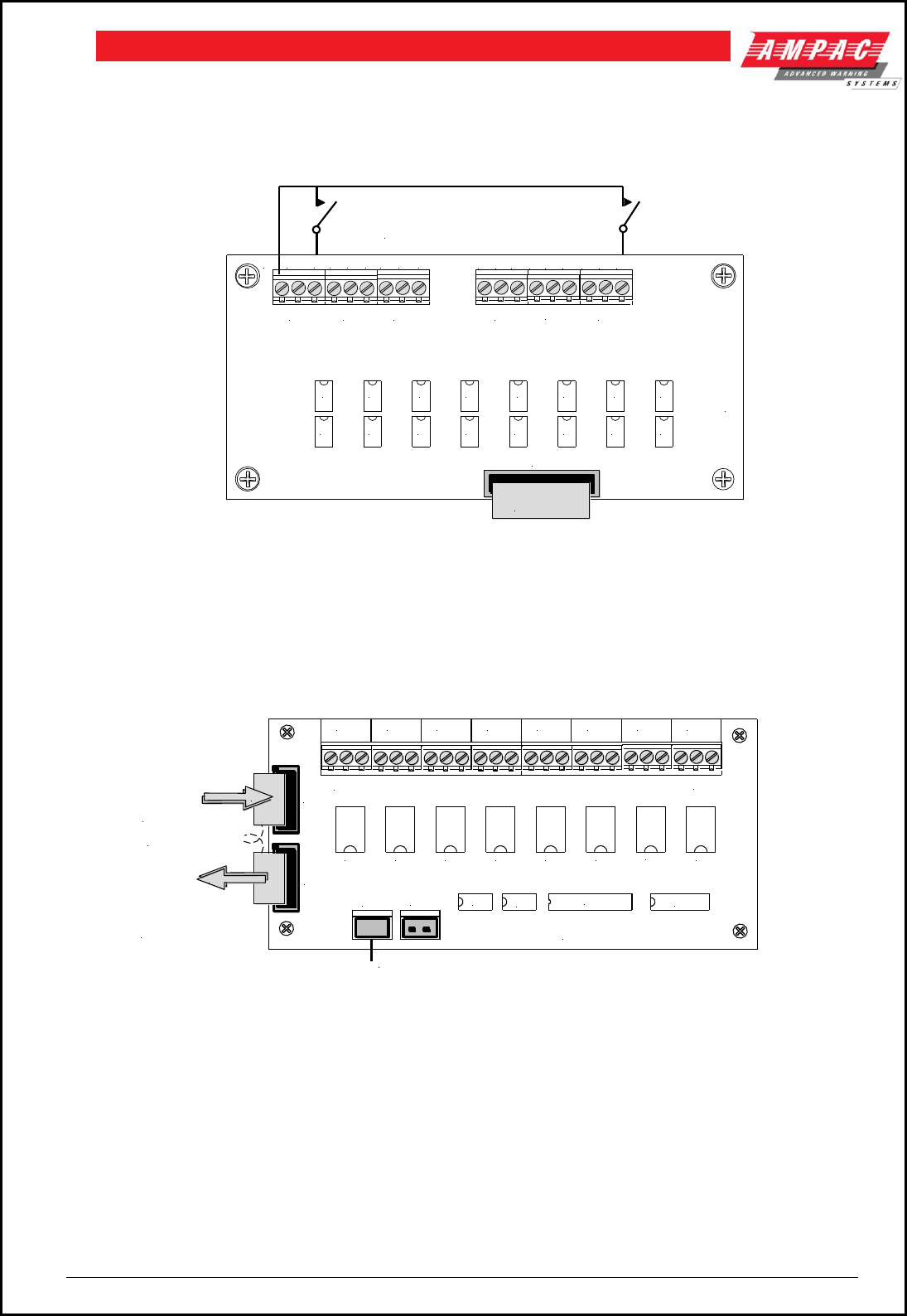
Page 27
FIREFINDERTM INSTALLATION COMMISSIONING & OPERATION
6.3 16 Way Input Board 302 - 6770
Opto-Inputs: Up to 16 inputs can be connected to the 16 Way Input Board. These inputs are required to
be voltage free contacts as shown below.
Figure 30: 16 Way Input Board (302-6770)
6.4 Serial Relay Board 302 - 7320
Relay Outputs: Each Serial Relay Board 302-7320 communicates with the Main Controller via the Serial
Bus and is fitted with eight 1A relays with voltage free contacts. A maximum of 16 boards can be daisy
chained together per Controller.
Figure 31: Serial Relay Board (302-7320)
Note: These boards are not monitored so should not be used for brigade calling or with
occupant warning systems
1 2
COMCOM
3 4 5 6 7 8 9 10 1112 13 141516
CN1
TB2 TB3 TB4 TB5 TB6
U4
U1
U2
U5 U7
U8
U9
U10
U11
U12
U13
U14
U15
U16U6
U3
TB1
302-6770
AS AN EXAMPLE
INPUTS 1 AND 16 CONNECTED TO
VOLTAGE-FREE CONTACTS
TO CN3 OF
302-6720
N/0 C N/C
O/P 1
N/0 C
O/P 2
N/C N/0 C
O/P 3
N/C N/0 C
O/P 4
N/C N/0 C
O/P 5
N/C N/0 C
O/P 6
N/C N/0 C
O/P 7
N/C N/0 C
O/P 8
N/C
302-7320
CN2
U5
U7 U6
CN1
CN4
RL1
TB2
TB1
RL8
RL7
RL6RL5RL4RL3RL2
U1
CN3
Cabled to
CN3 of
302-674 or
CN2 of
Previous
Serial Board
Cabled to CN1
(IN) of next
Serial Board
To 27VDC Regulated Output of Brigade / PSU Monitor Board
10 Way Ribbon
OUT
IN
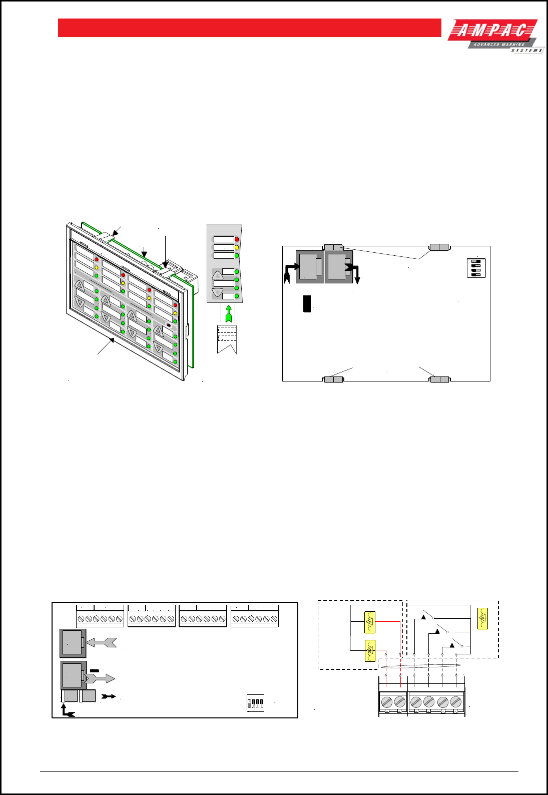
Page 28
FIREFINDERTM INSTALLATION COMMISSIONING & OPERATION
6.5 Fire Fan Module BRD25FCB
The Fire Fan Module has four ( 4 ) separate fan controls each having an On, Auto and Off function switch
and a set of three (3) monitoring LED’s. The LED’s indicate the status of the equipment eg. Run, Fault or
Stop. The two ( 2 ) arrow head keys are used to step up and / or down through the three ( 3 ) conditions. A
slip in label can also be inserted into the hinged cover for identification purposes.
A loop driven version is also available (159-0105 )
Note#: As per AS 1668.1 1991, Clause 14.17.4 lettering on any of the slip in labels must be at least
5mm in height.
Quiescent Current: 13.5mA
Slip In
Label
Module & PCB Securing Tabs
( Top & Bottom )
PCB
Clear Plastic Clip In Label
Clip On
Plastic Surround
( Push down here and pull
out to remove and insert labels )
WINDOWS
WINDOWS
FOR SLIP
IN LABELS
Lettering on slip in
labels must be at
least 5mm in height.
ACTIVATED PLANT TRIP RESET
K2 Termination Link
In Out Address
Switch
Set to 1
1 2 3 4
ON
C
N
1
C
N
2
CN1: Communications & 27V IN from CN2 off the previous
Front Panel Card or CN20 on the Main Control Board
CN2: Communications & 27V OUT to Next Front Panel Card.
If Unsed the Termination Link Must be Inserted.
Top Module &
PCB Securing Clips
Bottom Module &
PCB Securing Clips
Figure 32: Fire Fan Module Front Panel Figure 33: Fire Fan Module PCB Layout
6.6 Fan Termination Board BRD25FTB
The Fan Termination Board interfaces between the Fire Fan Module and the plant/equipment it controls via
the 24 volt 250mA Start, Stop, current limited, relay outputs and monitor inputs. Programmable monitoring
of the field equipment is achieved using 0 volts as an input level to indicate run, fault and stop conditions of
that equipment. Monitoring is programmed in the Function Menu for a 3, 4 or 5 Wire Start / Stop, Run,
Fault, Stop & Common functions. The inputs are protected by way of resetable transorbs and resistive /
capacitive networks.
Connectors
CN5 Is used for factory programming only and may not be available on all boards.
Terminal Blocks
TB2 – 5 Are used to connect the fan control and monitoring wiring to the board.
SW1
TB4
TB3
TB2
LK1
TB5
EOL Termination
0V +2 7V
POWER
Address SW
FAN 1FAN 1
STOP COMSTOPFLTRUN FAN 2
STOP COMSTOPFLTRUNSTART FAN 3
FAN 3
STOP COMSTOPFLTRUNSTART FAN 4 COMSTOPFLTRUNSTART
FAN 4
STOP
START FAN 2
CN1
CN2
CN3 CN4
RS485 Control in from CN2 of Previous
Board or CN21 of the Main Control Board
RS485 Control Out to Next Board or Link 1 EOL is Applied
27V In from the Brigade Broard or CN4 of the Previous Board
27V Out to Next Board if Applicable
1 2 3 4
ON
STOP
COM
STOP
FLT
RUN
START
TB 2, 3, 4 or 5
Cabling from FACP
to Plant / Equipment
1 2 3 4 5 6
FAN CONTROL
SOLID STATE OR
RELAY INTERFACE
FAN MONITORING
0V
INPUTS 1, 2 & 3
+24V O/Ps
RUN
STOP, START, RUN = 3 WIRE
STOP, START, RUN,
STOP = 4 WIRE
STOP, START, RUN, STOP,
FAULT = 5 WIRE
Figure 34: Fan Termination Board Layout and Typical I/O Wiring
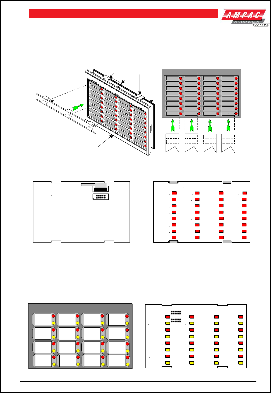
Page 29
FIREFINDERTM INSTALLATION COMMISSIONING & OPERATION
6.7 Zone & General Indicator Card
The General Indicator Card (BRD85GIBB) comes in two versions each consisting of a front clip on
surround, decal, mounting frame, PCB and is clipped into the front panel of the FACP to provide visual
LED indication of; Zones in alarm x 32 [red], or Zones in alarm x 16 [red] / Zones in fault x 16 [yellow].
Each Indicator can identified by way of slip in labels.
Panel & PCB Securing Tabs
PCB
Clear Plastic Clip In Label Holder
Clip On Plastic Surround
( Remove to Insert Labels )
To Remove Push Down
Here and Lift Upwards
Windows for
Slip in Label
Windows for
Slip in Label
Windows for
Slip in Label Windows for
Slip in Label
Slip In Label Slip In Label Slip In Label Slip In Label
Decal
Connectors
Figure 35: 32 Zone Alarm General Indicator Card
Figure 36: Bottom Overlay Figure 37: Top Overlay
Note #1: DO NOT USE excessive force to remove any component once it is clipped into position.
Note #2: If the indicator becomes illuminated it remains so until “Reset” is pressed.
Note #3: The indicators are tested by the Lamp Test control.
DEC2580-T1
Windows for
Slip in Labels
D1
D2
D3
D4
D5
D6
D7
D8
D9
D10
D11
D12
D13
D14
D15
D17
D18
D19
D20
D21
D22
D23
D24
D25
D26
D27
D28
D29
D30
D31
D32
050603
BRD85GIBB2
D16
RED
YELLOW
RED
YELLOW
RED
YELLOW
RED
YELLOW
LED's
Figure 38: 16 Zone Alarm / Fault Card Decal & PCB Layout
D32
D31
D30
D29
D28
D27
D26
D25
D24
D23
D22
D21
D20
D19
D18
D17
D16
D15
D14
D13
D12
D11
D10
D9
D8
D7
D6
D5
D4
D3
D2
D1
Top OverLay
CN2 Control Out
To Next Card
Control In From CN3
on the Main Board
(302-674E)
Bottom Overlay
CN3
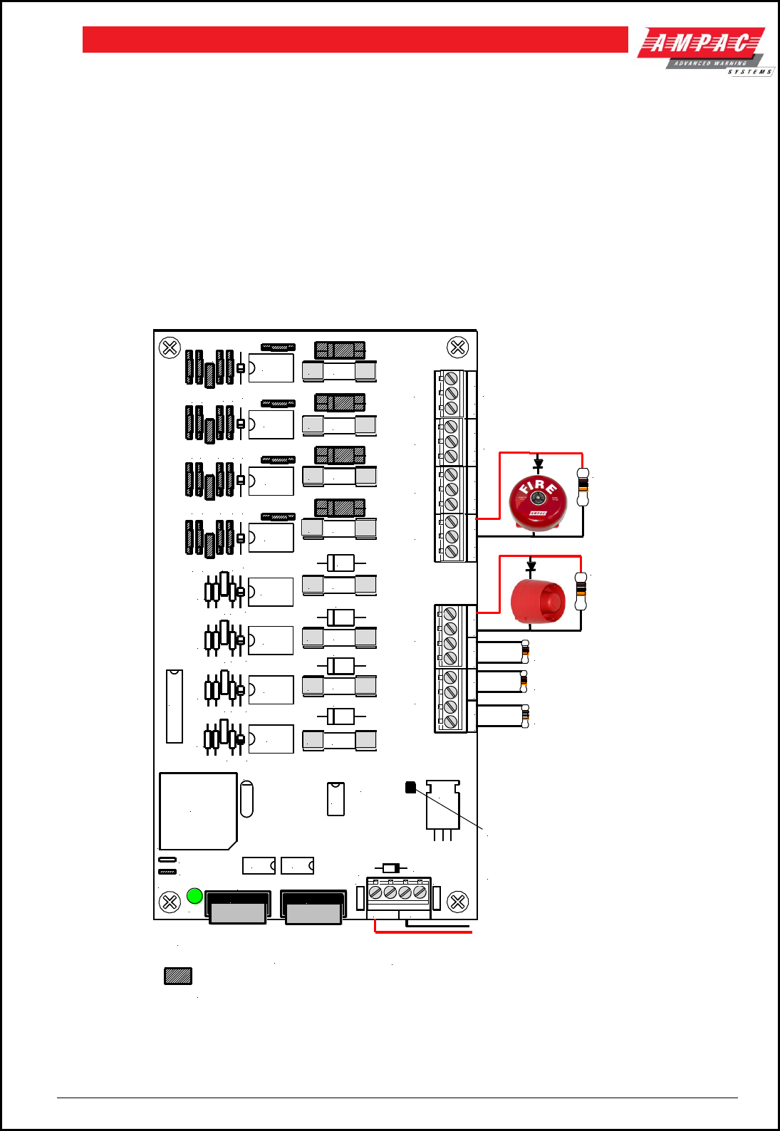
Page 30
FIREFINDERTM INSTALLATION COMMISSIONING & OPERATION
6.8 8 Way Sounder Monitor Board 302 – 7420 / 1
The 8 way Sounder Monitor Board allow a larger number of bells and sounders to be connected to the
FireFinder™ System.
The 302-742 is built in two versions:
1. 302-7420: All outputs are monitored and provide 1 Amp per circuit.
2. 302-7421: The first 4 circuits are Voltage free contacts, the second 4 are as per the 302-7420.
Wiring to the Monitored sounder outputs is as per the 302-6730.
The Sounder/ Bell monitor board connects to the serial peripheral interface (SPI) bus. This is the same bus
that connects to the Brigade Output Board and a maximum of 8 boards can be daisy chained together.
Note: Output current is dependent on the capacity of the Power Supply
Figure 39: Sounder / Bell Controller Board 302-742x
= Shaded Components are Not Fitted to 302-7421
Sounder Monitor Brd. Volt-Free but are Fitted to the 302-7420
10K EOL
10K EOL
10K EOL
This area will be
marked with the
correct Version
Number
RL7
TB5
C27
X1
U9
U7
U4
U3
U2
TB4
TB3
TB2
TB7
TB6
R40 R39 R38 R37
R36 R35 R34 R33
R32 R31 R30 R29
R23 R22 R21 R20
R13
R12
R11
R10
D35
D34
D33
D32
D31
D30
D29
D28
D1
C26 C25 C24
C5
C4
D5 D4 D3 D2
D9
D7
D6
RL6
RL1
RL2
RL4
D8
RL5
TB1
RL3
RL8
U1
302-742
NO+NC-
C
NO+NC-
C
NO+NC-
C
NO+NC-
C+VE-VE+VE-VE+VE-VE
+VE-VE
0V
+27V
AT90S8535-8JC
OUT
IN
1A
1A
1A
1A
1A
1A
1A
1A
LK2
LK1
D10
NORMAL
Note:
If the O/P was configured
as a monitored O/P, as
below, NO is the +ve leg
while NC is the -ve leg.
10K EOL
To CN7 of the
Main Controller To IN (CN1) of next
Sounder Monitor Board
or Output Brigade Board
CN5
To the AUX Power
O/P TB2 of the O/P
Brigade Board
EOL Resistors are not required
if the O/P is configured for Volt
Free Contacts NO, NC, & C
All Fuses are 1A M205 Style
10K EOL
CN1 CN2
F2
F1
F3
F4
F5
F6
F7
F8
R28 R27 R26 R25
R19 R18 R17 R16
R9
R8 R7 R6
C23 C22 C21 C20
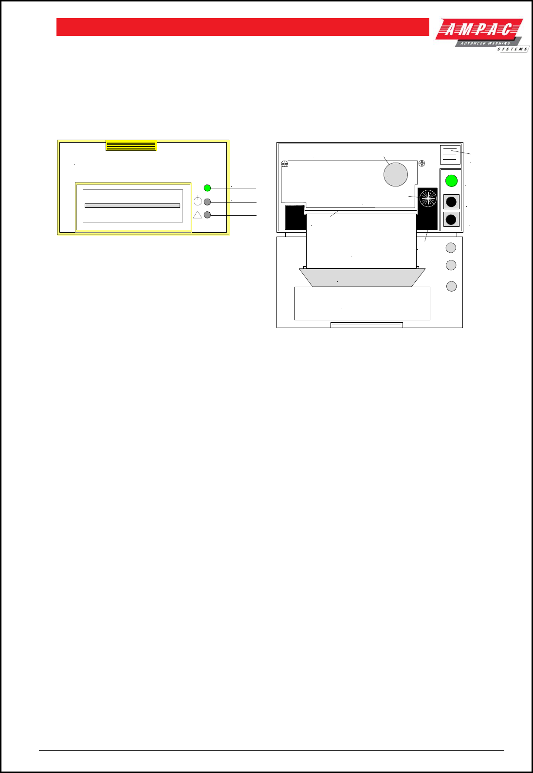
Page 31
FIREFINDERTM INSTALLATION COMMISSIONING & OPERATION
6.9 Printer
Specifications
Printing method: directed impact dot matrix
Interface: 8 bit parallel interface
Printing mechanism: 4/6 pin shuttle
Interface port: 26 PIN flat plug
6.9.1 Indicators and Buttons
The front panel has an LED indicator and two buttons SEL (SELECT), LF (LINE FEED).
Figure 40: Printer Front Panel Layout ( Front Cover Closed / Open )
1. Indicator
When the 3 colour LED indicator is illuminated;
red it indicates the printer is offline with no paper;
green it indicates the printer is On Line;
yellow it indicates the printer is On Line with no paper; or if it is
off indicates the printer is Off Line or printer is busy.
2. SEL Button
a) On Line / Off Line State
The printer enters the On Line state automatically when power is applied or on exiting from the
Self-Test mode. ( LED is green ).
Press the SEL button, the LED is turned off and the printer goes Off Line.
Press the SEL button again, the LED turns on and the printer is On Line again.
Note : The printer will not receipt data when the printer is off line.
b) Pausing the Printer While It Is Printing.
Press the SEL button while the printer is printing, the printer will pause and enter the Off Line
mode after it finishes printing the row it was currently printing. The printer will continue to print
when the SEL button is pressed again.
c) Enter the HEX-DUMP mode
Remove power from the printer, press the SEL button, then reconnect the printer to the power
supply. The printer will enter the HEX-DUMP mode. In this mode any programs sent from the host
CPU will be printed out in Hexadecimal.
LF Button
While the printer is Off Line press the LF button, paper feed will be initiated press again to cancel.
4. Self-Test Mode
With power applied (green LED illuminated ) push the SEL button. This will turn off the LED, press
and hold in the LF button then press the SEL button again and the printer will enter the Self Test
mode. Self-test will print out all the valid characters in the character sets.
SEL Button
LF Button
TP
INDICATOR
Paper
Paper Cutter
Instructions
Indicator
SEL
LF
Cassette
Ribbon
Press and turn
to tighten ribbon
Press to
Release
Mechanism
PUSH to lock Mechanism
PUSH
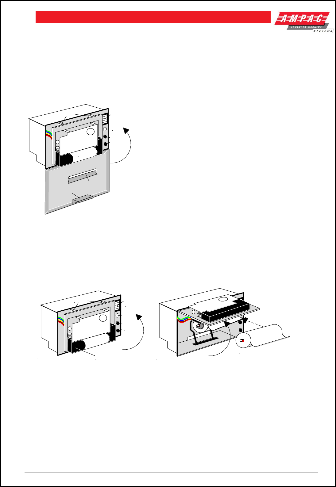
Page 32
FIREFINDERTM INSTALLATION COMMISSIONING & OPERATION
5) Exit the Self-Test Mode:
a) After printing out the complete Self-Test list the printer will exit the mode automatically; or
b) Press the SEL button and the printer will immediately exit the Self-Test mode.
6.9.2 Maintenance
Installing The Ribbon Cassette
The printer has a factory loaded ink ribbon cassette.
Ribbon Replacement;
Push back the mechanism head and lock it, close the cover of the printer and reconnect the power.
Loading the Paper Roll
1. Disconnect the power, unlock and open the front cover.
2. Push down on the mechanism release button in the top right corner to release the head.
3. Lift the mechanism as shown below.
Hinges
LED
Push
Buttons
Paper
PUSH
Mechanism
Release
Button
Note:
Front Door
Removed
Ink Ribbon
Cassette
Note:
Front Door
Removed
Replacement Paper Roll
Figure 42: Head Mechanism Rotation and Paper Roll Removal / Insertion
4. Take out the empty paper roll and roller
5. Put the new paper roll onto the paper roller and replace as shown above.
6. Connect to the power supply.
7. Press the SEL button to take the printer Off Line, ( LED is off ).
8. Press the LF button, ( paper feed ).
9. Feed the edge of the paper into the mechanism and allow it to feed through.
10. Once it established the paper is feeding through the head mechanism correctly press the
SEL button to stop the paper feed.
11. Return the printer head to its original position.
12. Pushing on the affixed label PUSH the head mechanism back into position.
13. Close the front cover.
Hinges
LED
Push
Buttons
Paper
PUSH
Mechanism
Release
Button
Front Door
Locking Tab
Paper Cutter
Figure 41: Front Panel
1. Remove the power from the printer.
2. Unlock the front cover by pushing down on the tab at the top
of the front panel.
3. Push the mechanism release button in the top right corner to
release the print head.
4. To remove the ribbon cassette gently pull out the left end
then the right.
Replace the cassette by putting the right end of the new
cassette slightly onto the drive axle then gentle pushing the
left end into the clips.
The left end of the cassette can only be pressed in after the
right end has been correctly seated onto the drive axle. If
alignment is difficult it may be necessary to turn the knob on
the cassette slightly. Now check that the ribbon is tight
across the face of the cassette, that is on the inside of the
cassette and across the paper. Turn the knob clockwise
again if the ribbon is on the outside of the cassette.
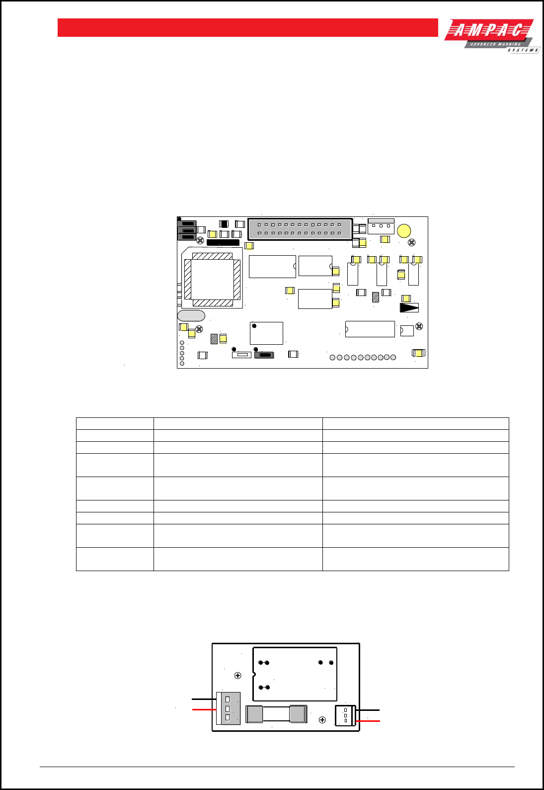
Page 33
FIREFINDERTM INSTALLATION COMMISSIONING & OPERATION
Note #1: Press only on the PUSH label to return the head mechanism back into
position.
Note #2 :The above instructions are graphically displayed on the inside of the front cover..
6.9.3 Printer Connections and Jumpering
Mounted on the back of the printer mechanism is the PCB that carries the;
1. connectors for interconnection to the Main Board,
2. jumper links required to set the programmed print modes; and
3. Printer 5 volt DC Power Supply.
R5
R6
C14
R7
C15 C16
C18
C8
C17 C7
C19
C21
D2
R9
T1
R8
C3 C20 C4
C22
R11
J7
J6
R10
C5
T2
C13
C12
X1
J1
J3
R1 C9 R2
D1 R4
R3
C1
C2
U1
U2
U3 U4
U6
C6
U7
U8
T4
T3
U5
J2
UP-ATHZP
VER:CC 2002.1
J1 OPEN ESC Command Set
CLOSE UP Command Set
J2 OPEN ASCII Char Mode
CLOSE Chinese Mode
J3 OPEN UP-A Direction
CLOSE UP-T Direction
U9
Connector to Print Head
Connector to
Front Panel
LED & Switches
Connector to Main Board 5V Power Supply
+ -
J7 Select 12X12 (Pins 1/2) or 15X16 (Pins 2/3) Chinese Characters
Figure 43: PCB Layout
Jumper Settings
Designator
Jumper State
Function
J1
NOT Inserted
Selects ESC Commands
Inserted
Selects UP Commands
J2 Set as
Default
NOT Inserted
Selects ASCII Character Printing Mode
Inserted
Selects Chinese Character Printing
Mode
J3
NOT Inserted
Select Printing by Contrary Direction
Inserted
Select printing in the Normal Direction
J7 Set as
Default
Insert the Shorting Clip Between
Pins 1 and 2
Selects the 12 X 12 Font
Insert the Shorting Clip Between
Pin 2 and 3
Selects the 15 X 16 Font
6.9.4 Printer 5 Volt Power Supply ( 302-713 )
27 volts DC is taken from Brigade / PSU Monitor Board and fed to CN 2 of the 5volt Printer Power Supply
Board. It is this board that drops this voltage from 27volts to 5volts for use by the Printer.
CN2
0.5A
F1
HY1
CN1
5V OUT
API-713
IN: 18 -36VDC
OUT: 5VDC
- IN +
OUT +
OUT -
TO PRINTER
+
-
+
-
-
27VDC IN
Figure 44: Printer Power Supply Board Layout
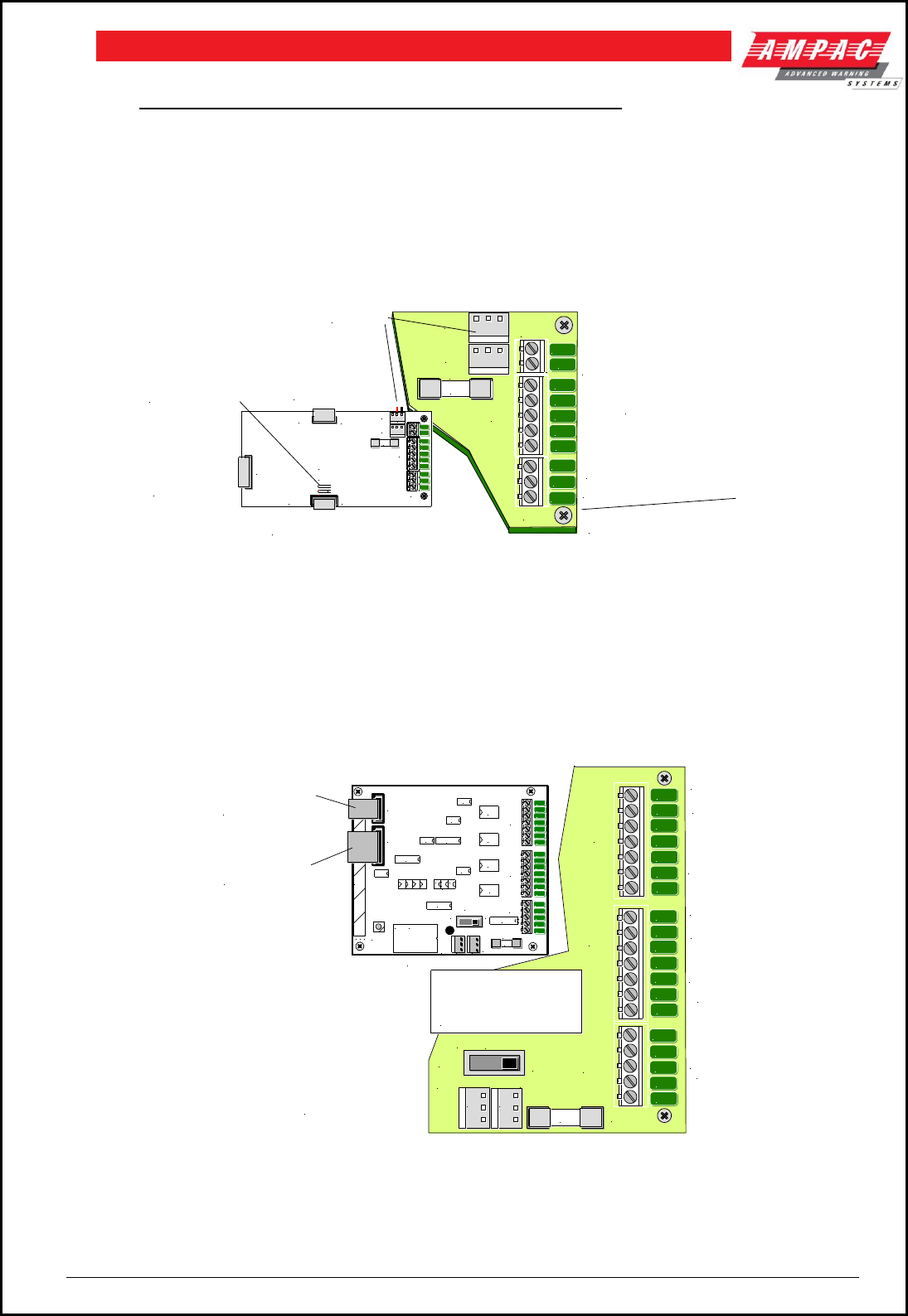
Page 34
FIREFINDERTM INSTALLATION COMMISSIONING & OPERATION
7 Expanding the System Through Networking
Expanding the system can be achieved in various ways and requires the use of boards specifically
designed for communications purposes and boards that actually expand the system.
7.1 Communications: Controller Interface Card 302 - 725
The Controller Interface Card ( CIC ) provides 1 X RS232 O/P for High Level Interfaces, Graphics etc., 1 X
half duplex RS485 O/P for external LED Mimics, High level Interfaces – EWIS- , Graphics etc and option to
allow for multiple CIC interconnection.
Figure 45: Controller Interface Card
7.2 Communications: Network Interface Card 302 - 724
The Network Interface Card provides two communication buses, RS232 and RS422, to allow the
networking of multiple panels in different combinations, eg. from Data Gathering panels to Peer to Peer
panels. Intercommunication can be via CN18 on the Main Controller (Loop Comms) or by way of a
Controller Interface Card connector CN3 (Out). Fitted to the rear of the NIC is the CPU IO Controller
(BRD85CPU) with NIC software to control the flow of communications in and out of the NIC.
Figure 46: Network Interface Card
AUX FUSED
( F1 )
27VDC OUT
RS232 COMMS
OUTPUT
HLI / GRAPHICS
OR BMS
TB1 302-7150 LED REPEATER
27VDC IN
TB2
TB1
+ -
+ -
F1
CN5
CN6 TB3
2A
+27V
0V
COM
TXD
RXD
RTS
CTS
TRX+
TRX-
SCRN
27VDC IN
TB2
TB1
+ -
+ -
F1
CN5
CN6 TB3
2A
+2 7V
0V
COM
TX D
RXD
RT S
CT S
TRX+
TRX-
SC RN
CN1
CN2
IN
To Loop Comms
( CN18 ) of the
Main Controller
To CN2 ( IN ) of the next
CIC or CN1 of the NIC
To Previous CIC
CN3 ( OUT )
K1, K2:
Link Pins 1 & 2
on LAST CIC only
CN3
OUT
321
K2
K1
- - -
- - -
CN16 302-422
IN EWIS SYSTEM
RS485 COMMS OUTPUT
27VDC (CN4,5) IN / OUT
RS232 COMMS
OUTPUT
RS422 COMMS
OUT
RS422
COMMS
IN
F1 FUSED
27V OUT
To Remote
Mimic
LCD Repeater
Other Panels
Graphics or BMS
F1 FUSED
27V OUT
To Remote
Mimic
COM
TXD
RXD
RTS
CTS
2A
S
D
C
B
A
+27v
0V
S
D
C
B
A
+27v
0V
+ -
+ -
ISOLATE
ON
OFF
SW2
CN4 CN5
F1
TB3
TB2
TB1
CN3
SW3
U15
U1
U6
EC3A21H
HY1
RL2
RL1
RL4
RL3
TB1
TB2
SW2
CN2
CN5
U3
CN1
U2
U4
U14
U8 U12
U11
U9
U10
U13
U5
U7
CN4
TB3
F1
ISOLATE
OFF
ON
RESET
a
b
c
1
TO CN3 (OUT) OF
THE CONTROLLER
INTERFACE CARD
IF CIC IS INSTALLED
TO CN18 (LOOP
COMMS) OF THE
MAIN CONTROLLER
(STAND ALONE USE)
27VDC (CN4,5) IN / OUT
+
-
+
-
2A
COM
TX D
RX D
RT S
CT S
S
D
C
B
A
+27v
0V
S
D
C
B
A
+27v
0V
Note:
The ISOLATE Switch turns
OFF the board and
effectively S/C's the O/P's
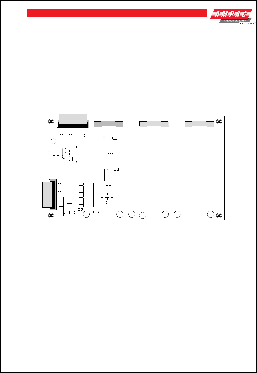
Page 35
FIREFINDERTM INSTALLATION COMMISSIONING & OPERATION
7.3 Expansion Board ( 302-688 )
The Expansion Connection Board is used t increase the capacity of the controller from 4 Slave CPU’s to 8.
Connection from the Controller to the Expansion Board, which must be mounted within 200mm of the
Controller, is made via a 20 way flat cable
Connections
Connector
Connects to
CN1
To Main Connection Board
CN2
Slave CPU 2
CN3
Slave CPU 3
CN4
Slave CPU 4
CN5
On board Slave CPU to 302-670. 302-671 and 302-672
Board Overlay
Slave CPU number 5 is an integral part of the Expansion Board, only Slave CPU’s 6, 7 and 8 are plug ins.
Figure 47: Expansion Board
7.4 Expansion Controller
An Expansion Controller ( Fast Fit Kit Number 159-0077 ) can be described as a Main Controller without a
without a Front Panel. A maximum of 3 can be introduced into any one Node, that is into any one FACP
and require Controller Interface Cards ( CIC ) and Network Interface Cards in order to communicate with
the Main Board / Controller.
Connecting Controllers together ( Networking within the same cabinet ) expands the system beyond 8
Slave CPU’s, that is the Main Board plus an Expansion Board.
Networking in this way enables the connection of up to 4 Expansion Controllers within the same FACP
cabinet. This requires the use of CIC’s and NIC’s but offers the added advantage that the RS422
communication bus is internal and all Controllers are physically and logically located at the same Node. It
is now possible to Network up to 32 Slave CPU’s in one cabinet with each Slave CPU connected to an
Addressable Loop, 16 Conventional Zone Board or Digital I/O Board. With this configuration only one
Controller has a Front Panel Board.
Once the system has been expanded to this degree it is obviously quite large and some form of indication
at a point remote from the FACP may become necessary. This is achieved with the use of a Controller
Interface Card (CIC ) and a Remote LED Mimic or a CIC, a Network Interface Card ( NIC ) and a Remote
LCD Repeater.
302 - 6880 JUN 98
7
68
RN5
RN4
C15
U10
C16
C18
C20
C22
C24
C26
C27
C28
U11
U5
RN3
U6
U4
C7
X1
CN5
C5
C6
TP1
R1
RN2
U2
U1
C2
+
C1
CN1
C23
R3
R2
U12
C11
C12
C13
C14
C17
C19
C21
C25
D3
L1
C29
TP2
C10
C8
U8
U7
U9
C9
D1D2
C3
U3
RN1
C4
CN2
CN3 CN4
Slave CPU
Slave CPU Slave CPU
To CN2 of the
Main Controller
Slave CPU 5
Note: Slave CPU 5 is incorporated
on the Expansion Borad
Slave CPU's 6,7,& 8 all mount onto
the Expansion Board in the same way
as they do to the Main Controller
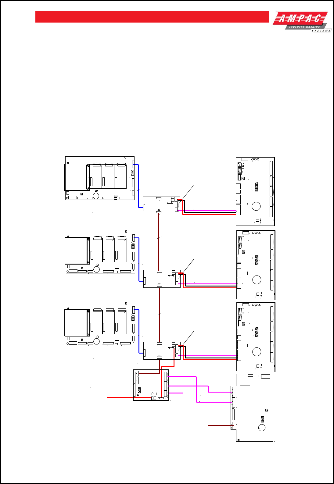
Page 36
FIREFINDERTM INSTALLATION COMMISSIONING & OPERATION
7.5 Networking
When FACP’s are connected to each other they form a “ NETWORK “. Individual FACP’s in the Network
are referred to as NODES. The Network as defined by the limitations of the installation can consist of a
number of Nodes, the number of Nodes being dependant on the configuration of each Node. Typically an
entire Network could consist of 60 Slave CPU’s connected to loops, zones and or input / output devices
spread over several nodes. The Network is Peer to Peer with the entire system configuration being stored
at each Node. The system is then programmed so that information can be made invisible to particular
Nodes or visible to all Nodes. Likewise system commands can be global or restricted to specific parts of
the network.
The entire system can be programmed from Node 1 in the Network and is connected as a data loop which
provides redundancy should there be a single cabling fault.
IMPORTANT
While it is important that proper documentation is kept and maintained for any installation it becomes even
more important as a system develops into the larger types described above.
NETWORK INTERFACE CARD
(NIC) 302-7240
27VDC POWER
10 WAY RIBBON
COMMS IN
COMMS OUT
RS232
NOT AVAILABLE
CN3
SW3
SW1
TB1
TB2
SW2
CN2
CN5
CN1
CN4
TB3
2A
F1
ISOLAT E
CTS
RTS
RXD
TXD
COM
OFF
ON
RESET
D ABCS-+ D ABCS-+
COMMS OU TCOMMS IN
a
b
c
1
FIREFINDER FACP
NODE 1 CONTROLLER 1
CONTROLLER
302-669
BRD85MBA
BRD85CPU
CIC 27V OUTPUT OR
EXTERNAL POWER SUPPLY
CN1
CN2
1
CN1
CN2
1
CN1
CN2
1
CN8
CN1
CN6
CN3
CN15
CN4
SW1
BZ1 CN5
CN2 CN7
CN11
CN16
CN9
CN17
CN13
CN10
CN18
SW3
LK2
+
c
ba
4 3 2
BRIGADE I/F
FRONT PANELEXPANSION LEDS
EXPANSION PANEL
MODEM
BACKLIGHT
27V IN
RESET
PRINTER
PSU MONITOR
LOOP COMMS
NODE ADDR ESS
1
c
ba
RS485 MULTIDROP
(SINGLE PAIR SHIELDED)
CABLE TYPE BELDEN 9841
REMOTE LED
REPEATER
302 - 715
16 WAY RIBBON
CONTROLLER INTERFACE CARD
(CIC) 302-7250
MUT E
TEST
N/F
SCR TX- TX+
+27 OV+27
K2
CN5
CN1
CN2
CN6
CN4
TB3
TB1
TB5
TB4
BZ1
SW6
SW4
SW5
SW2
SW7
CN7 SW3
D2 D3
D4
+
POWER OUT
BUZZER
RESET
LAMP
FAULTNO RMALPOWER O N
LED DISP LAY
N/ON/CC0VGPI
OUT
OV GND
IN
CPU RES ET
OFF ON
ADDRESS
SYSTEM
LEDS FLASH
FACTORY
USE ONLY
SCR TX- TX+
FIT K1 ON
LAST MIMIC
ONLY
FIT K2
FOR BUZZER
ALM
PRE
DBA
FLT
NOM
RST
LT
BM
BI
EVC
BZ
1
2
3
4
5
LED
6
7
8
9
10
11
12
13
14
15
16
17
18
19
20
21
22
23
24
25
26
27
28
29
30
31
32
LAMP
LED AUX 5V
321
OUT
CTS
RTS
RXD
TXD
COM
SCRN
TRX-
TRX+
2A
0V
+27V
TB3
K2
K1
F1
CN1
TB2
TB1
CN5 CN 6
CN3
NOTE:
ONLY RS485 OR RS422
NOT BOTH
REMOTE LCD
REPEATER
302 - 720
RS422 COMMS LOOP
COMMS OUT
COMMS IN
TWO PAIR SHIELDED
BELDEN 8132 OR 9842
OPTIONAL RS232
(AVAILABLE FOR
HIGH LEVEL INTERFACE OR
GRAPHICS OR
REMOTE SERIAL PRINTER)
BZ1
RV1
SW2
CN1
SW3
TB1
TB2
CN7
CN2
SW1
CN5
Jan 1 999
API 7 20
+
LCD OFF
ON
POW ER
BACKLIGH T-
A B C D S - + A B C D S - +
BACKLIGH T+
RESET
CONTRA ST
PRINTER
DEBUG
COM MS OUT COM MS IN
COM
TXD
RXD
RTS
CTS
TOP LAYER
CIC 27V OUTPUT OR
EXTERNAL POWER SUPPLY
CN1
CN2
1
CN1
CN2
1
CN1
CN2
1
CN8
CN1
CN6
CN3
CN15
CN4
SW1
BZ1 CN5
CN2 CN7
CN11
CN16
CN9
CN17
CN13
CN10
CN18
SW3
LK2
+
c
ba
4 3 2
BRIGADE I/F
FRONT PANELEXPANSION LEDS
EXPANSION PANEL
MODEM
BACKLIGHT
27V IN
RESET
PRINTER
PSU MONITOR
LOOP COMMS
NODE ADDR ESS
1
c
ba
RS485 MULTIDROP
(SINGLE PAIR SHIELDED)
CABLE TYPE BELDEN 9841
REMOTE LED
REPEATER
302 - 715
16 WAY
RIBBON
CONTROLLER INTERFACE CARD
(CIC) 302-7250
MUT E
TEST
N/F
SCR TX- TX+
+27 OV+27
K2
CN5
CN1
CN2
CN6
CN4
TB3
TB1
TB5
TB4
BZ1
SW6
SW4
SW5
SW2
SW7
CN7 SW3
D2 D3
D4
+
POWER OUT
BUZZER
RESET
LAMP
FAULTN ORMALPOWER ON
LED DISP LAY
N/ON/CC0VGPI
OUT
OV GND
IN
CPU RES ET
OFF ON
ADDRESS
SYSTEM
LEDS FLASH
FACTORY
USE ONLY
SCR TX- TX+
FIT K1 ON
LAST MIMIC
ONLY
FIT K2
FOR BUZZER
ALM
PRE
DBA
FLT
NOM
RST
LT
BM
BI
EVC
BZ
1
2
3
4
5
LED
6
7
8
9
10
11
12
13
14
15
16
17
18
19
20
21
22
23
24
25
26
27
28
29
30
31
32
LAMP
LED AUX 5V
321
OUT
CTS
RTS
RXD
TXD
COM
SCRN
TRX-
TRX+
2A
0V
+27V
TB3
K2
K1
F1
CN1
TB2
TB1
CN5 CN 6
CN3
NOTE:
ONLY RS485 OR RS422
NOT BOTH
CIC 27V OUTPUT OR
EXTERNAL POWER SUPPLY
CN1
CN2
1
CN1
CN2
1
CN1
CN2
1
CN8
CN1
CN6
CN3
CN15
CN4
SW1
BZ1 CN5
CN2 CN7
CN11
CN16
CN9
CN17
CN13
CN10
CN18
SW3
LK2
+
c
ba
4 3 2
BRIGADE I/F
FRONT PANELEXPANSION LEDS
EXPANSION PANEL
MODEM
BACKLIGHT
27V IN
RESET
PRINTER
PSU MONITOR
LOOP COMMS
NODE ADDR ESS
1
c
ba
RS485 MULTIDROP
(SINGLE PAIR SHIELDED)
CABLE TYPE BELDEN 9841
REMOTE LED
REPEATER
302 - 715
16 WAY
RIBBON
CONTROLLER INTERFACE CARD
(CIC) 302-7250
MUT E
TEST
N/F
SCR TX- TX+
+27 OV+27
K2
CN5
CN1
CN2
CN6
CN4
TB3
TB1
TB5
TB4
BZ1
SW6
SW4
SW5
SW2
SW7
CN7 SW3
D2 D3
D4
+
POWER OUT
BUZZER
RESET
LAMP
FAULTN ORMALPOWER O N
LED DISP LAY
N/ON/CC0VGPI
OUT
OV GND
IN
CPU RES ET
OFF ON
ADDRESS
SYSTEM
LEDS FLASH
FACTORY
USE ONLY
SCR TX- TX+
FIT K1 ON
LAST MIMIC
ONLY
FIT K2
FOR BUZZER
ALM
PRE
DBA
FLT
NOM
RST
LT
BM
BI
EVC
BZ
1
2
3
4
5
LED
6
7
8
9
10
11
12
13
14
15
16
17
18
19
20
21
22
23
24
25
26
27
28
29
30
31
32
LAMP
LED AUX 5V
321
OUT
CTS
RTS
RXD
TXD
COM
SCRN
TRX-
TRX+
2A
0V
+27V
TB3
K2
K1
F1
CN1
TB2
TB1
CN5 CN 6
CN3
NOTE:
ONLY RS485 OR RS422
NOT BOTH
IN
CN2
IN
CN2
IN
CN2
EXPANSION CONTROLLER
NODE 1 C2
10 WAY RIBBON
10 WAY RIBBON
EXPANSION CONTROLLER
NODE 1 C3
Figure 48: Example of 2 Expansion Controllers within an FACP
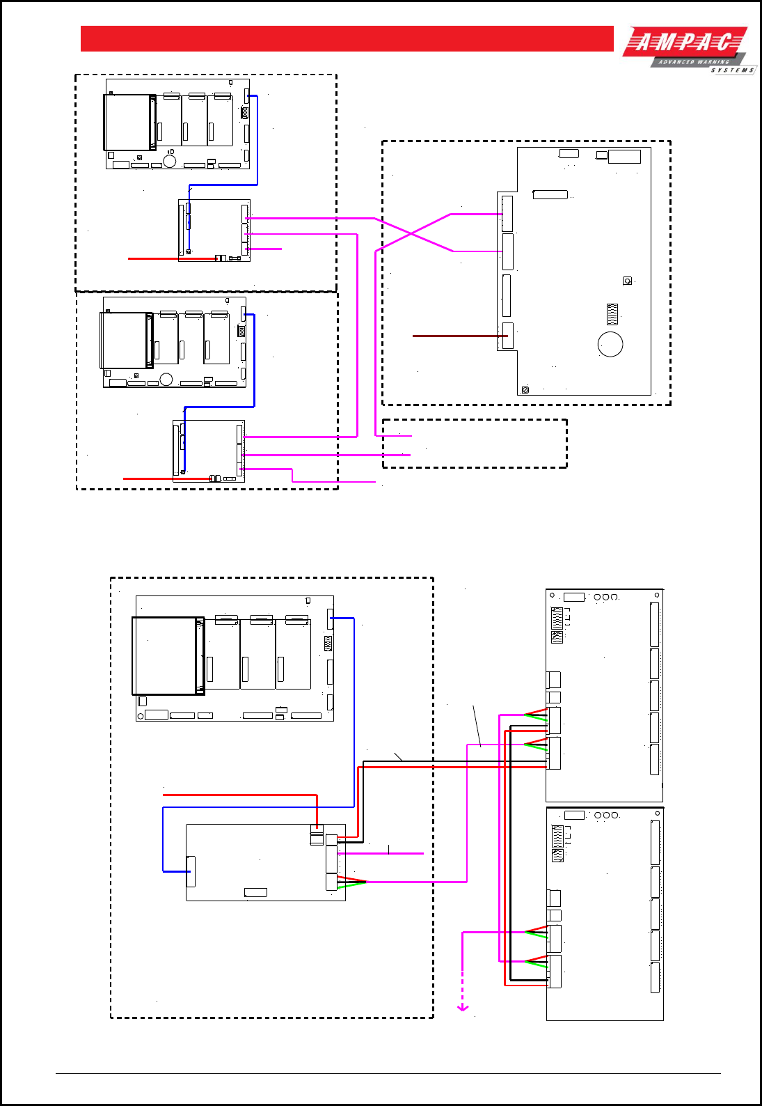
Page 37
FIREFINDERTM INSTALLATION COMMISSIONING & OPERATION
REMOTE LCD REPEATER
302 - 720
FIREFINDER
PANEL No1
CONTROLLER
NETWORK INTERFACE CARD
(NIC) 302 - 724
FIREFINDER
PANEL No2
27VDC POWER
27VDC POWER
CONTROLLER
RS422 COMMS LOOP
NETWORK INTERFACE CARD
(NIC) 302 - 724
TO OTHER LCD REPEATER PANELS
IF INSTALLED
IN
OUT
CN1
CN2
1
CN1
CN2
1
CN1
CN2
1
CN1
CN2
1
CN1
CN2
1
CN1
CN2
1
RV1
CN8
CN1
CN6
CN3
CN15
CN4
SW1
BZ1 CN5
CN2 CN7
CN11
CN16
CN9
CN17
CN13
CN10
SW3
LK2
RN17
+
c
ba
4 3 2
BRIGADE I/F
FRONT PANELEXPANSION LEDS
EXPANSION PANEL
MODEM
BACKLIGHT
27V IN
RESET
PRINTER
PSU MONITOR
LOOP COMMS
NODE ADDR ESS
1
RV1
CN8
CN1
CN6
CN3
CN4
SW1
BZ1 CN5
CN7
CN11
CN16
CN17
CN13
CN10
CN18
SW3
RN17
+
c
ba
4 3 2
BRIGADE I/F
FRONT PANELEXPANSION LEDS
EXPANSION PANEL
BACKLIGHT
27V IN
RESET
PRINTER
PSU MONITOR
LOOP COMMS
NODE ADDR ESS
1
C18
c
ba
c
ba
COMMS IN
COMMS OUT
COMMS OUT
COMMS IN
COMMS IN
COMMS OUT
16 WAY RIBBON
TWO PAIR SHIELDED
BELDEN 8132 OR 9842
OPTIONAL RS232
(AVAILABLE FOR
HIGH LEVEL INTERFACE OR
GRAPHICS OR
REMOTE SERIAL PRINTER)
OPTIONAL RS232 (AVAILABLE FOR HIGH LEVEL INTERFACE OR
GRAPHICS OR REMOTE SERIAL PRINTER)
OPTIONAL RS232
(AVAILABLE FOR
HIGH LEVEL INTERFACE OR
GRAPHICS OR
REMOTE SERIAL PRINTER)
16 WAY RIBBON
BZ1
RV1
SW2
CN1
SW3
TB1
TB2
CN7
CN2
SW1
CN5
Jan 1999
API 720
+
LCD OFF
ON
POWER
BACKL IGHT-
A B C D S - + A B C D S - +
BACKL IGHT+
RESET
CONTR AST
PRINTE R
DEBUG
COMMS OU T COMMS IN
COM
TXD
RXD
RTS
CTS
TOP LAYER
CN3
SW3
TB1
TB2
CN2
CN5
CN1
CN4
TB3
2A
F1
CTS
RTS
RXD
TXD
COM
RESET
D ABCS-+ D ABCS-+
COMMS OUTCOMMS IN
a
b
c
1
CN3
SW3
TB1
TB2
CN2
CN5
CN1
CN4
TB3
2A
F1
CTS
RTS
RXD
TXD
COM
RESET
D ABCS-+ D ABCS-+
COMMS OUTCOMMS IN
a
b
c
1
NOTES:
MAXIMUM DISTANCES BETWEEN PANELS = 1.2KM
IF GREATER DISTANCE ARE REQUIRED A RS422 REPEATER
(BLACK BOX 352A or 352A-F) TO BE FITTED EVERY 1.2KM
AFTER THE FIRST 1.2KM
CABLE TO BE USED = BELDEN 8132 OR 9842 TWO PAIR SHIELDED.
Figure 49: Example of Networking 2 Panels with LCD Repeaters
FACP (INTERNAL)
CONTROLLER MAIN BOARD
CN1
CN2
1
CN1
CN2
1
CN1
CN2
1
CN8
CN1
CN6
CN3
CN4
CN5
CN2 CN7
CN11
CN16
CN17
CN14
CN13
CN10
CN18
SW3
c
ba
4 3 2
BRIGADE I/F
FRONT PANELEXPANSION LEDS
EXPANSION PANEL
MODEM
BACKLIGHT
27V IN
PRINTER
PSU MONITOR
LOOP COMMS
NODE ADDRESS
1
c
ba
TO MAXIMUM OF
32 LED MIMICS
EXTERNAL FIELD
2 CORE SHIELDED
CABLE TYPE BELDEN
9841 OR SIMILAR
RS485 MULTIDROP
OPTIONAL RS232
(AVAILABLE FOR
HIGH LEVEL
INTERFACE
OR GRAPHICS OR
REMOTE SERIAL
PRINTER)
REMOTE
LED MIMIC 1
CIC 27V OUTPUT
(OR EXTERNAL
SUPPLY)
27VDC POWER
N/F
SCR TX- TX +
+27
OV
+27
CN5
CN1
CN2 CN 3 CN4
TB3
TB1
TB5
TB4
SW2
SW7
D2 D3
D4
FAULTNORM ALPOW ER ON
LED D ISPLAY
N/ON/CC0VG PI
OUT
OV GND
IN
OFF ON
ADDRESS
SYSTEM
LEDS FLASH
SCR TX- TX+
ALM
PRE
DBA
FLT
NOM
RST
LT
BM
BI
EVC
BZ
1
2
3
4
5
LED
6
7
8
9
10
11
12
13
14
15
16
17
18
19
20
21
22
23
24
25
26
27
28
29
30
31
32
32
31
30
29
28
27
26
25
24
23
22
21
20
19
18
17
16
15
14
13
12
11
10
9
8
7
6
LED
5
4
3
2
1
BZ
EVC
BI
BM
LT
RST
NOM
FLT
DBA
PRE
ALM
TX+TX-SC R
LEDS FLASH
SYSTEM
ADDRESS
ON
OFF
IN
GNDOV
OUT
GPI 0V C N/C N /O
LED D ISPLAY PO WER O N NORMAL FA ULT
D4
D3
D2
SW7
SW2
TB4
TB5
TB1
TB3
CN4
RN3
CN3
CN2
CN1
CN5
+27
OV
+27 TX+TX-SC R
N/F
NOTES:
MAXIMUM DISTANCE BETWEEN PANELS = 1.2KM
CABLE = BELDEN 9841 OR SIMILAR
SINGLE PAIR SHIELDED.
POWER REQUIREMENTS
27VDC CAN BE DERIVED FROM THE FIREFINDER OR
AN EXTERNAL APPROVED 27VDC SUPPLY CAN BE
USED AND WIRED INTO TB1 + AND - TERMINALS
16 WAY RIBBON
CONTROLLER
INTERFACE
CARD
OUT
CTS
RTS
RXD
TXD
COM
SCRN
TRX-
TRX+
0V
+27V
TB3
CN1
TB1
CN5 CN 6
CN3
MAIN CPU SLAVE CPU's 2,3,4
REMOTE
LED MIMIC 2
Figure 50:Example of Networking 1 Panel and 2 LED Mimics
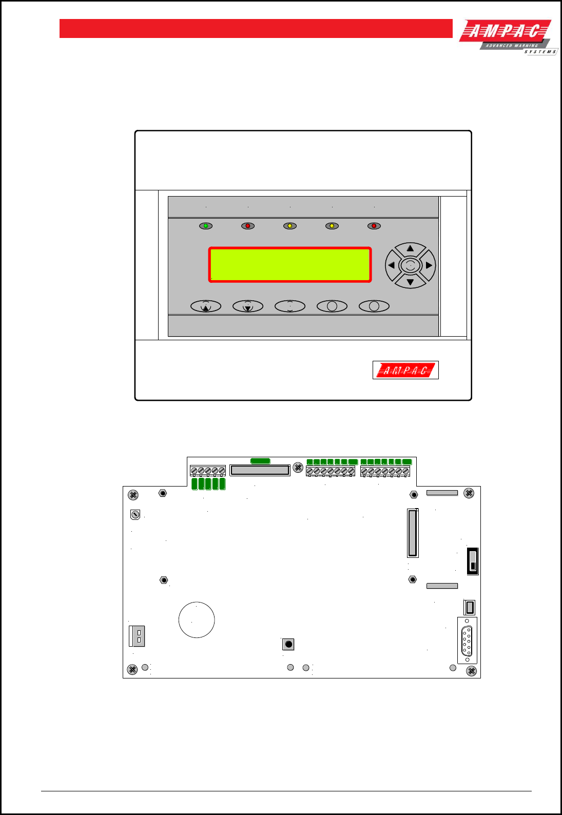
Page 38
FIREFINDERTM INSTALLATION COMMISSIONING & OPERATION
7.6 Liquid Crystal Display Repeater Panel 302 - 7200
The LCDR mimics all displays as those shown at the main panel, provides controls to interrogate the
system and would normally connect / communicate with the Network Interface Card using RS422
communication protocol. The controls function in the same way as those on the FACP.
.
Figure 51: Liquid Crystal Display Repeater Front Panel
Figure 52: Liquid Crystal Display Repeater Panel Board Layout
To set the address of the LCDR plug a PC into the Debug port, go to “Boot Mode” (BT) then type in EP82,
followed by a space and the Node address eg EP82 02. This address is hexadecimal format. The address
is that displayed on the screen in ConfigManager, typically NX. To display an address that has already
been set go to “Application Mode” and type in DA.
RS232 OUTPUT
HIGH LEVEL
INTERFACE
[ HLI ]
PRINTER
OUTPUT RS422 COMMS
IN TO TB1
NETWORK
INTERFACE
CARD [ NIC ]
RS422 COMMS
OUT TO TB2
NETWORK
INTERFACE
CARD [ NIC ]
BZ1
RV1
SW2
CN1
TB1
TB2
CN7
CN2
SW1
CN5
302-7200
+
LCD OFF
ON
POWER
BACKLIGHT -
BACKLIGHT +
RESET
CONTRAST
DEBUG
Pin2 Rx Data
Pin3 Tx Data
Pin5 Shield
CN3
LCD
CN4
LCD
LCD Mounting
S
D
C
B
A
+27v
0V
RXD
RTS
CTS
COM
TXD
S
D
C
B
A
+27v
0V
PRINTER
POWER
O O O O O O O O O O O O O O O O O O O O O O O O O O O O O O O O
O O O O O O O O O O O O O O O O O O O O O O O O O O O O O O O O
O O O O O O O O O O O O O O O O O O O O O O O O O O O O O O O O
O O O O O O O O O O O O O O O O O O O O O O O O O O O O O O O O
O O O O O O O O O O O O O O O O O O O O O O O O O O O O O O O O
O O O O O O O O O O O O O O O O O O O O O O O O O O O O O O O O
TB3
PRINTER
CN9
MENU
PREVIOUS
NEXT ACKNOWLEDGE
PRE-ALARMISOLATEFAULTFIRENORMAL
FireFinder 16/12/2004 12:32:42
AMPAC TECHNOLOGIES AUSTRALIA
SYSTEM IS NORMAL

Page 39
FIREFINDERTM INSTALLATION COMMISSIONING & OPERATION
8 SmartTerminal
SmartTerminal connects to the FireFinder™ Fire Alarm Control Panel (FACP) via the RS485 multidrop
communication port. Generally it is designed to be used anywhere where the status of the FACP is
required to be monitored by local personnel and limited control is required.
SmartTerminal;
Has front panel controls that allow the resetting of alarms and activation/silencing of alarm devices.
Enabling operational access to the controls is via a key-switch;
reports events from devices that are accessible to the host FACP. For example if the host FACP is
configured with global access then the connected SmartTerminal reports events from all devices. If
the host FACP is configured as local then the connected SmartTerminal reports events from devices
that are directly connected to the host FACP.
8.1 Operation
The operation of SmartTerminal can be considered to be in one of three states, these are;
1. power up - when the SmartTerminal is initialising
2. normal - when the SmartTerminal address has been set and is communicating with the FACP,
reporting normal / abnormal conditions and controlling the FACP via the front panel controls
3. fault where the SmartTerminal is in fault and/or is unable to communicate with the FACP.
Power Up
The LCD displays a message telling the operator SmartTerminal is being powered up and that the hardware
is being initialised. Once the hardware has been successfully initialised set the address and SmartTerminal
should automatically transition to the normal state. Should a failure occur on power up press the “RESET”
button located on the LCD PCB ( see Figure 5 ) and check the address is correct.
Normal
The Normal state is entered from the “Power-up” or a return from the “Fault” state and is displayed on the
LCD if the SmartTerminal is communicating with the FACP and operating correctly. In this state the front
panel Power indicator is illuminated.
Fault
SmartTerminal enters the Fault state upon;
1. a hardware failure
2. LCD module failure or
3. a loss of communications with the FACP ( indicated by the “DIAGNOSTIC” LED – not flashing and
the “no communications “ message being displayed)
In a Fault condition the front panel NORMAL indicator is extinguished and the details of the fault are
displayed on the LCD. The FACP will also indicate a fault in a similar manner.
8.2 Access levels
There are two levels of access.
Access level 1 only the Acknowledge, previous and next front panel controls are operative. All other
controls operate in access level two.
Access level 2 is entered when the key-switch is in the ENABLED position.
Keyswitch disabled Keyswitch enabled
Figure 53: Keyswitch in the Disabled / Enabled Postions

Page 40
FIREFINDERTM INSTALLATION COMMISSIONING & OPERATION
8.3 Specifications
Mechanical
Dimensions ABS Cabinet: ( mm )
300H x 360W x 100D
Environmental
Temperature:
Humidity:
-5ºC to + 55ºC
25% to 75%
Input Power
Operating Voltage ( nominal ):
Operating Voltage ( minimum ):
Quiescent Current @ 26.5VDC:
Maximum Current:
Cabling Requirements:
Optional 27VDC Power Supply:
Batteries:
27VDC
18VDC
12.4mA (back light, off buzzer off”)
43.8mA (back light on, buzzer on)
2 core 1.5 to 2.5mm²
1.8A plus 400mA Battery Charging
12Ahr
27VDC Outputs
Auxiliary 27VDC Distribution Protection:
Cabling Requirements:
24VDC 500mA Monitored
2 core 1.5 to 2.5mm²
Communications
Internal to FACP:
External to FACP:
Cabling Requirements:
Fault monitoring:
Maximum Number of SmartTerminals per FACP:
Maximum Distance ( from FACP ):
RS485
RS485
Twisted pair plus power
O/C, S/C
30
1.2Kms.
LCD
4 line X 40 character - backlit
8.4 Overview
SmartTerminal essentially consists of three PCBs;
1. BRD82CEB2 – FACP – Communications Extender Board (Item Number 159-0129)
The Communications Extender Board is mounted inside the FACP and provides the protected
RS485 communications and 27VDC to the SmartTerminal Termination Board/s and LCD/s.
2. BRD82LTB2 – Termination Board
A Termination Board is mounted in each SmartTerminal to protect and interface the RS485
communications and 27VDC supply to the LCD Board
3. BRD82ICC2 – Control, LCD Communications and LCD Driver Board
Note: A maximum of 30 SmartTerminals may be connected to the communications bus over a distance
of approximately 1.2Kms
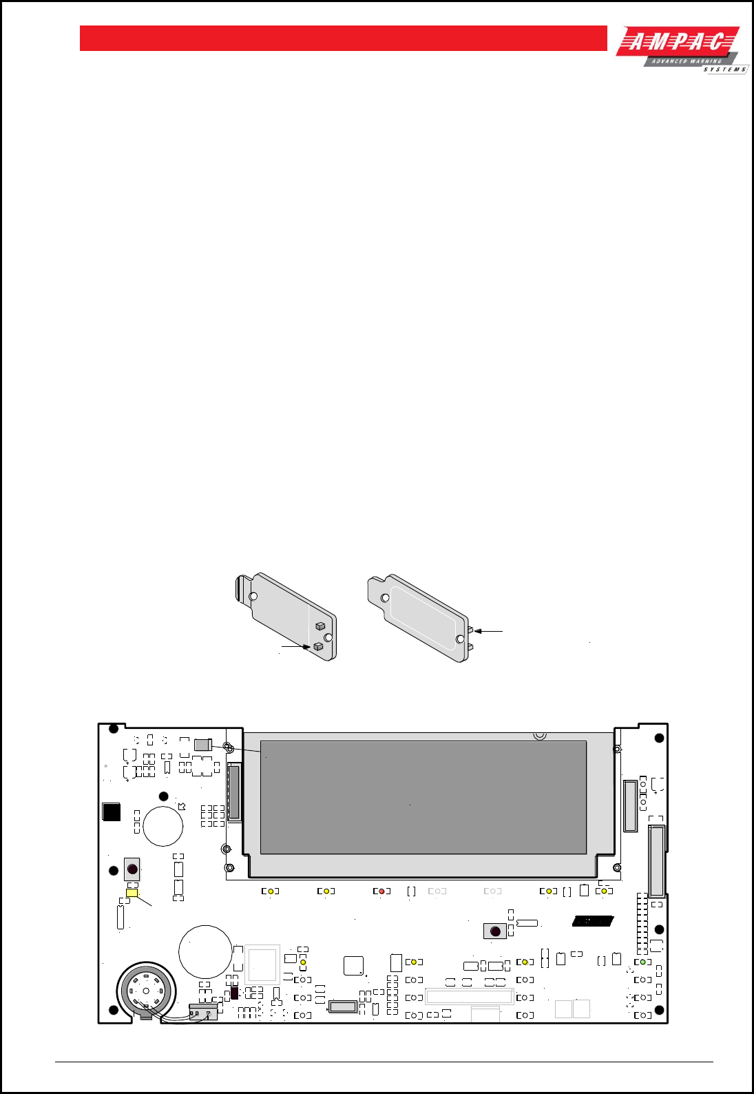
Page 41
FIREFINDERTM INSTALLATION COMMISSIONING & OPERATION
8.5 Operational & Key Features
SmartTerminal complies with AS4428 /NZS4512 and designed for use with the FireFinder™ series of
FACP’s.
4 line by 40 character LCD with backlight and navigation keys keys allow the SmartTerminal to
be used for FACP operation and interrogation. Note the backlight is only energised when alarms are
present, a key has been pressed or controls enable key switch is enabled
Buzzer and system Reset.
System expansion capabilities / options:
A wide range of secure user functions. This includes the ability to isolate / de-isolate a large number
of system functions.
Flush or surface mountable enclosure.
Controls have tactile and audible feedback of operation.
All terminals cater for 2.5mm cables.
8.6 Mechanical
SmartTerminal is supplied in a ABS cabinet and consists of;
1. The Main Card, with all controls and indicators mounted directly onto it
2. 1 X Termination Board
3. 2 X ABS door keys
4. 2 X 003 Enable / Disable keys
5. 2 X Jumper links
Note: A Communications Extender Board will be required if the Comms Bus in the FACP is fully
utilised and / or if one is not fitted.
The front door of the ABS version is locked by way of two clips on the right hand side of the cabinet. A
special locating key which has two raised pins that are inserted into the side of the cabinet unlocks the
door.
DOOR RELEASE PINS
DOOR RELEASE PINS
Figure 54: ABS Door Key and Front Panel Add On Card Surround Release Clip
CN5
TO
TERM
BRD
LCD
DIAGNOSTIC /
CONFIG LED
2
1
8
7
6
5
4
3
D24
CN12
CN11
CN10
BRD82ICC
Main Control PCB
CN7
PWR LINK
PWR LINK
KEYSWITCH
PRINTER
RESET
TOUCH HERE FIRST
DISCHARGE POINT
CONFIG
BRD82ICC2-
28/04/2006
R43
R42
SW27
SW28
Q2
R35
U11
BZ1
CN8
CN9
CN7
CN10
CN1
CN2 CN3
CN6
D2 D3 D4 D5 D6 D7 D8
D9
D10
D11
D12
D13
D14
D15
D16
D17
D18
D19
D20
D21
D22
D23
D29
D31D32
D35
LK1
Q4
Q6
Q1
Q5
R12
RN1
TH1
U12
U7 U8 U9
U4
U15
U6
U1
U14
U10
X1
RN13
U3
U2
U5
Q7
R45
R46
R47
FLASH
LCD BACKLIGHT
Figure 55: Main PCB Layout
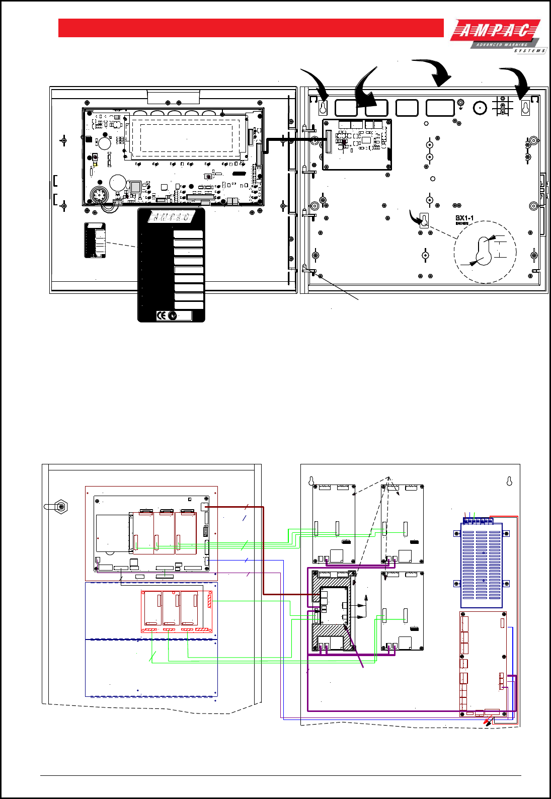
Page 42
FIREFINDERTM INSTALLATION COMMISSIONING & OPERATION
CAB2116
2
1
8
7
6
5
4
3
D24
CN12
CN11
CN10
BRD82ICC
BRD82LTB
LCDA Main
Control PCB
KNOCKOUTS
TOP ( x15 )
BACK ( x 4 )
KEY HOLE
MOUNTING
HOLE
CN7
LCD
CN1
R 6mm.
12 mm
COMPLIANCE &
CONFIGURATION LABEL
FRONT DOOR HINGES
KEY HOLE
MOUNTING
HOLE
KEY HOLE
MOUNTING
HOLE
PWR LINK
PWR LINK
KEYSWITCH
PRINTER
RESET
TOUCH HERE FIRST
DISCHARGE POINT
CONFIG
DIAGNOSTIC
BRD82ICC2-
28/04/2006
R43
R42
SW27
SW28
Q2
R13
R14
R15
R19
R35
C25
U11
R32
Q3
BZ1
C36 C26C29
C16
C15
C12
C23
C17
C13
C21 C19
C20
C9
CN8
CN9
CN7
CN10
CN1
CN2 CN3
CN5
CN6
CN11 CN12
D2 D3 D4 D5 D6 D7 D8
D9
D10
D11
D12
D13
D14
D15
D16
D17
D18
D19
D20
D21
D22
D23
D24
D25
D26
D29
D31D32
D35
LK1
Q4
Q6
Q1
Q5
R23
R12
R16
R34
R30
RN4
RN2
RN5
RN1
RN3
RN10
RN9
RN8
RN7
TH1
U12
U7 U8 U9
U4
U15
U6
U1
U14
U10
X1
C22
R20
RN13
U3
U2
U5
R44
Q7
R45
R46
R47
0V
PO WER OUT
PO WER IN
+24V
RS4 85 IN R S48 5 OU T
03/05/2006
BRD82LTB2-
TB2 TB1 TB4
TB3
LK1
COM
-
+
COM
-
+
0V
+24V
CERTIFICATE OF
COMPLIANCE No.
QA APPR
ADDRESS
TECHNOLOGIES PTY LTD
DATE OF MAN
TESTED
I/P VOLTAGE
ORDER CODE
N1236
27VDC
SERIAL NO
TESTED
I/P CURRENT
CER TIFI CATE OF
COM PLIA NCE N o.
QA APPR
ADDRESS
TECHNOLOGIES PTY LTD
DATE OF MAN
TESTED
I/P VOLTAGE
ORDER CODE
N123 6
27VDC
SERIAL NO
TESTED
I/P CURRENT
Figure 56: Typical Layout ( Externally Powered ) and Location of Keyholes
8.7 Installation & Cabling
The Communications Extender Board (Item Number 159-0129) should be mounted into the FACP and
cabled as shown below.
It should be noted the Communications Extender Board and its supporting plate is mounted in a piggy back
fashion onto one of the loop / zone boards.
Figure 57: FACP Internal Layout
CUTAWAY FRONT DOOR REAR VIEW
SHOWING INSTALLED BOARDS ON
FRONT DOOR AND WIRING DETAILS
+ -+ -
+ - AUXILIARY
+ BAT -
+ IN -DBA/MCP
DOOR SW
BELL2BELL1
FAULTVALVE MON
BATT FAIL NO C NC NO C NC NO C NC NO C NC NO C NC+ - + - NO C NC + - + -
ALARM ISOLATE
C
SGD II
WARN SYSAUX POW ER O/P
TB10
CN3
TB4
CN2
CN1
TB6
TB5
CN6
TB3
CN5
TB2
L(AC) N(AC)
-V -V +V +V
(AC)
CUTAWAY CABINET BACKPAN VIEW
SHOWING MODULES FITTED TO THE BACKPAN
AND WIRING DETAILS
BRIGADE
PSU MONITOR
BOARD
(302-6732)
5.6 AMP SWITCHMODE
POWER SUPPLY (330-0002)
MAIN CONTROL BOARD (BRD85MBA)
20 WAY
10 WAY
20 WAY
FRONT PANEL CONTROL (BRD85CTLA)
TO BATTERIES
CN3
EXPANSION LEDS
CN21
CN20
TH1 CN8
CN1
CN6
D13
CN3
BZ1
CN5
CN2
CN7
CN11
CH16
CH15
CH6 CH8
CH2
CH1
CN16
CN14
CN18
RN17
RN20
CN4
CN10
CN15
CN13
CN17
c
ba
4 3 2
BRIGADE I/F
FRONT PANELEXPANSION LEDS
EXPANSION PANEL
MODEM
27V IN
PRINTER
PSU MONITOR
LOOP COMMS
1
ENSURE CN13 - 15 ARE FITTED
WITH P IN ENTRY SIDE FACING
THE BOTTOM OF THE BOARD
3 WAY
CN1
CN2
1
SLAVE CPU
(302-6692)
POWER
CN4
CN3
CN2 TX1 POWE R
AUG 200 0
API-735
CN4
CN1CN3
CN2 TX1
POWER
AUG 200 0
API-735
CN4
CN1CN3
CN2 TX1
CH8
CN1
CN2
1
CH8
CN1
CN2
1
L2+ L1-
B
L2+ L1-
A EXT
+35V EXT
+35V
L2+ L1-
B
L2+ L1-
A EXT
+35V EXT
+35V
L2+ L1-
B
L2+ L1-
A EXT
+35V EXT
+35V
L2+ L1-
B
L2+ L1-
A EXT
+35V EXT
+35V
L2+ L1-
B
L2+ L1-
A EXT
+35V EXT
+35V
L2+ L1-
B
L2+ L1-
A EXT
+35V EXT
+35V
16 WAY
SLAVE CPU
(302-6692)
SLAVE CPU
(302-6692)
CH15
U15
CN2
a b c
U11
U10
U14
U13
CPU BOARD
(BRD85CPU)
FRONT PANEL
CN1
RJ45
2 LOOP TERMINATION BOARD
(302-7350)
CN3
76 8
CN5
CN1 CN2
CH8
CH8
CN1
CN2
1
CH8
CH8
CN1
CN2
1
CH8
CN2
R1
1
SLAVE CPU
(302-6692)
SLAVE CPU
(302-6692)
SLAVE CPU
(302-6692)
20 WAY
COMMUNICATIONS EXTENDER
BOARD IS MOUNTED HERE
TO
LCDA
CN1
POWER OUT
0V
+24V
TB4
27VDC
in/out
RS485 OUT
COM
-
+
TB1
CN3
CN2
CN5
CN4
RS485
27VDC DISTRIBUTION
POWER
AUG 200 0
API-735
CN4
CN1CN3
CN2 TX1
L2+ L1-
B
L2+ L1-
A EXT
+35V EXT
+35V
L2+ L1-
B
L2+ L1-
A EXT
+35V EXT
+35V
CN3 CN4
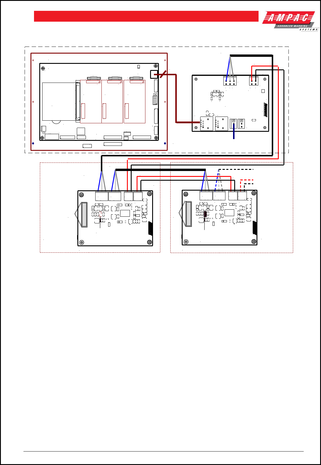
Page 43
FIREFINDERTM INSTALLATION COMMISSIONING & OPERATION
SmartTerminal is then connected to the FACP as shown below.
MAIN CONTROL BOARD (BRD85MBA)
FACP FRONT PANEL CONTROL (BRD85CTLA)
CN3
EXPANSION LEDS
CN21
CN20
TH1 CN8
CN1
CN6
D13
D14
CN3
BZ1
CN5
CN2
CN7
CN11
CH16
CH15
CH6 CH8
CH2
CH1
CN16
CN14
CN18
R17
TP3
RN17
RN20
CN4
CN10
CN15
CN13
CN17
c
ba
4 3 2
BRIGADE I/F
FRONT PANELEXPANSION LEDS
EXPANSION PANEL
MODEM
27V IN
PRINTER
PSU MONITOR
LOOP COMMS
1
+
CN1
CN2
1
SLAVE CPU
(302-6692)
CH8
CN1
CN2
1
CH8
CN1
CN2
1
SLAVE CPU
(302-6692) SLAVE CPU
(302-6692)
U15
CN2
a b c
U11
U10
U14
U13
CPU BOARD
(BRD85CPU)
CN1
25/11/2005
BRD82LTB2
TB1 TB4
M1
M2
CN2
CN5
CN4
TERMINATION BOARD No.1 ( BRD82LTB2 )
COMMUNICATIONS EXTENDER BOARD
( ITEM NUMBER 159 - 0129 )
FACP CABINET
SmartTerminal 1 SmartTerminal 2
(IF FITTED)
RJ45
CABLE
TO AVAILABLE 27VDC
CONNECTOR (3 WAY)
SHIELDED COMMS CABLE
SHIELD
TO NEXT LCDA
MAXIMUM OF 30
LK1 MUST BE FITTED TO
THE LAST BOARD ON
THE COMMS BUS
+24VDC
TERMINATION BOARD No.2 ( BRD82LTB2 )
TO
LCD TO
LCD
CN1
0V
POWER OUT
POWER IN
+24V
RS485
IN
RS485
OUT
03/05/2006
BRD82LTB2-
TB2 TB1 TB4
TB3
LK1 NOT FITTED
COM
-
+
COM
-
+
0V
+24V
CN1
0V
POWER OUT
POWER IN
+24V
RS485 IN RS485 OUT
03/05/2006
BRD82LTB2-
TB2 TB1 TB4
TB3
COM
-
+
COM
-
+
0V
+24V
C15
C12
ZD2
ZD3 TH2
TH1
L2 L1
L6
RS485 OUT
COM
-
+
POWER OUT
0V
+24V
CN3
+24V
0V
VDC
IN VDC
OUT
0V
Figure 58: Connecting SmartTerminal/s to the FACP
8.8 Setting the Address
1. Open the front door, locate the “CONFIG” button situated on the left hand side of the PCB and press
for 3 seconds. The buzzer and “Config” LED will double beep and flash respectively to indicate that
the Configuration mode has been entered. The LCD will now display the Configuration screen. This
screen consists of the code version number, current address and four adjustment markers. These
markers A-, A+, C-, and C+ are used to indicate the keys that adjust the address and LCD contrast.
2. Use the “PREVIOUS (A-) and NEXT” (A+) keys to select the desired address. The default value for
this address is 255 which is not a valid SmartTerminal address. The user must then select an
address value from 1 to 30, ie the same address as that set in the FACP. The keys corresponding to
C- (ACK) and C+ (RESET) are used in a similar manner to decrease and increase the LCD contrast
level. There is audible feedback for all key presses.
3. Once the address has been set press the “CONFIG” button again for 3 seconds and the screen will
return to its default and the “DIANOSTIC” LED will return to a slow flash. This slow flash indicates
SmartTerminal and the FACP are communicating normally ie the LED flashes if communications data
is being received from the FACP.
Note: If the address is not set within the time out period of approximately 75 seconds SmartTerminal
will return to its normal state.
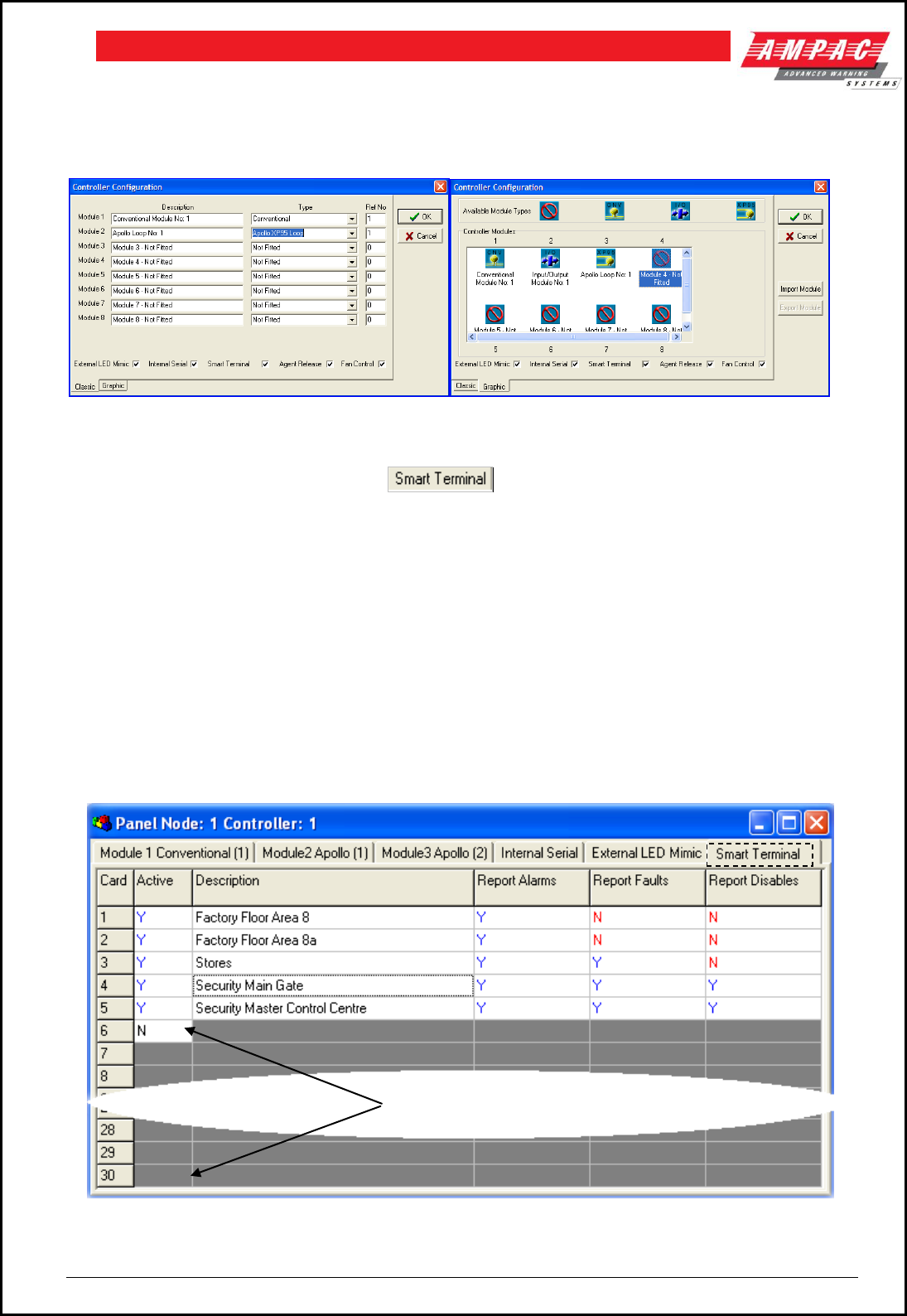
Page 44
FIREFINDERTM INSTALLATION COMMISSIONING & OPERATION
8.9 Setting the SmartTerminal Controller Configuration in
ConfigManager
Right click on the Controller icon and select “Edit Module Types” to bring up the following screen/s.
Figure 59: The Controller Edit / Add Module Types Screens
Click within the check box to “tick” the check box and click OK. Double click on the
Controller to open the Panel screen and the SmartTerminal tab should now be visible along with the other
installed functions.
8.10 Setting the SmartTerminal Reporting Parameters in ConfigManager
To set the SmartTerminal parameters click on the SmartTerminal tab and the following screen will be
displayed. Under the assigned SmartTerminal Card designator, 1 to 30, click in the Active box to change the
“N” (NO not fitted) to “Y” (YES fitted) and then enter or type in a “Description”. The description should be a
name given to the SmartTerminal or its physical location. Double click in each of the “Report” boxes to
display and set the, “Y” ( Yes reports the parameter) and “N” ( No does not report the parameter ) “Alarms,
Faults, Disables” parameters that SmartTerminal will display on each SmartTerminal at each location.
Note: A maximum of 30 SmartTerminals can be used in the configuration of the FACP.
Figure 60: Example of SmartTerminal Configuration Settings Screen
Note: In this case SmartTerminal
numbers 6 to 30 are not used.
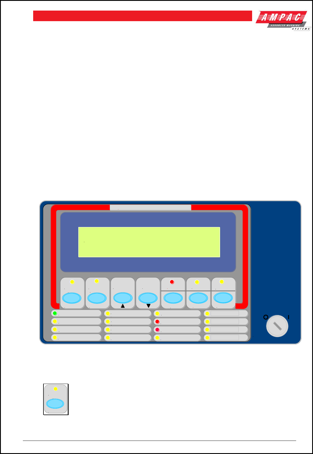
Page 45
FIREFINDERTM INSTALLATION COMMISSIONING & OPERATION
In the above example Card 1 & 2;
i. are active
ii. are situated in the factory floor area 8
iii. will display all Alarms
iv. will not display any Faults, and
v. will not display any Disables
Card 3
i. is active
ii. is situated in the stores area
iii. will display all Alarms
iv. will display any Faults, and
v. will not display any Disables
Card 4 & 5
i. are active
ii. are situated in the security areas
iii. will display all Alarms
iv. will display any Faults, and
v. will display any Disables
8.11 SmartTerminal Controls
All controls, except for the Enable / Disable keyswitch, are of a momentary push button style.
POWER
POWER FAULT
SYSTEM FAULT
EARTH FAULT
EXTERNAL BELL
FAULT
FAULT
FAULT / ISOLATED
ASE FAULT
ACF
WARNING SYSTEM
ISOLATE ISOLATE
EXTERNAL
BELL WARNING
SYSTEM PREVIOUS NEXT
PRE ALARM
AIF ACTIVE
TEST
DAY / NIGHT ACTIVE
FAULT
RESET
ISOLATED
ISOLATE
FIRE FIGHTER FACILITY
ACK
ALARM
16 : 02 : 2007 21:34
SYSTEM IS NORMAL
Figure 61: SmartTerminal Front Panel Layout
External Bell Isolate
ISOLATE
EXTERNAL
BELL
Press to isolate the External Bell output (associated LED illuminated).
Press again to re-enable the output (associated LED extinguished).
Active at access level 2.
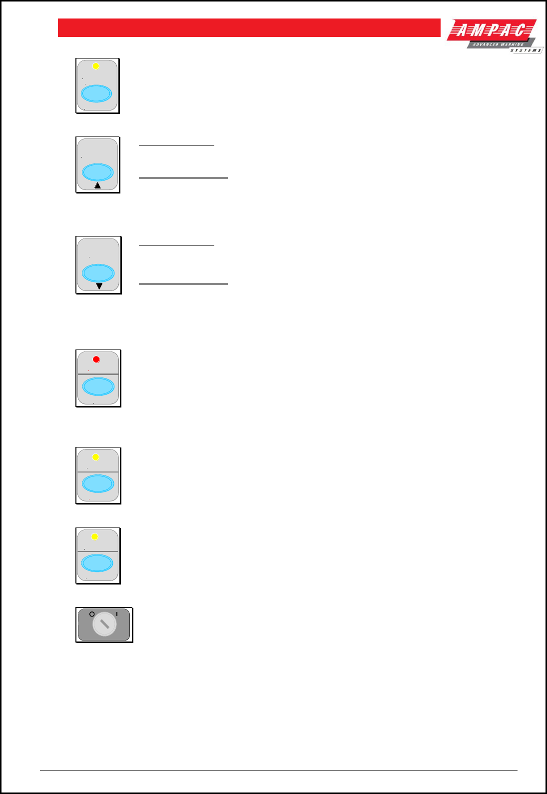
Page 46
FIREFINDERTM INSTALLATION COMMISSIONING & OPERATION
Warning System Isolate
ISOLATE
WARNING
SYSTEM
Press to isolate the Warning System output (associated LED illuminated).
Press again to re-enable the output (associated LED extinguished).
Active at access level 2 only.
Previous
PREVIOUS
Primary Function
Press to display the previously displayed LCD screen
Secondary Function
Set SmartTerminal address – A – (minus) decrement number
Active at access level 1 and 2
Next
NEXT
Primary Function
Press to display the next displayed LCD entry
Secondary Function
Set SmartTerminal address – A + (plus) increment number
Active at access level 1 and 2
Acknowledge
ACK
ALARM
Acknowledges the alarm condition of the sensor or conventional zone that is currently
displayed on the LCD.
If the key is held down for 3 seconds a lamp test is initiated. The Lamp Test
illuminates all indicators, segments on the LCD and momentarily sounds the buzzer
Active at access level 1 and 2.
Reset
FAULT
RESET
Resets the acknowledged alarm condition of the sensor or conventional zone
currently displayed on the LCD
Active at access level 2 only.
Isolate
ISOLATED
ISOLATE
Isolates (or de-isolates) the sensor or conventional zone currently displayed on the
LCD
Active at access level 2 only
Key Switch
Controls enable key switch. The SmartTerminal by default is in access level 1, and
when the control enable key switch is in the ENABLED position, the SmartTerminal is
in access level 2. Access level 2 is used to restrict access to certain controls.
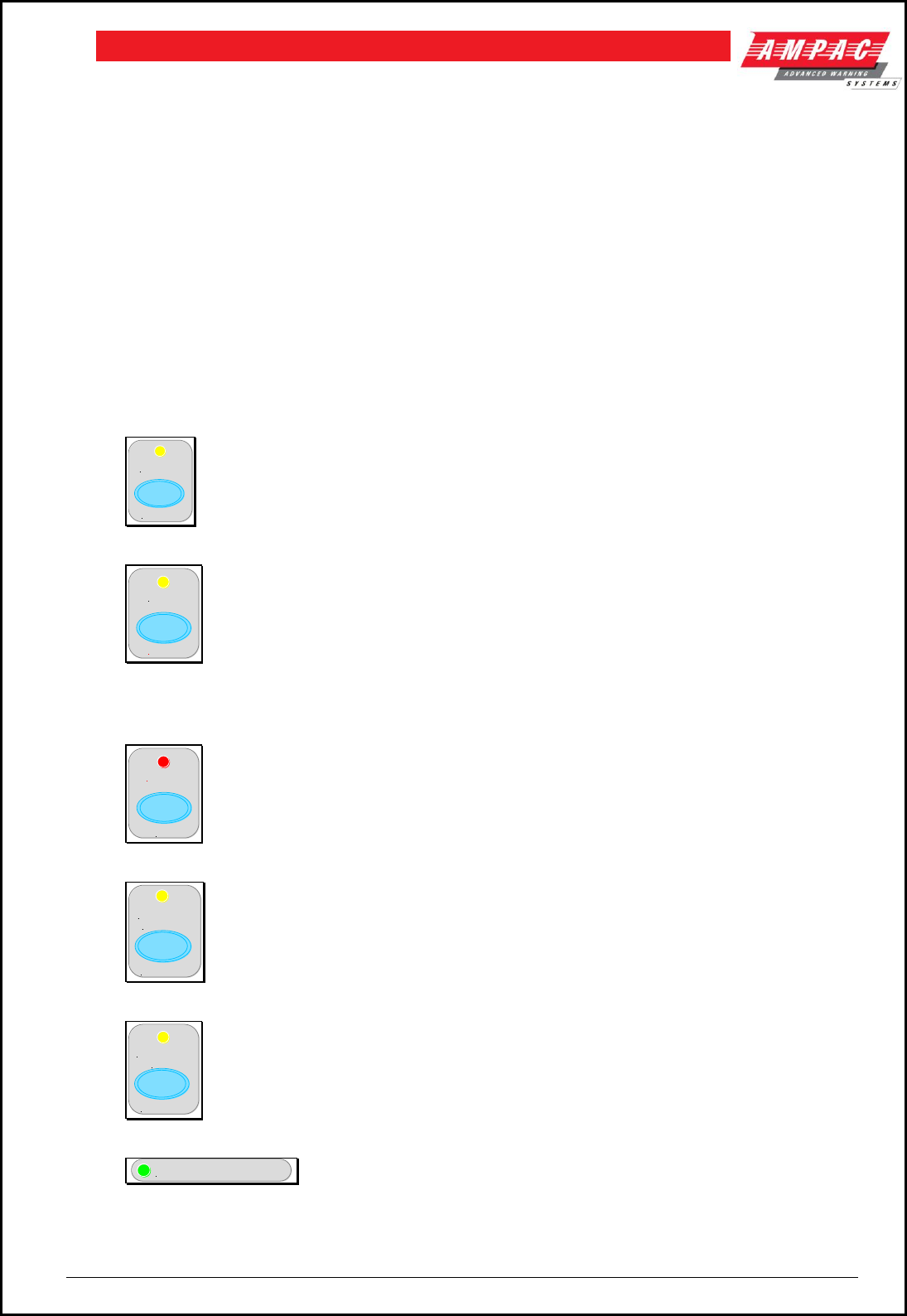
Page 47
FIREFINDERTM INSTALLATION COMMISSIONING & OPERATION
Buzzer
The Buzzer is activated under the following conditions and can be silenced by pressing the
Acknowledge (ACK) control locally or on the FACP.
Alarm condition
Devices – missing, out of calibration, wrong type, reporting an internal error
Loops – short circuit or open circuit
Monitored inputs and outputs on loop devices are in fault
Sounders – missing, wrong type or reporting an internal error
Modules within the panel – missing, wrong type or hardware error
Main and / or secondary power supply fault
8.12 SmartTerminal Indicators
Introduction
The following section details the operation of the front panel indicators on the SmartTerminal.
Isolate
ISOLATED
ISOLATE
Indicator is illuminated when one or more device/s or conventional zones are isolated
either at the SmartTerminal or the FACP.
Fault
FAULT
RESET
Indicator is illuminated when there is one or more faults on the system. Faults can be;
Devices – missing, out of calibration, wrong type, reporting an internal error
Loops – short circuit or open circuit
Monitored inputs and outputs on loop devices
Sounders – missing, wrong type or reporting an internal error
Modules within the panel – missing, wrong type or hardware error
Main and secondary supplies
Alarm
ACK
ALARM
General fire alarm indicator. The LED will flash until all alarms have been
acknowledged. Once Acknowledged the LED will remain steady until all alarms have
been cleared by Reset.
Warning System
ISOLATE
WARNING
SYSTEM
Illuminated when the Warning System output has been isolated either at the
SmartTerminal or the FACP.
External Bell
ISOLATE
EXTERNAL
BELL
Illuminated when the External Bell output has been isolated either at the
SmartTerminal or the FACP.
Power
POWER
Illuminated to show the presence of power. Flashes when mains have
failed
Page 48
FIREFINDERTM INSTALLATION COMMISSIONING & OPERATION
Power Fault
POWER FAULT
Illuminated when there is a fault with the power supply. Fault can be no
mains, high charger voltage, low battery voltage or missing/damaged
battery
System Fault
SYSTEM FAULT
Illuminated when the FACP is unable to provide mandatory functions.
Indicator is latched, until cleared by reset
Earth Fault
EARTH FAULT
Illuminated when there is an earth fault detected on the panel
External Bell Fault
EXTERNAL BELL
FAULT
Illuminated if the External Bell output is in fault
Warning System Fault
FAULT
WARNING SYSTEM
Illuminated is the Warning System output is in fault
ACF Fault / Isolated
FAULT / ISOLATED
ACF
Illuminated steady if the ACF output has been disabled and flashes if the
ACF output is in fault (open or short circuit). Isolate has priority over fault
ASE Fault
ASE FAULT
Illuminated when the ASE output is in fault
Test
TEST
Illuminated when the FACP is in the test mode. Possible tests are alarm,
fault, walk, lamp and loop.
AIF Active
AIF ACTIVE
Illuminated when the AIF facility is active at the FACP
Pre - Alarm
PRE ALARM
Illuminated when one or more devices are in the pre-alarm condition and
not disabled
Day / Night Active
DAY / NIGHT ACTIVE
Illuminated when day / night facility has been enabled on the FACP
Programmable
Programmable 1 to 4 – For future use

Page 49
FIREFINDERTM INSTALLATION COMMISSIONING & OPERATION
9 LCD Screen Format
There are 3 events that can be reported and displayed by SmartTerminal. The types of event are;
1. Fire
2. Faults and
3. Disables.
The types of events are only associated with sensors and detectors hence faults associated with modules,
loops O/C – S/C, power supplies and so forth are not reported on the LCD.
The SmartTerminal has front panel indicators for each type of event. When SmartTerminal is configured not
to report a type of event and that event type is present (and the corresponding front panel indicator is
illuminated on the SmartTerminal), then a standard information screen is displayed on the LCD stating the
system is not normal and the operator should see the FACP.
Alarm
If configured the screen format for reporting loop / sensor / zone fire condition is:
LCD Line Number
Information
1
Device descriptor (up to 33 characters) Type Descriptor (up to 6 characters)
2
Loop address and zone number(Lxx Syyy.zz Zwww) current device status
3
Date and Time of occurrence (DD/MM/YYYY HH:MM:SS)
4
Alarm sequence number ( Device Alarms nnn of nnn)
Fault If configured the screen format for reporting loop / sensor / zone fault condition is:
LCD Line Number
Information
1
Device descriptor (up to 33 characters) Type Descriptor (up to 6 characters)
2
Loop address and zone number(Lxx Syyy.zz Zwww) current device status
3
Blank
4
Fault sequence number ( Device Fault nnn of nnn)
Note: The fault types only relate to devices.
In the event of a loss of communications, for a period of greater than 15 seconds the SmartTerminal
will default to the No Communications screen. The format for this screen is:
LCD Line Number
Information
1
2
No Communications
3
4
Device Isolate / Disables
If configured the screen format for reporting loop / sensor / zone disable condition is:
LCD Line Number
Information
1
Device descriptor (up to 33 characters) Type Descriptor (up to 6 characters)
2
Loop address and zone number(Lxx Syyy.zz Zwww) current device status
3
Blank
4
Isolate / Disable sequence number ( Device Fault nnn of nnn)
Pre-alarm
If configured the screen format for reporting loop / sensor / zone Pre-alarm condition is:
LCD Line Number
Information
1
Loop address and zone number(Lxx Syyy.zz Zwww)
2
Pre-alarm descriptor (up to 15 characters)
3
Line is left blank
4
Pre-alarm sequence number ( Device Pre-alarms nnn of nnn)

Page 50
FIREFINDERTM INSTALLATION COMMISSIONING & OPERATION
Normal / Default
The format for reporting that everything is normal is:
LCD Line Number
Information
1
Current Date and Time (DD/MM/YYYY HH:MM)
2
System Status
3
Blank
4
Blank
The screen is only displayed when there are no alarms, fault or disables on the panel.
The default screen is only displayed when there are no device alarms, device faults or device
disables present on the system. The highest priority current system status will be displayed and can
be one of the following listed in order of highest to lowest priority:
1. “SYSTEM ALARM”
2. “SYSTEM PRE-ALARM”
3. “SYSTEM FAULT”
4. “SYSTEM ISOLATE”
5. “SYSTEM NORMAL”
Config
The Config screen displays the following
LCD Line Number
Information
1
VX.X ( This is the code software version number )
2
Address
3
4
A - A + C - C+
A - A + : adjusts the address 1 to 30, 30 being the maximum number of SmartTerminals that can be
connected to the FACP, ( default is 255 which is not a valid address).
The function keys perform the following;
A – press “Previous” A+ press “Next”
C - C+: decreases [-] and increases [+] the LCD contrast level.
The function keys perform the following;
C – press “Silence Buzzer” C+ press “Reset”
9.1 Trouble Shooting Chart
Problem
Solution
Normal Supply LED not illuminated
Check supply voltage it should be set to 27.2VDC.
Nominal fault voltages are - Low = (<18VDC)
High = (> 28VDC )
FACP Earth Fault LED illuminated
Check all input and output cabling and wiring
assemblies for short to ground
FACP System Fault LED illuminated
Ensure correct panel configuration
Check all connections for loose wiring
FACP Warning System Fault LED illuminated
Check correct E.O.L is fitted
Check wiring is connected correctly
RS485 Communication Bus not working
Refer FACP LCD. This may identify where there is a
break in the communication line
Check the SmartTerminal Diagnostic Config LED is
flashing. If not the FACP is not communicating with
the SmartTerminal. Check the RS485 cabling.
If flashing check the SmartTerminals address.

Page 51
FIREFINDERTM INSTALLATION COMMISSIONING & OPERATION
10 Agent Release Control
Agent Release control consists of a Agent Release Module, Termination Board and an optional Local
Control Station.
10.1 Operation
Introduction
The Agent Release Module and Termination Board communicate with the FACP via the RS485 multi-drop
bus.
The Local Control Station communicates only with the Termination Board via a separate RS485 bus. Up to
4 Local Control Stations can be connected to one termination board.
Agent discharge operates in two modes – automatic and manual. The manual mode is selected by
pressing the Inhibit switch on any Local Control Station. To indicate the system is in manual the Inhibit LED
will be illuminated. Pressing Inhibit again will toggle or return the mode to automatic and extinguish the
Inhibit LED.
The “ Agent Released ” Pressure Switch ( PSW ) is wired to the PSW input on the Termination Board and
is used to confirm that the agent has been released. The circuitry involved in this process can be
configured to accept a normally open contact, normally closed contact, normally open mechanically
operated (manual) or is ignored ( not fitted ) and is selected via FACP on-site programming. If the
mechanical ( manually operated ) option is selected the module monitors the pressure switch input and
provides notification the agent has been released manually, initiates an alarm and illuminates the “Agent
Released “ indicator.
Manual Mode
When the system is in manual mode, then;
The Local Control Station Inhibit indicator is lit at the FACP and all Local Control Station’s.
The buzzer at all Local Control Stations will sound until the inhibit is released.
The System Inoperative output is turned on.
The Automatic discharge sequences are prevented from starting.
If an automatic discharge sequence was underway and the inhibit switch is activated
(switched to manual mode) the discharge sequence is aborted and the sequence is reset.
This means the Stage 1 and Stage 2 outputs are switched off.
To manually discharge the agent the “ Lock Off Valve “ must be open and the Manual Release switch on
the Local Control Station pressed. The manual discharge sequence is;
Manual Activation indicator is lit on the FACP and Local Control Station.
The FACP activates its brigade alarm output.
Stage 1 outputs are switched to +24VDC. [FIRE ALARM sign illuminated, aural alarm
sounds].
Stage 2 outputs are switched to +24VDC. [ FIRE ALARM, EVACUATE & DO NOT ENTER
signs illuminated, aural alarm sounds ].
The optional pre-release start delay is activated ( Selected via FACP on-site programming ),
time out and an ON Interlock signal will then operate the selected release circuitry.
The Agent Discharge LED on the Agent Release Module and Local Control Station will
illuminate when the Pressure Switch input on the Termination Board is activated.
Activate gas-fired output.
Note: The Interlock Input can be defaulted to the on position by placing a 10K EOL termination
resistor across the terminals TB2. 7 / 8 of the Agent Release Module and Local Control Station.
Auto Mode
Automatic discharge is when one or two zones going into alarm initiate the agent discharge sequence.
Note: A “manual release” can still be initiated in “auto mode” but the LCS “Inhibit” control WILL
NOT inhibit / abort the agent release sequence.

Page 52
FIREFINDERTM INSTALLATION COMMISSIONING & OPERATION
Single Zone Activation, the following discharge sequence is executed;
Automatic Activation LED is illuminated on the Agent Release Module and Local Control
Station.
Stage 1 outputs are switched to +24VDC. [FIRE ALARM sign illuminated, aural alarm
sounds].
Stage 2 outputs are switched to +24VDC. [ FIRE ALARM, EVACUATE & DO NOT ENTER
signs illuminated, aural alarm sounds ].
Optional pre-release delay is started ( Selected via FACP on-site programming ).
The delay times out and if the Interlock signal is ON, the selected circuit will activate.
The Pressure Switch field input on the Termination Board is activated and the Agent
Discharge LED on the Agent Release Module and Local Control Station will be illuminated.
Activate gas-fired output.
Dual Zone Activation, if the first zone goes into alarm the following steps are initiated;
The automatic activation LED on the Agent Release Module and Local Control Station will
flash.
Stage 1 outputs are switch to –24VDC. [FIRE ALARM sign illuminated, aural alarm sounds].
When the second zone goes into alarm, then the following steps occur;
Automatic activation LED goes steady.
Stage 1 outputs are switched to +24VDC. [ FIRE ALARM & EVACUATE signs illuminated,
aural alarm sounds ].
Stage 2 outputs are switched to +24VDC. [ DO NOT ENTER sign illuminated ].
Optional pre-release delay commences ( Selected via FACP on-site programming ).
The delay times out and if the Interlock signal is on the selected circuit will activate.
The Pressure Switch field input on the Termination Board is activated and the Agent
discharge LED on the Agent Release Module and Local Control Station will be illuminated.
Activate gas-fired relay output.
Service Switch
The service switch is situated on the Agent Release Module when activated causes the following;
Electrically isolates the activation circuitry from the agent release device.
Operates the System Inoperative output.
Note: The service switch is NOT overridden by a manual discharge.
Lock-Off Valve
When the manual lock-off valve is operated;
The agent is blocked from reaching the release valve.
The lock-off valve inhibit indicator LED’s on the Agent Release Module and Local Control
Station are illuminated.
The system inoperative output operates.
Fault Monitoring
Fault conditions are initiated by:
The Pressure Switch monitoring circuit.
The Low Pressure Switch monitoring circuit.
The Lock-off Valve monitoring circuit.
Activation circuitry.
Stage 1 outputs. ( Aural & visual discharge alarms ).
Stage 2 outputs. ( Aural & visual discharge alarms ).
A Zone Fault.
A Fault on the interlock input.
A Fault with a LCS.
Note #1: The common fault indicator on the Agent Release Module and Local Control Station is
illuminated for any Fault condition.
Note #2: For a pressure switch fault, low pressure switch fault, lock-off valve fault, stage 1 output
fault, stage 2 output fault and interlock fault, the FACP will signal the brigade.

Page 53
FIREFINDERTM INSTALLATION COMMISSIONING & OPERATION
Note #3: When there is a fault in the activation circuit or in the trigger zones, in
addition to the above, the system inoperative output is operated.
Note #4: The FACP fault buzzer will sound for all faults.
Note #5: The FACP will report the type of fault on the LCD.
Isolation
If a trigger zone is isolated at the FACP the trigger zone isolated indicator at the Agent Release Module
and Local Control Station is illuminated, and the system inoperative output is operated.
System Inoperative Output
The system inoperative output is switched to +24VDC under the following conditions;
Operation of the Service Switch.
A Fault in the selected trigger circuit.
Operation of the Lock-off valve.
Operation of the Inhibit at an Local Control Station.
A Fault in any of the activation zones.
If any of the activation zones are isolated.
Manual Mechanical Release of the Agent
With agent release systems, a manual mechanical means can be provided to release the agent.
If the pressure switch is activated (indicating that the agent has been released), and the agent release
module has not activated the selected activation circuit, then the following will occur:
Stage 1 output is switched to +24VDC and stage 1 relay is output closed
Stage 2 output is switched to +24VDC and stage 2 relay output is closed
Light the agent release led on the ACC and LCSs
Activate gas-fired relay output
Monitoring of the Pressure Switch
Due to the requirements of Manual Mechanical Release of the Agent, the pressure switch input conveys
two pieces of information:
1. When the pressure switch input is active, it signals that the agent has been released. The
release can be as a result of the agent release module or due to a manual mechanical release.
2. When the pressure switch is not active, it signals that there is a full bottle of agent
available to be discharged.
In order for the agent release module to respond to a manual mechanical release, the pressure switch
must have been previously not active, to signify that a full bottle of agent is available
10.2 Agent Release Module BRD25ARB –A
The Agent Release Module controls and monitors all the requirements for agent release and carries the
slide in label for identification of the agent and application area.
Figure 62: Front Panel Layout
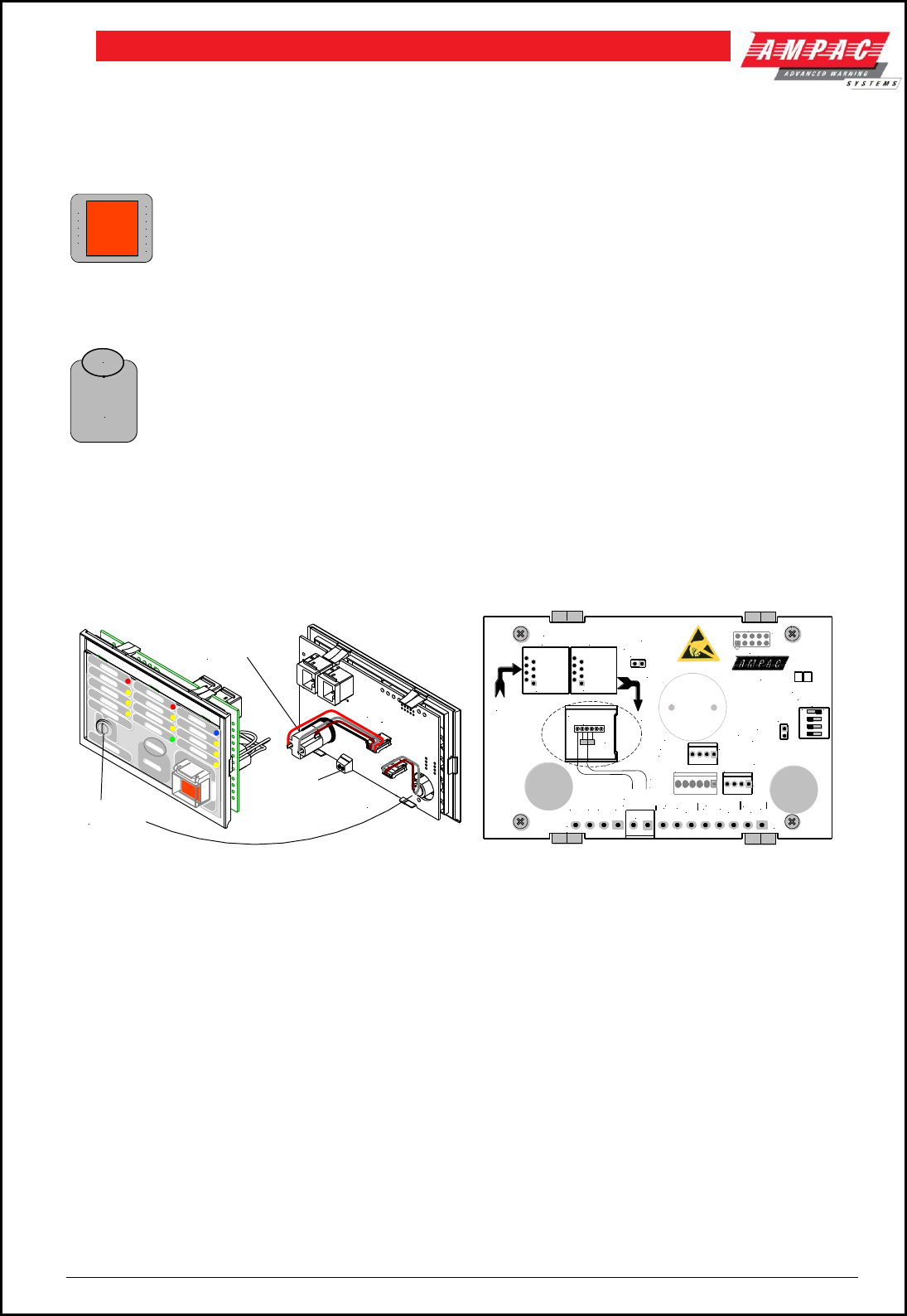
Page 54
FIREFINDERTM INSTALLATION COMMISSIONING & OPERATION
10.3 Controlled Access
Service Inhibit When activated, the module goes into service mode, which results in the selected agent
activation circuit being electrically isolated. Control to be secured from unauthorised use, therefore a key-
switch is required. Key is only removable in the off position.
A
G
E
N
T
N
H
I
B
I
T
I
Lifting the switch cover and pressing the push button places the system in manual mode –
which prevents an automatic release sequence from starting, and sounds the buzzer at the Local Control
Station(s). This two action safety feature prevents any accidental operation of the control and should not
be disabled.
AGENT
SELECT
When activated, causes the selected agent to toggle between Initial and Reserve. Indicators
show which agent has been selected.
Agent Release Module PCB Layout
The PCB is fitted with two 2 x RJ45 connectors CN6 & 7 for power (27VDC) and communications (RS485)
for communications between the Agent Release Module and the FACP Main Control Board.
PCB
Agent Inhibit
Switch
Agent Release
MCP (Fit 10K EOL)
Service Inhibit
Keyswitch
In Out
RS485
&
+/- 27v
In
RS485
&
+/- 27v
Out
1 2 3 4
ON
TB4
CN3
CN1
LK2
TB 2
TB 1
SW2
LK1
CN5
CN2
BZ1
+
CN7CN6
+
AGENT
MANUAL HOLD/
RE MOT E
MANUAL
-
+
RS 485 OUT
RS 485 IN
-+
KEYSWITCH
RELEASE
0V+24V
COM
LINK
TERMINATOR
SWITCH
ADDRESS
COM
0V+24V
BRD25ARB5-
INTERLOCK
-
JTAG
INHIBIT
SWITCH MON
DISABLE
INHIBIT
SWIT CHES
FU TU RE USE
EOL
COMMS IN / OUT
10K
EOL
MCP
AGENT RELEASE
Figure 63: Exploded View Figure 64: Underside of the Module PCB
Quiescent Current: 28.5mA
Note: If the keyswitch is not used CN2 will carry a link so as to enable the panel.

Page 55
FIREFINDERTM INSTALLATION COMMISSIONING & OPERATION
10.4 Local Control Station
The Local Control Station is supplied fitted into enclosure and has the same indicators and “Agent Inhibit
switch as the Agent Release Card but no Agent Select button or Service Inhibit keyswitch (this is replaced
by the Inhibit push button).
The Comms line is RS485 and is cabled to the Agent Termination Board.
The Interlock is a monitored input with 10K EOL. This input is used to determine if air conditioning
dampers and doors are closed but can be defaulted to the “ON” condition by terminating the input with a
2K2Ω EOL.
Note: Typically the agent is not discharged until all dampers / doors are closed.
LCS MCP Control
Lifting the cover and pressing the MCP starts the manual agent release sequence. This two action safety
feature prevents any accidental operation of the control and should not be disabled.
Buzzer (located at the FACP)
i. Buzzer sounds;
ii. under all fault conditions and can be silenced by using the FACP buzzer silence control.
iii. when the LCS Inhibit control is activated – after 8 hours – treated as an isolate condition.
iv. when the service inhibit is activated - after 8 hours – treated as an isolate condition
Buzzer Located at the LCS - To comply with AS4214 – the buzzer at the LCS sounds when the
automatic discharge of the agent has been inhibited via the agent inhibit push button located at the ACC or
LCS(s). In some installations, it is preferred not to sound the buzzer when the automatic discharge of the
agent has been inhibited because workers have a set exit procedure which includes checking the agent
inhibit condition has been removed. In order to meet both requirements, the continual sounding of the
buzzer when the automatic discharge of the agent has been inhibited is configurable through the
“Programming” menu at the FACP. This only affects the buzzer at the LCS(s).
LCS Local Control Panel Inhibit
TO INHIBIT AUTOMATIC AGENT RELEASE
LIFT COVER AND PRESS BUTTON
PRESS AND HOLD UNTIL THE LAMP IS ILLUMINATED
which indicates the inhibit is activated at the ARC or any of the LCSs. To disable the “Inhibit” PRESS AND
HOLD again until the lamp is no longer illuminated.
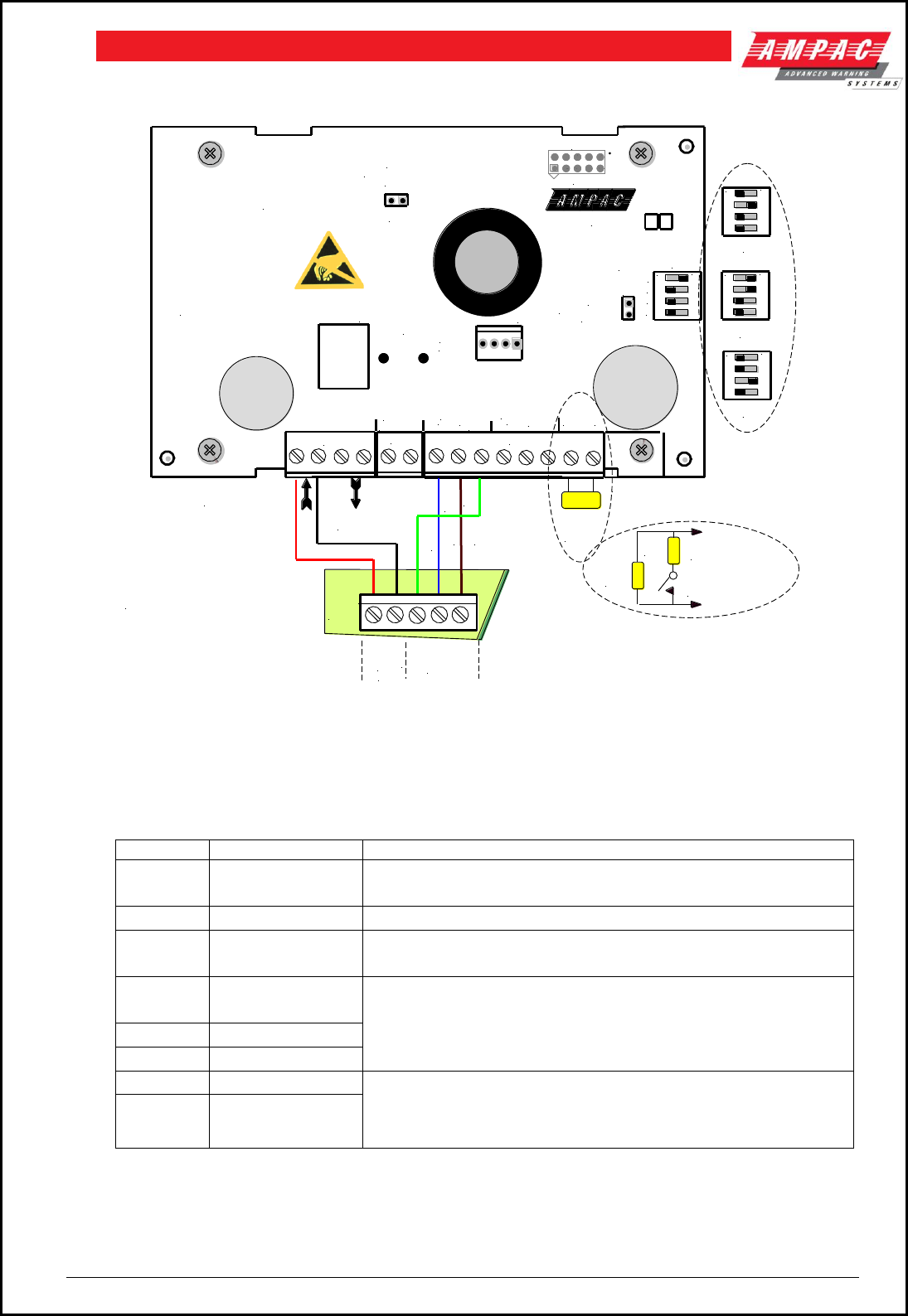
Page 56
FIREFINDERTM INSTALLATION COMMISSIONING & OPERATION
Local Control Station Interconnections
1 2 3 4
ON
1 2 3 4
ON
1 2 3 4
ON
2
3
4
+27VDC OUT
TO NEXT LCS
+27VDC IN FROM
TERMINATION BRD.
10K
EOL
+
ON
Address
Switch
Set to 1
1 2 3 4
Agent Termination Board
within the FACP
Local Control Station
ONLY USED ON THE LAST
LCS ON THE COMMS BUS
10K
EOL
2K2 INTER
LOCK
INSERT A 2K2 ACROSS
THE 10K EOL TO
DEFAULT TO "ON"
TB4
T1
CN1
LK2
TB2
TB1
SW2
4
3
2
1
LK1
CN5
+
AGENT
MANUAL HOLD/
MANUAL
-
+
RS 485 OUT
RS 485 IN
-+
RELEASE
0V+24V COM
LINK
TERMINATOR
COM
0V+24V
BRD25ARB5-
INTER-
LOCK
-
JTAG
INHIBIT
SWITCH MON.
DISABLE
INHIBIT
EOL
RS 485
COMMS
BUS
SIG
SIG
SCRN
27VDC
0VDC
+
+
-
TB1
LCS Interconnections
Quiescent Current: 18.5mA
The LCS is fitted with a 3 terminal strips TB1, 2 & 3
Pin
Assignment
TB1 1 &
3
+27VDC
2 & 4
0VDC
TB4 1&
2
Manual
Release
TB2 1 &
4
RS485 +
In/Out
The Comms line is RS485 and supports
communications between the local control station and
the termination board.
2 & 5
RS485 – In/out
3 & 6
RS485 Com
7
Interlock+
The Interlock is a supervised input which is used to determine if
air conditioning dampers and doors are closed. Typically the
agent is not released until all dampers and doors have been
closed.
8
Interlock-
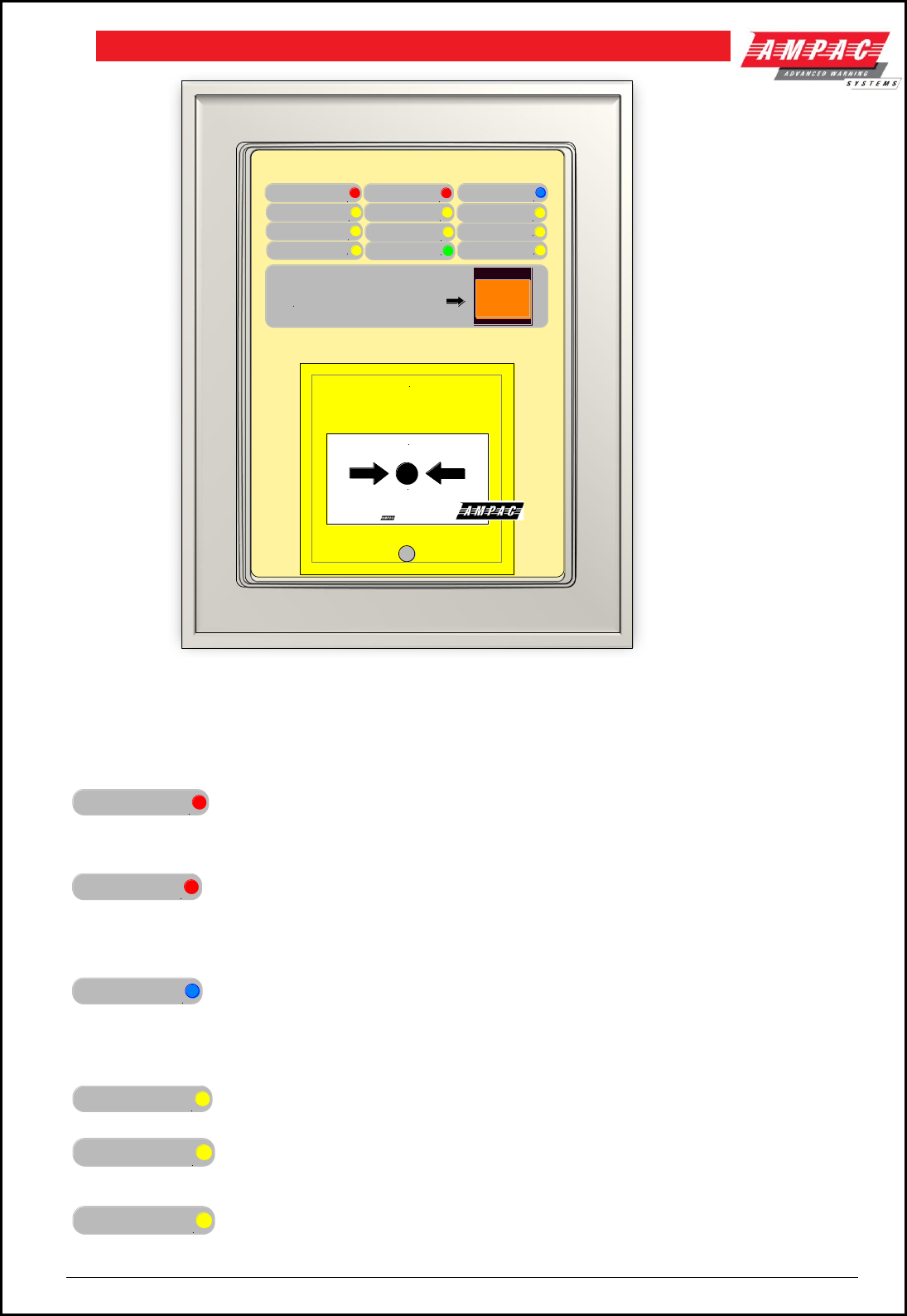
Page 57
FIREFINDERTM INSTALLATION COMMISSIONING & OPERATION
MANUAL
ACTIVATION AUTOMANTIC
ACTIVATION
LOCK OFF
VALVE INHIBITED
AGENT LOW
PRESSURE
INTERLOCK
STAGE 2
TIMER RUNNING
TRIGGER ZONE
ISOLATED
INITIAL AGENT
AGENT
DISCHARGED
AGENT CIRCUIT
FAULT
COMMON FAULT
RESERVE AGENT
AGENT
RELEASE
BREAK GLASS
PRESS HERE
TO INHIBIT AUTOMATIC AGENT RELEASE
LIFT COVER AND PRESS BUTTON
Figure 65: Local Control Station Layout
Common Agent Release & LCS Indicators
There are 12 indicators on both the Agent Release Module and Local Control Station. They are;
MANUAL
ACTIVATION
– Red Illuminated when a manual release sequence has commenced. Manual
release sequence can only be started by activating the manual release at the ACC or LCS.
Indicator is extinguished by initiating a “RESET” on the FACP.
AUTOMATIC
ACTIVATION
– Red Illuminated when an automatic release sequence has commenced. This
occurs when the selected zone(s) on the FACP have gone into alarm. For dual zones, the indicator should
flash when the first zone goes into alarm, and steady when the second zone goes into alarm.
Indicator is extinguished by activating RESET on the FACP.
AGENT
DISCHARGED
– Blue Illuminated when the pressure switch indicates the agent has been released.
For Pyrogen, feedback is from the thermal switch. If there is no pressure switch fitted, the indicator will be
illuminated immediately the agent release signal is activated (Selected via FACP on-site programming –
refer to relevant FACP Manual). Indicator is extinguished by activating RESET on the FACP.
LOCK OFF
VALVE INHIBITED
– Yellow Illuminated when the lock-off valve has been activated.
STAGE 2
TIMER RUNNING
– Yellow Stage 2 Timer Running Illuminated when the pre-discharge delay timer
is running. Indicator is extinguished by activating the RESET control on the FACP.
AGENT CIRCUIT
FAULT
– Yellow Illuminated when there is a fault on the monitored Main or Reserve
activation circuits. Eg S/C or O/C.
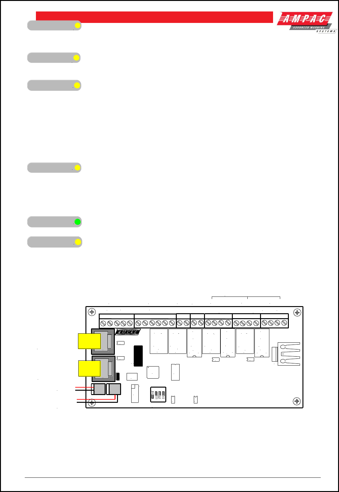
Page 58
FIREFINDERTM INSTALLATION COMMISSIONING & OPERATION
AGENT LOW
PRESSURE
– Yellow Illuminated when the low pressure switch is activated.
This indicates a leakage at the agent cylinder. The low pressure switch is a separate
switch. It is not the same pressure switch as used for the agent discharged indicator.
TRIGGER ZONE
ISOLATED
– Yellow Illuminated when any of the programmed trigger zones on the FACP are
isolated.
COMMON FAULT
– Yellow Illuminated under the following fault conditions;
pressure switch monitoring fault,
low pressure switch monitoring fault,
lock-off valve monitoring fault,
activation circuit fault,
stage 1 output fault,
stage 2 output fault,
LCS fault (missing or extra),
trigger zone(s) fault,
low agent pressure and interlock fault.
INTERLOCK
– Yellow Illuminated when the interlock input (eg from dampers, doors etc) is off
during the discharge sequence – meaning the dampers, doors etc are not closed as they should be or a
fault exists. The “Interlock” is overridden after 10 seconds and the agent is released
Note: The Interlock is a Monitored Input and can be defaulted to the ON position by terminating
the input ( TB2 7 & 8 ) into a 2.2K
EOL resistor.
INITIAL AGENT
– Green Illuminated when the “ Initial“ Agent is selected.
RESERVE AGENT
– Yellow Illuminated when the “ Reserve “ Agent is selected.
10.5 Agent Release Termination Board BRD25ATB
Figure 66: Agent Termination Board PCB Layout
The Agent Termination Board interfaces to;
1. The FACP via CN1, CN2 continuing the RS485 communications bus if required. LK1 is
inserted if this is the last backpan board on the bus.
2. LCS’s ( up to 4 ) via TB1. LK1 is inserted in the last board in the RS485 Bus
LK1
Q2
SW1
U5
U9 U7
U1
X1
RL6
RL4
RL1 RL2 RL5 RL3
CN5
U3 U4 U2
U10
RL7
+ LOCK-
+ L.PSW-
RELEASE
C
NC NO
///
+L
COMM
NC
NO
-L
C
NC NO
///
-
+
SIG+SIG-
LCS CABLE
+ PSW -
Monitored
INPUTS
N/0
STAGE2
GAS
FIRED
+-N/0 COMN/0 COM +
SYST.
INOP.
SCRN
+24VDC + -
C
NC NO
///
C
NC NO
///
-L
NO
NC
COMM
+L
-L
NO
NC
COMM
+L
03/09/02
0VDC + -
STAGE1
-
COM
302-7870
TB7TB6
TB5TB4TB3
TB2TB1
C
N
2
C
N
1
Address Setting
CN3 CN4
27V In
27V to
Next Board
RS485 Control
In From CN2 of
Previous Board
or CN21 of the
Main Control
Board
RS485 Control
Out to Next
Board or Link 1
EOL is Applied
MAIN RESV
+ - Outputs are Monitored
Contact
Rating
1A & 24V
Contact
Rating
1A & 24V
Contact
Rating
1A & 24V
Contact
Rating
1A & 24V
1 2 3 4
ON
EOL
Termination
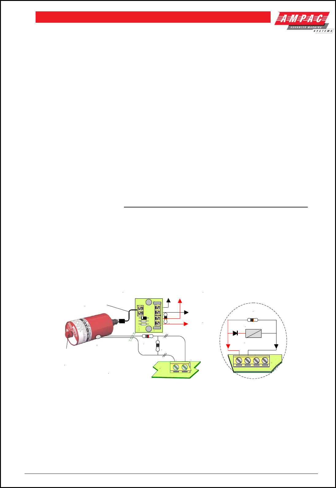
Page 59
FIREFINDERTM INSTALLATION COMMISSIONING & OPERATION
3. Monitored Inputs: via TB2. ( EOL Resistance 22K, Series Resistance
4K7 )
(a) Pressure Switch ( PSW ) agent released
(b) Low Pressure Switch ( LPSW ) agent storage cylinder pressure has dropped to a pre-
determined level; and
(c) Interlock, the manual lock-off valve has been operated.
4. Gas Fired: Output via RL2 N/O contacts rated at 1A @ 24VDC wired to TB3. Used to indicate
to other monitoring devices the agent has been released.
5. System Inoperative: via RL1 N/O contacts rated at 1A @ 24VDC wired to TB4. Used to warn
by way of signage / audible alarm and/or monitoring that the system is inoperative.
6. Stage 1: Output; initiates the visual and audible Fire Alarm and Evacuate warnings.
(a) Monitored; via RL4 C/O contacts wired to TB5 1 & 2 ( EOL required 10K ) and
(b) un-monitored; via RL5 N/O contacts wired to TB5 3 & 4.
7. Stage 2: output; initiates the visual and audible Fire Alarm and Do No Enter warnings
(a) Monitored; via RL6 C/O contacts wired to TB6 1 &2; ( EOL required is 10K ) and
(b) Un-monitored; via RL3 N/O contacts wired to TB6 3 & 4
8. Release: Main actuating circuit, monitored (10KΩ EOL required) via TB7 1 & 2 ( 2A current
limited ),
Release: Reserve actuating circuit, monitored (10KΩ EOL required) via TB7 3 & 4 ( 2A
current limited )
(a) To Pyrogen Igniter ( max of 10 )
(b) Metron Igniters ( max of 10 – a series 2watt 10
resister must be added to the circuit )
(c) Solenoid valve ( max current of 2 amps & 27VDC )
10.6 Interface Wiring
Monitored Inputs TB2 1 & 2
Pyrogen,
This input relies on a thermal fuse used in conjunction with 22K EOL and 4K7 series resistors.
The type of agent release mechanism has to be set in the Programming Menu for the input to
function as per the manufacturers specifications and be in accordance with the relevant Standard.
1 2
PSW
TB2
Termination Board
4K7 22K
EOL
Pyrogen
Canister
+ -
Pyrogen
Release
Point
FUSE
Pyrogen Release
Board 302-740
To TB7
MAIN or
RESERVE
Release
TB1
-VE
+VE
17/10/00
D1
R1
C1
C2
R2
TB2
302-7400
MAIN RESV
+ -
10K EOL
Solenoid
+ -
TB7
Alternative
Wiring to TB7
To Next 302-740 if Applicable
Place 10K EOL Across Last Board.
10K
EOL
* Keep cable length
to a minimum
Figure 67: Pyrogen Wiring
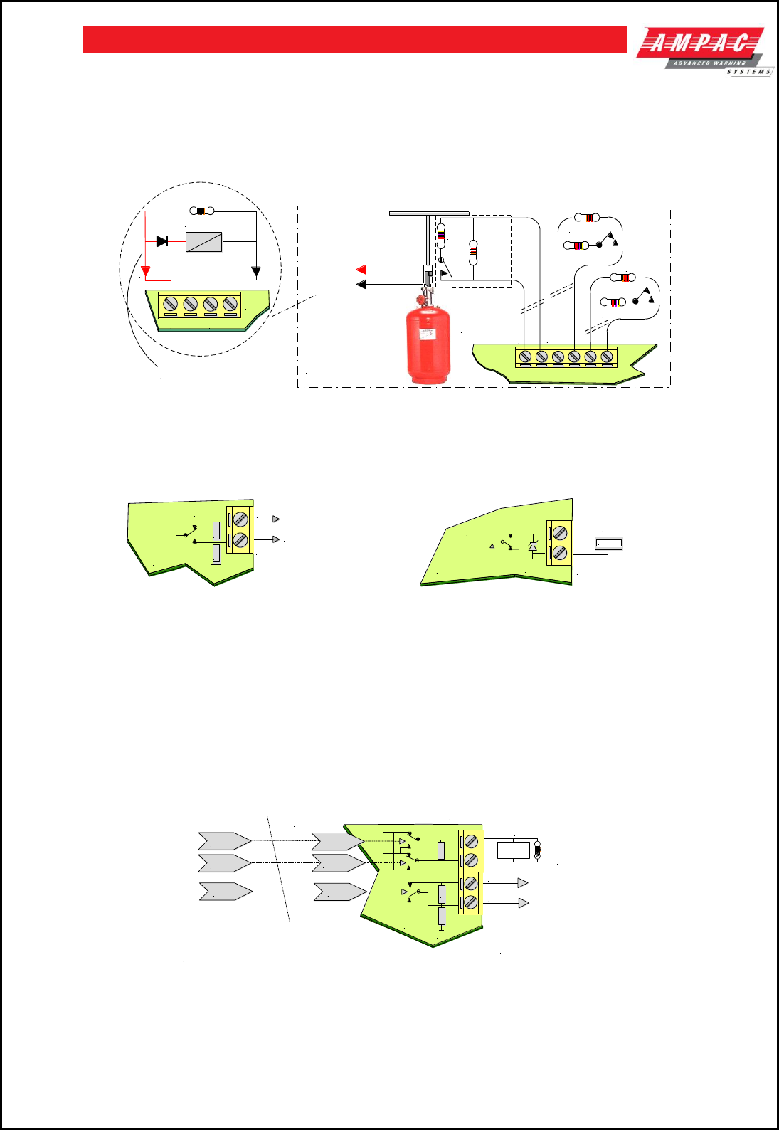
Page 60
FIREFINDERTM INSTALLATION COMMISSIONING & OPERATION
Solenoid & Metron
This input relies on N/O or N/C relay contacts used in conjunction with 22K EOL and 4K7 series
resistors. The type of agent release mechanism and contacts used has to be set in the Programming Menu
for the input to function as per the manufacturers specifications and be in accordance with the relevant
Standard.
Note: The PSW, LPSW & the Interlock Mechanisms are all
mounted onto the top of the cylinder containing the Agent
Termination
Board + -
4K7 22K
EOL
Agent
Distribution
4K7
22K EOL
LPSW LOCK
4K7
22K EOL
PSW
+ - + -
MAIN / RESERVE
RELEASE
To TB7
MAIN or
RESERVE
Release
Agent
MAIN RESV
+ -
10K EOL
Solenoid
+ -
TB7
For METRON
add a series 10ohm resistor here
*
*
Figure 68: Solenoid, Metron PSW, LPSW and “LOCK” Wiring
LPSW & Lock
These inputs are also monitored and should be wired as shown above
1
2
To Monitoring
Interface / Device
0V
RL2A TB3
= MOV
35V
*
*
*
To Sys
Inop Mon
+
-
Syst em Inop erative
1
2
0V
RL1A TB4
+27V Current
Limited to1A
Figure 69: Gas Fired Wiring Figure 70: System Inoperative Wiring
As can be seen from above the;
Gas Fired Output can be wired to any interfacing or 1A monitoring circuit that requires a closed relay
contact to indicate a change of state. This could be a relay or a solid state device.
System Inoperative Outputs 27V @ 1A to supply interfacing, signage and aural alarms to indicate the
system has been taken out of service or has developed a fault.
Stage 1, Stage 2
- ( + )
+ ( - )
*
0V
TB5 = Stage 1
TB6 = Stage 2
= MOV
35V
*
*
+ve
-ve
10K
EOL
1 or 2 Way
Signage
To audible / visual
device or interface
*
Stage 1 or Stage 2
RL3A
RL5A
RL4B
RL4A RL6A
Termination Board Relays
RL6B
1
2
3
4
The above circuitry applies to both
TB5 ( Stage 1 ) and TB6 ( Stage 2 )
TB5 / 6
Figure 71: Stage 1 and 2 Wiring

Page 61
FIREFINDERTM INSTALLATION COMMISSIONING & OPERATION
10.7 Warning Signs
Description
The warning signs are driven by a 2 wire system and may be configured for single or dual stage operation.
An on-board buzzer provides an audible warning which may be disabled by removing JP3.
External evacuation devices, eg sounders may be connected to TB3 of the input termination board. An
external mute push-button (N/O contacts) may also be connected to Term 3 on the warning sign PCB to
enable the user to silence the internal buzzer and evacuation device. Inserting JP4 disables this function.
Enclosures
The IP50 is a metal enclosure. The facia surround is fitted by removing the screw on the left hand side of
the enclosure and pulling it away to the left. The facia sign is fitted in place and the tabs bent over to hold it
in place. Two holes in the backpan of the chassis allow for mounting.
The IP65 ABS enclosure has 10 screws, tightened evenly but not over tightened, hold the facia in place.
Do not over tighten. 4 holes in the backpan allow for mounting.
Specifications:
Operational Voltage 28VDC
Power Consumption Continuous At 24VDC 55mA Stage 1
At 24VDC 140mA Stage 2 (100mA Muted)
IP Ratings IP50 ( Dim: 190H x 315W x 73D mm )
IP65 ( Dim: 200H x 295W x 65D mm )
Environmental -10˚C to +55˚C Dry heat
+40˚C @ 0 to 93% Relative Humidity
Installation
1. Remove the backpan from the enclosure to ensure it is not damaged while mounting the
enclosure.
2. Bring the cabling into the enclosure by removing the knockouts most appropriate for the
installation.
3. Mount the enclosure, remount thebackpan, set the configuration and then cable as per the
following diagram.
4. ENSURE THE AGENT IS ISOLATED and test from the Agent Release Module.
Cabling
Term 3 (Buzzer Mute)
BUZZER MUTE Normally Open [ N/O ] Push Button Switch (Optional)
INPUT
Term 4 ( Single pair polarity reversing / 2 Stage Input )
Stage 1
0V – 24VDC
Stage 2
24VDC – 0V
Configuration – Jumper Settings
JP 1 (Continuous / Flashing)
JP 2 (Single / Dual Stage)
1-2 Continuous
LED's Permanently ON
1-2 Single Stage
Full sign on for Stage 1&2
2-3 Flashing (DEFAULT)
LED's flashing at 1.5Hz
2-3 Dual Stage (DEFAULT)
Half sign on for Stage 1
Full sign on for Stage 2
JP 3 (Enable Buzzer)
JP 4 (Disable External Mute)
1-2 ENABLE BUZZER
(DEFAULT)
Buzzer activates for
both Stage 1 & 2
1-2 EXTERNAL MUTE
(DEFAULT)
Disable external mute for
internal Buzzer
JP 5 ( Enable External Evacuation Device ) [ not used ]
1-2 ENABLE EXTERNAL EVACUATION External evacuation device will activate on Stage 1 & 2
DEVICE (DEFAULT) with the tone dependent on the input polarity
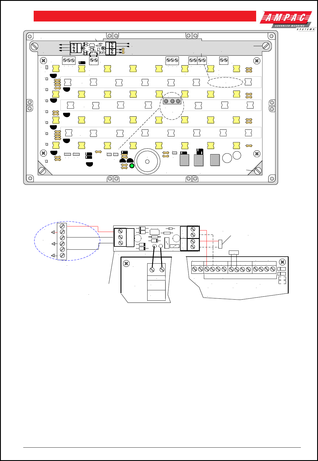
Page 62
FIREFINDERTM INSTALLATION COMMISSIONING & OPERATION
INPUT INPUT
LEVEL 2
LEVEL 1
COM +
- +
TONE 1
+ -
TONE 2
TERM 5 TERM
4TERM
6TERM
3TERM
1
OUTPUT
LEVEL 2
LEVEL 1
COM +
OUTPUT
- +
TONE 1
+ -
TONE 2
BUZZER
MUTE
OUTPUT
EXTERNAL
SOU NDER
SINGLE LEVEL
DUAL LEVEL
ENABLE
SOUNDER
(NOT USED)
ENABLE
BUZZER
DISABLE
EXT-MUTE
TP14
GND
TP9
TP8
TP7
TP13
TP12
TP11
TP10
TP1
GND
+
FLASHING
CONTINUOUS
ROW NOT USED
JP2 JP1 JP3
JP5 JP4
WARNING SIGN PCB
JP"X"
1 2 3
JUMPER
NUMBERING
BUZZER
TERM
2
ROW NOT USED
ROW NOT USED
TO N/O MUTE SWITCH
WARNING SIGN TERMINATION BRD
2 WIRE INPUT FROM AGENT TERMINATION BOARD
BUZZER MUTE
TO NEXT WARNING SIGN IF USED
FIT 10K EOL TO LAST SIGN (MAX 6)
10K
VANTAGE
SOUNDER
(MAX 1)
UNSCREW THE 4 SLOTTED
SCREWS TO REMOVE PCB
IN
-
OUT
+
+
-
CO M+
ST G1
ST G2
TB1
TB3
TB2
BRD 42WTB2-A
CN1/2
NO T
USED
BACKPAN RETAINING
SCREWS IN EACH CORNER
Figure 72: Warning Sign PCB Layout and Cabling
TERM 4
- +
TONE 1
INPUT
WARNING
SIGN
( MAXIMUM
OF 6 IN
TOTAL )
10K
1. (-) EVAC
2. (-) EVAC
3. (-) ALERT
4. (-) ALERT
5. (+) POS
6. (+) POS
VANTAGE SOUNDER
( ORDER CODE 205-0062 )
10K
FIT 10K EOL TO LAST
SIGN ON CHAIN
AGENT TERMINATION BOARD
RELEASE
-
+
STAGE2
+-N/0 COM
N/0 COM +
SYST.
+ - + -
STAGE1
-
TB7
TB6
TB5
TB4
MAIN RESV
+ - Outputs are Monitored
INOP
+ -
TONE 2
TO NEXT WARNING SIGN IF
MULTIPLE SIGNS ARE USED
BRD 42WTB1-A
IN
-
OUT
+
+
-
COM+
STG1
STG2
TB1
TB3
TB2
NOTE: THE WARNING SIGN
TERMINATION BRD IS MOUNTED
ON THE INSIDE BACK PLATE
OF THE WARNING SIGN
BRD 42WTB2-A
CN1 CN2
Figure 73: 2 Wire Cabling from the Agent Termination Board to the Warning Sign/s & Evacuation Device/s

Page 63
FIREFINDERTM INSTALLATION COMMISSIONING & OPERATION
11 Occupant Warning Systems
The EV20, EV40, EV60 and EV120 are compact single zone occupant warning devices that when
triggered produce Alert and Evacuation signals to meet the requirements of AS1670.4.
EV20
At the heart of an EV20 single zone occupant warning system is a microprocessor that generates the alert
and evacuation signals, controls timing and the input / output.
If an FACP warning system input is received when the rotary switch is in the AUTO position the EV20 will
begin to output the “Alert” signal for a duration determined by the setting of the 4 way DIL switch SW1. The
set duration is termed the changeover timeout and ranges from 0 seconds to a maximum of 300 seconds.
If the time out is set to 0 seconds then the alert signal is bypassed and the evacuation signal commences
immediately. The operator can manually stop the sequence by turning the rotary switch to the ISOLATE
position.
IC4 performs the task of an audio amplifier with TX1 providing the impedance matching to a 100 volt
speaker line. The alert and evacuation signal output Stages are set by adjusting RV1 and RV2
respectively.
Short or open circuit speaker faults are detected by the fault monitoring circuitry and will result in the
illumination of the FAULT indicator mounted on the front panel control module.
Public Address
A microphone and pre-amplifier (Order Code 222-0007) is used to provide the public address capabilities.
EV20 Verbal Messaging
An optional verbal messaging PCB (Order Code 222-0026) is available and is mounted directly onto the
main board.
EV40
At the heart of an EV40 single zone occupant warning system is a microprocessor that generates the alert
and evacuation signals, controls timing and the input / output.
If an FACP warning system input is received when the rotary switch is in the AUTO position the EV40 will
begin to output the “Alert” signal for a duration determined by the setting of the 4 way DIL switch. The set
duration is termed the changeover timeout and ranges from 0 seconds to a maximum of 540 seconds. If
the time out is set to 0 seconds then the alert signal is bypassed and the evacuation signal commences
immediately. The operator can manually stop the signal sequence by turning the rotary switch to the
ISOLATE position.
Amplifier 1 & 2 provides 40watts of audio output at 8 ohms which feeds TX1 to provide the impedance
matching to a 100 volt speaker line. The “ALERT” and “EVAC” Stage controls adjust the output Stage of
each set of signals.
Short or open circuit speaker faults are detected by the fault monitoring circuitry and will result in the
illumination of the FAULT indicator mounted on the front panel control module and “SPEAKER SHORT”
(red) or “SPEAKER OPEN” (yellow) LEDs on the main board.
Public Address
A microphone (Order Code 294-0001) is used to provide the public address capabilities.
EV40 Verbal Messaging
An optional verbal messaging PCB (Order Code 222-0013) is available and is mounted directly onto the
main board.
EV20 / 40 Verbal Message
Alert / Evacuation – “Emergency Evacuate Now”
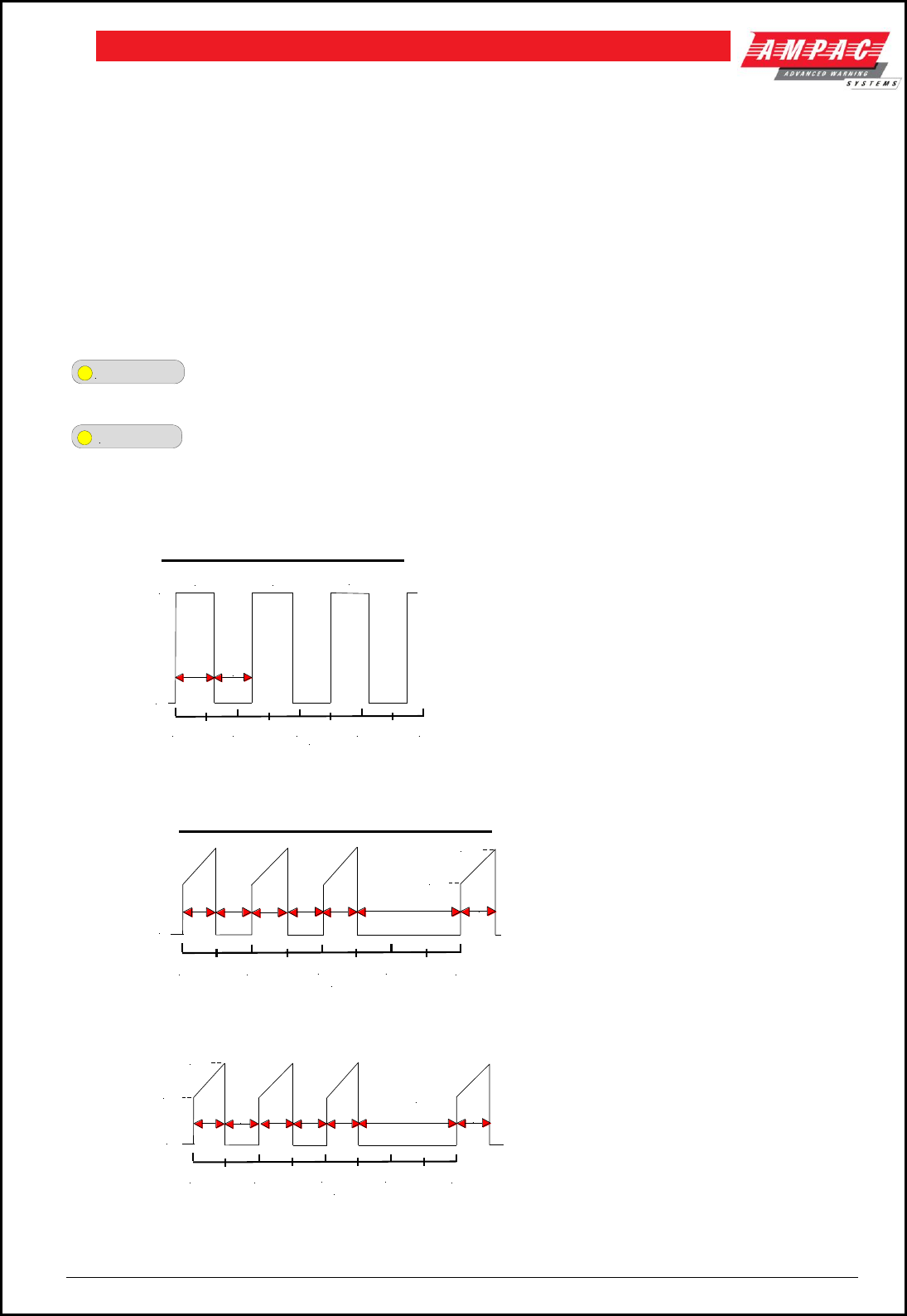
Page 64
FIREFINDERTM INSTALLATION COMMISSIONING & OPERATION
Control Module
When the control switch is in;
AUTOMATIC - occupant warning signals and if applicable verbal messaging is under the control of the
microprocessor and outputted to the speaker system when it receives a “warning system” signal from the
FACP.
ISOLATE – the occupant warning system is isolated from the FACP “warning system” signal and even if
the signal is present there will be no output.
PUBLIC ADDRESS – the occupant warning system can be used locally as a PA system.
MANUAL EVACUATION – the occupant warning signal/s will be transmitted over the system.
Indicators
LINE FAULT
- In the event of an open or short circuit speaker line the LINE FAULT indicator (yellow)
will be illuminated
ISOLATED
- the LED will be illuminated (yellow) when the warning system is isolated
Signal Structures
ALERT SIGNAL
0 1 2 3 4
0.625
sec 0.625
sec
ON
OFF
420Hz 420Hz 420Hz
Time in seconds
Australian AS1670.4 Alert Signal
AS1670.4:
420Hz pulsed on for 0.625 seconds
at 1.25 second intervals
EVACUATION SIGNAL
0 1 2 3 4
Time in seconds
OFF
500Hz
1200Hz
Australian AS1670.4 Evacuate Signal
0.5
sec
0.5
sec
1.5
secs
0.5
sec
0.5
sec
0.5
sec
0.5
sec
AS1670.4:
0.5 second sweep signal 500-1200
Hz for 2.5 seconds at 4 second
intervals
EVACUATE SIGNAL WITH VERBAL MESSAGE
0 1 2 3 4
Time in seconds
OFF
500Hz
1200Hz
0.5
sec
0.5
sec
"EMERGENCY
EVACUATE NOW"
1.5
secs
0.5
sec
0.5
sec
0.5
sec
0.5
sec
Figure 74: Alert & Evacuation Signal Structures
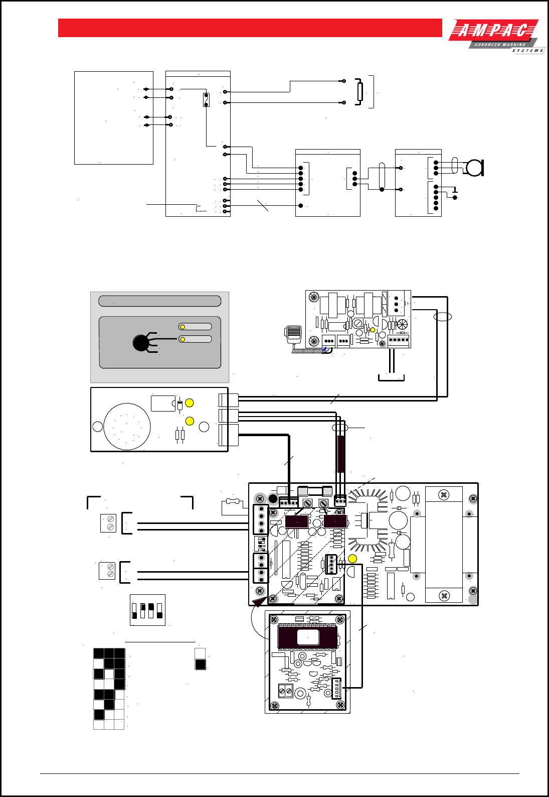
Page 65
FIREFINDERTM INSTALLATION COMMISSIONING & OPERATION
EV20 Cabling
WARNING
SYSTEM 2
1
ORANGE
GREEN
BLACK
PINK
RED
302-718
TB2
CN3
5
4
3
2
1
EV20 CONTROL
4
CN1
MANUAL EVAC
ISOLATE
COMMON 3
2
1
EVACUATION
SYSTEM
302-604A
3
4
2
1
TB2
-
+
1
2
TB1
EV20 222-0008
EV20
OUTPUT
+27V
47K
CN3
CN2
3
CN1 2
3
1
302-475
3
2
1
CN1
3
1
TB1
MIC PRE-AMP
CN2 3
2
1
4
5
+27V
PSU
BRIGADE
MONITOR
BOARD
TB5
5
3
4
TB2
COMMON
IF THE PA OPTION IS NOT
USED INSERT LINK ACROSS
PINS 1 & 2 OF CN3 3
2
1
IN
OUT
GND
47K IS PLACED ACROSS LAST
SPEAKER ON THE CIRCUIT
Figure 75: Typical EV20 & PA Wiring
Note: “WARNING SYSTEM” is a monitored O/P. The EOL is on board the EV20 and is effectively made to
be O/C (at TB1) during an EV20 fault condition. This produces the fault condition at the FACP.
ON
EXAMPLE OF
SETTING - 30SECS
( FACTORY SETTING "0" )
AND I/P SET TO
NON-LATCHING
0 ( EVAC ONLY )
30
60
120
180
240
300
ALERT ONLY NO CHANGE OVER
1 2 3 4
SW 1 2 3
SW1 TIME
OUT TABLE
4
LATCHING
NON-LATCHING
SW1/4 MUST BE SET
TO NON-LATCHING.
TB5
FireFinder
BRIGADE
PSU MON
BOARD
+27
VDC
3 4 2 1
TB2
WARNING
SYSTEM
( MONITORED )
S
E
C
O
N
D
S
+
-
1
1
1
2 CORE AUDIO TERMINATED ONE END
WITH 3 WAY PANDUIT CONNECTOR
+27V
SHEILD
261-0005 CABLE ASSEMBLEY
2 CORE AUDIO FITTED WITH
3 WAY PANDUIT CONNECTORS
RED .75mm (500mm)
BLACK .75mm (500mm)
GREY .22mm (500mm)
WHITE .22mm (500mm)
API-718
CN1
CN2
CN3
RL1
8
9
C
A
10
11
12
1
2
3
456
7
B
SW1
0V Pin1
+27V Pin 2
Shield Pin 3
Signal Pin 1
2 Core Audio
Shield
Signal
(Red)
F1 1A
GND
OUT
IN
AUDIO
TO VERBAL MESSAGE
BOARD
FAULT
+ IN - C OMEV
DC- DC+
TDA
2030
34
12
AMPAC
TIMER
BRD42ETG-01
O/P
TONE
VOICE
CTRL
C5
D4
CN2
CN1
CN3
U3
RV 1 RV2
SW1
+
C2
++ +
C14
C6
++
TB1
+
+
+
TX1
+
5 WAY PANDUIT
EVAC/ALERT
CONTROL
PUBLIC ADDRESS
PRE-AMP
NOTE: IF THE P.A. OPTION
IS NOT FITTED. FIT LINK ACROSS
CN3 PINS 1(IN) AND PIN 2(OUT)
-0V
47K
RES1093
+
-
FACP CONNECTIONS
RE C
PLAY
AM PAC
STD M SG3
EVAC MES SAG E
OPTIONAL VERBAL
MESSAGE BOARD
ORDER No 222-0013
5 WAY CABLE - MESSAGE
CONTROL 260-0027
FRONT
PANEL
CN2
D090 PHI LIPS
ON
1 2 3 4
+
+
TX1
TB1
TX2
RV1
+
LED1
+
*
O/P O/P
API-475/2
O/P O / P
TB1
CN1
CN3
ETH
MIC I/P
Shield
- + + -
VERBAL MESSAGE BOARD IS
MOUNTED ON STANDOFFS
ONTO THE MAIN BOARD IN THE
POSITION INDICATED ABOVE
FRONT PANEL PCB
Signal Pin 2
TONE
VOLUME
VOICE
VOLUME
LINE FAULT
ISOLATE
OCCUPANT WARNING SYSTEM
AUTOMATIC
PUBLIC ADDRESS
MANUAL EVACUATION
LINE FAULT
ISOLATED
Figure 76: EV20 Wiring to Control Module, FACP Cabling and Time Out Table
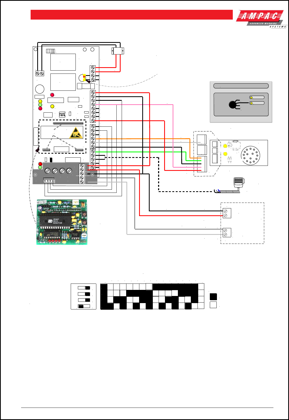
Page 66
FIREFINDERTM INSTALLATION COMMISSIONING & OPERATION
EV40 Cabling
FireFinder
BRIGADE
PSU MON
BOARD
+27VDC
NOTE:
Ensure F7
is 3Amps
1 2
1 2
TB2
WARNING
SYSTEM
MONITORED
TB5 +
-
MIC - OPTIONAL
ORDER SEPARATELY
RED +27V
BLACK 0V
GREY
WHITE
SYSTEM POWER
WARNING SYSTEM
+
-
D090 PH ILIPS
VOLUME CONTROLS
PAU PEV
TB1
PLUG IN VERBAL MESSAGE BOARD
( OPTIONAL ORDER SEPARATELY )
MICRO
TIMER
4321
ON
OFF
M/MAN
NOCF
PA2
CONT
SPEAKER OPEN
(YELLOW)
EV
PA1
AL
COM FLT
- +
TB3
FUSE
3A
TB4
AMP2
AMP1
SPARE
JUMPERS
o o o o o
o o o o o
A B
TB5
SPEAKER SHORT (RED)
CCT FLT
RELAY
ALM
PWR
o o
o o
o o
o o
o o
o o
NOTE 2: IF NO SPEAKER MONITORING IS REQUIRED
PLACE A 22K RESISTOR ACROSS TB4
TERMINALS 1 & 2 TO DISABLE OPEN CIRCUIT LED
8 OHM
40W LINE
TRANSFORMER
302-718
302-718A
14/8/00
o
o
o
o
o
o
o
o
o
o
o
o
o
o
o
o
o
o
o
o
o
o
100V IN
100V IN
MONITORED SPK OUT
MONITORED SPK OUT
+ 27VDC IN
- 27VDC IN
FAULT
FAULT
GND
ALARM
AL IND (0v SWITCH)
EV IND (0v SWITCH)
OUT CON (0v SWITCH)
+ 27VDC
GND
EV
AUTO
PA1
M1
GND
M2
PA2
EVACTRON
EV40
STATUS CONTROL
AL
22K
FRONT PANEL
PINK
RED
PINK
BLACK
GREEN
ORANGE
WHITE
BLACK
RED
MIC
CN3
CN2
CN1
TB2
1 2 3 4
ON
+
-
WARN
PWR
PWR
+
+
-
TERMINATION
BOARD
TB1
CN1
IN
OUT
ALERT EVAC MIC2 MIC1
MESSAGE BRD
MOUNTING SOCKETS
NOTE 1: "WARNING SYSTEM" IS A MONITORED FACP O/P. THE EOL
IS ONBOARD THE EV40 AND IS EFFECTIVELY MADE TO BE O/C
(AT TB1) DURING AN EV40 FAULT CONDITION. THIS PRODUCES
THE FAULT INDICATION AT THE FACP
VERBAL
MESSAGE
BOARD
OCCUPANT WARNING SYSTEM
AUTOMATIC
PUBLIC ADDRESS
MANUAL EVACUATION
LINE FAULT
ISOLATED
Figure 77: Typical EV40 Wiring to Control Module and FACP
ON
4
3
2
1
EVAC
ALERT
30
60
90
120
150
180
210
240
270
300
360
420
480
540
SECONDS
ON
ON
ON
ON
OFF
OFF
OFF
OFF
EVAC / ALERT = SEQUENCE GOES
STRAIGHT TO EVAC OR ALERT TONES
SW 1 - 4 = ON
SW 1 - 4 = OFF
TIME OUT TABLE
AND EXAMPLE OF
30SECS SETTING
(FACTORY SETTING
"0" SECONDS)
Figure 78: EV40 Time Out Table
Jumper settings
PEV: - PA + Evac – must be inserted when a selector switch is connected.
PAU: - PA in Auto – if inserted allows Mic 1 input (hand held microphone) to be used in “Auto”
(with no FACP alarm ) and paging in “Evac” mode.
PA2 CONT: - PA2 Control – if inserted allows the PA2 input to also switch the Control Output.
M2 1milli volt: - if inserted enables a 1mV microphone input for Mic 2, not inserted enables the
input for 100mV line level ( background music etc.)
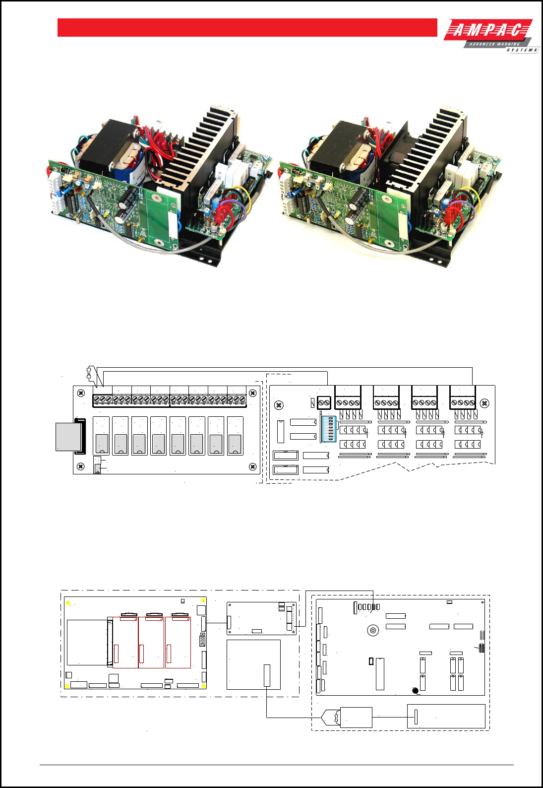
Page 67
FIREFINDERTM INSTALLATION COMMISSIONING & OPERATION
11.1 EV60 / 120
The EV60 & 120 are essentially an EV20 MPU and driver but with 60 and 120 watt output amplifiers
powered from a Current Limit Fuse Board.
Figure 79: EV60 EV120
11.2 EV3000
Relay Board Operation
One of the relays on the 8 Way Relay Board will be programmed to operate on “Alarm”. The subsequent
shorting of the 10KΩ EOL initiates the Alert / Evac sequence
CN1
TB2
TB1
RL9
N/O
C
N/C
RL10
N/O
C
N/C
RL16
N/O
C
N/C
RL15
N/O
C
N/C
RL14
N/O
C
N/C
RL13
N/O
C
N/C
RL12
N/O
C
N/C
RL11
N/O
C
N/C
O/P 1
N/C
CN/0
302-676x
O/P 2
N/0 C N/C
O/P 3
N/0 C N/C
O/P 4
N/0 C N/C
O/P 5
N/0 C N/C
O/P 6
N/0 C N/C
O/P 7
N/0 C N/C
O/P 8
N/0 C N/C
TO CN4
OR CN5
OR THE
1/0 BOARD
302-6720
RL1 RL2 RL3 RL4 RL5 RL6 RL7 RL8
5 Amp Version
Legend
1 Amp Version
RL9 N/O
C
N/C
RL1
F.I.P. INPUT
BOARD
INPUT
COMMON INPUT INPUT INPUT INPUT
16 15 14 13 12 11 10 9 8 7 6 5 4 3 2 1
CN1
CN2
IC41
IC40
IC39
SW1
IC38
IC37
TB5
IC9
TB4
TB3
IC18IC27
TB2 TB1
IC36
ON
1 2 3 4 5 6 7 8
RS485 IN
RS485 OUT
CN4 POWER OUT
10K EOL
8 WAY RELAY BOARD
FIREFINDER
EV3000
Figure 80: FACP / EV3000 Cabling Using Relay1 and I/P 1
HLI Interface Operation
The EV3000 Occupant Warning and Intercommunications System ( OWIS ) main central processing unit
communicates via a RS485 bus with a Controller Interface Card ( CIC ) in an FACP.
A fault in the EV3000 will be indicated by the Master Control Panel which in turn initiates, via the Common
Fault Relay Board and Brigade PSU Monitor Board, a Warning System Fault indication on the FACP.
MAIN CONTROL BOARD (BRD85MBA)
CN21
CN20
CN8
CN1
CN6
D13
CN3 CN5
CN2 CN7
CN11
CH16
CH15
CH6 CH8
CH2
CN16
CN14
CN18
RN17
RN20
CN4
CN10
CN15
CN13
CN17
c
ba
4 3 2
FRONT PANEL
EXPANSIO N LEDS
EXPANSION PANEL
MOD EM
27V IN
PRIN TER
LOOP
COMMS
1
CN1
CN2
1
SLAVE CPU
(302-6692)
CH8
CN1
CN2
1
CH8
CN1
CN2
1
SLAVE CPU
(302-6692)
SLAVE CPU
(302-6692)
U15
CN2
a b c
U11
U10
U14
U13
CPU BOARD
(BRD85CPU)
OUT
CTS
RTS
RXD
TXD
COM
SCR N
TRX-
TRX +
0V
+27V
TB3
CN1
TB2
TB1
CN3
302-7250
TIME OUT
SELECTION
SWITCH
API-422B
RESET
1 2 3 4 5 6 7 8
ON
CN17
CN16
CN15CN14
CN13
CN12
CN4
CN1
CN3
CN5
CN6
+
ON
876 5 4 3 2 1
CN10
CN11
CN7
CN8
CN9
SW 2
CN26
CONTROLLER
I/F CARD
OWIS EV3000 MAIN CENTRAL
PROCESSING UNIT
FireFinder
BRIGADE PSU
MONITOR
BOARD
TB5 1/2 (+/-)
WARN SYS
COMMON FAULT RELAY BRD
EV3000 MASTER
CONTROL PANEL
EV3000
CN18
10K
Note: The common fault methodology shown here is only
used in a combination EV3000 / FireFinder Panel.
302-673
Figure 81: HLI & Common Fault Cabling To & From the FACP and EV3000
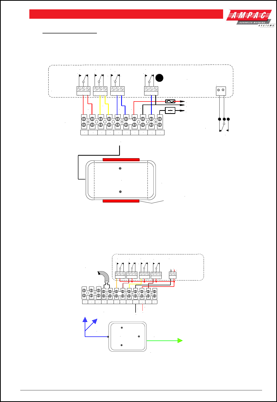
Page 68
FIREFINDERTM INSTALLATION COMMISSIONING & OPERATION
12 Brigade Devices
12.1 ASE ( Vic Metro ) Brigade Box
The ASE Brigade Box interfaces the Victorian Fire Brigade into the FireFinder™ SP series of FACP’s.
TERMINAL
BLOCK
ASE
BRIGADE
BOX
CABLE THE BRIGADE
BOX EARTH TO THE
CHASSIS EARTH IN A
STAR CONFIGURATION
ASE BRIGADE
BOX MOUNTING CLIP
RED
TB6
3
2
ALARM FAULT ISOL
TB8
32
TB7
3
2
N/C
CO M
N/0
123456
BRIGADE
PSU
MONITOR
BRD
78910
+ 27 VDC
111
CONTRACTOR
CONNECTIONS
3
2
BATT FAIL
TB10
1
N
NOTE: THE BATT FAIL RELAY
ON THE BRIGADE BOARD
IS NORMALLY ENERGISED
DURING NORMAL
OPERATION OF THE SYSTEM
HENCE TB10 2/3 WILL
PRESENT AN O/C TO THE I/F
1A
RL
1
COMMON
+ 27 VDC
BLACK
ASE
FAULT
CN6
5 6
RL/1
RED
YELLOW
BLUE
Figure 82: ASE FACP Internal Wiring
12.2 Brigade Box ( Deltec WA, SA, TAS,QLD )
The Brigade Box interfaces the Fire Brigade to the FireFinder™ SP series of FACP’s.
RED
BLACK
BRIGADE
BOX
BACKPAN
TELEPHONE
CABLE IN
TB6
3
2
ALARM FAULT ISOL
TB8
32
TB3
3
2
N/ C
COM
N/ 0
2
C
O
M
M
O
N
NOTE:
CABLE THE BRIGADE
BOX EARTH TO THE
CHASSIS EARTH IN A
STAR CONFIGURATION
+27V
0V
123456
BRIGADE PSU
MONITOR BRD
BRIGADE
BOX CABLING
78910 11 12
TB2
1
+
2
7
V
D
C
E
111
CONTRACTOR
CONNECTIONS
TB9
SPRINKLER
32
1
Figure 83: Brigade Box FACP Internal Wiring
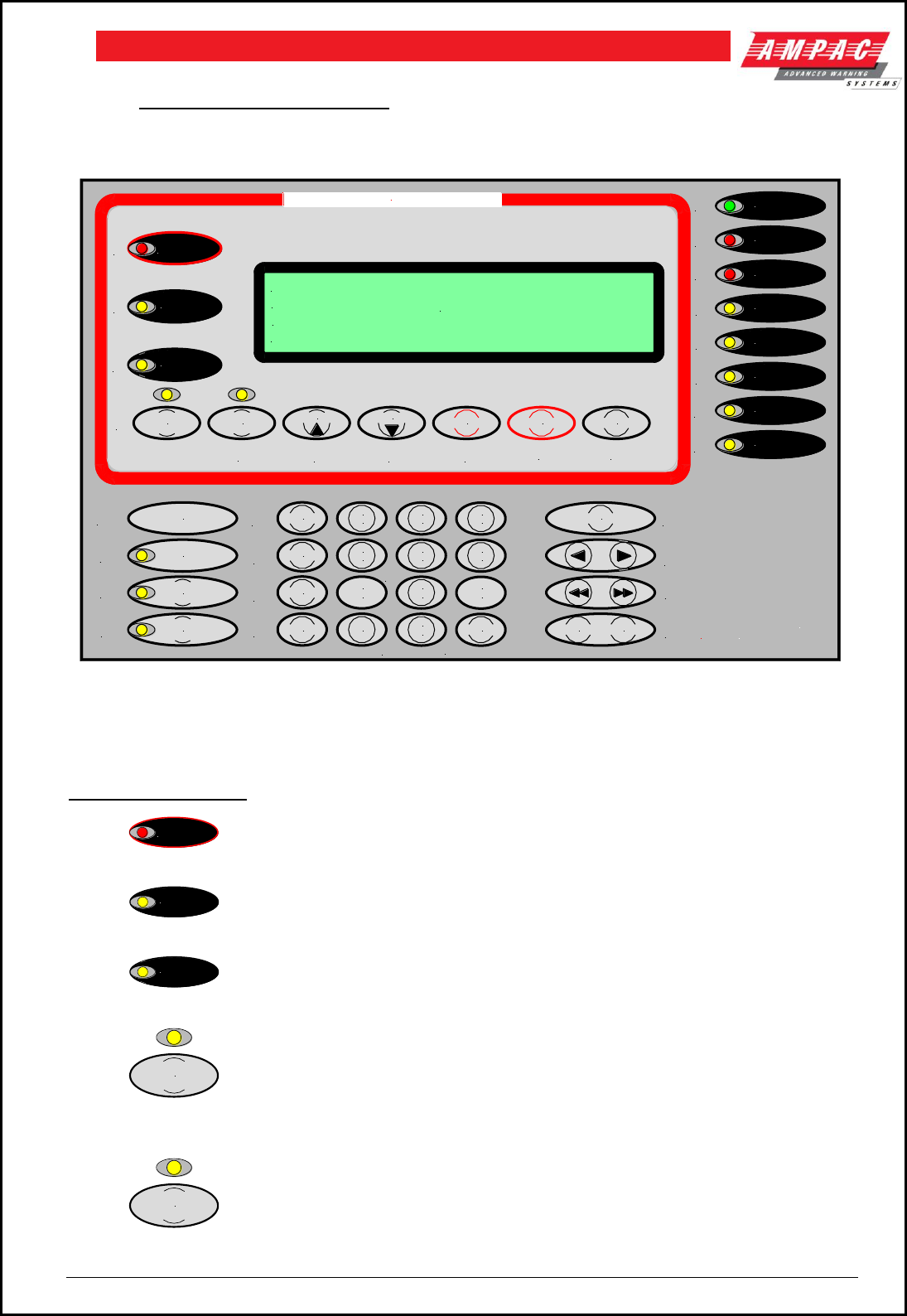
Page 69
FIREFINDERTM INSTALLATION COMMISSIONING & OPERATION
13 FireFinderTM Operation
13.1 The Control Panel
Figure 84: The FireFinder™ Control Panel with a 4 Line LCD
NOTE: The Italic numbers next to each of the Indicators and Keys / Buttons in the diagram above
relate to the explanations below.
FIRFIGHTER FACILITY
1.
ALARM
(Red): This LED will flash if any unacknowledged alarms are present on the system.
If all alarms have acknowledged it will light steady.
2.
FAULT
(Yellow): This LED will light steady if there are any faults on the system, whether
they are loop faults, module faults, device faults etc.
3.
ISOLATED
(Yellow): This LED will light steady if any detectors, devices or zones in the system
have been isolated.
4.
EXTERNAL BELL
ISOLATE
(Yellow): Pressing this button will isolate any bells connected to the fire panel If the
bell is isolated the LED just above the button will glow steady yellow. Pressing the button again will
de-isolate the bell.
5.
WARNING SYS
ISOLATE
Pressing this button will isolate the FACP output to the Warning System if it is
connected to one. Pressing the button again de-isolates the Warning System output. When the
Warning System is isolated the LED just above the button will be illuminated steady.
EARTH FAULT
TEST MODE
SYSTEM FAULT
SUPPLY FAULT
POWER ON
PRE-ALARM
AUX ALARM
WARNING
SYS FAULT
Finder
TM
Fire
WARNING SYS
ISOLATE
EXTERNAL BELL
ISOLATE
PREVIOUS NEXT
ACKNOWLEDGE
ISOLATERESET
ISOLATED
ALARM
FAULT
AUXILIARY
FAULT / ISOLATE
FAULT
OUTPUT ISOLATE
AIF
ACTIVE
DE-ISOLATE LOOP
1
ABC
2
DEF GHI
3
SENSOR
JKL
4
MNO
5
PQRS
6
ZONE
TUV
7 8
WXYZ
9
SYMB
TO
0
SPACE
ENTERDISPLAY
FUNCTION
MENU
CANCEL ENTRY
FIREFIGHTER FACILITY
FIREFINDER 15/1/2003 14:00:00
AMPAC
PH: 08 9242 3333
SYSTEM IS NORMAL
1
2
3
4
567 8 910
11
12
13
14
15
16
17
18
19
20
21
22
23
24
25
26
27
28 29
30
31
32
33
34

Page 70
FIREFINDERTM INSTALLATION COMMISSIONING & OPERATION
6.
PREVIOUS
Pressing this key scrolls the display backwards through the alarms,
faults, or isolates.
7.
NEXT
Pressing this key scrolls the display forwards through alarms, faults, or isolates .
8.
ACKNOWLEDGE
Pressing this key will acknowledge an alarm currently displayed on the LCD. It will
also silence the panel buzzer, which sounds whenever there is an alarm (optional) or fault.
9.
RESET
Pressing this key will reset the panel, clearing any acknowledged alarms and taking
the LCD display back to its default screen, unless there are any uncleared faults or isolated
devices, these will continue to be displayed.
10.
ISOLATE
This key is used to isolate individual or groups of detectors, devices or zones.
Indicators
11.
POWER ON
(Green): This LED will light when the mains power is turned on.
12.
PRE-ALARM
(Red): This LED will light when a sensor/detector is in the pre-alarm state.
13.
AUX ALARM
(Red): This LED will light if the auxiliary alarm output has been activated.
14.
WARNING
SYS FAULT
(Yellow): When a warning system is connected to the fire panel, this LED will
light if the connection to the warning system becomes faulty.
15.
SUPPLY FAULT
(Yellow): This LED will light if there is one of the following faults on the power
supply.
The output voltage is too low (less than 26.5V )
The output voltage is too high (greater than 28V )
The battery is not connected properly.
16.
EARTH FAULT
(Yellow): This LED will light if there is an incorrect earth on any of the signal
cables of the system.
17.
SYSTEM FAULT
(Yellow) This LED will light if the main system CPU is in fault.
18.
TEST MODE
(Yellow): This LED will light when the panel is in any of the test modes.
19.
DE-ISOLATE
If a detector currently displayed on the LCD has been isolated, pressing this
key will de-isolate it.
20.
FAULT
OUTPUT ISOLATE
( Yellow ): Pressing this button will isolate the fault output relay on the brigade
board. If the relay is isolated the associated LED will light. Pressing the button again will de-isolate
the relay.

Page 71
FIREFINDERTM INSTALLATION COMMISSIONING & OPERATION
21.
AUXILIARY
FAULT / ISOLATE
( Yellow ): Pressing this button or if the FACP is fitted with a
door switch and the door is opened the auxiliary output relay on the brigade board will be isolated.
If the auxiliary fault / isolate is isolated the associated LED will light steady. Pressing the button
again will de-isolate the auxiliary fault / isolate relay.
The auxiliary output line is monitored, should it go into fault, the LED will flash.
22.
AIF
ACTIVE
( Yellow ): Pressing this button will activate the Alarm Investigation Facility.
The LED just above the switch shall turn on.
23.
LOOP
Press this key followed by a number to select the loop you wish to access eg LOOP 4.
24.
SENSOR
After selecting the Loop number press this key to enter the sensor number for the device
to be interrogated.
25.
ZONE
Press this key followed by a number eg ZONE 4 to select the required zone.
26.
DISPLAY
Press this key after selecting the Zone number or the Loop and Sensor numbers to
display the state of the device.
27.
9
SYMB
These keys are used to navigate around the panel’s menus and enter data. If entering a
descriptor, or some other data that contains characters as well as numbers, pressing the keys
multiple times will scroll through the available letters written on the button, in sequence. Eg 1,A,B,C
28.
TO
Use this key to access a range of devices. Eg, 2 TO 7.
29.
ENTER
Press the ENTER key when using the panel, to enter data.
30.
CANCEL ENTRY
The CANCEL ENTRY key is used to delete data in a current field or return to
the previously displayed menu.
31. Used to move the cursor back and forth when entering data in a field.
32. These keys are used to move between fields when entering data.
33.
FUNCTION
MENU
Pressing the MENU key will display the main menu on the LCD. Similarly
pressing the FUNCTION key will display the function menu on the LCD.
34. LCD DISPLAY - This screen can be configured with the servicing companies name and phone
number. It also displays the current date, time and that the system is normal (no faults and alarms).
If there are any faults or alarms the LCD will display the device in question, if multiple detectors or zones
are not in their normal state, the PREVIOUS and NEXT keys are used to scroll through them.
FIREFINDER 15/7/2005 14:00:00
AMPAC
PH: 08 9242 3333
SYSTEM IS NORMAL

Page 72
FIREFINDERTM INSTALLATION COMMISSIONING & OPERATION
IMPORTANT NOTE:
It is strongly recommended that all field programming changes be properly recorded.
Function And Menu
13.2 The Default LCD Display
In its normal state the FireFinder™ will display a screen similar to that shown below.
FIREFINDER 15/7/2005 14:00:00
AMPAC
PH: 08 9242 3333
SYSTEM IS NORMAL
Figure 85: The Default LCD Display
This screen can be configured with the servicing company’s name and phone number via a laptop or
modem. The current date, time is set in the Function menu while system status is automatically displayed.
13.3 Accessing Functions and Menus
At Levels 2 and 3 access to the panel Functions are password protected.
A new panel has a pre-programmed password of 2222 for Level 2 and 3333 for Level 3. When the
customer takes control of the panel the password can be changed to suit their requirements.
NOTE: All menus are provided with screen prompts and a “Quick Reference Guide” ( see Section
24 ) guides the operator through the operation of the FAC .
13.4 Function Menu and Access Levels
Three levels of ACCESS are available. Level 1 has access to MENU only while Password protected Levels
2 and 3 access MENU and FUNCTION as listed below. ( also see the Quick Reference Guide, Section 24 )
Level II: Allows access to:
Date: Enter the Day, Month and Year (4 digit year).
Time: Enter the hours and minutes (24 hour mode).
Day/Night Settings: Enter the Day / Night ON times and Enable - Disable.
Logs: Fire Alarm, Fault, Isolate, System & Input / Output logs.
Tests: Walk and loop tests.
I/O: Sets the functionality of Input / Output devices.
Access: Password entry to Level 3
Level III: In addition to the Level I & II facilities, Add, Delete, Delete all passwords and Mode ( Zone /
Sensor ) onsite Programming.
13.4.1 Forgotten Passwords
Follow the following process if a password has been forgotten or misplaced;
a. entering 9999 into the password field;
b. take note of the 4 digit password number displayed on the screen; then
c. contact the AMPAC head office and quote the above number;
A temporary password will be issued and a new password can then be programmed into the FACP.
NOTE: The temporary password becomes invalid if 9999 is entered again or if the panel is re-
powered after 9999 has been entered.
FUNCTION
MENU
From the DEFAULT DISPLAY, press MENU or FUNCTION. The FUNCTION
menu is password protected (actually a pass-number as it can only contain
numbers) to prevent unauthorised changes to the panel's configuration.

Page 73
FIREFINDERTM INSTALLATION COMMISSIONING & OPERATION
14 The Main Menu
The MAIN MENU is accessed by pressing MENU.
FUNCTION
MENU
MAIN MENU
0: ALARMS 1:PREALARMS 2: FAULTS
3:ISOLATES 4: STATUS 5:TEST
SELECT NO.
Figure 86: The Main Menu
Pressing the appropriate number on the keypad while in the MAIN MENU the user can view any;
FIRE ALARMS;
PRE-ALARMS,
FAULTS; Pressing brings up a sub-menu from which a more detailed description of the fault
can be displayed. With a Fault present select a field ( to ) to view details of the fault.
Zones
Sensors
Loops
Modules
Power
Supply
Brigade
Test
Failures
Bells
ISOLATES on the system.
If there are no alarms, pre-alarms, faults or isolates, a message, eg. NO ZONES OR SENSORS IN
ALARM, will be displayed for 1 to 2 seconds and then the display will return to the Main menu.
14.1 Status Menu
Is pressed to access the STATUS MENU.
STATUS MENU
0: LOOPS 1: MODULES 2: I/O
3: SYSTEM 4:AVALUES
SELECT NO.
STATUS MENU
0: LOOPS 1: MODULES 2: I/O
3: NETWORK 4: SYSTEM 5:AVALUES
SELECT NO.
FACP WITH NETWORKING
FACP WITHOUT NETWORKING
Figure 87: The Status Menu
From the STATUS MENU the status of system components and settings can be selected and displayed as
listed below. Note that different screens are displayed for a system with and without networking.
Press
Loops: Enter the loop number and the LCD will display its status, eg normal, type of fault etc.
Press to print all devices on the loops ( Press RESET to stop printing )
Press to print totals of the loops ( Press RESET to stop printing )
Modules: Select the type of module, Slave , P/S , Brigade or External LED Mimic
and follow the screen prompts to display the status of the selected field.
I/O: The LCD will display the status of an input or output in a panel or on a loop.
Press to display Output status – IN A PANEL or ON A LOOP
Press to display Input status - – IN A PANEL or ON A LOOP
Once the above is selected follow the prompts and enter the;
i) I/O controller number then the input or output on that controller or,
ii) loop, sensor and output number on that device.
The LCD will display if it is configured and if so a description of what that input or output does
and its current state.

Page 74
FIREFINDERTM INSTALLATION COMMISSIONING & OPERATION
Network: Note: This option is only available if the system configuration is
networked.
Is pressed to access NETWORK STATUS.
DISPLAY NETWORK STATUS
0: NETWORK POINTS 1: REMOVE SLAVE MODULES
2: REMOTE EXTERNAL MIMIC MODULES
SELECT NO.
Figure 88: Display Network Status
Network Points:
DISPLAY NETWORK POINTS
0: STATUS 1: POWER SUPPLY 2: BRIGADE
SELECT NO.
Figure 89: Display Network Points
Network Points Screens are
Press
or
or
Status
Power Supply
Brigade
LCD
LCD
LCD
Displays
Select network point
Displays
Charger volts
Displays
Operational
Eg. Loop number
Battery Detected
Non- Op
Mains OK
Remote Slave Modules:
Select from Network Status Remote Slave Modules, then Module number, then ENTER .
Apollo Loop No: 1
TYPE: APOLLO LOOP NO: 1 VER: 6.2
NP: 1 MOD: 1 STAT: NORMAL
REMOTE MODULE STATUS
Figure 90: Display Remote Module Status
Remote External LED Mimic Modules:
Select from Network Status Remote External LED Mimic Modules, then NP number, then ENTER, then
External LED Mimic number, then ENTER
Is pressed to access SYSTEM STATUS.( If the system configuration is not networked Press )
SYSTEM STATUS
ALARMS: 0000 PREALARMS: 0000 ISOLATES: 0000
SENSOR FAULTS: 0000 MOD FAULTS: 0000 WDOG: 00
LOOP FAULTS: 00 VERSION: 6.0.30/AS4428
Figure 91: System Status

Page 75
FIREFINDERTM INSTALLATION COMMISSIONING & OPERATION
A Values:
Is pressed to access AVALUES. Enter Loop number, then ENTER , then Sensor number, then
ENTER . ( If the system configuration is not networked Press )
Loop 1 Sensor 1 SMOKE
L1 S1 Z2 STAT: NORMAL
AVALUE: 25 MODE: 0 1: 000 O: 000
Figure 92: Analogue Values
14.2 Testing Menu
Is pressed to access the ALARM, FAULT AND LAMP TESTING MENU.
TESTING MENU
0: ALARM 1: FAULT 2: LAMP
SELECT NO:
Figure 93: The Testing Menu
14.2.1 Alarm Test
Important: Ensure “Alarm” outputs are isolated / inhibited before commencing the test.
is pressed to initiate an Alarm Test: Alarm tests either a zone or a sensor on a loop or a range
of zones or sensors on a loop if the
TO
key is used, eg, ZONE 1
TO
3.
This test will force a zone/s or sensor/s to go into the Alarm state or a conventional zone to a
simulated Alarm condition. Pressing ENTER initiates the test.
ALARM TEST
0: ALARM 1: SENSOR
SELECT NO:
ALARM TEST
ZONE
SELECT NO:
select ZONE NO. then ENTER or TO key
Figure 94: Alarm Test Selection Screens
14.2.2 Fault Test
is pressed to initiate a Fault Test: Fault tests either a zone or a sensor on a loop or a range of
zones or sensors on a loop in the same way as for the Alarm test above.
This test will force a sensor to go into the Fault state or a conventional zone to a simulated Fault
condition. Pressing ENTER initiates the test.
FAULT TEST
0: ALARM 1: SENSOR
SELECT NO:
FAULT TEST
ZONE
SELECT NO:
select ZONE NO. then ENTER or TO key
Figure 95: Fault Test Selection Screens
Once the above tests have been completed the TEST FAILURE screen will appear. Each ALARM
and FAULT that was detected can be viewed by scrolling through them using the
NEXT
and
PREVIOUS
keys. If an Alarm or Fault was not detected a short message displays this result and the
screen returns to the Fault Test default screen.
14.2.3 Lamp Test
is pressed to initiate a Lamp Test: The test will sequentially flash the LED’s on the front panel
and illuminate the various segments on the LCD display.

Page 76
FIREFINDERTM INSTALLATION COMMISSIONING & OPERATION
15 Main Functions
LEVEL II MAIN FUNCTIONS
0: DATE 1: TIME 2: DAYNIGHT SETTINGS 3: LOGS
4: TESTS 5: I/O 6: ACCESS
SELECT NO:
LEVEL III MAIN FUNCTIONS
0: DATE 1: TIME 2: DAYNIGHT SETTINGS 3: LOGS
4: TESTS 5: I/O 6: PASSWORDS
SELECT NO:
Figure 96: The Level II & III Functions Menu
15.1 Setting the Function Date Facility
Select FUNCTION . A prompt will ask for a PASSWORD if the control panel is not currently active. Using
the keypad key in the Level 2 or 3 PASSWORD and press ENTER .
Press
to select the set DATE SCREEN. The prompt will ask for the date to be entered in this format,
DD/MM/YYYY ( EG 18/08/2005 ), key in and press ENTER . The screen will then return to the MAIN
FUNCTIONS MENU.
15.2 Setting the Function Time Facility
Press
then in the following format key in the time, HH:MM ( EG 16:00 ) using the 24 hour mode. Press
ENTER and the screen will return to the MAIN FUNCTIONS MENU.
15.3 Setting the Function Daynight Facility
Press
The DAY-NIGHT SETTINGS screen will appear. Time entry is the same as setting the “Time” facility
Press
to enter the DAY ON time then ENTER and,
to enter the NIGHT ON time then ENTER .
to ENABLE / DISABLE then ENTER .
For this Function to have control it must be ENABLED, press Re-pressing will
toggle to DISABLE.
15.4 Function Logs Facility
Press
and the EVENT LOG MENU will be displayed.
The LOGS MENU allows the operator to select and view the events that have occurred of all;
Press: ALARM, FAULT, ISOLATE, SYSTEM
EVENT LOG MENU ( MAXIMUM SIZE = 1162 )
0: ALARM 1: FAULT 2: ISOLATE 3: SYSTEM
4: I/O
SELECT NO:
FAULT LOG 7/7 11/7/2005 14:56 05
SUPPLY FAULT
ST: EARTH FAULT
SELECT 0: PRINT ENTRY 1: SHOW OPTIONS
Figure 97: Logs Function Menu & Fault Log Selected
Once the type of log is selected, eg. FAULT above, each entry can be viewed by stepping through them
using the
NEXT
and
PREVIOUS
keys

Page 77
FIREFINDERTM INSTALLATION COMMISSIONING & OPERATION
The type of log, number and totals logged, date and time of the ALARM, FAULT,
ISOLATE, SYSTEM or I/O as well as device information will be displayed. The SYSTEM screen displays
events and watchdog activity. From these screens the operator can select two other facilities, they are;
Press
PRINT ENTRY will print out the displayed information if a printer is installed, or
SHOW OPTIONS allows the operator to select how the Logs are viewed.
Press
to VIEW BY ENTRY NUMBER or to VIEW BY DATE. In each case the screen
will ask for the appropriate information ( ENTRY NUMBER or DATE ) to be entered before
the selected option will be displayed.
NOTE: it is possible to scroll through the alarms by using the PREVIOUS and NEXT keys.
15.5 The Function Test Facility
Press
TESTS: prompts the operator to select either the WALK or LOOP test.
Press
WALK TEST; the operator will be prompted to select either ZONE or SENSOR test.
Press
ZONE WALK TEST MENU;
This screen requires the operator to select a Zone or number of Zones to be tested, that is enter the
Zone number press ENTER or enter the Zone number press TO then the next highest
Zone number to be tested EG. 2 TO 7 then ENTER.
The TEST MODE LED will be illuminated for the duration of the test and the test will run until the
operator RESETS the system or the test times out [Time Out = 15 minutes + 3 to 5 seconds].
Press
SENSOR WALK TEST MENU
This screen requires the operator to select a Zone and then a Sensor or number of Sensors
(using the TO key) to be tested then pressing ENTER to start the test.
The TEST MODE LED will be illuminated for the duration of the test and the test will run until the
operator RESETS the system or the test times out [Time Out = 15 minutes + 3 to 5 seconds].
Press
LOOP TEST requires the operator to select a LOOP for DIAGNOSTIC TESTING
Entering the LOOP number and pressing ENTER will initiate the DIAGNOSTIC TEST.
NOTE: The LEDs on the Brigade Board will indicate which leg is being tested.
The tests displayed are;
TESTING SIDE A IDENTIFING DEVICES on SIDE A, and
TESTING SIDE B IDENTIFING DEVICES on SIDE B.
Once the testing is completed the final screen will display the number of devices found and tested
on the LOOP and a Reset is requested to return the system to normal.
NOTE: If the data is not entered within 2 minutes the screen will time out and return to the
DEFAULT SCREEN.

Page 78
FIREFINDERTM INSTALLATION COMMISSIONING & OPERATION
15.6 Function Manual I/O Control
Press
to display the Manual I/O Control menu
MANUAL I/O CONTROL
0: INPUT 1: OUTPUT
2: REMOVE MANUAL CONTROL
SELECT NO.
Figure 98: The Manual I/O Control Menu
Manual I/O control allows the technician to turn ON or Off inputs and outputs off a device to facilitate
testing or isolation of plant during maintenance. Removal of manual control returns control to the panel.
Press
Input Selected:
Press
IN A PANEL: Enter the I/O Controller number then the input number . This will
display the description for the input and its current state, you can then turn the input
ON or OFF or remove manual control.
ON A LOOP: Enter the loop number , the sensor number and the input number.
This will display the description for the input and its current state, you can then turn
the input ON or OFF or remove manual control.
Remove All Manual Input Control: Will remove all manual input control.
Output Selected: Same sequences as above for inputs but
substitute outputs for inputs.
Remove All Manual Control Selected: Globally removes all manual control.
15.7 Function Access ( Level II ) / Passwords ( Level III )
FUNCTIONS
PASSWORD
select PASSWORD then ENTER key
PASSWORD MENU
0: ADD PASSWORD 1: DELETE PASSWORD
2: DELETE ALL PASSWORDS 3: SENSOR MODE
SELECT NO.
Figure 99: The Level II Password Entry & Level III Password Menu Screens
Press
while in the Main Functions menu and enter the Level III Password if in Access Level II or, if in Access
Level III to display the Password Menu.
Add Password: Enter the new password, then press ENTER . The password is always a
4 digit number.
Delete Password: Enter the password that you want to delete, then press ENTER.
Delete All Passwords: This asks you to confirm that you want to delete all the passwords.
Press ENTER then ENTER again.
Zone / Sensor Mode: This sets the mode in which Alarms, Faults, Prealarms and Isolates
status information will be displayed. “Zone” is the default setting.

Page 79
FIREFINDERTM INSTALLATION COMMISSIONING & OPERATION
15.8 Function Programming
Press
to display the Level III Programming Menu.
ON SITE PROGRAMMING MENU
0: CONV ZONE 1: DEVICE 2: INPUT 3: OUTPUT
4: PANEL BASED MCP 5: SUB ADDRESS 6: WDOG
SELECT NO.
Figure 100: The Programming Menu
15.8.1 Conventional Zone Programming
Press
Zone:
Key in the zone number and enter or change the description ( DESC ) by pressing the numeric
buttons multiple times to access characters while at the same time using
EDIT Zx DESC AND TYPE SETTING
DESC < ZONE >
TYPE <
ALPHA KEYS ARE ACTIVE
Figure 101: Zone Description & Type Programming
EDIT Z CONFIGURATION
CONFIG LATCHING
use < or > to change alarm setting
Figure 102: Brigade Options
Press to move to the TYPE field or edit the information.
Press to move between fields use the reciprocal button
By going through all the fields a second screen can also be accessed to show the Output options.
Press to step through these fields.
The keys are used to set the Y/N field, that is the selected Zone that will activate
the Brigade Options ALRM, BELL etc and Config.
EDIT Z I/O GROUPS
GROUP 1: GROUP 2: GROUP 3:
GROUP 4: GROUP 5: GROUP 6:
Enter GROUP NO:
Figure 103: Zone Configuration Latching / Unlatching
Use or to change the setting
Configuration settings are Latching, Non-Latching, AVF, Self Reset ( 0 to 99 seconds ). After
setting the Configuration the ZONE I/O GROUPS are programmed.
ENTER Zx BRIGADE OPTIONS AND CONFIG
ALRM: Y/N BELL: Y/N AUX: Y/N SPK: Y/N AIF: Y/N
ALARM LED: Y/N CONFIG: LATCHING
use < or > to change setting
Figure 104: Zone I/O Groups
After scrolling through the groups and entering what I/O GROUPS will be turned on by what module/s or
device/s in a zone/s the operator is prompted to press ENTER to confirm the entries and / or changes.
buttons to move the flashing underline or curser.
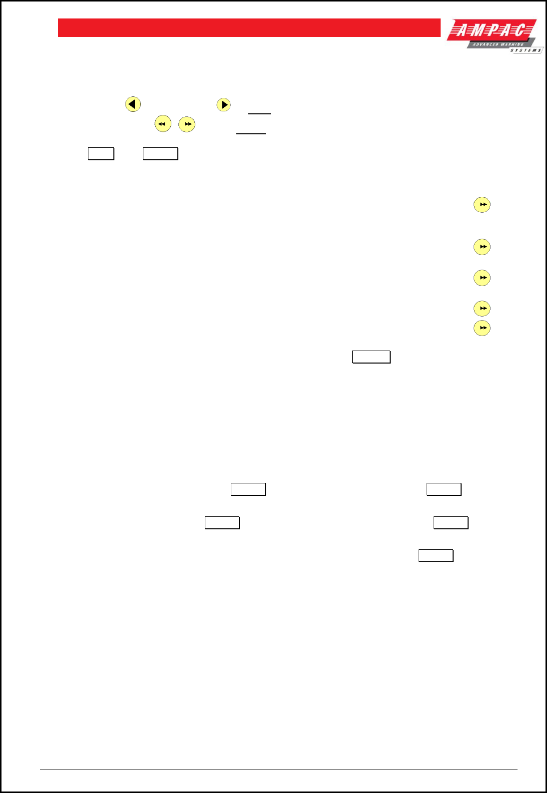
Page 80
FIREFINDERTM INSTALLATION COMMISSIONING & OPERATION
15.8.2 Device Programming
Press
DEVICE:
Screen: use these keys
to EDIT and move through wording &
these
keys to MOVE between fields ie: DESC & TYPE and next parameter
Enter the Loop and Sensor number then scroll through the following screens.
Press or Press
to EDIT or to DELETE
1. EDIT LxSx DESCRIPTION AND TYPE STRING. Edit then press.
eg: DESC Loop 1 Sensor 1
TYPE SMOKE
2. Allocate / Edit the Sensor to a Zone and set the device type then press.
eg: XP95 Photo, XP95 Heat etc-
3. Set /Edit and display the Output Configurations or options then press.
eg: Latching, AVF, Non-latching etc
4. Set / Edits and enables / disables the day/night settings then press.
5. Allocates / Edits the Loop and Sensors Groups.
After scrolling through the groups a prompt tells the operator to press ENTER to confirm the changes.
15.8.3 Input Programming
Press
INPUT:
By following the screen prompts as above Edit or Delete an INPUT in a panel or a loop.
Screen: PROGRAM MENU SELECTING AN INPUT
IN A PANEL
ON A LOOP
I/O MODULE
LOOP
Select I/O MODULE NO. then ENTER
Select LOOP NO. then ENTER
INPUT
SENSOR
Select I/P NO then ENTER
Select SENSOR NO. then ENTER
EDIT / DELETE DESC
INPUT
Select INPUT NO. then ENTER key
ALPHA KEYS ARE ACTIVE
EDIT LxSxI/Px DESC STRING DESC
15.8.4 Output Programming
Press
OUTPUT:
By following the screen prompts as above Add, Edit or Delete an output in a panel or on a loop.

Page 81
FIREFINDERTM INSTALLATION COMMISSIONING & OPERATION
15.8.5 Manual Control Point ( MCP )
Press
MCP:
The operator will be prompted to enter the NODE Number, that is the Node or panel on which the
MCP is mounted.
15.8.6 Sub Address
Press
Sub Address lets the operator EDIT or DELETE the address of an IO device on a Loop.
Note: an input is the only function that can bring up an alarm.
Select the LOOP, then ENTER, SENSOR, then ENTER then the SUBADDRESS ( eg 1, 2 or 3 for
3IO device ), or press to EDIT or press to DELETE.
Editing
If editing, the screen will display the Loop number, Sensor number and sub address followed by
DESC < TYPE < INPUT > and advise the Alpha keys are active. Once edited and pressing
ENTER the message UPDATE TO MEMORY message will be displayed.
ENTER should not be pressed if the CONFIGURATION is to be edited, instead press to go
to the next screen where the output is configured to be latching (general alarm requiring a Reset to
be returned to normal ), NON-LATCHING ( hence self resetting ) or FAULT which clears when the
fault is cleared. )
15.8.7 Watchdog
This Function provides a counter to record any re-initialisation of the processor. If due to a
software failure the panel is automatically reset then the counter will increment by 1 The maximum
count is 99 after which the counter resets to 00. Pressing will reset the counter. When the panel
is commissioned this counter MUST be reset to 0 as must be the Events Logs.
15.9 Self Learn
Self Learn is enabled / disabled in the EEPROM programming. If enabled FireFinder has the ability to
detect extra or missing modules or devices, (that is devices or modules that have been added or removed)
or there has been a change of the type of module or device.
Note: If a change does occur the FACP will take 30seconds to register the event on the LCD and
illuminate the FAULT LED.
15.9.1 Extra Devices Detected
The FireFinder LCD will indicate extra devices have been detected by displaying the screen below
and the FAULT LED will be illuminated.
FIREFINDER 4/7/2005 08:05:45
EXTRA DEVICES DETECTED
GOTO PROGRAMMING MENU TO RESOLVE
SYSTEM IS NOT NORMAL
Figure 105: Resolving Extra Modules And Devices

Page 82
FIREFINDERTM INSTALLATION COMMISSIONING & OPERATION
To resolve select FUNCTION, enter PASSWORD, press and the screen
below will appear
PROGRAMMING MENU
0: RESOLVE EXTRA MODULES AND DEVICES
1: ON SITE PROGRAMMING
SELECT NO:
Figure 106:Added Module Or Device
Select ( Selecting presents the PROGRAMMING MENU ) then or (as seen below) then
ENTER to ADD the module or device to the configuration, or skip to resolve the changes manually in the
Programming Menu.
0: ADD EXTRA MODULES 1: ADD EXTRA DEVICES
2: DEVICE TYPE MISMATCH 3: MODE MISMATCH
SELECT NO:
Figure 107: Resolving Extra Modules Or Devices
15.9.2 Mismatch Detected
If a mismatch is detected the Normal Default Screen will change to that shown below. Go to the
Programming Menu and select either Resolve Extra Modules and Devices then
( Device Type ) or ( Mode ) to resolve the mismatch, OR On Site Programming to resolve manually.
L1 S6 Z1 STAT: TYPE MISMATCH
ZONE FAULTS 1 OF 1
Loop 1 Sensor 1
Figure 108: Resolving A Mismatch
16 Incoming Fire Alarm Signal
Will operate the red common LED fire indicator
Will display location of fire alarm origin on the LCD
Will activate external alarm.
Will activate the internal FACP buzzer. (optional)
Will activate any ancillary equipment so programmed.
Will abort any test in progress.
The LCD will always display the first fire alarm signal received in the top section of the LCD. The lower
section of the LCD will also permanently display the most recent zone in alarm. Other essential fire alarm
information and fault or disablement information is available via the
PREVIOUS
and
NEXT
keys. After 30
seconds if no key is pressed the top section of the display will revert to displaying the first zone in alarm.
L1 S1 Z17 ALARM
5/7/2005 15:12:10
SENSOR ALARMS 1 OF 5
DETECTOR 1 SMOKE
Figure 109 LCD Screen With 5 Devices In Alarm
Note: The displayed information changes to that associated with the device as the PREVIOUS / NEXT
push buttons are pressed. If there is a fault condition or a fire alarm and the buzzer is sounding, press the

Page 83
FIREFINDERTM INSTALLATION COMMISSIONING & OPERATION
ACKNOWLEDGE button to stop it sounding
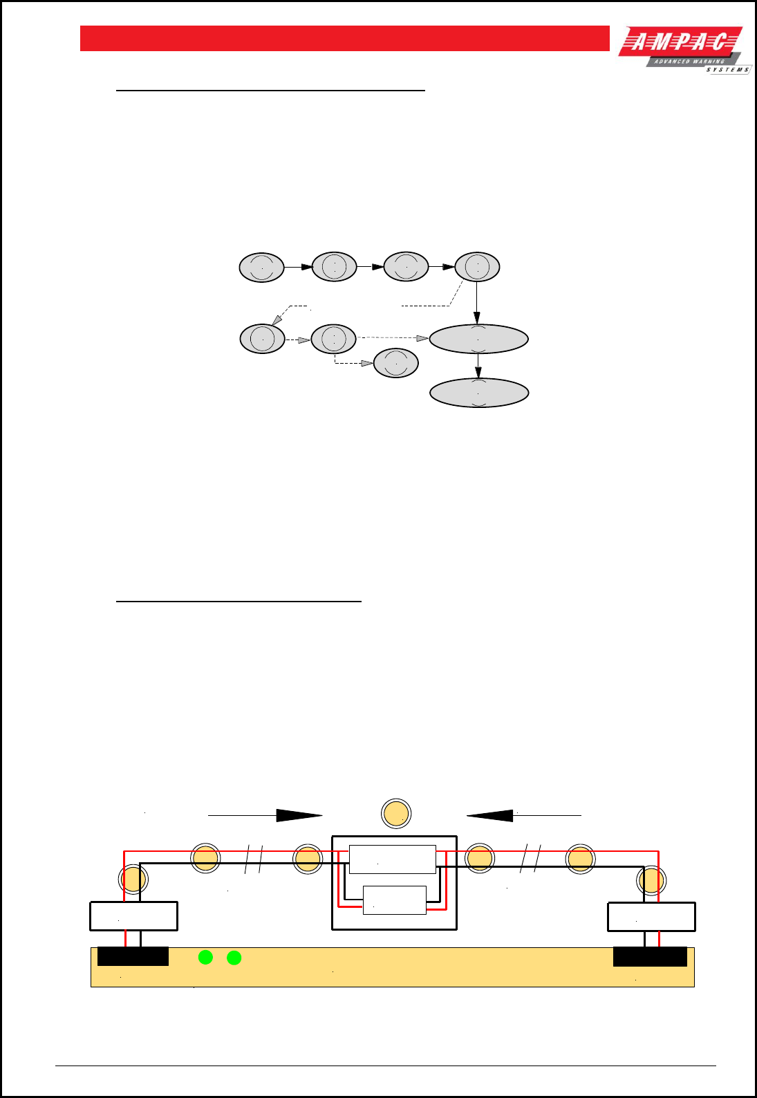
Page 84
FIREFINDERTM INSTALLATION COMMISSIONING & OPERATION
17 Accessing a Loop, Sensor or Zone
LOOP OR SENSOR
1. From the default display, press LOOP
2. Enter the loop number you wish to interrogate then press SENSOR.
3. Press the button for the sensor number.
4. Press the TO button if you wish to access a range of sensors on the loop,
5. Press the DISPLAY button if you wish to display the status of a sensor,
6. Press the ISOLATE button if you wish to isolate a sensor then ACKNOWLEDGE
7. Press the DE-ISOLATE button to de-isolate a sensor.
LOOP
1
ABC
SENSOR
JKL
4
TUV
7
TO
DISPLAY
For Multiple Devices
ISOLATE
ACKNOWLEDGE
Figure 110: Steps for Isolating Single and / or Multiple Devices
ZONE 1. From the default display, press ZONE
2. Press the button for the zone number.
3. Press the TO button if you wish to access a range of zones,
4. Press the DISPLAY button if you wish to display the status of a zone,
5. Press the ISOLATE button if you wish to isolate a zone then ACKNOWLEDGE
6. Press the DE-ISOLATE button to de-isolate a sensor.
18 List of Compatible Devices
18.1 Short Circuit Isolation
The Ampac modules listed above feature built-in Short Circuit Isolation that continually monitors the Apollo
detection loop. In the event the loop voltage drops below 14.0V DC, an open circuit condition is introduced
on the negative line of the loop. This action effectively isolates the short circuit condition, and allows the
device to function by drawing power from the unaffected side of the loop. The isolated section of the loop is
tested every four (4) seconds, and is automatically reconnected when a loop voltage of greater than 14 V
DC can be maintained.
Note: Should an OC/SC condition eventuate on a loop the LEDs A & B on the Loop Termination Board will
both be illuminated.
Figure 111: Short Circuit Isolation Block Diagram
Isolator Isolator
Isolator
Interface
Section A Section B
Direction of Current Flow Direction of Current Flow
Panel Loop Termination Board
L+ L- L- L+
Detectors
LEDs A & B
Loop 1

Page 85
FIREFINDERTM INSTALLATION COMMISSIONING & OPERATION
18.2 Compatible Devices
Description
Ampac Order Code
XP95 Analogue Thermal – ‘A’ & ‘B’
201-0001
Discovery Analogue Thermal ‘C’
201-0089
Discovery Analogue Thermal ‘D’
201-0090
XP95 Analogue Ionisation
201-0002
XP95 Analogue Photo Optical
201-0003
XP95 Analogue Universal Base
201-0004
XP95 Short Circuit Isolator
201-0005
XP95 S/C Isolator Base
201-0006
XP95 Input / Output Unit
201-0007
XP95 Sounder Control
201-0010
XP95 Zone Monitor
201-0012
XP95 Xpert Card (Nos. 1 – 126)
201-0013
XP95 Analogue Duct Probe inc. Detector
214-0004
XP95 1 Metre Inlet Tube
214-0005
XP95 Manual Call Point
213-0028
XP95 MCP Spare Glass
213-0030
XP95 Waterproof MCP
213-0034
XP95 Ionisation Black
201-0091
XP95 Photo Optical Black
201-0092
XP95 Universal Base Black
201-0093
Discovery Multisensor
201-0094
Discovery Carbon Monoxide Detector
201-0102
XP95 XPert Card blank
201-0095
Zone Interface Device
201-0100
Single Input Device Enc
201-0300
Single Input/Output Device Enc
201-0301
3 Input Device Enc
201-0308
3 Input/Output Device Enc Loop Powered
201-0309
3 Input/Output Device Enc Ext Powered
201-0310
Single Input Device DIN
201-0350
Single Input/Output Device DIN
201-0351
3 Input Device DIN
201-0358
3 Input/Output Device DIN Loop Powered
201-0359
3 Input/Output Device DIN Ext Powered
201-0360
Alarm Acknowledge Module
226-0001
ACP-01 Manual Call Point Square Red
213-0017
ACP-01 Manual Call Point Protective Cover
213-0014
Glass for ACP-01 MCP
213-0015
FP2 Manual Call Point Resettable Red
213-0021
FP2 Manual Call Point Resettable White
213-0022
FP2 Manual Call Point Protective Cover
213-0023

Page 86
FIREFINDERTM INSTALLATION COMMISSIONING & OPERATION
Description
Ampac Order Code
Thermal Type A Series 60 White Dot
201-0023
Thermal Type B Series 60 Blue Dot
201-0024
Thermal Type C Series 60 Green Dot
201-0025
Thermal Type D Series 60 Red Dot
201-0026
Smoke Ionisation Series 60
201-0027
Smoke Optical Series 60
201-0028
Universal Base Series 60
201-0029
S60 Duct Probe inc Detector
214-0001
Type E Detectors available on request
223-0001
Remote Indicator Latching Type E
209-0019
S60 I.S. Heat Grade 3
201-0032
S60 I.S. Heat Grade 1
201-0033
S60 I.S. Ionisation
201-0034
S60 I.S. Universal Base
201-0035
XP95 I.S. Ionisation Detector
201-0103
XP95 I.S. Photo Optical Detector
201-0104
XP95 I.S. Heat Detector
201-0105
XP95 I.S. Base
201-0106
XP95 I.S. Manual Call Point
201-0107
XP95 Protocol Translator Single Channel
201-0108
Beam Detector Fireray 2000
220-0004
EV20 single zone EWS AS1670.4
222-0020
EV40 single zone EWS AS1670.4
222-0021
EV60 single zone EWS AS1670.4
222-0022
EV120 single zone EWS AS1670.4
222-0023
Vantage Sounder Red Inc Shallow Base AS1670.4
205-0062
Vantage Sounder White Inc Shallow Base AS1670.4
205-0063
Vantage Combi Red Inc Shallow Base AS1670.4
205-0066
Vantage Combi White Inc Shallow Base AS1670.4
205-0067
Vantage Combi Red Inc Deep Base AS1670.4
205-0064
Vantage Combi White Inc Deep Base AS1670.4
205-0065
Vector White AS1670.4
205-0077
XP95 Ana Uni Base Inc Vector Sounder AS1670.4
205-0078
Ampac Integrated Base Sounder AS1670.4
201-0110
Ampac Integrated Base Sounder Lid AS1670.4
201-0114
Ampac Loop Powered Beacon
201-0113

Page 87
FIREFINDERTM INSTALLATION COMMISSIONING & OPERATION
19 Certification Information
The FireFinder™ is designed and manufactured by:
AMPAC TECHNOLOGIES PTY LTD
7 Ledgar Rd
Balcatta 6021
Western Australia
PH: 61-8-9242 3333
FAX: 61-8-9242 3334
Manufactured to: AS4428
SSL Certificate of Compliance Number:
Equipment Serial Number:
Job Number
Date of Manufacture:
HEAD OFFICE

Page 88
FIREFINDERTM INSTALLATION COMMISSIONING & OPERATION
20 Statement of Compliance
Please PRINT
1. Name of building
2. Address
3. I/WE have installed in the above building
Fire Alarm Control Panel Brand Name
an alteration to the system
manufactured by, OR
a system manufactured by
4. The system is connected to the
Name of Service Provider
monitoring service provider
by a permanent , non-permanent connection ( tick )
5. Date of connection / /
6. Ancillary equipment connected to the control and indicating equipment ( attach ).
7. Current drain of ancillary loads powered from the CIE power supply
8. Primary power source voltage
9. Battery type and capacity Manufacturer AH
10. Is maintenance agreement held for the system? Yes No
11. Operator's handbook supplied? Yes No
12. Logbook supplied? Yes No
13. 'As-installed' drawings supplied? Yes No
14. Portions of the building not protected by this system are; ( Please PRINT )
1.
2.
3.
4.
5.
6.
7.
8.
9.
10.

Page 89
FIREFINDERTM INSTALLATION COMMISSIONING & OPERATION
15. I/We
1. 2. 3.
Print Name/s
hereby certify that the installation has been thoroughly tested from each actuating device and that a test of
the transmission of the alarm signal to the monitoring service provider has been satisfactorily carried out.
I/We further certify that the whole system and all components called up in Clause 1.3 in connection
therewith are installed entirely in accordance with the current requirements of AS 1670.l, -
except with regard to the following details which have already been approved", approval attached.
Strike out the bolded sentence if there have not been any exceptions.
Signature Date / /
Installing Company
Please PRINT or Stamp

Page 90
FIREFINDERTM INSTALLATION COMMISSIONING & OPERATION
20.1 Installation Details
# Indicate with a number in brackets the number of actuating devices in concealed spaces.
* Add addressable loop number in brackets where applicable.
Zone
Number and Type of Actuating Devices
Alarm
Zone
#
* No of
Actuating
Devices
per Zone
Thermal
A B C D E
Fire
Smoke CO
Flame
IR UV
MCP
Other
1.
2.
3.
4.
5.
6.
7.
8.
9.
10.
11.
12.
13.
14.
15.
16.
17.
18.
19.
20.
21.
22.
23.
24.
25.
26.
27.
28.
29.
30.
31.
32.
Additional Information:
( Attach if necessary )
Name
Company
Signature
Date

Page 91
FIREFINDERTM INSTALLATION COMMISSIONING & OPERATION
21 Commissioning Test Report
This FireFinder Fire Alarm Control Panel is installed at:
Company Name
Street
Suburb
State / Country
( Company Name & Installation Address ) Postcode
Owner or Owners' Authorized Representative:
Company Name
Street
Suburb
State / Country
Postcode
Type of Installation:
NEW
MODIFIED
ADDITION
UPGRADE
( Circle )
Date of commissioning tests: / /
Name and address of commissioning company, ( in 'BLOCK LETTERS' )
Company Name
Street
Suburb
State / Country
Postcode
Commissioning Representative: Name ( Print )
Signature:

Page 92
FIREFINDERTM INSTALLATION COMMISSIONING & OPERATION
21.1 Procedure
The following tests are the minimum that shall be performed when commissioning a system using the
FireFinder Fire Alarm Control Panel. Supplements to these test may be added by way of attachments or
notation ( using waterproof ink ) to this documentation. If supplements or tests are added reference to them
shall be made at an appropriate point on this document.
This Commissioning Record is to be completed in conjunction with the -
1. operator's manual;
2. installer's statement(s);
3. 'as-installed' drawings; and
4. detector test records,
The Record provides a complete description of the installed system and its tested performance at the time
of being commissioned.
21.2 System Information Check relevant box
GENERAL
YES
NO
NA
(a) Equipment: Equipm ent has been designed and construct ed in
accordance w it h t he relevant St andards.
(b ) Installation: Equipm ent has been locat ed, inst alled and int erconnect ed in
accordance w it h t he syst em do cum ent at ion
(c) Compatibility: All det ect ors and ot her devices used in t he syst em are —
(i) list ed in t h e o p er at o r’s m an u al;
(ii) com pat ible w it h t he relevant p art s of CIE, p art icularly t hat t he
perm it t ed num ber of det ect ors and o ther devices f or each circuit is
not exceed ed;
(iii) inst alled in an environm ent f or w hich t hey are suit able;
(iv) not set t o a sensit ivit y out side t hat p r escribed in t h e relevant
product St andard.
(d ) Alarm zone limitations: The alarm zone lim it at ions in Clause 2.4 of AS 1670.1
are not exceeded.
(e) Primary power source
(i) The prim ary pow er source f or t he syst em has been provided in
accordance w it h AS/NZS 3000.
(ii) Th e isolat ing sw it ch disconnect s all act ive cond uct ors.
(iii) Five operat ions of t he prim ary pow er source sw it ch did not cause
an alarm t o be indicat ed on t h e syst em .
(f ) Secondary power source
(i) The secondary pow er source is of a suit able t ype and capacit y
com plying w it h t he requirem ent s of Clause 3.16.2 of AS 1670.1.
(ii) The f loat volt age, charger t ype and set t ing is correct and in
acco r d an ce w it h t h e b at t er y m an uf act ur er ’s reco m m en d at io n .
(g) Battery temperature and voltage: The b at t ery volt age corresponds to t hat
specif ied by t he bat t ery m anuf act urer f or the t em p erat ure m easured
af t er 24 h quiescent o perat ion.

Page 93
FIREFINDERTM INSTALLATION COMMISSIONING & OPERATION
(h ) Alarm zone parameters: Each alarm zone circuit is w it hin t he equipm ent
m an uf act ur er ’s sp ecif icat io n s.
(i) Wire-free alarm zones: Wire-f ree act uat ing device param et ers m eet t he
m inim um param et ers sp ecif ied by t he m anuf act urer, including t hat t he
receiver responds t o signals f rom an act uat ing device f or alarm , t am per,
low st andby pow er signals and gives a f ault signal w hen t he supervisory
signal condit ion is absent .
(j) Operation of fault and alarm signals: Fault and alarm condit ions correct ly
det ect and ind icat e as t h e correct . alarm zone, operat ing o ther required
indicat ors, and op erat e relevant out put s o f t he CIE.
(k) Mimic panel: All m im ic panels, annunciat ors, et c., operat e correct ly.
(l) Alarm zone controls: Alarm t est , f ault t est , isolat e and reset f acilit y of each
alarm zone operat es correct ly.
(m ) Alarm dependency: Alarm dependency w orks correct ly and does not
app ly t o devices list ed in Clause 3.3 of AS 1670.1.
(n ) CIE response to actuating device operation: Each act uat ing device has
operat ed w hen t est ed w it h a m edium suit ab le f or t he device t ype and t he
alarm has indicat ed on t he FIP and at t he t est ed device.
(o ) Fault response time: The response t o a f ault does not exceed 100 s f or
each alarm zone circuit .
(p ) Alarm response time: At least o ne det ect or in each alarm zone has been
t est ed and t he response t o t he alarm does not exceed 10 s or t he period
specif ied w hen depend ency o n m ore t han one alarm signal is used.
(q ) Supervisory signal response time: At least o ne supervisory device in each
alarm zone circuit has been t est ed and t he response t o t he supervisory
device do es not exceed 100 s.
(r) Alarm acknowledgment facility: Alarm acknow ledgem ent f acilit ies operat e in
accordance w it h t he requirem ent s of Clause 3.2 AS 1670.1.
(s) Occupant warning system
(i) A f ault signal is displayed at t he CIE w hen the circuit w iring at t he last
speaker or sound er is sh ort or op en circuit ed.
(ii) Each sounder/speaker operat es in accordance w it h t he requirem ent s
of Clause 3.22 of AS 1670.1 and a record of t he sound pressure level has
been m ade.
(t ) The ext ernal alarm indicat ion is visib le f rom t he m ain approach t o t he
build ing.
(u) Manual call points
(i) Each m an ual call point operat es correct ly.
(ii) The act ivat ion of m anual call point s do n ot cause exist ing det ect or
alarm indicat ions t o be ext inguished.
(iii) Manual call point s are not subject t o alarm dependency.
(v) Smoke and fire door release: Each door-release device operat es correct ly.

Page 94
FIREFINDERTM INSTALLATION COMMISSIONING & OPERATION
(w ) Flame detectors
(i) The n um ber and t ype of f lam e det ect ors provide adequat e
prot ect ion f or t h e area.
(ii) Th ere ar e n o ‘b lin d ’ sp o t s in t h e area p r o t ect ed .
(iii) Det ect ors are r igidly f ixed.
(iv) Det ect or lenses are clean and adequat ely p rot ect ed f rom d ust and
ext raneous radiat ion sources.
(v) Det ect ors respond t o a f lam e or sim ulat ed f lam e source.
(x) Multi-point aspirating smoke detectors
(i) Response t im e of all sam pling point s m eet s t he requirem ent s of AS
1670.1.
(ii) Alarm set t ings and indicat ors operat e co rrect ly.
(iii) Rem ot e indicat ion of alarm and f ault signals operat e correct ly.
(iv) Airf low f ailure indicat or operat es correct ly.
(v) Syst em (signal) f ailure indicat ors operat e correct ly.
(vi) Isolat e and reset f unct ions operat e correct ly.
(vii) Alarm and f ault t est f acilit ies operat e correct ly.
(y) Duct sampling unit: The alarm indicat or is clearly visible f rom a t raf f icable
area and t he duct air velocit y exceeds t he m in im um velocit y specif ied f or
t he unit . If not , t he m easured d if f erent ial pressure is at least t he m inim um
specif ied f or t he unit .
(z) Ancillary control functions: Each ancillary cont ro l f unct ion operat es w it h t he
act ivat ion of associat ed alarm zones.
(aa) Alarm signalling equipment: Alarm signalling equipm ent init iat es a f ire
alarm signal t o t he m onit oring service provider.
(b b) Labelling: Alarm zone locat ion is im m ediat ely apparent f rom t he alarm
zone labelling.
DOCUMENTATION
The f ollow ing docum ent at ion is locat ed in or adjacent t o t he FIP:
(a) ‘As-in st alled ’ d raw in gs.
(b ) CIE docum ent at ion required by AS 4428.1 or AS 7240.2.
(c) Com m issioning t est report .
(d ) In st aller ’s st at em en t in acco rd an ce w it h Ap p en d ix E o f AS 1670.1.
(e) A log com p lying w it h t he requirem ent s of Clause 7.3 of AS 1670.1.
(f ) Aspirat ing syst em design t ool calculat ion.

Page 95
FIREFINDERTM INSTALLATION COMMISSIONING & OPERATION

Page 96
FIREFINDERTM INSTALLATION COMMISSIONING & OPERATION
22 Troubleshooting Chart
Problem
Solution
No Mains Power
Check mains Fuse
Supply fault LED illuminated
Check output voltage it should be set to 27.6V.
Low = (less than 26.5V )
High = (greater than 28V )
Check the battery has been connected properly
Earth Fault LED illuminated
Check all input and output cabling and wiring assemblies for short
to ground
System Fault LED illuminated
Ensure correct software is installed
Check all connections for loose wiring
Warning System Fault LED illuminated
Check correct E.O.L is fitted (10K)
Check wiring is connected correctly
Maintenance Alarm cleared but FireFinder™ still
displays Maintenance Alarm
Carry out Loop Test
LCD displays LOOP (number) open circuit
Check in and out legs are connected correctly at the loop
termination board
Unable to clear an O/C or S/C on a loop
You must perform a loop test to clear the fault. This is a level 1
function.
Communication Loop not working
Check for correct software installed in all communication boards.
Check LCD at Main controller. This may identify where there is a
break in the communication line
Can not access Function menu
Incorrect Password entered
Forgotten password
Ring AMPAC and directions will be given to provide you with a
temporary code
An Analogue Fault occurs when using a Zone Monitor
to monitor a switch.
A 1.8k Ohm resistor must be placed in series with the switch
contacts.
Sounder Fault
Make sure you have a 10K Ohm EOL resistor fitted and a diode
(1N4004) in series with the sounder

Page 97
FIREFINDERTM INSTALLATION COMMISSIONING & OPERATION
23 Address Setting
BINARY ADDRESS SETTING (APOLLO)
SERIES XP95 - ADDRESS DATA
DIL SWITCH: ON = 1 OFF = 0 ADDRESS TAG FOR DETECTORS (I/O DEVICES)
ADDRESS 1234567
ADDRESS 1234567
01 = 1000000
02 = 0100000
03 = 1100000
04 = 0010000
05 = 1010000
06 = 0110000
07 = 1110000
08 = 0001000
09 = 1001000
10 = 0101000
11 = 1101000
12 = 0011000
13 = 1011000
14 = 0111000
15 = 1111000
16 = 0000100
17 = 1000100
18 = 0100100
19 = 1100100
20 = 0010100
21 = 1010100
22 = 0110100
23 = 1110100
24 = 0001100
25 = 1001100
26 = 0101100
27 = 1101100
28 = 0011100
29 = 1011100
30 = 0111100
31 = 1111100
32 = 0000010
33 = 1000010
34 = 0100010
35 = 1100010
36 = 0010010
37 = 1010010
38 = 0110010
39 = 1110010
40 = 0001010
41 = 1001010
42 – 0101010
43 = 1101010
44 = 0011010
45 = 1011010
46 = 0111010
47 = 1111010
48 = 0000110
49 = 1000110
50 = 0100110
51 = 1100110
52 = 0010110
53 = 1010110
54 = 0110110
55 = 1110110
56 = 0001110
57 = 1001110
58 = 0101110
59 = 1101110
60 = 0011110
61 = 1011110
62 = 0111110
63 = 1111110
64 = 0000001
65 = 1000001
66 = 0100001
67 = 1100001
68 = 0010001
69 = 1010001
70 = 0110001
71 = 1110001
72 = 0001001
73 = 1001001
74 = 0101001
75 = 1101001
76 = 0011001
77 = 1011001
78 = 0111001
79 = 1111001
80 = 0000101
81 = 1000101
82 = 0100101
83 = 1100101
84 = 0010101
85 = 1010101
86 = 0110101
87 = 1110101
88 = 0001101
89 = 1001101
90 = 0101101
91 = 1101101
92 = 0011101
93 = 1011101
94 = 0111101
95 = 1111101
96 = 0000011
97 = 1000011
98 = 0100011
99 = 1100011
100 = 0010011
101 = 1010011
102 = 0110011
103 = 1110011
104 = 0001011
105 = 1001011
106 = 0101011
107 = 1101011
108 = 0011011
109 = 1011011
110 = 0111011
111 = 1111011
112 = 0000111
113 = 1000111
114 = 0100111
115 = 1100111
116 = 0010111
117 = 1010111
118 = 0110111
119 = 1110111
120 = 0001111
121 = 1001111
122 = 0101111
123 = 1101111
124 = 0011111
125 = 1011111
126 = 0111111
ON
11
1 2 3 4 5 6 7 8
1
2
4
8
16
32
64
11
Figure 112: Switch and Tab Set to 11

Page 98
FIREFINDERTM INSTALLATION COMMISSIONING & OPERATION
24 Battery Capacity Calculation
INTRODUCTION
The standby power source capacity, or battery capacity, determines how long the system will continue
to operate in the event of the loss of the primary power source. It therefore becomes necessary to
calculate the battery and hence power supply / battery charger capacity required for each installation.
The following calculator has been designed to determine the required capacity to meet the required
standards. Should an existing panel be expanded the required battery and power supply capacity
should be recalculated to ensure the panel continues to operate within the required standards.
The standards considered in this document are:
AS1603/4428
EN54
NZS4512
UL72
MS1404
GB4717
DESCRIPTION
Enter the number of units listed in the left hand column which go to make up the panel, complete
the multiplication to obtain the quiescent current then multiply by the standby and alarm hours
required by the standard.
POWER SUPPLY RATING
The minimum Power Supply Rating ( 4 ) is obtained by calculating the manufacturers
recommended battery charge current [ see Note ] ( 1 ) then adding the quiescent current of the
entire system ( 2 ) and the alarm current ( 3 ).
1. Battery Capacity (AH) ( determined from Calculator ) = Amps
24 x 0.8
2. Add Quiescent Current of the System ( Iq) = Amps
3. Add the extra current that is drawn when in alarm ( Ia ) = Amps
4. Minimum Current Rating of Power Supply is = Amps
Note: Point 1 Battery Capacity
The capacity of the battery shall be such that in the event of failure of the primary power source the
batteries shall be capable of maintaining the system in normal working (quiescent) condition for at
least 24 h, after which sufficient capacity shall remain to operate two worst case AZFs and
associated ACFs for 30 min.
When calculating battery capacity, allowance shall be made for the expected loss of capacity over
the useful life of the battery. A new battery shall be at least 125% of the
calculated capacity requirements, based on a loss of 20% of its capacity over the useful life of the
battery.
Note: Where the fire control station will not receive the system's total power supply failure signal, the
battery should have sufficient capacity to maintain the system for 96 h.

Page 99
FIREFINDERTM INSTALLATION COMMISSIONING & OPERATION
POWER SUPPLY & BATTERY CALCULATOR
Panel Configuration
Iq Calculation
Iq
Evac
Type
Iq in
mA
Ia in
mA
No Off X mA
= Iq
Basic 1 loop panel
240
EV20
41
650
Basic 2 loop panel
254
Basic 16 Zone panel
360
EV40
140
2500
Extender
1.8
EV60
150
3800
LCD repeater
156.2
EV120
150
8500
LED repeater
27
Evac Module
Interface Modules
Additional 3,5 loops add
40 each
Additional 2,4 loops add
15 each
16 zone
143
16/16 I/O
5
Fire Fan Control
14
32 Zone LED
0
Network I/F
74
Controller I/F
5.1
Valve or Pump Display
3.7
8 Way Bell Monitor
20
Agent Release
29
Loop Devices
XP95 Thermal A / B
0.25
Discovery Thermal C&D
0.5
XP95 Ion
0.28
XP95 Photo
0.34
Discovery Multisensor
0.5
Discovery Photo
0.4
Discovery Ion
0.5
XP95 Short cct isolator
0.11
XP95 I/O module
1.2
XP95 Sounder control
1.9
XP95 MCP
0.35
XP95 Zone Monitor
6
Ampac 3 I/O loop power
2.1
Ampac 3 I/O ext. power
1.5
Ampac SID / SIOD
1.7
Iq =
Devices activating when the system is in alarm
8 x Relays
60
Bell
30
Other
Ida=
Devices de-activating when the system goes into alarm
Aircon Relays
20
Electric locks
100
Other
Idd=

Page 100
FIREFINDERTM INSTALLATION COMMISSIONING & OPERATION
I Alarm ( Ia = Iq + Ida – Idd ) = mA
Battery capacity at end of battery life
=
( Iq x 24 ) + Fc( Ia x 0.5 )
NOTE:
=
Note: The figure of 24 above
should be replaced with 96 if
Agent Release is used
=
Note: 1,000ma = 1 Amp
Fc = capacity de-rating factor
AS 1670.1 states a factor of 2 is deemed
to satisfy the criteria.
=
Ah
New battery capacity requirement
=
Ah x 1.25
=
Ah
Rounded up to nearest available
Ah
=
PRIMARY POWER SOURCE CALCULATIONS
Battery Charger Current
Requirement: Battery is charged for 24 hrs. to provide 5Iq + 0.5Ia
=
( 5x Iq ) + Fc( 0.5 x Ia )
=
=
Ah Requirement
=
Ah
Battery Charging Current Required
=
Ah above
24 x e
e is the battery efficiency, 0.8
=
A
Power Supply Requirement
Select the greater of 1 or 2
1. Ia + non- battery backed ancillary alarm loads
2. Iq + non – battery backed quiescent loads
If the power supply is used as the charger the current rating of the supply shall be [( 1 or 2 ) + battery
charger current ].

Page 101
FIREFINDERTM INSTALLATION COMMISSIONING & OPERATION
EXAMPLE CALCULATION
Panel Configuration
Iq Calculation
Iq
Evac
Type
Iq in
mA
Ia in
mA
No Off X mA
= Iq
Basic 1 loop panel
1
240
240
EV20
41
650
Basic 2 loop panel
254
0
Basic 16 Zone panel
360
0
EV40
140
2500
Extender
1
1.8
1.8
EV60
150
3800
LCD repeater
156.2
0
EV120
150
8500
LED repeater
2
27
54
Evac Module
0
0
Interface Modules
0
0
Additional 3,5 loops add
40 each
0
Additional 2,4 loops add
15 each
0
16 zone
3
143
429
16/16 I/O
1
5
5
Fire Fan Control
1
6
6.7
32 Zone LED
0
0
Network I/F
74
0
Controller I/F
5.1
0
Valve or Pump Display
1
3.7
3.7
8 Way Bell Monitor
20
0
Agent Release
29
0
Loop Devices
0
0
XP95 Thermal A & B
30
0.25
7.5
Discovery Thermal C&D
0.5
0
XP95 Ion
0.28
0
XP95 Photo
0.34
0
Discovery Multisensor
30
0.5
15
Discovery Photo
0.4
0
Discovery Ion
0.5
0
XP95 Short cct isolator
0.11
0
XP95 I/O module
5
1.2
6
XP95 Sounder control
1.9
0
XP95 MCP
0.35
0
XP95 Zone Monitor
6
0
Ampac 3 I/O loop power
2.1
0
Ampac 3 I/O ext power
1.5
0
Ampac SID / SIOD
1.7
0
0
Iq =
768.7
Devices activating when the system is in alarm
8 X Relays
10
60
600
Bell
4
30
120
Other
Ida=
720
Devices de-activating when the system goes into alarm
Aircon Relays
2
20
40
Electric locks
4
100
400
Other eg LAM
Idd=
440
I Alarm ( Ia = Iq + Ida – Idd ) = 769 + 720 – 440 = 1049mA

Page 102
FIREFINDERTM INSTALLATION COMMISSIONING & OPERATION
Battery capacity at end of battery life
=
( Iq x 24 ) + Fc( Ia x 0.5 )
=
( 769ma x 24 ) + 2( 1049ma x 0.5 )
=
18456ma + 1050ma
Note: 1,000ma = 1 Amp
=
19.506Ah
New battery capacity requirement
=
19.5 x 1.25
=
24.375 Ah
Rounded up to nearest available
25 Ah
PRIMARY POWER SOURCE CALCULATIONS
Battery Charger Current
Requirement: Battery is charged for 24 hrs. to provide 5Iq + 0.5Ia
=
( 5x Iq ) + Fc( 0.5 x Ia )
=
( 5 x 769 ) + 2( 0.5 x 1049 )
=
3845 + 1050
Ah Requirement
=
4.895Ah
Battery Charging Current Required
=
4.895
24 x e
e is the battery efficiency, 0.8
=
0.26A ( rounded )
Power Supply Requirement
Select the greater of 1 or 2
1. Ia + non- battery backed ancillary alarm loads
2. Iq + non – battery backed quiescent loads
If the power supply is used as the charger the current rating of the supply shall be
[( 1 or 2 ) + battery charger current ].
List of Compatible Batteries
( tested by SSL to comply with AS 1603 . 4 1987 Appendix G [ valid until June 2002 ] ).
Note 1: afp number is the SSL Listing Number.
Note 2: Types are the Manufacturers and not the suppliers.
Note 3: Automotive type batteries are not normally suitable for stationary use.
afp - 791
afp - 792
afp - 1220
afp - 1228
Yuasa
NP Series
Power-Sonic
PS Series
Matsushita
LCR Series
B & B
BP Series

Page 103
FIREFINDERTM INSTALLATION COMMISSIONING & OPERATION
NPH1.3-12
NPH2-12
NPH3.2-12
NPH5-12
NPH16-12
NP0.8-12
NP1.2-12
NP1.9-12
NP2.3-12
NP2-12
NP2.6-12
NP4-12
NP7-12
NP12-12
NP24-12
NP24-12B
NP38-12
NP65-12
PS-1208
PS-1212
PS-1219
PS-1232
PS-1240
PS-1270
PS-12120
PS-12180
PS-12240
PS-12330
PS-12400
PS-12650
LCR12V4BP
LC-R125P
LC-RC1217P
LC-R127P
LC-R127R2P
afp - 1221
Matsushita
LCL Series
LC-LA12V33P
Afp - 1222
Matsushita
LCX Series
LC-X1224P9(AP)
LC-X1228P(AP)
LC-X1238P(AP)
LC-X1242P(AP)
LC-X1265P
LC-XA12100P
BP 1.2-12
BP 1.9-12
BP 4 –12
BP 7 –12
BP 12-12
BP 17-12
BP 24-12
BP 40-12

Page 104
FIREFINDERTM INSTALLATION COMMISSIONING & OPERATION
25 Glossary of Terms
ACF : ANCILLARY CONTROL FACILITY
ACKD : ACKNOWLEDGED
AHU : AIR HANDLING UNIT
ALM : ALARM
AVF : ALARM VERIFICATION FACILITY
AZF : ALARM ZONE FACILITY
AZC : ALARM ZONE CIRCUIT
C : RELAY COMMON CONTACT (WIPER)
CIC : CONTROLLER INTERFACE CARD
CN : CONNECTOR
CPU : COMMON PROCESSOR UNIT
DGP : DATA GATHERING POINT
EARTH : BUILDING EARTH
EOL : END OF LINE
FDS : FIRE DETECTION SYSTEM
FACP : FIRE ALARM CONTROL PANEL
FLT : FAULT
GND : GROUND (0 VOLTS) NOT EARTH
I/O : INPUT/OUTPUT
LCD : LIQUID CRYSTAL DISPLAY
MAF : MASTER ALARM FACILITY
MCP : MANUAL CALL POINT
MOV : METAL OXIDE VARISTOR (TRANSIENT PROTECTION)
NIC : NETWORK INTERFACE CARD
N/C : NORMALLY CLOSED RELAY CONTACTS
N/O : NORMALLY OPEN RELAY CONTACTS
N/W : NETWORK
PCB : PRINTED CIRCUIT BOARDS
P/S : POWER SUPPLY
PSM : POWER SUPPLY MODULE
REM : REMOTE
SPOT : SINGLE PERSON OPERATING TEST
TB : TERMINAL BLOCK
VDC : DIRECT CURRENT VOLTS

Page 105
FIREFINDERTM INSTALLATION COMMISSIONING & OPERATION
26 Definitions
Addressable system - a fire alarm and detection system that contains addressable alarm zone facilities or
addressable control devices.
Alarm Verification Facility (AVF) - that part of the FACP, which provides an automatic resetting function
for spurious alarm signals so that they will not inadvertently initiate Master Alarm Facility (MAF), or ACF
functions. Using ConfigManager prior to downloading to the FireFinder™ sets this option
Alarm zone - the specific portion of a building or complex identified by a particular alarm zone facility.
Alarm Zone Circuit (AZC) - the link or path that carries signals from an actuating device(s) to an alarm
zone facility(s).
Alarm Zone Facility (AZF) - that part of the control and indicating equipment that registers and indicates
signals (alarm and fault) received from its alarm zone circuit. It also transmits appropriate signals to other
control and indicating facilities.
Alert signal - an audible signal, or combination of audible and visible signals, from the occupant warning
system to alert wardens and other nominated personnel as necessary to commence prescribed actions.
Ancillary Control Facility (ACF) - that portion of the control and indicating equipment that on receipt of a
signal initiates predetermined actions in external ancillary devices.
Ancillary equipment - remote equipment connected to FACP.
Ancillary relay - relay within FACP to operate ancillary equipment.
Ancillary output - output for driving ancillary equipment.
Approved and approval - approved by, or the approval of, the Regulatory Authority concerned.
Card-detect link - a link on a module connector to indicate the disconnection of the module.
Conventional System - is a fire detection system using a dedicated circuit for each alarm zone.
Distributed system - a fire alarm and detection system where sections of the control and indicating
equipment are remotely located from the FACP or where sub-indicator panel(s) communicate with a main
FACP.
Field connections - are connections made to FACP or ancillary equipment during installation.
Fire alarm system - an arrangement of components and apparatus for giving an audible, visible, or other
perceptible alarm of fire, and which may also initiate other action.
Fire detection system - an arrangement of detectors and control and indicating equipment employed for
automatically detecting fire and initiating other action as arranged.
Fire Alarm Control Panel (FACP) - a panel on which is mounted an indicator or indicators together with
associated equipment for the fire alarm or sprinkler system.
Fire resisting - an element of construction, component or structure which, by requirement of the
Regulatory Authority, has a specified fire resistance.
Indicating equipment - the part of a fire detection and or alarm system, which provides indication of any
warning signals (alarm and fault), received by the control equipment.
Interface - The interconnection between equipment that permits the transfer of data.
Main equipment - equipment essential to the operation of the system including, control equipment,
amplification equipment and power supply modules.
Master Alarm Facility (MAF) - that part of the equipment which receives alarm and fault signals from any
alarm zone facility and initiates the common signal (alarm and/or fault) for transmission to the fire control
station. Bells and other ancillary functions may be initiated from this facility.
Power Supply - that portion of the FACP which supplies all voltages necessary for its operation.
Regulatory Authority - an authority administering Acts of Parliament or Regulations under such Acts.
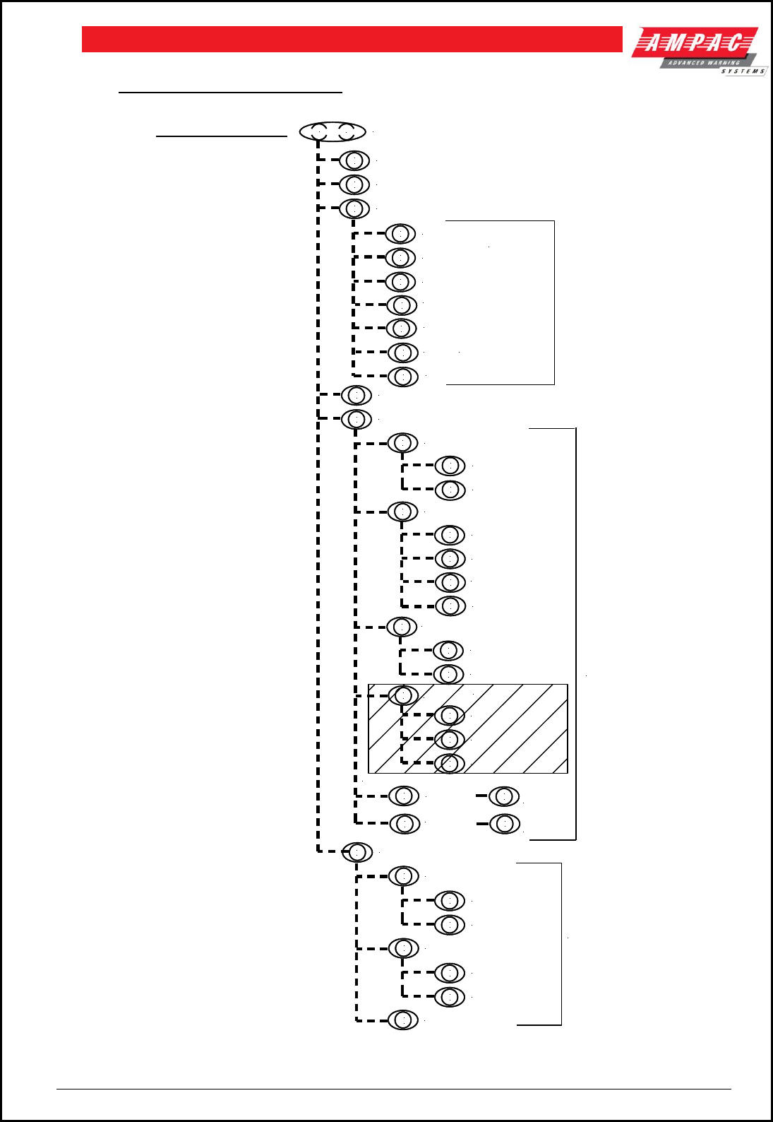
Page 106
FIREFINDERTM INSTALLATION COMMISSIONING & OPERATION
27 Quick Reference Guides
MAIN MENU OPTIONS
MENU KEY / FUNCTION KEY
( TO ENTER MENU / TO FUNCTION MENU )
ALARMS ( DISPLAY ALARMS )
PREALARMS ( DISPLAY PRE-ALARMS )
FAULTS ( DISPLAY FAULTS OF SELECTED FIELDS )
ZONES/SENSORS
LOOP
MODULE
BRIGADE
TFAILS
ISOLATES ( DISPLAY ALL SYSTEM ISOLATES)
STATUS (DISPLAY STATUS OF SELECTED FIELDS)
( FAULT FIELDS )
( STATUS FIELDS )
LOOPS ( LOOP / SENSOR No )
MODULES ( MODULE No )
TESTING ( TESTING THE SELECTED TEST FIELDS )
ALARM (TEST ALARM FIELDS )
OUTPUTS (OUTPUT No)
INPUT (INPUT No)
FAULT ( TEST FAULT FIELDS )
LAMP
( TEST
FIELDS )
ZONE ( ZONE No )
SENSOR
( LOOP/SENSOR No )
I/O
SYSTEM
AVALUES
( ANALOGUE
VALUE OF DET )
ZONE ( ZONE No )
SENSOR
( LOOP/SENSOR No )
SPACE
0
DEF
2
MENU
ABC
1
SPACE
0
ABC
1
DEF
2
MNO
5
PQRS
6
ABC
1
DEF
2
GHI
3
JKL
4
SPACE
0
SPACE
0
SPACE
0
SPACE
0
GHI
3
JKL
4
DEF
2
ABC
1
ABC
1
ABC
1
FUNCTION
SPACE
0
ABC
1
GHI
3P/SUPPLY
JKL
4
BELLS
NETWORK POINTS
REMOTE SLAVE MODULES
REMOTE LED MIMICS
SPACE
0
ABC
1
DEF
2
MNO
5
( IF NETWORK IS ENABLED )
PRINT ALL DEVICES
PRINT TOTALS
SPACE
0
ABC
1
MNO
5
(TEST FAILURES)
SLAVE
P/S
SPACE
0
ABC
1
EXTERNAL LED MIMICS
DEF
2
GHI
3
BRIGADE
NETWORK
GHI
3
NETWORK
NOT ENABLED
JKL
4
NETWORK
NOT ENABLED
( IF NETWORK IS ENABLED )
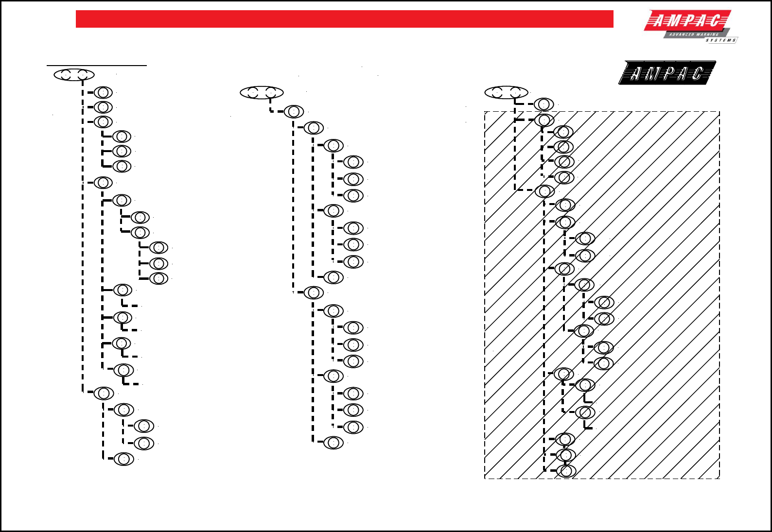
107
FIREFINDERTM INSTALLATION COMMISSIONING & OPERATION
FireFinder
TM
Quick Reference
FUNCTION KEY ( TO ENTER FUNCTION FIELD ( ENTER PASSWORD ) )
PROG ( PROGRAMMING FEILDS )
EDIT ( EDIT DESCRIPTION )
DELETE ( LOOP / SENSOR )
IN A PANEL
( SELECT INPUT CONTROL No AND INPUT No )
EDIT ( EDIT DESCRIPTION )
CON ZONE ( EDIT ZONE NUMBER, DESCRIPTION )
INPUT ( EDIT INPUT FIELDS )
EDIT ( DESCRIPTION, ZONE No,
DEVICE TYPE, BRIGADE OPTIONS,
CONFIGURATION, GROUP No )
DELETE ( DELETE DESCRIPTION )
ON A LOOP ( LOOP / SENSOR No )
DEVICE ( ENTER LOOP / SENSOR )
DELETE ( DELETE DESCRIPTION )
IN A PANEL
( SELECT OUTPUT CONTROL No AND OUTPUT No )
OUTPUT ( EDIT OUTPUT FIELDS )
ON A LOOP ( LOOP / SENSOR No )
PASSWORDS ( EDIT PASSWORD FIELDS )
ADD PASSWORD ( ADD PASSWORD (MAX 4 CHAR), LEVEL No )
DELETE PASSWORD ( DELETE SELECTED PASSWORD )
DELETE ALL PASSWORDS ( DELETE ALL PASSWORDS )
LEVEL 2 FUNCTION
FUNCTION KEY ( TO ENTER FUNCTION FIELD ( ENTER PASSWORD ) )
I/O ( MANUAL INPUT /OUTPUT CONTROL FIELDS )
OFF ( TURN INPUT OFF )
ON ( TURN INPUT ON )
ON A LOOP
( SELECT LOOP No, SENSOR No, INPUT No )
REMOVE ALL MANUAL INPUT CONTROL
( RETURN ALL MANUAL INPUTS TO ORIGINAL STATE )
INPUT ( INPUT FIELDS )
IN A PANEL
( SELECT I/O CONTROL NUMBER AND INPUT No )
REMOVE MANUAL CONTROL
( RETURN INPUT TO
ORIGINAL STATE)
OFF ( TURN INPUT OFF )
ON ( TURN INPUT ON )
REMOVE MANUAL CONTROL
( RETURN INPUT TO
ORIGINAL STATE)
OFF ( TURN OUTPUT OFF )
ON ( TURN OUTPUT ON )
ON A LOOP
( SELECT LOOP No, SENSOR No, OUTPUT No )
GLOBAL REMOVE ALL MANUAL OUTPUT CONTROL
( RETURN ALL MANUAL O/PS TO ORIGINAL STATE )
OUTPUT ( OUTPUT FIELDS )
IN A PANEL
( SELECT I/O CONTROL NUMBER AND OUTPUT No )
REMOVE MANUAL CONTROL
( RETURN OUTPUT TO
ORIGINAL STATE)
OFF ( TURN OUTPUT OFF )
ON ( TURN OUTPUT ON )
REMOVE MANUAL CONTROL
( RETURN OUTPUT TO
ORIGINAL STATE)
LEVEL 2
FUNCTIONS
FUNCTION MENU OPTIONS
FUNCTION KEY ( TO ENTER FUNCTION FIELD ( ENTER PASSWORD ) )
DATE ( DD/MM/YYYY )
TIME ( HH:MM )
DAY/NIGHT SETTINGS ( SET ON/OFF FIELDS )
DAY TIME (HH:MM)
ENABLE
LOGS
LEVEL 1
FUNCTIONS
NIGHT TIME (HH:MM)
ALARM ( ALARM LOG )
SHOW OPTIONS
VIEW BY ENTRY NO.
VIEW BY DATE
PRINT ENTRY (PRINT TO PANEL PRINTER (IF FITTED))
FAULT ( FAULT LOG )
ISOLATE ( ISOLATE LOG )
WALK ( ZONES OR SENSORS )
TESTS ( TEST SPECIFIED FIELD )
ZONE ( ENTER ZONE No )
SENSOR ( ENTER LOOP / SENSOR No )
LOOP ( ENTER LOOP No )
PQRS
6
SPACE
0
ABC
1
SPACE
0
SPACE
0
ABC
1
DEF
2
ABC
1
ABC
1
SPACE
0
ABC
1
SPACE
0
ABC
1
GHI
3
SPACE
0
TUV
7
SPACE
0
ABC
1
DEF
2
MENU
FUNCTION
MNO
5
SPACE
0
SPACE
0
ABC
1
DEF
2
ABC
1
SPACE
0
SPACE
0
ABC
1
DEF
2
SPACE
0
SPACE
0
ABC
1
DEF
2
ABC
1
SPACE
0
ABC
1
DEF
2
ABC
1
DEF
2
DEF
2
MENU
FUNCTION
SPACE
0
DEF
2
ABC
1
SPACE
0
ABC
1
GHI
3
MENU
FUNCTION
2
DEF
SPACE
0
SPACE
0
ABC
1
SPACE
0
ABC
1
DEF
2
1
ABC
JKL
4
SPACE
0
SPACE
0
ABC
1
ABC
1
PANEL BASED MCP ( DESCRIPTION / NODE )
JKL
4
SUB ADDRESS ( EDIT / DELETE )
MNO
5
WATCHDOG RESET
PQRS
6
PRINT MULTIPLE ENTRIES
2
DEF
SYSTEM ( SYSTEM LOG )
DEF
3
AS FOR ALARM
AS FOR ALARM
AS FOR ALARM
JKL
4
AS FOR ALARM
I/O (INPUT / OUTPUT LOG )
AS FOR INPUT
AS FOR INPUT
GHI
3
MODE ZONE / SENSOR
DISABLED IF FACP
IS NETWORKED
ACCESS LEVEL 3 ( ENTER LEVEL 3 PASSWORD )
PQRS
6
LEVEL 3 FUNCTION

UNCONTROLLED DOCUMENT
NOTE: Due to AMPAC’s commitment to continuous improvement specifications may change without notice.
