Analog Product Family Hardware Installation Manual Servo Control
User Manual: Analog-Servo-Control-Installation-Manual A M C
Open the PDF directly: View PDF ![]() .
.
Page Count: 72
- Preface
- Contents
- 1 Safety
- 2 Products and System Requirements
- 3 Integration in the Servo System
- 4 Operation
- A Through-hole Component Tuning
- B Troubleshooting
- Index

Everything’s possible.
www.a-m-c.com
Hardware
Installation Manual
Analog Drives
for Servo Systems
MNALHWIN-01

MNALHWIN-01 ii
Preface
ADVANCED Motion Controls constantly strives to improve all of its products. We review the information in
this document regularly and we welcome any suggestions for improvement. We reserve the right to modify
equipment and documentation without prior notice.
For the most recent software, the latest revisions of this manual, and copies of compliance and
declarations of conformity, visit the company’s website at www.a-m-c.com. Otherwise, contact the
company directly at:
ADVANCED Motion Controls • 3805 Calle Tecate Camarillo, CA • 93012-5068 USA
Agency Compliances
The company holds original documents for the following:
•UL 508c, file number E140173
•Electromagnetic Compatibility, EMC Directive - 2004/108/EC
EN61000-6-2:2001
EN61000-6-4:2001
EN61000-3-2:2000
EN61000-3-3:1995/A1:2001
•Electrical Safety, Low Voltage Directive - 72/23/EEC
EN 60 204-1 (IEC 60 204-1)
•Reduction of Hazardous Substances (RoHS), 2002/95/EC
Trademarks
ADVANCED Motion Controls™, the combined isosceles trapezoid/right triangle logo, DIGIFLEX®,
DIGIFLEX® Performance™ and DriveWare™ are either registered trademarks or trademarks of
ADVANCED Motion Controls in the United States and/or other countries. All other trademarks are the
property of their respective owners.
Related Documentation
•Product datasheet specific for your drive, available for download at www.a-m-c.com.
/
iii MNALHWIN-01
Attention Symbols
The following symbols are used throughout this document to draw attention to important operating
information, special instructions, and cautionary warnings. The section below outlines the overall directive
of each symbol and what type of information the accompanying text is relaying.
Revision History
Document ID Revision # Date Changes
MNALHWIN-01 19/25//2009 Analog Product Family Hardware Installation Manual First Release
© 2009 ADVANCED Motion Controls. All rights reserved.
Note - Pertinent information that clarifies a process, operation, or ease-
of-use preparations regarding the product.
Notice - Required instruction necessary to ensure successful completion
of a task or procedure.
Caution - Instructs and directs you to avoid damaging equipment.
Warning - Instructs and directs you to avoid harming yourself.
Danger - Presents information you must heed to avoid serious injury or
death.
Note

MNALHWIN-01 iv
Contents
1 Safety 1
1.1 General Safety Overview . . . . . . . . . . . . . . . . . . . . . . . . . . . . . . . . 1
2 Products and System Requirements 4
2.1 Analog Drive Family Overview . . . . . . . . . . . . . . . . . . . . . . . . . . . . 4
2.1.1 Products Covered . . . . . . . . . . . . . . . . . . . . . . . . . . . . . . . . . 4
Drive Datasheet . . . . . . . . . . . . . . . . . . . . . . . . . . . . . . . . . . . 4
Standard and Custom Models . . . . . . . . . . . . . . . . . . . . . . . 5
2.2 Analog PWM Servo Drive Basics and Theory . . . . . . . . . . . . . . . . . 6
2.2.1 Single Phase (Brushed) Servo Drives . . . . . . . . . . . . . . . . . . 7
2.2.2 Three Phase (Brushless) Servo Drives . . . . . . . . . . . . . . . . . . 7
2.3 Power Stage Specifications . . . . . . . . . . . . . . . . . . . . . . . . . . . . . . . 9
2.4 Command Inputs . . . . . . . . . . . . . . . . . . . . . . . . . . . . . . . . . . . . . . 10
2.4.1 ±10V Analog . . . . . . . . . . . . . . . . . . . . . . . . . . . . . . . . . . . . . 10
2.4.2 PWM and Direction . . . . . . . . . . . . . . . . . . . . . . . . . . . . . . . 10
2.4.3 Sinusoidal . . . . . . . . . . . . . . . . . . . . . . . . . . . . . . . . . . . . . . . 10
2.5 Feedback Specifications . . . . . . . . . . . . . . . . . . . . . . . . . . . . . . . . 11
2.5.1 Feedback Polarity . . . . . . . . . . . . . . . . . . . . . . . . . . . . . . . . 11
2.5.2 Incremental Encoder . . . . . . . . . . . . . . . . . . . . . . . . . . . . . 11
2.5.3 Hall Sensors . . . . . . . . . . . . . . . . . . . . . . . . . . . . . . . . . . . . . . 12
2.5.4 Tachometer . . . . . . . . . . . . . . . . . . . . . . . . . . . . . . . . . . . . . 13
2.6 Modes of Operation . . . . . . . . . . . . . . . . . . . . . . . . . . . . . . . . . . . . 14
2.6.1 Current (Torque) Mode . . . . . . . . . . . . . . . . . . . . . . . . . . . . 14
2.6.2 Open Loop (PWM Duty Cycle) Mode . . . . . . . . . . . . . . . . 14
2.6.3 Hall Velocity Mode . . . . . . . . . . . . . . . . . . . . . . . . . . . . . . . 15
2.6.4 Encoder Velocity Mode . . . . . . . . . . . . . . . . . . . . . . . . . . . 15

MNALHWIN-01 v
/
2.6.5 Tachometer Velocity Mode . . . . . . . . . . . . . . . . . . . . . . . . 15
2.6.6 Voltage Mode . . . . . . . . . . . . . . . . . . . . . . . . . . . . . . . . . . . 16
2.6.7 IR Compensation Mode . . . . . . . . . . . . . . . . . . . . . . . . . . . 16
2.6.8 Analog Position Loop Mode . . . . . . . . . . . . . . . . . . . . . . . . 16
2.7 System Requirements . . . . . . . . . . . . . . . . . . . . . . . . . . . . . . . . . . . 17
2.7.1 Analog Servo Drive Selection and Sizing . . . . . . . . . . . . . 17
Motor Current and Voltage . . . . . . . . . . . . . . . . . . . . . . . . 17
Motor Inductance . . . . . . . . . . . . . . . . . . . . . . . . . . . . . . . . 19
2.7.2 Power Supply Selection and Sizing . . . . . . . . . . . . . . . . . . 20
Power Supply Current and Voltage . . . . . . . . . . . . . . . . . . 20
Isolation . . . . . . . . . . . . . . . . . . . . . . . . . . . . . . . . . . . . . . . . . 22
Regeneration and Shunt Regulators . . . . . . . . . . . . . . . . . 23
Voltage Ripple . . . . . . . . . . . . . . . . . . . . . . . . . . . . . . . . . . . 25
2.7.3 Environmental Specifications . . . . . . . . . . . . . . . . . . . . . . . 26
Shock/Vibrations . . . . . . . . . . . . . . . . . . . . . . . . . . . . . . . . . . 26
3 Integration in the Servo System 27
3.1 LVD Requirements . . . . . . . . . . . . . . . . . . . . . . . . . . . . . . . . . . . . . 27
3.2 CE-EMC Wiring Requirements . . . . . . . . . . . . . . . . . . . . . . . . . . . . 28
General . . . . . . . . . . . . . . . . . . . . . . . . . . . . . . . . . . . . . . . . . 28
Analog Input Drives . . . . . . . . . . . . . . . . . . . . . . . . . . . . . . . 28
PWM Input Drives . . . . . . . . . . . . . . . . . . . . . . . . . . . . . . . . . 28
MOSFET Switching Drives . . . . . . . . . . . . . . . . . . . . . . . . . . . 28
IGBT Switching Drives . . . . . . . . . . . . . . . . . . . . . . . . . . . . . . 28
Fitting of AC Power Filters . . . . . . . . . . . . . . . . . . . . . . . . . . 28
3.2.1 Ferrite Suppression Core Set-up . . . . . . . . . . . . . . . . . . . . . 29
3.2.2 Inductive Filter Cards . . . . . . . . . . . . . . . . . . . . . . . . . . . . . . 29
3.3 Grounding . . . . . . . . . . . . . . . . . . . . . . . . . . . . . . . . . . . . . . . . . . . . 30
3.4 Wiring . . . . . . . . . . . . . . . . . . . . . . . . . . . . . . . . . . . . . . . . . . . . . . . . 31
3.4.1 Wire Gauge . . . . . . . . . . . . . . . . . . . . . . . . . . . . . . . . . . . . . 31
3.4.2 Motor Wires . . . . . . . . . . . . . . . . . . . . . . . . . . . . . . . . . . . . . . 32
3.4.3 Power Supply Wires . . . . . . . . . . . . . . . . . . . . . . . . . . . . . . . 32
DC Power Supplies . . . . . . . . . . . . . . . . . . . . . . . . . . . . . . . . 33
AC Power Supplies . . . . . . . . . . . . . . . . . . . . . . . . . . . . . . . . 33
3.4.4 Feedback Wires . . . . . . . . . . . . . . . . . . . . . . . . . . . . . . . . . . 34
Hall Sensors . . . . . . . . . . . . . . . . . . . . . . . . . . . . . . . . . . . . . . 34
Incremental Encoder . . . . . . . . . . . . . . . . . . . . . . . . . . . . . . 35
Tachometer . . . . . . . . . . . . . . . . . . . . . . . . . . . . . . . . . . . . . . 35

MNALHWIN-01 vi
/
3.4.5 Input Reference Wires . . . . . . . . . . . . . . . . . . . . . . . . . . . . . 35
±10V Analog Input . . . . . . . . . . . . . . . . . . . . . . . . . . . . . . . . 36
Potentiometer Input . . . . . . . . . . . . . . . . . . . . . . . . . . . . . . . 37
PWM and Direction Inputs . . . . . . . . . . . . . . . . . . . . . . . . . . 37
Sinusoidal Input . . . . . . . . . . . . . . . . . . . . . . . . . . . . . . . . . . . 38
3.5 Mounting . . . . . . . . . . . . . . . . . . . . . . . . . . . . . . . . . . . . . . . . . . . . . 39
4 Operation 40
4.1 Initial Setup and Features . . . . . . . . . . . . . . . . . . . . . . . . . . . . . . . 40
4.1.1 Pin Function Details . . . . . . . . . . . . . . . . . . . . . . . . . . . . . . . 40
Current Monitor Output . . . . . . . . . . . . . . . . . . . . . . . . . . . . 40
Current Reference Output . . . . . . . . . . . . . . . . . . . . . . . . . 41
Inhibit Input . . . . . . . . . . . . . . . . . . . . . . . . . . . . . . . . . . . . . . 41
Continuous Current Limit Pin . . . . . . . . . . . . . . . . . . . . . . . . 41
Fault Output . . . . . . . . . . . . . . . . . . . . . . . . . . . . . . . . . . . . . 42
Low Voltage Power Supply Outputs . . . . . . . . . . . . . . . . . 42
Velocity Monitor Output . . . . . . . . . . . . . . . . . . . . . . . . . . . 42
4.1.2 Potentiometer Function Details . . . . . . . . . . . . . . . . . . . . . 43
Test Points for Potentiometers . . . . . . . . . . . . . . . . . . . . . . . 43
4.1.3 Switch Function Details . . . . . . . . . . . . . . . . . . . . . . . . . . . . 44
4.1.4 Adjustable Acceleration and Deceleration Rate . . . . . . 44
4.1.5 Tachometer Input Gain Scaling . . . . . . . . . . . . . . . . . . . . . 45
4.1.6 Current Limiting Procedure . . . . . . . . . . . . . . . . . . . . . . . . . 46
4.1.7 Drive Set-up Instructions . . . . . . . . . . . . . . . . . . . . . . . . . . . 47
Single Phase (Brush Type) . . . . . . . . . . . . . . . . . . . . . . . . . . 47
Three Phase (Brushless) . . . . . . . . . . . . . . . . . . . . . . . . . . . . 47
Three Phase (Brushless) Drive with Brushed Motor . . . . . . 48
Sinusoidal Drive (S-Series) . . . . . . . . . . . . . . . . . . . . . . . . . . . 48
4.1.8 Tuning Procedure . . . . . . . . . . . . . . . . . . . . . . . . . . . . . . . . 49
Current Loop Proportional Gain Adjustment . . . . . . . . . . 50
Current Loop Integrator Adjustment . . . . . . . . . . . . . . . . . 51
Voltage or Velocity Loop Tuning . . . . . . . . . . . . . . . . . . . . 52
Analog Position Loop . . . . . . . . . . . . . . . . . . . . . . . . . . . . . . 52

MNALHWIN-01 vii
/
A Through-hole Component Tuning 53
A.1 Through-Hole Tuning . . . . . . . . . . . . . . . . . . . . . . . . . . . . . . . . . . . 53
A.1.1 Procedure . . . . . . . . . . . . . . . . . . . . . . . . . . . . . . . . . . . . . . 55
Tune the Current Loop Proportional Gain . . . . . . . . . . . . . 55
Tune the Current Loop Integral Gain . . . . . . . . . . . . . . . . . 55
Velocity Loop Integral Gain Tuning . . . . . . . . . . . . . . . . . . 56
B Troubleshooting 57
B.1 Fault Conditions and Symptoms . . . . . . . . . . . . . . . . . . . . . . . . . . 57
Over-Temperature . . . . . . . . . . . . . . . . . . . . . . . . . . . . . . . . 57
Over-Voltage Shutdown . . . . . . . . . . . . . . . . . . . . . . . . . . . 57
Under-Voltage Shutdown . . . . . . . . . . . . . . . . . . . . . . . . . . 58
Short Circuit Fault . . . . . . . . . . . . . . . . . . . . . . . . . . . . . . . . . 58
Invalid Hall Sensor State (Brushless Drives only) . . . . . . . . . 58
Inhibit Input . . . . . . . . . . . . . . . . . . . . . . . . . . . . . . . . . . . . . . 58
Power-On Reset . . . . . . . . . . . . . . . . . . . . . . . . . . . . . . . . . . 58
B.1.1 Overload . . . . . . . . . . . . . . . . . . . . . . . . . . . . . . . . . . . . . . . 58
B.1.2 Over-Current . . . . . . . . . . . . . . . . . . . . . . . . . . . . . . . . . . . . 59
B.1.3 Motor Problems . . . . . . . . . . . . . . . . . . . . . . . . . . . . . . . . . . 59
B.1.4 Causes of Erratic Operation . . . . . . . . . . . . . . . . . . . . . . . . 60
B.2 Technical Support . . . . . . . . . . . . . . . . . . . . . . . . . . . . . . . . . . . . . . 60
B.2.1 Product Label Description . . . . . . . . . . . . . . . . . . . . . . . . . 60
B.2.2 Drive Model Information . . . . . . . . . . . . . . . . . . . . . . . . . . . 61
B.2.3 Warranty Returns and Factory Help . . . . . . . . . . . . . . . . . 61
Index I
MNALHWIN-01 1
1 Safety
Thissectiondiscussescharacteristicsofyouranalogservodrivetoraiseyourawarenessofpotentialrisksand
hazards.Theseverityofconsequencesrangesfromfrustrationofperformance,throughdamagetoequipment,
injuryordeath.Theseconsequences,ofcourse,canbeavoidedbygooddesignandproperinstallationintoyour
mechanism.
1.1 General Safety Overview
You must install and operate motion control equipment so that you meet
all applicable safety requirements. Ensure that you identify the relevant
standards and comply with them. Failure to do so may result in damage
to equipment and personal injury.
Read this entire manual prior to attempting to install or operate the drive.
Become familiar with practices and procedures that allow you to
operate these drives safely and effectively. You are responsible for
determining the suitability of this product for the intended application.
The manufacturer is neither responsible nor liable for indirect or
consequential damages resulting from the inappropriate use of this
product.
High-performance motion control equipment can move rapidly with
very high forces. Unexpected motion may occur especially during
product commissioning. Keep clear of any operational machinery and
never touch them while they are working.
Inordertoinstallananalogdriveintoaservosystem,youmusthaveathoroughknowledge
andunderstandingofbasicelectronics,computersandmechanicsaswellassafetyprecautions
andpracticesrequiredwhendealingwiththepossibilityofhighvoltagesorheavy,strong
equipment.
Observeyourfacility’slock‐out/tag‐outproceduressothatworkcanproceedwithoutresidual
powerstoredinthesystemorunexpectedmovementsbythemachine.
Keep clear of all exposed power terminals (motor, DC Bus, shunt, DC
power, transformer) when power is applied to the equipment. Follow
these safety guidelines:
•Always turn off the main power and allow sufficient time for
complete discharge before making any connections to the drive.
•Do not rotate the motor shaft without power. The motor acts as a
generator and will charge up the power supply capacitors through
the drive. Excessive speeds may cause over-voltage breakdown in
the power output stage. Note that a drive having an internal power
converter that operates from the high voltage supply will become
operative.
•Do not short the motor leads at high motor speeds. When the motor is
shorted, its own generated voltage may produce a current flow as
high as 10 times the drive current. The short itself may not damage
the drive but may damage the motor. If the connection arcs or
opens while the motor is spinning rapidly, this high voltage pulse flows
back into the drive (due to stored energy in the motor inductance)
and may damage the drive.
•Do not make any connections to any internal circuitry. Only
connections to designated connectors are allowed.
•Do not make any connections to the drive while power is applied.
MNALHWIN-01 2
Safety / General Safety Overview
Do not reverse the power supply leads!
Severe damage will result!
Use sufficient capacitance!
Pulse Width Modulation (PWM) drives require a capacitor on the high
voltage supply to store energy during the PWM switching process.
Insufficient power supply capacitance causes problems particularly with
high inductance motors. During braking much of the stored mechanical
energy is fed back into the power supply and charges its output
capacitor to a higher voltage. If the charge reaches the drive’s over-
voltage shutdown point, output current and braking will cease. At that
time energy stored in the motor inductance continues to flow through
diodes in the drive to further charge the power supply capacitance. The
voltage rise depends upon the power supply capacitance, motor
speed, and inductance.

MNALHWIN-01 3
Safety / General Safety Overview
Make sure minimum inductance requirements are met!
Pulse Width modulation (PWM) servo drives deliver a pulsed output that
requires a minimum amount of load inductance to ensure that the DC
motor current is properly filtered. The minimum inductance values for
different drive types are shown in the individual data sheet
specifications. If the drive is operated below its maximum rated voltage,
the minimum load inductance requirement may be reduced. Most
servo-motors have enough winding inductance. Some types of motors
(e.g. "basket-wound", "pancake", etc.) do not have a conventional iron
core rotor, so the winding inductance is usually less than 50 μH.
If the motor inductance value is less than the minimum required for the
selected drive, use an external filter card.

MNALHWIN-01 4
2 Products and System Requirements
Thischapterisintendedasaguideandgeneraloverviewinselecting,installing,andoperatingananalogservo
drive.Containedwithinareinstructionsonsystemintegration,wiring,drive‐setup,andstandardoperating
methods.
2.1 Analog Drive Family Overview
TheanalogdrivefamilycontainsdrivesthatcanpowerSinglePhase(Brushed)andThree
Phase(Brushless)motors.AnalogdrivesarepoweredoffeitherasingleDCorACpower
supply,andprovideavarietyofcontrolandfeedbackoptions.Thedrivesaccepteithera±10V
analogsignal,aPWMandDirectionsignal,ortwosinusoidalcommandsignalsasinput.A
digitalcontrollercanbeusedtocommandandinteractwithanalogservodrives,andanumber
ofinput/outputpinsareavailableforparameterobservationanddriveconfiguration.
FIGURE 2.1 Analog Product Family Part Numbering Structure
QDI: Quick Disconnect with
Inverted Inhibit
Brushed drive.
A
Peak Voltage
Peak Current
-
Additional Options
B or BX: Brushless drive.
Maximum peak current rating in Amps.
Peak voltage rating scaled 1:10 in Volts.
Power Supply
(blank): DC Power Supply
Motor Type
Revision
Assigned a letter (A through Z) by
manufacturer.
AC: AC Power Supply
FAC: AC Power Connecter
Located in the Front
I: Optical Isolation
Isolation Option
(blank):
+/- 10 V Analog
D: Direct PWM
Command Type
DC: Torque Mode PWM
S or SX: Commutated Sine Wave
(blank):
Hall Sensors or None
E: Encoder and/or Hall Sensors
Feedback Type
(blank):
ANP: Analog Position Loop
H: Available Hall Velocity Mode
INV: Inverted Inhibit
DD: Brushed PWM Command
Command Type
QD: Quick Disconnect
(blank): Non-PWM Command
2.1.1 Products Covered
Theproductscoveredinthismanualadheretothefollowingpartnumberingstructure.
However,additionalfeaturesand/oroptionsarereadilyavailableforOEM’swithsufficient
orderingvolume.FeelfreetocontactADVANCEDMotionControlsforfurtherinformation.
Drive Datasheet Eachanalogdrivehasaseparatedatasheetthatcontainsimportantinformation
onthemodesandproduct‐specificfeaturesavailablewiththatparticulardrive,includingthe
MNALHWIN-01 5
Products and System Requirements / Analog Drive Family Overview
functionalblockdiagramofthespecificdrive’soperation.Thedatasheetistobeusedin
conjunctionwiththismanualforsystemdesignandinstallation.
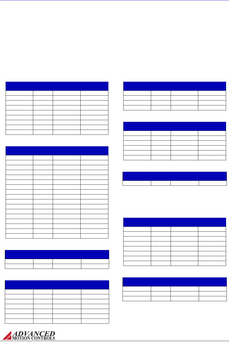
Standard and Custom Models Thedrivesinthetablesbelowarethestandardproductline
ofADVANCEDMotionControlsanalogservodrives.Notethatnotallpossiblepartnumber
combinationsfromtheproductfamilynumberingstructure(Figure2.1)areofferedas
standarddrives.PleasecontactADVANCEDMotionControlsSalesDepartmentforfurther
informationanddetailsoncustomdrivesolutions.
TABLE 2.1 Brushed ±10V Analog DC Drives
TABLE 2.2 Brushless ±10V Analog DC Drives
TABLE 2.3 Brushed ±10V Analog AC Drives
TABLE 2.4 Brushless ±10V Analog AC Drives
TABLE 2.5 Brushed PWM Input DC Drives
TABLE 2.6 Brushless PWM Input DC Drives
TABLE 2.7 Brushless PWM Input AC Drives
TABLE 2.8 Sinusoidal Input DC Drives
TABLE 2.9 Sinusoidal Input AC Supply Drives
Drive Number VDC
(Nominal)
Peak Current
(A)
Cont. Current
(A)
12A8 20-80 12 6
25A8 20-80 25 12.5
30A8 20-80 30 15
50A8 20-80 50 25
120A10 20-80 120 60
20A20 40-190 20 10
25A20I 40-190 25 12.5
50A20I 40-190 50 25
100A40 60-400 100 50
Drive Number VDC
(Nominal)
Peak Current
(A)
Cont. Current
(A)
B15A8 20-80 15 7.5
BE15A8 20-80 15 7.5
BE15A8-H 20-80 15 7.5
B30A8 20-80 30 15
BE30A8 20-80 30 15
BX30A8 20-80 30 15
B100A8 20-80 100 50
B25A20I 40-190 25 12.5
BE25A20I 40-190 25 12.5
BX25A20 60-200 25 12.5
B40A20 40-190 40 20
B40A20I 40-190 40 20
BE40A20I 40-190 40 20
B30A40 60-400 30 15
B40A40 60-400 40 20
B60A40 60-400 60 30
B100A40 60-400 100 50
Drive Number VAC
(Nominal)
Peak Current
(A)
Cont. Current
(A)
16A20AC 30-130 16 8
30A20AC 30-130 30 15
Drive Number VAC
(Nominal)
Peak Current
(A)
Cont. Current
(A)
B25A20AC 30-130 25 12.5
BE25A20AC 30-130 25 12.5
BX25A20AC 45-140 25 12.5
B30A40AC 45-270 30 15
B40A40AC 45-270 40 20
B60A40AC 45-270 60 30
B100A40AC 45-270 100 50
Drive Number VDC
(Nominal)
Peak Current
(A)
Cont. Current
(A)
30A8DD 20-80 30 15
50A8DD 20-80 50 25
25A20DD 40-190 25 12.5
50A20DD 40-190 50 25
Drive Number VDC
(Nominal)
Peak Current
(A)
Cont. Current
(A)
BD15A8 20-80 15 7.5
BD30A8 20-80 30 15
BDC30A8 20-80 30 15
BD25A20 40-190 25 12.5
BD25A20I 40-190 25 12.5
BDC40A20 60-190 40 20
Drive Number VAC
(Nominal)
Peak Current
(A)
Cont. Current
(A)
BD25A20AC 45-140 25 12.5
Drive Number VDC
(Nominal)
Peak Current
(A)
Cont. Current
(Arms)
S16A8 20-80 16 8
SX30A8 20-80 30 15
S60A8 20-80 60 30
S100A8 20-80 100 50
SX25A20 60-190 25 12.5
S30A40 60-400 30 15
S60A40 60-400 60 30
S100A40 60-400 100 50
Drive Number VAC
(Nominal)
Peak Current
(A)
Cont. Current
(Arms)
S30A40AC 45-265 30 15
S60A40AC 45-270 60 30
S100A40AC 45-270 100 50

FIGURE 2.3 PWM Current Control Circuit
Command
Current
Control
Switching
Logic
S1
D1
S2
D2
S3
D3
S4
D4
+
-
Motor
+HV
Rc
I
Current Feedback
FIGURE 2.2
Controller
Reference
Servo Drive Motor Feedback Load Feedback
Current
Typical Motion Control System
MNALHWIN-01 6
Products and System Requirements / Analog PWM Servo Drive Basics and Theory
2.2 Analog PWM Servo Drive Basics and Theory
Analogservodrivesareusedextensivelyinmotioncontrolsystemswhereprecisecontrolof
positionand/orvelocityisrequired.Thedrivetransmitsthelow‐energyreferencesignalsfrom
thecontrollerintohigh‐energysignals(motorvoltageandcurrent).Thereferencesignalscan
beeitheranalogordigital,witha±10VDCsignalbeingthemostcommon.Thesignalcan
representeitheramotortorqueorvelocitydemand.
Figure2.2showsthecomponentstypicallyusedinaservosystem(i.e.afeedbacksystemused
tocontrolposition,velocity,and/oracceleration).Thecontrollercontainsthealgorithmsto
closethedesiredservoloopsandalsohandlesmachineinterfacing(inputs/outputs,terminals,
etc.).Thedriverepresentstheelectronicpowerconverterthatdrivesthemotoraccordingto
thecontrollerreferencesignals.Themotor(whichcanbeofthebrushedorbrushlesstype,
rotary,orlinear)istheactualelectromagneticactuator,whichgeneratestheforcesrequiredto
movetheload.Feedbackelementsaremountedonthemotorand/orloadinordertoclosethe
servoloop.
Althoughthereexistmanywaysto"amplify"electricalsignals,pulsewidthmodulation(PWM)
isbyfarthemostefficientandcost‐effectiveapproach.AtthebasisofaPWMservodriveisa
currentcontrolcircuitthatcontrolstheoutputcurrentbyvaryingthedutycycleoftheoutput
powerstage(fixedfrequency,variabledutycycle).Figure2.3showsatypicalsetupforasingle
phaseload.
S1,S2,S3,andS4arepowerdevices(MOSFETorIGBT)thatcanbeswitchedonoroff.D1,D2,
D3,andD4arediodesthatguaranteecurrentcontinuity.Thebusvoltageisdepictedby+HV.
TheresistorRcisusedtomeasuretheactualoutputcurrent.Forelectricmotors,theloadis
typicallyinductiveduetothewindingsusedtogenerateelectromagneticfields.Thecurrentcan
beregulatedinbothdirectionsbyactivatingtheappropriateswitches.WhenswitchS1andS4
(orS2andS3)areactivated,currentwillflowinthepositive(ornegative)directionand
increase.WhenswitchS1isoffandswitchS4ison(orS2offandS3on)currentwillflowin
thepositive(ornegative)directionanddecrease(viaoneofthediodes).Theswitch"ON"time
isdeterminedbythedifferencebetweenthecurrentdemandandtheactualcurrent.The

FIGURE 2.4 Output Current and Duty Cycle Relationship
Current
ON time
Time
Pulse
width
MNALHWIN-01 7
Products and System Requirements / Analog PWM Servo Drive Basics and Theory
currentcontrolcircuitwillcomparebothsignalseverytimeinterval(typically50μsecorless)
andactivatetheswitchesaccordingly(thisisdonebytheswitchinglogiccircuit,whichalso
performsbasicprotectionfunctions).Figure2.4showstherelationshipbetweenthepulse
width(ONtime)andthecurrentpattern.Thecurrentrisetimewilldependonthebusvoltage
(+HV)andtheloadinductance.Therefore,certainminimumloadinductancerequirementsare
necessarydependingonthebusvoltage.
2.2.1 Single Phase (Brushed) Servo Drives
BrushtypeservodrivesaredesignedforusewithpermanentmagnetbrushedDCmotors
(PMDCmotors).ThedriveconstructionisbasicallyasshowninFigure2.3.PMDCmotorshave
asinglewinding(armature)ontherotor,andpermanentmagnetsonthestator(nofield
winding).Brushesandcommutatorsmaintaintheoptimumtorqueangle.Thetorque
generatedbyaPMDCmotorisproportionaltothecurrent,givingitexcellentdynamiccontrol
capabilitiesinmotioncontrolsystems.
Brusheddrivescanalsobeusedtocontrolcurrentinotherinductiveloadssuchasvoicecoil
actuators,magneticbearings,etc.
2.2.2 Three Phase (Brushless) Servo Drives
ThreePhase(brushless)servodrivesareusedwithbrushlessservomotors.Thesemotors
typicallyhaveathree‐phasewindingonthestatorandpermanentmagnetsontherotor.
Brushlessmotorsrequirecommutationfeedbackforproperoperation(thecommutatorsand
brushesperformthisfunctiononbrushtypemotors).Thisfeedbackconsistsofrotormagnetic
fieldorientationinformation,suppliedeitherbymagneticfieldsensors(HallEffectsensors)or
positionsensors(encoderorresolver).Brushlessmotorshavebetterpowerdensityratings
thanbrushedmotorsbecauseheatisgeneratedinthestator,resultinginashorterthermal
pathtotheoutsideenvironment.Figure2.5showsatypicalsystemconfiguration.
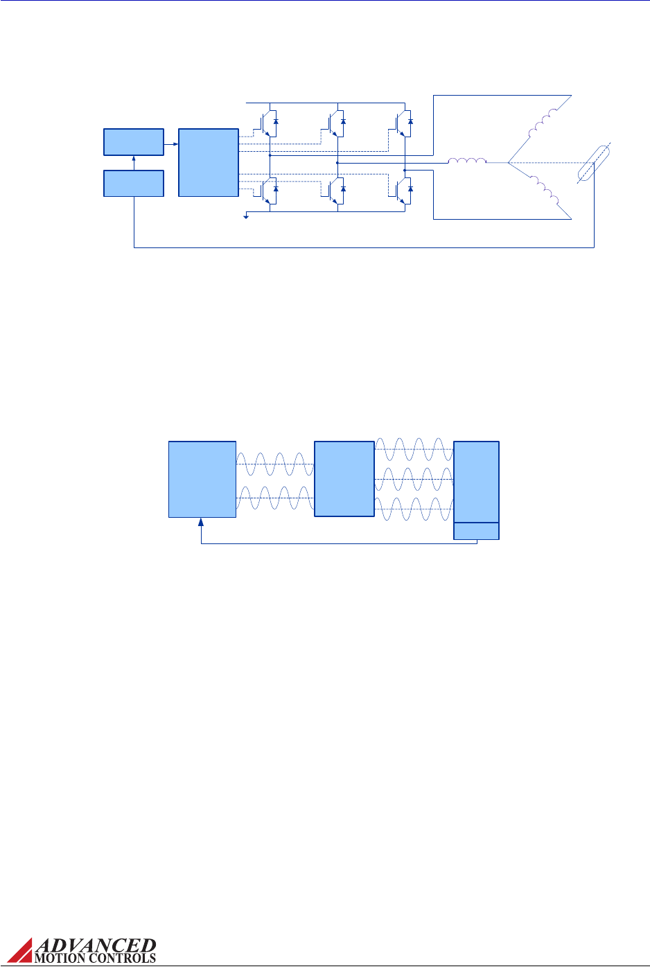
FIGURE 2.6 Controller-based Commutation
Analog Sinusoidal
reference signals
Motor Currents
Controller:
Position Control
Velocity Control
Commutation Control
Servo Drive
Feedback
Position and Commutation Feedback
Motor
FIGURE 2.5 Brushless Servo System
Current
Control
Switching
Logic
S1 S2
S1 S2
+HV
Commutation Feedback
Commutation
Control
S3
S3
N
S
MNALHWIN-01 8
Products and System Requirements / Analog PWM Servo Drive Basics and Theory
Thecommutationfunctioncanalsobeimplementedinthemotioncontroller,asinthecaseof
ADVANCEDMotionControlssinusoidalcommandinputdrives.Thedrivemerelyamplifiesthe
controllersignals(2analogsinusoidalsignalsthatrepresent2ofthe3motorphasecurrents)
andcreatesthethirdmotorphasecurrent(thesumofthe3currentsmustbezero)andadjusts
thephaseangletoobtainmaximumtorque.Nopositionfeedbackneedstobewiredintothe
drive.Themotorcurrentamplitudeisproportionaltothereferencesignalamplitude,whilethe
referencesignalfrequencydependsonthemotorvelocityandthemotorpolecount.
MNALHWIN-01 9
Products and System Requirements / Power Stage Specifications
2.3 Power Stage Specifications
Thedrivedatasheetliststhespecificvaluesforthefollowingdrivepowerspecifications.Note
thatnotallspecificationsapplytoeverydrive.
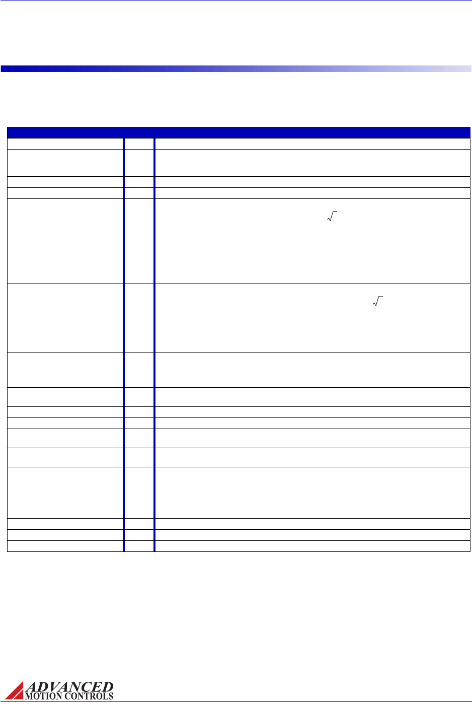
TABLE 2.10 Power Stage Specifications
Specification Units Description
DC Supply Voltage Range VDC Specifies the acceptable DC supply voltage range that the drive will operate within.
DC Bus Over Voltage Limit VDC Specifies the maximum DC supply voltage allowable. If the DC bus rises above the over voltage
limit, the drive will automatically disable, and will not re-enable until the DC bus voltage falls below
the over voltage limit.
AC Supply Voltage Range VAC Specifies the acceptable AC supply voltage range that the drive will operate within.
AC Supply Frequency Hz Specifies the acceptable frequency of the AC supply line.
Maximum Peak Output Current APertains to the maximum peak current the drive can output according to hardware limitations. An
RMS rating can be obtained by dividing this value by
2
. With the exception of S-series drives,
the maximum peak output duration is inherently limited to occur for no longer than 2 seconds, at
which point the current output will foldback over a period of 10 seconds to the continuous current
limit in order to protect the motor in stalled condition. Current limiting is implemented in the drive by
reducing the output voltage.
Most drive models feature peak current limit adjustments. The maximum peak current is needed
for fast acceleration and deceleration. Consult the drive datasheet to see which options are
available. For more information on the current limit see “Current Limiting Procedure” on page 46.
Maximum Continuous Output
Current
APertains to the maximum continuous current the drive can output according to hardware
limitations. An RMS rating can be obtained by dividing this value by
2
.
Most drive models feature continuous current limit adjustments by the use of DIP switches or a
potentiometer. Some models also allow an external resistor to be connected between a
continuous current limiting pin and signal ground as an additional method of current limiting.
Consult the drive datasheet to see which options are available. For more information on setting the
current limit see “Current Limiting Procedure” on page 46.
Maximum Continuous Sine Wave
Current
Arms Pertains to the maximum continuous RMS current that S-series (sinusoidal) drives can output
indefinitely. If the continuous RMS current output of the drive exceeds this value, the drive output
will be disabled. The drive will re-enable once the RMS current has returned to a level below the
maximum continuous sine wave current.
Maximum Power Dissipation at
Continuous Current
WThe power dissipation of the drive, assuming approximately 5% power loss to heat dissipation.
Calculated by taking 5% of P=V•I at continuous current and peak bus voltage.
Internal Bus Capacitance μFThe capacitance value between the internal DC bus voltage and power ground.
Internal Shunt Resistance WThe resistance value of the internal shunt resistor.
Internal Shunt Resistor Power
Rating
WThe power rating of the internal shunt resistor.
Internal Shunt Resistor Turn-on
Voltage
VDC The turn-on voltage of the internal shunt resistor.
Minimum Load Inductance mH The minimum inductance needed at the output of the drive for proper operation. For a brushless
motor, this corresponds to the phase-to-phase inductance. If this minimum inductance is not met,
a filter card should be used to add additional inductance. Some motors may operate with slightly
less than the required inductance if the bus voltage is low enough. ADVANCED Motion Controls
provides various accessories including inductive filter cards for a wide range of drives. See
“Inductive Filter Cards” on page 29 for more information.
Shunt Fuse AThe current rating of the internal shunt resistor fuse.
Bus Fuse AThe current rating of the input AC line fuses.
Switching Frequency kHz The switching frequency of the drive output power stage.

MNALHWIN-01 10
Products and System Requirements / Command Inputs
2.4 Command Inputs
Theinputcommandsourceforanalogservodrivescanbeprovidedbyoneofthefollowing
options.Consultthedrivedatasheettoseewhichcommandsourceisavailableforaspecific
drive.
2.4.1 ±10V Analog
Adifferentialorsingle‐ended±10Vanalogreferencesignalcanbeusedtocommandthedrive
byadjustingthemotorcurrent,voltage,orspeed,dependingonthemodethedriveisoperating
in.Forinformationontheproperwiringofa±10Vanaloginput,see“InputReferenceWires”
onpage35.
2.4.2 PWM and Direction
PWMandDirectionInputisaspecializedtypeofcommandthatrequiresacompatible
controller.ThecontrollerneedstwohighspeedTTLdigitaloutputstocontrolthesedrives,one
forPWMandtheotherforDirection.ThePWMdutycyclecorrespondstothemagnitudeofthe
output.DirectcontrolofthePWMswitchingputsresponsetimesinthesub‐microsecond
range.Sincethesedrivesdon’ttakeanaloginputsforcommandtheneedforaD/Aconverter
fordrivecontroliseliminated.
APWMandDirectiondrivecanbeoperatedineitherDirectPWMorTorqueModePWM.
•InDirectPWM(e.g."BD"drives)thePWMinputdirectlycontrolsthePWMoutput,giving
directcontroloftheswitchingfrequencyanddutycycle.
•InTorqueModePWM(e.g."BDC"drives)thePWMinputgoesintoaPWM‐to‐Analog
converter.Theanalogsignalisthenusedasacommandintothecurrentloop,resultingina
CurrentModedrivecontrolledwithPWMandDirection.
2.4.3 Sinusoidal
The"S‐Series"ofanalogservodrivesusesinusoidalinputsignalsasthecommandinput.
SinusoidalInputisaspecializedtypeofcommandthatrequiresacompatiblecontrollerwith
specializedcommutationalgorithmsforproperoperation.Twosinusoidalcommandsignals
(120degreesoutofphase)fromthecontrollercontrolthecommutationandtorqueofthe
motor.Thecontrolleriseffectivelyclosingthecurrentloopbycontrollingthetorqueangle(see
Figure2.6).Allfeedbackgoestothecontroller,notthedrive,includingcommutationfeedback.
Thisallowsawidevarietyoffeedbackoptions,limitedonlybythecompatibilityofthe
controller.

MNALHWIN-01 11
Products and System Requirements / Feedback Specifications
2.5 Feedback Specifications
Thereareanumberofdifferentfeedbackoptionsavailableinthefamilyofanalogdrives.The
feedbackcomponentcanbeanydevicecapableofgeneratingavoltagesignalproportionalto
current,velocity,position,oranyparameterofinterest.Suchsignalscanbeprovideddirectly
byapotentiometerorindirectlybyotherfeedbackdevicessuchasHallSensorsorEncoders.
TheselatterdevicesmusthavetheirsignalsconvertedtoaDCvoltage,ataskperformedbythe
drivecircuitry.
Consultaspecificdrivedatasheettoseewhichfeedbackdevicesareavailableforthatdrive.
2.5.1 Feedback Polarity
Thefeedbackelementmustbeconnectedfornegativefeedback.Thiswillcauseadifference
betweenthecommandsignalandthefeedbacksignal,calledtheerrorsignal.Thedrive
comparesthefeedbacksignaltothecommandsignaltoproducetherequiredoutputtothe
loadbycontinuallyreducingtheerrorsignaltozero.Thisbecomesimportantwhenusingan
incrementalencoderorHallsensors,asconnectingthesefeedbackelementsforpositive
feedbackwillleadtoamotor"run‐away"condition.Inacasewherethefeedbacklinesare
connectedtothedrivewiththewrongpolarityineitherHallVelocityorEncoderVelocityMode,
thedrivewillattempttocorrectthe"errorsignal"byapplyingmorecommandtothemotor.
Withthewrongfeedbackpolarity,thiswillresultinapositivefeedbackrun‐awaycondition.To
correctthis,eitherchangetheorderthatthefeedbacklinesareconnectedtothedrive,or
consultthedrivedatasheetfortheappropriateswitchontheDIPswitchbankthatreverses
theinternalfeedbackvelocitypolarity.Seethedrivedatasheetand“SwitchFunctionDetails”on
page44formoreinformationonDIPswitchsettings.
2.5.2 Incremental Encoder
Analogservodrivesthatuseencoderfeedbackutilizetwosingle‐endedordifferential
incrementalencoderinputsforvelocitycontrol.Theencoderprovidesincrementalposition
feedbackthatcanbeextrapolatedintoveryprecisevelocityinformation.Theencodersignals
arereadas"pulses"thatthedriveusestoessentiallykeeptrackofthemotor’spositionand
directionofrotation.Basedonthespeedandorderinwhichthesepulsesarereceivedfromthe
twoencodersignals,thedrivecaninterpretthemotorvelocity.
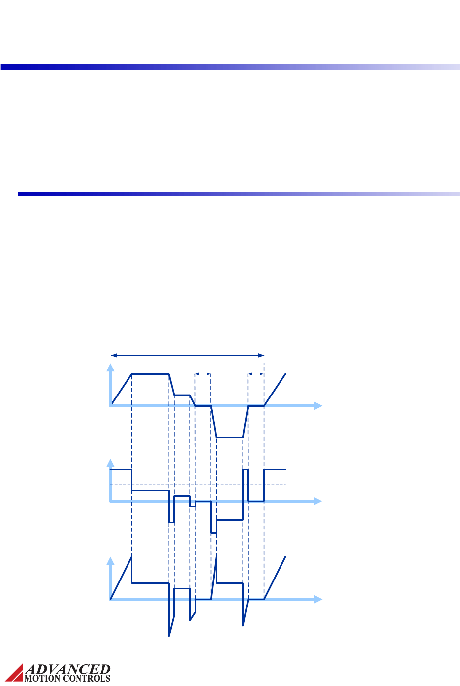
Figure2.7representsdifferentialencoder"pulse"signals,showinghowdependingonwhich
signalisreadfirstandatwhatfrequencythe"pulses"arrive,thespeedanddirectionofthe
motorshaftcanbeextrapolated.Bykeepingtrackofthenumberofencoder"pulses"with
respecttoaknownmotor"home"position,servodrivesareabletoascertaintheactualmotor
location.
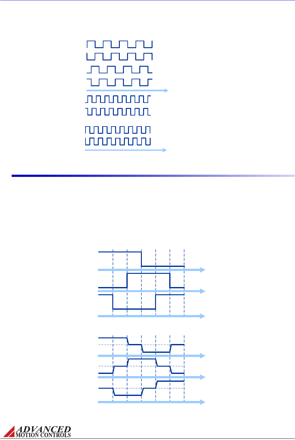
FIGURE 2.7 Encoder Feedback Signals
Encoder A+
Encoder B+
Encoder A+
Encoder B+
Example 1: Encoder-A precedes Encoder-B. The pulses
arrive at a certain frequency, providing speed and
directional information to the drive.
Example 2: Encoder-B precedes Encoder-A, meaning the
direction is opposite from Example 1. The signal frequency
is also higher, meaning the speed is greater than in
Example 1.
Encoder A-
Encoder B-
Encoder A-
Encoder B-
FIGURE 2.8 Hall Sensor Commutation and Motor Phase Current for 120-Degree Phasing
Electrical Degrees
Motor Phase
Current
060 120 180 240 300 360
Hall A
Hall B
Hall C
High (1)
Low (0)
High (1)
Low (0)
High (1)
Low (0)
Phase A
Phase B
Phase C
Hall Sensor
Commutation
Electrical Degrees
060 120 180 240 300 360
High
Low
High
Low
High
Low
MNALHWIN-01 12
Products and System Requirements / Feedback Specifications
2.5.3 Hall Sensors
ThreePhase(Brushless)drivesuseHallSensorsforcommutationfeedback,andinthespecial
caseofsomedrives,forvelocitycontrol.TheHallSensorsarebuiltintothemotortodetectthe
positionoftherotormagneticfield.Thesesensorsaremountedsuchthattheyeachgeneratea
squarewavewitheithera120‐degreeor60‐degreephasedifferenceoveroneelectricalcycle
ofthemotor.
MNALHWIN-01 13
Products and System Requirements / Feedback Specifications
Dependingonthemotorpolecount,theremaybemorethanoneelectricalcycleforevery
motorrevolution.Foreveryactualmechanicalmotorrevolution,thenumberofelectricalcycles
willbethenumberofmotorpolesdividedbytwo.Forexample:
•a6‐polemotorcontains3electricalcyclespermotorrevolution
•a4‐polemotorcontains2electricalcyclespermotorrevolution
•a2‐polemotorcontains1electricalcyclepermotorrevolution
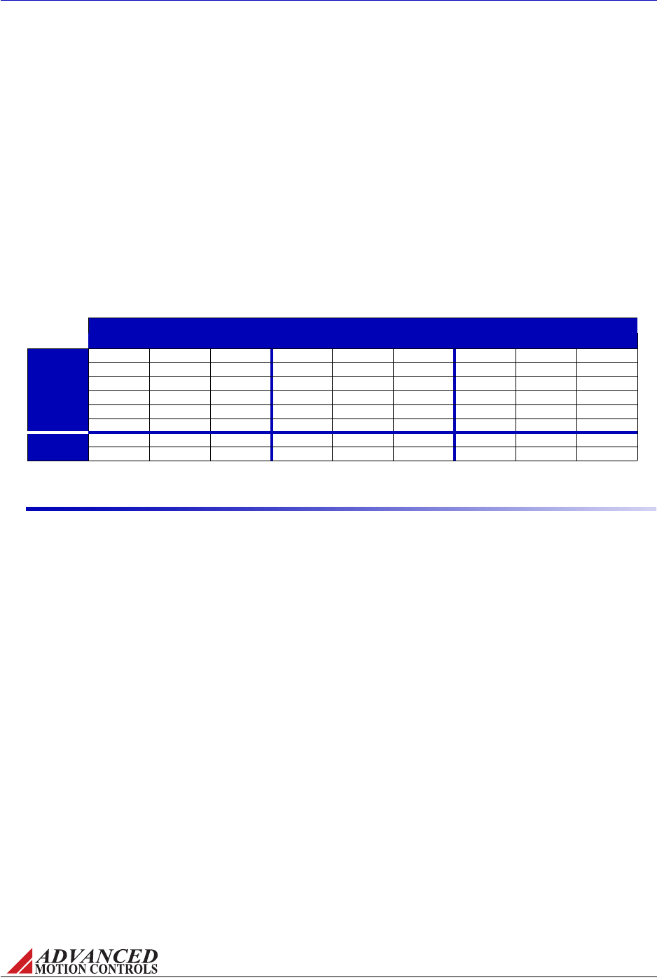
ThedrivepowerstwoofthethreemotorphaseswithDCcurrentduringeachspecificHall
Sensorstate:
Thetablebelowshowsthevalidcommutationstatesforboth120‐degreeand60‐degree
phasing.
TABLE 2.11 Commutation Sequence Table
60 Degree 120 Degree Motor
Hall 1 Hall 2 Hall 3 Hall 1 Hall 2 Hall 3 Phase A Phase B Phase C
Valid
1 0 0 1 0 0 HIGH -LOW
1 1 0 1 1 0 - HIGH LOW
1 1 1 0 1 0 LOW HIGH -
0 1 1 0 1 1 LOW -HIGH
0 0 1 0 0 1 - LOW HIGH
0 0 0 1 0 1 HIGH LOW -
Invalid 1 0 1 1 1 1 - - -
0 1 0 0 0 0 - - -
2.5.4 Tachometer
ADCTachometercanbeusedonsomedrivesforvelocitycontrol.Thetachometerprovidesan
analogDCvoltagefeedbacksignalthatisrelatedtotheactualmotorspeedanddirection.The
drivesubsequentlyadjuststheoutputcurrentbasedontheerrorbetweenthetachometer
feedbackandtheinputcommandvoltage.Themaximumrangeofthetachometerfeedback
signalis±60VDC.
Someapplicationsmayrequireanincreaseinthegainofthetachometerinputsignal.This
occurrencewillbemostcommonindesignswherethetachometerinputhasalowvoltageto
RPMscalingratio.Somedrivemodelsofferathrough‐holelocationlistedonthespecificdrive
datasheetwherearesistorcanbeaddedtoincreasethetachometergain.Usethedrive’sblock
diagramtodetermineanappropriateresistorvalue.
See“TachometerInputGainScaling”onpage45formoreinformation.

MNALHWIN-01 14
Products and System Requirements / Modes of Operation
2.6 Modes of Operation
Thefamilyofanalogdrivesoffersavarietyofdifferentcontrolmethods.Whilesomedrivesin
theseriesaredesignedtooperatesolelyinonemode,onotherdrivesitispossibletoselectthe
controlmethodbyDIPswitchsettings(see“PotentiometerFunctionDetails”onpage43for
moreinformation).Consultthedatasheetforthedriveinusetoseewhichmodesareavailable
foruse.
Thenameofthemodereferstowhichservoloopisbeingclosedinthedrive,nottheend‐result
oftheapplication.Forinstance,adriveoperatinginCurrent(Torque)Modemaybeusedfora
positioningapplicationiftheexternalcontrollerisclosingthepositionloop.Oftentimes,mode
selectionwillbedependentontherequirementsandcapabilitiesofthecontrollerbeingused
withthedriveaswellastheend‐resultapplication.
2.6.1 Current (Torque) Mode
InCurrent(Torque)Mode,theinputcommandvoltagecontrolstheoutputcurrent.Thedrive
willadjusttheoutputdutycycletomaintainthecommandedoutputcurrent.Thismodeisused
tocontroltorqueforrotarymotors(forceforlinearmotors),butthemotorspeedisnot
controlled.Theoutputcurrentcanbemonitoredthroughananalogcurrentmonitoroutput
pin.Thevoltagevaluereadatthe“CurrentMonitorOutput”canbemultipliedbyascaling
factorfoundonthedrivedatasheettodeterminetheactualoutputcurrent.
2.6.2 Open Loop (PWM Duty Cycle) Mode
InOpenLoop(PWMDutyCycle)Mode,theinputcommandvoltagecontrolstheoutputPWM
dutycycleofthedrive,indirectlycontrollingtheoutputvoltage.Notethatanyfluctuationsof
theDCsupplyvoltagewillaffectthevoltageoutputtothemotor.
While in Current (Torque) Mode, the drive will maintain a commanded
torque output to the motor based on the input reference command.
Sudden changes in the motor load may cause the drive to be outputting
a high torque command with little load resistance, causing the motor to
spin rapidly. Therefore, Current (Torque) Mode is recommended for
applications using a digital position controller to maintain system stability.
This mode is recommended as a method of controlling the motor
velocity when precise velocity control is not critical to the application,
and when actual velocity feedback is unavailable.
Note
Note

MNALHWIN-01 15
Products and System Requirements / Modes of Operation
2.6.3 Hall Velocity Mode
InHallVelocityMode,theinputcommandvoltagecontrolsthemotorvelocity,withtheHall
Sensorfrequencyclosingthevelocityloop.Ananalogvelocitymonitoroutputallows
observationoftheactualmotorspeedthroughaHz/Vscalingfactorfoundonthedrive
datasheet.Thevoltagevaluereadatthevelocitymonitoroutputcanbeusedtodeterminethe
motorRPMthroughthescalingfactor.See“VelocityMonitorOutput”onpage42forthemotor
RPMequation.
2.6.4 Encoder Velocity Mode
InEncoderVelocityMode,theinputcommandcontrolsthemotorvelocity,withthefrequency
oftheencoderpulsesclosingthevelocityloop.Ananalogvelocitymonitoroutputallows
observationoftheactualmotorspeedthroughakHz/Vscalingfactorfoundonthedrive
datasheet.Thevoltagevaluereadatthevelocitymonitoroutputcanbeusedtodeterminethe
motorRPMthroughthescalingfactor.See“VelocityMonitorOutput”onpage42forthemotor
RPMequation.
2.6.5 Tachometer Velocity Mode
InTachometerVelocityMode,theinputcommandvoltagecontrolsthemotorvelocity.This
modeusesanexternalDCtachometertoclosethevelocityloop.ThedrivetranslatestheDC
voltagefromthetachometerintomotorspeedanddirectioninformation.
Due to the inherent low resolution of motor mounted Hall Sensors, Hall
Velocity Mode is not recommended for low-speed applications below
300 rpm for a 6-pole motor, 600 rpm for a 4-pole motor, or 900 rpm for a
2-pole motor. Hall Velocity Mode is better suited for velocity control
applications where the motor will be spinning at higher speeds.
The high resolution of motor mounted encoders allows for excellent
velocity control and smooth motion at all speeds. Encoder Velocity
Mode should be used for applications requiring precise and accurate
velocity control, and is especially useful in applications where low-speed
smoothness is the objective.
DC Tachometers have infinite resolution, allowing for extremely accurate
velocity control. However, they also may be susceptible to electrical
noise, most notably at low speeds.
Note
Note
Note

MNALHWIN-01 16
Products and System Requirements / Modes of Operation
2.6.6 Voltage Mode
InVoltageModetheinputreferencesignalcommandsaproportionalmotorvoltageregardless
ofpowersupplyvoltagevariations.Thismodeisrecommendedforvelocitycontrolwhen
velocityfeedbackisunavailableandloadvariancesaresmall.
2.6.7 IR Compensation Mode
IfthereisaloadtorquevariationwhileinVoltageMode,themotorcurrentwillalsovaryas
torqueisproportionaltomotorcurrent.Hence,themotorterminalvoltagewillbereducedby
thevoltagedropoverthemotorwindingresistance(IR),resultinginaspeedreduction.Thus,
motorspeed,whichisproportionaltomotorvoltage(terminalvoltageminusIRdrop)varies
withtheloadtorque.
FIGURE 2.9
Pot1
(>20k)
Analog Servo
Drive
Motor
Tach
Motor
Outputs
Tach-
Tach+
+Ref
-Ref
GND
+10V
-10V
Command
Return
Load
Analog Position Loop Mode Configuration
Inordertocompensatefortheinternalmotorvoltagedrop,avoltag ep ropo rtio nalto mo tor
currentcanbeaddedtotheoutputvoltage.Aninternalresistoradjuststheamountof
compensation,andanadditionalthrough‐holeresistorcanbeaddedtothelocationlistedon
thedrivedatasheet.UsecautionwhenadjustingtheIRcompensationlevel.Ifthefeedback
voltageishighenoughtocauseariseinmotorvoltagewithincreasedmotorcurrent,instability
occurs.Sucharesultisduetothefactthatincreasedvoltageincreasesmotorspeedandthus
loadcurrentwhich,inturn,increasesmotorvoltage.Ifagreatdealof moto rtorquec hange i s
anticipated,itmaybewisetoconsidertheadditionofaspeedsensortothemotor(e.g.
tachometer,encoder,etc.).
2.6.8 Analog Position Loop Mode
Inthismodethefeedbackdeviceisananalogpotentiometermechanicallytiedtothe
positionedobject,thusprovidingpositionfeedback.Thewiperofthepotentiometeris
connectedtooneofthedifferentialinputterminals(‐REF).Thecommandisananalogsignal,
whichisconnectedtotheotherdifferentialinputterminal(+REF).
Itisrecommendedtouseatachometertoclosethevelocityloop.Theinputreferencegaincan
beincreasedinthedrivehardwarefortheAnalogPositionLoopModebyorderingthe‐ANP
extension.ThefollowingfigureisatypicalwiringdiagramofAnalogPositionLoopMode.
MNALHWIN-01 17
Products and System Requirements / System Requirements
2.7 System Requirements
Tosuccessfullyincorporateananalogservodriveintoyoursystem,youmustbesureitwill
operateproperlybasedonelectrical,mechanical,andenvironmentalspecifications,follow
somesimplewiringguidelines,andperhapsmakeuseofsomeaccessoriesinanticipating
impactsonperformance.Beforeselectingananalogservodrive,ausershouldconsiderthe
requirementsoftheirsystem.Thisinvolvescalculatingtherequiredvoltage,current,torque,
andpowerrequirementsofthesystem,aswellasconsideringtheoperatingenvironmentand
anyotherequipmentthedrivewillbeinterfacingwith.
2.7.1 Analog Servo Drive Selection and Sizing
Analogservodriveshaveagivencurrentandvoltageratinguniquetoeachdrive.Basedonthe
necessaryapplicationrequirementsandtheinformationfromthedatasheetofthemotorbeing
used,adrivemaybeselectedthatwillbestsuitthemotorcapabilities.
FIGURE 2.10 Example Velocity, Torque, and Power Curves
Velocity
Torque
Power
RMS
Power is equal to Torque x Velocity. Motor
Voltage (Vm) and Motor Current (Im) should
be chosen where power is at a maximum.
Time
Time
Time
1 Cycle
Dwell Dwell
Adriveshouldbeselectedthatwillmeetthepeakandcontinuouscurrentrequirementsofthe
application,andoperatewithinthevoltagerequirementsofthesystem.
Motor Current and Voltage Motorvoltageandcurrentrequirementsaredeterminedbased
onthemaximumrequiredtorqueandvelocity.Theserequirementscanbederivedfromthe
applicationmoveprofiles(Figure2.10).

MNALHWIN-01 18
Products and System Requirements / System Requirements
ThemotorcurrentIMistherequiredmotorcurrentinampsDC,andisrelatedtothetorque
neededtomovetheloadbythefollowingequation:
Where:
KT‐motortorqueconstant
Themotorcurrentwillneedtobecalculatedforbothcontinuousandpeakoperation.Thepeak
torquewillbeduringtheaccelerationportionofthemoveprofile.
Thecontinuoustorqueistheaveragetorquerequiredbythesystemduringthemoveprofile,
includingdwelltimes.Bothpeaktorqueandcontinuous,orRMS(rootmeansquare)torque
needtobecalculated.RMStorquecanbecalculatedbyplottingtorqueversustimeforonemove
cycle.
HereTiisthetorqueandtiisthetimeduringsegmenti.Inthecaseofaverticalapplication
makesuretoincludethetorquerequiredtoovercomegravity.
Thesystemvoltagerequirementisbasedonthemotorpropertiesandhowfastandhardthe
motorisdriven.Thesystemvoltagerequirementisequaltothemotorvoltage,VM,requiredto
achievethemoveprofile.Ingeneral,themotorvoltageisproportionaltothemotorspeedand
themotorcurrentisproportionaltothemotorshafttorque.Linearmotorsexhibitthesame
behaviorexceptthatintheircaseforceisproportionaltocurrent.Theserelationshipsare
describedbythefollowingequations:
IM
Torque
KT
-------------------=
TRMS
Ti
2ti
i
∑
ti
i
∑
-----------------=
VmImRmE+=
EK
eSm
=
TK
tIm
=
forrotarymotors
FK
fIm
=
forlinearmotors
MNALHWIN-01 19
Products and System Requirements / System Requirements
Where:
Vm‐motorvoltage
Im‐motorcurrent(usethemaximumcurrentexpectedfortheapplication)
Rm‐motorline‐to‐lineresistance
E‐motorback‐EMFvoltage
T ‐m otor to rque
F‐motorforce
Kt‐motortorqueconstant
Kf‐motorforceconstant
Ke‐voltageconstant
Sm‐motorspeed(usethemaximumspeedexpectedfortheapplication)
Themotormanufacturer’sdatasheetcontainKt(orKf)andKeconstants.Payspecialattention
totheunitsused(metricvs.English)andtheamplitudespecifications(peak‐to‐peakvs.RMS,
phase‐to‐phasevs.phase‐to‐neutral).
Themaximummotorterminalvoltageandcurrentcanbecalculatedfromtheaboveequations.
Forexample,amotorwithaKe=10V/Krpmandrequiredspeedof3000RPMwouldrequire
30Vtooperate.InthiscalculationtheIRterm(voltagedropacrossmotorwindingresistance)is
disregarded.MaximumcurrentismaximumtorquedividedbyKt.Forexample,amotorwithKt
=0.5Nm/Aandmaximumtorqueof5Nmwouldrequire10ampsofcurrent.Continuous
currentisRMStorquedividedbyKt.
Motor Inductance Themotorinductanceisvitaltotheoperationofanalogservodrives,asit
ensuresthattheDCmotorcurrentisproperlyfiltered.
Aminimummotorinductanceratingforeachspecificdrivecanbefoundinthedatasheet.Ifthe
driveisoperatedbelowthemaximumratedvoltage,theminimumloadinductance
requirementmaybereduced.
Intheaboveequationsthemotorinductanceisneglected.Inbrushlesssystemsthevoltagedrop
causedbythemotorinductancecanbesignificant.Thisisthecaseinhigh‐speedapplicationsif
motorswithhighinductanceandhighpolecountareused.Pleaseusethefollowingequationto
determinemotorterminalvoltage(mustbeinterpretedasavector).
Where:
L ‐phase‐to‐phasemotorinductance
ω‐maximummotorcurrentfrequency
A motor that does not meet the rated minimum inductance value of the
drive may damage the drive! If the motor inductance value is less than
the minimum required for the selected drive, use of an external filter card
is necessary. See “Inductive Filter Cards” on page 29 for more
information.
VmRmjωL+()ImE+=

MNALHWIN-01 20
Products and System Requirements / System Requirements
2.7.2 Power Supply Selection and Sizing
Thereareseveralfactorstoconsiderwhenselectingapowersupplyforananalogservodrive.
•PowerRequirements
•Isolation
•Regeneration
•VoltageRipple
PowerRequirementsreferstohowmuchvoltageandcurrentwillberequiredbythedrivein
thesystem.Isolationreferstowhetherthepowersupplyneedsanisolationtransformer.
Regenerationistheenergythepowersupplyneedstoabsorbduringdeceleration.Voltage
Rippleisthevoltagefluctuationinherentinunregulatedsupplies.
Power Supply Current and Voltage Thepowersupplycurrentratingisbasedonthe
maximumcurrentthatwillberequiredbythesystem.Ifthepowersupplypowersmorethan
onedrive,thenthecurrentrequirementsforeachdriveshouldbeaddedtogether.Duetothe
natureofservodrives,thecurrentintothedrivedoesnotalwaysequalthecurrentoutofthe
drive.However,thepowerinisequaltothepowerout.Usethefollowingequationtocalculate
thepowersupplyoutputcurrent,IPS,basedonthemotorvoltageandcurrentrequirements.
Where:
VPS ‐nominalpowersupplyvoltage
IM‐motorcurrent
VM‐motorvoltage
UsevaluesofVmandImatthepointofmaximumpowerinthemoveprofile,Figure2.10
(whenVMIM=max).Thiswillusuallybeattheendofahardaccelerationwhenboththetorque
andspeedofthemotorishigh.
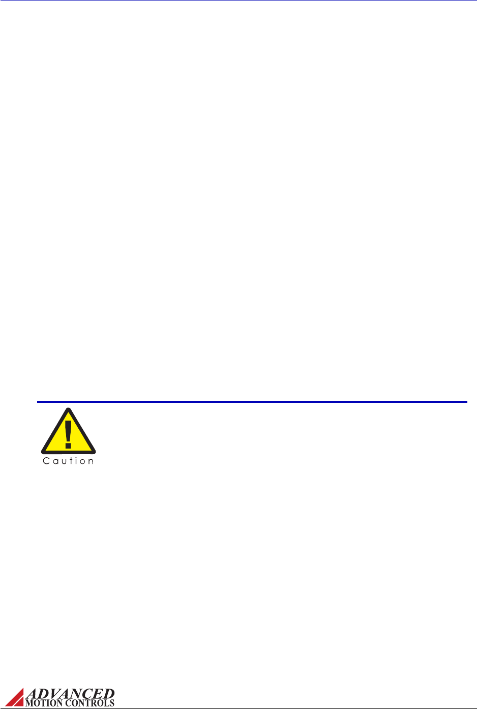
ThepowersupplycurrentisapulsedDCcurrent(Figure2.11):whentheMOSFETswitchis
on,itequalsthemotorcurrent;whentheMOSFETisoffitiszero.Therefore,thepowersupply
currentisafunctionofthePWMdutycycleandthemotorcurrent(e.g.30%dutycycleand12
ampsmotorcurrentwillresultin4ampspowersupplycurrent).30%dutycyclealsomeans
thattheaveragemotorvoltageis30%oftheDCbusvoltage.Powersupplypoweris
approximatelyequaltodriveoutputpowerplus3to5%.
The only time the power supply current needs to be as high as the drive
output current is if the move profile requires maximum current at
maximum velocity. In many cases however, maximum current is only
required at start up and lower currents are required at higher speeds.
IPS
VMIM
⋅
VPS 0.98()⋅
-----------------------------=
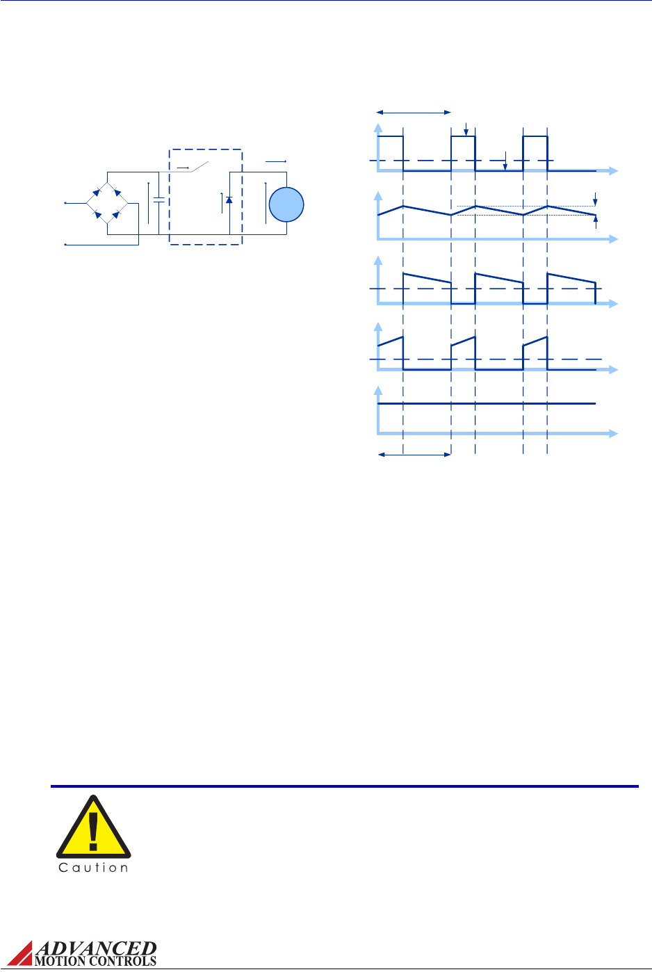
FIGURE 2.11 Unregulated DC Power Supply Current
Im
Id
Ip
Time
Time
Time
PWM
Switching
Time
Vp
Time
Vm
Time
Average
Ripple Current
MOSFET ON
MOSFET OFF
Average
Average
50usec
Vm = Motor Terminal Voltage
Im = Motor Current
Id = Diode Current
Ip = Power Supply Current
Vp = DC Power Supply Voltage
VAC = AC Supply Voltage (RMS)
The ripple current depends on the
motor inductance and the duty
cycle (MOSFET ON vs. OFF
time)
Motor
DIODE BRIDGE
AC Input
Voltage
Ip
Im
Vm
Id
Vp
SERVO DRIVE
Vp = VAC*1.41
—Driveovervoltage
—Externalshuntregulatorturn‐onvoltage(see“RegenerationandShuntRegulators”on
page23)
MNALHWIN-01 21
Products and System Requirements / System Requirements
Asystemwillneedacertainamountofvoltageandcurrenttooperateproperly.Ifthepower
supplyhastoolittlevoltage/currentthesystemwillnotperformadequately.Ifthepower
supplyhastoomuchvoltagethedrivemayshutdownduetoovervoltage,orthedrivemaybe
dam aged.
Toavoidnuisanceover‐orunder‐voltageerrorscausedbyfluctuationsinthepowersupply,
theidealsystempowersupplyvoltageshouldbeatleast10%abovetheentiresystemvoltage
requirement,andatleast10%belowthelowestvalueofthefollowing:
ThesepercentagesalsoaccountforthevariancesinKtandKe,andlossesinthesystem
externaltothedrive.Theselectedmargindependsonthesystemparametervariations.
Do not select a supply voltage that could cause a mechanical over-
speed in the event of a drive malfunction or a runaway condition.
Brushed Motors may have voltage limitations due to the mechanical
commutators. Consult the manufacturer’s data sheets.

FIGURE 2.12 Power Supply Selection
Drive Over Voltage Shutdown (88V)
0
20
40
60
80
100
VDC Acceptable Power Supply
Range (26 V-72V)
Shunt Regulator Turn-On Voltage (80V)
Drive Under Voltage Shutdown (9V)
System Power Supply Requirement (24V)
MNALHWIN-01 22
Products and System Requirements / System Requirements
Figure2.12providesonepossibleexampleofanappropriatesystempowersupplyvoltagefor
ananalogdriveusinganexternalshuntregulator.Theovervoltageandundervoltage
shutdownlevelsonADVANCEDMotionControlsdrivescanbefoundonthedrivedatasheet.The
shuntregulatorturn‐onvoltagewaschosenatanappropriateleveltoclampthepowersupply
voltagesoitwillnotexceedthedriveovervoltagelimitduringregeneration.Thesystempower
supplyrequirementisbasedonthemotorpropertiesandhowmuchvoltageisneededto
achievetheapplicationmoveprofile(see“MotorCurrentandVoltage”onpage17).Keepin
mindthatthecalculatedvalueforVmistheminimumvoltagerequiredtocompletemovesat
thedesiredspeedandtorque.Thereshouldbeatleast10%headroombetweenthecalculated
valueandtheactualpowersupplyvoltagetoallowformachinechangessuchasincreased
frictionduetowear,changeinload,increasedoperatingspeed,etc.
Isolation InsystemswhereanAClineisinvolved,isolationisrequiredbetweentheAClineandthe
signalpinsonthedrive.Thisappliestoallsystemsexceptthosethatuseabatteryasapower
supply.Therearetwooptionsforisolation:
1. Thedrivecanhavebuiltinelectricalisolation.
2. Thepowersupplycanprovideisolation(e.g.abatteryoranisolationtransformer).
Thesystemmusthaveatleastoneoftheseoptionstooperatesafely.
Drive with Isolation
SomeADVANCEDMotionControlsanalogdrivescomewithstandardelectricalisolation,while
otherscanbeorderedwithisolationasanoption(seeFigure2.1,“AnalogProductFamilyPart
NumberingStructure,”).Todetermineifadrivehasisolationrefertothefunctionalblock
diagramonthedrivedatasheet.Theisolationwillbeindicatedbyadashedlinethroughthe
functionalblockdiagramseparatingpowergroundfromsignalground.
Driveswithan"I"afterthecurrentratinginthepartnumber(i.e.30A8I),drivesthatarerated
to400VDCanddrivesthattakeAClinevoltageforpowercomestandardwithisolation.Other
drivesthatdonotfallintothesecategoriescanbeorderedbyspecialrequesttoinclude
isolation.
Power Supply with Isolation
Anisolatedpowersupplyiseitherabatteryorapowersupplythatusesanisolation
transformertoisolatetheAClinevoltagefromthepowersupplyground.Thisallowsboththe
powergroundonanisolatedpowersupplyandthesignalgroundonanon‐isolateddrivetobe
safelypulledtoearthground.Alwaysuseanisolatedpowersupplyifthereisnoisolationinthe
drive.
FIGURE 2.13 Four Quadrant Operation - Regeneration occurs when Torque and Velocity polarity are opposite
IV
Regenerating
Counterclockwise
Current/Torque
Voltage/Velocity
III
Motoring
Counterclockwise
II
Regenerating
Clockwise
I
Motoring
Clockwise
Torque +
Torque -
Torque -
Torque +
Velocity +
Velocity +
Velocity -
Velocity -
No Regen
Regen
No Regen
Regen
I
II
III
IV
MNALHWIN-01 23
Products and System Requirements / System Requirements
Regeneration and Shunt Regulators Useofashuntregulatorisnecessaryinsystems
wheremotordecelerationoradownwardmotionofthemotorloadwillcausethesystem’s
mechanicalenergytoberegeneratedviathedrivebackontothepowersupply.
Thisregeneratedenergycanchargethepowersupplycapacitorstolevelsabovethatofthe
driveover‐voltageshutdownlevel.Ifthepowersupplycapacitanceisunabletohandlethis
excessenergy,orifitisimpracticaltosupplyenoughcapacitance,thenanexternalshunt
regulatormustbeusedtodissipatetheregeneratedenergy.Shuntregulatorsareessentiallya
resistorplacedinparallelwiththeDCbus.Theshuntregulatorwill"turn‐on"atacertain
voltagelevel(setbelowthedriveover‐voltageshutdownlevel)anddischargetheregenerated
electricenergyintheformofheat.
Thevoltageriseonthepowersupplycapacitorswithoutashuntregulator,canbecalculated
accordingtoasimpleenergybalanceequation.Theamountofenergytransferredtothepower
supplycanbedeterminedthrough:
Where:
Ei‐initialenergy
Ef‐finalenergy
Theseenergytermscanbebrokendownintotheapproximatemechanicalandelectricalterms
‐capacitive,kinetic,andpotentialenergy.Theenergyequationsfortheseindividual
componentsareasfollows:
Where:
Ec‐energystoredinacapacitor(joules)
C‐capacitance
Vnom ‐nominalbusvoltageofthesystem
EiEf
=
Ec
1
2
---CVnom
2
=

Er
1
2
---Jω2
=
MNALHWIN-01 24
Products and System Requirements / System Requirements
Where:
Er‐kinetic(mechanical)energyoftheload(joules)
J ‐inertiaoftheload(kg‐m2)
ω‐angularvelocityoftheload(rads/s)
Epmgh=
Where:
Ep‐potentialmechanicalenergy(joules)
m ‐massoftheload(kg)
g ‐gravitationalacceleration(9.81m/s2)
h ‐verticalheightoftheload(meters)
Duringregenerationthekineticandpotentialenergywillbestoredinthepowersupply’s
capacitor.Todeterminethefinalpowersupplyvoltagefollowingaregenerativeevent,the
followingequationmaybeusedformostrequirements:
Whichsimplifiesto:
TheVfcalculatedmustbebelowthepowersupplycapacitancevoltageratingandthedriveover
voltagelimit.Ifthisisnotthecase,ashuntregulatorisnecessary.Ashuntregulatorissizedin
thesamewayasamotorordrive,i.e.continuousandRMSpowerdissipationmustbe
determined.Thepowerdissipationrequirementscanbedeterminedfromtheapplication
moveprofile(seeFigure2.10).
ADVANCEDMotionControlsoffersavarietyofshuntregulatorsforservodrives.When
choosingashuntregulator,selectonewithashuntvoltagethatisgreaterthantheDCbus
voltageoftheapplicationbutlessthantheovervoltageshutdownofthedrive.Verifytheneed
EcErEp
⋅⋅()
iEcErEp
⋅⋅()
f
=
1
2
---CVnom
21
2
---Jωi
2mghi
++ 1
2
---CVf
21
2
---Jωf
2mghf
++=
VfVnom
2J
C
----ωi
2ωf
2
–()
2mg hihf
–()
C
-------------------------------++=

MNALHWIN-01 25
Products and System Requirements / System Requirements
forashuntregulatorbyoperatingtheservodriveundertheworst‐casebrakingand
decelerationconditions.Ifthedriveshutsoffduetoover‐voltage,ashuntregulatorisnecessary.
Continuous Regeneration
Inthespecialcasewhereanapplicationrequirescontinuousregeneration(morethanafew
seconds)thenashuntregulatormaynotbesufficienttodissipatetheregenerativeenergy.
PleasecontactADVANCEDMotionControlsforpossiblesolutionstosolvethiskindof
application.Someexamples:
•Webtensioningdevice
•Electricvehiclerollingdownalonghill
•Spinningmasswithaverylargeinertia(grindingwheel,flywheel,centrifuge)
•Heavyliftgantry
Voltage Ripple Forthemostpart,ADVANCEDMotionControlsanalogservodrivesare
unaffectedbyvoltageripplefromthepowersupply.Thecurrentloopisfastenoughto
compensatefor60Hzfluctuationsinthebusvoltage,andthecomponentsinthedriveare
robustenoughtowithstandallbutthemostextremecases.Peaktopeakvoltagerippleashigh
as25Visacceptable.
Therearesomeapplicationswherethevoltageripplecancauseunacceptableperformance.
Thiscanbecomeapparentwhereconstanttorqueorforceiscriticalorwhenthebusvoltageis
pulledlowduringhighspeedandhighcurrentapplications.Ifnecessary,thevoltageripple
fromthepowersupplycanbereduced,eitherbyswitchingfromsinglephaseACtothree
phaseAC,orbyincreasingthecapacitanceofthepowersupply.
Thevoltagerippleforasystemcanbeestimatedusingtheequation:
Where:
VR‐voltageripple
CPS ‐powersupplycapacitance
IPS ‐powersupplyoutputcurrent
Ff‐frequencyfactor(1/hertz)
Thepowersupplycapacitancecanbeestimatedbyrearrangingtheaboveequationtosolvefor
thecapacitanceas:
VR
IPS
CPS
----------Ff
=
CPS
IPS
VR
--------Ff
=
MNALHWIN-01 26
Products and System Requirements / System Requirements
Thefrequencyfactorcandeterminedfrom:
wherefistheAClinefrequencyinhertz.Notethatforhalfwaverectifiedpowersupplies,f=
f/2.
Thepowersupplyoutputcurrent,ifunknown,canbeestimatedbyusinginformationfromthe
outputsideoftheservodriveasgivenbelow:
Where:
IM‐currentthroughthemotor
VPS ‐nominalpowersupplyvoltage
VM‐motorvoltage(see“MotorCurrentandVoltage”onpage17)
2.7.3 Environmental Specifications
Toensureproperoperationofananalogservodrive,itisimportanttoevaluatetheoperating
environmentpriortoinstallingthedrive.
TABLE 2.12 Environmental Specifications
Environmental Specifications
Parameter Description
Baseplate Temperature Range 0 - 65 ºC
Humidity 90%, non-condensing
Mechanical Shock 15g, 11ms, Half-sine
Vibration 2 - 2000 Hz @ 2.5g
Altitude 0-3000m
Shock/Vibrations Whileanalogdrivesaredesignedtowithstandahighdegreeofmechanical
shockandvibration,toomuchphysicalabusecancauseerraticbehavior,orcausethedriveto
ceaseoperationentirely.Besurethedriveissecurelymountedinthesystemtoreducethe
shockandvibrationthedrivewillbeexposedto.Thebestwaytosecurethedriveagainst
mechanicalvibrationistousescrewstomountthedriveagainstitsbaseplate.Forinformation
onmountingoptionsandprocedures,see“Mounting”onpage39andthedimensional
drawingsandinformationonthedrivedatasheet.
Care should be taken to ensure the drive is securely mounted in a
location where no moving parts will come in contact with the drive.
Ff
0.42
f
----------=
IPS
VMI⋅M
VPS 0.98()⋅
-----------------------------=

MNALHWIN-01 27
3 Integration in the Servo System
Thischapterwillgivevariousdetailsonincorporatingananalogservodriveintoasystem,suchashowto
properlygroundthedrivealongwiththeentiresystem,andhowtoproperlyconnectmotorwires,power
supplywires,feedbackwires,andinputsintotheanalogservodrive.
3.1 LVD Requirements
TheservodrivescoveredintheLVDReferencereportwereinvestigatedascomponents
intendedtobeinstalledincompletesystemsthatmeettherequirementsoftheMachinery
Directive.Inorderfortheseunitstobeacceptableintheendusers’equipment,thefollowing
conditionsofacceptabilitymustbemet.
1. Europeanapprovedoverloadandcurrentprotectionmustbeprovidedforthemotorsas
specifiedinsection7.2and7.3ofEN60204.1.
2. Adisconnectswitchshallbeinstalledinthefinalsystemasspecifiedinsection5.3of
EN60204.1.
3. Alldrivesthatdonothaveagroundingterminalmustbeinstalledin,andconductively
connectedtoagroundedenduseenclosureinordertocomplywiththeaccessibility
requirementsofsection6,andtoestablishgroundingcontinuityforthesystemin
accordancewithsection8ofEN60204.1.
4. Adisconnectingdevicethatwillpreventtheunexpectedstart‐upofamachineshallbe
providedifthemachinecouldcauseinjurytopersons.Thisdeviceshallpreventthe
automaticrestartingofthemachineafteranyfailureconditionshutsthemachinedown.
5. Europeanapprovedovercurrentprotectivedevicesmustbeinstalledinlinebeforethe
servodrive,thesedevicesshallbeinstalledandratedinaccordancewiththeinstallation
instructions(theinstallationinstructionsshallspecifyanovercurrentratingvalueaslow
aspossible,buttakingintoconsiderationinrushcurrents,etc.).Servodrivesthat
incorporatetheirownprimaryfusesdonotneedtoincorporateoverprotectionintheend
users’equipment.
Theseitemsshouldbeincludedinyourdeclarationofincorporationaswellasthenameand
addressofyourcompany,descriptionoftheequipment,astatementthattheservodrivesmust
notbeputintoserviceuntilthemachineryintowhichtheyareincorporatedhasbeendeclared
inconformitywiththeprovisionsoftheMachineryDirective,andidentificationoftheperson
signing.

MNALHWIN-01 28
Integration in the Servo System / CE-EMC Wiring Requirements
3.2 CE-EMC Wiring Requirements
ThefollowingsectionscontaininstallationinstructionsnecessaryformeetingEMC
requirements.
General
1. Shieldedcablesmustbeusedforallinterconnectcablestothedriveandtheshieldofthe
cablemustbegroundedattheclosestgroundpointwiththeleastamountofresistance.
2. Thedrive’smetalenclosuremustbegroundedtotheclosestgroundpointwiththeleast
amountofresistance.
3. Thedrivemustbemountedinsuchamannerthattheconnectorsandexposedprinted
circuitboardarenotaccessibletobetouchedbypersonnelwhentheproductisin
operation.Ifthisisunavoidabletheremustbeclearinstructionsthatthedriveisnottobe
touchedduringoperation.Thisistoavoidpossiblemalfunctionduetoelectrostatic
dischargefrompersonnel.
Analog Input Drives
4. AFairRitemodel0443167251roundsuppressioncoremustbefittedtothelowlevel
signalinterconnectcablestopreventpickupfromexternalRFfields.
PWM Input Drives
5. AFairRitemodel0443167251roundsuppressioncoremustbefittedtothePWMinput
cabletoreduceelectromagneticemissions.
MOSFET Switching Drives
6. AFairRitemodel0443167251roundsuppressioncoremustbefittedattheloadcable
connectortoreduceelectromagneticemissions.
7. AnappropriatelyratedCoselTACseriesACpowerfilterincombinationwithaFairRite
model5977002701torroid(placedonthesupplyendofthefilter)mustbefittedtotheAC
supplytoanyMOSFETdrivesysteminordertoreduceconductedemissionsfedbackinto
thesupplynetwork.
IGBT Switching Drives
8. AnappropriatelyratedCoselTACseriesACpowerfilterincombinationwithaFairRite
model0443167251roundsuppressioncore(placedonthesupplyendofthefilter)must
befittedtotheACsupplytoanyIGBTdrivesysteminordertoreduceconductedemissions
fedbackintothesupplynetwork.
9. AFairRitemodel0443164151roundsuppressioncoreandmodel5977003801torroid
mustbefittedattheloadcableconnectortoreduceelectromagneticemissions.
Fitting of AC Power Filters
Itispossiblefornoisegeneratedbythemachineto"leak"ontothemainACpower,andthen
getdistributedtonearbyequipment.Ifthisequipmentissensitive,itmaybeadverselyaffected
bythenoise.ACpowerfilterscanfilterthisnoiseandkeepitfromgettingontheACpower
signal.TheabovementionedACpowerfiltersshouldbemountedflatagainsttheenclosureof

MNALHWIN-01 29
Integration in the Servo System / CE-EMC Wiring Requirements
theproductusingthetwomountinglugsprovidedonthefilter.Paintshouldberemovedfrom
theenclosurewherethefilterisfittedtoensuregoodmetaltometalcontact.Thefiltershould
bemountedasclosetothepointwheretheACpowerfilterenterstheenclosureaspossible.
Also,theACpowercableontheloadendofthefiltershouldberoutedasfarfromtheACpower
cableonthesupplyendofthefilterandallothercablesandcircuitrytominimizeRFcoupling.
3.2.1 Ferrite Suppression Core Set-up
IfPWMswitchingnoisecouplesontothefeedbacksignalsorontothesignalground,thena
ferritesuppressioncorecanbeusedtoattenuatethenoise.Takethemotorleadsandwrap
themaroundthesuppressioncoreasmanytimesasreasonablepossible,usually2‐5times.
Makesuretostripbackthecableshieldandonlywrapthemotorwires.Therewillbetwo
wiresforsinglephased(brushed)motorsand3wiresforthreephase(brushless)motors.
Wrapthemotorwirestogetherasagrouparoundthesuppressioncoreandleavethemotor
casegroundwireoutoftheloop.Thesuppressioncoreshouldbelocatedasneartothedrive
aspossible.TDKZCATseriessnap‐onfiltersarerecommendedforreducingradiated
emissionsonallI/Ocables.
3.2.2 Inductive Filter Cards
Inductivefiltercardsareaddedinserieswiththemotorandareusedtoincreasetheload
inductanceinordertomeettheminimumloadinductancerequirementofthedrive.Theyalso
servetocounteracttheeffectsoflinecapacitancefoundinlongcablerunsandinhighvoltage
systems.ThesefiltercardsalsohavetheaddedbenefitofreducingtheamountofPWMnoise
thatcouplesontothesignallines.
Visitwww.a‐m‐c.com/content/prods/descriptions/filter_cards.htmlforinformationon
purchasingADVANCEDMotionControlsinductivefiltercards.
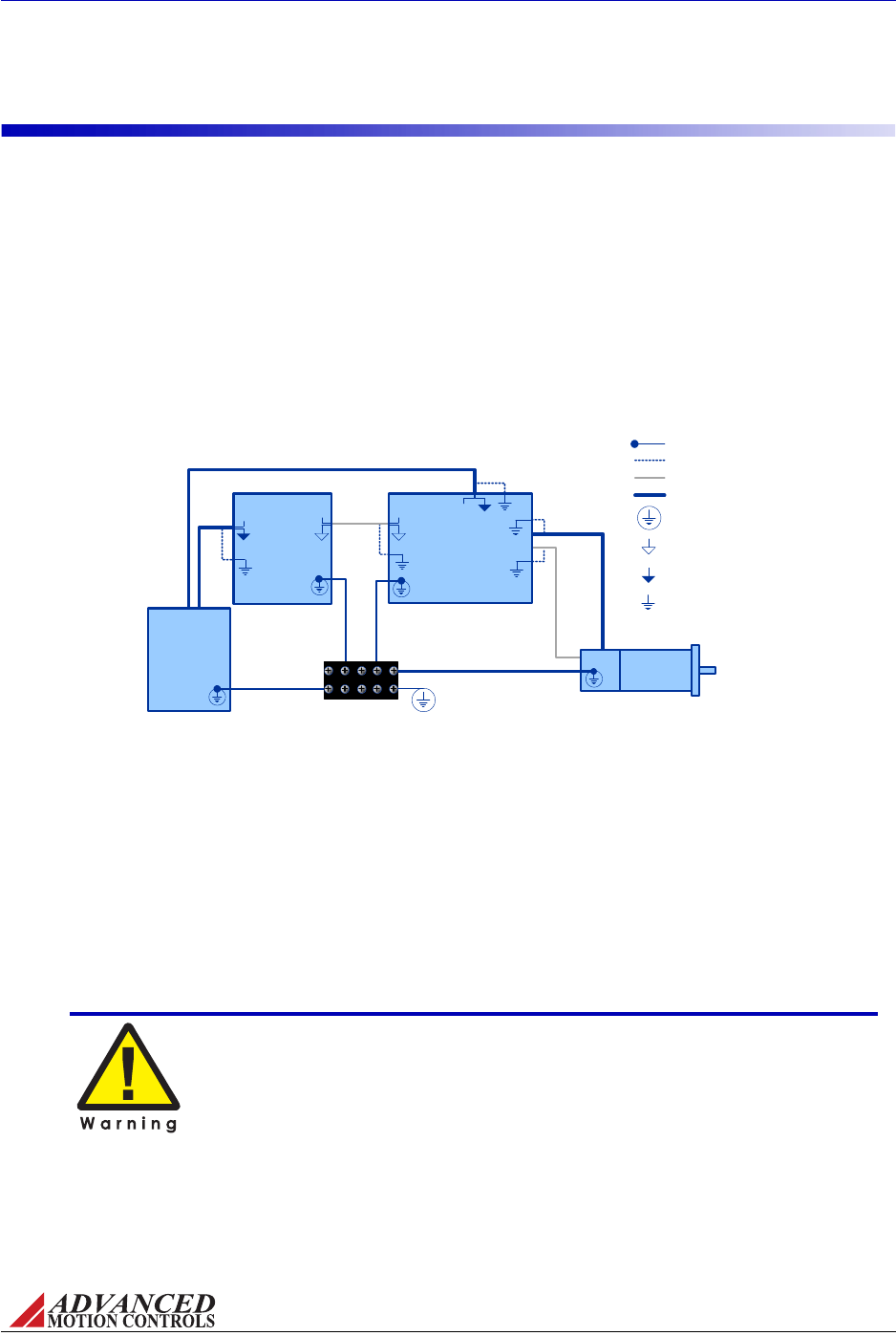
FIGURE 3.1
Shield Ground Wire
Case Ground Wire
Shielded Feedback/Signal Cable
Shielded Power Cable
Motor
Single Point System
Ground (PE Ground)
Analog Servo Drive
Controller
Isolated DC
Power Supply
+VDC +VDC PE Ground
Signal Ground
Power Ground
Command
Signal
Command
Signal
Chassis Earth Ground
System Grounding
MNALHWIN-01 30
Integration in the Servo System / Grounding
3.3 Grounding
InmostservosystemsallthecasegroundsshouldbeconnectedtoasingleProtectiveEarth
(PE)groundpointina"star"configuration.GroundingthecasegroundsatacentralPEground
pointreducesthechanceforgroundloopsandhelpstominimizehighfrequencyvoltage
differentialsbetweencomponents.Allgroundwiresmustbeofaheavygaugeandbeasshort
aspossible.ThefollowingshouldbesecurelygroundedatthecentralPEgroundingpoint:
•Motorchassis
•Controllerchassis
•Powersupplychassis
•AnalogServoDrivechassis
Groundcableshieldwiresatthedrivesidetoachassisearthgroundpoint.
TheDCpowergroundandtheinputreferencecommandsignalgroundareoftentimesata
differentpotentialthanchassis/PEground.Thesignalgroundofthecontrollermustbe
connectedtothesignalgroundofthedrivetoavoidpickingupnoiseduetothe"floating"
differentialservodriveinput.InsystemsusinganisolatedDCpowersupply,signalground
and/orpowergroundcanbereferencedtochassisground.Firstdecideifthisisboth
appropriateandsafe.Ifthisisthecase,theycanbegroundedatthecentralgroundingpoint.
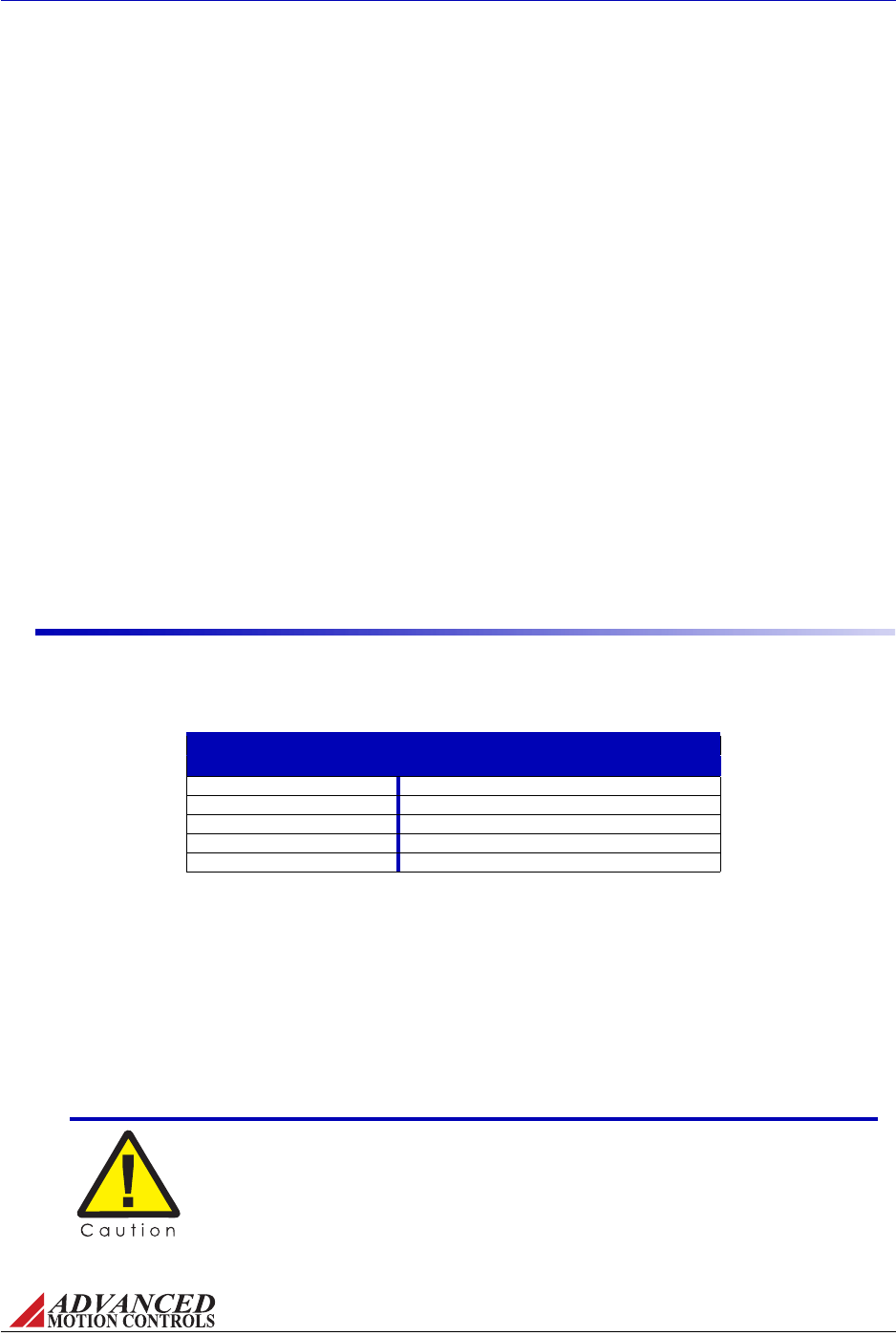
Grounding is important for safety. The grounding recommendations in
this manual may not be appropriate for all applications and system
machinery. It is the responsibility of the system designer to follow
applicable regulations and guidelines as they apply to the specific servo
system.

MNALHWIN-01 31
Integration in the Servo System / Wiring
3.4 Wiring
Servosystemwiringtypicallyinvolveswiringacontroller(digitaloranalog),aservodrive,a
powersupply,andamotor.Wiringtheseservosystemcomponentsisfairlyeasywhenafew
simplerulesareobserved.
AswithanyhighefficiencyPWMservodrive,thepossibilityofnoiseandinterferencecoupling
throughthecablingandwirescanbeharmfultooverallsystemperformance.Noiseinthe
formofinterferingsignalscanbecoupled:
•Capacitively(electrostaticcoupling)ontosignalwiresinthecircuit(theeffectismore
seriousforhighimpedancepoints).
•Magneticallytoclosedloopsinthesignalcircuit(independentofimpedancelevels).
•Electromagneticallytosignalwiresactingassmallantennasforelectromagneticradiation.
•Fromonepartofthecircuittootherpartsthroughvoltagedropsongroundlines.
ExperienceshowsthatthemainsourceofnoiseisthehighDV/DT(typicallyabout
1V/nanosecond)ofthedrive’soutputpowerstage.ThisPWMoutputcancouplebacktothe
signallinesthroughtheoutputandinputwires.Thebestmethodstoreducethiseffectareto
movesignalandmotorleadsapart,useaninductivefiltercard,addshielding,anduse
differentialinputsatthedrive.
Unfortunately,low‐frequencymagneticfieldsarenotsignificantlyreducedbymetalenclosures.
Typicalsourcesare50or60Hzpowertransformersandlowfrequencycurrentchangesinthe
motorleads.Avoidlargeloopareasinsignal,power‐supply,andmotorwires.Twistedpairsof
wiresarequiteeffectiveinreducingmagneticpick‐upbecausetheenclosedareaissmall,and
thesignalsinducedinsuccessivetwistcancel.
3.4.1 Wire Gauge
Asthewirediameterdecreases,theimpedanceincreases.Higherimpedancewirewill
broadcastmorenoisethanlowerimpedancewire.Therefore,whenselectingthewiregauge
forthemotorpowerwires,powersupplywires,andgroundwires,itisbettertoerrontheside
ofbeingtoothickratherthantoothin.Thisbecomesmorecriticalasthecablelength
increases.Thefollowingtableprovidesrecommendationsforselectingtheappropriatewire
sizeforaspecificcurrent.Thesevaluesshouldbeusedasreferenceonly.Consultany
applicablenationalorlocalelectricalcodesforspecificguidelines.
TABLE 3.1 Current and Wire Gauges
Current (A) Minimum Wire Size (AWG) mm2
10 #20 0.518
15 #18 0.823
20 #16 1.31
35 #14 2.08
45 #12 3.31
60 #10 5.26
80 #8 8.37
120 #6 13.3
150 #0 53.5
200 #00 67.4
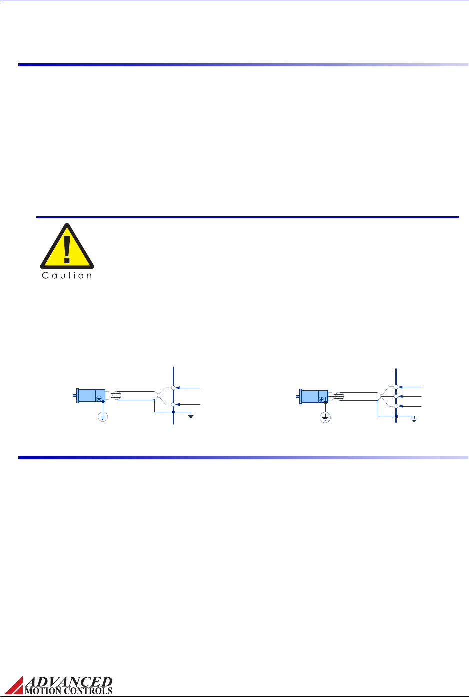
FIGURE 3.2 Motor Power Output Wiring
ANALOG
SERVO DRIVE
Shield
MOT -
MOT +
Motor
Single Point
System Ground
(PE Ground)
Chassis Ground
BRUSHED
MOTOR
ANALOG
SERVO DRIVE
Shield
Motor C
Motor B
Motor A
Motor
Single Point
System Ground
(PE Ground)
Chassis Ground
BRUSHLESS
MOTOR
MNALHWIN-01 32
Integration in the Servo System / Wiring
3.4.2 Motor Wires
Themotorpowerwiressupplypowerfromthedrivetothemotor.Useofatwisted,shielded
pairforthemotorpowercablesisrecommendedtoreducetheamountofnoisecouplingto
sensitivecomponents.
•Forabrushedmotororvoicecoil,twistthetwomotorwirestogetherasagroup.
•Forabrushlessmotor,twistallthreemotorwirestogetherasagroup.
Groundthemotorpowercableshiel
datoneendonlytotheservodrivechassisground.The
motorpowerleadsshouldbebundledandshieldedintheirowncableandkeptseparatefrom
feedbacksignalwires.
ThediagramsbelowshowhowananalogservodriveconnectstoaBrushed(single‐phase)and
Brushless(three‐phase)motors.Noticethatthemotorwiresareshielded,andthatthemotor
housingisgroundedtothesinglepointsystemground(PEGround).Thecableshieldshouldbe
groundedatthedrivesidetochassisground.
3.4.3 Power Supply Wires
ThePWMcurrentspikesgeneratedbythepoweroutput‐stagearesuppliedbytheinternal
powersupplycapacitors.Inordertokeepthecurrentrippleonthesecapacitorstoan
acceptablelevelitisnecessarytouseheavypowersupplyleadsandkeepthemasshortas
possible.Reducetheinductanceofthepowerleadsbytwistingthem.Groundthepowersupply
cableshieldatoneendonlytotheservodrivechassisground.
Whenmultipledrivesareinstalledinasingleapplication,precautionregardinggroundloops
mustbetaken.Whenevertherearetwoormorepossiblecurrentpathstoaground
connection,damagecanoccurornoisecanbeintroducedinthesystem.Thefollowingrules
applytoallmultipleaxisinstallations,regardlessofthenumberofpowersuppliesused(see
Figure3.3):
1. Runseparatepowersupplyleadstoeachdrivedirectlyfromthepowersupplyfilter
capacitor.
2. Never"daisy‐chain"anypowerorDCcommonconnections.Usea"star"‐connection
instead.
DO NOT use wire shield to carry motor current or power!
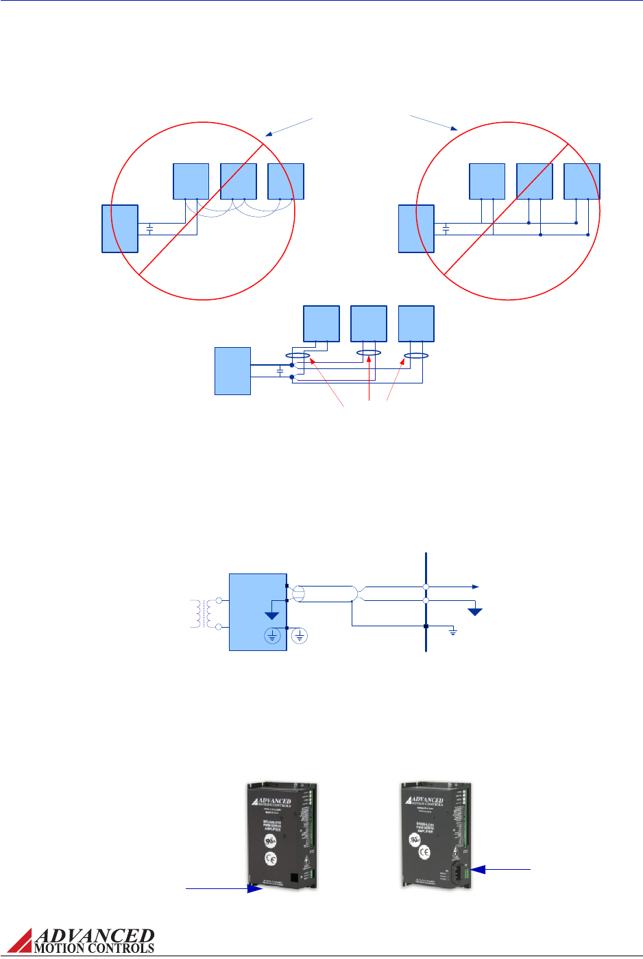
FIGURE 3.3 Multiple Power Supply Wiring
DC
Power
Supply
Analog
Servo
Drive
Analog
Servo
Drive
Analog
Servo
Drive
Power Supply
Capacitance
DC
Power
Supply
Analog
Servo
Drive
Analog
Servo
Drive
Analog
Servo
Drive
Power Supply
Capacitance
DC
Power
Supply
Analog
Servo
Drive
Analog
Servo
Drive
Analog
Servo
Drive
Wire pairs should be routed
together and twisted all the
way back to the power source
Power Supply
Capacitance
For AC input amplifiers, AC power
should be distributed from a
central AC source, not a capacitor
These wiring schemes are
commonly practiced but often
contribute to noise problems.
Each additional node in the
chain adds to the amount of
noise and unnecessarily loads
the connectors in each link.
FIGURE 3.4 DC Power Supply Wiring
ANALOG
SERVO DRIVE
DC Power Input
Isolated DC
Power
Supply
Shield
Single Point
System Ground
(PE Ground)
Power Ground
+HV
GND
Chassis Ground
FIGURE 3.5 Pluggable AC Line Connectors
StandardACconnector
underneathdrive
FACdrivemodel
featuresACconnector
ondriveface
MNALHWIN-01 33
Integration in the Servo System / Wiring
DC Power Supplies FordrivesusingaDCpowersupply,connectthetransformer‐isolatedDC
supplyhighvoltagetotheDCPowerInputterminal,andtheDCsupplygroundtothepower
groundterminal.
AC Power Supplies Drivesthatacceptonlysingle‐phaseAClinepowerincludeastandard3‐
prongpluggableACconnectorforattachmenttoanACsupplyontheundersideofthedrive
(standardACmodels),oronthefrontfaceofthedrive(FACmodels).
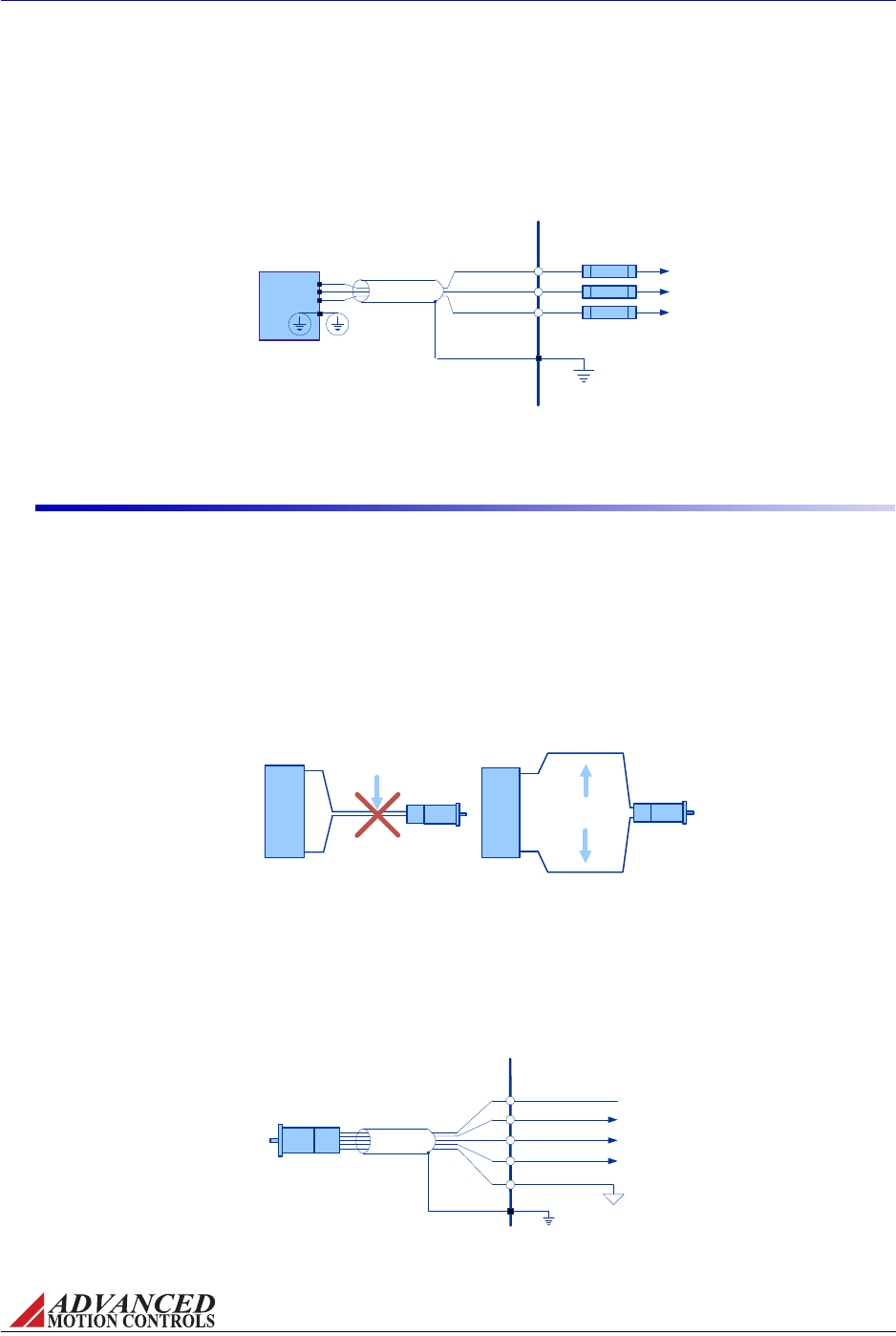
FIGURE 3.6 Single or Three Phase AC Line Connections
ANALOG
SERVO DRIVE
AC1
3-Phase AC
Power
Supply*
Shield
Chassis Ground
AC2
AC3
Single Point
System Ground
(PE Ground)
*For Single-phase AC Supply, connect AC lines to any two of AC1, AC2, and AC3. Do
not connect AC line neutral to ground!
FUSE
FUSE
FUSE
FIGURE 3.7 Feedback Wiring
Motor Feedback
Motor Power
Avoid running
feedback and power
wires together Motor Feedback
Motor Power
Separate power and
feedback wires
where possible
Motor
Analog
Servo
Drive
Motor
Analog
Servo
Drive
FIGURE 3.8 Hall Sensor Input Connections
ANALOG
SERVO DRIVE
Motor
Chassis Ground
Signal Ground
Shield HALL A +
HALL B +
HALL C +
+V HALL (Power for Hall Sensors)
MNALHWIN-01 34
Integration in the Servo System / Wiring
Drivesthataccepteithersingle‐phaseorthree‐phaseAClinepowerhavea5‐contactACinput
screwterminal.ConnectathreephaseACsupplytoAC1,AC2,andAC3.AsinglephaseAC
supplycanbeconnectedtoanytwoofthethree(AC1,AC2,AC3)ACterminals.
3.4.4 Feedback Wires
Useofatwisted,shieldedpairforthefeedbackwiresisrecommended.Groundtheshieldatone
endonlytotheservodrivechassisground.Routecablesand/orwirestominimizetheirlength
andexposuretonoisesources.Themotorpowerwiresareamajorsourceofnoise,andthe
motorfeedbackwiresaresusceptibletoreceivingnoise.Thisiswhyitisneveragoodideato
routethemotorpowerwireswiththemotorfeedbackwires,eveniftheyareshielded.
Althoughbothofthesecablesoriginateatthedriveandterminateatthemotor,trytofind
separatepathsthatmaintaindistancebetweenthetwo.Aruleofthumbfortheminimum
distancebetweenthesewiresis10cmforevery10mofcablelength.
Hall Sensors Brushlessdrivesacceptsingle‐endedHallSensorfeedbackforcommutationand
velocitycontrol.Mostdrivesalsoincludea+6V,30mAlowvoltagesupplyoutputthatcanbe
usedtopowertheHallSensors.Verifyonthemotordatasheetthatthevoltageandcurrent
ratingofthesupplyoutputwillworkwiththeHallSensorsbeforeconnecting.
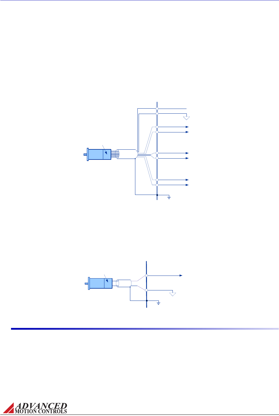
FIGURE 3.9 Incremental Encoder Connections
MOTOR ENC A+
MOTOR ENC A-
MOTOR ENC B+
MOTOR ENC B-
Enc A
Motor
Shield
Chassis
Ground
Enc B
MOTOR ENC I+
MOTOR ENC I-
ANALOG SERVO
DRIVE
+
-
+
-
+
-
Signal Ground
+5V Encoder Supply Output
Incremental
Encoder
Enc I
FIGURE 3.10 Tachometer Input Connections
ANALOG
SERVO DRIVE
TACHOMETER INPUT
SIGNAL GROUND
Tachometer
(± 60 VDC) Tach-
Tach+
Motor
Chassis
Ground
MNALHWIN-01 35
Integration in the Servo System / Wiring
Incremental Encoder Somedrivemodelssupporteithersingle‐endedordifferential
incrementalencoderfeedback.Ifusingasingle‐endedencoderwithadrivethataccepts
differentialinputs,leavethenegativeterminalopen.Boththe"A"and"B"channelsofthe
encoderarerequiredforoperation.Drivesthatacceptdifferentialsignalsalsoacceptan
optional"index"channelthatcanbeusedforsynchronizationandhoming.Ifusingthe+5V,
150mA(or250mA)lowvoltagepowersupplyoutputfromthedrive,verifythatthesupply
outputvoltageandcurrentratingissufficientfortheencoderspecifications.
Tachometer FordrivesthatacceptaTachometerforvelocitycontrol,connectthenegative
tachometerinputtothetachometerinputonthedrive,andconnectthepositivetachometer
inputtosignalground.ThedrivemustbeinTachometerVelocitymodeinordertoproperlyuse
thetachometerinput.SeethedrivedatasheetforspecificDIPswitchsettings.Thetachometer
hasarangeof±60VDC.
3.4.5 Input Reference Wires
Useofatwisted,shieldedpairfortheinputreferencewiresisrecommended.Connectthe
referencesource"+"to"+REFIN",andthereferencesource"‐"(orcommon)to"‐REFIN".
Connecttheshieldtotheservodrivechassisground.Theservodrive’sreferenceinputcircuit
willattenuatethecommonmodevoltagebetweensignalsourceanddrivepowergrounds.
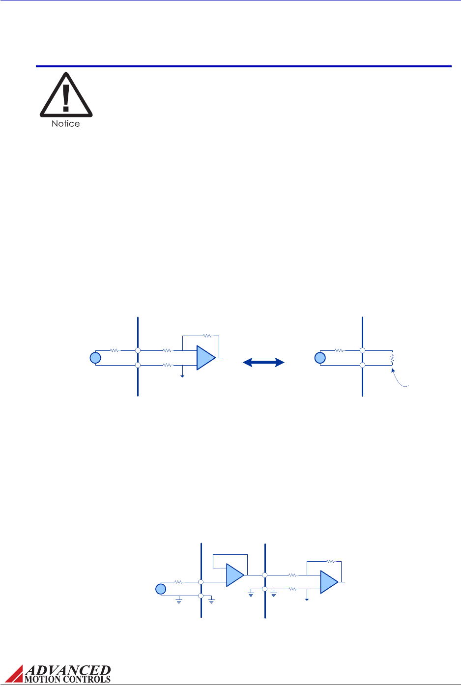
FIGURE 3.12
+/- 10V ANALOG
SOURCE
ANALOG
SERVO DRIVE
+REF
-REF +
-
Internal Offset
Reference Voltage
Vs+
-
Rsource +
-
Optimized Low Impedance Interface
FIGURE 3.11
+/- 10V ANALOG
SOURCE
ANALOG
SERVO DRIVE
+REF
-REF +
-
Internal Offset
Reference Voltage
Vs+
-
Rsource
+/- 10V ANALOG
SOURCE
ANALOG
SERVO DRIVE
+REF
-REF
Vs+
-
Rsource
Rin
Equivalent Input
Impedance
Analog Source and Drive Input
MNALHWIN-01 36
Integration in the Servo System / Wiring
Longsignalwires(10‐15feetandup)canalsobeasourceofnoisewhendrivenfromatypical
op‐ampoutput.Duetotheinductanceandcapacitanceofthewiretheop‐ampcanoscillate.Itis
alwaysrecommendedtosetafixedvoltageatthecontrollerandthencheckthesignalatthe
drivewithanoscilloscopetomakesurethatthesignalisnoisefree.
±10V Analog Input Whenusinga±10Vanalogsignalforaninputcommand,itisimportantto
considertheoutputimpedanceoftheanalogsourcewheninterfacingtoinputcircuitry.A
poorlydesigned±10Vanaloginputinterfacecanleadtoundesiredcommandsignal
attenuation.Figure3.11showsanexternalanalogsourceconnectedtoananaloginput.The
idealvoltagedeliveredtotheinputisVS.However,thevoltagedropacrossRsourcewillreduce
thesignalbeingdeliveredtothedriveinput.Thisvoltagedropisdependentonthevalueof
Rsourceandthedrive’sinputimpedance.
Thedrive’sanaloginputcanbesimplifiedtoasingleimpedance,Rin,asshowninFigure3.11.
IftheimpedanceofRsourceisofthesamemagnitudeorlargerthanRin,therewillbea
significantvoltagedropacrossRsource.ReducedvaluesofRsourcecausealowervoltagedrop
thatincreasessignalintegrity.Inordertoavoidavoltagedropofmorethan5%betweenthe
sourceandthedrive,itisrecommendedtouseanRsourcevalueoflessthanorequalto2kohm.
Ifthereisalargeoutputimpedancefromtheanalogsource,itisrecommendedtouseabuffer
circuitbetweentheanalogsourceoutputandthedriveinput.Aunitygainop‐ampcircuitas
showninFigure3.12willensurelowoutputimpedancewithminimalvoltagedrop.
In case of a single-ended reference signal, connect the command
signal to "+ REF IN" and connect the command return and "- REF IN" to
signal ground.
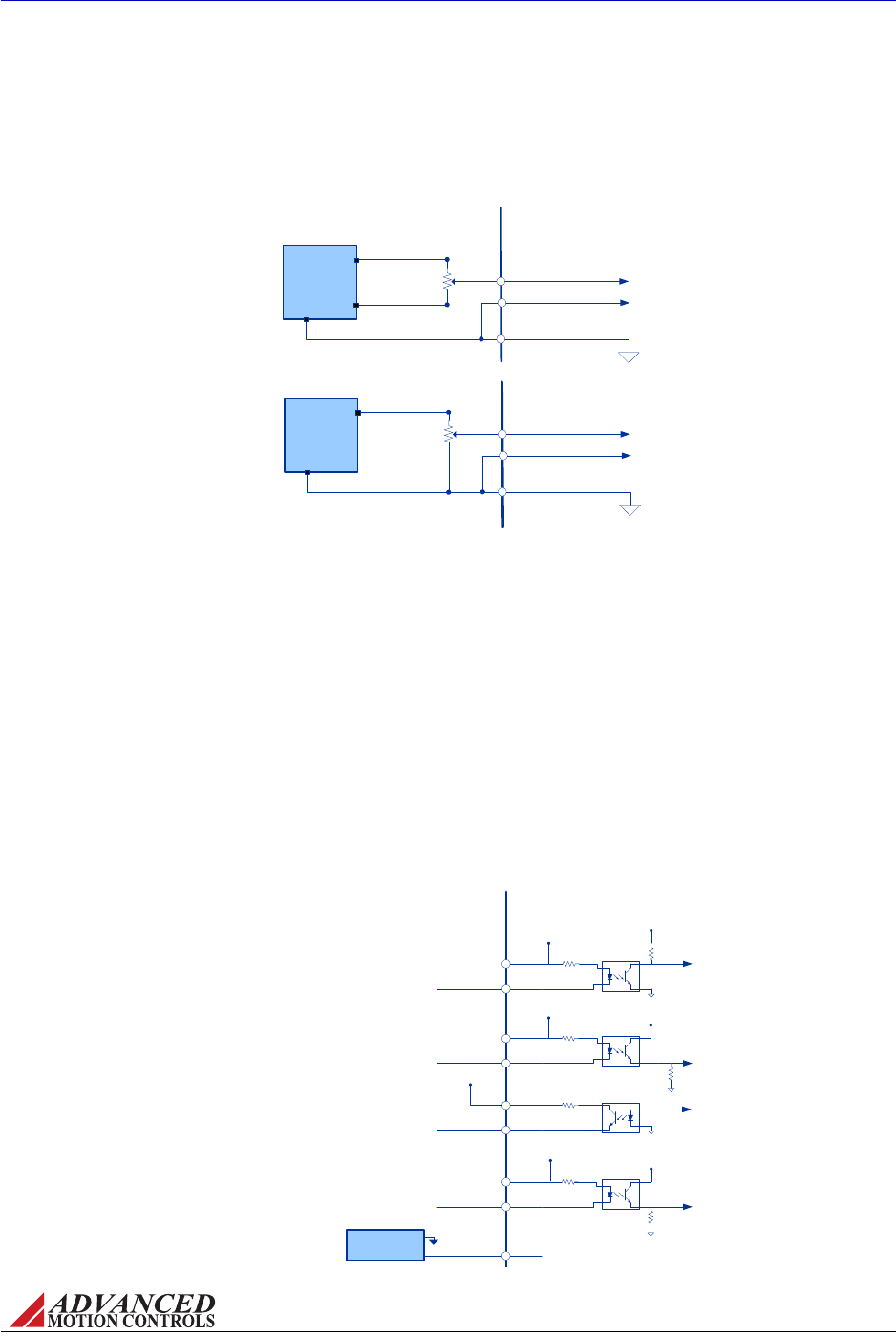
FIGURE 3.13 Potentiometer Input
ANALOG
SERVO DRIVE
+10V Max
Potentiometer
(~50kO)
-10V Max
+REF IN
+/- VDC
Power
Supply
+10V
-10V
GND
SIGNAL GROUND
-REF IN
Bi-directional Control
ANALOG
SERVO DRIVE
+10V Max
Potentiometer
(~50kO)
+REF IN
+VDC
Power
supply
+10V
GND
SIGNAL GROUND
-REF IN
Uni-directional Control
FIGURE 3.14 PWM and Direction Optocoupled Inputs, +5V supply input option
ANALOG
SERVO DRIVE
PWM+
PWM-
DIR+
DIR-
INHIBIT+
INHIBIT-
FAULT+
FAULT-
+5V Input
+5V
Input
+5V
Input
+5V
Input
+5V
+5V
GND
+5V
Supply
+5V
+5V
+5V
100k
100k
100k
100k
5k
5k
500
PWM Input Signal
Direction Input Signal
Fault Monitor Output
Ground to Inhibit / Open to Enable
MNALHWIN-01 37
Integration in the Servo System / Wiring
Potentiometer Input Analogservodrivesthataccept±10Vanaloginputcanbecommanded
withtheuseofanexternalpotentiometerandaDCsupplybyvaryingtheDCsupplyvoltage
acrossthepotentiometer.
PWM and Direction Inputs OndrivesthatacceptaPWMandDirectionsignalforacommand
input,theinputsareopticallyisolatedfromthepowerstageofthedrive.ThePWMand
Direction,Inhibit,andFaultI/Owillnotprovideanyfunctionalitytothedriveunlessthe
optocouplersareactivated.Dependingonthedrivemodel,therearetwomethodstoactivate
theoptocouplersandtherebyactivatethedrive.
•Somedrivemodelsfeaturea+5Vinputpinthatisusedtodrivetheoptocouplerinputs.
This+5VsupplymustbegroundedatthenegativeInhibitterminal.Thepositiveterminals
forthePWM,Direction,andInhibitinputsareallinternallyconnectedtothe+5Vinput.
Therefore,theexternalPWMandDirectioninputsignalsshouldbeconnectedatthe
negativePWMandDirectionterminals.ThepositiveFaultoutputterminalcanalsobe
connectedtothe+5Vinputsupply,andwhenthedriveentersafaultstage,thenegative
Faultoutputterminalwillrisetothe+5Vsupplyindicatingafaultcondition.
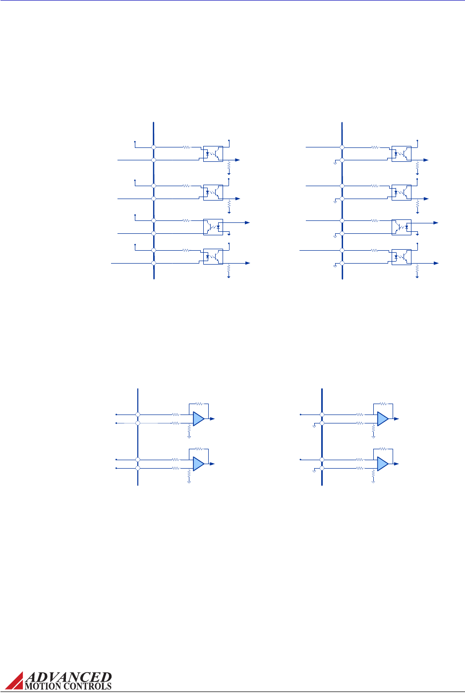
FIGURE 3.15
ANALOG
SERVO DRIVE
PWM+
PWM-
DIR+
DIR-
INHIBIT+
INHIBIT-
FAULT+
FAULT-
Ground to Inhibit / Open to Enable
100k
100k
100k
100k
5k
PWM Input Signal
Direction Input Signal
Fault Monitor Output
5k
ANALOG
SERVO DRIVE
PWM+
PWM-
DIR+
DIR-
INHIBIT+
INHIBIT-
FAULT+
FAULT-
GND
100k
100k
100k
100k
5k
PWM Input Signal
Direction Input Signal
Fault Monitor Output
5k
+5V
+5V
+5V
+5V
GND
GND
GND
+5V to Inhibit / Open to Enable
PWM and Direction Optocoupled Inputs
FIGURE 3.16 Sinusoidal Command Inputs
+
-
+ REF-IN-A
- REF-IN-A
Analog Servo
Drive
40k
40k
+
-
+ REF-IN-B
- REF-IN-B
40k
40k
Differential
Sine Input A
Differential
Sine Input B
+
-
+ REF-IN-A
- REF-IN-A
Analog Servo
Drive
40k
40k
+
-
+ REF-IN-B
- REF-IN-B
40k
40k
Single-ended
Sine Input A
Single-ended
Sine Input B
MNALHWIN-01 38
Integration in the Servo System / Wiring
•Ondrivesthatdonotcontainanadditional+5Vinputsupplypin,therearetwooptionsto
activatetheoptocouplers.ThepositiveterminalsofthePWM,Direction,Fault,andInhibit
I/Ocanbebroughttoanexternal+5Vsupply,orthenegativeterminalsofthePWM,
Direction,Fault,andInhibitI/Ocanbebroughttoground.
Sinusoidal Input TheS‐Seriesofanalogservodrivesaccepttwosinusoidalcommandsignalsthat
are120degreesoutofphase.Thesineinputsignalscanbeeitherdifferentialorsingle‐ended.
Ifusingasingle‐endedsignal,connecttheinputtothe+REFterminalofthereferenceinput
pins,andgroundthenegativeterminal.
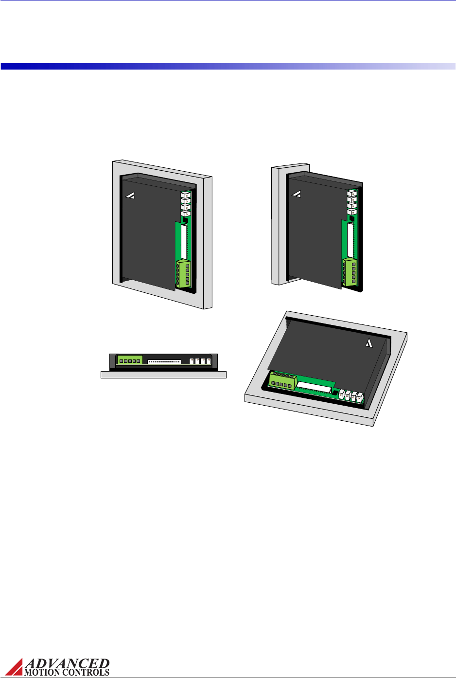
FIGURE 3.17 Analog Servo Drives Mounting Options
ADVANCED
MOTION CONTROLS
ADVANCED
MOTION CONTROLS
ADVANCED
MOTION CONTROLS
MNALHWIN-01 39
Integration in the Servo System / Mounting
3.5 Mounting
ADVANCEDMotionControlsanalogservodrivesprovidemountingholelocationsonthe
baseplateallowingthedrivetobemountedeitherverticallyorhorizontally.Drivescanbe
mountedtoaheatsinkorotherplanesurface,orattachedtoalabraileitheronatestbenchor
aspartofalargersystem.Consultthedrivedatasheetforspecificmountingdimensionsand
mountingholelocations.

MNALHWIN-01 40
4 Operation
ThischapterwilldescribetheoperationandsetupofanADVANCEDMotionControlsanalogservodrive.
4.1 Initial Setup and Features
Tobeginoperationwithyouranalogservodrive,besuretoreadandunderstandtheprevious
chaptersinthismanualaswellasthedrivedatasheet.Besurethatallsystemspecifications
andrequirementshavebeenmet,andbecomefamiliarwiththecapabilitiesandfunctionsof
thedrive.Also,beawareofthe“Troubleshooting”sectionattheendofthismanualfor
solutionstobasicoperationissues.
Donotinstalltheservodriveintothesystemwithoutfirstdeterminingthatallchassispower
hasbeenremovedforatleast10seconds.Neverremoveadrivefromaninstallationwith
powerapplied.Carefullyfollowthegroundingandwiringinstructionsintheprevious
chapterstomakesureyoursystemissafelyandproperlysetup.
4.1.1 Pin Function Details
Thefamilyofanalogdrivesprovideanumberofvariousinputandoutputpinsforparameter
observationanddriveconfigurationoptions.Notalldriveswillhaveeachofthefollowingpin
functions.Consultthedrivedatasheettoseewhichinput/outputpinfunctionsareavailablefor
eachdrive.
Current Monitor Output Measuredrelativetosignalground,powerground,oraseparate
currentmonitorground,dependingonthedrivemodel.Consultthedrivedatasheetto
determinethecorrectgroundconnection.Thecurrentmonitorprovidesananalogvoltage
outputsignalthatisproportionaltotheactualdrivecurrentoutput.Thescalingfactorforeach
individualdrivecanbefoundonthedrivedatasheet.Thedrivemustbeconnectedtoaloadin
orderforthedrivetooutputactualcurrent.
Example Measurement
Thecurrentmonitorpinonadrivewithacurrentmonitorscalingfactorof4A/Vismeasured
tobe1.3V.Thiswouldmeanthedriveisoutputting:(4A/V)(1.3V)=5.2A.

MNALHWIN-01 41
Operation / Initial Setup and Features
Current Reference Output Measuredrelativetosignalground,thecurrentreference
providesananalogvoltageoutputsignalthatisproportionaltothecommandsignaltothe
internalcurrentloop.Thedrivedoesnotneedtobeconnectedtoaloadtoreadthecurrent
referenceoutput.Theinternalcommandcurrentmaydifferfromtheactualdriveoutput
currentduetocertainconditionssuchasasmallload,drivefaults,undersizedpowersupplies,
inhibiteddrive,etc.Thecommandtotheinternalcurrentloopcanbesolvedforbythe
followingequation:
Where:
Icommand ‐commandcurrenttotheinternalcurrentloop
Vcurrentref ‐measuredvoltageatcurrentreferencepin
Ipeak ‐peakcurrentvalueofthedrive
Vmax ‐voltagecorrespondingtomaximuminternalcurrentcommand,value
foundondrivedatasheet;onmostdrivemodelsVmax=7.45V
Example Measurement
Thecurrentreferencepinonadrivewithapeakcurrentvalueof12AandVmaxof7.45Vis
measuredtobe2.63V.FollowingtheaboveequationtosolveforIcommand,thecommand
currenttotheinternalcurrentloopwouldbe4.24A.
Inhibit Input Thispinprovidesa+5VTTLinputthatallowsausertoenable/disablethedriveby
eitherconnectingthispintogroundorbyapplyinga+5VDCvoltageleveltothispin,
referencedtosignalground.Bydefault,thedrivewillbeenabledifthispinishigh,and
disabledifthispinislow.Thislogiccanbereversed,however,eitherthroughDIPswitch
settingorbyremovingaSMTjumperfromthePCB(consultthedrivedatasheettoseewhich
optionisavailable;notethatremovaloftheSMTjumpermustbedonebyapersonfamiliar
withSMTsoldering,andthatthedrivewarrantywillbevoidedifthedriveisdamaged).This
wi llre quirea llinh ibitl i nes tobebro ughtto grou ndtoen ablethedrive.Mostdrivescanalsobe
orderedwithinvertedinhibitlogicaswell(‐INVoption).Somedrivemodelsallowthedriveto
beconfiguredsotheinhibitinputdoesnottriggeradrivefaultstate.Typicallythisisachieved
byDIPswitchsetting.Consultthedrivedatasheettoseeifthisoptionisavailable.
Directional Inhibits
Somedrivesalsoincludedirectionalinhibitpinsthatdisablemotormotionineitherthe
positiveornegativedirection,typicallyusedforlimitswitches.Thesepinsdonotcauseadrive
faultcondition.Theywillfollowthesamelogic(eitherstandardorinverted)asthemain
inhibit/enableinput.
Continuous Current Limit Pin TheContinuousCurrentLimitpincanbeusedtoreducethe
factory‐presetmaximumcontinuouscurrentlimitwithoutaffectingthepeakcurrentlimitof
thedrivebyattachinganexternalresistorbetweenthispinandsignalground.Valuesfor
resistorsandthecorrespondingreductionincontinuouscurrentaregivenonthedrive
datasheet.ThiscontinuouscurrentreductioncomessecondarytoanyreductionsmadebyDIP
switchsettingsonthedriveandthecurrentlimitingpotentiometer.
Icommand Vcurrent ref
Ipeak
Vmax
-------------
⋅=
MNALHWIN-01 42
Operation / Initial Setup and Features
Fault Output Thispinprovidesa+5VTTLoutputmeasuredrelativetosignalgroundthatwill
indicatewhenthedriveissubjecttooneofthefollowingfaultconditions:inhibit,invalidHall
State,outputshortcircuit,overvoltage,overtemperature,orpower‐upreset.Onmostdrive
modelsthispinwillread+5V(High)whenthedriveisinafaultstate,butsomedrivesallowthe
logictobereversed,sothata0V(Low)faultoutputindicatesafault.
Analogdrivesautomaticallyself‐resetoncealloftheabove‐mentionedfaultconditionsareno
longertrue.ForinstanceiftheDCpowersupplyrisesabovetheover‐voltageshutdownlevelof
thedrive,theFaultOutputwillindicateafault,andthedrivewillbedisabled.OncetheDC
powersupplylevelisreturnedtoavaluebelowthedriveover‐voltageshutdownlevel,theFault
Outputwillreturntothenormalstate,andthedrivewillautomaticallybecomeenabled.
Low Voltage Power Supply Outputs Mostdrivesincludelowvoltagepowersupply
outputsmeantforcustomeruse.Consultthedrivedatasheettoseewhichlowvoltageoutputs
areincludedonaspecificdrive.
•±10V(or±5V),3mAOutput‐Typicallyusedasanon‐board±10Vanaloginputsignalfor
testingpurposes.Thisoutputcanbeusedinconjunctionwithanexternalpotentiometerto
varytheinputsignalbetween±10V.
•+6V,30mAOutput‐Availableonthreephase(brushless)driveonly.Thispinprovidesa
+6VDCoutputthatcanbeusedtopowerHallSensors.Consultthemotordatasheettofind
outwhichfeedbackwirefromthemotoristheHallSensorpowersupplywire.
•+5V,150mA(or250mA)Output‐Canbeusedaspowerforanencoder.Consultthe
motororencoderdatasheettodeterminetheappropriateencodervoltageandcurrent
requirementsbeforeconnectingthissupply.
Velocity Monitor Output Thispinprovidesananalogvoltageoutputthatisproportionalto
theactualmotorspeed.Thescalingfactorforeachindividualdrivecanbefoundonthedrive
data sheet.
•ForadriveinEncoderVelocityMode,substitutethevoltagevaluereadatthevelocity
monitorpin,Vmonitor
,intothebelowequationtodeterminethemotorRPM:
Motor Velocity [RPM] Vmonitor Scaling Factor 60⋅⋅
Number of encoder lines
----------------------------------------------------------------------=
•ForadriveinHallVelocityMode,substitutethevoltagevaluereadatthevelocitymonitor
pin,Vmonitor
,intothebelowequationtodeterminethemotorRPM:
Motor Velocity [RPM] Vmonitor Scaling Factor 120⋅⋅
Number of motor poles
-------------------------------------------------------------------------=
Do not use this +6V supply to power an encoder. An encoder will require
a separate power supply. Consult the encoder datasheet or
specifications to determine the encoder voltage and current
requirements. Typical values are +5VDC at 150mA.
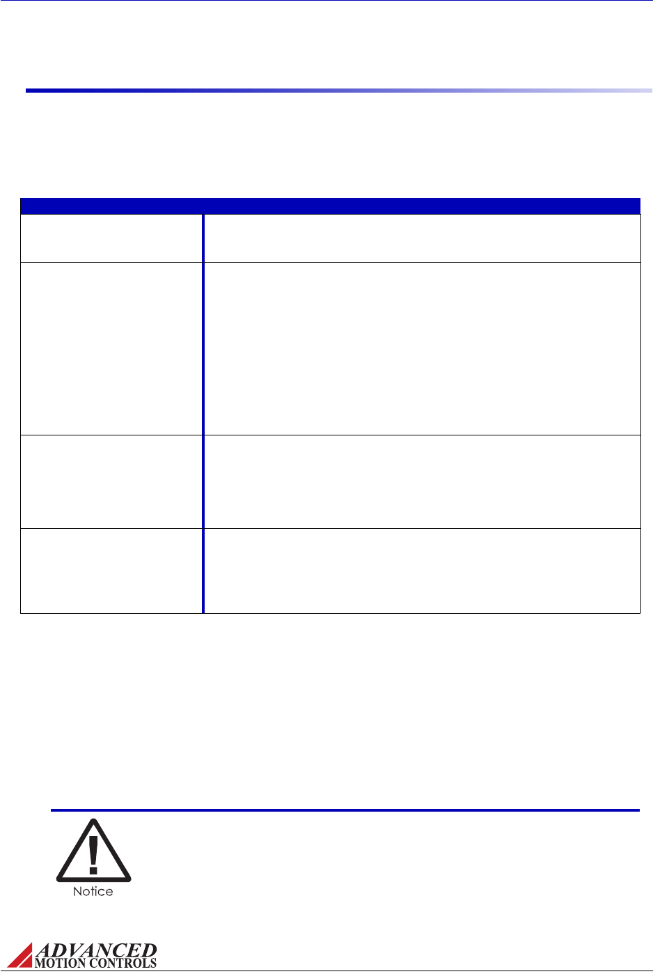
MNALHWIN-01 43
Operation / Initial Setup and Features
4.1.2 Potentiometer Function Details
Allpotentiometersvaryinresistancefrom0to50kohm,over12turns.Anadditionalfullturn
thatdoesnoteffectresistanceisprovidedoneitherend,foratotalof14turns.Whentheendof
potentiometertravelisreached,itwillclickonceforeachadditionalturn.Consultthedrive
datasheettoseewhichpotentiometersareincludedonaspecificdrive.
TABLE 4.1
Potentiometer Description
Loop Gain Adjustment This potentiometer must be set completely counter-clockwise in Current Mode. In Velocity or
Voltage Mode, this potentiometer adjusts the gain in the velocity forward position of the closed
loop. Turning this potentiometer clockwise increases the gain. Start from the full counter-clockwise
position, turn the potentiometer clockwise until the motor shaft oscillates, then back off one turn.
Current Limit This potentiometer adjusts the current limit of the drive. To adjust the current limit, first use any
available DIP switches or external current limiting resistors to set the maximum current limits and
ratios (consult drive datasheet to see which options are available). If further adjustment is
necessary, use the following equation to determine the number of clockwise turns from the full
counter-clockwise position necessary to set the desired current limit:
# of turns (from full CCW) Isystem
Imax
-----------------
⎝⎠
⎛⎞
12 1+=
Isystem = the desired current limit of the system (typically determined by motor current rating)
Imax = maximum current capability of the drive; this value is determined after any external current
limiting resistors have been used and/or any current scaling or current reduction DIP switches
have been set. If no DIP switches or external resistors have been used, then Imax is the default
maximum continuous current limit set by the drive hardware. See “Current Limiting Procedure” on
page 46 for an example of how to use this potentiometer.
Reference Gain This potentiometer adjusts the ratio between the input signal and the output variable (voltage,
current, or velocity). For a specific gain setting, turn this potentiometer fully counter-clockwise, and
adjust the command input to 1V. Then turn clockwise while monitoring motor velocity or drive
output voltage (depending on mode of operation) until the required output is obtained for the given
1V command. Turning this potentiometer counter-clockwise decreases the reference in gain, while
setting this potentiometer in the fully clockwise position makes the whole range of drive output
available. This potentiometer may be left in the fully clockwise position if a controller is used to
close the velocity or position loops.
Test/Offset This potentiometer acts as an internal command source for testing when the Test/Offset switch is
in the ON position. If the Test/Offset switch is in the OFF position, then this potentiometer can be
used to adjust a small amount of command offset in order to compensate for offsets that may be
present in the servo system. Turning this potentiometer clockwise adjusts the offset in a negative
direction relative to the +Ref input command.
Before offset adjustments are made, the reference inputs must be grounded or commanded to 0
volts.
Potentiometer Function Details
Test Points for Potentiometers Afterthepotentiometeradjustmentshavebeencompleted,
theresistancevaluescanbemeasuredforfutureadjustmentsorduplicationonotherservo
drivesofthesamepartnumber.Testpointsforpotentiometerwipersareprovidedandare
locatedatthefootofallfourpotentiometers.Resistancemeasurementsareonlytobeusedto
duplicatedrivesettings,sincesomepotentiometershaveotherresistorsinseriesorparallel.
Measuretheresistancebetweenthetestpointandtheouterlegofthepotentiometeror
betweenthetestpointandanappropriateground.Seetheblockdiagramonthedrive
datasheettodeterminewhichgroundshouldbeusedforeachpotentiometer.
Before taking potentiometer resistance measurements, make sure that
all potentiometers and DIP switches have been set to the desired
settings, and that all I/O and Feedback cables have been removed from
the drive, as these can affect resistance measurements.

MNALHWIN-01 44
Operation / Initial Setup and Features
4.1.3 Switch Function Details
Togetherwiththedescribedfunctionsbelowcertainswitchesmayalsobeusedinselectingthe
modeofoperation,whilesomemaybeusedstrictlyformodeselection.Switchimplementation
andfunctionalitywithinthedrivecircuitryisincludedontheblockdiagramofthedrive
datasheet.Consultthedrivedatasheettoseewhichswitchesareincludedonaspecificdrive.
TABLE 4.2
Switch Description
Current Scaling Changes the sensitivity of the current sense, thereby reducing the peak and continuous current
limits by a given amount.
Current Loop Proportional Gain
Adjustment
Adjusts the proportional gain of the current loop. For drive model S16A8, there are two Current
Loop Proportional Gain switches that must be set to the same setting.
Current Limit Ratio Sets the continuous-to-peak current limit ratio to a given percentage. The default setting for all
drives is a continuous-to-peak current limit ratio of 50% (i.e., 12 amp peak limit, 6 amp continuous
limit).
Current Loop Integral Gain Activates or deactivates the current loop integral gain. This switch is OFF by default. For drive
model S16A8, there are two Current Loop Integral Gain switches that must be set to the same
setting.
RMS Current Limit Setting Sets the RMS current limit setting on sinusoidal input drives, used to reduce the continuous
current limit to a percentage of the maximum continuous limit. Two RMS Current Limit Setting
switches are used to set the percentage. See the drive datasheet for specific switch configuration.
Peak Current Limit Sets the peak current to 50% or 100% of the maximum peak current limit on sinusoidal input
drives. Depending on the drive model, there are either two or three Peak Current Limit switches
that must all be set to the same setting.
Outer Loop Integration Activation Activates or deactivates the outer loop integration. For Current Mode, outer loop integration should
be deactivated, but should be activated for other modes.
Outer Loop Integral Gain Adjustment Increases or decreases the integral gain of the outer loop.
Duty Cycle Feedback Enables/disables the duty-cycle feedback. Duty-cycle feedback is only enabled when the drive is
configured for Open Loop Mode.
Hall Sensor Commutation Phasing Tells the drive the type of Hall sensor phasing the motor has. Switches between 120 and 60
degree phasing.
Test/Offset Switches the drive between Test mode and Offset mode. In Test mode, the command signal is
adjustable via the Test/Offset potentiometer. In Offset mode, the drive will accept commands via
the reference inputs, but a small amount of offset can be adjusted in order to compensate for
offsets that may be present in the servo system.
PWM and Direction Test Signal Activates or deactivates the PWM and Direction internal test signal, controlled by the PWM Test
Signal Adjustment potentiometer.
Velocity Feedback Polarity Changes the polarity of the internal feedback signal and the velocity monitor output signal.
Inversion of the feedback polarity may be required to prevent a motor run-away condition. See
“Motor Problems” on page 59 for more information.
IR Compensation Activates or deactivates IR feedback. IR feedback should be activated for IR Compensation Mode,
and deactivated for other modes.
Inhibit Logic Sets the logic of the inhibit pins to Active High or Active Low.
Input Range Selection Sets the voltage range of the sinusoidal command input pins. The input range can be set to ±5V or
±10V. Drives contain two Input Range Selection switches that must set to the same setting.
Switch Function Details
4.1.4 Adjustable Acceleration and Deceleration Rate
Onsomedrivemodels,theaccelerationanddecelerationratescanbesetindependentlyusing
through‐holeresistors.Thedrivedatasheetcontainsspecificresistorvaluesandthe
correspondingrampingtime.Theratesarebasedon±10voltstothereferenceinputs.The
"time"listedinthetableonthedrivedatasheetisthetimeittakestoreachthe10voltinput.
Therampingratesarelinearwithrespecttotime.Forexample,iftheinputwereonly5volts,
thetimetoramptothisvoltagewouldbehalfthetimetorampto10volts.Theselocationsare
silk‐screenedonthePCBforeasyidentification.TwoSMTjumpers(0ohmresistors)are
requiredtobesetappropriatelyinordertoenableadjustableacceleration/decelerationrate
control.Thedefaultsettingforbothjumpersistodisableadjustableratecontrol.Thespecific
configurationofthejumpersforadrivearegivenonthedrivedatasheet.
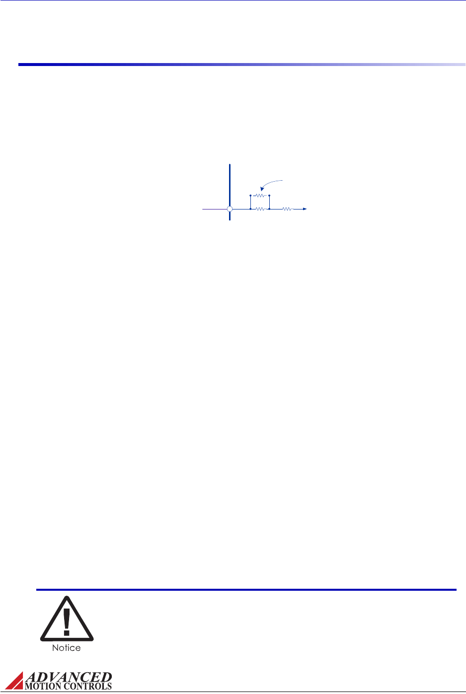
FIGURE 4.1 Tachometer Input Resistance
ANALOG
SERVO DRIVE
50k
Tachometer Input
10k
Optional
Through-Hole
Tach Gain
Resistor
MNALHWIN-01 45
Operation / Initial Setup and Features
4.1.5 Tachometer Input Gain Scaling
Standarddrivetachometerinputsaretypicallypre‐configuredsuchthatthestandard60kinput
resistancescalesthemaximumtachinputvoltageto60V.The60ktachometerinputresistance
isactuallypopulatedwitha50kresistorinserieswitha10kresistor.Mostdriveswitha
tachometerfeedbackinputwillalsohaveathrough‐holeresistorlocationinparallelwiththe
50kresistor.
Thisallowsuserstoreducetheeffectiveinputresistancetoavaluethatmorecloselymatches
theirmaximumapplicationfeedbackvoltageinordertoincreasethetachometerinputgain.An
appropriatetachometerinputresistancevalueshouldbeatleast1000timesthemaximum
tachometervoltagefeedbackvalue.Fromzerotoinfiniteresistance(openconnection),this
through‐holelocationcanscalethetachometer’smaximuminputvoltagerangefrom10Vto
60V.
Todeterminethemaximumfeedbackvoltagefortheapplication:
1. Determinetheabsolutemaximumspeedrequiredofthemotorfortheapplication(Sm,in
kRPM).
2. Lookupthetachometer’svoltagetospeedconstant(Kv,inV/kRPM).
3. Cal
culateforthetachometer’smaximumvoltageoutputintheapplication:
Vmax KvSm
⋅=
Example
Anapplication’smaximummotorspeedis4.7kRPM,andthetachometerisratedfor7
V/kRPM.Usingtheaboveequation,themaximumvoltagefromthetachometerinput,Vmax,
willbe33V.Therefore,theequivalenttachometerinputresistancemustbeatleast33k.
Choosinganequivalentresistancevalueof35k,solvefortherequiredresistanceofthe
through‐holeresistor.
Assolvedforabove,theequivalent35kresistancecanbeacheivedbyaddinga50kthrough‐
holeresistorinparallelwiththeexisting50kresistoronthedrivetachometerinput.
Scaling the tachometer input gain is not a required procedure for all
applications. Most applications will work well even with low gains. The
effect of low gains is only a slower velocity loop response.
Tach Gain Through-Hole Resistor (in kohm) 50 Vmax
⋅()500–
60 Vmax
–
----------------------------------------- 50 35⋅()500–
60 35–
------------------------------------50k===

MNALHWIN-01 46
Operation / Initial Setup and Features
4.1.6 Current Limiting Procedure
Beforeoperatingadrive,thecurrentoutputofthedrivemustbelimitedbasedonmotorand
systemcurrentlimitations.Dependingonthedrivemodel,ADVANCEDMotionControlsanalog
servodrivesfeatureanumberofdifferentcurrentlimitingmethods.However,theprocedure
forsettingthecurrentlimitwillessentiallybethesameforeachdrive.Consultthedrive
datasheettoseewhatcurrentlimitingoptionsareavailableonaspecificdrive.
Thecurrentlimitingstepsshouldbetakenwithnopowerappliedtothedrive.
1. Thefollowingtwooptionsmaybeusedseparatelyorinconjunctionwitheachotherto
reducethecurrentlimits.Keepinmindthatanycurrentreductionsenactedbytheuseof
anexternalresistorwillcomesecondarytoDIPswitchsettings.
—Ifavailable,positionanycurrentscalingorcurrentlimitratioDIPswitchestothe
desiredposition(see“PotentiometerFunctionDetails”onpage43).
—Ifavailable,useanexternalresistorconnectedtotheContinuousCurrentLimitingPin
basedonthevaluesgivenonthedrivedatasheet(see“ContinuousCurrentLimitPin”
onpage41).
2. Iffurthercurrentlimitingisnecessary,usetheCurrentLimitpotentiometerto"finetune"
thecurrentlimittoafinalvalue(see“PotentiometerFunctionDetails”onpage43).
Example
A30A8driveisgoingtobeusedwithanapplicationhavingacontinuouscurrentratingof2.5
amps,apeakcurrentrequirementof6amps,andapeakcurrentlimitof10amps.The30A8
hasaCurrentScalingandCurrentLimitRatioswitch,aCurrentLimitpotentiometer,andthe
optionofusinganexternalresistortoreducethecontinuouscurrentlimit.Thisexamplewill
onlyusetheDIPswitchesandpotentiometer.
1. Typicallyitisrecommendedtosetthecurrentlimitsofthedrivebelowthecontinuousand
peakcurrentratingsoftheapplication,allowingsomeheadroomforsafety.Inthiscase,
thedrivecontinuouscurrentlimitwillbechosenat2amps,andthepeakcurrentlimitat
9amps.
2. SettingtheCurrentScalingswitchtoOFFwillscalethepeakandcontinuouscurrentlimits
byhalf,yieldingapeaklimitof15amps,andacontinuouslimitof7.5amps.
3. SettingtheCurrentLimitRatioswitchtoONwillchangethecontinuous‐to‐peakcurrent
ratioto25%,yieldingapeaklimitof15amps,andacontinuouslimitof3.75amps.
4. Tofurtherreducethecurrentlimitstothedesiredvalues,theCurrentLimitpotentiometer
canbeused.Beginwiththecontinuouscurrentrequirement,usingtheequationto
determinethenumberofclockwiseturnsfortheCurrentLimitpotentiometer:
# of turns 2amps
3.75amps
------------------------ 12 1+=
Solvingforthenumberofturnsyieldsapproximately7.5turnsintheclockwisedirection
fromthefullycounter‐clockwiseposition.
5. Sincethecontinuous‐to‐peakratiowassetat25%inStep3,thenumberofturns
calculatedabovewillyieldapeakcurrentlimitofapproximately8amps,thereby
satisfyingboththecontinuousandpeakcurrentrequirementsoftheapplication.

MNALHWIN-01 47
Operation / Initial Setup and Features
4.1.7 Drive Set-up Instructions
Single Phase (Brush Type)
1. Itisrecommendedtoreducethedriveoutputcurrenttoavoidmotoroverheatingduring
thesetupprocedure.Makesurethecurrenthasbeensetappropriatelywithinthesystem
andmotorlimitsbasedontheprocedureoutlinedin“CurrentLimitingProcedure”on
page46.
2. Checkthepowerandconnectittothedrive.Donotconnectthemotorleadwires.
3. Makesurethedriveisinanenabledstateviaallinhibit/enableinputs.Seedrivedatasheet
fordetails.
4. CheckthatthestatusLEDindicatesnormaloperation(GREEN).
5. SetmodeaccordingtothedrivedatasheetforVoltageMode.
6. SettheTest/OffsetswitchtoTestmode.Measurethevoltageacrossthemotoroutputwith
aDCvoltmeter.SlowlyturntheTest/Offsetpotentiometer;thevoltageshouldvarybetween
±busvoltage.SettheoutputvoltagewiththeTest/Offsetpotentiometertoalowvalue.
7. Verifythattheloadcircuitmeetstheminimuminductancerequirementsandthatthe
powersupplyvoltagedoesnotexceedthedriveratedvoltageor150%ofthenominal
motorvoltage.
8. Turnthepoweroff.Connectthemotor.Turnthepowerbackon.Graduallyturnthe
Test/Offsetpotentiometertochangemotorspeedinbothdirections.SettheTest/Offset
switchtoOffset.
9. GroundbothreferenceinputsandthenusingtheTest/Offsetpotentiometer,setthemotor
forzerospeed.
10. Setthecontrolmodesuitablefortheapplication.
Three Phase (Brushless)
1. Itisrecommendedtoreducethedriveoutputcurrenttoavoidmotoroverheatingduring
thesetupprocedure.Makesurethecurrenthasbeensetappropriatelybasedonthe
procedureoutlinedin“CurrentLimitingProcedure”onpage46.
2. Accordingtothethemodeselectiontableonthedrivedatasheet,setthedriveforOpen
LoopMode,andsettheTest/OffsetswitchtoTest.
3. Checkthepowerandconnectittothedrive.Donotconnectthemotorleadwires.
4. Makesurethedriveisinanenabledstateviaallenableinputs.Seedrivedatasheetfor
details.
5. SettheHallSensorCommutationSwitchfortheappropriatephasing(typically120
degree).ConnecttheHallsensorinputs.ThedrivestatusLEDshouldbeGREEN.Manually
turnthemotorshaftonerevolution.TheLEDshouldremaingreen.IftheLEDturnsredor
changesbetweengreenandred:
—checktheHallSensorCommutationSwitch
—checkpowerfortheHallSensors
—checkthevoltageleveloftheHallinputs(seeTable4.3)
—for60degreephasinginterchangeHall1andHall2
(formoreinformationsee“InvalidHallSensorState(BrushlessDrivesonly)”onpage58)

MNALHWIN-01 48
Operation / Initial Setup and Features
TABLE 4.3 Commutation Sequence Table
60 Degree 120 Degree Motor
Hall 1 Hall 2 Hall 3 Hall 1 Hall 2 Hall 3 Phase A Phase B Phase C
Valid
1 0 0 1 0 0 HIGH -LOW
1 1 0 1 1 0 - HIGH LOW
1 1 1 0 1 0 LOW HIGH -
0 1 1 0 1 1 LOW -HIGH
0 0 1 0 0 1 - LOW HIGH
0 0 0 1 0 1 HIGH LOW -
Invalid 1 0 1 1 1 1 - - -
0 1 0 0 0 0 - - -
6. Removepower.Inall,therearesixdifferentwaystoconnectthethreemotorwirestothe
MotorA,MotorB,andMotorCpins.Allsixcombinationsmustbetestedtofindtheproper
combination.Thecorrectcombinationshouldyieldapproximatelyidenticalmotorspeed
inbothdirections.Ifthemotorrunsslowerinonedirection,orifthemotorshafthastobe
movedmanuallybyhandtostartthemotor,thecombinationisincorrect.Motorspeedcan
beverifiedbyusingthevelocitymonitororbymeasuringthefrequencyoftheHall
Sensors.
7. Tobegin,connectthethreemotorwiresinanyorder.
8. Applypowertothedrive,andslowlyturntheTest/Offsetpotentiometerinbothdirections.
Observethemotorspeedforbothdirections.Removepowerfromthedrive,andrewire
thethreemotorwiresforadifferentcombination.Testallsixdifferentcombinations
beforeproceeding.
9. Oncethepropercombinationhasbeenfound,settheTest/OffsetswitchtoOffset,ground
bothreferenceinputs,andthenadjusttheTest/Offsetpotentiometerforzerospeed.
10. Setthecontrolmodesuitablefortheapplication.
Three Phase (Brushless) Drive with Brushed Motor ThreePhase(Brushless)drives
arealsocompatiblewithSinglePhase(Brushed)motors.However,becausetherearenoHall
Sensorsonabrushedmotor,oneofthefollowingcourseofactionsmustbetakentoproperly
commutatethedrive:
•SettheHallSensorCommutationPhasingDIPswitchfor60‐degreephasing.Leaveallthe
HallSensorinputsonthedriveopen.Theseinputsareinternallypulledhighto+5V,
creatinga"1‐1‐1"commutationstate(seeTable4.3above)whichisavalidstatein60‐
degreephasing.OnlyuseMotorAandMotorBoutputinthisconfiguration.
or:
•TieoneoftheHallSensorinputsonthedrivetosignalground.SincetheHallSensorinputs
arebydefaultinternallybroughthighto+5V,thiswillputthedriveinacommutationstate
wheretwoHallinputsarehigh,andoneislow(asshowninTable4.3,havingallthreeHall
inputspulledhighisaninvalidcommutationstatein120‐degreephasing).Dependingon
whichHallSensorinputistiedtoground,consultTable4.3todeterminewhichtwomotor
outputwireswillbeconductingcurrentforthatspecificcommutati onsta te.
Sinusoidal Drive (S-Series)
1. Setthecurrentlimitto10%ofmotorcurrenttoavoidhighspeeds.Seethedrivedatasheet
forcurrentlimitingoptions.
2. Checkthepowerandconnectittothedrive.Donotconnectthemotorleadwires.

MNALHWIN-01 49
Operation / Initial Setup and Features
3. Makesurethedriveisinanenabledstateviaallenableinputs.Seedrivedatasheetfor
details.
4. SincethefeedbackandcommutationonS‐Seriesanalogservodrivesisfedbacktothe
externalmotioncontroller,thesetupprocedurewillbedependentonthetypeofcontroller
inuse.Consulttheinstructionsfortheexternalmotioncontrollertodeterminetheproper
setupmethod.
4.1.8 Tuning Procedure
ThestandardtuningvaluesusedinADVANCEDMotionControlsanalogservodrivesare
conservativeandworkwellinover90%ofapplications.Howeversomeapplicationsand
somemotorsrequiremorecompletecurrentlooptuningtoachievethedesiredperformance.
Thefollowingareindicationsthatadditionalcurrentlooptuningisnecessary:
•Motorrapidlyoverheatsevenatlowcurrent
•Driverapidlyoverheatsevenatlowcurrent
•Vibrationsoundcomesfromthedriveormotor
•Themotorhasahighinductance(+10mH)
•Themotorhasalowinductance(nearminimumratingofthedrive)
•Slowsystemresponsetimes
•Excessivetorqueripple
•Difficultytuningpositionorvelocityloops
•Electricalnoiseproblems
•Highpowersupplyvoltage(powersupplyissignificantlyhigherthanthemotorvoltage
ratingornearthedrive’suppervoltagelimit)
•Lowpowersupplyvoltage(powersupplyvoltageisnearthedrive’slowervoltagelimit)
Theaboveindicatorsaresubjectiveandsuggestthatthecurrentloopmayneedtobetuned.
Thesecanalsobesignsofotherproblemsnotrelatedtocurrentlooptuning.
Theresistorsandcapacitorsshownunderthecurrentcontrolblockonthedatasheetblock
diagramdeterminethefrequencyresponseofthecurrentloop.Itisimportanttotunethe
currentloopappropriatelyforthemotorinductanceandresistance,aswellasthebusvoltage
toobtainoptimumperformance.BrushtypeandBrushlessdriveshaveasinglecurrentloop,
whileSinusoidal(S‐Series)driveshavethreecurrentloops.Allthreeloopsmustbetunedthe
sameorthedrivewillnotoperateproperly.Theloopgainandintegratorcapacitanceofthe
currentloopmustbothbeadjustedforthetuningtobecomplete.
SincemostADVANCEDMotionControlsservodrivesclosethecurrentloopinternally,poor
currentlooptuningcannotbecorrectedwithtuningfromanexternalcontroller.Onlyafterthe
Improper current loop tuning may result in permanent drive and/or
motor damage regardless of drive current limits.

MNALHWIN-01 50
Operation / Initial Setup and Features
currentlooptuningiscompletecanoptimalperformancebeachievedwiththevelocityand
positionloops.
Thegeneralcurrentlooptuningprocedurefollowsthesesteps:
1. Determineifadditionalcurrentlooptuningisnecessary.
2. Ifavailable,tunethedriveusingthecurrentloopDIPswitches.
3. IfthecurrentloopcannotbesatisfactorilytunedwiththeDIPswitches,thenthecurrent
loopcomponentsmustbechanged.
‐Tunethecurrentloopproportionalgain.
‐Tunethecurrentloopintegralgain.
4. Oncethecurrentloopistuned,thenthevelocityand/orpositionloopsmaybetunedas
wellifnecessary.
FIGURE 4.2 Brushed Drives
Analog Servo
Drive
Motor
Motor +
+Ref
Square
Wave Input
Motor -
Current
Probe or
Resistor
Since the two motor wires are in series, the current through the wires is the same.
The current probe can be attached to either wire with the same results. To keep the
motor from turning during the tuning process the motor shaft must be locked.
Current Loop Proportional Gain Adjustment TheCurrentLoopGainshouldbe
adjustedwiththemotoruncoupledfromtheload,andthemotorsecuredassuddenmotorshaft
movementmayoccur.Thefollowingpointsshouldbekeptinmindbeforebeginningthetuning
procedure:
—Brushlessdrivesshouldbeconfiguredfor60degreephasinginordertogetoutput
current.ThecurrentcanbemeasuredthrougheithermotorphaseAorB.
—ForSinusoidal(S‐Series)drives,connectthefunctiongeneratorto+REF‐IN‐Aand
signalground,andmeasurethecurrentthroughmotorphaseA.
1. UsetheDIPswitchesandCurrentLimitPotentiometertoselectCurrentMode,theinput
range(ifapplicable)andtosettheappropriatecurrentlimitforthemotor(notethatS‐
SeriesdrivesareautomaticallyinCurrentMode).
2. Connectonlythemotorpowerleadstothedrive.Nootherconnectionsshouldbemadeat
thispoint.
3. Usingafunctiongenerator,applya±0.5V,50‐100Hzsquarewavereferencesignaltothe
inputreferencepins.
4. Shortoutthecurrentloopintegratorcapacitor(s)usingtheappropriateDIPswitchesor
jumpers(seethespecificdrivedatasheetandblockdiagramfordetails).
5. Applypowertothedrive.Useabusvoltagethatisapproximatetothedesiredapplication
voltageorthecurrentloopcompensationwillnotbecorrect.
6. Thedriveshouldbeenabled(GREENLED).Observethemotorcurrentusingacurrent
probeorresistorinserieswiththemotor(<10%ofmotorresistance).Thisobservation
shouldbedoneforboththehighandlowcurrentloopgain(seedrivedatasheetfor
availablecurrentloopgainDIPswitchsettings).Differentdrivesneedtobesetup
differentlytoviewthecurrentloopresponseproperly,asshowninthefollowingfigures.
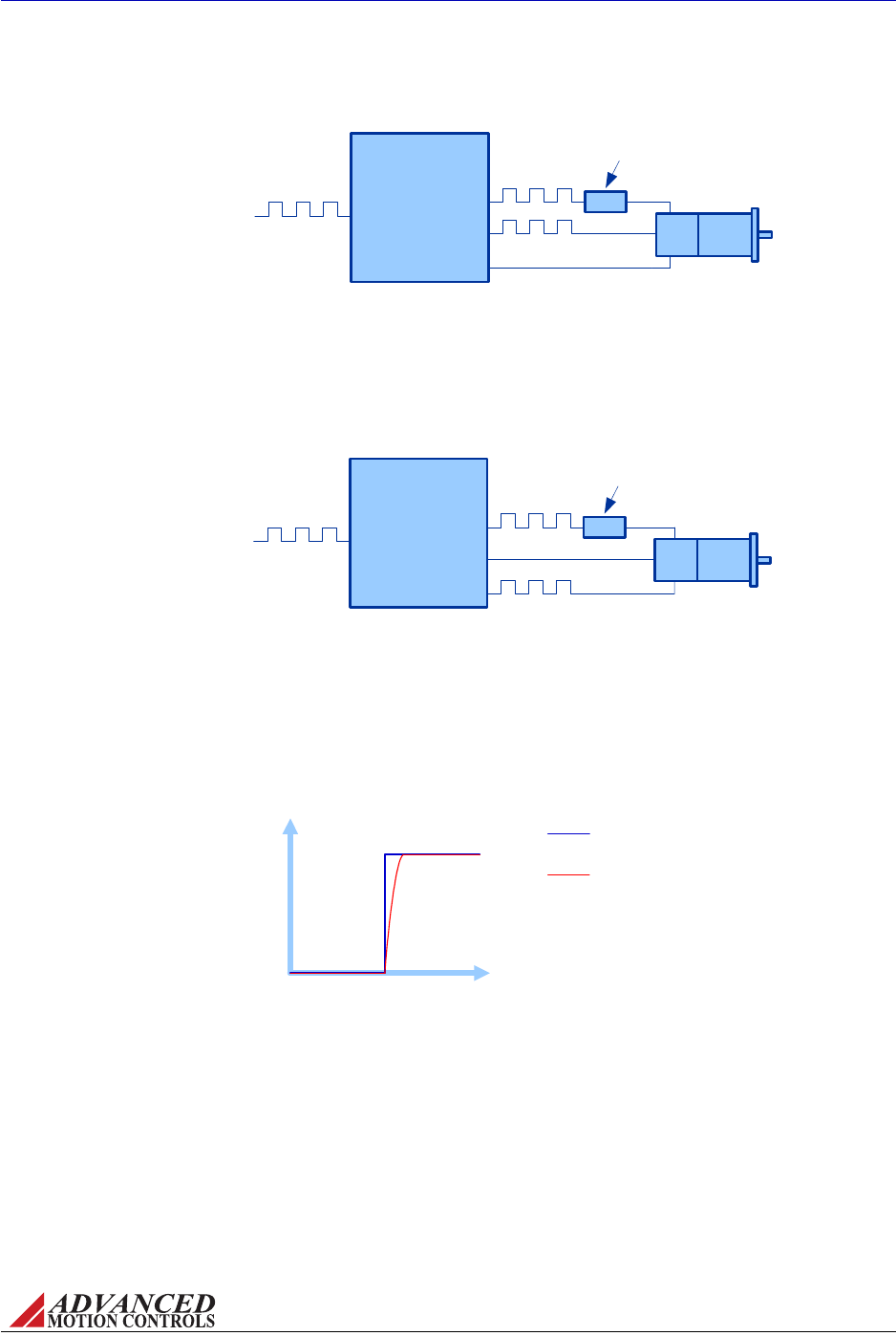
FIGURE 4.5 Current Loop Response
Time
Target Current
Signal
Output Current
Response
Current
FIGURE 4.4 S-Series Drives
Analog Servo
Drive
Motor
Motor A
Ref In A
Square
Wave Input
Motor B
Current
Probe or
Resistor
Motor C
The current out of the drive can be forced to go
through Motor A and Motor C by applying the square
wave command signal to Ref In A only. Attach the
current probe to either Motor A or Motor C.
The motor shaft does
not need to be locked
since the drive is not
commutating.
FIGURE 4.3 Brushless Drives
Analog Servo
Drive
Motor
Motor A
+Ref
Square
Wave Input
Motor B
Current
Probe or
Resistor
Motor C
The current out of the drive can be forced to go
through Motor A and Motor B by:
1) Disconnecting the Hall sensors from the drive
2) Setting the 60/120 degree phasing switch to 60 degrees
The motor shaft does
not need to be locked
since the drive will not
commutate without
the Hall Sensors.
MNALHWIN-01 51
Operation / Initial Setup and Features
7. Thedriveoutputshouldfollowtheinputcommand.Thebestresponsewillbeacritically
dampedoutputwaveform,similartowhatisshowninFigure4.5.
8. IfneithercurrentloopgainDIPswitchpositiongivesapropersquarewaveresponse,then
thecurrentloopgainresistorsmayneedtobechangedtooptimizetheresponse.See
“Through‐holeComponentTuning”onpage53formoreinformation.
9. Whentheproperresponsehasbeenachieved,removetheinputsignalfromthedrive,and
disconnectpower.
Current Loop Integrator Adjustment
1. EnabletheCurrentLoopIntegratorthroughDIPswitchorjumpersettings(seethedrive
datasheetforavailableoptions).

MNALHWIN-01 52
Operation / Initial Setup and Features
2. Usingafunctiongenerator,applya±0.5V,50‐100Hzsquarewavereferencesignal.
3. Applypowertothedrive.Useabusvoltagethatisapproximatetothedesiredapplication
voltageorthecurrentloopcompensationwillnotbecorrect.
4. Thedriveshouldbeenabled(GREENLED).Observethemotorcurrentusingacurrent
probeorresistorinserieswiththemotor(<10%ofmotorresistance).Ifavailable,useany
DIPswitchestoadjustthecurrentloopintegralgaincapacitance.Theoutputshouldsettle
toaflattopwithminimalcurrentfollowingerror(differencebetweencommanded
currentandactualcurrent).Therecanbesomeovershoot,butitshouldbelessthan10%.
Because the oscilloscope measurements are voltage representations of
current, the commanded and actual currents will most likely have
different current to voltage scalings and tolerances. Therefore, even with
perfect current loop tuning, the two amplitudes (scope traces) may not
line up as shown in Figure 4.5.
5. Ifthesquarewaveoutputovershootstoomuchorisover‐damped(sluggish),thecurrent
loopintegratorcapacitorwillneedtobechangedtooptimizetheresponse.See“Through‐
holeComponentTuning”onpage53formoreinformation.
Voltage or Velocity Loop Tuning Theseadjustmentsshouldinitiallybeperformedwith
themotoruncoupledfromthemechanicalload.
ConfigurethedriveforthedesiredoperationmodeusingtheDIPswitchsettings(seetheblock
diagramonthespecificdrivedatasheet).
•VoltageLooporOpenLoop‐Compensatingthevoltagelooprequirestheleastamountof
effort.TurntheLoopGainpotentiometerclockwiseuntiloscillationoccurs,thenbackoff
oneturn.
•IRFeedbackLoop‐Startwithaveryhigh(oropen)IRfeedbackresistorwithan
unloadedmotorshaft.Commandalowmotorspeed(about20‐200RPM).WithouttheIR
feedbackthemotorshaftcanbestalledeasily.DecreasingtheIRfeedbackresistorwill
makethemotorshaftmoredifficult tostop.Toomuc hIR fe edback,i.e.toolowaresistor
value,willcausemotorrun‐awaywhentorqueisappliedtothemotorshaft.
•VelocityLoop(Encoder,Halls,orTachometer)‐Thevelocityloopresponseis
determinedbytheLoopGainpotentiometer.Alargerresistancevalue(clockwise)results
inafasterresponse.Thevelocityintegratorcapacitorcanbeusedtocompensatefora
largeloadinertia.Alargeloadinertiawillrequirealargercapacitorvalue.Eitherusingthe
DIPswitchestoaddinanextracapacitororinstallingathrough‐holecapacitormay
accomplishthis(see“Through‐holeComponentTuning”onpage53formore
information).Theneedforanextracapacitorcanbeverifiedbyshortingoutthevelocity
integratorcapacitorbyDIPswitchsetting.Ifthevelocityloopisstablewiththecapacitor
shortedout,andunstablewiththecapacitorinthecircuit,thenalargercapacitorvalueis
needed.
Analog Position Loop Useofanencoderortachometerisrecommendedtoobtaina
responsivepositionloop,sincethepositionloopisclosedaroundthevelocityloop.Firstthe
velocityloopmustbestabilized(orvoltageloopforundemandingapplications).Theposition
loopgainisdeterminedbythefixedgainoftheinputdifferentialamplifierofthedrive.For
bestresultstheservodrivecanbeorderedwithahigherdifferentialgain.

MNALHWIN-01 53
A Through-hole Component Tuning
Ingeneral,ADVANCEDMotionControlsanalogservodriveswillnotneedtobefurthertunedwiththrough‐hole
components.However,forapplicationsrequiringmoreprecisetuningthanwhatisofferedbytheDIPswitches
andpotentiometers,thedrivecanbemanuallymodifiedwiththrough‐holeresistorsandcapacitorsasdenoted
inTableA.1below.Onmostanalogdrives,thethrough‐holelocationsarenotpopulatedwhenthedriveis
shipped.S‐Seriesdriveshoweverareshippedwiththrough‐holecomponentsinpinreceptaclesforeasy
removal.
ItisrecommendedtocontactADVANCEDMotionControlstodiscussapplicationrequirementsandproperdrive
tuningpriortomakinganyadjustments.
Beforeattemptingtoaddthrough‐holecomponentstotheboard,see“TuningProcedure”onpage49.Some
generalrulestofollowwhenaddingthrough‐holecomponentsare:
•Alargerresistorvaluewillincreasetheproportionalgain,andthereforecreateafaster
responsetime.
•Usenon‐polarizedcapacitors.
•Alargercapacitorvaluewillincreasetheintegrationtime,andthereforecreateaslower
responsetime.
A.1 Through-Hole Tuning
Propertuningusingthrough‐holecomponentswillrequirecarefulobservationoftheloop
responseonadigitaloscilloscopetofindtheoptimalthrough‐holecomponentvaluesforthe
specificapplication.
Thefollowingaresomehelpfulhintstomakethelooptuningprocesseasier:
•UsepinreceptaclestoreducetheneedforsolderingSomedriveshavepinreceptacles
thatmakeiteasytochangethetuningresistorsandcapacitorswithouttheneedfor
soldering.Otherdrivesdonothavethesereceptacles,sosolderingisrequired.Toavoidthe
needtosoldereverytimeatuningvalueneedstobechangedapinreceptaclecanbe
solderedintothethethroughholelocationofthetuningcomponent.
Any damage done to the drive while performing these modifications will
void the product warranty.
MNALHWIN-01 54
Through-hole Component Tuning / Through-Hole Tuning
•Useapotentiometertofindthecorrectcurrentlo o p gainvalueApotentiometercan
beusedtocontinuouslyadjustthegainresistancevalueduringthetuningprocess.Installa
potentiometerinplaceofthegainresistor.Adjustthepotentiometerwhileviewingthe
currentloopresponseonanoscilloscope.Whentheoptimalresponseisachievedturnoff
thedrive,removethepotentiometer,andmeasurethepotentiometerresistance.Usethe
closestresistorvalueavailable.(Note:Thismethodwillnotworkiftheoptimaltuning
valueisbeyondtherangeofthepotentiometer.Thismethodalsodoesnotworkforsine
drivessinceitisdifficulttokeepthetuningvaluesinthethreecurrentloopsthesame).
•Progressivelydou b le theresistancevaluewhentuningthecurrentloopgainfor
fasterresultsIfthegainresistorneedstobeincreasedduringthetuningprocessthe
fastestresultsareachievedbydoublingtheresistancefromthelastvaluetried.Usethis
methoduntilovershootisobservedandthenfinetunefromthere.
•Beawareofanycomponentsthatareinparallelwiththevaluesyouaretryingto
tuneOnsomedrives,theremaybeoneormoregainresistorsinparallelwiththe
through‐holeresistorlocation.TheequivalentresistancevalueoftheSMTresistorsonthe
boardandtheadditionalthrough‐holeresistorwillbelimitedbythesmallestresistance
valueofthegroupofresistorsinparallel.Consulttheblockdiagramonthedrivedatasheet
todeterminethespecificresistorvalues.Thesamesituationcanoccurwhentryingto
decreasetheintegratorcapacitorvalue,sincecapacitorsinparallelwillbeaddedtogether.
•Safety
Always remove power when changing components on the drive.
Float the oscilloscope and function generator grounds to avoid large
ground currents.
Decouple the motor from the load to avoid being injured by sudden
motor movements.
TableA.1liststhedifferentthrough‐holecomponentsthatcanbeusedforlooptuning.Some
modelsrequiremorethanonecomponentthatmusthaveidenticalvalues.Consultthedrive
datasheettoseewhichoptionsareavailableforaspecificdrive.PleasecontactADVANCED
MotionControlsApplicationsEngineeringforassistanceindeterminingthePCBlocationofthe
through‐holecomponentoptionsforthedrivemodelinuse.
TABLE A.1 Through-Hole Tuning Component
Component Description
Velocity Loop Integrator Through-hole capacitor that can be added for more precise velocity loop tuning.
Current Loop Integrator Through-hole capacitor that can be added for more precise current loop tuning.
Current Loop Proportional Gain Through-hole resistor that can be added for more precise current loop tuning.

MNALHWIN-01 55
Through-hole Component Tuning / Through-Hole Tuning
A.1.1 Procedure
BeforechanginganycomponentsonthePCBboard,followthestepsin“TuningProcedure”on
page49todetermineifanyadditionaltuningisnecessary.Observethedriveoutputcurrent
responseonanoscilloscopeforallthedifferentDIPswitchgainsettings(ifavailableonthe
driveinuse).Iffurthertuningisnecessaryordesired,pleasecontactADVANCEDMotion
Controlsbeforeproceedingthroughthethroughfollowingsteps.
Tune the Current Loop Proportional Gain
1. Followthestepsoutlinedin“CurrentLoopProportionalGainAdjustment”onpage50up
throughStep8.
2. Observethedrivecurrentresponseonanoscilloscope.Smallsteptuningisdifferentthan
largesteptuning,soadjustthefunctiongeneratorsquarewaveamplitudesothedrive
outputsacurrentstepsimilartowhatwillbeexpectedintypicaloperation.
—Ifthecurrentresponsedoesnotrisequicklyenoughtothestepinputcommand,orif
itneverreachestheinputcommand,theequivalentresistanceofthecurrentloop
proportionalgainresistorwillneedtobeincreased.Thiswillincreasethecurrent
loopproportionalgain,andachieveafaster,moreaggressiveresponse.
—Ifthecurrentresponseovershootsthestepinputcommand,theequivalentresistance
ofthecurrentloopproportionalgainresistorwillneedtobedecreased.Thiswill
decreasethecurrentloopproportionalgain,andprovideaslower,morestable
response.
3. Findinganacceptableequivalentresistancemaytakeafewiterations.Asoutlinedinthe
previoussection,usingpinreceptaclesoranexternalpotentiometerwillmaketheprocess
easier.Remembertoremovepowerfromthedrivepriortoremovingoraddingany
componentstothePCBboard.Alsorememberthatitisnotjustthethrough‐holeresistor
valuethatisimportant,buttheequivalentresistanceofthethrough‐holeresistorandany
SMTresistorsthatmaybeinparallelwiththethrough‐holelocation.Usetheblock
diagramonthedrivedatasheettoassistindeterminingtheequivalentgainresistance.
4. Useanequivalentresistancevaluethatbringsthecurrentresponserighttothepointof
overshoot.Ifthereisalargeamountofovershoot,orifthereareoscillations,decreasethe
equivalentresistancevalueuntilthereislittleornoovershoot.Dependingonthe
applicationrequirements,alittleovershootisacceptable,butshouldneverexceed10%.
5. Whenanacceptableresistancevaluehasbeenfound,removepowerfromthedrive.
Tune the Current Loop Integral Gain
1. Aftertheproportionalgainresistancehasbeenadjustedtoanacceptablevalue,re‐enable
thecurrentloopintegratorcapacitor(eitherthroughDIPswitchorjumpersettings,
dependingonthedrivemodel).
Remember that for Sinusoidal Input (S-Series) drives, all three current
loops must have identical through-hole component values (i.e. the
through-hole resistor value for phase A must match the through-hole
resistor values for phases B and C, and the through-hole capacitor value
for phase A must match the through-hole capacitor values for phases B
and C.

MNALHWIN-01 56
Through-hole Component Tuning / Through-Hole Tuning
2. Usingthesamefunctiongeneratorinputcommandasintheprevioussection,apply
powertothedriveandobservethecurrentloopresponseonanoscilloscope.
3. Dependingonthedrivemodel,thecurrentloopintegratorcapacitorcanbechangedor
shortedoutofthecircuitbyDIPswitchsetting.Testbothsettingswhileobservingthe
currentloopresponse.
—Ifthecurrentresponsesquarewaveoscillatesorovershoots,alargerequivalent
capacitancevalueisnecessary.
—Ifthecurrentresponsesquarewavecornersaretoorounded,asmallerequivalent
capacitancevalueisnecessarytosharpenthecorners.
4. Asintheprevioussection,usingpinreceptaclesatthethrough‐holelocationswillgreatly
assistinfindinganacceptablecapacitancevalue.Alsokeepinmindthatthethrough‐hole
capacitorlocationmaybeinparallelwithSMTcapacitorsonthePCBboard.Usetheblock
diagramonthedrivedatasheettodeterminetheequivalentintegratorcapacitancevalue
(capacitorsinparalleladdtogether).
5. Althoughtheidealcurrentloopresponseafterintegralgaintuningwillbeacritically
dampedsquarewave,theapplicationrequirementswilldeterminewhatthedesired
responsewillbe(i.e.howmuchovershoot,steady‐stateerror,oscillation,isacceptable).
Velocity Loop Integral Gain Tuning Thevelocityloopproportionalgainisadjustedbythe
on‐boardLoopGainpotentiometer.ThevelocityloopintegralgaincanbeadjustedbyDIP
switchsettingssimilartothecurrentloopintegralgain(capacitancevaluecanbechanged,
capacitorcanbeshortedout,extracapacitorcanbeaddedinparallel).However,somedrive
modelsalsoincludeadditionalthrough‐holelocationswherethrough‐holecapacitorscanbe
addedtofurtheradjustthevelocityloopintegralgain.Asintuningthecurrentloopintegral
gain,uselargervalueequivalentcapacitorstocorrectforovershootoroscillation,andsmaller
valueequivalentcapacitorsforaquickerresponsetime.

MNALHWIN-01 57
B Troubleshooting
Thissectiondiscusseshowtoensureoptimumperformanceand,ifnecessary,getassistancefromthefactory.
B.1 Fault Conditions and Symptoms
Aninoperativedrivecanindicateanyofthefollowingfaultconditions:
•over‐temperature
•over‐voltage
•under‐voltage
•short‐circuits
•invalidcommutation
•inhibitinput
•power‐onreset
Alloftheabovefaultconditionsareself‐resetbythedrive.Oncethefaultconditionisremoved
thedrivewillbecomeoperativeagainwithoutcyclingpower.Todeterminewhetherthedrive
isinafaultstate,measurethe“FaultOutput”pinwithadigitalmultimeterorvoltmeter.Ahigh
atthispin(oralow,dependingonthedrivemodelandconfiguration‐seedrivedatasheet)will
indicatethatthedriveissubjecttooneoftheabovefaultconditions,andthedrivewillbe
disableduntilthedriveisnolongerinafaultstate.Toremovethefaultcondition,followthe
instructionsinthesectionsbelowdescribingeachpossiblefaultstate.
Over-Temperature Verifythatthebaseplatetemperatureislessthanthemaximumallowable
baseplatetemperatureasdenotedonthedrivedatasheet,typically65ºC(149ºF)or75ºC
(167ºF).Thedriveremainsdisableduntilthetemperatureatthedrivebaseplatefallsbelow
thisthreshold.
Over-Voltage Shutdown
1. ChecktheDCpowersupplyvoltageforavalueabovethedriveover‐voltageshutdown
limit.IftheDCbusvoltageisabovethislimit,checktheACpowerlineconnectedtotheDC
powersupplyforpropervalue.
2. Checktheregenerativeenergyabsorbedduringdeceleration.Thisisdonebymonitoring
theDCbusvoltagewithavoltmeteroroscilloscope.IftheDCbusvoltageincreasesabove
thedriveover‐voltageshutdownlimitduringdecelerationorregeneration,ashunt

MNALHWIN-01 58
Troubleshooting / Fault Conditions and Symptoms
regulatormaybenecessary.See“RegenerationandShuntRegulators”onpage23formore
information.
Under-Voltage Shutdown Verifypowersupplyvoltagesforminimumconditionsper
specifications.Alsonotethatthedrivewillpullthepowersupplyvoltagedownifthepower
supplycannotprovidetherequiredcurrentforthedrive.Thiscouldoccurwhenhighcurrent
isdemandedandthepowersupplyispulledbelowtheminimumoperatingvoltagerequired
bythedrive.
Short Circuit Fault
1. Checkeachmotorleadforshortswithrespecttomotorhousingandpowerground.Ifthe
motorisshorteditwillnotrotatefreelywhennopowerisappliedwhileitisuncoupled
fromtheload.
2. Disconnectthemotorleadstoseeifthedrivewillenablewithoutthemotorconnected.If
thedriveenableswiththemotordisconnected,thereisapossibleshortcircuitinthe
motorwiring.
3. Measuremotorarmatureresistancebetweenmotorleadswiththedrivedisconnected.
Verifythesemeasurementsagainstthemotordatasheettodetermineifthereisashortor
opencircuitinthemotorwindings.
Invalid Hall Sensor State (Brushless Drives only) Seethe“CommutationSequence”
tablein“HallSensors”onpage12forvalidcommutationstates.Ifthedriveisdisabledcheck
thefollowing:
1. MakesurethattheHallSensorCommutationPhasingswitchisinthecorrectsettingper
motordatasheets.Whendrivingasinglephase(brushedtype)motorwithathreephase
(brushless)driveusethe60‐degreephasesetting(see“ThreePhase(Brushless)Drive
withBrushedMotor”onpage48formoreinformationonthisparticularconfiguration).
2. CheckthevoltagelevelsforalltheHallSensorinputs.Turnthemotorbyhandwhile
measuringtheHallSensorinputstoverifythatallthreeHallSensorsarechanging.The
voltageshouldreadapproximately+5Vfora"high(1)"Hallstate,andapproximately0V
fora"low(0)"Hallstate.
3. MakesureallHallSensorlinesareconnectedproperly.
Inhibit Input Checkinhibitinputforcorrectpolarity(thatis,pull‐to‐groundtoinhibitorpull‐to‐
groundtoenable).InhibitconfigurationdependseitherontheDIPswitchsettingsora0ohm
SMTresistormarkedontheboard.Also,keepinmindthatnoiseontheinhibitlinecouldbea
causeforafalseinhibitsignalbeinggiventothedrive.
Power-On Reset Alldriveshaveapower‐onresetfunctiontoensurethatallcircuitryonthe
boardisfunctionalpriortoenablingthedrive.Theboardwillonlybedisabledmomentarily,
andwillquicklyenableuponpowerup.
B.1.1 Overload
Verifythattheminimuminductancerequirementismet.Iftheinductanceistoolowitcould
appearlikeashortcircuittothedriveandthusitmightcausetheshortcircuitfaulttotrip.
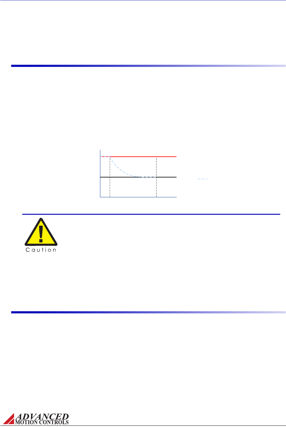
FIGURE B.1 Peak Current Fold-Back
Continuous Current Limit
212
Peak Current Limit
t(s)
Drive Current
Output
Amps
0
Sustained maximum current demand, when switching between positive
and negative maximum current without allowing sufficient time for fold-
back, will result in drive damage. Drive RMS current should be below the
continuous current setting!
MNALHWIN-01 59
Troubleshooting / Fault Conditions and Symptoms
Excessiveheatingofthedriveandmotorisalsocharacteristicoftheminimuminductance
requirementnotbeingmet.Seedrivedatasheetforminimuminductancerequirements.
B.1.2 Over-Current
WiththeexceptionofS‐Series(sinusoidalcommandinput)andDirectPWMcommand(e.g.
"BD")drives,analogservodrivesincorporatea“fold‐back”circuitforprotectionagainstover‐
current.This“fold‐back”circuitusesanapproximate“I2t”algorithmtoprotectthedrive.Drives
canrunatpeakcurrentforamaximumof2seconds(eachdirection).Currentsbelowthispeak
currentbutabovethecontinuouscurrentcanbesustainedforalongertimeperiod,andthe
drivewillautomaticallyfoldbackatanapproximaterateof"I2t"tothecontinuouscurrentlimit
withinatimeframeoflessthan10seconds.Anover‐currentconditionwillnotcausethedrive
tobecomedisabled.
OnS‐Seriesdrives,iftheRMScurrentthroughanymotorphaserisesabovethemaximum
continuoussinewavecurrentvalue,theovercurrentfaultoutputpinwilltriggerafaultstate,
andthedrivewillbedisableduntiltheRMScurrentvaluehasreturnedtoavaluewithinthe
acceptableoperatingrange.
B.1.3 Motor Problems
Amotorrun‐awayconditioniswhenthemotorspinsrapidlywithnocontrolfromthe
commandinput.Themostlikelycauseofthiserrorcomesfromhavingthefeedbackelement
connectedforpositivefeedback.Thiscanbesolvedbychangingtheorderthatthefeedback
elementlinesareconnectedtothedrive,orchangingthefeedbackpolarityswitchontheDIP
switchbanktotheoppositesetting.SeethedrivedatasheetformoreinformationonDIP
switchsettings.
AnothercommonmotorissueforbrushlessmotorswithHallSensorcommutationiswhenthe
motorspinsfasterinonedirectionthanintheotherforthesamevelocitycommandinthe
oppositedirection.Thisistypicallycausedbyimpropercommutation,usuallybecausethe
motorpowerwiresareconnectedinthewrongorderwithrespecttotheHallSensorwiring.
Tryallsixcombinationsofconnectingthemotorpowerwirestothedrivetofindthecorrect
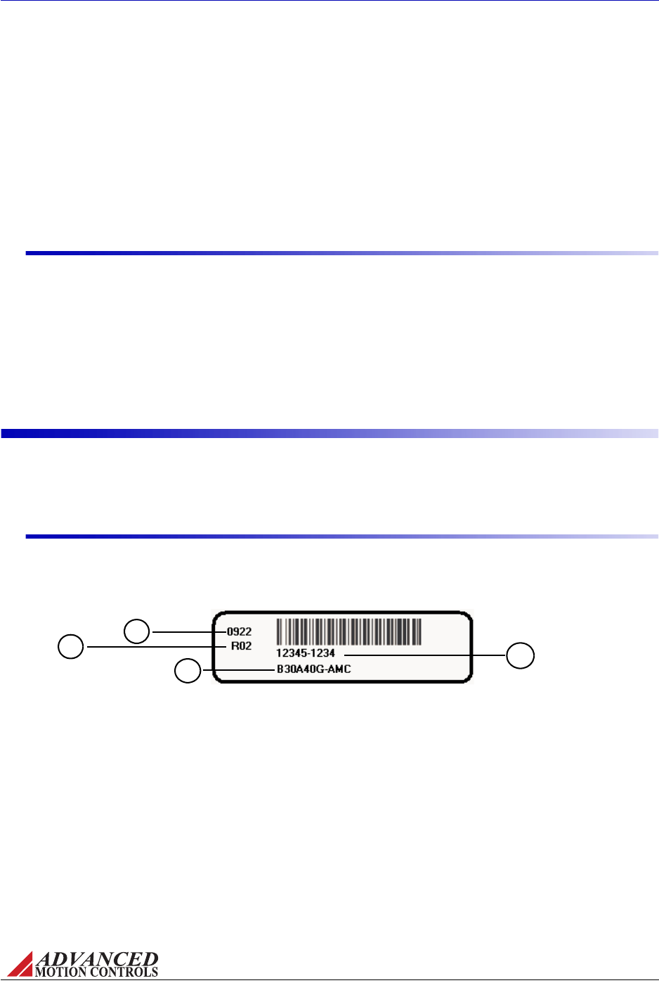
MNALHWIN-01 60
Troubleshooting / Technical Support
commutationorder.Thepropercombinationofmotorwireswillyieldsmoothmotionand
identicalspeedsinbothdirections.Impropercombinationswillcausejerkymotion,slow
movementinonedirection,and/oraudiblenoise.Asafinalverificationthatthecommutation
iscorrect,usetheVelocityMonitorOutputpintomeasuremotorspeedinbothdirections(see
“VelocityMonitorOutput”onpage42formoreinformation).Thiscanalsobecausedbyinvalid
Hallphasing.Checktoseeifthedriveissetfor120‐or60‐degreephasing,andverifythatthe
driveDIPswitchsettingcorrespondstotheHallphasingusedonthemotor.See“HallSensors”
onpage12formoreinformation.
B.1.4 Causes of Erratic Operation
•Impropergrounding(i.e.drivesignalgroundisnotconnectedtosourcesignalground).
•Noisycommandsignal.Checkforsystemgroundloops.
•Mechanicalbacklash,dead‐band,slippage,etc.
•Noisyinhibitinputline.
•Excessivevoltagespikesonbus.
B.2 Technical Support
FIGURE B.2
2
1
4
3
Analog Product Label
Forhelpfromthemanufacturerregardingdriveset‐uporoperatingproblems,pleasegather
thefollowinginformation.
B.2.1 Product Label Description
Thefollowingisatypicalexampleofaproductlabelasitisfoundonthedrive:
1. EIADateCode:Thedatecodeisa4‐digitnumbersignifyingtheyearandweekthatthe
drivewasmanufactured.Thefirsttwodigitsdesignatetheyearandthesecondtwodigits
designatetheweek.Forexample,theabovepartwouldhavebeenbuiltduringthetwenty‐
secondweekof2009.
2. Serialnumber:Theserialnumberisa5‐digitnumberfollowedbya4‐digitnumber.
3. Versionnumber:Threedigitcodethatreferstoproductversion.Differentversionsreflect
minorcomponentvaluechanges.RsignifiesRoHScompliancy.
4. Partnumber:Refertothedrivedatasheetsfortypicalpartnumbers.Thelastletterrefers
totherevision(intheaboveexampleG).ThepartnumbercanbeproceededbyanX,
whichsignifiesaprototypeunit.Thepartnumbercanalsohaveasuffix(e.g.B30A40G‐
AMC),whichdesignatesaspecialversionofthestandarddrive(B30A40Gisthestandard
drive,‐AMCdesignatesthespecialversion).

MNALHWIN-01 61
Troubleshooting / Technical Support
B.2.2 Drive Model Information
•DCbusvoltageandrange
•Motortype(brushed,brushless,ACinduction)
•Motorcharacteristics(inductance,torqueconstant,windingresistance,etc.)
•PositionofallDIPswitches
•Lengthandmake‐upofallwiringandcables
•Ifbrushless,includeHallsensorinformation
•Typeofcontroller
•Fulldescriptionoffeedbackdevices
•Descriptionofproblem:instability,run‐away,noise,over/undershoot,etc.
•Completepartnumberandserialnumberoftheproduct.Originalpurchaseorderis
helpful,butnotnecessary
B.2.3 Warranty Returns and Factory Help
Sellerwarrantsthatallitemswillbedeliveredfreefromdefectsinmaterialandworkmanship
andinconformancewithcontractualrequirements.TheSellermakesnootherwarranties,
expressorimpliedandspecificallyNOWARRANTYOFMERCHANTABILITYORFITNESSFOR
APARTICULARPURPOSE.TheSeller'sexclusiveliabilityforbreachofwarrantyshallbe
limitedtorepairingorreplacingattheSeller'soptionitemsreturnedtoSeller'splantatBuyer's
expensewithinoneyearofthedateofdelivery.TheSeller'sliabilityonanyclaimofanykind,
includingnegligence,forlossordamagearisingoutof,connectedwithorresultingfromthis
order,orfromtheperformanceorbreachthereoforfromthemanufacture,sale,delivery,
resale,repairoruseofanyitemorservicescoveredbyorfurnishedunderthisordershallin
nocaseexceedthepriceallocabletotheitemorserviceorpartthereofwhichgivesrisetothe
claimandintheeventSellerfailstomanufactureordeliveritemsotherthanstandardproducts
thatappearinSeller'scatalog.Seller'sexclusiveliabilityandBuyer'sexclusiveremedyshallbe
releaseoftheBuyerfromtheobligationtopaythepurchaseprice.INNOEVENTSHALLTHE
SELLERBELIABLEFORSPECIALORCONSEQUENTIALDAMAGES.Buyerwilltakeall
appropriatemeasurestoadviseusersandoperatorsoftheproductsdeliveredhereunderofall
potentialdangerstopersonsorproperty,whichmaybeoccasionedbysuchuse.Buyerwill
indemnifyandholdSellerharmlessfromallclaimsofanykindforinjuriestopersonsand
propertyarisingfromuseoftheproductsdeliveredhereunder.Buyerwill,atitssolecost,carry
liabilityinsuranceadequatetoprotectBuyerandSelleragainstsuchclaims.
Allreturns(warrantyornon‐warranty)requirethatyoufirstobtainaReturnMaterial
Authorization(RMA)numberfromthefactory.RequestanRMAnumberby:
web www.a-m-c.com/download/form/form_rma.html
telephone (805) 389-1935
fax (805) 389-1165
e-mail amcsupport@a-m-c.com

MNALHWIN-01 I
Index
Symbols
±10VAnalogCommand.................10
±10VAnalogInputWiring ............ 36
A
ACPowerSupplies ........................33
ACSupplyFrequency ......................9
ACSupplyVoltageRange.................9
AdjustableAccel.andDecel. .......... 44
AgencyCompliances .......................ii
Altitude............................................26
AnalogPositionLoopMode........... 16
AnalogPositionLoopTuning........ 52
AttentionSymbols ...........................iii
B
BaseplateTemperatureRange ......26
Brushed±10VAnalogDCDrives ....5
BrushedACSupplyDrives .............. 5
BrushedPWMInputDCDrives ......5
BrushedServoDrives...................... 7
Brushless±10VAnalogDCDrives ..5
BrushlessACSupplyDrives ............5
BrushlessPWMInputDCDrives .... 5
BrushlessServoDrives.................... 7
BrushlessServoSystem...................8
BusFuse ........................................... 9
C
CapacitiveInterferenceCoupling .31
CE‐EMCWiringRequirements...... 28
CentralPointGrounding ...............30
CommandInputs............................10
CommutationSequenceTable.13, 48
CompanyWebsite ............................ii
ContinuousCurrentLimitPin.......41
ContinuousRegeneration..............25
ControllerChassis .......................... 30
Controller‐basedCommutation.......8
Current(Torque)Mode .................14
CurrentLimitPotentiometer.........43
CurrentLimiting ............................46
CurrentLoopGain .........................50
CurrentLoopIntegrator ................ 51
CurrentMonitorOutput ................40
CurrentReferenceOutput.............41
CustomModels .................................5
D
DaisyChains...................................32
DateCode........................................60
DCBusOverVoltageLimit ..............9
DCPowerSupplies ........................33
DCPowerSupplyWiring...............33
DCSupplyVoltageRange.................9
DIPSwitchSettings........................44
DriveCaseGrounding ...................30
DriveDatasheet................................4
DriveSet‐upInstructions.........47–49
DwellTime .....................................18
E
EIADateCode.................................60
ElectromagneticInterference ........31
EncoderVelocityMode ..................15
EnvironmentalSpecifications .......26
ErrorSignal.................................... 11
ExternalFilterCard........................19
F
FACDriveModels ...........................33
FaultConditions .......................57–59
FaultOutput....................................42
FeedbackPolarity ..........................11
FeedbackSpecifications ..........11–13
FeedbackWiring......................34–35
Fold‐back.........................................59
FrequencyFactor ...........................25
G
GroundLoops ..........................30, 32
Grounding ......................................30
H
HallSensors
Feedback ....................................12
Wiring.........................................34
HallVelocityMode..........................15
Humidity.........................................26
I
Impedance ......................................31
IncrementalEncoder
Feedback ....................................11
Wiring .........................................35
InhibitInput.............................41, 58
InputReferenceWiring...........35–38
InterferenceCoupling....................31
InternalBusCapacitance.................9
InternalShuntResistance................9
InternalShuntResistor
PowerRating ................................9
Turn‐onVoltage ...........................9
InvalidHallCommutation .............58
IRCompensationMode .................16
IRFeedbackLoopTuning .............52
IsolatedPowerSupply ...................22
Isolation ..........................................22
L
LinearMotorEquation...................18
Lock‐out/tag‐outProcedures..........1
LoopGainPotentiometer...............43
LowVoltagePowerOutputs...........42
LVDRequirements .........................27
M
MagneticInterferenceCoupling ...31
Max.ContinuousOutputCurrent....9
Max.PeakOutputCurrent...............9
Max.PowerDissipationatContinuous
Current .............................9
MechanicalShock ..........................26
MinimumLoadInductance .............9
ModelMask ......................................4
ModesofOperation..................14–16
AnalogPositionLoop .................16
Current(Torque) ........................14
EncoderVelocity.........................15
HallVelocity................................15
IRCompensation........................16
OpenLoop ..................................14
TachometerVelocity...................15
VoltageMode ..............................16
MotionControlSystem.....................6
Motor"Run‐Away" ......................... 11
MotorBack‐EMFVoltage ...............19
MotorChassis.................................30
MotorCurrent ..........................18, 20

/
II MNALHWIN-01
MotorCurrentFrequency ............. 19
MotorForce ....................................19
MotorInductance .......................3, 19
Overload .....................................58
MotorProblems .............................59
Moto rRes is tance ............................19
MotorRun‐Away ............................59
MotorTorqueConstant..................18
Moto rVoltage ........................... 18, 20
MotorWiring..................................32
MountingOptions ..........................39
MoveProfile ...................................17
MultiplePowerSupplyWiring......33
N
NegativeFeedback ......................... 11
Noise............................................... 31
NominalPowerSupplyVoltage .... 20
O
OpenLoopMode............................14
Over‐Current..................................59
Overload ......................................... 58
Over‐Temperature.......................... 57
Over‐VoltageShutdown .................57
P
PartNumber ..................................60
PartNumberingStructure...............4
PEGround ......................................30
PeakCurrentFold‐back .................59
PeakTorque ...................................18
PinFunctions ...........................40–42
PositiveFeedback .......................... 11
PotentiometerFunctions ...............43
PotentiometerTestPoints .............43
PowerGround................................30
PowerOutputs,LowVoltage..........42
PowerStageSpecifications..............9
PowerSupplyCapacitance..2, 25, 32
PowerSupplyChassis ...................30
PowerSupplyCurrent...................21
PowerSupplyOutputCurrent 20, 25
PowerSupplyWiring ....................32
Power‐onReset..............................58
ProductLabel .................................60
ProductsCovered .............................4
ProtectiveEarth .............................30
PWMandDirectionCommand .....10
PWMandDirectionInputWiring.37
PWMCurrentControlCircuit..........6
R
REFIN,‐..........................................35
REFIN,+.........................................35
ReferenceGainPotentiometer ......43
Regeneration ..................................23
Continuous .................................25
Returns ...........................................61
Revision ..........................................60
RevisionHistory............................. iii
RMSTorque....................................18
S
Safety ............................................1–3
ScalingFactor .................................15
SelectionandSizing .................17–26
Serialnumber ................................60
ServoDriveTheory......................6–8
Shielding ...................................30, 31
Shock/Vibration ............................26
ShortCircuitFault..........................58
ShuntFuse........................................9
ShuntRegulator........................21, 23
SignalGround ................................30
SinglePhaseServoDrives ...............7
Single‐PhaseACSupply.................34
SinusoidalCommand.....................10
SinusoidalInputACSupplyDrives .5
SinusoidalInputDCDrives .............5
SinusoidalInputWiring ................38
StandardDriveModels .....................5
SwitchFunctions............................44
SwitchingFrequency.......................9
SystemRequirements ..............17–26
SystemVoltageRequirement ........18
T
Tachometer
Feedback ....................................13
VelocityMode .............................15
Wiring .........................................35
TechnicalSupport..........................60
TestPoints(Pots) ...........................43
Test/OffsetPotentiometer.............43
ThreePhaseServoDrives ...............7
Three‐PhaseACSupply .................34
Through‐holeComponents............53
Torque.............................................18
Trademarks ..................................... ii
Troubleshooting .......................57–61
Tuning
Procedure .............................49–52
Through‐HoleComponents.53–56
TwistedPairWires.........................31
U
Under‐VoltageShutdown...............58
V
VelocityLoopTuning .....................52
VelocityMonitorOutput.................42
VelocityScalingFactor ...................42
Vibration.........................................26
VoltageDropInterference .............31
VoltageLoopTuning ......................52
VoltageMode ..................................16
VoltageRipple.................................25
W
WarningSymbols ........................... iii
WarrantyInfo.................................61
WarrantyReturns ..........................61
WireDiameter................................31
WireGauge .....................................31
Wiring .......................................31–38

Analog Drive Product Family
Hardware Installation Manual
MNALHWIN-01
3805 Calle Tecate • Camarillo, CA 93012-5068
Tel: (805) 389-1935 Fax: (805) 389-1165 www.a-m-c.com
