000.005 Install Man B&W Armaflex Sheet Installation
User Manual: Armaflex Sheet Installation
Open the PDF directly: View PDF ![]() .
.
Page Count: 9
Installation:
9
4.b. Using Armaflex sheet
insulation on pipes
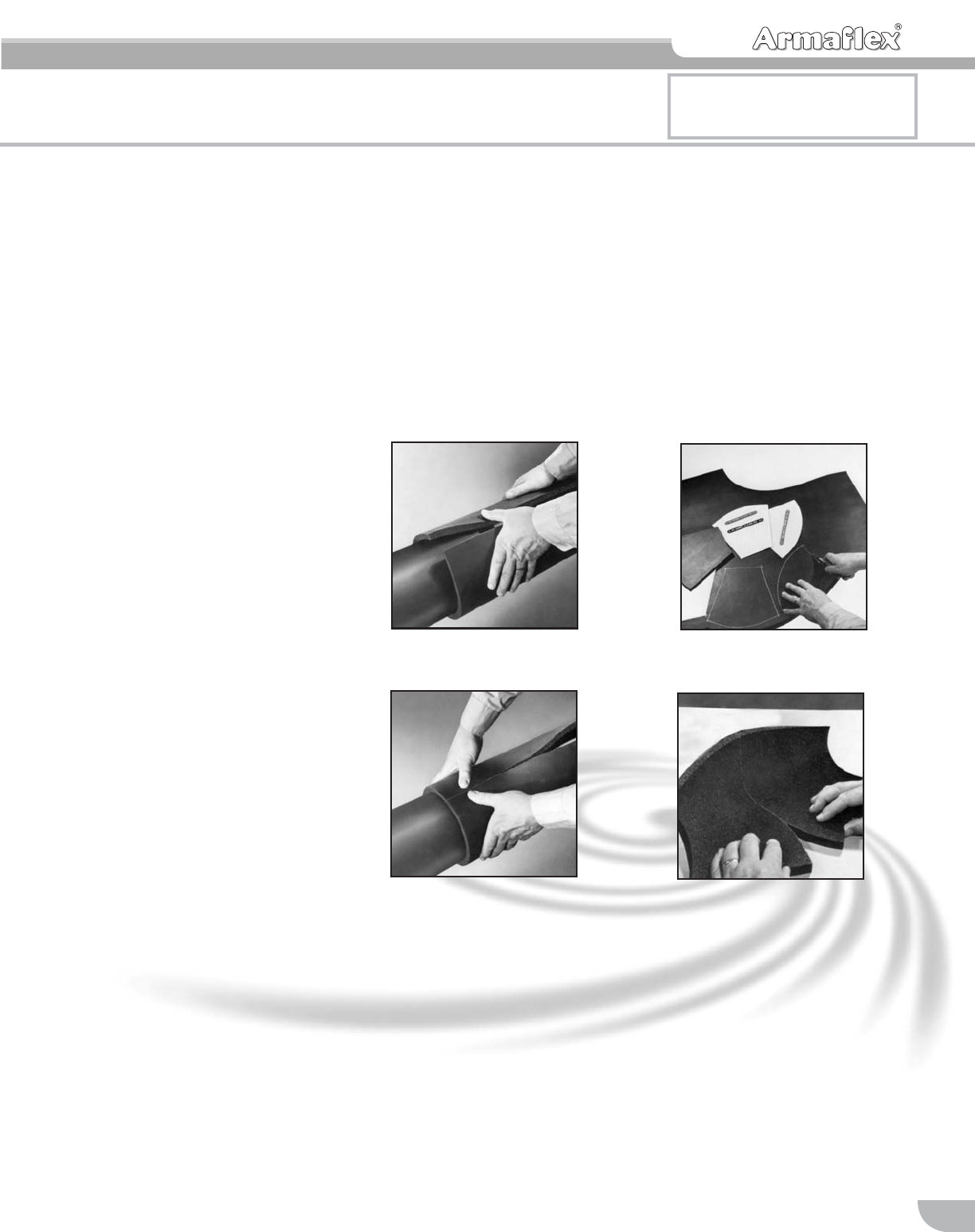
Application to pipes
1. Apply Armaflex Sheet
Insulation on pipes larger than
5″IPS. Cut the sheet insula-
tion to proper width, permitting
it to fit loosely without stretch-
ing around the pipe. (See pgs
11-12.) The fabrication must
be done at the job site, at the
same ambient conditions as
the application.
2. Brush-coat both surfaces of
the lengthwise seam with 520
or 520 BLV Adhesive. Allow
the adhesive to dry until tacky
to the touch under slight pres-
sure before joining surfaces.
Wrap the sheet around the
pipe, and seal the seam by
pressing the surfaces firmly
together. Join butt joints
between individual sections
using 520 or 520 BLV
Adhesive. On horizontal pipes
larger than 12″IPS, adhere
insulation on lower one-third.
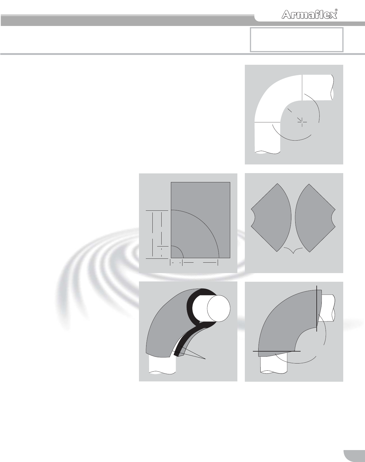
Application to fittings
3. Fitting covers are easily made,
using templates designed spe-
cially for screwed fittings 2″, 2-
1/2″and 3″and long-radius
weld fittings from 3″to 10″
IPS. (See size chart, pg 11.)
Note: Templates should be
traced on stiff paper, sheet
metal or hardboard and cut out to
make reusable patterns.
4. Since each template for 45˚
and 90˚ ells is shown as a
symmetrical half of the full fit-
ting cover, the complete fitting
cover is formed by adhering
two halves together at the long
outer arc. Coat both surfaces
with 520 or 520 BLV Adhesive.
Allow the adhesive to dry until
dry to the touch but tacky
under slight pressure before
joining surfaces. Then seal the
seam by pressing the surfaces
firmly together throughout. To
do
this, press the adhesive joint
on the rough side and then
snap the cover inside out and
press the joint on the smooth
skin side. (The tee template is
a symmetrical half, but, in this
case, both halves are laid out
together to form the complete
outline of the fitting cover.)
13
24
Please note: For installing self
adhering SA Armaflex sheets and
rolls, refer to p.19.
Installation:
10
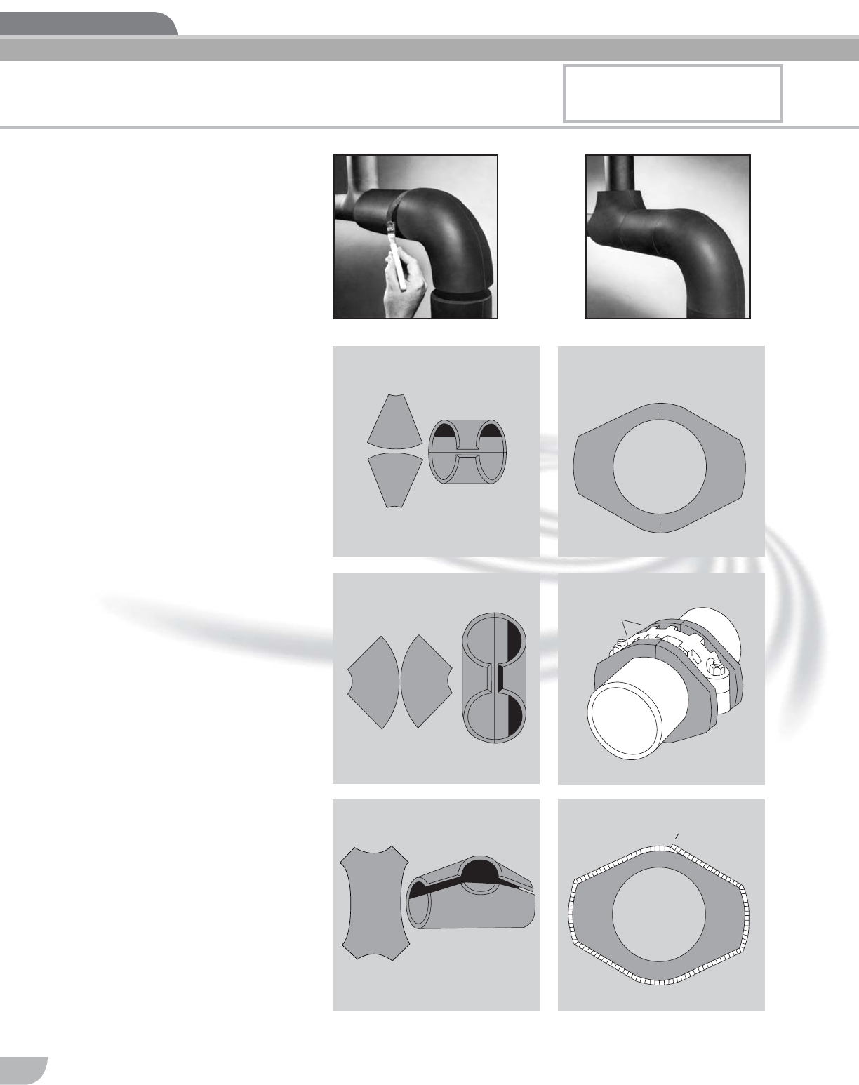
5. Snap the formed cover in place
over the fitting. Adhere the
mating surfaces of the inner
arc joint with 520 or 520 BLV
Adhesive. Join the straight
pipe covering to the fitting
cover, making sure to coat
both the pipe-section butt sur-
face and the fitting-cover butt
surface.
Note: On screwed fittings, select
the proper template from section
4.b.1., page 11. Notice that the
screwed fitting cover templates
allow for the 1″minimum overlap
on the straight pipe next to the
fitting. Remember to cement this
1″overlap with 520 or 520 BLV
Adhesive by forcing the brush
between the two surfaces.
6. Allow the adhesive to dry until
dry to the touch but tacky
under slight pressure before
joining surfaces. Press sur-
faces firmly together to seal.
Application to Victaulic
Couplings
Make two donuts, and place on
both sides of the Victaulic
Coupling. Complete the fitting
cover by gluing the circumferen-
tial strip of sheet insulation over
the two donuts.
▲
45° ELL
CIRCUMFERENCE
TEMPLATE FOR
VICTAULIC
COUPLING
90° ELL
TEE
ARMAFLEX
DONUTS
▲
▲
6
5
Please note: For installing self
adhering SA Armaflex sheets and
rolls, refer to p.19.
Installation:
11
SCREWED
Pipe
Size 3/8″1/2″3/4″
IPS 45˚90˚T45
˚90˚T45
˚90˚T
2" • • • • • • • • •
2-1/2″••••••
3" • • • • • •
VICTAULIC COUPLINGS
Pipe
Size 3/8″1/2″3/4″1″
3/4″•••
1″•••
1-1/4″•••
1-1/2″•••
2″•••
2-1/2″•••
3″•••
3-1/2″•••
4″•••
5″•••
6″•••
8″•••
10″•••
12″•••
WELD
Pipe
Size 3/8″1/2″3/4″1″
IPS 45˚90˚T45
˚90˚ T45
˚90˚T45
˚90˚ T
3″•••••••••
3-1/2″•••••••••
4″•••••••••
5″•••••••••
6″•••••••••
8″•••••••••
10″•••••••••
Template
number and
description
No. AT Set A
Screwed 45˚ Elbows
■3/8″—1/2″—3/4″Walls
■2″, 2-1/2″, 3″IPS
No. AT Set B
Screwed 90˚ Elbows
■3/8″—1/2″—3/4″Walls
■2″, 2-1/2″, 3″IPS
No. AT Set C
Screwed Tees
■3/8″—1/2″—3/4″Walls
■2″, 2-1/2″, 3″IPS
No. AT Set D
Weld 45˚ Long-Radius Elbows
■1/2″Wall
■3″IPS thru 10″IPS
No. AT Set E
Weld 45˚ Long-Radius Elbows
■3/4″Wall
■3″IPS thru 10″IPS
No. AT Set F
Weld 90˚ Long-Radius Elbows
■1/2″Wall
■3″IPS thru 10″IPS
No. AT Set G
Weld 90˚ Long-Radius Elbows
■3/4″Wall
■3″IPS thru 10″IPS
No. AT Set H
Weld Tees
■1/2″Wall
■3″IPS thru 10″IPS
No. AT Set I
Weld Tees
■3/4″Wall
■3″IPS thru 10″IPS
No. AT Set J
Weld Tees
■1″Wall
■3″IPS thru 10″IPS
No. AT Set K
Weld 45˚ Long-Radius Elbows
■1″Wall
■3″IPS thru 10″IPS
No. AT Set L
Weld 90˚ Long-Radius Elbows
■1″Wall
■3″IPS thru 10″IPS
4.b.2. yields of ...4.b.1 Templates are available
for screwed and long-radius
weld fittings
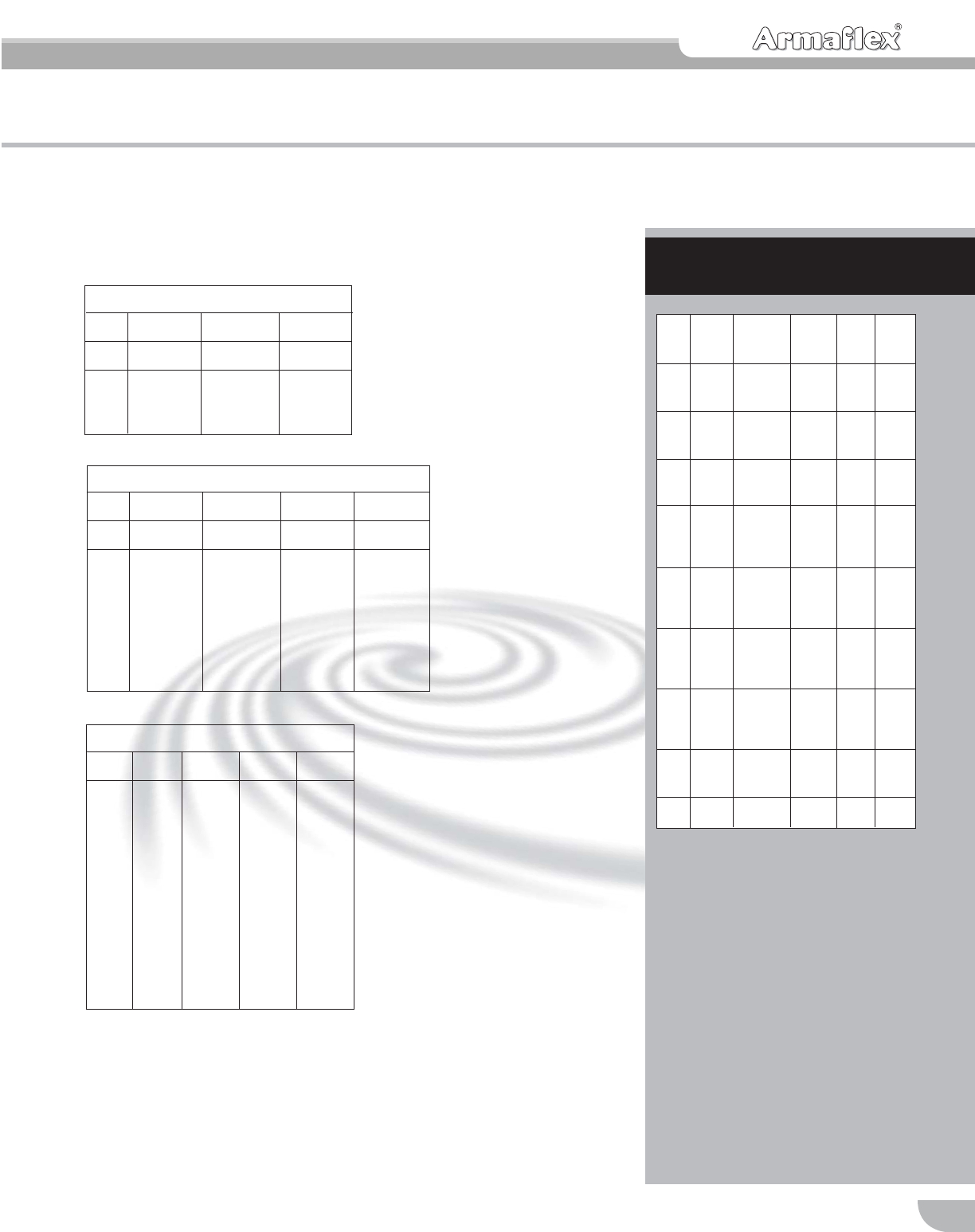
Templates for the Iron Pipe Sizes Shown
Below in 3/8″, 1/2″and 3/4″Armaflex:
There are twelve template sheets—order from
Armacell. Templates for Victaulic Couplings
and standard grooved end fittings are also
available.
... AP ARMAFLEX SHEET AS
PIPE INSULATION
Insula- Insulation
tion Width ″
Pipe Thick- (Pipe Sheet LF Drop-
Size ness Circum.) Length Sheet Off
3″1/2 13-1/2 36 9 7-1/2
IPS 3/4 14-5/8 36 9 4-1/8
115-5/8 36 9 1-1/8
3-1/2″1/2 15-1/8 36 9 2-5/8
IPS 3/4 16-1/8 48 8 3-3/4
117-1/8 48 8 1-3/4
4″1/2 16-5/8 48 8 2-3/4
IPS 3/4 17-3/4 48 8 1/2
118-3/4 36 6 10-1/2
5″1/2 20 36 6 8
IPS 3/4 21-1/8 36 6 5-3/4
122-1/8 36 6 3-3/4
1-1/2 25-3/8 48 4 10-5/8
6″1/2 23-3/8 36 6 1-1/4
IPS 3/4 24-1/2 48 4 11-1/2
125-3/8 48 4 10-5/8
1-1/2 28-1/2 48 4 7-1/2
8″1/2 29-5/8 48 4 6-3/8
IPS 3/4 30-3/4 48 4 5-1/4
131-3/4 48 4 4-1/4
1-1/2 34-7/8 48 4 1-1/8
10″1/2 36-1/4 36 3 11-3/4
IPS 3/4 37-3/8 36 3 10-5/8
138-3/8 36 3 9-5/8
1-1/2 41-1/2 36 3 6-1/2
12″1/2 42-5/8 36 3 5-3/8
IPS 3/4 43-5/8 36 3 4-3/8
144-5/8 36 3 3-3/8
14″1/2 46-1/2 36 3 1-1/2
IPS 3/4 47-5/8 36 3 3/8
For jobsite application sizing. Not intended for
shop prefabrication.
Yield of Armaflex Sheet (36″x 48″) when used
on various pipe sizes.
All dimensions are in inches.
Installation:
12
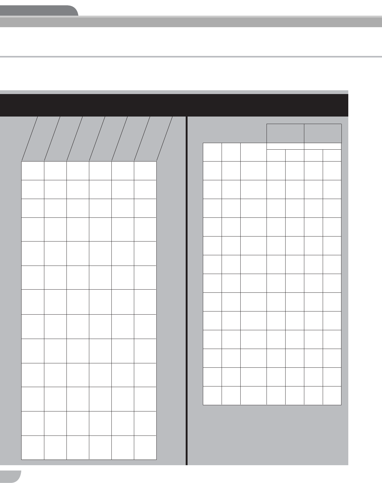
Yields of ... 4.c. measuring ...
Throat Meas.
Half
Circumference
Plus Throat Meas.
Pipe
Size
OD ″Pipe
OD ″Sheet
Thickness
R2
R1
Short
Radius Long
Radius
Short
Radius Long
Radius
33-1/2 1/2 1-1/4 2-3/4 8 9-1/2
33-1/2 3/4 1-1/4 2-3/4 8-1/2 10
33-1/2 1 1-1/4 2-3/4 9 10-1/2
3-1/2 4 1/2 1-1/2 3-1/4 9 10-3/4
3-1/2 4 3/4 1-1/2 3-1/4 9-1/2 11-1/4
3-1/2 4 1 1-1/2 3-1/4 10 11-3/4
44-1/2 1/2 1-3/4 3-3/4 10-1/8 12-1/8
44-1/2 3/4 1-3/4 3-3/4 10-5/8 12-5/8
44-1/2 1 1-3/4 3-3/4 11-1/8 13-1/8
55-9/16 1/2 2-1/4 4-3/4 12-1/4 14-3/4
55-9/16 3/4 2-1/4 4-3/4 12-3/4 15-1/4
55-9/16 1 2-1/4 4-3/4 13-1/4 15-3/4
66-5/8 1/2 2-3/4 5-5/8 14-1/2 17-1/4
66-5/8 3/4 2-3/4 5-5/8 15 17-3/4
66-5/8 1 2-3/4 5-5/8 15-1/2 18-1/4
88-5/8 1/2 3-3/4 7-5/8 18-1/2 22-3/8
88-5/8 3/4 3-3/4 7-5/8 19 23
88-5/8 1 3-3/4 7-5/8 19-1/2 23-3/8
10 10-3/4 1/2 4-5/8 9-5/8 22-3/4 27-3/4
10 10-3/4 3/4 4-5/8 9-5/8 23-1/4 28-1/4
10 10-3/4 1 4-5/8 9-5/8 23-3/4 28-3/4
12 12-3/4 1/2 5-5/8 11-5/8 26-7/8 32-7/8
12 12-3/4 3/4 5-5/8 11-5/8 27-3/8 33-3/8
12 12-3/4 1 5-5/8 11-5/8 27-7/8 33-7/8
14 14 1/2 7 14 30-1/4 37-1/4
14 14 3/4 7 14 30-3/4 37-3/4
14 14 1 7 14 31-1/4 38-1/4
16 16 1/2 8 16 34-3/8 42-3/8
16 16 3/4 8 16 34-7/8 42-7/8
16 16 1 8 16 35-3/8 43-3/8
18 18 1/2 9 18 38-1/2 47-1/2
18 18 3/4 9 18 39 48
18 18 1 9 18 39-1/2 48-1/2
20 20 1/2 10 20 42-5/8 52-5/8
20 20 3/4 10 20 43-1/8 53-1/8
20 20 1 10 20 43-5/8 53-5/8
24 24 1/2 12 24 51 63
24 24 3/4 12 24 51-1/2 63-1/2
24 24 1 12 24 52 64
3″IPS 1/2 13-1/2 70 62 248
3/4 14-5/8 50 41 164
115-5/8 35 26 104
3-1/2″IPS 1/2 15-1/8 70 55 220
3/4 16-1/8 50 37 148
117-1/8 35 24 96
4″IPS 1/2 16-5/8 70 50 200
3/4 17-3/4 50 33 132
118-3/4 35 22 88
5″IPS 1/2 20 70 42 168
3/4 21-1/8 50 28 112
122-1/8 35 18 72
1-1/2 25-3/8 25 11 44
6″IPS 1/2 23-3/8 70 35 140
3/4 24-1/2 50 24 96
125-3/8 35 16 64
1-1/2 28-1/2 25 10 40
8″IPS 1/2 29-5/8 70 28 112
3/4 30-3/4 50 19 76
131-3/4 35 13 52
1-1/2 34-7/8 25 8 32
10″IPS 1/2 36-1/4 70 23 92
3/4 37-3/8 50 16 64
138-3/8 35 10 40
1-1/2 41-1/2 25 7 28
12″IPS 1/2 42-5/8 70 19 76
3/4 43-5/8 50 13 52
144-5/8 35 9 36
1-1/2 47-3/4 25 6 24
14″IPS 1/2 46-1/2 70 18 72
3/4 47-5/8 50 12 48
148-1/2 35 8 32
1-1/2 51-3/4 25 5 20
16″IPS 1/2 52-3/4 70 15 60
3/4 53-3/4 50 11 44
154-3/4 35 7 28
1-1/2 58 25 5 20
18″IPS 1/2 59-1/8 70 14 56
3/4 60 50 10 40
161 35 6 24
1-1/2 64-1/4 25 4 16
20″IPS 1/2 65-3/8 70 12 48
3/4 66-3/8 50 9 36
167-3/8 35 6 24
1-1/2 70-1/2 25 4 16
24″IPS 1/2 77-7/8 70 10 40
3/4 78-7/8 50 7 28
179-7/8 35 5 20
1-1/2 83-1/8 25 3 12
PIPE
SIZE
INSULATION
THICKNESS
(In.)
INSULATION
LENGTH
(Pipe Circum., In.)
APPROX. ROLL
LENGTH (LF)
PCS./ROLL
(4-Ft. Lengths)
LF/ROLL (Ft.)
*For jobsite application sizing. Not intended for shop fabrication.
... 48-INCH-WIDE AP ARMAFLEX ROLLS
AS PIPE INSULATION ... AP ARMAFLEX SHEET FOR WELDED
90˚ ELBOW FITTINGS
13
4.c. Armaflex sheet on
90° elbows
1. Check the type ell (long or
short radius) and size.
2. Take throat measurement from
chart (R1). Swing an arc from
one corner of the Armaflex
sheet, using this measure-
ment. Take half circumference
plus throat measurement from
chart (R2). Using the same
corner of the sheet from which
the arc R1 was drawn, now
swing an arc, using the meas-
urement R2.
3. Cut out on arcs R1 and R2,
and use as a pattern for the
second half of the elbow
cover. Adhere outer arcs of the
two halves with Armaflex 520
or 520 BLV Adhesive. As arcs
are adhered, the cover will
“dish” upward. After seam is
squeezed together on one
side, “dish” the cover the oppo-
site direction, and squeeze the
other side of seam.
4. Put cover around elbow fitting,
and adhere inner arcs.
5. Trim ends of fitting cover
square to meet the straight
pipe insulation. Place metal
band or metal strap around fit-
ting cover, and scribe a
straight line. Then trim with a
sharp knife.
Outer
arcs
▲
▲
3
Weld
▲
1
▲
▲
R1
Inner
arcs
4
▲
▲
Trim to
line
5
▲
R2
R1
R1C/2
C/2
▲
▲
▲
▲
▲
▲
▲
▲
▲
2
Installation:
Please note: For installing self
adhering SA Armaflex sheets and
rolls, refer to p.19.
Installation:
14
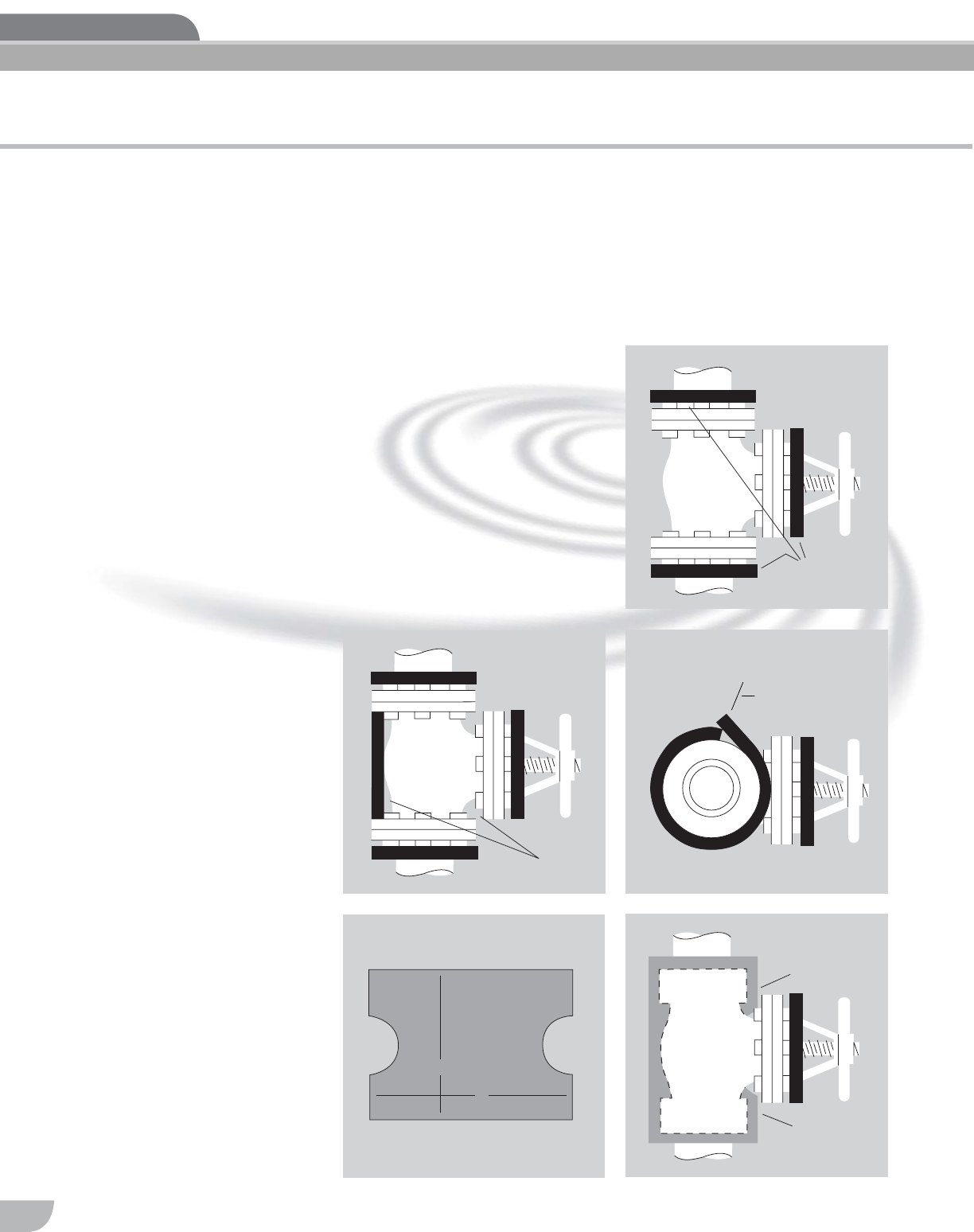
4.d. Armaflex sheet on
flanged valve fitting
covers
These instructions are meant to
serve as a guide for insulating
flanged valves with Armaflex.
Because of the variety in shape
and design of flanged valves,
some modifications to these
instructions may be necessary.
1. Cut Armaflex donuts the same
diameter as the flanges, and
install at pipe/flange and valve
stem areas.
2. Use scrap strips of Armaflex
Sheet to build the body of the
valve out until it is the same
dimension as the OD of the
flanges. Adhere the Armaflex
strips directly to the valve
body, using 520 or 520 BLV
Adhesive.
3. Use a strip of Armaflex Sheet
to wrap around the flange to
measure the circumference or
length of the Armaflex Sheet
needed for the valve body.
4. Cut Armaflex Sheet for the
valve body.
A. This length is determined as
shown in Figure 3.
B. This length is obtained by
measuring the distance
between the outer edges of
the Armaflex donuts which are
located at the flanges.
C. To fit around the valve throat, a
semicircle is cut from each
end of the Armaflex Sheet.
The diameter of semicircle is
determined by the measure-
ment across the throat of the
valve at a point under the
flange where the stem enters.
5. The Armaflex Sheet, cut out as
shown in Figure 4, is installed
around the valve body and the
joint adhered with 520
Adhesive.
At this time, the Armaflex donuts
at the ends of the fitting should
be sealed to the fitting body insu-
lation with 520 Adhesive.
This is accomplished by running
the adhesive brush between the
outer circumference of the
Armaflex donut and the inside of
the ends of the body insulation (a
wet joint).
Armaflex donuts
(Same OD as flange)
▲
1
▲
▲
Build out body
▲
2
▲
Adhered
▲
Adhered
▲
5
4
▲
▲
▲
▲
A
B
CC
▲
Circumference
(Do not stretch)
3
Installation:
15
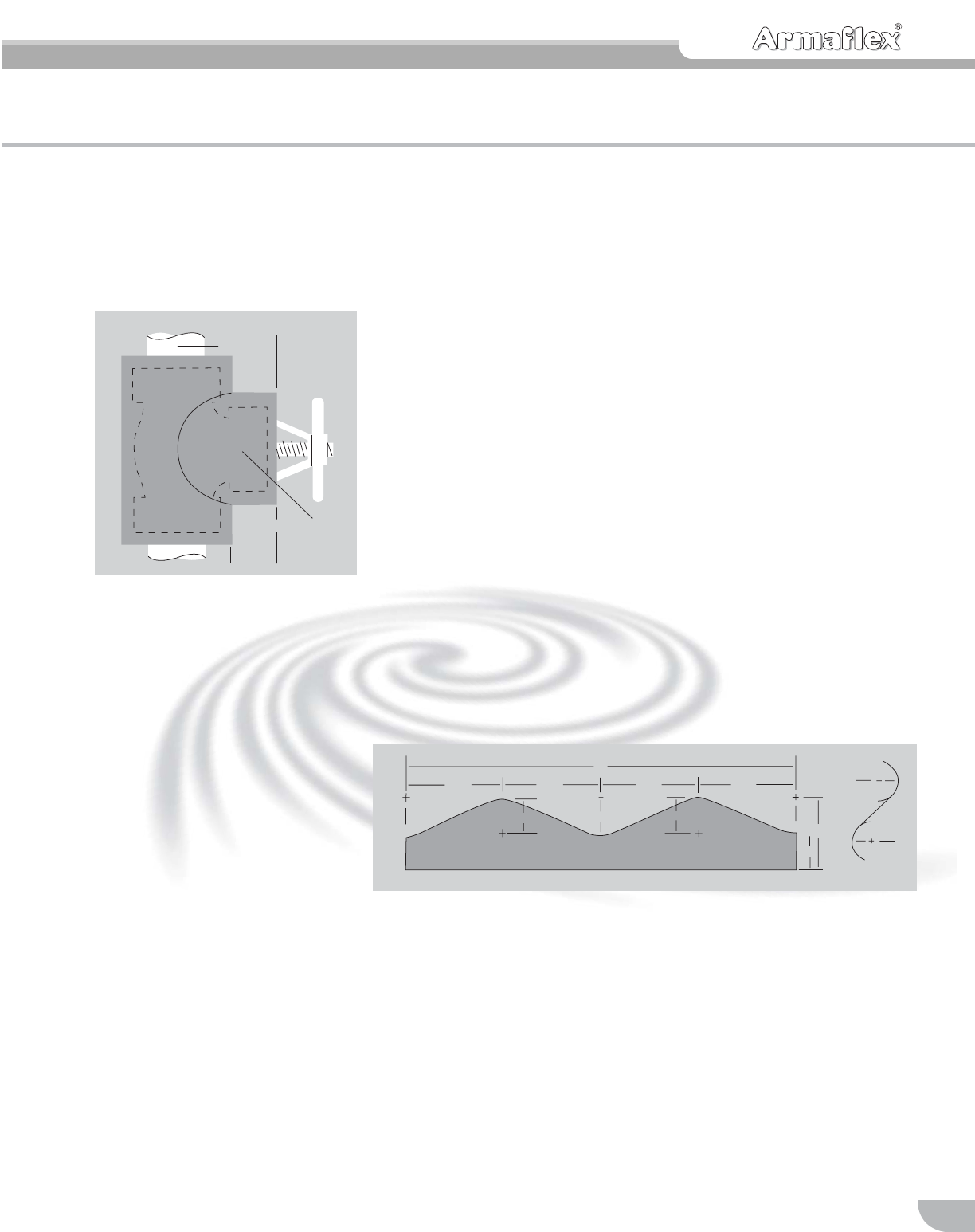
6. The last piece of insulation
needed will insulate the
bonnet area. This is shown
in Figure 6 and is made as
shown in
Figure 6A. The measurements for
Figure 6A are determined as fol-
lows:
C—The overall length is
determined by wrapping a
strip of Armaflex Sheet
around the bonnet flange
(do not stretch) and mark-
ing where the ends meet.
L1—This distance is obtained by
measuring from the outer
surface of the Armaflex
donut to the approximate
middle of the valve body
insulation.
L2—This distance is obtained by
measuring from the outer
surface of the Armaflex
donut to the closest surface
of the valve body insula-
tion.
Y—is the difference between L1
and L2.
The bonnet insulation of Armaflex
Sheet is cut to the size of C x L1.
This is then marked to show L2
and marked in quarters as shown
in Figure 6A. Next the scalloped
edge of the insulation is deter-
mined by swinging an arc from
each point marked + in Figure
6A. The radius of the arc is equal
to Y. These arcs are connected
with straight lines to give a
smooth scalloped edge (see
Figure 6B). The scalloped edge
of the insulation must be under-
cut (beveled) to correctly meet
the body insulation.
The bonnet insulation may now
be installed using 520 or 520 BLV
Adhesive to bond the two ends,
to adhere the bonnet insulation to
the body insulation and to adhere
the bonnet insulation around the
Armaflex donut. This should com-
plete the flange valve fitting.
▲
▲
▲
▲
▲
▲
▲
▲
▲
▲
▲
▲
▲
▲
▲
▲
▲
▲
▲
▲
C
YY
1/4 C 1/4 C
1/4 C
L2L1
1/4 C
Y
6 B
6A
6
Bonnet area
▲
L1
▲
▲
▲
L2
▲

Installation:
16
Armaflex sheet on metal
ductwork
The preferred method for square
and rectangular ducts is to cut
and fit the sheets, using full cov-
erage of Armaflex 520 or 520
BLV Adhesive to adhere the
insulation.
1. Measure—Sheets should be
sized with the following appli-
cation sequence in mind. Cut
the bottom piece first, making
it the same width as the duct.
Then cut the two side pieces,
so that they extend down over
the edges of the bottom insu-
lation; keep top edges flush
with the top of the duct. The
top insulation should be sized
so that it extends over the side
insulations. The fabrication
must be done at the job site,
at the same ambient condi-
tions as the application.
2. Cut—A sharp knife and a
straightedge are the only tools
required. Armaflex Sheet cuts
cleanly.
3. Apply Adhesive—First brush-
or roller-coat 520 or 520 BLV
Adhesive on the metal duct
surface. Then coat the back
side of the Armaflex Sheet,
leaving a 1/2″-wide uncoated
border at butt-edge seams.
Allow the adhesive to dry to
the touch but still tacky under
slight pressure before joining
surfaces.
4. Bond—Position the sheet so
that it overlaps the edges of
previously installed sheet or
sheets by 1/8″.Hold the sheet
in this position, and spot-adhere
it in the center. Compress the
butt edges into place for a tight
joint with adjoining sheets. Then
bond the remainder of the
sheet by pressing it firmly into
place. A small hand roller will
help apply pressure.
5. Adhere Joints—Spread the
joint, and with a small brush,
apply 520 or 520 BLV
Adhesive to both butt edges.
Do not flood joint with adhe-
sive. Align carefully for good
appearance, and apply pres-
sure to joint.
6. Standing Seams—These can
be insulated with strips of
Armaflex Sheet, generally cut
from scrap.
7. Alternate Method—Standing
seams can also be insulated
with half sections of Armaflex
Pipe Insulation, corresponding
in thickness to the sheet used
on the duct surface. Ends
should be miter-cut to insure
tight fit when bonded.
8. Apply WB Armaflex Finish—
Two coats of WB Armaflex
Finish, a white water-based
latex enamel coating, are all
that is required to provide a
protective finish for outdoor
installations. WB Armaflex
Finish can be brush- or roller-
applied.
13
2
45
7
6
8
Please note: For installing self
adhering SA Armaflex sheets and
rolls, refer to p.19.
Installation:
17
Flexible ArmaTuff Plus, ArmaTuff
White or ArmaTuff Silver can be
used for all exterior applications.
They are practical also for use on
exterior ducts, tanks, vessels,
large pipes and fittings. The
material provides a durable,
tough and maintenance-free sur-
face. The material is resistant to
UV, ozone, acid rain and most
industrial pollutants. No painting
is required.
The recommended temperature
usage range for ArmaTuff is
-70°F to 180°F (-57°C to 82°C).
The closed cell structure of
ArmaTuff insulation effectively
retards the flow of water vapor,
and it is considered a low trans-
mittance vapor retarder. ArmaTuff
does not require additional vapor
retarder. The white surface
reflects heat to reduce energy
load.
ArmaTuff is installed using
Armaflex 520 or 520 BLV adhe-
sive or with pre-applied pressure
sensitive adhesive (PSA). For
application to large, flat or curved
metal surfaces such as ducts,
vessels, very large pipes or tanks,
full Armaflex 520 or 520 BLV
adhesive coverage or product
with PSA is used. The seams
must be installed in compression
and sealed with Armaflex 520 or
520 BLV Adhesive. Cover the
seam with 4″and exposed edges
with 4″or 6″ArmaTuff Seal Tape.
Armaflex 520 or 520 BLV adhe-
sive is a contact adhesive: there-
fore it must be applied to both
surfaces, allowed to get tacky,
and the surfaces are joined with
pressure.
Please note: For installing self
adhering SA Armaflex sheets and
rolls, refer to p.19.
ArmaTuff is designed for installation in above ground applications.
Armaflex insulation products must be installed according to
Installation of Armaflex Insulations brochure. Proper installation is
required to assure Armaflex insulation performance.
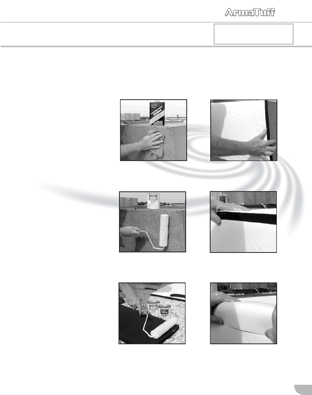
Applying Non-Self Adhering ArmaTuff Sheets
1. Always prepare surface by
cleaning with denatured
alcohol.
2. Insulate sides first. Apply
thin, uniform coat of
Armaflex 520 or 520 BLV
Adhesive.
3. Roll thin coat of 520 or
520 BLV Adhesive to
insulation.
4. Position carefully and apply
ArmaTuff. Contact
adhesive bonds instantly.
5. Apply ArmaTuff to top sur-
face, overlapping the side
pieces.
6. Seal and protect exposed
edges and seams with
ArmaTuff Seal Tape.
