BIG Kaiser Accessories Vol. 2 214 100A
User Manual: 214-100A
Open the PDF directly: View PDF ![]() .
.
Page Count: 24
- Front Cover
- Pg. 2 - Overview
- Pg. 3 - Index
- Tool Assembly Devices
- Tooling Cleaners
- Measuring Devices
- Pg. 10 - Base Master & Base Master Gold 50 & 100
- Pg. 11 - Base Master Micro, Base Master Mini & Tool Master
- Pg. 12 - Point Master
- Pg. 13 - Accu Center
- Pg. 14 - Dial Indicator Stands - Type MU/F & SU/F
- Pg. 15 - Dial Indicator Stands - Type MU/FS, SG & Dial Gauge Adapters
- Pg. 16 - Dial Indicator Stands - Accu Mini Mini
- Pg. 17 - Dyna Test
- Pg. 18 - Dyna Force
- Pg. 19 - ATC Alignment Tool
- Pg. 20 - Level Master
- In-Process Machine Devices
- Back Cover - Company Overview
2
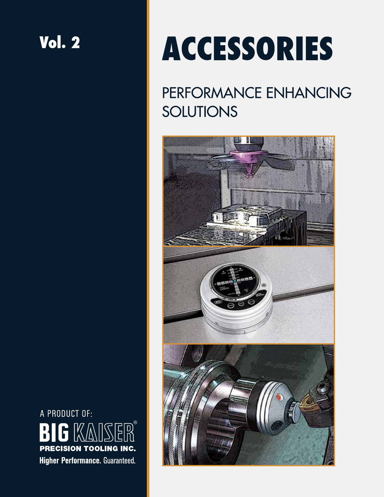
ACCESSORIZE TO MAXIMIZE
PERFORMANCE & EFFICIENCY
When purchasing new equipment, it is typical to spend a great deal of time
researching which machine offers the specifications and features to meet
your needs. But once you’ve purchased a machine and installation
is complete, what should you be doing to maximize its performance?
BIG Kaiser Precision Tooling offers a unique lineup of economical accessories
designed to optimize your productivity and help you operate at peak efficiency.
From dial indicator stands for fast, flexible measurement and inspection, to
compact sensors for touching off tools — we offer many ingenious setup
accessories that make your work flow faster and more efficient.
To keep your machines running smooth and operating at top performance,
don’t forget our unique line of clean-up accessories including
chip fans and spindle cleaners.
3
TECHNICAL DESCRIPTION KA/KAB CONNECTION
TOOL ASSEMBLY DEVICES
Tool Pro ................................................................Pg. 4
Kombi Grip
Tooling Mate .........................................................Pg. 5
ST Lock
Collet Ejector.........................................................Pg. 6
TOOLING CLEANERS
_
Taper Cleaner
_
Tooling Cleaner
HSK External Taper Cleaner ...................................Pg. 7
TK Cleaner
_
Wiper Cleaner ..................................................Pg. 8
MEASURING DEVICES
Base Master
Base Master Gold 50 & 100 ..................................Pg. 10
Base Master Micro
Base Master Mini
Tool Master ...........................................................Pg. 11
Point Master..........................................................Pg. 12
Accu Center ..........................................................Pg. 13
Dial Indicator Stands .............................................Pg. 14-16
Dyna Test ..............................................................Pg. 17
Dyna Force ...........................................................Pg. 18
ATC Alignment Tool ...............................................Pg. 19
Level Master ..........................................................Pg. 20
SPINDLE CLEANERS
ISO Taper Cleaner
Morse Taper Cleaner
HSK Taper Cleaner
Polygon Taper Cleaner ...........................................Pg. 9
IN-PROCESS MACHINE DEVICES
BIG-PLUS® Cleaner ................................................Pg. 21
Chip & Coolant Fan...............................................Pg. 22
T-Slot Clean ..........................................................Pg. 23
4
TOOL ASSEMBLY DEVICES
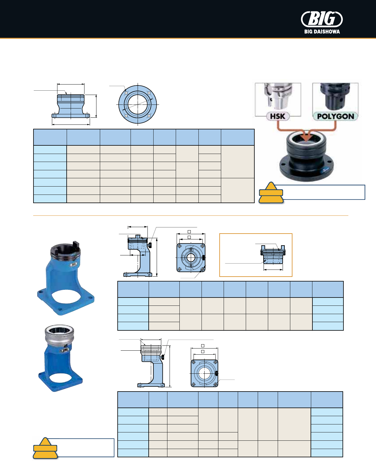
Quick-change system uses one permanently mounted base unit and
multiple adapters for different types and sizes of tool shanks.
Full 360° radial tool rotation, while clamped, permits easy access to large
diameter tools making it ideal for changing inserts on large face mills without
removing the tool from the drive keys. Tools can be locked at increments of 30°
by engaging an index pin. The adapter can also be rotated
360° and locked into any position in increments of 45° to
further improve ergonomic handling of any size and length
of tool.
Taper
Size
Catalog
Number
63A 31.300.214
100A 31.300.216
125A 31.300.217
HSK Taper
Taper
Size
Catalog
Number
32A 31.300.017
40A 31.300.015
50A 31.300.008
63A 31.300.006
100A 31.300.005
125A 31.300.029
Taper
Size
Catalog
Number
30 31.300.001
35 31.300.000
40 31.300.002
45 31.300.003
50 31.300.004
60 31.300.020
Steep Taper HSK Taper
• HSK Type E/F, VDI and Polygon taper also available
• Base unit must be ordered separately (Catalog Number 31.300.100)
• HSK Type E/F and VDI also available
Taper
Size
Catalog
Number
C3 31.300.153
C4 31.300.154
C5 31.300.155
C6 31.300.156
C8 31.300.158
Taper
Size
Catalog
Number
32A 31.300.130
40A 31.300.131
50A 31.300.132
63A 31.300.133
80A 31.300.134
100A 31.300.135
Taper
Size
Catalog
Number
30 31.300.110
35 31.300.111
40 31.300.112
45 31.300.113
50 31.300.114
Steep Taper HSK Taper Polygon Taper
Taper
Size
Catalog
Number
40 31.300.202
50 31.300.204
60 31.300.206
Steep Taper
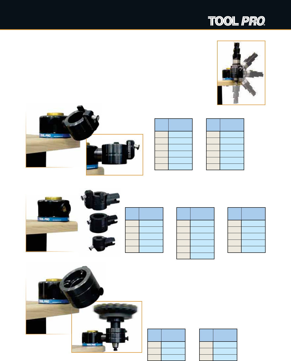
Tool Pro
The Tool Pro is a unique tool holding device for the assembly and disassembly of tapered
V-flange tooling and modular tooling systems. Depressing the large gold button permits the
adapter to rotate 360° and lock in 45° increments, allowing convenient access for all operations
in one setup. Tightening torque for tool clamping can be applied in a downward motion, rather
than horizontally, allowing the Tool Pro to be installed on tool carts. Tools are simply lowered into
the tool pot and automatically clamped into place with a spring loaded pin that locates precisely
into the V-groove of the tool holder. With the Tool Pro, you reduce damage to your expensive tool
holders, shanks and machine spindles while providing a safe working environment for your tool
assembly operators—advantages which pay off very quickly!
Spin
Vario
Standard
• Polygon taper also available
5
TECHNICAL DESCRIPTION KA/KAB CONNECTION
TOOL ASSEMBLY DEVICES
Tooling Mate
øC
øD
Taper No.
øM (x4)
øP
H
Kombi Grip
Innovative two way clutch and needle roller clamping system assures secure clamping at the tool flange periphery.
Safe design eliminates any possibility of damage to the shank taper during the tightening process.
Catalog
Number CV/BT No. øC øD H WPøMAdapter
Model
TMS40-30 30
2.992 2.362 5.906 4.331 3.543 .276 M6
TMA40-30
TMS40-40 40 TMA40-40
TMS50-40 40
4.134 3.465 7.480 6.299 5.118 .354 M8
TMA50-40
TMS50-50 50 TMA50-50
Catalog
Number
HSK
No.
Polygon
Coupling No. øC H WPøM Adapter
Model
TMS40-32R 32 C3
2.992 6.496
4.331 3.543 .276 M6
or UNC 1/4
TMA40-32R
TMS40-40R 40 C4 TMA40-40R
TMS40-50R 50 C5 TMA40-50R
TMS40-63R 63 C6 3.425 6.772 TMA40-63R
TMS50-80R 80 C8 4.488 8.465
6.299 5.118 .354 M8
or UNC 5/16
TMA50-80R
TMS50-100R 100 — 4.882 8.622 TMA50-100R
øC
H
øM (x4)
Adapter Lock Screw
W
P
Adapter
Taper No.
øC
H
Taper No.
øD
øM (x4)
W
P
Adapter Lock Screw
Taper No.
øD
Made of Special
Resin Material
Replaceable Adapter
• 1 adapter is included
• Adapters can be ordered individually
• Adapter Lock Screw is available as a
spare part (Model: RTM0615)
• Mounting bolts (4 pcs.) must be ordered
separately
Catalog
Number
HSK No.
(Form A/E/F)
Polygon
Coupling No. øC øD H øP øM
KG25R 25 — 1.890 3.110
2.559
2.441
.276 M6
or UNC 1/4
KG32R 32 C3 2.165 3.346 2.717
KG40R 40 C4 2.480 3.661
2.756
3.031
KG50R 50 C5 2.953 4.134 3.504
KG63R 63 C6 3.465 4.862 2.953 4.154
.354 M8
or UNC 5/16
KG80R 80 C8 4.213 5.591 3.543 4.882
KG100R 100 — 5.000 6.378 3.937 5.669
• Mounting bolts (4 pcs.) must be ordered separately
Kombi Grip must be securely fixed
to a bench with 4 mounting bolts.
!
CAUTION!
Tooling Mate must be
securely fixed to a bench
with 4 mounting bolts.
!
CAUTION!
6
ø3.465
1.575
ø.276 M6 or UNC 1/4 (x4)
ø20/ø25/ø32mm
1.575
3.543 6.457
TOOL ASSEMBLY DEVICES
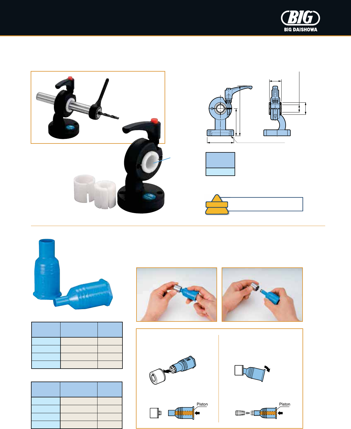
ST Lock
Ideal fixture for the setup of cylindrical shank tool holders. Clamps ø20, 25 & 32mm shanks by replacing the sleeve.
Collet Ejector
Collet Ejector can easily and quickly insert/remove small sizes of New Baby Collets from Mega Nuts &
New Baby Nuts.
Catalog
Number Nut Collet
NBC6-CE MGN6, NBN6 NBC6
NBC8-CE MGN8, NBN8 NBC8
NBC10-CE MGN10, NBN10 NBC10
NBC13-CE MGN13, NBN13 NBC13
Catalog
Number Nut Collet
NBC6E-CE MGN6, NBN6 NBC6E
NBC8E-CE MGN8, NBN8 NBC8E
NBC10E-CE MGN10, NBN10 NBC10E
NBC13E-CE MGN13, NBN13 NBC13E
New Baby Collet
New Baby End Mill Collet
Catalog
Number
STL40
• 1 pc. each of ø20, 25 & 32mm sleeves are included
• Mounting bolts (4 pcs.) must be ordered separately
Sleeve
How to Insert a Collet How to Remove a Collet
1. Insert the collet into the Collet
Ejector. Then insert it into the nut.
1. Tilt the Collet Ejector as shown
in the picture to remove the
collet from the nut.
2. Depress the piston and the
collet will be removed.
2. Depress the piston and
remove the Collet Ejector.
ST Lock must be securely fixed to a
bench with 4 mounting bolts.
!
CAUTION!
7
TECHNICAL DESCRIPTION KA/KAB CONNECTION
TOOLING CLEANERS
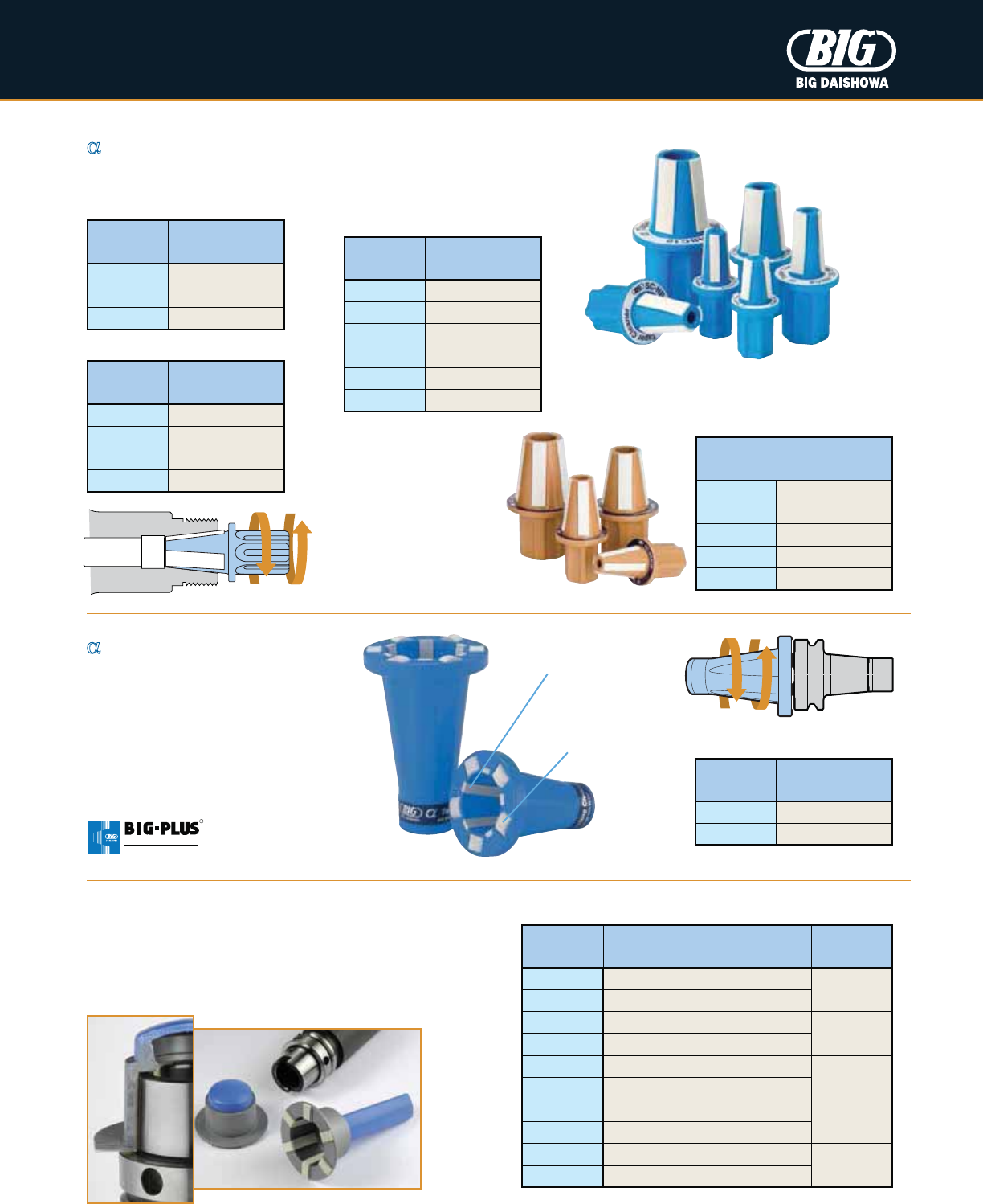
_Taper Cleaner
Maintain the accuracy of high precision collet chucks by cleaning the internal collet taper.
_Tooling Cleaner
For the cleaning of both mating surfaces
of BIG-PLUS® tool holders, which require
absolute cleanliness for optimum
performance.
Oil and particles on both the taper and
flange of 7/24 taper shanks are easily
removed.
Catalog
Number
Chuck
Body
SC-NBC3S MEGA3S
SC-NBC4S MEGA4S
SC-NBC6S MEGA6S
Mega Micro Chucks
Catalog
Number
Chuck
Body
SC-NBC6 MEGA6N, NBS6
SC-NBC8 MEGA8N, NBS8
SC-NBC10 MEGA10N, NBS10
SC-NBC13 MEGA13N, NBS13
SC-NBC16 MEGA16N, NBS16
SC-NBC20 MEGA20N, NBS20
Mega New Baby &
New Baby Chucks
Catalog
Number
Chuck
Body
SC-MEC6 MEGA6E
SC-MEC8 MEGA8E
SC-MEC10 MEGA10E
SC-MEC13 MEGA13E
Mega E Chucks
Catalog
Number
Chuck
Body
SC-MER11 ER11
SC-MER16 ER16
SC-MER20 ER20
SC-MER25 ER25
SC-MER32 ER32
ER Collet Chucks
HSK External Taper Cleaner
Reliable and indispensable taper cleaners for the efficient
cleaning of HSK tool holder shanks. Cleaning strips positioned
at well spaced intervals will remove even large residual particles.
Sturdy construction with high oil and grease resistance.
Catalog
Number Description Taper No.
20.580.041 Taper Cleaner w/ Handy Cap
HSK40
20.580.042 Taper Cleaner w/ Cylindrical Handle
20.580.051 Taper Cleaner w/ Handy Cap
HSK50
20.580.052 Taper Cleaner w/ Cylindrical Handle
20.580.064 Taper Cleaner w/ Handy Cap
HSK63
20.580.065 Taper Cleaner w/ Cylindrical Handle
20.580.081 Taper Cleaner w/ Handy Cap
HSK80
20.580.082 Taper Cleaner w/ Cylindrical Handle
20.580.101 Taper Cleaner w/ Handy Cap
HSK100
20.580.102 Taper Cleaner w/ Cylindrical Handle
Cleaning Strip
for Taper
Cleaning Strip
for Flange
Catalog
Number Taper No.
SCE-30 No. 30
SCE-40 No. 40
R
SPINDLE SYSTEM
DUAL CONTACT
8
TOOLING CLEANERS
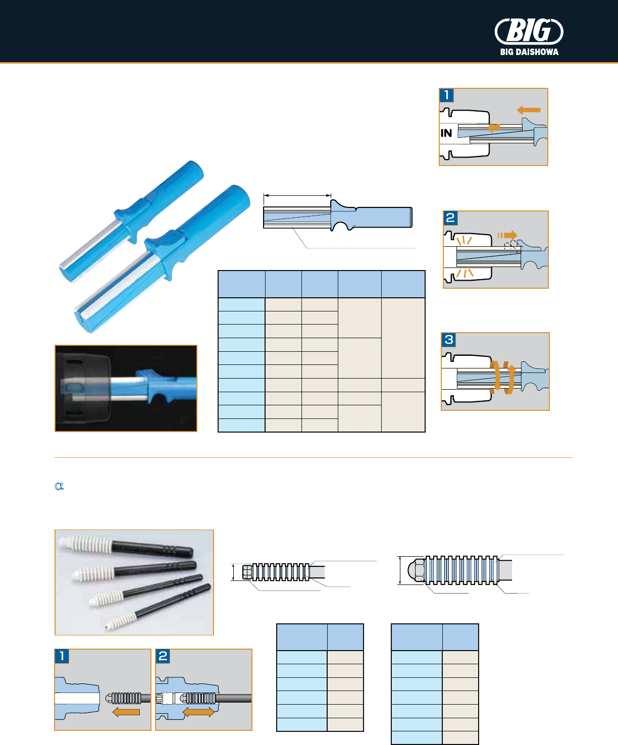
TK Cleaner
It is very difficult to remove oil and chips stuck to clamping bores, even with a wiping cloth
or air spray. TK Cleaner perfectly cleans the clamping bore of a tool holder in a very simple
manner to maintain the high performance of tool holders. Perfect for hydraulic chucks,
milling chucks and shrink fit holders.
_Wiper Cleaner
Easy cleaning of smaller cylindrical bores by simply inserting and removing before cutting tool insertion. Perfect for hydraulic
chucks and shrink fit holders.
L
Exclusive Synthetic Leather Strips
Slide the upper section forward to
reduce diameter and insert in the
clamping bore.
AWC1/4
AWC6
AWC5/16 - AWC 9/16
AWC7-12
Spring action draws back the sliding
section when released so the cleaning
strips contact the bore surface.
Rotate and remove the TK Cleaner
to clear oil and particles.
Catalog
Number
Bore ø
(mm)
Bore ø
(in)
Cleaning
Length L
Leather
Strip Qty.
TKC13 13 .500
2.362
2
TKC14 14 —
TKC15 15 —
TKC16 16 .625
2.756
TKC18 18 —
TKC20 20 .750
TKC25 25 1.000 3.150 3
TKC32 32 1.250 3.937
4
TKC40 40 —
4.134
TKC42 42 —
Catalog
Number øD
AWC6 6mm
AWC7 7mm
AWC8 8mm
AWC9 9mm
AWC10 10mm
AWC11 11mm
AWC12 12mm
Catalog
Number øD
AWC1/4 .250
AWC5/16 .312
AWC3/8 .375
AWC7/16 .437
AWC1/2 .500
AWC9/16 .562
Inch Style Metric Style
øD
Exclusive Synthetic
Leather Strips
Washer
Hexagon Nut (2 pcs.)
øD
Exclusive Synthetic
Leather Strips
Washer
Crown Nut
9
TECHNICAL DESCRIPTION KA/KAB CONNECTION
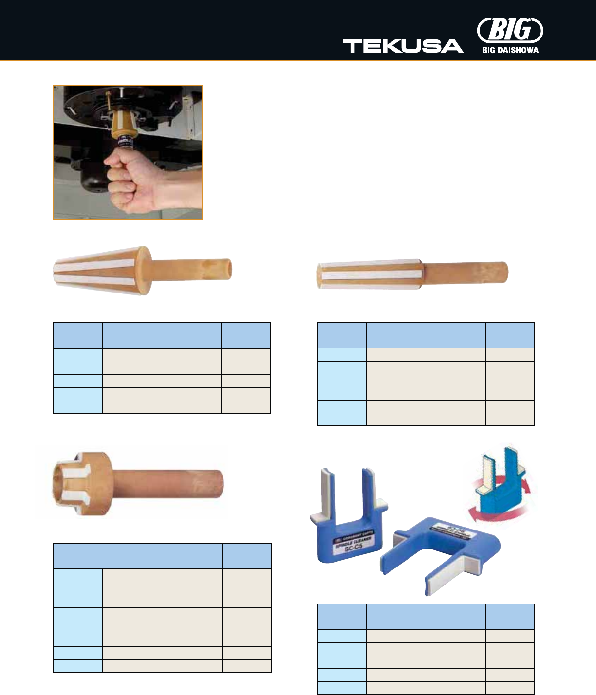
SPINDLE CLEANERS
Catalog
Number Description Taper No.
20.580.220 ISO20 Spindle Cleaner ISO20
20.580.230 ISO30 Spindle Cleaner ISO30
20.580.240 ISO40 Spindle Cleaner ISO40
20.580.245 ISO45 Spindle Cleaner ISO45
20.580.250 ISO50 Spindle Cleaner ISO50
Catalog
Number Description Taper No.
20.580.001 Morse Taper #1 Spindle Cleaner MT1
20.580.002 Morse Taper #2 Spindle Cleaner MT2
20.580.003 Morse Taper #3 Spindle Cleaner MT3
20.580.004 Morse Taper #4 Spindle Cleaner MT4
20.580.005 Morse Taper #5 Spindle Cleaner MT5
20.580.006 Morse Taper #6 Spindle Cleaner MT6
Morse Taper
Spindle Cleaners
The unbeatable tool to ensure absolute cleanliness of tapered spindles, which maintains the
precision and prolongs the life of your expensive machine tools, cutting tools and tool holders.
•
Robust construction with high oil and grease resistance
•
Plastic injection molded core with fluted locations for cleaning strips ensures
accurate sizing and cleaning efficiency
•
Cleaning strips will maintain adhesion to the taper core due to inset location
even under scrubbing action
•
Cleaning strips positioned at well spaced intervals to remove even large residual particles
•
A quality control product
Catalog
Number Description Taper No.
20.580.025 HSK25 Spindle Cleaner HSK25
20.580.032 HSK32 Spindle Cleaner HSK32
20.580.040 HSK40 Spindle Cleaner HSK40
20.580.050 HSK50 Spindle Cleaner HSK50
20.580.063 HSK63 Spindle Cleaner HSK63
20.580.080 HSK80 Spindle Cleaner HSK80
20.580.100 HSK100 Spindle Cleaner HSK100
20.580.125 HSK125 Spindle Cleaner HSK125
Catalog
Number Description Taper No.
SC-C3 Polygon Taper C3 Spindle Cleaner C3
SC-C4 Polygon Taper C4 Spindle Cleaner C4
SC-C5 Polygon Taper C5 Spindle Cleaner C5
SC-C6 Polygon Taper C6 Spindle Cleaner C6
SC-C8 Polygon Taper C8 Spindle Cleaner C8
Polygon Taper
HSK Taper
ISO Taper (With Pull Stud Recess)
10
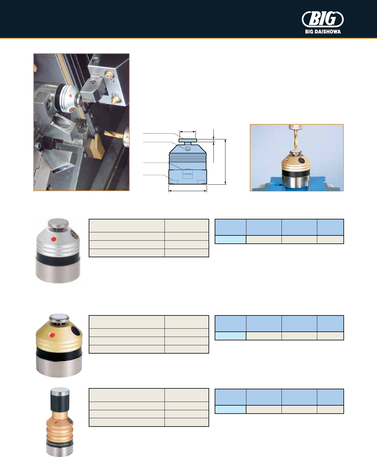
MEASURING DEVICES
Base Master Series
Precision touch sensor to define work offsets and tool lengths.
•
LED lamp illuminates at exactly 2" from the reference surface
•
Repeatability of
±
.00004"
•
Safety over-travel of sensor plate prevents damage to tooling
•
Magnetic base mounts vertically, horizontally, or at any angle
•
Battery life of 10 hours (continuous use)
Base Master
For cutting tools, workpieces and machine tools using conductive materials.
Base Master Gold 50 & 100
For all materials, including non-conductive cutting tools, workpieces, and machine tools.
Catalog
Number
Sensor Plate
Diameter øD
Sensor Plate
Material Stroke H
BM-2G .551 Ceramic .118
Catalog
Number
Sensor Plate
Diameter øD
Sensor Plate
Material Stroke H
BM-2 .709 Steel .118
Lamp (LED)
Battery
(SR44 x2)
Magnet
Sensor Plate
Stroke H
2.000 +.0002
0
ø1.673
øD
• 50mm metric units available upon request
• BM-2 will not work with non-conductive cutting tools,
workpieces, or machine tools
• 50mm metric units available upon request
Height Accuracy +.01mm
100mm 0
Measurable Pressure 2N
Min. Measurable Tool Diameter .039
Weight .79 lbs
Height Accuracy +.0002
2.000 0
Measurable Pressure 3N
Min. Measurable Tool Diameter .039
Weight .51 lbs
Height Accuracy +.0002
2.000 0
Measurable Pressure 3N
Min. Measurable Tool Diameter .039
Weight .53 lbs
Catalog
Number
Sensor Plate
Diameter øD
Sensor Plate
Material Stroke H
BM-100G 28mm Ceramic 10mm
TECHNICAL DESCRIPTION KA/KAB CONNECTION
11
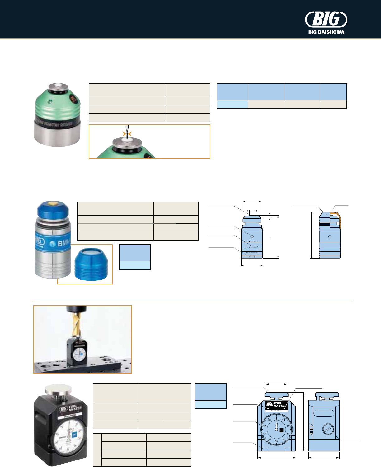
MEASURING DEVICES
Base Master Micro
Light pressure activation for small tools. Suitable for all materials, including non-conductive cutting tools, workpieces
and machine tools. Preset ø.002" tools for considerable reduction of set-up time.
Catalog
Number
Sensor Plate
Diameter øD
Sensor Plate
Material Stroke H
BM-2M .276 Ceramic .039
ø.002"
Base Master Mini
World's smallest body diameter (ø20mm). Best suited for measurements in limited space and complicated shapes. High intensity
blue LED indication when the offset position is detected. For all materials, including non-conductive cutting tools, workpieces
and machine tools.
• For cutting tools under ø.039", feed slowly and touch
the sensor plate carefully
• 50mm metric units available upon request
Tool Master
Precision touch sensor to define work offsets and tool lengths.
•
Large dial that is easy to view and includes approach LED lamp and sound
•
Adjustable height
•
Magnetic base mounts vertically, horizontally, or at any angle
•
For all materials, including non-conductive cutting tools,
workpieces and machine tools
ø40mm Audible Beep
Sensor Plate
Lamp (LED)
Magnet
65mm 55mm
Battery
(SR44 x2)
97mm -102mm
+.02mm
0
Metric Dial
Indicator
Catalog
Number
TM-100
Height
100mm
(after compressed by
approx. 2mm)
Stroke 5mm
Measurable Pressure 6N
Weight 2.65 lbs
Battery
(SR44 x2)
Lamp (LED)
ø17mm
Magnet
ø20mm
40mm
2mm
+.005mm
0
Stroke
Sensor Plate
ø5mm
Catalog
Number
BMM-20
Protection Cover with Magnifier (5x)
Protection
Cover
Loupe
43mm
Height Accuracy +.0002
2.000 0
Measurable Pressure .3N
Min. Measurable Tool Diameter .002
Weight .53 lbs
Height Accuracy +.005mm
40mm 0
Measurable Pressure 1.8N
Min. Measurable Tool Diameter .0039
Weight .12 lbs
Dial Graduation .01mm
Indication Tolerance .015mm
Repeatability .005mm
Return Tolerance .005mm
Dial Gauge
12
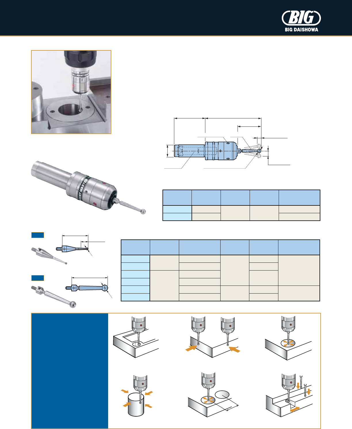
MEASURING DEVICES
Point Master Series
Precision 3-D touch sensor to quickly find edges and measurement locations.
•
Repeatability of
±
.00008" with safety over-travel
•
Replaceable stylus for different applications (M3 thread)
•
LED lamp illuminates when the stylus touches the workpiece
•
For use with conductive cutting tools, workpieces and machine tools
Catalog
Number øD (h7) L L1Standard Stylus
PMG-20 20mm
3.543 1.969
ST38-6P
PMG-.750 .750 ST38-.25P
Catalog
Number Fig. ød L L1Material
ST28-1P
1
1mm (.039)
1.102
.079
Carbide
ST28-2P 2mm (.079) .315
ST28-3P
2
3mm (.118)
—
ST28-4P 4mm (.157)
ST38-6P 6mm (.236)
1.496
—
Stainless Steel
ST38-.25P .250 —
Application Examples
Hole Locations Workpiece Offsets Bore Diameters
Boss Diameters Distance Between Centers Feature Locations
Additional Stylus
Cylindrical Shank Taper
Battery
(LR1 x2)
Stroke .197
Z
Stroke .472
L1L
1.496
PMG-20: ø.236 (6mm)
PMG-.750: ø.250
øD
Stylus
XY
Lamp (LED x3)
ød
L
ød
L
L1
Measurement
Depth
Fig. 1
Fig. 2
• Above table indicates the specifications when using standard stylus
13
MEASURING DEVICES
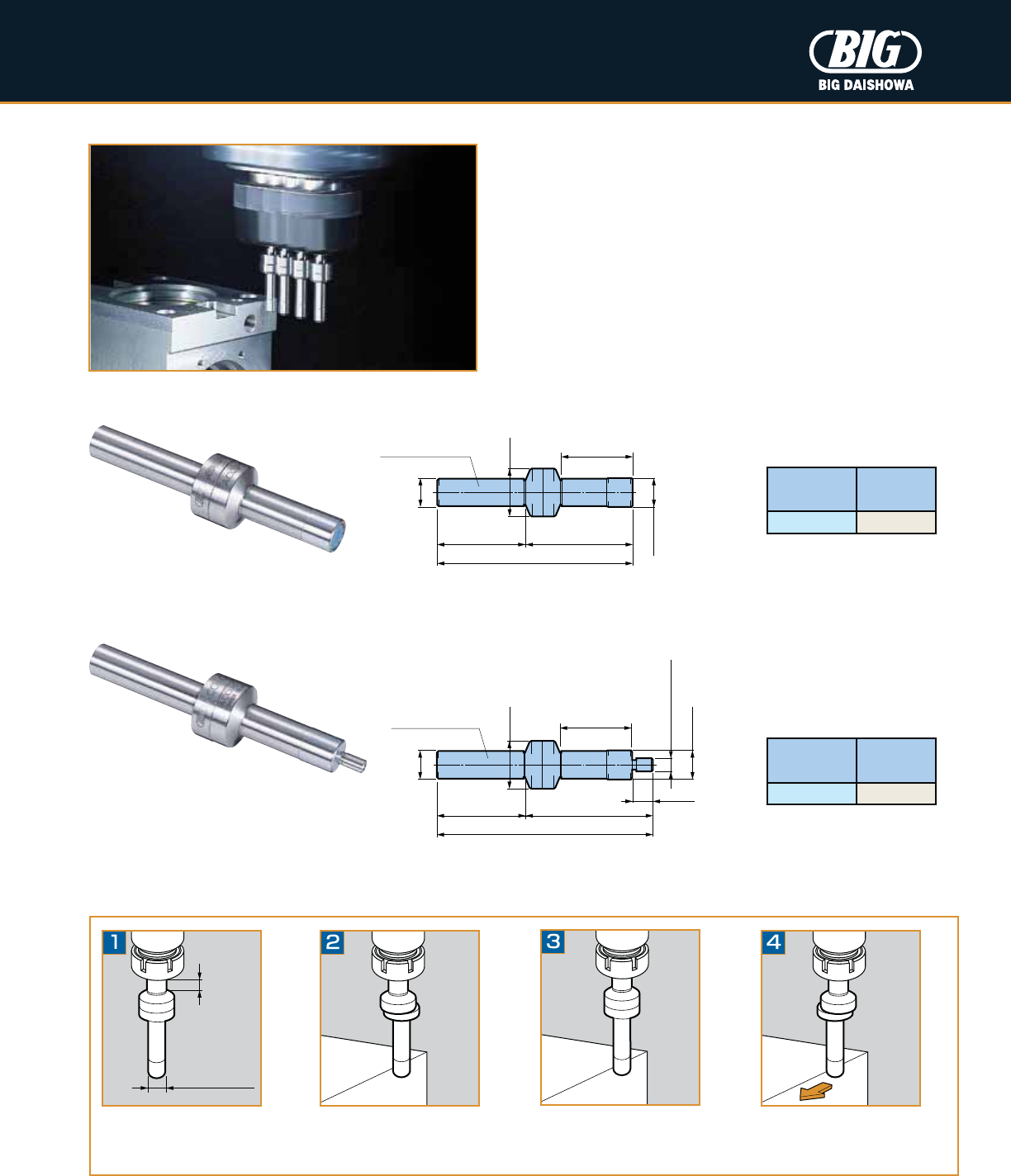
Accu Center
Precision edge finder suitable for all materials.
•
Repeatability of .00012"
•
Hard chrome plated cylindrical stylus for extended life
•
Not for use with horizontal machine tools
øD
ø.394
(10mm)
1.417
1.122
1.673
3.091
ø.748
Cylindrical Shank
ø.394
(10mm)
øD
ø.748
1.417 1.988
3.406
.315
ø.157
(4mm)
Cylindrical Shank 1.122
Catalog
Number øD
ACCU-C10 10mm
Catalog
Number øD
ACCU-C104 10mm
Clamp Accu Center
in a collet chuck.
Move the stylus off center, and
rotate between 400 and 600 RPM.
Bring the tool into contact with the
workpiece and advance slowly until
the stylus lines up with the body.
If advanced too far the stylus will again
move off center. Be sure to compensate
location for half the stylus diameter.
.197-.394
ø.394 (ø10mm)
ø.157 (ø4mm)
Operation Instructions
14
DIAL GAUGE ADAPTERS PG. 15
MEASURING DEVICES
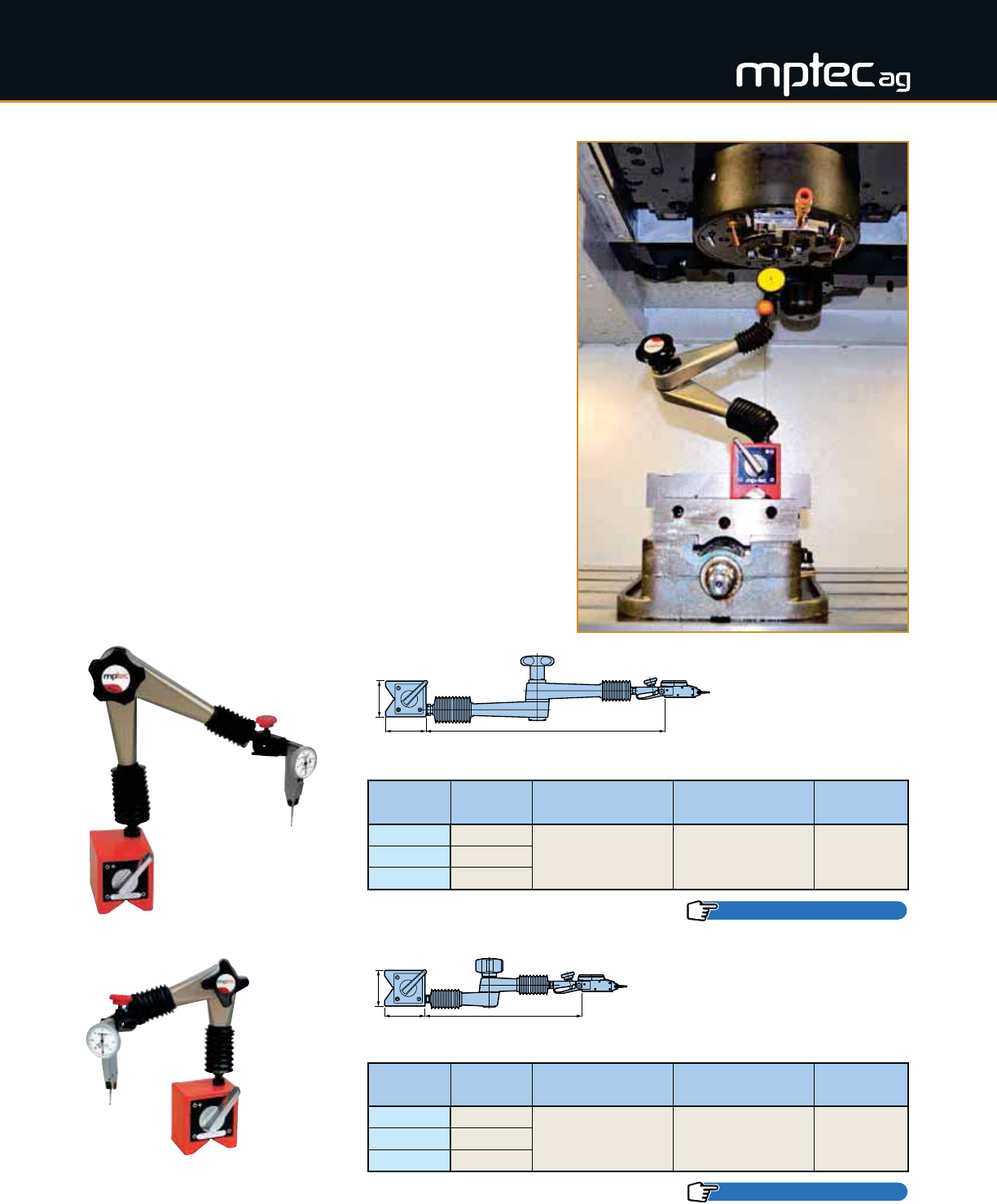
Dial Indicator Stands
Articulated stands for the demanding user, offering the highest
positioning precision and exact measurements in the μm range.
•
High clamping force thanks to a strong internal cam structure of steel
components.
•
Extremely flexible with 360 degrees freedom of positioning controlled
by one progressive clamping star grip
•
Ideal design for use in measurement, inspection (quality control)
and machining
•
Ultra strong magnet holds stand firmly in place
•
Each stand is equipped standard with (1) magnet, (2) extension
arms, (1) DGH dove-tail adapter and (1) cylindrical gauge
adapter (ø.375")
Catalog
Number Adapter Arm Extension Capacity L
(From Magnet Top)
Magnet Dimensions
W x H x D
Load Capacity
Approx.
20.510.102 DGH2
13.937
(354mm)
2.087 x 2.362 x 2.677
(53mm x 60mm x 68mm)
200 lbs.
(90 kg)
20.510.103 DGH3
20.510.104 DGH4
Catalog
Number Adapter Arm Extension Capacity L
(From Magnet Top)
Magnet Dimensions
W x H x D
Load Capacity
Approx.
20.520.102 DGH2
9.173
(233mm)
2.087 x 2.362 x 1.417
(53mm x 60mm x 36mm)
110 lbs.
(50 kg)
20.520.103 DGH3
20.520.104 DGH4
Type MU/F
Type SU/F
DIAL GAUGE ADAPTERS PG. 15
H L
W
H L
W
15
MEASURING DEVICES
Catalog
Number
20.580.402
Catalog
Number
20.580.403
Catalog
Number
20.580.404
• Precision micro model
• Standard adapter for
MU and SU stands
• Basic model
(without fine-tuning screw)
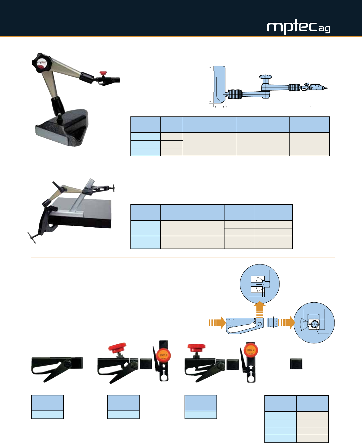
Dial Gauge Adapters
A significant disadvantage of current models of dial gauge adapters is
that their construction, out of two or more components, results in an
unavoidable play or slackness in the adapter. The solution to this
challenge is a new type of adjustable adapter consisting of a single
shaped part. This part forms two opposing legs whose relative position
can be fine-adjusted by means of a tensioning screw (DGH3). A
special micro model (DGH4) with a fine-adjustment rocker is also
available for measurement precision in the μm range. All adapters
include a ø.375" cylindrical gauge adapter.
DGH4
DGH3
DGH2
Catalog
Number Adapter Arm Extension Capacity L
(From Magnet Top)
Base Size
W x H x D
Weight
(Not Including Arm)
20.530.102 DGH2
13.937 (354mm) 5.984 x 1.850 x 5.984
(152mm x 47mm x 152mm) 6.6 lbs. (3 kg)
20.530.103 DGH3
20.530.104 DGH4
Catalog
Number Description Extension
Number Extension Length
20.540.001 Type SG 3/4
Arm with One Tension Clamps
No. 3 2.953 (75mm)
No. 4 3.937 (100mm)
20.540.002 Type SG 4/4
Arm with Two Tension Clamps No. 4 3.937 (100mm)
Type MU/FS
•
Dial indicator stand with
cast iron base
•
Specifications of clamp
arm same as type MU/F
•
Base with 3-point sliding
contact and one flat side
for parallel measurement
Type SG
•
Articulated clamping arm for gluing, welding or soldering
•
Quickly solves all tricky angling problems
•
Simultaneous tensioning action
ø.375"
14mm
12mm
6mm
1.65mm
60º
4.6mm
60º
M8 P1.25
Thread
Catalog
Number Clamping ø
20.580.501 .250
20.580.502 .375
20.580.511 4mm
20.580.512 8mm
• 100mm extension arm available to increase work radius (Catalog Number 20.580.513)
Cylindrical Gauge Adapter
H L
W
16
MEASURING DEVICES
L
L
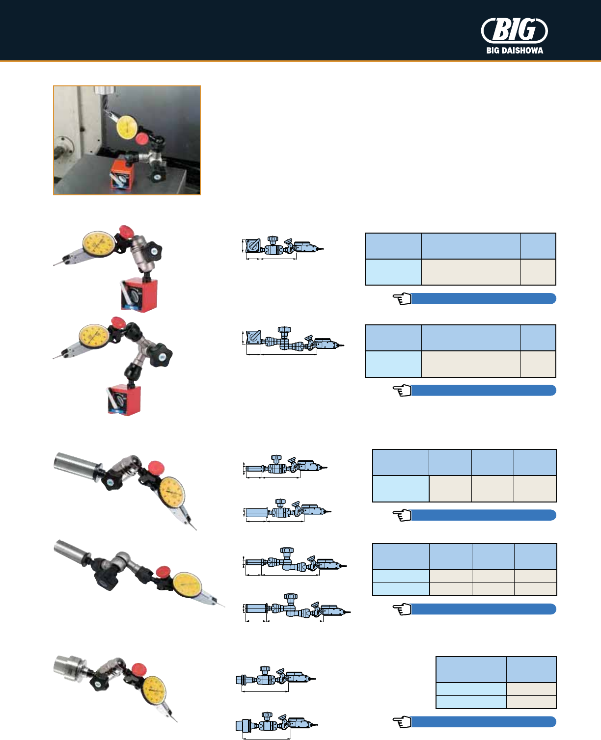
Dial Indicator Stands — Accu Mini Mini
•
Very rigid, short and sturdy stand with internal steel cam action components
•
Clamping of articulating arms by one progressive clamping star grip
•
Ultra strong magnet holds stand firmly in place
•
Optional models can be supplied with straight shank (ø12 or 20mm) or HSK shank
(E25, E32) instead of the magnet to go directly into a machine tool spindle
•
Each stand is equipped standard with a dove-tail adapter; cylindrical gauge adapters
are optional items (see Pg. 15)
Catalog
Number
Magnet Dimensions
W x H x D L
AML-M 1.260 x 1.378 x 1.378
(32mm x 35mm x 35mm) 5.433
Catalog
Number
Magnet Dimensions
W x H x D L
AMM-M 1.260 x 1.378 x 1.378
(32mm x 35mm x 35mm) 3.543
Catalog
Number øD L1L2
AML-12 12mm 1.535 5.630
AML-20 20mm 1.969 5.551
Catalog
Number øD L1L2
AMM-12 12mm 1.535 3.701
AMM-20 20mm 1.969 3.622
Magnet Type
Straight Shank Type
HSK Shank Type
Catalog
Number L
HSK-E25-AMM 4.567
HSK-E32-AMM 4.685
H L
W
W
H L
L1L2
øD
AMM-12
AMM-20
L1L2
øD
L1L2
øD
AML-12
AML-20
L1L2
øD
HSK-E25-AMM
HSK-E32-AMM
CYLINDRICAL GAUGE ADAPTERS PG. 15
CYLINDRICAL GAUGE ADAPTERS PG. 15
CYLINDRICAL GAUGE ADAPTERS PG. 15
CYLINDRICAL GAUGE ADAPTERS PG. 15
CYLINDRICAL GAUGE ADAPTERS PG. 15
17
MEASURING DEVICES
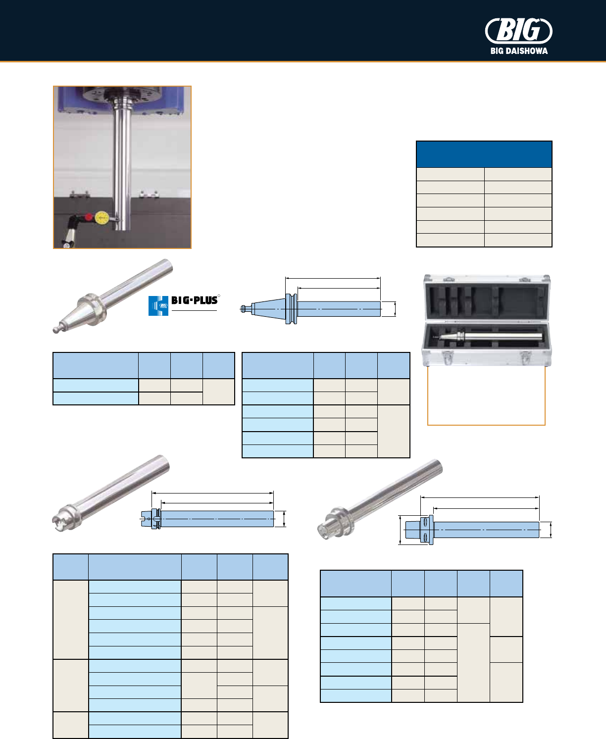
Included:
Dyna Test & Aluminum
Storage Case
Dyna Test
The cause of machine tool runout stems from wear of the spindle bearings. Regular
inspection with Dyna Test helps identify potential problems, and can reduce downtime
and costly repairs of the machine tool spindle.
•
Precision test bar for static runout accuracy
•
Produced under a strict quality control process;
calibration certificate available upon request
as per ISO 9000 requirements
Catalog
Number L A øD
BBT30-32-L150 5.906 4.921
1.260
BBT30-32-L235 9.252 8.268
BBT40-50-L200 7.874 6.693
1.969
BBT40-50-L350 13.780 12.598
BBT50-50-L200 7.784 6.260
BBT50-50-L360 14.173 12.559
Catalog
Number L A øD øD1
C5-32-150 7.087 5.906
1.260
2.480
C5-32-215 9.646 8.465
C5-32-250 11.024 9.843
1.575
C6-40-150 7.165 5.906
2.953
C6-40-200 9.134 7.874
C6-40-320 13.858 12.598
3.346
C8-40-200 9.449 7.874
C8-40-320 14.173 12.598
HSK
Form
Catalog
Number L A øD
A
HSK-A40-32-L180SD 7.087 6.181
1.260
HSK-A50-32-L240SD 9.449 8.307
HSK-A63-50-L200SD 7.874 6.732
1.969
HSK-A63-50-L350SD 13.780 12.638
HSK-A100-50-L200SD 7.784 6.614
HSK-A100-50-L350SD 13.780 12.520
E
HSK-E25-20-L175 6.890 6.417
.787
HSK-E32-20-L180
7.087
6.220
HSK-E40-32-L180 6.181
1.260
HSK-E50-32-L240 9.449 8.307
F
HSK-F63-50-L200 7.874 6.732
1.969
HSK-F63-50-L350 13.780 12.638
BCV (ASME B5.50)
HSK (ISO 12164/DIN 69893)
BBT (MAS 403)
BIG CAPTO
Catalog
Number L A øD
BCV40-2.000-L13.5SD 13.500 12.500
2.000
BCV50-2.000-L13.5SD 13.500 12.500
R
SPINDLE SYSTEM
DUAL C O N T ACT
L
Effective Test Length A
øD
L
øD
øD1
Effective Test Length A
L
Effective Test Length A
øD
*The trademark CAPTO is licensed from Sandvik Coromant
Precision Standards of
BIG Daishowa Test Arbors
Runout .002mm (.00008")
Roundness .001mm (.00004")
Cylindricity .003mm (.00012")
Roughness Ra: .1µm (.000004")
Taper Contact AT1
Diameter Tol. ±.005mm (.0002")
18
MEASURING DEVICES
øD2
øD1
L
H
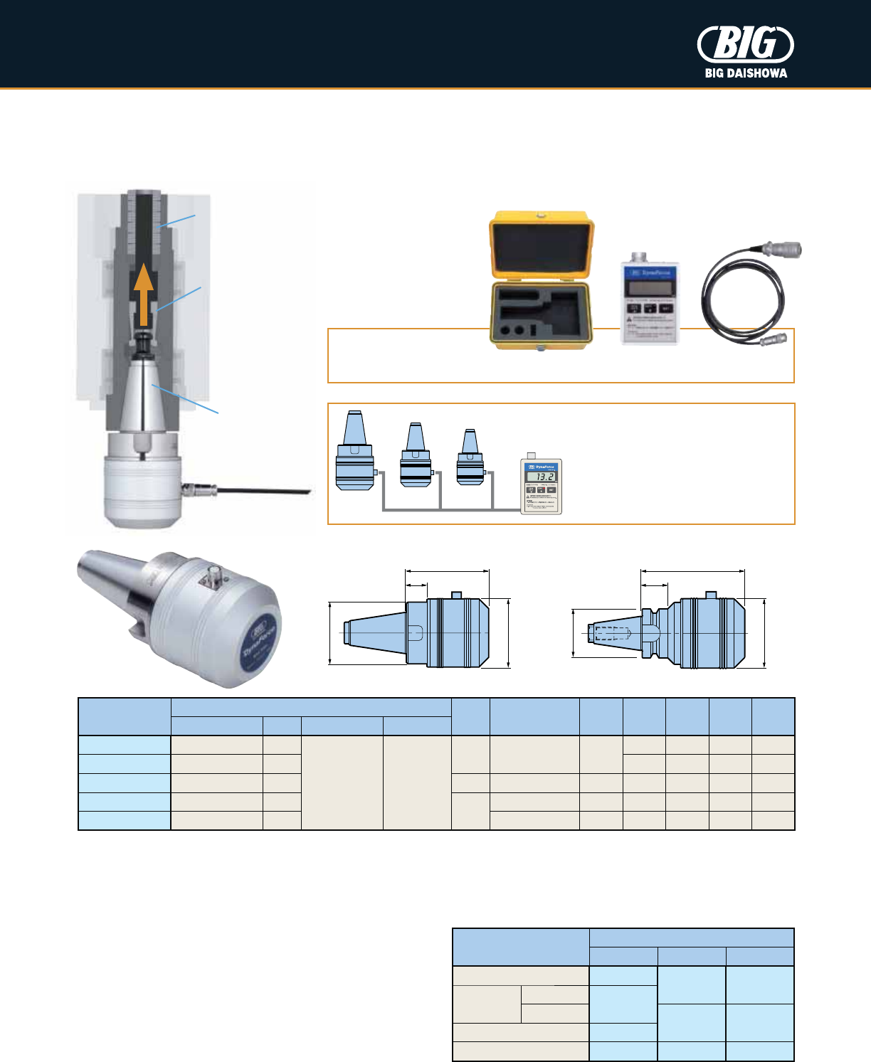
Included:
Dyna Force, Plastic Storage Case, Display & Cable
Dyna Force
Machine tool maintenance is a necessity. Periodical measurement of the spindle retention force avoids unknown reduced rigidity,
which leads to vibrations, loss of machining quality and shortened tool life. A full length taper stabilizes the value of measurements.
Catalog
Number
Contents of Set Taper
No. Rated Capacity øD1øD2LH
Weight
(lbs.)
Measuring Device Fig. Display Cable
SNT30-DF10 NT30-DF10 1
DFA-1
(AA battery x2)
DFC-1
(1m)
30 10 kN (980 kgf) 2.559
2.283 3.150 .787 3.3
SBT30-DF10 BT30-DF10 2 1.811 2.858 1.024 3.5
SNT40-DF30 NT40-DF30 1 40 30 kN (2,940 kgf) 2.874 2.958 3.543 .945 5.5
SNT50-DF50 NT50-DF50 1
50
50 kN (4,900 kgf) 3.780 3.543 4.331 1.299 13.2
SNT50-DF30 NT50-DF30 1 30 kN (2,940 kgf) 2.874 2.756 3.386 .787 8.6
• Each component is also available separately
• SBT30-DF10 is designed exclusively for machines not capable of automatic tool change
• SBT30-DF10 is suitable for BT/BBT30 machines only
• Pull stud bolt must be ordered separately, and for DIN, ISO, ANSI & CAT standard machines, an exclusive pull stud bolt for Dyna Force is required
• SNT50-DF30 marked indicates light-weight model
• Certificate of calibration and diagram of traceability system are available for a charge in order to maintain the reliability of the device
øD2
øD1
L
H
304050
Fig. 1 Fig. 2
Only one display for all taper sizes
One common display can be used
for all taper sizes.
Belleville Springs
Collet
Taper
Standard No.
Taper No.
30 40 50
DIN 69872 DF-PDV30
DF-PDV40A DF-PDV50A
ISO 7388
Type A
—
Type B
DF-PAV40 DF-PAV50
ANSI B5.50 DF-PAV30
ASME B5.50 DF-PCV30 DF-PCV40 DF-PCV50
Pull Stud Bolts for Dyna Force
An exclusive pull stud bolt is needed for machine spindles
with DIN, ANSI or CAT tapers. Pull stud bolts in MAS and JIS
standards can be used.
•
•
19
MEASURING DEVICES
Dial indicator stylus
L
M
øD1
øD2
L1
L2
L4
L3
Dial Indicator
(1 Div = .01mm)
øD
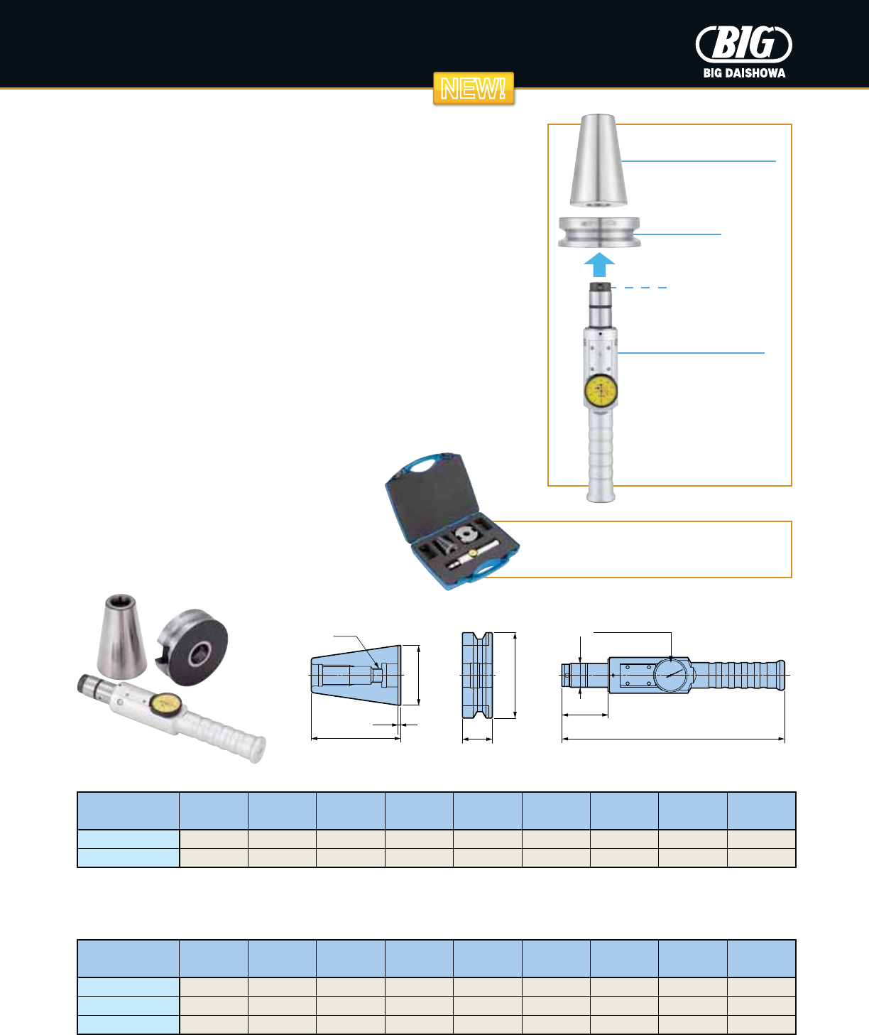
ATC Alignment Tool
Misalignment of the center between the machine tool spindle and ATC gripper
may cause damage to the spindle taper when a tool holder is loaded into the
spindle. A clamped tool holder under misalignment leads to increased runout,
resulting in shorter life of machine tools and tool holders, as well as cutting
tools. The ATC Alignment Tool can also be used for re-aligning the ATC
gripper and tool magazine pots. Overall cost reduction is achieved by using
equipment in good condition.
How To Use
1.
Load the AL Shank in the machine spindle and mount the AL Flange on
the ATC arm.
2.
Insert the AL Plug into the AL Flange.
3.
Rotate the AL Plug and read the highest and lowest values of the dial
indicator. This direction is the eccentric direction. Half of the gap of the
values is the eccentric amount.
4.
Adjust the position of the ATC arm so that the front end of the AL Plug
will be inserted into the AL Flange fully.
AL Shank AL Plug
Catalog
Number øD D1D2LL1L2L3L4M
CV40-ATC20 1.750 2.500 .787 2.812 .123 .958 9.882 1.732 1/2"-13
CV50-ATC28 2.750 3.875 1.102 4.125 .123 1.301 10.276 2.126 5/8"-11
CV Taper
AL Flange
• DIN 7/24 taper spindle models available
Catalog
Number øD D1D2LL1L2L3L4M
BT30-ATC18 31.75mm 46mm 18mm 50.4mm 2mm 20mm 251mm 44mm 12mm
BT40-ATC20 44.45mm 63mm 20mm 67.4mm 2mm 25mm 251mm 44mm 12mm
BT50-ATC28 69.85mm 100mm 28mm 104.8mm 3mm 35mm 261mm 54mm 16mm
BT Taper
Included:
ATC Alignment Tool & Plastic Storage Case
AL Shank
In machine tool spindle
AL Flange
In ATC arm
AL Plug
NEW!NEW!
20
MEASURING DEVICES
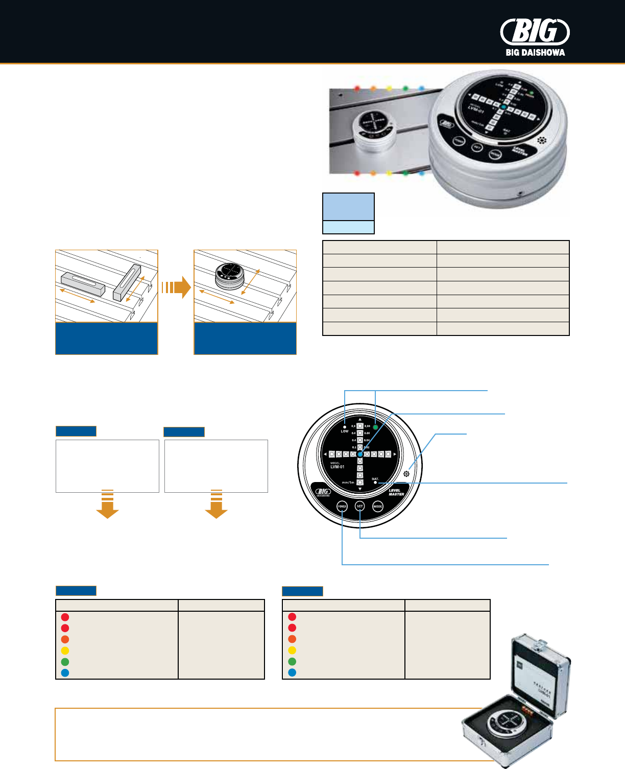
Level Master
High precision device for the leveling of machine tool tables.
•
Simultaneous 2-axis detection leveler
•
LED and buzzer indication when leveling is complete
•
Uses optical level sensor technology
•
10 micron per meter precision (.01mm/m)
Mode Display
Leveling Complete LED (Blue)
Buzzer
Power Switch (Auto On/Off Function)
Power Is Automatically Turned Off 30 Minutes After Turned On
Battery Alarm
“BAT” Indication Blinks When Battery Is Low
Set Switch (Zero Adjustment Function)
Used To Calibrate The Unit
Minimum Read Value .01mm inclination/m
Power Source Alkaline batteries (AAA x 4 pcs.)
Auto Power Off 30 minutes after power is turned on
Operational Temperature 32-104º F (Recommended 66º F
±
9°)
Battery Life 50 hours
Dimensions ø4.3 x 2.2 H
Weight 2.2 lbs
• In the case of high precision leveling, we recommend that you check the
Level Master in advance on a reference level, such as a level block
LED (red) on: over .8mm/m
LED (red) blinking: within .8mm/m
LED (orange) blinking: within .6mm/m
LED (yellow) blinking: within .4mm/m
LED (green) blinking: within .2mm/m
LED (blue) blinking: within .1mm/m
LED Status Inclination
Traditional method
where 2 levelers
are used
Easy leveling with
simultaneous
2-axis detection
Simultaneous 2-axis detection saves the extra time & cost
of using 2 levelers
When the required
level condition is
within .01mm/m
LED (blue) & buzzer are simultaneously activated
When the required
level condition is
within .1mm/m
LED and buzzer indicates leveling completion
Included:
Level Master, Aluminum Storage Case, Alkaline Batteries (AAA x 4 pcs.),
Manual, Guarantee Certificate & Inspection Sheet
LED (red) on: over .08mm/m
LED (red) blinking: within .08mm/m
LED (orange) blinking: within .06mm/m
LED (yellow) blinking: within .04mm/m
LED (green) blinking: within .02mm/m
LED (blue) blinking: within .01mm/m
LED Status Inclination
Catalog
Number
LVM-01
High Mode Low Mode
High Mode Low Mode
21
IN-PROCESS MACHINE DEVICES
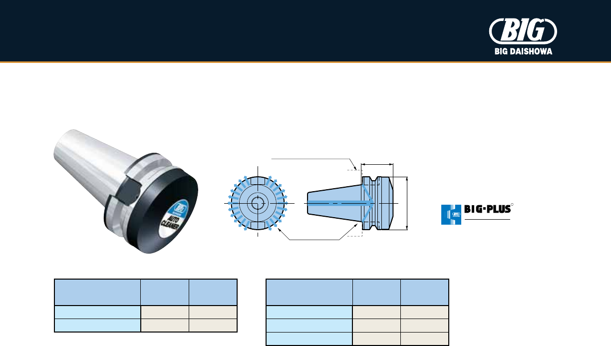
BIG-PLUS
®
Cleaner
Blowing air cleans the BIG-PLUS® machine spindle face of all debris.
øD
L
Air Blow
BIG-PLUS® Spindle Face
R
SPINDLE SYSTEM
DUAL C O N T ACT
Catalog
Number øD L
SBT30-ASC-30T 1.811 1.181
SBT40-ASC-40T 2.480 1.575
SBT50-ASC-60T 3.937 2.362
Catalog
Number øD L
SCV40-ASC-1.750T 2.480 1.750
SCV50-ASC-2.5T 3.875 2.480
BCV BBT
• When the cleaner is clamped into a BIG-PLUS® machine spindle, faces have 1mm (.039") clearance
22
IN-PROCESS MACHINE DEVICES
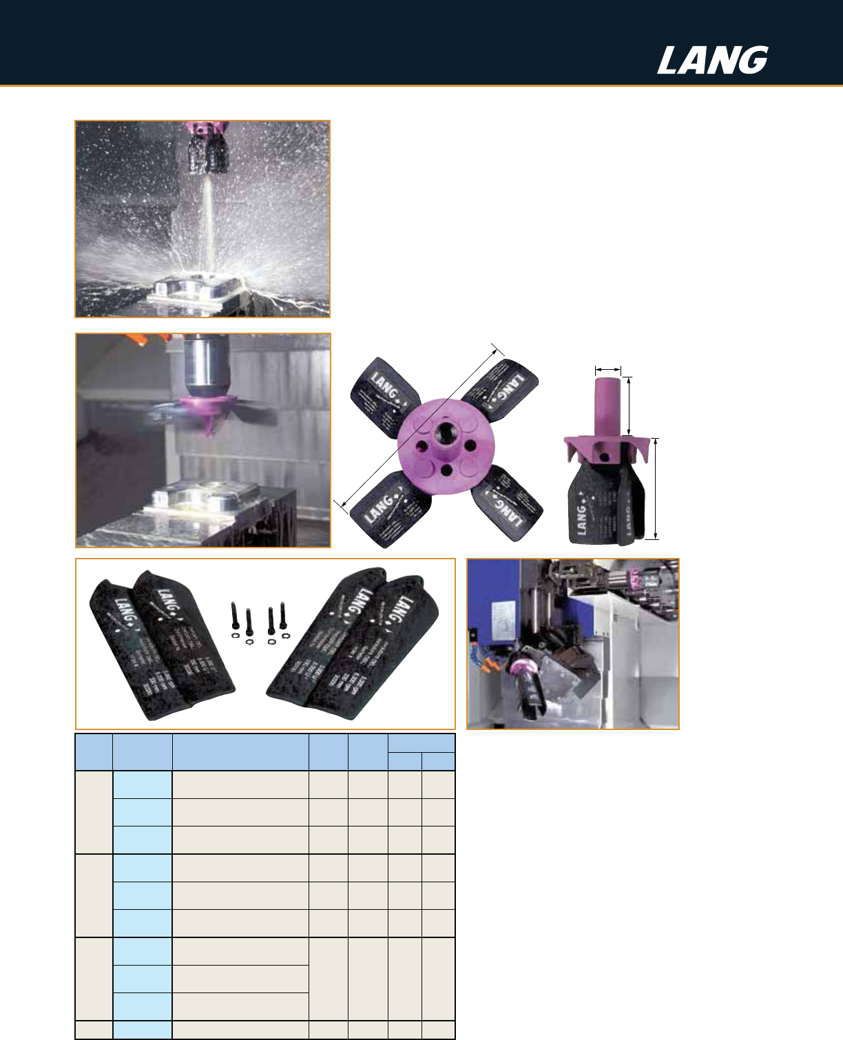
Shank ø
1.654
(42mm)
Length L
Blade ø
Shank
ø
Catalog
Number Description Blade
ø
Length
L
Speed (RPM)
Min Max
20mm
24.303.202 Chip Fan 20mm x 160mm 160mm 82mm
(3.228) 6,000 12,000
24.303.203 Chip Fan 20mm x 260mm 260mm 130mm
(5.118) 5,000 8,000
24.303.201 Chip Fan 20mm x 330mm 330mm 166mm
(6.535) 5,000 8,000
.750
24.313.202 Chip Fan 3/4" x 160mm 6.299 3.228
(82mm) 6,000 12,000
24.313.203 Chip Fan 3/4" x 260mm 10.236 5.118
(130mm) 5,000 8,000
24.313.201 Chip Fan 3/4" x 330mm 12.992 6.535
(166mm) 5,000 8,000
Repair
Kits
24.303.206 Chip Fan Repair Kit 160
————
24.303.207 Chip Fan Repair Kit 260
24.303.205 Chip Fan Repair Kit 330
Springs 24.303.210 Replacement Springs (10/pack) — — — —
Operating Instructions
•
Clean-Tec fans should only be used in enclosed
machining centers
•
Clean-Tec fans equipped with either a ø.750 or
ø20mm straight shank should be securely mounted
in either a collet chuck or end mill holder
•
Rotational direction clockwise only
•
Optimum feed rate for cleaning is between
120-390 in/min
•
Distance from workpiece should be between 4"-6"
•
Upon rotational start-up, program an initial speed of
2,000 RPM (max) before obtaining running speed to
reduce the possibility of blade failure due to excessive
centrifugal force
• Please note the clearance dimensions with Clean-Tec fans for optimum
performance and to avoid collisions upon cycle starts and stops
Repair Kit
Can be
used in all
enclosed
horizontal &
vertical
machining
centers
Clean-Tec Chip & Coolant Fan
Fast, safe and automatic chip and coolant fans for in-process cleaning
without stopping production. As the machine spindle turns, the blades
deploy to provide high volume air cleaning power.
•
Clean-Tec provides a safer and faster method of removing chips and
coolant from your tables, fixtures and workpieces
•
No more dripping coolant and flying chips from conventional air hose blasts
•
A quieter workplace environment
•
Less spindle downtime for cleaning results in increased profits
•
Saves expensive compressed air
•
Coolant-through shank for rinsing capability (coolant-through spindle required)
23
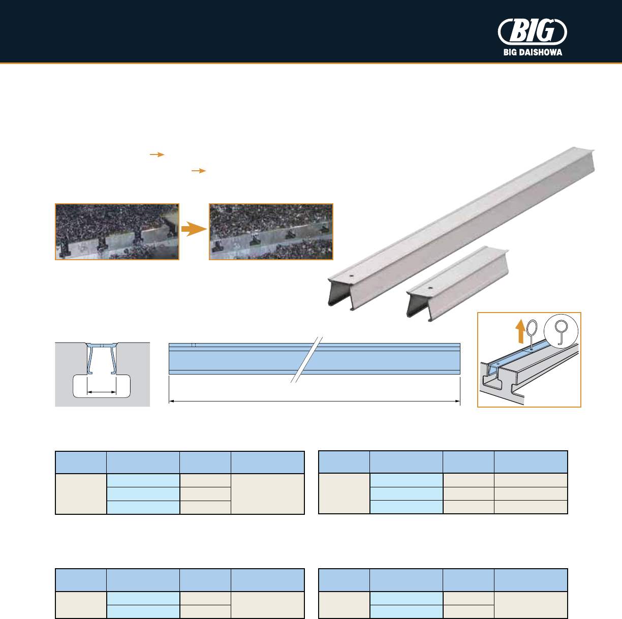
1,000mm / 400mm / 100mm
W
IN-PROCESS MACHINE DEVICES
T-Slot Clean
Improve your work safety environment and efficiency of table cleaning. Save the time required to clean T-slots packed with chips.
Coolant quickly removes heated swarf and helps to prevent thermal displacement of the machine.
•
Quick removal of chips from a machine
•
Faster table cleaning A reduction of clean-up time
•
Volume control of heated chips Better machining precision
•
Three sizes of T-slot widths are available to fit your machine table
T-slots packed with difficult
to remove chips
T-slots protected & clear
by T-Slot Clean
Type Catalog
Number Width W Contents
Metric
TS18-1000L-10P 18mm
1,000mm x 10 pcs.
TS22-1000L-10P 22mm
Type Catalog
Number Width W Contents
Metric
TS18-400L-100P 18mm
400mm x 100 pcs.
TS22-400L-100P 22mm
Type Catalog
Number Width W Contents
Metric
TS14-10S 14mm TS14-S x 10 sets
TS18-10S 18mm TS18-S x 10 sets
TS22-10S 22mm TS22-S x 10 sets
Type Catalog
Number Width W Contents
Metric
TS14-S 14mm
400mm x 4 pcs.
100mm x 4 pcs.
TS18-S 18mm
TS22-S 22mm
Standard Set Cost Saving Set
Long Set Extra Long Set
• If necessary, cut to the length that you need
• Removal pin is included
• Contains 10 Standard Sets for cost savings
Removal pin
for easy removal
06/2013 © Copyright 2013 BIG Kaiser Precision Tooling Inc. All rights reserved.
2600 Huntington Blvd, Hoffman Estates, IL 60192
Phone: 847.228.7660 • Fax: 847.228.0881
www.bigkaiser.com • bigkaiser@bigkaiser.com
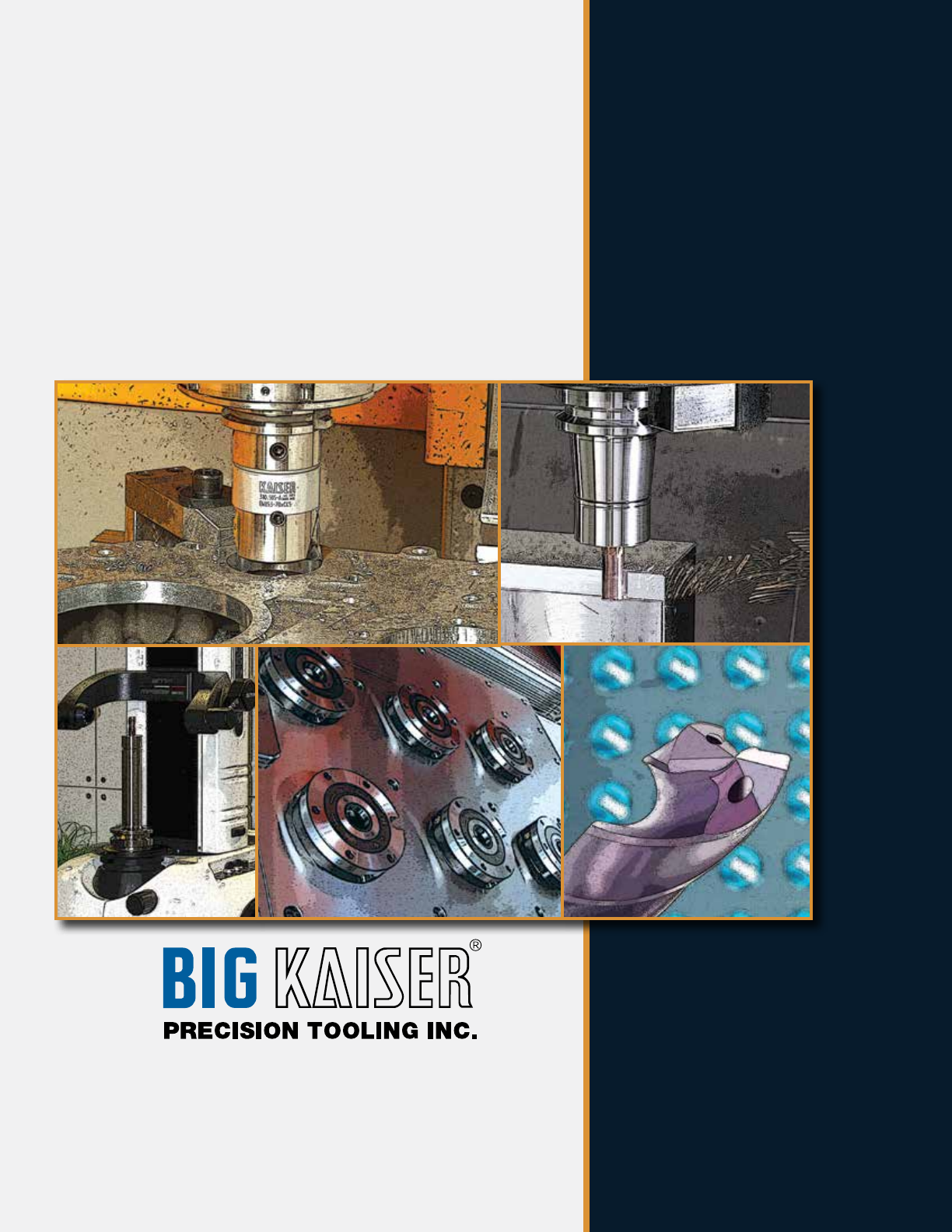
BIG Kaiser Precision Tooling Inc. is not just
accessories. We’re boring tools, tool holders,
cutting tools, tool presetters, zero-point workholding
and so much more. We’re BIG-PLUS®, CAT, BT,
HSK and BIG CAPTO. We’re tightening
tolerances, reducing set-up and cycle times,
increasing tool life, and enhancing performance
while driving down cost. We’re delivering
high-performance products and ingenuity for
shops that demand results.
