RN4020 Bluetooth Low Energy Module Data Sheet MP Tool User Guide
User Manual:
Open the PDF directly: View PDF ![]() .
.
Page Count: 82

Advance Information
2015MicrochipTechnologyInc.
page1
BLUETOOTH
MASS PRODUCTION (MP) TOOL
SOFTWARE USER GUIDE

Advance Information
2015MicrochipTechnologyInc.
page2
BLUETOOTH MASS PRODUCTION (MP) TOOL
SOFTWARE USER GUIDE
NOTES:
Quick Link:
- For the Merge Tool for EEPROM Configuration users, please visit MPET
- For the MP Script file editor and MSF generator users, please visit MPSE
- For the MPBT usage, please visit MPBT
- For the Multiple Update Device’s Flash users, please visit MPMF

Advance Information
2015MicrochipTechnologyInc.
page3
BLUETOOTH MP TOOL
SOFTWARE USER GUIDE
Table of Contents
Table of Contents
NOTES: ............................................................................................................................................... 2
Table of Contents .................................................................................................................................. 3
Chapter 1 Preface ....................................................................................................................................... 6
Chapter 2 Overview .................................................................................................................................... 7
2.1 MP Tool Overview ............................................................................................................ 7
2.2 Test Instrument Overview ............................................................................................ 8
2.2.1 Personal Computer (PC) ............................................................................................................. 8
2.2.2 MP Fixtures ..................................................................................................................................... 8
2.2.3 RF Instruments (Option) ............................................................................................................. 9
2.2.4 Audio USB Soundcard .............................................................................................................. 10
Chapter 3 Installation ............................................................................................................................... 11
3.1 MP Tool Package ........................................................................................................... 11
3.2 MPBT Environment Setup ........................................................................................... 11
3.3 MPMF Environment Setup........................................................................................... 12
3.4 USB to UART driver ...................................................................................................... 12
Chapter 4 Mass Production EEPROM Tool (MPET) ........................................................................... 15
4.1 MPET Introduction......................................................................................................... 15
4.2 MPET Related File ......................................................................................................... 15
4.3 Generate a Binary File of Full EEPROM .................................................................. 16
4.3.1 Welcome page ............................................................................................................................. 16
4.3.2 Select output file format............................................................................................................ 17
4.3.3 Select base bin file ..................................................................................................................... 18
4.3.4 Add / Remove Merge Files ........................................................................................................ 19
4.3.5 Select Output Destination ........................................................................................................ 19
4.3.6 Generate Binary File .................................................................................................................. 20
4.3.7 Complete Info ............................................................................................................................... 21
4.4 Generate a Patch File of Part of EEPROM .............................................................. 22
4.4.1 Welcome page ............................................................................................................................. 22
4.4.2 Select output file format............................................................................................................ 23
4.4.3 Select base bin file ..................................................................................................................... 23
4.4.4 Add / Remove Merge Files ........................................................................................................ 24

Advance Information
2015MicrochipTechnologyInc.
page4
4.4.5 Select Output Destination ........................................................................................................ 25
4.4.6 Generate Patch File .................................................................................................................... 26
4.4.7 Calibration Parameter Check ................................................................................................... 27
4.4.8 Complete Info ............................................................................................................................... 28
4.5 Error Message ................................................................................................................ 30
4.5.1 Project Name Not Match ........................................................................................................... 30
4.5.2 Device ID Not Match ................................................................................................................... 30
Chapter 5 Mass Production Script Editor (MPSE) ............................................................................... 31
5.1 Introduction ..................................................................................................................... 31
5.2 Graphical User Interface .............................................................................................. 32
5.2.1 Solution Area ............................................................................................................................... 32
5.2.2 Test Item Area .............................................................................................................................. 32
5.2.3 Condition Area ............................................................................................................................. 32
5.2.4 Input / Output Area ..................................................................................................................... 32
5.3 Test Items Overview ..................................................................................................... 33
5.4 Generate MP Script File Step by Step ...................................................................... 34
5.4.1 Select your solution ................................................................................................................... 34
5.4.2 Give your own product name .................................................................................................. 35
5.4.3 Select RF test instrument ......................................................................................................... 35
5.4.4 Choose test items for MP ......................................................................................................... 37
5.4.5 Configure test item’s parameter and limitation .................................................................. 37
5.4.6 Save MP Script File (MSF) ........................................................................................................ 40
5.5 FAQ .................................................................................................................................... 40
Chapter 6 Mass Production Board level test Tool (MPBT) .................................................................. 46
6.1 Introduction ..................................................................................................................... 46
6.2 Testing environment Setup......................................................................................... 46
6.2.1 Single-Site ..................................................................................................................................... 46
6.2.2 Dual-Site ........................................................................................................................................ 47
6.2.3 Sound Card connection ............................................................................................................ 48
6.2.4 VICTOIRA Identification ............................................................................................................ 48
6.3 Configuration .................................................................................................................. 49
6.3.1 SYSTEM Page .............................................................................................................................. 49
6.3.2 DEVICE Page ................................................................................................................................ 51
6.3.3 INSTRUMENT Page .................................................................................................................... 52
6.3.4 BT ADDRESS Page ..................................................................................................................... 53
6.3.5 RF METER Page .......................................................................................................................... 57

Advance Information
2015MicrochipTechnologyInc.
page5
6.3.6 HANDLER Page ........................................................................................................................... 58
6.3.7 MANUFACTURE INFO Page ..................................................................................................... 59
6.3.8 APPLY Page ................................................................................................................................. 60
6.4 Run the Test .................................................................................................................... 61
6.4.1 Put Device Under Test (DUT) in Socket ................................................................................ 61
6.4.2 Single-Site Test Page ................................................................................................................. 61
6.4.3 Dual-Site Test Page .................................................................................................................... 63
6.4.4 Dual-Site Test Page for Special Bar Code COM Port ........................................................ 64
6.4.5 Auto-Handler Test Page ............................................................................................................ 65
6.5 Error-Code ....................................................................................................................... 66
6.6 Test Log ........................................................................................................................... 66
6.7 FAQ .................................................................................................................................... 66
Chapter 7 Mass Production Multi Flash (MPMF) ................................................................................. 70
7.1 Introduction ..................................................................................................................... 70
7.2 Graphical User Interface .............................................................................................. 70
7.3 Configuration Dialog..................................................................................................... 71
7.4 Write the Flash with Multiple DUTs........................................................................... 72
7.5 FAQ .................................................................................................................................... 74
Appendix A. Revision History ................................................................................................................. 76
Appendix B. MPBT Communicate with Customer’s tool ..................................................................... 77

Advance Information
2015MicrochipTechnologyInc.
page6
BLUETOOTH MP TOOL
SOFTWARE USER GUIDE
Chapter 1 Preface
MP Tool is a Windows XP and Win7 compatible software package that supports rapid the
production on Microchip’s BT ICs and Modules.
MP Tool simplifies the manufactory process by providing a high-level, menu-driven
environment that allows the users to quickly and easily develop a Test Script and an
automatic MP Testing.
This user’s guide will explain how to setup the tool and configure it with an applicable
example of creating a MP testing. This document will help the user become familiar with
the purpose and functionality of the Microchip’s ICs and Modules and be able to use the
MP Tool with ease.

Advance Information
2015MicrochipTechnologyInc.
page7
BLUETOOTH MP TOOL
SOFTWARE USER GUIDE
Chapter 2 Overview
This chapter provides an overview of the Bluetooth MP Tool and identifies the instrument
of MP test environment. Topics covered include:
• MP Tool Overview
• Test Instrument Overview
2.1 MP Tool Overview
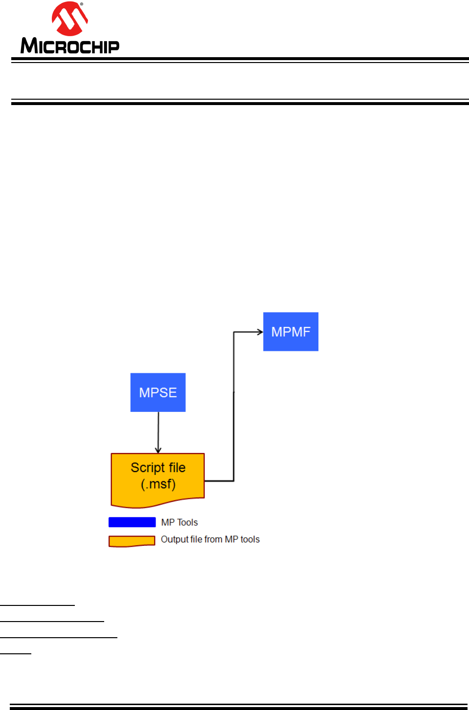
The MP Tool consists of four tools include:
Mass Production EEPROM Tool (MPET),
Mass Production Script Editor (MPSE),
Mass Production Board Level Test Tool (MPBT) and
Mass Production Multi Flash (MPMF).
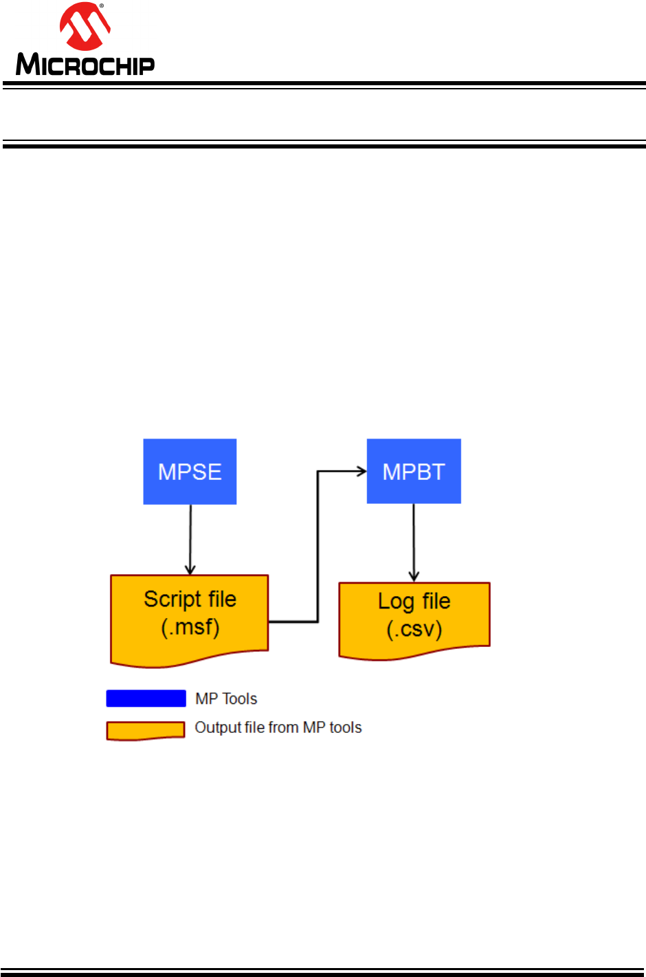
That can have their own functions and related to others (FIGURE 2-1). This provides
greater flexibility and potential in MP process.
The following chapter will descript more detail of these tools.
FIGURE 2-1 MP Tool Overview
Advance Information
2015MicrochipTechnologyInc.
page8
2.2 Test Instrument Overview
This section will provide MP related instruments overview.
2.2.1 Personal Computer (PC)
- The Operation System (OS) with Windows XP or 7 (32bit)
- Must two or more RS232 port interface
- Must four or more USB port interface
- NI GPIB-USB-HS is option and depend on RF test item selection
2.2.2 MP Fixtures
The MP Fixture is a device to hold the DUT (Device Under Test). Which can be easily
fix and remove the DUT. Allow it to be tested by being subjected to controlled
electronic test signals.
Two kind of fixture:
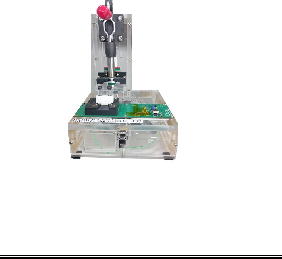
- MPBT fixture for MPBT usage (FIGURE 2-2)
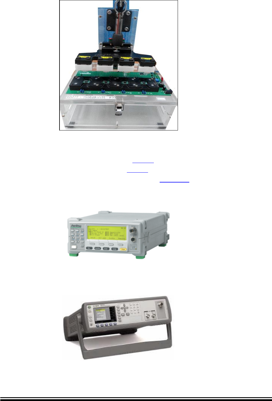
- MPMF fixture for MPMF usage (FIGURE 2-3)
FIGURE 2-2 MPBT fixture
Advance Information
2015MicrochipTechnologyInc.
page9
FIGURE 2-3 MPMF one to four fixture
2.2.3 RF Instruments (Option)
MP Tool is support three kind of RF testers:
- Anritsu MT8852 (FIGURE 2-4) (Visit: Anritsu)
- Agilent N4010 (FIGURE 2-5) (Visit: Agilent)
- Lite-Point IQview / IQflex (FIGURE 2-6) (Visit: Lite-Point)
FIGURE 2-4 Anritsu MT8852
FIGURE 2-5 Agilent N4010

Advance Information
2015MicrochipTechnologyInc.
page11
BLUETOOTH MP TOOL
SOFTWARE USER GUIDE
Chapter 3 Installation
This chapter provides a setup of MP (Mass Production) test environment, which includes
MP fixture, test environment. Topics covered include:
• MP Tool package
• MPBT environment setup
• MPMF environment setup
• USB to UART driver
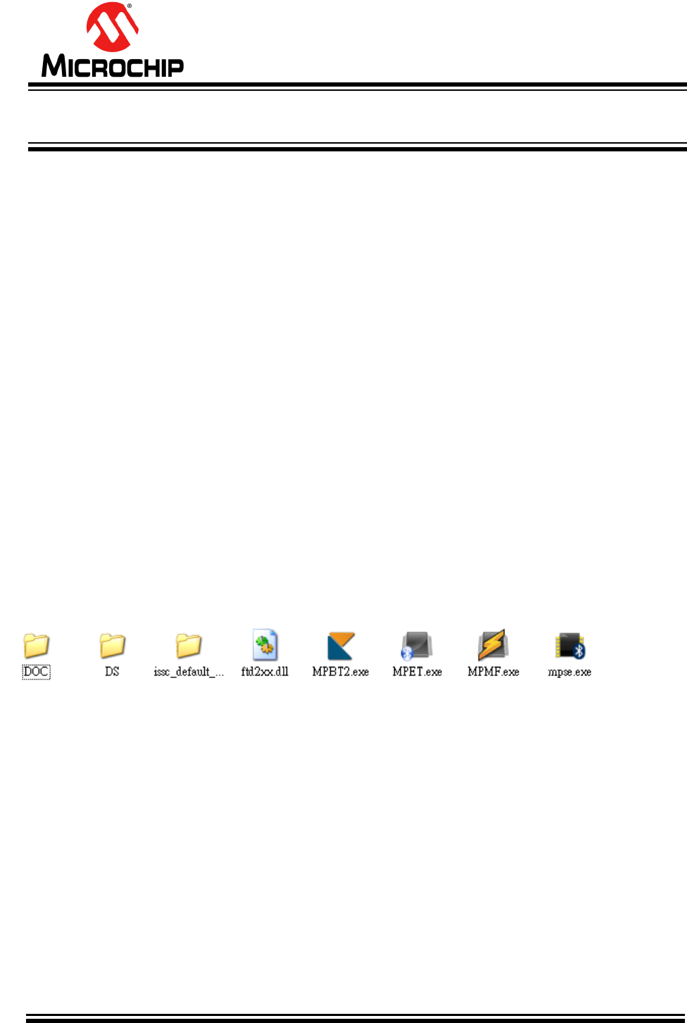
3.1 MP Tool Package
Figure 3-1 shows MP related tools and files when you un-zip the MP Tool package.
Includes:
- DOC folder: User Manuals of MP Tools.
- DS folder: The Default Setting for MPSE used.
- issc_default_bin folder: Binary file of default EEPROM, used to merge other
EEPROM by MPSE.
- ftd2xx.dll: USB driver.
- MPBT2: Mass Production Board level Test
- MPET: Mass Production EEPROM Tool
- MPSE: Mass Production Script Editor
- MPMF: Mass Production Multi Flash
FIGURE 3-1 Un-Zip MP Tool Package
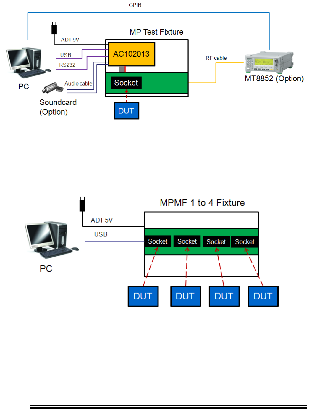
3.2 MPBT Environment Setup
Figure 3-2 illustrates overview of MPBT test environment. The Power supply (+9V) is a
source and plugged into the MP Fixture. USB and RS232 are connected between PC and
MP fixture for communication.
In RF BT test, you can choose extension RF BT testers to instead of GU like Anritsu
MT8852, Lite-point IQ View or Agilent N4010.
Advance Information
2015MicrochipTechnologyInc.
page12
FIGURE 3-2 Overview of MPBT test Environment
3.3 MPMF Environment Setup
Figure 3-3 illustrates overview of MPMF test environment. The Power supply (+5V) is a
source and plugged into the MPMF 1 to 4 Fixture. USB is connected between PC and
MPMF 1 to 4 fixture for communication.
FIGURE 3-3 Overview of MPMF test Environment
3.4 USB to UART driver
You may get the notice of driver when you first setup MP Fixture with you test PC. That
means your test PC doesn’t have MP Fixture driver. Please flow below steps to finish USB
to UART driver installation.
Advance Information
2015MicrochipTechnologyInc.
page13
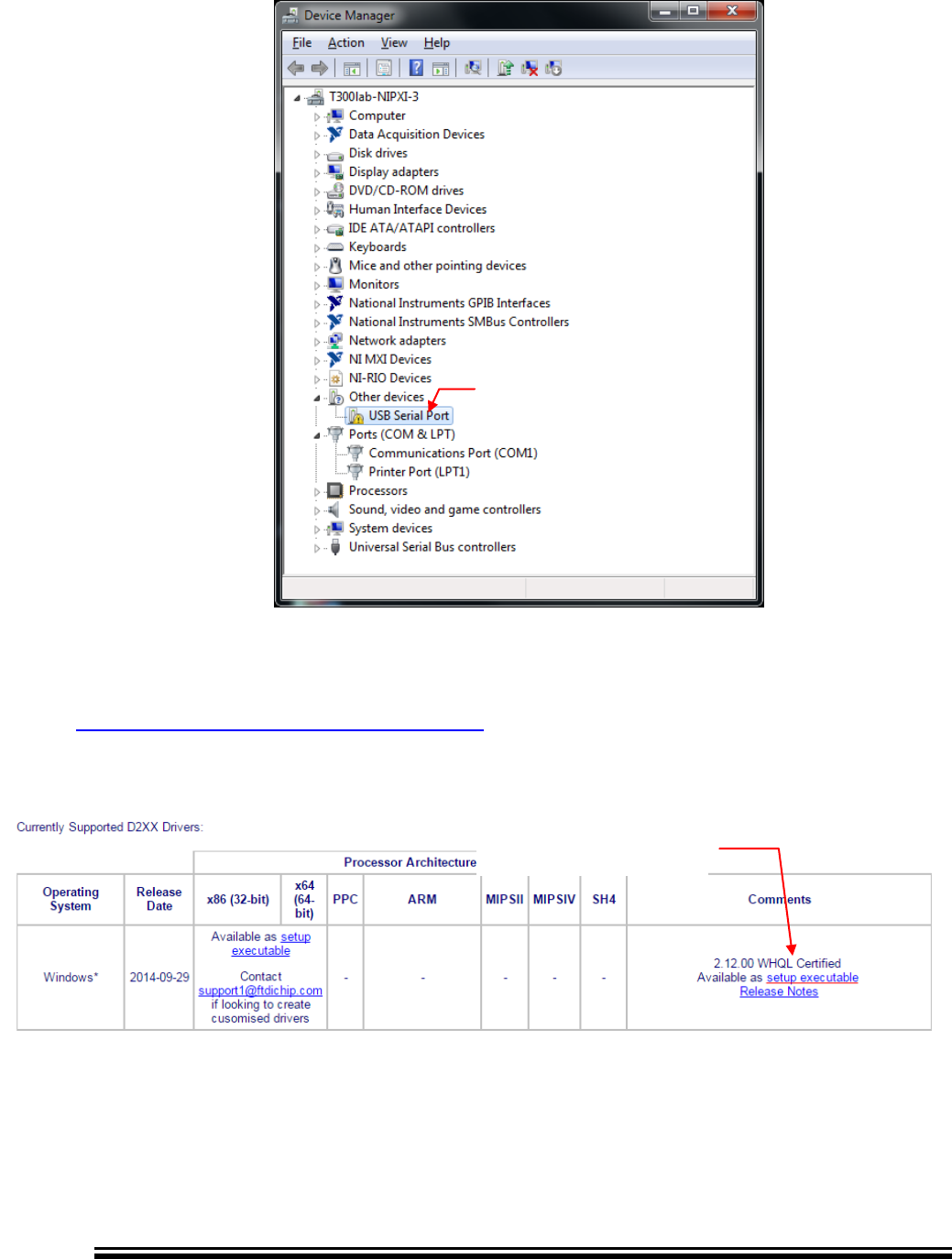
FIGURE 3-4 Device Manager
Open Device Manager (Figure 3-4) to check the MP Fixture’s driver is installed correct
or not. If not, Please download MP Fixture driver from FTDI web site. You can visit
http://www.ftdichip.com/Drivers/D2XX.htm and check section Currently Supported D2XX
Drivers (Figure 3-5) download it via your IE.
FIGURE 3-5 Download FTDI D2xxx Driver
Execute as administrator (Figure 3-6). And flow the Wizard to finish MP Fixture driver
installation. After that, you will get new COM port number of MP Fixture on your Device
Manager (Figure 3-7).
Click here download
No Driver

Advance Information
2015MicrochipTechnologyInc.
page14
FIGURE 3-6 Open FTDI D2XXX Driver
FIGURE 3-7 USB to UART Driver Finish
New COM port

Advance Information
2015MicrochipTechnologyInc.
page15
BLUETOOTH MP TOOL
SOFTWARE USER GUIDE
Chapter 4 Mass Production EEPROM Tool (MPET)
The MPET is EEPROM merge tool. This chapter provides an Introduction and operation of
MPET. Topics covered include:
• Introduction
• Related File
• Generate Bin
• Generate IPF
• Generate IPF for UI
• Error Message
4.1 MPET Introduction
This tool is used to merge variety customer setting like User Interface (UI), DSP (Digital
Signal Processing), 8051 and so on. The end result of using the tool will be a generated
Binary File (.bin) or Patch File (.ipf), which can be written into a BT device both IC and
Module by MPBT.
4.2 MPET Related File
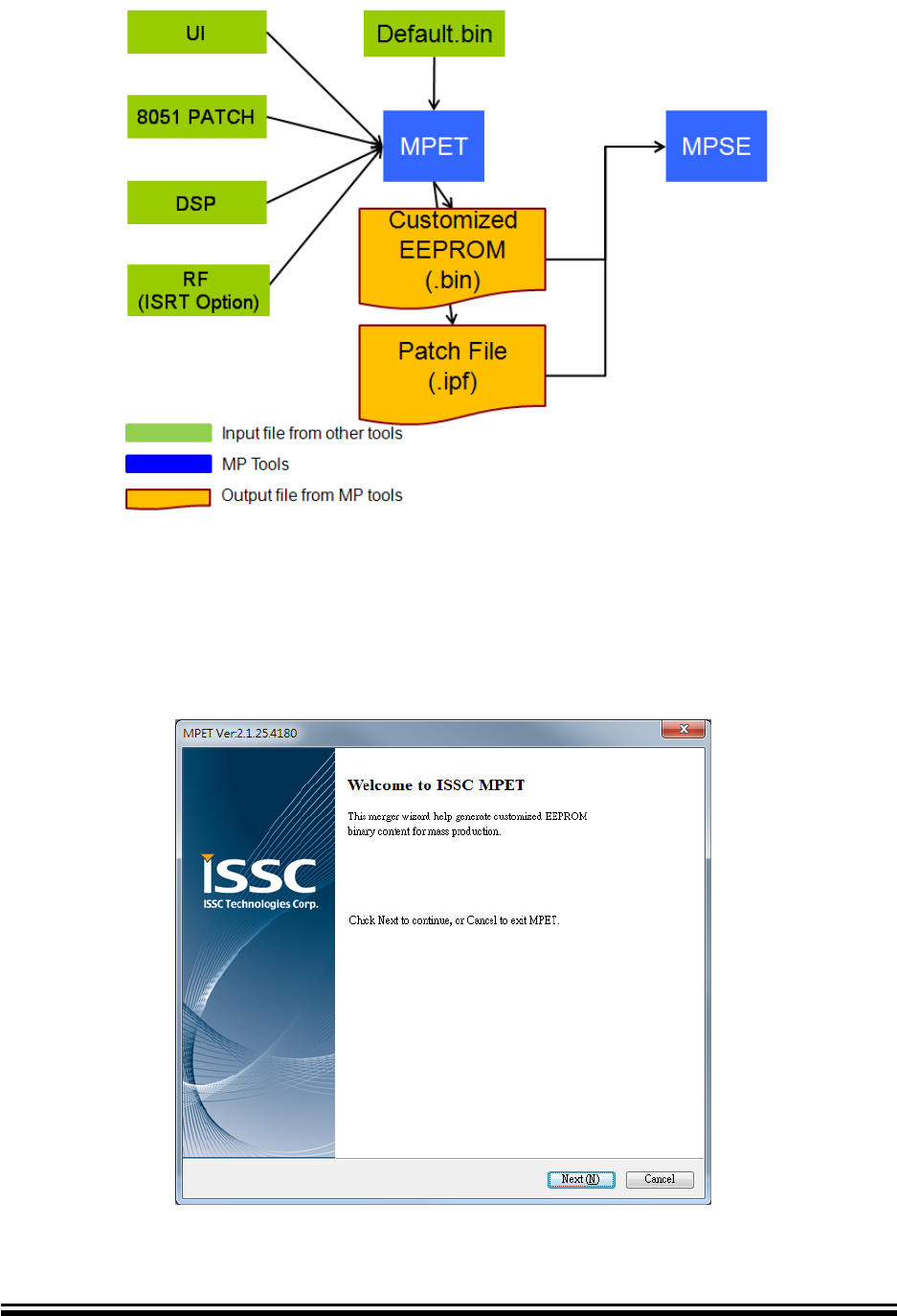
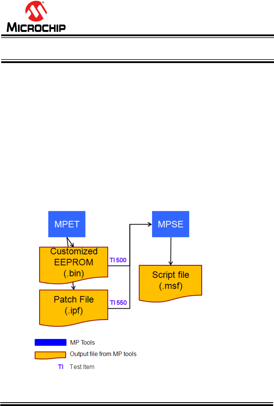
Figure 4-1 illustrates the related files of MPET.
The Input (green color) includes default.bin as a base file, UI (User Interface).txt, 8051.txt,
DSP (Digital Signal Processor).txt, and others.txt as customize file. After that, Output
(orange color) binary file of fully EEPROM or patch file (ipf) of part of EEPROM depend of
what kind of operation mode you selected.
Advance Information
2015MicrochipTechnologyInc.
page16
FIGURE 4-1 MPET Files Relationship
4.3 Generate a Binary File of Full EEPROM
4.3.1 Welcome page
FIGURE 4-2 MPET Wizard - Welcome Page
Advance Information
2015MicrochipTechnologyInc.
page17
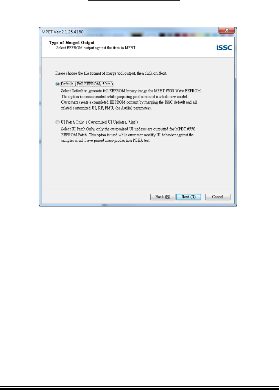
4.3.2 Select output file format
Select output file format as Default (Full EEPROM, *.bin) tool will output *.bin and *.txt
after merge success. Please select “Next” for next step.
FIGURE 4-3 MPET Wizard – Output Selection Page
Advance Information
2015MicrochipTechnologyInc.
page18
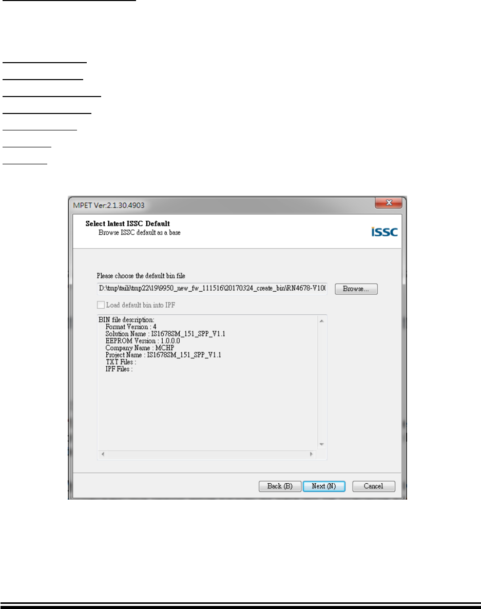
4.3.3 Select base bin file
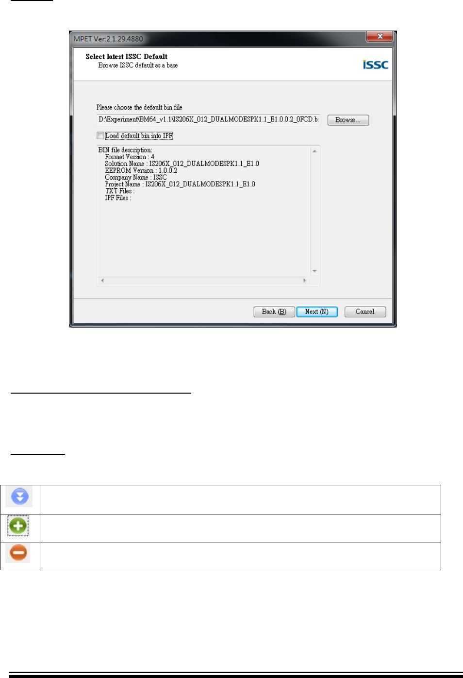
Press “Browse” button to open file browser to select base bin file. The bin file
description will show below information. And make sure that Solution Name is
corrected. Please select “Next” for next step.
Load default bin into IPF: Load default bin content into IPF. Please note that once
enable (checked) this option while EEPROM data will be overwrite except MP
calibrated data. (MPET didn’t support this function in the output bin file mode.)
Format Version: Show merge base bin file format version.
Solution Name: Show merge base bin file solution name.
EEPROM Version: Show merge base bin file EEPROM version.
Company Name: file contain company name
Project Name: file contain product name.
TXT files: Show merge base bin file contain all txt files’ name.
IPF files: Show merge base bin file contain all ipf files’ name.
FIGURE 4-4 MPET Wizard – Default Binary File Selection Page

Advance Information
2015MicrochipTechnologyInc.
page19
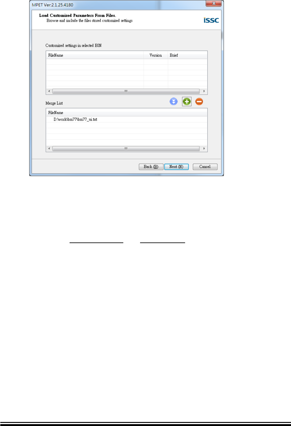
4.3.4 Add / Remove Merge Files
Customized setting in selected BIN
This list shows files that included by bin file. If the bin file you selected is default that
will be empty. Please select “Next” for next step.
Merge List
This list show all files that you want to merge with base bin file. Output file will content
all in this list box.
Press this button to move file from customized bin to merge list
Press this button to open file browser dialog to select new file to merge list
Press this button to remove merge list selected file.
FIGURE 4-5 MPET Wizard – Add/Remove File Page
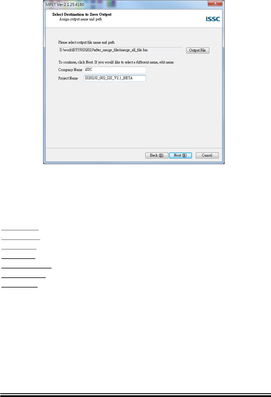
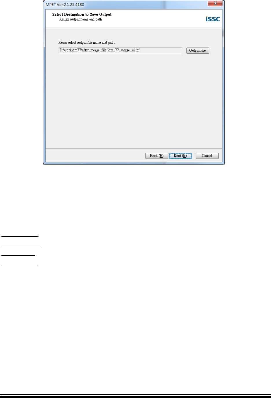
4.3.5 Select Output Destination
Press “Output File” button to open file browser to select output destination. Tool will
bring out the default Company Name and Project Name and that can be changed by
users. Please select “Next” for next step.
Advance Information
2015MicrochipTechnologyInc.
page20
FIGURE 4-6 MPET Wizard – Output Destination Page
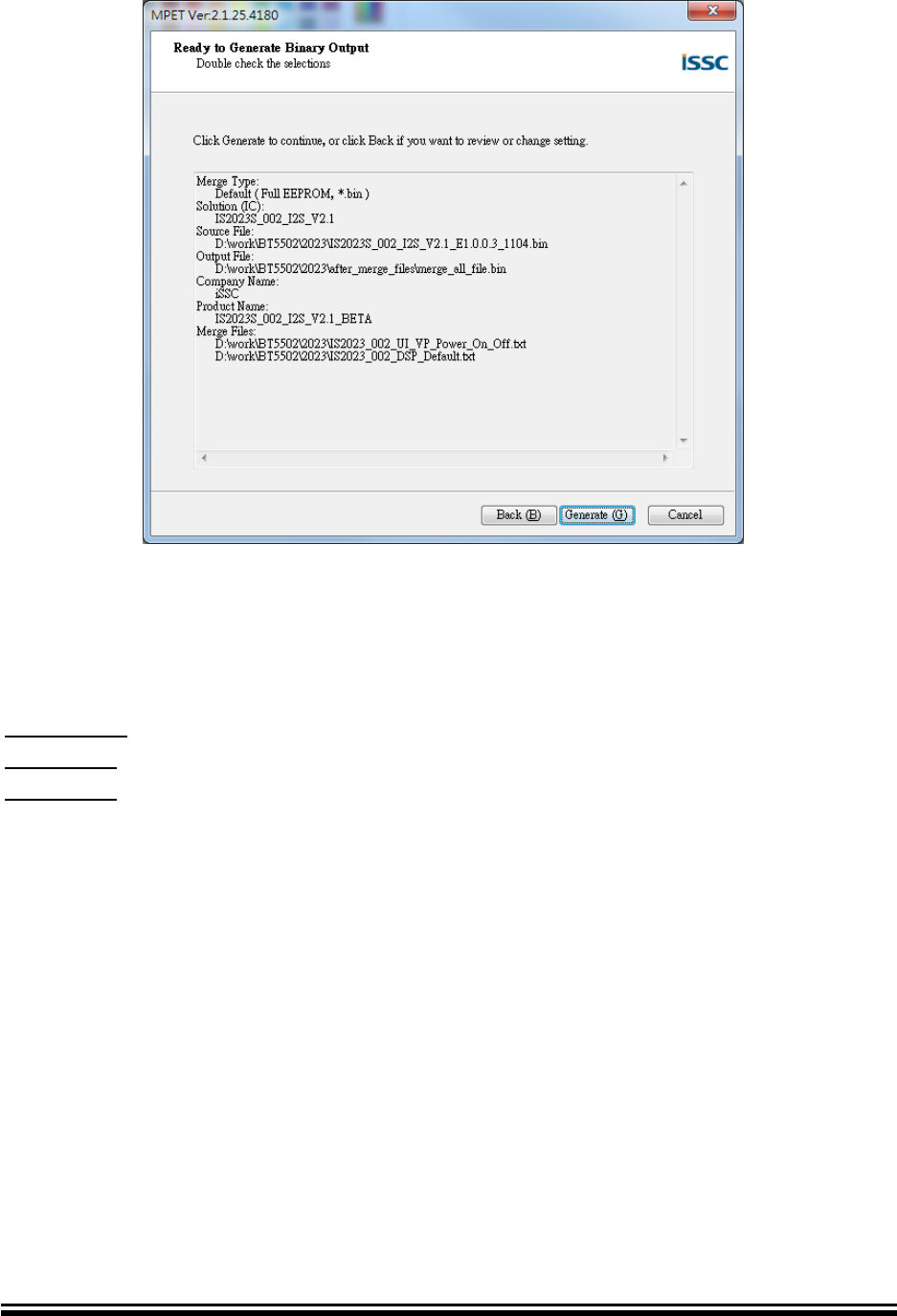
4.3.6 Generate Binary File
Press “Generate” button to generate binary file of full EEPROM. And page shows
merged information. Please select “Next” for next step.
Merge Type: output file type, bin or ipf.
Solution (IC): solution name of base bin file
Source File: path of base bin file
Output File: path of output file
Company Name: company name
Product Name: product name
Merge Files: merge file list
Advance Information
2015MicrochipTechnologyInc.
page21
FIGURE 4-7 MPET Wizard – Generate Page
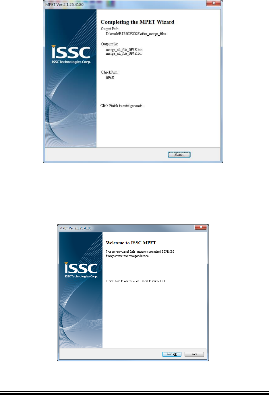
4.3.7 Complete Info
Press “Finish” button to close tool. And page shows output file information.
Output Path: output file path
Output File: output file name of bin and txt.
CheckSum: File check sum number.
Advance Information
2015MicrochipTechnologyInc.
page22
FIGURE 4-8 MPET Wizard – Finish Page
4.4 Generate a Patch File of Part of EEPROM
4.4.1 Welcome page
FIGURE 4-9 MPET Wizard - Welcome Page

Advance Information
2015MicrochipTechnologyInc.
page23
4.4.2 Select output file format
Select output file format as UI Patch Only (Customized UI Updates, *.ipf), tool will
output *.ipf after merge success. Please select “Next” for next step.
FIGURE 4-10 MPET Wizard – Output Selection Page
4.4.3 Select base bin file
Press “Browse” button to open file browser to select base bin file. The bin file
description will show below information. And make sure that Solution Name is
corrected. Please select “Next” for next step.
Load default bin into IPF: Load default bin content into IPF. Please note that once
enable (checked) this option while EEPROM data will be overwrite except MP
calibrated data.
Format Version: Show merge base bin file format version.
Solution Name: Show merge base bin file solution name.
EEPROM Version: Show merge base bin file EEPROM version.
Company Name: file contain company name
Project Name: file contain product name.
TXT files: Show merge base bin file contain all txt files’ name.
Advance Information
2015MicrochipTechnologyInc.
page24
IPF files: Show merge base bin file contain all ipf files’ name.
FIGURE 4-11 MPET Wizard – Default Binary File Selection Page
4.4.4 Add / Remove Merge Files
Customized setting in selected BIN
This list shows files that included by bin file. If the bin file you selected is default that
will be empty. Please select “Next” for next step.
Merge List
This list show all files that you want to merge with base bin file. Output file will content
all in this list box.
Press this button to move file from customized bin to merge list
Press this button to open file browser dialog to select new file to merge list
Press this button to remove merge list selected file.
Advance Information
2015MicrochipTechnologyInc.
page25
FIGURE 4-12 MPET Wizard – Add/Remove File Page
4.4.5 Select Output Destination
Press “Output File” button to open file browser to select output destination. Tool will
bring out the default Company Name and Project Name and that can be changed by
users. Please select “Next” for next step.
Advance Information
2015MicrochipTechnologyInc.
page26
FIGURE 4-13 MPET Wizard – Output Destination Page
4.4.6 Generate Patch File
Press “Generate” button to generate patch file of part of EEPROM. And page shows
merged information. Please select “Next” for next step.
Merge Type: output file type, bin or ipf.
Solution (IC): solution name of base bin file
Output File: path of output file
Merge Files: merge file list

Advance Information
2015MicrochipTechnologyInc.
page27
FIGURE 4-14 MPET Wizard – Generate Page
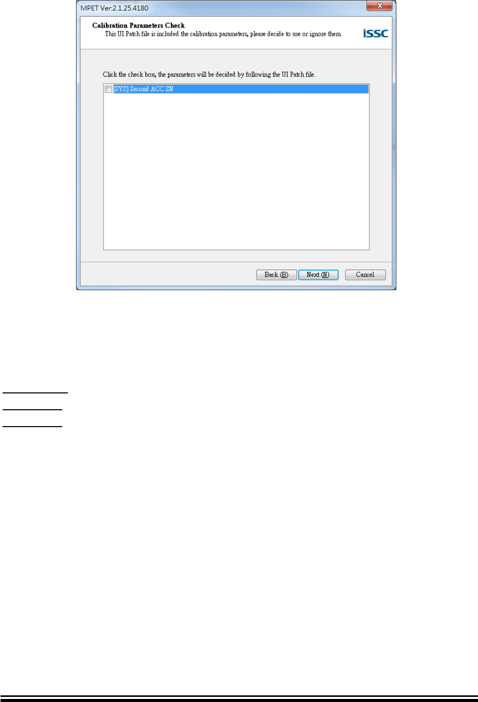
4.4.7 Calibration Parameter Check
This page will appear when UI patch cover with calibration address. If you want to
replace it with merge file, please check box. Then press “Next” button to generate
output file.
Advance Information
2015MicrochipTechnologyInc.
page28
FIGURE 4-15 MPET Wizard – Calibration Parameter Check Page
4.4.8 Complete Info
Press “Finish” button to close tool. And page shows output file information.
Output Path: output file path
Output File: output file name of bin and txt.
CheckSum: File check sum number.

Advance Information
2015MicrochipTechnologyInc.
page29
FIGURE 4-16 MPET Wizard – Finish Page
Advance Information
2015MicrochipTechnologyInc.
page30
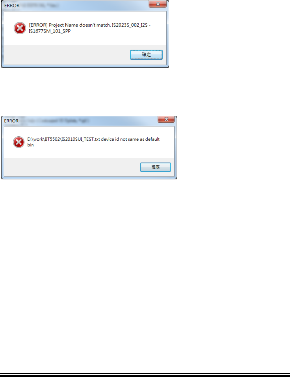
4.5 Error Message
4.5.1 Project Name Not Match
If you see this dialog as bellow, that means the merge base bin file project information
not match merge list files project information.
4.5.2 Device ID Not Match
If you see this dialog as bellow, that means the merge base bin file device id not
same as merge list files project information. This check only on BT5502 series device.
Advance Information
2015MicrochipTechnologyInc.
page31
BLUETOOTH MP TOOL
SOFTWARE USER GUIDE
Chapter 5 Mass Production Script Editor (MPSE)
The MPSE is a script editor tool. This chapter provides an Introduction and operation of
MPSE. Topics covered include:
• Introduction
• Graphical User Interface
• Test Items Overview
• Generate MP Script File (MSF) Step By Step
• FAQ
5.1 Introduction
This tool is used to create test script file (called .msf) for MPBT. Which file includes MP
test items, sequence, conditions and DUT (Device Under Test) information. So that, MPBT
knows that what DUT version is, which test items have, and judge the DUT with test
conditions.
FIGURE 5-1 MPSE Files Relationship

Advance Information
2015MicrochipTechnologyInc.
page32
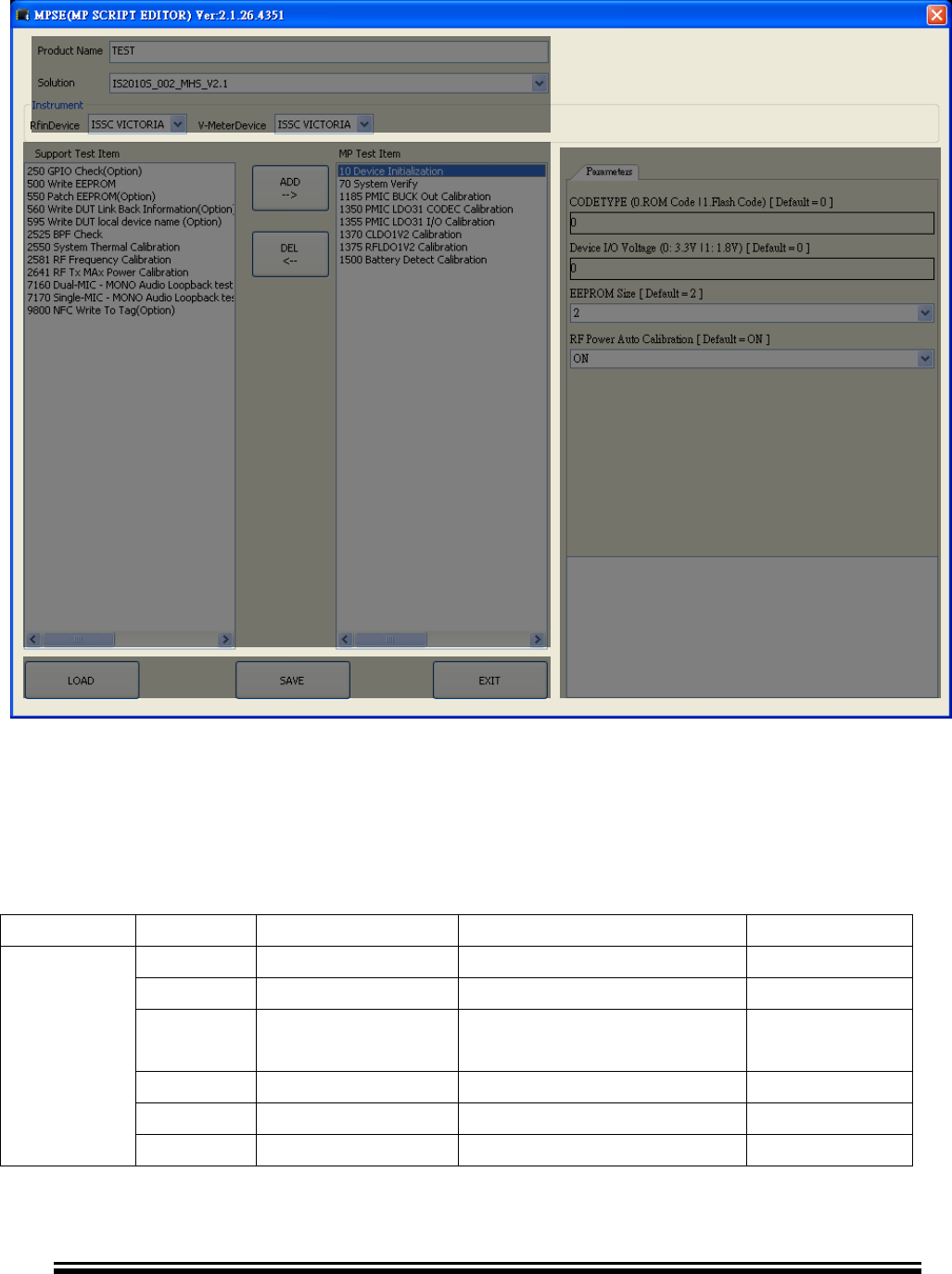
5.2 Graphical User Interface
This section split up MPSE GUI into four areas for description. Please refer following
subsection.
5.2.1 Solution Area
- Product Name: Product name (changeable).
- Solution: List of all Microchip solutions.
- RFinDevice: The selection of RF test instrument.
- V-MeterDevice: Power supply and meter
5.2.2 Test Item Area
How many test items supported is depend on what solution and RF test Instrument you
selected. Each test item was designed at RD stage. You can only change parameters and
limitations in Condition Area. And have some default recommend basic test item.
- Support Test Item (Left): The solution supported test items but not selected yet.
- MP Test Item (Right): These test items will save into MP Script File (MSF) when you
press “SAVE” button. You can modify it depend on your request.
- ADD --> Add selected item from Support Test Item to MP Test Item.
- DEL <-- Remove selected item from MP Test Item list to Support Test Item.
5.2.3 Condition Area
- Selection: List of defined value is select only
- Editor: You can input parameter, but be careful the valid range.
5.2.4 Input / Output Area
- SAVE: Save all of test setting as MP Script File (*.msf) for MPBT uses.
- LOAD: Load back all of test setting from Script File (*.msf) for modification.
- EXIT: Exit tool
Advance Information
2015MicrochipTechnologyInc.
page33
FIGURE 5-2 MPSE GUI
5.3 Test Items Overview
This Table indicates the most popular used case that may change in the future. If you’re
abnormal case doesn’t on the test list. Please contact your FAE for clarification.
Table 5-1 Test Item
Category
ID
Name
Description
Requirement
SYSTEM
10
Initialization
MP Fixture
20
Write Flash
5x
7x
System verify
25x
GPIO test
26x
LED test
500
Write EEPROM
The Bin File usually from
Solution Area
Test Item Area
Condition Area
Input / Output Area

Advance Information
2015MicrochipTechnologyInc.
page34
MPET
550
Patch EEPROM
The Patch file usually
from MPET
PMU
1000 ~
1400
System power
calibration
MP Fixture
15xx
Battery Detect
Calibration
RF
Calibration
2000 ~
2070
RF loopback
self-test
MP Fixture
RF Tester
208x
258x
Frequency
Calibration
21xx
26xx
Tx Power
Calibration
27xx
Tx DEVM check
28xx
Rx Sensitivity
Test
Audio Test
7000 ~
7500
Audio test
USB
soundcard
RF Test
77xx
8xxx
BT test
RF Tester
Peripheral
9xxx
NFC,
External Flash
5.4 Generate MP Script File Step by Step
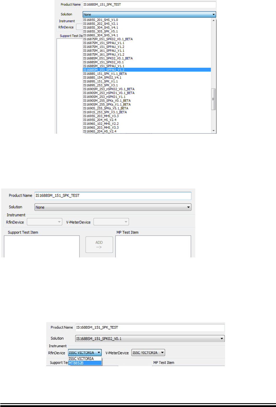
5.4.1 Select your solution
You can see all of solution when you drop-down the list. To select the solution that
suits your DUT (Device Under Test).
Advance Information
2015MicrochipTechnologyInc.
page35
FIGURE 5-3 MPSE Solution
5.4.2 Give your own product name
After selection of solution, MPSE will bring out the default Production Name You can
change it with your own production name.
FIGURE 5-4 MPSE Product Name
5.4.3 Select RF test instrument
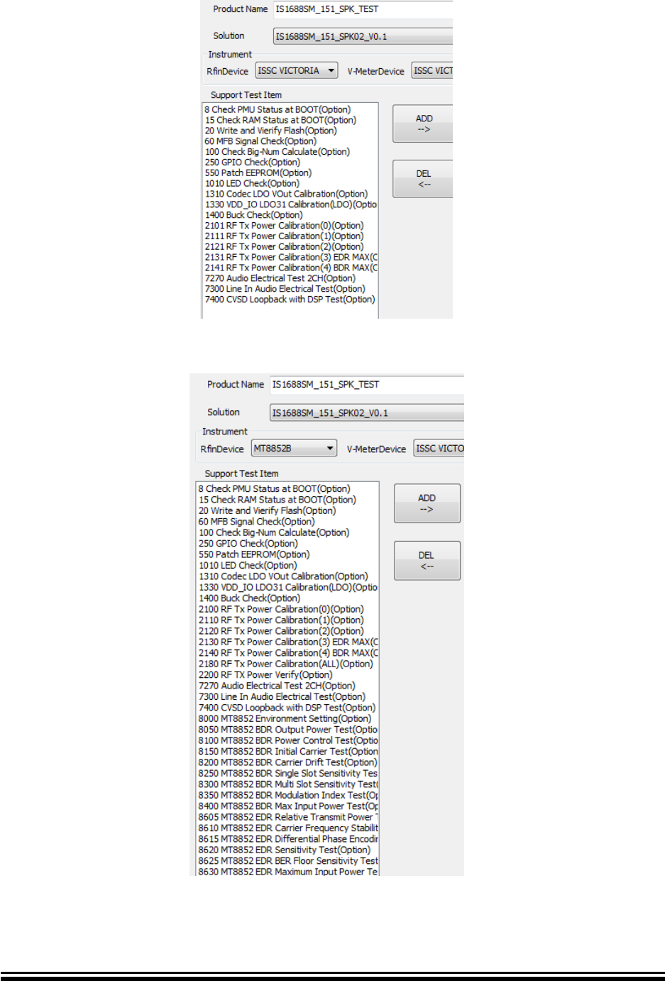
Base on your test environment to select RF test instrument. If your RF instrument
doesn’t show on the list, please contact your FAE to get more supporting.
The kind of RF test items will different when you changed RF instrument type.
FIGURE 5-5 MPSE RF Instrument
Advance Information
2015MicrochipTechnologyInc.
page36
FIGURE 5-6 MPSE RF GU Test Item
FIGURE 5-7 MPSE RF 8852 Test Item
Advance Information
2015MicrochipTechnologyInc.
page37
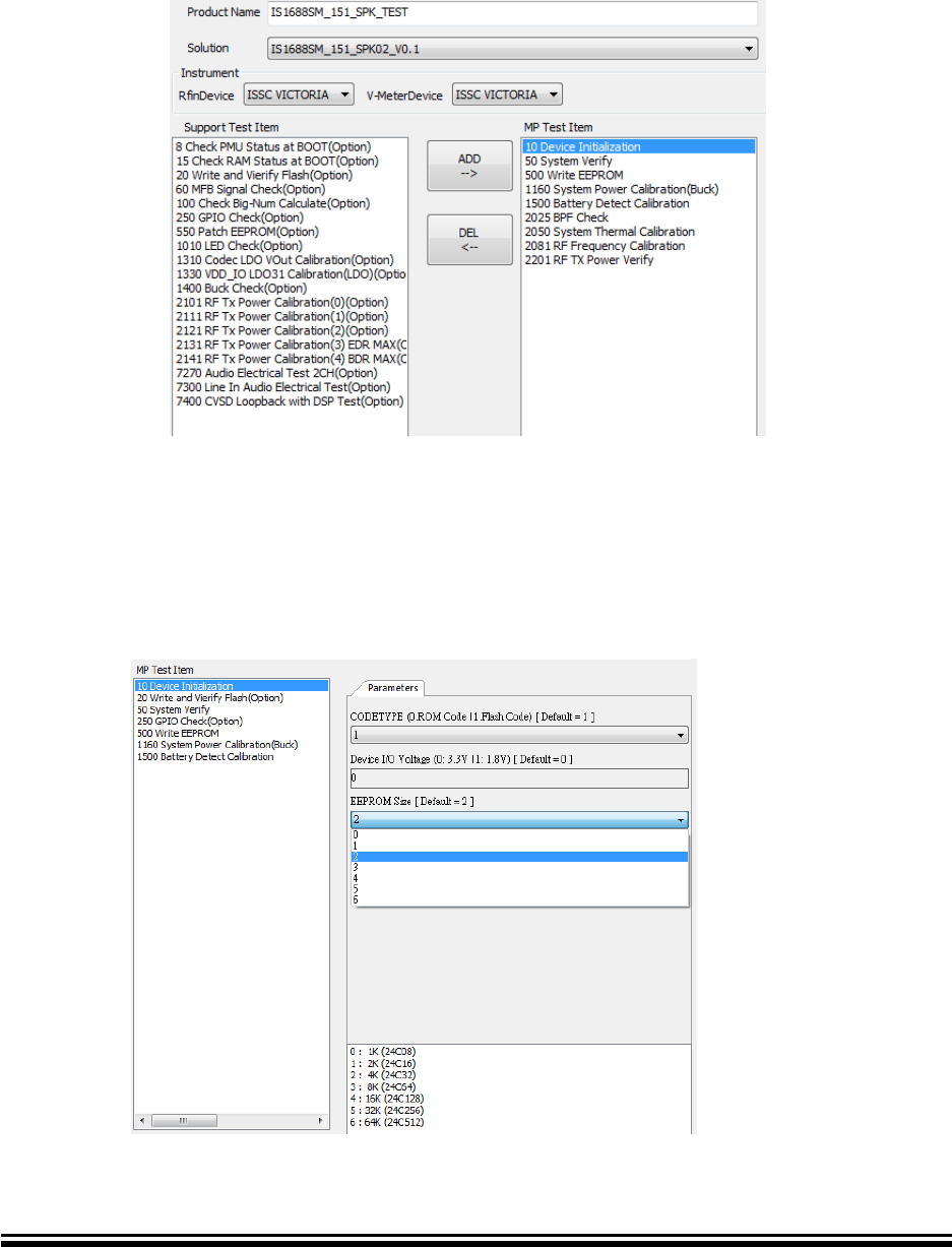
5.4.4 Choose test items for MP
Move the mouse cursor to test item in Support Test Item and left click. And then
Press “ADD” button to add item into MP Test Item. Repeat it until the items is enough
for your tests. Otherwise you can remove items you don’t want in MP Test Item with
“DEL” button.
FIGURE 5-8 MPSE Add Test Item
5.4.5 Configure test item’s parameter and limitation
Move the mouse cursor to test item in MP Test Item and left click. The item’s
parameters and limitation will show on Condition Area. That has default setting, you
can change it.
FIGURE 5-9 MPSE Test Condition
Advance Information
2015MicrochipTechnologyInc.
page38
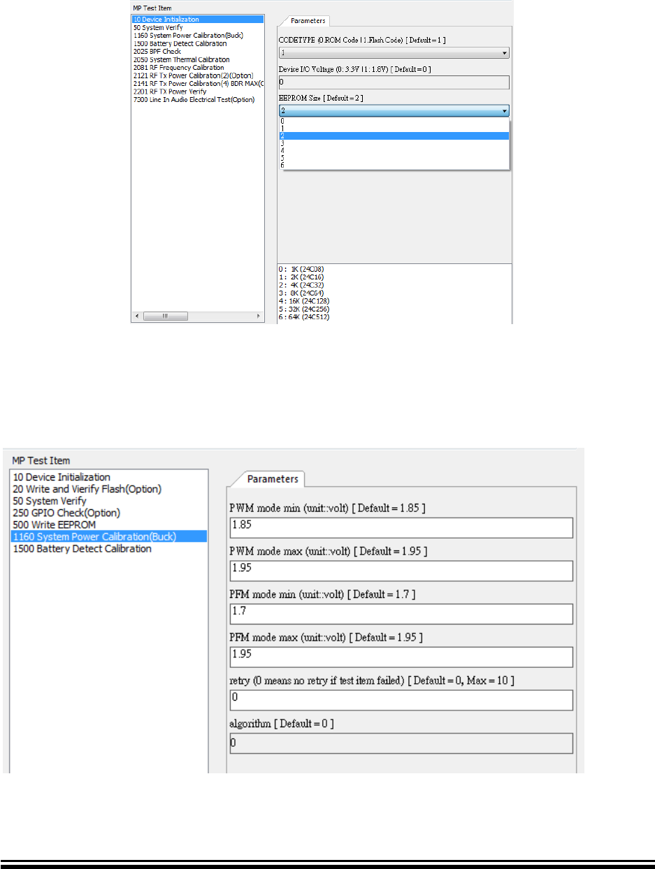
The MPSE has four type of editor:
- Select type
The option values are defined at RD stage. You just choose a fit one.
FIGURE 5-10 MPSE Editor Type - Select
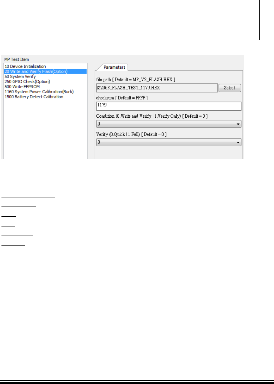
- Edit type
In this type, you can key value in editor. And tool will check validation after “SAVE”
button clicked.
FIGURE 5-11 MPSE Editor Type - Edit
Advance Information
2015MicrochipTechnologyInc.
page39
- File type
In this type, you need input specific file and key-in checksum.
Table 5-2 MPSE File Type
Extension File Name
ITEMs
Comment
HEX
20,9850,9870
Write Flash
BIN
500
Write EEPROM
IPF
550
Patch EEPROM
FIGURE 5-12 MPSE Editor Type - File
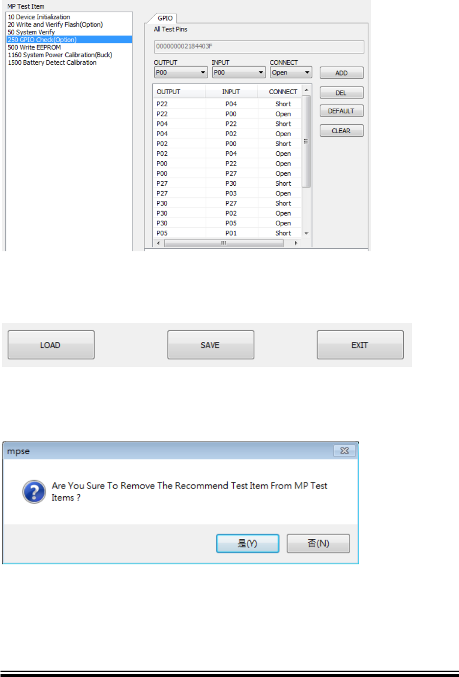
- GPIO type
This type is for Item 250 GPIO Check. Refer following comment:
OUTPUT/ INPUT: GPIO PIN selection.
CONNECT: test type Open/Short
ADD: add one test case in the list
DEL: delete selected test case in list
DEFAULT: Load back the default test cases list
CLEAR: clear test cases list
Advance Information
2015MicrochipTechnologyInc.
page40
FIGURE 5-13 MPSE Editor Type - GPIO
5.4.6 Save MP Script File (MSF)
Click “SAVE” button to save configuration as MSF. And you can click “LOAD” button
when you want to load back MSF. Click “EXIT” to close the tool.
5.5 FAQ
Q1 Why is there a warning message when we remove default test item from MP Test
Item list? How can I do?
A1 Because those test items are Microchip recommend that the basic test items.
This message just want user double check match your request。Click (Y) to remove
test Item. Otherwise click (N) to keep this test item.
Advance Information
2015MicrochipTechnologyInc.
page41
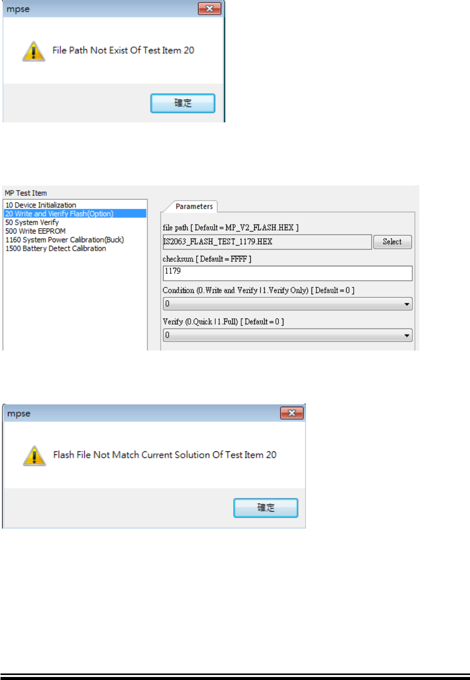
Q2 Why is there an error message when I save file?
A2 Please check Item 20 file path & checksum. File path can’t use default file. User
need select Flash.HEX file. Checksum can’t use default value. User need key-in
Flash.HEX checksum.
Q3 Why is there an error message when I save file﹖
A3 Please confirm the correct of the Flash.hex file.
The Flash.hex file didn’t match Solution name
Advance Information
2015MicrochipTechnologyInc.
page42
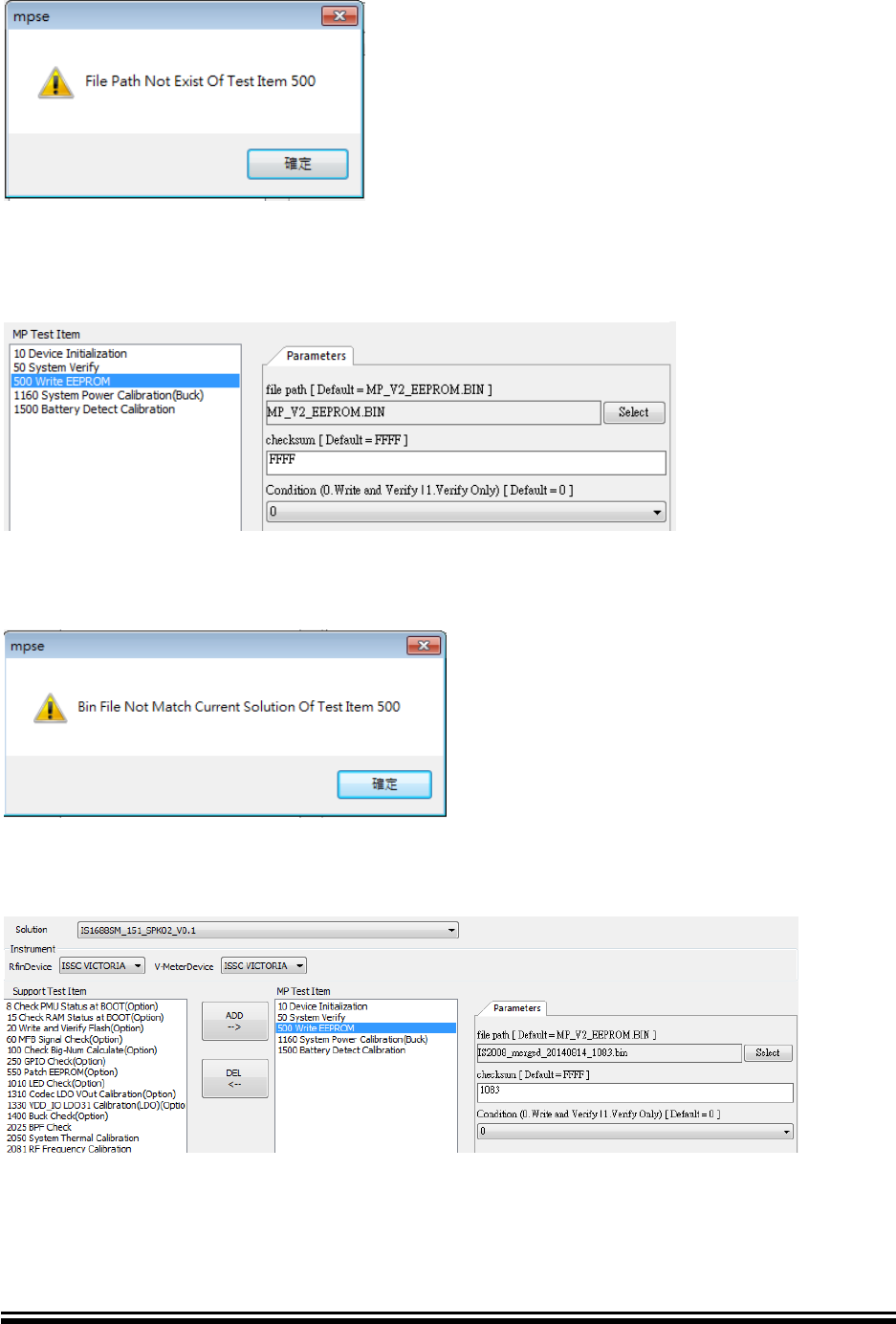
Q4 Why is there an error message when I save file?
A4 Please check Item 500 file path & checksum. File path can’t use default file. User
need select EEPROM.BIN file. Checksum can’t use default value. User need key-in
EEPROM.BIN checksum.
Q5 Why is there an error message when I save file?
A5 Please confirm the correct of the EEPROM.BIN file.
The EEPROM.BIN file didn’t match Solution name.
Advance Information
2015MicrochipTechnologyInc.
page43
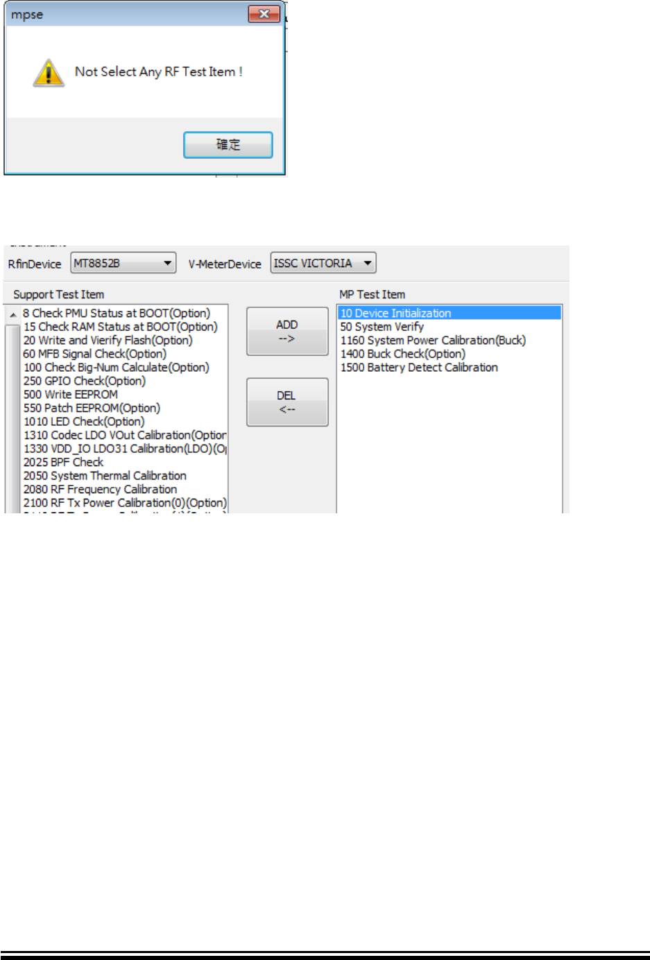
Q6 Why is there an error message when I save file?
A6 Please select any RF test item into MP Test Item list when you select MT8852B
instrument.
Advance Information
2015MicrochipTechnologyInc.
page44
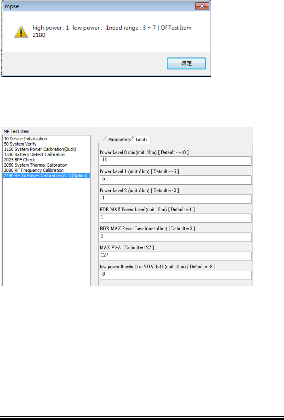
Q7 Why is there an error message when I save file?
A7 Please check Item 2180 Power level 0, 1, 2, EDR, BDR values. Please find High
power : 1 is EDR Max Power and Low power: -1 is power level 2.
EDR Power minus Power level2 to less than 7 and more than 3
The difference between each of power level need had 3 ~ 7
Advance Information
2015MicrochipTechnologyInc.
page45
Q8 Why is there an error message when I load file?
A8 The *.msf file had been modified without use the MPSE tool.
Please create new *.msf file.
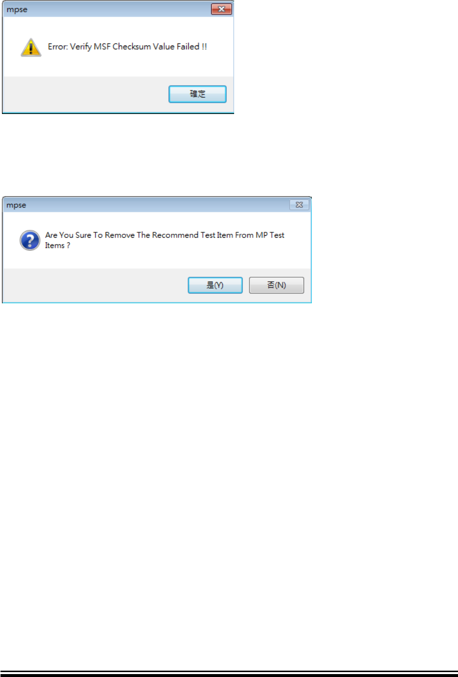
Q9 Why I got this warring message?
A9 When you remove the recommend test item from Microchip tool will show warring
message.
Advance Information
2015MicrochipTechnologyInc.
page46
BLUETOOTH MP TOOL
SOFTWARE USER GUIDE
Chapter 6 Mass Production Board level test Tool (MPBT)
The MPBT is major of MP tool. That executes testing and judges DUT by test result. This
chapter provides an Introduction and operation of MPBT. Topics covered include:
• Introduction
• Testing Environment Setup
• Configuration
• Run the Test
• FAQ
6.1 Introduction
This tool is used test DUT with MP Fixture. It will follow the script file (.msf) automatically
testing and calibration. After that, it will show result of DUT and save testing log.
FIGURE 6-1 Relationship of MPBT
6.2 Testing environment Setup
6.2.1 Single-Site

Advance Information
2015MicrochipTechnologyInc.
page47
FIGURE 6-2 RF Test with GU at Single-Site
FIGURE 6-3 RF Test with RF Tester at Single-Site
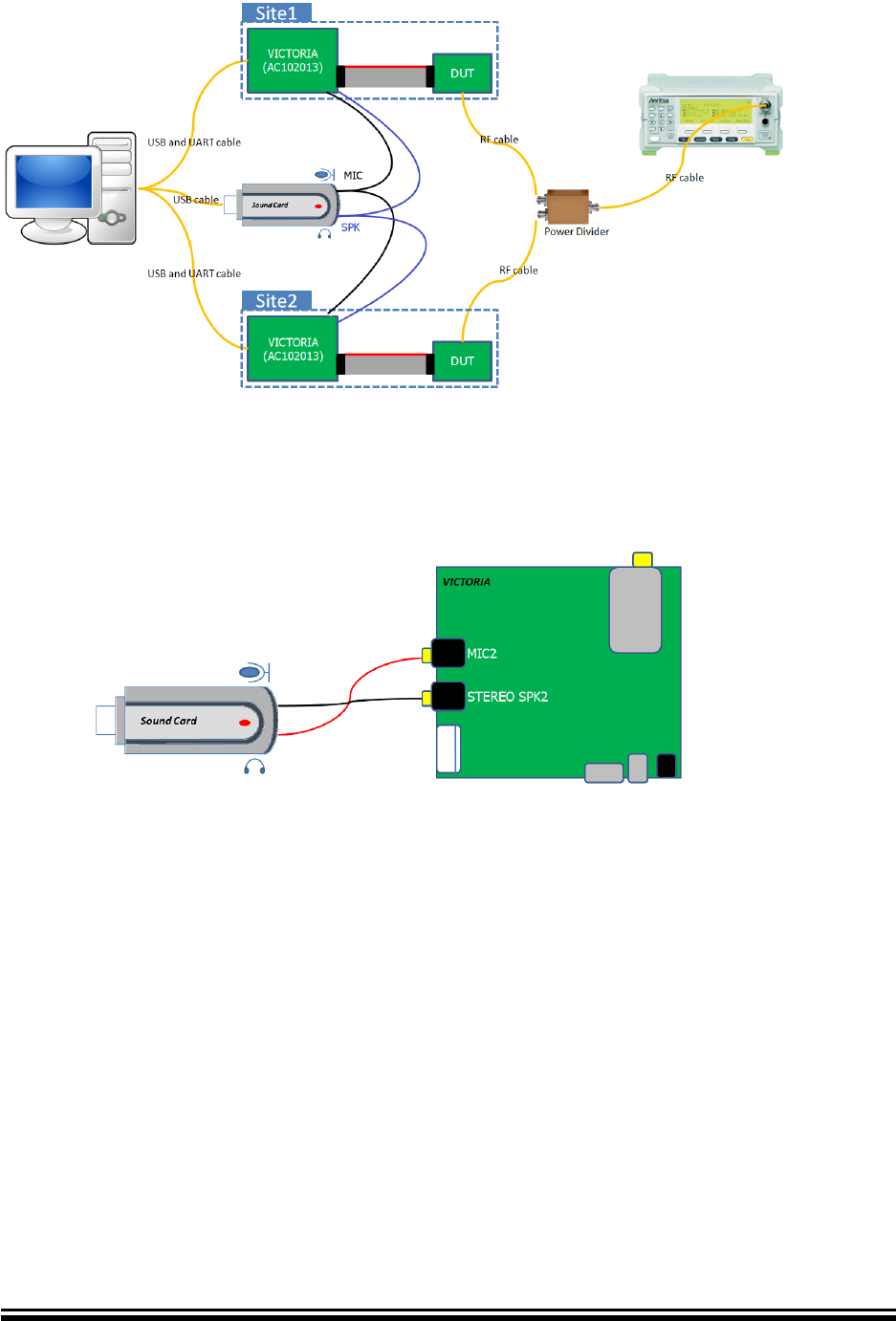
6.2.2 Dual-Site
FIGURE 6-4 RF Test with GU at Dual-Site
Advance Information
2015MicrochipTechnologyInc.
page48
FIGURE 6-5 RF Test with RF Tester at Dual-Site
6.2.3 Sound Card connection
FIGURE 6-6 Connection audio cable between Soundcard and AC102013
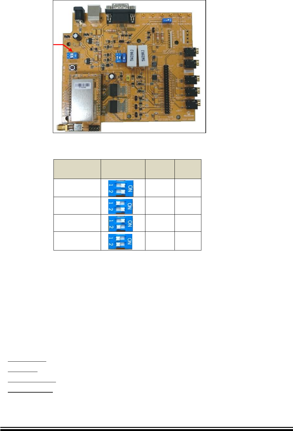
6.2.4 VICTOIRA Identification
In Dual-Site test environment, you need configure the switch (SW) for identification
of VICTORIA. Please refer Table 6-1.
Advance Information
2015MicrochipTechnologyInc.
page49
FIGURE 6-7 VICTORIA Overview
Table 6-1 VICTORIA Identification
Site
Number
Side
Switch
1
2
1 (default)
ON
ON
2
OFF
ON
3
ON
OFF
4
OFF
OFF
More details for VICTORIA (PN: AC102013), please refer Bluetooth MP Board
AC102013 User Guide you find it from Microchip web site.
6.3 Configuration
The MPBT configuration is divided into several tabbed pages. Each page includes a
parameter summary which allows the user to keep track of the changes made.
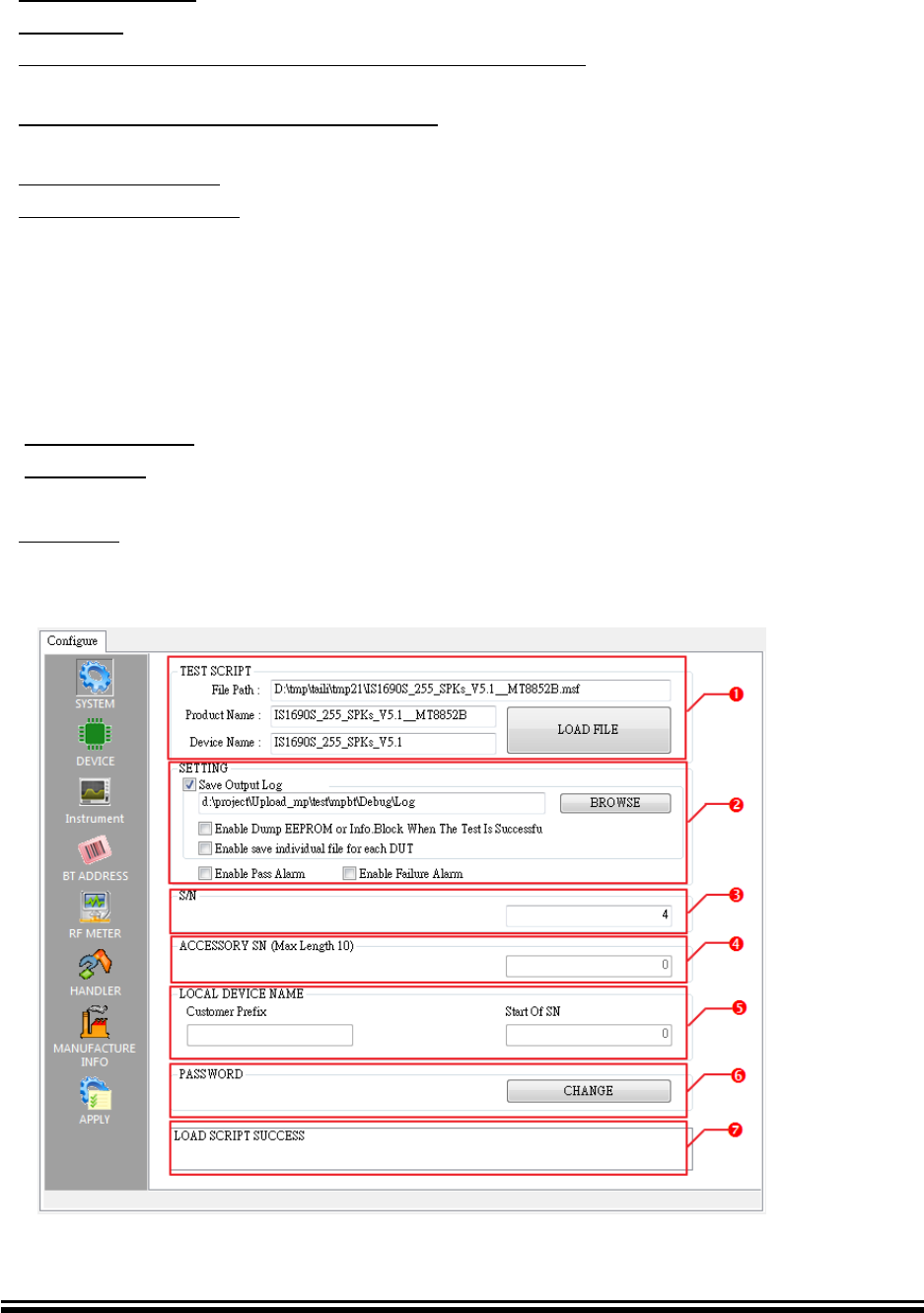
6.3.1 SYSTEM Page
TEST SCRIPT
LOAD FILE button: Input .msf file, after load file show other pages
File Path: file location of msf
Product Name: name of product
Device Name: name of DUT
Side SW
Advance Information
2015MicrochipTechnologyInc.
page50
SETTING
Save Output Log: Enable MP testing log
BROWSE button: Select log file location
Enable Dump EEPROM When The Test Is Successful: Dump EEPROM table when
test result is Pass.
Enable save individual file for each DUT: Save every individual test log file into Pass
folder or Fail folder when test finish.
Enable Pass Alarm: Alarm when test result is Pass
Enable Failure Alarm: Alarm when test result is Fail.
S/N
Begin of Serial Number
ACCESSORY SN
Product Serial Number (Maximum is 10 numbers)
LOCAL DEVICE NAME
When .msf has ITEM 595 Write Local Device Name, It will enable
Customer Prefix: Set Device Name
Start Of SN: When enable Device Name with SN, it will enable
PASSWORD
CHANGE button: Changes the password of LOAD FILE
STATUS of configurations
FIGURE 6-8 SYSTEM Configure Page
Advance Information
2015MicrochipTechnologyInc.
page51
6.3.2 DEVICE Page
Site Number: Select platform number, 1: Single-Site, 2: Dual-Site
Shielding Box:
NONE_SBOX: No uses
GIT_SBOX: Use kind of GIT_SBOX shielding box. Global Instrument Tech
SITE 1
Access Port
COM Port: Set DUT’s UART port number
Baud Rate: Set DUT’s UART baud rate
Information: Set SITE1 information, this data will save in Log.
Box Port
COM Port: Set shielding box UART port number
Baud Rate: Set shielding box UART baud rate
GIT_BOX baud rate is 9600
SITE 2 is as above SITE1.
FIGURE 6-9 DEVICE Configure Page
Advance Information
2015MicrochipTechnologyInc.
page52
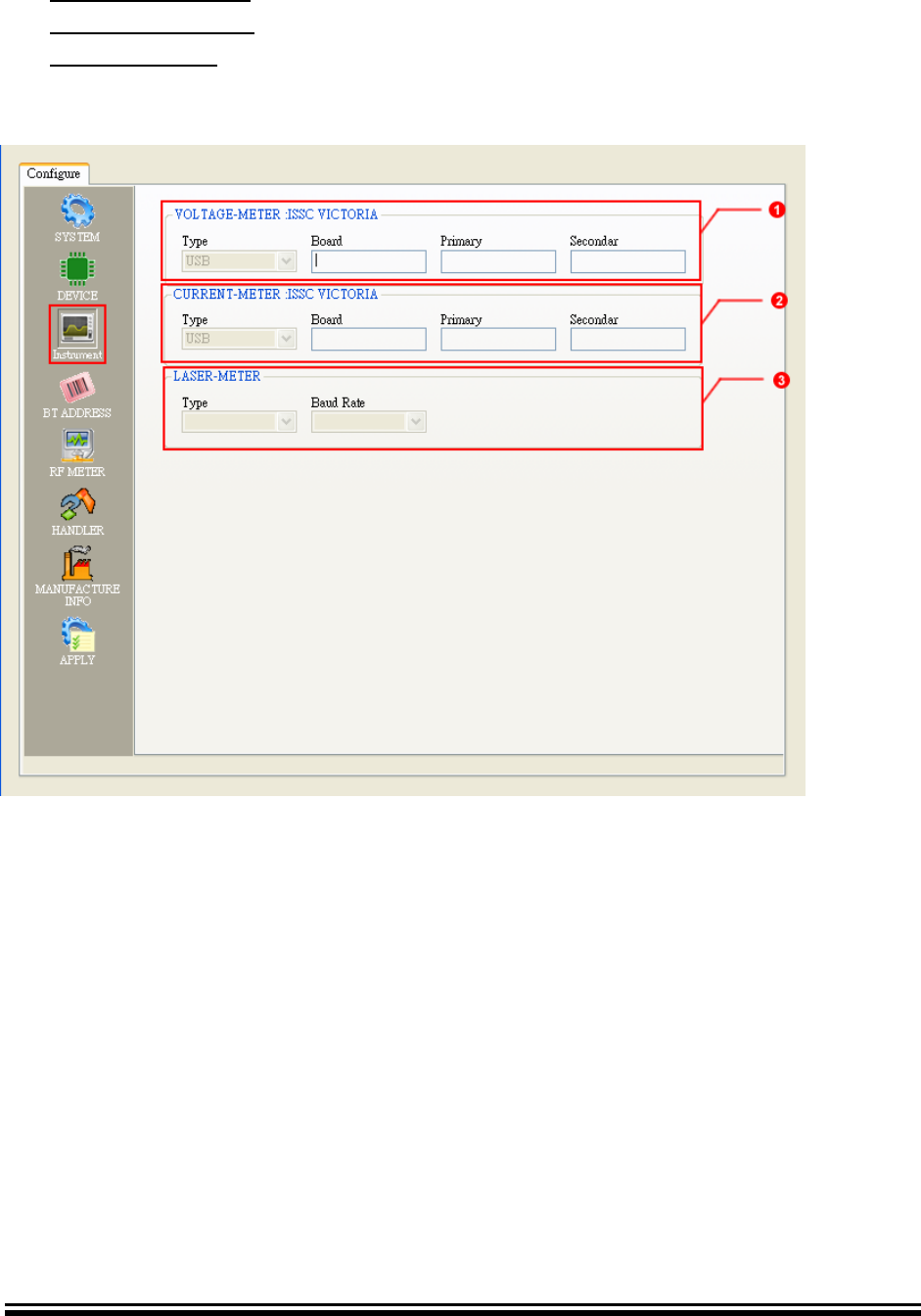
6.3.3 INSTRUMENT Page
VOLTAGE-METER: Only support Microchip BT MP Test Board AC102013.
CURRENT-METER: Only support Microchip BT MP Test Board AC102013.
LASER-METER: No Use.
FIGURE 6-10 INSTRUMENT Configure Page
Advance Information
2015MicrochipTechnologyInc.
page53
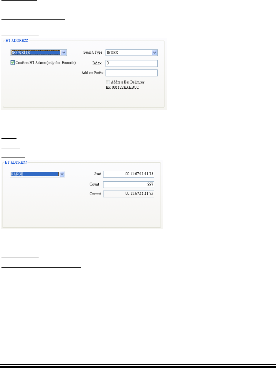
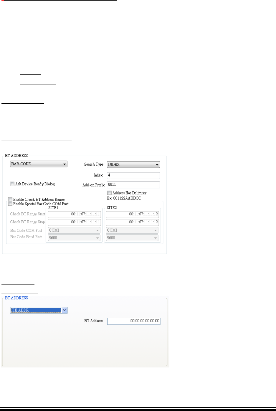
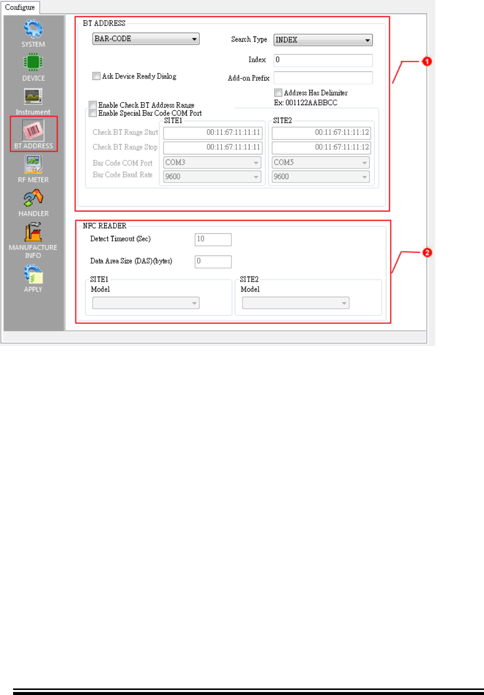
6.3.4 BT ADDRESS Page
BT ADDRESS: MPBT supports six type of DUT’s BT address writing. Please refer
following description
NO WRITE:
No write (no change) DUT BD Address after testing.
Confirm BT Address: This option used to verifies DUT’s existing BT Address
connection. And it needs Barcode Reader. About Barcode configuration, please refer
BAR-CODE type.
RANGE:
Start: Beginning of BT Address
Count: Amount of BT Address
Current: Current use BT Address
BAR-CODE:
Ask Device Ready Dialog: When option is enabled (checked) MPBT will appear a
dialog to ask operator to start the test. Therefore, operator has time to input DUT in
fixture when barcode label is hard to read.
Enable Check BT Address Range: User can define the “Check BT Range Start” and
“Check BT Range Stop” range. After run finish, MP will check input Barcode need in
the Range. The Site1 range and Site2 range can’t repeat region.
Advance Information
2015MicrochipTechnologyInc.
page54
*Enable Special Bar Code COM Port: User can define the “Bar Code COM Port” and
“Bar Code Baud Rate”. MP will inquire this com port data. If MP get data (BT Address)
from COM port, MP will used this data and start test flow.
*Note: 1. This function just for special bar code scanner.(SUNITEC)
2. This function only available in the dual mode.
Search Type: The parser for BT address in Barcode label.
INDEX: BT Address start point (index origin = 0)
KEYWORD: Keyword of BT Address in Barcode label
Add-on Prefix: Input fixed BT Address, it will merged with read data of Barcode label
(maximum is 12 numbers)
Ex: Add-on Prefix 001167, Barcode read 123456 => 001167123456
Address Has Delimiter: Barcode and Add-on Prefix has delimiter symbol.
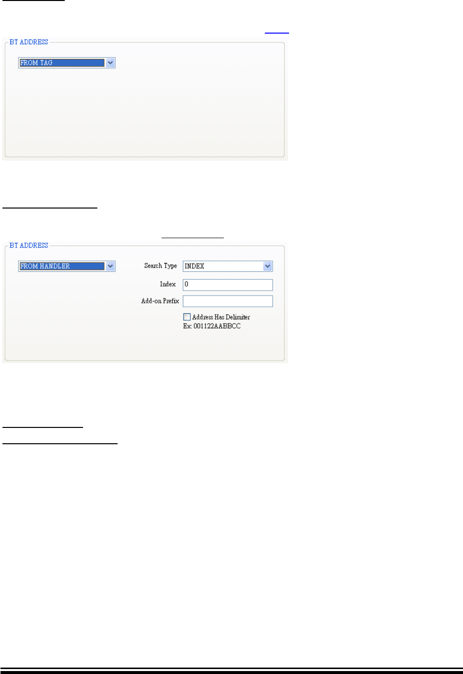
FIX ADDR:
BT Address: Input fixed BT Address.
Advance Information
2015MicrochipTechnologyInc.
page55
FROM TAG:
Read BT Address from NFC Tag. Note that, this type needs NFC Reader.
MPBT support NFC Reader: ACS ACR 122 (visit: ACS)
FROM HANDLER:
If Auto-Handler can provide a BT Address, you can choose this type. That also needs
Barcode parser. (Please refer BAR-CODE type)
NFC READER
Detect Timeout: limited detect tag. (sec)
Data Area Size (DAS): Set NFC tag’s size. When .msf include ITEM 9800 it will
enable
SITE1: Select model of NFC reader
SITE2: As above SITE1
Advance Information
2015MicrochipTechnologyInc.
page56
FIGURE 6-11 BT ADDRESS Configure Page
Advance Information
2015MicrochipTechnologyInc.
page57
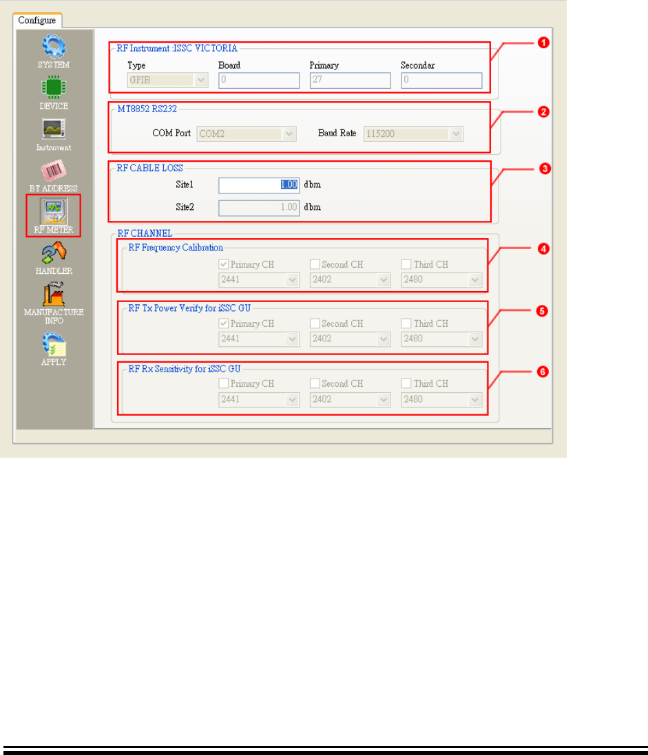
6.3.5 RF METER Page
RF METER: RF instrument setting
MT8852 RS232: MT8852 COM port and Baud rate setting
RF CABLE LOSS: SITE 1 and SITE2 RF cable loss
RF Frequency Calibration: Channel of Frequency calibration. (Enable depend on
MSF setting)
RF Tx Power Verify: Channel of Tx power. (Enable depend on MSF setting)
RF Rx Sensitivity: Channel of Rx sensitivity. (Enable depend on MSF setting)
FIGURE 6-12 RF METER Configure Page

Advance Information
2015MicrochipTechnologyInc.
page58
6.3.6 HANDLER Page
MODE: Select DUT exchange type. MPBT support three modes. Please refer
Table 6-2 Auto-Handler
Table 6-2 Auto-Handler Name and Interface
Name
Interface
Parameter
Note
MANUAL
N/A
N/A
Operator changed by hand
HT3000
RS232
COM port
GIT_ATS
.ini file
Ini Folder
Refer Appendix B more detail
Handler No: Set Handler number. This number will save in Log.
COM Port: UART COM port number
Baudrate: UART baud rate
*Ini Folder: .ini files location. (Barcode.ini, EOT.ini, SOT.ini, Status.ini)
*Note: After APPLY process will auto create SITE1 folder to store these .ini files.
(SITE2 folder for second site if site number is 2. Refers 6.3.2 DEVICE Page)
ASSIGN BIN LIST: BIN table. Table change flow:
1. Select Test Item
2. Select BIN number
3. Click MODIFY button to save new setting on list
FIGURE 6-13 HANDLER Configure Page

Advance Information
2015MicrochipTechnologyInc.
page59
6.3.7 MANUFACTURE INFO Page
INFORMATION: Save the list data in Log’s title
Ex: WorkingOrder:WO123
Load button: Input Manufacture Information text file
Text Format: [Name], [Data]
EX: WorkingOrder, WO123
ManufactureOrder, MO456
Clear button: Clear list
FIGURE 6-14 MANUFACTURE INFO Configure Page
Advance Information
2015MicrochipTechnologyInc.
page60
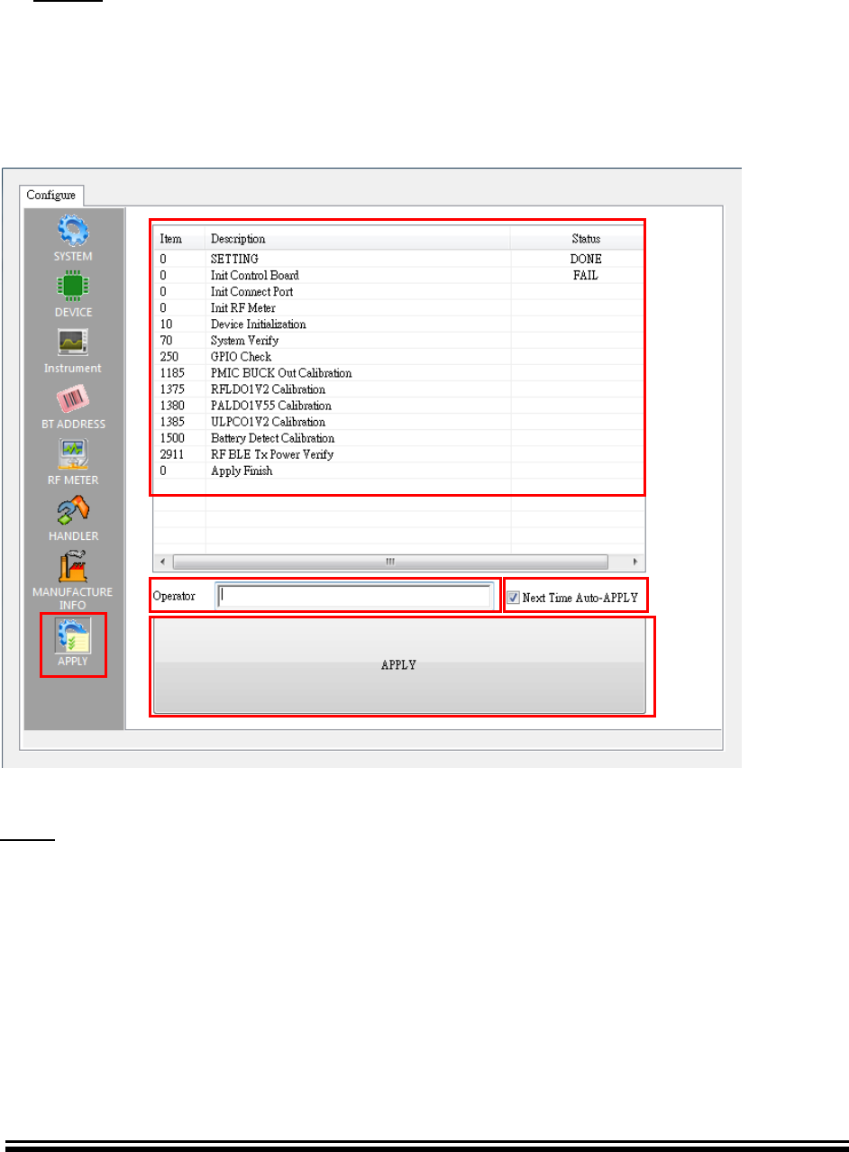
6.3.8 APPLY Page
1. List of test item and test environment check result
2. OPERATOR: Input Operator’s ID, This ID will save in Log
3. APPLY button: Apply all of setting.
4. Next Time Auto-APPLY: auto apply last setting when this option enabled.
Click TEST Page start test
FIGURE 6-15 APPLY Configure Page
TEST page will appeared next to Configure page when all setting is OK.
1
2
3
4

Advance Information
2015MicrochipTechnologyInc.
page61
FIGURE 6-16 TEST Page
6.4 Run the Test
6.4.1 Put Device Under Test (DUT) in Socket
Put DUT in MP fixture’s socket before you run the MP testing.
FIGURE 6-17 DUT Into Socket
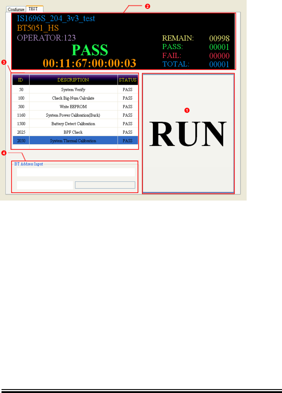
6.4.2 Single-Site Test Page
RUN button: Start test button
Testing information
FIGURE 6-18 Single-Site Testing Information
(REMAIN enabled when BT ADDRERSS type is RANGE)
Test items and status.
Statistics
Project Name
Result
Written BT Address
Device Name
Advance Information
2015MicrochipTechnologyInc.
page62
Bar-Code input area, when BD Address type is BAR-CODE.
FIGURE 6-18 Single-Site TEST Page

Advance Information
2015MicrochipTechnologyInc.
page63
6.4.3 Dual-Site Test Page
SITE1:
RUN: Start test.
SITE1 test result and written BT Address.
SITE2:As above SITE1
Information
FIGURE 6-20 Dual-Site Testing Information
(REMAIN enabled when BT ADDRERSS type is RANGE)
Bar-Code input area, when BD Address is BAR-CODE mode.
FIGURE 6-21 Dual-Site Test Page
Project Name
Device Name
Statistics
Advance Information
2015MicrochipTechnologyInc.
page64
6.4.4 Dual-Site Test Page for Special Bar Code COM Port
Key-in “START”. MP start to inquire bar code data.
SITE1: bar code scanner input BT Address to start test.
SITE1 test result and written BT Address.
SITE2: As above SITE1.
Information
Key-in “STOP”. MP stop to inquire bar code data.
FIGURE 6-22 Dual-Site Testing Information
(REMAIN enabled when BT ADDRERSS type is RANGE)
FIGURE 6-23 Dual-Site Test Page
Project Name
Device Name
Statistics
Advance Information
2015MicrochipTechnologyInc.
page65
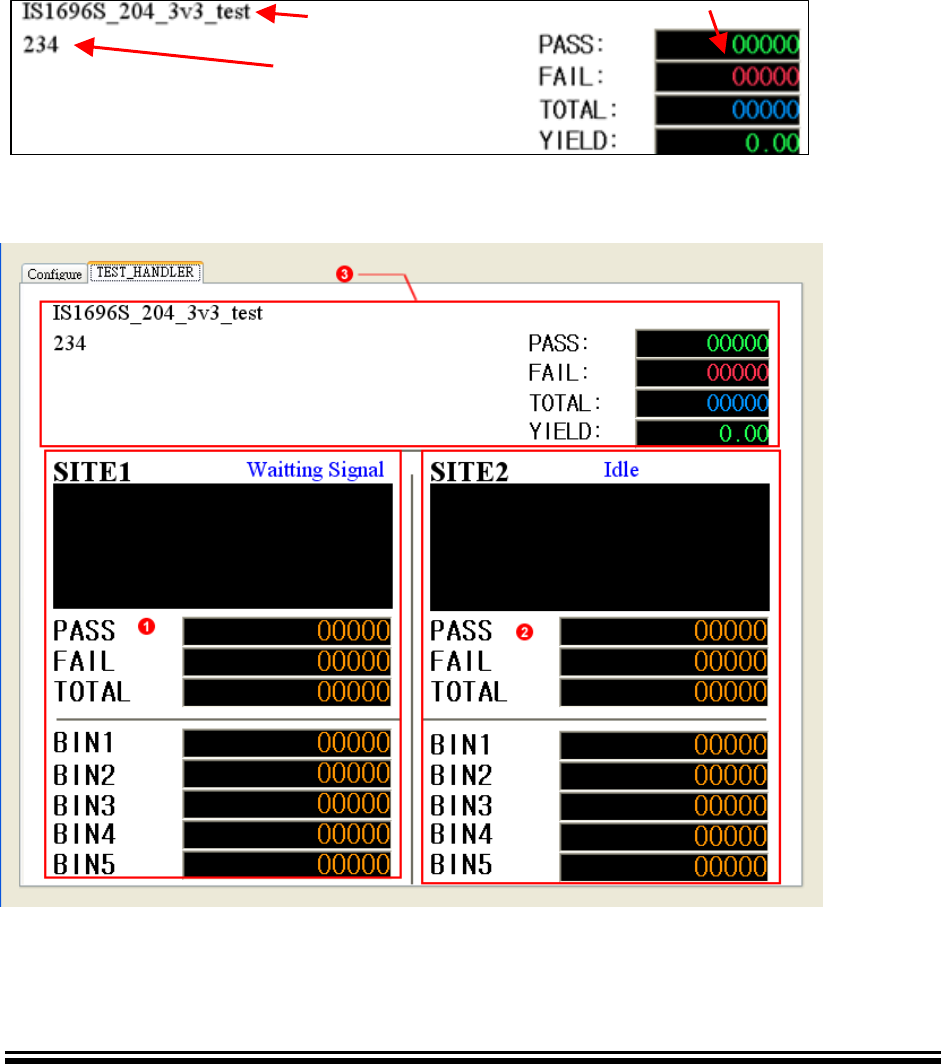
6.4.5 Auto-Handler Test Page
SITE1:
Test result and Information
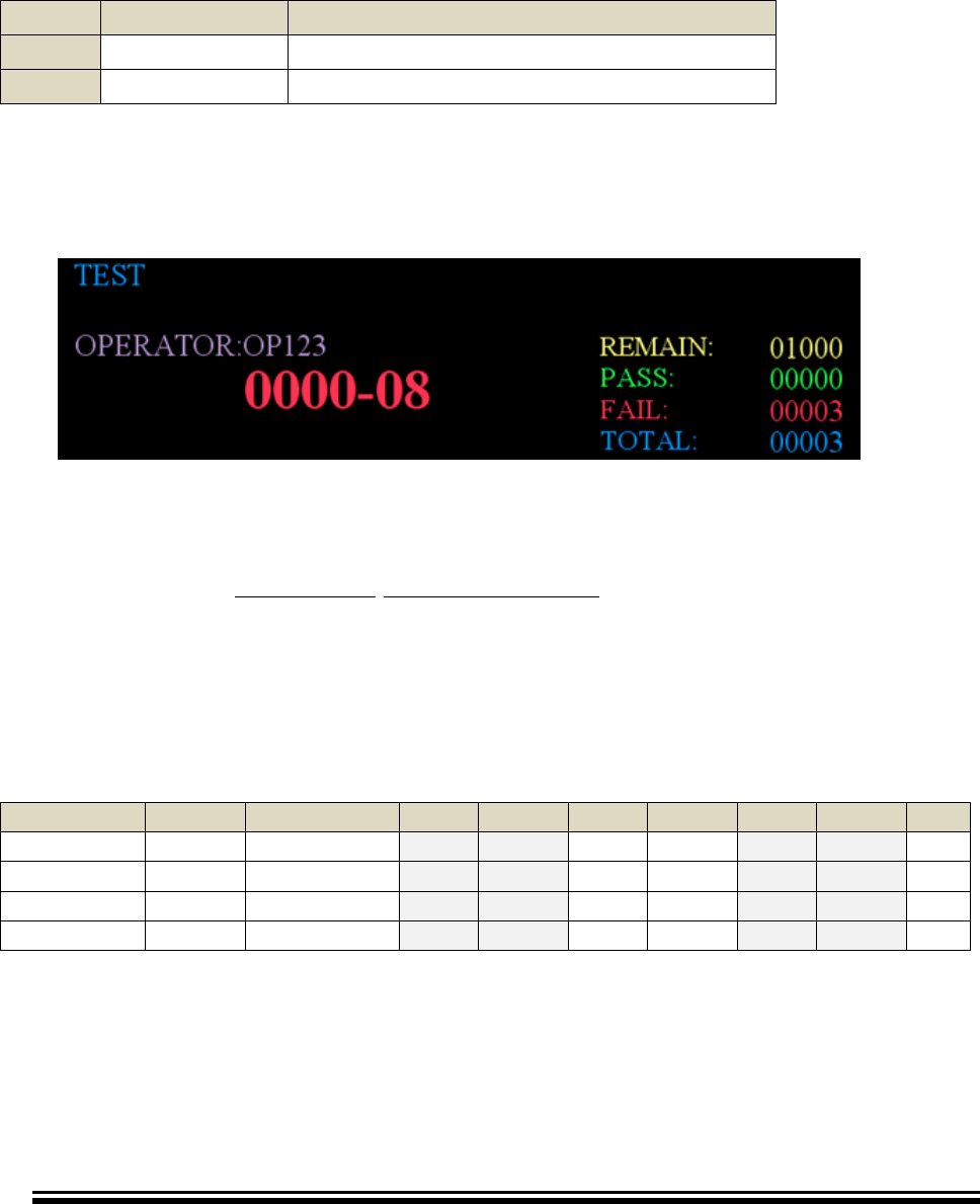
Result statistic includes PASS, FAIL and TOTAL.
Binning information the blue color means last one
SITE2: As above SITE1
Test information
FIGURE 6-24 Auto-Handler Testing Information
FIGURE 6-25 Auto Handler Test Page
Project Name
Device Name
Statistics
Advance Information
2015MicrochipTechnologyInc.
page66
6.5 Error-Code
When DUT occurs some error at testing process, MPBT will show error-code on test
information area.
The Error-Code consists of Main Error Code and Sub Error Code. Main Error Code is
equal the test item number. Sub Error Code represents that what kind of error type. For
example, Error code 1500-00.
Table 6-3 Error-Code Description Sample
Error Code
Description
Main
1500
Battery Detect Calibration test item
Sub
00
Calibration value Out of limitation
Please refer Mass Production Test Tool release note.pdf section MPBT Error Code for
more details
FIGURE 6-26 Error-Code
6.6 Test Log
File name consist of ProjectName-YYMMDDHHMMSS.csv. You can change the file
path at SYSTEM configure page.
The log has all of test data, like test result, error-code, testing time, measured data and
pass condition. And append each test item at left site. The log’s order is depend on MP
script file (MSF).
Table 6-25 Test Log sample
BTADDRESS
RESULT
ERRORCODE
ITEM
VALUE
ITEM
VALUE
ITEM
VALUE
…
DUT NO1
PASS
0
500
xx
1500
xx
2080
xx
…
DUT NO2
FAIL
1500-00
500
xx
1500
xx
2080
xx
…
DUT NO3
PASS
0
500
xx
1500
xx
2080
xx
…
…
…
…
…
…
…
…
…
…
…
6.7 FAQ
Q1 How to change Operator’s ID after APPLY?
A1 On TEST page push F8 Key, and shows dialog of operator ID
Advance Information
2015MicrochipTechnologyInc.
page67
Q2 What can I do if show “Please First Input Tester Id” on APPLY page?
A2 Please input the Operator ID before push APPLY button
Q3 It shows “connect VICTORIA (Site1/Site2) failed” on APPLY page, How can I do?
A3 Please check the SITE1 (SITE2) fixture (VICTORIA/VENUS) is power on, connected
and switch (switch please refer 3. Control Board Setting)
Q4 What mean is this dialog on APPLY?
A4 Please makes sure all of instrument is ready before you press APPLY button. Ex:
Device, Audio Card, MT8852 and so on.
Q5 When I use BAR-CODE mode to input BT Address, I already scan the barcode of BT
Address but it doesn’t run test?
A5 Because MPBT support multi-site test, so you need to notice MPBT which Site is on
Advance Information
2015MicrochipTechnologyInc.
page68
test by scan barcode of SITE1 or SITE2 again.
Q6 My barcode length is small than 12 bytes, How to solve it?
A6 You can use the Add-on Prefix to full the BD Address to 12 bytes.
Ex: Barcode Address is “7808DF0”. You can input “00116” as Add-on Prefix, finally MPBT
will merge both to “001167808DF0”.
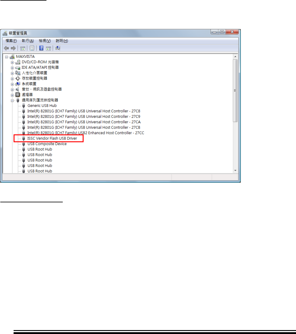
Q7 How to know Control board (VICTORIA) is ready?
A7 Have two versions:
VICTORIA 2.1:
You can see the Device Manager -> USB bus, If Control Board is ready, it will show
name of ISSC Vendor Flash USB Driver. If you have two or more Control Board and
you can see two names of ISSC Vendor Flash USB Driver, and so on.
VICTORIA 2.15/2.5:
Device Manager -> COM and LPT, If Control Board is ready, it will shows USB Serial
Port(COMx). (x means COM’s number). Just like USB bus, if you have two or more
Control Board you can see two names of COMx and so on.

Advance Information
2015MicrochipTechnologyInc.
page69
Q8 What is means of error code?
A8
Error
Code
Description
0000-10
The input BD Address is error
0000-50
The test item does not support
0000-51
Initial parameter error
0000-70
Create Log error
0000-71
Open Log error
****-98
Load test parameters error(*.msf)
More error code you can refer Release Note of each MP tools released:
ISSC Mass Production Test Tool_release_note.pdf
Q9 How many supported Test item MPBT have?
A9 Please refers Release Note of each MP tools released.
ISSC Mass Production Test Tool_release_note.pdf
Advance Information
2015MicrochipTechnologyInc.
page70
BLUETOOTH MP TOOL
SOFTWARE USER GUIDE
Chapter 7 Mass Production Multi Flash (MPMF)
The MPMF is a write multiple flash tool. This chapter provides an Introduction and
operation of MPBT. Topics covered include:
• Introduction
• Graphical User Interface
• Configuration
• Write the flash with multiple DUT
• FAQ
7.1 Introduction
This tool is used to write flash of multiple DUTs, and maximum to 8 DUTs at once. Duo
to write a flash take a lot of time, this is cost efficiency way to update the flash.
FIGURE 7-1 Relationship of MPMF
7.2 Graphical User Interface
Product Name: Product’s name, changeable by MPSE.
Checksum (FLASH): Checksum of FLASH file
Checksum (EEPROM): Checksum of bin file
PASS: Counter of Pass
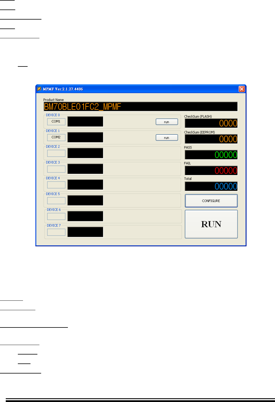
Advance Information
2015MicrochipTechnologyInc.
page71
FAIL: Counter of Fail
Total: Counter of total
CONFIGURE button: Open configuration dialog
RUN: Execute all of device testing
DEVICE 0~7
COM Port: Show Device’s COM Port
Result: Show testing result
run button: Single run
FIGURE 7-2 MPMF Main Page
7.3 Configuration Dialog
Browse button: Select path of MP Script File
Write Mode: MPMF supports two modes IBDK and BOOT to write the flash. Confirm the
device mode before your running.
Support Item Indicator: This table indicates that MPMF supported test item from MP
Script File (MSF).
DEVICE 0~7
Check: Enable (checked) select what Device you want to test
Port: Configure Device’s COM Port
Log Directory: Enable save log when test finish
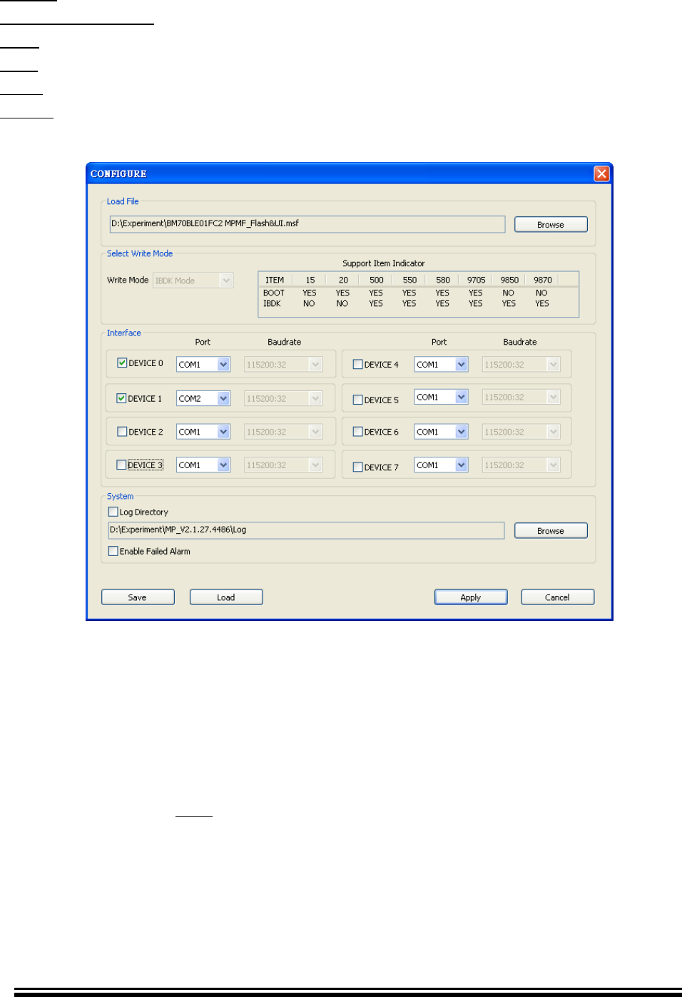
Advance Information
2015MicrochipTechnologyInc.
page72
Browse button: Select path of Log file
Enable Failed Alarm: Alarm when test fail
Save: Save current configuration into .ini file
Load: Load back configuration from .ini file
Apply button: Apply all of settings and leave configuration dialog.
Cancel button: Cancel the settings and leave configuration dialog.
FIGURE 7-3 MPMF Configure Page
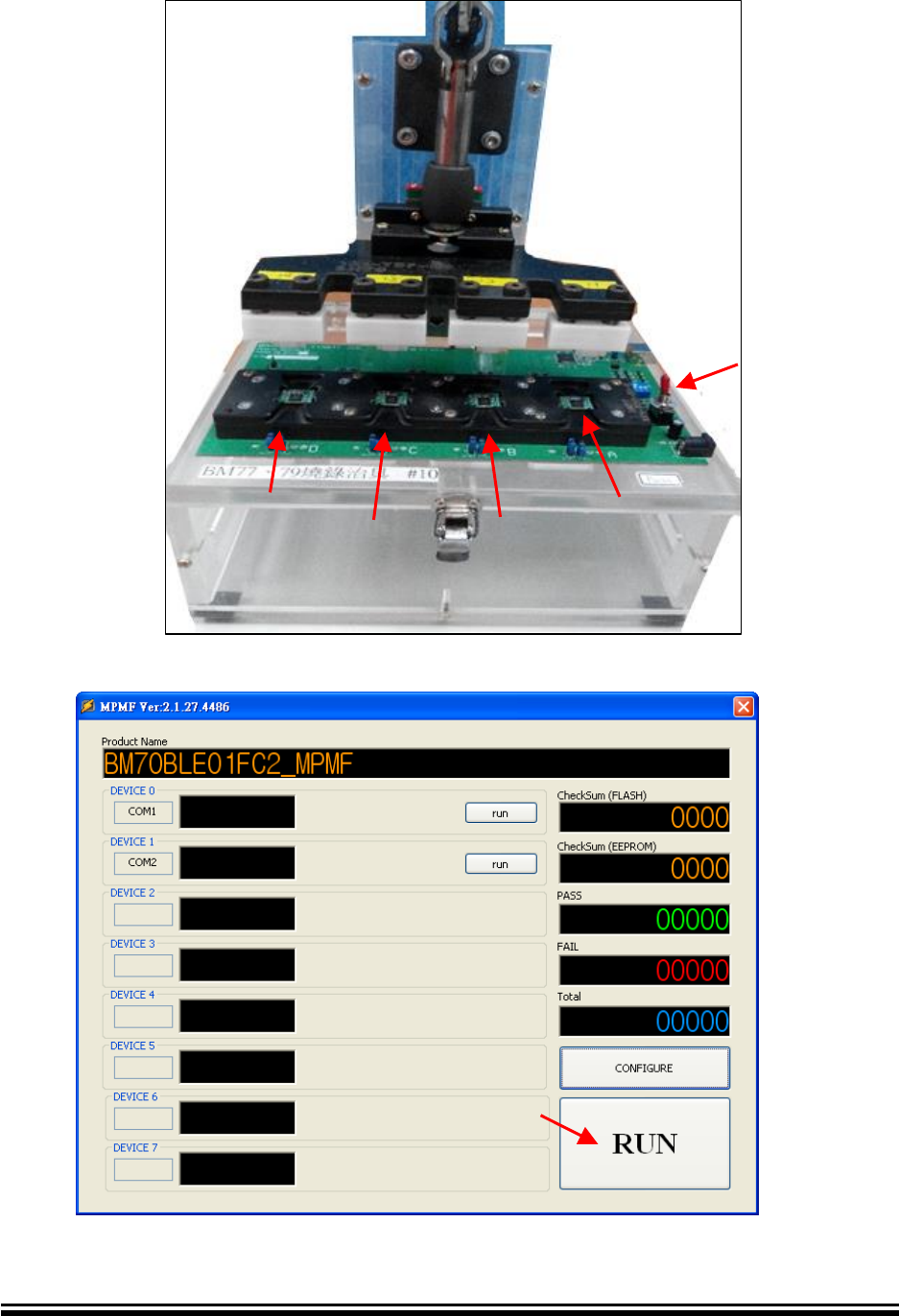
7.4 Write the Flash with Multiple DUTs
After configuration, please flow below step to write flash
1. Put DUTs into socket of MPMF fixture
2. Power on by switch
3. Press MPMF RUN button to write flash
4. Wait test result and change DUTs
Advance Information
2015MicrochipTechnologyInc.
page73
FIGURE 7-4 MPMF 1 to 4 Fixture
FIGURE 7-5 MPMF Main Page
Write Flash
Power Switch
DUT 4
DUT 3
DUT 2
DUT 1
Advance Information
2015MicrochipTechnologyInc.
page74
7.5 FAQ
Q1 Is MPMF support all of MPBT test item?
A1 No. Only support Write Flash and Write EEPROM related item. Please refer Support
Item Indicator at Configuration Dialog.
Q2 How to create .msf file?
A2 MPSE can creates .msf
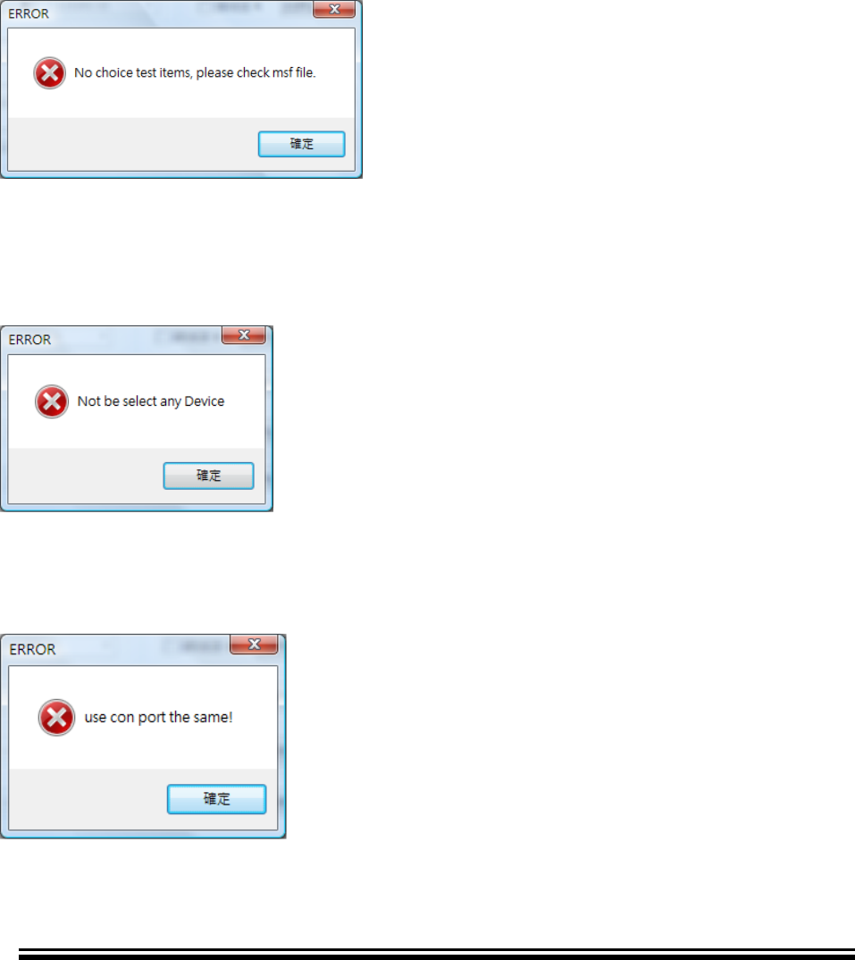
Q3 How to solve this problem?
A3 The .msf does not have any item of MPMP supported. Please confirm your test
items with MPSE
Q4 How to solve “Not be select any Device”?
A4 You have no select any device (Device 0~7) on Configuration dialog
Q5 How to solve “Use con port the same”
A5 The selected test Devices has same COM Port number. Please change COM Port.
Advance Information
2015MicrochipTechnologyInc.
page75
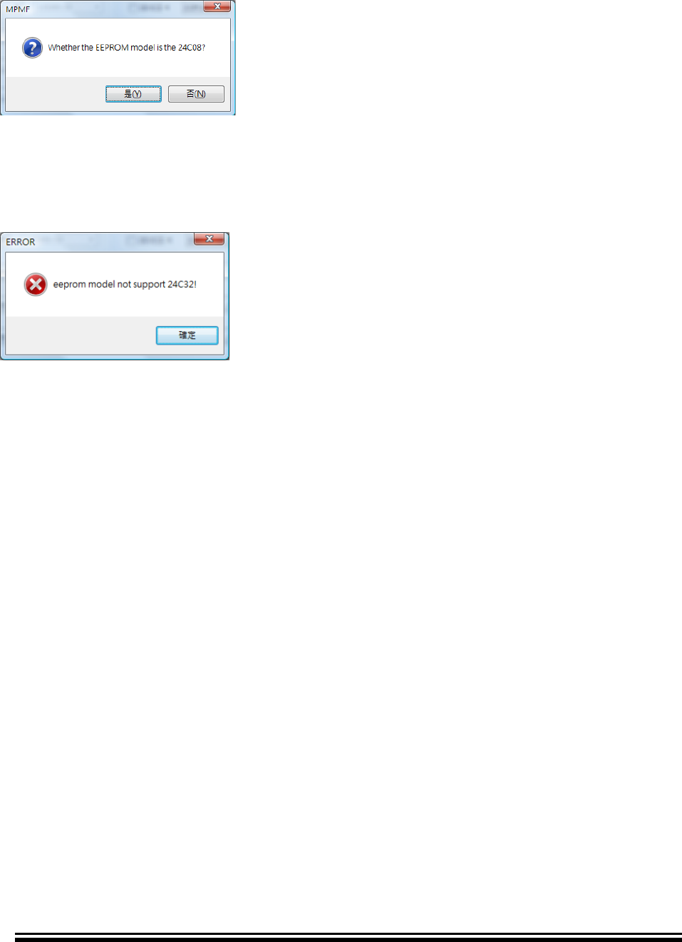
Q6 What is “Whether the EEPROM model is the 24C08”?
A6 This message is notice. Please double confirm your DUT’s EEPROM size is 1k
bytes (24C08).
Q6 How to solve “EEPROM model not support 24C32”?
A6 MPMF does not support write EEPROM size over 1k bytes at BOOT mode

Advance Information
2015MicrochipTechnologyInc.
page76
BLUETOOTH MP TOOL
SOFTWARE USER’S GUIDE
Appendix A. Revision History
REVISION HISTORY
Revision 3 (May, 2016)
Add Appendix B MPBT communicate with customer’ tool for automatically
testing.
Add Auto-Apply feature at MPBT APPLY page section.
Revision 2 (Oct, 2015)
Added the Quick Link page at cover to link each sub MP tool quickly.
Renamed the Figure of MP Tool overview
Revision 1 (Aug, 2015) Initial Release of this document

Advance Information
2015MicrochipTechnologyInc.
page77
BLUETOOTH MP TOOL
SOFTWARE USER GUIDE
Appendix B. MPBT Communicate with Customer’s tool
PREFACE
The GIT_ATS (Global Instrument Tech – Auto Test Station) is one of MPBT
communication types to communicate with outside tool (such as customer’s testing tool
and robot handler). And then, become an automatic testing system.
When this feature enable, MPBT will be entering standby mode and wait customer’s tool
instruction through the .ini file. Once testing finish, MPBT log testing data and notice
customer’ tool through .ini as well.
Please refer following sections for more detail description.

Advance Information
2015MicrochipTechnologyInc.
page78
INI FILEs
EOT.ini: (End of Test)
Create by MPBT after Status.ini setting done.
No any content.
Status.ini:
Create by MPBT when testing finish to save the testing results.
Content:
SOT.ini: (Start of Test)
Create by Customer’s Tool after Barcode.ini setting done.
No any content.
Barcode.ini:
Create by Customer’s Tool to set testing data (OP ID, BT ADDR…) to instruct
MPBT to start tests.
[Status]
TestResult=FAIL # test result
BIN=1 # BIN number, which Tray DUT in
SN=1 # Serial Number the same with Barcode.ini
YieldRate=90 # Yield Rate = YieldPass / YieldTotal * 100
YieldPass=9 # amount of PASS
YieldTotal=10 # amount of Tests
ErrorMessage=Error # Error Message when TestResult FAIL
ErrorCode=0000 # Error Code when TestResult FAIL
TestTime=3 # Testing Time (sec)
LogFilePath =d:\Log\xxx.csv # log path and file name.
[Data]
*MAC=001167123456 # BT Address will be update by this when test pass
OP_ID=10305001 # Operator’s ID
SN=1 # Serial Number
**DEVICE_NAME=name # Device Name will be update by this when test pass
Advance Information
2015MicrochipTechnologyInc.
page79
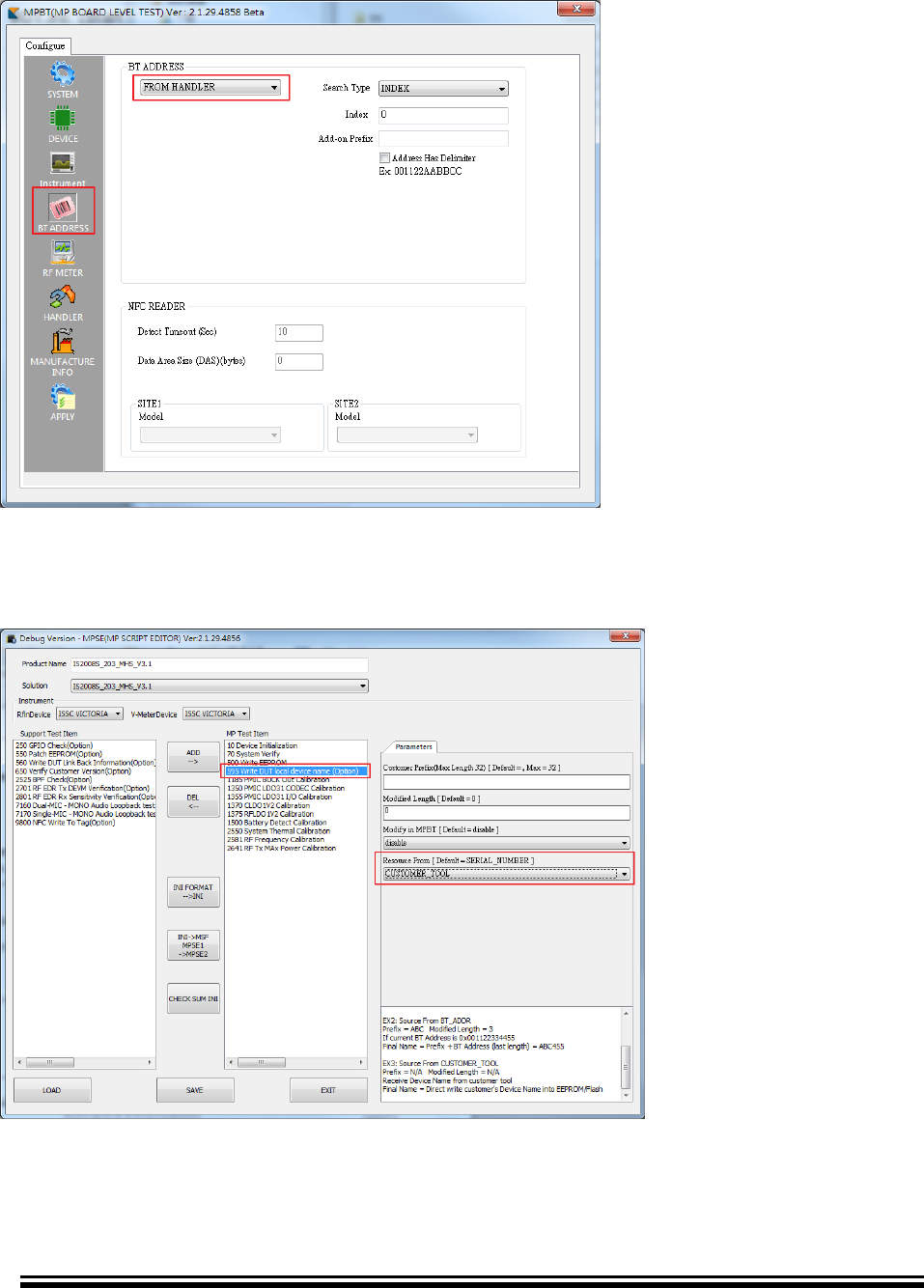
*Note: To send MAC address to MPBT via GIT_ATS protocol. You also need to
configure MPBT BT ADDRESS Page -> FROM HANDLER. Please refers below
screenshot
**Note: To send Device Name to MPBT via GIT_ATS protocol. You also need to select
Test Item “595 Write DUT local device name” and configure as Resource From ->
CUSTOMER_TOOL at MPSE. Please refers below screenshot
Advance Information
2015MicrochipTechnologyInc.
page80
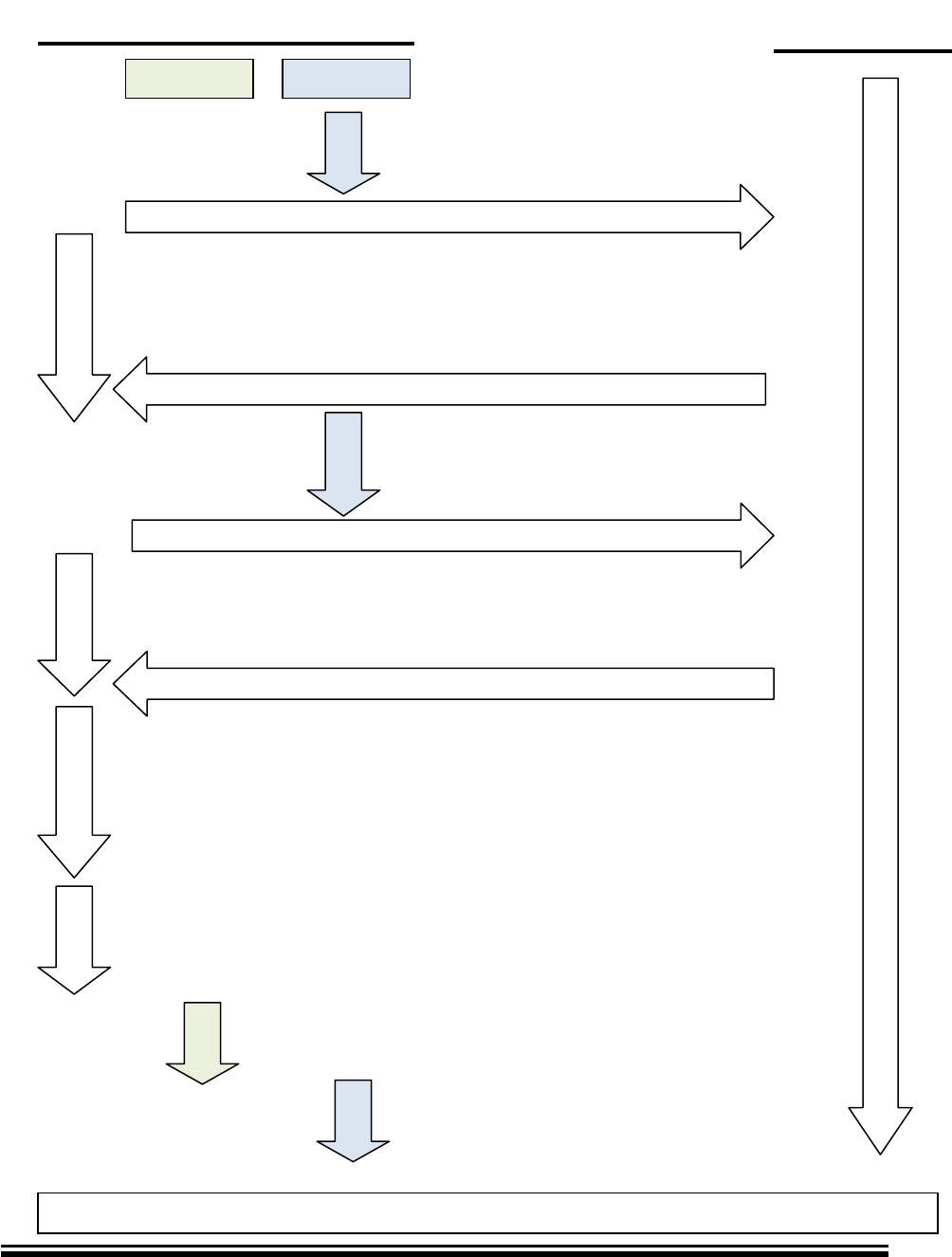
TIMING/ROLE DIAGRAM
MPBT Aspect:
Create
To notice Customer’ Tool that MPBT is at Test End state
Wait SOT created
To notice Customer Tool, MPBT was get Start instruction
SOT was Del?
Customer Tool deletes SOT, to notice MPBT, DUT was settled
Customer Tool Create SOT to notice MPBT Barcode.ini was set finish
Read Barcode.ini
Run Tests
Barcode.i
ni
Create
Create
Delete
Customer Tool
Customer Tool Behavior
Change Next Device
EOT.ini
Status.ini
MPBT
Advance Information
2015MicrochipTechnologyInc.
page81
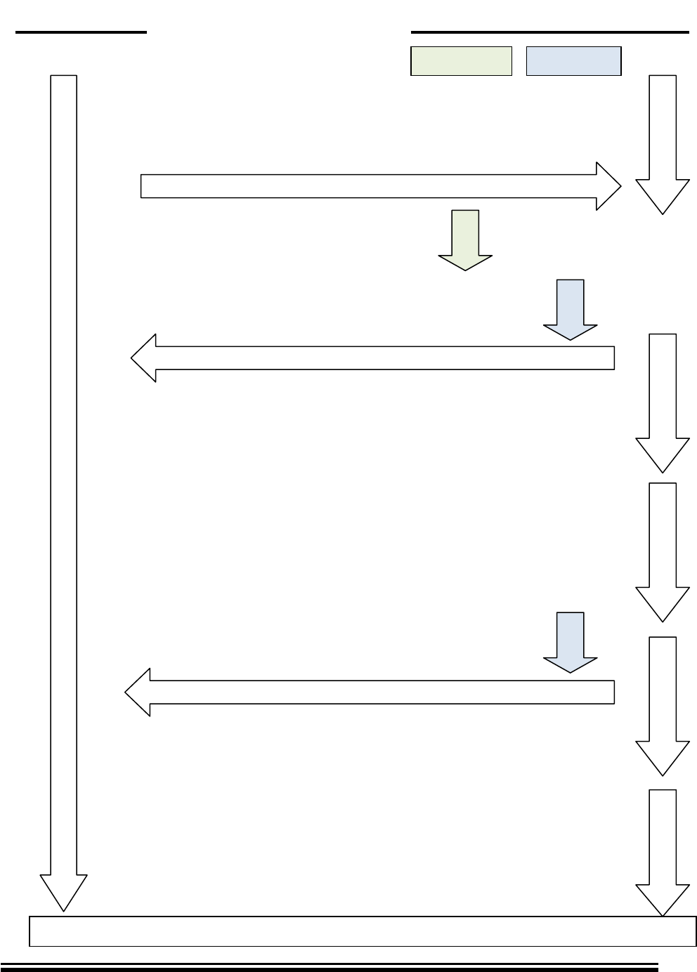
Customer’s Tool Aspect:
MPBT
MPBT Behavior
Change Next Device
Wait EOT created
SOT.ini
Barcode.ini
Customer’s Tool
Create
MPBT creates EOT to tell at Test End State
Create
Customer Tool Create SOT to notice MPBT Barcode.ini was set finish
Wait EOT deleted
Set DUT into JIG
Customer Tool deletes SOT, to notice MPBT, DUT was settled
Delete
Wait EOT created
Read Status.ini

Advance Information
2015MicrochipTechnologyInc.
DS50002279A-page82
WorldwideSalesandService
AMERICAS
CorporateOffice
2355WestChandlerBlvd.
Chandler,AZ85224-6199
Tel:480-792-7200
Fax:480-792-7277
TechnicalSupport:
http://w
ww.microchip.com/
support
WebAddress:
www.microchip.com
Atlanta
Duluth,GA
Tel:678-957-9614
Fax:678-957-1455
Austin,TX
Tel:512-257-3370
BostonWestboroug
h,MATel:774-760-
0087
Fax:774-760-0088
Chicago
Itasca,IL
Tel:630-285-0071
Fax:630-285-0075
ClevelandIndepen
dence,OHTel:216-
447-0464
Fax:216-447-0643
Dallas
Addison,TX
Tel:972-818-7423
Fax:972-818-2924
Detroit
Novi,MI
Tel:248-848-4000
Houston,TX
Tel:281-894-5983
IndianapolisNobl
esville,INTel:317-
773-8323
Fax:317-773-5453
LosAngelesMission
Viejo,CATel:949-
462-9523
Fax:949-462-9608
NewYork,NY
Tel:631-435-6000
SanJose,CA
Tel:408-735-9110
Canada-Toronto
Tel:905-673-0699
Fax:905-673-6509
ASIA/PACIFIC
AsiaPacificOfficeSuites3
707-
14,37thFloorTower6,TheG
atewayHarbourCity,Kowlo
onHongKong
Tel:852-2943-5100
Fax:852-2401-3431
Australia-Sydney
Tel:61-2-9868-6733
Fax:61-2-9868-6755
China-Beijing
Tel:86-10-8569-7000
Fax:86-10-8528-2104
China-Chengdu
Tel:86-28-8665-5511
Fax:86-28-8665-7889
China-Chongqing
Tel:86-23-8980-9588
Fax:86-23-8980-9500
China-Hangzhou
Tel:86-571-8792-8115
Fax:86-571-8792-8116
China-HongKongSAR
Tel:852-2943-5100
Fax:852-2401-3431
China-Nanjing
Tel:86-25-8473-2460
Fax:86-25-8473-2470
China-Qingdao
Tel:86-532-8502-7355
Fax:86-532-8502-7205
China-Shanghai
Tel:86-21-5407-5533
Fax:86-21-5407-5066
China-Shenyang
Tel:86-24-2334-2829
Fax:86-24-2334-2393
China-Shenzhen
Tel:86-755-8864-2200
Fax:86-755-8203-1760
China-Wuhan
Tel:86-27-5980-5300
Fax:86-27-5980-5118
China-Xian
Tel:86-29-8833-7252
Fax:86-29-8833-7256
China-Xiamen
Tel:86-592-2388138
Fax:86-592-2388130
China-Zhuhai
Tel:86-756-3210040
Fax:86-756-3210049
ASIA/PACIFIC
India-Bangalore
Tel:91-80-3090-4444
Fax:91-80-3090-4123
India-NewDelhi
Tel:91-11-4160-8631
Fax:91-11-4160-8632
India-Pune
Tel:91-20-3019-1500
Japan-Osaka
Tel:81-6-6152-7160
Fax:81-6-6152-9310
Japan-Tokyo
Tel:81-3-6880-3770
Fax:81-3-6880-3771
Korea-Daegu
Tel:82-53-744-4301
Fax:82-53-744-4302
Korea-Seoul
Tel:82-2-554-7200
Fax:82-2-558-5932or
82-2-558-5934
Malaysia-KualaLumpur
Tel:60-3-6201-9857
Fax:60-3-6201-9859
Malaysia-Penang
Tel:60-4-227-8870
Fax:60-4-227-4068
Philippines-Manila
Tel:63-2-634-9065
Fax:63-2-634-9069
Singapore
Tel:65-6334-8870
Fax:65-6334-8850
Taiwan-HsinChu
Tel:886-3-5778-366
Fax:886-3-5770-955
Taiwan-Kaohsiung
Tel:886-7-213-7830
Taiwan-Taipei
Tel:886-2-2508-8600
Fax:886-2-2508-0102
Thailand-Bangkok
Tel:66-2-694-1351
Fax:66-2-694-1350
EUROPE
Austria-Wels
Tel:43-7242-2244-39
Fax:43-7242-2244-393
Denmark-Copenhagen
Tel:45-4450-2828
Fax:45-4485-2829
France-Paris
Tel:33-1-69-53-63-20
Fax:33-1-69-30-90-79
Germany-Dusseldorf
Tel:49-2129-3766400
Germany-Munich
Tel:49-89-627-144-0
Fax:49-89-627-144-44
Germany-Pforzheim
Tel:49-7231-424750
Italy-Milan
Tel:39-0331-742611
Fax:39-0331-466781
Italy-Venice
Tel:39-049-7625286
Netherlands-Drunen
Tel:31-416-690399
Fax:31-416-690340
Poland-Warsaw
Tel:48-22-3325737
Spain-Madrid
Tel:34-91-708-08-90
Fax:34-91-708-08-91
Sweden-Stockholm
Tel:46-8-5090-4654
UK-Wokingham
Tel:44-118-921-5800
Fax:44-118-921-5820
