BA63 01 Titelseite FA IdNr5985940.p65 Blum M51P Minipress User Manual
User Manual: Blum M51P Minipress User Manual
Open the PDF directly: View PDF ![]() .
.
Page Count: 60
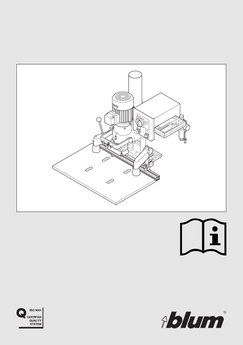
Blum MINIPRESS
The machine shall only be
used by trained personnel
who have completely read
and understand the
manual.
L
L
BAU0004823171 IDX00
1
THE MACHINE SHALL ONLY BE USED BY TRAINED
PERSONNEL WHO HAVE COMPLETELY READ AND
UNDERSTAND THE MANUAL.
US
CONTENTS Page:
AHow to use this manual 2
BSafety instructions 3
CDesignation of parts 6
DInitial set-up of MINIPRESS
áUnpacking and assembly 10
áConnection to compressed air system 13
áElectrical connection 14
áDust extraction 14
EDescription of operating panel 15
FHinge insertion process
áDrilling of hinge pattern 18
áHinge insertion 26
GInstallation of wing mounting plates 29
HDrilling of line patterns 32
JService and maintenance 35
KTroubleshooting - What to do, if...? 38
LAppendix
áDo-it-yourself worktable 46
áWarranty 47
áTechnical data 48
áWarranty cards --
%$0,1,35(66)$,G1US $0
2
A
How to use the manual
B
(G1)
!
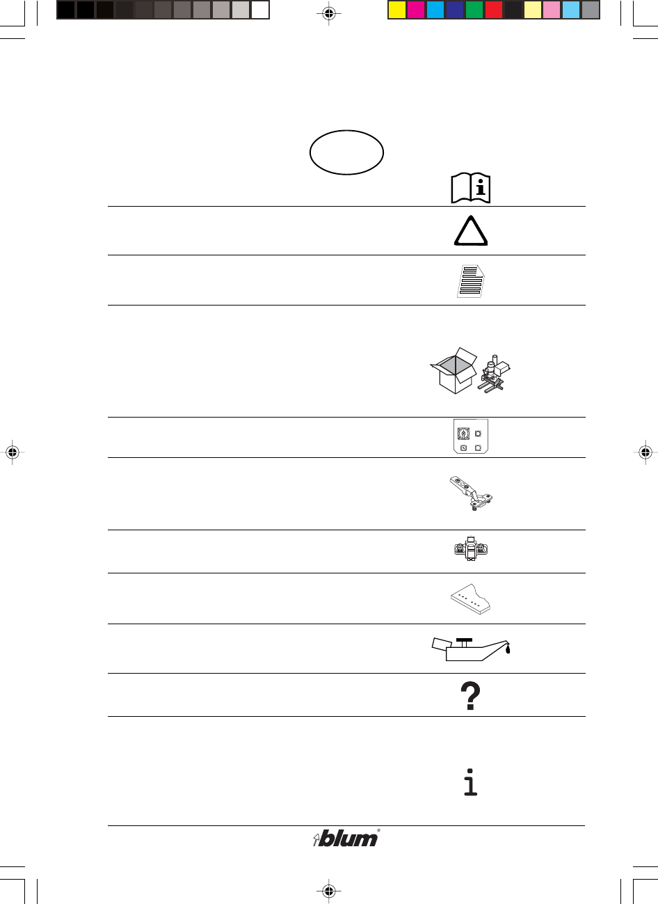
How to use this manual
1. Understanding this manual 2. Symbols and their descriptions:
• THE MACHINE
SHOULD ONLY BE
USED BY TRAINED
PERSONNEL WHO
HAVE COMPLETELY
READ AND UNDER-
STAND THE MANUAL
• To better identify the machine
components, see section C -
„Designation of parts“.
• Each section is marked with a capital
letter and a symbol that corresponds
to the Table of Contents.
Indicates important safety
rules which must be followed!
Indicates an important
comment.
Component description code
found throughout the manual
and on the fold-out pages.
The letter corresponds to the
section where the component
and it’s function is described.
Example:
G1 is described in section G.
This capital letter indicates
the section and is shown on
the outer edge of the section.
It is intended to aid in
searching through the
machine manual.
%$0,1,35(66)$,G1US $0
3
B
Safety instructions
DANGER
This control box
must only be
opened by a
qualified electrician
!
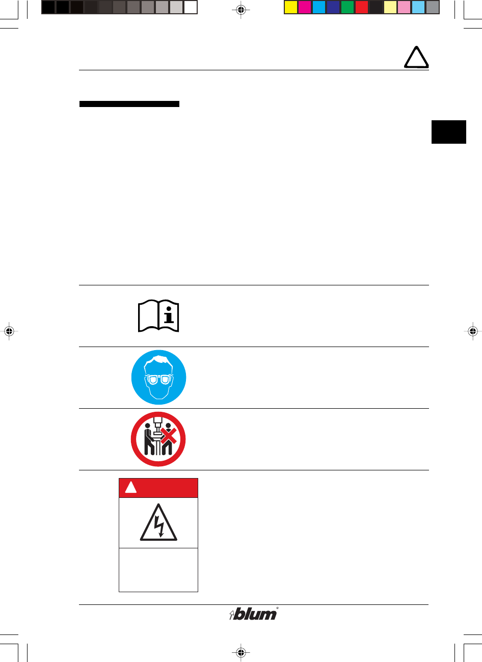
Safety instructions
Read before operation
• Failure to properly follow all safety
rules and procedures in this manual,
and all warnings and instructions on
the machine, may result in serious
personal injury or property damage.
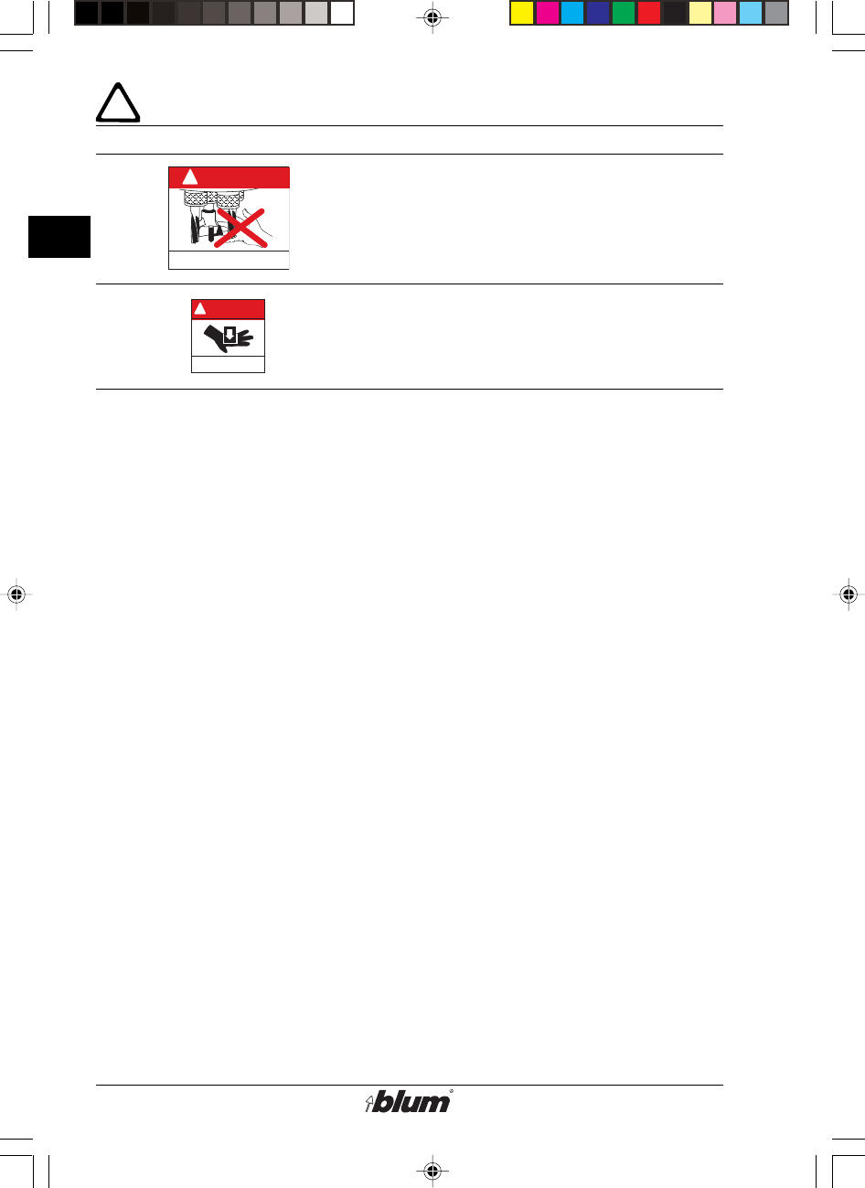
Safety decal description
• Before connecting your machine
to a power source, be sure to read
ALL Safety Rules and the
instruction manual!
• Wear safety glasses or a full face
shield when operating this machine.
• Keep unauthorized people away
from the machine. Only one person
at a time must operate the machine.
• Disconnect electrical and pneumatic
connections before making any
repairs or adjustments.
• Electrical connections and
maintenance must be performed by
a qualified electrician. An electrical
diagram is included in the
instructions.
%$0,1,35(66)$,G1US $0
4
B
Safety instructions
DANGER
!
KEEP HANDS OUT
DANGER
KEEP HANDS OUT
!
• Keep hands and fingers away from drill
bits while the machine is power
connected, even if it is not running.
• Never attempt to operate machine
without the guards in place.
• Never move your hands in the area of
pinch points.
Safety rules
• This machine is designed for
commercial and industrial
applications and shall be used by
fully trained professionals only.
The machine is only intended for the
drilling and insertion of Blum
hardware into panels of wood,
particle board, or laminated particle
board.
• Always place operation mode switch
to „set up“ position and disconnect
the power (unplugged) before
performing any work on the drill
heads, fences or stops.
• Keep work area clean. Cluttered
areas and work stations increase the
chance of accidents.
• Protect yourself from electrical
shock. Do not use this machine in
damp or wet locations, or expose it
to rain.
• Consider environmental factors and
local laws when setting-up and
operating the machine.
• The hold-down clamps or other
adequate means must be used to
secure the panel during the
operation.
• Observe the location of the control
switches and become familiar with
their operation.
• Wear proper clothing. Do not wear
shirts with bulky sleeves and ties
that could be caught in moving
parts.
• Do not wear jewelry when operating
this machine. Individuals with long
hair should wear a hairnet to protect
their hair from moving parts.
%$0,1,35(66)$,G1US $0

5
B
Safety instructions
• Before every use of the machine,
make sure that all safety devices
and parts of the machine function
properly. Any defective safety
devices and accessories must be
repaired or exchanged by a qualified
service technician only.
• Do not overreach. Keep proper
footing and balance at all times.
• CAUTION: For your own safety, use
only those accessories which are
recommended or indicated in the
manual or Blum sales literature.
• All accessories and attachments
must be installed as described in the
manual to assure a proper and safe
operation of the machine.
• Maintain tools with care. Keep tools
sharp, clean and organized for the
best and safest performance. Follow
instructions for lubricating and
changing accessories.
• Protect electrical and pneumatic
lines from heat, oil, traffic, sharp
edges, etc.
• Do not use cables and pneumatic
lines for purposes other than those
originally intended.
• The actual noise levels in your work
area may vary. Appropriate hearing
protection may be necessary. This
determination must be made by the
user with consideration for the entire
working environment and any
applicable regulation. Factors liable
to influence current immission levels
in the workplace include the length
of exposure, the characteristics of
the workroom, and other noise
sources.
• This machine, being cord and plug
connected is in compliance with
OSHA regulations 1910.147 (lock-out
/ tag-out) and does not require
padlocks or other locking devices.
• For any question or problem with the
machine, contact the Blum
Customer Service Department:
1-800-438-6788
%$0,1,35(66)$,G1US $0

6
C
Designation of parts
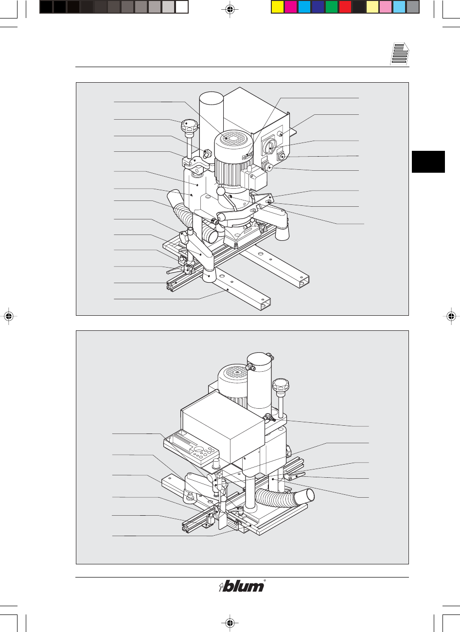
Designation of parts
D1 ...machine base
D2 ...base ruler
D3 ...clamping lever
D4 ...fencing system
D5 ...fixing pins for ruler
D6 ...indexing plate
D7 ...swivel stop
D8 ...air filter
D9 ...fan
D10 ...rotation direction arrow
E1 ...main switch
E2 ...drill / press stroke button
E3 ...hold-down switch
E4 ...operation Indicator Lamp
F8 ...swing arm
F9 ...drilling depth gauge
F10 ...adjustment for drilling depth
F13 ...adjustment screw for stroke
speed
F14 ...adjustment screw for braking
stroke
F15 ...clamping lever
F16 ...fixing pin
F17 ...hold-down clamp
F18 ...locking screw
F19 ...hold-down guard
F20 ...fastening screw for ram
F21 ...adjustment screw for swing
arm
F23 ...drill/press unit
J1 ...air filter - water trap
J2 ...guide shafts
J3 ...lubricating nipples
J4 ...motor fastening bolts
%$0,1,35(66)$,G1US $0
7
C
Designation of parts
R
R
D9
F10
F14
F9
D1
D2
D7
F19
F17
F18
F21
E4
E2
E3
E1
F20
J3 F8
F23
J4
D10
D3
D5
D8
D4
D6
F15
F16
J2
F13
J1
D3
%$0,1,35(66)$,G1US $0

8
C
Designation of parts
Designation of parts
D7 ...swivel stop
D13 ...box support
F3 ...cover caps
F5 ...fixing pin for drill head
F6 ...lever (to rotate gearbox)
F7 ...symbol furniture hinge
F11 ...drilling depth stop
F12 ...retaining ring
G3 ...symbol line boring pattern
H3 ...setting gauge
J6 ...clutch
%$0,1,35(66)$,G1US $0

9
C
Designation of parts
F7
F12
F6
F5
G3
D7
F3
F11
LL
H3 J6
D13
6
4
%$0,1,35(66)$,G1US $0
10
D
Initial set-up of MINIPRESS
H
BT
L
L
L
L
D1
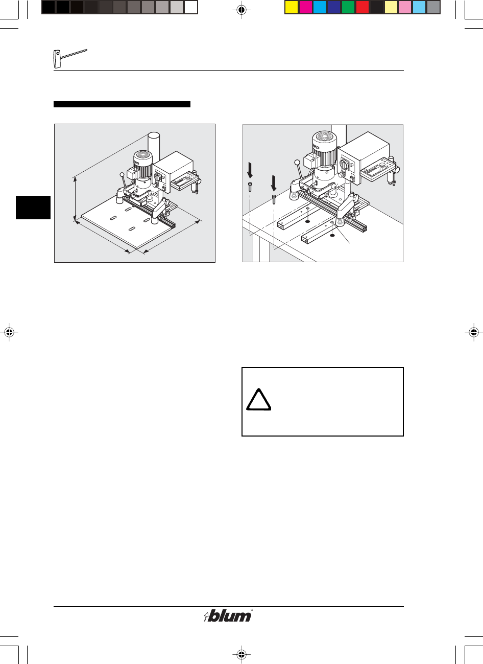
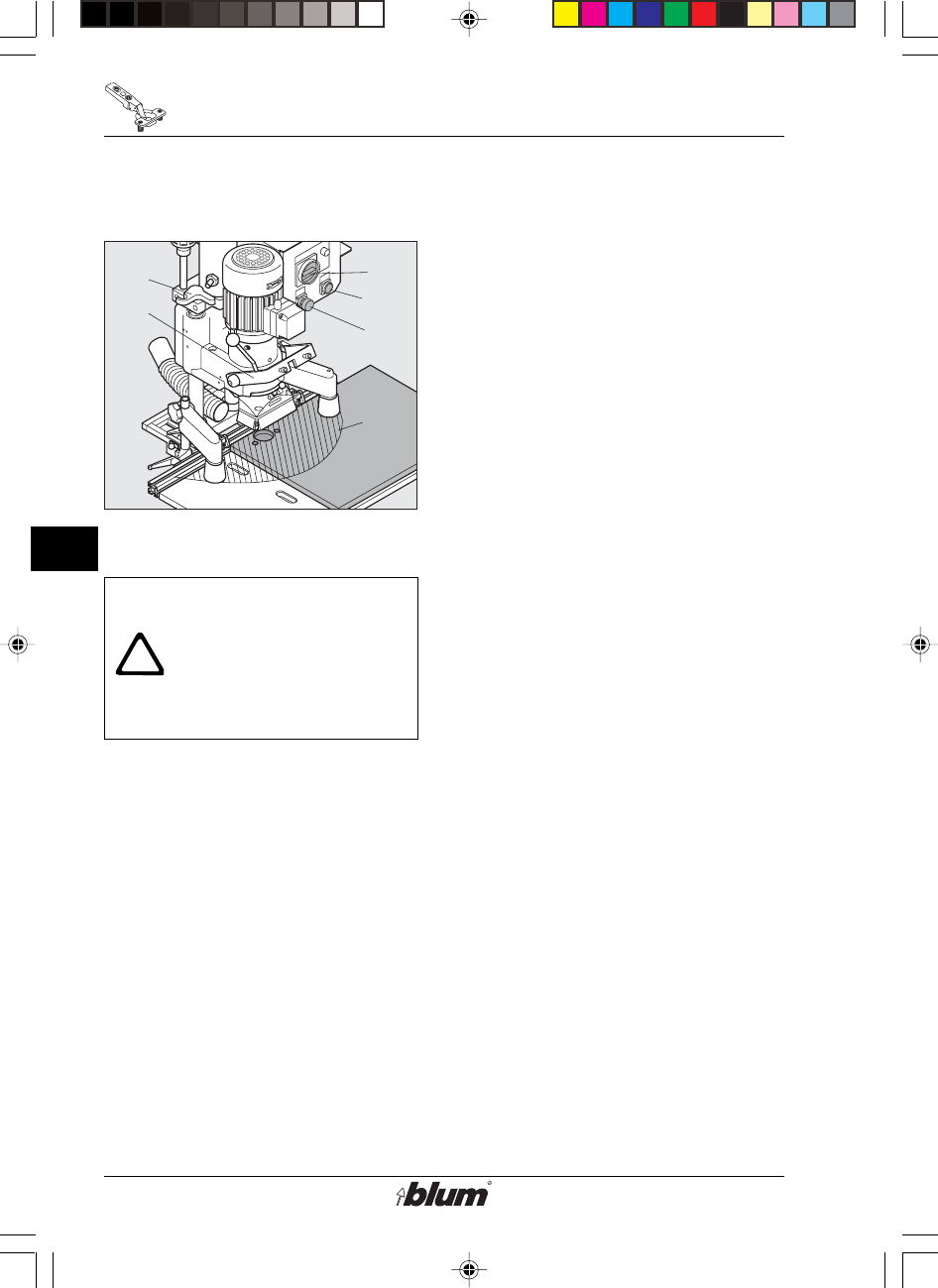
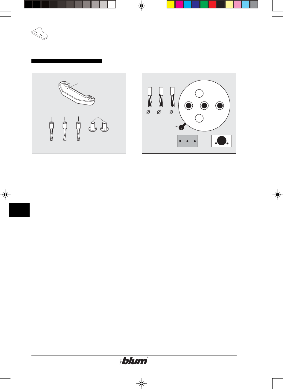
Unpacking and assembly
1. MINIPRESS footprint
H = 27-15/16"
B=24"
T = 29-15/16"
2. Unpack MINIPRESS and fasten it
to a suitable table using bolts.
• Open the box.
• Get an assistant to help you lift
MINIPRESS onto the worktable.
Warning:
The machine weights
approx. 82 lbs (37 kg) so
make sure that the table is
sturdy enough!
• Fit M8 bolts through the drill holes
(D1) and tighten them.
• Do not install MINIPRESS in a damp
area but in a dry room.
%$0,1,35(66)$,G1US $0
11
D
Initial set-up of MINIPRESS
!
D5
D6
D3
D2
3/8"
(10 mm)
L
L
1.
2.
3.
D7
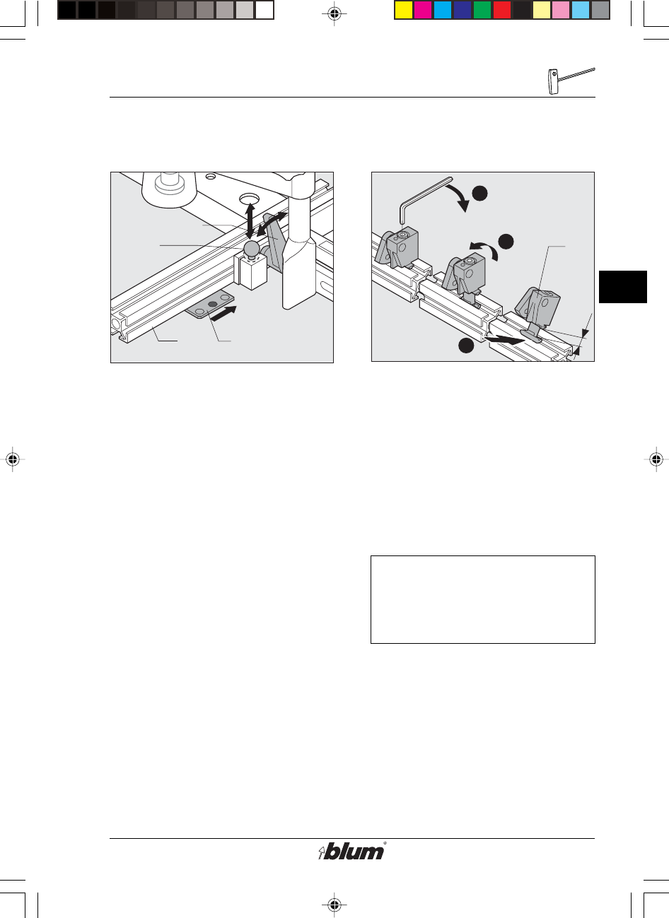
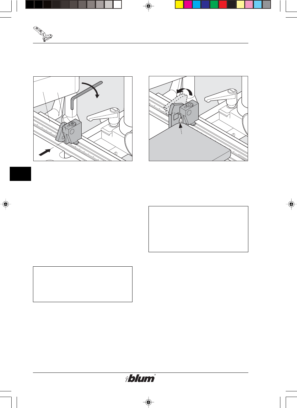
3. Installation of base ruler (D2)
• Loosen both clamping levers (D3)
on the fencing System.
• Lift locating pin (D5), and slide base
ruler (D2), until the locating pin
snaps into the center hole of the
locating plate (D6).
• Tighten clamping levers (D3).
4. Mounting the swivel stops (D7)
• Loosen the locking bolt until the T-
nut projects by 3/8“ (10 mm).
• Tilt the swivel stop against the ruler
and raise the stop.
• Tighten the locking bolt.
Note:
Follow the same procedure to
place a stop between two
existing stops.
%$0,1,35(66)$,G1US $0
12
D
Initial set-up of MINIPRESS
D4
X
D13
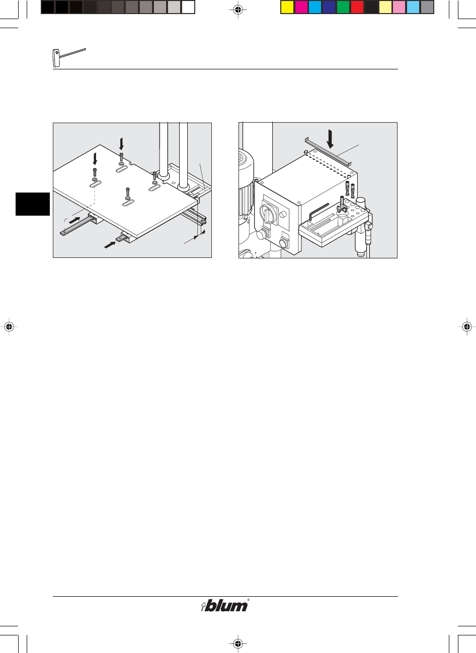
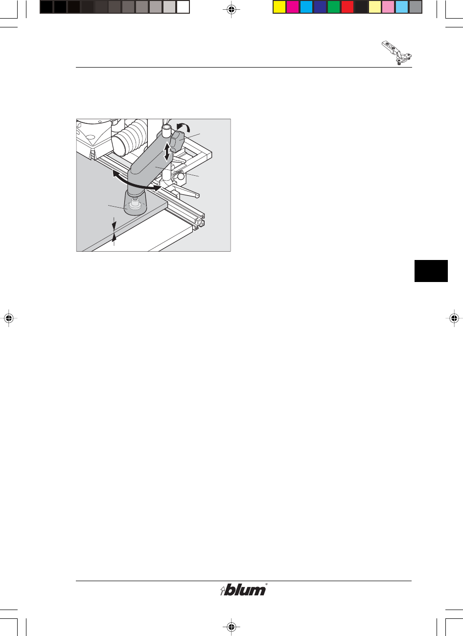
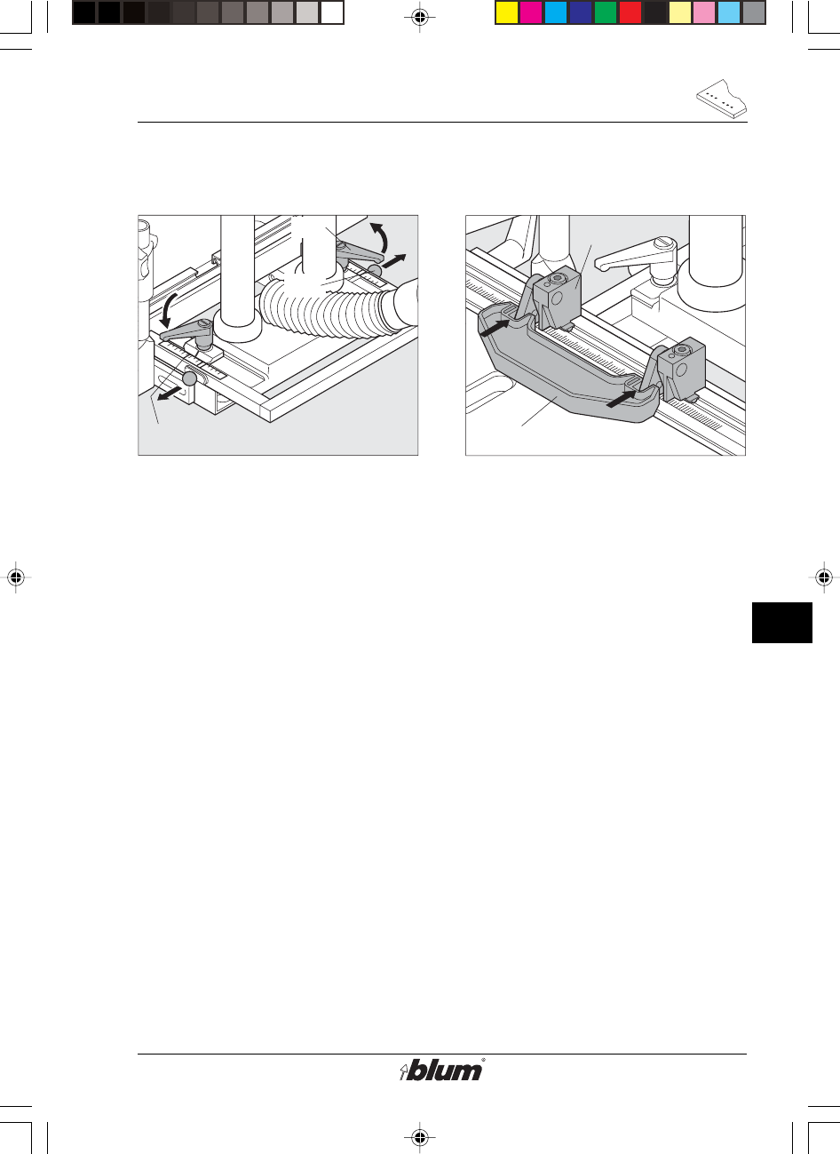
5. Assembling the worktable
a) Accessory worktable MZA.1000
• Set the fencing System (D4) to
position DP.
• Place the worktable on the machine
base.
• Slide the threaded rail into the
hollow profiles and hold them while
pushing upward.
• Fit hex set bolts through the holes
in the hollow profiles and fasten the
table to the counter-plates (x - gap
for chips).
b) Do-it-yourself worktable
(see page 46)
6. Mounting the box Support (D13)
• Use glue to attach the Box Support
(D13) to the rear end of the control
box (surface must be dry and oil-
free).
%$0,1,35(66)$,G1US $0
13
D
Initial set-up of MINIPRESS
!
D8
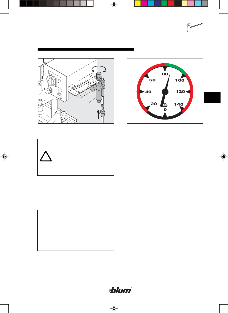
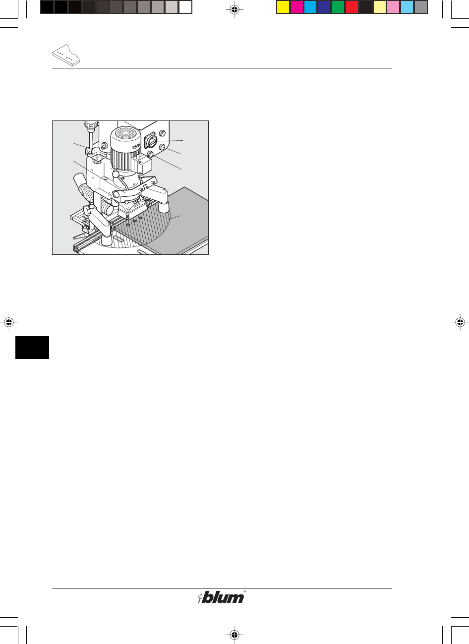
Connection to compressed air system
1. Connection of air supply
Warning:
The drilling unit (F23)
moves upward when the
steps below are carried out!
• Attach a 1/4" I.D. flexible hose onto
barbed hose fitting (D8) of the
machine.
Important:
A „quick disconnect“ fitting
must be installed on the
compressed air hose, no
more than 10“ (3 m) away
from the machine.
2. Setting the working pressure
• The working pressure is 6 bar
(80 - 100 psi). If the machine is
operated either below or above the
recommended air pressure, could
result in personal injury or damage
to the machine.
• The compressed air supplied to the
machine must be oil free and dry.
%$0,1,35(66)$,G1US $0
14
D
Initial set-up of MINIPRESS
!
XXX V / XX HZ
mwttttt mmmmtm tmttt ttt tmttttttmt mttt mwttttt mmm
mwttttt
mwtttttmm mmtm tmttt ttt tmttttttmt mtt
mwttttt mmm
mwtt tttmmhb nhnhn hhnh nmmtm tmttt ttt tmtttlkl kll lkkltttmt mttt
mwttttt mmhb nhnhn hhnh nmmtm tmttt ttt tmtttlkl kll lkkltttmt mttt
mwttttt mmm
mwttttt mmhb nhnhn hhnh nmmtm tmttt ttt tmtttlkl kll lkkltttmt mttt
mwttt ttmmm
mwttttt mmhb nhnhn hhnh nmmtm tmttt ttt tmtttlkl kll lkkltttmt mttt
mwttttt mmhb nhnhn hhnh nmmtm tmttt ttt tmtttlkl kll lkkltttmt mttt
mwttttt
mwt
mwt
mwt
mwt
mwt
mwt
mwt
mwt
mwt
mwt
mwt
mwt
mwt
mwt
mwt
mw
mwt
mwt
mwt
mw
mw
mw
mw
mw
mw
mw
mw
mw
mw
mw
mw
mw
mw
mw
mw
1.
2.
3.
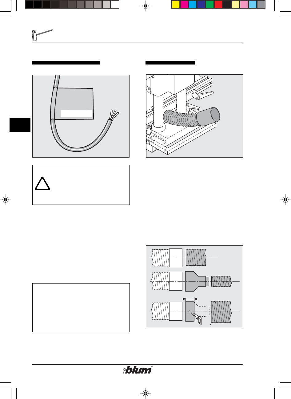
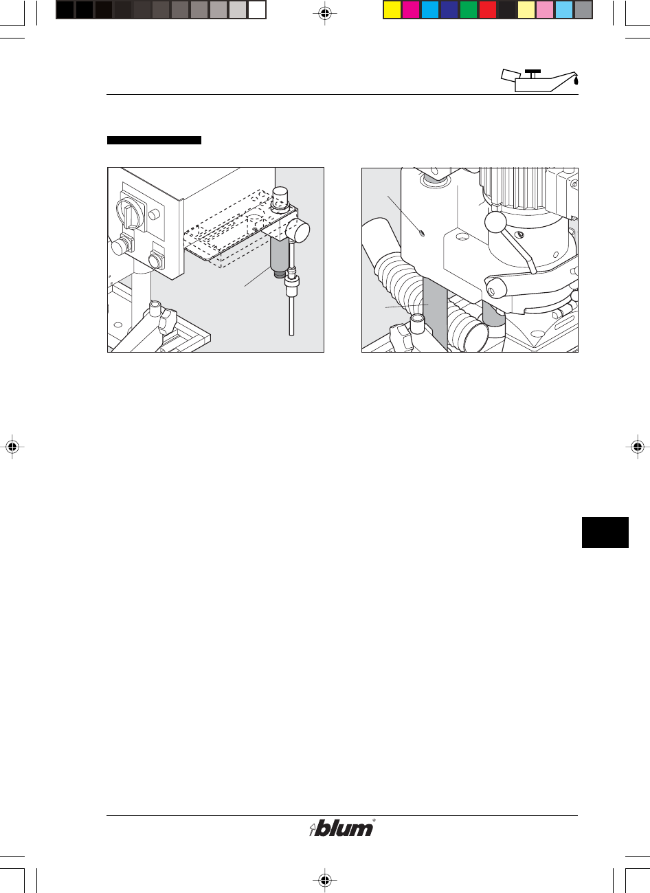
Electrical connection Dust extraction
Warning:
Electrical wiring shall be
carried out by an
authorized electrician only!
1. Electrical connection
• Set main switch (E1) to set up
position.
• Mount a plug conforming to NEC.
This machine must be connected
through a circuit breaker
(see wiring diagram).
Important:
The machine has been
prepared for the voltage
printed on the label of the
connection cable.
1. This machine may be connected
to a dust extraction system.
• Insert a spiral hose with an inside
diameter of 3-1/8“ (80 mm) into the
receiving tube and fix it.
• If no 3-1/8“ (80 mm) extraction
connection is available, use the
adapters (illus. 2) supplied
with the machine.
%$0,1,35(66)$,G1US $0
15
E
Desciption of operating panel
E1
E3
E4
E2
set up
drill/press
Auto off drill/press
stroke
E1 set up
drill/press
Auto off drill/press
stroke
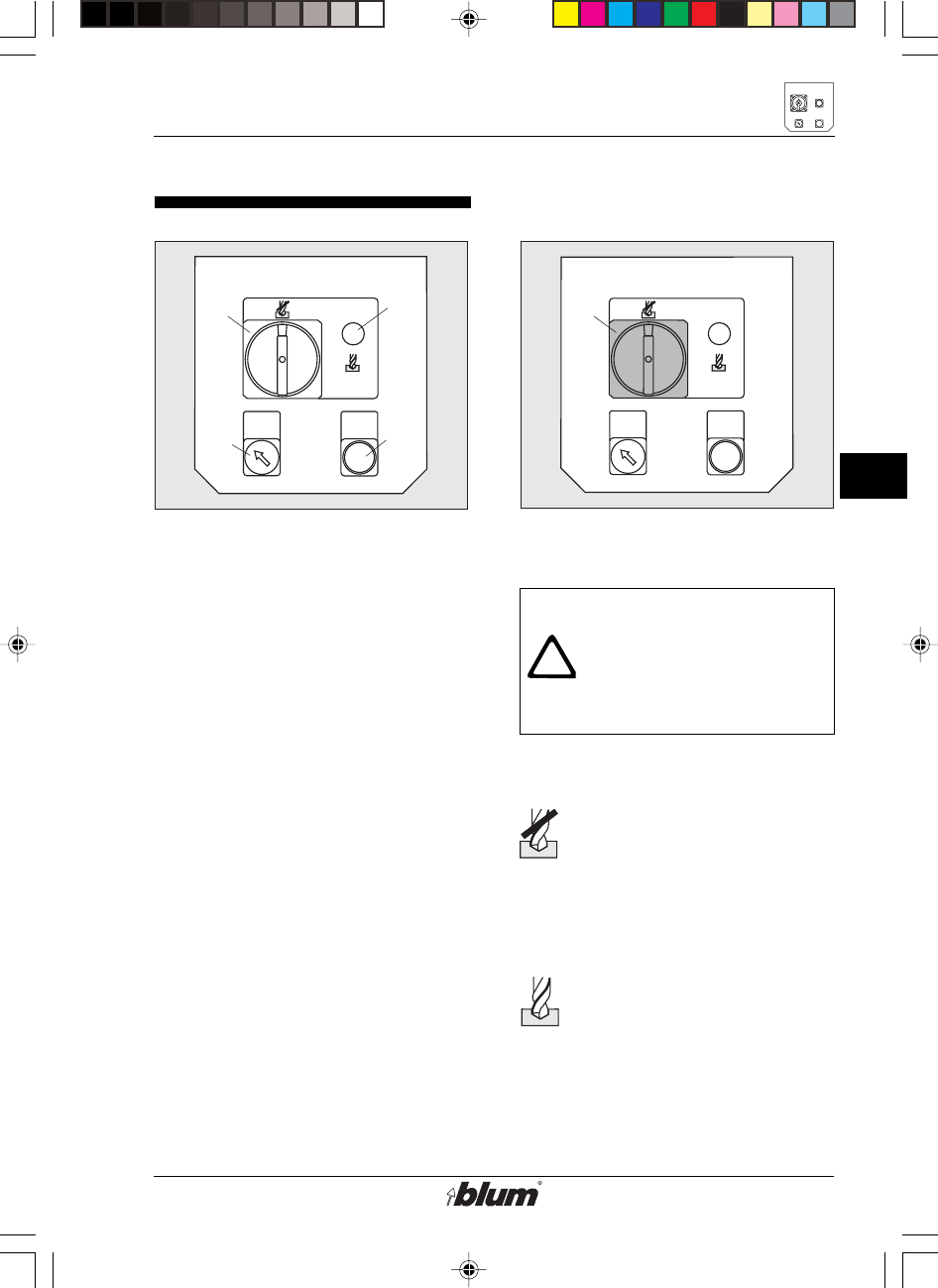
Description of operating panel
2. Designation of operating
elements
• (E1) ... main switch
• (E2) ... press drill / press stroke
button
• (E3) ... hold-down switch
• (E4) ... operation indicator lamp
3. Main switch (E1)
Warning:
The main switch does not
disengage the machine
from the compressed-air
system.
Set up position:
Operation indicator lamp (E4)
does not light up. machine is
in set-up mode.
- Motor cannot start.
- stroke can be performed.
drill / press position:
Operation indicator lamp
(E4) lights up. machine is
in operating mode.
- Drilling and insertion of
fittings is possible.
%$0,1,35(66)$,G1US $0
16
E
Description of operating panel
!
drill/press
stroke
drill/press
stroke
drill/press
stroke
+
+
+
R
R
D10
D9 E1
E2
A
E2
set up
drill/press
Auto off drill/press
stroke
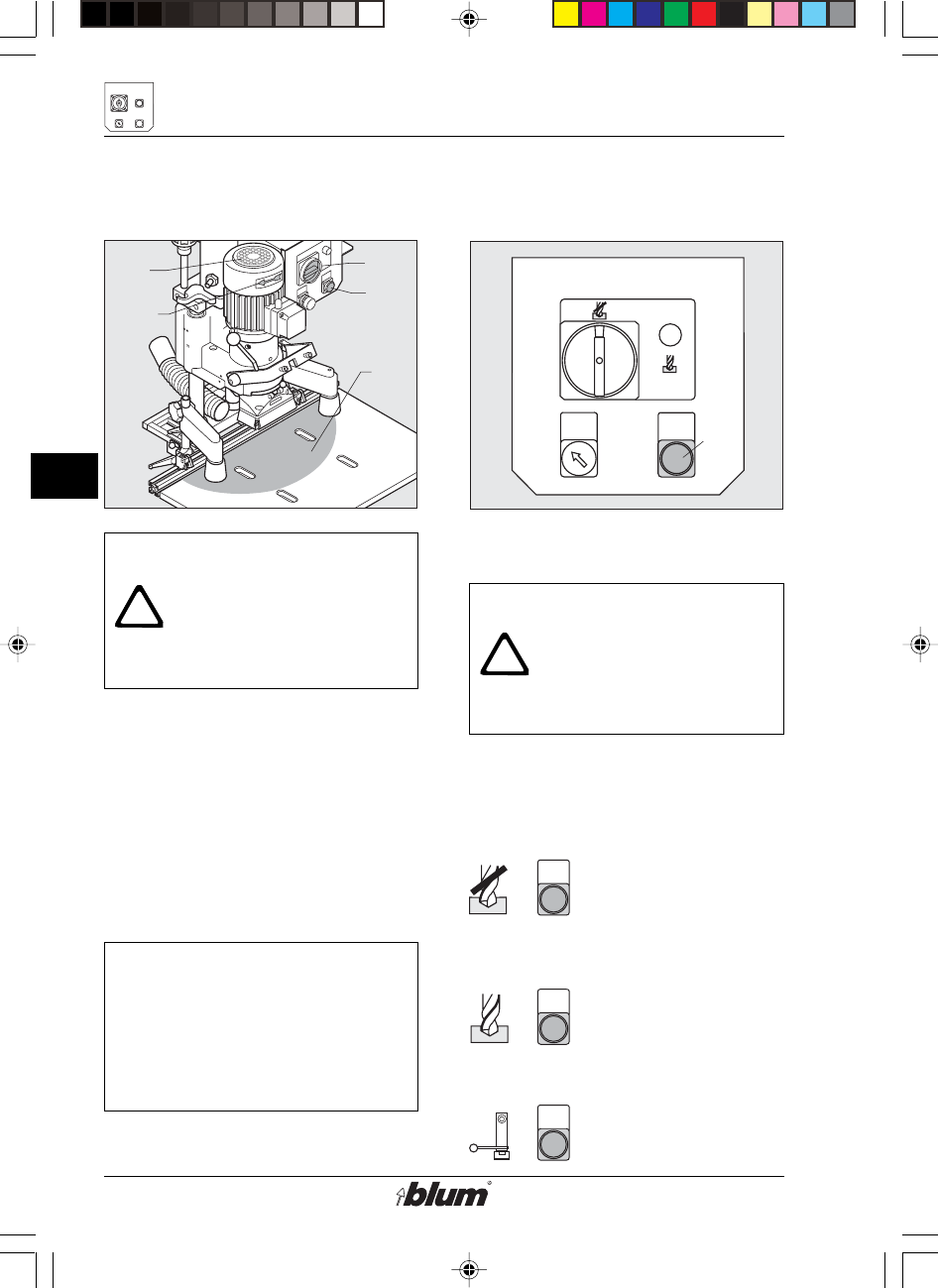
Warning:
Keep your hands out of
working area (A) of the
machine when performing
the tasks below!
4. Checking the motor rotation
• Set main switch (E1) to
drill / press position.
• Briefly touch the drill / press stroke
button (E2).
• The motor fan (D9) must rotate in
the direction of the arrow (D10).
Note:
If you press the drill / press
stroke button (E2) by only a
few mm (1/16"), the drilling
and pressing unit will move
down at a slower speed.
5. Drill / press stroke button (E2)
Warning:
Keep your hands away from
the working area (A) of the
machine when pressing the
drill / press stroke button.
By pressing the drill / press stroke
button, one of the following preselected
operations is carried out.
set-up:
main switch to set up
position + drill /
press stroke button
pressed
drilling:
main switch to drill /
press position + drill
/ press stroke button
pressed
insertion of fitting:
Swing Arm retracted
+ drill / press stroke
button pressed
%$0,1,35(66)$,G1US $0
17
E
Desciption of operating panel
Auto off
Auto off
E3
set up
drill/press
Auto off drill/press
stroke
E2
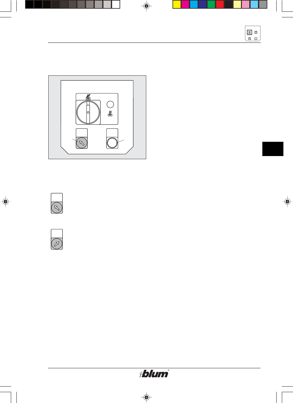
5. Hold-down switch (E3)
Pos. Hold-down clamps on
Pressing the drill / press
stroke button (E2) causes the
hold-down clamps to extend
automatically.
Pos. Hold-down clamps off
The clamps remain retracted
if you press the drill / press
stroke button (E2).
%$0,1,35(66)$,G1US $0
18
F
Drilling of hinge pattern
!
F1F2 F2 F3
F4
2-1/4"
(57 mm)
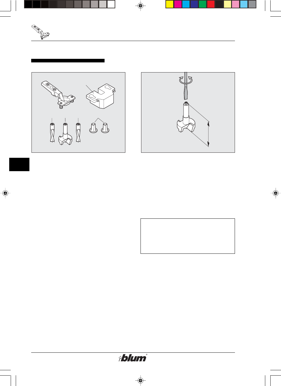
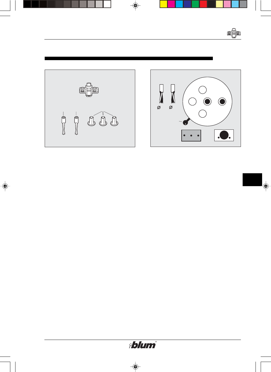
Drilling of hinge pattern
1. Necessary parts
• drill bits:
- one 35 mm dia. rotating clockwise
(F1) (marked black).
- two 8 mm dia. rotating counter-
clockwise (F2) (marked orange).
• Two cover caps (F3)
• Insertion ram MZM.XXXX (F4).
See Blum catalog for correct ram.
• Door panel
• Hinge
2. drill-bit length
• The max length of the drill bits (from
bit-tip to adjustment screw) shall be
2 -1/4“ (57 mm).
• To correct drill-bit length, adjust
screw accordingly.
Important:
All drill bits shall be the same
length!
%$0,1,35(66)$,G1US $0
19
F
Drilling of hinge pattern
35
F
3
8
F
2
F
1
F
2
F
1
F
2
F
2
F
3
8
F5
F7
F6
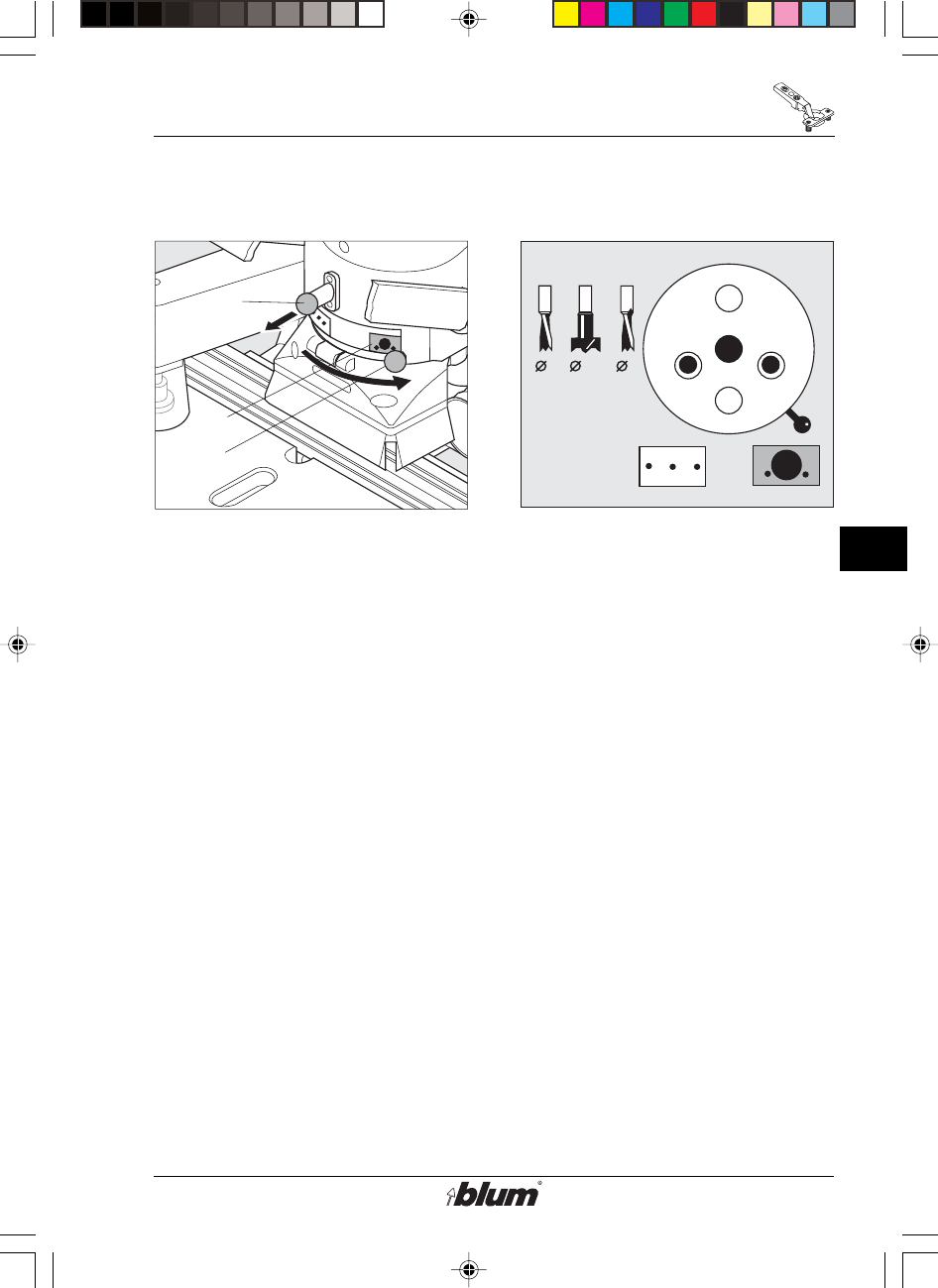
3. Select drill pattern
• Pull out fixing pin (F5) on drill
head.
• At the same time, move lever (F6)
to symbol for hinge drilling pattern
(F7).
• Make sure fixing pin (F5) snaps
back to lock gearbox position!
4. Install drill bits
• Before installing drill bits, always
disconnect the machine from it’s
electrical source (unplugged).
• main switch (E1) to set up position.
• Push drill bits all the way in to the
chucks. Tighten set screw on flat
spot of drill-bit shank only.
• Use a hex wrench to tighten the
fastening screws. (4 mm)
• Insert cover cap (F3) into the empty
chucks. This keeps set screws in
place, and prevents wood chips from
accumulating in chucks.
%$0,1,35(66)$,G1US $0
20
F
Drilling of hinge pattern
!
Auto off
F10
F9
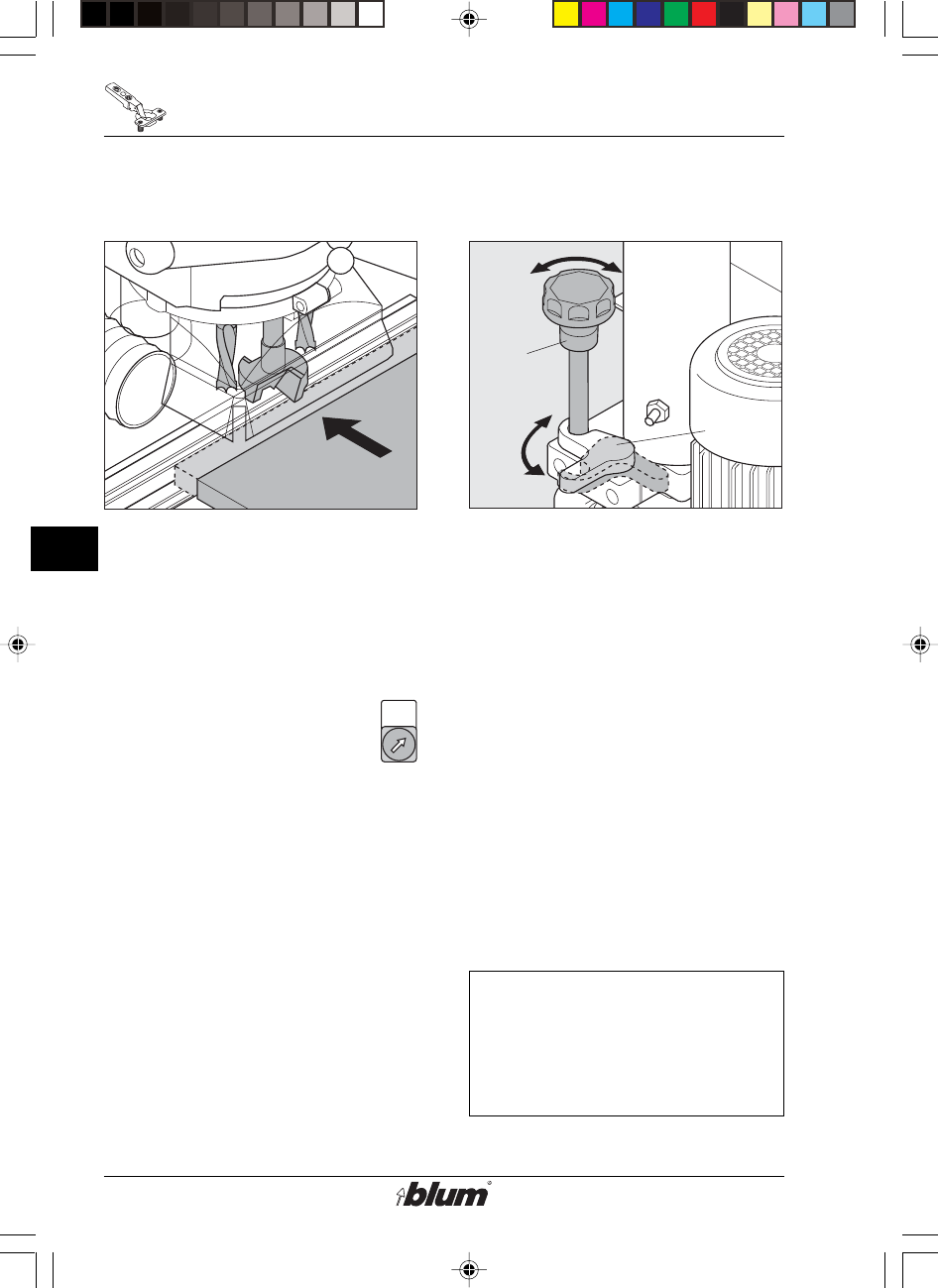
5. Check drilling depth adjustment
• Always place operation mode switch
to set up position and disconnect the
machine from it’s electrical source
(unplugged) before performing any
work on the drill heads, fences or
stops.
• Hold-down switch (E3) to pos. off
• Move swing arm (F8) into upper
position.
• Place door on the worktable clear
of drill-head path.
• Move drilling depth gauge (F9)
against adjustment screw (see
drawing 6).
• Press and hold the drill / press stroke
button (E2) to move head down.
• Slide door towards drill bits, and
check if the cutting edges of the bits
are even with top surface of the door
panel.
• Release drill / press stroke button
6. Correcting drilling depth
adjustment
• If the Cutting edges do not touch the
door panel top, correct adjustment.
• Correct adjustment
lower drilling depth :
turn bolt (F10) clockwise
deeper drilling depth :
turn bolt (F10) counter-cklockwise
(One turn on the depth adjustment
bolt [E10] equals 1/16“ (2 mm)
adjustment.)
• Cycle drill / press stroke again, and
check adjustment.
Important:
Swivelling out the drilling
depth gauge (F9) results
in a drilling depth of
1/2“ (12.7 mm).
%$0,1,35(66)$,G1US $0
21
F
Drilling of hinge pattern
!
F11
F12
F13
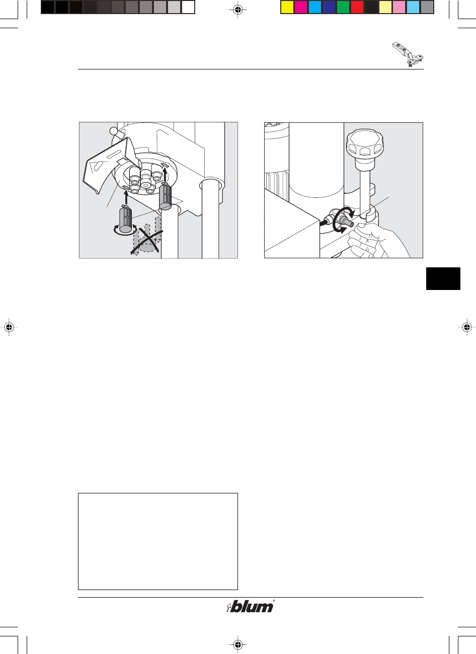
7. Drilling depth stop (F11)
Alternatively, drilling depth stops can be
mounted to ensure a constant drilling
depth. If these stops are mounted, the
drilling depth will always be 1/2“ (12.7
mm), regardless of the thickness of
the workpiece.
Mounting the drilling depth stops:
• Before mounting the depth stops,
disconnect the machine from it’s
electrical source (unplugged).
• Main switch to setup position.
• Remove the drill bit.
• Push the drilling depth stops into the
keyholes of the retaining ring (F12)
until they won’t go any further and
turn them by 90°.
Important:
The drill bit length must be
set to 2-1/4“ (57 mm) (see
section F, item 2). The drilling
depth adjuster (F10) bolt must
not stop before the drilling
depth is reached (turn it back
by a sufficient amount).
8. Adjusting the stroke speed
Adjustment of the stroke speed is made
by means of the knurled screw (F13) at
the back of the cylinder.
•faster: turn screw (F13)
counter-clockwise
•slower: turn screw (F13)
clockwise
%$0,1,35(66)$,G1US $0
22
F
Drilling of hinge pattern
R
R
F9 E1
E2
A
F14
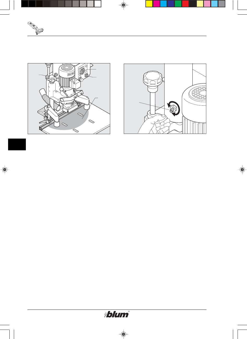
9. Checking the pneumatic brake
The pneumatic brake causes the drill
head to slow down just before the drill
bits penetrate the wood.
(This ensures chip-free holes and
longer bit life.)
• Always place operation mode switch
to set up position and disconnect the
machine from it’s electrical source
(unplugged) before performing any
work on the drill heads, fences,
stops, or pneumatic break.
• Main switch (E1) to set up position.
• Keep hands and fingers away from
drill bits while the machine is power
connected, even if it is not running.
• Swivel out the drilling depth gauge
(F9).
• Press the drill / press stroke button
(E2) and watch stroke.
10. Adjusting the pneumatic brake
To adjust the pneumatic brake, use the
screw (F14) on the left side of the
cylinder.
•Hardwood: turn screw (F14)
clockwise for major
deceleration of drill
stroke.
•Softwood: turn screw (F14)
counter-clockwise
for minor deceleration
of drill stroke.
%$0,1,35(66)$,G1US $0
23
F
Drilling of hinge pattern
!
F15
F16
SY MB DP
SY MB DP
0
10
20
30
40
50
SY
MB
DP
F16
Pos.
1/2
Pos.
3/4
Pos.
5
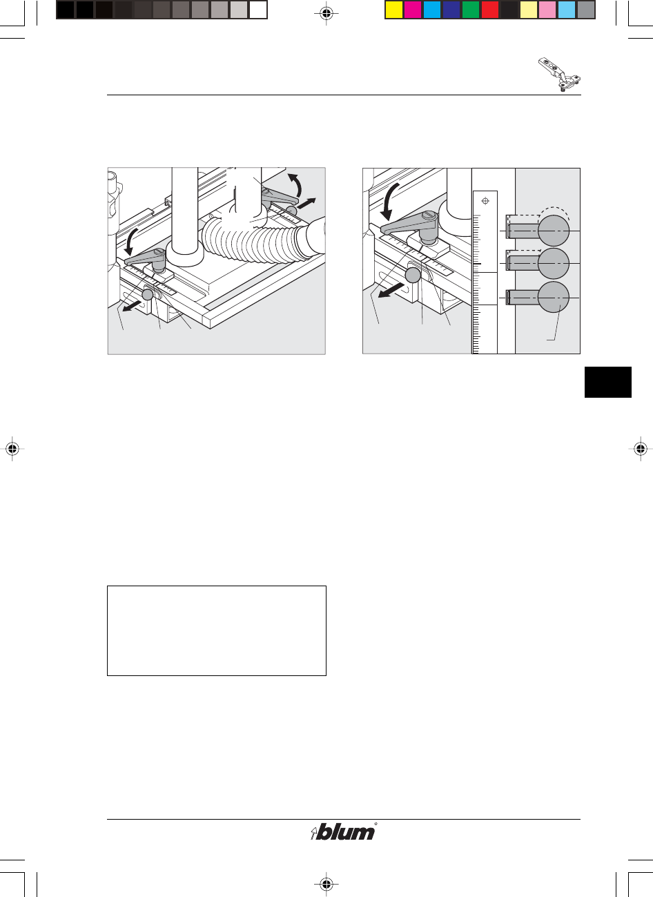
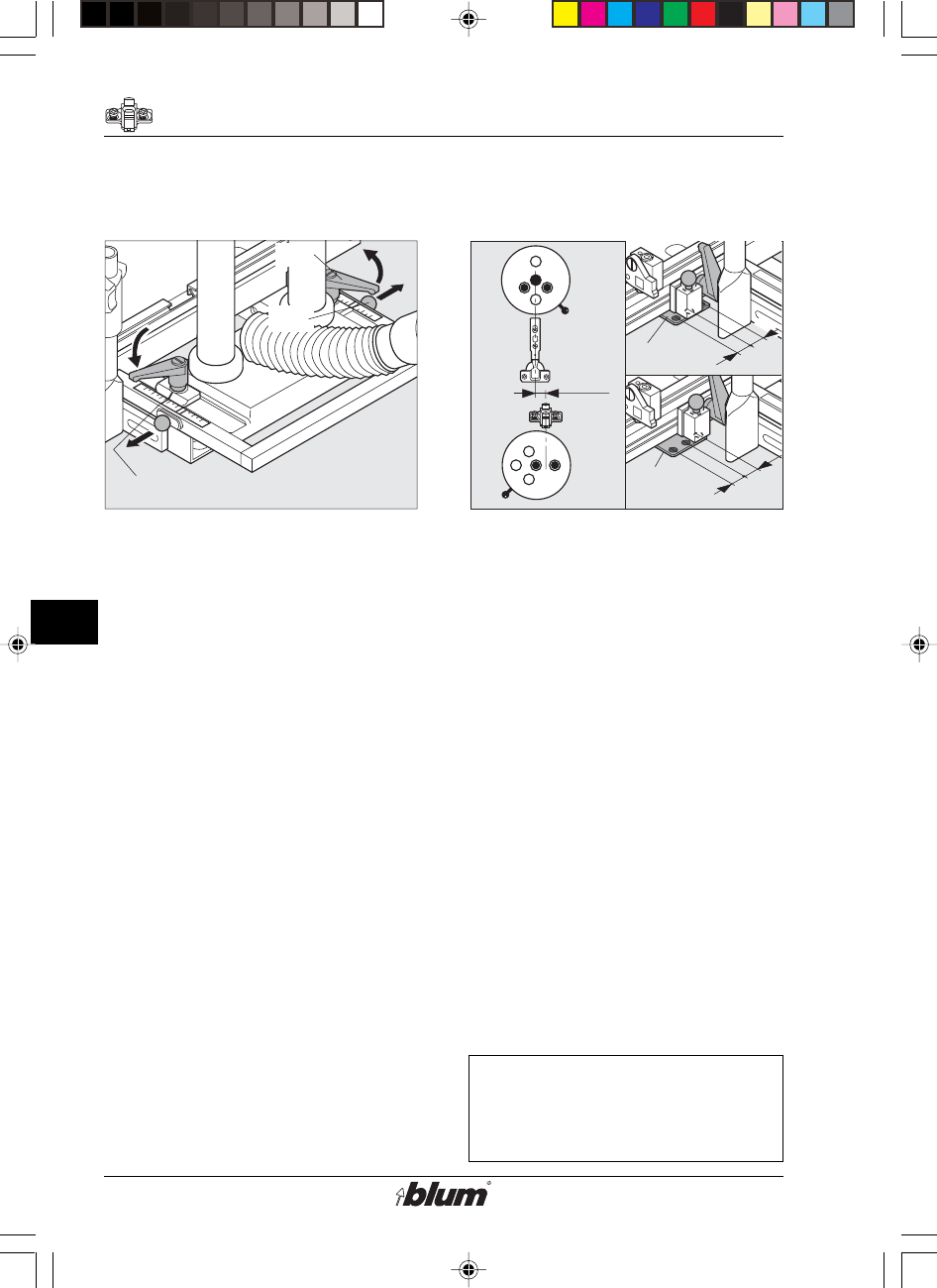
11. Fencing System (D4) adjustments
• Always place operation mode switch
to set up position and disconnect the
machine from it’s electrical source
(unplugged) before performing any
work on the drill heads, fences,
stops, or pneumatic break.
• Release both clamping levers (F15).
• Pull out the fixing pins (F16) on both
sides and set the stop system (D4)
to MB.
Note:
The fencing system includes
5 fixing positions.
(see point 12 )
• Tighten the clamping levers (F15) on
both sides.
12. Fixed positions of the stop system
• Always place operation mode switch
to set up position and disconnect the
machine from it’s electrical source
(unplugged) before performing any
work on the drill heads, fences,
stops, or pneumatic break.
Pos. 1 = 5 mm (3/16“)
Lock the fixing bolts (F16) into place
and pull the stop system forward.
Pos. 2 = 9 mm (3/8“)
Lock the fixing bolts (F16) into place
and push the stop system backward.
Pos. 3 = 20 mm (13/16“)
Lock the fixing bolts (F16) into place
and pull the stop system forward.
Setting: ‘DP’
Pos. 4 = 23.5 mm (15/16“)
Lock the fixing bolts (F16) into place
and push the stop system backward.
Setting: ‘MB’
Pos. 5 = 37 mm (1-7/16“)
Lock the fixing bolts (F16) into place.
Setting: ‘SY’
%$0,1,35(66)$,G1US $0
24
F
Drilling of hinge pattern
!
!
L
D7
D2
R
13. Setting the swivel stops (D7)
• Always place operation mode
switch to set up position and
disconnect the machine from it’s
electrical source (unplugged) before
performing any work on the drill
heads, fences, stops, or pneumatic
break.
Set the swivel stops (D7) to the
required dimension and secure them.
Note:
The reading edge is on the
inside of the swivel part!
14. Place the door on the worktable
and slide it until positioned
at the stop.
Note:
For work pieces with grooves
or radii (see illus.), the stop face
can be increased by pulling the
stop lock forward.
%$0,1,35(66)$,G1US $0
25
F
Drilling of hinge pattern
X
F18
F17
F19
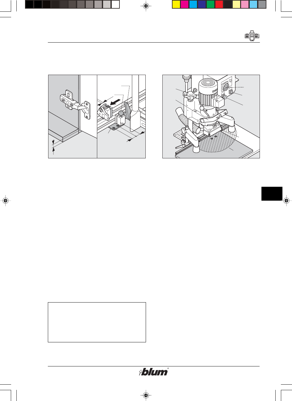
15. Adjust hold down clamps (F17)
• Loosen clamp screw (F18).
• Position clamp over panel surface.
• Position clamp over panel surface,
no more than 6 mm (1/4").
• Tighten clamp screws (F18).
%$0,1,35(66)$,G1US $0
26
F
Hinge insertion
F20
F8
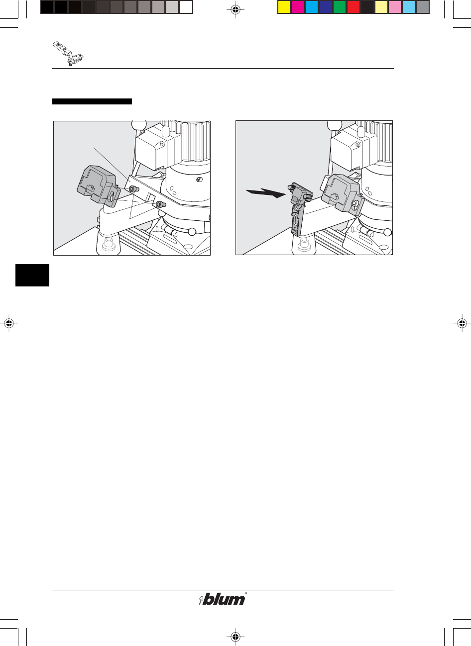
16. Mount insertion ram onto swing
arm (F8) in upright position
• Place ram over fixing bolts (F20)
on swing arm (F8) and tighten.
• Make sure that ram adjustment
screws sit on fixing bolt.
Hinge insertion
17. Attaching the hinge on to the
ram.
%$0,1,35(66)$,G1US $0
27
F
Hinge insertion
Auto off
!
R
R
E1
E2
E3
F9
D7
A
F8
F21
F8
F22
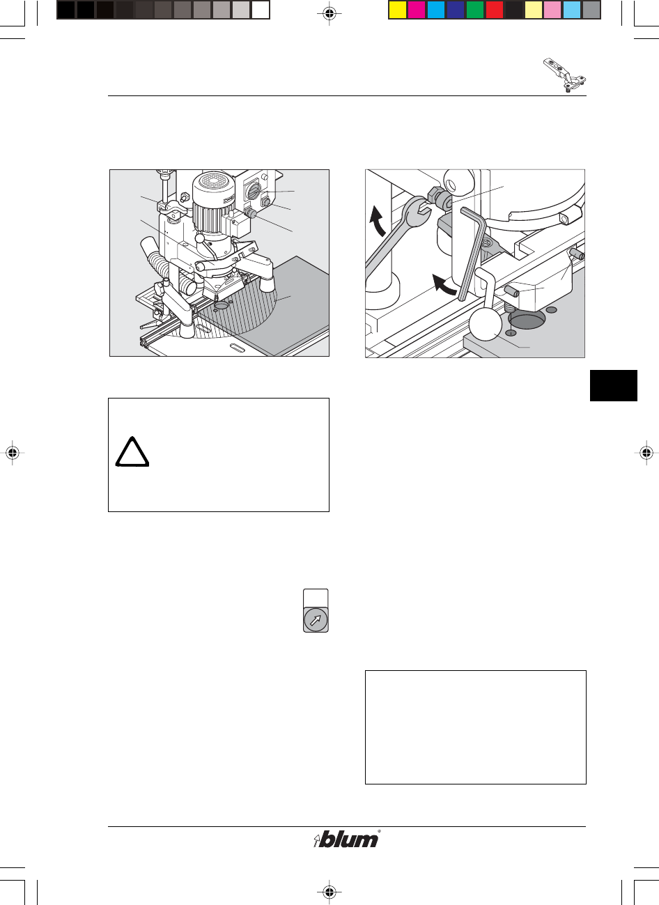
18. Drilling
WARNING!
To avoid serious injury, all
items must be removed
from the working area of the
machine, except the
workpiece! Keep your hands
out of working area (A).
• Swivel out the drilling depth gauge (F9).
• Set the main switch (E1) to drill /
press position.
• Set the hold-down switch (E3)
to pos. off
• Be sure to swivel the swing arm (F8)
upward.
• When drilling, keep one hand against
the outside edge of the door nearest
to you (outside of zone A) and push it
against the swivel stops - D7.
• Press the drill / press stoke button
(E2) until the drilling depth is reached.
• Release the drill / press stroke button
19. Check alignment of swing arm
(F8)
• Move Swing Arm (F8) down to stop
• Make sure the hinge is aligned with
the drilled hole.
• There are two possibilities which
could cause misalignment:
a) Swing arm (F8) is not vertical:
adjust screw (F21).
b) Insertionram is off center:
adjust ram adjustment screws
(F22).
Note:
If you press the drill / press
stroke button (E2) by only a
few mm (1/16"), the drilling
and pressing unit will move
down at a slower speed.
%$0,1,35(66)$,G1US $0
28
F
Hinge insertion
R
R
E1
E2
E3
F9
D7
A
F8
19. Hinge insertion
WARNING!
To avoid serious injury stay
clear of drilling area and all
pinch points (zone A)
except the workpiece.
• When inserting hinge, keep one
hand on the drill / press stroke
button (E2) and the other hand on
the swing arm (F8) or on the edge
of the door nearest you until the
hinge is totally pressed in (outside
of zone A).
• Release drill / press stroke button.
• Move swing arm (F8) up.
• Release the hold-down clamps by
briefly touching the hold-down
switch (E3).
%$0,1,35(66)$,G1US $0
29
G
Installation of wing mounting plates
G1G2 F3
G
1
5
F
3
G
3
F
6
G
2
F
3
F
3
G
1
G
2
5
Installation of wing mounting plates with system screws
1. Necessary parts
• Drill bits:
- one 5 mm dia. rotating clock wise
(G1) (marked black)
- one 5 mm dia. rotating counter
clockwise (G2) (marked orange)
• Three cover caps (F3)
• Cabinet side panel
• Mounting plates with system screws
2. Drill-bit length
(see section F- point 2)
3. Change drill pattern
• Pull out fixing pin (F5) on drill head.
• At the same time, move lever (F6)
to Symbol for line boring pattern
(G3).
• Make sure, fixing pin snaps back to
lock gearbox position.
4. Install drill bits
(see section F- point 4)
5. Check drilling depth adjustment
(see section F - points 5/6/7)
6. Check pneumatic brake setting
(see section F -point 8/9/10)
%$0,1,35(66)$,G1US $0
30
G
Installation of wing mounting plates
!
F15
F16
SY
16
D5
D6
L
16
16
D5
D6
16
L
16mm
7. Setting the fencing system (D4)
• Always place operation mode switch
to set up position and disconnect the
machine from it’s electrical source
(unplugged) before performing any
work on the drill heads, fences,
stops, or pneumatic break.
• Release both clamping levers (F15).
• Pull out both fixing pins (F16) and
set the stop system (D4) to SY.
• Firmly tighten both clamping levers
(F15).
This fixed setting provides for a
drilling distance of 1-7/16“ (37 mm).
8. Setting the swivel stops (D7)
• Always place operation mode switch
to set up position and disconnect the
machine from it’s electrical source
(unplugged) before performing any
work on the drill heads, fences,
stops, or pneumatic break.
a) If the lower edge of the door is to be
flush with the lower edge of the
cabinet, only the base ruler (D2)
needs to be repositioned.
Repositioning the base ruler:
• Release the two clamping levers
(D3) which hold the ruler in place.
• Lift up the fixing pin (D5) and move
the ruler (D2) in the direction of the
outer drill bit until the fixing pin (D5)
locks into the outer drill hole of the
indexing plate (D6).
• Firmly tighten clamping levers (D3).
Note:
This step compensates for
the 0-point offset of the wing
mounting plate (see illus. 8).
%$0,1,35(66)$,G1US $0
31
G
Installation of wing mounting plates
!
16
D3
D5
D6
16
L
X
D3
D5
X
R
R
E1
E2
E3
F9
F8
D7
A
b) If the lower edge of the door is to be
longer or shorter than the lower
edge of the cabinet, the stops (D7)
must be adjusted accordingly by the
difference in dimension. In addition,
the base ruler (D2) must be
repositioned.
Positioning the stops and ruler:
• Relocate the stops by dimension (x).
• Release the two clamping levers
(D3) which hold the ruler in place.
• Lift up the fixing pin (D5) and move
the ruler (D2) in the direction of the
outer drill bit until the fixing pin (D5)
locks into the outer drill hole of the
indexing plate (D6).
Note:
This step compensates for
the 0-point offset of the wing
mounting plate (see illus 8).
9. Place the cabinet side on the
worktable and slide it to the stop
(see section F - point 14)
10. Set the hold down clamp over
panel surface, no more than
6 mm (1/4"),
(see section F - point 15).
11. Drilling
(see section F - point 18)
12. Releasing the hold-down clamps
• Briefly touch the hold-down switch
(E3).
• Slide the cabinet side to the next
stop.
%$0,1,35(66)$,G1US $0
32
H
Drilling of line patterns
H1H2 F3
H2
H3
F
3
G
3
H
1
H
2
H
2
F
3
H
1
H
2
H
2
F
6
5 5 5
Drilling of line patterns
1. Necessary parts
• Drill bits:
one 5 mm dia. rotating clockwise
(H1) (marked black)
two 5 mm dia. rotating counter
clockwise (H2) (marked orange)
• Two cover caps (F3)
• Distance gauge for positioning stops
(H3).
• Cabinet side panel
2. Drill bit length
(see section F - point 2)
3. Change drill pattern
• Pull out fixing pin (F5) on drill head.
• At the same time, move lever (F6)
to symbol for line boring pattern
(G3).
• Make sure, fixing pin snaps back to
lock gearbox position.
4. Install drill bits
(see section F - point 4)
5. Check drilling depth adjustment
(see section F - points 5/6/7)
6. Check pneumatic brake setting
(see section F - points 8/9/10)
%$0,1,35(66)$,G1US $0
33
H
Drilling of line patterns
F15
F16
SY
L
L
D7
H3
7. Adjust fencing system (D4)
• Always place operation mode
switch to set up position and
disconnect the machine from it’s
electrical source (unplugged) before
performing any work on the drill
heads, fences, stops, or pneumatic
brake.
• Release clamping levers (F15).
• Pull out locating pin (F16), and
adjust fencing system (D4) to pos.
SY.
• Tighten clamping levers (F15).
With this adjustment, the distance
between fence and the centerline of
the drill bits is 37 mm.
8. Adjust positioning stops (D7)
(see section F - point 13)
9. Line boring
• Use Distance Gauge (H3) to set
additional positioning stops.
This will set a 3-3/4“ (96 mm) distance
between the stops and provide a
consecutive 1-1/4“ (32 mm) line boring
pattern.
%$0,1,35(66)$,G1US $0
34
H
Drilling of line patterns
R
R
E1
E2
E3
F9
D7
A
F8
10. Slide cabinet side panel against
the fence until positioned at the
stop
(see section F- point 14)
11. Adjust hold down clamps (F17)
(see section F - point 15)
12. Drilling
(see section F - point 18)
13. Releasing hold down clamps
• Briefly touch the down-hold switch
(E3).
• Position cabinet side panel to the
next stop.
%$0,1,35(66)$,G1US $0
35
J
Service and maintenance
J1
J2
J3
Maintenance
1. Maintenance
• During all maintenance operations,
disconnect the machine from it’s
electrical source (unplugged).
Re-connect only for testing.
• Regularly remove drilling dust from
the machine.
• Before every use of the machine,
check the air filter unit (J1) for water
which may accumulate in the filter
unit. Empty the unit if necessary.
• Before every use of the machine,
check the pneumatic lines and
electrical lines for damage.
• The guide elements (J2) must be
cleaned regularly with a dry cloth to
remove dust. (Do not use cleaners
or solvents)
%$0,1,35(66)$,G1US $0
36
J
Service and maintenance
J4
J5
J6
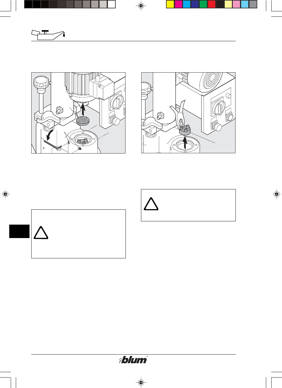
2. Replacing a damaged clutch
The clutch is defective if:
• The drill bits get jammed in the
workpiece while the motor fan (D9)
keeps on rotating.
Warning !
Replace defective or
damaged parts
immediately! Use only
original BLUM parts for
replacement!
• Set main switch to set up position.
• When replacing a damaged clutch,
machine must be disconnected from
it’s electrical power source and from
it’s compressed air supply and
pressure released from machine
(use filter bowl drain).
• Remove drill bit.
• Release the four lateral fastening
bolts (J4) from the motor (requires
about 4 complete turns).
• Lift the motor and rest it on the
control system.
Warning:
Secure the motor against
dropping!
• Remove the damping ring (J5).
• Remove the old clutch (J6).
• Mount the new clutch (J6) on the
shaft (ensure correct position
between clutch and shaft).
• Insert the damping ring (J5).
• Position the bottom part of the clutch
ready to receive the motor.
• Place the motor on the bottom part
of the clutch and make sure that it
rests properly on the flange.
• Tighten the four lateral fastening
bolts (J4).
%$0,1,35(66)$,G1US $0
37
J
Service and maintenance
J7
J8
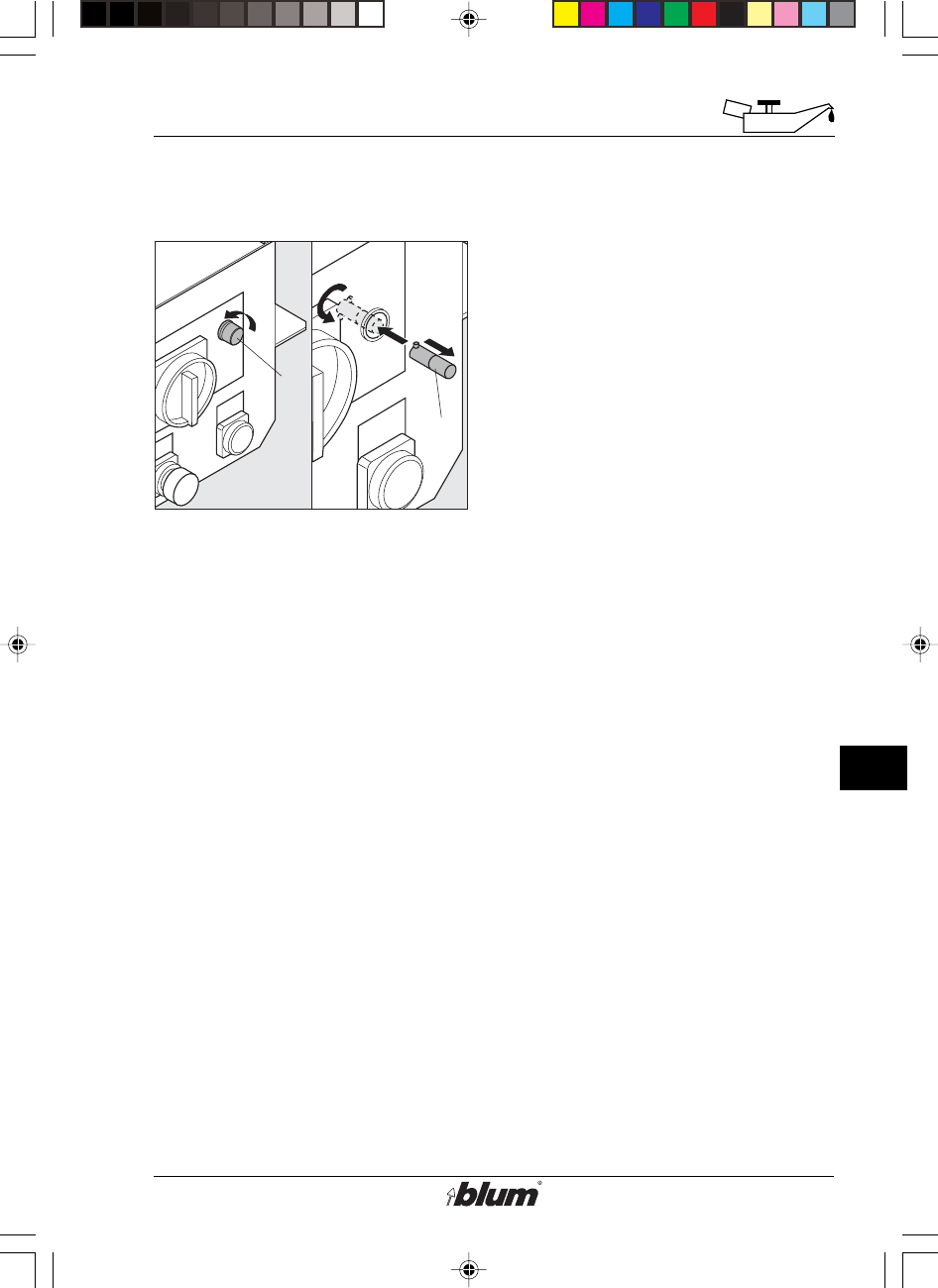
3. Replacing the operation indicator
lamp
• Disconnect the machine from the
electrical supply.
• Set the main switch to set up
position.
• Remove the lamp cover (J7) by
releasing the screw.
• Remove the defective lamp (J8).
(Push and turn counter-clockwise).
• Install a new lamp (J8). (Push and
turn clockwise).
• Reattach the cover (J7) of the
operation indicator lamp.
%$0,1,35(66)$,G1US $0

38
K
Troubleshooting - What to do, if ...?
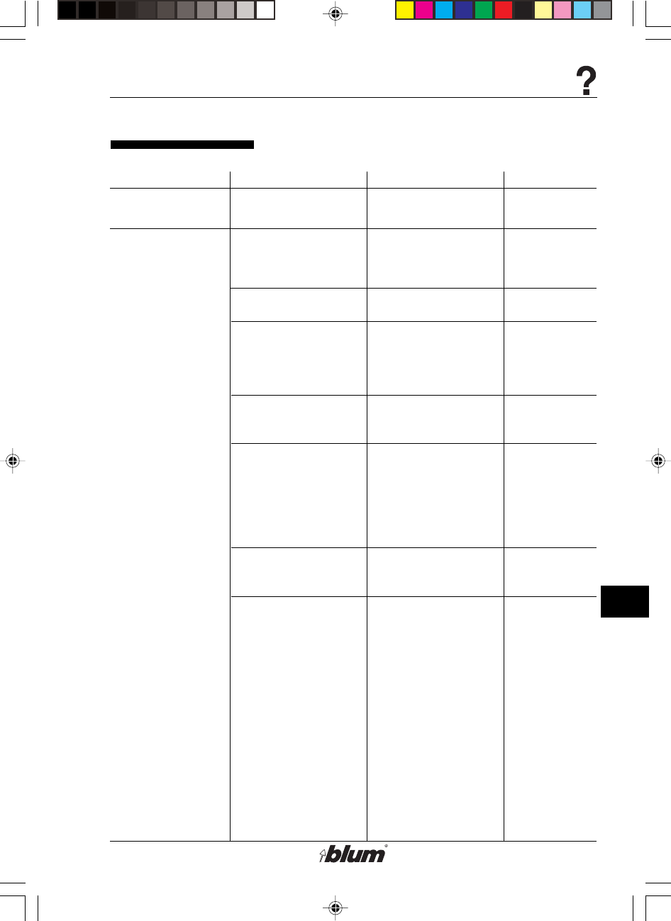
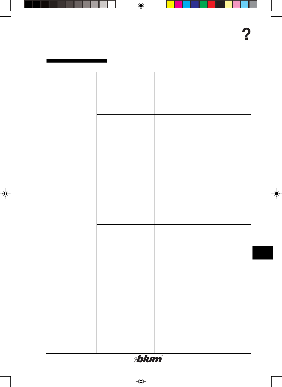
Fault during drilling
•Drilling depth is not
reached
•Setting of depth
adjustment bolt is
wrong
•Drilling depth gauge
swung in
•Drill shorter than
2-1/4“ (57 mm)
•Drill bits not
completely pushed
into the chucks
•Panel thickness is
different than
assumed thickness
(e. g. 9/16“ (15 mm)
instead of 5/8“
(16 mm))
•Machine hits an
object during down
stroke
•Drill / press stroke
button was released
before drilling depth
was reached
•Worktable lower than
15/16“ (24 mm)
•Check setting of the
depth adjustment
bolt
•Swing out drilling
depth gauge
•Adjust drill bit
•Clean chucks and
push drill bit
completely into the
chuck
•Check panel
thickness
•Adjust drilling depth
if necessary
•Use drilling depth
stop
•Remove object
•Press the drill stroke
button until the
drilling depth is
reached
•Build up the
worktable to
15/16“ (24 mm) height
See chapter F
F-10
See chapter F
F-9
See chapter F
See chapter F
No comments
See chapter F
See chapter F
No comments
No comments
No comments
Fault Cause of fault Eliminating fault Remarks
%$0,1,35(66)$,G1US $0
39
K
Troubleshooting - What to do, if ...?
Fault during drilling
Fault Cause of fault Eliminating fault Remarks
•Drilled holes are
off-center or hole
position is incorrect
•Pneumatic brake is
set too tight
•The fence stops are
set wrong
•Ruler incorrectly set
•Wood chips are
between the fence
and the fence
supports
•Fencing System
incorrectly set
•The fence extension
is not installed
properly
•Gear box does not
engage
•Location pin does not
engage into the
locating plate
•Slightly open the
throttle valve
•Check position of
fence stops and
adjust if necessary
•Adjust ruler
•Remove wood chips
and dirt from fence
support
•Check setting and if
necessary rectify
•Check fence
extension and fence
extension supports
•Check the distance
between the rulers
•Allow fixing pin for
drill head to engage
•Check position of
the location pin
See chapter F
No comments
No comments
No comments
See chapter F
No comments
No comments
See chapter F
See chapter
D and G
%$0,1,35(66)$,G1US $0
40
K
Troubleshooting - What to do, if ...?
Fault during drilling
Fault Cause of fault Eliminating fault Remarks
•Drilled holes too
large, oval or
ragged
•Drill bits get stuck
in the panel
•Drill bit diameter too
large
•Drill bit is bent
•Drills bits are dull
•Stroke speed too
high for drilling
•The panel was drilled
through completely
•Gearbox shafts are
bent
•Panel material other
than stated in the
intended use of this
machine was used
•Down stroke speed
during drilling is too
fast
•The clutch is
damaged (the drill
bits get jammed in
the workpiece while
the motor fan keeps
on rotating)
•Check drill bit
diameter
•Replace drill bit
•Regrind or replace
drill bit
•Adjust stroke speed
•Adjust drilling depth
•Replace gearbox
•Only panels of
wood, particle board
or laminated particle
board are to be used
•Adjust down stroke
brake properly
•Replace defective
clutch
No comments
No comments
No comments
See chapter F
No comments
No comments
No comments
See chapter F
See chapter I
%$0,1,35(66)$,G1US $0
41
K
Troubleshooting - What to do, if ...?
Fault during drilling
Fault Cause of fault Eliminating fault Remarks
•Drill bit cannot be
inserted in to the
chuck.
•Drill bits are dull
•Wrong motor rotation
•Wrong handed drill
bits are used
•Motor connected to
wrong voltage
•Drill chuck very dirty
•Drill shank diameter
too large
•Replace or
resharpen drill bits
•Correct the motor
rotation
•Install left hand drill
bits into chucks
marked in orange
and right hand drill
bits into chucks
marked in black
•Check the main
voltage and
compare with motor
data. If voltage
wrong, replace
machine
•Clean drill chuck -
Use cover cap!
•Replace drill bit
No comments
See chapter
D
No comments
See electrical
schematic
No comments
No comments
%$0,1,35(66)$,G1US $0
42
K
Troubleshooting - What to do, if ...?
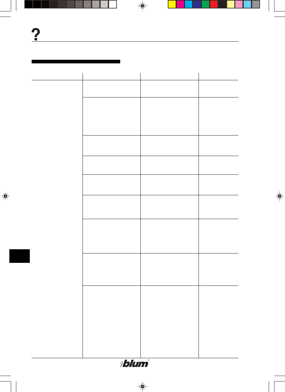
No comments
No comments
Use counter-
sink bit
No comments
No comments
See section F
See section F
No comments
See section F
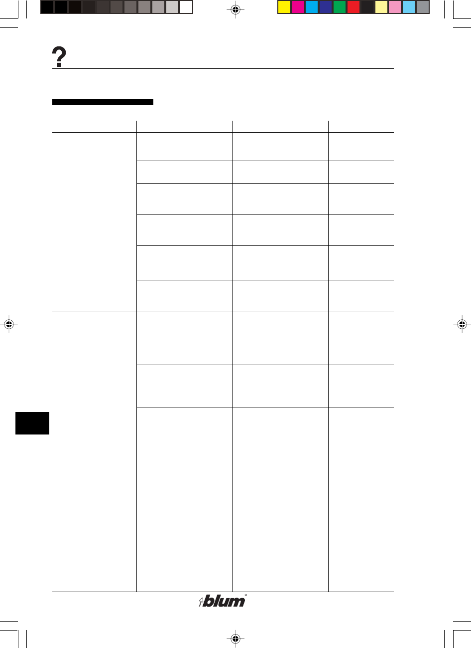
Fault during Hinge insertion
Fault Cause of fault Eliminating fault Remarks
•Hinges or fittings
cannot be inserted
at all, or can only
be inserted with
difficulties
•Air pressure is not
sufficient
•The insertion ram or
the swing arm is
hitting an object
•The surface of the
panel is too hard
•The drilling depth is
not deep enough
•The diameter of the
drill bits is too small
•The insertion ram is
off-set or installed
wrong
•The panel moved on
the work table before
the insertion cycle
•Shavings in holes
•Insertion ram or
swing arm is
displaced or twisted
•Adjust air pressure
to 6 bar (80-100 psi)
•Remove object from
path of insertion ram
or swing arm
•Check drilling
distance
•Countersink holes
•See point: Wrong
drilling depth
•Check drill bits and
replace if necessary
•Adjust insertion ram
•Adjust hold-down
clamps so panel
does not move
during the operation
•Check the shavings
air jet
•drill deeper,
if possible
•Adjust insertion ram
or swing arm
%$0,1,35(66)$,G1US $0
43
K
Troubleshooting - What to do, if ...?
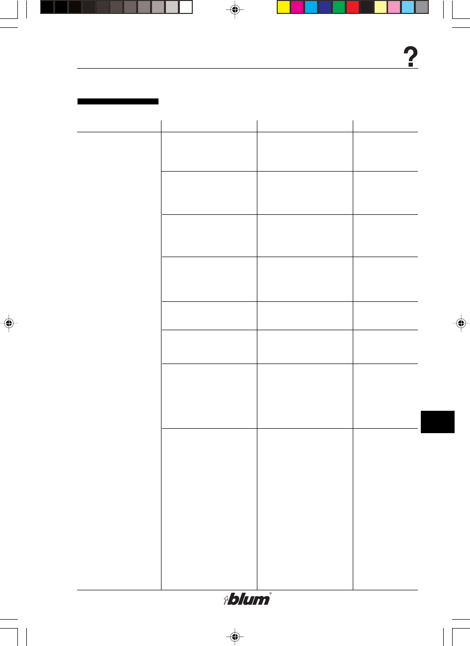
Functional fault
Fault Cause of fault Eliminating fault Remarks
•Motor does not run •Machine not
connected to
electrical source
•Machine not
connected to air
supply
•Circuit breaker has
been thrown or fuse
has expired
•Fuse under the
control panel has
expired
•Switch not on
•Swing arm is moved
down
•Motor connected to
wrong voltage
•Motor defective
•Connect machine to
electrical source
•Connect machine to
air supply
•Switch on or replace
fuse
•Repair by authorized
electrician or Blum
repair center
•Main switch on
Pos.1
•Move swing arm up
•Check main voltage
and compare with
motor data. Replace
machine if voltage is
wrong
•Replace motor by
authorized
electrician or return
to Blum repair
center
No comments
No comments
No comments
See electrical
schematic
See section E
See section F
See electrical
schematic
No comments
%$0,1,35(66)$,G1US $0

44
K
Troubleshooting - What to do, if ...?
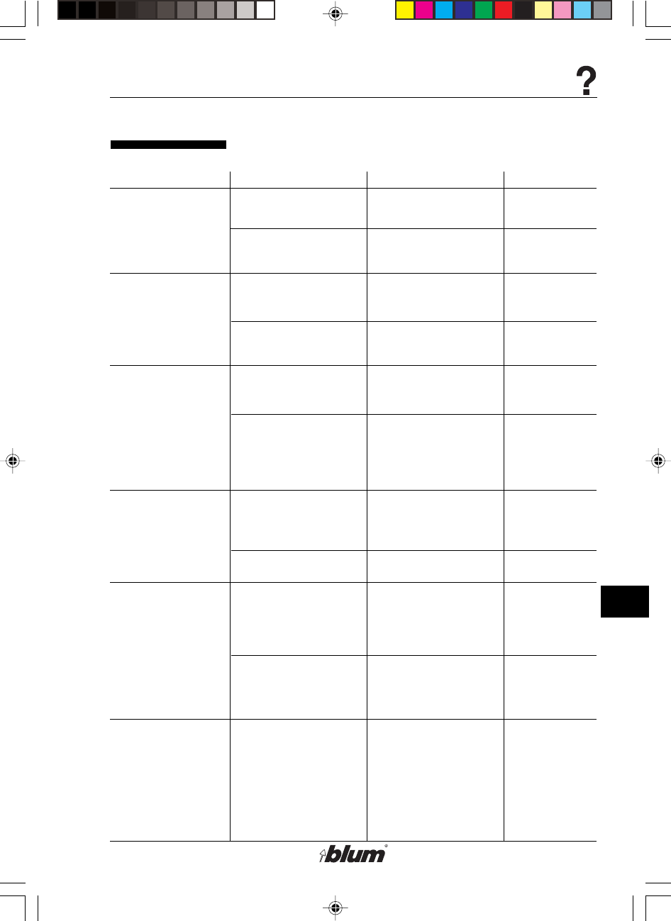
Functional fault
Fault Cause of fault Eliminating fault Remarks
•Motor overheats
•Machine does not
cycle when the
drill / press stroke
button is activated
•Motor connected to
wrong voltage
•Drilling in hard wood
with too great a
stroke speed
•Motor is so dusty that
cooling is not
possible
•Machine not
connected to air
supply
•Air pressure not
sufficient
•Hose has a kink in it
•Throttle valve of the
pneumatic brake is
closed
•Check main voltage
and compare with
motor data. If
voltage is wrong,
replace machine
•Adjust stroke speed
•Clean dust off
machine
•Connect machine to
air supply
•Adjust air pressure
(min 80 psi to max
100 psi)
•Examine air hose
•Adjust pneumatic
brake
See electrical
schematic
See section F
No comments
See section D
See section D
No comments
See section F
%$0,1,35(66)$,G1US $0
45
K
Troubleshooting - What to do, if ...?
Functional fault
Fault Cause of fault Eliminating fault Remarks
•Hold-down clamp
malfunctions
•Operation indicator
lamp does not light
•Air filter connection
leaks
•Shavings air jet is
too weak
•Gearbox is
defective
•Drill / press stroke
valve defect
•Cylinder defect
•Wrong switch
position
•Hold-down clamp
valve defect
•Operation indicator
lamp defective
•Control circuit- fuse
defective
•Angle screw does not
seal
•Other faults
•Air hose is kinked or
there is a leaky
connection
somewhere
•Shavings air jet is
misadjusted
•Bearings, gears or
spindles are
defective
•Repair by Blum
repair center
•Repair by Blum
repair center
•Check switch
position
•Repair by Blum
repair center
•Replacing the lamp
•Replace control
circuit fuse by an
authorised
electrician only
•Replace angle
screw or use sealing
agent
•Replace air filter
•Replace the air hose
•Reset shavings air
jet by turning the air
hose
•Replace gearbox
No comments
No comments
See section E
No comments
See section J
No comments
No comments
No comments
No comments
No comments
No comments
%$0,1,35(66)$,G1US $0
46
L
Appendix
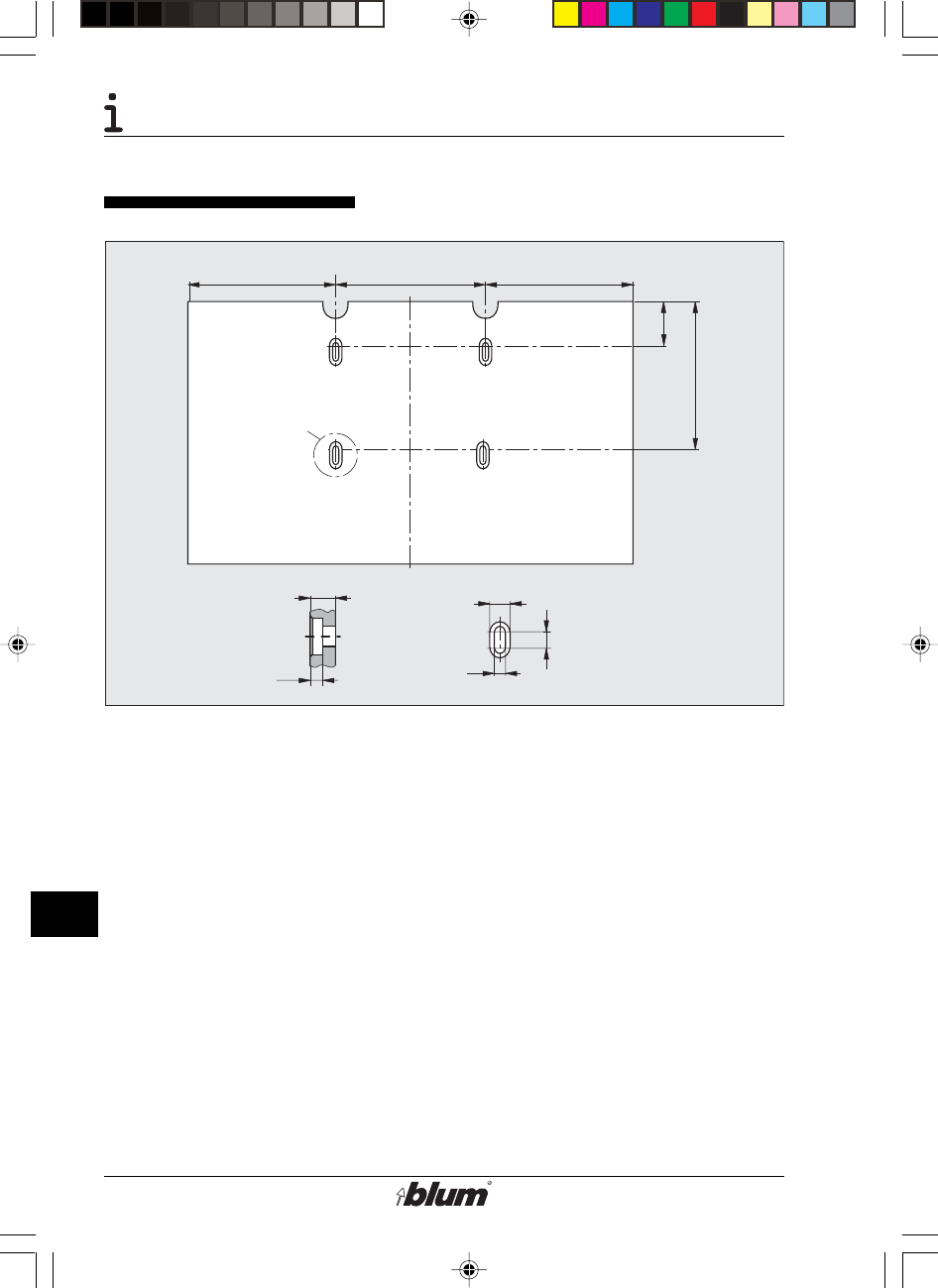
198.5 198.5200
24
11
18
9
14
45
205
X
Detail X
Do-it-yourself-worktable
• Use plywood or laminated wood for
the worktable!
• Use M8 bolts with nuts and
washers to secure the worktable,
or order the Blum mounting set
MZA.1002.
%$0,1,35(66)$,G1US $0
47
L
Appendix
Limited warranty
The Blum MINIPRESS has been manufactured using the highest quality materials to
provide long lasting performance.
Rigorous quality controls and a final inspection ensures that each machine is
delivered in good working condition. These quality control measures enable Blum to
offer this one year limited warranty on the machine, starting with the date of delivery.
(Please return the enclosed „Warranty Reply Card“ to our address).
The Blum MINIPRESS is warranted to be free of defects in materials and
workmanship for a period of one year from the date of purchase. This warranty is in
lieu of any other warranties expressed or implied.
This warranty does not include any implied warranties of fitness or
merchantability, such warranties are specifically excluded.
In no event shall Blum be liable for any incidental or consequential damages, damage
in transportation, damage from misuse or improper handling of machine, lost
production time or materials, parts which are subject to normal wear (such as drill
bits), or for any other damages directly or indirectly arising from the sale, exept as
provided specifically in this warranty.
Some portions of this warranty may not be applicable due to provisions of State Law.
The non-applicability of any portion of this warranty shall not affect the remaining
terms and conditions of the warranty.
Any damages under this warranty shall be limited to a maximium of the purchase
price of the machine.
Should any defect be found in the machine, please submit to Blum, in writing, the
reference number, the serial number, and the name of the distributor from whom the
machine was purchased. Replacement parts included under this warranty will be
furnished, free-of-charge.
This warranty is also subject to the specific terms and conditions set forth in the
purchase agreement for this equipment. The warranty language in the purchase
agreement shall govern in the event of any difference in terms.
%$0,1,35(66)$,G1US $0
48
L
Appendix
!
Technical Data
1. General data
• Voltage: See type plate
• Power supply: See type plate
• Connected load
motor 1.1 kW
• rpm See type plate
• Compressed air: 80 - 100 psi
• Air consumption: 1.5 liters per
cycle
Important:
Provide a 16 A backup fuse
breaker.
2. Weight and measurements
• Weight: m = 81 lbs (37 kg)
• Dimensions:
H = 27-15/16" (710 mm)
W = 24" (610 mm)
D = 29-15/16" (760 mm)
3. Maximum thickness of workpiece
• Drilling only 1-3/4“ (45 mm)
• Insertion of fittings
depending on fitting max. 13/16“
max. (20 mm)
max. 1-1/4“
max. (32 mm)
4. Maximum drilling distance
• Drilling distance
center spindle: (-3/16“) - 2-1/2“
(-5mm) - 64 mm
5. Maximum drilling diameter
• Maximum drilling
diameter 1-3/8“ (35 mm)
6. Accessories
• For accessories see BLUM catalog
%$0,1,35(66)$,G1US $0

49
L
Appendix
%$0,1,35(66)$,G1US $0
50
L
Appendix
%$0,1,35(66)$,G1US $0
51
L
Appendix
%$0,1,35(66)$,G1US $0

52
L
Appendix
Subject to change without notice! IDNR: 598.608.0
BAU0004822774 IDX:01
BA63.02 EN-US / 08.06
Printed in Austria
%$0,1,35(66)$,G1US $0
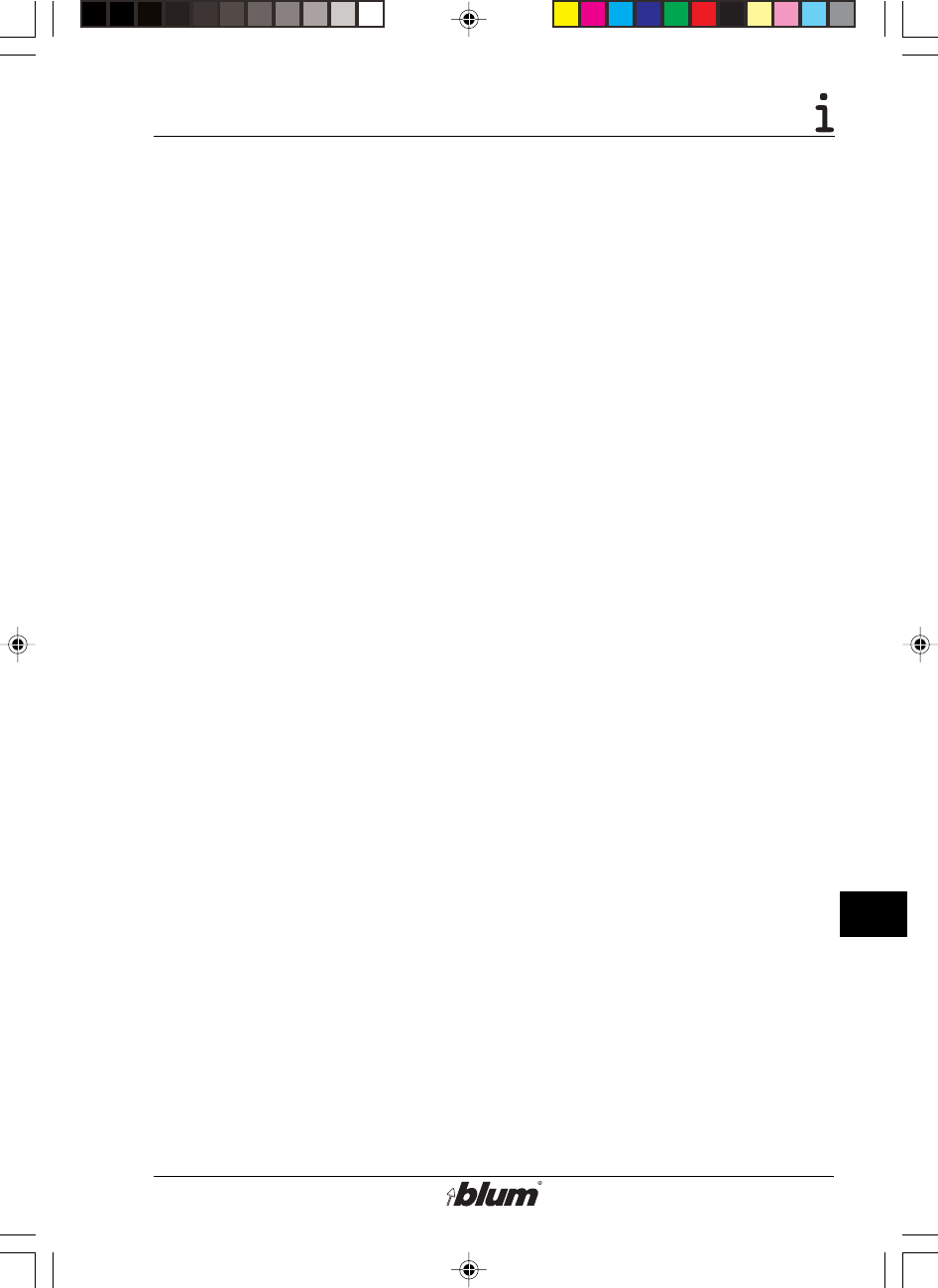
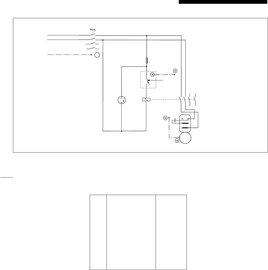
Änderungen vorbehalten ! Id. Nr. 5986300 Printed in Austria Schema MP FA 3x460V CSA/06.04-tg
MINIPRESS MP FA 3x460V 60Hz
File: Schema MP FA 3x460V CSA.p65
SCHALTSCHEMA / CIRCUIT DIAGRAM
SCHÉMA ÉLECTRIQUE / ESQUEMA DE CONEXIONES
SCHEMA ELETTRICO / KYTKENTÄKAAVIO
S1 690V IEC, 600V UL/CSA 4552380
T1 460V/230V, 15VA 5994850
F1, F2 250V, Ø5x20mm, 0,1AT 3809200
1S2 250V/6A, G1/4" 3988890
H1 230VAC 2456160
K1 400V (max.690V), 12A 2456300
M1 1,1kW, 3x460V 3282959
13 5
2 4 6
13
14
K1
A1
A2
1
2
4
1S2
P
File: MP FA 3x460V.FH9
prim: 460V 50/60Hz
sek: 230V, 10VA
0,1AT 0,1AT
T1
0V 460V
0V 230V
3x460V 60Hz
2,3A, 1,1kW,
3275 Upm
3x460V
U 1 V 1 W 1
W 2 U 2 V 2
1
3
5
2
4
6
S1
78
PE
L1
L2
schwarz - black
L3
weiss - white
PE grün - green
rot - red
H1
3~ M1
BAU0004966023 IDX:00

Änderungen vorbehalten ! Id. Nr. 5986300 Printed in Austria Schema MP FA 3x460V CSA/06.04-tg
MINIPRESS MP FA 3x460V 60Hz
File: Schema MP FA 3x460V CSA.p65
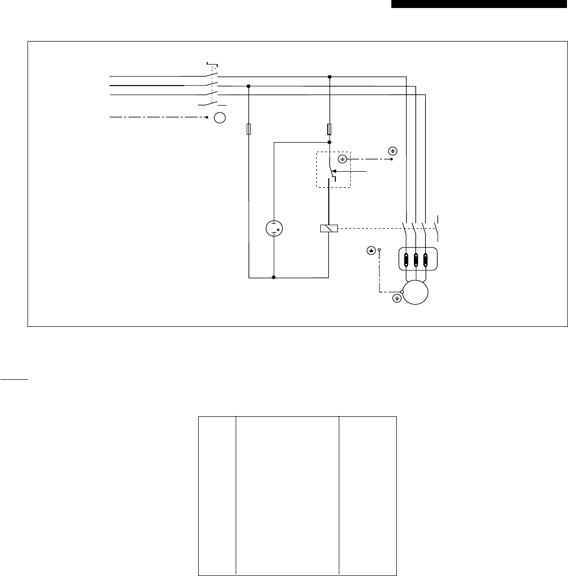
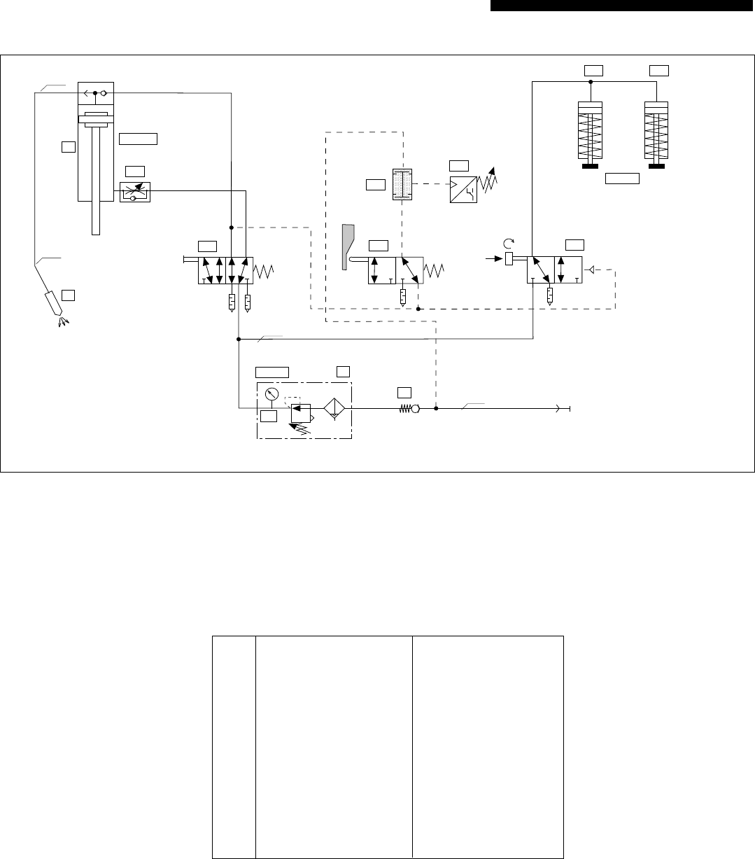
PNEUMATIKSCHEMA / PNEUMATIC DIAGRAM
SCHÉMA PNEUMATIQUE / ESQUEMA DEL CIRCUITO NEUMATICO
SCHEMA PNEUATICO / PAINEILMAKAAVIO
0Gr.3 0474060
0V G1/8" 1799490
0Z G1/8", 5µm 3975560
0Z1 G1/8", DM40, 0-10 4398790
1A G1/8" 2454384
1V1 G1/8" 8585365
1V2 M5 3976000
1V3 G1/8" 3988600
1V5 G1/8" 2454970
1S2 G1/4", 250V/6A 3988890
2V1 G1/8" 1800330
2A1 G1/8" 2285329 li/left
2A2 G1/8" 2285679 re/right
ø80x105
5 1 3
42
13
2
1
1
2
PR
A
Y
1A
2A1 2A2
2V1
1Z
1V1
0V
0Z
1V5 1S2
1V2
p = 6bar
(p min = 5bar/p max = 7bar)
File: MP EA Pneumatik.fh9
0-10bar
ø6/4
ø8/6
1V3
1-10 bar / 3 bar
0Z1
ø25x25
ø8/6
ø6/4
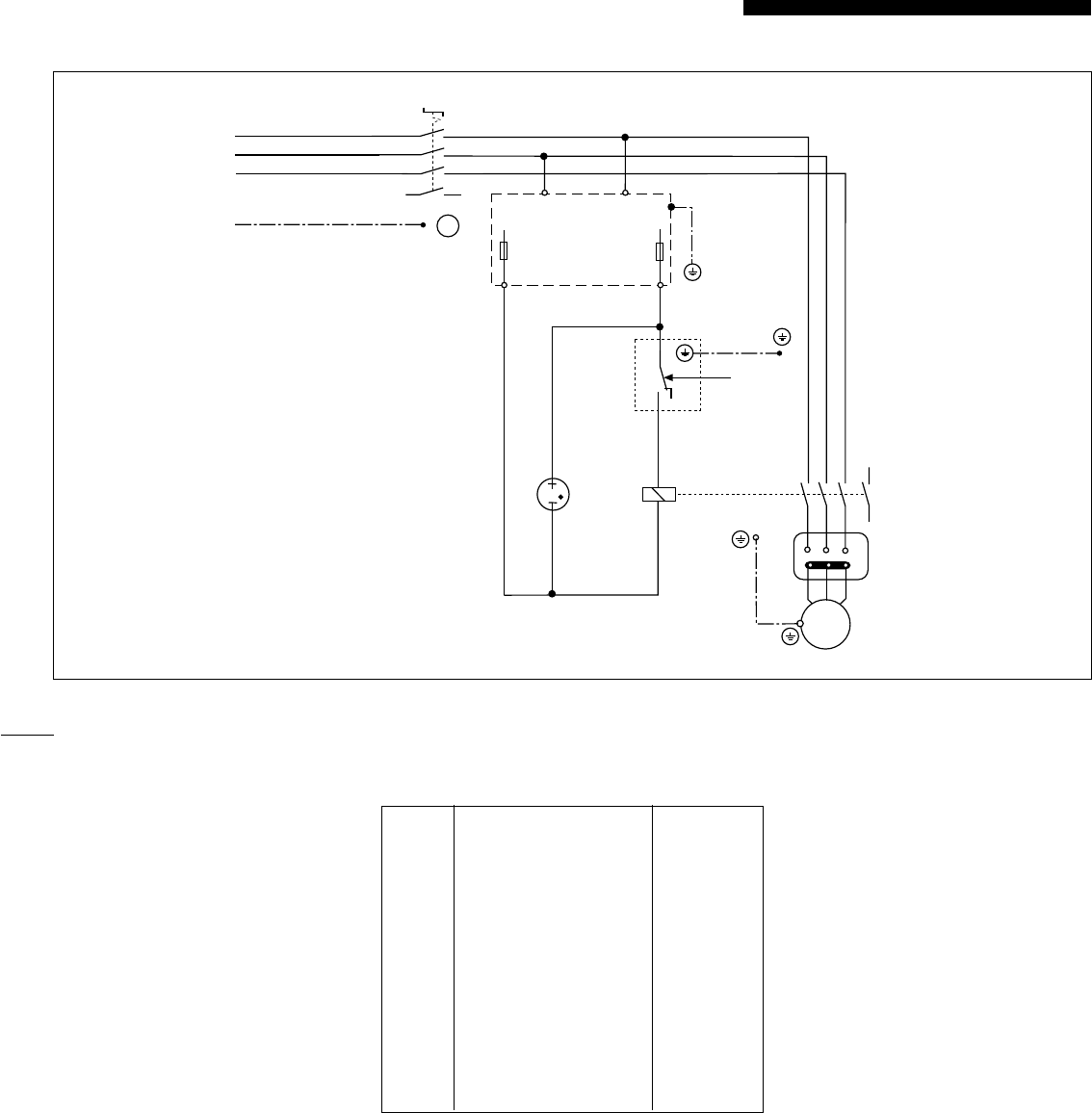
Änderungen vorbehalten ! Id. Nr. 5986240 Printed in Austria Schema MP FA 3x220V CSA/06.04-tg
MINIPRESS MP FA 3x220V
File: Schema MP FA 3x220V CSA.p65
SCHALTSCHEMA / CIRCUIT DIAGRAM
SCHÉMA ÉLECTRIQUE / ESQUEMA DE CONEXIONES
SCHEMA ELETTRICO / KYTKENTÄKAAVIO
S1 690V IEC, 600V UL/CSA 4552380
F1, F2 250V, Ø5x20mm, 1,6AT 1788700
1S2 250V/6A, G1/4" 3988890
H1 230VAC 2456160
K1 400V (max.690V), 12A 2456300
M1 1,1kW, 3x220V 3247969
13 5
2 4 6
13
14
K1
A1
A2
1
2
4
1S2
P
File: MP FA 3x220V CSA.FH9
F2 T1,6A F1 T1,6A
3x220V 60Hz
4,7A, 1,1kW,
3275 Upm
3x220V
U 1 V 1 W 1
W 2 U 2 V 2
1
3
5
2
4
6
S1
78
PE
L1
L2
schwarz - black
L3
weiss - white
PE grün - green
rot - red
H1
3~ M1
BAU0004966005 IDX:00
Änderungen vorbehalten ! Id. Nr. 5986240 Printed in Austria Schema MP FA 3x220V CSA/06.04-tg
MINIPRESS MP FA 3x220V
File: Schema MP FA 3x220V CSA.p65
PNEUMATIKSCHEMA / PNEUMATIC DIAGRAM
SCHÉMA PNEUMATIQUE / ESQUEMA DEL CIRCUITO NEUMATICO
SCHEMA PNEUATICO / PAINEILMAKAAVIO
0Gr.3 0474060
0V G1/8" 1799490
0Z G1/8", 5µm 3975560
0Z1 G1/8", DM40, 0-10 4398790
1A G1/8" 2454384
1V1 G1/8" 8585365
1V2 M5 3976000
1V3 G1/8" 3988600
1V5 G1/8" 2454970
1S2 G1/4", 250V/6A 3988890
2V1 G1/8" 1800330
2A1 G1/8" 2285329 li/left
2A2 G1/8" 2285679 re/right
ø80x105
5 1 3
42
13
2
1
1
2
PR
A
Y
1A
2A1 2A2
2V1
1Z
1V1
0V
0Z
1V5 1S2
1V2
p = 6bar
(p min = 5bar/p max = 7bar)
File: MP EA Pneumatik.fh9
0-10bar
ø6/4
ø8/6
1V3
1-10 bar / 3 bar
0Z1
ø25x25
ø8/6
ø6/4
Änderungen vorbehalten ! Id. Nr. 632.075.0 Printed in Austria Schema MP FA 1x220V CSA-ATB/07.04-tg
BAU0005694594 IDX00
MINIPRESS MP FA 1x220V
File: Schema MP FA 1x220V CSA-ATB.p65
SCHALTSCHEMA / CIRCUIT DIAGRAM
SCHÉMA ÉLECTRIQUE / ESQUEMA DE CONEXIONES
SCHEMA ELETTRICO / KYTKENTÄKAAVIO
S1 690V IEC, 600V UL/CSA 4552380
F1 250V, Ø5x20mm, 1,6AT 1788700
1S2 250V/6A, G1/4" 3988890
H1 230VAC 2456160
K1 400V (max.690V), 12A 2456300
M1 1,1kW, 220V/60Hz 3244009
C25µF, 400VDB 2649801
13 5
2 4 6
13
14
K1
A1
A2
1
2
4
1S2 P
File: MP FA 1x220V-ATB.FH9
F1 T1,6A
PE
N
L1 white
black
PE green
T1
T5
T4
T8
L
N
H1
X1
X2
1~ M1
1x220V 60Hz,
S6-60%
6,5A, 1,48HP, 3420RPM
C 25µF 400VDB
C
1
3
5
2
4
6
S1
78
Änderungen vorbehalten ! Id. Nr. 632.075.0 Printed in Austria Schema MP FA 1x220V CSA-ATB/07.04-tg
BAU0005694594 IDX00
MINIPRESS MP FA 1x220V
File: Schema MP FA 1x220V CSA-ATB.p65
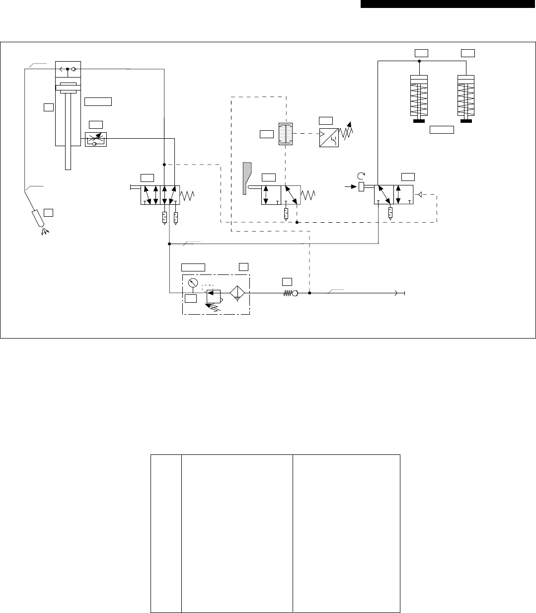
PNEUMATIKSCHEMA / PNEUMATIC DIAGRAM
SCHÉMA PNEUMATIQUE / ESQUEMA DEL CIRCUITO NEUMATICO
SCHEMA PNEUATICO / PAINEILMAKAAVIO
0Gr.3 0474060
0V G1/8" 1799490
0Z G1/8", 5µm 3975560
0Z1 G1/8", DM40, 0-10 4398790
1A G1/8" 2454384
1V1 G1/8" 8585365
1V2 M5 3976000
1V3 G1/8" 3988600
1V5 G1/8" 2454970
1S2 G1/4", 250V/6A 3988890
2V1 G1/8" 1800330
2A1 G1/8" 2285329 li/left
2A2 G1/8" 2285679 re/right
ø80x105
5 1 3
42
13
2
1
1
2
PR
A
Y
1A
2A1 2A2
2V1
1Z
1V1
0V
0Z
1V5 1S2
1V2
p = 6bar
(p min = 5bar/p max = 7bar)
File: MP EA Pneumatik.fh9
0-10bar
ø6/4
ø8/6
1V3
1-10 bar / 3 bar
0Z1
ø25x25
ø8/6
ø6/4

Blum, Inc.
7733 Old Plank Rd.
Stanley, NC 28164
toll free 800-438-6788
local 704-827-1345
fax 704-827-0799
internet www.blum.us
Subject to change without notice! IDNR: 598.594.0
BAU0004823171 IDX:00
BA63.01 EN-US / 12.03
Printed in Austria
