54 7891 02E Bogen ENHANCER ESYSx(M) Systems Wiring Diagrams ENHANCE ESYSdia
User Manual: Bogen ENHANCER ESYSx(M) Systems Wiring Diagrams Bogen Microphones s - Telecomuserguides.com
Open the PDF directly: View PDF ![]() .
.
Page Count: 4

+
25V
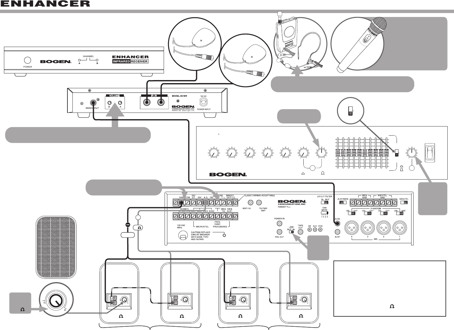
ESYS1(M)
S86T725PG8WVR
Ceiling Speakers (4)
Gold Seal Series
Amplifier
FRONT VIEW
MASTER
6
4
100
IN
OUT
8
O
ACOUSTIC
EQ
16K12K
+
12
T
FEEDBACK
CONTROL
8K5K
-
12
U
02
8K4K1K500 2K
3.1K2K500 800 1.2K
250125
12
+
6
3
9
62.5
315200
3
6
12
-
9
125
80
POWERAUX 2
4
6
4
010
82
6
4
MIC 5/TEL
100
82 82
0
MIC 6/AUX 1MIC 4
6
4
6
10010
82
4
6
4
MIC 2
0100
282
MIC 3
OUTIN
CONTOUR
MIC 1
6
4
100
2 8
GOLD SEAL SERIES
6
10
FRONT VIEW
REAR VIEW
REAR VIEW
FRONT VIEW
ENHANCER
IR Receiver
REAR VIEW
ESYS1 NOTES:
1.
When switch is set to "FEEDBACK CONTROL,"
the amplifier can be used to improve
"Max Volume before Feedback".
(see Fig. A)
2. Cut/Remove bare wire tips off of unused
speaker leads on all speakers.
(see Fig. B)
3.
If necessary, individual speaker output levels
can be adjusted by the Speaker’s Recessed
Volume Control or by Power Taps. (see Fig. C)
+
O
ACOUSTIC
EQ
T
FEEDBACK
CONTROL
U
The Enhancer Receiver's mixed output level (for each
channel) is controlled by the "A" and "B" Volume Controls.
Fig. A
(see NOTE 1)
Volume Control
for Enhancer
Master
Volume
Control
for System
Output
ground
25V
BCIRS
Unit 1
BCIRS
Unit 2
Fig. B
(see NOTE 2)
CUT BLACK BROWN
+
25V
+
25V
+
25V
BLACK
COMMON
BROWN 4W
RED 2W
ORANGE 1W
YELLOW 1/2W
GREEN 1/4W
BLUE 1/8W
VIOLET --------
GREY --------
WHITE --------
WIRE COLOR
25V
Fig. C
(see NOTE 3)
Recessed
Volume Control.
BCWBT
MAX
CHG.
BATTMI
The Enhancer Body-Pack Transmitter (BCWBT) output
level is controlled by the body-pack's volume control.
SYSTEMS
WIRING DIAGRAMS
LINK
switch
set to
“IN”
Both LINK
Connection
jumpers
should remain
in place
BCWHT
Wireless
Handheld
MIC
The (
BCWHT) Wireless
Handheld Microphone
operates solely on
channel "B".
The BCWHT Mic
is
available with the
ESYS “M” package.
ENHANCEMENT
AUDIO
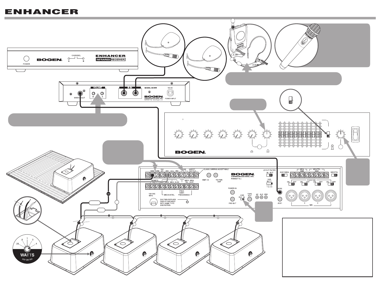
ESYS2(M)
FG15W
Surface-Mount
Speakers (4)
Gold Seal Series
Amplifier
FRONT VIEW
MASTER
6
4
100
IN
OUT
8
O
ACOUSTIC
EQ
16K12K
+
12
T
FEEDBACK
CONTROL
8K5K
-
12
U
02
8K4K1K500 2K
3.1K2K500 800 1.2K
250125
12
+
6
3
9
62.5
315200
3
6
12
-
9
125
80
ENHANCEMENT
AUDIO
POWERAUX 2
4
6
4
010
82
6
4
MIC 5/TEL
100
82 82
0
MIC 6/AUX 1MIC 4
6
4
6
10010
82
4
6
4
MIC 2
0100
282
MIC 3
OUTIN
CONTOUR
MIC 1
6
4
100
2 8
GOLD SEAL SERIES
6
10
FRONT VIEW
REAR VIEW
REAR VIEW
FRONT VIEW
ENHANCER
IR Receiver
REAR VIEW
O
ACOUSTIC
EQ
T
FEEDBACK
CONTROL
U
The Enhancer Receiver's mixed output level (for each
channel) is controlled by the "A" and "B" Volume Controls.
Fig. A
(see NOTE 1)
Volume Control
for Enhancer
Master
Volume
Control
for System
Output
BCIRS
Unit 1
BCIRS
Unit 2
+
8
8
LINE
1W
2W
4W
7.5W
15W
INPUT
+
8
8
LINE
1W
2W
4W
7.5W
15W
INPUT
++
8
8
LINE
1W
2W
4W
7.5W
15W
INPUT
+
8
8
LINE
1W
2W
4W
7.5W
15W
INPUT
+
ground
8
+
8
8
LINE
1W
2W
4W
7.5W
15W
Fig. B
(see NOTE 2)
8
8
88
FG15W
set to
8
ESYS2 NOTES:
1.
When switch is set to "FEEDBACK CONTROL,"
the amplifier can be used to improve
"Max Volume before Feedback".
(see Fig. A)
2. On each FG15W speaker, turn the Tap
Selector setting to 8 . (see Fig. B)
BCWBT
MAX
CHG.
BATTMI
The Enhancer Body-Pack Transmitter (BCWBT) output
level is controlled by the body-pack's volume control.
++
Series Connected Series Connected
LINK
switch
set to
“IN”
Both LINK Connection
jumpers
should remain in place
BCWHT
Wireless
Handheld
MIC
The (
BCWHT) Wireless
Handheld Microphone
operates solely on
channel "B".
The BCWHT Mic
is
available with the
ESYS “M” package.
+
25V
ESYS1(M)
S86T725PG8WVR
Ceiling Speakers (4)
Gold Seal Series
Amplifier
FRONT VIEW
MASTER
6
4
100
IN
OUT
8
O
ACOUSTIC
EQ
16K12K
+
12
T
FEEDBACK
CONTROL
8K5K
-
12
U
02
8K4K1K500 2K
3.1K2K500 800 1.2K
250125
12
+
6
3
9
62.5
315200
3
6
12
-
9
125
80
POWERAUX 2
4
6
4
010
82
6
4
MIC 5/TEL
100
82 82
0
MIC 6/AUX 1MIC 4
6
4
6
10010
82
4
6
4
MIC 2
0100
282
MIC 3
OUTIN
CONTOUR
MIC 1
6
4
100
2 8
GOLD SEAL SERIES
6
10
FRONT VIEW
REAR VIEW
REAR VIEW
FRONT VIEW
ENHANCER
IR Receiver
REAR VIEW
ESYS1 NOTES:
1.
When switch is set to "FEEDBACK CONTROL,"
the amplifier can be used to improve
"Max Volume before Feedback".
(see Fig. A)
2. Cut/Remove bare wire tips off of unused
speaker leads on all speakers.
(see Fig. B)
3.
If necessary, individual speaker output levels
can be adjusted by the Speaker’s Recessed
Volume Control or by Power Taps. (see Fig. C)
+
O
ACOUSTIC
EQ
T
FEEDBACK
CONTROL
U
The Enhancer Receiver's mixed output level (for each
channel) is controlled by the "A" and "B" Volume Controls.
Fig. A
(see NOTE 1)
Volume Control
for Enhancer
Master
Volume
Control
for System
Output
ground
25V
BCIRS
Unit 1
BCIRS
Unit 2
Fig. B
(see NOTE 2)
CUT BLACK BROWN
+
25V
+
25V
+
25V
BLACK
COMMON
BROWN 4W
RED 2W
ORANGE 1W
YELLOW 1/2W
GREEN 1/4W
BLUE 1/8W
VIOLET --------
GREY --------
WHITE --------
WIRE COLOR
25V
Fig. C
(see NOTE 3)
Recessed
Volume Control.
BCWBT
MAX
CHG.
BATTMI
The Enhancer Body-Pack Transmitter (BCWBT) output
level is controlled by the body-pack's volume control.
SYSTEMS
WIRING DIAGRAMS
LINK
switch
set to
“IN”
Both LINK
Connection
jumpers
should remain
in place
BCWHT
Wireless
Handheld
MIC
The (
BCWHT) Wireless
Handheld Microphone
operates solely on
channel "B".
The BCWHT Mic
is
available with the
ESYS “M” package.
ENHANCEMENT
AUDIO
ESYS2(M)
FG15W
Surface-Mount
Speakers (4)
Gold Seal Series
Amplifier
FRONT VIEW
MASTER
6
4
100
IN
OUT
8
O
ACOUSTIC
EQ
16K12K
+
12
T
FEEDBACK
CONTROL
8K5K
-
12
U
02
8K4K1K500 2K
3.1K2K500 800 1.2K
250125
12
+
6
3
9
62.5
315200
3
6
12
-
9
125
80
ENHANCEMENT
AUDIO
POWERAUX 2
4
6
4
010
82
6
4
MIC 5/TEL
100
82 82
0
MIC 6/AUX 1MIC 4
6
4
6
10010
82
4
6
4
MIC 2
0100
282
MIC 3
OUTIN
CONTOUR
MIC 1
6
4
100
2 8
GOLD SEAL SERIES
6
10
FRONT VIEW
REAR VIEW
REAR VIEW
FRONT VIEW
ENHANCER
IR Receiver
REAR VIEW
O
ACOUSTIC
EQ
T
FEEDBACK
CONTROL
U
The Enhancer Receiver's mixed output level (for each
channel) is controlled by the "A" and "B" Volume Controls.
Fig. A
(see NOTE 1)
Volume Control
for Enhancer
Master
Volume
Control
for System
Output
BCIRS
Unit 1
BCIRS
Unit 2
+
8
8
LINE
1W
2W
4W
7.5W
15W
INPUT
+
8
8
LINE
1W
2W
4W
7.5W
15W
INPUT
++
8
8
LINE
1W
2W
4W
7.5W
15W
INPUT
+
8
8
LINE
1W
2W
4W
7.5W
15W
INPUT
+
ground
8
+
8
8
LINE
1W
2W
4W
7.5W
15W
Fig. B
(see NOTE 2)
8
8
88
FG15W
set to
8
ESYS2 NOTES:
1.
When switch is set to "FEEDBACK CONTROL,"
the amplifier can be used to improve
"Max Volume before Feedback".
(see Fig. A)
2. On each FG15W speaker, turn the Tap
Selector setting to 8 . (see Fig. B)
BCWBT
MAX
CHG.
BATTMI
The Enhancer Body-Pack Transmitter (BCWBT) output
level is controlled by the body-pack's volume control.
++
Series Connected Series Connected
LINK
switch
set to
“IN”
Both LINK Connection
jumpers
should remain in place
BCWHT
Wireless
Handheld
MIC
The (
BCWHT) Wireless
Handheld Microphone
operates solely on
channel "B".
The BCWHT Mic
is
available with the
ESYS “M” package.
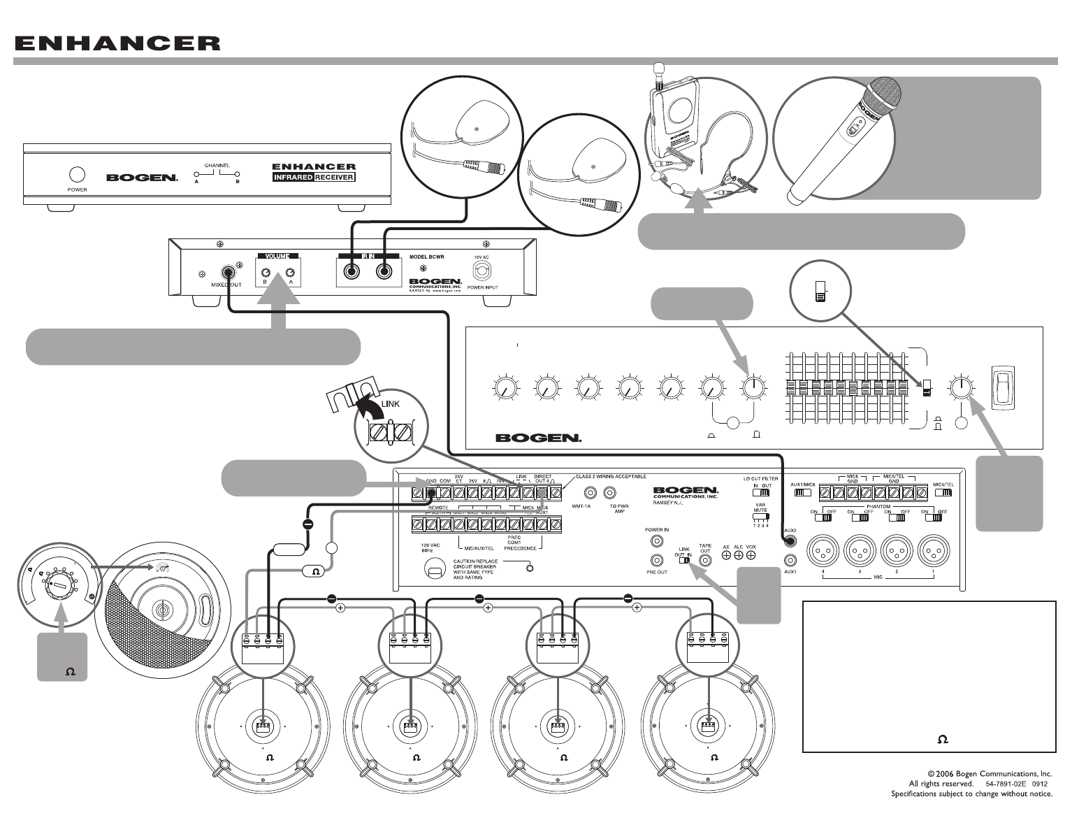
ESYS3(M)
CSD2X2 Ceiling
Speakers (4)
FULL VIEW
MASTER
6
4
100
IN
OUT
8
O
ACOUSTIC
EQ
16K12K
+
12
T
FEEDBACK
CONTROL
8K5K
-
12
U
02
8K4K1K500 2K
3.1K2K500 800 1.2K
250125
12
+
6
3
9
62.5
315200
3
6
12
-
9
125
80
POWERAUX 2
4
6
4
010
82
6
4
MIC 5/TEL
100
82 82
0
MIC 6/AUX 1MIC 4
6
4
6
10010
82
4
6
4
MIC 2
0100
282
MIC 3
OUTIN
CONTOUR
MIC 1
6
4
100
2 8
GOLD SEAL SERIES
6
10
FRONT VIEW
REAR VIEW
TOP VIEW
FRONT VIEW
ENHANCER
IR Receiver
REAR VIEW
ESYS3 NOTES:
1.
When switch is set to "FEEDBACK CONTROL,"
the amplifier can be used to improve
"Max Volume before Feedback".
(see Fig. A)
2. Cut/Remove bare wire tips off of unused
speaker leads.
(see Fig. B)
3.
If necessary, individual speaker output levels
can be adjusted by the Speaker’s Power Tap
Selector Switch. (see Fig. C)
+
O
ACOUSTIC
EQ
T
FEEDBACK
CONTROL
U
The Enhancer Receiver's mixed output level (for each
channel) is controlled by the "A" and "B" Volume Controls.
Fig. A
(see NOTE 1)
Volume Control
for Enhancer
Master
Volume
Control
for System
Output
ground
25V
BCIRS
Unit 1
BCIRS
Unit 2
BLACK YELLOW
++ + +
Fig. B
(see NOTE 2)
CUT
Gold Seal Series
Amplifier
25V 25V 25V 25V
Fig. C
(see NOTE 3)
BCWBT
MAX
CHG.
BATTMI
The Enhancer Body-Pack Transmitter (BCWBT) output
level is controlled by the body-pack's volume control.
LINK
switch
set to
“IN”
Both LINK
Connection
jumpers
should remain
in place
RED
BCWHT
Wireless
Handheld
MIC
The (
BCWHT) Wireless
Handheld Microphone
operates solely on
channel "B".
The BCWHT Mic
is
available with the
ESYS “M” package.
ENHANCEMENT
AUDIO
ESYS4(M)
MASTER
6
4
100
IN
OUT
8
O
ACOUSTIC
EQ
16K12K
+
12
T
FEEDBACK
CONTROL
8K5K
-
12
U
02
8K4K1K500 2K
3.1K2K500 800 1.2K
250125
12
+
6
3
9
62.5
315200
3
6
12
-
9
125
80
POWERAUX 2
4
6
4
010
82
6
4
MIC 5/TEL
100
82 82
0
MIC 6/AUX 1MIC 4
6
4
6
10010
82
4
6
4
MIC 2
0100
282
MIC 3
OUTIN
CONTOUR
MIC 1
6
4
100
2 8
GOLD SEAL SERIES
6
10
FRONT VIEW
REAR VIEW
FRONT VIEW
ENHANCER
IR Receiver
REAR VIEW
O
ACOUSTIC
EQ
T
FEEDBACK
CONTROL
U
The Enhancer Receiver's mixed output level (for each
channel) is controlled by the "A" and "B" Volume Controls.
Fig. B
(see NOTE 2)
Volume Control
for Enhancer
Master
Volume
Control
for System
Output
BCIRS
Unit 1
BCIRS
Unit 2
HFCS1
Ceiling
Speakers (4)
70V
100V
2
1
2
4
16
16
32
8
4
16
8
32
16
70V
100V
2
1
2
4
16
16
32
8
4
16
8
32
16
FRONT VIEW
REAR VIEW
+ + _ _ + + _ _ + + _ _ + + _ _
16 16 16 16
Fig. C
(see NOTE 3)
HFCS1
set to
16
+
4
ground
Gold Seal Series
Amplifier
Remove
Fig. A
(see NOTE 1)
ESYS4 NOTES:
1. On rear panel of the amplifier, remove
the "LINK" connection. (see Fig. A)
2.
When switch is set to "FEEDBACK CONTROL,"
the amplifier can be used to improve
"Max Volume before Feedback".
(see Fig. B)
3. On each HFCS1 speaker, turn the Tap
Selector setting to 16 . (see Fig. C)
BCWBT
MAX
CHG.
BATTMI
The Enhancer Body-Pack Transmitter (BCWBT) output
level is controlled by the body-pack's volume control.
LINK
switch
set to
“IN”
LINK Connection
jumper
should remain in place
BCWHT
Wireless
Handheld
MIC
The (
BCWHT) Wireless
Handheld Microphone
operates solely on
channel "B".
The BCWHT Mic
is
available with the
ESYS “M” package.
ENHANCEMENT
AUDIO
