Panasonic Air Conditioner PDF C18KKS
CS-C18KKS to the manual a9f60c52-3533-4c54-b637-4039cf578b8a
User Manual: PDF Panasonic Service Manuals - Panasonic Middle East
Open the PDF directly: View PDF ![]() .
.
Page Count: 67
© Panasonic HA Air-Conditioning (M) Sdn. Bhd. 2010.
Unauthorized copying and distribution is a violation of law.
Order No: PHAAM1006051C3
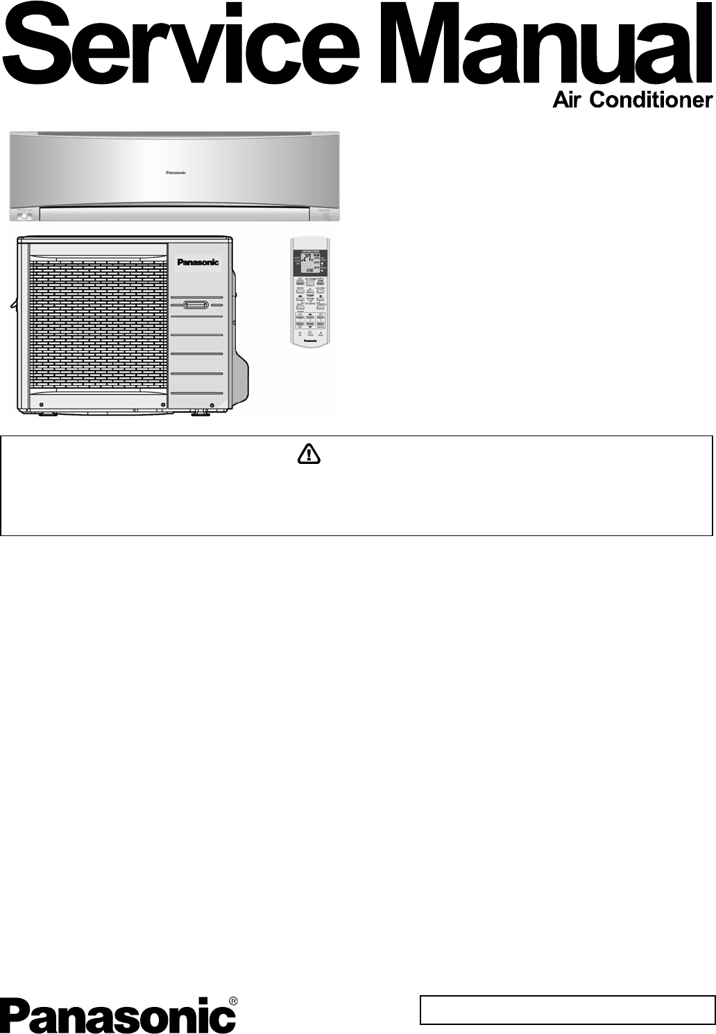
Indoor Unit Outdoor Unit
CS-C18KKS
CS-C24KKS
CU-C18KKS
CU-C24KKS
TABLE OF CONTENTS
1. Safety Precautions.............................................3
2. Specification .......................................................5
3. Features ..............................................................7
4. Location of Controls and Components ...........8
4.1 Indoor Unit....................................................8
4.2 Outdoor Unit .................................................8
4.3 Remote Control ............................................8
5. Dimensions.........................................................9
5.1 Indoor Unit....................................................9
5.2 Outdoor Unit ...............................................10
6. Refrigeration Cycle Diagram...........................11
7. Block Diagram ..................................................12
8. Wiring Connection Diagram............................13
8.1 CS-C18KKS CU-C18KKS ..........................13
8.2 CS-C24KKS CU-C24KKS ..........................14
9. Electronic Circuit Diagram ..............................15
9.1 CS-C18KKS CU-C18KKS ..........................15
9.2 CS-C24KKS CU-C24KKS ..........................16
10. Printed Circuit Board .......................................17
10.1 Indoor Unit..................................................17
11. Installation Instruction.....................................20
11.1 Select the Best Location ............................20
11.2 Indoor Unit..................................................21
11.3 Outdoor Unit ...............................................25
12. Operation Control.............................................29
12.1 Cooling Operation ......................................29
12.2 Soft Dry Operation......................................30
12.3 Automatic Operation ..................................31
12.4 Indoor Fan Speed Control..........................32
12.5 Outdoor Fan Speed Control .......................34
12.6 Vertical Airflow Direction Control................34
12.7 Horizontal Airflow Direction Control ...........35
12.8 Powerful Operation.....................................35
12.9 Quiet Operation ..........................................36
12.10 Timer Control..............................................37
12.11 Random Auto Restart Control ....................37
12.12 Remote Control Signal Receiving Sound...37
12.13 Patrol Operation .........................................38
12.14 E-ion operation ...........................................42
12.15 ECO Patrol Operation ................................45
This service information is designed for experienced repair technicians only and is not designed for use by the general public.
It does not contain warnings or cautions to advise non-technical individuals of potential dangers in attempting to service a product.
Products powered by electricity should be serviced or repaired only by experienced professional technicians. Any attempt to service
or repair the products dealt with in this service information by anyone else could result in serious injury or death.
WARNING
2
13. Protection Control............................................49
13.1 Restart Control (Time Delay Safety Control)..
....................................................................49
13.2 7 Minutes Time Save Control .....................49
13.3 60 Seconds Forced Operation ...................49
13.4 Starting Current Control .............................49
13.5 Freeze Prevention Control .........................50
13.6 Compressor Reverse Rotation Protection
Control ........................................................50
13.7 Dew Prevention Control .............................50
14. Servicing Mode.................................................51
14.1 Auto OFF/ON Button ..................................51
14.2 Remote Control Button...............................52
15. Troubleshooting Guide....................................53
15.1 Refrigeration cycle system .........................53
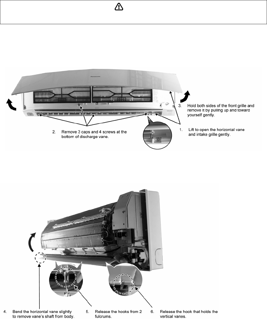
16. Disassembly and Assembly Instructions ......55
16.1 Indoor Electronic Controllers, Cross Flow
Fan and Indoor Fan Motor Removal
Procedures .................................................55
17. Technical Data ..................................................59
17.1 Operation Characteristics...........................59
18. Exploded View and Replacement Parts List..63
18.1 Indoor Unit ..................................................63
18.2 Outdoor Unit ...............................................66
3
CAUTION
WARNING
WARNING
1. Safety Precautions
• Read the following “SAFETY PRECAUTIONS” carefully before perform any servicing.
• Electrical work must be installed or serviced by a licensed electrician. Be sure to use the correct rating of the
power plug and main circuit for the model installed.
• The caution items stated here must be followed because these important contents are related to safety. The
meaning of each indication used is as below. Incorrect installation or servicing due to ignoring of the instruction
will cause harm or damage, and the seriousness is classified by the following indications.
This indication shows the possibility of causing death or serious injury.
This indication shows the possibility of causing injury or damage to properties.
• The items to be followed are classified by the symbols:
• Carry out test running to confirm that no abnormality occurs after the servicing. Then, explain to user the
operation, care and maintenance as stated in instructions. Please remind the customer to keep the operating
instructions for future reference.
1. Do not modify the machine, part, material during repairing service.
2. If wiring unit is supplied as repairing part, do not repair or connect the wire even only partial wire break. Exchange the whole wiring unit.
3. Do not wrench the fasten terminal. Pull it out or insert it straightly.
4. Engage dealer or specialist for installation and servicing. If installation of servicing done by the user is defective, it will cause water leakage,
electrical shock or fire.
5. Install according to this installation instructions strictly. If installation is defective, it will cause water leakage, electric shock or fire.
6. Use the attached accessories parts and specified parts for installation and servicing. Otherwise, it will cause the set to fall, water leakage, fire
or electrical shock.
7. Install at a strong and firm location which is able to withstand the set’s weight. If the strength is not enough or installation is not properly done,
the set will drop and cause injury.
8. For electrical work, follow the local national wiring standard, regulation and the installation instruction. An independent circuit and single outlet
must be used. If electrical circuit capacity is not enough or defect found in electrical work, it will cause electrical shock or fire.
9. This equipment is strongly recommended to install with Earth Leakage Circuit Breaker (ELCB) or Residual Current Device (RCD). Otherwise, it
may cause electrical shock and fire in case equipment breakdown or insulation breakdown.
10. Do not use joint cable for indoor / outdoor connection cable. Use the specified Indoor/Outdoor connection cable, refer to installation instruction
CONNECT THE CABLE TO THE INDOOR UNIT and connect tightly for indoor / outdoor connection. Clamp the cable so that no external force
will be acted on the terminal. If connecting or fixing is not perfect, it will cause heat up or fire at the connection.
11. Wire routing must be properly arranged so that control board cover is fixed properly. If control board cover is not fixed perfectly, it will cause
heat-up or fire at the connection point of terminal, fire or electrical shock.
12. When install or relocate air conditioner, do not let any substance other than the specified refrigerant, eg. air etc. mix into refrigeration
cycle (piping). (Mixing of air etc. will cause abnormal high pressure in refrigeration cycle and result in explosion, injury etc.).
13. Do not install outdoor unit near handrail of veranda. When installing air-conditioner unit at veranda of high rise building, child may climb up to
outdoor unit and cross over the handrail and causing accident.
14. This equipment must be properly earthed. Earth line must not be connected to gas pipe, water pipe, earth of lightning rod and
telephone. Otherwise, it may cause electric shock in case equipment breakdown or insulation breakdown.
15. Keep away from small children, the thin film may cling to nose and mouth and prevent breathing.
16. Do not use unspecified cord, modified cord, joint cord or extension cord for power supply cord. Do not share the single outlet with
other electrical appliances. Poor contact, poor insulation or over current will cause electrical shock or fire.
17. Tighten the flare nut with torque wrench according to specified method. If the flare nut is over-tightened, after a long period, the flare
may break and cause refrigerant gas leakage.
18. During pump down operation, stop the compressor before remove the refrigeration piping. (Removal of compressor while compressor
is operating and valves are opened will cause suck-in of air, abnormal high pressure in refrigeration cycle and result in explosion,
injury etc.)
19. During installation, install the refrigerant piping properly before run the compressor. (Operation of compressor without fixing refrigeration piping
and valves at opened condition will caused suck-in of air, abnormal high pressure in refrigeration cycle and result in explosion, injury etc).
This symbol denotes item that is PROHIBITED from doing.
4
CAUTION
WARNING
20. After completion of installation or service, confirm there is no leakage or refrigerant gas. It may generate toxic gas when the refrigerant
contacts with fire.
21. Ventilate if there is refrigerant gas leakage during operation. It may cause toxic gas when refrigerant contacts with fire.
22. Do not insert your fingers or other objects into the unit, high speed rotating fan may cause injury.
23. Must not use other parts except original parts described in catalog and manual.
1. Do not install the unit at place where leakage of flammable gas may occur. In case gas leaks and accumulates at surrounding of the
unit, it may cause fire.
2. Carry out drainage piping as mentioned in installation instructions. If drainage is not perfect, water may enter the room and damage
the furniture.
3. Tighten the flare nut with torque wrench according to specified method. If the flare nut is over-tightened, after a long period, the flare
may break and cause refrigerant gas leakage.
4. Do not touch outdoor unit air inlet and aluminium fin. It may cause injury.
5. Select an installation location which is easy for maintenance.
6. Pb free solder has a higher melting point than standard solder; typically the melting point is 50°F – 70°F (30°C – 40°C) higher. Please use
a high temperature solder iron. In case of the soldering iron with temperature control, please set it to 700 ± 20°F (370 ± 10°C).
Pb free solder will tend to splash when heated too high (about 1100°F / 600°C).
7. Power supply connection to the air conditioner. Connect the power supply cord of the air conditioner to the mains using one of the following
methods.
Power supply point shall be the place where there is ease for access for the power disconnection in case of emergency. In some countries,
permanent connection of this room air conditioner to the power supply is prohibited.
i. Power supply connection to the receptacle using a power plug. Use an approved 15/16A (3/4~1.5HP) or 16A (2.0HP) or 20A (2.5HP) or
25A (3.0HP) power plug with earth pin for the connection to the socket.
ii. Power supply connection to a circuit breaker for the permanent component. Use an approved 16A (3/4~2.0HP) or 20A (2.5HP) or
25A (3.0HP) circuit breaker for the permanent connection. It must be a double pole switch with a minimum 3.0 mm contact gap.
8. Do not release refrigerant during piping work for installation, servicing, reinstallation and during repairing a refrigerant parts. Take
care of the liquid refrigerant, it may cause frostbite.
9. Installation or servicing work: It may need two people to carry out the installation or servicing work.
10. Do not install this appliance in a laundry room or other location where water may drip from the ceiling, etc.
11. Do not sit or step on the unit, you may fall down accidentally.
12. Do not touch the sharp aluminum fins or edges of metal parts.
If you are required to handle sharp parts during installation or servicing, please wear hand glove.
Sharp parts may cause injury.
5
2. Specification
Indoor CS-C18KKS CS-C24KKS
Model
Outdoor CU-C18KKS CU-C24KKS
Performance Test Condition SASO (T3) SASO (T1) SASO (T3) SASO (T1)
Phase, Hz Single, 60 Single, 60
Power Supply
V 220 220
kW 4.40 5.10 5.60 6.50
BTU/h 15000 17400 19100 22200
Capacity
kcal/h 3780 4390 4820 5590
Running Current A 9.1 7.8 13.9 11.9
Input Power W 1.96k 1.69k 3.00k 2.56k
W/W 2.24 3.02 1.87 2.54
EER
BTU/hW 7.65 10.30 6.35 8.65
Power Factor % 98 98 98 98
dB-A 42 / 37 42 / 37 46 / 40 46 / 40
Indoor Noise (H / L)
Power Level dB - - - -
dB-A 56 / - 56 / - 57 / - 57 / -
Cooling
Outdoor Noise (H / L)
Power Level dB - - - -
Max Current (A) / Max Input Power (W) 11.5 / 2.60k 16.8 / 3.70k
Starting Current (A) 38.0 63.0
Type Hermetic Motor Hermetic Motor
Motor Type Rotary (2-poles) Rotary (2-poles)
Compressor
Output Power W 1.2k 1.8k
Type Cross-Flow Fan Cross-Flow Fan
Material ASG30K1 ASG30K1
Motor Type Transistor (8-poles) Transistor (8-poles)
Input Power W - -
Output Power W 40 40
QLo rpm 930 960
Lo rpm 1020 1110
Me rpm 1110 1230
Hi rpm 1200 1350
Indoor Fan
Speed
SHi rpm 1370 1500
Type Propeller Fan Propeller Fan
Material PP Resin PP Resin
Motor Type Induction (6 - poles) Induction (6 - poles)
Input Power W 138 135
Output Power W 86 79
Hi rpm 850 840
Outdoor Fan
Speed
Lo rpm - 490
Moisture Removal L/h (Pt/h) 0.7 (1.5) 1.3 (2.7)
QLo m3/min (ft3/min) 12.2 (432) 12.9 (457)
Lo m3/min (ft3/min) 13.4 (474) 15.0 (528)
Me m3/min (ft3/min) 14.6 (516) 16.6 (586)
Hi m3/min (ft3/min) 15.8 (558) 18.2 (642)
Indoor Airflow
SHi m3/min (ft3/min) 18.0 (637) 20.2 (714)
Hi m3/min (ft3/min) 54.0 (1910) 54.0 (1910)
Outdoor
Airflow Lo m3/min (ft3/min) - 31.5 (1110)

6
Control Device Capillary tube Capillary tube
Refrigerant Oil cm3 ATMOS NM56M or SUNISO 4GDID (650) ATMOS M60 or SUNISO 4GDID (1130)
Refrigeration
Cycle
Refrigerant Type g (oz) R22, 1.27k (44.8) R22, 1.61k (56.8)
Height(I/D / O/D) mm (inch) 290 (11-7/16) 750 (29-17/32) 290 (11-7/16) 750 (29-17/32)
Width (I/D / O/D) mm (inch) 1070 (42-5/32) 875 (34-15/32) 1070 (42-5/32) 875 (34-15/32)
Dimension
Depth (I/D / O/D) mm (inch) 235 (9-9/32) 345 (13-19/32) 235 (9-9/32) 345 (13-19/32)
Weight Net (I/D / O/D) kg (lb) 12.0 (26) 48.0 (106) 12.0 (26) 56.0 (123)
Pipe Diameter (Liquid / Gas) mm (inch) 6.35 (1/4) / 12.70 (1/2) 6.35 (1/4) / 15.88 (5/8)
Standard length m (ft) 5.0 (16.4) 5.0 (16.4)
Length range (min – max) m (ft) 3 (9.8) ~ 25 (82.0) 3 (9.8) ~ 25 (82.0)
I/D & O/D Height different m (ft) 20 (65.6) 20 (65.6)
Additional Gas Amount g/m (oz/ft) 20 (0.2) 30 (0.3)
Piping
Length for Additional Gas m (ft) 7.5 (24.6) 7.5 (24.6)
Inner Diameter mm 16 16
Drain Hose
Length mm 650 650
Fin Material Pre Coat Pre Coat
Fin Type Slit Fin Slit Fin
Row x Stage x
FPI 2 x 15 x 21 2 x 15 x 21
Indoor Heat
Exchanger
Size (W x H x L) mm 810 x 315 x 25.4 810 x 315 x 25.4
Fin Material Blue Coated Blue Coated
Fin Type Slit Fin Slit Fin
Row x Stage x
FPI 2 x 34 x 17 2 x 34 x 17
Outdoor Heat
Exchanger
Size (W x H x L) mm 25.4 x 714 x 826.2:846.2 25.4 x 714 x 826.2:846.2
Material Polypropelene Polypropelene
Air Filter
Type One-touch One-touch
Power Supply Indoor Indoor
Power Supply Cord A 16 20
Thermostat - Mechanical
Protection Device - -
Dry Bulb Wet Bulb Dry Bulb Wet Bulb
Maximum 32 23 32 23
Indoor Operation Range
Minimum 16 11 16 11
Maximum 52 31 52 31
Outdoor Operation Range
Minimum 16 11 16 11
1. Cooling capacities are based on indoor temperature of 27°C Dry Bulb (80.6°F Dry Bulb), 19.0°C Wet Bulb (66.2°F Wet Bulb) and outdoor air
temperature of 35°C Dry Bulb (95°F Dry Bulb), 24°C Wet Bulb (75.2°F Wet Bulb)
2. Specifications are subjected to change without prior notice for further improvement.
3. Outdoor Dry Bulb temperature can be set up to 55°C with Indoor Dry Bulb temperature is 29°C. When humidity does not exceed 90% and
room temperature is above 21°C.
7
3. Features
• E-ion Air Purifying System with Patrol Sensor
o Active e-ions are released to catch dust particles and bring them back the large positively charged filter.
o Patrol Sensor color changes to indicate the dirt level in the air
• Long Installation Piping
o CS/CU-C18KK, CS/CU-C24KK, long piping up to 25 meters.
• Easy to use remote control
• Quality Improvement
o Random auto restart after power failure for safety restart operation
o Gas leakage protection
o Prevent compressor reverse cycle
o Inner protector to protect compressor
o Noise prevention during soft dry operation
o Blue coated condenser for high resistance to corrosion
• Operation Improvement
o Quiet mode to reduce the indoor unit operating sound
o Powerful mode to reach the desired room temperature quickly
o 24-hour timer setting
8
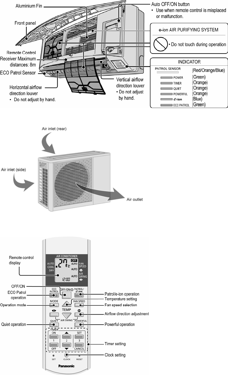
4. Location of Controls and Components
4.1 Indoor Unit
4.2 Outdoor Unit
4.3 Remote Control
9
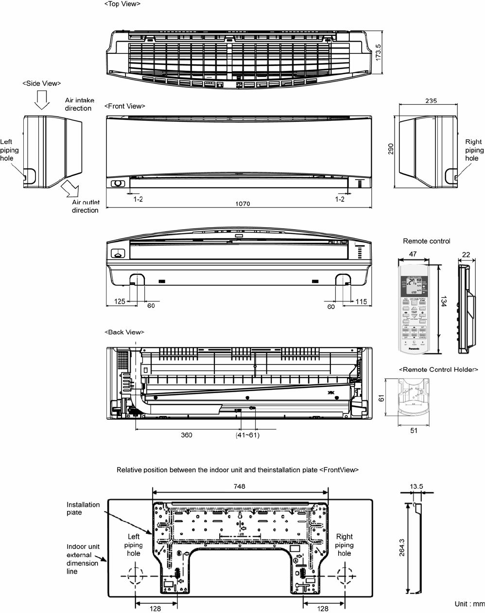
5. Dimensions
5.1 Indoor Unit
10
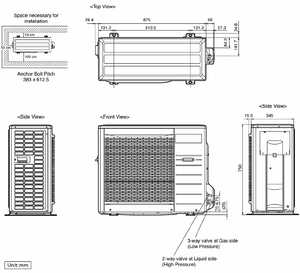
5.2 Outdoor Unit
11
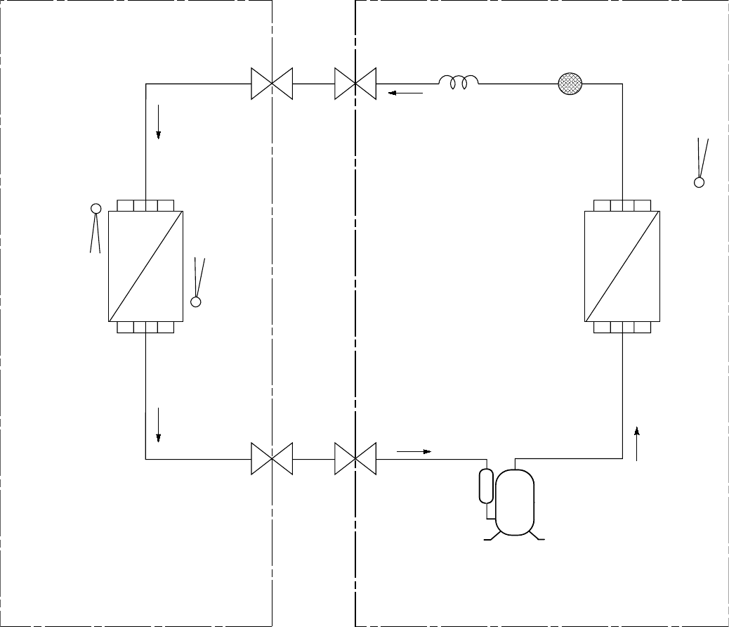
6. Refrigeration Cycle Diagram
INDOOR OUTDOOR
LIQUID
SIDE
GAS
SIDE
CAPILLARY
TUBE
HEAT EXCHANGER
(CONDENSER)
THERMOSTAT
(C24KK only)
HEAT EXCHANGER
(EVAPORATOR)
COMPRESSOR
2-WAY
VALVE
PIPE
TEMP.
SENSOR
INTAKE
AIR
TEMP.
SENSOR
3-WAY
VALVE
STRAINER
12
7. Block Diagram
13
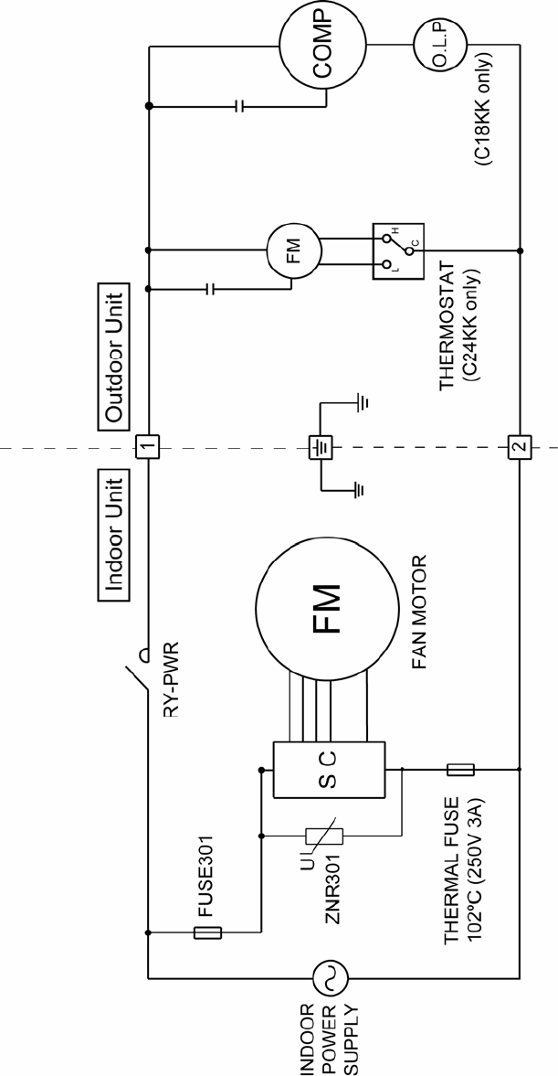
8. Wiring Connection Diagram
8.1 CS-C18KKS CU-C18KKS
Resistance of Outdoor Fan Motor Windings
Resistance of Compressor Windings
MODEL CU-C18KKS MODEL CU-C18KKS
CONNECTION CWA951401J CONNECTION 2KS252F5AA04
BLUE-YELLOW 59.47Ω C-R 1.959Ω
YELLOW-RED 60.95Ω C-S 3.083Ω
Note: Resistance at 20°C of ambient temperature. Note: Resistance at 20°C of ambient temperature.
14
8.2 CS-C24KKS CU-C24KKS
Resistance of Outdoor Fan Motor Windings
Resistance of Compressor Windings
MODEL CU-C24KKS MODEL CU-C24KKS
CONNECTION CWA951399J CONNECTION 2J39S236A1A
YELLOW-BLUE 59.47Ω C-R 0.933Ω
YELLOW-ORANGE 80.58Ω C-S 1.584Ω
YELLOW-RED 60.95Ω Note: Resistance at 20°C of ambient temperature.
Note: Resistance at 20°C of ambient temperature.

15
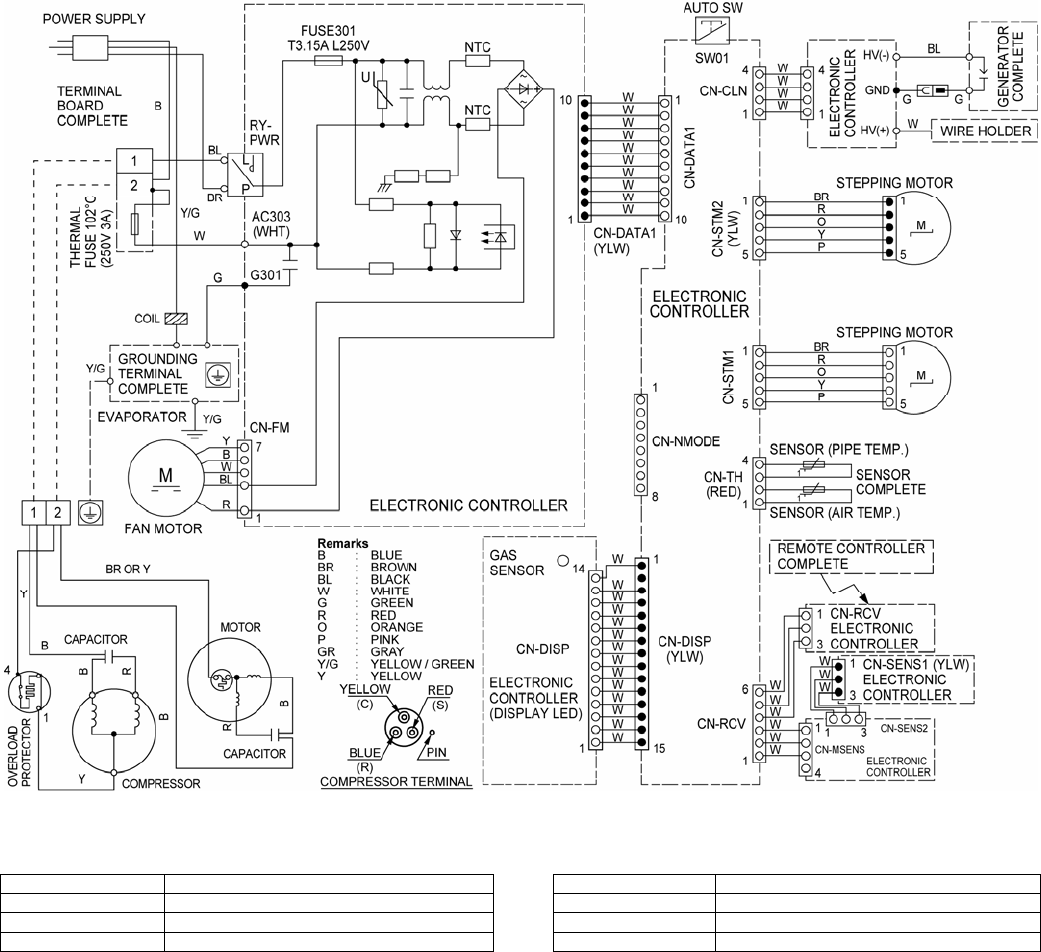
9. Electronic Circuit Diagram
9.1 CS-C18KKS CU-C18KKS
16
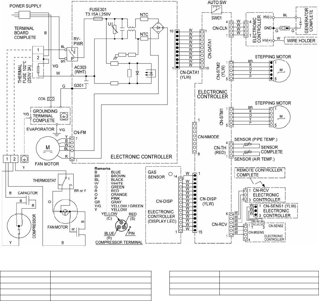
9.2 CS-C24KKS CU-C24KKS
17
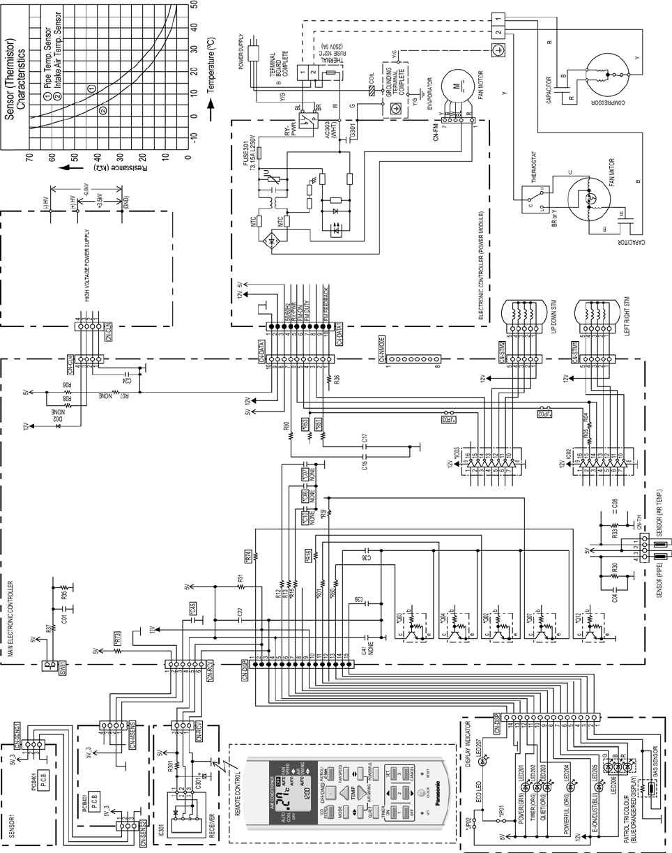
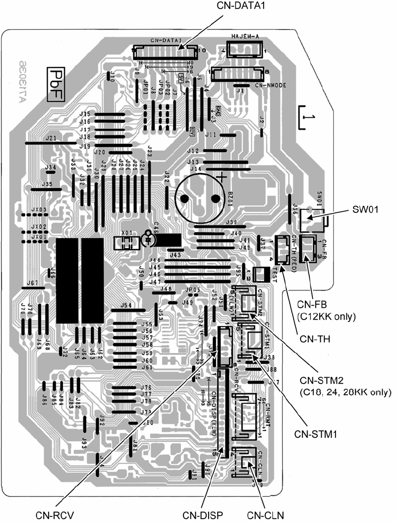
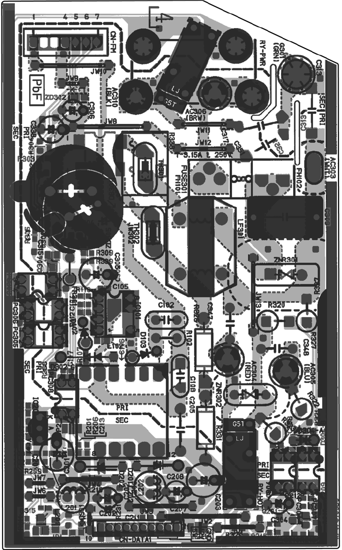
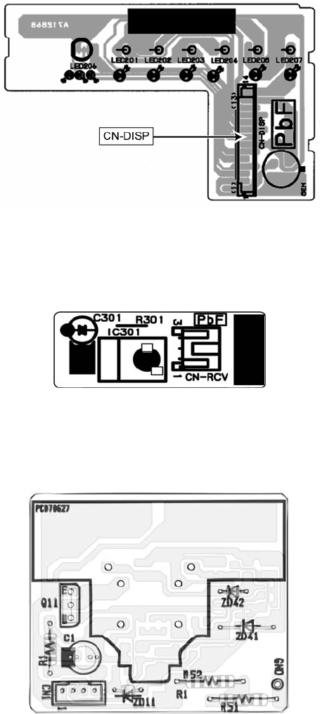
10. Printed Circuit Board
10.1 Indoor Unit
10.1.1 Main Printed Circuit Board
18
10.1.2 Power Printed Circuit Board
19
10.1.3 Indicator Printed Circuit Board
10.1.4 Receiver Printed Circuit Board
10.1.5 High Voltage Power Supply Printed Circuit Board
20
11. Installation Instruction
11.1 Select the Best Location
11.1.1 Indoor Unit
• Do not install the unit in excessive oil fume area
such as kitchen, workshop and etc.
• There should not be any heat source or steam
near the unit.
• There should not be any obstacles blocking the air
circulation.
• A place where air circulation in the room is good.
• A place where drainage can be easily done.
• A place where noise prevention is taken into
consideration.
• Do not install the unit near the door way.
• Ensure the spaces indicated by arrows from the
wall, ceiling, fence or other obstacles.
• Recommended installation height for indoor unit
shall be at least 2.5 m.
11.1.2 Outdoor Unit
• If an awning is built over the unit to prevent direct
sunlight or rain, be careful that heat radiation from
the condenser is not obstructed.
• There should not be any animal or plant which
could be affected by hot air discharged.
• Keep the spaces indicated by arrows from wall,
ceiling, fence or other obstacles.
• Do not place any obstacles which may cause a
short circuit of the discharged air.
• If piping length is over the [piping length for
additional gas], additional refrigerant should be
added as shown in the table.
C18***
C24***
Piping size
Gas Liquid
6.35 mm
(1/4")
12.7 mm
(1/2")
15.88 mm
(5/8")
5
20 3 25 20 7.5
20 3 25 30 7.5
Model Additional
Refrigerant
(g/m)
Max.
Elevation
(m)
Max.
Piping
Length
(m)
Min.
Piping
Length
(m)
Horse
Power
(HP)
Std.
Length
(m)
Piping
Length
for add.
gas (m)
2.0HP
2.5HP
Example: For C18***
If the unit is installed at 10 m distance, the quantity of
additional refrigerant should be 50 g….(10-7.5) m x 20
g/m = 50 g.
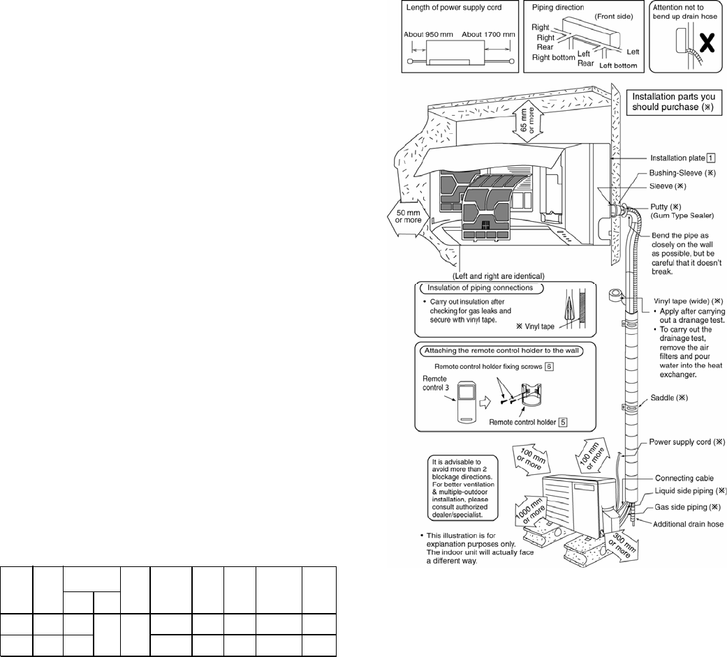
11.1.3 Indoor/Outdoor Unit Installation
Diagram
21
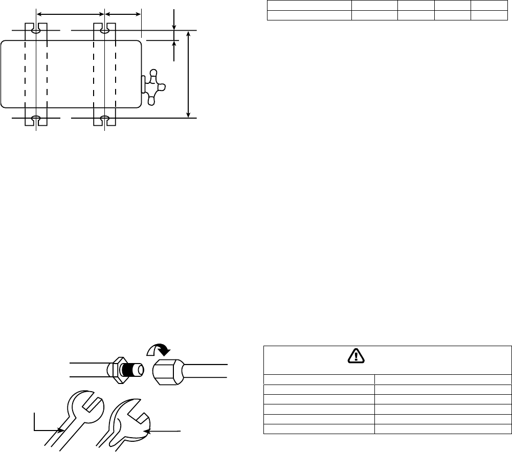
11.2 Indoor Unit
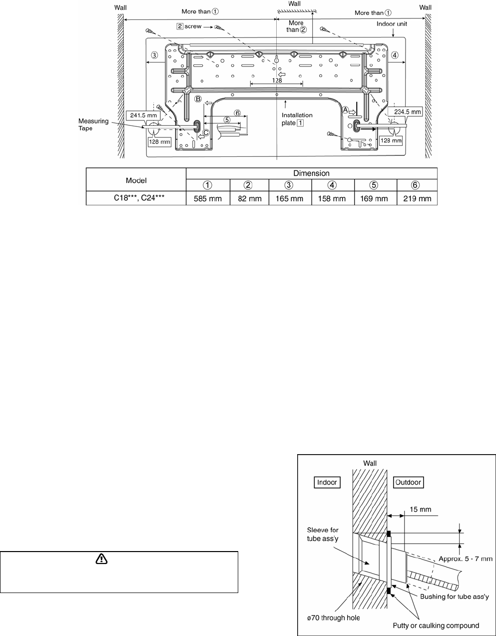
11.2.1 How to Fix Installation Plate
The mounting wall shall be strong and solid enough to prevent if from the vibration.
The centre of installation plate should be at more than c at right and left of the wall.
The distance from installation plate edge to ceiling should more than d.
From installation plate left edge to unit’s left side is e.
From installation plate right edge to unit’s right side is f.
○
B : For left side piping, piping connection for liquid should be about g from this line.
: For left side piping, piping connection gas should be about h from this line.
1 Mount the installation plate on the wall with 5 screws or more (at least 5 screws).
(If mounting the unit on the concrete wall, consider using anchor bolts.)
o Always mount the installation plate horizontally by aligning the marking-off line with the thread and using
a level gauge.
2 Drill the piping plate hole with ø70mm hole-core drill.
o Putting measuring tape at position as shown in the diagram above.
The hole centre is obtained by measuring the distance namely 128 mm for left and right hole
respectively. Another method is intersection point of arrow mark extension.
The meeting point of the extension arrow mark is the hole center position.
o Drill the piping hole at either the right or the left and the hole should be slightly slanting to the outdoor
side. (refer to step 3)
11.2.2 To Drill a Hole in the Wall and
Install a Sleeve of Piping
1 Insert the piping sleeve to the hole.
2 Fix the busing to the sleeve.
3 Cut the sleeve until it extrudes about 15mm
from the wall.
Caution
When the wall is hollow, please be sure to use the sleeve for tube
ass’y to prevent dangers caused by mice biting the connecting
cable.
4 Finish by sealing the sleeve with putty or
caulking compound at the final stage.
22
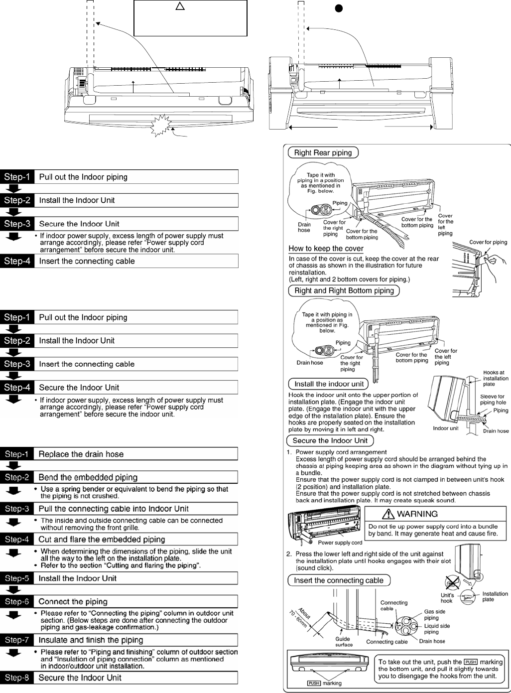
11.2.3 Indoor Unit Installation
Piping Piping
Intake grille
Shock absorber
Use shock absorber during pull out
thepipingtoprotecttheintakegrille
from damage.
Do not turn over the unit without it ’s shock
absorber during pull out the piping. Itmay
causeintakegrilledamage
Caution
!!
11.2.3.1 For the right rear piping
11.2.3.2 For the right and right bottom
piping
11.2.3.3 For the embedded piping
(This can be used for left rear piping and bottom
piping also.
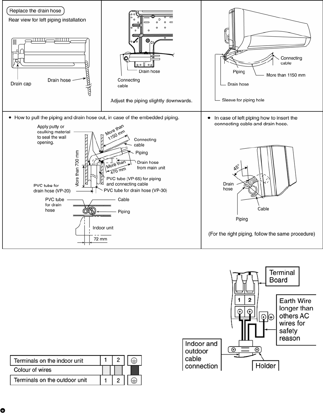
23
11.2.4 Connect the Cable to the Indoor Unit
1. The inside and outside connecting cable can
be connected without removing the front grille.
2. Connecting cable between indoor unit and
outdoor unit shall be approved
polychloroprene sheathed 3 x 2.5mm2 (2.0 ~
2.5HP) flexible cord, type designation 245 IEC
57 or heavier cord. Do not use joint
connection cable. Replace the wire if the
existing wire (from concealed wiring, or
otherwise) is too short.
• Secure the connecting cable onto the control board with the holder.
This equipment must be properly earthed.
• Ensure the colour of wires of outdoor unit and the terminal Nos. are the same to the indoor’s respectively.
• Earth wire shall be Yellow/Green (Y/G) in colour and longer than the other AC wires for safety reason.
24
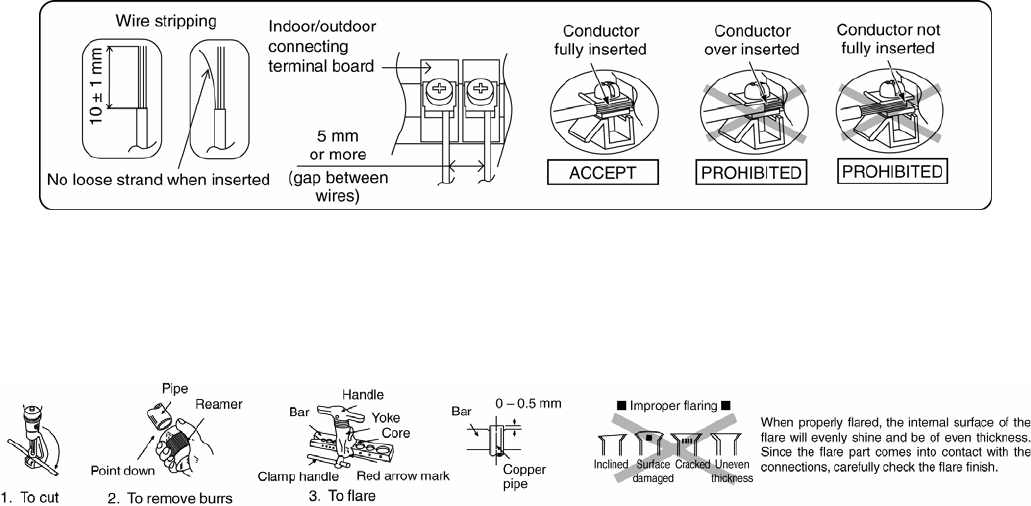
11.2.5 Wire Stripping And Connecting Requirement
11.2.5.1 Cutting and flaring the piping
1 Please cut using pipe cutter and then remove the burrs.
2 Remove the burrs by using reamer. If burrs are not removed, gas leakage may be caused. Turn the piping
end down to avoid the metal powder entering the pipe.
3 Please make flare after inserting the flare nut onto the copper pipes.
25
CAUTION
11.3 Outdoor Unit
11.3.1 Install the Outdoor Unit
• After selecting the best location, start installation to Indoor/Outdoor Unit Installation Diagram.
1 Fix the unit on concrete or rigid frame firmly and horizontally by bolt nut (ø10mm).
2 When installing at roof, please consider strong wind and earthquake.
Please fasten the installation stand firmly with bolt or nails.
A
B
C
D
Model A B C D
C18***, C24*** 612.5 mm 131 mm 19 mm 383 mm
11.3.2 Connecting the Piping
11.3.2.1 Connecting the piping to indoor
Please make flare after inserting flare nut (locate at joint portion of tube assembly) onto the copper pipe. (In case of
using long piping)
Connect the piping
• Align the center of piping and sufficiently tighten the flare nut with fingers.
• Further tighten the flare nut with torque wrench in specified torque as stated in the table.
11.3.2.2 Connecting the piping to outdoor
Decide piping length and then cut by using pipe cutter. Remove burrs from cut edge.
Make flare after inserting the flare nut (locate at valve) onto the copper pipe.
Align center of piping to valves and then tighten with torque wrench to the specified torque as stated in the table.
To r qu e
wrench
Spanner
or Wrench
Do not overtighten, overtightening may cause gas leakage.
Piping size Torque
(6.35 mm) 1/4” [18 N•m (1.8 kgf.m)]
(9.52 mm) 3/8” [42 N•m (4.3 kgf.m)]
(12.7 mm) 1/2” [55 N•m (5.6 kgf.m)]
(15.88 mm) 5/8” [65 N•m (6.6 kgf.m)]
(19.05 mm) 3/4” [100 N•m (10.2 kgf.m)]
26
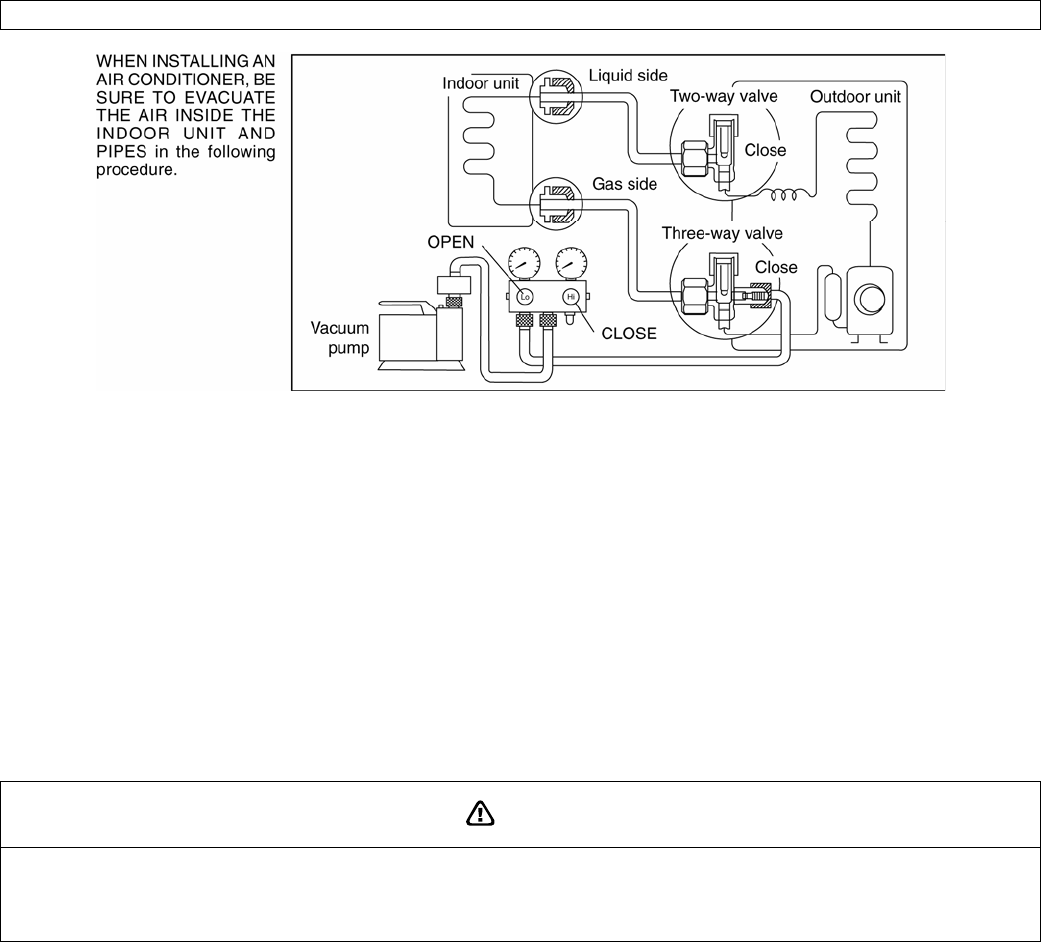
11.3.3 Evacuation of the Equipment
FOR ENVIRONMENTAL PROTECTION, MANUFACTURER STRONGLY RECOMMENDS TO USE EVACUATION METHOD.
1 Connect a charging hose with a push pin to the Low side of a charging set and the service port of the 3-way
valve.
o Be sure to connect the end of the charging hose with the push pin to the service port.
2 Connect the center hose of the charging set to a vacuum pump.
3 Turn on the power switch of the vacuum pump and make sure that the needle in the gauge moves from 0
cmHg (0 MPa) to -76 cmHg (-0.1 MPa). Then evacuate the air approximately ten minutes.
4 Close the Low side valve of the charging set and turn off the vacuum pump. Make sure that the needle in the
gauge does not move after approximately five minutes.
Note: BE SURE TO TAKE THIS PROCEDURE IN ORDER TO AVOID REFRIGERENT GAS LEAKAGE.
5 Disconnect the charging hose from the vacuum pump and from the service port of the 3-way valve.
6 Tighten the service port caps of the 3-way valve at a torque of 18 N•m with a torque wrench.
7 Remove the valve caps of both of the 2-way valve and 3-way valve. Position both of the valves to “OPEN”
using a hexagonal wrench (4 mm).
8 Mount valve caps onto the 2-way valve and the 3-way valve.
o Be sure to check for gas leakage.
CAUTION
• If gauge needle does not move from 0 cmHg (0 MPa) to -76 cmHg (-01 MPa), in the step e above take the following measure:
- If the leak stops when the piping connections are tightened further, continue working from step e.
- If the leak does not stop when the connections are retightened, repair location of leak.
- Do not release refrigerant during piping work for installation and reinstallation.
- Take care of the liquid refrigerant, it may cause frostbite.
27
11.3.4 Air Purging of the Piping and Indoor
The remaining air in the Refrigerant cycle which contains moisture may cause malfunction on the compressor.
1 Remove the caps from the 2-way and 3-way valves.
2 Remove the service-port cap from the 3-way valves.
3 To open the valve, turn the valve stem of 2-way valve counter-clockwise approx. 90° and hold it there for ten
seconds, then close it.
4 Check gas-leakage of the connecting portion of the pipings.
o For the left piping, refer to 4 (A).
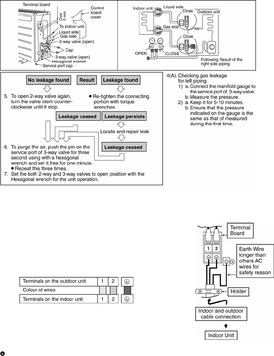
11.3.5 Connect the cable to the Outdoor Unit
1 Remove the control board cover from the
unit by loosening the screw.
2 Connecting cable between indoor unit and
outdoor unit shall be approved
polychloroprene sheathed 3 x 2.5mm2 (2.0 ~
2.5HP) flexible cord, type designation 245 IEC
57 or heavier cord. Do not use joint
connection cable. Replace the wire if the
existing wire (from concealed wiring, or
otherwise) is too short.
3 Secure the cable onto the control board with
the holder.
4 Attach the control board cover back to the
original position with the screw.
5 For wire stripping and connection requirement,
refer to instruction g of the indoor unit.
This equipment must be properly earthed.
• Earth wire shall be Yellow/Green (Y/G) in colour and longer than the other AC wires for safety reason.
28
11.3.6 Pipe Insulation
1 Please carry out insulation at pipe connection portion as mentioned in Indoor/Outdoor Unit Installation
Diagram. Please wrap the insulated piping end to prevent water from going inside the piping.
2 If drain hose or connecting piping is in the room (where dew may form), please increase the insulation by
using POLY-E-FOAM with thickness 6mm or above.
29
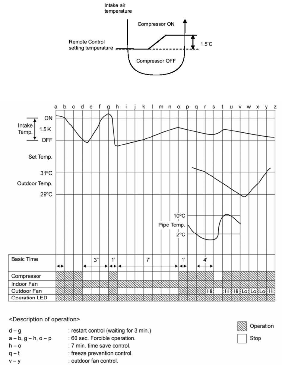
12. Operation Control
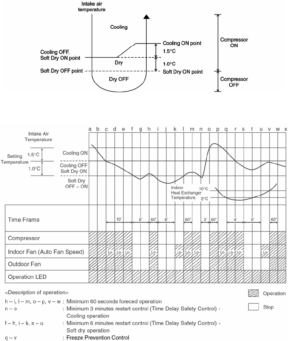
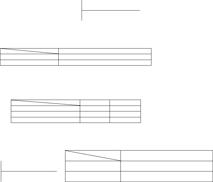
12.1 Cooling Operation
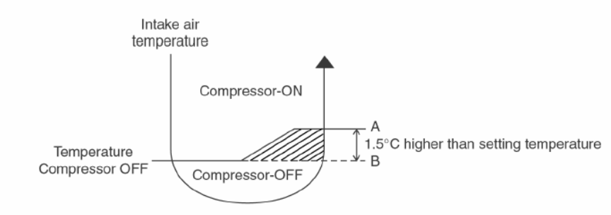
• Cooling operation can be set using remote control.
• This operation is applied to cool down the room temperature to the setting temperature set on the remote control.
• The remote control setting temperature, which takes the reading of intake air temperature sensor, can be
adjusted from 16°C to 30°C.
• During cooling operation, the compressor will stop and restart as shown in figure below:
12.1.1 Cooling Operation Time Diagram
30
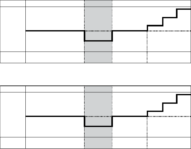
12.2 Soft Dry Operation
• Soft Dry operation can be set using remote control.
• Soft Dry operation is applied to dehumidify and to perform a gentle cooling to the room.
• This operation starts when the intake air temperature sensor reaches the setting temperature on the remote
control.
• When operation begins, Soft Dry will be switched “ON” for a maximum 10 minutes, then Soft Dry operation will be
turn “OFF” for a minimum 6 minutes. After that, the Soft Dry operation will be “ON” and “OFF” based on the
setting temperature as shown in figure below.
• However after 3 minutes of compressor off, during Soft Dry “OFF” (within 6 minutes Soft Dry restart control), the
indoor unit will start to operate at normal Cooling mode if the intake temperature is higher than Cooling “ON”
point.
12.2.1 Soft Dry Operation Time Diagram
31
12.3 Automatic Operation
• Automatic operation can be set using remote control.
• This operation starts to operate with indoor fan at SLo speed for 20 seconds to judge the intake air temperature.
• After judged the temperature, the operation mode is determined by referring to the below standard.
• Then, the unit starts to operate at determined operation mode, until it is switched off using remote control, with
the setting temperature as shown in table below.
Setting Temperature (Standard)
Cooling Operation 25°C
Soft Dry Operation 22°C
• The setting temperature for all the operations can be changed one level up or one level down from the standard
temperature as shown in table below by pressing the temperature up or temperature down button at remote
control.
Cooling Soft Dry
Higher Æ +2°C 27°C 24°C
Standard Æ ±0°C 25°C 22°C
Lower Æ -2°C 23°C 20°C
• The operation mode judging temperature and standard setting temperature can be increased by 2°C
permanently, by open the circuit of JX03 at indoor unit’s printed circuit board.
Setting Temperature (Standard)
Cooling Operation Cooling Operation 27°C
Intake Air
Temperature
↑
25°C
↓ Soft Dry Operation Soft Dry Operation 24°C
Cooling Operation
Intake Air
Temperature
↑
23°C
↓ Soft Dry Operation
32
12.4 Indoor Fan Speed Control
• Indoor fan speed can be set using remote control.
12.4.1 Fan Speed Rotation Chart
Fan Speed (rpm)
Speed CS-C18KKS CS-C24KKS
Shi 1370 1500
Hi 1200 1350
Me 1110 1230
HLo 1080 1190
CLo 1020 1110
Lo- 850 970
SLo 670 750
Qhi 1110 1150
QMe 1020 1050
QLo 930 960
12.4.2 Automatic Fan Speed Control
• When set to Auto Fan Speed, the fan speed is adjusted between maximum and minimum setting as shown in the
table.
o Fan speed rotates in the range of Hi, Me and Lo-.
o Deodorizing Control will be activated.
SHi Hi Me HLo CLo Lo- SLo Stop
Hi o
Me o
Manual
Lo o
Normal
Auto o o o o
QHi Hi-90
QMe Me-90
Manual
QLo CLo-90
Quiet
Auto Hi-100 Me-100 o o
Manual o
Cooling
Powerful Auto o
Manual o o
Normal Auto o o
Manual o o
Soft Dry
Quiet Auto o o
33
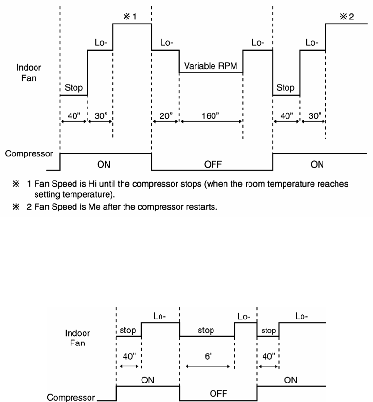
• Auto Fan Speed during cooling operation:
1 Indoor fan will rotate alternately between off and on as shown in below diagram.
2 At the beginning of each compressor starts operation, indoor fan speed increases gradually for deodorizing
purpose.
3 For the first time the compressor operates, indoor fan will be switched to Hi fan speed from Lo- after 70
seconds from the start of compressor. This cause the room temperature to achieve the setting temperature
quickly.
4 During compressor stops, indoor fan will operate at Lo- for the beginning 20 seconds to prevent higher
volume of refrigerant in liquid form returning to the compressor.
5 After the compressor turned off for 3 minutes, indoor fan will start to operate at Lo- to circulate the air in the
room. This is to obtain the actual reading of the intake air temperature.
6 For the resume of compressor operation, indoor fan will operate at Me fan speed to provide comfort and
lesser noise environment, after 70 seconds from the restarts of compressor.
• Auto Fan Speed during Soft Dry operation.
1 Indoor fan will rotate alternately between off and Lo-.
2 At the beginning of each compressor starts operation, indoor fan will increase fan speed gradually for
deodorizing purpose.
3 When compressor turned off for 6 minutes, indoor fan will start at Lo- to circulate the air in the room. This is
to obtain the actual reading of intake air temperature.
12.4.3 Manual Fan Speed Control
• Manual fan speed adjustment can be carried out by using the Fan Speed selection button at the remote control.
• There are 3 types of fan speed settings: Lo, Me, Hi.
12.4.4 Indoor Fan Motor rpm Abnormal Control
• Immediate after the fan motor is started, rpm abnormal control is performed every second.
• During fan motor on, if fan motor feedback ≥ 2550 rpm or < 50 rpm continuously for 10 seconds, the fan motor
error counter increased; fan motor is then stopped and restarted. If the fan motor error counter increased to 7,
then air conditioner will stop operation.
34
12.5 Outdoor Fan Speed Control
• There is only one speed for outdoor fan motor. (Applicable for CU-C18KK)
• There is 2 speeds for outdoor fan motor. Outdoor fan speed can be changed to Hi or Lo according to outdoor
temperature. (Applicable for CU-C24KK).
• For Cooling and Soft Dry operation, when outdoor temperature reaches to 31°C (Hi-speed), 29°C (Lo-speed).
(Applicable for CU-C24KK).
• When air conditioner is turned on, the compressor and the outdoor fan will operate simultaneously.
• Likewise, both compressor and outdoor fan will stop at the same time if the unit is turned off.
12.6 Vertical Airflow Direction Control
12.6.1 Auto Control
• When the vertical airflow direction is set to Auto using the remote control, the louver swings up and down as
shown in the diagram.
• When stops operation using the remote control, the discharge vent is reset and stops at the closing position.
• During Cooling operation or Soft Dry operation, indoor fan motor may stop to rotate at certain periods. At that
condition, the louver will stop swinging.
12.6.2 Manual Control
• When the vertical airflow direction is set to Manual using the remote control, the automatic airflow is released and
the airflow direction louver move up and down in the range shown in the diagram.
• The louver can be adjusted by pressing the button to the desired louver position.
• When stop operation using the remote control, the discharge vent is reset, and stop at the closing position.
Upper limit for cooling mode
and soft dry mode/17°
28°
Closing
position
/ 148°
Swing up and down
Lower limit for cooling mode and
soft dry mode/45°
Horizontal
Upper limit/0°
Closing
position
/ 148°
Lower limit for cooling mode
and soft dry mode
Horizontal
17°
22°
33°
28°
39°
Upper limit for
cooling mode and
soft dry mode
Upper limit / 0°
35
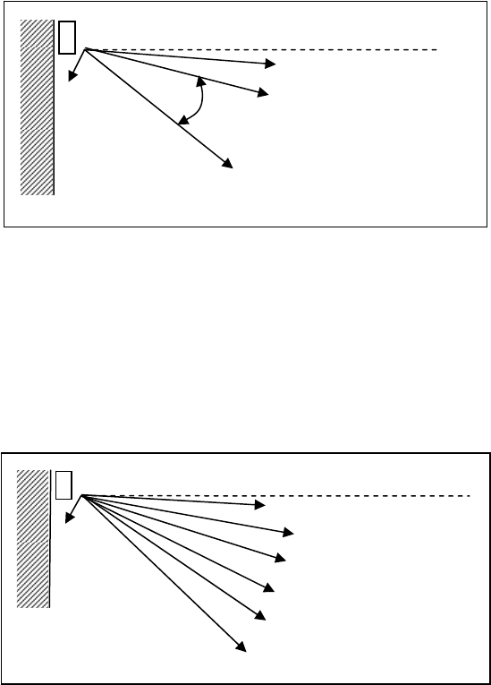
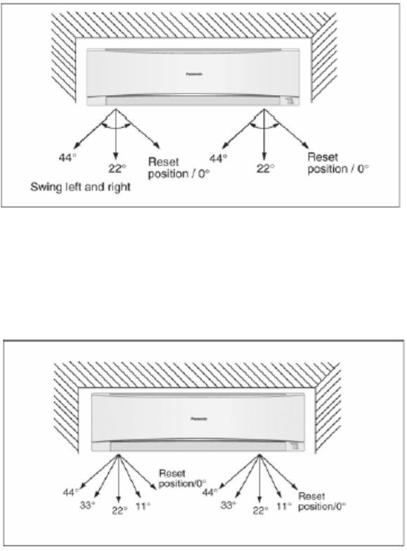
12.7 Horizontal Airflow Direction Control
12.7.1 Auto Control
• When the horizontal airflow is set to Auto using the remote control, the vanes swings left and right as shown in
the diagram.
• When stopped with remote control, the discharge vanes are reset and stop at the reset position.
• During Cooling operation or Soft Dry operation, indoor fan motor may stop to rotate at certain periods. At that
condition, the vane will stop swinging and rest at 22° angle.
12.7.2 Manual Control
• When the horizontal airflow direction is set to Manual using the remote control, the automatic airflow is released
and the airflow direction vane move left and right in the range shown in the diagram.
• The louver can be adjusted by pressing the button to the desired vane position.
• When stopped with remote control, the vanes is reset and stopped at reset position.
12.8 Powerful Operation
• To achieve the setting temperature quickly.
• When powerful operation is set, the setting temperature will be automatically decreased 3°C internally against
the present setting temperature (Lower temperature limit: 16°C).
• This operation automatically running under Shi fan speed (Cooling).
• Vertical Airflow Direction:
o In “Manual” setting, the vane will automatically shift down 10° lower than previous setting.
o In “Auto” setting, the vane will automatically swing up and down. However the lower limit will be shifted 10°
downward.
• Powerful operation stops when:
o Quiet/Powerful button is pressed again
o Powerful operation has operate for 15 minutes
o Stopped by OFF/ON operation button.
o Timer OFF activates
o Operation mode is changed
36
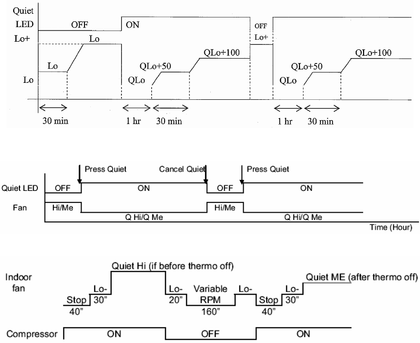
12.9 Quiet Operation
(For Cooling Operation or cooling region of Soft Dry Operation)
• To provide quiet cooling operation condition.
• Once the Quiet Operation is set at the remote control, the Quiet LED illuminated. The sound level will reduce
around 2dB(A) for Lo fan speed or 3dB(A) for Hi/Me fan speed against the present operation sound level.
• Dew formation become severe at Quite Lo Cool, therefore Quiet Lo cool operated only 1 hour 30 minutes (1 hour
QLo, 30 minutes QLo + 50 rpm).
• Manual Airflow Direction:
o RPM control during Lo cool
o RPM control during Hi & Me cool
• Auto Fan Speed
• Quiet operation stops when:
o Quiet button is pressed again.
o Stopped by OFF/ON operation button.
o Timer OFF activates.
o Operation mode button is changed.
o Powerful button is pressed.
37
12.10 Timer Control
12.10.1 ON Timer
• When the ON Timer is set by using the remote control, the unit will start to operate slightly before the set time, so
that the room will reach nearly to the set temperature by the set time.
• For Cooling and Soft Dry operation, the operation will start 15 minutes before the set time.
• For Automatic operation, the indoor fan will operate at SLo speed for 20 seconds, 15 minutes before the set time
to detect the intake air temperature to determine the operation mode. The power LED will blink.
12.10.2 OFF Timer
• When the OFF Timer is set using the remote control, the unit will stop operate according to the desired setting.
Notes:
1 By pressing ON/OFF operation button, the ON Timer or OFF Timer will not be cancel.
2 To cancel the previous timer setting, press CANCEL button.
3 To activate the previous timer setting, press SET button.
4 If main power supply is switched off, the Timer setting will be cancel.
12.11 Random Auto Restart Control
• If there is a power failure during operation, the air conditioner will automatically restart after 3 to 4 minutes when
the power is resumed.
• It will start with previous operation mode and airflow direction.
• If there are more than one air conditioner unit in operation and power failure occur, restart time for each unit to
operate will be decided randomly using 4 parameters:- intake air temperature, fan speed and air swing louver
position.
• This Random Auto Restart Control is not available when Timer is set.
12.12 Remote Control Signal Receiving Sound
• Short beep sound will be heard when turn ON the air conditioner or enabling other operations.
• Long beep sound will be heard when turn OFF the air conditioner or disabling other operations.
38
12.13 Patrol Operation
• To monitor air dirtiness level by using Patrol sensor and to maintain air freshness by activates e-ion operation
• Patrol operation starts condition
o When the unit operation is started with “OFF/ON” button
o When the unit stops, “Patrol” operation is selected, Patrol individual operation will start.
o During cooling only operation, “Patrol” operation is selected.
• Patrol operation stops condition (when any of the following condition is fulfilled):
o When “OFF/ON” button is selected.
o During any operation with Patrol, “PATROL/e-ion” button is pressed.
o When OFF Timer activates.
• To disable the Patrol Operation during unit starts (default) with “OFF/ON” button
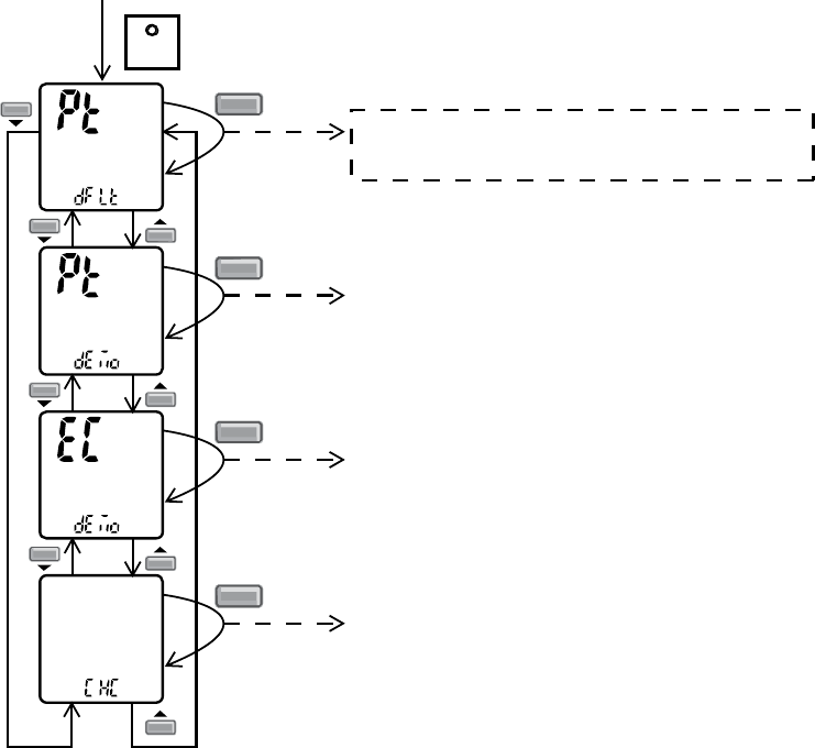
o Press “Set” button continuously for 15 seconds by using pointer during Air Conditioner is OFF condition to
enter internal setting mode.
o Press “Timer Decrement" button to select “Pt dFLt”.
o Press “Timer Set” button to toggle Patrol operation default OFF/ON.
Long "beep": Turn OFF Patrol operation default.
Short "beep": Turn ON Patrol operation default.
SET
SET
Transmit Patrol default OFF/ON code
(Buzzer: OFF:Long Beep, ON:Short Beep)
Press continously for 15s
SET
Transmit Patrol demo code
(Buzzer: OFF:Long Beep, ON:Short Beep)
SET
Transmit ECO demo code
(Buzzer: OFF:Long Beep, ON:Short Beep)
SET
Transmit check code
(Buzzer:Short Beep)
39
• Patrol Sensor Control
o First 2 minutes from Patrol function activates is stabilization time, during stabilization time, no air dirtiness
level is monitored. The Air Dirtiness level is set to Clean, Patrol LED turns blue color.
o After that, Patrol sensor starts to record the resistance value at fixed interval. Higher resistance value
indicates cleaner air.
o The air dirtiness level is monitored by comparing the current resistance value with maximum resistance value
from time to time to get the Air Dirtiness Value.
o There are 3 air dirtiness level, based on the Air Dirtiness Value:
Air Dirtiness level 0: Clean – Patrol LED = blue color
Air Dirtiness level 1: Moderate – Patrol LED = orange color
Air Dirtiness level 2: Contaminated – Patrol LED = red color
Air Dirtiness Level 0 Air Quality Worsen
G1
Air Dirtiness Level 1
G3
G2
G4
Air Dirtiness Level 2
Air Quality Improve
• Dirtiness level sensitivity adjustment
It is possible to change the Patrol sensor sensitivity, where the Threshold value (G1 ~ G4) will be shifted
accordingly:
1 Press and release “SET” button.
2 Press Timer ▲ / Timer ▼ button to select sensitivity.
(Air 1 “Low Sensitivity” ↔ Air 2 “Standard” (Default) ↔ Air 3 “High Sensitivity”)
3 Confirm setting by pressing “Timer Set” button. LCD returned to original display after 2 seconds.
4 LCD returned to original display if remote control does not operate for 30 seconds
• e-ion Control
o e-ion operation starts condition
When dirtiness at level 2 (Patrol LED turns red).
2 minutes after stabilization time (Patrol LED turns red).
4 hours at level 0 (Patrol LED turns red).
o e-ion operation time
If dirtiness level improves from level 2 to level 1 (Patrol LED from red to orange), the unit carries out level
change after 60 seconds.
When dirtiness level returns to level 0 (Patrol LED turns blue) continuously for 11 minutes or more, e-ion
operation stops.
• Dirtiness Level and fan speed
o When e-ion operation starts, the fan speed increases based on dirtiness level:
rpm shift
Dirtiness level Patrol individual
operation
Combine operation
Dirtiness level 0 No change No change
Auto Manual
Dirtiness level 1 +20 +1 fan tap (max - Hi)
e-ion ON
Dirtiness level 2 +40
No change
Me -
Me +2 fan tap (max - Hi)
o Indoor Fan Control
During any operation mode combines with Patrol operation, fan speed follows respective operation mode.
During Patrol individual operation if e-ion starts, only Auto Fan Speed and no Powerful operation is
allowed. Even if “Fan Speed” button is pressed, no signal is sent to air conditioner, and no change on
LCD display.
During Patrol individual operation if e-ion stops, Indoor Fan stop operation.
Air Dirtiness Value
Dirty Moderate Clean
40
• Airflow direction (Horizontal, Vertical) Control
o During any operation mode combines with Patrol operation, airflow direction follows respective operation
mode.
o During Patrol individual operation if e-ion starts, only Auto Air Swing is allowed. Even if “Air Swing” button is
pressed, no signal is sent to air conditioner, and no change on LCD display.
o During Patrol individual operation if e-ion stops, Airflow direction louver closed.
• LED display (Applicable to all models except KKD models)
o When Patrol operation is selected, Patrol LED illuminates.
o During Patrol individual operation, only Patrol LED illuminates. When e-ion air purifying operation starts
based on dirtiness level, Power LED, Patrol LED and e-ion LED illuminates.
PATROL LED E-ION TIMER
No Description BLUE ORANGE RED BLUE ORANGE
1 When patrol function is not selected OFF OFF OFF - -
2 During gas sensor error detection control OFF OFF Blinking OFF OFF
3 During E-ion abnormal discharge error OFF OFF OFF Blinking OFF
4 During E-ion breakdown error OFF OFF OFF Blinking Blinking
5 During Test Mode OFF OFF OFF OFF OFF
6 During stop OFF OFF OFF OFF OFF
7 2 minutes gas sensor initial stabilization time (Level 0) ON OFF OFF OFF OFF
a. Dirtiness level 0* ON OFF OFF OFF OFF
b. Dirtiness level 1 OFF ON OFF OFF OFF
c. Dirtiness level 1* OFF ON OFF ON OFF
8 During operation
During patrol
d. Dirtiness level 2 OFF OFF ON ON OFF
• Remote Control Receiving Sound
o Normal Operation Î Patrol Mode : Beep
o Patrol Mode Î Stop : Long Beep
o Patrol Mode Î Normal Operation : Beep
o Stop Î Patrol : Beep
• Timer Control
o When ON timer activates when unit stops, previous operation resumes and restored last saved Patrol
operation status.
o When ON timer activates during any operation, no change and carry on current operation.
o When OFF timer activates during any operation, all operation stops and the latest Patrol operation status is
saved.
• Power Failure Control
o During Patrol individual operation, if power failure occurs, after power resumes, Patrol individual operation
resumes immediately.
o During combination operation, if power failure occurs, after power resumes combination operation resume
immediately.
41
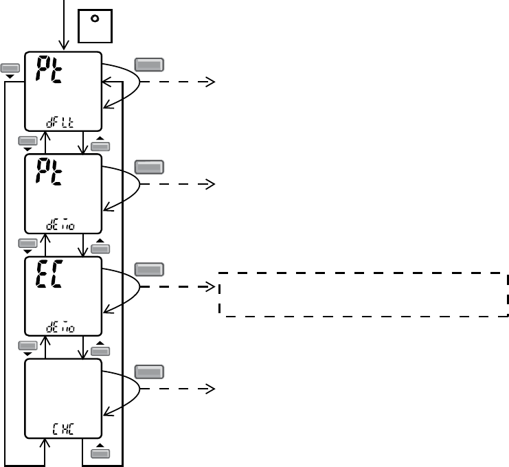
• Patrol Operation Demo Mode
o Patrol Operation Demo Mode start condition
Press “Set” button continuously for 15 seconds by using pointer during Air Conditioner is OFF condition
to enter internal setting mode.
Press “Timer Decrement" button to select “Pt demo”.
Press “Timer Set” button to toggle Patrol operation demo mode.
• Long "beep": Turn OFF Patrol operation demo mode.
• Short "beep": Turn ON Patrol operation demo mode.
SET
SET
Transmit Patrol default OFF/ON code
(Buzzer: OFF:Long Beep, ON:Short Beep)
Press continously for 15s
SET
Transmit Patrol demo code
(Buzzer: OFF:Long Beep, ON:Short Beep)
SET
Transmit ECO demo code
(Buzzer: OFF:Long Beep, ON:Short Beep)
SET
Transmit check code
(Buzzer:Short Beep)
o The Patrol indicator change color every 10 seconds follows the pattern below for demo purpose:
BLUE (10 seconds)
(10 seconds) ORANGE (10 seconds)
(10 seconds) RED (10 seconds)
o During demo, all operation stops, remote control buttons and auto OFF/ON button are ignored.
o Patrol Operation Demo Mode stop condition
Power supply reset.
42
12.14 E-ion operation
• This operation provides clean air by producing negative ions to attract dust captured at the positively charged
active e-ion filters.
• e-ion operation start condition
o During unit running at any operation mode, if “e-ion” operation is selected, combination operation (operation
mode + e-ion operation) starts.
o During unit is OFF, if “e-ion” operation is selected, e-ion individual operation starts.
• e-ion operation stop condition
o When “OFF/ON” button is pressed to stop the operation.
o When “PATROL/e-ion” button is pressed.
o When OFF Timer activates.
• e-ion operation pause condition
o When indoor fan stop (during deice, odor cut control, thermostat off, etc.). e-ion operation resume after
indoor fan restarts.
o When indoor intake temperature ≥ 40°C. e-ion operation resume after indoor intake temperature < 40°C
continuously for 30 minutes.
• Indoor fan control
o During any operation mode combines with e-ion operation, fan speed follows respective operation mode.
o During e-ion individual operation – only Auto Fan Speed and no Powerful operation is allowed. Even if Fan
Speed button is pressed, no signal is sent to air conditioner, and no change on LCD display.
Auto Fan Speed for e-ion operation switches from SHi to Hi after 4 hours of operation.
• Airflow direction control
o During any operation mode combines with e-ion operation, airflow direction follows respective operation
mode.
o During e-ion individual operation, only Auto Air Swing is allowed. Even if Air Swing button is pressed, no
signal is sent to air conditioner, and no change on LCD display.
• Timer control
o When ON timer activates when unit stops, previous operation resumes and restored last saved e-ion
operation status.
o When ON timer activates during any operation, no change and carry on current operation.
o When OFF timer activates during any operation, all operation stops and the latest e-ion operation status is
saved.
• Indicator
o When e-ion operation starts, e-ion indicator ON.
• Remote Control Receiving Sound
o Normal Operation Î e-ion Operation : Beep
o e-ion Operation Î Normal Operation : Beep
o Stop Î e-ion individual Operation : Beep
o e-ion individual Operation Î Stop : Long Beep
• Power failure
o During e-ion individual operation, if power failure occurs, after power resumes, e-ion individual operation
resumes immediately.
o During combination operation, if power failure occurs, after power resumes, combination operation resume
immediately.
o e-ion operation status is not memorized after OFF the unit. After OFF, when the operation is ON again, air
conditioner operates without e-ion operation.
43
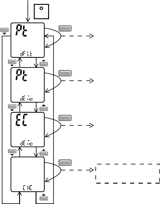
• e-ion Check Mode
o e-ion abnormality check mode
o Purpose is to improve sensor serviceability when sensor is malfunction.
(1) Control starting condition
When all of the conditions are formed
Not in Patrol Demo mode.
e-ion operation ON.
When e-ion check mode signal is received; the procedure of selection is as shown:
• Press “Set” button continuously for 15 seconds by using pointer to enter internal setting mode.
• Press “Timer Decrement" button to select “CHC”.
• Confirm setting by pressing “Timer Set” button, a “beep” sound will be heard.
SET
SET
Transmit Patrol default OFF/ON code
(Buzzer: OFF:Long Beep, ON:Short Beep)
Press continously for 15s
SET
Transmit Patrol demo code
(Buzzer: OFF:Long Beep, ON:Short Beep)
SET
Transmit ECO demo code
(Buzzer: OFF:Long Beep, ON:Short Beep)
SET
Transmit check code
(Buzzer:Short Beep)
o If abnormal discharge is detected at filter (short-circuited) due to water or dust adhesion, etc., the e-ion
indicator blinks immediately.
44
• Error Detection Control
When e-ion indicator blink, it indicates error listed below:
o Active e-ion Air Purifying system PCB main connector open:
Judgment Method
• During e-ion operation (include during Patrol operation), Active e-ion Air Purifying system main
connector to PCB is opened.
Troubleshooting Methods
• Connect the connector or stop operation (include during Patrol operation) to cancel the blinking.
o Abnormal Discharge error:
Judgment Method
• During e-ion operation, feedback voltage is-Lo (at microcontroller) is detected, it is judged abnormal
discharge and stops power supplies to the Active e-ion Air Purifying system.
• Abnormal discharge is caused by ionizer or filter’s high voltage power supply short-circuits due to
water or dust adhesion, and so forth.
• When abnormal discharge occurred, every 30 minutes the unit supplies power to the Active e-ion Air
Purifying system.
• When abnormal discharge occurs for 24 times continuously, e-ion indicator blinks (not applicable for
e-ion Check Mode, where the error will shows immediately despite the 24 times counter)
Troubleshooting Method
• Press “PATROL/e-ion” button or “OFF/ON” button to stop the operation and check the Active e-ion
Air Purifying system main connector to PCB.
• After that, press “e-ion” button again to confirm the e-ion indicator not blinking.
• The 24 times counter will be clear after 10 minutes of normal operation or when operation stops.
Error Reset Method
• Press “OFF/ON” button to OFF the operation.
• Press AUTO OFF/ON button at indoor unit to OFF the operation.
• OFF Timer activates
• Power supply reset
o Active e-ion Air Purifying system breakdown error:
Judgment Method
• When hi-feedback voltage (at microcontroller) supplied to filter during e-ion stop, Active e-ion Air
Purifying system breakdown error shows immediately.
• It is due to indoor PCB or filter’s high voltage power supply damage.
• Operations except e-ion continue. Both Timer indicator and e-ion indicator blink.
Troubleshooting Method
• Press “PATROL/e-ion” button or “OFF/ON” button to stop the operation.
• Change main circuit board or filter’s high voltage power supply.
• When lo-feedback voltage supplied to Active e-ion Air Purifying system during e-ion operation, e-ion
indicator and Timer indicator stop blinking.
45
12.15 ECO Patrol Operation
• A Pyoelectric infrared sensor is used to detect injection strength variation of infrared at setting area to determine
the presence or absence of human and its activity level. Human detection area is shown in figure below:
• ECO Patrol operation – Human presence/absence detection outlined flow
Process infrared sensor output signal
Human detection (movement) every 3 seconds.
▼
Human detection records
Records human detection (movement) result for 30 seconds and determine its activity level i.e. Hi/Lo.
▼
Presence / absence detection
Compares current and previous human detection result every 30 seconds to determine the presence
or absence of human.
▼
Presence / absence determination
Based on human presence / absence detection, if human presence detection showed within 30
minutes, it is recognised that human is present. If human absence detection showed continuously for
more than 30 minutes, it is recognised that no human is present.
• ECO Patrol Sensor abnormality detection
(1) Connnector pulled out (disconnected), Wire cut Abnormality (Fix Output at Hi)
c Abnormal judgment start condition.
Start from ECO Patrol Sensor power ON, and end after 30 seconds.
d Control content.
Judge ECO Patrol Sensor power level every 100ms.
e Abnormal Judgment condition.
When ECO Patrol Sensor has continues for 25 seconds Hi level.
(2) Circuit Abnormal (Fix Output Lo)
c Abnormal judgment start condition.
After ECO Patrol Sensor unit power ON, and after pressed 70 seconds.
d Control content.
Judge ECO Patrol Sensor power level every 100ms.
e Abnormal Judgment condition.
When ECO Patrol Sensor has continues at Lo level for 25 seconds.
(3) Abnormal treatment
Any one of the above self-diagnosis result is abnormal
• Abnormal counter +1 and ECO Patrol Sensor power supply OFF.
• After ECO Patrol Sensor unit power is OFF for 5 seconds, Retry the ECO Patrol operation.
• When Abnormal counter reach 4 counts, ECO Patrol sensor abnormality is confirmed.
(Abnormal counter is cleared when sensor power ON and maintain normal for 120 seconds and above or
Clear Anormal counter by power reset)
• Save ECO Patrol Sensor Abnormality (no Timer LED blinking).
• ECO Patrol Sensor operation OFF, but ECO Patrol LED maintain ON.
• The unit still operate as normal.
• Sensor error counter can be cleared only after power supply reset or AC Reset button on the remote
control is pressed.
46
• ECO Patrol Demo Mode
Press “Set” button continuously for 15 seconds by using pointer during Air Conditioner is OFF condition
to enter internal setting mode.
Press “Timer Decrement" button to select “EC demo”.
Press “Timer Set” button to toggle ECO Patrol Demo mode.
• Short "beep": Turn ON ECO Patrol Demo mode.
• Long "beep": Turn OFF ECO Patrol Demo mode.
SET
SET
Transmit Patrol default OFF/ON code
(Buzzer: OFF:Long Beep, ON:Short Beep)
Press continously for 15s
SET
Transmit Patrol demo code
(Buzzer: OFF:Long Beep, ON:Short Beep)
SET
Transmit ECO demo code
(Buzzer: OFF:Long Beep, ON:Short Beep)
SET
Transmit check code
(Buzzer:Short Beep)
Control details:
• During ECO Patrol Demo mode, operation LED ON and horizontal vane will set to Auto Swing.
• When Hi activity judge, Fan speed change to Hi Fan and ECO Patrol LED ON.
• When Lo activity judge, Fan speed change to Lo Fan and ECO Patrol LED OFF.
• No setting temperature adjustment.
47
• During ECO Patrol operation, the internal setting temperature and fan speed are adjusted in order to provide
comfort and energy saving.
• ECO Patrol Start condition.
Press ECO Patrol button to select ECO1 and ECO2.
• ECO Patrol Stop condition.
Press ECO Patrol button again.
OFF Timer activates.
Press OFF/ON button to turn off the air conditioner.
Press AUTO OFF/ON button to turn off the air conditioner.
Press POWERFUL/QUIET button.
• ECO Patrol operation could ON when any of the following conditions is fulfilled:
During forced cooling or forced heating operation.
During e-ion or individual patrol operation.
• Power Failure
ECO Patrol operation will be resuming after recovered from power failure.
• Timer Operation
When unit is turn on by ON Timer and ECO Patrol operation is ON during previous operation before OFF,
ECO Patrol operation will not be ON automatically.
When unit is turn on by ON Timer and ECO Patrol operation is OFF during previous operation before
OFF, ECO Patrol operation will not be ON automatically.
• Other Information
ECO Patrol, Powerful and Quiet cannot be operated at the same time.
ECO Patrol sensor initialized time is 70 seconds from power supplied to ECO Patrol sensor, or 70
seconds from the operation start.
• ECO 1 Operation
-1
o
C
+2
o
C
HighLow None
Fan Speed
Set
Temperature
Activity Level
Set Speed Set Speed Med Fan
+1tap Up
• ECO 2 Operation
-1
o
C
HighLow None
Fan Speed
Set
Temperature
Activity Level
Set Speed Set Speed Med Fan
+1tap Up
+3
o
C
48
• ECO Patrol Sensor abnormality check mode
• Purpose is to improve sensor serviceability when sensor is malfunction.
(1) Control starting condition
When all of the conditions are formed
Not in ECO Patrol Demo mode.
ECO Patrol mode ON.
When ECO Patrol sensor check mode signal is received; the procedure of selection is as shown:
• Press “Set” button continuously for 15 seconds by using pointer to enter internal setting mode.
• Press “Timer Decrement" button to select “CHC”.
• Confirm setting by pressing “Timer Set” button, a “beep” sound will be heard.
SET
SET
Transmit Patrol default OFF/ON code
(Buzzer: OFF:Long Beep, ON:Short Beep)
Press continously for 15s
SET
Transmit Patrol demo code
(Buzzer: OFF:Long Beep, ON:Short Beep)
SET
Transmit ECO demo code
(Buzzer: OFF:Long Beep, ON:Short Beep)
SET
Transmit check code
(Buzzer:Short Beep)
(2) Control ending condition.
When any of the conditions are formed
Operation stops.
“Timer Cancel” button pressed.
When ECO Patrol sensor check mode signal is not received for more than 30 seconds.
(3) Control content.
During ECO Patrol mode ON, when check signal is received, if (1) or (2) is detected.
ECO Patrol LED start blinking (ECO Patrol sensor operation stops but the unit operates as normal) and
ECO Patrol sensor abnormal code is memorized (the 4 times counter is ignored)
The blinking of ECO Patrol LED can be cancelled by pressing ECO Patrol button again.
Sensor error counter can be cleared only after power supply reset or “AC Reset” button on remote
control is pressed.
However, if there is no ECO Patrol sensor abnormally happen, ECO Patrol sensor operation will continues as normal.
49
13. Protection Control
13.1 Restart Control (Time Delay Safety Control)
• When the thermo-off temperature (temperature which compressor stops to operate) is reach during:-
o Cooling operation – the compressor stops for 3 minutes (minimum) before resume operation.
o Soft Dry operation – the compressor stops for 6 minutes (minimum) before resume operation.
• If the operation is stopped by the remote control, the compressor will not turn on within 3 minutes from the
moment operation stop, although the unit is turn on again within the period.
• This phenomenon is to balance the pressure inside the refrigerant cycle.
13.2 7 Minutes Time Save Control
• The compressor will start automatically if it has stopped for 7 minutes and the intake air temperature falls
between the compressor ON temperature (A) and compressor OFF temperature (B) during the period.
• This phenomenon is to reduce the built up humidity inside a room.
13.3 60 Seconds Forced Operation
• Once the air conditioner is turned on, the compressor will not stop within 60 seconds in a normal operation
although the intake air temperature has reached the thermo-off temperature. However, forced stop by pressing
the OFF/ON operation button at the remote control is permitted.
• The reason for the compressor to force operate at the minimum 60 seconds is to allow the refrigerant oil run in a
full cycle and return back to the outdoor unit.
13.4 Starting Current Control
• When the compressor, outdoor fan motor and indoor fan motor are simultaneously started, the indoor fan motor
will start to operate at 1.6 seconds later.
• The reason of the difference is to reduce the starting current flow.
50
Compressor starts for ≥ 5 minutes
▲T ≤ 2.5°C for 2 minutes
Compressor
OFF
Compressor
restart
▲ T = Intake air temperature – Indoor heat exchanger temperature
13.5 Freeze Prevention Control
• To protect indoor heat exchanger from freezing and to prevent higher volume of refrigerant in liquid form return to
compressor.
• This control will activate when temperature of indoor heat exchanger falls below 2°C continuously for more than 4
minutes and compressor turn off.
10 Recovery
4 min
2
Indoor Heat
Exchanger
Temperature
(°C)
Compressor OFF
• Compressor will restart again when the indoor heat exchanger temperature rises to 10°C (Recovery).
• Restart control (Time Delay Safety Control) will be applied in this control if the recovery time is too short.
13.6 Compressor Reverse Rotation Protection Control
• If the compressor is operating continuously for 5 minutes or longer and the temperature difference between
intake air and indoor heat exchanger is 2.5°C or less for continuously 2 minutes, compressor will stop and restart
automatically.
• Time Delay Safety Control is activated before the compressor restart.
• This is to prevent compressor from rotate reversely when there is an instantaneous power failure.
• If this condition happens continuously for 5 times within 50 minutes, unit will turn OFF with TIMER LED blinks.
• The 5 Times counter can be reset when either one of the following condition happen:
o Unit is OFF by remote control or AUTO OFF/ON button.
o Indoor intake temperature – Indoor piping temperature > 5°C for one minute or more.
o Operation mode change.
• The unit could be ON by pressing OFF/ON button at remote control but the TIMER LED will continue blinking.
• TIMER LED blinking will be reset if:
o Indoor intake temperature – Indoor piping temperature > 5°C for one minute or more.
o Power supply reset.
13.7 Dew Prevention Control
• To prevent dew formation at indoor unit discharge area.
• This control starts if:
o Cooling mode or Quiet mode is activated.
o Remote Control setting temperature is less than 25°C.
o Fan speed is at CLo or QLo.
o Room temperature is constant (±1°C) for 30 minutes.
o Compressor is continuously running.
• Fan speed will be adjusted accordingly in this control.
o Fan sped will be increased slowly if the unit is in quiet mode and Lo fan speed.
• Dew prevention stop condition.
o Remote control setting temperature is more than 25°C.
o Fan speed is not at Lo or QLo.
o Select Powerful operation.
51
14. Servicing Mode
14.1 Auto OFF/ON Button
Auto OFF/ON
Button Pressed Auto OFF/ON
Button Pressed
Auto OFF/ON
Button Pressed
5 sec 5 sec
Auto Operation Test Run Operation
(Forced Cooling Operation)
Stop Various Setting Mode Stop
1 AUTO OPERATION MODE
The Auto Operation will be activated immediately once the Auto OFF/ON button is pressed. This operation
can be used to operate air conditioner with limited function if remote control is misplaced or malfunction.
2 TEST RUN OPERATION (FOR PUMP DOWN/SERVICING PURPOSE)
The Test Run Operation will be activated if the Auto OFF/ON button is pressed continuously for more than 5
seconds. A “beep” sound will be heard at the fifth seconds, in order to identify the starting of this operation.
3 VARIOUS SETTING MODE
The Various Setting Mode will be activated if (within 20 seconds of Test Run Operation) the Auto OFF/ON
button is pressed for more than 5 seconds. 2 “beep” sounds will be heard to identify the starting of this
operation.
Under Various Setting Mode, user could perform the following operation:
i. Press Auto OFF/ON button to toggle remote control receiving sound.
- Short “beep”: Turn ON remote control receiving sound.
- Long “beep”: Turn OFF remote control receiving sound.
After Auto OFF/ON button is pressed, the 20 seconds counter for Remote Control Receiving Sound OFF/ON
Mode is restarted.
ii. Remote Control Number Switch.
- There are 4 types of remote control transmission code could be selected and stored in EEPROM of
indoor unit. The indoor unit will only operate when received signal with same transmission code from
remote control. This could prevent signal interference when there are 2 or more indoor units installed
nearby together.
- To change remote control transmission code, short or open jumpers at the remote control printed circuit
board.
Remote Control Printed Circuit Board
Jumper A (J-A) Jumper B (J-B) Remote Control No.
Short Open A (Default)
Open Open B
Short Short C
Open Short D
- During Various Setting Mode, press any button at remote control to transmit and store the desired
transmission code to the EEPROM.
- After signal is received, the Various Setting Mode is cancelled and return to normal operation.
- If there is no code is transmitted of Auto OFF/ON button is not pressed within 20 seconds, the
Various Setting Mode will be cancelled.
J_A
J_B
J - A
J - B
52
14.2 Remote Control Button
14.2.1 SET Button
• To check current remote control transmission code and store the transmission code to EEPROM:
o Press “Set” button for more than 10 seconds
o Press “Timer Set” button until a “beep” sound is heard as confirmation of transmission code change.
• To change the air quality sensor:
o Press and release by using pointer
o Press the Timer Decrement button to select sensitivity:
1. Low sensitivity
2. Standard (Default)
3. Hi sensitivity
o Confirm setting by pressing Timer Set button, a “beep” sound will be heard. LCD returns to original display
after 2 seconds.
o LCD returns to original display if remote control does not operate for 30 seconds.
14.2.2 CLOCK Button
• To change the remote control time format:
o Press for more than 5 seconds
14.2.3 RESET (RC) Button
• To clear and restore the remote control setting to factory default.
o Press once to clear the memory
14.2.4 TIMER ▲
• To change indoor unit indicators’ intensity:
o Press continuously for 5 seconds.
14.2.5 TIMER ▼
• To change remote control display from Degree Celsius (°C) to Degree Fahrenheit (°F)
o Press continuously for 10 seconds.
53
15. Troubleshooting Guide
15.1 Refrigeration cycle system
In order to diagnose malfunctions, ensure the air conditioner is free
from electrical problems before inspecting the refrigeration cycle.
Such problems include insufficient insulation, problem with the
power source, malfunction of a compressor and a fan. The normal
outlet air temperature and pressure of the refrigeration cycle
depends on various conditions, the standard values for them are
shown in the table to the right.
Normal Pressure and Outlet Air Temperature (Standard)
Gas Pressure
Mpa
(kg/cm2G)
Outlet air
Temperature
(°C)
Cooling Mode 0.4 ~ 0.6 (4 ~ 6) 12 ~ 16
Condition: Indoor fan speed = High
Outdoor temperature = 35°C
Different in the intake
and outlet
air temperatures
Normal
Value of electric current
during operation
Dusty condenser
preventing heat radiation
Excessive amount
of refrigerant
Gas side
pressure Inefficient compressor
Insufficient refrigerant
Clogged strainer or
capillary cube
•
Measuring the air
temperature different
•
Measuring electric current
during operation
•
Measuring gas side
pressure
More than 8°C
(15 minutes after an
operation is started)
Less than 8°C at the cooling mode
Higher than specified
Cooling
Mode High
Low
Low
Lower than specified

54
15.1.1 Relationship between the condition of the air conditioner and pressure and
electric current
Cooling Mode
Condition of the
air conditioner Low Pressure High Pressure Electric current during operation
Insufficient refrigerant
(gas leakage) Ô Ô Ô
Clogged capillary tube or
strainer Ô Ô Ô
Short circuit in the indoor unit Ô Ô Ô
Heat radiation deficiency
of the outdoor unit Ò Ò Ò
Inefficient compression Ò Ô Ô
• Carry out the measurement of pressure, electric current, and temperature fifteen minutes after an operation is started.
15.1.2 Diagnosis methods of a malfunction of a compressor
Nature of fault Symptom
Insufficient compressing of a compressor
• Electric current during operation becomes approximately 20% lower than the normal value.
• The discharge tube of the compressor becomes abnormally hot (normally 70°C to 90°C).
• The different between high pressure and low pressure becomes almost zero.
Locked compressor
• Electric current reaches a high level abnormally, and the value exceeds the limit of an
ammeter. In some cases, a breaker turns off.
• The compressor has a humming sound.
55
WARNING
16. Disassembly and Assembly Instructions
High Voltage is generated in the electrical parts area by the capacitor. Ensure that the capacitor has discharged sufficiently before proceeding with
repair work. Failure to heed this caution may result in electric shocks.
16.1 Indoor Electronic Controllers, Cross Flow Fan and Indoor Fan Motor
Removal Procedures
16.1.1 To remove front grille
Figure 1
16.1.2 To remove horizontal vane
Figure 2
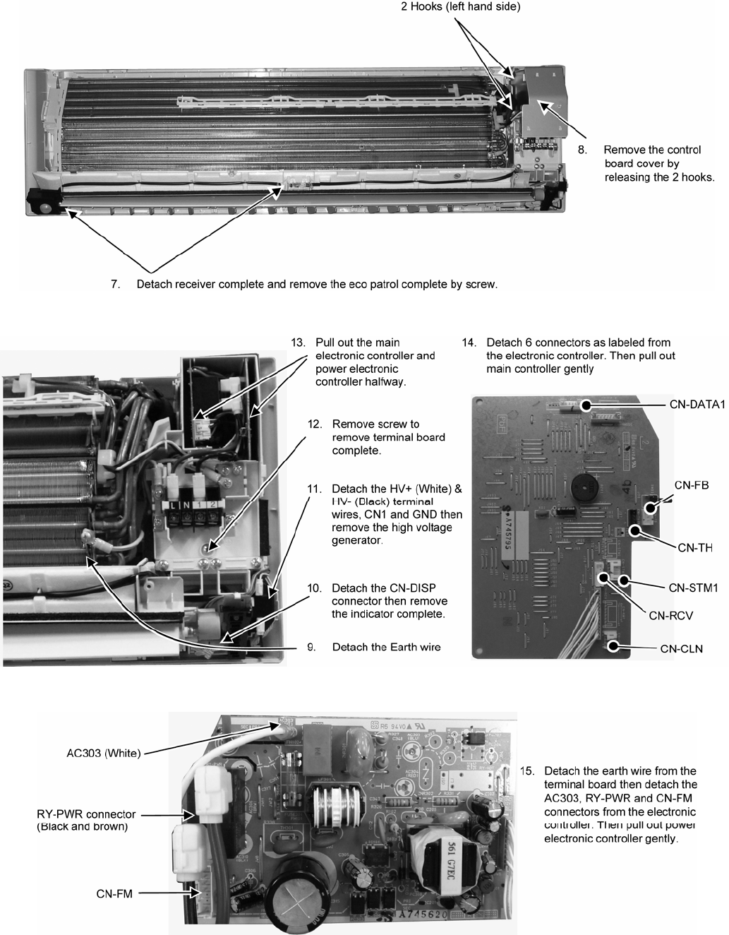
56
16.1.3 To remove power electronic controller
Figure 3
Figure 4 Figure 5
Figure 6
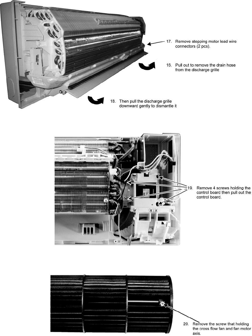
57
16.1.4 To remove discharge grille
Figure 7
16.1.5 To remove control board
Figure 8
16.1.6 To remove cross flow fan and indoor fan motor
Figure 9
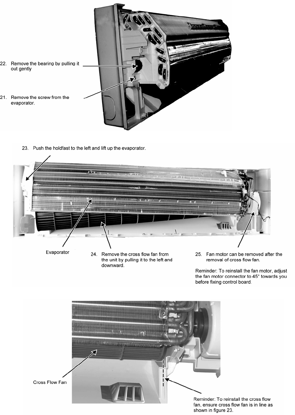
58
Figure 10
Figure 11
Figure 12

59
17. Technical Data
17.1 Operation Characteristics
17.1.1 CS-C18KKS CU-C18KKS
• Cooling Characteristic
o Room temperature: 27°C (DBT), 19°C (WBT)
o Operation condition: High fan speed
o Piping length: 5.0m
Gas Side
Piping Pressure (MPa)
Capacity (kW)
Outdoor Temperature (ºC)
Outdoor Temperature (ºC)
220V
220V
Current (A)
Outdoor Temperature (ºC)
220V
3.80
4.10
4.40
4.70
5.00
5.30
5.60
30 35 40 45 50 55
Outlet Air (ºC)
Outdoor Temperature (ºC)
220V
7.00
7.50
8.00
8.50
9.00
9.50
10.00
10.50
11.00
30 35 40 45 50 55
14.1
14.6
15.1
15.6
16.1
16.6
30 35 40 45 50 55
0.470
0.500
0.530
0.560
0.590
0.620
30 35 40 45 50 55
60
• Piping Length Characteristic
o Outdoor temperature: 35°C (DBT), 24°C (WBT)
o Operation condition: High fan speed
o Piping length: 5.0m
Current (A)
Gas Side
Piping Pressure (MPa)
Capacity (kW)Outlet Air (ºC)
220V
Piping Length (m)
220V
Piping Length (m)
Piping Length (m)
220V
Piping Length (m)
220V
14.5
14.6
14.7
14.8
14.9
15.0
15.1
15.2
15.3
3 5 7 9 11 13 15 17 19 21 23 25
7.20
7.30
7.40
7.50
7.60
7.70
7.80
7.90
3 5 7 9 11 13 15 17 19 21 23 25
0.430
0.440
0.450
0.460
0.470
0.480
0.490
0.500
3 5 7 9 11 13 15 17 19 21 23 25
4.50
4.60
4.70
4.80
4.90
5.00
5.10
5.20
3 5 7 91113151719212325
61
17.1.2 CS-C24KKS CU-C24KKS
• Cooling Characteristic
o Room temperature: 27°C (DBT), 19°C (WBT)
o Operation condition: High fan speed
o Piping length: 5.0m
Current (A)
Gas Side
Piping Pressure (MPa)
Capacity (kW)Outlet Air (ºC)
Outdoor Temperature (ºC)
Outdoor Temperature (ºC)
Outdoor Temperature (ºC)
Outdoor Temperature (ºC)
220V
220V
220V
220V
30 35 40 45 50 55
13.0
13.5
14.0
14.5
15.0
15.5
16.0
30 35 40 45 50 55
11.00
12.00
13.00
14.00
15.00
16.00
17.00
30 35 40 45 50 55
4.90
5.20
5.50
5.80
6.10
6.40
6.70
7.00
30 35 40 45 50 55
0.400
0.430
0.460
0.490
0.520
0.550
62
• Piping Length Characteristic
o Outdoor temperature: 35°C (DBT), 24°C (WBT)
o Operation condition: High fan speed
o Piping length: 5.0m
Current (A)
Gas Side
Piping Pressure (MPa)
Capacity (kW)Outlet Air (ºC)
220V
Piping Length (m)
220V
Piping Length (m)
Piping Length (m)
220V
Piping Length (m)
220V
3 5 7 9 11 13 15 17 19 21 23 25
13.5
13.7
13.9
14.1
14.3
14.5
3 5 7 9 11 13 15 17 19 21 23 25
11.00
11.20
11.40
11.60
11.80
12.00
12.20
3 5 7 9 11 13 15 17 19 21 23 25
5.80
5.90
6.00
6.10
6.20
6.30
6.40
6.50
6.60
3 5 7 9 11 13 15 17 19 21 23 25
0.360
0.370
0.380
0.390
0.400
0.410
0.420
0.430

63
18. Exploded View and Replacement Parts List
18.1 Indoor Unit
Note
The above exploded view is for the purpose of parts disassembly and replacement.
The non-numbered parts are not kept as standard service parts.

64
REF.
NO. PART NAME & DESCRIPTION QTY CS-C18KKS CS-C24KKS REMARK
1 CHASSY COMPLETE 1 CWD50C1654 ←
2 FAN MOTOR 1 L6CBYYYL0037 L6CBYYYL0039 O
3 CROSS FLOW FAN COMPLETE 1 CWH02C1077 ←
4 BEARING ASS’Y 1 CWH64K007 ←
5 SCREW - CROSS FLOW FAN 1 CWH551146 ←
6 ION GENERATOR 1 CWH94C0028 ←
7 EVAPORATOR 1 CWB30C3126 CWB30C3268
8 FLARE NUT (LIQUID) 1 CWT251026 ←
9 FLARE NUT (GAS) 1 CWT251062 CWT251036
10 E-ION AIR PURIFYING SYSTEM 1 CWD93C1090 ←
11 HOLDER SENSOR 1 CWH32143 ←
12 BACK COVER CHASSIS 1 CWD933031 ←
13 CONTROL BOARD CASING 1 CWH102370 ←
14 TERMINAL BOARD COMPLETE 1 CWA28C2393 CWA28C2394 O
15 ELECTRONIC CONTROLLER - MAIN 1 CWA73C4492 CWA73C4493 O
16 ELECTRONIC CONTROLLER - POWER 1 CWA745303 CWA745620 O
17 ELECTRONIC CONTROLLER-HVU 1 CWA745348 ← O
18 ELECTRONIC CONTROLLER-INDICATOR 1 CWA745820 ← O
19 ELECTRONIC CONTROLLER-RECEIVER 1 CWA745288 ← O
20 COVER FOR RECEIVER(BOTTOM) 1 CWD933209 ←
21 COVER FOR RECEIVER(UPPER) 1 CWD933022 ←
22 INDICATOR HOLDER 1 CWD933021 ←
23 SENSOR COMPLETE 1 CWA50C2401 ← O
24 SENSOR COMPLETE(ECO) 1 CWA50C2709 ← O
25 ELECTRONIC CONTROLLER (ECO
SENSOR) 1 CWA745791 ← O
26 ELECTRONIC CONTROLLER
(COMPARATOR) 1 CWA745790 ← O
27 LEAD WIRE - PCB ECO 1 CWA67C8484 ←
28 COVER FOR PCB ECO(BOTTOM) 1 CWD933193 ←
29 COVER FOR PCB ECO(UPPER) 1 CWD933192 ←
30 DISCHARGE GRILLE COMPLETE 1 CWE20C3007 ←
31 VERTICAL VANE 15 CWE241289 ←
32 CONNECTING BAR 1 CWE261156 ←
33 CONNECTING BAR 1 CWE261158 ←
34 CONNECTING BAR 1 CWE261157 ←
35 CONNECTING BAR 1 CWE261159 ←
36 CONNECTING BAR 1 CWE261160 ←
37 A.S.MOTOR,DC SINGLE 12V 300OHM 1 CWA981241 ← O
38 A.S MOTOR,DC SINGLE 12V300 OHM 1 CWA98K1014 ← O
39 HORIZONTAL VANE 1 CWE24C1295 ←
40 CAP - DRAIN TRAY 1 CWH521096 ←
41 CONTROL BOARD TOP COVER 1 CWH131350 ←
42 CONTROL BOARD FRONT COVER 1 CWH13C1183 ←
43 REMOTE CONTROL COMPLETE 1 CWA75C3560 ← O
44 FRONT GRILLE COMPLETE 1 CWE11C4737 ← O
45 INTAKE GRILLE COMPLETE 1 CWE22C1483 ← O
46 GRILLE DOOR 1 CWE14C1029 ←
47 E-ION FILTER 2 CWD00K1017 ←
48 SCREW - FRONT GRILLE 4 XTT4+16CFJ ←
49 CAP - FRONT GRILLE 3 CWH521194 ←

65
50 DRAIN HOSE 1 CWH851173 ←
51 BAG COMPLETE - INSTALLATION SCREW 1 CWH82C1705 ←
52 INSTALLATION PLATE 1 CWH361098 ←
53 FULCRUM 2 CWH621103 ←
54 OPERATING INSTRUCTION 1 CWF567115 ←
55 INSTALLATION INSTRUCTION 1 CWF614219 ←
56 INSTALLATION INSTRUCTION 1 CWF614220 ←
57 POWER SUPPLY CORD 1 CWA20C2836 ←
(Note)
• All parts are supplied from PHAAM, Malaysia (Vendor Code: 00029488).
• “O” marked parts are recommended to be kept in stock.
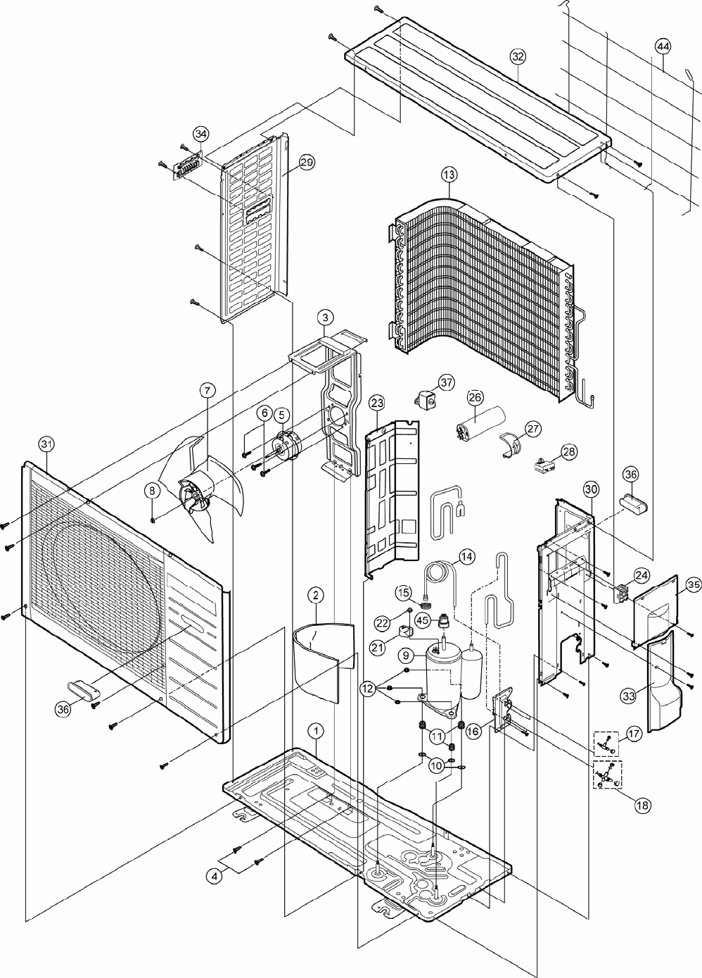
66
18.2 Outdoor Unit
Note
The above exploded view is for the purpose of parts disassembly and replacement.
The non-numbered parts are not kept as standard service parts.

67
REF. NO. PART NAME & DESCRIPTION QTY CU-C18KKS CU-C24KKS REMARK
1 CHASSY ASS’Y 1 CWD50K2115 CWD50K2100
2 SOUND PROOF MATERIAL 2 CWG302408 ←
3 FAN MOTOR BRACKET 1 CWD541065 ←
4 SCREW - FAN MOTOR BRACKET 2 CWH551217 ←
5 FAN MOTOR 1 CWA951401J CWA951399J O
6 SCREW - FAN MOTOR MOUNT 3 CWH55252J ←
7 PROPELLER FAN ASS’Y 1 CWH03K1017 ←
8 NUT - PROPELLER FAN 1 CWH561038J ←
9 COMPRESSOR 1 2KS252F5AA04 2J39S236A1A O
10 PACKING 3 CWB81043 ←
11 ANTI - VIBRATION BUSHING 3 CWH50055 ←
12 NUT - COMPRESSOR MOUNT 3 CWH561049 ←
13 CONDENSER 1 CWB32C2966 CWB32C2684
14 CAPILLARY TUBE ASS’Y 1 CWB15K1252 CWB15K1282
15 STRAINER 1 CWB11025 ←
16 HOLDER COUPLING 1 CWH351036 ←
17 2-WAY VALVE (LIQUID) 1 CWB021175 ← O
18 3-WAY VALVE (GAS) 1 CWB011483 CWB011484 O
21 TERMINAL COVER 1 CWH171011 CWH171012
22 NUT - TERMINAL COVER 1 CWH7080300J ←
23 SOUND PROOF BOARD 1 CWH151056 ←
24 TERMINAL BOARD ASS’Y 1 CWA28K1064J ←
26 CAPACITOR - COM. 1 CWA312078 CWA312088 O
27 HOLDER CAPACITOR 1 CWH30060 CWH30071
28 CAPACITOR - F.M 1 DS441355NPQA ← O
29 CABINET SIDE PLATE 1 CWE041082A ←
30 CABINET SIDE PLATE COMPLETE 1 CWE04C1127 ←
31 CABINET FRONT PLATE ASS’Y 1 CWE06K1045 ←
32 CABINET TOP PLATE 1 CWE03K1011A ←
33 CONTROL BOARD COVER COMP 1 CWH131168 ←
34 HANDLE 1 CWE161010 ←
35 CONTROL BOARD COVER(RIGHT-TOP) 1 CWH131169A ←
36 HANDLE 2 CWE16000E ←
37 THERMOSTAT 1 - CWA151061
44 WIRE NET 1 CWD041041A ←
45 OVERLOAD PROTECTOR WITH WIRE 1 CWA67C7546 -
(Note)
• All parts are supplied from PHAAM, Malaysia (Vendor Code: 00029488).
“O” marked parts are recommended to be kept in stock.
Printed in Malaysia
SSYW1006-00
