C20 8078_Form_and_Card_Design_1961 8078 Form And Card Design 1961
C20-8078_Form_and_Card_Design_1961 C20-8078_Form_and_Card_Design_1961
User Manual: C20-8078_Form_and_Card_Design_1961
Open the PDF directly: View PDF ![]() .
.
Page Count: 20
Form and Card
Design
This manual
is
divided in two
sections-the
first de-
voted to form design and the second to card design.
Its use presupposes a knowledge of
IBM
data process-
ing equipment.
It
can be used
as
a guide for indi-
vidual study or a text for class study.
Form C20-8078
Design

© 1961
by
International Business Machines Corporation
Copies
of
this
and
other
mM
publications
can
be
obtained
through
mM
Branch
Offices.
Address
comments
concerning
the
contents
of
this
publication
to
mM,
Technical
Publications
Department,
112
East Post
Road,
White
Plains,
N.
Y.
10601
Contents
Form Design
..........................................
1
Steps to
be
Taken. . . . . . . . . . . . . . . . . . . . . . . . . . . . . . . . . . . . . . 1
Design Considerations
.................................
1
Form
Width
..
. . . . . . . . . . . . . . . . . . . . . . . . . . . . . . . . . . . . . . 1
,
Form
Length
.......................................
1
Horizontal Spacing
..
. . . . . . . . . . . . . . . . . . . . . . . . . . . . . . . . 3
Vertical Spacing . . . . . . . . . . . . . . . . . . . . . . . . . . . . . . . . . . . . . 3
Form
Skipping . . . . . . . . . . . . . . . . . . . . . . . . . . . . . . . . . . . . . . 3
Availability of Characters for
Each
Printing Position
..
. . . . . . . . . . . . . . . . . . . . . . . . . . . . . 3
Form
Alignment Guide . . . . . . . . . . . . . . . . . . . . . . . . . . . . . . . 3
Numerical
Amounts..
.
..
. . . .
..
. . . .
..
.
..
.
..
. . .
..
. .
..
. 3
Check Protection . . . . . . . . . . . . . . . . . . . . . . . . . . . . . . . . . . . . 4
Marginal
Perforations.
. . . . . . . . . . . . . . . . . . . . . . . . . . . . . . . 4
Binding
...........................
,
..
. . . . .
..
..
.
...
. 4
Carbon Copies
..
. . . . . . . . . . . . . . . . . . . . . . . . . . . . . . . . . . . . 4
Form
Types
........................................
5
Card Design
..........................................
6
Determining
Card
Data
. . . . . . . . . . . . . . . . . . . . . . . . . . . . . . . . 6
Determining Field Size
................................
6
Determining
Data
Sequence . . . . . . . . . . . . . . . . . . . . . . . . . . . . 8
Location of
Data
in
Other
Cards. . . . . . . . . . . . . . . . . . . . . . 9
Sequence of
Data
on
the
Source Document. . . . . . . . . . . . . . 9
Machine Characteristics
.............................
9
Card
Layout Forms
...................................
10
Drawing
the
Layout . . . . . . . . . . . . . . . . . . . . . . . . . . . . . . . . .
..
12
Designing Short Cards
..
. . . . . . . . . . . . . . . . . . . . . . . . . . . . .
..
14
Designing PORT-A-PUNCH® Cards
....................
15
Tumble
and
Sectional
Cards.
. . . . . . . . . . . . . . . . . . . . . . . . .
..
15
Testing Card Design
..................................
15

Introduction
To insure efficient processing, cards
and
forms should
be
designed specifically for the application in which
they are to
be
used.
In
doing this,
it
is necessary to:
• Know thoroughly the procedure
and
the machines
to
be
used.
• Understand the reports to
be
prepared
and
know
the use to which each will
be
put.
• Know the· rules of good card
and
form design.
The application of these must
be
accompanied
by
in-
genuity, common sense
and
experience.
This manual
is
divided into two sections -the first
devoted to form design
and
the second to card design.
Each
is intended to serve as a guide
and
in no way re-
places the valuable assistance
that
is
available through
your local
IBM
representative.
The
design of efficient, economical forms requires a
certain amount of preparatory evaluation
and
analysis.
Bear in
mind
that
the
major objectives are
(1)
forms
which are legible, simple
and
economical,
and
(2)
forms which can
be
prepared
efficiently. Local
IBM
rep-
resentatives should
be
consulted early; their guidance
and
reference materials will help insure against costly
mistakes.
Steps to
be
Taken
First,
the
necessity of designing a particular
new
form
should
be
established.
There
may
be
existing forms
which are similar to
the
proposed one
and
which, with
minor changes, will satisfy the
new
requirements.
Next,
study
the
machine to
be
used for printing.
In
so
doing, use
the
reference manual for this machine;
most manuals have
at
least one section devoted to
the
tape-controlled carriage
and/or
form design. These sec-
tions contain valuable information
about
forms specifi-
cations as well as different printer characteristics and
operation.
Thirdly, list all types of information to
be
recorded
and
the
number
of positions which will
be
allotted for
printing each.
In
doing this,
past
and
present
statistics
should
be
assembled
and
studied; these
can
be
eval-
uated
in light of
future
plans
and
then
used as
an
indi-
cation of
probable
needs.
One
of
the
greatest weak-
nesses in form design
is
the
tendency to
burden
a form
with unessential information. Since entire
data
process-
ing procedures
may
be
geared to
the
preparation of a
certain report, unnecessary information
is
extremely
costly.
As
a fourth step,
layout
the
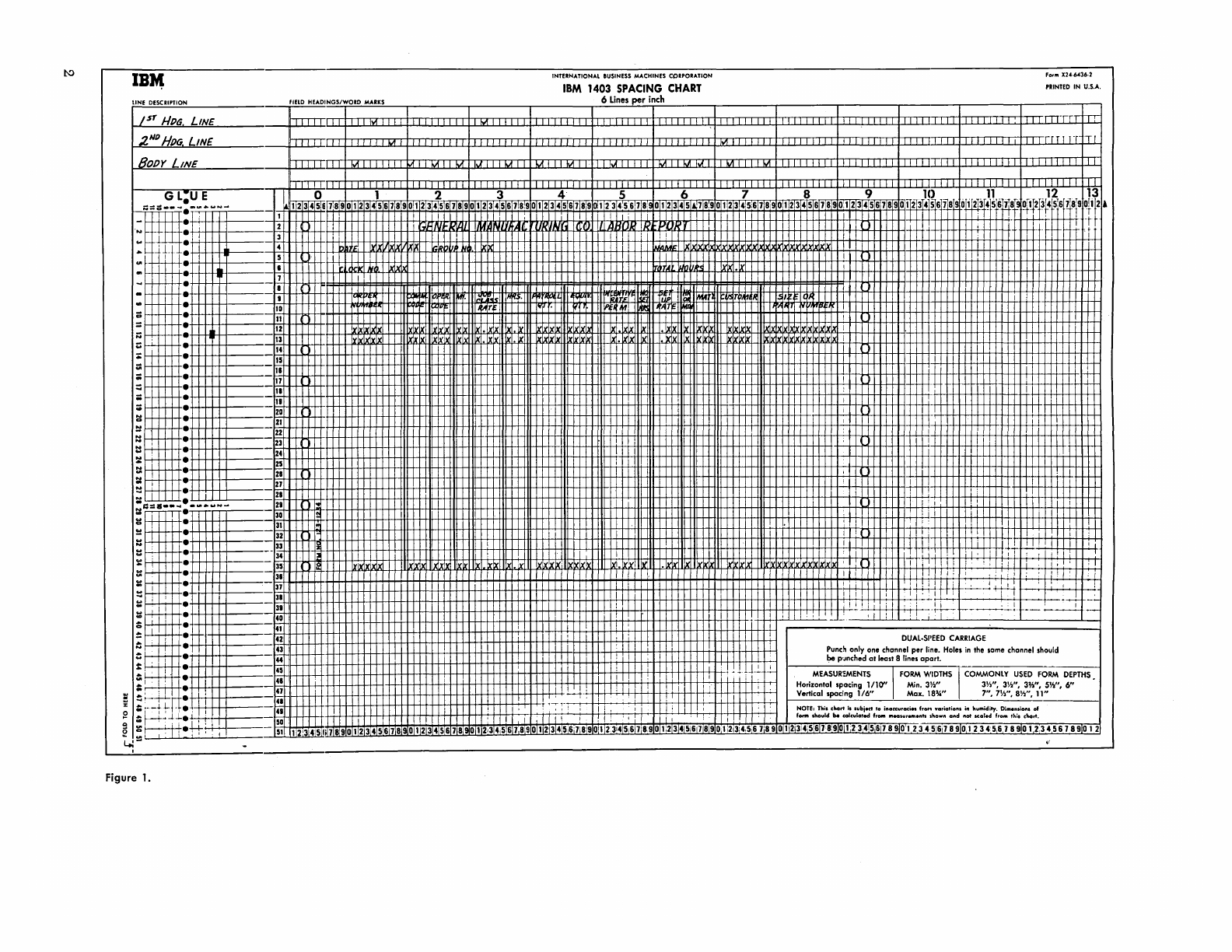
form on a spacing chart.
(Note: A 1403 spacing
chart
is
illustrated in
Figure
1.
Spacing charts for
each
IBM
printer
are available
through your local
IBM
representative.)
In
so
doing,
the
following tips will
be
helpful, some of which will
be
discussed in
greater
detail later:
• Use
bold
type
to make special information
or
head-
ings
stand
out.
•
In
columns for figures allow sufficient space for
the
largest amount.
• Place filing information
near
the top of
the
form.
• Title
the
form.
• Include form
number
and
date.
• Keep headings small, to allow sufficient room for
written data.
• Consider headings
at
the
bottom of
the
form.
Form
Design
•
For
multiple copies, use colors as
an
aid
in routing
each
copy.
• Use double-ruled lines to set off sections.
• A void horizontal rulings as
much
as possible to
eliminate adjusting.
• Consider guide marks for names, addresses
and
folding.
• Use some type of check protection for payroll, ac-
counts payable
and
other checks.
•
If
possible, choose a form
width
that
is
standard.
• Make certain
that
the
form length is compatible
with
the spacing to
be
used.
• Include a guide for forms alignment in
the
printer.
The
final step in form design should
be
a test in which
a copy of
the
proposed form
is
used.
In
making
the
test,
examine
the
report
carefully to make certain
that
zeros
are printing properly
and
that
amount
fields are large
enough. Make certain
that
all possible conditions
that
can arise during processing are tested.
Design
Considerations
During
the
design of a form
the
designer should under-
stand
and
keep in
mind
the
following:
Form
Width
The
overall width of a form
is
important
in determining
printing space. Although
the
IBM
form-feeding devices
available will
handle
a great variety of
document
sizes,
certain practical aspects should
be
observed.
Form
costs can
be
reduced
by
confining form widths
to
the
standard
sizes of
paper
stock used
by
business
forms companies. These
standard
sizes can
be
obtained
from
the
forms company; reference to
the
individual
machine
manual
will indicate which are acceptable.
In
addition, standardization permits
(1)
purchase of
report
binding
and
filing supplies in fewer sizes
and
greater quantities
at
reduced
cost,
(2)
more convenient
forms handling
and
(3)
a reduction in
the
setup time
of form-feeding devices.
Form Length
The
total
number
of
body
lines which a form con-
tains (regardless
whether
six- or eight-lines-per-inch
spacing
is
employed) can
be
any whole
number
in
the case of single spacing, should
be
evenly divisible
by
two in
the
case of double spacing,
and
should
be
evenly divisible
by
three
in
the
case of triple
spacing.
1
INTERN
...
TlON
...
L
eUSINESS
M"'CHINES
CORPOR
...
TlON For'"
X2
.. -6.t36·2
IB,.,
IBM
1403
SPACING
CHART
PRINTED
IN
u.s
.....
LINE
DESCRIPTION
fiELD
HE
...
DINGS/WORD M
...
RKS
6
Lines
per
inch
1
ST
/-11)6
LINE
1111
hi'!
TT,rn-
2ND
HI)G.
LINE
hi'!
I.IJ
llrlTI
BOpy
LINE
I""
Iv1
IvI I.IJ
I.
U U
I'"
hi'!
1.Jl1.A
Iv'I
IvI
G
L:U
E 0 1 2 3 4 5 6 7 8 9
1()
11
12 13
-
cOif
-
:~.---
12345,67,8901234567890.123456789012345
617
8,9
0
12345678'9
01123 456!7 8 01112345 7 89 0 I 23 45;6 7
890
I
234
5 6 7 8 9
0:
I 2 3
4567
890112 3 4 5 6 7 8
91i¥f4jf~
SiS
i8
~~2W415T6
i8
1
9
0~112
•
I I I I
II
' I I
'.
:'
"it
2 , L
~J
IJr.
y{.
I
..
. 3 I
i!
I
..
I
: 11. : I 4
i4,
t;,
I
I I 5 I
UI
• •
tTA.
~.5
I.Clr I
..
1 I
...
•
-•
~.
!4
~
~
To
I
~
1 I
...
10
T
Iii
fl
I
c:
11
I
= Ii
12
IX
Ix
I
~~
13
Ix.
\)(
I
14
I
.:
15
1
U1
II
1
;;;
11
I
==
II
: I
;;;
11
I I
;:
20
I
~
21
I
~
22
I ,
..
23
I I
;~
24
I I
25
, I
21
I I
~t±
21
, ! I , I
21
1 I ! : [
~r··
....
WN-
21
, I I ! I I
30
I
-H
i I i I
31
I ' I I
32
I I I
I;
! I i I
33
I I 1 1 1 i
I!
I ,
::n-~-
34
I I
+-t
" ' ! il"
I'
T
~r-+-
35
Ix
~.
~ ~
Ix" Ix"
Ix"
I 1 I
,'I
I
i,
t:f-+-
3.
I I
I.
I I I
II I:
, . , , , :
:;:~
37
I I
~
~-+
H-+-
~...l
+-4
I , I
~f-+-
31
I I I ,
~~~~I:
I
.1
:;:~h-
3.
I '
II
I,
t--.W--:-
f-----'...;..!
.~
I
-:...
wf+r+
...
--
~ttp.=
40
, , . ,
.-
' I ' i
i I
41
,
42
DUAl·SI'EED
CARRIAGE
-~+
43
1 :
~t~
Punch
only
one
channel
per
line. Holes
in
the
same
chonnel
should
44
I be p'Jnched
atleost
8 lines
apart.
s:
.
H-
45
: : I ; •
-TJ..:..·.l..
~~f+
41
: I I ,
MEASUR~ENTS
I FORM WIDTHS I COMMONLY
USED
FORM
DEPTHS
:~r+
47
I I
~-~
I
I"
1 I Horizontal
spacing
1/10" Min.
3W'
3%",
3W',
3~",
5W',
6"
•
~;:~.,
..
:
41
I T , I , 1 I Vertical
spacing
1/6"
Max.
18>;4"
7",7%",
8W',
11"
4.
T
~-:-;-!
II,
,
i:
I I 1 NOTE: Thi,
chart
I,
."bittet
to inaccuracies fro
..
'f'o,ia.ionl
in
humidity. Dimen.ion. of
::
r-+-
4J. •
.l.-i-t-
50
!
"I
III!
, .1 :
.,
:
i,
I I fonft
.hould
be calculated from measur
...
en"
shown
and
not
Koled
from this chart.
~I
I I ;.4++
51
I 2 3 4
51i
7
890
1 2
34
56
7
890
I 2 34516 7 8 o I 2,34567819
0111213l4r5,671819
01
1123
1
415
617890
1.2131415i6171819
01,213:4,56
7'89
011
2314'56
78!9IOf1:2
34!5'617
8
9101
2345'61789101
2345678910
I 2.345678910 1 2
I~
,I!
I I • !
Figure 1.
Horizontal Spacing
For
ten-characters-per-inch spacing, vertical lines sepa-
rating
fields,
and
periods of
numbers
should
be
drawn
so
that
each
splits a
printing
position.
If
they
are
drawn
between
adjacent positions,
paper
shrinkage, variations
in
form insertion
and
alignment, as well as
other
vari-
ables,
may
prevent
satisfactory registration
during
printing.
For
402-3 spacing,
the
lines
can
be
drawn
between
printing
positions.
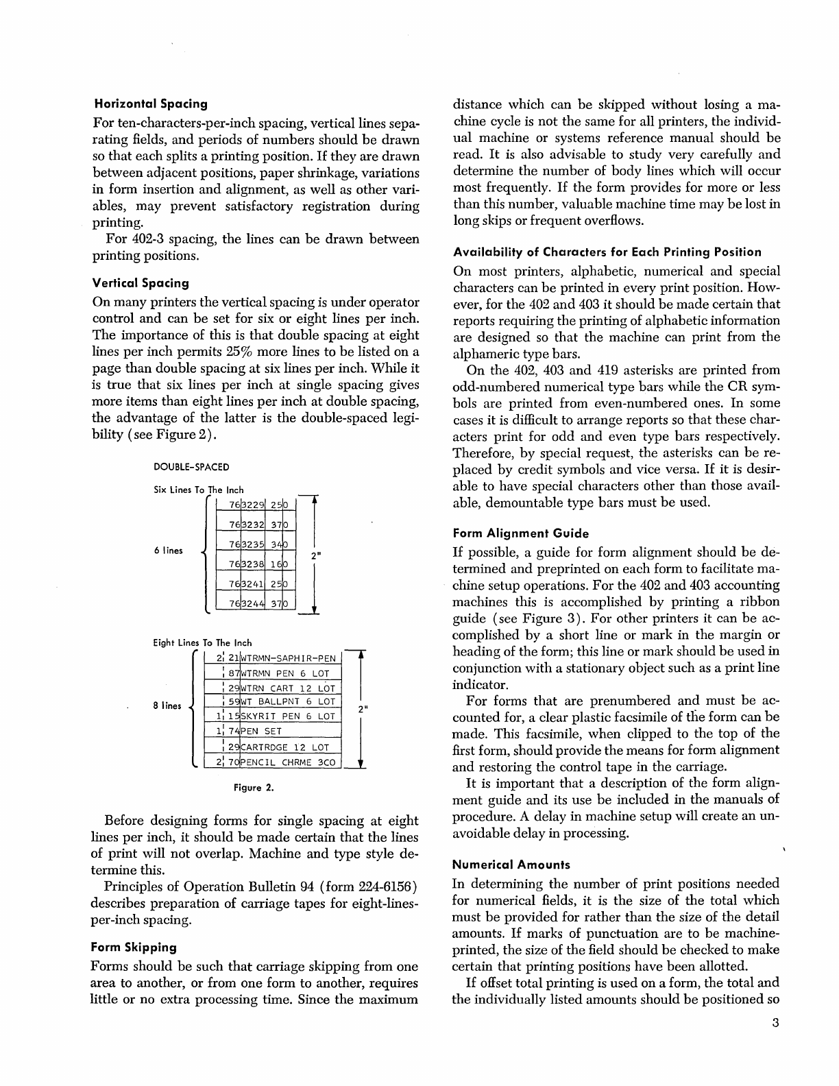
Vertical Spacing
On
many
printers
the
vertical spacing is
under
operator
control
and
can
be
set for six
or
eight
lines
per
inch.
The
importance of this is
that
double
spacing
at
eight
lines
per
inch
permits 25%
more
lines to
be
listed
on
a
page
than
double spacing
at
six lines
per
inch.
While
it
is
true
that
six lines
per
inch
at
single spacing gives
more
items
than
eight
lines
per
inch
at
double
spacing,
the
advantage
of
the
latter
is
the
double-spaced legi-
bility
(see
Figure
2)
.
DOUBLE-SPACED
Six
Lines
To
The
Inch
6 lines 1
2"
763229
250
763232
370
763235
34P J
763238
160
7E3241
250
7E3244 370
Eight
Lines
To
The
Inch
8 lines
2:
21
WTRMN-SAPHIR-PEN
: 87
WTRMN
PEN
6
LOT
: 29
WTRN
CART
12
LOT
: 59
WT
BALLPNT
6
LOT
1:
15
SKYRIT
PEN
6
LOT
1: 74
PEN
SET
: 29
CARTRDGE
12
LOT
2:
70
PENCIL
CHRME
3CO
1
2"
J
Figure 2.
Before designing forms for single spacing
at
eight
lines
per
inch,
it
should
be
made
certain
that
the
lines
of
print
will
not
overlap. Machine
and
type
style de-
termine this.
Principles of
Operation
Bulletin 94 (form 224-6156)
describes
preparation
of
carriage tapes for eight-lines-
per-inch spacing.
Form Skipping
Forms should
be
such
that
carriage skipping from
one
area
to another, or from
one
form to another, requires
little
or
no extra processing time. Since
the
maximum
distance which
can
be
skipped
without
losing a ma-
chine cycle is
not
the
same for all printers,
the
individ-
ual
machine or systems reference
manual
should
be
read.
It
is also advisable to
study
very carefully
and
determine
the
number
of
body
lines
which
will
occur
most frequently.
If
the
form provides for
more
or
less
than
this
number,
valuable machine time may
be
lost
in
long skips or
frequent
overflows.
Availability
of
Characters for Each Printing Position
On
most printers, alphabetic, numerical
and
special
characters can
be
printed
in every
print
position. How-
ever, for
the
402
and
403
it
should
be
made
certain
that
reports requiring
the
printing
of alphabetic information
are designed
so
that
the
machine can
print
from
the
alphameric
type
bars.
On
the
402, 403
and
419 asterisks are
printed
from
odd-numbered
numerical
type
bars while
the
CR
sym-
bols
are
printed
from
even-numbered
ones.
In
some
cases it is difficult to
arrange
reports
so
that
these char-
acters
print
for
odd
and
even
type
bars respectively.
Therefore,
by
special request,
the
asterisks
can
be
re-
placed
by
credit
symbols
and
vice versa.
If
it
is
desir-
able to have special characters
other
than
those avail-
able,
demountable
type
bars
must
be
used.
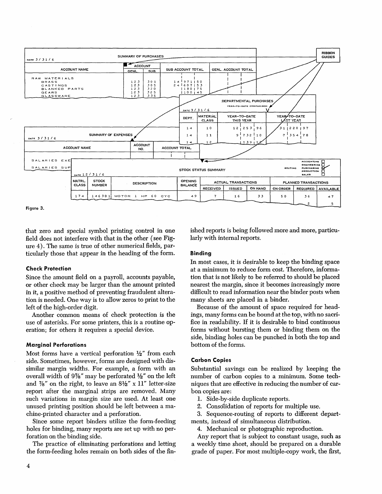
Form
Alignment
Guide
If
possible, a guide for form alignment should
be
de-
termined
and
preprinted
on
each
form to facilitate ma-
chine setup operations.
For
the
402
and
403 accounting
machines this is accomplished
by
printing a
ribbon
guide (see
Figure
3).
For
other
printers
it
can
be
ac-
complished
by
a short line
or
mark
in
the
margin
or
heading
of
the
form; this line or
mark
should
be
used
in
conjunction
with
a stationary object such
as
a
print
line
indicator.
For
forms
that
are
prenumbered
and
must
be
ac-
counted
for, a clear plastic facsimile of
t1ie
form
can
be
made. This facsimile,
when
clipped to
the
top of
the
first form, should
provide
the
means for form alignment
and
restoring
the
control
tape
in
the
carriage.
It
is
important
that
a description of
the
form align-
ment
guide
and
its use
be
included
in
the
manuals of
procedure. A delay
in
machine setup will
create
an
un-
avoidable delay in processing.
Numerical Amounts
In
determining
the
number
of
print
positions
needed
for numerical fields,
it
is
the
size of
the
total
which
must
be
provided
for
rather
than
the
size of
the
detail
amounts.
If
marks of
punctuation
are
to
be
machine-
printed,
the
size of
the
field should
be
checked to
make
certain
that
printing
positions
have
been
allotted.
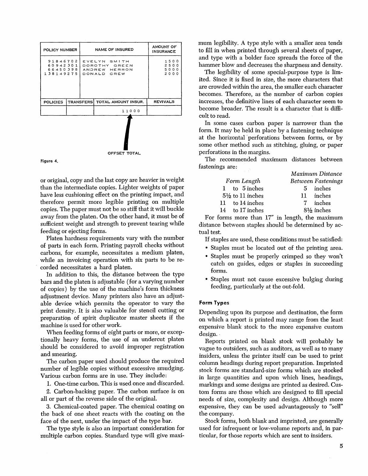
If
offset total
printing
is
used
on a form,
the
total
and
the
individually listed amounts should
be
positioned so
3
RIBBON
DATE
3 / 3 1 / 6
5U~~~E~S_S-U-B-A-CC-~-U-NT~7-T-A-L~~-G-EN-L-.-A~-,:C-OO-N-T-::~~T-AL~~~~~~-~~~~1~~
GWDES
123
301
14
1
971150
123
305
241607153
123
320
1180175
123
325
1100145
ACCOONT
NAME
RAW
MATERIALS
BRASS
CASTINGS
BLANKED
PARTS
GEARS
12
3
/335
-
~
DE::A:~:~~::~:"~~~':NvS~
/
DATE
3 / 3 1 / 6
GLASSWARE
DEPT.
MATERIAL
YEAR-To-DATE
YEARho-DATE
~~~~C~LA~S~S-r~~~rn~.IS~YE~ft~.R.-~~~~-~~SSTT~~~._~A~n~~
1 2 l 2 5 3 : 9 6 I
~
1
\2
2 0 : 9 7
SUMMARY
OF
EXPENSES / 1 4 1 1 9 I 7 3 2 I 1 0 V ·7 I 3 5 4 I 7 8
~
I I I I
10
DATE
3 / 3 1 / 6
14
14
12
113911.£
I J.
ACCOUNT
I
/-
ACCOUNT
NAME
NO.
ACCOUNT
~TAL
I I I
EXEr-~~~~~~~~~~~~L-~~~~~~~Y~~~~~~~~~~~~~~~~~~AC~C~OU~NT~'N~GrD'-~-'
SALARIES
':"~L
AR
I
ES
SUP
Figure
3.
DATE
1 2 / 3 1 / 6
MATRL.
CUSS
174
STOCK
NUMBER
146301
DESCRIPTION
MOTOR
1
HP
60
CYC
that
zero
and
special symbol
printing
control
in
one
field does
not
interfere
with
that
iIi
the
other
(see
Fig-
ure
4).
The
same
is
true
of
other
numerical
fields,
par-
ticularly those
that
appear
in
the
heading
of
the
form.
Check Protection
Since
the
amount
field on a payroll, accounts
payable,
or
other
check
may
be
larger
than
the
amount
printed
in
it, a positive
method
of
preventing
fraudulent
altera-
tion is
needed.
One
way
is
to
allow zeros
to
print
to
the
left
of
the
high-order
digit.
Another
common
means
of check
protection
is
the
use
of
asterisks.
For
some printers, this is a
routine
op-
eration; for others
it
requires
a special device.
Marginal
Perforations
Most forms
have
a vertical perforation
1f2"
from
each
side. Sometimes, however, forms
are
designed
with
dis-
similar
margin
widths.
For
example, a
form
with
an
overall
width
of
9Ys"
may
be
perforated
1/
2"
on
the
left
and
%"
on
the
right, to leave
an
81/2"
x 11" letter-size
report
after
the
marginal
strips
are
removed.
Many
such
variations
in
margin
size
are
used.
At
least
one
unused
printing
position should
be
left
between
a ma-
chine-printed
character
and
a perforation.
Since some
report
binders
utilize
the
form-feeding
holes
for
binding,
many
reports
are
set
up
with
no
per-
foration on
the
binding
side.
The
practice
of
eliminating perforations
and
letting
the
form-feeding holes
remain
on
both
sides
of
the
fin-
4
STOCK
STATUS
SUMMARY
:::~::~:~:CI
V
PRODUCTION
0
SAL.ES
0
~:~~~~~
r-~_A_C_TUTA_L_T_RA_N_S_AC~T_IO_N_S~~~~_P_U_N~N_ED_T_R_A_N_SA_C~T_IO_N~S~~
RECEIVED
I ISSUED I
ON
HAND
ON
ORDER
REOUIRED
AVAIUBLE
49
7 1
16
1
33
-~
--
5 0
36
47
~
5
ished
reports
is
being
followed
more
and
more,
particu-
larly
with
internal
reports.
Binding
In
most cases,
it
is desirable
to
keep
the
binding
space
at
a
minimum
to
reduce
form
cost. Therefore, informa-
tion
that
is
not
likely to
be
referred
to
should
be
placed
nearest
the
margin, since
it
becomes increasingly
more
difficult
to
read
information
near
the binder
posts
when
many
sheets
are
placed
in
a binder.
Because
of
the
amount
of
space
required
for
head-
ings,
many
forms
can
be
bound
at
the
top,
with
no
sacri-
fice
in
readability.
If
it
is desirable
to
bind
continuous
forms
without
bursting
them
or
binding
them
on
the
side,
binding
holes
can
be
punched
in
both
the
top
and
bottom
of
the
forms.
Carbon Copies
Substantial savings
can
be
realized
by
keeping
the
number
of
carbon
copies
to
a minimum. Some tech-
niques
that
are
effective
in
reducing
the
number
of
car-
bon
copies are:
1.
Side-by-side
duplicate
reports.
2. Consolidation
of
reports for
multiple
use.
3. Sequence-routing of reports
to
different
depart-
ments,
instead
of
simultaneous distribution.
4. Mechanical
or
photographic
reproduction.
Any
report
that
is
subject
to
constant usage,
such
as
a weekly
time
sheet, should
be
prepared
on
a
durable
grade
of
paper.
For
most
multiple-copy work,
the
first,
NAME
OF
INSURED
AMOUNT
OF
POLICY
NUMBER
INSURANCE
91846702
EVELYN
SMITH
150
0
60942301
DOROTHY
GREEN
2 5 0 0
66450398
ANOREW
HERRON
5 0 0 0
138149275
DONALD
CREW
2 0 0 0
POLICIES
I
TRANSFERS
I
TOTAL
AMOUNT
INSUR.
REVIVALS
I I 1
10
0 0
r
~
OFFSET
TOTAL
Figure
4.
or original, copy
and
the
last copy
are
heavier
in
weight
than
the
intermediate
copies.
Lighter
weights of
paper
have
less cushioning effect
on
the
printing
impact,
and
therefore
permit
more
legible
printing
on multiple
copies.
The
paper
must
not
be
so stiff
that
it
will buckle
away
from
the
platen.
On
the
other
hand,
it
must
be
of
sufficient
weight
and
strength
to
prevent
tearing while
feeding or ejecting forms.
Platen
hardness requirements vary
with
the
number
of
parts
in
each
form.
Printing
payroll checks
without
carbons, for example, necessitates a
medium
platen,
while an invoicing operation
with
six parts to
be
re-
corded
necessitates a
hard
platen.
In
addition to this,
the
distance
between
the
type
bars
and
the
platen
is adjustable
(for
a varying
number
of copies)
by
the
use
of
the
machine's form thickness
adjustment device.
Many
printers also have an adjust-
able
device
which
permits
the
operator to
vary
the
print
density.
It
is also valuable for stencil
cutting
or
preparatiop
of
spirit duplicator
master
sheets
if
the
machine is
used
for
other
work.
When
feeding forms of
eight
parts
or
more, or excep-
tionally heavy forms,
the
use
of
an
undercut
platen
should
be
considered to avoid
improper
registration
and
smearing.
The
carbon
paper
used
should
produce
the
required
number
of legible copies
without
excessive smudging.
Various carbon forms
are
in use.
They
include:
1.
One-time carbon. This is
used
once
and
discarded.
2.
Carbon-backing paper.
The
carbon surface is
on
all
or
part
of
the
reverse side of
the
original.
3.
Chemical-coated
paper.
The
chemical coating on
the
back
of one sheet reacts
with
the
coating
on
the
face of
the
next,
under
the
impact
of
the
type
bar.
The
type
style
is
also
an
important
consideration for
multiple carbon copies.
Standard
type
will give maxi-
mum
legibility. A
type
style
with
a smaller
area
tends
to fill in
when
printed
through
several sheets of
paper,
and
type
with a
bolder
face spreads
the
force of
the
hammer
blow
and
decreases
the
sharpness
and
density.
The
legibility of some special-purpose
type
is lim-
ited. Since
it
is fixed
in
size,
the
more
characters
that
are
crowded
within
the
area,
the
smaller
each
character
becomes. Therefore, as
the
number
of carbon copies
increases,
the
definitive lines of
each
character
seem
to
become broader.
The
result is a character
that
is diffi-
cult
to read.
In
some cases carbon
paper
is
narrower
than
the
form.
It
may
be
held
in
place
by
a fastening
technique
at
the
horizontal'
perforations
between
forms,
or
by
some
other
method
such as stitching, gluing,
or
paper
perforations in
the
margins.
The
recommended maximum distances
between
fastenings are:
Form Length
1 to 5 inches
5%
to
11
inches
11
to 14 inches
14
to 17 inches
Maximum Distance
Between Fastenings
5 inches
11
inches
7 inches
81
h inches
For
forms more
than
17"
in
length,
the
maximum
distance
between
staples should
be
determined
by
ac-
tual
test.
If
staples are used, these conditions
must
be
satisfied:
• Staples
must
be
located
out
of
the
printing
area.
• Staples
must
be
properly
crimped
so
they
won't
catch
on guides, edges
or
staples
in
succeeding
forms.
• Staples
must
not
cause excessive
bulging
during
feeding, particularly
at
the
out-fold.
Form Types
Depending
upon
its
purpose
and
destination,
the
form
on
which
a
report
is
printed
may
range
from
the
least
expensive blank stock to
the
more expensive custom
design
..
Reports
printed
on
blank
stock will
probably
be
vague
to outsiders, such as auditors, as well as
to
many
insiders, unless
the
printer
itself
can
be
used
to
print
column headings
during
report
preparation.
Imprinted
stock forms are standard-size forms
which
are
stocked
in
large quantities
and
upon
which
lines, headings,
markings
and
some designs
are
printed
as desired. Cus-
tom
forms are those which
are
designed to fill special
needs of size, complexity
and
design. Although
more
expensive,
they
can
be
used
advantageously to "sell"
the
company.
Stock forms,
both
blank
and
imprinted, are generally
used
for
infrequent
or low-volume reports and,
in
par-
ticular, for those reports
which
are
sent
to insiders.
5
Card Design
Generally speaking, cards can
be
categorized
by
the
manner
in
which
they
are
prepared:
Transcript cards
are
punched
from information pre-
viously
recorded
on
other
documents. Examples in-
clude
the
customer
order
cards
punched
from orders,
accounts receivable cards
punched
from invoices,
voucher cards
punched
from accounting vouchers.
Dual cards
are
punched
from information previously
\vritten on
thc
cards themselves.
Thus
they
serve a
dual
purpose as
both
source
document
and
process-
ing medium. Examples include
(1)
inventory count-
ing
and
recording cards, which
have
the
physical
count
written
on
them
in
the
warehouse,
and
which
are
then
sent
to
the
data
processing installation for
punching
of
the
handwritten
data,
and
later
used
in
printing
the
inventory report,
(2)
payroll
change
cards, which
have
the
change
written
on them,
and
which
are
then
signed
by
the
employee,
punched,
and
automatically machine-processed to effect
the
change,
and
(3)
certain requisition
and
personnel
cards.
Mark-sensed cards are automatically
punched
from
electro graphic pencil marks
that
are
recorded
in
mark-sensing positions on
the
face of
the
cards. Cer-
tain weekly
attendance
and
meter
reading
cards
are
of this type.
They
are
marked
by
an
employee on
the
job, sent to
the
machine room
where
the
mark-sense
data
is
machine-read
and
punched
into
the
same or
a different
card
for processing.
Output
cards
are
automatically machine-created as a
result of processing disk storage records,
tape
records
or
other
IBM
cards. Examples include summary, bal-
ance forward,
updated
file, exception
and
certain de-
tail cards. Some of these
undergo
additional process-
ing
for
report
preparation, while others
replace
the
corresponding
but
outdated
cards in a file.
Special
cards
are
used
with
the
IBM
PORT-A-PUNC:a@
to
enable
on-the-spot
punching
of data.
Punching
posi-
tions of those columns
that
are
to
be
used
for record-
ing
data
are
pres cored;
the
holes
are
created
by
punching
out
the
pres cored chips
with
a special in-
strument.
Regardless of
the
manner
in which
it
is
prepared,
in
no case should a
card
be
imposed
upon
a procedure; in-
stead
it
should
be
designed for
the
particular
use to
which
it
will
be
put.
This is
the
only
way
to achieve
maximum effectiveness
and
efficiency.
6
Determining
Card
Data
The
first
step
in
card
design requires a
study
of
the
final
report
that
is to
be
printed
from
the
card
and
a listing
of
data
needed
for it. Next,
the
procedure
is
studied
and
any
data
needed
for processing
that
is
not
also
needed
for
the
report
is
added
to
the
same listing.
Every
item
except
that
which
comes from a table,
master
card
and/or
storage is extracted
and
recorded on a form sim-
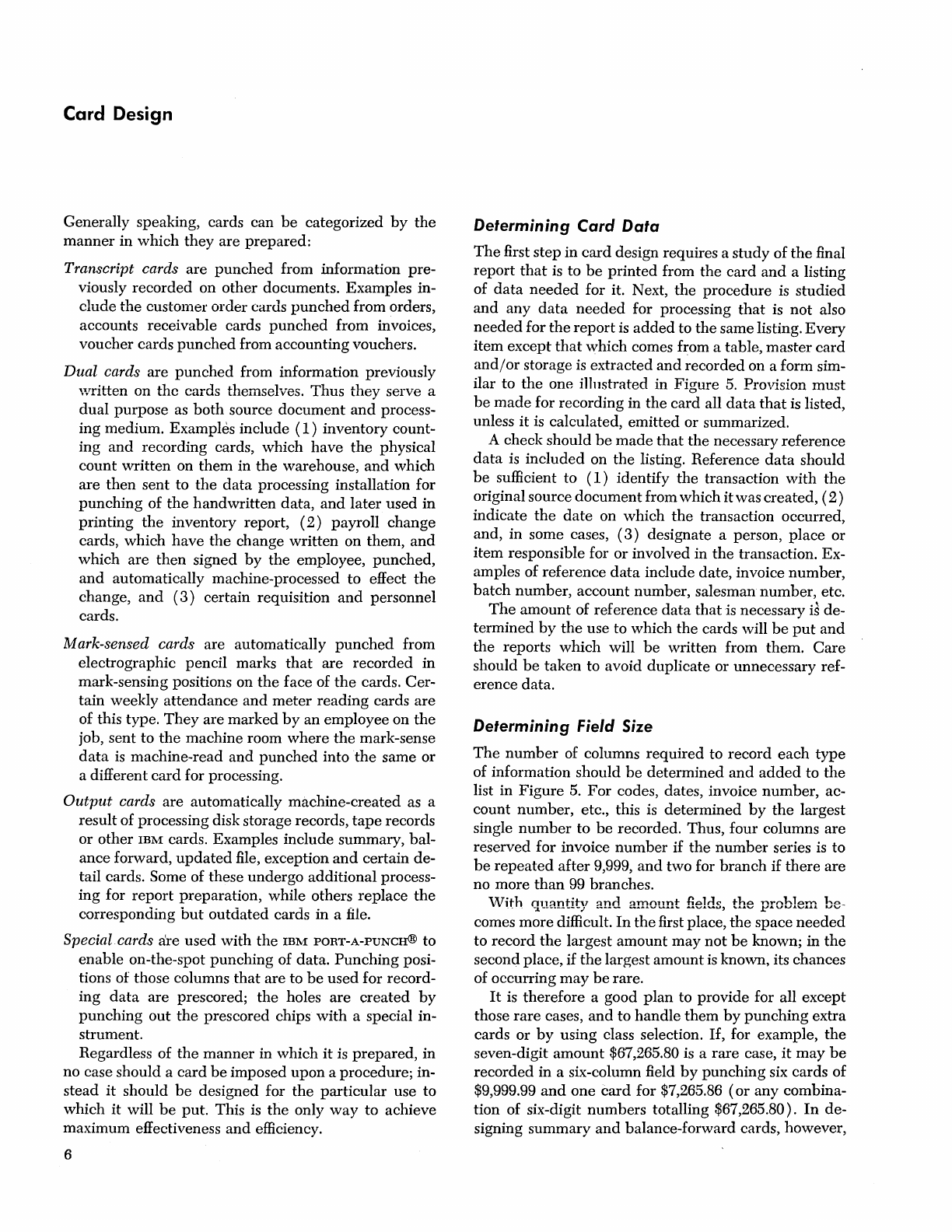
ilar to
the
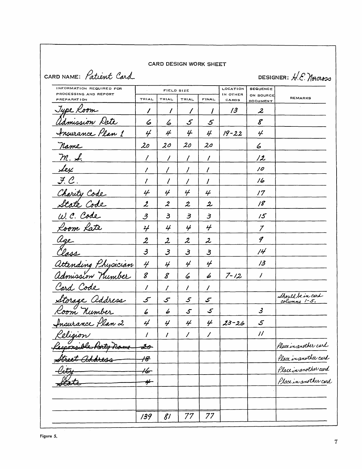
one illustrated in
Figure
5.
Provision
must
be
made
for recording in
the
card
all
data
that
is listed,
unless
it
is calculated,
emitted
or
summarized.
A check should
be
made
that
the
necessary reference
data
is
included
on
the
listing. Reference
data
should
be
sufficient to
(1)
identify
the
transaction
with
the
original source
document
from which
it
was created,
(2)
indicate
the
date
on
which
the
transaction occurred,
and, in some cases,
(3)
designate a person,
place
or
item
responsible for
or
involved in
the
transaction. Ex-
amples of reference
data
include date, invoice
number,
batch
number,
account number, salesman
number,
etc.
The
amount
of reference
data
that
is necessary is de-
termined
by
the
use to which
the
cards will
be
put
and
the
reports which will
be
written from them.
Care
should
be
taken
to avoid duplicate or unnecessary ref-
erence data.
Determining
Field Size
The
number
of columns
required
to
record
each
type
of information should
be
determined
and
added
to
the
list in
Figure
5.
For
codes, dates, invoice
number,
ac-
count
number,
etc., this is
determined
by
the
largest
single
number
to
be
recorded. Thus, four columns
are
reserved for invoice
number
if
the
number
series is to
be
repeated
after
9,999,
and
two
for
branch
if
there
are
no more
than
99 branches.
With
quantity
and
amount
fields,
the
problem
be-
comes
more
difficult.
In
the
first place,
the
space
needed
to
record
the
largest
amount
may
not
be
known; in
the
second place,
if
the
largest
amount
is
known, its chances
of occurring
may
be
rare.
It
is therefore a good
plan
to provide for all except
those
rare
cases,
and
to
handle
them
by
punching
extra
cards or
by
using class selection.
If,
for example,
the
seven-digit
amount
$67,265.80 is a
rare
case,
it
may
be
recorded
in a six-column field
by
punching
six cards of
$9,999.99
and
one
card
for $7,265.86
(or
any combina-
tion of six-digit
numbers
totalling $67,265.80).
In
de-
signing
summary
and
balance-forward cards, however,
CARD
DESIGN
WORK
SHEET
.
CARD
NAME:
(Ja.b..iM;6
~
DESIGNER:
J/.c.I1&l~
INFORMATION
REQUIRED
FOR
FIELD
SIZE
LOCATION
SEQUENCE
PROCESSING,AND
REPORT
IN
OTHER
ON
SOURCE
TRIAL TRIAL
TRIAL
FINAL
CARDS
REMARKS
PREPARAT
ION
DOCUMENT
.J~~
/ / / I
/3
.2
,1)'-;AA~~
,l.JtJ1L
~
~
..5
5 K
~fJ~l
tf
4-
'/-
II-
19-·2.,2 ¥
~
~o
,20
20
20
b
m.J
I / I I
/,t
k / I 1 I
/0
J.
e.
I / / I
/~
~Ah;rU~
if
'/-
if
If
17
~U-b-
~
,2
:z
z
/~
w.~.~
3
.3
3 3
/5
~~
Zf
J.j.
Jf
Jf
7
~
2,
2.-
,Z
:L
tf
&AL1A-
3 3 3 3
/1/
tJ.i;;hAA~~~
i!h.l/U·1'1;'~
7'
J/
J/
1-
/3
~~AN/~
g s
~
6
7-/'z
/
~~
/ / / /
~~
S S
.5
S
Jku14~~~
~
/-..5.
~~
h b .s
..s
.3
LAIlJAAlf'1
;?~
c2.
4
Jj
II-
~
,ta-:l6
.s
....,.-
£R~
/ / / / /1
A"
~
A'
11#"
ill+'.
'n.
-
..!f...t:J.
/!tw.~~
'I
--7
r ....
....
......
.....
MIt"-!-
/7.1
~lAA
....
10..
.jJ14cL~~
,-"
v~
~
.........
---
I~
/J~
1-:.
IL
t&a;,v~
""""""'/1-
--
pJ4-1J,
.LL
/?ka~~
7
~~
139 SI
77
77
Figure 5. 7
the
amount
fields
must
be
made
large
enough
to accom-
modate
the
summary totals.
For
punching
names, 20 columns
are
generally suffi-
cient; this should
be
carefully checked, however, on
each
individual job. A
study
of
the
number
of columns
required
for recording names
and
addresses reveals
that
95% of names of individuals can
be
recorded in
18 columns
or
less;
that
9S% of names of companies
require
20 columns or less;
that
90% of
street
addresses
require
18 columns
or
less;
and
that
99% of cities
and
states
(abbreviated)
require 20 columns or less.
The
total of
the
columns
required
for all fields will
indicate
whether
the
capacity of
the
card
has
been
exceeded.
When
the
number
of columns exceeds 80
but
does
not
go over 100,
the
decision
must
be
made
whether
to use two cards or to
reduce
the
number
to
80.
If
the
total
number
reaches 100
or
more,
it
is
evi-
dent
that
an additional
card
is needed.
If
it
is
decided
to
reduce
the
number
of columns to
80,
the
following techniques
may
be
used:
1.
Reduce
the
size of reference fields
by
repeating
the
numbering
series more frequently; for example, in-
voice
numbers
may
start
with
1
each
month
instead of
each
quarter.
2.
Reduce
the
size of control fields
by
having certain
ones serve as subclassifications of others.
3. Reduce
the
size of reference or control fields
by
recoding.
It
is often possible to eliminate several digits.
4.
Reduce
the
number
of columns
required
for re-
cording reference or control fields
by
ignoring one or
more
digits
which
may
not
be
essential. Thus,
it
may
be
possible to
punch
only four digits of a six-digit invoice
number
and
preserve positive identification.
S.
Reduce
the
size of
amount
fields in those cases
where
the
number
of digits in
the
amount
seldom ex-
ceeds
the
capacity of
the
field.
6.
Record in
the
lIth
and
12th
punching
positions
information
which
is
never
used
for printing. These
positions
can
be
easily
used
in columns
that
are
set aside
for multiple punching; however,
they
should
not
be
used
in control
or
alphabetic fields.
7.
Use a single
card
column for recording several
one-digit codes.
If
an
applicant
is categorized male
(11
punch)
or
female (12
punch)
and
by
age group
(for
example, a zero
punch
for age lS-20, a 1
punch
for
21-23, a 2
punch
for 24-26
...
and
a 9
punch
for 65
and
above),
then
both
codes can
be
punched
in
the
same
column. Since this is multiple punching, caution should
be
exercised
and
the
user should
make
certain
that
the
different combinations
are
machine-readable.
8.
Investigate
the
use
of
the
group-sorting device
if
master
and
detail cards
are
sorted together. Its use
may
make
it
possible to eliminate from
the
detail cards a
sorting field or fields.
8
9.
A void unnecessary data; for example,
the
use of
both
an
order
number
and
an invoice
number
is un-
necessary
if
one will provide
adequate
reference.
10. Use one field instead of two
when
alternative in-
formation is to
be
recorded. An example
is
an
accounts
receivable transaction
card
that
is
to
be
used
to record
either
an invoice
or
a credit memorandum.
The
use of
two
fields-one
titled "Invoice No."
and
the
other
"Cr.
Memo.
No."-will
suffice
if
an X
or
digit
punch
is also
punched
in some specified
card
column as identifica-
tion of
the
credit memo.
11.
For
cards
that
are
to
be
used
for statistical anal-
ysis, combine several classes
of
statistical
data
into a
single column. This
technique
is especially applicable
in
the
case of yes-no responses.
If
it
is necessary to use more
than
one card,
the
data
is
separated
or classified to determine which should
be
placed
in
each
card. Such a division
may
be
based
upon
anyone
of several schemes:
1.
Place
the
repetitive
or
recurring information in
one
card
and
temporary
or
non-repeating information
in a second card, as in
the
case of
master
cards
and
de-
tail cards.
2.
If
more
than
one source
document
is involved, de-
sign a different
card
for
each
and
use
card
codes.
3.
In
cases
where
one transaction affects
two
differ-
ent
accounts, design two
cards-each
with
a different
degree
of detail. Examples are accounts
payable
and
payables distributio.n cards, accounts receivable
and
sales cards, payroll
and
labor distribution cards.
4.
For
printing invoices, orders, etc., design a
card
for
each
section of
the
form.
For
example, a job
may
include for
each
customer
(1)
heading
cards,
(2)
a
miscellaneous
data
card
and
( 3 ) detail commodity
cards. Such an arrangement is simple
and
effective;
the
heading
and
miscellaneous
data
cards
may
also
be
used
for
other
jobs, such as
printing
credit
memorandums
and
packing slips.
Determining
Data
Sequence
There
are four major considerations
in
determining a
card's
data
sequence.
In
the
order
of importance, these
are
(1)
the
location of identical
data
in
other
cards
with
which
the
new
one will
be
processed,
(2)
the
se-
quence
of
data
on
the
source
docnment
from which
the
card
will
be
punched,
(3)
the
machines
and/or
pro-
grams to
be
used
during
processing
and
(
4)
the
manual
operations in
which
the
card
will
be
used.
Specific areas
have
been
made
available
on
the
Card
Design
Work
Sheet
(Figure
S) for recording
the
loca-
tion of
data
in other cards as well as
the
sequence of
data
on
the
source document.
The
effect
upon
sequence
of machines
and/or
programs as well as
manual
opera-
tions
and
the
location of
interpreted
information
can
be
indicated
in
the
remarks column.
The
completed
Card
Design
Work
Sheet is very useful
in
later
design opera-
tions.
Location
of
Data
in
Other
Cards
A given field of information in
the
new
card
should
be
placed
in
the
same columns previously assigned to
it
in
the
other
cards. This assures
that
sorting
and
control-
ling can
be
accomplished
when
the
cards
are
processed
together;
it
also facilitates control
panel
wiring
and
programming.
In
cases
where
summary cards
are
de-
signed to accommodate year-to-date figures
or
balance-
forward amounts
which
by
their
nature
must
be
larger
than
corresponding fields in
the
detail transaction cards,
the
amount
fields
in
both
should
be
aligned as
nearly
as possible.
Examples of different cards
which
are
processed to-
gether
include a customer
name
card
used
with
ac-
counts receivable cards to write a statement, a daily
time
ticket
used
with
labor distribution cards
to
obtain
zero balance,
and
a labor distribution
card
with
mate-
rial distribution cards for cost analysis.
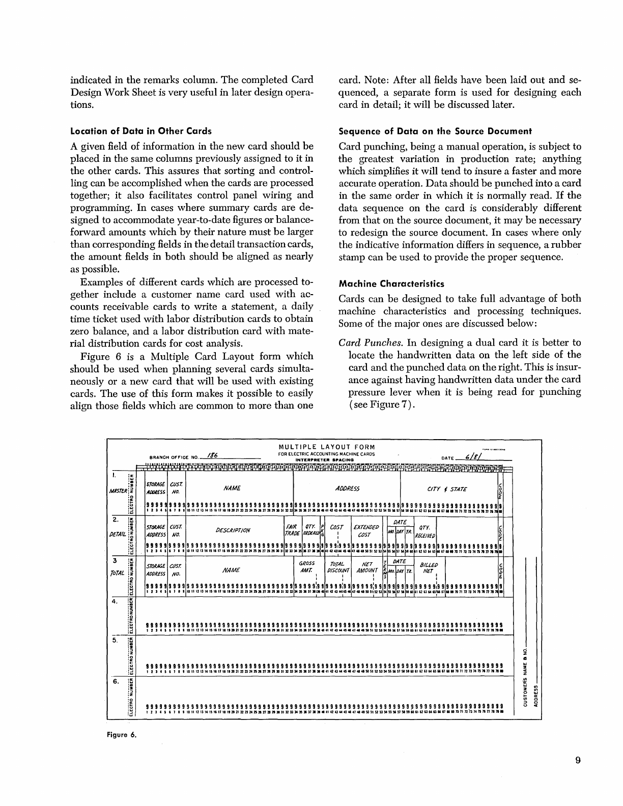
Figure
6 is a Multiple
Card
Layout
form
which
should
be
used
when
planning
several cards simulta-
neously
or
a
new
card
that
will
be
used
with
existing
cards.
The
use of this form makes
it
possible to easily
align those fields
which
are
common to
more
than
one
card. Note: After all fields
have
been
laid
out
and
se-
quenced, a
separate
form is
used
for designing
each
card
in detail;
it
will
be
discussed later.
Sequence
of
Data
on the Source Document
Card
punching,
being
a
manual
operation,
is
subject to
the
greatest variation in production rate;
anything
which simplifies
it
will
tend
to insure a faster
and
more
accurate operation.
Data
should
be
punched
into a
card
in
the
same
order
in
which
it
is normally read.
If
the
data
sequence
on
the
card
is considerably different
from
that
on
the
source document,
it
may
be
necessary
to redesign
the
source document.
In
cases
where
only
the
indicative information differs in sequence, a
rubber
stamp can
be
used
to provide
the
proper
sequence.
Machine
Characteristics
Cards can
be
designed to
take
full
advantage
of
both
machine characteristics
and
processing techniques.
Some of
the
major ones
are
discussed below:
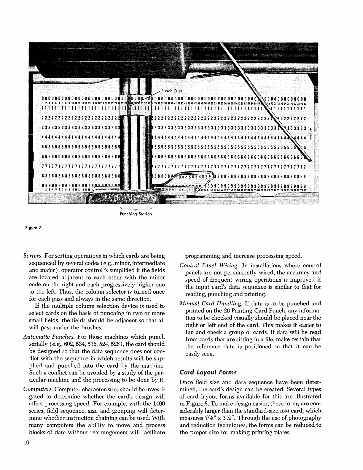
Card Punches.
In
designing a
dual
card
it
is
better
to
locate
the
handwritten
data
on
the
left
side of
the
card
and
the
punched
data
on
the
right. This is insur-
ance against having
handwritten
data
under
the
card
pressure lever
when
it
is being
read
for
punching
( see
Figure
7)
.
MULTIPLE
LAYOUT
FORM
2.
i~
:2
PETAIL
i;
ia
Figure 6.
STallAGE
CUST.
ADCiESS
NO.
NAME
ADDRlSS
CITY
~
STATE C
o
i
99
9 9 9 9 9 9 9 9 9 9 9 9 9 9 9 9 9 9 9 9 9 9 9 9 9 9 9 9 9 9 9 9 9 9 9 9 9
99
9 9 9 9 9 9 9 9 9 9 9 9 9 9 9 9 9 9 9 9 9 9 9 9 9 9 9 9 9 9 9 9 9 9 9 9 9 9 9
IZI41IJ'IIIIII2I21115111111112OV2l23142S2I272121111111213I415.»
•••
~aa44a4lU4l4l5G~525154~5I~SlSlIOUI2IlWIl.UlIlIlQlInn"lIl1nllllll
PATE
5ToMGE
cusr.
PE5CIUPT/OII
FAIl(
((TYo
P
COST
EXTENOEP
~
-,-
QTY.
C
APPRESS
NO.
THAI)[
OJPEKlt
Ii
:
~ST
,w.
I4Y
rR.
l[CE/VEP
~
999999999999999999999999999999999999999!999~999999999999999999999999999999991999
I Z
14'
II
••
101l12111415111111112OZI2I23I42S2I27212t1ll111213I415.17
....
14UU444141.I4I4I5G51525154PS5lS1SlptlO
II2IlWIl~11IIIIlQll12nI411I1nllllll
5T0M6E
C//Sr. GROSS
TOTAL
NET
I
r£~
-
BILLEP
c
APPI?ESS
NO.
NAME
AMT.
I
PISCOU(,T
AMOIJ~T
~~D.
pAY
rio
NET
I
~
99999999999999999999999999999999999999:999999:99999
9
9:9
9 9 9 9 9 9 9 9 9 9 9 9
9:9
9 9 9 9 9 9 9 9 9 9 9 9 9 9
I Z I 4 I I I • 110111212 II 1511111111202121
23242S2I27212tlllll13131415.17.I."~
a4l4414141U4l4l5G11I525154~5I11SlSlIOU
12
11
WIl:1I u
IIlIlQ
11
nnl411l1nll~
II
99999999999999999999999999999999999999999999999999999999999999999999999999999999
I
ZI4'IJIIIIIII2I211I5"II""2OV2Z23Mn2ln2l2l1ll1l121314n.17
....
~Qa444141U4l.5G~525154S1I4~Sl9IOUIlU44Il.n
••
lQlInn"lIl1nllllll
99999999999999999999999999999999999999999999999999999999999999999999999999999999
1214111'11I1I12121115"1I1I1I201I2I23I42S2In2l2l1ll1l1213I415.17
•••
~a4l444141U4l4l5G~525154~5I»SI"IOUI2IlWIl.UU.lQlInn"lIl1nllllll
99999999999999999999999999999999999999999999999999999999999999999999999999999999
lZI41IJ""I1I2I2111511111111201I2I23M2S2In2l2t1ll»1213I415.17
•••
~a4l444141U4lU5G~525154~5I»SI"~UI2Il44Il.UU.~lInh"lIl1nllllll
9
00000010000000000000000
1 2 3 4 5 8 7 • 9
lG
11
12
13
l'
15
16
1118
19
2021
22
23
25
26112§;n
3f3ul~
3536
31 31
39
40
41
42
43 44 45
46
47
48
49
50
51
52 53 54
55
56 51
56
59
SO
61
62
63
64
65
11111111111111111111111
111111111111111111111111111111111
22222222222222222222222
33333333333333333333333
44444444444444444444444
55555555555555555555555
66666666666666666666666
77777777777777777777777
88888888888888888888888
22222222222222222222222222222222222
3333333333333333333333333333333333333
4444444444444444444444444444444444444444
555555555555555555555555555555555555555555
66666666666666666666666666666666~66666666666
'--y----J
Punching
Station
Figure
7.
Sorters.
For
sorting operations in which cards are
being
sequenced
by
several codes (e.g., minor,
intermediate
and
major),
operator contro] is simplified
if
the
fields
are located
adjacent
to
each
other
with
the
minor
code on
the
right
and
each
progressively
higher
one
to
the
left. Thus,
the
column seiector is
turned
once
for
each
pass
and
always in
the
same direction.
If
the
multiple column selection device is
used
to
select cards on
the
basis of
punching
in
two
or
more
small fields,
the
fields should
be
adjacent so
that
all
will pass
under
the
brushes.
Automatic Punches.
For
those machines which
punch
serially (e.g., 602, 534, 536, 524,
526),
the
card
should
be
designed so
that
the
data
sequence does
not
con-
flict
with
the
sequence in which results will
be
sup-
plied
and
punched
into
the
card
by
the
machine.
Such a conflict can
be
avoided
by
a
study
of
the
par-
ticular machine
and
the
processing to
be
done
by
it.
Computers.
Computer
characteristics should
be
investi-
gated
to determine
whether
the
card's design will
affect processing speed.
For
example,
with
the
1400
series, field sequence, size
and
grouping
wm
deter-
mine
whether
instruction chaining can
be
used.
With
many
computers
the
ability to move
and
process
blocks of
data
without
rearrangement
will facilitate
10
programming
and
increase processing speed.
Control Panel Wiring.
In
installations
where
control
panels are
not
permanently
wired,
the
accuracy
and
speed of
frequent
wiring operations
is
improved
if
the
input
card's
data
sequence is similar to
that
for
reading,
punching
and
printing.
Manual Card Handling.
If
data
is to
be
punched
and
printed
on
the
26 Printing
Card
Punch,
any
informa-
tion to
be
checked visually should
be
placed
near
the
right
or left
end
of
the
card. This makes
it
easier to
fan
and
check a
group
of cards.
If
data
will
be
read
from cards
that
are
sitting
in
a file,
make
certain
that
the
reference
data
is positioned so
that
it
can
be
easily seen.
Card
Layout
Forms
Once
field size
and
data
sequence
have
been
deter-
mined,
the
card's design can
be
created. Several types
of card layout forms available for this are illustrated
in
Figure
8.
To
make
design easier, these forms
are
con-
siderably larger
than
the
standard-size
IBM
card, which
measures 73
/8"
x
31f4".
Through
the
use of
photography
and
reduction techniques,
the
forms can
be
reduced
to
the
proper
size for
making
printing plates.
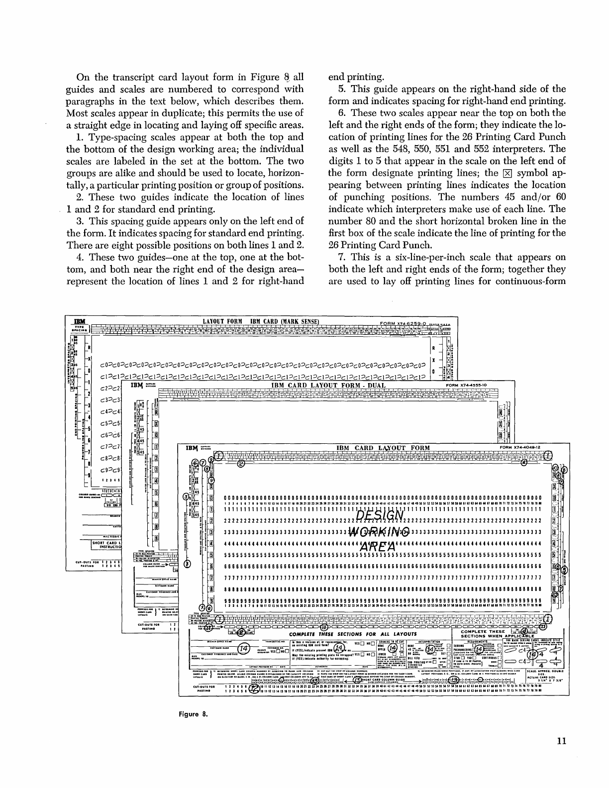
On
the
transcript card layout form in
Figure
~,
all
guides
and
scales are
numbered
to correspond
with
paragraphs
in
the
text below,
which
describes them.
Most scales
appear
in duplicate; this permits
the
use of
a straight edge in locating
and
laying off specific areas.
1.
Type-spacing scales
appear
at
both
the
top
and
the
bottom of
the
design working area;
the
individual
scales are labeled in
the
set
at
the
bottom.
The
two
groups are alike
and
should
be
used to locate, horizon-
tally, a particular printing position
or
group of positions.
2.
These two guides indicate
the
location of lines
1
and
2 for
standard
end
printing.
3. This spacing guide appears only on
the
left
end
of
the
form.
It
indicates spacing for
standard
end
printing.
There
are eight possible positions on
both
lines 1
and
2.
4.
These two
guides-one
at
the
top, one
at
the
bot-
tom,
and
both
near
the
right
end
of
the
design
area-
represent
the
location of lines 1
and
2 for right-hand
end
printing.
5.
This guide appears on
the
right-hand side of
the
form
and
indicates spacing for right-hand
end
printing.
6.
These two scales
appear
near
the
top on
both
the
left
and
the
right ends of
the
form;
they
indicate
the
lo-
cation of printing lines for
the
26 Printing
Card
Punch
as well as the 548, 550, 551
and
552 interpreters.
The
digits 1 to 5
that
appear
in
the
scale on
the
left
end
of
the
form designate printing lines;
the
[8]
symbol ap-
pearing
between
printing lines indicates the location
of punching positions.
The
numbers 45
and/or
60
indicate which interpreters make use of
each
line.
The
number
80
and
the short horizontal broken line in
the
first box of
the
scale indicate
the
line of printing for
the
26 Printing
Card
Punch.
7.
This
is
a six-line-per-inch scale
that
appears on
both
the
left
and
right ends of
the
form; together they
are
used
to
layoff
printing lines for continuous-form
1111111111111111111111111111111111A1r:tB
J)4,.I,11111111111111111111111111111111111
2 2 2 2 2 2 2 2 2 2 2 2 2 2 2 2 2 2 2 2 2 2 2 2 2 2 2 2 2 2 2 2 2 f.{
fM~
~
~
~
Y 2 2 2 2 2 2 2 2 2 2 2 2 2 2 2 2 2 2 2 2 2 2 2 2 2 2 2 2 2 2 2 2 2 2 2
SHOIT CAID l
INSTlUCTlC
CUT·oun
.0.
1 2 ) 4 I
'''$1."IG I 2 ) • I
"~""----l
12
12
Figure 8.
333333333333333333333333333333
3
W~I4IN(fj
3 3
333
3 3 3 3 3 33 3 3 3 3 3 3 33 3 3 3 33 3 3 3 33 3 3 3
444444444444444444444444444444444
4
~1?
e~
4444444444444444444444444444444444444
55555555555555555555555555555555555555555555555555555555555555555555555555555555
11
card
stock
and
bill-feed cards.
Note
that
some
of
the
printing
lines
overlap
punching
positions;
avoid
the
use
of
these
in
areas
of
the
card
where
there
will
be
a
lot
of
punching.
S.
These
scales
locate
printing
lines
for
the
557 in-
terpreter.
There
is
one
at
each
end
of
the
form.
9.
This
guide
shows
the
location of
each
of
the
twelve
rows
of
punching.
10.
In
addition
to
indicating
the
location
of
punch-
ing
positions, this
guide
shows
the
location
of
each
of
the
twelve
rows
of
mark
sensing.
Note
that
they
do
not
overlap
punching
positions.
11.
This
guide
indicates
the
location of mark-sensing
columns.
Each
overlaps
three
card
columns
and
always
ends
over
a
card
column
whose
number
is divisible
by
three.
12.
These
numbers
can
be
cut
out
and
used
for
num-
bering
areas
on
the
card
as
well
as
for
numbering
card
columns.
In
addition
to
being
used
for
cutouts,
the
top
row
is also
used
as
index
for
the
Short
Card
Column
Guide.
13.
The
Short
Card
Column
Guide
is
in
two
sections,
each
containing
the
numbers
22
through
66.
It
is
used
in
laying
out
a
stub
or
short
card
that
is
to
come
from
the
midsection
of
an
SO-column
card.
(A
short
card
is
any
card
having
between
22
and
60
columns.)
The
guide
is
used
to
indicate
the
beginning
and
ending
card
columns. Assume
that
a 51-column
card
is
being
de-
signed;
the
number
51 is
located
and
circled
in
both
sections of
the
guide.
The
column
number
in
which
the
short
card
will
begin
is 15;
it
is
the
number
which.
ap-
pears
in
the
index
below
51
in
the
left-hand
section of
the
guide.
The
column
in
which
the
short
card
will
end
is
number
65;
it
appears
in
the
index
below
51 in
the
right-hand
section of
the
guide.
(Note:
A
short
card
may
come
from
one
end
rather
than
from
the
center
of
the
standard
card;
if
it
does,
the
guide
is
not
used.
)
14.
This
section is
near
the
bottom
and
extends
the
full
width
of
the
form.
For
each
layout
it
should
be
read
to
make
certain
that
appropriate
areas
are
com-
pleted.
There
are
certain
areas
to
which
attention
should
be
called.
Reading
from
left
to
right,
in
both
the
third
and
fourth
boxes,
at
least
one
condition
should
be
checked.
(Note:
If a
lower
right
corner
cut
is specified
for
an
IBM
24-26
card
punch
having
the
self-checking
number
feature,
then
a C-3
corner
cut
is
recommended;
for
tumble
cards
it
should
be
remembered
that
an
upper
left
corner
cut
becomes
a
lower
right
corner
cut
when
the
card
is
turned.
)
At
the
bottom
of
the
fifth
box
one
of
two
conditions,
Book
or
Tumble,
should
be
checked
if
the
card
is
to
be
printed
on
both
sides. "Book" is
checked
if
the
card
will
be
turned
right
to
left
when
the
reverse
side
is
read:
12
"Tumble"
is
checked
if
the
eard
is
turned
bottom
to
top
when
the
reverse
side
is
read:
If
mark
sensing is used, its style
should
be
indicated
in
the
sixth box.
It
makes
no
difference
which
style is
pasted
on
the
layout
itself;
it
is
the
one
which
is
checked
off
in
this
box
which
determines
the
style
that
will
be
printed
on
the
card.
Drawing
the
Layout
In
drawing
the
card
layout,
there
are
a
number
of
points
to
be
considered.
The
value
of
each
should
be
determined
by
the
card
being
designed
and
the
appli-
cation
in
which
it
will
be
used.
These
points
will
be
discussed
in
the
following text.
Figure
9 shows
the
lay-
out
for
a
material
accounting
card;
much
of
the
discus-
sion
which
follows
can
be
related
to
it.
All field
and
box
headings
should
be
explicit,
and
ambiguous
abbreviations
avoided.
Headings
for
written
information
should
be
such
that
they
force
w~iting
into
the
desired
location.
Make
certain
that
adequate
space
has
been
allowed
for
this writing.
If a
dual
card
is
being
designed,
the
right-hand
side
of
each
area
or
box
containing
handwritten
data
should
be
at
least
five
card
columns
to
the
left
of
the
field
in
which
it
is
to
be
punched.
This
prevents
the
data
from
being
obscured
when
it
is
time
to
punch
it.
Figure
7
shows
the
position of
the
punch
dies
and
the
number
of
card
columns
to
the
right
and
left
of
them
which
are
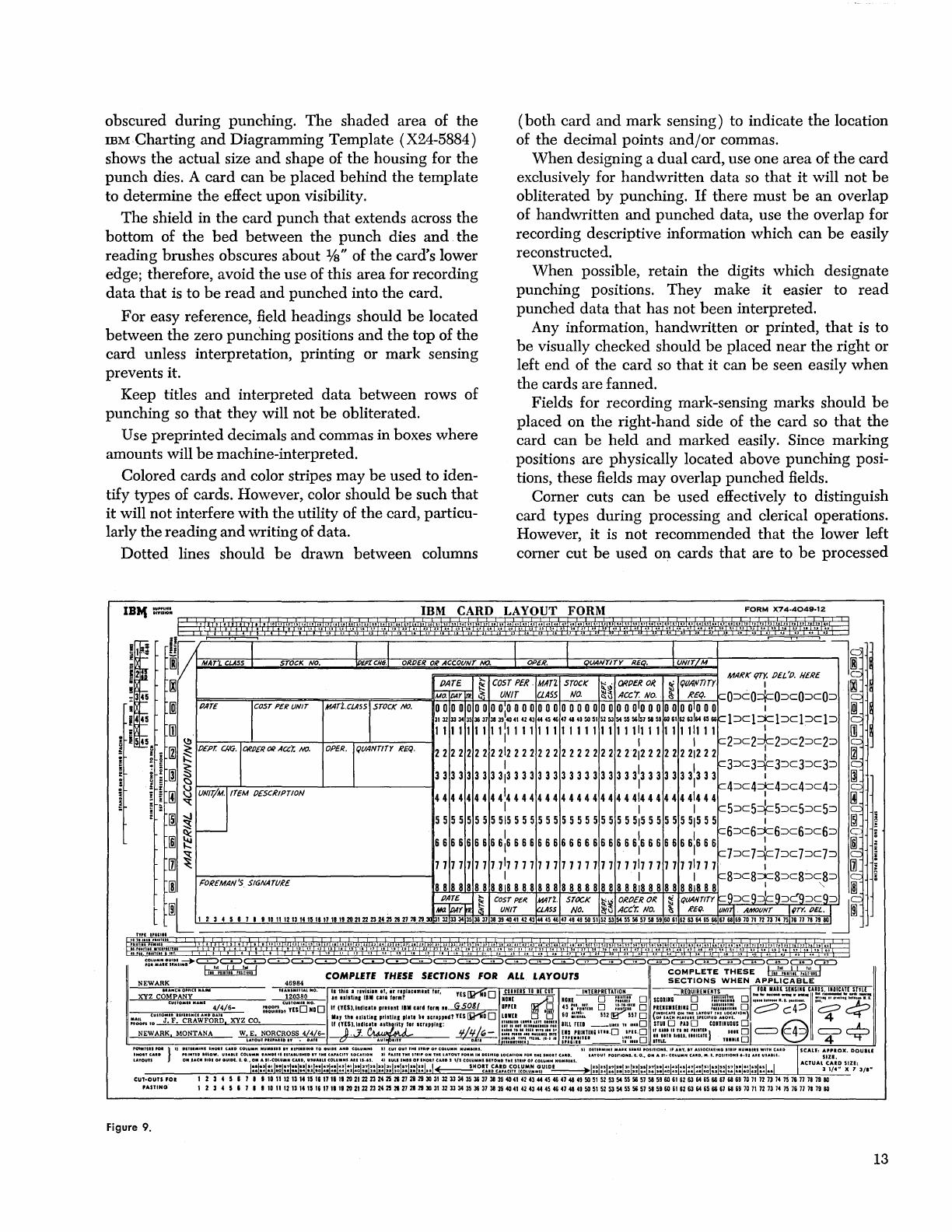
obscured during punching.
The
shaded
area of
the
mM.Charting
and
Diagramming Template (X24-5884)
shows
the
actual size
and
shape of
the
housing for
the
punch
dies. A
card
can
be
placed
behind
the
template
to determine
the
effect
upon
visibility.
(both
card
and
mark sensing) to indicate
the
location
of
the
decimal points
and/or
commas.
The
shield in
the
card
punch
that
extends across
the
bottom of
the
bed
between
the
punch
dies
and
the
reading brushes obscures about
lis"
of
the
card's lower
edge; therefore, avoid
the
use of this area for recording
data
that
is to
be
read
and
punched
into
the
card.
When
designing a
dual
card, use one
area
of
the
card
exclusively for
handwritten
data
so
that
it
will
not
be
obliterated
by
punching.
If
there must
be
an
overlap
of handwritten
and
punched
data, use
the
overlap for
recording descriptive information which can
be
easily
reconstructed.
For
easy reference, field headings should
be
located
between
the
zero punching positions
and
the
top of
the
card unless interpretation, printing
or
mark sensing
prevents it.
When
possible, retain
the
digits which designate
punching positions.
They
make
it
easier to
read
punched
data
that
has not
been
interpreted.
Keep titles
and
interpreted
data
between
rows of
punching so
that
they will not
be
obliterated.
Any information, handwritten or printed,
that
is to
be
visually checked should
be
placed
near
the
right or
left
end
of
the
card
so
that
it
can
be
seen easily
when
the cards are fanned.
Use
preprinted
decimals
and
commas in boxes
where
amounts will
be
machine-interpreted.
Colored cards
and
color stripes may
be
used to iden-
tify types of cards. However, color should
be
such
that
it
will
not
interfere with
the
utility of
the
card, particu-
larly
the
reading
and
writing of data.
Fields for recording mark-sensing marks should
be
placed on
the
right-hand side of
the
card so
that
the
card can
be
held
and
marked easily. Since marking
positions are physically located above punching posi-
tions, these fields may overlap
punched
fields.
Dotted
lines should
be
drawn
between
columns
Comer
cuts can
be
used effectively to distinguish
card types during processing
and
clerical operations.
However,
it
is
not
recommended
that
the
lower left
comer
cut
be
used on cards
that
are to
be
processed
IB",
~~~.'':~
IBM CARD LAYOUT FORM
FORM
X.74-4049-12
:,12M),'
,;,:,
...
~,!
I
i''''
\1,;
t;;'I'
I;;'':\';'!:'',')
,,~.1
:::':',i',;.:I)·",(.'(I,':/!
·,::j~'?i."~':
X,'
t~,'::f';,,',I::?':'::'i'·k:
'("l:7.:i;·y',·:b,t!:,(::
:}'
i,\'::;\rj:~~i:~\'."{J
.,;"
i~":,i\i:,i::{j'~'!W:',I'i!
i:\;I:((:~'i'!b'Al',l:,
i:~,'I:'::'\"'!""iiiX}
1:·~:j'i·I'\6:.':,
' I
d
~V
L I I I I I
1l'9
IRI
MAT'j.CLA5S STOCK
NO.
IPEPCCH6.
ORDER
OR
ACCOIINT
NO.
OPER.
IlANTITY
REO.
UNIT/M
!BI
'I
MARK
qry.
PEL'O.
HERE
<;.::::
00
PATE
~
COST
PEl?
MATZ
srOCK
~~
OROER
OR
IlC
qUlIl/TlTY I
00
1;i:;o.1ii4Y[ii.
~
UNIT aASS
NO.
~~
IICC/.
NO.
~
REf(.
rO~cO=t=O~cO~CO~
1("-'
345
445
PArE I
COST
PCR
UNIT
MAri..CLASS;ISTOCK
NO.
0 0 0 0 0 0 0 0 01
0 0 0 0 0 0 0 0 0 0 0 0 0 0 0 0 01
0 0 0 0 0 0 01
0 0 0 I
lif
3132
33 34
35
36 37 38 39
1
404142
43
4445
46 47 48 49
50
515253
54 55
56157
58 59
606162
63164
65
66~l~cl:x:l~cl~cl~
I~
ill
1111111111111111111111111111111111111111
~:~
rn
545
(,!)
1------,,-1-----+---r-.-J-----I
I I
~2~c2:::JC2~c2~c2~
Ie:::
~
;
IZI
~
PEP!:
CIKi.
ORPERORA(Xr.
NO.
OP£R·If«()ANmr
REQ.
222222222122222222222222222122222221222:
IZI
;
~
~
I I I
~3~c3::::F3~c3~c3~
Ie
i 2
00
~
333333333133333333333333333133333331333
I
~
~
i 8
~4~c4:::x:4~c4::;:)c4~
I~
~
~
~
~
UNIr/M. ITEM OESCRIPTION
4444444
44
1
44
4
44
4 4
44
4
44 44
4 4
414
4
44
44
414
44:
91
- • I 1 I
~5::;:)c5+5~c5~c5~
Ie:::::
i .
rID
~
55 5 5 5 5 5 5
515
5 5 5
555
5 5 5 5
555
5 5
515
5 5 5 5 5
515
5 5 I
rID
~
r--
1 I I
~6~c6:::x:6~c6~c6~
c
I§]
~
666666666
1
66666666666666666
1
6665666
1
666:
I§]
~
c7~c7=1c7~c7::;:)c7~
I~
III
~
77 77 1 77 771
77 77 1 77 1 77
17777
7711
77 77
77177
1 I
III
I . 1 I
c8~c8::::c8~c8~c8~
IS.
[j]
FOReMAN'S
SIGNAT()R£
888888888188888888888888888188888881888:"
[§]
L
~
~
COST
PER
MIlT'/.
STOCK
!\:~
OROfR
OR
~
~tJANTlTr
C~~C9=¥=9~C9~C9~:JI~
rnl
I
Me:!
I/JAYr.e
§
UNIT
CLASS
NO.
~\J
lleer.
NO.
~
RE(J.
VIIITj
AMOIINT
IpTY.
DEL. I
rnl
~587'll011121314151'17111'20212223242526272829I32333435363738394041424344454647484950515253545556575859606162636465666763697071727374757671717980
'MOlT
c.,.
'IINTID
Inow.
U'.'U
COLUMN
........
'S
IsrAeLl.HID
IT
,
..
I CA'ACITY LOCAnON
:1)
'Ani
T .. I
snl'
ON
tHI
l"TOUT
'01.
IN
DUllia
LOCA'ION
'01
'"IIMOIT
C
....
O.
LA.TOUI
'OSIHOH
•.
t.
G., ON
...
'10
COLUMN
C.UD.
M.'.
'011110HS
'-21
.....
us.UU.
SIZI
'OIN'II.
POI
} 1)
DIYI
••
tN'
'NO.'
CAID
co~u
....
"U.I
..
I I
.........
1
...
to
.'1101
AND
COLUMN'
21
CUt
0101'
'"I
nl"
o.
COLUMN
,.101
.....
,
51
DIU'.IN'
"'AIIC
UIIIU
.0SI1ION'.
I'
A
..
T.
IT
AUOet"'''NO
STII'
"UMUU
WITM
c..... \5(.\.11=
APPIOX.
OQuin
'A,Oun
ON
'ACN 1101
0'
0101101.
S.
···I::I;:i:~~:i::I::i;!I:~i;;f:~;:E!N,:!~I~i;~::,:;I:~j;;j;;,::j::j::j
~HM~;i:~~::~:~~l:~iu~:;~~D~I::I!:I:!I::I:~I::I::I::I!:I:~I::I::I::I::I:~I::I:!I:!I::I:~I::I::I
.•
I ACTUAL3
c,~:~
~z;;
311M
CUT·OUTS
fOI
1 2 3 4 5 8 7
••
10
II
12
13 14
15
18 17 18 11
20
21
22
23 24
25
26 27 28 29
30
31
32
33 34 35 36
37
38 39
40
41
424344
45
46
47
48
49
50
51
5253
54 55
56 57
58
59
60
61
62 63 64 65 66 67 63 69
10
71
72
73
74 75 76
77
78
79
80
12345'7'IWI1U13U15"17""~~2223N2526V282930~3233343538»38394O~~~444548~48U50~~~54
5556~58960~626364~66~~~~7I72nU~nnn~~
Figure 9.
13
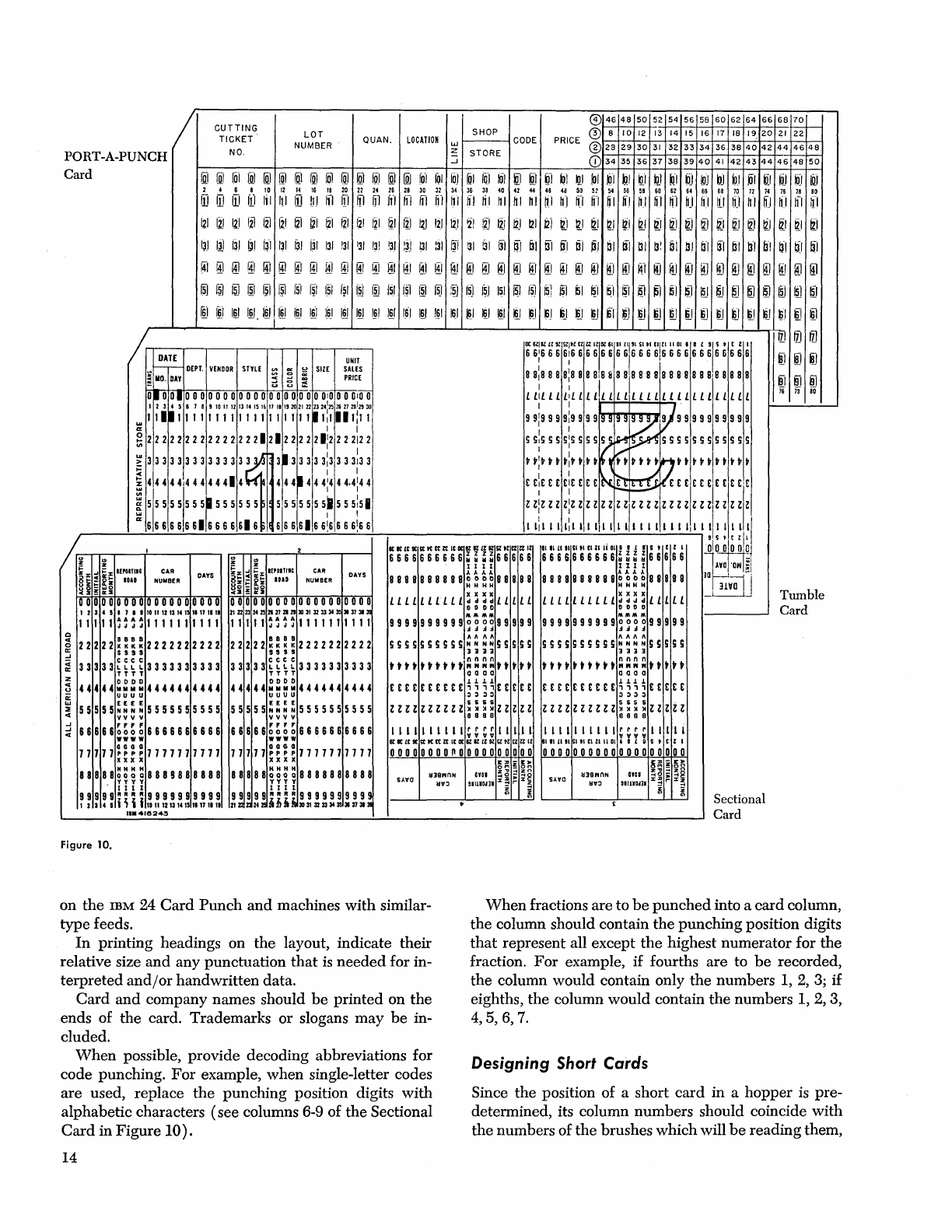
/
LOT
NUMBER
QUAN.
SHOP
LOCATION
w
f-----\
CODE
PORT
-A-PUNCH
Card
CUTTING
TICKET
NO.
z
-.J
STORE
@)
46
48
50
52
54 56
58
60
62
64
66 68
70
PRICE
® 8
10
12
13
14
15 16
17
18
19,20
21
22
®
28
29
30
31
32
33
34
36
38
40
42
44
46
48
CD
34
35
36
37 38 39
40
41
42
43
44
46
48
50
!Q) !Q)
[01
[qJ
rru
[ql
~I
1.0.1
101
toJ
@
IPJ
~I
[ijJ
liil
IQI
fOI
~I
fol
101
ijJ
kil
~-I
oi
~I ~I ~I
~I
~i
k]J
~J
ijJ
IPJ
pJ
~J
ijl
til
kil
~J
[Q)
2 4 6 8
10
12
14 16 18
20
22 24
26 28
30
32
34
36 38
40
42 44 46 48
50 52
S4
56
58
60
62
64
66
68
70
72 74
76
78
80
11]
11]
(1J
flJ
Iii
111
ID
tl)
III
fl fl
Iil
fl"1
If I
111
WI
~I
[I
hi
~I
hi
hi
~.I
"1
hJ
Ifl
hi
hi
h.1
ijl
~i
hJ
hi
~I
hJ
hi
[I
hi
fl
ff·1
121
Ii!
12)
iii
l"ij
~.I
IZl
~I
121
III
121 121
~I
I~I
I~
liJ
12J
~l
Ii.)
Ii!
~J
121
J2i
~I ~I
~I ~J
~I ~I ~I
~ ~
[I
®
~I
®
Ii!
~
~I
iii
I~J
I~
ill
~I
i~·1
131
~I
ijl
131 131
'31
!31
'31
Iii
III
:31
I~i
131
~I
131
~J ~I
ffl
ttl
BI
PJ
bl
til
~I
~:
~I ~I
n-I
til
61
tfl
b·1
b-'
[I
til
~
@ @ @ @ @ @ @ @ @ @ @ @ ® @ @ @ @ @ @ @ @ @ @ @ @
~
@
~
@
~
@
~ ~
@ @
~
ID
@ @
[5J
iID
I~
tID
@
I~
f51
~I
151
f~1
I.~)
lID
[51
i~
lID
[5]
:~
15J
I~)
151
~
ISJ
IS]
151
~I ~I ~I
~I
1[1
~)
51
$.1
Iru
ru
~ ~
lID
1m
~
rru
®
I~I
1m
1m.
1m
tru
im
1m
'-6-'
1m
1m
I~I
1M
161
1m
'~I
~I ~I ~I
I§.I
~
~J
~J
tJ
~
ru
~I
ru ru ru
ru ru ru
ru
~
~I
~
~I
~ ~
DATE
~~
DEPT.
VENDOR
STYLE
'"
~
SIZE
u u :t
UNIT
SALES
PRICE
.0
0.0
0 0 00 0 0 0 0 0 0 0 0 000 0 0
010
0 0
010
0
23456789101112131415161111192021222324:25262728'2930
11.11111111111111111111,1111:11
, I
2 2 2 2 2 2 2 2 2 2 2 2 2 2
21212
2 2 2 21'2 2 2
212
2
, I
3 3 3 3 3 3 3 3 3 3 3 3
3.
~
313 3 3 3
3:3
3 3
313
3
, I
44444144444414
444.444:444.4:44
515
5 5
515
5
5~
5 5 5 5 5 5 5 5 55 5 5 51 5 5
5:5.
6666666116666616
61666166!6666!66
CAR
NUIIBER
DAYS
o
0000000000000000
2 4 5 • 7 • I 10111213141
1111
1111
1 11
~
~
~
~
1111111111
22222::::2222222222
S s s s
33333~~~~3333333333
T T T T
DODD
44444111111114444444444
U U U u
55555~:~:5555555555
vv v v
66666~~~~6666666666
wwww
77777~~::7777777777
x x x x
88888~~~~8889888888
Y Y Y y
III
I
~::~:i~ii!~~!!~~~~~
1
••
4Ie243
Figure 10.
DAYS
0000000000000000000
2122232425212721213031323334353113731311
11 1 11
~
~
~ ~
11
11111
1 11
22222:::~2222222222
s s s s
C C C C
33333LLLL3333333333
TTTT
DODD
44444111111114444444444
UUUU
E E E E
55555NNNN
5555555555
vvvv
66666~~~~6666666666
WWWW
GGGO
77777PPPP7777777777
xxxx
88888~~~~8888888888
y y y Y
III
t
99999"""R999999999~
21
ZI
21
242!
ibii
303132 333435
311373131
OC61'IlLl91SlltltllZIII0l6lIlLlI9ISltltllll
11011 I L
9/1.
t l I
6
6:6
6 6
6:6
6 6 6 6 6 6 6
1
6 6 6
6,6
6 6 6 6 6 6 6 6 6 6 6
88:8888:888818 & 8 8
1
8 8 8 8 8 8 8 8 8 8 8 8 8
888
, I I
£
£,
£ £ £
£1
L £ £ £ L £ £ £ £ £ L £ £ £ £ L £ £ £ £ £ £ £ £
I'
OJI·
9
9!9
9 9
9i9
9 9 9 9
919
9 9
Y'l'
9 9 9 9 9 9 9 9 9 9
S
S,S
S S
s:s
S S S
f~~
S S S S S 5 S S S S S S
t tit t t t:t t t
t~
~I(;
t t t
t')t
t t t t t t t t t
t
tiE
E £
£it
£ £ £
~b:~:c
E £ £ £ £
£1£
£ £
£1'£
Z
Z:Z
Z z
z:z
z z z z z Z
zlZ
Z Z Z Z Z Z Z Z Z Z Z Z Z
zz
I
I:
I I I
I:
I
1,1
III
I I I I I I I I I I
I,I
I
!I!
! ! :
!/
KKLtlt
l:tttttzt
ItOCYIlLUlSl.lUlZ
Il
IIII
L11111.1
tlZlli
01.
I L r s • C l
10100
0
~olOj
6 6 6 6 6 6 6 6 6 6
II
~
~ ~
6 6 6 6 6 6 6 6 6 6 6 6 6 6 6
~
~ ~ ~
6 6 6 6 6
~~.;'
I I 1 I I I I I
AYO
·OW
;1
8 88 8 8 8 8 8 8 8
~
~
~
~
8 8 8 8 8 8 8 8 8 8 8 8 8 8 8
~
~ ~
~
8 8 8 8 8
ID~.
':.;-1
~
il·
HHHH HHHH
~
£LLL£LLLLL~~~~LLLLL LLLLLLLLLL~:~~LLLLL
-
!)
I)
!)!)
!)
!)!)
!)
MMMM
MMMM
9999999999~~~~99999 9999999999~~~~99999
""
""
h
""
h
SS55555555
NNNN
55555
5555555555
NNNN
55555
1111 1111
tttttttttt~~~~ttttt
tttttttttt~~~~ttttt
0000
0000
££££££EE£E~~~~E£E££
£££E£££EEE~~~~££EE£
0000 0000
ZZZZZZZZZZ~~~:ZZZZZ
ZZZZZZZZZZ~:~:ZZZZZ
ssss
8SS8
llllllllll~~~~llill
llllllllll~~~~llill
6CICLCltstKttzt
ICOCIlIlLl91SltlUlZll
~ll1tlllll.IC1l1
11016
I L Q S • C l I
OOoooooonooooooOOOO
0000000000000000000
SAYO
SA'fO
Sectional
Card
II!
I7J
IZJ
iJ
[QJ
iJ
il il
§j
i6
7s
80
Tumble
Card
on
the
IBM
24
Card
Punch
and
machines
with
similar-
type feeds.
When
fractions are to
be
punched
into a card column,
the
column should contain
the
punching position digits
that
represent all except
the
highest numerator for
the
fraction.
For
example,
if
fourths are to
be
recorded,
the
column would contain only
the
numbers
1,
2,
3;
if
eighths,
the
column would contain
the
numbers 1, 2, 3,
4,5,6,7.
In
printing headings on
the
layout, indicate their
relative size
and
any punctuation
that
is
needed
for in-
terpreted
and/or
handwritten data.
Card
and
company names should
be
printed on
the
ends of
the
card. Trademarks or slogans
may
be
in-
cluded.
When
possible, provide decoding abbreviations for
code punching.
For
example,
when
single-letter codes
are used, replace
the
punching position digits
with
alphabetic characters (see columns 6-9 of
the
Sectional
Card
in Figure
10).
14
Designing
Short
Cards
Since
the
position of a short card in a hopper
is
pre-
determined, its column numbers should coincide
with
the
numbers of
the
brushes which will
be
reading them,

so
that
sorting
and
control
panel
wiring will
be
easier.
The
first column of a 22-column
card
will
be
read
by
brush
30,
and
the
22nd column will
be
read
by
brush
51. Cards designed for a 51-column operation are
read
by
brushes 15
through
65.
If
the
whole
card
is
to
be
processed before
the
stubs are detached,
it
may
also
be
desirable to show column numbers for
the
standard
80-column card as well as those for
the
short card.
Designing
PORT
-A-PUNCH® Cards
A
PORT-A-PUNCH
card
is
illustrated in
Figure
10. A maxi-
mum
of 40 columns
may
be
punched; however,
the
punching
positions
must
be
prescored to
permit
use of
the
PORT-A-PUNCH.
The
scoring
is
limited to consecutive,
even-numbered columns.
In
considering
the
card
design,
it
must
be
remem-
bered
that
normal machine
punching
cannot
be
accom-
plished in columns adjacent
to
PORT-A-PUNCH
columns.
In
some cases
it
may
be
necessary to reproduce
the
PORT-A-PUNCH
card
into another
card
in
order
to
provide
additional space for calculated results or other
data
to
be
added.
Tumble and Sectional Cards
In
cases such as merchandise control for retailing
and
freight
car
accounting for transportation,
where
40 or
fewer
card
columns
are
required
for a transaction, a
sectional or tumble
card
is
frequently designed
and
used. This cuts
card
costs in half;
with
the
sectional
card
they
may
be
cut
even more.
Figure
10 illustrates
both
types.
Their
nature
is
such
that
it
does
not
easily
permit their use as a
permanent
record card.
Testing Card Design
After
the
design of a
card
has
been
established,
it
should
be
tested. An effective
way
of doing this
is
to
layout
the
design on several cards
(IBM
cards
with
form numbers 5081 or 1001 are satisfactory)
and
use
them
in
the
procedure. Any serious
drawback
to
the
design should become apparent.
The
IBM
Charting
and
Diagramming
Template
is
helpful in preparing for
the
test. Its height
and
its
length
up
to
the
notch
that
appears
on
the
bottom
edge
are
the
exact dimensions of a
standard
IBM
card.
On
the
face of
the
template are shown
(1)
along
the
bot-
tom edge,
the
location of
card
and
mark-sense columns,
( 2) along
the
left edge,
the
location of punching
and
end-printing positions
and
(3)
along
the
top edge,
alphabetic interpreter
type
spacing.
Whenever
conflicts arise in
the
design of cards
that
are processed together,
the
cards
and
their uses should
be
studied
to determine which one should have priority.
In
so doing, consider for
each
type
(1)
its volume,
(2)
the
number
of
manual
operations in
which
it
is used,
(
3)
the
nature
of
each
manual
operation
and
(4)
its
effect
upon
such things as
board
wiring
and
program-
ming.
15

C20-8078
International
Business
Machines
Corporation
Data
Processing
Division
112
East
Post
Road,
White
Plains,
N.Y.106Ot
[USA Only]
IBM World
Trade
Corporation
821 United
Nations
Plaza,
New
York,
New
York
10017
[International]
