C30D C30 Cut Sheet Series
User Manual: C30D
Open the PDF directly: View PDF ![]() .
.
Page Count: 487 [warning: Documents this large are best viewed by clicking the View PDF Link!]
- Table of Contents
- Preface
- Printing and Troubleshooting Overview
- TAG Cross-Reference Tables
- Troubleshooting Analysis Guide (TAGs)
- Print Quality Samples
- Print Quality Samples
- Sample 1: Good Quality Print
- Sample 2: Washout
- Sample 3: Blank Print
- Sample 4: Light Print
- Sample 5: Light Print With Background
- Sample 6: Voids or White Spots
- Sample 7: Light Vertical Streaks
- Sample 8: Blank Vertical Bands
- Sample 9: Light Horizontal Bands
- Sample 10: Black or Dark Print
- Sample 11: Dark Specks, Lines, or Areas
- Sample 12: Dark Vertical Lines
- Sample 13: Skewed Prints
- Sample 14: Misregistration
- Sample 15: Overtoned Print
- Sample 16: Blurred Images or Characters
- Sample 17: Varying Print Density
- Sample 18: Background
- Sample 19: Residual Images
- Sample 20: Wrinkles
- Sample 21: Fusing Problems
- Diagnostic Tests
- Diagnostic Tests
- How to Run Diagnostics
- 001 Operator Panel Test
- 002 Upper Cassette Test
- 003 Lower Cassette Test
- (004 intentionally excluded)
- 005 Sensor Test Sequence
- 006 Paper Transport Clutch Test Sequence
- 007 Counter Test
- 008 Jogging Motor Test
- 009 Photoconductor Test
- 010 Toner Supply Motor Test
- 011 Charge Corona Test
- 012 Transfer Corona Test
- 013 Erase Lamp Test
- (014 intentionally excluded)
- 015 Negative Developer Bias Test
- 016 Duplex Feed Motor Test
- 017 Duplex Input Sensor Test Sequence
- 018 Duplex Clutch Test Sequence
- 019 Duplex Tray Paper-Guide Motor Test
- 020 High-Capacity Output Unit Test
- 021 High-Capacity Input Unit Test
- 022 Envelope Fuser Solenoid Test
- (023-100 intentionally excluded)
- 101 EIGS/MIGS Board Test
- 102 EIGS/MIGS Board Test (Continuous Loop)
- 103 Communication Loop-back Test (Single Loop)
- 104 Communication Loop-back Test (Continuous Loop)
- 105 EIGS Program RAM Test (Continuous Loop)
- (106 intentionally excluded)
- 107 EIGS/MIGS Bit Map Test (Single Loop)
- 108 EIGS/MIGS Bit Map Test (Continuous Loop)
- (109 intentionally excluded)
- 110 Format Disk/Clear Error Log
- 111 LED Printhead Test
- 112 Disk Drive Test (Single Loop With Stop on Error)
- 113 Disk Drive Test (Continuous Loop)
- Wiring Diagrams and Electrical Data
- Wiring Diagrams and Electrical Data
- Connector (J/P) Index
- Connector Locations
- Connectors Inside the Front Cover
- Connectors Inside the Left Cover
- Connectors on the Duplex Cover
- Connectors Inside the Right Cover
- Connectors Inside the Top Cover
- Connectors on the Back Cover
- Connectors Inside the Back Cover (J/P2-14)
- Connectors Inside the Back Cover (Continued) J/P18-62
- Connectors Inside the Back Cover (Continued) J/P 64-85
- Connectors Inside the Back Cover (Continued) J/P 90-800
- Voltage Isolation Diagrams
- Ground System
- Host Interface Reference
- RS-232C Host Interface
- Standard DCE to DTE RS-232C Cable
- Special Considerations for RS-232 Host Interface Users
- DTE Host to Printer (Option 1)
- DTE Host to Printer (Option 2)
- IBM PC/XT to Printer
- IBM PC/AT to Printer
- Macintosh Communication Port to Printer
- RS-422 Host interface
- Centronics Parallel Host Interface
- IBM Parallel to Printer
- Special Considerations for Centronics Parallel Interface Users
- Circuit Board Settings
- Power Supply Strapping
- Removal/Replacement Procedures
- Removal
- Before You Begin
- Front Cover Removal
- Back Cover Removal
- Lower Back Cover Removal
- Left Side Cover Removal
- Right Side Cover Removal (Simplex)
- Right Side Cover Removal (Duplex)
- Vacuum Transport Unit Removal (Simplex)
- Vacuum Transport Unit Removal (Duplex)
- Top Cover Removal
- Top Cover Support Removal
- Top Cover Hinge Removal
- Rear Duplex Cover Removal
- Front Duplex Cover Removal
- Operator Panel Removal
- Counter Removal
- IGS Board Removal
- PCL Board Removal
- Printhead Assembly Removal
- Disk Drive Housing Removal
- Cooling Fan Removal
- Duplex Fan Removal
- Toner Motor Removal
- AC Power Supply Removal
- DC Power Supply Removal
- High Voltage Unit Removal
- Photoconductor Seam Sensor Removal
- Photoconductor Rear Guide Rail Removal
- Signal Interface Board Removal
- Power Control Board Removal
- Jogging Motor Control Board Removal
- Upper or Lower Paper Size Sensor Removal
- Upper Cassette Mount Removal
- Lower Cassette Mount Removal
- Upper Paper Guide Removal
- Upper Paper Guide Roller Removal
- Lower Paper Guide Removal
- Paper Timing Guide Removal
- Cleaner Drive Belt Removal
- Cleaner Drive Removal
- Fuser Drive Belt Removal
- Fuser Drive Removal
- Paper Feed Drive Belt Removal
- Paper Timing Roller Removal
- Upper Feed Roller Removal
- Lower Feed Roller Removal
- Upper Pick-Up Roller Removal
- Upper Pick-Up Roller Drive Removal
- Lower Pick-Up Roller Removal
- Lower Pick-Up Roller Drive Removal
- Job Offset Assembly Removal
- Exit Pinch Roller Removal
- Upper Static Brush Removal
- Lower Static Brush Removal
- Exit Roller Assembly Removal
- Exit Cover Removal (Simplex)
- Exit Cover Removal (Duplex)
- Paper Exit Sensor Removal
- Paper Full Sensor Removal
- Front Cover Interlock Switch Removal
- Back Cover Interlock Switch Removal
- Top Cover Interlock Switch Removal
- Erase Lamp Removal
- EP Cover Removal
- Main Motor Removal
- Main Gear Drive Removal
- Duplex Control Board #1 Removal
- Duplex Control Board #2 Removal
- Duplex Tray Registration Motor Removal
- Duplex Skew Correction Cable Removal
- Upper Duplex Drive/Clutch Assembly Removal
- Duplex Route Motor/Solenoid Assembly Removal
- “A” Roller Removal
- “B” Roller Removal
- “C” Roller Removal
- “C” Roller Solenoid Removal
- Duplex Route Separator Removal
- Duplex Paper Path Sensor Removal
- Options
- General Printer Maintenance
- Abbreviations and Acronyms
- Index

Cut Sheet Printers
Maintenance Manual
Models C30 and C30D
HP Part No. C4000-90006

ii June 1999
Notice
Hewlett-Packard makes no warranty of any kind with regard to this material, including,
but not limited to, the implied warranties of merchantability and fitness for a particular
purpose. Hewlett-Packard shall not be liable for errors contained herein or for incidental
or consequential damages in connection with the furnishing, performance, or use of this
material.
Hewlett-Packard assumes no responsibility for the use or reliability of its software on
equipment that is not furnished by Hewlett-Packard.
This document contains proprietary information which is protected by copyright. All
rights are reserved. No part of this document may be photocopied, reproduced, or trans-
lated to another language without the prior written consent of Hewlett-Packard Company.
The information contained in this document is subject to change without notice.
Printing History
New editions are complete revisions of the manual. The dates on the title page change
only when a new edition is published.
The software code (EXXX) printed below the date indicates the version level of the soft-
ware product at the time of publication.
Edition 1 . . . . . . . . . . . . . . . . . . . . . . . . . . .March 1994
Edition 2. . . . . . . . . . . . . . . . . . . . . . . . . . . December 1994
Edition 3. . . . . . . . . . . . . . . . . . . . . . . . . . . June 1999
Trademarks
PCL is a trademark of the Hewlett-Packard Company. CG Times, a product of Agfa Cor-
poration, is based on Times New Roman, a registered trademark of Monotype Corporation
PLC. ITC Zapf Dingbats is a U.S. registered trademark of International Typeface Corpora-
tion. PostScript is a registered trademark of Adobe Systems, Inc. in the U.S.A. and other
countries. Times Roman and Univers are trademarks of Linotype AG and its subsidiaries.
Centronics is a U.S. registered trademark of Centronics Corporation. PhoenixPage is a
trademark of Phoenix technologies, Ltd. UNIX is a registered trademark of UNIX System
Laboratories Inc. in the U.S.A. and other countries. DEC LN03+ is a registered trademark
of Digital Equipment Corporation. All other trademarks are the properties of their respec-
tive owners.

June 1999 iii
Warnings and Cautions
A WARNING denotes a hazard. It calls attention to a procedure or practice, which, if not
done correctly or adhered to, could result in personal injury. Do not proceed beyond a
WARNING sign until the indicated conditions are fully understood and met.
A CAUTION denotes a hazard. It calls attention to a procedure which, if done incorrectly
or inattentively, could damage or destroy part or all of the product. Do not proceed beyond
a CAUTION until the indicated conditions are fully understood and met.
Conventions
The following conventions are used throughout this manual:
Notes contain important information set off from the text.
Note
Caution messages indicate procedures which, if not observed,
could result in damage to the equipment.
Caution
Warning messages call attention to situations that could result
in personal injury.
Warning

iv June 1999
Preface
The C30/C30D Maintenance Manual contains all the information needed to maintain and
service Hewlett Packard C30 and C30D printers. The C30 printer series are high-speed,
non-impact printers utilizing electrophotographic imaging technology.
The information in this maintenance manual is for authorized field representatives who are
familiar with basic printer operations. It serves as a supplement to training classes and pro-
vides a basis for discussion with regional field service engineers and customer support
representatives.
Using This Manual
This manual is organized into the following sections:
Chapter 1, “Printer and Troubleshooting Overview”
Reviews the organization of the manual, the way the printer works, and how to trouble-
shoot the printer, including some standard procedures to follow when troubleshooting.
This chapter also includes a chart detailing exactly what each causes each error code, illus-
trations of all sensors in the printer, and a list of abbreviations used throughout the manual.
Chapter 2, “TAG Cross- Reference Tables”
Provides cross-reference tables; look up specific printer problem description (in either the
mechanical malfunction, error code, or print quality description tables), then turn to the
TAG indicated on the chart to troubleshoot the problem.
Chapter 3, “Troubleshooting Analysis Guide (TAGs)”
Detailed step-by-step procedures to help you isolate and resolve specific printer problems.
If you are not sure which TAG to start with, begin with the overview, TAG 001.
Chapter 4, “Print Quality Samples”
Shows print test patterns indicating specific problems, and referencing the TAG that treats
each problem.
Chapter 5, “Diagnostic Tests”
Reviews each printer software diagnostic.
Chapter 6, “Wiring Diagrams and Electrical Data”
Shows printer schematics and locations of individual components.
Chapter 7, “Removal/Replacement Procedures”
Outlines procedures to follow when removing and replacing printer parts, also called
FRUs (Field-Replaceable Units).
June 1999 v
Chapter 8, “Options”
Provides information about the optional High Capacity Input and High Capacity Output
accessories and the optional hard disk upgrade.
Chapter 9, “General Printer Maintenance”
Reviews printer maintenance procedures to complete during service calls.
Appendix A
Lists the abbreviations and acronyms used in the manual.
Index
Provides a list of references to topics and part numbers mentioned in the Maintenance
Manual
Other Manuals
The C-Series Illustrated Parts Catalog shows every FRU and CRU (customer-replaceable
unit) in the printer, including part number information. This information is frequently
updated.
The HP C30 and C30D Guide to Operations, C4000-96006, contains all the information
needed to operate Hewlett Packard C30 and C30D printers.
The HP C30/30D and C40D Paper Specifications Guide, C4672-90002, explains the vari-
ous papers usable in the printer, how to care for them, and how to minimize paper-related
problems with the C30/30D and C40D.
Copyright © 1999 Hewlett-Packard Company. All rights reserved. May 1999
Please address any comments or questions with respect to this document to:
Publication Department
Hewlett-Packard Company
HP Printers - MS 44MC
System Peripherals Operation
19111 Pruneridge Avenue
Cupertino, CA 95014
vi June 1999

Contents
June 1999 vii
Printer and Troubleshooting Overview
Contents . . . . . . . . . . . . . . . . . . . . . . . . . . . . . . . . . . . . . . . . . . . . . . . . . . . . . . . . . .1-2
Theory of Operation . . . . . . . . . . . . . . . . . . . . . . . . . . . . . . . . . . . . . . . . . . . . . . . . .1-3
Paper Path and Cycle Sequence . . . . . . . . . . . . . . . . . . . . . . . . . . . . . . . . . . . . . . . .1-5
Simplex Printing. . . . . . . . . . . . . . . . . . . . . . . . . . . . . . . . . . . . . . . . . . . . . . . . . . . . . . . 1-5
Duplex Printing . . . . . . . . . . . . . . . . . . . . . . . . . . . . . . . . . . . . . . . . . . . . . . . . . . . . . . . 1-5
Error Code Technical Definitions. . . . . . . . . . . . . . . . . . . . . . . . . . . . . . . . . . . . . . .1-7
Sensor and Switch Locations . . . . . . . . . . . . . . . . . . . . . . . . . . . . . . . . . . . . . . . . .1-11
Troubleshooting Overview . . . . . . . . . . . . . . . . . . . . . . . . . . . . . . . . . . . . . . . . . . .1-15
General Troubleshooting Tips . . . . . . . . . . . . . . . . . . . . . . . . . . . . . . . . . . . . . . . . . . . 1-15
The Problem: Printer or Host? . . . . . . . . . . . . . . . . . . . . . . . . . . . . . . . . . . . . . . . . . . . 1-16
Protocol Converters . . . . . . . . . . . . . . . . . . . . . . . . . . . . . . . . . . . . . . . . . . . . . . . . . . . 1-17
Reading the Error Log . . . . . . . . . . . . . . . . . . . . . . . . . . . . . . . . . . . . . . . . . . . . . . . . . 1-17
Confirming Line Power . . . . . . . . . . . . . . . . . . . . . . . . . . . . . . . . . . . . . . . . . . . . . . . . 1-18
Using the Troubleshooting Analysis Guide (TAG) . . . . . . . . . . . . . . . . . . . . . . . . 1-19
Sample TAG. . . . . . . . . . . . . . . . . . . . . . . . . . . . . . . . . . . . . . . . . . . . . . . . . . . . . . . . . 1-19
Standard Procedures . . . . . . . . . . . . . . . . . . . . . . . . . . . . . . . . . . . . . . . . . . . . . . . .1-21
Power-on-reset (POR) . . . . . . . . . . . . . . . . . . . . . . . . . . . . . . . . . . . . . . . . . . . . . . . . . 1-21
Checking Continuity. . . . . . . . . . . . . . . . . . . . . . . . . . . . . . . . . . . . . . . . . . . . . . . . . . . 1-21
Installing the Interlock By-pass Tool. . . . . . . . . . . . . . . . . . . . . . . . . . . . . . . . . . . . . . 1-22
Producing a Developed Image . . . . . . . . . . . . . . . . . . . . . . . . . . . . . . . . . . . . . . . . . . . 1-22
Producing a Toner Patch . . . . . . . . . . . . . . . . . . . . . . . . . . . . . . . . . . . . . . . . . . . . . . . 1-22
Completing a Service Call . . . . . . . . . . . . . . . . . . . . . . . . . . . . . . . . . . . . . . . . . . . . . . 1-23
Clearing the Error Log . . . . . . . . . . . . . . . . . . . . . . . . . . . . . . . . . . . . . . . . . . . . . . . . . 1-24
TAG Cross-Reference Tables
TAG Cross-Reference Tables . . . . . . . . . . . . . . . . . . . . . . . . . . . . . . . . . . . . . . . . .2-2
Error Code/TAG Cross-Reference . . . . . . . . . . . . . . . . . . . . . . . . . . . . . . . . . . . . . .2-3
Print Quality/TAG Cross-Reference . . . . . . . . . . . . . . . . . . . . . . . . . . . . . . . . . . . .2-9
Mechanical Malfunction/TAG Cross-Reference . . . . . . . . . . . . . . . . . . . . . . . . . .2-12
Troubleshooting Analysis Guide (TAGs)
Contents . . . . . . . . . . . . . . . . . . . . . . . . . . . . . . . . . . . . . . . . . . . . . . . . . . . . . . . . . .3-2
Troubleshooting Analysis Guide (TAGs). . . . . . . . . . . . . . . . . . . . . . . . . . . . . . . . .3-4
TAG 001: Troubleshooting a Problem. . . . . . . . . . . . . . . . . . . . . . . . . . . . . . . . . . . . . . 3-5
TAG 002: Check & Problem Resolution . . . . . . . . . . . . . . . . . . . . . . . . . . . . . . . . . . . . 3-8
TAG 010: Upper Cassette Malfunction . . . . . . . . . . . . . . . . . . . . . . . . . . . . . . . . . . . . 3-12
E10: Envelope Tray Out of Envelopes. . . . . . . . . . . . . . . . . . . . . . . . . . . . . . . . . . . . . 3-14
TAG 011: Lower Cassette Malfunction . . . . . . . . . . . . . . . . . . . . . . . . . . . . . . . . . . . . 3-16
Contents
viii June 1999
TAG 012: Upper Cassette Not Latched . . . . . . . . . . . . . . . . . . . . . . . . . . . . . . . . . . . .3-18
TAG E12: Envelope Tray or Feeder Not Latched . . . . . . . . . . . . . . . . . . . . . . . . . . . .3-21
TAG 013: Lower Cassette Not Latched . . . . . . . . . . . . . . . . . . . . . . . . . . . . . . . . . . . .3-24
TAG 020: Paper Jam/Misfeed in Upper Cassette Area . . . . . . . . . . . . . . . . . . . . . . . .3-26
TAG 021: Paper Jam/Misfeed in /Lower Cassette Area. . . . . . . . . . . . . . . . . . . . . . . .3-30
TAG 022: Paper Jam in the Transfer or Fuser Area . . . . . . . . . . . . . . . . . . . . . . . . . . .3-34
TAG 023: Paper Jam in the Output Area . . . . . . . . . . . . . . . . . . . . . . . . . . . . . . . . . . .3-39
TAG 025: Paper in Input Area Before Printing . . . . . . . . . . . . . . . . . . . . . . . . . . . . . .3-41
TAG 026: Paper in Output Area Before Printing . . . . . . . . . . . . . . . . . . . . . . . . . . . . .3-43
TAG 030: Developer Bias Short/Failure . . . . . . . . . . . . . . . . . . . . . . . . . . . . . . . . . . .3-44
TAG 031: Toner Patch Reference Level Too Low. . . . . . . . . . . . . . . . . . . . . . . . . . . .3-47
TAG 032: Toner Patch Too Light. . . . . . . . . . . . . . . . . . . . . . . . . . . . . . . . . . . . . . . . .3-49
TAG 035: Out of Toner or ADD TONER Indicator On. . . . . . . . . . . . . . . . . . . . . . . .3-51
TAG 036: Developer Unit Not Installed. . . . . . . . . . . . . . . . . . . . . . . . . . . . . . . . . . . .3-53
TAG 040: Photoconductor Seam Sensor Malfunction . . . . . . . . . . . . . . . . . . . . . . . . .3-54
TAG 044: Charge Corona/Transfer Corona Circuit Open . . . . . . . . . . . . . . . . . . . . . .3-58
TAG 045: Charge Corona Circuit Shorted . . . . . . . . . . . . . . . . . . . . . . . . . . . . . . . . . .3-61
TAG 050: Transfer Corona Circuit Shorted . . . . . . . . . . . . . . . . . . . . . . . . . . . . . . . . .3-63
TAG 055: Erase Lamp Malfunction . . . . . . . . . . . . . . . . . . . . . . . . . . . . . . . . . . . . . . .3-65
TAG 070: Fuser Unit Malfunction . . . . . . . . . . . . . . . . . . . . . . . . . . . . . . . . . . . . . . . .3-67
TAG 071: Open Fuser Thermistor . . . . . . . . . . . . . . . . . . . . . . . . . . . . . . . . . . . . . . . .3-72
TAG 072: Fuser Unit Temperature Too High . . . . . . . . . . . . . . . . . . . . . . . . . . . . . . .3-73
TAG 083: Job Offset Mechanism Malfunction . . . . . . . . . . . . . . . . . . . . . . . . . . . . . .3-75
TAG 097: +12 Vdc Power Shorted or Sensing Problem . . . . . . . . . . . . . . . . . . . . . . .3-79
TAG 098: -12 Vdc Power Shorted . . . . . . . . . . . . . . . . . . . . . . . . . . . . . . . . . . . . . . . .3-90
TAG 099: +24 Vdc Power Shorted. . . . . . . . . . . . . . . . . . . . . . . . . . . . . . . . . . . . . . . .3-92
TAG 100: PCL Board Interface Malfunction . . . . . . . . . . . . . . . . . . . . . . . . . . . . . . .3-102
TAG 101: IGS Controller Diagnostic Failure. . . . . . . . . . . . . . . . . . . . . . . . . . . . . . .3-103
TAG 130: Diskette/Disk Drive Malfunction . . . . . . . . . . . . . . . . . . . . . . . . . . . . . . .3-104
TAG 200: IGS Internal Communication Malfunction . . . . . . . . . . . . . . . . . . . . . . . .3-108
TAG 201: IGS-PCL Interface Malfunction . . . . . . . . . . . . . . . . . . . . . . . . . . . . . . . .3-110
TAG 405: IGS Bit-Map RAM Malfunction . . . . . . . . . . . . . . . . . . . . . . . . . . . . . . . .3-112
TAG 500: +5 Vdc Power Malfunction . . . . . . . . . . . . . . . . . . . . . . . . . . . . . . . . . . . .3-113
TAG 600: AC Power Malfunction . . . . . . . . . . . . . . . . . . . . . . . . . . . . . . . . . . . . . . .3-118
TAG 610: Operator Panel Malfunction . . . . . . . . . . . . . . . . . . . . . . . . . . . . . . . . . . .3-125
TAG 700: Output Tray Circuit Malfunction. . . . . . . . . . . . . . . . . . . . . . . . . . . . . . . .3-130
TAG 702: Paper Size Detection Malfunction. . . . . . . . . . . . . . . . . . . . . . . . . . . . . . .3-132
TAG 703: Upper Cassette Malfunction . . . . . . . . . . . . . . . . . . . . . . . . . . . . . . . . . . .3-135
TAG 704: Lower Cassette Malfunction . . . . . . . . . . . . . . . . . . . . . . . . . . . . . . . . . . .3-136
TAG 705: Multiple Paper Feeding . . . . . . . . . . . . . . . . . . . . . . . . . . . . . . . . . . . . . . .3-137
TAG 706: Paper Damaged or Wrinkled . . . . . . . . . . . . . . . . . . . . . . . . . . . . . . . . . . .3-138
TAG 707: Upper Paper Guide Assembly Not Closing. . . . . . . . . . . . . . . . . . . . . . . .3-139
TAG 750: Counter Malfunction . . . . . . . . . . . . . . . . . . . . . . . . . . . . . . . . . . . . . . . . .3-140
TAG 751: Main Drive Motor Runs Continuously . . . . . . . . . . . . . . . . . . . . . . . . . . .3-142
TAG 753: External Communications Malfunction. . . . . . . . . . . . . . . . . . . . . . . . . . .3-143
TAG 754: Attachment Option Malfunction . . . . . . . . . . . . . . . . . . . . . . . . . . . . . . . .3-146
TAG 800: Prints Blank or With Dark Horizontal Bands . . . . . . . . . . . . . . . . . . . . . .3-148
TAG 801: Prints Light or Light With Carrier Particles . . . . . . . . . . . . . . . . . . . . . . .3-152
TAG 802: Prints With Voids or White Spots . . . . . . . . . . . . . . . . . . . . . . . . . . . . . . .3-158
TAG 803: Prints With Light or White Vertical Streaks . . . . . . . . . . . . . . . . . . . . . . .3-160

Contents
June 1999 ix
TAG 804: Prints With Light Horizontal Bands . . . . . . . . . . . . . . . . . . . . . . . . . . . . . 3-162
TAG 805: Black Prints. . . . . . . . . . . . . . . . . . . . . . . . . . . . . . . . . . . . . . . . . . . . . . . . 3-163
TAG 806: Prints with Dark Spots or Scratches . . . . . . . . . . . . . . . . . . . . . . . . . . . . . 3-166
TAG 807: Misregistered/Skewed Prints (Simplex) . . . . . . . . . . . . . . . . . . . . . . . . . . 3-168
TAG 808: Prints Overtoned/Dark Vertical Streaks . . . . . . . . . . . . . . . . . . . . . . . . . . 3-172
TAG 809: Blurred or Smeared Vertical Streaks on Prints . . . . . . . . . . . . . . . . . . . . . 3-177
TAG 810: Uneven Density or Dark Areas on Prints . . . . . . . . . . . . . . . . . . . . . . . . . 3-180
TAG 811: Background/Residual Images/Dark Prints . . . . . . . . . . . . . . . . . . . . . . . . 3-182
TAG 812: Uneven or No Fusing on Prints. . . . . . . . . . . . . . . . . . . . . . . . . . . . . . . . . 3-187
TAG 813: Residual Images on Prints. . . . . . . . . . . . . . . . . . . . . . . . . . . . . . . . . . . . . 3-189
TAG 815: Prints Resulting From Printhead Malfunctions. . . . . . . . . . . . . . . . . . . . . 3-191
TAG 900: Top Cover Interlock Malfunction, Duplex . . . . . . . . . . . . . . . . . . . . . . . . 3-192
TAG 901: Misregistration/Skewed Prints (Duplex). . . . . . . . . . . . . . . . . . . . . . . . . . 3-194
TAG 902: Paper Jam in Duplex Area. . . . . . . . . . . . . . . . . . . . . . . . . . . . . . . . . . . . . 3-198
Print Quality Samples
Contents . . . . . . . . . . . . . . . . . . . . . . . . . . . . . . . . . . . . . . . . . . . . . . . . . . . . . . . . . .4-2
Print Quality Samples. . . . . . . . . . . . . . . . . . . . . . . . . . . . . . . . . . . . . . . . . . . . . . . .4-3
Sample 1: Good Quality Print. . . . . . . . . . . . . . . . . . . . . . . . . . . . . . . . . . . . . . . . . .4-4
Sample 2: Washout . . . . . . . . . . . . . . . . . . . . . . . . . . . . . . . . . . . . . . . . . . . . . . . . . .4-5
Sample 3: Blank Print. . . . . . . . . . . . . . . . . . . . . . . . . . . . . . . . . . . . . . . . . . . . . . . .4-6
Sample 4: Light Print . . . . . . . . . . . . . . . . . . . . . . . . . . . . . . . . . . . . . . . . . . . . . . . .4-7
Sample 5: Light Print With Background . . . . . . . . . . . . . . . . . . . . . . . . . . . . . . . . .4-8
Sample 6: Voids or White Spots. . . . . . . . . . . . . . . . . . . . . . . . . . . . . . . . . . . . . . . .4-9
Sample 7: Light Vertical Streaks . . . . . . . . . . . . . . . . . . . . . . . . . . . . . . . . . . . . . .4-10
Sample 8: Blank Vertical Bands. . . . . . . . . . . . . . . . . . . . . . . . . . . . . . . . . . . . . . .4-11
Sample 9: Light Horizontal Bands . . . . . . . . . . . . . . . . . . . . . . . . . . . . . . . . . . . . .4-12
Sample 10: Black or Dark Print . . . . . . . . . . . . . . . . . . . . . . . . . . . . . . . . . . . . . . .4-13
Sample 11: Dark Specks, Lines, or Areas . . . . . . . . . . . . . . . . . . . . . . . . . . . . . . .4-14
Sample 12: Dark Vertical Lines . . . . . . . . . . . . . . . . . . . . . . . . . . . . . . . . . . . . . . .4-15
Sample 13: Skewed Prints . . . . . . . . . . . . . . . . . . . . . . . . . . . . . . . . . . . . . . . . . . .4-16
Sample 14: Misregistration. . . . . . . . . . . . . . . . . . . . . . . . . . . . . . . . . . . . . . . . . . .4-17
Sample 15: Overtoned Print . . . . . . . . . . . . . . . . . . . . . . . . . . . . . . . . . . . . . . . . . .4-18
Sample 16: Blurred Images or Characters . . . . . . . . . . . . . . . . . . . . . . . . . . . . . . .4-19
Sample 17: Varying Print Density . . . . . . . . . . . . . . . . . . . . . . . . . . . . . . . . . . . . .4-20
Sample 18: Background . . . . . . . . . . . . . . . . . . . . . . . . . . . . . . . . . . . . . . . . . . . . .4-21
Sample 19: Residual Images. . . . . . . . . . . . . . . . . . . . . . . . . . . . . . . . . . . . . . . . . .4-22
Sample 20: Wrinkles. . . . . . . . . . . . . . . . . . . . . . . . . . . . . . . . . . . . . . . . . . . . . . . .4-23
Sample 21: Fusing Problems . . . . . . . . . . . . . . . . . . . . . . . . . . . . . . . . . . . . . . . . .4-24

Contents
xJune 1999
Diagnostic Tests
Contents . . . . . . . . . . . . . . . . . . . . . . . . . . . . . . . . . . . . . . . . . . . . . . . . . . . . . . . . . .5-2
Diagnostic Tests . . . . . . . . . . . . . . . . . . . . . . . . . . . . . . . . . . . . . . . . . . . . . . . . . . . .5-3
How to Run Diagnostics . . . . . . . . . . . . . . . . . . . . . . . . . . . . . . . . . . . . . . . . . . . . .5-3
001 Operator Panel Test . . . . . . . . . . . . . . . . . . . . . . . . . . . . . . . . . . . . . . . . . . . . . .5-4
002 Upper Cassette Test . . . . . . . . . . . . . . . . . . . . . . . . . . . . . . . . . . . . . . . . . . . . . .5-4
003 Lower Cassette Test. . . . . . . . . . . . . . . . . . . . . . . . . . . . . . . . . . . . . . . . . . . . . .5-5
005 Sensor Test Sequence . . . . . . . . . . . . . . . . . . . . . . . . . . . . . . . . . . . . . . . . . . . .5-6
006 Paper Transport Clutch Test Sequence . . . . . . . . . . . . . . . . . . . . . . . . . . . . . . .5-7
007 Counter Test. . . . . . . . . . . . . . . . . . . . . . . . . . . . . . . . . . . . . . . . . . . . . . . . . . . .5-7
008 Jogging Motor Test . . . . . . . . . . . . . . . . . . . . . . . . . . . . . . . . . . . . . . . . . . . . . .5-8
009 Photoconductor Test . . . . . . . . . . . . . . . . . . . . . . . . . . . . . . . . . . . . . . . . . . . . .5-8
010 Toner Supply Motor Test. . . . . . . . . . . . . . . . . . . . . . . . . . . . . . . . . . . . . . . . . .5-9
011 Charge Corona Test . . . . . . . . . . . . . . . . . . . . . . . . . . . . . . . . . . . . . . . . . . . . .5-10
012 Transfer Corona Test . . . . . . . . . . . . . . . . . . . . . . . . . . . . . . . . . . . . . . . . . . . .5-11
013 Erase Lamp Test . . . . . . . . . . . . . . . . . . . . . . . . . . . . . . . . . . . . . . . . . . . . . . .5-12
015 Negative Developer Bias Test . . . . . . . . . . . . . . . . . . . . . . . . . . . . . . . . . . . . . 5-13
016 Duplex Feed Motor Test . . . . . . . . . . . . . . . . . . . . . . . . . . . . . . . . . . . . . . . . .5-14
017 Duplex Input Sensor Test Sequence . . . . . . . . . . . . . . . . . . . . . . . . . . . . . . . .5-15
018 Duplex Clutch Test Sequence . . . . . . . . . . . . . . . . . . . . . . . . . . . . . . . . . . . . .5-16
019 Duplex Tray Paper-Guide Motor Test . . . . . . . . . . . . . . . . . . . . . . . . . . . . . . .5-17
020 High-Capacity Output Unit Test . . . . . . . . . . . . . . . . . . . . . . . . . . . . . . . . . . .5-18
021 High-Capacity Input Unit Test . . . . . . . . . . . . . . . . . . . . . . . . . . . . . . . . . . . .5-19
022 Envelope Fuser Solenoid Test . . . . . . . . . . . . . . . . . . . . . . . . . . . . . . . . . . . . .5-19
101 EIGS/MIGS Board Test. . . . . . . . . . . . . . . . . . . . . . . . . . . . . . . . . . . . . . . . . .5-20
102 EIGS/MIGS Board Test (Continuous Loop) . . . . . . . . . . . . . . . . . . . . . . . . . . 5-20
103 Communication Loop-back Test (Single Loop) . . . . . . . . . . . . . . . . . . . . . . .5-21
104 Communication Loop-back Test (Continuous Loop) . . . . . . . . . . . . . . . . . . .5-22
105 EIGS Program RAM Test (Continuous Loop) . . . . . . . . . . . . . . . . . . . . . . . .5-22
107 EIGS/MIGS Bit Map Test (Single Loop) . . . . . . . . . . . . . . . . . . . . . . . . . . . .5-23
108 EIGS/MIGS Bit Map Test (Continuous Loop) . . . . . . . . . . . . . . . . . . . . . . . .5-23
110 Format Disk/Clear Error Log. . . . . . . . . . . . . . . . . . . . . . . . . . . . . . . . . . . . . .5-24
111 LED Printhead Test . . . . . . . . . . . . . . . . . . . . . . . . . . . . . . . . . . . . . . . . . . . . .5-24
112 Disk Drive Test (Single Loop With Stop on Error). . . . . . . . . . . . . . . . . . . . .5-25
113 Disk Drive Test (Continuous Loop) . . . . . . . . . . . . . . . . . . . . . . . . . . . . . . . .5-26
Wiring Diagrams and Electrical Data
Contents . . . . . . . . . . . . . . . . . . . . . . . . . . . . . . . . . . . . . . . . . . . . . . . . . . . . . . . . . .6-2
Wiring Diagrams and Electrical Data. . . . . . . . . . . . . . . . . . . . . . . . . . . . . . . . . . . .6-3
Connector (J/P) Index . . . . . . . . . . . . . . . . . . . . . . . . . . . . . . . . . . . . . . . . . . . . . . . .6-4
Connector Locations. . . . . . . . . . . . . . . . . . . . . . . . . . . . . . . . . . . . . . . . . . . . . . . . .6-6
Connectors Inside the Front Cover . . . . . . . . . . . . . . . . . . . . . . . . . . . . . . . . . . . . . . . . .6-6
Connectors Inside the Left Cover . . . . . . . . . . . . . . . . . . . . . . . . . . . . . . . . . . . . . . . . . .6-7

Contents
June 1999 xi
Connectors on the Duplex Cover . . . . . . . . . . . . . . . . . . . . . . . . . . . . . . . . . . . . . . . . . . 6-8
Connectors Inside the Right Cover. . . . . . . . . . . . . . . . . . . . . . . . . . . . . . . . . . . . . . . . . 6-9
Connectors Inside the Top Cover. . . . . . . . . . . . . . . . . . . . . . . . . . . . . . . . . . . . . . . . . 6-10
Connectors on the Back Cover. . . . . . . . . . . . . . . . . . . . . . . . . . . . . . . . . . . . . . . . . . . 6-11
Connectors Inside the Back Cover (J/P2-14) . . . . . . . . . . . . . . . . . . . . . . . . . . . . . . . . 6-12
Connectors Inside the Back Cover (Continued) J/P18-62 . . . . . . . . . . . . . . . . . . . . . . 6-13
Connectors Inside the Back Cover (Continued) J/P 64-85. . . . . . . . . . . . . . . . . . . . . . 6-14
Connectors Inside the Back Cover (Continued) J/P 90-800. . . . . . . . . . . . . . . . . . . . . 6-15
Voltage Isolation Diagrams . . . . . . . . . . . . . . . . . . . . . . . . . . . . . . . . . . . . . . . . . .6-16
Ground System . . . . . . . . . . . . . . . . . . . . . . . . . . . . . . . . . . . . . . . . . . . . . . . . . . . .6-21
Host Interface Reference . . . . . . . . . . . . . . . . . . . . . . . . . . . . . . . . . . . . . . . . . . . .6-22
RS-232C Host Interface . . . . . . . . . . . . . . . . . . . . . . . . . . . . . . . . . . . . . . . . . . . . . . . . 6-22
Standard DCE to DTE RS-232C Cable . . . . . . . . . . . . . . . . . . . . . . . . . . . . . . . . . . . . 6-23
Special Considerations for RS-232 Host Interface Users. . . . . . . . . . . . . . . . . . . . . . . 6-23
DTE Host to Printer (Option 1) . . . . . . . . . . . . . . . . . . . . . . . . . . . . . . . . . . . . . . . . . . 6-24
DTE Host to Printer (Option 2) . . . . . . . . . . . . . . . . . . . . . . . . . . . . . . . . . . . . . . . . . . 6-24
IBM PC/XT to Printer . . . . . . . . . . . . . . . . . . . . . . . . . . . . . . . . . . . . . . . . . . . . . . . . . 6-25
IBM PC/AT to Printer . . . . . . . . . . . . . . . . . . . . . . . . . . . . . . . . . . . . . . . . . . . . . . . . . 6-25
Macintosh Communication Port to Printer. . . . . . . . . . . . . . . . . . . . . . . . . . . . . . . . . . 6-26
RS-422 Host interface . . . . . . . . . . . . . . . . . . . . . . . . . . . . . . . . . . . . . . . . . . . . . . . . . 6-26
Centronics Parallel Host Interface . . . . . . . . . . . . . . . . . . . . . . . . . . . . . . . . . . . . . . . . 6-27
IBM Parallel to Printer . . . . . . . . . . . . . . . . . . . . . . . . . . . . . . . . . . . . . . . . . . . . . . . . . 6-28
Special Considerations for Centronics Parallel Interface Users. . . . . . . . . . . . . . . . . . 6-29
Circuit Board Settings. . . . . . . . . . . . . . . . . . . . . . . . . . . . . . . . . . . . . . . . . . . . . . .6-30
Signal Interface Board Settings . . . . . . . . . . . . . . . . . . . . . . . . . . . . . . . . . . . . . . . . . . 6-30
PCL Board Settings . . . . . . . . . . . . . . . . . . . . . . . . . . . . . . . . . . . . . . . . . . . . . . . . . . . 6-31
Printhead Circuit Board Settings . . . . . . . . . . . . . . . . . . . . . . . . . . . . . . . . . . . . . . . . . 6-31
Power Supply Strapping . . . . . . . . . . . . . . . . . . . . . . . . . . . . . . . . . . . . . . . . . . . . .6-32
Removal/Replacement Procedures
Contents . . . . . . . . . . . . . . . . . . . . . . . . . . . . . . . . . . . . . . . . . . . . . . . . . . . . . . . . . .7-2
Removal . . . . . . . . . . . . . . . . . . . . . . . . . . . . . . . . . . . . . . . . . . . . . . . . . . . . . . . . . .7-4
Before You Begin . . . . . . . . . . . . . . . . . . . . . . . . . . . . . . . . . . . . . . . . . . . . . . . . . .7-4
Power Considerations. . . . . . . . . . . . . . . . . . . . . . . . . . . . . . . . . . . . . . . . . . . . . . . . . . . 7-4
Photoconductor Removal . . . . . . . . . . . . . . . . . . . . . . . . . . . . . . . . . . . . . . . . . . . . . . . . 7-4
Front Cover Removal . . . . . . . . . . . . . . . . . . . . . . . . . . . . . . . . . . . . . . . . . . . . . . . .7-5
Back Cover Removal . . . . . . . . . . . . . . . . . . . . . . . . . . . . . . . . . . . . . . . . . . . . . . . .7-6
Lower Back Cover Removal. . . . . . . . . . . . . . . . . . . . . . . . . . . . . . . . . . . . . . . . . . .7-7
Left Side Cover Removal . . . . . . . . . . . . . . . . . . . . . . . . . . . . . . . . . . . . . . . . . . . . .7-8
Replacement Note: . . . . . . . . . . . . . . . . . . . . . . . . . . . . . . . . . . . . . . . . . . . . . . . . . . . . . 7-8
Right Side Cover Removal (Simplex) . . . . . . . . . . . . . . . . . . . . . . . . . . . . . . . . . . .7-9
Replacement Note: . . . . . . . . . . . . . . . . . . . . . . . . . . . . . . . . . . . . . . . . . . . . . . . . . . . . . 7-9
Right Side Cover Removal (Duplex) . . . . . . . . . . . . . . . . . . . . . . . . . . . . . . . . . . .7-10
Contents
xii June 1999
Replacement Note: . . . . . . . . . . . . . . . . . . . . . . . . . . . . . . . . . . . . . . . . . . . . . . . . . . . .7-10
Vacuum Transport Unit Removal (Simplex) . . . . . . . . . . . . . . . . . . . . . . . . . . . . .7-11
Vacuum Transport Unit Removal (Duplex) . . . . . . . . . . . . . . . . . . . . . . . . . . . . . .7-13
Top Cover Removal . . . . . . . . . . . . . . . . . . . . . . . . . . . . . . . . . . . . . . . . . . . . . . . .7-14
Top Cover Support Removal . . . . . . . . . . . . . . . . . . . . . . . . . . . . . . . . . . . . . . . . .7-15
Replacement Note: . . . . . . . . . . . . . . . . . . . . . . . . . . . . . . . . . . . . . . . . . . . . . . . . . . . .7-15
Top Cover Hinge Removal. . . . . . . . . . . . . . . . . . . . . . . . . . . . . . . . . . . . . . . . . . .7-16
Replacement Note: . . . . . . . . . . . . . . . . . . . . . . . . . . . . . . . . . . . . . . . . . . . . . . . . . . . .7-16
Rear Duplex Cover Removal . . . . . . . . . . . . . . . . . . . . . . . . . . . . . . . . . . . . . . . . .7-17
Replacement Note: . . . . . . . . . . . . . . . . . . . . . . . . . . . . . . . . . . . . . . . . . . . . . . . . . . . .7-17
Front Duplex Cover Removal. . . . . . . . . . . . . . . . . . . . . . . . . . . . . . . . . . . . . . . . .7-18
Operator Panel Removal. . . . . . . . . . . . . . . . . . . . . . . . . . . . . . . . . . . . . . . . . . . . .7-19
Counter Removal . . . . . . . . . . . . . . . . . . . . . . . . . . . . . . . . . . . . . . . . . . . . . . . . . .7-20
IGS Board Removal . . . . . . . . . . . . . . . . . . . . . . . . . . . . . . . . . . . . . . . . . . . . . . . .7-21
PCL Board Removal. . . . . . . . . . . . . . . . . . . . . . . . . . . . . . . . . . . . . . . . . . . . . . . .7-22
Printhead Assembly Removal. . . . . . . . . . . . . . . . . . . . . . . . . . . . . . . . . . . . . . . . .7-23
Replacement Note: . . . . . . . . . . . . . . . . . . . . . . . . . . . . . . . . . . . . . . . . . . . . . . . . . . . .7-24
Disk Drive Housing Removal. . . . . . . . . . . . . . . . . . . . . . . . . . . . . . . . . . . . . . . . .7-25
Replacement Note: . . . . . . . . . . . . . . . . . . . . . . . . . . . . . . . . . . . . . . . . . . . . . . . . . . . .7-25
Cooling Fan Removal . . . . . . . . . . . . . . . . . . . . . . . . . . . . . . . . . . . . . . . . . . . . . . .7-26
Duplex Fan Removal . . . . . . . . . . . . . . . . . . . . . . . . . . . . . . . . . . . . . . . . . . . . . . .7-27
Toner Motor Removal . . . . . . . . . . . . . . . . . . . . . . . . . . . . . . . . . . . . . . . . . . . . . .7-28
AC Power Supply Removal . . . . . . . . . . . . . . . . . . . . . . . . . . . . . . . . . . . . . . . . . .7-29
DC Power Supply Removal . . . . . . . . . . . . . . . . . . . . . . . . . . . . . . . . . . . . . . . . . .7-31
Replacement Note: . . . . . . . . . . . . . . . . . . . . . . . . . . . . . . . . . . . . . . . . . . . . . . . . . . . .7-31
High Voltage Unit Removal . . . . . . . . . . . . . . . . . . . . . . . . . . . . . . . . . . . . . . . . . .7-32
Photoconductor Seam Sensor Removal . . . . . . . . . . . . . . . . . . . . . . . . . . . . . . . . .7-33
Photoconductor Rear Guide Rail Removal. . . . . . . . . . . . . . . . . . . . . . . . . . . . . . .7-35
Signal Interface Board Removal. . . . . . . . . . . . . . . . . . . . . . . . . . . . . . . . . . . . . . .7-37
Replacement Note: . . . . . . . . . . . . . . . . . . . . . . . . . . . . . . . . . . . . . . . . . . . . . . . . . . . .7-37
Power Control Board Removal. . . . . . . . . . . . . . . . . . . . . . . . . . . . . . . . . . . . . . . .7-38
Replacement Note: . . . . . . . . . . . . . . . . . . . . . . . . . . . . . . . . . . . . . . . . . . . . . . . . . . . .7-38
Jogging Motor Control Board Removal . . . . . . . . . . . . . . . . . . . . . . . . . . . . . . . . .7-39
Upper or Lower Paper Size Sensor Removal . . . . . . . . . . . . . . . . . . . . . . . . . . . . .7-40
Upper Cassette Mount Removal. . . . . . . . . . . . . . . . . . . . . . . . . . . . . . . . . . . . . . .7-41
Lower Cassette Mount Removal. . . . . . . . . . . . . . . . . . . . . . . . . . . . . . . . . . . . . . .7-45
Upper Paper Guide Removal . . . . . . . . . . . . . . . . . . . . . . . . . . . . . . . . . . . . . . . . .7-49
Upper Paper Guide Roller Removal . . . . . . . . . . . . . . . . . . . . . . . . . . . . . . . . . . . .7-51
Lower Paper Guide Removal . . . . . . . . . . . . . . . . . . . . . . . . . . . . . . . . . . . . . . . . .7-52
Paper Timing Guide Removal . . . . . . . . . . . . . . . . . . . . . . . . . . . . . . . . . . . . . . . .7-53
Cleaner Drive Belt Removal. . . . . . . . . . . . . . . . . . . . . . . . . . . . . . . . . . . . . . . . . .7-55
Cleaner Drive Removal . . . . . . . . . . . . . . . . . . . . . . . . . . . . . . . . . . . . . . . . . . . . .7-56
Fuser Drive Belt Removal . . . . . . . . . . . . . . . . . . . . . . . . . . . . . . . . . . . . . . . . . . .7-57
Fuser Drive Removal . . . . . . . . . . . . . . . . . . . . . . . . . . . . . . . . . . . . . . . . . . . . . . .7-58
Paper Feed Drive Belt Removal . . . . . . . . . . . . . . . . . . . . . . . . . . . . . . . . . . . . . . .7-59
Contents
June 1999 xiii
Paper Timing Roller Removal . . . . . . . . . . . . . . . . . . . . . . . . . . . . . . . . . . . . . . . .7-60
Replacement Notes: . . . . . . . . . . . . . . . . . . . . . . . . . . . . . . . . . . . . . . . . . . . . . . . . . . . 7-60
Upper Feed Roller Removal . . . . . . . . . . . . . . . . . . . . . . . . . . . . . . . . . . . . . . . . . .7-61
Lower Feed Roller Removal. . . . . . . . . . . . . . . . . . . . . . . . . . . . . . . . . . . . . . . . . .7-62
Upper Pick-Up Roller Removal . . . . . . . . . . . . . . . . . . . . . . . . . . . . . . . . . . . . . . .7-63
Upper Pick-Up Roller Drive Removal . . . . . . . . . . . . . . . . . . . . . . . . . . . . . . . . . .7-64
Lower Pick-Up Roller Removal . . . . . . . . . . . . . . . . . . . . . . . . . . . . . . . . . . . . . . .7-65
Lower Pick-Up Roller Drive Removal . . . . . . . . . . . . . . . . . . . . . . . . . . . . . . . . . .7-66
Job Offset Assembly Removal . . . . . . . . . . . . . . . . . . . . . . . . . . . . . . . . . . . . . . . .7-67
Exit Pinch Roller Removal . . . . . . . . . . . . . . . . . . . . . . . . . . . . . . . . . . . . . . . . . . .7-69
Upper Static Brush Removal . . . . . . . . . . . . . . . . . . . . . . . . . . . . . . . . . . . . . . . . . 7-71
Lower Static Brush Removal . . . . . . . . . . . . . . . . . . . . . . . . . . . . . . . . . . . . . . . . .7-72
Exit Roller Assembly Removal . . . . . . . . . . . . . . . . . . . . . . . . . . . . . . . . . . . . . . .7-73
Exit Cover Removal (Simplex). . . . . . . . . . . . . . . . . . . . . . . . . . . . . . . . . . . . . . . .7-75
Exit Cover Removal (Duplex) . . . . . . . . . . . . . . . . . . . . . . . . . . . . . . . . . . . . . . . .7-77
Paper Exit Sensor Removal . . . . . . . . . . . . . . . . . . . . . . . . . . . . . . . . . . . . . . . . . .7-79
Paper Full Sensor Removal. . . . . . . . . . . . . . . . . . . . . . . . . . . . . . . . . . . . . . . . . . .7-80
Front Cover Interlock Switch Removal . . . . . . . . . . . . . . . . . . . . . . . . . . . . . . . . .7-81
Back Cover Interlock Switch Removal . . . . . . . . . . . . . . . . . . . . . . . . . . . . . . . . .7-82
Top Cover Interlock Switch Removal . . . . . . . . . . . . . . . . . . . . . . . . . . . . . . . . . .7-83
Erase Lamp Removal . . . . . . . . . . . . . . . . . . . . . . . . . . . . . . . . . . . . . . . . . . . . . . .7-84
EP Cover Removal . . . . . . . . . . . . . . . . . . . . . . . . . . . . . . . . . . . . . . . . . . . . . . . . .7-85
Replacement Note: . . . . . . . . . . . . . . . . . . . . . . . . . . . . . . . . . . . . . . . . . . . . . . . . . . . . 7-86
Main Motor Removal . . . . . . . . . . . . . . . . . . . . . . . . . . . . . . . . . . . . . . . . . . . . . . .7-87
Replacement Notes: . . . . . . . . . . . . . . . . . . . . . . . . . . . . . . . . . . . . . . . . . . . . . . . . . . . 7-88
Main Gear Drive Removal . . . . . . . . . . . . . . . . . . . . . . . . . . . . . . . . . . . . . . . . . . .7-89
Duplex Control Board #1 Removal . . . . . . . . . . . . . . . . . . . . . . . . . . . . . . . . . . . .7-90
Duplex Control Board #2 Removal . . . . . . . . . . . . . . . . . . . . . . . . . . . . . . . . . . . .7-91
Duplex Tray Registration Motor Removal . . . . . . . . . . . . . . . . . . . . . . . . . . . . . . .7-92
Duplex Skew Correction Cable Removal. . . . . . . . . . . . . . . . . . . . . . . . . . . . . . . .7-93
Replacement Notes: . . . . . . . . . . . . . . . . . . . . . . . . . . . . . . . . . . . . . . . . . . . . . . . . . . . 7-93
Upper Duplex Drive/Clutch Assembly Removal . . . . . . . . . . . . . . . . . . . . . . . . . .7-95
Duplex Route Motor/Solenoid Assembly Removal . . . . . . . . . . . . . . . . . . . . . . . . 7-96
“A” Roller Removal . . . . . . . . . . . . . . . . . . . . . . . . . . . . . . . . . . . . . . . . . . . . . . . .7-97
“B” Roller Removal . . . . . . . . . . . . . . . . . . . . . . . . . . . . . . . . . . . . . . . . . . . . . . . .7-98
“C” Roller Removal . . . . . . . . . . . . . . . . . . . . . . . . . . . . . . . . . . . . . . . . . . . . . . . .7-99
“C” Roller Solenoid Removal. . . . . . . . . . . . . . . . . . . . . . . . . . . . . . . . . . . . . . . .7-100
Replacement Note: . . . . . . . . . . . . . . . . . . . . . . . . . . . . . . . . . . . . . . . . . . . . . . . . . . . 7-100
Duplex Route Separator Removal . . . . . . . . . . . . . . . . . . . . . . . . . . . . . . . . . . . . 7-101
Duplex Paper Path Sensor Removal . . . . . . . . . . . . . . . . . . . . . . . . . . . . . . . . . . .7-103

Contents
xiv June 1999
Options
Contents . . . . . . . . . . . . . . . . . . . . . . . . . . . . . . . . . . . . . . . . . . . . . . . . . . . . . . . . . .8-2
Introduction. . . . . . . . . . . . . . . . . . . . . . . . . . . . . . . . . . . . . . . . . . . . . . . . . . . . . . . .8-3
1200-Sheet/2500-Sheet Feeder. . . . . . . . . . . . . . . . . . . . . . . . . . . . . . . . . . . . . . . . .8-4
Bench Test Procedure . . . . . . . . . . . . . . . . . . . . . . . . . . . . . . . . . . . . . . . . . . . . . . . . . . .8-5
Prefeed Adjustment Procedure . . . . . . . . . . . . . . . . . . . . . . . . . . . . . . . . . . . . . . . . . . . .8-6
Input Control Board Logic . . . . . . . . . . . . . . . . . . . . . . . . . . . . . . . . . . . . . . . . . . . . . . .8-7
1400-Sheet Stacker . . . . . . . . . . . . . . . . . . . . . . . . . . . . . . . . . . . . . . . . . . . . . . . . . .8-9
Bench Test Procedure . . . . . . . . . . . . . . . . . . . . . . . . . . . . . . . . . . . . . . . . . . . . . . . . . .8-10
Connector Locations . . . . . . . . . . . . . . . . . . . . . . . . . . . . . . . . . . . . . . . . . . . . . . . . . . .8-12
Output Control Board Logic . . . . . . . . . . . . . . . . . . . . . . . . . . . . . . . . . . . . . . . . . . . . .8-14
Hard Disk . . . . . . . . . . . . . . . . . . . . . . . . . . . . . . . . . . . . . . . . . . . . . . . . . . . . . . . .8-16
Troubleshooting Hard Disk Problems. . . . . . . . . . . . . . . . . . . . . . . . . . . . . . . . . . . . . .8-16
General Printer Maintenance
Contents . . . . . . . . . . . . . . . . . . . . . . . . . . . . . . . . . . . . . . . . . . . . . . . . . . . . . . . . . .9-2
Introduction. . . . . . . . . . . . . . . . . . . . . . . . . . . . . . . . . . . . . . . . . . . . . . . . . . . . . . . .9-3
Every-Call Cleaning Procedure . . . . . . . . . . . . . . . . . . . . . . . . . . . . . . . . . . . . . . . . . . .9-3
Paper Feed Tension Adjustment Procedure . . . . . . . . . . . . . . . . . . . . . . . . . . . . . . . . . .9-3
Lubrication Procedures . . . . . . . . . . . . . . . . . . . . . . . . . . . . . . . . . . . . . . . . . . . . . . . . . .9-3
Tune-Up Procedure. . . . . . . . . . . . . . . . . . . . . . . . . . . . . . . . . . . . . . . . . . . . . . . . . . . . .9-3
Safety Precautions. . . . . . . . . . . . . . . . . . . . . . . . . . . . . . . . . . . . . . . . . . . . . . . . . . . . . .9-3
Tool Requirements: Service Kit . . . . . . . . . . . . . . . . . . . . . . . . . . . . . . . . . . . . . . . . . . .9-4
Tools/Supplies. . . . . . . . . . . . . . . . . . . . . . . . . . . . . . . . . . . . . . . . . . . . . . . . . . . . . . . . .9-4
End User Cleaning Kit . . . . . . . . . . . . . . . . . . . . . . . . . . . . . . . . . . . . . . . . . . . . . . . . . .9-4
Printer/Maintenance Record . . . . . . . . . . . . . . . . . . . . . . . . . . . . . . . . . . . . . . . . . . . . . .9-4
Every-Call Cleaning Procedure . . . . . . . . . . . . . . . . . . . . . . . . . . . . . . . . . . . . . . . .9-6
Remove Major Consumable Supplies. . . . . . . . . . . . . . . . . . . . . . . . . . . . . . . . . . . . . . .9-6
Inspect and Vacuum . . . . . . . . . . . . . . . . . . . . . . . . . . . . . . . . . . . . . . . . . . . . . . . . . . . .9-6
Clean Internal Areas . . . . . . . . . . . . . . . . . . . . . . . . . . . . . . . . . . . . . . . . . . . . . . . . . . . .9-6
Clean the Fuser Unit . . . . . . . . . . . . . . . . . . . . . . . . . . . . . . . . . . . . . . . . . . . . . . . . . . . .9-6
Clean the Developer Unit . . . . . . . . . . . . . . . . . . . . . . . . . . . . . . . . . . . . . . . . . . . . . . . .9-7
Clean the Cleaner Unit/Main Charger . . . . . . . . . . . . . . . . . . . . . . . . . . . . . . . . . . . . . .9-7
Clean the Photoconductor Unit Area . . . . . . . . . . . . . . . . . . . . . . . . . . . . . . . . . . . . . . .9-7
Clean the Transfer Corona . . . . . . . . . . . . . . . . . . . . . . . . . . . . . . . . . . . . . . . . . . . . . . .9-7
Run Test Prints . . . . . . . . . . . . . . . . . . . . . . . . . . . . . . . . . . . . . . . . . . . . . . . . . . . . . . . .9-7
Adjusting Paper Feed Tension . . . . . . . . . . . . . . . . . . . . . . . . . . . . . . . . . . . . . . . . .9-8
Printers With Paper Tension Levers . . . . . . . . . . . . . . . . . . . . . . . . . . . . . . . . . . . . . . . .9-8
Lubrication Procedure. . . . . . . . . . . . . . . . . . . . . . . . . . . . . . . . . . . . . . . . . . . . . . . .9-9
Front View Lubrication Tables. . . . . . . . . . . . . . . . . . . . . . . . . . . . . . . . . . . . . . . . . . .9-11
Duplex Only . . . . . . . . . . . . . . . . . . . . . . . . . . . . . . . . . . . . . . . . . . . . . . . . . . . . . . . . .9-11
Rear View Lubrication Tables . . . . . . . . . . . . . . . . . . . . . . . . . . . . . . . . . . . . . . . . . . .9-13

Contents
xvi June 1999

June 1999 Printer and Troubleshooting Overview 1-1
Chapter 1
Printer and
Troubleshooting
Overview
Section 1 Troubleshooting

1-2 Printer and Troubleshooting Overview June 1999
Chapter Contents
Printing and Troubleshooting Overview
Theory of Operation . . . . . . . . . . . . . . . . . . . . . . . . . . . . . . . . . . . . . . . . . . . . . . . . .1-3
Paper Path and Cycle Sequence. . . . . . . . . . . . . . . . . . . . . . . . . . . . . . . . . . . . . . . .1-5
Simplex Printing . . . . . . . . . . . . . . . . . . . . . . . . . . . . . . . . . . . . . . . . . . . . . . . .1-5
Duplex Printing . . . . . . . . . . . . . . . . . . . . . . . . . . . . . . . . . . . . . . . . . . . . . . . . .1-5
Error Code Technical Definitions . . . . . . . . . . . . . . . . . . . . . . . . . . . . . . . . . . . . . .1-7
Sensor and Switch Locations . . . . . . . . . . . . . . . . . . . . . . . . . . . . . . . . . . . . . . . . .1-11
Troubleshooting Overview. . . . . . . . . . . . . . . . . . . . . . . . . . . . . . . . . . . . . . . . . . .1-15
General Troubleshooting Tips . . . . . . . . . . . . . . . . . . . . . . . . . . . . . . . . . . . . .1-15
The Problem: Printer or Host?. . . . . . . . . . . . . . . . . . . . . . . . . . . . . . . . . . . . .1-16
Protocol Converters . . . . . . . . . . . . . . . . . . . . . . . . . . . . . . . . . . . . . . . . . . . . .1-17
Reading the Error Log . . . . . . . . . . . . . . . . . . . . . . . . . . . . . . . . . . . . . . . . . . .1-17
Confirming Line Power . . . . . . . . . . . . . . . . . . . . . . . . . . . . . . . . . . . . . . . . . .1-18
Using the Troubleshooting Analysis Guide (TAG) . . . . . . . . . . . . . . . . . . . . . . . .1-19
Sample TAG . . . . . . . . . . . . . . . . . . . . . . . . . . . . . . . . . . . . . . . . . . . . . . . . . .1-19
Standard Procedures. . . . . . . . . . . . . . . . . . . . . . . . . . . . . . . . . . . . . . . . . . . . . . . .1-21
Power-on-reset (POR) . . . . . . . . . . . . . . . . . . . . . . . . . . . . . . . . . . . . . . . . . . .1-21
Checking Continuity . . . . . . . . . . . . . . . . . . . . . . . . . . . . . . . . . . . . . . . . . . . .1-21
Installing the Interlock By-pass Tool. . . . . . . . . . . . . . . . . . . . . . . . . . . . . . . .1-22
Producing a Developed Image. . . . . . . . . . . . . . . . . . . . . . . . . . . . . . . . . . . . .1-22
Producing a Toner Patch . . . . . . . . . . . . . . . . . . . . . . . . . . . . . . . . . . . . . . . . .1-22
Completing a Service Call . . . . . . . . . . . . . . . . . . . . . . . . . . . . . . . . . . . . . . . .1-23
Clearing the Error Log. . . . . . . . . . . . . . . . . . . . . . . . . . . . . . . . . . . . . . . . . . .1-24

Theory of Operation
June 1999 Printer and Troubleshooting Overview 1-3
Theory of Operation
The printer uses an electrophotographic imaging system based on LED array technology.
Two key components of the printer are the image generation system (IGS) controller and
the printer control logic (PCL) board.
Image Generation System (IGS) controller: Each printer is equipped with an IGS con-
troller, which provides the interface between the host computer, the PCL board, LED
printhead, and the disk drives. The controller may be an EIGS or RIGS board.
Printer Control Logic (PCL) board: The PCL board directs the mechanical functions of
the printer and print cycle timing. The PCL board also receives initial machine informa-
tion, such as empty paper cassettes, paper jams, and fuser unit problems.
The illustration on the following page details the printing process. The numbers represent
the sequence of events from the time that the system interface receives data, through the
production of a print image, to the preparation for another print.
1Receiving data
Data from the host is received by the Signal Interface (SI) PCA and is passed to the
Image Generating System (IGS) PCA, which temporarily stores the data in RAM. The
data may consist of information generated on the host computer and sent over the host
communication interface or it may consist of information generated by printer soft-
ware, such as a request for test prints or to print the directory of a diskette.
2Bit Image
The IGS transforms the host file into a bit map image of 1s and 0s and stores them in
user bitmap RAM. Bitmap memory is nothing more than an electronic piece of paper.
3Charging the photoconductor belt
When the IGS controller has a full page of data, it causes the PCL board to turn on the
main motor, which rotates the photoconductor belt. As the photoconductor belt
rotates, the charge corona applies a high negative charge to it, which repels toner from
the photoconductor belt except in the areas to print.
4Exposing the image
The negatively charged belt then passes the LED printhead, where the IGS controller
turns the LEDs on and off to discharge the areas of the belt at a density of 300 dots per
inch. The 1s in the bitmap memory turn the LEDs on; 0s turn the LEDs off. The dis-
charged areas create a latent mirror image of the print on the photoconductor belt.
5 Developing the image
As the photoconductor belt continues to rotate, it brings the latent image to the devel-
oper unit. A negative developer bias is applied to toner and the toner is transferred to
the surface of the photoconductor belt. The negatively charged toner (which clings to
small metal carrier beads) is attracted to the discharged areas of the belt. The carrier
beads do not transfer. The belt, with the developed image on its surface, rotates out of
the developer unit. At this time you can remove the photoconductor belt and read what
is printed on it, which you may need to do when troubleshooting print problems.
Theory of Operation
1-4 Printer and Troubleshooting Overview June 1999
6Activating paper
As the image is being developed, a sheet of paper is transported to the photoconductor
belt. The PCL board controls this activity. A series of paper pick-up, feed, and timing
rollers guide the paper so the developed image is properly registered with the leading
edge of the sheet.
7Transferring the image to the paper
Next, the paper contacts the surface of the photoconductor belt. Above the paper and
the belt is the transfer corona, which has a high positive charge, and attracts the devel-
oped image from the belt to the surface of the paper. At this point, you can remove the
printed image to verify print quality, but the toner is not yet fused.
8Fusing the image to the paper
The vacuum transport unit advances the paper with the developed image to the fuser
unit where heat and pressure bond the toner to the paper. The finished print then
arrives at the paper output tray.
9Cleaning routine
After a print is made, the photoconductor belt must be cleaned for the next print. The
belt first passes the erase lamp where any remaining latent image is erased. The belt
continues to the cleaning unit where a charged brush rotates against the surface to
remove any residual toner. This toner is recycled to the developer unit for reuse.
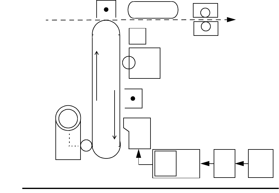
Figure 1-1. Cycle of Operation
Toner
Photoconductor
Developer Unit
LED Printhead
Charge Corona
Cleaner
Vacuum Transport Fuser Unit
Erase Lamp
Transfer Corona
Paper Input Paper
Output
3
4
5
6
9
8
7
Bitmap
RAM
2
IGS SI
1Host

Paper Path and Cycle Sequence
June 1999 Printer and Troubleshooting Overview 1-5
Paper Path and Cycle Sequence
The IGS board signals the PCL board that a page of data is ready to be printed. When this
happens the following sequence takes place.
Simplex Printing
1PCL software downloaded to the PCL board from the disk drive system turns on the
main motor.
2The PCL board engages the paper pick clutch which causes the roller to feed a sheet of
paper.
3The paper is passed to the feed roller where the PCL board has engaged the feed roller
clutch.
4The feed roller passes the paper to the paper timing roller. Prior to reaching the paper
timing roller, the paper passes over the paper timing sensor. (If the paper does not
energize this sensor in a specified amount of time, an error 020/021 will occur.) The
leading edge of the paper is registered against the paper timing roller. The paper tim-
ing clutch is engaged and the paper is passed over the photoconductor for transfer.
This registers the paper to the printer and the image to the paper. The paper timing
sensor signal also alerts the PCL to inform the IGS that it can begin to send the data.
5The PCL board engages the paper timing roller clutch and, at the same time, turns on
the transfer corona to provide a high positive voltage. The developed image on the
photoconductor comes in contact with the paper and the high positive voltage causes
the image to transfer to the paper.
6Because the toner is not yet fixed to the paper, a vacuum transport assembly, gripping
the paper from the back side, moves the paper to the fuser unit, where heat and pres-
sure bond the toner to the paper.
7Upon leaving the fuser unit, the paper comes in contact with the paper exit sensor. (If
the paper does not energize this sensor in a given amount of time after leaving the
paper timing sensor [step 4], an error 022 will occur.)
8The exit roller moves the paper to the exit tray. (If the exit sensor is not cleared in a
specified amount of time, an error 023 will occur.)
Duplex Printing
When duplex is selected, the PCL board controls the paper motion with page scheduling
assistance from the IGS board. The duplex page router is engaged. When in duplex mode,
it is important to note that the printer runs multiple pages through the paper path at the
same time to increase speed. (See Figure 1-2, “Paper Path,” on page 1-6.)
1In a duplex job, the duplex router solenoid behind the fuser is engaged and mechanical
fingers route the paper to the duplex area. Also, the “A” roller clutch engages to turn
the “A” and “B” rollers (connected via a belt).
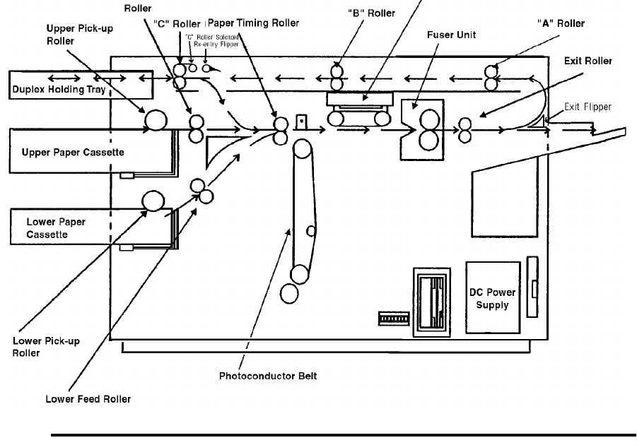
Paper Path and Cycle Sequence
1-6 Printer and Troubleshooting Overview June 1999
2The paper upon passing through the “B” roller comes in contact with the duplex sen-
sor. (If the paper does not energize this sensor in a given amount of time, an error 060
will occur.)
3The “C” roller bidirectional motor turns on and passes the paper into the turnaround
tray. The paper sensor in the turnaround tray is activated and the paper is center regis-
tered. (If the paper does not energize this sensor in a given amount of time after leav-
ing the duplex sensor, an error 061 will occur.)
4At this time the solenoid for the router at the turnaround tray engages so the paper can
be routed to be printed on the duplex side.
5In a given amount of time after the paper energizes the paper sensor in the turnaround
tray, the bi-directional motor reverses and passes the paper to the paper timing roller.
(If the paper does not energize the paper timing sensor in a given amount of time after
leaving the turnaround sensor, an error 062 will occur.)
6At this point, the same steps happen as during a simplex cycle.
Figure 1-2. Paper Path

Error Code Technical Definitions
June 1999 Printer and Troubleshooting Overview 1-7
Error Code Technical Definitions
The following table lists the printer error codes and their descriptions.
Table 1-1. Error Code Technical Definitions
Type Error Description
Cassette Errors
010, E10 PCL board detected no signal from upper paper cassette empty
sensor indicating no paper present
011 PCL board detected no signal from lower paper cassette empty
sensor indicating no paper present
012, E12 PCL board detected no signal from upper cassette in switch
013 PCL board detected no signal from lower cassette in switch
Paper Jams in the Primary Paper Path
020 PCL board detected that the paper being fed from the upper cas-
sette did not reach the timing paper sensor within the allotted time
021 PCL board detected that the paper being fed from the lower cas-
sette did not reach the timing paper sensor within the allotted time
022 PCL board detected that the exit paper sensor did not activate or
the timing sensor did not deactivate within the allotted time
023 PCL board detected that either:
1. The exit paper sensor (within the printer) became activated but
did not deactivate within the specified time.
2. (HCO only). The paper exit sensor (within the HCO) did not
become activated or deactivated within the allotted time
025 PCL board detected that the timing paper sensor was activated
immediately after one of the covers was closed
026 PCL board detected that either the exit paper sensor (within the
printer) or the paper exit sensor (within the HCO) was activated
immediately after one of the covers was closed
027 PCL board detected paper in the duplex area after clearing a jam
Toner Control Errors
030 PCL board detected a signal from the high-voltage power supply
unit indicating an abnormal load on the bias voltage to either the
developer unit, cleaner unit, or printhead-cleaning bias plates.
031 PCL board detected a signal from the toner patch sensor board
indicating that the reference voltage level on the photoconductor
was too low.
032 PCL board detected a signal from the toner patch sensor board
indicating that the toner patch on the photoconductor was too light.
035 PCL board detected too many successive signals from the toner
patch sensor board for a toner feed.
036 PCL board detected no developer unit electrical interlock signal
from the J25 connector.

Error Code Technical Definitions
1-8 Printer and Troubleshooting Overview June 1999
OPC Rotation Errors
040 PCL board sensed that the signal from the photoconductor seam
sensor either was not of sufficient amplitude or did not show the
proper timing.
041 PCL board detected an abnormally high amount of current needed
to drive the photoconductor seam sensor LED (within the photo-
conductor unit).
042 PCL board detected an open connection to the photoconductor
seam sensor LED (within the photoconductor unit).
044 PCL board detected a signal from the high-voltage power supply
unit indicating that either the charge corona or transfer corona cir-
cuits have an open connection.
045 PCL board detected a signal from the high-voltage power supply
unit indicating an abnormally high load on the bias voltage to the
charge corona.
046 PCL board detected a signal from the high-voltage power supply
unit indicating an open connection in the charge corona circuit
(diagnostic test only).
HVPS Errors
050 PCL board detected a signal from the high-voltage power supply
unit indicating an abnormally high load on the bias voltage to the
transfer corona.
051 PCL board detected a signal from the high-voltage power supply
unit indicating an open connection in the transfer corona circuit
(diagnostic test only).
055 PCL board detected that the current needed to drive the erase
lamp assembly was either higher or lower than the specified limits.
Duplex Jams
060 PCL board detected that the exit paper sensor did not deactivate
or the paper path sensor did not activate within the allotted time.
061 PCL board detected that the duplex paper path sensor did not
deactivate, the turnaround tray sensor did not activate in the allot-
ted time, or the duplex paper path sensor activated at POR.
062 PCL board detected that paper leaving the duplex turnaround tray
did not reach the timing sensor within the allotted time or the
duplex turnaround sensor was activated at POR.
Fuser Control Errors
070 PCL board sensed, via the fuser thermistor, that the temperature of
the fuser unit did not change within the allotted time.
071 PCL board sensed an open connection in the fuser thermistor cir-
cuit
072 PCL board sensed that the resistance of the fuser thermistor was
too low indicating that the temperature of the fuser unit was higher
than the specified limit.
073 PCL board sensed that the resistance of the fuser thermistor was
too high indicating that the temperature of the fuser unit was lower
than the specified limit.
Table 1-1. Error Code Technical Definitions (Continued)
Type Error Description

Error Code Technical Definitions
June 1999 Printer and Troubleshooting Overview 1-9
Jogger Errors
081 PCL board activated the jogging motor but did not detect a change
in the signal from the front sensor in the job offset assembly (diag-
nostic test only).
082 PCL board activated the jogging motor but did not detect a change
in the signal from the rear sensor in the job offset assembly (diag-
nostic test only).
083 PCL board activated the jogging motor but did not detect a change
in the signal from either the front or rear sensors in the job offset
assembly.
084 PCL board detected a signal from the duplex control board #2 indi-
cating that the registration side sensor did not activate after com-
mand was sent to the duplex control board #2 to turn on the resist
motor (diagnostic test only).
085 PCL board detected a signal from the duplex control board #2 indi-
cating that the registration side sensor did not deactivate after a
command was sent to the duplex control board #2 to turn on the
resist motor (diagnostic test only).
086 PCL board detected a signal from the duplex control board #2 indi-
cating that either the registration side sensor was activated and
would not deactivate or was deactivated and would not activate
after a command was sent to the duplex control board #2 to turn on
the resist motor.
LVPS Errors
090 PCL board detected that one of the cover interlocks was not acti-
vated (diagnostic test only).
097 PCL board detected a signal from the IGS board indicating the
absence of +12 Vdc.
098 PCL board detected a signal from the IGS board indicating the
absence of ‚-12 Vdc.
099 PCL board detected a signal from the IGS board indicating the
absence of +24 Vdc.
Controller Errors
100, 102 IGS board detected a failure of the PCL board status codes.
101 PCL board detected that the IGS board was in a halt state (diag-
nostic test only).
121-127 PCL board detected an error in the communication between the
PCL board and the IGS board.
130-134 PCL board detected an error during the internal diagnostic testing
of the PCL board.
140 PCL board detected an error during the internal diagnostic testing
of the PCL board.
145 PCL board detected an error during the internal diagnostic testing
of the PCL board.
160-182 PCL board detected an error during the internal diagnostic testing
of the PCL board.
199-215 PCL board detected an error in the communication between the
PCL board and the IGS board.
301-401 IGS board detected an error during the internal diagnostic testing
of the IGS board.
Table 1-1. Error Code Technical Definitions (Continued)
Type Error Description

Error Code Technical Definitions
1-10 Printer and Troubleshooting Overview June 1999
DD Errors
405-409 IGS board detected an error in the program RAM during the inter-
nal diagnostic testing of the IGS board.
450-566 IGS board detected an error during the internal diagnostic testing
of the IGS board and software.
Controller
Errors
570-586 IGS board detected an error when communicating with the floppy
disk drive.
600-610 IGS board detected an error during the internal diagnostic testing
of the IGS board.
Communication
Errors
701-703 IGS board detected an error when communicating with a host
using RS232 communications.
770-784 IGS board detected an error when communicating with a host
using RS422 communications.
888 IGS board detected that the PCL board was in a halt or reset state.
Table 1-1. Error Code Technical Definitions (Continued)
Type Error Description
Sensor and Switch Locations
June 1999 Printer and Troubleshooting Overview 1-11
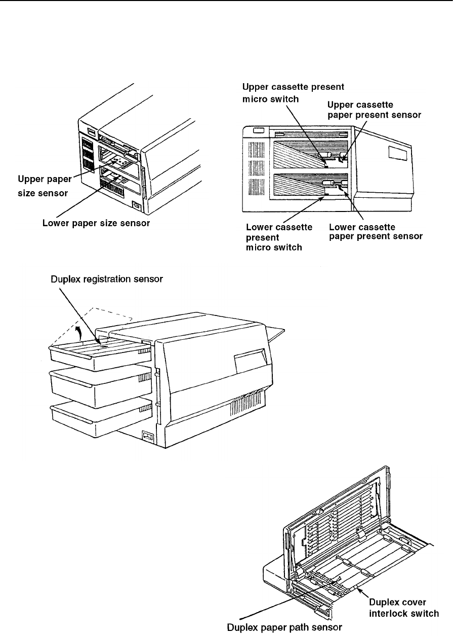
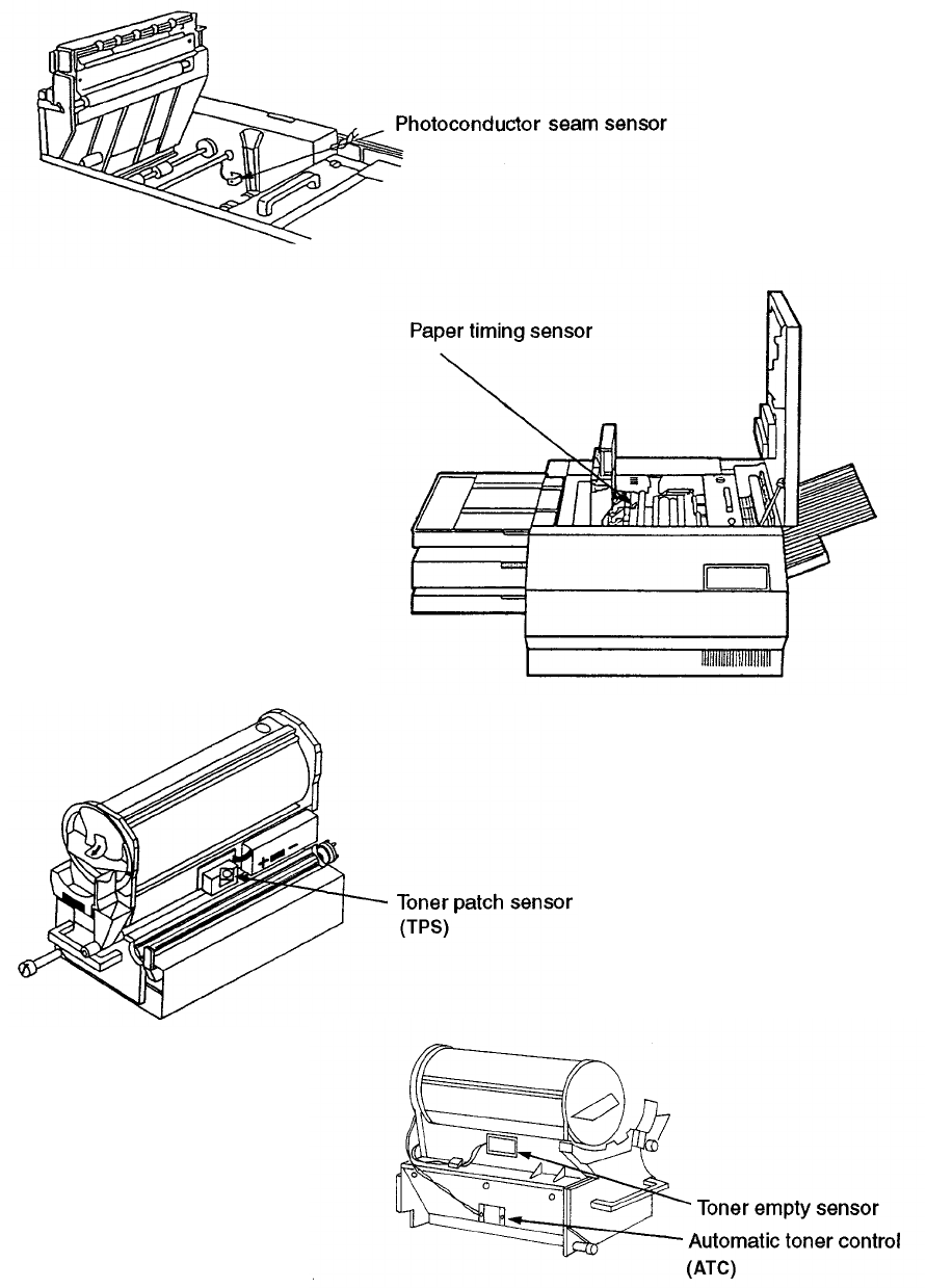
Sensor and Switch Locations
The following pages illustrate the locations of the printer’s sensors and switches. Table 1-
2, “Sensor and Switch List,” on page 1-14, lists them.
Left end view
Left end view
Front left view
Top view, duplex
Sensor and Switch Locations
1-12 Printer and Troubleshooting Overview June 1999
Top view
Front view
Developer right view
Developer left view

Sensor and Switch Locations
June 1999 Printer and Troubleshooting Overview 1-13
Right side view
Top left, duplex tray view
Front view
Sensor and Switch Locations
1-14 Printer and Troubleshooting Overview June 1999
Table 1-2. Sensor and Switch List
Sensor/Switch Name Page No.
Automatic toner control sensor 1-12
Cassette paper present sensors, upper and lower 1-11
Cassette present micro switches, upper and lower 1-11
Duplex registration sensor 1-11
Duplex paper path sensor 1-11
Duplex cover interlock switch 1-11
Interlock switch, top 1-13
Interlock switch, front 1-13
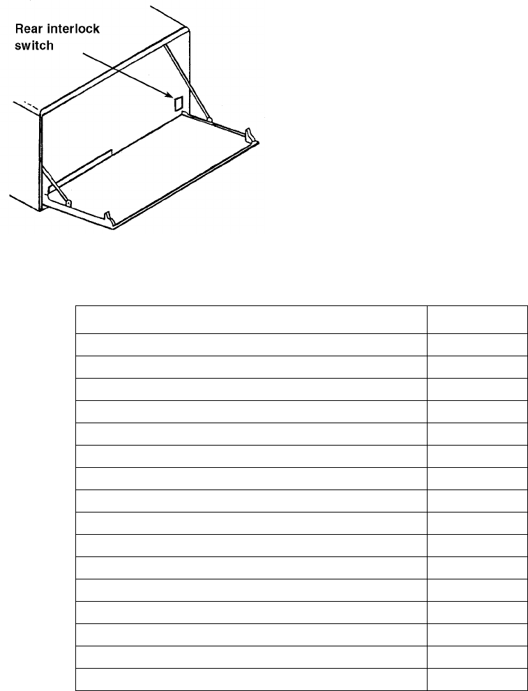
Interlock switch, rear 1-14
Paper exit sensor 1-13
Paper full sensor 1-13
Paper size sensors, upper and lower 1-11
Paper timing sensor 1-12
Photoconductor seam sensor 1-12
Toner empty sensor 1-12
Toner patch sensor 1-12
Rear view

Troubleshooting Overview
June 1999 Printer and Troubleshooting Overview 1-15
Troubleshooting Overview
Throughout the printer’s life problems occur, such as those indicated when an error code
displays on the operator panel, a printer produces poor quality prints, or the printer mal-
functions. Use the tools provided in this manual to diagnose and resolve printer problems.
These tools include:
•The Troubleshooting Analysis Guide, which contains troubleshooting procedures
called TAGs. TAG 001: Troubleshooting A Printer Problem provides an overview of
how to use TAGs.
•Cross reference tables, which link error codes, print quality problems, and mechanical
malfunctions to specific TAGs.
•Print quality samples, which you can use to identify a printing problem and its associ-
ated TAGs.
•Diagnostics, through which the printer checks itself for a range of problems.
The next several pages review troubleshooting basics and standard procedures followed in
every troubleshooting session, including:
•Identifying whether a problem belongs to the printer or host
•Isolating protocol converter problems
•Running test prints
•Reading the error log
•Confirming line power
•Using TAGs
•Power-On Reset
•Installing the interlock by-pass tool
•Checking continuity
•Producing a developed image
•Producing a toner patch
•Completing a service call
•Clearing the error log
General Troubleshooting Tips
When a printer problem arises, swapping out all printer supplies may temporarily mask
the problem. This is an unsatisfactory, short-term, and expensive solution to correcting the
problem. Dust and other contamination, rather than printer supplies, are more often the
causes of problems. Clean consumable connectors, alignment guides, and areas before
changing consumables.
Many failures add excess toner to the printer’s engine. When you are advised to de-tone
the printer as part of a problem fix, run at least 200 test prints before evaluating whether
the problem has been resolved.
Troubleshooting Overview
1-16 Printer and Troubleshooting Overview June 1999
The Problem: Printer or Host?
The printer is one component in a large host system. Before you start any troubleshooting,
make sure that the problem really belongs to the printer rather than to some other compo-
nent in the host system. Print quality problems and mechanical malfunctions are almost
always associated with the printer. However, host interface and software emulation prob-
lems can be caused by some other component of the host system even though, at first Z
glance, they appear to be printer problems. For instance, text printed in the wrong location
on a page, improper page breaks, and missing segments of data strongly indicate a host,
not a printer, problem.
The first step in troubleshooting any problem is to isolate the printer from the host system;
you can then run test prints. Producing test prints exercises the printer as a stand-alone
ones machine, ensuring that the basic printer software and all mechanical functions of the
printer are working.
Running Test Prints
To run test prints:
1Disconnect the host interface.
2Run a series of test prints. A directory of the boot device and multiple listings of fonts
print, followed by an unformatted and formatted error log. A continuous flow of the
test pattern then prints. To run test prints:
•For simplex printers, press:
STOP
TEST
•For duplex printers, press:
STOP
DUPLEX
TEST
•To stop printing the test pattern, press:
STOP
On pressing STOP, the printer will print all test prints stored in the printer’s buffer, then
stop.
If the test pattern prints successfully, the problem probably originates with the host system
or a protocol converter connected to the host.
Troubleshooting Overview
June 1999 Printer and Troubleshooting Overview 1-17
Protocol Converters
Many protocol converters have a self-test function or configuration mode that enables the
user to check the proper functioning of the control. You can reconnect the host interface
and ask the customer to exercise this function of the converter. If the printer receives data
and prints it (even if the output is garbled) you have isolated the problem as one that
belongs to the host or the protocol converter. The problem is not a printer problem and the
customer must seek assistance elsewhere in resolving the problem.
Reading the Error Log
One of the sheets printed prior to the test pattern is the formatted error log maintained by
the printer in a file named ERROR.LOG.
•The first line of the formatted log lists paper jams. A 3-digit error code (or codes) is
followed by a 4-digit number indicating how many times the error has occurred since
the error log was last cleared. (See “Clearing the Error Log” on page 1-24.)
•The second line lists the last 15 errors.
•The last line indicates the last error that required a power-on-reset (POR).
Figure 1-3. Sample Simplex Printer Error Log
020 0001 021 0000 022 0001
023 020 020 022 022 022 022 071 042 000 000 000 000 000 000
000
Paper Jams
Last 15 errors
Last error requiring POR (not used)

Troubleshooting Overview
1-18 Printer and Troubleshooting Overview June 1999
Confirming Line Power
Erratic printer problems can be caused by improper line power. As a rule, the voltage of
the outlet should be checked at installation. However, if you are unable to isolate an inter-
mittent problem, the power should be checked again. Consult your country’s national elec-
tric code for the proper procedures to check for acceptable voltages, as shown in Table 1-
3, “Acceptable Voltages”.
Please see Chapter 5, “Diagnostic Tests” for additional information about running diag-
nostic printer tests.
Please see Chapter 6, “Wiring Diagrams and Electrical Data” for additional information
about the printer’s electrical systems.
Table 1-3. Acceptable Voltages
Probe connections 100-127v printer 200-240v printer
red to AC hot
black to AC neutral 120v +/- 10% 230v +/- 10%
red to AC neutral
black to ground 3 vac or less 3 vac or less
red to AC hot
black to ground 120v +/- 10% 230v +/- 10%

Using the Troubleshooting Analysis Guide (TAG)
June 1999 Printer and Troubleshooting Overview 1-19
Using the Troubleshooting Analysis Guide (TAG)
The Troubleshooting Analysis Guide provides problem-solving sequences to help you
identify and resolve printer problems. Each TAG addresses a particular symptom or error
code of the printer. The TAG number often matches an error code displayed on the
printer’s operator panel.
Sample TAG
TAG 001: Troubleshooting a Problem
Error Code: All related error messages are listed here.
Possible Causes: All possible causes are listed here.
Possible Defects: All possible defective parts are listed here. (In no particular order.)
1
To start:
•Disconnect all peripheral cables
•Power-on-reset the printer.
Did all of the status lights come on, followed by 888 flashing briefly and an error code?
Yes: Run test prints, following the procedure outlined in Section 1, then repeat this step. If the
answer is still no, refer to the mechanical malfunctions cross-reference chart in Section 2
to determine which TAG to follow. Then turn to that TAG.
Yes: Note the error message and continue.
2
Power-on-reset the printer.
Did the power-on-reset end with an error code?
No: Continue.
Yes: Refer to the error code cross-reference table in Section 2, using either the code that dis-
played after steps 1 and 2, or if multiple error codes continue to appear, the first error
code that displays. Turn to the TAG associated with the code.
3
Did only the READY light come on with no numeric display?
No: Continue
Yes: Go to TAG 753
Each TAG walks through a comprehensive procedure specific to a single problem. As you
progress through a TAG and eliminate possible causes, you may be directed to another
step out of sequence in the same TAG or to another TAG altogether.
The TAG number and its title may be followed by a listing of possible error messages,
possible causes, or possible defective parts related to the TAG.
Using the Troubleshooting Analysis Guide (TAG)
1-20 Printer and Troubleshooting Overview June 1999
The TAG then directs you to perform certain tasks. Based on the results of these tasks, the
TAG poses questions that can be answered by either yes or no. For yes answers, you fol-
low one path; for no answers, follow another path. Some of the paths may lead you to
other TAGs, so that you can methodically diagnose and resolve problems. When you have
corrected a problem, you will be directed to TAG 002 to confirm that the problem has been
completely resolved and standard cleanup procedures observed.
If it’s not clear how to diagnose a problem you’re working on, follow the steps outlined in
TAG 001, which includes references to the cross reference tables contained in Chapter 2,
“”. Or, you may turn directly to the tables to get started.
As you use TAGs, you will sometimes refer to other sections of this manual for additional
information:
•Chapter 4, “Print Quality Samples” contains print quality samples you’ll use to com-
pare the customer’s test prints with flawed and good print samples.
•Chapter 5, “Diagnostic Tests” outlines how to conduct printer diagnostic tests.
•Chapter 6, “Wiring Diagrams and Electrical Data” provides all wiring and connector
diagrams.
•Chapter 7, “Removal/Replacement Procedures” provides step-by-step procedures for
removing and replacing all field-replaceable parts on the printer.
•Chapter 8, “Options” reviews printer options (HCI, HCO) information.
•Chapter 9, “General Printer Maintenance” presents general printer maintenance proce-
dures.

Standard Procedures
June 1999 Printer and Troubleshooting Overview 1-21
Standard Procedures
While using the TAGs, you may be asked to perform some of the following procedures.
Specific instructions for completing these procedures are included here, rather than
repeated in the body of each TAG. Please read this information before following any TAG.
Power-on-reset (POR)
When directed to power-on-reset the printer:
1Turn off the printer.
2Wait at least 5 seconds.
3Turn the power back on.
Checking Continuity
To perform a continuity check:
1Turn off the printer and disconnect the power cord.
2Set your meter to the lowest ohm setting.
3Interpret the results as follows:
•An infinite reading indicates an open circuit.
•A zero or specific reading indicates continuity.
4To check an open or short circuit to ground:
•Turn off the printer and disconnect the power cord.
•Locate the circuit in question. (Refer to Chapter 6, “Wiring Diagrams and Electri-
cal Data”, for circuit locations.)
•Check all connectors and wiring on each side for corrosion, foreign objects, bent
pins, loose socket housings, and/or loose wires.
Make sure the printer is turned off and the power disconnected.
or both.
Failure to do so may result in personal injury, equipment damage,
Warning
The printer is equipped with safety interlock switches on all of
covers are opened. These areas present the risk of electrical
its covers. These switches disable parts of the printer when the
Warning
shock, burns, and injury from mechanical hazards.

Standard Procedures
1-22 Printer and Troubleshooting Overview June 1999
Installing the Interlock By-pass Tool
The interlock by-pass tool overrides the cover interlock switches, allowing you to operate
the printer with the covers open. The interlock by-pass tool is a white plastic, “V”-shaped
tool with two finger pads. To use the tool, open the cover and locate the interlock switch
(for locations, see illustrations beginning page 1-11). Squeeze the tool between thumb and
fore finger and insert it into the interlock switch.
The printer ships with two spare interlock by-pass tools concealed behind the right cover.
Replace them when you are finished using them.
Producing a Developed Image
Producing a developed image helps determine where exactly in the print cycle a problem
may be occurring. To produce a developed image:
1Open the top cover and install an interlock by-pass tool.
2Power-on-reset the printer.
3Run a series of test prints. The directory of the boot device will print, followed by con-
tinuous test patterns.
4As test patterns print, observe paper moving from the upper paper tray to the paper
timing roller where it pauses briefly.
5When a sheet of paper begins to move from the paper timing roller, turn off the printer.
6Remove the photoconductor unit.
7Examine the photoconductor belt to verify that a developed image was produced.
Producing a Toner Patch
To produce a toner patch:
1Turn off the printer.
2Open the top cover and install an interlock by-pass tool.
3Turn on the printer.
4Start running test prints using Simplex Print mode. When the leading edge of the first
print enters the fuser unit, remove the interlock by-pass tool.
Do not attempt to close the printer cover while the interlock
bypass tool is in place.
Caution
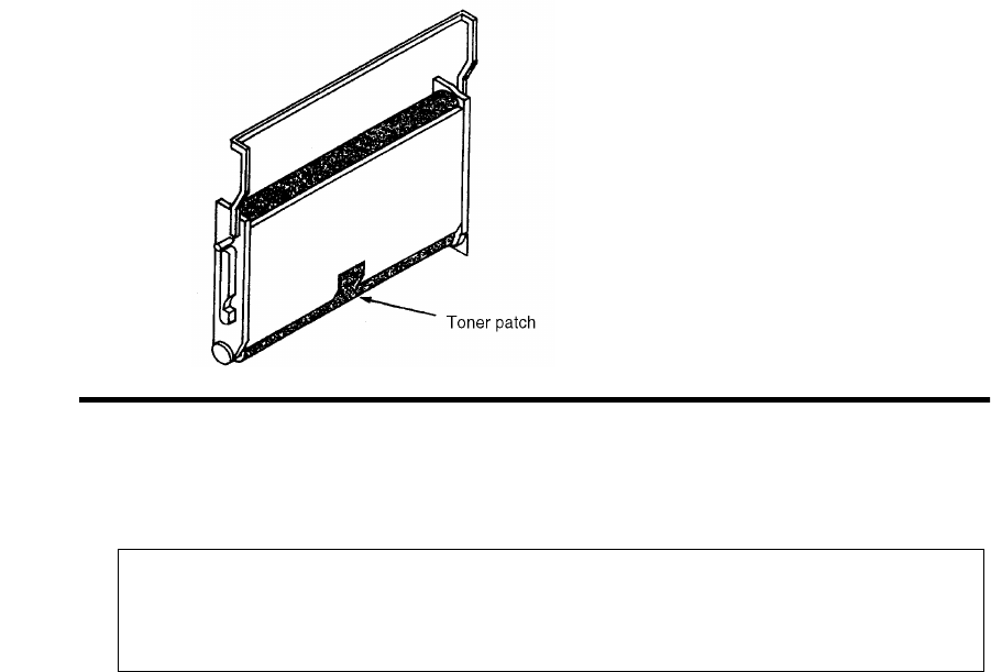
Standard Procedures
June 1999 Printer and Troubleshooting Overview 1-23
5Remove the photoconductor unit.
Figure 1-4. Producing a Toner Patch on the Photoconductor Unit
6Examine the photoconductor unit to verify that a toner patch has been produced. You
may have to rotate the belt slightly to observe the patch.
Completing a Service Call
After resolving any printer problem, complete the service call as follows:
1Reassemble the printer.
2Perform the every-call cleaning procedure, described in Chapter 9, “General Printer
Maintenance”.
3If you have removed the printer’s diskette(s), reinstall them.
4Power-on-reset the printer.
5Clear the error log. (See the procedure described next.)
6Run test prints in both the simplex and duplex mode from both the upper and lower
paper cassettes.
7Fill in the Repair/Maintenance log. Make sure the problem description and steps taken
to resolve the problem are clearly documented.
Do not touch the surface of the photoconductor belt; this
damages the belt and results in poor print quality.
Caution

Standard Procedures
1-24 Printer and Troubleshooting Overview June 1999
Clearing the Error Log
1Enter the diagnostic mode of the printer:
•Turn off the printer and wait 5 seconds.
•Hold down the STOP and TEST keys simultaneously as you turn the printer back
on.
•The tone, followed by “00” on the display, indicates you are in the test mode. This
takes approximately 1 minute.
2Press: CANCEL to advance the counter to “110.”
3Press READY to activate the procedure. “0” appears on the display, indicating the A:
drive.
4Press: CANCEL to advance to the drive where the error log is maintained. This is usu-
ally the boot drive.
5Press: READY to select the drive specified. “1-0” appears on the display.
6Press: READY to select the clear error log function. “6-0” appears on the display.
7Press: CANCEL to clear the error log. “6-1” appears on the display.
8Press: STOP to exit the procedure.
9Cycle printer power to exit diagnostic mode.
10 Confirm that the error log has been cleared. When you run your test prints, check to
make sure the error log entries appear as “0000.”
Table 1-4. Drive Indication
Display Indication
0 Diskette drive A:
1 Diskette drive B:
2 Hard drive C:
At this point, be careful! “1-0” represents the clear error log
function. Do not advance the counter to “1-1,” which represents
Caution
the format disk option.
If “7-0” appears, press STOP immediately. DO NOT CONTINUE
WITH THIS PROCEDURE. POR the printer and start over.
Caution

June 1999 2-1
Chapter 2

2-2 June 1999
Chapter Contents
TAG Cross-Reference Tables
This section contains the three cross reference charts for troubleshooting print problems:
Error Code/TAG Cross-Reference Chart . . . . . . . . . . . . . . . . . . . . . . . . . . . . . . . . .2-3
Print Quality/TAG Cross-Reference Chart . . . . . . . . . . . . . . . . . . . . . . . . . . . . . .2-10
Mechanical Malfunction/TAG Cross-Reference Chart . . . . . . . . . . . . . . . . . . . . .2-12

Error Code/TAG Cross-Reference
June 1999 2-3
Error Code/TAG Cross-Reference
Error codes, which appear on the 3-digit display of the operator’s panel, indicate a wide
variety of printer problems related to the control boards, software, and/or host communi-
cation problems. On the chart find the error code in question, then turn to TAG associated
with the code.
Table 2-1. Printer Error Codes
Code Printer Error Code Meaning Go to TAG
010 Upper paper tray out of paper 010
011 Lower paper tray out of paper 011
E10 Envelope feeder out of envelopes E10
012 Upper paper tray not plugged in 012
013 Lower paper tray not plugged in 013
E12 Envelope feeder not plugged in E12
020 Upper paper tray paper jam 020
021 Lower paper tray paper jam 021
022 Transfer or fuser area paper jam 022
023 Exit area paper jam 023
025 Transfer or fuser area paper jam not cleared 025
026 Exit area paper jam not cleared 026
027 Duplex area paper jam 902
030 Developer bias short 030
031 Toner patch sensor reference level too low 031
032 Toner patch sensor black patch too light 032
035 No toner 035
036 No developer 036
040 Photoconductor seam sensor malfunction 040
041 Photoconductor seam sensor short 040
042 Photoconductor seam sensor open 040
044 Charge corona open 044
045 Charge corona short 045
046 Charge corona open 044
050 Transfer corona short 050
055 Eraser lamp malfunction 055
057 Fan stopped sensor 752
060 Duplex area 1 paper jam 902
061 Duplex area 2 paper jam 902
062 Duplex area 3 paper jam 902
069 Duplex tray not plugged in 900

Error Code/TAG Cross-Reference
2-4 June 1999
070 Fuser lamp or thermal fuse malfunction 070
071 Fuser thermistor open or no fuser 071
072 Fuser temperature too high 072
073 Fuser temperature too low 070
081 No front job offset sensor 083
082 No back job offset sensor 083
083 Job offset mechanism malfunction 083
084 Duplex tray registration sensor not activated 901
085 Duplex tray registration sensor not deactivated 901
086 Duplex registration tray malfunction 901
090 Cover open 900
097 DC +12v power failure 097
098 DC -12v power failure 098
099 DC +24v power failure 099
100 PCL board command timeou 100
101 IGS controller diagnostic failure 101
Table 2-2. PCL/IGS Communication Error Codes
Code PCL/IGS Communication Error Code Meaning Go to TAG
121 No controller command; PCL board VSC command asserted 201
122 Command tag asserted; VSC command not asserted 201
123 VSS not asserted; PCL board status tag asserted 201
124 VSS asserted after PCL board sent status 201
125 VSS not asserted again though PCL board expects it 201
126 Command tag asserted during data byte sequence 201
127 PCL board detected parity/overrun on command line 201
Table 2-3. PCL Error Codes
Code PCL Error Code Meaning Go to TAG
130 Address or length error at initial microcode load 130
131 Checksum error at initial microcode load 130
132 RAM error at initial microcode load 100
133 No next block at initial microcode load 130
134 Incorrect format in initial microcode load file 130
140 PCL board ROM checksum error at power on diagnostic 100
Table 2-1. Printer Error Codes (Continued)
Code Printer Error Code Meaning Go to TAG

Error Code/TAG Cross-Reference
June 1999 2-5
145 PCL board RAM error at power on diagnostic 100
160 PCL board PIA1 register error after reset 100
161 PCL board PIA1 registers read/write error 100
162 PCL board PIA1 PA or PB read/write error 100
170 PCL board PIA2 register error after reset 100
171 PCL board PIA2 register read/write error 100
172 PCL board PIA2 PB read/write error 100
180 PCL board PTM register error after reset 100
181 PCL board PTM read/write error 100
182 No IRQ generation on PTM 100
Table 2-4. PCL/IGS Communication Error Codes
Code PCL/IGS Communication Error Code Meaning Go to TAG
199 VSS not asserted before communication test 201
200 Status tag not asserted 201
201 Timeout waiting for a failed IGS controller 201
202 No data received after VSS line asserted 201
203 VSS asserted after PCL board sent status 201
204 Status tag asserted after VSS not asserted 201
205 No command tag after status tag not asserted 201
206 VSC command not asserted after command tag asserted 201
207 No data received after VSC asserted 201
208 VSC command asserted after command line asserted 201
209 Command tag asserted after VSC not asserted 201
210 No RQI after “request RQI” command 201
211 Parity error on command line 201
212 Parity or overrun sensed by PCL board 201
213 Incorrect command received from PCL board 201
214 Incorrect command received from IGS controller 201
215 No transfer buffer empty on asynchronous communications
interface adapter after PCL board sent data 201
Table 2-3. PCL Error Codes (Continued)
Code PCL Error Code Meaning Go to TAG

Error Code/TAG Cross-Reference
2-6 June 1999
Table 2-5. IGS Firmware Error Codes
Code
IGS Firmware Error Code Meaning
These error codes signal a problem with the IGS controller
firmware. No TAGs address these problems; report them to the
printer’s manufacturer.
Go to TAG
301 Status received after VSS asserted No TAG
302 Status tag asserted after VSS not asserted No TAG
303 VSC command not asserted after command tag asserted No TAG
304 VSC command asserted after data was sent No TAG
305 VSC command not asserted for next data byte No TAG
306 Status tag asserted while data was being sent No TAG
307 Parity error on command line No TAG
Table 2-6. PCL Failure Error Codes
Code PCL Failure Error Code Meaning Go to TAG
380 PCL board failure - command retries 201
381 PCL board failure - command rejected 201
382 PCL board failure - bad command received 201
383 PCL board failure - unexpected byte received 201
384 PCL board failure - no status received 201
385 PCL board failure - bad status information block count 201
386 PCL board failure - bad status information block offset 201
387 PCL board failure - parity error 201
389 Floppy disk retry 130
Table 2-7. IGS Software Error Codes
Code
IGS Software Error Code Meaning
These error codes signal a problem with the IGS controller
software. No TAGs address these problems; to determine
whether the faulty software is the customer’s or the
manufacturer’s, contact the printer’s manufacturer.
Go to TAG
397 IGS software trap No TAG
398 IGS software trap No TAG
399 IGS software trap No TAG

Error Code/TAG Cross-Reference
June 1999 2-7
Table 2-8. IGS/Disk Drive Error Codes
Code Disk Drive Error Code Meaning Go to TAG
401 Fatal IGS PB error No TAG
450 Incorrect diskette 130
451 Diskette format error or incorrect disk 130
454 Fatal trap 200
455 Trap 200
500 Incorrect PIT0 registers contents; no reset 200
501 PIT0 register read/write error 200
502 No countdown/zero detection in PIT0 timer 200
503 PIT0 timer; no halt 200
504 No PIT0 timer interrupt 200
505 Incorrect PIT2 registers contents; no reset 200
506 PIT2 register read/write error 200
507 No countdown/zero detection in PIT2 timer 200
508 PIT2 timer; no halt 200
509 No PIT2/timer interrupt 200
520 No DMAC reset 200
521 DMAC registers read/write error 200
522 No DMA transfer 200
523 No DMA transfer termination 200
524 No DMAC termination interrupt 200
525 No software abort operation 200
526 No software abort interrupt 200
527 DMAC operation error 200
528 DMA transfer error 200
529 Two-channel DMA transfer error 200
530 No two-channel DMA transfer 200
540 PCL board serial controller registers read/write error 200
541 PCL board break condition detected 200
542 PCL board serial controller transmitter not ready 200
543 No PCL board serial controller transfer 200
544 PCL board serial controller transfer error 200
545 Host serial controller registers read/write error 200
546 Host transmitter not ready 200
547 No serial controller interrupts 200
548 Host serial controller/PCL board parity error 200
549 Serial controller unexpected interrupt 200
550 Two-channel transfer error 200
551 No PCL board/serial controller interrupt on break 200

Error Code/TAG Cross-Reference
2-8 June 1999
552 No serial controller/DMAC interaction 200
553 Serial controller/DMAC transfer count error 200
554 Serial controller/DMAC transfer error 200
555 RS232 send/receive path error 200
556 RS232 DTR/DTC path error 200
557 RS232 RTS/CTS path error 200
558 RS422 send/receive path error 200
559 RS422 send clock/receive clock path error 200
560 CRTC register read/write error 200
561 No page begin (PIT2) interrupt 200
562 No CRTC address generation 200
563 No VSYNC generation (end of page) 200
564 No end of page (PIT2) interrupt 200
565 No CRTC count termination 200
566 VSYNC timeout error 200
570 Drive controller/SCSI read/write error 200
571 Drive controller busy timeout 200
572 Diskette is write protected 130
573 Drive not ready 130
574 Drive controller restore error 130
575 Drive controller seek error 130
576 Drive controller read sector error 130
577 Drive controller read sector data/checksum error 200
578 Drive controller write sector error 200
579 Drive controller read/modify/write error 200
580 No drive controller/PIT0 interrupt 200
581 No drive controller-DMA interaction 200
582 Drive controller/DMAC transfer error 200
583 Drive controller/DMAC transfer count error 200
584 Drive controller/DMAC read sector error 200
585 Drive controller/DMAC write sector error 200
586 Drive hard error 130
Table 2-9. Bit Map RAM Error Codes
Code Bit Map RAM Error Code Meaning Go to TAG
600 Bit-map RAM data path error 200
Table 2-8. IGS/Disk Drive Error Codes (Continued)
Code Disk Drive Error Code Meaning Go to TAG

Error Code/TAG Cross-Reference
June 1999 2-9
601 Bit-map RAM bank selection error 200
602 Bit-map RAM refresh error 200
603 Bit-map RAM address path error 200
604 Incorrect ALU operation in bit-map RAM data path 200
605 Incorrect origin data modifications 200
606 Total bit-map RAM bank fault 405
610 Bit-map RAM chip error 405
Table 2-10. Host Communication Error Codes
Code Host Communication Error Code Meaning Go to TAG
701 No communication with host 753
702 Host communication protocol error 753
703 Host communication recoverable error 753
770-784 Ethernet communication error No TAG; con-
tact software
support
Table 2-9. Bit Map RAM Error Codes (Continued)
Code Bit Map RAM Error Code Meaning Go to TAG
Print Quality/TAG Cross-Reference
2-10 June 1999
Print Quality/TAG Cross-Reference
Poor quality prints are another indication of printer problems. Begin by running a set of
test prints. Then, compare the test prints to the samples located in Chapter 4, “Print Qual-
ity Samples”. The chart summarizes the possible print quality problems you may encoun-
ter and recommends a TAG to follow to address the problem.
Table 2-11. Blank Print TAGs
Blank Prints Go to TAG
Complete 800
Partial 800
With dark horizontal bands 800
Table 2-12. Light Print TAGs
Light Prints Go to TAG
With carrier particles 801
With background 811
With voids/white spots 802
With light vertical streaks 803
With blank or white vertical lines 803
With light horizontal bands 804
Table 2-13. Dark Print TAGs
Dark Prints Go to TAG
Dark black prints 805
With dark spots or scratches 806
With dark blotches 810
With dark vertical streaks (without fusing) 812
With dark vertical streaks (with fusing) 808
Table 2-14. Skewed Path TAGs
Skewed Prints Go to TAG
Simplex 807
Duplex 901

Print Quality/TAG Cross-Reference
June 1999 2-11
Table 2-15. Misregistration TAGs
Misregistered Prints Go to TAG
Simplex 807
Duplex 901
Table 2-16. Smeared, Blurred, and Uneven Print TAGs
Smeared, Blurred, Uneven Prints Go to TAG
Smeared vertical streaks 809
Blurred prints 809
Uneven density 810
Prints with background 811
Prints with background and residual images 811
Prints with residual images 813
Prints with offset images 814
Table 2-17. Additional Print Quality Problem TAGs
Additional Print Quality Problems Go to TAG
Wrinkled or torn prints 706
Prints improperly fused 812
Prints exhibiting printhead problems 815
Mechanical Malfunction/TAG Cross-Reference
2-12 June 1999
Mechanical Malfunction/TAG Cross-Reference
The chart below outlines possible mechanical malfunctions and recommends an appropri-
ate TAG to follow to resolve the problem.
Table 2-18. Operator Panel Problems TAGs
Operator Panel Problems Go to TAG
Blank with AC power fan and cooling fan on 500
Blank with AC power fan on 500
Blank with no fans on 600
All lights on 610
Incomplete display immediately after POR 610
Close cover light remains on 600
Remove prints light remains on or lights 700
Add toner light remains on 035
Machine check light is on with no numerical Display 201
One or more lights are off at POR 610
Tone not working 610
Incorrect paper size 702
Other operator panel malfunctions 610
Table 2-19. Output Tray Problem TAGs
Output Tray Problems Go to TAG
Sensor not sensing condition 701
Jogging incorrectly 083
Will not stop jogging 083
Job offset incorrect 083
Table 2-20. Cassette Problem TAGs
Cassette Problems Go to TAG
Upper cassette 703
Lower cassette 704

Mechanical Malfunction/TAG Cross-Reference
June 1999 2-13
Table 2-21. Paper Handling Problem TAGs
Paper Handling Problems Go to TAG
Multiple paper feed 705
Multiple sheet feeds and jams 705
Wrinkled or torn paper 706
Simplex: misregistration and paper skew 807
Duplex: misregistration and paper skew 901
Paper will not feed from upper cassette 012
Paper jam in duplex area 902
Upper paper guide not closing 707
Table 2-22. Counter Problem TAGs
Counter Problems Go to TAG
Supplies seem to have short life span 750
Incorrect counting 750
Table 2-23. Communication Problem TAGs
Communication Problems Go to TAG
Printer will produce test prints 753
Incorrect data being printed 753
Table 2-24. Additional Mechanical Malfunction TAGs
Additional Mechanical Malfunctions Go to TAG
Test prints won’t run after POR 130
Cooling fan not running 752
Vacuum transport unit fan not running 752
Circuit breaker trip 600
Main drive motor not turning off 751
Mechanical Malfunction/TAG Cross-Reference
2-14 June 1999

June 1999 Troubleshooting Analysis Guide (TAGs) 3-1
Chapter 3
Troubleshooting
Analysis Guide
(TAGs)

3-2 Troubleshooting Analysis Guide (TAGs) June 1999
Chapter Contents
Troubleshooting Analysis Guide (TAGs)
TAG 001: Troubleshooting a Problem . . . . . . . . . . . . . . . . . . . . . . . . . . . . . . . . . .3-5
TAG 002: Check &Problem Resolution. . . . . . . . . . . . . . . . . . . . . . . . . . . . . . . . . .3-8
TAG 010: Upper Cassette Malfunction . . . . . . . . . . . . . . . . . . . . . . . . . . . . . . . . .3-12
E10: Envelope Tray Out of Envelopes. . . . . . . . . . . . . . . . . . . . . . . . . . . . . . . . . .3-14
TAG 011: Lower Cassette Malfunction . . . . . . . . . . . . . . . . . . . . . . . . . . . . . . . . .3-16
TAG 012: Upper Cassette Not Latched . . . . . . . . . . . . . . . . . . . . . . . . . . . . . . . . .3-18
TAG E12: Envelope Tray or Feeder Not Latched . . . . . . . . . . . . . . . . . . . . . . . . .3-21
TAG 013: Lower Cassette Not Latched. . . . . . . . . . . . . . . . . . . . . . . . . . . . . . . . .3-24
TAG 020: Paper Jam/Misfeed in Upper Cassette Area . . . . . . . . . . . . . . . . . . . . .3-26
TAG 021: Paper Jam/Misfeed in /Lower Cassette Area . . . . . . . . . . . . . . . . . . . .3-30
TAG 022: Paper Jam in the Transfer or Fuser Area. . . . . . . . . . . . . . . . . . . . . . . .3-34
TAG 023: Paper Jam in the Output Area . . . . . . . . . . . . . . . . . . . . . . . . . . . . . . . .3-39
TAG 025: Paper in Input Area Before Printing . . . . . . . . . . . . . . . . . . . . . . . . . . .3-41
TAG 026: Paper in Output Area Before Printing. . . . . . . . . . . . . . . . . . . . . . . . . .3-43
TAG 030: Developer Bias Short/Failure . . . . . . . . . . . . . . . . . . . . . . . . . . . . . . . .3-44
TAG 031: Toner Patch Reference Level Too Low . . . . . . . . . . . . . . . . . . . . . . . .3-47
TAG 032: Toner Patch Too Light . . . . . . . . . . . . . . . . . . . . . . . . . . . . . . . . . . . . .3-49
TAG 035: Out of Toner or ADD TONER Indicator On . . . . . . . . . . . . . . . . . . . .3-51
TAG 036: =Developer Unit Not Installed . . . . . . . . . . . . . . . . . . . . . . . . . . . . . . .3-53
TAG 040: Photoconductor Seam Sensor Malfunction. . . . . . . . . . . . . . . . . . . . . .3-54
TAG 044: Charge Corona/Transfer Corona Circuit Open . . . . . . . . . . . . . . . . . . .3-58
TAG 045: Charge Corona Circuit Shorted. . . . . . . . . . . . . . . . . . . . . . . . . . . . . . .3-61
TAG 050: Transfer Corona Circuit Shorted. . . . . . . . . . . . . . . . . . . . . . . . . . . . . .3-63
TAG 055: Erase Lamp Malfunction. . . . . . . . . . . . . . . . . . . . . . . . . . . . . . . . . . . .3-65
TAG 070: Fuser Unit Malfunction. . . . . . . . . . . . . . . . . . . . . . . . . . . . . . . . . . . . .3-67
TAG 071: Open Fuser Thermistor . . . . . . . . . . . . . . . . . . . . . . . . . . . . . . . . . . . . .3-72
TAG 072: Fuser Unit Temperature Too High . . . . . . . . . . . . . . . . . . . . . . . . . . . .3-73
TAG 083: Job Offset Mechanism Malfunction . . . . . . . . . . . . . . . . . . . . . . . . . . .3-75
TAG 097: +12 Vdc Power Shorted or Sensing Problem . . . . . . . . . . . . . . . . . . . .3-79
TAG 098: -12 Vdc Power Shorted. . . . . . . . . . . . . . . . . . . . . . . . . . . . . . . . . . . . .3-90
TAG 099: +24 Vdc Power Shorted . . . . . . . . . . . . . . . . . . . . . . . . . . . . . . . . . . . .3-92
TAG 100: PCL Board Interface Malfunction. . . . . . . . . . . . . . . . . . . . . . . . . . . .3-102
TAG 101: IGS Controller Diagnostic Failure . . . . . . . . . . . . . . . . . . . . . . . . . . .3-103
June 1999 Troubleshooting Analysis Guide (TAGs) 3-3
TAG 130: Diskette/Disk Drive Malfunction . . . . . . . . . . . . . . . . . . . . . . . . . . . . 3-104
TAG 200: IGS Internal Communication Malfunction. . . . . . . . . . . . . . . . . . . . . 3-108
TAG 201: IGS-PPCL Interface Malfunction. . . . . . . . . . . . . . . . . . . . . . . . . . . . 3-110
TAG 405: IGS Bit-Map RAM Malfunction . . . . . . . . . . . . . . . . . . . . . . . . . . . . 3-112
TAG 500: +5 Vdc Power Malfunction . . . . . . . . . . . . . . . . . . . . . . . . . . . . . . . . 3-113
TAG 600: Vac Power Malfunction . . . . . . . . . . . . . . . . . . . . . . . . . . . . . . . . . . . 3-118
TAG 610: Operator Panel Malfunction . . . . . . . . . . . . . . . . . . . . . . . . . . . . . . . . 3-125
TAG 700: Output Tray Circuit Malfunction . . . . . . . . . . . . . . . . . . . . . . . . . . . . 3-130
TAG 702: Paper Size Detection Malfunction . . . . . . . . . . . . . . . . . . . . . . . . . . . 3-132
TAG 703: Upper Cassette Malfunction. . . . . . . . . . . . . . . . . . . . . . . . . . . . . . . . 3-135
TAG 704: Lower Cassette Malfunction. . . . . . . . . . . . . . . . . . . . . . . . . . . . . . . . 3-136
TAG 705: Multiple Paper Feeding . . . . . . . . . . . . . . . . . . . . . . . . . . . . . . . . . . . 3-137
TAG 706: Paper Damaged or Wrinkled . . . . . . . . . . . . . . . . . . . . . . . . . . . . . . . 3-138
TAG 707: Upper Paper Guide Assembly Not Closing . . . . . . . . . . . . . . . . . . . . 3-139
TAG 750: Counter Malfunction. . . . . . . . . . . . . . . . . . . . . . . . . . . . . . . . . . . . . . 3-140
TAG 751: Main Drive Motor Runs Continuously. . . . . . . . . . . . . . . . . . . . . . . . 3-142
TAG 753: External Communications Malfunction . . . . . . . . . . . . . . . . . . . . . . . 3-143
TAG 754: Attachment Option Malfunction. . . . . . . . . . . . . . . . . . . . . . . . . . . . . 3-146
TAG 800: Prints Blank or With Dark Horizontal Bands. . . . . . . . . . . . . . . . . . . 3-148
TAG 801: Prints Light or Light With Carrier Particles. . . . . . . . . . . . . . . . . . . . 3-152
TAG 802: Prints With Voids or White Spots . . . . . . . . . . . . . . . . . . . . . . . . . . . 3-158
TAG 803: Prints With Light or White Vertical Streaks . . . . . . . . . . . . . . . . . . . 3-160
TAG 804: Prints With Light Horizontal Bands. . . . . . . . . . . . . . . . . . . . . . . . . . 3-162
TAG 805: Black Prints. . . . . . . . . . . . . . . . . . . . . . . . . . . . . . . . . . . . . . . . . . . . . 3-163
TAG 806: Prints with Dark Spots or Scratches . . . . . . . . . . . . . . . . . . . . . . . . . . 3-166
TAG 807: Misregistered/Skewed Prints (Simplex). . . . . . . . . . . . . . . . . . . . . . . 3-168
TAG 808: Prints Overtoned/Dark Vertical Streaks . . . . . . . . . . . . . . . . . . . . . . . 3-172
TAG 809: Blurred or Smeared Vertical Streaks on Prints. . . . . . . . . . . . . . . . . . 3-177
TAG 810: Uneven Density or Dark Areas on Prints . . . . . . . . . . . . . . . . . . . . . . 3-180
TAG 811: Background/Residual Images/Dark Prints . . . . . . . . . . . . . . . . . . . . . 3-182
TAG 812: Uneven or No Fusing on Prints . . . . . . . . . . . . . . . . . . . . . . . . . . . . . 3-187
TAG 813: Residual Images on Prints . . . . . . . . . . . . . . . . . . . . . . . . . . . . . . . . . 3-189
TAG 815: Prints Resulting From Printhead Malfunctions . . . . . . . . . . . . . . . . . 3-191
TAG 900: Top Cover Interlock Malfunction, Duplex. . . . . . . . . . . . . . . . . . . . . 3-192
TAG 901: Misregistration/Skewed Prints (Duplex) . . . . . . . . . . . . . . . . . . . . . . 3-194
TAG 902: Paper Jam in Duplex Area . . . . . . . . . . . . . . . . . . . . . . . . . . . . . . . . . 3-198

3-4 Troubleshooting Analysis Guide (TAGs) June 1999
Troubleshooting Analysis Guide (TAGs)
This chapter describes each of the TAGs used to diagnose and resolve specific printer
problems related to error codes, print quality, and mechanical malfunctions.
Chapter 1, “Printer and Troubleshooting Overview”, is an overview of how the TAGs are
organized and how to use them. If you are using a TAG for the first time, please refer to
this chapter for more specific instructions.
Chapter 2, “”, provides comprehensive tables which cross reference specific error codes,
print quality problems, and mechanical malfunctions to the TAGs contained in this chap-
ter.
As you use these TAGs, you may need to refer to other chapters of this manual for addi-
tional information. Please turn to these chapters as required.

TAG 001: Troubleshooting a Problem
June 1999 Troubleshooting Analysis Guide (TAGs) 3-5
TAG 001: Troubleshooting a Problem
If you are not sure how to troubleshoot a printer problem, start with this TAG. This and all
TAGs assume you are familiar with standard procedures, such as power-on-reset, pre-
sented in Chapter 1, “Printer and Troubleshooting Overview”. In addition, TAG may refer
you to Chapter 2, “”, which contain:
•Error code cross-reference table
Arranged by error code; refers you to the TAG associated with the code.
•Print quality cross-reference table
Arranged by description of print-quality problem; refers you to the TAG associated
with the problem.
•Mechanical malfunction cross-reference table
Arranged by description of the mechanical malfunction; refers you to the TAG associ-
ated with the malfunction.
1
To start:
• Disconnect all peripheral cables.
• Power-on-reset the printer.
Did all of the status lights come on, followed by 888 flashing briefly and an error
code?
No: Run test prints, following the procedure described in Chapter 1, “Printer and Trouble-
shooting Overview”, then repeat this step. If the answer is still no, refer to the mechanical
malfunctions cross-reference table in Chapter 2, “” to determine which TAG to follow.
Then turn to that TAG.
Yes: Note the error code and continue.
2
Power-on-reset the printer.
Did the power-on-reset end with an error code?
No: Continue.
Yes: Refer to the error code cross-reference table in Chapter 2, “”, using either the code that
displayed after steps 1 and 2, or if multiple error codes continue to appear, the first error
code that displays. Turn to the TAG associated with the code.
3
Did only the READY light come on with no numeric display?
No: Continue.
Yes: Go to TAG 753: External Communications Malfunction.
4
Did only the READY and ON LINE lights come on with no numeric display?
No: Continue.
Yes: Go to TAG 753: External Communications Malfunction.
5
Did the READY, ON LINE, and JOB IN PROCESS lights come on with no numeric
display?
No: Refer to Chapter 2, “” to determine which TAG to follow, then turn to that TAG.
Yes: Continue.

TAG 001: Troubleshooting a Problem
3-6 Troubleshooting Analysis Guide (TAGs) June 1999
6
Run test prints from the upper cassette by completing the following:
• Power-on-reset the printer.
• Run test prints from the upper cassette.
Did an error code appear while running the prints?
No: Continue.
Yes: Look up the code in Chapter 2, “” to determine which TAG to follow, and then turn to
that TAG.
7
Run test prints from the lower cassette by completing the following:
• Press STOP and allow the cycle to finish.
• Remove the upper cassette.
• Power-on-reset the printer.
• Run test prints from the lower cassette.
Did an error code appear while running test prints?
No: Continue.
Yes: Look up the code in Chapter 2, “” to determine which TAG to follow, then turn to that
TAG.
8
Check communications by completing the following:
• Turn the printer off.
• Reinstall all communication cables.
• Reinstall the upper cassette.
• Power-on-reset the printer.
• Re-run the customer’s problem print job.
Does the job fail?
No: Continue.
Yes: Go to TAG 753: External Communications Malfunction.
9
Complete the following:
• Run test prints.
• Re-run the customer’s problem print job.
Does an error code appear?
No: Continue.
Yes: Look up the code in Chapter 2, “”, then turn to TAG indicated in the table.
10
Run a job which is known to be good.
• Compare the output from the problem print job to the output from the good print job.
Can you identify the problem?
No: Return to the beginning of the TAG, following the procedures carefully to determine the
kind of problem your customer has.
Yes: Identify the problem as either a print quality problem or a mechanical malfunction, find
the problem in the appropriate cross-reference table, identify a TAG addressing that prob-
lem, then turn to that TAG.

TAG 002: Check & Problem Resolution
June 1999 Troubleshooting Analysis Guide (TAGs) 3-7
TAG 002: Check & Problem Resolution
1
Complete any actions directing you to this TAG.
• Make sure all connectors, covers, parts, and hardware have been reinstalled.
In the course of resolving the printer problem, did you complete the every-call
cleaning procedure?
No: Continue.
Yes: Go to #3 in this TAG.
2
Clean the printer thoroughly, following the every-call cleaning procedure described below.
1Remove these major printer supplies:
• Photoconductor unit; place it in its protective packaging
•Cleaner unit
• Developer unit
•Fuser unit
2Inspect and vacuum the printer:
• Inspect the areas in the printer around the developer unit, cleaner unit, photoconductor
unit, and fuser unit for damage and wear.
• Vacuum these areas to remove all excess toner, contamination, and/or foreign objects.
3Clean internal areas:
• Clean the erase lamp with a cotton swab.
• Clean the printhead bias plates with a soft cloth.
• Clean the LED lens with a cotton swab, making sure no lint remains on the lens.
4Inspect and clean the fuser unit:
• Inspect the unit for damage and contamination; repair or replace as necessary.
• Clean the fuser unit connector, both on the fuser unit and in the printer, with a cotton swab.
• Vacuum in and around the rollers to remove excess toner, contamination, and any foreign
objects.
• Reinstall the fuser unit.
5Inspect and clean the developer unit:
• Inspect the unit for damage or contamination; repair or replace as necessary.
• Clean any excess toner from the developer unit with a soft cloth.
• Clean the toner patch sensor lens with a cotton swab, making sure no lint remains on the
lens.
• Vacuum the felt areas around the magnetic roller, being careful not to vacuum toner from
Note
Follow the procedure described in this TAG when you have
completed an action to resolve a problem, and are sent to
this TAG from another TAG
Warning
The fuser unit may be hot

TAG 002: Check & Problem Resolution
3-8 Troubleshooting Analysis Guide (TAGs) June 1999
the magnetic roller.
• Reinstall the developer unit.
6Inspect and clean the cleaner unit/charge corona:
• Inspect the unit for damage or contamination; repair or replace as necessary.
• Remove the charge corona from the cleaner unit.
• Clean the grid with the cleaner brush.
• Remove the grid to expose the corona wire.
• Clean the corona wire with a cotton swab or corona cleaning tool.
• Reinstall the grid.
• Clean any excess toner from the cleaner unit with a soft cloth.
• Reinstall the charge corona in the cleaner unit.
• Reinstall the cleaner unit.
7Clean and inspect the photoconductor unit area
• Clean the photoconductor seam sensor inside the printer with a cotton swab or compressed
air.
• Remove the photoconductor from its protective packaging.
• Inspect the photoconductor for damage or contamination; repair or replace as necessary.
• Reinstall the photoconductor unit.
8Clean the transfer corona
• Remove the transfer corona.
• Clean the transfer corona housing with a soft cloth.
• Clean the transfer corona wire with a cotton swab.
• Reinstall the transfer corona.
Have you completed the every-call cleaning procedure?
No: Complete the procedure, then continue.
Yes: Continue.
Caution
Handle gently to avoid breaking the corona wire
Caution
Do not touch the photoconductor belt as this
permanently
damages the unit
Caution
Handle gently to avoid breaking the corona wire
TAG 002: Check & Problem Resolution
June 1999 Troubleshooting Analysis Guide (TAGs) 3-9
3
Run test prints to confirm print quality, in both simplex and duplex modes and from upper and
lower paper cassettes. When you enter test print mode by pressing the keys listed below, the follow-
ing items print in the order listed: a directory of the boot device and multiple listings of fonts; a for-
matted and unformatted error log; a continuous flow of test prints.
1Power-on-reset the printer.
2Run test prints:
• For simplex printers, press:
STOP
TEST
• For duplex printers, press:
STOP
DUPLEX
TEST
3Stop printing the pattern by pressing STOP. On pressing STOP, the printer will stop generating
test prints. The printer will print all test prints stored in the printer’s buffer, then stop.
Are the test prints clean and printing correctly?
No: Go to Chapter 4, “Print Quality Samples”; identify a sample with the problem you see in
the test print; then turn to the TAG indicated.
Yes: Continue.
4
Clear the error log:
1Enter the diagnostic mode of the printer:
• Turn off the printer and wait 5 seconds.
• Hold down the STOP and TEST keys simultaneously as you turn the printer back on.
• The tone, followed by 001 on the display, indicates you are in the test mode. This takes
about 1 minute.
2Press: CANCEL to advance the counter to 110.
3Press: START to activate the procedure. 0 appears on the display, indicating the A: drive.
4Press: CANCEL to advance to the drive where the error log is maintained. This is usually the
boot drive.
Display Indication
0 Diskette drive A:
1 Diskette drive B:
2 Hard drive C:
Caution
With this procedure you can either clear the error log or
format a disk. Pay careful attention to the options you select.

TAG 002: Check & Problem Resolution
3-10 Troubleshooting Analysis Guide (TAGs) June 1999
5Press: START to select the drive specified. 1-0 appears on the display
6Press: START to select the clear error log function. 6-0 appears on the display.
7Press: CANCEL to clear the error log. 6-1 appears on the display.
8Press: STOP to exit the procedure.
9Confirm that the error log has been cleared; to do this, power-on-reset the printer and run test
prints, checking to make sure the error log entries appear as 0000.
Do the error log entries appear as 0000?
No: Return to the beginning of this step.
Yes: Continue.
5
Fill in the Repair/Maintenance record taped inside the printer’s front cover.
• Make sure the problem description and steps taken to resolve the problem are clearly docu-
mented.
• Reinstall all connectors, covers, parts, and hardware.
You have successfully resolved the printer’s problem. Congratulations!
Caution
1-0 represents the clear error log function. Do not advance the counter
to 1-1, which represents the format disk option, described in the
Guide to Operations
Caution
If 7-0 appears, press STOP immediately. DO NOT PROCEED

TAG 010: Upper Cassette Malfunction
June 1999 Troubleshooting Analysis Guide (TAGs) 3-11
TAG 010: Upper Cassette Malfunction
Error Code: 010
Possible Causes: Cassette empty
Paper incorrectly loaded
Possible Defects: Upper paper empty actuator
Upper paper empty sensor
Upper cassette tray
Upper pressure lever
Upper cassette release cam
Upper cassette release latch
Upper cassette release lever
Spring
Connectors/wiring
PCL board
1
Make sure paper is in the upper cassette.
• Make sure the paper is loaded correctly so that the side and rear guides are positioned securely
against the paper in the cassettes.
• Power-on-reset the printer.
• Run test prints.
Is error code 010 displayed?
No: The paper was loaded incorrectly. Turn to TAG 002: Check & Problem Resolution.
Yes: Continue.
2
Check upper cassette:
• Remove the upper cassette.
• Inspect the upper paper empty sensor actuator for binding, or for a damaged or broken part.
Is it in good working order?
No: Replace the actuator, then turn to TAG 002: Check & Problem Resolution.
Yes: Continue.
3
Check voltage:
• Open the rear door and install an interlock by-pass tool.
• Check the voltage from TP3-15 to ground on the PCL board.
• Activate the upper paper sensor actuator manually.
Does the voltage change from 0 Vdc to +12Vdc?
No: Replace the upper paper empty sensor, then turn to TAG 002: Check & Problem Resolu-
tion.
Yes: Continue.

TAG 010: Upper Cassette Malfunction
3-12 Troubleshooting Analysis Guide (TAGs) June 1999
4
Check pressure lever:
• Reinsert the upper cassette.
• Watch the pressure lever as the cassette is inserted.
Does the pressure lever elevate the paper to the correct feeding position?
No: Check the following for defects or incorrect mounting:
• Cassette tray
• Damper assembly
• Upper pressure lever
• Upper cassette release cam
• Upper cassette release latch
• Wire cable, pulley and spring
• Upper cassette release lever
Replace the defective part, then turn to TAG 002: Check & Problem Resolution.
Yes: Replace the PCL board, then turn to TAG 002: Check & Problem Resolution.

E10: Envelope Tray Out of Envelopes
June 1999 Troubleshooting Analysis Guide (TAGs) 3-13
E10: Envelope Tray Out of Envelopes
This TAG refers to the error code for the envelope tray, which handles 75 envelopes.
Error Code: E10
Possible Causes: Cassette empty
Envelopes incorrectly loaded
Possible Defects: Upper paper empty actuator
Upper paper empty sensor
Paper size sensor assembly
Envelope cassette tray
Upper pressure lever
Upper cassette release cam
Upper cassette release latch
Upper cassette release lever
Spring
Connectors/wiring
PCL board
1
Make sure envelopes are in the envelope cassette.
• Make sure the envelopes are correctly loaded.
• Power-on-reset the printer.
• Remove and insert the envelope cassette while watching the operator panel.
Does 1-8 appear on the operator panel?
No: Replace the upper paper size sensor assembly, then turn to TAG 002: Check & Problem
Resolution.
Yes: Continue.
2
Run a job in which you are using envelopes.
Is error code E10 displayed?
No: The cassette was loaded incorrectly. Turn to TAG 002: Check & Problem Resolution.
Yes: Continue.
3
Remove the envelope cassette.
• Inspect the paper empty sensor actuator.
Is it in good working order?
No: Replace the actuator, then turn to TAG 002: Check & Problem Resolution.
Yes: Continue.
4
Open the rear door and install an interlock by-pass tool.
• Check the voltage from TP3-15 to ground on the PCL board.
• Activate the upper paper sensor actuator manually.
Does the voltage change from 0Vdc to +12Vdc?
No: Replace the upper paper empty sensor, then turn to TAG 002: Check & Problem Resolu-
tion.
Yes: Continue.

E10: Envelope Tray Out of Envelopes
3-14 Troubleshooting Analysis Guide (TAGs) June 1999
5
Reinsert the envelope cassette.
• Watch the pressure lever as the cassette is inserted.
Does the pressure lever elevate the envelopes to the correct feeding position?
No: Check the following for defects or incorrect mounting:
• Cassette tray
• Damper assembly
• Upper pressure lever
• Upper cassette release cam
• Upper cassette release latch
• Wire cable, pulley and spring
• Upper cassette release lever
Replace the defective part, then turn to TAG 002: Check & Problem Resolution.
Yes: Replace the PCL board, then turn to TAG 002: Check & Problem Resolution.

TAG 011: Lower Cassette Malfunction
June 1999 Troubleshooting Analysis Guide (TAGs) 3-15
TAG 011: Lower Cassette Malfunction
Error Code: 011
Possible Causes: Cassette empty
Paper incorrectly loaded
Possible Defects: Lower paper empty actuator
Lower paper empty sensor
Lower cassette tray
Lower pressure lever
Lower cassette release cam
Lower cassette release latch
Lower cassette release lever
Spring
Connectors/wiring
PCL board
1
Make sure paper is in the lower cassette.
• Make sure the paper is loaded correctly so that the side and rear guides are positioned securely
against the paper in the cassettes.
• Power-on-reset the printer.
• Run test prints.
Is error code 011 displayed?
No: The paper was loaded incorrectly. Turn to TAG 002: Check & Problem Resolution
Yes: Continue.
2
Remove the lower cassette.
• Inspect the lower paper empty sensor actuator for binding, or for a damaged or broken part.
Is it in good working order?
No: Replace the actuator, then turn to TAG 002: Check & Problem Resolution.
Yes: Continue.
3
Open the rear door and install an interlock by-pass tool.
• Check the voltage from TP3-14 to ground on the PCL board.
• Activate the lower paper sensor actuator manually.
Does the voltage change from 0 Vdc to +12Vdc?
No: Replace the lower paper empty sensor, then turn to TAG 002: Check & Problem Resolu-
tion.
Yes: Continue.

TAG 011: Lower Cassette Malfunction
3-16 Troubleshooting Analysis Guide (TAGs) June 1999
4
Reinsert the lower cassette.
• Watch the pressure lever as the cassette is inserted.
Does the pressure lever elevate the paper to the correct feeding position?
No: Check the following for defects or incorrect mounting:
• Cassette tray
• Lower pressure lever
• Lower cassette release cam
• Lower cassette release latch
• Wire cable, pulley and spring
• Lower cassette release lever
Replace the defective part, then turn to TAG 002: Check & Problem Resolution.
Yes: Replace the PCL board, then turn to TAG 002: Check & Problem Resolution.

TAG 012: Upper Cassette Not Latched
June 1999 Troubleshooting Analysis Guide (TAGs) 3-17
TAG 012: Upper Cassette Not Latched
Error Code: 012
Possible Defects: Upper cassette release cam
Upper cassette release latch
Upper cassette in latch
Upper pressure lever
Spring
Wire cable and pulley
Upper cassette
Upper cassette in switch
Upper paper size sensor
Lower paper size sensor
Connectors or wiringr
PCL board
1
Turn off the printer and unplug the power cord.
• Verify that J/P40 and J/P52 are connected properly.
• Remove the upper cassette.
• Inspect it for damage.
• Reinsert the cassette.
Is the upper cassette properly latched?
No: Continue.
Yes: Go to #3 in this TAG.
2
Check for damage:
• Upper cassette release cam
• Upper cassette release latch
• Upper cassette in latch
• Upper pressure lever
•Spring
• Wire cable and pulley
Are any of these parts damaged?
No: Return to the beginning of this TAG.
Yes: Replace the damaged parts, then turn to TAG 002: Check & Problem Resolution.
3
Remove the upper cassette.
• Make sure the upper cassette in switch actuator is functioning properly.
Is it in good working order?
No: Replace the actuator, then turn to TAG 002: Check & Problem Resolution.
Yes: Continue.

TAG 012: Upper Cassette Not Latched
3-18 Troubleshooting Analysis Guide (TAGs) June 1999
4
Run diagnostic test 002.
Is 1-0 displayed?
No: Replace the PCL board, then turn to TAG 002: Check & Problem Resolution.
Yes: Continue.
5
Install the upper cassette.
Is a value other than 1-0 displayed?
No: Continue.
Yes: Replace the PCL board, then turn to TAG 002: Check & Problem Resolution.
6
Turn the printer off and unplug the power cord.
• Remove the upper cassette.
• Loosen the upper paper size sensor assembly for access to the circuit board.
• Disconnect J/P46.
• Activate the cassette in switch.
• Check P46-1 to P46-2 for continuity.
Is there continuity?
No: Replace the upper cassette in switch or wire hardness W58, then turn to TAG 002: Check
& Problem Resolution.
Yes: Continue.
7
Reconnect J/P46.
• Disconnect J/P40 and J/P45.
• Check P40-49 to P45-2 for continuity.
Is there continuity?
No: Go to #10 in this TAG.
Yes: Continue.
8
Check P40-48 to P45-3 for continuity.
Is there continuity?
No: Continue.
Yes: Replace the upper paper size sensor assembly. If this does not resolve the problem,
replace the PCL board. Turn to TAG 002: Check & Problem Resolution.

TAG 012: Upper Cassette Not Latched
June 1999 Troubleshooting Analysis Guide (TAGs) 3-19
9
Reconnect J/P40 and J/P45.
• Remove the lower cassette.
• Loosen the lower paper size sensor assembly for access to the circuit board.
• Disconnect J/P43 and J/P47.
• Check J43-8 to J47-3 for continuity.
Is there continuity?
No: Replace lower paper size sensor assembly, then turn to TAG 002: Check & Problem Res-
olution.
Yes: Repair or replace the connectors or wiring from:
P45-3 to P47-3,
P43-8 to J52-3, or
P40-48 to P52-3.
If this does not resolve the problem, replace the upper paper size sensor assembly. Then
turn to TAG 002: Check & Problem Resolution
10
Reconnect J/P40 and J/P45.
• Remove the lower cassette.
• Loosen the lower paper size sensor assembly for access to the circuit board.
• Disconnect J/P43 and J/P47.
• Check J43-9 to J47-2 for continuity.
Is there continuity?
No: Replace the lower paper size sensor assembly.
Yes: Repair or replace the connectors or wiring from:
P45-2 to P47-2,
P43-9 to J52-2 or
P40-49 to P52-2.
If this does not resolve the problem, replace the upper paper size sensor assembly. Then
turn to TAG 002: Check & Problem Resolution

TAG E12: Envelope Tray or Feeder Not Latched
3-20 Troubleshooting Analysis Guide (TAGs) June 1999
TAG E12: Envelope Tray or Feeder Not Latched
Error Code: E12
Possible Defects: Upper cassette release cam
Upper cassette release latch
Upper cassette in latch
Upper pressure lever
Spring
Wire cable and pulley
Envelope cassette or high capacity envelope feeder
Upper cassette in switch
Upper paper size sensor
Lower paper size sensor
Connectors or wiring
PCL board
1
Turn off the printer and unplug the power cord.
• Confirm that J/P40 and J/P52 are connected properly.
• Remove the envelope tray or high capacity envelope feeder.
• Inspect it for damage.
• Reinsert the envelope tray or feeder.
Is the upper cassette properly latched?
No: Continue.
Yes: Go to #3 in this TAG.
2
Check for damage:
• Upper cassette release cam
• Upper cassette release latch
• Upper cassette in latch
• Upper pressure lever
•Spring
• Wire cable and pulley
Are any of these parts damaged?
No: Return to the beginning of this TAG.
Yes: Replace the damaged parts, then turn to TAG 002: Check & Problem Resolution.
3
Remove the envelope tray or feeder.
• Make sure the upper in switch actuator is functioning properly.
Is it in good working order?
No: Replace the actuator, then turn to TAG 002: Check & Problem Resolution.
Yes: Continue.

TAG E12: Envelope Tray or Feeder Not Latched
June 1999 Troubleshooting Analysis Guide (TAGs) 3-21
4
Run diagnostic test 002.
Is 1-0 displayed?
No: Replace the PCL board, then turn to TAG 002: Check & Problem Resolution.
Yes: Continue.
5
Install the envelope tray.
Is a value other than 1-0 displayed?
No: Continue.
Yes: Replace the PCL board, then turn to TAG 002: Check & Problem Resolution.
6
Turn the printer off and unplug the power cord.
• Remove the envelope tray or feeder.
• Loosen the upper paper size sensor assembly for access to the circuit board.
• Disconnect J/P46.
• Activate the cassette in switch.
• Check P46-1 to P46-2 for continuity.
Is there continuity?
No: Replace the upper cassette in switch or wire harness W58, then turn to TAG 002: Check
& Problem Resolution.
Yes: Continue.
7
Reconnect J/P46.
• Disconnect J/P40 and J/P45.
• Check P40-49 to P45-2 for continuity.
Is there continuity?
No: Go to #10 in this TAG.
Yes: Continue.
8
Check P40-48 to P45-3 for continuity.
Is there continuity?
No: Continue.
Yes: Replace the upper paper size sensor assembly. If this does not resolve the problem,
replace the PCL board. Then turn to TAG 002: Check & Problem Resolution.

TAG E12: Envelope Tray or Feeder Not Latched
3-22 Troubleshooting Analysis Guide (TAGs) June 1999
9
Reconnect J/P40 and J/P45.
• Remove the lower cassette.
• Loosen the lower paper size sensor assembly for access to the circuit board.
• Disconnect J/P43 and J/P47.
• Check J43-8 to J47-3 for continuity.
Is there continuity?
No: Replace the lower paper size assembly, then turn to TAG 002: Check & Problem Resolu-
tion.
Yes: Repair or replace the connectors or wiring from:
P45-3 to P47-3,
P43-8 to J52-3, or
P40-48 to P52-3.
If this does not resolve the problem, replace the upper paper size sensor assembly. Then
turn to TAG 002: Check & Problem Resolution.
10
Reconnect J/P40 and J/P45.
• Remove the lower cassette.
• Loosen the lower paper size sensor assembly for access to the circuit board.
• Disconnect J/P43 and J/P47.
• Check J43-9 to J47-2 for continuity.
Is there continuity?
No: Replace the lower paper size sensor assembly.
Yes: Repair or replace the connectors or wiring from:
P45-2 to P47-2,
P43-9 to J52-2, or
P40-49 to P52-2.
If this does not resolve the problem, replace the upper paper size sensor assembly. Then
turn to TAG 002: Check & Problem Resolution.

TAG 013: Lower Cassette Not Latched
June 1999 Troubleshooting Analysis Guide (TAGs) 3-23
TAG 013: Lower Cassette Not Latched
Error Code: 013
Possible Defects: Lower cassette release cam
Even Lower cassette release latch
Lower cassette in latch
Lower pressure lever
Spring
Lower cassette
Lower cassette in switch
Lower paper size sensor
Connectors or wiring
PCL board
1
Turn the printer off and unplug the power cord.
• Verify that J/P40 and J/P52 are connected properly.
• Remove the lower cassette.
• Inspect it for damage.
• Reinsert the cassette.
Is the lower cassette properly latched?
No: Continue.
Yes: Go to #3 in this TAG.
2
Check the following for damage:
• Lower cassette release cam
• Lower cassette release latch
• Lower cassette in latch
• Lower pressure lever
•Spring
Are any of these parts damaged?
No: Return to the beginning of this TAG.
Yes: Replace the damaged parts, then turn to TAG 002: Check & Problem Resolution.
3
Remove the lower cassette.
• Make sure the lower cassette in switch actuator is functioning properly.
Is it in good working order?
No: Replace the actuator, then turn to TAG 002: Check & Problem Resolution.
Yes: Continue.
4
Run self diagnostic test 003.
Is 1-0 displayed?
No: Replace the PCL board, then turn to TAG 002: Check & Problem Resolution.
Yes: Continue.

TAG 013: Lower Cassette Not Latched
3-24 Troubleshooting Analysis Guide (TAGs) June 1999
5
Install the lower cassette.
Is a value other than 1-0 displayed?
No: Continue.
Yes: Replace the PCL board, then turn to TAG 002: Check & Problem Resolution.
6
Turn the printer off and unplug the power cord.
• Remove the lower cassette.
• Loosen the lower paper size sensor assembly for access to the circuit board.
• Disconnect J/P48.
• Activate the cassette in switch.
• Check P48-1 to P48-2 for continuity.
Is there continuity?
No: Replace the lower cassette in switch or wire harness W59, then turn to TAG 002: Check
& Problem Resolution.
Yes: Continue.
7
Reconnect J/P48.
• Disconnect J/P43 and J/P40.
• Check P40-50 to P43-10 for continuity.
Is there continuity?
No: Repair or replace the connectors or wiring from P43-10 to J52-1 or P40-50 to P52-1.
Then turn to TAG 002: Check & Problem Resolution.
Yes: Continue.
8
Check P43-8 to P40-48 for continuity.
Is there continuity?
No: Repair or replace the connectors or wiring from P43-8 to J52-3 or P40-48 to P52-3. Then
turn to TAG 002: Check & Problem Resolution.
Yes: Replace the lower paper size sensor assembly. If this does not resolve the problem,
replace the PCL board. Then turn to TAG 002: Check & Problem Resolution.

TAG 020: Paper Jam/Misfeed in Upper Cassette Area
June 1999 Troubleshooting Analysis Guide (TAGs) 3-25
TAG 020: Paper Jam/Misfeed in Upper Cassette Area
Error Code: 020
Possible Causes: Paper incorrectly loaded
Wrong weight or type of paper loaded
Paper path obstructed
Possible Defects: Upper pick-up roller assembly
Upper feed roller assembly
Upper pick-up roller drive assembly
Upper paper guide assembly
Lower paper guide assembly
Upper paper cassette
Pick pressure adjustment
Main drive gear assembly
Paper feed drive belt
Paper feed drive idler assembly
Paper timing sensor.
Wiring or connectors
PCL board
1
Check both paper paths and remove any paper jams.
• Make sure paper is loaded properly in both cassettes.
• Make sure the paper guides are positioned properly.
• Make sure the upper pick-up roller, feed roller, and pinch roller assemblies are clean.
• Verify that J/P40, J/P60, J/P66, and J/P68 are connected properly.
• Confirm that the paper in the cassettes meets paper specifications, described in the Guide to
Operations manual.
• Power-on-reset the printer.
• Run test prints from the upper cassette.
Is error code 020 still displayed?
No: Go to #14 in this TAG.
Yes: Continue.
2
Turn the printer off and inspect the following for damage or binding:
• Upper paper guide assembly
• Lower paper guide assembly
• Paper feed drive belt
• Paper feed drive pulley
• Paper feed drive idler assembly
• Main drive gear assembly
• Upper pick-up roller drive assembly
Are all the parts in good working order?
No: Replace any damaged parts, then turn to TAG 002: Check & Problem Resolution.
Yes: Continue.

TAG 020: Paper Jam/Misfeed in Upper Cassette Area
3-26 Troubleshooting Analysis Guide (TAGs) June 1999
3
Clear the paper path.
• Remove the upper cassette.
• Power-on-reset the printer.
• Run test prints from the lower cassette.
Is error code 021 displayed?
No: Go to #10 in this TAG.
Yes: Continue.
4
Clear the paper path.
• Inspect the paper timing sensor actuator for damage or binding.
Is it in good working order?
No: Replace the paper timing guide assembly, then turn to TAG 002: Check & Problem Reso-
lution.
Yes: Continue.
5
Check the voltage between TP3-16 and ground on the PCL board.
• With the printer powered on, press and release the paper timing sensor.
• Check for a voltage change from 0 Vdc to +12 Vdc.
Does the voltage change from 0 Vdc to +12 Vdc?
No: Go to #9 in this TAG.
Yes: Continue.
6
Check TP3-11 for +24 Vdc.
Is the voltage +24 Vdc?
No: Continue.
Yes: Return to the beginning of this TAG.
7
Check J/P91-1 for +24 Vdc.
Is the voltage +24 Vdc?
No: Continue.
Yes: Replace the PCL board, then turn to TAG 002: Check & Problem Resolution.
8
Check J/P8-13 for +24 Vdc.
Is the voltage +24 Vdc?
No: Replace the DC power supply, then turn to TAG 002: Check & Problem Resolution.
Yes: Repair or replace the connectors or wiring from P91-1 to P8-13, then turn to TAG 002:
Check & Problem Resolution.

TAG 020: Paper Jam/Misfeed in Upper Cassette Area
June 1999 Troubleshooting Analysis Guide (TAGs) 3-27
9
Turn the printer off and unplug the power cord.
• Disconnect J/P40 and J/P57.
• Check the following for continuity:.
P40-16 to P57-2
P40-25 to P57-1
P40-12 to P57-3
Is there continuity on all?
No: Repair or replace the connectors or wiring from P40-25 to J/P58-1 to P57-1, P40-16 to J/
P58-2 to P57-2, or P40-12 to J/P58-3 to P57-3. Then turn to TAG 002: Check & Problem
Resolution.
Yes: Replace the paper timing guide. If this does not resolve the problem, replace the PCL
board. Then turn to TAG 002: Check & Problem Resolution.
10
Turn the printer off.
• Open the back cover and install an interlock by-pass tool.
• Remove the paper feed cover to expose the upper paper pick roller assembly.
• Run diagnostic test 006, testing the upper pick-up roller clutch.
• Check TP3-9 for a voltage change from +24 Vdc to 0 Vdc.
Does the voltage change from +24 Vdc to 0 Vdc?
No: Continue.
Yes: Go to #12 in this TAG.
11
Turn off the printer and unplug the power cord.
• Disconnect J/P40 and J/P68.
• Check P40-9 to J68-2 and P40-11 to J68-1 for continuity.
Is there continuity?
No: Repair or replace the connectors or wiring from P40-9 to J68-2 or P40-11 to J68-1. Then
turn to TAG 002: Check & Problem Resolution.
Yes: Replace the upper pick-up roller assembly, then turn to TAG 002: Check & Problem Res-
olution.
12
Run diagnostic test 006, testing the upper feed roller clutch.
• Check TP3-6 for a voltage change from +24 Vdc to 0 Vdc.
Does the voltage change from +24 Vdc to 0 Vdc?
No: Continue.
Yes: Go to #14 in this TAG.
Warning
To avoid the risk of injury, use extreme caution as gears
and belts are exposed

TAG 020: Paper Jam/Misfeed in Upper Cassette Area
3-28 Troubleshooting Analysis Guide (TAGs) June 1999
13
Turn off the printer and unplug the power cord.
• Disconnect J/P40 and J/P66.
• Check P40-6 to J66-2 and P40-11 to J66-1 for continuity.
Is there continuity?
No: Repair or replace connectors or wiring from P40-6 to J66-2 or P40-11 to J66-1. Then turn
to TAG 002: Check & Problem Resolution.
Yes: Replace the upper feed roller assembly, then turn to TAG 002: Check & Problem Resolu-
tion.
14
Inspect the upper pick-up roller assembly for damage or binding.
Is it in good working order?
No: Replace the upper pick-up roller assembly, then turn to TAG 002: Check & Problem Res-
olution.
Yes: Continue.
15
Inspect the upper feed roller assembly for damage or binding.
Is it in good working order?
No: Replace the upper feed roller assembly, then turn to TAG 002: Check & Problem Resolu-
tion.
Yes: The upper pick-up roller or the feed rollers may not be delivering paper to the paper tim-
ing sensor at the correct time. Return to the beginning of this TAG.

TAG 021: Paper Jam/Misfeed in /Lower Cassette Area
June 1999 Troubleshooting Analysis Guide (TAGs) 3-29
TAG 021: Paper Jam/Misfeed in /Lower Cassette Area
Error Code: 021
Possible Causes: Paper loaded incorrectly
Wrong weight or type of paper loaded
Paper path obstruction
Possible Defects: Lower pick-up roller assembly
Lower feed roller assembly
Lower pick-up roller drive assembly
Upper paper guide assembly
Lower paper guide assembly
Lower paper cassette
Pick pressure adjustment
Main drive gear assembly
Idler assembly
Paper feed drive belt
Paper feed drive idler assembly
Paper timing sensor
Wiring or connectors
PCL board
1
Check both paper paths and remove any jams.
• Make sure paper is loaded properly in both cassettes.
• Make sure the paper guides are positioned properly.
• Check that the pick-up roller, feed roller, and backup roller assemblies are clean.
• Verify that J/P40, J/P62, J/P67, and J/P69 are connected properly.
• Confirm that the paper in the cassettes meets paper specifications, which are described in the
Guide to Operations manual.
• Remove the upper cassette.
• Power-on-reset the printer.
• Run test prints from the lower cassette.
Is error code 021 displayed?
No: Go to #14 in this TAG.
Yes: Continue.
2
Turn the printer off and inspect the following for damage or binding:
• Lower paper guide assembly
• Upper paper guide assembly
• Paper feed drive belt
• Paper feed drive pulley
• Paper feed drive idler assembly
• Main drive gear assembly
• Lower pick-up roller drive assembly
Are all the parts in good working order?
No: Replace the damaged parts, then turn to TAG 002: Check & Problem Resolution.
Yes: Continue.

TAG 021: Paper Jam/Misfeed in /Lower Cassette Area
3-30 Troubleshooting Analysis Guide (TAGs) June 1999
3
Clear the paper path.
• Reinsert the upper cassette.
• Power-on-reset the printer.
• Run test prints from the upper cassette.
Is error code 020 displayed?
No: Go to #10 in this TAG.
Yes: Continue.
4
Clear the paper path.
• Inspect the paper timing sensor actuator for damage or binding.
Is it in good working order?
No: Replace the paper timing guide assembly, then turn to TAG 002: Check & Problem Reso-
lution.
Yes: Continue.
5
Check the voltage between TP3-16 and ground on the PCL board.
• With the printer powered on, activate the paper timing sensor.
• Check for a voltage change from 0 Vdc to +12 Vdc.
Does the voltage change from 0 Vdc to +12 Vdc?
No: Go to #9 in this TAG.
Yes: Continue.
6
Check TP3-11 for +24 Vdc.
Is the voltage +24 Vdc?
No: Continue.
Yes: Return to the beginning of this TAG.
7
Check J/P91-1 for +24 Vdc.
Is the voltage +24 Vdc?
No: Continue.
Yes: Replace the PCL board, then turn to TAG 002: Check & Problem Resolution.
8
Check J/P8-13 for +24 Vdc.
Is the voltage +24 Vdc?
No: Replace the DC power supply, then turn to TAG 002: Check & Problem Resolution.
Yes: Repair or replace the connectors or wiring from P91-1 to P8-13, then turn to TAG 002:
Check & Problem Resolution.
9
Turn the printer off and unplug the power cord.
• Disconnect J/P40 and J/P57.
• Check the following for continuity:
P40-16 to P57-2

TAG 021: Paper Jam/Misfeed in /Lower Cassette Area
June 1999 Troubleshooting Analysis Guide (TAGs) 3-31
P40-25 to P57-1
P40-12 to P57-3
Is there ground?
No: Repair or replace the connectors or wiring from:
P40-25 to J/P58-1 to P57-1,
P40-16 to J/P58-2 to P57-2, or
P40-12 to J/P58-3 to P57-3.
Then turn to TAG 002: Check & Problem Resolution.
Yes: Replace the paper timing guide. If this does not correct the problem, replace the PCL
board. Then turn to TAG 002: Check & Problem Resolution.
10
Turn off the printer.
• Open the back cover and install an interlock by-pass tool.
• Remove the paper feed cover to expose the lower paper pick-up assembly.
• Run diagnostic test 006, testing the lower pick-up roller clutch.
• Check TP3-8 for a voltage change from +24 Vdc to 0 Vdc.
Does the voltage change from +24 Vdc to 0 Vdc?
No: Continue.
Yes: Go to #12 in this TAG.
11
Turn the printer off and unplug the power cord.
• Disconnect J/P40 and J/P69.
• Check P40-8 to J69-2 and P40-10 to J69-1 for continuity.
Is there continuity?
No: Repair or replace the connectors or wiring from:P40-8 to J69-2 or P40-10 to J69-1. Then
turn to TAG 002: Check & Problem Resolution.
Yes: Replace the lower pick-up roller assembly, then turn to TAG 002: Check & Problem Res-
olution.
12
Run diagnostic test 006, testing the lower feed roller clutch.
• Check TP3-5 for a voltage change from +24 Vdc to 0 Vdc.
Does the voltage change from +24 Vdc to 0 Vdc?
No: Continue.
Yes: Go to #14 in this TAG.
Warning
To avoid the risk of injury, use extreme caution as gears
and belts are exposed

TAG 021: Paper Jam/Misfeed in /Lower Cassette Area
3-32 Troubleshooting Analysis Guide (TAGs) June 1999
13
Turn the printer off and unplug the power cord.
• Disconnect J/P40 and J/P67.
• Check P40-5 to J67-2 and P40-11 to J67-1 for continuity.
Is there continuity?
No: Repair or replace the connectors or wiring from P40-5 to J67-2 or P40-11 to J67-1. Then
turn to TAG 002: Check & Problem Resolution.
Yes: Replace the lower feed roller assembly, then turn to TAG 002: Check & Problem Resolu-
tion.
14
Inspect the lower pick-up roller assembly for damage or binding.
Is it in good working order?
No: Replace the lower pick-up roller assembly, then turn to TAG 002: Check & Problem Res-
olution.
Yes: Continue.
15
Inspect the lower feed roller assembly for damage or binding.
Is it in good working order?
No: Replace the lower feed roller assembly, then turn to TAG 002: Check & Problem Resolu-
tion.
Yes: The lower pick-up roller or lower feed roller may not be delivering the paper to the paper
timing sensor at the correct time. Return to the beginning of this TAG.

TAG 022: Paper Jam in the Transfer or Fuser Area
June 1999 Troubleshooting Analysis Guide (TAGs) 3-33
TAG 022: Paper Jam in the Transfer or Fuser Area
Error Code: 022
Possible Causes: Paper loaded incorrectly
Wrong weight or type of paper loaded
Paper path obstruction
Possible Defects: Fuser unit
Paper supply
Paper timing roller assembly
Fuser drive assembly
Fuser drive belt
Vacuum transport unit
Exit roller assembly
Upper paper guide assembly
Lower paper guide assembly
Paper timing guide assembly
Pick pressure adjustment
PCL board
Connectors or wiring.
1
Check the paper path and remove any jammed paper.
• Check the fuser unit for paper wrapped around the heat roller.
Is paper wrapped around the heat roller?
No: Continue.
Yes: If the paper is black or very dark with no printing, go to TAG 805: Black Prints. If the
paper is very dark and does have printing, go to TAG 811: Background/Residual Images/
Dark Prints.
2
Check both paper paths for damage or obstructions.
• Confirm that J/P13, J/P22, J/P40, J/P58, and J/P65 are connected properly.
• Check that the paper is properly loaded.
• Confirm that the paper in the cassettes meets paper specifications, described in the Guide to
Caution
When clearing this jam, be careful not to get toner on your clothing,
as it may stain. If toner gets on your clothing, rinse your clothes
with cold water immediately to avoid stains
Warning
The fuser unit may be very hot

TAG 022: Paper Jam in the Transfer or Fuser Area
3-34 Troubleshooting Analysis Guide (TAGs) June 1999
Operations manual.
• Check that the fuser unit is installed properly.
• Power-on-reset the printer.
• Run test prints.
Is error code 022 still displayed?
No: Paper incorrectly loaded, incorrect paper type in use, or a loose connector was at fault.
Turn to TAG 002: Check & Problem Resolution.
Yes: Continue.
3
Has the fuser unit been replaced recently?
No: Continue.
Yes: Go to #5 in this TAG.
4
Replace the fuser unit.
• Run test prints.
Has the problem been resolved?
No: Reinstall the original fuser unit and continue.
Yes: The fuser unit was at fault. Turn to TAG 002: Check & Problem Resolution.
5
Inspect the following for damage:
• Upper paper guide assembly
• Paper timing roller assembly
• Lower paper guide assembly
• Paper timing guide assembly
Are any of these parts damaged?
No: Continue.
Yes: Replace the damaged part, then turn to TAG 002: Check & Problem Resolution.
6
Is more than one sheet of paper jamming?
No: Go to #8 in this TAG.
Yes: Continue.
7
Make sure the natural curl of the paper is turned up in the cassettes.
• Make sure the paper is under the corner separators.
• Make sure the rear and side paper guides are positioned properly.
• Make sure the paper being used does not have a high static charge.
• Run test prints.
Does the multiple feed problem still exist?
No: The paper appears to be at fault. Turn to TAG 002: Check & Problem Resolution.
Yes: Adjust the paper tension lever or pick pressure, as described in Chapter 9, “General
Printer Maintenance”, then turn to TAG 002: Check & Problem Resolution.

TAG 022: Paper Jam in the Transfer or Fuser Area
June 1999 Troubleshooting Analysis Guide (TAGs) 3-35
8
Check the paper path for jams.
• Open the printer’s front cover and insert the interlock bypass tool.
• Power-on-reset the printer.
• Run test prints.
• Watch the end of the paper timing roller shaft.
Does the paper timing roller shaft turn?
No: Continue.
Yes: Go to #14 in this TAG.
9
Check TP3-11 for +24 Vdc.
Is the voltage +24 Vdc?
No: Continue.
Yes: Go to #12 in this TAG.
10
Check J/P91-1 for +24 Vdc.
Is the voltage +24 Vdc?
No: Continue.
Yes: Replace the PCL board, then turn to TAG 002: Check & Problem Resolution.
11
Check J/P8-13 for +24 Vdc.
Is the voltage +24 Vdc?
No: Replace the DC power supply unit, then turn to TAG 002: Check & Problem Resolution.
Yes: Repair or replace the connectors or wiring from P91-1 to P8-13, then turn to TAG 002:
Check & Problem Resolution.
12
Run diagnostic test 006, testing the paper timing roller clutch.
• Check TP3-7 for a voltage change from +24 Vdc to 0 Vdc.
Does the voltage change from +24 Vdc to 0 Vdc?
No: Continue.
Yes: Go to #14 in this TAG.
13
Turn off the printer and unplug the power cord.
• Disconnect J/P40 and J/P65.
• Check P40-7 to J65-2 and P40-11 to J65-1 for continuity.
Is there continuity on both?
No: Repair or replace the connectors and wiring from: P40-7 to J65-2 or P40-11 to J65-1.
Then turn to TAG 002: Check & Problem Resolution.
Yes: Replace the paper timing roller assembly, then turn to TAG 002: Check & Problem Reso-
lution.

TAG 022: Paper Jam in the Transfer or Fuser Area
3-36 Troubleshooting Analysis Guide (TAGs) June 1999
14
Does paper stop or jam either before or during entry into the fuser unit?
No: Go to #17 in this TAG.
Yes: Continue.
15
Remove the fuser unit.
• Check the fuser unit rollers for damage or toner contamination.
Are they damaged or contaminated with toner?
No: Continue.
Yes: Replace the fuser unit, then turn to TAG 002: Check & Problem Resolution.
16
Inspect the following for damage or binding:
•Fuser unit
• Fuser drive belt
• Fuser drive assembly
Are any of these parts damaged?
No: Go to #22 in this TAG.
Yes: Replace the damaged parts, then turn to TAG 002: Check & Problem Resolution.
17
Turn the printer off.
• Check for paper jams.
• Inspect the exit roller, and exit pinch roller assemblies for damage, binding and contamination.
Are these parts in good working order?
No: Repair or replace the defective parts, then turn to TAG 002: Check & Problem Resolu-
tion.
Yes: Continue.
18
Run test prints.
• Check the leading edge of the prints for improper registration.
Is there improper registration?
No: Continue.
Yes: Go to TAG 807: Misregistered/Skewed Prints (Simplex) or TAG 901: Misregistration/
Skewed Prints (Duplex).
19
Inspect the vacuum transport unit for damage or binding.
Are the parts in good working order?
Repair or replace the vacuum transport unit, then turn to TAG 002: Check & Problem Resolu-
tion.
No: Continue.
Yes: Open the top cover and install an interlock by-pass tool.

TAG 022: Paper Jam in the Transfer or Fuser Area
June 1999 Troubleshooting Analysis Guide (TAGs) 3-37
20
Power-on-reset the printer.
• While the main motor is running, cover all of the holes in the vacuum unit with a piece of paper.
Does the vacuum transport unit fan hold the paper in place?
No: Continue.
Yes: Return to the beginning of this TAG.
21
Use extreme caution: Check for 100 Vac from J/P22-1 to J/P22-2.
Is the voltage 100 Vac?
No: Continue.
Yes: Replace the vacuum transport assembly.
22
Power-on-reset the printer. Use extreme caution:
• While the main motor is running, monitor J/P13-6 and J/P13-3 for 100 Vac.
Is the voltage 100 Vac?
No: Replace the power control board, then turn to TAG 002: Check & Problem Resolution.
Yes: Repair or replace the connectors or wiring from J22-1 to P13-6 or J22-2 to P13-3. Then
turn to TAG 002: Check & Problem Resolution.

TAG 023: Paper Jam in the Output Area
3-38 Troubleshooting Analysis Guide (TAGs) June 1999
TAG 023: Paper Jam in the Output Area
Error Code: 023
Possible Causes: Paper path obstruction
Output tray obstruction
Possible Defects: Exit paper sensor
Fuser drive unit
Exit roller assembly
Exit pinch roller assembly
PCL board
Connectors or wiring
If the printer has a high capacity output unit (HCO), unplug and remove it before you
begin. Test the printer without the HCO; if the problem remains, proceed with this TAG. If
the problem occurs only with the HCO, the HCO is causing the problem. Repair or replace
the HCO.
1
Turn the printer off and unplug the power cord.
• Verify that J/P50 and J/P40 are connected properly.
• Check the paper path and remove any paper jams.
• Check the output tray and remove any paper jams.
• Power-on-reset the printer.
• Run test prints.
Is error code 023 displayed?
No: Loose connectors or obstructions were at fault. Turn to TAG 002: Check & Problem Res-
olution.
Yes: Continue.
2
Is paper stopped or jammed at the output tray?
No: Continue.
Yes: Go to #5 in this TAG.
3
Inspect the exit paper sensor actuator for damage or binding.
Is it in good working order?
No: Repair or replace the exit paper sensor actuator, then turn to TAG 002: Check & Problem
Resolution.
Yes: Continue.
4
Turn the printer off and unplug the power cord.
• Disconnect J/P40 and J/P49.
• Check the following for continuity:
P40-24 to P49-2,
P40-26 to P49-1, and

TAG 023: Paper Jam in the Output Area
June 1999 Troubleshooting Analysis Guide (TAGs) 3-39
P40-13 to P49-3.
Is there continuity?
No: Repair or replace the connectors or wiring from:
P40-26 to J/P50-1 to P49-1,
P40-24 to J/P50-2 to P49-2, or
P40-13 to J/P50-3 to P49-3.
Yes: Replace the exit paper sensor.
5
Turn the printer off and unplug the power cord.
• Open the back cover and install an interlock bypass tool.
• Remove the fuser drive cover.
• Inspect the following for damage, binding, or contamination:
• Exit roller assembly
• Exit roller drive gear
• Exit pinch roller assembly
Are all the parts in good working order?
No: Replace the defective parts, then turn to TAG 002: Check & Problem Resolution.
Yes: Continue.
6
Remove the fuser unit.
• Inspect the following for damage or binding:
• Fuser drive assembly
• Fuser drive belt
• Main drive gear assembly
Are all the parts in good working order?
No: Replace the defective parts, then turn to TAG 002: Check & Problem Resolution.
Yes: Reinstall the fuser unit and continue.
7
Run diagnostic test 009.
• Watch the fuser drive and the exit roller assembly.
Are they in good working order?
No: Replace the defective parts, then turn to TAG 002: Check & Problem Resolution.
Yes: Replace the fuser unit, then turn to TAG 002: Check & Problem Resolution.

TAG 025: Paper in Input Area Before Printing
3-40 Troubleshooting Analysis Guide (TAGs) June 1999
TAG 025: Paper in Input Area Before Printing
Error Code: 025
Possible Defects: Paper timing sensor
PCL board
Connectors or wiring
1
Turn the printer off and unplug the power cord.
• Check the paper path and remove any paper jams.
• Confirm that J/P58 and J/P40 are connected properly.
• Inspect the paper timing sensor actuator for damage or binding.
Is it in good working order?
No: Replace the paper timing guide assembly and continue.
Yes: Continue.
2
Power-on-reset the printer.
Is error code 025 displayed?
No: Jammed paper, loose connectors, or the sensor actuator were at fault. Turn to TAG 002:
Check & Problem Resolution.
Yes: Continue.
3
Check TP3-25 for +12 Vdc.
Is the voltage +12 Vdc?
No: Replace the PCL board, then turn to TAG 002: Check & Problem Resolution.
Yes: Continue.
4
Loosen the paper timing guide.
• Confirm that J/P57 is connected properly.
Is J/P57 connected properly?
No: Continue.
Yes: Go to #6 in this TAG.
5
Reconnect J/P57.
• Reinstall the paper timing guide.
• Power-on-reset the printer.
Is error code 025 still displayed?
No: J/P57 was at fault. Turn to TAG 002: Check & Problem Resolution.
Yes: Continue.

TAG 025: Paper in Input Area Before Printing
June 1999 Troubleshooting Analysis Guide (TAGs) 3-41
6
Turn the printer off and unplug the power cord.
• Loosen the paper timing guide.
• Disconnect J/P57 and J/P40.
• Check the following for continuity:
• P40-16 to P57-2
• P40-25 to P57-1
• P40-12 to P57-3
Is there continuity?
No: Repair or replace the connectors or wiring from:
• P40-25 to J/P58-1 to P57-1
• P40-16 to J/P58-2 to P57-2
• P40-12 to J/P58-3 to P57-3
Then turn to TAG 002: Check & Problem Resolution.
Yes: Replace the paper timing guide. If that doesn’t resolve the problem, replace the PCL
board. Then turn to TAG 002: Check & Problem Resolution.

TAG 026: Paper in Output Area Before Printing
3-42 Troubleshooting Analysis Guide (TAGs) June 1999
TAG 026: Paper in Output Area Before Printing
Error Code: 026
Possible Defects: Exit paper sensor
PCL board
Connectors or wiring
If the printer has a high capacity output unit (HCO), unplug and remove it before begin-
ning this TAG. Test the printer without the HCO; if the problem remains, proceed with this
TAG. If the problem occurs only with the HCO, the HCO is causing the problem. Repair or
replace the HCO.
1
Turn the printer off and unplug the power cord.
• Check the paper path and remove any paper jams.
• Confirm that J/P50 and J/P40 are connected properly.
• Inspect the exit paper sensor actuator for damage or binding.
Is it in good working order?
No: Replace the exit paper sensor actuator and continue.
Yes: Continue.
2
Power-on-reset the printer.
Is error code 026 displayed?
No: Jammed paper, loose connectors, or sensor actuator were at fault; go to TAG 002: Check
& Problem Resolution.
Yes: Continue.
3
Check J/P40-26 for +12 Vdc.
Is the voltage +12 Vdc?
No: Replace the PCL board, then turn to TAG 002: Check & Problem Resolution.
Yes: Continue
4
Turn off the printer and unplug the power cord.
• Remove the exit cover.
• Disconnect J/P49 and J/P40.
• Check the following for continuity:
P40-26 to P49-1,
P40-24 to P49-2, and
P40-13 to P49-3
Is there continuity?
No: Repair or replace the connectors or wiring from:
P40-26 to J/P50-1 to P49-1,
P40-24 to J/P50-2 to P49-2, or
P40-13 to J/P50-3 to P49-3.
Then turn to TAG 002: Check & Problem Resolution.
Yes: Replace the exit paper sensor. If this doesn’t resolve the problem, replace the PCL board.
Then turn to TAG 002: Check & Problem Resolution.

TAG 030: Developer Bias Short/Failure
June 1999 Troubleshooting Analysis Guide (TAGs) 3-43
TAG 030: Developer Bias Short/Failure
Error Code: 030
Possible Defects: Cleaner unit
High voltage unit
DC power supply
Connectors or wiring
PCL board
Printhead assembly
Power control #2 board
Developer unit
1
Turn the printer off and unplug the power cord.
• Verify that J/P23, J/P24, J/P40, J/P41, J/P96, and J/P85 are connected properly.
• Power-on-reset the printer.
Is error code 030 still displayed?
No: A loose connector was at fault. Turn to TAG 002: Check & Problem Resolution.
Yes: Continue.
2
Check the voltages, as described in Chapter 9, “General Printer Maintenance”.
Are the voltages correct?
No: Replace the high voltage power supply unit, then turn to TAG 002: Check & Problem
Resolution.
Yes: Continue.
3
Has the developer unit been replaced recently?
No: Go to #5 in this TAG.
Yes: Continue.
4
Replace the cleaner unit.
• Run test prints.
Is error code 030 still displayed?
No: The cleaner unit was defective; turn to TAG 002: Check & Problem Resolution.
Yes: Reinstall the original cleaner unit and go to #6 in this TAG.
5
Replace the developer unit.
• Install a new toner cartridge.
• Run test prints.
Is error code 030 still displayed?
No: The developer unit was defective; turn to TAG 002: Check & Problem Resolution.
Yes: Reinstall the original developer unit and continue.

TAG 030: Developer Bias Short/Failure
3-44 Troubleshooting Analysis Guide (TAGs) June 1999
6
Open the back cover and install an interlock by-pass tool.
• Power-on-reset the printer.
• Check TP4-35 for +24 Vdc.
Is the voltage +24 Vdc?
No: Go to #11 in this TAG.
Yes: Continue.
7
Check J/P23-5 for +24 Vdc.
Is the voltage +24 Vdc?
No: Repair or replace the connectors or wiring from P41-35 to P23-5, then turn to TAG 002:
Check & Problem Resolution.
Yes: Continue.
8
Turn the printer off and unplug the power cord.
• Disconnect J/P41 and J/P24.
• Check the following for continuity:
P41-31 to P24-1
P41-30 to P24-2
P41-40 to P24-3
Is there continuity?
No: Repair or replace the connectors or wiring from:
P41-31 to P24-1
P41-30 to P24-2
P41-40 to P24-3
Then turn to TAG 002: Check & Problem Resolution.
Yes: Continue.
9
Disconnect P85 from the high voltage unit.
• Check P85-3 to J25-7 for continuity.
Is there continuity?
No: Repair or replace the connectors or wiring from P85-3 to J25-7, then turn to TAG 002:
Check & Problem Resolution.
Yes: Continue.
10
Disconnect J/P96.
• Check P96-1 to J25-7 for continuity.
Is there continuity?
No: Repair or replace the developer power supply lead from J/P96-1 to P85-3, then turn to
TAG 002: Check & Problem Resolution.
Yes: Replace the high voltage unit, then turn to TAG 002: Check & Problem Resolution.

TAG 030: Developer Bias Short/Failure
June 1999 Troubleshooting Analysis Guide (TAGs) 3-45
11
Check TP3-27 for +24 Vdc.
Is the voltage +24 Vdc?
No: Continue.
Yes: Replace the PCL board, then turn to TAG 002: Check & Problem Resolution.
12
Check J/P12-1 for +24 Vdc.
Is the voltage +24 Vdc?
No: Continue.
Yes: Repair or replace the connectors or wiring from P40-27 to P12-1, then turn to TAG 002:
Check & Problem Resolution.
13
Check J/P11-1 for +24 Vdc.
Is the voltage +24 Vdc?
No: Continue.
Yes: Replace the power control #2 board, then turn to TAG 002: Check & Problem Resolu-
tion.
14
Check J/P8-11 for +24 Vdc.
Is the voltage +24 Vdc?
No: Replace the DC power supply unit, then turn to TAG 002: Check & Problem Resolution.
Yes: Repair or replace the connectors or wiring from P8-11 to P11-1, then turn to TAG 002:
Check & Problem Resolution.

TAG 031: Toner Patch Reference Level Too Low
3-46 Troubleshooting Analysis Guide (TAGs) June 1999
TAG 031: Toner Patch Reference Level Too Low
Error Code: 031
Possible Causes: Contamination of the toner patch sensor or printhead lens
Possible Defects: Photoconductor unit
Connectors or wiring
PCL board
Developer unit
1
Turn the printer off and unplug the power cord.
• Perform the every-call cleaning procedure, described in Chapter 9, “General Printer Mainte-
nance”.
• Clean the toner patch sensor on the developer unit.
• Clean the printhead lens.
• Run at least 200 test prints to detone the printer’s engine.
Has the problem been resolved?
No: Contamination was at fault. Turn to TAG 002: Check & Problem Resolution.
Yes: Continue.
2
Check the voltages, as described in Chapter 9, “General Printer Maintenance”.
Are the voltages correct?
No: Replace the high voltage power supply unit, then turn to TAG 002: Check & Problem
Resolution.
Yes: Continue.
3
Have the photoconductor and developer units been replaced recently?
No: Continue.
Yes: Go to #6 in this TAG.
4
Replace the photoconductor unit.
• Run 200+ test prints to reduce toner concentration in the developer unit.
Has the problem been resolved?
No: Reinstall the original photoconductor unit and continue.
Yes: The photoconductor was at fault; turn to TAG 002: Check & Problem Resolution.
5
Replace the developer unit.
• Run test prints.
Has the problem been resolved?
No: Reinstall the original developer unit and continue.
Yes: Turn to TAG 002: Check & Problem Resolution. If the problem reappears, the toner/car-
rier mix may be old or contaminated.

TAG 031: Toner Patch Reference Level Too Low
June 1999 Troubleshooting Analysis Guide (TAGs) 3-47
6
Turn the printer off and unplug the power cord.
• Remove the developer unit.
• Disconnect J/P41.
• Check P41-47 to J25-3 for continuity.
Is there continuity?
No: Repair or replace the connectors or wiring from P41-47 to J25-3.
Yes: Replace the PCL board, then turn to TAG 002: Check & Problem Resolution.

TAG 032: Toner Patch Too Light
3-48 Troubleshooting Analysis Guide (TAGs) June 1999
TAG 032: Toner Patch Too Light
Error Code: 032, 033
Possible Defects: Photoconductor unit
IGS board
PCL board
1
Check the voltages, as described in Chapter 9, “General Printer Maintenance”.
Are the voltages correct?
No: Replace the high voltage power supply unit, then turn to TAG 002: Check & Problem
Resolution.
Yes: Continue.
2
Have the photoconductor unit been replaced recently?
No: Continue.
Yes: Go to #4 in this TAG.
3
Replace the photoconductor unit.
• Run 200+ test prints to reduce toner concentration in the developer unit.
Has the problem been resolved?
No: Reinstall the original photoconductor unit and continue.
Yes: The photoconductor was at fault; turn to TAG 002: Check & Problem Resolution.
4
Turn the printer off and unplug the power cord.
• Perform the every-call cleaning procedure, described in Chapter 9, “General Printer Mainte-
nance”.
• Clean the toner patch sensor on the developer unit.
• Clean the printhead lens.
• Run at least 55 test prints
Has the problem been resolved?
No: Contamination was at fault. Turn to TAG 002: Check & Problem Resolution.
Yes: Continue
5
Run test prints.
Do the test prints appear overtoned, dark, or have background?
No: Go to #8 in this TAG
Yes: Continue.
6
Develop a toner patch, as described in Chapter 1, “Printer and Troubleshooting Overview”.
Is the toner patch developed and properly positioned?
No: Replace the IGS board, then turn to TAG 002: Check & Problem Resolution.
Yes: Continue

TAG 032: Toner Patch Too Light
June 1999 Troubleshooting Analysis Guide (TAGs) 3-49
7
Check the toner patch sensor board in the developer unit for loose wiring connectors.
Are all connectors and wiring connected properly?
No: Reconnect the wiring and connectors or replace the developer unit, then turn to TAG 002:
Check & Problem Resolution.
Yes: Go to TAG 808: Prints Overtoned/Dark Vertical Streaks, TAG 811: Background/Resid-
ual Images/Dark Prints, or both, to identify the problem further.
8
Do the prints appear light or blank?
No: Replace the PCL board, then turn to TAG 002: Check & Problem Resolution.
Yes: Replace the photoconductor unit, then turn to TAG 002: Check & Problem Resolution.

TAG 035: Out of Toner or ADD TONER Indicator On
3-50 Troubleshooting Analysis Guide (TAGs) June 1999
TAG 035: Out of Toner or ADD TONER Indicator On
Error Code: 035
Possible Causes: Photoconductor unit
Toner cartridge seal not removed
Toner cartridge empty
High print coverage
Possible Defects: PCL board
Developer unit connectors or wiring
An 035 error may occur if the print coverage exceeds 25%. Do not run high print coverage
jobs for extended periods of time.
1
Power-on-reset the printer.
• Run test prints.
Is error code 035 displayed?
No: Continue.
Yes: Perform the every-call cleaning procedure, described in Chapter 9, “General Printer
Maintenance”. Clean the toner patch sensor and the printhead lens, then continue.
2
Check the voltages, as described in Chapter 9, “General Printer Maintenance”.
Are the voltages correct?
No: Replace the high voltage power supply unit, then turn to TAG 002: Check & Problem
Resolution.
Yes: Continue.
3
Has the photoconductor unit been replaced recently?
No: Continue.
Yes: Go to #5 in this TAG.
4
Replace the photoconductor unit.
• Run 200+ test prints to reduce toner concentration in the developer unit.
Has the problem been resolved?
No: Reinstall the original photoconductor unit and continue.
Yes: The photoconductor unit was at fault. Turn to TAG 002: Check & Problem Resolution.
5
Has the seal has been removed from the toner cartridge?
No: Continue.
Yes: Go to #7 in this TAG.

TAG 035: Out of Toner or ADD TONER Indicator On
June 1999 Troubleshooting Analysis Guide (TAGs) 3-51
6
Remove the toner cartridge seal.
• Power-on-reset the printer.
• Run test prints.
Has the problem been resolved?
No: Continue.
Yes: The toner cartridge seal was at fault. Turn to TAG 002: Check & Problem Resolution.
7
Turn the printer off and unplug the power cord.
• Disconnect J/P41.
• Remove the developer unit.
• Check P41-48 to J25-6 for continuity.
Is there continuity?
No: Repair or replace the connectors or wiring from P41-48 to J25-6, then turn to TAG 002:
Check & Problem Resolution.
Yes: Replace the PCL board. If this resolves the problem, then turn to TAG 002: Check &
Problem Resolution. If the problem is still not resolved, go to TAG 610: Operator Panel
Malfunction.

TAG 036: Developer Unit Not Installed
3-52 Troubleshooting Analysis Guide (TAGs) June 1999
TAG 036: Developer Unit Not Installed
Error Code: 036
Possible Defects: Developer unit not installed properly
Connectors or wiring
PCL board
1
Turn the printer off and unplug the power cord.
• Make sure the developer unit is installed properly.
• Confirm that J/P41 is connected properly.
• Confirm that the proper developer unit is installed.
• Power-on-reset the printer.
Is error code 036 displayed?
No: A loose connector or improper developer unit was at fault. Turn to TAG 002: Check &
Problem Resolution.
Yes: Continue.
2
Check the voltages, as described in Chapter 9, “General Printer Maintenance”.
Are the voltages correct?
No: Replace the high voltage power supply unit, then turn to TAG 002: Check & Problem
Resolution.
Yes: Continue.
3
Turn the printer off and unplug the power cord.
• Disconnect J/P41.
• Check P41-45 to P41-46 for continuity.
Is there continuity?
No: Continue.
Yes: Replace the PCL board, then turn to TAG 002: Check & Problem Resolution.
4
Remove the developer unit.
• Check P41-45 to J25-12 and P41-46 to J25-8 for continuity.
Is there continuity on both?
No: Repair or replace the connectors or wiring from: P41-45 to J25-12 or P41-46 to J25-8,
then turn to TAG 002: Check & Problem Resolution.
Yes: Replace the developer unit, then turn to TAG 002: Check & Problem Resolution.

TAG 040: Photoconductor Seam Sensor Malfunction
June 1999 Troubleshooting Analysis Guide (TAGs) 3-53
TAG 040: Photoconductor Seam Sensor Malfunction
Error Code: 040, 041, 042
Possible Defects: Photoconductor unit
Main motor gear
Main motor gear keys
Main drive gear assembly
Main drive motor assembly
Connectors or wiring
PCL board
Software
Seam sensor
Transfer corona
1
Turn the printer off and unplug the power cord.
• Verify that J/P4, J/P9, J/P12, J/P14, J/P20, J/P40, J/P41, J/P63 (photoconductor seam sensor),
J/P64, J/P251, and J/P252 are connected properly.
• Remove the photoconductor unit.
• Clean the photoconductor unit contacts, the guide rail contacts, and the photoconductor cavity.
• Clean the seam sensor lens and cavity, and remove any obstructions.
• Reinstall the photoconductor unit.
• Power-on-reset the printer.
Is error code 040, 041, or 042 still displayed?
No: Loose connectors or dirty contacts were at fault. Turn to TAG 002: Check & Problem
Resolution.
Yes: Continue.
2
Has the photoconductor unit been replaced recently?
No: Continue.
Yes: Go to #4 in this TAG.
3
Replace the photoconductor unit.
• Run test prints.
Has the problem been resolved?
No: Reinstall the original photoconductor unit and continue.
Yes: The photoconductor was at fault. Turn to TAG 002: Check & Problem Resolution.
4
Open the top cover and insert an interlock by-pass tool.
• Run diagnostic test 009.
Does the photoconductor belt rotate?
No: Continue.
Yes: Go to #11 in this TAG.
5
Is error code 041 or 042 displayed while running diagnostic test 009?
No: Continue.
Yes: Go to #12 in this TAG.

TAG 040: Photoconductor Seam Sensor Malfunction
3-54 Troubleshooting Analysis Guide (TAGs) June 1999
6
Turn the printer off.
• Remove the photoconductor unit.
• Inspect it for damaged drive mechanism or belt slippage.
Is it in good working order?
No: Replace the photoconductor unit, then turn to TAG 002: Check & Problem Resolution.
Yes: Continue.
7
Reinstall the photoconductor unit.
• Remove the interlock by-pass tool and close the top cover.
• Open the back cover and install an interlock by-pass tool.
• Remove the main drive motor assembly cover.
• Turn the printer on.
• Run diagnostic test 009.
• Watch the main motor.
Does the main motor gear turn while running diagnostic test 009?
No: Continue.
Yes: Replace the main motor gear, main motor gear key, or both, or replace the main drive
gear assembly, as needed. Then turn to TAG 002: Check & Problem Resolution.
8
Run diagnostic test 009. Use extreme caution:
• Check J/P20-2 to J/P20-3 for 100 Vac while the test is running.
Is the voltage 100 vac?
No: Continue.
Yes: Replace the main drive motor assembly, then turn to TAG 002: Check & Problem Reso-
lution.
9
Run diagnostic test 009. Use extreme caution:
• Check J/P14-2 to J/P14-3 for 100 Vac while the test is running.
Is the voltage 100 Vac?
No: Continue.
Yes: Repair or replace the connectors or wiring from P14-2 to P20-3 or P14-3 to P20-2; then
turn to TAG 002: Check & Problem Resolution.
10
Turn the printer off and unplug the power cord.
• Disconnect J/P40 and J/P12.
• Check P40-33 to P12-7 for continuity.
Is there continuity?
No: Repair or replace the connectors or wiring from P40-33 to P12-7.
Yes: Replace the power control board; if this does not correct the problem, replace the PCL
board. Then turn to TAG 002: Check & Problem Resolution.

TAG 040: Photoconductor Seam Sensor Malfunction
June 1999 Troubleshooting Analysis Guide (TAGs) 3-55
11
Remove the photoconductor unit.
• Inspect the photoconductor belt for damage.
• Check the timing hole for contamination or blockage.
Are the photoconductor belt and the timing hole both in good working order?
No: Replace the photoconductor unit, then turn to TAG 002: Check & Problem Resolution.
Yes: Continue.
12
Turn the printer off.
• Disconnect J/P40.
• Turn the printer on.
• Check TP3-20 for +12 Vdc.
Is the voltage +12 Vdc?
No: Replace the PCL board, then turn to TAG 002: Check & Problem Resolution.
Yes: Continue.
13
Check TP3-21 for between +2 to +6 Vdc.
Is the voltage between +2 to +6 Vdc?
No: Replace the PCL board, then turn to TAG 002: Check & Problem Resolution.
Yes: Continue.
14
Turn the printer off and unplug the power cord.
• Remove the photoconductor unit.
• Disconnect J/P63, observing carefully the plug’s orientation before you remove it.
• Check the following for continuity:
• P40-19 to J/P64-1 to J/P252, which is the center connector contact on the photoconductor
guide rail;
• P40-21 to J/P64-2 to J/P251, which is the top connector contact on the photoconductor
guide rail;
• P40-18 to J/P 64-3 to P63-1;
• P40-20 to J/P64-4 to P63-2.
Is there continuity on all?
No: Repair or replace the connectors or wiring that did not have continuity, then turn to TAG
002: Check & Problem Resolution.
Yes: Continue.
15
Repair or replace the photoconductor seam sensor.
• Reconnect J/P40 and J/P63.
• Reinstall the photoconductor.
• Power-on-reset the printer.
Has the problem been resolved?
No: Continue.
Yes: Go to TAG 002: Check & Problem Resolution.

TAG 040: Photoconductor Seam Sensor Malfunction
3-56 Troubleshooting Analysis Guide (TAGs) June 1999
16
Clean both the photoconductor LED and seam sensor using a cotton swab or compressed air.
• Run diagnostic 009.
• Using an oscilloscope connected to TP3-20 on the PCL board, adjust the signal so that it
matches figure A by moving the sensor bracket closer or farther from the photoconductor unit.
Figure B illustrates a bad signal. Note that 7ms is the recommended minimum length of time the
waveform should maintain 0v; you may have to settle for less. The two small signals prior to the
12v signal are from the smaller holes in the photoconductor unit; the larger signal is from the
cutout for the PC sensor.
Is the signal adjusted to match that illustrated in Figure A?
No: Repeat this step until the signal has been adjusted properly.
Yes: Turn to TAG 002: Check & Problem Resolution.
Figure A Figure B
12V
0V
7 ms
12V
0V

TAG 044: Charge Corona/Transfer Corona Circuit Open
June 1999 Troubleshooting Analysis Guide (TAGs) 3-57
TAG 044: Charge Corona/Transfer Corona Circuit Open
Error Code: 044
Possible Defects: Charge corona
Transfer corona
Connectors or wiring
High voltage unit
Upper paper guide
Charge corona terminal assembly
PCL board
1
Turn the printer off and unplug the power cord.
• Verify that J/P23 and J/P41 are connected properly.
• Make sure the high voltage unit charge corona lead is connected properly.
• Make sure the transfer corona lead is connected properly.
• Verify that the charge corona and transfer corona ground circuits are connected properly.
• Remove the transfer corona from the upper paper guide.
• Clean the transfer corona housing and contacts.
• Clean the transfer corona wire.
• Inspect the transfer corona socket in the upper paper guide for contamination.
• Verify that the transfer corona static eliminator brush on the transfer corona housing is grounded
to the transfer corona metal housing.
• Reinstall the transfer corona.
• Clean the charge corona contacts.
• Power-on-reset the printer.
• Run test prints.
Is error code 044 displayed?
No: Loose connectors or a dirty transfer corona were at fault. Turn to TAG 002: Check &
Problem Resolution.
Yes: Continue.
2
Has the charge corona been replaced recently?
No: Continue.
Yes: Go to #4 in this TAG.
3
Replace the charge corona and photoconductor unit.
• Power-on-reset the printer.
• Run test prints.
Has the problem been resolved?
No: Reinstall the original charge corona and photoconductor unit, and continue.
Yes: The charge corona was at fault. Turn to TAG 002: Check & Problem Resolution.

TAG 044: Charge Corona/Transfer Corona Circuit Open
3-58 Troubleshooting Analysis Guide (TAGs) June 1999
4
Remove the transfer corona.
• Inspect the housing for jammed paper.
Is paper jammed inside the transfer corona housing?
No: Continue.
Yes: Remove the jammed paper and check the transfer corona for damage, then turn to TAG
022: Paper Jam in the Transfer or Fuser Area.
5
Run diagnostic test 011.
Is error code 046 displayed?
No: Continue.
Yes: Go to #11 in this TAG.
6
Run diagnostic test 012.
Is error code 051 displayed?
No: Continue.
Yes: Go to #8 in this TAG.
7
Run diagnostic test 012.
Is error code 050 displayed?
No: The problem appears to be intermittent. Go to TAG 050: Transfer Corona Circuit
Shorted.
Yes: Go to TAG 050: Transfer Corona Circuit Shorted.
8
Turn the printer off and unplug the power cord.
• Remove the transfer corona.
• Inspect the transfer corona wire.
Is the transfer corona wire damaged?
No: Continue.
Yes: Replace the transfer corona, then turn to TAG 002: Check & Problem Resolution.
9
With the upper paper guide assembly in its fully upright position, check the transfer corona's lower
receptacle for continuity to ground.
Is there continuity?
No: Replace or repair the upper paper guide assembly, then turn to TAG 002: Check & Prob-
lem Resolution.
Yes: Continue.
10
Disconnect high voltage unit lead to the transfer corona.
• Check the transfer corona's upper receptacle to the lead removed from the high voltage unit for
continuity.
Is there continuity?

TAG 044: Charge Corona/Transfer Corona Circuit Open
June 1999 Troubleshooting Analysis Guide (TAGs) 3-59
No: Replace the upper paper guide assembly, then turn to TAG 002: Check & Problem Reso-
lution.
Yes: Go to #13 in this TAG.
11
Turn the printer off and unplug the power cord.
• Disconnect the charge corona lead from the high voltage unit.
• Check for continuity the charge corona lead terminal assembly’s lower contact to the lead
removed from the high voltage unit.
Is there continuity?
No: Repair or replace the charge corona lead or the charge corona terminal assembly, then
turn to TAG 002: Check & Problem Resolution.
Yes: Continue.
12
Remove the cleaner unit.
• Disconnect J/P85.
• Check for continuity between the connector for the charge corona terminal assembly’s upper
contact and J/P85-10 at the high voltage unit.
Is there continuity?
No: Repair or replace the connectors or wiring, then turn to TAG 002: Check & Problem Res-
olution.
Yes: Continue.
13
Disconnect J/P41 and J/P23.
• Check P41-35 to P23-5 for continuity.
Is there continuity?
No: Repair or replace the connectors or wiring from P41-35 to P23-5, then turn to TAG 002:
Check & Problem Resolution.
Yes: Continue.
14
Check P41-39 to P23-1 for continuity.
Is there continuity?
No: Repair or replace the connectors or wiring from P41-39 to P23-1, then turn to TAG 002:
Check & Problem Resolution.
Yes: Continue.
15
Reconnect the power.
• Turn the printer on.
• Check J/P41-35 for +24 Vdc.
Is the voltage +24 Vdc?
No: Replace the PCL board, then turn to TAG 002: Check & Problem Resolution.
Yes: Determine whether the high voltage unit or the charge corona terminal assembly is at
fault, replace the faulty unit, then turn to TAG 002: Check & Problem Resolution.

TAG 045: Charge Corona Circuit Shorted
3-60 Troubleshooting Analysis Guide (TAGs) June 1999
TAG 045: Charge Corona Circuit Shorted
Error Code: 045
Possible Defects: Charge corona
High voltage unit
Charge corona terminal assembly
Connectors or wiring
PCL board
1
Turn the printer off and unplug the power cord.
• Verify that J/P23, J/P41, J/P85, P124, P143, and the high voltage unit charge corona lead are
connected properly.
• Clean the charge corona contacts.
• Power-on-reset the printer.
• Run test prints.
Is error code 045 displayed?
No: Loose connectors or dirty contacts were at fault. Turn to TAG 002: Check & Problem
Resolution.
Yes: Continue.
2
Has the charge corona been replaced recently?
No: Continue.
Yes: Go to #4 in this TAG.
3
Replace the charge corona and photoconductor unit.
• Run test prints.
Is error code 045 still displayed?
No: The charge corona was at fault. Turn to TAG 002: Check & Problem Resolution.
Yes: Reinstall the original charge corona and photoconductor unit, then continue.
4
Turn the printer off and unplug the power cord.
• Disconnect the charge corona lead from the high voltage unit.
• Check for continuity the charge corona terminal assembly’s lower contact to the lead removed
from the high voltage unit.
Is there continuity?
No: Repair or replace the high voltage lead or the charge corona terminal block, then turn to
TAG 002: Check & Problem Resolution.
Yes: Continue.

TAG 045: Charge Corona Circuit Shorted
June 1999 Troubleshooting Analysis Guide (TAGs) 3-61
5
Reconnect the charge corona high voltage lead.
• Disconnect P23 and J/P41.
• Check J/P41-34 to P23-6 for continuity.
Is there continuity?
No: Repair or replace the connectors or wiring from P41-34 to P23-6, then turn to TAG 002:
Check & Problem Resolution.
Yes: Continue.
6
Check P41-35 to P23-5 for continuity.
Is there continuity?
No: Repair or replace the connectors or wiring from P41-35 to P23-5.
Yes: Replace the high voltage unit. If this corrects the problem, turn to TAG 002: Check &
Problem Resolution. If this does not correct the problem, replace the PCL board, then
turn to TAG 002: Check & Problem Resolution.

TAG 050: Transfer Corona Circuit Shorted
3-62 Troubleshooting Analysis Guide (TAGs) June 1999
TAG 050: Transfer Corona Circuit Shorted
Error Code: 050
Possible Defects: Transfer corona
High voltage unit
Connectors or wiring
PCL board
Upper paper guide assembly
1
Turn the printer off and unplug the power cord.
• Verify that J/P23, J/P41 and the transfer corona high voltage unit lead are connected properly.
• Power-on-reset the printer.
• Run test prints.
Is error code 050 displayed?
No: A loose connector was at fault. Turn to TAG 002: Check & Problem Resolution.
Yes: Continue.
2
Turn the printer off and unplug the power cord.
• Remove and clean the transfer corona housing and contacts.
• Check between the two terminals on the back of the transfer corona for continuity.
Is there continuity?
No: Continue.
Yes: Repair or replace the transfer corona, then turn to TAG 002: Check & Problem Resolu-
tion.
3
Reinstall the transfer corona.
• Power-on-reset the printer.
• Run test prints.
Is error code 050 displayed?
No: A dirty transfer corona was at fault. Turn to TAG 002: Check & Problem Resolution.
Yes: Continue.
4
Turn the printer off and unplug the power cord.
• Disconnect the transfer corona lead from the high voltage unit.
• Check the transfer corona high voltage unit lead for continuity to ground.
Is there continuity to ground?
No: Continue.
Yes: Repair or replace the upper paper guide assembly or transfer corona, then turn to TAG
002: Check & Problem Resolution.

TAG 050: Transfer Corona Circuit Shorted
June 1999 Troubleshooting Analysis Guide (TAGs) 3-63
5
Reconnect the transfer corona high voltage unit lead.
• Disconnect J/P23 and J/P41.
• Check P41-37 to P23-3 for continuity.
Is there continuity?
No: Repair or replace the connectors or wiring from P41-37 to P23-3, then turn to TAG 002:
Check & Problem Resolution.
Yes: Continue.
6
Replace the transfer corona.
Has the problem been resolved?
No: Replace the high voltage unit. If this resolves the problem, turn to TAG 002: Check &
Problem Resolution. If the problem has not been resolved, replace the PCL board, then
turn to TAG 002: Check & Problem Resolution.
Yes: Turn to TAG 002: Check & Problem Resolution.

TAG 055: Erase Lamp Malfunction
3-64 Troubleshooting Analysis Guide (TAGs) June 1999
TAG 055: Erase Lamp Malfunction
Error Code: 055
Possible Defects: Erase lamp assembly
Connectors or wiring
PCL board
1
Turn the printer off and unplug the power cord.
• Verify that J/P26, J/P40 are connected properly.
• Power-on-reset the printer.
Is error code 055 displayed?
No: Continue.
Yes: Go to #3 in this TAG.
2
Run diagnostic test 013.
Is the value displayed less than 220?
No: A loose connector was at fault. Turn to TAG 002: Check & Problem Resolution.
Yes: Continue.
3
Run diagnostic test 009.
• Watch all the LEDs on the erase lamp.
Do all the LEDs on the erase lamp come on, even momentarily?
No: Continue.
Yes: Replace the PCL board, then turn to TAG 002: Check & Problem Resolution.
4
Run diagnostic test 013.
• Check J/P26-2 for +12 Vdc immediately. After the start of the test, the voltage may drop to 0
Vdc.
Did you measure +12 Vdc?
No: Continue.
Yes: Go to #6 in this TAG.
5
Turn off the printer and unplug the power cord.
• Disconnect J/P26 and J/P40.
• Check P26-2 to P40-3 for continuity.
Is there continuity?
No: Repair or replace the connectors or wiring from P26-2 to P40-3, then turn to TAG 002:
Check & Problem Resolution.
Yes: Replace the PCL board, then turn to TAG 002: Check & Problem Resolution.

TAG 055: Erase Lamp Malfunction
June 1999 Troubleshooting Analysis Guide (TAGs) 3-65
6
Turn off the printer and unplug the power cord.
• Disconnect P26 and P40.
• Check P26-1 to P40-2 for continuity.
Is there continuity?
No: Repair or replace the connectors or wiring from P26-1 to P40-2, then turn to TAG 002:
Check & Problem Resolution.
Yes: Repair or replace the erase lamp assembly. If this resolves the problem, turn to TAG 002:
Check & Problem Resolution. If this does not resolve the problem, replace the PCL
board, turn to TAG 002: Check & Problem Resolution.

TAG 070: Fuser Unit Malfunction
3-66 Troubleshooting Analysis Guide (TAGs) June 1999
TAG 070: Fuser Unit Malfunction
Error Code: 070, 073
Symptoms: No AC power at the fuser
Possible Defects: Fuser unit
Power control #2 board
AC power supply unit
DC power supply unit
Connectors or wiring
PCL board
1
Turn the printer off and unplug the power cord.
• Verify that J/P44, J/P4, J/P10, J/P11, J/P12, J/P70, J/P40, J/P41, J/P8, and J/P5 (bottom of fuser
unit) are connected properly.
• Verify that the fuser unit is installed properly.
• Read the following steps before taking further action.
• Power-on-reset the printer.
• Watch through the output tray opening to see if the fuser lamp comes on.
Is error code 070 or 073 displayed?
No: A loose connector was at fault.Turn to TAG 002: Check & Problem Resolution.
Yes: Continue.
2
Has the fuser unit been replaced recently?
No: Continue.
Yes: Go to #4 in this TAG.
3
Replace the fuser unit.
• Power-on-reset the printer.
• Watch through the output tray opening to see if the fuser lamp comes on.
• If the fuser lamp comes on immediately after power on, turn off the printer and replace the AC
power supply.
Has the problem been resolved?
No: Reinstall the original fuser unit and continue.
Yes: Turn to TAG 002: Check & Problem Resolution.
Note
A lack of continuity can result in fuser unit damage. If there
is no continuity, replace the fuser unit when replacing the
connectors and/or wiring
Note
If the fuser lamp comes on immediately after power on,
turn off the printer and replace the AC power supply.

TAG 070: Fuser Unit Malfunction
June 1999 Troubleshooting Analysis Guide (TAGs) 3-67
4
Power-on-reset the printer.
• Watch through the output tray opening to see if the fuser lamp comes on during the 15 seconds
following the output tray jogging test.
• If the fuser lamp comes on immediately after power on, turn the printer off and replace the AC
power supply.
Does the fuser lamp light?
No: Go to #10 in this TAG.
Yes: Continue.
5
Read this entire step before taking any action.
• Power-on-reset the printer.
• Check the voltage between TP4-21 and ground on the PCL board for a voltage increase during
the 15 seconds following the output tray jogging test.
Did the voltage remain constant for 15 seconds after the output tray jogging test?
No: Replace the PCL board, then turn to TAG 002: Check & Problem Resolution.
Yes: Continue.
6
Check TP4-22 on the PCL board for +5 Vdc.
Is the voltage approximately +5 Vdc?
No: Replace the PCL board, then turn to TAG 002: Check & Problem Resolution.
Yes: Continue.
7
Turn the printer off and unplug the power cord.
• Remove the fuser unit.
• Disconnect J/P41.
• Check P41-22 to P5-6 for continuity.
Is there continuity?
No: Repair or replace the connectors or wiring from P41-22 to P83-1 or J83-1 to P5-6, then
turn to TAG 002: Check & Problem Resolution.
Yes: Continue.
Caution
If the voltage does not increase within 15 seconds, turn the
printer off immediately or additional damage may occur.
Caution
Do not allow the printer to remain on for more than five
seconds or additional damage may occur.

TAG 070: Fuser Unit Malfunction
3-68 Troubleshooting Analysis Guide (TAGs) June 1999
8
Check P41-21 to P5-7 for continuity.
Is there continuity?
No: Repair or replace the connectors or wiring from P41- 21 to P83-2 or J83-2 to P5-7, then
turn to TAG 002: Check & Problem Resolution.
Yes: Continue.
9
Reinstall the fuser unit.
• Check P41-21 to P41-22 for resistance.
Is the resistance between I KΩ and 400 KΩ?
No: The new fuser unit seems to be defective. Replace it with a new fuser unit, then turn to
TAG 002: Check & Problem Resolution.
Yes: Replace the PCL board, then turn to TAG 002: Check & Problem Resolution.
10
Power-on-reset the printer.
• Check J/P10-2 for +24 Vdc during the 15 seconds following power-on-reset.
Is the voltage +24 Vdc?
No: Go to #16 in this TAG.
Yes: Continue.
11
Turn the printer off.
• Continue to check J/P10-2 for +24 Vdc.
• Power-on-reset the printer.
Does the voltage drop from +24 Vdc to 0 Vdc during the 15 seconds following the
output tray jogging test?
No: Go to #24 in this TAG.
Yes: Continue.
12
Power-on-reset the printer. Use extreme caution:
• Check J/P44-1 to J/P44-2 for at least 100 Vac during the 15 seconds following the output tray
jogging test.
Is the voltage at least 100 Vac?
No: Go to #15 in this TAG.
Yes: Continue.

TAG 070: Fuser Unit Malfunction
June 1999 Troubleshooting Analysis Guide (TAGs) 3-69
13
Turn off the printer.
• Remove the fuser unit.
• Clean the contacts of connector J/P5.
• Disconnect J/P44.
• Check J44-2 to J5-4 and J44-1 to J5-1 for continuity.
Is there continuity on both?
No: Repair or replace the connectors or wiring as needed, then turn to TAG 002: Check &
Problem Resolution.
Yes: Continue.
14
Reinstall the fuser unit.
• Power-on-reset the printer.
Has the problem been resolved?
No: Replace the fuser unit, then turn to TAG 002: Check & Problem Resolution.
Yes: Cleaning the contacts resolved the problem. Turn to TAG 002: Check & Problem Resolu-
tion.
15
Power-on-reset the printer. Use extreme caution:
• Check J/P4-1 to J/P4-2 for at least 100 Vac during the 15 seconds following the output tray jog-
ging test.
Was the voltage at least 100 Vac?
No: Replace the AC power supply, then turn to TAG 002: Check & Problem Resolution.
Yes: Repair or replace the connectors or wiring from J/P4-1 to J/P44-1, or J/P4-2 to J/P44-2,
then turn to TAG 002: Check & Problem Resolution.
16
Check J/P10-1 for +24 Vdc.
Is the voltage +24 Vdc?
No: Continue.
Yes: Go to #19 in this TAG.
17
Check J/P11-1 for +24 Vdc.
Is the voltage +24 Vdc?
No: Continue.
Yes: Replace power control #2 board, then turn to TAG 002: Check & Problem Resolution.
18
Check J/P8-11 for +24 Vdc.
Is the voltage +24 Vdc?
No: Replace the DC power supply unit, then turn to TAG 002: Check & Problem Resolution.
Yes: Repair or replace the connectors or wiring from P11-1 to P8-11, then turn to TAG 002:
Check & Problem Resolution.

TAG 070: Fuser Unit Malfunction
3-70 Troubleshooting Analysis Guide (TAGs) June 1999
19
Turn the printer off and unplug the power cord.
• Disconnect J/P70 and J/P10.
• Check P70-1 to P10-1 for continuity.
Is there continuity?
No: Repair or replace the connectors or wiring from P70-1 to P10-1, then turn to TAG 002:
Check & Problem Resolution.
Yes: Continue.
20
Check P70-2 and P10-2 for continuity.
Is there continuity?
No: Repair or replace the connectors or wiring from P70-2 to P10-2, then turn to TAG 002:
Check & Problem Resolution.
Yes: Continue.
21
Reconnect J/P70.
• Connect negative lead of meter to P10-2 and positive lead of meter to P10-1.
Is the resistance approximately 550KΩ?
No: Replace the AC power supply, then turn to TAG 002: Check & Problem Resolution.
Yes: Continue.
22
Disconnect J/P12.
• Check J10-2 (power control #2 board) for continuity to ground.
Is there continuity?
No: Continue.
Yes: Replace the power control #2 board, then turn to TAG 002: Check & Problem Resolu-
tion.
23
Reconnect J/P10 and J/P12.
• Disconnect J/P40.
• Check P40-36 for continuity to ground.
Is there continuity?
No: Replace the PCL board, then turn to TAG 002: Check & Problem Resolution.
Yes: Repair or replace the connectors or wiring from P40-36 to P12-1, then turn to TAG 002:
Check & Problem Resolution.
24
Power-on-reset the printer.
• Check TP3-36 on the PCL board for a voltage change from +24 Vdc to 0 Vdc during the 15 sec-
onds after the output tray jogging test.
Does the voltage change from +24 Vdc to 0 Vdc?
No: Replace the PCL board, then turn to TAG 002: Check & Problem Resolution.
Yes: Go to #11 in this TAG.

TAG 071: Open Fuser Thermistor
June 1999 Troubleshooting Analysis Guide (TAGs) 3-71
TAG 071: Open Fuser Thermistor
Error Code: 071
Possible Defects: Connectors or wiring
Fuser unit
PCL board
1
Turn the printer off and unplug the power cord.
• Make sure the fuser unit is installed properly.
• Confirm that J/P41 and J/P44 are connected properly.
Has the fuser unit been replaced recently?
No: Continue.
Yes: Go to #3 in this TAG.
2
Replace the fuser unit.
• Power-on-reset the printer.
Is error code 071 displayed during power-on-reset?
No: The fuser unit was at fault. Turn to TAG 002: Check & Problem Resolution.
Yes: Reinstall the original fuser unit and continue.
3
Turn the printer off and unplug the power cord.
• Disconnect J/P41.
• Remove the fuser unit.
• Check P41-21 to P5-7 and P41-22 to P5-6 for continuity.
Is there continuity on both?
No: Repair or replace the connectors or wiring as necessary, then turn to TAG 002: Check &
Problem Resolution.
Yes: Continue.
4
Check P41-21 and P41-22 for continuity to ground.
Is there continuity to ground on either?
No: Replace the fuser unit. If this resolves the problem, then turn to TAG 002: Check & Prob-
lem Resolution. If this does not resolve the problem, replace the PCL board, then turn to
TAG 002: Check & Problem Resolution.
Yes: Repair or replace the connectors or wiring that have continuity to ground:
P41-21 to P44-2,
J44-2 to P5-7, or
P41-22 to P44-1, J44-1 to P5-6;
then turn to TAG 002: Check & Problem Resolution.

TAG 072: Fuser Unit Temperature Too High
3-72 Troubleshooting Analysis Guide (TAGs) June 1999
TAG 072: Fuser Unit Temperature Too High
Error Code: 072
Possible Defects: Connectors or wiring
Fuser unit
AC power supply unit
PCL board
The conditions that cause error code 072 often cause the fuser unit’s thermal fuse to open.
This usually necessitates replacement of the fuser unit.
1
Turn the printer off and unplug the power cord.
• Verify that J/P44, J/P40, J/P10, J/P70, and J/P8 are connected properly.
• Make sure the fuser unit is properly installed.
• Read the following steps before taking further actions.
• Power-on-reset the printer.
• Watch through the output tray opening to see if the fuser lamp comes on.
• If the fuser lamp comes on immediately after power on, turn off the printer and replace the AC
power supply.
• Run test prints.
Has the problem been resolved?
No: Continue.
Yes: A loose connector was at fault. Turn to TAG 002: Check & Problem Resolution.
2
Has the fuser unit been replaced recently?
No: Continue.
Yes: Go to #4 in this TAG.
3
Replace the fuser unit.
• Power-on-reset the printer.
• Watch through the output tray opening to see if the fuser lamp comes on during the 15 seconds
after the output tray jogging test.
• If the fuser lamp comes on immediately after power on, turn off the printer and replace the AC
power supply.
Has the problem been resolved?
No: Reinstall the original fuser unit and continue.
Yes: The fuser unit was at fault. Turn to TAG 002: Check & Problem Resolution.
4
Power-on-reset the printer.
• Watch the fuser unit’s lamp.
Does the lamp turn on before error code 072 is displayed?
No: Replace the PCL board, then turn to TAG 002: Check & Problem Resolution.
Yes: Continue.

TAG 072: Fuser Unit Temperature Too High
June 1999 Troubleshooting Analysis Guide (TAGs) 3-73
5
Turn the printer off and unplug the power cord.
• Disconnect J/P41.
• Check P41-21 for continuity to ground.
Is there continuity?
No: Continue.
Yes: Repair or replace the connectors or wiring that have continuity to ground:
P41-21 to P44-2, or J44-2 to P5-7; then turn to TAG 002: Check & Problem Resolution.
6
Check P41-21 to P41-22 for resistance.
Is the resistance at least 1K‡WW?
No: Continue.
Yes: Replace the PCL board, then turn to TAG 002: Check & Problem Resolution.
7
Remove the fuser unit.
• Check P41-21 to P5-7 for resistance.
Is there resistance?
No: Continue.
Yes: Repair or replace the connectors or wiring that have resistance:
P41-21 to P44-2, or J44-2 to P5-7; then turn to TAG 002: Check & Problem Resolution.
8
Check P41-22 to P5-6 for resistance.
Is there resistance?
No: Replace the fuser unit, then turn to TAG 002: Check & Problem Resolution.
Yes: Repair or replace the connectors or wiring that have resistance: P41-22 to P44-1, or J44-1
to P5-6; then turn to TAG 002: Check & Problem Resolution.

TAG 083: Job Offset Mechanism Malfunction
3-74 Troubleshooting Analysis Guide (TAGs) June 1999
TAG 083: Job Offset Mechanism Malfunction
Error Code: 081, 082, 083
Symptoms: Jobs not offsetting
Jobs offsetting improperly
Continuous jogging
Possible Defects: Job offset mechanism
Jogging motor
Connectors or wiring
Tray front sensor
Tray rear sensor
Power control #3 board
1
Turn the printer off and unplug the power cord.
• Verify that J/P100, J/P101, J/P102, J/P19, J/P40, J/P54, J/P53, and J/P55 are connected properly.
• Power-on-reset the printer.
Has the problem been resolved?
No: Continue.
Yes: Loose connectors were at fault. Turn to TAG 002: Check & Problem Resolution.
2
Does the output tray jog continuously?
No: Go to #4 in this TAG.
Yes: Continue.
3
Turn the printer off and unplug the power cord.
• Disconnect J/P40 and J/P102.
• Check P40-32 for continuity to ground.
Is there continuity to ground?
No: Replace the power control #3 board, then turn to TAG 002: Check & Problem Resolu-
tion.
Yes: Repair or replace the connectors or wiring from P40-32 to P102-2, then turn to TAG 002:
Check & Problem Resolution.
4
Run diagnostic test 008.
Does the output tray move back and forth?
No: Continue.
Yes: Go to #15 in this TAG.
5
Run diagnostic test 008. Use extreme caution:
• Check J/P19-1 to J/P19-3 for 100 Vac while the test is running.
Is the voltage 100 Vac?
No: Continue.
Yes: Replace the jogging motor, then turn to TAG 002: Check & Problem Resolution.

TAG 083: Job Offset Mechanism Malfunction
June 1999 Troubleshooting Analysis Guide (TAGs) 3-75
6
Run diagnostic test 008.
Is the voltage 100 Vac?
No: Go to #9 in this TAG.
Yes: Continue.
7
Turn the printer off.
• Disconnect J/P101 and J/P19.
• Check P101-2 to P19-1 for continuity.
Is there continuity?
No: Repair or replace the connectors or wiring from P101-2 to P19-1, then turn to TAG 002:
Check & Problem Resolution.
Yes: Continue.
8
Check P101-1 to P19-3 for continuity.
Is there continuity?
No: Repair or replace the connector or wiring from P101-1 to P19-3, then turn to TAG 002:
Check & Problem Resolution.
Yes: Repair or replace the job offset assembly, then turn to TAG 002: Check & Problem Reso-
lution.
9
Run diagnostic test 008.
• Check J/P102-2 for +12 Vdc while the test is running.
Is the voltage +12 Vdc?
No: Go to #11 in this TAG.
Yes: Replace the power control #3 board, then turn to TAG 002: Check & Problem Resolu-
tion.
10
Run diagnostic test 008.
• Check TP3-32 on the PCL board for +12 Vdc while the test is running.
Is the voltage +12 Vdc?
No: Repair or replace the connectors or wiring from P102-2 to P40-32, then turn to TAG 002:
Check & Problem Resolution.
Yes: Replace the PCL board, then turn to TAG 002: Check & Problem Resolution.
Caution
Check J/P101-2 to J/P101-1 for 100 Vac while the test is running

TAG 083: Job Offset Mechanism Malfunction
3-76 Troubleshooting Analysis Guide (TAGs) June 1999
11
Run diagnostic test 008.
• Check J/P102-1 for +12 Vdc while the test is running.
Is the voltage +12 Vdc?
No: Continue.
Yes: Replace the power control #3 board, then turn to TAG 002: Check & Problem Resolu-
tion.
12
Run diagnostic test 008.
• Check TP3-35 on the PCL board for +12 Vdc while the test is running.
Is the voltage +12 Vdc?
No: Replace the PCL board, then turn to TAG 002: Check & Problem Resolution.
Yes: Repair or replace the connectors or wiring from P102-1 to P40-35, then turn to TAG 002:
Check & Problem Resolution.
13
Run diagnostic test 008.
Does the tone sound steadily while the output tray moves back and forth?
No: Continue.
Yes: Repair or replace the job offset assembly, then turn to TAG 002: Check & Problem Reso-
lution.
14
Turn the printer off and unplug the power cord.
• Disconnect J/P53, J/P55, and J/P40.
• Check P40-26 to P53-1 for continuity.
Is there continuity?
No: Repair or replace the connectors or wiring from P40-26 to J/P54-1 to P53-1, then turn to
TAG 002: Check & Problem Resolution.
Yes: Continue.
15
Check P40-23 to P53-2 for continuity.
Is there continuity?
No: Repair or replace the connectors or wiring from P40-23 to J/P54-2 to P53-2, then turn to
TAG 002: Check & Problem Resolution.
Yes: Continue.
16
Check P40-13 to P53-3 for continuity.
Is there continuity?
No: Repair or replace the connectors or wiring from P40-13 to J/P54-3 to P53-3, then turn to
TAG 002: Check & Problem Resolution.
Yes: Continue.

TAG 083: Job Offset Mechanism Malfunction
June 1999 Troubleshooting Analysis Guide (TAGs) 3-77
17
Check P40-26 to P55-1 for continuity.
Is there continuity?
No: Repair or replace the connectors or wiring from P40-26 to J/P54-4 to P55-1, then turn to
TAG 002: Check & Problem Resolution.
Yes: Continue.
18
Check P40-22 to P55-2 for continuity.
Is there continuity?
No: Repair or replace the connectors or wiring from P40-22 to J/P54-5 to P55-2, then turn to
TAG 002: Check & Problem Resolution.
Yes: Continue.
19
Check P40-13 to P55-3 for continuity.
Is there continuity?
No: Repair or replace the connectors or wiring from P40-13 to J/P54-6 to P55-3, then turn to
TAG 002: Check & Problem Resolution.
Yes: Continue.
20
Reconnect J/P40, J/P53, and J/P55.
• Run diagnostic test 008.
Is error code 083 displayed?
No: Continue.
Yes: Verify again that J/P40, J/P53, J/P55, and J/P54 are connected properly. If they’re not,
connect them properly, then turn to TAG 002: Check & Problem Resolution. If they are,
replace the PCL board, then turn to TAG 002: Check & Problem Resolution.
21
Interchange P53 and P55.
• Run diagnostic test 008.
Does the error code change from 081 to 082?
No: Continue.
Yes: Adjust the tray front sensor position. If this resolves the problem, turn to TAG 002:
Check & Problem Resolution. If this does not resolve the problem, replace the tray front
sensor, then turn to TAG 002: Check & Problem Resolution.
22
Does the error code change from 082 to 081?
No: Replace the job offset assembly, then turn to TAG 002: Check & Problem Resolution.
Yes: Adjust the tray rear sensor position. If this resolves the problem, turn to TAG 002: Check
& Problem Resolution. If this does not resolve the problem, replace the tray rear sensor or
job offset sensor, then turn to TAG 002: Check & Problem Resolution.

TAG 097: +12 Vdc Power Shorted or Sensing Problem
3-78 Troubleshooting Analysis Guide (TAGs) June 1999
TAG 097: +12 Vdc Power Shorted or Sensing Problem
Error Code: 097
Possible Defects: DC power supply unit
Connectors or wiring
Signal interface board
IGS board
Optional external attachment
Power control #2 board
Power control #3 board
Developer unit
Paper timing sensor
Upper paper empty sensor
Lower paper empty sensor
Output tray full sensor
Paper exit sensor
Tray front sensor
Tray rear sensor
Erase lamp
PCL board
Possible Defects, Duplex Printers:
Duplex control board #1
Duplex control board #2
Paper path sensor
Cover open sensor
Restart side sensor
Restart paper sensor
1
Turn off the printer and unplug the power cord.
• Verify that J/P303, J/P331, J/P323, J/P305, J/P310, J/P306, J/P32, and J/P33 are connected
properly.
• Power-on-reset the printer.
Has the problem been resolved?
No: Continue.
Yes: Loose connectors were at fault. Turn to TAG 002: Check & Problem Resolution.
2
Check J/P8-6 for +12 Vdc.
Is the voltage +12 Vdc?
No: Continue.
Yes: Replace the PCL board, then turn to TAG 002: Check & Problem Resolution.

TAG 097: +12 Vdc Power Shorted or Sensing Problem
June 1999 Troubleshooting Analysis Guide (TAGs) 3-79
3
Turn the printer off.
• Disconnect J/P330.
• Turn the printer on.
• Check J/P8-6 for +12 Vdc.
No: Is the voltage +12 Vdc?
No: Continue.
Yes: Go to #35 in this TAG.
4
Turn the printer off.
• Disconnect J/P32.
• Turn the printer on.
• Check J/P8-6 for +12 Vdc.
Is the voltage +12 Vdc?
No: Go to #8 in this TAG.
Yes: Continue.
5
Turn the printer off.
• Reconnect J/P32.
• Disconnect J/P74.
• Turn the printer on.
• Check J/P8-6 for +12 Vdc.
Is the voltage +12 Vdc?
No: Replace the IGS board, then turn to TAG 002: Check & Problem Resolution.
Yes: Continue.
6
Does the printer have an attachment option?
No: Replace the signal interface board, then turn to TAG 002: Check & Problem Resolution.
Yes: Continue.
7
Turn the printer off.
• Reconnect J/P74.
• Disconnect the DC cable (J/P73) for the attachment option.
• Check J/P8-6 for +12 Vdc.
Is the voltage +12 Vdc?
No: Replace the signal interface board, then turn to TAG 002: Check & Problem Resolution.
Yes: Replace the attachment option, then turn to TAG 002: Check & Problem Resolution.

TAG 097: +12 Vdc Power Shorted or Sensing Problem
3-80 Troubleshooting Analysis Guide (TAGs) June 1999
8
Turn the printer off.
• Reconnect J/P32.
• Disconnect J/P91.
• Turn the printer on.
• Check J/P8-6 for +12 Vdc.
Is the voltage +12 Vdc?
No: Go to #13 in this TAG.
Yes: Continue.
9
Turn the printer off.
• Reconnect J/P91.
• Disconnect J/P40 and J/P41.
• Turn the printer on.
• Check J/P8-6 for +12 Vdc.
Is the voltage +12 Vdc?
No: Replace the PCL board, then turn to TAG 002: Check & Problem Resolution.
Yes: Continue.
10
Turn the printer off.
• Reconnect J/P40.
• Turn the printer on.
• Check J/P8-6 for +12 Vdc.
Is the voltage +12 Vdc?
No: Go to #15 in this TAG.
Yes: Continue.
11
Turn the printer off.
• Reconnect J/P41.
• Remove the developer unit.
• Turn the printer on.
• Check J/P8-6 for +12 Vdc.
Is the voltage +12 Vdc?
No: Continue.
Yes: Replace the developer unit, then turn to TAG 002: Check & Problem Resolution.

TAG 097: +12 Vdc Power Shorted or Sensing Problem
June 1999 Troubleshooting Analysis Guide (TAGs) 3-81
12
Turn the printer off and unplug the power cord.
• Reconnect J/P41.
• Remove the fuser unit.
• Check P41-49 to P25-4 and P41-50 to P25-1 for continuity to ground.
Is there continuity?
No: Go to #15 in this TAG.
Yes: Repair or replace the appropriate connectors or wiring, then turn to TAG 002: Check &
Problem Resolution.
13
Turn the printer off and unplug the power cord.
• Reconnect J/P91.
• Disconnect J/P8 and J/P32.
• Check J8-6 for continuity to ground.
Is there continuity?
No: Continue.
Yes: Repair or replace the connectors or wiring from P8-6 to P32-10 to P91-3, then turn to
TAG 002: Check & Problem Resolution.
14
Reconnect J/P32 and J/P8.
• Disconnect J/P77.
• Turn on the printer.
• Check J/P8-3 for +12Vdc.
Is the voltage +12 Vdc?
No: Replace the DC power supply, then turn to TAG 002: Check & Problem Resolution.
Yes: Replace the disk drive assembly, then turn to TAG 002: Check & Problem Resolution.
15
Turn the printer off.
• Reconnect J/P41.
• Disconnect J/P58, J/P60, and J/P62.
• Turn the printer on.
• Check J/P8-6 for +12 Vdc.
Is the voltage +12 Vdc?
No: Go to #21 in this TAG.
Yes: Continue.
16
Turn the printer off.
• Reconnect J/P58.
• Turn on the printer.
• Check J/P8-6 for +12 Vdc.
Is the voltage +12 Vdc?
No: Go to #19 in this TAG.
Yes: Continue.

TAG 097: +12 Vdc Power Shorted or Sensing Problem
3-82 Troubleshooting Analysis Guide (TAGs) June 1999
17
Turn the printer off.
• Reconnect J/P60.
• Turn the printer on.
• Check J/P8-6 for +12 Vdc.
Is the voltage +12 Vdc?
No: Go to #20 in this TAG.
Yes: Continue.
18
Disconnect J/P61.
• Check P62-1 to P61-1 for continuity to ground.
Is there continuity?
No: Replace the lower paper empty sensor, then turn to TAG 002: Check & Problem Resolu-
tion.
Yes: Repair or replace the connectors or wiring from P62-1 to P61-1, then turn to TAG 002:
Check & Problem Resolution.
19
Disconnect J/P58 and J/P57.
• Check P58-1 to P57-1 for continuity to ground.
Is there continuity?
No: Replace the paper timing sensor.
Yes: Repair or replace the connectors or wiring from P58-1 to P57-1, then turn to TAG 002:
Check & Problem Resolution.
20
Disconnect J/P60 and J/P59.
• Check P60-1 to P59-1 for continuity to ground.
Is there continuity?
No: Replace the upper paper empty sensor.
Yes: Repair or replace the connectors or wiring from P60-1 to P59-1, then turn to TAG 002:
Check & Problem Resolution.
21
Turn the printer off and unplug the power cord.
• Disconnect J/P40.
• Check for continuity to ground:
P40-25 to J58-1, P40-25 to J60-1, and P40-25 to J62-1.
Is there continuity?
No: Continue.
Yes: Repair or replace the connectors or wiring from P40-25 to J58-1, P40-25 to J60-1, or
P40-25 to J62-1, then turn to TAG 002: Check & Problem Resolution.

TAG 097: +12 Vdc Power Shorted or Sensing Problem
June 1999 Troubleshooting Analysis Guide (TAGs) 3-83
22
Turn the printer off.
• Reconnect J/P40, J/P58, J/P60, and J/P62.
• Disconnect J/P50 and J/P54.
• Turn the printer on.
• Check J/P8-6 for +12 Vdc.
Is the voltage +12 Vdc?
No: Go to #30 in this TAG.
Yes: Continue.
23
Turn the printer off.
• Reconnect J/P50.
• Turn the printer on.
• Check J/P8-6 for +12 Vdc.
Is the voltage +12 Vdc?
No: Go to #27 in this TAG.
Yes: Continue.
24
Turn the printer off.
• Reconnect J/P54.
• Disconnect J/P53.
• Turn the printer on.
• Check J/P8-6 for +12 Vdc.
Is the voltage +12 Vdc?
No: Continue.
Yes: Replace the front tray sensor, then turn to TAG 002: Check & Problem Resolution.
25
Turn the printer off.
• Disconnect J/P55.
• Turn the printer on.
• Check J/P8-6 for +12 Vdc.
Is the voltage +12 Vdc?
No: Continue.
Yes: Replace the rear tray sensor, then turn to TAG 002: Check & Problem Resolution.
26
Turn the printer off and unplug the power cord.
• Disconnect J/P54.
• Check J54-1 and J54-4 for continuity to ground.
Is there continuity to ground at either?
No: You have failed to isolate the problem. Return to the beginning of this TAG.
Yes: Repair or replace the connectors or wiring from: J54-1 to P53-1 or J54-4 to P55-1, then
turn to TAG 002: Check & Problem Resolution.

TAG 097: +12 Vdc Power Shorted or Sensing Problem
3-84 Troubleshooting Analysis Guide (TAGs) June 1999
27
Turn the printer off.
• Remove the exit cover.
• Disconnect J/P49 and J/P51.
• Turn the printer on.
• Check J/P8-6 for +12 Vdc.
Is the voltage +12 Vdc?
No: Go to #29 in this TAG.
Yes: Continue.
28
Turn the printer off.
• Reconnect J/P49.
• Turn the printer on.
• Check J/P8-6 for +12 Vdc.
Is the voltage +12 Vdc?
No: Replace the paper exit sensor, then turn to TAG 002: Check & Problem Resolution.
Yes: Replace the output tray full sensor, then turn to TAG 002: Check & Problem Resolution.
29
Turn the printer off and unplug the power cord.
• Disconnect J/P50.
• Check J50-1 and J50-4 for continuity to ground.
Is there continuity at either?
No: You have failed to isolate the problem. Return to the beginning of this TAG.
Yes: Repair or replace the connectors or wiring from: J50-1 to P49-1 or J50-4 To P51-1, then
turn to TAG 002: Check & Problem Resolution.
30
Turn the printer off.
• Disconnect J/P40.
• Check P40-26 for continuity to ground.
Is there continuity to ground?
No: Continue.
Yes: Repair or replace the connectors or wiring from: P40-26 to P54-1, P40-26 to P54-4, P40-
26 to P50-1, or P40-26 to P50-4, then turn to TAG 002: Check & Problem Resolution
31
Turn the printer off.
• Reconnect J/P40, J/P50, and J/P54.
• Disconnect J/P12.
• Turn the printer on.
• Check J/P8-6 for +12 Vdc.
Is the voltage +12 Vdc?
No: Continue.
Yes: Replace the power control #2 board, then turn to TAG 002: Check & Problem Resolu-
tion.

TAG 097: +12 Vdc Power Shorted or Sensing Problem
June 1999 Troubleshooting Analysis Guide (TAGs) 3-85
32
Turn the printer off and unplug the power cord.
• Disconnect J/P40.
• Check P40-34 to P12-8 for continuity to ground.
Is there continuity?
No: Continue.
Yes: Repair or replace the connectors or wiring from P40-34 to P12-8, then turn to TAG 002:
Check & Problem Resolution.
33
Reconnect J/P40 and J/P12.
• Disconnect J/P102.
• Turn on the printer.
• Check J/P8-6 for +12 Vdc.
Is the voltage +12 Vdc?
No: Continue.
Yes: Replace the power control #3 board, then turn to TAG 002: Check & Problem Resolu-
tion.
34
Turn off the printer and unplug the power cord.
• Disconnect J/P40.
• Check P40-35 to P102-1 for continuity to ground.
Is there continuity?
No: You have failed to isolate the problem. Return to the beginning of this TAG.
Yes: Repair or replace the connectors or wiring from P40-35 to P102-1, then turn to TAG 002:
Check & Problem Resolution.
35
Turn off the printer.
• Reconnect J/P330.
• Disconnect J/P323.
• Turn on the printer.
• Check J/P330-2 for +12 Vdc.
Is the voltage +12 Vdc?
No: Go to #40 in this TAG.
Yes: Continue.
36
Turn off the printer.
• Reconnect J/P323.
• Disconnect J/P305.
• Turn on the printer.
• Check J/P330-2 for +12Vdc.
Is the voltage +12 Vdc?
No: Go to #39 in this TAG.
Yes: Continue.

TAG 097: +12 Vdc Power Shorted or Sensing Problem
3-86 Troubleshooting Analysis Guide (TAGs) June 1999
37
Turn off the printer.
• Reconnect J/P305.
• Disconnect J/P310 (inside the duplex tray).
• Turn on the printer.
• Check J/P330-2 for +12 Vdc.
Is the voltage +12 Vdc?
No: Continue.
Yes: Go to #4 in this TAG.
38
Turn the printer off and unplug the power cord.
• Disconnect J/P305.
• Check P305-2 and P310-2 for continuity to ground.
Is there continuity?
No: Return to the beginning of this TAG and start again.
Yes: Repair or replace connectors or wiring P305-2 to P310-2, then turn to TAG 002: Check &
Problem Resolution.
39
Turn off the printer and unplug the power cord.
• Disconnect J/P323.
• Check J323-2 and J305-2 for continuity to ground.
Is there continuity at either?
No: Return to the beginning of this TAG and start again.
Yes: Repair or replace the connectors or wiring from J323-2 to J305-2, then turn to TAG 002:
Check & Problem Resolution.
40
Turn off the printer.
• Reconnect J/P323.
• Disconnect J/P306.
• Turn on the printer.
• Check J/P330-2 for +12 Vdc.
Is the voltage +12 Vdc?
No: Continue.
Yes: Go to #45 in this TAG.
41
Turn off the printer and unplug the power cord.
• Disconnect J/P331.
• Check J331-2 to P306-2 for continuity to ground.
Is there continuity?
No: Repair or replace the connectors or wiring from: P330-2 to P331-2, or P330-2 to P323-2.
Yes: Repair or replace the connectors or wiring from J331-2 to P306-2.

TAG 097: +12 Vdc Power Shorted or Sensing Problem
June 1999 Troubleshooting Analysis Guide (TAGs) 3-87
42
Turn off the printer.
• Reconnect J/P310.
• Disconnect J/P320 and J/P322.
• Turn on the printer.
• Check J/P330-2 for +12 Vdc.
Is the voltage +12 Vdc?
No: Continue.
Yes: Go to #44 in this TAG.
43
Turn off the printer and unplug the power cord.
• Disconnect J/P312.
• Check for continuity to ground: P312-1 to P320-1, and P312-4 to P322-1
Is there continuity?
No: Replace the duplex control board #2, then turn to TAG 002: Check & Problem Resolu-
tion.
Yes: Repair or replace the connectors or wiring from P312-1 to P320-1, or P312-4 to P322-1,
then turn to TAG 002: Check & Problem Resolution.
44
Turn off the printer.
• Reconnect J/P320.
• Turn on the printer.
• Check J/P330-2 for +12 Vdc.
Is the voltage +12 Vdc?
No: Replace the restart side sensor, then turn to TAG 002: Check & Problem Resolution.
Yes: Replace the restart paper sensor, then turn to TAG 002: Check & Problem Resolution.
45
Turn off the printer.
• Reconnect J/P306.
• Disconnect J/P319 and J/P318.
• Turn on the printer.
• Check J/P330-2 for +12 Vdc.
Is the voltage +12 Vdc?
No: Go to #47 in this TAG.
Yes: Continue.
46
Turn off the printer.
• Reconnect J/P319.
• Turn on the printer.
• Check J/P330-2 for +12 Vdc.
Is the voltage at +12 Vdc?
No: Replace the paper path sensor, then turn to TAG 002: Check & Problem Resolution.
Yes: Replace the cover open sensor, then turn to TAG 002: Check & Problem Resolution.

TAG 097: +12 Vdc Power Shorted or Sensing Problem
3-88 Troubleshooting Analysis Guide (TAGs) June 1999
47
Turn off the printer and unplug the power cord.
• Disconnect J/P309.
• Check for continuity to ground:
P309-4 to P319-1, and
P309-3 to P318-1
Is there continuity at either?
No: Replace duplex control board #1, then turn to TAG 002: Check & Problem Resolution.
Yes: Repair or replace the connectors or wiring from:
P309-4 to P319-1, or
P309-3 to P318-1;
then turn to TAG 002: Check & Problem Resolution.

TAG 098: -12 Vdc Power Shorted
June 1999 Troubleshooting Analysis Guide (TAGs) 3-89
TAG 098: -12 Vdc Power Shorted
Error Code: 098
Possible Defects: Connectors or wiring
DC power supply unit
PCL board
IGS board
Signal interface board
External attachment option
1
Turn the printer off and unplug the power cord.
• Verify that J/P8, J/P32, J/P33, J/P73, and J/P74 are connected properly.
• Power-on-reset the printer.
Has the problem been resolved?
No: Continue.
Yes: Loose connectors were at fault. Turn to TAG 002: Check & Problem Resolution.
2
Check J/P32-3 for -12 Vdc.
Is the voltage -12 Vdc?
No: Continue.
Yes: Replace PCL board, then turn to TAG 002: Check & Problem Resolution.
3
Turn the printer off.
• Disconnect J/P32.
• Turn the printer on.
• Check J/P8-8 for -12 Vdc.
Is the voltage -12 Vdc?
No: Continue.
Yes: Go to #5 in this TAG.
4
Turn the printer off.
• Disconnect J/P8.
• Check P8-8 to P32-3 for continuity to ground.
Is there continuity?
No: Replace the DC power supply, then turn to TAG 002: Check & Problem Resolution.
Yes: Repair or replace the connectors or wiring from P8-8 to P32-3.

TAG 098: -12 Vdc Power Shorted
3-90 Troubleshooting Analysis Guide (TAGs) June 1999
5
Turn the printer off.
• Reconnect J/P32.
• Disconnect J/P74.
• Turn the printer on.
• Check J/P8-8 for -12 Vdc.
Is the voltage -12 Vdc?
No: Replace the IGS board, then turn to TAG 002: Check & Problem Resolution.
Yes: Continue.
6
Does the printer have an attachment option?
No: Replace the signal interface board, then turn to TAG 002: Check & Problem Resolution.
Yes: Continue.
7
Turn the printer off.
• Reconnect J/P74.
• Disconnect the DC cable (J/P73) for the attachment option.
• Turn the printer on.
Is the voltage at J/P8-8 -12 Vdc?
No: Replace the signal interface board, then turn to TAG 002: Check & Problem Resolution.
Yes: Replace the attachment option, then turn to TAG 002: Check & Problem Resolution.

TAG 099: +24 Vdc Power Shorted
June 1999 Troubleshooting Analysis Guide (TAGs) 3-91
TAG 099: +24 Vdc Power Shorted
Error Code: 099
Possible Defects: DC power supply unit
AC power supply unit
Connectors or wiring
PCL board
IGS board
Power control #2 board
High voltage unit
Paper timing clutch
Upper feed roller clutch
Upper pick-up clutch
Lower pick-up clutch
Lower feed roller clutch
Counter assembly
Possible Defects, Duplex Printers:
Duplex control board #1
Duplex control board #2
Route motor
In solenoid
‘C’ roller solenoid
‘A’ roller clutch
Exit solenoid
Restart motor
1
Turn the printer off and unplug the power cord.
• Verify that J/P11, J/P8, J/P32, J/P33, J/P91, J/P303, J/P305, J/P306, J/P310, J/P323, and J/P331
are connected properly.
• Power-on-reset the printer.
Has the problem been resolved?
No: Continue.
Yes: A loose connector was at fault. Turn to TAG 002: Check & Problem Resolution.
2
Check J/P8-11 for +24 Vdc.
Is the voltage +24 Vdc?
No: Continue.
Yes: Replace the PCL board, then turn to TAG 002: Check & Problem Resolution.
3
Turn the printer off.
• Disconnect J/P330.
• Turn the printer on.
• Check J/P8-11 for +24 Vdc.
Is the voltage +24 Vdc?
No: Continue.
Yes: Go to #22 in this TAG.

TAG 099: +24 Vdc Power Shorted
3-92 Troubleshooting Analysis Guide (TAGs) June 1999
4
Turn the printer off.
• Reconnect J/P330.
• Disconnect J/P11.
• Turn the printer on.
• Check J/P8-11 for +24 Vdc.
Is the voltage +24 Vdc?
No: Go to #11 in this TAG.
Yes: Continue.
5
Turn the printer off.
• Reconnect J/P11.
• Disconnect J/P10.
• Turn the printer on.
• Check J/P8-11 for +24 Vdc.
Is the voltage +24 Vdc?
No: Go to #7 in this TAG.
Yes: Continue.
6
Turn the printer off.
• Reconnect J/P10.
• Disconnect J/P70.
• Turn the printer on.
• Check J/P8-11 for +24 Vdc.
Is the voltage +24 Vdc?
No: Repair or replace the connectors or wiring from P10 to P70, then turn to TAG 002: Check
& Problem Resolution.
Yes: Replace the AC power supply unit, then turn to TAG 002: Check & Problem Resolution.
7
Turn the printer off.
• Reconnect J/P10.
• Disconnect J/P12.
• Turn the printer on.
• Check J/P8-11 for +24 Vdc.
Is the voltage +24 Vdc?
No: Replace power control #2 board, then turn to TAG 002: Check & Problem Resolution.
Yes: Continue.

TAG 099: +24 Vdc Power Shorted
June 1999 Troubleshooting Analysis Guide (TAGs) 3-93
8
Turn the printer off.
• Reconnect J/P12.
• Disconnect J/P41.
• Turn the printer on.
• Check J/P8-11 for +24 Vdc.
Is the voltage +24 Vdc?
No: Replace the PCL board, then turn to TAG 002: Check & Problem Resolution.
Yes: Continue.
9
Turn the printer off.
• Reconnect J/P41.
• Disconnect J/P23.
• Turn the printer on.
• Check J/P8-11 for +24 Vdc.
Is the voltage +24 Vdc?
No: Continue.
Yes: Replace the high voltage unit, then turn to TAG 002: Check & Problem Resolution.
10
Turn off the printer and unplug the power cord.
• Disconnect J/P41.
• Check P41-35 to P23-5 for continuity to ground.
Is there continuity?
No: You have failed to isolate the problem. Return to the beginning of this TAG.
Yes: Repair or replace the connectors or wiring from P41-35 to P23-5, then turn to TAG 002:
Check & Problem Resolution.
11
Turn the printer off.
• Reconnect J/P11.
• Disconnect J/P91.
• Turn the printer on.
• Check J/P8-13 for +24 Vdc.
Is the voltage +24 Vdc?
No: Go to #21 in this TAG.
Yes: Continue.

TAG 099: +24 Vdc Power Shorted
3-94 Troubleshooting Analysis Guide (TAGs) June 1999
12
Turn the printer off.
• Reconnect J/P91.
• Disconnect J/P40 and J/P41.
• Turn the printer on.
• Check J/P8-13 for +24 Vdc.
Is the voltage +24 Vdc?
No: Replace the PCL board, then turn to TAG 002: Check & Problem Resolution.
Yes: Continue.
13
Turn the printer off.
• Reconnect J/P40.
• Turn the printer on.
• Check J/P8-13 for +24 Vdc.
Is the voltage +24 Vdc?
No: Go to #16 in this TAG.
Yes: Continue.
14
Turn the printer off.
• Reconnect J/P41.
• Disconnect J/P81.
• Turn the printer on.
• Check J/P8-13 for +24 Vdc.
Is the voltage +24 Vdc?
No: Repair or replace the connectors or wiring from P41-26 to P81-1, then turn to TAG 002:
Check & Problem Resolution.
Yes: Continue.
15
Turn the printer off.
• Reconnect J/P81.
• Disconnect J/P82.
• Turn the printer on.
• Check J/P8-13 for +24 Vdc.
Is the voltage +24 Vdc?
No: Repair or replace the connectors or wiring from J81-1 to P82-1, then turn to TAG 002:
Check & Problem Resolution.
Yes: Replace the counter assembly, then turn to TAG 002: Check & Problem Resolution.

TAG 099: +24 Vdc Power Shorted
June 1999 Troubleshooting Analysis Guide (TAGs) 3-95
16
Turn the printer off.
• Reconnect J/P41.
• Disconnect J/P69.
• Turn the printer on.
• Check J/P8-13 for +24 Vdc.
Is the voltage +24 Vdc?
No: Continue.
Yes: Replace the lower pick-up roller assembly, then turn to TAG 002: Check & Problem Res-
olution.
17
Turn the printer off.
• Reconnect J/P69.
• Disconnect J/P65.
• Turn the printer on.
• Check J/P8-13 for +24 Vdc.
Is the voltage +24 Vdc?
No: Continue.
Yes: Replace the paper timing roller assembly, then turn to TAG 002: Check & Problem Reso-
lution.
18
Turn the printer off.
• Reconnect J/P65.
• Disconnect J/P66.
• Turn the printer on.
• Check J/P8-13 for +24 Vdc.
Is the voltage +24 Vdc?
No: Continue.
Yes: Replace the upper feed roller assembly, then turn to TAG 002: Check & Problem Resolu-
tion.
19
Turn the printer off.
• Reconnect J/P66.
• Disconnect J/P67.
• Turn the printer on.
• Check J/P8-13 for +24 Vdc.
Is the voltage +24 Vdc?
No: Continue.
Yes: Replace the lower feed roller assembly, then turn to TAG 002: Check & Problem Resolu-
tion.

TAG 099: +24 Vdc Power Shorted
3-96 Troubleshooting Analysis Guide (TAGs) June 1999
20
Turn the printer off.
• Reconnect J/P67.
• Disconnect J/P68.
• Turn the printer on.
• Check J/P8-13 for +24 Vdc.
Is the voltage +24 Vdc?
No: Repair or replace the connectors or wiring from:
P40-10 to J69-1,
P40-11 to J65-1,
P40-11 to J66-1,
P40-11 to J67-1, or
P40-11 to J 68-1;
then turn to TAG 002: Check & Problem Resolution.
Yes: Replace the upper pick-up roller assembly, then turn to TAG 002: Check & Problem Res-
olution.
21
Turn the printer off and unplug the power cord.
• Disconnect J/P8, J/P11, and J/P91.
• Check P8-11 to P11-1 and P8-13 to P91-1 for continuity to ground.
Is there continuity?
No: Replace the DC power supply unit, then turn to TAG 002: Check & Problem Resolution.
Yes: Repair or replace the connectors or wiring from:
P8-13 to P91-1, or
P8-11 to P11-1;
then turn to TAG 002: Check & Problem Resolution.
22
Turn the printer off.
• Reconnect J/P330.
• Disconnect J/P323.
• Turn the printer on.
• Check J/P330-1 for +24 Vdc.
Is the voltage +24 Vdc?
No: Go to #27 in this TAG.
Yes: Continue.
23
Turn the printer off.
• Reconnect J/P323.
• Disconnect J/P305.
• Turn the printer on.
• Check J/P330-1 for +24 Vdc.
Is the voltage +24 Vdc?
No: Go to #26 in this TAG.
Yes: Continue.

TAG 099: +24 Vdc Power Shorted
June 1999 Troubleshooting Analysis Guide (TAGs) 3-97
24
Turn the printer off.
• Reconnect J/P305.
• Disconnect J/P310 (inside duplex tray).
• Turn the printer on.
• Check J/P330-1 for +24 Vdc.
Is the voltage +24 Vdc?
No: Continue.
Yes: Go to #29 in this TAG.
25
Turn the printer off and unplug the power cord.
• Disconnect J/P305.
• Check P305-1 and P310-1 for continuity to ground.
Is there continuity?
No: Return to the beginning of this TAG and start again.
Yes: Repair or replace the connectors or wiring from P305-1 to P310-1, then turn to TAG 002:
Check & Problem Resolution.
26
Turn the printer off and unplug the power cord.
• Disconnect J/P323.
• Check J323-1 and J305-1 for continuity to ground.
Is there continuity?
No: Return to the beginning of this TAG and start again.
Yes: Repair or replace the connectors or wiring from J323-1 to J305-1, then turn to TAG 002:
Check & Problem Resolution.
27
Turn the printer off.
• Reconnect J/P323.
• Disconnect J/P306.
• Turn the printer on.
• Check J/P330-1 for +24 Vdc.
Is the voltage +24 Vdc?
No: Continue.
Yes: Go to #31 in this TAG.

TAG 099: +24 Vdc Power Shorted
3-98 Troubleshooting Analysis Guide (TAGs) June 1999
28
Turn the printer off and unplug the power cord.
• Disconnect J/P331.
• Check J331-1 and P306-1 for continuity to ground.
Is there continuity?
No: Repair or replace the connectors or wiring from:
P330-1 to P331-1 or
P330-1 to P323-1;
then turn to TAG 002: Check & Problem Resolution.
Yes: Repair or replace the connectors or wiring from P331-1 to P306-1, then turn to TAG 002:
Check & Problem Resolution.
29
Turn the printer off.
• Reconnect J/P310.
• Disconnect J/P321.
• Turn the printer on.
• Check J/P330-1 for +24 Vdc.
Is the voltage +24 Vdc?
No: Continue.
Yes: Replace the restart motor, then turn to TAG 002: Check & Problem Resolution.
30
Turn the printer off.
• Reconnect J/P321.
• Disconnect J/P312.
• Turn the printer on.
• Check J/P330-1 for +24 Vdc.
Is the voltage +24 Vdc?
No: Repair or replace the connectors or wiring from P312 to J321, then turn to TAG 002:
Check & Problem Resolution.
Yes: Replace the duplex control board #2, then turn to TAG 002: Check & Problem Resolu-
tion.
31
Turn the printer off.
• Reconnect J/P306.
• Disconnect J/P313.
• Turn the printer on.
• Check J/P330-1 for +24 Vdc.
Is the voltage +24 Vdc?
No: Continue.
Yes: Replace the route motor, then turn to TAG 002: Check & Problem Resolution.

TAG 099: +24 Vdc Power Shorted
June 1999 Troubleshooting Analysis Guide (TAGs) 3-99
32
Turn the printer off.
• Reconnect J/P313.
• Disconnect J/P314.
• Turn the printer on.
• Check J/P330-1 for +24 Vdc.
Is the voltage +24 Vdc?
No: Continue.
Yes: Replace the “in” solenoid, then turn to TAG 002: Check & Problem Resolution.
33
Turn the printer off.
• Reconnect J/P314.
• Disconnect J/P315.
• Turn the printer on.
• Check J/P330-1 for +24 Vdc.
Is the voltage +24 Vdc?
No: Continue.
Yes: Replace the “C” roller solenoid, then turn to TAG 002: Check & Problem Resolution.
34
Turn the printer off.
• Reconnect J/P315.
• Disconnect J/P316.
• Turn the printer on.
• Check J/P330-1 for +24 Vdc.
Is the voltage +24 Vdc?
No: Continue.
Yes: Replace the “A” roller clutch, then turn to TAG 002: Check & Problem Resolution.
35
Turn the printer off.
• Reconnect J/P316.
• Disconnect J/P317.
• Turn the printer on.
• Check J/P330-1 for +24 Vdc.
Is the voltage +24 Vdc?
No: Continue
Yes: Replace the exit solenoid, then turn to TAG 002: Check & Problem Resolution.

TAG 099: +24 Vdc Power Shorted
3-100 Troubleshooting Analysis Guide (TAGs) June 1999
36
Turn the printer off.
• Reconnect J/P317.
• Disconnect J/P308 and J/P309.
• Turn the printer on.
• Check J/P330-1 for +24 Vdc.
Is the voltage +24 Vdc?
No: Repair the duplex control board #1, then turn to TAG 002: Check & Problem Resolution.
Yes: Repair or replace the connectors or wiring from:
P309 pins 7 through 10 to J313 pins 1 through 4
P308-1 to J314-1
P308-2 to J315-1
P308-3 to J316-1, or
P308-4 to P317-1;
then turn to TAG 002: Check & Problem Resolution.

TAG 100: PCL Board Interface Malfunction
June 1999 Troubleshooting Analysis Guide (TAGs) 3-101
TAG 100: PCL Board Interface Malfunction
Error Code: 100, 132, 140, 145, 160-162, 170-172, 180-182
Symptoms: PCL board failure
Possible Defects: Connectors or wiring
PCL board
1
Turn off the printer and unplug the power cord.
• Verify that J/P40, J/P41, J/P33, and J/P91 are connected properly.
• Power-on-reset the printer.
Has the problem been resolved?
No: Continue.
Yes: A loose connector was at fault. Turn to TAG 002: Check & Problem Resolution.
2
Was an error code displayed during the power-on-reset?
No: Refer to the mechanical malfunctions cross-reference table in “Mechanical Malfunction/
TAG Cross-Reference” on page 2-12.
Yes: Continue.
3
Was the error code the same as the one used to enter this TAG?
No: Refer to the error code cross-reference table in “Error Code/TAG Cross-Reference” on
page 2-3.
Yes: Replace the PCL board, then turn to TAG 002: Check & Problem Resolution.

TAG 101: IGS Controller Diagnostic Failure
3-102 Troubleshooting Analysis Guide (TAGs) June 1999
TAG 101: IGS Controller Diagnostic Failure
Error Code: 101
Possible Defects: IGS board
1
Power-on-reset the printer.
Is error 101 displayed on the operator panel.
No: The problem may be caused by power fluctuation. Turn to TAG 002: Check & Problem
Resolution.
Yes: Replace the IGS controller, then turn to TAG 002: Check & Problem Resolution.

TAG 130: Diskette/Disk Drive Malfunction
June 1999 Troubleshooting Analysis Guide (TAGs) 3-103
TAG 130: Diskette/Disk Drive Malfunction
Error Code: 130, 131, 133, 134, 450, 451, 572-576, 586
Symptoms: Test prints do not run
Possible Defects: Diskette
Disk drive assembly
Connectors or wiring
PCL board
IGS board
DC power supply
Electrical problems on wires J/P31 to J/P79 and J/P31 to ground may cause diskette and
disk drive malfunctions. If this TAG does not correct the problem, suspect an intermittent
failure from the disk drive to the IGS board cable and replace the cable from J/P31 to J/
P79 to J/P30.
The causes of error code 574 or 576 may alter the information on the diskette. You may
have to replace the diskette with another known to be good.
1
Verify that a diskette has been inserted properly.
• Verify that the write/protect notch is closed.
• Turn off the printer.
• Verify that J/P8, J/P77, J/P79, and J/P31 are connected properly.
• Power-on-reset the printer.
Has the problem been resolved?
No: Continue.
Yes: Loose connectors were at fault. Turn to TAG 002: Check & Problem Resolution.
2
Is error code 451 displayed?
No: Go to #5 in this TAG.
Yes: Continue.
3
Power-on-reset the printer.
Is error code 451 still displayed?
No: Go to #5 in this TAG.
Yes: Continue.
4
Replace the diskette with another diskette known to be correct for the customer's system configura-
tion.
• Power-on-reset the printer.
Is error code 451 still displayed?
No: The diskette was at fault. Turn to TAG 002: Check & Problem Resolution.
Yes: Replace the disk drive assembly, then turn to TAG 002: Check & Problem Resolution.

TAG 130: Diskette/Disk Drive Malfunction
3-104 Troubleshooting Analysis Guide (TAGs) June 1999
5
Is error code 572 displayed?
No: Go to #7 in this TAG.
Yes: Continue.
6
Turn the printer off and unplug the power cord.
• Disconnect J/P31 and J/P79.
• Check P31-28 to P79-28 for continuity to ground.
Is there continuity?
No: Replace the disk drive assembly. If this resolves the problem, turn to TAG 002: Check &
Problem Resolution. If this does not resolve the problem, replace the IGS board, then turn
to TAG 002: Check & Problem Resolution.
Yes: Replace wire harness W46, then turn to TAG 002: Check & Problem Resolution.
7
Is error code 573 displayed?
No: Go to #13 in this TAG.
Yes: Continue.
8
Turn the printer on.
• Check J/P8-1 for +5 Vdc.
Is the voltage +5 Vdc?
No: Replace the DC power supply unit, then turn to TAG 002: Check & Problem Resolution.
Yes: Continue.
9
Check J/P77-4 for +5 Vdc.
Is the voltage +5 Vdc?
No: Repair or replace the connectors or wiring from P8-1 to P77-4, then turn to TAG 002:
Check & Problem Resolution.
Yes: Continue.
10
Check J/P8-3 for +12 Vdc.
Is the voltage +12 Vdc?
No: Replace the DC power supply unit, then turn to TAG 002: Check & Problem Resolution.
Yes: Continue.
11
Check J/P77-1 for +12 Vdc.
Is the voltage +12 Vdc?
No: Repair or replace the connectors or wiring from P8-3 to P77-1, then turn to TAG 002:
Check & Problem Resolution.
Yes: Continue.
12
Turn the printer off and unplug the power cord.
• Disconnect J/P31 and J/P79.
• Check for continuity to ground: P31-34 to P79-34, P31-32 to P79-32, P31-16 to P79-16, and

TAG 130: Diskette/Disk Drive Malfunction
June 1999 Troubleshooting Analysis Guide (TAGs) 3-105
P31-10 to P79-10.
Is there continuity on any?
No: Replace the disk drive assembly. If this does not resolve the problem, replace the IGS
board, then turn to TAG 002: Check & Problem Resolution.
Yes: Replace wire harness W46, then turn to TAG 002: Check & Problem Resolution.
13
Is error code 574 displayed?
No: Go to #16 in this TAG.
Yes: Continue.
14
Turn the printer off and unplug the power cord.
• Disconnect J/P31 and J/P79.
• Check P31-30 to P79-30 for continuity.
Is there continuity?
No: Replace wire harness W46, then turn to TAG 002: Check & Problem Resolution.
Yes: Continue.
15
Check for continuity to ground: P31-18 to P79-18, P31-24 to P79-24, and P31-26 to P79-26.
Is there continuity on any?
No: Replace the disk drive assembly. If this resolves the problem, turn to TAG 002: Check &
Problem Resolution. If this does not resolve the problem, replace the IGS board, then turn
to TAG 002: Check & Problem Resolution.
Yes: Replace wire harness W46, then turn to TAG 002: Check & Problem Resolution.
16
Is error code 575 displayed?
No: Go to #18 in this TAG.
Yes: Continue.
17
Turn the printer off and unplug the power cord.
• Disconnect J/P31 and J/P79.
• Check P31-20 to P79-20 and P31-18 to P79-18 for continuity.
Is there continuity on each?
No: Replace wire harness W46, then turn to TAG 002: Check & Problem Resolution.
Yes: Replace the disk drive assembly. If this resolves the problem, turn to TAG 002: Check &
Problem Resolution. If this does not resolve the problem, replace the IGS board, then turn
to TAG 002: Check & Problem Resolution.
18
Is error code 576 displayed?
No: Go to #21 in this TAG.
Yes: Continue.
19
Turn the printer off and unplug the power cord.
• Disconnect J/P31 and J/P79.
• Check for continuity:

TAG 130: Diskette/Disk Drive Malfunction
3-106 Troubleshooting Analysis Guide (TAGs) June 1999
P31-22 to P79-22,
P31-24 to P79-24,
P31-26 to P79-26,
P31-28 to P79-28, and
P31-32 to P79-32.
Is there continuity on each?
No: Replace wire harness W46, then turn to TAG 002: Check & Problem Resolution.
Yes: Continue.
20
Check for continuity to ground:
P31-20,
P31-22,
P31-26, and
P31-32.
Is there continuity to ground on any?
No: Replace the disk drive assembly, then turn to TAG 002: Check & Problem Resolution.
Yes: Replace wire harness W46.
21
Is error code 130, 131, 133, or 134 displayed?
No: Continue.
Yes: Replace the PCL board, then turn to TAG 002: Check & Problem Resolution.
22
Can the printer run test prints?
No: Continue.
Yes: Replace the disk drive assembly. If this resolves the problem, turn to TAG 002: Check &
Problem Resolution. If this does not resolve the problem, replace the IGS board, then turn
to TAG 002: Check & Problem Resolution.
23
Turn the printer off and unplug the power cord.
• Disconnect J/P31 and J/P79.
• Check P31-34 to P79-34 for continuity to ground.
Is there continuity?
No: Replace the disk drive assembly. If this resolves the problem, turn to TAG 002: Check &
Problem Resolution. If this does not resolve the problem, replace the IGS board, then turn
to TAG 002: Check & Problem Resolution.
Yes: Replace wire harness W46, then turn to TAG 002: Check & Problem Resolution.

TAG 200: IGS Internal Communication Malfunction
June 1999 Troubleshooting Analysis Guide (TAGs) 3-107
TAG 200: IGS Internal Communication Malfunction
Error Code: 401, 454, 455, 500-509, 520-530, 540-566, 570, 571, 577-585, 600-605
Symptoms: IGS board failure
Possible Causes: IGS program error
Possible Defects: Wiring or connectors
IGS board
Software
Signal interface
1
Turn the printer off and unplug the power cord.
• Verify that J/P31, J/P32, J/P33, J/P79, and J/P74 are connected properly.
• Power-on-reset the printer.
Has the problem been resolved?
No: Continue.
Yes: A loose connector was at fault. Turn to TAG 002: Check & Problem Resolution.
2
Was an error code displayed?
No: Refer to the mechanical malfunctions cross-reference table in “Mechanical Malfunction/
TAG Cross-Reference” on page 2-12.
Yes: Continue.
3
If the operator panel displayed more than one error code, was it the first code that
displayed on the panel that led you to this TAG?
No: Look in “Error Code/TAG Cross-Reference” on page 2-3 for the first error code that dis-
played, then turn to the TAG referenced in the table.
Yes: Continue.
4
Turn the printer off.
• Disconnect J/P31 and J/P79.
• Check P31-34 for continuity to ground.
Is there continuity to ground?
No: Continue.
Yes: Replace wire harness W46, then turn to TAG 002: Check & Problem Resolution.
5
Replace the IGS board, making sure that IGS EPROM version is correctly matched to the software
release installed on the printer.
• Power-on-reset the printer.
Has the problem been resolved?
No: Reinstall the original IGS board and continue.
Yes: Turn to TAG 002: Check & Problem Resolution.
6
Does this printer contain a hard drive?
No: Continue.
Yes: Go to #8 in this TAG.

TAG 200: IGS Internal Communication Malfunction
3-108 Troubleshooting Analysis Guide (TAGs) June 1999
7
Replace the software diskettes in drives A and B.
• Power-on-reset the printer.
Has the problem been resolved?
No: Replace the signal interface board, then turn to TAG 002: Check & Problem Resolution.
Yes: Software diskettes were at fault. Turn to TAG 002: Check & Problem Resolution.
8
Disconnect J/P76 (hard drive cable).
• Insert the emulation diskette into drive A.
• Power-on-reset the printer.
Has the problem been resolved?
No: Replace the signal interface board, then turn to TAG 002: Check & Problem Resolution.
Yes: Reconnect J/P76 and reload the software onto the hard drive; instructions for loading
software onto the printer’s hard drive are outlined in the Guide to Operations. Then turn
to TAG 002: Check & Problem Resolution.

TAG 201: IGS-PCL Interface Malfunction
June 1999 Troubleshooting Analysis Guide (TAGs) 3-109
TAG 201: IGS-PCL Interface Malfunction
Error Code: 121-127, 199-215, 380-387
Symptoms: Communication failure between the IGS board and the PCL board
Possible Causes: Insufficient delay period between power off and power on
Electrical spikes
Optional hard drive not spinning up
Possible Defects: Connectors or wiring
PCL board
IGS board
DC power supply
High voltage power supply
Optional hard drive
1
Is error code 201 displayed?
No: Go to #3 in this TAG.
Yes: Continue.
2
Turn the printer off and unplug the power cord.
• Verify that J/P33 is connected properly.
• Power-on-reset the printer.
Has the problem been resolved?
No: Confirm that the IGS firmware is correct for the version of software being used; then
replace the IGS board. Turn to TAG 002: Check & Problem Resolution.
Yes: Turn to TAG 002: Check & Problem Resolution.
3
Is error code 121 or 123 displayed?
No: Go to #6 in this TAG.
Yes: Continue.
4
Turn the printer off and unplug the power cord.
• Confirm that J/P33 is connected properly.
Are the connectors or wiring damaged?
No: Continue.
Yes: Replace the PCL board, then turn to TAG 002: Check & Problem Resolution.
5
Replace the PCL board.
• Power-on-reset the printer.
Has the problem been resolved?
No: Continue.
Yes: Turn to TAG 002: Check & Problem Resolution.

TAG 201: IGS-PCL Interface Malfunction
3-110 Troubleshooting Analysis Guide (TAGs) June 1999
6
Replace the IGS board.
• Power-on-reset the printer.
Has the problem been resolved?
No: If error code 121 or 123 brought you to this TAG, replace the DC or high voltage power
supply, then turn to TAG 002: Check & Problem Resolution. For all other error codes,
replace the IGS board, then turn to TAG 002: Check & Problem Resolution.
Yes: Turn to TAG 002: Check & Problem Resolution.


TAG 500: +5 Vdc Power Malfunction
3-112 Troubleshooting Analysis Guide (TAGs) June 1999
TAG 500: +5 Vdc Power Malfunction
Error Code: 500
Symptoms: Operator panel blank with AC power supply cooling fan running
Possible Defects: DC fuse
DC power supply unit
Connectors or wiring
Operator panel circuit board
PCL board
IGS board
Disk drive assembly
LED printhead assembly
Attachment option
AC power supply
Signal interface board
Duplex control board #1
Duplex control board #2
1
Turn off the printer and unplug the power cord.
• Confirm that J/P94, J/P4, J/P41, J/P91, J/P90, J/P6, and J/P8 are connected properly.
• Power-on-reset the printer.
Is the operator panel still blank?
No: Loose connectors were at fault. Turn to TAG 002: Check & Problem Resolution.
Yes: Continue.
2
Check J/P8-10 for +5 Vdc.
Is the voltage +5 Vdc?
No: Go to #7 in this TAG.
Yes: Continue.
3
Check J/P91-5 for +5 Vdc.
Is the voltage +5 Vdc?
No: Repair or replace the connectors or wiring from P8-10 to P91-5, then turn to TAG 002:
Check & Problem Resolution.
Yes: Continue.
4
Check J/P94-1 for +5 Vdc.
Is the voltage +5 Vdc?
No: Repair or replace the connectors or wiring from P8-14 to J94-1, then turn to TAG 002:
Check & Problem Resolution.
Yes: Continue.

TAG 500: +5 Vdc Power Malfunction
June 1999 Troubleshooting Analysis Guide (TAGs) 3-113
5
Check J/P42-1 for +5 Vdc.
Is the voltage +5 Vdc?
No: Repair or replace the connectors or wiring from P94-1 to J/P90-1 to P42-1, then turn to
TAG 002: Check & Problem Resolution.
Yes: Continue.
6
Turn the printer off and unplug the power cord.
• Disconnect J/P8 and J/P42.
• Check P42-20 to P8-15 for continuity.
Is there continuity?
No: Repair or replace the connectors or wiring from P42-20 to J/P90-20 to J/P94-2 to P8-15,
then turn to TAG 002: Check & Problem Resolution.
Yes: Replace the operator panel circuit board. If this resolves the problem, turn to TAG 002:
Check & Problem Resolution. If this does not resolve the problem, replace the PCL
board, wire harness W72, or wire harness W63, then turn to TAG 002: Check & Problem
Resolution.
7
Turn the printer off.
• Disconnect J/P330.
• Turn the printer on.
• Check J/P8-1 for +5 Vdc.
Is the voltage +5 Vdc?
No: Continue.
Yes: Go to #15 in this TAG.
8
Turn the printer off.
• Disconnect J/P8.
• Turn the printer on.
• Check J/P330-3 for +5 Vdc.
Is the voltage +5 Vdc?
No: Go to #22 in this TAG.
Yes: Continue.
9
Turn the printer off.
• Reconnect J/P8.
• Disconnect J/P77.
• Turn the printer on.
• Check J/P8-10 for +5 Vdc.
Is the voltage +5 Vdc?
No: Continue.
Yes: Replace the disk drive assembly, then turn to TAG 002: Check & Problem Resolution.

TAG 500: +5 Vdc Power Malfunction
3-114 Troubleshooting Analysis Guide (TAGs) June 1999
10
Turn the printer off.
• Reconnect J/P77.
• Disconnect J/P27.
• Turn the printer on.
• Check J/P8-10 for +5 Vdc.
Is the voltage +5 Vdc?
No: Continue.
Yes: Replace the LED printhead assembly, then turn to TAG 002: Check & Problem Resolu-
tion.
11
Turn the printer off.
• Reconnect J/P27.
• Disconnect J/P91.
• Turn the printer on.
• Check J/P8-10 for +5 Vdc.
Is the voltage +5 Vdc?
No: Continue.
Yes: Replace the PCL board, then turn to TAG 002: Check & Problem Resolution.
12
Turn the printer off.
• Reconnect J/P91.
• Disconnect J/P32.
• Turn the printer on.
• Check J/P8-10 for +5 Vdc.
Is the voltage +5 Vdc?
No: Continue.
Yes: Replace the IGS board, then turn to TAG 002: Check & Problem Resolution.
13
Turn the printer off.
• Reconnect J/P32.
• Disconnect J/P94.
• Turn the printer on.
• Check J/P8-10 for +5 Vdc.
Is the voltage +5 Vdc?
No: Replace wire harness W36, then turn to TAG 002: Check & Problem Resolution.
Yes: Continue.

TAG 500: +5 Vdc Power Malfunction
June 1999 Troubleshooting Analysis Guide (TAGs) 3-115
14
Turn the printer off.
• Disconnect J/P42.
• Check P42-1 for continuity to ground.
Is there continuity to ground?
No: Replace the operator panel circuit board, then turn to TAG 002: Check & Problem Reso-
lution.
Yes: Repair or replace the connectors or wiring from P94-1 to J/P90-1 to P42-1, then turn to
TAG 002: Check & Problem Resolution.
15
Turn the printer off.
• Reconnect J/P330.
• Disconnect J/P331.
• Turn the printer on.
• Check J/P8-10 for +5 Vdc.
Is the voltage +5 Vdc?
No: Go to #17 in this TAG.
Yes: Continue.
16
Turn the printer off.
• Reconnect J/P331.
• Disconnect J/P306.
• Turn the printer on.
• Check J/P8-10 for +5 Vdc.
Is the voltage +5 Vdc?
No: Repair or replace the connectors or wiring from J331-3 to P306-3, then turn to TAG 002:
Check & Problem Resolution.
Yes: Replace the duplex control board #1, then turn to TAG 002: Check & Problem Resolu-
tion.
17
Turn the printer off.
• Reconnect J/P331.
• Disconnect J/P333.
• Turn the printer on.
• Check J/P8-10 for +5 Vdc.
Is the voltage +5 Vdc?
No: Go to #20 in this TAG.
Yes: Continue.
18
Does the printer have an attachment option?
No: Replace the signal interface board, then turn to TAG 002: Check & Problem Resolution.
Yes: Continue.

TAG 500: +5 Vdc Power Malfunction
3-116 Troubleshooting Analysis Guide (TAGs) June 1999
19
Turn the printer off.
• Reconnect J/P333.
• Disconnect J/P73, the DC cable for the attachment option.
• Turn the printer on.
• Check J/P8-10 for +5 Vdc.
Is the voltage +5 Vdc?
No: Replace the signal interface board, then turn to TAG 002: Check & Problem Resolution.
Yes: Replace the attachment option, then turn to TAG 002: Check & Problem Resolution.
20
Turn the printer off.
• Reconnect J/P333.
• Disconnect J/P323.
• Turn the printer on.
• Check J/P8-10 for +5 Vdc.
Is the voltage +5 Vdc?
No: Replace wire harness W127 or W128, then turn to TAG 002: Check & Problem Resolu-
tion.
Yes: Continue.
21
Turn the printer off.
• Disconnect J/P310, found inside the duplex tray.
• Check P310-3 for continuity to ground.
Is there continuity to ground?
No: Replace the duplex control board #2, then turn to TAG 002: Check & Problem Resolu-
tion.
Yes: Repair or replace the connectors or wiring from J323-3 to J/P305-3 to P310-3, then turn
to TAG 002: Check & Problem Resolution.
22
Turn the printer on. Use extreme caution:
• Check from J/P6-1 to J/P6-2 (neutral) for 100 Vac or more.
Is the voltage at least 100 Vac?
No: Continue.
Yes: Replace the DC power supply unit, then turn to TAG 002: Check & Problem Resolution.
23
Use extreme caution: Check from J/P4-7 to J/P4-8 (neutral) for 100 Vac or more.
Is the voltage at least 100 Vac?
No: Replace the AC power supply unit.
Yes: Repair or replace the connectors or wiring from:
P4-7 to P6-1 or
P4-8 to P6-2;
then turn to TAG 002: Check & Problem Resolution.

TAG 600: AC Power Malfunction
June 1999 Troubleshooting Analysis Guide (TAGs) 3-117
TAG 600: AC Power Malfunction
Error Code: 600
Symptoms: Operator panel blank with fans not running
Printer Open indicator on
Circuit breaker keeps tripping
Possible Defects: Upper fuse in the AC power supply
AC power supply unit
DC power supply unit
Connectors or wiring
Power control #2 board
Power control #3 board
Fuser unit
Back cover interlock switch
Front cover interlock switch
Top cover interlock switch
Toner supply motor
Cooling fans
Jogging motor
Main drive motor
Vacuum transport unit
Operator panel assembly
1
Turn the printer off and unplug the power cord.
• Verify that J/P44, J/P84, J/P4, J/P9, J/P12, J/P40, J/P6, and the AC power cord are connected
properly.
• Power-on-reset the printer.
Has the problem been resolved?
No: Continue.
Yes: Loose connectors were at fault. Turn to TAG 002: Check & Problem Resolution.
2
Turn the printer off.
• Open the back cover and install an interlock by-pass tool.
• Turn the printer on. Use extreme caution:
• Check from J/P9-2 to J/P9-1 for +100 Vac.
Is the voltage +100 Vac?
No: Go to #4 in this TAG.
Yes: Continue.
3
Turn the printer off and unplug the power cord.
• Disconnect J/P40 and J/P12.
• Check P40-29 to P12-3 and P40-30 to P12-4 for continuity.
Is there continuity on each?
No: Repair or replace the connectors or wiring as needed.
Yes: Replace the power control #2 board. If this resolves the problem, turn to TAG 002: Check
& Problem Resolution. If this does not resolve the problem, replace the PCL board, then
turn to TAG 002: Check & Problem Resolution.

TAG 600: AC Power Malfunction
3-118 Troubleshooting Analysis Guide (TAGs) June 1999
4
Does the PRINTER OPEN light come on with all the covers closed?
No: Go to #25 in this TAG.
Yes: Continue.
5
Operate the top and front cover interlock switch actuators.
Are the interlock switch actuators working properly?
No: Repair or replace any defective actuator, then turn to TAG 002: Check & Problem Reso-
lution.
Yes: Continue.
6
Use extreme caution: Check from J/P4-4 to J/P4-3 for +100 Vac.
Is the voltage +100 Vac?
No: Continue.
Yes: Repair or replace the connectors or wiring from: P9-2 to P4-4 or P9-1 to P4-3. If this is a
duplex printer and the problem remains, go to TAG 900: Top Cover Interlock Malfunc-
tion, Duplex. If this corrects the problem, turn to TAG 002: Check & Problem Resolu-
tion.
7
Turn the printer off and unplug the power cord.
• Remove the upper fuse in the AC power supply unit.
• Check the fuse for continuity.
Does the fuse have continuity?
No: Continue.
Yes: Go to #10 in this TAG.
8
Replace the upper fuse in the AC power supply unit.
• Reconnect the power.
• Power-on-reset the printer.
Was the power-on-reset successful?
No: Go to #14 in this TAG.
Yes: Continue.
9
Remove the developer unit.
• Run diagnostic test 010 for approximately 5 seconds, then stop.
• Turn the printer off and unplug the power cord.
• Remove the fuse.
• Check the fuse for continuity.
Does the fuse have continuity?
No: Go to #12 in this TAG.
Yes: A defective fuse was at fault. Turn to TAG 002: Check & Problem Resolution.

TAG 600: AC Power Malfunction
June 1999 Troubleshooting Analysis Guide (TAGs) 3-119
10
Reinstall the fuse.
• Disconnect J/P4.
• Close the top cover.
• Check P4-5 to P4-6 for continuity.
Is there continuity?
No: Go to #34 in this TAG.
Yes: Continue.
11
Remove the AC power supply unit.
• Operate the front cover interlock switch.
• Check for continuity as you operate the front interlock switch.
Does the front cover interlock switch have continuity?
No: Repair or replace the front interlock switch, then turn to TAG 002: Check & Problem
Resolution.
Yes: Repair or replace the AC power supply unit, then turn to TAG 002: Check & Problem
Resolution.
12
Disconnect J/P13.
• Install a new upper fuse in the AC power supply unit.
• Run diagnostic test 010 for approximately 5 seconds, then stop.
• Remove the fuse.
• Check the fuse for continuity.
Does the fuse have continuity?
No: Replace the power control #2 board, then turn to TAG 002: Check & Problem Resolu-
tion.
Yes: Continue.
13
Disconnect J/P18.
• Check P13-5 to P18-1 for continuity to ground.
Is there continuity to ground?
No: Replace the toner supply motor, then turn to TAG 002: Check & Problem Resolution.
Yes: Repair or replace the connectors or wiring from P18-1 to P13-5, then turn to TAG 002:
Check & Problem Resolution.
14
Turn off the printer.
• Disconnect J/P9.
• Install a new upper fuse in the AC power supply unit.
• Turn the printer on for 5 seconds, then off.
• Remove the upper fuse.
• Check the fuse for continuity.
Does the fuse have continuity?
No: Go to #20 in this TAG.
Yes: Continue.

TAG 600: AC Power Malfunction
3-120 Troubleshooting Analysis Guide (TAGs) June 1999
15
Reconnect J/P9.
• Install a good upper fuse in the AC power supply unit.
• Disconnect J/P13 and J/P14.
• Turn the printer on for 5 seconds, then off.
• Remove the fuse.
• Check the fuse for continuity.
Does the fuse have continuity?
No: Replace the power control #2 board, then turn to TAG 002: Check & Problem Resolu-
tion.
Yes: Continue.
16
Reconnect J/P13 and J/P14.
• Disconnect J/P20, J/P21, J/P22, and J/P326 (duplex printers).
• Power-on-reset the printer.
• Wait 2-1/2 minutes, then turn the printer off.
• Remove the upper fuse in the AC power supply unit.
• Check the fuse for continuity.
Does the fuse have continuity?
No: Repair or replace connectors or wiring that have continuity to ground: P21-1 to P13-4,
P22-1 to P13-6, J326-1 to P13-4, or P20-2 to P14-6; then turn to TAG 002: Check &
Problem Resolution.
Yes: Continue.
17
Turn the printer off.
• Reconnect J/P21.
• Turn the printer on for 5 seconds, then off.
• Remove the upper fuse in the AC power supply unit.
• Check the fuse for continuity.
Does the fuse have continuity?
No: Replace the large cooling fan assembly, then turn to TAG 002: Check & Problem Resolu-
tion.
Yes: Continue.
18
Turn the printer off.
• Reconnect J/P20.
• Turn the printer on for 2-1/2 minutes, then off.
• Remove the upper fuse from the AC power supply unit.
• Check the fuse for continuity.
Does the fuse have continuity?
No: Replace the main drive motor, then turn to TAG 002: Check & Problem Resolution.
Yes: Continue.

TAG 600: AC Power Malfunction
June 1999 Troubleshooting Analysis Guide (TAGs) 3-121
19
Turn the printer off.
• Reconnect J/P22.
• Turn on the printer for 2-1/2 minutes, then off.
Was the power-on-reset successful?
No: Replace the vacuum transport unit, then turn to TAG 002: Check & Problem Resolution.
Yes: Replace the small cooling fan assembly, then turn to TAG 002: Check & Problem Reso-
lution.
20
Reconnect J/P9.
• Disconnect J/P100.
• Install a new upper fuse in the AC power supply unit.
• Run diagnostic test 008 for approximately five seconds, then turn off the printer.
• Remove the fuse.
• Check the fuse for continuity.
Does the fuse have continuity?
No: Go to #23 in this TAG.
Yes: Continue.
21
Turn off the printer.
• Reconnect J/P100.
• Install a good upper fuse in the AC power supply unit.
• Disconnect J/P101.
• Run diagnostic test 008 for approximately five seconds, then stop.
• Remove the fuse.
• Check the fuse for continuity.
Does the fuse have continuity?
No: Replace the power control #3 board, then turn to TAG 002: Check & Problem Resolu-
tion.
Yes: Continue.
22
Disconnect J/P19.
• Check P101-2 to P19-2 for continuity to ground.
Is there continuity to ground?
No: Replace the jogging motor, then turn to TAG 002: Check & Problem Resolution.
Yes: Repair or replace the connectors or wiring from P101-2 to P19-2, then turn to TAG 002:
Check & Problem Resolution.
23
Disconnect J/P4 and J/P9.
• Check P4-4 to P9-2 and P4-4 to P100-1 for continuity to ground.
Is there continuity to ground?
No: Continue.
Yes: Repair or replace the connectors or wiring from P4-4 to P9-2 or P4-4 to P100-1; then turn
to TAG 002: Check & Problem Resolution.

TAG 600: AC Power Malfunction
3-122 Troubleshooting Analysis Guide (TAGs) June 1999
24
Close the top cover.
• Check P4-5 for continuity to ground.
Is there continuity?
No: Replace the AC power supply, then turn to TAG 002: Check & Problem Resolution.
Yes: Repair or replace the top cover interlock switch assembly. If this resolves the problem,
turn to TAG 002: Check & Problem Resolution. If this does not resolve the problem,
repair or replace the connectors or wiring from: P4-5 to J/P84-1 to P131, or P132 to J/
P84-2 to P4-6; then turn to TAG 002: Check & Problem Resolution.
25
Is the operator panel blank and are the cooling and AC power supply fans off?
No: You have chosen an incorrect TAG. Refer to the mechanical malfunctions cross-reference
table in “Mechanical Malfunction/TAG Cross-Reference” on page 2-12, to identify a
more appropriate TAG.
Yes: Continue.
26
Turn off the printer and unplug the power cord.
• Check the wall power outlet for proper voltage.
Is the voltage correct? If the circuit breaker was reset after beginning this TAG,
answer no.
No: Go to #28 in this TAG.
Yes: Continue.
27
Unplug power cord from the printer and the wall outlet.
• Check the power cord for continuity.
Is there continuity?
No: Replace the power cord, then turn to TAG 002: Check & Problem Resolution.
Yes: Replace the AC power supply, then turn to TAG 002: Check & Problem Resolution.
28
Disconnect J/P4.
• Check P4-1 for continuity to ground.
Is there continuity?
No: Go to #30 in this TAG.
Yes: Continue.
29
Remove the fuser unit.
• Check P4-1 to J/P44-3 to J5-1 to the fuser unit for continuity to ground.
Is there continuity?
No: Replace the fuser unit, making sure the fuser has the proper voltage rating, then turn to
TAG 002: Check & Problem Resolution.
Yes: Repair or replace connectors or wiring that have continuity, then turn to TAG 002: Check
& Problem Resolution.

TAG 600: AC Power Malfunction
June 1999 Troubleshooting Analysis Guide (TAGs) 3-123
30
Check J4-1 at the AC power supply unit for continuity to ground.
Is there continuity?
No: Continue.
Yes: Replace the AC power supply unit, then turn to TAG 002: Check & Problem Resolution.
31
Check P4-7 for continuity to ground.
Is there continuity?
No: Go to #33 in this TAG.
Yes: Continue.
32
Disconnect J/P6.
• Check P4-7 to P6-1 for continuity to ground.
Is there continuity?
No: Replace the DC power supply unit, then turn to TAG 002: Check & Problem Resolution.
Yes: Repair or replace the connectors or wiring from P4-7 to P6-1, then turn to TAG 002:
Check & Problem Resolution.
33
Check J4-7 at the AC power supply unit for continuity to ground.
Is there continuity?
No: The customer’s circuit breaker may be defective. Verify that the wall outlet has the proper
voltage. If it does, continue; otherwise, turn to TAG 002: Check & Problem Resolution.
Yes: Replace the AC power supply unit, then turn to TAG 002: Check & Problem Resolution.
34
Disconnect J/P84.
• Check P4-5 to P84-1 and P4-6 to P84-2 for continuity.
Is there continuity on both?
No: Repair or replace the connectors or wiring that lack continuity, then turn to TAG 002:
Check & Problem Resolution.
Yes: Continue.
35
Check J84-1 to P131 and J84-2 to P132 for continuity.
Is there continuity on both?
No: Repair or replace the connectors or wiring that lack continuity, then turn to TAG 002:
Check & Problem Resolution.
Yes: Continue.
36
Check J131 to J132 (top interlock switch) for continuity while activating the top cover interlock
switch.
Is there continuity?
No: Repair or replace the top cover interlock switch, then turn to TAG 002: Check & Problem
Resolution.
Yes: You have failed to isolate the problem. Return to the beginning of this TAG.

TAG 610: Operator Panel Malfunction
3-124 Troubleshooting Analysis Guide (TAGs) June 1999
TAG 610: Operator Panel Malfunction
Error Code: 610
Symptoms: One or more message indicators will not light
Incomplete numbers are displayed
Tone does not work properly
All status lights remain on
One or more function keys do not work
Possible Causes: Operator panel
Connectors or wiring
PCL board
1
Turn the printer off and unplug the power cord.
• Turn the volume control (on operator panel inside front cover) up fully.
• Verify that J/P90, J/P42, J/P8, J/P41, and J/P94 are connected properly.
• Run diagnostic test 001.
Has the problem been resolved?
No: Continue.
Yes: Loose connectors were at fault. Turn to TAG 002: Check & Problem Resolution.
2
Do the status lights stay on continuously?
No: Continue.
Yes: Replace the PCL board, then turn to TAG 002: Check & Problem Resolution.
3
Turn the printer off and unplug the power cord.
• Disconnect J/P42, J/P91, J/P8, and J/P32.
• Check P8-15 to P42-20 for continuity.
Is there continuity?
No: Repair or replace the connectors or wiring from P8-15 to J/P94-2 to J/P90-20 to P42-20,
then turn to TAG 002: Check & Problem Resolution.
Yes: Continue.
4
Reconnect J/P42, J/P91, J/P8, and J/P32.
• Power-on-reset the printer.
• Press each function key and listen for the tone.
• Test prints may be produced. Press the STOP key or turn the printer off to quit.
Did you hear the tone after pressing each function key?
No: Go to #14 in this TAG.
Yes: Continue.
5
Is one of the function keys not working properly?
No: Go to #16 in this TAG.
Yes: Continue.

TAG 610: Operator Panel Malfunction
June 1999 Troubleshooting Analysis Guide (TAGs) 3-125
6
Turn the printer off and unplug the power cord.
• Disconnect J/P42 and J/P41.
• Check P42-18 to P41-3 for continuity.
Is there continuity?
No: Repair or replace the connectors or wiring from P42-18 to J/P90-18 to P41-3, then turn to
TAG 002: Check & Problem Resolution.
Yes: Continue.
7
Check P41-3 to P42-18 for continuity to ground.
Is there continuity?
No: Continue.
Yes: Repair or replace the connectors or wiring from P42-18 to J/P90-18 to P41-3, then turn to
TAG 002: Check & Problem Resolution.
8
Check P42-17 to P41-4 for continuity.
Is there continuity?
No: Repair or replace the connectors or wiring from P42-17 to J/P90-17 to P41-4, then turn to
TAG 002: Check & Problem Resolution.
Yes: Continue.
9
Check P41-4 to P42-17 for continuity to ground.
Is there continuity?
No: Continue.
Yes: Repair or replace the connectors or wiring from P42-17 to J/P90-17 to P41-4, then turn to
TAG 002: Check & Problem Resolution.
10
Check P42-16 to P41-5 for continuity.
Is there continuity?
No: Repair or replace the connectors or wiring from P42-16 to J/P90-16 to P41-5, then turn to
TAG 002: Check & Problem Resolution.
Yes: Continue.
11
Check P41-5 to P42-16 for continuity to ground.
Is there continuity?
No: Continue.
Yes: Repair or replace the connectors or wiring from P42-16 to J/P90-16 to P41-5, then turn to
TAG 002: Check & Problem Resolution.
12
Check P42-15 to P41-6 for continuity.
Is there continuity?
No: Repair or replace the connectors or wiring from P42-15 to J/P90-15 to P41-6, then turn to
TAG 002: Check & Problem Resolution.
Yes: Continue.

TAG 610: Operator Panel Malfunction
3-126 Troubleshooting Analysis Guide (TAGs) June 1999
13
Check P41-6 to P42-15 for continuity to ground.
Is there continuity?
No: Replace the operator panel. If this resolves the problem, turn to TAG 002: Check & Prob-
lem Resolution. If this does not resolve the problem, replace the PCL board, then turn to
TAG 002: Check & Problem Resolution.
Yes: Repair or replace the connectors or wiring from P42-15 to J/P90-15 toP41-6, then turn to
TAG 002: Check & Problem Resolution.
14
Turn the printer off and unplug the power cord.
• Disconnect J/P41 and J/P42.
• Check P41-18 to P42-3 for continuity to ground.
Is there continuity?
No: Continue.
Yes: Repair or replace the connectors or wiring from P41-18 to J/P90-3 to P42-3, then turn to
TAG 002: Check & Problem Resolution.
15
Check P41-18 to P42-3 for continuity.
Is there continuity?
No: Repair or replace the connectors or wiring from P41-18 to J/P90-3 to P42-3, then turn to
TAG 002: Check & Problem Resolution.
Yes: Replace the operator panel. If this resolves the problem, turn to TAG 002: Check & Prob-
lem Resolution. If this does not resolve the problem, replace the PCL board, then turn to
TAG 002: Check & Problem Resolution.
16
Run diagnostic test 001.
• Note which status lights come on and what is displayed each time the tone sounds. Some of the
status lights may be very dim.
• Refer to the table at the end of this TAG.
Is the combination of lights and display you noted identified in the table?
No: Replace the operator panel. If this resolves the problem, then turn to TAG 002: Check &
Problem Resolution. If this does not resolve the problem, replace the PCL board, then
turn to TAG 002: Check & Problem Resolution.
Yes: Continue.
17
Turn the printer off and unplug the power cord.
• Disconnect J/P41 and J/P42.
• Check the wiring indicated on the table below.
Is there an open or short to ground continuity?
No: Replace the operator panel. If this resolves the problem, then turn to TAG 002: Check &
Problem Resolution. If this does not resolve the problem, replace the PCL board, then
turn to TAG 002: Check & Problem Resolution.
Yes: Repair or replace the defective connectors or wiring, then turn to TAG 002: Check &
Problem Resolution.

TAG 610: Operator Panel Malfunction
June 1999 Troubleshooting Analysis Guide (TAGs) 3-127
Wiring Table
Refer to the table below to check the wiring for an open or short to ground. In the display
panel illustrations, “on” status lights (which may be dimly lit) are black.
Table 3-1. Drive Indication
Wiring Failure Description Operator Panel
J/P42-7 to
J/P90-7 to
J/P41-14
Open
No indications
J/P42-7 to
J/P90-7 to
J/P41-14
Short to ground
All lights ON
CLR PAPER JAM light may be very dim
J/P42-11 to
J/P90-11 to
J/P41-10
Open
J/P42-12 to
J/P90-12 to
J/P41-9
Open
J/P42-13 to
J/P90-13 to
J/P41-8
Open
J/P42-14 to
J/P90-14 to
J/P41-7
Open
J/P42-8 to
J/P90-8 to
J/P41-13
Open
J/P42-8 to
J/P90-8 to
J/P41-13
Short to ground
CLOSE COVER light may be very dim
J/P42-9 to
J/P90-9 to
J/P41-12
Open
J/P42-9 to
J/P90-9 to
J/P41-12
Short to ground
ADD PAPER light may be very dim

TAG 610: Operator Panel Malfunction
3-128 Troubleshooting Analysis Guide (TAGs) June 1999
J/P42-10 to
J/P90-10 to
J/P41-11
Open
J/P42-10 to
J/P90-10 to
J/P41-11
Short to ground
CLR PAPER light may be very dim
J/P42-11 to
J/P90-11 to
J/P41-10
Short to ground
J/P42-12 to
J/P90-12 to
J/P41-9
Short to ground
J/P42-13 to
J/P90-13 to
J/P41-8
Short to ground
J/P42-14 to
J/P90-14 to
J/P41-7
Short to ground
Table 3-1. Drive Indication
Wiring Failure Description Operator Panel

TAG 700: Output Tray Circuit Malfunction
June 1999 Troubleshooting Analysis Guide (TAGs) 3-129
TAG 700: Output Tray Circuit Malfunction
Error Code: 700
Symptoms: Output Tray Full light remains on, will not light, or lights prematurely
Possible Defects: Output tray full sensor
Connectors or wiring
Job offset assembly
PCL board
High capacity output unit
1
Turn the printer off and unplug the power cord.
• Verify that J/P50 and J/P40 are connected properly.
• Power-on-reset the printer.
Has the problem been resolved?
No: Continue.
Yes: Loose connectors were at fault. Turn to TAG 002: Check & Problem Resolution.
2
Is a high capacity output unit installed on the printer?
No: Go to #4 in this TAG.
Yes: Continue.
3
Turn off the printer.
• Remove the high capacity output unit.
• Turn on the printer.
Has the problem been resolved?
No: Continue.
Yes: The high capacity output unit is malfunctioning. Refer to Chapter 8, “Options”, for
instructions on repairing the high capacity unit.
4
Inspect the output tray full sensor actuator for damage or binding.
Is it in good working order?
No: Replace the actuator, then turn to TAG 002: Check & Problem Resolution.
Yes: Continue.
5
Does Output Tray Full come on too soon?
No: Continue.
Yes: Repair or replace the job offset assembly, then turn to TAG 002: Check & Problem Reso-
lution.

TAG 700: Output Tray Circuit Malfunction
3-130 Troubleshooting Analysis Guide (TAGs) June 1999
6
Turn the printer off and unplug the power cord.
• Disconnect J/P51 and J/P40.
• Check P40-26 to P51-1 for continuity.
Is there continuity?
No: Repair or replace the connectors or wiring from P40-26 to J/P50-4 to P51-1, then turn to
TAG 002: Check & Problem Resolution.
Yes: Continue.
7
Check P40-17 to P51-2 for continuity.
Is there continuity?
No: Repair or replace the connectors or wiring from P40-17 to J/P50-5 to P51-2, then turn to
TAG 002: Check & Problem Resolution.
Yes: Continue.
8
Check P40-13 to P51-3 for continuity.
Is there continuity?
No: Repair or replace the connectors or wiring from P40-13 to J/P50-6 to P51-3, then turn to
TAG 002: Check & Problem Resolution.
Yes: Continue.
9
Verify that the output tray full sensor is mounted properly.
• Verify that it moves down fully.
Is the output tray full sensor in good working order?
No: Replace the sensor, then turn to TAG 002: Check & Problem Resolution.
Yes: Replace the PCL board. If this resolves the problem, then turn to TAG 002: Check &
Problem Resolution. If this does not resolve the problem, replace wire harness W71 or
W52, then turn to TAG 002: Check & Problem Resolution.

TAG 702: Paper Size Detection Malfunction
June 1999 Troubleshooting Analysis Guide (TAGs) 3-131
TAG 702: Paper Size Detection Malfunction
Error Code: 702
Symptoms: Incorrect paper size displayed
Possible Defects: Upper cassette
Lower cassette
Upper paper size sensor
Lower paper size sensor
Connectors or wiring
PCL board
1
Turn the printer off and unplug the power cord.
• Verify that J/P52 and J/P40 are connected properly.
• Remove the upper and lower cassettes.
• Make sure that the rear and side paper guides are securely against the paper.
• Power-on-reset the printer.
• Insert the cassette exhibiting the problem.
Does the display still indicate the incorrect paper size?
No: A loose connector or incorrectly positioned paper guides were at fault. Turn to TAG 002:
Check & Problem Resolution.
Yes: Continue.
2
Remove the cassette exhibiting the problem.
• Take out the paper.
• Inspect the two paper size sensing balls on the bottom of the cassette by changing positions of
the side and rear paper guides.
Is the paper size sensing mechanism in good working order?
No: Replace the defective cassette, then turn to TAG 002: Check & Problem Resolution.
Yes: Continue.
3
Inspect the upper and lower paper size sensor assemblies.
Is either paper size sensor assembly damaged or improperly mounted?
No: Continue.
Yes: Remount, repair or replace the faulty paper size sensor assembly, then turn to TAG 002:
Check & Problem Resolution.
4
Remove the upper paper size sensor assembly.
• Disconnect the upper circuit board from its mounting.
• Inspect the paper size sensor circuit board and mounting for damage or contamination.
Is the circuit board or mounting damaged or contaminated?
No: Continue.
Yes: Repair or replace the upper paper size sensor assembly, then turn to TAG 002: Check &
Problem Resolution.

TAG 702: Paper Size Detection Malfunction
3-132 Troubleshooting Analysis Guide (TAGs) June 1999
5
Remove the lower paper size sensor assembly.
• Disconnect the circuit board from its mounting.
• Inspect the paper size sensor circuit board and mounting for contamination or damage.
Is the circuit board or mounting contaminated or damaged?
No: Continue.
Yes: Repair or replace the lower paper size sensor assembly, then turn to TAG 002: Check &
Problem Resolution.
6
Is the paper size sensing problem occurring with the upper cassette?
No: Go to #8 in this TAG.
Yes: Continue.
7
Turn the printer off and unplug the power cord.
• Disconnect J/P40 and J/P45.
• Refer to the tables at the end of this TAG.
• Check the connectors or wiring for the upper paper size sensor.
Is there a wiring problem?
No: Replace the upper paper size sensor assembly. If this resolves the problem, turn to TAG
002: Check & Problem Resolution. If this does not resolve the problem, replace the PCL
board, then turn to TAG 002: Check & Problem Resolution.
Yes: Repair or replace the connectors or wiring that are defective, then turn to TAG 002:
Check & Problem Resolution.
8
Turn the printer off and unplug the power cord.
• Disconnect J/P40 and J/P43.
• Refer to the table at the end of this TAG.
• Check the connectors or wiring for the lower paper size sensor.
Is there a wiring problem?
No: Replace the lower paper sensor assembly. If this resolves the problem, turn to TAG 002:
Check & Problem Resolution. If this does not resolve the problem, replace the PCL
board, then turn to TAG 002: Check & Problem Resolution.
Yes: Repair or replace the connectors or wiring that are defective, then turn to TAG 002:
Check & Problem Resolution.
TAG 702: Paper Size Detection Malfunction
June 1999 Troubleshooting Analysis Guide (TAGs) 3-133
Wiring for the Upper Paper Size Sensor
Refer to the following table when performing continuity checks for an open or short to
ground for the upper paper size sensor.
Wiring for the Lower Paper Size Sensor
Refer to the following table when performing continuity checks for an open or short to
ground for the lower paper size sensor.
Table 3-2. Wiring for the Upper Paper Size Sensor
Wiring Upper Paper Size Sensor
P40-41 to J/P52-10 to J43-1 to J47-10 to J45-10
P40-42 to J/P52-9 to J43-2 to J47-9 to J45-9
P40-43 to J/P52-8 to J43-3 to J47-8 to J45-8
P40-44 to J/P52-7 to J43-4 to J47-7 to J45-7
P40-45 to J/P52-6 to J43-5 to J47-6 to J45-6
P40-46 to J/P52-5 to J43-6 to J47-5 to J45-5
P40-47 to J/P52-4 to J43-7 to J47-4 to J45-4
P40-48 to J/P52-3 to J43-8 to J47-3 to J45-3
P40-49 to J/P52-2 to J43-9 to J47-2 to J45-2
Table 3-3. Wiring for the Lower Paper Size Sensor
Wiring for the Lower Paper Size Sensor
P40-41 to J/P52-10 to J43-1
P40-42 to J/P52-9 to J43-2
P40-43 to J/P52-8 to J43-3
P40-44 to J/P52-7 to J43-4
P40-45 to J/P52-6 to J43-5
P40-46 to J/P52-5 to J43-6
P40-47 to J/P52-4 to J43-7
P40-49 to J/P52-2 to J43-9
P40-50 to J/P52-1 to J43-10

TAG 703: Upper Cassette Malfunction
3-134 Troubleshooting Analysis Guide (TAGs) June 1999
TAG 703: Upper Cassette Malfunction
Error Code: 703
Symptoms: Upper cassette does not load or unload properly
Upper cassette does not latch properly
Possible Defects: Upper cassette
Upper pressure lever
Upper cassette release latch
Upper cassette release
Damper assembly
Upper cassette release cam
Wire cable/roller/spring
1
Inspect the upper cassette for damage.
Is the upper cassette in good working order?
No: Replace the upper cassette, then turn to TAG 002: Check & Problem Resolution.
Yes: Continue.
2
Inspect the following for damage:
• Upper pressure lever
• Upper cassette release latch
• Upper cassette release
• Damper assembly
• Upper cassette release cam
• Wire cable/roller/spring
Are all parts in good working order?
No: Repair or replace the damaged part, then turn to TAG 002: Check & Problem Resolution.
Yes: Only mechanical defects and malfunctions can cause this type of problem. Carefully rein-
spect each part. Repair or replace and defective parts, then turn to TAG 002: Check &
Problem Resolution.

TAG 704: Lower Cassette Malfunction
June 1999 Troubleshooting Analysis Guide (TAGs) 3-135
TAG 704: Lower Cassette Malfunction
Error Code: 704
Symptoms: Lower cassette does not load or unload properly
Lower cassette does not latch properly
Possible Defects: Lower cassette
Lower pressure lever
Lower cassette release latch
Lower cassette release
Lower cassette release cam
Spring
1
Inspect the lower cassette for damage.
Is the lower cassette in good working order?
No: Replace the lower cassette, then turn to TAG 002: Check & Problem Resolution.
Yes: Continue.
2
Inspect the following for damage:
• Lower pressure lever
• Lower cassette release latch
• Lower cassette release
• Lower cassette release cam
•Spring
Are all the parts in good working order?
No: Repair or replace the damaged part, then turn to TAG 002: Check & Problem Resolution.
Yes: Only mechanical defects and malfunctions can cause this type of problem. Carefully rein-
spect each part. Repair or replace the damaged part, then turn to TAG 002: Check &
Problem Resolution.

TAG 705: Multiple Paper Feeding
3-136 Troubleshooting Analysis Guide (TAGs) June 1999
TAG 705: Multiple Paper Feeding
Error Code: 705
Possible Causes: Wrong weight or type of paper loaded
Paper improperly loaded
Possible Defects: Upper feed roller assembly
Lower feed roller assembly
Paper cassette
1
Remove paper from the cassette.
• Fan the paper stack and place it in the cassette.
• Make sure the paper curl is turned up in the cassette.
• Make sure the paper is under the corner separators.
• Make sure the rear and side paper guides are positioned properly.
• Make sure the paper being used does not have a high static charge.
• Confirm that the paper in the cassettes meets paper specifications, outlined in the Guide to
Operations at the back of this manual.
• Run at least 20 test prints.
Has the problem been resolved?
No: Continue.
Yes: The paper being used was at fault. Turn to TAG 002: Check & Problem Resolution.
2
Adjust the paper tension lever or pick pressure as outlined in Chapter 9, “General Printer Mainte-
nance”.
Has the problem been resolved?
No: Replace the pick-up roller assembly, then turn to TAG 002: Check & Problem Resolu-
tion.

TAG 706: Paper Damaged or Wrinkled
June 1999 Troubleshooting Analysis Guide (TAGs) 3-137
TAG 706: Paper Damaged or Wrinkled
Error Code: 706
Possible Causes: Paper incorrectly loaded
Wrong weight or type of paper loaded
Paper path obstructed
Possible Defects: Fuser unit
Exit roller assembly
Exit pinch roller assembly
1
Make sure the paper being used is not damaged.
• Make sure the paper is loaded properly.
• Make sure the side and rear paper guides in the paper cassettes are positioned properly.
• Check both upper and lower paper paths for obstructions or roller contamination.
• Confirm that the paper in the cassettes meets paper specifications, outlined in the Guide to
Operations at the back of this manual.
• Power-on-reset the printer.
• Run test prints from the upper cassette.
Are the prints wrinkled or damaged?
No: Continue.
Yes: Go to #3 in this TAG.
2
Remove the upper cassette.
• Power-on-reset the printer.
• Run test prints from the lower cassette.
Are the prints wrinkled or damaged?
No: The paper in use was at fault. Turn to TAG 002: Check & Problem Resolution.
Yes: Continue.
3
Run a test print from the cassette exhibiting the problem.
Is the print on the paper skewed?
No: Continue.
Yes: Go to TAG 807: Misregistered/Skewed Prints (Simplex).
4
Remove the exit cover assembly.
• Inspect the exit roller assembly for damage, wear, or contamination.
• Inspect the exit pinch roller for damage, wear, or contamination.
Is either part damaged, worn, or contaminated?
No: Replace the fuser unit, then turn to TAG 002: Check & Problem Resolution.
Yes: Repair or replace the part as needed, then turn to TAG 002: Check & Problem Resolu-
tion.

TAG 707: Upper Paper Guide Assembly Not Closing
3-138 Troubleshooting Analysis Guide (TAGs) June 1999
TAG 707: Upper Paper Guide Assembly Not Closing
Error Code: 707
Possible Causes: Obstructions
Photoconductor unit front or rear latch arm springs
Photoconductor unit latch arms in incorrect position
Upper paper guide latching mechanism damaged or binding
Front or rear photoconductor unit guides damaged
Possible Defects: Photoconductor latch arms
Upper paper guide latch
Photoconductor guide rails
1
Check under the upper paper guide assembly for obstructions.
• Remove the photoconductor unit from the printer.
• Inspect the front and rear photoconductor unit latch arm springs for damage.
• Inspect the front and rear photoconductor unit guide rails for damage.
• Make sure there are no obstructions in the mounting area of the photoconductor unit.
• Make sure the upper paper guide latching mechanism is functioning properly.
• Make sure the photoconductor unit latch arms are in the upper position.
Are all parts in good working order?
No: Repair or replace any malfunctioning parts, then turn to TAG 002: Check & Problem
Resolution.
Yes: Continue.
2
Remove the photoconductor unit.
• Close and lock the upper paper guide.
Did the upper paper guide lock into place?
No: Replace the upper paper guide, then turn to TAG 002: Check & Problem Resolution.
Yes: Only mechanical defects and malfunctions can cause this type of problem. Go to #1 in
this TAG and carefully reinspect each part.

TAG 750: Counter Malfunction
June 1999 Troubleshooting Analysis Guide (TAGs) 3-139
TAG 750: Counter Malfunction
Error Code: 750
Symptoms: Counter does not count
Counter counts too often
Consumable components require replacement too frequently
Possible Defects: Counter assembly
Connectors or wiring
PCL board
1
Run diagnostic test 007.
Is the counter functioning properly?
No: Continue.
Yes: The counter is working correctly. Turn to TAG 002: Check & Problem Resolution.
2
Verify that J/P41, J/P81, and J/P82 are connected properly.
• Run diagnostic test 007.
Is the counter functioning properly?
No: Continue.
Yes: Loose connectors were at fault. Turn to TAG 002: Check & Problem Resolution.
3
Is the counter either counting when it shouldn’t or counting too many times?
No: Go to #5 in this TAG.
Yes: Continue.
4
Replace the counter.
• Run test prints.
Has the problem been resolved?
No: Replace the PCL board, then turn to TAG 002: Check & Problem Resolution.
Yes: The counter was at fault. Turn to TAG 002: Check & Problem Resolution.
5
Check TP4-26 for +24 Vdc.
Is the voltage +24 Vdc?
No: Replace the PCL board, then turn to TAG 002: Check & Problem Resolution.
Yes: Continue.
6
Check TP4-25 for +24 Vdc.
Is the voltage +24 Vdc?
No: Go to #8 in this TAG.
Yes: Continue.

TAG 750: Counter Malfunction
3-140 Troubleshooting Analysis Guide (TAGs) June 1999
7
Run test prints.
• Check TP4-25 for a voltage change from +24 Vdc to 0 Vdc while running the prints.
Does the voltage change from +24 Vdc to 0 Vdc?
No: Replace the PCL board, then turn to TAG 002: Check & Problem Resolution.
Yes: Replace the counter, then turn to TAG 002: Check & Problem Resolution.
8
Turn the printer off and unplug the power cord.
• Disconnect J/P41 and J/P82.
• Check P41-26 to J82-1 for continuity.
Is there continuity?
No: Repair or replace the connectors or wiring from P41-26 to J/P81-1 to J82-1, then turn to
TAG 002: Check & Problem Resolution.
Yes: Continue.
9
Check P41-25 to J82-2 for continuity.
Is there continuity?
No: Repair or replace the connectors or wiring from P41-25 to J/P81-2 to J82-2, then turn to
TAG 002: Check & Problem Resolution.
Yes: Replace the counter. If this resolves the problem, turn to TAG 002: Check & Problem
Resolution. If this does not resolve the problem, replace the PCL board, then turn to TAG
002: Check & Problem Resolution.

TAG 751: Main Drive Motor Runs Continuously
June 1999 Troubleshooting Analysis Guide (TAGs) 3-141
TAG 751: Main Drive Motor Runs Continuously
Error Code: 751
Possible Defects: Power control #2 board
Connectors or wiring
PCL board
1
Turn the printer off and unplug the power cord.
• Disconnect J/P12 and J/P40.
• Check P40-33 for continuity to ground.
Is there continuity?
No: Replace the power control #2 board. If this resolves the problem, turn to TAG 002: Check
& Problem Resolution. If this does not resolve the problem, replace the PCL board, then
turn to TAG 002: Check & Problem Resolution.
Yes: Repair or replace the connectors or wiring from P40-33 to P12-7, then turn to TAG 002:
Check & Problem Resolution.

TAG 753: External Communications Malfunction
3-142 Troubleshooting Analysis Guide (TAGs) June 1999
TAG 753: External Communications Malfunction
Error Code: 753
Symptoms: Test prints can be made but jobs do not run
Jobs do not print correctly
Possible Causes: Improper DIP switch settings
Host computer
Improper application
Possible Defects: IGS board communications cable
Cable connectors
Signal interface board
Diskette
Wrap connector
DC power supply unit
Attachment options.
1
Turn the printer off and unplug the power cord.
• Verify that J/P8, J/P32, J/P74, and J/P92 are connected properly.
• Verify that all communication cables are attached properly.
• Verify that the correct diskette is installed in the printer.
• Confirm that the DIP switches on the signal interface board are set to their proper positions.
• Power-on-reset the printer.
• Confirm that the printer’s soft configuration is set properly.
• Run the failing job.
Has the problem been resolved?
No: Continue.
Yes: Loose connectors, software configuration, or DIP switches were at fault. Determine
which of these is at fault, correct the problem, then turn to TAG 002: Check & Problem
Resolution.
2
Turn the printer off.
• Recheck the diskette for suitability.
• Verify that the DIP switch settings on signal interface boards are correct.
• Power-on-reset the printer.
• Confirm that the printer’s software configuration is set correctly to the interface you are using.
Has the problem been resolved?
No: Continue.
Yes: Software configuration or DIP switch settings were at fault. Determine which of these is
at fault, correct the problem, then turn to TAG 002: Check & Problem Resolution.
Note
Communication problems may require trial replacement of numerous
parts. After each trial replacement, run the job that exhibited the failure.

TAG 753: External Communications Malfunction
June 1999 Troubleshooting Analysis Guide (TAGs) 3-143
3
Turn off the printer and unplug the power cord.
• Remove fuse FH2, which is mounted to the signal interface board, and check for continuity.
Is there continuity?
No: Install a new fuse and retest. If the fuse is okay, turn to TAG 002: Check & Problem Res-
olution. If the new fuse fails, replace the signal interface board or attachment option and
install a new fuse, then turn to TAG 002: Check & Problem Resolution.
Yes: Continue.
4
Disconnect the interface cable from the printer.
• Disconnect any attachment option.
• Install the RS-232C and RS-422 wrap connectors.
• Run diagnostic test 103.
Did the diagnostic test run properly?
No: Continue.
Yes: Go to #11 in this TAG.
5
Turn the printer off and unplug the power cord.
• Inspect J/P71 (RS-232C), J/P72 (RS-422), and J/P74 for connector body cracks or damaged
pins.
Is there a problem with the connectors or pins?
No: Go to #7 in this TAG.
Yes: Continue.
6
Replace the signal interface board.
• Run diagnostic test 103.
Did the diagnostic test run properly?
No: Continue.
Yes: The signal interface board was at fault. Turn to TAG 002: Check & Problem Resolution.
7
Open the back cover and install an interlock by-pass tool.
• Power-on-reset the printer.
• Check J/P32-10 for +12 Vdc.
Is the voltage +12 Vdc?
No: Repair or replace the connectors or wiring from P8-6 to P32-10, then turn to TAG 002:
Check & Problem Resolution.
Yes: Continue.
8
Check J/P32-3 for -12 Vdc.
Is the voltage -12 Vdc?
No: Continue.
Yes: Replace the signal interface board, then turn to TAG 002: Check & Problem Resolution.
If this does not resolve the problem, replace the IGS board, then turn to TAG 002: Check
& Problem Resolution.

TAG 753: External Communications Malfunction
3-144 Troubleshooting Analysis Guide (TAGs) June 1999
9
Check J/P8-8 for -12 Vdc.
Is the voltage -12 Vdc?
No: Replace the DC power supply unit, then turn to TAG 002: Check & Problem Resolution.
Yes: Repair or replace connectors or wiring from P8-8 to P32-3, then turn to TAG 002: Check
& Problem Resolution.
10
Does the problem appear while using RS-232C communications?
No: The problem may be caused by the IGS board, signal interface board, host computer, or
host interface cable. Determine which of these are at fault, correct the problem, then turn
to TAG 002: Check & Problem Resolution.
Yes: Continue.
11
Turn the printer off and unplug the power cord.
• Install a breakout box on the printer to confirm that the host interface cable works as outlined in
the table that follows.
• Reconnect all communication lines.
• Reconnect any external attachment option.
• Power-on-reset the printer.
• Run the failing job again.
Does your cable work as outlined in the Cable Reference Table above?
No: The problem appears to be related to the host computer or host interface cable. Correct
the problem, then turn to TAG 002: Check & Problem Resolution.
Yes: The problem may be caused by the IGS board, signal interface board, or outdated printer
software. Determine which of these is at fault, correct the problem, then turn to TAG 002:
Check & Problem Resolution.
Table 3-4. RS-232 Cable Reference Table
Host Computer Printer Description
Signal Pin # Directions Pin # Signal
FG 1 1 FG
SG 7 7 SG
TD2_<2TDData Out (status)
TD 2 < _ 3 RD Data In (CMD/Data)
RTS 4 _ < 4 RTS Optional; continuous positive volt-
age for host computers that require
a “printer present” indication.
CTS 5 < 5 CTS Must go to a positive voltage from
the host computer. It is only looked
at by the printer at power-on initial-
ization.
DSR 6 < _
DTR 20 _ 20 DTR Depends on printer soft configura-
tion option 15. DTR will always be a
positive voltage if set to “DTR High.”
DTR will change from a positive to a
negative voltage if set to “DTR Pac-
ing” and the buffer is full

TAG 754: Attachment Option Malfunction
June 1999 Troubleshooting Analysis Guide (TAGs) 3-145
TAG 754: Attachment Option Malfunction
Error Code: 754
Symptoms: Job fails only when an attachment option is used.
Possible Causes: Lack of voltage
Possible Defects: Attachment option
Communication cables
Cable connectors
Signal interface board
Signal interface board fuse
IGS board
Host computer
Host interface cable
Communication problems may require trial replacement of numerous parts. After each
trial replacement, run the job that exhibited failure.
1
Turn off the printer and unplug the power cord.
• Disconnect all attachment cables.
• Open the back cover and install an interlock by-pass tool.
• Confirm that J/P8, J/P32, and J/P74 are connected properly.
• Confirm that the signal interface board DIP switches are set correctly.
• Reinstall all communication cables.
• Power-on-reset the printer.
• Confirm that the printer has been correctly configured using the printer’s soft configuration
mode.
• Run the failing job.
Has the problem been resolved?
No: Continue.
Yes: Loose or damaged connectors, software configuration, or DIP switches were at fault.
Turn to TAG 002: Check & Problem Resolution.
2
Turn the printer off and unplug the power cord.
• Check the signal interface board fuse for continuity.
Does the fuse have continuity?
No: Continue.
Yes: Go to #5 in this TAG.
3
Disconnect the cables from the attachment option to the printer.
• Replace the signal interface board fuse.
• Turn on the printer for five seconds, then turn it off.
• Check the signal interface board fuse for continuity.
Does the fuse have continuity?
No: Replace the signal interface board, then turn to TAG 002: Check & Problem Resolution.
Yes: Continue.

TAG 754: Attachment Option Malfunction
3-146 Troubleshooting Analysis Guide (TAGs) June 1999
4
Reconnect the attachment cables.
• Turn on the printer for five seconds, then turn it off.
• Check the signal interface board fuse for continuity.
Does the fuse have continuity?
No: Replace the attachment option, then turn to TAG 002: Check & Problem Resolution.
Yes: The signal interface board fuse was at fault. Turn to TAG 002: Check & Problem Resolu-
tion.
5
Turn on the printer.
• Check for the indicated voltages:
J73-1 should be +5 Vdc;
J73-3 should be +12 Vdc;
J73-4 should be -12 Vdc;
J73-6 should be +5 Vdc.
Are all voltages correct?
No: Replace the signal interface board. If this resolves the problem, turn to TAG 002: Check
& Problem Resolution. If this doesn’t resolve the problem, go to TAG 753: External
Communications Malfunction, step 4.
Yes: Continue.
6
Turn off the printer and unplug the power cord.
• Replace the external attachment option.
• Reconnect all communication cables.
• Run the failing job.
Has the problem been resolved?
No: The problem appears to be related to the host computer or the host interface cable. Cor-
rect the problem, then turn to TAG 002: Check & Problem Resolution.
Yes: The external attachment option was at fault. Turn to TAG 002: Check & Problem Resolu-
tion.

TAG 800: Prints Blank or With Dark Horizontal Bands
June 1999 Troubleshooting Analysis Guide (TAGs) 3-147
TAG 800: Prints Blank or With Dark Horizontal Bands
Error Code: 800
Possible Defects: Photoconductor unit,
Printhead assembly
IGS board
Main drive gear assembly
Connectors or wiring
Transfer corona
High voltage unit
Upper paper guide assembly
Developer unit
If there is a developed image on the paper other than dark horizontal bands, follow TAG
804: Prints With Light Horizontal Bands.
1
Turn the printer off and unplug the power cord.
• Verify that J/P7, J/P27, J/P41, J/P23, J/P30, J/P31, and transfer corona high voltage unit lead are
connected properly.
• Perform the every-call cleaning procedure, described in Chapter 9, “General Printer Mainte-
nance”.
• Run test prints.
Has the problem been resolved?
No: Continue.
Yes: Loose connectors or contamination were at fault. Turn to TAG 002: Check & Problem
Resolution.
2
Check the voltages, as outlined in Chapter 9, “General Printer Maintenance”.
Are the voltages correct?
No: Replace the high voltage power supply unit, then turn to TAG 002: Check & Problem
Resolution.
Yes: Continue.
3
Have the photoconductor unit, charge corona, developer unit, and toner cartridge
been replaced recently?
No: Continue.
Yes: Go to #6 in this TAG.
4
Replace the photoconductor unit and charge corona.
• Run test prints.
Has the problem been resolved?
No: Reinstall original photoconductor unit and charge corona and continue.
Yes: The photoconductor unit was at fault. Turn to TAG 002: Check & Problem Resolution.

TAG 800: Prints Blank or With Dark Horizontal Bands
3-148 Troubleshooting Analysis Guide (TAGs) June 1999
5
Replace the developer unit and toner cartridge.
• Run test prints.
Has the problem been resolved?
No: Reinstall the original developer unit and continue.
Yes: Turn to TAG 002: Check & Problem Resolution. If the problem recurs, the toner carrier
mix may be old or contaminated.
6
Produce a developed image on the photoconductor.
Is a developed image on the photoconductor?
No: Go to #10 in this TAG.
Yes: Continue.
7
Remove and clean the transfer corona unit.
• Clean the transfer corona unit contacts in the upper paper guide.
• Inspect the transfer corona contacts for proper alignment.
• Reinstall the transfer corona unit.
• Power-on-reset the printer.
• Run test prints.
Has the problem been resolved?
No: Continue.
Yes: Turn to TAG 002: Check & Problem Resolution.
8
Turn the printer off and unplug the power cord.
• Remove the transfer corona unit.
• Check the lower transfer corona unit contact, with the upper paper guide assembly in its fully
upright position, for continuity to ground.
Is there continuity?
No: Replace the upper paper guide assembly, then turn to TAG 002: Check & Problem Reso-
lution.
Yes: Continue.
9
Replace the transfer corona unit.
• Power-on-reset the printer.
• Run test prints.
Has the problem been resolved?
No: Replace the upper paper guide assembly. If this resolves the problem, turn to TAG 002:
Check & Problem Resolution. If this does not resolve the problem, replace the high volt-
age unit, then turn to TAG 002: Check & Problem Resolution.
Yes: The transfer corona unit was at fault. Turn to TAG 002: Check & Problem Resolution.

TAG 800: Prints Blank or With Dark Horizontal Bands
June 1999 Troubleshooting Analysis Guide (TAGs) 3-149
10
Run diagnostic test 111.
• Watch the printhead LEDs while the test is running.
Do the LEDs illuminate?
No: Go to #18 in this TAG.
Yes: Continue.
11
Are the prints blank without dark bands?
No: Go to #15 in this TAG.
Yes: Continue.
12
Remove the photoconductor unit and place it in its protective packaging.
• Remove the developer unit.
• Inspect the drive coupling on the developer unit for damage.
Is the coupling damaged?
No: Continue.
Yes: Replace the developer unit, then turn to TAG 002: Check & Problem Resolution.
13
Rotate the drive coupling on the developer unit clockwise.
• Watch the magnetic brush.
Does the magnetic brush turn?
No: Replace the developer unit, then turn to TAG 002: Check & Problem Resolution.
Yes: Continue.
14
Reinstall the photoconductor unit.
• Run diagnostic test 009.
• Watch the developer drive coupling at the rear of the developer unit cavity.
Does the developer drive coupling turn?
No: Repair or replace the main drive gear assembly, then turn to TAG 002: Check & Problem
Resolution.
Yes: Replace the high voltage unit, then turn to TAG 002: Check & Problem Resolution.
15
Do the prints have one or more horizontal dark bands?
No: The problem has not been identified. Go back to TAG 001: Troubleshooting a Problem
and begin again.
Yes: Continue.

TAG 800: Prints Blank or With Dark Horizontal Bands
3-150 Troubleshooting Analysis Guide (TAGs) June 1999
16
Turn the printer off and unplug the power cord.
• Remove the photoconductor.
• Clean the photoconductor unit contacts and guide rail contacts.
• Check the bottom connector contact on the photoconductor guide rail for continuity to ground.
Is there continuity?
No: Repair or replace the grounding circuit wiring, then turn to TAG 002: Check & Problem
Resolution.
Yes: Continue.
17
Reinstall the photoconductor unit.
• Turn the printer on.
• Run test prints.
Has the problem been resolved?
No: Replace the photoconductor unit, then turn to TAG 002: Check & Problem Resolution.
Yes: Contamination was at fault. Turn to TAG 002: Check & Problem Resolution.

TAG 801: Prints Light or Light With Carrier Particles
June 1999 Troubleshooting Analysis Guide (TAGs) 3-151
TAG 801: Prints Light or Light With Carrier Particles
Error Code: 801
Possible Defects: Photoconductor unit
Connectors or wiring
Main drive gear assembly
Transfer corona unit
Power control #2 board
Print-head assembly
High voltage unit
Toner supply motor
PCL board
Upper paper guide assembly
Developer unit
If the problem still exists after completing this TAG, go to TAG 800: Prints Blank or With
Dark Horizontal Bands.
1
Run test prints.
• Examine the letters A, V, and W for jaggedness on the diagonal lines.
Are they jagged?
No: Continue.
Yes: Refer to Chapter 4, “Print Quality Samples”. Review the printhead problem print sam-
ples, identify one similar to the test prints, and turn to the associated TAG.
2
Turn the printer off and unplug the power cord.
• Verify that J/P12, J/P13, J/P18, and J/P41 are connected properly.
• Perform the every-call cleaning procedure, described in Chapter 9, “General Printer Mainte-
nance”.
• Clean the printhead lens and toner patch sensor located on the developer unit.
• Turn the printer on.
• Run test prints.
Has the problem been resolved?
No: Continue.
Yes: Contamination or loose connectors were at fault. Turn to TAG 002: Check & Problem
Resolution.
3
Check the voltages, as outlined in Chapter 9, “General Printer Maintenance”.Are the voltages cor-
rect?
No: Replace the high voltage power supply unit, then turn to TAG 002: Check & Problem
Resolution.
Yes: Continue.
4
Have the photoconductor unit, charge corona, developer unit, and toner cartridge
been replaced recently?
No: Continue.
Yes: Go to #7 in this TAG.

TAG 801: Prints Light or Light With Carrier Particles
3-152 Troubleshooting Analysis Guide (TAGs) June 1999
5
Replace the photoconductor unit and charge corona.
• Run test prints.
Has the problem been resolved?
No: Reinstall the original photoconductor unit and charge corona and continue.
Yes: Run at least 200 test prints to detone the engine, then turn to TAG 002: Check & Problem
Resolution.
6
Replace the developer unit and toner cartridge.
• Run test prints.
Has the problem been resolved?
No: Reinstall the original developer unit and continue.
Yes: Turn to TAG 002: Check & Problem Resolution.
7
Produce a developed image on the photoconductor.
Is the developed image on the photoconductor correct?
No: Go to #11 in this TAG.
Yes: Continue.
8
Remove and clean the transfer corona unit.
• Clean the transfer corona unit contacts in the upper paper guide.
• Inspect the transfer corona contacts for proper alignment.
• Reinstall the transfer corona unit.
• Power-on-reset the printer.
• Run test prints.
Has the problem been resolved?
No: Continue.
Yes: Turn to TAG 002: Check & Problem Resolution.
9
Turn the printer off and unplug the power cord.
• Remove the transfer corona unit.
• Check the lower transfer corona unit contact, with the upper paper guide assembly in its fully
upright position, for continuity to ground.
Is there continuity?
No: Repair or replace the upper paper guide assembly, then turn to TAG 002: Check & Prob-
lem Resolution.
Yes: Continue.

TAG 801: Prints Light or Light With Carrier Particles
June 1999 Troubleshooting Analysis Guide (TAGs) 3-153
10
Turn the printer off and unplug the power cord.
• Replace the transfer corona unit.
• Power-on-reset the printer.
• Run test prints.
Has the problem been resolved?
No: Replace the upper paper guide assembly. If this resolves the problem, turn to TAG 002:
Check & Problem Resolution. If this does not resolve the problem, replace the high volt-
age unit, then turn to TAG 002: Check & Problem Resolution.
Yes: The transfer corona unit was at fault. Turn to TAG 002: Check & Problem Resolution.
11
Open the front cover and install an interlock by-pass tool.
• Remove the photoconductor unit.
• Remove the developer unit.
• Run diagnostic test 010.
• Watch the toner motor coupling in the developer unit cavity.
Does the coupling turn?
No: Go to #20 in this TAG.
Yes: Continue.
12
Inspect the toner drive coupling on the developer unit for damage.
Is the coupling damaged?
No: Continue.
Yes: Replace the developer unit, then turn to TAG 002: Check & Problem Resolution.
13
Rotate both the drive couplings on the developer unit clockwise.
Do both drive couplings rotate freely?
No: Replace the developer unit, then turn to TAG 002: Check & Problem Resolution.
Yes: Continue.
14
Reinstall the photoconductor unit.
• Run diagnostic test 009.
• Watch the developer drive coupling in the developer cavity.
Does the coupling turn?
No: Repair or replace the main drive gear assembly, then turn to TAG 002: Check & Problem
Resolution.
Yes: Continue.

TAG 801: Prints Light or Light With Carrier Particles
3-154 Troubleshooting Analysis Guide (TAGs) June 1999
15
Turn the printer off and unplug the power cord.
• Disconnect J/P41, J/P24, and J/P23.
• Check the following for continuity:
P41-30 to J24-4,
P41-38 to J23-2,
P41-43 to J25-5,
P41-44 to J25-2,
P41-47 to J25-3,
P41-48 to J25-6,
P41-49 to J25-4, and
P41-50 to J25-1.
Is there continuity on all?
No: Repair or replace the connectors or wiring that do not have continuity, then turn to TAG
002: Check & Problem Resolution.
Yes: Continue.
16
Reconnect J/P23, J/P41, and J/P24.
• Reinstall the developer unit.
• Power-on-reset the printer.
• Check TP4-30 for +24 Vdc for one minute.
Is the voltage +24 Vdc for the first minute after power-on-reset?
No: Replace the high voltage unit, then turn to TAG 002: Check & Problem Resolution.
Yes: Continue.
17
Run test prints.
• Check TP4-30 for 0 Vdc while running the prints.
Does the voltage change to 0 Vdc?
No: Replace the PCL board, then turn to TAG 002: Check & Problem Resolution.
Yes: Continue.
18
Is a meter with a high voltage probe available?
No: Go to #24 in this TAG.
Yes: Continue.
19
Power-on-reset the printer.
• Run test prints.
• Using a high voltage probe, check J/P25-7 for the proper voltage, as outlined in Chapter 9,
“General Printer Maintenance”.
Is the voltage correct?
No: Replace the high voltage unit, then turn to TAG 002: Check & Problem Resolution.
Yes: Go to #25 in this TAG.

TAG 801: Prints Light or Light With Carrier Particles
June 1999 Troubleshooting Analysis Guide (TAGs) 3-155
20
Run diagnostic test 010. Use extreme caution:
• Check J/P13-5 to J/P13-2 for 100 Vac while the test is running.
Is the voltage 100 Vac?
No: Go to #22 in this TAG.
Yes: Continue.
21
Run diagnostic test 010. Use extreme caution:
• Check J/P18-1 to J/P18-2 for 100 Vac while the test is running.
Is the voltage 100 Vac?
No: Repair or replace the connectors or wiring from P18-1 to P13-5, P18-2 to P13-2, or both.
Yes: Replace the toner supply motor, then turn to TAG 002: Check & Problem Resolution.
22
Run diagnostic test 010.
• Check TP3-31 for 0 Vdc while the test is running.
Is the voltage 0 Vdc?
No: Replace the PCL board, then turn to TAG 002: Check & Problem Resolution.
Yes: Continue.
23
Turn the printer off and unplug the power cord.
• Check P40-31 to P12-5 for continuity.
Is there continuity?
No: Repair or replace the connectors or wiring from P40-31 to P12-5.
Yes: Replace the power control #2 board, then turn to TAG 002: Check & Problem Resolu-
tion.
24
Turn the printer off and unplug the power cord.
• Replace the high voltage unit.
• Power-on-reset the printer.
• Run test prints.
Has the problem been resolved?
No: Reinstall the original high voltage unit and continue.
Yes: Turn to TAG 002: Check & Problem Resolution.
25
Turn the printer off and unplug the power cord.
• Replace the charge corona terminal assembly.
• Power-on-reset the printer.
• Run test prints.
Has the problem been resolved?
No: Reinstall the original charge corona terminal assembly and continue.
Yes: Turn to TAG 800: Prints Blank or With Dark Horizontal Bands.

TAG 801: Prints Light or Light With Carrier Particles
3-156 Troubleshooting Analysis Guide (TAGs) June 1999
26
Turn the printer off and unplug the power cord.
• Replace the printhead assembly unit.
• Power-on-reset the printer.
• Run test prints.
Has the problem been resolved?
No: Reinstall the original printhead assembly unit and continue.
Yes: Turn to TAG 002: Check & Problem Resolution.
27
Turn the printer off and unplug the power cord.
• Replace the IGS board.
• Power-on-reset the printer.
• Run test prints.
Has the problem been resolved?
No: Reinstall the original IGS board and go to TAG 800: Prints Blank or With Dark Horizon-
tal Bands.
Yes: Turn to TAG 002: Check & Problem Resolution.

TAG 802: Prints With Voids or White Spots
June 1999 Troubleshooting Analysis Guide (TAGs) 3-157
TAG 802: Prints With Voids or White Spots
Error Code: 802
Possible Causes: Wrong weight or type of paper loaded
Possible Defects: Photoconductor unit
Developer unit
1
Perform the every-call cleaning procedure.
• Confirm that the paper in the cassettes meets paper specifications, outlined in the Guide to
Operations manual.
• Turn the printer on.
• Run test prints.
Has the problem been resolved?
No: Continue.
Yes: Contamination was at fault. Turn to TAG 002: Check & Problem Resolution.
2
Check the voltages, as outlined in Chapter 9, “General Printer Maintenance”.
Are the voltages correct?
No: Replace the high voltage power supply unit, then turn to TAG 002: Check & Problem
Resolution.
Yes: Continue.
3
Have the photoconductor unit, developer unit, and fuser unit been replaced
recently?
No: Continue.
Yes: Refer to the Chapter 4, “Print Quality Samples”. Compare the test prints with the print
samples and identify a sample having the same print flaw as the test prints; turn to the
TAG listed under the sample.
4
Replace the photoconductor unit and charge corona.
• Run test prints.
Has the problem been resolved?
No: Reinstall the original photoconductor unit and charge corona, and continue.
Yes: Turn to TAG 002: Check & Problem Resolution.
5
Replace the developer unit and toner cartridge.
• Run test prints.
Has the problem been resolved?
No: Reinstall the original developer unit and continue.
Yes: Turn to TAG 002: Check & Problem Resolution.

TAG 802: Prints With Voids or White Spots
3-158 Troubleshooting Analysis Guide (TAGs) June 1999
6
Replace the fuser unit.
• Run test prints.
Has the problem been resolved?
No: Reinstall the original fuser unit. Refer to the Chapter 4, “Print Quality Samples”. Com-
pare the test prints with the print samples, and identify a sample having the same print
flaw as the test prints; turn to the TAG listed under the sample.
Yes: Turn to TAG 002: Check & Problem Resolution.

TAG 803: Prints With Light or White Vertical Streaks
June 1999 Troubleshooting Analysis Guide (TAGs) 3-159
TAG 803: Prints With Light or White Vertical Streaks
Error Code: 803
Possible Defects: Transfer corona unit
Printhead assembly unit
Photoconductor unit
Developer unit
1
Turn off the printer and unplug the power cord.
• Verify that J/P13, J/P30, and J/P31 are connected properly.
• Make sure the customer's paper supply is not at fault.
• Perform the every-call cleaning procedure, described in Chapter 9, “General Printer Mainte-
nance”.
• Turn the printer on.
• Run test prints.
Has the problem been resolved?
No: Continue.
Yes: Loose connectors or contamination were at fault. Turn to TAG 002: Check & Problem
Resolution.
2
Check the voltages, as outlined in Chapter 9, “General Printer Maintenance”.
Are the voltages correct?
No: Replace the high voltage power supply unit, then turn to TAG 002: Check & Problem
Resolution.
Yes: Continue.
3
Have the photoconductor unit, charge corona, and developer unit been replaced
recently?
No: Continue.
Yes: Go to #6 in this TAG.
4
Replace the photoconductor unit and charge corona.
• Run test prints.
Has the problem been resolved?
No: Reinstall the original photoconductor unit and charge corona, and continue.
Yes: Turn to TAG 002: Check & Problem Resolution.
5
Replace the developer unit and toner cartridge.
• Run test prints.
Has the problem been resolved?
No: Reinstall the original developer unit and continue.
Yes: Turn to TAG 002: Check & Problem Resolution.

TAG 803: Prints With Light or White Vertical Streaks
3-160 Troubleshooting Analysis Guide (TAGs) June 1999
6
Turn on the printer.
• Produce a developed image on the photoconductor.
Are there vertical streaks on the photoconductor belt image?
No: Replace the transfer corona unit, then turn to TAG 002: Check & Problem Resolution.
Yes: Replace the printhead assembly unit, then turn to TAG 002: Check & Problem Resolu-
tion.

TAG 804: Prints With Light Horizontal Bands
June 1999 Troubleshooting Analysis Guide (TAGs) 3-161
TAG 804: Prints With Light Horizontal Bands
Error Code: 804
Possible Causes: Loose printhead connectors
Possible Defects: Transfer corona unit
Photoconductor unit
Charge corona
1
Turn the printer off and unplug the power cord.
• Perform the every-call cleaning procedure, described in Chapter 9, “General Printer Mainte-
nance”.
• Verify that J/P30 and J/P31 are connected properly.
• Turn the printer on.
• Run test prints.
Has the problem been resolved?
No: Continue.
Yes: Contamination or loose connectors were at fault. Turn to TAG 002: Check & Problem
Resolution.
2
Check the voltages, as outlined in Chapter 9, “General Printer Maintenance”.
Are the voltages correct?
No: Replace the high voltage power supply unit, then turn to TAG 002: Check & Problem
Resolution.
Yes: Continue.
3
Have the photoconductor unit and charge corona have been replaced recently?
No: Continue.
Yes: Go to #5 in this TAG.
No: Replace the photoconductor unit and charge corona.
Yes: Turn on the printer.
4
Run test prints.
Has the problem been resolved?
No: Reinstall the original photoconductor unit and charge corona, then continue.
Yes: Turn to TAG 002: Check & Problem Resolution.
5
Replace the transfer corona unit.
Has the problem been resolved?
No: Replace the photoconductor unit. If this resolves the problem, turn to TAG 002: Check &
Problem Resolution. If this does not resolve the problem, refer to the Chapter 4, “Print
Quality Samples”. Compare the test prints with the print samples, and identify a sample
having the same print flaw as the test prints; turn to the TAG listed under the sample.
Yes: Turn to TAG 002: Check & Problem Resolution.

TAG 805: Black Prints
3-162 Troubleshooting Analysis Guide (TAGs) June 1999
TAG 805: Black Prints
Error Code: 805
Possible Causes: Contaminated toner/carrier mix
Possible Defects: Charge corona
Printhead assembly
Connectors or wiring
PCL board
IGS board
High voltage unit
Charge corona lead
Photoconductor unit
Developer unit
Charge corona terminal assembly
1
Turn the printer off and unplug the power cord.
• Verify that J/P23, J/P24, J/P41, and the charge corona high voltage lead are connected properly.
• Perform the every-call cleaning procedure, described in Chapter 9, “General Printer Mainte-
nance”.
• Clean the contacts on the charge corona.
• Open the printer’s top cover and install an interlock by-pass tool.
• Run diagnostic test 009.
Is the photoconductor belt covered with toner?
No: Loose connectors or contamination were at fault. Turn to TAG 002: Check & Problem
Resolution.
Yes: Continue.
2
Check the voltages, as outlined in Chapter 9, “General Printer Maintenance”.
Are the voltages correct?
No: Replace the high voltage power supply unit, then turn to TAG 002: Check & Problem
Resolution.
Yes: Continue.
3
Has the photoconductor unit, charge corona, developer unit, and cleaner unit been
replaced recently?
No: Continue.
Yes: Go to #6 in this TAG.
4
Replace the photoconductor unit and charge corona.
• Turn the printer on.
• Run test prints.
Has the problem been resolved?
No: Reinstall the original photoconductor unit and charge corona, then continue.
Yes: Turn to TAG 002: Check & Problem Resolution.

TAG 805: Black Prints
June 1999 Troubleshooting Analysis Guide (TAGs) 3-163
5
Replace the developer unit, toner cartridge, and cleaner unit.
• Turn the printer on.
• Run test prints.
Has the problem been resolved?
No: Reinstall the original developer unit and cleaner unit, then continue.
Yes: Turn to TAG 002: Check & Problem Resolution. If the problem recurs, the toner/carrier
mix may be old or contaminated.
6
Turn the printer off and unplug the power cord.
• Disconnect J/P41, J/P23, and J/P24.
• Check P41-33 to P23-7 for continuity.
Is there continuity?
No: Repair or replace the connectors or wiring from P41-33 to P23-7, then turn to TAG 002:
Check & Problem Resolution.
Yes: Continue.
7
Check P41-30 to P24-4 for continuity.
Is there continuity?
No: Repair or replace the connectors or wiring from P41-30 to P24-4.
Yes: Continue.
8
Replace the charge corona terminal assembly.
• Run test prints.
Has the problem been resolved?
No: Continue.
Yes: Turn to TAG 002: Check & Problem Resolution.
9
Replace the high voltage unit.
• Run test prints.
Has the problem been resolved?
No: Reinstall the original high voltage unit and continue.
Yes: Turn to TAG 002: Check & Problem Resolution.
10
Replace the printhead assembly.
• Run test prints.
Has the problem been resolved?
No: Reinstall the original printhead assembly and continue.
Yes: Turn to TAG 002: Check & Problem Resolution.


TAG 806: Prints with Dark Spots or Scratches
June 1999 Troubleshooting Analysis Guide (TAGs) 3-165
TAG 806: Prints with Dark Spots or Scratches
Error Code: 806
Possible Causes: Paper path contamination
Paper supply defects
Toner
Possible Defects: Photoconductor unit
Charge corona
Fuser unit
Developer unit
Cleaner unit
1
Turn the printer off and unplug the power cord.
• Perform the every-call cleaning procedure, described in Chapter 9, “General Printer Mainte-
nance”.
• Turn the printer on.
• Run test prints.
Has the problem been resolved?
No: Continue.
Yes: Contamination was at fault. Turn to TAG 002: Check & Problem Resolution.
2
Check the voltages, as outlined in Chapter 9, “General Printer Maintenance”.
Are the voltages correct?
No: Replace the high voltage power supply unit, then turn to TAG 002: Check & Problem
Resolution.
Yes: Continue.
3
Have the photoconductor unit, charge corona, fuser unit, cleaner unit, and devel-
oper unit with new toner cartridge been replaced recently?
No: Continue.
Yes: Go to #8 in this TAG.
4
Replace the photoconductor unit and charge corona.
• Run test prints.
Has the problem been resolved?
No: Reinstall the original photoconductor unit and charge corona and continue.
Yes: Turn to TAG 002: Check & Problem Resolution.
5
Replace the cleaner unit.
• Run test prints.
Has the problem been resolved?
No: Reinstall the original cleaner unit and continue.
Yes: Turn to TAG 002: Check & Problem Resolution.

TAG 806: Prints with Dark Spots or Scratches
3-166 Troubleshooting Analysis Guide (TAGs) June 1999
6
Replace the fuser unit.
• Run test prints.
Has the problem been resolved?
No: Reinstall the original fuser unit and continue.
Yes: Turn to TAG 002: Check & Problem Resolution.
7
Replace the developer unit and toner cartridge.
• Run test prints.
Has the problem been resolved?
No: Reinstall the original developer unit and continue.
Yes: Turn to TAG 002: Check & Problem Resolution. If this problem recurs, the toner/carrier
mix may be old or contaminated.
8
Inspect the paper being used for scratches or dark spots.
Does the paper have any problems?
No: Continue.
Yes: Replace the paper. Turn to TAG 002: Check & Problem Resolution.
9
Inspect the following for damage or binding:
• Main drive motor gear
• Main drive gear assembly
• Developer coupling on the developer unit and the printer
Are these mechanisms in good working order?
No: Replace the defective parts, then turn to TAG 002: Check & Problem Resolution.
Yes: Verify that the photoconductor, charge corona, developer, and fuser units are new. If these
items are new, defective or contaminated toner may be the cause of the problem. Replace
the developer and cleaner units with units from the printer’s manufacturer, then turn to
TAG 002: Check & Problem Resolution.

TAG 807: Misregistered/Skewed Prints (Simplex)
June 1999 Troubleshooting Analysis Guide (TAGs) 3-167
TAG 807: Misregistered/Skewed Prints (Simplex)
If this problem occurs in the duplex printing mode only, go to TAG 901: Misregistration/
Skewed Prints (Duplex).
Error Code: 807
Possible Causes: Paper incorrectly loaded
Wrong weight or type of paper loaded
Possible Defects: Upper cassette
Lower cassette
Upper paper guide assembly
Lower paper guide assembly
Paper timing guide assembly
Paper timing roller assembly
Upper pick-up roller assembly
Upper feed roller assembly
Upper pinch rollers
Lower feed roller assembly
Lower pick-up roller assembly
Lower pinch rollers
Paper feed drive belt
Paper feed idler assembly
Main drive gear assembly
PCL board
If the test pattern has a 20 line indicator at the top of the page, registration is correct when
the line of the indicator is at the leading edge of the print (+ or-2).
If the problem varies from print to print, a mechanical binding malfunction may be at
fault.
1
Inspect both paper cassettes for damage.
• Make sure the paper in the cassettes is loaded properly.
• Make sure the side and rear paper guides are positioned properly.
• Inspect both paper paths for contamination and remove any obstructions.
• Confirm that the paper in the cassettes meets paper specifications, outlined in the Guide to
Operations at the back of this manual.
• Power-on-reset the printer.
• Remove and insert the cassette causing the problem. Confirm that the code, which displays on
the operator’s panel, corresponds to the paper size in the cassette. (The codes and the paper sizes
to which they correspond are listed in the Guide to Operations. Refer to TAG 702: Paper Size
Detection Malfunction.
• Run test prints from the upper cassette.
Is the problem with the upper cassette?
No: Go to #5 in this TAG.
Yes: Continue.

TAG 807: Misregistered/Skewed Prints (Simplex)
3-168 Troubleshooting Analysis Guide (TAGs) June 1999
2
Remove the upper cassette.
• Power-on-reset the printer.
• Run test prints from the lower cassette.
Is the problem also with the lower cassette?
No: Go to #4 in this TAG.
Yes: Continue.
3
Turn the printer off and unplug the power cord.
• Inspect the following for damage or contamination:
• Paper timing roller assembly
• Upper paper guide assembly
• Lower paper guide assembly
• Paper timing guide assembly
• Paper feed drive belt
• Paper feed idler assembly
• Main drive gear assembly
Are these parts clean and in good working order?
No: Repair or replace the parts as needed, then turn to TAG 002: Check & Problem Resolu-
tion.
Yes: Go to #7 in this TAG.
4
Inspect the following for damage and contamination:
• Upper pick-up roller assembly
• Upper feed roller assembly
• Upper pinch rollers
• Upper cassette
Are these parts clean and in good working order?
No: Repair or replace the parts as needed, then turn to TAG 002: Check & Problem Resolu-
tion.
Yes: You have not isolated the problem. Return to the beginning of this TAG.
5
Remove the upper cassette.
• Power-on-reset the printer.
• Run test prints from the lower cassette.
Is the problem with the lower cassette?
No: Incorrectly loaded paper was at fault. Turn to TAG 002: Check & Problem Resolution.
Yes: Continue.

TAG 807: Misregistered/Skewed Prints (Simplex)
June 1999 Troubleshooting Analysis Guide (TAGs) 3-169
6
Inspect the following for damage or contamination:
• Lower pick-up roller assembly
• Lower feed roller assembly
• Lower pinch rollers
• Lower cassette.
Are these parts clean and in good working order?
No: Repair or replace the parts as needed, then turn to TAG 002: Check & Problem Resolu-
tion.
Yes: You have not isolated the problem. Return to the beginning of this TAG.
7
Is misregistration the symptom of the problem?
No: Skew problems can only result from mechanical causes. Return to the beginning of this
TAG.
Yes: Continue.
8
Run test prints.
Is the amount of misregistration within + or - 2 lines of the 20-line indicator from the
leading edge of the test print?
No: Continue.
Yes: The registration is within specification. Turn to TAG 002: Check & Problem Resolution.
9
Open the printer’s rear cover and insert an interlock by-pass tool.
• Set the four registration switches on the PCL board to off.
• Run test prints.
• Based on the test prints, increase the registration by changing the switches. Refer to the follow-
ing chart.
Did resetting the switches resolve the problem?
No: Replace the paper timing roller assembly, then turn to TAG 002: Check & Problem Reso-
lution. If this does not resolve the problem, replace the upper paper guide assembly or the
paper timing guide, then turn to TAG 002: Check & Problem Resolution.
Yes: Turn to TAG 002: Check & Problem Resolution.
Table 3-5. PCL Board Switch Settings
Setting
Number
DIP Switches
1234
0 OFF OFF OFF OFF
1 OFF OFF OFF ON
2 OFF OFF ON OFF
3OFFOFFONON
4 OFF ON OFF OFF
5 OFF ON OFF ON
6 OFF ON ON OFF

TAG 807: Misregistered/Skewed Prints (Simplex)
3-170 Troubleshooting Analysis Guide (TAGs) June 1999
7 OFF ON ON ON
8 ON OFF OFF OFF
9ONOFFOFFON
10 ON OFF ON OFF
11 ON OFF ON ON
12 ON ON OFF OFF
13 ON ON OFF ON
14 ON ON ON OFF
15 ON ON ON ON
Table 3-5. PCL Board Switch Settings
Setting
Number
DIP Switches
1234

TAG 808: Prints Overtoned/Dark Vertical Streaks
June 1999 Troubleshooting Analysis Guide (TAGs) 3-171
TAG 808: Prints Overtoned/Dark Vertical Streaks
Error Code: 808
Possible Causes: Clogged cleaner
Contaminated toner/carrier mix
Possible Defects: Cleaner unit
Photoconductor unit
Charge corona
High voltage unit
Power control #2 board
PCL board
Connectors or wiring
Developer unit
Overtoned print and dark print problems are very similar. If this TAG does not resolve the
problem, go to TAG 811: Background/Residual Images/Dark Prints.
1
Turn the printer off and unplug the power cord.
• Verify that J/P23, J/P12, J/P25, and J/P41 are connected properly.
• Perform the every-call cleaning procedure, described in Chapter 9, “General Printer Mainte-
nance”.
• Power-on-reset the printer.
• Run test prints.
Has the problem been resolved?
No: Continue.
Yes: Contamination or loose connectors were at fault. Turn to TAG 002: Check & Problem
Resolution.
2
Check the voltages, as outlined in Chapter 9, “General Printer Maintenance”
Are the voltages correct?
No: Replace the high voltage power supply unit, then turn to TAG 002: Check & Problem
Resolution.
Yes: Continue.
3
Have the photoconductor unit, charge corona, cleaner unit, and developer unit with
toner cartridge been replaced recently?
No: Continue.
Yes: Go to #7 in this TAG.
4
Replace the photoconductor unit and charge corona.
• Run test prints.
Has the problem been resolved?
No: Reinstall the original photoconductor unit and charge corona, then continue.
Yes: Run at least 200 test prints to detone the printer’s engine, then turn to TAG 002: Check &
Problem Resolution.

TAG 808: Prints Overtoned/Dark Vertical Streaks
3-172 Troubleshooting Analysis Guide (TAGs) June 1999
5
Replace the cleaner unit.
• Run test prints.
Has the problem been resolved?
No: Reinstall the original cleaner unit and continue.
Yes: Turn to TAG 002: Check & Problem Resolution.
6
Replace the developer unit with toner cartridge.
• Run test prints.
Has the problem been resolved?
No: Reinstall the original developer unit and continue.
Yes: Turn to TAG 002: Check & Problem Resolution. If the problem recurs, the toner/carrier
mix may be old or contaminated.
7
Turn the printer off.
• Open the front cover and install an interlock by-pass tool.
• Remove the developer unit.
• Power-on-reset the printer.
• Watch the toner motor coupling at the rear of the developer cavity.
Does the coupling turn continuously?
No: Go to #10 in this TAG.
Yes: Continue.
8
Check TP3-31 for 0 Vdc.
Is the voltage 0 Vdc?
No: Replace the power control #2 board, then turn to TAG 002: Check & Problem Resolu-
tion.
Yes: Continue.
9
Turn off the printer and unplug the power cord.
• Disconnect J/P12 and J/P40.
• Check P40-31 to P12-5 for continuity.
Is there continuity?
No: Repair or replace the connectors or wiring from P40-31 to P12-5, then turn to TAG 002:
Check & Problem Resolution.
Yes: Replace the power control #2 board. If this resolves the problem, turn to TAG 002: Check
& Problem Resolution. If this doesn’t resolve the problem, replace the PCL board, then
turn to TAG 002: Check & Problem Resolution.

TAG 808: Prints Overtoned/Dark Vertical Streaks
June 1999 Troubleshooting Analysis Guide (TAGs) 3-173
10
Reinstall the developer unit.
• Run test prints.
• Check TP3-31 for a voltage change from +12 Vdc to 0Vdc while running test prints.
Does the voltage change from +12 Vdc to 0Vdc every other print cycle?
No: Go to #14 in this TAG.
Yes: Continue.
11
Turn the printer off and unplug the power cord.
• Disconnect J/P41.
• Remove the developer unit.
• Check for continuity:
P4 P41-44 to P25-2,
P41-47 to P25-3, and
P41-50 to P25-1.
Is there continuity at each?
No: Repair or replace the connectors or wiring from:
P41-44 to P25-2,
P41-47 to P25-3, or
P41-50 to P25-1;
then turn to TAG 002: Check & Problem Resolution.
Yes: Continue.
12
Verify that the connector is securely plugged into the toner patch sensor circuit board, which is
mounted on the developer unit.
Is it connected properly?
No: Reconnect the connector, then turn to TAG 002: Check & Problem Resolution.
Yes: Continue.
13
Clean the printhead lens and toner patch sensor.
• Reinstall the developer unit.
• Reconnect J/P41.
• Run test prints while checking TP3-31 for a voltage change.
Does the voltage still change from +12 Vdc to 0 Vdc every other print cycle?
No: Contamination was at fault. Turn to TAG 002: Check & Problem Resolution.
Yes: Replace the developer unit and cleaner unit, then turn to TAG 002: Check & Problem
Resolution.
14
Turn the printer off and unplug the power cord.
• Disconnect J/P41 and J/P24.
• Check P41-30 for continuity to ground.
Is there continuity?
No: Continue.
Yes: Repair or replace the connectors or wiring from P41-30 to P24-2, then turn to TAG 002:
Check & Problem Resolution.

TAG 808: Prints Overtoned/Dark Vertical Streaks
3-174 Troubleshooting Analysis Guide (TAGs) June 1999
15
Reconnect J/P24.
• Disconnect J/P23.
• Check P41-38 to P23-2 for continuity.
Is there continuity?
No: Repair or replace the connectors or wiring from P41-38 to P23-2, then turn to TAG 002:
Check & Problem Resolution.
Yes: Continue.
16
Remove the developer unit.
• Check P85-8 to J25-7 for continuity.
Is there continuity?
No: Repair or replace the connectors or wiring from P85-8 to J25-7, then turn to TAG 002:
Check & Problem Resolution.
Yes: Continue.
17
Is a meter with a high voltage probe available?
No: Go to #19 in this TAG.
Yes: Continue.
18
Reinstall the developer unit.
• Reconnect J/P85.
• Run test prints.
• Using a high voltage probe, check J/P25-7 for the proper voltage, as outlined in Chapter 9,
“General Printer Maintenance”.
Is the voltage correct?
No: Replace the high voltage unit, then turn to TAG 002: Check & Problem Resolution.
Yes: Go to #20 in this TAG.
19
Reconnect J/P85.
• Reinstall the developer unit.
• Replace the high voltage unit.
• Run test prints.
Has the problem been resolved?
No: Reinstall the original high voltage unit and continue.
Yes: Turn to TAG 002: Check & Problem Resolution.

TAG 808: Prints Overtoned/Dark Vertical Streaks
June 1999 Troubleshooting Analysis Guide (TAGs) 3-175
20
Repair or replace the PCL board.
• Run test prints.
Has the problem been resolved?
No: Reinstall the original PCL board. Confirm that the photoconductor, charge corona, devel-
oper unit, and fuser units are new. If these items are new, the toner/carrier mix may be old
or contaminated. Replace the developer and cleaner units with units from the printer’s
manufacturer. If this resolves the problem, turn to TAG 002: Check & Problem Resolu-
tion. Otherwise, turn to TAG 811: Background/Residual Images/Dark Prints.
Yes: Turn to TAG 002: Check & Problem Resolution.

TAG 809: Blurred or Smeared Vertical Streaks on Prints
3-176 Troubleshooting Analysis Guide (TAGs) June 1999
TAG 809: Blurred or Smeared Vertical Streaks on Prints
Error Code: 809
Possible Defects: Photoconductor unit
Charge corona
Cleaner unit
Fuser unit
Vacuum transport unit
Fuser unit drive gear
Fuser drive idler and spring
Fuser drive belt
Main drive assembly
Printhead assembly
Power control #2 board
1
Turn the printer off and unplug the power cord.
• Verify that J/P23, J/P41, and J/P13 are connected properly.
• Perform the every-call cleaning procedure, described in Chapter 9, “General Printer Mainte-
nance”.
• Clean the printhead lens.
• Turn the printer on.
• Run test prints.
Has the problem been resolved?
No: Continue.
Yes: Contamination or loose connectors were at fault. Turn to TAG 002: Check & Problem
Resolution.
2
Check the voltages, as outlined in Chapter 9, “General Printer Maintenance”.
Are the voltages correct?
No: Replace the high voltage power supply unit, then turn to TAG 002: Check & Problem
Resolution.
Yes: Continue.
3
Have the photoconductor, charge corona, cleaner, or fuser units been replaced
recently?
No: Continue.
Yes: Go to #7 in this TAG.
4
Replace the photoconductor unit and charge corona.
• Run test prints.
Has the problem been resolved?
No: Reinstall the original photoconductor and charge corona and continue.
Yes: Turn to TAG 002: Check & Problem Resolution.

TAG 809: Blurred or Smeared Vertical Streaks on Prints
June 1999 Troubleshooting Analysis Guide (TAGs) 3-177
5
Replace the fuser unit.
• Run test prints.
Has the problem been resolved?
No: Reinstall the original fuser unit and continue.
Yes: Turn to TAG 002: Check & Problem Resolution.
6
Replace the cleaner unit.
• Run test prints.
Has the problem been resolved?
No: Reinstall the original cleaner unit and continue.
Yes: Turn to TAG 002: Check & Problem Resolution.
7
Check the following for damage:
• Vacuum transport unit
• Vacuum transport assembly ozone filter
• Fuser unit drive gear on the fuser unit and fuser unit cavity
• Fuser drive belt
• Main drive assembly
• Cleaner unit drive belt
• Cleaner drive idler assembly
• Cleaner drive assembly
Are they in good working order?
No: Repair or replace the parts as needed, then turn to TAG 002: Check & Problem Resolu-
tion.
Yes: Continue.
8
Open the printer’s top cover and install an interlock by-pass tool.
• Turn the printer on.
• Wait until the motor turns on, then proceed.
• Verify the vacuum transport fan is running by placing a sheet of paper over the holes in the
transport unit.
Does the vacuum fan hold the paper?
No: Go to #10 in this TAG.
Yes: Continue.
9
Inspect the vacuum transport belts and gear for damage or binding.
Is the vacuum transport unit in good working order?
No: Repair or replace the vacuum transport unit, then turn to TAG 002: Check & Problem
Resolution.
Yes: Go to #12 in this TAG.

TAG 809: Blurred or Smeared Vertical Streaks on Prints
3-178 Troubleshooting Analysis Guide (TAGs) June 1999
10
Run test prints. Use extreme caution:
• Check J/P22-1 to J/P22-2 for 100 Vac.
Is the voltage 100 vac?
No: Continue.
Yes: Replace the vacuum transport unit, then turn to TAG 002: Check & Problem Resolution.
11
Run test prints. Use extreme caution:
• Check J/P13-6 to J/P13-3 for 100 Vac.
Is the voltage 100 vac?
No: Replace the power control #2 board, then turn to TAG 002: Check & Problem Resolu-
tion.
Yes: Repair or replace the connectors or wiring from J22-1 to P13-6 or J22-2 to P13-3, then
turn to TAG 002: Check & Problem Resolution.
12
Inspect the fuser drive assembly and the fuser drive belt for damage or a slipping belt.
Are they in good working order?
No: Replace the parts that are defective, then turn to TAG 002: Check & Problem Resolution.
Yes: Replace the printhead assembly, then turn to TAG 002: Check & Problem Resolution.

TAG 810: Uneven Density or Dark Areas on Prints
June 1999 Troubleshooting Analysis Guide (TAGs) 3-179
TAG 810: Uneven Density or Dark Areas on Prints
Error Code: 810
Possible Defects: Photoconductor unit
Charge corona
Developer unit
Cleaner unit
1
Perform the every-call cleaning procedure, described in Chapter 9, “General Printer Maintenance”.
• Turn the printer on.
• Run test prints.
Has the problem been resolved?
No: Continue.
Yes: Contamination was at fault. Turn to TAG 002: Check & Problem Resolution.
2
Check the voltages, as outlined in Chapter 9, “General Printer Maintenance”.
Are the voltages correct?
No: Replace the high voltage power supply unit, then turn to TAG 002: Check & Problem
Resolution.
Yes: Continue.
3
Have the photoconductor unit, charge corona, cleaner unit and developer unit with
new toner cartridge been replaced recently?
No: Continue.
Yes: Go to TAG 811: Background/Residual Images/Dark Prints.
4
Replace the photoconductor unit and charge corona.
• Run test prints.
Has the problem been resolved?
No: Reinstall the original photoconductor unit and charge corona and continue.
Yes: Turn to TAG 002: Check & Problem Resolution.
5
Replace the cleaner unit.
• Run test prints.
Has the problem been resolved?
No: Reinstall the original cleaner unit and continue.
Yes: Turn to TAG 002: Check & Problem Resolution.

TAG 810: Uneven Density or Dark Areas on Prints
3-180 Troubleshooting Analysis Guide (TAGs) June 1999
6
Replace the developer unit and toner cartridge.
• Run test prints.
Has the problem been resolved?
No: Reinstall the original developer unit and toner cartridge, then turn to TAG 811: Back-
ground/Residual Images/Dark Prints.
Yes: Turn to TAG 002: Check & Problem Resolution. If the problem recurs, the toner/carrier
mix may be old or contaminated.

TAG 811: Background/Residual Images/Dark Prints
June 1999 Troubleshooting Analysis Guide (TAGs) 3-181
TAG 811: Background/Residual Images/Dark Prints
Error Code: 811
Possible Causes: Contaminated toner/carrier mix
Possible Defects: Photoconductor unit
Charge corona
Cleaner unit
Developer unit
Erase lamp assembly
High voltage unit
Power control #2 board
Connectors or wiring
PCL board
Charge corona terminal assembly
Cleaner terminal assembly
1
Turn the printer off and unplug the power cord.
• Verify J/P23, J/P24, J/P85, and the charge corona high voltage lead are connected properly.
• Perform the every-call cleaning procedure, described in Chapter 9, “General Printer Mainte-
nance”.
• Clean the contacts on the charge corona.
• Clean the printhead lens and toner patch sensor located on the developer unit.
• Turn the printer on.
• Run test prints.
Has the problem been resolved?
No: Continue.
Yes: Contamination or a loose connector was at fault. Turn to TAG 002: Check & Problem
Resolution.
2
Check the voltages, as outlined in Chapter 9, “General Printer Maintenance”.
Are the voltages correct?
No: Replace the high voltage power supply unit, then turn to TAG 002: Check & Problem
Resolution.
Yes: Continue.
3
Have the photoconductor unit, charge corona, cleaner unit and developer unit with
new toner cartridge been replaced recently?
No: Continue.
Yes: Go to #5 in this TAG.
4
Replace the photoconductor unit and charge corona.
• Run 200+ test prints, then evaluate the test print background.
Has the problem been resolved?
No: Reinstall the original photoconductor unit and charge corona and continue.
Yes: Turn to TAG 002: Check & Problem Resolution.

TAG 811: Background/Residual Images/Dark Prints
3-182 Troubleshooting Analysis Guide (TAGs) June 1999
5
Replace the developer unit and cleaner unit.
• Run test prints.
Has the problem been resolved?
No: Reinstall the original developer unit and cleaner unit and continue.
Yes: Turn to TAG 002: Check & Problem Resolution.
6
Remove the photoconductor unit from the printer.
• Run diagnostic test 013.
• Watch the erase lamp while the test is running.
Are all the erase lamps on?
No: Replace the erase lamp assembly, then turn to TAG 002: Check & Problem Resolution.
Yes: Continue.
7
Turn the printer off.
• Open the front cover and install an interlock by-pass tool.
• Remove the developer unit.
• Power-on-reset the printer.
• Watch the toner motor coupling in the developer cavity.
Does the coupling turn continuously before error code 036 is displayed?
No: Continue.
Yes: Go to #21 in this TAG.
8
Reinstall the developer unit.
• Run test prints.
• Check TP3-31 for voltage change from +12 Vdc to 0 Vdc while running test prints.
Does the voltage change from +12 Vdc to 0 Vdc every other print cycle?
No: Go to #11 in this TAG.
Yes: Continue.
9
Turn the printer off and unplug the power cord.
• Disconnect J/P41.
• Remove the developer unit.
• Check for continuity: P41-44 to J25-2, P41-47 to J25-3, and P41-50 to J25-1.
Is there continuity on each?
No: Repair or replace the connectors or wiring: P41-44 to J24-2, P41-47 to J25-3, or P41-50
to J25-1; then turn to TAG 002: Check & Problem Resolution.
Yes: Continue.

TAG 811: Background/Residual Images/Dark Prints
June 1999 Troubleshooting Analysis Guide (TAGs) 3-183
10
Verify that the toner patch sensor board connector, mounted on the developer unit, is connected
properly.
Is it connected properly?
No: A loose connection was at fault. Turn to TAG 002: Check & Problem Resolution.
Yes: Replace the PCL board, then turn to TAG 002: Check & Problem Resolution.
11
Turn the printer off and unplug the power cord.
• Disconnect J/P41 and J/P24.
• Check P41-30 to P24-2 for continuity.
Is there continuity?
No: Repair or replace the connectors or wiring from P41-30 to P24-2, then turn to TAG 002:
Check & Problem Resolution.
Yes: Continue.
12
Reconnect J/P24.
• Disconnect J/P23.
• Check P41-33 to P23-7 for continuity.
Is there continuity?
No: Continue.
Yes: Repair or replace the connectors or wiring from P41-33 to P23-7, then turn to TAG 002:
Check & Problem Resolution.
13
Reconnect J/P23.
• Disconnect J/P85 from the high voltage unit.
• Check P85-8 to J25-7 for continuity.
Is there continuity?
No: Repair or replace the connectors or wiring from P85-8 to J25-7, then turn to TAG 002:
Check & Problem Resolution.
Yes: Continue.
14
Reinstall the developer unit.
• Reconnect J/P85.
• Disconnect J/P41 and J/P24.
• Check P41-40 to P24-3 for continuity.
Is there continuity?
No: Repair or replace the connector or wiring from P41-40 to P24-3, then turn to TAG 002:
Check & Problem Resolution.
Yes: Continue.

TAG 811: Background/Residual Images/Dark Prints
3-184 Troubleshooting Analysis Guide (TAGs) June 1999
15
Reconnect J/P41 and J/P24.
• Turn the printer on.
• Run test prints.
• Check TP4-40 for 0.5 Vdc while running the prints.
Is the voltage 0.5 Vdc?
No: Replace the PCL board, then turn to TAG 002: Check & Problem Resolution.
Yes: Continue.
16
Is a meter with a high voltage probe available?
No: Go to #19 in this TAG.
Yes: Continue.
17
Using a high voltage probe, check J/P25-7 for the proper voltage, as described in Chapter 9, “Gen-
eral Printer Maintenance”.
Is the voltage correct?
No: Replace the high voltage unit, then turn to TAG 002: Check & Problem Resolution.
Yes: Continue.
18
Check the charge corona, transfer corona, grid, and cleaning bias described in Chapter 9, “General
Printer Maintenance”.
Are any of the values out of specification?
No: Go to #20 in this TAG.
Yes: Replace the high voltage unit, then turn to TAG 002: Check & Problem Resolution.
19
Replace the high voltage unit.
Has the problem been resolved?
No: Reinstall the original high voltage unit and continue.
Yes: Turn to TAG 002: Check & Problem Resolution.
20
Replace the PCL board.
Has the problem been resolved?
No: Reinstall original PCL board. Go back to #3 in this TAG. If this does not resolve the prob-
lem, the IGS board, cleaner terminal assembly, or charge corona terminal assembly may
be at fault. Determine which of these is at fault, correct the problem, then turn to TAG
002: Check & Problem Resolution.
Yes: Turn to TAG 002: Check & Problem Resolution.
21
Check J/P40-31 for 0 Vdc.
Is the voltage 0 Vdc?
No: Replace the power control #2 board, then turn to TAG 002: Check & Problem Resolu-
tion.
Yes: Continue.

TAG 811: Background/Residual Images/Dark Prints
June 1999 Troubleshooting Analysis Guide (TAGs) 3-185
22
Turn the printer off and unplug the power cord.
• Disconnect J/P40.
• Check P40-31 for continuity to ground.
Is there continuity?
No: Replace the PCL board, then turn to TAG 002: Check & Problem Resolution.
Yes: Continue.
23
Disconnect J/P12.
• Check P40-31 and P12-5 for continuity to ground.
Is there continuity?
No: Replace the power control #2 board, then turn to TAG 002: Check & Problem Resolu-
tion.
Yes: Repair or replace the connectors or wiring from P40-31 to P12-5, then turn to TAG 002:
Check & Problem Resolution.

TAG 812: Uneven or No Fusing on Prints
3-186 Troubleshooting Analysis Guide (TAGs) June 1999
TAG 812: Uneven or No Fusing on Prints
Error Code: 812
Possible Causes: Wrong weight or type of paper loaded
Possible Defects: Fuser unit
Connectors or wiring
AC power supply unit
PCL board
1
Turn the printer off and unplug the power cord.
• Verify that J/P44, J/P4, J/P10, J/P11, J/P12, J/P40, J/P83, J/P91, and J/P8 are connected prop-
erly.
• Perform the every-call cleaning procedure, described in Chapter 9, “General Printer Mainte-
nance”.
• Turn the printer on.
• Run test prints.
Has the problem been resolved?
No: Continue.
Yes: Contamination or loose connectors were at fault. Turn to TAG 002: Check & Problem
Resolution.
2
Check the voltages, as outlined in Chapter 9, “General Printer Maintenance”
Are the voltages correct?
No: Replace the high voltage power supply unit, then turn to TAG 002: Check & Problem
Resolution.
Yes: Continue.
3
Have the fuser unit and developer unit with new toner cartridge been replaced
recently?
No: Continue.
Yes: Go to #6 in this TAG.
4
Replace the fuser unit.
• Run test prints.
Has the problem been resolved?
No: Reinstall the original fuser unit and continue.
Yes: Turn to TAG 002: Check & Problem Resolution.
5
Replace the developer unit and toner cartridge.
• Run test prints.
Has the problem been resolved?
No: Reinstall the original developer unit and continue.
Yes: Turn to TAG 002: Check & Problem Resolution.

TAG 812: Uneven or No Fusing on Prints
June 1999 Troubleshooting Analysis Guide (TAGs) 3-187
6
Power-on-reset the printer.
• Watch through the output tray opening to see if the fuser lamp comes on.
Does the lamp light within 1.5 minutes?
No: Go to TAG 070: Fuser Unit Malfunction.
Yes: Continue.
7
Run test prints.
Does the print seem to be excessively dark or do the characters feel raised on the
paper?
No: Continue.
Yes: Go to TAG 808: Prints Overtoned/Dark Vertical Streaks.
8
Confirm that the paper in the cassettes meets paper specifications, outlined in the Guide to Opera-
tions manual.
Is the paper within specification?
No: Do not use this paper. Turn to TAG 002: Check & Problem Resolution.
Yes: Continue.
9
Turn the printer off and unplug the power cord.
• Remove the fuser unit.
• Disconnect J/P41.
• Check P41-22 to P5-6 for continuity.
Is there continuity?
No: Repair or replace the connectors or wiring from P41-22 to P83-1, or J83-1 to P5-6, then
turn to TAG 002: Check & Problem Resolution.
Yes: Continue.
10
Check P41-21 to P5-7 for continuity.
Is there continuity?
No: Repair or replace the connectors or wiring from P41-21 to P83-2, or J83-2 to P5-7, then
turn to TAG 002: Check & Problem Resolution.
Yes: Continue.
11
Reinstall the fuser unit.
• Check P41-21 to P41-22 for resistance.
Is the resistance between I KΩ and 400 KΩ?
No: Replace the fuser unit. If this resolves the problem, turn to TAG 002: Check & Problem
Resolution. If this does not resolve the problem, replace the PCL board, then turn to TAG
002: Check & Problem Resolution.
Yes: Replace the PCL board, then turn to TAG 002: Check & Problem Resolution.

TAG 813: Residual Images on Prints
3-188 Troubleshooting Analysis Guide (TAGs) June 1999
TAG 813: Residual Images on Prints
Error Code: 813
Possible Defects: Cleaner unit drive belt
Cleaner unit
High voltage unit
Photoconductor unit
Erase lamp assembly
Developer unit
1
Turn the printer off and unplug the power cord.
• Perform the every-call cleaning procedure, described in Chapter 9, “General Printer Mainte-
nance”.
• Turn the printer on.
• Run test prints.
Has the problem been resolved?
No: Continue.
Yes: Contamination was at fault. Turn to TAG 002: Check & Problem Resolution.
2
Open the printer’s back cover.
• Remove the paper feed drive cover.
• Check the cleaner unit drive belt.
Is the belt attached?
No: Repair or replace the cleaner unit drive belt, then turn to TAG 002: Check & Problem
Resolution.
Yes: Continue.
3
Check the voltages, as outlined in Chapter 9, “General Printer Maintenance”.
Are the voltages correct?
No: Replace the high voltage power supply unit, then turn to TAG 002: Check & Problem
Resolution.
Yes: Continue.
4
Have the cleaner unit, developer unit with new toner cartridge, and photoconductor
unit been replaced recently?
No: Continue.
Yes: Go to #8 in this TAG.
5
Replace the cleaner unit.
• Run test prints.
Has the problem been resolved?
No: Reinstall the original cleaner unit and continue.
Yes: Turn to TAG 002: Check & Problem Resolution.

TAG 813: Residual Images on Prints
June 1999 Troubleshooting Analysis Guide (TAGs) 3-189
6
Replace the developer unit and toner cartridge.
• Run test prints.
Has the problem been resolved?
No: Reinstall the original developer unit and continue.
Yes: Turn to TAG 002: Check & Problem Resolution.
7
Replace the photoconductor unit and charge corona.
• Run test prints.
Has the problem been resolved?
No: Reinstall the original photoconductor unit and charge corona, then continue.
Yes: Turn to TAG 002: Check & Problem Resolution. If the problem recurs, the toner may be
old or contaminated.
8
Turn the printer off and unplug the power cord.
• Disconnect J/P40 and J/P24.
• Check P40-40 to P24-3 for continuity.
Is there continuity?
No: Repair or replace the connector or wiring from P40-40 to P24-3, then turn to TAG 002:
Check & Problem Resolution.
Yes: Continue.
9
Is a meter with a high voltage probe available?
No: Go to #11 in this TAG.
Yes: Continue.
10
Check the charge corona, transfer corona, grid, and cleaning bias described in Chapter 9, “General
Printer Maintenance”.
Are any of the values out of specification?
No: Go to #12 in this TAG.
Yes: Replace the high voltage unit, then turn to TAG 002: Check & Problem Resolution.
11
Replace the high voltage unit.
Has the problem been resolved?
No: Reinstall the original high voltage unit and continue.
Yes: Turn to TAG 002: Check & Problem Resolution.
12
Repair or replace the cleaner terminal assembly.
• Run test prints.
Has the problem been resolved?
No: Reinstall the original cleaner terminal assembly, then go back to #5 in this TAG.
Yes: Turn to TAG 002: Check & Problem Resolution.

TAG 815: Prints Resulting From Printhead Malfunctions
3-190 Troubleshooting Analysis Guide (TAGs) June 1999
TAG 815: Prints Resulting From Printhead Malfunctions
Error Code: 815
Possible Causes: Additional lines or missing lines on page.
Possible Defects: Printhead assembly
Connectors or wiring
IGS board
1
Turn off the printer and unplug the power cord.
• Replace wire harness 46.
Has the problem been resolved?
No: Continue.
Yes: Turn to TAG 002: Check & Problem Resolution.
2
Turn off the printer and unplug the power cord.
• Replace the printhead assembly.
Has the problem been resolved?
No: Replace the IGS board, then turn to TAG 002: Check & Problem Resolution.
Yes: Turn to TAG 002: Check & Problem Resolution.

TAG 900: Top Cover Interlock Malfunction, Duplex
June 1999 Troubleshooting Analysis Guide (TAGs) 3-191
TAG 900: Top Cover Interlock Malfunction, Duplex
Error Code: 900
Possible Defects: Cover open sensor
PCL board
Duplex control board #1
Connectors or wiring
Complete TAG 600: AC Power Malfunction before starting this TAG.
1
Turn the printer off and unplug the power cord.
• Verify that J/P306, J/P307, J/P309, and J/P318 are connected properly.
• Confirm that the top and front covers are closing completely.
• Power-on-reset the printer.
Is error code 090 displayed?
No: Loose connectors or obstructions were at fault. Turn to TAG 002: Check & Problem Res-
olution.
Yes: Continue.
2
Open the printer’s top cover and insert the interlock by-pass tool.
• Turn on the printer.
• Check J/P309-3 on duplex control board #1 for +12 Vdc.
Is the voltage +12 Vdc?
No: Replace the duplex control board #1, then turn to TAG 002: Check & Problem Resolu-
tion.
Yes: Continue.
3
Check J/P309-1 on duplex control board #1 for +12 Vdc.
Is the voltage +12 Vdc?
No: Continue.
Yes: Go to #5 in this TAG.
4
Turn the printer off and unplug the power cord.
• Disconnect J/P318 and J/P309.
• Check the following for continuity:
P309-1 to P318-2,
P309-3 to P318-1, and
P309-5 to P318-3.
Is there continuity?
No: Repair or replace the wiring or connectors from:
P309-1 to P318-2,
P309-3 to P318-1, or
P309-5 to P318-3;
then turn to TAG 002: Check & Problem Resolution.
Yes: Replace the cover open sensor, then turn to TAG 002: Check & Problem Resolution.

TAG 900: Top Cover Interlock Malfunction, Duplex
3-192 Troubleshooting Analysis Guide (TAGs) June 1999
5
Turn on the printer.
• Check J/P36-1 on the PCL board for +12 Vdc.
Is the voltage +12 Vdc?
No: Replace the duplex control board #1, then turn to TAG 002: Check & Problem Resolu-
tion.
Yes: Replace the PCL board, then turn to TAG 002: Check & Problem Resolution.

TAG 901: Misregistration/Skewed Prints (Duplex)
June 1999 Troubleshooting Analysis Guide (TAGs) 3-193
TAG 901: Misregistration/Skewed Prints (Duplex)
Error Code: 901
Possible Causes: Wrong weight or type of paper loaded
Possible Defects: Duplex holding tray sensors
Duplex holding tray motor
Duplex drive/clutch
Pinch rollers A and B
Route separator
Duplex control board #2
Connectors or wiring
PCL board
Registration is correct when the top (+ or -2) of the 20-line indicator, found on the top of a
test print, is at the leading edge of the print.
If the problem varies from print to print, suspect a mechanical binding problem. if prob-
lems exist in the simplex mode, go to TAG 807: Misregistered/Skewed Prints (Simplex).
1
Verify that the upper and lower paper cassettes are not damaged.
• Confirm that the paper in the cassettes meets paper specifications, outlined in the Guide to
Operations manual.
• Make sure the paper in both paper cassettes is loaded properly.
• Make sure the side and rear paper guides in the paper cassettes are positioned properly.
• Check both paper paths for obstructions or contamination.
• Run test prints.
Has the problem been resolved?
No: Continue.
Yes: Turn to TAG 002: Check & Problem Resolution.
2
Turn the printer off and unplug the power cord.
• Inspect the following for damage or contamination:
• Duplex drive/clutch assembly
• Timing belts
• Upper paper guide assembly
• Pinch roller springs
• Route separator and springs
Are these parts clean and in good working order?
No: Repair or replace any damaged parts as needed, then turn to TAG 002: Check & Problem
Resolution.
Yes: Continue.

TAG 901: Misregistration/Skewed Prints (Duplex)
3-194 Troubleshooting Analysis Guide (TAGs) June 1999
3
Verify that J/P305, J/P310, J/P311, J/P312, J/P320, J/P321, and J/P322 are connected properly to
duplex control board #2.
• Verify that J/P306, J/P307, J/P308, J/P309, and J/P324 are connected properly to duplex control
board #1.
• Verify that J/P315 and J/P316 are connected properly to the “A” and “C” roller clutches.
• Run test prints in duplex.
Did the test indicate an error code?
No: Registration or skew problems can only result from mechanical causes. Return to the
beginning of this TAG.
Yes: Continue.
4
Did the side guides in the duplex tray move in and out while the test was running?
No: Go to #8 in this TAG.
Yes: Continue.
5
Check J/P312-1 on duplex control board #2 for +12 Vdc.
Is the voltage +12 Vdc?
No: Replace duplex control board #2, then turn to TAG 002: Check & Problem Resolution.
Yes: Continue.
6
Manually move the side guides in the duplex tray to the inside positions.
• Check J/P312-2 on duplex control board #2 for 0 Vdc.
Is the voltage 0 Vdc?
No: Continue.
Yes: Replace duplex control board #2, then turn to TAG 002: Check & Problem Resolution.
7
Turn the printer off and unplug the power cord.
• Disconnect J/P320 and J/P312.
• Check the following for continuity:
P312-1 to P320-1,
P312-2 to P320-2, and
P312-3 to P320-3.
Is there continuity?
No: Repair or replace the wiring or connectors from:
P312-1 to P320-1,
P312-2 to P320-2, or
P312-3 to P320-3;
then turn to TAG 002: Check & Problem Resolution.
Yes: Replace the side sensor. If this resolves the problem, turn to TAG 002: Check & Problem
Resolution. If this does not resolve the problem, replace duplex control board #2, then
turn to TAG 002: Check & Problem Resolution.

TAG 901: Misregistration/Skewed Prints (Duplex)
June 1999 Troubleshooting Analysis Guide (TAGs) 3-195
8
Run diagnostic test 017.
Did diagnostic test 017 indicate a duplex tray paper sensor problem?
No: Continue.
Yes: Go to #13 in this TAG.
9
Turn the printer off.
• Disconnect J/P312 and J/P321.
• Check P312-7 to J321-1 for continuity.
Is there continuity?
No: Repair or replace the wiring or connectors from P312-7 to J321-1, then turn to TAG 002:
Check & Problem Resolution.
Yes: Continue.
10
Check P312-8 to J321-2 for continuity.
Is there continuity?
No: Repair or replace the wiring or connectors from P312-8 to J321-2, then turn to TAG 002:
Check & Problem Resolution.
Yes: Continue.
11
Check P312-9 to J321-3 for continuity.
Is there continuity?
No: Repair or replace the wiring or connectors from P312-9 to J321-3, then turn to TAG 002:
Check & Problem Resolution.
Yes: Continue.
12
Check P312-10 to J321-4 for continuity.
Is there continuity?
No: Repair or replace the wiring or connectors from P312-10 to J321-4, then turn to TAG
002: Check & Problem Resolution.
Yes: Replace duplex control board #2. If this resolves the problem, turn to TAG 002: Check &
Problem Resolution. If this does not resolve the problem, replace the registration motor,
then turn to TAG 002: Check & Problem Resolution.
13
Check J/P312-4 for +12 Vdc.
Is the voltage +12 Vdc?
No: Replace duplex control board #2, then turn to TAG 002: Check & Problem Resolution.
Yes: Continue.

TAG 901: Misregistration/Skewed Prints (Duplex)
3-196 Troubleshooting Analysis Guide (TAGs) June 1999
14
Manually activate the duplex tray paper sensor.
• Check J/P312-5 for 0 Vdc.
Is the voltage 0 Vdc?
No: Replace the duplex tray paper sensor. If this resolves the problem, turn to TAG 002:
Check & Problem Resolution. If this doesn’t resolve the problem, repair or replace the
wiring or connectors from:
P312-4 to J322-1,
P312-5 to J322-2, or
P312-6 to J322-3;
then turn to TAG 002: Check & Problem Resolution.
Yes: Continue.
15
Manually activate the duplex tray paper sensor.
• Check J/P36-6 on the PCL board for 0 Vdc.
Is the voltage 0 Vdc?
No: Replace duplex control board #2. If this resolves the problem, turn to TAG 002: Check &
Problem Resolution. If this doesn’t resolve the problem, repair or replace the wiring or
connectors from P311-7 to J/P305-11 to P36-4, then turn to TAG 002: Check & Problem
Resolution.
Yes: Replace the PCL board, then turn to TAG 002: Check & Problem Resolution.

TAG 902: Paper Jam in Duplex Area
June 1999 Troubleshooting Analysis Guide (TAGs) 3-197
TAG 902: Paper Jam in Duplex Area
Error Code: 027, 060, 061, 062
Possible Causes: Paper incorrectly loaded
Paper path not clear
Possible Defects: Duplex drive/clutch
“A” roller clutch
Duplex input solenoid
“C” roller clutch
Duplex feed motor
Duplex control board #1
Connectors or wiring
1
Turn the printer off and unplug the power cord.
• Verify that J/P306, J/P307, J/P308, J/P309, J/P313, J/P314, J/P315, J/P316, J/P317, and J/P319
are connected properly.
• Check the following components for damage:
• Duplex drive/clutch
• Timing belts
• Route separator
• Power-on-reset the printer.
Has the problem been resolved?
No: Continue.
Yes: Loose connectors were at fault. Turn to TAG 002: Check & Problem Resolution.
2
Turn on the printer.
• Run diagnostic test 017.
Is the duplex paper path sensor in good working order?
No: Continue.
Yes: Go to #7 in this TAG.
3
Turn the printer off.
• Disconnect J/P309.
• Turn on the printer.
• Check J309-4 on duplex control board #1 for +12 Vdc.
Is the voltage +12 Vdc?
No: Replace duplex control board #1, then turn to TAG 002: Check & Problem Resolution.
Yes: Continue.
4
Check J/P309-2 on duplex control board #1 for +12 Vdc.
Is the voltage +12 Vdc?
No: Replace duplex control board #1, then turn to TAG 002: Check & Problem Resolution.
Yes: Continue.

TAG 902: Paper Jam in Duplex Area
3-198 Troubleshooting Analysis Guide (TAGs) June 1999
5
Turn the printer off.
• Reconnect J/P309.
• Disconnect J/P319.
• Turn the printer on.
• Check J319-1 for +12 Vdc.
Is the voltage +12 Vdc?
No: Repair or replace the wiring or connectors from P309-4 to J319-1, then turn to TAG 002:
Check & Problem Resolution.
Yes: Continue.
6
Check J319-2 for +12 Vdc.
Is the voltage +12 Vdc?
No: Repair or replace the wiring or connectors from P309-2 to J319-2, then turn to TAG 002:
Check & Problem Resolution.
Yes: Replace the paper pass sensor, then turn to TAG 002: Check & Problem Resolution.
7
Turn the printer on.
• Run diagnostic test 018.
Is the “A” roller clutch in good working order?
No: Continue.
Yes: Go to #10 in this TAG.
8
Turn the printer off.
• Disconnect J/P308.
• Turn the printer on.
• Check J308-3 on the duplex control board #1 for +24 Vdc.
Is the voltage +24 Vdc?
No: Replace duplex control board #1, then turn to TAG 002: Check & Problem Resolution.
Yes: Continue.
9
Turn the printer off.
• Reconnect J/P308.
• Disconnect J/P316.
• Turn the printer on.
• Check P316-1 for +24 Vdc.
Is the voltage +24 Vdc?
No: Repair or replace the wiring or connectors from P308-3 to J316-1, then turn to TAG 002:
Check & Problem Resolution.
Yes: Replace the “A” roller clutch, then turn to TAG 002: Check & Problem Resolution.

TAG 902: Paper Jam in Duplex Area
June 1999 Troubleshooting Analysis Guide (TAGs) 3-199
10
Turn the printer on.
• Run diagnostic test 018.
Is the input solenoid in good working order?
No: Continue.
Yes: Go to #13 in this TAG.
11
Turn off the printer.
• Disconnect J/P308.
• Turn on the printer.
• Check J308-1 and J308-5 for +24 Vdc.
Is the voltage +24 Vdc?
No: Replace duplex control board #1, then turn to TAG 002: Check & Problem Resolution.
Yes: Continue.
12
Disconnect J/P314.
• Check for continuity:
P308-1 to J314-1
P308-5 to J314-2
Is there continuity?
No: Repair or replace the wiring or connectors from:
P308-1 to J314-1 or
P308-5 to J314-2;
then turn to TAG 002: Check & Problem Resolution.
Yes: Replace the input solenoid, then turn to TAG 002: Check & Problem Resolution.
13
Turn the printer on.
• Run diagnostic test 018.
Is the C roller solenoid in good working order?
No: Continue.
Yes: Go to #16 in this TAG.
14
Turn off the printer.
• Disconnect J/P308.
• Turn on the printer.
• Check J308-2 and J308-6 for +24 Vdc.
Is the voltage +24 Vdc?
No: Replace duplex control board #1, then turn to TAG 002: Check & Problem Resolution.
Yes: Continue.
15
Disconnect J/P315.
• Check the following for continuity:
P308-2 to P315-1, and

TAG 902: Paper Jam in Duplex Area
3-200 Troubleshooting Analysis Guide (TAGs) June 1999
P308-6 to P315-2.
Is there continuity?
No: Repair or replace the wiring or connectors from:
P308-2 to P315-1, or
P308-6 to P315-2,
then turn to TAG 002: Check & Problem Resolution.
Yes: Replace the “C” roller solenoid, then turn to TAG 002: Check & Problem Resolution.
16
Turn the printer on.
• Run diagnostic test 016.
Is the feed motor in good working order?
No: Continue.
Yes: Go to #21 in this TAG.
17
Turn the printer off.
• Disconnect J/P309.
• Check P309-7 to P309-8 for continuity.
Is there continuity?
No: Go to #19 in this TAG.
Yes: Continue.
18
Check P309-9 to P309-10 for continuity.
Is there continuity?
No: Continue.
Yes: Replace duplex control board #1, then turn to TAG 002: Check & Problem Resolution.
19
Disconnect J/P313.
• Check the following for continuity:
P309-7 to J313-1,
P309-8 to J313-2,
P309-9 to J313-3, and
P309-10 to J313-4.
Is there continuity?
No: Repair or replace the wiring or connectors from P309 to J313 that have no continuity,
then turn to TAG 002: Check & Problem Resolution.
Yes: Continue.
20
Check the following for continuity:
• P313-1 to P313-2
• P313-3 to P313-4
Is there continuity?
No: Replace the route motor, then turn to TAG 002: Check & Problem Resolution.
Yes: Replace the duplex control board #1, then turn to TAG 002: Check & Problem Resolu-
tion.

TAG 902: Paper Jam in Duplex Area
June 1999 Troubleshooting Analysis Guide (TAGs) 3-201
21
Turn the printer on.
• Check J/P306-3 to J/P306-4 for +5 Vdc.
Is the voltage +5 Vdc?
No: Repair or replace the wiring or connectors from P306-3 to J/P331-3 to P330-3, then turn
to TAG 002: Check & Problem Resolution.
Yes: Continue.
22
Check J/P306-2 to J/P306-4 for +12 Vdc.
Is the voltage +12 Vdc?
No: Repair or replace the wiring or connectors from P306-2 to J/P331-2 to P330-2, then turn
to TAG 002: Check & Problem Resolution.
Yes: Continue.
23
Check J/P306-1 to J/P306-4 for +24 Vdc.
Is the voltage +24 Vdc?
No: Repair or replace the wiring or connectors from P306-1 to J/P331-1 to P330-1, then turn
to TAG 002: Check & Problem Resolution.
Yes: Return to the beginning of this TAG.
TAG 902: Paper Jam in Duplex Area
3-202 Troubleshooting Analysis Guide (TAGs) June 1999

June 1999 Print Quality Samples 4-1
Chapter 4
Print Quality
Samples
Section 2 Troubleshooting

4-2 Print Quality Samples June 1999
Chapter Contents
Print Quality Samples
Sample 1: Good Quality Print . . . . . . . . . . . . . . . . . . . . . . . . . . . . . . . . . . . . . . . . .4-4
Sample 2: Washout . . . . . . . . . . . . . . . . . . . . . . . . . . . . . . . . . . . . . . . . . . . . . . . . .4-5
Sample 3: Blank Print . . . . . . . . . . . . . . . . . . . . . . . . . . . . . . . . . . . . . . . . . . . . . . .4-6
Sample 4: Light Print . . . . . . . . . . . . . . . . . . . . . . . . . . . . . . . . . . . . . . . . . . . . . . . .4-7
Sample 5: Light Print With Background . . . . . . . . . . . . . . . . . . . . . . . . . . . . . . . . .4-8
Sample 6: Voids or White Spots . . . . . . . . . . . . . . . . . . . . . . . . . . . . . . . . . . . . . . 4-9
Sample 7: Light Vertical Streaks . . . . . . . . . . . . . . . . . . . . . . . . . . . . . . . . . . . . . .4-10
Sample 8: Blank Vertical Bands . . . . . . . . . . . . . . . . . . . . . . . . . . . . . . . . . . . . . .4-11
Sample 9: Light Horizontal Bands . . . . . . . . . . . . . . . . . . . . . . . . . . . . . . . . . . . .4-12
Sample 10: Black or Dark Print . . . . . . . . . . . . . . . . . . . . . . . . . . . . . . . . . . . . . . .4-13
Sample 11: Dark Specks, Lines, or Areas . . . . . . . . . . . . . . . . . . . . . . . . . . . . . . .4-14
Sample 12: Dark Vertical Lines . . . . . . . . . . . . . . . . . . . . . . . . . . . . . . . . . . . . . .4-15
Sample 13: Skewed Prints . . . . . . . . . . . . . . . . . . . . . . . . . . . . . . . . . . . . . . . . . . .4-16
Sample 14: Misregistration . . . . . . . . . . . . . . . . . . . . . . . . . . . . . . . . . . . . . . . . . .4-17
Sample 15: Overtoned Print . . . . . . . . . . . . . . . . . . . . . . . . . . . . . . . . . . . . . . . . .4-18
Sample 16: Blurred Images or Characters . . . . . . . . . . . . . . . . . . . . . . . . . . . . . . .4-19
Sample 17: Varying Print Density . . . . . . . . . . . . . . . . . . . . . . . . . . . . . . . . . . . . .4-20
Sample 18: Background . . . . . . . . . . . . . . . . . . . . . . . . . . . . . . . . . . . . . . . . . . . .4-21
Sample 19: Residual Images . . . . . . . . . . . . . . . . . . . . . . . . . . . . . . . . . . . . . . . . .4-22
Sample 20: Wrinkles . . . . . . . . . . . . . . . . . . . . . . . . . . . . . . . . . . . . . . . . . . . . . . .4-23
Sample 21: Fusing Problems . . . . . . . . . . . . . . . . . . . . . . . . . . . . . . . . . . . . . . . . .4-24

Print Quality Samples
June 1999 Print Quality Samples 4-3
Print Quality Samples
This section contains flawed test prints, along with a good test print for comparison. Com-
pare print samples from your customer’s print job or from test prints you’ve run with the
samples in this section. If you find a match, note the TAG (i.e., troubleshooting procedure)
listed under the sample. Turn to that TAG to begin troubleshooting. All of the TAGs are
outlined in Chapter 3, “Troubleshooting Analysis Guide (TAGs)”
If your customer’s prints show more than one problem, resolve them one at a time, in the
order in which they are listed in this section.
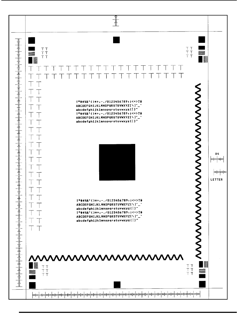
Sample 1: Good Quality Print
4-4 Print Quality Samples June 1999
Sample 1: Good Quality Print
Figure 4-1. Good Quality Print
Description: Good, properly registered print.
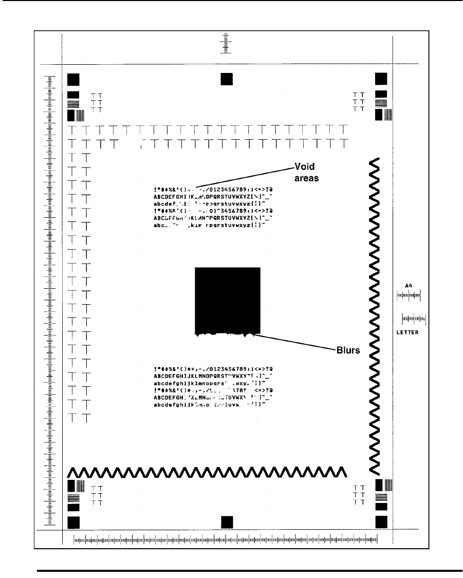
Sample 2: Washout
June 1999 Print Quality Samples 4-5
Sample 2: Washout
Figure 4-2. Washout
Description: Void areas, light spots, or blurs. This is a composite of possible symptoms.
Go to TAG 801: Prints Light or Light With Carrier Particles, TAG 802: Prints With Voids
or White Spots, TAG 809: Blurred or Smeared Vertical Streaks on Prints, or TAG 810:
Uneven Density or Dark Areas on Prints.

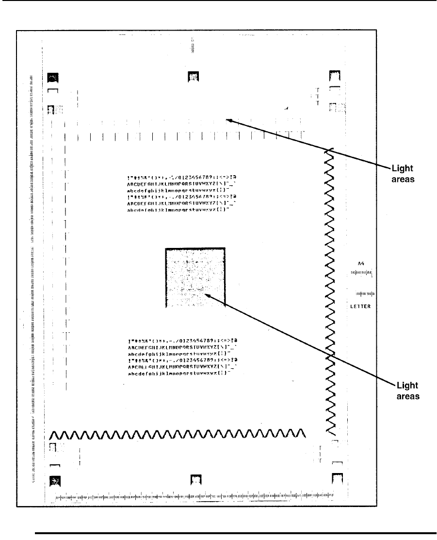
Sample 4: Light Print
June 1999 Print Quality Samples 4-7
Sample 4: Light Print
Figure 4-4. Light Print
Description: Images or characters are lighter than normal. Examine the letters H, T, M,
and E; if the vertical strokes are dark enough but the diagonal strokes are stair-stepped, the
problem is related to the printhead. Carrier particles may make the print feel gritty.
Go to TAG 801: Prints Light or Light With Carrier Particles.
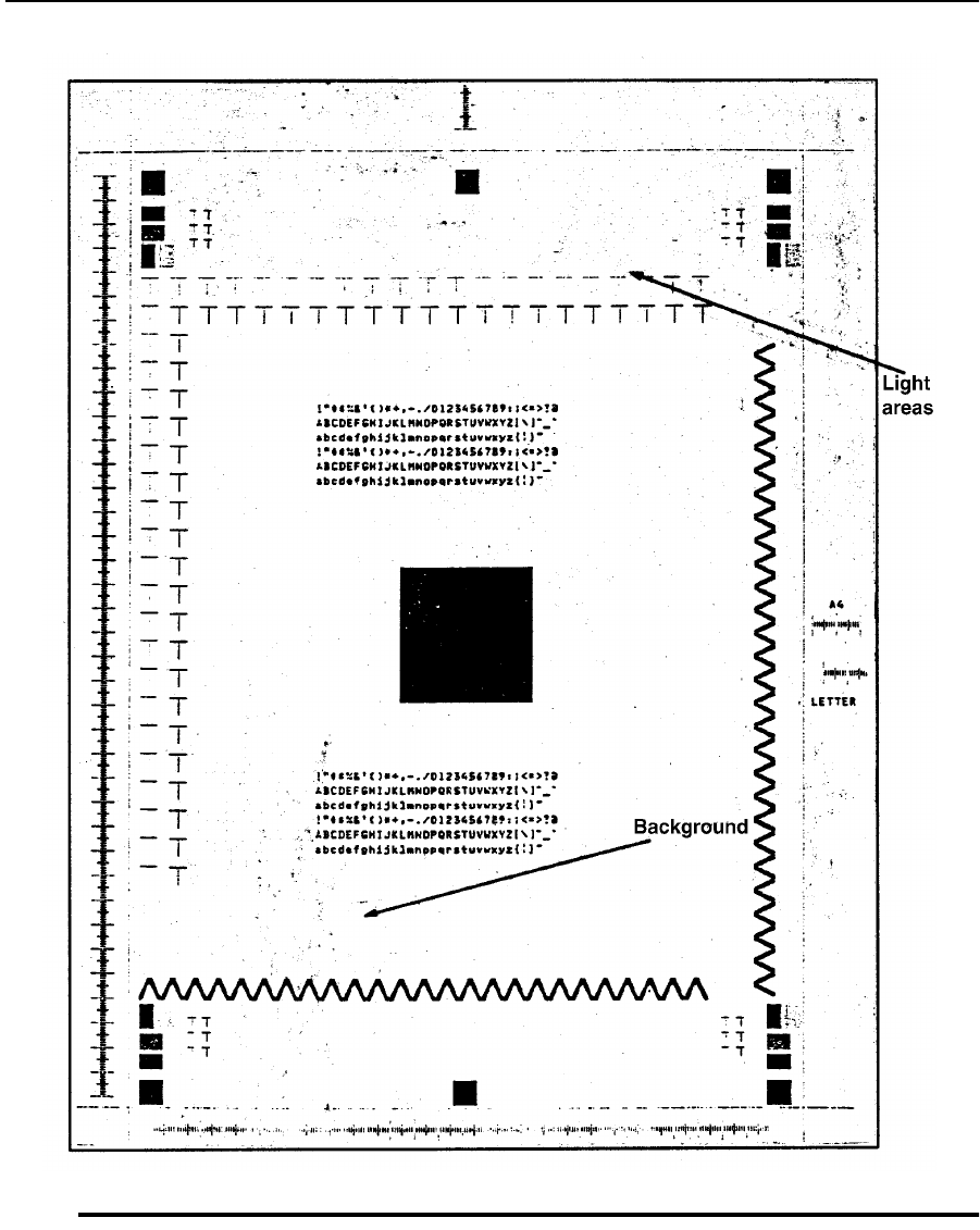
Sample 5: Light Print With Background
4-8 Print Quality Samples June 1999
Sample 5: Light Print With Background
Figure 4-5. Light Print With Background
Description: Images or characters lighter than normal, ranging from a few dark specks to a
large speckled background.
Go to TAG 811: Background/Residual Images/Dark Prints.
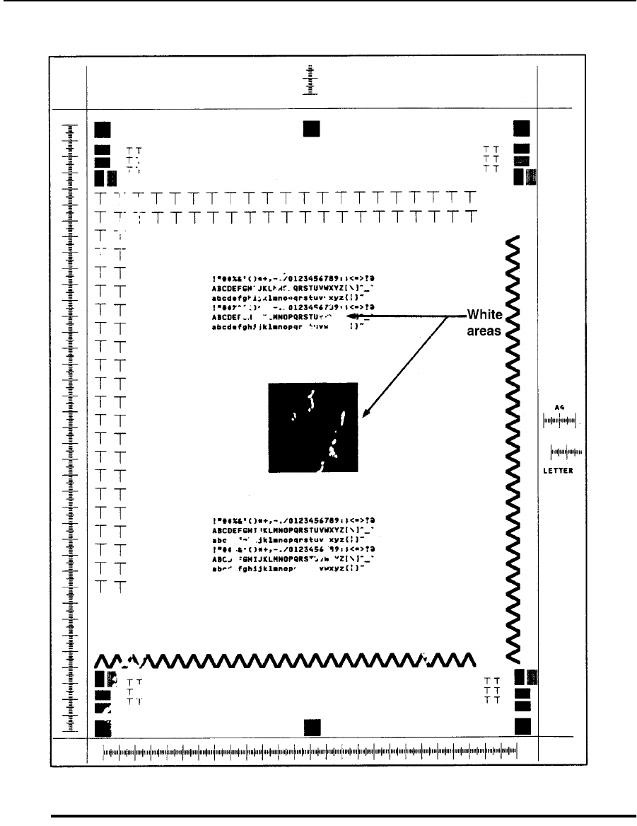
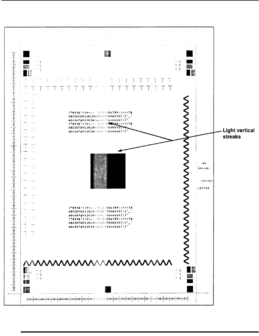
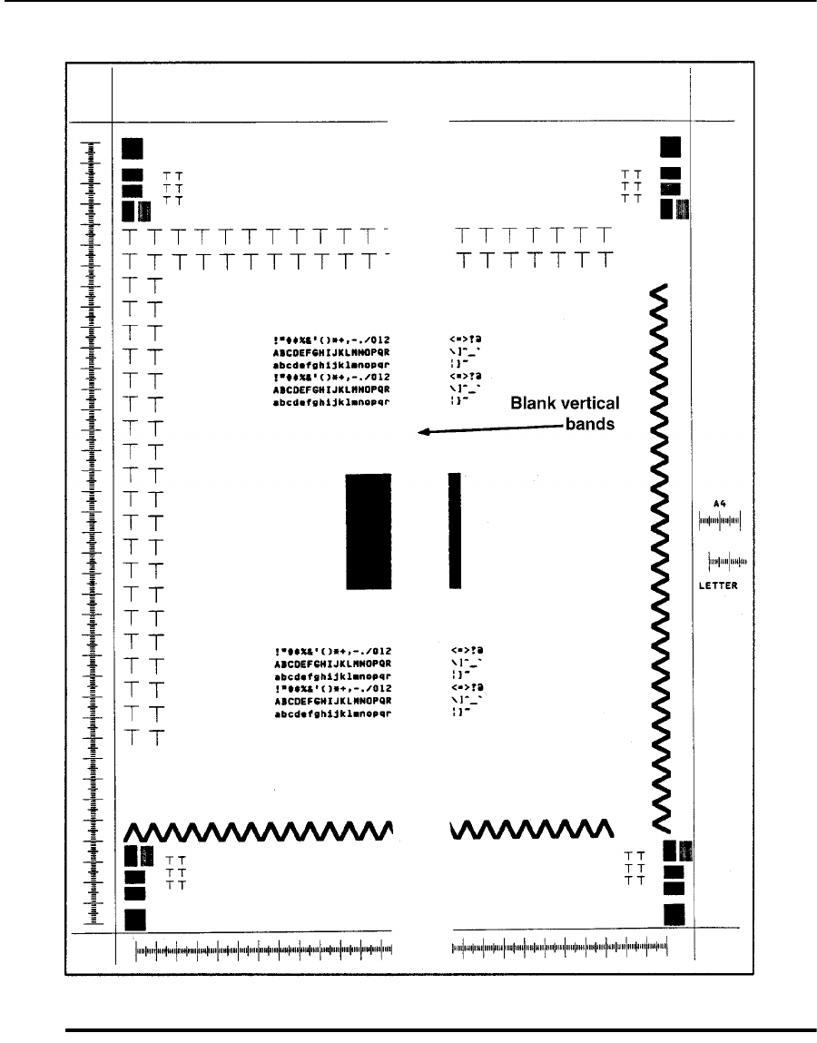
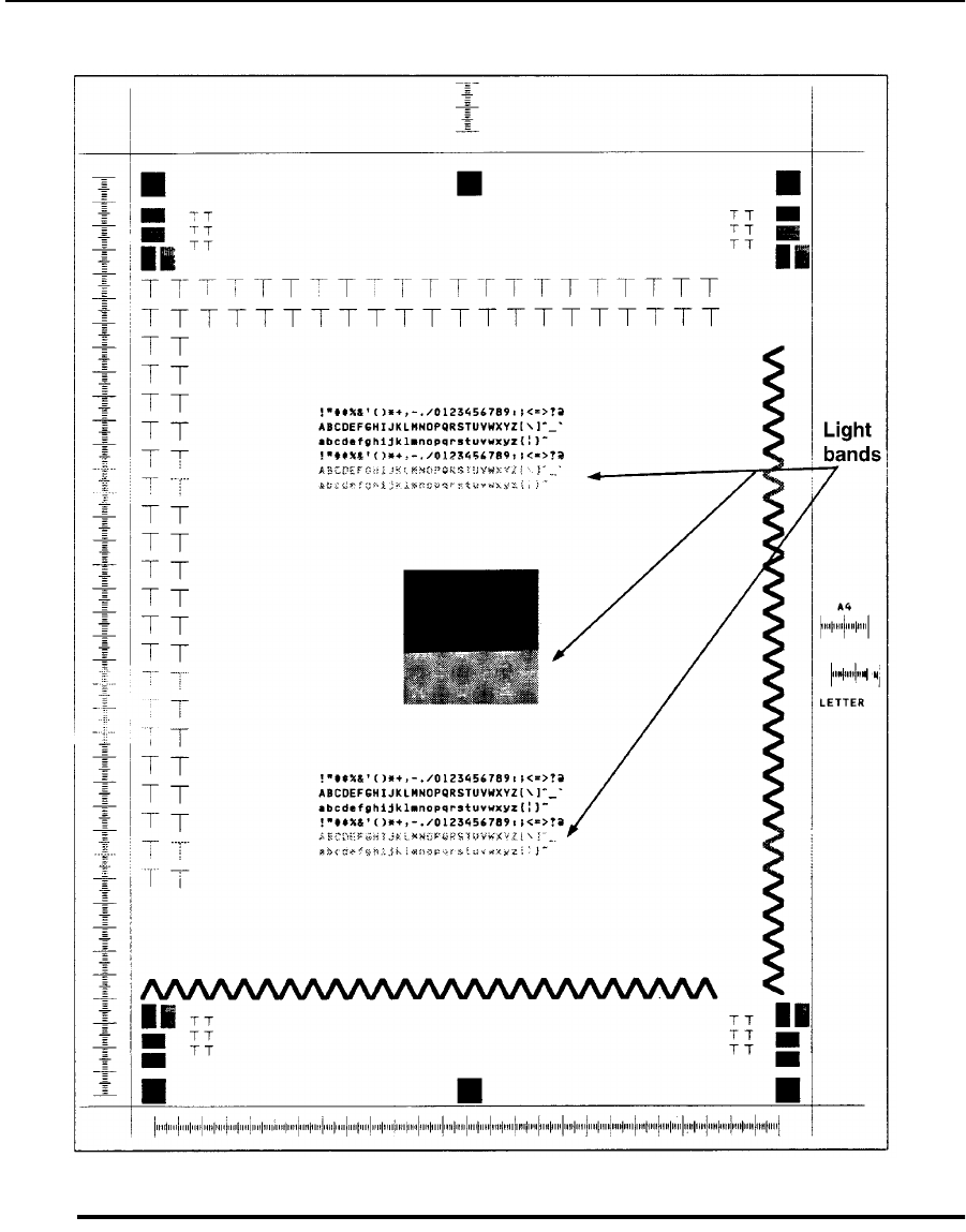

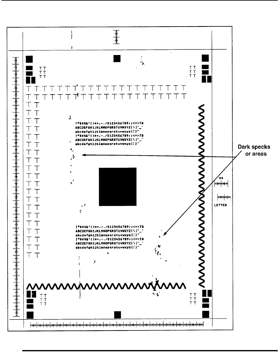
Sample 11: Dark Specks, Lines, or Areas
4-14 Print Quality Samples June 1999
Sample 11: Dark Specks, Lines, or Areas
Figure 4-11. Dark Specks, Lines, or Areas
Description: Dark specks or lines (like scratches), some in the same place on each print.
Go to TAG 806: Prints with Dark Spots or Scratches, TAG 810: Uneven Density or Dark
Areas on Prints.
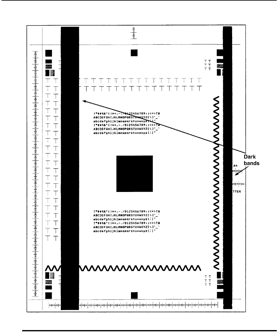
Sample 12: Dark Vertical Lines
June 1999 Print Quality Samples 4-15
Sample 12: Dark Vertical Lines
Figure 4-12. Dark Vertical Lines
Description: One or more dark lines of varying density. If the image can be rubbed off, go
to TAG 812: Uneven or No Fusing on Prints. If the image cannot be rubbed off, go to
TAG 808: Prints Overtoned/Dark Vertical Streaks.
Go to TAG 812: Uneven or No Fusing on Prints, TAG 808: Prints Overtoned/Dark Verti-
cal Streaks.
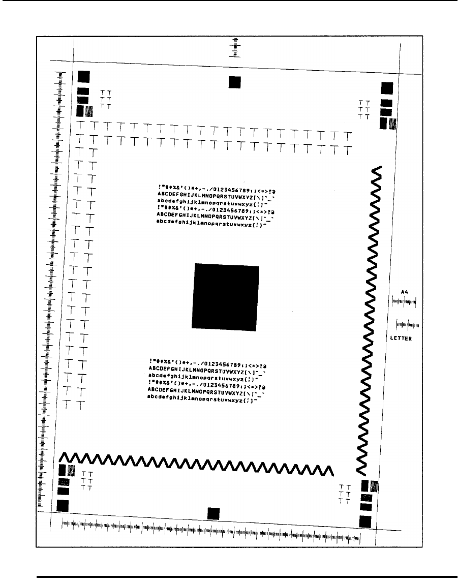
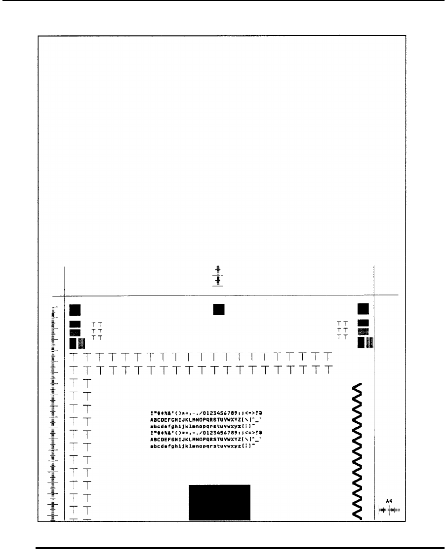
Sample 14: Misregistration
June 1999 Print Quality Samples 4-17
Sample 14: Misregistration
Figure 4-14. Misregistration
Description: The entire image is not correctly located from the leading edge of the paper.
The top or bottom image area may be missing.
Go to TAG 807: Misregistered/Skewed Prints (Simplex) or TAG 901: Misregistration/
Skewed Prints (Duplex).
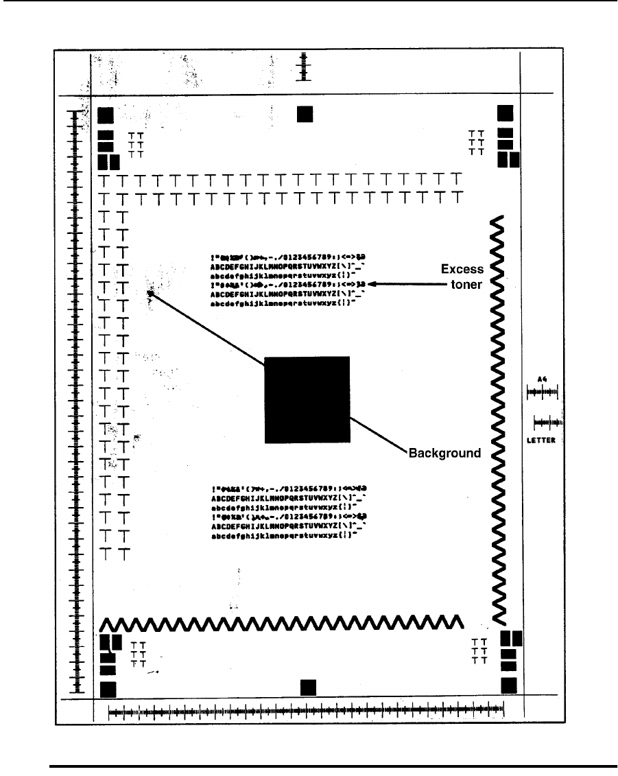
Sample 15: Overtoned Print
4-18 Print Quality Samples June 1999
Sample 15: Overtoned Print
Figure 4-15. Overtoned Print
Description: Similar to dark print quality problems. Narrow gaps between letters and
images may be filled with toner. Excess toner may be present on the surface of the print.
Extra toner can also cause background in the white areas.
Go to TAG 809: Blurred or Smeared Vertical Streaks on Prints.
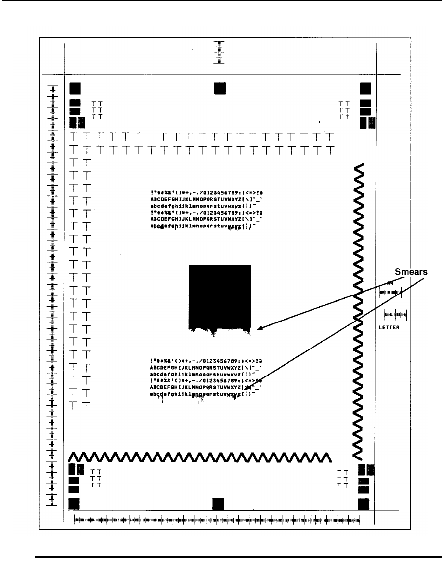
Sample 16: Blurred Images or Characters
June 1999 Print Quality Samples 4-19
Sample 16: Blurred Images or Characters
Figure 4-16. Blurred Images or Characters
Description: The images or characters are not clear. The lower edges of images and/or
characters are extended and may appear smeared.
Go to TAG 809: Blurred or Smeared Vertical Streaks on Prints.
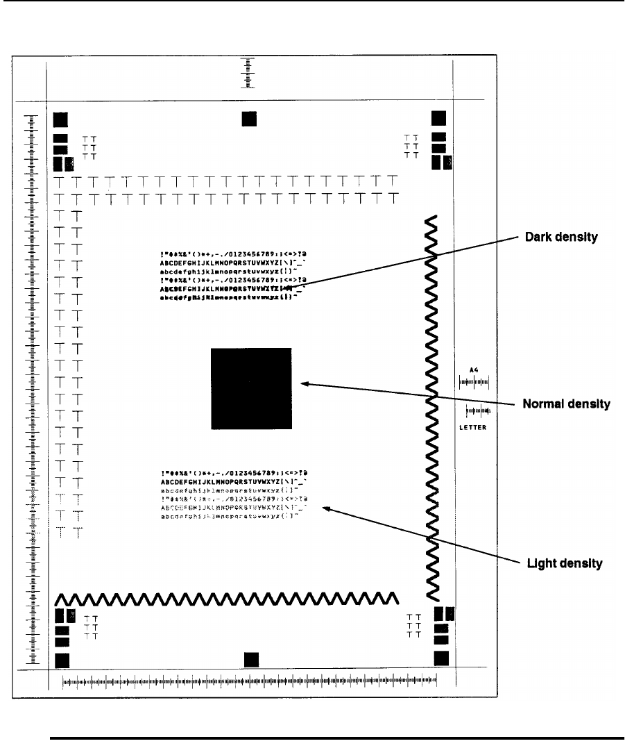
Sample 17: Varying Print Density
4-20 Print Quality Samples June 1999
Sample 17: Varying Print Density
Figure 4-17. Varying Print Density
Description: Some areas of the print are lighter or darker than normal. Examine the letters
H, T, M, and E on your test print. If the vertical sections are sufficiently dark, but the diag-
onal sections appear stair-stepped, the problem may be is related to the printhead.
Go to TAG 810: Uneven Density or Dark Areas on Prints, TAG 815: Prints Resulting
From Printhead Malfunctions.
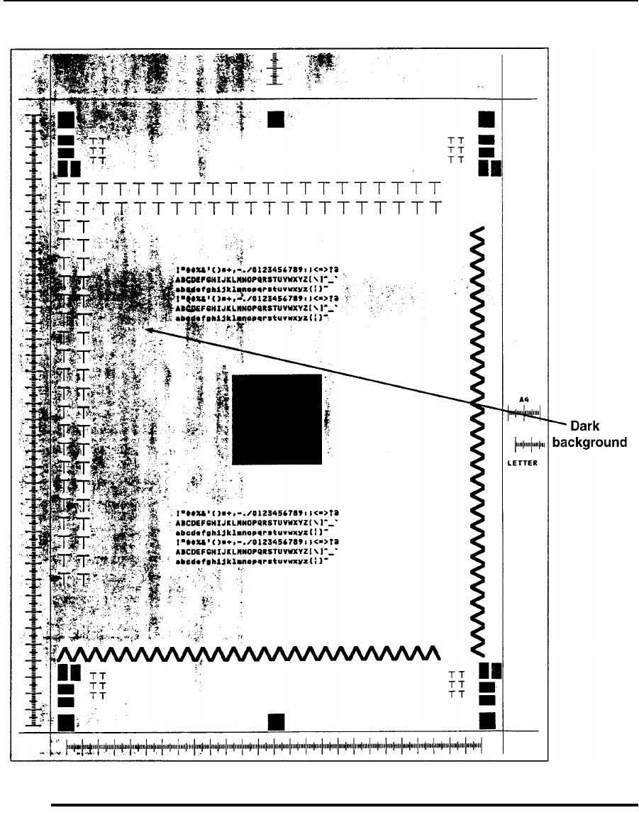

Sample 19: Residual Images
4-22 Print Quality Samples June 1999
Sample 19: Residual Images
Figure 4-19. Residual Images
Description: Images from a previous print are visible. White areas on the print may have
varying degrees of specks appearing in a specific pattern.
Go to TAG 811: Background/Residual Images/Dark Prints, TAG 813: Residual Images on
Prints.
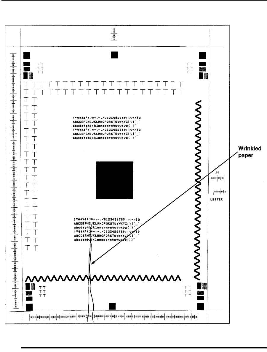
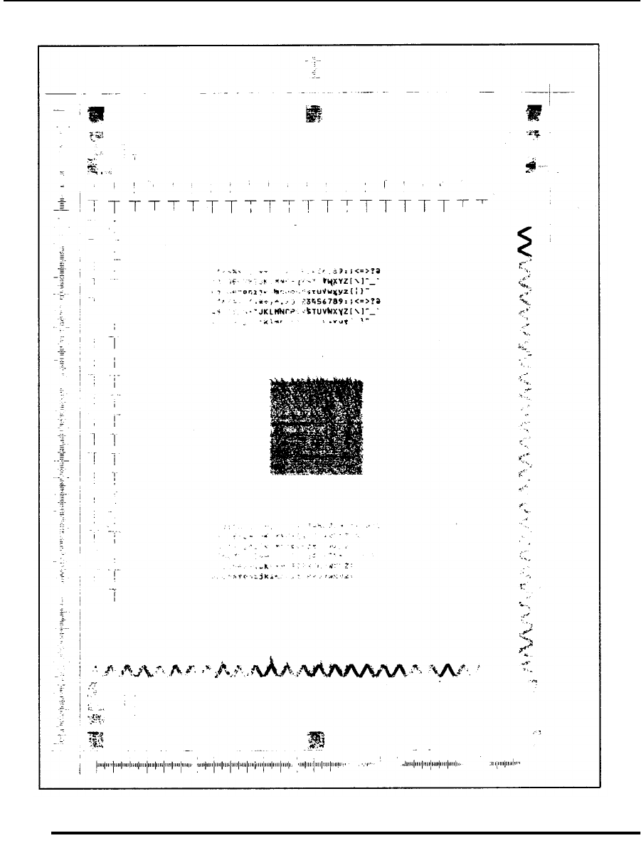

June 1999 Diagnostic Tests 5-1
Chapter 5
Diagnostic
Tests
Section 3 Troubleshooting

5-2 Diagnostic Tests June 1999
Chapter Contents
Diagnostic Tests
How to Run Diagnostics . . . . . . . . . . . . . . . . . . . . . . . . . . . . . . . . . . . . . . . . . . . . .5-3
001 Operator Panel Test . . . . . . . . . . . . . . . . . . . . . . . . . . . . . . . . . . . . . . . . . . . . .5-4
002 Upper Cassette Test . . . . . . . . . . . . . . . . . . . . . . . . . . . . . . . . . . . . . . . . . . . . .5-4
003 Lower Cassette Test . . . . . . . . . . . . . . . . . . . . . . . . . . . . . . . . . . . . . . . . . . . . .5-5
005 Sensor Test Sequence . . . . . . . . . . . . . . . . . . . . . . . . . . . . . . . . . . . . . . . . . . . .5-6
006 Paper Transport Clutch Test Sequence . . . . . . . . . . . . . . . . . . . . . . . . . . . . . . .5-7
007 Counter Test . . . . . . . . . . . . . . . . . . . . . . . . . . . . . . . . . . . . . . . . . . . . . . . . . . .5-7
008 Jogging Motor Test . . . . . . . . . . . . . . . . . . . . . . . . . . . . . . . . . . . . . . . . . . . . . .5-8
009 Photoconductor Test . . . . . . . . . . . . . . . . . . . . . . . . . . . . . . . . . . . . . . . . . . . . .5-8
010 Toner Supply Motor Test . . . . . . . . . . . . . . . . . . . . . . . . . . . . . . . . . . . . . . . . .5-9
011 Charge Corona Test . . . . . . . . . . . . . . . . . . . . . . . . . . . . . . . . . . . . . . . . . . . .5-10
012 Transfer Corona Test . . . . . . . . . . . . . . . . . . . . . . . . . . . . . . . . . . . . . . . . . . .5-11
013 Erase Lamp Test . . . . . . . . . . . . . . . . . . . . . . . . . . . . . . . . . . . . . . . . . . . . . . .5-12
015 Negative Developer Bias Test . . . . . . . . . . . . . . . . . . . . . . . . . . . . . . . . . . . .5-13
016 Duplex Feed Motor Test . . . . . . . . . . . . . . . . . . . . . . . . . . . . . . . . . . . . . . . . .5-14
017 Duplex Input Sensor Test Sequence . . . . . . . . . . . . . . . . . . . . . . . . . . . . . . . .5-15
018 Duplex Clutch Test Sequence . . . . . . . . . . . . . . . . . . . . . . . . . . . . . . . . . . . .5-16
019 Duplex Tray Paper-Guide Motor Test . . . . . . . . . . . . . . . . . . . . . . . . . . . . . .5-17
020 High-Capacity Output Unit Test . . . . . . . . . . . . . . . . . . . . . . . . . . . . . . . . . .5-18
021 High-Capacity Input Unit Test . . . . . . . . . . . . . . . . . . . . . . . . . . . . . . . . . . . .5-19
022 Envelope Fuser Solenoid Test . . . . . . . . . . . . . . . . . . . . . . . . . . . . . . . . . . . .5-19
101 EIGS/MIGS Board Test . . . . . . . . . . . . . . . . . . . . . . . . . . . . . . . . . . . . . . . . .5-20
102 EIGS/MIGS Board Test (Continuous Loop) . . . . . . . . . . . . . . . . . . . . . . . . .5-20
103 Communication Loop-back Test (Single Loop) . . . . . . . . . . . . . . . . . . . . . . .5-21
104 Communication Loop-back Test (Continuous Loop) . . . . . . . . . . . . . . . . . . .5-22
105 EIGS Program RAM Test (Continuous Loop) . . . . . . . . . . . . . . . . . . . . . . . .5-22
107 EIGS/MIGS Bit Map Test (Single Loop) . . . . . . . . . . . . . . . . . . . . . . . . . . . .5-23
108 EIGS/MIGS Bit Map Test (Continuous Loop) . . . . . . . . . . . . . . . . . . . . . . .5-23
110 Format Disk/Clear Error Log . . . . . . . . . . . . . . . . . . . . . . . . . . . . . . . . . . . . .5-24
111 LED Printhead Test . . . . . . . . . . . . . . . . . . . . . . . . . . . . . . . . . . . . . . . . . . . .5-24
112 Disk Drive Test (Single Loop With Stop on Error) . . . . . . . . . . . . . . . . . . . .5-25
113 Disk Drive Test (Continuous Loop) . . . . . . . . . . . . . . . . . . . . . . . . . . . . . . . .5-26

Diagnostic Tests
June 1999 Diagnostic Tests 5-3
Diagnostic Tests
This section provides step-by-step instructions for running each of the diagnostic tests
available through the self-diagnostic mode of the printer. Each test is referenced by num-
ber. Check the contents page to find the page on which a specific test is described.
How to Run Diagnostics
Follow these steps to access the self-diagnostic mode of the printer:
1Turn off the printer and wait five seconds.
2Hold down the STOP and TEST keys simultaneously as you turn the printer back on.
Continue to hold the keys down until O appears on the display. The STANDBY light
flashes as the printer accesses its soft diagnostic mode, which takes approximately 1
minute. The tone, followed by 001 on the display, indicates you can now run a test.
3Change the counter to the number of the test you wish to run by pressing CANCEL to
increase the counter or # TEST to decrease the counter. If you press these keys before
a test is complete, a long tone sounds and the test continues without interruption.
4Press READY to run the test.
5Press STOP to end the test (in most cases; see specific diagnostic procedures for direc-
tions on exiting a test).
6To exit diagnostic mode, cycle printer power.
Most errors or conditions reported are valid for about 90 seconds, which is the timeout
period set for most of the diagnostic tests described in this section.
Only diagnostics useful for field maintenance are documented
in this manual.
Note
001 Operator Panel Test
5-4 Diagnostic Tests June 1999
001 Operator Panel Test
1Turn the volume control on the operator panel up fully.
2Go to: 001
3Press: READY to run the test.
4Confirm that the tone sounds and all lights turn on and off continuously.
5Press: STOP to exit.
002 Upper Cassette Test
1Make sure the upper paper cassette is installed with paper, the side and rear guides
securely against the edges of the paper in the cassette.
2Go to: 002
3Press: READY to run the test.
4Refer to the chart below to confirm that the code that displays corresponds to the
paper size in the cassette. (For example, if the cassette holds letter size paper, “1-3”
should appear on the display.) This indicates the paper size sensor is working properly.
The following codes indicate paper sizes:
5Press: STOP to exit.
Table 5-1. Paper Size Codes
Display Indication
1-0 Cassette not installed
1-1 A4-size paper in use
1-2 B5-size paper in use
1-3 Letter-size paper in use
1-4 Legal-size paper in use
1-5 Executive 1 size paper in use
1-6 Executive 2 size paper in use
1-7 Executive 3 size paper in use
1-8 Envelopes in use
1-9 Undefined paper size

003 Lower Cassette Test
June 1999 Diagnostic Tests 5-5
003 Lower Cassette Test
1Make sure the lower paper cassette is installed with paper, the side and rear guides
securely against the edges of the paper in the cassette.
2Go to: 003
3Press: READY to run the test.
4Refer to the chart below to confirm that the code that displays corresponds to the
paper size in the cassette. (For example, if the cassette holds letter size paper, “1-3”
should appear on the display.) This indicates the paper size sensor is working properly.
Table 5-1, “Paper Size Codes”, lists the paper size codes.
5Press: STOP to exit.
(004 intentionally excluded)
A 1-9 is displayed when a high-capacity paper feed unit is
installed; refer to “021 - High Capacity Unit Input Test”
Note
005 Sensor Test Sequence
5-6 Diagnostic Tests June 1999
005 Sensor Test Sequence
1Go to: 005
2Press: READY to run the test. The code for the first sensor (i.e., “0-0” or “0-1”)
appears on the display, confirming that the sensor is working properly.
3Press: READY to advance to the next sensor. The display changes, showing the code
for the next sensor as outlined in Table 5-2, “Sensor Test Displays”, below.
4To check a specific sensor, press READY repeatedly until the code on the display cor-
responds to the sensor you want to check. Manually activate the sensor. Confirm that
the display changes when you activate the sensor. Refer to “Sensor and Switch Loca-
tions” on page 1-11 for sensor locations.
5Press: STOP to exit.
Table 5-2. Sensor Test Displays
Sensor Description Display
Upper paper cassette 0-0: Cassette full
0-1: Cassette empty
Lower paper cassette 1-0: Cassette full
1-1: Cassette empty
Paper timing sensor 2-0: No paper at sensor location
2-1: Paper at sensor
Paper exit sensor 3-0: No paper at sensor location
3-1: Paper at sensor
Paper full sensor 4-0: Tray empty
4-1: Tray full
Jogging sensor, front 5-0: Tray in front position
5-1: Error – tray in rear position
Jogging sensor, rear 6-0: Tray in rear position
6-1: Error – tray in front position
PC seam sensor 7-0: Active
7-1: Not active
Developer interlock 8-0: Developer unit in place
8-1: Developer unit not in place
No paper moves through the machine, so indications of
“No paper at sensor location” are normal.
Note
006 Paper Transport Clutch Test Sequence
June 1999 Diagnostic Tests 5-7
006 Paper Transport Clutch Test Sequence
1Go to: 006
2Press: READY to run the test. The first clutch engages, signaled by a continuous
clicking sound. “3-0” appears on the display, corresponding to the upper pick-up roller
clutch.
3Press: READY to test the next clutch. Listen for the clicking sound as the next clutch
engages. The number on the display changes to indicate the next clutch. The display
codes and the clutch they represent are listed in Table 5-3, “Clutch Test Displays”.
4Repeat Step 3 until you have tested all of the clutches.
5Press: STOP to exit.
007 Counter Test
1Open the front cover.
2Go to: 007
3Press: READY to run the test.
•Confirm that the page counter advances by 1.
•The test then exits automatically.
Table 5-3. Clutch Test Displays
Display Indication
3-0 Upper pick-up roller clutch
3-1 Lower pick-up roller clutch
3-2 Upper feed roller clutch
3-3 Lower feed roller clutch
3-3 Paper timing roller clutch
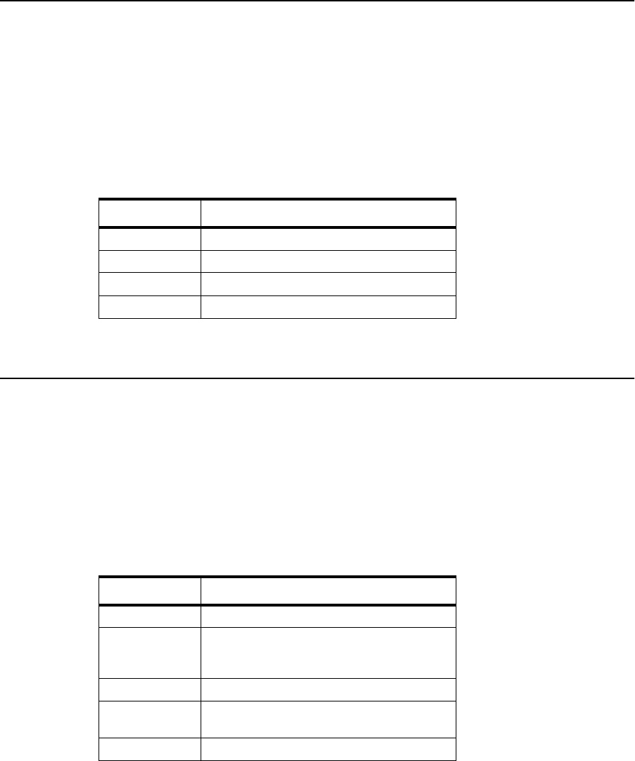
008 Jogging Motor Test
5-8 Diagnostic Tests June 1999
008 Jogging Motor Test
1Go to: 008
2Press: READY to run the test. The output tray jogs back and forth.
3Confirm that a tone sounds each time the tray contacts the sensor at each side.
The codes in the following table indicate specific error conditions:
4Press: STOP to exit.
009 Photoconductor Test
1Go to: 009
2Press: READY to run the test. The main motor rotates the photoconductor belt.
3Confirm that a tone sounds repeatedly, indicating that the photoconductor belt is rotating.
These codes may indicate specific error conditions:
4Press: STOP to exit
Table 5-4. Jogging Motor Test Error Displays
Display Indication
081 Front tray sensor signal not received
082 Rear tray sensor signal not received
083 No signal received from either sensor
090 Close covers
Table 5-5. Photoconductor Error Test Displays
Display Indication
030 Developer bias short detected
040 Photoconductor seam sensor not
received or detected or the developer
unit is not installed
041 Seam sensor (sender) short
042 Seam sensor (sender) open or the
photoconductor is not installed
055 Erase lamp malfunction

010 Toner Supply Motor Test
June 1999 Diagnostic Tests 5-9
010 Toner Supply Motor Test
1Open the front and top covers.
2Remove the photoconductor unit and the developer unit. Place the photoconductor
unit in its protective packaging.
3Insert the interlock by-pass tool in the front cover. Close the top cover.
4Go to: 010
5Press: READY to run the test. The toner supply motor runs continuously.
6Observe the toner supply motor through the open developer unit cavity. Confirm that
the motor is turning counterclockwise, accompanied by a “1” on the display.
7Press STOP and READY alternately several times to verify the toner supply motor
starts and stops. (This stops and restarts the test.)
These codes may indicate specific error conditions:
8Press: STOP to exit.
9Reinstall the developer unit and photoconductor unit.
10 Remove the interlock by-pass tool and close the front cover.
Table 5-6. Toner Supply Motor Test Error Displays
Display Indication
4-0 You forgot to remove the developer unit
090 You forgot to insert the interlock by-pass tool

011 Charge Corona Test
5-10 Diagnostic Tests June 1999
011 Charge Corona Test
1Remove the photoconductor unit and place it in its protective packaging. Close the top
cover.
2Go to: 011
3Press: READY to run the test. The charge corona turns on and off repeatedly.
4Confirm that the display alternates between “0” and “1,” accompanied each time by a
brief tone. The display indicates the following:
These codes may indicate specific error conditions:
5Press: STOP to exit.
6Reinstall the photoconductor unit.
Table 5-7. Charge Corona Test Displays
Display Indication
0 Charge corona off
1 Charge corona on
Table 5-8. Charge Corona Test Error Displays
Display Indication
041 Photoconductor seam sensor short
045 Charge corona short
046 Charge corona open
4-1 You forgot to remove the photoconductor
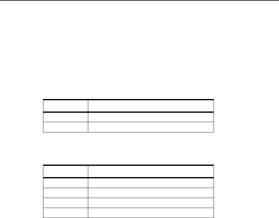
012 Transfer Corona Test
June 1999 Diagnostic Tests 5-11
012 Transfer Corona Test
1Remove the photoconductor unit and place it in its protective packaging. Close the top
cover.
2Go to: 012
3Press: READY to run the test. The transfer corona turns on and off repeatedly.
4Confirm that the display alternates between “0” and “1,” accompanied each time by a
brief tone. The display indicates the following:
These codes may indicate specific error conditions:
5Press: STOP to exit.
6Reinstall the photoconductor unit.
Table 5-9. Transfer Corona Test Displays
Display Indication
0 Transfer corona off
1 Transfer corona on
Table 5-10. Transfer Corona Test Error Displays
Display Indication
041 Seam sensor (sender) short
050 Transfer corona short
051 Transfer corona open or not installed
4-1 You forgot to remove the photoconductor
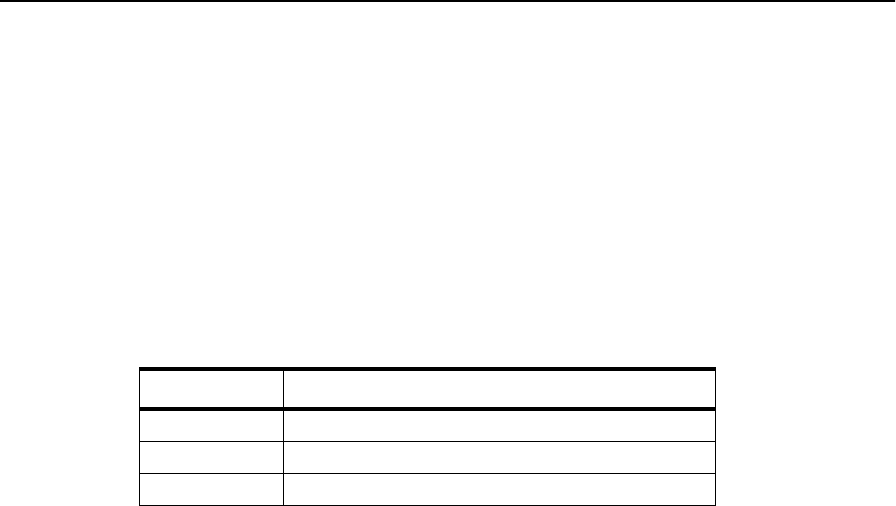
013 Erase Lamp Test
5-12 Diagnostic Tests June 1999
013 Erase Lamp Test
1Open the top cover and insert the interlock by-pass tool.
2Remove the photoconductor unit and place it in its protective cover.
3Select: 013
4READY to run the test. The erase lamp turns on with all LEDs lighted.
5Verify that all LEDs are illuminated and a number(s) appears on the display. The num-
ber is a readout from the A/D converter and does not affect the erase lamp test.
These codes may indicate specific error conditions:
6Press: STOP to exit.
7Reinstall the photoconductor unit.
8Remove the interlock by-pass tool and close the top cover.
(014 intentionally excluded)
Table 5-11. Erase Lamp Test Error Displays
Display Indication
041 Seam sensor (sender) short
055 Erase lamp malfunction
4-1 You forgot to remove the photoconductor unit
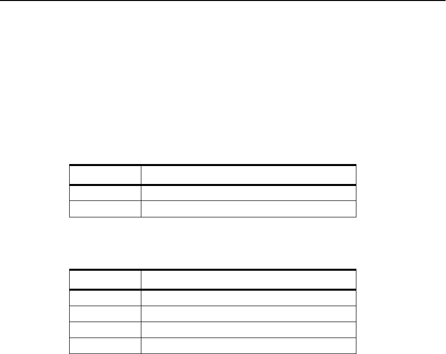
015 Negative Developer Bias Test
June 1999 Diagnostic Tests 5-13
015 Negative Developer Bias Test
1Open the top cover and insert the interlock by-pass tool.
2Remove the photoconductor unit and place it in its protective packaging.
3Go to: 015
4Press: READY to run the test. The negative developer bias turns on and off repeatedly.
5Confirm that the display alternates between “0” and “1,” accompanied each time by a
brief tone. The display indicates the following:
These codes may indicate specific error conditions:
6Press: STOP to exit.
7Reinstall the photoconductor unit.
8Remove the interlock by-pass tool and close the top cover.
Table 5-12. Negative Developer Bias Test Displays
Display Indication
0 Negative developer bias off
1 Negative developer bias on
Table 5-13. Negative Developer Bias Test Error Displays
Display Indication
030 Developer bias short
041 Seam sensor (sender) short
090 You forgot to insert the interlock by-pass tool
4-1 You forgot to remove the photoconductor unit
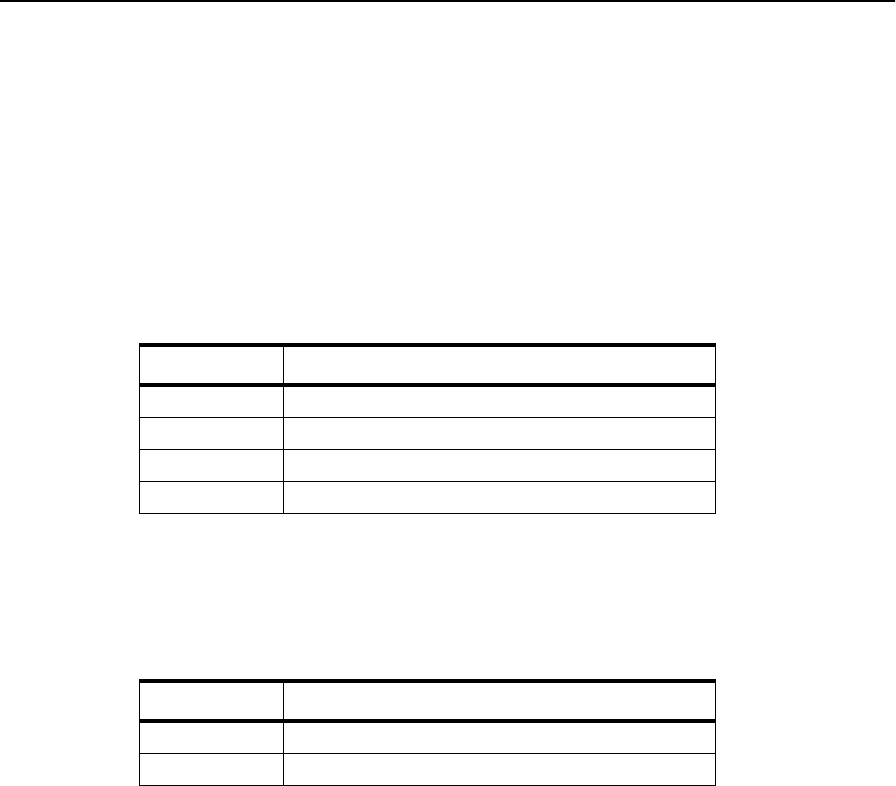
016 Duplex Feed Motor Test
5-14 Diagnostic Tests June 1999
016 Duplex Feed Motor Test
1Go to: 016
2Press: READY to run the test. The duplex feed motor operates at full forward speed
and “7-0” appears on the display.
3Press: READY to advance to the next motor speed.
4Listen for the following motor frequencies and check the code that displays as you
move through the test sequence. The codes and their meaning are outlined in the chart
below:
Note: To view roller movement while running the duplex feed motor test, open the
duplex cover and bypass the cover interlock switch.
These codes may indicate specific error conditions:
5Press: STOP to exit.
Table 5-14. Duplex Motor Feed Test Displays
Display Indication
7-0 Full forward speed (high frequency)
7-1 Low forward speed (low frequency)
7-2 Full reverse speed (high frequency)
7-3 Half reverse speed (low frequency)
Table 5-15. Duplex Motor Feed Test Error Displays
Display Indication
069 Duplex is not installed.
090 Cover is open. Close cover
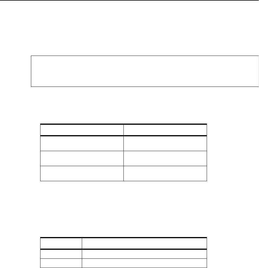
017 Duplex Input Sensor Test Sequence
June 1999 Diagnostic Tests 5-15
017 Duplex Input Sensor Test Sequence
1Go to: 017
2Press: READY to run the test. The code for the first sensor (i.e., “0-0” or “0-1”)
appears on the display, confirming that the sensor is working properly.
3Press: READY to advance to the next sensor. The display changes, showing the code
for the next sensor as outlined in the chart below.
4To check a specific sensor, press READY repeatedly until the code on the display cor-
responds to the sensor you want to check, then manually activate the sensor. Confirm
that the display changes when you activate the sensor.
These codes may indicate specific error conditions:
5Press: STOP to exit.
Table 5-16. Duplex Input Sensor Test Displays
Sensor Description Display
Paper sensor 0-0: No paper
0-1: Paper at sensor
Cover sensor 1-0: Cover closed
1-1: Cover open
Duplex tray sensor 2-0: No paper
2-1: Paper at sensor
Table 5-17. Duplex Input Sensor Test Error Displays
Display Indication
069 Duplex tray not installed
090 Cover is open. Close cover
No paper moves through the machine, so indications of
“No paper at sensor location” are normal.
Note

018 Duplex Clutch Test Sequence
5-16 Diagnostic Tests June 1999
018 Duplex Clutch Test Sequence
1Go to: 018
2Press: READY to run the test. The first flipper engages, accompanied by a continuous
clicking sound, and “7-0” appears on the display.
3Press: READY to activate the next clutch or flipper. Listen for the clicking sound as it
engages. The number on the display changes to indicate the next clutch or flipper. The
display codes and the clutch or flipper they represent are listed in the following chart.
4To check a specific clutch or flipper, press READY repeatedly until the code on the
display corresponds to the item you want to check. Manually activate the sensor. Con-
firm that the display changes when you activate the sensor. For the locations of the
sensors, see “Sensor and Switch Locations” on page 1-11.
These codes may indicate specific error conditions:
5Press: STOP to exit.
Table 5-18. Duplex Clutch Test Displays
Display Indication
7-0 Duplex exit flipper
7-1 Duplex roller clutch A
7-2 Duplex re-entry flipper
7-3 Duplex roller C solenoid
Table 5-19. Duplex Clutch Test Error Displays
Display Indication
069 Duplex is not installed.
090 Cover is open. Close cover.
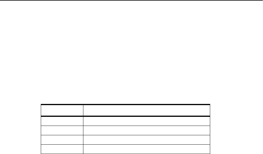
019 Duplex Tray Paper-Guide Motor Test
June 1999 Diagnostic Tests 5-17
019 Duplex Tray Paper-Guide Motor Test
1Go to: 019
2Press: READY to run the test.
3Press: READY again. The paper guide in the duplex tray moves to and from its home
position.
4Confirm that the paper guide in the duplex tray moves back and forth each time you
press READY.
These codes may indicate specific error conditions:
5Press: STOP to exit.
Table 5-20. Duplex Tray Paper Guide Motor Test Displays
Display Indication
069 Duplex tray not installed
084 Duplex tray registration sensor not active
085 Duplex tray registration sensor active
090 Cover is open. Close cover.

020 High-Capacity Output Unit Test
5-18 Diagnostic Tests June 1999
020 High-Capacity Output Unit Test
1Go to: 020
2Press: READY to run the test. The code for the first sensor (i.e., “0-0” or “0-1”)
appears on the display, confirming that the sensor is working properly.
3Press: READY to advance to the next sensor. The sensor’s code appears on the dis-
play; codes and their meaning are outlined in Table 5-21, “High-Capacity Output Unit
Test Displays”, below.
4To check a specific sensor, press READY repeatedly until the code on the display cor-
responds to the sensor you want to check. Manually activate the sensor. Confirm that
the display changes when you activate the sensor.
5Press: STOP to exit.
Table 5-21. High-Capacity Output Unit Test Displays
Sensor Description Display
Installation sensor 0-0: Unit not installed
0-1: Unit installed
Paper exit sensor 1-0: No paper at sensor location
1-1: Paper at sensor
Paper full sensor 2-0: Paper not full
2-1: Paper full
Lower limit sensor 3-0: Tray stationary or moving down
3-1: Tray moving up
No paper moves through the machine, so indications of
“No paper at sensor location” are normal.
Note
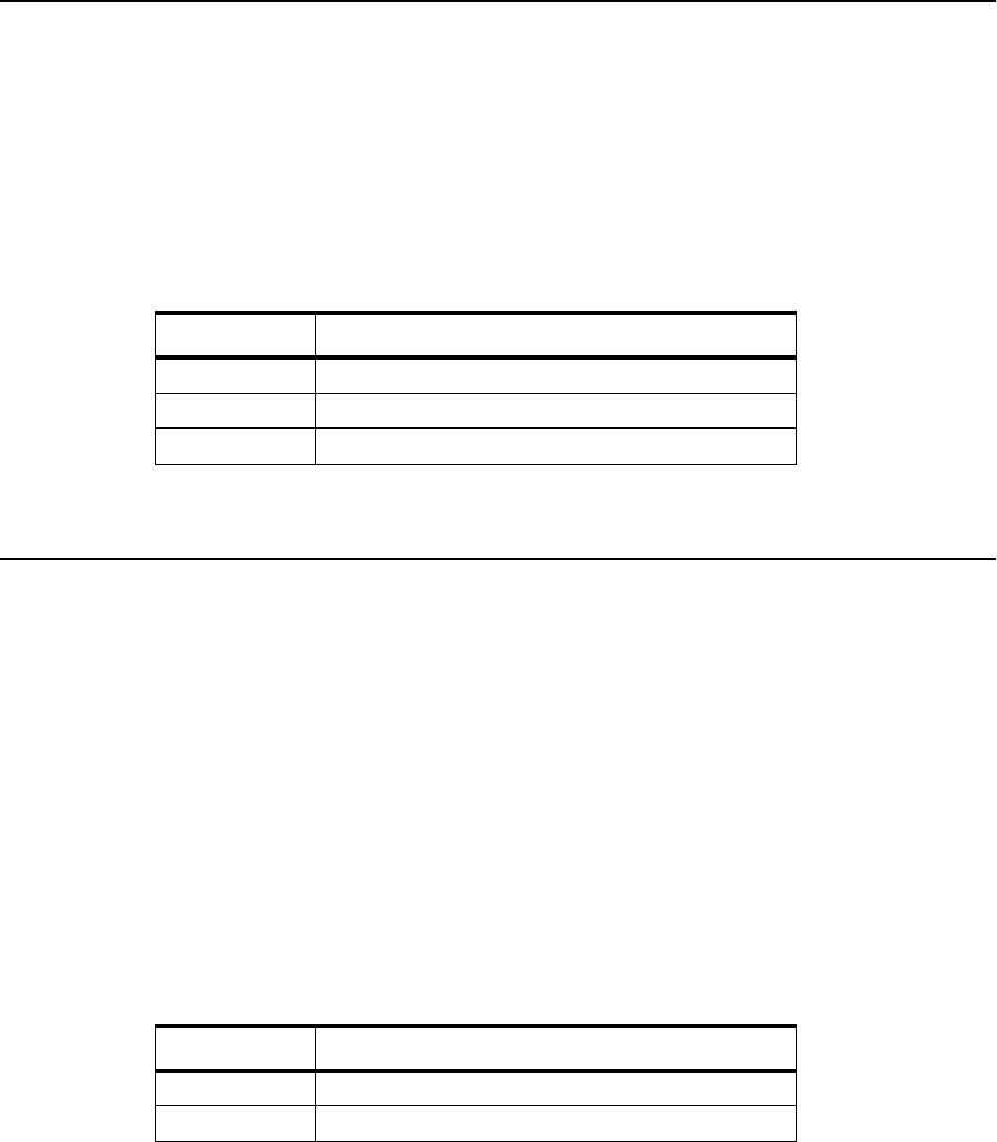
021 High-Capacity Input Unit Test
June 1999 Diagnostic Tests 5-19
021 High-Capacity Input Unit Test
1Go to: 021
2Press: READY to run the test. The display registers the paper size installed in the unit,
as outlined on the chart (“1-0” will appear on the display if a high-capacity input unit
is not installed.)
3Verify the correct paper size, as follows:
4Press: STOP to exit.
022 Envelope Fuser Solenoid Test
1Remove the photoconductor unit and place it in its protective packaging.
2Go to: 022
3Press: READY to run the test. The main motor turns on and “0” appears on the dis-
play.
4Press: READY again to activate the envelope fuser solenoid.
5Listen for a clicking sound and confirm that the display alternates between “0” and
when the solenoid is activated. If you hear no clicking, either the machine does not
have an envelope fuser installed or the solenoid is not working properly.
6Check for the following conditions:
7Press: STOP to exit.
(023-100 intentionally excluded)
Table 5-22. High-Capacity Input Unit Test Displays
Display Indication
1-1 A4-size paper in use
1-3 Letter-size paper in use
1-4 Legal-size paper in use
Table 5-23. Envelope Fuser Solenoid Test Displays
Display Indication
4-1 You forgot to remove the photoconductor unit.
090 Cover is open. Close cover.

101 EIGS/MIGS Board Test
5-20 Diagnostic Tests June 1999
101 EIGS/MIGS Board Test
1Select: 101
2Press: READY to run the test.
3If an error is found:
•The error code appears.
•Look up the code in “Error Code/TAG Cross-Reference” on page 2-3 to determine
which TAG to follow.
•Power-on-reset to exit.
4If no errors are found:
•The test continues to run.
•After about five minutes, press STOP to exit.
102 EIGS/MIGS Board Test (Continuous Loop)
1Go to: 102
2Press: READY to run the test.
3If an error is found:
•The error code is displayed for at least 1 second.
•Look up the code in “Error Code/TAG Cross-Reference” on page 2-3 to determine
which TAG to follow.
•If the test resumes, press STOP to exit; if the test does not resume, power-on-reset.
4If no errors are found:
•The test continues to loop.
•Press STOP to exit.
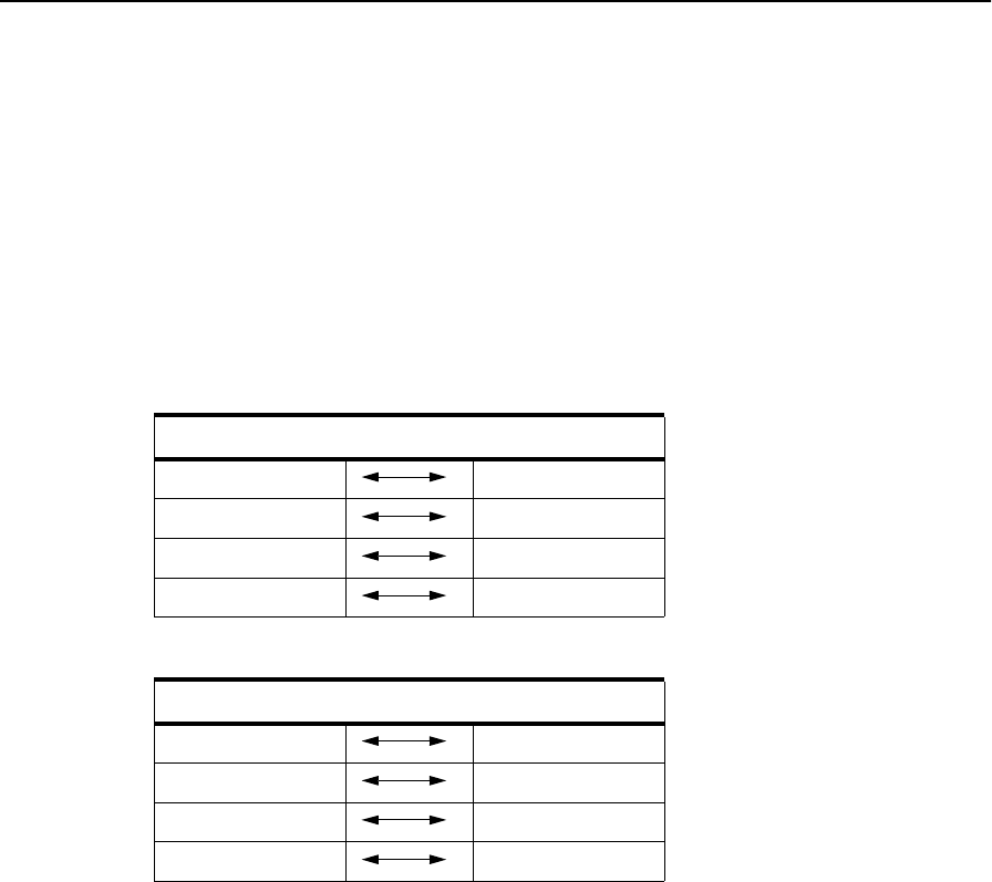
103 Communication Loop-back Test (Single Loop)
June 1999 Diagnostic Tests 5-21
103 Communication Loop-back Test (Single Loop)
1Remove the interface cable from the printer.
2Check to make sure the four DIP switches on the signal interface board have been
pulled toward the printer’s back cover. Close the back cover.
3Install the RS-232C and RS-422 loop-back connectors, found in the tool kit mounted
inside the right printer cover.
If you do not have loop-back connectors, jumper the connections as outlined in Table
5-24, “RS-232 Loopback Connections” and Table 5-25, “RS-422 Loopback Connec-
tions”.
4Go to: 103
5Press: READY to run the test.
6If an error code appears, check the “Error Code/TAG Cross-Reference” on page 2-3
to determine which TAG to follow.
7If no error is detected, the test exits automatically.
8Press: STOP to exit, if an error is detected. (For some errors, you may have to power-
on-reset the printer.)
9Remove the wrap connectors.
10 Reinstall the interface cable.
Table 5-24. RS-232 Loopback Connections
RS-232 Loopback Connection Reference
pin 2 pin 3
pin 4 pin 5
pin 8 pin 20
pin 17 pin 24
Table 5-25. RS-422 Loopback Connections
RS-232 Loopback Connection Reference
pin 2 pin 4
pin 9 pin 11
pin 7 pin 6
pin 14 pin 13

104 Communication Loop-back Test (Continuous Loop)
5-22 Diagnostic Tests June 1999
104 Communication Loop-back Test (Continuous Loop)
1Remove the interface cable from the printer.
2Make sure the DIP switches on the signal interface board have been pulled toward the
printer’s back cover. Close the back cover.
3Install the RS-232C and RS-422 loop-back connectors, found in the tool kit mounted
inside the right printer cover. If you do not have loop-back connectors, jumper the
connections as outlined in Table 5-24, “RS-232 Loopback Connections,” on page 5-
21 and Table 5-25, “RS-422 Loopback Connections,” on page 5-21.
4Go to: 104
5Press: READY to run the test.
6If an error is detected, the error code is displayed briefly and the test continues. Note
the error code and check the “Error Code/TAG Cross-Reference” on page 2-3 to
determine which TAG to follow.
7If no errors are found, the test continues to loop. Allow the test to continue for at least
one minute.
8Press: STOP to exit. (For some errors, you may have to power-on-reset the printer.)
9Remove the loop-back connectors.
10 Reinstall the interface cable.
105 EIGS Program RAM Test (Continuous Loop)
1Go to: 105
2Press: READY to run the test.
3If an error code appears before the test has run for five minutes, look up the code in
“Error Code/TAG Cross-Reference” on page 2-3 to determine which TAG to follow.
4Otherwise, a “201” may display after about five minutes, indicating that the test has
run successfully.
5Power-on-reset the printer to exit.
(106 intentionally excluded)
This test does not run on printers with MIGS boards.
Note

107 EIGS/MIGS Bit Map Test (Single Loop)
June 1999 Diagnostic Tests 5-23
107 EIGS/MIGS Bit Map Test (Single Loop)
1Go to: 107
2Press: READY to run the test.
3If no error is detected, the test exits automatically.
4If an error code appears, look it up in “Error Code/TAG Cross-Reference” on page 2-
3 to determine which TAG to follow.
5Press: STOP to exit, if an error is reported.
108 EIGS/MIGS Bit Map Test (Continuous Loop)
1Go to: 108
2Press: READY to run the test.
3If no errors are detected:
•The test continues to loop.
•Press STOP to exit.
4If an error is found:
•The error code displays briefly. If more than one error is detected, the error codes
appear sequentially.
•Look up the codes in the “Error Code/TAG Cross-Reference” on page 2-3 to deter-
mine which TAG to follow.
•Power-on-reset to exit after codes display.
(109 intentionally excluded)
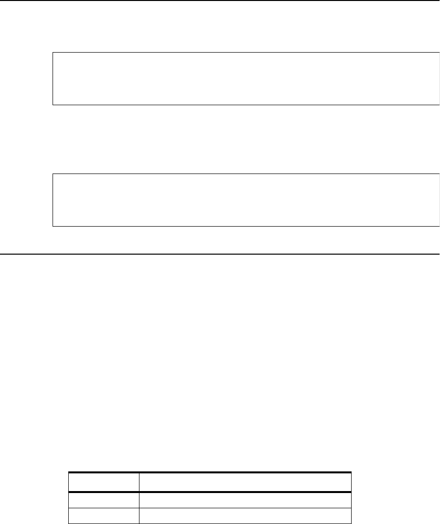
110 Format Disk/Clear Error Log
5-24 Diagnostic Tests June 1999
110 Format Disk/Clear Error Log
•To format a disk, refer to the Guide to Operations manual.
5To clear the error log, follow the procedure on clearing the log found in “Clearing the
Error Log” on page 1-24.
111 LED Printhead Test
1Open the top cover.
2Remove the photoconductor unit and place it in its protective packaging.
3Remove the developer station.
4To help you identify the LEDs, place a white sheet of paper in the photoconductor
cavity over the printhead’s fiber optics.
5Go to: 111
6Press: READY to run the test. The LED printhead turns on.
7Verify that the LEDs cycle on and off from front to back.
These codes may indicate specific error conditions:
8Press: STOP to exit.
9Reinstall the photoconductor unit.
Table 5-26. LED Printhead Test Error Displays
Display Indication
4-1 You forgot to remove the photoconductor unit
040 Seam sensor (sender) short
When using the 110 function of the self-diagnostic mode,
any existing data on the specified disk is at risk!
Caution
If you access this function by mistake, do not proceed.
Press STOP immediately to exit the utility.
Caution
112 Disk Drive Test (Single Loop With Stop on Error)
June 1999 Diagnostic Tests 5-25
112 Disk Drive Test (Single Loop With Stop on Error)
This test reads data from the drive selected. It checks the seek function, cycle redundancy,
parity, checksum, directory and allocation table integrity, and disk format.
1Go to: 112
2Insert a diskette or diskettes in the diskette drive or drives you wish to test.
3Press: READY to run the test. “0” appears on the display indicating the A: drive.
4Press: CANCEL to advance to the drive you wish to test.
5Press: READY to activate the drive.
6If no errors are found, the test exits automatically.
7If an error code appears, refer to the Table 2-8, “IGS/Disk Drive Error Codes,” on
page 2-7, to determine which TAG to follow.
8Press: STOP to exit, if errors are found.
9To test another drive, repeat this procedure starting with Step 2.
Table 5-27. Disk Drive Test Drive Indications
Display Indication
0 Floppy drive A:
1 Floppy drive B:
2 Hard drive C:

113 Disk Drive Test (Continuous Loop)
5-26 Diagnostic Tests June 1999
113 Disk Drive Test (Continuous Loop)
This test reads data directly from the drive selected. It checks the seek function, cycle
redundancy, parity, checksum, directory and allocation table integrity, and disk format.
1Go to: 113
2Insert a diskette or diskettes in the diskette drive or drives you wish to test.
3Press: READY to run the test. “0” appears on the display indicating the A: drive.
4Press: CANCEL to advance to the drive you wish to test. Table 5-27, “Disk Drive Test
Drive Indications,” on page 5-25 lists the drive indications.
5Press: READY to activate the drive.
6If an error code appears, look it up in Table 2-8, “IGS/Disk Drive Error Codes,” on
page 2-7, to determine which TAG to follow.
7Power-on-reset to exit.
113 Disk Drive Test (Continuous Loop)
June 1999 Diagnostic Tests 5-27
113 Disk Drive Test (Continuous Loop)
5-28 Diagnostic Tests June 1999

Chapter 6
Wiring Diagrams
and Electrical Data
Section 4 Troubleshooting

6-2 Wiring Diagrams and Electrical Data June 1999
Chapter Contents
Wiring Diagrams and Electrical Data
Wiring Diagrams and Electrical Data . . . . . . . . . . . . . . . . . . . . . . . . . . . . . . . . . . .6-3
Connector (J/P) Index . . . . . . . . . . . . . . . . . . . . . . . . . . . . . . . . . . . . . . . . . . . . . . .6-4
Connector Locations . . . . . . . . . . . . . . . . . . . . . . . . . . . . . . . . . . . . . . . . . . . . . . . .6-6
Connectors Inside the Front Cover . . . . . . . . . . . . . . . . . . . . . . . . . . . . . . . . . .6-6
Connectors Inside the Left Cover . . . . . . . . . . . . . . . . . . . . . . . . . . . . . . . . . . .6-7
Connectors on the Duplex Cover . . . . . . . . . . . . . . . . . . . . . . . . . . . . . . . . . . .6-8
Connectors Inside the Right Cover . . . . . . . . . . . . . . . . . . . . . . . . . . . . . . . . . .6-9
Connectors Inside the Top Cover . . . . . . . . . . . . . . . . . . . . . . . . . . . . . . . . . .6-10
Connectors on the Back Coverr . . . . . . . . . . . . . . . . . . . . . . . . . . . . . . . . . . .6-11
Connectors Inside the Back Cover (J/P2-14) . . . . . . . . . . . . . . . . . . . . . . . . .6-12
Connectors Inside the Back Cover (Continued) J/P18-6262 . . . . . . . . . . . . .6-13
Connectors Inside the Back Cover (Continued) J/P 64-85 . . . . . . . . . . . . . . .6-14
Connectors Inside the Back Cover (Continued) J/P 90-800 . . . . . . . . . . . . . .6-15
Voltage Isolation Diagrams . . . . . . . . . . . . . . . . . . . . . . . . . . . . . . . . . . . . . . . . . .6-16
Ground System . . . . . . . . . . . . . . . . . . . . . . . . . . . . . . . . . . . . . . . . . . . . . . . . . . .6-21
Host Interface Reference . . . . . . . . . . . . . . . . . . . . . . . . . . . . . . . . . . . . . . . . . . . .6-22
RS-232C Host Interface . . . . . . . . . . . . . . . . . . . . . . . . . . . . . . . . . . . . . . . . .6-22
Standard DCE to DTE RS-232C Cable . . . . . . . . . . . . . . . . . . . . . . . . . . . . .6-23
Special Considerations for RS-232 Host Interface Users . . . . . . . . . . . . . . . .6-23
DTE Host to Printer (Option 1) . . . . . . . . . . . . . . . . . . . . . . . . . . . . . . . . . . .6-24
DTE Host to Printer (Option 2) . . . . . . . . . . . . . . . . . . . . . . . . . . . . . . . . . . .6-24
IBM PC/XT to Printer . . . . . . . . . . . . . . . . . . . . . . . . . . . . . . . . . . . . . . . . . . .6-25
IBM PC/AT to Printer . . . . . . . . . . . . . . . . . . . . . . . . . . . . . . . . . . . . . . . . . . .6-25
Macintosh Communication Port to Printer . . . . . . . . . . . . . . . . . . . . . . . . . . .6-26
RS-422 Host interface . . . . . . . . . . . . . . . . . . . . . . . . . . . . . . . . . . . . . . . . . . .6-26
Centronics Parallel Host Interface . . . . . . . . . . . . . . . . . . . . . . . . . . . . . . . . .6-27
IBM Parallel to Printer . . . . . . . . . . . . . . . . . . . . . . . . . . . . . . . . . . . . . . . . . .6-28
Special Considerations for Centronics Parallel Interface Users . . . . . . . . . . .6-29
Circuit Board Settings . . . . . . . . . . . . . . . . . . . . . . . . . . . . . . . . . . . . . . . . . . . . . .6-30
Signal Interface Board Settings . . . . . . . . . . . . . . . . . . . . . . . . . . . . . . . . . . .6-30
PCL Board Settings . . . . . . . . . . . . . . . . . . . . . . . . . . . . . . . . . . . . . . . . . . . . .6-31
Printhead Circuit Board Settings . . . . . . . . . . . . . . . . . . . . . . . . . . . . . . . . . .6-31

Wiring Diagrams and Electrical Data
June 1999 Wiring Diagrams and Electrical Data 6-3
Wiring Diagrams and Electrical Data
This section provides a reference guide for all information related to the electrical system
of the printer, including:
•An index, arranged by connector number, to the connector’s location in the printer and
on the simplex and duplex schematics, which are found in this chapter.
•Complete connection diagram showing plugs, connectors, and wiring.
•Connector locations and illustrations.
•Voltage isolation diagrams.
•Host interface signal definitions and DIP switch settings.
Connectors are referred to by J/P (jack/plug) numbers throughout
in the index, schematics, and illustration.
this manual. Use the J/P number when looking up the connector
Note

Connector (J/P) Index
6-4 Wiring Diagrams and Electrical Data June 1999
Connector (J/P) Index
Connector Page Schematic
Location
J/P 1 6-7 simplex/duplex F5
J/P 2 6-12 simplex/duplex F4
J/P 3 6-12 simplex/duplex F4
J/P 4 6-12 simplex/duplex E6
J/P 5 6-10 simplex/duplex E5
J/P 6 6-12 simplex/duplex E7
J/P 7 6-12 simplex/duplex D8
J/P 8 6-12 simplex/duplex D7
J/P 9 6-12 simplex/duplex C4
J/P 10 6-12 simplex/duplex C4
J/P 11 6-12 simplex/duplex B4
J/P 12 6-12 simplex/duplex B4
J/P 13 6-12 simplex/duplex B3
J/P 14 6-12 simplex/duplex C3
J/P 15 6-9 simplex/duplex D11
J/P 18 6-13 simplex/duplex B3
J/P 19 6-13 simplex/duplex C3
J/P 20 6-13 simplex/duplex C3
J/P 21 6-13 simplex/duplex B3
J/P 22 6-9,
6-13 simplex/duplex C3
J/P 22-1 6-8 duplex C2
J/P 23 6-13 simplex/duplex A7
J/P 24 6-13 simplex/duplex B7
J/P 25 6-13 simplex/duplex C4
J/P 26 6-13 simplex/duplex B6
J/P 27 6-13 simplex/duplex C6
J/P 30 6-13 simplex/duplex B6
J/P 31 6-11 simplex/duplex B8
J/P 32 6-11 simplex/duplex B8
J/P 33 6-11 simplex/duplex B8
J/P 36 6-11 duplex C8
J/P 37 6-11 simplex/duplex C8
J/P 40 6-11 simplex/duplex C8
J/P 41 6-11 simplex/duplex C8
J/P 42 6-6 simplex/duplex B9
J/P 43 6-7 simplex/duplex D10
J/P 44 6-13 simplex/duplex E5
J/P 45 6-7 simplex/duplex C10
J/P 46 6-7 simplex/duplex C9
J/P 47 6-7 simplex/duplex D10
J/P 48 6-7 simplex/duplex C10
J/P 49 6-9 simplex/duplex E9
J/P 50 6-13 simplex/duplex E9
J/P 51 6-9 simplex/duplex E9
J/P 52 6-13 simplex/duplex D9
J/P 53 6-9 simplex/duplex D10
J/P 54 6-9,
6-13 simplex/duplex E10
J/P 55 6-9 simplex/duplex D10
J/P 56 6-13 simplex/duplex B4
J/P 57 6-10 simplex/duplex E9
J/P 58 6-13 simplex/duplex E9
J/P 59 6-7 simplex/duplex E9
J/P 60 6-13 simplex/duplex E9
J/P 61 6-7 simplex/duplex E10
J/P 62 6-13 simplex/duplex E10
J/P 63 6-10 simplex/duplex C5
J/P 64 6-14 simplex/duplex C5
J/P 65 6-14 simplex/duplex F8
J/P 66 6-14 simplex/duplex F9
J/P 67 6-14 simplex/duplex F9
J/P 68 6-14 simplex/duplex F9
J/P 69 6-14 simplex/duplex F10
J/P 70 6-14 simplex/duplex E5
J/P 71 6-14 simplex/duplex A8
J/P 72 6-14 simplex/duplex A8
J/P 73 6-14 simplex/duplex A8
J/P 74 6-11 simplex/duplex B8
J/P 76 6-11 simplex/duplex B8
J/P 77 6-14 simplex/duplex C6
J/P 79 6-14 simplex/duplex C6
J/P 81 6-14 simplex/duplex A5
J/P 82 6-6 simplex/duplex A4
Connector Page Schematic
Location

Connector (J/P) Index
June 1999 Wiring Diagrams and Electrical Data
J/P 83 6-14 simplex/duplex E5
J/P 84 6-14 simplex/duplex E6
J/P 85 6-14 simplex/duplex B6
J/P 87 6-11 simplex/duplex C8
J/P 90 6-15 simplex/duplex B9
J/P 91 6-11 simplex/duplex C8
J/P 94 6-15 simplex/duplex B8
J/P 95 6-6 simplex/duplex C3
J/P 96 6-15 simplex/duplex C5
J/P 100 6-15 simplex/duplex D4
J/P 101 6-15 simplex/duplex D3
J/P 102 6-15 simplex/duplex C4
J/P 119 6-7 simplex/duplex C9
J/P 120 6-7 simplex/duplex C9
J/P 121 6-15 simplex/duplex B6
J/P 122 6-15 simplex/duplex B6
J/P 124 6-15 simplex/duplex B6
J/P 127 6-7 simplex/duplex C9
J/P 128 6-7 simplex/duplex C9
J/P 131 6-10 simplex/duplex E6
J/P 132 6-10 simplex/duplex E6
J/P 139 6-15 simplex/duplex B6
J/P 140 6-15 simplex/duplex B6
J/P 143 6-15 simplex/duplex B6
J/P 251 6-15 simplex/duplex B5
J/P 252 6-15 simplex/duplex B5
J/P 255 6-15 simplex/duplex A5
J/P 305 6-10 duplex E3
J/P 306 6-8 duplex E2
J/P 307 6-8 duplex E3
J/P 308 6-8 duplex E2
J/P 309 6-8 duplex E2
J/P 310 6-10 duplex F3
J/P 311 6-10 duplex F3
J/P 312 6-10 duplex F3
J/P 313 6-8 duplex F2
J/P 314 6-8 duplex E2
J/P 315 6-8 duplex E2
Connector Page Schematic
Location
J/P 316 6-8 duplex E2
J/P 317 6-9 duplex D2
J/P 318 6-6 duplex F1
J/P 319 6-8 duplex F2
J/P 320 6-10 duplex G2
J/P 321 6-10 duplex G2
J/P 322 6-10 duplex F2
J/P 323 6-15 duplex D3
J/P 324 6-15 duplex E3
J/P 330 6-15 simplex/duplex E8
J/P 331 6-15 duplex D3
J/P 333 6-15 simplex/duplex A8,
simplex/duplex D2
J/P 500 6-15 simplex/duplex A8
J/P 800 6-15 simplex/duplex E5
Connector Page Schematic
Location
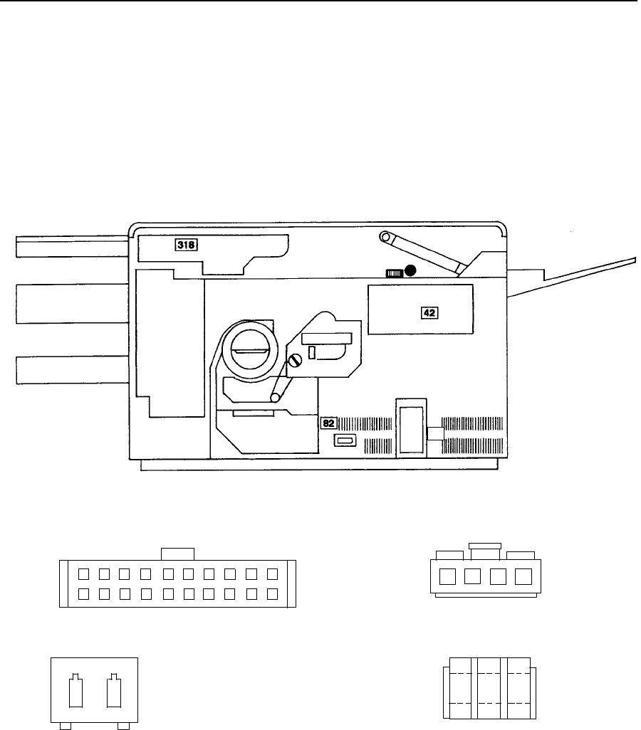
Connector Locations
6-6 Wiring Diagrams and Electrical Data June 1999
Connector Locations
The illustrations that follow show the relative location of all accessible connectors in the
printer, and illustrate the connector (except for a few instances in which the connector is so
simple that an illustration is unnecessary). For the connector’s schematic location, refer to
the chart on the preceding pages.
Connectors Inside the Front Cover
J/P 318
J/P 42
J/P 82
1
2
3
4
5
6
7
81012
13
14
15
16
17
18
19
20
1212 3
1234
J/P 95
95
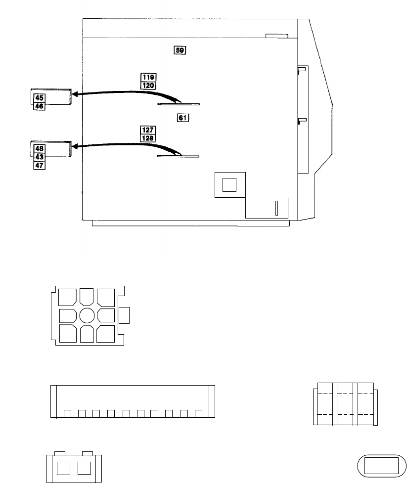
Connector Locations
June 1999 Wiring Diagrams and Electrical Data 6-7
Connectors Inside the Left Cover
J/P 43, 45, 47
J/P 46, 48
J/P 59, 61
J/P 119, 120, 127, 128
2345678910 1
12 3
12 1
1
2
3
4
5
6
7
8
9
J/P 1
1
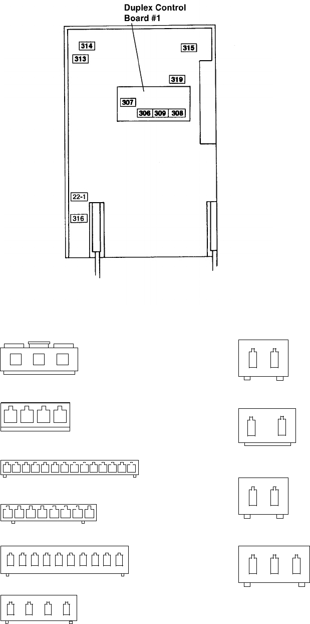
Connector Locations
6-8 Wiring Diagrams and Electrical Data June 1999
Connectors on the Duplex Cover
J/P 316
J/P 22-1
J/P 307
J/P 315
J/P 319
J/P 306
J/P 309
J/P 308
J/P 314
J/P 313
12
12
123
12
1234
1 2 3 4 5 6 7 8 91011121314
12345678
12345678910
1234
123
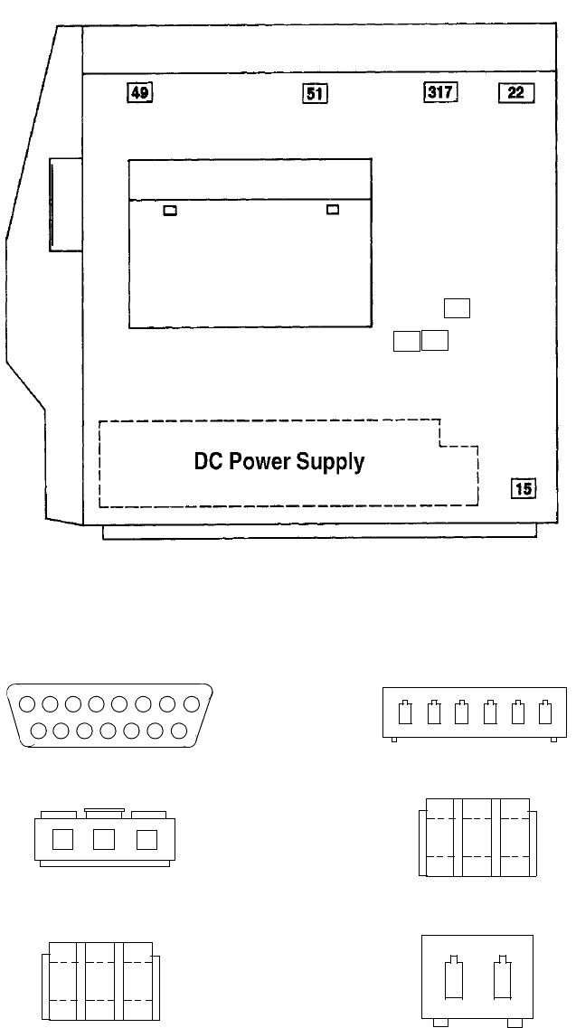
Connector Locations
June 1999 Wiring Diagrams and Electrical Data 6-9
Connectors Inside the Right Cover
J/P 49, 51, 53
J/P 22
J/P 317
J/P 15
12345678
9101112131415
123
12 3
12 3
12
J/P 55
123456
J/P 54
53 55
54

Connector Locations
6-10 Wiring Diagrams and Electrical Data June 1999
Connectors Inside the Top Cover
J/P 305 J/P 322
J/P 310
J/P 311
J/P 312
J/P 321
J/P 5
J/P 57
J/P 320
J/P 63
J/P 131-132
1
2
3
4
5
6
7
8
9
10
11
12
1
12
12 3
12345678
12345678910
12 3
12 34
1234
123
1234
5678
+
+
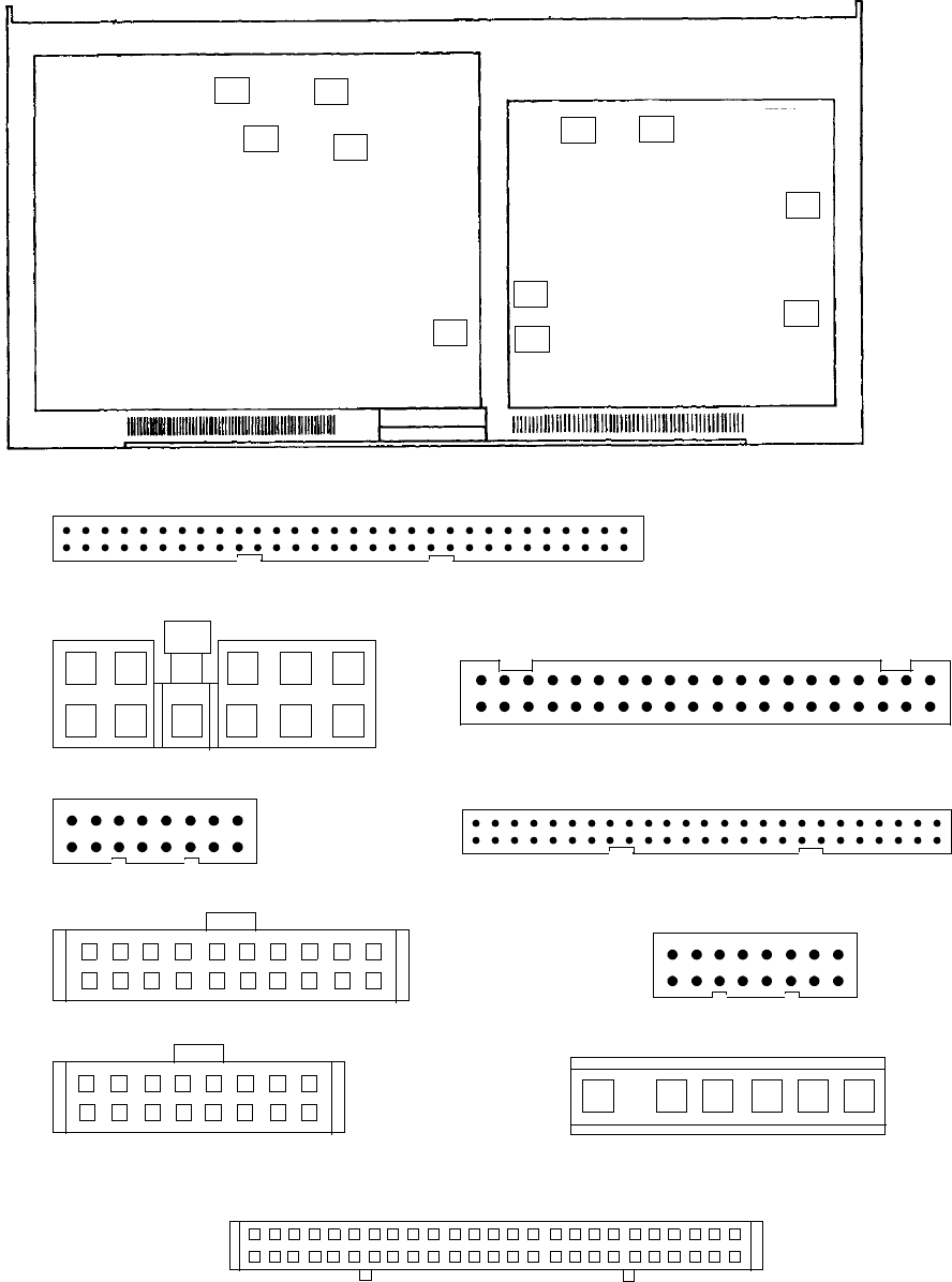
Connector Locations
June 1999 Wiring Diagrams and Electrical Data 6-11
Connectors on the Back Cover
J/P 32
J/P 31
J/P 36
J/P 40, 41
J/P 37
J/P 76
1
2
3
4
5
6
7
8
9
10
11
12
13 15
1614
17
18
19
20
21
22
23
24
25
26
27
28
29
30
31
32
33
34
35
36
37
38
39
40
2 4 6 8 1012 1614 18 20 22 2426 28 30 3234 36 38 4042
41 43
44
45
46
47
48
49
50
1 3 5 7 9 11 131517 19 2123 25 27 29 3133 35 37 39
1
2
3
4
5
6
7
81012
13
14
15
16
17
18
19
20
1
2
3
4
5
681012
13
14
15
16
11
1
2
3
4
5
6
7
8
9
10
11
12
1315
16 14
J/P 74
2 4 6 8 1012 1614 18 2022 2426 28 30 32 34 36 38 40 42
41 43
44
45
46
47
48
49
50
1 3 5 7 9 11 1315 17 19 2123 25 27 29 3133 35 37 39 51
52
53
54
55
56
57
58
59
60
1
2
3
4
5
6
7
8
9
10
11
J/P 87
123456
J/P 91
2 4 6 8 10 12 1614 18 20 2224 26 28 30 3234 36 38 4042 44 46 48 50
41 43 45 47 49135
7
9 1517192123252729313335
1
2
3
4
5
6
7
8
9
10
11
12
1315
16 14
J/P 33
31
32
76
33
91
87 37
36
40
41
74
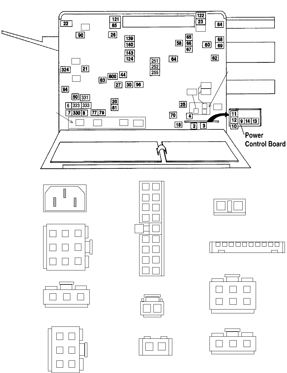
Connector Locations
6-12 Wiring Diagrams and Electrical Data June 1999
Connectors Inside the Back Cover (J/P2-14)
J/P 2, 3
J/P 4
J/P 6
J/P 7
J/P 8
J/P 9
J/P 10
J/P 13
J/P 14
J/P 11
J/P 12
1
2
3
4
5
6
7
8
9
123
4
56
123
123
1
2
3
4
5
6
1
2
3
4
5
6
7
8
9
10
11
12
13
14
15
16
17
1
2
12
12345678910
1
2
72
71
102
73
100
101
500
56
19
54
24
Jogging Motor
Control Board
Signal Interface
Board
52
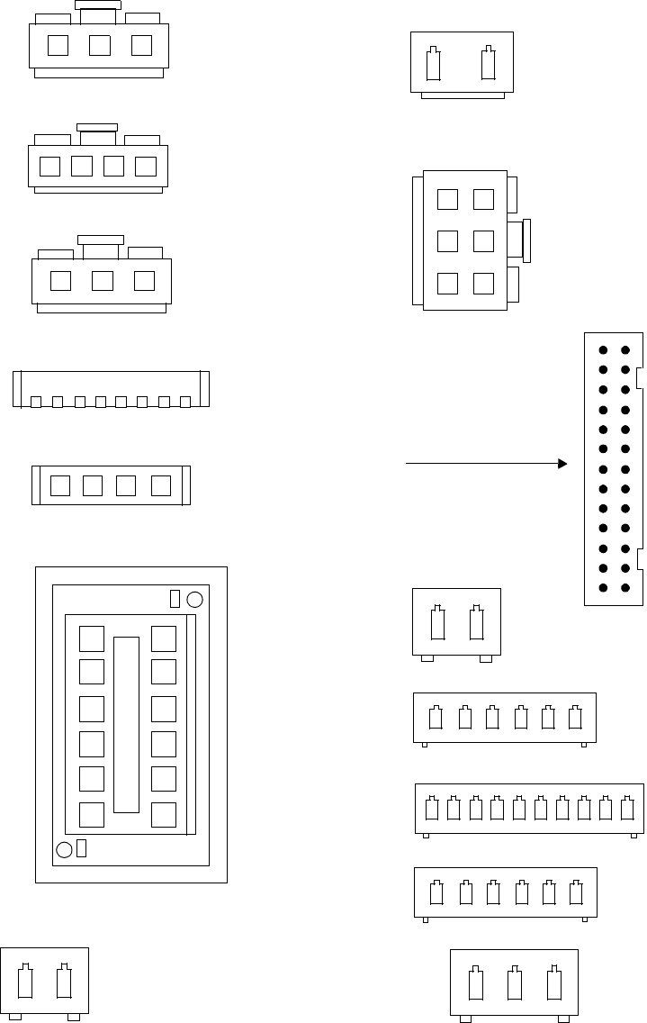
Connector Locations
June 1999 Wiring Diagrams and Electrical Data 6-13
Connectors Inside the Back Cover (Continued) J/P18-62
J/P 18
J/P 19, 20
J/P 21, 22
J/P 23
J/P 25
J/P 26
J/P 27
J/P 50
J/P 56, 58, 60, 62
J/P 30
J/P 44
123
123
1
2
3
4
5
6
12
1234
12
1234
J/P 24
2345678 1
+
+
1
2
3
4
5
6
7
8
9
10
11
12
123456
123
12345678910
123456
J/P 52
J/P 54
J/P 44
12
1
2
3
4
5
6
7
8
9
10
11
12
13
1516
14
17
18
19
20
21
22
23
24
25
26

Connector Locations
6-14 Wiring Diagrams and Electrical Data June 1999
Connectors Inside the Back Cover (Continued) J/P 64-85
72
71
102
73
101
500
56
19
54
24
Jogging Motor
Control Board
Signal Interface
Board
52
100
J/P 77
J/P 79
J/P 81, 83
J/P 84
J/P 65, 66, 67, 68, 69, 70
J/P 64
12345678
9101112131415
12345678910111213
1415
16171819202122232425
12
12
1
2
1234
1234
1
2
3
4
5
6
7
8
9
10
11
12
13
1516
14
17
18
19
20
21
22
23
24
25
26
27
28
29
30
31
32
33
34
J/P 71
(RS-232C)
J/P 72
(RS-422)
J/P 85
12345
69 78
12345678910
J/P 73
(DC)
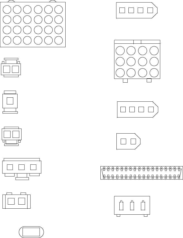
Connector Locations
June 1999 Wiring Diagrams and Electrical Data 6-15
Connectors Inside the Back Cover (Continued) J/P 90-800
J/P 90
J/P 94
J/P 96
J/P 121, 122, 124
J/P 323
J/P 333
139, 140, 143
J/P 251, 252, 255 not illustrated
J/P 800
J/P 330, 331
J/P 324
1
2
1234
1234
12
123
1
1
1
2
3
4
5
6
7
8
9
10
11
12
13
14
15
16
17
18
19
20
21
22
23
24
1
2
3
4
5
6
7
8
9
10
11
12
123
12
12
J/P 100
J/P 101
J/P 102
123456789101112131516 141718
1920212223242526
27282930313233343536
J/P 500
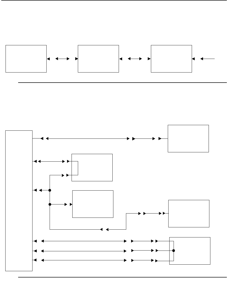
Voltage Isolation Diagrams
6-16 Wiring Diagrams and Electrical Data June 1999
Voltage Isolation Diagrams
Use the following voltage isolation diagrams to locate the presence or loss of proper DC
potentials within the printer. Simplex circuit are shown first, followed by duplex circuits.
Figure 6-1. (Simplex) -12 Vdc Circuits
Figure 6-2. (Simplex) +5 Vdc Circuit
DC Power
Supply
IGS
Board
J/P8-8
J/P32-3 J/P88-32
J/P74-32 J/P73-4
Signal Interface
Board
External
Attachment
Connector
PCL Board
DC Power
Supply
IGS Board
J/P8-1
Operator Panel
Board
Printhead
Board
Disk Drive
J/P77-4
J/P8-10 J/P32-5
J/P8-14
J/P91-5
J/P7-1
J/P7-2
J/P7-3
J/P94-1
J/P90-1 J/P42-1
J/P27-1
J/P27-2
J/P27-3
J/P32-6
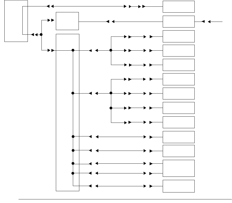
Voltage Isolation Diagrams
June 1999 Wiring Diagrams and Electrical Data 6-17
Figure 6-3. (Simplex) +12 Vdc Circuits
J/P8-3
J/P32-10
J/P91-3
J/P8-6
J/P77-1
J/P40-25
J/P40-26
J/P40-34
J/P50-4
J/P50-1
J/P62-1
J/P60-1
J/P58-1 J/P57-1
J/P59-1
J/P61-1
J/P49-1
J/P51-1
J/P12-8
J/P41-50 J/P25-1
J/P41-49 J/P25-4
J/P40-3 J/P26-1
DC IGS
PCL
Board
Power
Supply Board
Disk drive
Signal interface
External
connector
Paper timing
Upper paper
empty sensor
Lower paper
empty sensor
Paper exit
Output tray
full sensor
Power control
board #2
Developer unit
Erase lamp
board
J/P40-35 J/P12-1
J/P53-1
J/P55-1
sensor
sensor
Power control
Board #3
Tray rear
sensor
Tray front
sensor
attachment
J/P73-3
J/P74-34
J/P54-4
J/P54-1
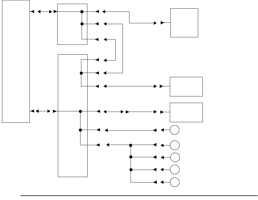
Voltage Isolation Diagrams
6-18 Wiring Diagrams and Electrical Data June 1999
Figure 6-4. (Simplex) +24 Vdc Circuits
PCL
Board
Power
Control
Board #2
Counter
High Voltage
Unit
AC
Power
Lower pick-up clutch
Paper timing clutch
Upper paper feed clutch
Lower paper feed clutch
Upper pick-up clutch
Supply
DC
Power
Supply
J/P8-11
J/P11-1
J/P8-13
J/P91-1
J/P10-1
J/P12-2
J/P12-1
J/P40-27
J/P40-28
J/P41-35
J/P41-26
J/P40-10
J/P40-11
J/P23-5
J/P82-1
J/P69-1
J/P65-1
J/P66-1
J/P67-1
J/P81-1
J/P70-1
J/P68-1

Voltage Isolation Diagrams
June 1999 Wiring Diagrams and Electrical Data 6-19
Figure 6-5. (Duplex) +5 Vdc Circuit
Figure 6-6. (Duplex) +24 Vdc Circuits
DC
Power
Supply
Signal
Interface
Board
Duplex
Control
Board #1
Duplex
Control
Board #2
J/P330-3
J/P331-3
J/P323-3
J/P333-1
J/P305-3
J/P306-3
J/P310-3
Fuse (FH2)
J/P73-1
J/P73-6
External
Attachment
Connector
(
)
)
(
J/P331-1
J/P330-1
J/P323-1
J/P306-1
J/P310-1
J/P305-1
Duplex
Duplex
Control
Board #2
DC
Power
Supply
J/P309-7~10
J/P308-1
J/P308-2
J/P308-4
Board #1
Control
J/P308-3
J/P312-7~10 J/P321-1~4
J/P317-1
J/P316-1
J/P315-1
J/P314-1
J/P313-1~4 Route motor
In solenoid
Exit solenoid
“C” roller solenoid
Restart motor
“A” roller clutch
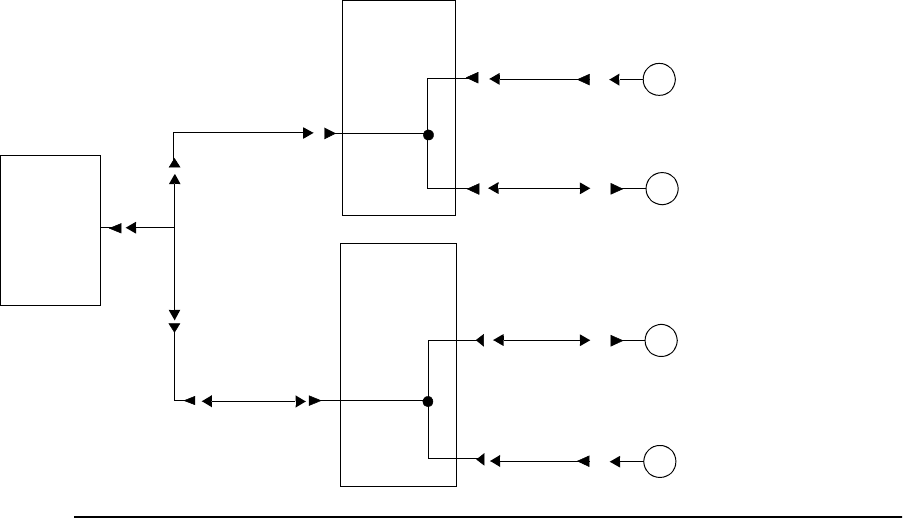
Voltage Isolation Diagrams
6-20 Wiring Diagrams and Electrical Data June 1999
Figure 6-7. (Duplex) +12 Vdc Circuits
J/P331-2
J/P330-2
J/P323-2
J/P306-2
J/P310-2
J/P305-2
Duplex
Duplex
Control
Board #2
DC
Power
Supply
Board #1
Control
J/P319-1 Paper pass
J/P309-4
J/P318-1 Cover open
J/P309-3
J/P320-1 Registration side
J/P312-1
J/P322-1 Registration paper
J/P312-4
sensor
sensor
sensor
sensor
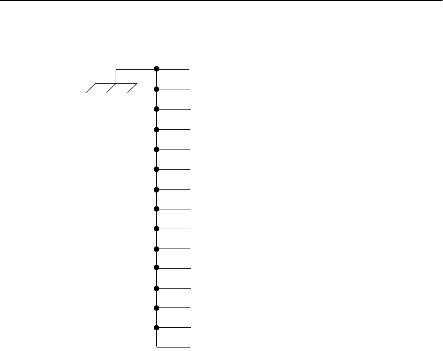
Ground System
June 1999 Wiring Diagrams and Electrical Data 6-21
Ground System
J/P4-9 – AC power supply
J/P5-8 – Fuser unit
J/P6-3 – DC power supply
J/P18-3 – Toner supply motor
J/P19-4 – Jogging motor
J/P21-3 – Large cooling fan
J/P326-3 – Small cooling fan
J/P22-3 – Vacuum transport unit
J/P23-8 – High voltage unit
J/P20-1 – Main motor
J/P 255 – Photoconductor unit
J/P305-12 – Duplex control board #2
Back cover to frame grounding strap
Charge corona
Transfer corona

Host Interface Reference
6-22 Wiring Diagrams and Electrical Data June 1999
Host Interface Reference
Standard printers support three host interfaces: RS-232C, RS-422, and Centronics Parallel.
User-level information about the installation, configuration, and use of these interfaces is
included in the printer’s Guide to Operations.
RS-232C Host Interface
A printer is standard data terminal equipment (DTE), designed specifically for a direct
connection to a standard data communication equipment (DCE) host. The standard signal
definitions for DTE to DCE equipment are outlined in the table that follows.
Table 6-1. RS-232C DCE to DTE Signal Definitions
Pin Signal
Name Function
1 FG Frame or chassis ground
2 TD Transmitted data
3 RD Received data
4 RST Request to send
5 CTS Clear to send
6 DSR Data set ready
7 SG Signal ground
8 DCD Data carrier detect
9 Positive DC test voltage
10 Negative DC test voltage (unassigned)
11 (S)DCD Secondary data carrier detect
12 (S)CTS Secondary clear to send
13 (S)CTS Secondary clear to send
14 (S)TD Secondary transmitted data
15 TC Transmitter clock
16 (S)RD Secondary received data
17 RC Receiver clock
18 RDC Receiver debit clock
19 (S)RTS Secondary receive to send
20 DTR Data terminal ready
21 SQ Signal quality detect
22 RI Ring indicator
23 DRS Data rate select
24 (TC) External transmitter clock
25 BSY Busy
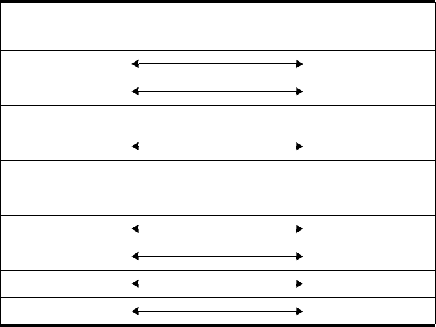
Host Interface Reference
June 1999 Wiring Diagrams and Electrical Data 6-23
Standard DCE to DTE RS-232C Cable
The standard DCE host to the printer (DTE) pin configuration follows..
Special Considerations for RS-232 Host Interface Users
If the READY light comes on and the ON-LINE light does not come on when you are
installing the printer, one or more of the pin signals on the RS-232 cable may be incorrect.
The host computer may be using a non-DCE RS-232C port. If so, you may have to modify
your cable or purchase a new cable with the proper pin assignments. Several possible
alternate RS-232C cable configurations follow.
Table 6-2. Standard DCE to DTE Signal Definition
Host
Signal DCE DTE Printer
Signal
GND 1 1 GND
GND 7 7 GND
RI 22 22 RI
DTR 20 20 DTR
DCD 8 8 DCD
DSR 6 6 DSR
RTS 4 4 RTS
CTS 5 5 CTS
TD 2 2 TD
RD 3 3 RD
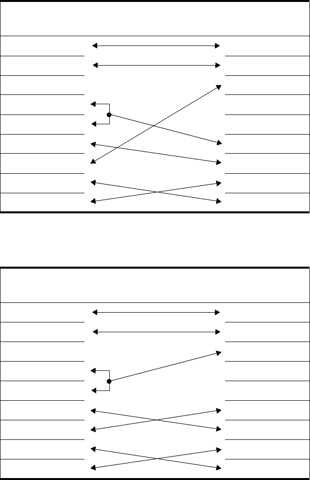
Host Interface Reference
6-24 Wiring Diagrams and Electrical Data June 1999
DTE Host to Printer (Option 1)
DTE Host to Printer (Option 2)
Table 6-3. DTE Host to Printer Connector Wiring (Option 1)
Host
Signal DCE DTE Printer
Signal
GND 1 1 GND
GND 7 7 GND
DTR 20 20 DTR
DCD 8 8 DCD
DSR 6 6 DSR
RTS 4 4 RTS
CTS 5 5 CTS
TD 2 2 TD
RD 3 3 RD
Table 6-4. DTE Host to Printer Connector Wiring (Option 2)
Host
Signal DCE DTE Printer
Signal
GND 1 1 GND
GND 7 7 GND
DTR 20 20 DTR
DCD 8 8 DCD
DSR 6 6 DSR
RTS 4 4 RTS
CTS 5 5 CTS
TD 2 2 TD
RD 3 3 RD
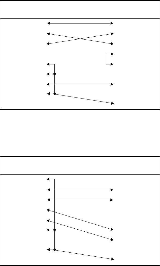
Host Interface Reference
June 1999 Wiring Diagrams and Electrical Data 6-25
IBM PC/XT to Printer
Normally, the IBM PC/XT comes with a parallel interface for the printer with a 25-pin
female connector. To run RS-232, you must install a serial board, which will have a male
connector.
IBM PC/AT to Printer
Normally, the IBM AT comes with a 9-pin serial connector.
Table 6-5. IBM PC/XT to Printer Connector Wiring
PC/XT
Signal DTE DTE Printer
Signal
------- 1 1 FG
TD 2 2 TD
RD 3 3 RD
RTS 4 4 RTS
CTS 5 5 CTS
DSR 6 6 DSR
SG 7 7 SG
DCD 8 8 DCD
DTR 20 20 DTR
Table 6-6. IBM PC/AT to Printer Connector Wiring
PC/AT
Signal DCE DTE Printer
Signal
DCD 1 1 FG
RD 2 2 TD
TD 3 3 RD
DTR 4 4 RTS
SG 5 5 CTS
DSR 6 6 ------
RTS 7 7 SG
CTS 8 8 DCD
RI 9 20 DTR
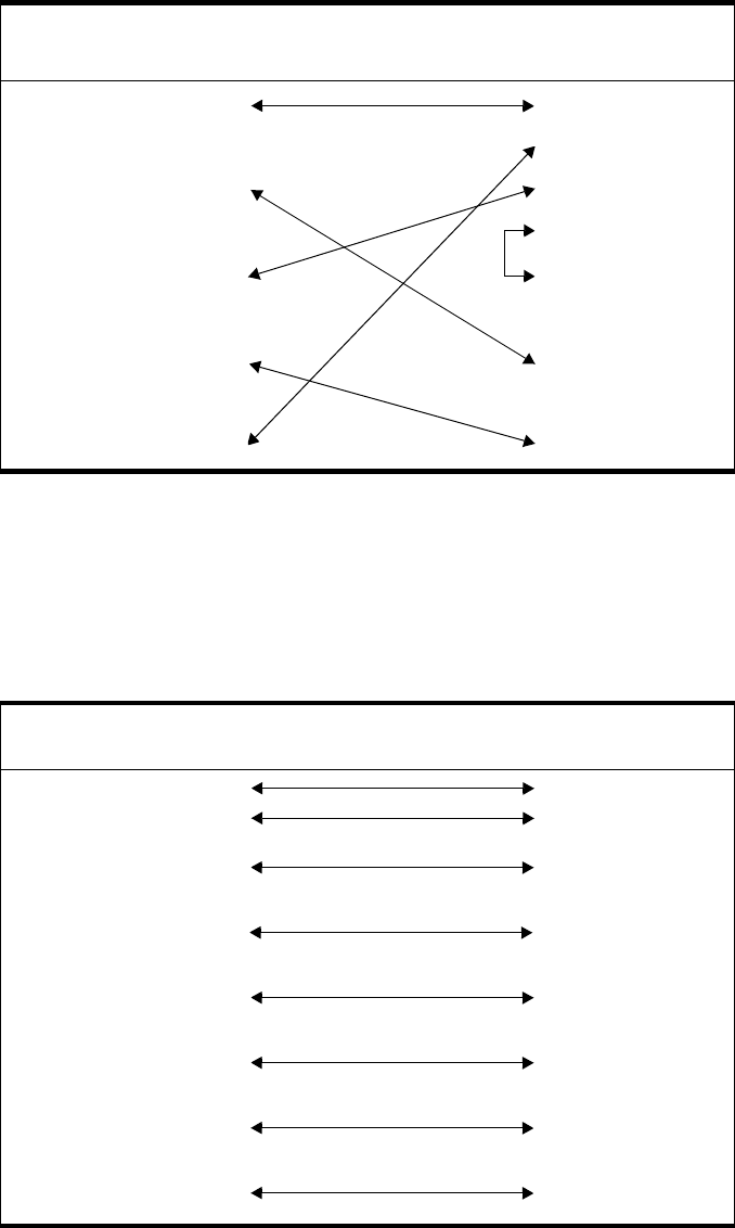
Host Interface Reference
6-26 Wiring Diagrams and Electrical Data June 1999
Macintosh Communication Port to Printer
Normally, the Macintosh comes with a 9-pin male connector.
RS-422 Host interface
The RS-422 host interface uses the signal definitions defined below. A shielded cable is
required with the shield connected on one end only, preferably at the printer end.
Table 6-7. Macintosh Communication Port to Printer Connector Wiring
Macintosh
Signal DCE DTE Printer
Signal
FG 1 1 FG
22TD
SG 3 3 RD
44RTS
TD 5 5 CTS
6 6 ------
DSR 7 7 SG
8 8 DCD
RD 9 20 DTR
Table 6-8. RS-422 Host Interface Connector Wiring
Host
Signal Printer
Signal
GND 1 1 FG
SG 8 8 SG
TD 22
TD
99
RD 44
RD
11 11
DCD 55
DCD
12 12
ST2 66
ST2
13 13
ST1 77
ST1
14 14
DTR 33
DTR
10 10

Host Interface Reference
June 1999 Wiring Diagrams and Electrical Data 6-27
Centronics Parallel Host Interface
The Centronics Parallel host interface uses the signal definitions defined below.
Table 6-9. Centronics Parallel Signal Definitions
Pin Signal
Name Function
1 DS Data strobe (active low)
2 DB0 Data bit 0
3 DB1 Data bit 1
4 DB2 Data bit 2
5 DB3 Data bit 3
6 DB4 Data bit 4
7 DB5 Data bit 5
8 DB6 Data bit 6
9 DB7 Data bit 7
10 ACK Acknowledge (active low)
11 BSY Busy (active high)
12 PE Paper empty (active high)
13 SEL Select (active high)
14 AF Auto feed
15 Not used
16 SG Signal ground
17 FG Frame or chassis ground
18 PLH Peripheral logic high
19 to 30 Signal ground
31 IP INIT
32 ERR Error (active low)
33 to 35 Not used
36 SI Select input
Host Interface Reference
6-28 Wiring Diagrams and Electrical Data June 1999
IBM Parallel to Printer
Table 6-10. IBM Parallel to Printer Connector Wiring
Host
Signal Printer
Signal
DS 1 1 DS
DB0 2 2 DB0
DB1 3 3 DB1
DB2 4 4 DB2
DB3 5 5 DB3
DB4 6 6 DB4
DB5 7 7 DB5
DB6 8 8 DB6
DB7 9 9 DB7
ACK 10 10 ACK
BSY 11 11 BSY
PE 12 12 PE
SEL 13 13 SEL
AF 14 14 AF
ERR 15 32 ERR
IP 6 31 IP
SI 17 36 SI
GND 18 33 GND
GND 19 19 GND
GND 20 21 GND
GND 21 23 GND
GND 22 25 GND
GND 23 27 GND
GND 24 29 GND
GND 25 30 GND
Host Interface Reference
June 1999 Wiring Diagrams and Electrical Data 6-29
Special Considerations for Centronics Parallel Interface Users
For DOS host computers, add the following line to the AUTOEXEC.BAT file:
MODE PRN,,P
To edit the AUTOEXEC.BAT file, use any text editor or the EDLIN facility of DOS. If
you do not know how to edit this file, refer to the reference manual that came with the
DOS software.

Circuit Board Settings
6-30 Wiring Diagrams and Electrical Data June 1999
Circuit Board Settings
Several of the circuit boards in the printer have jumpers and/or DIP switches used to con-
trol the functionality of the board. These settings are described the following section.
Signal Interface Board Settings
The signal interface board has both jumpers and DIP switches used to control host inter-
face interactions.
Figure 6-8. Signal Interface Board Jumper/Switch Locations
In general, the four jumpers on the signal interface board should remain as set at the fac-
tory. The jumpers control the following:
The four DIP switches on the signal interface board should be changed based on the host
interface being used.
For an RS-232C host interface: the DIP switches may be set in either direction; they
have no effect on an RS-232C interface.
Table 6-11. Signal Interface Board Jumper Settings
Jumper Direction Description
JP1 b-c
a-b Baud rate crystal oscillator on IGS board 3.6854 MHz
Baud rate crystal oscillator on IGS board 7.3728 MHz
JP2 d-e
e-f Unsolicited status reports enabled after power-on-reset
Unsolicited status reports disabled after power-on-reset
JP3 g-h
No jumper ERR (pin 32) error line output enabled
ERR (pin 32) error line output disabled
JP4 i-j
j-k PE (pin 12) out of paper line enabled
PE (pin 12) out of paper line disabled
JP3
JP4
JP1
JP2
SW 1234A
B
C
D
E
F
G
H
K
J
I
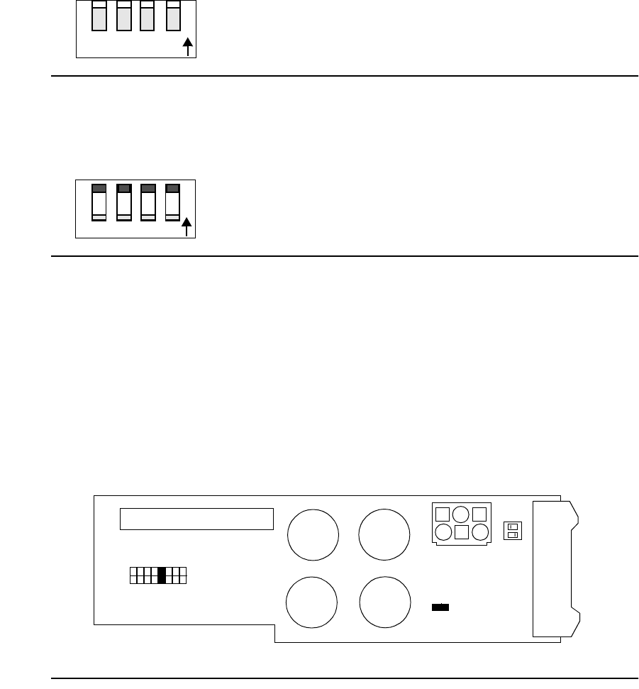
Circuit Board Settings
June 1999 Wiring Diagrams and Electrical Data 6-31
For an RS-422 host interface: set all four DIP swiches to ON by raising them up away
from the printed circuit board.
Figure 6-9. RS-422 Host Interface DIP Settings
For a Centronics Parallel Host Interface: set all four DIP switches to OFF by pushing
them down toward the printed circuit board.
Figure 6-10. Centronics Parallel Host Interface DIP Settings
PCL Board Settings
The PCL board uses DIP switches to control the registration of prints. Change these set-
tings only if directed to do so when following TAG #807.
Printhead Circuit Board Settings
The printhead circuit board uses jumpers to match printhead characteristics to controller
characteristics. Do not change these jumper settings; they should remain as set at the fac-
tory.
Figure 6-11. Printhead Circuit Board Jumper/Switch Locations
ON
12 34
ON
1234
••
••
•
•
•
••
••
••
••
••
•
•
•
•
J30
J29
SW1
JP2
J28
JP1
18

Power Supply Strapping
6-32 Wiring Diagrams and Electrical Data June 1999
Power Supply Strapping
The input source voltage for the printer is set by a strapping plug located behind the left
cover near the AC power switch. The strapping options and corresponding voltages are
shown in the following table.
Table 6-12. AC Power Strapping
Jumper Pins AC Voltage
1 to 3 100
1 to 4 120
1 to 5 200
1 to 6 220
1 to 7 230
1 to 8 240
1
2
3
4
5
6
7
8
9
Strapping Plug

June 1999 Removal/Replacement Procedures 7-1
Chapter 7
Removal/Replacement
Procedures
Section 5 Troubleshooting

7-2 Removal/Replacement Procedures June 1999
Chapter Contents
Removal/Replacement Procedures
Front Cover Removal . . . . . . . . . . . . . . . . . . . . . . . . . . . . . . . . . . . . . . . . . . . . . . . 7-5
Back Cover Removal . . . . . . . . . . . . . . . . . . . . . . . . . . . . . . . . . . . . . . . . . . . . . . . .7-6
Lower Back Cover Removal . . . . . . . . . . . . . . . . . . . . . . . . . . . . . . . . . . . . . . . . . .7-7
Left Side Cover Removal . . . . . . . . . . . . . . . . . . . . . . . . . . . . . . . . . . . . . . . . . . . .7-8
Right Side Cover Removal (Simplex) . . . . . . . . . . . . . . . . . . . . . . . . . . . . . . . . . . .7-9
Right Side Cover Removal (Duplex) . . . . . . . . . . . . . . . . . . . . . . . . . . . . . . . . . .7-10
Vacuum Transport Unit Removal (Simplex) . . . . . . . . . . . . . . . . . . . . . . . . . . . .7-11
Vacuum Transport Unit Removal (Duplex) . . . . . . . . . . . . . . . . . . . . . . . . . . . . .7-13
Top Cover Removal . . . . . . . . . . . . . . . . . . . . . . . . . . . . . . . . . . . . . . . . . . . . . . .7-14
Top Cover Support Removal . . . . . . . . . . . . . . . . . . . . . . . . . . . . . . . . . . . . . . . . .7-15
Top Cover Hinge Removal . . . . . . . . . . . . . . . . . . . . . . . . . . . . . . . . . . . . . . . . . .7-16
Rear Duplex Cover Removal . . . . . . . . . . . . . . . . . . . . . . . . . . . . . . . . . . . . . . . . .7-17
Front Duplex Cover Removal . . . . . . . . . . . . . . . . . . . . . . . . . . . . . . . . . . . . . . . .7-18
Operator Panel Removal . . . . . . . . . . . . . . . . . . . . . . . . . . . . . . . . . . . . . . . . . . . .7-19
Counter Removal . . . . . . . . . . . . . . . . . . . . . . . . . . . . . . . . . . . . . . . . . . . . . . . . . .7-20
IGS Board Removal . . . . . . . . . . . . . . . . . . . . . . . . . . . . . . . . . . . . . . . . . . . . . . .7-21
PCL Board Removal . . . . . . . . . . . . . . . . . . . . . . . . . . . . . . . . . . . . . . . . . . . . . . .7-22
Printhead Assembly Removal . . . . . . . . . . . . . . . . . . . . . . . . . . . . . . . . . . . . . . . .7-23
Disk Drive Housing Removal . . . . . . . . . . . . . . . . . . . . . . . . . . . . . . . . . . . . . . . .7-25
Cooling Fan Removal . . . . . . . . . . . . . . . . . . . . . . . . . . . . . . . . . . . . . . . . . . . . . .7-26
Duplex Fan Removal . . . . . . . . . . . . . . . . . . . . . . . . . . . . . . . . . . . . . . . . . . . . . . .7-27
Toner Motor Removal . . . . . . . . . . . . . . . . . . . . . . . . . . . . . . . . . . . . . . . . . . . . . .7-28
AC Power Supply Removal . . . . . . . . . . . . . . . . . . . . . . . . . . . . . . . . . . . . . . . . . .7-29
DC Power Supply Removal . . . . . . . . . . . . . . . . . . . . . . . . . . . . . . . . . . . . . . . . . .7-31
High Voltage Unit Removal . . . . . . . . . . . . . . . . . . . . . . . . . . . . . . . . . . . . . . . . .7-32
Photoconductor Seam Sensor Removal . . . . . . . . . . . . . . . . . . . . . . . . . . . . . . . . .7-33
Photoconductor Rear Guide Rail Removal . . . . . . . . . . . . . . . . . . . . . . . . . . . . . .7-35
Signal Interface Board Removal . . . . . . . . . . . . . . . . . . . . . . . . . . . . . . . . . . . . . .7-37
Power Control Board Removal . . . . . . . . . . . . . . . . . . . . . . . . . . . . . . . . . . . . . . .7-38
Jogging Motor Control Board Removal . . . . . . . . . . . . . . . . . . . . . . . . . . . . . . . .7-39
Upper or Lower Paper Size Sensor Removal . . . . . . . . . . . . . . . . . . . . . . . . . . . .7-40
Upper Cassette Mount Removal . . . . . . . . . . . . . . . . . . . . . . . . . . . . . . . . . . . . . .7-41
Lower Cassette Mount Removal . . . . . . . . . . . . . . . . . . . . . . . . . . . . . . . . . . . . . .7-45
Upper Paper Guide Removal . . . . . . . . . . . . . . . . . . . . . . . . . . . . . . . . . . . . . . . . .7-49
Upper Paper Guide Roller Removal . . . . . . . . . . . . . . . . . . . . . . . . . . . . . . . . . . .7-51
Lower Paper Guide Removal . . . . . . . . . . . . . . . . . . . . . . . . . . . . . . . . . . . . . . . .7-52
Paper Timing Guide Removal . . . . . . . . . . . . . . . . . . . . . . . . . . . . . . . . . . . . . . . .7-53
Cleaner Drive Belt Removal . . . . . . . . . . . . . . . . . . . . . . . . . . . . . . . . . . . . . . . . .7-55
Cleaner Drive Removal . . . . . . . . . . . . . . . . . . . . . . . . . . . . . . . . . . . . . . . . . . . . .7-56
Fuser Drive Belt Removal . . . . . . . . . . . . . . . . . . . . . . . . . . . . . . . . . . . . . . . . . . .7-57
June 1999 Removal/Replacement Procedures 7-3
Fuser Drive Removal . . . . . . . . . . . . . . . . . . . . . . . . . . . . . . . . . . . . . . . . . . . . . . 7-58
Paper Feed Drive Belt Removal . . . . . . . . . . . . . . . . . . . . . . . . . . . . . . . . . . . . . . 7-59
Paper Timing Roller Removal . . . . . . . . . . . . . . . . . . . . . . . . . . . . . . . . . . . . . . . 7-60
Upper Feed Roller Removal . . . . . . . . . . . . . . . . . . . . . . . . . . . . . . . . . . . . . . . . . 7-61
Lower Feed Roller Removal . . . . . . . . . . . . . . . . . . . . . . . . . . . . . . . . . . . . . . . . . 7-62
Upper Pick-Up Roller Removal . . . . . . . . . . . . . . . . . . . . . . . . . . . . . . . . . . . . . . 7-63
Upper Pick-Up Roller Drive Removal . . . . . . . . . . . . . . . . . . . . . . . . . . . . . . . . . 7-64
Lower Pick-Up Roller Removal . . . . . . . . . . . . . . . . . . . . . . . . . . . . . . . . . . . . . . 7-65
Lower Pick-Up Roller Drive Removal . . . . . . . . . . . . . . . . . . . . . . . . . . . . . . . . . 7-66
Job Offset Assembly Removal . . . . . . . . . . . . . . . . . . . . . . . . . . . . . . . . . . . . . . . 7-67
Exit Pinch Roller Removal . . . . . . . . . . . . . . . . . . . . . . . . . . . . . . . . . . . . . . . . . . 7-69
Upper Static Brush Removal . . . . . . . . . . . . . . . . . . . . . . . . . . . . . . . . . . . . . . . . 7-71
Lower Static Brush Removal . . . . . . . . . . . . . . . . . . . . . . . . . . . . . . . . . . . . . . . . 7-72
Exit Roller Assembly Removal . . . . . . . . . . . . . . . . . . . . . . . . . . . . . . . . . . . . . . 7-73
Exit Cover Removal (Simplex) . . . . . . . . . . . . . . . . . . . . . . . . . . . . . . . . . . . . . . . 7-75
Exit Cover Removal (Duplex) . . . . . . . . . . . . . . . . . . . . . . . . . . . . . . . . . . . . . . . 7-77
Paper Exit Sensor Removal . . . . . . . . . . . . . . . . . . . . . . . . . . . . . . . . . . . . . . . . . 7-79
Paper Full Sensor Removal . . . . . . . . . . . . . . . . . . . . . . . . . . . . . . . . . . . . . . . . . . 7-80
Front Cover Interlock Switch Removal . . . . . . . . . . . . . . . . . . . . . . . . . . . . . . . . 7-81
Back Cover Interlock Switch Removal . . . . . . . . . . . . . . . . . . . . . . . . . . . . . . . . . 7-82
Top Cover Interlock Switch Removal . . . . . . . . . . . . . . . . . . . . . . . . . . . . . . . . . 7-83
Erase Lamp Removal . . . . . . . . . . . . . . . . . . . . . . . . . . . . . . . . . . . . . . . . . . . . . . 7-84
EP Cover Removal . . . . . . . . . . . . . . . . . . . . . . . . . . . . . . . . . . . . . . . . . . . . . . . . 7-85
Main Motor Removal . . . . . . . . . . . . . . . . . . . . . . . . . . . . . . . . . . . . . . . . . . . . . . 7-87
Main Gear Drive Removal . . . . . . . . . . . . . . . . . . . . . . . . . . . . . . . . . . . . . . . . . . 7-89
Duplex Control Board #1 Removal . . . . . . . . . . . . . . . . . . . . . . . . . . . . . . . . . . . 7-90
Duplex Control Board #2 Removal . . . . . . . . . . . . . . . . . . . . . . . . . . . . . . . . . . . 7-91
Duplex Tray Registration Motor Removal . . . . . . . . . . . . . . . . . . . . . . . . . . . . . . 7-92
Duplex Skew Correction Cable Removal . . . . . . . . . . . . . . . . . . . . . . . . . . . . . . . 7-93
Upper Duplex Drive/Clutch Assembly Removal . . . . . . . . . . . . . . . . . . . . . . . . . 7-95
Duplex Route Motor/Solenoid Assembly Removal . . . . . . . . . . . . . . . . . . . . . . . 7-96
“A” Roller Removal . . . . . . . . . . . . . . . . . . . . . . . . . . . . . . . . . . . . . . . . . . . . . . . 7-97
“B” Roller Removal . . . . . . . . . . . . . . . . . . . . . . . . . . . . . . . . . . . . . . . . . . . . . . . 7-98
“C” Roller Removal . . . . . . . . . . . . . . . . . . . . . . . . . . . . . . . . . . . . . . . . . . . . . . . 7-99
“C” Roller Solenoid Removal . . . . . . . . . . . . . . . . . . . . . . . . . . . . . . . . . . . . . . . 7-100
Duplex Route Separator Removal . . . . . . . . . . . . . . . . . . . . . . . . . . . . . . . . . . . 7-101
Duplex Paper Path Sensor Removal . . . . . . . . . . . . . . . . . . . . . . . . . . . . . . . . . . 7-103

Removal
7-4 Removal/Replacement Procedures June 1999
Removal
This section includes step-by-step instructions for removing all field service replaceable
parts in the printer. Each part is addressed under its own heading, as outlined on the pre-
ceding contents pages. Most of the procedures are applicable to both the simplex and
duplex printer models. When the procedures differ between the two printers, the word
simplex or duplex is included in parentheses.
Before You Begin
To remove a part, follow the instructions provided. To replace a part, follow the steps in
reverse order unless otherwise noted. During reassembly, make sure to reconnect all con-
nectors properly and seat gears and other moving parts properly.
Power Considerations
Before removing a part, make sure the printer is turned off and that the power cord is dis-
connected.
Photoconductor Removal
If it is necessary to remove the photoconductor unit as part of a removal procedure, make
sure to place it in its protective packaging.
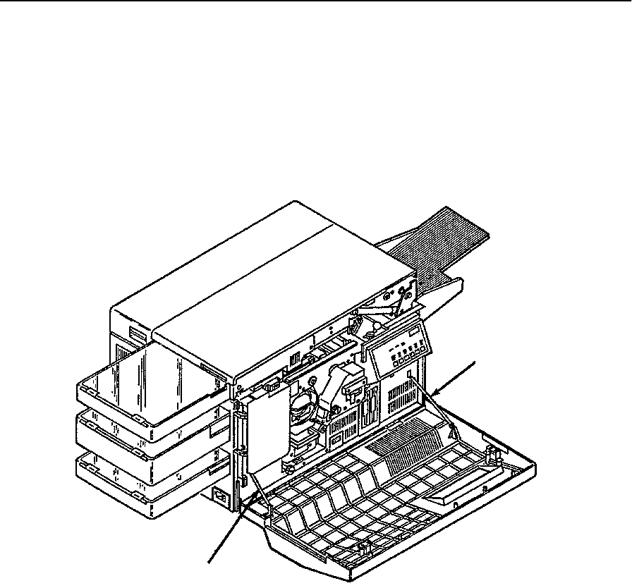
Front Cover Removal
June 1999 Removal/Replacement Procedures 7-5
Front Cover Removal
To remove the front cover:
1Open the front cover.
2While holding the cover up halfway, unhook the strap from the right side.
3Duplex only: Remove the strap from the left side.
4Slide the front cover to the right off its hinges.
Left Strap
Right Strap
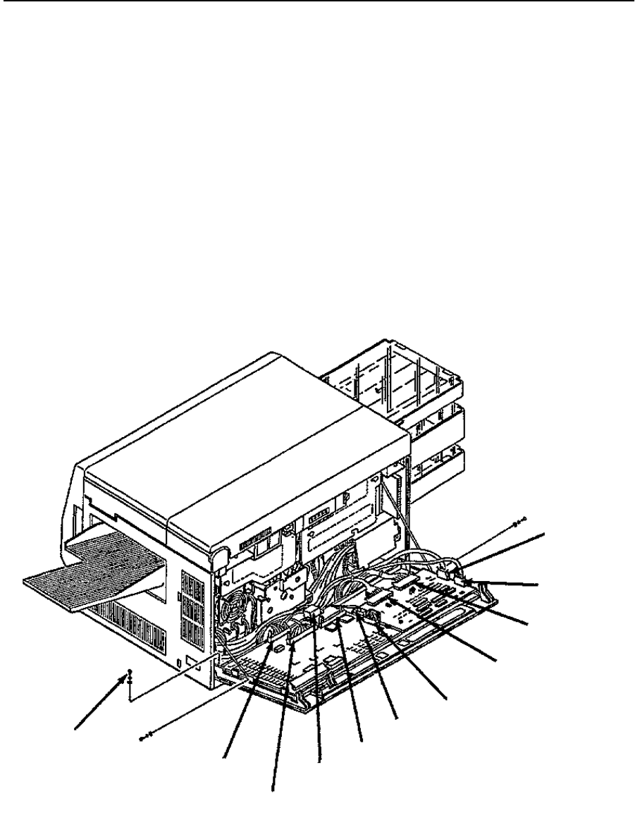
Back Cover Removal
7-6 Removal/Replacement Procedures June 1999
Back Cover Removal
To remove the back cover:
1Remove all external cables and attachments.
2Open the top and back covers.
3Disconnect CN31, CN32, CN37, CN40, CN41, CN74, and CN91.
4Duplex only: Disconnect CN36.
5For the hard drive option, disconnect the drive’s data cable.
6Remove the ground screw from the back cover.
7While supporting the back cover, remove the screw holding each strap.
Caution: hold the plastic strap to avoid throwing the screw as it comes loose.
8Lift the back cover up and away from the printer.
CN36
(C30D only)
CN37
CN40
CN41
CN33
CN91
Hard Disk Drive
Connector
CN32
CN31
CN74
Ground
Screw
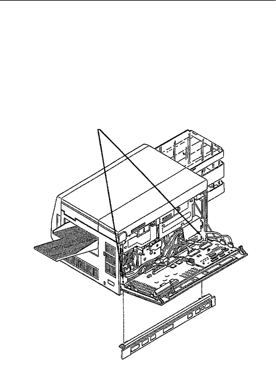
Lower Back Cover Removal
June 1999 Removal/Replacement Procedures 7-7
Lower Back Cover Removal
To remove the lower back cover:
1Disconnect all external cables and attachments.
2Open the back cover.
3Loosen the two screws holding the lower back cover in place.
4Lift the back cover off its hinges.
5While supporting the back cover, lift the lower back cover out and away from the
printer.
6Return the back cover to its hinges.
Loosen Screws
Lower Back Cover

Left Side Cover Removal
7-8 Removal/Replacement Procedures June 1999
Left Side Cover Removal
To remove the left side cover:
1Open the top, back, and front covers.
2Duplex only: Remove the duplex tray by disconnecting P305 and loosening the two
thumb screws.
3Remove the upper and lower paper cassettes.
4Loosen the two screws for the left side cover.
5Lift the cover up and away from the printer.
Replacement Note:
When reinstalling, make sure the inside mounting tabs are properly positioned.
Loosen Screws
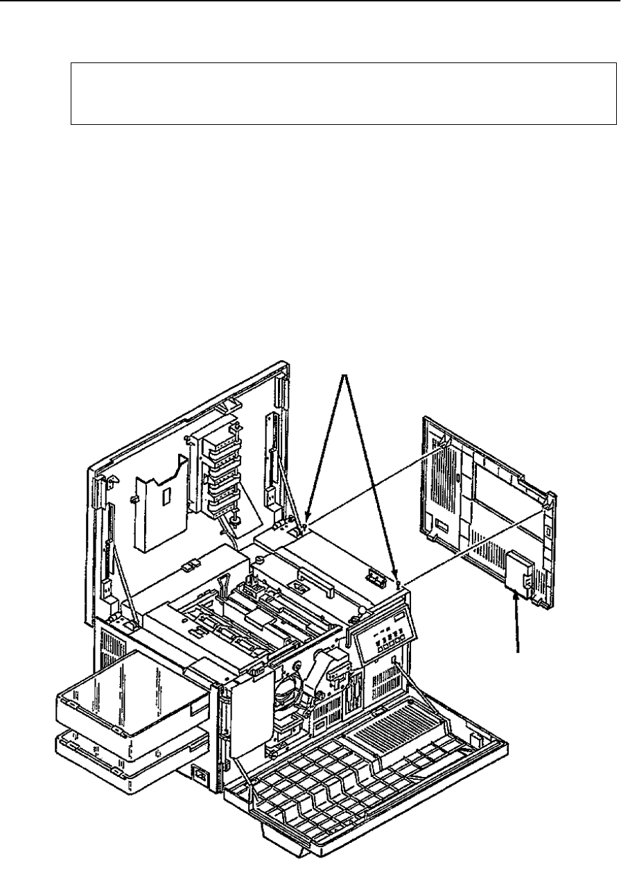
Right Side Cover Removal (Simplex)
June 1999 Removal/Replacement Procedures 7-9
Right Side Cover Removal (Simplex)
To remove the right side cover:
1Remove the paper output tray.
2Open the top and front covers.
3Loosen the two screws holding the right side cover.
4Pull the cover out and away from the printer.
Replacement Note:
When reinstalling, make sure the inside mounting tabs are properly positioned.
The service kit is attached inside the right side cover.
Note
Loosen Screws
Service Kit

Right Side Cover Removal (Duplex)
7-10 Removal/Replacement Procedures June 1999
Right Side Cover Removal (Duplex)
To remove the right side cover:
1Remove the paper output tray.
2Open the top, back, and front covers.
3Remove the two screws holding the right side cover in place.
4Close the top cover.
5Pull the cover out and away from the printer.
Replacement Note:
Tighten the screws first. Then, gently lift the bottom tabs into place. Hold the top of the
right side cover in place as you open the top cover. (This avoids the possibility of damag-
ing the top cover.)
The service kit is attached inside the right side cover.
Note
Service Kit
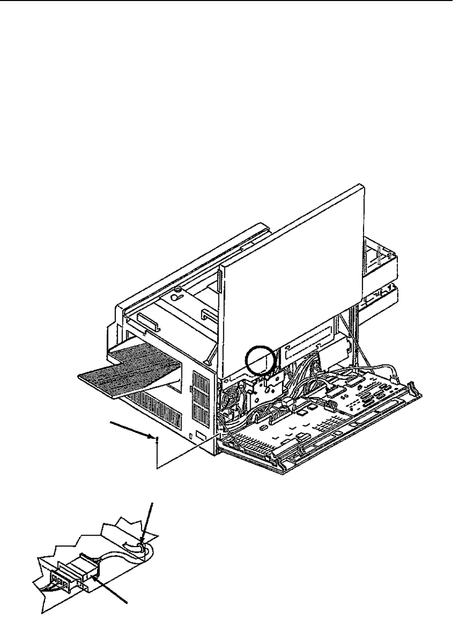
Vacuum Transport Unit Removal (Simplex)
June 1999 Removal/Replacement Procedures 7-11
Vacuum Transport Unit Removal (Simplex)
To remove the simplex vacuum transport unit:
1Open the top and back cover.
2Disconnect CN22A.
3Remove the retaining clip holding the cable in place.
4Remove the ground screw on the left side of the back cover.
5Remove the harness stays holding the cable in place.
6Remove the vacuum transport unit (four screws).
Ground Screw
CN22A
Back Detail
Retaining Clip

Vacuum Transport Unit Removal (Simplex)
7-12 Removal/Replacement Procedures June 1999
Vacuum Transport Detail
Mounting Screws
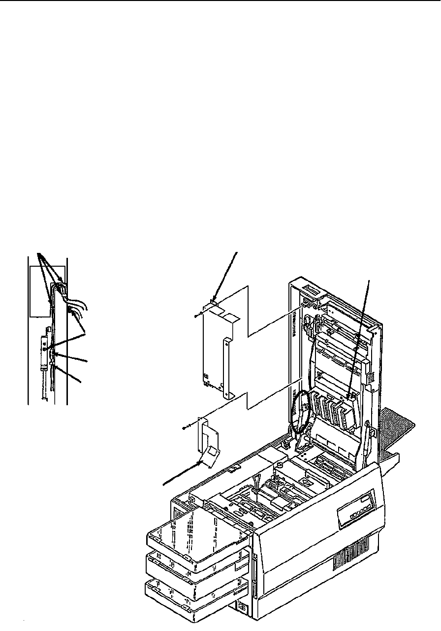
Vacuum Transport Unit Removal (Duplex)
June 1999 Removal/Replacement Procedures 7-13
Vacuum Transport Unit Removal (Duplex)
To remove the duplex vacuum transport unit:
1Open the top cover.
2Remove the upper duplex roller cover (four screws).
3Remove the lower duplex roller cover (four screws).
4Disconnect CN22.
5Remove the C-clip from the gas spring on the side marked “up.” Gently move the gas
spring out of the way so it does not block the wire harness area.
6Remove the four harnesses stays holding the cable in place.
7Remove the three ground screws.
8Remove the vacuum transport unit (four screws).
Harness Stays
Ground Screws
CN22
Harness Stay
Spring Detail
Lower Duplex
Roller Cover
Upper Duplex
Roller Cover
Vacuum Transport
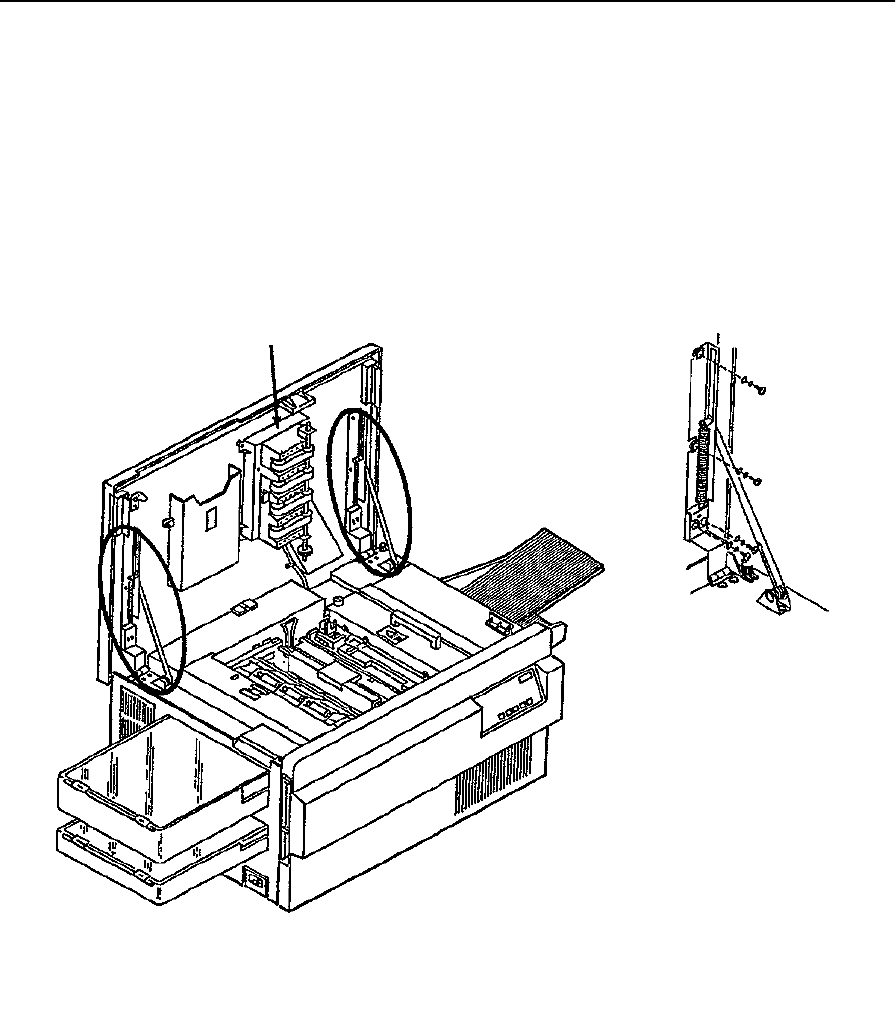
Top Cover Removal
7-14 Removal/Replacement Procedures June 1999
Top Cover Removal
To remove the top cover:
1Open the top cover.
2Remove the vacuum transport unit from the top cover. It is not necessary to remove it
completely from the printer (see page 7-11).
3Remove the four screws for each support assembly.
4Lift the top cover up and away from the printer.
Vacuum Transport Unit
Support Assembly Detail
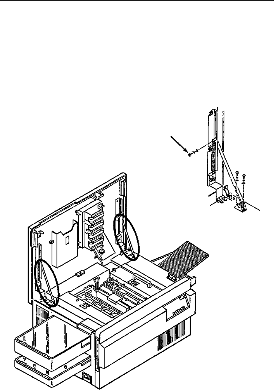
Top Cover Support Removal
June 1999 Removal/Replacement Procedures 7-15
Top Cover Support Removal
To remove the top cover support:
1Open the top cover.
2Remove the spring from the top cover support (single screw).
3Remove the screws holding the support to the base of the printer.
Replacement Note:
Replace one support at a time so that the other remains in place to stabilize the top cover.
Spring Screw
Support Detail
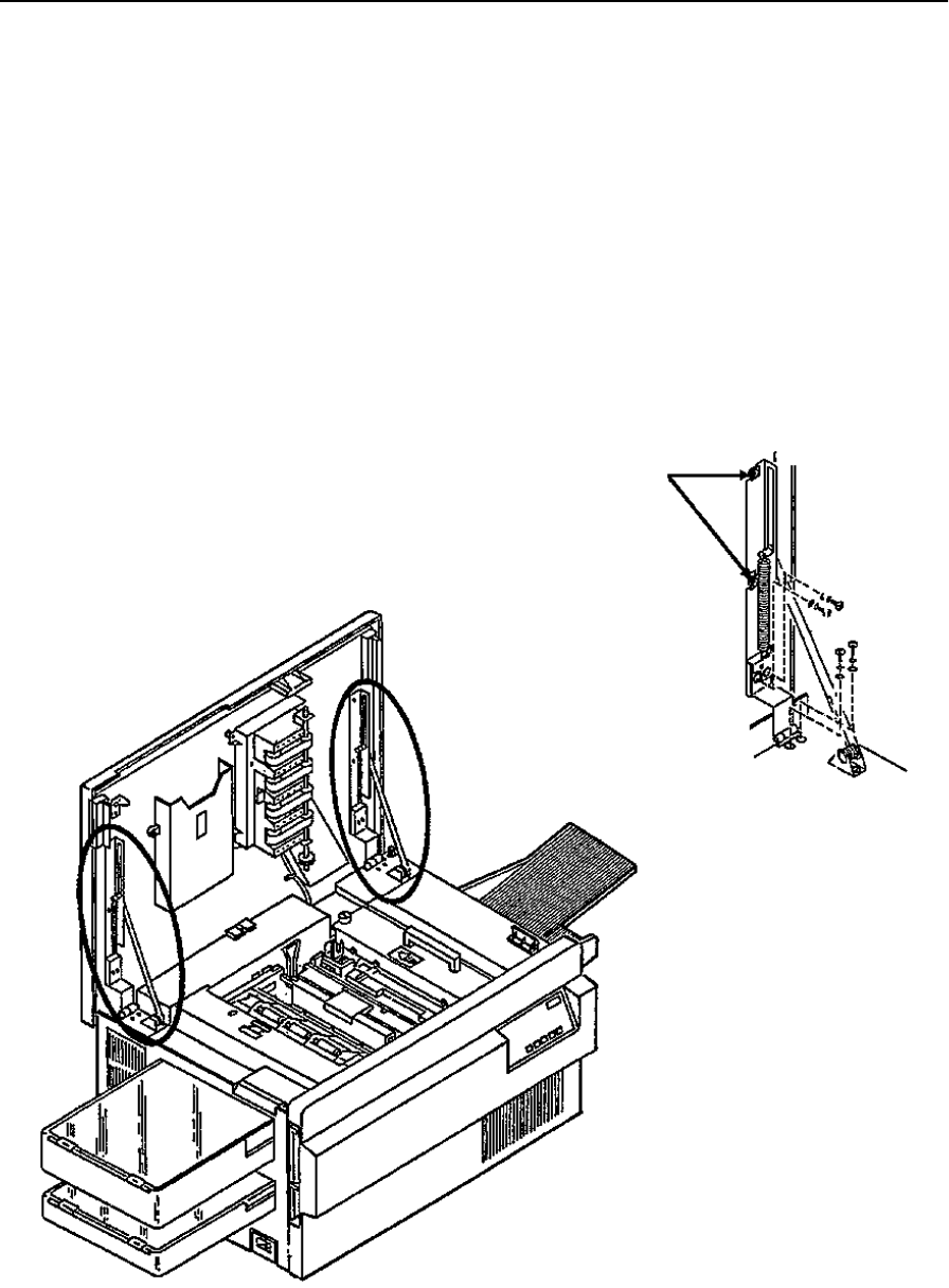
Top Cover Hinge Removal
7-16 Removal/Replacement Procedures June 1999
Top Cover Hinge Removal
To remove the top cover hinge:
1Open the top cover.
2Remove the two screws holding the hinge/support to the top cover.
3Remove the two screws holding the hinge/support to the printer base.
4While supporting the top cover, loosen the top two screws.
5Remove the hinge.
Replacement Note:
Replace one hinge at a time so that one always remains in place to support the top cover.
Loosen Screws
Hinge Detail
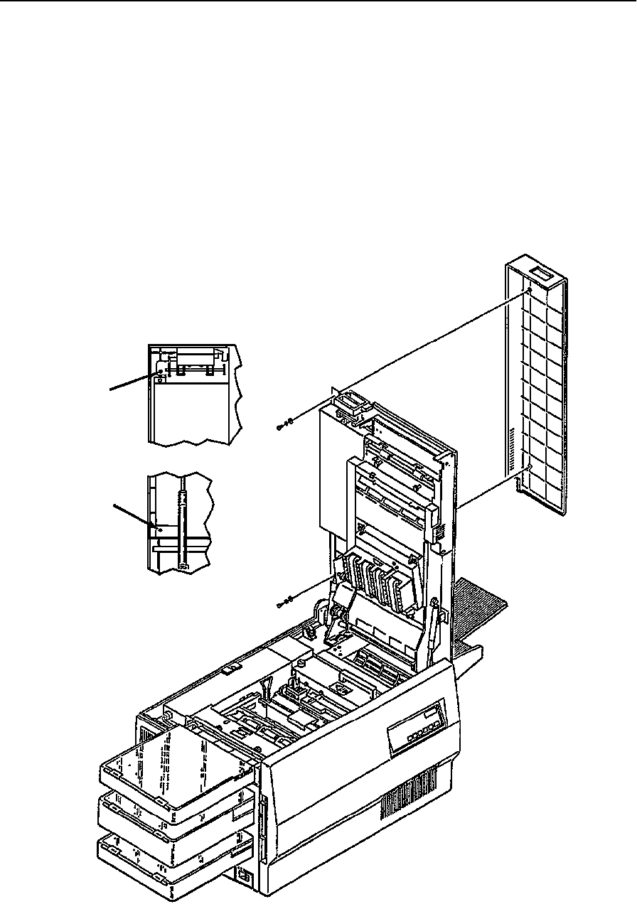
Rear Duplex Cover Removal
June 1999 Removal/Replacement Procedures 7-17
Rear Duplex Cover Removal
To remove the rear duplex cover:
1Open the top cover.
2Remove the lower screw for the rear duplex cover.
3While supporting the cover, remove the upper screw for the rear duplex cover.
Replacement Note:
Do not substitute longer screws to hold the rear duplex cover in place.
Upper
Screw
Lower
Screw
Mounting Screw Detail
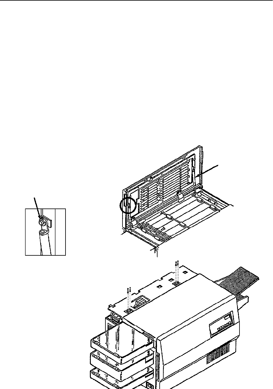
Front Duplex Cover Removal
7-18 Removal/Replacement Procedures June 1999
Front Duplex Cover Removal
To remove the front duplex cover:
1Open the top cover.
2Remove the rear duplex cover (see page 7-17).
3Close the top cover.
4Open the front duplex cover.
5Remove the C-clip from each gas spring.
6While supporting the cover, remove each gas spring from its post and lower it.
7Close the front duplex cover.
8Remove the front hinges from the top cover (two screws each).
9Remove the two screws from each front cover hinge.
C-Clip
Gas Spring Detail
Gas Spring
Inside Front
Duplex Cover
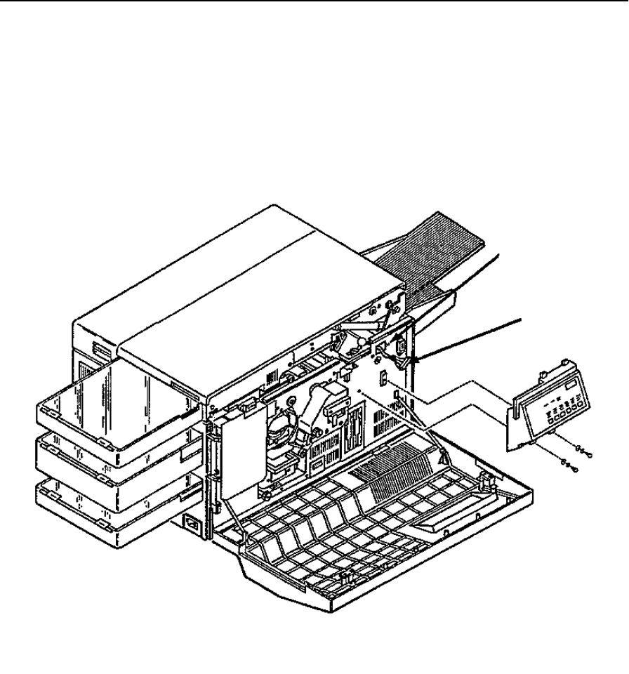
Operator Panel Removal
June 1999 Removal/Replacement Procedures 7-19
Operator Panel Removal
To remove the operator panel:
1Open the front cover.
2Remove the two screws holding the operator panel in place.
3Disconnect connector CN42.
4Remove the ground screw.
Ground Screw
CN42
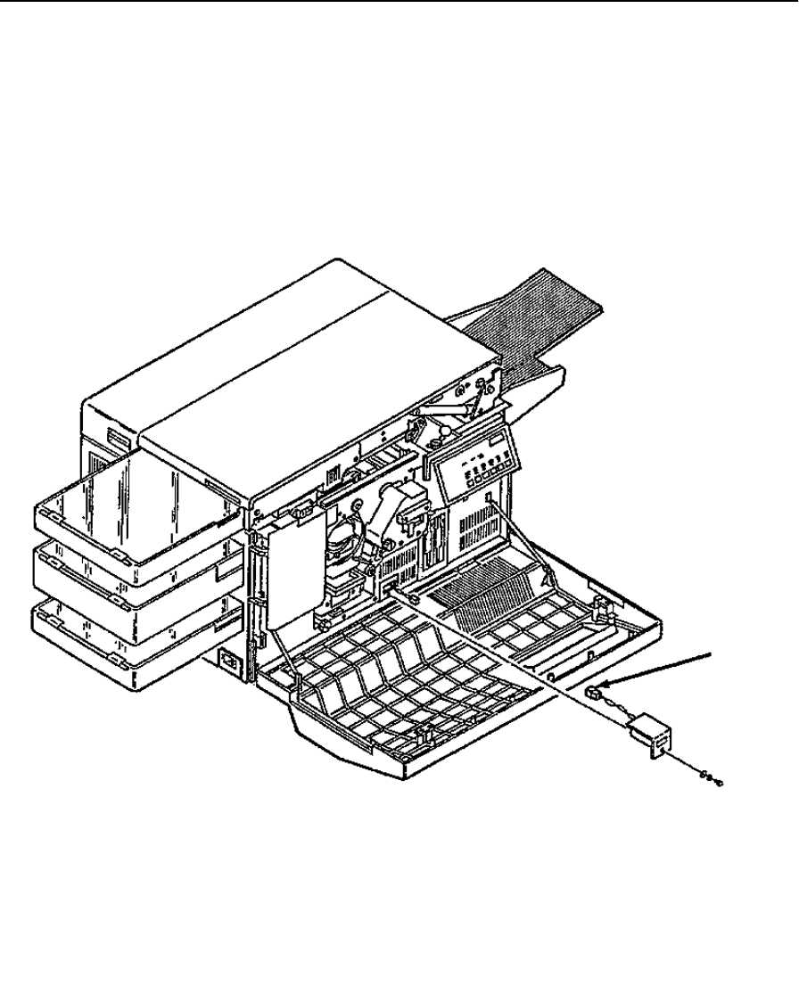
Counter Removal
7-20 Removal/Replacement Procedures June 1999
Counter Removal
To remove the counter:
1Open the front cover.
2Remove the screw holding the counter in place.
3Pull out the counter.
4Disconnect connector CN82.
CN82
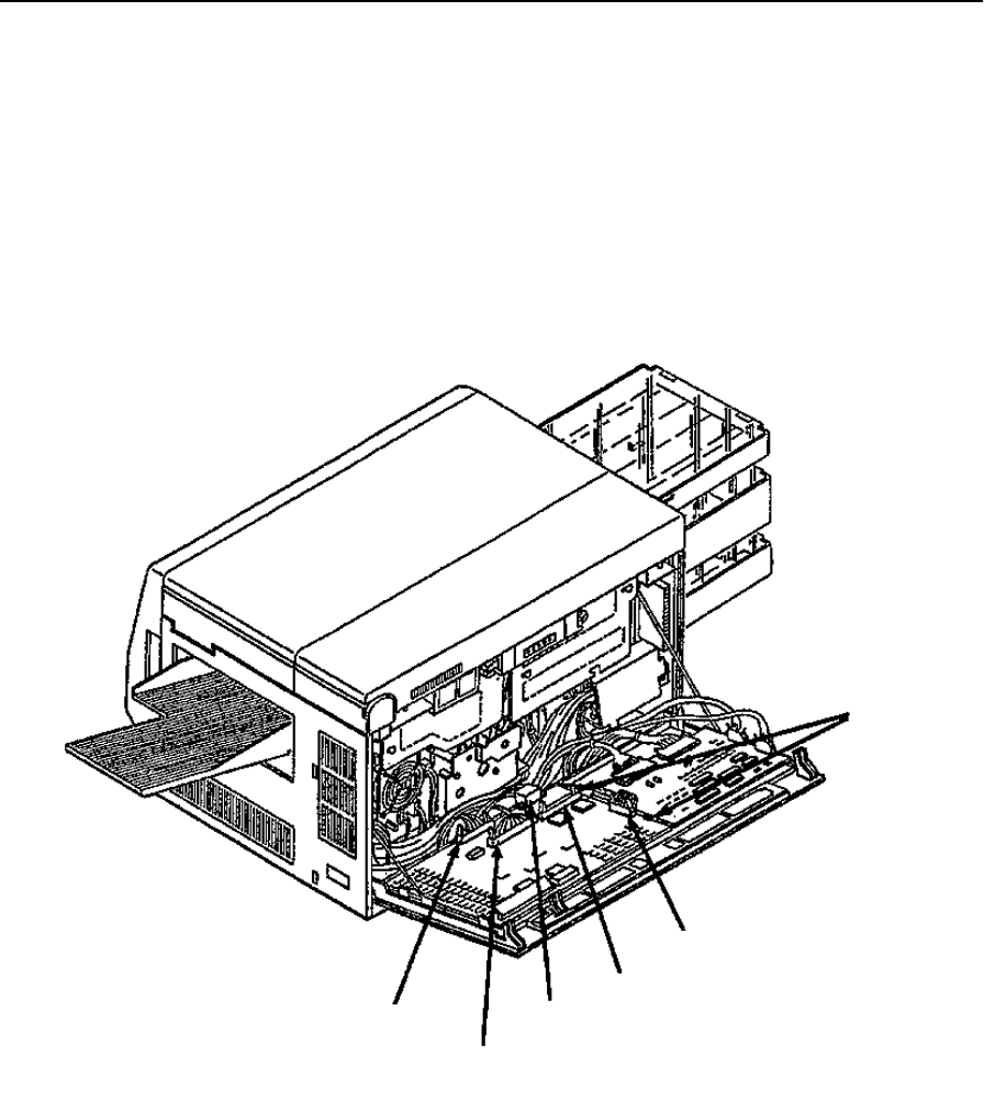
IGS Board Removal
June 1999 Removal/Replacement Procedures 7-21
IGS Board Removal
To remove the IGS board:
1Open the back cover.
2Disconnect connectors CN31, CN32, CN33, and CN74.
3For the hard drive option, disconnect the drive’s data cable.
4Push the two retaining clips away from the board.
5Remove the IGS board.
Retaining
Clips
CN33
Hard Disk Drive
Connector
CN32
CN31
CN74

PCL Board Removal
7-22 Removal/Replacement Procedures June 1999
PCL Board Removal
To remove the PCL board:
1Open the back cover.
2Disconnect connectors CN33, CN37, CN40, CN41, and CN91.
3Duplex only: also disconnect connector CN36.
4Push the two retaining clips away from the board.
5Remove the PCL board.
6Change the settings of the DIP switches on the replacement PCL to match the switch
settings on the original PCL.
CN91
CN36
(C30D only)
CN37
CN40
CN41
Retaining Clip
CN33
Retaining Clip
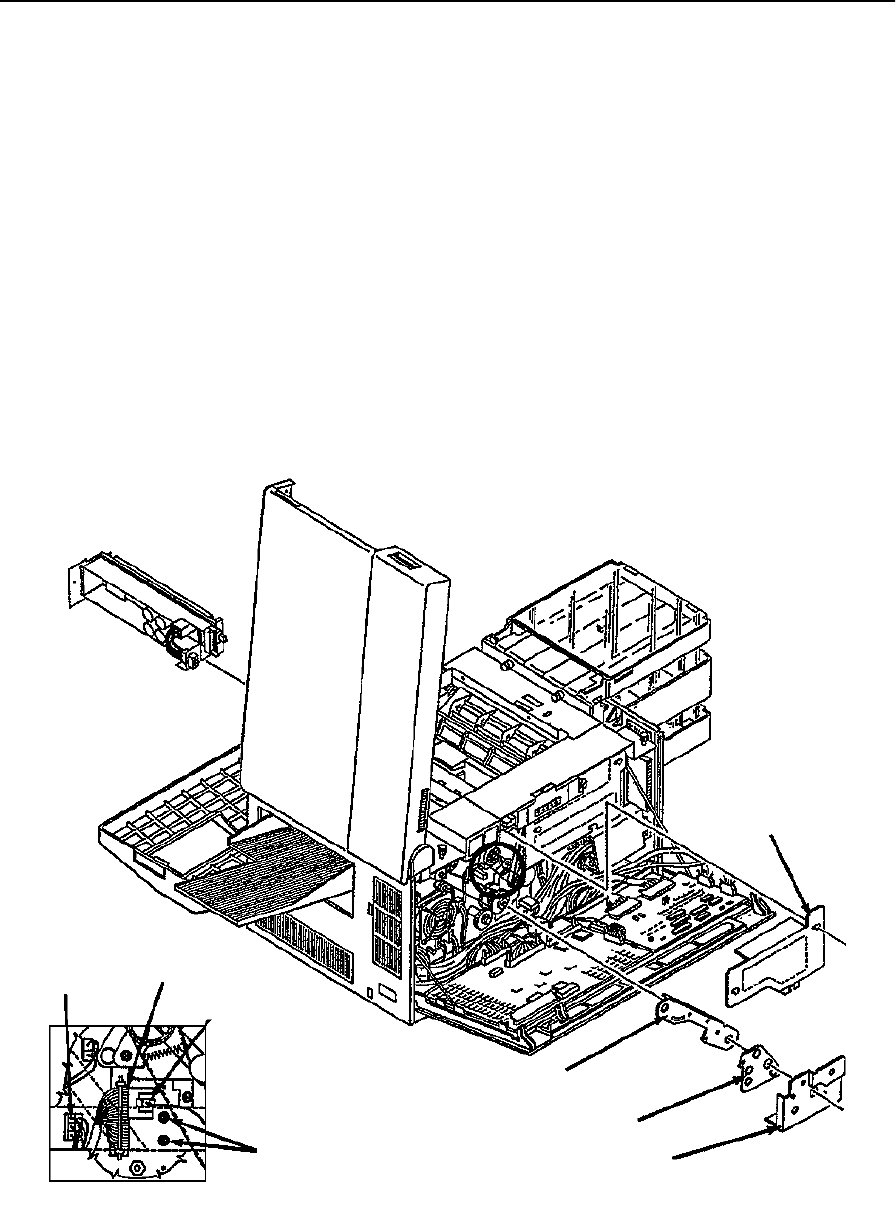
Printhead Assembly Removal
June 1999 Removal/Replacement Procedures 7-23
Printhead Assembly Removal
To remove the printhead assembly:
1Open the front, top, and back covers.
2Remove the photoconductor unit and place in its protective packaging.
3Remove the cleaner unit.
4Remove the fuser drive cover (three screws).
5Remove the main drive cover (one screw).
6Remove the gear stay cover (one screw).
7Remove the gear stay (three screws).
8Disconnect connectors CN27, CN30, and CN96 (see back detail).
9Remove the two back screws holding the printhead assembly in place.
Fuser Drive
Cover
Gear Stay
Gear Stay Cover
Main Drive Cover
Mounting Screws
Back Detail
CN27 CN30
CN96
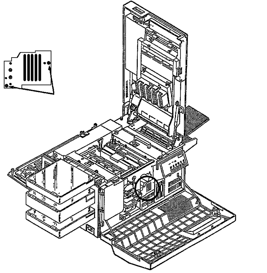
Printhead Assembly Removal
7-24 Removal/Replacement Procedures June 1999
10 Remove the two front screws holding the printhead assembly in place.
11 Pull the printhead assembly from the front of the printer.
Replacement Note:
Do not change the DIP switch setting on the replacement printhead circuit board. These
are set at the factory.
Mounting Screws
Front Detail
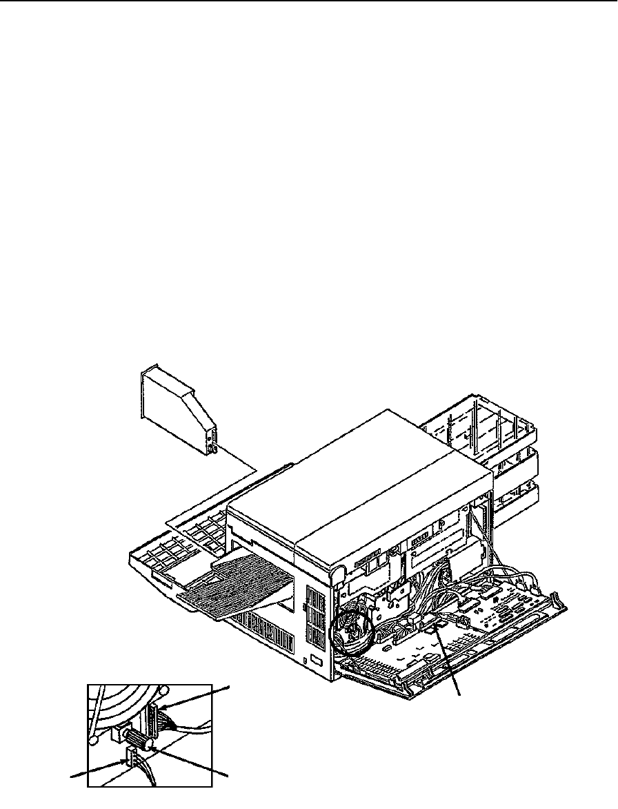
Disk Drive Housing Removal
June 1999 Removal/Replacement Procedures 7-25
Disk Drive Housing Removal
To remove the disk drive housing:
1Open the front and back covers.
2Remove the diskette(s).
3Disconnect CN77 and CN79.
4For the hard drive option, disconnect the drive’s data cable.
5Loosen the thumbscrew on the back of the disk drive housing.
6Remove the disk drive housing from the front of the printer. Be careful not to damage
the cables on the sharp edges of the chassis.
Replacement Note:
For A drives, set the jumper on the drive circuit board to 0; for B drives, set the jumper to
1.
CN79
Back Detail
Thumbscrew
CN77
Hard Disk Drive
Connector
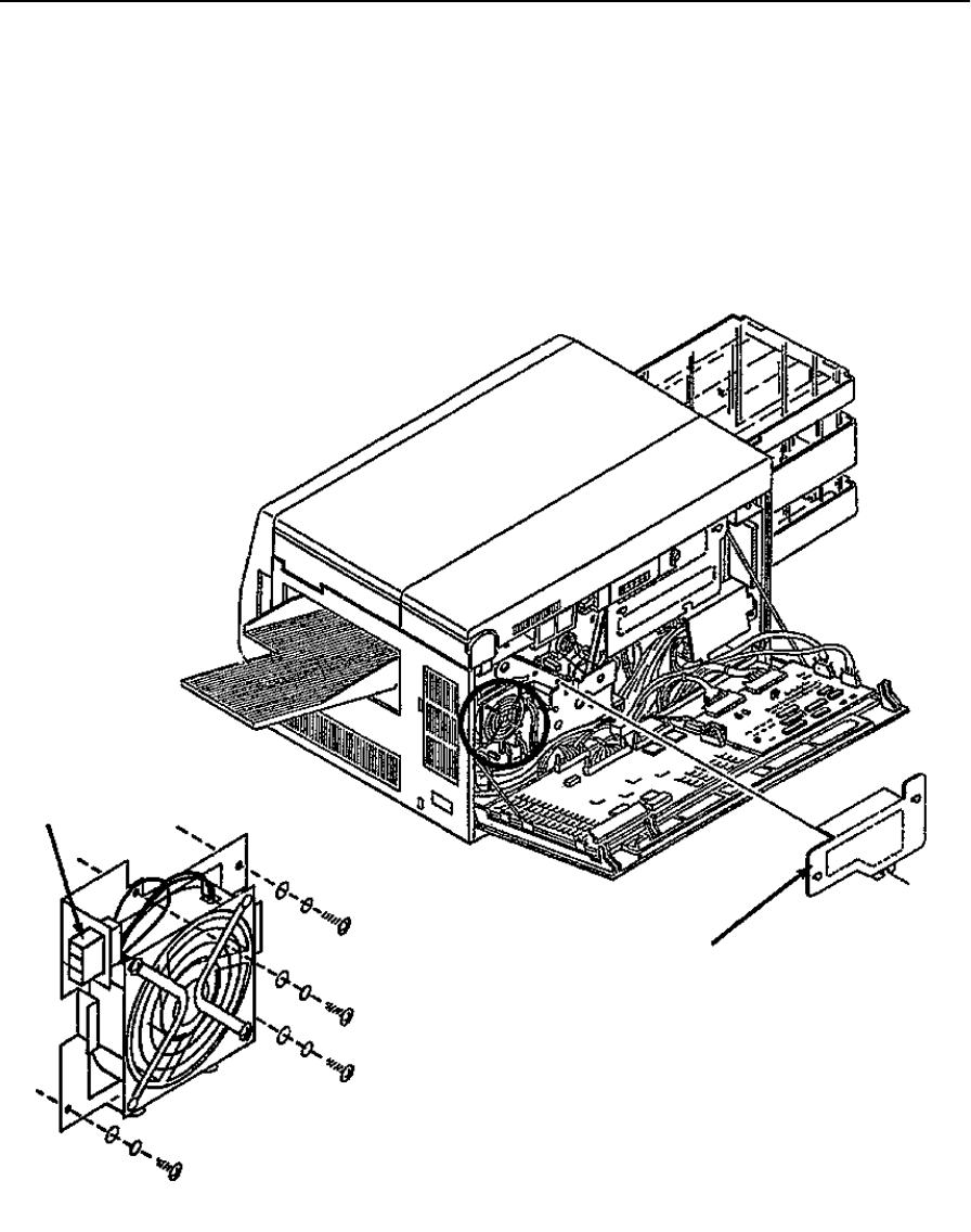
Cooling Fan Removal
7-26 Removal/Replacement Procedures June 1999
Cooling Fan Removal
To remove the cooling fan:
1Open the back cover.
2Remove the fuser drive cover (three screws).
3Disconnect CN21.
4Remove the cooling fan (four screws).
Fuser Drive Cover
CN21
Cooling Fan Detail

Duplex Fan Removal
June 1999 Removal/Replacement Procedures 7-27
Duplex Fan Removal
To remove the duplex fan:
1Open the back and top covers.
2Remove the fuser drive cover (three screws).
3Remove the EMI grounding plate (if present) from the rear of the printer (four
screws).
4Remove the four screws holding the duplex fan in place.
5Disconnect CN326.
6Lift the duplex fan from the printer.
CN326
Fuser Drive Cover
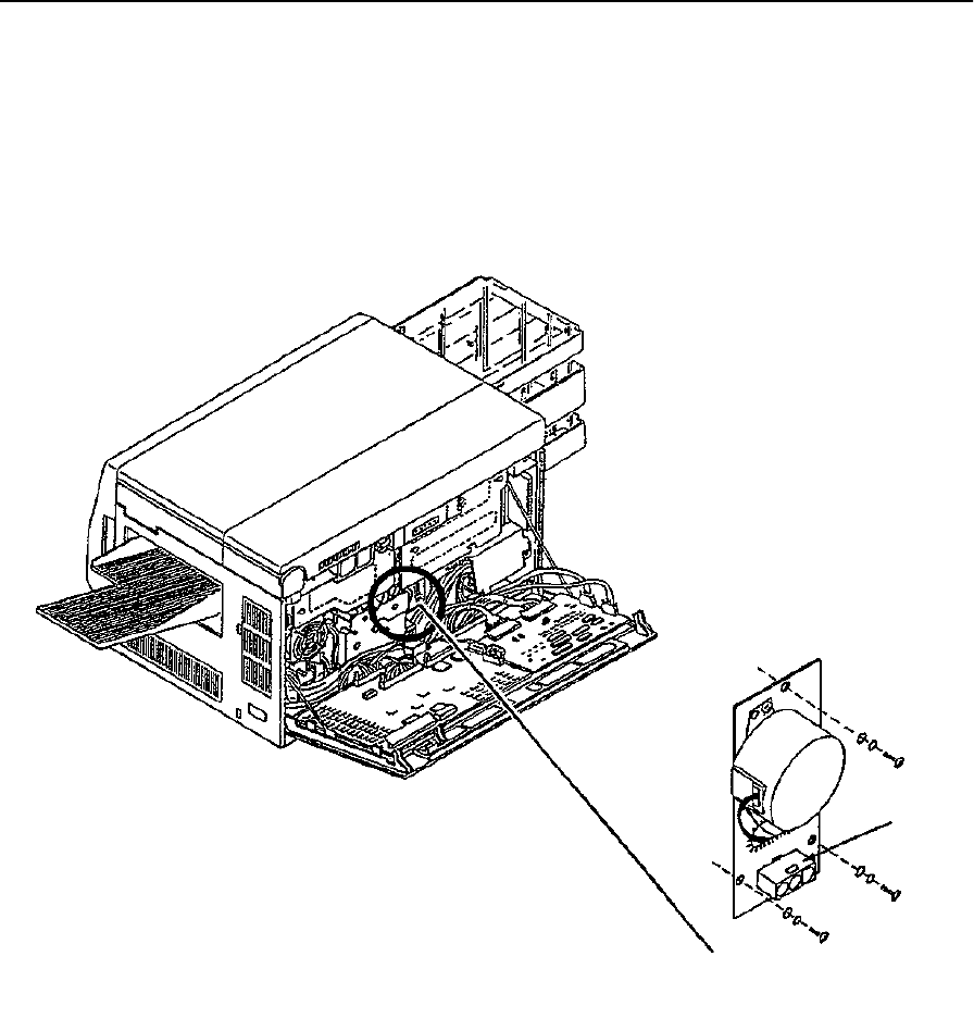
Toner Motor Removal
7-28 Removal/Replacement Procedures June 1999
Toner Motor Removal
To remove the toner motor:
1Open the back cover.
2Disconnect CN18.
3Remove the toner motor (three screws).
Toner Motor Detail
CN18
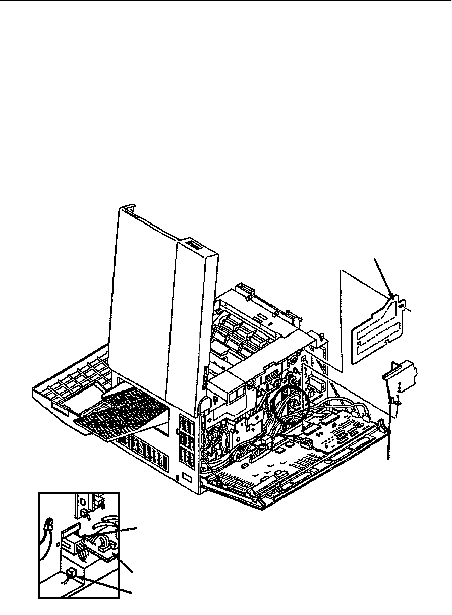
AC Power Supply Removal
June 1999 Removal/Replacement Procedures 7-29
AC Power Supply Removal
To remove the AC power supply:
1Open the front, back, and top covers.
2Duplex only: Remove the duplex tray.
3Remove the upper and lower paper cassettes.
4Remove the left side cover (see page 7-8).
5Remove the paper feed drive cover (three screws).
6Remove the power control board cover (one screw).
7Disconnect CN4 and CN70.
Paper Feed Drive Cover
Power Control
Board Cover
CN4
Power Control Board
CN70
Back Detail

AC Power Supply Removal
7-30 Removal/Replacement Procedures June 1999
8From the side of the printer, remove the three screws holding the AC power supply in
place.
9Slide the AC power supply out from the side of the printer.
Note: Make sure that strapping plug P1 is correctly configured and installed on connector
J1. For jumper settings, see “Power Supply Strapping” on page 6-32.
Strapping
Plug
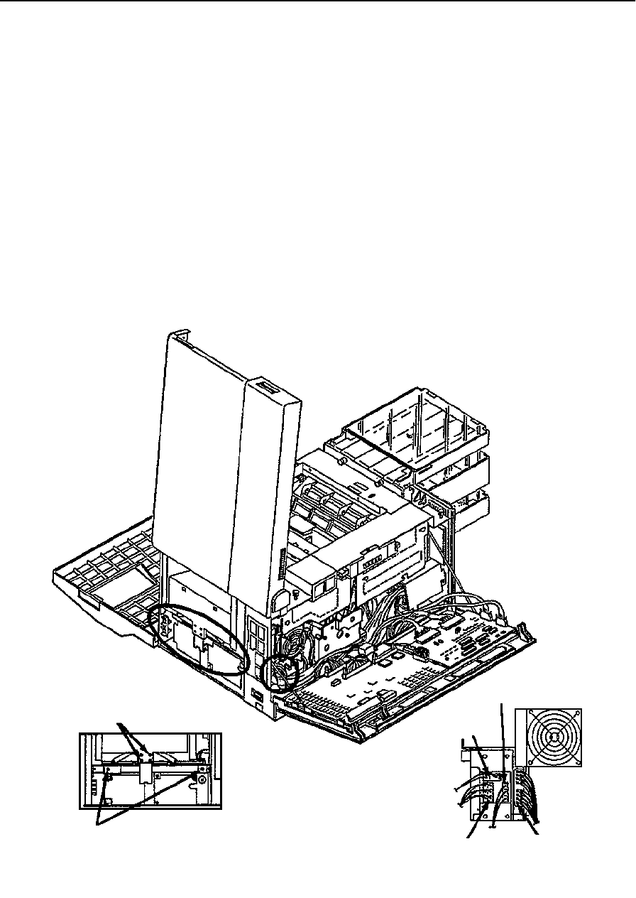
DC Power Supply Removal
June 1999 Removal/Replacement Procedures 7-31
DC Power Supply Removal
To remove the DC power supply:
1Open the front, top, and back covers.
2Disconnect CN6, CN7, CN8, and CN330.
3Remove the output tray.
4Remove the right side cover (see page 7-9).
5Remove the bracket for the output tray guide (two screws).
6Remove the DC power supply (two screws).
Replacement Note:
When replacing the output tray bracket, make sure it is seated inside the DC power supply.
Bracket Screws
DC Power Supply Screws
Right Side Detail
CN330
CN6
CN7 CN8
Back Detail

High Voltage Unit Removal
7-32 Removal/Replacement Procedures June 1999
High Voltage Unit Removal
To remove the high voltage unit:
1Open the top and back covers.
2Remove the EMI grounding plate (if present) from the rear of the printer (four
screws).
3From the top, loosen the screw holding the high voltage unit in place.
4Pull the high voltage unit out from the back of the printer.
5Disconnect connectors CN23, CN24, CN85, and the two high voltage leads.
6Remove the high voltage unit.
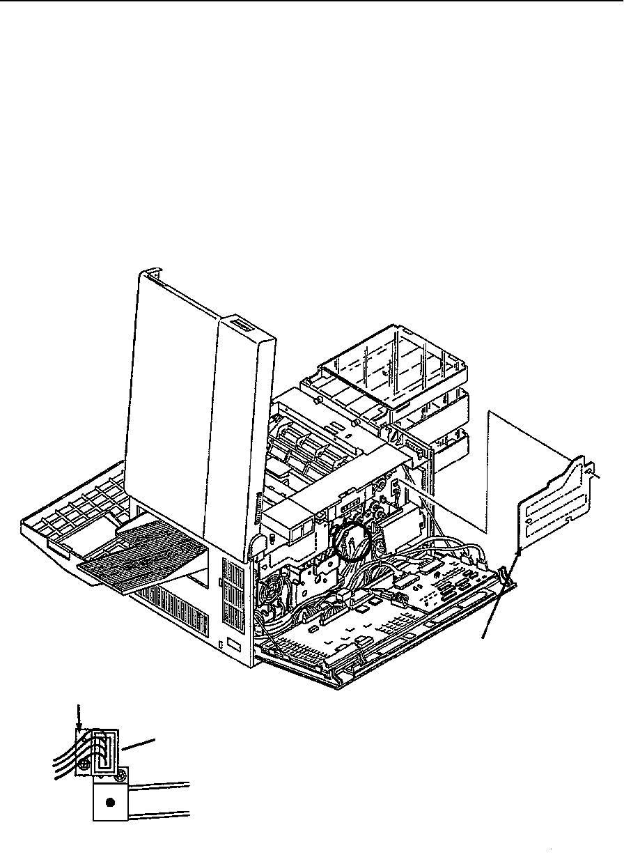
Photoconductor Seam Sensor Removal
June 1999 Removal/Replacement Procedures 7-33
Photoconductor Seam Sensor Removal
To remove the photoconductor seam sensor:
1Open the front, back, and top covers.
2Remove the photoconductor and place in its protective packaging.
3Remove the developer unit.
4Remove the paper feed drive cover (three screws).
5Remove the bracket holding CN64 in place (one screw).
6Remove the screw holding the seam sensor bracket in place. It is situated under the
bracket for CN64.
Paper Feed Drive Cover
CN64 Bracket
Mounting Screw
(under CN64 bracket)
Back Detail
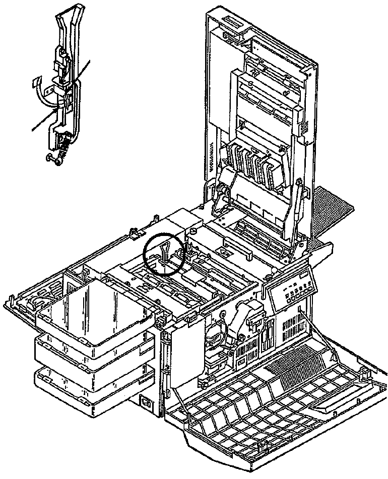
Photoconductor Seam Sensor Removal
7-34 Removal/Replacement Procedures June 1999
7From inside the empty photoconductor cavity, disconnect connector CN63.
8Lift the photoconductor seam sensor and bracket up out of the printer.
Note: Use caution not to bend the bracket.
Seam Sensor
and Bracket
CN63
Front Detail
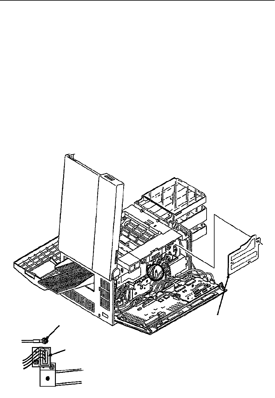
Photoconductor Rear Guide Rail Removal
June 1999 Removal/Replacement Procedures 7-35
Photoconductor Rear Guide Rail Removal
To remove the photoconductor rear guide rail:
1Open the front, back, and top covers.
2Remove the photoconductor and place in its protective packaging.
3Remove the developer unit.
4Remove the paper feed drive cover (three screws).
5Remove the photoconductor seam sensor (see illustration on page 7-33).
6Remove the spring at the base of the guide rail. To do this, gently pull the spring for-
ward off its post.
7Disconnect CN64.
8Remove the ground screw.
9Remove CN64 from its bracket.
Ground Screw
CN64
Back Detail
Paper Feed Drive Cover

Photoconductor Rear Guide Rail Removal
7-36 Removal/Replacement Procedures June 1999
10 From inside the photoconductor cavity, remove the two screws holding the guide rail
in place.
11 Push CN64 and the ground wire through the photoconductor cavity to the front of the
printer.
12 Lift the photoconductor guide rail from the printer.
Spring
Front Detail
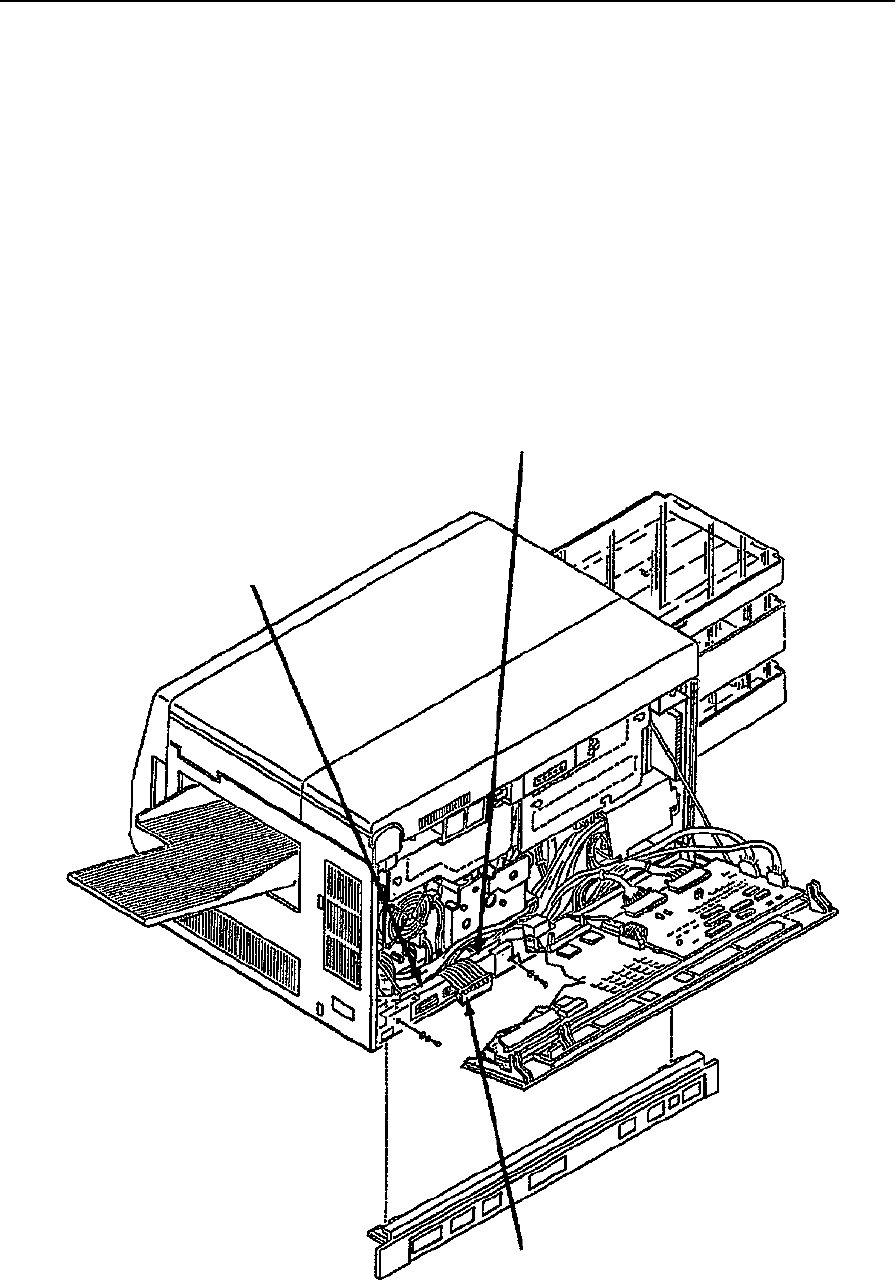
Signal Interface Board Removal
June 1999 Removal/Replacement Procedures 7-37
Signal Interface Board Removal
To remove the signal interface board:
1Disconnect all external cables and attachments.
2Open the back cover.
3Remove the lower back cover (see page 7-7).
4Disconnect CN74 and P333.
5Remove the signal interface board (two screws).
Replacement Note:
Replicate the DIP switch settings and jumper locations on any new signal interface board.
DIP Switches
Jumpers
CN74
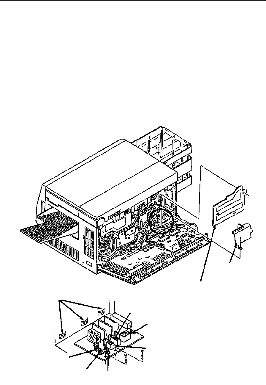
Power Control Board Removal
7-38 Removal/Replacement Procedures June 1999
Power Control Board Removal
To remove the power control board:
1Open the back cover.
2Remove the paper feed drive cover (three screws).
3Remove the power control board cover (one screw).
4Disconnect CN9, CN10, CN11, CN12, CN13, and CN14.
5Remove power control board (two screws).
Replacement Note:
Be sure that the back of the board is mounted properly in the frame slots.
Power Control
Board Cover
Paper Feed Drive Cover
Mounting Slots
CN11
CN12 CN10
CN9
CN13
CN14
Power Control Board Detail
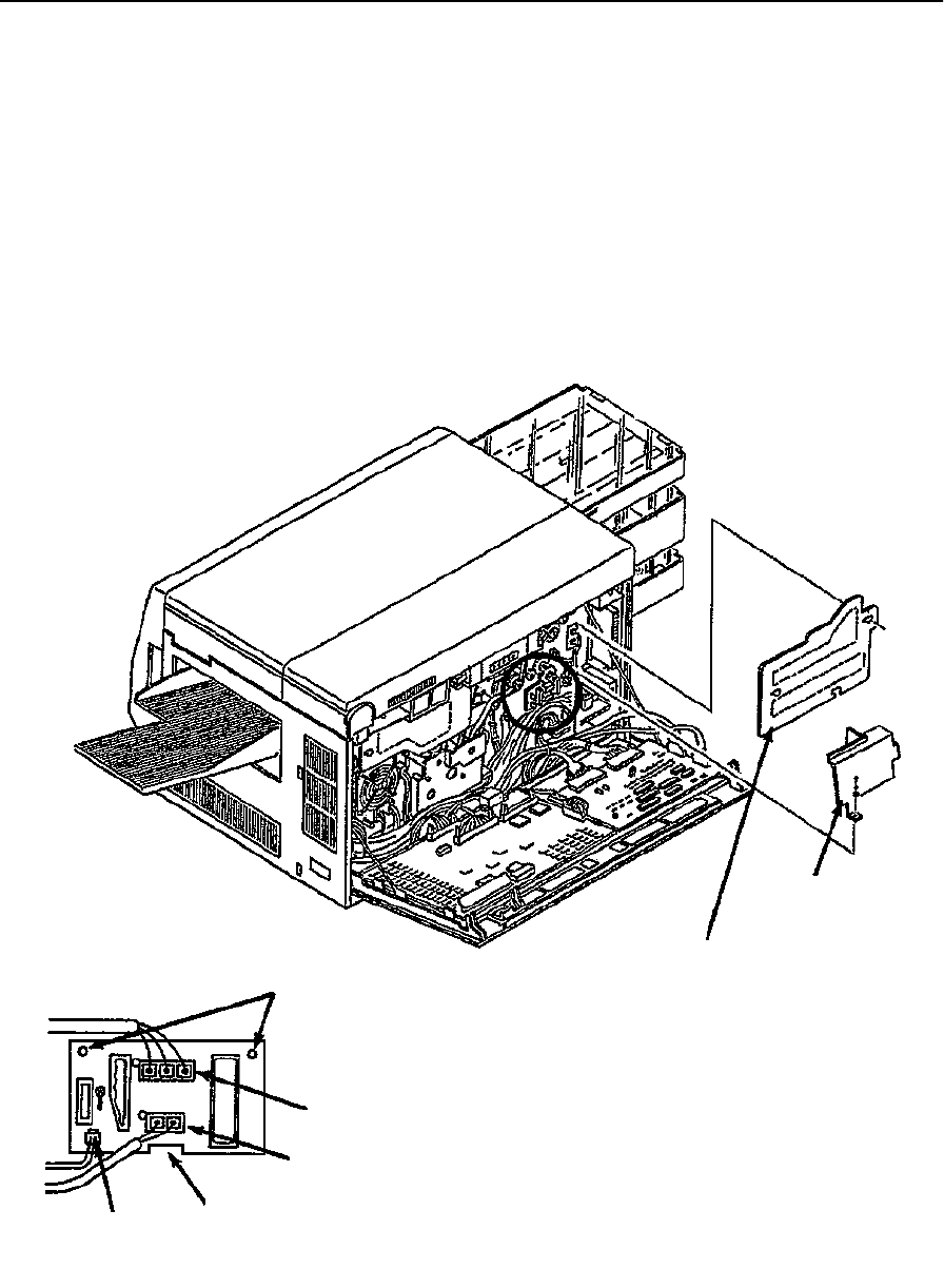
Jogging Motor Control Board Removal
June 1999 Removal/Replacement Procedures 7-39
Jogging Motor Control Board Removal
To remove the jogging motor control board:
1Open the back cover.
2Remove the paper feed drive cover (three screws).
3Remove the power control board cover (one screw).
4Disconnect CN100, CN101, and CN102.
5Disengage the board. To do this, pinch the two standoffs on the board.
6Lift the board from its mounting bracket.
Power Control
Board Cover
Paper Feed Drive Cover
Standoffs
CN101
CN100
CN102 Mounting Bracket
Jogging Motor Power Control Board Detail
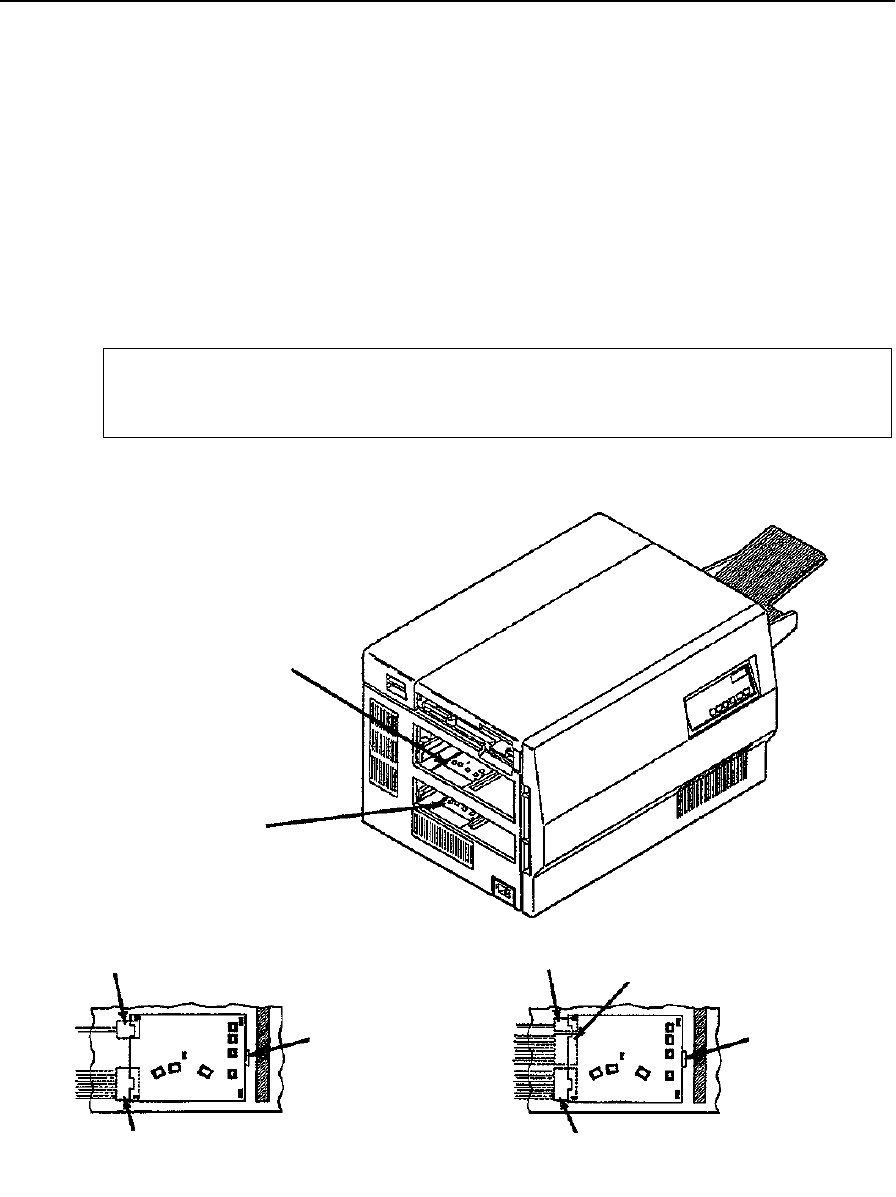
Upper or Lower Paper Size Sensor Removal
7-40 Removal/Replacement Procedures June 1999
Upper or Lower Paper Size Sensor Removal
To remove the upper or lower paper size sensor:
1Duplex only: Remove the duplex tray.
2Remove the upper and lower paper cassettes.
3Using a small screwdriver, pry up the paper size sensor. Turn the sensor counterclock-
wise and lift up.
4For the upper paper size sensor, disconnect CN45 and CN46.
5For the lower paper size sensor, disconnect CN43, CN47, and CN48.
Be careful not to damage the cables when disconnecting
Note
Upper Paper
Lower Paper
CN46
Pry Slot
CN45
Upper Paper Size Sensor Detail
CN48 CN43
Pry Slot
CN47
Lower Paper Size Sensor Detail
Size Sensor
Size Sensor
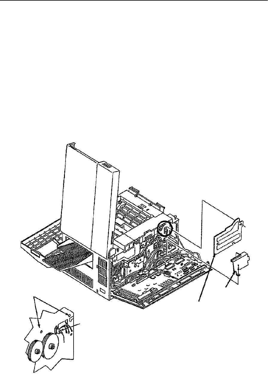
Upper Cassette Mount Removal
June 1999 Removal/Replacement Procedures 7-41
Upper Cassette Mount Removal
To remove the upper cassette mount:
1Open the front, back, and top covers.
2Duplex only: Remove the duplex tray.
3Remove the upper and lower paper cassettes.
4Remove the left side cover (see page 7-8).
5Remove the paper feed drive cover (three screws).
6Remove the power control board cover (one screw).
7From the back, remove the two screws holding the upper cassette mount in place.
8Loosen the CN62 jack and pull it to the back of the printer.
9Disconnect CN62.
Mounting Screws
CN62
Back Detail
Power Control
Board Cover
Paper Feed Drive Cover
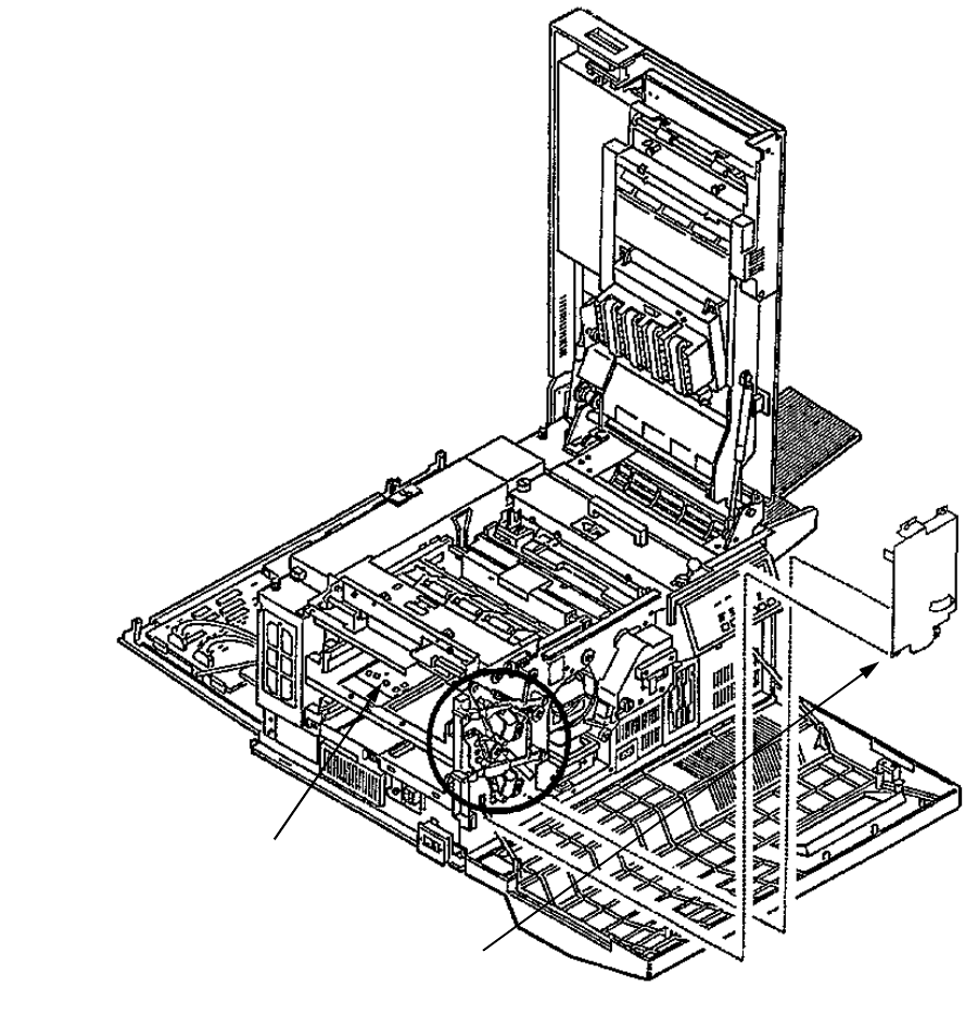
Upper Cassette Mount Removal
7-42 Removal/Replacement Procedures June 1999
10 Remove the upper paper size sensor (see page 7-40).
11 Remove the cassette release cover (two screws).
12 Remove the plastic guide on the vertical edge of the printer. Depress the tabs visible
through the cassette housing. Gently turn the guide and lift from the printer.
Cassette Release Cover
Upper Paper Size Sensor
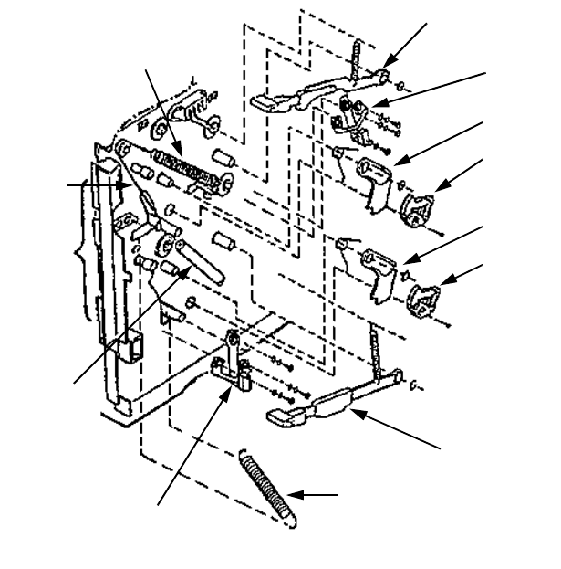
Upper Cassette Mount Removal
June 1999 Removal/Replacement Procedures 7-43
13 For the tray release mechanisms:
•Remove the upper and lower cassette release levers (one spring and C-clip each).
•Set the paper tension levers to their minimum (–) position.
•Carefully release the cable tension springs from their cables (only included on
more recent versions of the printer); remove the springs and cables.
•Remove the upper and lower latches (one spring and C-clip each).
•Remove the upper and lower cams (one screw each).
14 Disengage the top of the damper assembly. Push it to the right out of the way.
Upper Paper
Upper Latch
Upper Cam
Lower Cam
Lower Cassette
Release Lever
Cable Tension Spring
Damper
Edge
Guide
Cable
Cable Tension Spring
Lower Latch
Tension Lever
Assembly
Upper Cassette
Release Lever
Lower Paper
Tension Lever

Upper Cassette Mount Removal
7-44 Removal/Replacement Procedures June 1999
15 Remove the lower bracket (four screws; two front and two back).
16 Remove the tray (four screws; two front and two back).
17 Remove the upper tray lift arm (two screws with two plastic retainers).
18 Remove the upper bracket (four screws; two front and two back).
19 Remove the screws holding the upper cassette mount in place (two front and two
side).
20 Pull the upper cassette mount from its front and back mounting pins.
21 Rotate the upper cassette mount upwards and out of the printer.
Paper
Lift Arm
Retainers
Cassette Mount Detail
Mounting Screws
Upper Bracket
Upper Cassette
Mount
Tray
Lower Bracket
Left Side Detail
Upper Bracket
Upper Cassette
Mount
Tray
Lower Bracket
Front Mounting Screw Detail
Upper Bracket
Upper Cassette
Mount
Tray
Lower Bracket
Back Mounting Screw Detail
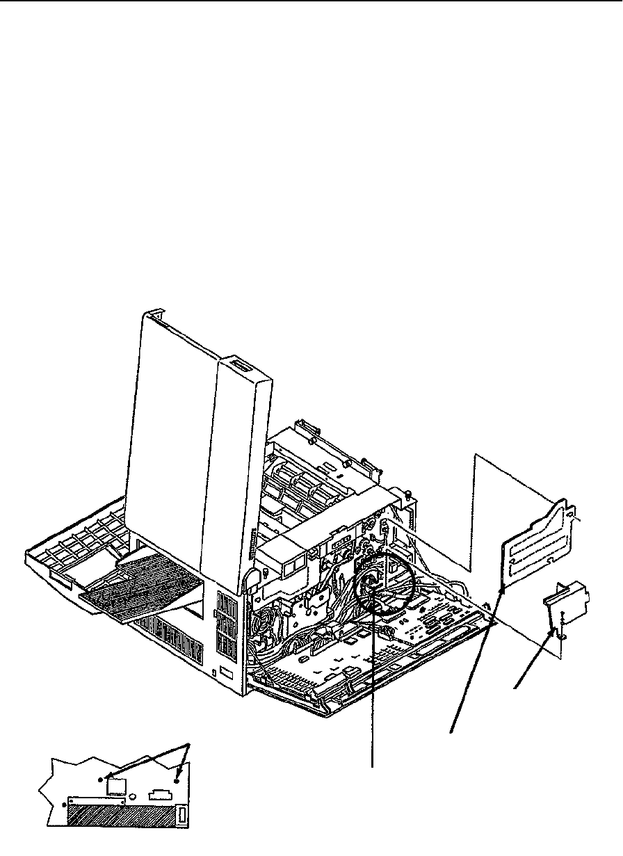
Lower Cassette Mount Removal
June 1999 Removal/Replacement Procedures 7-45
Lower Cassette Mount Removal
To remove the lower cassette mount:
1Open the front, back, and top covers.
2Duplex only: Remove the duplex tray.
3Remove the upper and lower paper cassettes.
4Remove the left side cover (see page 7-8).
5Remove the paper feed drive cover (three screws).
6Remove the power control board cover (one screw).
7Remove the power control board (see page 7-38).
8From the back, remove the two screws holding the lower cassette mount in place.
Mounting Screws
Back Detail
Power Control Board
Paper Feed Drive Cover
Power Control
Board Cover
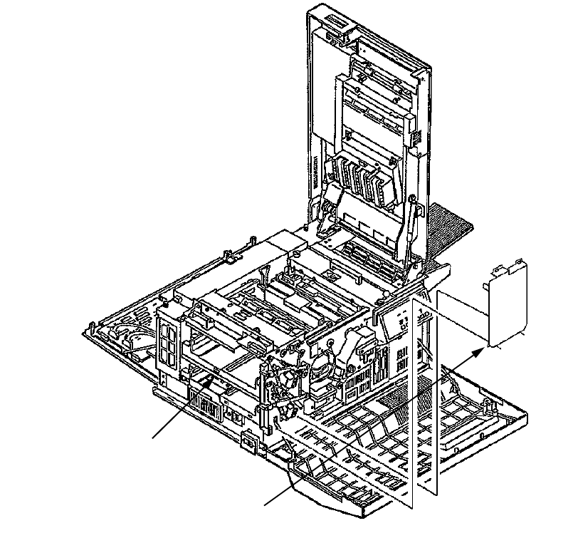
Lower Cassette Mount Removal
7-46 Removal/Replacement Procedures June 1999
9Remove the lower paper size sensor (see page 7-40).
10 Remove the cassette release cover (two screws).
11 Remove the plastic guide on the vertical edge of the printer. Depress the tabs visible
through the cassette housing. Gently turn the guide and lift it from the printer.
Lower Paper Size Sensor
Cassette Release Cover

Lower Cassette Mount Removal
June 1999 Removal/Replacement Procedures 7-47
12 For the lower tray release:
•Remove the lower cassette release lever (one spring and C-clip).
•Set the lower paper tension lever to its minimum (–) position.
•Carefully release the cable tension spring from its cable (only on the most recent
versions of the printer); remove the spring and cable.
•Remove the lower latch (one spring and C-clip).
•Remove the lower cam (one screw).
Upper Cassette
Upper Latch
Upper Cam
Lower Cam
Lower Paper
Tension Lever
Cable Tension Spring
Damper
Edge
Guide
Cable
Cable Tension Spring
Lower Latch
Release Lever
Assembly
Upper Paper
Tension Lever
Lower Cassette
Release Lever
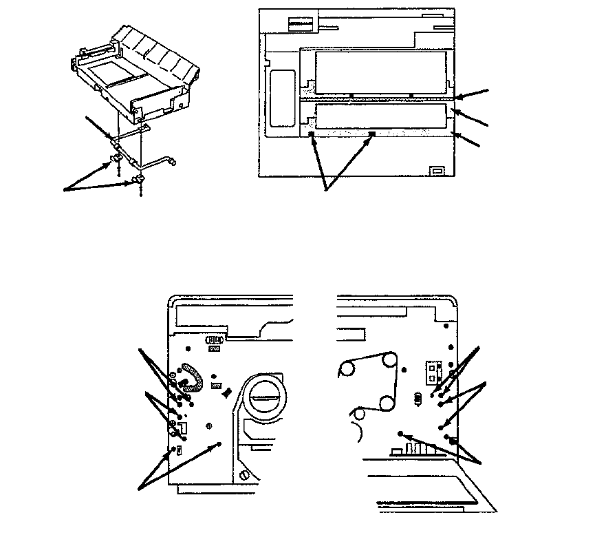
Lower Cassette Mount Removal
7-48 Removal/Replacement Procedures June 1999
13 Remove the lower bracket (four screws; two front and two back).
14 Remove the tray (four screws, two front and two back)
15 Remove the AC power supply (see page 7-29).
16 Remove the lower tray lift arm (two screws with two plastic retainers).
17 Remove the screws holding the lower cassette mount in place (two front and two
side).
18 Pull the lower cassette mount from its front and back mounting pins.
19 Rotate the lower cassette mount upwards and out of the printer.
Paper
Lift Arm
Retainers
Tray
Lower Bracket
Lower Cassette
Mount
Front Mounting Screw Detail
Tray
Lower Bracket
Lower Cassette
Mount
Mounting Screws
Left Side Detail
Cassette Mount Detail
Tray
Lower Bracket
Lower Cassette
Mount
Back Mounting Screw Detail
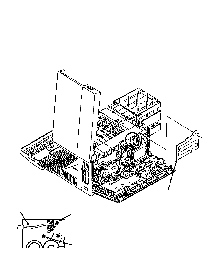
Upper Paper Guide Removal
June 1999 Removal/Replacement Procedures 7-49
Upper Paper Guide Removal
To remove the upper paper guide:
1Open the front, back, and top covers.
2Remove the paper feed drive cover (three screws).
3Disconnect the transfer corona high voltage lead from the HVPS.
4Disconnect the ground screw for the transfer corona.
Paper Feed Drive Cover
High Voltage Lead Ground Screw
Mounting Screw
Back Detail
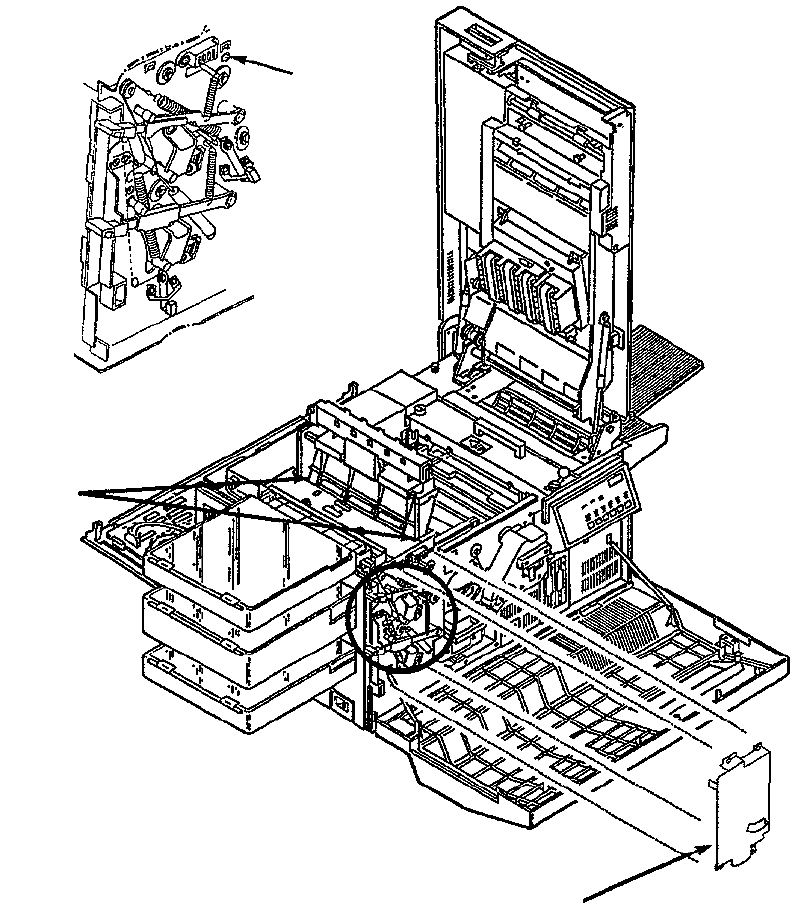
Upper Paper Guide Removal
7-50 Removal/Replacement Procedures June 1999
5Remove the cassette release cover (two screws).
6Raise the upper paper guide.
7Remove the back screw holding the upper paper guide in place.
8Remove the front screw holding the upper paper guide in place.
9Release the two springs at the base of the upper paper guide.
10 Lift the upper paper guide out of the printer.
Mounting
Screw
Front Detail
Springs
Cassette Release Cover
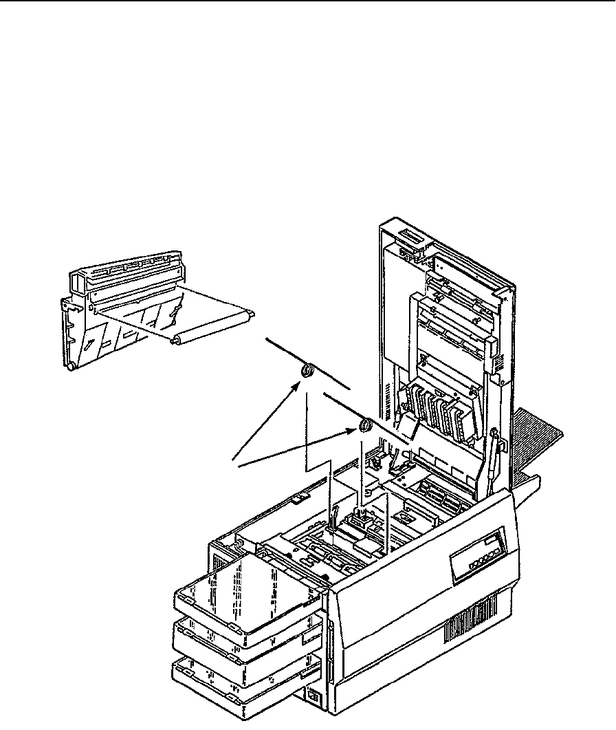
Upper Paper Guide Roller Removal
June 1999 Removal/Replacement Procedures 7-51
Upper Paper Guide Roller Removal
To remove the upper paper guide roller:
1Open the top cover.
2Remove the two springs at each end of the roller. To do this, press down gently on the
end of the spring and move it out from under the plastic.
3Raise the upper paper guide.
4Remove the roller and bearings from the underside of the upper paper guide.
Upper Paper Guide
Underside
Springs
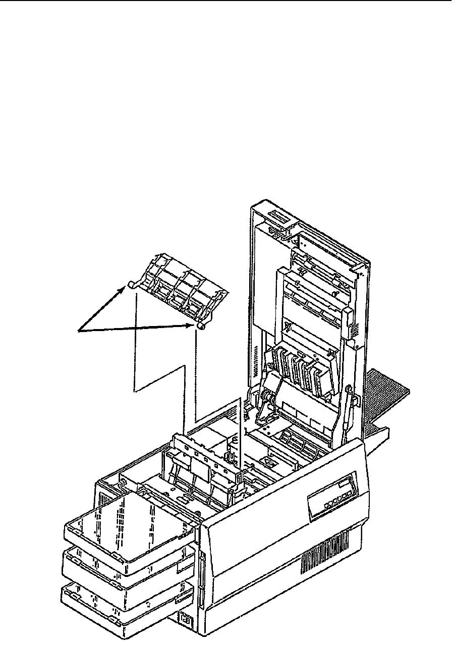
Lower Paper Guide Removal
7-52 Removal/Replacement Procedures June 1999
Lower Paper Guide Removal
To remove the lower paper guide:
1Open the top cover.
2Raise the upper paper guide.
3Raise the lower paper guide slightly.
4Push the base of the lower paper guide toward the back of the printer until the front
mounting peg is free.
5Lift the lower paper guide out of the printer.
Note: Use caution. This piece is made of plastic and can easily break if mishandled.
Mounting
Pegs
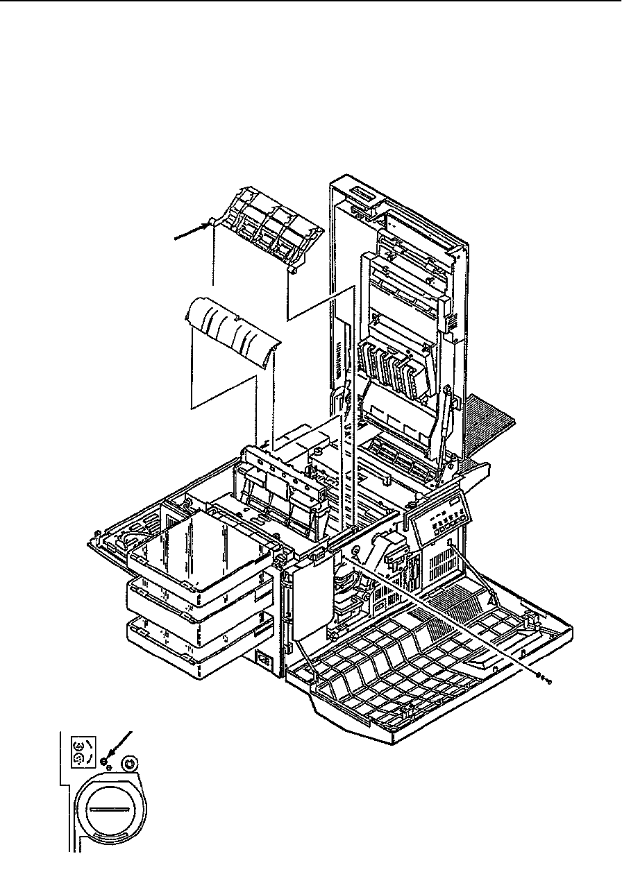
Paper Timing Guide Removal
June 1999 Removal/Replacement Procedures 7-53
Paper Timing Guide Removal
To remove the paper timing guide:
1Open the front, back, and top covers.
2Raise the upper paper guide.
3Remove the lower paper guide (see page 7-52).
Lower Paper Guide
Paper Timing Guide
Mounting Screw
Front Detail
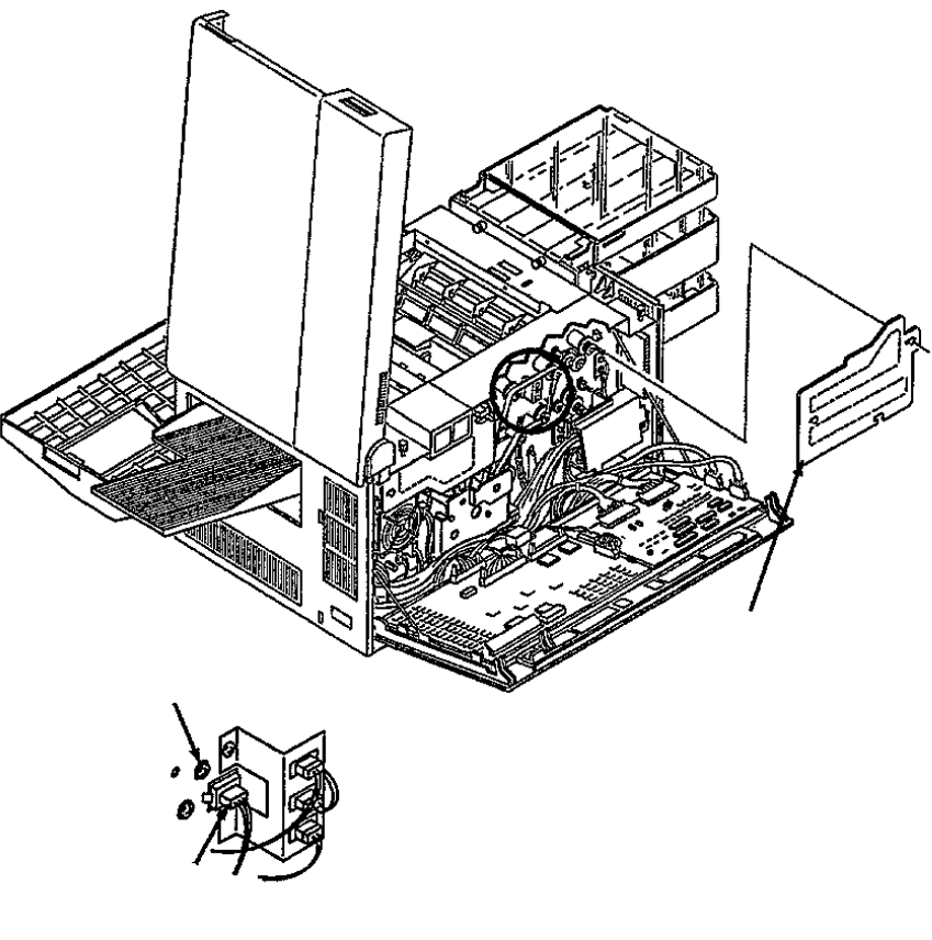
Paper Timing Guide Removal
7-54 Removal/Replacement Procedures June 1999
4Remove the paper feed drive cover (three screws).
5Remove the back screw holding the paper timing guide in place. Remove the paper
timing guide.
6Disconnect CN58.
Mounting Screw
CN58
Back Detail
Paper Feed Drive Cover

Cleaner Drive Belt Removal
June 1999 Removal/Replacement Procedures 7-55
Cleaner Drive Belt Removal
To remove the cleaner drive belt:
1Open the back cover.
2Remove the fuser drive cover (three screws).
3Remove the main drive cover (one screw).
4Lift the idler arm and slide the cleaner drive belt off the gear.
Idler Arm
Cleaner Drive Belt Detail
Fuser Drive
Main Drive
Cover
Cover
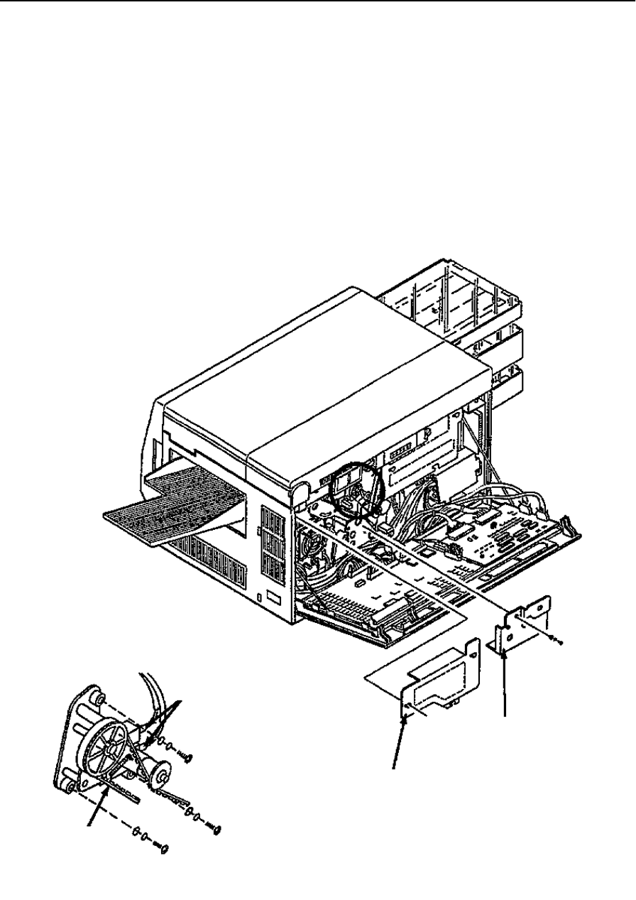
Cleaner Drive Removal
7-56 Removal/Replacement Procedures June 1999
Cleaner Drive Removal
To remove the cleaner drive:
1Open the back cover.
2Remove the fuser drive cover (three screws).
3Remove the main drive cover (one screw).
4Remove the cleaner drive belt (see page 7-55).
5Remove the two high voltage leads.
6Remove the cleaner drive (three screws).
Fuser Drive
Cover
Main Drive
Cover
High Voltage Leads
Drive Belt
Cleaner Drive Detail
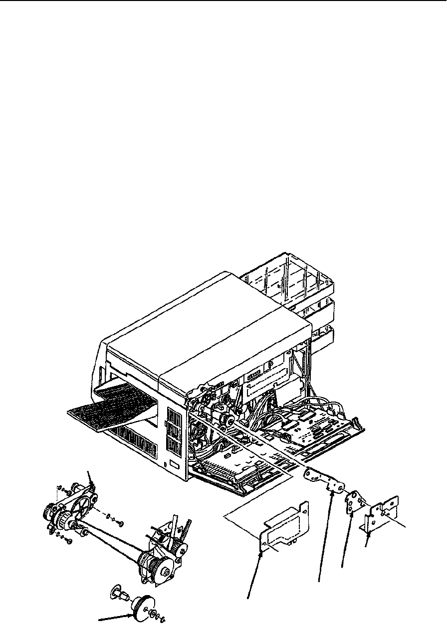
Fuser Drive Belt Removal
June 1999 Removal/Replacement Procedures 7-57
Fuser Drive Belt Removal
To remove the fuser drive belt:
1Open the back cover.
2Remove the fuser drive cover (three screws).
3Remove the main drive cover (one screw).
4Remove the gear stay cover (one screw).
5Remove the gear stay (three screws).
6Remove the main drive gear and bearing (single C-clip).
7Remove the single upper left screw and the two lower screws holding the fuser drive
in place.
8Loosen the upper right screw for the fuser drive and pivot the drive down.
9Slide the fuser drive belt off the gear.
Loosen
Main Motor Fuser Drive Cover
Gear Stay Gear Stay
Main Drive
Screw
Gear
Cover
Cover
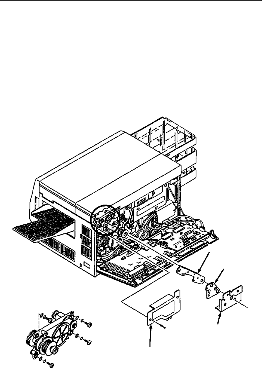
Fuser Drive Removal
7-58 Removal/Replacement Procedures June 1999
Fuser Drive Removal
To remove the fuser drive:
1Open the back cover.
2Remove the fuser drive cover (three screws).
3Remove the main drive cover (one screw).
4Remove the gear stay cover (one screw).
5Remove the gear stay (three screws).
6Remove the fuser drive belt (see page 7-57).
7Remove the fuser drive (four screws).
Gear Stay
Gear Stay
Main Drive
Fuser Drive
Fuser Drive Detail
Cover
Cover
Cover
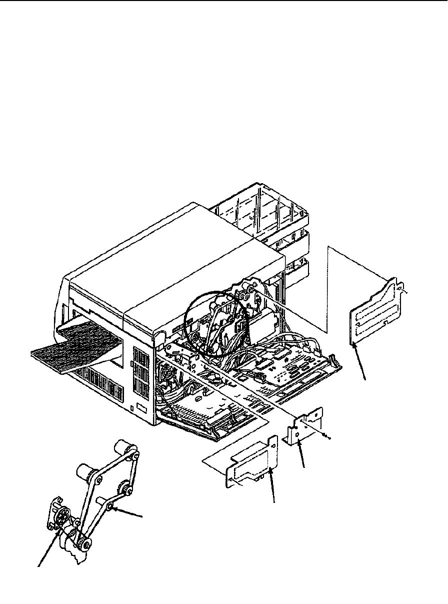
Paper Feed Drive Belt Removal
June 1999 Removal/Replacement Procedures 7-59
Paper Feed Drive Belt Removal
To remove the paper feed drive belt:
1Open the back cover.
2Remove the fuser drive cover (three screws).
3Remove the paper feed drive cover (three screws).
4Remove the main drive cover (one screw).
5Remove the cleaner drive belt (see page 7-55).
6Push down on the idler arm and slide the paper feed drive belt off the gear.
Paper Feed
Drive Cover
Main Drive Cover
Fuser Drive Cover
Idler Arm
Cleaner Drive Belt
Paper Feed Drive Belt Detail
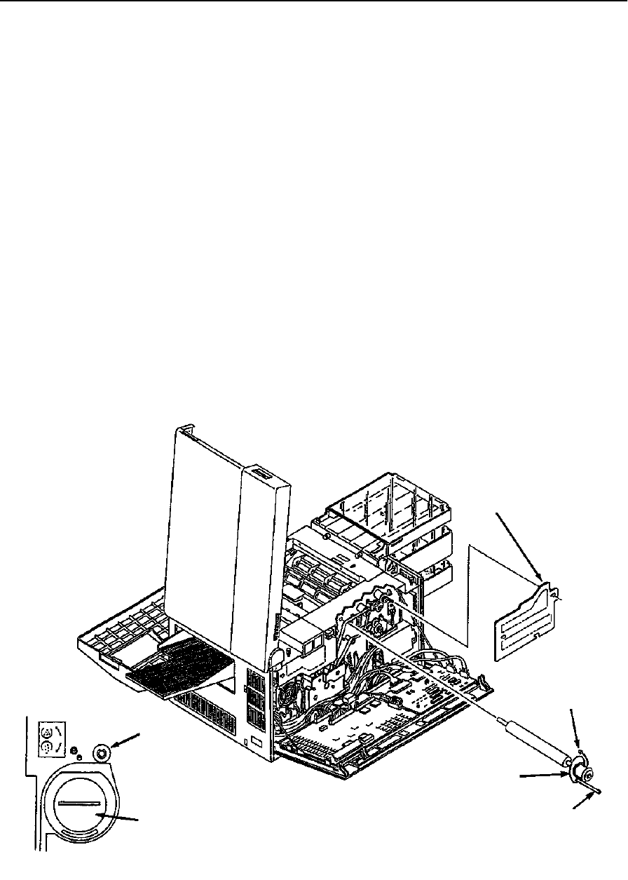
Paper Timing Roller Removal
7-60 Removal/Replacement Procedures June 1999
Paper Timing Roller Removal
To remove the paper timing roller:
1Open the front, back, and top covers.
2Raise the upper paper guide.
3Remove the photoconductor and place it in its protective bag.
4Remove the paper feed drive cover (three screws).
5Remove the paper feed drive belt from the paper timing roller gear.
6Disconnect CN65.
7Unscrew the standoff post from the collar surrounding the end of the roller.
8Remove the front C-clip and bearing.
9Slide the paper timing roller out the back of the printer.
Replacement Notes:
•Reinstall the original collar and standoff post with any new paper timing roller.
•Be sure to align all of the guide pins or the C-clip will not fit correctly.
Paper Feed
CN65
Collar
Standoff Post
C-Clip
Cassette Release Cover
Drive Cover
and Bearing
Front Detail
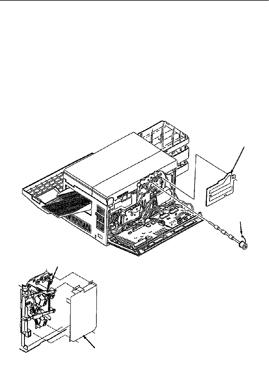
Upper Feed Roller Removal
June 1999 Removal/Replacement Procedures 7-61
Upper Feed Roller Removal
To remove the upper feed roller:
1Open the front and back covers.
2Remove the paper feed drive cover (three screws).
3Disconnect CN66.
4Remove the paper feed drive belt from the upper feed roller gear.
5Remove the cassette release cover (two screws).
6Remove the front C-clip and bearing.
7Slide the upper feed roller out the back of the printer.
Paper Feed
Drive Cover
CN66
C-Clip and Bearing
Front Detail Cassette Release Cover

Lower Feed Roller Removal
7-62 Removal/Replacement Procedures June 1999
Lower Feed Roller Removal
To remove the lower feed roller:
1Open the front and back covers.
2Remove the paper feed drive cover (three screws).
3Disconnect CN67.
4Remove the paper feed drive belt from the lower feed roller gear.
5Remove the cassette release cover (two screws).
6Remove the front C-clip and bearing.
7Slide the lower feed roller out the back of the printer.
Paper Feed
Drive Cover
CN67
C-Clip and Bearing
Front Detail Cassette Release Cover
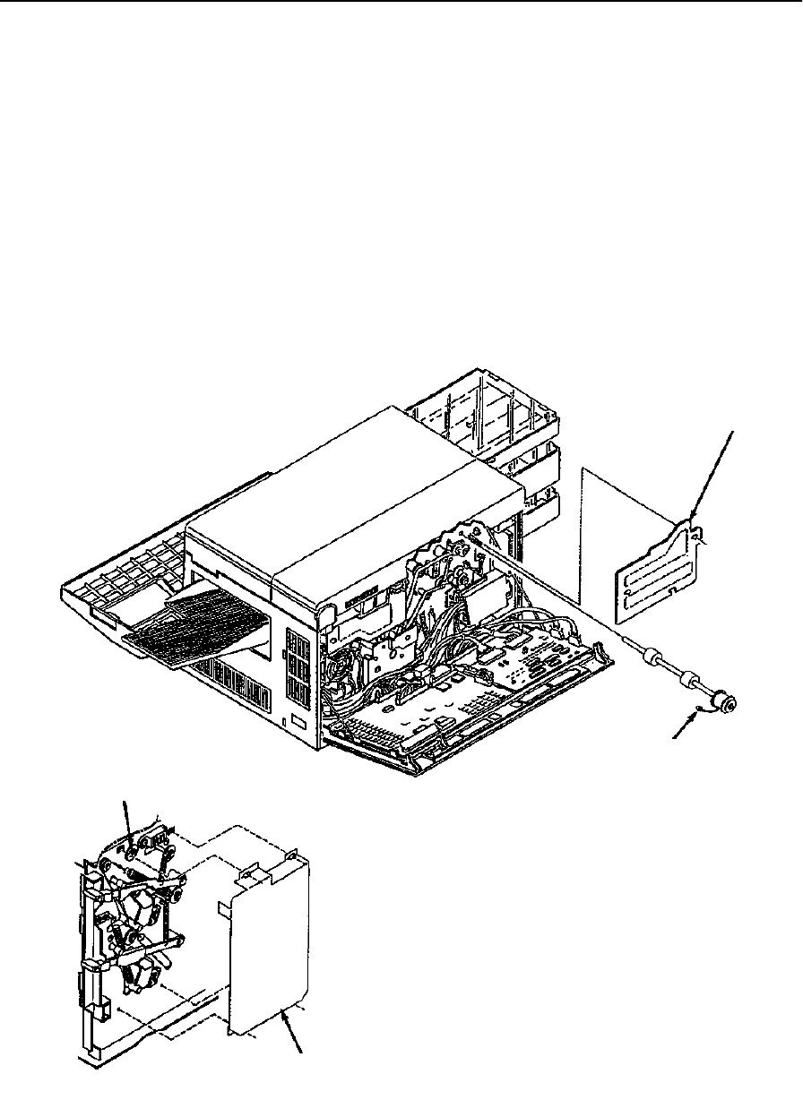
Upper Pick-Up Roller Removal
June 1999 Removal/Replacement Procedures 7-63
Upper Pick-Up Roller Removal
To remove the upper pick-up roller:
1Open the front and back covers.
2Remove the paper feed drive cover (three screws).
3Disconnect CN68.
4Remove the cassette release cover (two screws).
5Remove the front C-clip and bearing.
6Slide the upper pick-up roller out the back of the printer.
Note: You may need to remove the EMI grounding plate.
Paper Feed
Drive Cover
CN68
C-Clip and Bearing
Cassette Release Cover
Front Detail
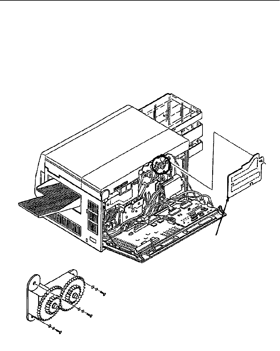
Upper Pick-Up Roller Drive Removal
7-64 Removal/Replacement Procedures June 1999
Upper Pick-Up Roller Drive Removal
To remove the upper pick-up roller drive:
1Open the back cover.
2Remove the paper feed drive cover (three screws).
3Remove the upper pick-up roller drive (three screws).
Note: You may need to remove the EMI grounding plate.
Paper Feed
Upper Pick-up Roller Drive Detail
Drive Cover
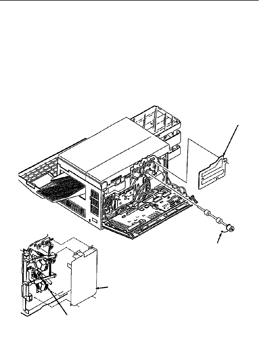
Lower Pick-Up Roller Removal
June 1999 Removal/Replacement Procedures 7-65
Lower Pick-Up Roller Removal
To remove the lower pick-up roller:
1Open the front and back covers.
2Remove the paper feed drive cover (three screws).
3Disconnect CN69.
4Remove the cassette release cover (two screws).
5Remove the front C-clip and bearing.
6Slide the lower pick-up roller out the back of the printer.
Paper Feed
Drive Cover
CN69
Cassette Release Cover
C-Clip and Bearing
Front Detail
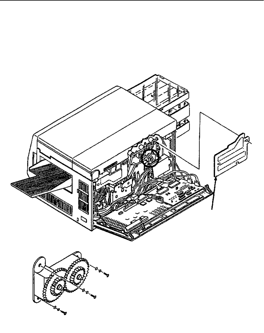
Lower Pick-Up Roller Drive Removal
7-66 Removal/Replacement Procedures June 1999
Lower Pick-Up Roller Drive Removal
To remove the lower pick-up roller drive:
1Open the back cover.
2Remove the paper feed drive cover (three screws).
3Remove the lower pick-up roller drive (three screws).
Paper Feed
Drive Cover
Lower Pick-up Roller Drive Detail
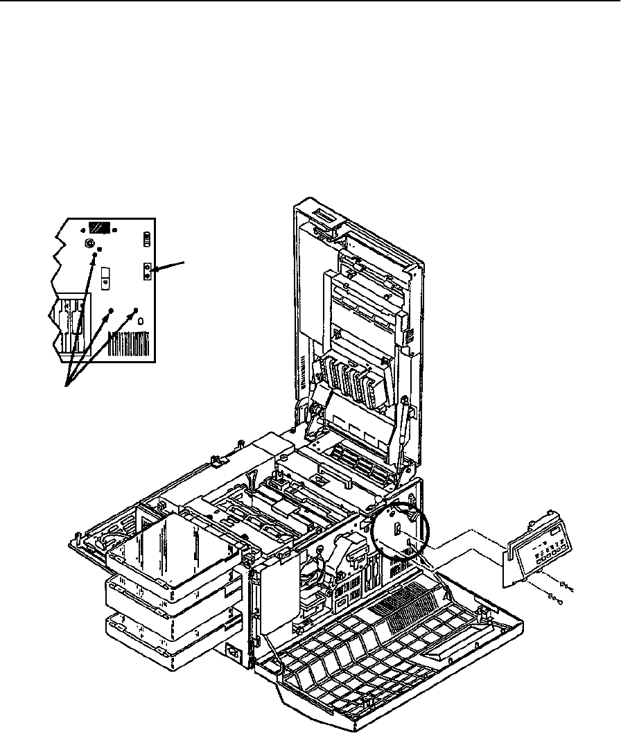
Job Offset Assembly Removal
June 1999 Removal/Replacement Procedures 7-67
Job Offset Assembly Removal
To remove the job offset assembly:
1Open the front, top, and back covers.
2Remove the paper output tray.
3Remove the right side cover (see page 7-10).
4Remove the operator panel (see page 7-19).
Output Option
Mounting Pin
Mounting Screws
Front Detail
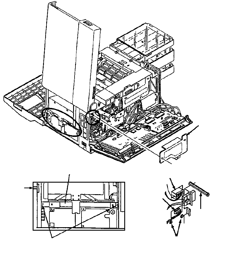
Job Offset Assembly Removal
7-68 Removal/Replacement Procedures June 1999
5Remove the DC power supply (see page 7-31).
6Remove the mounting bracket for the DC power supply (two screws).
7Remove the fuser drive cover (three screws).
8Disconnect CN19 and CN54.
9Remove the five screws holding the job offset assembly in place (three front and two
back).
10 Remove the fuser drive cover mounting post.
11 Remove the output option mounting pin (single screw, located on the front of the
printer).
12 Remove the job offset assembly.
Mounting
Pin
Bracket
Bracket Mounting Screws
Right Side Detail
CN54
CN19
Mounting Screws
Back Detail
Fuser Drive Cover
Mounting Post
Fuser Drive
Cover

Exit Pinch Roller Removal
June 1999 Removal/Replacement Procedures 7-69
Exit Pinch Roller Removal
To remove the exit pinch roller:
1Open the front, back, and top covers.
2Remove the fuser.
3Remove the operator panel (see page 7-19).
4Remove the front screw holding the exit pinch roller in place.
5Remove the front screw holding the exit guide in place.
Exit Pinch Roller Screw
C-Clip and Bearing
Exit Guide Screw
Front Detail
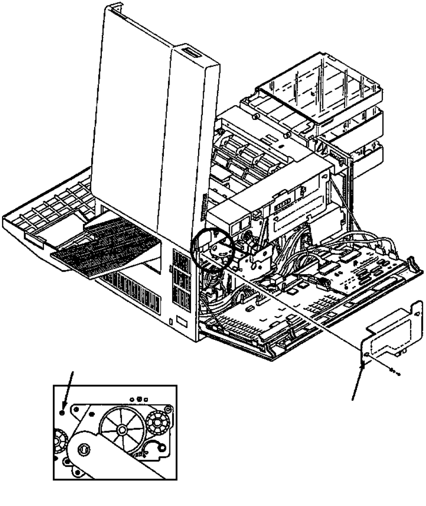
Exit Pinch Roller Removal
7-70 Removal/Replacement Procedures June 1999
6Remove the fuser drive cover (three screws).
7Remove the back screw holding the exit pinch roller in place.
8Lift the exit pinch roller from the printer.
Note: Use caution so as not to damage the paper full or exit sensors.
Mounting Screw
Back Detail
Fuser Drive Cover
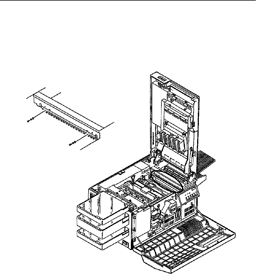
Upper Static Brush Removal
June 1999 Removal/Replacement Procedures 7-71
Upper Static Brush Removal
To remove the upper static brush:
1Open the top and front covers.
2Remove the fuser.
3Remove the upper static brush from the exit pinch roller assembly (two screws).
Upper Static Brush Detail
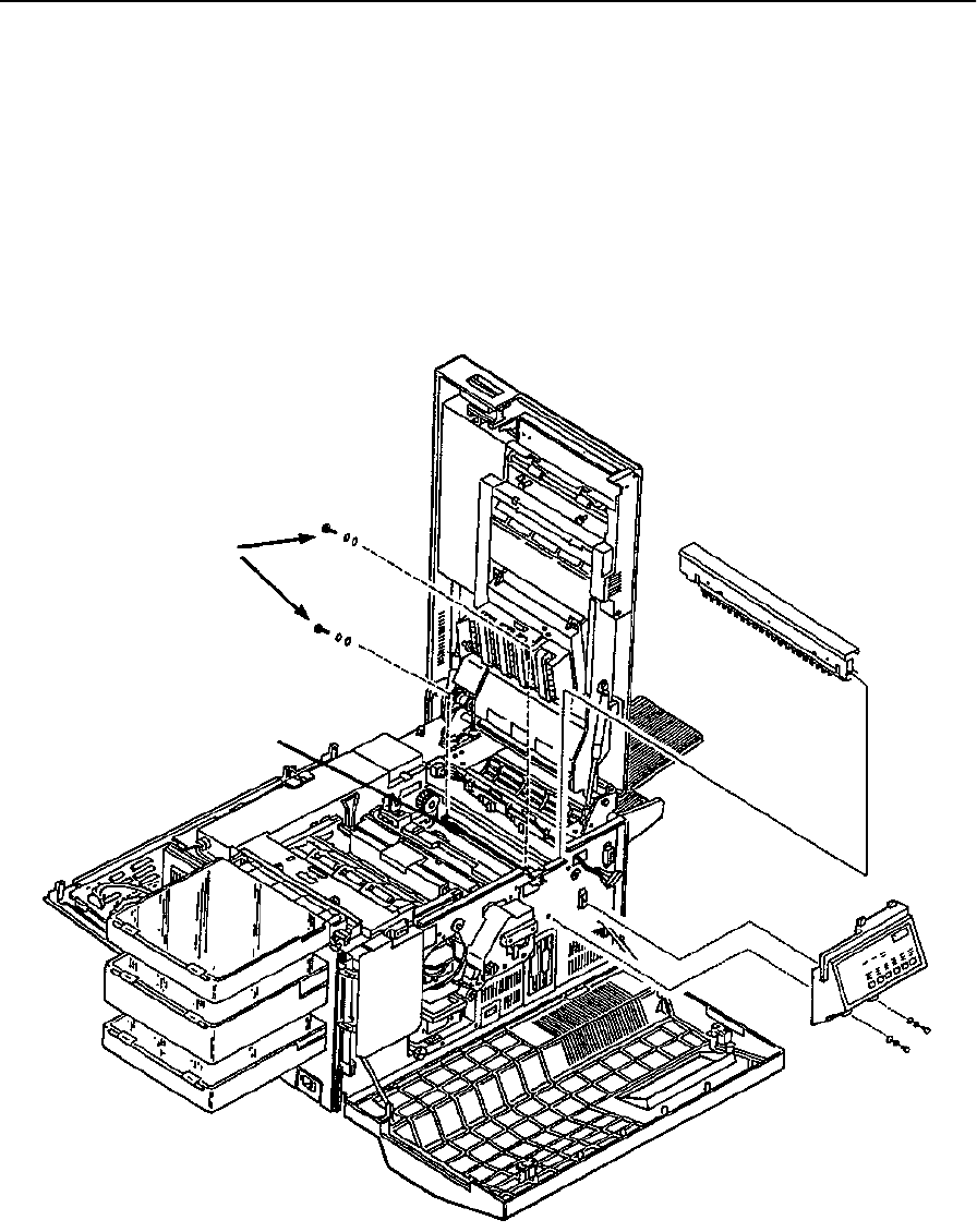
Lower Static Brush Removal
7-72 Removal/Replacement Procedures June 1999
Lower Static Brush Removal
To remove the lower static brush:
1Open the top, front and back covers.
2Remove the fuser.
3Remove the operator panel (see page 7-19).
4Remove the exit pinch roller assembly (see page 7-69).
5Remove the lower static brush (two screws).
Mounting Screws
Lower Static Brush
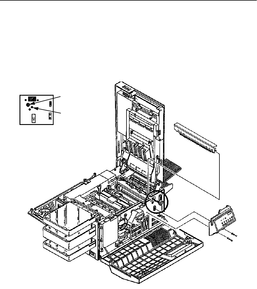
Exit Roller Assembly Removal
June 1999 Removal/Replacement Procedures 7-73
Exit Roller Assembly Removal
To remove the exit roller assembly:
1Open the front, back, and top covers.
2Remove the fuser.
3Remove the operator panel (See page 7-19).
4Remove the front screw holding the exit guide in place.
C-Clip and Bearing
Exit Guide Screw
Front Detail
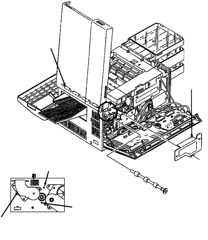
Exit Roller Assembly Removal
7-74 Removal/Replacement Procedures June 1999
5Remove the fuser drive cover (three screws).
6Remove the exit pinch roller (see page 7-69).
7Duplex only: Remove the lower duplex drive (three screws).
8Remove the back screw holding the exit guide in place.
9Tilt the exit guide toward the center of the printer.
10 Remove the front C-clip and bearing.
11 Slide the exit roller out the back of the printer.
Note: Use caution so as not to damage the paper full or exit sensors.
Fuser
Drive
Cover
Exit Guide
Exit Pinch Roller Screw
Exit Guide Screw
Lower Duplex Drive
(C30D only)
Back Detail
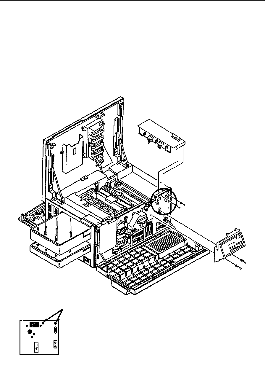
Exit Cover Removal (Simplex)
June 1999 Removal/Replacement Procedures 7-75
Exit Cover Removal (Simplex)
To remove the simplex exit cover:
1Open the front, back, and top covers.
2Remove the fuser.
3Remove the right side cover (see page 7-9).
4Remove the paper output tray.
5Remove the operator panel (see page 7-19).
Mounting Screws
Front Detail
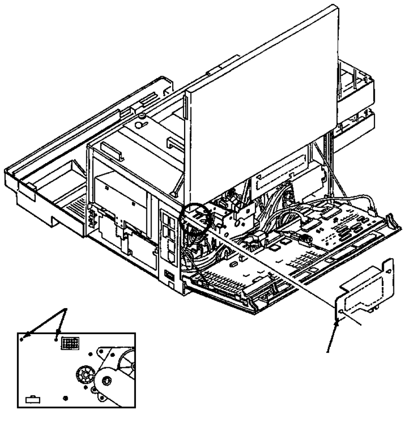
Exit Cover Removal (Simplex)
7-76 Removal/Replacement Procedures June 1999
6Remove the fuser drive cover (three screws).
7Remove the exit pinch roller (see page 7-69).
8Disconnect CN49 and CN51.
9Remove the four screws holding the exit cover in place (two front and two back).
10 Remove the wiring harness for CN42, CN49, and CN51 from the exit cover.
11 Lift the exit cover from the printer.
Mounting Screws
Fuser Drive Cover
Back Detail
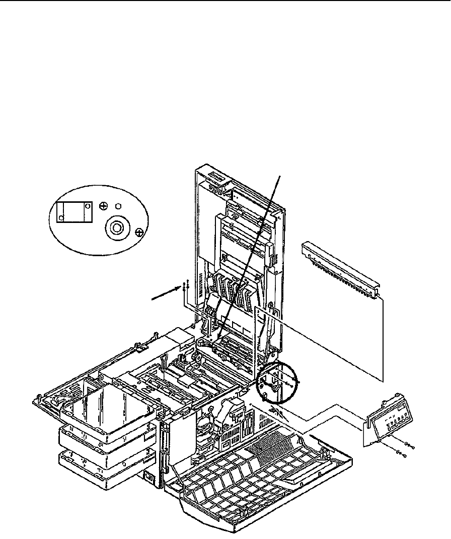
Exit Cover Removal (Duplex)
June 1999 Removal/Replacement Procedures 7-77
Exit Cover Removal (Duplex)
To remove the duplex exit cover:
1Open the front, top, and back covers.
2Remove the fuser.
3Remove the paper output tray.
4Remove the right side cover (see page 7-10).
5Remove the operator panel (see page 7-19).
CN317
Solenoid Screws
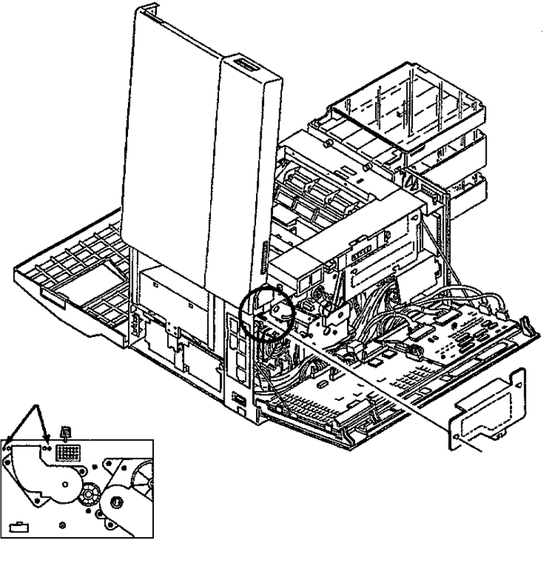
Exit Cover Removal (Duplex)
7-78 Removal/Replacement Procedures June 1999
6Remove the fuser drive cover (three screws).
7Remove the exit pinch roller (see page 7-69).
8Disconnect CN49 and CN51.
9Remove the wiring harness for CN42, CN49, and CN51 from the exit cover.
10 Disconnect CN317.
11 Remove the four screws holding the exit cover in place (two front and two back).
12 Lift the exit cover from the printer.
13 Remove the solenoid from the exit cover (two screws).
Fuser Drive Cover
Mounting Screws
Back Detail
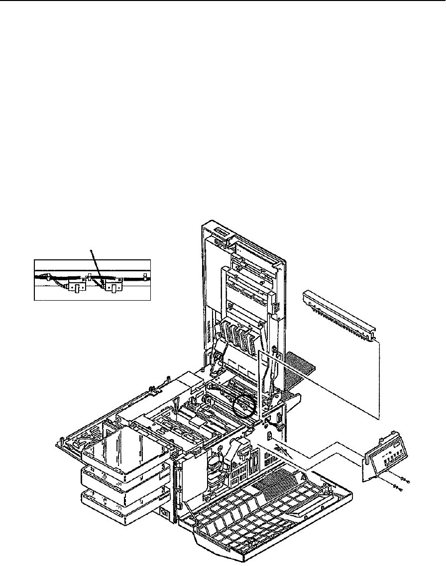
Paper Exit Sensor Removal
June 1999 Removal/Replacement Procedures 7-79
Paper Exit Sensor Removal
To remove the paper exit sensor:
1Open the front, back, and top covers.
2Remove the fuser.
3Remove the operator panel (see page 7-19).
4Remove the exit pinch roller (see page 7-69).
5Disconnect CN49.
6Remove the two screws holding the exit cover in place (one front and one back).
7Tilt the exit cover assembly toward the center of the printer.
8From the underside, remove the paper exit sensor (single screw).
CN49
Paper Exit Sensor Detail

Paper Full Sensor Removal
7-80 Removal/Replacement Procedures June 1999
Paper Full Sensor Removal
To remove the paper full sensor:
1Open the front, back, and top covers.
2Remove the fuser.
3Remove the operator panel (see page 7-19).
4Remove the exit pinch roller (see page 7-69).
5Disconnect CN51.
6Remove the two screws holding the exit cover in place (one front and one back).
7Tilt the exit cover toward the center of the printer.
8From the underside, remove the paper full sensor (single screw).
CN51
Paper Full Sensor Detail

Front Cover Interlock Switch Removal
June 1999 Removal/Replacement Procedures 7-81
Front Cover Interlock Switch Removal
To remove the front cover interlock switch:
1Open the front, top, and back covers.
2Duplex only: Remove the duplex tray.
3Remove the upper and lower paper cassettes.
4Remove the left side cover (see page 7-8).
5Remove the AC power supply (see page 7-29).
6Remove the AC power supply top cover (two screws).
7Disconnect the two wires connected to the interlock switch.
8Remove the front interlock switch (two screws).
Wires
Front Cover Interlock Switch Detail

Back Cover Interlock Switch Removal
7-82 Removal/Replacement Procedures June 1999
Back Cover Interlock Switch Removal
To remove the back cover interlock switch:
1Open the front, top, and back covers.
2Duplex only: Remove the duplex tray.
3Remove the upper and lower paper cassettes.
4Remove the left side cover (see page 7-8).
5Remove the AC power supply (see page 7-29).
6Remove the AC power supply side cover (one screw).
7Disconnect the four wires connected to the interlock switch.
8Remove the back cover interlock switch (two screws).
Wires
Side Cover
Back Cover Interlock Switch Detail
AC Power Supply
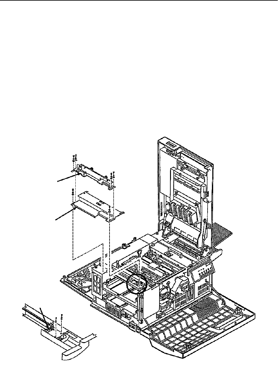
Top Cover Interlock Switch Removal
June 1999 Removal/Replacement Procedures 7-83
Top Cover Interlock Switch Removal
To remove the top cover interlock switch:
1Open the top, front, and back covers.
2Duplex only: Remove the duplex tray.
3Remove the upper and lower paper cassettes.
4Remove the left side cover (see page 7-8).
5Duplex only: Remove the duplex tray mount (four screws).
6Remove the paper feed drive cover (three screws; duplex two screws).
7Disconnect the two wires connected to the interlock switch.
8Remove the top cover interlock switch (two screws).
Duplex Tray
(C30D only)
Paper Feed
Mount
Drive Cover
Wires
Top Cover Interlock Switch Detail
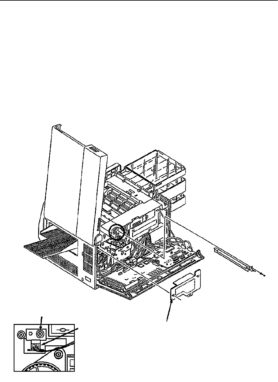
Erase Lamp Removal
7-84 Removal/Replacement Procedures June 1999
Erase Lamp Removal
To remove the erase lamp:
1Open the top and back covers.
2Remove the photoconductor and place it in its protective packaging.
3Remove the fuser drive cover (three screws).
4Disconnect CN26.
5Remove the screw holding the erase lamp in place.
6Disengage the front of the erase lamp from its guide pin.
7Slide the unit out from the back of the printer.
Back Detail
CN26
Mounting Screw
Fuser Drive Cover
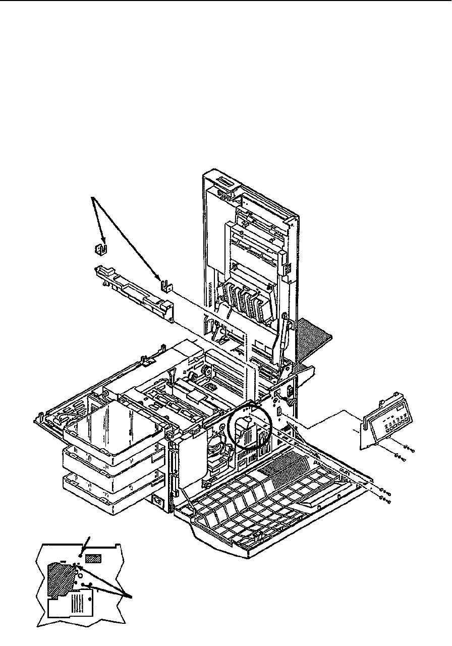
EP Cover Removal
June 1999 Removal/Replacement Procedures 7-85
EP Cover Removal
To remove the EP cover:
1Open the front, back, and top covers.
2Remove the fuser.
3Remove the photoconductor and place it in its protective packaging.
4Remove the cleaner unit.
5Remove the operator panel (see page 7-19).
Support Screw
EP Cover Screws
Vacuum Transport
Supports
Front Detail
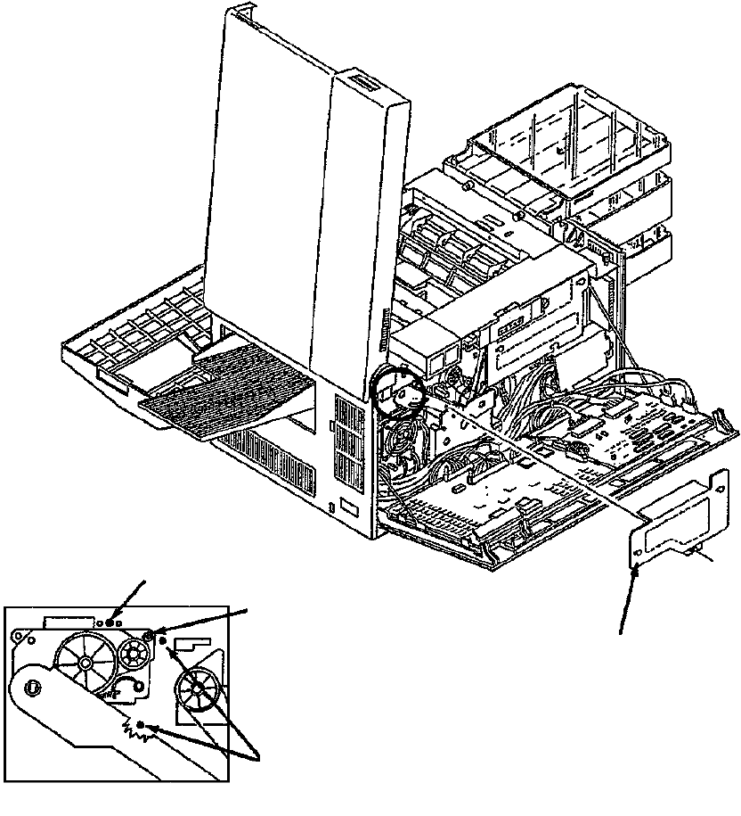
EP Cover Removal
7-86 Removal/Replacement Procedures June 1999
6Remove the fuser drive cover (three screws).
7Remove the two supports for the vacuum transport unit (one screw each).
8Duplex only: Remove the duplex fan (see page 7-27).
9Remove the four screws holding the EP cover in place (two front and two back).
10 Remove the upper right screw holding the fuser drive in place.
11 Lift the EP cover straight up and out of the printer.
Replacement Note:
The higher of the two drive shaft support arms should be facing the left side of the printer.
Support Screw
Fuser Drive Screw
EP Cover Screws
Back Detail
Fuser Drive Cover
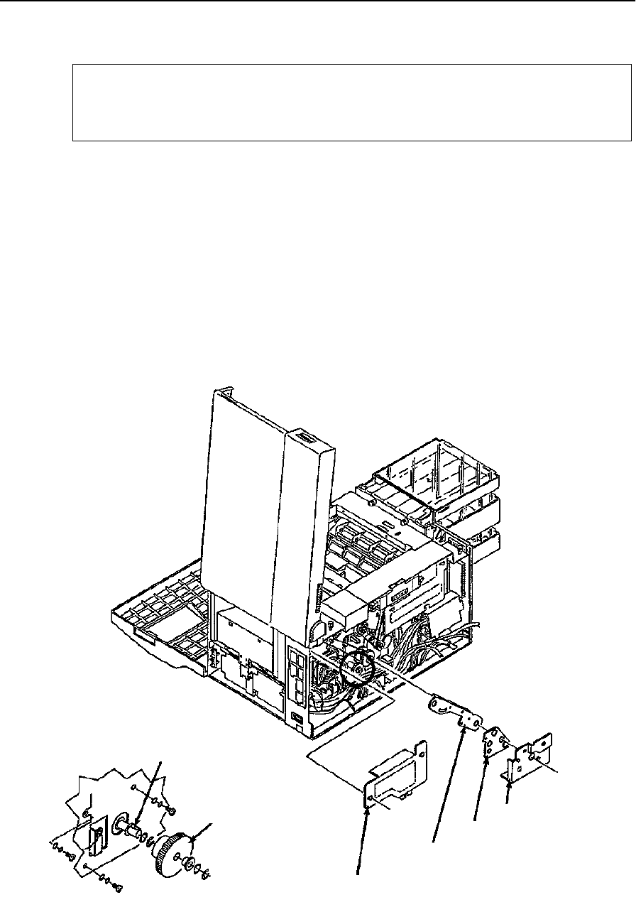
Main Motor Removal
June 1999 Removal/Replacement Procedures 7-87
Main Motor Removal
To remove the main motor:
1Disconnect all external cables and attachments.
2Open the front, back, and top covers.
3Remove the photoconductor and place it in its protective packaging.
4Remove the cleaner unit.
5Remove the back cover (see page 7-6).
6Remove the lower back cover (see page 7-7).
7Remove the signal interface board (see page 7-37).
Do not allow the capacitor contacts to short out against your
Caution
body or the printer frame.
Fuser Drive Cover
Gear Stay
Gear Stay Cover
Main Drive Cover
Drive Shaft Key
Main Motor Gear
Back Detail
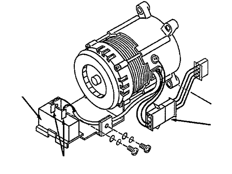
Main Motor Removal
7-88 Removal/Replacement Procedures June 1999
8Remove the right side cover (see page 7-9).
9Remove the counter (see page 7-20).
10 Remove the main drive cover (one screw).
11 Remove the fuser drive cover (three screws).
12 Remove the gear stay cover.
13 Remove the gear stay (three screws).
14 Remove the disk drive housing (see page 7-25).
15 Remove the printhead (see page 7-23).
16 Remove the DC power supply (see page 7-31).
17 Remove the main motor gear and bearing (two C-clips).
18 Disconnect CN95.
19 From the right side, remove the two screws holding the main motor in place.
20 From the back, remove the three screws holding the main motor in place.
21 Remove the main motor through the side of the printer.
Replacement Notes:
•Remove the drive shaft key from the old motor. Replacement motors are not sup-
plied with a key.
•Be sure to tuck the CN95 connector under the motor after installation so that the
wires do not protrude into the disk drive assembly area.
CN95
Main Motor Detail
Capacitor
Capacitor Contacts

Main Gear Drive Removal
June 1999 Removal/Replacement Procedures 7-89
Main Gear Drive Removal
To remove the main gear drive:
1Open the back cover.
2Remove the lower back cover (see page 7-7).
3Remove the paper feed drive cover (three screws).
4Remove the fuser drive cover (three screws).
5Remove the main drive cover (one screw).
6Remove the gear stay cover (one screw).
7Remove the gear stay (three screws).
8Remove the cleaner drive belt (see page 7-55).
9Remove the paper feed drive belt (see page 7-59).
10 Remove the main gear drive (three screws).
Fuser Drive Cover
Gear Stay
Gear Stay Cover
Main Drive
Paper Feed
Drive Cover
Main Gear Drive Detail
Cover
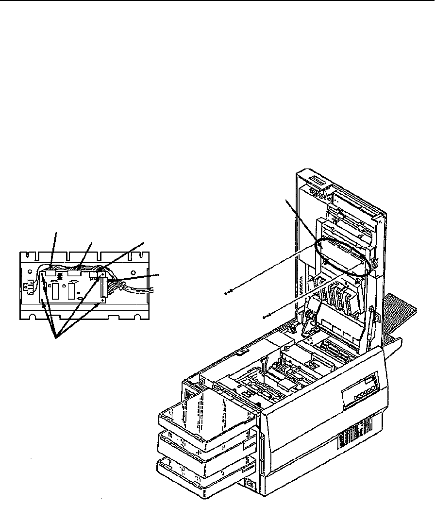
Duplex Control Board #1 Removal
7-90 Removal/Replacement Procedures June 1999
Duplex Control Board #1 Removal
To remove duplex control board #1:
1Open the top cover.
2Remove the duplex control board cover (two screws).
3Disconnect CN306, CN307, CN308, and CN309.
4Disengage duplex control board #1. To do this, pinch the four standoffs on the board
one at a time.
5Lift the board from the mounting bracket.
CN308 CN309 CN306
CN307
Standoffs
Duplex Control Board Cover
Duplex Control Board #1 Detail
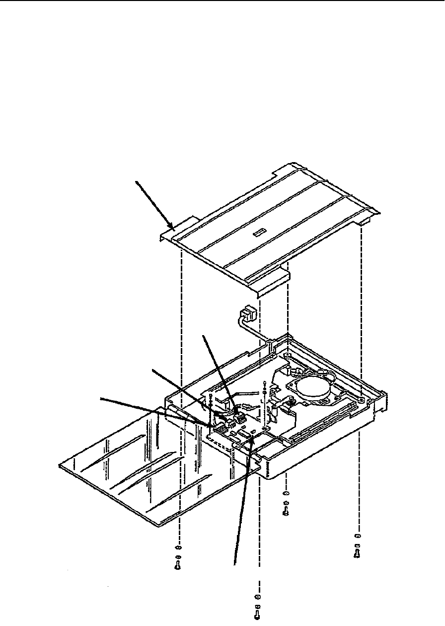
Duplex Control Board #2 Removal
June 1999 Removal/Replacement Procedures 7-91
Duplex Control Board #2 Removal
To remove duplex control board #2:
1Open the top cover.
2Remove the duplex tray.
3Remove the paper guide from the duplex tray (four screws).
4Disconnect CN310, CN311, and CN312.
5Remove duplex control board #2 (two screws).
CN312
CN310
CN311
Paper Guide
Duplex Control Board #2
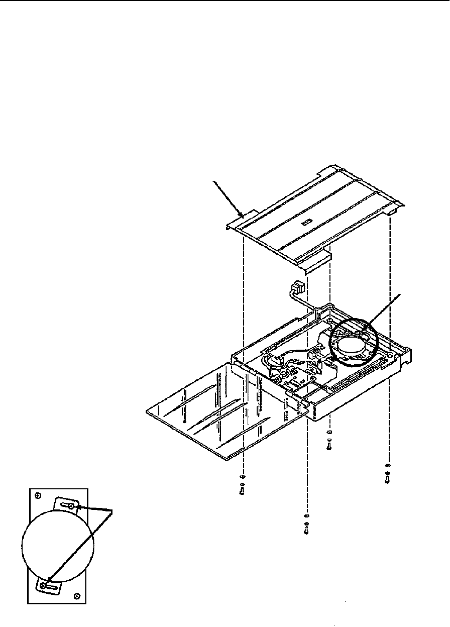
Duplex Tray Registration Motor Removal
7-92 Removal/Replacement Procedures June 1999
Duplex Tray Registration Motor Removal
To remove the duplex tray registration motor:
1Open the top cover.
2Remove the duplex tray.
3Remove the paper guide inside the duplex tray (four screws).
4Disconnect CN321.
5Remove the registration motor (two screws).
Paper Guide
CN321
Mounting Screws
Registration Motor Detail

Duplex Skew Correction Cable Removal
June 1999 Removal/Replacement Procedures 7-93
Duplex Skew Correction Cable Removal
To remove the duplex skew correction cable:
1Open the top cover.
2Remove the duplex tray.
3Remove the paper guide from inside the duplex tray (four screws).
4Slide the skew correction guides toward the center of the duplex tray.
5Remove the bracket holding the shaft in place (two screws).
6Remove the screw holding the cable mounting plate in place.
7Lift the skew correction guides and shaft up out of the duplex tray.
8Remove two screws holding each pulley assembly in place.
9Remove the spring from the cable.
10 Lift the skew correction cable and pulley assemblies from the duplex tray.
Replacement Notes:
The placement of the mounting bead is critical. Set it on precisely. Replace parts in this
order:
•First reinstall the pulley assembly.
•Then, wrap the cable three times around the drive gear pulley.
•Finally, connect the spring.
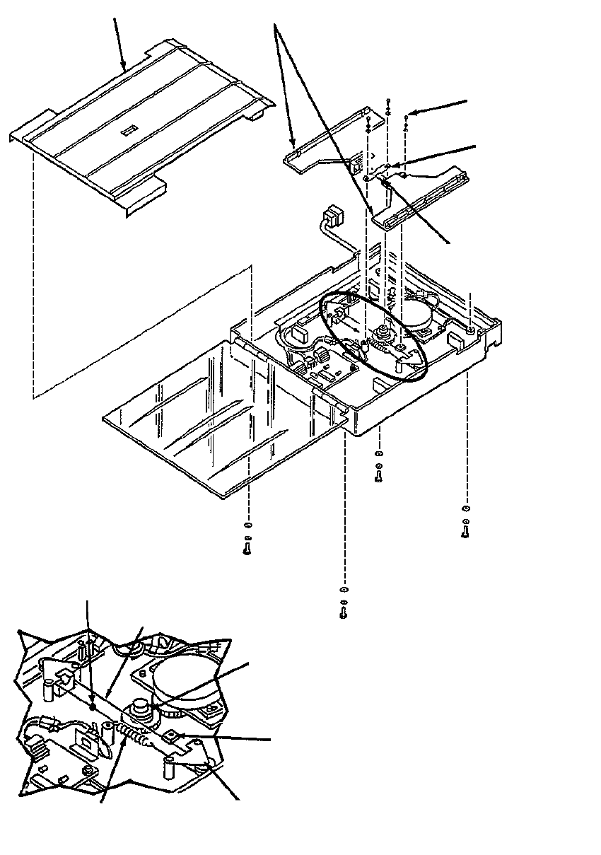
Duplex Skew Correction Cable Removal
7-94 Removal/Replacement Procedures June 1999
Paper Guide Skew Correction Guides
Mounting Plate
Shaft Bracket
Shaft
Mounting Bead
Skew Correction Cable
Drive Gear Pulley
Cable Mounting Plate
Pulley Assembly
Tension Spring
Skew Correction Cable Detail
Screw
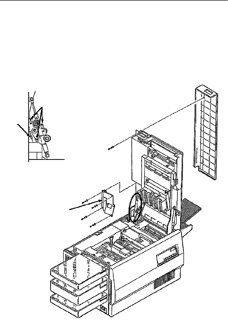
Upper Duplex Drive/Clutch Assembly Removal
June 1999 Removal/Replacement Procedures 7-95
Upper Duplex Drive/Clutch Assembly Removal
To remove the upper duplex drive/clutch assembly:
1Open the top cover.
2Remove the rear duplex cover (see page 7-17).
3Remove the lower duplex roller cover (four screws).
4Disconnect CN316.
5Remove the upper duplex drive/clutch assembly (three screws).
Mounting Screws
CN316
Side Detail
Lower Duplex
Roller Cover
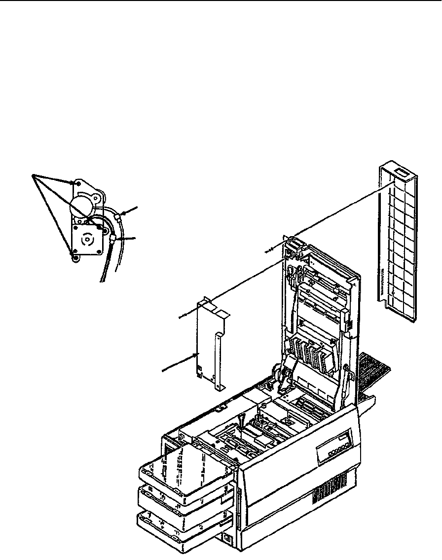
Duplex Route Motor/Solenoid Assembly Removal
7-96 Removal/Replacement Procedures June 1999
Duplex Route Motor/Solenoid Assembly Removal
To remove the duplex route motor/solenoid assembly:
1Open the top cover.
2Remove the rear duplex cover (see page 7-17).
3Remove the upper duplex roller cover (four screws).
4Disconnect CN313 and CN314.
5Remove the duplex route motor/solenoid assembly (three screws).
Mounting Screws
Duplex Route Motor/Solenoid Detail
CN314
CN313
Upper Duplex
Roller Cover
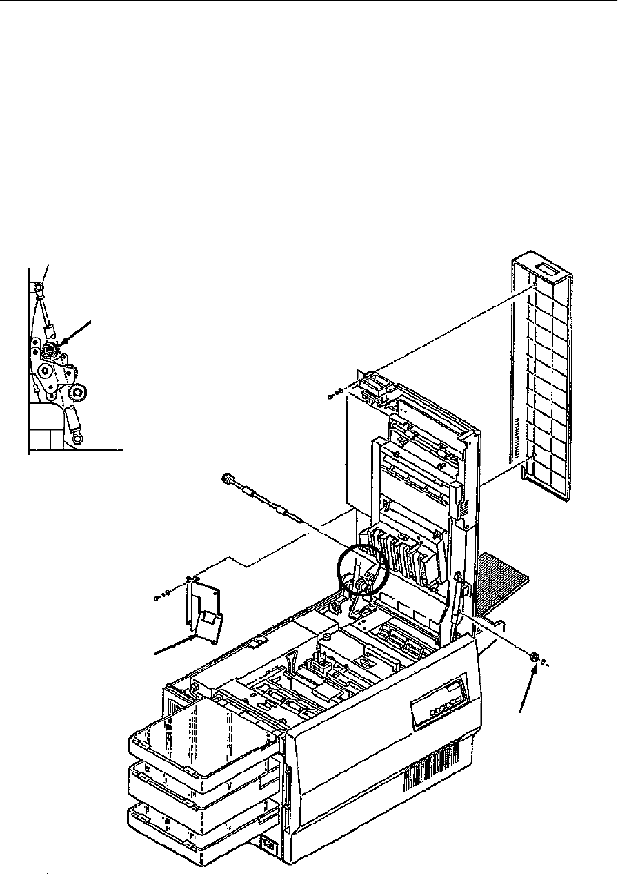
“A” Roller Removal
June 1999 Removal/Replacement Procedures 7-97
“A” Roller Removal
To remove the “A” roller:
1Open the top cover.
2Remove the rear duplex cover (see page 7-17).
3Remove the lower duplex roller cover (four screws).
4Remove the front C-clip and bearing from the “A” roller.
5Lower the top cover to a 45 degree angle.
6Slide the “A” roller out the back of the printer.
A Roller
Side Detail
Lower Duplex
Roller Cover
C-Clip and
Bearing
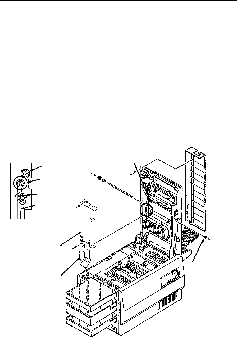
“B” Roller Removal
7-98 Removal/Replacement Procedures June 1999
“B” Roller Removal
To remove the “B” roller:
1Open the top cover.
2Remove the rear duplex cover (see page 7-17).
3Remove the upper duplex roller cover (four screws).
4Remove the lower duplex roller cover (four screws).
5Remove the front C-clip and bearing from the “B” roller.
6Remove two screws holding the duplex control board cover in place.
7Move the cover to the left out of the way.
8Loosen the screw holding the idler roller in place.
9Remove the duplex drive belt.
10 Remove the drive gear (single C-clip).
11 Slide the “B” roller out from the back of the printer.
B Roller
Drive Gear
Loosen Screw
Duplex
Drive Belt
Side Detail
Upper Duplex
Roller Cover
Lower Duplex
Roller Cover
Duplex Control
Board Cover
C-Clip and
Bearing
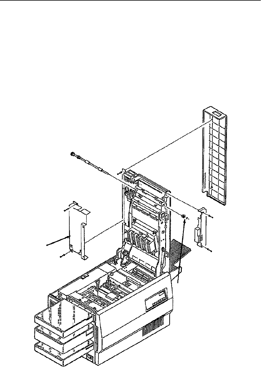
“C” Roller Removal
June 1999 Removal/Replacement Procedures 7-99
“C” Roller Removal
To remove the “C” roller:
1Open the top cover.
2Remove the rear duplex cover (see page 7-17).
3Remove the upper duplex roller cover (four screws).
4Remove the front mechanism cover (two screws).
5Remove the front C-clip and bearing from the “C” roller.
6Slide the “C” roller out from the back of the printer.
Upper Duplex
Roller Cover
C-Clip and Bearing
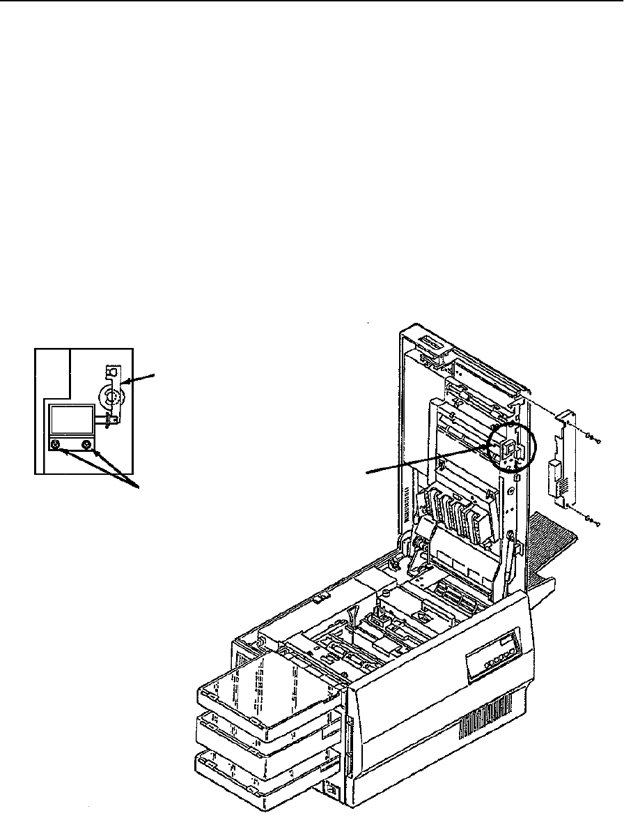
“C” Roller Solenoid Removal
7-100 Removal/Replacement Procedures June 1999
“C” Roller Solenoid Removal
To remove the “C” roller solenoid:
1Open the top cover.
2Remove the front mechanism cover (two screws).
3Disconnect CN315 and cut the cable tie securing the wires to the mounting plate.
4Remove the two screws holding the “C” roller solenoid in place.
5Loosen the set screw securing the actuator arm to the “C” roller.
6Disengage the solenoid from the actuator arm and remove it.
Replacement Note:
Install a new cable tie to secure the wires from CN315 to the mounting plate.
Actuator Arm
Mounting Screws
C Roller Solenoid Detail
CN315
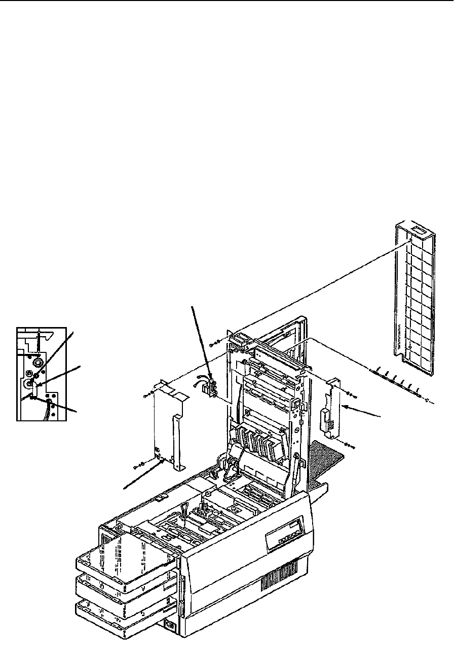
Duplex Route Separator Removal
June 1999 Removal/Replacement Procedures 7-101
Duplex Route Separator Removal
To remove the duplex route separator:
1Open the top cover.
2Remove the rear duplex cover (see page 7-17).
3Remove the upper duplex roller cover (four screws).
4Remove the duplex route motor/solenoid assembly (see page 7-96).
5Remove the front mechanism cover (two screws).
6Open the duplex cover.
7Remove screw holding the return arm in place.
8Disengage the return spring.
Return Arm Screw
Return Arm
Return Spring
Side Detail
Duplex Route Motor/
Solenoid Assembly
Front
Cover
Upper Duplex
Roller Cover
Mechanism
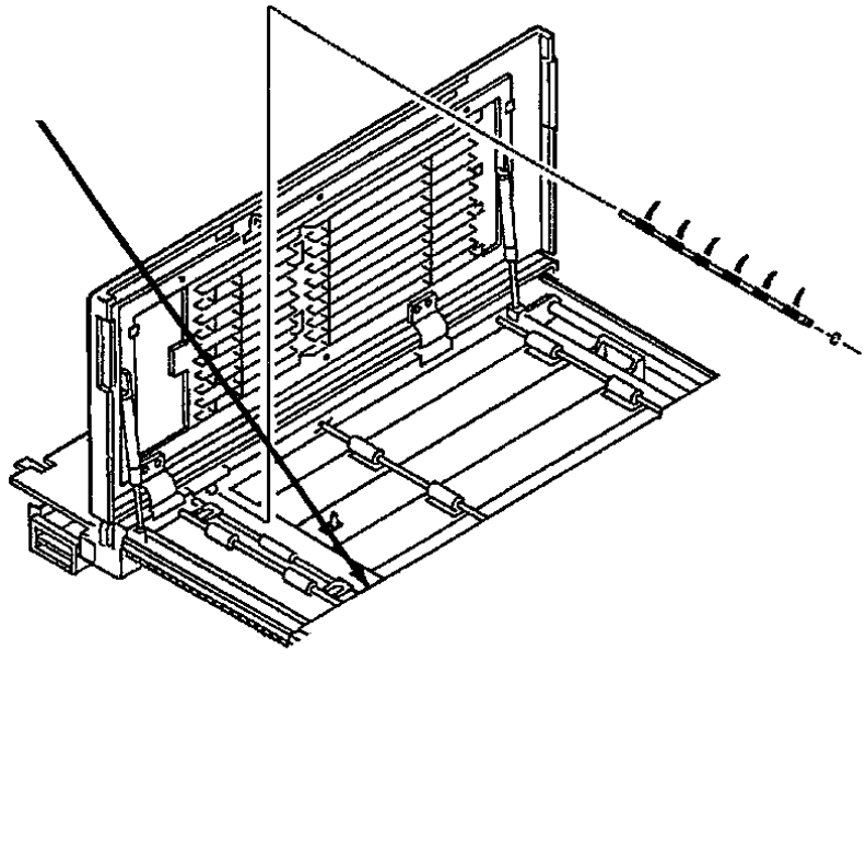
Duplex Route Separator Removal
7-102 Removal/Replacement Procedures June 1999
9Remove the front C-clip from the route separator.
10 Disengage the route separator from its side supports.
11 Lift the route separator out from the duplex cover.
C-Clip Location
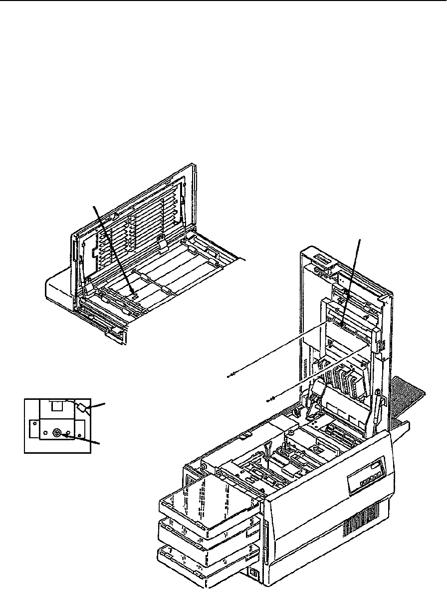
Duplex Paper Path Sensor Removal
June 1999 Removal/Replacement Procedures 7-103
Duplex Paper Path Sensor Removal
To remove the duplex paper path sensor:
1Open the top cover.
2Remove the two screws holding the duplex control board cover in place.
3Move the cover to the left out of the way.
4Disconnect CN319.
5Remove the duplex paper path sensor (single screw).
Paper Path Sensor
CN319
Mounting Screw
Paper Path Sensor
Underside Detail
Duplex Control
Board Cover
Duplex Paper Path Sensor Removal
7-104 Removal/Replacement Procedures June 1999

June 1999 Options 8-1
Chapter 8
Options
Section 6 Troubleshooting

8-2 Options June 1999
Chapter Contents
Options
Introduction . . . . . . . . . . . . . . . . . . . . . . . . . . . . . . . . . . . . . . . . . . . . . . . . . . . . . . . 8-3
1200-Sheet/2500-Sheet Feeder . . . . . . . . . . . . . . . . . . . . . . . . . . . . . . . . . . . . . . . .8-4
Bench Test Procedure . . . . . . . . . . . . . . . . . . . . . . . . . . . . . . . . . . . . . . . . . . . .8-5
Prefeed Adjustment Procedure . . . . . . . . . . . . . . . . . . . . . . . . . . . . . . . . . . . . .8-6
Input Control Board Logic . . . . . . . . . . . . . . . . . . . . . . . . . . . . . . . . . . . . . . . .8-7
1400-Sheet Stacker . . . . . . . . . . . . . . . . . . . . . . . . . . . . . . . . . . . . . . . . . . . . . . . . .8-9
Bench Test Procedure . . . . . . . . . . . . . . . . . . . . . . . . . . . . . . . . . . . . . . . . . . .8-10
Connector Locations . . . . . . . . . . . . . . . . . . . . . . . . . . . . . . . . . . . . . . . . . . . .8-12
Output Control Board Logic . . . . . . . . . . . . . . . . . . . . . . . . . . . . . . . . . . . . . .8-14
Hard Disk . . . . . . . . . . . . . . . . . . . . . . . . . . . . . . . . . . . . . . . . . . . . . . . . . . . . . . . .8-16
Troubleshooting Hard Disk Problems . . . . . . . . . . . . . . . . . . . . . . . . . . . . . . .8-16

Introduction
June 1999 Options 8-3
Introduction
This section provides information on testing and troubleshooting of specific printer
options not covered elsewhere in this manual. These options include the 1200-sheet and
2500-sheet feeders, the 1400-sheet stacker, and the hard disk.
Installation instuctions for the sheets feeders and for the sheet stacker are included in the
C30/C30D Guide to Operations manual. Installation instructions for the hard disk are
included with the packaged option.
For a complete list of the parts contained in the 1200-sheet feeder, the 2500-sheet feeder,
and the 1400-sheet stacker, please see the Illustrated Parts Catalog.
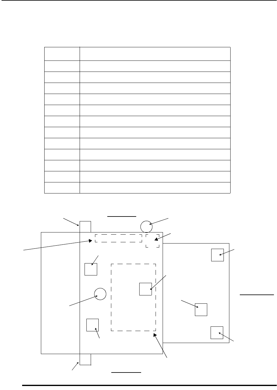
1200-Sheet/2500-Sheet Feeder
8-4 Options June 1999
1200-Sheet/2500-Sheet Feeder
Figure 8-1. 1200-Sheet/2500-Sheet Physical Locations
Table 8-1. 1200-Sheet/2500-Sheet Component Acronyms
Acronym Component
DSW Door Switch (magnetic door lock)
IEM Input Elevator Motor (M1 – elevator motor)
ILLS Input Lower Limit Sensor
IPES Input Paper Tray Sensor
IPM Input Pick-up Motor (M2 – paper pick-up motor)
IULS Input Upper Limit Sensor
NF AC Noise Filter
NPS No Paper Solenoid
PCSW Power Control Switch (slope tray interlock switch)
PES Paper End Sensor
PHS Paper Head Sensor
SOL Solenoid
Printer side
PCSW
PHS
SOL
M1 (IEM)
PES
IPES
DSW
M2
(IPM)
Door
ILLS
IULS
Front side
Power supply
Input
control
board
NF
Rear side
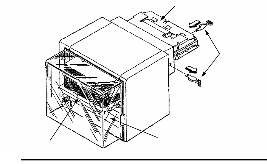
1200-Sheet/2500-Sheet Feeder
June 1999 Options 8-5
Bench Test Procedure
The bench test procedure references the component acronyms in Table 8-1 on page 8-4
and the component locations in Figure 8-1 on page 8-4. To bench test the printer:
1Turn the printer’s main power switch off, then disconnect the unit’s power cord.
2Press down the printer’s lower cassette release lever, then remove the unit from the
printer and place it on a work bench or other suitable surface.
3Remove the paper size lever, then lift up the slope tray and place the lever between the
slope tray and the frame. This will bypass the interlock switch (PCSW) located under
the slope tray, allowing 12 Vdc to be applied to the input control board.
Note: The slope tray is normally lifted into operating position by the printer’s lower
paper lift arm.
Figure 8-2. Bench Test Procedure
4Restore AC power to the unit (either the unit’s power cord or the printer’s power cord
may be used).
5Open the paper access door. The elevator motor (M1) should turn on, moving the
paper stock down. There is an actuator attached to the elevator’s chain drive that will
activate photosensor ILLS signalling the input control board that the paper supply tray
is completely down.
Note: Remove any paper that may be on the unit’s slope tray
Slope Tray
Paper Size Lever
Paper Access Door
Paper Supply Tray
1200-Sheet/2500-Sheet Feeder
8-6 Options June 1999
6Close the paper access door. The elevator motor (M1) should turn on, moving the
paper stack up. There are two actuators that must enable two photosensors. Photosen-
sor IPES signals the input control board that paper is present on the elevator. Photo-
sensor IULS signals the input control board that the upper limit for the paper supply
tray and paper stack has been reached.
7With the paper supply tray all the way up and with no paper present on the slope tray
(indicated to the input control board by photosensor PES, located in the middle of the
paper path), the pick-up roller assembly motor (M2) will turn on and transport a piece
of paper to the slope tray.
8When the paper in transported to the slope tray, note that the (SOL) solenoid (under
the slope tray) energizes.
Note: The solenoid causes contact with the printer’s paper present sensor.
9By removing the piece of paper from the slope tray, photosensor PHS signals the input
control board to turn the pick-up motor (M2) on to replace the piece of paper that was
removed.
10 When the last sheet of paper has been fed from the paper supply tray to the slope tray,
the actuator arm of photosensor IPES falls through a hole in the paper supply tray.
This signals the input control board to turn the elevator motor (M1) on to move the
paper supply tray down. The paper supply tray will remain down until the paper
access door is reopened (more paper is loaded), then closed.
11 When the last sheet of paper has been removed from the slope tray, confirm that the
solenoid (SOL) de-energizes.
Prefeed Adjustment Procedure
Because of subsequent revision to the input controller PCA, prefeed adjustments are no
longer necessary nor possible.

1200-Sheet/2500-Sheet Feeder
June 1999 Options 8-7
Input Control Board Logic
The table below indicates switching logic for the unit’s various components. Except for
the power control switch (PCSW), each component can be monitored from the various
pins of CN508 (located on the input control board).
When performing these checks, use test point TP 1 (located below CN507 on the input
control board).
Table 8-2. Monitoring Input Control Board Logic at Connector CN508
Connector Component Monitored Condition
CN508-4 PHS High
Low Paper present
No paper present
CN508-13 PES High
Low Paper present
No paper present
CN508-19 IPES High
Low Paper present
No paper present
CN508-16 IULS High
Low Limit
No Limit
CN508-21 DSW High
Low Door open
Door closed
CN508-10 ILLS High
Low Limit
No Limit
CN508-2 NPS High
Low ON
Off
CN508-25, 26 IPM (M2) +12 Vdc
0 Vdc Feed
No feed
CN508-23 IEM (M1) +12 Vdc
0 Vdc Up
Off
CN508-24 IEM (M1) +12 Vdc
0 Vdc Down
Off
CN507-2 PCSW 0 Vdc
+12 Vdc Unit mounted
Unit not mounted

1200-Sheet/2500-Sheet Feeder
8-8 Options June 1999
Figure 8-3. Connection Diagram for 1200-Sheet/2500-Sheet Feeder
NPS PHS ILLS PES IULS IPES DSW IEM IPM
J529
W514 P530
P529 W507
J509
P509
P512 P513 P514 P515 J500
P500
M
1
M
2
P518 P519
J518 J519
W510
PCSW
SW2
P508
P507
W508
J400
+ 12Vdc
P527 P528
J506
W506
P506
Gnd
Input
Control
Board
Power
Supply
J600
W520
P522
W505
NF
P523
PH-1
AC
SOL
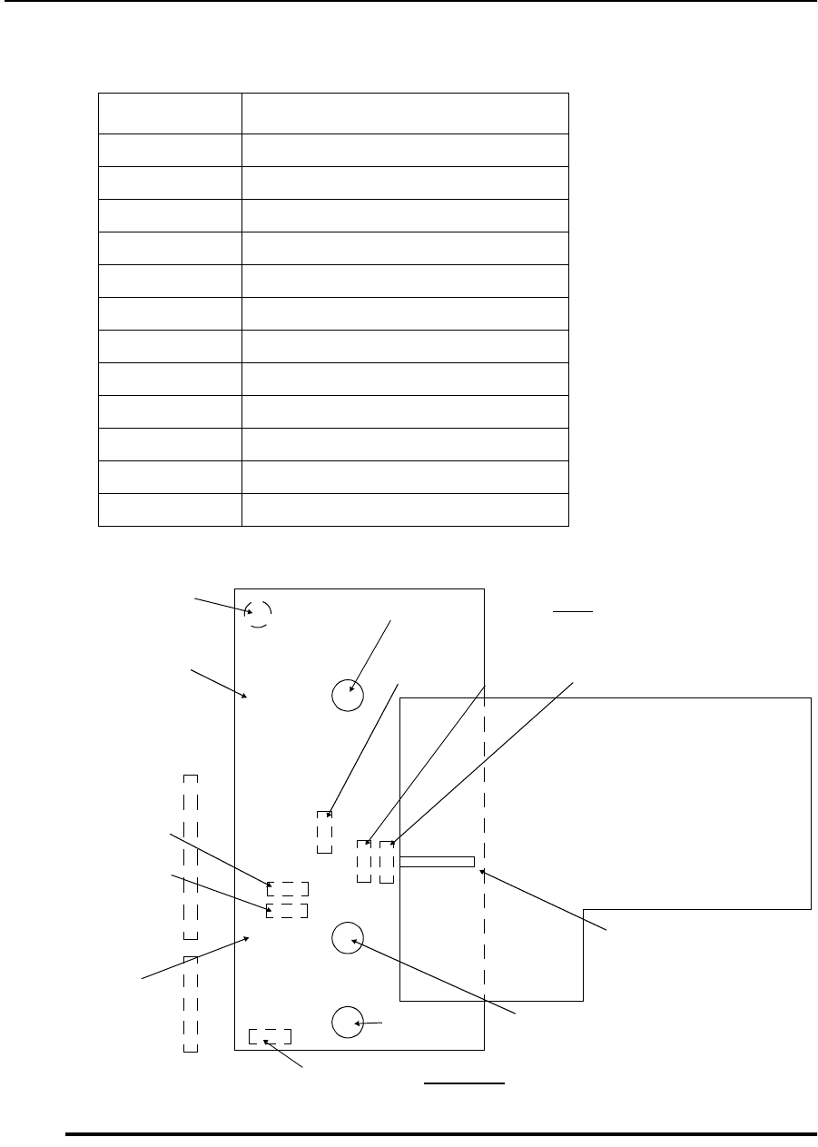
1400-Sheet Stacker
June 1999 Options 8-9
1400-Sheet Stacker
Figure 8-4. 1400-Sheet Stacker Component Locations
Table 8-3. 1400-Sheet Stacker Component Acronyms
Acronym Component
ERM Exit Roller Motor (M1)
EPS Exit Paper Sensor
ERS Exit Roller Sensor
OEM Out Elevator Motor (M2)
OELS Out Elevator Limit Sensor
OEPS Out Exit Paper Sensor
OJFM Out Jogging Front Motor (M4)
OJFS Out Jogging Front Sensor
OJRM Out Jogging Rear Motor (M3)
OJRS Out Jogging Rear Sensor
OLLS Out Lower Limit Sensor
OULS Out Upper Limit Sensor
ERM (M1)
OEM (M2)
Power
supply
Front side
OJRS
OJFS
Output
control
board
OELS
OJFM (M4) OJRM (M3)
Paper tray
full actuator
Output tray
OULSOLLSOEPS
Rear
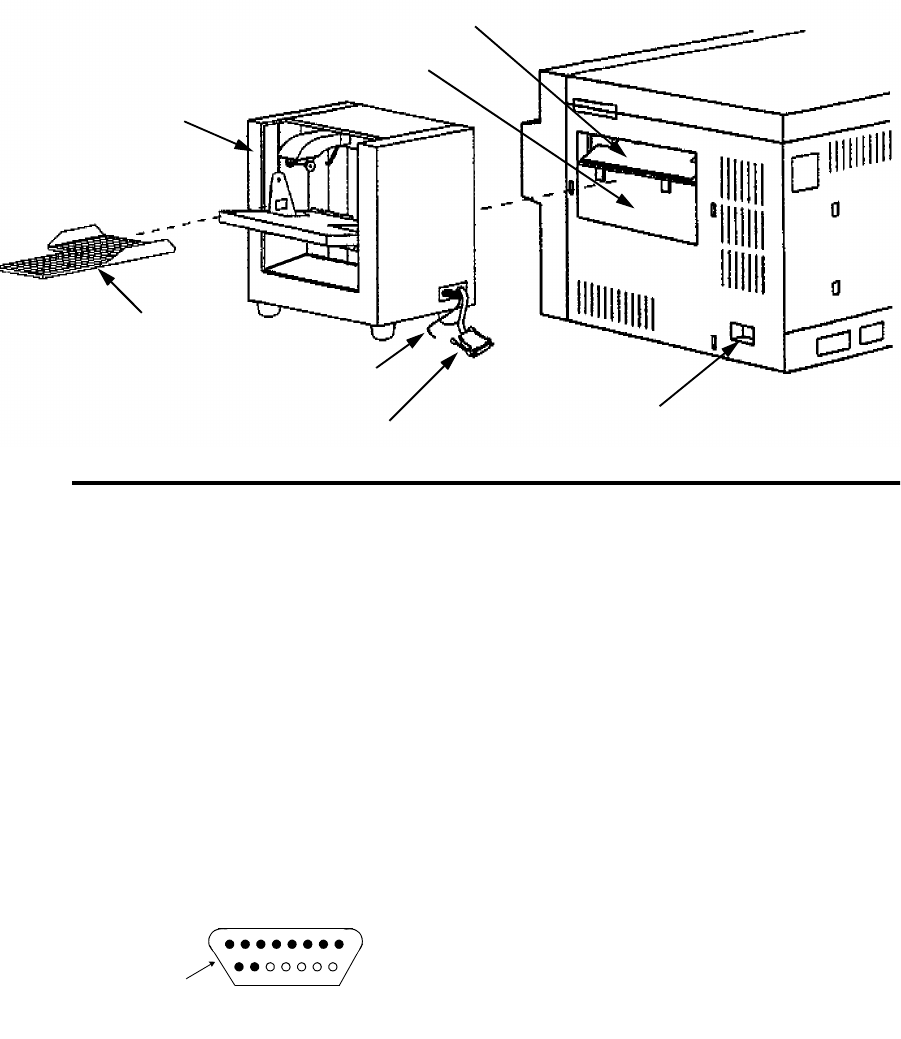
1400-Sheet Stacker
8-10 Options June 1999
Bench Test Procedure
The bench test procedure references the component acronyms in Table 8-3 on page 8-9
and the component locations in Figure 8-4 on page 8-9.
Figure 8-5. 1400-Sheet Stacker Bench Test Preparation
To bench test the 1400-sheet stacker:
1Turn the printer’s main power switch off.
2Remove the output tray from the stacker unit.
3Disconnect the stacker unit’s power cord from the printer and from the stacker, then
disconnect the unit’s control connector cable from the printer’s jack.
4Remove the stacker unit from the printer, then place it on a work bench or other suit-
able surface.
5Remove the printer’s power cord from the wall outlet and the printer’s lower back
cover.
6Observe the pin configuration of the stacker unit’s control connector cable plug .
Output Tray
Stacker Unit
Power Cord
Control Connector Cable
Adapter Plate
Output Tray Guide
Jack
1 2 3 4 5 6 7
910 X X X X X
Plug
Control Connector Cable
1400-Sheet Stacker
June 1999 Options 8-11
7Place a jumper from pin 9 to pin 10 (ground). Using the printer’s power cord in place
of the unit’s power cord, plug the printer’s power cord in the stacker unit, then into the
wall outlet.
8With the power applied to the stacker unit, the exit roller motor (ERM-M1) will be off.
This will signal the output control board to turn the exit roller motor (ERM-M1) on.
9Remove the jumper from pin 9 and pin 10.
10 Lift the paper tray full actuator to enable photosensor OLLS to signal the output con-
trol board to cause the elevator motor (OEM-M2) to turn on and lower the output tray
guide.
11 As the output tray guide reaches its lowest allowable position, photosensor OELS is
enabled and signals the output control board to turn the elevator motor (OEM-M2) off.
12 Releasing the paper tray full actuator then enables photosensor OULS to signal the
output control board to turn the elevator (OEM-M2) on and raise the output tray guide.
13 As the output tray guide reaches its highest allowable position, the paper tray full actu-
ator enables both photosensor OLLS and photosensor OULS, which in turn signal the
output control board to turn the elevator motor (OEM-M2) off.
14 Disconnect the power cord from the stacker, then place a jumper from pin 3 to pin 6
and a second jumper from pin 2 to pin 7.
15 Reconnect the power cord, then (from the printer side of the unit) insert a folded piece
of paper into the unit to trigger the actuator and enable photosensor OEPS. This will
signal the output control board to turn the jogging rear motor (OJRM-M3) on.
16 After jogging has occurred, remove the piece of paper then reinsert it. This will again
trigger the acturator and enable photosensor OEPS. This will signal the output control
board to turn the jogging front motor (OJFM-M4) on.
17 The procedure is completed. Disconnect the power cord, remove the jumpers, then
reinstall the unit into the printer.
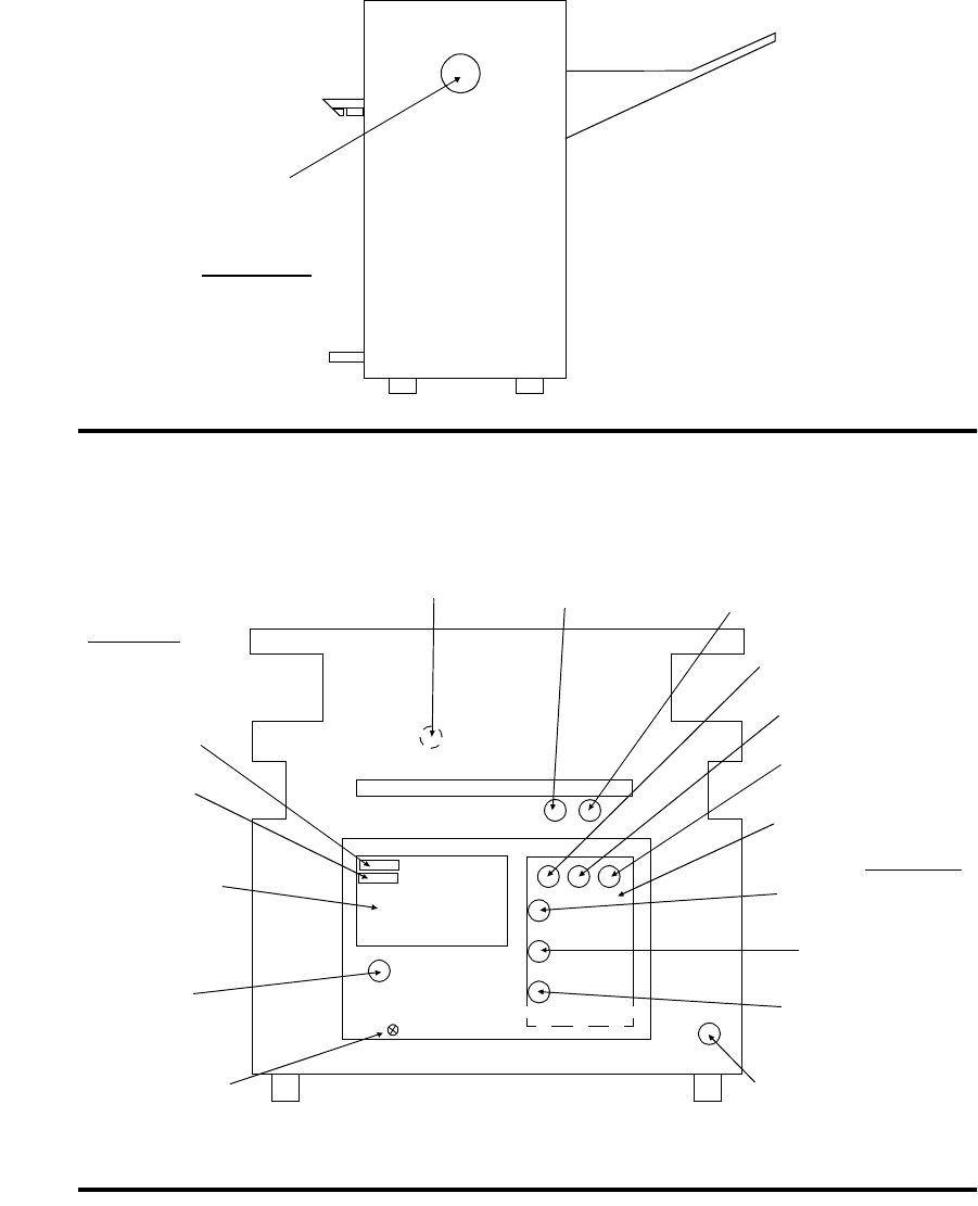
1400-Sheet Stacker
8-12 Options June 1999
Connector Locations
Figure 8-6. Connector Locations (front view, cover removed)
Connectors/circuit boards shown with broken lines are concealed from view.
Figure 8-7. Connector Locations (left side view, left cover removed)
CN416
Printer side
CN409 CN426 CN425
CN405
CN406
CN401
CN404
CN402
CN403
CN412
Fuse 1
Fuse 2
Power supply
CN417
Frame ground
Rear side
Output control
board
Front side
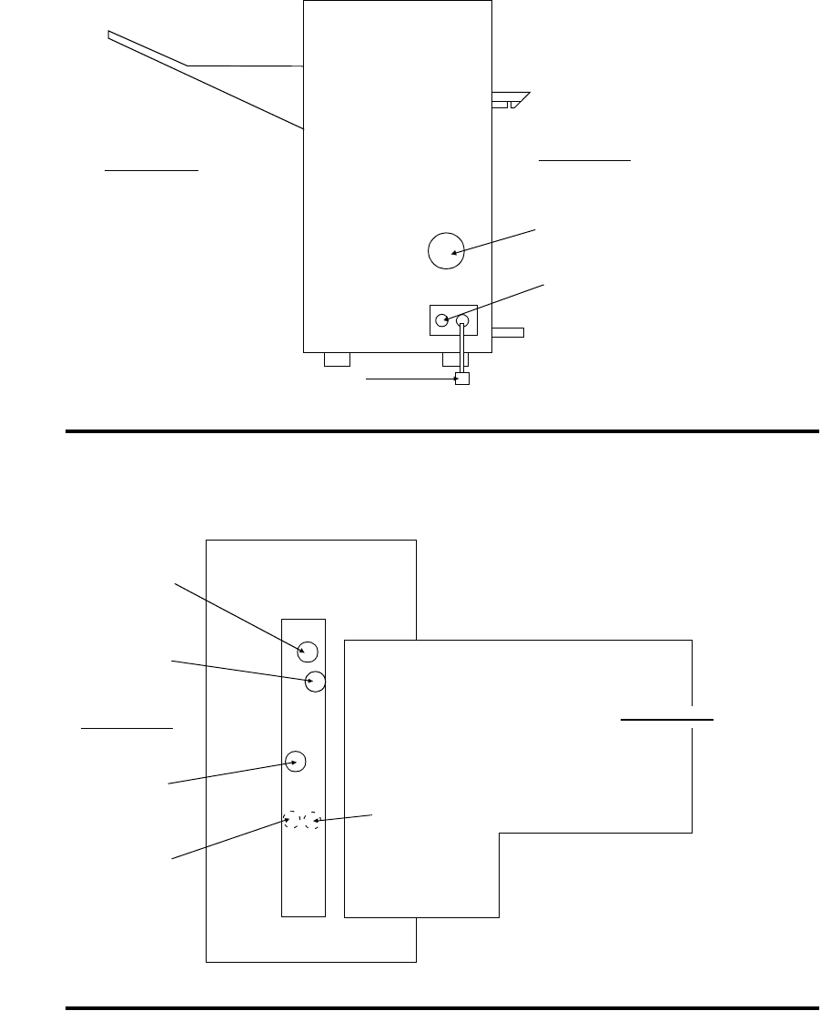
1400-Sheet Stacker
June 1999 Options 8-13
Figure 8-8. Rear Side View (cover removed)
Connectors/circuit boards shown with broken lines are concealed from view.
Figure 8-9. Top View (top cover removed)
CN415
Printer side
Output side
CN424 (AC power)
CN420 (Control connector plug)
CN413
CN419
CN414
CN408
CN407
Printer side Output side

1400-Sheet Stacker
8-14 Options June 1999
Output Control Board Logic
The table below details specific stacker actions and which sensors supply the signals
needed for each action. Signals from the printer are also included.
Table 8-4. Stacker Actions and Sensor Inputs
Action Sensor Input
Elevator up
(Wait signal to printer) OULS
OLLS
OELS
Elevator stop OULS
OLLS
OELS
Remove prints
(signal to printer) OULS
OLLS
OELS
Elevator down OULS
OLLS
OELS
Paper exit EPS
OEPS
Paper exit jam (023) OEPS
Jogging start From printer
Jogging ERS (from printer)
OJRS
OEPS
OJFS
Jogging stop From printer
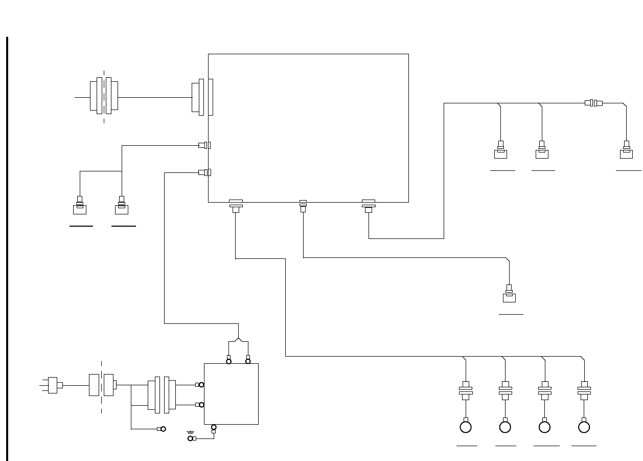
1400-Sheet Stacker
June 1999 Options 8-15
Figure 8-10. Connection Diagram for the 1400-Sheet Stacker
OULS
ERM
P407
M1
J41
Output
Control
Board
PH-1 12V
Power
Supply
OEM
M2
J41
OJRM
M3
J41
OJFM
M4
J41
OELS
P412
S-1
OLLS
P408
S-2
OEPS
P409
S-3
W5 P419 J419
W-
P403P402
P404
J404 J402 J403
J406
J405
J401
P401
P420
W2
P406
W7
P425 P426
OJFS
S-5
OJRS
S-6
AC
100 ~ 240V
P424
W1
P418
P417
L
N
+–
S-4
W4
W6 P41 P41 P41 P41
PCL board
interface

Hard Disk
8-16 Options June 1999
Hard Disk
Instructions for installing and updating a hard disk are included with the packaged option.
Please refer to the original documentation.
Troubleshooting Hard Disk Problems
If you have difficulty installing your hard disk:
•Service Error 573 is most often caused by a loose cable. Recheck all cable connections
and retry the load process. Note that it may be necessary to remove the disk drive
assembly to recheck the cable connections at the hard disk.
•Make sure that the data cable from the hard disk is connected securely to both the back
of the drive and to the controller board.
•Make sure that the printer’s floppy drive is configured as the A: drive (i.e., make sure
that the jumper on the back of the drive is on DS0).
If your hard disk still does not function correctly, note any error codes displayed and
report them to your service representative.

General Printer Maintenance 9-1
Chapter 9
General Printer
Maintenance
Section 7 Troubleshooting

9-2 General Printer Maintenance
Chapter Contents
General Printer Maintenance
Introduction . . . . . . . . . . . . . . . . . . . . . . . . . . . . . . . . . . . . . . . . . . . . . . . . . . . . . . .9-3
Every-Call Cleaning Procedure . . . . . . . . . . . . . . . . . . . . . . . . . . . . . . . . . . . . . . . .9-6
Adjusting Paper Feed Tension . . . . . . . . . . . . . . . . . . . . . . . . . . . . . . . . . . . . . . . . .9-8
Lubrication Procedure . . . . . . . . . . . . . . . . . . . . . . . . . . . . . . . . . . . . . . . . . . . . . . .9-9
Tune-Up Maintenance Procedure . . . . . . . . . . . . . . . . . . . . . . . . . . . . . . . . . . . . .9-16

Introduction
General Printer Maintenance 9-3
Introduction
This section describes the primary printer maintenance procedures to be completed during
service calls. In addition, this introduction reviews safety precautions, tool requirements,
and the printer maintenance record.
Every-Call Cleaning Procedure (
page 9-6
)
The every-call cleaning procedure, as the name implies, is performed every time the
printer is serviced. It includes a thorough cleaning of the printer, requiring the removal of
all major components and performance of specific cleaning tasks related to each one. It
also includes vacuuming all excess toner and other contamination from the interior of the
printer.
Paper Feed Tension Adjustment Procedure (
page 9-8
)
You may need to adjust the paper feed tension to correct jamming.
Lubrication Procedures (
page 9-9
)
Lubrication procedures are performed whenever needed, though lubrication should be
applied sparingly. The required lubricants, including oil, molycote and red grease, can be
purchased from the printer’s manufacturer.
Tune-Up Procedure (
page 9-16
)
The tune-up maintenance procedure is performed when the printer has yielded sub-stan-
dard prints after you’ve completed standard maintenance procedures, or has printed one-
to two-million images. A tune-up maintenance kit is required for this procedure.
Safety Precautions
Whenever servicing sophisticated electronic/electro-mechanical equipment, common
sense, training, caution and experience help in avoiding accidents and mishaps. Be aware
of the following safety precautions:
•Follow all instructions in this document.
•Follow all warnings and instructions marked on the printer.
•Unplug the printer when performing any removal, replacement or cleaning procedure.
•Ensure that the power source for the printer matches the power specification label
located above the power outlet on the back of the printer.
•Keep combustible materials away from the printer.
•Provide adequate ventilation for the printer so that slots and openings in the cabinet
sides are not blocked.
•Do not push objects of any kind through the cabinet slots. They may contact danger-
ous voltage points or other hazards.
Introduction
9-4 General Printer Maintenance
•Do not expose the printer to liquids of any kind.
•Protect the power cord. Do not place it in a traffic pattern or allow anything to rest on
it.
Tool Requirements: Service Kit
A service kit intended for use solely by the service technician is shipped inside the right
side cover of the printer. This kit includes:
•Interlock by-pass tools (2)
•RS-232C loop back assembly
•RS-422 loop back assembly
•Multimeter jumpers (2)
•Corona cleaner brush
Tools/Supplies
To service the printer properly, you will also need to carry the following:
•Soft cleaning cloth
•Cotton swabs
•Corona cleaner
•Basic set of hand tools suitable for office automation equipment repair
•Digital multimeter with test leads, alligator clips, and a high voltage probe
•Service vacuum cleaner, properly grounded and equipped with a 10 micron filter
End User Cleaning Kit
Printers are shipped with an end-user cleaning kit taped inside the front cover. The clean-
ing kit consists of:
•Cotton swabs
•Corona cleaner brush
This kit is intended for use by the end user.
Printer/Maintenance Record
A maintenance record must be kept for every printer. During the initial service call or at
the time of installation, set up a maintenance record for the customer. A copy of the form,
illustrated on the following page, should be kept in the Guide to Operations so that the
maintenance form is always easily accessible.
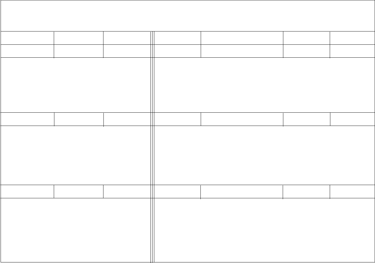
Introduction
General Printer Maintenance 9-5
HISTORY LOG
To Be Completed By User To Be Completed By HP
Page Counter Operator HP Notified
Date/Time Down-Time HP Customer
Engineer On Site Date Time
Malfunction Description: Action Required and Comments:
Malfunction Description:
Malfunction Description:
Action Required and Comments:
Action Required and Comments:

Every-Call Cleaning Procedure
9-6 General Printer Maintenance
Every-Call Cleaning Procedure
Perform the every-call cleaning procedure every time the printer is serviced. When trou-
bleshooting a printer problem, you may be directed to complete this procedure as you iso-
late or correct the problem. If the procedure is not specifically called out, always complete
it before concluding the service call.
The every-call cleaning procedure begins by removing the major consumable supplies
from the printer. When the supplies are out, use a toner vacuum to vacuum the printer thor-
oughly. Clean each consumable supply, following the instructions listed in this section,
before returning it to the printer. Conclude the every-call procedure by running test prints
to confirm the print quality.
The location of all major printer supplies and instructions for their removal are outlined
later in this manual.
Remove Major Consumable Supplies
•Photoconductor unit; place it in its protective packaging.
•Cleaner unit
•Developer unit
•Fuser unit
Inspect and Vacuum
•Inspect the areas in the printer around the developer unit, cleaner unit, photoconducto
unit, and fuser unit for damage and wear.
•Vacuum these areas to remove all excess toner, contamination, and/or foreign objects.
Clean Internal Areas
•Clean the erase lamp with a cotton swab.
•Clean the printhead bias plates with a soft cloth.
•Clean the LED lens with a cotton swab, making sure no lint remains on the lens.
Clean the Fuser Unit
•Inspect the unit for damage and contamination; repair or replace as necessary.
•Clean the fuser unit connector, both on the fuser unit and in the printer, with a cotton
swab.
•Vacuum in and around the rollers to remove excess toner, contamination, and any for-
eign objects.
•Reinstall the fuser unit.
Every-Call Cleaning Procedure
General Printer Maintenance 9-7
Clean the Developer Unit
•Inspect the unit for damage or contamination; repair or replace as necessary.
•Clean any excess toner from the developer unit with a soft cloth.
•Clean the toner patch sensor lens with a soft cloth, making sure no lint remains on the
lens.
•Vacuum the felt areas around the magnetic roller, being careful not to vacuum toner
from the magnetic roller.
•Reinstall the developer unit.
Clean the Cleaner Unit/Main Charger
•Inspect the unit for damage or contamination; repair or replace as necessary.
•Remove the charge corona from the cleaner unit.
•Clean the grid with the cleaner brush.
•Remove the grid to expose the corona wire.
•Clean the corona wire with a cotton swab.
•Reinstall the grid.
•Clean any excess toner from the cleaner unit with a soft cloth.
•Reinstall the charge corona in the cleaner unit.
•Reinstall the cleaner unit.
Clean the Photoconductor Unit Area
•Clean the photoconductor seam sensor inside the printer.
•Remove the photoconductor from its protective packaging.
•Inspect the photoconductor for damage or contamination; repair or replace as neces-
sary.
•Reinstall the photoconductor unit.
Clean the Transfer Corona
•Remove the transfer corona.
•Clean the transfer corona housing with a soft cloth.
•Clean the transfer corona wire with a cotton swab.
•Reinstall the transfer corona.
Run Test Prints
•Run test prints to verify print quality.

Adjusting Paper Feed Tension
9-8 General Printer Maintenance
Adjusting Paper Feed Tension
Printers With Paper Tension Levers
Recently released simplex and duplex printers have pressure tension levers inside the front
cover, as illustrated in Figure 9-1, Paper Feed Tension Levers, below:
Figure 9-1. Paper Feed Tension Levers
To adjust the tension:
1Open the printer’s front cover.
2Identify the cassette whose tension is to be adjusted, and select the correct lever.
3Adjust the tension:
•To correct multiple feeds: move the lever toward the minus sign, decreasing the
feed pressure.
•To ease paper feeds: move the lever toward the plus sign, increasing the feed pres-
sure.
4Close the front cover, then print paper from the cassette you are adjusting.
5If the paper is still not feeding properly, repeat Steps 3 through 5 until the feed is prop-
erly adjusted.
Upper Paper Tension Lever
Lower Paper Tension Lever

Lubrication Procedure
General Printer Maintenance 9-9
Lubrication Procedure
Complete the lubrication procedure as-needed. Apply lubrication sparingly. Insufficient
lubrication may result in unnecessary noise and premature wear of components; excessive
lubrication may contaminate printer supplies and make the printer difficult to keep clean.
The following printer illustrations indicate where lubrication may be required. Charts fol-
lowing the illustrations include symbols that indicate the type of lubricant to use on each
component:
HOil
PMolycote
LRed grease
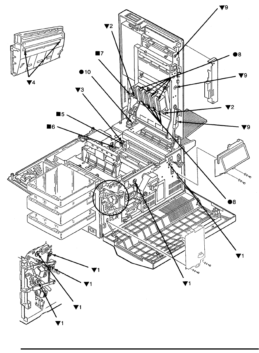
Lubrication Procedure
9-10 General Printer Maintenance
Figure 9-2. Front View Lubrication Points

Lubrication Procedure
General Printer Maintenance 9-11
Front View Lubrication Tables
Duplex Only
Table 9-1. All Printers – Front View Lubrication
Symbol Part Lubricant
H 1 Front roller bearings (paper feed, paper pickup, timing
and exit rollers) oil
H 2 Vacuum transport drive shaft oil
H 3 Fuser drive bearing oil
H 4 Upper paper guide roller oil
L 5 Fuser drive gear red grease
L 6 Vacuum transport drive gear red grease
L 7 Vacuum transport gear red grease
P 8 Vacuum transport rollers Molycote
Table 9-2. Duplex Front View Lubrication
Symbol Part Lubricant
H 9 Duplex roller bearings oil
P 10 Lower duplex drive assembly Molycote

Lubrication Procedure
9-12 General Printer Maintenance
Figure 9-3. Rear View Lubrication
1
2
1
1
1
1
3
2
4
5
6
7
8
9
10
11
12
13

Lubrication Procedure
General Printer Maintenance 9-13
Rear View Lubrication Tables
Duplex Only
Table 9-3. All Printers – Rear View Lubrication
Symbol Part Lubricant
H 1 Clutch shafts: upper pick-up roller, lower pick-up roller,
upper feed roller, lower feed roller, paper timing roller oil
P 2 Upper and lower pick-up roller drive assemblies Molycote
P 3 Main drive gear assembly Molycote
P 4 Main drive gear Molycote
P 5 Main drive motor gear Molycote
P 6 Fuser drive gear Molycote
P 7 Fuser drive assembly Molycote
Table 9-4. Duplex Only Rear Lubrication
Symbol Part Lubricant
H 8 Clutch shaft bearing oil
P 9 Lower duplex drive assembly Molycote
P 10 Upper duplex drive assembly Molycote
P 11 A roller drive gears Molycote
P 12 B roller drive gears Molycote
P 13 C roller drive gears Molycote
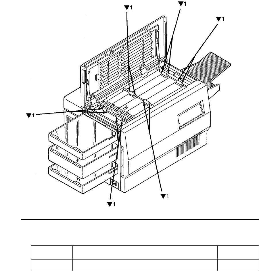
Lubrication Procedure
9-14 General Printer Maintenance
Figure 9-4. Duplex Only: Top View Lubrication
Table 9-5. Duplex Top View Lubrication
Symbol Part Lubricant
H 1 Duplex pinch rollers oil
1
1
1
1
1
1
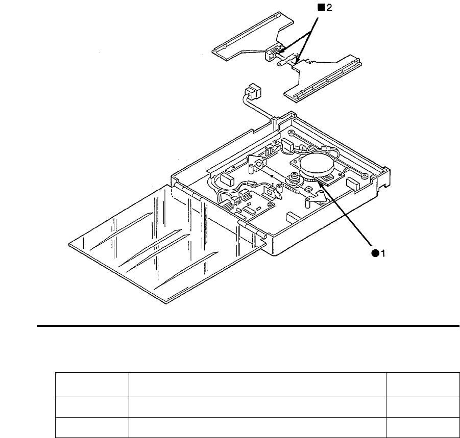
Lubrication Procedure
General Printer Maintenance 9-15
Figure 9-5. Duplex Only: Duplex Holding Tray Lubrication
Table 9-6. Duplex Holding Tray Lubrication
Symbol Part Lubricant
P 1 Drive gears Molycote
L 2 Tray shaft red grease

Tune-Up Maintenance Procedure
9-16 General Printer Maintenance
Tune-Up Maintenance Procedure
The tune-up maintenance procedure should be performed when the printer: jams fre-
quently; yields sub-standard print quality even after completing regular maintenance pro-
cedures; and has printed more than one- or two-million prints. At this point in the life of
the printer, the roller assemblies, transfer corona, and static brushes must be replaced. All
of the required components are packaged together in a Tune-Up Maintenance Kit.
1For detailed instructions on how to replace each of these components, refer to Chapter
7, “Removal/Replacement Procedures”. General guidelines follow for unpacking the
component, along with an outline of the order in which the components should be
replaced.
2Unpack the maintenance kit, which is shipped in a folded cardboard pack. Remove the
shipping carton and unfold the cardboard pack.
3Make sure that you have received all of these replacement components, shown in Fig-
ure 9-6, “Tune-Up Kit Components,” on page 9-17:
•Roller assembly, lower feed
•Roller assembly, upper feed
•Roller assembly, paper timing
•Roller assembly, exit
•Roller assembly, upper paper guide
•Transfer corona
•Roller assembly, upper pick up
•Roller assembly, lower pick up
•Static brush, upper (in cardboard folder)
•Static brush, lower (in cardboard folder)
•Label (taped to the top of the package)
4Unplug the printer.
5Open the top cover.
6Remove the photoconductor unit. Place the unit in its protective packaging in a safe
place away from the work area.
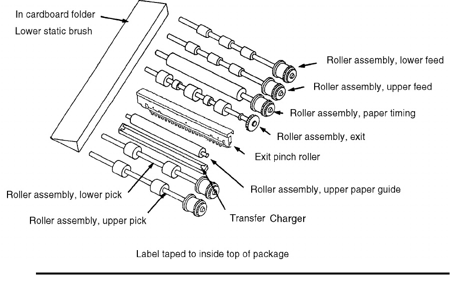
Tune-Up Maintenance Procedure
General Printer Maintenance 9-17
Figure 9-6. Tune-Up Kit Components
7Replace the component assemblies in this order:
•Paper timing roller
•Exit roller
•Upper pick up roller
•Lower pick up roller
•Upper feed roller
•Lower feed roller
•Transfer corona
•Lower static brush
•Upper static brush
•Upper paper guide roller
8Perform the every-call cleaning procedure on page 9-6.
9Plug in the printer and turn it on.
10 Run test prints to ensure that the paper feeds correctly through the printer.
11 Fill in the label with the date and meter count. Affix it inside the front cover next to
the printer’s serial number.
Tune-Up Maintenance Procedure
9-18 General Printer Maintenance

June 1999 Abbreviations and Acronyms A-1
Appendix A
Abbreviations and Acronyms
ACIA . . . . . . . . .Asynchronous Communication
Interface Adapter
ALU . . . . . . . . . . Arithmetic Logic Unit
APA . . . . . . . . . . All Points Addressable
ARC . . . . . . . . . .“A” Roller Clutch
(Duplex only)
ARIF. . . . . . . . . . Array Interface
ATC . . . . . . . . . . Auto Toner Control
CLEANER . . . . .Cleaner Unit
CNT . . . . . . . . . .Counter
COOLING FA2 . Cooling Fan
COS . . . . . . . . . .Cover Open Sensor
(Duplex only)
CRS . . . . . . . . . . “C” Roller Solenoid
(Duplex only)
CRT . . . . . . . . . .Cathode Ray Tube
CRTC . . . . . . . . . CRT Controller
CRU . . . . . . . . . . Customer-Replaceable Unit
DB-. . . . . . . . . . .Developer Bias Negative
DB+ . . . . . . . . . .Developer Bias Positive
DC P.S.1 . . . . . . .DC Power Supply
DEV . . . . . . . . . . Developer Unit
DMAC . . . . . . . .Direct Memory Access
Controller
DMC. . . . . . . . . .Dynamic Memory Controller
DRAM . . . . . . . .Dynamic Random Access
Memory
DUPLEX1 . . . . . Duplex Control #1
(Duplex only)
DUPLEX2 . . . . . Duplex Control #2
(Duplex only)
EIGS. . . . . . . . . .Enhanced Image Generation
System
EL. . . . . . . . . . . . Eraser LED
EPROM. . . . . . . Erasable Programmable Read
Only Memory
EPP . . . . . . . . . . Electrophotographic Process
EPS . . . . . . . . . . Exit Paper Sensor
ERASER . . . . . . Erase Lamp
EV30 . . . . . . . . . Enhanced Video K30 printer
EXS. . . . . . . . . . Exit Solenoid (Duplex only)
FA4 . . . . . . . . . . Cooling Fan (Duplex only)
FDC. . . . . . . . . . Floppy Disk Controller
FDD. . . . . . . . . . Floppy Disk Drive
FL . . . . . . . . . . . Fuser Halogen Lamp
FRU. . . . . . . . . . Field-Replaceable Unit
FUSER . . . . . . . Fuser Unit
HCI . . . . . . . . . . High Capacity Input
HCO . . . . . . . . . High Capacity Output
HEAD . . . . . . . . LED Array Print Head
HDD . . . . . . . . . Hard Disk Drive
HVU . . . . . . . . . High Voltage Unit
IGS . . . . . . . . . . Image Generation System
IGS CONT . . . . Image Control System
I.L. SW Front . . Interlocking Switch (Front)
I.L. SW Top. . . . Interlocking Switch (Top)
INS . . . . . . . . . . In Solenoid (Duplex only)
IPL. . . . . . . . . . . Initial Program Load)
Jogging . . . . . . . Jogging Motor
L PAPS . . . . . . . Lower Paper Sensor
LN03 . . . . . . . . . DEC emulation language
LPC . . . . . . . . . . Lower Paper Feed Clutch
LPE . . . . . . . . . . Lower Paper Empty Sensor
LPP . . . . . . . . . . Lower Pick Up Clutch
LPSS . . . . . . . . . Lower Tray Interlock Switch
Main . . . . . . . . . Main Motor
MAP . . . . . . . . . Maintenance Analysis
Procedures

Abbreviations and Acronyms
A-2 Abbreviations and Acronyms June 1999
MCH . . . . . . . . . .Charge Corona Unit
MCS . . . . . . . . . .Charge Corona Sensor
MIGS . . . . . . . . .Minter Image Generation
System
MPU . . . . . . . . . .Micro Processing Unit
MUX. . . . . . . . . .Multiplexer
OPC. . . . . . . . . . .Organic Photoconductor
OPPNL . . . . . . . .Operator Panel
PC . . . . . . . . . . . .Photoconductor
PCL. . . . . . . . . . .Hewlett-Packard Printer Con-
trol Language (Software)
PCL. . . . . . . . . . .Printer Control Logic Board
(Hardware)
PCL5. . . . . . . . . .HP Printer Control Language
(Version 5)
PCU. . . . . . . . . . .Photoconductor Unit
PFS . . . . . . . . . . .Paper Full Sensor
PH 1 . . . . . . . . . .A.C. Power Cord
PIA . . . . . . . . . . .Peripheral Interface Adapter
PIT . . . . . . . . . . .Parallel Interface/Timer
PMP . . . . . . . . . .Page Map Primitives
POR. . . . . . . . . . .Power On Reset
PPS . . . . . . . . . . .Paper Path Sensor
(B-C Sensor) (Duplex only)
PROM. . . . . . . . .Programmable Read Only
Memory
PS . . . . . . . . . . . .PostScript
PSS . . . . . . . . . . .Photoconductor Seam Sensor
PTM . . . . . . . . . .Programmable Timer Module
PTS . . . . . . . . . . .Paper Timing Sensor
PW CONT2 . . . .Power Control #2
PW CONT3 . . . .Power Control #3
PWBA. . . . . . . . .Printed Wire Board Assembly
RAM . . . . . . . . . .Random Access Memory
Resist Motor . . . .Registration Motor
(Duplex only)
ROM . . . . . . . . . .Read Only Memory
Root Motor . . . . .“C” Roller Motor
(Duplex only)
RPS . . . . . . . . . . Registration Paper Sensor
(Duplex only)
RSS . . . . . . . . . . Registration Side Sensor
(Duplex only)
SCC . . . . . . . . . . Serial Communication
Controller
SIG IF or SIF. . . Signal Interface Board
SRAM . . . . . . . . Static Random Access
Memory
SRC . . . . . . . . . . System Reference Code
SRMR2 . . . . . . . Side Registration Motor
Control #2 (Duplex only)
Suction FA3. . . . Suction Fan
SW5 . . . . . . . . . . Upper Cassette In Switch
SW6 . . . . . . . . . . Lower Cassette In Switch
TAG . . . . . . . . . . Troubleshooting Analysis
Guide
TC . . . . . . . . . . . Toner Concentration
TCH . . . . . . . . . . Transfer Corona Unit
TCS . . . . . . . . . . Transfer Corona Sensor
TDS . . . . . . . . . . Toner Density Sensor
TES . . . . . . . . . . Toner Empty Sensor
TFS . . . . . . . . . . Tray Front Sensor
TH . . . . . . . . . . . Thermistor
TO SIG IF . . . . . To Signal Interface
TOSIGIF CENT To Signal Interface Centronics
TONER . . . . . . . Toner Motor
TPS . . . . . . . . . . Timing Paper Sensor
(Schematics)
TPS . . . . . . . . . . Toner Patch Sensor (Printer)
TRC . . . . . . . . . . Timing Roller Clutch
TRS . . . . . . . . . . Tray Rear Sensor
PAPS . . . . . . . . . Upper Paper Sensor
UMT 1-3 . . . . . . Usage Meter Drive Signal
UPC . . . . . . . . . . Upper Paper Feed Clutch
UPE . . . . . . . . . . Upper Paper Empty Sensor
UPP . . . . . . . . . . Upper Pick Up Clutch
UPSS . . . . . . . . . Upper Tray Interlock
VPCL. . . . . . . . . Video Printer Control Logic
Board

Index
June 1999 Index-1
A
"A" roller
removal 7-97
abbreviations A-1
AC power
malfunctions 3-118
AC power supply
removal 7-29
acronyms A-1
add toner indicator
problems 3-51
B
"B" roller
removal 7-98
back cover
connectors 6-11
removal 7-6
back cover interlock switch
removal 7-82
basic troubleshooting 3-5
belts
removing cleaner drive 7-55
removing fuser drive 7-57
removing paper feed drive 7-59
board tests
EIGS/MIGS 5-20
brushes
removing lower static 7-72
removing upper static 7-71
C
"C" roller
removal 7-99
"C" roller solenoid
removal 7-100
cassette mounts
removing lower 7-45
removing upper 7-41
cassettes
problems 2-12
problems with lower 3-136
problems with upper 3-135
testing lower 5-5
testing upper 5-4
charge corona
circuit malfunctions 3-61
problems 3-58
testing 5-10
circuit boards
IGS 1-3
IGS bit-map RAM malfunction 3-112
IGS communication malfunctions 3-108
IGS controller malfunctions 3-103
IGS to PCL interface malfunctions 3-110
PCL 1-3
PCL interface problems 3-102
removing duplex control #1 7-90
removing duplex control #2 7-91
removing IGS 7-21
removing jogging motor 7-39
removing PCL 7-22
removing power control 7-38
removing signal interface 7-37
settings 6-30
cleaner drive
removal 7-56
cleaner drive belt
removal 7-55
cleaning kit 9-4
cleaning procedure 9-6
communications
external problems 3-143
problems 2-13, 3-146
testing 5-21, 5-22
connector index 6-4
connector locations 6-6
connectors
back cover 6-11
duplex cover 6-8
front cover 6-6
left cover 6-7
right cover 6-9

Index
Index-2 June 1999
sheet stacker 8-12
top cover 6-10
continuity checks 1-21
cooling fan
removal 7-26
counter
malfunctions 3-140
problems 2-13
removal 7-20
testing 5-7
covers
removing back 7-6
removing EP 7-85
removing exit 7-75, 7-77
removing front 7-5
removing front duplex 7-18
removing left side 7-8
removing lower back 7-7
removing rear duplex 7-17
removing right side 7-9, 7-10
removing top 7-14
cross references
error code/TAG 2-3
mechanical malfunction/TAG 2-12
print quality/TAG 2-10
D
damaged paper 3-138
DC power supply
removal 7-31
developed image
producing 1-22
developer bias
problems 3-44
testing 5-13
developer unit
problems 3-53
diagnostics
charge corona 5-10
communication loop-back 5-21, 5-22
counter 5-7
developer bias 5-13
disk drive 5-25, 5-26
duplex clutch 5-16
duplex feed motor 5-14
duplex input sensor 5-15
duplex tray paper guide motor 5-17
EIGS program RAM 5-22
EIGS/MIGS bit map 5-23
EIGS/MIGS board 5-20
envelope fuser solenoid 5-19
erase lamp 5-12
input feeder 5-19
jogging motor 5-8
lower cassette 5-5
operator panel 5-4
output stacker 5-18
paper transport clutch 5-7
photoconductor 5-8
printhead assembly 5-24
running 5-3
sensor sequence 5-6
toner supply motor 5-9
transfer charger 5-11
upper cassette 5-4
diagrams
voltage isolation 6-16–6-20
disk drive
formatting 5-24
malfunctions 3-104
testing 5-25, 5-26
disk drive housing
removal 7-25
diskette drive
malfunctions 3-104
duplex clutch
test sequence 5-16
duplex control board #1
removal 7-90
duplex control board #2
removal 7-91
duplex cover
connectors 6-8
duplex fan
removal 7-27
duplex feed motor 5-14
duplex input sensor
test sequence 5-15
duplex paper path sensor
removal 7-103
duplex print cycle 1-5
duplex route motor/solenoid assembly

Index
June 1999 Index-3
removal 7-96
duplex route separator
removal 7-101
duplex skew correction cable
removal 7-93
duplex tray paper guide motor
testing 5-17
duplex tray registration motor
removal 7-92
E
EIGS program RAM
testing 5-22
EIGS/MIGS bit map
testing 5-23
envelope fuser solenoid
testing 5-19
envelope tray
latch problems 3-21
problems 3-14
EP cover
removal 7-85
erase lamp
malfunctions 3-65
removal 7-84
testing 5-12
error code/TAG cross reference 2-3
error codes 1-7
bit-map RAM 2-8
host communication 2-9
IGS firmware 2-6
IGS software 2-6
IGS/disk drive 2-7
PCL 2-4
PCL failure 2-6
PCL/IGS communication 2-4, 2-5
printer 2-3
error log 1-17
clearing 1-24, 5-24
every-call cleaning procedure 9-6
exit cover
removal 7-75, 7-77
exit pinch roller
removal 7-69
exit roller assembly
removal 7-73
F
fans
removing cooling 7-26
removing duplex 7-27
front cover
connectors 6-6
removal 7-5
front cover interlock switch
removal 7-81
front duplex cover
removal 7-18
fuser drive
removal 7-58
fuser drive belt
removal 7-57
fuser unit
high temperature problems 3-73
malfuctions 3-67
thermistor malfunctions 3-72
G
ground system 6-21
guides
problems with upper paper 3-139
removing lower paper 7-52
removing paper timing 7-53
removing upper paper 7-49
H
high voltage unit
removal 7-32
I
IGS board 1-3
bit-map RAM malfunction 3-112
communication malfunctions 3-108
malfunctions 3-103
removal 7-21
IGS to PCL interface
malfunctions 3-110
input feeder
testing 5-19
input sheet feeder 8-4
input tray
paper size detection malfunctions 3-132
interfaces 6-22
Centronics parallel 6-27

Index
Index-4 June 1999
RS-232C 6-22
RS-422 6-26
interlock by-pass tool 1-22
interlock switches
overriding 1-22
top cover 3-192
J
job offset assembly
problems 3-75
removal 7-67
jogging motor
testing 5-8
jogging motor control board
removal 7-39
jumpers
signal interface board 6-30
L
left side cover
connectors 6-7
removal 7-8
locating connectors 6-6
lower back cover
removal 7-7
lower cassette
latch problems 3-24
paper jams/misfeeds 3-30
problems 3-16, 3-136
testing 5-5
lower cassette mount
removal 7-45
lower feed roller
removal 7-62
lower paper guide
removal 7-52
lower paper size sensor
removal 7-40
lower pick-up roller
removal 7-65
lower pick-up roller drive
removal 7-66
lower static brush
removal 7-72
lubrication 9-9
M
main gear drive
removal 7-89
main motor
problems 3-142
removal 7-87
maintenance
cleaning 9-6
lubricating 9-9
tune-up procedure 9-16
maintenance record 9-4
maintenance supplies 9-4
mechanical malfunction/TAG cross
reference 2-12
misfeeds
lower cassette 3-30
upper cassette 3-26
motors
problems with main 3-142
removing duplex tray registration 7-92
removing main 7-87
removing toner 7-28
testing duplex feed 5-14
testing duplex tray paper guide 5-17
testing jogging 5-8
testing toner supply 5-9
multiple feeds 3-137
O
operator panel
malfunctions 3-125
problems 2-12
removal 7-19
testing 5-4
out of toner indicator
problems 3-51
output sheet stacker 8-9
output stacker
testing 5-18
output tray
malfunctions 3-130
problems 2-12
P
paper
damaged 3-138

Index
June 1999 Index-5
multiple feeds 3-137
wrinkled 3-138
paper exit sensor
removal 7-79
paper feed drive belt
removal 7-59
paper feed tension
adjusting 9-8
paper full sensor
removal 7-80
paper handling
problems 2-13
paper input timing
problems 3-41
paper jams
duplex area 3-198
fuser area 3-34
lower cassette 3-30
output area 3-39
transfer area 3-34
upper cassette 3-26
paper output timing
problems 3-43
paper path 1-6
paper size
codes 5-4
paper timing guide
removal 7-53
paper timing roller
removal 7-60
paper transport clutch
test sequence 5-7
parallel interface 6-27
PCL board 1-3
malfunctions 3-102
removal 7-22
PCL to IGS interface
malfunctions 3-110
photoconductor
testing 5-8
photoconductor rear guide rail
removal 7-35
photoconductor seam sensor
problems 3-54
removal 7-33
power control board
removal 7-38
power supplies
+12 Vdc malfunctions 3-79
+24 Vdc malfunctions 3-92
+5 Vdc malfunctions 3-113
-12 Vdc malfunctions 3-90
removing AC 7-29
removing DC 7-31
removing high voltage 7-32
power-on-reset (POR) 1-21
print cycle 1-3
print quality
background print example 4-21
black print 3-163
example 4-13
blank print 2-10, 3-148
example 4-6
blank vertical bands example 4-11
blurred print 2-11
example 4-19
blurred vertical streaks 3-177
dark areas 3-180
dark horizontal bands 3-148
dark print 2-10, 3-182
example 4-13
dark speck example 4-14
dark spots 3-166
dark vertical band example 4-15
dark vertical streaks 3-172
fusing problems 3-187
example 4-24
light horizontal bands 3-162
example 4-12
light print 2-10, 3-152
example 4-7
light print with background example 4-8
light vertical streaks 3-160
example 4-10
misregistration 2-11, 3-168, 3-194
example 4-17
overtoned print example 4-18
residual images 3-182, 3-189
example 4-22
samples 4-3
scratches 3-166
skewed print 2-10, 3-168, 3-194

Index
Index-6 June 1999
example 4-16
smeared vertical streaks 3-177
smearing 2-11
uneven print density 2-11, 3-180
varying print density
example 4-20
voids
example 4-9
voids or white spots 3-158
washout example 4-5
white spots
example 4-9
wrinkle example 4-23
print quality/TAG cross reference 2-10
printer operation 1-3
printhead assembly
malfunctions 3-191
removal 7-23
testing 5-24
problem resolution 3-8
R
rear duplex cover
removal 7-17
right side cover
connectors 6-9
removal 7-9, 7-10
rollers
removing "A" 7-97
removing "B" 7-98
removing "C" 7-99
removing exit pinch 7-69
removing lower feed 7-62
removing lower pick-up 7-65
removing paper timing 7-60
removing upper feed 7-61
removing upper paper guide 7-51
removing upper pick-up 7-63
S
safety precautions 9-3
self-diagnostic mode 5-3
sensors
locations 1-11
lower paper size wiring 3-134
malfunctioning photoconductor seam 3-
54
removing duplex paper path 7-103
removing lower paper size 7-40
removing paper exit 7-79
removing paper full 7-80
removing photoconductor seam 7-33
removing upper paper size 7-40
test sequence 5-6
testing duplex input 5-15
upper paper size wiring 3-134
serial interface 6-22
service calls
completing 1-23
service record 9-4
service tool kit 9-4
sheet feeder 8-4
input control board interface 8-7
prefeed adjustment 8-6
test procedure 8-5
sheet stacker 8-9
connector locations 8-12
output control board interface 8-14
test procedure 8-10
signal interface board
removal 7-37
settings 6-30
simplex print cycle 1-5
supplies 9-4
switches
locations 1-11
overriding interlock 1-22
PCL board registration 3-170
removing back cover interlock 7-82
removing front cover interlock 7-81
removing top cover interlock 7-83
signal interface board 6-30
top cover interlock 3-192
T
test prints 1-16
testing 5-14
timing
paper input 3-41
paper output 3-43
toner motor
removal 7-28
toner patch

Index
June 1999 Index-7
low reference level 3-47
producing 1-22
too light 3-49
toner supply motor
testing 5-9
tool kit 9-4
top cover
connectors 6-10
removal 7-14
top cover hinge
removal 7-16
top cover interlock switch
removal 7-83
top cover support
removal 7-15
transfer charger
circuit problems 3-58, 3-63
testing 5-11
troubleshooting analysis guide (TAG) 1-19
tune-up maintenance procedure 9-16
U
upper cassette
latch problems 3-18
paper jams/misfeeds 3-26
problems 3-12, 3-135
testing 5-4
upper cassette mount
removal 7-41
upper duplex drive/clutch assembly
removal 7-95
upper feed roller
removal 7-61
upper paper guide
problems 3-139
removal 7-49
upper paper guide roller
removal 7-51
upper paper size sensor
removal 7-40
upper pick-up roller
removal 7-63
upper pick-up roller drive
removal 7-64
upper static brush
removal 7-71
V
vacuum transport unit
removal 7-11, 7-13
voltage
isolation diagrams 6-16–6-20
voltage ranges
operating 1-18
W
wrinkled paper 3-138
