ZM3E_319U75_V2.0_multi CAME ZM3E
User Manual: CAME-ZM3E
Open the PDF directly: View PDF ![]() .
.
Page Count: 30
Z SERIES
INSTALLATION MANUAL
ZM3E - ZM3EC
CONTROL PANEL FOR 230V OPERATORS
En
g
lis
h
EN
Pag.
2
2 - Manual code:
319U75
319U75 ver.
2.0
2.0 01/2009 © CAME cancelli automatici s.p.a. - The data and information reported in this installation manual are susceptible to change at any time and without obligation on CAME cancelli automatici s.p.a. to notify users.
ENGLISH
The ZM3 control panel is designed to command the following swing-gate operators ATI, AXO, FAST, FERNI, FROG, KRONO.
The ZM3EC control panel is engineered to command CBX - F4000 industrial doors. It comes with its own safety release and buttons.
The use of this product for purposes other than as described above and installation executed in a manner other than as
instructed in this technical manual are prohibited.
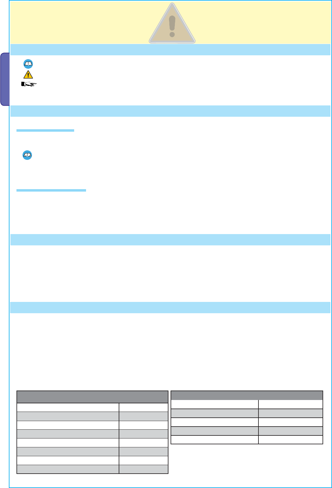
4 Description
1 Legend of symbols
This symbol indicates sections to be read with particular care.
This symbol indicates sections concerning safety.
This symbol indicates notes to communicate to users.
2 Intended use and application
3 Reference Standards
“IMPORTANT INSTALLATION, SAFETY INSTRUCTIONS”
“CAUTION: IMPROPER INSTALLATION MAY CAUSE SERIOUS DAMAGE, FOLLOW ALL INSTALLATION INSTRUCTIONS CAREFULLY”
“THIS MANUAL IS ONLY FOR PROFESSIONAL INSTALLERS OR QUALIFIED PERSONS”
For its quality processes management Came Cancelli Automatici is ISO 9001:2000 certified, and for its environmental management it is
ISO 14001 certified. Came designs and manufactures entirely in Italy.
This product complies with the following standards: see Declaration of Compliance.
Make sure you respect the distances and cable diameters as shown in “cable types and minimal thicknesses” table.
The overall power of the motors must not exceed 750 W.
This product is engineered and manufactured by CAME cancelli automatici s.p.a. and complies with current safety regulations.
Guaranteed 24 months if not tampered with.
The control panel works on 230V a.c. of power, 50/60Hz frequency.
Both command and control devices and accessories are 24V powered. Warning! Accessories must not exceed 35 W overall.
All connections are protected by quick fuses, see table.
The input and output contact functions, the timing settings and users’ management, are set and viewed on the display, which is run by
software.
FUSES
protection: fuse type:
Electrolock 3.15A-F
Electronic board (power supply line) 5A-F
Accessories 1.6A-F
Control devices 630mA-F
TECHNICAL FEATURES
Power supply 230V - 50/60Hz
max. rated power 750W
Power draw when idling 85mA
Max power of 24V accessories 35W
Insulation rating II
Material ABS
Protection rating IP54
operating temperature -20 / +55°C
2.1 Intended use
2.2 Application
4
3
2
1
!02%
#()5$%
4
10
1
8
5 6 7
9
11
12
13
14
16
15
17
#!-%
#!-%
2
18
19
20
21
3
(mm) ZM3EC
ZM3C
Pag.
3
3 - Manual code:
319U75
319U75 ver.
2.0
2.0 01/2009 © CAME cancelli automatici s.p.a. - The data and information reported in this installation manual are susceptible to change at any time and without obligation on CAME cancelli automatici s.p.a. to notify users.
ENGLISH
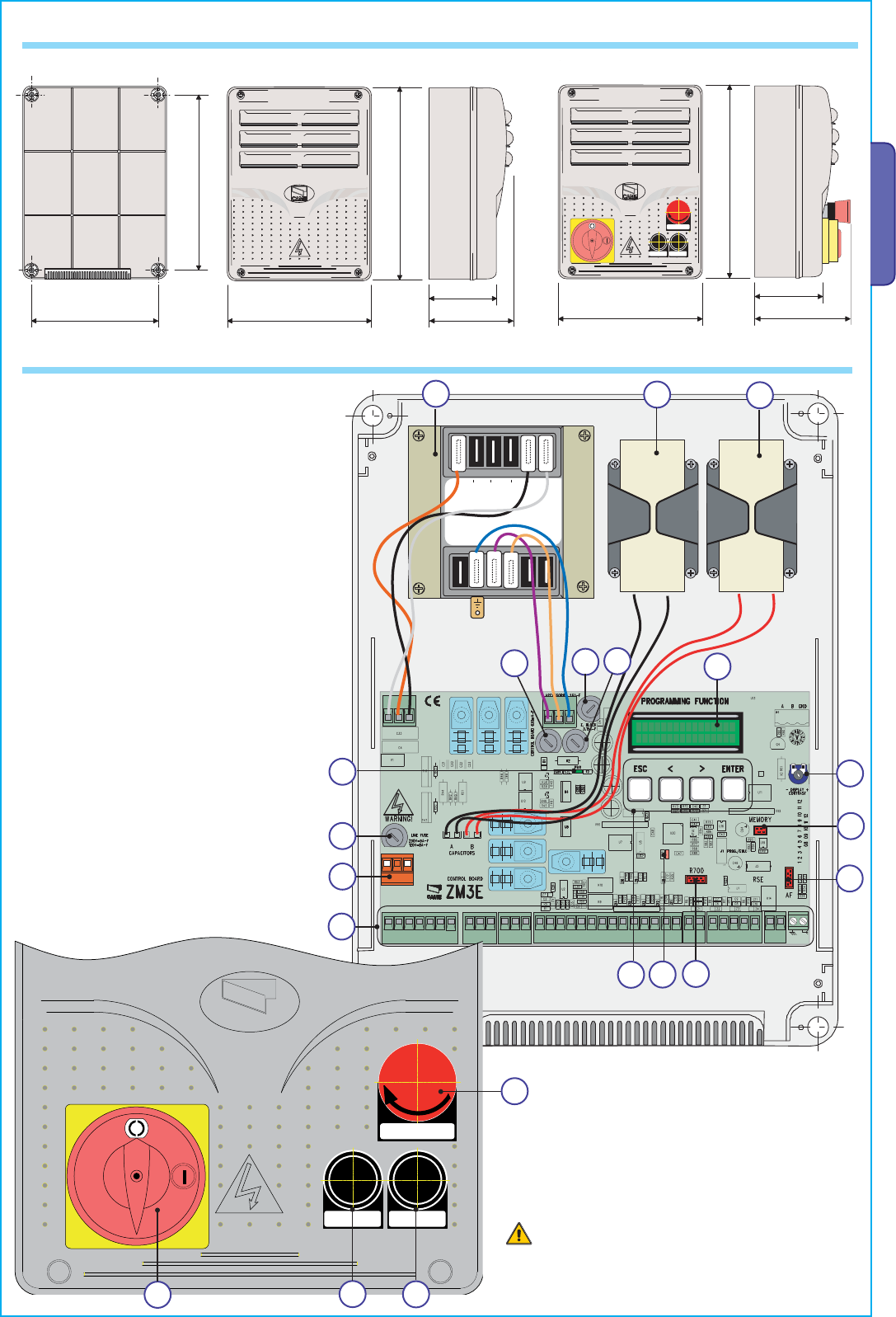
4.2 Main components
Warning! Before acting on the machinery, cut off the
main power supply and disconnect any emergency
batteries.
1 - Transformer
2 - M1 gearmotor condenser (black wires)
3 - M2 gearmotor condenser (red wires)
4 - Card fuse
5 - Accessories fuse
6 - Electrolock fuse
7 - Display
8 - Display lighting adjustment trimmer
9 - Memory roll card connector
10 - AF card connector
11 - R700 card connector
12 - Open contact error - warning LED
13 - Programming buttons
14 - Terminal board for connecting
15 - Terminal board for 230V a.c. power grid
16 - Line fuse
17 - 230V-power signalling LED
18 - STOP button
19 - CLOSE button
20 - OPEN button
21 - Safety block
{
4.1 Dimensions, spans and anchoring holes
ZM3EC
!!
15 mm~
Pag.
4
4 - Manual code:
319U75
319U75 ver.
2.0
2.0 01/2009 © CAME cancelli automatici s.p.a. - The data and information reported in this installation manual are susceptible to change at any time and without obligation on CAME cancelli automatici s.p.a. to notify users.
ENGLISH
Before installing do the following:
• Check that the panel’s anchoring point is protected from possible blows, and that the anchoring surface is solid. Also check that the
anchoring is done using the appropriate bolts, screws etc.;
• Make sure you have a suitable omnipolar cut-off device with contacts more than 3 mm apart, and independent (sectioned off) power
supply;
• Make sure that any connections inside the case (that provide continuance to the protective circuit) are fitted with extra insulation
as compared to the other conductive parts inside;
• Make sure you have suitable tubing and conduits for the electrical cables to pass through and be protected against mechanical
damage.
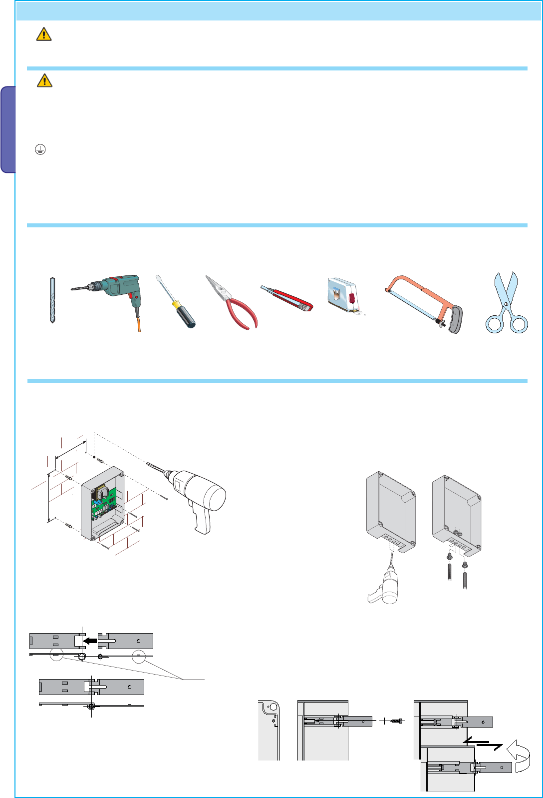
Make sure you have all the tools and materials you will need for the installation at hand to work in total safety and compliance with the
current standards and regulations. The following figure illustrates the minimum equipment needed by the installer.
Here are some examples.
5 Installation
5.1 Preliminary checks
5.2 Tools and materials
Installation must be carried out by expert qualified personnel and in full observance of regulations in force.
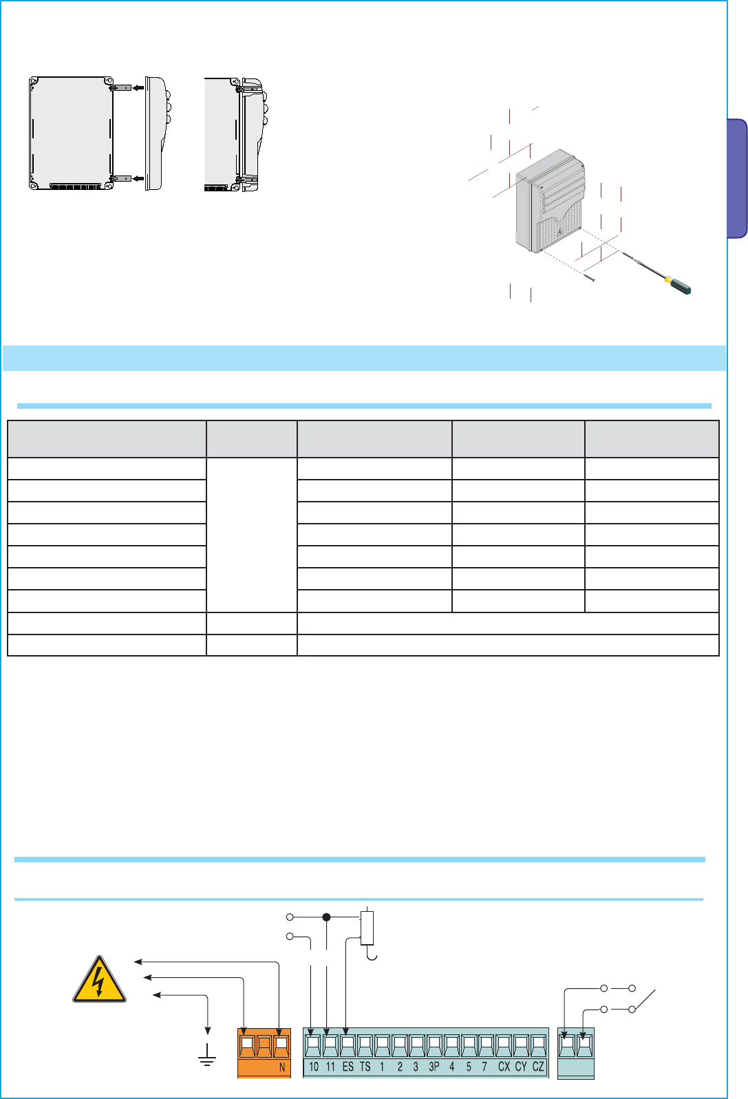
1) Fix the base of the panel in a protected area; we suggest
using round top Phillips recessed head screws of max.
6mm in diameter.
5.3 Fixing and mounting the box
2) Perforate the pre-punched holes and insert the cable
glands with the corrugated tubing for the electrical
cables to travel through.
N.B.: diameter of the pre-punched holes: 20 mm.
3) Assemble the pressure hinges.
4) Insert the pressure hinges into the box (on the left or right as you
wish) and set them using the provided screws and washers.
They must slide in
order to tum
," "
+
-
Pag.
5
5 - Manual code:
319U75
319U75 ver.
2.0
2.0 01/2009 © CAME cancelli automatici s.p.a. - The data and information reported in this installation manual are susceptible to change at any time and without obligation on CAME cancelli automatici s.p.a. to notify users.
ENGLISH
N.B.: If the cable length differs from that specified in the table, then you must determine the proper cable diameter based on the actual
power draw from the connected devices and according to the CEI EN 60204-1 standards.
For connections that require several, sequential loads, the sizes given on the table must be re-evaluated based on actual power draw
and distances.
When connecting products that are not specified in this manual, please follow the documentation provided with said products.
6.1 Cable and type and section
Connections Type
of cable
Length of cable
1 < 10 m
Length of cable
10 < 20 m
Length of cable
20 < 30 m
Control panel power supply
FROR CEI
20-22
CEI EN
50267-2-1
3G x 1,5 mm23G x 1,5 mm23G x 2,5 mm2
Motor power supply 3G x 1,5 mm23G x 1,5 mm23G x 2,5 mm2
flashing lamp 2 x 1,5 mm22 x 1,5 mm22 x 1,5 mm2
Transmitter photocells 2 x 0,5 mm22 x 0.5 mm22 x 0,5 mm2
Receiver photocells 4 x 0,5 mm24 x 0,5 mm24 x 0,5 mm2
Power supply to accessories 2 x 0,5 mm22 x 0,5 mm22 x 1 mm2
Control and safety devices 2 x 0,5 mm22 x 0,5 mm22 x 0,5 mm2
Encoder connection 2402C 22AWG max. 30 m
Antenna connection RG58 max. 10 m
6 Electrical connections
6) After the adjustments and settings, fix the cover
using the provided screws.
5) Snap the cover into place onto the hinges. Close it and fix it
using the provided screws.
Terminals for powering the following accessories:
- 24V A.C. Overall power allowed: 20W
Power supply to accessories
Power supply
230V (A.C.) 50/60 Hz
Electrolock connection
(12V - 15W max)
Possible output of the radio
receiver’s second channel
(N.O. socket).
Socket rating: 1A-24V (D.C.).
6.2 Electrical connections
CAME
ACCESS CONTROL
CANCELLI AUTOMATICI
R700
3'.$
Pag.
6
6 - Manual code:
319U75
319U75 ver.
2.0
2.0 01/2009 © CAME cancelli automatici s.p.a. - The data and information reported in this installation manual are susceptible to change at any time and without obligation on CAME cancelli automatici s.p.a. to notify users.
ENGLISH
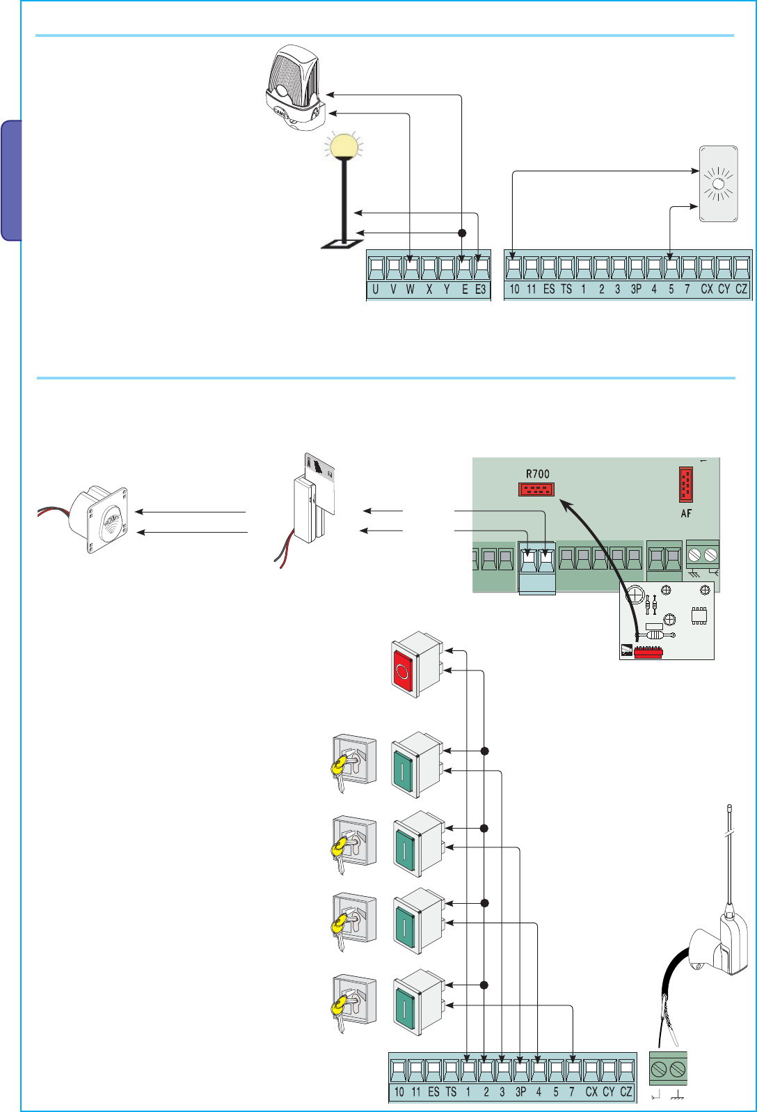
Cycle lamp: (contact rating: 230V – 60W max.)
It lights up the driving area and stays on from the
moment the gate begins to open until it is fully closed
(including the automatic closing time). If automatic
closing is not activated, the lamp stays on only during
movement or for a set time of 5 minutes if used as a
courtesy lamp.
Signal Flasher (socket rating: 230V
- 25W max.) Flashes during opening
and closing phases.
Signalling and Lighting devices
Command devices
Stop button (N.C. contact) - Button to stop gate while
excluding the automatic closing cycle. For movement to
resume you must press the command button or transmitter
button.
N.B.: if contact is unused, select Disabled on the
“FUNCTIONS” menu.
Key selector and/or opening button (N.O. contact) -
Gate opening command.
Key selector and/or commands button (N.O.
contact) - Commands for opening and closing the
gate – pressing the button or turning the key-
switch, inverts the gate’s movement or stops it
depending on how it is set on the 2-7 command in
the “FUNCTIONS” menu.
Key selector and/or partial opening button (N.O.
contact) - Partial gate opening for pedestrian
access.
Key selector and/or closing button (N.O. contact) -
Gate closing command.
Open gate indicator-light
(socket rating: 24V - 3W max.).
Turns on when the gate is ajar or open.
It turns off when the gate is closed.
TSP00 - Transponder sensor
N.B.: insert the R700 emcoding card for the
TSP00 sensors and LT001 card readers to be
recognised.
LT001 - Magnetic card reader
Black
Red
Antenna with RG58
cable for the remote
control.
&!&# &!&#
RX TX
RX TX
./ # .#
F4000
FERNI
FROG A
F4000
CBX
F7001
ATI
F7001
FERNI
KRONO KRONO
FROG A
ATI
FROG AE FROG AE
ENCODER BENCODER A
F7001E F7001E
AXOAXO
Pag.
7
7 - Manual code:
319U75
319U75 ver.
2.0
2.0 01/2009 © CAME cancelli automatici s.p.a. - The data and information reported in this installation manual are susceptible to change at any time and without obligation on CAME cancelli automatici s.p.a. to notify users.
ENGLISH
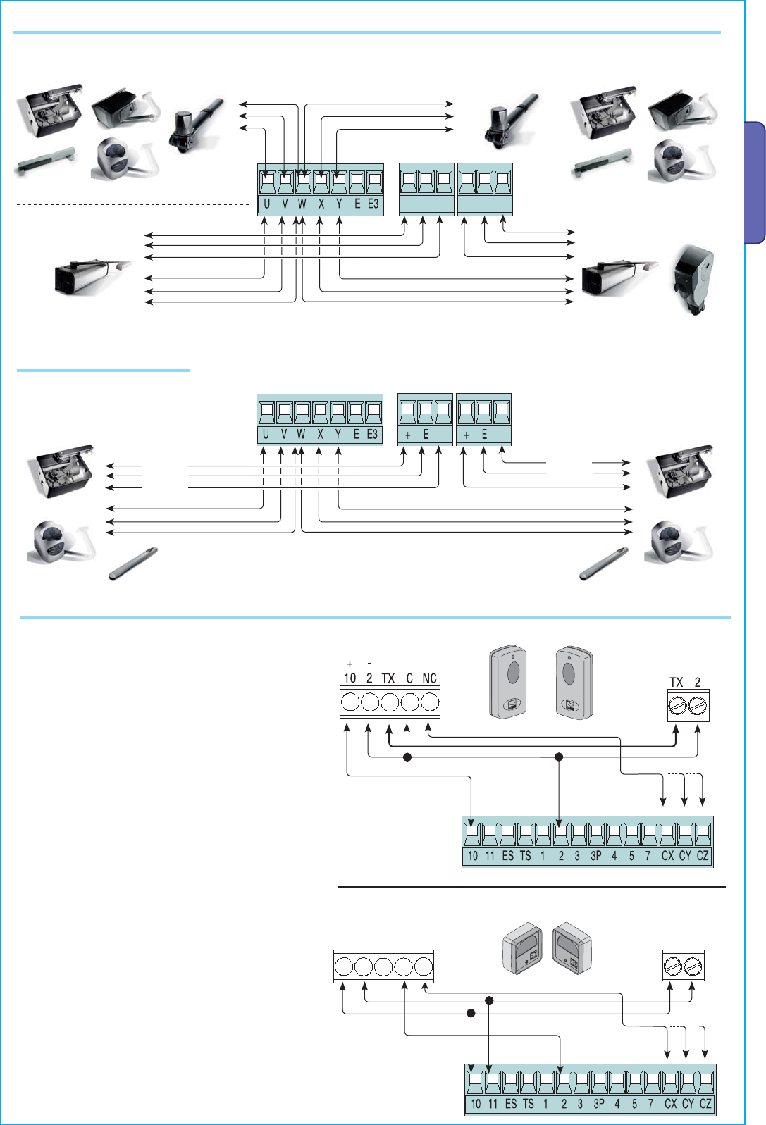
M1 - 230V A.C. gearmotor featuring delayed action on opening M2 - 230V A.C. gearmotor featuring delayed action on closing
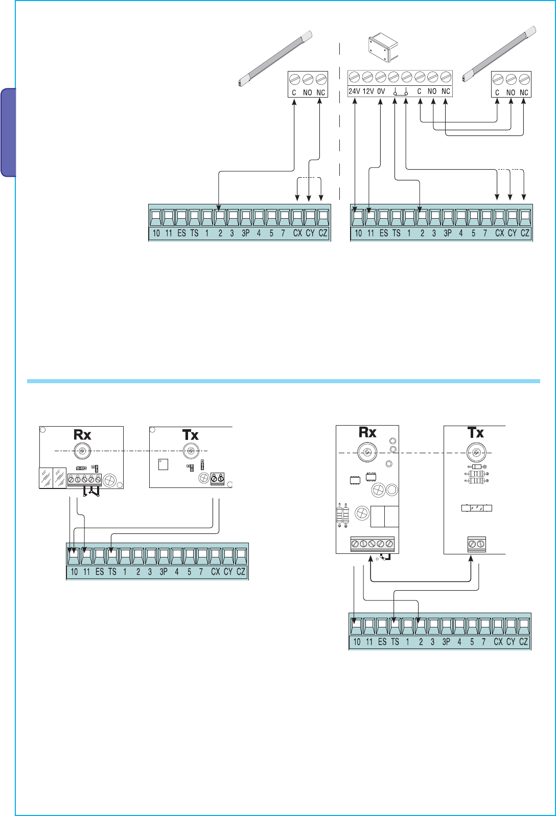
Safety devices
Confi gure either (N.C.) contacts CX, CY or CZ, input
for safety devices such as photocells, that comply
with EN 12978 standards. See CX, CY or CZ input
functions in:
- C1 «re-open during closing phase», When the
gate leaf is closing, opening the contact triggers the
inversion of the direction of movement until the gate
leaf is fully open.
- C2 «re-close during opening phase», When gate
is opening, if the contact is opened it triggers an
inversion of the direction until gate is fully closed;
- C3 «partial stop», Halts moving gate leaves and
causes them to automatically close (if this functions
has been selected);
- C4 «stand-by Obstacle», Halts the moving gate
leaves causing them to start moving again once
obstacle is removed.
- Deactivated, if contact is unused.
DIR photocells
DOC photocells
Gearmotor, mechanical stops
Gearmotor, encoder
M1 - 230V A.C. gearmotor featuring
delayed action on opening
M2 - 230V A.C. gearmotor featuring
delayed action on closing
White
Brown
Green
Green
Brown
White
DF
./
.#
#
&53)"),%M!
48
48
48 #
.#
(DOC) (DIR)
Pag.
8
8 - Manual code:
319U75
319U75 ver.
2.0
2.0 01/2009 © CAME cancelli automatici s.p.a. - The data and information reported in this installation manual are susceptible to change at any time and without obligation on CAME cancelli automatici s.p.a. to notify users.
ENGLISH
DF with DFI connections
monitor card
At each opening and closing command, the control board assesses the effi ciency status of the control devices (photocells). Any
anomaly found is signalled with the fl ashing of the LED on the control panel. Consequently it cancels any commands coming from the
remote control or the button.
Electrical connection to enable the photocell safety test:
- the transmitter and the receiver, must be connected as per the diagram;
- from the functions menu, select “safety tests” and select either CX - CY - CZ input/s to activate the test.
6.3 Electrical connection for the photocells functions test
Confi gure either (N.C.) contacts CX, CY or CZ,
input for EN 12978 compliant safety devices such
as sensitive edges. See CX input functions in:
- C7 «Open while closing», During gate closing,
opening the contact causes inversion of movement
until gate is fully open;
- C8 «close while opening», During gate opening,
opening the contact causes inversion of movement
until gate is fully close.
- Deactivated, if contact is unused.
Lingua
Italiano
Þß
{
{
{
{
Pag.
9
9 - Manual code:
319U75
319U75 ver.
2.0
2.0 01/2009 © CAME cancelli automatici s.p.a. - The data and information reported in this installation manual are susceptible to change at any time and without obligation on CAME cancelli automatici s.p.a. to notify users.
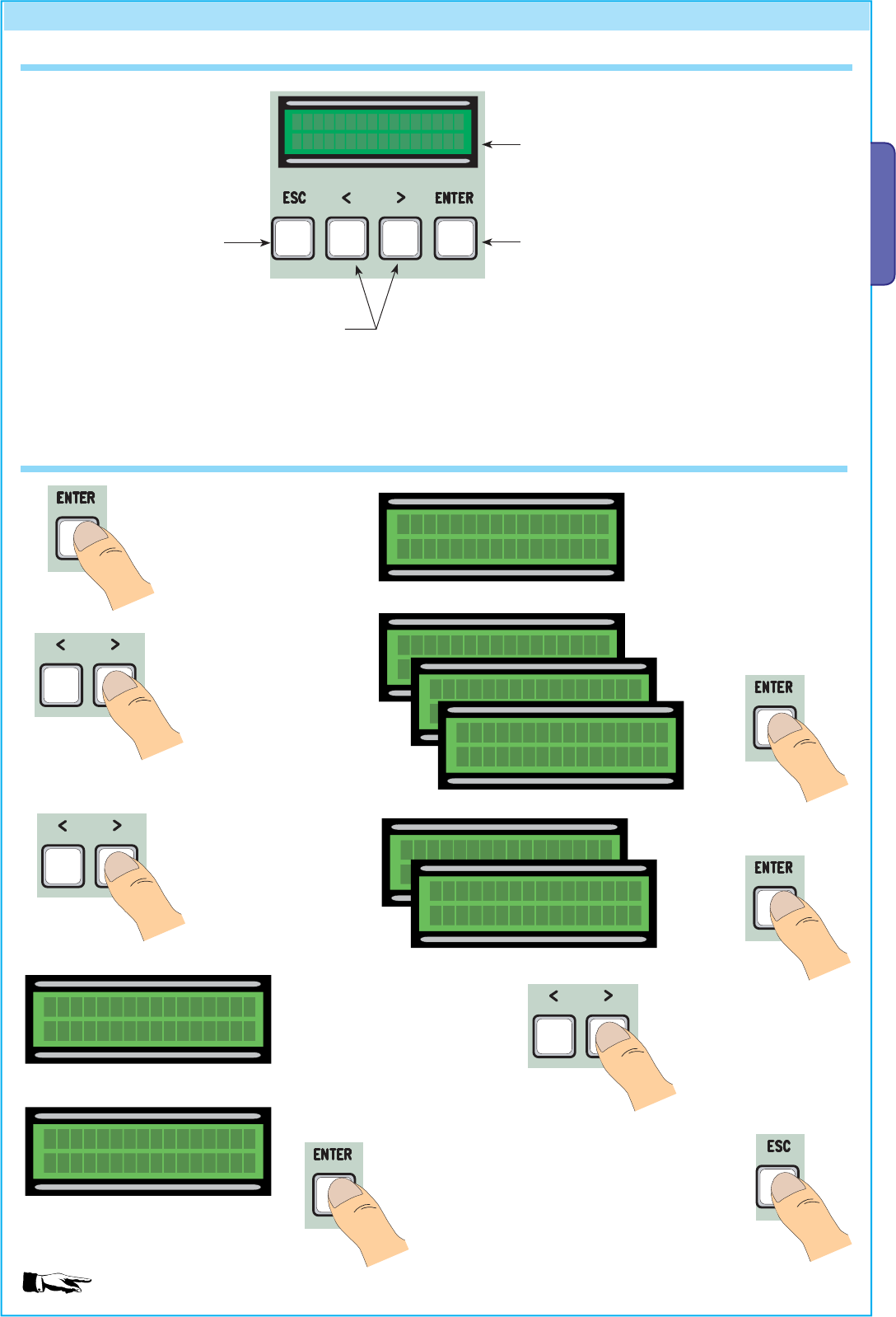
ENGLISH
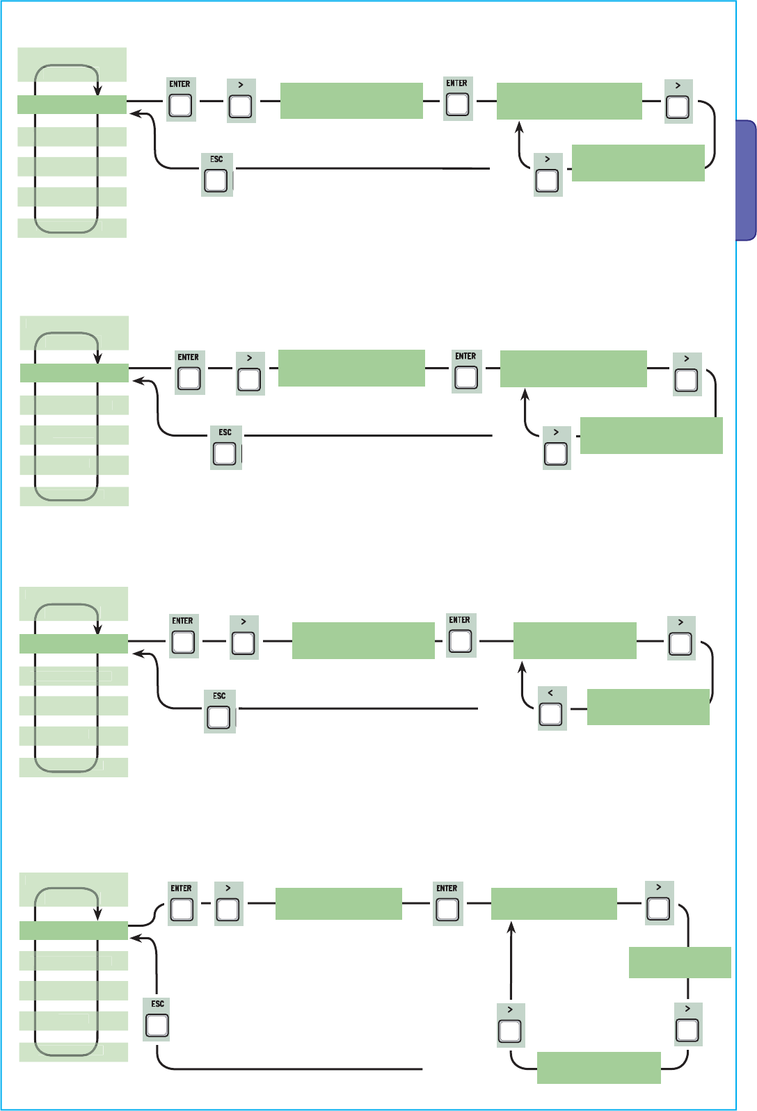
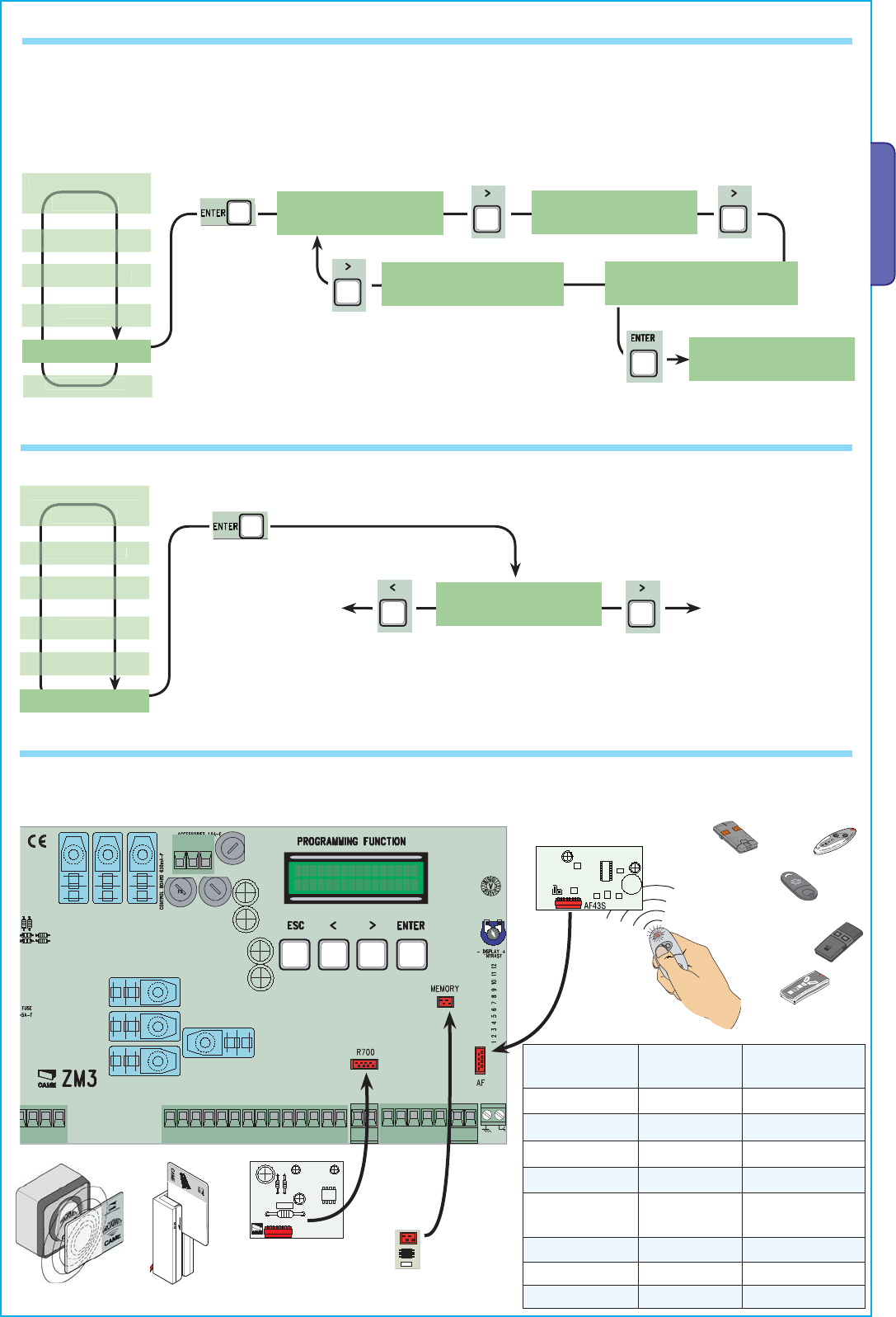
To enter the menu, keep the
ENTER key pressed for at least one
second.
To select a menu item,
mode using the greater
than-lesser than keys...
...then press ENTER
also use the greater
than-lesser than keys
for the “sub-menus”...
If the <> are on the TIME
function, you may modify the
value.
To increase or reduce values,
use the greater than-lesser
than keys...
...then press ENTER to confirm...
...to exit the menu, wait 30
seconds, or press ESC, until start
screen is displayed.
N.B.: when the menu is active, the system cannot be used.
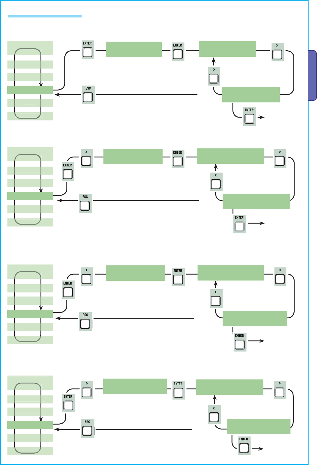
7 Programming
...then press ENTER
7.2 Browsing the menu
7.1 Description of display commands
The ENTER key is for:
- entering the menu;
- confirming and memorising set values.
The ESC key is for:
- exiting the menu;
- cancelling modifications.
The < > keys are for:
- shifting from one menu item to another;
- increase or decrease values.
the <...> symbols on the display are for:
-pointing out the currently, selected item
LANGUAGE
English
Þß
LANGUAGE
English
Þß
FUNCTIONS
English
Þß
TIMING ADJ.
Þß
A.C.T.
90s
Þß
Cycle Time
90s
Þß
Cycle Time
90s
Þß
Cycle Time
100s
Þß
ENTER
>
ENTER >
ENTER
>
>
ENTER
ENTER
ENTER >
>
>
>
>
>
ENTER
>
>
>
>
>
>
>
>
ENTER
>
>
>
>
>
>
>
>
>
>
>
>
>
>
>
ENTER
>
>
ENTER
>
>
ENTER
>
>
ENTER
>
>
ENTER
>
>
ENTER
>
>
ENTER
>
>
ENTER
>
>
ENTER
>
ENTER
>
>
ENTER
>
>
ENTER
>
>
ENTER
>
>
ENTER
>
>
ENTER
>
>
>
>
>
>
>
ENTER
ENTER
>
>
ESC
Pag.
10
10 - Manual code:
319U75
319U75 ver.
2.0
2.0 01/2009 © CAME cancelli automatici s.p.a. - The data and information reported in this installation manual are susceptible to change at any time and without obligation on CAME cancelli automatici s.p.a. to notify users.
ENGLISH
< LANGUAGE > <English><Francais> <Deutsch>
<Espanol><Italian o>
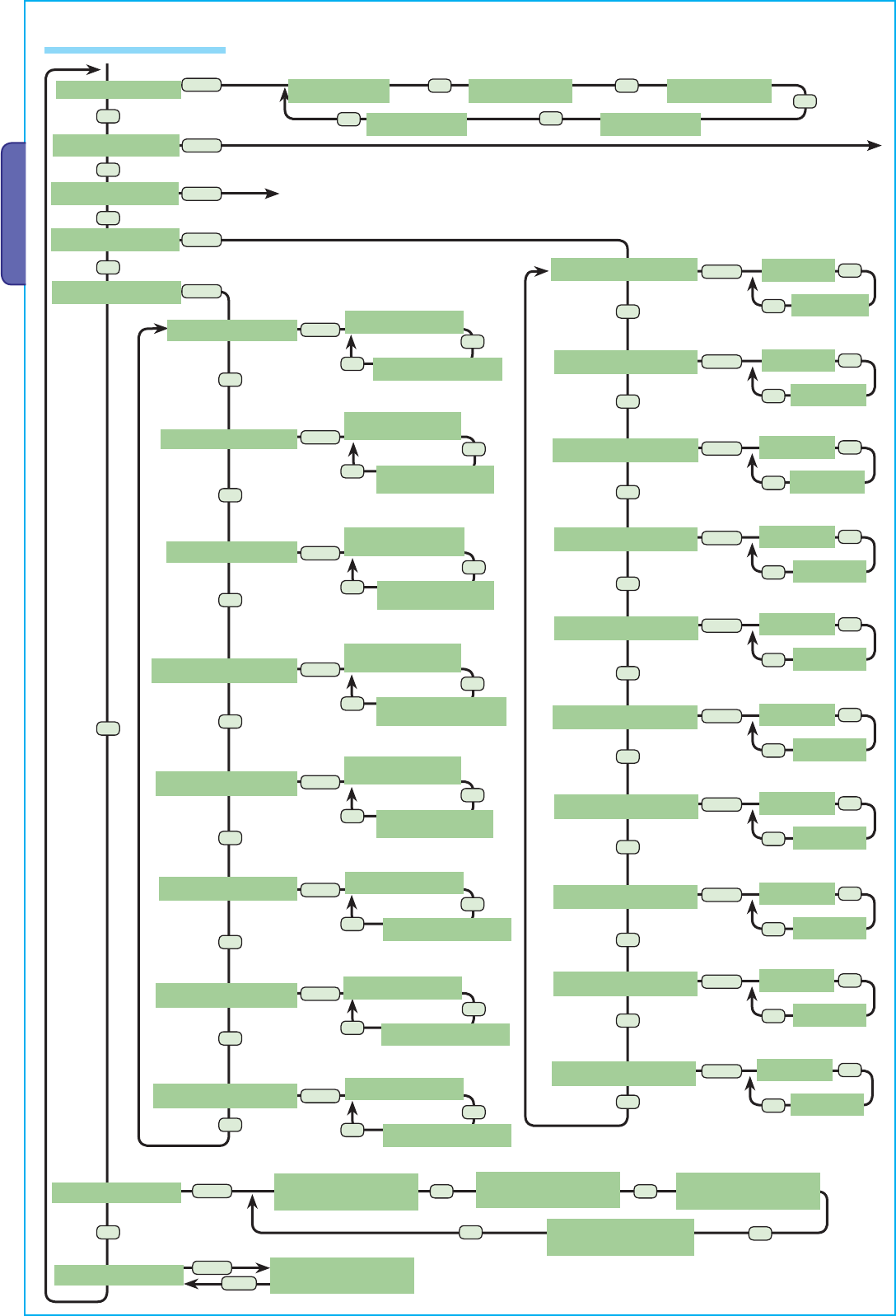
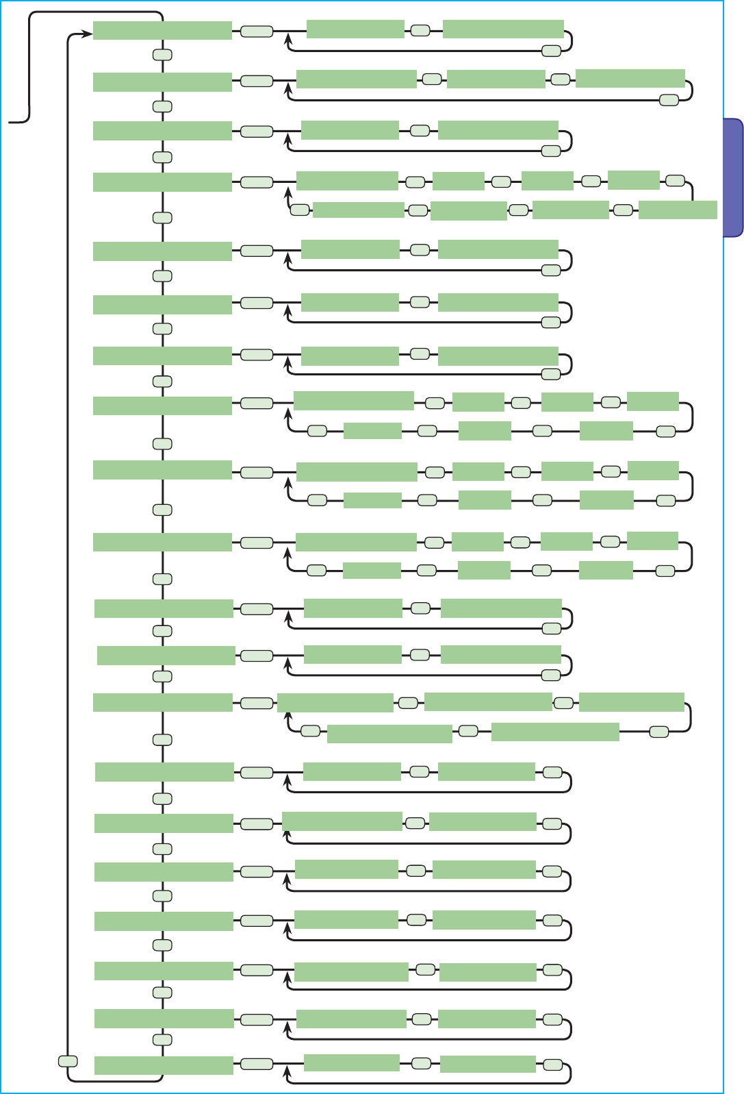
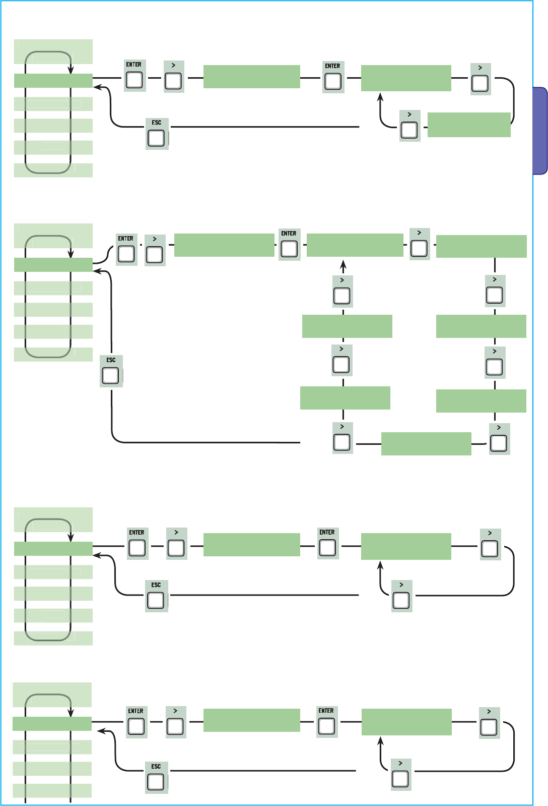
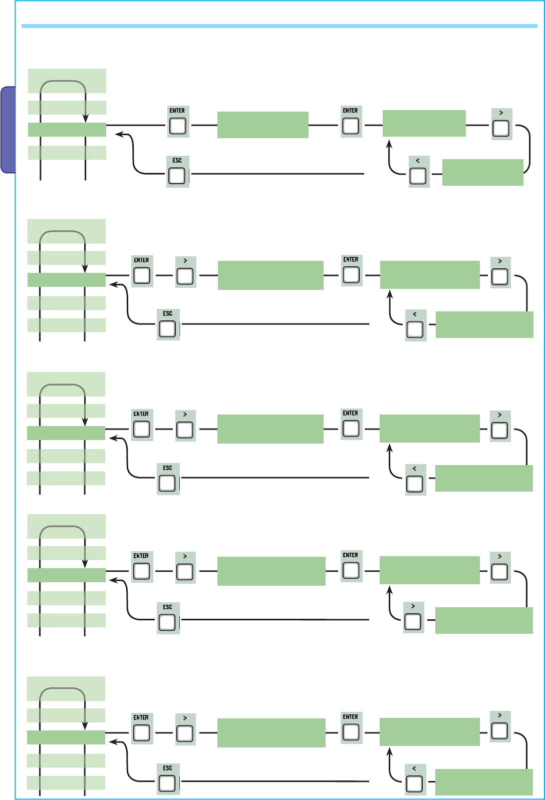
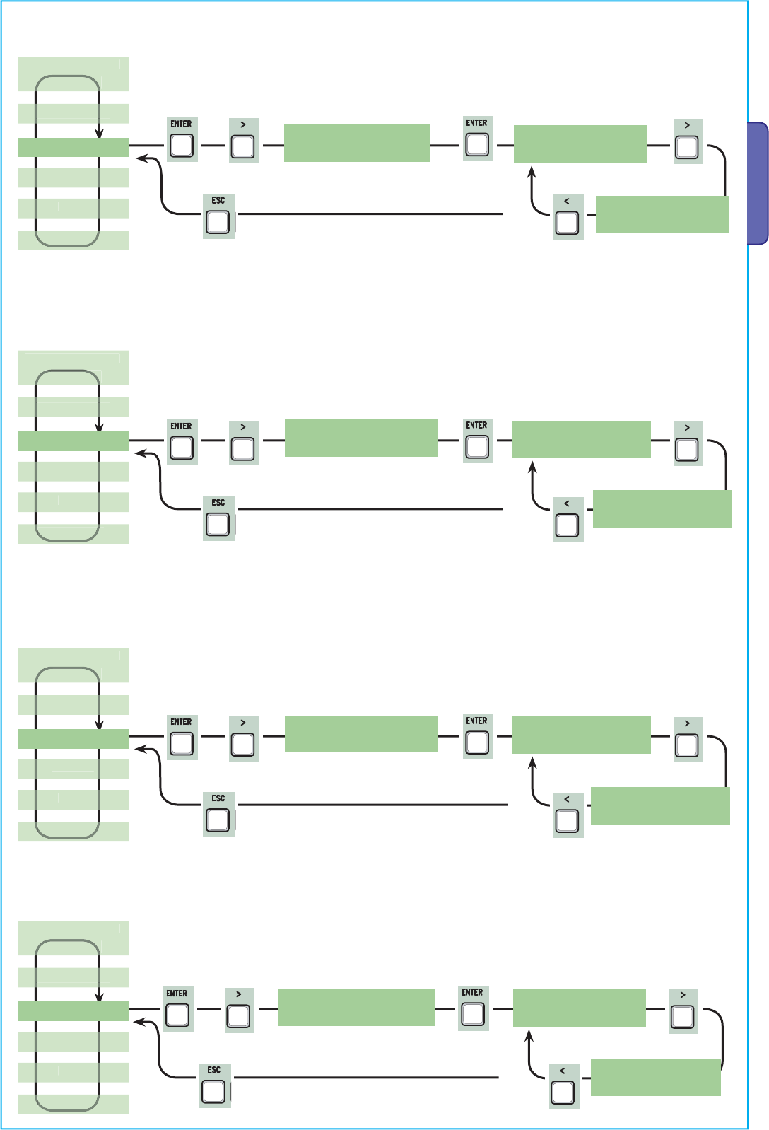
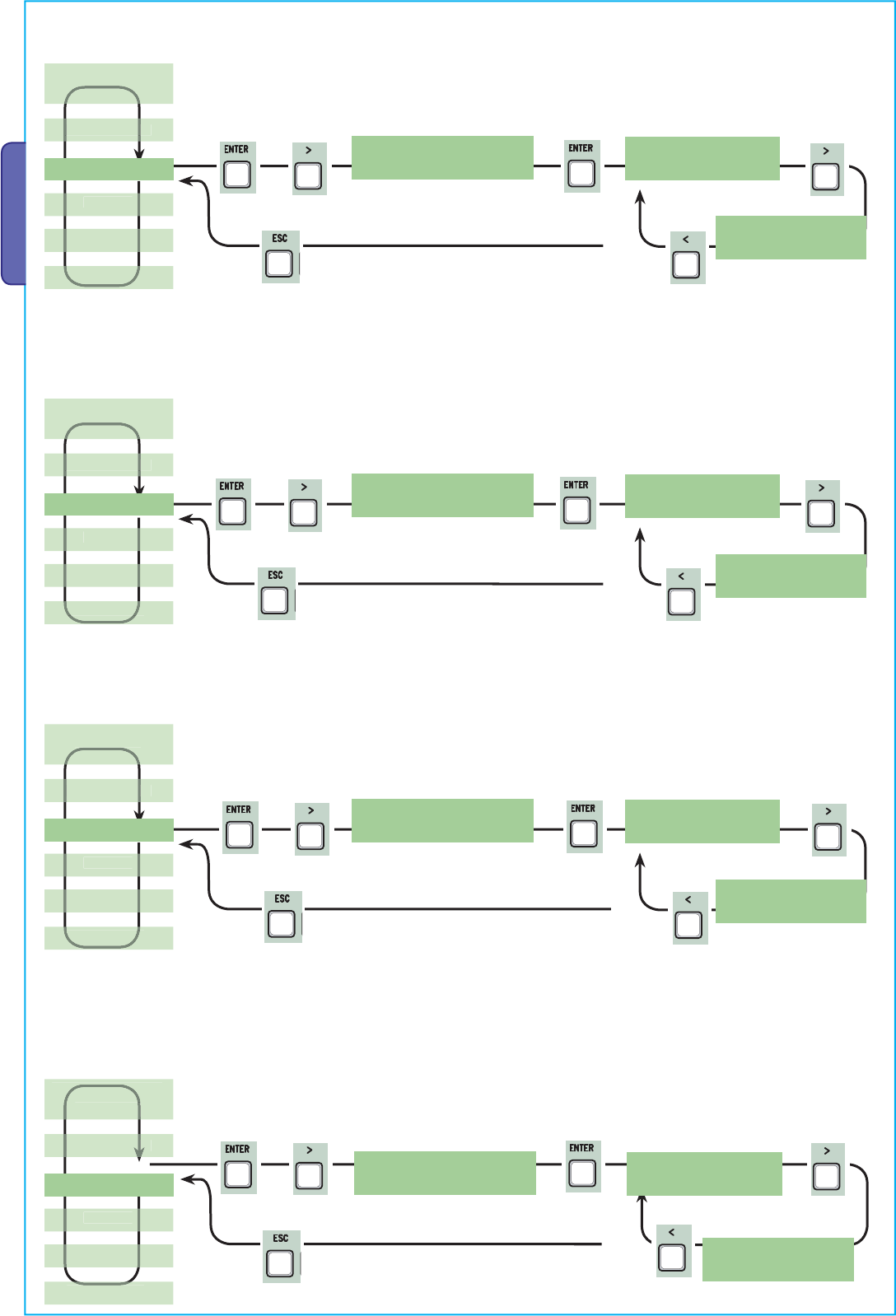
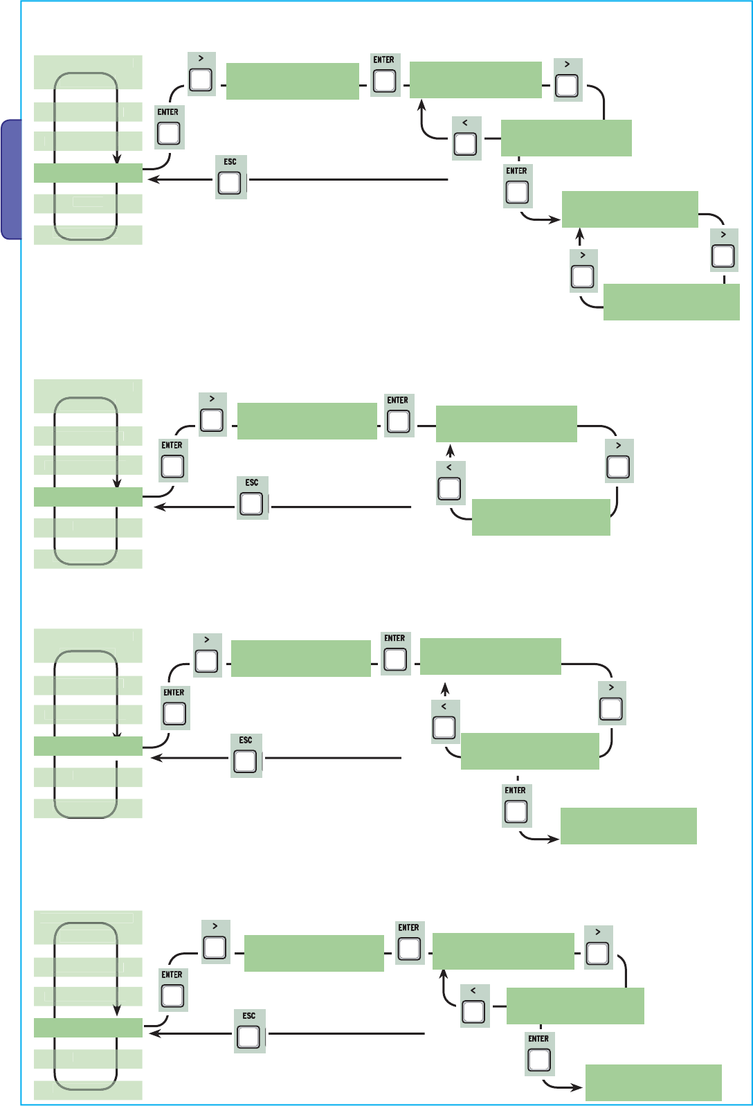
7.3 Menu structure
< TIMING ADJ >
< INFO >
< T.C.A. >
< FUNCTIONS >
< USERS >
Choose User
<001:-U001->
< 0s. >
< 300s.>
< 0s. >
< 300s.>
< 10s. >
< 150s.>
< 1s. >
< 10s. >
< 1s. >
< 60s >
< 1s. >
< 60s.>
< 1s. >
< 5s. >
< 1s. >
< 10s. >
< 5s. >
< 60s.>
< 0s. >
< 30s.>
Sel.Utente
<002:-U002->
Choose User
<001:-U001->
Sel.Utente
<002:-U002->
Choose User
<001:-U001->
Sel.Utente
<002:-U002->
Choose User
<001:-U001->
Sel.Utente
<002:-U002->
< TEST MOT. > TEST MOT.
< <=M1 M2=> >
< ENCODER > See detailed functions on pages 17, 18, 19 and 20 (the “ENCODER” function, appears only if
selected from the “Config.” function in the FUNCTIONS menu.
< System Reset >
<Pedestrian ACT>
< Cycle Time >
< Op. Delay M1 >
< Cl. Delay M2 >
<Preflashing T.>
< Lock time >
< Ram hit time >
< Ped.opening >
<Slow down time>
< Add User >
< Mod. name >
< Mod. Code >
<Related Func.>
< Remove Usr. >
<Delete all Usr>
< Backup data >
<Restore backup>
< Standby Msg. >
< Version >
fw. 3.0
< No. of Runs >
16480
confirm? (no)
confirm? (yes)
confirm? (no)
confirm? (yes)
confirm? (no)
confirm? (yes)
confirm? (no)
confirm? (yes)
>
>
>>>
>
>>
>
ENTER
>
ENTER >
>
>
ENTER
>
>
>
>
>
>
>
>
>
>
>
>
>
>
ENTER
>
>
ENTER
>
>
ENTER
>
>
ENTER
>
>
ENTER
>
>>
>
>>
>
ENTER
>
>>
>
>>
>
ENTER
>
>>
>
>>
>
ENTER
>
>
ENTER >
>>
>
ENTER >
>
ENTER >
>
ENTER >
>
ENTER >
>
ENTER >
>
ENTER >
>
ENTER
>
< -ooo+ >
•< -ooo+ >
••
>
>
>
>
>
>
>
>
>
ENTER
>
Pag.
11
11 - Manual code:
319U75
319U75 ver.
2.0
2.0 01/2009 © CAME cancelli automatici s.p.a. - The data and information reported in this installation manual are susceptible to change at any time and without obligation on CAME cancelli automatici s.p.a. to notify users.
ENGLISH
<when close>
< Disabled > < Turn on >
< CX >
< CX+CZ >
<CX+CY+CZ> < CX+CY >
< CY > < CZ >
< CY+CZ >
< Config. >
< C1 >
< C7 >
< C8 > < C4 >
< C2 > < C3 >
< Disabled > < C1 >
< C7 >
< C8 > < C4 >
< C2 > < C3 >
< Disabled > < C1 >
< C7 >
< C8 > < C4 >
< C2 > < C3 >
< N.C. > < N.A. >
< M1 + M2 > < M2 >
< encoder >
< Cl. Thrust > < Turn on > < Disabled >
< AutoClose >
<M aintained A ct>
< Obstacle Det. >
< Safety d.Test >
< Preflashing >
< Total Stop >
< CX Input >
< CY Input >
< CZ Input >
<Ram hit funct.>
< Turn on > < Disabled >
< Turn on > < Disabled >
< Disabled >
< Turn on > < Disabled >
< Turn on > < Disabled >
< Turn on > < Disabled >
< Disabled >
< Turn on > < Disabled >
< Slow run > < Fcap-RallCh >
<Limit switch> < Time of Run >
< Lock >
< endstop >
< cmd 2-7 >
< cmd 2-3P >
< lamp E3 >
<output B1-B2>
< No. Motors >
<Slow Down Spd>
<Op.-Stop-Cl.> <Open-Close>
<Pedestrian> < Partial >
< Cycle > < Courtesy >
<Monostable> <Bistable>
X 2
X 2
Pag.
12
12 - Manual code:
319U75
319U75 ver.
2.0
2.0 01/2009 © CAME cancelli automatici s.p.a. - The data and information reported in this installation manual are susceptible to change at any time and without obligation on CAME cancelli automatici s.p.a. to notify users.
ENGLISH
LANGUAGE
< English >
LANGUAGE
< Francais >
LANGUAGE
< Deutsch >
LANGUAGE
< Espanol >
LANGUAGE
< Italiano >
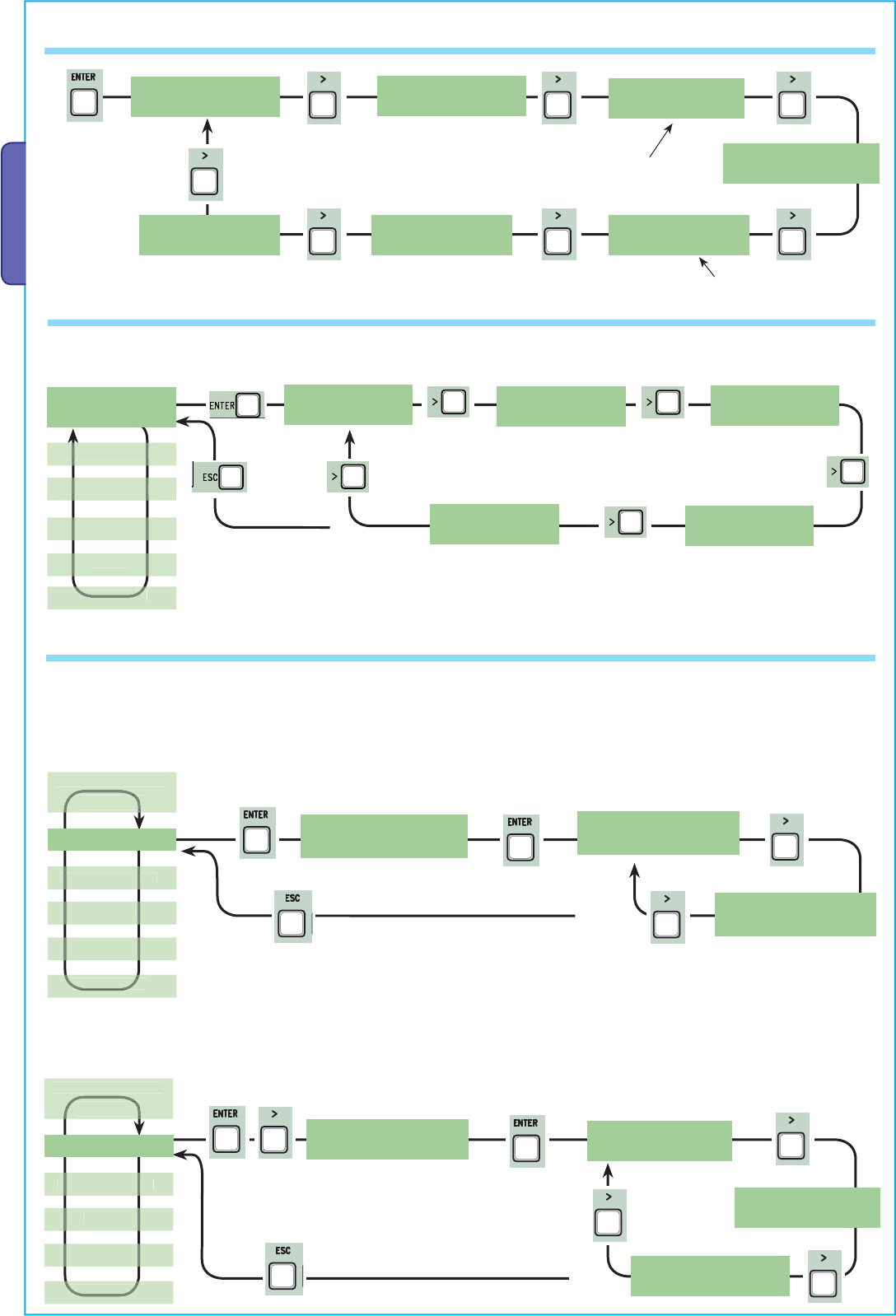
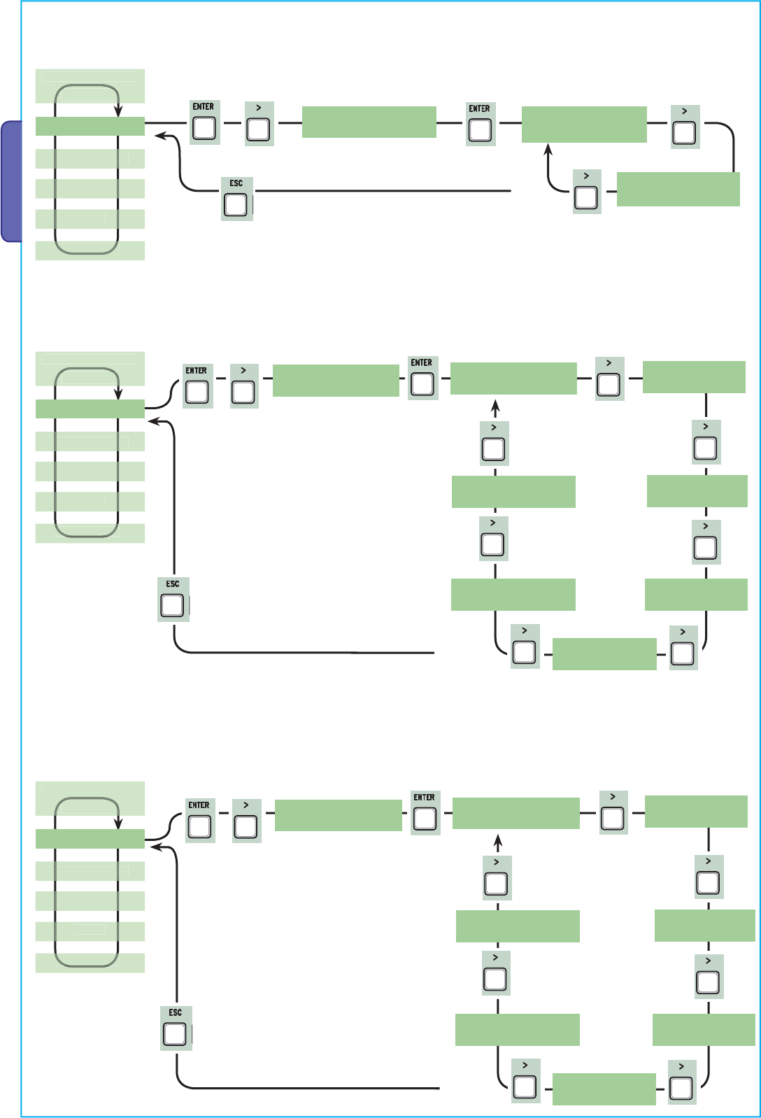
7.4 Main menu
Press ENTER
for 1 second
7.5 Language menu
Select language: selects among the languages displayed.
< LANGUAGE >
English
FUNCTIONS
FUNCTIONS
TIMING ADJ.
IMING ADJ
USERS
INFO
7.6 Functions menu
< AutoClose >
Turn o n
AutoClose
< Turn on >
AutoClose
< Disabled >
Automatic Closing: activates or deactivates the automatic closing function.
The automatic closing timer activates at each opening endpoint. The predetermined time may be adjusted, and is in any case
dependent on any safety devices that may activate; and it does not activate after a total safety “stop” or during a power outage.
< TIMING ADJ. >
Maintained Act
< Disabled >
<M aintained A ct>
Disabled
Maintained action: the gate works by keeping the button pressed (button 2-3 for opening, button 2-4 for closing, or if set to the “On
Closing” function, only with button 2-4.
Maintained Act
< when close >
< USERS >
250
< INFO >
Max. 250 users
< ENCODER >
< TEST MOT. >
It appears only if selected from the “Config.”
Section in the FUNCTIONS menu.
< LANGUAGE >
English
< FUNCTIONS >
<
LANGUAGE
>
English
sh
FUNCTIONS
TIMING ADJ.
TIMING AD
USERS
INFO
TEST MOT.
TEST MOT
<
LANGUAGE
>
English
h
FUNCTIONS
TIMING ADJ.
TIMING AD
USERS
INFO
TEST MOT.
TEST MOT
TEST MOT.
TEST MOT
Maintained Act
< Turn on >
X 2
X 2
X 4
X 2
X 5
X 2
X 3
X 2
Pag.
13
13 - Manual code:
319U75
319U75 ver.
2.0
2.0 01/2009 © CAME cancelli automatici s.p.a. - The data and information reported in this installation manual are susceptible to change at any time and without obligation on CAME cancelli automatici s.p.a. to notify users.
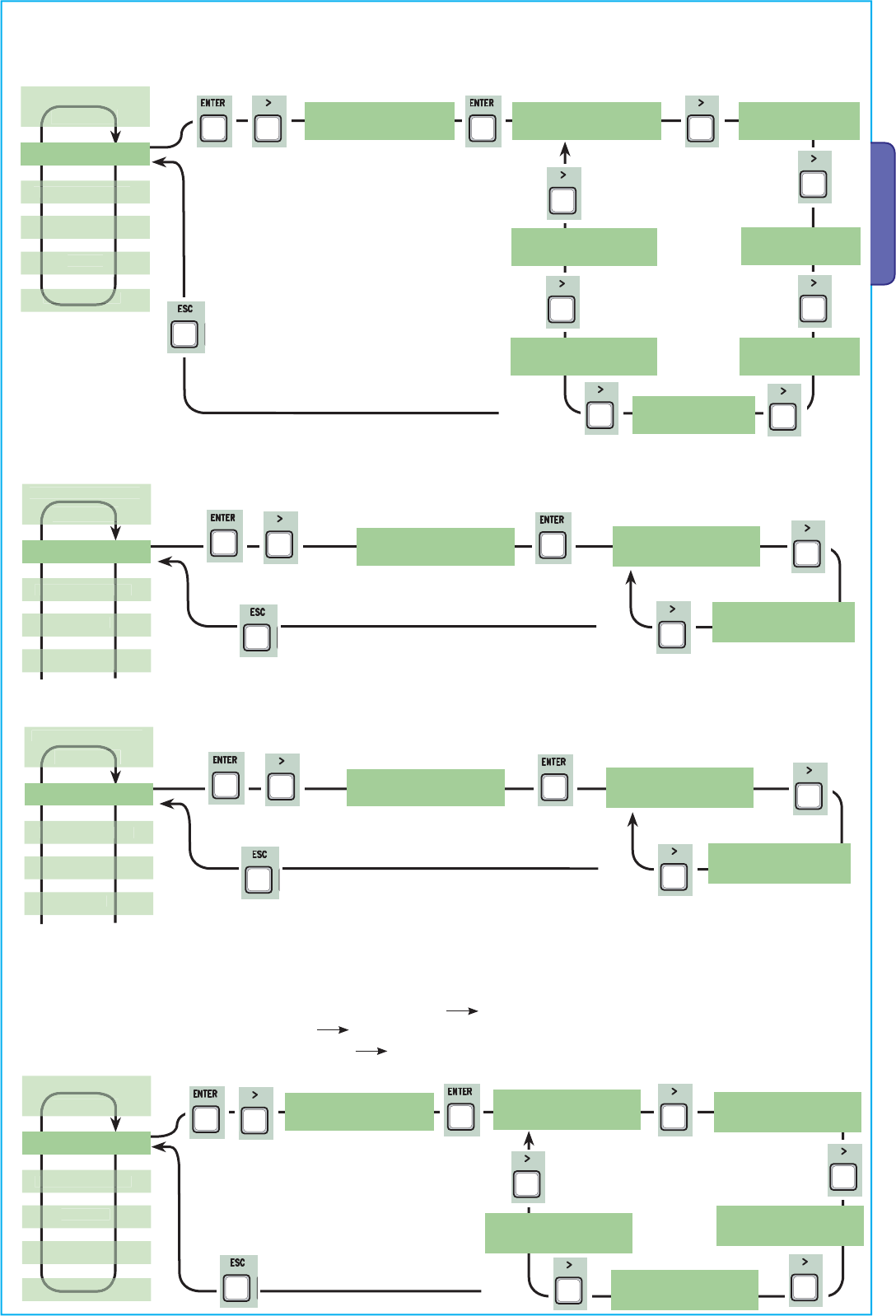
ENGLISH
<Safety d.Tes t>
Disabled
Safety d.Test
< Disabled >
Safety d.Test
< CX >
Safety d.Test
< CY >
Safety d.Test
< CZ >
Safety d.Test
< CX+CY >
Safety d.Test
< CX+CZ >
Safety d.Test
< CX+CY+CZ >
Obstacle Det.
< Disabled >
<Obstacle Det.>
Disabled
Obstacle Det.
< Turn on >
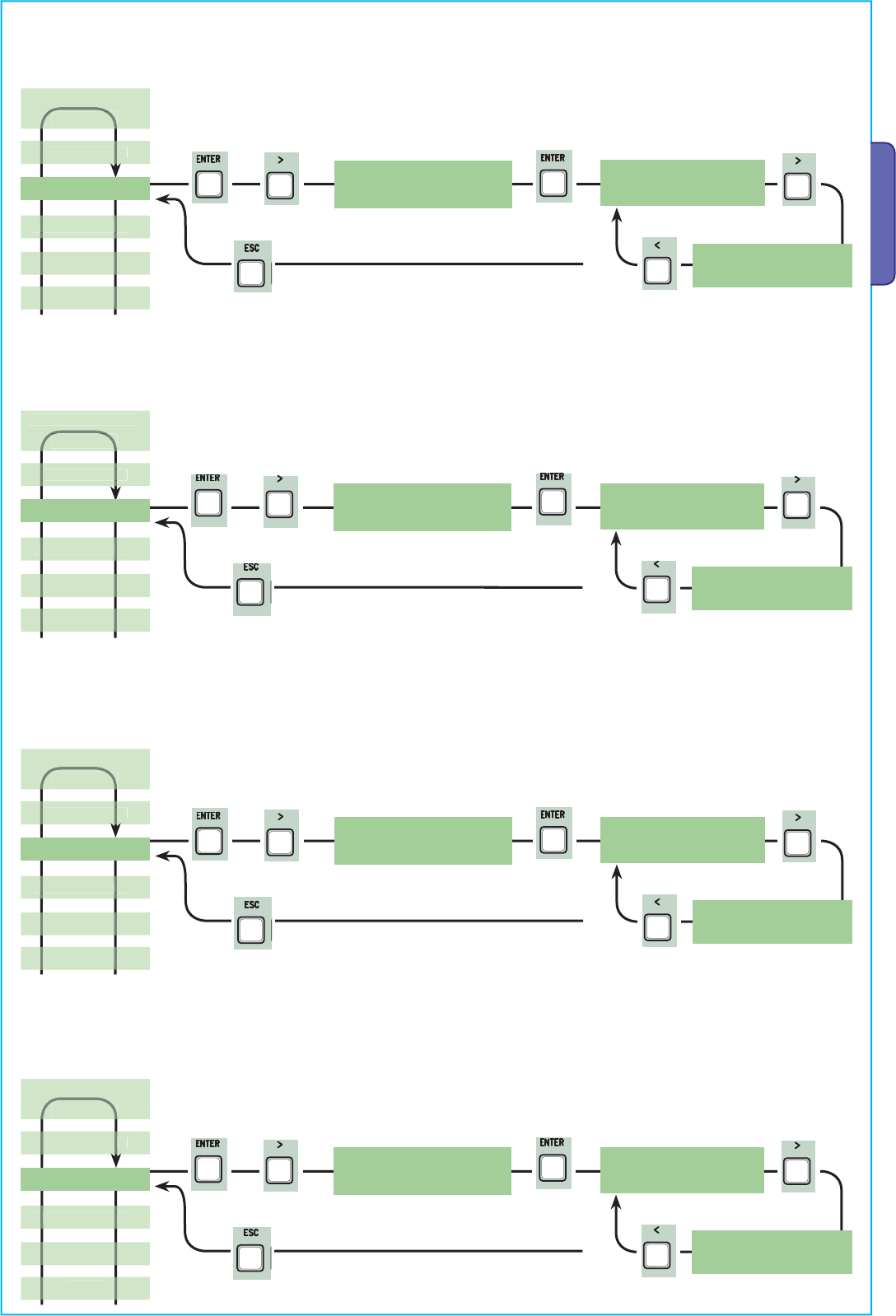
Obstacle detected: when motor is stopped (gate closed or after a total stop command) it prevents any movement if safety devices,
such as photocells, detect any obstacles.
Safety test: allows the card to check the efficiency of any safety devices (i.e. photocells) after every opening or closing command.
Preflashing
< Disabled >
< Preflashing >
Disabled
Pre-flashing: after an opening or closing command, the flashing light, connected to W-E, starts flashing before the gate begins its run
(to set the time, see “Pre-flashing timing” from the Adjust Timings menu
Ram hit funct.
< Disabled >
<Ram hit funct.>
Disabled
<
LANGUAGE
>
English
sh
FUNCTIONS
TIMING ADJ.
TIMING AD
USERS
INFO
TEST MOT.
TEST MOT
<
LANGUAGE
>
English
English
FUNCTIONS
TIMING ADJ.
T
D
USERS
I
NF
O
<
LANGUAGE
>
English
sh
FUNCTIONS
TIMING ADJ.
TIMING AD
USERS
INFO
TEST MOT.
TEST MOT
<
LANGUAGE >
English
sh
FUNCTIONS
TIMING ADJ.
TIMING AD
USERS
INFO
TEST MOT.
TEST MOT
Ram blow: before any opening run, the gate leaves will press onto the mechanical endstop for a few seconds, to help release the elec-
trolock (to set the time, see “Starting ram timing” in the Adjust Timings menu).
X 2
X 8
X 2
X 7
X 2
X 6
Pag.
14
14 - Manual code:
319U75
319U75 ver.
2.0
2.0 01/2009 © CAME cancelli automatici s.p.a. - The data and information reported in this installation manual are susceptible to change at any time and without obligation on CAME cancelli automatici s.p.a. to notify users.
ENGLISH
< CY Input >
Disabled
CY Input
< Disabled >
CY Input
< C2 >
CY Input
< C3 >
CY Input
< C4 >
CY Input
< C1 >
CY Input
< C7 >
CY Input
< C8 >
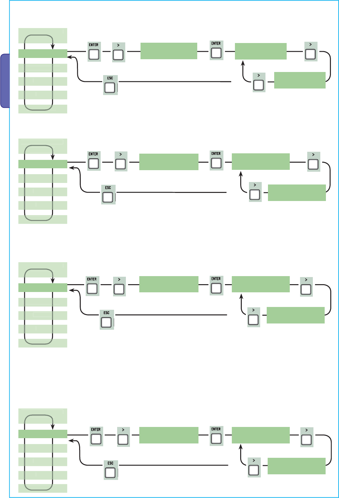
CX input: the N.C. safety contact input can take on the following functions: C1 (re-opening when closing), C2 (re-closing when
opening), C3 (partial stop), C4 (obstacle stall), C7 (re-opening when closing, for sensitive edges), C8 (re-closing when opening, for
sensitive edges) or, be deactivated. See safety devices on electrical connections.
< CX Input >
Disabled
CX Input
< Disabled >
CX Input
< C2 >
CX Input
< C3 >
CX Input
< C4 >
CX Input
< C1 >
Total Stop
< Turn on >
< Total Stop >
Turn o n
Total Stop
< Disabled >
Total Stop: this function stops the gate and consequently excludes any automatic closing cycle; for movement to resume, you need to
use the keypad or transmitter. Insert safety device on [1-2]; Insert the safety device on [1 -2]; if unused, select “Deactivated”
CX Input
< C7 >
CX Input
< C8 >
CY input: safety contact input can take on the following functions: C1 (re-opening when closing), C2 (re-closing when opening), C3
(partial stop), C4 (obstacle stall), C7 (re-opening when closing, for sensitive edges), C8 (re-closing when opening, for sensitive edges)
or, be deactivated. See safety devices on electrical connections.
<
LANGUAGE
>
EnglishEnglish
FUNCTIONS
TIMING ADJ.
IMING ADJ
USERS
INFO
TEST MOT.
TEST MOT.
<
LANGUAGE
>
EnglishEnglish
FUNCTIONS
TIMING ADJ.
IMING ADJ
USERS
I
NFO
TEST MOT.
TEST MOT.
<
LANGUAGE
>
EnglishEnglish
FUNCTIONS
TIMING ADJ.
IMING ADJ
USERS
INFO
TEST MOT.
TEST MOT.
X 2
X 9
X 2
X 11
X 2
X 10
X 2
X 12
Pag.
15
15 - Manual code:
319U75
319U75 ver.
2.0
2.0 01/2009 © CAME cancelli automatici s.p.a. - The data and information reported in this installation manual are susceptible to change at any time and without obligation on CAME cancelli automatici s.p.a. to notify users.
ENGLISH
Lock: to lock the gate leaves. Required for gate leaves longer than 2.50 m.
CZ input: safety contact input can take on the following functions: C1 (re-opening when closing), C2 (re-closing when opening), C3
(partial stop), C4 (obstacle stall), C7 (re-opening when closing, for sensitive edges), C8 (re-closing when opening, for sensitive edges)
or, be deactivated. See safety devices on electrical connections.
Closing thrust: at the endpoint stage during closing, the gearmotors perform a final closing-thrust of the doors for a few seconds.
Cl. Thrust.
< Disabled >
< Cl. Thrust. >
Disabled
Cl. Thrust.
< Turn on >
Config.
< Fcap-RallCh >
Deceleration configuration: configuring decelerations when opening or closing:
- slow run: decelerations when opening and closing;
- Fcap-RallCh.: end stop when opening and deceleration when closing;
- ecoder: managing decelerations, obstacle detection and sensitivity; (FROG-AE)
- Time of Run: timed end stop (default function); (FROG-A, FERNI 230V, ATI 230V, FAST 230V and KRONO)
- Limit switch (endstop): opening and closing endstop. (C-BX and F4000)
Config.
< encoder >
<
LANGUAGE
>
English
English
FUNCTIONS
TIMING ADJ.
TIMING AD
USERS
INFO
TEST MOT.
TEST MOT
< CZ Input >
Disabled
CZ Input
< Disabled >
CZ Input
< C1 >
CZ Input
< C2 >
CZ Input
< C3 >
CZ Input
< C4 >
CZ Input
< C7 >
CZ Input
< C8 >
Lock
< Disabled >
< Lock >
Disabled
Lock
< Turn on >
<
LANGUAGE
>
English
h
FUNCTIONS
TIMING ADJ.
T
D
USERS
INFO
<
LANGUAGE
>
English
sh
FUNCTIONS
TIMING ADJ.
T
D
USERS
INFO
<
LANGUAGE
>
English
h
FUNCTIONS
TIMING ADJ.
TIMING AD
USERS
INFO
TEST MOT.
TEST MOT
< Config. >
Slow run
Config.
< Slow run >
Config.
<Time of Run>
Config.
<Limit switch>
X 2
X 2
X 2
X 2
X 15
X 16
X 13
X 14
Pag.
16
16 - Manual code:
319U75
319U75 ver.
2.0
2.0 01/2009 © CAME cancelli automatici s.p.a. - The data and information reported in this installation manual are susceptible to change at any time and without obligation on CAME cancelli automatici s.p.a. to notify users.
ENGLISH
< endstop >
N.C
endstop
< N.C >
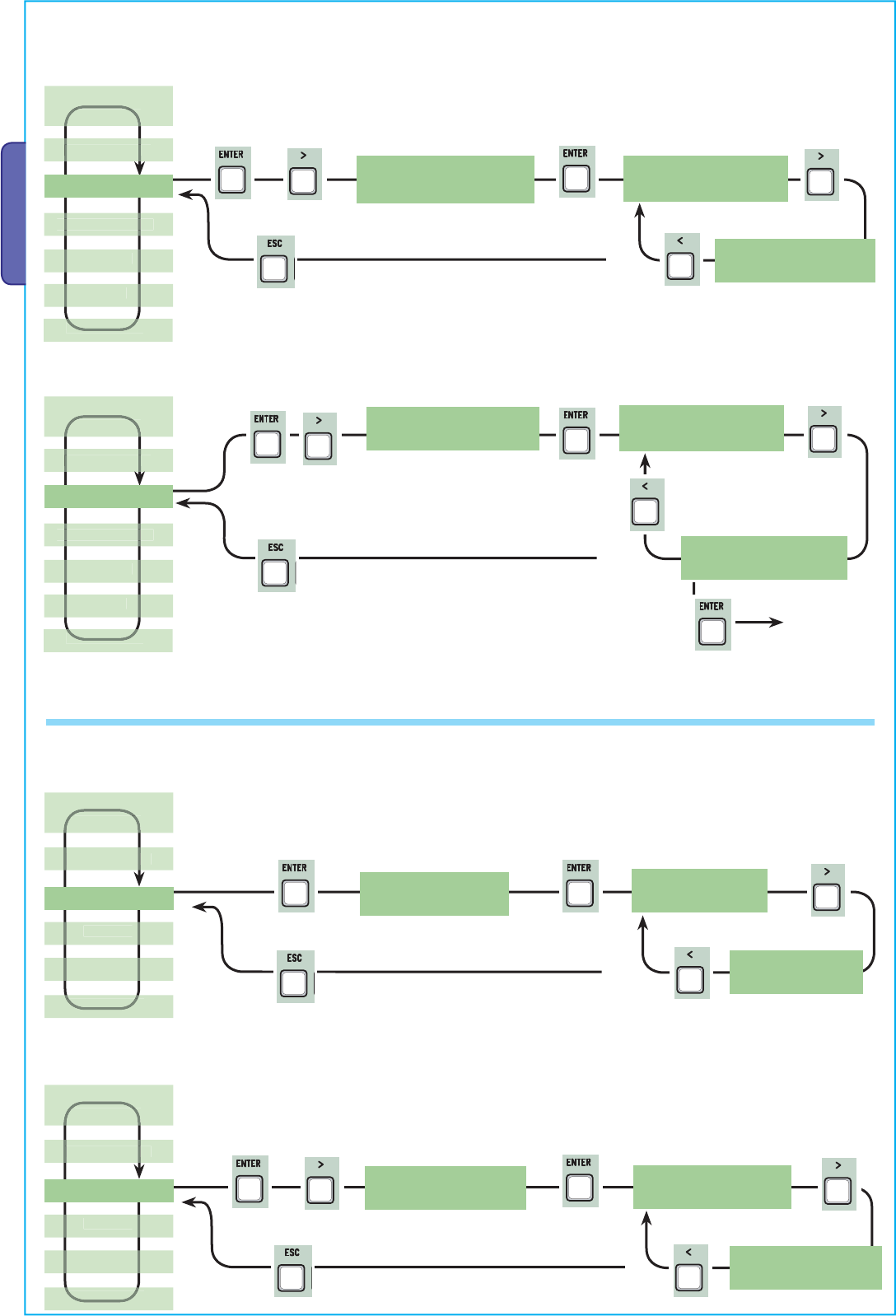
Endstop: configure the endpoints are normally closed or open contacts.
N.B.: this function appears only if selected from the “Config.” function in the FUNCTIONS menu.
< cmd 2-7 >
Op.-Stop-Cl.
cmd 2-7
<Op.-Stop-Cl.>
Command 2-7: setting the 2-7 contact to step-by- step mode (open-close) or sequential (open-stop-close-stop).
endstop
< N.A >
cmd 2-7
<Open-Close>
< cmd 2-3P >
Pedestrian
cmd 2-3P
< Pedestrian >
cmd 2-3P
< Partial >
< lamp E3 >
Cycle
lamp E3
< Cycle >
lamp E3
< Courtesy >
Command 2-3P: setting the 2-3P contact to pedestrian opening (second gate leaf opens fully) or partial (second gate leaf opens
partially depending on the time set on “Partial opening” from the Adjust Times menu).
E3 lamp: configuring the lamp connected to E-E3:
- cycle: outdoor lamp, which can be positioned at leisure, for better illumination in the parking/driveway area.
It stays on from the moment the gate leaf begins to open, until it is fully closed (including automatic closing time).
In case the automatic closing function is not inserted, it stays on only during gate movement.
- courtesy: outdoor lamp, which can be positioned at leisure, for better illumination in the parking/driveway area.
It stays on for a set time of 5 minutes.
<
LANGUAGE
>
English
sh
FUNCTIONS
TIMING ADJ.
TIMING AD
USERS
INFO
TEST MOT.
TEST MOT
<
LANGUAGE
>
English
sh
FUNCTIONS
TIMING ADJ.
TIMING AD
USERS
INFO
TEST MOT.
TEST MOT
< LANGUAGE >
English
sh
FUNCTIONS
TIMING ADJ.
TIMING AD
USERS
INFO
TEST MOT.
TEST MOT
<
LANGUAGE
>
English
sh
FUNCTIONS
TIMING ADJ.
TIMING AD
USERS
INFO
TEST MOT.
TEST MOT
X 2
X 2
X 2
X 19
X 17
X 18
X 2
Pag.
17
17 - Manual code:
319U75
319U75 ver.
2.0
2.0 01/2009 © CAME cancelli automatici s.p.a. - The data and information reported in this installation manual are susceptible to change at any time and without obligation on CAME cancelli automatici s.p.a. to notify users.
ENGLISH
< output B1-B2 >
Monostable
output B1-B2
< Bistable >
B1-B2 output: setting contact B1-B2 to MONO-STABLE or BI-STABLE (switch) mode.
< No. Motors >
M1 + M2
No. Motors
< M1 + M2 >
Number of motors: setting the number of motors, either one or two, depending on the number of gate leaves installed on the system.
Slow Down: setting the deceleration speed when opening or closing, or, only when closing if said deceleration is configured as (Fcap-
RallCh.).
N.B.: this function only appears if the decelerations are selected.
output B1-B2
< Monostable
No. Motors
< M2 >
<Slow Down Spd.>
-ooo+ •
Slow Down Spd.
< -ooo+ >
<
LANGUAGE
>
English
English
FUNCTIONS
TIMING ADJ.
TIMING AD
USERS
INFO
TEST MOT.
TEST MOT
<
LANGUAGE
>
English
English
FUNCTIONS
TIMING ADJ.
TIMING AD
USERS
INFO
TEST MOT.
TEST MOT
<
LANGUAGE
>
English
sh
FUNCTIONS
TIMING ADJ.
TIMING AD
USERS
INFO
TEST MOT.
TEST MOT
•
Slow Down Spd.
< -ooo+ >
•
••
Motor Type: setting up the type of swing gate motor installed in the system.
< Motor Type >
FROG
Motor Type
< FROG >
Motor Type
< AXO >
Motor Type
< FAST >
<
LANGUAGE
>
English
sh
FUNCTIONS
TIMING ADJ.
TIMING AD
USERS
INFO
TEST MOT.
TEST MOT
X 2
X 2
X 3
X 2
X 4
X 2
X 2
X 2
Pag.
18
18 - Manual code:
319U75
319U75 ver.
2.0
2.0 01/2009 © CAME cancelli automatici s.p.a. - The data and information reported in this installation manual are susceptible to change at any time and without obligation on CAME cancelli automatici s.p.a. to notify users.
ENGLISH
<Sensib. Decel.>
-oooooooo+
Sensib. Decel.
< -oooooooo+ >
Sensib. Decel.
< -oooooooo+ >
Deceleration sensitivity: it adjusts the obstacle detection sensitivity during opening and closing gate deceleration.
N.B.: this function appears only if the “sensitivity” function is activated in the ENCODER menu.
•
•
••
< Slow run Enc >
ON
Slow run Enc
< ON >
Slow run Enc
< OFF >
Encoder Deceleration: this activates the opening and closing deceleration starting points.
< M1 Slow.AP.% >
10
M1 Slow.AP.%
< 10 >
M1 Slow.AP.%
< 11 >
M1 opening deceleration%: this adjusts the (M1) first motor’s deceleration starting point before the opening endpoint.
The deceleration starting point is calculated as a percentage (from 1% to 40% of a full gate run). See illustration on page 28.
N.B.: this function appears only if it is activated in the “decel. Enc” function in the ENCODER menu.
< Sensib. Run >
-oooooooo+
Sensib. Run
< -oooooooo+ >
Sensib. Run
< -oooooooo+ >
•
•
••
<
LANGUAGE
>
English
English
FUNCTIONS
FUNCTION
TIMING ADJ.
D
T
USERS
ENCODER
<
LANGUAGE
>
EnglishEnglish
FUNCTIONS
FUNCTION
TIMING ADJ.
D
T
USERS
ENCODER
< LANGUAGE >
English
English
FUNCTIONS
FUNCTION
TIMING ADJ.
D
T
USERS
ENCODER
<
LANGUAGE
>
English
sh
FUNCTIONS
FUNCTION
TIMING ADJ.
D
T
USERS
ENCODER
Gate operation sensitivity: this adjusts the obstacle detection sensitivity during opening and closing gate operation.
N.B.: this function appears only if the “sensitivity” function is activated in the ENCODER menu.
< Sen sibility >
Turn o n
Sensibility
< Turn on >
Sensibility
<Disabled>
7.7 Encoder Menu (the ENCODER menu, appears only if selected from the “Config.” function in the FUNCTIONS menu.)
Sensitivity: the obstacle detection function is activated during gate operation and deceleration.
N.B.: before setting the functions in the encoder menu, run the gearmotor checks to verify the proper turning direction.
<
LANGUAGE
>
English
English
FUNCTIONS
FUNCTION
TIMING ADJ.
T
D
ENCODER
X 5
X 2
X 6
X 2
X 7
X 2
X 8
X 2
Pag.
19
19 - Manual code:
319U75
319U75 ver.
2.0
2.0 01/2009 © CAME cancelli automatici s.p.a. - The data and information reported in this installation manual are susceptible to change at any time and without obligation on CAME cancelli automatici s.p.a. to notify users.
ENGLISH
< M1 Slow.CH % >
10
M1 Slow.CH %
< 10 >
M1 Slow.CH %
< 11 >
M1 closing deceleration%: this adjusts the (M1) first motor’s deceleration starting point before the closing endpoint.
The deceleration starting point is calculated as a percentage (from 1% to 40% of a full gate run). See illustration on page 28.
N.B.: this function appears only if it is activated in the “decel. Enc” function in the ENCODER menu.
< M2 Slow.AP % >
10
M2 Slow.AP %
< 10 >
M2 Slow.AP %
< 11 >
M2 opening deceleration%: this adjusts the (M2) second motor’s deceleration starting point before the opening endpoint.
The deceleration starting point is calculated as a percentage (from 1% to 40% of a full gate run). See illustration on page 28.
N.B.: this function appears only if it is activated in the “decel. Enc” function in the ENCODER menu.
< M2 Slow.CH % >
10
M2 Slow.CH %
< 10 >
M2 Slow.CH %
< 11 >
M2 closing deceleration %: this adjusts the (M2) second motor’s deceleration starting point before the closing endpoint.
The deceleration starting point is calculated as a percentage (from 1% to 40% of a full gate run). See illustration on page 28.
N.B.: this function appears only if it is activated in the “decel. Enc” function in the ENCODER menu.
< M1 Appr.CH % >
5
M1 Appr.CH %
< 5 >
M1 Appr.CH %
< 6 >
M1 closing acceleration %: this adjusts the (M1) first motor’s percentage rate of approach to the final closing and opening points
before reaching the opening and closing endpoints. The percentage rate of approach to (goes from 1% to 15% of the full gate run). See
illustration on page 28.
<
LANGUAGE
>
English
English
FUNCTIONS
FUNCTION
TIMING ADJ.
T
D
USERS
INFO
ENCODER
<
LANGUAGE
>
English
English
FUNCTIONS
FUNCTION
TIMING ADJ.
T
D
USERS
I
NF
O
ENCODER
<
LANGUAGE
>
English
sh
FUNCTIONS
FUNCTION
TIMING ADJ.
T
D
USERS
INFO
ENCODER
<
LANGUAGE
>
English
English
FUNCTIONS
FUNCTION
TIMING ADJ.
T
D
USERS
INFO
ENCODER
X 2
X 2
X 8
X 2
X 9
X 2
Pag.
20
20 - Manual code:
319U75
319U75 ver.
2.0
2.0 01/2009 © CAME cancelli automatici s.p.a. - The data and information reported in this installation manual are susceptible to change at any time and without obligation on CAME cancelli automatici s.p.a. to notify users.
ENGLISH
<Pedestrian ACT>
10s.
Pedestrian ACT
< 10s. >
Pedestrian ACT
< 11s. >
Automatic Pedestrian Closing: waiting time of the (M2) second gate leaf when in the open position. Once this time interval has
elapsed, the gate automatically closes. The waiting time interval can go anywhere from 0” to 300”.
< M2 Appr.CH % >
5
M2 Appr.CH %
< 5 >
M2 Appr.CH %
< 6 >
M2 closing acceleration %: this adjusts the (M2) second motor’s percentage rate of approach to the final closing and opening points
before reaching the opening and closing endpoints. The percentage rate of approach to (goes from 1% to 15% of the full gate run). See
illustration on page 28.
< Set Encoder > Set Encoder
<confirm?(no)>
Set Encoder
<confirm?(yes)>
< A.C.T. >
10s.
A.C.T.
< 10s. >
A.C.T.
< 11s. >
7.8 Time setting menu
Automatic closing: to set the waiting time when gate is in the open position.
Once this time is elapsed, the gate closes automatically. The waiting time can be set to between 0” and 300”.
<
LANGUAGE
>
EnglishEnglish
FUNCTIONS
FUNCTION
TIMING ADJ.
TIMING AD
USERS
INFO
ENCODER
TEST MOT.
TEST MOT
<
LANGUAGE
>
EnglishEnglish
FUNCTIONS
FUNCTION
TIMING ADJ.
TIMING AD
USERS
INFO
TEST MOT.
TEST MOT
<
LANGUAGE
>
English
h
FUNCTIONS
FUNCTION
TIMING ADJ.
USERS
INFO
TEST MOT.
TEST MOT
<
LANGUAGE
>
English
h
FUNCTIONS
FUNCTION
TIMING ADJ.
USERS
INFO
TEST MOT.
TEST MOT
See detailed
description on
page 28
ENCODER
X 2
X 2
X 2
X 3
X 2
X 4
X 2
X 5
Pag.
21
21 - Manual code:
319U75
319U75 ver.
2.0
2.0 01/2009 © CAME cancelli automatici s.p.a. - The data and information reported in this installation manual are susceptible to change at any time and without obligation on CAME cancelli automatici s.p.a. to notify users.
ENGLISH
< Cycle Time >
90s.
Cycle Time
< 90s. >
< Op. Delay M1 >
2s
Op. Delay M1
< 2s >
M1 delayed opening: the waiting time of the (M1) first gate lead, unlike the (M2) second one, after each opening command. The
waiting time can be set to between 0” and 10”.
Cycle time: the working time of the motor during opening or closing phases is anywhere from 10” to 150”.
Cycle Time
< 91s. >
Op. Delay M1
< 3s >
< Cl. Delay M2 >
2s
Cl. Delay M2
< 2s >
M2 delayed closing: the waiting time of the (M2) second gate leaf, unlike the (M1) first one, after each closing command. the waiting
time can be set to between 0” and 60”.
Cl. Delay M2
< 3s >
<Preflashing T.>
5s.
Preflashing T.
< 5s. >
Pre-flashing time: after an opening or closing command is given, the flasher connected to “W-E), flashes for between 1” and 60”,
before the gate begins to move.
Preflashing T.
< 6s. >
<
LANGUAGE
>
English
English
FUNCTIONS
FUNCTION
TIMING ADJ.
USERS
I
NFO
TEST MOT.
TEST MOT
<
LANGUAGE
>
English
English
FUNCTIONS
FUNCTION
TIMING ADJ.
USERS
INFO
TEST MOT.
TEST MOT
<
LANGUAGE >
English
English
FUNCTIONS
FUNCTION
TIMING ADJ.
U
SER
S
INFO
TEST MOT.
TEST MOT
<
LANGUAGE
>
English
English
FUNCTIONS
FUNCTION
TIMING ADJ.
USERS
INFO
TEST MOT.
TEST MOT
X 2
X 6
X 2
X 7
X 2
X 8
X 2
X 9
Pag.
22
22 - Manual code:
319U75
319U75 ver.
2.0
2.0 01/2009 © CAME cancelli automatici s.p.a. - The data and information reported in this installation manual are susceptible to change at any time and without obligation on CAME cancelli automatici s.p.a. to notify users.
ENGLISH
< Lock time >
2s.
Lock time
< 2s. >
Lock time: the time required for releasing the electro-lock after each opening command. The time of operation can be set to between
1” and 5”.
Lock time
< 3s. >
< Ram hit time >
2s.
Ram hit time
< 2s. >
Ram hit time: the gearmotor’s thrust time when fully closing after each opening command. The thrust time can be set to between 1”
and 10”.
Ram hit time
< 3s. >
< Ped. opening >
5s.
Ped. opening
< 5s. >
Partial opening: the opening time of the (M2) second gate leaf. The time can be set to between 5” and 60”.
Ped. opening
< 6s. >
< Slow down time >
5s.
Slow down time
< 5s. >
Slow down time: the gate leaf’s deceleration time before every endpoint. The time can be set to between 0” and 30”.
N.B.: this function only appears if the decelerations are selected.
<
LANGUAGE
>
English
English
FUNCTIONS
FUNCTION
TIMING ADJ.
USERS
INFO
TEST MOT.
TEST MOT
<
LANGUAGE
>
English
English
FUNCTIONS
FUNCTION
TIMING ADJ.
USERS
I
NFO
TEST MOT.
TEST MOT
<
LANGUAGE
>
English
English
FUNCTIONS
FUNCTION
TIMING ADJ.
USERS
INFO
TEST MOT.
TEST MOT
< LANGUAGE >
LANGUAG
English
h
FUNCTIONS
FUNCTION
NS
TIMING ADJ.
USERS
INFO
TEST MOT.
EST MO
Slow down time
< 6s. >
X 2
X 2
X 2
X 2
X 3
X 2
Pag.
23
23 - Manual code:
319U75
319U75 ver.
2.0
2.0 01/2009 © CAME cancelli automatici s.p.a. - The data and information reported in this installation manual are susceptible to change at any time and without obligation on CAME cancelli automatici s.p.a. to notify users.
ENGLISH
7.9 Users Radio Menu
< Add User > Add User
<confirm? (no) >
Add User: to create a new user and assigned function (max. 250 users).
< Mod. name > Choose User
< 001:--001-- >
Mod. Name: to change a user number or existing name to another name.
< Mod. Code > Choose User
< 001:--001-- >
Mod. Code: to change a user’s current code.
Choose User
< 002:--002-- >
Add User
<confirm? (yes)>
See detailed
description on
page 26
Choose User
< 002:--002-- >
See detailed
description on
page 26
See detailed
description on
page 27
< Related Func >
Choose User
< 002:--002-- >
Choose User
< 001:--001-- >
See detailed
description on
page 27
<
LANGUAGE
>
English
English
FUNCTIONS
FUNCTION
TIMING ADJ.
TIMING AD
USERS
INFO
TEST MOT.
TEST MOT
<
LANGUAGE
>
English
English
FUNCTIONS
FUNCTION
TIMING ADJ.
TIMING AD
USERS
INFO
TEST MOT.
TEST MOT
<
LANGUAGE >
English
English
FUNCTIONS
FUNCTION
TIMING ADJ.
TIMING AD
USERS
INFO
TEST MOT.
TEST MOT
<
LANGUAGE
>
English
English
FUNCTIONS
FUNCTION
TIMING ADJ.
TIMING AD
USERS
INFO
TEST MOT.
TEST MOT
Related Function: to change the function assigned to the user.
X 2
X 4
X 2
X 5
X 2
X 6
X 2
X 7
Pag.
24
24 - Manual code:
319U75
319U75 ver.
2.0
2.0 01/2009 © CAME cancelli automatici s.p.a. - The data and information reported in this installation manual are susceptible to change at any time and without obligation on CAME cancelli automatici s.p.a. to notify users.
ENGLISH
Backup data
<confirm? (no) >
Backup data
<confirm? (yes)>
< Remove Usr. > Choose User
< 001:--001-- >
Remove user: to remove an exisiting user. Confirm the use you wish to remove with the ENTER key.
< Backup data >
Backup data: to save the users in the memory roll. Confirm saving of users on the memory roll with ENTER.
Delete all user: to cancel all registered users. Confirm cancellation of all users with ENTER.
Choose User
< 002:--002-- >
Remove Usr.
<confirm? (no) >
Remove Usr.
<confirm? (yes)>
<D elete all Usr> Delete all Usr
<confirm? (no) >
Delete all Usr
<confirm? (yes)>
Backup data
WRITE:250
Restore backup: to load the data saved on the memory roll onto card.
Restore backup
<confirm? (no) >
Restore backup
<confirm? (yes)>
<Restore backup>
Restore backup
READ:250
< LANGUAGE >
ANGUAG
English
h
FUNCTIONS
FUNCTIONS
TIMING ADJ.
IMING ADJ
USERS
INFO
TEST MOT.
TEST MOT
<
LANGUAGE
>
English
English
FUNCTIONS
FUNCTIONS
TIMING ADJ.
IMING ADJ
USERS
INFO
TEST MOT.
TEST MOT.
<
LANGUAGE
>
English
English
FUNCTIONS
FUNCTIONS
TIMING ADJ.
IMING ADJ
USERS
INFO
TEST MOT.
TEST MOT.
<
LANGUAGE
>
English
English
FUNCTIONS
FUNCTIONS
TIMING ADJ.
IMING ADJ
USERS
INFO
TEST MOT.
TEST MOT.
Lingua
Italiano
Þß
CANCELLI AUTOMATICI
R700
ACCESS CONTROL
TOP
TSP00 LT001
CAME
TAM
ATOMO
TWIN
TOUCH
CAME
TFM
Memory roll
Pag.
25
25 - Manual code:
319U75
319U75 ver.
2.0
2.0 01/2009 © CAME cancelli automatici s.p.a. - The data and information reported in this installation manual are susceptible to change at any time and without obligation on CAME cancelli automatici s.p.a. to notify users.
ENGLISH
Frequency/MHz Card Transmitter
FM 26.995 AF130 TFM
FM 30.900 AF150 TFM
AM 26.995 AF26 TOP
AM 30.900 AF30 TOP
AM 433.92 AF43S TAM / TOP
ATOMO / TWIN
AM 433.92 AF43TW TWIN
AM 40.685 AF40 TOUCH
AM 868.35 AF868 TOP
7.10 nfo Menu
< Version >
fw : 3.0
Version: to view software version.
Number of gate runs: to view the number of runs performed by the gate.
Starting Mssg: to view the starting message, confirm with ENTER to change text. Use the ENTER key to move the cursor forward, ESC
to move it backwards and <> to select the letter of number. Confirm the text by pressing the ENTER key for a few seconds.
System reset: it resets the system to its original settings. Press ENTER key to confirm.
<
LANGUAGE
>
English
sh
FUNCTIONS
FUNCTION
TIMING ADJ.
TIMING AD
USERS
INFO - WWW.CAME.IT
ZM3E
7.11 Motor test menu
TEST MOT.: Test to check the proper direction of the gearmotors.
<
LANGUAGE
>
English
sh
FUNCTIONS
FUNCTION
TIMING ADJ.
TIMING AD
USERS
INFO
TEST MOT.
Gate leaf opening run
of the second (M2)
gearmotor. If the
direction is wrong,
invert the motor’s
phases.
Gate leaf opening
run of the first (M1)
gearmotor. If the
direction is wrong,
invert the motor’s
phases.
< TEST MOT. >
<=M1 M2=>
< System Reset >
TEST MOT.
TEST MOT
7.12 Decoding card
Connect the required (R700, AF43S cards) to insert, change, remove and command the operator via transmitter, card or transponder.
Insert the memory roll to save and load all setting including users registered by another card.
AF Card
R700 Card
< No. of Runs >
10
< Standby Msg. >
ACCESS CONTROL
Pag.
26
26 - Manual code:
319U75
319U75 ver.
2.0
2.0 01/2009 © CAME cancelli automatici s.p.a. - The data and information reported in this installation manual are susceptible to change at any time and without obligation on CAME cancelli automatici s.p.a. to notify users.
ENGLISH
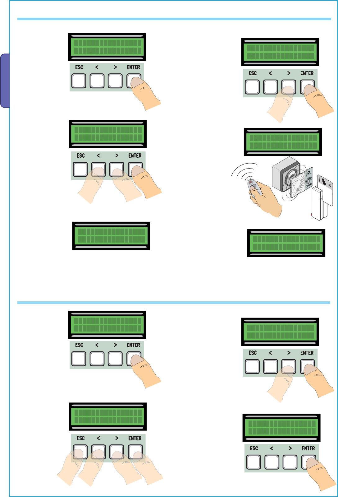
7.13 Inputting users
Add User
Þß
Add User
confirm? (yes)
Þß
1) From the Users
menu, select “Add
User”.
Press ENTER to
confirm.
2) Select “ confirm
(yes)” and press
ENTER key to confirm.
--001--
radio
4) .... will ask to input
a code. Send the
code with the radio-
command button or
slide-through card or
transponder.
5) ... once the code
is inputted, the user
name will come up
showing the type of
command that was
memorised...
Code exist
001:--001--
... or if the code is
already inputted,
“Existing Code” will
appear.
3) Choose which
function to assign to
the user....
Related Func.
2-7
Þß
Waiting Code
>>>>
7.14 Changing users
Mod. name
Þß
Choose User
001:--U001--
Þß
1) From the Users
menu, choose
“Mod. name”.
Press ENTER to
confirm.
2) Choose the user
number or name you
wish to change the
text of and press
ENTER to confirm.
4) Confirm the text by
pressing the ENTER key
for a few seconds.
3) Use the ENTER
key to move the
cursor forward, ESC
to move it backwards
and < > to select the
letter or number.
Mod. name
--001-- Mod. name
JOHN
ACCESS CONTROL
Pag.
27
27 - Manual code:
319U75
319U75 ver.
2.0
2.0 01/2009 © CAME cancelli automatici s.p.a. - The data and information reported in this installation manual are susceptible to change at any time and without obligation on CAME cancelli automatici s.p.a. to notify users.
ENGLISH
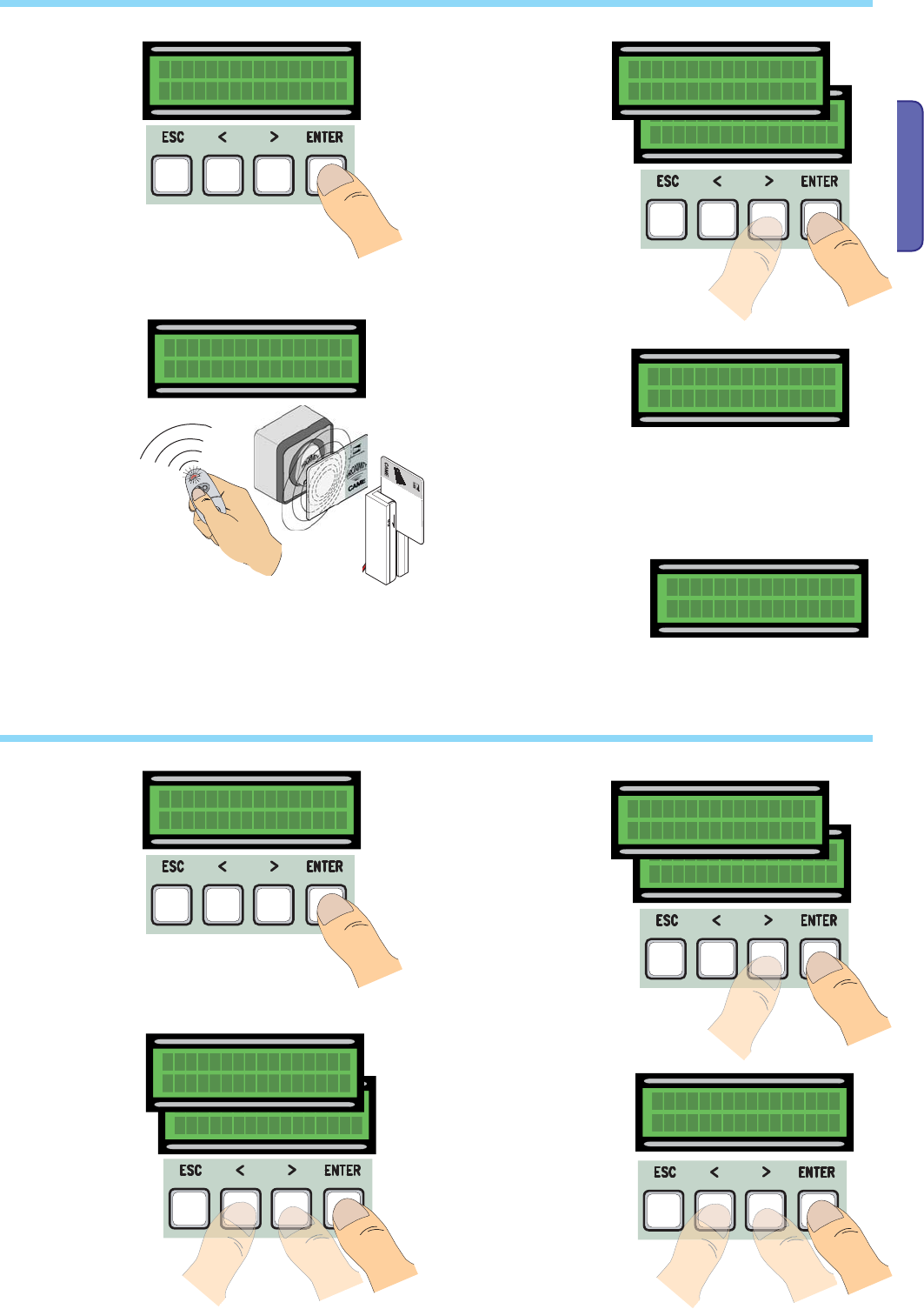
7.15 Changing code
Mod. Code
1) From the Users
menu, choose
“Mod. Code”.
Press ENTER to
confirm.
2) Choose the user
name for which you
wish to change the
code and press ENTER
to confirm.
4) .. once the code
is inputted, the user
name will come up
showing the type of
command that was
memorised...
3) .... you will be
asked to input a
code. Send the code
using the transmitter
button or the slide -
through card or the
transponder.
--002--
radio
7.16 Function assigned to the user
Related Func.
Þß
1) From the Users
menu, choose
“Related Fuc.”.
Press ENTER to
confirm.
2) Choose the user
name fo which you
wish to change the
command function
and press ENTER to
confirm.
4) Choose “confirm
(yes)” and press
ENTER to confirm.
3) Choose the new
function to assign
to the user. Press
ENTER to confirm.
Choose User
002:--U002--
Þß
Related Func.
confirm? (yes)
Þß
Choose User
001:--U001--
Þß
Related Func.
open
Þß
Related Func.
2-7
Þß
Choose User
002:--U002--
Þß
Choose User
001:--U001--
Þß
Mod. Code
confirm? (yes)
Þß
Waiting Code
>>>>
5) Select “ confirm (yes)”
and press ENTER key to
confirm.
0
0
0
0
0
0
0
0
Pag.
28
28 - Manual code:
319U75
319U75 ver.
2.0
2.0 01/2009 © CAME cancelli automatici s.p.a. - The data and information reported in this installation manual are susceptible to change at any time and without obligation on CAME cancelli automatici s.p.a. to notify users.
ENGLISH
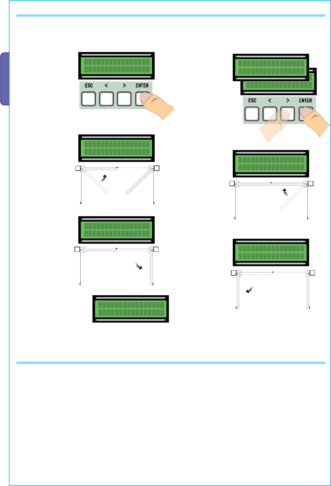
7.17 Gate run calibration
Set Encoder
Þß
1) From the Encoder
menu, select “Set
Encoder”. Press ENTER
to confirm.
2) Select “confirm
(yes) and press ENTER
to confirm.
3) the gate leaf of the
first motor will perform
a closing run until fully
closed.....
Set Encoder
confirm? (yes)
<>
Set Encoder
confirm? (no)
Þß
Set Encoder
Close 1 4) …then, the
gate leaf of the
second motor will
perform the same
manoeuvre…
5) …then, the gate leaf
of the second motor, will
perform and opening run
until fully open… 6) ...after which,
the gate leaf of
the first motor will
perform the same
manoeuvre…
7) When the procedure is
finished, the display will show
“Set Encoder ok” for a few
seconds.
Set Encoder
Close 2
Set Encoder
Open 2
Set Encoder
Open 1
Set Encoder
OK
N.B. before calibrating the gate run, check that the manoeuvring area is free of any obstacles and check the proper direction of rotation of the
gearmotors. (para. 7.11)
7.18 Error messages
-“encoder ERROR”: check proper connections or functionality of the device and possibly even the motor’s torque”
-“safety d. test ERROR”: malfunctioning of safety devices, check proper functioning of connections and functionalities;
-“end stop ERROR”: check proper connections on end point connections or functionality of devices;
-“cycle time ERROR”: check the working time settings, the set time may be insufficient to complete the duty cycle.
- Safety STOP, C1, C3, C4”: check proper functioning of connections and functionalities of devices.
0
0
D
B
A
B
D
B
B
D
A
D
E
F H
G
IL
M
M
M
CC
IL
Pag.
29
29 - Manual code:
319U75
319U75 ver.
2.0
2.0 01/2009 © CAME cancelli automatici s.p.a. - The data and information reported in this installation manual are susceptible to change at any time and without obligation on CAME cancelli automatici s.p.a. to notify users.
ENGLISH
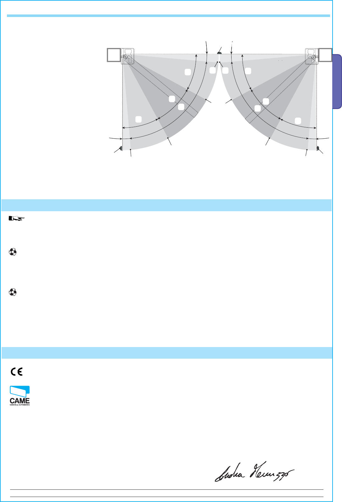
7.19 Illustration depicting the areas and points of deceleration and final opening and closing approaches per encoder device.
A = Area of movement at normal speed
B* = Run zone at decelerated speed
C = Encoder intervention zone with
movement inversion
D= Encoder intervention zone with
movement stop
E = Opening deceleration beginning point
(M1 Open Deceler %)
F = Closing deceleration beginning point
(M1 Close Deceler %)
G = Opening deceleration beginning point
(M2 Open Deceler %)
H = Closing deceleration beginning point
(M2 Close Deceler %)
I** = Closing and opening fi nal phase
beginning point (M1 Final Close %)
L** = Closing and opening fi nal phase
beginning point (M2 Final Close %)
M= endstops
Note: the areas and points of deceleration and fi nal opening and closing approaches are tested according to the parameters set forth by
Technical Norms EN12445 and EN12453 regarding compatibility of impact forces generated by moving gate leaves.
* Minimum 600 mm from the Final full stop.
**Set the function’s fi nal phase % “M1 Final Close” for the fi rst (M1) mtors and “M2 Final Close” for the second (M2) motor from the
“ENCODER” menu so as to obtain a distance of between 1 and 50 mm maximum from the fi nal full stop.
In its premises, CAME CANCELLI AUTOMATICI S.p.A. implements an Environmental Management System certifi ed in
compliance with the UNI EN ISO 14001 standard to ensure environmental protection.
Please continue our efforts to protect the environment—which CAME considers one of the cardinal elements in the development of its
operational and market strategies—simply by observing brief recommendations as regards disposal:
DISPOSAL OF PACKAGING
The packaging components (cardboard, plastic, etc.) are all classifi able as solid urban waste products and may be disposed of easily,
keeping in mind recycling possibilities.
Prior to disposal, it is always advisable to check specifi c regulations in force in the place of installation.
PLEASE DISPOSE OF PROPERLY!
PRODUCT DISPOSAL
Our products are made up of various types of materials. Most of them (aluminium, plastics, iron, electrical wires, etc.) may be disposed
of in normal garbage collection bins and can be recycled by disposing of in specifi c recyclable material collection bins and disposal in
authorized centres. Other components (electrical boards, remote control batteries, etc.), however, may contain polluting substances.
They should therefore be removed and given to qualifi ed service companies for proper disposal.
Prior to disposal, it is always advisable to check specifi c regulations in force in the place of disposal.
PLEASE DISPOSE OF PROPERLY!
8 Demolition and disposal
MANUFACTURER’S DECLARATION OF CONFORMITY
Pursuant to the Low Voltage Directive 2006/95/EC
CAME Cancelli Automatici S.p.A.
via Martiri della Libertà, 15
31030 Dosson di Casier - Treviso - ITALY
tel (+39) 0422 4940 - fax (+39) 0422 4941
internet: www.came.it - e-mail: info@came.it
Declares under its own responsibility that the equipments for automatic garage doors and gates listed below:
… comply with the National Law related to the following European Directives and to the applicable parts of the
following Standards.
2006/95/EC LOW VOLTAGE DIRECTIVE
2004/108/EC ELECTROMAGNETIC COMPATIBILITY DIRECTIVE
EN 60335-1 EN 61000-6-2
EN 13241-1 EN 61000-6-3
IMPORTANT WARNING!
Do not use the equipment specifi ed here above, before
completing the full installation
In full compliance with the Machinery Directive 98/37/EC
MANGING DIRECTOR
Mr. Andrea Menuzzo
ZM3E - ZM3EC
9 Manufacturer’s warranty
Reference code to request a true copy of the original: DDF L EN Z002e
CAME France S.a.
CAME France S.a.
7, Rue Des Haras
Z.i. Des Hautes Patures
92737
Nanterre Cedex -
Nanterre Cedex - FRANCE
(+33) 1 46 13 05 05
(+33) 1 46 13 05 00
CAME Gmbh Seefeld
CAME Gmbh Seefeld
Akazienstrasse, 9
16356
Seefeld
Seefeld
Bei Berlin - DEUTSCHLAND
(+49) 33 3988390
(+49) 33 39883985
CAME Automatismes S.a.
CAME Automatismes S.a.
3, Rue Odette Jasse
13015
Marseille -
Marseille - FRANCE
(+33) 4 95 06 33 70
(+33) 4 91 60 69 05
CAME Gmbh
CAME Gmbh
Kornwestheimer Str. 37
70825
Korntal
Korntal
Munchingen Bei Stuttgart - DEUTSCHLAND
(+49) 71 5037830
(+49) 71 50378383
CAME Automatismos S.a.
CAME Automatismos S.a.
C/juan De Mariana, N. 17-local
28045
Madrid -
Madrid - SPAIN
(+34) 91 52 85 009
(+34) 91 46 85 442
CAME Americas Automation Llc
CAME Americas Automation Llc
1560 Sawgrass Corporate Pkwy, 4th Floor
Sunrise
Sunrise, FL 33323 - U.S.A
(+1) 305 433 3307
(+1) 305 396 3331
CAME Automatismos Catalunya S.a.
CAME Automatismos Catalunya S.a.
P.i. Moli Dels Frares N. 23 C/a
08620
Sant Vicenc Del Horts -
Sant Vicenc Del Horts - SPAIN
(+34) 93 65 67 694
(+34) 93 67 24 505
CAME Middle East Fzco
CAME Middle East Fzco
Po Box 17131 Warehouse N. Be02
South Zone - Jebel Ali Free Zone -
Dubai -
Dubai - U.A.E.
(+971) 4 8860046
(+971) 4 8860048
Paf - CAME
Paf - CAME
Estrada Nacional 249-4 Ao Km 4,35
Cabra Figa - Trajouce
2635-047
Rio De Mouro -
Rio De Mouro - PORTUGAL
(+351) 219 257 471
(+35) 219 257 485
CAME Polska Sp.Zo.o
CAME Polska Sp.Zo.o
Ul. Ordona 1
01-237
Warszawa -
Warszawa - POLAND
(+48) 22 8365076
(+48) 22 8363296
CAME United Kingdom Ltd.
CAME United Kingdom Ltd.
Unit 3 Orchard Business Park
Town Street, Sandiacre
Nottingham
Nottingham - Ng10 5du - UNITED KINGDOM
(+44) 115 9210430
(+44) 115 9210431
S.c. CAME Romania S.r.l.
S.c. CAME Romania S.r.l.
B-dul Mihai Eminescu, Nr. 2, Bloc R2
Scara A, Parter, Ap. 3
Buftea, Judet Ilfov
Bucarest -
Bucarest - ROMANIA
(+40) 21 3007344
(+40) 21 3007344
CAME Belgium Sprl
CAME Belgium Sprl
Zoning Ouest 7
7860
Lessines -
Lessines - BELGIUM
(+32) 68 333014
(+32) 68 338019
CAME Russia
CAME Russia
Leningradskij Prospekt, Dom 80
Pod’ezd 3, offi ce 608
125190,
Moskva
Moskva - RUSSIA
(+7) 495 937 33 07
(+7) 495 937 33 08
CAME Cancelli Automatici S.p.a.
CAME Cancelli Automatici S.p.a.
Via Martiri Della Libertà, 15
31030
Dosson Di Casier
Dosson Di Casier (Tv)
(+39) 0422 4940
(+39) 0422 4941
Informazioni Commerciali 800 848095
www.came.it
CAME Nord s.r.l.
CAME Nord s.r.l.
Piazza Castello, 16
20093
Cologno Monzese
Cologno Monzese (MI)
(+39) 02 26708293
(+39) 02 25490288
CAME Service Italia S.r.l.
CAME Service Italia S.r.l.
Via Della Pace, 28
31030
Dosson Di Casier
Dosson Di Casier (Tv)
(+39) 0422 383532
(+39) 0422 490044
Assistenza Tecnica 800 295830
Assistenza Tecnica 800 295830
CAME Sud s.r.l.
CAME Sud s.r.l.
Via F. Imparato, 198
Cm2 Lotto A/7
80146
Napoli
Napoli
(+39) 081 7524455
(+39) 081 7529109
English
English - Manual code:
119EU75
119EU75 ver.
2.0
2.0 01/2009 © CAME cancelli automatici s.p.a.
The data and information reported in this installation manual are susceptible to change at any time and without obligation on CAME cancelli automatici s.p.a. to notify users.
