CHRocodile MPS User Manual
CHRocodile%20MPS_User_Manual
CHRocodile%20MPS_User_Manual
User Manual:
Open the PDF directly: View PDF ![]() .
.
Page Count: 68
1
CHRocodile MPS
Optical Multi-Point Sensor for non-contact distance and thickness
measurement
Operation Manual

2
Imprint
This documentation is under the copyright of Precitec Optronik GmbH.
It may not be reproduced or used in a manner contrary to the company’s legal interests without prior
written approval of Precitec Optronik GmbH. It is strictly intended for use in the context of service
operations. Any other use is impermissible. Any sharing of this documentation with third parties
requires the prior, expressed written approval of Precitec Optronik GmbH.
Changes in the technical details from the descriptions, data and figures in this documentation are
reserved.
Printed in the Federal Republic of Germany.
Responsible for Cont
ents
Original Edition
Precitec Optronik GmbH
Schleussnerstrasse 54
63263 Neu
-Isenburg / Germany
Telephone:
0049 (0)6102 / 36 76 – 100
Telefax:
0049 (0)6102 / 36 76 – 126
e
-mail: info@precitec-optronik.de
Website:
http://www.precitec.de/en/precitec-group-start-page/
Representatives
Please visit our website to know the current addresses of our representatives.
PRECITEC OPTRONIK's regional contacts for the Optical Measuring Technology can be found here:
http://www.precitec.de/en/contact/precitec
-worldwide/

3
Version Control
Version –
Manual Date
Type of Change
1.0.0.0
2015/01/29
Original edition

4
Table of Contents
Table of Contents ........................................................................................................... 4
Basic Safety Instructions ................................................................................................ 7
1.1 Warranty and Liability ...................................................................................... 7
1.2 Safety Symbols .................................................................................................. 7
1.3 Proper Use ......................................................................................................... 8
1.4 Duty of Operator and Personnel ....................................................................... 9
1.5 Safety Measurements in Normal Operation ..................................................... 9
1.5.1 Protection from Electronic Shock ......................................................................................... 9
1.5.2 Protection from Optic Radiation / Eye Safety ..................................................................... 9
1.5.3 Grounding the device ........................................................................................................... 10
1.6 Medical or safety-relevant usage ................................................................... 10
1.7 Storage and Transport .................................................................................... 10
1.8 Emergency Procedures ................................................................................... 10
Product Description ....................................................................................................... 11
2.1 General Description ......................................................................................... 11
2.2 Measuring principle .......................................................................................... 11
2.2.1 Optical principle ................................................................................................................... 11
2.2.2 Principle applied to multiple points sensor ........................................................................ 13
2.3 Sensor Functionalities ...................................................................................... 14
2.4 Typical applications (Overview) ...................................................................... 16
2.5 List of Deliverables ......................................................................................... 18
2.6 Connections and Interfaces ............................................................................. 19
2.6.1 ON / OFF Switch button ....................................................................................................... 19

5
2.6.2 Power supply jack ................................................................................................................. 19
2.6.3 USB port RS232 serial communication ................................................................................ 20
2.6.4 Ethernet connector .............................................................................................................. 20
2.6.5 Encoder-input ....................................................................................................................... 20
2.6.6 Trigger Input/Output / RS422 serial communication ......................................................... 21
2.6.7 Status LED ............................................................................................................................ 23
2.7 Sensor unit Characteristics ............................................................................. 24
2.8 Optical Head Specifications definitions ......................................................... 26
2.9 CHRocodile MPS performance specifications: ............................................... 27
2.10 Connections and Interfaces ......................................................................... 29
2.11 CHRocodile MPS Explorer and Drivers installations ........................................ 31
2.12 Communication with CHRocodile MPS ......................................................... 31
Measurements Start Up ................................................................................................ 33
3.1 Calibration Table ............................................................................................ 33
3.2 Dark Acquisition .............................................................................................. 33
3.3 Mechanical interfacing ................................................................................... 34
3.4 Basic Settings Configuration ........................................................................... 34
3.5 Data measurement Training ........................................................................... 35
Advanced Configuration ............................................................................................... 37
4.1 Commands List ................................................................................................ 37
4.2 Detailed Commands Description .................................................................... 39
4.2.1 DNLD Command ................................................................................... 39
4.2.2 ETR Command ..................................................................................... 39
4.2.3 IPCN Command .................................................................................... 40
4.2.4 LAI Command ..................................................................................... 41
4.2.5 NOP Command .................................................................................... 42
4.2.6 SCA Command ..................................................................................... 43

6
4.2.7 SHZ Command ..................................................................................... 44
4.2.8 SODX Command ................................................................................... 45
4.2.9 SSU Command ..................................................................................... 52
4.2.10 STA Command ..................................................................................... 53
4.2.11 STO Command .................................................................................... 54
4.2.12 THR Command .................................................................................... 55
4.2.13 TRE Command ..................................................................................... 56
4.2.14 TRG Command .................................................................................... 57
4.2.15 VER Command ..................................................................................... 58
4.2.16 Calibration Table Download Function ......................................................... 58
Mechanical plans .......................................................................................................... 59
5.1 Optical Head Mechanical plans ...................................................................... 59
5.2 CHRocodile MPS unit mechanical plans ......................................................... 64
Trouble Shooting ........................................................................................................... 65
6.1 Power off: ........................................................................................................ 65
6.2 Communication error: .................................................................................... 65
6.3 Distance Measurement: .................................................................................. 65
6.4 Thickness measurement: ................................................................................ 66
Technical support ......................................................................................................... 68
7
Basic Safety Instructions
This operation manual contains the most important instructions for the safe operation of the product.
Observe all instructions and guidelines in this documentation.
Moreover, the locally applicable regulations and codes for accident
prevention at the use site must be observed.
1.1 Warranty and Liability
The general terms and conditions of delivery for products and services in the electronics industry
along with the amendments and restrictions deriving from the general terms and conditions of delivery
for Precitec Optronik GmbH apply to all of our products.
We reserve the right to make any changes to the device’s construction for reasons of improving quality
or expanding the possible applications as well as any made for production-related reasons.
Dismantling the device voids all warranty claims. The exception to this is the replacement of parts that
are subject to wear and tear and require maintenance or calibration, to the extent that these are
expressly identified in this documentation.
Changes made to the device on own authority render liability claims void.
1.2 Safety Symbols
The following terms and symbols for hazards and instructions are used in the operation manual.
W
ARNING
This symbol indicates a possibly dangerous situation. Failure to heed
these instructions can result in minor injuries or cause property damage.
W
ARNING
High volta
ge hazard –
indicates a hazard from electrical shock and
warns of immediate or impending danger to the life and health of
persons or of extensive property damage.

8
W
ARNING
Do not touch
–
indicates that touching the contact/optics surface can
cause dam
age/destruction of the component.
IMPORTANT
Information which the user must pay attention to/ be aware of in order to
avoid disruptions in the course of processing/ in product use.
TIP
Provides information that the user needs in order to achieve the
intended result of an action most directly and without difficulty.
PREREQUISITE
Describes all components as well as all conditions that must be present/
be fulfilled in order to the action to be successfully completed.
ADDITIONAL I
NFORMATION
Informs the user whenever there is additional information about a
context being described.
1.3 Proper Use
The optical sensor is intended as a stand-alone device or as part of a measurement apparatus for
measuring distance, thickness and surfaces for
quality and dimensional control.
Only use the optical sensor in a dry environment. The device may only be operated within the
specifications given in the technical data.
Any use deviating from the intended and proper use is considered
improper. The user assumes liability for the consequences in these
cases.
Electromagnetic
Compatibility (EMC)
Both as an individual device and in combination with the devices
designated in this documentation, the optical sensor fulfils the
requirements of the standa
rds DIN EN 61326-1:2013-07 and
DIN EN
61010
-1:2011-07, and therefore corresponds to the EU-
Directive
2014/35/EU and 2014/30/EU. This declaration is valid for all units with
the CE label on it, and it loses its validity if a modification is done on
the prod
uct.
When customer
-
supplied devices or cables are used this can mean
that these Norms may not be fulfilled. For this reason, you should only

9
use the original devices and replacement parts and observe the
instructions for EMC
-compliant installation in the h
andbooks that
come with them.
If the optical sensor is operated inside a facility with other devices, the
entire facility must comply with the provisions in the EC
-
Guidelines in
the demands of the general operating permit.
1.4 Duty of Operator and Personnel
The operator of the device is obligated only to allow persons to work on the device who:
x are familiar with the basic regulations concerning workplace safety and accident prevention and
who have been instructed in the operation of the device
x
have read an
d understood the safety chapter of this operation manual and have confirmed this with
their signature.
The personnel must be trained in compliance with the regulations and safety instructions and must
have been informed of possible hazards.
1.5 Safety Measurements in Normal Operation
When it is assumed that the device can no longer be operated safety, the device or the plant must be
taken out of operation. The device must be secured against unintended use. Unauthorized
interventions will void your rights to assert warranty claims.
Any attempt to copy or analyze the software will lead without fail to the voiding of all rights to assert
warranty claims.
1.5.1 Protection from Electronic Shock
Please make sure that the live components are uncovered after
opening the housing or removing components. Touching these
components presents a potentially lethal hazard.
When service
-
and repair work is performed on opened devices and
modules, the main power supply must be reliably shut off (mains cable
unplugged).
1.5.2 Protection from Optic Radiation / Eye Safety
When performing service and maintenance work, make sure that you

10
do not look directly into the LED’s light. The light can harm your eyes.
1.5.3 Grounding the device
Make sure that the device is grounded in compliance with
regulations. Please make sure that the optical sensor is supplied
with power via a grounded main power input line (cold device
plug).
1.6 Medical or safety-relevant usage
If the CHRocodile Line Sensor is used in medical or safety-relevant
app
lications, the operator must ensure that the CHRocodile
Line
Sensor is qualified for the specific application. This includes the
optical characteristics of the measured sample as well as the
influence of temperature and vibrations to the CHRocodile sensor.
Furthermore the user has to check the CHRocodile
Line S
ensor for
correct measurements and for exceeding the specified measuring
uncertainty.
1.7 Storage and Transport
In order to avoid damages in storage and transport, the following ground rules are to be observed:
x Maintain the storage temperature range allowed in the technical specifications
x Take suitable measures to avoid any damage from humidity or moisture, vibrations or impact
x Do not store in or near magnetic fields (e.g. permanent magnet or alternating electrical field)
1.8 Emergency Procedures
x Disconnect the plant from the main power supply
x Extinguish any flames with a Class B fire extinguisher
11
Product Description
2.1 General Description
The CHRocodile MPS optical multi-point sensor offers up to 24 simultaneous altitude and/or thickness
measurements. Thanks to its 24 independent channels, CHRocodile MPS is used to couple different
probes (single point or multipoint) in the limit of 24 measured points. This sensor is based on Confocal
Chromatic principle which authorizes high resolution and high speed thickness and altitude
measurement. The CHRocodile MPS can measure 24 points simultaneously with a measuring rate of
4500 points/s per channel corresponding to 96000 points/s. Also depending on the number of required
probes, it is possible to measure faster (e.g. 12 channels at 8000points/s).
This device consist in a sensor unit that contains a light source, a spectrometer and all electronic and
software for data processing and transmission. Up to 24 different single point optical probe can be
connected to the sensor unit, using optical fiber cable.
The CHRocodile MPS can accommodate different types of optical probe. Depending on the probe
which are connected, the operator must move to the right calibration table by software operation.
Finally, data transmission is carried out by ETHERNET communication.
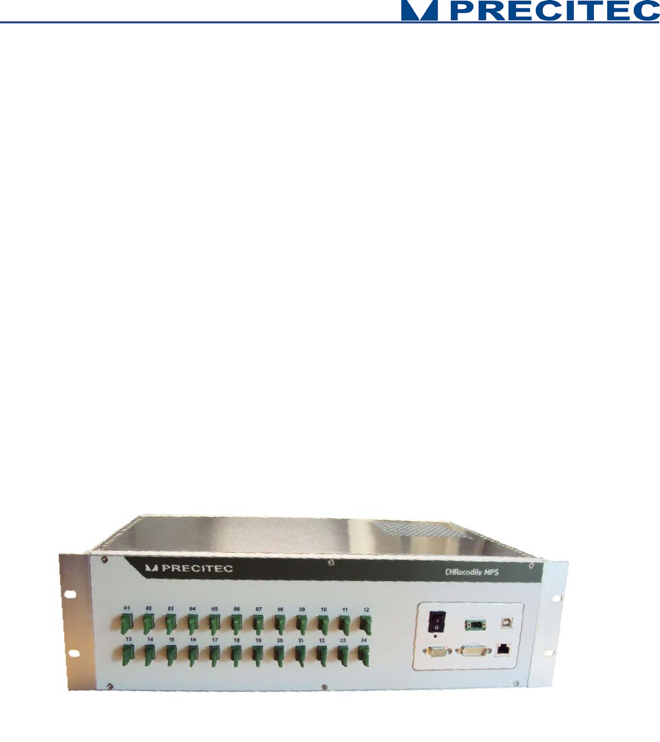
Fig 2-1: CHRocodile MPS sensor unit: 3D view:
2.2 Measuring principle
2.2.1 Optical principle
For most industrial applications the chromatically coded distance detection method turned out to be
very well suited. CHRocodile MPS is based on this method and more precisely on the Confocal
Chromatic principle. This principle combines the properties of confocality and axial chromatism.

12
Axial Chromatism:
That method takes advantage from a lens optical error commonly known as axial chromatic aberration:
the axial position of the focal point depends on the wavelength (color) of the light to be focused. For
example, in the visible spectral range, the focal distance for blue light (a 400nm) is shorter than for red
light (a 700nm). The focal points of intermediate wavelengths are located in between according to a
continuous axial position variation. Thus, considering White Light passing through an optical objective
provided with axial chromatic aberration, a continuum of color along the optical axis is generated, as
an axial rainbow.
Confocality:
That method also takes advantage from confocal opto-mechanical configuration. A confocal optical
system uses illumination point source and a pinhole in an optically conjugate plane in front of the
detecting system to eliminate out-of-focus signal. As only in focus light can be detected, the image's
optical lateral and axial resolution is improved. Consequently the pinhole act as a spatial filter which
block light which is out of focus or light which come from an external light source.
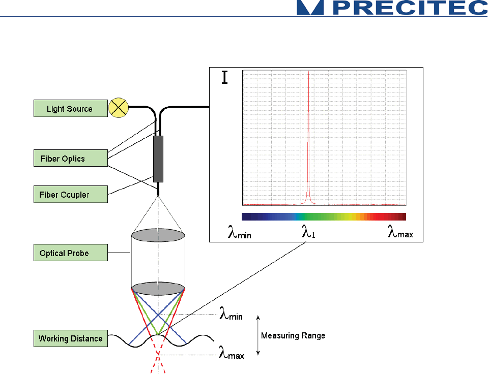
Confocal Chromatic Imaging:
Considering both confocality and axial chromatism properties, a White Light illumination point is
imaged through the chromatic objective on a target object. Depending on the distance of the target
from the focusing chromatic objective, light of just a very narrow wavelength bandwidth is perfectly
focused on the target’s surface. All other spectral components of the light source are out of focus. In
the back path, from the target’s surface to the detector, the reflected light passes through the
chromatic objective, the optically conjugate pinhole which is in front of the spectrometer. The pinhole
filters all wavelengths except the narrow bandwidth which is in focus. The spectrometer analyses the
spectrum of the light reflected back by the target’s surface, and only a chromatic peak is observed
corresponding to the narrow wavelength bandwidth perfectly in focus. The analysis and the barycenter
calculation of this chromatic peak allow to determine the distance of the target surface from the
chromatic objective. (Cf. Fig. 2.2 and 2.3)
13
Fig. 2-2: Chromatic Confocal Imaging principle (point sensor)
2.2.2 Principle applied to multiple points sensor
Applying Confocal Chromatic Imaging to multipoint sensor consists in increasing the number of
illumination point’s source and the number of pinhole in front of the detector spectrometer. In this
configuration, the spectrometer is preferably bidimensionnal. One direction corresponds to the channel
number and the other direction carry the wavelength information. Consequently the spectrometer carry
the information of each point focused on the target’s surface, and the distance of the target surface
from the chromatic objective can be calculated for all the focused points. According to CHRocodile
MPS, the operator can position the focused points anywhere on the object.
14
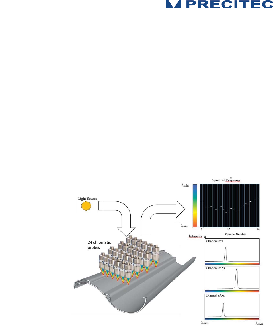
2.3 Sensor Functionalities
The CHRocodile MPS has two different measuring mode: Distance and Thickness measurement. The
principle of these two measuring mode are explained hereafter.
Mode 1
Chromatic Distance Measurement
Topographic, profile or roughness measurements are performed in Mode
1 (confoca
l distance measurement). In this process,
light spots
associated to channels delivering distance data (distance channel)
are
focused on the surface of the measured object using an optic with a
known chromatic aberration. The reflected light is more intense
for the
wavelength in focus on the surface. For each of the
distance
channels,
reflected light is spectrally analyzed and the spectral response is a peak
centered on focused wavelengths. The spectral peak positions determine
the distance to the surface of
each of the distance channels
. The
distances are simultaneously calculated and transmitted to host computer
at up to 8
KHz frequency. See Fig. 2-3.
Fig. 2-3: Chromatic measurement principle, distance measurement
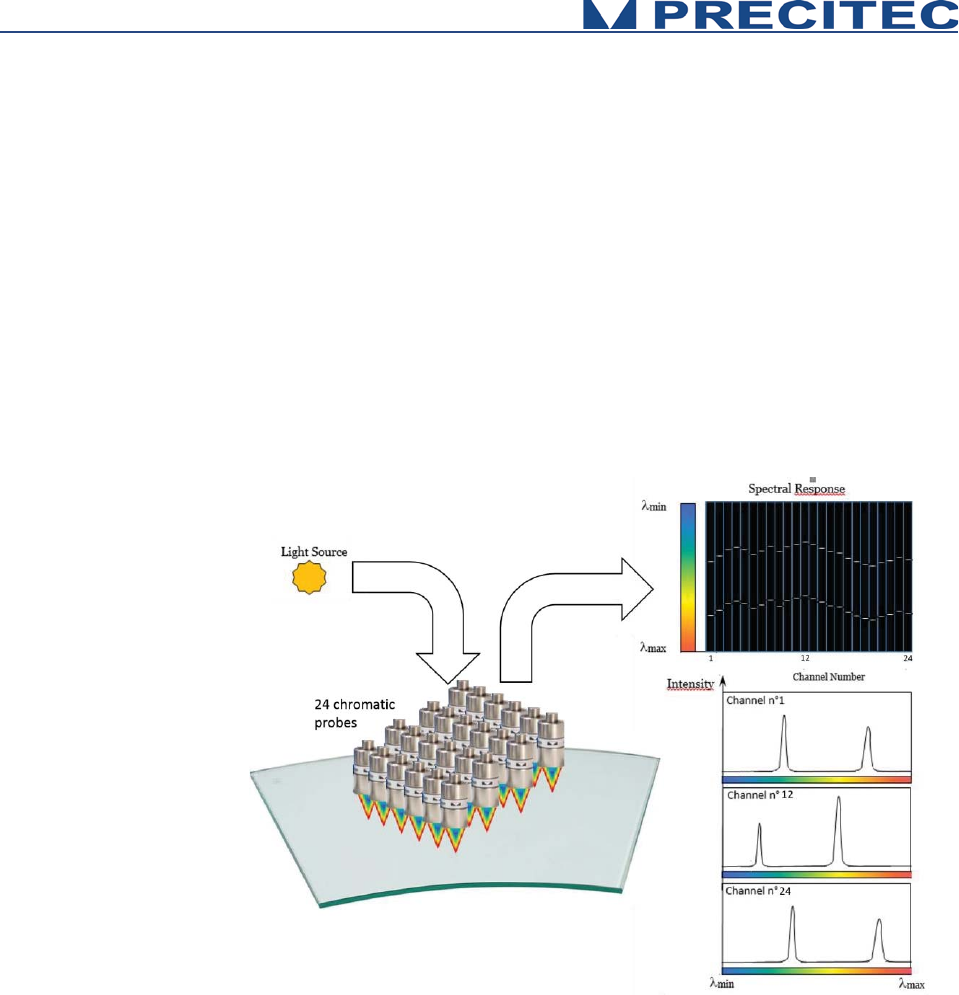
15
Mode 2
Chromatic Thickness Measurement
Thickness measurements are performed in Mode 2 (confocal thickness
measurement). If a transparent material is within the measurement
volume of the Chromatic Optical Head,
24
points are focused on both the
two surfaces of the measured object. The reflected light is more intense
for the two wavelengths in focus on the two surfaces. For each of the 24
channels, reflected light is spectrally analyzed and the spectral response
is constituted of two peaks centered on focused wavelengths.
Considering the refractive index of the object, one can determine the
thickness of the object for the 24 points. The 24
thicknesses are
simultaneously calculated and transmitted to host computer at up to
4
KHz
frequency. See
Fig. 2-4.
Fig. 2-4: Chromatic measurement principle, thickness measurement

16
2.4 Typical applications (Overview)
A broad range of possible applications is available to this highly precise sensor.
The CHRocodile MPS is fast sensor based on confocal chromatic imaging principle. They are perfectly
suitable for demanding measuring tasks, like non-contact measurement of microtopography, layer
thickness measurements. It could be used both on various reflecting and scattering surfaces.
Efficient
x Measurement of layer thickness and distance along a line
x Replaces up to 24 individual sensors
Versatile
x Any combination of point and line measuring heads
x 5 encoder inputs, trigger input, sync-output
x Wall thickness measurements of colored container glass
User-friendly and safe
x 19“wide housing/rack mountable or Height 3U x 230mm x 213mm /rack mountable also
available
x Non-contact measurements
x Robust and maintenance-free
Association of CHRocodile MPS with a multipoint optical probe make a powerful sensor for glass
industry application. The CHRocodile MPS simultaneously measures wall thickness at 24 locations at
a rate up to 96 000 points per seconds. This results in the shortest measuring times. Also thin-walled
areas of glass containers are found more reliable using a CHRocodile MPS, thus saving money and
time by avoiding unnecessary rejects.
The CHRocodile MPS offers the ability to perform fast and accurate metrological control of production,
by being built on automatic or semi -automatic inspection machines, or by being directly integrated on
production line in order to pick simultaneously 24 metrological information at different location. In this,
this new technology fully meets the current needs of the industry as it is suitable for many applications:
- The measurement of wafer in the field of semiconductor and generally microelectronics,
- The measurement and online control of mechanical or optical parts,
- Or even the measurement and control of glass or plastic film thickness.
Other fields of applications exist, the common point is to seek a measurement system going faster and
faster and more and more flexible, it is the case in laboratory environment and even more in industrial
environment. It appears clearly here that the CHRocodile MPS unit of measurement meet these
different needs. Depending on your application, it is possible to associate different type of optical
probes to adapt to the required performances. All PRECITEC probes can be used with CHRocodile
MPS except CHRocodile MPS probes.

17
Optical Head
Application
100μm
300μm-
350μm
600μm
2mm
6mm-
10mm
25mm
Electronics
¹ ¹ ¹ ¹
Micro-Electronics
¹ ¹ ¹
Mechanics
¹ ¹ ¹ ¹ ¹
Micro-Mechanics
¹ ¹ ¹
Optics
¹ ¹ ¹ ¹
Micro-Optics
¹ ¹ ¹
Shape
¹ ¹ ¹ ¹ ¹
Flatness
¹ ¹ ¹
Roughness
¹ ¹ ¹
Plastic and glass thickness
¹ ¹ ¹ ¹ ¹ ¹
Thin film thickness
¹ ¹ ¹
Coating thickness
¹
Table 2.1: Sensor applications
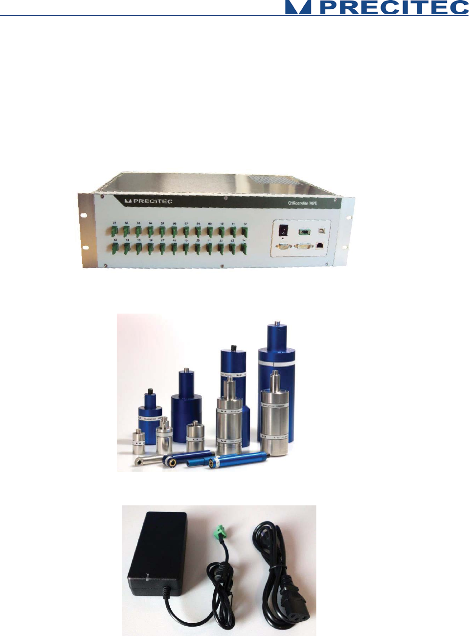
18
2.5 List of Deliverables
- One operational CHRocodile MPS unit (see Fig. 2-5),
- Operational Optical Heads (see Fig. 2-6),
- Power Supply Adapter (100-240VAC to 24VDC +/-10%)) (see Fig. 2-7),
- A CD with DLL and firmware and Operation Manual,
- Calibration Test report.
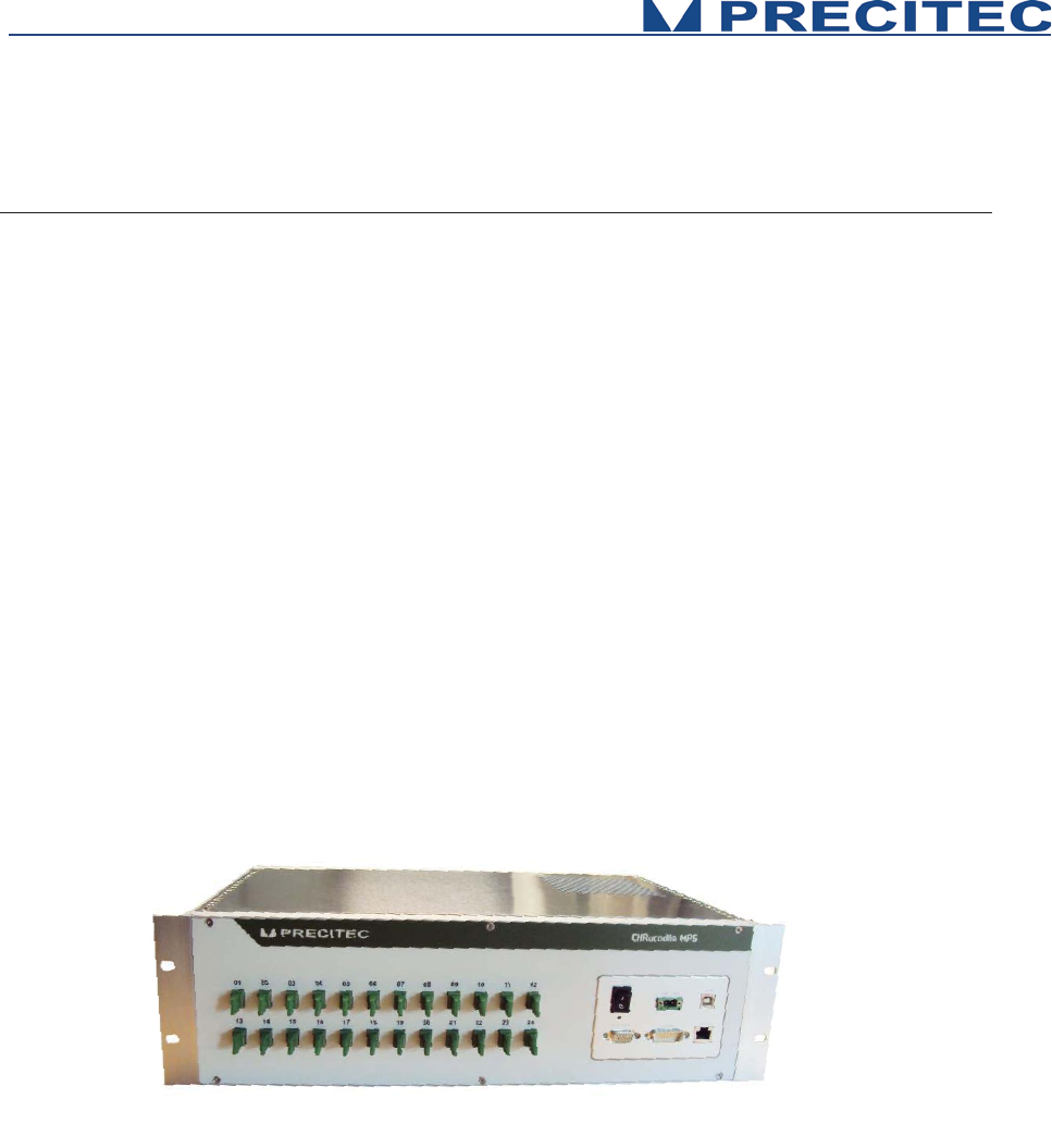
Fig 2-5: CHRocodile MPS unit:
Fig 2-6: Compatible Optical Heads:
Fig 2-7: Set of electrical cables: a- Power supply b- Adapter
19
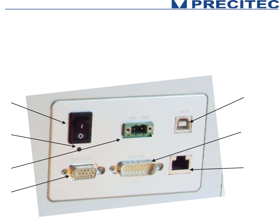
2.6 Connections and Interfaces
All of the connection ports for the sensor unit are located at the rear of the system (see Fig 2-8):
1. ON / OFF Switch button,
2. Power supply jack
3. Serial interface RS232, USB port,
4. Ethernet interface, RJ45 port
5. Encoder-Input, Sub-D26 male connector
6. Trigger Input/Output + RS422, Sub-D15 female
connector
7. Status LED
Fig. 2-8: CHRocodile MPS rear panel: Connections
2.6.1 ON / OFF Switch button
The CHRocodile MPS has a Power switch ON / OFF button.
2.6.2 Power supply jack
The CHRocodile MPS has two pluggable screw terminal for power supply with 24VDC +/-10%.
Connect the set of power cable supply associated to the Power Supply Adapter (100-240VAC to
24VDC +/-10%) delivered with the CHRocodile MPS unit.
1
6
2
5
3
4
7

20
2.6.3 USB port RS232 serial communication
The serial RS232 is interfaced on the USB port. Serial communication are mostly used for sending
command as a hyper-terminal. As the number of channel is high with a huge amount of data, serial
communication port cannot support data transfer.
2.6.4 Ethernet connector
The CHRocodile MPS has a RJ45 standard connector for Ethernet communication.
Connect the isolated RJ45 standard connector from the CHRocodile MPS unit to an Ethernet network
(PC). Ethernet is the only port which can support the data transfer. Ethernet is also used for setting
configuration through commands (Cf. command SODX in section 5.2), for loading Calibration Table
(Cf. command TABL in section 5.2). Use shielded Ethernet cable for the data port connection.
Ethernet communication allows to transmit 6 data at 2KHz. If more than 6 data are requested, it is
possible to use Jumbo Packet configuration. In that case, you need to check network hardware for
Jumbo Packet support and use the IPCN command to configure the Jumbo Packet size. Disconnect
the sensor and configure the PC network hardware for the identical size and reconnect the sensor.
2.6.5 Encoder-input
The incremental encoder-input makes it possible to precisely assign each measurement points along
the line and axis positions without additional hardware. The CHRocodile MPS can manage with 5-axis
Encoders.
For an exact distance or thickness measurement it is necessary for every measurement value to be
assigned to the exactly correct spatial coordinates. This data must be recorded in the system and
transferred to the evaluation processing unit over the internal interface. To accomplish this, the sensor
is equipped with an encoder-interface.
Default are the encoder inputs not terminated.
Tye Sw0t02 to GND to terminate with 100 Ohm channel 0 to 2
Tye Sw3t04 to GND to terminate with 100 Ohm channel 3 to 4
If the encoder-signals are fed through the sensor and additional other devices are connected (e.g. for
axis control), the 100 Ohm termination can also be deactivated.
PIN
Signal
Input
Signal to which ground
Sub-D26
1
A0-
I
Differential encoder input 120 Ohm terminated
2
A0+
I
Differential encoder input 120 Ohm terminated
3
B0-
I
Differential encoder input 120 Ohm terminated
4
B0+
I
Differential encoder input 120 Ohm terminated
5
A1-
I
Differential encoder input 120 Ohm terminated
6
A1+
I
Differential encoder input 120 Ohm terminated
7
B1-
I
Differential encoder input 120 Ohm terminated

21
Table 2.2: Encoder interface (PIN-Configuration)
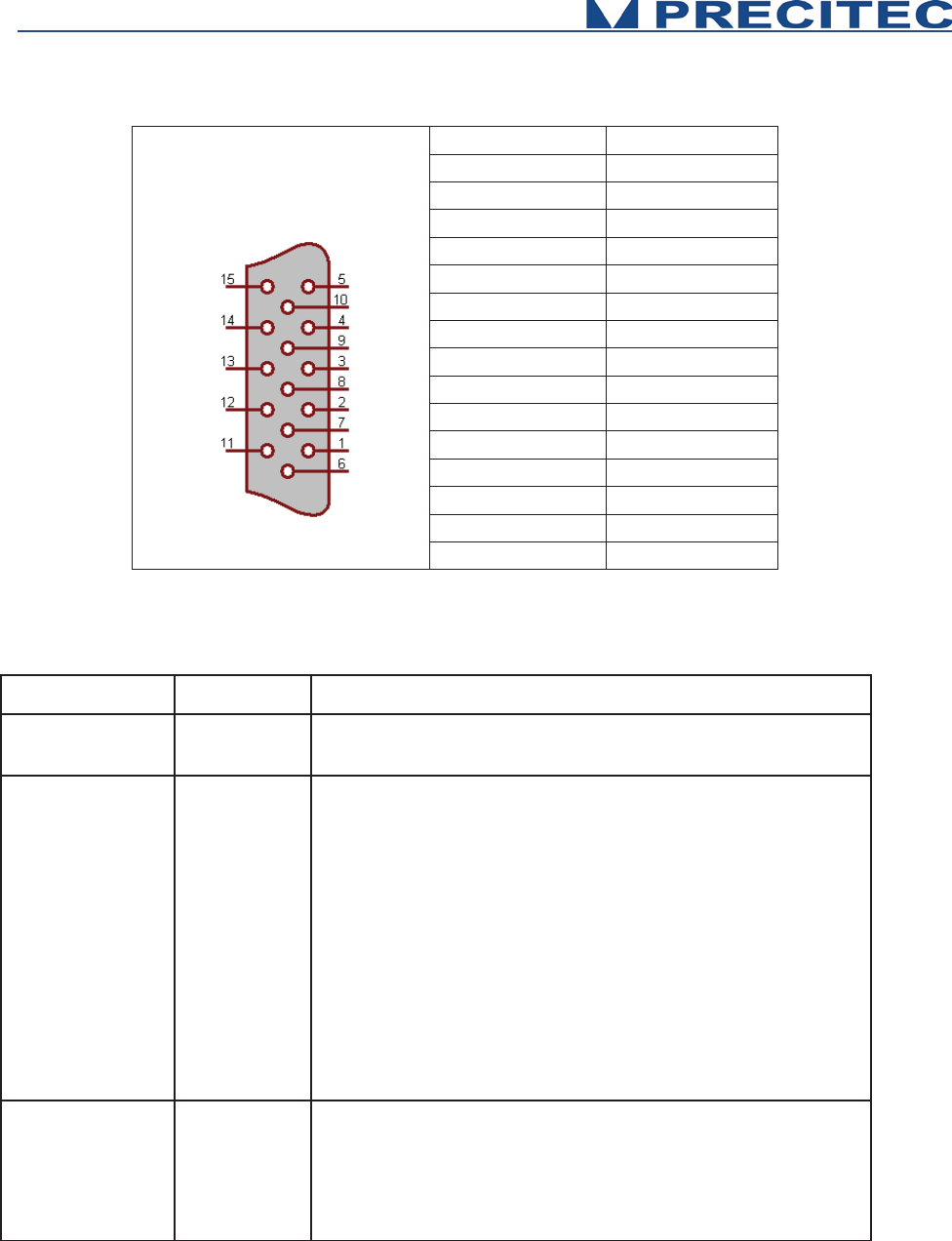
2.6.6 Trigger Input/Output / RS422 serial communication
The Trigger output use a Sub-D 15 female connector. This connector is used for trigger Input / Output
and for RS422 serial communication (Cf. Table 2-3 and Table 2-4).
The trigger options make the lighting cycle externally controllable and the synchronization between
e.g. a scanning system cycle and the CHRocodile MPS measurement rate. This means that external
triggering is possible for every measurement up to the full measurement rate of the CHRocodile MPS
sensor.
The interface contains the connection points for the synchronization and RS422 serial communication.
The serial RS422 is interfaced on the Sub-D15 female connector. Serial communication are mostly
used for sending command as a hyper-terminal. As the number of channel is high with a huge amount
of data, serial communication port cannot support data transfer.
8 B1+ I Differential encoder input 120 Ohm terminated
9 GND P ground
10 A2- I Differential encoder input 120 Ohm terminated
11 A2+ I Differential encoder input 120 Ohm terminated
12 B2- I Differential encoder input 120 Ohm terminated
13 B2+ I Differential encoder input 120 Ohm terminated
14 GND P ground
15 NC - Not connected
16 A3- I Differential encoder input with switchable 120
17 A3+ I Differential encoder input with switchable 120
18 B3- I Differential encoder input with switchable 120
19 B3+ I Differential encoder input with switchable 120
20 Sw0t02 - Not connected
21 +5V / 120mA P,O 5V /120mA supply for external encoder
22 Sw3t04 I Low = termination ON, NC or 5V = termination
23 A4- I Differential encoder input with switchable 120
24 A4+ I Differential encoder input with switchable 120
25 B4- I Differential encoder input with switchable 120
26 B4+ I Differential encoder input with switchable 120
22
Signal
Pin
SyncIn
1
GND
2
SyncOut
3
Isolated-GND
4
[A] RS422 (CTS)
5
[A] RS422 (RTS)
6
[A] RS422 (RXD)
7
[A] RS422 (TXD)
8
Isolated-GND
9
Isolated-GND
10
Isolated-GND
11
[B] RS422 (CTS)
12
[B] RS422 (RTS)
13
[B] RS422 (RXD)
14
[B] RS422 (TXD)
15
Table 2.3: Interface (pin configuration)
Signal
Function
Description
RS432
RS422
Interface
Isolated (Isolated-GND) RS422 Interface
Sync In
Trigger-Input
Positive slope from 0V to 5-24V causes according to the
settings of the sensor:
x
starts the continuous measurement, if the command
wait for trigger was received first (TRG Command)
x
starts the single measurement in mode trigger each
(TRE Command)
x the sensor differentiates between
pulses < 13 μs and
>13 μs. This information is attached to the output
telegram which is triggered by this pulse. This way
more sensors can be synchronized.
x the input is equipped with 10 kΩ pullup-
resistance at
5 V.
Sync Out
Sync. Output
Isolated Sync Output
Positive slope 0 V to 5 V with the start of each measurement.
The pulse duration is 50μs in general and every second one
pulse is shorted to 10μs. This i
s for synchronizing more
sensors when their Sync
-In is connected with the Sync-
Out.
Table 2.4: Interface

23
Wait for trigger – signal characteristics to Analog Out
The sensor stops after the current data telegram is transmitted and
goes into a standby m
ode.
The last transmitted analog value persists until the next exposure
(also see TRG command).
2.6.7 Status LED
LED Status
CHRocodile MPS Status
No Signal
RED LED
Flashing GREEN LED
BLUE LED
Flashing
BLUE
/ GREEN LED
GREEN LED
Power OFF
Power ON, Firm
ware badly configured
Power ON,
Firmware is configuring
Power ON,
Firmware is configured
/ Continuous Measurement
Power ON, Triggering session
Power ON, Waiting for Trigger
Table 2.5: Status LED definition

24
2.7 Sensor unit Characteristics
Optical sensor
Measuring principle
(1)
Confocal Chromatic
Measuring data
(1)
Distance, Thickness
Number of Channel
(1)
24
Light source
LED
Dimensions (sensor unit)
19‘‘ x 3 HE x 306 mm
(2)
(Height 3U x 230mm x 213mm also available)
Weight
5.5 kg
Data Transmission
Measuring rate
(3)
(4500Hz (24 channels); 8000Hz (12 channels)
Interfaces
Ethernet, RS232, RS422
Communication Protocol
Ethernet
Transfer rate
100 Mbit (Ethernet), 9600 - 921600 Baud (RS-422), 921600 Baud (USB: virtual comport)
Synchronization with ext. devices
Trigger-input / Output (TTL)
Encoder-inputs
Yes (5 axis)
SDK
Via a DLL, compatibility .NET
OS
Windows XP, Windows 7, Windows 8
Data Processing / Calculation
Embedded processing unit
Standard to be met
Power Supply
24V
DC
+/-10% / 40W with separate main supply unit 100 to 240V
AC –
50Hz to 60Hz
Operating Temperature
+5 °C to +50 °C
Storage Temperature
-20°C to +70°C
CE marking / EMC
Compliant with applicable regulation
RoHS
Compliant with applicable regulation
Protection Class
IP50 (DIN 40050/ IEC 144)
Optical Head Specifications
See Table 2.7
Table 2.6: Sensor Characteristics
(1) See section 2-3: Sensor Functionnalities
(2) See Fig 6-2 Sensor unit mechanical plan in section 6.2 CHRocodile MPS unit mechanical plan
(3) T
Th
he
e
m
ma
ax
xi
im
mu
um
m
m
me
ea
as
su
ur
re
em
me
en
nt
t
r
ra
at
te
e
d
de
ep
pe
en
nd
ds
s
o
on
n
t
th
he
e
n
nu
um
mb
be
er
r
o
of
f
u
ut
ti
il
li
iz
ze
ed
d
c
ch
ha
an
nn
ne
el
ls
s.
.
C
Ch
ha
an
ng
ge
es
s
a
an
nd
d/
/o
or
r
i
in
nn
no
ov
va
at
ti
io
on
ns
s
m
ma
ay
y
l
le
ea
ad
d
t
to
o
d
di
if
ff
fe
er
re
en
nc
ce
es
s
i
in
n
t
th
he
e
l
li
is
st
te
ed
d
t
te
ec
ch
hn
ni
ic
ca
al
l
d
da
at
ta
a.
.
25
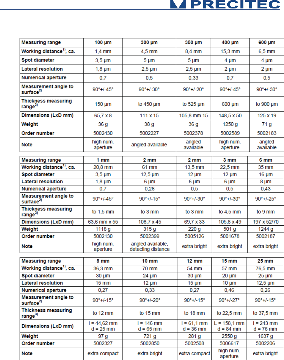
Table 2.7: One point Optical Heads Specifications
(1) Bottom of probe to middle of measuring range
(2) Decreasing accuracy on the limits
(3) Refractive index n=1.5
26
Table 2.7 shows one point optical heads specifications. Some line optical head design are in
progress and should be available by the end of year 2015. Optical heads are interchangeable: the
same CHRocodile MPS unit can store up to 5 different calibration tables per channel
corresponding to different optical heads. The Optical Head is totally passive, only the CHRocodile
MPS unit has an internal light source and electronic board which can be considered as heat and
electrical sources.
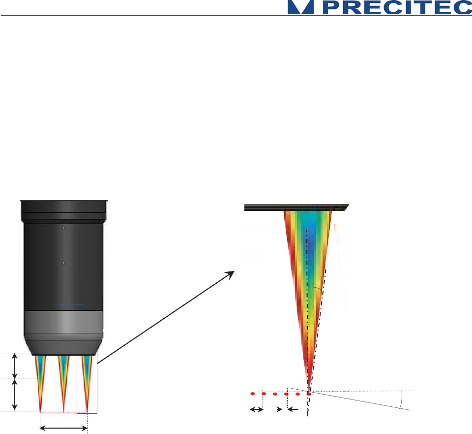
2.8 Optical Head Specifications definitions
W.D : Working Distance
M.R : Measuring Range
L: Line length (only for multipoint optical
head)
P: Pitch between measuring spot (only for
multipoint optical head)
S.D: Spot Diameter (Size)
M.S: Max Object Slope (specified for specular
object. On diffuse object, it is possible to
measure on slope up to 85°)
Fig 2-10: Optical Head Specification definition
W.D
L
M.R
P
S.D
M.S
Acceptance Angle:
related to M.S
27
2.9 CHRocodile MPS performance specifications:
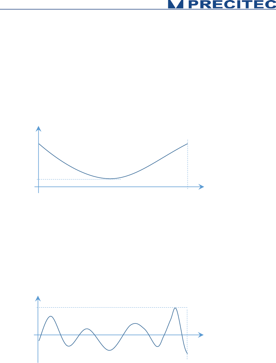
Axial Resolution:
Axial resolution corresponds to the static noise on altitude or thickness measurements. It is an
experimental specification. It is measured on 1000 continuous points along the measuring range for
each channel of the CHRocodile MPS sensor. Axial resolution as a function of object position inside
measuring range is calculated for each channel along the line. By default axial resolution specification
corresponds to the minimum value (ARmin). (See Fig. 2-11),
Fig 2-11: Axial Resolution as function of object position in Measuring Range for one channel
Accuracy:
Accuracy corresponds to the altitude deviation for each channel along the measuring range between
the CHRocodile MPS and a calibrated interferometric reference sensor. Consequently, accuracy is an
experimental specification. Accuracy as a function of object position inside measuring range is
calculated for each channel. By default accuracy specification corresponds to the maximum of
absolute value (Amax). (See Fig. 2-12),
Fig 2-12: Accuracy as function of object position in Measuring Range for one channel
Position in the
Measuring Range
Channel p
Axial Resolution (nm)
ARmin
0
0
Position in the
Measuring Range
Channel p
Accuracy (nm)
Amax
0
28
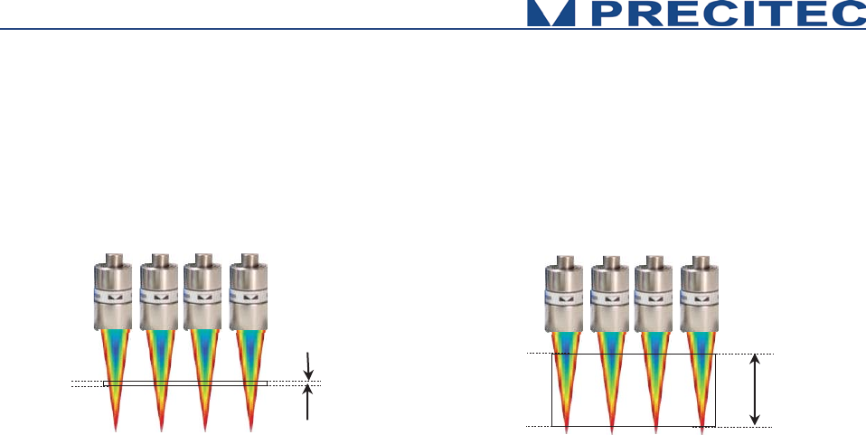
Minimum and Maximum Measurable Thicknesses:
The minimum and maximum measurable thickness specification is given for n=1.5 refractive index. It
is measured on a standard sample in the center of measuring range for each channel. T=n.(D1-D2)
Fig 2-13: Minimum and Maximum measurable thicknesses
D1
D2
T
min
T
max
D1
D2

29
Operational Start up
2.10 Connections and Interfaces
All of the connection ports are located at the front panel of the CHRocodile MPS (Cf. section 2.6
Connections and Interfaces):
x the connection ports for the serial interfaces RS232/RS422
x the connection for the encoder
x the interface port for synchronization with external devices and
x the power supply jack.
2.10.1 CHRocodile MPS Stand Alone device:
The device can be used as a stand-alone device in order to perform selective distance or thickness
measurements.
Power supply
The CHRocodile MPS has two pluggable screw terminal for power supply with 24VDC +/-10%.
Connect the set of power cable supply associated to the Power Supply Adapter (100-240VAC to
24VDC +/-10%) delivered with the CHRocodile MPS unit.
Ethernet connector
Connect the isolated RJ45 standard connector from the CHRocodile MPS unit to an Ethernet network
(PC). Use shielded cable for the data port connection (minimum category 5 cable).
The default CHRocodile MPS IP address is: 192.168.170.2
Configure the PC Ethernet port to the following address: 192.168.170.X (X≠2)
To configure the Ethernet port of your PC, you must open the ‘Network connection properties’ menu.
After selecting the right Ethernet card (connected to the sensor), click on ‘network protocol (TCP/IPv4)’
and click ‘Properties’. Set the IP address of the PC and the mask. For a standard use the mask should
be set to 255.255.255.0.
If you need to configure the sensor to another IP address (different than 192.168.170.2), contact your
vendor. This could be useful in case of multiple CHRocodile MPS connection on 1 computer.
ON / OFF Switch button
Switch on the Power button.

30
2.10.2 CHRocodile MPS integrated on measurement system:
In addition to the Power supply and Ethernet connector used for stand alone device, the CHRocodile
MPS need to be connected to other interfaces to be integrated into complex measurement
configuration systems. The other possible interfaces are described hereafter:
- The USB port (Serial interface RS232),
- The Sub-D15 female connector (Trigger Input/Output and Serial interface RS422),
- And the Sub-D26 male connector (Encoder-input),
Encoder-input
The incremental encoder-input makes it possible to precisely assign each measurement points along
the line and axis positions without additional hardware. The CHRocodile MPS can manage with 5-axis
Encoders.
For an exact distance or thickness measurement it is necessary for every measurement value to be
assigned to the exactly correct spatial coordinates. This data must be recorded in the system and
transferred to the evaluation processing unit over the internal interface. To accomplish this, the sensor
is equipped with an encoder-interface.
Default are the encoder inputs not terminated.
Tye Sw0t02 to GND to terminate with 100 Ohm channel 0 to 2
Tye Sw3t04 to GND to terminate with 100 Ohm channel 3 to 4
If the encoder-signals are fed through the sensor and additional other devices are connected (e.g. for
axis control), the 100 Ohm termination can also be deactivated. Since the device has to be opened to
do this, you should contact Precitec Optronik before beginning any work of this kind.
Trigger Input/Output
The trigger options make the lighting cycle externally controllable and the synchronization between
e.g. a scanning system and the CHRocodile MPS measurement rate. This means that external
triggering is possible for every measurement up to the full measurement rate.
The interface contains the connection points for the synchronization and RS422 serial communication.
Serial interface RS232 and RS422
The serial RS232 and RS422 are interfaced on respectively the USB port and the Sub-D15 female
connector. Serial communication are mostly used for configuring the sensor by sending command as a
hyper-terminal. As the number of channel is high with a huge amount of data, serial communication
port cannot support data transfer.

31
2.11 CHRocodile MPS Explorer and Drivers installations
2.11.1 CHRocodile MPS Explorer installation:
CHRocodile MPS Explorer is not yet done. This Man-Machine interface will allow to configure, to
visualize measurement, to update firmware, to load calibration table etc…
2.12 Communication with CHRocodile MPS
There are three possible way to communicate with the CHRocodile MPS: via the CHRocodile MPS
Explorer software, via the CHRocodile MPS DLL and using the ASCII commands sent to the
CHRocodile MPS via serial interface (RS232 or RS 422) or Ethernet. Up to 3 CHRocodile MPS can be
connected and controlled by a single computer (Windows XP, Windows 7 or Windows 8 OS, 32 and
64bits). CHRocodile MPS is automatically detected through Ethernet network (broadcast mode).
2.12.1 Via CHRocodile MPS Explorer:
CHRocodile MPS Explorer software is delivered with the sensor and is useful to configure sensor, to
visualize continuous measurements, to perform statistic and to save data, to upload firmware and DLL
version.
In order to configure the sensor using CHRocodile MPS explorer, one can use the basic sensor
parameters menu or the expert menu:
• Basic sensor parameters setting give access to Measuring Range (Optical Head selection),
Measuring Mode (Altitude or Thickness measurement), Measuring Rate, LED intensity.
• Expert command window is an advanced mode which allows to configure every sensors
parameter by sending commands (Cf. paragraph 5.1 Command List). This advanced mode
allows to do very specific configurations in order to fit with customer application.
MPS Explorer is not yet available, however, software examples are provided pending the end of MPS
Explorer development project beginning of January 2016.
2.12.2 Via CHRocodile MPS DLL:
DLL may be used to interface the sensor with a general-purpose user program. The CHRocodile MPS
DLL is intended for .NET compatible language. A CD containing the DLL, some code examples and
the operating Manual is delivered with the CHRocodile MPS.
Sensor configuration, processing and data transmission can be performed through CHRocodile MPS
DLL.

32
The CHRocodile MPS DLL functions are described in section 5.4, and have the same properties as
the ASCII Commands. Consequently, what can be done using ASCII commands can be done using
the CHRocodile MPS DLL.
2.12.3 ASCII command communication
The ASCII commands can be sent to the controller via the RS232 or RS422 interface using a specific
command structure described on section 5.2.
Serial interface communication can be used to configure the sensor, but cannot be used to receive
measurement data, due to the high amount of data simultaneously transmitted by CHRocodile MPS.
Only Ethernet allows unlimited data transmission at the maximum measuring rate.
As an example, the Windows™ « Hyper Terminal »™ utility can be used to send the commands and
configure the sensor via the RS232 or RS422 communication port.
33
Measurements Start Up
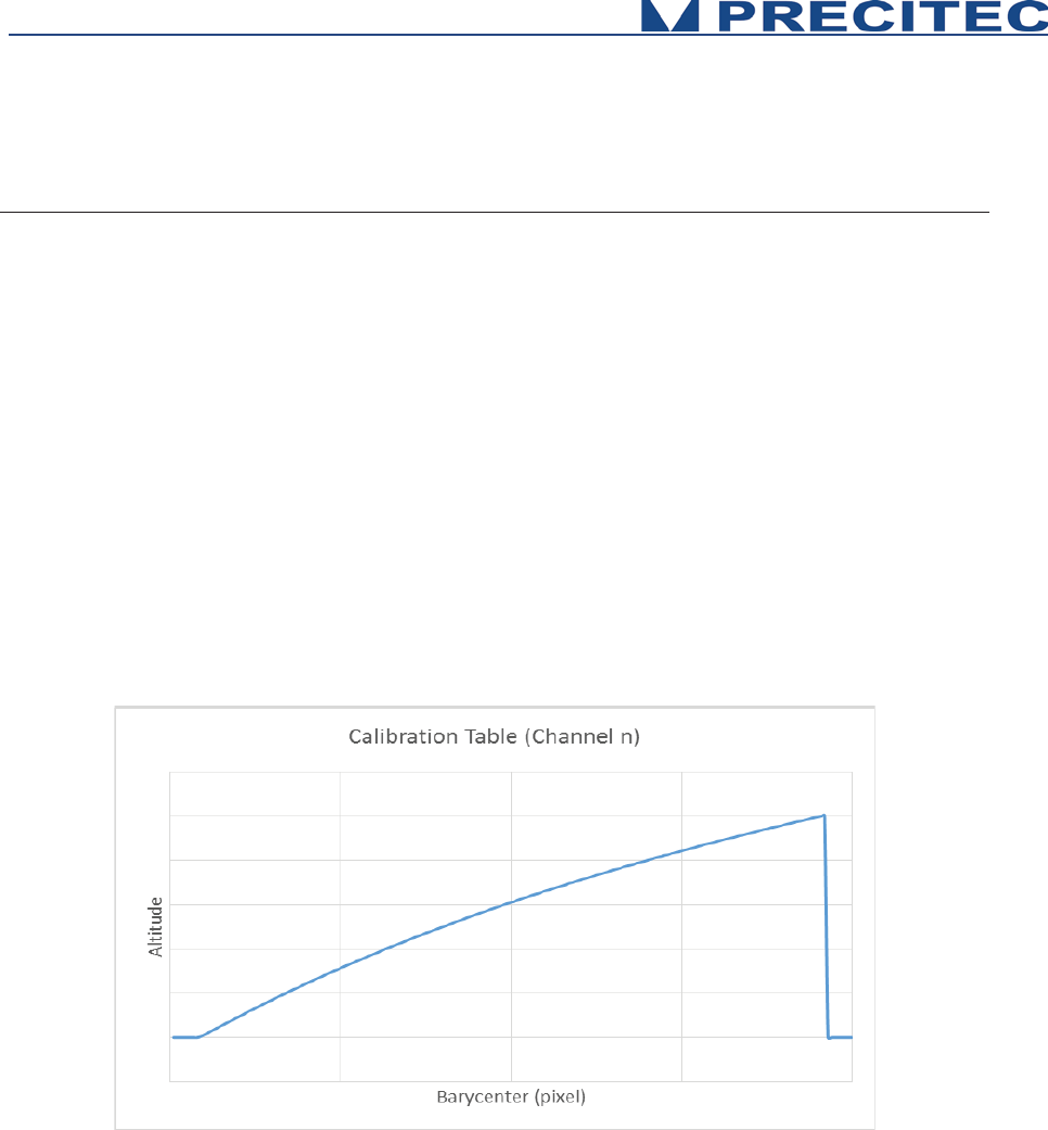
3.1 Calibration Table
The CHRocodile MPS unit can store up to 5 different calibration tables per channel corresponding to
different Optical Heads. In order to start measurement you need to download or select the calibration
which correspond to the used Optical Head (Cf. section 5.2 in user manual). Calibration table consists
in a Look Up Table which give the correspondence between the peak position (Barycenter data) and
the Altitude data.
The global calibration table contains 24 single calibration tables for each of the 24 channels of the
CHRocodile MPS. Consequently, each channel are calibrated independently at factory.
The calibration table depends on both spectrometer and optical head. Consequently a calibration table
is specific to one set of CHRocodile MPS sensor (CHRocodile MPS unit + Optical Head), it can’t be
used on another set even if you are using the same optical head type (i.e same measuring range).
Fig 4-1: Example of calibration table for a single channel
3.2 Dark Acquisition
Even when there is no surface in the probe’s measurement range, the signal on the detector is not
zero. This non-zero values for each pixel on the detector is due to electronic dark and mostly to flare
corresponding to unwanted back-reflected light on optical lenses surfaces. This Dark signal which
limits the measurement dynamics of the sensor can be remove from the useful signal.

34
In order to eliminate the influence of this undesirable light, a dark reference is performed on the sensor
(Cf command DRK in section 5). The Dark reference acquisition must be done when no object is in the
measurement range.
This procedure takes less than 1 second.
3.3 Mechanical interfacing
Mechanical interface depends on the optical head that you are using.
The optical head is held by its diameter. The mechanical drawing of each single point optical head are
at section 5-1.
3.4 Basic Settings Configuration
In order the CHRocodile MPS to be operational for startup some basic parameters should be set up.
Basic setting configuration consists in selection of:
• Measuring Range: The CHRocodile MPS could accept 5 calibration tables, and each
calibration table corresponds to a unique Optical Head. Consequently, depending on the
Optical Head which is mounted on the CHRocodile MPS unit, the operator must select the
right Measuring Range or Calibration Table. (Cf. command $TABL in section 5.2)
• Measuring Mode: The CHRocodile MPS has two measuring mode: Altitude and Thickness
measurement. Depending on the application, operator must select the right Measuring Mode.
(Cf. command $MOD in section 5.2)
• LED Intensity Level: The LED intensity Level can be adjusted from 0 to 100%. As for
Measuring Rate, this adjustment essentially depends on object reflectivity. Adjust LED
intensity in order to obtain a high signal intensity on the 24 channels of the CHRocodile MPS.
The goal is to obtain the higher intensity without saturation. On homogeneous target, each
channel’s intensity is mostly the same, this is not the case on inhomogeneous target and in
that case, it is recommended to adjust intensity in order to obtain the maximum intensity close
to saturation. In order to adjust LED intensity, use the LAI command or the equivalent DLL
function (Cf. sections 5.2 and 5.4).
• Measuring Rate: Instead of adjusting intensity, it is also possible to adjust the measuring rate.
The Measuring Rate is related to data transmission frequency. The higher the Measuring Rate
is the lower the signal intensity is. Consequently, depending on the object reflectivity under
measurement, the Measuring Rate (measuring frequency) must be adjusted in order to
remove saturation or too low intensity signal. In order to adjust measuring frequency, use the
SHZ command or the equivalent DLL function (Cf. sections 5.2 and 5.4).
35
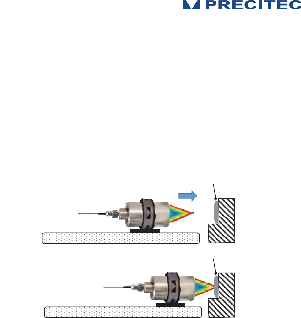
3.5 Data measurement Training
When mechanical interfacing is done, the object to be measured must be positioned inside the
measuring range of the CHRocodile MPS.
This procedure is valid for Altitude and Thickness mode, i.e. to perform topographic measurement on
reflecting object or to perform thickness measurement on transparent object.
Measuring Altitude procedure consists in:
- Adjusting the axial position of the target in order the target is centered inside the optical
sensor measuring range. To do this, one can move the optical head or the target along the
optical axis. Thus, it is recommended to fix the optical head or the target on a translation plate.
- Adjust the light spot position on the area to be measured.
Fig 4-5: Axial position adjustment
When the target is correctly positioned in front of the optical head and basic configuration is
correctly set, it is possible to collect the required data using the SODX command or the equivalent
DLL function (Cf. sections 5.2 and 5.4). In order to record the data corresponding to the 24
channels of the CHRocodile MPS sensor, the Ethernet cable must be connected with the right IP
address to enable the communication between CHRocodile MPS and the computer.
As the sensor is configured to measure simultaneously the 24 channel’s data, then it is possible to
perform an area scan:
Target
Target
Translation plate
Translation plate

36
- In order to scan the target, one can move the optical head or the target along the axis which is
perpendicular to the measuring line. Thus, a translation system is required. The Altitude or
Thickness data is recorded during the scan. In order to synchronized the data acquisition with
the moving session, one need to connect the trigger in/out to the translation system. The
command TRG, enables an exact alignment of the sensors sampling intervals with the
movement of a scanning axis.
- However, if scan velocity is not constant, the pitch between each recorded line is not constant
and the global topography will be distorted. To overcome this image deformation it is important
to assign precisely each measurement points along the line and axis positions. To do so, one
need to connect the incremental encoder-input. The CHRocodile MPS can manage with 5-axis
Encoders.

37
Advanced Configuration
4.1 Commands List
command
arguments
answer on query comments
CTN
Continue (Measuring)
DRK
<n>(<x>)
n: Index of the lowest measuring
rate
x:
lowest frequency in Hz, floating
point
“Dark reference”
take dark reference and save to flash
DNLD
<1..3>
-
Download spectrum. Currently for packet connections only.
ENC
<0..4> [<0..3>]
<
-
2147483648
..
4294967295,
?>
encoder position
“Encoder Position“ :
$ENC <axis#> <function> <arg>
-
index of axis
-optional: Function
-
position (treated modulo 2^32)
Defined functions:
• 0: Set / Read Pos.
•
1: set count source <value> (0..9: A0, B0, A1, B1,
…; 10: SyncIn; 11..14: n.a., 15: Quardr.)
• 2: set preload value <value>
• 3: set preload event <value>
-
Query currently supported for position only.
ETR
<func. Index>
<arguments>
see detailed description
“Encoder Trigger“,
see detailed description
IPCN
<0,1>, [eight
numbers
<0..255>]
-
Configure TCP address and subnet mask. 1st arg: DHCP
on/off, args 2.5: fixed IP addr. args 6..9: mask (only if
DHCP off, i.e. 1st arg = 0)
LAI
<0…100, ?>
<value in %>
“Lamp intensity”
LED version: set on-time of LED between 1-100% of the
exposure time.
NOP
<1..16>
<1..16>
Set nu
mber of peaks to evaluate.
WARNING: see detailed description below
.
SCA
-
-
distance or thickness value [μm] for output value 32768

38
SEN
<0 .. 15, ?>
<optical probe Index>
„optical probe“
index of used optical probe
SHZ
<30 ..10000, ?>
<x>Hz
x meaning the exact sample rate in
Hz in floating point format
“Set sample rate in Hz”.
SODX
<0..17> <0..17>
… <0..17>
(max 16 times)
or <?>
<0..17> <0..17> … <0..17> (max 16
times)
“Set output data extended” definition of the output telegram
by enumeration of the indices of the data.
SSU
-
-
“Save Setup”, saves Setup Parameters to Eeprom Memory
STA
-
-
Start serial data output.
This mode will be stored in the Eeprom when executing the
SSU command. If stored the CHR will begin immediately to
output data telegrams
on the next power up.
STO
-
-
Stop serial data output
This mode will be stored in the EEPROM when executing
the SSU command, so on the next power up the CHR will
not begin to send measurement data until the output is
restarted by the “STA” command
TABL
<Table ID>
<args...>
<binary data,
?>
Upload table to device (or read back in case of '?'). See
below for details.
THR
<0..4094, ?>
<threshold value>
„threshold“ threshold for peak detection in the confocal
modes (0 and 1)
TRE
-
-
“Trigger Each”
– Mode
TRG
-
-
”Wait For Trigger” Stops the sensor after completion of the
current data telegram and puts it in a waiting state.
VER
-
output version data
WHT
3141
Int. ok![CR/LF]
or
Int. too weak![CR/LF]
or
Int. too high![CR/LF]
White Reference
Table 5.1: Commands list
Additionally to this list, CRA command allows to select the number of used channels.
Examples:
CRA0 24 allows to measure with channels 0 to 23. (24 channels are enables starting from channel 0)
CRA0 12 allows to measure with channels 0 to 11. (12 channels are enables starting from channel 0)
CRA4 8 allows to measure with channels 4 to 11. (8 channels are enables starting from channel 4).

39
4.2 Detailed Commands Description
4.2.1 DNLD Command
Short description:
Clients use this command to request a spectrum from the device. Since acquiring spectra can
take up several sample periods, a DNLD request from the client causes the device to first
respond with a DNLD response that does not contain any spectrum data. It just acknowledges
the request. Later, when the spectrum is available, the device sends one or more command
packets (“update” packet) containing the real spectrum data. Data packets may arrive in the
meantime, i. e. between the response and the spectrum. Update packets are structured
exactly like command (response) packets, only with the “update” flag set.
Currently, DNLD command does not function for ASCII command connections.
4.2.2 ETR Command
This command groups several functions related to encoder triggering.
WARNING: The settings will not be saved in the EEPROM by the $SSU command.
The encoder trigger is implemented as a state machine. In the idle state, it waits for the
encoder counter of the selected axis to pass the start position (in either direction)
where it generates the first trigger event. Then the trigger interval value is added to the
current position and when this position is reached, the next trigger event is generated.
This step is repeated until the stop position is encountered.
The generation of trigger events is now stopped. If Triggering during return movement
is selected, the state machine waits for the stop position to be passed once again and
generates trigger events similarly to the forward movement (the trigger interval is now
subtracted instead of added) until the start position is reached. The state machine then
goes back to the idle state. If no Trigger during return movement is selected, the state
machine waits for the start position to be passed over (during return movement) and
then passes to the idle state.

40
4.2.3 IPCN Command
Short description:
This command allows to configure TCP/IP address and subnet mask.
Command syntax:
$IPCN <DHCP> <IPA> <IPB> <IPC> <IPC> <MA> <MB> <MC> <MD> <MTU>
Command
Description
NET
$IPCN 1
$IPCN <DHCP>
Configured as DHCP client
Client.Network.DhcpMode = true;
$IPCN 0 192 168 170 2 255 255 255 0 0
$IPCN <DHCP> <IPA> <IPB> <IPC> <IPC> <MA> <MB> <MC>
<MD> <MTU>
Configured as static IP address
IP Address = 192.168.170.2
Subnet Mask = 255.255.255.0
MTU = 0 (no jumbo packets
)
MTU argument gives the maximum
transferable unit which
can be anything
between 1500 and 9000 bytes per TCP
packet (jumbo packets).
Client.Network.DhcpMode = false;
Client.Network.IPAdress =
"192.168.170.2";
Client.Network.SubnetMask =
"255.255.255.0";

41
4.2.4 LAI Command
Short description:
This command allows to adjust LED intensity in order i.e. to remove saturation.
Command syntax:
$LAI <I>
Param: <I> is Led intensity (0...100%)
Command
Description
NET
$LAI 95
Response: $LAI 95[CR]ready[CR/LF].
Write Led intensity 95%
Client.LedIntensity = 90;
$LAI ?
Response: $LAI ? 95ready[CR/LF].
Read Led Intensity
float Led = Client.LedIntensity;

42
4.2.5 NOP Command
Short description:
This command allows to set the number of peak to evaluate.
WARNING: In confocal mode, if less than NOP peeks are detected, all thicknesses signals will be invalidated because peek identification is not possible.
Command syntax:
$NOP <I>
Param: <I> is Number of Peak from 1 to 16
Command
Description
NET
$NOP 3
Response: $NOP 3[CR]ready[CR/LF].
Write Number of Peak (3)
Client.NumberOfPeaks = 3;
$NOP ?
Response: $NOP ? 3ready[CR/LF].
Read Number of Peak
int Number = Client.NumberOfPeaks;

43
4.2.6 SCA Command
Short description:
The command Scale allows to query of Full Scale in micrometers.
A distance value of 32768 on the serial interface would mean a distance in (Full Scale) micrometers. To convert the integer distance value (d) received
from the serial interface to a value in micrometers (D), use the formula:
D[μm] = d[integer] / 32768 * Full Scale.
Command syntax:
$SCA
Command
Description
NET
$SCA ?
Response: $
SCA ? 3320ready[CR/LF].
Read Full Scale
int FullScale = client.Scale;

44
4.2.7 SHZ Command
Short description:
The command SHZ set sample rate in Hz
It is possible with this command to realize any sample rates between 30Hz and up to the maximum rate of CHRocodile MPS.
If the value is not accepted, the sensor responds with the string "not valid".
Due to the nature of the internal time base, not every sample rate can be realized exactly. In order to give the user the possibility to know the exact
frequency, to which the sample rate has been "rounded", the frequency can be queried with "?" and will be returned as ASCII floating point number with 6
decimals.
Command syntax:
$SHZ <I>
Param: <I> is sample rate (ie: 4500Hz)
Command
Description
NET
$SHZ 1000
Response: $SHZ 1000[CR]ready[CR/LF].
Write Sample Rate (1000 Hz)
Client.FreeSampleRate = 1000;
$SHZ ?
Response: $
SHZ ? 1000ready[CR/LF].
Read Sample Rate
float SampleRate = Client.FreeSampleRate;

45
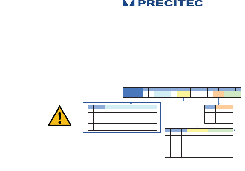
4.2.8 SODX Command
Short description:
Select Output Data (extended)
SODX directly selects the data words that will be included in the output telegram by specifying their indices.
For example SODX 83, 16640, 16641 will output the sample counter, the distance and the intensity.
Command syntax:
$SODX [A0] [A1]…[AN]
[Ax] is optional parameters
Signal ID's scheme
420
8
420
440
110
440
450
150
450
Table 5.4: SODX command: Signal Identity’s scheme.

46
Global Exposure Information:
Definition: Bit 8 = 0 (Bit 8 to 15 = 0)
Type:
Float
Command
Description
NET
$SODX 64
Response: $SODX 64[CR]ready[CR/LF].
StartTime (in nanoseconds)
sodx.GlobalSignalStartTime = true;
(
Acquisition Format : UInt32)
$SODX 65
Response: $SODX 6
5[CR]ready[CR/LF].
StartPositionX(X encoder position on
beginning of exposure
)
sodx.GlobalSignalStartPositionX = true;
(
Acquisition Format : UInt32)
$SODX 66
Response: $SODX 66[CR]ready[CR/LF].
StartPositionY(Y encoder position on
beginni
ng of exposure)
sodx.GlobalSignalStartPositionY = true;
(
Acquisition Format : UInt32)
$SODX 67
Response: $SODX 6
7[CR]ready[CR/LF].
StartPositionZ(Z encoder position on
beginning of exposure
)
sodx.GlobalSignalStartPositionZ = true;
(
Acquisition Format : UInt32)
$SODX 68
Response: $SODX 68[CR]ready[CR/LF].
StartPositionU(U encoder position on
beginning of exposure
)
sodx.GlobalSignalStartPositionU = true;
(
Acquisition Format : UInt32)
$SODX 69
Response: $SODX 6
9[CR]ready[CR/LF].
StartPositionV(V encoder position on
beginning of exposure
)
sodx.GlobalSignalStopPositionV = true;
(
Acquisition Format : UInt32)
$SODX 70
Response: $SODX 70[CR]ready[CR/LF].
StopPositionX(X encoder position on
end
of exposure)
sodx.GlobalSignalStopPositionX = true;
(
Acquisition Format : UInt32)
$SODX 71
Response: $SODX
71[CR]ready[CR/LF].
StopPositionY(Y encoder position on
end
of exposure)
sodx.GlobalSignalStopPositionY = true;
(
Acquisition Format : UInt32)

47
$SODX 72
Response: $SODX 72[CR]ready[CR/LF].
StopPositionZ(Z encoder position on
end
of exposure)
sodx.GlobalSignalStopPositionZ = true;
(
Acquisition Format : UInt32)
$SODX 73
Response: $SODX
73[CR]ready[CR/LF].
StopPositionU(U encoder position on
end
of exposure)
sodx.GlobalSignalStopPositionU = true;
(Acquisition Form
at : UInt32)
$SODX 74
Response: $SODX 74[CR]ready[CR/LF].
StopPositionV(V encoder position on
end
of exposure)
sodx.GlobalSignalStopPositionV = true;
(
Acquisition Format : UInt32)
$SODX 75
Response: $SODX
75[CR]ready[CR/LF].
FirstExposureCount
sodx.GlobalSignalFirstExposureCount = true ;
(Acquisition Format : UInt16)
$SODX 76
Response: $SODX 76[CR]ready[CR/LF].
ExposureFlags
sodx.GlobalSignalExposureFlags = true;
(
Acquisition Format : UInt16)
$SODX 77
Response: $SODX
77[CR]ready[CR/LF].
RealExpTimeNs(Effective exposure
period in nanoseconds
)
sodx.GlobalSignalRealExposureTime = true ;
(Acquisition Format : UInt32)
$SODX 78
Response: $SODX 78[CR]ready[CR/LF].
RealLightingTimeNs(Effective lighting
period in nanoseconds
)
sodx.GlobalSignalRealLightningTime = true;
(
Acquisition Format : UInt32)
$SODX 79
Response: $SODX
79[CR]ready[CR/LF].
TriggerLostCounter (Accumulates
trigge
r events that have occurred
during exposure and therefore have
been ignored.
sodx.GlobalSignalTriggerLostCount = true ;
(Acquisition Format : UInt16)
$SODX 80
Response: $SODX
80[CR]ready[CR/LF].
NumberOfValidPeaks (Number of
peaks that have been found in the
spectrum)
sodx.GlobalSignalNumberOfValidPeaks = true;
(
Acquisition Format : UInt16)
$SODX 83
Response: $SODX
83[CR]ready[CR/LF].
SampleCounter
sodx.GlobalSignalSampleCounter = true ;
(Acquisition Format : UInt32)
48
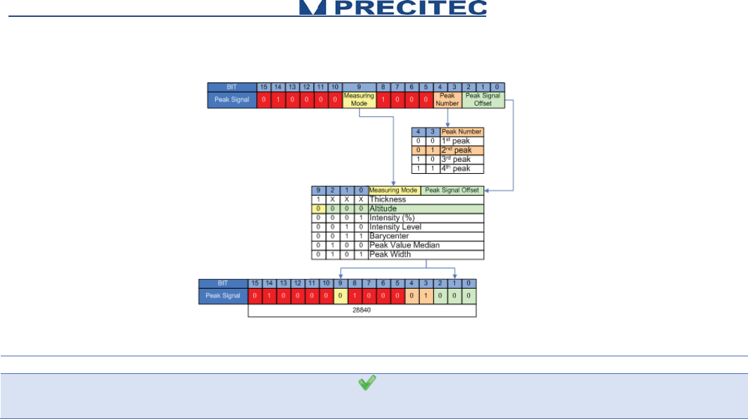
Peak Signal:
Definition: Bit 8 = 1 (Bit 8 and 14 = 1)
Type:
For geometrical quantities like thickness or distance
Integer 16bit, scaled as fraction of measurement range, without refractive index (optical thickness) Distance and thickness values are given as:
d[μm] = value * $SCA[μm] / 32768.
In order to get the geometrical thickness, the value has to be multiplied by the index of refraction of the material.
For non-geometrical quantities (like intensity)
Truncated 16bit integer value
Statistics13 12 11
Average
Std. Deviation
Number of valid values
Minimum
Maximum
Peak-to-peak difference (max-min)
000
001
010
011
100
101
Peak Number4 3
1st peak
2nd peak
3rd peak
4th peak
0 0
0 1
1 0
1 1
BIT 15 14 13 12 11 10 9 8 7 6 5 4 3 2 1 0
Peak Signal 0 1 Statistics Measuring
Mode
0 1 0 0 0 Peak Signal
Offset
Peak
Number
Measuring Mode2 1 0 Peak Signal Offset9
X X X1
Thickness
0 0 00
Altitude
0 0 10
Intensity (%)
0 1 00
Intensity Level
0 1 10
Barycenter
1 0 00
Peak Value Median
1 0 10
Peak Width
Statistics are not supported by MPS. Statistics will be supported by MPS
explorer. Consequently the respective bit 11 to 13 are set to 0.
Corresponding to .NET function:
sodx.AltitudePeakSignalOffset1 = eSodxPeakSignalOffset.Average;
See Following Example
49
Example:
Command
Description
NET
$SODX 28840
Response: $SODX
28840[CR]ready[CR/LF].
Altitude, 2nd peak
sodx.Altitude = true;
sodx.AltitudePeak2 =
true;
sodx.AltitudePeakSignalOffset1 =
eSodxPeakSignalOffset.Average;

50
Additional information:
Peak Signal Offset (Bits 0 to 2)
Signal ID Offset
Signal Name
Remarks
0
Peak Value
Scaled peak distance
1
PeakIntensity
Intensity of peak
2
CCDSaturation
max. CCD illumination of related spectrum
3
PeakPos
CCD pixel pos
4
PeakValue Median
median of peak value (CHRocodile 2 only)
5
PeakWidth
confocal mode only: given in CCD pixels
6
reserved
7
reserved
Peak Number (Bits 3 and 4)
Bits 3 and 4 are used to define the Peak Number which will be processed to calculate the demanded data. The following
quantities are available:

51
Measuring Mode (Bit 9)
Thickness: If bit 9 is set to 1, then the resulting value is thickness corresponding to the difference of the peak as defined in
bits 3 and 4 and the next peak. This facility is used to request thicknesses directly.
NOTE
This difference value is not corrected for the index of refraction. Consequently, in order to obtain the real thickness data, one
must divide the result by the refractive index.
Altitude: If bit 9 is set to 0, then the resulting value is the Altitude corresponding to the peak number defined in bits 3 and 4.
Statistics (Bit 11 to 13)
Statistics are not supported by MPS. Statistics will be supported by MPS explorer. Consequently the respective
bit 11 to 13 are set to 0. Corresponding to .NET function:
sodx.AltitudePeakSignalOffset1 = eSodxPeakSignalOffset.Average;

52
4.2.9 SSU Command
Short description:
The command SSU saves Setup
Saves current setup to non-volatile memory (EEPROM). The Setup will be restored upon next power up.
Command syntax:
$SSU
Command
Description
NET
$SSU
Response: $SSU [CR]ready[CR/LF].
Saves current setup
Client.SaveSetup();

53
4.2.10 STA Command
Short description:
The command STA starts serial data output
This mode can be stored in the EEPROM. If stored, the CHRocodile MPS will begin immediately to output data telegrams on the next power-up
Command syntax:
$STA
Command
Description
NET
$STA
Response: $STA [CR]ready[CR/LF].
Starts serial data output

54
4.2.11 STO Command
Short description:
The command STO stops serial data output
This mode can be stored in the EEPROM, so on the next power up the CHRocodile MPS will not begin to send measurement data until the output is
restarted by the "STA" command.
Command syntax:
$STO
Command
Description
NET
$STO
Response: $STO [CR]ready[CR/LF].
Stops serial data output

55
4.2.12 THR Command
Short description:
The command THR lets you specify an intensity threshold for the distance detection.
It may be useful to specify a high threshold to reject all noise spikes during a measurement or to specify a low threshold to get a (noisy) result from very
black surfaces. When the signal is below the threshold, 0 is output for distance and intensity. The threshold is in arbitrary units which may be subject to
change in future software versions.
At faster sample rates, lower settings for threshold can be used than at slower sampling rates. The reason is, that at slower sampling rates, the stray light
of fiber and coupler is integrated longer on the detector. Even though this signal is automatically subtracted as "dark reference", the statistical variations of
this signal are stronger, the higher the dark signal becomes. If a typical value for good noise suppression and maximum sensitivity at 2kHz sampling rate
could be 20, at 100Hz 50 would be needed.
If the sensor doesn’t detect a signal which passes the threshold, 0 is output for distance and intensity.
Command syntax:
$THR <I>
Param: <I> is intensity threshold
Command
Description
NET
$THR 35
Response: $THR 35[CR]ready[CR/LF].
Write Intensity Threshold
client.Threshold = 35;
$THR ?
Response: $THR ? 35ready[CR/LF].
Read Intensity Threshold
float Thr = client.Threshold;

56
4.2.13 TRE Command
Short description:
The command TRE is a Trigger each.
Trigger each mode. Every exposure will be started by a rising edge of the sync-in-input. The exposure time of the detector is determined by the selected
sample rate ($SHZ).
Command syntax:
$TRE
Command
Description
NET
$TRE
Response: $TRE[CR]ready[CR/LF].
Trigger each
client.TriggerEach();

57
4.2.14 TRG Command
Short description:
The command TRG is a Wait For Trigger. The command enables an exact alignment of the sensors sampling intervals with the movement of a scanning
axis.
It stops the sensor after completion of the current data telegram and puts it in a waiting state. This state is left by a trigger event (rising edge on the Sync
in, Encoder Trigger).
Command syntax:
$TRG
Command
Description
NET
$TRG
Response: $TRG[CR]ready[CR/LF].
Wait For Trigger
client.TriggerStartStop();

58
4.2.15 VER Command
Short description:
The command VER give the Version of CHRocodile MPS.
The command sends back an ASCII string which gives information on the serial number of the CHRocodile MPS (SN: ...), the DSP software (DSPsoft: ...)
and the microcontroller software (C: ...).
Command syntax:
$VER
Command
Description
NET
$VER
Response:
$VER 73;C:V5.95/240909;
DSPsoft:V5.95/160909ready[CR/LF]
Read Versions
string versions = client.Version;
4.2.16 Calibration Table Download Function
It is also possible to upload calibration tables using the MPS Explorer (Cf. section 3.2.1). For information MPS Explorer is not yet available.
Consequently the calibration table uploading is done at PRECITEC OPTRONIC site.
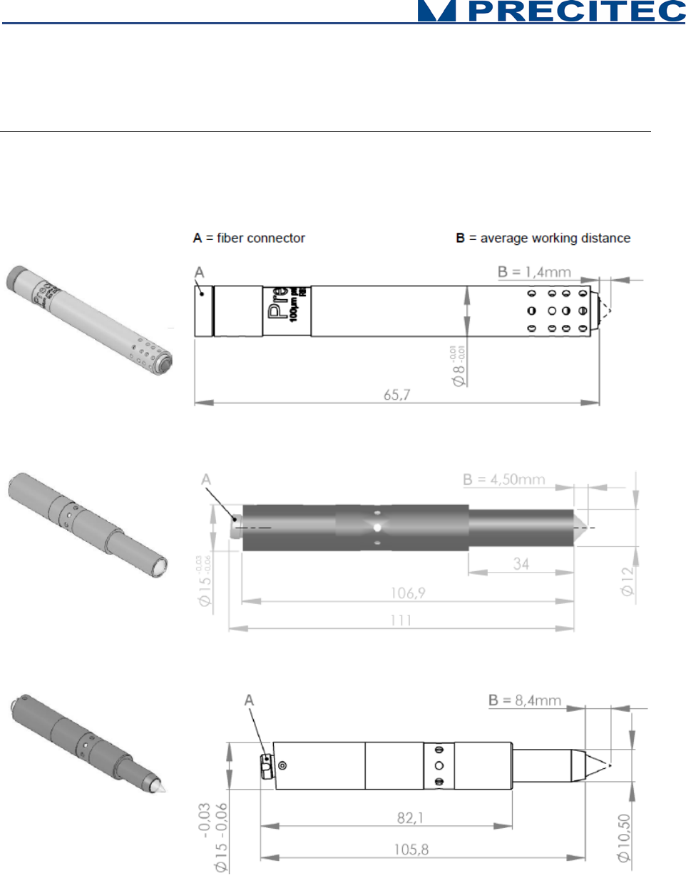
59
Mechanical plans
5.1 Optical Head Mechanical plans
Fig 6-1-a: 100µm probe
Fig 6-1-b: 300µm probe
Fig 6-1-c: 350µm probe
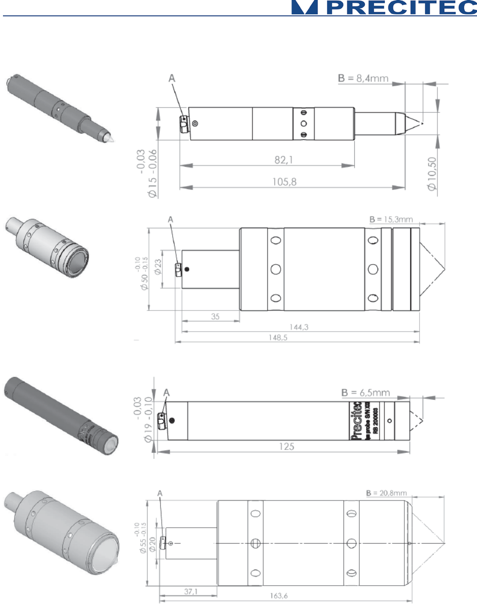
60
Fig 6-1-c: 350μm probe
Fig 6-1-d: 400μm probe
Fig 6-1-e: 600μm probe
Fig 6-1-f: 1mm probe
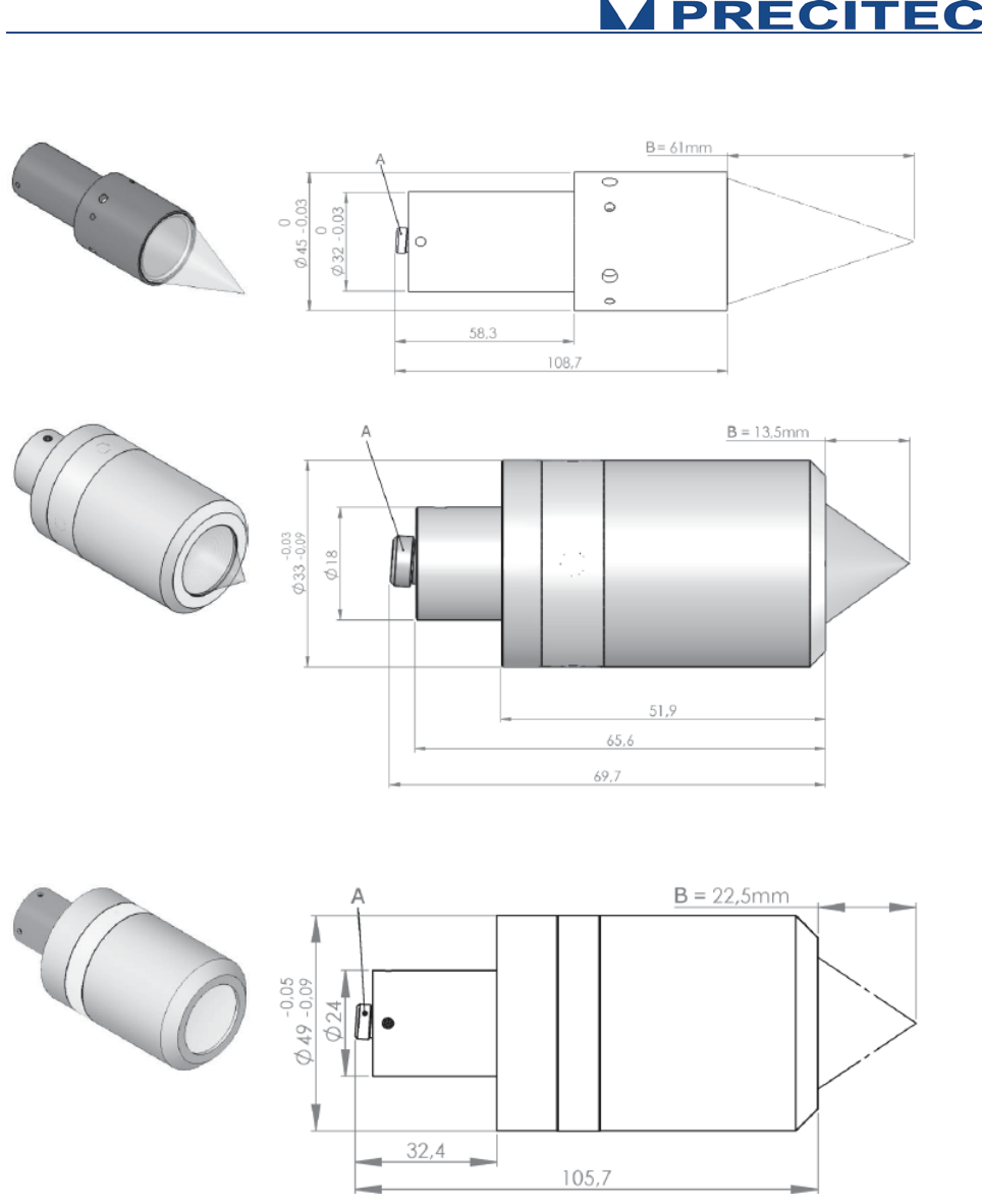
61
Fig 6-1-g: 2mm probe
Fig 6-1-h: 2mm probe
Fig 6-1-i: 3mm probe
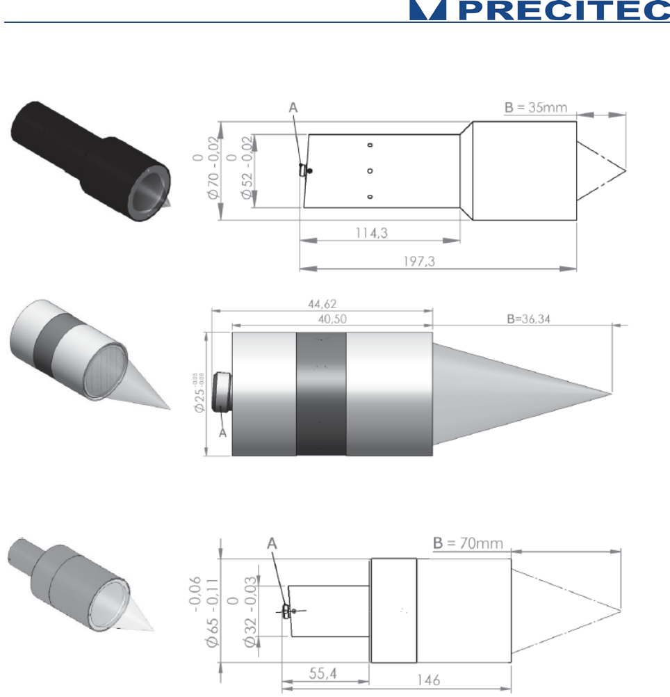
62
Fig 6-1-j: 6mm probe
Fig 6-1-k: 8mm probe
Fig 6-1-l: 10mm probe
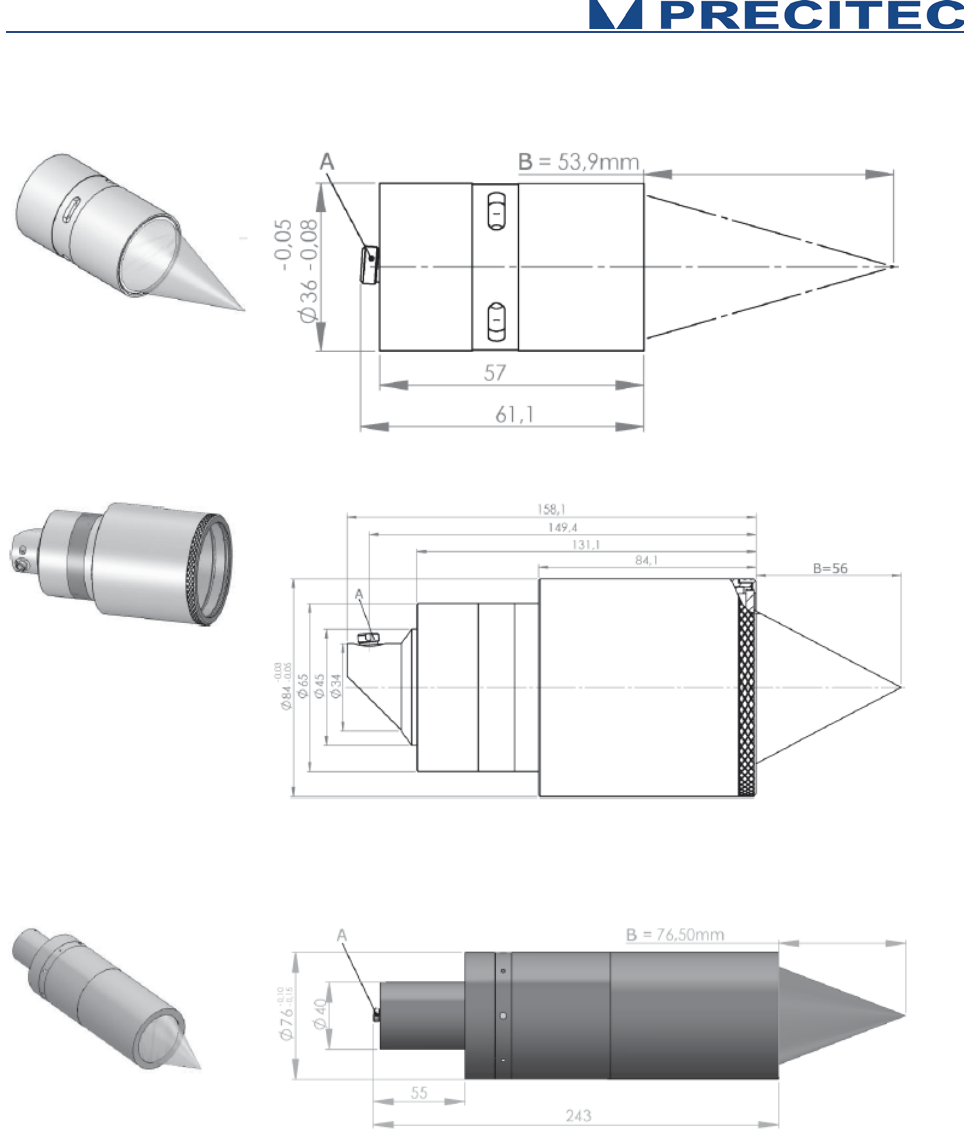
63
Fig 6-1-m: 12mm probe
Fig 6-1-n: 15mm probe
Fig 6-1-o: 25mm probe
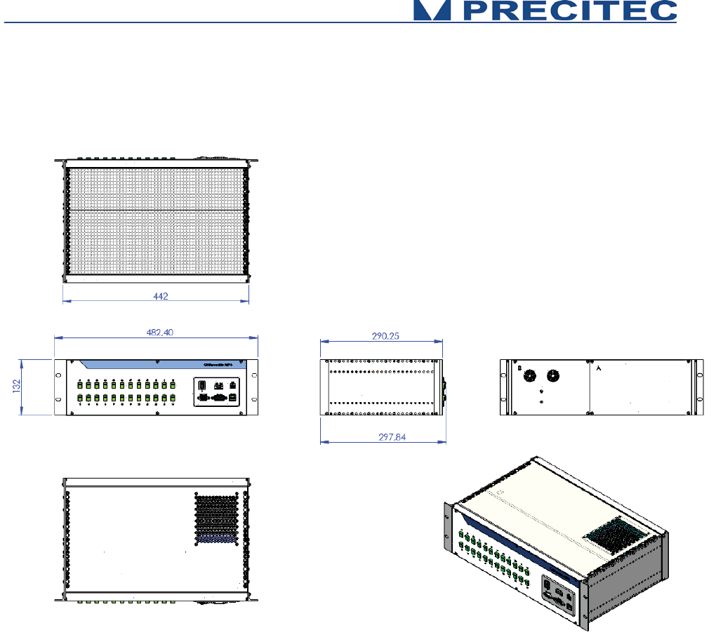
64
5.2 CHRocodile MPS unit mechanical plans
Fig 6-2: CHRocodile MPS controller mechanical plans:

65
Trouble Shooting
6.1 Power off:
The Status LEDs are off when the power supply cable is connected:
- Check the CHRocodile MPS Switch button is ON.
- Check the power cordon.
6.2 Communication error:
No possible Ethernet communication between MPS and your computer:
- Check the Ethernet cable is plugged correctly in RJ45 sensor unit connector.
- Check the IP configuration for your PC and the CHRocodile MPS unit (Cf. $IPCN command in
section 5.2.2).
- If you are using a switch, then try to connect directly from your LAN network to the sensor unit.
- If possible, a Peer-to-Peer connection is recommended.
6.3 Distance Measurement:
Case 1: The target is positioned in front of the sensor, and no distance measurement is collected for
all channels.
- Set the measuring frequency to minimum ($SHZ100 or equivalent DLL function).
- Set the LED intensity to maximum ($LAI100 or equivalent DLL function).
- Check if a white light line emitted from the optical head is focused on the target.
- Check if the target is inside the measuring range of the used channels (up to 24 channels) (Cf.
section 2.9.1).
- Check if the target surface is normal to the optical head axis. The maximum angle between
target surface and optical axis is given by the maximum measurable slope (Cf. section 2.9.1).
- Check if the measuring mode is Distance mode.
- Check if the distance is transmitted ($SODX 16640 or equivalent function),

66
- Then, check and store the raw signal (this file could be demanded by PRECITEC technical
support team). The raw signal should show a peak for channels which contribute to the
measurement.
Case 2: The target is positioned in front of the sensor, and distance measurement is valid only for
some channels:
- Set the measuring frequency to minimum ($SHZ100 or equivalent DLL function).
- Set the LED intensity to maximum ($LAI100 or equivalent DLL function).
- Check if the sample topography variations along the line are fitting with optical head
measuring range; i.e. - Peak to Valley altitude variation should be less than measuring range -
, - maximum local slope on target should be less than maximum measuring slope -, - target is
not homogeneous and show high reflectivity variations along the line -
- Set a mirror in place of your target and store the raw signal for each channels (this file could
be demanded by PRECITEC technical support team).
6.4 Thickness measurement:
Case 1: The target is positioned in front of the sensor, and no thickness measurement is collected for
all channels.
- Check that the target thickness is inside minimal and maximal measuring thickness range,
- Check the target transparency,
- Set the measuring frequency to minimum ($SHZ100 or equivalent DLL function).
- Set the LED intensity to maximum ($LAI100 or equivalent DLL function).
- Check if a white light line emitted from the optical head is focused on the target.
- Check if the two surfaces of the target are inside the measuring range of the used channels
(up to 24 channels) (Cf. section 2.9.1).
- Check if the target surface is normal to the optical head axis. The maximum angle between
target surface and optical axis is given by the maximum measurable slope (Cf. section 2.9.1).
- Check if the measuring mode is Thickness mode.
- Check if the Thickness is transmitted ($SODX 17152 or equivalent function),

67
- Then, check and store the raw signal (this file could be demanded by PRECITEC technical
support team). The raw signal should show two peaks for channels which contribute to the
measurement.
Case 2: The target is positioned in front of the sensor, and thickness measurement is valid only for
some channels:
- Set the measuring frequency to minimum ($SHZ100 or equivalent DLL function).
- Set the LED intensity to maximum ($LAI100 or equivalent DLL function).
- Check if the sample thickness variations along the line are fitting with optical head measuring
range; i.e. - Peak to Valley thickness variation should be inside minimal and maximal
measuring thickness range -, - maximum local slope on both target surface should be less
than maximum measuring slope -, - one or two target surface(s) are not homogeneous and
show high reflectivity variations along the line -
- Set a mirror in place of your target and store the raw signal for each channels (this file could
be demanded by PRECITEC technical support team).
If after reading the previous section you didn’t succeed in resolving your problem, please contact your
vendor for technical support. In order to help to be more efficient, we recommend to fill the following
technical support datasheet and if necessary prepare the files which are demanded in previous
section.

68
Technical support
Technical Support
Date :
CUSTOMER :
PRECITEC Number:
PRODUCT IDENTIFICATION
Sensor Unit Serial Number :
Optical Head Serial Number :
Firmware Serial Number :
PROBLEM IDENTIFICATION
Type :
Software
Optic
Mechanic
Electronic
Description :
Photos:
Attached files :
Photos
Raw data
Diagnostic file
