CMC 256plus Technical Data Sheet Brochure ENU
User Manual: CMC-256plus-Technical-Data-Sheet-Brochure-ENU
Open the PDF directly: View PDF ![]() .
.
Page Count: 3
- Test Set Overview
- CMControl
- Test Universe
- Software / Modules
- QuickCMC
- State Sequencer
- Ramping
- TransPlay
- Harmonics
- Binary I/O Monitor
- CB Simulation
- Pulse Ramping
- Overcurrent
- Overcurrent Characteristics Grabber
- Distance
- Differential
- Autoreclosure
- Advanced Distance
- VI Starting
- Advanced Differential
- Annunciation Checker
- Synchronizer
- Transient Ground Fault
- Advanced TransPlay
- Meter
- Transducer
- OMICRON Control Center
- Pause Module, Text View, ExeCute
- Test Object Definition with XRIO
- PTL Protection Testing Library
- CM Engine Programming Interface
- FCS Field Calibration Software
- Additional Software
- IEC 61850 Testing Tools
- RelaySimTest
- RelayLabTest
- CMC Test Sets
- Accessories
- CMGPS 588 Synchronization Unit
- CMIRIG-B Interface
- SEM Scanning Equipment for Meters
- SER Scanning Equipment for Relays
- CMLIB A Low Level Signal Connector
- Cable Connector for REF 54x
- CMLIB REF6xx Interface Adapter
- CMLIB 7Sx8 Interface Adapter
- RIB1 Low Level Isolation Box
- RXB1 Binary Output Extension
- CPOL Polarity Checker
- C-Probe 1 Current Clamp
- C-Shunt
- CMTAC 1 AC to DC Trigger Rectifier
- ARC 256x Arc Flash Initiator
- PoE Injector
- CMUSB-P USB to Parallel Converter
- Generator Combination Cable
- CMC Wiring Accessory Package
- Standard Test Set Accessories
- Transport Cases
- Foldable Stand
- Recloser and Sectionalizer Control Test Cables
- ISIO 200
- DANEO 400
- ADMO
- OMICRON Worldwide
The CMC256plus is the first choice for applications requiring very high accuracy. This unit is not
only an excellent test set for protection devices of all kinds but also a universal calibration tool.
Its high precision allows the calibration of a wide range of measuring devices, including: elec-
tricity meters of class 0.2S, measuring transducers, power quality measurement devices and
phasor measurement units (PMU). Its unique accuracy and flexibility make the CMC256plus
ideal for protection and measurement equipment manufacturers for research and develop-
ment, production and type testing.
Operation: PC or CMControl
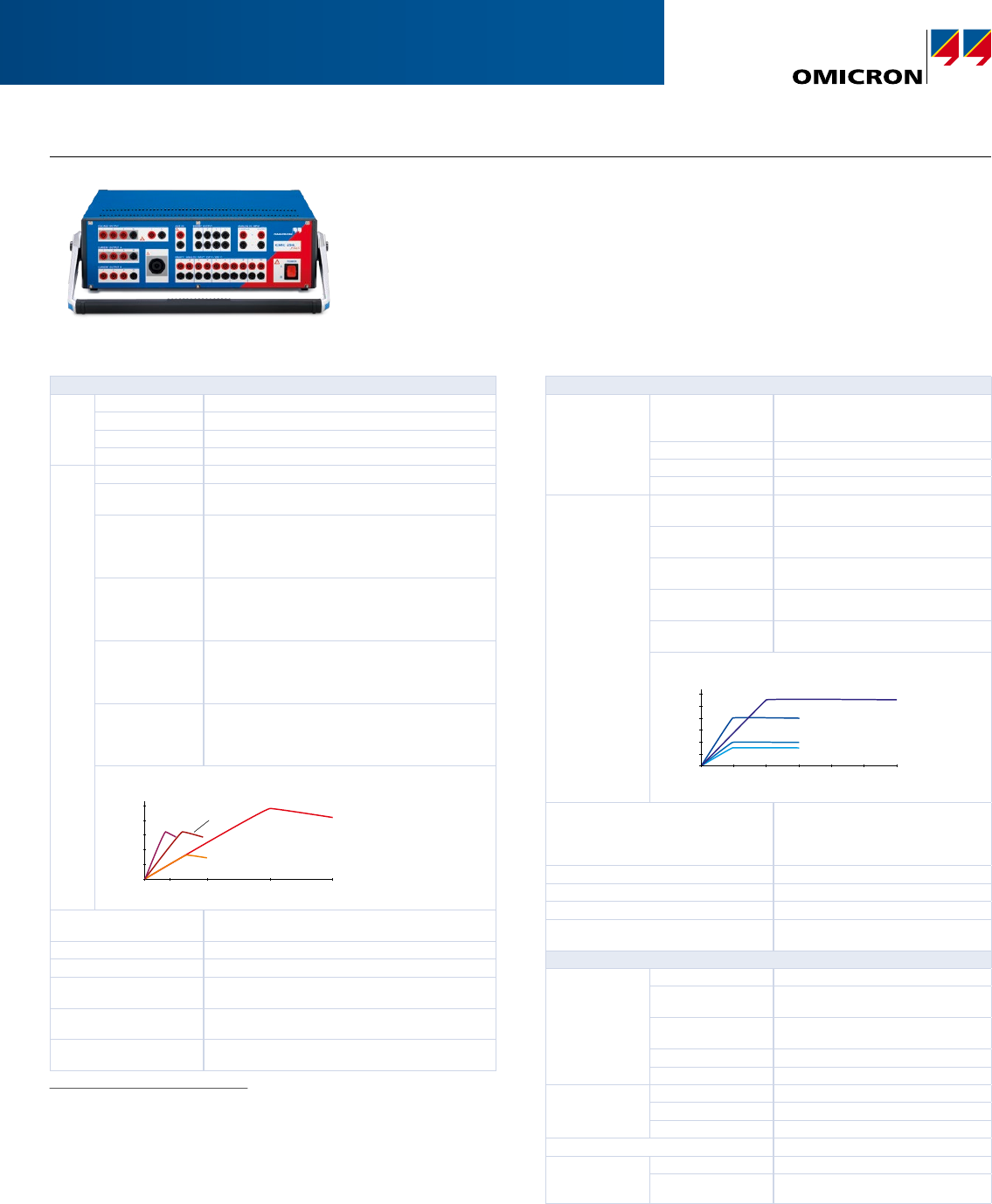
CMC256plus:6 Phase Current + 4 Phase Voltage Test Set and Universal Calibrator
Current generators
Setting
range
6-phase AC (L-N) 6 x 0 ... 12.5A
3-phase AC (L-N) 3 x 0 ... 25A (GroupA II B)
1-phase AC (3L-N) 1 x 0 ... 75A (GroupA II B), 2 x 0 ... 37.5A
DC (3L-N) 1 x 0 ... ±35A (GroupA II B), 2 x 0 ... ±17.5A
Power 6-phase AC (L-N) 6 x 80VA typ. at 8.5A, 6 x 70VA guar. at 7.5A
3-phase AC (L-N) 3 x 160VA typ. at 17A (GroupA II B)
3 x 140VA guar. at 15A (GroupA II B)
1-phase AC (3L-N) 1 x 480VA typ. at 51A (GroupA II B),
2 x 240VA at 25.5A
1 x 420VA guar. at 45A (GroupA II B),
2 x 210VA at 22.5A
1-phase AC (L-L) 1 x 320VA typ. at 8.5A (GroupA II B),
2 x 160VA at 8.5A
1 x 280VA guar. at 15A (GroupA II B),
2 x 140VA at 7.5A
1-phase AC (L-L-L-L) 1 x 320VA typ. at 8.5A
(40VRMS, GroupA and B in series)
1 x 280VA guar. at 7.5A
(40VRMS, Group A and B in series)
DC (3L-N) 1 x 480W typ. at ±35A (Group A II B),
2 x 240W at ±17.5A
1 x 470W guar. at ±35A (Group A II B),
2 x 235W at ±17.5A
500
400
300
200
100
00 10 25 50 75
Output current / A
Group A
and B in
series
1-phase
AC (L-L)
3-phase AC (L-N)
1-phase AC (L-N)
Output power (typ.) / VA
Accuracy 2error <0.015% rd.3 + 0.005% rg.3 typ. at 0 ... 12.5A
error <0.04% rd. + 0.01% rg. guar. at 0 ... 12.5A
Distortion (THD+N) 4<0.025% typ., <0.07% guar.
Ranges 1.25A / 12.5A (Group A, B) or 2.5A / 25A (Group A II B)
Resolution
(for respective range)
50µA / 100µA / 500µA / 1mA
Max. compliance voltage
(L-N)/(L-L)
15Vpk / 60Vpk
Connection 4mm (0.16in) banana sockets / combination socket
(Group A only)
Voltage generators
Setting range 4-phase AC (L-N) 4 x 0 ... 300V (VL4(t) automatically
calculated: VL4 = (VL1+VL2+VL3)*c
or freely programmable)
3-phase AC (L-N) 3 x 0 ... 300V
1-phase AC (L-L) 1 x 0 ... 600V
DC (L-N) 4 x 0 ... ±300V
Power 3-phase AC (L-N) 3 x 100VA typ. at 100 ... 300V
3 x 85VA guar. at 85 ... 300V
4-phase AC (L-N) 4 x 75VA typ. at 100 ... 300V
4 x 50VA guar. at 85 ... 300V
1-phase AC (L-N) 1 x 200VA typ. at 100 ... 300V
1 x 150VA guar. at 75 ... 300V
1-phase AC (L-L) 1 x 275VA typ. at 200 ... 600V
1 x 250VA guar. at 200 ... 600V
DC (L-N) 1 x 420W typ. at ±300V
1 x 360W guar. at ±300V
Output voltage / V
Output power (typ.) / VA
1-phase AC (L-L)
1-phase AC (L-N)
3-phase AC (L-N)
4-phase AC (L-N)
300
250
200
150
100
50
00 100 200 300 400 500
600
Accuracy 5Error <0.015% rd.3 + 0.005% rg.3 typ. at
0 ... 300V
Error <0.04% rd. + 0.01% rg. guar. at
0 ... 300V
Distortion (THD+N) 40.015% typ., <0.05% guar.
Ranges 150V / 300V
Resolution 5mV / 10mV in range 150V / 300V
Connection 4mm (0.16in) banana sockets /
combination socket (1,2,3,N)
Generators, general
Frequency Range sine signals 10 ... 1000Hz
Range harmonics /
interharmonics 6
10 ... 3000Hz
Range transient
signals 6
DC ... 3.1kHz
Accuracy / drift ±0.5ppm / ±1ppm
Resolution <5µHz
Phase Angle range -360° ... +360°
Resolution 0.001°
Error at 50 / 60Hz <0.005° typ., <0.02° guar.
Bandwidth (-3 dB) 3.1kHz
Simulated power
S, P (calibration of
energy meters)
Accuracy 7Error <0.05% rd. typ., <0.1% rd. guar.
Temperature drift <0.001% / °C typ., <0.005% / °C guar.
Technical Data1
1 All data specified are guaranteed, except where indicated otherwise.
OMICRON guarantees the specified data for one year after factory calibration,
within 23°C ±5°C (73°F ±10°F) in the frequency range from 10 to 100Hz and
after a warm-up phase >25 minutes
2 Rload: 0 ... 0.5Ω
3 rd. = reading, rg. = range
4 THD+N: Values at 50/60Hz, >1A / 20V with 20kHz bandwidth
5 Rload: >250Ω
6 Amplitude derating at >1000Hz
7 Data are valid from 0.1 to 12.5A (current amplifier A or B) and 50 to 300V
(voltage amplifier) at 50/60Hz
Permissible load for current outputs:
Range 1.25A: 0 to 1 Ω and 1VA max., cos φ = 0.5 to 1
Range 12.5A: 0 to 0.5 Ω and 6VA max., cos φ = 0.5 to 1
Permissible load for voltage outputs:
10VA max. at 50 to 300V, cos φ = 0.5 to 1
CMC256plus

Technical Data CMC256plus (continued)
Low level outputs 1
Number of outputs 6 (12 with Option LLO-2)
Setting range 0 ... ±10Vpk
Max. output current 1mA
Accuracy Error <0.025% typ., <0.07% guar.
at 1 ... 10Vpk
Resolution 250µV
Distortion (THD+N) 2<0.015% typ., <0.05% guar.
Unconventional CT/VT simulation linear, Rogowski (transient and sinewave)
Overload indication Yes
Isolation SELV
Usability Completely independent from internal
amplifier outputs
Connection 16 pin combination socket (rear side)
Auxiliary DC supply
Voltage ranges 0 ... 264VDC, 0.2A / 0 ... 132VDC,
0.4A / 0 ... 66VDC, 0.8A
Power Max. 50W
Accuracy Error <2% typ., <5% guar.
Binary inputs
Number 10
Trigger criteria Toggling of potential-free contacts or DC
voltage compared to threshold voltage
Input characteristics 0 ... ±600VDC threshold or potential-free
Ranges 100mV / 1V / 10V / 100V / 600V
Resolution of threshold ±2 mV, ±20mV, ±200mV, ±2V,
±20V in ranges
Sample rate 10kHz (resolution 100µs)
Time stamping accuracy ±0.00015% of rd.3 ±70µs
Max. measuring time Infinite
Debounce / Deglitch time 0 ... 25ms / 0 ... 25ms
Counting function <3kHz at pulse width >150µs
Galvanic isolation 5 galvanically isolated groups (2+2+2+2+2)
Max. input voltage CATIV / 150V, CATIII / 300V,
CATII / 600V (850Vpk)
Counter inputs 100kHz
Number 2
Max. counting frequency 100kHz
Pulse width >3µs
Threshold voltage 6V
Voltage hysteresis 2V
Max. input voltage ±30V
Isolation SELV
Connection 16 pin combination socket (rear side)
Trigger on overload
Supported generators Current generators
Timer accuracy Error <1ms
Binary outputs, relays
Type Potential-free relay contacts, software
controlled
Number 4
Break capacity AC Vmax: 300VAC / Imax: 8A / Pmax: 2000VA
Break capacity DC Vmax: 300VDC / Imax: 8A / Pmax: 50W
Binary outputs, transistor
Type Open collector transistor outputs
Number 4
Update rate 10kHz
Imax 5mA
Connection 16 pin combination socket (rear side)
DC voltage measuring input
Measuring range 0 ... ±10V
Accuracy Error <0.003% rg. 3 typ.,
<0.02% rg. guar.
Input impedance 1 MΩ
DC current measuring input
Measuring range 0 ... ±1mA, 0 ... ±20mA
Accuracy Error <0.003% rg. 3 typ., <0.02% rg. guar.
Input impedance 15Ω
Analog AC+DC measuring inputs 4
Type AC + DC analog voltage inputs (current
measurement with external current
clamps or shunt resistors)
Number 10
Nominal input ranges (RMS values) 100mV, 1V, 10V, 100V, 600V
Amplitude accuracy Error <0.06% typ., <0.15% guar.
Bandwidth DC ... 10kHz
Sampling frequency 28.44kHz, 9.48kHz, 3.16kHz
Input impedance 500kΩ // 50pF
Transient input buffer at 28kHz 3.5 s for 10 input channels / 35 s for 1
input channel
Transient input buffer at 3kHz 31 s for 10 input channels / 5 min. for 1
input channel
Transient trigger Threshold voltage, power quality trigger:
sag, swell, harmonic, frequency, frequency
change, notch
Measurement functions I (AC + DC), V (AC + DC), phase, frequency,
power, harmonics, transient recording,
event recording, trend recording
Input overload indication Yes
Input protection Yes
Max. input voltage CATIV / 150V, CATIII / 300V, CATII /
600V (850Vpk)
Galvanic isolation 5 groups (2+2+2+2+2)
Time synchronization
Timing accuracy
IRIG-B synchronization with CMIRIG-B
GPS synchronization with CMGPS588
Error <1µs typ., <5µs guar.
Error <1µs typ., <5µs guar.
To external voltage Reference signal on binary input 10:
10 ... 300V / 15 ... 70Hz
Precision Time Protocol (PTP) IEEE1588-2008
IEEEC37.238-2011 (Power Profile)
With the unique PermaSync functionality, analog and Sampled Values outputs stay
permanently in sync with the internal CMC time reference.
When a CMC is time-synchronized (IRIG-B, GPS, or PTP), the output quantities are
continuously synchronized to the external time source.
With CMIRIG-B it is also possible to transmit the internal PPS signal of the CMC to the
device under test (e.g. PMUs or IEDs stimulated with a synchronized Sampled Values
data stream).
1 For directly testing relays with low level inputs by simulating signals from non
conventional CTs and VTs with low level interfaces and for controlling external
amplifier units
2 THD+N: Values at 50/60Hz, 20kHz measurement bandwidth, nominal value,
and nominal load
3 rd. = reading, rg. = range
4 Up to three inputs can be used for measuring RMS values, frequency, and
phase angle without the EnerLyzer software license. Full functionality requires
EnerLyzer software license
IEC61850 GOOSE 1
Simulation Mapping of binary outputs to data attributes in
published GOOSE messages.
Number of virtual binary outputs: 360
Number of GOOSEs to be published: 128
Subscription Mapping of data attributes from subscribed GOOSE
messages to binary inputs.
Number of virtual binary inputs: 360
Number of GOOSEs to be subscribed: 128
Performance Type 1A; Class P2/3 (IEC61850-5).
Processing time (application to network or vice
versa): <1ms
VLAN support Selectable priority and VLAN-ID
IEC61850 Sampled Values (Publishing) 1
Specification According to the “Implementation Guideline for
Digital Interface to Instrument Transformers Using
IEC61850-9-2“ of the UCA International Users Group
Sampling Rate 80 samples per cycle for nominal frequencies of
50Hz and 60Hz.
Synchronization Synchronization attribute (smpSynch) is set when the
CMC is in synchronized operation mode.
Sample count (smpCnt) zero is aligned with top of
the second.
Accuracy data see above
VLAN support Selectable priority and VLAN-ID
Max. number of SV streams 2 (with option LLO-2: 3 SV streams)
Power supply
Nominal input voltage 2 100–240VAC, 1-phase
Permissible input voltage 85 ... 264VAC
Nominal frequency 50/60Hz
Permissible frequency range 45 ... 65Hz
Rated current 12A at 115V / 10A at 230V
Connection Standard AC socket (IEC60320)
Environmental conditions
Operation temperature 30 ... +50°C (+32 ... +122°F)
Storage temperature -25 ... +70°C (-13 ... +158°F)
Humidity range Relative humidity 5 ... 95%, non-condensing
Vibration IEC60068-2-6 (20 m/s2 at 10 ... 150Hz)
Shock IEC60068-2-27 (15g/11ms half-sine)
Safety standards, electromagnetic compatibility
EMC The product adheres to the electromagnetic com pa-
ti bility (EMC) Directive 2004/108/EC (CE conform).
International IEC61326-1; IEC61000-6-4; IEC61000-3-2/3
USA FCC Subpart B of Part 15 ClassA
Safety The product adheres to the low voltage Directive
2006/95/EC (CE conform).
International / USA IEC61010-1 / UL61010-1
Canada CAN/CSA-C22.2 No61010-1-04
1 Testing with GOOSE and Sampled Values functionality requires software
licences for the corresponding configuration modules
2 For line inputs below 115VAC, it is not possible to drive all outputs (voltage
output, current output, Aux DC) simultaneously at full load. All other technical
specifications (e.g. the maximum output power of a single amplifier) are not
affected
3 For an operational temperature above +30°C (+86°F) a duty cycle of down to
50% may apply
4 PoE = Power over Ethernet
Miscellaneous
Weight 16.0kg (35.3lbs)
Dimensions
(W x H x D, without handle)
450 x 145 x 390mm (17.7 x 5.7 x 15.4in)
PC connection Two PoE 4 Ethernet ports:
• 10/100/1000 Base-TX
• IEEE802.3af compliant
• Port capability limited to one Class1 (3.84W) and
one Class2 (6.49W) powered device
USB port:
• USB 2.0 High Speed up to 480 Mbit/s
USB 1.1-compatible
Signal indication (LED) >42V for voltage outputs and AUX DC
Connection to ground (earth) 4mm (0.16in) banana socket (rear side)
Hardware diagnostics Self diagnostics upon each start-up
Galvanically separated groups The following groups are galvanically separated from
each other: mains, voltage amplifier output, current
amplifier group A/B, auxiliary DC supply, binary/
analog input
Protection All current and voltage outputs are fully overload and
short circuit proof and protected against external
high-voltage transient signals and over temperature
Certifications
Developed and manufactured under an ISO9001
registered system
Ordering Information
CMC256plus with Test Universe software
VE002701 CMC256plus Basic
VE002702 CMC256plus Protection
VE002703 CMC256plus Advanced Protection
VE002704 CMC256plus Universal
VE002705 CMC256plus Meter
VE002706 CMC256plus Measurement
VE002720 CMC256plus Recloser
CMC256plus with CMControl (without Test Universe software)
VE002715 CMC256plus with CMControlP
VE002719 CMC256plus with CMControlR
VE002721 CMC256plus with CMControlP App activation key
VE002723 CMC256plus with CMControlR App activation key
The CMControl can also be ordered as add-on together with a
CMC256plus with Test Universe software or as a later upgrade.
CMC256plus hardware options
VEHO2703 Option LLO-2 if ordered with a new unit
VEHO2704 Option LLO-2 if ordered as an upgrade
