CPC 100 Manual Brochure ENU 1
CPC-100-Manual-Brochure-ENU CPC-100-Manual-Brochure-ENU
CPC-100-Manual-Brochure-ENU-1-1 CPC-100-Manual-Brochure-ENU-1-1
CPC-100-Manual-Brochure-ENU-2 CPC-100-Manual-Brochure-ENU-2
CPC-100-Manual-Brochure-ENU-4 CPC-100-Manual-Brochure-ENU-4
CPC-100-Manual-Brochure-ENU-3 CPC-100-Manual-Brochure-ENU-3
User Manual: CPC-100-Manual-Brochure-ENU-1
Open the PDF directly: View PDF ![]() .
.
Page Count: 44
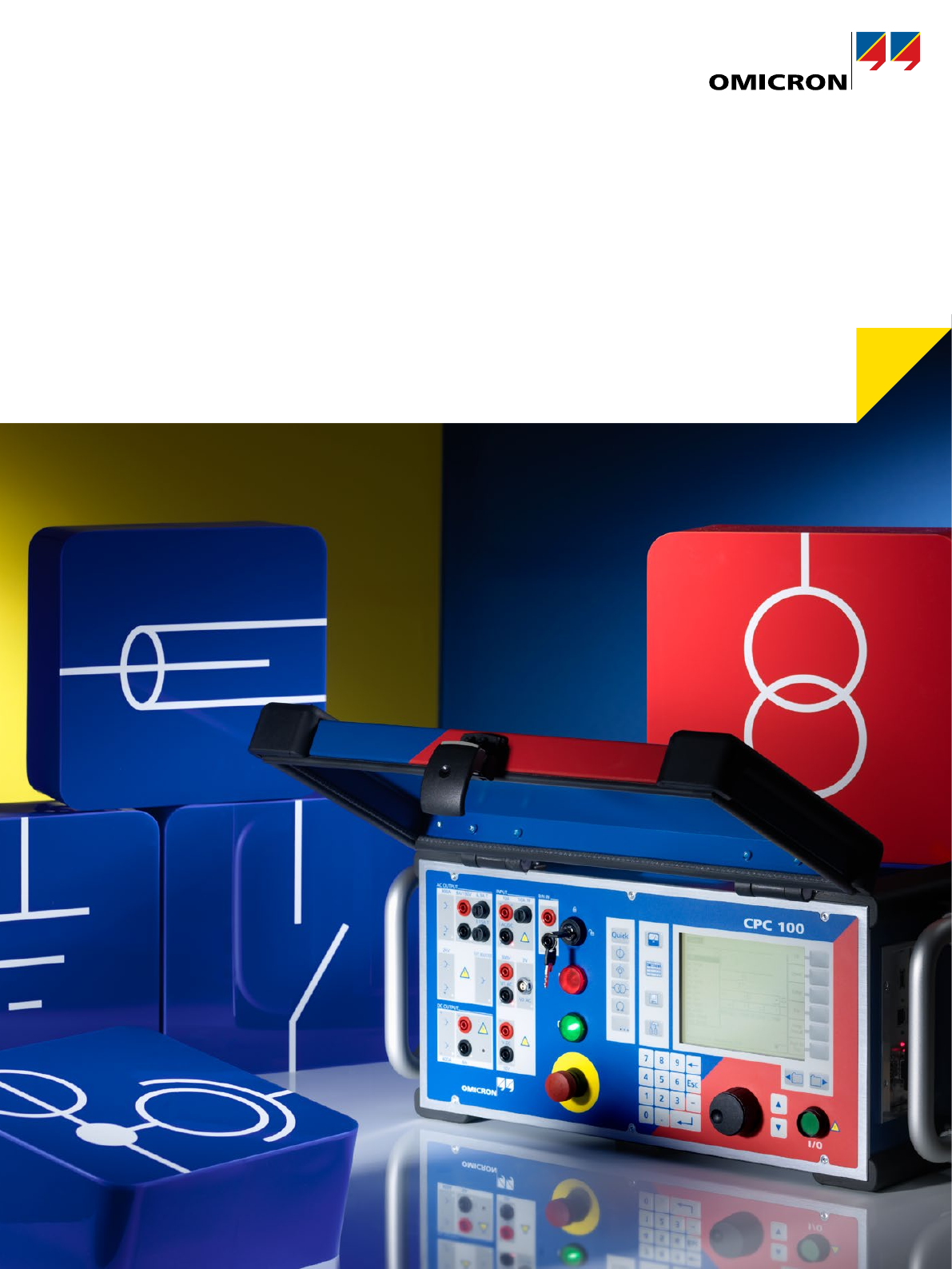
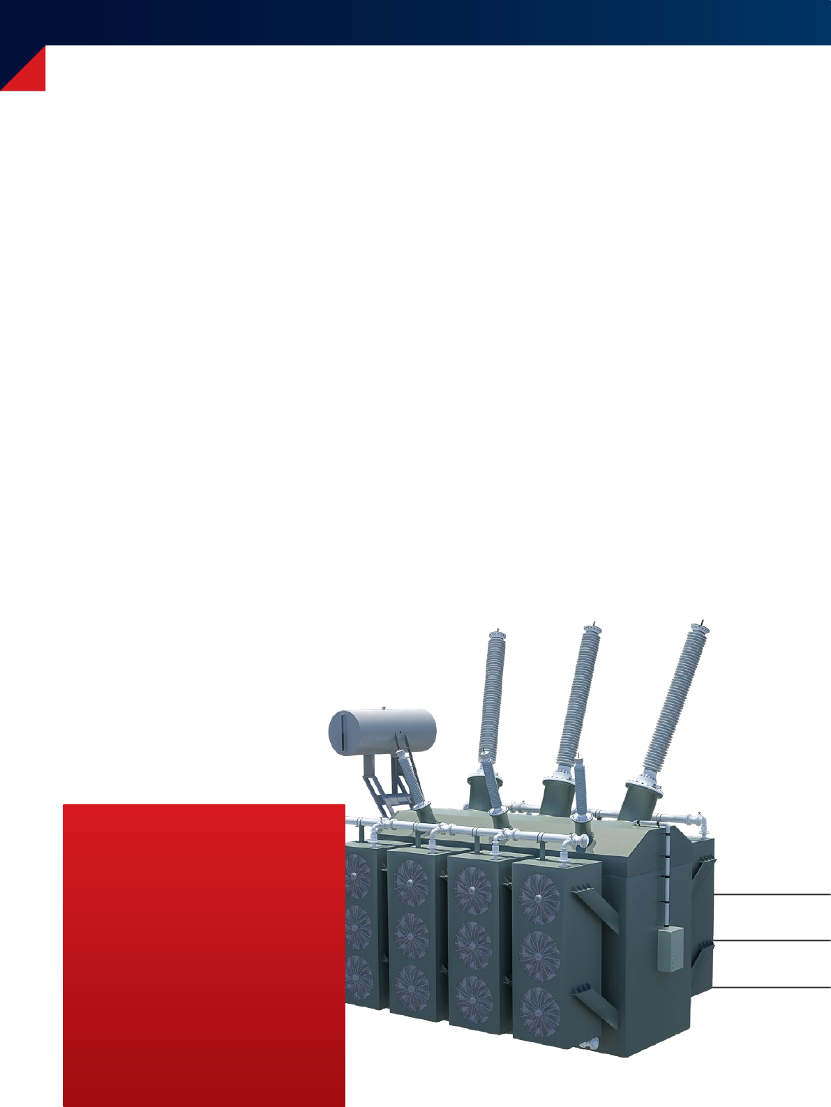
CPC 100
Multi-functional primary test system for
substation commissioning and maintenance

2
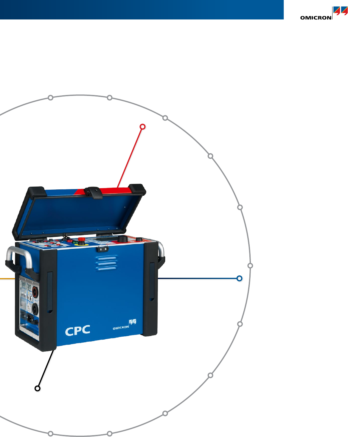
CPC 100 – The revolutionary all-in-one test system
The patented test system replaces numerous individual
testing devices and offers new, innovative testing
methods. This makes testing with the CPC 100 a time-
saving and cost-effective alternative for conventional
testing methods. Despite its expansive capabilities, the
CPC100 is very simple to use.
The powerful testing device provides up to 800 A or 2 kV
(2 kA or 12 kV with accessories) with up to 5 kVA over a
frequency range of 15 Hz to 400 Hz or 400 ADC.
Its compact design (29 kg / 64 lbs) makes it easy to
transport and ideal for on-site testing.
Using the CPC 100, electrical tests on various assets
can be performed:
> Current transformers
> Voltage transformers
> Power transformers
> Power lines
> High-voltage (HV) cables
> Grounding systems
> Rotating machines
> GIS systems
> Switchgear and circuit breakers
> IEC 61850 installations
> Protection relays
Quality & Experience
The usage of high-quality components & intensive routine
testing in our factory have made the CPC 100 a reliable
companion for for our customers worldwide.
The CPC 100 is being improved continuously in close
cooperation with our customers. Its new accessories and
continuous updates guarantee a future proof concept.
On load tap changer
test equipment
High-current injection
transformer
Phase angle
meter
Polarity
checker
Excitation
curve tester
Power meter (P, Q, S)
Line impedance and
cable measurement
Turns ratio meter for transformers,
CTs and V Ts 29 kg / 64 lbs
2 kV
12 kV (with booster)
3
CPC 100 – The revolutionary all-in-one test system
Micro ohmmeter
400 ADC
Ground
resistance meter
Step up transformer
2 000 V
Winding resistance meter
Polarity
checker
Vector group verification system
for power transformers
Multimeter
(V, I, R, Z, ...)
Power / dissipation factor
measurement set
Protection relay tester
(one phase V, I, f)
Tester for Rogowski coils and other
unconventional CTs / VTs (IEC 61850)
Complex impedance meter
(burdens, cables, lines and
transformers)
400 ADC
800 AAC
2 kA (with booster)
29 kg / 64 lbs
single phase wall outlet
15 Hz - 400 Hz
12 kV (with booster)
4
9 good reasons for one system
> Test several assets
(e.g. CT, VT, CB, power transformer)
> Test different parts of an asset
(e.g. core, windings, bushing, insulation)
> Perform numerous tests
(e.g. ratio, polarity, burden,
excitation current)
> Voltage and current injection with variable frequency
> Suppression of mains-related interference and
disturbances
> Test results at different frequencies provide more
detailed information about an asset
> Variable frequency testing is necessary for some
standardized and advanced diagnostic tests
> CPC 100 fulfills highest safety requirements
> CPC 100 is CE tested
> CPC 100 tests according to IEEE and IEC standards
> Measurements with the CPC 100 deliver reliable
and repeatable results due to high signal and
measure ment accuracy
> Offline test preparation possibilities
(time-saving and less error-prone)
> CPC 100 software automatically guides
the user through the test
> Automated report generation
> Customizable test reports
(e.g. different languages, customer logo)
> Light-weight (29 kg / 64 lbs)
> Compact design
> Save costs on:
> Transport
> Handling
> Storage
5
9 good reasons for one system
> Emergency switch-off button
> Ground connection check
> Overload detection
> Multiple isolated outputs
> Safety key lock
> Discharge circuit to de-energize DC
test objects
> Strobe light
> 3-position safety switch
> Grounding box
> Further applications can be covered by
adding additional hardware accessories
> By upgrading the software:
> Additional tests can be performed
> Additional assets can be tested
> Durable case design for rough environments with
test field accuracy
> Long lifetime due to high quality components
> Premium quality cables and clamps
> Comprehensive documentation (e.g. user manual
with connection diagrams, software help function,
videos, application notes)
> Unconventional assets can be tested
(e.g. Rogowski coils, low power CTs)
> Testing according to IEC 61850-9-2
(e.g. Sample Values, Merging Unit testing)
> Future applications areas will be covered
by newly developed accessories and software
6
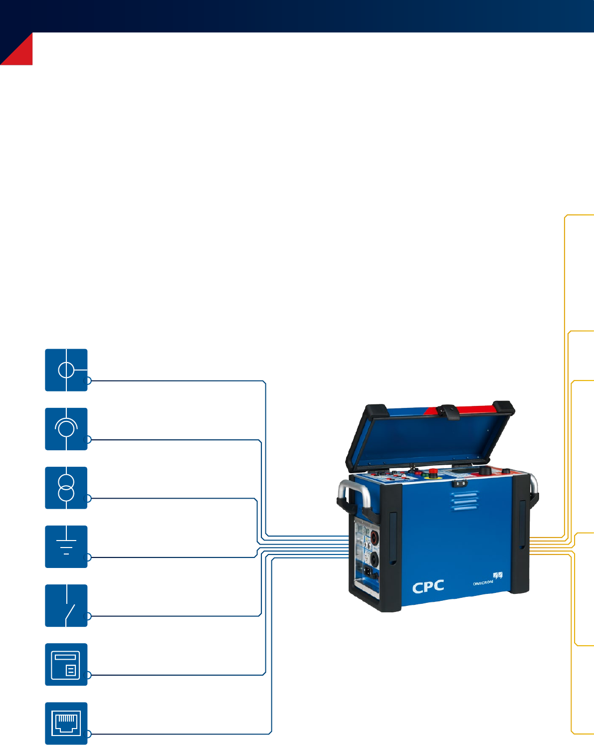
CPC 100 product family – Extended range of applications
Voltage transformer testing
(page 10 – 11)
Current transformer testing
(page 8 – 9)
Power and distribution
transformer diagnosis (page 12 – 13)
Switchgear / circuit breaker testing
(page 22 – 23)
Sampled Values testing
(page 26 – 27)
Grounding system analysis
(page 16 – 17)
Commissioning protection systems
(page 24 – 25)
CPC 100
Applications
The CPC 100 covers a lot of different applications in and around substations as well as at the manufacturer’s production site.
Extended by a high number of valuable accessories the application range of the CPC 100 is further expanded.
Thus it is the ideal instrument for all major applications in the area of primary testing.
Primary test system
7
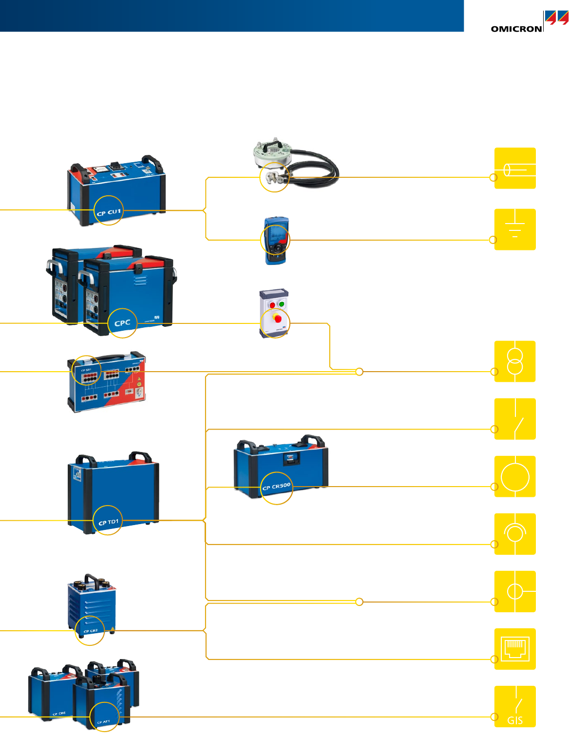
CPC 100 product family – Extended range of applications
Rotating machine diagnosis
(page 18 – 19)
HV cable and power line analysis
(page 14 – 15)
Gas Insulated Switchgear testing
(page 20 – 21)
Extended range
with accessories
Coupling unit
HV-source
Switch box
Tan Delta test set
(power factor)
Current booster
Compensation reactor
Resonance circuit
Current transformer testing
(page 8 – 9)
Voltage transformer testing
(page 10 – 11)
Sampled Values testing
(page 26 – 27)
Grounding system analysis
(page 16 – 17)
Switchgear / circuit breaker testing
(page 22 – 23)
Power and distribution transformer
diagnosis (page 12 – 13)
M/G
Handheld grounding tester
Remote control
Grounding box
Current transformer (CT) testing
Why testing CTs?
Testing current transformers helps to detect installation
related and in-service related problems, such as:
Installation related
> Transportation damages
> Wiring errors
> Manufacturing defects
In-service related
> Degradation of accuracy class
> Shorted turns
> Magnetized core
> Burden failures in secondary circuit
> Insulation material failures
With the CPC 100 many standard electrical tests for CTs
can be performed with one single device saving testing
time and labor costs. Additionally, unconventional CTs, like
Rogowski coils and IEC61850 integrated systems, can also
be tested.
CT testing with the CPC 100
Supplied from a single phase wall outlet, the CPC 100
can generate up to 800 AAC (2 000 A with CP CB2 current
booster) for injecting into the CT‘s primary side and
testing its ratio, polarity and burden.
Excitation curve measurement
For excitation curve measurement, the CPC 100‘s output
is connected to the secondary terminals of the core. Within
an automatic test run, the CPC 100 measures the excitation
curve and displays the knee point voltage and knee point
current at rated frequency (according to the relevant IEC
or IEEE / ANSI standard). The CPC100 also automatically
demagnetizes the CT core after the test.
8
Your benefits
> Mulifunctional CT tests
> Primary injection up to 2 kA
> Simple wiring test with handheld
polarity checker (CPOL2)
> Voltage withstand test up to 2 kV
+ CPOL2
The CPOL2 can check the correct
polarity along the different
connection points in the secondary
wiring by analyzing the sawtooth
signal injected into the CT’s primary
side using the CPC 100.
Current transformer (CT) testing
Current transformer testing
> CT ratio (with burden)
up to 800 A or 2 000 A with CP CB2, 5 kVA output power
> CT burden
up to 6 AAC | secondary
> CT excitation curve
(knee point) up to 2 kVAC
> Polarity check with CPOL2
up to 800 A or up to 2 000 A with CP CB2
> Accuracy limiting factor (ALF) test
> CT ratio with voltage
up to 130 VAC | bushing CTs
> CT winding resistance
up to 6 ADC
> CT demagnetisation and remanence
> CT voltage withstand test
up to 2 kVAC
> CT ratio Rogowski and CT ratio low power
up to 800 A or up to 2 000 A with CP CB2, 5 kVA output power
> Power/dissipation factor test
up to 12 kV, 300 mA | with CP TD1
> IEC 61850 Sampled Values testing
9
Winding resistance measurment
Using the winding resistance measurement function also
allows the user to calculate the accuracy limiting factor (ALF)
for protection circuits and the instrument security factor (FS)
for metering circuits.
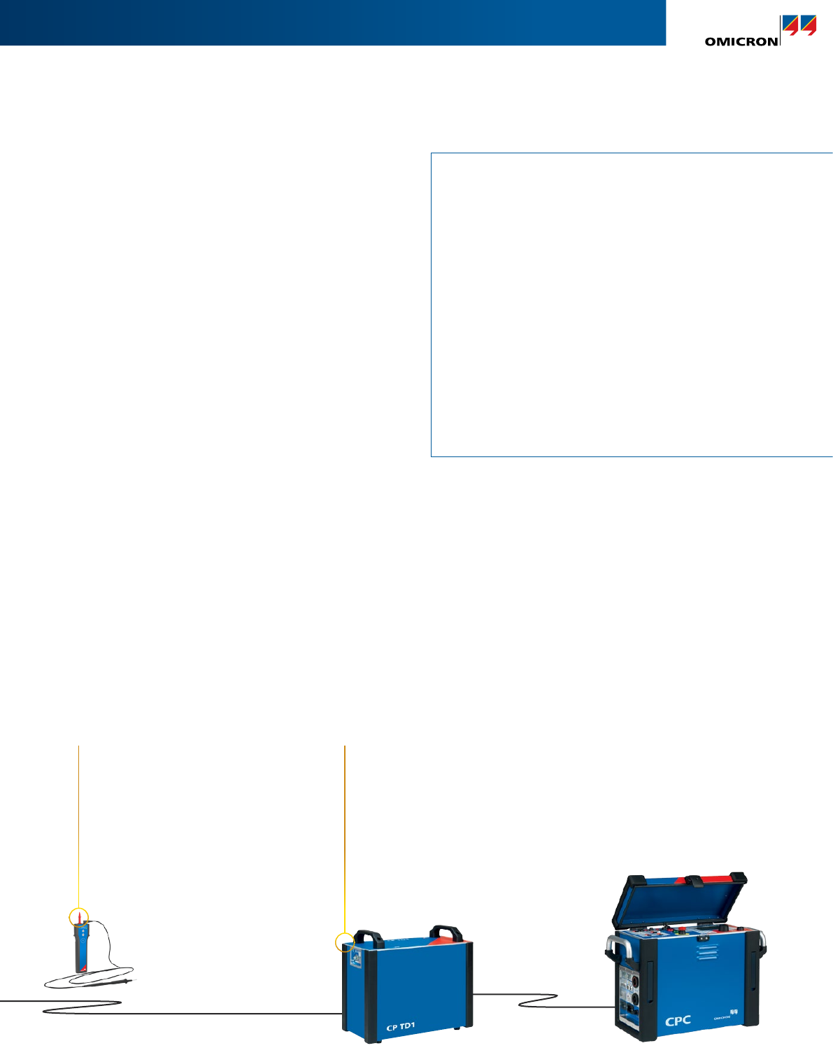
Power/dissipation factor (PF/DF) measurement
When combined with the CP TD1, the CPC 100 is also
capable of performing PF/DF measurements. This helps
to assess the insulation condition of the CT.
+ CP CB2
With the CP CB2 primary injection of
current up to 2 kA can be realized for
CT testing.
+ CP TD1
For high-voltage CTs, insulation material
tests are very important and can be easily
done with the CP TD1 accessory.

10
Voltage transformer (VT) / potential transformer testing
VT testing with the CPC 100
With a voltage output of up to 2 000 VAC the CPC 100 can
be used to test VT ratio, polarity and burden.
By injecting voltage into the primary side, ratio can be mea-
sured. Thereby the phase angles of high-voltage output and
voltage measurement input are also measured. Thus the
correct VT polarity can be verified.
Applying voltage to the secondary VT circuits and measuring
the load current in amplitude and phase allows the actual
burden to be measured, ensuring that it is within the VT´s
specification data.
Why testing VTs?
The majority of VT failures occur due to electrical stresses
or manufacturing and installation errors. Typically electrical
stresses are caused by:
> Thunderstorms
> Ferro-resonances effects
> Over-voltages
Especially in high-voltage and extra high-voltage
installations supervision of the VT insulation system is
important to ensure that its dielectric characteristics have
not degraded over time.
In case of (re-)commissioning of substations VT circuits
should also be checked. Verifying the VT´s nameplate data
helps to identify damages of the VT or wrong connections.
Your benefits
> Ratio testing from 15 Hz - 400 Hz
> Multi-functional VT testing
> Simple wiring check with handheld
polarity checker (CPOL2)
11
Voltage transformer (VT) / potential transformer testing
+ CPOL2
The CPOL2 can check the correct polarity
along the different connection points in
the secondary wiring by analyzing the
sawtooth signal injected into the VT’s
primary side using the CPC 100.
Voltage/potential transformer testing
> VT ratio
up to 2 kVAC | polarity and burden
> VT burden
up to 130 VAC | secondary
> VT secondary voltage withstand test
up to 2 kVAC
> Polarity check with CPOL2
up to 2 kVAC
> VT electronics
up to 2 kVAC
> IEC 61850 Sampled Values testing
> Power/dissipation factor test
up to 12 kV, 300 mA | with CP TD1
Disturbance-free measurement
The VT‘s secondary signal may be difficult to measure if it
is small in amplitude – especially if neighboring parts of the
substation are in operation. In case of strong disturbances,
the user can select a frequency different to that of the
power system and utilizes the “frequency selective mea-
surement” function. Thus only the VT‘s output signal with
this particular frequency is measured while all other signals
are filtered out.
+ CP TD1
For high-voltage VTs, insulation material
tests are very important and can be easily
done with the CP TD1 accessory.
12
Power transformer testing
Winding resistance measurement
The CPC 100 provides an easy and accurate (4-wire connection)
winding resistance measurement. Automatic measurement
for tapped windings (by using CP SB1 with the on load
tap changer) speeds up the measurement. The CPC100
automatically discharges the inductive energy, which makes
the measurement safe.
Demagnetisation
After switching off a transformer or after applying DCsignals
to a transformer, the core remains magnetized. This can cause
problems for further diagnostic measurements or can lead
to higher inrush currents. By using the CPSB1 switch box the
integrated algorithm in the CPC 100 completely demagnetizes
the transformer core.
Ratio & excitation current measurement
For measuring ratio and excitation current, the CPC 100
provides a 2 kV output, delivering 2500 VA. The test voltage
is generated digitally and the current is automatically
measured within the CPC 100. This makes the measurement
highly accurate, easy to set up, fast and safe.
Testing power transformers – Most common
electrical tests with one device
Testing to assess the health of power transformers and
to diagnose problems is of utmost importance to ensure
the long-term and safe operation of these very expensive
power assets.
With the CPC 100 power transformers and their ancillary
components can be tested:
> Windings
> Tap changer
> Bushings
> Insulation
> Core
> Connection leads
> Surge arrestors
Your benefits
> Most common power transformer
tests with one device
> Fully automated testing with
switchbox CP SB1
> Advanced tap changer diagnostics
using OLTC scan (DRM)
> Effective core demagnetization
13
Power transformer testing
Power transformer testing
> DC winding resistance (up to 100 ADC)
> Transformer demagnetization (with CP SB1)
> Dynamic load tap changer diagnostics
(on load tap changer test) (up to 100 ADC | optionally with CP SB1)
> Transformer turns ratio (TTR) per tap
up to 2 kVAC | including polarity and excitation current |
IEC 61387-1 support for transformer with unconventional vector groups
> Automatically determination of the transformer’s
vector group (with CP SB1)
> Leakage reactance / short circuit impedance (up to 6 AAC)
> Transformer, bushing: power/dissipation factor
+ insulation capacitance
up to 12 kV, 300 mA | frequency from 15 Hz to 400 Hz | with CP TD1
> Insulating fluids: power/dissipation factor
up to 12 kV, 300 mA | with CP TD1 and CP TC12
> Excitation current per tap (up to 12 kV, 300 mA | with CP TD1)
> Frequency response of stray losses (FRSL)
> Surge arrestors: leakage current and watt losses
up to 12 kV, 300 mA | with CP TD1
> HV source for voltage withstand test
up to 15 kVA | with 3 CPCs + TRC1
> HV source for PD measurements
up to 15 kVA | with 3 CPCs + TRC1
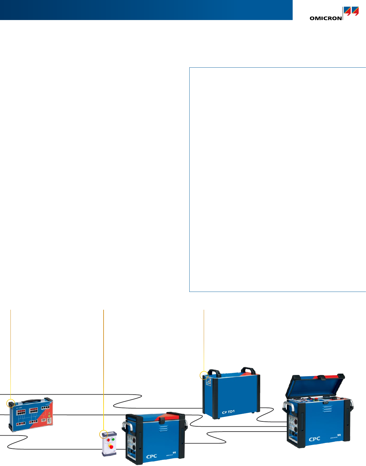
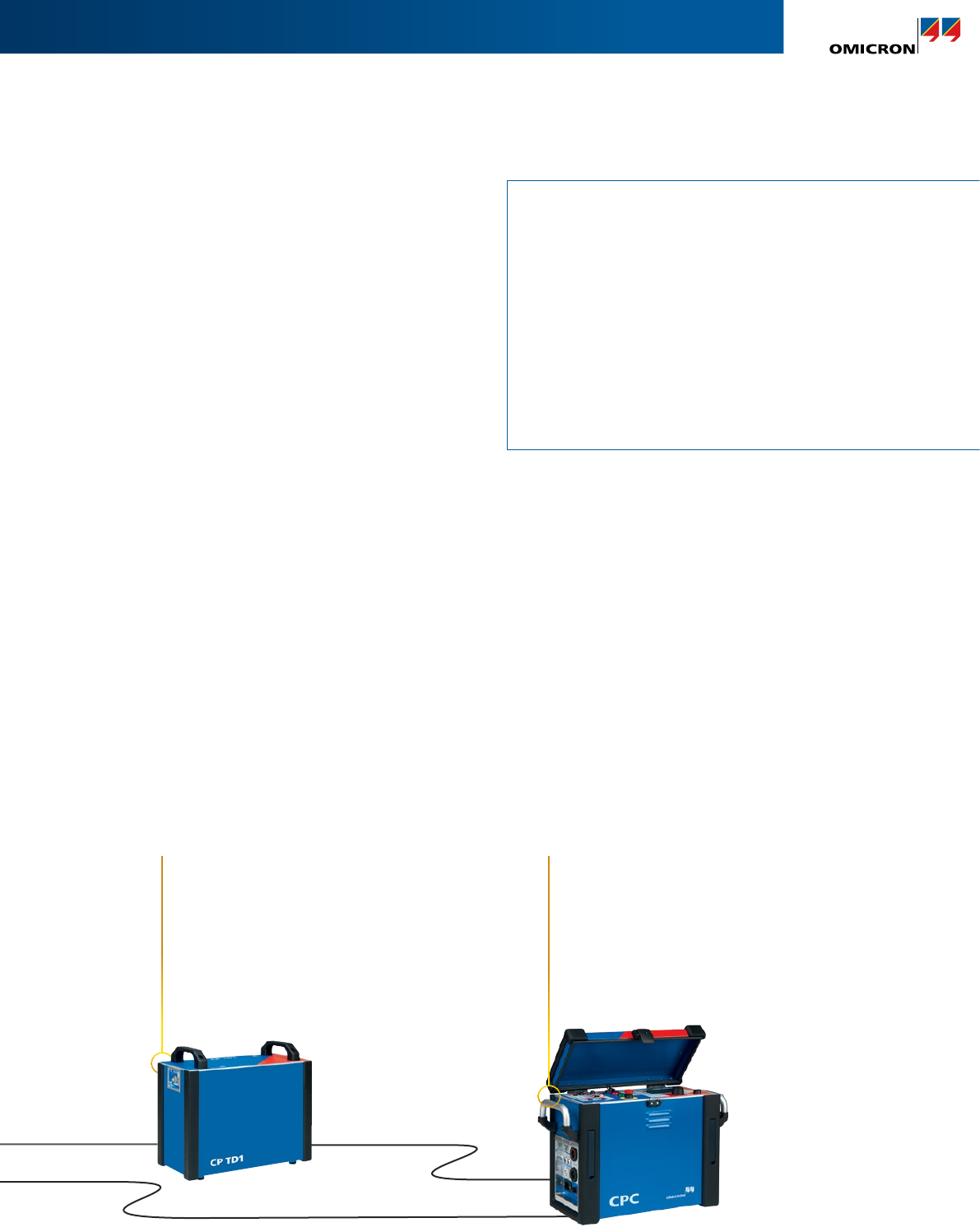
Power/dissipation factor (PF/DF) measurement
For PF/DF measurement on power transformers and
bushings, the CPC 100 is combined with the CP TD1.
Measuring this factor over a broad frequency range – in
addition to mains frequency – helps to better assess the
insulation condition, for example detect whether the
cellulose or the oil is contaminated by moisture.
Dynamic resistance measurement (DRM)
The DRM can be performed as a supplementary
measurement in order to analyze the OLTC’s switching
process. The CPC 100 + CP SB1 injects a DC current in
the same way that it does for static winding resistance
measurements with the the addition of recording the
dynamic behaviour of the diverter switch. Based on this
non-invasive testing method, failures can be detected
without opening the OLTC compartment.
+ TRC1
The triple remote control
TRC1 allows three CPCs to be
synchronized safely. This allows
the CPC 100 to be used as a
powerful HV source. Matching
transformers are provided in
order to match the rated voltage
on the LV side.
+ CP SB1
The switchbox CP SB1
reduces wiring work at power
transformers. Thereby, the
time needed for testing
can be reduced and, at the
same time, safety can be
significantly increased.
+ CP TD1
Insulation condition assessment
of transformers, bushings and
insulation fluids (with the CP TC12).
HV-source
14
Line impedance measurement
Line parameters for distance protection
Correct line parameters are crucial for reliable and selective
distance protection. The set of parameters contains the
positive and the zero sequence impedance (Z1, Z0) as well
as the k-factor (kL, RE/RL and XE/XL, k0).
These parameters are often calculated from software
tools, which do not provide actual line parameters due to
unknown soil properties, such as different soil resistivities,
pipelines or other unknown conductors. This leads to
under- or overreach of your distance protection relay
resulting in outage and loss of grid stability.
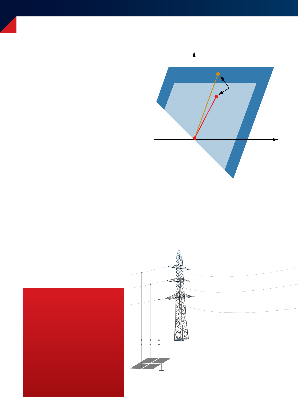
Zone under- and overreach
The most frequent faults on power lines are ground faults.
In particular, inaccuracies from software calculation effect
this kind of fault. The example on the right shows a zone
overreach for a ground fault due to an incorrect k-factor
setting. In this case the assumed k-factor is higher than the
actual one. Therefore, a ground fault at the remote end of
the line is seen incorrectly in the first zone.
Mutual coupling
With this unique testing equipment, the mutual coupling
impedance between parallel lines can also be determined
to consider coupling effects for correct parameterization.
Incorrect k-factor (tendancy to overreach)
100 % of
Line length
Phase-to-ground
Fault: Calculated
impedance
Line impedance Z
L
Zone 1, t
1
= 0 ms
Zone 2, t
2
= 300 ms
R in
X in
Your benefits
> Accurate distance protection relay
settings by performing a line impedance
measurement
> Safe and quick determination of Z1, Z0
and k-factors
> Mutual coupling impedance
measurement between parallel lines
Ground grid
15
Cable and transmission line diagnosis
> Line impedance and k-factor
up to 100 A | with CP CU1
> Mutual coupling
up to 100 A | with CP CU1
> Positive or zero sequence impedance
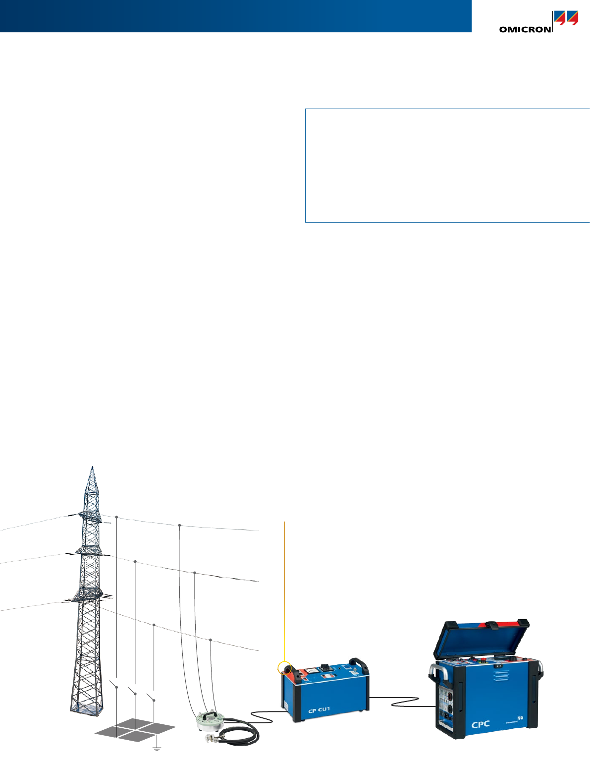
Testing with the CPC 100
The main unit CPC 100 generates the frequency variable
test current and measures current and voltage by applying
digital filtering for high accuracy. The complex loop
impedance is then calculated accordingly.
The CP CU1 provides galvanic isolation between the line
under test and the CPC 100 as well as impedance matching
for short and long lines.
The CP GB1 protects the test equipment and the user
from any unexpected overvoltage on the line under test.
Furthermore it allows a direct connection to the power line
for a convenient execution of the test.
A dedicated test template provides the positive and
the zero sequence impedance as well as the k-factor in
commonly used formats. Furthermore it shows the actual
zone reach for each fault type based on the measured
values and relay parameters that are currently being used.
+ CP CU1
The CP CU1 allows the safe connection
of the CPC 100 to a power line or
HV cable. The impedance matching
transformer within the CP CU1 ensures
optimum power transfer from the
CPC 100 to the power line.
Ground grid CP GB1
16
Grounding system testing
Personnel safety
In the event of a ground fault hazardous step and touch
voltage can occur inside and outside of a substation.
Ground tests prove the effectiveness of grounding systems
and guarantee safety of people inside and outside the
substation.
A fall-of-potential measurement is usually performed to
determine the condition of the entire ground grid. On top
of that, step and touch voltages are measured at exposed
locations in order to ensure human safety in select areas.
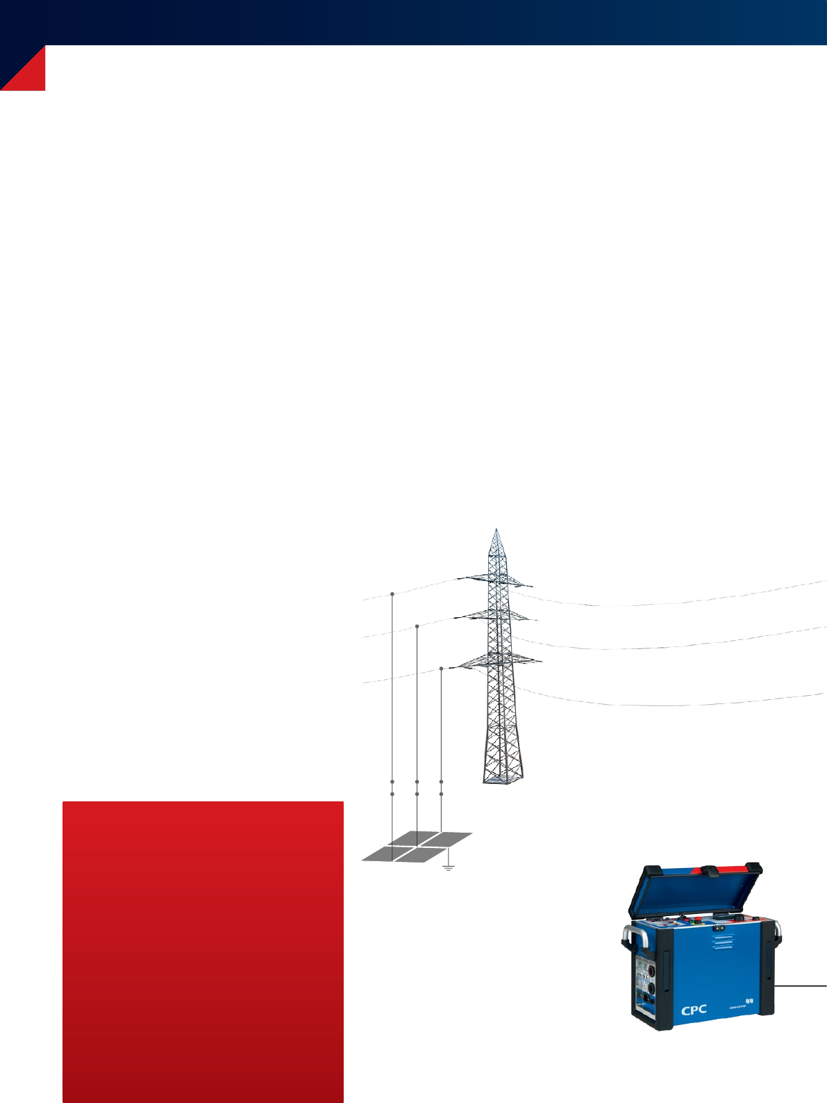
Fall-of-potential measurement (3-point test)
The fall-of-potential measurement with the CPC 100
is performed according to EN 50522 or IEEE 81.
For the fall-of-potential measurement the voltage
between the ground grid and ground electrodes in
different distances to the ground grid is measured
until reference ground is reached. Dedicated software
transforms the test results into a voltage and impedance
chart which allows the ground potential rise and the
ground impedance to be determined.
Your benefits
> Determine true test values by
power line injection
> Simple and accurate step and touch
voltage measurements with handheld
HGT1 device
> Reduction factor measurement on
ground wires and cable shields
Ground grid
17
Grounding system testing
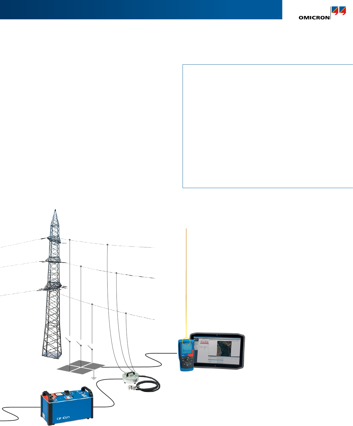
When testing large ground grids the potential of the ground grid under test and
the counter electrode must not overlap. This is done in order to ensure human
safety in a worst case scenario, which is always crucial. The CPC 100 + CP CU1
overcomes this problem by injecting the test current into a remote substation via
an existing power line.
Ground system analysis
> Ground grid impedance for large systems
up to 100 A | with CP CU1
> Step and touch voltage
up to 100 A | with CP CU1 and HGT1
> Ground grid impedance for small systems
up to 6 AAC
> Soil resistivity
up to 6 AAC
> Integrity check of grounding connection
up to 400 ADC
> Reduction factor / current split factor
> Measure multiple current paths with Rogowski coil
Step and touch voltage measurement
Step and touch voltage measurements according to
EN 50522 and IEEE 81 are performed with the HGT1.
This handheld device employs frequency selective
measurements for effective noise suppression.
Furthermore, tests can be executed quickly and easily since
long test cables for connecting to the main device are no
longer necessary.
Dedicated test templates assess measured step and touch
voltages according to EN 50522 and IEEE 80 automatically.
+ HGT1
Primary Test Manager (PTM) and
HGT1 enable you to quickly, simply
and conveniently measure ground
impedance as well as step and touch
voltage. Due to a new approach there
is no operational personal required at
the CPC 100 anymore. Together, the
test director and assistants perform all
measurements out in the field in order to
avoid miscommunication and selection of
inadequate test points.
Ground grid CP GB1
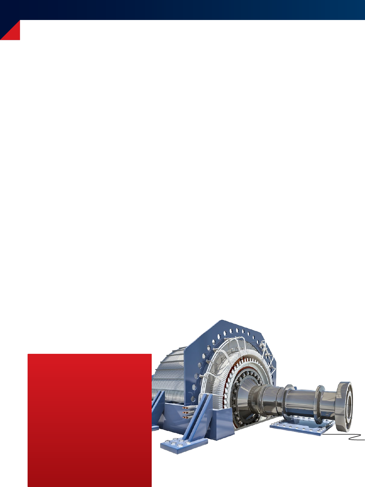
Rotating machines diagnosis
Why test rotating machines?
Rotating machines, such as motors and generators, are
highly important components in power generation and
industrial applications. Therefore machine reliability and
availability are in high demand. Motors and generators are
exposed to high thermal, mechanical and electrical stress
that influences their reliability and life expectancy.
Premature failure may lead to significant economical
losses, due to unexpected outages and possible damage to
the asset itself. In order to plan maintenance effectively, it
is essential to have accurate condition information about
when components need to be repaired or replaced.
A variety of electrical tests can be performed with the
CPC100 over the complete life cycle of machines to
increase their reliability, prevent premature failures and to
extend reliable service life.
18
Your benefits
> Portable HV source
> High accurate PF/DF measurement
with reference capacitance for
maximum usability
> Defined voltage steps for a combined
partial discharge and PF/DF
measurement enable reproducible
test conditions
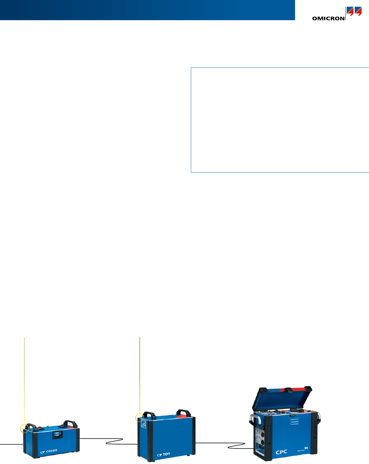
PF/DF measurement and PF/DF tip-up test
The PF/DF measurement is used as a maintenance tool for
entire windings. The portable solution CPC 100 + CPTD1 +
CPCR500 allows PF/DF measurements to be carried out at
nominal frequency.
The measurement results can be compared with previous
measurements, factory acceptance tests or a phase-to-
phase comparison can be made. An acceptable
PF/DF offers assurance that the insulation condition allows
reliable operation.
Furthermore, a parallel partial discharge measurement
allows for a more detailed diagnosis of the type of fault.
The CPC 100 + CP TD1 can be used as HV source for the
partial discharge measurement.
The measurement complies with international standards
such as IEC 60894 and IEEE 286.
Rotating machines diagnosis
Rotating machines diagnosis
> Power/dissipation factor tip-up test
at 50 Hz/ 60 Hz
up to 12 kV | 5 A| with CP TD1 and CPCR500
> Power/dissipation factor test with variable frequency
up to 12 kV | frequency from 15 Hz to 400 Hz | with CP TD1
> HV source for testing rotating machines
up to 12 kV | max. 2 µF | with CP TD1 and CPCR500
> DC winding resistance measurement
up to 400 A DC and 5 kVA down to the microohm range.
> Pole drop test
19
+ CP CR500
The CP CR500 compensator
reactor enables the CP TD1 to be
used with test objects with large
capacitance such as large motors
and generators.
+ CP TD1
Insulation condition assessment of
motors and generators. The CPC 100
+ CP TD1 can provide up to 12 kV. It
can be be used as HV source and
PF/DF measurement system at the
same time.
DC winding resistance measurement
A DC resistance measurement is performed to detect
possible contact problems in the stator and rotor winding
of a machine.
The CPC 100 offers an integrated micro ohmmeter with
a maximum output of 400 A. The 4-wire method is used
to detect connection problems in the stator winding (bad
soldering contacts) as well as contact problems on the pole
connectors of the rotor winding.
Both failures can be the root cause of a local hotspot and
potentially damage the machine.
Pole drop test
Mechanical stress in rotor windings cause inter turn faults
(short circuits), which can lead to a magnetic imbalance.
This causes higher shaft vibrations which puts more stress
on the bearings and can potentially damage them. The
CPC 100 provides the AC source and the accurate voltage
inputs nedded to perform the pole drop test.
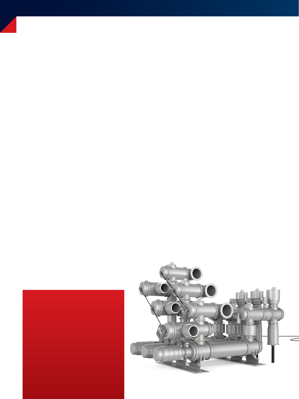
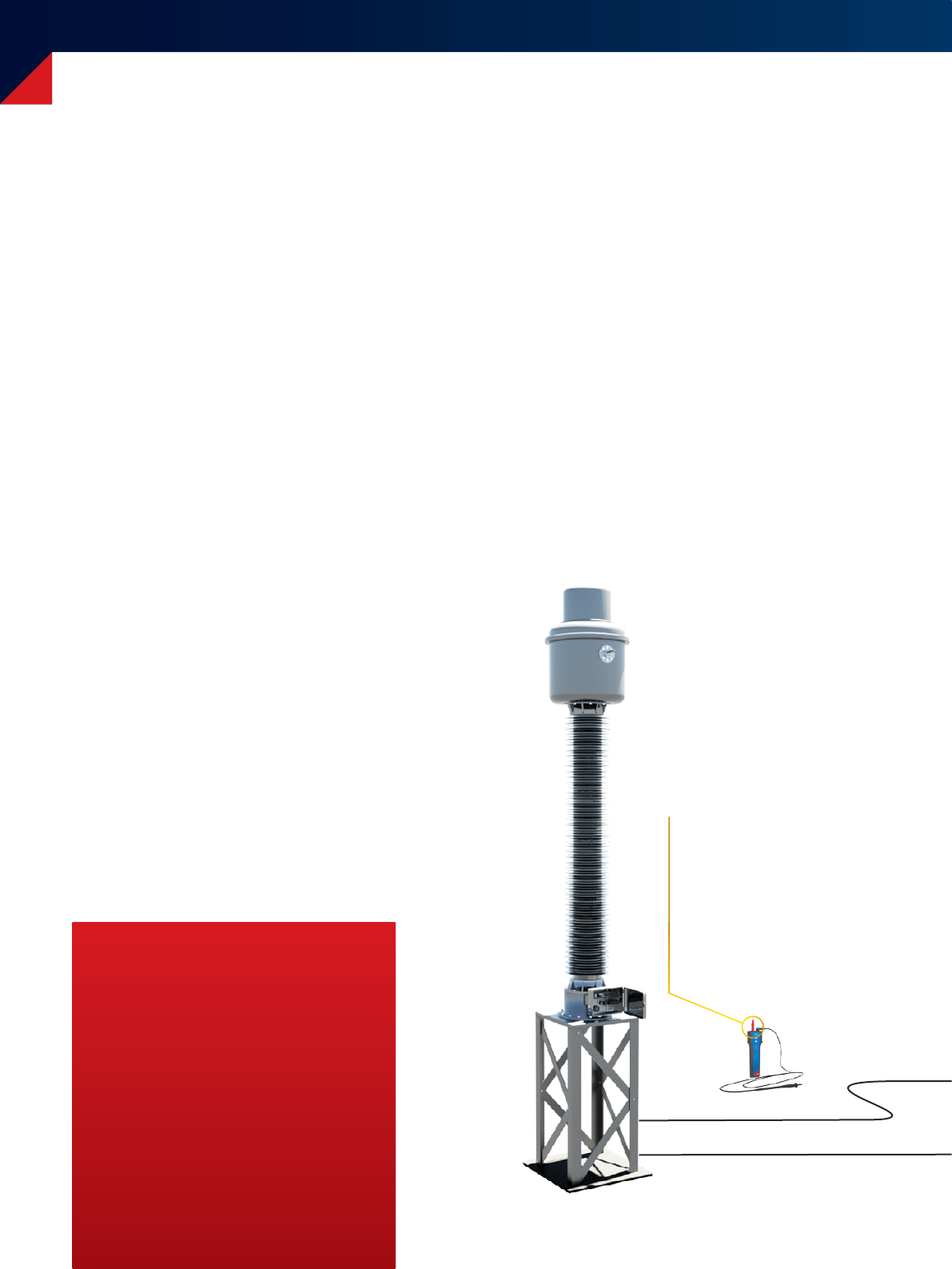
Gas-insulated switchgear testing
20
Testing gas-insulated switchgear to date
Gas-insulated switchgears (GIS) are compact and are,
therefore, used in applications where space is limited. For
commissioning of GIS a high-voltage (HV) withstand test is
required in accordance with standards (IEC62271-203).
To date the test voltage needed for a withstand test has
been produced by a resonance circuit. This test system
consists of an HV test transformer, a coupling capacitor
and a power control unit. The HV test transformer and the
coupling capacitor have to be connected directly to the GIS.
Weak points of this testing principle:
> The complete test system is difficult to transport,
because it consists of very heavy and large
components.
> It is difficult to use it at test sites with limited space,
such as wind turbines.
> The HV test lead must be connected to, and
disconnected from, the GIS system for testing. This
normally includes a time-consuming venting and
refilling process of the SF6 gas.
Innovative GIS testing
With the CPC 100 + CP RC it is possible to perform GIS tests
without the need of a big HV transformer. This is possible
because the system directly makes use of a specially
designed “PowerVT” for testing.
This Power VT is an integral part of the GIS and generates
the required test voltage. CPC 100 injects power at the
LVside of the VT, producing the necessary voltage on the
HV side. A direct connection of the measuring system to
the integrated VT of the GIS system eliminates the need
for draining and refilling any SF6 gas.
The CPC 100 + CP RC system comprises several small and
light-weight components (< 21 kg / 46 lbs) which can
be transported by one person. With its modular design
GIS tests can even be accomplished at test sites with
limited space.
Your benefits
> Small and light-weight test system
with high output power
> Testing without gas venting and
refilling procedure
> Automatic frequency tuning for
ideal load compensation
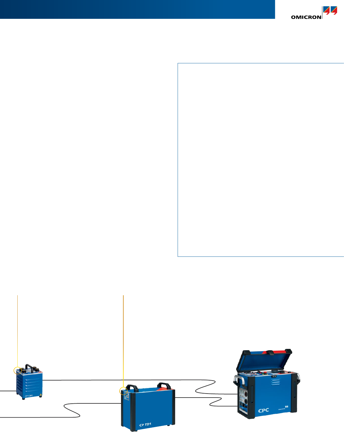
21
Gas-insulated switchgear testing
GIS testing
> Withstand test
up to 235 kV | max 1.6 nF | with CP RC2
> HV source for partial discharge measurements
up to 235 kV | max 1.6 nF | with CP RC2
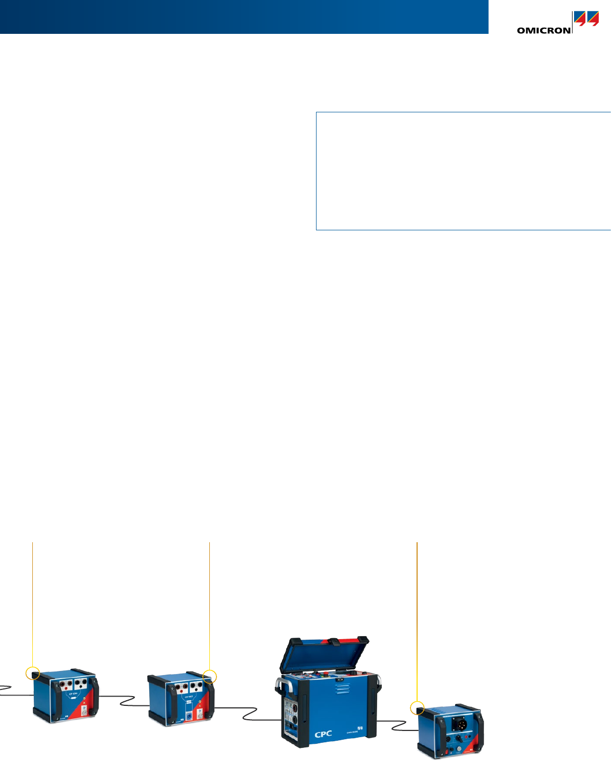
+ CP CR
With the compensating reactor
4 mH CP CR4 or 6mH CPCR6
the CP CR compensates the
capacitance in a modular fashion.
+ CPAT1
The auto-transformer CP AT1
allows to connect the mains
supply of the CPC 100 to a
three-phase 16A power outlet,
and delivers the required power
for the test setup.
+ CP TR
The isolation transformer CP TR
provides a potential-free output
signal and compensates the
capacitive load.
Powerful voltage withstand testing
When combined with the CP RC1, the CPC 100 allows
withstand tests with a maximum test voltage of 200 kV
to be carried out on GIS systems up to a rated voltage of
123 kV. The CPC 100 + CP RC2 is appropriate for testing
GIS systems with a rated voltage of up to 145 kV and a
maximum test voltage of 235 kV. This package is supplied
with the additional CPAT1 auto-transformer to guarantee
the necessary output power of the CPC100 for higher loads.
HV source for partial discharge measurements
During production or maintenance, impurities can occur
in GIS. These can cause major problems in operation.
Therefore, it is recommended to perform a partial discharge
measurement during commissioning (acceptance tests).
While performing these measurements with our MPD series
the CPC 100 + CP RC can be used as the HV source.
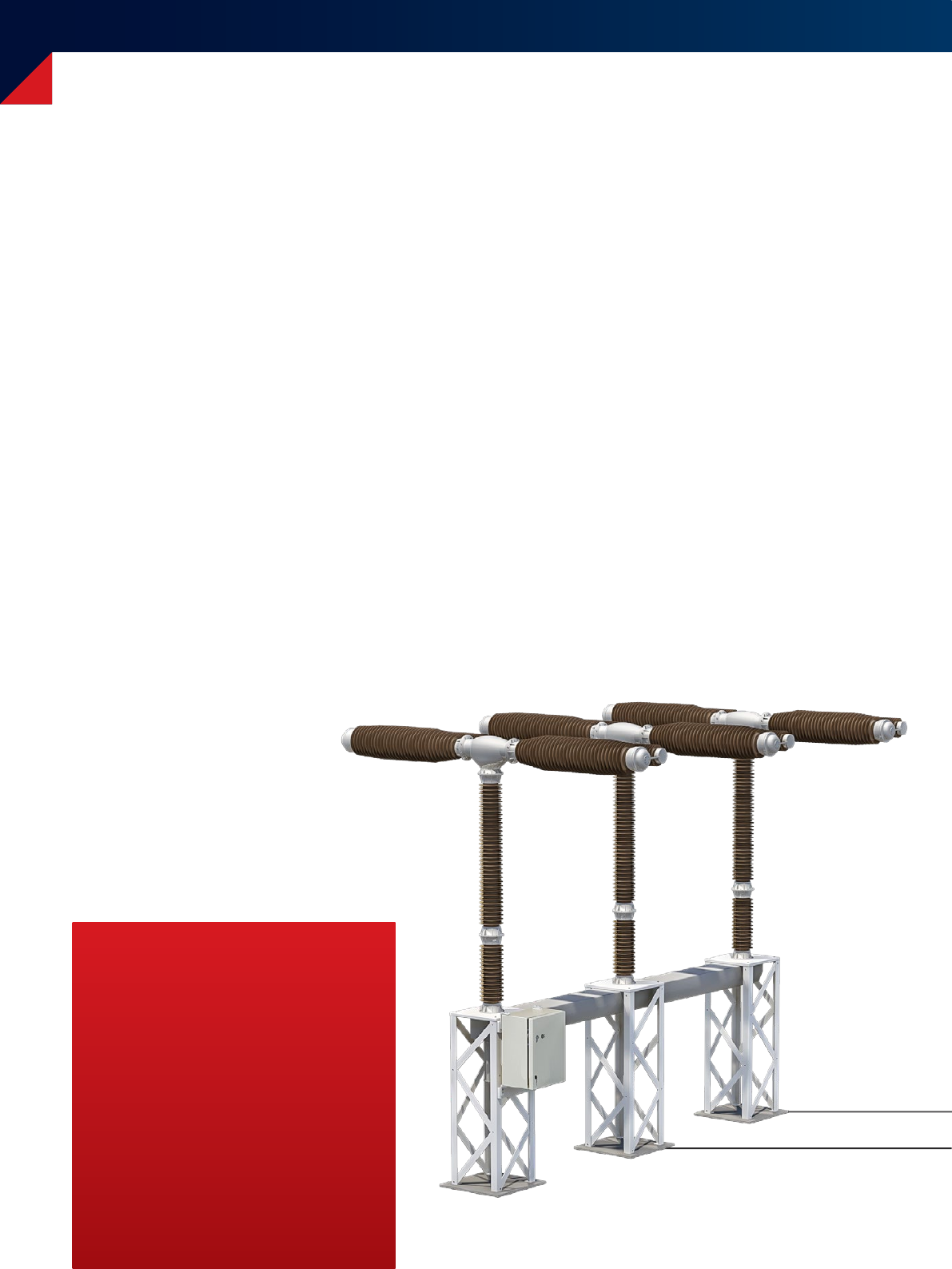
Switchgear and circuit breaker testing
Contact resistance measurement
The CPC 100 can measure contact resistance by injecting a
current of up to 400 ADC into the contacts and measuring
the voltage drop (using the 4-wire method). The resistance
value can be compared to the value given by the manufac-
turer as well as to previous records.
Why test switchgear and circuit breaker?
Switchgear consists of busbars, circuit breakers (CB),
disconnectors and earthing switches. There are various
connections and contacts within the switchgear. Poorly
maintained or damaged contacts can cause arcing, single
phasing or even fire which can lead to the total loss of
the asset.
Therefore, it is common practice to conduct contact resis-
tance measurements to ensure that the connections have
been made with the appropriate contact pressure.
Additionally, the insulation of CBs within the switchgear
has to be tested. These assets are frequently exposed to
HVstresses, switching currents and very high fault currents,
which heat up the circuit breakers and impact on the insu-
lation material.
22
Your benefits
> Contact resistance testing with up to
400 A DC
> Power/dissipation factor measurement
> Testing of entire chain from the CT to
the CB's main contacts
Switchgear and circuit breaker testing
Switchgear / circuit breaker testing
> Contact resistance
up to 400 ADC
> Bushing: power/dissipation factor (tan δ)
+ insulation capacitance
12 kV, 300 mA | frequency from 15 Hz to 400 Hz | with CP TD1
> Circuit breaker: power/dissipation factor (tan δ)
up to 12 kV, 300 mA | frequency from 15 Hz to 400 Hz | with CP TD1
> Insulating fluids: power/dissipation factor (tanδ)
up to 12 kV, 300 mA | with CP TD1 and CP TC12
23
Insulation testing of circuit breakers
For power/dissipation factor measurements on CBs, the
CPC100 is combined with the CP TD1. Measuring this
factor over a wide frequency range – in addition to mains
frequency – helps to better assess the insulation condition.
+ CP TD1
Insulation condition assessment of
circuit breakers and insulation fluids
(with CPTC12).
CPC 100
Ω measurement with the CPC 100‘s
400 ADC capabilities enables accurate
contact resistance measurements on
circuit breakers.
Commissioning and trouble shooting of protection systems
CT & VT performance check
The CPC 100 allows the verification of the ratio and polar-
ity of CTs and VTs – preventing wrong connections, espe-
cially in the case of tapped CTs. Injecting current or voltage
into individual CTs / VTs and checking the reading at the
relay ensures that phases are not mixed up and that the
CT and VT ratio setting in the relay is correct.
The CPC 100 can also measure the burden on the CTs
and VTs and, by determining the CT’s excitation curve, it
ensures that the protection circuits are connected to the
appropriate CT cores.
Wiring check
The CPC 100 can help to verify that the secondary wiring
is correct. By injecting a sawtooth signal into the CT or VT,
the operator verifies with a handheld device that the signal
has the correct polarity at the connection points of the sec-
ondary systems.
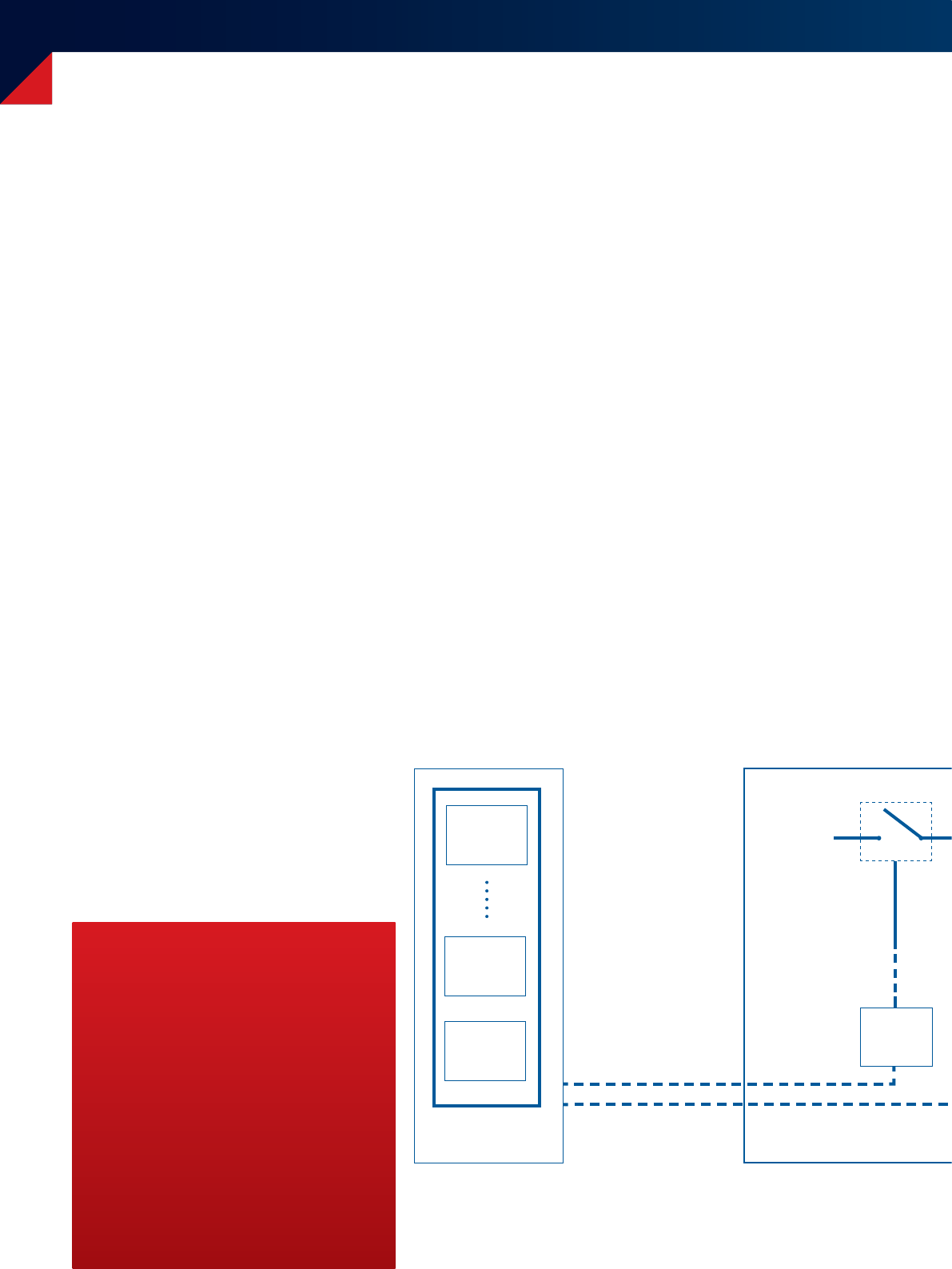
Commissioning protection systems
In order to work properly, protection and control systems
have to be correctly integrated into the substation or
power plant. Quantities from the primary system are trans-
formed at the VTs and CTs – using their different cores
– and so the voltage and current signals must be correctly
connected to the protection relays, automation units and
meters.
From these protection and control units, the trip signals
are routed back to the primary apparatus, for example,
the circuit breakers. A fault in any part of this system may
result in a system failure – false tripping or a failure to trip.
To prevent such a failure, the system’s functionality can be
verified by injecting into the primary side of the CT or VT
and checking the measured values at the relay or automa-
tion unit. Finally, injecting current at the magnitude of
a fault should result in the tripping of the circuit breaker,
which allows the verification of the complete chain.
24
Control room
Relay
Your benefits
> Testing of entire chain from the CT
to the CB's main contacts
> Versatile due to high-current and
high-voltage outputs
> Wide range of applications covered
CB
Busbar
Wires
Wiring
terminal
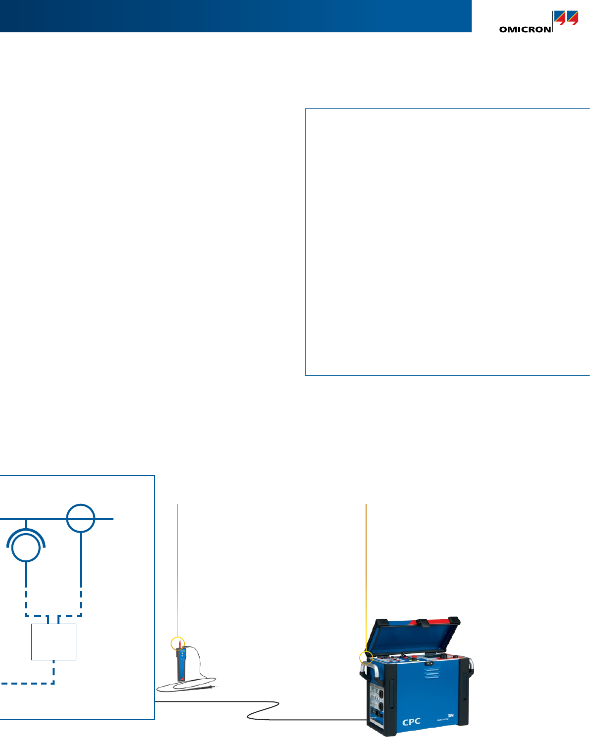
Commissioning and trouble shooting of protection systems
Protection installation testing
> CT ratio (with burden)
up to 800 A or 2000 A with the CP CB2, 5 kVA output power
> CT burden
up to 6 AAC | secondary
> CT excitation curve (knee point)
up to 2 kVAC
> VT ratio
up to 2 kVAC | polarity and burden
> VT burden
up to 130 VAC | secondary
> Overcurrent relays with primary injection (MV)
up to 800 A or 2000 A with the CP CB2, 5 kVA output power
> Polarity check with CPOL2
up to 800 A or 2 kVAC , 5 kVA output power
> Testing of the entire protection chain
by primary fault current injection and live CB tripping
CTVT
HV yard
Wiring
terminal
25
CPC 100
The CPC 100 can inject up to 800 A (2 000 A
with the CP CB2) or up to 2 kV as well as a
sawtooth polarity check signal into CTs or
VTs in the HV yard, hence performing testing
on the whole system.
Timing of CBs with overcurrent elements
For testing of CBs or load breaker switches with integrated
overcurrent elements, the CPC 100 can inject AC primary
currents up to 800 A (or 2000 A together with the current
booster CPCB2), and measure the time from the start of
the injection to the interruption of the current.
Primary injection
With the CPC 100 primary faults can be simulated to check
if overcurrent, differential or distance relays operate cor-
rectly. The total trip time including the CB operating time
can also be measured in this test.
+ CPOL2
The CPOL2 can check the correct polarity
along the different connection points
in the secondary wiring by analyzing the
sawtooth signal injected into the VT’s
and CT´s primary side using the CPC 100.

800 A
2 kV
CT
0111000001
IEC 61850-9-2 Sampled Values testing
IEC 61850
The standard for “Communication Networks and Systems
for Power Utility Automation”, IEC 61850, utilizes network
technologies for all types of information exchange.
Within IEC 61850, protocols for the transmission of
instantaneous voltage and current values are specified.
The sensors used in the transmission process can be
conventional CTs and VTs as well as unconventional
current and voltage sensors.
26
Your benefits
> Ready for applications in digital
substations
> Closed loop testing of merging units
> Primary injection works independently
of the sensor technology used
Sampled Values
A merging unit (MU) collects the measured current and
voltage values from the current and voltage sensors. Then
it merges the digitized values, which are called “Sampled
Values” (SV), into a data stream published to the substation
network.
Using this method, measured values (for example, the
bus voltage for a busbar protection scheme) can easily be
distributed to multiple bay devices.
CTs, VTs and
unconventional
sensors
MU
0111000001
Closed-loop testing
VT
Substation
Network
0111000001
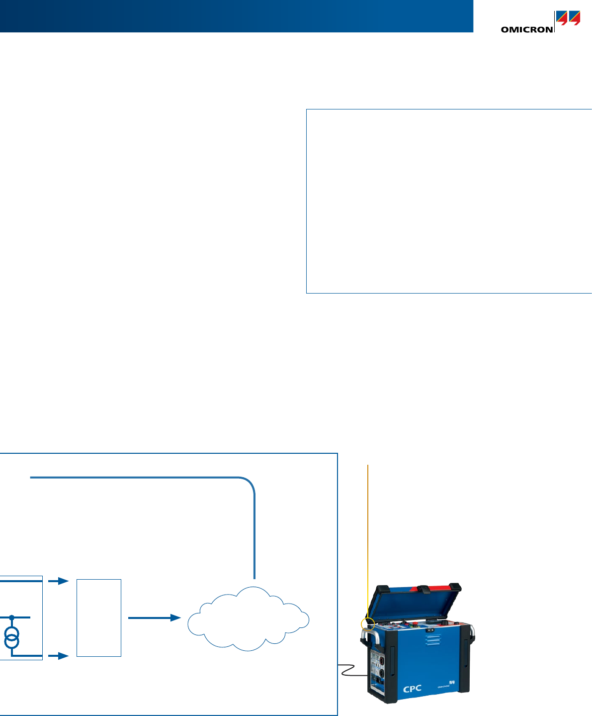
IEC 61850-9-2 Sampled Values testing
Sampled Values testing with the CPC 100
The CPC 100 test system performs closed-loop testing
whereby a test signal is injected on the primary side
of the current / voltage sensors. The MU converts the
sensor output into a SV stream which is published to the
substation network. The CPC 100 then reads the data
back from the network in order to perform a variety of
different tests.
Automatic MU and channel detection is achieved by
injecting a test signal with a specific wave form. An
optimized and time-effective algorithm searches for the
unique test pattern within all the available MUs on the
network to identify the correct channel for testing.
The CPC 100’s SV test card operates according to the
“Implementation Guideline for Digital Interface to
Instrumental Transformers using IEC 61850-9-2” published
by the UCA International User Group.
Sampled Values testing
> SV CT ratio test and polarity check
up to 800 A or up to 2 000 A , 5 kVA output power | with the CP CB2
> SV VT ratio test and polarity check
up to 2 kVAC
> Automatic MU detection
> Automatic voltage / current channel detection
> Frequency selective voltage / current meter
> Noise level measurement
> Amplitude response of the signal processing chain
up to 800 A or up to 2 kVAC | frequency from 15 Hz to 400 Hz
27
CPC 100
The CPC 100 injects a sinusoidal test
signal to perform tests such as the ratio
test. Additionally, the CPC 100 generates
specific periodic wave shapes to identify
the correct MU and corresponding test
channel.
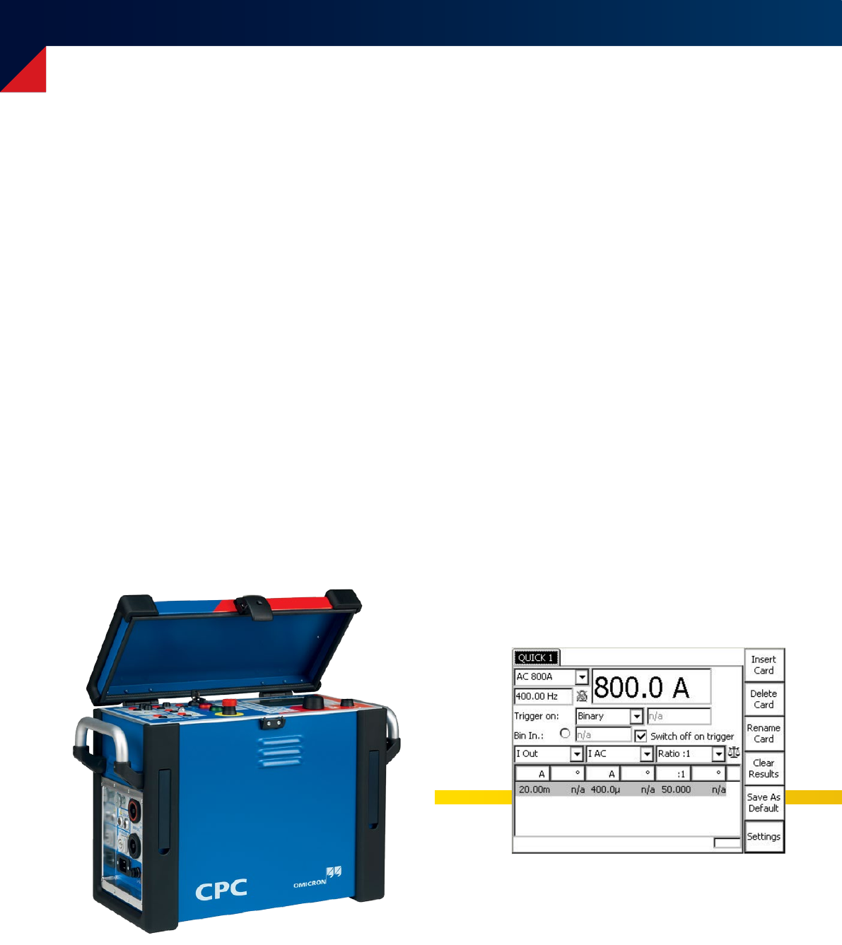
Operation of CPC 100: front panel
Operating from the front panel
Selecting test cards directly
Operating the CPC 100 manually provides the quickest
results with minimal training and preparation – perfect for
users who only operate the device occasionally. The user just
selects the test card to be used, connects the CPC 100 to the
asset and performs the test by pressing the start button.
Using pre-defined test templates
Additionally, pre-defined test templates help the user to
perform frequently used tests conveniently and efficiently.
A number of test cards (for example, power/dissipation
factor, winding resistance, ratio measurement,etc.) are
combined into one test template. An example is the
template containing all the recommended measurements
for testing a current transformer.
28
The test template can be seen as a test plan. It tells the user
which measurements to make and provides the basis for
the overall test report.
Test templates can be prepared in advance in the office on
the PC – without the CPC 100 connected – and can then be
executed on site, step by step. Users can also create their
own test templates and define, which test cards they want
to include.
The settings and results of all manual tests can be stored
on a flash memory and transfered to a PC using a USB
memory stick or ethernet connection.
CPC 100 test card
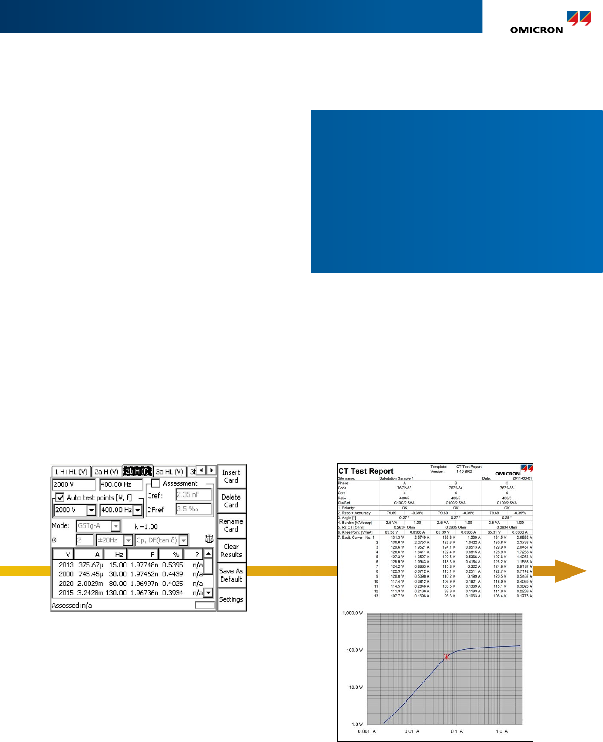
Operation of CPC 100: front panel
Customized reporting: Microsoft Excel™
After transferring the test results to a PC, report templates
in numerical and graphical form are available.
The measurement data – including settings and results as
well as administrative information such as date and time,
filename, etc. – can also be imported to these templates
for customized reporting, graphical result evaluation and
further analyses.
Microsoft Excel™ reports provide the basis for client-
specific reporting and allow test reports to be adapted to
utility or manufacturer specific formats. Further content,
such as company logos, can also be added.
Test reports can then be printed in a variety of languages.
Test template with test cards
Test report
29
Different ways to operate
The CPC 100 offers different operating modes, to meet
the personal preferences of the user:
> From the front panel:
Selecting test cards directly
> From the front panel:
Using pre-defined test templates
> Fully automated:
Using Primary Test Manager™ (see next page)
30
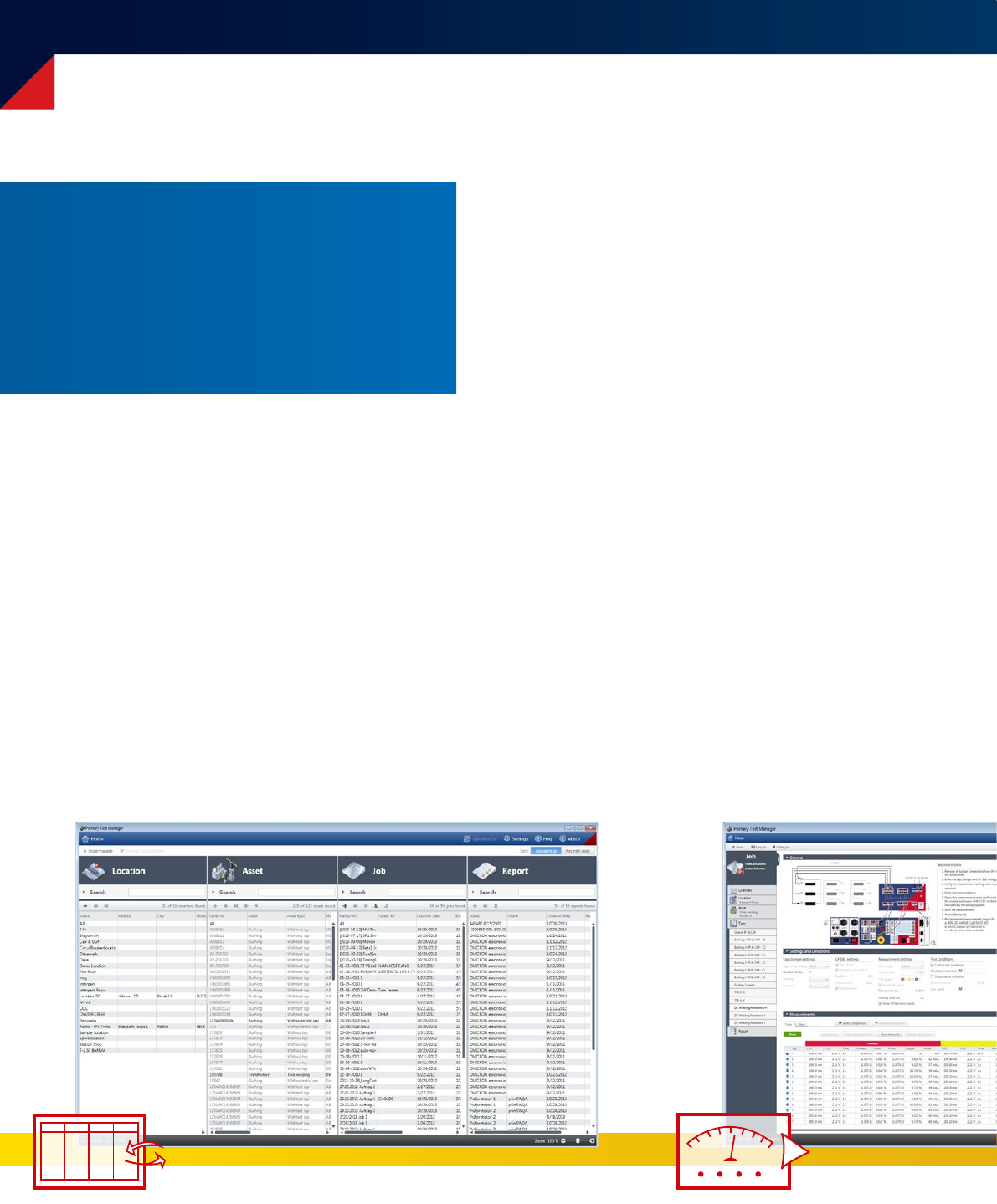
Step by step through the test procedure with Primary Test ManagerTM
Managing location, asset and test data
PTM provides a well-structured database for managing
test results and getting a comprehensive overview of the
asset's condition. Locations, assets, jobs and reports can
be defined and managed quickly and easily.
Import and export functionality
PTM supports data exchange between different test
systems. Data can be imported easily in the PTM database.
In addition, they can be filtered or exported in common
formats (XML, PDF, Microsoft Word™, Microsoft Excel™).
Data synchronization and back-up
During on-site testing, data is often generated by multiple
testing teams. With the ‘PTM DataSync’ module all data
can be synchronized to a central database hosted on
premises or in the cloud. In doing so, data synchronization
and storage becomes safer and more convenient. The
relevant locations can be selected in order to keep the
local database small.
Easy management of location, asset and test data due to a structured database,
implemented search and filter functions and automatic data synchronization.
The Primary Test ManagerTM (PTM) software
solution makes it possible to perform a multitude
of tests on power transformers, circuit breakers,
and current transformers. It provides active
guidance for the user during the process of testing
with the CPC 100, making tests faster, easier, and
safer.
PTM supports in the best possible way during execution of diagnostic tests via
wiring diagrams and asset-specific test plans according to international standards.
Step by step through the test procedure with Primary Test ManagerTM
31
Executing diagnostic tests
PTM helps to define the test asset with specific nameplate
views. It indicates mandatory and recommended
parameters, making data entry fast and easy.
Based on the nameplate values, PTM generates a
customized test plan according to current standards and
guidelines for each asset. This way PTM is able to provide
you with a comprehensive test plan for assessing the
condition of your asset thoroughly.
Easy connection due to wiring diagrams
Pre-configured wiring diagrams based on selected assets
help to set up the CPC 100 correctly. This minimizes the
likelihood of measurement errors and speeds up the
testing process.
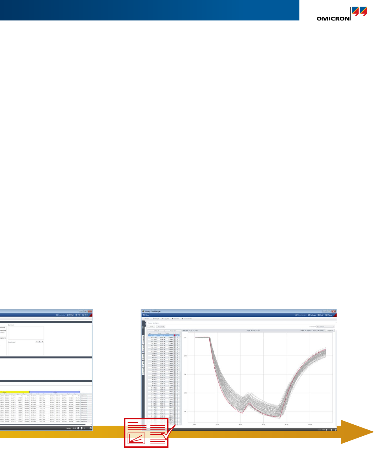
Result analysis and reporting
A real-time overview of the test results is given during the
measurement and an instant “pass/fail” assessment of
the test results is displayed based on specified limit values.
PTM automatically generates reports including all asset-
related information and the tests that have been performed.
This gives a comprehensive overview of the test object, test
results and assessment.
Comparison tools for detailed analysis
For a detailed analysis, different test results can be
compared side-by-side or trended over time. Users can
choose between a time- and type-based comparison
as well as a phase-based comparison.
Customized, individual reports
User can adapt reports to their needs in PTM. Reports can
be generated in Microsoft Word™, Microsoft Excel™ and
as a PDF file.
They can be further adapted by e.g. compiling the included
parts, providing comments or incorporating a company logo.
PTM supports in the best possible way during execution of diagnostic tests via
wiring diagrams and asset-specific test plans according to international standards.
For a comprehensive analysis, PTM offers automatic result assessment
and comparison as well as customized reporting.
32
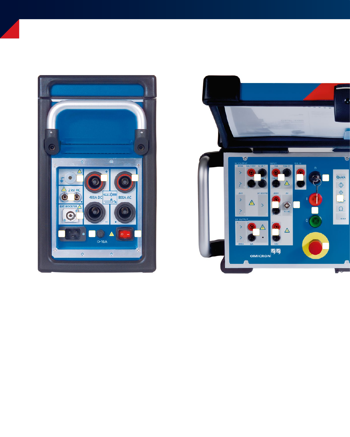
Front panel and connection possibilities
10
19
1
2
3
4 5
6 7 8
18
11
9
12 13
14
15 16
17
1. Grounding terminal
2. High AC voltage output 2 kV AC
3. External booster output
4. High DC current output 400 A DC
5. High AC current output 800 A AC
6. Mains power supply
7. Overcurrent protection
8. Power switch
9. 6 A or 130 V output
10. Current output 6 A DC
11. Current measuring input 10 A AC or DC
12. Voltage measuring input 300 V AC
13. Low level voltage measuring input 3 V AC
14. Voltage measuring input 10 V DC
15. Binary input for potential-free contacts or
voltages up to 300 V DC
16. Safety key lock
17. Signal lights
18. Emergency stop button
33
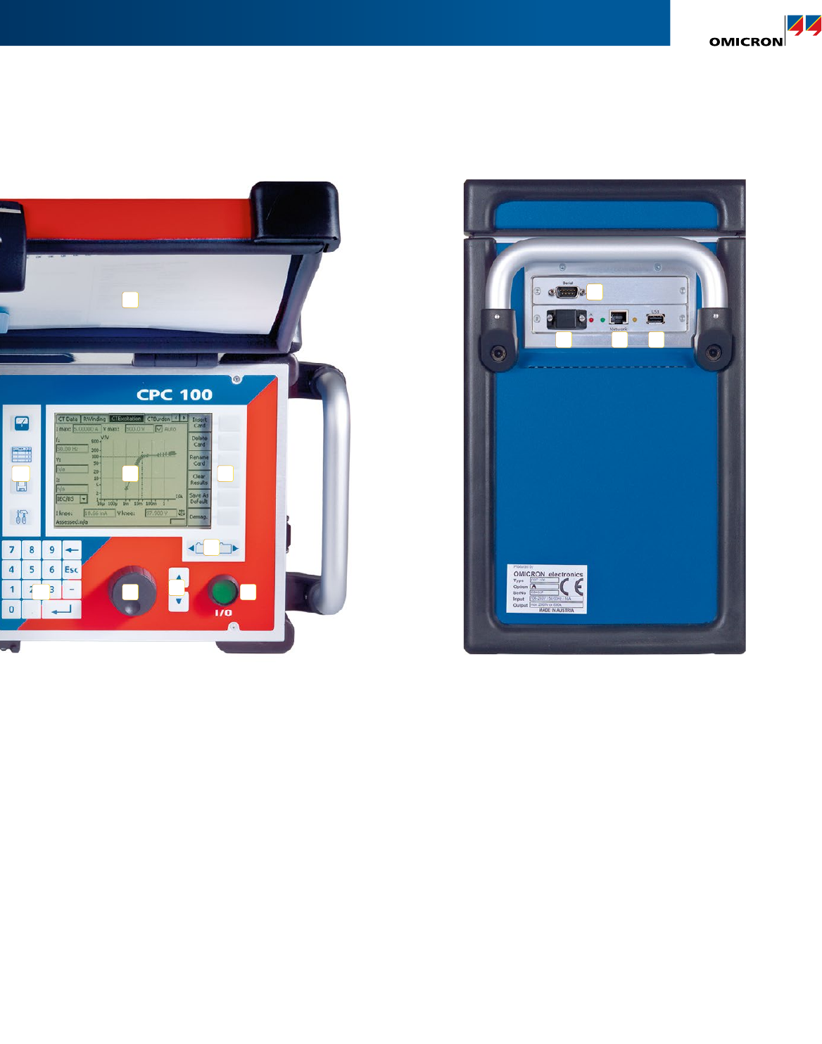
Front panel and connection possibilities
20
24 25
21
26
22
23
27
28 29
30 31 32
19. Keys for the quick selection of applications
20. Keys for the quick selection of the desired view
21. LCD monitor
22. Soft-touch keys which change their function
according to the selected application
23. Keys for selecting stacked test cards
24. Numerical keyboard
25. Advanced jog-dial hand wheel with “click”
(Enter) function
26. Up / down keys for navigation and entering values
27. Test start / stop button
28. User manual
29. Serial interface for devices such as CP TD1
30. Plug to connect external safety functions
31. Socket for the connection of the CPC 100
to a network or direct connection to a
PC’s network connector
32. USB memory stick connection

34
Technical data CPC 100
CPC 100
Generator / Outputs
Current outputs
Range Amplitude tmax
1Vmax
2Powermax
2f
800 A AC3 0 ... 800 A 25 s 6.0 V 4 800 VA 15 Hz ... 400 Hz
0 ... 400 A 8 min. 6.4 V 2 560 VA 15 Hz ... 400 Hz
0 ... 200 A > 2 h 6.5 V 1 300 VA 15 Hz ... 400 Hz
6 A AC10 0 ... 6 A > 2 h 55 V 330 VA 15 Hz ... 400 Hz
3 A AC10 0 ... 3 A > 2 h 110 V 330 VA 15 Hz ... 400 Hz
400 A DC 0 ... 400 A 2 min. 6.5 V 2 600 VA DC
0 ... 300 A 3 min. 6.5 V 1 950 VA DC
0 ... 200 A > 2 h 6.5 V 1 300 VA DC
6 A DC4, 10 0 ... 6 A > 2 h 60 V 360 VA DC
2 000 A AC3 with an optional current booster (CP CB2)
Inputs
Measuring inputs (Accuracy6)
Amplitude Amplitude Phase
Input Imped. Range Reading
Error
Full scale
Error
Full scale
Error
I AC / DC4, 7 < 0.1 Ω 10 A AC < 0.05 % < 0.05 % < 0.10°
1 A AC < 0.05 % < 0.05 % < 0.15°
10 A DC < 0.03 % < 0.08 % –
1 A DC < 0.03 % < 0.08 % –
V1 AC8500 kΩ 300 V < 0.05 % < 0.05 % < 0.10°
30 V < 0.05 % < 0.05 % < 0.10°
3 V < 0.10 % < 0.05 % < 0.10°
300 mV < 0.15 % < 0.05 % < 0.10°
V2 AC8, 11 10 MΩ 3 V < 0.03 % < 0.08 % < 0.10°
300 mV < 0.08 % < 0.08 % < 0.10°
30 mV < 0.10 % < 0.25 % < 0.15°
V DC4, 7 10 V < 0.03 % < 0.08 % –
1 V < 0.03 % < 0.08 % –
100 mV < 0.05 % < 0.10 % –
10 mV < 0.05 % < 0.15 % –
Voltage outputs
Range Amplitude5tmax Imax Powermax
5f
2 kV AC3 0 ... 2 kV 1 min. 1.25 A 2 500 VA 15 Hz ... 400 Hz
0 ... 2 kV > 2 h 0.5 A 1 000 VA 15 Hz ... 400 Hz
1 kV AC30 ... 1 kV 1 min. 2.5 A 2 500 VA 15 Hz ... 400 Hz
0 ... 1 kV > 2 h 1.0 A 1 000 VA 15 Hz ... 400 Hz
500 V AC30 ... 500 V 1 min. 5.0 A 2 500 VA 15 Hz ... 400 Hz
0 ... 500 V > 2 h 2.0 A 1 000 VA 15 Hz ... 400 Hz
130 V AC10 0 ... 130 V > 2 h 3.0 A 390 VA 15 Hz ... 400 Hz
Internal measurement of outputs (Accuracy6)
Amplitude Amplitude Phase
Output Range Reading
Error
Full scale
Error
Full scale
Error
800 A AC –< 0.10 % < 0.10 % < 0.10°
400 A DC –< 0.20 % < 0.05 % –
2 kV AC 2 000 V < 0.05 % < 0.05 % < 0.10°
1 000 V < 0.05 % < 0.05 % < 0.15°
500 V < 0.05 % < 0.05 % < 0.20°
5 A < 0.20 % < 0.05 % < 0.10°
500 mA < 0.05 % < 0.05 % < 0.10°
Additional features of the measuring inputs
Automatic range switching (except Amplifier test card)
Galvanically separated potential groups: I AC/DC ; V1 & V2 ; V DC
AC frequency range: 15 Hz to 400 Hz (except Amplifier test card)
Protection of I AC/DC input: 10 A very fast acting (FF) fuse4
Binary input for dry contacts or voltages up to 300 V DC7
Trigger criteria: Toggling with potential-free contacts or
voltages of up to 300 V
Input impedance: > 100 kΩ
Response time: 1 ms
Output to input synchronization
Test cards Quick,
Sequencer, Ramping
Amplifier test card
Frequency range 48 Hz ... 62 Hz 48 Hz ... 62 Hz
Synchronization
inputs
V1 AC
(automatic range switch)
V1 AC, V2 AC, I AC
(fixed to maximum range)
Input
magnitude
10 % of input range full scale
Output
magnitude
5 % of output range full scale
Settling time 100 ms after 5 % of
output range full scale
is reached
1 000 ms after 5 % of
output range full scale
is reached
Signal changes All quantities must be
ramped within 20 signal
periods
No changes of frequency
and phase. Magnitude
changes without limitation.
Output follows within
250 ms
Phase tolerance 0.5 ° within the limits as specified above

Technical data CPC 100
35
Power supply and mechanical data
Single-phase,
nominal9
100 VAC ... 240 VAC, 16 A
Single-phase,
permissible
85 VAC ... 264 VAC (L-N or L-L)
Frequency, nominal 50 Hz / 60 Hz
Power consumption < 3 500 VA (< 7 000 VA for a time < 10 s)
Connection IEC320 / C20
Weight 29 kg / 64 lbs (case without protection cover)
Dimensions
(W × H × D)
468 × 394 × 233 mm (18.4 × 15.5 × 9.2 in),
cover, without handles.
Environmental conditions for CPC 100 and CPC 100 accessories
Operating temperature -10 °C ... +55 °C /+14 °F ... +131 °F
Storage temperature -20 °C ... +70 °C / -4 °F ... +158 °F
Humidity range 5 % ... 95 % relative humidity, no condensation
Resistance measurement
4-wire measurement with 400 A DC output and 10 V DC input
Current Resistance Voltage Accuracy (full scale)
400 A 10 Ω 4 mV Error < 0.70 %
400 A 100 Ω 40 mV Error < 0.55 %
400 A 1 mΩ 400 mV Error < 0.50 %
400 A 10 mΩ 4 V Error < 0.50 %
4-wire measurement with 6 A DC output and 10 V VDC input
Current Resistance Voltage Accuracy (full scale)
6 A 100 mΩ 0.6 V Error < 0.35 %
6 A 1 Ω 6 V Error < 0.35 %
1 A 10 Ω 10 V Error < 0.25 %
2-wire measurement with 10 V VDC input
Current Resistance Voltage Accuracy (full scale)
> 5 mA 100 Ω Error < 0.60 %
> 5 mA 1 kΩ Error < 0.51 %
> 5 mA 10 kΩ Error < 0.50 %
All input / output values are guaranteed for one year within an
ambient temperature of 23 °C ± 5 °C / 73 °F ± 10 °F, a warm-up time
longer than 25 min. and in a frequency range of 45 Hz to 60 Hz or DC.
Accuracy values indicate that the error is smaller than ± (value read x
reading error + full scale of the range x full scale error).
1. With a mains voltage of 230 V using a 2 × 6 m high-current cable
at an ambient temperature of 23 °C ± 5 °C / 73 °F ± 10 °F.
2. The power and maximum voltage may be reduced above 60 Hz
or below 50 Hz.
3. Output can be synchronized with V1 AC in Quick, Sequencer,
Ramping and Amplifier test cards.
4. The inputs and outputs are protected with lightning arrestors
between the connector and against the protective earth. In the
event of application of energy exceeding a few hundred Joule the
lightning arrestors apply a permanent short-circuit to the input /
output.
5. The power and amplitude may be reduced above 200 Hz or
below 50 Hz.
6. 98 % of all units have an accuracy better than specified as “typical”.
7. This input is galvanically separated from all other inputs.
8. V1 and V2 are galvanically coupled but separated from all other
inputs.
9. There are power restrictions for mains voltages below 190 VAC.
10. Fuse-protected.
11. When using the CTRogowski test card, the 3 V V2 AC input uses
an additional software based integration method. In the range of
50 Hz < f < 60 Hz, this results in a phase shift of 90 ° as well as an
additional phase error of ± 0.1 ° and an additional amplitude er-
ror of ± 0.01 %. For frequencies in the range of 15 Hz < f < 400Hz,
the phase error is not specified, and the amplitude error can be
up to ± 0.50 % higher.
Equipment reliability
Shock IEC / EN 60068-2-27, 15 g / 11 ms,
half-sinusoid, each axis
Vibration IEC / EN 60068-2-6, frequency range from
10 Hz to 150 Hz, continuous acceleration 2 g
(20 m⁄s / 65 ft ⁄s), 10 cycles per axis
36
CP TD1 – Tan-delta unit
High-voltage output
U/f I S tmax f
0 ...12 kV AC 300 mA 3 600 VA > 2 min. 15 Hz ... 400 Hz
0 ...12 kV AC 100 mA 1 200 VA > 60 min. 15 Hz ... 400 Hz
Internal measurement of voltage output / current inputs
Range Resolution Typical accuracy Conditions
0 ... 12 000 VAC 1 V Error < 0.3 % of
reading + 1 V
V > 2 000 V
0 ... 5 AAC 5 digits Error < 0.3 % of
reading + 100 nA
Ix < 8 mA
5 digits Error < 0.5 % of
reading
Ix > 8 mA
Capacitance Cp (equivalent parallel circuit)
Range Resolution Typical accuracy Conditions
1 pF ... 3 F 6 digits Error < 0.05 % of
reading + 0.1 pF
Ix < 8 mA, Vtest =
300 V ... 10 kV
1 pF ... 3 F 6 digits Error < 0.2 % of
reading
Ix > 8 mA, Vtest =
300 V ... 10 kV
Power factor PF / dissipation factor DF
Range Resolution Typical accuracy Conditions
0 ... 10 %
(capacitive)
5 digits Error < 0.1 % of
reading + 0.005 %
f = 45 Hz ... 70 Hz,
I < 8 mA, Vtest =
300V ... 10 kV
0 ... 100 % (PF)
0 ... 10 000 % (DF)
5 digits Error < 0.5 % of
reading + 0.02 %
Vtest =
300 V ... 10 kV
Impedance
Range Resolution Typical accuracy Conditions
1 kΩ ...
1, 200 MΩ
6 digits Error < 0.5 %
of reading
Vtest =
300 V ... 10 kV
Phase angle
Range Resolution Typical accuracy Conditions
-90° ... +90° 4 digits Error < 0.01 ° Vtest = 300 V ... 10 kV
Quality factor
Range Resolution Typical accuracy
0 ... 1 000 5 digits Error < 0.5 % of reading + 0.2 %
> 1 000 5 digits Error < 5 % of reading
Inductance
Range Resolution Typical accuracy
1 H ... 1 000 kH 6 digits Error < 0.3 % of reading
Watts / power (P, Q, S)
Range Resolution Typical accuracy
0 ... 3.6 kVA 5 digits Error < 0.5 % reading + 1 mVA
0 ... 3.6 kW/kVAr6 digits Error < 0.5 % reading + 1 mW / mVAr
Mechanical data
Dimensions (W × H × D) 450 × 330 × 220 mm / 17.7 × 13 × 8.7 in
Weight 25 kg / 55.2 lbs
Technical data CPC 100 accessories
Combined with the CPC 100, the CP TD1 measures the capacitance and dissipation factor (power factor)
with laboratory precision.
CP SB1 – Switch box
AC input / V1 AC output Max. 300 Vrms
DC input Max. 6 ADC
Transformer high and
low voltage connections
Max. 300 Vrms between all connectors
and ground
Supply Via serial interface from CPC 100 (+15 V)
Dimensions (W × H × D) 357 × 235 × 111 mm / 14.1 × 9.2 × 4.4 in
Weight 3.5 kg / 7.7 lbs
The CP SB1 switch box enables fully automatic
testing of three-phase power transformers.
CP TC12 – 12 kV oil test cell
Cell type Three-electrode design
with guard
Test gap 11 mm / 0.43 in
Capacitance of empty cell (air) Approx. 65 pF ± 10 %
Sample volume 1.2 liters ... 2 liters / 41 ... 68 fl.oz.
Max. RMS test voltage 12kV
Inner dimensions (diameter × height) 172 mm × 180.8 mm / 6.8 × 7.1 in
Outer dimensions (W × H × D) 220 × 235.5 × 220 mm /
8.7 × 9.3 × 8.7 in
Weight Approx. 9.2 kg / 20 lbs
The CP TC12 oil test cell precisely determines the dielectric
constant, the dissipation factor (tan delta) and the power
factor of insulating liquids such as transformer oil.
37
CP CU1 – Coupling unit
Output ranges
Range Current Compliance voltage at > 45 Hz
10 A 0 ... 10 Arms 500 Vrms
20 A 0 ... 20 Arms 250 Vrms
50 A 0 ... 50 Arms 100 Vrms
100 A 0 ... 100 Arms 50 Vrms
Measuring transformers
Transformer Ratio Accuracy at 50 Hz / 60 Hz
VT 600 V : 30 V Class 0.1
CT 100 A : 2.5 A Class 0.1
Inputs
Characteristic Rating
V SENSE Overvoltage
category
CAT III (IEC 61010-1)
Voltage range 0 ... 600 Vrms
BOOSTER Overvoltage
category
CAT I
Voltage range 0 ... 200 Vrms
Current range 0 ... 30 Arms
Frequency range 15 Hz ... 400 Hz
Fuse 30 A fast acting,
automatic circuit breaker
Output power
Characteristic Rating
Maximum
power
5 000 VA (45 Hz ... 70 Hz), cos φ < 1.0 for 8 s at 230 VAC
5 000 VA (45 Hz ... 70 Hz), cos φ < 0.4 for 8 s at 115 VAC
Continuous
power
0 ... 1 600 VA
Mechanical data
Dimensions (W × H × D) 450 × 220 × 220 mm / 17.7 × 8.7 × 8.7 in
Weight 28.5 kg / 62.78 lbs
Accuracy
Range Accuracy
of absolute
value
Accuracy
of phase
angle
V SENSE
voltage
I OUT
current
Current
range
0.05 ... 0.2 1.0 ... 0.5 % 1.5 ... 0.8° 5 ... 20 V 100 A 100 A
0.2 ... 2 0.5 ...0.3 % 0.8 ...0.5° 20 ... 50 V 100 ... 25 A 100 A
2 ... 5 0.3 % 0.5° 100 V 50 ... 20 A 50 A
5 ... 25 0.3 % 0.5° 100 ... 250 V 20 ... 10 A 20 A
25 ... 300 0.3 ... 1.0 % 0.5 ... 1.5° 250 ... 500 V 10 ... 1,5 A 10 A
Technical data CPC 100 accessories
In combination with the CPC 100 the CP CU1 is used for line parameter measurements and ground testing.
CP GB1 – Grounding box
Nominal ac spark-over voltage < 1 000 Vrms
Impulse spark-over voltage < 2 000 Vpeak
Short circuit proof with:
16 mm cylindrical or 20 mm ball studs 26.5 kA (< 100 ms) / 67 kApeak
25 mm ball studs 30 kA (< 100 ms) / 75 kApeak
Torsional moment for changing
arrestors
> 15 Nm
Dimensions (Ø × H) 200 × 190 mm / 7.9 × 7.5 in
Weight 6.8 kg / 13.2 lbs
(including grounding cable)
The CP GB1 grounding box features high current
surge arrestors to protect the CP CU1 and the CPC 100
from unexpected overvoltages on the line under test.
HGT1 – Handheld grounding tester
Voltage input Max. 25 Vrms
Power supply 1 × 3.7 V lithium polymer
(Li-Po) battery
Dimensions (W × H × D) 90 × 180 × 45 mm /
3.5 × 7.1 × 1.8 in
Weight (including battery) 0.48 kg / 1 lb
The HGT1 handheld grounding tester can be combined with
the CPC 100 and CP CU1 to measure step and touch voltages.
38
Technical data CPC 100 accessories
Inductors 2 × 40 H 2 × 80 H 1 × 40 H and 1 × 80 H
Current compensation
50 Hz 2 × 1 A 2 × 0.5 A 1 × 1 A + 1 × 0.5 A
60 Hz 2 × 0.8 A 2 × 0.4 A 1 × 0.8 A + 1 x 0.4 A
Capacitance compensation
50 Hz 2 × 250 nF 2 × 125 nF 1 × 250 nF + 1 × 125 nF
60 Hz 2 × 180 nF 2 × 90 nF 1 × 180 nF + 1 × 90 nF
On/off times at 25 °C
0.5 A on/off times:
6 min/6 min
on/off times:
6 min/6 min
on/off times:
6 min/6 min
1 A on/off times:
2 min/6 min
-on/off times:
2 min/6 min
Maximum test voltage 12 kVrms (≥ 50 Hz)
Dimensions (W×H×D) 455 × 275 × 220 mm /
17.9 × 10.8 × 8.7 in
Weight 36 kg / 79.4 lbs
CP CR500 – Compensation reactor
The CP CR500 compensating reactor allows to test the
insulation quality of generators, motors, cables and other
systems with large capacitance.
CPOL2 – Polarity checker
Measuring range 250 Vrms ... 300 Vrms
Evaluated signal form Polarity test signal with slope ratio ≥ 3:1
Nominal frequency 52.6 Hz
Power consumption Measurement active: < 100mW
Standby: < 50 W
Input impedance > 300 k
Batteries Type and number:
2 × 1,5 V Mignon LR6 AA AM4 MN1500
Dimensions (W × H × D) 180 × 55 × 35 mm / 7.1 × 2.2 × 1.4 in
Weight 150 g / 0.33 lb
The CPOL2 can check the correct polarity along the
different connection points in an instrument transformer's
secondary wiring.
CP DB1 – Discharge box
6 A path Switch closed 6 A continuous
Switch open The discharge process is faster by a
factor of 4 compared to the CPC 100
6 Apeak
Overtemperature protection:
85 ºC / 185 ºF
Overvoltage protection: 150 V / 5 kA
between connectors
100 A path Switch closed 100 A continuous
Switch open The discharge process is faster by a
factor of 10 compared to the CPC 100
100 Apeak
2 500 Jmax
Overvoltage protection: 200 V / 30 kA
between connectors
Mechanical data
Dimensions (W × H × D) 357 × 235 × 147 mm / 14.0 × 9.2 × 5.8 in
Weight 4 kg / 8.8 lbs
The CP DB1 transformer discharge box facilitates
fast discharging of power transformers during the test process.
CP CB2 – Current booster
Output current up to 2 000 A
Output power at 2 000 A 5 kVA
Accuracy of current at 50 Hz / 60 Hz Error < ± 0.13 % (rd) ± 0.13 % (fs)
Phase tolerance at full scale Error < ± 0.25 %
Dimensions (W×H×D) 186 × 166 × 220 mm
7.3 × 6.5 × 8.7 in
Weight 16.0 kg / 35.3 lbs
The CP CB2 is an current booster for applications
requiring currents up to 2000 A.
The CP RC resonance circuit units in combination with
the CPC 100 can be used for voltage withstand testing
of gas-insulated switchgears (GIS).
CP RC – Compensating reactor
CP TR7 / CP TR8 CP CR4 /CP CR6 CP AT1
Voltage output 180 V1/ 220 V 220 V 254 V - 278 V
Current output 60 A 150 A 16 A
Apparent power on
secondary side
13.2 kVAr 33 kVAr4.4 kVAr
Frequency 80 Hz ... 120 Hz 80 Hz ... 120 Hz 50 Hz / 60 Hz
Insulation class F F F
Weight 19 kg / 42 lbs 20.5 kg / 45 lbs 15.5 kg / 34 lbs
Dimensions
(W × H × D)
262 × 277.5 × 222 mm / 10.31 × 10.9 × 8.74 in
39
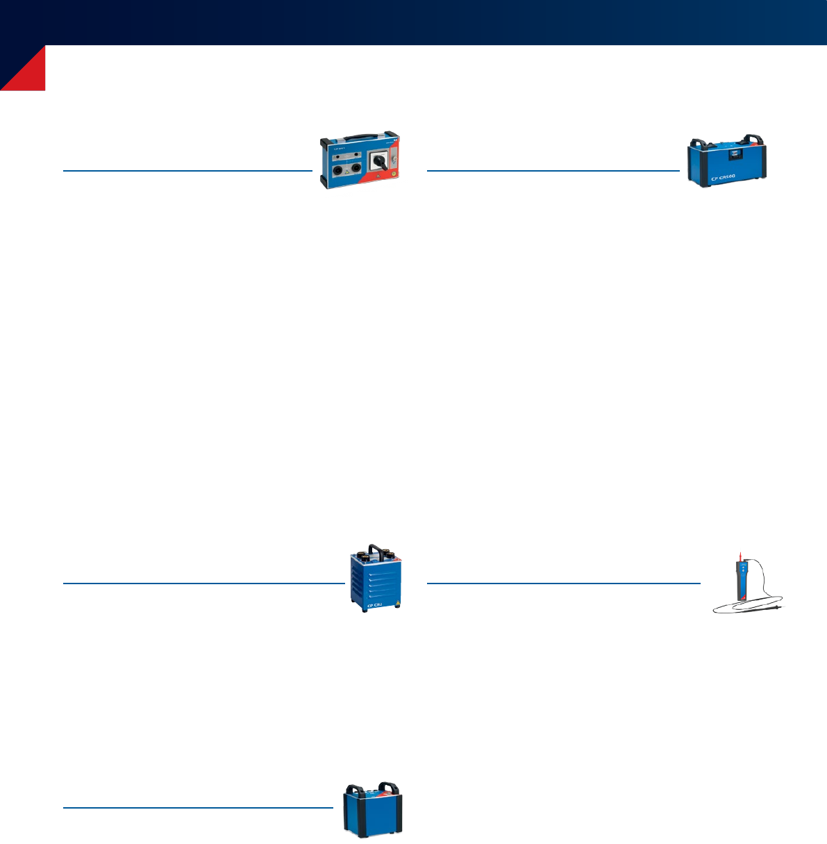
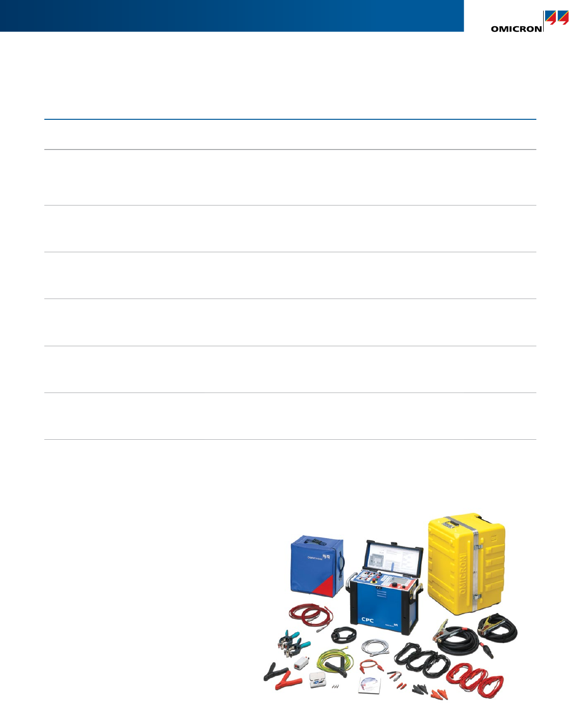
Package Description Ordering No.
CPC 100 Basic Package Package including CPC 100 and all accessories to perform basic
checks on primary assets. VE000601
CPC 100 Standard Package
includes CPC 100 Basic Package
Package including CPC 100 and all accessories to perform
common electrical tests on instrument and power transformers. VE000611
CPC 100 Enhanced Package
includes CPC 100 Standard Package
In addition to the standard package powerful tools for
substation comissioning are provided. VE000621
CPC 100 Transformer Test System
Package including CPC 100, CP TD1 and all accessories to
perform common electrical tests and power/dissipation factor
measurements on power transformers.
VE000645
CPC 100 Line Impedance Test System
Package including CPC 100, CP CU1, CP GB1 and all accessories
to perform impedance measurements for determination of
distance protection relay settings.
VE000602
CPC 100 Rotating Machines
Test System
Package including CPC 100, CP TD1, CP CR500 and all
accessories to perform common electrical tests and power/
dissipation factor measurements on rotating machines.
VE000648
CPC 100 PF/DF Test System Package including CPC 100, CP TD1 and all accessories to
perform power/dissipation factor measurements on all assets. VE000640
Ordering information
CPC 100 Packages
CPC 100 Standard Package

40
Package Description Ordering No.
CP TD1 Upgrade Option Upgrade option to expand your existing CPC 100
to a power/dissipation factor test system. VE000641
CP CB2 Upgrade Option Upgrade option allowing test currents of up to 2000 A
in conjunction with the CPC 100. VEHZ0630
CP SB1 Upgrade Option Upgrade option to expand your existing CPC 100 standard
package to a fully automated transformer test system. VEHZ0692
CP CU1 and CP GB1 Upgrade Option
Upgrade option to expand your existing CPC 100
to a line impedance measurent test system.
Note: CP sequencer test card has to be ordered separately
(order no. VESM0635)
VEHZ0671
Ground Impedance and
Step & Touch Voltage Set
Package to measure ground impedance and stepandtouch
voltages of substations. Including handheld grounding tester
HGT1 and accessories.
VEHZ0708
CPC Sync Upgrade Option
for existing CPC
Upgrade option including the TRC1 which allows
synchronizing up to three CPC in order to create
a powerful source for HV applications.
VEHO0648
CPC Sync Upgrade Option
for new CPC
Upgrade option including the TRC1 which allows
synchronizing up to three CPC in order to create
a powerful source for HV applications.
VEHO0649
CPC 80 Slave unit including accessories for synchronization of CPCs.
Note: Only CPC 100 can be used as master and slave unit. VE000649
CP RC1 Upgrade Option Upgrade option for high voltage testing on gas-insulated
switchgear (GIS) up to 123 kV rated voltage. VEHZ0760
CP RC2 Upgrade Option Upgrade option for high voltage testing on gas-insulated
switchgear (GIS) up to 145 kV rated voltage. VEHZ0770
CPC 100 Upgrade Options
Ordering information

41
Package Description Ordering No.
CPOL2 Upgrade Option Upgrade option to check polarity of a CT's or VT's
secondary wiring. VESM0645
CP TC12 Upgrade Option
Upgrade option for determination of power/dissipation factor
and permittivity of insulaton liquids, e.g. transformer oil.
It is used in conjuction with the CPC 100 and the CP TD1.
VEHZ0601
CP DB1 Upgrade Option Upgrade option for faster discharging after a winding
resistance measurement on a power transformer. VEHZ0695
CP CR500 Upgrade Option
Upgrade option for power/dissipation factor measurements
on rotating machines in conjuction with the CPC 100 and
the CP TD1.
VEHZ0604
PTM advanced Upgrade Option Upgrade option to operate your CPC using the guided
workflow, depending on available software licences. VESM0671
PTM advanced for HGT1
Upgrade Option
Upgrade option for the Ground Impedance and Step & Touch
Voltage Set to use the guided PTM workflow with your HGT1. VESM0626
PTM DataSync "OnPremises"
Upgrade Option
Separate module for data synchronization and back-up:
For up to 3 users
For up to 10 users
For up to 25 users
Upgrade for 1 user
VESM0677
VESM0678
VESM0679
VESM0680
PTM DataSync "Cloud"
Upgrade Option
Separate module for data synchronization and back-up:
For up to 3 users
For up to 10 users
For up to 25 users
Upgrade for 1 user
VESM0681
VESM0682
VESM0683
VESM0684
CPC 100 Upgrade Options

4242
A strong and safe connection
Welcome to the team
At OMICRON you can always depend on an experienced team that actively
supports you and an infrastructure that you can rely on. We always listen
attentively in order to understand your needs so that we can offer you the best
possible solutions. We strive for lasting partnerships and ensure that you can
continue to rely on your product long after you've purchased it. In order to
do this, we focus on quality, the transfer of knowledge and unique customer
support.
Don, Wenyu and Christoph are able to tell you about the services we have
available for you and why it pays to be part of the team.
Don Platts
Application Specialist
Solutions you can rely on...
... developed with experience, passion and an innovative approach that we use to
continually set groundbreaking standards in our industry sector.
We invest more than 15 % of the total turnover in research and development so
that we can even guarantee the reliable use of the latest technology and methods
in the future.
Our comprehensive product care concept also guarantees that your investment in
our solutions – like free software updates – pays off in the long term.

43
Wenyu Guo
OMICRON Academy
Christoph Engelen
Technical Support
We share our knowledge...
… by maintaining a constant dialogue with users and experts. Some examples
of this are our customer events and conferences that take place all over the
world and our collaboration with numerous standardization committees.
We also make our knowledge available to you in the customer section of our
website in the form of application reports, specialized articles and articles in
the discussion forum. With the OMICRON Academy, we also provide a wide
spectrum of training possibilities and assist you with Start-up training and free
webinars.
When rapid assistance is required...
… our excellent level of support is always appreciated. You can reach the highly-
qualified and committed technicians in our customer support department 24 hours
a day, seven days a week – and it's completely free. We deal with repair services and
service features in a fair and non-bureaucratic manner.
We can help minimize your downtime by lending you equipment from a readily
available plant at one of our service centers in your area. A comprehensive offer of
services for consulting, testing and diagnostics completes our range of services.

www.omicronenergy.com
The following publications provide further information on the solutions described in this
brochure:
For more information, additional literature, and detailed contact information of our
worldwide offices please visit our website.
OMICRON is an international company serving the electrical power industry with
innovative testing and diagnostic solutions. The application of OMICRON products
allows users to assess the condition of the primary and secondary equipment on
their systems with complete confidence. Services offered in the area of consulting,
commissioning, testing, diagnosis and training make the product range complete.
Customers in more than 140 countries rely on the company’s ability to supply leading-
edge technology of excellent quality. Service centers on all continents provide a broad
base of knowledge and extraordinary customer support. All of this together with our
strong network of sales partners is what has made our company a market leader in the
electrical power industry.
Subject to change without notice.
Diagnostic Testing
Solutions for Power
Transformers Brochure
CP CU1 Brochure Primary Test Manager™
(PTM) Brochure
CP CU1
Coupling unit for line and ground testing
Primary Test Manager™ (PTM)
Testing and management software for primary assets
© OMICRON L2791, November 2017
