CPS235W
User Manual: CPS235W
Open the PDF directly: View PDF ![]() .
.
Page Count: 66
SPECIFICATIONS AND PARTS ARE SUBJECT TO CHANGE FOR IMPROVEMENT.
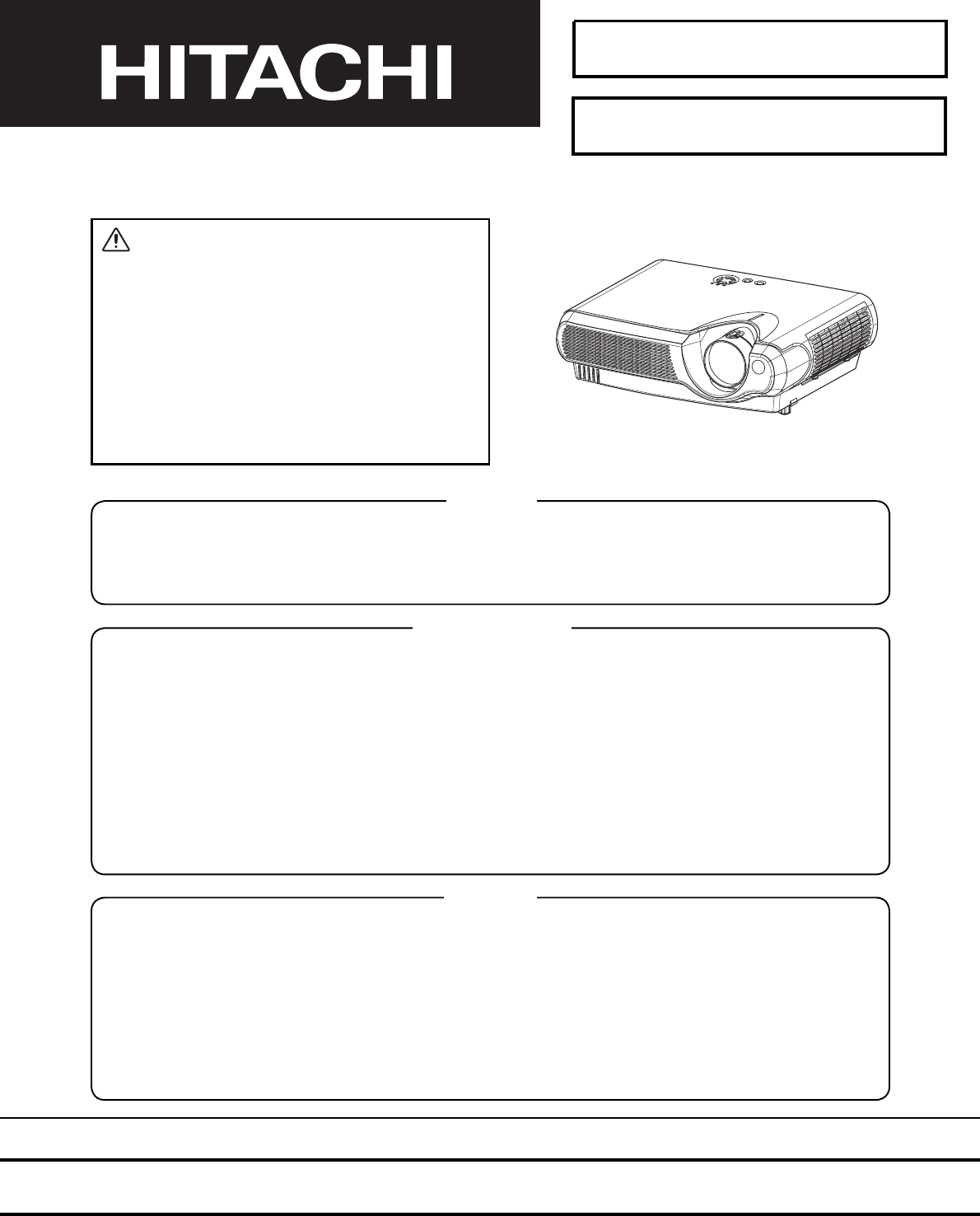
Multimedia LCD Projector
March 2004 Digital Media Division
SM0541
CP-S235W(C10SM2)
SERVICE MANUAL
Be sure to read this manual before servicing. To assure safety from fi re, electric shock, injury, harmful radi-
ation and materials, various measures are provided in this Hitachi Multimedia LCD Projector. Be sure to
read cautionary items described in the manual to maintain safety before servicing.
Caution
1. When replacing the lamp, avoid burns to your fi ngers. The lamp becomes very hot.
2. Never touch the lamp bulb with a fi nger or anything else. Never drop it or give it a shock. This may
cause bursting of the bulb.
3. This projector is provided with a high voltage circuit for the lamp. Do not touch the electric parts of
power unit (main) when the projector is turned on.
4. Do not touch the exhaust fan during operation.
5. The LCD module assembly is easily damaged. When replacing the LCD LENS/PRISM assembly, do
not hold the FPC of the LCD module assembly.
6. Use only the cables included with the projector or specified.
Service Warning
1. Features --------------------------------------------------- 2
2. Specifi cations --------------------------------------------- 2
3. Part names ------------------------------------------------ 3
4. Adjustment ----------------------------------------------- 5
5. Troubleshooting ----------------------------------------11
6. Service notes -------------------------------------------- 16
7. Wiring diagram ----------------------------------------- 30
8. Assembly diagram-------------------------------------- 35
9. Replacement parts list ------------------------------- 38
10.RS-232C communication --------------------------- 39
11.Block diagram ------------------------------------------ 47
12.Connector connection diagram ----------------- 48
13.Basic circuit diagrams -------------------------------- 49
Contents
Warning
The technical information and parts shown in this
manual are not to be used for the development,
design, production, storage or use of nuclear, chemical,
biological or missile weapons or other weapons of
mass destruction; or military purposes; or purposes that
endanger global safety and peace. Moreover, do not
sell, give or export these items or grant permission for
use to parties with such objectives. Forward all inquiries
to Hitachi Ltd.
2
CP-S235 (C10SM2)
1. Features
Ultra high brightness
Whisper mode equipped
User memory function
Partial magnification function
Keystone distortion correction
2. Specifications
Liquid
Crystal
Panel
Drive system TFT active matrix
Panel size 1.4cm (0.55type)
Number of pixels 800 (H) × 600 (V)
Lamp 160W UHB
Video Input System NTSC, PAL (BGDHI), SECAM, PAL-M, PAL-N, NTSC4.43, PAL60
Level Composite 1.0 ±0.1Vp-p (75Ω termination)
S-Video Y : 1.0 ±0.1Vp-p (75Ω termination)
C : 0.286 ±0.1Vp-p (NTSC burst signal,75Ω termination)
0.3 ±0.1Vp-p
(PAL/SECAM burst signal,75Ω termination)
Component Y: 1.0 ±0.1Vp-p (75Ω termination)
CB/PB: 0.7 ±0.1Vp-p (75Ω termination)
CR/PR: 0.7 ±0.1Vp-p (75Ω termination)
RGB input /
output
Analog RGB 0.7Vp-p (75Ω termination)
Sync. TTL level
Audio Input 200mVrms, 50KΩ
Speaker output 1.0W (mono)
Power supply 100~120VAC / 2.6A, 220~240VAC / 1.4A
Power consumption 240W
Dimensions 332(W) × 92(H) × 254(D) mm (No including protruding parts)
Weight 3.0Kg
Temperature Operation : 0~35°C Storage : -20~60°C
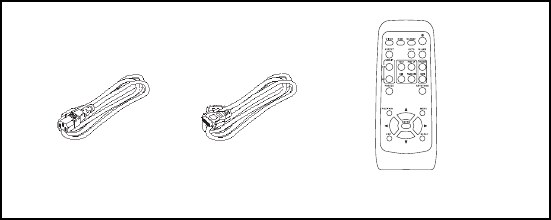
Accessories Remote control transmitter × 1
RGB cable × 1
(Power cord)
Strap for lens cap × 1
Rivet for lens cap × 1
Battery × 2
Soft case × 1
User's manual operating guide (Book × 2 or CD-ROM × 1)
User's manual quick guide (Book× 1)
User's manual safety guide (Book× 1)
3
CP-S235 (C10SM2)
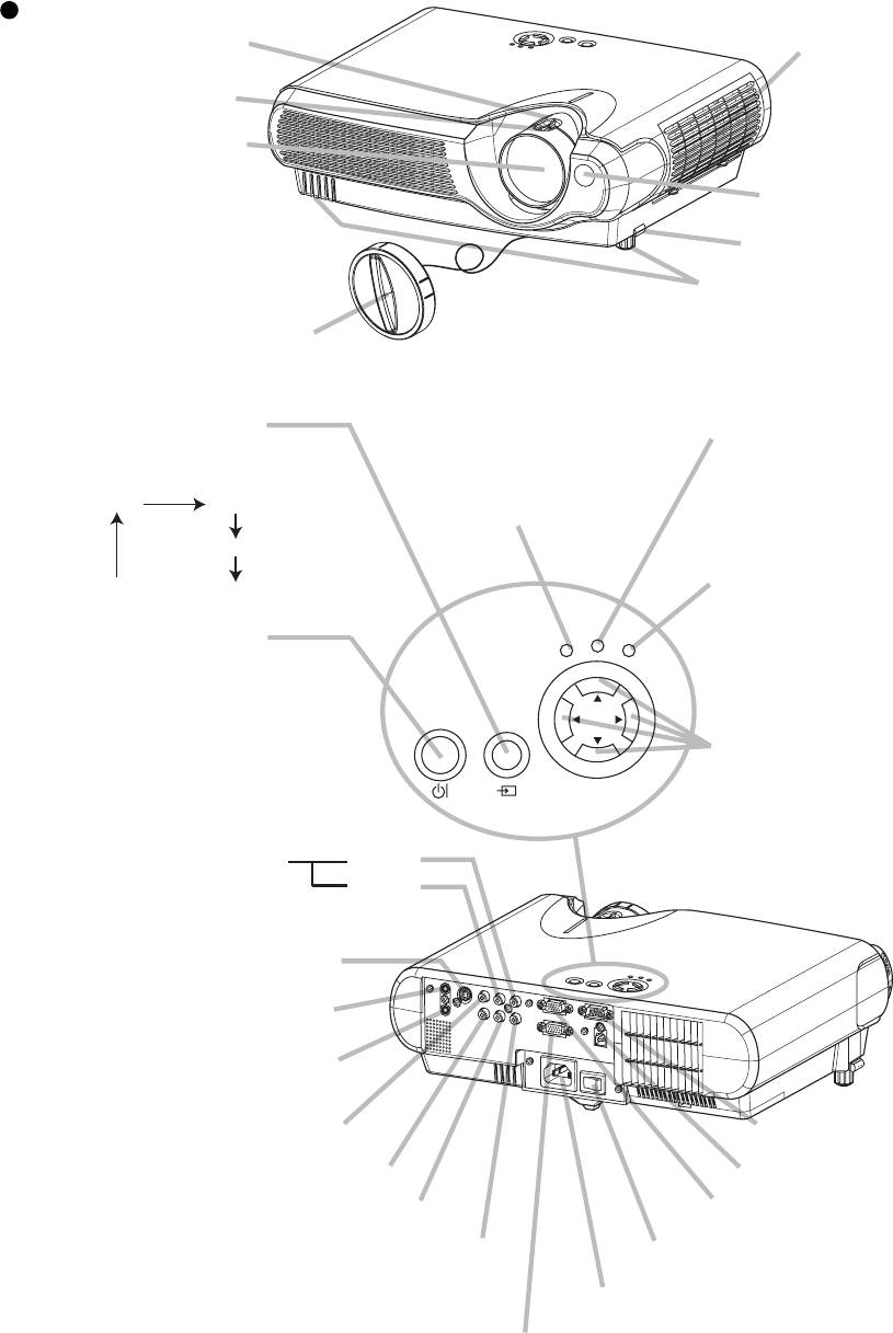
3. Part names
Projector
Zoom ring
Focus ring
Air filter cover
(An air filter is
inside.)
Elevator button
Elevator feet
Lens cap
Lens
(The picture is
projected from
here.)
Remote sensor
Projector (Front/Right)
AC inlet
CONTROL port
VIDEO port
AUDIO OUT port
AUDIO IN port
(from a computer)
S-VIDEO port
COMPONENT VIDEO - Y
COMPONENT VIDEO - CB/PB
COMPONENT VIDEO - CR/PR
AUDIO R port
L port
(from a video equipment)
Power switch
RGB IN port
Projector (Rear/Left)
STANDBY/ON INPUT
POWER LAMP
TEMP
MENU
POWER indicator
tells the state of power
supply. Refer to the section
“Power ON/OFF”.
INPUT button
toggles between the signal
ports.
MENU buttons
operate the menu function.
STANDBY/ON
button
prepares for turning the
power on/off. Refer to the
section “Power ON/OFF”.
TEMP indicator
lights or blinks when any
problem about internal
temperature has happened.
LAMP indicator
lights or blinks when any
problem about the lamp has
happened.
RGB VIDEO
S-VIDEO
COMPONENT VIDEO
AC IN
RGB OUT port
USB port
4
CP-S235 (C10SM2)
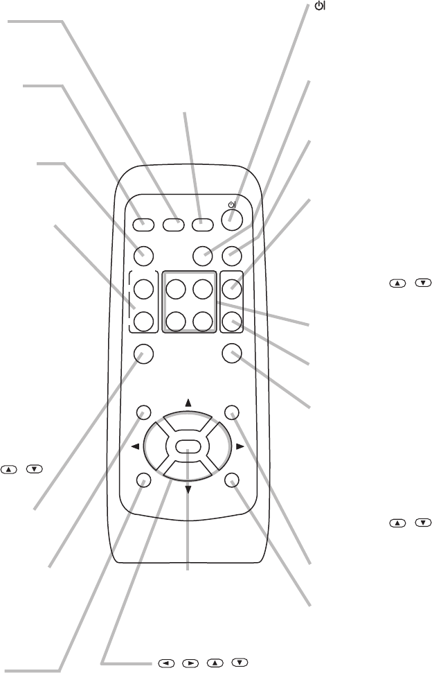
Remote control transmitter
(STANDBY/ON)
button
prepares for turning the
power on/off.
VIDEO button
toggles between the signal
ports of VIDEO, S-VIDEO
and COMPONENT VIDEO.
MENU button
opens/closes the menu.
RGB button
selects the input signal of
RGB port.
BLANK button
blanks the screen
temporarily.
SEARCH button
searches for an input
signal between the
following signal ports of
RGB, VIDEO, S-VIDEO
and COMPONENT VIDEO.
VOLUME button
turns on/off the VOLUME
mode.
In the VOLUME mode,
To adjust the volume,
use the cursor /
buttons.
MUTE button
mutes/restores the sound.
KEYSTONE
button
turns on/off the KEYSTONE
mode.
In the KEYSTONE mode,
To adjust the
keystone,
use the cursor /
buttons.
ASPECT button
toggles between the
modes for aspect ratio.
AUTO button
executes automatic
adjustment.
MAGNIFY ON/OFF
buttons
turns on/off the MAGNIFY
mode.
In the MAGNIFY mode,
To move the
magnified area,
(1) Press the POSITION
button.
(2) Use the cursor buttons
to move the picture.
(3) Press the POSITION
button again to finish.
To shift the magnify
level,
use the cursor /
buttons.
FREEZE button
freezes/reactivates the
picture.
POSITION button
turns on/off the POSITION
mode. (for RGB input)
In the POSITION mode,
To move the picture,
use the cursor buttons.
ESC button
returns to the previous display
at the menu functions.
(Available for operating PC screen)
,,,
(Cursor) buttons
works for adjusting or
menu controlling.
(Available for operating PC screen)
RESET button
cancels the adjustment in
progress.
* The adjustments of the
volume etc. are not reset.
ENTER button
proceeds to the next operation
at the menu functions.
(Available for
operating PC screen)
VIDEO
ASPECT
MUTE
PAGE DOWN
END
KEYSTONEFREEZE
MENUPOSITION
ENTER
ESC RESET
VOLUME
MAGNIFY HOME PAGE UP
AUTO BLANK
RGB SEARCH
OFF
ON
KEYBOARD button
operate the PC screen.
5
CP-S235 (C10SM2)
4-2 Ghost adjustment
Signals for internal adjustment
30%
30%
112/255
0/255
Adjustment procedure
1.
Use DAC-P - GHOST - R: in the FACTORY MENU
to adjust so that R colour ghost is at a minimum.
(Set the adjustment value to default, and then
raise the value. When a ghost appears to the left
of a vertical line, reduce the value by 4 steps.)
2. In the same way, use DAC-P - GHOST-G: in the
FACTORY MENU to adjust so that G colour ghost
is at a minimum.
3. In the same way, use DAC-P - GHOST-B: in the
FACTORY MENU to adjust so that B colour ghost
is at a minimum.
4. Adjustment
4-1 Before adjusting
4-1-1 Selection of adjustment
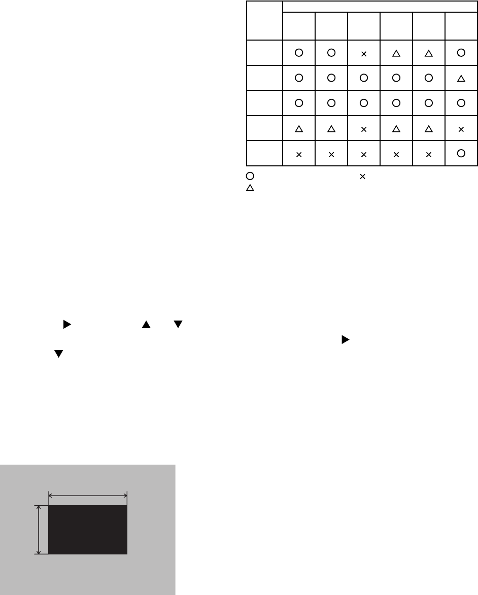
When any parts in the table 4-1 are changed, choose
the proper adjusting items with the chart.
Table 4-1: Relation between the replaced part and adjustment
4-1-2 Setting of condition before adjustment
1. Before starting adjustment, warm up the projector
for about 10 minutes. (Blank white)
2. Set Zoom Wide to Max. And project an image
with more than 1m (40 type) in diagonal size.
3. Normalising the video adjustment.
(Press the [MENU] button of the Remote control
transmitter to display the MAIN menu. After
pressing the [ ] key, use the [ ] or [ ] key to
select [RESET]. Next, open MAIN menu and
press the [ ] key to display the PICTURE1
menu. Choose RESET and perfom EXECUTE by
the same operation described above.
*note :The MAIN and PICTURE1 menu is not
reset with no signal.
4. Set the NORMAL at GAMMA in the PICTURE1
menu.
5.
Perform all adjustments from the FACTORY MENU.
Perform the following operations to display the
FACTORY MENU.
a.
Press the [MENU] button on the Remote control
transmitter (the MAIN menu will appear).
b. Select the [RESET] in the MAIN menu, and
then press the [ ] button.
c. Next, press the [RESET] button one time. And
hold the [RESET] button for 3 seconds or
more (the
FACTORY MENU
will appear).
Replaced
part
Adjustment
Ghost
(Chap.4-2)
Flicker
(Chap.4-3)
NRSH
(Chap.4-4)
White
balance
(Chap.4-5)
Colour
uniformity
(Chap.4-6)
AIR
SENSOR
(Chap.4-7)
Dichroic
optics unit
LCD/LENS
prism
assembly
Main
Board
Lamp
unit
assembly
Sensor
Board
: means need for adjustment. : means not need for adjustment.
: means recommended.

6
CP-S235 (C10SM2)
4-5
White balance adjustment
(visual inspection)
Preparations
1. Perform these adjustments after the NRSH
adjustment described in Section 4-4.
2. Reset gamma correction before adjustment.
Place the cursor on [GAMMA] in the FACTORY
MENU, press the [RESET] key and select [DEFAULT].
Adjustment procedure
1. First, adjust the G colour.
2.
Select GAMMA, SUB-CNT, and G: in the FACTORY
MENU. If the background is white solid, press the
[ENTER] key on the Remote control transmitter to
change to [G] monochrome in the 29-tone greyscale.
3.
Adjust GAMMA, SUB-CNT, and G: in the FACTORY
MENU so that brightness of 29 steps is best.
4. Don’t adjust GAMMA, SUB-BRT, and G: in the
FACTORY MENU. Because we want to keep the
best contrast ratio.
5. Then adjust colours R and B.
6.
Select GAMMA, SUB-CNT, and G: in the FACTORY
MENU. If the background is white solid, press the
[ENTER] key on the Remote control trasmitter to
change to [W] monochrome in the 29-tone greyscale.
7. Adjust GAMMA, SUB-BRT, R: and B: in the
FACTORY MENU so that low-brigtness white
balance is best.
8.
Adjust GAMMA, SUB-CNT, R: and B: in the FACTORY
MENU so that middle-brightness white balance is best.
9. Repeat steps 7 to 8 above, and adjust so that
brightness white balance of 29 steps is best.
4-4
NRSH adjustment
(vertical stripe adjustment)
Signals for internal adjustment
64
/255
88
/255
112
/255
136
/255
160
/255
160/255
136/255
112/255
88/255
64/255
Adjustment procedure
1. Either of adjustment patterns as shown on the left
appears, which depends on the firmware version.
If any other pattern is displayed, press the
[ENTER] key on the remote control.
2.
Use the DAC-P - NRSH - R: in the FACTORY MENU to
adjust so that the vertical stripes with one pixel width
every 6 pixels are as inconspicuous as possible.
(Note that when the adjustment value is lowered, stripes
with 6 pixels width every 12 pixels may appear on the
right side of the darkest or the 2nd darkest tone. Should
this happen, make as inconspicuous stripes as possible
on the whole screen.)
3.
In the same way, use DAC-P - NRSH - G: in the
FACTORY MENU to adjust vertical stripes of G colour.
4-3 Flicker adjustment
(V.COM adjustment)
Signals for internal adjustment Adjustment procedure
1. Make this adjustment after completing the
adjustment in 4-2 Ghost adjustment.
2. Use DAC-P - V.COM - R: in the FACTORY MENU
to adjust so that the flicker at the centre of the
screen is less than the flicker at the periphery.
(When the flicker is about the same across the
whole screen, adjust so that the flicker at the centre
of the screen is somewhat less than elsewhere.)
3. In the same way, use DAC-P - V.COM-G: in the
FACTORY MENU to adjust the G colour flicker.
4. In the same way, use DAC-P - V.COM-B: in the
FACTORY MENU to adjust the B colour flicker.
7
CP-S235 (C10SM2)
VID-AD
MIN
MID-L
MID-H
MAX
DAC-P
GAMMA
C. UNIF.
No. 1 R 0
STRIPE
C.UNIF
ON/OFF ON
OFF
G0 B0
Major adjustment lattice point No.
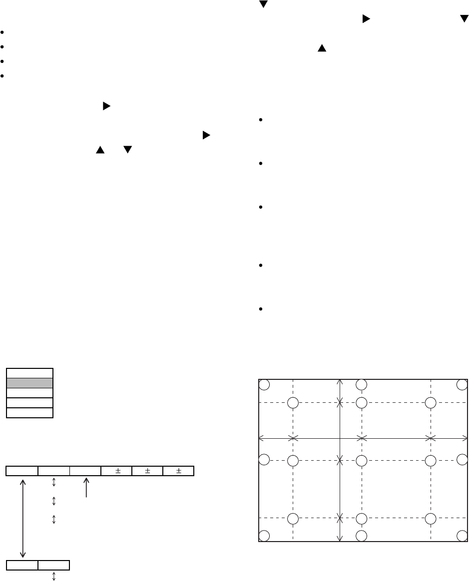
4-6 Colour uniformity adjustment
Preparations
1. Perform these adjustments after the white
balance adjustment described in Section 4-5.
2. Make a colour uniformity adjustment for the
following four tones.
MIN tone (approx. 3% input signal)
MID-L tone (approx. 13% input signal)
MID-H tone (approx. 22% input signal)
MAX tone (approx. 50% input signal)
3. Place the cursor on [C.UNIF.] in the FACTORY
MENU and press the [ ] key. This displays the
Adjust Tone menu at the bottom of the screen.
To choose the tone to be adjusted, press the [ ]
key and then use the [ ] or [ ] key.
Select the major adjustment lattice point No. and
color, and then adjust them.
4. The major adjustment lattice point numbers (a
total of 17 points) corresponds to the major
adjustment lattice point positions in the diagram
on the right. The colour uniformity of the entire
screen can be adjusted by adjusting the white
balance for each of the points starting in order
from the low numbers.
5. Adjustment point No.1 should not be adjusted,
because it controls the brightness of the entire
screen.
6. To temporarily turn correction off, place the cursor
on [C.UNIF.] in the Adjust Tone menu and press the
[] key. The ON/OFF menu appears. Place the
cursor on [ON] with the [ ] key and press the [ ]
key. To turn it on again, place the cursor on [OFF]
and press the [ ] key.
7. Although this adjustment can also be made using
internal signals, we will here use the [ENTER] key
on the Remote control transmitter to select the
following two signals.
Solid monochrome adjustment colour (use G
colour adjustment when a colour differential meter
is used).
Solid white (use for adjustment other than
above).
8. Reset colour-shading correction before adjustment.
When 4 tones and all colours are to be reset,
place the cursor on [C.UNIF.] in the FACTORY
MENU, press the [RESET] key and select
[DEFAULT].
When only 1 tone is to be reset, place the
cursor on the tone to be reset, press the
[RESET] key and select [DEFAULT].
Single tone and monochrome resets cannot be
performed.
FACTORY MENU
Major adjustment lattice point position
14 12
13
16
15 17
6 4 8
2 1 3
7 5 9
10 11
V/6
H/6 H/3 H/3 H/6
V/3
V/3
V/6
Adjust tone menu

8
CP-S235 (C10SM2)
Adjustment procedure 1
(when a colour differential meter is used)
1. First adjust [MID-L] tone [G:].
2. Select adjustment point [No.2][G:].
When the background is not [G] monochrome,
press the [ENTER] key on the Remote control
transmitter to change to solid [G] monochrome.
3. Measure the illumination at adjustment points No.
2, No.3, No.10 and No.11.
The values should be:
No.2 = Y2 [lx] No.10 = Y10 [lx]
No.3 = Y3 [lx] No.11 = Y11 [lx]
4. No.2 and No.3 adjustment point have the average
of Y2 and Y3.
Y2 = ( Y2 + Y3 ) / 2 ±2 [%]
Y3 = ( Y2 + Y3 ) / 2 ±2 [%]
5. No.10 and No.11 adjustment point have the
average of Y10 and Y11.
Y10 = ( Y10 + Y11 ) / 2 ±2 [%]
Y11 = ( Y10 + Y11 ) / 2 ±2 [%]
6. Then adjust [MID-L] tone [R] and [B].
When the background is [G] monochrome, press
the [ENTER] key on the Remote control
transmitter to change to solid white.
7. Measure the colour co-ordinates of adjustment
point [No.1] and make a note of them.
Assume that they are x = x1, y = y1.
Note: When the CL-100 colour and colour
difference meter is used, the [ ](delta)
mode is convenient. When adjustment
point [No.1] colour co-ordinate has been
selected, set the slide switch on the side to
[](delta) while holding down the [F] button
on the front panel. The measurement
shown after this displays the deviation from
measurement point 1.
8. Measure the colour co-ordinates of measurement
point [No.2] and adjust [No.2][R:] and [B:] so that
the co-ordinates are as follows.
x = x1 ± 0.005 , y = y1 ± 0.010
9. Similarly, measure adjustment points [No.3] to
[No.17] and adjust their colour co-ordinates starting
in order from the small number points.
This completes adjustments required for [MIN].
Note: Since excessive correction may lead to a
correction data overview during internal
calculations, use the following values for
reference.
[No.2] to [No.5] ±40 or less
[No.6] to [No.9] ±50 or less
[No.10] to [No.13] ±70 or less
[No.14] to [No.17] ±120 or less
10. Then adjust [MIN] tone [G] so that the adjustment
data set two times as much as [MID-L] tone [G].
This completes [G] colour adjustments.
11. Then adjust [MIN] tone [R] and [B].
Select [No.2] [B:] and press the [ENTER] key on
the Remote control transmitter to change to solid
white.
12. Measure the colour co-ordinates of adjustment
point [No.1] and make a note of them.
Assume that they are x = x1, y = y1.
13. Now measure the colour co-ordinates of
measurement point [No.2] and adjust [No.2][R:]
and [B:] so that the co-ordinates are as follows.
x = x1 ±0.005 , y = y1 ±0.010 (Target)
x = x1 ±0.020 , y = y1 ±0.040
14. Similarly, measure adjustment points [No.3] to
[No.17] and adjust their colour co-ordinates starting
in order from the small number points.
This completes [MIN] tone adjustments.
15. Now make similar adjustments for [MID-H] tone.
(Adjust [MID-H] tone [G] so that the adjustment
data set half as many as [MID-L] tone [G].)
16. Now make similar adjustments for [MAX] tone.
(Adjust [MAX] tone [G] so that the adjustment
data set half as many as [MID-L] tone [G].)
9
CP-S235 (C10SM2)
Adjustment procedure 2
(visual inspection)
1. First adjust [MIN] tone [G:].
2. Select [No.2] [G:].
If the background is [G] monochrome, press the
[ENTER] key on the Remote control transmitter to
change to solid white.
3. View measurement point [No.2] and [No.3].
Lower the [G] colour intensity only of the colour
point whose [G] colour is more intense than
measurement point [No.1].
4. View measurement point [No.10] and [No.11].
Lower the [G] colour intensity only of the colour
point whose [G] colour is more intense than
measurement point [No.1], and raise the intensity
of the point whose colour intensity is lower than
measurement point [No.1].
5. Now adjust the [MIN] tone for colours [R] and [B].
6. View measurement points [No.2], [No.3], [No.10]
and [No.11]. Adjust the [R] and [B] of each
measurement point so that they have the same
color as measurement point [No.1].
Adjustment technique:
First, adjust [B:] of the point whose colour is to be
adjusted so that it approximates that of [No.1]. If
[R:] is low at this time, the image will have cyan
cast, in which case [R:] is increased. On the other
hand, if [R:] is excessive, the image will have a
magenta cast, in which case [R:] is decreased.
Overall, a cyan cast makes it easy to see colour
shading.
7. Next, view measurement points [No.4], [No.5],
[No.12], [No.13] and make similar adjustments.
8.
Then adjust measurement points [No.6], [No.7], [No.8],
[No.9], [No.14], [No.15], [No.16] and [No.17].
This completes the [MIN] tone adjustments.
9. Make similar another three tones as described in
steps 1 to 8 above.
8
3
16
17
9
11
6
14
2
12
15 13
10
7
4
1
5
8
3
16
17
9
11
14 12
15 13
10
4
1
5
6
2
7
8
3
16
17
9
11
6
2
12
13
14
15
10
7
4
1
5
14 12
15 13
10
4
1
5
6
2
7
8
3
16
17
9
11
17
9
15 13
75
3
17
9
11
15 13
10 1
5
6
2
7
8
16
17
9
6
12
13
7
4
5
14 12
10
4
1
6
2
8
3
16
17
9
11
311
2
10 1
16
14 12
8
648
4
16
14 12
311
2
14
15
10 1
5
7
15 13
17
9
15 13
75
3
17
9
11
6
17
9
6
13
75
14 12
10
4
6
2
8
16
311
2
10 1
16
14 12
8
648
4
16
14 12
311
2
14
15
10
5
7
15
10 1
2
13
15
5
7
12
4
1
8
17
13
1311
16
9
5
17
9
15 13
75
3
17
9
11
6
17
9
6
13
75
14 12
10
4
6
2
8
16
311
21
16
14 12
8
48
4
16
14 12
3
2
14
15
10
5
7
15
10 1
2
13
5
7
12
4
1
17
13
13
5
11
9
11
8
16
15
10
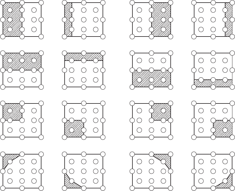
6
No. 2 deviation range No. 10 deviation range No. 3 deviation range No. 11 deviation range
No. 4 deviation range No. 12 deviation range No. 5 deviation range No. 13 deviation range
No. 6 deviation range No. 7 deviation range No. 8 deviation range No. 9 deviation range
No. 14 deviation range No. 15 deviation range No. 16 deviation range No. 17 deviation range
10
CP-S235 (C10SM2)
4-7 AIR-SENSOR adjustment
When the MAIN board or the SENSOR board is replaced, perform this adjustment after
completing reassembling the projector.
1. Open SERVICE MENU and choose AIR-SENSOR by using button.
Service menu comes up by following operation. Set the cursor on the OPTION menu and press the
MAGNIFY OFF button on the Remote controller. Next hold the MAGNIFY OFF button for 3 seconds or more.
2. Press the button. Next press the [ ] button to select EXECUTE. The adjustment program runs
automatically.
3. After the massage of "END" is displayed, check the Offset value displayed according to the following spec
Spec. : 150 Offset: 227
4. If out of spec, confirm the below conditions Then retry the same adjustment.
Description
(a) Installing the air filter correctly.
(b) No obstruction and dust on air filter. (If not good condition, clean or replace
the air filter.)
(c) Using the proper type of air filter.
(d) Installing the SENSOR board correctly.
(e) Connecting the proper wires to E7A1 and E981 firmly.
(f) The component I7A2 on the MAIN board stands vertically
(g) The component D981 on the SENSOR board stands vertically
5. If the all conditions above is okay, replace the MAIN board.
11
CP-S235 (C10SM2)
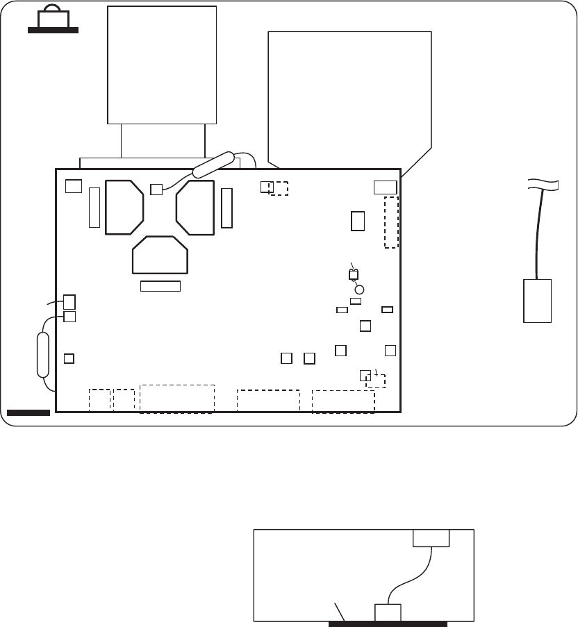
5. Troubleshooting
Check points
TSW
MAIN Board
E801
E803
E301
E800
D841
C
P701
E804
E802
ET01
E805 E302
E7A1
ESPL
P501
P601 D303
(LAMP)
D301
(POWER)
D302
(TEMP)
S301
(P-ON)
S302
(INP)
EA01 EV01
E102 E103
ET01
EM01
CNCT
E101
SENSOR Board
Rear view
CONTROL
Board
REMC
Board
#6430
#6800

12
CP-S235 (C10SM2)
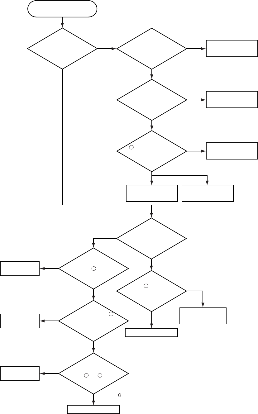
Power cannot be turned on
Are
voltage input
at pins , , , of
E800 on the MAIN
board at standby
mode? : +12V
: +17V
:+6.6V
:+4.1V
Power unit (circuit) Fuse
on the Filter unit Filter unit
NO
YES
Disconnect
TSW form Power unit
(circuit). And check
TSWshortor
open?
MAIN board
Short
TSW
Open
What is the state of
TEMP indicator D302?
No light
DC FAN
Blinks
Jump to * on the page 13
What is the state of
LAMP indicator D303?
No light
Blinks
1
1
3
5
7
35 7
H (More than 12.6V) Measure
voltage at the of
E803 on the MAIN
board.
L(OV)
Limit SW board
MAIN board
Is the LAMP DOOR
set?
OK
Set the LAMP DOOR
NG
2
13
CP-S235 (C10SM2)
Lamp does not light
What is the
state of LAMP
indicator D303 during
operation?
Power unit (ballast)
Lamp
MAIN board
Power unit (ballast)
Light
MAIN board
YES
No light
NO
YES
Change the lamp.
Does lamp light?
Power unit (circuit)
Not light
Install the Lamp
Light
NG
Is the LAMP
installation correct?
YES
NO
What is the
state of TEMP indicator
D302?
No light
Blinks
DC FAN
(Lamp)
H (3.3V)
"L" = 0V
L(OV)
1
Is the
voltage at the
of E804 on the
MAIN board fixed to "L"
during warming-up?
"L"=0V
Measure
sure voltage at the
cathode pin of D841 on
the MAIN board.
DC FAN
(Panel)
YES
(Normal)
Does the
signal at the pin
of E801 have a amplitude
of 3.3V and a frequency
of 40Hz or
more?
MAIN board
Thermistor A
(#6430)
Infinity
about 10k
Measure
the resistance of
external air sensor
between and of #6430.
(at disconnecting
from E302)
Is the voltage
at the of E804 on
the MAIN board
set to "L" during
warming-up?
3
1
1
2
C
*
NO
(Fan lock)
14
CP-S235 (C10SM2)
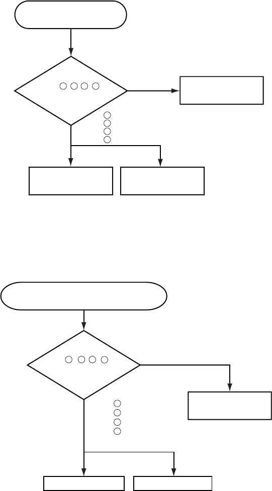
Picture is not displayed
when the RGB signal is input
MAIN board LCD panel
Check at operating mode
Power unit
(circuit)
NO
YES
Are
voltage input
at pins , , , of
E800 on the
MAIN board?
1 3 5 7
1
3
5
7
: +12V
: +17V
:+6.6V
:+4.1V
Power unit (circuit)
NO
YES
Are
voltage input at
pins , , , of
E800 on the
MAIN board?
:+12V
:+17V
: +6.6V
: +4.1V
MAIN board
LCD module assembly
Check at operating mode
7
1
3
5
Picture is not displayed when the
VIDEO, S-VIDEO, Component Signal is input
7
1 3 5
15
CP-S235 (C10SM2)
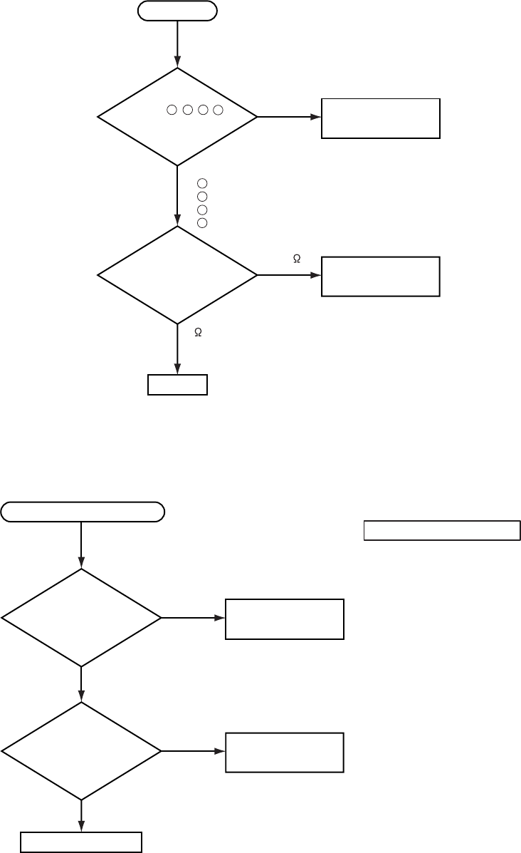
Speaker
Check at operating mode
No sound
NO
YES
Power unit (circuit)
Are
voltage input
at pin , , ,
of the E800 on the
MAIN board?
71 3 5
MAIN board
Turn off
the projector and
disconnect the Speaker
cable from ESPL.
Measure the resistance
of the Speaker.
: +12V
: +17V
: +6.6V
: +4.1V
7
1
3
5
about 8
0 or infinity
The check after parts change
1. PC power supply OFF
2. Connection of cable
3. Projector starting
4. PC starting
*When not operating :
PC set up change of cable.
No control to RS-232C
MAIN board
NO
YES
NO
YES
Use cross cable
Check the
RS-232C cable.
Are pin No. 2 and 3
crossed?
Power unit (circuit)
Check the
power supply voltage
of E800 the voltage
correct?
16
CP-S235 (C10SM2)
6. Service notes
6-1 Lead-free solder [CAUTION]
This product uses lead-free solder (unleaded) to help preserve the environment. Please read these instructions
before attempting any soldering work.
Lead-free solder indicator
Printed circuit boards using lead-free solder are engraved with an "F."
Properties of lead-free solder
The melting point of lead-free solder is 40-50 ˚C higher than leaded solder.
Servicing solder
Solder with an alloy composition of Sn-3.0Ag-0.5Cu or Sn-0.7Cu is recommended.
Although servicing with leaded solder is possible, there are a few precautions that have to be taken. (Not taking
these precautions may cause the solder to not harden properly, and lead to consequent malfunctions.)
Precautions when using leaded solder
Remove all lead free solder from soldered joints when replacing components.
If leaded solder should be added to existing lead free joints, mix in the leaded solder thoroughly after the lead-
free solder has been completely melted (do not apply the soldering iron without solder).
Servicing soldering iron
A soldering iron with a temperature setting capability (temperature control function) is recommended.
The melting point of lead-free solder is higher than leaded solder. Use a soldering iron that maintains a high
stable temperature (large heat capacity), and that allows temperature adjustment according to the part being
serviced, to avoid poor servicing performance.
Recommended soldering iron:
Soldering iron with temperature control function (temperature range: 320-450˚C)
Recommended temperature range per part:
Part Soldering iron temperature
Mounting (chips) on mounted PCB 320 ±30˚C
Mounting (chips) on empty PCB 380 ±30˚C
Chassis, metallic shield, etc. 420 ±30˚C
MAIN board
SENSOR board
REMC board
COVER SW board
POWER UNIT (BALLAST)
POWER UNIT (CIRCUIT)
FILTER UNIT
The boards using lead-free solder
CAUTION
Always wear safety glasses to prevent fumes or molten solder from getting into the eyes. Lead-free solder can
splatter at high temperatures (600˚C).
17
CP-S235 (C10SM2)
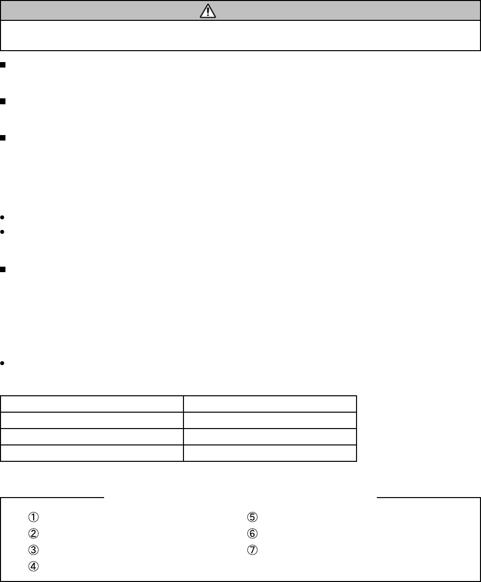
6-2 Cautions when removing the MAIN board
When removing the MAIN board, there is danger of damaging the connector connecting cables.
1) Disconnect 11 cables and remove 4 screws.
ATTENTION
Handling FPC cable
Be careful not to add strong load, such as pulling or twisting the FPC cable.
If load is added to FPC cable, convergence may shift.
In case FPC cable is being removing, or when attaching, or when opening a intake LID, or when closing,
please carry out carefully and slowly so that load is not added to FPC cable.
MAIN Board
4 screws
2) Remove 2 screw.
2 screw
AC IN
3) Lift the rear of the MAIN board to the front.
6-3 Cautions when removing the power unit (BALLAST)
When removing the cable (CNBAR) connected to Power Unit (BALLAST), there is danger of damaging the small
PCB connecting cables.
REAR Disconnect the 2 cables.
FRONT
Lift
MAIN Board
CN200
CN100
T102
Disconnect the CNBAR from connector CN200,
while pressing the sub-board
(to prevent the stress on the sub-board).
CNBAR
Power Unit (BALLAST)
18
CP-S235 (C10SM2)
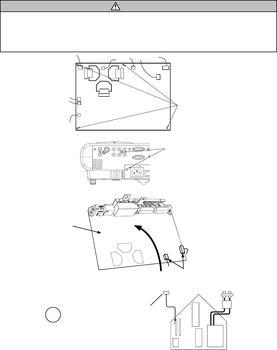
6-4 Before replacing the LCD/Lens prism
You should not separately replace the parts of the liquid crystal LCD/Lens prism because they only work properly
when used together. Therefore, you can either replace the LCD/Lens prism assembly or send the whole
LCD/Lens prism assembly unit back to HITACHI where we will replace the malfunctioning part,
recondition the device and send it back to you.
DISTRIBUTOR HITACHI
G Panel
Do not disassemble the unit
because replacement of separate
parts is not possible.
Return
Replacement of G Panel Reconditioning
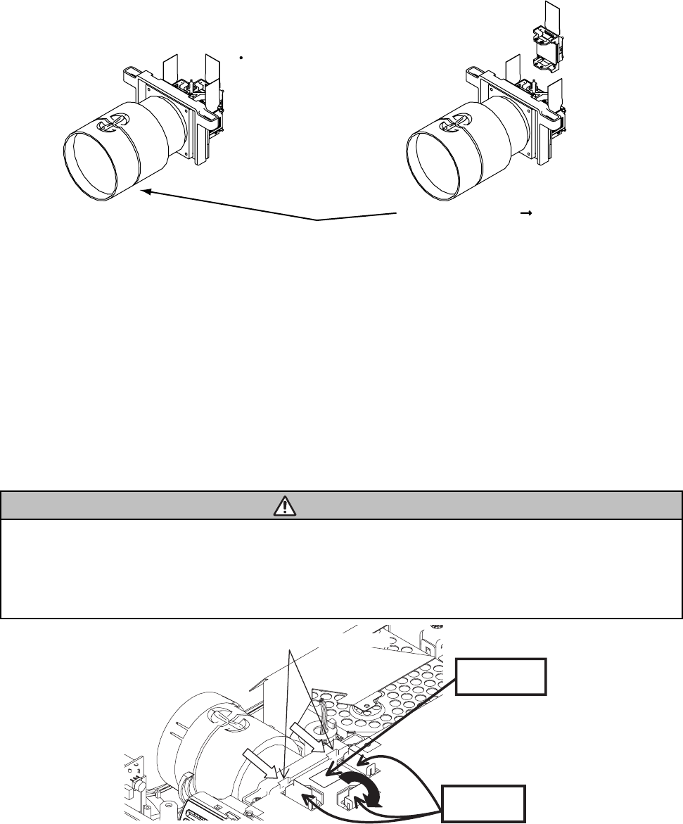
6-5 Cleaning dust from panels and optical filters
1. Preparation
Prepare cleaning tools and materials as follows. Work in a relatively clean room so as to remove
additional dust while in removal operation.
(1) Swab for cleaning •••••• P#: NX08061, "Cotton stick L147"
(2) Air duster (Dust blower, spray can)
(3) Vacuum cleaner
2. Disassemble and open the maintenance hole.
(1) Turn off the projector, and unplug the power cord.
(2) Remove the top cover, according to the disassembling diagram of chapter 8.
(3) Remove the MAIN board, according to the Chapter 6-2.
(4) Remove the intake LID.
ATTENTION
Handling FPC cable
Be careful not to add strong load, such as pulling or twisting the FPC cable.
If load is added to FPC cable, Convergence may shift.
When the FPC cable is being removed, attached, when opening or closing a intake LID, perform the operation
carefully and slowly so that load is not added to FPC cable.
(5) Re-assemble the MAIN board and re-connect all the connectors.
Intake LID
FPC cable
Lift
Release two latches
19
CP-S235 (C10SM2)
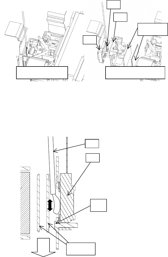
3. Maintenance point
Each colour part has same
construction.
By using swab and air duster,
you can easily remove dust from
panel and optical filters.
4. Cleaning the panels and optical filters
(1) Turn on the set and lit on the lamp.
(2) Set blank screen to black or white.
(3) By using swab and air duster, remove the dust. While cleaning you can check the dust on screen.
• While removing the dust, separated dust will be
blown off by air cooling system.
• Please pay attention not to damage panel and
filters.
5. Re-assembly
(1) Turn off the set and remove the MAIN board.
(2) Set the intake LID.
(3) Re-assemble the MAIN board.
(4) Re-assemble the set.
(5) While re-assembling, clean the intake LID and intake filter and filter cover using a vacuum cleaner.
ᴾ
Panel
Swab
Holder
Optical filters
Separatied formationActua l formation
Swab
Panel
Optical filters
Holder
Air
20
CP-S235 (C10SM2)
6-5 Putting batteries
CAUTION
Always handle the batteries with care and use them only as directed. Improper use may result in battery
cracking or leakage, which could result in fire, injury and/or pollution of the surrounding environment.
• Keep the battery away from children and pets.
•
Be sure to use only the batteries specifi ed for use with the remote control. Do not mix new batteries with used ones.
• When inserting batteries, verify that the plus and minus terminals are aligned correctly (as indicated in the
remote control).
• When you dispose the battery, you should obey the law in the relative area or country.
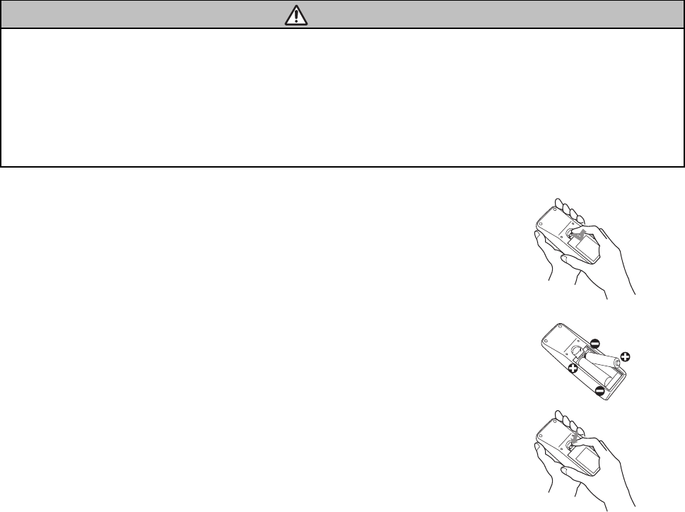
1. Remove the battery cover.
Slide back and remove the cover in the direction of the arrow.
2. Insert the batteries.
Align and insert the two AA batteries according to their plus and minus terminals.
(as indicated in the remote control.)
3. Close the battery cover.
Replace the cover in the direction of the arrow and snap it back into place.
21
CP-S235 (C10SM2)
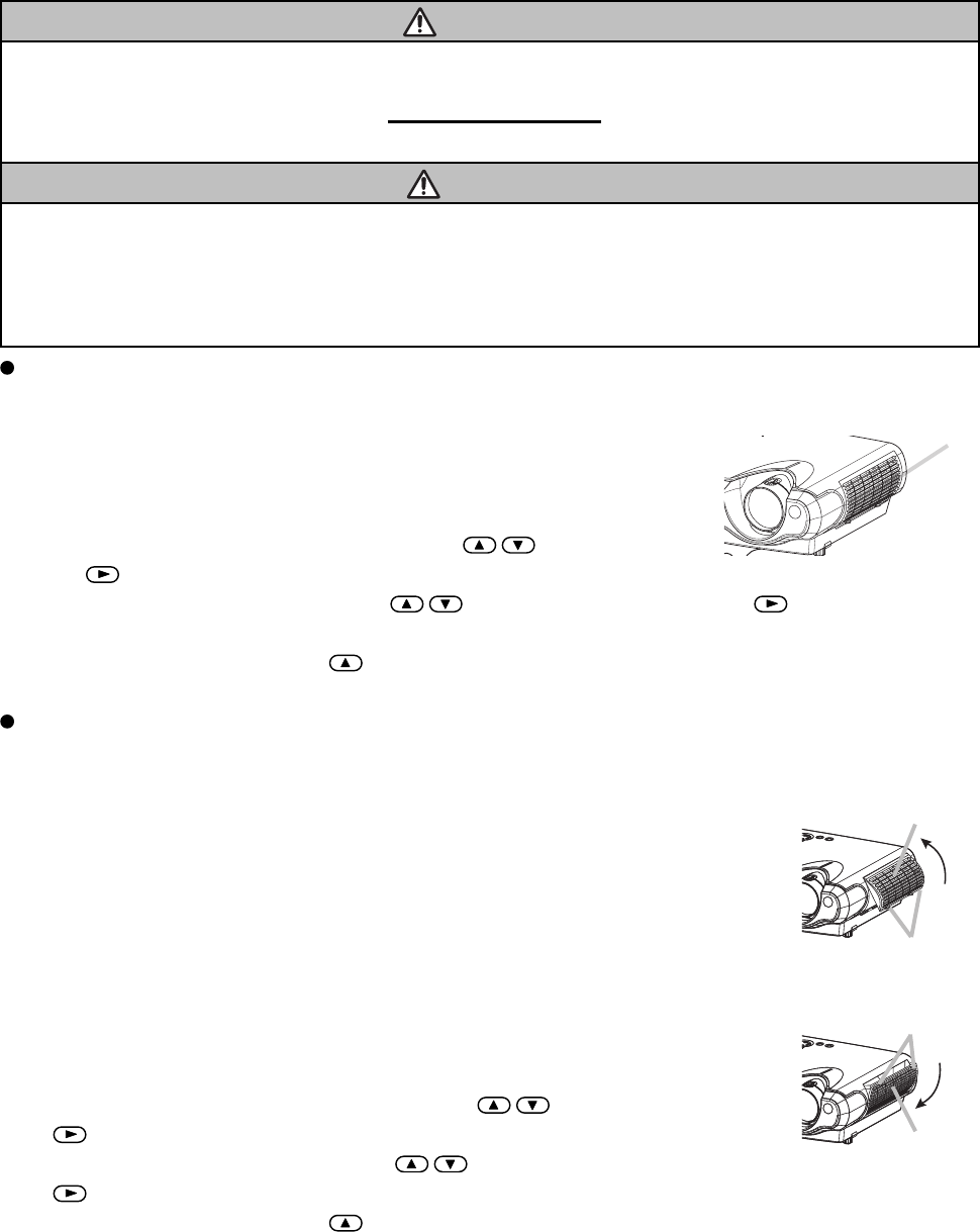
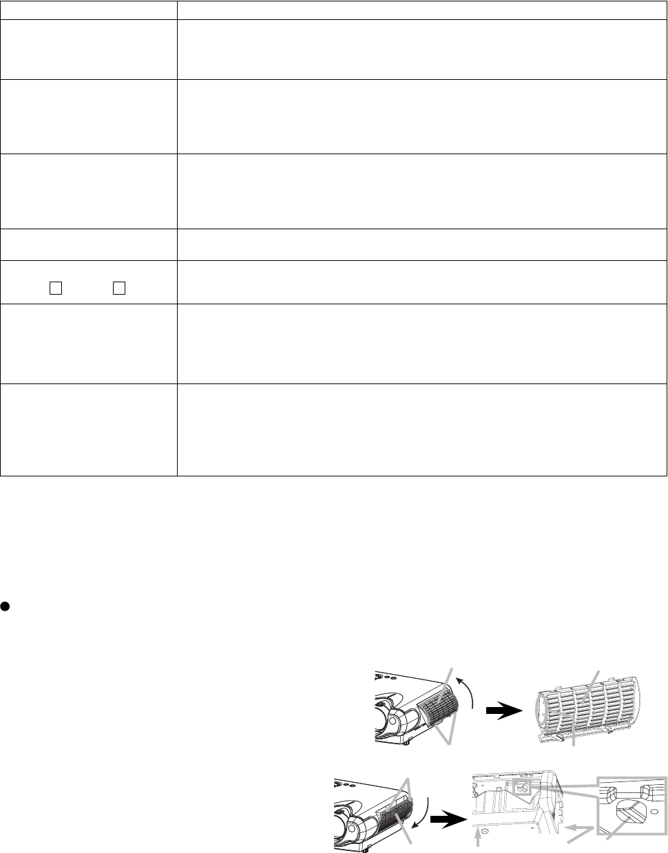
6-6 Air filter
The air filter should be cleaned about every 100 hours. If the indicators or a message prompts you to clean the
air filter, clean the air filter as soon as possible. If the air filter becomes clogged by dust or the like, internal
temperature rises and could cause malfunction.
WARNING
• Please carefully read the "User’s Manual - Safety Guide".
• Before replacing the air fi lter, make sure the power switch is off and the power cable is not plugged in.
• Use the air fi lter of the specifi ed type only. Type number: NJ08292
•
Do not use the projector with the air fi lter and fi lter cover removed. The use without the air fi lter could result in damage.
CAUTION
• Do not reset the fi lter timer without cleaning or replacing the air fi lter.
• If the air fi lter becomes clogged by dust or the like, internal temperature rises and could cause malfunction.
The power is automatically turned off in order to prevent the projector from overheating internally.
• When you replace the lamp, please replace also the air fi lter. The air fi lter may be attached to the replace-
ment lamp.
Caring for the air filter
1. Turn off the projector and unplug the power cord.
2. Apply a vacuum cleaner to the top of the filter cover to clean the air filter.
3. Reset the filter timer, according to following "Reset The Filter Timer".
(1) Turn on the projector. While the projector running, press the MENU button
to open the menu.
(2) Choose the "OPTION" on the menu using the / button, then press
the button or ENTER button.
(3) Choose the "FILTER TIME" using the / button, then press and hold the button of projector or
the RESET button of remote control for 3 seconds.
(4) Choose the "RESET" using the button.
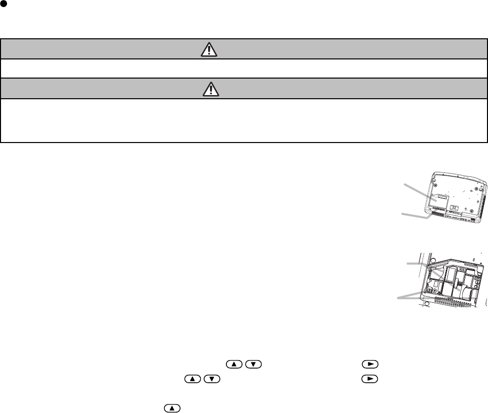
Replacing the air filter
If the soiling will not come off the air filter or it becomes damaged, then it needs to be replaced. Please replace
the air filter as soon as possible.
1. Turn off the projector and unplug the power cord.
2. Contact your local dealer to prepare a new air filter. Tell the dealer your air filter type
number.
3. After making sure that the projector has cooled adequately, remove the filter cover.
Hold the release buttons of the filter cover while pulling up it.
4. Hold the release buttons of the air filter while pulling down it.
5. Insert a new air filter and replace the filter cover.
6. Reset the filter timer, according to following "Reset The Filter Timer".
(1) Turn on the projector. While the projector running, press the MENU button to
open the menu.
(2) Choose the "OPTION" on the menu using the / button, then press the
button or ENTER button.
(3) Choose the "FILTER TIME" using the / button, then press and hold the
button of projector or the RESET button of remote control for 3 seconds.
(4) Choose the "RESET" using the button.
Filter Cover
Filter cover
Release buttons
Air filter
Release buttons
22
CP-S235 (C10SM2)
6-5 Lamp
WARNING
The projector uses a high-pressure mercury glass lamp. The lamp can break with a loud bang, or burn out,
if jolted or scratched, handled while hot or worn-out over time.
Note that each lamp has a different lifetime and some may burst or burn out soon after you start using them.
In addition, when the bulb bursts, it is possible for shards of glass to fly into the lamp housing and for gas
containing mercury to escape from the projector’s vent holes.
About disposal of a lamp • This product contains a mercury lamp; do not put in trash. Dispose of in accord
with environmental laws.
For lamp recycling, go to www.lamprecycle.org. (in USA)
For product disposal, contact your local government agency or www.eiae.org (in the US) or www.epsc.ca (in Canada).
For more information, call your dealer.
• If the lamp should break (it will make a loud bang when it does), unplug the power cord from the
outlet and make sure to request a replacement lamp from your local dealer. Note that shards of
glass could damage the projector’s internals or cause injury during handling, so please do not
try to clean the projector or replace the lamp yourself.
•
If the lamp should break (it will make a loud bang when it does), ventilate the room well and make
sure not to breathe the gas that comes out of the projector vents or get it in your eyes or mouth
.
• Before replacing the lamp, make sure the power switch is off and the power cable is not plugged
in, then wait at least 45 minutes for the lamp to cool suffi ciently. Handling the lamp while hot can
cause burns as well as damaging the lamp.
• Do not open the lamp cover while the projector is suspended from above. This is dangerous,
since if the lamp’s bulb has broken, the shards will fall out when the cover is opened. In addition,
working in high places is dangerous so ask your local dealer to have the lamp replaced even if
the bulb is not broken.
• Do not use the projector with the lamp cover removed. When replacing the lamp, make sure that
the screws are screwed in fi rmly. Loose screws could result in damage or injury.
• Use only the lamp of the specifi ed type: DT00621
.
•
If the lamp breaks soon after the fi rst time it is used, it is possible that there are electrical problems
elsewhere besides the lamp. If this happens, contact your local dealer or a service representative.
• Handle with care: jolting or scratching could cause the lamp bulb to burst during use.
• If the indicators or a message prompts you to replace the lamp (see the section “Related Mes-
sages” and “Regarding the indicator Lamps”), replace the lamp as soon as possible. Using the
lamp for long periods of time or past the replacement date could cause it to burst. Do not use
old (used) lamps; this is a cause of breakage.
HIGH VOLTAGE HIGH TEMPERATURE HIGH PRESSURE
power outlet
plug from the
Disconnect the
23
CP-S235 (C10SM2)
Replacing the lamp
If the indicators or a message prompts you to replace the lamp, replace the lamp as soon as possible. Using the
lamp for long periods of time, or past the replacement date, could cause it to burst.
WARNING
• Please carefully read the “User’s Manual - Safety Guide”.
CAUTION
• Do not reset the lamp timer without replacing the lamp.
• When you replace the lamp, please replace also the air fi lter. The air fi lter may be attached when you buy a
replacement lamp for this projector. Please ask your dealer.
1. Turn off the projector and unplug the power cord. Allow the lamp bulb to cool
for at least 45 minutes and prepare a new lamp.
2. After making sure that the projector has cooled adequately, slowly flip over the
projector so that the bottom is facing up.
3. Hold the release button while sliding and taking the lamp cover up.
4. Unscrew the 2 screws and slowly pick up the lamp by the handles.
5. Insert the new lamp and tighten the 2 screws firmly to lock it in place.
6. Slide the lamp cover into place until it locks into position.
7. Slowly turn the projector so that the top is facing up.
8. Turn on the projector and reset the lamp timer. When the lamp has been
replaced after the message of "THE POWER WILL TURN OFF AFTER 0hr." is
displayed, complete the following operation within 10 minutes of switching
power on.
(1) While the projector running, press the MENU button to open the menu.
(2) Choose the "OPTION" on the menu using the / button, then press the button or ENTER button
(3) Choose the "LAMP TIME" using the / button, then press and hold the button of projector or the
RESET button of remote control for 3 seconds.
(4) Choose the "RESET" using the button.
Lamp cover
Release
button
Handles
Screws

24
CP-S235 (C10SM2)
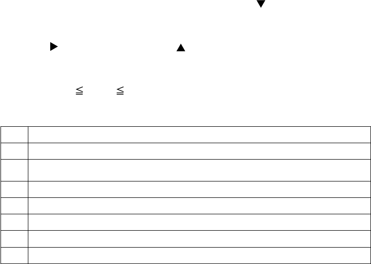
6-8 Notice of AUTO adjustment
Use of AUTO adjustment with the image through RGB input optimises V_POSI, H_POSI, H_SIZE and
H_PHASE automatically.
In case that projected image has dark tone around its peripheral, AUTO operation sometimes makes artifacts in
the image, shifts capture area and so on. Those failures are caused by period of image data is not exactly
distinguished to period of blanking on signal processing.
To avoid such phenomena, AUTO function should be used with the full size picture that has bright tone on its
peripheral.
NOTE
•
The phenomenon at the failure of AUTO adjustment depends on resolution of input source, scene of picture etc.
•
There is no failure above in AUTO with video source through VIDEO, S-VIDEO or COMPONENT input. The reason
is why recognition of input signal’s standard does not need to search the capture range from input signal itself.
Image when AUTO fails.
Noting image of top or bottom lines.
Shift of the image to East or West.
Artifacts on image. Etc.
Image when AUTO operates correctly
25
CP-S235 (C10SM2)
6-9 PIN LOCK System
If the following PIN BOX menu appears after power on the projector, the PIN LOCK system has been activated.
Under such a condition, key operations and signal displaying are inhibited. To open the PIN LOCK system, 4
correct PIN CODE digits need to be input. If correct PIN CODE is not input in 5 min., the lamp will be
automatically turned off.
PIN BOX
Returning repaired unit
Use the Master PIN code. See the paragraph of Releasing the PIN LOCK system inactivation.
Swap unit/Returned unit
Inactivate the PIN LOCK system. See the paragraph of the PIN LOCK system inactivation.
Releasing the PIN LOCK System
When the PIN BOX menu is displayed, sequentially enter the codes with remote controller as follows. In
accordance with remote controller button entry, “ ” mark appears in the PIN BOX menu.
Master PIN codes
1st entry code: Press the “MENU” button.
2nd entry code: Press the “ ” button.
3rd entry code: Press the “KEYSTONE” button.
4th entry code: Press the “ ” button.
Note: The Master PIN codes can be used up to 30 times. The codes cannot be used thereafter. If the Master
PIN codes cannot be used, see the following paragraph.
The PIN LOCK System inactivation
1. When the PIN BOX menu is displayed, press “RESET” for 3 seconds or more in order to get the ID Inquiring
Code.
PIN BOX (ID Inquiring Code)
2. Send the HITACHI sales company the Inquiring code (10 digits) to receive the correct PIN code.
3. With the PIN BOX menu displayed, input the correct PIN code. Enter the correct PIN CODE that has been
received.
4. Open the menu and select “TURN OFF” from the PIN LOCK items in the OPTION menu. Then the PIN BOX
menu appears.
5. Input the correct PIN code in the PIN BOX menu.
6. The OPTION menu then appears.
After the PIN LOCK system is inactivated, the PIN BOX is no longer displayed in the OPTION menu.
If the PIN LOCK items keep displaying, the PIN LOCK system is not inactivated. Input the correct PIN
CODE again.
PIN BOX
Input PIN Code
PIN BOX
Inquiring Code
Inquiring Code
12 1234 1234
26
CP-S235 (C10SM2)
6-10 Related messages
When the unit's power is ON, messages such as those shown below may be displayed. When any such
message is displayed on the screen, please respond as described below.
Message Description
CHANGE THE LAMP
AFTER REPLACING LAMP,
RESET THE LAMP TIMER.
(*1)
Lamp usage time is approaching 2000 hours. (*2)
Preparation of a new lamp and an early lamp change is recommended. After you have
changed the lamp, please be sure to reset the lamp timer.
CHANGE THE LAMP
AFTER REPLACING LAMP,
RESET THE LAMP TIMER.
THE POWER WILL TURN OFF
AFTER ** hr. (*1)
Lamp usage time is approaching 2000 hours. (*2)
A lamp change within ** hours is recommended. When lamp usage reaches 2000 hours,
the power will automatically be turned OFF. Please change the lamp by referring to the
"Lamp" section of this manual. After you have changed the lamp, please be sure to reset
the lamp timer.
CHANGE THE LAMP
AFTER REPLACING LAMP,
RESET THE LAMP TIMER.
THE POWER WILL TURN OFF
AFTER 0 hr.
As lamp use has reached 2000 hours (*2), the power will soon be automatically turned
OFF.
Please immediately turn the power off and change the lamp by referring to the "Lamp"
section of this manual. After you have changed the lamp, please be sure to reset the lamp
timer.
NO INPUT IS DETECTED
ON ***
There is no input signal.
Please confi rm the signal input connection and the status of the signal source.
SYNC IS OUT OF RANGE
ON ***
fH
*****kHz
fV
*****Hz
The horizontal or vertical wavelength of the inputted signal is outside of the response
parameters of this unit.
Please confi rm the specs for this unit or the signal source specs.
CHECK THE AIR FLOW
The internal portion temperature is rising.
Please turn the power OFF and allow the unit to cool down at least 20 minutes. After
having confi rmed the following items, please turn the power ON again.
• Is there blockage of the air passage aperture?
• Is the air fi lter dirty?
• Does the peripheral temperature exceed 35°C?
CLEAN THE AIR FILTER
POWER OFF FIRST,
THEN CLEAN THE AIR FILTER.
AFTER CLEANING
THE AIR FILTER,
RESET THE FILTER TIMER.
A note of precaution when cleaning the air fi lter.
Please immediately turn the power OFF and clean or change the air fi lter by referring
to the "Air Filter" section of this manual. After you have cleaned or changed the air fi lter,
please be sure to reset the fi lter timer.
If the same message is displayed after the treatment, please clean the transparent area
of fi lter cover and the dust-detecting window, according to the following "Caring Of The
Transparent Area Of Filter Cover and The Dust-detecting Window" .
Note: (*1) • Although this message will automatically disappear after around 3 minutes, it will
reappear every time the power is turned ON.
(*2) • Lamps have a finite product life. Lamps are characterised by the fact that, after long hours of usage, a
lamp will no longer light or the lamp will break or burst, etc. This unit is equipped with an automatic shut-
down function such that the power will automatically be turned OFF when lamp usage time has reached 2,000
hours. Please be aware, however, that among lamp types there are major differences in product lifetimes; a
lamp may thus fail to light even prior to the functioning of the automatic shut-down function of this unit.
Caring of the Transparent Area of filter cover and the dust-detecting window.
The transparent area of filter cover and the dust-detecting window should be cleaned for normal operation of the
optical dust detecting system. Pay attention not to leave fibre or fragment from a cleaning cloth inside the duct.
1. Turn off the projector and unplug the power cord.
2. After making sure that the projector has cooled
adequately, remove the fi lter cover.
Hold the release buttons of the fi lter cover while
pulling up it.
3. Wipe the transparent area of the fi lter cover by using
a swab or a soft cloth.
4. Remove the air fi lter.
Hold the release buttons of the air fi lter while pulling
down it.
5.
Wipe the dust-detecting window by using a soft cloth.
6. Replace the air fi lter and fi lter cover.
Filter cover
Release buttons Transparent area
Filter cover
Air filter
Release buttons
Dust detecting
window
(Rear side)
(Bottom side)

27
CP-S235 (C10SM2)
6-11 Indicator lamps
ATTENTION
When the interior portion has become overheated, for safety purposes, the power source may be automatically
turned off and the indicator lamps may also be turned off. In such a case, press the "○" (OFF) side of the power
switch and wait at least 45 minutes. After the unit has suffi ciently cooled down, please con fi rm the attachment
state of the lamp and lamp cover then turn the power on again.
Lighting and fl ashing of the POWER indicator, the LAMP indicator and the TEMP indicator have the meanings
as described in the Table below. Please respond in accordance with the instructions within the Table.
POWER
indicator
LAMP
indicator
TEMP
indicator Description
Lights in
orange
Turned
off
Turned
off
The unit is in a standby state. Please refer to the "Power ON/OFF" section of this manual.
Flashes
in green
Turned
off
Turned
off
The unit is warming up. Please wait.
Lights
green
Turned
off
Turned
off
The unit is in an ON state. Ordinary operations may be performed.
Flashes
in orange
Turned
off
Turned
off
The unit is cooling down. Please wait.
Blinks in
red --
The unit is cooling down. A certain error has been detected. Wait until the POWER
indicator has fi nished fl ashing and then perform the proper response measure using the
item descriptions below as reference.
Lights or
blinks in
red
Lights
in red
Turned
off
The projector lamp has not been properly fi xed (attached), the projector lamp does not
light and/or there is a possibility that the interior portion has become heated. Turn the
power OFF and wait at least 20 minutes. After the unit has suffi ciently cooled down,
please make con fi rmation of the following items and then turn the power ON again. If the
same indication is displayed, please change the lamp.
• Is there blockage of the air passage aperture?
• Is the air fi lter is dirty?
• Does the peripheral temperature exceed 35°C?
Lights or
blinks in
red
Blinks
in red
Turned
off
The lamp cover has not been properly fi xed (attached). Turn the power OFF and wait at
least 45 minutes. After the unit has suffi ciently cooled down, please make confi rmation of
the attachment state of the lamp and lamp cover and then turn the power ON again.
Lights or
blanks
in red
Turned
off
Blinks
in red
The cooling fan is not operating. Turn the power OFF and wait at least 20 minutes. After
the unit has suffi ciently cooled down, please make con fi rmation of the following item and
then resent the power to ON.
• Is there no foreign matter caught in the cooling fan?
Lights or
blinks in
red
Turned
off
Lights
in red
There is a possibility that the interior portion has become heated. Turn the power OFF
and wait at least 20 minutes. After the unit has suffi ciently cooled down, please make
confi rmation of the following item and then resent the power to ON.
• Is there blockage of the air passage aperture?
• Is the air fi lter is dirty?
• Does the peripheral temperature exceed 35°C?
Lights in
green
Alternative blinking
in red
There is a possibility that the interior portion has become overcooled. Please use the unit
within the usage temperature parameters (0°C to 35°C). After the treatment, resent the
power to ON.
Lights in
green
Simultaneous
blinking in red
It is time to clean the air fi lter, or there is no air fi lter. Please immediately turn the power
OFF and clean or change the air fi lter by referring to the "Air Filter" section of this manual.
After you have cleaned or changed the lamp, please be sure to reset the fi lter timer. After
the treatment, resent the power to ON.
28
CP-S235 (C10SM2)
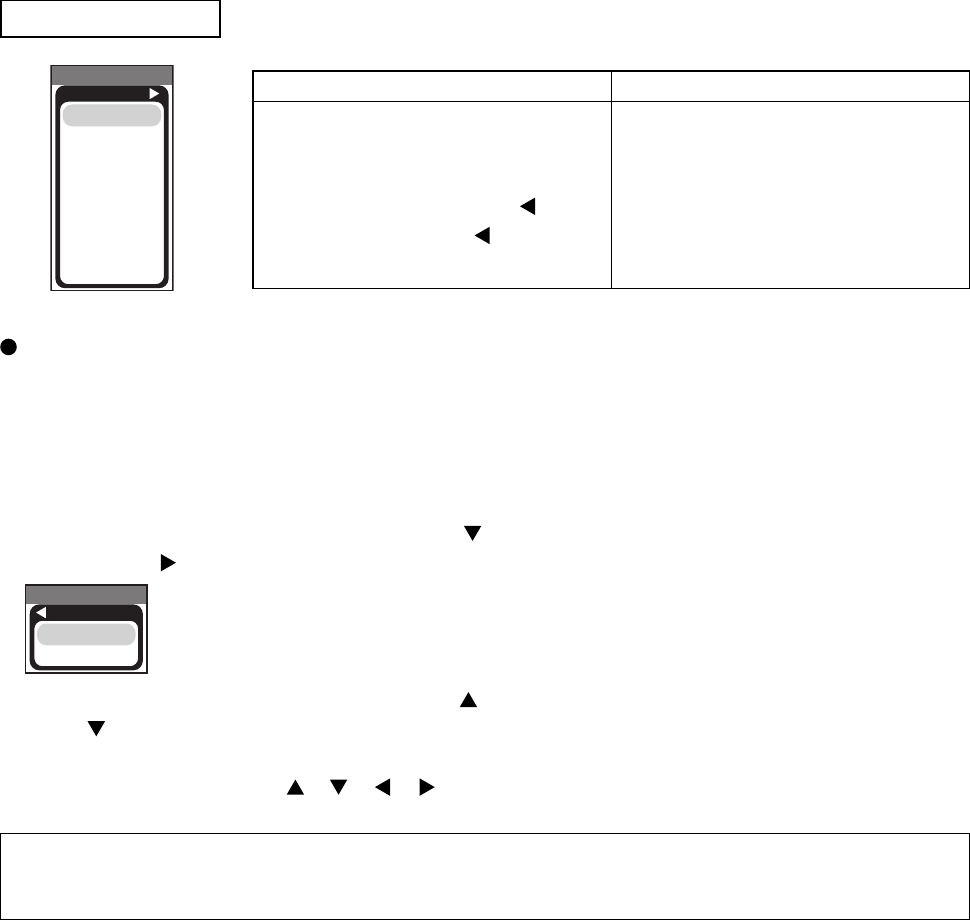
Setup of cooling fan speed
When using this projector in the place where altitude is high, we recommend you to set a cooling fan’s speed as
“HIGH”. It is because the cooling effi ciency of a projector falls and the temperature inside a projector rises easily
in such a place since the density of air becomes low.
Setting method of cooling fan speed
1. Select the “FAN SPEED” on the OSD using button “ ”.
Next press the “ ” to select “FAN SPEED MENU” by the SERVICE MENU.
By the control panel By the remote control transmitter
1. Display the menu by the “MENU”
button.
2. Select the “OPTION” on the menu.
3. Continue press the button “ ” fi rst,
then press the button “ ” together
with “INPUT”, and hold for 3 seconds.
1. Display the menu by the “MENU”
button.
2. Select the “OPTION” on the menu.
3. Press the “MAGNIFY OFF” button.
Next hold the “MAGNIFY OFF” button
for 3 seconds.
2. Select the “HIGH” on the OSD using the button “ ”. To reset this setup, select the “NORMAL” using the
button “ ”.
3. The OSD will be ended by no operation for 10 seconds or change of input signal. To end immediately, use
one of buttons except buttons “ ”, “ ”, “ ”, “ ”.
NOTE • The “HIGH” mode makes the fan noisy than “NORMAL” mode.
• The recall of factory setting sets the fan speed to “NORMAL” mode. You must set the fan speed after recall of
factory setting if you need “HIGH” mode.
SERVICE MENU
To display the OSD for “SERVICE MENU” set up.
SERVICE MENU
C10S
FANSPEED
B-SPEED
DURABLE
VIDEO NR
LENS
FILTER TIME
MUTE COLOR
AIR-SENSOR
SERVICE MENU
FANSPEED
HIGH
NORMAL
29
CP-S235 (C10SM2)
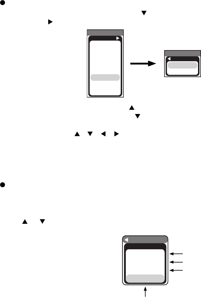
Setup of filter time (“ON” or “OFF”)
1. Select the “FILTER TIME” on the OSD using button “ ” .
Next press the “ ” to select “FILTER TIME MENU” by the SERVICE MENU.
SERVICE MENU
C10S
FANSPEED
B-SPEED
DURABLE
VIDEO NR
LENS
FILTER TIME
MUTE COLOR
AIR-SENSOR
SERVICE MENU
FILTER TIME
ON
OFF
2. ON : Select the “ON” on the OSD using button “ ”.
OFF : Select the “OFF” on the OSD using button “ ”.
3. The OSD will be ended by no operation for 10 seconds or change of input signal. To end immediately, use one
of buttons except buttons “ ”, “ ”, “ ”, “ ”.
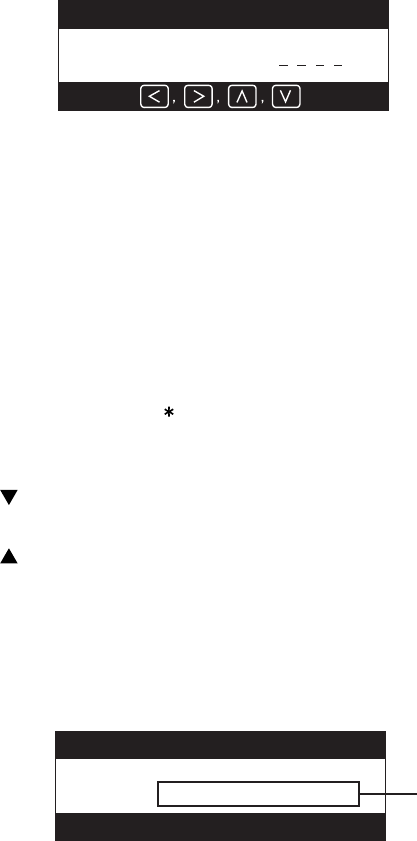
Set operating time display method (accumulated lamp time display method)
1. Select [Option] from the [Menu] display, then select [Lamp Time].
2. Press the [Reset] button once, then press [Keystone] for 3 seconds or more to display the screen shown
below. (The menu will close after 10 seconds if there are no further operations.)
3. Use “ ” or “ ” to select the usage status number. (The usage status is as shown below.)
OPTION
RUN TIME
1234h
On 00012
Off 00011
No.0
Usage status number (See below)
Usage status number
0 ..... Total usage status
1 ..... Current usage status
2 ..... Usage status before first reset
3 ..... Usage status before second reset
||
9 ..... Usage status before seventh reset
Time
Number of times on
Number of times off
30
CP-S235 (C10SM2)
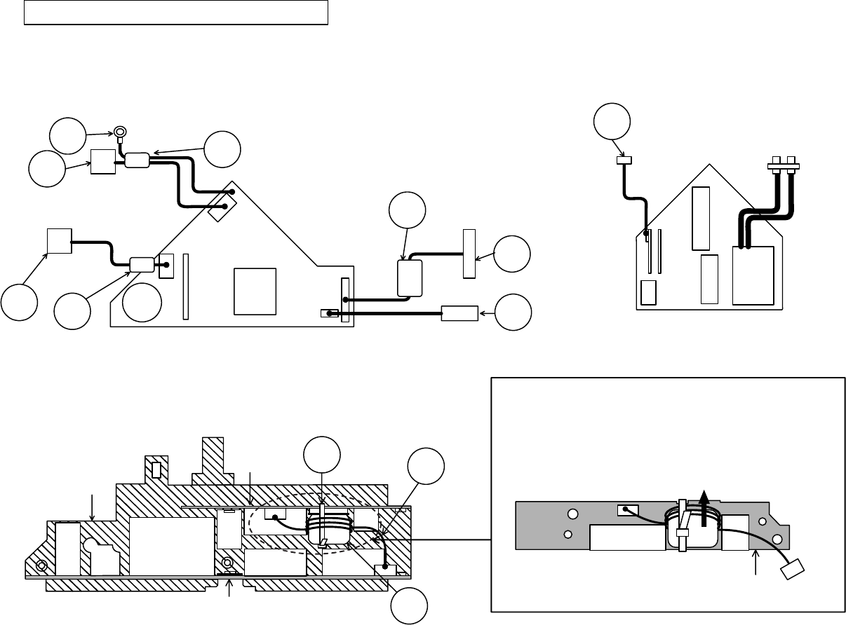
7. Wiring diagram
Circuit/ballast power board, Control - Main board wiring
Circuit power board wiring
(1) Connect TSW.
(2) Connect CNPOW and FEB3.
(3) Connect FEB2.
(4) Connect CN1,CD2,FEB1, and FEB5.
Ballast power board wiring
(1) Connect CNBAR.
CD2
CN1
Lock completely when
connecting CNPWR
connector to CN101.
Attach FEB2 (ferrite core)
to CNPWR and keep
close to board.
Confirm that CN102 and CN103
are connected properly
(confirmation is not possible later).
Installation details for the CNCT, FEB9 and Z3 are as per the
following diagram.
Place the wiring in the notch that runs along the control board,
fasten down the FEB9 that was installed in the CNCT with a Z3
(band) and cut off any excess length.
Then, Wiring the CNCT into the FEB9 brings near to the notch in
the Control board and Z3 should be fixed directly to FEB9.
Install the FEB9 (ferrite core) in the
CNCT. Wind the CNCT three times
around the FEB9 making sure that it
passes through it four times.
CNBAR
CN200
Confirm that CN200 is connected properly.
(confirmation is not possible later)
CN100
T102
Lock completely when
connecting CN1 connector.
FEB1
CN3
CN101
CNPWR
FEB2
<I/O metal back view>
T201 CN103
CN102
FEB3
CNPOW
TSW
Attach FEB1
(ferrite core)
to CN1 and CD2.
Attach FEB3 (ferrite core)
to CNPOW.
Do not wedge lead.
Control - Main board wiring
(1) Connect CNCT.
Z3
CNCT
FEB9
I/O metal (back)
Control board
EM01
ET01
Main board
EM01 Z3
FEB9
CNCT
Control board
Wiring diagram 1 (C10SM2)
31
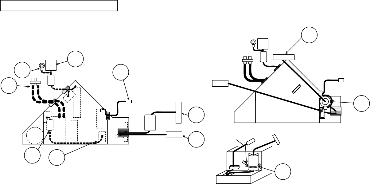
CP-S235 (C10SM2)
Power block wiring (board block SUB ASS'Y)
Attaching ballast power block
(1) Connect and wire CNPWR.
(2) Wire lamp lead.
(3) Wire CN1 and CD2.
(4) Wire TSW and CNPOW.
Pass lamp
lead through circuit
power case fastener.
Pass TSW and CNPOW
through ballast power case fastener.
After attaching ballast power block
(1) Secure FEB3.
Pass tie band through side hole
of ballast power case and secure FEB3.
Bind the band on back side of set
and crop loose end to minimize hindrance
when attaching upper case.
However, if any excess length of the SK
binder (Z2) comes into contact with the
projector lens, cut the excess off.
Lock CNPWR completely when connecting the connector
to ballast power CN100. Arrange the lead as shown
and attach FEB2 close to the circuit power.
Do not wedge in cooling wheel or igniter transformer.
Assembly procedure
(1) Pass CNBAR through ballast power block fastener and lock.
(2) Pass CN1 and CD2 through circuit power block fastener and lock.
(3) Connect one end of CNPWR to ballast power.
(4) Pass lamp lead through circuit power block fastener and lock when attaching
ballast power block to circuit power block.
Pass TSW and CNPOW through ballast power block fastener and lock.
Pass CN1 and CD2 through circuit power case fastener.
Caution: Parts differ for C10S and C10H.
Pass CNBAR through ballast
power case fastener.
CNBAR
CN1
CD2
Lamp
lead
FEB2
CNPWR
CN100
CNPOW
TSW
CNPOW
FEB3
Z2
Knot
Wiring diagram 2 (C10SM2)
32
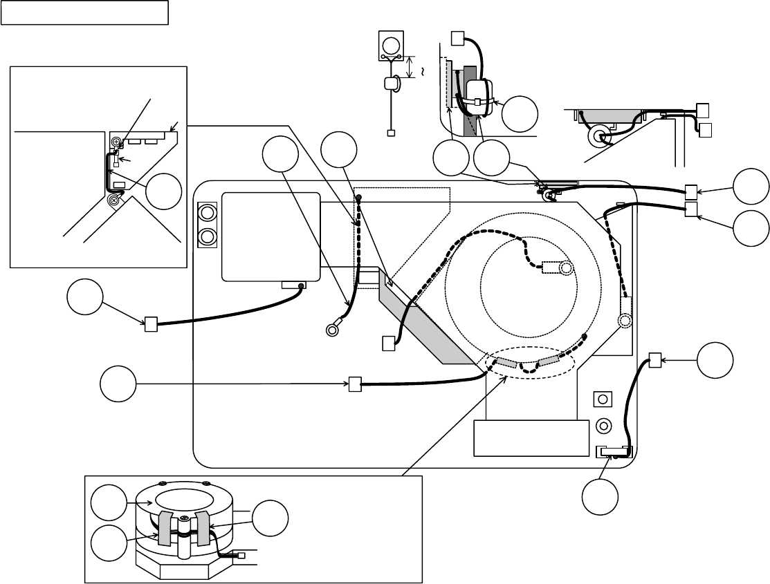
CP-S235 (C10SM2)
Wiring diagram 3 (C10SM2)
FG
Bottom case assembly
(1) Do not wedge wires when mounting optical unit.
Bottom case assembly wiring
Guide leads away from optical unit
positions to prevent leads from
becoming wedged when mounting
optical unit.
When wiring the
FG, bend the cables
that are in the vicinity
of the fuses for the
filter board and make
sure that the cables
do not come into
contact with
anything on
the filter board.
This section of the FG was bent by
the manufacturer, operators must
not touch this.
#6430 A83 FEBA
Z4
Secure ZTP4 and ZTP5
with tape to prevent #6460
connector lead from overlapping.
A83
#6800
CNRM
#6460
ZTP5
ZTP4
Pass wire
between PBS
duct and optical
unit.
After fastening
down the FEBA
totheZ4onthe
ribs of the bottom
case, cut off any
excess length.
Pass the A83
leads twice
through the
FEBA.
Arrange speaker and internal air sensor leads
as shown below. Extract the speaker leads
from the right hand side of the rear panel.
Ensure external air sensor lead is hooked on
optical unit hook. (To prevent lead getting
caught when attaching main board.)
CNLC CN2
#6460
FG
Filter
board
Fuse
Power case
Bottom
case
Rib
40 50mm
Speaker
Sensor
Optical
unit
Intake
upper
Speaker
R/C
board
33
CP-S235 (C10SM2)
CN
CN2
Power case
Power
case
CNSH
Ring lug
CNSH
CD2
CD2
Filter board
POWER CASE
FG
CN1
CN1
CNSH
CNSH
FEB6
Lamp
lead
SW
board
FEB4
80+10mm
_
Attach FEB4 as shown
Fasten CNSH, FG, CD2, and crown washer
to power case with a screw as shown below.
Angle each round
terminal to prevent
hitting duct or power
case as shown right.
Pull CN1 and CN2 leads in direction of arrow and
arrange along power case.
(To prevent leads getting caught when attaching OPT unit
and lamp house.)
Guide leads away from duct positions to prevent leads
from becoming wedged when mounting ducts.
Power block integration wiring
Power block integration
(1) Connect CN1.
(2) Secure FG, CD2 and CNSH to power block with screw.
(3) Connect and wire lamp lead
Confirm that lamp lead is
embedded properly into rib on
underside of bottom case.
Confirm same for erect part.
Ensure erect part of lead does
not protrude from rib.
(To prevent lead getting caught
between duct and rib.)
Run CNSH
through FEB5
four times
and then
clamp it down.
#6430
A83
#6800
#6460
CNBAR
CNRM
R/C
board
TSW
CNPOW
CNLC
Lamp
lead
FEB6
CD2
FG
CD2
FG
Wiring diagram 4 (C10SM2)
FEB1
Bend crimped part
of leads to 45ofor
FG and CD2 round
terminals as shown
below.
Use caution to prevent CN1,
FG and CD2 being pinched by
the bottom case during
installation of the optical engine,
exhaust duct, etc.
Lock completely when connecting
CN1 connector to CN2.
0 5mm
34
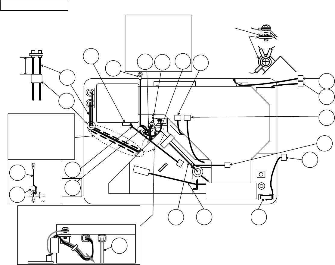
CP-S235 (C10SM2)
CN
1
Duct
E800
E801
E804
EM01
ET01
Main board
Control board
E803 E802
P501
P601
E302 E805
P701
ESPL
E301
E7A1
FEB8
TSW
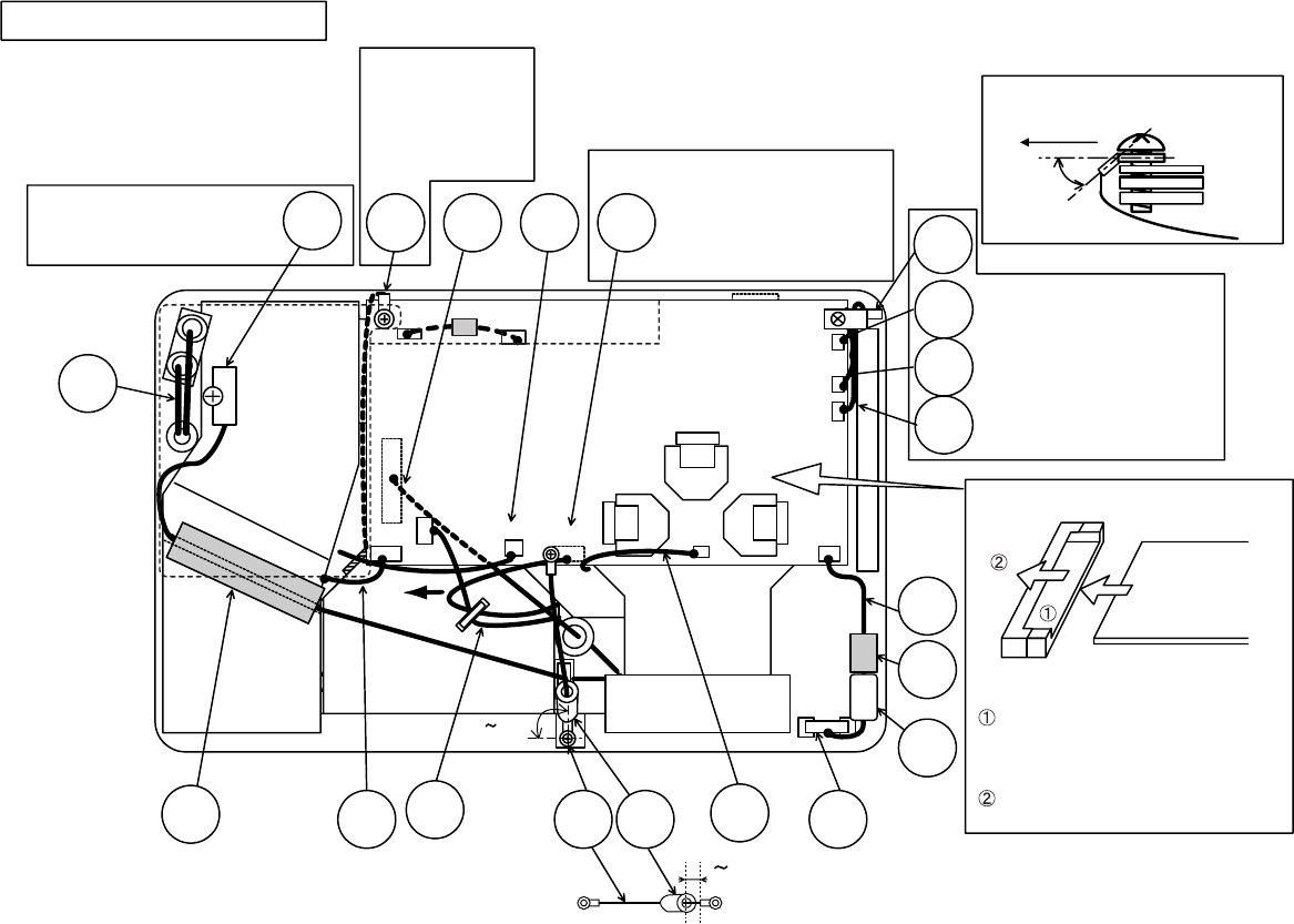
Duct and drive board mounting wiring
CNSH
CNPOW
CNLC #6460 LED
board
back side of set
Down 45o
Attach flexible cable as shown below.
Screw CNSH as shown below.
Pass CNME, #6430, and A83
leads below LED board fitting
and arrange in groove located
at top of ventilation duct.
Pull lead toward front of set
as shown and maintain slack.
(To prevent lead getting
caught in upper case rib.)
1. Mounting duct
(1) Do not wedge lamp lead.
(2) Do not wedge CNLC and CN1.
(3) Attach TSW
Check that TSW marking reads
"YS11A90A-**," and assemble
with marked surface down.
Arrange CNSH lead
between main board
and sub board shield
(to prevent wedging
between main board
and upper case).
2. Mounting drive board
(1) Connect CNPOW and #6460 (Underside of board: exercise caution).
(2) Connect CNBAR, CNLC, A83, #6800, #6430, CNRM, CNME, #3055,
and CNSH connectors.
(3) Connect LCD panel cable.
Arrange #6460 lead
eliminating slack and
secure with fastener
located on top of power
block (to prevent interference
with projection lense).
Connector
base
Insert flexible cable into connector
base properly.
(Confirm cable facing correct direction
as connector is top contact type.)
Move lock hinge in direction of
arrow and lock properly.
flexible Cable
CNSH
Shield
Main board
I/O metal
A83
#6800
CNME
CNRM
R/C
board
CNPC FEB7 #6430
CNBAR
Secure CNBAR and
#6460 with fastener
located on top of
power block.
Pay attention
to angles.
75 90
o
Run CNPC through FEB7
and then clamp it down.
Nestle the FEB8 in the remote control board so that it will not move,
then tape the CNRM leads to the ZTP1 on the insides of the bottom
case. (This prevents the leads from getting pinched by the screw
clamp bosses on the upper and bottom cases and also prevents
the adjustable feet on the cases from coming into contact with
each other.)
#3055
ZTP2
Guide TSW along
duct groove and
secure to ZTP2
with tape.
Lamp
lead
CNRM
FEB8
0 5mm
Wiring diagram 5 (C10SM2)
35
CP-S235 (C10SM2)
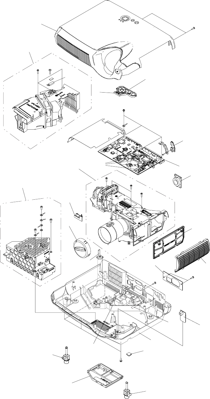
8. Disassembly diagram
M: Machine screw
T: Tapping screw
65
6
2
1
Dichroic optics unit
Power supply
unit
LCD/Lens prism
21
19
Lamp fan/duct
28
20
27
22
3
M3x10
T3x12
T3x16
M3x6(lock)
M4x8
T3x12
T3x12
(Notice 4)
10
(Notice 5)
18
T2x5
T3x12
T3x12
T3x12
(Notice 3)
(Notice 1)
8
T3x12(black)
26
25
4
M3x10
9
12
7
T3x12
(black)
36
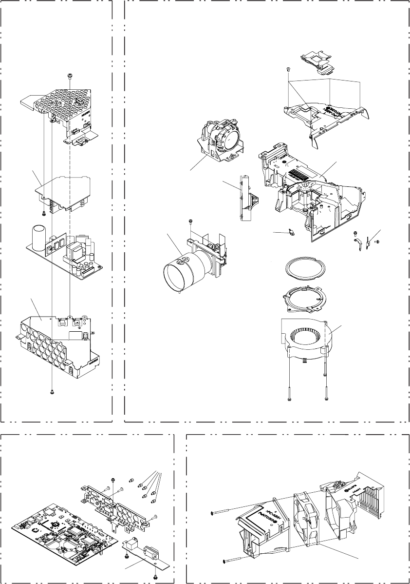
CP-S235 (C10SM2)
M: Machine screw
T: Tapping screw
24
16
16
14
29
30
17
13
15
Dichroic optics unit
LCD/Lens prism
Lamp fan/duct
MAIN Board
Power supply
unit
23
11
31
M3x8(black)
M3x8(black)
M3x8
M3x8
M3x30
T3x35
M3x6
M3x10
M3x10
T3x8
T3x35
M3x30
M3x30
M3x6
(Notice 2)
37
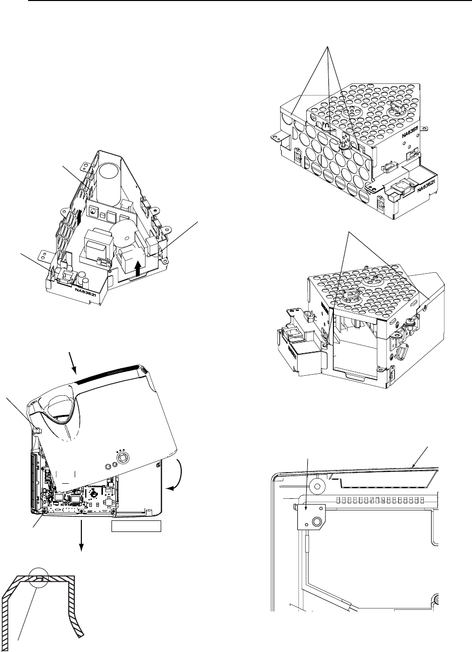
CP-S235 (C10SM2)
1. After attaching MAIN board assembly to case with
M3x6 lock screws, tighten screws on back of
bottom case.
2. To remove power board from shield case, push
board in direction of arrow, and unlock catches (a)
and (b) on board holders with screwdriver. (Lift
board toward (d).)
Unlock catch (c) with screwdriver and remove
holding (e).
3. Swivel case as shown below when attaching or
dismantling upper case.
Notice
(a)
(b)
(c)
(d)
(e)
4. Align shield case joints.
5. Attach lamp case bracket as shown below after
removing dichroic optics unit and duct assembly.
Ԙ
ԙ
Ԛ
Insert in direction ,
then swivel in direction .
Ԙ
ԙ
Precautions
Swivel case to avoid
applying pressure to
projection lens when
mounting. Same applies
to REMC board and
sensor board.
Insert while pulling back.
REMC board
sensor board
Fit attaching ribs on upper case
and bottom case together correctly.
Outside
Outside
Bottom case
Lamp case bracket
38
CP-S235 (C10SM2)
9. Replacement Parts list
Power cord RGB cable Remote control
THE UPDATED PARTS LIST
FOR THIS MODEL IS
AVAILABLE ON ESTA
39
CP-S235 (C10SM2)
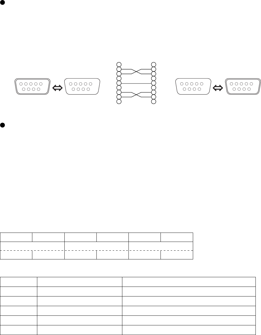
10. RS-232C communication
Connecting the cable
(1) Turn off the projector and the computer power supplies.
(2) Connect the CONTROL port of the projector with a RS-232C port of the computer by a RS-232C cable. Use
the cable that fulfills the specification shown in the following figure.
(3) Turn on the computer power supply and after the computer has started up, turn on the projector power
supply.
CONTROL
port
D-sub 9-pin
plug
RS-232C port
D-sub 9-pin
plug
D-sub 9-pin
jack
D-sub 9-pin
jack
1
2
3
4
5
6
7
8
9
RD
TD
GND
CTS
RTS
1
2
3
4
5
6
7
8
9
CD
RD
TD
DTR
GND
DSR
RTS
DTS
RI
Projector RS-232C cross cable Computer
9876
12345
6789
54321
6789
54321
9876
12345
Communications setting
19200bps, 8N1
1. Protocol
Consist of header (7 bytes) + command data (6 bytes).
2. Header
BE + EF + 03 + 06 + 00 + CRC_low + CRC_high
CRC_low : Lower byte of CRC flag for command data
CRC_high : Upper byte of CRC flag for command data
3. Command data
Command data chart
byte_0 byte_1 byte_2 byte_3 byte_4 byte_5
Action Type Setting code
low high low high low high
Action (byte_0 - 1)
Action Classification Content
1 SET Change setting to desired value.
2 GET Read projector internal setup value.
4 INCREMENT Increment setup value by 1.
5 DECREMENT Decrement setup value by 1.
6 EXECUTE Run a command.

40
CP-S235 (C10SM2)
Requesting projector status (Get command)
(1) Send the request code Header + Command data (‘02H’+‘00H’+ type (2 bytes)+‘00H’+‘00H’) from the
computer to the projector.
(2) The projector returns the response code ‘1DH’+ data (2 bytes) to the computer.
Changing the projector settings (Set command)
(1) Send the setting code Header + Command data (‘01H’+‘00H’+ type (2 bytes) + setting code (2 bytes)) from
the computer to the projector.
(2) The projector changes the setting based on the above setting code.
(3) The projector returns the response code ‘06H’ to the computer.
Using the projector default settings (Reset Command)
(1) The computer sends the default setting code Header + Command data (‘06H’+‘00H’+ type (2 bytes) +‘00H’+
‘00H’) to the projector.
(2) The projector changes the specified setting to the default value.
(3) The projector returns the response code ‘06H’ to the computer.
Increasing the projector setting value (Increment command)
(1) The computer sends the increment code Header + Command data (‘04H’+‘00H’+ type (2 bytes) +‘00H’+
‘00H’) to the projector.
(2) The projector in creases the setting value on the above setting code.
(3) The projector returns the response code ‘06H’ to the computer.
Decreasing the projector setting value (Decrement command)
(1) The computer sends the decrement code Header + Command data (‘05H’+‘00H’+ type (2 bytes) +‘00H’ +
‘00H’) to the projector.
(2) The projector decreases the setting value on the above setting code.
(3) The projector returns the response code ‘06H’ to the computer.
When the projector cannot understand the received command.
When the projector cannot understand the received command, the error code ‘15H’ is sent back to the computer.
Sometimes the projector cannot properly receive the command. In such a case, the command is not executed
and the error code ‘15H’ is sent back to the computer. If this error code is returned, send the same command
again.
When the projector cannot execute the received command.
When the projector cannot execute the received command, the error code ‘1cH’ + ‘xxxxH’ is sent back to the
computer. When the data length is greater than indicated by the data length code, the projector ignore the
excess data code.
Conversely when the data length is shorter than indicated by the data length code, an error code will be returned
to the computer.
NOTE • Operation cannot be guaranteed when the projector receives an undefi ned command or data.
• Provide an interval of at least 40ms between the response code and any other code.
•
The projector outputs test data when the power supply is switched ON, and when the lamp is lit. Ignore this data.
• Commands are not accepted during warm-up.

41
CP-S235 (C10SM2)
Command data chart
Names Operation type Header Command data
CRC Action Type Setting code
Keystone
Get BE EF 03 06 00 B9 D3 02 00 07 20 00 00
Increment BE EF 03 06 00 DF D3 04 00 07 20 00 00
Decrement BE EF 03 06 00 0E D2 05 00 07 20 00 00
Keystone Reset Execute BE EF 03 06 00 08 D0 06 00 0C 70 00 00
Brightness
Get BE EF 03 06 00 89 D2 02 00 03 20 00 00
Increment BE EF 03 06 00 EF D2 04 00 03 20 00 00
Decrement BE EF 03 06 00 3E D3 05 00 03 20 00 00
Brightness Reset Execute BE EF 03 06 00 58 D3 06 00 00 70 00 00
Contrast
Get BE EF 03 06 00 FD D3 02 00 04 20 00 00
Increment BE EF 03 06 00 9B D3 04 00 04 20 00 00
Decrement BE EF 03 06 00 4A D2 05 00 04 20 00 00
Contrast Reset Execute BE EF 03 06 00 A4 D2 06 00 01 70 00 00
Aspect Set
4:3 BE EF 03 06 00 9E D0 01 00 08 20 00 00
16:9 BE EF 03 06 00 0E D1 01 00 08 20 01 00
15:9 BE EF 03 06 00 6E D0 01 00 08 20 03 00
32:15 BE EF 03 06 00 5E D2 01 00 08 20 04 00
WIDE BE EF 03 06 00 CE D3 01 00 08 20 05 00
ZOOM BE EF 03 06 00 3E D3 01 00 08 20 06 00
Get BE EF 03 06 00 AD D0 02 00 08 20 00 00
Whisper Set NORMAL BE EF 03 06 00 3B 23 01 00 00 33 00 00
WHISPER BE EF 03 06 00 AB 22 01 00 00 33 01 00
Get BE EF 03 06 00 08 23 02 00 00 33 00 00
Mirror Set
Normal BE EF 03 06 00 C7 D2 01 00 01 30 00 00
H Inverse BE EF 03 06 00 57 D3 01 00 01 30 01 00
V lnverse BE EF 03 06 00 A7 D3 01 00 01 30 02 00
H&V Inverse BE EF 03 06 00 37 D2 01 00 01 30 03 00
Get BE EF 03 06 00 F4 D2 02 00 01 30 00 00
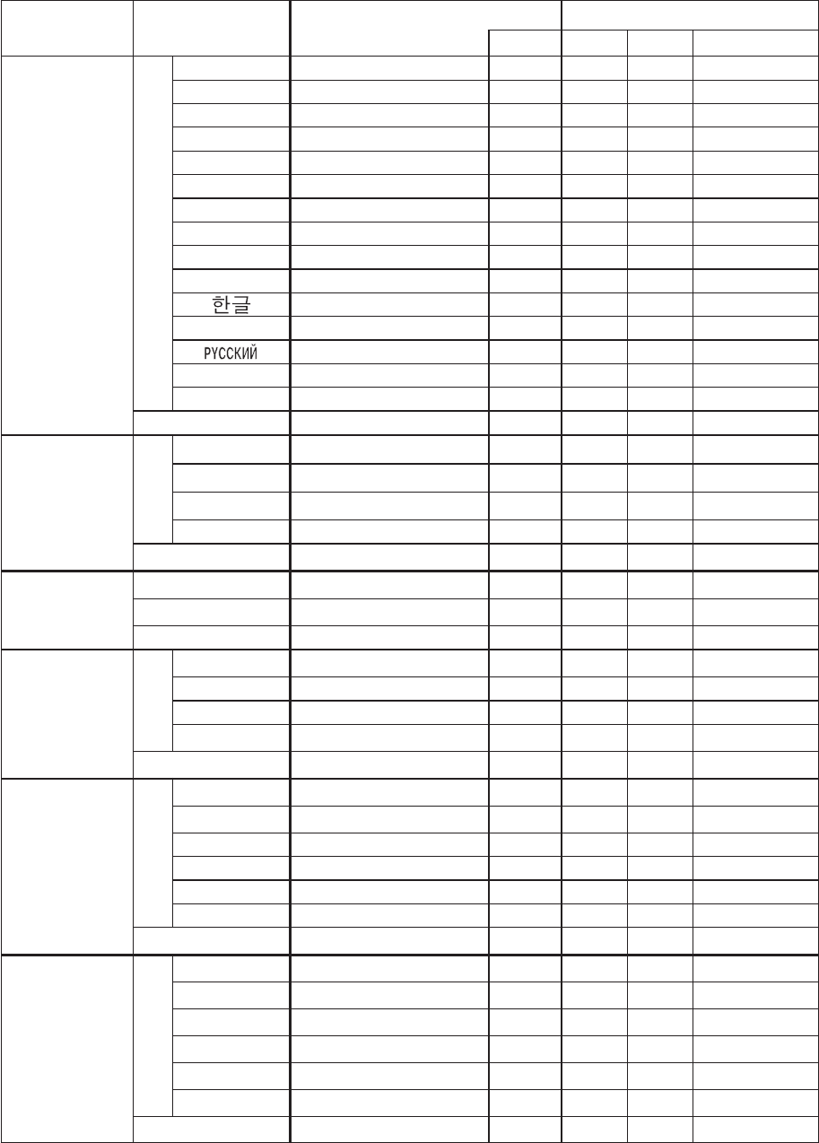
42
CP-S235 (C10SM2)
Names Operation type Header Command data
CRC Action Type Setting code
Language Set
English BE EF 03 06 00 F7 D3 01 00 05 30 00 00
FRANÇAIS
BE EF 03 06 00 67 D2 01 00 05 30 01 00
Deutsch BE EF 03 06 00 97 D2 01 00 05 30 02 00
ESPAÑOL BE EF 03 06 00 07 D3 01 00 05 30 03 00
Italiano BE EF 03 06 00 37 D1 01 00 05 30 04 00
Norsk BE EF 03 06 00 A7 D0 01 00 05 30 05 00
Nederlands
BE EF 03 06 00 57 D0 01 00 05 30 06 00
PORTUGUÊS
BE EF 03 06 00 C7 D1 01 00 05 30 07 00
日本語
BE EF 03 06 00 37 D4 01 00 05 30 08 00
中文
BE EF 03 06 00 A7 D5 01 00 05 30 09 00
BE EF 03 06 00 57 D5 01 00 05 30 0A 00
SVENSKA BE EF 03 06 00 C7 D4 01 00 05 30 0B 00
BE EF 03 06 00 F7 D6 01 00 05 30 0C 00
SUOMI BE EF 03 06 00 67 D7 01 00 05 30 0D 00
POLSKI BE EF 03 06 00 97 D7 01 00 05 30 0E 00
Get BE EF 03 06 00 C4 D3 02 00 05 30 00 00
Gamma Set
NORMAL BE EF 03 06 00 C7 F0 01 00 A1 30 00 00
CINEMA BE EF 03 06 00 57 F1 01 00 A1 30 01 00
DYNAMIC BE EF 03 06 00 A7 F1 01 00 A1 30 02 00
CUSTOM BE EF 03 06 00 07 FD 01 00 A1 30 10 00
Get BE EF 03 06 00 F4 F0 02 00 A1 30 00 00
Custom Gamma
Get BE EF 03 06 00 08 F1 02 00 A0 30 00 00
Increment BE EF 03 06 00 6E F1 04 00 A0 30 00 00
Decrement BE EF 03 06 00 BF F0 05 00 A0 30 00 00
Custom
Colour Temp
Set
USER BE EF 03 06 00 3B F8 01 00 B0 30 10 00
HIGH BE EF 03 06 00 0B F5 01 00 B0 30 03 00
MIDDLE BE EF 03 06 00 9B F4 01 00 B0 30 02 00
LOW BE EF 03 06 00 6B F4 01 00 B0 30 01 00
Get BE EF 03 06 00 C8 F5 02 00 B0 30 00 00
Custom User R Set
50 BE EF 03 06 00 57 F7 01 00 B1 30 05 00
60 BE EF 03 06 00 C7 F6 01 00 B1 30 04 00
70 BE EF 03 06 00 F7 F4 01 00 B1 30 03 00
80 BE EF 03 06 00 67 F5 01 00 B1 30 02 00
90 BE EF 03 06 00 97 F5 01 00 B1 30 01 00
100 BE EF 03 06 00 07 F4 01 00 B1 30 00 00
Get BE EF 03 06 00 34 F4 02 00 B1 30 00 00
Custom User G Set
50 BE EF 03 06 00 13 F7 01 00 B2 30 05 00
60 BE EF 03 06 00 83 F6 01 00 B2 30 04 00
70 BE EF 03 06 00 B3 F4 01 00 B2 30 03 00
80 BE EF 03 06 00 23 F5 01 00 B2 30 02 00
90 BE EF 03 06 00 D3 F5 01 00 B2 30 01 00
100 BE EF 03 06 00 43 F4 01 00 B2 30 00 00
Get BE EF 03 06 00 70 F4 02 00 B2 30 00 00

43
CP-S235 (C10SM2)
Names Operation type Header Command data
CRC Action Type Setting code
Custom User B Set
50 BE EF 03 06 00 EF F6 01 00 B3 30 05 00
60 BE EF 03 06 00 7F F7 01 00 B3 30 04 00
70 BE EF 03 06 00 4F F5 01 00 B3 30 03 00
80 BE EF 03 06 00 DF F4 01 00 B3 30 02 00
90 BE EF 03 06 00 2F F4 01 00 B3 30 01 00
100 BE EF 03 06 00 BF F5 01 00 B3 30 00 00
Get BE EF 03 06 00 8C F5 02 00 B3 30 00 00
Colour Balance R
Get BE EF 03 06 00 01 D2 02 00 05 20 00 00
Increment BE EF 03 06 00 67 D2 04 00 05 20 00 00
Decrement BE EF 03 06 00 B6 D3 05 00 05 20 00 00
Colour Balance R
Reset Execute BE EF 03 06 00 94 D3 06 00 05 70 00 00
Colour Balance G
Get BE EF 03 06 00 B5 D7 02 00 12 20 00 00
Increment BE EF 03 06 00 D3 D7 04 00 12 20 00 00
Decrement BE EF 03 06 00 02 D6 05 00 12 20 00 00
Colour Balance G
Reset Execute BE EF 03 06 00 04 DB 06 00 29 70 00 00
Colour Balance B
Get BE EF 03 06 00 45 D2 02 00 06 20 00 00
Increment BE EF 03 06 00 23 D2 04 00 06 20 00 00
Decrement BE EF 03 06 00 F2 D3 05 00 06 20 00 00
Colour Balance B
Reset Execute BE EF 03 06 00 D0 D3 06 00 06 70 00 00
Sharpness
Get BE EF 03 06 00 F1 72 02 00 01 22 00 00
Increment BE EF 03 06 00 97 72 04 00 01 22 00 00
Decrement BE EF 03 06 00 46 73 05 00 01 22 00 00
Sharpness Reset Execute BE EF 03 06 00 C4 D0 06 00 09 70 00 00
Colour
Get BE EF 03 06 00 B5 72 02 00 02 22 00 00
Increment BE EF 03 06 00 D3 72 04 00 02 22 00 00
Decrement BE EF 03 06 00 02 73 05 00 02 22 00 00
Colour Reset Execute BE EF 03 06 00 80 D0 06 00 0A 70 00 00
Tint
Get BE EF 03 06 00 49 73 02 00 03 22 00 00
Increment BE EF 03 06 00 2F 73 04 00 03 22 00 00
Decrement BE EF 03 06 00 FE 72 05 00 03 22 00 00
Tint Reset Execute BE EF 03 06 00 7C D1 06 00 0B 70 00 00
My Memory Load
Set
1 BE EF 03 06 00 0E D7 01 00 14 20 00 00
2 BE EF 03 06 00 9E D6 01 00 14 20 01 00
3 BE EF 03 06 00 6E D6 01 00 14 20 02 00
4 BE EF 03 06 00 FE D7 01 00 14 20 03 00
My Memory Save
Set
1
BE EF 03 06 00 F2 D6 01 00 15 20 00 00
2
BE EF 03 06 00 62 D7 01 00 15 20 01 00
3
BE EF 03 06 00 92 D7 01 00 15 20 02 00
4
BE EF 03 06 00 02 D6 01 00 15 20 03 00

44
CP-S235 (C10SM2)
Names Operation type Header Command data
CRC Action Type Setting code
V Position
Get BE EF 03 06 00 0D 83 02 00 00 21 00 00
Increment BE EF 03 06 00 6B 83 04 00 00 21 00 00
Decrement BE EF 03 06 00 BA 82 05 00 00 21 00 00
V Position Reset Execute BE EF 03 06 00 E0 D2 06 00 02 70 00 00
H Position
Get BE EF 03 06 00 F1 82 02 00 01 21 00 00
Increment BE EF 03 06 00 97 82 04 00 01 21 00 00
Decrement BE EF 03 06 00 46 83 05 00 01 21 00 00
H Position Reset Execute BE EF 03 06 00 1C D3 06 00 03 70 00 00
H Phase
Get BE EF 03 06 00 49 83 02 00 03 21 00 00
Increment BE EF 03 06 00 2F 83 04 00 03 21 00 00
Decrement BE EF 03 06 00 FE 82 05 00 03 21 00 00
H Size
Get BE EF 03 06 00 B5 82 02 00 02 21 00 00
Increment BE EF 03 06 00 D3 82 04 00 02 21 00 00
Decrement BE EF 03 06 00 02 83 05 00 02 21 00 00
H Size Reset Execute BE EF 03 06 00 68 D2 06 00 04 70 00 00
Over Scan
Get BE EF 03 06 00 91 70 02 00 09 22 00 00
Increment BE EF 03 06 00 F7 70 04 00 09 22 00 00
Decrement BE EF 03 06 00 26 71 05 00 09 22 00 00
Over Scan Reset Execute BE EF 03 06 00 EC D9 06 00 27 70 00 00
Colour Space
Set
AUTO BE EF 03 06 00 0E 72 01 00 04 22 00 00
RGB BE EF 03 06 00 9E 73 01 00 04 22 01 00
SMPTE240 BE EF 03 06 00 6E 73 01 00 04 22 02 00
REC709 BE EF 03 06 00 FE 72 01 00 04 22 03 00
REC601 BE EF 03 06 00 CE 70 01 00 04 22 04 00
Get BE EF 03 06 00 3D 72 02 00 04 22 00 00
Component
Set COMPONENT BE EF 03 06 00 4A D7 01 00 17 20 00 00
SCART RGB BE EF 03 06 00 DA D6 01 00 17 20 01 00
Get BE EF 03 06 00 79 D7 02 00 17 20 00 00
Video Format Set
AUTO BE EF 03 06 00 9E 75 01 00 00 22 0A 00
NTSC BE EF 03 06 00 FE 71 01 00 00 22 04 00
PAL BE EF 03 06 00 6E 70 01 00 00 22 05 00
SECAM BE EF 03 06 00 6E 75 01 00 00 22 09 00
NTSC 4.43 BE EF 03 06 00 5E 72 01 00 00 22 02 00
M-PAL BE EF 03 06 00 FE 74 01 00 00 22 08 00
N-PAL BE EF 03 06 00 0E 71 01 00 00 22 07 00
Get BE EF 03 06 00 0D 73 02 00 00 22 00 00
Frame Lock Set TURN OFF BE EF 03 06 00 CB D6 01 00 14 30 00 00
TURN ON BE EF 03 06 00 5B D7 01 00 14 30 01 00
Get BE EF 03 06 00 F8 D6 02 00 14 30 00 00
3D-YCS Set
TURN OFF BE EF 03 06 00 E6 70 01 00 0A 22 00 00
NORMAL BE EF 03 06 00 76 71 01 00 0A 22 01 00
STILL IMAGE BE EF 03 06 00 86 71 01 00 0A 22 02 00
Get BE EF 03 06 00 D5 70 02 00 0A 22 00 00

45
CP-S235 (C10SM2)
Names Operation type Header Command data
CRC Action Type Setting code
Video NR Set
LOW BE EF 03 06 00 26 72 01 00 06 22 01 00
MIDDLE BE EF 03 06 00 D6 72 01 00 06 22 02 00
HIGH BE EF 03 06 00 46 73 01 00 06 22 03 00
Get BE EF 03 06 00 85 73 02 00 06 22 00 00
Progressive Set
Turn off BE EF 03 06 00 4A 72 01 00 07 22 00 00
TV BE EF 03 06 00 DA 73 01 00 07 22 01 00
Film BE EF 03 06 00 2A 73 01 00 07 22 02 00
Get BE EF 03 06 00 79 72 02 00 07 22 00 00
S2-Aspect Set TURN OFF BE EF 03 06 00 1A 71 01 00 0B 22 00 00
TURN ON BE EF 03 06 00 8A 70 01 00 0B 22 01 00
Get BE EF 03 06 00 29 71 02 00 0B 22 00 00
Auto Adjust Execute BE EF 03 06 00 91 D0 06 00 0A 20 00 00
Auto off
Get BE EF 03 06 00 08 86 02 00 10 31 00 00
Increment BE EF 03 06 00 6E 86 04 00 10 31 00 00
Decrement BE EF 03 06 00 BF 87 05 00 10 31 00 00
Auto Search Set TURN OFF BE EF 03 06 00 B6 D6 01 00 16 20 00 00
TURN ON BE EF 03 06 00 26 D7 01 00 16 20 01 00
Get BE EF 03 06 00 85 D6 02 00 16 20 00 00
Blank Colour Set
Blue BE EF 03 06 00 CB D3 01 00 00 30 03 00
White BE EF 03 06 00 6B D0 01 00 00 30 05 00
Black BE EF 03 06 00 9B D0 01 00 00 30 06 00
Get BE EF 03 06 00 08 D3 02 00 00 30 00 00
Blank on/off
Set TURN OFF BE EF 03 06 00 FB D8 01 00 20 30 00 00
TURN ON BE EF 03 06 00 6B D9 01 00 20 30 01 00
Get BE EF 03 06 00 C8 D8 02 00 20 30 00 00
Startup
Set TURN ON BE EF 03 06 00 0B D2 01 00 04 30 00 00
TURN OFF BE EF 03 06 00 9B D3 01 00 04 30 01 00
Get BE EF 03 06 00 38 D2 02 00 04 30 00 00
Menu Position V
Get BE EF 03 06 00 40 D7 02 00 16 30 00 00
Increment BE EF 03 06 00 26 D7 04 00 16 30 00 00
Decrement BE EF 03 06 00 F7 D6 05 00 16 30 00 00
Menu Position V
Reset Execute BE EF 03 06 00 A8 C7 06 00 44 70 00 00
Menu Position H
Get BE EF 03 06 00 04 D7 02 00 15 30 00 00
Increment BE EF 03 06 00 62 D7 04 00 15 30 00 00
Decrement BE EF 03 06 00 B3 D6 05 00 15 30 00 00
Menu Position H
Reset Execute BE EF 03 06 00 DC C6 06 00 43 70 00 00
Message Set TURN OFF BE EF 03 06 00 8F D6 01 00 17 30 00 00
TURN ON BE EF 03 06 00 1F D7 01 00 17 30 01 00
Get BE EF 03 06 00 BC D6 02 00 17 30 00 00

46
CP-S235 (C10SM2)
Names Operation type Header Command data
CRC Action Type Setting code
Volume
Get BE EF 03 06 00 31 D3 02 00 01 20 00 00
Increment BE EF 03 06 00 57 D3 04 00 01 20 00 00
Decrement BE EF 03 06 00 86 D2 05 00 01 20 00 00
MUTE Set TURN ON BE EF 03 06 00 46 D3 01 00 02 20 00 00
TURN OFF BE EF 03 06 00 D6 D2 01 00 02 20 01 00
Get BE EF 03 06 00 75 D3 02 00 02 20 00 00
Screen type Set
4:3 BE EF 03 06 00 7A D6 01 00 00 00
16:9- Top BE EF 03 06 00 EA D7 01 00 13 20 01 00
16:9- Center BE EF 03 06 00 1A D7 01 00 02 00
16:9- Bottom BE EF 03 06 00 8A D6 01 00 13 20 03 00
Get BE EF 03 06 00 49 D6 02 00 00 00
Lamp Time Get BE EF 03 06 00 C2 FF 02 00 90 10 00 00
Lamp Time Reset Execute BE EF 03 06 00 58 DC 06 00 30 70 00 00
Filter Time Get BE EF 03 06 00 C2 F0 02 00 A0 10 00 00
Filter Time Reset Execute BE EF 03 06 00 98 C6 06 00 40 70 00 00
Magnify
Get BE EF 03 06 00 7C D2 02 00 07 30 00 00
Increment BE EF 03 06 00 1A D2 04 00 07 30 00 00
Decrement BE EF 03 06 00 CB D3 05 00 07 30 00 00
Freeze Set Normal BE EF 03 06 00 83 D2 01 00 02 30 00 00
Freeze BE EF 03 06 00 13 D3 01 00 02 30 01 00
Get BE EF 03 06 00 B0 D2 02 00 02 30 00 00
Power
Set TURN OFF BE EF 03 06 00 2A D3 01 00 00 60 00 00
TURN ON BE EF 03 06 00 BA D2 01 00 00 60 01 00
Get
BE EF 03 06 00 19 D3 02 00 00 60 00 00
(Example Return)
00 00 01 00 02 00
(Off) (On) (Cool down)
Input Source Set
RGB BE EF 03 06 00 FE D2 01 00 00 20 00 00
Video BE EF 03 06 00 6E D3 01 00 00 20 01 00
S-Video BE EF 03 06 00 9E D3 01 00 00 20 02 00
Component BE EF 03 06 00 AE D1 01 00 00 20 05 00
Get BE EF 03 06 00 CD D2 02 00 00 20 00 00
Error Status Get
BE EF 03 06 00 D9 D8 02 00 20 60 00 00
(Example of Return)
00 00 01 00 02 00 03 00
(Normal) (Cover-error) (Fan-error) (Lamp-error)
04 00 05 00 06 00 07 00 08 00 09 00
(Temp-error) (Air flow- (Lamp- (Cool-error) (Filter-Error) (Filter-
error) Time-over) Missing)
13 20
13 20
13 20
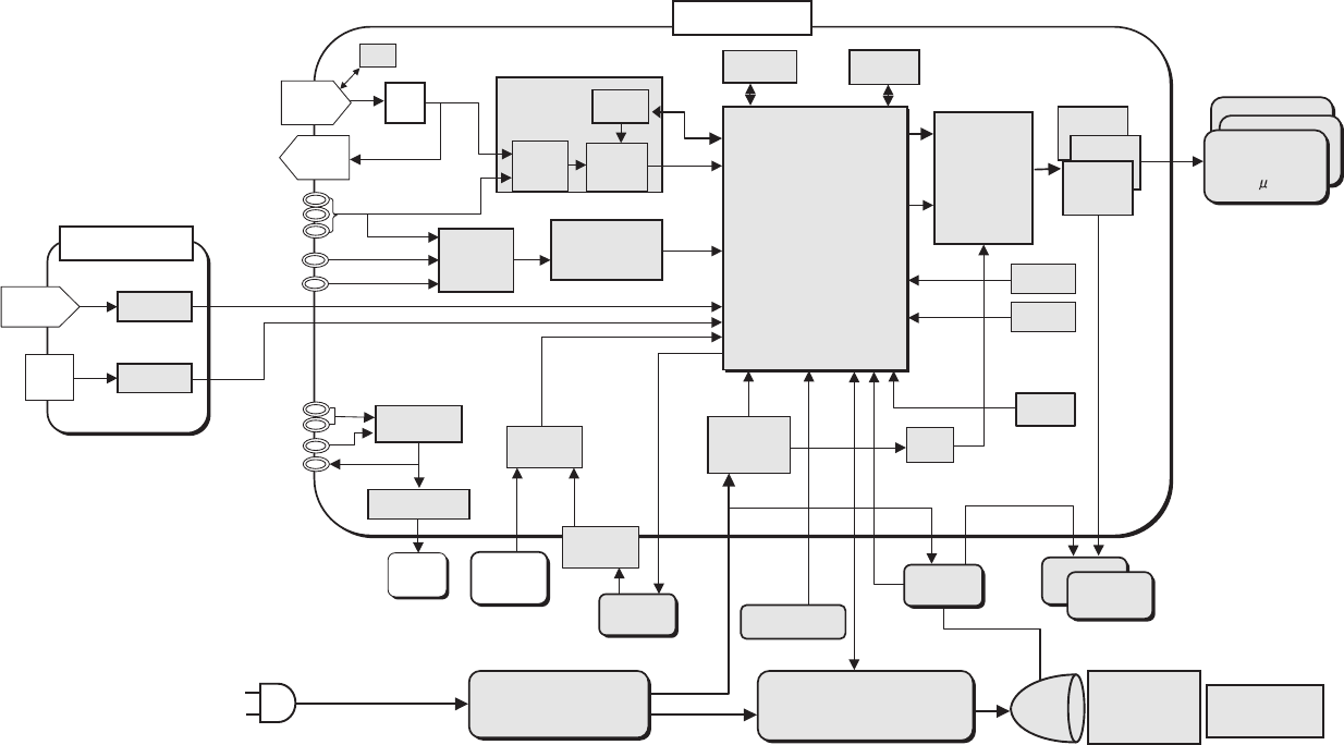
47
CP-S235 (C10SM2)
11. Block diagram
Block diagram (C10SM2)
+
Component
Video
0.55" LCD
SVGA PANEL
with LENZ
DC POWER
SUPPLYPCB
LAMPPOWER
SUPPLYPCB
2nd PLL
MAIN PCB
AC
INPUT
CLAMP
RGB in
Flash
ROM
SP
(RGB)Audio
Video
OPTICAL
UNIT PROJECTION
LENS
FAN
Lamp
EEPROM
Crystal
A/D, PLL
THC7216
S-Video
S/P
COLOUR
UNIFORMITY
&
TIMING
GENERATOR
AUDIO AMP
VIDEO
DECODER
TC90A92AFG
(Video)Audio
SELECTOR
CONTROL PCB
RGB out
DDC
PW168-05RK
Image Processor
VOLUME
CONTROL
RS-232C
1st PLL
RGB
A/D
6dB
AMP
Audio out
CTL
S/H
LEVEL
SHIFTER
KEY
TEMP
SENSOR
STUCK
SENSOR
SUB CPU
SEL./
COMP.
USB MOUSE
SW PCB
IR RECEIVER
PCB
SENSOR
PCB
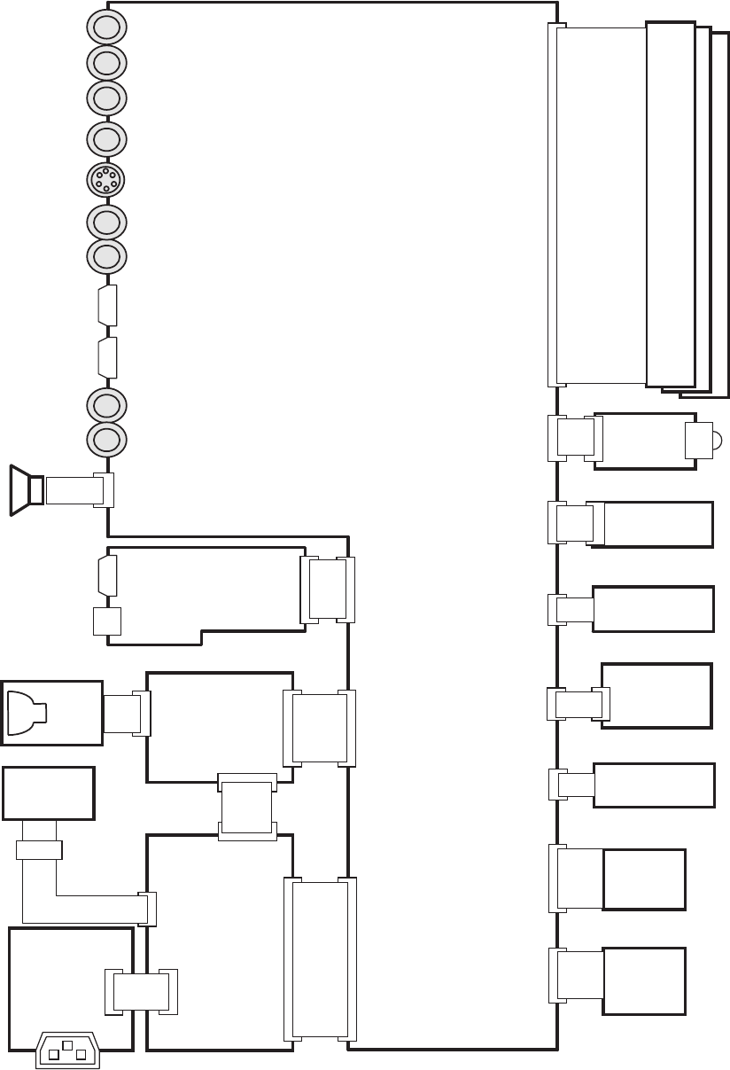
48
CP-S235 (C10SM2)
12. Connector connection diagram
Connector connection diagram (C10SM2)
Power unit
(Ballast)
Power Unit
(Circuit)
1:POWER-
ON/OFF
2:GND
3:LAMP MISS
4:SELCT
VIDEO IN
S-VIDEO IN
RGB IN
CONTROL
AUDIO-L IN
Exhaust
fan
In
Sensor
1:+12.6V(F)
2:GND(F)
3:+17V
4:GND
5:+6.0V
6:+6.0V
7:+4.3V
8:+4.3V
9:GND
10:GND
11:GND
12:ACTIVE-
ON/OFF
Lamp
Unit
AC INLET
1:GND
2:R/C
3:+3.3V
1:HV
2:GND
1:DC IN
2:NC
3:GND
4:+16V
R/C Front
Board
DRIVE Board
CN101
CN103
SVGA Wide
(EPSON) (EPSON)
1:COM 1:NC
2:VVDD 2:DY
3:DWN 3:CLY
4:PCG 4:/CLY
5:VST 5:VDDY
6:VCK 6:LCCOM
7:ENB 7:NC
8:NC 8:NRG
9:VSS 9:ENB1
10:HCK2 10:ENB2
11:HCK1 11:ENB3
12:HST 12:ENB4
13:NC 13:DIRX
14:NC 14:CLX
15:CLR 15:/CLX
16:RGT 16:VDDX
17:HVDD 17:DX
18:SIG1 18:VSSX
19:SIG6 19:VID1
20:SIG2 20:VID2
21:SIG5 21:VID3
22:SIG3 22:VID4
23:SIG4 23:VID5
24:PSIG 24:VID6
25:LCCOM 25:LCCOM
26:NC 26:NC
27:LCCOM 27:LCCOM
28:DIRY 28:DIRY
29:VSSY 29:VSSY
30:MON 30:MON
LCD Panel
Cover SW
Board
1:LAMP TEMP DET. OUT
2:LAMP TEMP DET. RETURN
1:TO-SW
2:COVER
Panel
fan
1:FAN2S
2:VCC
3:GND
4:CONT-P
1:OUT
2:GND
YIN
Pb/Cb IN
Pr/Cr IN
AUDIO-R IN
CNBAR:4P-ZH 160mm (P#:EF23002)
CN102
ESPL
E804
With Ballast Power Unit
CNPWR:4P-VH 130mm
(P#:EF22877)
CNPOW:12P-PH 190mm
(P#:EF21953)
A83:2P-DF13 90mm
SP Assy (P#:GK00393)
J1
J2
E800
1:FAN1S
2:VCC
3:GND
4:CONT-E
5:NC
2P-ZH 250mm
(P#:AZ00253)
RGB
CNRM:3P-ZH 140mm
(P#:EF22999)
CNLC:2P-ZH 130mm
(P#:EF22997)
#3055:Exhaust-Fan(5P-ZH)
50mm(P#:GS00912)
#6460:Panel-Fan(4P-PH)
250mm(P#:GS00891)
30P FPC(Flat)
With Panel(OPT Unit)
R:P501
G:P601
B:P701
E805
E301
E803
E801
E802
#6430
1: SP-
2: SP+
E901
E941
CNTS:2P-EH 270mm
(P#:EF08764)
Soldering
(W151097)
AUDIO IN
Out
Sensor
1:OUT
2:GND
2P-ZH 230mm
(P#:AZ00252)
E302 #6800
1:L
2:NC
3:N
Filter Unit
CN1:3P-VH
150mm
(P#:EF22876)
CN2 CN3
LED
Board
CNME:3P-ZH 80mm
(P#:EF23004)
1:GND
2:HPLL
3:NC
E7A1
E981
RGB OUT
AUDIO OUT
Temp. SW
TSW:(P#:FH00275)
1:+5V
2:RMT
3:TXD
4:RXD
5:GND
CONTROL
BOARD
CNRM:3P-ZH 140mm
(P#:EF22999)
ET01
EM01
USB

49
13. Basic circuit diagrams
CP-S235 (C10SM2)
SENSOR Board
COVER SWITCH Board
REMOTE CONTROL Board
FILTER UNIT
POWER UNIT CIRCUIT
POWER UNIT BALLAST 1
POWER UNIT BALLAST 2
CONTROL Board
MAIN Board 1
MAIN Board 2
MAIN Board 3
MAIN Board 4
MAIN Board 5
MAIN Board 6
MAIN Board 7
MAIN Board 8
MAIN Board 9
MAIN Board 10
MAIN Board 11
Basic circuit diagram list
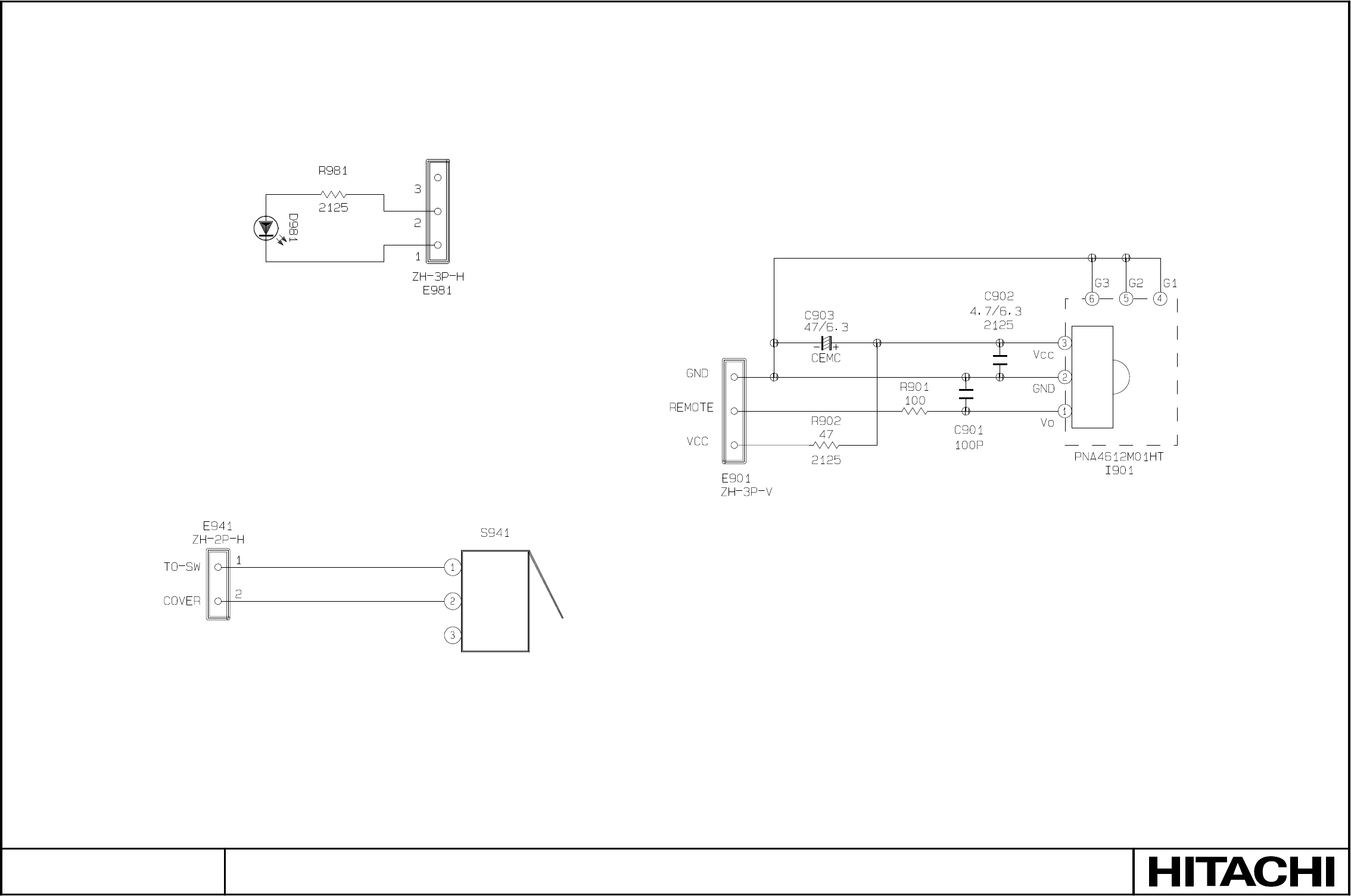
SM0541
SENSOR, COVER SWITCH & REMOTE CONTROL BOARDS
COVER SWITCH BOARD
REMOTE CONTROL BOARD
SENSOR BOARD
PARTS WITH HATCHING ARE NOT MOUNTED
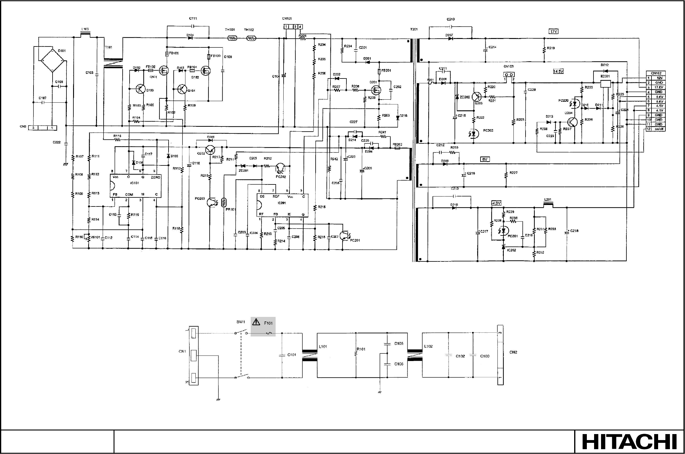
SM0541
POWER UNIT (CIRCUIT) & FILTER UNIT
PARTS WITH HATCHING ARE NOT MOUNTED
POWER UNIT (CIRCUIT)
FILTER UNIT
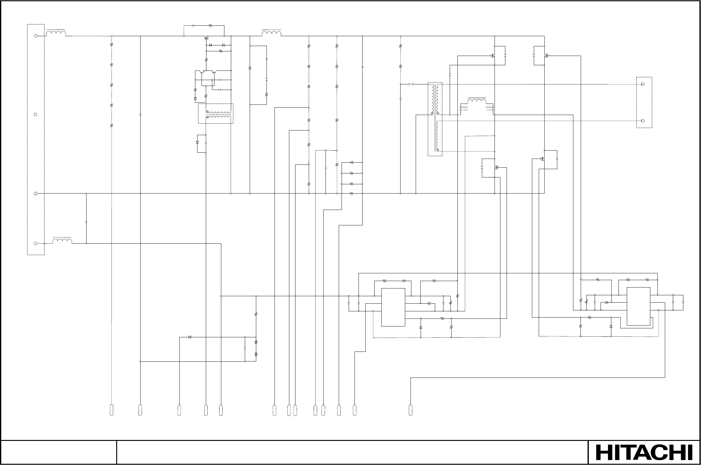
SM0541
POWER UNIT (BALLAST) 1
PARTS WITH HATCHING ARE NOT MOUNTED
+370V
GND
Q100
D150
ZD150
R154 T101
4
1
56
3
R119
R124
IC102
1 Vcc
2 IN
3 COM
5
VB 8
HO 7
VS 6
LO 4
IC103
8 VB
7 HO
6 VS
5
Vcc 1
IN 2
COM 3
LO 4
VCC
23
SGND
26
TEMP
14
DRIVE
24
16V
25
VSENSE
21
OVP
22
CV0
18
VP0
10
SGND
11
NAV1
7
NAV2
9
CPO
+16V
CN100
1
CN100
2
CN100
3
CN100
4
L100
L104
R100
R101
R102
R103
C100
R104
C140
C152 R160
R113
R112
Q150 Q151
C151
C133
R151
D151
D105
C108
ZD100
L102
D106
C153
C154
R161
R145
C130
TH101 TH102
R114
R140
R141
R133
C109
R142R143R134
R115
R116
C122
R117
R135
C131
C110
R123 D107
D121
R156
R118
D115
R125
C155
D116
R127 C112
R126
R121R122C111
Z100 T102
C120
Q101
C114
Q104
C116
Q103
C117
L103
C113
Q102
R131
R130
R128
D118
C118
C156
R129
D117
D108 R132
C119
C132
1
2
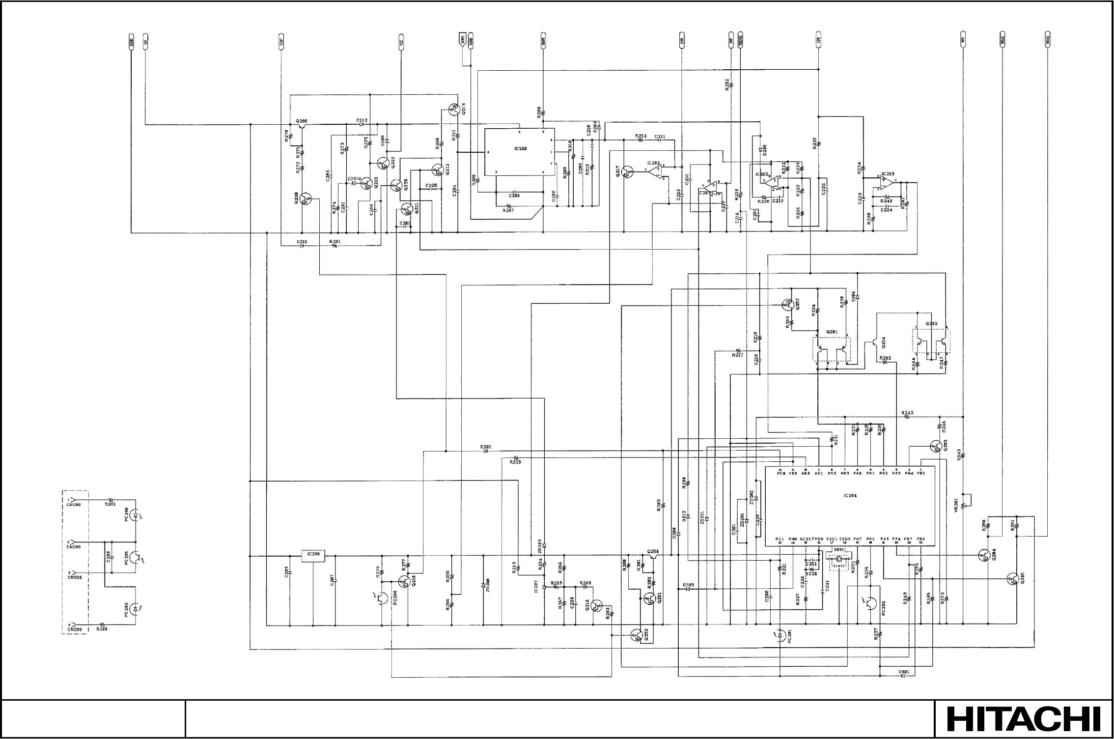
SM0541
POWER UNIT (BALLAST) 2
PARTS WITH HATCHING ARE NOT MOUNTED
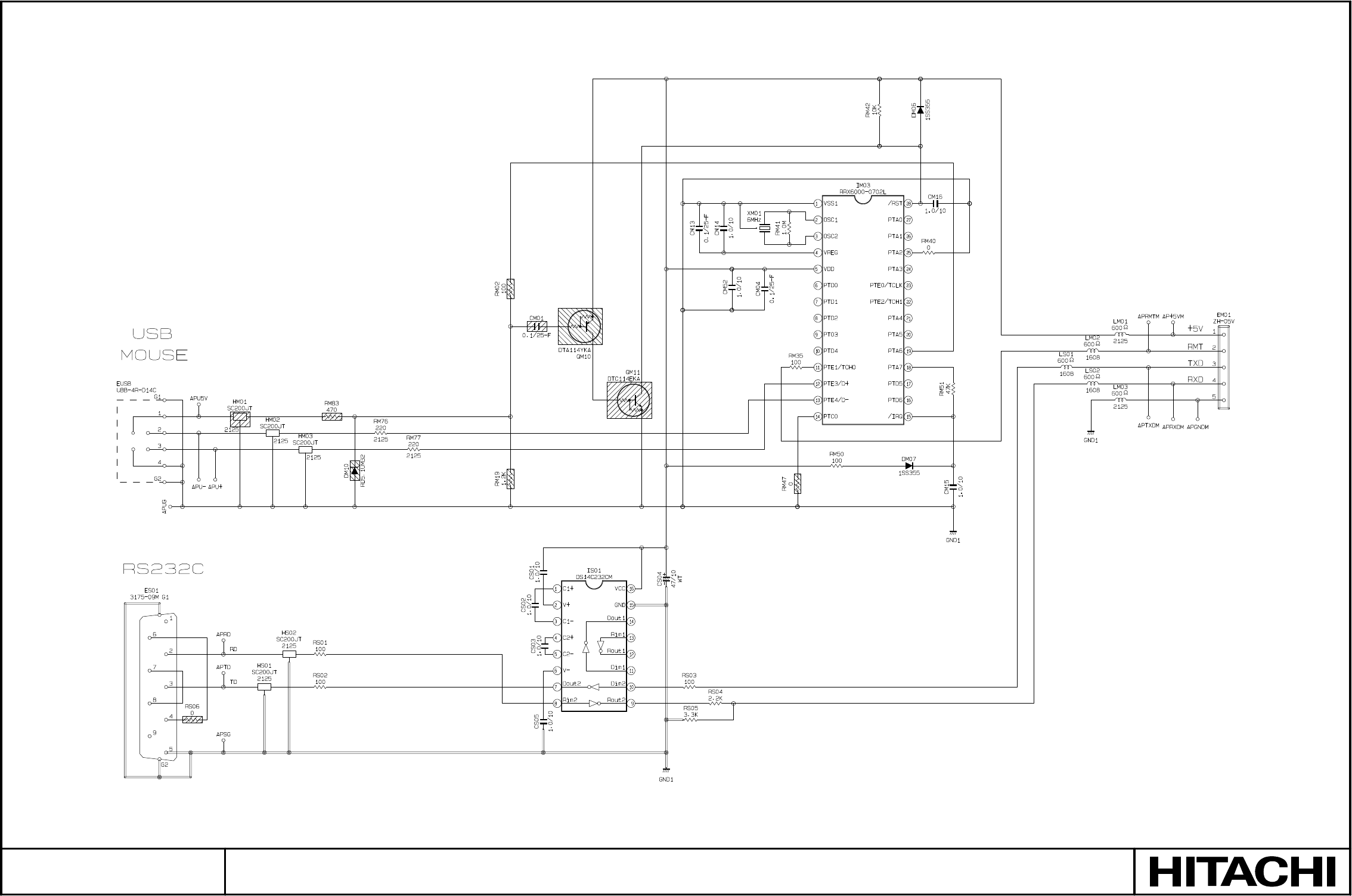
SM0541
CONTROL BOARD
PARTS WITH HATCHING ARE NOT MOUNTED
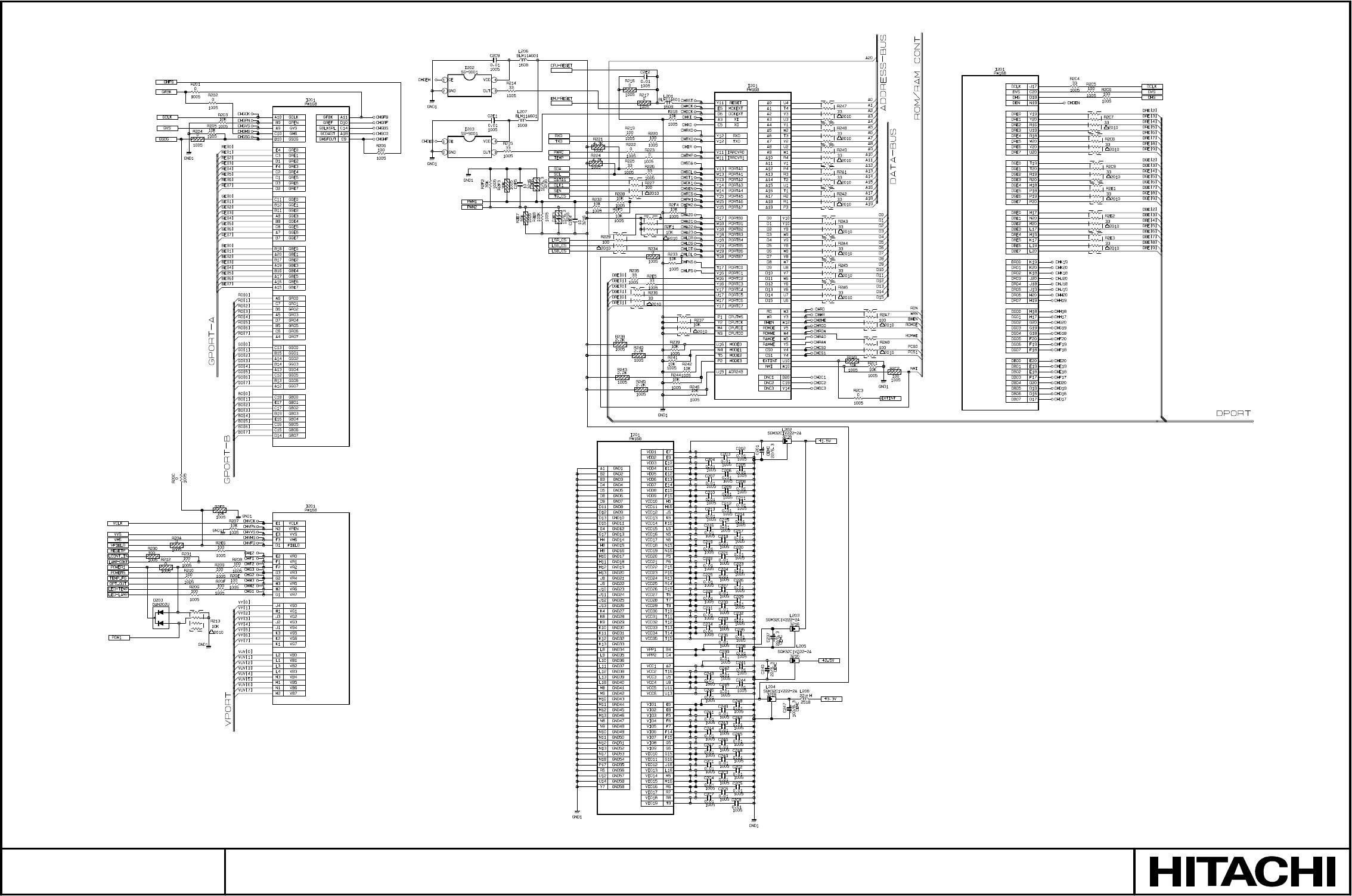
SM0541
MAIN BOARD 1
PARTS WITH HATCHING ARE NOT MOUNTED
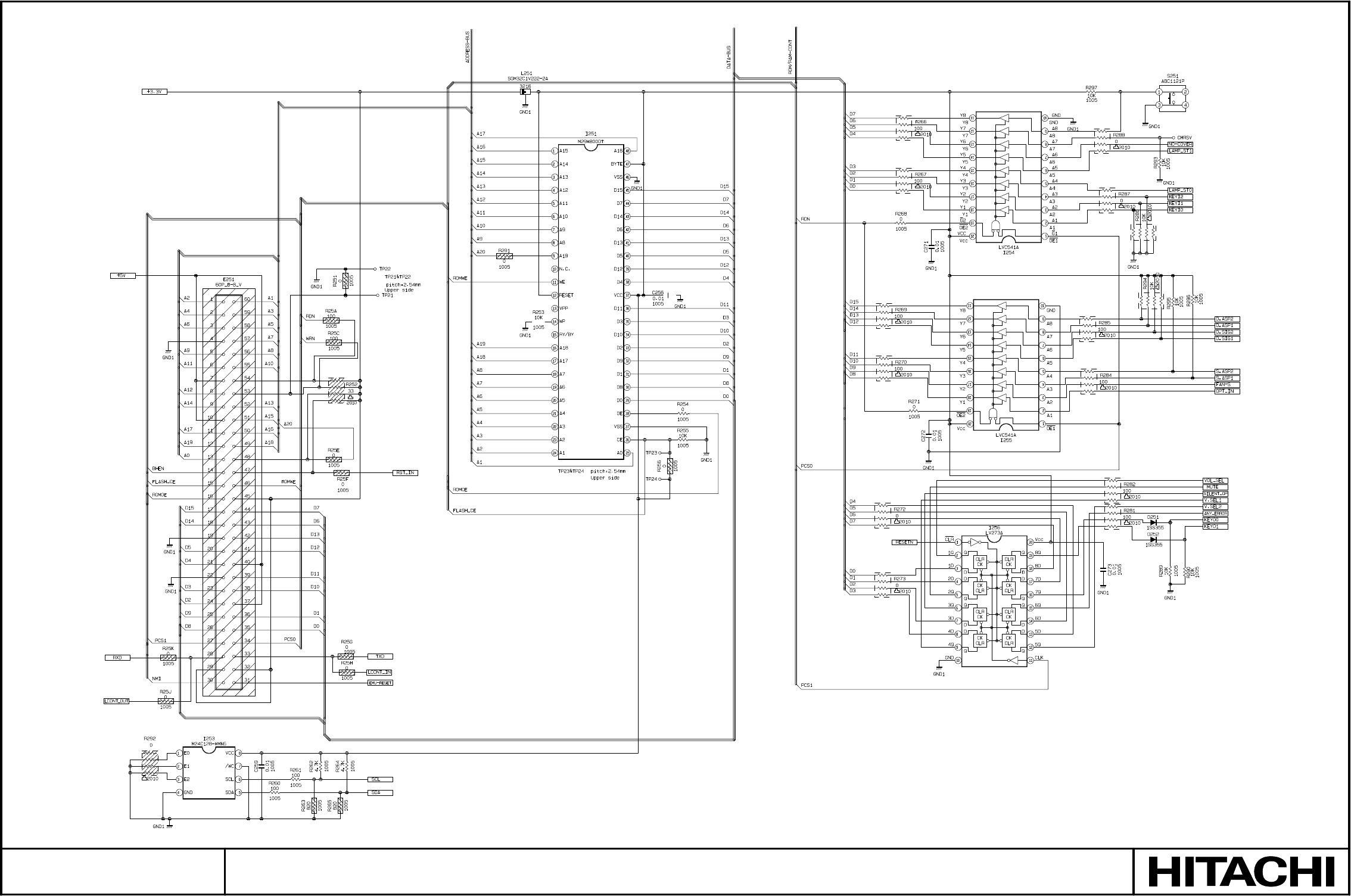
SM0541
MAIN BOARD 2
PARTS WITH HATCHING ARE NOT MOUNTED
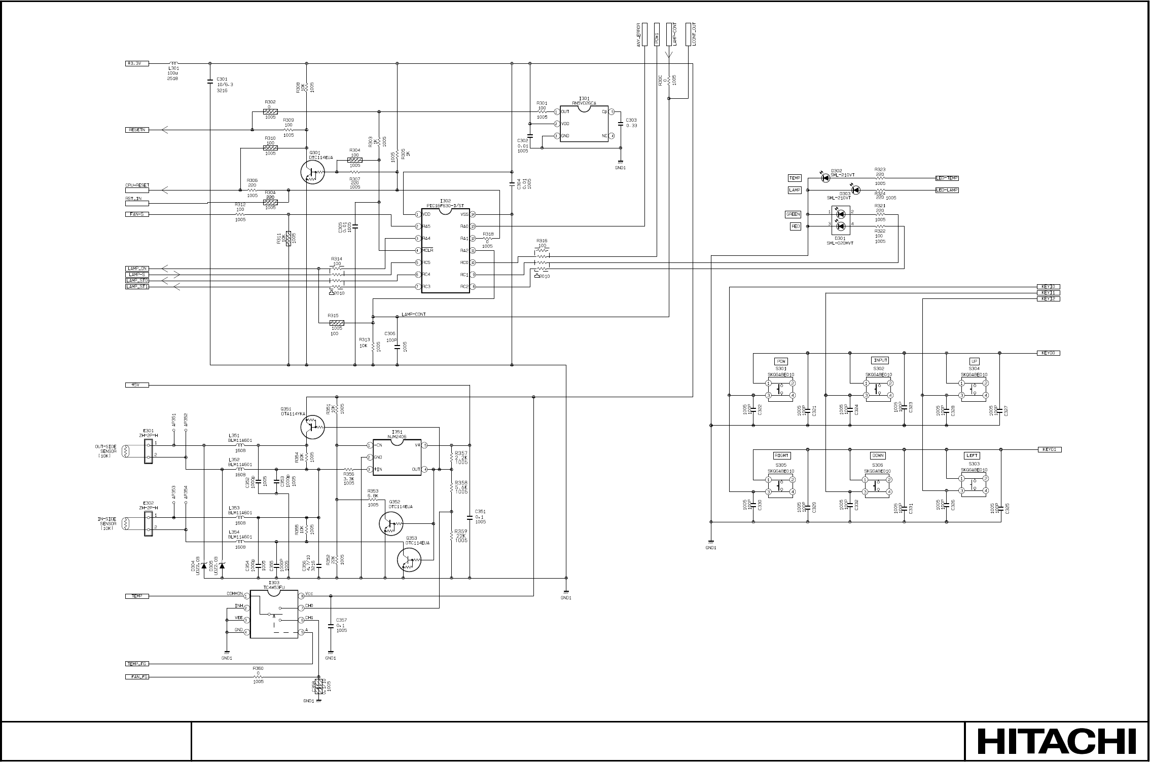
SM0541
MAIN BOARD 3
PARTS WITH HATCHING ARE NOT MOUNTED
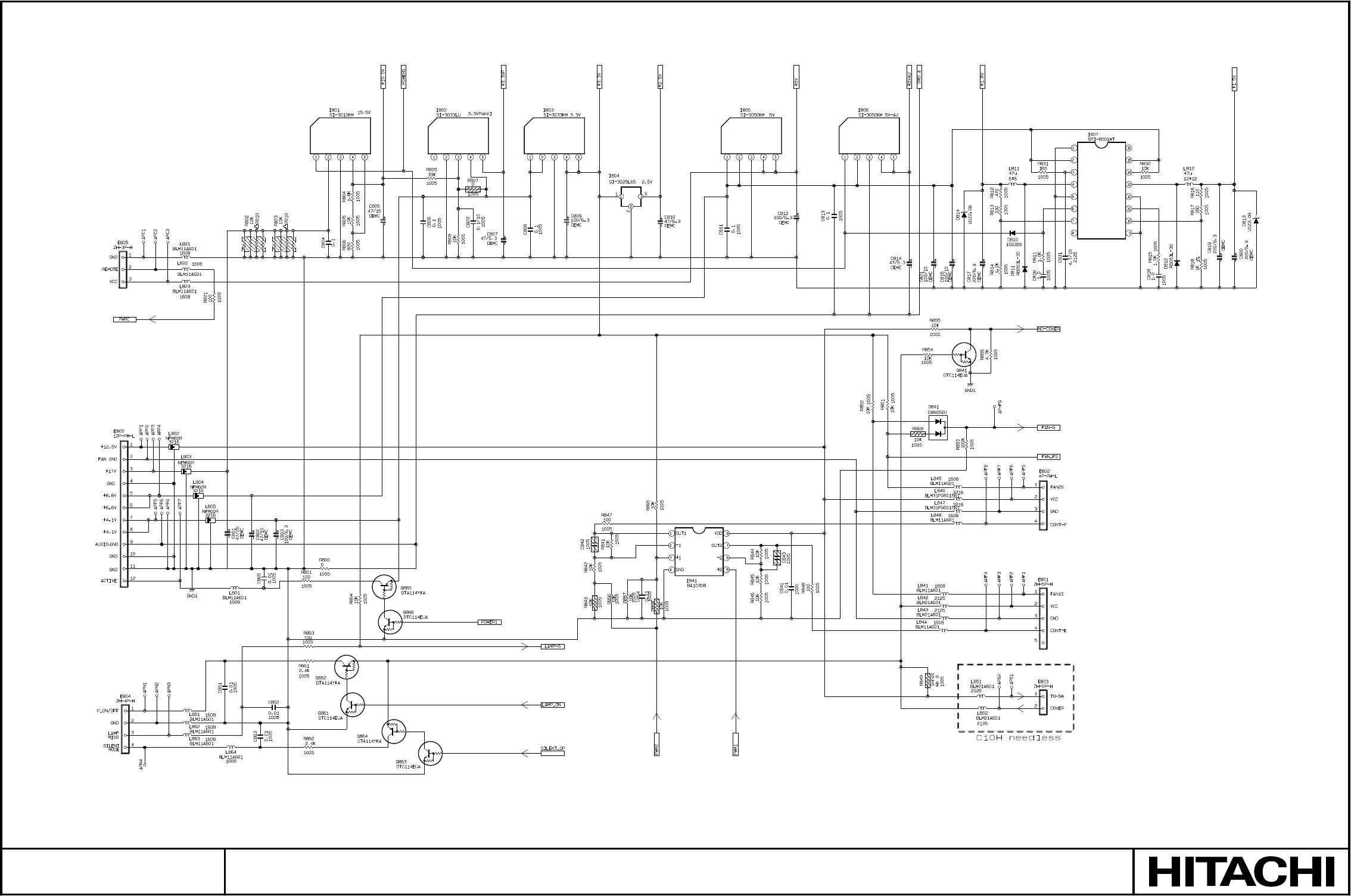
SM0541
MAIN BOARD 4
PARTS WITH HATCHING ARE NOT MOUNTED
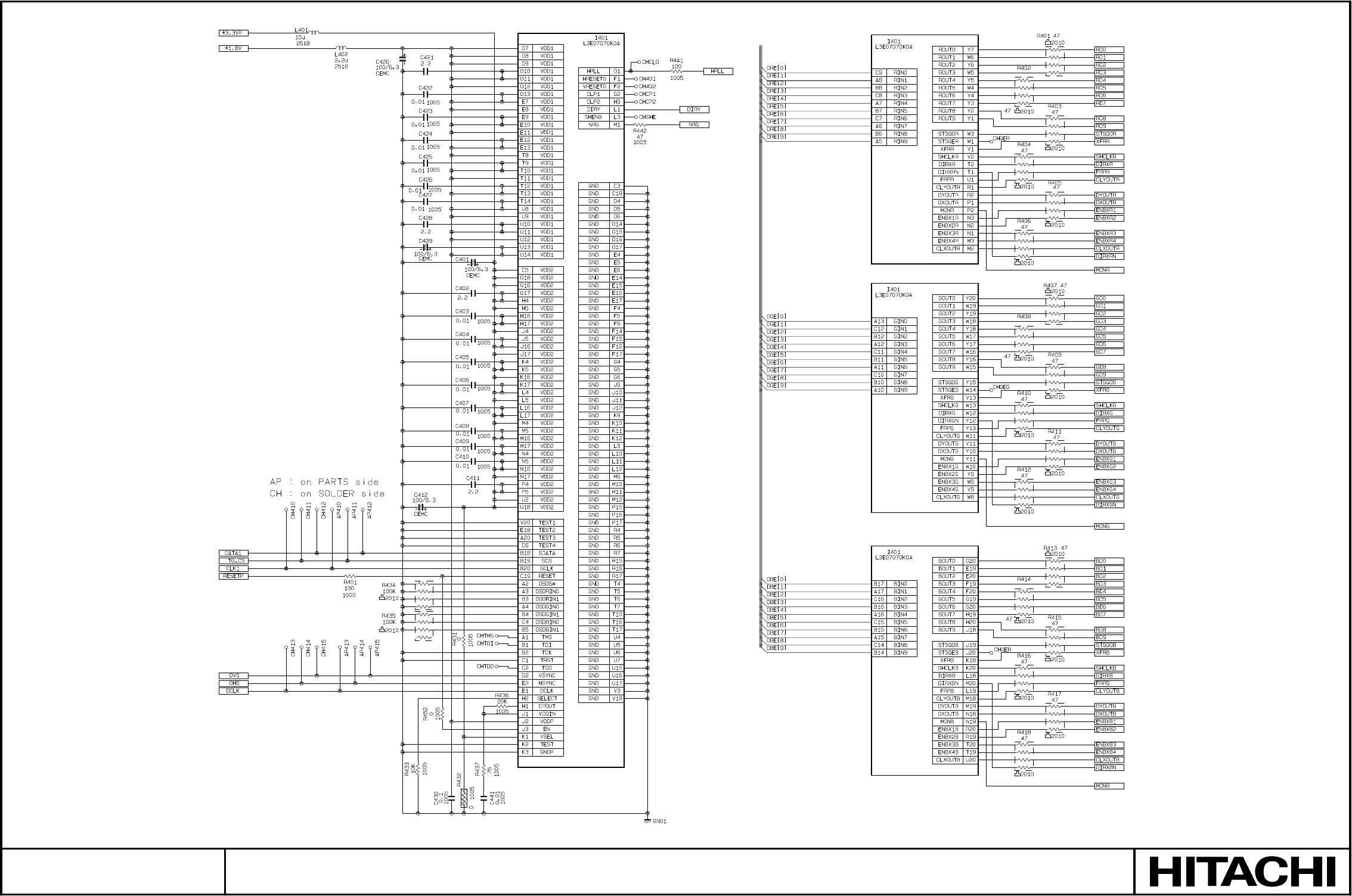
SM0541
MAIN BOARD 5
PARTS WITH HATCHING ARE NOT MOUNTED
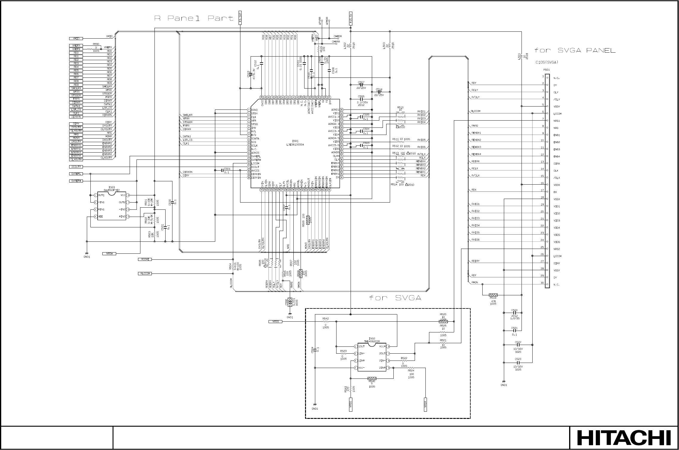
SM0541
MAIN BOARD 6
PARTS WITH HATCHING ARE NOT MOUNTED
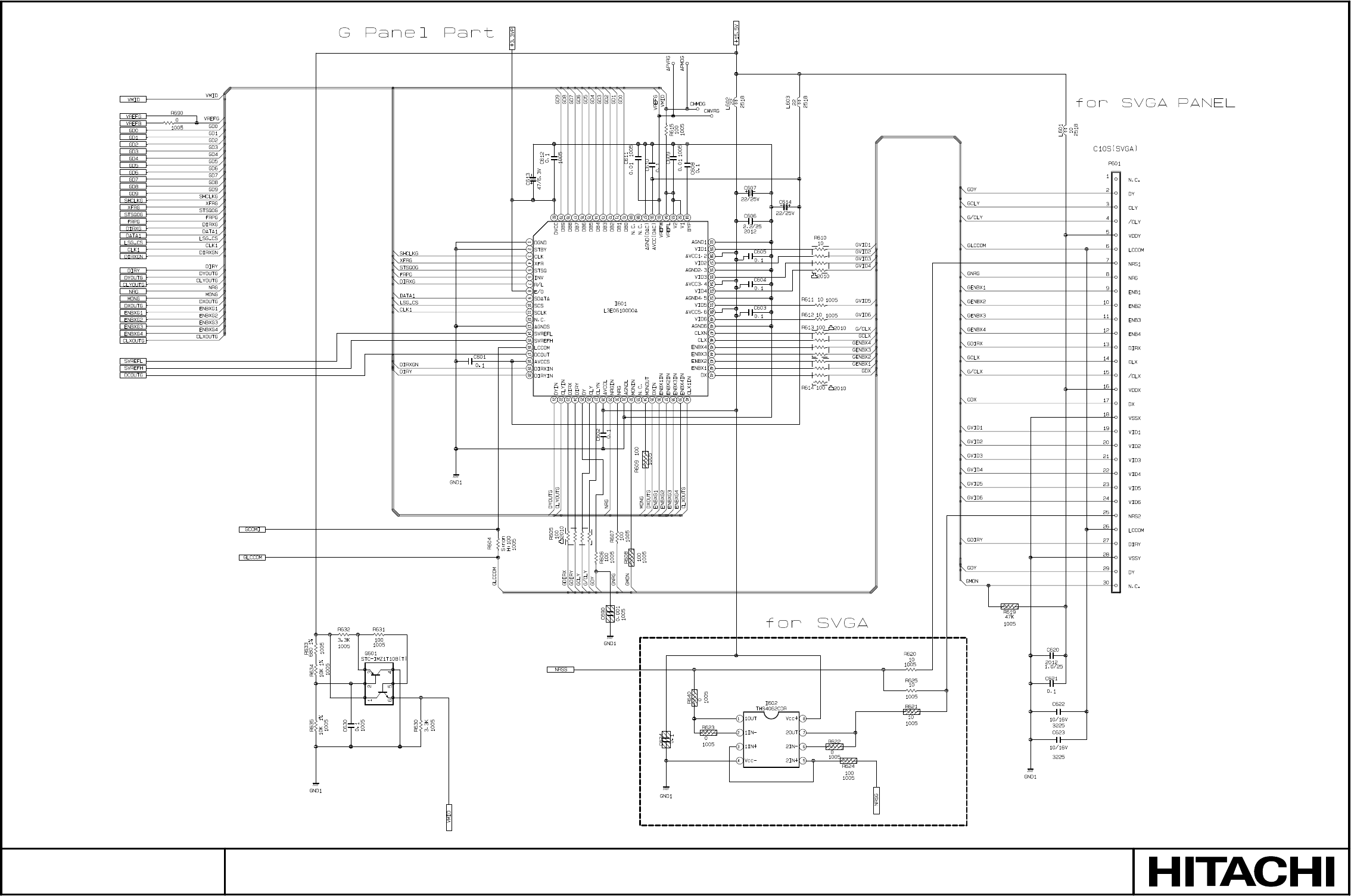
SM0541
MAIN BOARD 7
PARTS WITH HATCHING ARE NOT MOUNTED
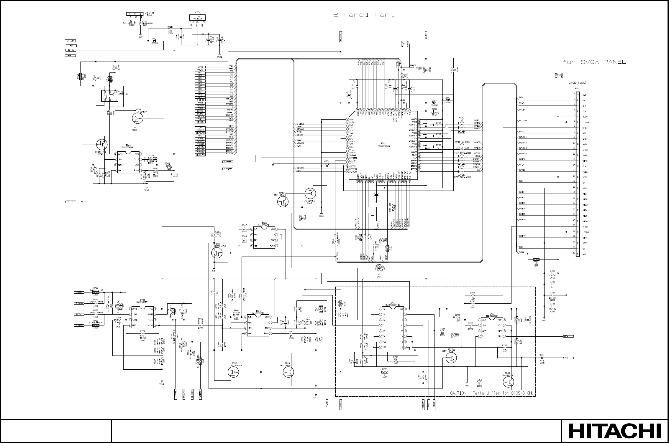
SM0541
MAIN BOARD 8
PARTS WITH HATCHING ARE NOT MOUNTED
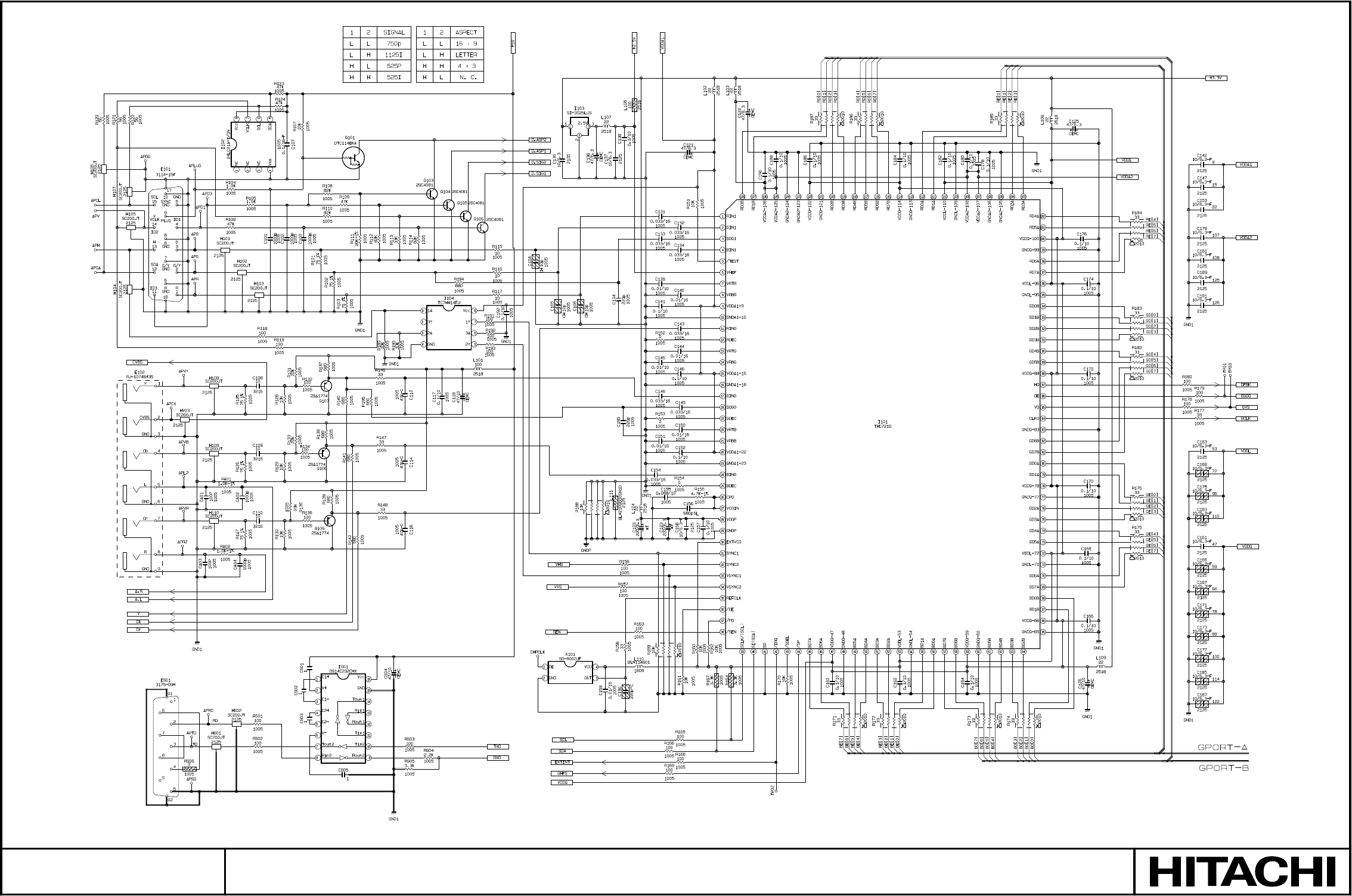
SM0541
MAIN BOARD 9
PARTS WITH HATCHING ARE NOT MOUNTED
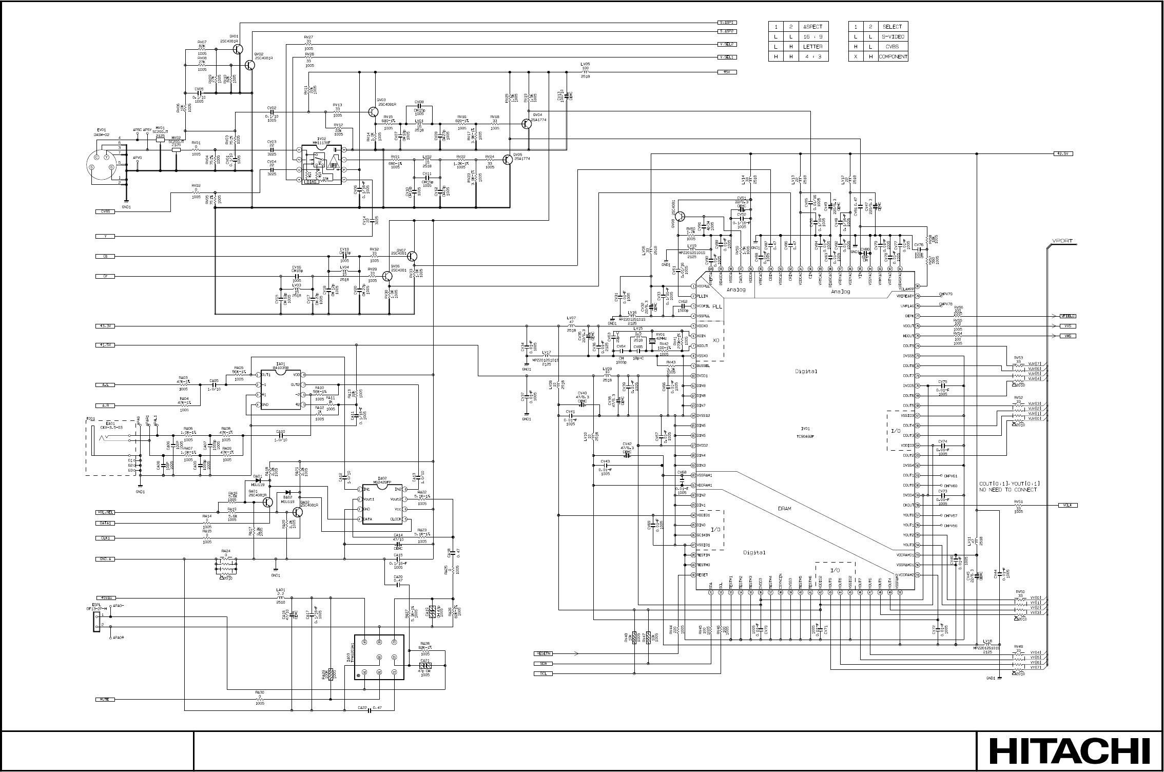
SM0541
MAIN BOARD 10
PARTS WITH HATCHING ARE NOT MOUNTED
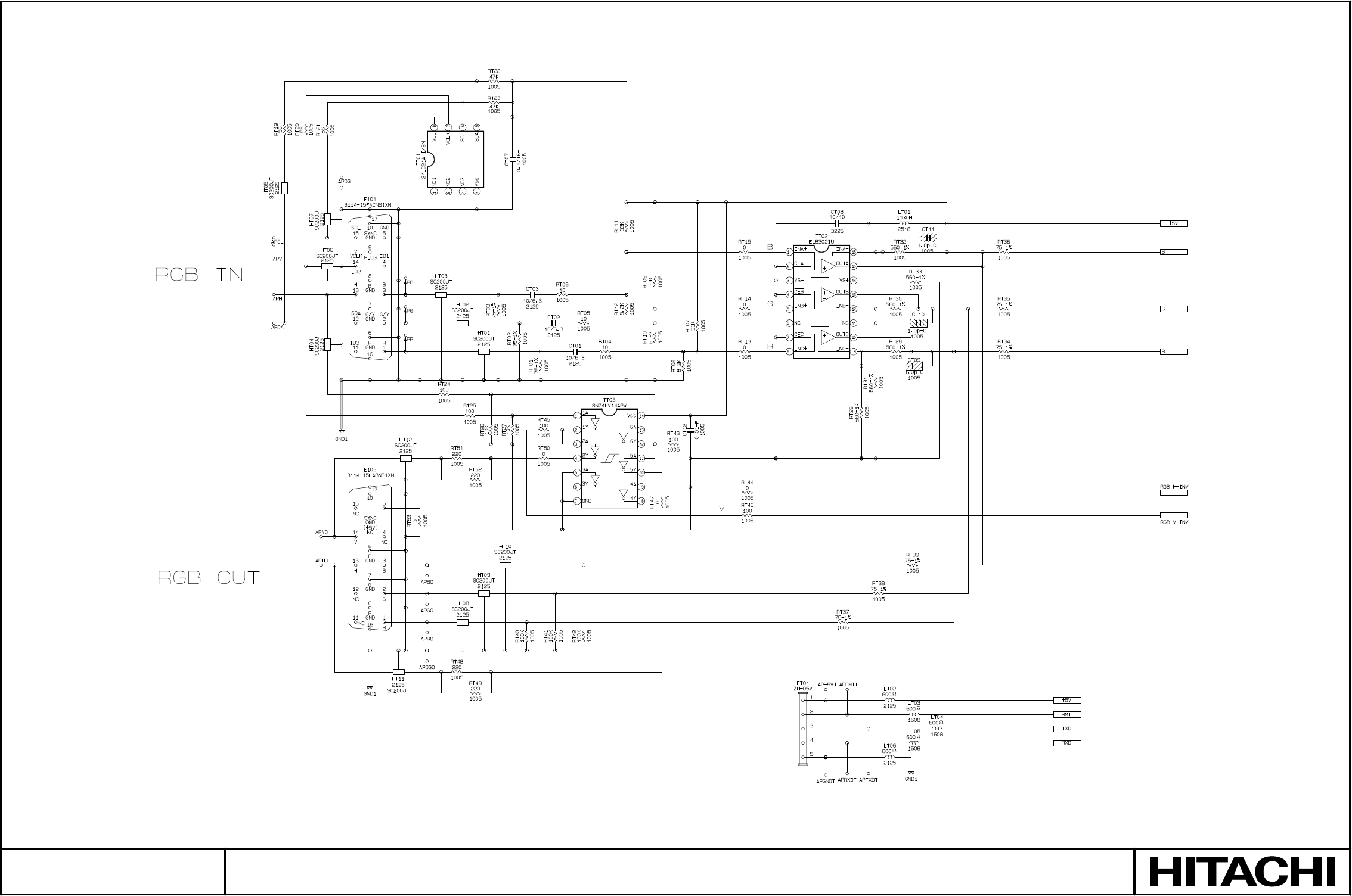
SM0541
MAIN BOARD 11
PARTS WITH HATCHING ARE NOT MOUNTED

Hitachi, Ltd. Tokyo, Japan
International Sales Division
THE HITACHI ATAGO BUILDING,
No. 15 –12 Nishi Shinbashi, 2 – Chome,
Minato – Ku, Tokyo 105-8430, Japan.
Tel: 03 35022111
HITACHI EUROPE LTD,
Whitebrook Park
Lower Cookham Road
Maidenhead
Berkshire
SL6 8YA
UNITED KINGDOM
Tel: 01628 643000
Fax: 01628 643400
Email: consumer-service@hitachi-eu.com
HITACHI EUROPE S.A.
364 Kifissias Ave. & 1, Delfon Str.
152 33 Chalandri
Athens
GREECE
Tel: 1-6837200
Fax: 1-6835964
Email: service.hellas@hitachi-eu.com
HITACHI EUROPE GmbH
Munich Office
Dornacher Strasse 3
D-85622 Feldkirchen bei München
GERMANY
Tel: +49-89-991 80-0
Fax: +49-89-991 80-224
Hotline: +49-180-551 25 51 (12ct/min)
Email: HSE-DUS.service@hitachi-eu.com
HITACHI EUROPE S.A.
Gran Via Carlos III, 86, planta 5
Edificios Trade - Torre Este
08028 Barcelona
SPAIN
Tel: 93 409 2550
Fax: 93 491 3513
Email: atencion.cliente@hitachi-eu.com
HITACHI EUROPE srl
Via Tommaso Gulli N.39, 20147
Milano, Italia
ITALY
Tel: +39 02 487861
Tel: +39 02 38073415 Servizio Clienti
Fax: +39 02 48786381/2
Email: customerservice.italy@hitachi-eu.com
HITACHI Europe AB
Box 77 S-164 94 Kista
SWEDEN
Tel: +46 (0) 8 562 711 00
Fax: +46 (0) 8 562 711 13
Email: csgswe@hitachi-eu.com
HITACHI EUROPE S.A.S
Lyon Office
B.P. 45, 69671 BRON CEDEX
FRANCE
Tel: 04 72 14 29 70
Fax: 04 72 14 29 99
Email: france.consommateur@hitachi-eu.com
HITACHI EUROPE LTD (Norway) AB
STRANDVEIEN 18
1366 Lysaker
NORWAY
Tel: 67 5190 30
Fax: 67 5190 32
Email: csgnor@hitachi-eu.com
HITACH EUROPE AB
Egebækgård
Egebækvej 98
DK-2850 Nærum
DENMARK
Tel: +45 43 43 6050
Fax: +45 43 60 51
Email: csgnor@hitachi-eu.com
HITACHI EUROPE AB
Neopoli / Niemenkatu 73
FIN-15140 Lahti
FINLAND
Tel : +358 3 8858 271
Fax: +358 3 8858 272
Email: csgnor@hitachi-eu.com
Hitachi Europe Ltd
Bergensesteenweg 421
1600 Sint-Pieters-Leeuw
BELGIUM
Tel: +32 2 363 99 01
Fax: +32 2 363 99 00
Email: sofie.van.bom@hitachi-eu.com
HITACHI EUROPE LTD
Na Sychrove 975/8
101 27 Pr aha 10 – Bohdalec
CZECH REPUBLIC
Tel: +420 267 212 383
Fax: +420 267 212 385
Email: csgnor@hitachi-eu.com
www.hitachidigitalmedia.com
