3000 SERIES 3015 CROWN SP3020
User Manual: 3000 SERIES 3015
Open the PDF directly: View PDF ![]() .
.
Page Count: 5
C
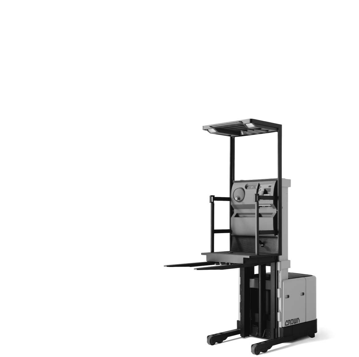
SP 3000 Series
stockpicker
specifications
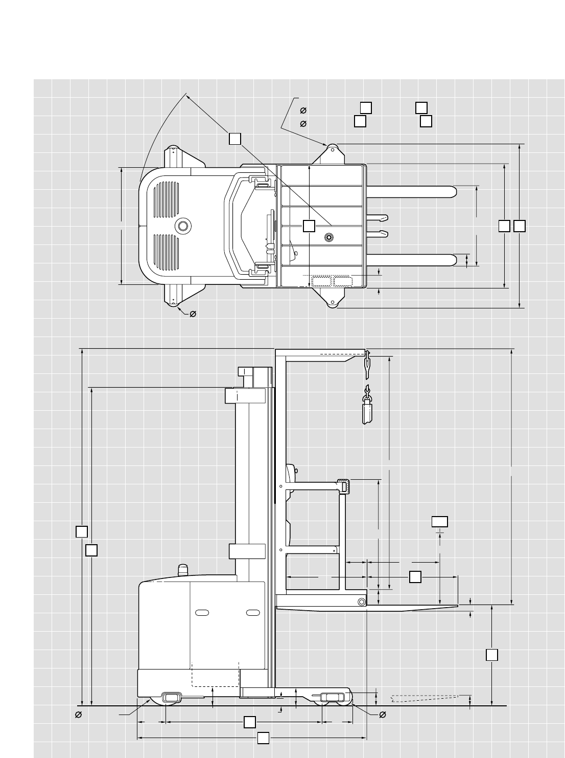
79"
12
11
87"
10
3"
2"
24"
7. 5"
36"
5"
6" x 2.8"
13
10"
6"
15
13" x 5.5" 7" 2"
9.5"
18
24 – 30"
adjustable
40"
4"
Poly Wheels
2.5" x 2" when is less than + 8.5
4" x 2" when is greater than + 8
16
3.7"
14
LC
4" x 2"
4"
17
17
18
18
17
19
24"
27"
CSP 3000 Series
stockpicker

1Manufacturer Crown Equipment Corporation Crown Equipment Corporation Crown Equipment Corporation Crown Equipment Corporation 1
2Model SP 3010-30 SP 3015-30 SP 3020-30 SP 3040-30 2
3Load Capacity* lb See Chart See Chart See Chart See Chart 3
4Load Center Platform face to load CG in 24 24 24 24 4
5Power Electric Volts 24 24 24 24 5
6Operator Type Stand-up Rider Stockpicker Stockpicker Stockpicker Stockpicker 6
7Tire Type Load/Drive Poly/Poly Poly/Poly Poly/Poly Poly/Poly 7
8Wheels (x = driven) Load/Drive 4/1x 4/1x 4/1x 4/1x 8
10 Lift Height in See Chart** See Chart** See Chart See Chart 10
13 Head Length TL/TT in 74.6/75.6 74.6/75.6 74.6/75.6 74.6/75.6 13
14 Forks Standard L x W x T in 36 x 4 x 2 36 x 4 x 2 36 x 4 x 2 36 x 4 x 2 14
Optional Lengths in 30, 39, 42, 45, 48, 54, 60, 72, 84 30, 39, 42, 45, 48, 54, 60, 72, 84 30, 39, 42, 45, 48, 54, 60, 72, 84 30, 39, 42, 45, 48, 54, 60, 72, 84
15 Wheelbase TL/TT in 52/51 52/51 52/51 52/51 15
16 Turning Radius TL/TT in 69/68 69/68 69/68 69/68 16
20 Speed Travel Empty/Loaded mph See Chart See Chart See Chart See Chart 20
21 Speed Lift TL Empty/Loaded fpm 45/28 45/28 45/28 Low, 80/46 High 45/28 Low, 80/46 High 21
TT Empty/Loaded fpm 40/26 40/26 40/26 Low, 71/43 High 40/26 Low, 71/43 High
22 Speed Lower TL Empty/Loaded fpm 40/38 40/38 40/38 Low, 80/75 High 40/38 Low, 80/75 High 22
TT Empty/Loaded fpm 40/38 40/38 40/38 Low, 80/75 High 40/38 Low, 80/75 High
23 Battery Type Lead Acid Lead Acid Lead Acid Lead Acid 23
Min Weight/Max Amp 1520/1085 1520/1085 1520/1085 1520/1085
Max Battery Size 14.25 x 36.25 x 31 high 14.25 x 36.25 x 31 high 14.25 x 36.25 x 31 high 14.25 x 36.25 x 31 high
24 Traction Motor 60 Min Rating hp 3.5 4.0 3.5 4.0 24
TL TT
10 Lift Height in 136 148 172 194 214 195 210 240 276 294 312 330 348 366
3Load Capacity SP 3010 lb 3000 3000 3000 3000 3000 3000 3000 3000 na na na na na na
SP 3015 lb 3000 3000 3000 3000 3000 3000 3000 3000 na na na na na na
SP 3020 lb 3000 3000 3000 3000 3000 3000 3000 3000 2000 na 1500 na na na
SP 3040 lb 3000 3000 3000 3000 3000 3000 3000 3000 2500 2350 2200 2000 1900 1750
Free Lift in3 6 6 6 6 3 8 203238 44 5662 68
11 Collapsed Height in 89.5 95 107 119 131 89.5 95 107 119 125 131 143 149 155
12 Extended Height in 223 235 259 281 301 283 298 328 364 382 400 418 436 454
18 Straddle Width in 42 42 42 42 42 42 42 42 48 54 54 56 60 60
19 Operator Compartment Width in 42 42 42 42 42 42 42 42 48 54 54 54 60 60
17 Aisle Guide Wheel Range† in 47.75 to 65.25 47.75 to 65.25 47.75 to 65.25 47.75 to 65.25 47.75 to 65.25 47.75 to 65.25 47.75 to 65.25 47.75 to 65.25 53.75 to 65.25 59.75 to 65.25 59.75 to 65.25 61.75 to 71.25 65.75 to 71.25 65.75 to 71.25
Truck Weight without Battery lb 5183 5248 5377 5666 5795 5753 5846 6072 6293†† 6619 6623††† 6907 7053 7483
General Information
Dimensions
Performance
* Contact factory. Capacity may be subject to derating,depending upon lifting height, load center and fork length.
**Not available above 240" lifting heights.
Battery
Mast
† In .5" increments.
†† SP 3020 as shown, SP 3040 is 6381 lb.
††† SP 3020 as shown, SP 3040 is 6711 lb.
Capacity
SP 3000 Series Specifications

SP 3000 Series Specifications
Standard Equipment
1. 24-volt electrical system
2 GE EVT-100 FL transistor
control
3. Start up and run time
diagnostics
4 Programmable performance
features
5. Information Display Panel in
operator platform
6. Elapsed time counter
7. Battery discharge indicator
with lift interrupt
8. Drive tire direction indicator
9. Hour meters for key on,
traction, lift and steer motors
10. 14.25" battery compartment
11. 350 amp battery connector
12. 2.75" diameter battery
compartment rollers
13. Top battery access for service
14. Color-coded wiring
15. Key switch
16. Horn
17. Strobe light
18. Electronic on-demand power
steering
19. Emergency power cut-out
20. Hinged side gate with power
disconnect
21. Upper elevation travel
22. Elevated Braking System
(EBS) with low profile
brake pedal
23. 6" diameter tandem load
wheels
24. Lift off left and right side steel
battery covers
25. Adjustable battery retainer
26. Hinged, lift off steel power
unit doors
27. Cushioned floorboard
28. Soft urethane twist grip with
“cam grip”
29. 10 degree angled steer
wheel with soft feel spinner
30. Clear visibility platform
window
31. Clear visibility mast design
32. Storage compartment
33. Operator belt and
lanyard
34. Pallet clamp
Optional Equipment
1. Wire guidance
2. Aisle guide wheels for rail
guidance
3. Motor brush wear indicators
and motor temperature indi-
cators (Only available on
SP 3015 and SP 3040)
4. Battery retainer interlock
switch
5. Work lights, dome light and
two-speed fan
6. Spotlights
7. Flashing amber light
8. Fork raise and/or lower cut-
out with or without override
9. Zone select key switch
10. 48", 54" and 60" wide oper-
ator platforms
11. Corrosion conditioning
12. Freezer conditioning
13. Wire mesh screen. (Standard
with freezer conditioning)
14. Retractable tether
15. Load wheel and drive tire
compounds
16. 30" lanyard boom
17. Special paint
18. Fire extinguisher
Human Factor
The operator area is designed for
maximum visibility and stability
for increased operator confi-
dence and comfort.
The operator platform features a
large window, (1088 sq in), for
excellent visibility. A Crown-
designed clear-visibility mast
affords the platform window one
forward and two peripheral win-
dows for maximum visibility even
when the platform is lowered.
The clear-visibility mast, with full
free lift, extends the platform
window above the mast chan-
nels for unobstructed visibility
when raised.
A low profile power unit, low
placement of the lower cross
brace and an outer C-channel
rail assembly also contribute to
excellent visibility.
A soft urethane twist grip is
solidly mounted to the truck
console to provide excellent
stability for the operator during
travel, plugging and braking.
Controls for lift/lower, horn and
emergency disconnect are con-
veniently located for efficient
operation and minimal operator
fatigue. The steering wheel is
angled at 10° and recessed to
maximize the work area and
reduce steer effort. The steering
wheel and spinner knob are
covered with soft urethane to
reduce grip force and insulate
against vibration. Control loca-
tion keeps the operator’s pos-
ture neutral at all times. The
platform cushion absorbs shock
and vibration. The brake pedal
has a low profile design and
when engaged is flush with the
platform cushion for maximum
comfort. Heavy-duty side gates,
with two horizontal and one ver-
tical support rails, communicate
security to the operator. Cut-out
switches disengage truck opera-
tion when side gates are raised
for maximum safety. Two work
lights, two dome lights and a
two-speed fan are optional.
“Power-on” key prevents unau-
thorized operation of the truck;
start position initializes truck
“self-test”. The new Information
Display Panel provides concise,
clear feedback for the operator
during truck operation.
Travel Speeds - Models 3010, 3015, 3020, 3040
Lift Height Steered Wheel < 10° Steered Wheel ≥10°
(inches)
Travel Speed (mph) Brake Travel Speed (mph) Brake
Empty/Loaded Force Empty/Loaded Force
0-24 6.0/5.3 3/3 6.0/5.3 3/3
25-60 6.0/5.3 3/3 3.8/3.2 3/3
61-120 3.8/3.2 2/3 2.7/2.2 2/3
121-150 2.7/2.2 2/3 1.9/1.5 1/3
151-180 1.9/1.5 1/3 1.5/1.2 1/3
181-366 1.5/1.2 1/3 See Note
SP 3000 Series Technical Information
Note: Steering is automatically limited to within 10° straight travel above 180".

New Bremen, Ohio 45869 USA
Phone: 419/629-2311
Fax: 419/629-3796
crown.com
Copyright 2002 Crown Equipment Corporation
All rights reserved. Unauthorized copying, in
whole or in part, without the express written
permission of Crown is prohibited.
Responsibly Innovative
Electronics
Environmentally hardened heavy
duty 24-volt electrical system. An
intelligent, networked Control
System is used to provide real
time truck control, display, diag-
nostics and calibration. A distribu-
tion panel provides a central
location for troubleshooting, re-
duces wiring requirements, and
enables future options to be
added easily. The Control System
can be accessed by the Service
Terminal to provide calibration of
truck parameters and optional
features set-up. The Control Sys-
tem is also used to extract service
diagnostic and management
data. The link-up port is conven-
iently located on the platform and
is easily accessible without re-
moval of covers for connection.
The Crown Program Analysis
Cartridge (PAC) works in conjunc-
tion with the Service Terminal and
ensures users simple, fast pro-
gram upgrade of systems.
Information Display Panel
The Information Display Panel
travels with the operator at all
times. Features include audible
and visual prompts for the opera-
tor, steer wheel direction indicator,
battery fuel gauge with lift inter-
rupt, wire guidance status lights,
hour meters for all motors, elapsed
time counter, optional battery
retainer interlock light, optional
brush wear indicators and motor
temperature indicators and op-
tional fork height “zone select”
control.
The Service Terminal also pro-
vides extensive service history
information as well as “real time”
electrical system diagnostics and
fault isolation information for
servicing.
Simplified Hydraulics
Heavy duty series wound pump
motors and gear pumps are as-
sembled into an integral unit.
Optional high speed lift version is
available. Crown-manufactured
solenoid type manifolds with
built-in checks and relief valves.
Maximum lowering speed is regu-
lated by a pressure compensating
flow control valve. Velocity fuses
are used in all cylinders to stop
lowering should lowering speed
exceed a pre-set value due to a
line rupture. A hydraulic
accumulator is used to cushion
raise and lower functions. Manual
lowering control on manifold block
allows lowering of platform from
ground level. Oil reservoir is de-
signed with a 100 mesh screen at
the fill location, a suction strainer,
spin-on type 10 micron return line
filter and a magnetic drain plug.
The Crown Mast Assembly
High visibility two- and three-
stage masts feature nested rail
design with lift cylinders posi-
tioned behind mast rails. Three
stage mast has a low center posi-
tion cylinder for free lift. Improved
mast cable life due to larger, 5"
diameter pulleys. Routing of hos-
ing and cables optimizes visibility
through mast. Built-in sensors
detect chain slack and shut down
primary lower function. Exclusive
spring-loaded staging bumpers
virtually eliminate platform impact
as platform stages. Negative rail
drop allows shimming of mast
rollers without major disassembly.
Stronger Low Profile
Power Unit
Power unit is fabricated from
heavy gauge steel. Lower skirt is
.75" steel that runs 9" high for
component protection. Rugged
steel doors suspended on heavy
duty pin hinges cover power unit
componentry. Doors swing wide
for open access. Doors can also
be lifted off for unrestricted ser-
vice access. Door bolts have ex-
clusive convex design that mates
with concave door holes for fast
re-installation of door bolts. Bat-
tery side covers are all steel. An
optional battery retainer interlock
switch is available. Top battery
access is available by lifting cover.
Cover has integral support post.
Enhanced and
Interchangeable Drive Unit
Crown-manufactured drive unit
uses spiral bevel and helical gears
from motor to drive wheel axle.
Fixed, mounted drive motor does
not rotate minimizing wear on
electrical cables. Drive tire chang-
ing is simplified with this new
drive unit. Crown Turret Trucks
and Reach Trucks also use this
drive unit.
Travel System
Traction control uses the GE EVT-
100 FL micro-processor based
transistor control. Smooth, quiet
operation, extended battery shift
life and component protection/
truck reliability are all features of
this GE system. System features
include a 450 amp rating, a by-
pass contactor, truck perfor-
mance adjustability, SRO, ramp
start, diagnostics with 16 fault
memory in conjunction with the
service light. Traction is connect-
ed to the Control System for full
diagnostics and set-ups via the
Crown Service Terminal.
Responsive Steering
Standard on the SP 3000 Series
is electronic on-demand power
steering that is microprocessor-
based. Steering wheel rotation
provides smooth, operator feed-
back. Steer effort is minimal, lock
to lock revolutions is 4.5 turns.
Drive wheel rotates a full 180° for
maximum maneuverability. Auto
centering drive tire for trucks
equipped with rail guidance.
Steering is connected to the
Control System for full diagnos-
tics and operator interface.
Crown PAC also interfaces with
steering system for fast upgrade.
Elevated Braking System
(EBS)
Exclusive three force levels of
braking, determined by platform
height, provides smooth braking
at all elevations. Electric disc brake,
spring applied and electrically
released, is controlled by pedal in
platform. Pedal cuts traction
power and activates brake when
released. Brake system elimi-
nates hydraulic lines running in
mast to control braking. Braking
can also be accomplished by pro-
portional plugging which permits
the operator to control the rate of
deceleration when extended stop-
ping distance is preferred.
Wheels and Tires
Polyurethane drive tire, 13"
diameter x 5.5" wide x 8" hub
diameter. Tandem load wheels
2.8" wide, 6" diameter polyure-
thane. Optional aisle guide wheels
2" wide x 4" diameter
polyurethane, 2" wide x 2.5"
diameter polyurethane.
Forks
2" thick x 4" wide forged steel.
Fork spread (adjustable) 24" to
30". Standard length is 36".
Optional lengths available.
Pallet Clamp
Standard equipment includes a
foot applied, hand released pallet
clamp designed for use with
pallets having center stringers.
Safety Shield
Safety glass to protect operator
from chains and moving parts
while in his normal operating
position.
Other Options
1. Audible Travel Alarm.
2. Contact factory for additional
options.
Safety considerations and dangers
associated with audible travel
alarms include:
• Multiple alarms can cause
confusion.
• Workers ignore the alarms
after day-in and day-out
exposure.
• Operator may transfer the
responsibility for “looking out”
to the pedestrians.
• Annoys operators and
pedestrians.
Dimensions and performance
data given may vary due to manu-
facturing tolerances. Performance
is based on an average size vehicle
and is affected by weight, condi-
tion of truck, how it is equipped
and the conditions of the operating
area. Crown products and speci-
fications are subject to change
without notice.
SF12226 Rev. 7/02
Printed in U.S.A.
SP 3000 Series Technical Information
