D2064 1 13 152 SERIES (1978 THRU 1985) Cessna_152_1978 1985_MM_D2064 Cessna 1978 1985 MM
User Manual: Cessna_152_1978-1985_MM_D2064-1-13
Open the PDF directly: View PDF ![]() .
.
Page Count: 484 [warning: Documents this large are best viewed by clicking the View PDF Link!]
- D2064-1-13 - MODEL 152 SERIES (1978 THRU 1985)
- TEMPORARY REVISION NUMBER 3
- TEMPORARY REVISION NUMBER 2
- LIST OF EFFECTIVE PAGES
- TABLE OF CONTENTS
- CROSS REFERENCE LISTING OF POPULAR NAME VS. MODEL NUMBERS AND SERIALS
- INTRODUCTION
- KEEPING CESSNA PUBLICATIONS CURRENT
- CUSTOMER CARE SUPPLIES AND PUBLICATIONS CATALOG
- SUPPLEMENTAL TYPE CERTIFICATE INSTALLATIONS
- CUSTOMER COMMENTS ON MANUAL
- SECTION 1 - GENERAL DESCRIPTION
- SECTION 2 - GROUND HANDLING, SERVICING, CLEANING, LUBRICATION, AND INSPECTION
- TABLE OF CONTENTS
- GROUND HANDLING
- SERVICING
- CLEANING
- LUBRICATION
- INSPECTION REQUIREMENTS
- SECTION 3 - FUSELAGE
- SECTION 4 - WINGS AND EMPENNAGE
- SECTION 5 - LANDING GEAR AND BRAKES
- TABLE OF CONTENTS
- LANDING GEAR
- DESCRIPTION
- TROUBLE SHOOTING
- MAIN LANDING GEAR
- DESCRIPTION
- STRUT REMOVAL
- STRUT INSTALLATION
- STEP BRACKET INSTALLATION
- FAIRINGS
- SPEED FAIRING REMOVAL
- SPEED FAIRING INSTALLATION
- WHEEL REMOVAL
- DISASSEMBLY (MCCAULEY)
- INSPECTION AND REPAIR (MCCAULEY)
- REASSEMBLY (MCCAULEY)
- DISASSEMBLY (CLEVELAND)
- INSPECTION AND REPAIR (CLEVELAND)
- REASSEMBLY (CLEVELAND)
- WHEEL INSTALLATION
- WHEEL AXLE REMOVAL
- WHEEL AXLE INSTALLATION
- WHEEL ALIGNMENT CHECK
- WHEEL BALANCING
- NOSE GEAR
- DESCRIPTION
- TROUBLE SHOOTING
- REMOVAL
- INSTALLATION
- FAIRING REMOVAL
- FAIRING INSTALLATION
- WHEEL REMOVAL
- DISASSEMBLY (MCCAULEY)
- INSPECTION AND REPAIR (MCCAULEY)
- REASSEMBLY (MCCAULEY)
- DISASSEMBLY (CLEVELAND)
- INSPECTION AND REPAIR (CLEVELAND)
- REASSEMBLY (CLEVELAND)
- INSTALLATION
- WHEEL BALANCING
- STRUT DISASSEMBLY
- STRUT INSPECTION AND REPAIR
- STRUT REASSEMBLY
- TORQUE LINKS
- SHIMMY DAMPENER
- STEERING SYSTEM
- STEERING ROD ASSEMBLY
- STEERING ADJUSTMENT
- BRAKE SYSTEM
- SECTION 6 - AILERON CONTROL SYSTEM
- SECTION 7 - WING FLAP CONTROL SYSTEM
- SECTION 8 - ELEVATOR CONTROL SYSTEM
- SECTION 9 - ELEVATOR TRIM TAB CONTROL SYSTEM
- SECTION 10 - RUDDER CONTROL SYSTEM
- SECTION 11 - ENGINE
- TABLE OF CONTENTS
- ENGINE COWLING
- ENGINE
- OIL SYSTEM
- ENGINE FUEL SYSTEM
- INDUCTION AIR SYSTEM
- IGNITION SYSTEM
- ENGINE CONTROLS
- STARTING SYSTEM
- EXAUST SYSTEM
- EXTREME WEATHER MAINTENANCE
- SECTION 12 - FUEL SYSTEM
- SECTION 13 - PROPELLER
- SECTION 14 - UTILITY SYSTEMS
- SECTION 15 - INSTRUMENTS AND INSTRUMENT SYSTEMS
- TABLE OF CONTENTS
- INSTRUMENTS/INSTRUMENT SYSTEMS
- GENERAL
- INSTRUMENT PANEL
- PITOT AND STATIC SYSTEMS
- VACUUM SYSTEM
- TROUBLE SHOOTING
- STANDBY VACUUM SYSTEM
- ENGINE INDICATORS
- MAGNETIC COMPASS
- ACCELEROMETER
- STALL WARNING SYSTEM
- TURN-AND-SLIP INDICATOR
- TURN COORDINATOR
- OUTSIDE AIR TEMPERATURE GAGE
- SECTION 16 - ELECTRICAL SYSTEMS
- TABLE OF CONTENTS
- ELECTRICAL SYSTEMS
- GENERAL
- ELECTRICAL POWER SUPPLY SYSTEM
- BATTERY POWER SYSTEM
- BATTERY BOX
- BATTERY CONTACTOR
- GROUND SERVICE RECEPTACLE
- ALTERNATOR POWER SYSTEM
- VOLTAGE REGULATOR
- AIRCRAFT LIGHTING SYSTEM
- DESCRIPTION
- TROUBLE SHOOTING
- LANDING AND TAXI LIGHT
- DUAL LANDING AND TAXI LIGHTS
- LANDING AND TAXI LIGHTS
- NAVIGATION LIGHTS
- ANTI-COLLISION STROBE LIGHTS
- FLASHING BEACON LIGHT
- INSTRUMENT/DOME LIGHTS
- POST LIGHTING
- TRANSISTORIZED LIGHT DIMMING
- COMPASS AND RADIO DIAL LIGHTING
- CONTROL WHEEL MAP LIGHT
- MAP LIGHT
- EMERGENCY LOCATOR TRANSMITTER
- ELECTRICAL LOAD ANALYSIS CHART
- SECTION 17 - STRUCTURAL REPAIR
- TABLE OF CONTENTS
- STRUCTURAL REPAIR
- REPAIR CRITERIA
- EQUIPMENT AND TOOLS
- WING TWIST AND STABILIZER ANGLE-OF-INCIDENCE
- REPAIR MATERIALS
- WING
- ELEVATORS AND RUDDER
- FIN AND STABILIZER
- FUSELAGE
- BONDED DOORS
- BULKHEADS
- FASTENERS
- ENGINE MOUNT
- BAFFLES
- ENGINE COWLING
- SECTION 18 - PAINTING
- SECTION 19 - WIRING DIAGRAMS
Cessna
A
Textron
Company
SERVICE
MANUAL
1978
thru
1985
MODEL
152
SERIES
Member
of
GAMA
FAA
APPROVAL
HAS
BEEN
OBTAINED ON
TECHNICAL
DATA
IN
THIS
PUBLICATION
THAT
AFFECTS
AIRPLANE
DESIGN.
REVISION 1
INCORPORATES
TEMPORARY
REVISION
1.
DATED
3
OCTOBER
1994.
COPYRIGHT
1995
WICHITA.
KANSAS. USA
7 FEBRUARY 1985
(RGI-100-4/02)
REVISION
1
2
OCTOBER
1995
(RGI-100-4/02)
Cessna
A Textron
Company
TEMPORARY
REVISION
NUMBER
3
DATE
10
March
2003
MANUAL
TITLE
Model
152
Series
1978 Thru
1985
Service
Manual
MANUAL
NUMBER
-
PAPER
COPY
MANUAL
NUMBER
-
AEROFICHE
TEMPORARY REVISION NUMBER
MANUAL
DATE
7
February
1985
D2064-1-13
D2064-1-13AF
D2064-1
TR3
REVISION
NUMBER
1
DATE
2
October
1995
This
Temporary
Revision
consists
of
the following
pages,
which
affect
and
replace
existing
pages
in
the
paper
copy
manual
and
supersede
aerofiche
information.
AEROFICHE
SECTION PAGE
FICHE/FRAME
12
12-7
AEROFICHE
SECTION
PAGE FICHE/FRAME
2/A08
REASON
FOR
TEMPORARY
REVISION
1.
To
add
a
note
to
Figure 12-3, Detail
A
that
provides
a
description
of
the
vent
valve
tube position
in
the
fuel
tank.
FILING INSTRUCTIONS
FOR
THIS
TEMPORARY
REVISION
1.
For
Paper
Publications,
file
this cover
sheet
behind
the
publication's
title
page
to
identify
the
inclusion
of
the
Temporary
Revision
into
the
manual.
Insert
the
new
pages into
the
publication
at
the
appropriate locations
and
remove
and discard
the
superseded
pages.
2.
For
Aerofiche
Publications,
draw
a
line
with permanent
red
ink marker, through
any
aerofiche
frame
(page)
affected
by
the
Temporary
Revision.
This will
be
a
visual
identifier
that
the
information
on
the
frame
(page)
is no
longer
valid and
the
Temporary
Revision should
be
referenced.
For "added"
pages
in
a
Temporary Revision,
draw
a
vertical
line between
the
applicable frames.
Line
should
be
wide
enough
to
show
on
the
edges
of
the
pages.
Temporary
Revisions
should
be
collected
and
maintained
in
a
notebook
or
binder
near
the
aerofiche
library
for
quick
reference.
COPYRIGHT
0
2003
CESSNA
AIRCRAFT COMPANY
WICHITA,
KANSAS,
USA
TEMPORARY
REVISION NUMBER
2
DATED 7
January
2000
MANUAL
TITLE
MODEL
152
SERIES
1978 THRU 1985
SERVICE
MANUAL
MANUAL
NUMBER
-
PAPER
COPY
D2064-1-13
AEROFICHE
D2064-1-13AF
TEMPORARY
REVISION NUMBER
PAPER COPY
D2064-1TR2
AEROFICHE
N/A
MANUAL
DATE
7
FEBRUARY
1985
REVISION
NUMBER
1
DATE
2
OCTOBER
1995
This
Temporary Revision
consists
of
the
following
pages,
which
affect existing
pages
in
the
paper
copy
manual
and
supersede
aerofiche information.
AEROFICHE
AEROFICHE
SECTION PAGE
FICHE/FRAME
SECTION
PAGE
FICHE/FRAME
2
38A
Added
2
42A
Added
17
4A
Added
17
6A
Added
REASON
FOR
TEMPORARY
REVISION
To
include
the
inspection requirements
of
Cessna Service Bulletin
SEB99-18.
To
provide
additional
information for
the stop
drilling
of
cracks
that originate
at
the
trailing
edge
of
control
surfaces
with
corrugated
skins.
FILING
INSTRUCTIONS
FOR
THIS
TEMPORARY
REVISION
For
Paper
Publications:
File
this
cover
sheet behind
the
publication's
title
page
to
identify
the
inclusion
of
the
Temporary
Revision into
the
manual.
Insert
the
new
pages
into
the
publication
at the
appropriate
locations.
Draw
a
line,
with
a
permanent
red
ink
marker,
through
any
superceded
information.
For
Aerofiche
Publications:
Draw
a
line
through
any
aerofiche
frame
(page)
affected
by
the
Temporary
Revision
with
a
permanent
red
ink
marker.
This
will
be
a
visual
identifier that
the
information
on
the
frame
(page) is
no
longer
valid
and
the
Temporary
Revision
should
be
referenced.
For
"added"
pages
in
a
Temporary
Revision,
draw
a
vertical
line
between
the
applicable
frames which
is
wide
enough
to
show
on
the
edges
of
the pages.
Temporary
Revisions should
be
collected
and
maintained
in a
notebook
or
binder near
the
aerofiche
library
for
quick reference.
COPYRIGHT
2000
CESSNA
AIRCRAFT
COMPANY
WICHITA,
KANSAS,
USA
MODEL 152
SERIES
SERVICE
MANUAL
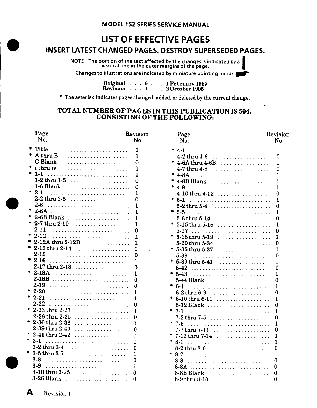
LIST
OF
EFFECTIVE
PAGES
INSERT
LATEST
CHANGED
PAGES.
DESTROY
SUPERSEDED
PAGES.
NOTE:
The
portion
of
the
text
affected
by
the
changes
is
indicated
by
a
vertical line
in
the
outer
margins
of
the
page.
Changes
to illustrations
are
indicated
by
miniature
pointing
hands.
Original
...
0
... 1
February
1985
Revision
. . .1 . . .
2
October
1995
*The
asterisk
indicates
pages
changed,
added,
or
deleted
by
the
current
change.
TOTAL
NUMBER
OF
PAGES
IN THIS
PUBLICATION
IS
504,
CONSISTING
OF
THE
FOLLOWING:
Page
Revision
Page
Revision
No.
No.
No.
No.
*
T
itle
............................ 1
*
4-1
.............................
1
*
A
thru
B
........................ 1
4-2
thru
4-6
....................
. 0
C
Blank
........................
0
*
4-6A
thru
4-6B
..................
1
*
i
thruiv
......................... 1
4-7thru
4-8
.....................
0
*1-1
..........................
*
4-8A
............................
1
1-2thru
1-5
.....................
0
*
4-8B
Blank
......................
1
1-6
B
lank
.......................
0
*
4-9
.............................
1
*
2-1
............................. 1
4-10thru
4-12
...................
0
2-2
thru
2-5
....................
0
*
5-1
.............................
1
2-6
............................. 1
5-2thru
5-4
.....................
0
*
2-6A
............................ 1
*
5-5
.............................
1
*
2-6B
Blank
..................... 1
5-6
thru
5-14
....................
0
*
2-7thru
2-10
.................... 1
*
5-15thru
5-16
...................
1
2-11
............................
0
5-17
............................
0
*
2-12
............................ 1
*
5-18thru
5-19
...................
1
*
2-12A
thru
2-12B
................ 1
5-20
thru
5-34
...................
0
*
2-13
thru
2-14
............
......
1
*
5-35
thru
5-37 ...................
1
2-15
............................
0
5-38
............................
0
*
2-16
............................ 1
*
5-39thru
5-41
...................
1
2-17thru2-18
...................
0
5-42
............................
0
*
2-18A
.......................... 1
*
5-43
............................
1
2-18B
...........................
0
5-44
Blank
......................
0
2-19
............................
0
*
6-1
........................
1
*
2-20
............................ 1
6-2
thru
6-9
.....................
0
*
2-21
............................ 1
*
6-10thru
6-11
...................
1
2-22
............................
0
6-12
B
lank
......................
0
*
2-23
thru
2-27
................... 1
*
7-1
.............................
1
2-28
thru
2-35
...................
0
7-2
thru
7-5
.....................
0
*
2-36
thru
2-38
................... 1
7-6
.......
......................
1
2-39
thru
2-40
...................
0
7-7thru
7-11
....................
0
*
2-41
thru
2-42
................... 1
*
7-12
thru
7-14 ...................
1
*
3
-1 ..................
..........
1
*
8
-1
.............................
1
3-2
thru
3-4
.....................
0
8-2
thru
8-6
.....................
0
*
3-5
thru
3-7
..................... 1
*
8-7
.................. ..........
1
3-8
.............................
0
8-8
.... ....
..............
... 0
3
-9
............................. 1
8-8
A
............................
0
3-10
thru
3-25
...................
0
8-8B
Blank
.......
........
0
3-26
Blank
......................
0
8-9
thru
8-10
....................
0
A
Revision
1

MODEL
152
SERIES
SERVICE
MANUAL
Page
Revision
Page
Revision
No.
No.
No. No.
*
9
1
............................. 1
15-14
thru
15-18
.................
0
9-2
.............................
0
*
15-19
thru
15-20
.................
1
*
9-3
............................. 1
15-20A
thru
15-20B
..............
0
9-4
thru
9-7
.....................
0
*
15-20C
thru
15-20D
..............
1
*
9-8
thru
9-9
0 1
*
15-21
...........................
1
9-10
thru
9-11
...................
0
15-22
thru
15-24
.................
0
*
9-12
............................ 1
*
15-25
thru
15-26
.................
1
*
10-1
............................ 1
*
15-26A
.........................
1
10-2
thru
10-10
.................
0
*
15-26B
Blank
...................
1
*
11-1
thru
11-2
................... 1
15-27
thru
15-30
.................
0
11-3
thru
11-4
...................
0
*
16-1
thru
16-2
...................
1
*
11-5
......................
......
1
16-3
thru
16-6
...................
0
11-6
............................
0
*
16-7
thru
16-8
...................
1
*
11-6A
thru
11-6B
................
1
*
16-8A
..........................
1
*
1-7
thru
11-8
................... 1
*
16-8B
Blank
....................
1
11-9
thru
11-10
.................
0
*
16-9
............................
1
*
11-10A
......................... 1
16-10
thru
16-18
.................
0
*
11-10B
Blank
................... 1
*
16-19
...........................
1
*
11-11
.......................... 1
16-20
thru
16-22
.................
0
11-12thru
11-15
................
0
*
16-23
...................
......
1
*
11-16
.......................... 1
16-24thru
16-25
.................
0
*
11-16A
......................... 1
*
16-26thru
16-27
.................
1
*
11-16B
Blank
................... 1
16-28
thru
16-29
.................
0
11-17
thru
11-19
................
0
*
16-30
................... 1....
.. 1
*
11-20
.......................... 1
16-31thru
16-32
.................
0
11-21
thru
11-24
................
0
*
16-33
thru
16-34
.................
1
11-24A
.........................
0
*
16-34A
.......................
1
*
11-24B
......................... 1
*
16-34B
Blank
...................
1
11-25
...............
0
16-35
thru
16-36
.................
0
*
11-26
..........................
1
16-36A
thru
16-36B
..............
0
11-27
thru
11-29
................
0
16-37
thru
16-38
.................
0
*
1i-30
.......................... 1
16-38A
.........................
0
*
11-30A
......................... 1
16-38B
Blank
...................
0
*
11-30B
Blank
................... 1
16-39
thru
16-46
.................
0
11-31
thru
11-41
................
0
16-46A
thru
16-46B
..............
0
11-42
Blank
...................
0
16-47
thru
16-48
................
0
12-
thru
12-4
..................
0
16-48A
.........................
0
*
12-5
thru
12-7
................... 1
16-48B
Blank
...................
0
12-8
thru
12-15
.................
0
16-49
thru
16-51
.................
0
12-16
Blank
....................
0
*
16-52
..........................
1
*
13-1
............................ 1
16-53
thru
16-55
.................
0
13-2
thru
13-3
.........
0..........
*
16-56
...........................
1
134
Blank
.....................
0
16-57
thru
16-59
.................
0
14-1
thru
14-5
...................
0
16-60
Blank
.....................
0
14-6
Blank
.....................
0 17-1
thru
17-51
..................
0
:
15-1
............................ 1
17-52
Blank
.....................
0
15-2
............................
0
*
1
8-1
............................
1
15-2A
..........................
0
18-2
thru
18-8
...................
0
15-2B
Blank
....................
0
*
19-1
............................
1
15-3
thru
15-11
.................
0
19-2
thru
19-38
..................
0
15-12
.......................... 1
19-38A
.........................
0
*
15-12A
......................... 1
19-38B
Blank
...................
0
*
15-12B
Blank
................... 1
19-39
thru
19-43
.................
0
*
15-13
.......................... 1
19-44
Blank
.....................
0
Revision
1
B/(C
blank)
MODEL 152
SERIES
SERVICE
MANUAL
TABLE
OF
CONTENTS
SECTION
PAGE
NO.
Aerofiche/Manual
1.
GENERAL
DESCRIPTION
..........................................
1A9/1-1
2.
GROUND HANDLING, SERVICING,
CLEANING,
LUBRICATION,
AND
INSPECTION
...............................
1A15/2-1
3.
FUSELAGE
.......................................................
1C18/3-1
4.
WINGS
AND
EMPENNAGE
........................................
1D22,4-1
5.
LANDING
GEAR
AND
BRAKES
....................................
E16/5-1
6.
AILERON
CONTROL SYSTEM
.....................................
1G14/6-1
7.
WING
FLAP
CONTROL SYSTEM
...................................
1H4/7-1
8.
ELEVATOR
CONTROL
SYSTEM
...................................
1H22/8-1
9.
ELEVATOR
TRIM TAB CONTROL SYSTEM
..................
..........
11139-1
10.
RUDDER
CONTROL
SYSTEM
.........
.............................
J7/10-1
11.
ENGINE ..........................................................
1J19/11-1
12.
FUEL
SYSTEM
.
................ .............................
2A2/12-1
13.
PROPELLER
......................................................
2A20/13-1
14.
UTILITY
SYSTEMS
................................................
2B5/14-1
15.
INSTRUMENTS
AND
INSTRUMENT
SYSTEMS
.....................
2B15/15-1
16.
ELECTRICAL
SYSTEMS
...........................................
2D9/16-1
17.
STRUCTURAL
REPAIR
............................................
2G11/17-1
18.
PAINTING
........................................................
212118-1
19.
WIRING
DIAGRAMS
...............................................
2J11/19-1
WARNING
When
performing
any
inspection
or
maintenance
that
requires
turning
on
the
master
switch,
installing
a
battery,
or
pulling
the
propeller
through
by
hand,
treat
the
propeller
as
if
the
ignition
switch
were
ON.
Do
not
stand.
nor
allow anyone
else
to
stand within
the
arc
of
the
propeller,
since
a
loose
or
broken
wire,
or
a
component
malfunction,
could
cause the
propeller
to
rotate.
Revision
I
MODEL
152
SERIES
SERVICE
MANUAL
CROSS
REFERENCE LISTING
OF
POPULAR
NAME
VS. MODEL
NUMBERS
AND
SERIALS
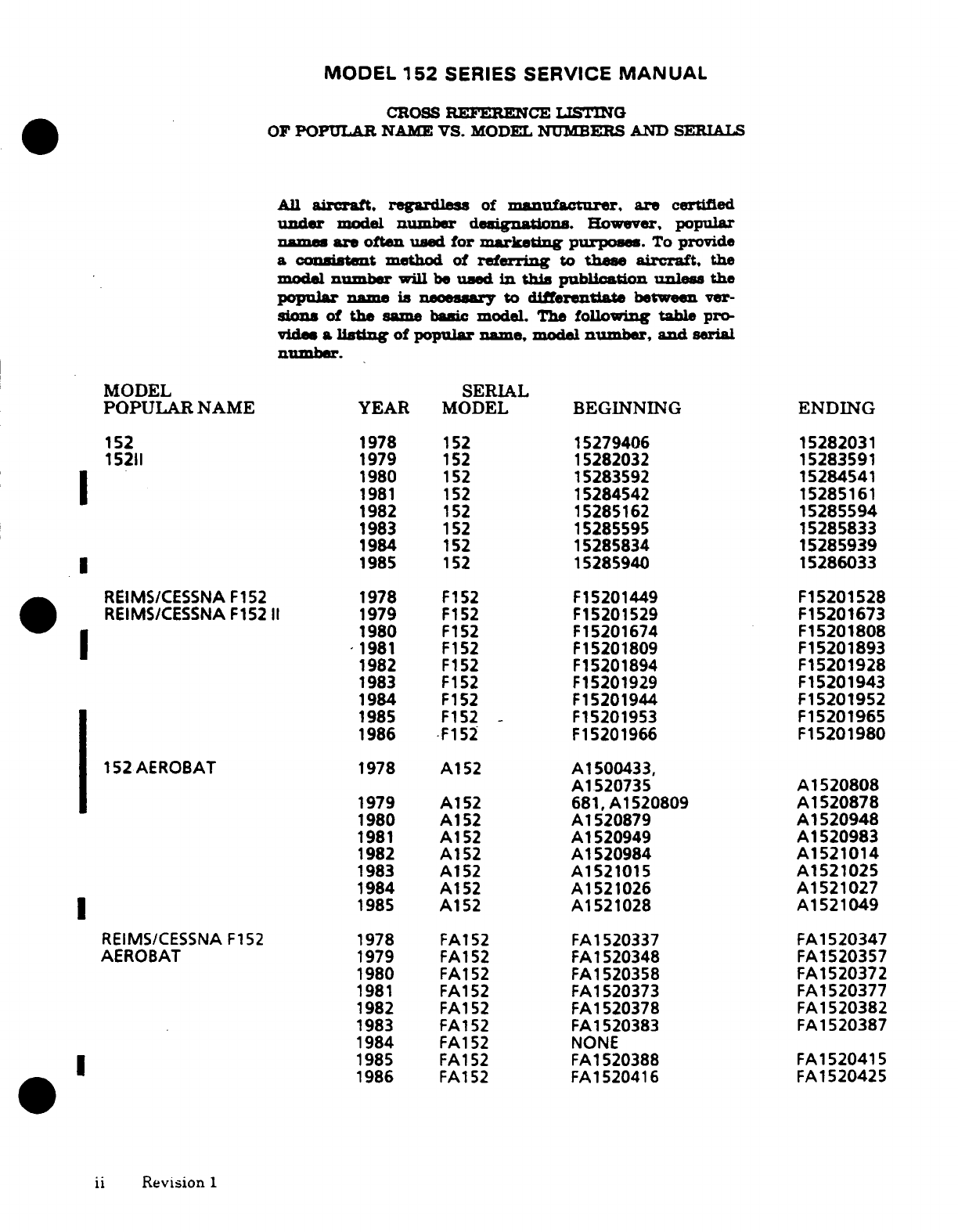
All
aircraft,
regardless
of
manufacturer,
are
certified
under
model
number
degnations.
However,
popular
names
are
often
used
for
marketing
purposes.
To
provide
a consistent
method
of
referring
to
these
aircraft,
the
model
number
will
be
used
in
this
pblication
unless
the
popular
name
is
necessary
to
differentiate
between
ver-
sions
of
the
same
basic
model.
The
following
table
pro-
vide
a
listing
of
popular name,
model
number,
and
serial
number.
MODEL
SERIAL
POPULAR
NAME
YEAR
MODEL
BEGINNING
ENDING
152
1978
152
15279406 15282031
15211
1979
152
15282032
15283591
1980
152
15283592
15284541
1981
152
15284542
15285161
1982
152
15285162
15285594
1983
152
15285595
15285833
1984
152
15285834
15285939
1985
152
15285940
15286033
REIMS/CESSNA
F152
1978
F152
F15201449
F15201528
REIMS/CESSNA
F15211
1979
F152
F15201529
F15201673
1980
F152
F15201674
F15201808
1981 F152
F15201809
F15201893
1982
F152
F15201894
F15201928
1983
F152
F15201929
F15201943
1984
F152
F15201944
F15201952
1985
F152
-
F15201953
F15201965
1986
F152
F15201966
F15201980
152AEROBAT
1978
A152
A1500433,
A1520735
A1520808
1979 A152
681,
A1520809
A1520878
1980
A152
A1520879
A1520948
1981
A152
A1520949
A1520983
1982
A152
A1520984
A1521014
1983
A152
A1521015
A1521025
1984
A152
A1521026
A1521027
1985
A152
A1521028
A1521049
REIMS/CESSNA
F152
1978
FA152
FA1520337
FA1520347
AEROBAT
1979
FA152
FA1520348
FA1520357
1980
FA152
FA1520358
FA1520372
1981
FA152
FA1520373
FA1520377
1982
FA152
FA1520378
FA1520382
1983
FA152
FA1520383
FA1520387
1984
FA152
NONE
1985
FA152
FA1520388 FA1520415
1986
FA152
FA1520416
FA1520425
ii
Revision
1
MODEL
152
SERIES
SERVICE
MANUAL
INTRODUCTION
This
manual
contains
factory-recommended
procedures
and
instructions
for
ground
handling,
ser-
vicing,
and
maintaining
Cessna
152
Series
Models.
Besides
serving
as
a
reference
for
the
exper-
ienced
mechanic,
this
manual
also
covers
step-by-step procedures
for
the
less
experienced.
This
service
manual
is
designed
for
aerofiche
presentation.
To
facilitate
the
use
of
the
aerofiche,
re-
fer
to
the
aerofiche
header
for
basic
information.
KEEPING
CESSNA
PUBLICATIONS
CURRENT
The
information
in
this
publication
is
based
on
data available
at
the
time
of
publication
and
is
up-
dated,
supplemented,
and
automatically
amended
by
all
information issued
in
Service News
Let-
ters,
Service
Bulletins,
Supplier
Service
Notices,
Publication
Changes,
Revisions,
Reissues
and
Temporary
Revisions.
All
such
amendments
become
part
of
and
are
specifically
incorporated
within
this
publication.
Users
are
urged
to
keep
abreast
of
the
latest
amendments
to
this
publication
through
the
Cessna
Product
Support
subscription
services. Cessna
Service
Stations
have
also
been
supplied
with
a
group
of
supplier publications
which
provide
disassembly,
overhaul,
and
parts
breakdowns
for
some
of
the
various
supplier
equipment items.
Suppliers
publications
are
updated,
supplemented,
and
specifically
amended
by
supplier
issued
revisions and
service
information
which
may
be
reissued
by
Cessna;
thereby
automatically
amending this
publication
and
is
communicated
to
the
field
through
Cessna's
Authorized
Service
Stations
and/or
through
Cessna's
subscription
ser-
vices.
WARNING
ALL
INSPECTION
INTERVALS,
REPLACEMENT
TIME LIMITS,
OVERHAUL
TIME
LIMITS,
THE
METHOD
OF INSPECTION,
LIFE
LIMITS,
CYCLE
LIMITS, ETC., RECOMMENDED
BY
CESSNA
ARE
SOLELY
BASED
ON
THE
USE
OF
NEW,
REMANUFACTURED,
OR
OVERHAULED
CESSNA
APPROVED
PARTS.
IF
PARTS
ARE
DESIGNED, MANUFACTURED,
REMANUFACTURED, OVERHAULED,
PURCHASED,
AND/OR
APPROVED
BY
ENTITIES
OTHER
THAN
CESSNA,
THEN
THE
DATA
IN
CESSNA'S MAINTENANCE/SERVICE
MANUALS
AND
PARTS
CATALOGS
ARE
NO
LONGER
APPLICABLE
AND
THE
PURCHASER
IS
WARNED
NOT
TO
RELY
ON
SUCH
DATA
FOR
NON-CESSNA
PARTS.
ALL
INSPECTION
INTERVALS,
REPLACEMENT
TIME LIMITS,
OVERHAUL
TIME
LIMITS,
THE
METHOD
OF
INSPECTION,
LIFE
LIMITS,
CYCLE
LIMITS,
ETC.,
FOR
SUCH
NON-CESSNA
PARTS
MUST
BE
OBTAINED
FROM
THE
MANUFACTURER
AND/OR
SELLER
OF
SUCH
NON-CESSNA
PARTS.
1.
REVISIONS/CHANGES.
These are
issued
to
the
dealers
by
Cessna Aircraft Company
for
this
publications required,
and
include
only
pages
that
require
updating.
2.
REISSUE.
Manual
is
reissued
to
dealers
as
required,
and
is
a
complete
manual
incorpo-
rating
all the
latest
information
and
outstanding
revisions/changes.
It supersedes
and
re-
places
previous
issue(s).
REVISIONS/CHANGES
and
REISSUES
can
be
purchased
from
a
Cessna Service
Station
or
di-
rectly
from
Cessna
Parts
Distribution
(CPD
2),
Dept.
701,
Cessna
Aircraft
Company, P.
O.
Box
949,
Wichita,
Kansas
67201.
All
supplemental
service
information
concerning
this manual
is
supplied
to
all
appropriate
Cessna
Service
Stations
so
that
they
have
the
latest
authoritative
recommendations
for
servicing
these
Cessna
aircraft.
Therefore,
it
is
recommended
that
Cessna
owners
utilize
the
knowledge
and exper-
ience
of
the
factory-trained
Service
Station
Organization.
Revision
1
iii
MODEL
152
SERIES
SERVICE
MANUAL
CUSTOMER
CARE
SUPPLIES
AND
PUBLICATIONS
CATALOG
A
Customer
Care
Supplies
and
Publications
Catalog
is
available
from
a
Cessna
Service
Station
or
I
directly
from
Cessna
Parts
Distribution,
Dept.
701,
Cessna
Aircraft
Company,
5800
East
Pawnee,
Wichita,
Kansas
67201.
This
catalog
lists
all
publications
and
Customer
Care
Supplies
available
from
Cessna
for
prior
year
models
as
well
as
new
products.
To
maintain
this
catalog
in
a
current
status,
it
is
revised
quarterly
and
issued
on
Aerofiche
with
the
quarterly
Service
Information
Sum-
maries.
A
listing
of
all available
publications
is
issued
periodically
by
the
Cessna Propeller
Prod-
uct
Support
Department.
SUPPLEMENTAL
TYPE
CERTIFICATE
INSTALLATIONS
Inspection,
maintenance, and
parts
requirements
for
supplemental
type
certificate
(STC)
installa-
tions
are
not included
in
this
manual.
When
an
STC
installation
is
incorporated
on
the
airplane,
those
portions
of
the airplane
affected
by
the
installation
must
be
inspected
in
accordance
with
the
inspection
program
published
by
the
owner of
the
STC.
Since
STC
installations
may
change
sys-
tems
interface,
operating characteristics,
and
component
loads
or
stresses
on
adjacent
structures,
Cessna
provided
inspection
criteria
may
not
be
valid
for
airplanes
with
STC
installations.
CUSTOMER
COMMENTS ON
MANUAL
Cessna
Aircraft
Company
has
endeavored
to
furnish
you
with
an
accurate,
useful,
up-to-date
man-
ual.
This
manual
can
be
improved
with
your
help.
Please use
the
return
card,
provided
with
your
manual,
to
report
any errors,
discrepancies,
and
omissions in
this
manual
as
well
as any
general
comments
you
wish
to
make.
iv
Revsion
1
MODEL
152
SERIES
SERVICE
MANUAL
SECTION
1
GENERAL DESCRIPTION
Page
No.
TABLE
OF
CONTENTS
Aerofiche/
Manual
GENERAL DESCRIPTION
.....
A9/1-1
Aircraft
Specification
.......
1A9/1-1
Model
152
and
F152
.........
IA9/1-1
Stations
...................
1A9/1-1
Description
................
1A9/1-1
Bolt
Torques
...............
1A12/1-4
Model
A152
and
FA152
......
1A9/1-1
Description
................
1A9/1-1
1-1.
GENERAL DESCRIPTION.
1-2.
MODEL
152
AND
F152
SERIES.
1-3.
DESCRIPTION.
Cessna
Model
152
and
F152
Series
aircraft
described
in
this
manuaL
are
high-wing
monoplanes
of
all-metal
semimonocoque
construction
They
are
equipped
with
fixed
tubular spring-steel
main
gear
struts
and
a
steerable
nose
gear.
The
nose
gear
has
an
air/hydraulic
fluid
shook
strut.
Two-place
seating
is
standard,
and
a
double-width, fold-up
auxiliary
rear
seat
is
optional.
Also
featured
is a
"wrap-around"
rear
window
and
a
swept-
back
fin and
rudder.
Powering
these
aircraft
is a
four-cylinder.
horizontally-opposed.
air-
cooled
Lycoming
"Blue
Streak"
engine,
driving
an
all-metal
fixed-pitch
propeller.
1-4.
MODEL
A152
AND
FA52
SERIES.
1-5.
DESCRIPTION.
Aerobat
Model
A152
and
FA152
Series
aircraft
are
a
modified
version of
the
current
production
Model
152.
The
strucure
has
been
beefed-up"
in
some
areas
to
meet
re-
quirements set
forth
in
Acrobatic
Category,
CAR,
Part
3.
In
addition,
quick-relese
cabin
doors.
two-strap
shoulder harnesses,
and
aerbatic
paint
design are
standard
Removable
seat
and
back
cushions
are
provided
to
allow
occupants
to use
either
seat-pack
or
back-pack
type
parachutes
for
arobatic
maneuvers.
The
FA152
is
powered
by
a
Rolls
Royce
built,
four-cy-
linder,
horizontally-opposed,
air-cooled
Lycoming
engine.
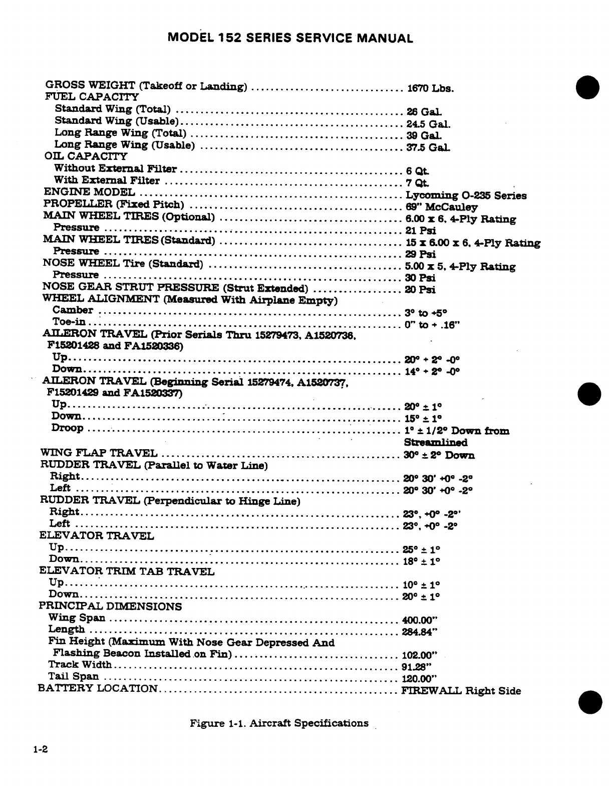
1-6.
AIRCRAFT
SPECIFICATIONS.
Leading
particulars
of
these
aircraft.
with
dimensions
based on
gross
weight,
are
given
in
figure
1-1. If
these dimensions
are
used
for
constructing
a
hangar
or
computing clearances, remember
that
such factors
as
nose
gear
strut
inflation.
tire
pressures,
tire
sizes
and
load
distribution
may
result
in
some
dimensions
that
are
considerably
different
from those
listed.
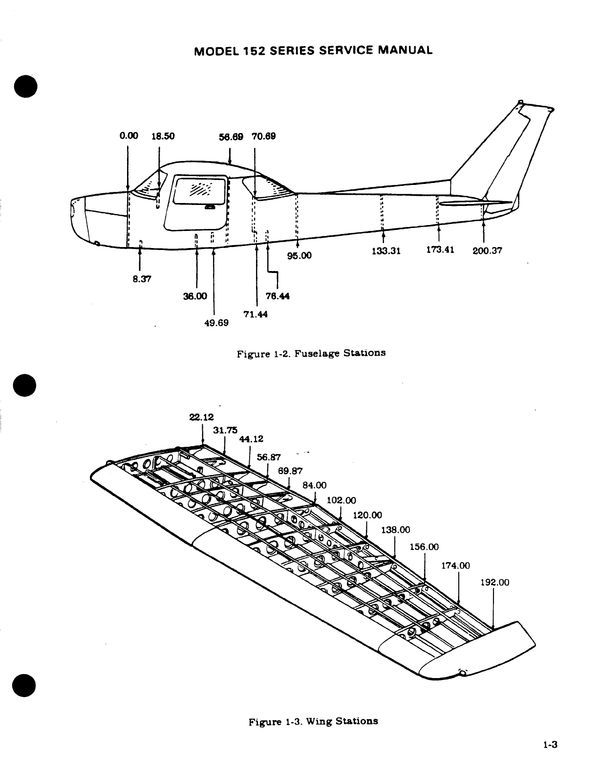
1-7.
STATIONS.
Station
diagrams
are
shown
in
figures
1-2
and
1-3
to
assist
in
locating
equipment
when
a
written description
is
inadequate
or
impractical.
Revision
1
1-1
MODEL
152
SERIES
SERVICE
MANUAL
GROSS
WEIGHT
(Takeoff
or
Landing)
...............................
1670
Lbs.
FUEL
CAPACITY
Standard
Wing
(Total)
................... 2.........................
26
GaL
Standard
Wing
(Usable)
............................................
245
Gal.
Long
Range
Wing
(Total)
...........................................
39
GaL
Long
Range
Wing
(Usable)
....................................
..
37.5
Gal
OIL
CAPACITY
Without
External
Filter
.............................................
6
Qt.
With
External
Filter
................................................
7
Qt.
ENGINE
MODEL
...................................................
Lycoming
0-235
Series
PROPELLER
(Fixed
Pitch)
.....................................
.....
69"
McCauley
MAIN
WHEEL
TIRES (Optional)
.....................................
6.00
x
6,
4-Ply
Rating
Pressure
.........................................................
21
Psi
MAIN
WHEEL
TIRES
(Standard)
.............................
15
x
600
x
6,
4-Ply
Rating
Pressure
......... ......
....................................
29
Psi
NOSE
WHEEL
Tire
(Standard)
.......................................
5.00
x
5,
4-Ply
Rating
Pressure
.....................................................
30
Psi
NOSE GEAR
STRUT
PRESSURE
(Strut
Extended)
..................
20
Psi
WHEEL
ALIGNMENT
(Measured
With
Airplane
Empty)
Camber
.....................
.......................................
3
to
+5°
Toe-in
................................. ......................
0"
to
+
.16"
AILERON
TRAVEL
(Prior
Serials
Thru
15279473,
A1520736,
F15201428
and
FA1520336)
Up
...............................................................
20°
+
2°
.- 0
Down
........................................................ ... ..
14
.+
20
-0
AILERON
TRAVEL
(Beginning
Serial
15279474,
A1520737,
F15201429
and
FA1520337)
Up
....................................................................
200e
1°
Down
.......................... : ....................................
150°
10
Droop
.....
......................................................... 1° +
1/2
°
Down
from
Streamlined
WING
FLAP
TRAVEL
................................................
30°
2
°
Down
RUDDER TRAVEL
(Parallel
to
Water
Line)
Right
...............................................................
20°
30'
+0
-2°
Left
.......
...........................................
......
.20
30'
+0
°
-2
°
RUDDER
TRAVEL
(Perpendicular
to
Hinge
Line)
Right
................................................................
23,
+00
-20'
Left
.................................................... .........
23°,
.+0
-2
ELEVATOR TRAVEL
Up
................................................................ ..
25
°1°
Down
..............................................................
.
18° +
1
°
ELEVATOR
TRIM
TAB
TRAVEL
Up........................... ......................................
10
°1
Down
...............................................................
20°
1°
PRINCIPAL
DIMENSIONS
Wing
Span
...........
..........................................
400.00"
Length
..................................... ........................
284.84"
Fin
Height
(Maximum
With
Nose
Gear
Depressed
And
Flashing
Beacon
Installed
on
Fin)
.................................
102.00"
Track
Width
.........................................................
91.28"
Tail
Span
...........................................................
120.00"
BATTERY
LOCATION
...............................................
FIREWALL
Right
Side
Figure
1-1.
Aircraft Specifications
1-2
MODEL
152
SERIES
SERVICE
MANUAL
0.00
18.50
56.69
70.69
49.69
Figure
1-2.
Fuselage
Stations
22.12
31.75
44.12
69.878
Figure
1-3.
Wing
Stations
95.0~120.00~1-3
138.00
156.00
Figure
1-3.
Wing
Stations
MODEL
152
SERIES SERVICE
MANUAL
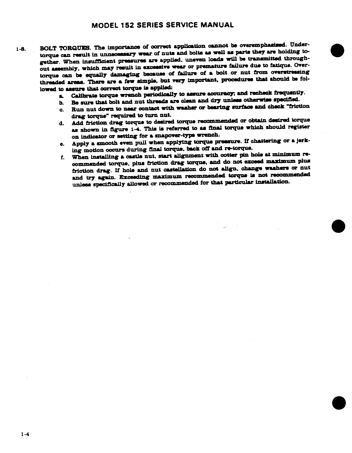
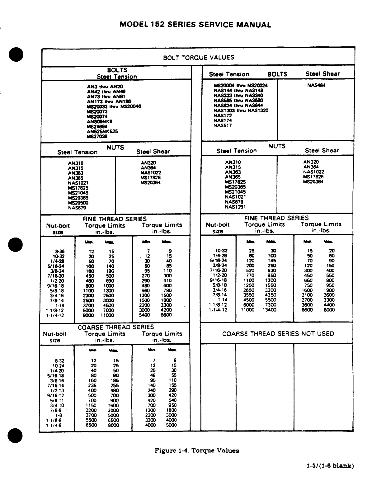
1-8.
BOLT
TORQUES.
The
importance
of
correct
application
cannot
be
overemphasisd.
Under-
torque
can
result
in
unnecesary
wear
of
nuts
and
bolt. as
wall
as
parts
they
are
holding
to-
gether.
When
insuficient
pressures
are
applied,
uneven
loads
will
be
transmitted
through-
out
assembly,
which
may
result
in
excesive
wear or
premature
failure due
to
fatique.
Over-
torque
can
be
equally
damging
beause
of
failure
of
a
bolt
or
nut
from
overstrssing
threded
areas.
There
are
a
few
simple,
but
very
important,
procedure
that
should
be
fol-
lowed
to
assure
that
correct
torque
is
applied
a.
Calibrate
torque
wrench
periodically
to
asure
accuracy
and
recheck
frequently.
b.
Be
sur
that
bolt
and
nut
threads are
lean
and
dry
unless
othrwise
specified.
o.
Run
nut
down
to
near
contact
with washer
or bearing
surface
and
check
"fiction
drag
torque
required
to
turn
nut.
d. Add
friction drag
torque
to
desired
torque
recommended
or
obtain
desired torque
as
shown
in
figure
1-4.
This is
referred
to
a
final
torque
which
should
register
on Indicator
or
setting
for
a
snapover-type wrench.
e.
Apply
a
smooth
even
pull
when
applying
torque pressure.
If
chattering
or
a
jerk-
ing
motion
occurs
during
final
torque,
back
off
and
re-torque.
f.
When
instlling
a
castle
nut, start
alignment
with
cotter
pin
hole
at
minimum
re-
commended
torque, plus
friction
drag
torque,
and
do
not
exceed
maimum
or
plus
friction
drag.
If
hole
and
nut
castellation
do
not
align,
change washers
or
nut
and
try
again
Exceeding
aximum recommnded
torque
is
not
reommended
unless
specifically
allowed
or
recommended
for
that
particulr
instllation
1-4
MODEL
152
SERIES
SERVICE
MANUAL
BOLT
TORQUE VALUES
BOLTS
Steel
Tension
Steel
Tension
BOLTS
Steel
Shear
AN3
thru
AN20
MS20004
thru
MS20024 NAS44
AN42
thru AN49
NAS144
thru
NAS148
AN73
thru
AN81
NAS333 thru
NAS340
AN173
thru
AN186
NAS585
thru
NAS644
MS20033
thru
MS20046
NAS624
thru
NAS644
MS20073
NAS1303
tru
NAS1320
MS20074
NAS172
AN509NK9
NAS174
MS24694
NAS517
AN525NK525
MS27039
Steel
Tension
NUTS
Steel
Shear
Steel
Tension
NUTS
Steel Shear
AN310
AN320
AN310
AN320
AN315
AN364
AN315
AN364
AN363 NAS1022
AN363
NAS1022
AN365
MS
17826
AN365
MS
17826
NAS1021
MS20364
MS17825 MS20364
MS17825 MS20365
MS21045 MS21045
MS20365
NAS1021
MS20500
NAS679
NAS679
NAS1291
FINE
THREAD
SERIES
FINE
THREAD
SERIES
Nut-bolt
Torque
Limits
Torque
Limits
Nut-bolt
Torque
Limits Torque
Limits
size
in.-lbs.
in.-lbs.
size
in.-lbs.
in.-lbs.
.
8-36 12
15
7
9
10-32
25
30
15
20
10-32
20
25
.
12
15
/4-28
80
100
50 60
1/4-28
50
70 30
40
5/16-24
120
145 70 90
5/16-24
100
140
60
85
3/8-24
200
250
120
150
3/8-24
160
190
95
110
7/16-20
520
630
300
400
7/16-20
450
500 270
300
1/2-20
770
950
450
550
1/2-20
480
690 290 410
9/16-18
1100
1300
650
800
9/16-18
800
1000
480
600 5/8-18
1250
1550
750
950
5/8-18
1100
1300
660
780
3/4-16
2650
3200
1600
1900
3/4-16
2300
2500
1300
1500
7/8-14 3550
4350
2100 2600
7/8-14
2500
3000
1500
1800
1-14
4500 5500
2700 3300
1-14
3700
4500
2200
3300
.
1-1/8-12
6000
7300
3600
4400
1-1/8-12
5000 7000 3000
4200
1-1/4-12
11000
13400
6600
8000
1-1/4-12
9000
11000
5400
6600
COARSE
THREAD
SERIES
Nut-bolt
Torque
Limits
Torque
Limits
COARSE
THREAD
SERIES
NOT
USED
size
in.-lbs. in.-lbs.
8-32
12
15
7
9
10-24
20
25
12
15
1/4-20
40 50
25
30
5/16-18
80
90
48
55
3/8-16
160
185
95
110
7/16-14 235
255
140
155
1/2-13
400
480
240 290
9/16-12
500 700
300
420
5/8-11
700
900
420 540
3/4-10
1150
1600
700
950
7/8-9
2200
3000
1300
1800
1-8
3700
5000
2200 3000
1-1/8-8
5500
6500
3300
4000
11/4-8
6500
8000
4000 5000
Figure
1-4.
Torque
Values
1-5/(1-6
blank)
MODEL
152
SERIES
SERVICE
MANUAL
SECTION
2
GROUND
HANDLING, SERVICING,
CLEANING
LUBRICATION
AND
INSPECTION
WARNING
When
performing
any
inspection
or
maintenacne
that
re-
quires
turning
on
the
master
switch,
installing
a
battery,
or
pulling
the
propeller
through
by
hand,
treat
the
prop-
eller
as
if
the
ignition
switch
were
ON.
Do
not
stand,
nor
allow
anyone
else
to stand,
within
the
arc
of
the
propel-
ler,
since
a
loose
or
broken
wire,
or
a
component
mal-
function,
could
cause
the
propeller
to
rotate.
Page
No.
TABLE
OF
CONTENTS
Aerofiche/
Manual
GROUND
HANDLING
........
1A16/2-2
Engine
Induction
Air
Filter
..
1B7/2-14
Towing
.....................
1A16/2-2
Vacuum
System
Filter
......
1B9/2-16
Hoisting
....................
1A18/2-4
Battery
....................
1B92-16
Jacking
....................
1A19/2-5
Tires
.....................
1B9/2-16
Leveling
.
..................
1A1912-5
Nose
Gear
Shock
Strut
......
1B9/2-16
Parking
....................
1A19/2-5
Nose
Gear
Shimmy
Dampener
1B10/2-17
Tie-Down
.
..............
1A19/2-5
Hydraulic
Brake
System
....
1B10/2-17
Weighing
Aircraft
...........
1A19/2-5
CLEANING
.................
1B10/2-17
Flyable
Storage
.
..........
A19/2-5
Windshield
and
Windows
....
B11/2-18
ReturningAircraft
to
Service
.
1A20/2-6
Plastic
Trim
................
1B13/2-18B
Temporary
Storage
..........
1A20/2-6
Painted
Surfaces
...........
1B13/2-18B
Inspection
During
Storage
..
1A22/2-7
Aluminum
Surfaces
.........
1B13/2-18B
Returning
Aircraft
to
Engine
and
Engine
Service
.
.................
A23,'2-8
Compartment
.............
1B14/2-19
Indefinite
Storage
.........
1A23/2-8
Valves
and
Valve
Guides ....
1B15/2-20
Inspection
During
Storage
..
1A24/2-9
Upholstery
andInterior
.....
B18/2-21
Returning
Aircraft
to
Propeller
..................
1B18/2-21
Service
..................
1B1/2-10
W
heels
....................
1B18/2-21
SERVICING
.
.................
1B1/2-10
LUBRICATION
.............
B182-21
Fuel
.............
B1/2-10
Tachometer
Drive
Shaft
.....
1B19/2-22
Use
of
Fuel
Additives
for
Wheel
Bearings
............
1B19/2-22
Cold
Weather
Operations
... 1B1/2-10
Nose
Gear
Torque
Links
.....
B19/2-22
Use
of Fuel
Additives
to
Wing
Flap
Actuator
.........
1B19/2-22
Inhibit
LeadFouling
.......
1B3/2-12
Rod
End
Bearings
..........
1B19/2-22
Fuel
Drains
.................
1B42-12A
INSPECTION
REQUIREMENTS
1C6/2-33
Carburetor
Drian
Plug
100
Hour/Annual
...........
1C6/2-33
Inspection
.
.....
5/2-12B Special
...................
1C6/2-33
Carburetor
Heat
Butterfly
Progressive
................
1C6/2-33
Screw
Inspection
..........
1B6/2-13
Guide-lines
..........
C62-33
Engine
Oil
.......
...........
1B6/2-13
Charts
.....................
C92-36
Engine
Induction
Air
Filter
1
B7/2-14
Revision
1
2-1
MODEL
152
SERIES
SERVICE
MANUAL
2-1.
GROUND
HANDLING.
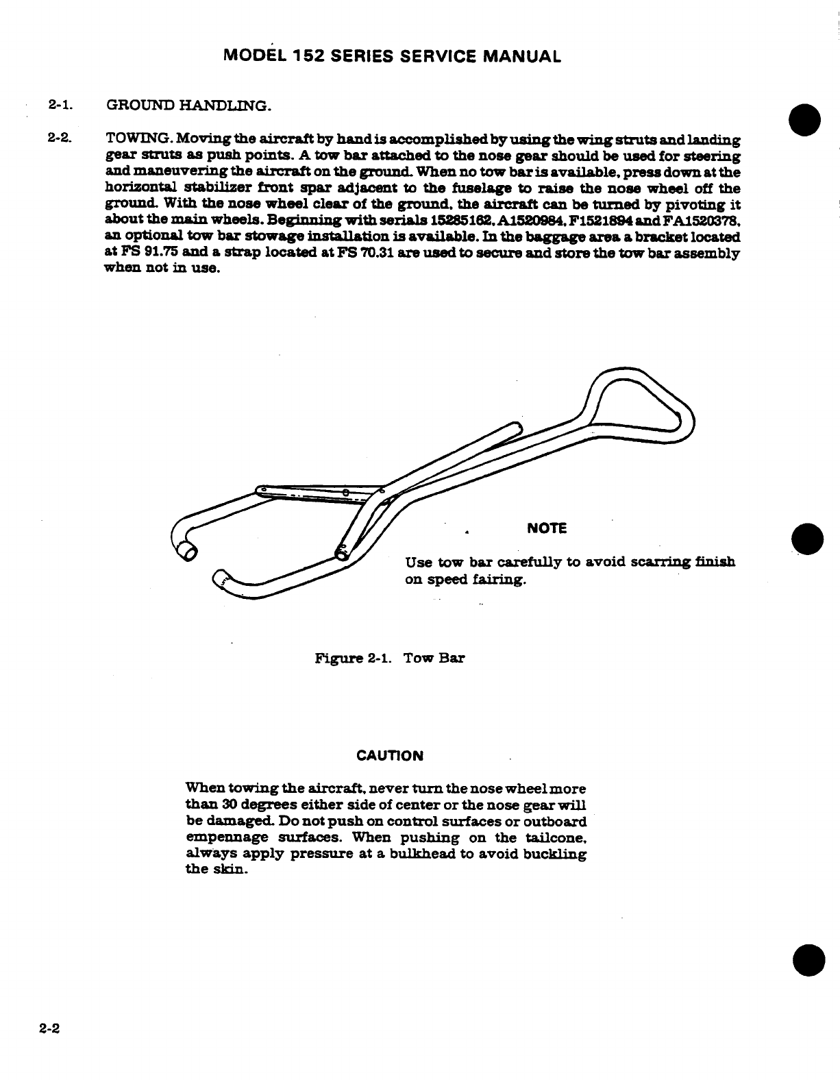
2-2.
TOWING.
Moving
the
aircraft
by
hand is accomplished
by
using
the
wing
struts
and
landing
gear
struts as
push
points.
A
tow
bar
attached
to
the
nose
gear
should
be
used for
steering
and
maneuvering the
aircraft
on
the
ground.
When
no
tow
bar
is
available,
press
down
at
the
horizontal
stabilizer
front
spar
adjacent
to
the
fuselage
to
raise
the
nose
wheel
off
the
ground.
With
the nose wheel
clear
of
the
ground,
the
aircraft
can
be
turned
by
pivoting
it
about
the
main
wheels.
Beinning
with
serials
15285162, A1520984,
F1521894
and
FA1520378,
an
optional
tow
bar
stowage
installation
is
available.
In
the
baggage
area
a
bracket
located
at
FS
91.75
and
a
strap
located at
FS
70.31
are
used
to
secure
and
store the
tow
bar
assembly
when
not
in
use.
Use tow
bar
carefully
to
avoid
scarring
finish
on
speed
fairing.
Figure
2-1.
Tow
Bar
CAUTION
When
towing
the
aircraft,
never
turn
the
nose wheel
more
than
30
degrees
either
side
of
center
or the
nose
gear
will
be
damaged.
Do
not
push
on
control surfaces
or
outboard
empennage
surfaces.
When
pushing
on
the tailcone.
always
apply
pressure
at
a
bulkhead
to
avoid
buckling
the
skin.
2-2
MODEL
152
SERIES
SERVICE
MANUAL
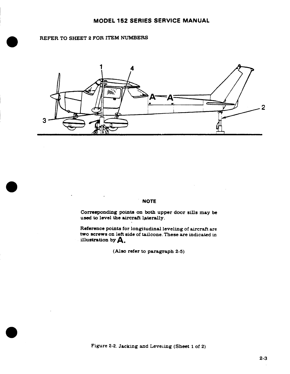
REFER
TO
SHEET
2
FOR
ITEM
NUMBERS
NOTE
Corresponding
points
on
both
upper
door
sills
may
be
used
to
level the
aircraft
laterally.
Reference
points
for
longitudinal
leveling
of
aircraft
are
two
screws
on
left
side
of
tailcone. These
are
indicated
in
illustration
by
A.
(Also
refer
to
paragraph
2-5)
Figure
2-2.
Jacking
and
Leveling (Sheet
1
of
2)
2-3
MODEL
152
SERIES SERVICE
MANUAL
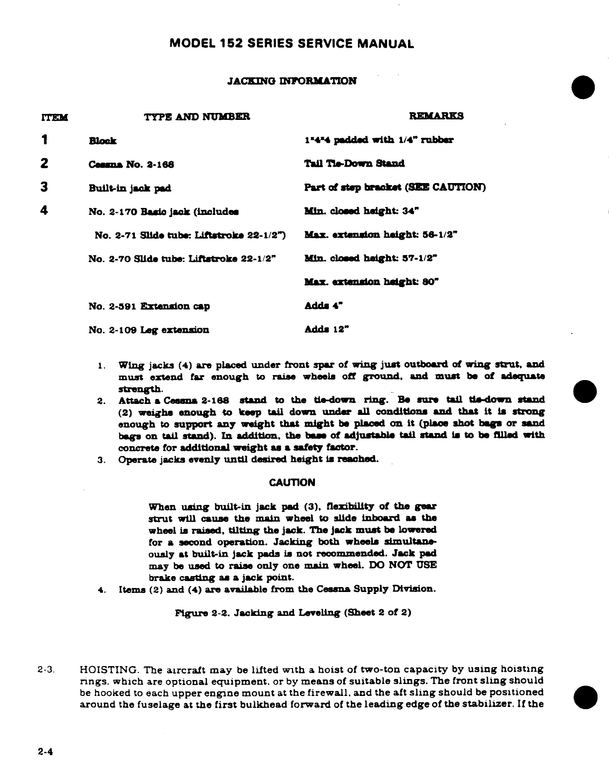
JACKING
INFORMATION
ITEM
TYPE
AND
NUMBER
REMARS
1
Block
14'4
padded
with
1/4"
rubber
2
Cessna
No.
2-168
Tail
TieDown
Stand
3
Built-in
Jack
pad
Part
of
step bracket
(SEE
CAUTION)
4
No.
2-170
Basic
jack
(includes
Min.
closed
height:
34"
No.
2-71
Slide tube:
Liftstroke
22-1/2")
Max
extension
heght:
56-1/2"
No.
2-70
Slide
tube:
Liftstroke
22-1/2"
in.
closed
height:
57-1/2"
Max.
extension
height:
80"
No.
2-591
Extension
cap
AddA
4"
No.
2-109
Leg
extension
Add
12"
1.
Wing
jacks
(4)
are
placed
under
front
spar
of
wing
just
outboard
of
wing
strut,
and
must
extend far
enough
to
raise
wheels
off
ground,
and
must
be
of
adequate
strength.
2.
Attach
a
Cessna
2-168
stand
to
the
tie-down
ring.
Be
sure
tail
tie-down
stand
(2)
weighs
enough to
keep tail
down
under
all
conditions
and
that
it is
strong
enough
to
support
any
weight
that
might
be
placed
on
it
(place
shot
bags
or
sand
bags on
tail
stand).
In
addition, the
base of
adjustable
tail
stand
is
to
be
filled
with
concrete
for
additional
weight
as
a
safety
factor.
3.
Operate
jacks
evenly
until
desired
height
is
reached.
CAUTION
When
using
built-in
jack
pad
(3),
flexibility of
the
gear
strut
will
cause
the
main
wheel
to
slide
inboard
as the
wheel
is
raised,
tilting
the
jack.
The
jack
must
be
lowered
for
a
second
operation.
Jacking
both wheels
simultane-
ously
at
built-in
jack
pads is
not
recommended.
Jack
pad
may
be
used
to
raise
only
one
main
wheel.
DO
NOT
USE
brake
casting
as
a
jack
point.
4.
Items
(2)
and
(4)
are
available
from
the
Cessna
Supply
Division.
Figure
2-2.
Jacking
and
Leveling
(Sheet
2
of
2)
2-3.
HOISTING. The
aircraft
may
be
lifted
with
a
hoist
of
two-ton
capacity
by
using
hoisting
rings.
which are
optional
equipment.
or
by
means
of
suitable
slings.
The
front
sling
should
be
hooked
to
each
upper
engine mount
at
the
firewall,
and
the
aft
sling
should
be
positioned
around
the
fuselage
at
the
first
bulkhead forward
of
the
leading
edge
of
the
stabilizer.
If
the
2-4
MODEL
152
SERIES
SERVICE
MANUAL
optional
hoisting
rings
are
used,
a
minimum
cable
length
of
60
inches
for
each cable is
required
to
prevent
bending
of
the
eyebolt-type
hoisting
rings.
If
desired,
a
spreader
jig
may
be
fabricated
to
apply
vertical
force
to
the
eyebolts.
2-4.
JACKING.
See
figure
2-2
for
jacking
procedures.
2-5.
LEVELING.
Corresponding
points
on
both
upper
door
sills
may
be
used to
level
the
aircraft
laterally.
The
reference
points
for
longitudinal
leveling
of
the
aircraft
are
the
two
screws
on
the
left
side
of
the
tailcone.
2-6.
PARKING.
Parking
precautions
depend
principally
on
local
conditions.
As
a
general
precaution,
set
parking
brake
or
chock
the
wheels
and
install
the
controls
lock.
In severe
weather
and
high
wind
conditions,
tie
down
the
aircraft
as
outlined
in
paragraph
2-7
if
a
hangar
is
not
available.
2-7.
TIE-DOWN.
When
mooring
the
aircraft
in
the
open,
head
into
the
wind
if
possible.
Secure
control
surfaces
with the
internal
control
lock
and
set
brakes.
CAUTION
Do
not
set
parking
brakes
when
they
are
overheated
or
during
cold
weather
when
accumulated
moisture may
freeze
them
After
completing the
preceding,
proceed
to moor
the
aircraft
as
follows:
a.
Tie
ropes,
cables,
or
chains
(700
lbs tensile
strength)
to
the
wing
tie-down
fittings
located
at
the
upper
end
of
each
wing
strut.
Secure
the
opposite
ends
of
ropes,
cables,
or
chain
to
ground
anchors.
b.
Secure
a
tie-down
rope
(no
chains
or
cables)
to
the
exposed
portion
of
the
engine
mount
and
secure
opposite
end
of
rope
to
a
ground
anchor.
c.
Secure
the
middle
of
a
rope
to
the
tail
tie-down
ring.
Pull
each
end
of
rope away
at
a
45
degree
angle
and
secure
to
ground
anchors
at
each side
of
tail
d.
Secure
control
lock
on
pilot
control
column.
If
control
lock
is
not available,
tie
pilot
control
wheel back
with
front
seat
belt.
e.
These
aircraft
are
equipped with
a
spring-loaded
steering
bungee system
which
affords
protection
against
normal
wind
gusts.
However,
if
extremely
high
wind
gusts
are
anticipated,
additional external
locks
may
be
installed.
2-7A.
WEIGHING
AIRCRAFT.
Refer
to
Pilot's
Operating
Handbook.
2-8.
FLYABLE
STORAGE.
Flyable
storage
is
defined
as
a
maximum
of
30
days
nonoperational
storage
and/or
the
first
25
hours
of
intermittent
engine
operation.
NOTE
The
aircraft
is
delivered
from
Cessna
with
straight
min-
eral
oi,
conforming
to Mr-L-6082.
This
oil
should
be
used
for
the
first
25
hours
of
engine
operation. In
the
event
it
is
necessary
to
add
oil
during
the
first
25
hours
of
operation,
use
only
aviation
grade
straight
mineral
oil
of
the
recommended viscosity
conforming
to
MIL-6082.
2-5

MODEL
152
SERIES
SERVICE
MANUAL
During
the
30
day
nonoperational
storage or
the
first
25
hours
of
intermittent
engine
operation.
every
seventh day
the
propeller
shall
be
rotated
through
six
revolutions,
without
running
the
engine.
WARNING
When
rotating
engine
by
hand, always take
proper pre-
cautions
to
make
sure
the
engine
cannot
fire
or
start
when
the propeller
is
moved.
If
the
aircraft
is
stored outside, tie
it
down
in
accordance
with
paragraph
2-7.
In
addition.
the
pitot
tube.
static
air
vents,
air
vents,
openings
in
the
enine
cowling,
and
other
similar
openings
shall
have
protective
covers
installed
to
prevent
entry
of
foreign
material.
After
30
days,
aircraft
should
be
flown
for
30
minutes
or
ground
run-up
until
oil
has
reached
operating
temperature.
(lower
green
arc
range)
CAUTION
Excessive ground operation
shall
be
avoided.
2-9.
RETURNING
AIRCRAFT
TO
SERVICE.
After
flyable
storage,
returning
the aircraft
to
service
is
accomplished by
performing
a
thorough
preflight
inspection.
At the
end
of
the
first
25
hours
of
engine
operation drain
engine
oil
and
clean
oil
pressure
screen
(or
change
external
oil
filter
element).
Service
engine
with
correct
grade
and
quantity
of
engine
oil
See
figure
2-4
and
paragraph
2-21
for
correct grade
of
engine oil
2-10.
TEMPORARY
STORAGE.
Temporary
storage
is
defined
as
aircraft
in
a
nonoperational
status
for
a
maximum
of
90
days.
The
aircraft is
constructed
of
corrosion
resistant
alclad
aluminum, which
will
last
indefinitely under normal
conditions
if
kept
clean
however.
these
alloys are
subject
to
oxidation.
The
first
indication
of
corrosion
on
unpainted
surfaces
is
in
the
form
of
white
deposits
or
spots.
On
painted
surfaces.
the
paint
is
discolored
or
blistered.
Storage
in
a
dry
hangar
is
essential
to
good
preservation
and
should
be
procured
if
possible.
Varying conditions
will
alter
the
measures
of
preservation,
but
under
normal
conditions
in
a
dry
hangar,
and
for
storage
periods
not
to
exceed
90
days.
the
following
methods
of
treatment
are
suggested.
NOTE
In
order
to
maintain
stored
airplanes
in
"new"
condition,
it
is
important
they
be
inspected,
cleaned,
and
serviced
regu-
larly.
Routine
inspections
for
overall
condition
such
as
cleanliness,
damage,
corrosion,
and
water leaks
are
impera-
tive
to
assure
the
airplane
is
being
properly
maintained.
Moisture
damage,
corrosion,
or
other
damage
resulting
from
neglect
while
in
storage
is
not
covered
under
the
air-
plane,
engine,
or
other
equipment
warranties.
a.
Fill
fuel
tanks
with correct
grade
of
aviation
fuel
b.
Clean
and
wax
aircraft
thoroughly.
c.
Clean
any
oil
or
grease
from
tires
and
coat
tires
with
a
tire
preservative.
Cover
tires
to
protect
against
grease
and
oil.
d.
Either
block
up
fuselage
to
relieve
pressure
on
tires
or
rotate
wheels every
30
days
to
change
supporting points
and
prevent
flat
spotting
the
tires.
e.
Lubricate
all
airframe
items
and
seal
or
cover
all
openings
which
could
allow
moisture
and/or
dust
to
enter.
2-6
Revision
1
MODEL
152
SERIES
SERVICE
MANUAL
NOTE
The
aircraft
battery serial
number
is
recorded
in
the
aircraft
equipment
list.
To
assure accurate
warranty
records,
the
battery
should
be
reinstalled
in
the same
aircraft
from
which
it
was
removed.
If
the
battery
is
returned
to
service
in
a
different
aircraft,
appropriate
record changes
must
be
made
and
notification sent
to
Cessna
Warranty Administration.
Revision
I
2-6Ai(2-6B
blank)
MODEL
152
SERIES SERVICE
MANUAL
f.
Remove
battery
and
store
in a
cool.
dry
place:
service
battery periodically
and
charge
as
required.
NOTE
An
engine
treated
in
accordance
with
the
following
may
be
considered protected
against
normal
atmospheric
corrosion for
a
period
not
to
exceed
90
days.
g.
Disconnect
spark
plug
leads
and
remove
upper
and
lower
spark
plugs
from
each
cylinder.
NOTE
The
corrosion
preservative
oil
mixture
should
conform
to
MIL-L-6529C
Type
I
heated
to
200°F
to
220°F
spray
nozzle
temperature.
h.
Using
a
portable
pressure
sprayer.
atomize
spray
preservative
oil
through
the upper
spark
plug
hole
in
each
cylinder with the piston
in. a
down
position. Rotate
crankshaft
about
five
revolutions
as
each
cylinder
is
sprayed.
i.
After
completing
step
"h."
rotate
crankshaft
so
that
no
piston
is
at
a
top
position.
If
the
aircraft
is
to
be
stored
outside.
stop
two-bladed
propeller
so
that
blades
are
as
near
horizontal
as
possible
to
provide maximum
clearance
with
passing
aircraft
j.
Again
spray
each
cylinder
without moving
the
crankshaft,
to
thoroughly
cover
all
interior
surfaces
of
the cylinder
above
the
piston.
k.
Install
spark
plugs
and
connect
spark
plug
leads.
1.
Apply
preservative
oil
to
the
engine
interior
by
spraying
approximately
two
ounces
of
the
preservative
oil
through
the
oil
filler
tube.
m.
Seal
all
engine openings
exposed
to
the
atmosphere.
using
suitable
plugs
or
non-
hygroscopic
tape. Attach
a
red streamer at
each
point
that
a
plug
or
tape
is
installed.
n.
If
the
aircraft
is
to
be
stored outside,
perform
the
procedures
outlined
in
paragraph
2-7.
In
addition,
the
pitot
tube,
static
source
vents,
air
vents,
openings
in
the
engine
cowling,
and
other
similar
openings
should
have
protective
covers
installed
to
prevent entry
of
foreign
material
o.
Attach
a
warning
placard
to
the
propeller
with
the
fullowing
notation,
"DO
NOT
TURN
PROPELLER--ENGINE
PRESERVED--preservation date."
2-11.
INSPECTION
DURING
STORAGE.
a.
Inspect
airframe
for corrosion
at
least
once
a
month and
remove
dust
collections
as
frequently
as
possible.
Clean
and
wax
aircraft
as
required.
b.
Inspect
the
interior
of
at
least
one
cylinder
through
the
spark
plug
hole
for
corrosion
at
least
once
a
month.
NOTE
Do
not
move
crankshaft
when
inspecting interior
of
cylinder
for corrosion.
c.
If
at
the
end
of
the
90
day
period,
the
aircraft
is
to
be
continued
in
non-operational
storage, repeat
the
procedural
steps
"g"
thru
"o"
of
paragraph
2-10.
Revision
1
2-7
MODEL
152
SERIES
SERVICE
MANUAL
2-12.
RETURNING
AIRCRAFT
TO
SERVICE.
After
temporary
storage.
use the following
procedures
to
return
the
aircraft
to
service.
a.
Remove
aircraft
from
blocks
and
check
tires
for
proper
inflation.
Check
for
proper
nose
gear
strut
inflation.
b.
Check
battery
and
install.
c.
Check
that
oil
sump
has
proper
grade
and
quantity
of
engine
oil
d.
Service
induction
air
filter
and
remove
warning
placard
from
propeller.
e.
Remove
materials
used
to
cover
openings.
f.
Remove,
clean
and
gap
spark
plugs.
g.
While
spark
plugs
are
removed.
rotate
propeller
several
revolutions
to
clear
excess
rust
preventive
oil from
cylinders.
h.
Install
spark
plugs
and
torque
to
value
specified
in
Section
11
and
connect
spark
plug
leads.
i.
Check
fuel
strainer.
Remove
and
clean
filter
screen
if
necessary.
Check
fuel
tanks
and fuel
lines
for
moisture
and
sediment,
drain
enough
fuel
to
eliminate
moisture and
sediment.
j.
Perform
a
thorough
preflight inspection,
then
start
and warm-up
engine.
2-13.
INDEFINITE
STORAGE.
Indefinite
storage
is
defined
as
aircraft
in
a
nonoperational
status
for
an
indefinite
period
of
time.
Engines
treated
in
accordance
with the
following
may
be
con-
sidered
protected
against
normal
atmosphere
corrosion,
provided
the
procedures
outlined
in
paragraph
2-14
are
performed
at
the
intervals
specified.
NOTE
In
order
to
maintain
stored
airplanes
in
"new"
condition,
it
is
important
they
be
inspected,
cleaned,
and
serviced
regularly.
Routine
inspections
for
overall
condition
such
as
cleanliness,
damage,
corrosion,
and
water
leaks
are
imperative
to
assure
the
airplane
is
being
properly
maintained.
Moisture
damage,
corrosion,
or
other
damage
resulting
from
neglect
while
in
storage
is
not
covered
under the
airplane,
engine,
or other
equipment
warranties.
a.
Operate
engine
until
oil
temperature
reaches
normal
operating
range.
Drain
engine
oil
sump
and
reinstall
drain
plug
and
safety.
b.
Fill
oil
sump
to
normal
operating
capacity
with
corrosion-preventive
mixture
which
has
been
thoroughly
mixed.
NOTE
Corrosion-preventive
mixture
consists
of
one
part
by
volume
MIL-C-6529C,
type
I.
added
to
three parts
by
volume
of
MIL-
L-6082C
mineral
aircraft
engine
oil.
c.
Immediately after
filling
the
oil
sump
with
a
corrosion-preventive
mixture,
fly
the
air-
craft
for
a
period
of
time
not
to
exceed
a
maximum
of
30
minutes.
d.
With
engine
operating
at
1200
to
1500
RPM
and
induction
air
filter
removed,
spray
corrosion-preventive
mixture
into
induction
airbox,
at
the
rate
of
one-half
gallon
per
minute,
until
heavy
smoke
comes
from
exhaust
stack,
then
increase
the spray
until
en-
gine
is
stopped.
CAUTION
Injecting
corrosion-preventive
mixture
too
fast
can
cause
hy-
drostatic
lock.
2-8
Revision
1
MODEL
152
SERIES
SERVICE
MANUAL
e. Do
not
rotate
propeller
after
completing
step
"d."
f.
Remove
all
spark
plugs
and
spray
corrosion-preventive
mixture,
which
has
been
pre-
heated
to
220°F
to
250°F,
into
all spark
plug
holes
to
thoroughly
cover
interior
sur-
faces
of
cylinders.
g.
Install
lower
spark
plug
or
install
solid
plugs,
and
install
dehydrator
plugs in
the
up-
per
spark
plug
holes.
Be
sure
that
dehydrator
plugs
are
blue
in
color
when
installed.
h.
Cover
spark
plug
lead
terminals
with
shipping
plugs
(AN4060-1),
or
other
suitable
covers.
i.
With
throttle
in
full
open
position,
place
a
bag
of
desiccant
in
the carburetor
intake
and
seal
opening
with moisture
resistant
paper
and
tape.
j.
Place
a
bag
of
desiccant
in
the
exhaust
tailpipe(s)
and
seal
openings
with
moisture
resistant
tape.
k.
Seal
cold
air inlet
to
the
heater
muff
with
moisture
resistant
tape.
1. Seal
engine
breather
hose
by
inserting
a
protex
plug
in
the
breather
hose
and
clamp-
ing
in
place.
m.
Seal
all
other
engine
openings
exposed
to
atmosphere,
using
suitable
plugs
or
non-
hygroscopic
tape.
n.
If
the
aircraft
is to
be
stored
outside,
perform
the
procedures
outlined
in
paragraph
2-7.
In
addition, the
pitot
tube,
static
source
vents,
air
vents, openings
in
the
engine
cowling
and
other
similar
openings should
have
protective
covers
installed
to
pre-
vent
entry
of
foreign
material.
NOTE
Attach
a
red
streamer
to
each
place
plugs
or
bags
of desic-
cant
is
placed
or
moisture
resistant
tape
is
installed.
Either
attach
red
streamers
outside
of
the sealed
area
with
tape
or
to
the inside
of
the
sealed
area
with
safety
wire
to
prevent
wicking
of
moisture into
the
sealed area.
o.
Drain
corrosion-preventive
mixture
from
engine
sump
and
reinstall
drain
plug.
NOTE
The
corrosion-preventive
mixture
is
harmful
to
paint
and
should
be
wiped
from
painted
surfaces
immediately.
p.
Attach
a
warning
placard
on
the
throttle
control
knob,
to
the
effect
that
the
engine
contains
no
lubricating
oil.
Attach
a
warning
placard
to
the
propeller with
the
follow-
ing
notation,
"DO
NOT TURN
PROPELLER--ENGINE
PRESERVED--preservation
date."
q.
Prepare airframe
for
storage
as
outlined
in
paragraph
2-1Oa.
thru
step
"f."
NOTE
As
an
alternate
method
of
indefinite
storage,
the
aircraft
may
be
serviced
in
accordance
with
paragraph
2-10,
provid-
ing
the
aircraft
is
run-up
at
maximum
intervals
of
90
days
and
then
reserviced per
paragraph
2-10.
2-14.
INSPECTION
DURING
STORAGE.
Aircraft
in
indefinite
storage
shall
be
inspected
as
follows:
a.
Inspect cylinder
protex
plugs each seven
days.
b.
Change
protex
plugs
if
their
color
indicates
an
unsafe
condition.
c.
If
the
dehydrator
plugs
have
changed
color
in
one-half
of
the
cylinders,
all desiccant
material
in
the
engine
should
be
replaced with new
material.
d.
Every
six months,
respray
the
cylinder
interiors
with corrosion-preventive
mixture.
Revision
1
2-9
MODEL
152
SERIES SERVICE
MANUAL
NOTE
Before
spraying,
inspect
the
interior
of
one
cylinder
for
corro-
sion
through
the spark
plug
hole
and
remove
at
least
one
rocker
box
cover
and
insect
the
valve
mechanism.
2-15.
RETURNING
AIRCRAFT
TO
SERVICE.
After
indefinite
storage,
use
the following
procedure
to
return
the
aircraft
to
service.
a.
Remove
aircraft
from
blocks
and
check
tires
for
correct
inflation.
Check
for
correct
nose
gear
strut
inflation.
b.
Check
battery
and
install.
c.
Remove
all
paper,
tape, desiccant
bags,
and
streamers
used
to
seal
and
cover
openings.
d.
Remove
warning
placards
posted
at
throttle
and
propeller.
e.
Remove
and
clean
engine
oil
screen,
then
reinstall
and safety.
On
aircraft
that
are
equipped
with
an
external
oil
filter,
install
new
filter
element.
f.
Remove
oil
sump
drain
plug
(or
open
quick
drain
valve)
and
drain
oil
sump.
Install
and
safety
drain
plug
(or
close
quick
drain
valve)
and
service
engine with
correct
amount
and
grade
of
oil
per
figure
2-4.
NOTE
The
corrosion-preventive
mixture
will mix
with
the
engine
lubricating
oil,
so
flushing
the
oil
system
is
not necessary.
Draining
the
oil
sump
wilt
remove
enough
of
the
corrosion-
preventive
mixture.
NOTE
The
corrosion-preventive
mixture
is
harmful
to
paint
and
should
be
wiped
from
painted
surfaces
immediately.
g.
Service
and
install
the
induction
air
filter.
h.
Remove
dehydrator
plugs
and
spark
plugs
or
plugs
installed
in
spark plug
holes
and
ro-
tate
propeller several revolutions
to
clear
corrosion-preventive
mixture
from
cylinders.
i.
Clean,
gap,
and
install
spark
plugs.
Torque
spark
plugs
to
value
listed
in
Section
11.
j.
Check
fuel
strainer.
Remove
and
clean
filter
screen.
Check
fuel
tanks
and
fuel
lines
for
|
moisture
and sediment,
and
drain
enough
fuel
to
eliminate
moisture and
sediment.
k.
Perform
a
thorough
preflight
inspection,
then
start
and
warm-up
engine.
| 1.
Thoroughly
clean and
visually
inspect
aircraft
and
flight
test
aircraft.
2-16.
SERVICING.
2-17.
Servicing
requirements
are
shown
in
figure
2-4.
The
following
paragraphs
supplement
this
figure
by
adding
details
not
included
in
the
figure.
2-18.
FUEL.
Fuel
tanks
should
be
filled
immediately
after
flight
to
lessen
moisture
condensation.
Tank
capacities
are
listed
in Section
1.
The
recommended fuel
grade
to
be
used
is
given
in
fig-
ure
2-4.
WARNING
Do
not
fly
with
contaminated
or
unapproved
fuel.
2-18A.
USE
OF
FUEL
ADDITIVES
FOR
COLD
WEATHER
OPERATION.
Strict
adherence
to
rec-
ommended
preflight
draining
instructions
will
eliminate
any
free
water accumulations
from
the
tank
sumps.
While
small
amounts
of
water
may
still
remain
in
solution
in
the
gasoline, it
will
normally
be
consumed
and
go
unnoticed
in
the
operation
of
the engine.
2-10
Revision
1
MODEL
152
SERIES SERVICE
MANUAL
One
exception
to
this
can
be
encountered
when
operating
under
the
combined
effect
of:
(1)
use
of
certain
fuels, with
(2)
high
humidity
conditions
on
the
ground
(3)
followed
by
flight
at
high
altitude
and
low
temperature.
Under
these
unusual
conditions
small
amounts
of
water
in
solution
can
precipitate
from
the
fuel
stream
and
freeze
in
sufficient
quantities
to
induce
partial
icing
of
the
engine
fuel
system.
While
these conditions
are
quite
rare
and
will
not
normally
pose
a
problem
to
owners
and
operators,
they
do
exist
in
certain
areas
of
the
world
and
consequently
must
be
dealt
with,
when
encountered.
Therefore,
to
alleviate
the
possibility
of
fuel
icing
occurring
under
these
unusual
conditions
it is
permissible
to
add
isopropyl
alcohol
or
ethylene
glycol
monomethyl
ether
(EGME)
compound
to
the fuel
supply.
See
Figure
2-2A
for
fuel
additive
mixing
ratio.
The
introduction
of
alcohol
orEGME compound
into
the
fuel
provides
two
distinct
effects:
(1)
it
absorbs
the dissolved
water
from
the
gasoline
and
(2)
alcohol
has
a
freezing
temperature
depressant
effect.
Alcohol,
if
used,
is
to
be
blended
with
the
fuel
in
a
concentration
of
1%
by
volume.
Concentrations
greater
than
1%
are
not
recommended since
they
can
be
detrimental
to
fuel
tank materials.
The
manner
in
which
the
alcohol
is
added
to
the
fuel
is
significant
because
alcohol
is
most
effective
when
it is
completely
dissolved
in
the
fuel.
To
insure
proper
mixing
the
following
is
recommended:
1.
For
best
results
the
alcohol
should
be
added
during
the fueling operation
by
pouring
the
alcohol
directly
on
the
fuel
stream
issuing
from
the
fueling
nozzle.
2.
An
alternate
method
that
may
be
used
is
to
premix
the
complete
alcohol
dosage
with
some
fuel
in
a.separate clean
container (approximately
2-3
gallon capacity)
and
then
transfer
this
mixture
to
the
tank prior
to
the
fuel
operation.
Any
high
quality
isopropyl
alcohol
may
be
used,
such as:
Anti-icing
fluid
(MILF-5566)
or
Isopropyl
alcohol (Federal
Specification
TT-I-735a).
Ethylene
glycol
monomethyl
ether
(EGME)
compound
in
compliance
with
MIL-I-27686
or
Phillips
PFA-55MB,
if
used,
must
be
carefully
mixed
with
the
fuel
in
concentrations
not
to
exceed
0.15%
by
volume.
CAUTION
Mixing
of
the
EGME
compound
with
the
fuel
is
extremely
important
because
concentration
in
excess
of
that
recom-
mended
(0.15
percent
by
volume
maximum)
will result
in
detrimental
affects to
the
fuel
tanks,
such
as
deterioration
of
protective
primer
and
sealants
and
damage
to O-rings
and
seals
in
the
fuel
system
and
engine
components.
Use
only
blending
equipment
that
is
recommended
by
the
manufacturer
to
obtain
proper
proportioning.
Do
not
allow
the
concentrated
EGME
compound
to
come
in
contact
with
the
airplane
finish or
fuel
cell
as
damage
can
result.
2-11
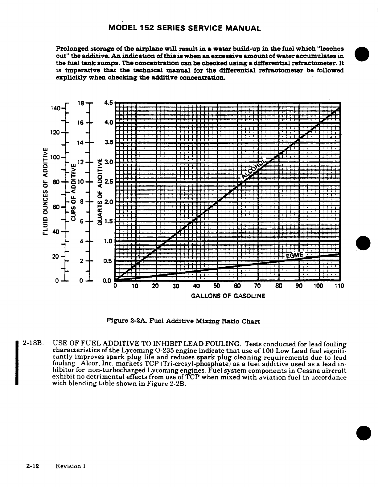
MODEL
152
SERIES
SERVICE
MANUAL
Prolonged
storage
of
the
airplane
will
result
in a
water
build-up
in
the
fuel
which
"leeches
out"
the
additive.
An
indication
of
this
is
when
an excessive
amount
of
water
accumulates
in
the
fuel
tank
sumps.
The
concentration
can
be
checked
using
a
differential
refractometer.
It
is
imperative
that
the
technical manual
for the
differential
refractometer
be
followed
explicitly
when
checking the additive
concentration.
18 4.5
140
0
10
20
30
40
50
60
70
80 90
100
110
characteristics
of
the
Lycoming
0-235
engine
indicate
that
use
of
100
Low
Lead
fuel
signifi-
cantly
improves
spark
plug
life
and reduces
spark
plug
cleaning
requirements
due
to
lead
fouling.
Alcor, Inc.
markets
TCP
(Tri-cresyl-phosphate)
as
a
fuel
additive
used as
a
lead
in-
hibitor
for
non-turbocharged
Lycoming
engines. Fuel
system
components
in
Cessna
aircraft
exhibit
no
detrimental
effects
from
use of
TCP
when
mixed
with
aviation
fuel
in
accordance
with
blending table
shown
in
Figure
2-2B.
2-12
Revision
1
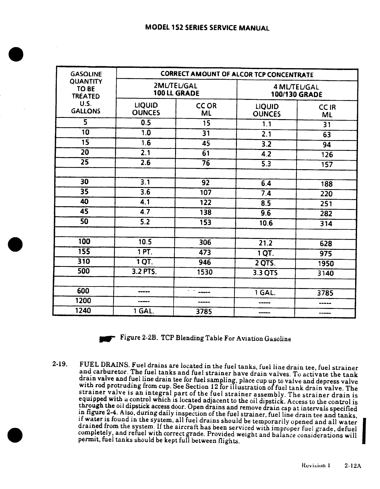
MODEL
152
SERIES
SERVICE
MANUAL
GASOLINE
CORRECT
AMOUNT
OF
ALCOR
TCP
CONCENTRATE
QUANTITY
2ML/TEL/GAL
4ML/TEL/GAL
TO
BE
TREATED
100
LL
GRADE
100/130
GRADE
TREATED
U.S.
LIQUID
CC
OR
LIQUID
CC
IR
GALLONS
OUNCES
ML
OUNCES
ML
5
0.5
15
1.1
31
10
1.0
31
2.1
63
15
1.6
45
3.2
94
20
2.1
61
4.2
126
25
2.6
76
5.3
157
30
3.1
92
6.4
188
35
3.6 107
7.4
220
40
4.1
122
8.5 251
45
4.7
138
9.6
282
50
5.2
153
10.6 314
100
10.5
306
21.2
628
155
1
PT.
473
1
QT.
975
310
1
QT.
946
2
QTS.
1950
500
3.2
PTS.
1530
3.3
QTS
3140
600
1
GAL.
3785
1200
1240
1
GAL.
3785
--
Figure
2-2B.
TCP
Blending
Table
For
Aviation
Gasoline
2-19.
FUEL
DRAINS.
Fuel
drains
are
located
in
the
fuel
tanks,
fuel
line
drain
tee,
fuel
strainer
and
carburetor.
The fuel
tanks
and
fuel
strainer
have
drain
valves.
To
activate
the
tank
drain
valve
and
fuel
line
drain
tee
for
fuel
sampling,
place
cup
up
to
valve
and
depress valve
with
rod
protruding
from
cup. See
Section
12
for
illustration
of
fuel
tank
drain
valve.
The
strainer
valve
is an
integral
part
of
the
fuel
strainer
assembly.
The
strainer
drain
is
equipped
with
a
control
which
is
located
adjacent
to
the
oil
dipstick.
Access
to
the
control
is
through the
oil
dipstick
access
door.
Open
drains
and
remove
drain
cap
at
intervals
specified
in
figure
2-4. Also,
during
daily inspection
of
the
fuel
strainer,
fuel
line
drain
tee
and
tanks,
if
water
is
found
in
the system,
all
fuel
drains
should
be
temporarily
opened
and
all
water
drained
from
the
system.
If
the
aircraft
has
been
serviced with
improper
fuel
grade,
defuel
completely,
and
refuel
with
correct
grade. Provided
weight
and
balance
considerations
will
permit,
fuel
tanks
should
be
kept
full
between
flights.
Revision
1
2-12A
MODEL
152
SERIES
SERVICE
MANUAL
NOTE
If
fuel
tank
quick-drains
are
not
installed,
at
least
one
quart
of
fuel
should
be
drained
from
the
fuel
strainer
with
the
selector valve
in
a
position
to
assure
each
tank
is
drain-
ing
fuel.
2-20.
CARBURETOR
DRAIN
PLUG
INSPECTION. In
order
to
prevent
the
possibility
of
thread
sealant
contamination
in
the
carburetor
float chamber.
cleaning
and
inspection
of
the
carburetor
should
be
accomplished
at
each
100-hour
inspection
and
anytime
water
in
the
fuel
is suspected.
a.
With
the
fuel
valve
OFF.
remove
carburetor
drain
plug
and
clean
off
any
sealant
present
on
the
end
of
the plug
or
in
the
threads
on the
plug.
b.
Inspect drain
plug
hole
in
the
carburetor
and
remove any
sealant
remaining
in
the
hole.
c.
Turn
fuel
valve
to
ON
to
flush float
chamber
and
drain
plug
chamber
while
probing
drain
plug
hole
to
ascertain
that all
residue
of
sealant
material
is
dislodged
and
washed
out
of
the
chamber.
Flushing
operation
should
last
15
to
30
seconds.
d.
A
second
flushing
should
then
be
accomplished
and the
drained fuel retained
for
inspection
to
ensure
that
no
sealant
particles
are
present
e.
Install
drain
plug
as
follows:
1.
Install
drain
plug
in
carburetor
1-1/2
to
2
turns.
2.
Apply
sealant
to
drain
plug
threads
(use
NS-40
(RAS-4)
or
equivalent).
3.
Tighten
and
safety
drain
plug.
f.
Turn
fuel
valve
ON
and
inspect
for
evidence
of
fuel
leakage.
2-128
Revision
I
MODEL
152
SERIES
SERVICE
MANUAL
2-20A.
CARBURETOR
HEAT
BUTTERFLY
SCREW
INSPECTION.
The
two
screws
attaching
the carburetor
heat
to
its
shaft
on
the
aircraft
listed
below
must
be
checked
for
(and
tight-
ened,
if
loose)
as
a
part
of
every 100-hour
or
annual
inspection.
a.
Affected
aircraft
serials numbers:
15279406
thru
15282096,
A1520735
thru
A1520810,
F15201429
thru
F15201638,
and
FA1520337
thru
FA1520351.
2-21.
ENGINE
OIL.
Check
engine
lubricating
oil
with
the
dipstick
five
to
ten
minutes
after
the
engine
has
been
stopped.
The
aircraft
should
be
in
as
near
a
level
position
as
possible
when
checking
the engine
oil,
that
a
true
reading
is
obtained. Engine
oil
should
be
drained
while
the
engine
is
still
hot, and
the
nose
of
the
aircraft
should
be
raised
slightly
for
more
positive
draining
of
any
sludge
which
may
have
collected
in
the
engine
oil
sump.
Engine
oil
should
be
changed
as
specified
in
servicing
intervals
figure
2-4.
Reduce
these
intervals
for
pro-
longed
operations
in
dusty areas,
in
cold
climates where
sludging
conditions
exist,
or
where
short
flights
and
long
idle
periods
are encountered.
Always change
oil
and
oil
filter
(or
clean
pressure
screen)
whenever
oil
appears
dirty
on
dipstick. Aviation
grade
oil
conforming
to
AVCO
Lycoming Service
Instruction
No.
1014,
and
any
revisions
or
supplements
thereto,
shall
be
used
in
the
"Blue
Streak"
(Lycoming)
engine.
NOTE
New
or
newly-overhauled
engines
should
be
operated
on
aviation
grade
straight
mineral
oil
until
the
first
oil
change.
If
an
ashless
dispersant
oil is
used
in
a
new
or
newly-overhauled engine,
high
oil
consumption may
be
ex-
perienced.
The
anti-friction
additives
in
detergent
and
dispersant
oils will
retard
"break-in"
of
the
pistons,
rings
and
cylinder
walls.
This
condition
can
be
avoided
by
the
use
of
straight
mineral
oil.
If
oil
must
be
added
during
the
first
25
hours,
us
only
aviation
grade
straight
mineral
oil
(non-
detergent)
conforming
to
MIL-L-6082.
After
the
first
25
hours
of
operation,
drain
engine
oil
sump
and clean
the
oil
pressure
screen.
If
an
external
oil
filter
is
installed,
change
the
oil
filter.
Refill
sump
with
straight
mineral
oil and
use
until
a
total
of
50
hours
have
accumulated
or
oil
consump-
tion
has
stabilized,
then
change
to
ashless
dispersant
oil.
NOTE
Engine
oil
contamination increases possibility
of
sticking
and/or
stuck
valves.
More
frequent
oil
and
filter
changes
(5l0-houri
will
minimize
accumulation
of
harmful
contami-
nants.
When
the
aircraft
cannot
be
flown
frequently,
the
oil
and
filter
should
be
changed
souner
than
50-hour
interval.
Change
oil
and
filter
every
25
hours
to
eliminate
moisture
and
acids
that
collect
in
oil
of
an inactive
engine.
NOTE
Phillips
X/C
II-Aviation
Multi-viscosity
oil
has not
been
ap-
proved
for
use
by
AVCO
Lycoming
and
should
not
be
used
in
Cessna
airplanes.
Revision
1
2-13
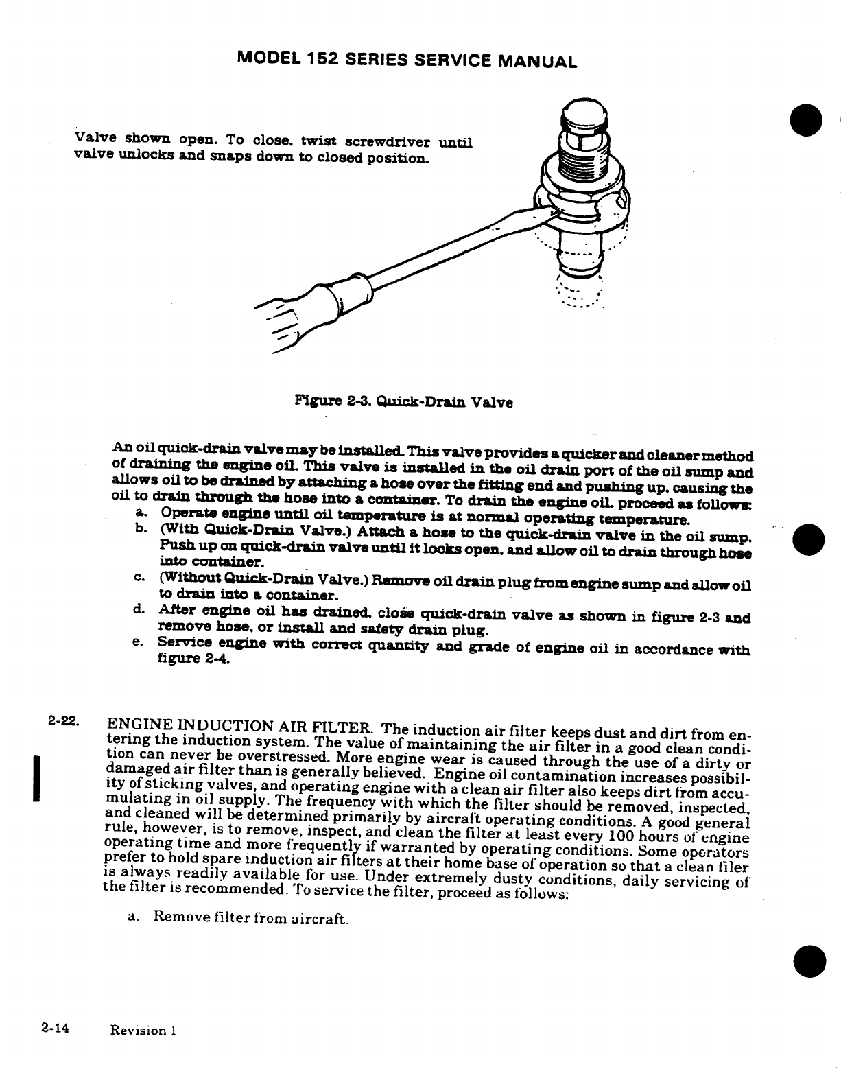
MODEL
152
SERIES
SERVICE
MANUAL
Valve shown
open.
To
close,
twist
screwdriver
until
valve
unlocks
and
snaps
down to
closed
position.
Figure
2-3.
Quick-Drain
Valve
An
oil
quick-drain
valve may
be
installed.
This
valve
provides
a
quicker
and
cleaner
method
of
draining
the
engine
oil
This
valve
is
installed
in
the
oil
drain
port
of
the
oil
sump
and
allows
oil
to
be
drained
by
attaching
a
hose
over
the
fitting
end
and
pushing
up.
causing
the
oil
to
drain
through
the
hose
into
a
container.
To
drain
the
engine
oil
proceed
as follow
a.
Operate
engine
until
oil
temperature
is
at
normal
operating
temperature.
b.
(With
Quick-Drain
Valve.)
Attach
a
hose
to
the
quick-drain
valve
in
the
oil
sump.
Push up
on
quick-drain valve
until
it
locks
open.
and
allow oil
to
drain
through
hose
into
container.
c.
(Without
Quick-Drain
Valve.)
Remove
oil
drain
plug
from
engine
sump
and
allow
oil
to
drain
into
a
container.
d.
After
engine
oil
has
drained.
close
quick-drain
valve
as
shown
in
figure
2-3
and
remove
hose,
or
install
and
safety
drain
plug.
e.
Service
engine
with
correct
quantity
and
grade
of
engine
oil in
accordance
with
figure
2-4.
2-22.
ENGINE
INDUCTION
AIR
FILTER.
The
induction
air
filter
keeps
dust
and
dirt
from
en-
tering
the
induction
system.
The
value
of
maintaining
the
air
filter
in
a
good
clean
condi-
tion can
never
be
overstressed.
More
engine
wear
is
caused
through
the
use
of
a
dirty
or
damaged
air
filter
than
is
generally
believed.
Engine
oil
contamination
increases
possibil-
ity
of
sticking
valves, and
operating
engine
with
a
clean
air
filter
also keeps
dirt
from
accu-
mulating
in
oil
supply.
The frequency
with
which
the
filter
should
be
removed,
inspected,
and
cleaned will
be
determined primarily
by
aircraft operating
conditions.
A
good
general
rule,
however,
is
to remove,
inspect,
and
clean
the
filter
at
least
every
100
hours
of
engine
operating
time
and
more
frequently
if
warranted
by
operating
conditions.
Some
operators
prefer
to
hold
spare
induction
air
filters
at
their
home
base
of
operation
so
that
a
clean
filer
is
always
readily
available
for
use.
Under
extremely
dusty conditions,
daily
servicing
of
the
filter
is
recommended.
To
service
the
filter,
proceed
as
follows:
a.
Remove
filter
from
aircraft.
2-14
Revision
1
MODEL
152
SERIES SERVICE
MANUAL
NOTE
Use
care
to
prevent
damage
to
filter
element
when
cleaning
filter
with
compressed
air.
b.
Clean
filter
by
blowing
with
compressed
air
(not
over
100
psi)
from
direction
opposite
of
normal
air
flow.
Arrows
on
filter
case
indicate
direction
of
normal
air
flow.
CAUTION
Do
not
use
solvent
or
cleaning
fluids
to
wash
filter. Use
only
a
water
and
household
detergent
solution
when
washing
the
filter.
c.
After
cleaning
as outlined
in
step
"b",
the
filter
may
be
washed,
if
necessary,
in a
solution
of
warm
water
and
a
mild household
detergent.
A
cold
water
solution may
be
used.
NOTE
The
filter
assembly
may
be
cleaned
with
compressed
air
a
maximum
of
30
times
or
it
may
be
washed
a
maximum
of
20
times.
A
new
filter
should
be
installed
after
500
hours
of
engine
operating
time
or
one
year,
whichever
should
occur
first.
However,
a
new
filter
should
be
installed
at
anytime
the
existing
filter
is
damaged.
A
damaged
filter
may
have
sharp
or
broken
edges
in
the
filtering
panels
which
would allow
unfiltered
air
to
enter
the induction
system.
Any
filter
that
appears
doubtful,
shall
have
a
new
filter
installed
in
its
place.
d.
After
washing,
rinse
filter
with
clear
water
until
rinse
water
draining
from
filter
is
clear.
Allow
water
to
drain
from
filter
and
dry
with
compressed
air
(not
over
100
psi).
NOTE
The
filtering
panels
of
the
filter may
become
distorted
when
wet,
but
they will return
to
their
original
shape
when dry.
e.
Be
sure
that
the
air
box
is
clean,
inspect
filter.
If
filter
is
damaged,
install
a
new
filter.
f.
Install
filter
at
entrance
to
air
box
with
gasket
on
aft
face
of
filter
frame
and
pointed
in
the
correct
direction.
2-15
MODEL
152
SERIES
SERVICE
MANUAL
2-23.
VACUUM
SYSTEM
FILTER.
The
vacuum
system
central
air
filter
keeps
dirt
and
dust
from
entering
the
vacuum
operated
instruments.
Inspect
filter
element
every
200
hours
of
operat-
ing
time
for
damage. Change
central
air
filter
element
every
500
hours
of
operating
time
and
whenever
it
becomes
sufficiently
clogged
to
cause
suction
gage
readings
to
drop
below
4.6
inches of
mercury.
Also,
do
not
operate
the
vacuum
system
with
the
filter
removed,
or
a
vacuum
line
disconnected
as
particles
of
dust or
other
foreign
matter
may
enter
the
system
and
damage
the
vacuum operated
instruments.
CAUTION
Excessive smoking
will
cause
premature
filter
clogging.
2-24.
BATTERY.
Servicing
the
24-volt
battery
involves
adding
distilled water
to
maintain
the
elec-
trolyte
level
no
higher
than
bottom
of
split
ring
indicator
and
no
lower
than
top
of
separators
(approximately
1/8-inch
below
split
ring)
within filler
holes,
checking the
battery
cable
con-
nections,
and
neutralizing
and
cleaning
spilled
electrolyte
or corrosion.
Use
bicarbonate
of
so-
da
(baking
soda)
and
water
to
neutralize
electrolyte
or
corrosion.
Follow
with
a
thorough
flushing
with
water.
Brighten
cables
and
terminals
with
a
wire
brush, then
coat
with
petro-
leum
jelly
before
connecting.
The
battery
box
also
should
be
checked
and
cleaned
if
any
corro-
sion
is noted.
Distilled
water, not
acid
or
"rejuvenators,"
should
be
used
to
maintain
electro-
lyte
level.
Check
the
battery
every
100
hours
(or
at
least
every
30
days), more
often
in
hot
weather.
See
Section
16
for
detailed
battery
removal,
installation,
and
testing
instructions.
2-25.
TIRES.
Maintain
tire
pressure
at
the
airpressures
specified
in
figure
1-1.
When
checking
tire
pressure,
examine
tires
for
wear. cuts.
bruises,
and
slippage.
Remove
oil
grease.
and
mud
from
tires
with
soap
and
water.
NOTE
Recommended
tire
pressures
should
be
maintained.
Especially
in
cold
weather.
remember
that
any
drop
in
temperature
of
the
air
inside
a
tire
causes
a
correspond-
ing
drop
in
air
pressure.
2-26.
NOSE
GEAR
SHOCK
STRUT.
The
nose
gear
shock
strut
requires
periodic
checking
to
ensure that
the
strut
is
filled
with
hydraulic
fluid and
is
inflated
to
the
correct
air
pressure.
To
service
the
nose
gear
shock
strut,
proceed
as
follows:
a.
Remove
valve
cap
and
release
all
air.
b.
Remove
valve
housing
assembly.
c.
Compress
strut
completely
(stops
in
contact
with
outer
barrel
hub).
d.
Oil
level.
(1)
Fluid
used
should comply
with
specification
MIL-H-5606.
(2)
Fill
strut
to
bottom
of
valve
installation
hole.
(3)
Maintain
oil
level
at
bottom
of
valve
installation
hole.
e.
Fully
extend
strut.
f.
Replace
valve
housing
assembly.
g.
With
strut
fully
extended
and
nose wheel
clear
of
ground,
inflate
strut
to
20
PSI.
2-16
Revision
I
MODEL
152
SERIES
SERVICE
MANUAL
NOTE
The
nose
landing
gear
shock
strut
will
normally
require
only
a
minimum
amount
of
service.
Maintain
the
strut
extension
pressure,
as
shown
in
figure
1-1.
Lubricate
landing
gear
as
shown
in
figure
2-5.
Check
landing
gear
daily
for
general
cleanliness,
security
of
mounting,
and
for
hydraulic
fluid
leakage.
Keep
machined
surfaces
wiped
free
of
dirt
and
dust,
using
a
clean lint-free
cloth
saturated
with
MIL-H-5606
hydraulic
fluid
or
kerosene.
All
surfaces
should
be
wiped
free
of
excessive
hydraulic
fluid.
2-27.
NOSE GEAR
SHIMMY
DAMPENER.
The
shimmy
dampener
should
be
serviced
at
least
every
50
hours.
The
shimmy
dampener
must
be
filled
completely
with
fluid,
free
of
entrapped
air,
to
serve
its
purpose.
To
service
the
shimmy
dampener,
proceed
as
follows:
a.
Remove
shimmy
dampener from
aircraft.
b.
While
holding
the
dampener
in a
vertical
position
with fitting
end
pointed
downward.
pull
fitting
end
of
the
dampener
shaft
to
its
limit
of
travel.
c.
While
holding
dampener
in
this
position, fill
dampener through
open
end
of
cylinder
with
hydraulic
fluid.
d.
Push
the
shaft
upward
slowly
to
seal
off
the
filler
hole.
e.
Clean
dampener
with
solvent.
Be
sure to
keep
the shaft
protruding
through
the
filler
hole
until
dampener
is
installed
on
the
aircraft.
f.
Install
dampener
on
aircraft.
NOTE
Keep
shimmy
dampener,
especially
the
exposed
portions
of
the
dampener
piston
shaft,
clean to
prevent
collection
of
dust
and
grit
which
could
cut
the
seals
in
the
dampener
barrel.
Keep
machined
surfaces wiped free
of
dirt
and
dust,
using
a
clean
lint-free
cloth
saturated
with
MIT-H-
5606
hydraulic
fluid
or
kerosene. All
surfaces
should
be
wiped
free
of
excessive
hydraulic fluid.
2-28.
HYDRAULIC
BRAKE
SYSTEM.
Check
brake
master
cylinders
and
refill with
hydraulic
fluid
as
specified
in
the
inspection charts.
Bleed
the
brake system
of
entrapped
airwhenever
there
is a
spongy
response
to
the
brake
pedals.
Refer
to
Section
5
for
filling
and
bleeding
of
the
brakes.
2-29.
CLEANING.
2-30.
Keeping
the
aircraft
clean
is
important.
Besides
maintaining
the
trim
appearance
of
the
aircraft,
cleaning
lessens
the
possiblity
of
corrosion
and
makes inspection
and
maintenance
easier.
2-17
MODEL
152
SERIES SERVICE
MANUAL
2-31.
CLEANING AND
CARE
OF
THE
WINDSHEILD
AND
WINDOW.
a.
General
Maintnanoe
Procedures.
The
following
procedures
provide
information
re-
garding
cleaning
and
servicing windshields
and
windows.
Improper
cleaning,
or
use
of
unapproved
cleaning
agents
can cause
damage
to
windshield
and
windows.
b.
Materials
Required:
NAME
MANUFACTURER
USE
Mild
soap
or
detergent
Commercially
available Cleaning
windshields
and
(hand
dishwashing
type)
windows.
Aliphatic
Naphtha
Type
II
Commercially available
Removing
deposits
which
conforming
to Federal
cannot
be
removed
with
Specification
TT-N-95
mild
soap
solution.
Polishing
wax:
S.C.
Johnson and
Son,
Inc.
Waxing acrylic
wind-
(Refer
to
Note
1)
shields
and
windows.
Turtle
Wax
(paste)
Turtle
Wax,
Inc.
Chicago,
IL
60638
Great
Reflections
El.
duPont
deNemours
Paste
Wax
and
Co.
(Inc)
Wilmington,
DE
19898
Slip-stream
Wax
Classic
Chemical
(paste) Grand
Prairie,
TX
75050
Acrylic
polish
conforming
Permatex
Company,
Inc.
Cleaning
and
polishing
to
Federal
Specification
Kansas
City,
KS
66115
acrylic
windshields and
P-P-560
such
as:
windows.
Permatex plastic
cleaner
Number
403D
Soft
cloth,
such
as:
Commercially
available
Applying
and removing
wax
Cotton
flannel
or
old
and
polish.
tee
shirt
material
c.
Cleaning
Instructions.
CAUTION
Windshields
and
windows
(Acrylic
Faced)
are
easily
dam-
aged
by
improper
handling
and
cleaning
techniques.
1.
Place
airplane
inside
hangar
or
in
shaded
area
and
allow
to cool
from
heat
of
sun's
direct
rays.
2.
Using
clean
(preferably
running)
water,
flood
the
surface.
Use
bare
hands
with
no
jewelry
to feel
and
dislodge
any
dirt
or
abrasive
materials.
3.
Using
a
mild
soap or
detergent
(such
as
a
dishwashing
liquid)
in
water,
wash
the
surface.
Again
use
only
the
bare
hand
to provide
rubbing
force.
(A
clean
cloth
may
be
used
to
transfer
the
soap
solution
to
the
surface,
but
extreme
care
must
be
exercised
to
prevent
scratching
the
surface.)
2-18

MODEL 152
SERIES
SERVICE
MANUAL
4.
On
acrylic
windshields
and
windows only,
if
soils
which
cannot
be
removed
by
a
mild
detergent
remain,
Type
II
aliphatic
naphtha
applied
with
a
soft
clean
cloth
may
be
used
as
a
cleaning
solvent.
Be
sure
to
frequently
refold
cloth
to
avoid
rede-
positing
soil
and/or
scratching
windshield
with
any
abrasive particles.
5.
Rinse surface
thoroughly
with
clean
fresh
water
and
dry
with
a
clean
cloth.
Do
not
rub
plastic
with
a
dry
cloth
as
this
builds
up
an
electrostatic charge
which
at-
tracts
dust.
CAUTION
Do
not
use
any
of
the
following
on
or
for
cleaning
wind-
shields
and
windows:
methanol,
denatured
alcohol,
gaso-
line,
benzene,
xylene,
MEK,
acetone,
carbon
tetrachloride,
fire
extinguisher
fluid,
de-icer
fluid,
lac-
quer
thinners,
commercial
or
household
glass
window
cleaning
sprays.
6.
Hard
polishing
wax
should
be
applied
to
acrylic
surfaces.
(The
wax
has
an
index
of
refraction
nearly
the
same
as
transparent
acrylic
and
will
tend
to
mask
any
shallow
scratches
on
the windshield
surface).
7.
Acrylic
surfaces
may
be
polished
using
a
polish
meeting
Federal
Specification
P-
P-560
applied
per
the
manufacturer's
instructions.
NOTE
When
applying and
removing
wax
and
polish,
use
a
clean
soft
cloth
such
as
well
worn
tee
shirt
material
or
cotton
flannel
8.
DO
NOT
USE
rain
repellent
on
acrylic
surfaces.
d.
Windshield
and
Window
Preventive
Maintenance.
NOTE
Utilization
of
the
following
techniques
will
help
minimize
windshield
and
window
crazing.
1.
Keep
all surfaces
of
windshields
and
windows clean.
2.
If
desired,
wax acrylic
surfaces.
3.
Do
not
park
or
store
airplane
where
it
might
be
subjected
to
direct
contact
with
or
vapors
from:
methanol,
denatured
alcohol,
gasoline,
benzene,
xylene,
MEK.
acetone,
carbon
tetrachloride,
lacquer
thinners,
commercial or
household
window
cleaning
sprays,
paint
strippers,
or other
types
of
solvents.
4.
Do
not
use
solar screens
or
shields installed
on
inside
of
airplane
or
leave
sun
vis-
ors
up
against
windshield.
The
reflected
heat
from these
items causes
elevated
temperatures
which
accelerate
crazing
and
may
cause
formation
of
bubbles
in
the
inner
ply
of
multiple
ply
windshields.
5.
Do
not
use
a
canvas
cover
on
the windshield
or
windows
unless
freezing
rain
or
sleet
is
anticipated
since
the
cover
may
scratch
the
plastic
surface.
Revision
I
2-18A
MODEL
152
SERIES
SERVICE
MANUAL
2-32.
PLASTIC
TRIM.
The
instrument
panel,
plastic
trim,
and
control
knobs
need
only.
be
wiped
with
a
damp
cloth.
Oil
and
grease
on
the
control
wheel
and
control knobs
can
be
removed
with
a
cloth
moistened
with
Stoddard
solvent.
Volatile
solvents,
such
as
mentioned
in
paragraph
2-32,
must
never
be
used since
they
soften
and
craze the
plastic.
2-33.
PAINTED
SURFACES.The
painted exterior
surfaces
of
your
new
Cessna
have
a
durable,
long
lasting
finish
Approximately
10
days
are
required
for
the
paint
to
cure
completely;
in
most
cases,
the
curing
period
will have
been
completed
prior
to
delivery
of
the
airplane.
In
the
event
that
polishing
or
buying
is
required within
the
curing
period,
it is
recommended
that
the
work
be
done
by
someone
experienced
in
handling
uncured
paint.
Any
Cessna
Dealer
can
accomplish
this
work.
Generally,
the
painted
surfaces
can
be
kept
bright
by
washing
with
water
and
mild
soap,
fol-
lowed by
a
rinse
with
water
and
drying
with
cloths
or
a
chamois.
Harsh
or
abrasive
soaps
or
detergents
which
cause
corrosion
or
scratches
should never
be
used.
Remove
stubborn
oil
and
grease
with
a
cloth
moistened
with
Stoddard
solvent.
To
seal
any
minor
surface chips or
scratches
and
protect
against
corrosion,
the
airplane
should
be
waxed
regularly
with
a
good
automotive
wax
applied
in
accordance
with
the
man-
ufacturer's
instructions.
If
the
airplane
is
operated
in a
seacoast or
other
salt water
environ-
ment,
it
must
be
washed
and
waxed more
frequently
to
assure
adequate
protection
Special
care should
be
taken
to
seal
around
rivet
heads
and
skin
laps,
which
are
the
areas
most
sus-
ceptible
to
corrosion.
A
heavier
coating of
wax
on
the
leading
edges
of
the wings
and tail
and
on
the
cowl
nose cap
and
propeller
spinner
will
help
reduce
the
abrasion
encountered
in
these
areas.
Reapplication
of wax
will
generally
be
necessary
after
cleaning
with
soap
solu-
tions
or
after
chemical
de-icing
operations.
2-34. ALUMINUM
SURFACES.
The
aluminum
surfaces
require
a
minimum
of
care,
but
should
never
be
neglected.
The
aircraft
may
be
washed
with
clean
water
to
remove
dirt
and may
be
washed
with
nonalkaline
grease
solvents
to
remove
oil
and/or
grease.
Household
type
detergent
soap
powders
are
effective
cleaners,
but
should
be
used
cautiously since
some
of
them
are
strongly
alkaline.
Many
good
aluminum
cleaners,
polishes
and
waxes
are
available
from
commercial
suppliers
of
aircraft
products.
2-18B
MODEL
152
SERIES SERVICE
MANUAL
2-35 ENGINE
AND ENGINE
CO
ARTMENT.
An
engine
and
accessories
wash-down
should
be
accomplished
during
each
100-hour
inspection
to
remove
oil,
grease,
salt corrosion
or
other
residue
that
might
conceal
component
defects
during
inspction.
Also,
periodic
cleaning
can
be
very
effective
in
preventive
mantenance.
Precautions
should
be
taken
when
working
with
cleaning
agents
such
as
wearing
of
rubber
gloves,
an
apron
or
coveralls
and
a
face
shield
or
goggles.
Use
the
least
toxic
of available
cleaning
agents
that
will
satisfactorily
accomplish
the
work.
These
cleaning
agents
include:
(1)
Stoddard
Solvent
(Specification
P-D-680
type
II
(2)
A
water
alkaline
detergent
cleaner
(MILC-25769J)
mixed,
1
part
cleaner,
2
to
3
parts
water
and
8
to
12
parts
Stoddard
solvent
or
(3)
A
solvent
base
emulsion
cleaner
(MIL-C-4361B)
mixed
1
part
cleaner
and
3
parts
Stod-
dard
solvent.
CAUTION
Do
not
use
gasoline
or
other
highly
flammable
sub-
stances
for
wash
down.
Perform
all
cleaning
operations
in
well
ventilated
work
areas
and
ensure
that
adequate
fire-
fighting
and
safety
equipment
is
available.
Do
not
smoke
or
expose
a
flame,
within
100
feet
of
the
cleaning
area
Compressed
air,
used
for
cleanig agent,
application
or
drying
,
should
be
regulated
to
the
lowest
practical
pressure.
Use
of
a
stiff bristle
brush
rather than
a
steel
brush
is
recommended
if
cleaning
agents
do
not
remove
excess grease
and
grime
during
spraying.
A
recommended procedure
for
cleaning
an
engine
and
accessories
is
as
follows:
CAUTION
Do
not
attempt
to
wash
an
engine
which
is
still
hot
or
running.
Allow
the
engine
to
cool
before
cleaning
a
Remove
engine
cowling.
b.
Carefully
cover
the
coupling
area
between
the
vacuum
pump
and the engine
drive
shaft
so
that
no cleaning
solvent
can
reach
the
coupling
or
seal
c.
Cover
the
open
end
of
the
vacuum
discharge
tube.
d.
Cover
the
vacuum
relief
valve
filter,
if
installed
in
the
engine
compartment.
e.
Use
fresh water
for
wash-down
when
the engine
is
contaminated
with
salt
or
cor-
rosive
chemicals.
A
cleaning
agent
such
as
described
previously
may
then
be
used
to
remove
oil
and
grime.
CAUTION
Care
should
be
exercised
to
not
direct
cleaning
agents
or
water
streams
at
openings
on
the
starter,
magnetos,
al-
ternator
or
vacuum
pump.
f.
Thoroughly
rinse
with
clean
warm
water
to
remove
all
traces
of
cleaning
agents.
2-19
MODEL
152
SERIES
SERVICE
MANUAL
CAUTION
Cleaning
agents
should
never
be
left
on engine
compo-
nants
for an
extended period
of
time.
Failure
to
remove
them
may
cause
damage
to
components such
as
neoprene
seals
and
silicone
fire
sleeves,
and
could
cause
additional
corrosion.
g.
Completely
dry engine
and
accessories
using
clean
dry
compressed
air.
h.
Remove
the
cover
over
the
coupling
area.
i.
Remove
the
cover
from
the
vacuum
discharge
tube.
j.
Remove
the
cover
from
the
vacuum
relief
valve
filter,
if
installed.
k.
If
desired,
engine
cowling
may
be
washed
with the
same
cleaning
agents,
then
rinsed thoroughly
and
wiped
dry.
After
cleaning
engine,
relubricate
all
control
arms and
moving
parts
as
required.
L
Reinstall
engine
cowling.
WARNING
For
maximum
safety,
check
that
the
magneto
switches
are
OFF,
the
throttle
is
closed.
the
mixture
control
is
in
the
idle
cut-off
position
and
the airplane
is
secured
be
fore
rotating
the
propeller
by
hand.
Do
not
stand
within
the
arc
of
the
propeller
blades
while
turning
the
propel-
lar.
m.
Before
starting
engine, rotate
the propeller
by
hand
no
less
thanfour
complete
revolution.
CAUTION
Particular
care
should
be
given
to
electrical
equipment
be-
fore
cleaning.
Solvent
should
not
be
allowed
to
enter
magne-
tos,
starter,
alternator,
voltage
regulator,
and
the
like.
Hence,
these components
should
be
protected
before
saturat-
ing
the
en
gine
with
solvent.
Any
fuel,
oil,
and
air
openings
should
be
covered
before
washing
the
e
ngine
with
solvent.
Caustic
cleaning
solutions
should
not
be
used.
After
clean-
ing
engine,
relubricate
all
control
arms
and
moving
parts.
2-35A. VALVES AND
VALVE
GUIDES.
Operating
with
any
of
the
following
conditions
present
can
promote
deposit build-up
reducing
valve
guide
clearance
and
resulting
in valve
stick-
ing:
a.
Contaminated,
dirty
engine
oil
supply.
b.
High
ambient temperatures.
c.
Slow
flight
with
reduced
cooling.
d.
High
lead
content
of
fuel.
If
any
of
the
above
is
present
or
valve
hesitation
or
engine
missing
is
observed,
then
inspec-
tion
and
cleaning
is
recommended.
Field
experience
has
shown
that
valve
guide
cleaning
is
beneficial
for
reducing
valve
sticking
when
accomplished
every
500
to
1000
hours,
depend-
ing
on
individual
engine
operating
conditions.
(Refer
to
Lycoming
Service
Instruction
1425
for
suggested
maintenance
procedures).
2-20
Revision
1
MODEL
152
SERIES SERVICE
MANUAL
2-36.
UPHOLSTERY AND
INTERIOR.
Keeping the
upholstery
and
interior
trim
clean
prolongs
upholstery
fabric and
interior
trim
life.
To
clean
the
interior,
proceed
as
follows
a.
Empty
all
ash
trays
and
refuse
containers.
b.
Brush
or
vacuum
clean
the
upholstery
and
carpet
to
remove
dust
and
dirt.
c.
Wipe
leather
and
plastic
trim
with
a
damp
cloth.
d.
Soiled
upholstery
fabrics
and
carpet may
be
cleaned
with
a
foam-type
detergent
used
according
to
manufacturer's
instructions.
e.
Oil
spots
and
stains
may
be
cleaned
with
household spot removers, used
sparingly.
Before
using
any
solvent,
read
the
instructions
on
the
container
and
test
it
on
an
obscure
place
in
the
fabric
to
be
cleaned.
Never
saturate
the
fabric
with
volatile
solvent:
it
may
damage
the
padding
and
backing
material.
NOTE
Repair kits are available
for
the
repair
of
cracks
in
ABS,
PBC,
PVCP,
graphite
and
fiberglass
material.
(Contact
a
Cessna
Service
Station
for
information
or to
order.
2-37.
PROPELLER.
Wash
hub
and
blade
with
a
soft
cloth
and
Stoddard
cleaning
solvent
or
equivalent,
then
dry
thoroughly
with
compressed
air.
The
propeller
should
be
wiped
occasionally
with
an
oily cloth,
then
wiped
with
a
dry
cloth.
In
salt
water
areas
this
will
assist
in
corrosion
proofing
the propeller.
2-38.
WHEELS.
The
wheels should
be
washed periodically
and
examined
for
corrosion,
chipped
paint,
and
cracks
or
dents
in
the
wheel
halves
or
in
the
flanges
or hubs.
If
defects
are
found.
remove
and
repair
in
accordance
with
Section
5.
Discard
cracked
wheel
halves,
flanges
or
hubs
and
install
new
parts.
2-39.
LUBRICATION.
2-40.
Lubrication
requirements
are
shown
in
figure
2-5.
Before
adding
grease
to
grease
fittings.
wipe
dirt from
fitting.
Lubricate
until
grease
appears
around
parts
being
lubricated.
and
wipe
excess
grease
from
parts.
The
following
paragraphs
supplement
figure
2-5
by
adding
details.
Revision
1
2-21
MODEL
152
SERIES
SERVICE
MANUAL
2-41.
TACHOMETER
DRIVE
SHAFT.
Refer
to
Section
15.
2-42.
WHEEL
BEARINGS.
Clean
and
repack
the
wheel
bearings
at
the
first
100-hour
inspection
and
at
each
500-hour
inspection thereafter.
If
more
than
the
usual
number
of
takeoffs
and
landings
are
made,
extensive
taxiing
is
required,
or
the
aircraft
is
operated
in
dusty
areas
or
under seacoast
conditions,
cleaning
and
lubrication
of
the wheel
bearings
shall
be
accomp-
lished
at
each
100-hour
inspection.
2-43.
NOSE
GEAR
TORQUE
LINKS.
Lubricate
nose gear
torque
links
every
50
hours.
When
operating
in
dusty
conditions,
more
frequent
lubrication
is
required.
2-44.
WING
FLAP
ACTUATOR.
Clean
and
lubricate
wing
flap
actuator
jack
screw
each
100
hours
as
follows:
a.
Expose
jack
screw
by
operating
flaps
to
full
down
position.
b.
Clean
jack
screw
threads
with
solvent
rag
and
dry
with
compressed
air.
NOTE
It is
not
necessary
to
remove
actuator
from
aircraft
to
clean
or
lubricate
threads.
c.
With
oil can,
apply
light
coat
of
No.
10
weight
nondetergent
oil-to
threads
of
jack
screw.
2-45.
ROD
END
BEARINGS.
Periodic
inspection
and
lubrication
is
required
to
prevent
corrosion
of
the
bearing
in
the
rod
end.
At
each
100-hour
inspection,
disconnect
the control
rods
at
the
aileron
flap
and
nose
gear
steering
tubes.
and
inspect
each rod
end
for
corrosion.
If
no
corrosion
is
found,
wipe
the
surface
of
the
rod end
balls
with
general purpose oil
and
rotate
ball
freely to
distribute the
oil
over
its
entire
surface
and
connect
the
control
rods
to
their
respective
units.
If
corrosion
is
detected
during the
inspection,
install
new
rod
ends.
2-22
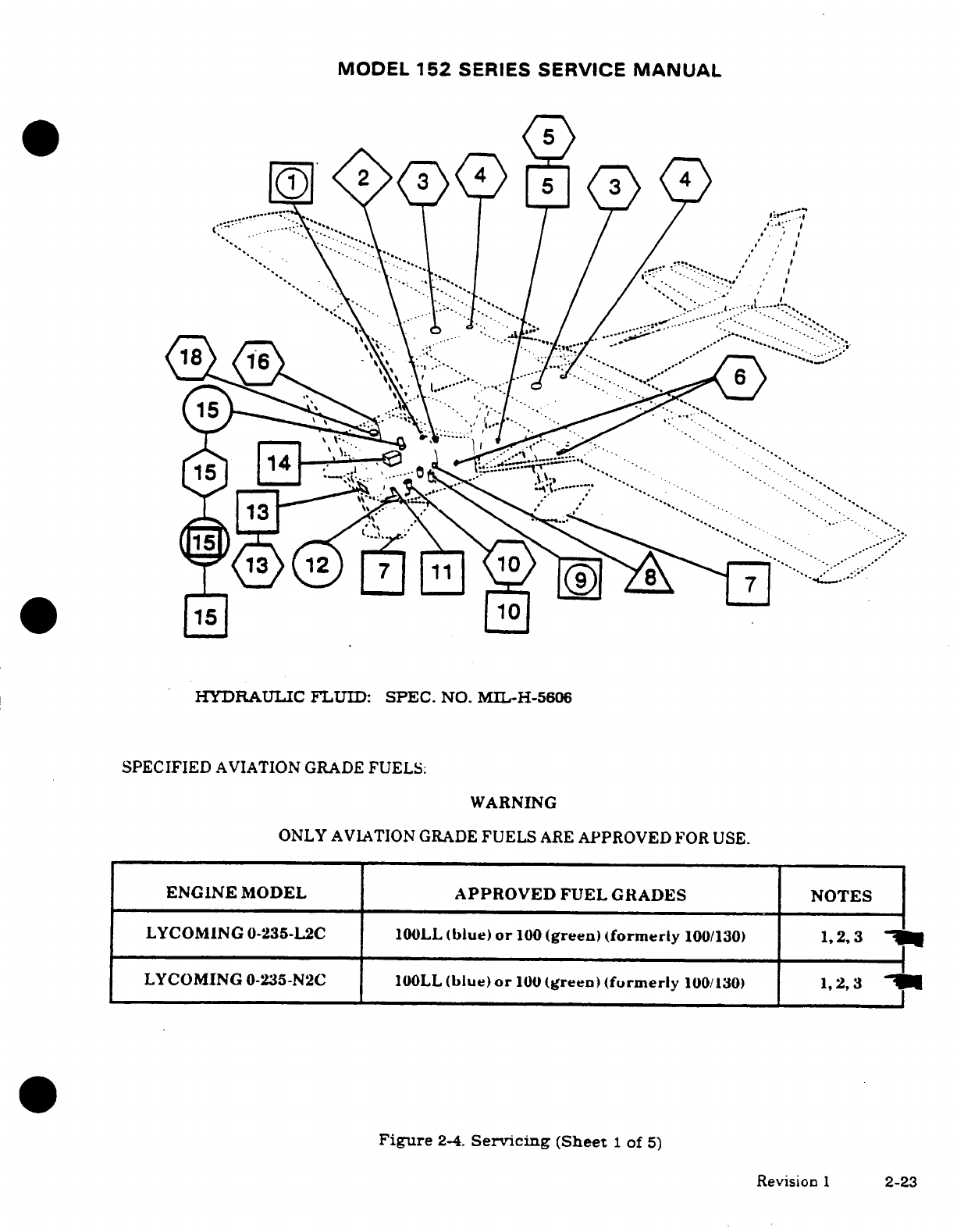
MODEL
152
SERIES
SERVICE
MANUAL
HYDRAULIC FLUID:
SPEC.
NO.
MIL-H-5606
SPECIFIED
AVIATION
GRADE
FUELS:
WARNING
ONLY
AVIATION
GRADE
FUELS
ARE
APPROVED
FOR
USE.
ENGINE
MODEL
APPROVED
FUEL GRADES
NOTES
LYCOMING
0-235-L2C
100LL
(blue)
or
100
(green)
(formerly
100/130)
1,
2,
3
LYCOMING
0-235-N2C
100LL
(blue)
or
100
(green)
(formerly
100/130)
1,
2,3
Figure
2-4.
Servicing
(Sheet
1
of
5)
Revision
1
2-23
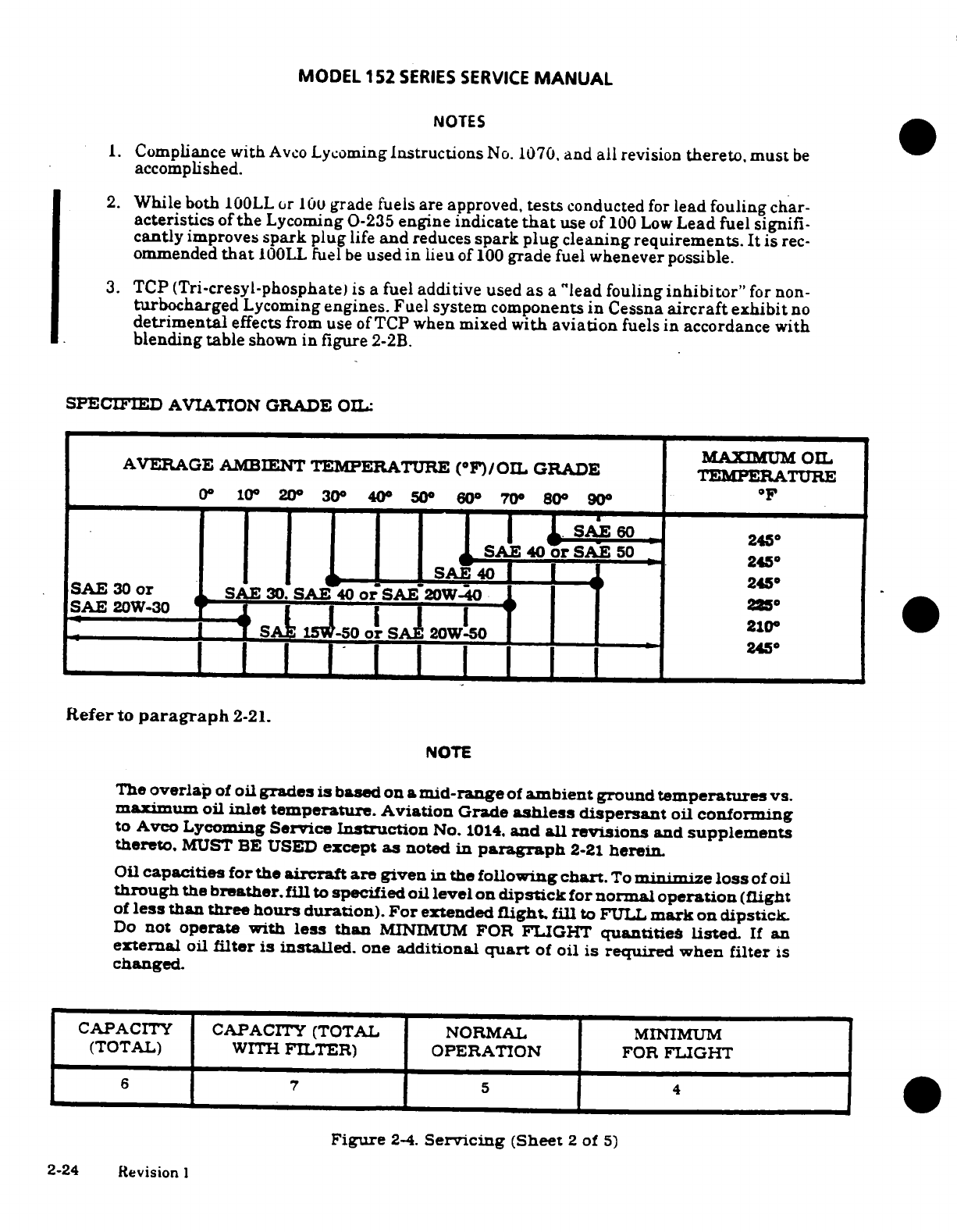
MODEL
152
SERIES
SERVICE
MANUAL
NOTES
1.
Compliance
with
Avco
Lycoming
Instructions
No. 1070,
and
all
revision
thereto,
must
be
accomplished.
2.
While
both
100LL
or
100
grade
fuels
are approved,
tests
conducted
for
lead
fouling
char-
acteristics
of
the
Lycoming
0-235
engine
indicate
that
use
of
100
Low
Lead
fuel
signifi-
cantly
improves
spark
plug
life
and
reduces
spark
plug
cleaning
requirements.
It
is
rec-
ommended
that
100LL
fuel
be
used
in
lieu
of
100
grade
fuel
whenever
possible.
3.
TCP
(Tri-cresyl-phosphate)
is
a
fuel
additive
used
as
a
"lead
fouling
inhibitor"
for
non-
turbocharged
Lycoming
engines.
Fuel
system
components
in
Cessna
aircraft
exhibit
no
detrimental
effects
from
use
of
TCP when
mixed
with
aviation
fuels
in
accordance
with
blending
table
shown
in
figure
2-2B.
SPECIFIED
AVIATION
GRADE
OIL:
MAXIMUM
OIL
AVERAGE
AMBIENT
TEMPERATURE
(°F)/OIL
GRADE
TEMPERATURE
0°
10°
20
°
30°
40
°
50
°
60
°
70
°
80
°
90°
SAE
60
145
SAE
40
or
SAE
50
245
SAE
40
245
SAE
30
or
SAE
30.
SAE
40
o
SAE
W-40
.
15-50
or
SAI
20W-50
245
Refer
to
paragraph
2-21.
NOTE
The
overlap
of
oil
grades
is
based
on
a
mid-range
of
ambient
ground
temperatures
vs.
maximum
oil
inlet
temperature.
Aviation
Grade
ashless
dispersant
oil
conforming
to
Avco
Lycoming
Service
Instruction
No.
1014.
and
all
revisions
and
supplements
thereto.
MUST
BE
USED
except
as
noted
in
paragraph
2-21
herein.
Oil
capacities
for
the
aircraft
are
given
in
the
following
chart.
To
minimi
e
loss
of
oil
through
the
breather.
fill
to
specified
oil level
on
dipstick
for
normal
operation
(flight
of
less
than
three
hours
duration).
For
extended
flight,
fill
to
FULL
mark
on
dipstick.
Do
not
operate
with
less
than
MINIMUM
FOR
FLIGHT
quantities
listed.
If
an
external
oil
filter
is
installed,
one
additional
quart
of
oil
is required
when
filter
is
changed.
CAPACITY
CAPACITY
(TOTAL NORMAL
MINIMUM
(TOTAL)
WITH
FILTER) OPERATION
FOR
FLIGHT
6
7
5
5 4
Figure
2-4.
Servicing
(Sheet
2
of
5)
2-24 Revision
I
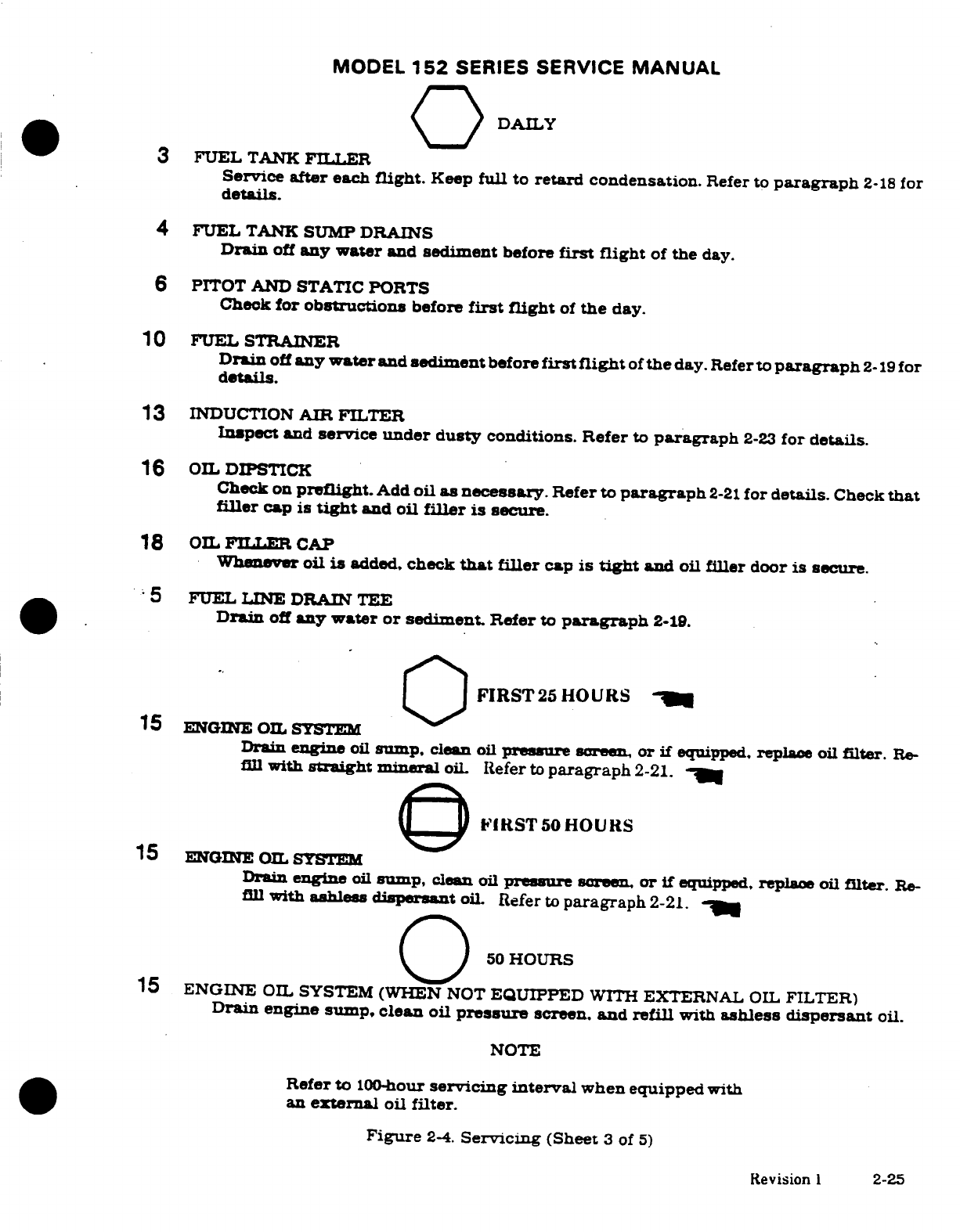
MODEL
152
SERIES
SERVICE
MANUAL
DAILY
0
3
FUEL
TANK
FILLER
Service
after
each
flight.
Keep
full
to
retard condensation.
Refer
to
paragraph
2-18
for
details.
4
FUEL
TANK
SUMP
DRAINS
Drain
off
any
water
and
sediment
before
first
flight
of
the
day.
6
PITOT
AND
STATIC PORTS
Check
for
obstructions
before
first
flight
of
the
day.
10
FUEL STRAINER
Drain
off
any
water
and
sediment
before
first
flight
of
the
day.
Refer
to
paragraph
2-19
for
details.
13
INDUCTION
AIR FILTER
Inspect
and
service
under dusty
conditions.
Refer
to
paragraph
2-23
for
details.
16
OIL
DIPSTICK
Check
on
preflight.
Add
oil as
necessary.
Refer
to
paragraph
2-21
for
details.
Check
that
filler
cap
is
tight
and
oil
filler
is
secure.
18
OIL
FILLER
CAP
Whenever
oil
is
added,
check
that
filler
cap
is
tight
and
oil
filler
door
is
secure.
5
FUEL
LINE
DRAIN
TEE
Drain
off
any water
or
sediment.
Refer
to
paragraph
2-19.
FIRST
25
HOURS
15
ENGINE
OIL
SYSTEM
Drain
engine
oil
sump,
clean
oil
pressure
screen,
or
if
equipped.
replace
oil
filter.
Re-
fill
with
straight
mineral
oil
Refer
to
paragraph
2-21.
IRST50
HOURS
15
ENGINE
OIL
SYSTEM
Drain
engine
oil
sump,
clean
oil
pressure
screen,
or
if
equipped,
replace
oil
filter.
Re-
fill
with
ashles
disperant
oil.
Refer
to
paragraph
2-21.
50
HOURS
15
ENGINE
OIL
SYSTEM
(WHEN
NOT
EQUIPPED
WITH
EXTERNAL
OIL
FILTER)
Drain
engine
sump, clean
oil
pressure
screen,
and
refill
with
ashless
dispersant
oil.
NOTE
Refer
to
100-hour
servicing interval
when
equipped
with
an
external
oil filter.
Figure
2-4.
Servicing
(Sheet
3
of
5)
Revision
1
2-25
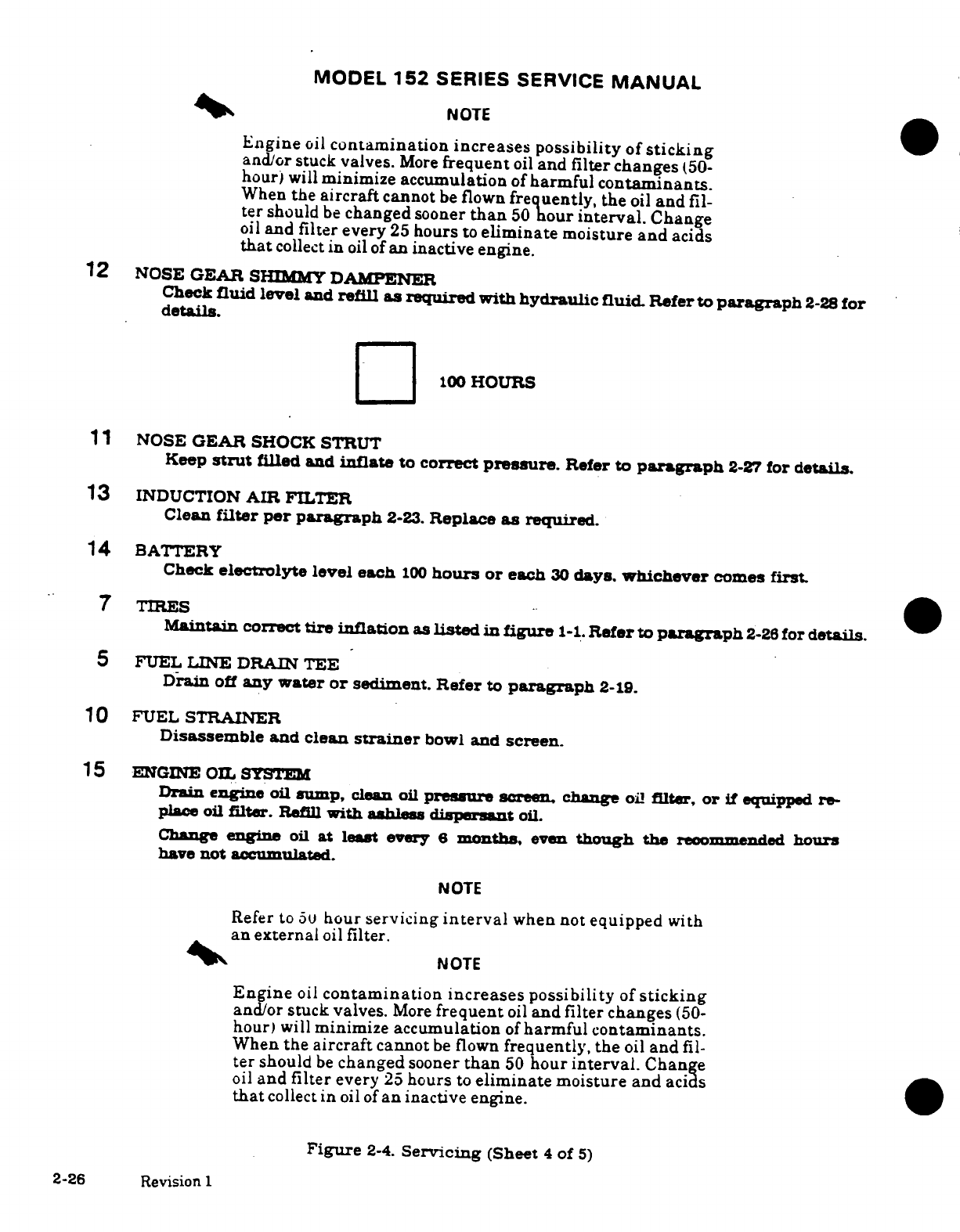
MODEL
152
SERIES
SERVICE
MANUAL
NOTE
Engine
oil
contamination
increases
possibility
of
sticking
and/or
stuck
valves.
More
frequent
oil
and
filter changes
(50-
hour)
will
minimize accumulation
of
harmful
contaminants.
When
the
aircraft
cannot
be
flown
frequently,
the
oil
and
fil-
ter
should
be
changed
sooner
than
50
hour
interval.
Change
oil
and
filter
every
25
hours
to
eliminate
moisture
and
acids
that
collect
in
oil
of
an
inactive engine.
12
NOSE
GEAR
SHIMMY
DAMPENER
Check
fluid
level
and
refill
as
required with
hydraulic
fluid.
Refer
to
paragraph
2-28
for
details.
100
HOURS
11
NOSE
GEAR
SHOCK
STRUT
Keep
strut
filled
and
inflate
to
correct
pressure.
Refer
to
paragraph
2-27
for
details.
13
INDUCTION
AIR
FILTER
Clean
filter per
paragraph
2-23.
Replace
as
required.
14
BATTERY
Check
electrolyte
level
each
100
hours
or
each
30
days.
whichever
comes
first.
7
TIRES
Maintain
correct
tire
inflation
as
listed
in figure
1-1.
Refer
to
paragraph
2-26
for
details.
5
FUEL
LINE DRAIN
TEE
Drain
off
any
water
or
sediment.
Refer
to
paragraph
2-19.
10
FUEL
STRAINER
Disassemble
and
clean
strainer
bowl
and
screen.
15
ENGINE
OIL
SYSTEM
Drain
engine
oil
sump,
clean
oil
pressure
screen.
change
oil
filter,
or
if
equipped
re-
place
oil
filter.
Refill
with ashless
dispersant
oil.
Change
engine
oil
at
least
every
6
months,
even
though
the
recommended
hours
have
not
accumulated.
NOTE
Refer
to
50
hour
servicing
interval
when
not
equipped
with
an
external
oil
filter.
NOTE
Engine
oil
contamination
increases possibility
of
sticking
and/or
stuck
valves.
More
frequent
oil
and filter changes
(50-
hour)
will
minimize
accumulation
of
harmful contaminants.
When
the
aircraft
cannot
be
flown
frequently, the
oil
and
fil-
ter
should
be
changed
sooner
than
50
hour
interval.
Change
oil
and
filter
every
25
hours
to
eliminate
moisture
and
acids
that
collect
in
oil
of
an
inactive
engine.
Figure
2-4.
Servicing
(Sheet
4
of
5)
2-26
Revision
1
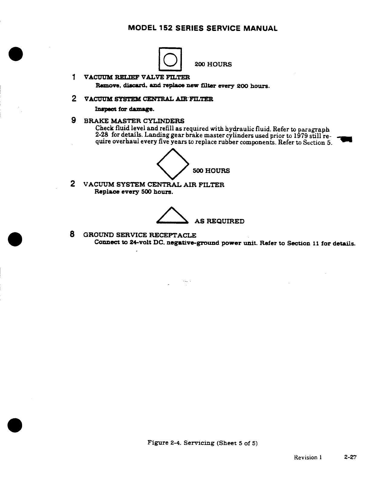
MODEL
152
SERIES
SERVICE
MANUAL
200
HOURS
VACUUM
RELIEF
VALVE
FILTER
Remove,
discard
and
replace
new
filter
every
200
hours.
2
VACUUM
SYSTEM
CENTRAL
AIR
FILTER
Inspect
for
damage.
9
BRAKE
MASTER
CYLINDERS
Check
fluid
level
and
refill
as
required
with
hydraulic
fluid.
Refer
to
paragraph
2-28
for
details. Landing
gear
brake
master
cylinders
used
prior
to
1979
still
re-
quire
overhaul
every
five
years
to
replace
rubber
components.
Refer
to
Section
5.
500
HOURS
2
VACUUM
SYSTEM
CENTRAL
AIR FILTER
Replace
every
500
hours.
AS
REQUIRED
GROUND
SERVICE
RECEPTACLE
Connect
to 24-volt
DC.
negative-ground
power
unit.
Refer
to
Section
11
for
details.
Figure
2-4.
Servicing
(Sheet
5
of
5)
Revision
1
2-27
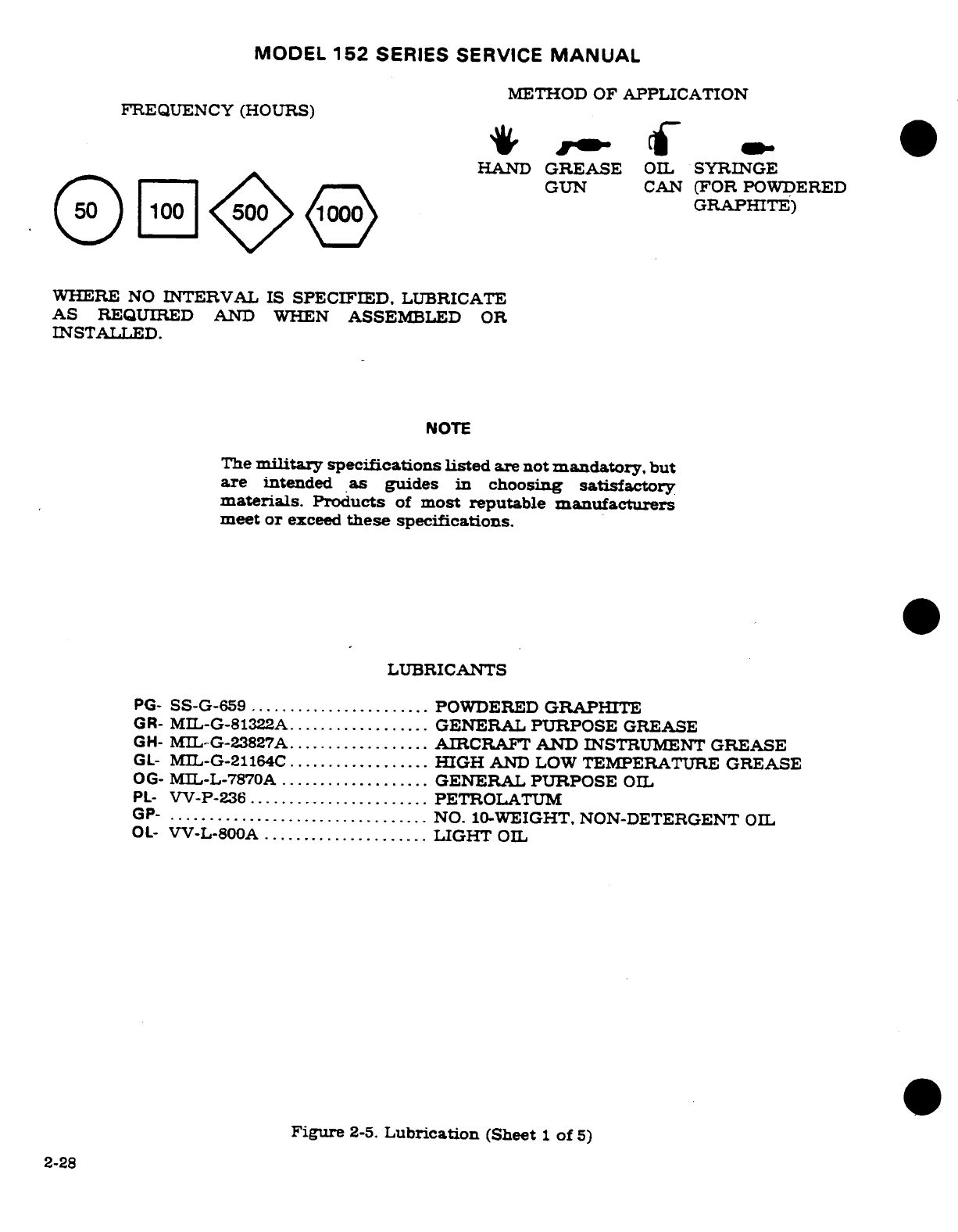
MODEL
152
SERIES
SERVICE
MANUAL
METHOD
OF
APPLICATION
FREQUENCY
(HOURS)
HAND
GREASE
OIL
SYRINGE
GUN
CAN
(FOR
POWDERED
GRAPHITE)
WHERE
NO
INTERVAL
IS
SPECIFIED,
LUBRICATE
AS
REQUIRED AND
WHEN
ASSEMBLED
OR
INSTALLED.
NOTE
The
military
specifications
listed
are
not
mandatory.
but
are
intended
as
guides
in
choosing
satisfactory
materials.
Products
of
most reputable
manufacturers
meet or
exceed
these
specifications.
LUBRICANTS
PG-
SS-G-659
.......................
POWDERED
GRAPHITE
GR-
MIL-G-81322A
.................
GENERAL
PURPOSE
GREASE
GH-
MIL-G-23827A
.................
AIRCRAFT AND
INSTRUMENT
GREASE
GL-
MIL-G-21164C
..................
HIGH
AND
LOW
TEMPERATURE
GREASE
OG-
MIL-L-7870A
...................
GENERAL
PURPOSE
OIL
PL-
VV-P-236
.......................
PETROLATUM
GP-
...............................
NO.
10-WEIGHT.
NON-DETERGENT
OIL
OL-
VV-L-800A
.....................
LIGHT
OIL
Figure
2-5.
Lubrication
(Sheet
1
of
5)
2-28
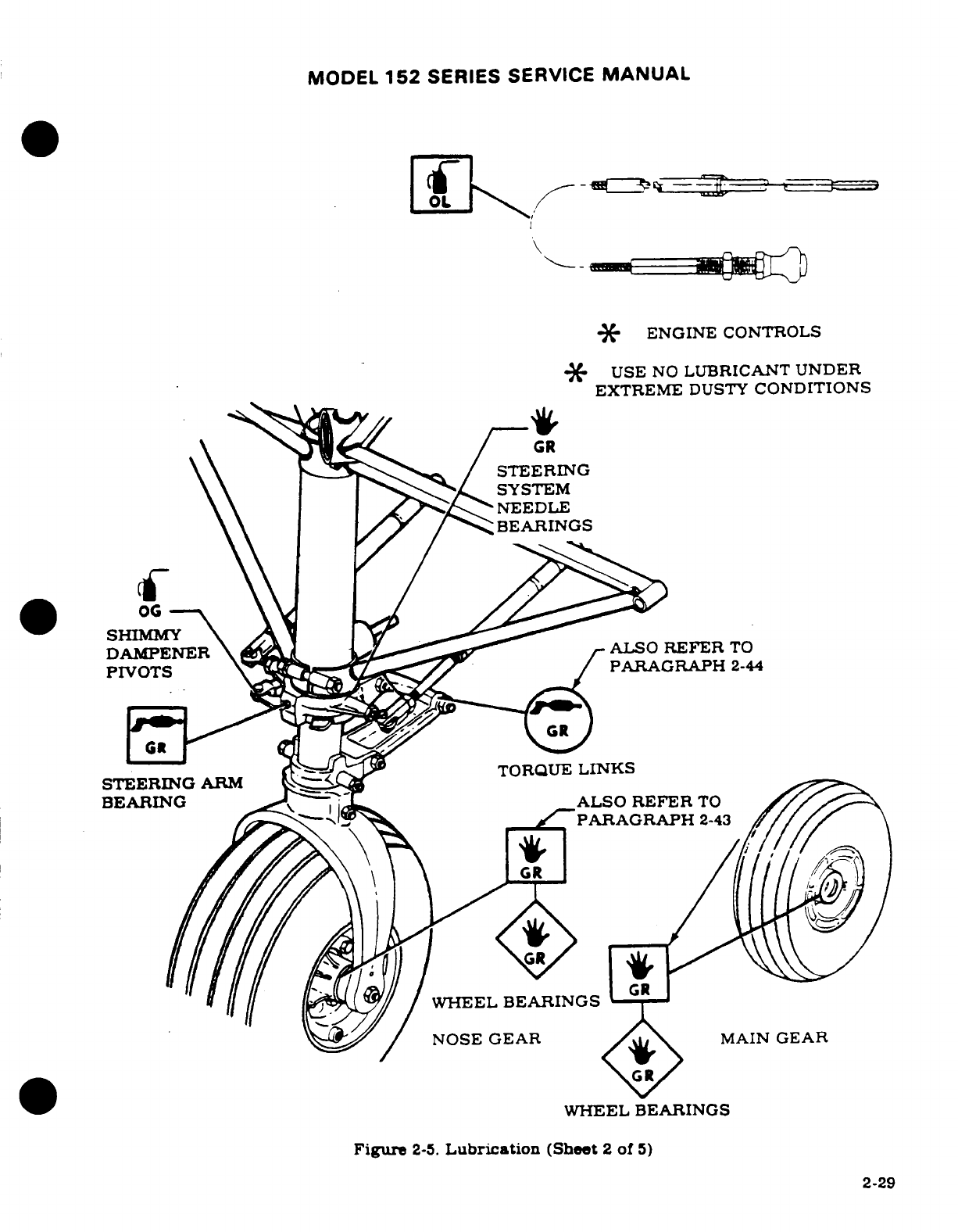
MODEL
152
SERIES
SERVICE
MANUAL
\
ENGINE
CONTROLS
*
USE
NO
LUBRICANT
UNDER
EXTREME
DUSTY
CONDITIONS
STEERING
SYSTEM
NEEDLE
BEARINGS
DAMPENEtR
AL
S O R E F E R T O
PIVOTS
PARAGRAPH
2-44
TORQUE
LINKS
STEERING
ARM
BEARING ALSO
REFER
TO
PARAGRAPH
2-43
WHEEL
BEARINGS
NOSE
GEAR
MAIN
GEAR
WHEEL
BEARINGS
Figure
2-5.
Lubrication
(Sheet
2
of
5)
2-29
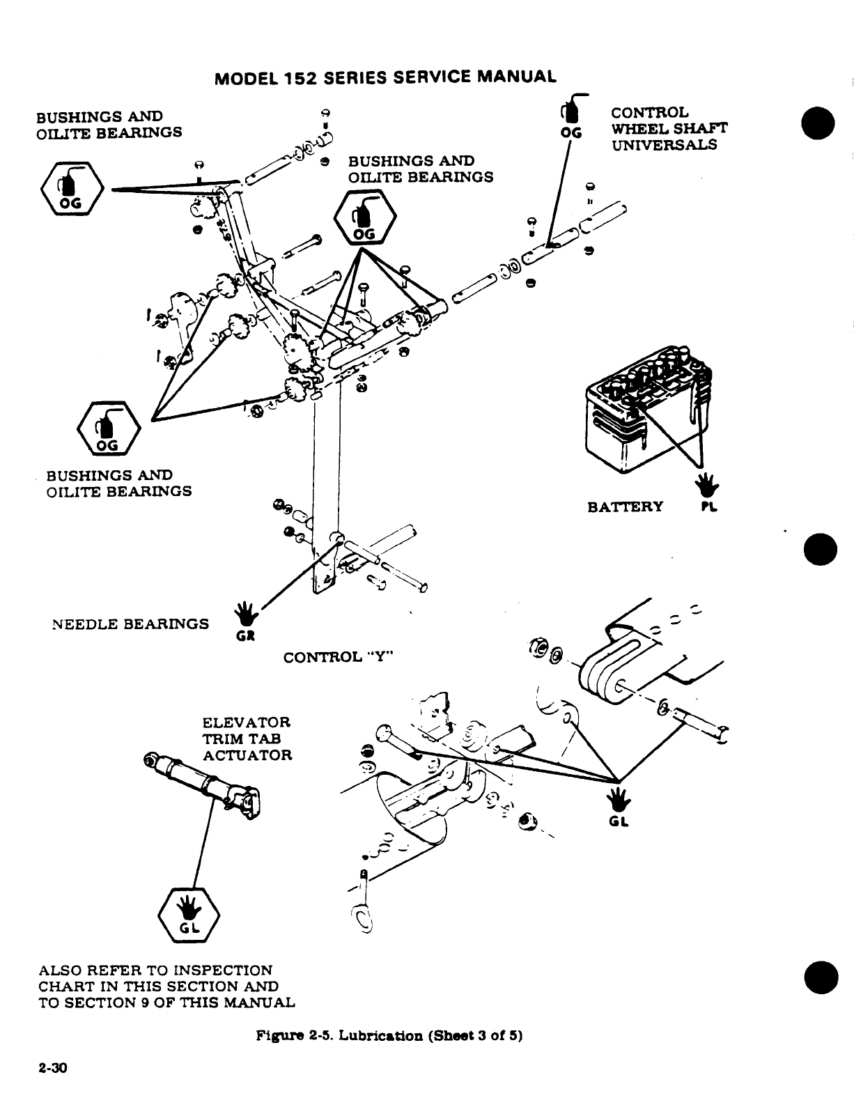
MODEL
152
SERIES
SERVICE
MANUAL
BUSHINGS
AND
CONTROL
OILITE
BEARINGS
WHEEL SHAFT
UNIVERSALS
BUSHINGS
AND
OILITE
BEARINGS
BUSHINGS
AND
OILITE
BEARINGS
4
BATTERY
NEEDLE BEARINGS
CONTROL
"Y"
ELEVATOR.
TRIM
TAB
ACTUATOR
ALSO
REFER
TO
INSPECTION
CHART
IN
THIS
SECTION
AND
TO
SECTION
9
OF
THIS
MANUAL
Figure
2-5.
Lubrication
(Sheet
3
of
5)
2-30
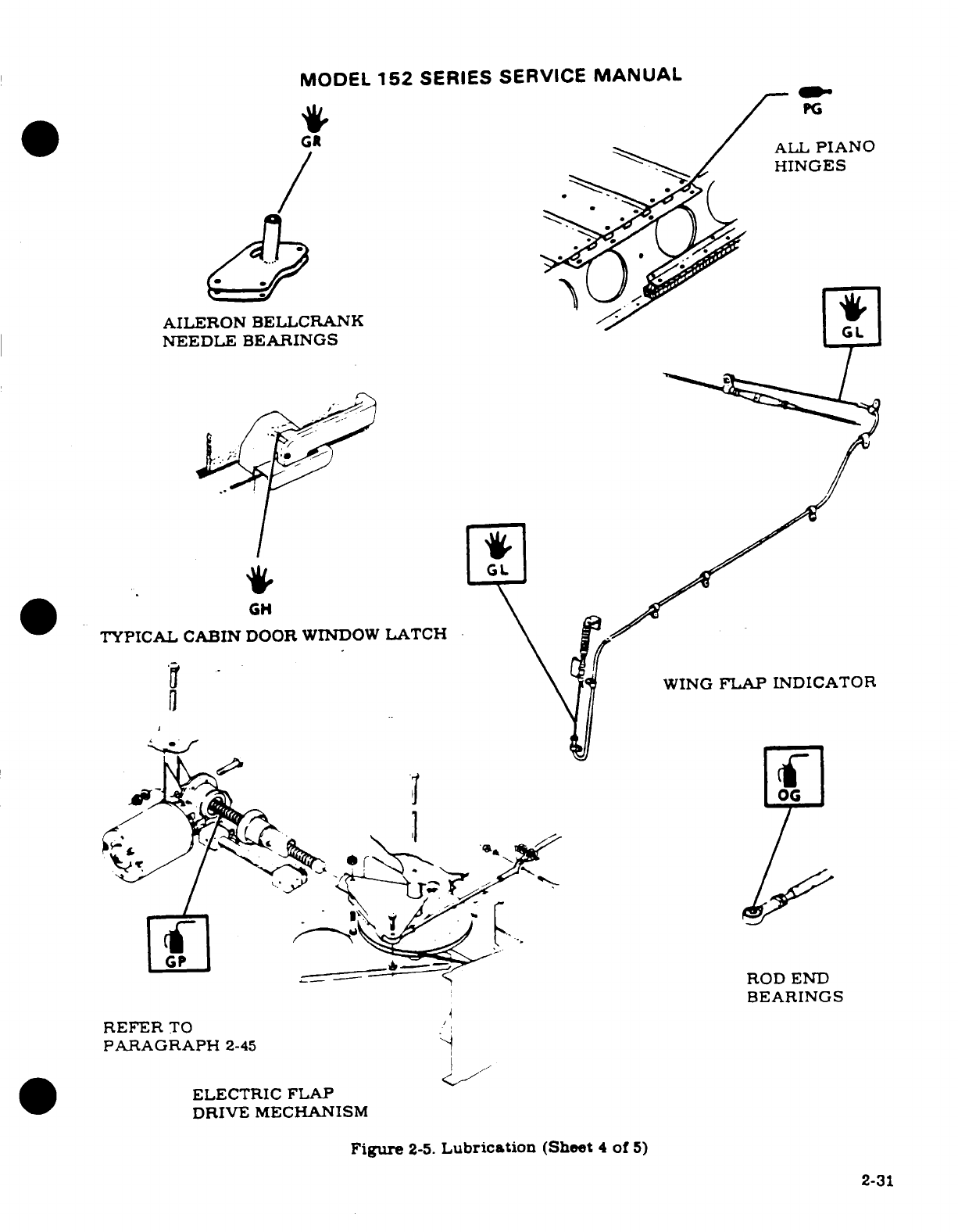
MODEL
152
SERIES SERVICE
MANUAL
PG
ALL
PIANO
HINGES
AILERON
BELLCRANK
NEEDLE BEARINGS
GL
GL
TYPICAL CABIN
DOOR
WINDOW
LATCH
WING
FLAP
INDICATOR
ROD
END
BEARINGS
PARAGRAPH
2-45
ELECTRIC
FLAP
DRIVE MECHANISM
Figure
2-5.
Lubrication
(Sheet
4
of
5)
2-31
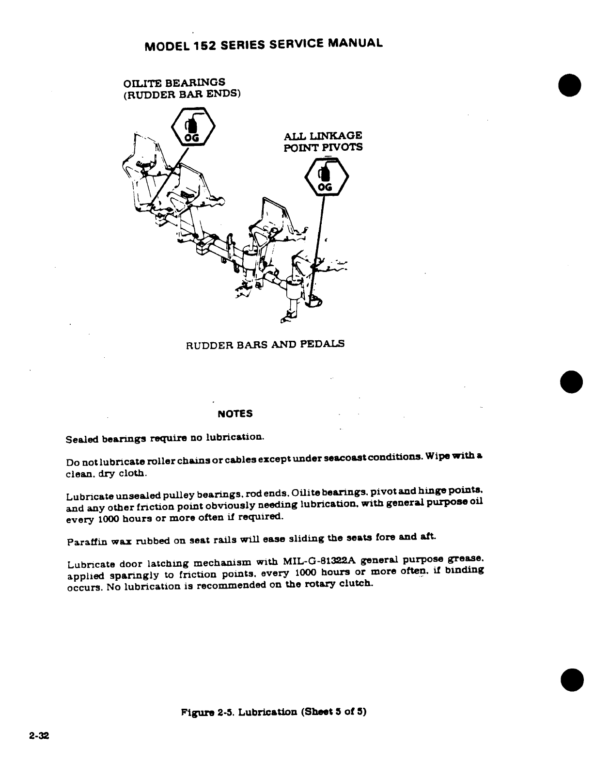
MODEL
152
SERIES
SERVICE
MANUAL
OILITE BEARINGS
(RUDDER
BAR
ENDS)
RUDDER
BARS
AND
PEDALS
NOTES
Sealed
bearings
require
no
lubrication.
Do
not
lubricate
roller
chains
or
cables
except
under
seacoast conditions.
Wipe
with
a
clean. dry
cloth.
Lubricate
unsealed
pulley
bearings.
rod
ends.
Oilite
bearings.
pivot
and
hinge
points.
and any
other
friction
point
obviously
needing
lubrication, with
general
purpose
oil
every
1000
hours
or
more
often
if
required.
Paraffin
wax
rubbed
on
seat
rails
will
ease
sliding
the
seats
fore
and
aft.
Lubricate door
latching
mechanism
with
MIL-G-81322A
general
purpose
grease,
applied
sparingly
to
friction
points.
every
1000
hours
or
more
often,
if
binding
occurs.
No
lubrication
is
recommended
on
the
rotary
clutch.
Figure
2-5.
Lubrication
(Sheet
5
of
5)
2-32
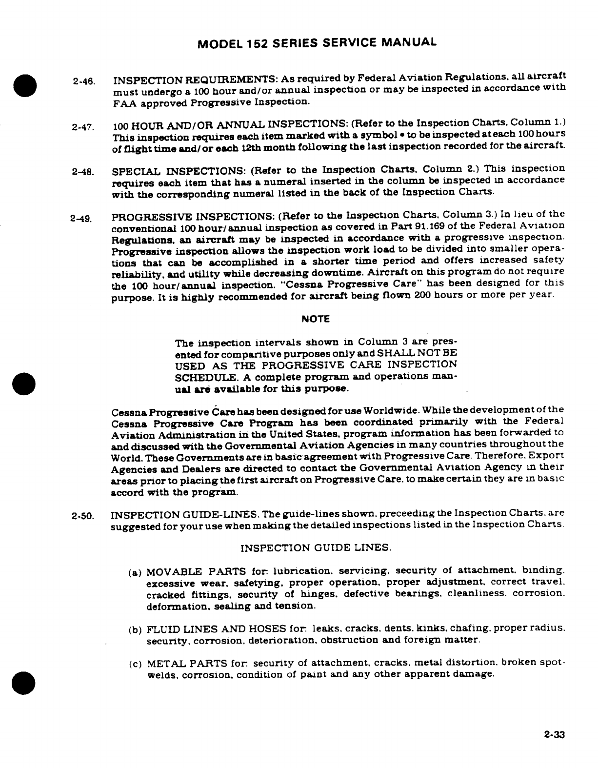
MODEL
152
SERIES SERVICE
MANUAL
2-46.
INSPECTION
REQUIREMENTS:
As
required
by
Federal
Aviation
Regulations.
all
aircraft
must
undergo
a
100
hour
and/or
annual
inspection
or may
be
inspected
in
accordance
with
FAA
approved
Progressive
Inspection.
2-47.
100
HOUR
AND/OR
ANNUAL
INSPECTIONS:
(Refer
to
the
Inspection Charts.
Column
1.)
This
inspection
requires
each
item
marked
with
a
symbol
*
to
be
inspected
at
each
100
hours
of
flight
time
and/
or
each
12th
month
following
the
last
inspection
recorded
for
the
aircraft.
2-48.
SPECIAL INSPECTIONS:
(Refer
to
the
Inspection Charts,
Column
2.)
This
inspection
requires
each
item
that
has
a
numeral
inserted
in
the
column
be
inspected
in
accordance
with
the
corresponding
numeral
listed
in
the
back
of
the
Inspection Charts.
2-49.
PROGRESSIVE
INSPECTIONS:
(Refer
to
the
Inspection
Charts.
Column
3.)
In
lieu
of
the
conventional
100
hour/annual
inspection
as
covered
in
Part
91.169
of
the Federal
Aviation
Regulations,
an
aircraft
may
be
inspected
in
accordance
with
a
progressive
inspection.
Progressive inspection
allows
the
inspection
work
load
to
be
divided
into
smaller
opera-
tions that
can
be
accomplished
in a
shorter
time period
and
offers
increased
safety
reliability,
and
utility
while
decreasing
downtime.
Aircraft
on
this
program
do
not
require
the
100
hour/annual
inspection.
"Cessna
Progressive
Care"
has
been
designed
for
this
purpose.
It
is
highly
recommended
for
aircraft
being
flown
200
hours
or
more
per
year
NOTE
The
inspection
intervals
shown
in
Column
3
are
pres-
ented
for
comparitive
purposes
only
and
SHALL
NOT
BE
USED
AS
THE
PROGRESSIVE
CARE
INSPECTION
SCHEDULE.
A
complete
program
and
operations
man-
ual
are
available
for
this
purpose.
Cessna
Progressive
Care
has
been
designed
for
use
Worldwide.
While
the
development
of
the
Cessna
Progressive
Care
Program
has
been
coordinated
primarily
with
the
Federal
Aviation
Administration
in
the
United
States,
program
information
has
been
forwarded
to
and
discussed
with
the
Governmental
Aviation
Agencies
in
many
countries throughout
the
World.
These
Governments
are
in
basic
agreement with
Progressive
Care.
Therefore.
Export
Agencies
and
Dealers
are
directed to
contact
the
Governmental
Aviation
Agency
in
their
areas
prior
to
placing
the
first
aircraft
on
Progressive
Care.
to
make
certain
they
are
in
basic
accord
with
the
program.
2-50.
INSPECTION
GUIDE-LINES.
The
guide-lines
shown.
preceeding
the
Inspection
Charts.
are
suggested
for
your use
when
making
the
detailed
inspections
listed
in
the
Inspection
Charts.
INSPECTION
GUIDE
LINES.
(a)
MOVABLE
PARTS
for:
lubrication,
servicing.
security
of
attachment.
binding.
excessive wear.
safetying.
proper
operation,
proper
adjustment,
correct
travel.
cracked
fittings.
security
of
hinges.
defective
bearings,
cleanliness.
corrosion.
deformation,
sealing
and
tension.
(b)
FLUID
LINES
AND
HOSES
for
leaks.
cracks,
dents.
kinks.
chafing.
proper
radius.
security.
corrosion, deterioration,
obstruction
and
foreign
matter.
(c)
METAL
PARTS
for
security
of
attachment,
cracks.
metal
distortion. broken
spot-
welds,
corrosion,
condition
of
paint
and any
other
apparent
damage.
2-33
MODEL
152
SERIES
SERVICE
MANUAL
(d)
WIRING
for
security.
chafing,
burning,
defective
insulation.
loose or
broken
terminals,
heat
deterioration
and
corroded
terminals.
(e)
BOLTS
IN
CRITICAL
AREAS
for:
correct
torque
in
accordance with
torque
values
given
in
the
chart
in
Section
1.
when
installed
or when
visual
inspection
indicates
the
need
for
a
torque
check.
(f)
FILTERS.
SCREENS
&
FLUIDS
for
cleanlines,
contamination
and/or
replace-
ment
at
specified
intervals.
(g)
AIRCRAFT
FILE.
Miscellaneous
data,
information
and
licenses
are
a
part
of
the
aircraft
file.
Check
that
the
following
documents are
up-to-date
and
in
accordance with
current
Federal
Aviation
Regulations.
Most
of
the
items
listed are
required
by
the United
States
Federal Aviation
Regulations.
Since
the
regulations
of
other
nations
may
require
other
documents
and
data,
owners
of
exported
aircraft
should
check
with their
own
aviation
officials
to
determine
their
individual
requirements.
To
be
displayed
in
the
aircraft
at
all
times:
1.
Aircraft
Airworthiness
Certificate
(FAA
Form
8100-2).
2.
Aircraft
Registration
Certificate
(FAA
Form
8050-3).
3.
Aircraft
Radio
Station
License.
if
transmitter
is
installed
(FCC
Form
556).
To
be
carried
in
the
aircraft
at
all
times:
1.
Weight
and
Balance,
and
associated
papers
(Latest
copy
of
the
Repair
and
Alteration
Form.
FAA
Form
337.
if
applicable).
2.
Aircraft
Equipment
List.
3.
Pilot's
Operating
Handbook.
To
be
made
available
upon
request:
1.
Aircraft
Log
Book
and
Engine
Log
Book.
2-34
MODEL
152
SERIES
SERVICE
MANUAL
(h)
ENGINE
RUN-UP.
Before
beginning
the
step-by-step
inspection,
start,
runup
and
shut
down
the
engine
in
accordance
with
instructions
in
the
Pilot's
Operating
Handbook
During
the
run-
up
observe
the
following,
making
note
of
any
discrepancies
or
abnormalities:
1.
Engine
temperatures
and
pressures
2.
Static
RPM.
(Alo
refer
to
Section
11
of
this
manual.)
3.
Magneto
drop.
Also
refr
to
Section
11
of
this
manual.)
4.
Engine
response
to
changes
in
power.
5.
Any
unusual
engine
noises.
.
Fuel
shutoff
valve;
oprate
engine
long
enough
to
ensure
shutoff
valve
functions
properly.
7.
Idling
speed
and
mixture
proper
idle
cut-off.
8.
Alternator
and
ammeter.
9.
Suction
gage.
After
the
inspection
has
been
completed.
an
engine run-up
should
again
be
per-
formed
to
determine
that
any discrepancie
or
abnormalities
have
been
corrected.
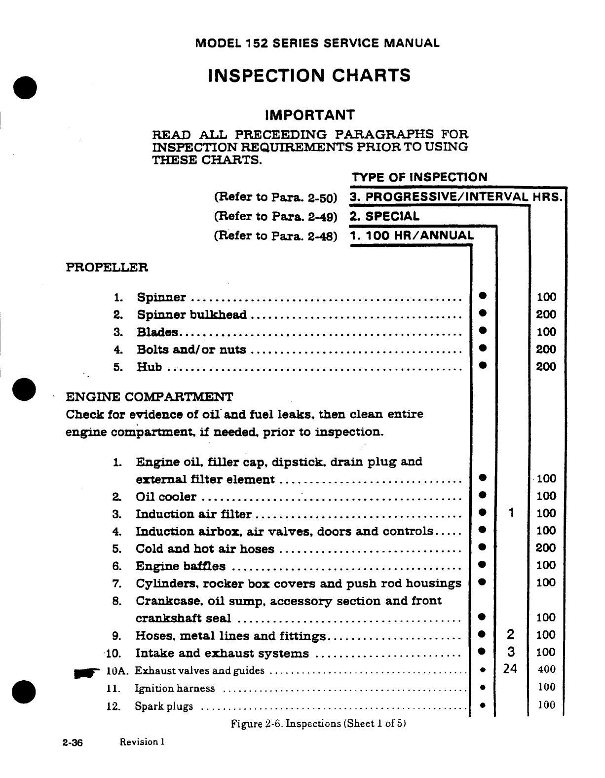
MODEL
152
SERIES
SERVICE
MANUAL
INSPECTION
CHARTS
IMPORTANT
READ
ALL
PRECEEDING PARAGRAPHS
FOR
INSPECTION
REQUIREMENTS
PRIOR
TO
USING
THESE
CHARTS.
TYPE
OF
INSPECTION
(Refer
to
Para.
2-50)
3.
PROGRESSIVE/INTERVAL
HRS.
(Refer
to
Para.
2-49)
2.
SPECIAL
(Refer
to
Para.
2-48)
1.
100
HR/ANNUAL
PROPELLER
1.
Spinner
..............................................
100
2.
Spinner
bulkhead
....................................
200
3.
Blades................................................
100
4.
Bolts
and/or
nuts
....................................
200
5.
H
ub
..................................................
200
ENGINE
COMPARTMENT
Check
for evidence
of
oil
and
fuel
leaks,
then
clean
entire
engine
compartment,
if
needed,
prior
to
inspection.
1.
Engine
oil,
filler
cap,
dipstick,
drain
plug
and
external
filter
element
..............................
100
2.
Oil
cooler
..........
..........................
100
3.
Induction
air
filter
................................... 1
100
4.
Induction
airbox,
air
valves,
doors
and
controls....
100
5.
Cold
and
hot
air
hoses
...............................
200
6.
Engine
baffles
.......................................
100
7.
Cylinders,
rocker
box
covers
and
push
rod
housings
*
100
8.
Crankcase,
oil
sump,
accessory
section
and
front
crankshaft
seal
......................................
100
9.
Hoses,
metal
lines
and
fittings
.......................
2
100
10.
Intake
and
exhaust systems
.........................
3
100
10A.
Exhaust
valves
and
guides
......................................
*
24
400
11.
Ignitionharness
...............................................
00
12.
Spark
plugs
...................................................
100
Figure
2-6.
Inspections
(Sheet
1
of
5)
2-36
Revision
1
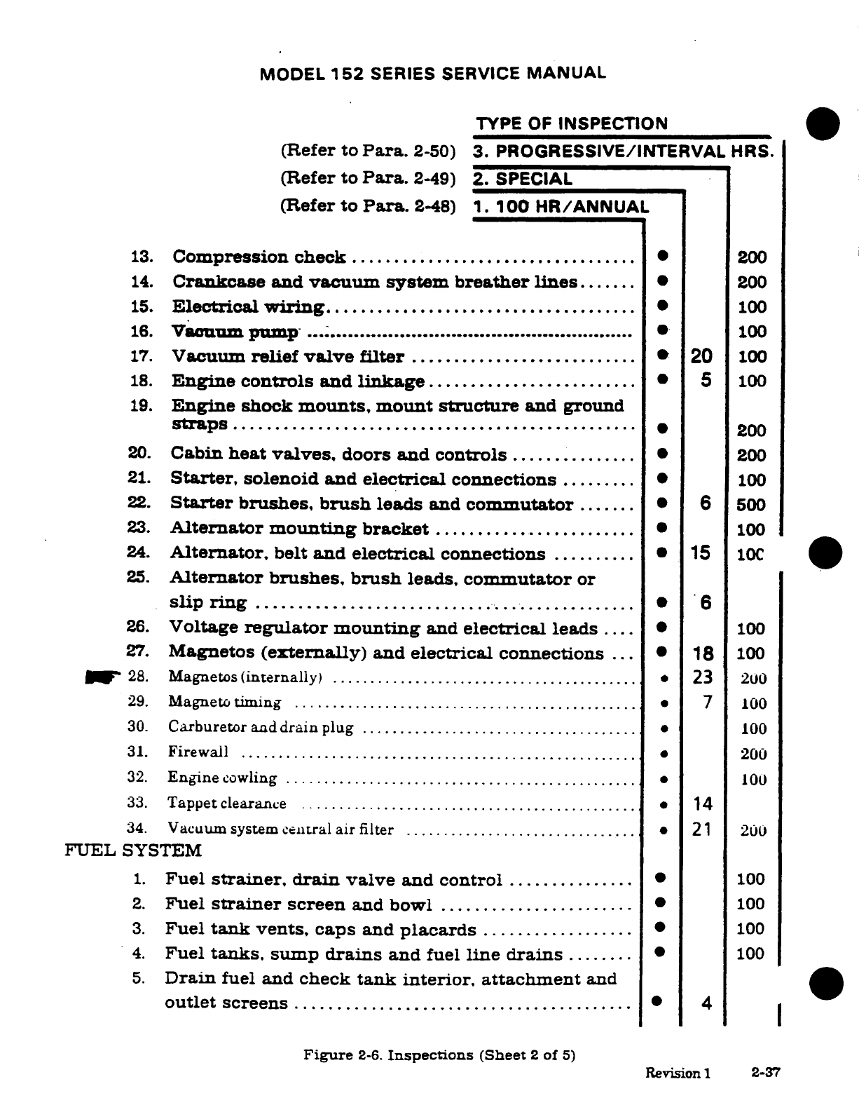
MODEL
152
SERIES SERVICE
MANUAL
TYPE
OF
INSPECTION
(Refer
to
Para.
2-50)
3.
PROGRESSIVE/INTERVAL
HRS.
(Refer to
Para.
2-49)
2.
SPECIAL
(Refer
to
Para.
2-48)
1.
100
HR/ANNUAL
13.
Compression check
..................................
200
14.
Crankcase
and
vacuum
system
breather
lines
.......
200
15.
Electrical
wiring
.....................................
100
16.
Vacuum
pump
..................................................
100
17.
Vacuum
relief
valve filter
...........................
20
100
18.
Engine
controls
and
linkage
.........................
5
100
19.
Engine
shock
mounts,
mount
structure
and ground
straps
.................................. ..............
200
20.
Cabin
heat
valves,
doors
and controls
...............
200
21.
Starter,
solenoid and
electrical
connections
.........
100
22.
Starter
brushes,
brush
leads
and
commutator
.......
6
500
23.
Alternator
mounting
bracket
.......................
100
24.
Alternator,
belt
and
electrical
connections
..........
15
10C
25.
Alternator brushes, brush
leads,
commutator
or
slip
ring
.........................................
6
26.
Voltage
regulator
mounting
and
electrical
leads
....
*
100
27.
Magnetos
(externally)
and
electrical
connections
... *
18
100
28.
Magnetos
(internally)
.........................................
23
200
29.
Magneto
timing
..............................................
*
7
100
30.
Carburetor
and
drain
plug
.....................................
100
31.
Firew all
...........
..................................... ....
200
32.
Engine
cowling
...............................................
100
33.
Tappet
clearance
.........................
....................
14
34.
Vacuum system
central
air
filter
...............................
*
21 200
FUEL
SYSTEM
1.
Fuel
strainer,
drain
valve
and
control
..............
.
100
2.
Fuel
strainer
screen
and
bowl
.......................
.
100
3.
Fuel
tank
vents,
caps
and
placards
..............
.....
100
4.
Fuel
tanks,
sump
drains
and
fuel
line
drains
........
*
100
5.
Drain
fuel and
check
tank interior,
attachment
and
outlet
screens
.....................................
.4
Figure
2-6.
Inspections
(Sheet
2
of
5)
Revision
1
2-37
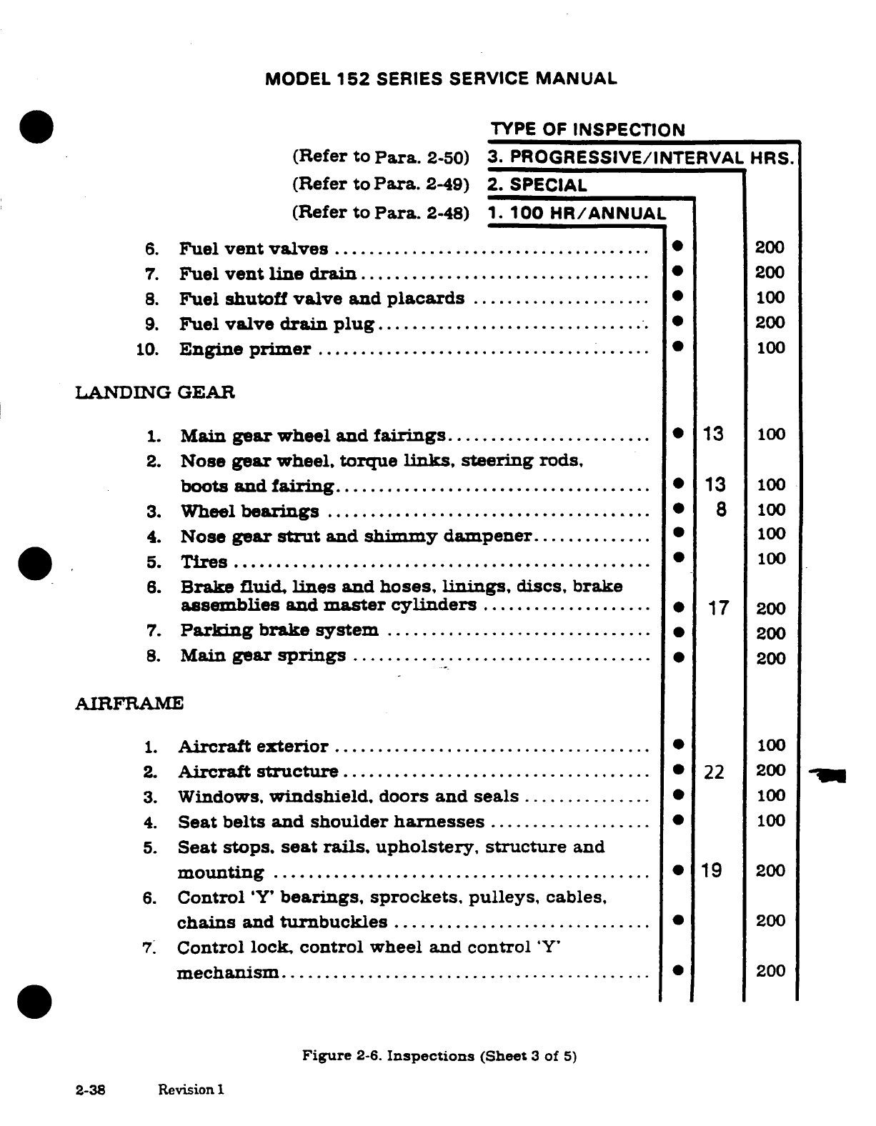
MODEL
152
SERIES SERVICE
MANUAL
TYPE OF
INSPECTION
(Refer
to
Para.
2-50)
3.
PROGRESSIVE/INTERVAL
HRS.
(Refer
to
Para.
2-49)
2.
SPECIAL
(Refer
to
Para.
2-48)
1.
100
HR/ANNUAL
6.
Fuel
vent
valves
.....................................
*
200
7.
Fuel
vent
line
drain
..................................
200
8.
Fuel
shutoff
valve
and
placards
..................... 100
9.
Fuel
valve
drain
plug
............................
200
10.
Engine
prim
er
.......................................
100
LANDING
GEAR
1.
Main
gear
wheel
and
fairings
........................
13
100
2.
Nose
gear
wheel,
torque
links,
steering
rods,
boots
and
fairing
.....................................
13
100
3.
Wheel
bearings
......................................
8
100
4.
Nose
gear
strut
and
shimmy
dampener..............
100
5.
Tires
........... ......................................
100
6.
Brake
fluid,
lines
and
hoses,
linings,
discs,
brake
assemblies
and
master
cylinders
....................
*
17
200
7.
Parking
brake
system
...............................
·
200
8.
Main
gear
springs
..................................
200
AIRFRAME
1.
Aircraft
exterior
.....................................
*
100
2.
Aircraft
structure
....................................
22 200
3.
Windows,
windshield,
doors
and
seals
...............
0
100
4.
Seat
belts
and
shoulder
harnesses
...................
0
100
5.
Seat
stops,
seat
rails,
upholstery,
structure
and
m
ounting
............................................
19
200
6.
Control
'Y'
bearings,
sprockets,
pulleys,
cables,
chains
and
turnbuckles
..............................
200
7.
Control
lock,
control
wheel
and
control
'Y'
m
echanism
...........................................
200
Figure
2-6.
Inspections
(Sheet
3
of
5)
2-38
Revision
1
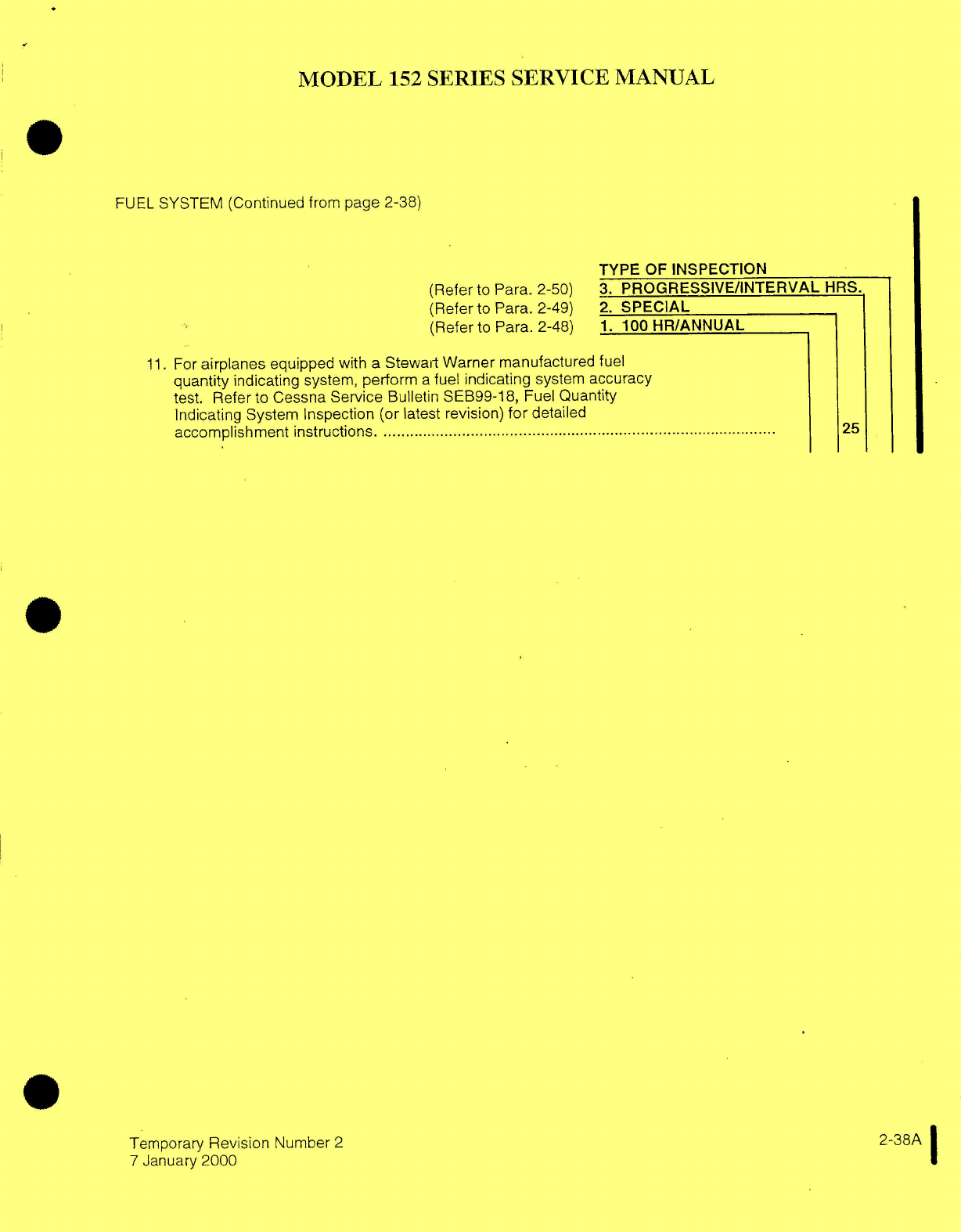
MODEL
152
SERIES
SERVICE
MANUAL
FUEL
SYSTEM (Continued
from
page 2-38)
TYPE
OF
INSPECTION
(Refer
to
Para.
2-50)
3.
PROGRESSIVE/INTERVAL
HRS.
(Refer
to Para. 2-49)
2.
SPECIAL
(Refer
to
Para. 2-48)
1.
100
HR/ANNUAL
11.
For
airplanes
equipped
with
a
Stewart
Warner
manufactured
fuel
quantity
indicating
system,
perform
a
fuel
indicating
system
accuracy
test.
Refer
to Cessna
Service
Bulletin SEB99-18,
Fuel
Quantity
Indicating System Inspection
(or
latest
revision)
for
detailed
accom
plishm
ent
instructions. .........................................................................................
25
Temporary
Revision
Number
2
2-38A
7
January
2000
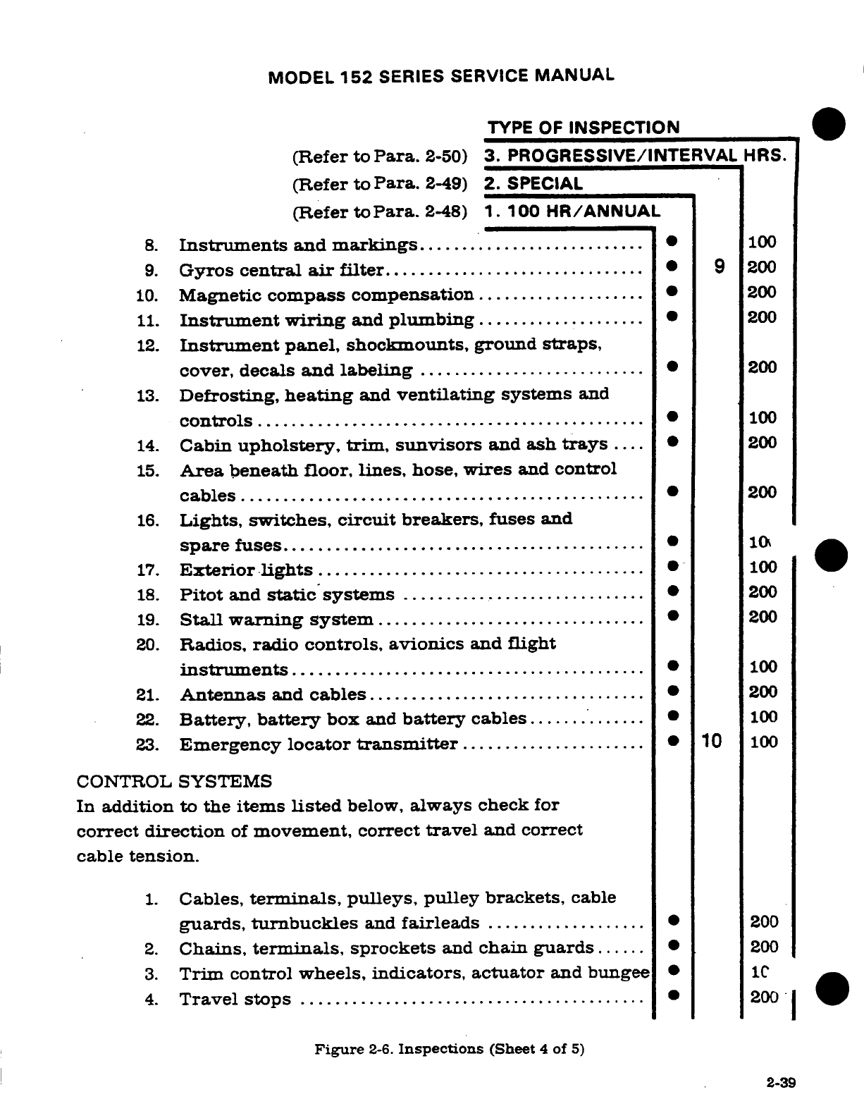
MODEL
152
SERIES
SERVICE
MANUAL
TYPE
OF
INSPECTION
(Refer
to
Para.
2-50)
3.
PROGRESSIVE/INTERVAL
HRS.
(Refer
to
Para.
2-49)
2.
SPECIAL
(Refer
to
Para.
2-48)
1.
100
HR/ANNUAL
8.
Instruments
and
markings.
...................
.......
100
9.
Gyros
central
air
filter
...............................
9
200
10.
Magnetic
compass
compensation
....................
200
11.
Instrument
wiring
and
plumbing
....................
*
200
12.
Instrument
panel,
shockmounts,
ground
straps,
cover,
decals
and
labeling
...........................
200
13.
Defrosting,
heating
and
ventilating
systems
and
controls
..............................................
100
14.
Cabin
upholstery,
trim,
sunvisors
and
ash
trays
....
*
200
15.
Area
beneath
floor,
lines,
hose, wires
and
control
cables
...............................................
200
16.
Lights, switches,
circuit
breakers,
fuses
and
spare
fuses
.............................................
*
10
17.
Exterior
lights
.................... ..................
100
18.
Pitot
and
static
systems
............................
*
200
19.
Stall
warning
system
................................
200
20.
Radios,
radio
controls,
avionics
and
flight
instrum
ents
..........................................
100
21.
Antennas
and
cables.................................
200
22.
Battery,
battery
box
and
battery
cables
..............
100
23.
Emergency
locator
transmitter
.......................
10
100
CONTROL
SYSTEMS
In
addition
to
the
items
listed
below,
always
check
for
correct
direction
of
movement,
correct
travel
and
correct
cable
tension.
1.
Cables,
terminals,
pulleys,
pulley brackets,
cable
guards,
turnbuckles
and
fairleads
...................
200
2.
Chains,
terminals,
sprockets
and
chain
guards......
200
3.
Trim
control
wheels,
indicators, actuator
and
bungee
*
10
4.
Travel
stops
.........................................
200
Figure
2-6.
Inspections
(Sheet
4
of
5)
2-39
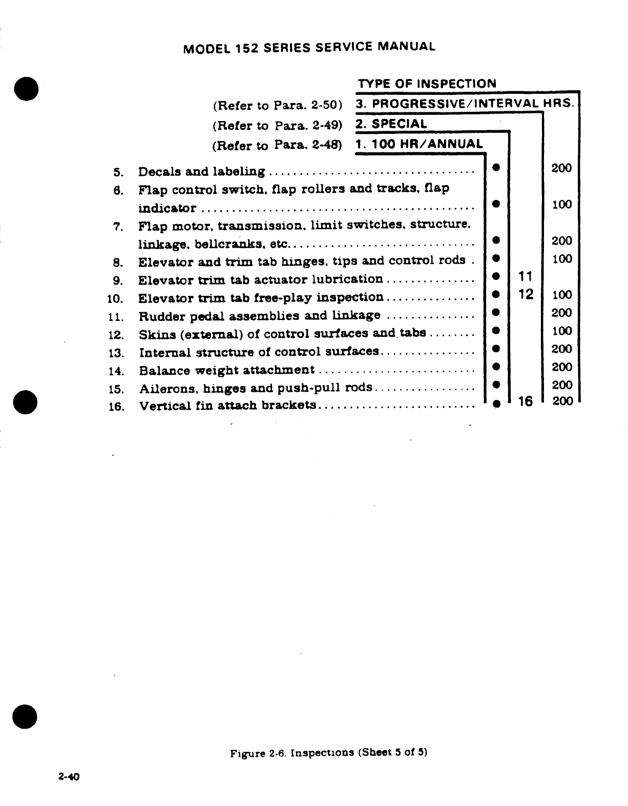
MODEL
152
SERIES
SERVICE
MANUAL
TYPE
OF
INSPECTION
(Refer
to
Para.
2-50)
3.
PROGRESSIVE/INTERVAL
HRS.
(Refer
to
Para.
2-49)
2.
SPECIAL
(Refer
to
Para.
2-48)
1.
100
HR/ANNUAL
5.
Decals and
labeling
..................................
0
200
6.
Flap
control switch,
flap
rollers
and
tracks,
flap
indicator
.............................................
100
7.
Flap
motor,
transmission,
limit
switches,
structure,
linkage,
bellcranks,
etc
...............................
200
8.
Elevator
and
trim
tab
hinges,
tips
and
control
rods
.*
100
9.
Elevator
trim
tab
actuator
lubrication
............... 11
10.
Elevator trim
tab
free-play
inspection
...............
12
100
11.
Rudder pedal
assemblies
and
linkage
...............
·
200
12.
Skins
(external)
of
control
surfaces
and
tabs
........
100
13.
Internal
structure
of
control surfaces
................
*
200
14.
Balance
weight
attachment
.......................... *
200
15.
Ailerons,
hinges
and
push-pull
rods
.................
200
16.
Vertical
fin
attach
brackets...........................
16
200
Figure
2-6.
Inspections
(Sheet
5
of
5)
2-40
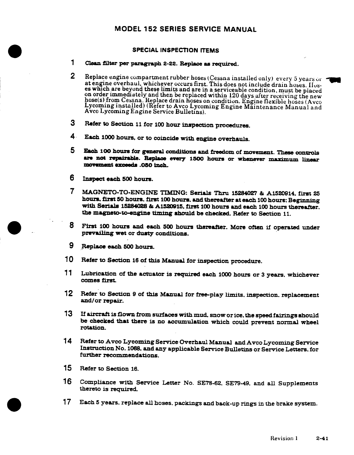
MODEL
152
SERIES
SERVICE
MANUAL
SPECIAL
INSPECTION
ITEMS
1
Clean
filter
per
paragraph
2-22.
Replace
as
required.
2
Replace
engine compartment
rubber
hoses
(Cessna
installed
only)
every
5
years
or
at
engine
overhaul,
whichever
occurs
first.
This
does
not include
drain
hoses.
IIus-
es
which
are
beyond
these
limits and
are
in
a
serviceable condition,
must
be
placed
on
order
immediately
and
then
be
replaced
within
120
days
after
receiving
the
new
hose(s)
from
Cessna.
Replace
drain
hoses
on
condition.
Engine
flexible
hoses
(Avco
Lycoming
installed)
(Refer
to
Avco
Lycoming
Engine
Maintenance
Manual
and
Avco
Lycoming
Engine
Service
Bulletins).
3
Refer
to
Section
11
for
100
hour
inspection
procedures.
4
Each
1000
hours,
or
to
coincide
with
engine
overhauls.
5
Each
100
hours
for
general
conditions
and
freedom
of
movement.
These
controls
are
not
repairable.
Replace
every
1500
hours
or
whenever
maximum
linear
movement
exceeds
.050
inch
6
Inspect
each
500
hours.
7
MAGNETO-TO-ENGINE
TIMING:
Serials
Thru
15284027
&
A1520914.
first
25
hours,
first
50
hours,
first
100
hours,
and
thereafter
at
each
100
hours:
Beginning
with
Serials
15284028
&
A1520915.
first
100
hours
and
each
100
hours
thereafter.
the
magneto-to-engine
timing
should
be
checked.
Refer
to Section
11.
8
First
100
hours
and
each
500
hours
thereafter.
More
often
if
operated
under
prvailing
wet
or
dusty
conditions.
9
Replace
each
500
hours.
10
Refer
to
Section
16
of
this
Manual
for inspection
procedure.
11
Lubrication
of
the
actuator is
required
each
1000
hours
or
3
years.
whichever
comes
first.
12
Refer to
Section
9
of
this
Manual
for
free-play
limits.
inspection.
replacement
and/or
repair.
13
If
aircraft
is
flown from
surfaces with
mud. snow
or
ice.
the
speed
fairings
should
be
checked
that
there is
no
accumulation
which
could
prevent normal
wheel
rotation.
14
Refer
to
Avco
Lycoming Service Overhaul
Manual
and
Avco
Lycoming
Service
Instruction
No.
1068.
and
any
applicable
Service
Bulletins
or
Service Letters.
for
further
recommendations.
15
Refer
to
Section
16.
16
Compliance
with
Service
Letter
No.
SE78-62.
SE79-49.
and
all
Supplements
thereto
is
required.
17
Each
5
years.
replace
all hoses.
packings
and
back-up
rings
in
the
brake
system.
Revision
1
2-41
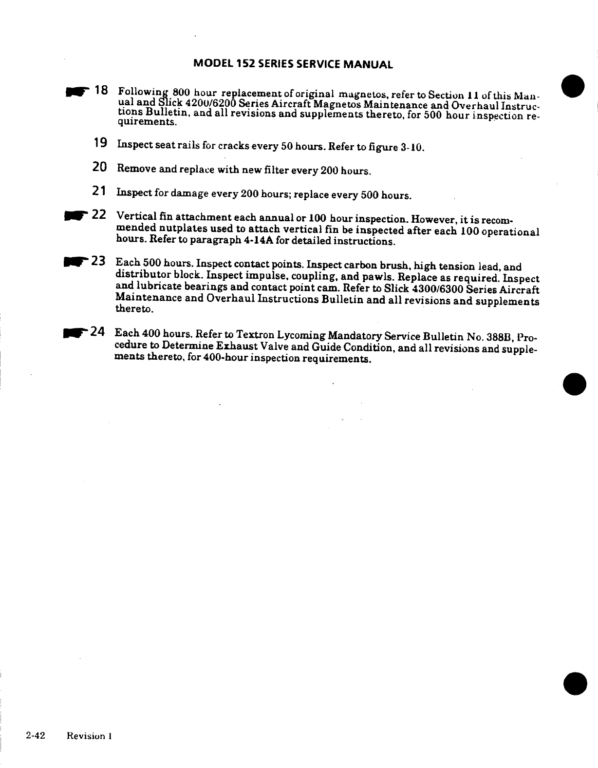
MODEL
152
SERIES
SERVICE
MANUAL
18
Following
800
hour replacement
of
original magnetos,
refer
to
Section
II
of
this
Man-
ual
and
Slick
4200/6200
Series
Aircraft
Magnetos
Maintenance
and
Overhaul
Instruc-
tions
Bulletin,
and all
revisions
and
supplements thereto,
for
500
hour
inspection
re-
quirements.
19 Inspect
seat
rails
for
cracks
every
50
hours.
Refer
to
figure
3-10.
20
Remove
and
replace
with
new
filter
every
200
hours.
21
Inspect
for
damage
every
200
hours;
replace every
500
hours.
22
Vertical
fin
attachment
each
annual
or
100
hour
inspection.
However,
it
is
recom-
mended
nutplates
used
to
attach
vertical
fin
be
inspected
after
each
100
operational
hours.
Refer
to
paragraph
4-14A
for
detailed
instructions.
23
Each
500
hours.
Inspect contact
points.
Inspect
carbon
brush,
high
tension
lead,
and
distributor
block.
Inspect
impulse,
coupling,
and
pawls.
Replace as
required.
Inspect
and
lubricate
bearings and
contact
point
cam. Refer
to
Slick
4300/6300
Series
Aircraft
Maintenance
and
Overhaul
Instructions Bulletin
and
all
revisions
and
supplements
thereto.
24
Each
400
hours.
Refer
to
Textron
Lycoming
Mandatory
Service
Bulletin
No. 388B,
Pro-
cedure
to
Determine
Exhaust
Valve
and
Guide
Condition,
and
all
revisions
and
supple-
ments
thereto,
for
400-hour
inspection
requirements.
2-42
Revision
I
MODEL
152
SERIES SERVICE
MANUAL
SPECIAL
INSPECTION
ITEMS
(Continued from
page
2-42)
25.
Fuel
quantity indicating
system
accuracy
test
is
required every
12
months.
Refer
to
Cessna
Service
Bulletin SEB99-18,
Fuel
Quantity
Indicating
System
Inspection
(or
latest
revision)
for
detailed
accomplishment instructions.
Temporary Revision
Number
2
2-42A
7
January
2000
MODEL
152
SERIES
SERVICE
MANUAL
SECTION
3
FUSELAGE
Page
No.
TABLE OF
CONTENTS
Aerofiche/
Manual
FUSELAGE
...................
1C18/3-1
Adjustment
.............
1D5/3-12
Windshield/Windows........
1C18/3-1
Lock
.....................
1D5/3-12
Description
................
1C18/3-1
Seats
......................
1D5/3-12
Cleaning
..................
1C18/3-1
Pilot
and
Copilot
..........
1D5/3-12
Waxing
..............
1C18/3-1
Description
.............
1D11/3-18
Repair
....................
1C18/3-1
Removal/Installation
.....
1D11/3-18
Scratches
.................
1C19/3-2
Auxiliary
.................
1D11/3-18
Cracks
...................
1C22/3-5
Description
..............
1D11/3-18
Windshield.
1C22/3-5
Removal/Installation
.....
1D11/3-18
Removal
...............
1C22/3-5
Repair
...................
1D11/3-18
Installation.
1C22/3-5
Cabin
Uphosltery
...........
1D11/3-18
Windows
...................
1D2/3-9
Materials
and
Tools
.........
1D1/3-18
Movable
..................
1D2/3-9
Soundproofing
..............
1D11/3-18
Removal/Installation
.....
1D2/3-9
Cabin
Headliner
............
1D11/3-18
Wrap-Around
Rear
.........
1D2/3-9
Removal/Installation
......
1D13/3-20
Removal/Installation
.....
1D2/3-9
Upholstery
Side
Panels
......
1D13/3-20
Overhead
.................
1D2/3-9
Carpeting
..................
1D13/3-20
Removal/Installation
.....
1D2/3-9
Baggage
Compartment
Cabin
Doors
................
1D2/3-9
Upholstery
...............
1D13/3-20
Removal/Installation
.......
1D2/3-9
Safety
Provisions
...........
1D13/3-20
Adjustment
...............
1D5/3-12
Cargo
Tie-Downs
..........
1D13/3-20
Weatherstrip
..............
1D5/3-12
Safety
Belts
...............
1D13/3-20
Wedge
Adjustment
.........
1D5/3-12
Shoulder
Harness
.........
1D13/3-20
Latche
...................
1D5/3-12
Inertia
Reel
Mirror
........
1D13/3-20
Description
..............
1D5/3-12
Rear
View
Mirror
...........
1D13/3-20
Seat
Rail Inspection
.........
1D17/3-24
3-1.
FUSELAGE.
3-2.
WINDSHIELD
AND
WINDOWS.
3-3.
DESCRIPTION.
The windshield
and
windows
are
single-piece,
acrylic
panels
set
in
sealing
strips
and
held
by
formed
retaining
strips,
secured to
the
fuselage
with
screws
and
rivets.
Isocryl
5603
sealant
(TMK01
Kit; contact
a
Cessna
Service
Station)
used
in
conjunction
with
a
felt seal
is
applied
to
all
edges
of
windshield
and
windows
with
exception
of
the
wing
root
area.
The
wing
root
fairing
has
a
heavy
felt
strip
which completes
the
windshield
sealing.
3-4.
CLEANING.
(Refer to
Section
2.)
3-5.
WAXING.
Waxing
will
fill
in
minor
scratches
in
clear
plastic
and
help
protect
the
surface
from
further
abrasion.
Use
a
good
grade
of
commercial
wax applied
in
a
thin.
even
coat.
Bring
wax
to
a
high
polish
by
rubbing
lightly
with
a
clean,
dry
flannel
cloth.
3-6.
REPAIR.
Replace
extensively
damaged
transparent
plastic rather
than
repair
whenever
possible.
since even
a
carefully
patched
part
is
not
the
equal
of
a
new
section.
either
optically
or
structurally.
At the
first
sign
of
crack
development.
drill
a
small
hole
at
the
extreme
end
of
the
crack
as
shown
in
figure
3-1.
This
serves
to
localize
the
cracks
and to
prevent
further
splitting
by
distributing
the
strain
over
a
large
area.
If
the
cracks
are
small.
stopping them
Revision
1
3-1
MODEL
152
SERIES
SERVICE
MANUAL
with
drilled holes
will
usually
suffice
until
replacement
or
more
permanent
repair
can
be
made.
The
following
repairs
are
permissible;
however,
they
are
not
to
be
located
in
the
pilot'
s
line
of
vision
during
landing
or
normal
flight.
a.
SURFACE
PATCH.
If
a
surface patch
is
to
be
installed,
trim
away
the
damaged
area
and
round
all
corners.
Cut
a
piece
of
plastic
of
sufficient
size to
cover
the
damaged
area and
extend
at least
3/4-inch
on
each
side
of
the
crack
or
hole.
Bevel
the
edges
as
shown
in
figure
3-1.
If the
section
to
be
repaired
is
curved,
shape
the
patch
to
the
same
contour
by
heating
it
in
an
oil
bath
at
a
temperature
of
248
°
to
302°F..
or
it
may
be
heated
on
a
hot
plate
until
soft.
Boiling
water
should
not
be
used
for
heating.
Coat
the
patch
evenly
with
plastic
solvent
adhesive
and
place
immediately
over
the
hole.
Maintain
a
uniform
pressure
of
from
5
to
10
psi
on
the
patch
for
a
minimum
of
3
hours.
Allow
the
patch
to
dry
24
to
36
hours
before
sanding or polishing
is
attempted.
b.
PLUG
PATCH.
In
using
inserted
patches
to
repair
holes
in
plastic structures,
trim
the
holes
to
a
perfect
circle
or
oval and
bevel
the
edges
slightly.
Make
the
patch
slightly
thicker
than
the
material
being
repaired,
and
similarly
bevel
the
edges.
Install
patches
in
accordance
with
procedure
illustrated
in
figure
3-1.
Heat the
plug
until
soft
and
press
into
the
hole
without
cement and
allow
to
cool
to
MAKE
a
perfect
fit.
Remove
the
plug,
coat
the
edges
with
adhesive,
and
then
reinsert
in
the
hole.
Maintain
a
firm
light
pressure
until
the cement
has
set,
then
sand
or
file
the
edges
level
with
the surface;
buff
and
polish.
3-7.
SCRATCES.
Scratches
on
clear
plastic
surfaces
can
be
removed by
hand-sanding
opera-
tions,
followed
by
buffing
and
polishing
as
shown
in
Sanding
epair,
figure
3-1,
if
steps
below
are
followed
carefully.
a.
Wrap
a
piece
of
No.
320
(or
finer)
sandpaper or
abrasive
cloth
around
a
rubber pad
or
wood
block.
Rub
surface
around scratch
with
a
circular
motion,
keeping
abrasive
constantly
wet
with
clean
water
to
prevent
scratching
surface
further.
Use
minimum
pressure
and
cover
an
area
large
enough
to
prevent
formation
of
bull's-eye
or
other
optical
distortions.
CAUTION
Do
not
use
coarse
grade
abrasive.
Number
320
grit
or
finer is
recommended.
b.
Continue
sanding
operation,
using
progressively
finer
grade
abrasives
until
scratches disappear.
c.
When
scratches
have
been
removed,
wash
area
thoroughly
with
clean
water
to
remove
all
gritty
particles.
The
entire
sanded
area
will
be
clouded
with
minute
scratches
which
must
be
removed
to
restore
transparency.
d.
Apply
fresh
tallow
or
buffing
compound
to
a
motor-driven
buffing
wheel.
Hold
wheel
against plastic
surface,
moving
it
constantly
over
damaged
area
until
cloudy
appearance
disappears.
A
2000-foot-per-minute
surface
speed
is
recommended
to
prevent overheating
and
distortion.
(Example:
750
rpm
polishing
machine
with a
10
inch
buffing
bonnet.)
NOTE
Polishing
can
be
accomplished
by
hand
but
will
require
a
considerably longer
period
of
time
to
attain
the
same
result
as
produced
by
a
buffing
wheel.
e.
When
buffing
is
finished, wash
area
thoroughly
and
dry
with
a
soft
flannel
cloth.
Allow
surface
to
cool
and
inspect
area
to
determine
if
full
transparency has
been
3-2
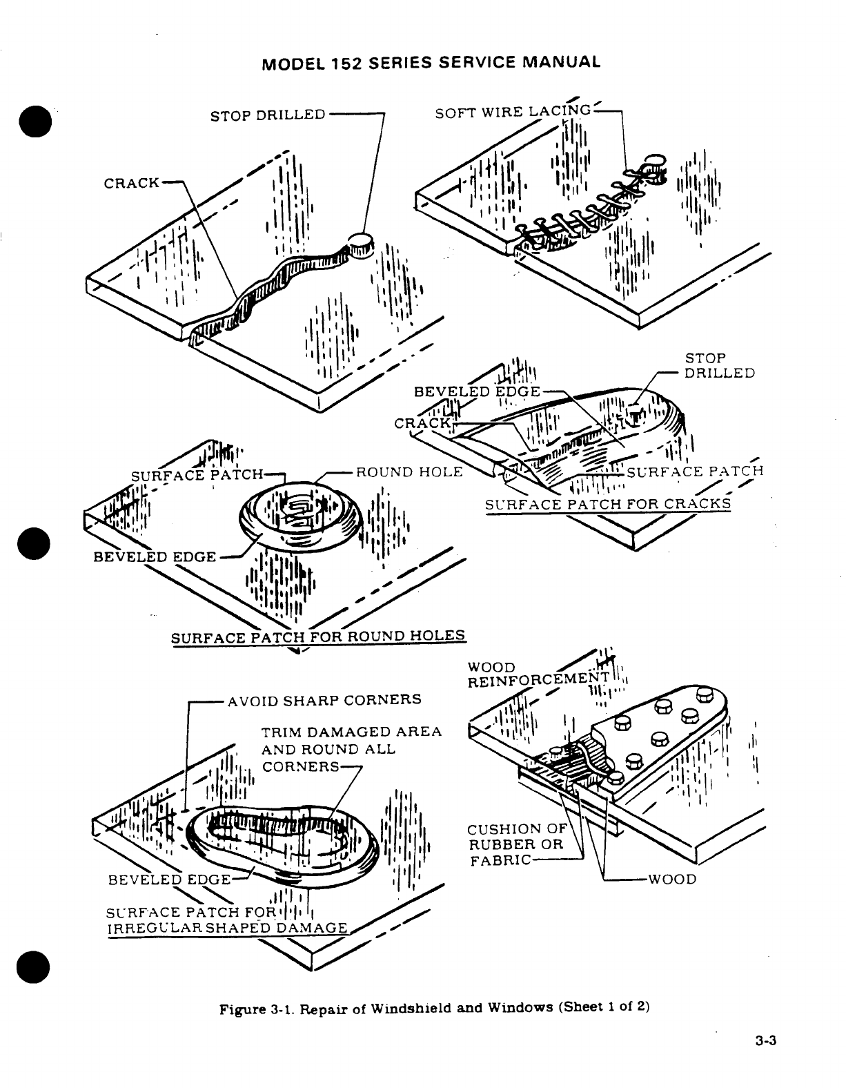
MODEL
152
SERIES
SERVICE
MANUAL
STOP
DRILLED
SOFT
WIRE
LACING
I
i
CRACK'
SURFACE
PATCH
SURFACE PATCH
FOR
ROUND
HOLES
WOOD
REINFORCEMEN
AVOID
SHARP
CORNERS
TRIM
DAMAGED
AREA
AND
ROUND
ALL
BEVELED
EDGE
SURFACE
PATCH
FOR
IRREULAR
SHAPED
DAMAGE
Figure
3-1.
Repair
of
Windshield
and
Windows
(Sheet
1
of
2)
3-3
3-3
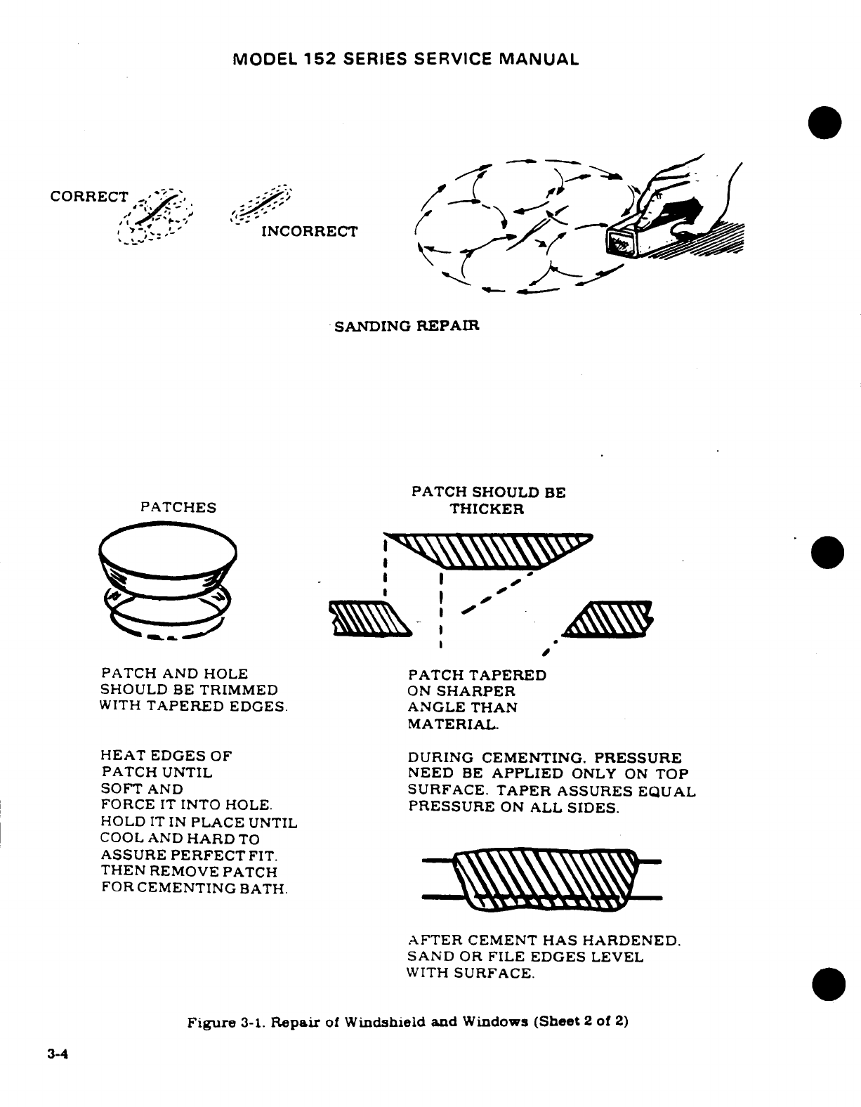
MODEL
152
SERIES
SERVICE
MANUAL
CORRECT'-
INCORRECT
SANDING
REPAIR
PATCH
SHOULD
BE
PATCHES
THICKER
PATCH
AND HOLE
PATCH
TAPERED
SHOULD
BE
TRIMMED
ON
SHARPER
WITH
TAPERED
EDGES.
ANGLE
THAN
MATERIAL.
HEAT
EDGES
OF
DURING
CEMENTING.
PRESSURE
PATCH UNTIL
NEED
BE
APPLIED
ONLY
ON
TOP
SOFT
AND
SURFACE.
TAPER
ASSURES
EQUAL
FORCE
IT
INTO HOLE.
PRESSURE
ON
ALL
SIDES.
HOLD
IT
IN
PLACE
UNTIL
COOL AND
HARD
TO
ASSURE
PERFECT
FIT.
THEN
REMOVE
PATCH
FOR
CEMENTING
BATH.
AFTER
CEMENT HAS
HARDENED.
SAND
OR
FILE EDGES
LEVEL
WITH
SURFACE.
Figure
3-1.
Repair
of
Windshield and
Windows
(Sheet
2
of
2)
3-4
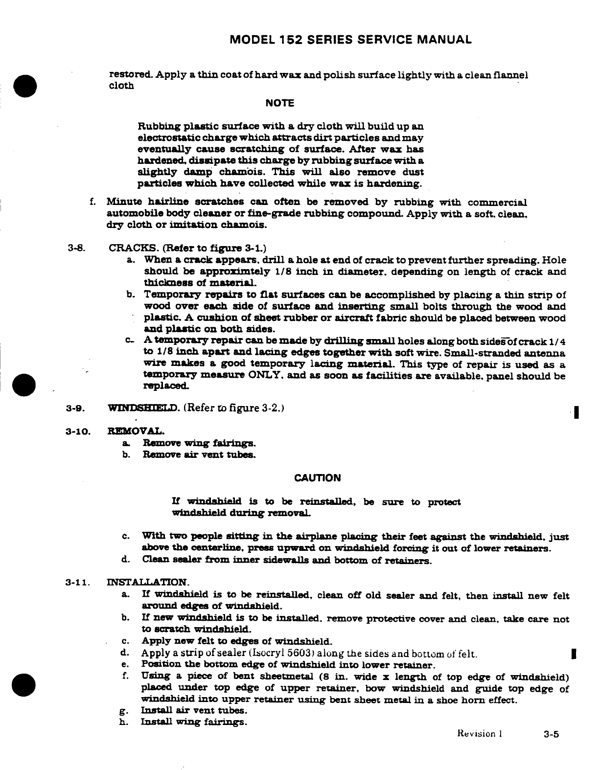
MODEL
152
SERIES
SERVICE
MANUAL
restored. Apply
a
thin
coat
of
hard
wax
and
polish
surface
lightly
with
a
clean
flannel
cloth
NOTE
Rubbing
plastic
surface
with
a
dry
cloth will
build
up
an
electrostatic
charge
which
attracts
dirt
particles
and
may
eventually
cause
scratching
of
surface. After
wax
has
hardened,
dissipate
this
charge
by
rubbing
surface
with
a
slightly
damp
chamois.
This
will
also
remove
dust
particles
which
have
collected
while
wax
is
hardening.
f.
Minute
hairline
scratches
can often
be
removed
by
rubbing
with
commercial
automobile
body
cleaner
or
fine-grade
rubbing
compound.
Apply with
a
soft. clean.
dry
cloth
or
imitation
chamois.
3-8.
CRACKS.
(Refer
to
figure
3-1.)
a.
When
a
crack
appears.
drill
a
hole
at
end
of
crack
to
prevent
further
spreading.
Hole
should
be
approximtely
1/8
inch
in
diameter,
depending
on
length
of
crack
and
thickness
of
material.
b.
Temporary
repairs
to
flat
surfaces
can
be
accomplished
by
placing
a
thin
strip
of
wood
over
each side
of
surface
and
inserting
small
bolts
through
the
wood
and
plastic.
A
cushion
of
sheet
rubber
or
aircraft fabric
should
be
placed
between
wood
and
plastic
on
both
sides.
c.
A
temporary
repair
can
be
made
by
drilling
small
holes
along both
sides-of
crack
1/
4
to
1/8
inch
apart
and
lacing
edges
together
with
soft
wire.
Small-stranded
antenna
wire
makes
a
good
temporary lacing
material.
This
type
of
repair
is
used as
a
temporary
measure
ONLY,
and
as
soon
as
facilities
are
available, panel
should
be
replaced.
3-9.
WINDSHIELD.
(Refer
to
figure
3-2.)
3-10.
REMOVAL.
a.
Remove
wing
fairings.
b.
Remove
air
vent
tubes.
CAUTION
If
windshield
is
to
be
reinstalled,
be
sure
to
protect
windshield
during
removal.
c.
With two people
sitting
in the
airplane
placing
their
feet
against
the
windshield,
just
above
the
centerline,
press
upward
on
windshield forcing
it
out of
lower
retainers.
d.
Clean
sealer
from
inner
sidewalls
and
bottom
of
retainers.
3-11.
INSTALLATION.
a.
If
windshield
is
to
be
reinstalled,
clean
off
old
sealer
and
felt,
then
install
new
felt
around
edges
of
windshield.
b.
If new
windshield
is
to
be
installed,
remove
protective
cover
and
clean,
take
care
not
to
scratch
windshield.
c.
Apply
new
felt
to
edges
of
windshield.
d.
Apply
a
strip
of
sealer
(Ilocryl
5603)
along
the
sides
and
bottom
of
felt.
e.
Position
the
bottom
edge
of
windshield
into
lower
retainer.
f.
Using
a
piece
of
bent
sheetmetal
(8
in.
wide
x
length
of
top
edge
of
windshield)
placed
under
top
edge
of
upper
retainer,
bow
windshield
and
guide
top
edge
of
windshield
into upper
retainer
using
bent
sheet
metal
in a
shoe
horn
effect.
g.
Install
air
vent
tubes.
h.
Install
wing
fairings.
Revision
1
3-5
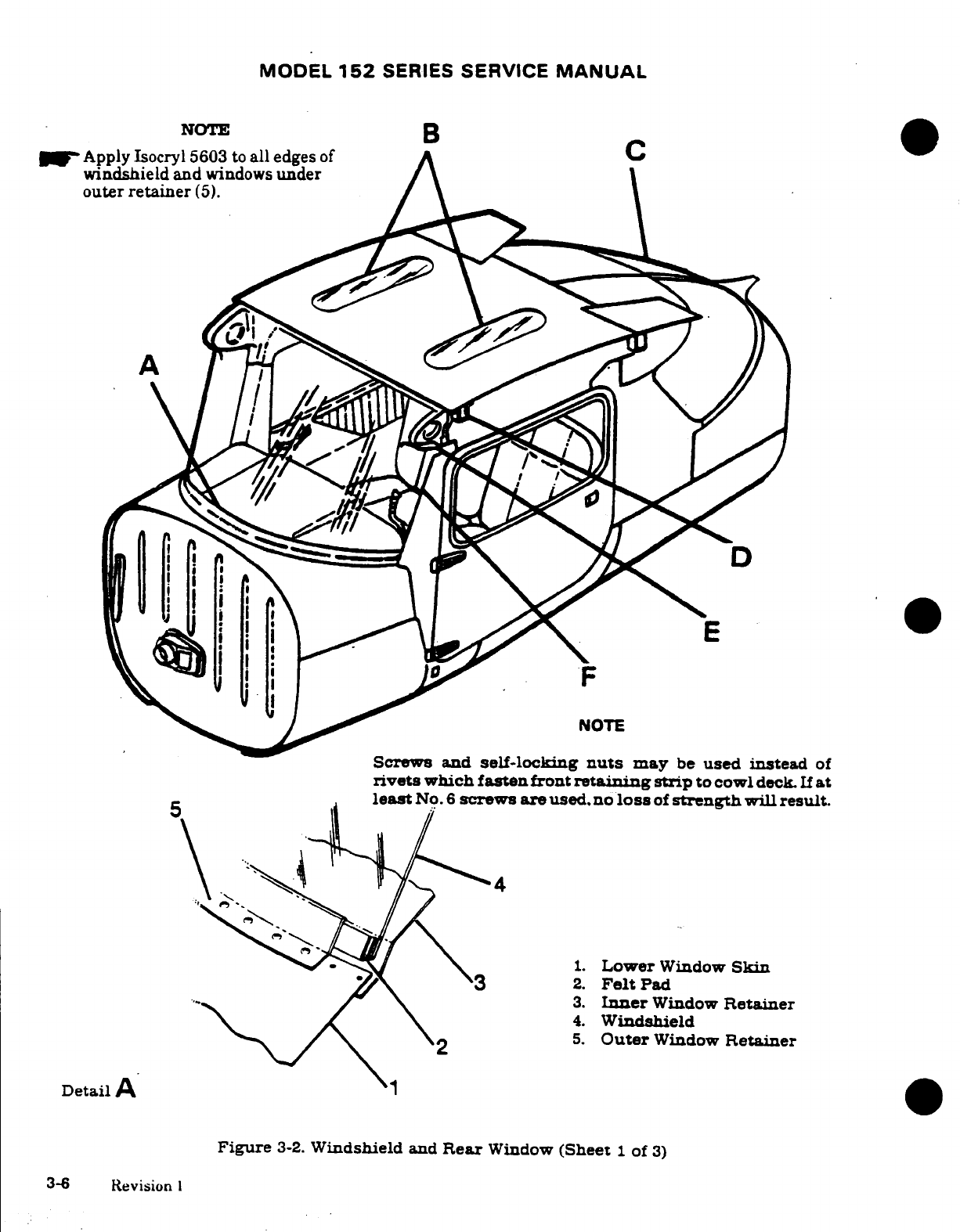
MODEL
152
SERIES
SERVICE
MANUAL
-NOTE
B
|
Apply
Isocryl
5603
to
all
edges
of
A
windshield
and
windows
under
outer
retainer
(5).
NOTE
Screws and
self-locking
nuts
may
be
used instead
of
rivets
which
fasten
front
retaining
strip
to cowl
deck.
If
at
least
No.
6
screws
are
used.
no
loss
of
strength
will
result.
1.
Lower
Window
Skin
2.
Felt
Pad
3.
Inner
Window
Retainer
4.
Windshield
5.
Outer
Window
Retainer
Detail
A
Figure
3-2.
Windshield
and
Rear
Window
(Sheet
1
of
3)
3-6
Revision
I
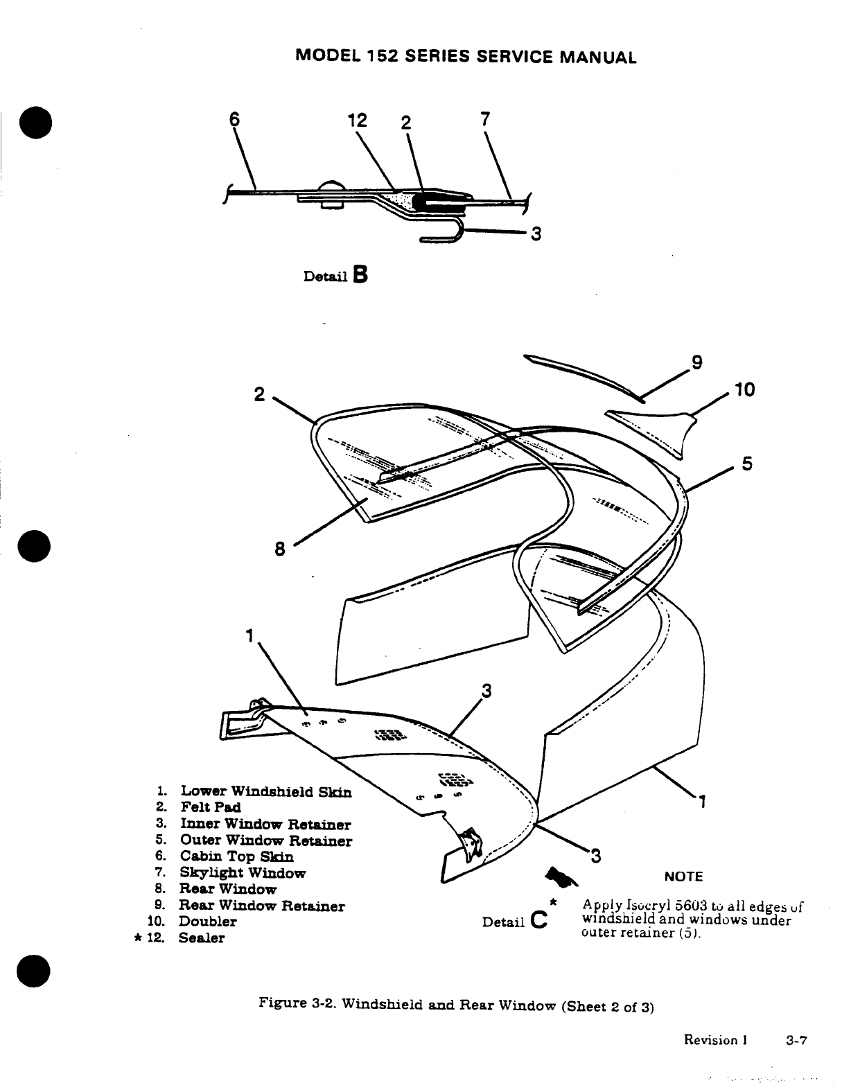
MODEL
152
SERIES
SERVICE
MANUAL
6
12
2
7
Detail
B
2
10
8
5
1.
Lower
Windshield
Skin
2.
Felt
Pad
3.
Inner
Window
Retainer
5.
Outer
Window
Retainer
6.
Cabin
Top
Skin
7.
Skylight
Window
NOTE
8.
Rear
Window
9.
Rear
Window
Retainer
*
Apply
Isocryl
5603 to
all
edges
uf
Detail
C
windshield
and
windows
under
10.
Doubler
outer
retainer
(5).
*
12.
Sealer
Figure
3-2.
Windshield
and Rear
Window
(Sheet
2
of
3)
Revision
1
3-7
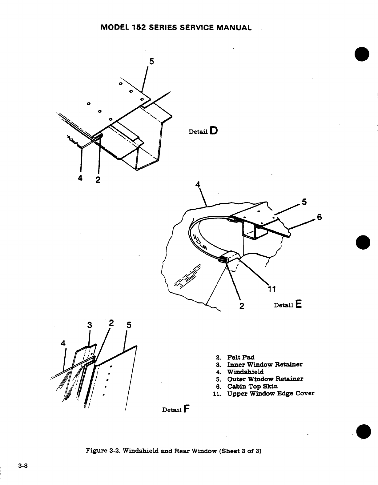
MODEL
152
SERIES SERVICE
MANUAL
5
Detail
D
4
2
2
Detail
E
3
2
5
2.
Felt Pad
3.
Inner
Window
Retainer
4.
Windshield
5.
Outer
Window
Retainer
6.
Cabin
Top
Skin
11.
Upper
Window
Edge
Cover
Detail
F
Figure
3-2.
Windshield
and
Rear
Window
(Sheet
3
of
3)
3-8
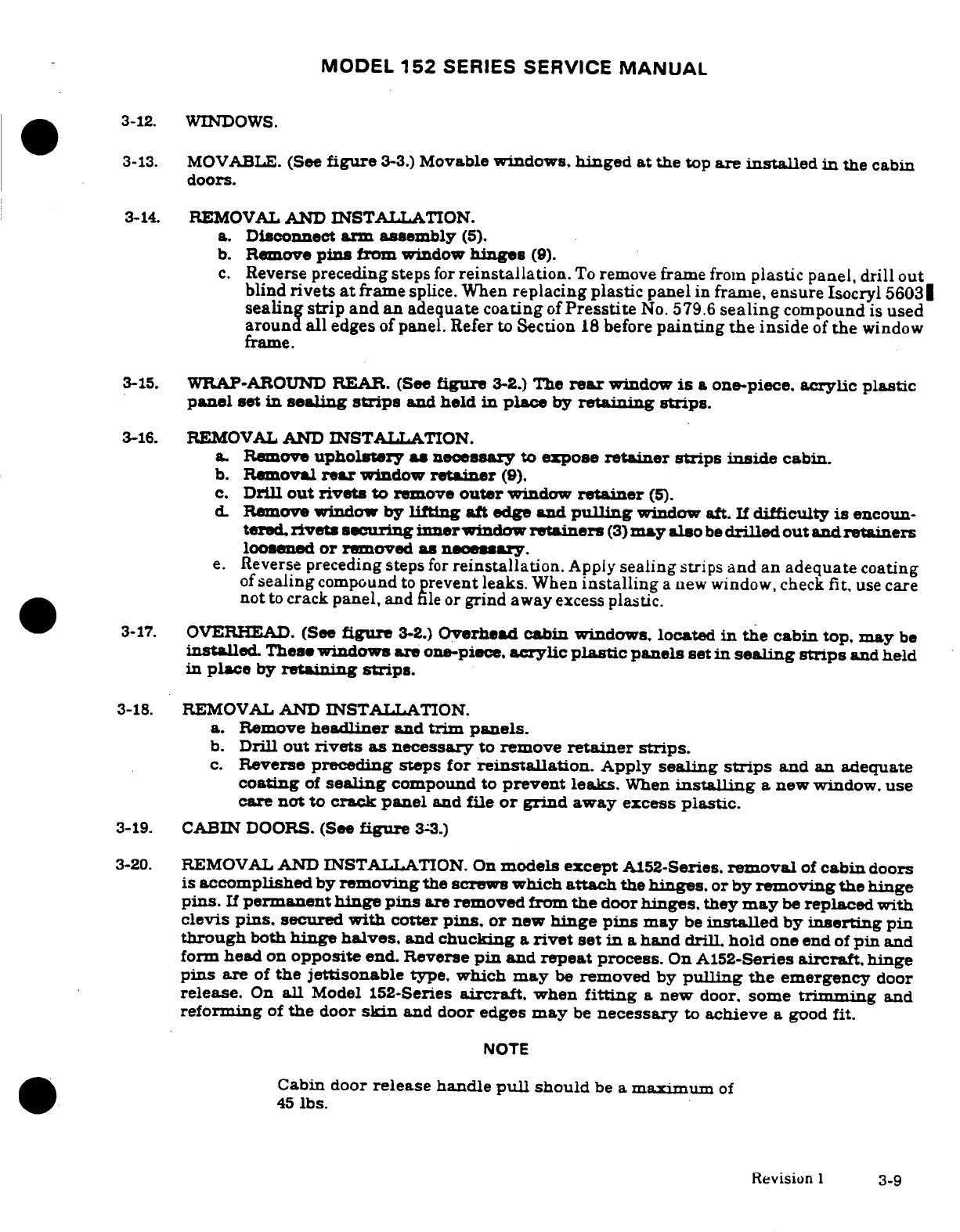
MODEL
152
SERIES
SERVICE
MANUAL
3-12.
WINDOWS.
3-13.
MOVABLE.
(See
figure
3-3.)
Movable
windows,
hinged
at
the
top
are
installed
in
the
cabin
doors.
3-14.
REMOVAL
AND
INSTALLATION.
a.
Disconnect
arm
assembly
(5).
b.
Remove
pins
from
window
hinges
(9).
c.
Reverse
preceding steps
for
reinstallation.
To
remove
frame
from
plastic
panel,
drill
out
blind
rivets
at
frame
splice.
When
replacing
plastic
panel
in
frame,
ensure
Isocryl
5603
sealing
strip
and
an
adequate
coating
of
Presstite
No.
579.6
sealing
compound
is
used
around all
edges
of
panel.
Refer
to
Section
18
before
painting the
inside
of
the
window
frame.
3-15.
WRAP-AROUND
REAR.
(See
figure
3-2.)
The
rear
window
is a
one-piece,
acrylic
plastic
panel
set
in
sealing
strips
and
held
in
place
by
retaining
strips.
3-16.
REMOVAL
AND
INSTALLATION.
a.
Remove
upholstery
as
necessary
to
expose
retainer strips
inside
cabin.
b.
Removal
rear
window
retainer
(9).
c.
Drill
out
rivets
to
remove
outer
window
retainer
(5).
D.
Remove
window
by
lifting
aft
edge
and
pulling
window
aft.
If
difficulty
is
encoun-
tered,
rivets
securing
inner
window
retainers
(3)
may
also
be
drilled
out and
retainers
loosened
or
removed
as
necessary.
e.
Reverse
preceding
steps
for
reinstallation.
Apply
sealing
strips
and
an
adequate
coating
of
sealing
compound
to
prevent
leaks.
When
installing
a
new window, check
fit,
use
care
not
to
crack
panel,
and
file
or
grind
away
excess
plastic.
3-17.
OVERHEAD.
(See
figure
3-2.)
Overhead
cabin
windows,
located
in
the cabin
top,
may
be
installed
These
windows
are
one-piece.
acrylic
plastic
panels
set
in
sealing
strips
and
held
in
place
by
retaining
strips.
3-18.
REMOVAL
AND
INSTALLATION.
a.
Remove
headliner
and
trim
panels.
b.
Drill
out
rivets
as
necessary
to
remove
retainer
strips.
c.
Reverse
preceding steps
for
reinstallation.
Apply
sealing
strips
and
an adequate
coating
of
sealing
compound
to
prevent
leaks.
When
installing
a
new
window,
use
care
not
to
crack
panel
and
file
or
grind
away
excess
plastic.
3-19.
CABIN DOORS.
(See
figure
33.)
3-20.
REMOVAL
AND
INSTALLATION.
On
models
except
A152-Series.
removal
of
cabin
doors
is
accomplished
by
removing
the
screws
which
attach
the
hinges.
or
by
removing
the
hinge
pins.
If
permanent
hinge
pins
are
removed
from
the
door
hinges,
they
may
be
replaced
with
clevis
pins.
secured
with
cotter
pins,
or
new
hinge pins
may
be
installed
by
inserting
pin
through
both
hinge
halves,
and
chucking
a
rivet
set
in a
hand
drill
hold
one
end
of
pin
and
form
head
on
opposite end.
Reverse
pin
and
repeat
process.
On
A152-Series
aircraft,
hinge
pins
are
of
the
jettisonable
type,
which
may
be
removed
by
pulling
the
emergency
door
release.
On
all
Model
152-Series
aircraft,
when
fitting
a
new
door.
some
trimming
and
reforming
of
the
door
skin
and
door
edges
may
be
necessary
to
achieve
a
good
fit.
NOTE
Cabin
door
release
handle
pull
should
be
a
maximum
of
45
lbs.
Revision
1
3-9
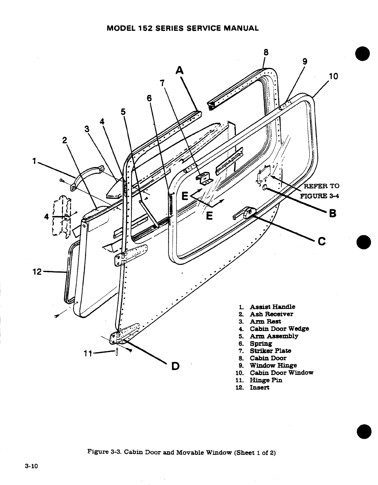
MODEL
152
SERIES
SERVICE
MANUAL
8
9
7
4
1.
Assist
Handle
2.
Ash
Receiver
14.
Cabin
Door
Wedge
6
Spring
12.
Insert
Figure
3-3.
Cabin
Door
and
Movable
Window
(Sheet
1
of
2)
3-10
3-10
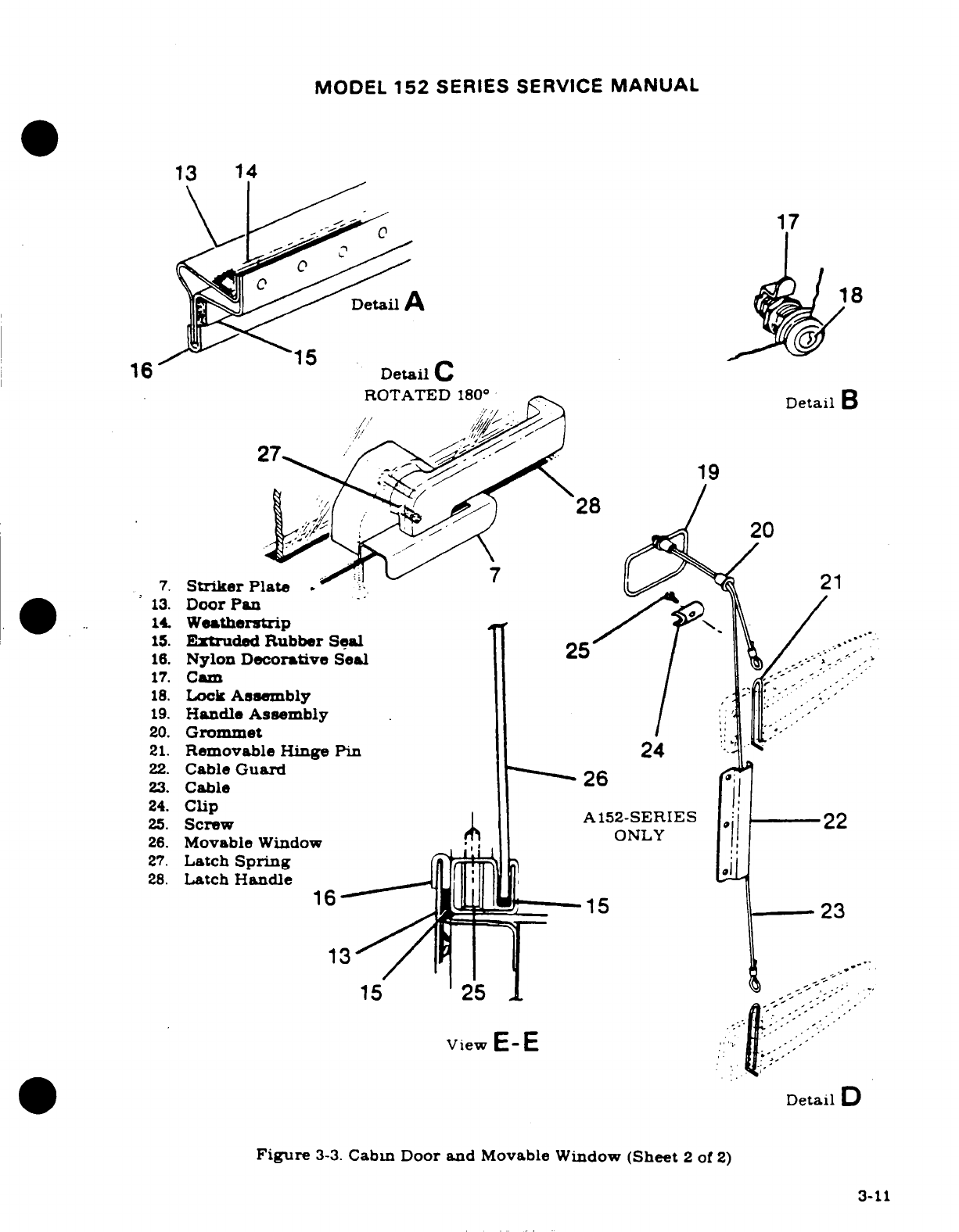
MODEL
152
SERIES
SERVICE
MANUAL
13
14
17
Detail
A
18
16
Detail
C
ROTATED
180
°
Detail
B
27
19
20
7.
Striker
Plate
21
13.
Door
Pan
14.
Weatherstrip
15.
Extruded
Rubber
Seal
25
16.
Nylon
Decorative
Seal
25
17.
Cam
18.
Lock
Assembly
19.
Handle
Assembly
20.
Grommet
21.
Removable
Hinge
Pin
24
22.
Cable
Guard
26
23.
Cable
24.
Clip
A152-SERIES
22
25.
Screw
ONLY
26.
Movable
Window
27.
Latch
Spring
28.
Latch
Handle
13
15
25
View
E-E
Detail
D
Figure
3-3.
Cabin
Door and
Movable Window
(Sheet
2
of
2)
3-11
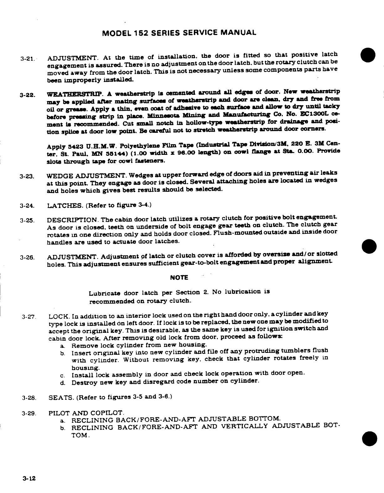
MODEL
152
SERIES
SERVICE
MANUAL
3-21.
ADJUSTMENT.
At
the
time
of
installation.
the
door
is
fitted
so
that
positive
latch
engagement
is
assured.
There
is
no
adjustment
on
the door
latch.
but
the
rotary clutch
can
be
moved
away
from
the
door latch.
This
is
not
necessary
unless
some
components
parts
have
been
improperly
installed.
3-22.
WEATHERSTRIP.
A
weatherstrip
is
cemented
around
all
edges
of
door.
New
weatherstrip
may
be
applied
after
mating
surfaces
of
weatherstrip
and
door
are
clean,
dry
and
free from
oil
or
grease.
Apply
a
thin,
even
coat
of
adhesive
to each
surface
and
allow
to
dry until
tacky
before
pressing
strip
in
place.
Minnesota
Mining
and
Manufacturing
Co.
No.
EC1300L
ce-
ment
is
recommended.
Cut small
notch
in
hollow-type
weatherstrip
for
drainage
and
posi-
tion
splice
at
door
low
point.
Be
careful not
to
stretch weatherstrip
around
door
corners.
Apply
5423
U.H.M.W.
Polyethylene
Film Tape
(Industrial
Tape
Division/3M,
220
E.
3M
Cen-
ter,
St.
Paul,
MN
55144)
(1.00
width
x
96.00
length)
on
cowl
flange
at
Sta.
0.00.
Provide
slots
through
tape for
cowl
fasteners.
3-23.
WEDGE
ADJUSTMENT.
Wedges
at
upper
forward
edge of
doors
aid
in
preventing
air
leaks
at
this
point.
They
engage
as
door
is
closed.
Several
attaching
holes
are
located
in
wedges
and
holes
which
gives
best
results
should
be
selected.
3-24.
LATCHES.
(Refer
to
figure
3-4.)
3-25.
DESCRIPTION.
The
cabin
door
latch
utilizes
a
rotary clutch
for
positive
bolt
engagement.
As
door
is
closed,
teeth
on
underside
of
bolt
engage
gear
teeth
on
clutch.
The
clutch
gear
rotates
in
one
direction
only
and
holds
door
closed.
Flush-mounted outside
and
inside
door
handles
are
used
to
actuate
door
latches.
3-26.
ADJUSTMENT.
Adjustment
pf
latch
or
clutch
cover
is
afforded
by
oversize
and/or
slotted
holes.
This
adjustment
ensures
sufficient
gear-to-bolt
engagement
and
proper alignment.
NOTE
Lubricate
door
latch
per
Section
2.
No
lubrication
is
recommended
on
rotary
clutch.
3-27.
LOCK.
In
addition
to
an
interior
lock used
on
the
right
hand
door
only.
a
cylinder and
key
type
lock
is
installed
on left
door.
If
lock
is
to
be
replaced.
the
new
one
may
be
modified
to
accept
the
original
key.
This
is
desirable.
as
the same
key
is
used
for
ignition
switch
and
cabin
door
lock.
After
removing
old
lock
from
door.
proceed
as
follows
a.
Remove lock
cylinder
from
new
housing.
b.
Insert
original
key
into
new
cylinder
and
file
off
any
protruding
tumblers
flush
with
cylinder.
Without
removing
key,
check
that
cylinder
rotates
freely
in
housing.
c.
Install
lock
assembly
in
door
and
check
lock
operation
with
door
open.
d.
Destroy
new
key and
disregard
code
number
on
cylinder.
3-28.
SEATS.
(Refer
to
figures
3-5
and
3-6.)
3-29.
PILOT
AND
COPILOT.
a.
RECLINING
BACK/FORE-AND-AFT
ADJUSTABLE
BOTTOM.
b.
RECLINING
BACK/FORE-AND-AFT
AND
VERTICALLY
ADJUSTABLE
BOT-
TOM.
3-12
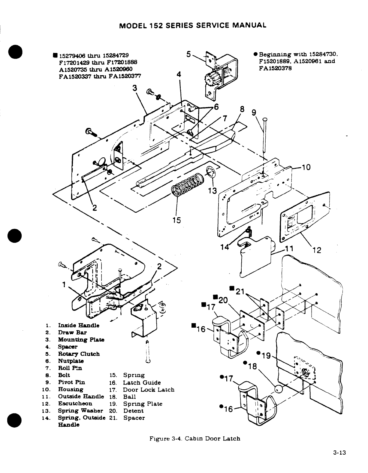
MODEL
152
SERIES SERVICE
MANUAL
15279406
thru
15284729
5
*
Beginning
with
15284730.
F17201429
thru
F17201888 F15201889.
A1520961
and
A1520735
thru
A1520960
FA1520378
FA1520337
thru
FA1520377
4
9
4.
Spacer
7.
Roll
Pin
11. Outside
Handle
18.
Ball
13.
Spring
Washer
20.
Detent
14
Spring.
Outside
21.
Spacer
Handle
Figure
3-4.
Cabin
Door Latch
3-13
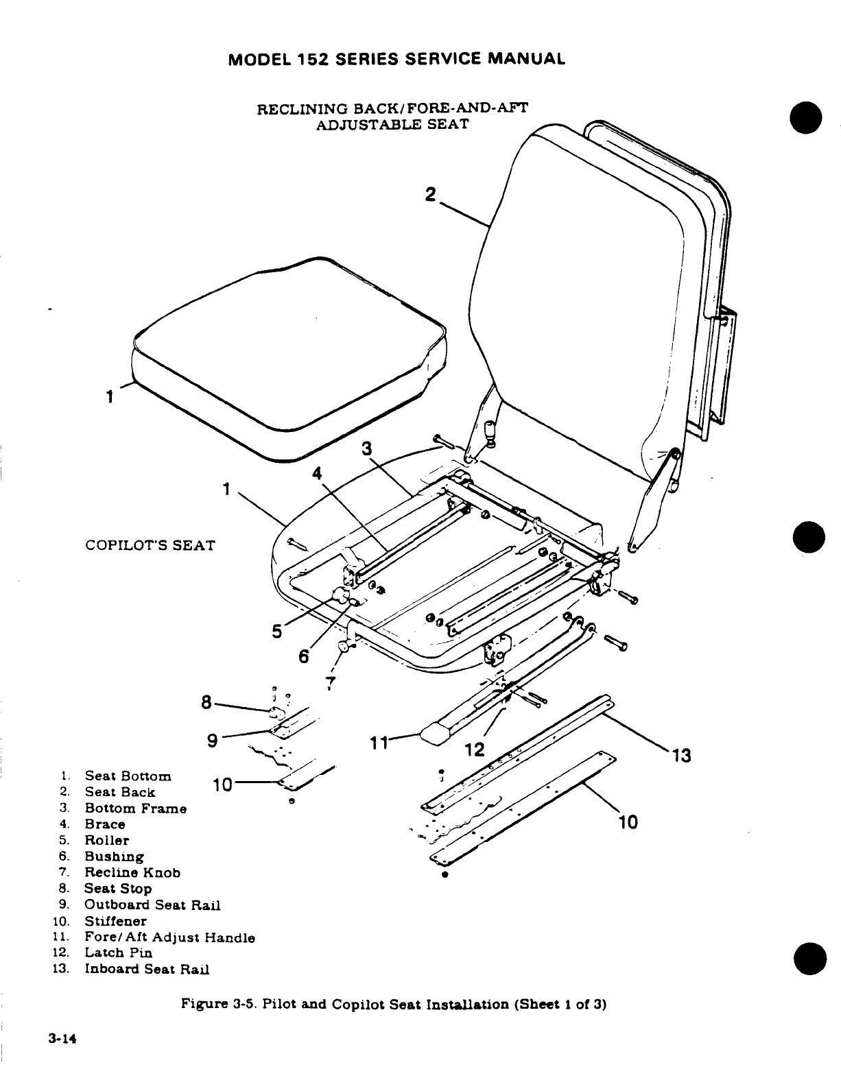
MODEL
152
SERIES
SERVICE
MANUAL
RECLINING
BACK/FORE-AND-AFT
ADJUSTABLE
SEAT
COPILOT'S
SEAT
1.
Seat
Bottom
2.
Seat
Back
3.
Bottom
Frame
4.
Brace
10
5.
Roller
6.
Bushing
7.
Recline
Knob
8.
Seat
Stop
9.
Outboard
Seat
Rail
10.
Stiffener
11.
Fore/Aft
Adjust
Handle
12.
Latch
Pin
13.
Inboard
Seat
Rail
Figure
3-5.
Pilot
and
Copilot
Seat
Installation
(Sheet
1
of
3)
3-14
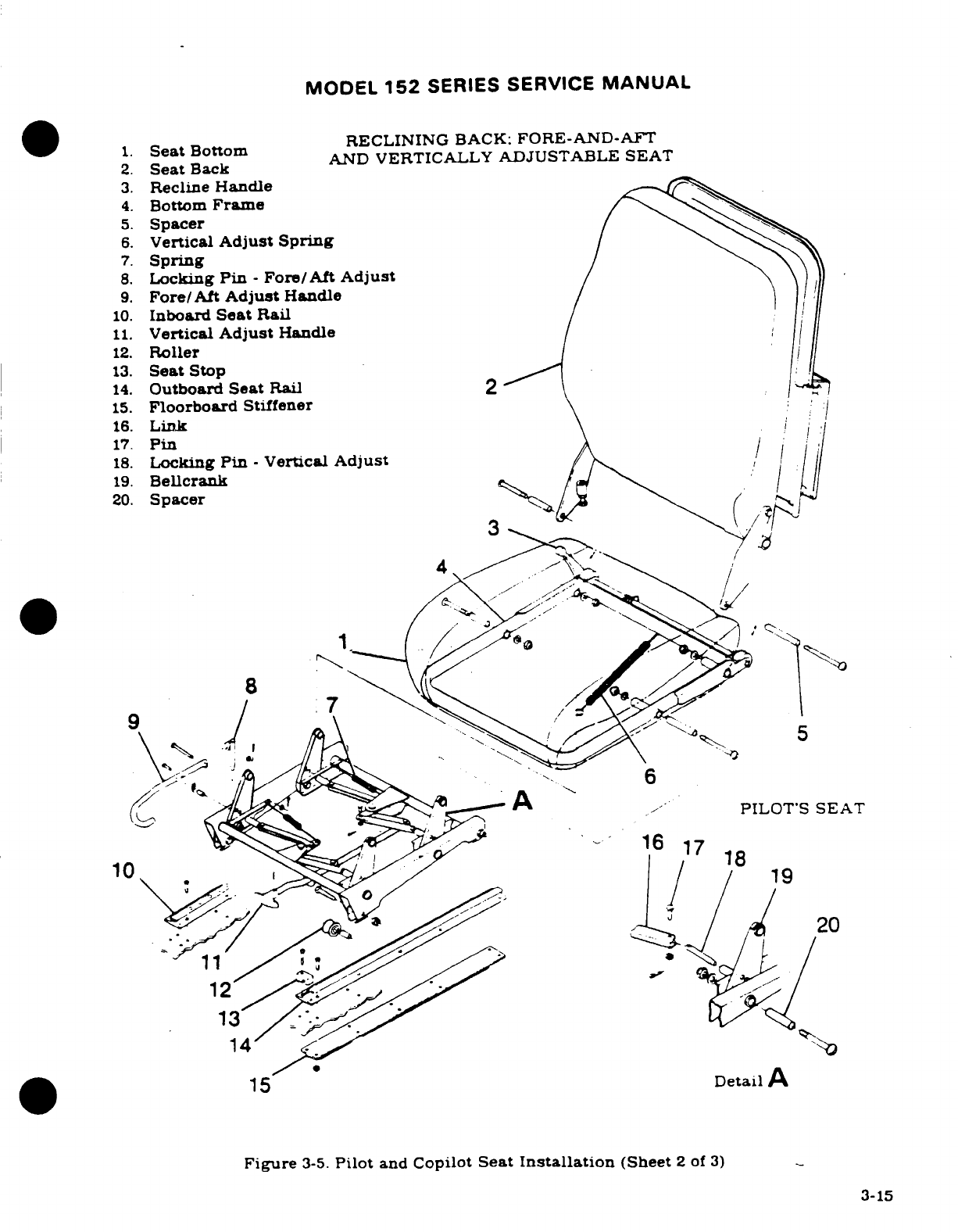
MODEL
152
SERIES
SERVICE
MANUAL
1.
Seat
Bottom
RECLINING
BACK:
FORE-AND-AFT
2.
Seat
Back
AND
VERTICALLY
ADJUSTABLE SEAT
3.
Recline
Handle
4.
Bottom
Frame
5.
Spacer
6.
Vertical
Adjust
Spring
7.
Spring
8.
Locking
Pin
-
Fore/Aft
Adjust
9.
Fore/Aft
Adjust
Handle
10.
Inboard
Seat
Rail
11.
Vertical
Adjust
Handle
12.
Roller
13.
Seat
Stop
14.
Outboard
Seat
Rail
2
15.
Floorboard
Stiffener
16.
Link
17.
Pin
18.
Locking
Pin
-
Vertical
Adjust
19.
Bellcrank
20.
Spacer
4
PILOTS
SEAT
Detail
A
Figure
3-5.
Pilot
and
Copilot
Seat
Installation
(Sheet
2
of
3)
3-15
3-15
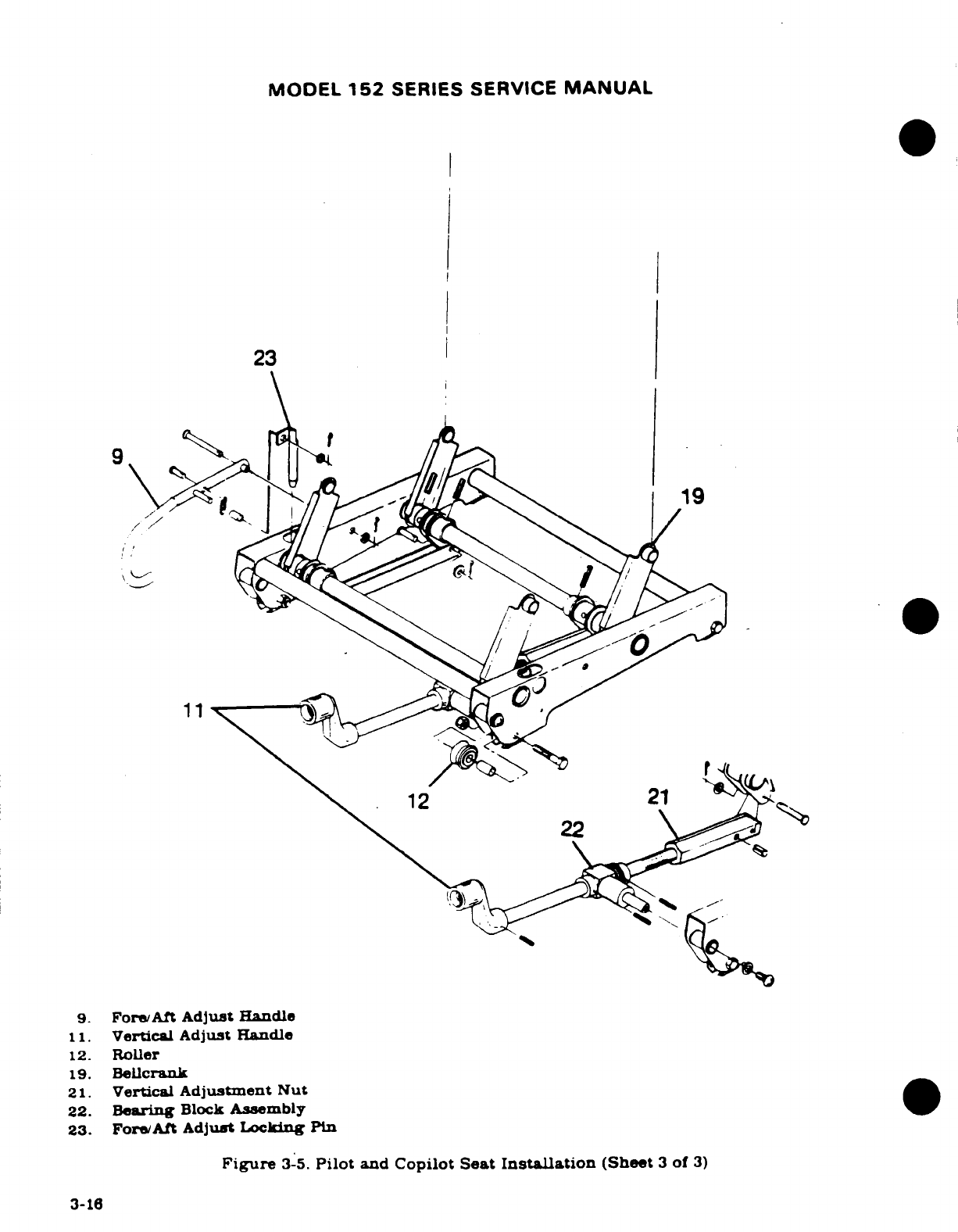
MODEL
152
SERIES
SERVICE
MANUAL
23
~19
11
12
21
9.
Fore/Aft
Adjust
Handle
11.
Vertical Adjust Handle
12.
Roller
19.
Bellcrank
21.
Vertical
Adjustment
Nut
22.
Bearing
Block
Assembly
23.
Fore/Aft
Adjust
Locking
Pin
Figure
3-5.
Pilot
and
Copilot
Seat
Installation
(Sheet
3
of
3)
3-16
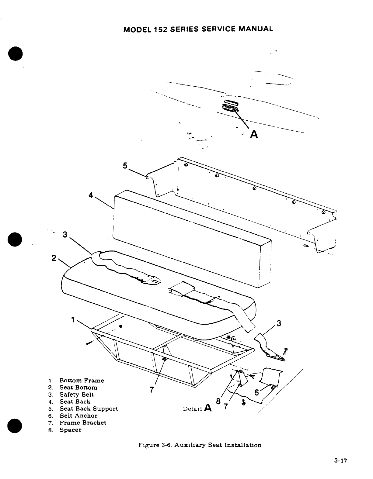
MODEL
152
SERIES SERVICE
MANUAL
*..-
1.
Bottom
Frame
2.
Seat
Bottom
7
3.
Safety
Belt
6
4.
Seat
Back
8
5.
Seat
Back
Support
Detail
A
6.
Belt
Anchor
7.
Frame
Bracket
8.
Spacer
Figure
3-6.
Auxiliary
Seat
Installation
3-17
MODEL
152
SERIES
SERVICE
MANUAL
3-30.
DESCRIPTION. The
standard
seats
consist
of
individual
chairunits
for
the pilot
and
copilot
positions
with
fore-and-aft
adjustment
on
seat
rails
and
two
position
adjustable
backs.
Optional
pilot
and
copilot
seats
feature
a
fore-and-aft
adjustment
plus
a
3
position
vertical
adjustment.
Standard
and
optional seats
feature
removable
seat
bottom
cushions
on
A152
and
FA152
ONLY.
3-31.
REMOVAL AND
INSTALLATION.
a.
Remove
seat
stops
from
rails.
b.
Slide
seat
fore-and-aft
to
disengage
seat
rollers
from
rails
and
lift
seat
out.
c.
Reverse
preceding
steps
for
installation.
Ensure
all
seat
stops
are
reinstalled.
WARNING
Be
sure
seat
stops
are
installed.
because
acceleration
and
deceleration
can
cause seat
to
disengage
from
rails
creating
a
safety
of
flight
condition.
This
is
especially
dangerous
during
takeoff
and
landing attitudes.
3-32.
AUXILIARY.
3-33.
DESCRIPTION.
The
double
width
auxiliary
seat
is
permanently
bolted
to
the
cabin
structure
and
has
no
adjustment
provisions.
The
seat
structure
is
mounted
on
hinge
brackets
with
pivot
bolts.
thus
allowing
seat
to
be
pivoted
upward
for more
baggage
area.
3-34.
REMOVAL
AND
INSTALLATION.
a.
Remove
bolts
securing seat
structure
to
hinge brackets.
b.
Unsnap
seat
back
from
aft
cabin
wall.
c.
Lift
seat
out.
d.
Reverse
preceding
steps
for
installation.
3-35.
REPAIR.
Replacement
of
defective
parts
is
recommended
in
repair
of
seats.
3-36.
CABIN
UPHOLSTERY.
Due
to
the
wide
selection
of
fabrics,
styles
and
colors.
it
is
impossible
to
depict
each
particular
type
of
upholstery.
The
following
paragraphs
describe
general
procedures
which
will
serve
as
a
guide
in
removal
and
replacement
of
upholstery.
Major
work
if
possible. should
be
done
by
an
experienced
mechanic.
If
the
work
must
be
done
by
a
mechanic
unfamiliar
with
upholstery
practices.
the
mechanic
should
make
careful
notes
during
removal
of
each
item
to
facilitate replacement
later.
3-37
MATERIALS
AND
TOOLS.
Materials
and
tools
will
vary
with the
job.
Scissors
for
trimming upholstery
to
size
and
a
dull-bladed
putty
knife
for
wedging
material
beneath
retainer
strips
are
the
only tools
required
for
most
trim
work.
Use
industrial
rubber
cement
to
hold
soundproofing
mats
and
fabric edges
in
place.
3-38.
SOUNDPROOFING. The
aircraft
is
insulated
with
spun
glass
mat-type
insulation
and
a
sound
deadener compound
applied
to
inner
surfaces
of
skin
in
most
areas
of
cabin
and
baggage
compartment.
All
soundproofing
material
should
be
replaced
in
its original
position
any time
it
is
removed.
A
soundproofing
panel
is
placed
in
gap
between
wing
and
fuselage
and
held
in
place
by
wing
root
fairings.
3-39.
CABIN
HEADLINER.
(Refer
to
figure
3-7.)
3-18
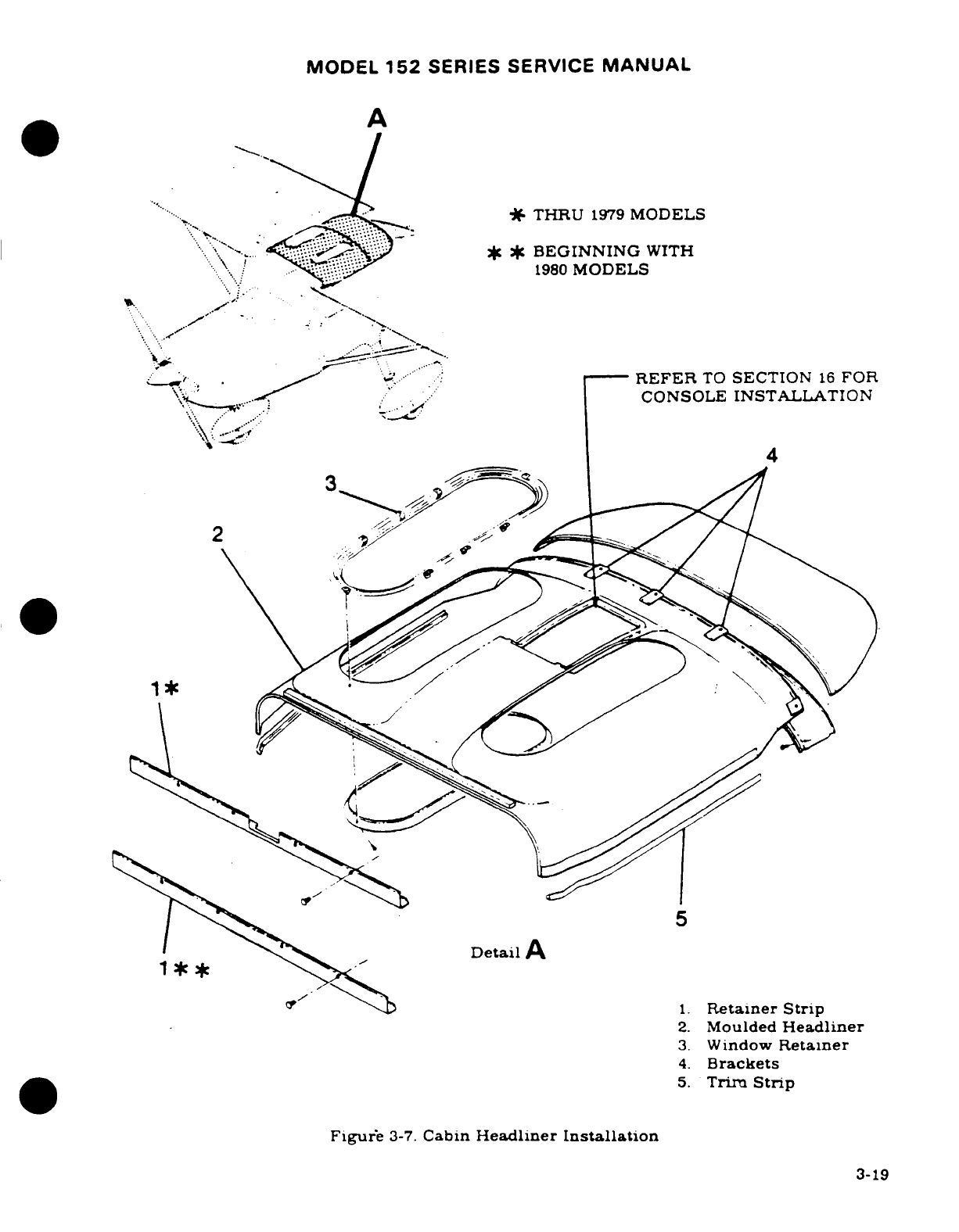
MODEL
152
SERIES SERVICE
MANUAL
A
THRU
1979
MODELS
BEGINNING
WITH
1980
MODELS
REFER
TO
SECTION
16
FOR
CONSOLE
INSTALLATION
Detail
A
1.
Retainer Strip
2.
Moulded
Headliner
3.
Window
Retainer
4.
Brackets
5.
Trim
Strip
Figure
3-7.
Cabin
Headliner
Installation
3-19
MODEL
152
SERIES
SERVICE
MANUAL
3-40.
REMOVAL AND
INSTALLATION.
a.
Remove
sun
visors,
all
inside
finish
strips
and
plates,
overhead
console.
upper
doorpost
shields
and
any
other
visible
retainers
securing
headliner.
b.
Remove
molding
from
fixed
windows.
c.
Remove
screws
securing
headliner
and
carefully take
down
headliner.
d.
Remove
spun
glass
soundproofing
panels
above
headliner.
NOTE
The
lightweight
soundproofing
panels
are
held
in
place
with
industrial
rubber
cement.
e.
Reverse
preceding
steps
for
installation.
Before
installation,
check
all
items
con-
cealed
by
headliner
for
security.
Use
wide
cloth
tape
to
secure
loose
wires
to
fuselage
and
to
seal
openings
in
wing
roots.
3-41.
UPHOLSTERY SIDE
PANELS.
Removal
of
upholstery
side
panels
is
accomplished
by
removing
seats
for
access,
then
removing
parts
attaching
panels.
Remove
screws,
retaining
strips,
arm
rests
and
ash
trays
as required
to
free
the
various
panels.
Automotive
type
spring
clips
attach
most
door
panels.
A
dull
putty
knife
makes
an
excellent
tool
for
prying
clips
loose.
When
installing
upholstery
side
panels.
do
not
over-tighten
sheet
metal
screws.
Larger
screws
may
be
used
in
enlarged holes
as
long
as
area
behind
hole
is
checked
for
electrical
wiring,
fuel
lines
and
other
components
which
might
be
damaged
by
using
a
longer
screw.
3-42
CARPETING.
Cabin
area
and
baggage
compartment
carpeting
is
held
in
place
by
rubber
cement,
sheet
metal
screws
and
retaining
stips.
When
fitting
a new
carpet.
use
old
one
as
a
pattern
for
trimming
and
marking
screw
holes.
3-43.
BAGGAGE
COMPARTMENT
UPHOLSTERY.
A
washable
plastic
held
in
place
by
screws
and
retainers
is
used
in
the
baggage compartment.
Cargo
tie-down
and/
or
seat
belt
brackets
must
be
removed
as
necessary
to
facilitate upholstery
removal.
3-44.
SAFETY
PROVISIONS.
3-45.
CARGO
TIE-DOWNS.
Cargo tie-downs
are
used
to
retain
baggage.
A
net
designed
to
be
secured
to
the
aft
wall
and
cabin
floor
is
available
to
hold
baggage
in
the
aft
cabin
area.
3-46.
SAFETY BELTS.
Safety
belts,
bolted
to
the
cabin
structure
are
provided
for
each
seat
Belts
should
be
replaced
if
frayed or
cut,
latches are
defective
or
stitching
is
broken.
Attaching
parts
should
be
replaced
if
worn
excessively
or
defective.
Refer
to
figure
3-8.
3-47
SHOULDER
HARNESS.
Shoulder
harnesses
may
be
installed
in the
aircraft.
The
latches
require
no
lubrication.
Component
parts
should
be
replaced
as
outlined
in
preceding
paragraph.
Refer
to
figure
3-8.
3-48.
INERTIA
REEL
SHOULDER
HARNESS.
An
inertia
reel
shoulder
harness
may
be
installed.
The
inertia
reel
allows
free
movement
for
the
seat
occupant
but
will
lock
when
subjected
to
a
sudden
load.
Proper
operation
of
the
reel
can
be
checked
by
applying
a
quick
jerk
to
the
belt.
inertia
reel
should
lock
and
hold.
Figure
3-8
may
be
used as
a
guide
for
removal
and
installation.
3-49.
REAR
VIEW
MIRROR.
Thru
seral
15282031
a
rear
view
mirror
may
be
installed
in
the
instrument
panel
glareshield.
Refer
to
figure
3-9
for
removal
and
installation.
3-20
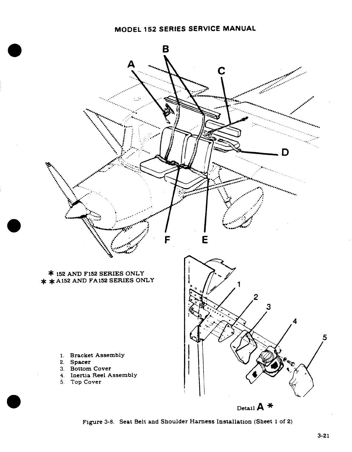
MODEL
152
SERIES
SERVICE
MANUAL
B
*
152
AND
F152
SERIES
ONLY
*f
*A152
AND
FA152
SERIES
ONLY
1.
Bracket
Assembly
3.
Bottom
Cover
\
4.
Inertia
Reel
Assembly
..
*
.
Detail
A
*
Figure
3-8.
Seat
Belt
and
Shoulder
Harness
Installation
(Sheet
1
of
2)
3-21
***

MODEL
152
SERIES SERVICE
MANUAL
12
*
14
Detail
C
16
12
Detail
F
6
1
Bracket
Assembly
2
Spacer
6.
Washer
2
7
Shoulder
Harness
8
8.
Cover
9.
Bolt
10.
Cable
Assembly
11.
Eyebolt Detail
B
9
12.
Seat
Belt
Detal
13.
Bulkhead
14.
Floorboard
Structure
15.
Nutplate
16.
Grommet
Detail
E
Figure
3-8.
Seat
Belt
and
Shoulder
Harness
Installation
(Sheet
2
of
2)
3-22
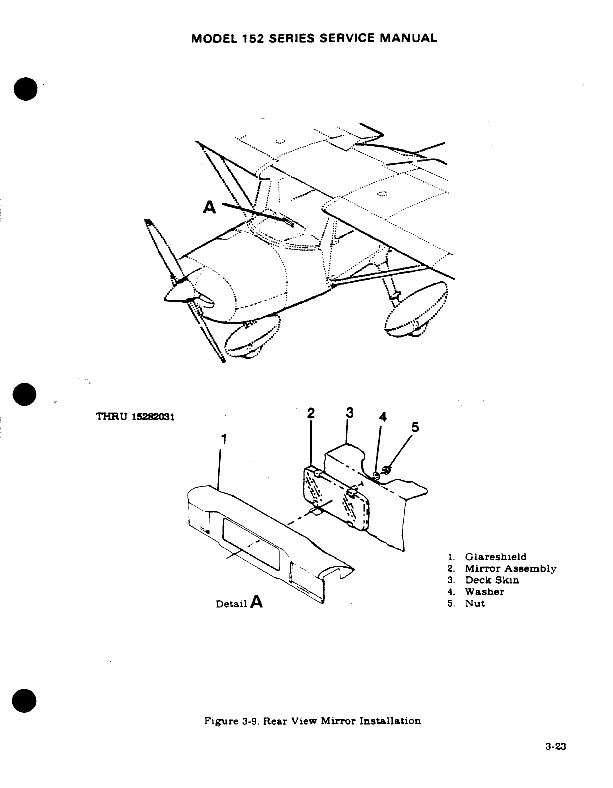
MODEL
152
SERIES
SERVICE
MANUAL
THRU
15282031
2
1.
Glareshield
2.
Mirror
Assembly
3.
Deck
Skin
4.
Washer
Detail
A
5.
Nut
Figure
3-9.
Rear
View
Mirror
Installation
3-23
MODEL
152
SERIES
SERVICE
MANUAL
3-50.
SEAT
RAIL
INSPECTION.
A
special
inspection
of
seat
rails
should
be
conducted
each
50
hours.
See
figure
3-10
for
inspection
procedures.
3-24
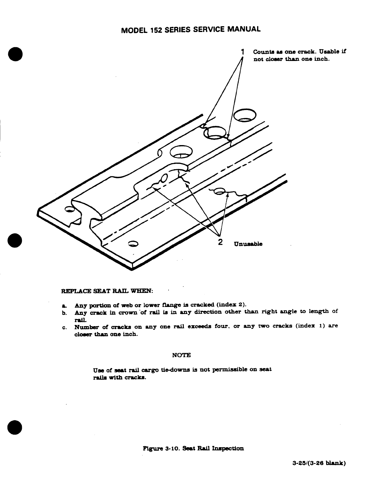
MODEL
152
SERIES
SERVICE
MANUAL
1
Counts
as
one
crack.
Usable
if
not
closer
than
one
inch.
2
Unusable
REPLACE SEAT
RAIL
WHEN:
a
Any
portion of
web
or
lower
flange
is
cracked
(index
2).
b.
Any
crack
in
crown
of
rail
is
in
any
direction
other
than
right
angle
to
length
of
rail.
c.
Number
of
cracks
on
any
one
rail
exceeds
four,
or
any
two
cracks
(index
1)
are
closer
than
one
inch.
NOTE
Use of
set
rail
cargo
tie-downs
is
not
permissible
on
seat
rails
with cracks.
Figure
3-10.
Seat
Rail
Inspection
3-25/(3-26
blank)
MODEL
152
SERIES
SERVICE
MANUAL
SECTION
4
WINGS
AND
EMPENNAGE
Page
No.
TABLE
OF
CONTENTS
Aerofiche/
Manual
Fin
........................
E4/4-6A
Description
...............
1E4/4-6A
WINGS
AND
EMPENNAGE
...
1D22/4-1
Removal/Installation
......
1E44-6A
Wings
......................
lD22/4-1
Attachment
Inspection
and
Description
................
1D22/4-1
Nutplate
Replacement
....
1E4/4-6A
Removal
...........
D22/4-1
Repair
.
...........
.......
E
104-9
Repair
....................
1D23/4-2
Horizontal Stabilizer
........
E10/4-9
Installation
...............
1D23/4-2
Description
...............
1E10/4-9
Adjustment
...............
E1/4-4
Removal/Installation
......
1E10/4-9
Wing
Struts
................
1E3/4-6
Repair
..................
.
1E10/4-9
Description
................
1E3/4-6
Stabilizer
Abrasion
Boots
....
E
10/4-9
Removal/Installation
.......
1E3/4-6
Description ...............
1E13/4-12
Repair
....................
1E3/4-6
Removal
..................
1E13/4-12
Installation
...............
1E13/4-12
4-1.
WINGS AND
EMPENNAGE.
4-2.
WINGS.
(See
figure
4-L)
4-3.
DESCRPTION.
Each
all-metal wing
is
a
semicantilever.
semimonocoque
type,
with
two
main
spars
and
suitable
ribs
for the
attachment
of
the
skin
Skin
panels
are
riveted
to
ribs.
spars
and
stringers
to
complete
the
structure.
An
all-metal.
piano-hinged
aileron.
flaps
and
a
detachable
wing
tip
are
mounted
on each
wing assembly.
A
single
metal
fuel
tank
is
mounted
between
the
wing
spars
at
the
inboard
end
of
each
wing.
Colored
navigation lights
are
mounted
at
each
wing
tip.
4-4.
REMOVAL
Wing
panel
removal
is
most easily
accomplished if
four
men
are
available
to
handle
th
wing. Otherwise,
the
wing
should
be
supported
with
a
sling
or
maintenance
stand
when
the
fastenings
are
loosened
a.
Remove
wing root
fairings
and
fairing
plates.
b.
Remove
all
wing
inspection
plates.
c.
Drain
fuel
from tank
of
wing
being
removed.
d.
Disconnect:
1.
Electrical
wires
at
wing
root
disconnects.
2.
Fuel
lines
at
wing
root.
(Observe
precautions
outlined
in
Section
12.)
3.
Pitot
line
(left
wing
only)
t
wing
root.
4.
Cabin
ventilator
hose
t
wing
root
e.
Reduce
aileron
cable
tension
by
loosening turnbuckles
and
disconnect
cables
at
aileron
bellcranks.
Disconnect
flap
cables
at
turnbuckles
above
headliner.
and
pull
cables
into
wing root
area.
NOTE
To
ease
rerouting
the
cables,
a
guide
wire
may
be
att-
ached
to
each cable
before
it
is pulled
free
of
the
wing.
Cable
may
then
be
disconnected
from
the
wire.
Leave
the
guide
wire
routed
through
the
wing.
it may
be
attached
again
to
the
cable
during
reinstallation
and used
to
pull
the
cable
into place.
Revision
1
4-1
MODEL
152
SERIES
SERVICE
MANUAL
f.
Remove
screws
from
strut
fairings
and
slide
toward
center
of
strut.
g.
Support
wing
at
outboard
end and
remove
strut-to-wing
attach
bolt.
h.
Lower
strut
carefully
to
avoid
damage
to
lower strut-to-fuselage
fitting.
NOTE
Tape
flaps
in
the
streamlined
position during
wing
removal.
This
will
prevent flap
damage
due
to
the
unse-
cured free
swinging
action
when
handling
wing.
i.
Mark
position
of
wing
attachment
eccentric
bushings
(See
figure
4-1.);
these
bushings
are
used
to
rig
out
"wing
heaviness".
j.
Remove
nuts,
washers, bushings
and
bolts
attaching wing
spars
to
fuselage.
NOTE
It
may
be
necessary
to
rock
the
wings
slightly
while
pulling
attaching
bolts,
or
to
use
a
long
drift
punch
to
drive
out
attaching
bolts.
k.
Remove
wing
and
lay
on padded
stand.
4-5.
REPAIR.
A
damaged
wing
panel
may
be
repaired
in
accordance
with
instructions
outlined
in
Section
17.
Extensive
repairs
of
wing
skin
or
structure
are
best accomplished
using
the
wing
repair
jig,
which
may
be
obtained
from
Cessna.
The
wing
jig
serves
not
only
as
a
holding
fixture,
making
work
on
the
wing
easier,
but also
assures
the
absolute
alignment
of
the
repaired
wing.
4-6.
INSTALLATION.
(See
figure
4-1.)
NOTE
There
are
2
sizes
of
forward
wing-attach
bolts
in
the
field.
Some
aircraft
are
equipped
with
AN8-24
bolts,
and
some
are
equipped
with
AN8-23
bolts,
each
type
of
bolt
must
be
installed
with
its
own
washer
and
nut
configuration.
Figure
4-1
illustrates
both
configurations.
The
torque
value
is
the
same
for
both
configurations
since
they
are
both
1/2-inch
bolts.
Minimum
torque
is
300
lb-in,
and the
maximum
torque
is
690
lb-in.
The
aft
wing-attach fittings
are
fastened
with
AN7-24
bolts.
These
bolts have
a
minimum
torque
of
300
lb-in
and
a
maximum
torque
of
500
lb-in.
a.
Hold
wing
in
position
and
install
bolts,
bushings,
washers
and
nuts
attaching
wing
spars
to
fuselage
fittings.
Ensure
eccentric
bushings
are positioned
as
marked.
Torque
nuts
to
values
stipulated
in
note
preceding
this
step.
4-2
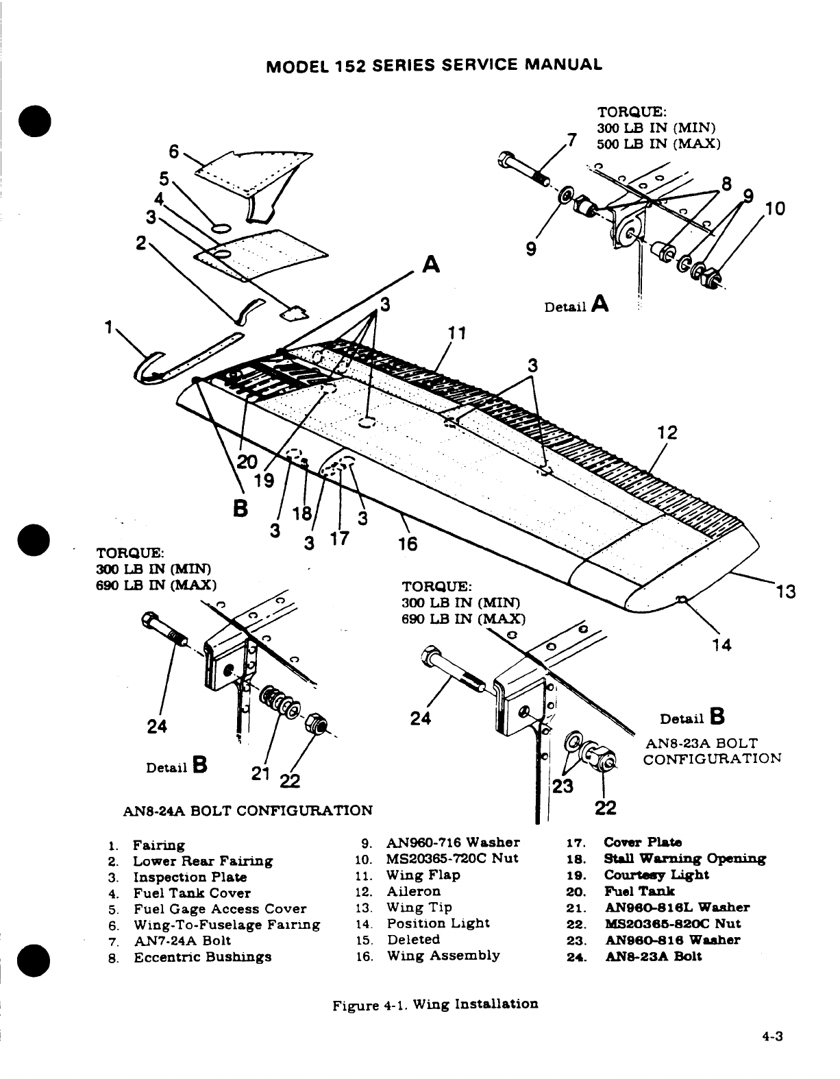
MODEL
152
SERIES
SERVICE
MANUAL
TORQUE:
300
LB
IN
(MIN)
7
500
LB
IN
(MAX)
2
A
300
LB
IN
(MIN)
lN
24
24
DetailB
22
23
AN8-23A
BOLT
AN8-24A BOLT
CONFIGURATION
22
1.
Fairing
9.
AN960-716
Washer
17.
Cover
Plate
2.
Lower
Rear
Fairng
10.
MS20365-720C
Nut
18.
Stall
Warning
Opening
3.
Inspection
Plate
11.
Wing
Flap
19.
Courtsey
Light
4.
Fuel
Tank
Cover
12.
Aileron
20.
Fuel
Tank
5.
Fuel Gage
Access
Cover
13.
Wing
Tip
21.
AN960-816L
Washer
6.
Wing-To-Fuselage
Fairing
14.
Position
Light
22.
MS20365-820C
Nut
7.
AN7-24A
Bolt
15.
Deleted
23.
AN960-816
Washer
8.
Eccentric
Bushings
16.
Wing
Assembly
24.
AN8-23A
Bolt
Figure
4-1.
Wing
Installation
4-3
4-3
MODEL
152
SERIES SERVICE
MANUAL
b.
Install
bolts.
spacers
and
nuts
to
secure
upper
and
lower
ends
of
wing
strut
to
wing
and
fuselage
fittings.
c.
Route
flap
and
aileron
cables.
using
guide
wires.
(Refer
to
note
in
following
step
"e"
in
paragraph
4-4.)
d.
Connect
the
following.
1.
Electrical
wires
at
wing
root disconnects.
2.
Fuel
lines
at
wing
root.
(Observe
precautions
outlined
in
Section
12.)
3.
Pitot
line.
if
left
wing
is
being
installed.
e.
Rig
aileron
system
as
outlined
in
Section
6.
f.
Rig
flap
system as
outlined
in
Section
7.
g.
Fill
tank
with
fuel
and
check for
leaks.
observing
precautions
outlined
in
Section
12.
h.
Check
operation
of
fuel
quantity
gage.
i.
Install
wing
root
fairings.
NOTE
Apply
fillet-type
sealant
(Permagum
576.1.
Inmont
Corp..
St.
Louis.
Missouri) or
equivalent
to
area
between
cabin
top
and wing
skin,
and
also
to
area
across top
of
lower
strut
fitting
at
skin
cutout.
Gap
between
windshield
and
wing
leading
edge
with
cloth-backed,
waterproof
tape
(Polyken
230
or
231.
Kendall-Polyken
Division.
Chicago.
Illinois)
or
equivalent.
NOTE
Be
sure
to
insert
soundproofing
panel
in
wing
gap.
if
such
a
panel
was
installed
originally,
before
replacing
wing
root
fairings.
j.
Install
all
wing
inspection
plates.
interior
panels
and upholstery.
4-7
ADJUSTMENT
(CORRECTING
"WING-HEAVY"
CONDITION).
(Refer
to
figure
4-1.)
If
considerable
control
wheel
pressure
is
required
to
keep
the
wings
level
in
normal flight.
a
"wing-heavy"
condition
exists.
To
remedy
this
condition,
proceed as
follows:
a.
Remove
wing
root
fairing
strip
on
"wing-heavy"
side
of
aircraft.
b.
Loosen
nut
(10)
and
rotate
eccentric
bushings
(8)
simultaneously
until
the
bushings
are
positioned
with
the
thick
sides
of
the
eccentrics
up.
This
will
lower
the
trailing
edge
of
the
wing.
and
decrease
"wing-heaviness"
by
increasing
the
angle-of-
incidence
of
the
wing.
CAUTION
Be
sure
to
rotate
the eccentric
bushings
simultaneously.
Rotating
them
separately
will
destroy
the
alignment
between
the off-center
bolt
holes
in
the
bushings,
thus
exerting
a
shearing
force
on
the
bolt.
with
possible
damage
to
the
hole
in
the
wing
spar
fitting.
4-4

MODEL
152
SERIES
SERVICE
MANUAL
4
Detail
A
*
NOTE
6
1.
Mooring
Ring
LUBRICATE
BOLT
AND
2.
Upper
Fairing
HOLE
PER
SECTION
2.
A
3.
Screw
4.
Washer
5.
Nut
6.
Bolt
7.
Wing
Attachment
Fitting
8.
Spacer
9.
Fuselage
Attachment
Fitting
10.
Lower
Fairing
6
4
B
5
Detail
B
3
10
Figure
4-2.
Wing
Strut
4-5
MODEL
152
SERIES SERVICE
MANUAL
c.
Torque
nuts
(10).
and
reinstall
fairing
strip.
d.
Test-fly
the
aircraft.
If
the
wing-heavy
condition
still
exists.
remove
fairing
strip
on
the
"lighter"
wing,
loosen
nut
and
rotate
bushings
simultaneously until
the
bushings
are
positioned
with
the
thick
side
of
the
eccentrics
down.
This
will
raise
the
trailing
edge
of
the
wing,
thus
increasing
wing-heaviness
to
balance
heaviness
in
the
opposite
wing.
e.
Torque
nut
(10).
install
fairing
strip.
and
repeat
test
flight.
4-8.
WING
STRUTS.
(See
figure
4-2.)
4-9.
DESCRIPTION.
Each
wing
has
a
single
lift
strut
which
transmits
a
part
of
the
wing
load
to
the
lower
portion
of
the
fuselage.
The
strut
consists
of
a
streamlined
tube
with
fittings
for
attachment
at the fuselage
and wing.
4-10.
REMOVAL
AND
INSTALLATION.
a.
Remove
screws
from
strut
fairings
and
slide
fairings
along
strut.
b.
Remove
fuselage
and
wing
inspection
plates
at
strut
junction points.
c.
Support
wing
securely,
then
remove
nut
and
bolt
securing
strut
to
fuselage.
d.
Remove
nut.
bolt
and
spacer
used
to
attach
strut
to
wing.
then
remove
strut
from
aircraft
e.
Reverse
preceding
steps
to
install
strut.
NOTE
Seal
across
top
of
lower
strut
fitting
at
skin
cutout
with
576.1
Permagum.
4-11.
REPAIR.
a.
For
grooves
in
wing
strut
caused
by
strut
fairings. the
following
applie:
1.
If
groove
exceeds
.010
inch
in
depth
and
is
less
than
.75
inch
from
a
rivet
center
the
strut
should
be
replaced.
2.
If
groove
exceeds
.030
inch
in
depth
and
is
more
than
.75
inch
from
a
rivet
cen-
ter,
the
strut
should
be
replaced.
3.
If
groove
depth
is
less
than
.030
inch
and
is
more
than
.75
inch
from
a
rivet
cen-
ter,
strut
should
be
repaired
by
tapering
gradually
to
the
original
surface
and
burnishing
out
to
a
smooth
finish.
The
local
area
should
be
checked
with
dye
penetrant
to
ensure
that
no
crack
has
developed.
4-6
MODEL
152
SERIES
SERVICE
MANUAL
b.
The
following applies
to
wing
struts
with
grooves
worn
in
the
lower
trailing
edge.
This
type
damage
can
occur
after
extensive
cabin
door
usage
with
a
misaing
or
im-
properly
adjusted
door
stop
which
allows
the
door
to
bang
against
the
aft
edge
of
the
strut
at the
lower
end.
NOTE
Struts
with
a
groove
deeper
than
50%
of
the
original
ma-
terial
thickness
should
be
replaced.
Lesser
dammage
y
be
repaired
as
follows:
1.
Without
making
the
damage
deeper,
remove
strut
material on
each
side
of
groove
to
reduce
notch
effect
of
damage.
Smooth
and
blend
the
surface
to
provide
a
gradual
transition
of
strut
tube
material
thicknesr
in
damaged
area.
The
local
area
should
be
checked
with
dye
penetrant
to
insure that
no
crack
has
developed.
2.
Apply
brush
alodine
or
nonzinc
chromate
primer
and
repaint
area.
3.
Re-rig
the
door
stop
and/or re-form
the
lower
portion
of
the
door
pan
and
skin
in-
board
to
prevent
the
door
from
rubbing
the
strut
tube.
If
these
actions
prove to
be
ineffective,
install
some
form
of
protective
bumper,
either
on
strut
or
lower
por-
tian
of
door,
to
prevent
further
damage.
A
short,
hard
rubber
strip
bonded
to
the
trailing
edge of
the
strut
where
the
door comes
close
to
strut
is
a
possibility.
c.
Tie-downs
and
attachibng
parts
may
be
replaced.
If
the
strut
is badly
dented,
cracked
or
deformed,
it
should
be
replaced.
4-12.
FIN.
(See
figure
4-3.)
4-13.
DESCRIPTION.
The
fin
is
primarily
of
metal
construction, consisting
of
ribs
and
spars
covered
with
skin.
Fin
tips
are
of
ABS
or
glass
fiber
construction.
Hinge
brackets
at
the
fin
rear
spar
attach
the
rudder.
4-14.
REMOVAL
AND INSTALLATION.
The
fin
may
be
removed
without
first
removing
the
rudder.
However,
for access
and
ease
of
handling,
the
rudder
may
be
removed
in
accordance
with
procedures
outlined
in
Section
10.
Remove
fin
as
follows:
a.
Remove
fairings
(3)
and
(4)
from
sides
of
fin.
b.
Disconnect
flashing
beacon
lead,
tail
navigation
light
lead,
antennas
and
antenna
leads,
and
rudder
cables,
if
rudder
has
not been
removed.
c.
Thru
1979
Models,
remove
bolts
attaching
rear
fin
brackets
to
horizontal
stabilizer.
d.
Beginning
with
1980 Models,
remove screws
attaching
rear
fin
to tailcone
bulkhead.
e.
Remove
bolts
attaching
front
fin
brackets
to
fuselage and
remove fin.
f.
Install
fin
by
reversing
preceding
steps.
Be
sure
to
check
and
reset
rudder and
eleva-
tor
travel
if
any
stop
bolts
wee
removed
or
their
settings
disturbed.
(Refer
to
Sections
2,9
and
10).
NOTE
Torque
screws
(16)
to a
value
of
100-120
lb-in.
4-14A.
ATTACHMENT
INSPECTION
AND
NUTPLATE
REPLACEMENT.
(See
figure
4-3A.)
Federal
Aviation Regulations
(FAR)
rules
call
for
inspection
of
key
and primary
structural
'attachments,
including
the
vertical
fin
attachment,
on
either
an
annual
or
100
hour basis.
However,
for
airplanes
through
1980
models,
it
is
recommended
that
the
nutplates
used
to
attach
the
fin
be
inspected
after
each
100
hours
of
operation.
Revision
1
4-6A
MODEL
152
SERIES
SERVICE
MANUAL
a.
Position
rudder
to
one
side
as
far
as
possible.
Through
access holes
in
end
of
vertical
fin
attach
bracket,
use
an
inspection
light
and
small
mirror
to
inspect
fin
attach
bracket
and
nutplates
on
upper and
lower
flange
of
attach
bracket.
Inspect
for
cracks
in
fittings.
b.
Position
rudder
to
opposite
side,
and
repeat
same
inspection
for
opposite
end
of
attach
bracket.
c.
If
nutplates
show
no
indication
of
cracking,
they
are
correct.
d.
If
nutplates
are
cracked
in
threaded
area,
they
require
replacement.
e.
Replace
nutplates.
1.
Remove
rudder,
elevators,
and
vertical
fin
per
sections
10,
8,
and
paragraph
4-14.
2.
Remove
bolts
securing
stabilizer
rear
spar
to
fuselage
tailcone.
3.
Remove
bolts
securing
forward
stabilizer
attach
points.
Remove
stabilizer.
4.
Drill
out
existing
rivets
that
secure
the
attach
bracket
to
the
stabilizer
spar
and
remove
bracket
assembly.
5.
Remove
damaged
nutplates
by
drilling
out
securing
rivets.
6.
Using
rivets,
install
replacement
nutplates
to
attach
bracket.
7.
Remove
access cover
from
top
of
stabilizer
skin
for
use
of
bucking
bar
below
skin.
8.
Reinstall
attach
bracket
to
stabilizer
spar.
9.
Reinstall
stabilizer,
vertical
fin,
rudder,
and
elevators
per
paragraph
4-14
and
sections
10
and
8.
NOTE
Torque
bolts to
70
to
100
lb-in.
4-6B
Revision
1
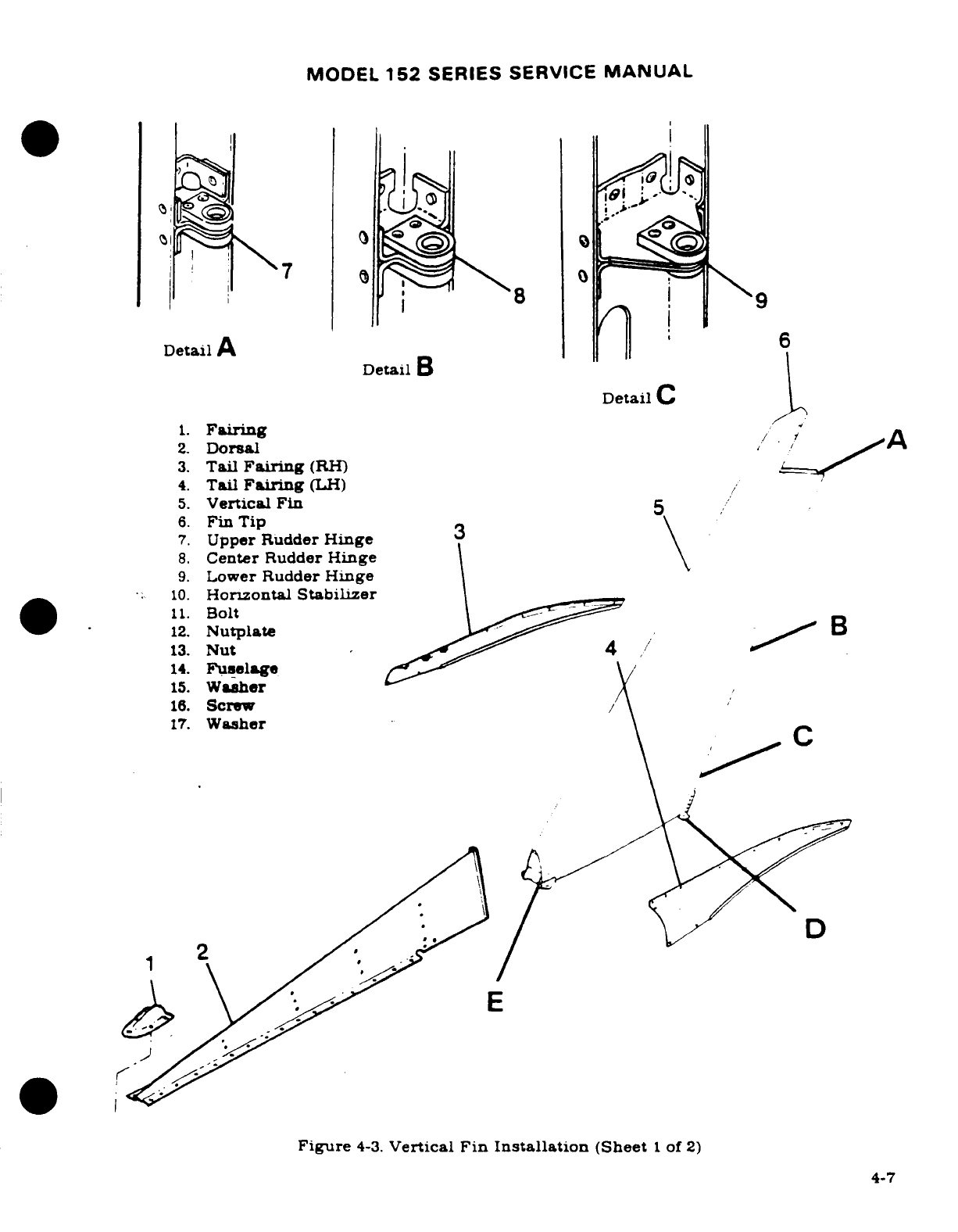
MODEL
152
SERIES
SERVICE
MANUAL
8
7
DetailA
6
Detail
B
Detail
C
1.
Fairing
A
2.
Dorsal
3.
Tail
Fairing
(RH)
4.
Tail
Fairing
(LH)
5.
Vertical
Fin
6.
Fin
Tip
7.
Upper
Rudder
Hinge
8.
Center
Rudder
Hinge
9.
Lower
Rudder
Hinge
10.
Horizontal
Stabilizer
11.
Bolt
12.
Nutplate
B
13.
Nut
4
14.
Fuselage
15.
Washer
16.
Screw
/
17.
Washer
E
Figure
4-3.
Vertical
Fin Installation
(Sheet
1
of
2)
4-7
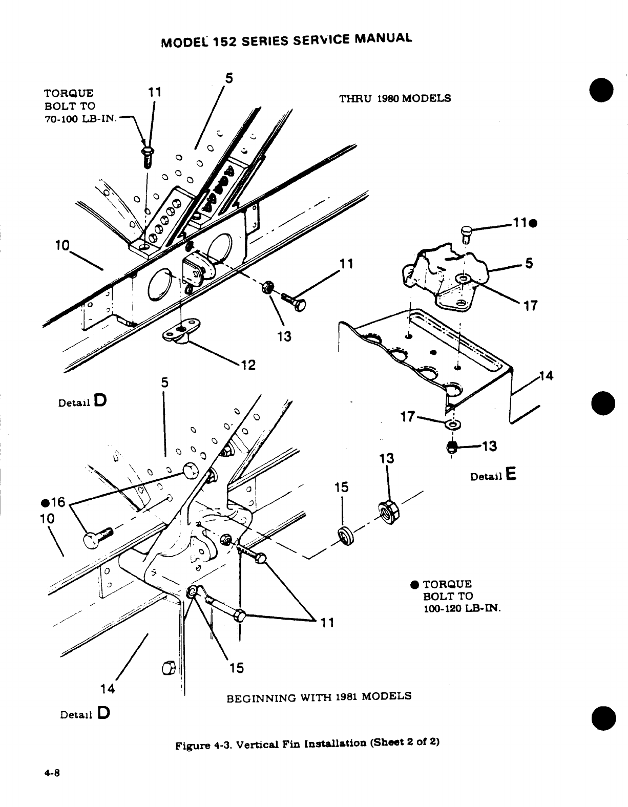
MODEL
152
SERIES SERVICE
MANUAL
5
TORQUE
11
BOLT
TO
THRU
1980
MODELS
70-100
LB-IN.
13
DetailD
15
14
BEGINNING
WITH
1981
MODELS
Detail
D
Figure
4-3.
Vertical
Fin
Installation
(Sheet
2
of
2)
4-8
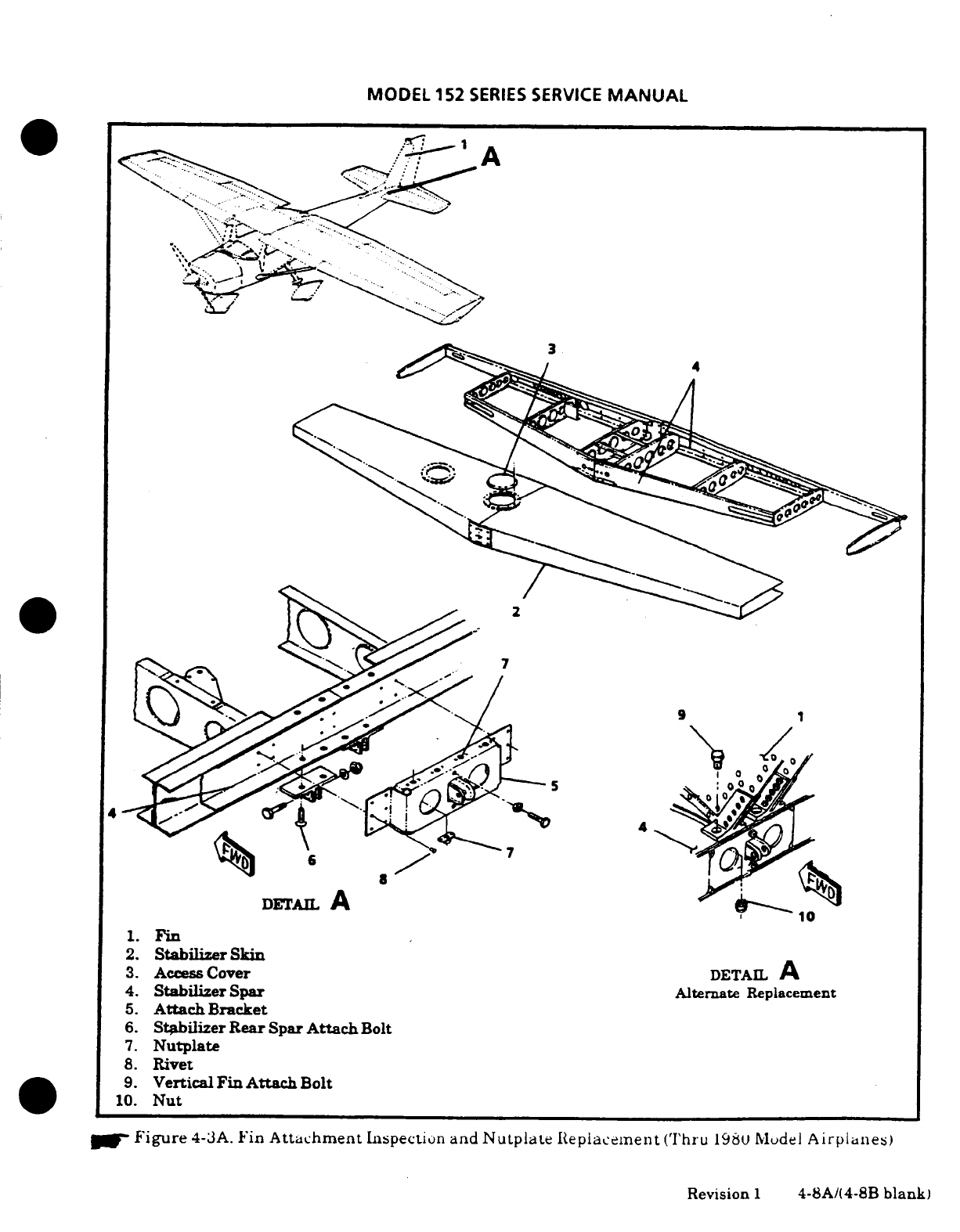
MODEL
152
SERIES
SERVICE
MANUAL
*.
DETAIL
A
1.
Fin
2.
Stabilizer
Skin
3.
Access
Cover
DETAIL
A
4.
Stabilizer
Spar
Alternate
Replacement
5.
Attach
Bracket
6.
Stabiizer
Rear
Spar
Attach
Bolt
7.
Nutplate
8.
Rivet
9.
Vertical
Fin
Attach
Bolt
10.
Nut
Figure
4-3A.
Fin
Attachment
Inspection
and
Nutplate
Replacement
(Thru
1980 Model
Airplanes)
Revision
1
4-8A/(4-8B
blank)
MODEL
152
SERIES
SERVICE
MANUAL
e.
Remove
bolts
attaching
front
fin
brackets
to
fuselage
and
remove
fin.
f.
Install
fin
by
reversing
preceding
steps.
Be
sure
to
check
and
reset
rudder
and
elevator
travel
if
any
stop
bolts
were
removed
or
their
settings
disturbed.
(Refer
to
Sections
2.
9
and
10.)
NOTE
Torque
screws
(16)
to
a
value
of
100-120
lb-in.
4-15.
REPAIR.
Fin
repair
should
be
accomplished
in
accordance
with
applicable
instructions
outlined in
Section
17.
4-16.
HORIZONTAL
STABITIZER.
(See
figure
4-4.)
4-17.
DESCRIPTION.
The
horizontal stabilizer
is
primarily
of
all-metal
construction.
consisting
of
ribs
and
spars
covered
with skin.
Stabilizer
tips
are
of ABS
construction.
A
formed
metal
leading
edge
is
riveted
to
the
assembly
to
complete
the
structure.
The
elevator
trim
tab
actuator
is
contained
within
the
horizontal
stabilizer.
The
underside
of
the
stabilizer
contains
a
covered
opening
which
provides
access
to
the
actuator.
Hinges
are
located
on
the
rear
spar
assembly
to
support
the
elevators.
4-18.
REMOVAL
AND
INSTALLATION.
a.
Remove
elevators
and
rudder
in
accordance
with
procedures
outlined
in
Sections
8
and
10.
b.
Remove
vertical
fin
in
accordance
with
procedures
outlined
in
paragraph
4-14.
c.
Disconnect
elevator
trim
control
cables
at
clevis
and
turnbuckle
inside
tailcone.
remove
pulleys
which
route
the
aft
cables
into horizontal
stabilizer
and
pull
cables
out
of
tailcone.
d.
Remove
bolts
securing
horizontal
stabilizer
to
fuselage.
e.
Remove
horizontal stabilizer.
f.
Install
horizontal stabilizer
by
reversing
preceding
steps.
Rig
control
systems
as
necessary.
Check
operation
of
tail
navigation
light
and
flashing
beacon.
NOTE
When
installing
horizontal stabilizer
to
fuselage
attach
bolts,
torque
bolts
100-120
lb-in.
4-19.
REPAIR.
Horizontal
stabilizer
repair
should
be
accomplished
in
accordance
with
applica-
ble
instructions
outlined
in
Section
17.
4-20.
STABILIZER
ABRASION
BOOTS.
(See
figure
4-4.)
NOTE
An Accessory
Kit
(AK182-217)
is
available
from
Cessna
Parts
Distribution
(CPD
2)
through
Cessna
Service Sta-
tions
for
installation
of
abrasion
boots
on
aircraft
not
so
equipped.
Revision
1
4-9
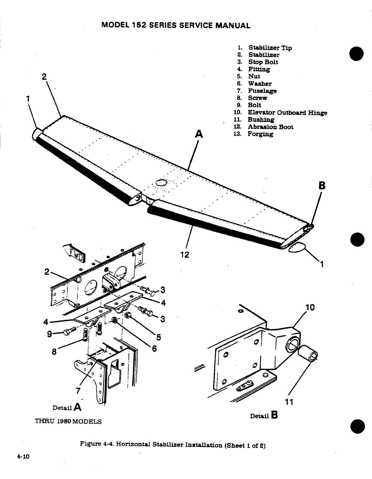
MODEL
152
SERIES SERVICE
MANUAL
1.
Stabilizer
Tip
2.
Stabilizer
3.
Stop
Bolt
4.
Fitting
2
5.
Nut
6.
Washer
7.
Fuselage
8.
Screw
9.
Bolt
10.
Elevator
Outboard
Hinge
11.
Bushing
12.
Abrasion
Boot
13.
Forging
4
12
7
Detail
A
Detail
B
THRU
1980
MODELS
Figure
4-4.
Horizontal
Stabilizer
Installation
(Sheet
1
of
2)
4-10
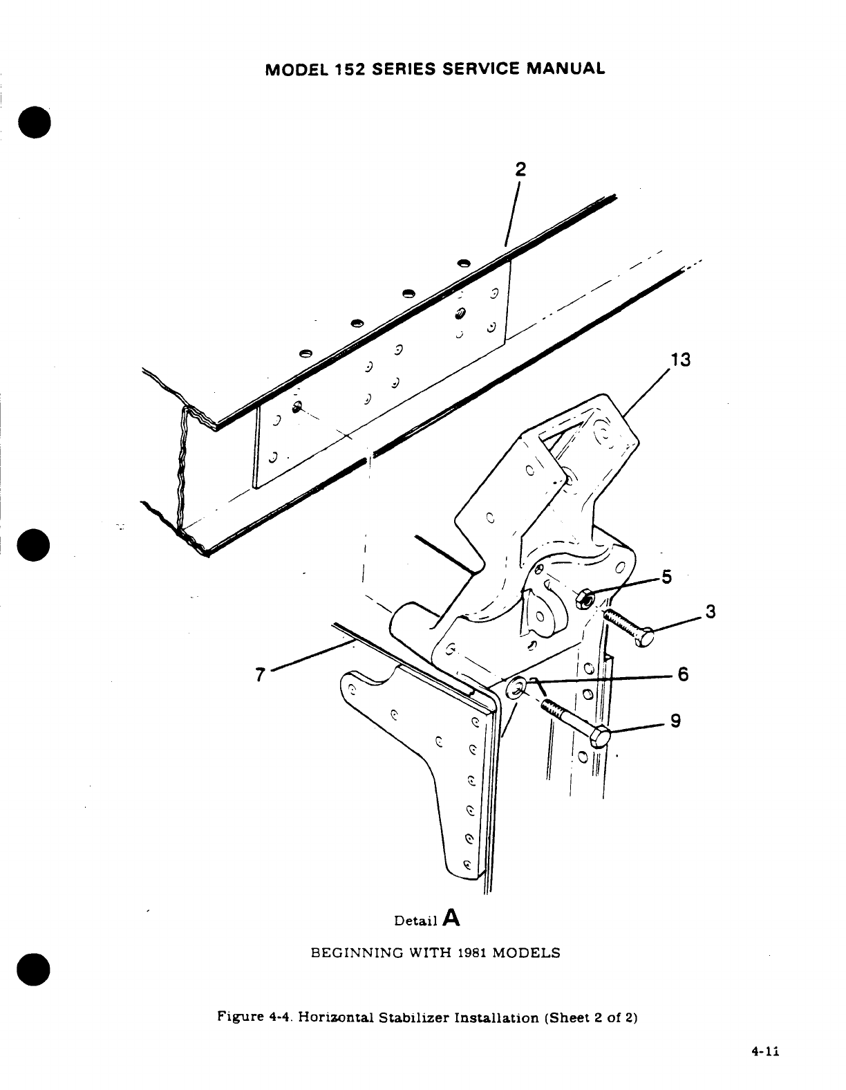
MODEL
152
SERIES
SERVICE
MANUAL
2
Detail
A
BEGINNING
WITH
1981
MODELS
Figure
4-4.
Horizontal
Stabilizer
Installation
(Sheet
2
of
2)
4-11
MODEL
152
SERIES
SERVICE
MANUAL
4-21.
DESCRIPTION.
The
aircraft
may
be
equipped
with
two
extruded rubber
abrasion
boots,
one
on
the
leading
edge
of
each
horizontal
stabilizer.
These
boots
are
installed
to
protect the
stabilizer
leading
edge
from
damage
caused
by
rocks
thrown
back
by
the
propeller.
4-22.
REMOVAL.
The
abrasion
boots
can
be
removed
by
loosening
one
end
of
the
boot
and
pulling
it
off
the
stabilizer
with
an
even
pressure.
Excess
adhesive or
rubber
can
be
removed
with
Methyl-Ethyl-Ketone.
4-23.
INSTALLATION.
Install
abrasion
boots
as outlined
in
the following
procedures.
a.
Trim
boots
to
desired
length.
b.
Mask
off
boot
area
on
leading
edge
of
stabilizer
with
1-inch
masking tape.
allowing
1/
4-inch
margin.
c.
Clean
metal
surfaces
of
stabilizer,
where
boot
is
to
be
installed
with
Methyl-Ethyl-
Ketone.
d.
Clean
inside
surface
of
abrasion
boot
with
Methyl-Ethyl-Ketone
and
a
Scotch
brite
pad
to
ensure
complete
removal
of
paraffin/talc.
Then.
a
normal
wipe
down
with
MEK
on
a
cloth
will
leave
surface
suitable
for
bonding
to
the
aluminum.
NOTE
Boots
may
be
applied over
epoxy
primer,
but
if
the
surface
has
been
painted,
the
paint
shall
be
removed
from
the
bond
area.
This
shall
be
done
by
wiping
the
surfaces
with
a
clean.
lint-free
rag,
soaked
with
solvent,
and
then
wiping the
surfaces
dry,
before
the
solvent
has
time
to
evaporate, with
a
clean, dry
lint-free
rag.
e.
Stir
cement
(EC-1300
Minnesota
Mining
and
Manufacturing
Co.)
thoroughly.
f.
Apply
one
even
brush
coat
to
the
metal
and the
inner
surface
of
the
boot.
Allow
cement
to
air-dry
for
a
minimum
of
30
minutes,
and
then apply
a
second
coat
to
each
surface.
Allow
at
least
30
minutes
(preferably
one-hour)
for
drying.
g.
After
the
cement
has
thoroughly
dried.
reactivate
the
surface
of
the
cement
on
the
stabilizer
and
boot,
using
a
clean,
lint-free
cloth.
heavily
moistened
with
toluol.
Avoid
excess
rubbing
which
would
remove
the
cement
from
the
surfaces.
h.
Position
boot
against
leading
edge.
exercising
care
not
to
trap
air
between
boot
and
stabilizer.
NOTE
Should
boot
be
attached
"off-course",
pull
it
up
imme-
diately
with
a
quick
motion,
and
reposition
properly.
i.
Press
or
roll
entire
surface
of
boot
to
assure
positive
contact
between
the
two
surfaces.
j.
Apply
a
coat
of
GACO
N700A
sealer
or
equivalent
(conforming
to
MIL-C-21067)
along
the
trailing
edges
of
the
boot
to
the
surface
of
the skin
to
form
a
neat
straight
fillet.
k.
Remove
masking
tape and clean
stabilizer
of
excess
material.
1.
Mask
to
the
edge
of
boot
for
painting
stabilizer.
4-12
MODEL
152
SERIES
SERVICE
MANUAL
SECTION
5
LANDING
GEAR.
BRAKES
AND
HYDRAULIC
SYSTEM
Page
No.
TABLE
OF
CONTENTS
Aerofiche/
Manual
Torque
Links
.............
1F22/5-31
LANDING
GEAR
..............
E17/5-2
Description
..............
1F22/5-31
Description
.................
1E17/5-2
Removal
................
1F22/5-31
Trouble
Shooting
............
1E17/5-2
Inspection
...............
1F22/5-31
Main
Landing
Gear
.........
1E17/5-2
Installation
.............
1F22/5-31
Description
................
1E17/5-2
Shimmy
Dampener
........
1F23/5-32
Strut
Removal
...............
E18/5-3
Description
..............
1F23/5-32
Strut
Installation
..........
1E18/5-3
Removal
................
1F23/5-32
Step
Bracket
Installation
...
1E19/5-4
Disassembly
and
Fairings.
.............
1E19/5-4
Reassembly
............
F23/5-32
Description ...........
1E19/5-4
Installation
.............
1F24/5-33
Removal/Installation
.....
1E19/5-4
Steering
System
...........
1F24/5-33
Speed
Fairing
Removal
.....
1E22/5-7
Description
.............
1F24/5-33
Speed
Fairing Installation
..
1E22/5-7
Steering
Rod
Assembly
....
1F24/5-33
Wheel Removal
............
E23/5-8
Description
..............
IF24/5-33
Disassembly
(McCauley)
...
1E23/5-8
Steering
Adjustment
......
G1/5-34
Inspection
and
Repair
Brake
System
..............
1G1/5-34
(McCauley)
..............
E23/5-8
Description
..............
1G1/5-34
Reassembly
(McCauley)
....
1F4/5-13
Trouble Shooting
..........
1G1/5-34
Disassembly
(Cleveland)
1F4/5-13
Master
Cylinders
..........
1G2/5-35
Inspection and Repair
Description
..............
1G2/5-35
(Cleveland)
.
..........
1F5/5-14
Removal
................
1G2/5-35
Reassembly
(Cleveland)
....
1F5/5-14
Disassembly
(Thru
1978) 1G2/5-35
Wheel
Installation
..........
1F5/5-14
Inspection,
Repair,
and
Wheel
Axle
Removal
.......
1F6/5-15
Overhaul
(Thru
1978)
...
1G2/5-35
Wheel Axle
Installation
....
1F7/5-16
Reassembly
(Thru
1978)
1G2/5-35
Wheel
Alignment
Check
....
1F9/5-18
Disassembly
(Beginning
Wheel
Balancing
..........
1F9/5-18
with
1979)
.............
G6/5-39
Nose
Gear
..................
1F10/5-19
Inspection and
Repair
Description
................
1F10/5-19
(Beginning
with
1979)
1G615-39
Trouble
Shooting
..........
1F10/5-19
Reassembly
(Beginning
Removal
..................
1F10/5-19
with
1979)
.............
1G6/5-39
Installation
...............
1F12/5-21
Installation
.............
1G6/5-39
Fairing
Removal
...........
F13/5-22
Hydraulic
Brake
Lines
.....
1G6/5-39
FairingInstallation
........
1F13/5-22
Description
..............
1G7/5-40
Wheel
Removal
............
1F13/5-22
Brake
Assemblies
.........
1G7/5-40
Disassembly
(McCauley)
...
1F13/5-22
Description
..............
1G7/5-40
Inspection
and
Repair
Removal
................
1G7/5-40
(McCauley)
..............
1F16/5-25
Inspection
and
Repair
....
1G7/5-40
Reassembly
(McCauley)
....
1F16/5-25
Reassembly
.............
1G7/5-40
Disassembly (Cleveland)
...
1F17/5-26
Installation
.............
1G7/5-40
Inspection
and
Repair
Checking
Lining
Wear
...
1G8/5-41
(Cleveland)
.............
1F17/5-26
Lining Installation
.......
1G8/5-41
Reassembly
(Cleveland)
....
1F17/5-26
System
Bleeding
.........
1G8/5-41
Installation
...............
F18/5-27
LiningConditioning
......
1G10/5-43
Wheel
Balancing
..........
1F18/5-27
Parking
Brake
System
.....
1G10/5-43
Strut
Disassembly
.........
1F18/5-27
Description
..............
1G10/5-43
Strut
Inspection
and
Repair
.
1F21/5-30
Removal/Installation
.....
1G10/5-43
Strut
Reassembly
..........
1F21/5-30
Inspection
and
Repair
....
1G10/5-43
Revision
1 5-1
MODEL
152
SERIES
SERVICE
MANUAL
5-1.
LANDING
GEAR
5-2.
DESCRIPTION.
The
aircraft
is
equipped with
a
fixed
tricycle
landing
gear,
consisting
of
tubular
spring-steel
main
gear
struts,
and
an
air/oil
steerable
nose
gear
shock
strut.
Two-
piece,
die-cast
aluminum
wheels
are
installed
on
the
main and
nose
landing
gear.
The
wheels
are
equipped with
tubes
and
disc-type brakes.
The
nose
wheel
is
steerable
with
the
rudder
pedals
up
to
a
maximum
pedal
deflection,
after which
it
becomes
free-swiveling.
up
to
a
maximum
of
30
degrees,
each side
of
center.
Nose
and
main
wheel
fairings
are
available
for
installation.
5-3.
TROUBLE
SHOOTING.
TROUBLE
PROBABLE
CAUSE
REMEDY
AIRCRAFT
LEANS
TO
ONE
Incorrect
tire
inflation.
Inflate
to
pressure
specified
SIDE.
in
figure
1-1.
Landing
gear
attaching
Tighten
loose
parts:
replace
parts
too
tight.
defective
parts
with
new
parts.
Landing
gear
spring
Remove
and
install
new
excessively
sprung. part(s).
Bent
axles.
Install
new
part(s).
TIRES
WEAR
EXCESSIVELY.
Incorrect
tire
inflation.
Inflate
to
pressure
specified
in
figure
1-1.
Main
wheels
out
of
Remove
and
install
new
alignment.
part(s).
Landing
gear
spring
Remove
and
install
new
excessively
sprung.
part(s).
Bent
axles.
Install
new
part(s).
Dragging
brakes.
Refer
to
paragraph
5-62.
Wheel
bearings
excessively
Adjust
properly.
tight.
Wheels
out
of
balance. Correct
in
accordance
with
paragraph
5-25.
Loose
torque
links.
Add
shims
or
install
new
parts
as
required.
WHEEL BOUNCE
EVIDENT Out
of
balance
condition. Refer
to
paragraph
5-25.
ON SMOOTH
SURFACE.
5-4.
MAIN
LANDING
GEAR.
5-5.
DESCRIPTION.
The
tubular, spring-steel
main
landing gear
struts
are attached
to
the
5-2
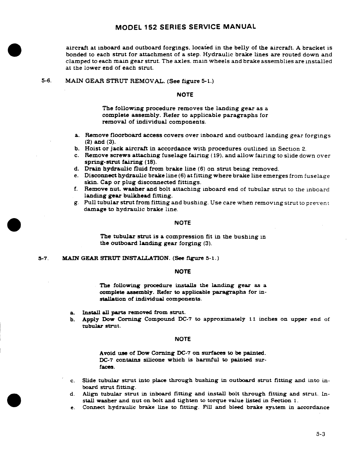
MODEL
152
SERIES
SERVICE
MANUAL
aircraft
at inboard and
outboard
forgings,
located
in
the
belly
of
the
aircraft.
A
bracket
is
bonded
to
each
strut
for
attachment
of
a
step.
Hydraulic brake
lines
are
routed
down
and
clamped
to
each
main
gear
strut.
The
axles.
main
wheels
and
brake
assemblies
are
installed
at
the
lower
end
of
each
strut.
5-6.
MAIN
GEAR
STRUT
REMOVAL.
(See
figure
5-1.)
NOTE
The
following procedure removes
the
landing
gear
as
a
complete
assembly.
Refer
to
applicable
paragraphs
for
removal
of
individual
components.
a.
Remove
floorboard access
covers
over inboard
and
outboard
landing
gear
forgings
(2)
and
(3).
b.
Hoist
or
jack
aircraft
in
accordance
with
procedures
outlined
in
Section
2.
c.
Remove
screws
attaching
fuselage
fairing
(19).
and
allow
fairing
to
slide
down
over
spring-strut fairing
(18).
d.
Drain
hydraulic
fluid
from
brake
line
(6)
on
strut
being
removed.
e.
Disconnect
hydraulic
brake
line
(6)
at
fitting
where brake
line
emerges
from
fuselage
skin.
Cap
or
plug
disconnected
fittings.
f.
Remove
nut.
washer
and
bolt
attaching
inboard
end
of
tubular
strut
to
the
inboard
landing
gear
bulkhead fitting.
g.
Pull
tubular
strut
from
fitting
and
bushing.
Use
care
when
removing
strut
to
prevent
damage
to
hydraulic
brake
line.
NOTE
The
tubular strut
is
a
compression
fit
in
the
bushing
in
the
outboard
landing
gear
forging
(3).
5-7.
MAIN GEAR
STRUT
INSTALLATION.
(See
figure
5-1.)
NOTE
The
following
procedure
installs
the
landing
gear
as
a
complete
assembly.
Refer
to
applicable
paragraphs
for
in-
stallation
of
individual
components.
a.
Install
all
parts
removed
from
strut.
b.
Apply
Dow
Corning
Compound
DC-7
to
approximately
11
inches
on
upper
end
of
tubular
strut.
NOTE
Avoid
use
of
Dow
Corning
DC-7
on
surfaces
to
be
painted.
DC-7
contains
silicone
which
is
harmful
to
painted
sur-
faces.
c.
Slide
tubular
strut
into
place
through
bushing
in
outboard
strut
fitting
and
into
in-
board
strut
fitting.
d.
Align
tubular
strut
in
inboard
fitting
and
install
bolt
through fitting
and
strut.
In-
stall
washer
and
nut
on
bolt
and
tighten
to
torque
value
listed
in Section
1.
e.
Connect
hydraulic
brake
line
to
fitting.
Fill
and
bleed
brake
system
in
accordance
5-3
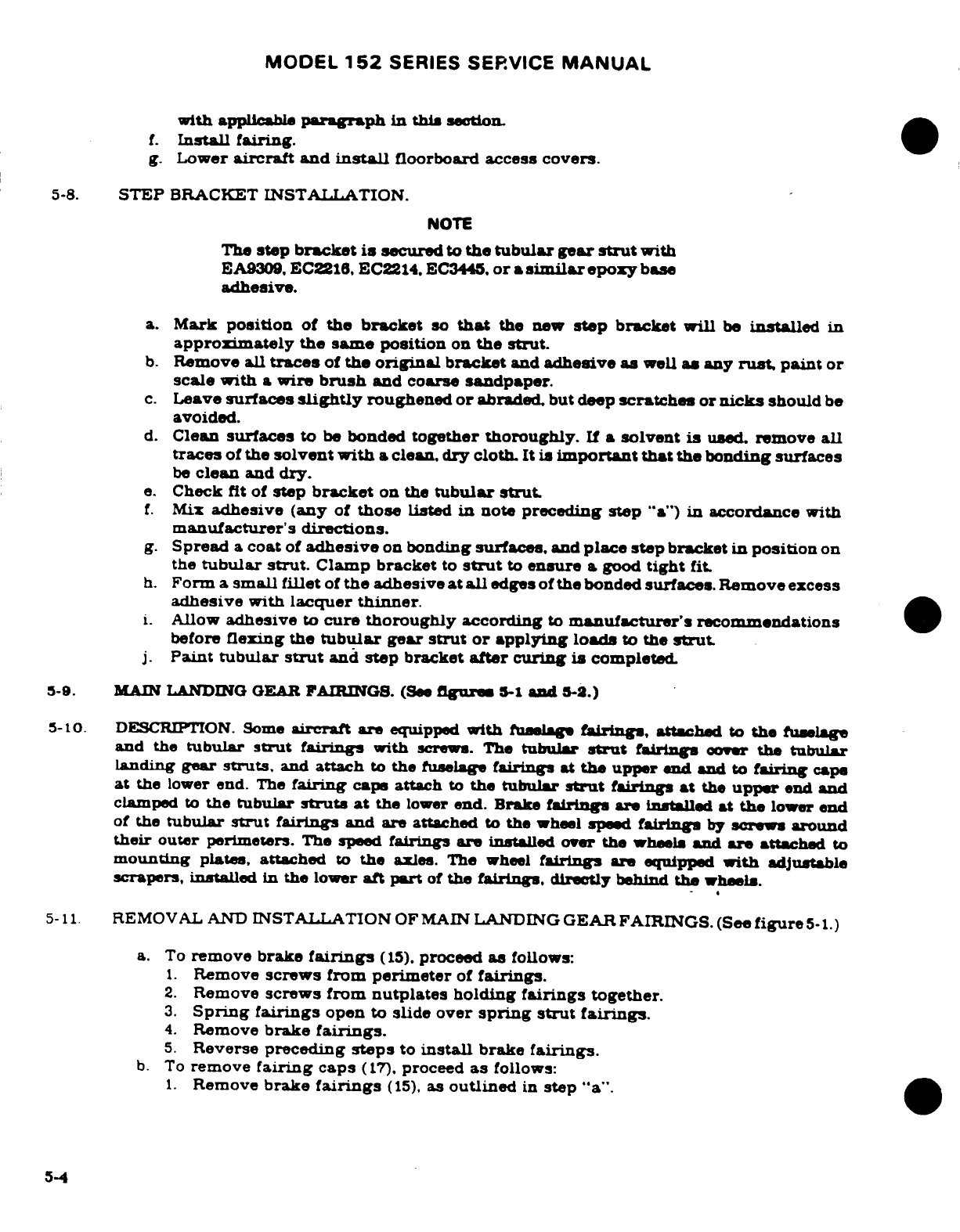
MODEL
152
SERIES SERVICE
MANUAL
with
applicable
paragraph
in
this
section.
f.
Install
fairing.
g.
Lower
aircraft
and
install
floorboard
access
covers.
5-8.
STEP
BRACKET
INSTALLATION.
NOTE
The
step
bracket
is
secured
to
the
tubular gear
strut
with
EA9309,
EC2216.
EC2214. EC3445.
or
a
similar
epoxy
base
adhesive.
a.
Mark
position
of
the
bracket
so
that
the
new
step
bracket
be
installed
in
approximately the same
position
on
the
strut.
b.
Remove
all
traces
of
the
original
bracket
and
adhesive
as
well
as
any
rust
paint
or
scale
with
a
wire
brush
and
coarse
sandpaper.
c.
Leave
surfaces
slightly
roughened
or
abraded,
but deep
scratches
or
nicks
should
be
avoided.
d.
Clean
surfaces
to
be
bonded
together
thoroughly.
If
a
solvent
is
used.
remove
all
traces
of
the
solvent
with
a
clean, dry
cloth.
It is
important that
the
bonding
surfaces
be
clean
and
dry.
e.
Check
fit
of
step
bracket
on
the
tubular
strut.
f.
Mix
adhesive
(any
of
those
listed
in
note
preceding
step
"a")
in
accordance
with
manufacturer's
directions.
g.
Spread
a
coat
of
adhesive
on
bonding
surfaces,
and
place
step
bracket
in
position
on
the
tubular
strut.
Clamp
bracket
to
strut
to
ensure
a
good
tight
fit.
h.
Form
a
small fillet
of
the
adhesive
at
all
edges
of
the
bonded
surfaces. Remove
excess
adhesive
with
lacquer
thinner.
i.
Allow
adhesive
to
cure
thoroughly
according
to
manufacturer's
recommendations
before
flexing
the
tubular
gear
strut
or
applying
loads
to
the
strut
j.
Paint
tubular
strut
and
step
bracket
after curing
is
completed.
5-9. MAIN
LANDING
GEAR
FAIRINGS.
(See
figures
5-1
and
5-S.)
5-10.
DESCRIPTION.
Some
aircraft
are
equipped
with
fuselage
fairings,
attached
to
the
fuselage
and
the
tubular
strut
fairings
with
screws. The
tubular
strut
fairings
cover
the
tubular
landing
gear
struts,
and
attach
to
the
fuselage
fairings
at
the
upper
end
and
to
fairing
cape
at
the
lower
end.
The
fairing
caps
attach
to
the tubular
strut
fairings
at
the
upper
end
and
clamped
to
the
tubular
struts
at
the
lower
end.
Brake
fairings
are
installed
at
the
lower
end
of
the
tubular
strut
fairings
and
are attached
to
the
wheel
speed
fairings
by
screws
around
their
outer
perimeters.
The speed
fairings
are
installed
over
the
wheels
and
are
attached
to
mounting
plates,
attached
to
the
axles.
The
wheel
fairings
are
equipped
with
adjustable
scrapers,
installed
In
the
lower
aft
part
of
the
fairings,
directly
behind
the
wheels.
5-11
REMOVAL AND
INSTALLATION
OF
MAIN
LANDING
GEAR FAIRINGS.
(See
figure
5-1.)
a.
To
remove brake
fairings
(15),
proceed
as
follows:
1.
Remove
screws
from
perimeter
of
fairings.
2.
Remove
screws from
nutplates
holding
fairings
together.
3.
Spring fairings
open
to
slide
over
spring
strut
fairings.
4.
Remove
brake
fairings.
5.
Reverse
preceding
steps
to
install
brake
fairings.
b.
To
remove
fairing
caps
(17).
proceed
as
follows:
1.
Remove
brake
fairings
(15).
as
outlined
in
step
"a".
5-4
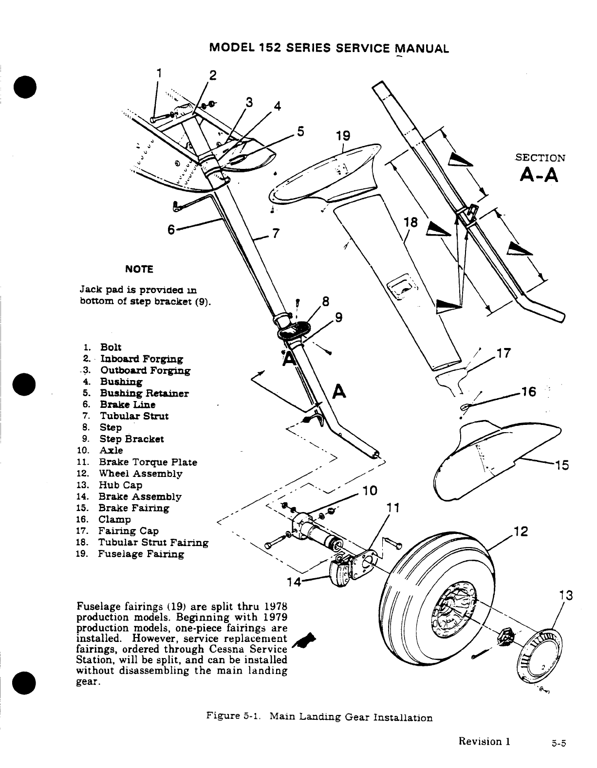
MODEL
152
SERIES
SERVICE
MANUAL
1
2
19
.SECTION
A-A
18
NOTE
Jack
pad
is
provide
in
bottom
of
step
bracket
(9).
1.
Bolt
17
2.
Inboard
Forging
3.
Outboard
Forging
4.
Bushing\
16
5.
Bushing
Retainer\
A
16
6.
Brake
Line
7.
Tubular
Strut
8.
Step
9.
Step
Bracket
10.
Axle
/
11.
Brake
Torque
Plate
15
12.
Wheel
Assembly
13.
Hub Cap
10
14.
Brake
Assembly
/
15.
Brake
Fairing
.
11
16.
Clamp
17.
Fairing
Cap
18.
Tubular
Strut
Fairing
19.
Fuselage
Fairing
14 13
Fuselage
fairings
(19)
are
split
thru
1978
production
models.
Beginning
with
1979
production
models,
one-piece
fairings
are
installed.
However,
service
replacement
fairings,
ordered
through
Cessna
Service
Station,
will
be
split,
and
can
be
installed
without
disassembling
the
main
landing
gear.
Figure
5-1.
Main
Landing
Gear
Installation
Revision
1
5-5
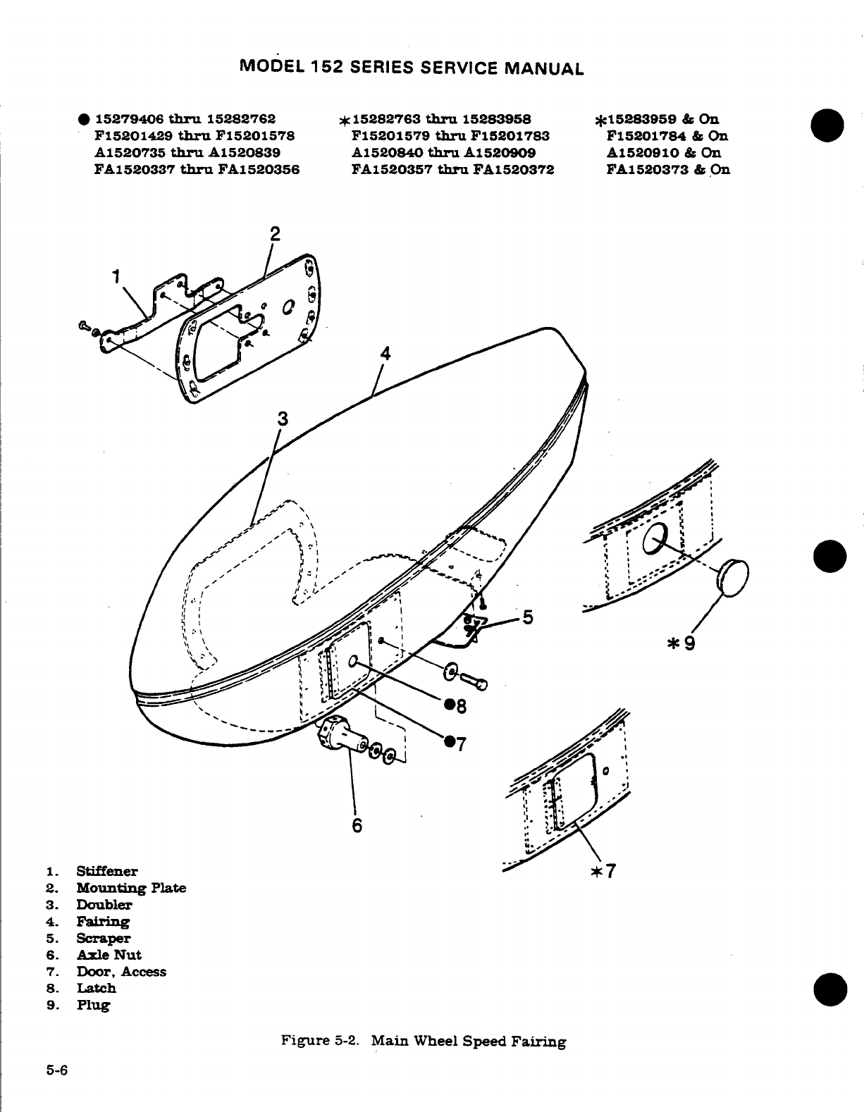
MODEL
152
SERIES
SERVICE
MANUAL
*
15279406
thru
15282762
*
15282763
thru
15283958 *15283959
&
On
F15201429
thru
F15201578
F15201579
thru
F15201783
F15201784
&
On
A1520735
thru
A1520839 A1520840
thru
A1520909
A1520910
&
On
FA1520337
thru
FA1520356
FA1520357
thru
FA1520372
FA1520373
&
On
2
.
5.
Scraper
6.
Axle
Nut
7.
Door,
Access
8.
Latch
9.
Plug
Figure
5-2.
Main
Wheel
Speed
Fairing
5-6
MODEL
152
SERIES
SERVICE
MANUAL
2.
Remove
screws
attaching
fairing
caps
to
spring
strut
fairings
(18).
3.
Remove
bolt
and
nut
attaching
clamps
(16)
to
spring
struts
(7).
4.
Slide
clamps
(16)
down
tubular
struts
(7):
remove
fairing
caps
(17).
NOTE
Clamps
may
be
sprung
over
tubular
struts
for
removal.
5.
Reverse
preceding
steps
to
install
fairing
caps.
c.
To
remove
fuselage fairings
(19).
proceed
as
follows:
1.
Remove
screws
attaching
fairings
to
fuselage.
2.
Slide
fairings
down
tubular
strut
fairings
and.
thru
1978
Models.
remove
screws
from
nutplates
holding
fairings
together.
and
spring
fairings
open
to
slide
over
strut
fairings.
Beginning
with
1979
Models,
fairings
are one-piece
and
cannot
be
sprung
apart.
3.
Reverse
preceding
steps
to
install
fuselage fairings.
d.
To
remove
tubular
strut
fairings
(18).
proceed
as
follows:
1.
Remove
brake
fairings
(15)
as
outlined
in
step
"a".
2.
Remove
fairing
caps
(17)
as outlined
in
step
"b".
3.
Remove
fuselage
fairings
(19)
as
outlined
in
step
"c".
4.
Remove
steps
(8).
5.
Remove
screws
from
nutplates
along
strut
fairings.
6.
Spring
fairing
over
tubular
struts.
using care
not
to
damage
brake
lines
(6).
7.
Reverse
the
preceding
steps
to
install fairings.
5-12.
MAIN
WHEEL
SPEED FAIRING
REMOVAL.
(See
figure
5-2.)
a.
Remove
brake
fairing
as
outlined
in
paragraph
5-11.
step
"a".
b.
Remove
screws
attaching
stiffener
(1)
and
inboard
side
of
wheel
speed
fairnng
(4)
to
mounting
plate
(2).
which
is
attached
to
the
axle.
c.
Remove
bolt
securing
outboard side
of
fairing
to
axle
nut
(6).
d.
Loosen
scraper
(5),
if
necessary,
and
work
speed
fairing
from
wheel.
5-13.
MAIN
WEEL
SPEED
FAIRING
INSTALLATION.
(See
figure
5-2.)
a.
Work speed
fairing
down
over wheel.
b.
Install
bolt
securing
outboard
side
of speed
fairing
to
axle
nut.
c.
Install
screws
attaching
stiffener
(1)
and
inboard
side
of
wheel
speed
fairing
(4)
to
mounting
plate
(2),
which
is
bolted
to
the
axle.
d.
Install
brake
fairing
by
reversing
procedures
outlined
in
step
"a"
of
paragraph
5-11.
e.
After
installation,
check
scraper-to-tire clearance for
a
minimum
of
0.25-inch
to
a
maximum
of
0.50-inch. Elongated
holes
are
provided
in
the
scraper
for
clearance
ad-
justments.
CAUTION
Always
check
scraper
clearance
after
installing
speed
fairing,
whenever
a
tire
has
been
changed,
and
whenever
scraper
adjustment
has
been
disturbed.
Set
clearance
be-
tween
tire
and
scraper
for
a
minimum
of
0.25-inch
to
a
mn-imum
of
0.50-inch.
Elongated
holes
in
the
scraper
are
provided
for
adjustment.
If
the
aircraft
is flown
from
surfaces
with
mud,
snow.
or
ice,
the
speed
fairings
should
be
checked
to
make
sure
there
is
no
accumulation
which
could
prevent
normal
wheel
rotation.
Wipe
fuel
and
oil
from
speed
fairing
to
prevent
staining
and
de-
terioration
of
the fairing.
5-7
MODEL
152
SERIES SERVICE
MANUAL
5-14.
MAIN WHEEL
REMOVAL.
(See
figure
5-1.)
NOTE
It
is
not
necessary
to
remove
the
main
wheel
to
reline
brakes
or
to
remove
brake
parts,
other than the
brake
disc
on
the
torque
plate.
a.
Hoist or
jack
aircraft
in
accordance with
procedures
outlined
in
Section
2.
b.
Remove
speed
fairing,
if
installed,
as
outlined
in
paragraph
5-12.
c.
Remove
hub
caps,
if
installed.
cotter
pin
and
axle
nut.
d.
Remove
bolts
and
washers attaching
brake
back
plate
to
brake
cylinder,
and remove
back
plate.
e.
Pull
wheel
from
axle.
5-15.
MAIN
WHEEL
DISASSEMBLY.
(McCauley)
(See
figure
5-3.)
a.
Completely
deflate
tire
and
tube
and
break
loose
tire
beads.
Extreme
care must
be
exercised
to
prevent
tire
tool
damage
when
removing
tire
from
wheel
halves
(6).
WARNING
Serious
injury
can
result
from
attempting
to
separate
wheel
halves
with
tire
and
tube
inflated.
b.
Remove
nuts
(10)
and
washers
(9).
c.
Remove
thru-bolts
(24)
and
washers
(25).
d.
Separate
and
remove
wheel
halves
(6)
from
tire
and
tube.
e.
Remove
retaining
rings
(1),
grease
seal
retaining
rings
(2),
grease
seal
felts
(3).
grease
seal
retainers
(4)
and
bearing
cones
(5)
from
both
wheel
halves
(6).
NOTE
Bearing
cups
(races)
(27)
are
a
press
fit
in
wheel
halves
(6).
and
should
not
be
removed
unless
a
new
part
is
to
be
Installed.
To
remove
bearing
cups.
heat
wheel
half
in
boiling water
for
30
minutes. or
in
an
oven,
not
to exceed
121°C
(250°F).
Using
an
arbor
press,
if
available,
press
out
bearing
cup
and
press
in
a
new
bearing
cup while
wheel
half
is
still
hot.
5-16
MAIN
WHEEL
INSPECTION
AND
REPAIR. (McCauley)
(See
figure
5-3.)'
NOTE
A
soft
bristle
brush
may
be
used
to
remove
hardened
grease.
dust
or
dirt.
.
Inspect
wheel
halves
(6)
for
cracks
or
damage.
b
Inspect
bearing
cones
(5).
cups
(27).
retaining
rings
(1).
grease
seal
retainers
(2).
Grease
seal
felts
(3)
and
grease
seal
retainers
(4)
for
wear
or
damage.
Inspect
brakes
per
paragraph
5-78.
c.
Inspect
thru-bolts
(24)
and
nuts
(10)
for
cracks
in
threads
or
cracks
in
radius
under
bolt head.
d.
Replace
cracked
or
damaged
wheel
half
(6).
5-8
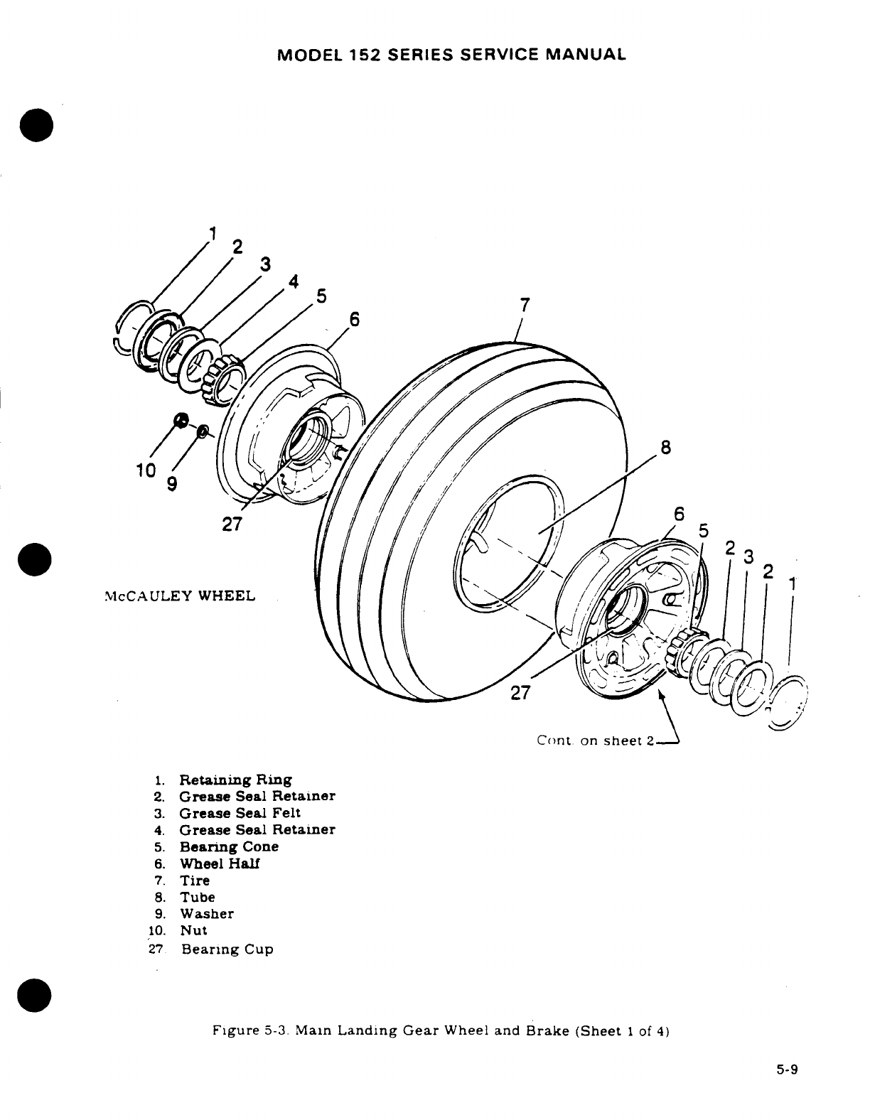
MODEL
152
SERIES
SERVICE
MANUAL
10
2
McCAULEY
WHEEL
Cont
on
sheet
2
1.
Retaining
Ring
2.
Grease
Seal
Retainer
3.
Grease
Seal
Felt
4.
Grease
Seal
Retainer
5.
Bearing
Cone
6.
Wheel
Half
7.
Tire
8.
Tube
9.
Washer
10.
Nut
27
Bearing
Cup
Figure
5-3.
Main
Landing
Gear
Wheel
and
Brake (Sheet
1
of
4)
5-9
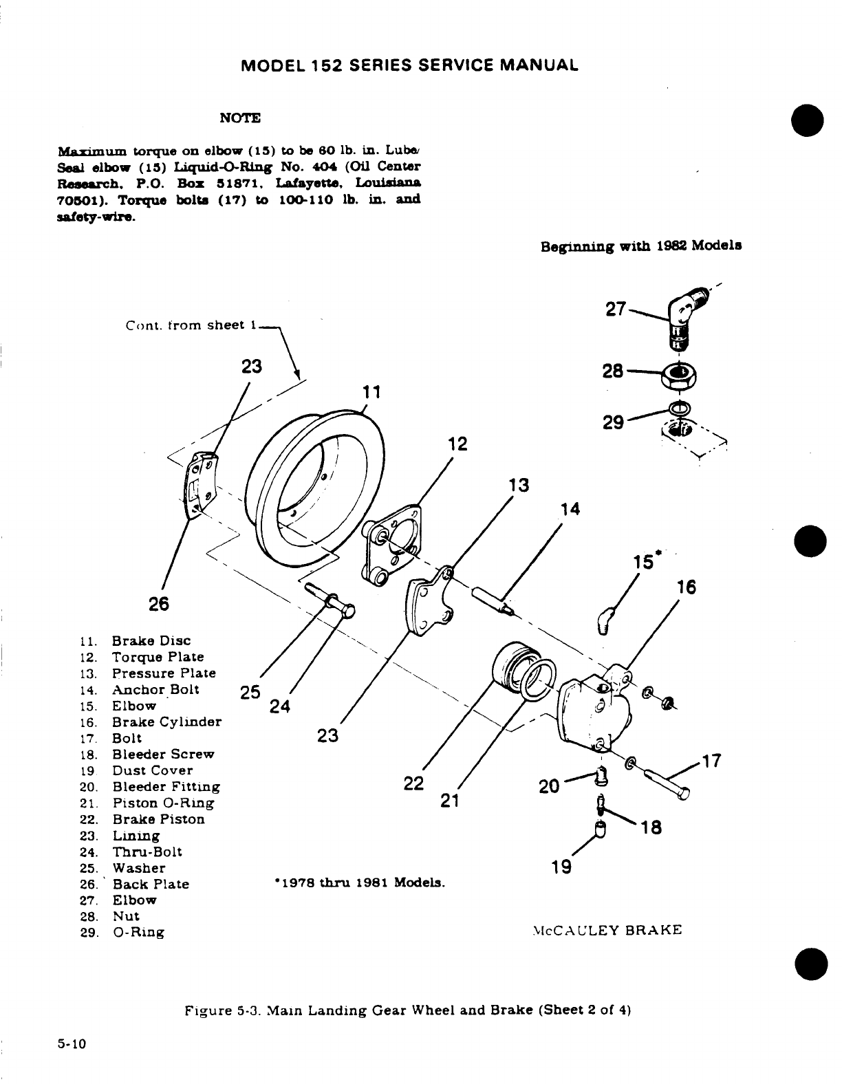
MODEL
152
SERIES SERVICE
MANUAL
NOTE
Maximum
torque
on
elbow
(15)
to
be
80
lb.
in.
Lube
Seal
elbow
(15)
Liquid-O-Ring
No.
404
(Oil
Center
Research. P.O.
Box
51871,
Lafayette,
Louisiana
70501).
Torque
bolts
(17)
to
100-110
lb.
in.
and
safety-wire.
Beginning
with
1982
Models
27
Cont. from
sheet
1
23
28
/
1
29.
12
29
12
13
14
15 16
26
11.
Brake
Disc
12.
Torque
Plate
13.
Pressure
Plate
14.
Anchor
Bolt
25
15.
Elbow
24
16.
Brake
Cylinder
17.
Bolt
23
18.
Bleeder Screw
17
19
Dust
Cover
20.
Bleeder
Fitting
22
21.
Piston
0-Ring
21
22.
Brake
Piston
23.
Lining
1
24.
Thru-Bolt
25.
Washer
19
26.
Back
Plate
1978
thru
1981
Models.
27.
Elbow
28.
Nut
29.
0-Ring
McCAULEY
BRAKE
Figure
5-3.
Main
Landing
Gear
Wheel
and
Brake (Sheet
2
of
4)
5-10
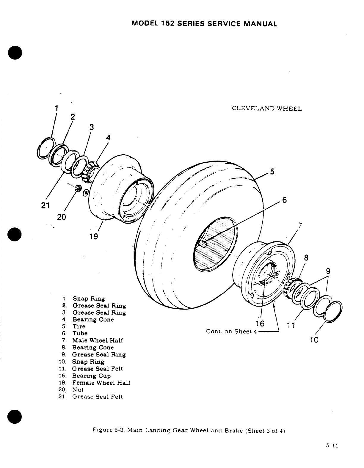
MODEL
152
SERIES
SERVICE
MANUAL
CLEVELAND WHEEL
2
21
20
19
3.
Grease
Seal
Ring
4.
Bearing
Cone
5.
Tire
11
6.
Tube
Cont.
on
Sheet
4
7.
Male
Wheel
Half
10
8.
Bearing
Cone
9.
Grease
Seal
Ring
10.
Snap
Ring
11.
Grease
Seal
Felt
16.
Bearing
Cup
19.
Female
Wheel
Half
20.
Nut
21.
Grease
Seal
Felt
Figure
5-3.
Main
Landing Gear
Wheel
and
Brake (Sheet
3
of
4)
5-11
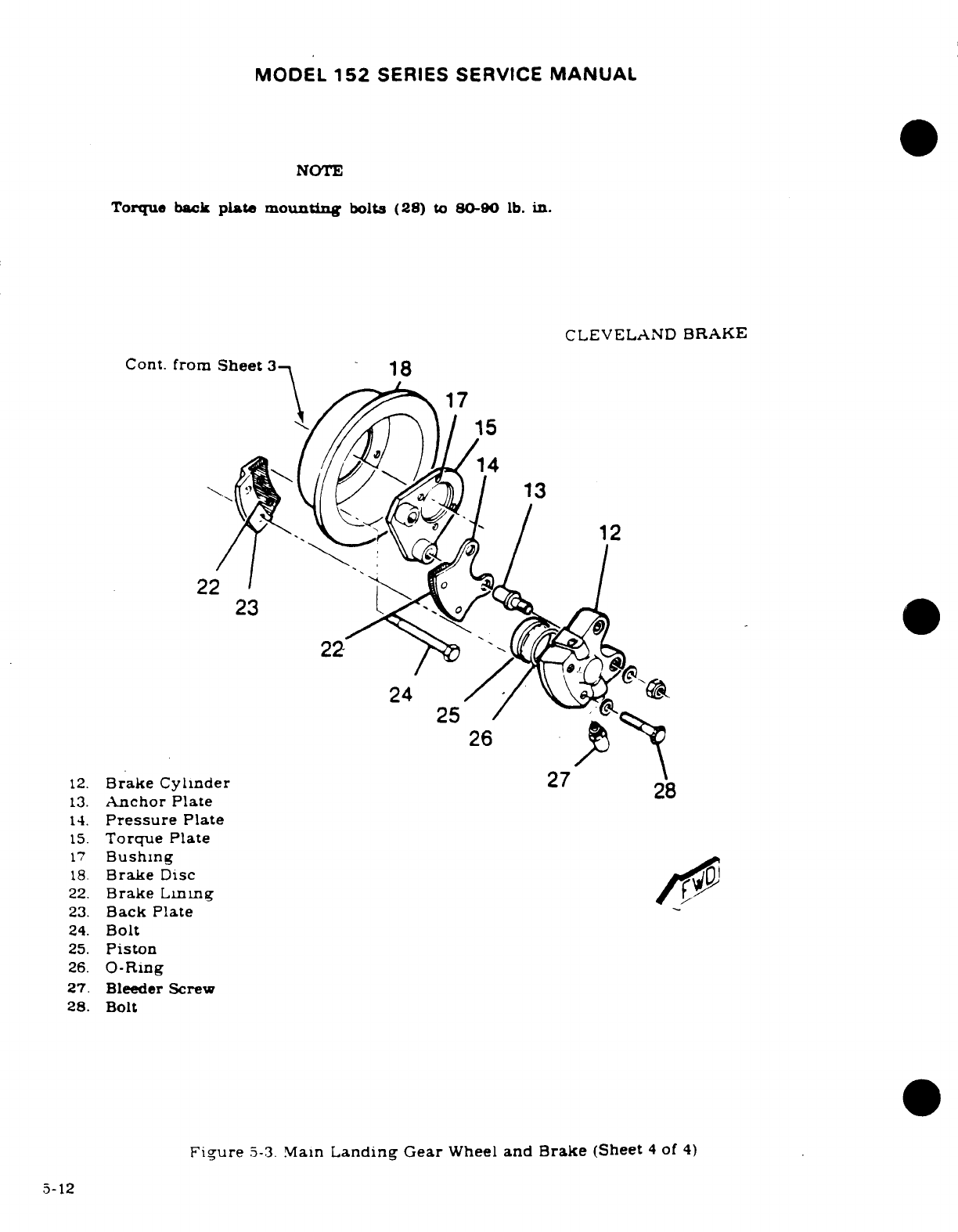
MODEL
152
SERIES SERVICE
MANUAL
NOTE
Torque
back
plate
mounting
bolts
(28)
to
80-90
lb.
in.
CLEVELAND
BRAKE
Cont.
from
Sheet
3
18
17
15
12
22
23
22
12.
Brake
Cylinder
27
28
13.
Anchor
Plate
14.
Pressure
Plate
15.
Torque
Plate
17
Bushing
18.
Brake
Disc
23.
Back
Plate
25.
Piston
26.
O-Ring
27.
Bleeder Screw
28.
Bolt
Figure
5-3.
Main
Landing
Gear
Wheel
and
Brake
(Sheet
4
of
4)
5-12
MODEL
152
SERIES SERVICE
MANUAL
e.
Replace
damaged
retainer
rings
(1)
and
seals
(2),
(3)
and
(4).
f.
Replace worn
or
damaged
bearing
cups
(27)
and
cones
(5).
g.
Replace
any
worn
or
cracked
thru-bolts
(24)
or
nuts
(10).
h.
Remove
any
corrosion
or
small
nicks.
i.
Repair
reworked
areas
of
wheel
by
cleaning
thoroughly,
then
applying
one
coat
of
clear
lacquer
paint.
j.
Pack
bearings
with
grease
specified
in
Section
2
of
this
manual.
5-17.
MAIN
WHEEL
REASSEMBLY.
(McCauley)
(See
figure
5-3.)
a.
Assemble
bearing
cone
(5).
grease seal
retainer
(4).
grease seal
felt
(3).
grease
seal
retainer
(2)
and
retaining ring
(1)
into each
wheel
half
(6).
b.
Insert
tube
in
tire.
aligning
index
marks
on
tire
and tube.
c.
Place
wheel
half
(6)
into
tire
and
tube
(side
opposite
valve
stem).
aligning
base
of
valve stem
in
valve
slot.
With
washer
(25)
under
head
of
thru-bolt
(24).
insert
bolt
through
wheel
half
(6).
d.
Place
wheel
half
(6)
into
other
side
of
tire
and
tube.
aligning
valve stem
in
valve
slot.
e.
Insert
washers
(9)
and
nuts
(10)
on
thru-bolts
(24).
and
pre-torque
to
10
to 50
lb. in.
CAUTION
Uneven
or
improper
torque
of
the
nuts
can
cause
failure
of
the bolts
with
resultant
wheel
failure.
f.
Prior
to
torquing nuts
(10).
inflate
tube with
approximately
15-20
psi
air
pressure
to
seat
tire.
CAUTION
Do
not
use
impact
wrenches
on
thru-bolts
or
nuts.
g.
Dry
torque
all
nuts
(10)
evenly
to
a
torque
value
of
140-150
lb.
in.
h.
Inflate
tire
to
correct
pressure
specified
in
figure
1-1
of
this
manual.
5-18.
DISASSEMBLY.
(Cleveland.)
(See
figure
5-3.)
WARNING
Injury
can
result
from
attempting
to
separate
wheel
halves
with
tire
inflated.
Avoid
damaging
wheel flanges
when
breaking
tire
beads
loose.
a.
Deflate
tire
and
break
tire
beads
loose.
Tire
irons
should
not
be
used
b.
Remove
thru-bolts
and
separate
wheel
halves.
c.
Remove
tire
and
tube.
d.
From
brake
side
of
wheel,
remove
brake disc
and
inner
wheel
half.
If
disc
sticks. pry
out.
using
non-metallic
instrument.
e.
To
disassemble
inner
and
outer
wheel
half.
remove
snap
rings.
grease
seal.
felts
and
bearing
cone
5-13
MODEL
152
SERIES
SERVICE
MANUAL
NOTE
Bearing
cups are
press-fit
in
the
wheel
halves
and
should
not
be
removed
unless
replacement
is
necessary.
To
remove
cups,
insert
wheel
half
in
boiling
water
for
15
minutes,
or
place
in
an
oven not
to
exceed
250°F
for
15
minutes.
Remove
from
source
of
heat
and
invert
wheel
half.
If
cup
does
not
drop
out.
tap
cup
evenly
from
axle
bore
with fiber
drift
pin
or
suitable
arbor
press.
To
replace
a
new
cup,
press
in
new
cup
while
wheel
half
is
still
hot.
5-19.
INSPECTION
AND
REPAIR.
(Cleveland.)
a.
Degrease
all
parts
and
dry
thoroughly.
b.
Visually
inspect bearing
cups
and cones
for
nicks,
heat
discoloration.
roller
wear.
cracks
or
distortion.
Replace
all
worn
parts.
c.
Inspect
wheel
halves
for
cracks.
corrosion.
nicks
and
other
damage. Cracked
or
badly
damaged
wheel
halves
will
be
replaced.
Small
nicks.
scratches
or
pits
can
be
blended
out.
using
fine
400
grit
sandpaper.
d.
Inspect
snap rings
and
grease
seal
distortion
or
wear.
Replace
grease
seal
felts
if
they
are
hard
or
contaminated. Lightly
saturate
grease
seal
felts
with
SAE
10
oil
(do
not
soak.)
e
Inspect
brakes
per
paragraph
5-78.
f
Inspect
wheel bolts
for
cracks
and
corrosion.
Replace
cracked bolts.
Inspect
metallic
self-
locking
nuts.
Replace
if
nut
can
be
turned
onto
bolt
past
nut's locking
section.
by
hand.
g.
Wheels
may
be
repainted
if
parts
have
been
repaired
and
thoroughly
cleaned.
Paint
exposed
area
with
one
coat
of
zinc
primer
and
one
coat
of
aluminum
lacquer.
NOTE
Never
paint
working
surfaces
of
bearng
cups.
5-20
REASSEMBLY
(Cleveland.)
a.
Reassemble
bearing
cones,
grease
seals.
felts
and
snap rings
into
the
proper
wheel
halves.
b.
Inflate tube
sufficiently
to
round
it
out.
Insert
tube
into
tire
so
that
balance
mark
(yellow
or
white
band)
is
radially
aligned
with
tire balance
mark
(red
dot).
c.
Place
outer
wheel
half
into
tire
and
pull
tube
valve
stem
through valve
hole.
d.
Turn
tire
and
outer
wheel
half
over,
and
place
inner
wheel
half
into
tire
and
align
bolts
holes
with
outer
wheel
half.
Place
brake
disc
into
inner
wheel
half
and
align
bolt
holes.
Install
bolts
through
inner
wheel
half
and
washers
and
nuts
on
outer
wheel
half.
Torque
wheel
nuts
to
torque
value
of
90
lb-in.
e.
Inflate
tire
to
pressure
stipulated
in
Section
1
of
this manual.
5-21.
MAIN
WHEEL
INSTALLATION.
a.
Place
wheel
assembly
on
axle.
b.
Install
axle nut
and
tighten
axle
nut
until
a
slight bearing
drag
is
obvious
when the
wheel is
rotated.
Back
off
nut
to
nearest
castellation
and
install
cotter
pin.
c
Place
brake
back
plate
in
position
and
secure
the
bolts
and
washers.
d.
Install
hub
cap.
Install
speed
fairing
(if
used)
as
outlined
in
paragraph
5-13.
5-14
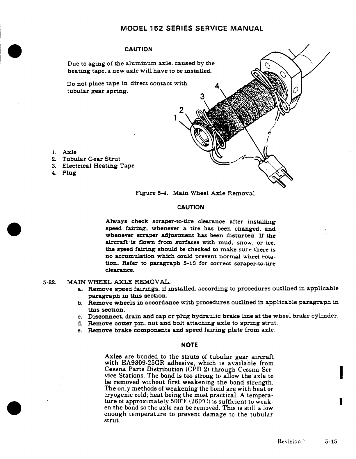
MODEL
152
SERIES SERVICE
MANUAL
CAUTION
Due
to
aging
of
the
aluminum
axle. caused
by
the
heating
tape..a
new
axle
will
have
to
be
installed.
Do
not
place
tape
in
direct contact
with
4
tubular
gear
spring.
2
1.
Axle
2.
Tubular
Gear
Strut
3.
Electrical
Heating
Tape
4.
Plug
Figure
5-4.
Main
Wheel
Axle
Removal
CAUTION
Always
check
scraper-to-tire
clearance
after
installing
speed
fairing,
whenever
a
tire
has
been
changed.
and
whenever
scraper
adjustment
has
been
disturbed.
If
the
aircraft
is
flown
from
surfaces
with
mud,
snow,
or
ice.
the
speed
fairing
should
be
checked
to
make
sure
there
is
no
accumulation
which
could
prevent
normal
wheel
rota-
tion.
Refer
to
paragraph
5-13
for
correct
scraper-to-tire
clearance.
5-22.
MAIN
WHEEL
AXLE
REMOVAL.
a.
Remove
speed
fairings.
if
installed.
according
to
procedures
outlined
in
applicable
paragraph
in
this
section.
b.
Remove
wheels
in
accordance
with
procedures
outlined
in
applicable
paragraph
in
this
section.
c.
Disconnect.
drain
and
cap or
plug
hydraulic
brake
line
at
the
wheel
brake
cylinder.
d.
Remove
cotter pin. nut
and
bolt
attaching axle
to
spring strut.
e.
Remove
brake
components
and
speed
fairing
plate
from axle.
NOTE
Axles
are
bonded to
the
struts
of
tubular
gear
aircraft
with
EA9309-25GR
adhesive,
which
is
available
from
Cessna
Parts
Distribution
(CPD
2)
through
Cessna
Ser-
vice
Stations.
The bond
is
too
strong
to
allow
the
axle
to
be
removed
without
first
weakening
the
bond
strength.
The
only
methods
of
weakening
the
bond
are
with
heat
or
cryogenic
cold;
heat
being
the
most
practical.
A
tempera-
ture
of
approximately
500°F
(260°C)
is
sufficient
to
weak-
en
the
bond
so
the
axle
can
be
removed.
This
is
still
a
low
enough
temperature
to
prevent
damage
to
the
tubular
strut.
Revision
1
5-15
MODEL
152
SERIES
SERVICE
MANUAL
f.
Remove
axles as
follows:
NOTE
Axles
should
be
removed
from
strut,
using
electric
heat-
ing
tape.
Heating
tape,
P/N
135-459,
can
be
obtained
from
Cessna
Parts
Distribution
(CPD
2)
through
Cessna
Service
Stations.
g.
Wrap
heating
tape
around
axle
from
base head
to
outer
end
of
axle
and
tie
it
on
with
string
provided
with
the tape,
as
shown
in
the
figure.
CAUTION
Do
not
place
tape
in direct
contact
with
tubular
gear
spring.
h.
Plug
electric
tape into
110
volt
wall
socket
and
heat for
20
to
30
minutes.
i.
Unplug
tape
and
remove
from axle.
Remove
axle
by
striking
axle
base
head
with
a
few
sharp
blows.
j.
Clean
any
old
adhesive
off
landing gear
spring
with
a
wire brush.
Brush
strokes
should
run
lengthwise
along
the
spring.
After
old
adhesive
has
been
removed, wipe
with
clean
rag
saturated
with
acetone
or
alcohol.
Immediately
wipe
dry
with
a
clean
lint
free cloth.
WARNING
Due
to
aging
of
the
aluminum
axle.
caused
by
the
heating
tape.
a
new
axle will
have
to
be
installed.
5-23.
MAIN
WHEEL
AXLE
INSTALLATION.
a.
Prior
to
installing
new axle,
wipe
outer
surface
of
tubular
gear and
inside
of
axle
with
solvent,
drying
immediately
with
a
clean.
lint
free
cloth.
b.
Mix
EA9309-25GR
adhesive, available
from
Cessna
Parts
Distribution
(CPD
2)
through
Cessna
Service
Stations,
in
accordance
with
instruction
in
the
package.
Spread
adhesive
thinly
and
evenly
on
outer
surface
of
landing
gear
spring
in
area
that
will
be
covered
by
axle.
c.
Place
axle
on
gear
spring
and
rotate
axle
to
assure
even
coverage
between
inner
sur-
face
of
axle
and outer
surface
of
spring.
d.
Install
retaining
bolt,
washers,
nut
and
cotter
pin.
Tighten
nut
securely.
I
e.
Allow
24
hours
at
75°F
(24°C)
for
adhesive
to
cure,
or
30
minutes
at
250°F
(121°C),
if
heating
equipment
is
available.
f.
Install
brake
components
and
speed
fairing
mounting
plate
to
axle.
g.
Install
wheel
on
axle in
accordance
with
procedures
outlined
in
applicable
para-
graph
of
this
section.
h.
Connect
hydraulic
brake
line
to wheel
brake cylinder.
i.
Fill
and
bleed
hydraulic
brake
system in
accordance
with
applicable
paragraph
in
this
section.
5-16
Revision
1
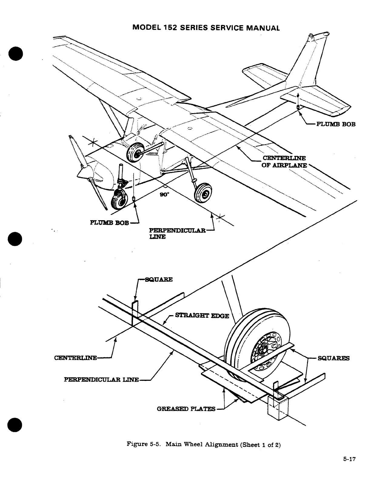
MODEL
152
SERIES
SERVICE
MANUAL
Figure
5-5.
Main
Wheel
Alignment
(Sheet
1
of
2)
5-17
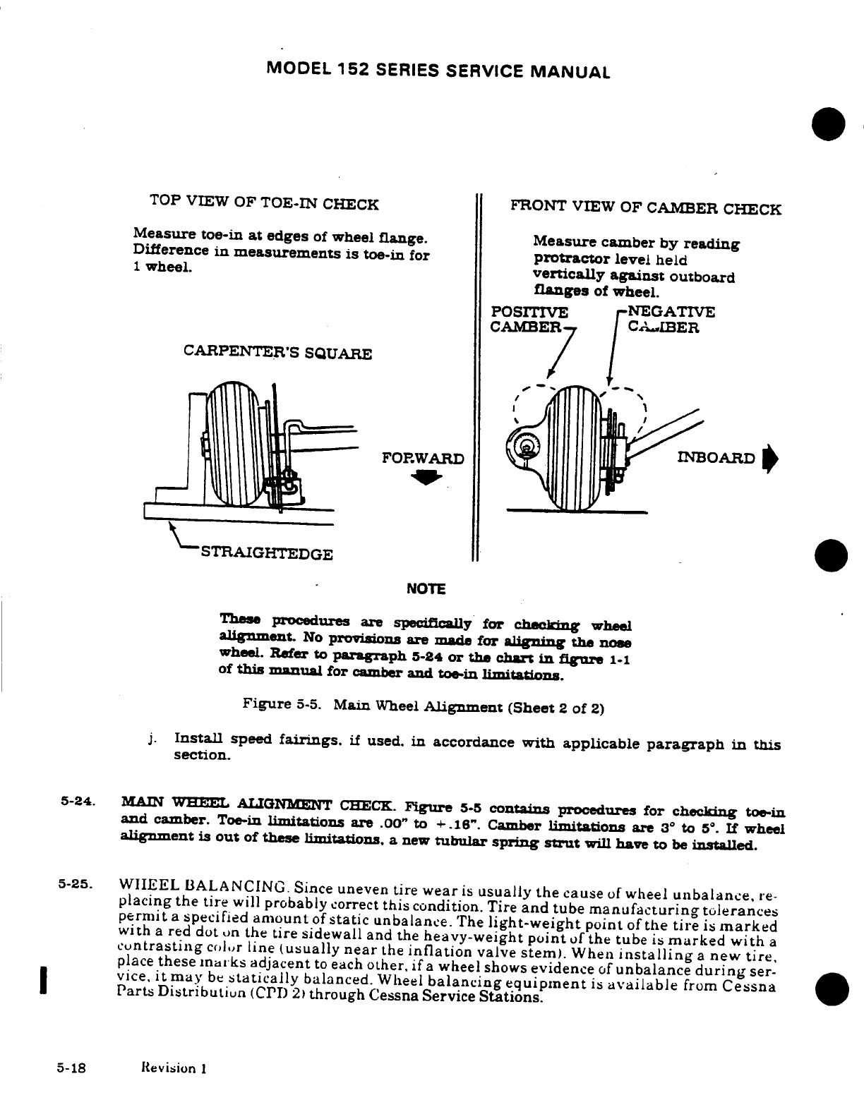
MODEL
152
SERIES
SERVICE
MANUAL
TOP
VIEW
OF
TOE-IN
CHECK
FRONT
VIEW OF
CAMBER
CHECK
Measure
toe-in
at
edges
of
wheel
flange.
Measure
camber
by
reading
Difference
in
measurements
is
toe-in
for
protractor
level
held
1
wheel.
vertically
against
outboard
flanges
of
wheel.
CAMBER
CAMBER
CARPENTER'S
SQUARE
FORWARD
INBOARD
STRAIGHTEDGE
NOTE
These
procedures
are
specifically
for
checking
wheel
alignment.
No
provisions are
made
for
aligning
the
nose
wheel.
Refer
to
paragraph
5-24
or
the
chart
in
figure
1-1
of
this
manual
for
camber
and
toe-in
limitations.
Figure
5-5.
Main
Wheel
Alignment
(Sheet
2
of
2)
j.
Install
speed
fairings.
if
used.
in
accordance
with
applicable
paragraph
in
this
section.
5-24.
MAIN
WHEEL
ALIGNMENT
CHECK.
Figure
5-5
contains
procedures
for
checking
toe-in
and
camber.
Toe-in
limitations
are
.00"
to
+.16".
Camber
limitations
are
3°
to
5.
If
wheel
alignment
is
out
of
these
limitations,
a
new
tubular
spring
strut
will
have
to
be
installed.
5-25.
WIEEL
BALANCING. Since
uneven
tire
wear
is
usually
the
cause
of
wheel
unbalance,
re-
placing
the
tire
will
probably
correct
this
condition. Tire
and
tube
manufacturing
tolerances
permit
a
specified
amount
of
static
unbalance.
The
light-weight
point
of
the
tire
is
marked
with
a
red
dot
on
the
tire
sidewall
and
the
heavy-weight
point
of
the tube
is
marked with
a
cuntrasting
Color
line
(usually
near
the
inflation
valve
stem).
When
installing
a
new
tire,
place
these
marks
adjacent
to
each
other,
if
a
wheel
shows
evidence
of
unbalance
during
ser-
vice,
it
may
be
statically
balanced.
Wheel
balancing
equipment
is
available
from
Cessna
Parts
Distribution
(CPD
2)
through
Cessna Service
Stations.
5-18
Revision
1
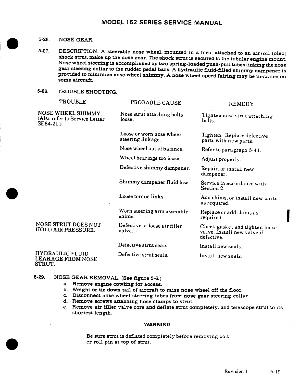
MODEL
152
SERIES
SERVICE
MANUAL
5-26.
NOSE
GEAR.
5-27.
DESCRIPTION.
A
steerable
nose wheel,
mounted
in
a
fork.
attached
to
an
air/oil
(oleo)
shock
strut.
make
up
the
nose
gear.
The
shock
strut
is
secured
to
the
tubular
engine
mount.
Nose wheel
steering
is
accomplished
by
two
spring-loaded
push-pull
tubes
linking
the
nose
gear steering
collar
to
the rudder
pedal
bars.
A
hydraulic
fluid-filled
shimmy
dampener
is
provided
to
minimize
nose wheel
shimmy.
A
nose
wheel
speed
fairing
may
be
installed
on
some
aircraft.
5-28.
TROUBLE
SHOOTING.
TROUBLE PROBABLE CAUSE
REMEDY
NOSE WHEEL
SHIMMY.
Nose
strut
attaching
bolts
Tighten
nose
strut attaching
(Also
refer
to
Service
Letter
loose.
bolts.
SE84-21.)
Loose or
worn
nose
wheel
Tighten.
Replace
defective
steering
linkage.
parts
with new
parts.
Nose
wheel
out
of
balance.
Refer
to
paragraph
5-41.
Wheel
bearings
too
loose.
Adjust
properly.
Defective
shimmy
dampener.
Repair,
or
install
new
dampener.
Shimmy
dampener fluid
low.
Service
in
accordance
with
Section
2.
Loose
torque
links.
Add
shims, or
install
new
parts
as
required.
Worn
steering
arm
assembly
Replace
or
add shims
as
shims.
required.
NOSE STRUT
DOES
NOT
Defective
or
loose
air
filler
Check
gasket
and
tighten
loose
HOLD
AIR
PRESSURE.
valve..
valve.
Install
new
valve
if
defective.
Defective
strut
seals.
Install
new
seals.
HYDRAULIC
FLUID
Defective
strut
seals.
Install
new
seals.
LEAKAGE
FROM
NOSE
STRUT.
5-29.
NOSE GEAR REMOVAL.
(See
figure
5-6.)
a.
Remove
engine
cowling
for
access.
b.
Weight
or
tie
down
tail
of
aircraft
to
raise
nose
wheel
off
the
floor.
c.
Disconnect
nose
wheel
steering
tubes
from
nose
gear
steering
collar.
d.
Remove
screws
attaching
hose
clamps
to
strut.
e.
Remove
air
filler
valve
core
and
deflate
strut
completely.
and
telescope
strut
to
its
shortest
length.
WARNING
Be
sure
strut
is
deflated
completely
before
removing
bolt
or
roll
pin
at
top
of
strut.
Revision
I
5-19
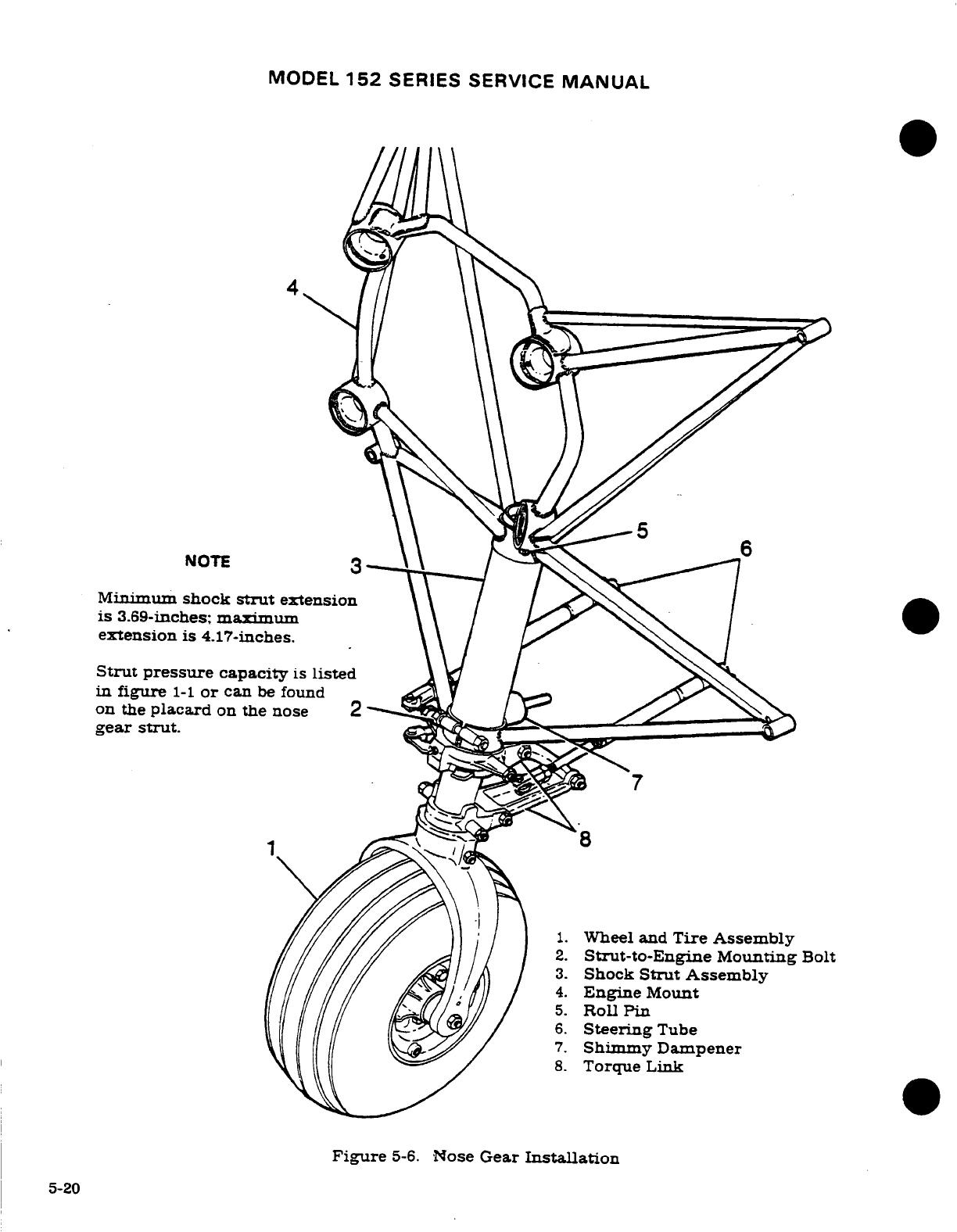
MODEL
152
SERIES SERVICE
MANUAL
NOTE
3
Minimum
shock
strut
extension
is
3.69-inches;
maximum
extension
is
4.17-inches.
Strut
pressure
capacity
is
listed
in
figure
1-1
or
can
be
found
on
the
placard
on
the nose
2
gear
strut.
8
1.
Wheel
and
Tire Assembly
2.
Strut-to-Engine
Mounting
Bolt
3.
Shock
Strut
Assembly
4.
Engine
Mount
5.
Roll
Pin
6.
Steering
Tube
7.
Shimmy
Dampener
8.
Torque
Link
Figure
5-6.
Nose
Gear
Installation
5-20

MODEL
152
SERIES
SERVICE
MANUAL
*
15279406
thru
15282762
*
15282763
thru
15283958
*
15283959
&
On
F15201429
thru
F15201578 F15201579
thru
F15201783
F15201784
&
On
A1520735
thru
A1520839
A1520840
thru
A1520909 A1520910
&
On
FA1520337
thru
FA1520356 FA1520357
thru
FA1520372 FA1520373
&
On
**9
1.
Speed
Fairing
*7 8
6*
2.
Cover
Plate
3.
Fork
Bolt
4.
Scraper
5.
Axle
Stud
6.
Ferrule
7.
Door,
Access
Figure
5-7
Nose
Wheel
Speed
Fairing
8.
Latch
9.
Plug
f.
Remove
roll
pin
at
top
of
strut.
and
remove
bolt which
clamps
strut
to
lower
part
of
engine
mount.
g.
Pull
the
strut
assembly
down
out
of
engine
mount fitting.
5-30.
NOSE
GEAR
INSTALLATION. (See
figure
5-6.)
a.
Reverse
steps
in
paragraph
5-29
to
install
nose
gear.
NOTE
Always
install
roll
pin
before
clamping
strut
into
lower
portion
of
engine
mount
to
prevent
misalignment.
Torque
clamp
bolt
in
lower
portion
of
engine
mount
fitting
to
120
20
lb-in.
5-21
MODEL
152
SERIES
SERVICE
MANUAL
5-31.
NOSE
WHEEL
SPEED
FAIRING
REMOVAL.
a.
Weight
or
tie
down
tail
of
aircraft
to
raise
nose
wheel
off
floor.
b.
Remove
nose
wheel
axle
stud.
c.
Remove
bolt
securing
cover plate
and
fairing
to
strut:
remove
cover plate.
WARNING
Do
not
remove
bolt
attaching
tow
bar spacers.
unless
strut
has
been
completely
deflated.
d.
Slide
speed
fairing
up
and remove
nose
wheel.
Loosen
scraper
if
necessary.
e.
Rotate
speed
fairing
90
degrees
and
work
fairing
down
over the
fork
to
remove.
5-32.
NOSE
WHEEL
SPEED FAIRING
INSTALLATION.
a.
Rotate
speed
fairing
90
degrees
and
work
fairing
up
over
the
fork:
rotate
fairing
to
correct
position.
b.
Slide
fairing
to
correct position.
c.
Tighten axle
stud
until
a
slight
bearing drag
is
obvious
when
the
wheel
is
rotated.
Back
off
nut
to
the
nearest castellation.
and
install
cotter
pins.
d.
If
shock
strut
was
deflated.
service
after
installation has
been
completed.
Refer
to
servicing instructions
in
Section
2.
e.
Adjust
wheel
scraper
clearance
in
accordance
with
the
following caution.
CAUTION
Always
check
scraper
clearance
after
installing
speed
fairing,
whenever
a
tire
has
been
changed,
and
whenever
scraper
adjustment
has
been
disturbed.
Set
clearance
be-
tween
tire
and
scraper
for
a
minimum
of
0.25-inch
to
a
maximum
of
0.50-inch.
Elongated
holes
in
the
scraper
are
provided
for
adjustment.
If
the
aircraft
is
flown
from
surfaces
with
mud,
snow,
or
ice,
the
speed
fairings
should
be
checked
to
make
sure
there
is
no
accumulation
which
could
prevent normal
wheel
rotation.
Wipe
fuel
and
oil
from speed
fairing
to
prevent
staining
and
de-
terioration
of
the
fairing.
5-33
NOSE
WHEEL
REMOVAL.
a.
Weight
or
tie
down
tall
of
aircraft
to
raise
the
nose
wheel
off
the
floor.
b.
Remove nose
wheel
axle
stud.
c.
Pull
nose
wheel
assembly
from
fork
and remove
axle
tube
from
nose
wheel.
Loosen
wheel
scraper
if
necessary,
if
wheel
is
equipped with
a
speed
fairing.
5-34.
DISASSEMBLY
(McCauley)
(See
figure
5-8,
sheet
1.)
a.
Completely
deflate
tire
and
tube
and
break
loose
tire
beads.
Extreme
care must
be
exercised
to
prevent
tire
tool
damage
when
removing
tire
from
wheel
halves
(6).
WARNING
Serious
injury
can
result
from
attempting
to
separate
wheel
halves
with
tire
and
tube
inflated.
b.
Remove
nuts
(4)
and
washers
(5).
c.
Remove
thru-bolts
(8)
and
washers
(5)
5-22
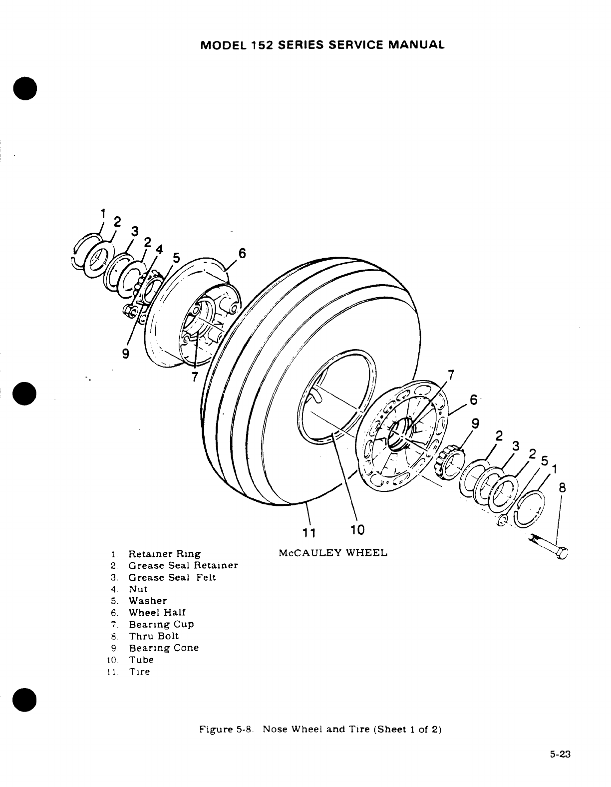
MODEL
152
SERIES SERVICE
MANUAL
4.
Nut
5.
Washer
6
Wheel
Half
7.
Bearing
Cup
8.
Thru
Bolt
10.
Tube
5-23
4.
Nut
5.
Washer
6.
Wheel
Half
7.
Bearing
Cup
8
Thru
Bolt
9
Bearing
Cone
10
Tube
11.
Tire
Figure
5-8.
Nose
Wheel
and
Tire
(Sheet
1
of
2)
5-23
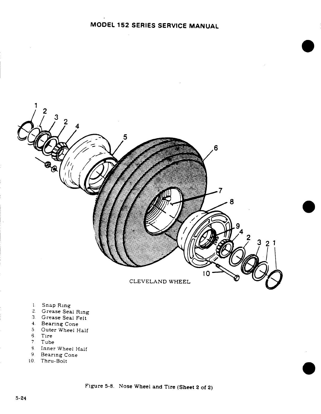
MODEL
152
SERIES SERVICE
MANUAL
CLEVELAND
WHEEL
1
Snap
Ring
2.
Grease
Seal
Ring
3.
Grease
Seal
Felt
4.
Bearing
Cone
5
Outer
Wheel
Half
6
Tire
7
Tube
3
Inner
Wheel
Half
9
Bearing
Cone
10.
Thru-Bolt
Figure
5-8.
Nose
Wheel
and
Tire
(Sheet
2
of
2)
5-24
MODEL
152
SERIES
SERVICE
MANUAL
d.
Separate
and
remove
wheel
halves
(6)
from
tire
and tube.
e.
Remove
retaining
rings
(1).
grease
seal
retainer
(2).
felt
grease
seal
(3).
grease
retainer
(2)
and
bearing
cone
(9)
from
both
wheel
halves
(6).
NOTE
Bearing
cups
(races)
(7)
are
a
press
fit
in
wheel
half
(6)
and
should
not
be
removed
unless
a
new
part
is
to
be
installed.
To
remove
bearing
cups,
heat
wheel
half
in
boiling
water
for
30
minutes,
or
in
an
oven. not
to
exceed
121°C
(250°F).
Using an
arbor press.
if
available,
press
out
bearing
cup
and
press
in
new
bearing
cup
while
wheel
half
is
still
hot.
5-35.
INSPECTION
AND
REPAIR.
(McCauley) (See
figure
5-8,
sheet
1.)
a.
Clean
all
metal
parts
and felt
grease
seals
in
Stoddard solvent
or
equivalent,
and
dry
thoroughly.
NOTE
A
soft
bristle
brush
may
be
used
to
remove
hardened
grease.
dust
or
dirt.
b.
Inspect
wheel
halves
(6)
for
cracks
or
damage.
c.
Inspect
bearing
cones
(9).
cups
(7),
retaining
rings
(1)
and
seals
(2)
and
(3).
for
wear
or
damage.
d.
Inspect
thru-bolts
(8)
and
nuts
(4)
for
cracks
in
threads
or
cracks
in
radius
under
bolt
head.
e.
Replace
cracked
or
damaged
wheel
half
(6).
f.
Replace
damaged
retaining
rings
(1)
and
seals
(2)
and
(3).
g.
Replace
worn
or
damaged
bearing
cups
(7)
and
cones
(9).
h.
Replace
any
worn
or
cracked
thru-bolts
(8)
or
nuts
(4).
i.
Remove
any
corrosion
or
small
nicks.
j.
Repair
reworked
areas
of
wheel
by
cleaning
thoroughly,
then
applying
one
coat
of
clear lacquer
paint.
k.
Pack
bearings
with
grease
specified
in
Section
2.
5-36.
REASSEMBLY.
(McCauley)
(See
figure
5-8.
sheet
1.)
a.
Assemble
bearing
cone
(9).
grease
seal
retainer
(2).
felt
grease
seal
(3).
grease
seal
retainer
(2)
and
retaining
ring
(1)
into
both
wheel
halves
(6).
b.
Insert
tube
in
tire,
aligning
index
marks
on
tire
and tube.
c.
Place
wheel
half
(6)
into
tire
and tube
(side
opposite
valve
stem).
aligning
base
of
valve
stem
in
valve
slot.
With
washer
(5)
under
head
of
thru-bolt
(8).
insert
bolt
through
wheel
half
(6).
d.
Place
wheel
half
(6)
into
other
side
of
tire
and
tube,
aligning
valve
stem
in
valve slot.
e.
Install washers
(5)
and
nuts
(4)
on
thru-bolts
(8)
and
pre-torque
to
10-50
lb.
in.
CAUTION
Uneven
or
improper
torque
of
the
nuts
can
cause
failure
of
the
bolts
with
resultant
wheel
failure.
f.
Prior
to
torquing
nuts
(4).
inflate
tube
with
approximately
10-15
psi
air
pressure
to
seat
tire.
5-25
MODEL
152
SERIES SERVICE
MANUAL
CAUTION
Do
not
use
impact
wrenches
on
thru-bolts
or
nuts.
g.
Dry
torque
all
nuts
(4)
evenly
to
a
torque
value
of
140-150
lb.
in.
h.
Inflate
tire
to
correct
pressure
specified
in
figure
1-1.)
5-37.
DISASSEMBLY.
(Cleveland)
(See
figure
5-8.
sheet
2.)
WARNING
Injury
can
result
from
attempting
to
separate
wheel
halves
with
tire
inflated.
Avoid
damaging
wheel
flanges
when
breaking
tire
beads
loose.
a.
Deflate
tire
and
break
tire
beads loose.
b.
Remove
thru-bolts
and
separate
wheel
halves.
c.
Remove
tire
and
tube.
d.
Remove
snap
ring,
grease
seal
felt.
grease
seal
rings
and
bearing
cones
from
both
wheel
halves.
NOTE
Bearing
cups
are
a
press-fit
in the
wheel
halves
and
should
not
be
removed
unless
replacement
is
necessary.
To
remove
bearing
cups.
heat
wheel
half
in
boiling
water
for
15
minutes.
Using
an
arbor
press.
if
available,
press
out
bearing
cup
and
press
in
new
cup while
wheel
is
still
hot.
5-38.
INSPECTION
AND
REPAIR. (Cleveland)
(See
figure
5-8.
sheet
2.)
a.
Clean
all
metal
parts
and
grease seal
felts
in
solvent
and
dry
thoroughly.
b.
Inspect
wheel
halves
for
cracks.
Cracked
wheel
halves
must
be
replaced.
Sand
out
nicks,
gouges
and
corroded
areas.
Where
protective
coating
has
been
removed.
area
should
be
cleaned
thoroughly,
primed
with
zinc
chromate
primer
and
painted
with
aluminum
lacquer.
c.
Bearig
cups
and
cones
must
be
inspected
carefully
for
damage
and
discoloration.
After
cleaning,
repack
cones
with
clean
aircraft
wheel
bearing
grease
(Section
2)
before
installation
in
the wheel.
To
replace
bearing
cups,
refer
to
note
in
paragraph
5-
37.
5-39.
REASSEMBLY.
(Cleveland)
(See
figure
5-8.
sheet
2.)
a.
Insert
tire
in
tube,
aligning
index
marks
on
tire
and
tube.
b.
Place
tire
and
tube
on
wheel
half
and
position
valve
stem through
hole
in
wheel
half.
c.
Insert thru-bolts,
position
other
wheel
half.
and
secure
with
nuts
and
washers.
Take
care
to
avoid
pinching
tube
between
wheel
halves.
Torque bolts
to
90
lb-in.
CAUTION
Uneven
or
improper
torque
on
thru-bolt
nuts
may cause
bolt
failure
with
resultant
wheel
failure.
d.
Clean
and
repack
bearing
cones
with
clean
aircraft
wheel
bearing
grease
(Section
2.)
e.
Assemble
bearing
cones.
seals
and
retainers
into
wheel
halves.
5-26
MODEL
152
SERIES
SERVICE
MANUAL
f.
Inflate
tire
to
seat
tire
beads,
then
adjust
to
correct
pressure.
g.
Install
wheel
in
accordance
with
paragraph
5-40.
5-40.
NOSE WHEEL
INSTALLATION.
a.
Install
axle
tube
in
nose
wheel.
b.
Install
nose
wheel
assembly
in
fork
and
install
nose
wheel
axle
stud.
c.
Tighten
axle
stud until
a
slight
bearing
drag
is obvious
when
wheel
is
rotated.
Back
the
nut
off
to
the
nearest castellation
and
insert
cotter
pin.
CAUTION
On
aircraft
thru
serials
15285834
and
A1521034.
equipped
with
speed
fairings,
always check scraper-to-
tire
clearance
after
instaling
speed
fairing,
whenever
a
tire
has
been
changed,
or
whenever
scraper
adjustment
has
been disturbed.
Set
scraper
clearance
in
accordance
with
procedures
outlined
in the
Caution following
para-
graph
5-32.
5-41.
WHEEL
BALANCING.
Refer
to
paragraph
5-25
for
procedures.
5-42.
NOSE
GEAR
SHOCK STRUT
DISASSEMBLY.
(See
figure
5-9.)
NOTE
The
following
procedures apply
to
the
nose
gear
shock
strut
after
it
has
been
removed
from
the aircraft.
and
the
speed
fairing
and nose
wheel
have
been
removed.
In
many
cases,
separation
of
the
upper
and lower
strut
will
permit
inspection
and
parts
installation
without
removal
or
complete
disassembly
of
the
strut.
WARNING
Be
sure
strut
is
completely
deflated
before
removing
lock
ring
in
lower
end
of
upper strut,
or
disconnecting
torque
links.
a.
Remove
shimmy
dampener.
b.
Remove
torque
links.
Note
position
of
washers.
shims
and
spacers.
c.
Remove lock
ring
from
groove
inside lower
end
of
upper
strut.
A
small
hole
is
provided
at
the
lock
ring
groove
to
facilitate removal
of
the
lock
ring
(refer
to
view
C-C.)
NOTE
Hydraulic
fluid
will
drain
from
strut
halves
as
lower
strut
is
pulled
from
upper strut.
d.
Using
a
straight.
sharp
pull.
separate
upper
and lower
strut.
Invert
lower
strut
and
drain
hydraulic
fluid.
e.
Remove
lock
ring
and
bearing
at
upper
end
of
lower
strut
assembly.
Note
top
side
of
bearing.
f.
Slide
packing
support
ring.
scraper
ring.
retaining
ring
and
lock
ring
from
lower
5-27
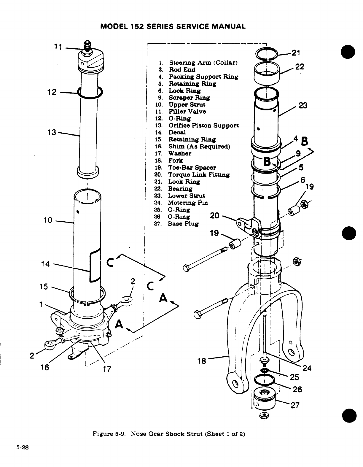
MODEL
152
SERIES
SERVICE
MANUAL
11
21
1.
Steering
Arm
(Collar)
2.
Rod
End
4.
Packing
Support
Ring
.
Retaining
Ring
12
6.
Lock
Ring
9.
Scraper
Ring
10.
Upper
Strut
23
11.
Filler
Valve
12.
O-Ring
13.
Orifice
Piston
Support
13
14.
Decal
15.
Retaining
Ring
4
B
16.
Shim
(As
Required)
17.
Washer
9
18.
Fork
19.
Toe-Bar
Spacer
5
20.
Torque
Link
Fitting
21.
Lock
Ring
6
22.
Bearing
19
23.
Lower
Strut
24.
Metering
Pin
25.
O-Ring
26.
O-Ring
20
27.
Base
Plug
14
-
16 17
24
26
27
Figure
5-9.
Nose
Gear
Shock
Strut
(Sheet
1
of
2)
5-28
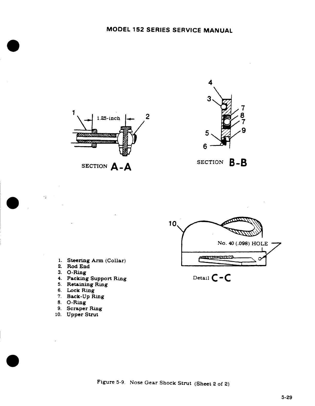
MODEL
152
SERIES
SERVICE
MANUAL
4
37
7
1.25-inch
2
7
5
9
6
sEcTION
B-B
SECTION
A-A
10
No.
40
(.098)
HOLE
1.
Steering
Arm
(Collar)
2.
Rod
End
3.
O-Ring
Detail
4.
Packing
Support
Ring Detail
C - C
5.
Retaning
Ring
6.
Lock
Ring
7.
Back-Up
Ring
8.
O-Ring
9.
Scraper
Ring
10.
Upper
Strut
Figure
5-9.
Nose
Gear
Shock
Strut
(Sheet
2
of
2)
5-29
MODEL
152
SERIES
SERVICE
MANUAL
strut,
noting
relative
position
and
top
side
of
each
ring
wire
or
tape
together,
if
de-
sired.
g.
Remove
O-rings
and
back-up
rings
from
packing
support ring.
h.
Remove
bolt
securing
tow
bar
spacers.
NOTE
Bolt
attaching
tow
bar
spacers
also
hold
base
plug
in
place.
i.
Remove
bolt
attaching
fork
to
strut
barrel, and
remove
bas
plug
and
metering
pin
from
lower
strut.
Remove O-rings
and
metering
pin
from
base
plug.
j.
Pull
orifice
piston
support
from
upper
strut.
Remove
0-ring
and
filler
valve.
k.
Remove
retaining
ring
securing
steerng
collar
to
upper
strut.
Slid
steering
collar.
shims
and
washer
from
upper
strut.
Noee
number
of
shims
between
washer
and
steering
collar.
5-43.
NOSE
GEAR
SHOCK
STRUT
INSPECTION
AND
REPAIR.
See
figure
5-9.)
a
Thoroughly
clean
all
parts
in
cleaning
solvent
and
inspect
them
carefully.
b.
All
worn
or
defective
parts
and
all
O-rings
and
back-up
rings
must
be
replaced
with
new
parts.
c.
Sharp
metal
edges
should
be
smoothed
with
No.
400
emery paper,
then
cleaned
with
solvent.
5-4.
NOSE
GEAR
SHOCK
STRUT
REASSEMBLY. (See
figure
5-9.)
NOTE
Asemble
these
parts,
lubricated with
a
film
of
Pet-
rolatum
VV-P-236,
Hydraulic Fluid
MIL-H-5606,
or
Dow-
Corning
DC-7.
Do
not
use
DC-7
on
surfaces
to
be
painted.
a.
Install washer
(17)
and
shim(s)
(16),
if
installed.
b.
Lubricate
needle
bearings
in
steering
collar
(1),
as
shown
in
Section
2,
and
install
collar
and
retaining
ring
(15).
c.
Check
steering
collar
for
snug
fit
against
waher.
Shims
of
variable
thicknes
are
available
from
the
Cessna
Supply
Diviion
to
provide
a
snug
fit
for
collar
against
washer.
NOTE
If
shims
a
required,
remove
retaining ring
and
steering
collar
and
add
shims
as
necessary
to
provide
a
snug
fit
with
steering
collar
retaining
ring
installed.
Shims
are
available
in
the
following
part
numbers
and
thickness:
1243030-5
(.006 inch),
1243030-6
(.012
inch),
and
1243030-7
(.020
inch).
d.
Install
rod
ends
(2)
in
steering
collar
(1),
and
adjust
rod
ends
to
dimension
specified
in Section
view
A-A.
e.
Install
O-ring
(12)
and
filler
valve
(11)
in
orifice
piston
support
(13),
and
install
orifice
piston
support
in
upper
strut
(10).
5-30
MODEL
152
SERIES
SERVICE
MANUAL
f.
Install
O-ring
(26)
and
metering
pin
assembly
in
lower
strut
(23);
install
bolt
attaching
fork
(18)
to
lower
strut.
g.
Align
base
plug
(27)
holes with
holes
in
lower
strut/fork
(23)
and
(18)
assembly:
install
bolt and
tow
bar
spacers
(19).
Install
and
tighten
nut.
NOTE
If
base
plug
(27)
is
to
be
replaced.
new
part
will
need
to
be
line-drilled
to
accept
AN5
bolt.
h.
Install
lock
ring
(6),
retaining
ring
(5)
and
scraper
ring
(9)
on
lower
strut,
making
sure
they
are
installed
in
same
positions
as
they
were
removed.
i.
Install
O-rings
(8)
and
(3)
and
back-up
rings
in
packing
support
ring
(4);
slide
packing
support
ring
over
lower
strut
(23).
j.
Install
bearing
(22)
and
lock
ring
(21)
at
upper
end
of
lower
strut
assembly.
Note
top
side
of
bearing.
k.
Install
upper
strut
assembly over
lower
strut
assembly.
l
Install
lock
ring
(6)
in
groove
in
lower
end
of
upper
strut.
Position
lock
ring
so
that
one
of
its
ends
covers
the
small
access
hole
in
the
lock
ring
groove
at
the
bottom
of
the
upper
strut.
(Refer
to
Detail
C-C.)
m.
Install
torque
links,
positioning
washers,
shims
and
spacers exactly
as
removed.
n.
Install
shimmy
dampener.
o.
After
shock
strut
assembly
is
complete.
install strut
on
aircraft
as
outlined
in
paragraph
5-30.
p.
After
strut
is
installed
in
aircraft,
fill
and
inflate
shock
strut
in
accordance
with
procedures outlined
in
Section
2.
See
figure
5-6
for
minimum
and
maximum
extension.
5-45.
TORQUE
LINKS.
(See
figure
5-10.)
5-46.
DESCRIPTION.
Torque
links
keep
the
lower
strut
aligned
with
the
nose
gear
steering
system,
but
permit
shock
strut
action.
5-47.
REMOVAL.
WARNING
Completely
deflate
strut
before
removing
torque
links.
a.
Completely
deflate
shock
strut.
b.
Disconnect
upper
and
lower
attaching
bolts,
spacers.
shims
and
nuts.
and
remove
torque
links.
5-48.
INSPECTION.
Torque
link
bushings
should
not
be
removed except
for
replacement
of
parts:
replace
if
excessively
worn.
5-49.
INSTALLATION.
(See
figure
5-10.)
NOTE
If
bolts
(8).
safety
lug
(10)
and
stop
lug
(5)
were
removed.
upon
installation,
torque
bolts
(8)
to
20-25
lb-in.
then
safety
the
bolts
by
bending
tips
of
safety
lug
(10).
a.
With
shock
strut
completely
deflated,
install
upper
and lower
torque
link
assemblies.
5-31
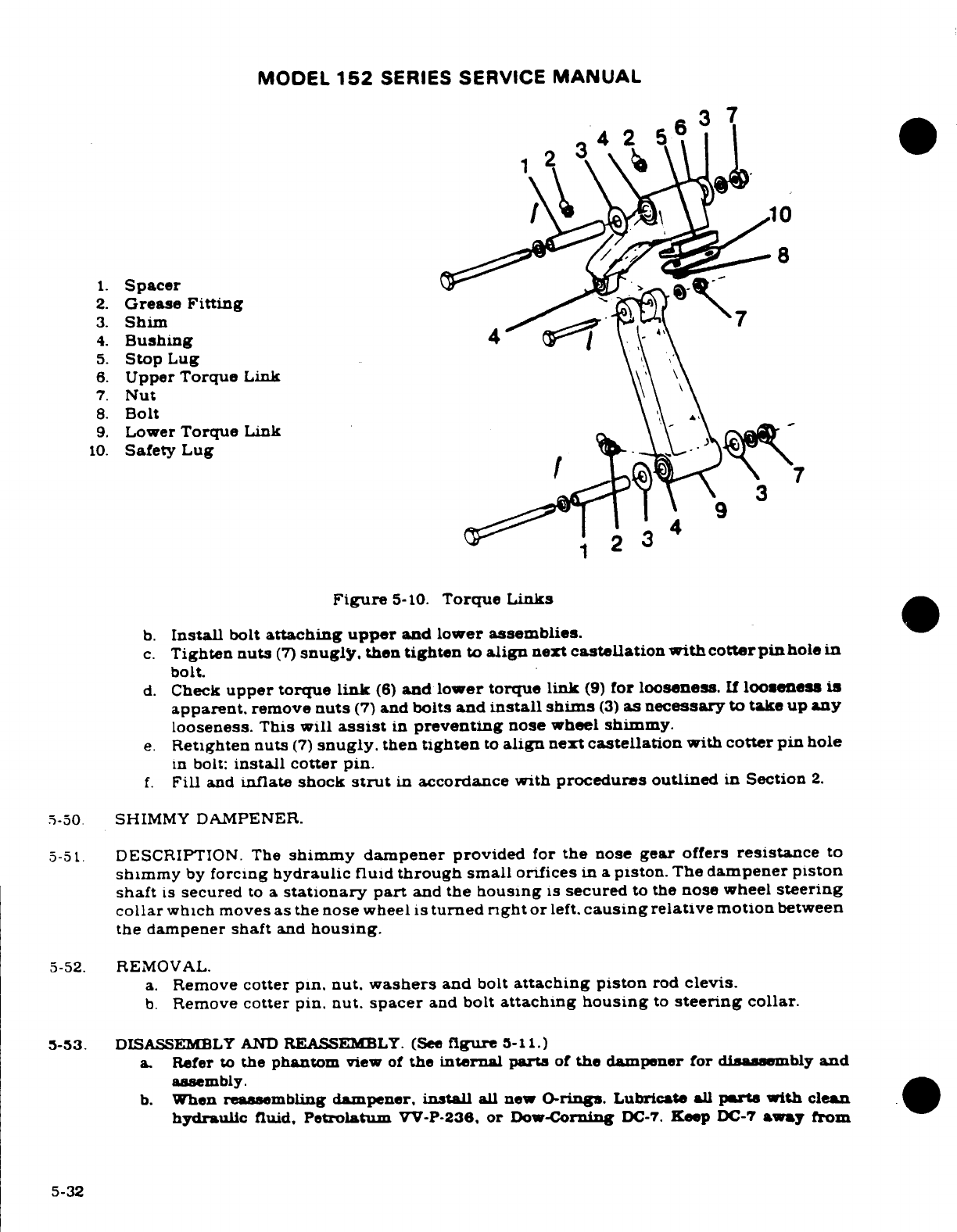
MODEL
152
SERIES
SERVICE
MANUAL
1 3
2
4
1.
Spacer
2.
Grease
Fitting
3.
Shim
7
4.
Bushing
4
5.
Stop
Lug
6.
Upper
Torque
Link
7.
Nut
8.
Bolt
9.
Lower
Torque
Link
10.
Safety
Lug
9
2
3
Figure
5-10.
Torque
Links
b.
Install
bolt
attaching
upper
and
lower assemblies.
c.
Tighten
nuts
(7)
snugly,
then
tighten
to
align
next
castellation
with
cotter
pin
hole
in
bolt.
d.
Check
upper
torque
link
(6)
and
lower
torque
link
(9)
for
looseness.
If
looseness
is
apparent,
remove
nuts
(7)
and
bolts
and
install shims
(3)
as
necessary
to
take up
any
looseness.
This
will
assist
in
preventing
nose
wheel
shimmy.
e.
Retighten
nuts
(7)
snugly.
then
tighten
to
align
next
castellation
with
cotter
pin
hole
in
bolt:
install
cotter
pin.
f.
Fill
and
inflate
shock
strut
in
accordance
with
procedures
outlined
in
Section
2.
.5-50
SHIMMY
DAMPENER.
5-51.
DESCRIPTION.
The
shimmy
dampener
provided
for
the
nose
gear
offers
resistance
to
shimmy
by
forcing
hydraulic
fluid
through
small
orifices
in
a
piston.
The
dampener
piston
shaft
is
secured
to
a
stationary
part
and
the
housing
is
secured
to
the
nose
wheel
steering
collar
which
moves
as
the
nose
wheel is
turned
rght
or
left,
causing
relative
motion
between
the
dampener
shaft
and
housing.
5-52.
REMOVAL.
a.
Remove
cotter
pin. nut.
washers
and
bolt
attaching piston
rod
clevis.
b.
Remove
cotter
pin. nut.
spacer
and
bolt
attaching
housing
to
steering
collar.
5-53.
DISASSEMBLY
AND
REASSEMLY.
(See
figure
5-11.)
a.
Refer
to
the
phantom
view
of
the
internal parts
of
the
dampener
for
disassembly
and
assembly.
b.
When
reassembling dampener,
install
all
new
O-rings. Lubricate
all
parts
with
clean
hydraulic
fluid.
Petrolatum
VV-P-236,
or
Dow-Corning
DC-7.
Keep
DC-7
away
from
5-32
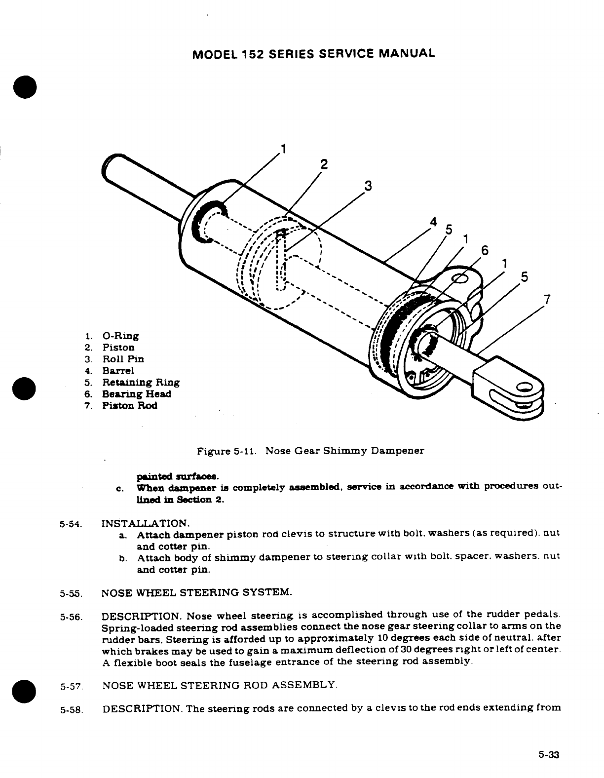
MODEL
152
SERIES
SERVICE
MANUAL
3
4
3.
Roll
Pin
5.
Retaining
Ring
6.
Bearing
Head
7.
Piston
Rod
Figure
5-11.
Nose
Gear
Shimmy
Dampener
painted
surfaces.
c.
When
dampener
is
completely
assembled,
service
in
accordance
with
procedures
out-
lined
in Section
2.
5-54.
INSTALLATION.
a.
Attach
dampener
piston
rod
clevis
to
structure
with
bolt.
washers
(as
required).
nut
and
cotter
pin.
b.
Attach
body
of
shimmy
dampener
to
steering
collar
with
bolt.
spacer.
washers.
nut
and
cotter
pin.
5-55.
NOSE
WHEEL
STEERING
SYSTEM.
5-56.
DESCRIPTION.
Nose
wheel
steering
is
accomplished
through
use
of
the
rudder
pedals.
Spring-loaded
steering
rod
assemblies
connect
the
nose
gear
steering
collar
to
arms
on
the
rudder
bars.
Steering
is
afforded up
to
approximately
10
degrees
each
side
of
neutral.
after
which
brakes
may
be
used
to
gain
a
maximum
deflection
of
30
degrees
right
or
left
of
center.
A
flexible
boot
seals
the
fuselage
entrance
of
the
steering
rod
assembly.
5-57
NOSE
WHEEL
STEERING
ROD
ASSEMBLY.
5-58.
DESCRIPTION. The
steering
rods
are connected
by
a
clevis
to
the
rod
ends
extending
from
5-33
MODEL
152
SERIES
SERVICE
MANUAL
the
nose
gear steering
collar.
and
to
an
arm
on
the
rudder
pedal
crossbars.
5-59.
NOSE
WHEEL
STEERING
ADJUSTMENT.
Since
the
nose wheel
steering
system
and
the
rudder
system
are
interconnected.
adjustment
to
one
system
might
affect
the
other system.
Refer
to
Section
10
of
this manual
for
instructions
for
rigging
the
nose
wheel
steering
and
the
rudder
system.
5-60.
BRAKE
SYSTEM.
5-61.
DESCRIPTION.
The
hydraulic
brake
system
is
comprised
of
two
master cylinders.
located
immediately
forward
of
the
pilot's
rudder
pedals. brake
lines
and
hose
connecting
each
master cylinder
to
its
wheel
brake
cylinder.
and the
single-disc.
floating cylinder-type
brake
assembly.
located
at
each
main
landing
gear
wheel.
5-62.
TROUBLE
SHOOTING.
TROUBLE
PROBABLE CAUSE REMEDY
DRAGGING
BRAKES.
Brake
pedal
binding.
Check
and
adjust
properly.
Parking
brake
linkage
hold-
Check
and
adjust properly.
ing
brake
pedal
down.
Worn
or
broken
piston
Repair.
or
install
new
return spring
(in
master cylinder.
cylinder.)
Insufficient clearance
at Adjust as
outlined
in
para-
Lock-O-Seal
or
incorrect
graph
5-68.
adjustment
of
cylinder
overall
length
(Thru
1978
Models.)
Restriction
in
hydraulic
Drain
brake line
and
clear
lines
or
restrictions
in
the
inside
of
the
brake
line
compensating
port
in
with
filtered
compressed
air.
brake
master
cylinder.
If
cleaning
the
lines
fails
to
give
satisfactory
results.
the
master cylinder
may
be
faulty
and
should
be
repaired.
Worn.
scored
or
warped
Install
new
disc
and
brake
brake
disc.
linings.
Damaged
or
accumulated
Clean
and
repair or
install
dirt
restricting
free move-
new
parts
as
necessary.
ment
of
wheel
brake
parts.
5-34
MODEL
152
SERIES SERVICE
MANUAL
5-62.
TROUBLE
SHOOTING
(Cont).
TROUBLE
PROBABLE
CAUSE REMEDY
BRAKES
FAIL
TO
Leak
in
system.
If
brake
master
cylinders
or
OPERATE.
wheel
cylinder
assemblies
are
leaking,
repair.
or
in-
stall
new
parts.
Air
in
system.
Bleed
system.
Lack
of
fluid
in
master
Fill
and
bleed
system.
cylinders.
Defective
master
cylinder.
Repair.
or
install
new
parts.
5-63.
BRAKE
MASTER CYLINDERS.
5-64.
DESCRIPTION.
The
brake
master
cylinders,
located
immediately forward
of
the
pilot's
rudder
pedals.
are
actuated
by
applying
pressure
at
the
top
of
the
rudder
pedals.
A
small
reservoir
is
incorporated
into
each
master
cylinder
for
the
fluid
supply.
When
dual
brakes
are
installed.
mechanical
linkage permits
the
copilot
pedals
to
operate
the
master
cylinders.
5-65.
BRAKE
MASTER
CYLINDER
REMOVAL.
a.
Remove
bleeder
screw
at
wheel
brake
assembly
and
drain
hydraulic
fluid
from
brake
cylinders.
b.
Remove
front
seats
and
rudder
bar
shield
for
access
to the
brake
master
cylinders.
c.
Disconnect
parking
brake
linkage
and
disconnect
brake
master
cylinders
from
rudder
pedals.
d.
Disconnect
brake
master
cylinders
at
lower
attach
points.
e.
Disconnect
hydraulic
hose
from
master
cylinders
and
remove
cylinders.
f.
Plug
or
cap
hydraulic
fittings.
hose
and
lines
to
prevent
entry of
foreign
matter.
5-66.
DISASSEMBLY.
(Thru
1978
Models.)
(See
figure
5-12.
sheet
1
of
3.)
a.
Unscrew
clevis
(1)
and
jamnut
(2).
b.
Remove
screw
(18).
spring
(21).
lock
plate
(22),
washer
(19)
and
spacer
(20).
c.
Remove
filler
plug
(17).
d.
Remove
setscrew
(5).
e.
Unscrew
cover
(4)
and
remove
up
over
piston
rod
(3).
f.
Remove
piston
rod
(3)
and
compensating
sleeve
(16).
g.
Slide
sleeve
(16)
up
over
rod
(3).
h.
Unscrew
nut
(12)
from
threads
of
piston rod
(3).
i.
Remove
Lock-O-Seal
(15).
5-67.
INSPECTION,
REPAIR,
AND OVERHAUL.
(Thru
1978
Models.)
(See
figure
5-12,
sheet
1
of
3).
Repair and
overhaul
are
limited
to
installation
of
new
parts,
cleaning, and
adjusting.
(Refer to
reassembly
paragraph
for
adjustment.)
Use
clean
hydraulic
fluid
(MIL-H-5606)
as
a
lubricant
during
reassembly
of
the
cylinders.
a.
Inspect
Lock-O-Seal
(Parker
Seal
Co.
p/n
800-001-6)
and
replace
if
damaged.
Re-
place
all
O-rings.
Filler
plug
(17)
must
be
vented
so
pressure
cannot
build
up
in
the
reservoir
during
brake
operation.
Remove
plug
and
drill
1/16-inch
hole,
30
°
from
vertical,
if
plug
is
not
vented.
5-68.
REASSEMBLY.
(Thru
1978
Models.)
(See
figure
5-12,
sheet
1
of
3.)
a.
Install
Lock-O-Seal
(12)
at
bottom
of
piston
rod
(3).
Revision
1
5-35
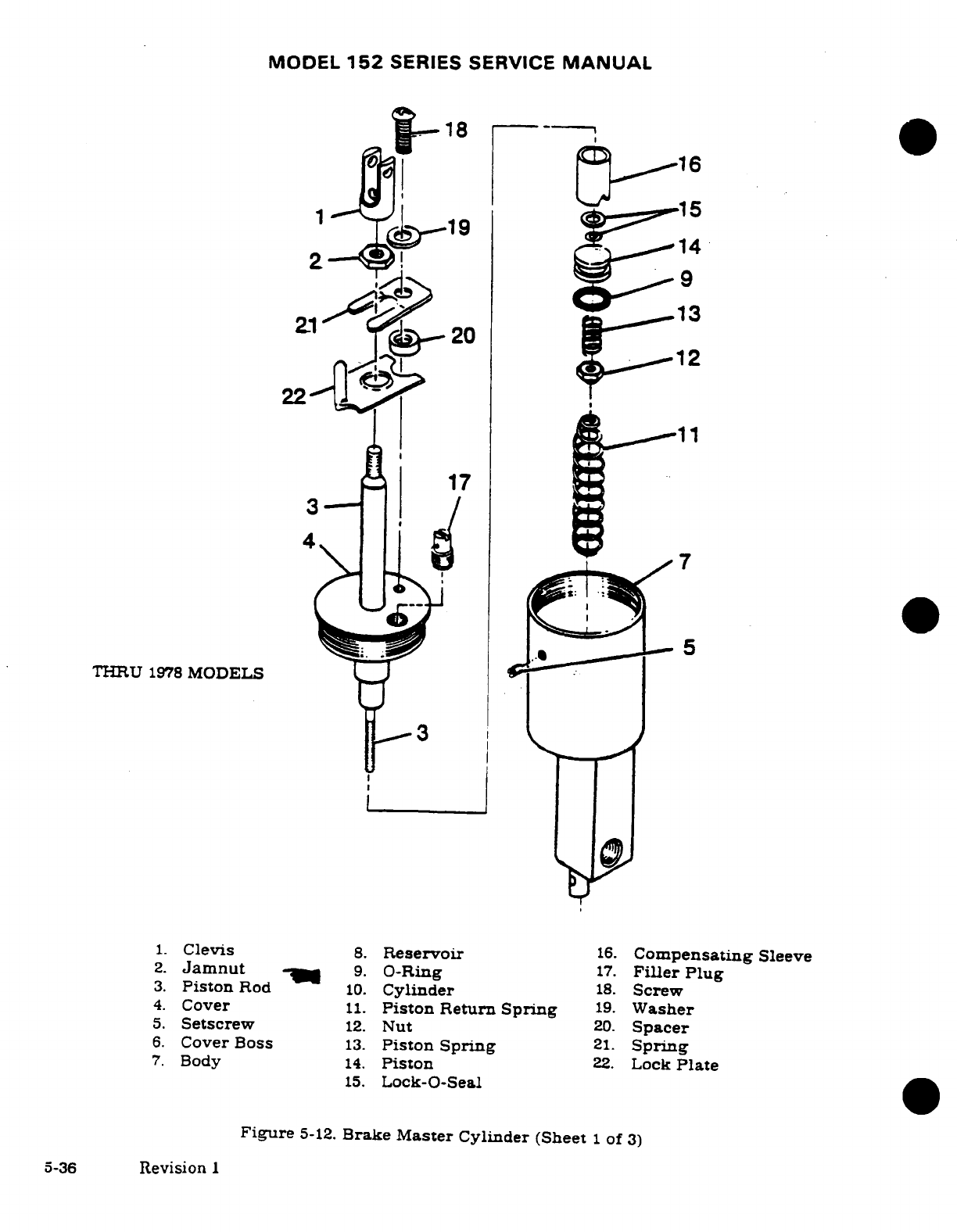
MODEL
152
SERIES SERVICE
MANUAL
.
18
19
9
13
20
22
11
17
3
THRU
1978
MODELS
1.
Clevis
8.
Reservoir
16.
Compensating
Sleeve
2.
Jamnut
9.
O-Ring
17.
Filler
Plug
3.
Piston
Rod
10.
Cylinder
18.
Screw
4.
Cover
11.
Piston
Return
Spring
19.
Washer
5.
Setscrew
12.
Nut
20.
Spacer
6.
Cover
Boss
13.
Piston
Spring
21.
Spring
7.
Body
14.
Piston
22.
Lock
Plate
15.
Lock-O-Seal
Figure
5-12.
Brake
Master Cylinder
(Sheet
1
of
3)
5-36
Revision
I
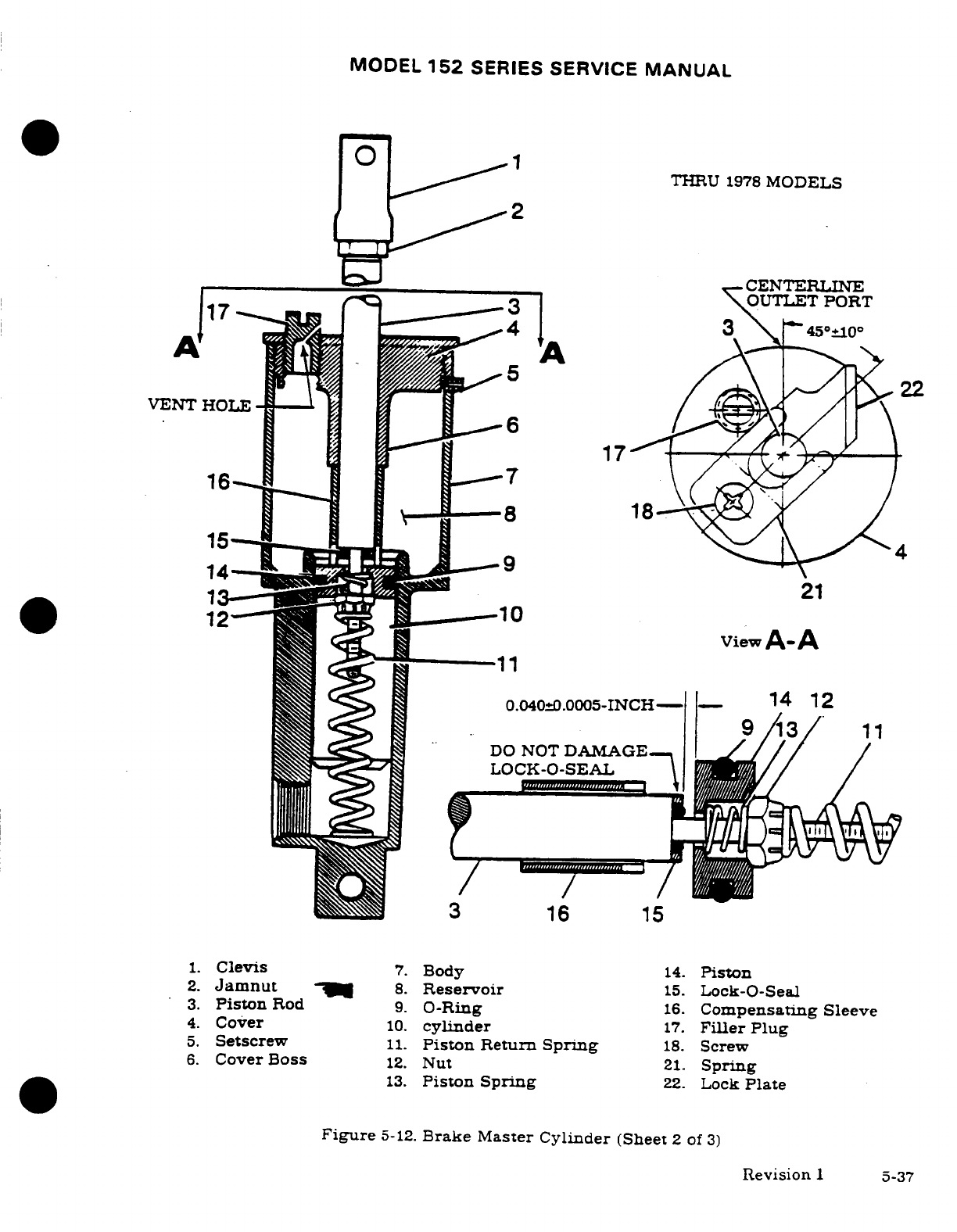
MODEL
152
SERIES
SERVICE
MANUAL
THRU
1978
MODELS
2
CENTERLINE
O
U
T
L
E T
P
O
R
T
1.
Clevis
7.
Body
14.
Piston
2.
Jamnut
8.
Reservoir
15.
Lock-O-Seal
3.
Piston
Rod
9.
O-Ring
16.
Compensating
Sleeve
4.
Cover
10.
cylinder
17.
Filler
Plug
5.
Setscrew
11.
Piston
Return
Spring
18.
Screw
15
4
14
13.
Piston
Spring
22.
Lock
Plate
Figure
5-12.
Brake
Master
Cylinder
(Sheet
2
of
3)
1
viewA-A
11
0.040±0.0005-INCH
14
12
DO
NOT
DAMAGE
LOCK-O-SEAL
3
16
15
1.
Clevis
7.
Body
14.
Piston
2.
Jamnut
8.
Reservoir
15.
Lock-O-Seal
3.
Piston
Rod
9.
O-Ring
16.
Compensating Sleeve
4.
Cover
10.
cylinder
17.
Filler
Plug
5.
Setscrew
11.
Piston
Return
Spring
18.
Screw
6.
Cover
Boss
12.
Nut
21.
Spring
13.
Piston
Spring
22.
Lock
Plate
Figure
5-12.
Brake
Master
Cylinder
(Sheet
2
of
3)
Revision
1
5-37
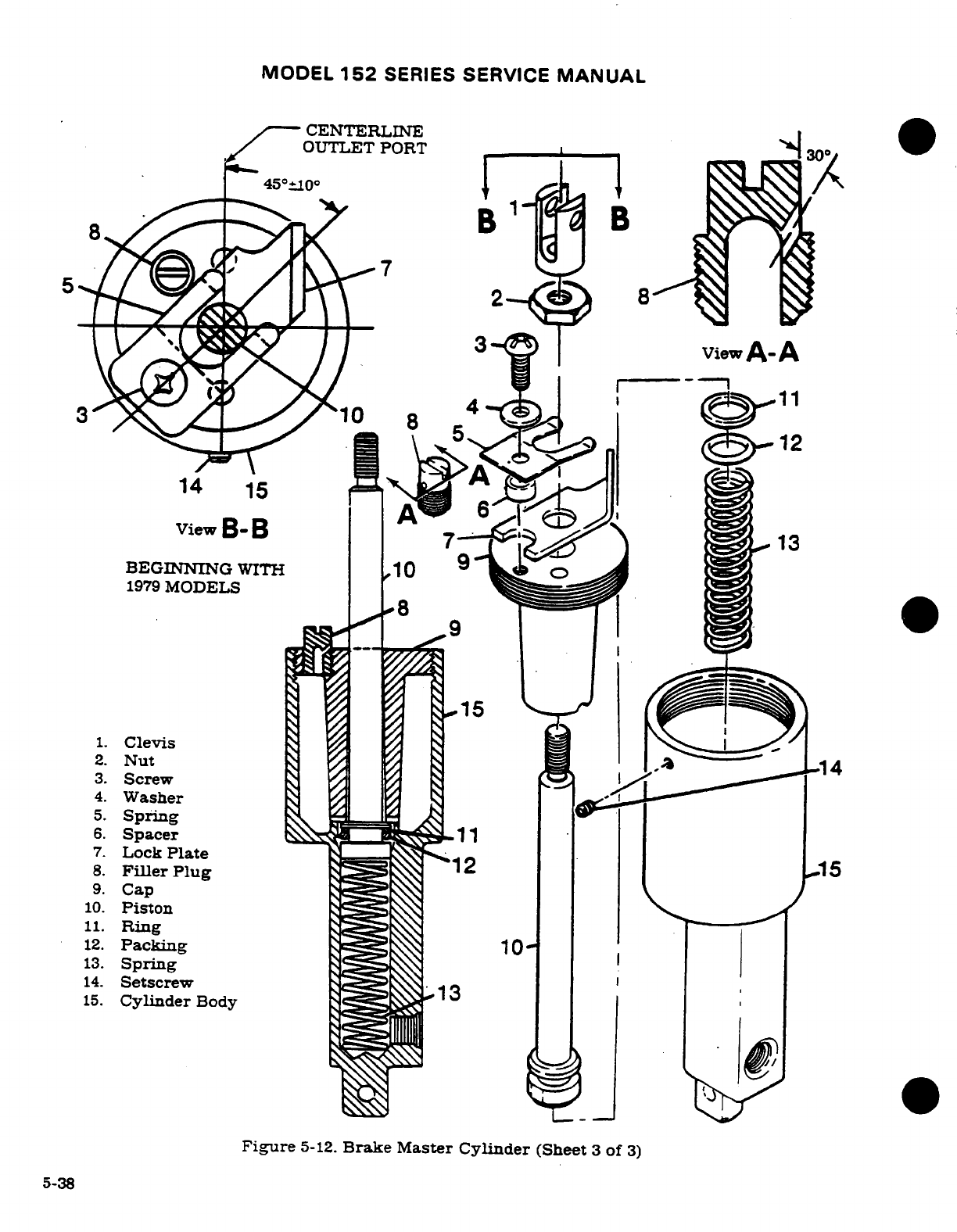
MODEL
152
SERIES
SERVICE
MANUAL
CENTERLINE
OUTLET PORT
300
B
72
viewA-A
5
12
14
15
ViewB
-B 3
BEGINNING
WITH
10
9
1979
MODELS
3.
Screw
6.
Spacer
11
7.
Lock
Plate
15
9.
Cap
10.
Piston
11.
Ring
12.
Packing
13.
Spring
14.
Setscrew
15.
Cylinder
Body
Figure
5-12.
Brake
Master
Cylinder
(Sheet
3
of
3)
5-38
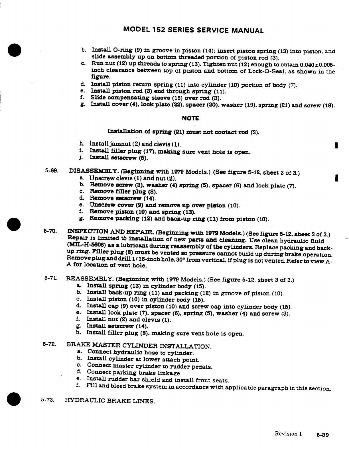
MODEL
152
SERIES
SERVICE
MANUAL
b.
Install
O-ring
(9)
in
groove
in
piston
(14);
insert
piston
spring
(13)
into
piston.
and
slide
assembly
up
on
bottom
threaded
portion
of
piston
rod
(3).
c.
Run
nut
(12)
up
threads
to
spring
(13).
Tighten
nut
(12)
enough
to
obtain
0.040
±0.005-
inch
clearance
between top
of
piston
and
bottom
of
Lock-O-Seal.
as
shown
in
the
figure.
d.
Install
piston
return spring
(11)
into
cylinder
(10)
portion
of body
(7).
e.
Install
piston
rod
(3)
end
through
spring
(11).
f.
Slide
compensating
sleeve
(16)
over
rod
(3).
g.
Install
cover
(4),
lock
plate
(22).
spacer
(20).
washer
(19).
spring
(21)
and
screw
(18).
NOTE
Installation
of
spring
(21)
must
not
contact
rod
(3).
h.
Install
jamnut
(2)
and
clevis
(1).
i.
Install filler
plug
(17).
making
sure
vent
hole
is
open.
j.
Install
setscrew
(5).
5-69.
DISASSEMBLY.
(Beginning
with
1979
Models.)
(See
figure
5-12,
sheet
3
of
3.)
a.
Unscrew
clevis
(1)
and
nut
(2).
b.
Remove
screw
(3).
washer
(4)
spring
(5).
spacer
(6)
and lock
plate
(7).
c.
Remove
filler
plug
(8).
d.
Remove
setscrew
(14).
e.
Unscrew
cover
(9)
and
remove
up
over
piston
(10).
f.
Remove
piston
(10)
and
spring
(13).
g.
Remove
packing
(12)
and
back-up
ring
(11)
from
piston
(10).
5-70.
INSPECTION
AND
REPAIR.
(Beginning
with
1979
Models.)
(See
figure
5-12.
sheet
3
of
3.)
Repair
is
limited
to
installation
of
new
parts
and
cleaning.
Use
clean
hydraulic
fluid
(MIL-H-5606)
as
a
lubricant during reassembly
of
the
cylinders.
Replace
packing
and
back-
up
ring.
Filler plug
(8)
must
be
vented
so
pressure
cannot
build
up
during
brake
operation.
Remove
plug
and
drill
1
/
16-inch
hole.
30
from
vertical,
if
plug
is
not
vented.
Refer to
view
A-
A
for
location
of
vent
hole.
5-71.
REASSEMBLY.
(Beginning
with
1979
Models.)
(See
figure
5-12.
sheet
3
of
3.)
a.
Install
spring
(13)
in
cylinder
body
(15).
b.
Install
back-up
ring
(11)
and
packing
(12)
in
groove
of
piston
(10).
c.
Install
piston
(10)
in
cylinder
body
(15).
d.
Install
cap
(9)
over
piston
(10)
and
screw
cap
into cylinder
body
(15).
e.
Install
lock
plate
(7).
spacer
(6).
spring
(5),
washer
(4)
and
screw
(3).
f.
Install
nut
(2)
and
clevis
(1).
g.
Install
setscrew
(14).
h.
Install filler
plug
(8),
making
sure
vent hole
is
open.
5-72.
BRAKE MASTER
CYLINDER
INSTALLATION.
a.
Connect
hydraulic
hose
to
cylinder.
b.
Install
cylinder
at
lower
attach
point.
c.
Connect
master
cylinder
to
rudder
pedals.
d.
Connect
parking
brake
linkage
e.
Install
rudder bar
shield
and
install
front
seats.
f.
Fill
and
bleed
brake
system
in
accordance
with
applicable
paragraph
in
this
section.
5-73.
HYDRAULIC
BRAKE
LINES.
Revision
1
5-39
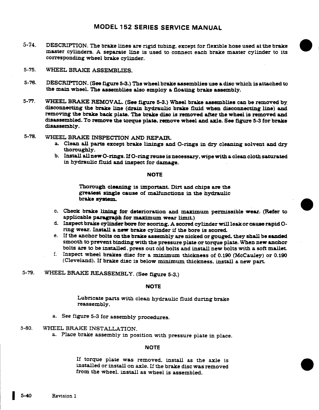
MODEL
152
SERIES
SERVICE
MANUAL
5-74.
DESCRIPTION.
The
brake
lines
are
rigid
tubing.
except
for
flexible
hose used
at
the
brake
master
cylinders.
A
separate
line is
used
to
connect
each brake
master
cylinder
to
its
corresponding
wheel brake
cylinder.
5-75.
WHEEL
BRAKE
ASSEMBLIES.
5-76.
DESCRIPTION.
(See
figure
5-3.)
The
wheel
brake
assemblies
use
a
disc
which
is
attached
to
the
main
wheel.
The
assemblies
also
employ
a
floating
brake assembly.
5-77.
WHEEL
BRAKE
REMOVAL.
(See
figure
5-3.)
Wheel
brake
assemblies
can be
removed
by
disconnecting
the
brake
line
(drain
hydraulic
brake
fluid
when
disconnecting line)
and
removing
the
brake
back
plate.
The
brake
disc
is
removed
after the
wheel
is
removed
and
disassembled.
To
remove
the
torque
plate.
remove
wheel
and
axle.
See
figure
5-3
for
brake
disassembly.
5-78.
WHEEL
BRAKE
INSPECTION
AND
REPAIR.
a.
Clean
all
parts
except
brake
linings
and
O-rings
in
dry
cleaning
solvent
and
dry
thoroughly.
b.
Install
all
new
O-rings. If
O-ring
reuse
is
necessary,
wipe
with
a
clean
cloth
saturated
in
hydraulic
fluid
and
inspect
for
damage.
NOTE
Thorough
cleaning
is
important.
Dirt
and
chips
are
the
greatest
single
cause
of
malfunctions
in
the
hydraulic
brake
system.
c.
Check
brake
lining
for
deterioration
and
maximum
permissible
wear.
(Refer
to
applicable
paragraph
for
maximum
wear
limit.)
d.
Inspect
brake
cylinder
bore for
scoring.
A
scored
cylinder
will leak
or
cause
rapid
0-
ring
wear.
Install
a
new
brake
cylinder
if
the
bore
is
scored.
e.
If
the
anchor
bolts
on
the
brake
assembly
are
nicked
or
gouged.
they
shall
be
sanded
smooth to
prevent
binding
with
the
pressure
plate
or
torque
plate.
When
new
anchor
bolts
are
to
be
installed,
press
out
old
bolts
and
install
new
bolts
with
a
soft
mallet.
f.
Inspect
wheel
brakes
disc
for a
minimum
thickness
of
0.190
(McCauley)
or
0.190
(Cleveland).
If
brake
disc
is
below
minimum
thickness.
install
a
new
part.
5-79.
WHEEL
BRAKE
REASSEMBLY.
(See
figure
5-3.)
NOTE
Lubricate
parts
with
clean
hydraulic
fluid
during
brake
reassembly.
a.
See
figure
5-3
for
assembly
procedures.
5-80.
WHEEL
BRAKE
INSTALLATION.
a.
Place
brake
assembly in
position
with
pressure plate
in
place.
NOTE
If
torque plate was
removed.
install
as
the
axle
is
installed
or
install
on
axle.
If
the brake
disc
was
removed
from
the
wheel.
install
as
wheel is assembled.
5-40
Revision
1
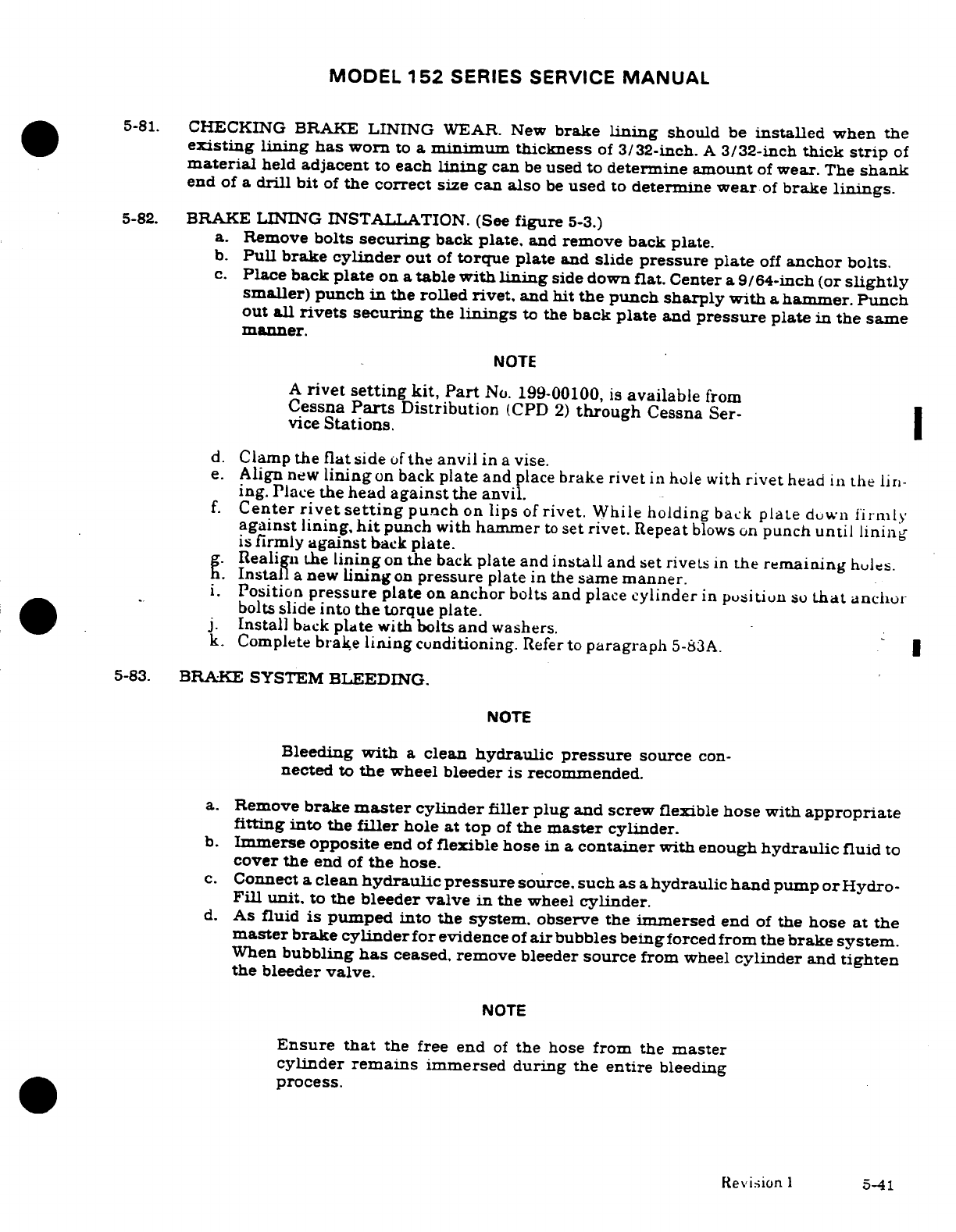
MODEL
152
SERIES
SERVICE
MANUAL
5-81.
CHECKING
BRAKE
LINING
WEAR.
New
brake
lining
should
be
installed
when
the
existing
lining has
worn
to
a
minimum
thickness
of
3/32-inch.
A
3/32-inch
thick
strip
of
material
held
adjacent
to
each
lining
can
be
used
to
determine
amount
of
wear.
The
shank
end
of
a
drill
bit
of
the
correct
size
can
also
be
used
to
determine
wear
of
brake
linings.
5-82.
BRAKE
LINING
INSTALLATION.
(See
figure
5-3.)
a.
Remove
bolts
securing
back
plate,
and
remove
back
plate.
b.
Pull
brake
cylinder
out
of
torque
plate
and
slide
pressure plate
off
anchor bolts.
c.
Place
back
plate
on
a
table with
lining
side down
flat.
Center
a
9/64-inch
(or
slightly
smaller)
punch
in
the
rolled
rivet,
and
hit
the
punch
sharply with
a
hammer.
Punch
out
all
rivets securing
the
linings
to
the
back
plate
and
pressure
plate
in
the
same
manner.
NOTE
A
rivet
setting
kit,
Part
No.
199-00100,
is
available
from
Cessna
Parts
Distribution
(CPD
2)
through
Cessna
Ser-
vice
Stations.
d.
Clamp
the
flat
side
of
the
anvil
in
a
vise.
e.
Align
new
lining
on
back
plate
and
place
brake
rivet
in hole
with
rivet
head
in
the
lin-
ing.
Place
the
head
against
the
anvil.
f.
Center
rivet
setting
punch
on
lips
of
rivet.
While
holding
back
plate
down
firmly
against
lining,
hit
punch
with hammer
to
set
rivet.
Repeat
blows
on
punch
until lining
is
firmly
against
back
plate.
g.
Realign
the
lining
on
the
back
plate
and
install
and
set
rivets
in
the
remaining
holes.
h.
Install
a
new
lining
on
pressure
plate in
the
same
manner.
i.
Position
pressure plate
on
anchor
bolts
and
place
cylinder
in
position
so
that
anchor
bolts
slide
into
the
torque
plate.
j.
Install
back
plate
with
bolts
and
washers.
k.
Complete
brake
lining
conditioning.
Refer
to
paragraph
5-83A.
5-83.
BRAKE
SYSTEM
BLEEDING.
NOTE
Bleeding
with
a
clean
hydraulic
pressure
source
con-
nected
to
the
wheel
bleeder
is
recommended.
a.
Remove
brake
master
cylinder
filler
plug
and screw
flexible
hose
with
appropriate
fitting
into
the
filler
hole
at top
of
the
master
cylinder.
b.
Immerse
opposite
end
of
flexible
hose
in
a
container
with
enough
hydraulic
fluid
to
cover
the
end
of
the
hose.
c.
Connect
a
clean
hydraulic
pressure
source.
such
as
a
hydraulic
hand
pump
or
Hydro-
Fill unit,
to
the
bleeder
valve
in
the
wheel
cylinder.
d.
As
fluid
is
pumped
into
the
system.
observe the
immersed
end
of
the
hose
at
the
master
brake
cylinder
for
evidence
of
air
bubbles
being
forced
from
the
brake
system.
When
bubbling
has
ceased,
remove
bleeder
source
from
wheel
cylinder
and
tighten
the
bleeder
valve.
NOTE
Ensure
that
the
free end
of
the
hose
from
the
master
cylinder
remains
immersed
during
the
entire
bleeding
process.
Revision
1
5-41
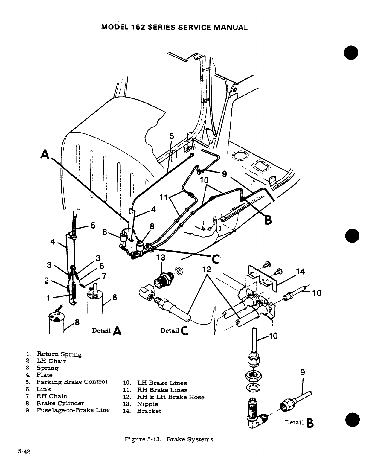
MODEL
152
SERIES SERVICE
MANUAL
5
5
14
0
Detail
A
Detail
C/
1.
Return
Spring
2.
LH
Chain
3.
Spring
4.
Plate
5.
Parking
Brake Control
10.
LH
Brake
Lines
6.
Link
11.
RH
Brake
Lines
7.
RH
Chain
12.
RH
&
LH
Brake
Hose
8.
Brake
Cylinder
13.
Nipple
9.
Fuselage-to-Brake
Line
14.
Bracket
Detail
B
Figure
5-13.
Brake Systems
5-42
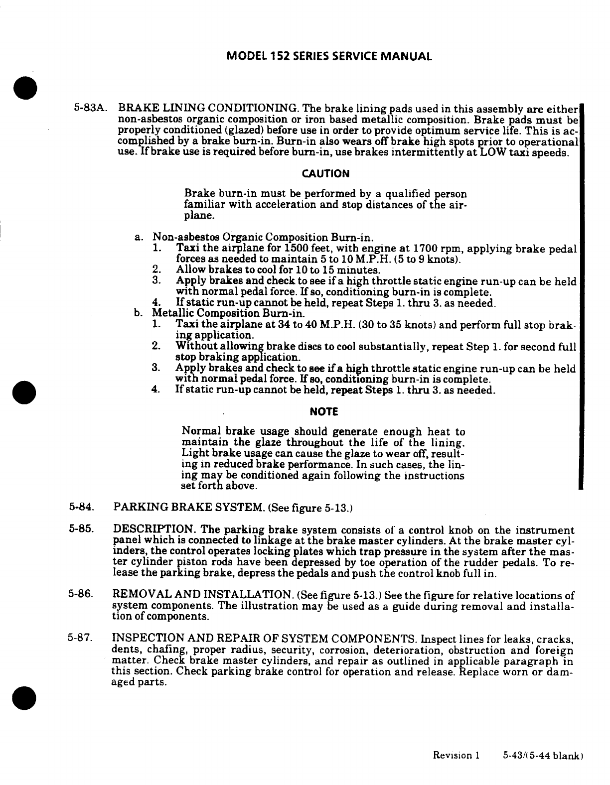
MODEL
152
SERIES
SERVICE
MANUAL
5-83A.
BRAKE
LINING
CONDITIONING. The
brake
lining
pads
used
in
this
assembly
are
either
non-asbestos organic
composition
or
iron
based
metallic
composition.
Brake
pads
must
be
properly
conditioned
(glazed)
before
use in
order
to provide
optimum service
life.
This
is ac-
complished
by
a
brake burn-in.
Burn-in
also
wears
off
brake
high
spots
prior
to
operational
use.
If
brake
use is
required
before
burn-in,
use
brakes
intermittently
at
LOW
taxi
speeds.
CAUTION
Brake
burn-in must
be
performed
by
a
qualified
person
familiar
with
acceleration and
stop
distances
of
the
air-
plane.
a.
Non-asbestos Organic
Composition
Burn-in.
1.
Taxi
the
airplane
for
1500
feet,
with
engine
at
1700
rpm,
applying
brake
pedal
forces
as
needed
to
maintain
5
to
10
M.P.H.
(5
to
9
knots).
2.
Allow
brakes
to
cool
for
10
to
15
minutes.
3.
Apply
brakes
and
check
to
see
if
a
high
throttle
static
engine
run-up
can
be
held
with
normal
pedal
force.
If
so,
conditioning
burn-in
is
complete.
4.
If
static run-up
cannot
be
held,
repeat
Steps
1.
thru
3.
as
needed.
b.
Metallic
Composition
Burn-in.
1.
Taxi
the
airplane
at
34
to
40
M.P.H.
(30
to
35
knots)
and
perform
full
stop
brak-
ing
application.
2.
Without
allowing
brake
discs
to
cool
substantially,
repeat
Step
1.
for
second
full
stop
braking
application.
3.
Apply
brakes
and
check
to
see
if
a
high
throttle
static
engine
run-up
can
be
held
with normal
pedal
force.
If
so,
conditioning
burn-in
is
complete.
4.
If static run-up
cannot
be
held,
repeat
Steps
1.
thru
3.
as
needed.
NOTE
Normal
brake
usage
should
generate
enough
heat
to
maintain
the
glaze
throughout
the
life
of
the
lining.
Light
brake
usage
can
cause
the
glaze
to
wear
off,
result-
ing
in reduced
brake
performance.
In
such
cases,
the
lin-
ing
may
be
conditioned
again
following
the
instructions
set
forth
above.
5-84.
PARKING
BRAKE
SYSTEM.
(See
figure
5-13.)
5-85.
DESCRIPTION.
The
parking
brake
system
consists
of
a
control
knob
on
the
instrument
panel
which
is
connected
to
linkage
at
the
brake
master
cylinders.
At
the
brake
master
cyl-
inders,
the
control
operates
locking
plates
which
trap
pressure
in
the
system
after
the
mas-
ter
cylinder
piston
rods
have
been
depressed
by
toe
operation
of
the
rudder
pedals.
To
re-
lease
the
parking
brake,
depress
the
pedals
and
push
the
control
knob
full
in.
5-86.
REMOVAL
AND INSTALLATION.
(See
figure
5-13.)
See
the
figure
for
relative
locations
of
system
components.
The
illustration
may
be
used
as
a
guide
during
removal
and
installa-
tion
of
components.
5-87.
INSPECTION
AND
REPAIR
OF
SYSTEM
COMPONENTS.
Inspect
lines
for
leaks,
cracks,
dents,
chafing, proper
radius,
security,
corrosion,
deterioration,
obstruction
and
foreign
matter.
Check
brake
master
cylinders, and
repair
as outlined
in
applicable
paragraph
in
this
section.
Check
parking
brake
control
for
operation
and
release.
Replace
worn
or
dam-
aged
parts.
Revision
1
5-43/(5-44
blank)
MODEL
152
SERIES
SERVICE
MANUAL
SECTION
6
AILERON
CONTROL
SYSTEM
Page
No.
TABLE
OF
CONTENTS
Aerofiche/
Manual
AILERON
CONTROL
SYSTEM
G114/6-1
Description
................. G14/6-1
Ailerons
....................
1G23/6-10
Trouble
Shooting
............ 1G14/6-1
Removal
..................
1G23/6-10
Control
"Y"
.................
1G15/6-2
Installation
...............
IG23/6-10
Description
................
1G15/6-2
Rigging (Thru
15279473,
Removal/Installation
.......
1G15/6-2
A1520736, F15201428,
Bellcrank
..................
IG16/6-3
and
FA1520336)
...........
1G23/6-10
Removal
..................
1G16/6-3
Rigging
(Beginning
with
Installation
...............
1G16/6-3
15279474,
A1520737,
Cables
and
Pulleys
..........
1G16/6-3
F15201429,
and
Remova/Installation
.......
1G16/6-3
FA1520337)
...............
1G24/6-11
6-1.
AILERON
CONTROL SYSTEM.
(See
figure
6-1.)
6-2
DESCRIPTION. The
aileron
control
system
is
comprised
of
push-pull
rods.
bellcranks.
cables.
pulleys, sprockets
and
roller
chains,
all
of
which
link
the
control
wheels
to
the
ailerons.
A
control
"Y"
interconnects
the
control wheels
to
the
aileron
cables.
6-3.
TROUBLE
SHOOTING.
NOTE
Due
to
remedy
procedures
in
the
following
trouble
shoot-
ing
chart, it
may
be
necessary
to
rerig
system.
Refer
to
I
paragraph
6-15
or
6-16.
TROUBLE
PROBABLE CAUSE
REMEDY
LOST
MOTION
IN
CONTROL
Loose
control
cables.
Adjust
cables
to
proper
WHEELS.
tension.
Broken
pulley
or bracket.
Replace
worn
or
broken
cable
off
pulley
or
worn
parts.
install
cables
rod end
bearings.
correctly.
Sprung
bellcrank.
Replace
bellcrank.
Loose
chains.
Adjust
chain
tension.
Revision
1
6-1
MODEL
152
SERIES
SERVICE
MANUAL
6-3.
TROUBLE
SHOOTING
(Cont).
TROUBLE
PROBABLE CAUSE REMEDY
RESISTANCE
TO
CONTROL
Cables
too
tight.
Adjust
cables
to
proper
WHEEL MOVEMENT.
tension.
Pulleys
binding
or
cable
Replace
defective
pulleys.
off.
Install
cables
correctly.
Bellcrank
distorted or
Replace
bellcrank.
damaged.
Defective
U-joints.
Replace
defective
U-joints.
Clevis
bolts
in
system
too
Loosen,
then
tighten
prop-
tight
erly
and
safety.
Rusty
chain
or chain
bind-
Replace
chain
or
defective
ing
with
sprocket.
parts.
CONTROL
WHEELS
NOT
Improper
adjustment
of
Adjust
in
accordance with
LEVEL
WITH
AILERONS
chains
or
cables.
paragraph
6-15
and
6-16.
NEUTRAL.
Improper
adjustment
of
Adjust
in
accordance
with
aileron
push-pull
rods.
paragraph
6-15
and
6-16.
DUAL CONTROL
WHEELS
Chains
improperly
Adjust
in
accordance
with
NOT
COORDINATED.
adjusted.
paragraph
6-15
and
6-16.
INCORRECT AILERON
Push-pull
rods
not
Adjust
in
accordance
with
TRAVEL.
adjusted
properly.
paragraph
6-15
and
6-16.
Worn
bellcrank
stop bush- Replace
worn
parts.
ings
on bellcrank
slots.
6-4.
CONTROL
"Y".
(See
figure
6-2.)
6-5.
DESCRIPTION.
The
control
"Y"
transforms
rotation
of
the control
wheels
into
pulling
motion
on
the
aileron
cables
by means
of
sprockets
and
chains.
The
"Y"
is
pivoted
at
the
lower
end
to
operate
the
elevator
control
system.
6-6.
REMOVAL AND
INSTALLATION.
a.
Remove
control cover
and
carpeting
as necessary
to
gain access
to
lower
end
of
control
"Y".
b.
Release
cable
tension
by
loosening
turnbuckle
(index
3,
figure
6-1).
c.
Remove
bolt
(17)
attaching
control
link
(14).
d.
Remove
bolts
(8)
securing
control
wheel
tubes
(9)
to
universal
joints
(7).
e.
Remove
bolts
securing
cable
ends
to
control arm
(5).
f.
Remove
pivot
bolt
(16)
and
remove
control
"Y".
g.
Reverse
preceding
steps
for
installation.
h.
Rig
aileron
system
in
accordance
with
applicable
paragraph
in
this
section.
safety
turnbuckle
and
reinstall all
items
removed
in
step
"a".
i.
Check
and/or
rig
elevator
control
system
in
accordance
with
applicable
paragraph
in
Section
8.
6-2
MODEL
152
SERIES SERVICE
MANUAL
6-7.
AILERON BELLCRANK.
(See
figure
6-3.)
6-8.
REMOVAL.
a.
Remove
access
plate
inboard
of
each
bellcrank
on
underside
of
wing.
Remove
headliner
if
required.
b.
Relieve
control
cable
tension
by
loosening
turnbuckle
barrel
(index
3.
figure
6-1).
c.
Disconnect
control
cables from
bellcrank.
Retain
all
spacers
(15).
d.
Disconnect
aileron
push-pull
rod
(7)
at
bellcrank.
e.
Remove
nut.
washer
and
bolt
securing
bellcrank
stop
bushing
(17)
and
bellcrank
(11)
to
wing
structure.
f.
Remove
bellcrank
through
access opening.
using
care
that
bushing
(5)
is
not
dropped
from
bellcrank.
NOTE
Brass washers
(10)
may
be
used
as
shims
between
lower
end
of
bellcrank
and
wing
channel
(8).
Retain
these
shims.
Tape
open
ends of
bellcrank
to
prevent
dust
and
dirt
from
entering
bellcrank
needle
bearings
(6).
6-9.
INSTALLATION.
a.
Place
bushing
(5)
and
stop
bushing
(17)
in
bellcrank
and
position
bellcrank
in
wing.
b.
Install
brass washers
(10)
between
lower
end
of
bellcrank
and
wing
channel
(8)
to
shim
out
excess
clearance.
c.
Install
bellcrank
pivot
bolt
(4).
washers
and
nut.
d.
Position
bellcrank stop-bushing
(17)
and
install
attaching
bolt
(18).
washers
and
nut.
e.
Connect
aileron
cables
to
bellcrank.
f.
Rig
aileron
system
in
accordance
with
applicable
paragraph
in
this
section.
safety
turnbuckle
and
install
access
plates.
6-10.
CABLES
AND
PULLEYS.
(See
figure
6-1.)
6-11.
REMOVAL
AND
INSTALLATION.
a.
Remove
access
plates.
wing root
fairings
and
upholstery
as
required.
b.
Disconnect
cables
from
aileron
bellcranks
and
remove
cable
guards
and
pulleys
as
necessary
to
work
cables
free
of
aircraft.
NOTE
To
ease
routing
of
cables.
a
length
of
wire
may
be
attached
to
end
of
cable
before
being
withdrawn
from
aircraft.
Leave
wire
in
place.
routed
through
structure:
then
attach
to
cable
being installed
and
use
to
pull
cable into
position.
Carry-thru
cable
turnbuckle
(3)
may
be
located
at
either
the
right
or
left
aileron
bellcrank.
Direct
cable
turn-
buckles
are
located
at
bellcranks.
c.
After
cable
is
routed.
install
pulleys
and
cable
guards.
Ensure
cable
is
positioned
in
pulley groove
before
installing
guard.
d.
Rig
aileron
system
in
accordance with
applicable
paragraph
in
this
section.
safety
turnbuckles
and
install
access
plates.
fairings
and
upholstery
removed
in
step
"a"
6-3
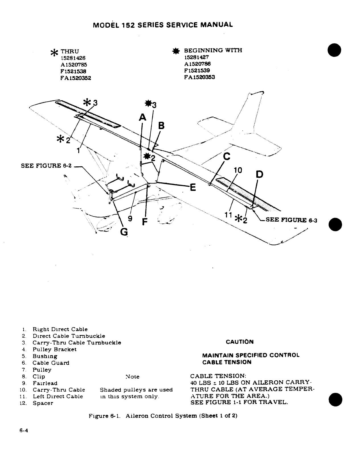
MODEL
152
SERIES
SERVICE
MANUAL
THRU
*
BEGINNING
WITH
15281426
15281427
A
1520785
A1520786
F1521538 F1521539
FA1520352
FA1520353
3
1.
Right
Direct
Cable
2.
Direct
Cable
Turnbuckle
3.
Carry-Thru
Cable
Turnbuckle
CAUTION
6.
Cable
Guard
CABLE
TENSION
7.
Pulley
8.
Clip
Note
CABLE
TENSION:
9.
Fairlead
40
LBS
-
10
LBS
ON
AILERON
CARRY-
10.
Carry-Thru
Cable
Shaded
pulleys
are
used
THRU
CABLE
(AT
AVERAGE
TEMPER-
11.
Left
Direct
Cable
in
this
system
only.
ATURE
FOR
THE
AREA.)
12.
Spacer
SEE
FIGURE
1-1
FOR
TRAVEL.
Figure
6-1.
Aileron
Control
System
(Sheet
1
of
2)
6-4
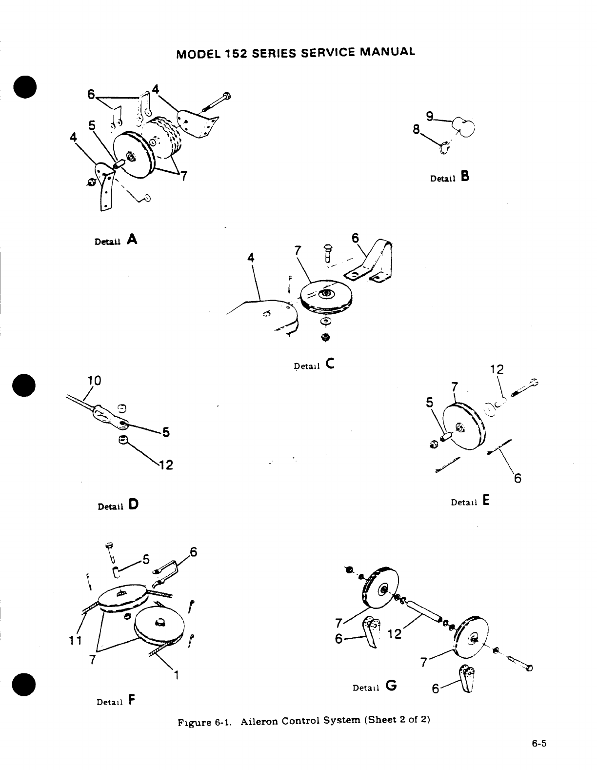
MODEL
152
SERIES
SERVICE
MANUAL
Detail
A
6
Detail
C
12
6
Detail
D
Detail
E
Detail
G
6-
DetaFl
FG
Figure
6-1.
Aileron
Control System
(Sheet
2
of
2)
6-5
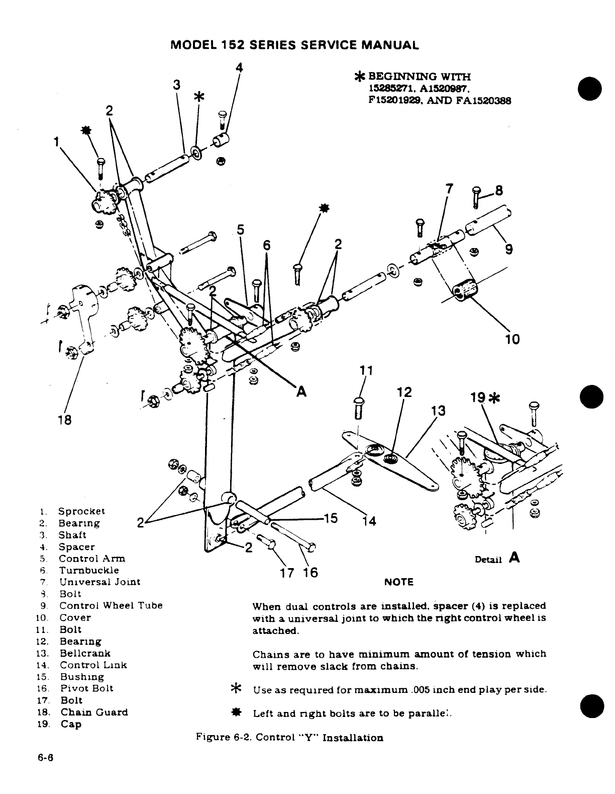
MODEL
152
SERIES SERVICE
MANUAL
*
BEGINNING
WITH
3
15285271.
A1520987.
F15201929,
AND
FA1520388
10
19*
18
1.
Sprocket
2
Bearing
2
14
3.
Shaft
4.
Spacer
5.
Control
Arm
Detail
A
6.
Turnbuckle
17 16
7.
Universal
Joint
NOTE
8.
Bolt
9.
Control
Wheel
Tube When
dual
controls
are
installed.
spacer
(4)
is
replaced
10.
Cover with
a
universal
joint
to
which
the
right
control
wheel
is
11.
Bolt
attached.
12.
Bearing
13.
Bellcrank
Chains are
to
have
minimum
amount
of
tension
which
14.
Control
Link
will
remove
slack
from
chains.
15.
Bushing
16.
Pivot
Bolt
*
Use
as
required
for
maximum
.005
inch
end
play per
side.
17.
Bolt
18.
Chain
Guard
*
Left
and
nrght
bolts
are
to
be
parallel.
19.
Cap
Figure
6-2.
Control
"Y"
Installation
6-6
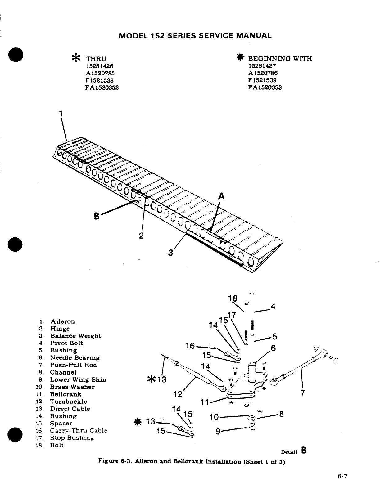
MODEL
152
SERIES SERVICE
MANUAL
*
THRU
*
BEGINNING
WITH
15281426
15281427
A1520785
A1520786
F1521538
F1521539
FA
1520352
FA1520353
18
1.
Aileron
2.
Hinge
3.
Balance
Weight
5
4.
Pivot
Bolt
5.
Bushing
6.
Needle
Bearing
.
7.
Push-Pull
Rod
14
8.
Channel
9.
Lower
Wing
Skin
*13
10.
Brass
Washer
11.
Bellcrank
12
7
12.
Turnbuckle
11
13.
Direct Cable
14
15
14.
Bushing
\15
15.
Spacer
1
16.
Carry-Thru
Cable
15
9
17.
Stop
Bushing
18.
Bolt
Detail
B
Figure
6-3.
Aileron
and
Bellcrank
Installation
(Sheet
1
of
3)
6-7
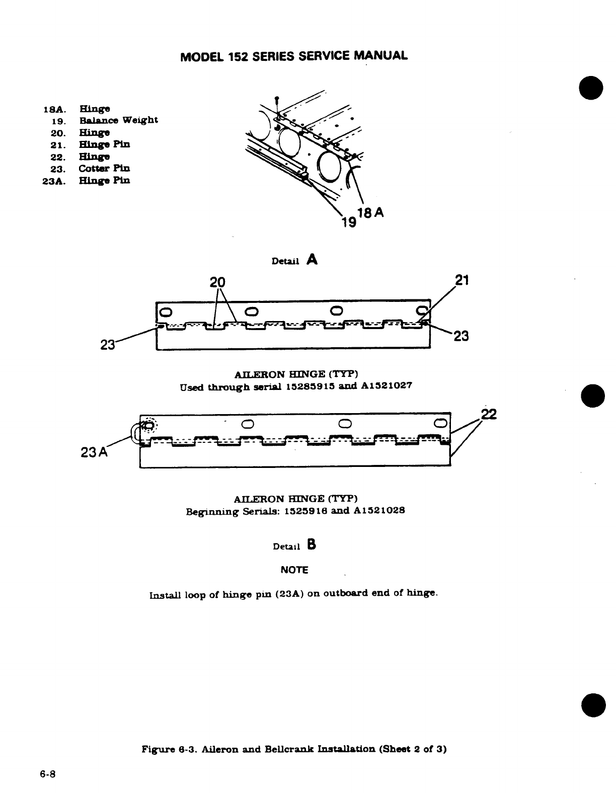
MODEL
152
SERIES
SERVICE
MANUAL
18A.
Hinge
19.
Balance
Weight
20.
Hinge
21.
Hinge
Pin
22.
Hinge
23.
Cotter
Pin
23A.
Hinge
Pin
18A
1918A
Detail
A
20
21
23 23
AILERON
HINGE (TYP)
Used
through
serial
15285915
and
A1521027
23A
AILERON
HINGE
(TYP)
Beginning
Serials:
1525916
and
A1521028
Detail
B
NOTE
Install
loop
of
hinge
pin
(23A)
on
outboard end
of
hinge.
Figure
6-3.
Aileron
and
Bellcrank
Installation
(Sheet
2
of
3)
6-8
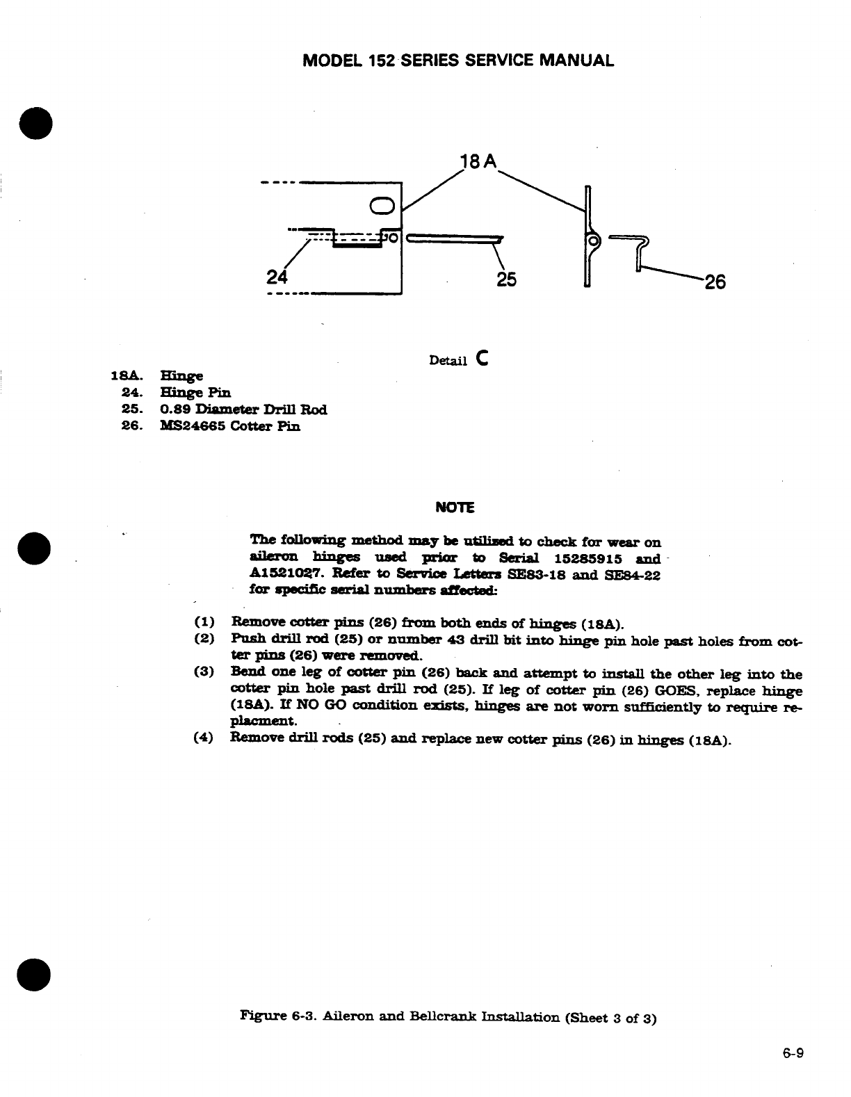
MODEL
152
SERIES
SERVICE
MANUAL
18A
24
25
26
Detail
C
18A.
Hinge
24.
Hinge
Pin
25.
0.89
Diameter
Drill
Rod
26.
MS24665
Cotter
Pin
NOTE
The
following
method
may
be
utilized
to
check
for
wear
on
aileron
hinges
used
prior
to Serial 15285915
and
A1521027.
Refer
to
Service
Letters
SE83-18
and
SE84-22
for
specific
serial
numbers
affected:
(1)
Remove
cotter
pins
(26)
from
both
ends
of
hinges
(18A).
(2)
Push
drill
rod
(25)
or
number
43
drill
bit
into
hinge
pin
hole
past
holes
from
cot-
ter
pins
(26)
were
removed.
(3)
Bend one
leg
of
cotter
pin
(26)
back
and
attempt
to
install
the
other
leg
into
the
cotter
pin
hole
past
drill rod
(25).
If
leg
of
cotter
pin
(26)
GOES,
replace
hinge
(18A).
If
NO
GO
condition
exists,
hinges
are
not worn
sufficiently
to
require
re-
placment.
(4)
Remove
drill
rods
(25)
and
replace
new
cotter
pins
(26)
in
hinges
(18A).
Figure
6-3.
Aileron
and
Bellcrank
Installation
(Sheet
3
of
3)
6-9
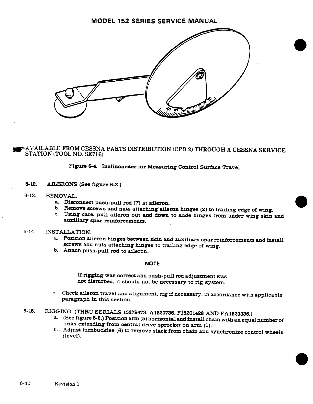
MODEL
152
SERIES
SERVICE
MANUAL
AVAILABLE
FROM
CESSNA
PARTS
DISTRIBUTION
(CPD
2)
THROUGH
A
CESSNA
SERVICE
STATION
(TOOL
NO.
SE716)
Figure
6-4.
Inclinometer
for
Measuring
Control
Surface
Travel
6-12.
AILERONS
(See
figure
6-3.)
6-13.
REMOVAL.
a.
Disconnect
push-pull
rod
(7)
at aileron.
b.
Remove
screws
and
nuts
attaching
aileron
hinges
(2)
to
trailing
edge
of
wing.
c.
Using
care.
pull
aileron
out
and
down
to
slide
hinges
from
under
wing
skin
and
auiliary
spar
reinforcements.
6-14.
INSTALLATION.
a.
Position
aileron
hinges
between
skin
and
auxiliary
spar
reinforcements
and
install
screws
and
nuts attaching hinges
to
trailing
edge
of
wing.
b.
Attach
push-pull
rod
to
aileron.
NOTE
If
rigging
was
correct and
push-pull
rod
adjustment
was
not
disturbed,
it
should
not
be
necessary
to
rig
system.
c.
Check
aileron
travel
and
alignment. rig
if
necessary.
in
accordance
with
applicable
paragraph
in
this
section.
6-15.
RIGGING.
(THRU
SERIALS
15279473.
A1520736.
F15201428
AND
FA1520336.)
a.
(See
figure
6-2.)
Position arm
(5)
horizontal
and
install
chain with
an
equal
number
of
links
extending
from
central
drive
sprocket
on
arm
(5).
b.
Adjust
turnbuckles
(6)
to
remove
slack
from
chain
and synchronize
control
wheels
(level).
6-10
Revision
1
MODEL 152
SERIES
SERVICE
MANUAL
NOTE
Adjust chain
turnbuckles
(6)
to
minimum
tension
re-
quired
to
remove slack.
c.
Tape
a
bar
across
both
control
wheels
to
hold
them
in
neutral
position.
d.
(Refer
to
figure
6-3.)
Adjust
turnbuckles
at
bellcranks
(11)
so
stop
bushings
(17)
are
centered
in
bellcrank
slots
(11)
with
40
+
10
pounds
tension
on
carry-thru
cable
(16).
e.
Adjust
push-pull
rod
(7)
at
each
aileron
until
ailerons
are
neutral
with
reference
to
trailing
edge
of
wing
flaps.
Be
sure
wing
flaps
are
fully
up
when
making
this
adjust-
ment.
Tighten
push-pull
rod
jamnuts.
f.
Safety
all
turnbuckles
by
the
single-wrap
method
using
0.040-inch
diameter
monel
safety wire.
g.
Remove
bar
from
control
wheels
and
install
all
parts
removed
for
access.
h.
Using
inclinometer,
check
ailerons
for
correct
travel.
An
inclinometer
is
shown
in
figure
6-4.
Refer to
figure
1-1.
for
travel
specifications.
WARNING
Be
sure
ailerons
move
in
correct
direction
when
operated
by
control
wheel.
6-16.
RIGGING
(BEGINNING
WITH
SERIALS 15279474, A1520737,
F15201429,
AND
FA1520337.)
a.
Complete
steps a.
thru
d.
of
paragraph
6-15.
b.
Manually
hold
one
aileron
in
streamline
position
so
that
trailing
edge
aligns
with
trailing
edge
of
flap.
Be
sure
flaps
are
fully
UP.
c.
Mount
an inclinometer
on
aileron
trailing
edge
and
set
to
0
°.
NOTE
An
inclinometer
suitable
for
measuring
control
surface
travel
is
available
from
Cessna
Parts
Distribution
(CPD
2)
through
a
Cessna
Service
Station.
See
figure
6-4.
d.
Adjust
push-pull
rod
(7)
so
that
aileron
droops
1°±
1/2°
DOWN
from
0
°
position set
in
step
c.
Tighten
push-pull
rodjamnuls.
e.
Repeat steps
b.
thru
d.
for opposite
aileron.
f.
Safety
all
turnbuckles
using
single
wrap method
and
0.040-inch
diameter
monel
safety
wire.
g.
Remove
bar
from
control
wheels
and
check
aileron
travel
with
values shown
in
Sec-
tion
1.
NOTE
Measure
aileron travel
from
"DROOP"
position
deter-
mined
in
step
d.
above.
h.
Reinstall
all
items
removed
for
access.
WARNING
Ensure
ailerons
move
in
correct
direction
when
operated
by
control
wheel.
1
Revision
1
6-11/A6-12
blank)
MODEL
152
SERIES
SERVICE
MANUAL
SECTION
7
WING
FLAP
CONTROL
SYSTEM
Page
No.
TABLE
OF
CONTENTS
Aerofiche/
Manual Flaps
....
...............
1H8/7-5
WING
FLAP
CONTROL
SYSTEM
1H4/7-1
Removal/Installation
......
1H8/7-5
Description
................
1H4/7-1
Repair
...................
1H8/7-5
Operational
Check
..........
1H4/7-1
Cable
and
Pulleys
..........
1H8/7-5
Trouble Shooting
...........
1H5/7-2
Removal/Installation
......
1H11/7-8
Motor/Transmission
Assembly
1H6/7-3
Rigging
....................
1H11/7-8
Removal/Installation
.......
1H6/7-3
Follow-Up
and
Indicating
Repair
.....................
1H6/7-3
System
...................
1H17/7-14
Flap Control
Lever
.........
1H6/7-3
Description
...............
1H17/7-14
Removal/Installation
......
1H8/7-5
Removal/Installation
......
1H17/7-14
Repair
...................
1H8/7-5
Rigging
..................
1H17/7-14
7-1.
WING
FLAP
CONTROL
SYSTEM.
(See
figure
7-1.)
7-2.
DESCRIPTION. The
wing
flap
control
system
is
comprised
of
an
electric
motor
and
transmission
assembly,
drive
pulleys,
push-pull
rods.
cables
and
a follow-up
control
Power
from
the
motor and
transmission
assembly
is
transmitted
to
the
flaps
by
a
system
of
drive
pulleys.
cables
and
push-pull
rods.
Electrical
power
to
the
motor
is
controlled
by two
microswitches
mounted
on
a
floating arm
assembly,
by
a
camming lever
and
follow-up
control.
As
the
flap
control
lever
is
moved
to the
desired
flap
setting.
the
attached
cam
trips
one
of
the
microswitches.
activating
the
flap
motor.
As
the
flaps move
to
the
position
selected.
the
floating
arm
is rotated
by
the
follow-up
control until
the
active
microswitch
clears
the
cam
breaking
the
circuit
and
stopping
the
motor.
To
reverse
flap
direction.
the
control
lever
is
moved
in
the opposite
direction
causing
the
cam
to
trip
the
second
microswitch
which
reverses
the flap
motor.
The
follow-up
control moves
the
cam
until
it
is
clear
of
the
second
switch,
shutting
off
the
flap
motor.
Limit
switches
on
flap actuator
assembly
prevent
over-travel
of
the
flaps
in
the
full
UP
or
DOWN
positions.
7-3.
OPERATIONAL
CHECK.
a.
Operate
flaps
through
their
full
range
of
travel
observing
for
uneven
travel or
jumpy
motion,
binding
or
lost
motion.
Ensure
flaps
are
moving
together
through
their
full
range
of
travel.
b.
Check
for
positive
shutoff
of
motor
at
flap
travel
extremes
to
prevent
damage
to
actuator
assembly.
c.
With
flaps
full
UP.
mount
an
inclinometer
on
one
flap
and
set
to
0
°
.
Lower
flaps
to
full
DOWN
position
and
check
flap angle
as
specified
in
figure
1-1.
Check
approximate
mid-range percentage
setting
against
degrees
as
indicated
on
inclinometer.
Repeat
the same procedure
for opposite flap.
NOTE
An
inclinometer
tor
measuring
control
surface
travel
is
available
from
Cessna
Parts
Distribution
(CPD
2)
throuh
a
Cessna
Service
Station.
See
figure
6-4.
d.
Remove
access
plates
adjacent
to
flap
drive
pulleys
and
attempt
to
rock
pulleys
to
check for
bearing
wear.
e.
Inspect
flap
rollers
and
tracks
for
evidence
of
binding
or
defective
parts.
Revision
1
7-1
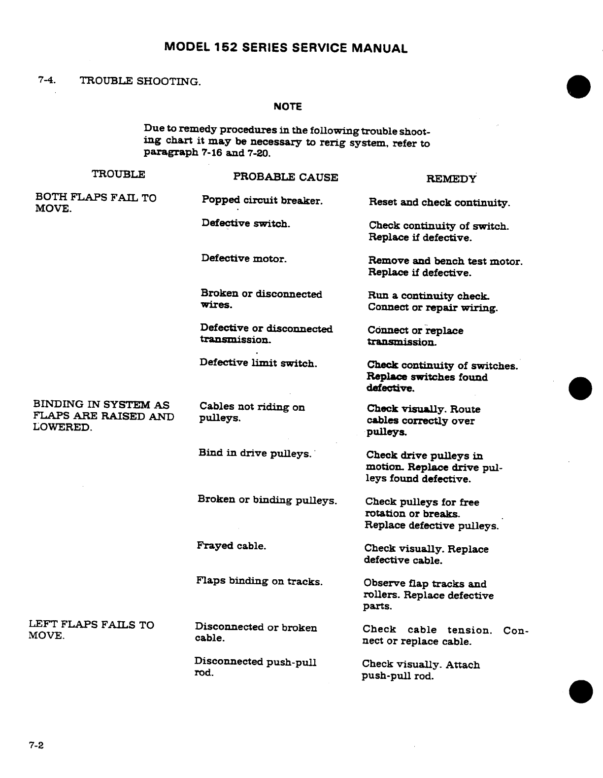
MODEL
152
SERIES
SERVICE
MANUAL
7-4.
TROUBLE
SHOOTING.
NOTE
Due
to
remedy
procedures
in
the
following trouble
shoot-
ing
chart
it
may
be
necessary
to
rerig
system, refer
to
paragraph
7-16
and
7-20.
TROUBLE
PROBABLE CAUSE REMEDY
BOTH
FLAPS
FAIL
TO
Popped
circuit
breaker.
Reset
and
check
continuity.
MOVE.
Defective
switch.
Check
continuity
of
switch.
Replace
if
defective.
Defective
motor.
Remove
and
bench
test
motor.
Replace
if
defective.
Broken
or
disconnected
Run
a
continuity
check.
wires.
Connect
or
repair
wiring.
Defective
or
disconnected
Connect or
replace
transmission.
transmission.
Defective
limit
switch.
Check
continuity
of
switches.
Replace
switches
found
defective.
BINDING IN
SYSTEM
AS
Cables
not
riding
on
Check
visually.
Route
FLAPS ARE RAISED
AND
pulleys.
cables
correctly
over
LOWERED.
pulleys.
Bind
in
drive
pulleys.
Check
drive
pulleys
in
motion.
Replace
drive
pul-
leys
found
defective.
Broken
or
binding
pulleys.
Check
pulleys
for
free
rotation
or
breaks.
Replace
defective
pulleys.
Frayed
cable.
Check
visually.
Replace
defective
cable.
Flaps
binding
on
tracks.
Observe
flap
tracks
and
rollers.
Replace defective
parts.
LEFT
FLAPS FAILS
TO
Disconnected
or
broken
Check
cable
tension.
Con-
MOVE.
cable.
nect
or
replace
cable.
Disconnected
push-pull
Check
visually.
Attach
rod.
push-pull
rod.
7-2
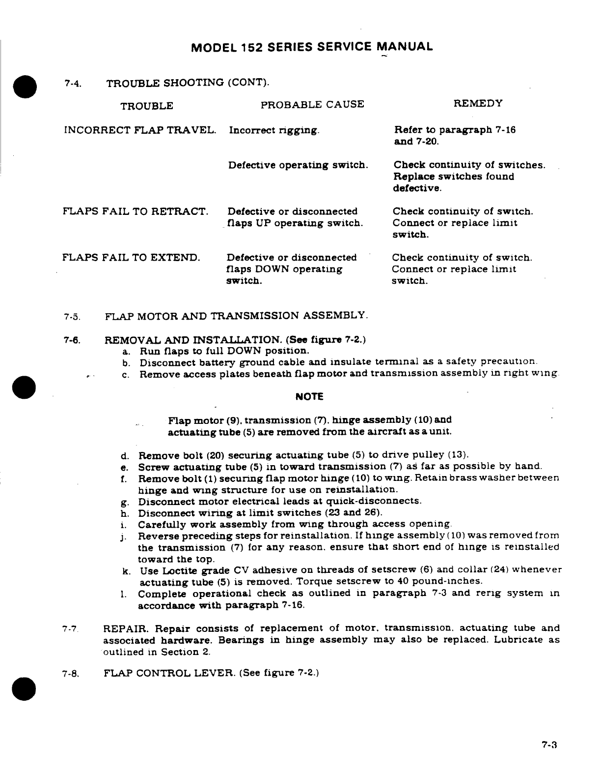
MODEL
152
SERIES
SERVICE
MANUAL
7-4.
TROUBLE
SHOOTING
(CONT).
TROUBLE
PROBABLE
CAUSE REMEDY
INCORRECT
FLAP
TRAVEL.
Incorrect
rigging.
Refer
to
paragraph
7-16
and
7-20.
Defective
operating
switch.
Check
continuity
of
switches.
Replace
switches
found
defective.
FLAPS
FAIL
TO
RETRACT.
Defective
or
disconnected
Check
continuity
of
switch.
flaps
UP
operating
switch.
Connect
or
replace
limit
switch.
FLAPS
FAIL
TO
EXTEND.
Defective
or
disconnected
Check
continuity
of
switch.
flaps
DOWN
operating
Connect
or
replace limit
switch.
switch.
7-5.
FLAP
MOTOR
AND
TRANSMISSION
ASSEMBLY.
7-6.
REMOVAL AND
INSTALLATION. (See
figure
7-2.)
a.
Run
flaps
to
full
DOWN
position.
b.
Disconnect
battery
ground
cable
and
insulate
terminal
as
a
safety
precaution
c.
Remove
access
plates
beneath
flap motor
and
transmission
assembly
in
right
wing
NOTE
Flap motor
(9).
transmission
(7).
hinge
assembly
(10)
and
actuating
tube
(5)
are
removed
from
the
aircraft
as
a
unit.
d.
Remove
bolt
(20)
securing
actuating
tube
(5)
to
drive
pulley
(13).
e.
Screw
actuating
tube
(5)
in
toward
transmission
(7)
as
far
as
possible
by
hand.
f.
Remove
bolt
(1)
securing
flap
motor
hinge
(10)
to
wing.
Retain
brass
washer
between
hinge
and
wing
structure
for
use
on
reinstallation.
g.
Disconnect motor
electrical
leads at
quick-disconnects.
h.
Disconnect
wiring
at
limit
switches
(23
and
26).
i.
Carefully work
assembly
from
wing
through
access
opening.
j.
Reverse
preceding
steps
for
reinstallation.
If
hinge assembly
(10)
was
removed
from
the
transmission
(7)
for
any
reason.
ensure
that
short
end
of
hinge
is
reinstalled
toward
the
top.
k.
Use
Loctite
grade
CV
adhesive
on
threads
of
setscrew
(6)
and
collar
(24)
whenever
actuating
tube
(5)
is
removed.
Torque
setscrew
to
40
pound-inches.
1.
Complete
operational
check
as
outlined
in
paragraph
7-3
and
rerig
system
in
accordance
with
paragraph
7-16.
7-7
REPAIR.
Repair
consists
of
replacement
of
motor,
transmission.
actuating
tube
and
associated
hardware. Bearings
in
hinge assembly
may also
be
replaced.
Lubricate
as
outlined
in
Section
2.
7-8.
FLAP
CONTROL
LEVER.
(See
figure
7-2.)
7-3
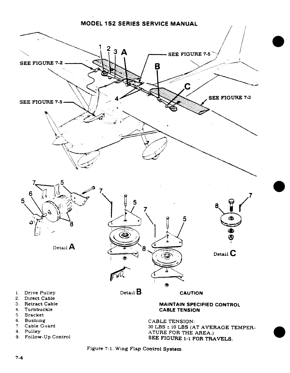
MODEL
152
SERIES
SERVICE
MANUAL
3
A
SEE
FIGURE
7-5
SEE
FIGURE
SEE FIGURE
7-3
SEE
FIGURE
7-5
Detail
A
Detail
C
1.
Drive
Pulley
Detail
B
CAUTION
2.
Direct
Cable
3.
Retract
Cable
MAINTAIN
SPECIFIED
CONTROL
4.
Turnbuckle
CABLE
TENSION
5.
Bracket
6.
Bushing
CABLE
TENSION:
7.
Cable
Guard
30
LBS
10
LBS
(AT
AVERAGE
TEMPER-
8.
Pulley
ATURE
FOR
THE
AREA.)
9.
Follow-Up
Control
SEE FIGURE
1-1
FOR
TRAVELS.
Figure
7-1.
Wing
Flap
Control
System
7-4
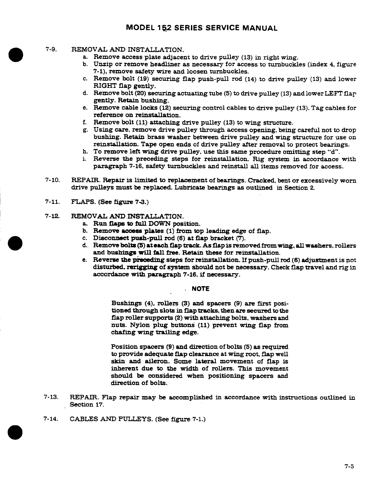
MODEL
152
SERIES SERVICE
MANUAL
7-9.
REMOVAL
AND
INSTALLATION.
a.
Remove
access
plate
adjacent
to
drive
pulley
(13)
in
right
wing.
b.
Unzip
or
remove
headliner
as
necessary for
access
to
tunbuckles
(index
4,
figure
7-1),
remove
safety
wire
and
loosen
turnbuckles.
c.
Remove
bolt
(19)
securing
flap
push-pull
rod
(14)
to
drive
pulley
(13)
and
lower
RIGHT
flap
gently.
d.
Remove
bolt
(20)
securing
actuating
tube
(5)
to
drive
pulley
(13)
and lower
LEFT
flap
gently.
Retain
bushing.
e.
Remove cable
locks
(12)
securing
control cables
to
drive
pulley
(13).
Tag
cables
for
reference
on
reinstallation.
f.
Remove
bolt
(11)
attaching
drive
pulley
(13)
to
wing
structure.
g.
Using
care,
remove drive
pulley
through
access
opening,
being
careful
not
to
drop
bushing.
Retain
brass
washer
between
drive
pulley
and
wing
structure
for
use
on
reinstallation.
Tape open ends
of
drive
pulley
after
removal
to
protect bearings.
h.
To
remove
left
wing
drive
pulley,
use
this
same
procedure
omitting
step
"d".
i.
Reverse
the preceding
steps
for
reinstallation.
Rig
system
in
accordance
with
paragraph
7-16,
safety
turnbuckles
and
reinstall
all
items
removed for
access.
7-10.
REPAIR.
Repair
is limited
to
replacement
of
bearings.
Cracked,
bent
or
excessively
worn
drive
pulleys
must
be
replaced.
Lubricate
bearings
as
outlined
in
Section
2.
7-11.
FLAPS.
(See
figure
7-3.)
7-12.
REMOVAL
AND INSTALLATION.
a.
Run
flaps
to
full
DOWN
position.
b.
Remove
access
plates
(1)
from
top
leading
edge
of
flap.
c.
Disconnect
push-pull
rod
(6)
at
flap
bracket
(7).
d.
Remove
bolts
(5)
at
each
flap
track.
As
flap
is
removed
from
wing,
all
washers,
rollers
and
bushings
will
fall
free.
Retain
these
for
reinstallation.
e.
Reverse the
preceding
steps
for
reinstallation.
If
push-pull
rod
(6)
adjustment
is
not
disturbed,
rerigging
of
system
should
not
be
necessary.
Check
flap
travel
and
rig
in
accordance
with
paragraph
7-16,
if
necessary.
NOTE
Bushings
(4),
rollers
(3)
and
spacers
(9)
are
first
posi-
tioned
through
slots
in flap
tracks,
then
are secured
to
the
flap
roller
supports
(2)
with
attaching
bolts,
washers
and
nuts.
Nylon
plug
buttons
(11)
prevent
wing
flap
from
chafing
wing
trailing
edge.
Position spacers
(9)
and
direction
of
bolts
(5)
as required
to
provide adequate
flap
clearance
at wing
root,
flap
well
skin
and
aileron.
Some
lateral
movement
of
flap
is
inherent
due
to the
width
of
rollers. This
movement
should
be
considered
when
positioning
spacers
and
direction
of
bolts.
7-13.
REPAIR.
Flap
repair
may
be
accomplished
in
accordance
with instructions
outlined
in
Section
17.
7-14.
CABLES
AND
PULLEYS. (See
figure
7-1.)
7-5
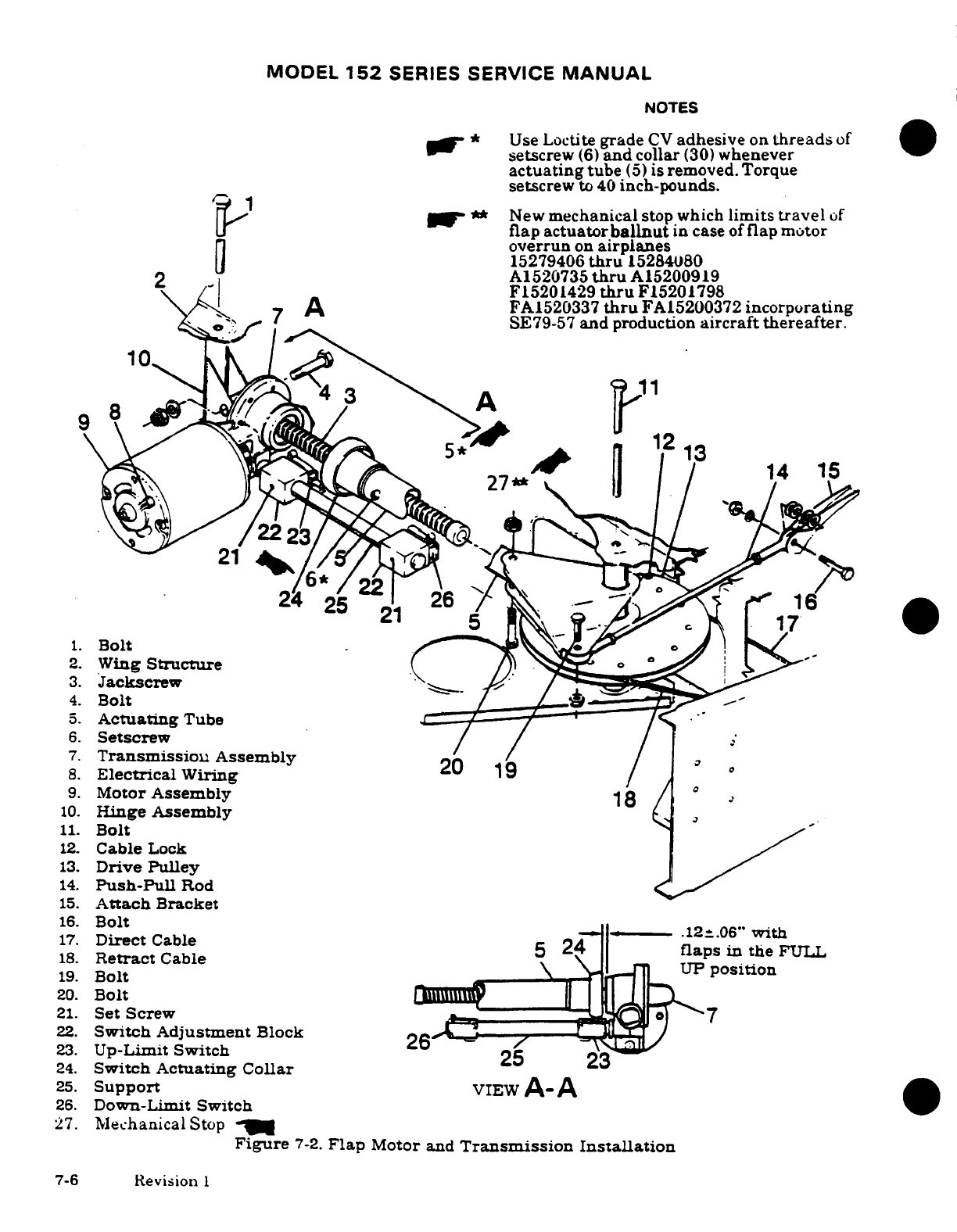
MODEL
152
SERIES
SERVICE
MANUAL
NOTES
"
Use
Loctite
grade
CV
adhesive
on
threads
of
setscrew
(6)
and
collar
(30)
whenever
actuating
tube
(5)
is
removed.
Torque
setscrew
to
40
inch-pounds.
y **
New
mechanical
stop
which
limits
travel
of
flap
actuator
ballnut
in
case
of
flap
motor
overrun
on
airplanes
15279406
thru
15284080
2
A1520735
thru
A15200919
F15201429
thru
F15201798
7
A
FA1520337
thru
FA15200372
incorporating
7
SE79-57
and
production
aircraft
thereafter.
9
2.
Wing
Structure
7.
Transmission
Assembly
8.
Electrical
Wiring
19
9.
Motor
Assembly
18
1.
Bolt
12.
Cable
Lock
13.
Wing
Structure
1.
Jackscrew
4.
Bolt
5.
Actuating
Tube
2.
Set
crew
2.
Transmissitch
Adjustment
Block
23.
Up-Limit
Switch
25
2
a
,
24.
Switch
Actuating
Collar
3
25.
Support
VIEW A-A
d
26.
Down-Limit
Switch
s
2.
Moor
11.
Bolt
12.
Cable
Lock
13.
Drive
Pulley
14.
Push-Pull
Rod
15.
Attach
Bracket
16.
Bolt
17.
Direct
Cable
18.
Retract
Cable
5
24
flaps
in
the
FULL
19.
Bolt
UP
position
20.
Bolt
21.
Set
Screw
7
22.
Switch Adjustment
Block
23.
Up-Limit
Switch
26
24.
Switch
Actuating
Collar
25.
Support
VIEw
A-A
26.
Down-Limit
Switch
27.
Mechanical
Stop
Figure
7-2.
Flap
Motor
and
Transmission
Installation
7-6
Revision
I
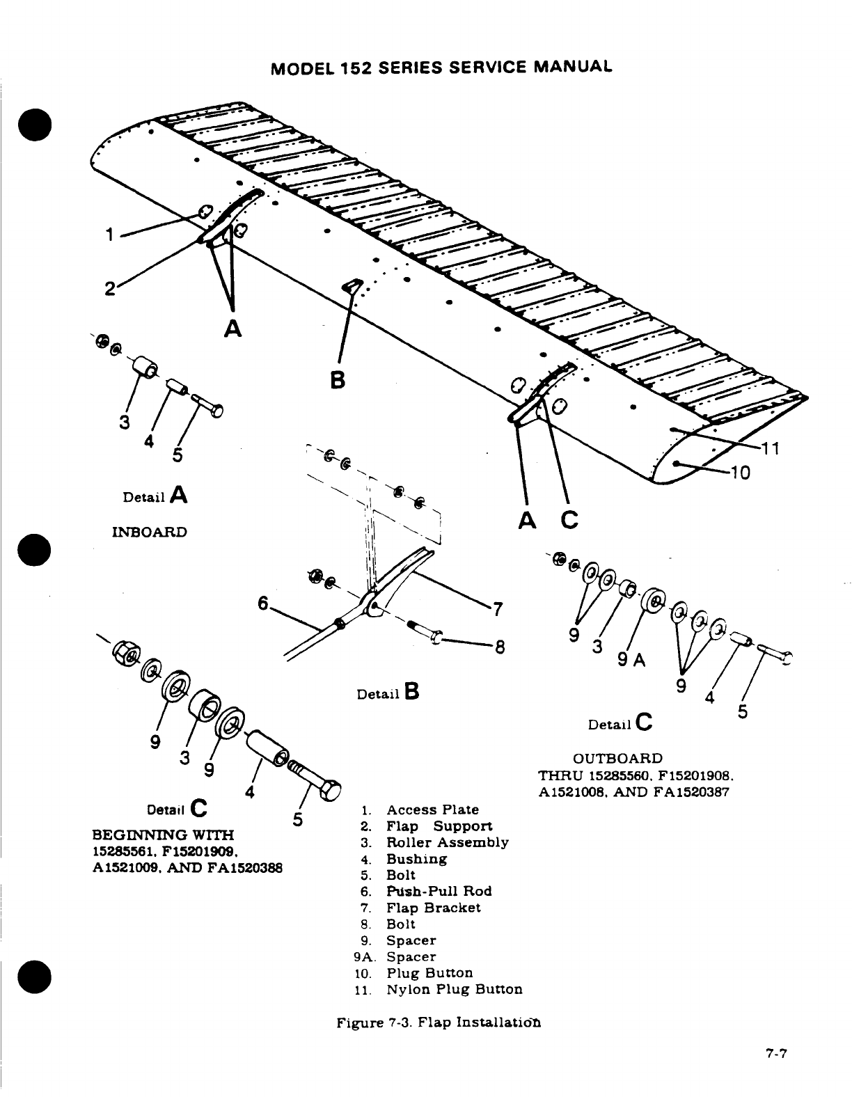
MODEL
152
SERIES
SERVICE
MANUAL
A
Detail
B
4
BEGINNING
WITH
2.
Flap
Support
15285561.
F15201909
3.
Roller
Assembly
8.
Bolt
9.
Spacer
9A.
Spacer
10.
Plug
Button
11.
Nylon
Plug
Button
Figure
7-3.
Flap Installation
7-7
MODEL
152
SERIES
SERVICE
MANUAL
7-15.
REMOVAL
AND
INSTALLATION.
a.
Remove
access
plates. fairings.
headliner
and
upholstery
as
necessary
for
access.
b.
If
the
direct
cables
(2)
are
to
be
removed.
disconnect
clamp
(index
19.
figure
7-5)
from
bellcrank
(index
15.
figure
7-5).
c.
Remove
safety
wire,
relieve
cable
tension,
disconnect
turnbuckles
(4)
and
carefully
lower
LEFT
flap.
d.
Disconnect
cables
at
drive
pulleys.
remove
cable
guards
and
pulleys
as
necessary
to
work
cables
free
of
aircraft.
NOTE
To
ease
routing
of
cables,
a
length
of
wire
may
be
attached
to
the
end
of
cable
being withdrawn
from
aircraft.
Leave
wire
in
place. routed
through
structure;
then
attach
the
cable
being
installed
and
use
wire
to
pull
cable into
position.
e.
Reverse
the
preceding
steps
for
reinstallation.
f.
After
cables
are
routed
in
position.
install
pulleys
and
cable
guards.
Ensure
cables
are positioned
in
pulley
grooves
before
installing
guards.
g.
Rerig
flap
system
in
accordance
with
paragraph
7-16
and
safety
turnbuckles.
h.
Rerig
follow-up
system
in
accordance
with
paragraph
7-19
and
reinstall
all
items
removed
in
step
"a"
7-16.
RIGGING.
a.
(See
figure
7-1.)
Unzip
or
remove
headliner as
necessary
for
access
to
turnbuckles
(4).
b.
With
flaps
in
the
full
UP
position. disconnect
follow-up
cable
(index
1.
figure
7-5)
by
loosening
clamp
bolt
(14).
c.
(See
figure
7-1.)
Remove
safety wire.
relieve
cable
tension,
disconnect
turnbuckles
(4)
and
carefully lower
LEFT
flap.
d.
(See
figure
7-2.)
Disconnect
push-pull
rods
(14)
at
drive
pulleys
(13)
in
both
wings
and
lower
RIGHT
flap
gently.
e.
Disconnect
actuating
tube
(5)
from
drive pulley
(13).
NOTE
If
control
cables are
not connected
to
left
and
right
drive
pulleys,
actuating
tube
(5)
and
push-pull
rods
(14)
must
be
disconnected
before
installing
cables.
If
drive pulleys
(13)
are
not
installed.
attach
control
cables
before
installing
drive
pulleys
in
the
wings
as
illustrated
in
figure
7-4.
7-8
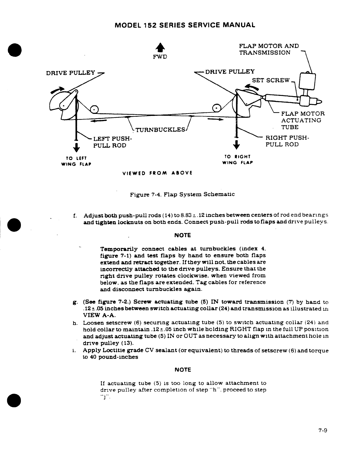
MODEL
152
SERIES
SERVICE
MANUAL
FLAP
MOTOR AND
FWD
TRANSMISSION
DRIVE
PULLEY
DRIVE PULLEY
SET
SCREW
FLAP
MOTOR
ACTUATING
TURNBUCKLES
TUBE
LEFT
PUSH RIGHT
PUSH-
PULL ROD
PULL
ROD
TO
LEFT
TO
RIGHT
WING
FLAP
WING
FLAP
VIEWED
FROM
ABOVE
Figure
7-4.
Flap
System
Schematic
f.
Adjust
both
push-pull
rods
(14)
to
8.83
+.12
inches
between
centers
of
rod
end
bearings
and
tighten locknuts
on
both
ends.
Connect
push-pull
rods
to
flaps
and
drive
pulleys.
NOTE
Temporarily
connect
cables
at
turnbuckles
(index
4.
figure
7-1)
and
test
flaps
by
hand
to
ensure
both
flaps
extend
and
retract
together.
If
they
will
not.
the
cables
are
incorrectly
attached
to
the
drive
pulleys.
Ensure
that
the
right drive
pulley
rotates
clockwise.
when viewed
from
below.
as
the
flaps
are
extended.
Tag
cables
for
reference
and
disconnect
turnbuckles
again.
g.
(See
figure
7-2.)
Screw
actuating
tube
(5)
IN
toward
transmission
(7)
by
hand
to
.12
.05
inches
between
switch
actuating
collar
(24)
and
transmission
as
illustrated
in
VIEW
A-A.
h.
Loosen
setscrew
(6)
securing
actuating
tube
(5)
to
switch
actuating
collar
(24)
and
hold
collar
to
maintain
.12
-.
05
inch
while
holding
RIGHT
flap
in
the
full
UP
position
and
adjust
actuating
tube
(5)
IN
or
OUT
as
necessary
to
align
with
attachment
hole
in
drive
pulley
(13).
i.
Apply
Loctitie
grade
CV
sealant
(or
equivalent)
to
threads
of
setscrew
(6)
and
torque
to
40
pound-inches
NOTE
If
actuating
tube
(5)
is
too
long
to
allow
attachment
to
drive pulley
after
completion
of
step
"h".
proceed
to
step
7-9
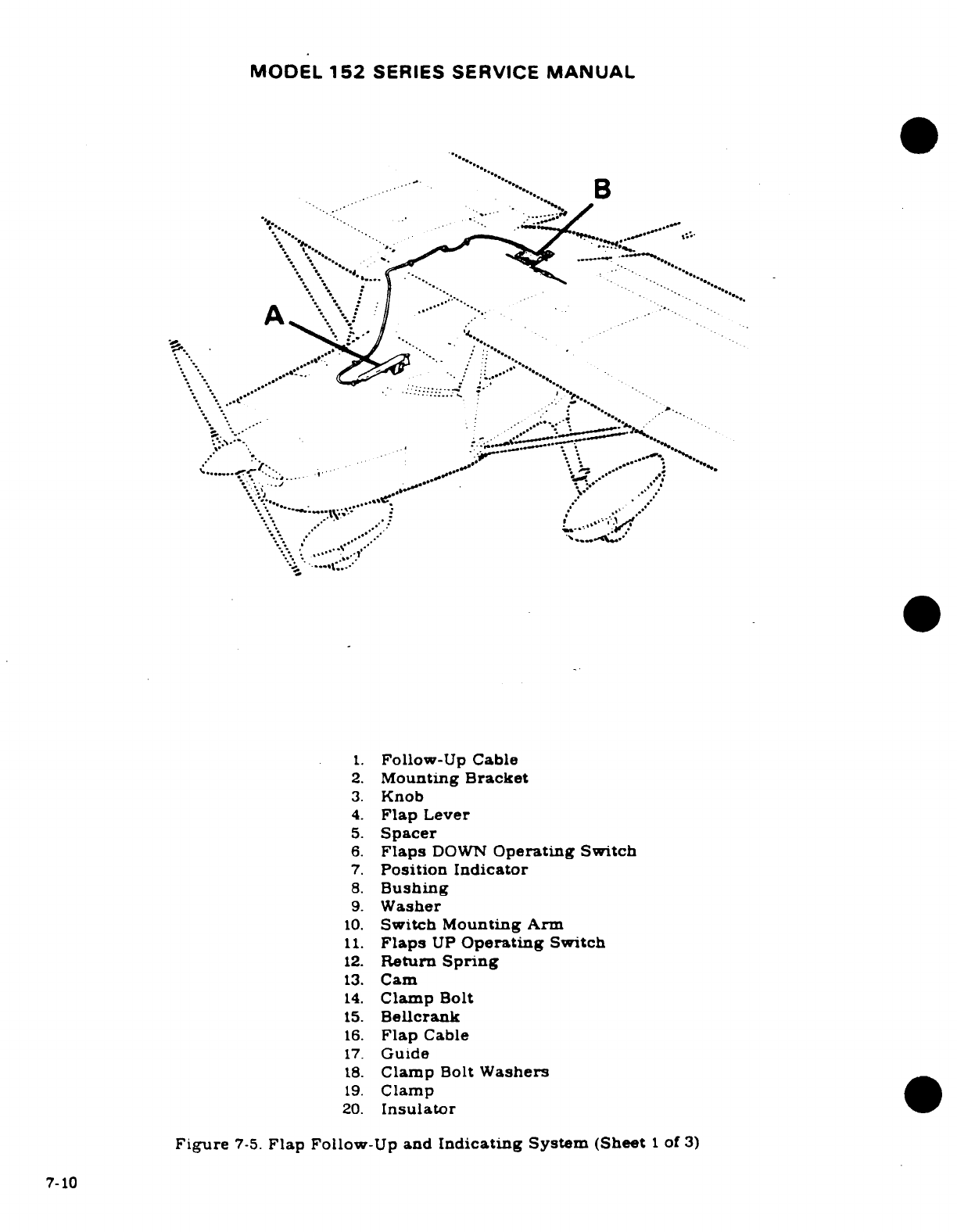
MODEL
152
SERIES
SERVICE
MANUAL
1.
Follow-Up Cable
2.
Mounting
Bracket
3.
Knob
4.
Flap
Lever
5.
Spacer
6.
Flaps
DOWN
Operating
Switch
7.
Position Indicator
8.
Bushing
9.
Washer
10.
Switch
Mounting Arm
11.
Flaps
UP
Operating
Switch
12.
Return
Spring
13.
Cam
14.
Clamp
Bolt
15.
Bellcrank
16.
Flap
Cable
17.
Guide
18.
Clamp
Bolt
Washers
19.
Clamp
20.
Insulator
Figure
7-5.
Flap
Follow-Up
and
Indicating
System
(Sheet
1
of
3)
7-10
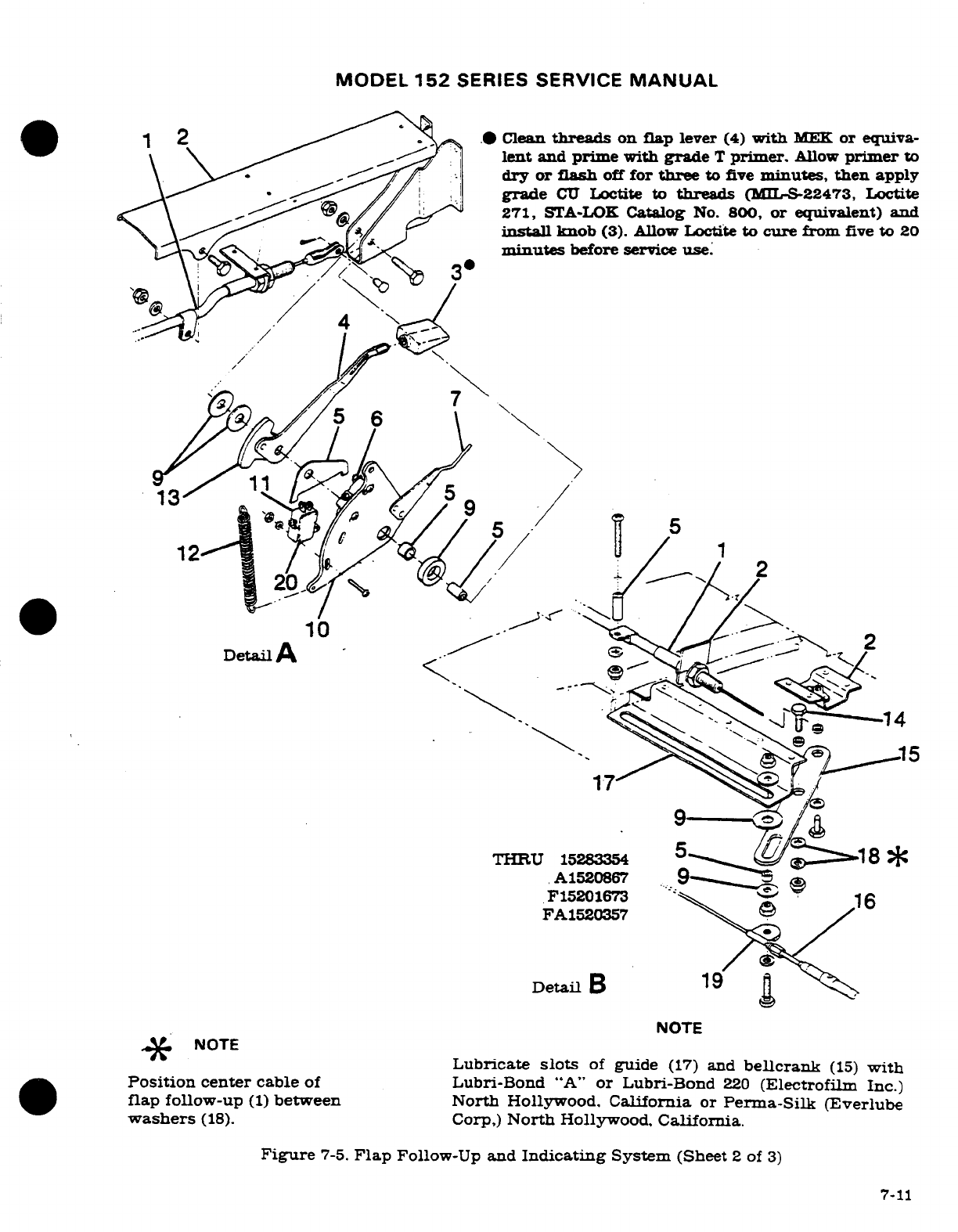
MODEL
152
SERIES SERVICE
MANUAL
271,
STA-LOK
Catalog
No.
800,
or
equivalent)
and
install
knob
(3). Allow
Loctite
to
cure
from
five
to
20
minutes
before
service
use.
THRU
15283354
A1520867
F15201673
16
FA1520357
Detail
B
NOTE
*
NOTE
Lubricate
slots
of
guide
(17)
and
bellcrank
(15)
with
Position
center
cable
of
Lubri-Bond
"A"
or
Lubri-Bond
220
(Electrofilm
Inc.)
flap
follow-up
(1)
between North
Hollywood.
California
or
Perma-Silk (Everlube
washers
(18).
Corp,)
North
Hollywood,
California.
Figure
7-5.
Flap
Follow-Up
and
Indicating
System
(Sheet
2
of
3)
7-11
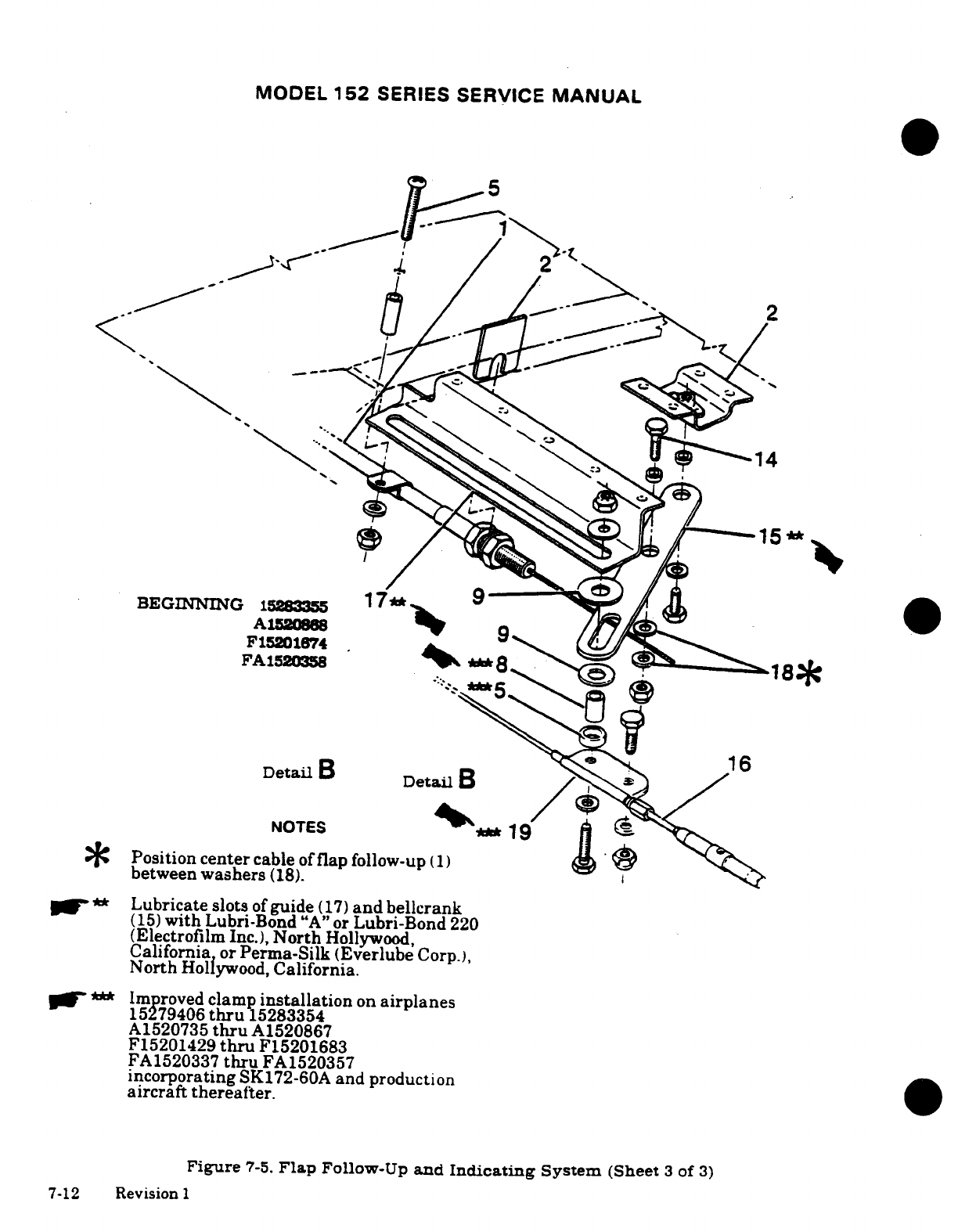
MODEL
152
SERIES
SERVICE
MANUAL
BEGINNING
15283355
1
9
F1520
1674s
FA1520358
Detail
B
Detail
B
NOTES
19
Position
center
cable
of
flap
follow-up
(1)
between
washers
(18).
f**
Lubricate
slots
of
guide
(17)
and
bellcrank
(15)
with
Lubri-Bond
"A"
or
Lubri-Bond
220
(Electrofilm
Inc.),
North
Hollywood,
California
or
Perma-Silk
(Everlube
Corp.),
North
Hollywood,
California.
***
Improved
clamp
installation
on
airplanes
15279406
thru
15283354
A1520735
thru
A1520867
F15201429
thru
F15201683
FA1520337
thru
FA1520357
incorporating
SK172-60A
and
production
aircraft
thereafter.
Figure
7-5.
Flap
Follow-Up
and
Indicating
System
(Sheet
3
of
3)
7-12
Revision
1
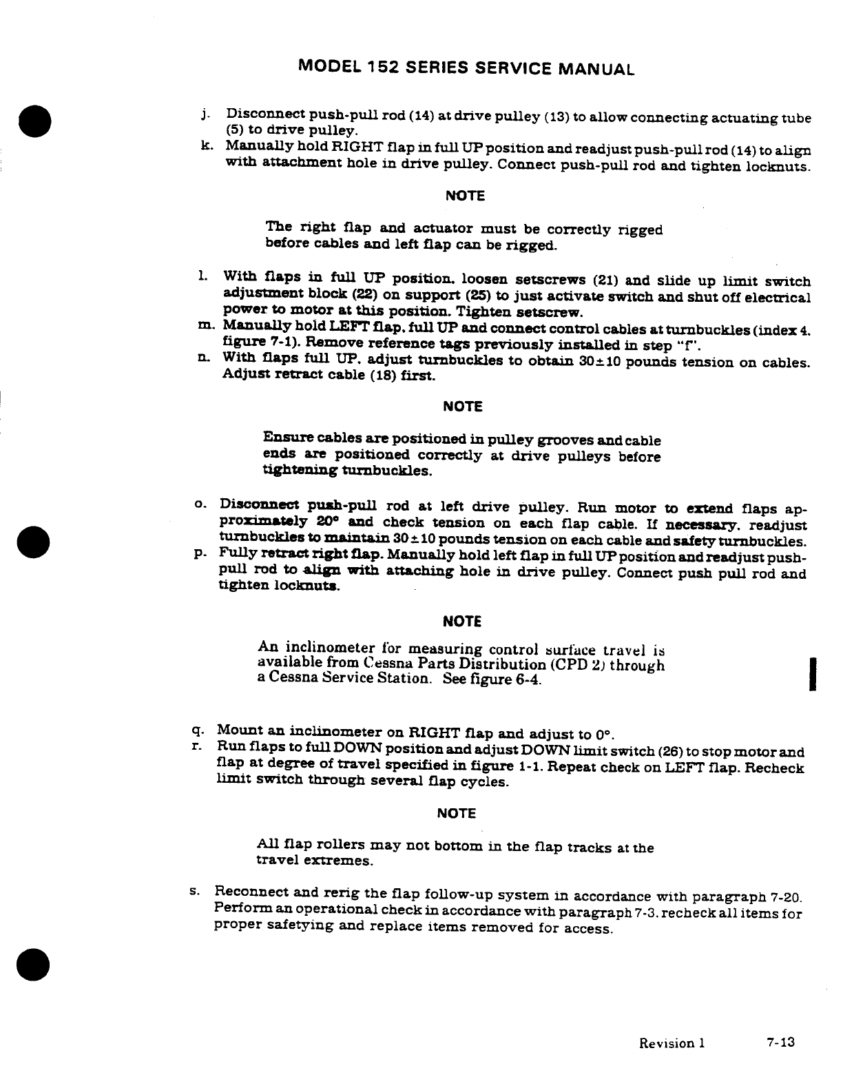
MODEL
152
SERIES
SERVICE
MANUAL
j.
Disconnect
push-pull
rod
(14)
at
drive
pulley
(13)
to
allow
connecting
actuating
tube
(5)
to
drive
pulley.
k.
Manually
hold
RIGHT
flap
in
full
UP
position
and
readjust
push-pull
rod
(14)
to
align
with
attachment
hole
in
drive pulley.
Connect
push-pull
rod and
tighten
locknuts.
NOTE
The
right
flap
and
actuator
must
be
correctly
rigged
before
cables
and
left
flap
can
be
rigged.
1.
With
flaps
in
full
UP
position.
loosen
setscrews
(21)
and
slide
up
limit
switch
adjustment
block
(22)
on
support
(25)
to
just
activate
switch and
shut
off
electrical
power
to
motor
at
this
position.
Tighten
setscrew.
m.
Manually
hold
LEFT
flap.
full
UP
and
connect
control
cables
at
turnbuckles
(index
4.
figure
7-1).
Remove
reference
tags
previously
installed
in
step
"f".
n. With
flaps
full
UP.
adjust
turnbuckles to
obtain
30±
10
pounds
tension
on
cables.
Adjust
retract
cable
(18)
first.
NOTE
Ensure
cables
are
positioned
in
pulley
grooves
and
cable
ends
are
positioned
correctly
at
drive
pulleys
before
tightening
turnbuckles.
o.
Disconnect
push-pull
rod
at
left
drive
pulley.
Run
motor
to
extend
flaps
ap-
proximately
20°
and
check
tension
on
each
flap
cable.
If
necessary.
readjust
turnbuckles
to
maintain
30±
10
pounds
tension
on
each
cable
and
safety turnbuckles.
p.
Fully
retract
right
flap.
Manually
hold left
flap
in
full
UP
position
and
readjust
push-
pull
rod
to
align
with
attaching
hole
in
drive
pulley.
Connect
push
pull
rod
and
tighten locknuts.
NOTE
An
inclinometer
for
measuring
control
surface
travel
is
available
from
Cessna
Parts
Distribution
(CPD
2)
through
a
Cessna
Service
Station.
See
figure
6-4.
q.
Mount
an
inclinometer
on RIGHT
flap
and
adjust
to
0° .
r.
Run
flaps
to
full
DOWN
position
and
adjust
DOWN
limit
switch
(26)
to
stop
motor
and
flap
at
degree
of
travel
specified
in
figure
1-1.
Repeat
check
on
LEFT
flap.
Recheck
limit
switch
through several
flap
cycles.
NOTE
All
flap
rollers
may
not
bottom
in
the
flap
tracks
at
the
travel
extremes.
s.
Reconnect and
rerig
the
flap
follow-up
system
in
accordance
with
paragraph
7-20.
Perform an
operational
check
in
accordance
with
paragraph
7-3.
recheck
all
items
for
proper
safetying
and
replace
items removed
for
access.
Revision
1
7-13
MODEL
152
SERIES
SERVICE
MANUAL
7-17.
FLAP
FOLLOW-UP
AND
INDICATING
SYSTEM.
(See
figure
7-5.)
7-18.
DESCRIPTION.
The
flap
follow-up and
indicating
system
consists
of
a
sheathed
cable
assembly
one end
of
which
is
attached
to
the
flap
operating
switch mounting
arm
and
the
other
end
is
clamped
to
the flap
direct
cable
above
the
headliner
in
the
rear
cabin
area.
Motion
of
the
flap
cable
is
transmitted through
the
follow-up
control
to
the
pointer
along
a
scale
as
the
flaps
are
extended
or
retracted.
7-19.
REMOVAL
AND
INSTALLATION.
Figure
7-5
can
be
used as
a
guide
to
removal
and
installation
of
the
flap
follow-up
and
indicating
system.
7-20.
RIGGING. (See
figure
7-5.)
a.
Flap control
system
must
be
rigged
in
accordance
with
paragraph
7-16
before
flap
follow-up
control
can
be
rigged.
b.
Disconnect
spring
(12)
from
switch mounting
arm
(10).
c.
With
flaps
in
full
UP
position,
pull
center
cable
of
flap
follow-up
control
(1)
detail
B.
figure
7-5)
to
remove
slack.
d.
Ensure
flap
lever
(4)
is in
full
UP
position
while
indicator
(7)
has
a
.03
-
.06
inch
clearance
with
top
of
instrument
panel
cut-out.
Secure
follow-up cable
to
bellcrank
(15)
with
clamp
bolt
(14)
while
observing
note
in
figure
7-5.
e.
Connect
spring
(12)
to
switch
mounting
arm
(10).
f.
Adjust switches
(6)
and
(11)
in
slotted
holes
on
mounting
arm
(10)
until
cam
(13)
is
centered
between
switch
rollers.
g.
Mount
an
inclinometer
on one
flap
and
set
to
0°
(flaps
full
UP).
Turn
master
switch
ON
and
move
flap
lever
(4)
to
10
°
flap
position.
NOTE
An
inclinometer
for
measuring
control
surface
travel
is
available
from
Cessna
Parts
Distribution
(CPD
2)
through
a
Cessna
Service
Station.
See
figure
6-4.
h.
Observe
inclinometer
reading
when
flaps
stop.
Adjust
flaps
DOWN
operating
switch
(6)
in
slotted
holes
on
mounting
arm
(10)
as
required
to
obtain
flap
travel
of
10±2.
i.
Adjust
flaps
UP
operating
switch
(11)
in
slotted
holes
to
obtain
positive
clearance
with
cam
(13)
when
flaps
DOWN
operating
switch
has
just
opened
in
the
10°
position.
j.
Repeat
steps
"h"
and
"i"
for
20
°
flap
position.
k.
Run
flaps
to
full
DOWN
position
and
check
that flaps
DOWN
operating
switch
(6)
remains
closed
as
flap motor
limit
switch
(index
26.
figure
7-2)
stops
flaps
at
full
DOWN
position.
1.
Check
flaps
through
several
cycles.
recheck
all
items
removed
for
security
and
replace
items
removed for
access.
7-14
Revision
I
MODEL
152
SERIES
SERVICE
MANUAL
SECTION
8
ELEVATOR
CONTROL
SYSTEM
Page
No.
TABLE
OF
CONTENTS
Aerofiche/
Manual
ELEVATOR
CONTROL
SYSTE
.
1H22/8-1
Forward
................
1H24/8-3
Description
...............
1H22/8-1
Removal/lnstllation
.....
1H24/8-3
Trouble
Shooting
...........
1H22/8-1
Rear
.................. 1H24/8-3
Elevators
.................
1H23/8-2
Removal/Installtion
.....
1H24/8-3
Removal/lnstaliation
.......
1H23/8-2 Cables
and
Pulleys
........
1H24/8-7
Repair
.............
.....
lH24/8-3
Removal/lnsallaon
.....
1H24/8-7
Bellcranks
................
1H24/8-3
Rigging
................
1H24/8-7
8-1.
ELEVATOR
CONTROL
SYSTEM.
8-2.
DESCRIPTION. The
elevators
are
operated
by
power transmitted
from
the
control
wheels
through
a
series
of
cables.
bellcranks
and
a
push-pull
tube. The
rear
bellcrank
serves
as
an
interconnect
between
the
elevators
and
a
bearing
point
for
the
travel
stop
bolts.
An elevator
trim
tab
is
installed
on
the right
elevator
and
is
described
in
Section
9.
8-3.
TROUBLE
SHOOTING.
NOTE
Due
to
remedy
procedures
in
the
following
trouble
shoot-
ing
chart,
it
may
be
necessary
to
rerig
system.
Refer
to
paragraph
8-14.
TROUBLE
PROBABLE
CAUSE
REMEDY
NO
RESPONSE
TO
CON-
Forward
or
aft
end
of
push-
Attach
push-pull
tube
TROL
WHEEL
FORE-AND-
pull
tube disconnected.
correctly.
AFT
MOVEMENT.
Cables
disconnected. Attach
cables
and
rig system
in
accordance
with
para-
graph
8-14.
Revision
1
8-1
MODEL
152
SERIES SERVICE
MANUAL
8-3.
TROUBLE
SHOOTING
(CONT).
TROUBLE
PROBABLE
CAUSE REMEDY
BINDING
OR
JUMPY
Defective
forward
or
rear
Replace
bellcrank
MOTION
FELT
IN
MOVE-
bellcrank pivot
bearing.
MENT OF
ELEVATOR
SYSTEM.
Cables
slack.
Adjust
to
tension
specified
in
figure
8-1.
Cables
not
riding
correctly
Route
cables
correctly
on
pulleys.
over
pulleys.
Nylon
grommet
on
instru-
Replace
grommet.
ment
panel
binding.
Defective
control
"y"
pivot
Replace
bearing.
bearing.
Defective
elevator
hinges
Replace defective
hinges.
or
lubrication
needed.
Lubricate
per
Section
2.
Clevis
bolts
too
tight.
Readjust
to
eliminate
bolt
binding.
Lubrication
needed.
Lubricate
piano hinges.
Defective
pulleys or
cable
Replace defective
parts
and
guards.
install
guards
properly.
ELEVATORS FAIL
TO
AT-
Stops
incorrectly
set.
Rig
system
in
accordance
TAIN
PRESCRIBED
TRAVEL.
with
paragraph
8-14.
Cables
tightened
unevenly. Rig
system
in
accordance
with
paragraph
8-14.
Interference
at
firewall Rig
system
in
accordance
or
instrument
panel.
with
paragraph
8-14.
8-4.
ELEVATORS.
(See
figure
8-2.)
8-5.
REMOVAL
AND INSTALLATION.
NOTE
This
procedure
is
written primarily
for the
right
elevator
since
the
trim
tab
is
attached
to
this
elevator.
a.
Disconnect
trim
tab
push-pull
tube
(2)
at
tab
actuator.
b.
Remove
bolts
(8)
securing
elevators
to
bellcrank
(7).
8-2
MODEL
152
SERIES SERVICE
MANUAL
NOTE
If
trim
system
is
not moved
and
actuator
screw
is
not
turned,
rigging
of
trim system
should
not
be
necessary
after
reinstallation
of
elevator.
c.
Remove
bolts
(10)
from
elevator
hinges.
d.
Using
care.
remove
elevator.
e.
To
remove
left
elevator
use
same
procedure,
omitting
step
"a".
f.
Reverse
the
preceding
steps
for
installation.Rig
system
in
accordance with
applica-
ble
paragraph
in
this
section
if
necessary.
8-6.
REPAIR.
Repair
may
be
accomplished
as
outlined
in
Section
17.
Hinge
bearings
may
be
replaced
as
necessary.
If
repair
has
affected
static
balance.
check
and
rebalance
as
required.
8-7.
BELLCRANKS.
8-8.
FORWARD.
(See
figure
8-1.)
8-9.
REMOVAL
AND
INSTALLATION.
a.
Remove
seats,
upholstery
and
access
plates
as
necessary.
b.
Relieve
tension
at
turnbuckles
(9)
and disconnect
cables
from
bellcrank
(16).
c.
Disconnect
push-pull
tube
(12)
from
bellcrank.
d.
Remove
pivot bolt
(15)
and
remove
bellcrank.
*.
Reverse
preceding
steps
for
installation.
Rig
system
in
accordance with
applicable
paragraph
in
this
section, safety
turnbuckles
and
reinstall
all
items
removed
in step
8-10.
REAR.
(See
figure
8-2.)
8-11.
REMOVAL
AND
INSTALLATION.
a.
Remove
rudder.
(Refer
to
Section
10.)
b.
Remove
seats,
upholstery
and
access plates
as
necessary
for
access
to
turnbuckles
(index
10.
figure
8-1).
c.
Relieve
cable
tension
at
turnbuckles
and
disconnect
cables
from
rear
bellcrank
(7).
d.
Remove
bolts
(8)
securing
elevators
to
bellcrank.
e.
Remove
bellcrank
pivot
bolt
and
slide
bellcrank
from
between
tube
assemblies
(6).
NOTE
It
may
be
necessary
to
remove
one
of
the
attaching
bolts
(10)
for
clearance
when
removing
the
bellcrank
pivot
bolt.
f.
Reverse
preceding
steps
for
installation.
Rig
system
in
accordance with
applicable
paragraph
in
this
section,
safety
turnbuckles
and
reinstall
all
items
removed
in
step
"b".
8-3
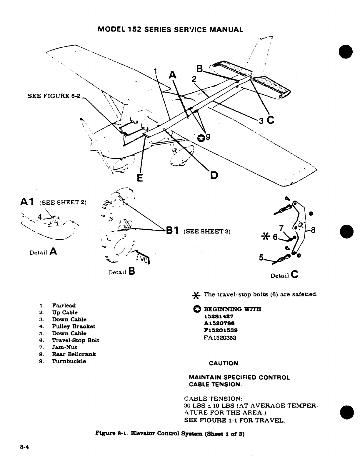
MODEL
152
SERIES
SERVICE
MANUAL
SEE
FIGURE
6-2
D
A1
(SEE
SHEET2)
C
(SEE
SHEET
2)
Detail
A
Detall
B
Detail
C
*
The
travel-stop
bolts
(6)
are safetied.
1.
Fairlead
O
BEGIqNG
wT
2.
Up
Cable15281427
3.
Down
Cable
A1520786
4.
Pulley
Bracket
F15201539
5.
Down Cable
FA1520353
6.
Travel-Stop
Bolt
7.
Jam-Nut
8.
Rear
Belicrank
9.
Turnbuckle
CAUTION
MAINTAIN
SPECIFIED
CONTROL
CABLE
TENSION.
CABLE
TENSION:
30
LBS
*
10
LBS
(AT
AVERAGE
TEMPER-
ATURE
FOR
THE
AREA.)
SEE
FIGURE
1-1
FOR
TRAVEL.
Figure
8-1.
Elevator Control
System
(Sheet
1
of
3)
8-4
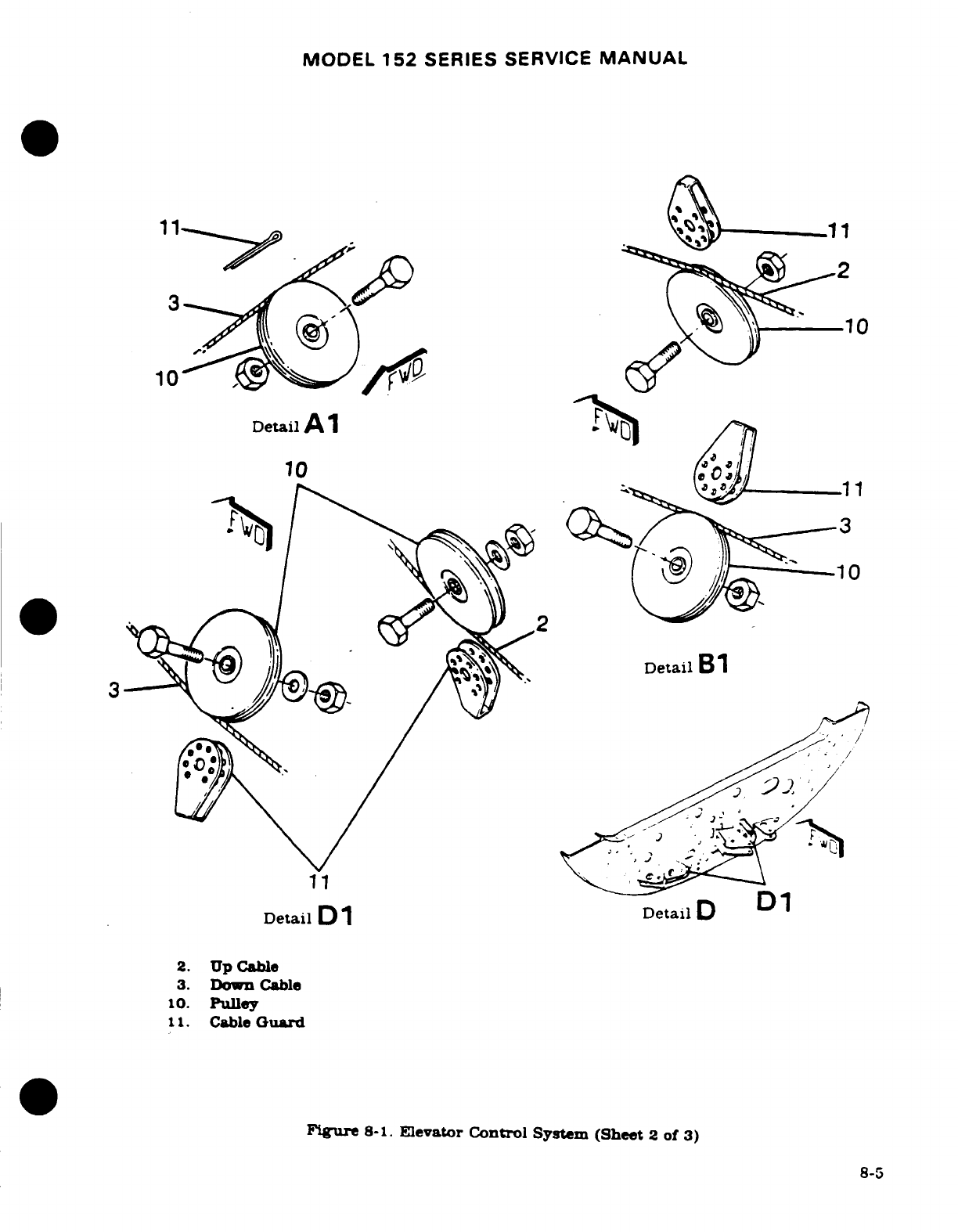
MODEL
152
SERIES
SERVICE
MANUAL
10
10
Detail
Al
10 11
3
Detail
B1
Detail
Dl
Detail
D
D1
2.
Up
Cable
3.
Down
Cable
10.
Pulley
11.
Cable
Guard
Figure
8-1.
Elevator
Control
System
(Sheet
2
of
3)
8-5
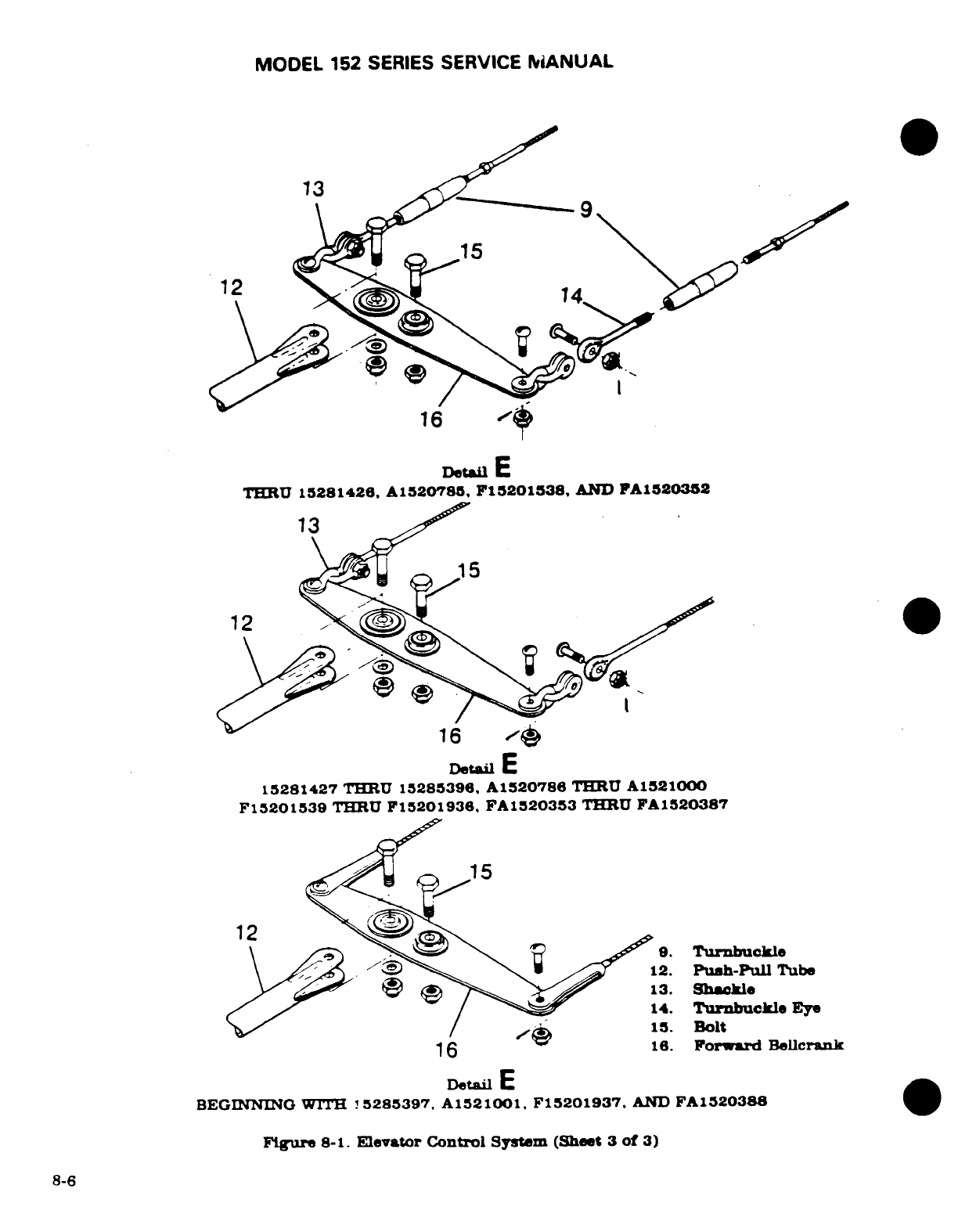
MODEL
152
SERIES
SERVICE
MANUAL
13
12
16
Detal
E
THRU
15281426,
A1520785,
F15201538,
AND
FA1520352
13
12
16
Detail
E
15281427
THRU
15285396,
A1520786
TE[RU
A1521000
F15201539
THRU
F15201936,
FA1520353
THRU
FA1520387
16.
Forward
Bellcrank
Detail
E
BEGINNING
WITH
!5285397,
A1521001,
F15201937,
AND
FA1520388
Figure
8-1.
Elevator Control
System
(Sheet
3
of
3)
8-6
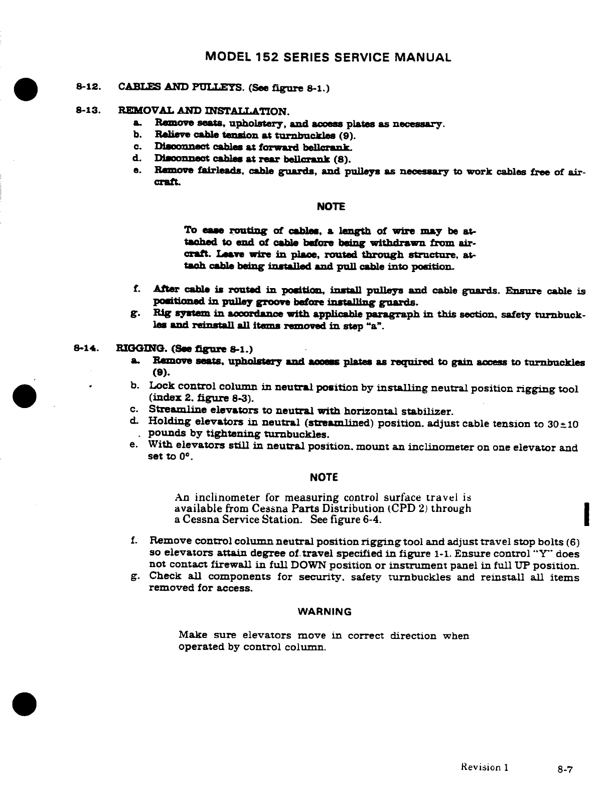
MODEL
152
SERIES SERVICE
MANUAL
8-12.
CABLES
AND PULLEYS.
(See
figure
8-1.)
8-13.
REMOVAL
AND
INSTALLATION.
a.
Remove
seats,
upholstery,
and
access
plates
as necessary.
b.
Relieve
cable
tenion
at
turnbuckles
(9).
c.
Disconnect
cables
at
forward
bellcrank.
d.
Disoonnect
cables
at
rear
bellcrank
(8).
e.
Remove
fairleads,
cable
guards,
and
pulleys
as
necessary
to
work
cables
free
of
air-
craft
NOTE
To
ease
routing
of
cables,
a
length
of
wire
may
be
at-
tached
to
end
of
cable
before
being
withdrawn
from
air-
craft.
Leave
we
in
place,
routed
through
structure,
at-
tach
cable
being
installed and
pull
cable
into
position.
f.
After
cable
is
routed
in
position
install
pulleys
and
cable
guards. Ensure
cable
is
positioned
in
pulley
groove
before
installing
guards.
g.
Rig
system
in
accordance
with
applicable
paragraph
in
this
section, safety turnbuck-
les
and
reinstll
all
items
removed
in
step
"a".
8-14.
RIGGING. (See
figure
8-1.)
a
Remove
seats,
upholstery
and
acces
plates
as
required
to
gain
access
to
turbuckles
(9).
b.
Lock
control
column
in
neutral
position
by
installing
neutral
position
rigging
tool
(index
2.
figure
8-3).
c.
Streamline
elevators
to
neutral
with
horizontal
stabilizer.
d
Holding
elevators in
neutral
(strealined)
position.
adjust
cable
tension
to
30=10
pounds
by
tightening
turnbuckles.
e.
With
elevators
still
in
neutral
position.
mount
an inclinometer
on
one
elevator
and
set
to
0° .
NOTE
An
inclinometer
for
measuring
control
surface
travel
is
available
from
Cessna
Parts
Distribution
(CPD
2)
through
a
Cessna
Service
Station.
See
figure
6-4.
f.
Remove
control column
neutral
position
rigging
tool
and adjust
travel
stop
bolts
(6)
so
elevators
attain
degree
of.travel
specified
in
figure
1-1.
Ensure
control
"Y"
does
not
contact
firewall
in
full
DOWN
position
or
instrument
panel
in
full
UP
position.
g.
Check
all
components
for
security.
safety
tunbuckles
and
reinstall
all
items
removed
for
access.
WARNING
Make
sure
elevators
move
in
correct
direction
when
operated
by
control
column.
Revision
1
8-7
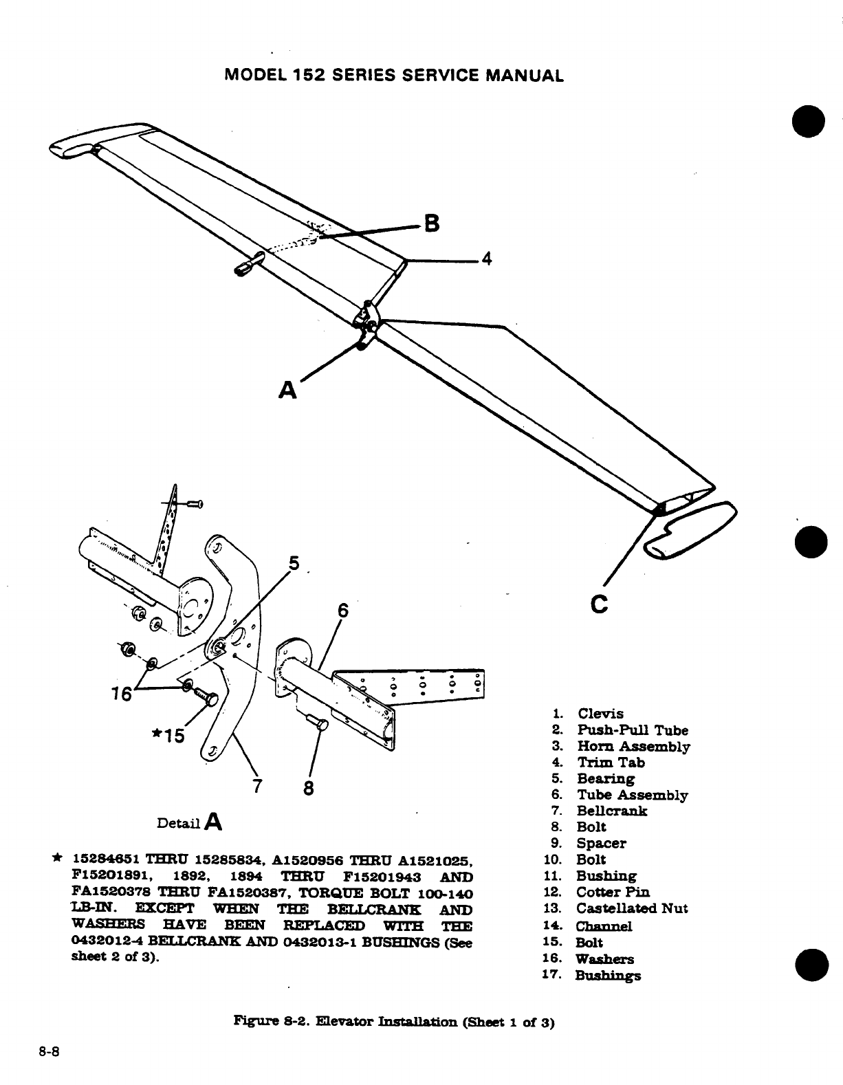
MODEL
152
SERIES
SERVICE
MANUAL
B
4.
Trim
Tab
5.
Bearing
7 8
6.
Tube
Assembly
7.
Bellcrank
Detail
A
8.
Bolt
9.
Spacer
*
15284651
THRU
15285834,
A1520956
THRU
A1521025,
10.
Bolt
F15201891,
1892,
1894
THRU
F15201943
AND
11.
Bushing
FA1520378
THRU
FA1520387,
TORQUE
BOLT
100-140
12.
Cotter
Pin
LB-IN.
EXCEPT
WHEN
THE
BELLCRNK
AND
13.
Castellated
Nut
WASHERS
HAVE
BEEN
REPLACED
WITH
THE
14.
Channel
0432012-4
BELLCRANK
AND
0432013-1
BUSHINGS
(See
15.
Bolt
sheet
2
of
3).
16.
Washers
17.
Bushings
Figure
8-2.
Elevator
Installation
(Sheet
1
of
3)
8-8
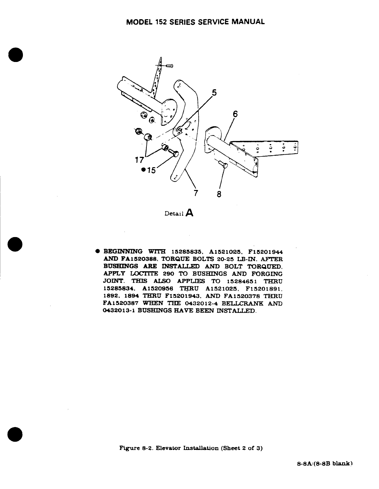
MODEL
152
SERIES
SERVICE
MANUAL
7
8
Detail
A
*
BEGINNING
WITH
15285835.
A1521025,
F15201944
AND
FA1520388.
TORQUE
BOLTS
20-25
LB-IN.
AFTER
BUSHINGS
ARE
INSTALLED
AND
BOLT
TORQUED,
APPLY
LOCTITE
290
TO
BUSHINGS
AND
FORGING
JOINT.
THIS
ALSO
APPLIES
TO
15284651
THRU
15285834.
A1520956
THRU
A1521025,
F15201891,
1892,
1894
THRU
FI5201943,
AND
FA1520378
THRU
FA1520387
WHEN
THE
0432012-4
BELLCRANK AND
0432013-1
BUSHINGS HAVE
BEEN
INSTALLED.
Figure
8-2.
Elevator
Installation
(Sheet
2
of
3)
8-8A/(8-8B
blank)
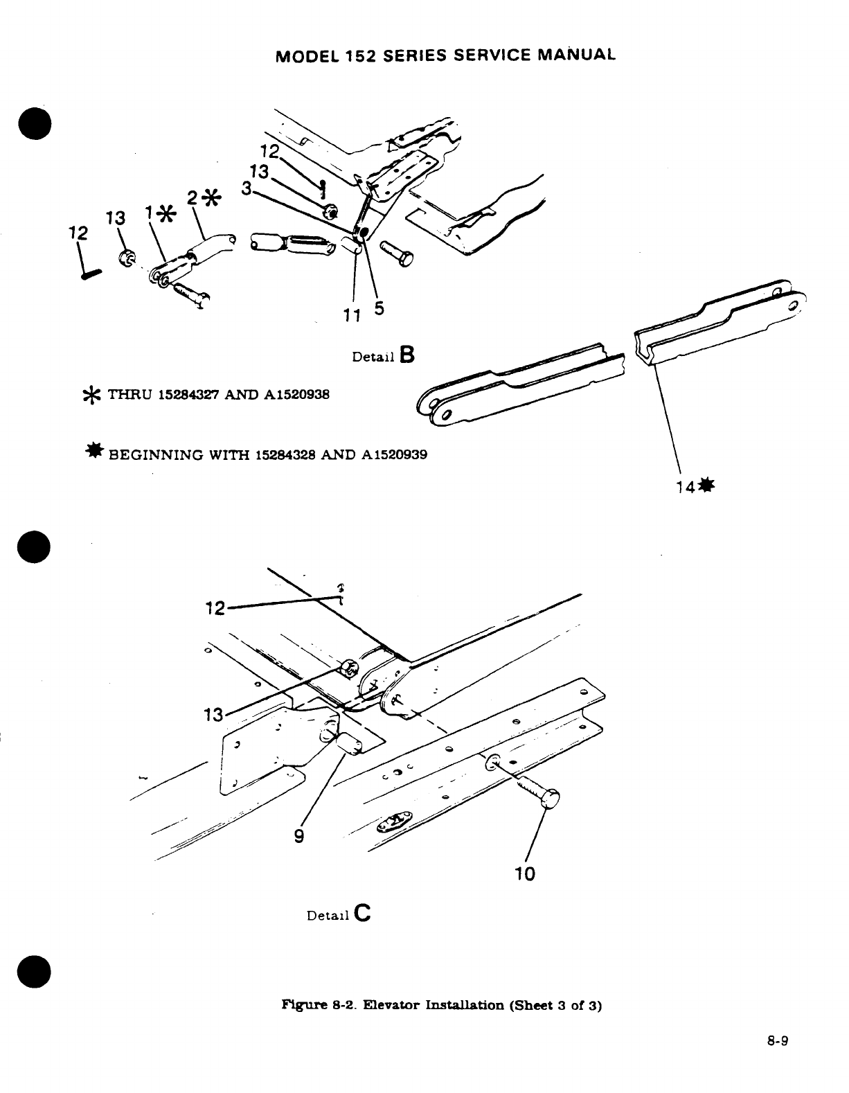
MODEL
152
SERIES
SERVICE
MANUAL
12
Detail
B
*
THRU
15284327
AND
A1520938
*
BEGINNING
WITH
15284328
AND
A1520939
1
4*
10
Detail
C
Figure
8-2.
Elevator
Installation
(Sheet
3
of
3)
8-9
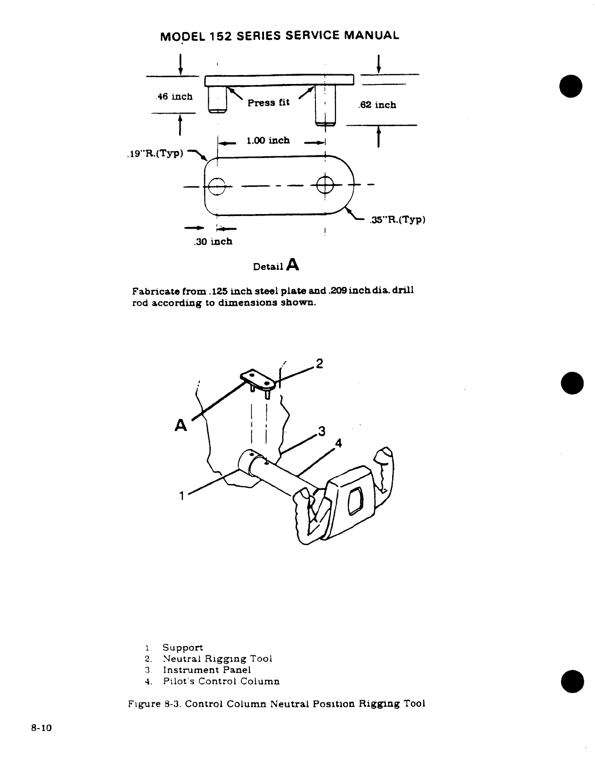
MODEL
152
SERIES
SERVICE
MANUAL
.46
inch
.46
inch
Press
fit
.62
inch
1.00
inch
.19"R.(Typ)
.35"R.(Typ)
.30
inch
Detail
A
Fabricate
from
.125
inch
steel
plate
and
.209
inch
dia.
drill
rod
according
to
dimensions
shown.
1O2
1
Support
2.
Neutral
Rigging
Tool
3
Instrument
Panel
4.
Pilot's
Control
Column
Figure
8-3.
Control Column
Neutral Position Rigging
Tool
8-10
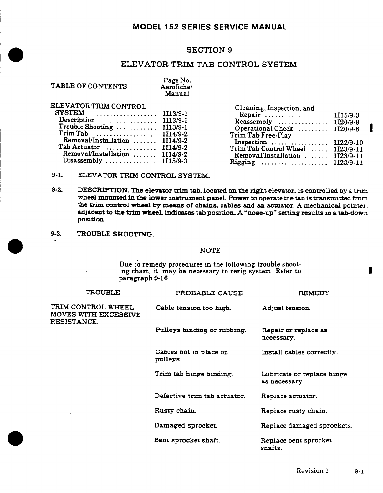
MODEL
152
SERIES
SERVICE
MANUAL
SECTION
9
ELEVATOR
TRIM
TAB
CONTROL
SYSTEM
Page
No.
TABLE
OF
CONTENTS
Aerofiche/
Manual
ELEVATOR
TRIM
CONTROL
Cleaning,
Inspection, and
SYSTEM
....................
1113/9-1
Repair
...................
1I15/9-3
Description
.................
1I13/9-1
Reassembly
...............
1I20/9-8
Trouble
Shooting
............
1I13/9-1
Operational
Check
.........
1I20/9-8
Trim
Tab
...................
1I14/9-2
Trim
Tab
Free-Play
Removal/Installation
.......
1I14/9-2
Inspection
.................
1I22/9-10
Tab
Actuator
...............
1I14/9-2
Trim
Tab
Control
Wheel
.....
1I23/9-11
Removal/Installation
.......
1I14/9-2
Removal/Installation
.......
1I23/9-11
Disassembly
...............
1I15/9-3
Rigging
....................
1I23/9-11
9-1.
ELEVATOR
TRIM
CONTROL
SYSTEM.
9-2.
DESCRIPTION.
The
elevator
trim
tab,
located
on
the
right
elevator.
is controlled
by a
trim
wheel
mounted
in
the
lower
instrument
panel.
Power
to
operate
the tab is
transmitted
from
the
trim
control
wheel
by
means
of
chains,
cables
and
an
actuator.
A
mechanical
pointer.
adjacent
to
the
trim
wheel
indicates tab
position.
A
"nose-up"
setting
results
in
a
tab-down
position.
9-3.
TROUBLE
SHOOTING.
NOTE
Due
to
remedy
procedures
in
the
following
trouble
shoot-
ing
chart,
it
may
be
necessary
to
rerig
system.
Refer
to
I
paragraph
9-16.
TROUBLE
PROBABLE
CAUSE
REMEDY
TRIM
CONTROL
WHEEL
Cable
tension
too
high. Adjust tension.
MOVES
WITH
EXCESSIVE
RESISTANCE.
Pulleys
binding
or
rubbing.
Repair
or
replace
as
necessary.
Cables
not
in
place
on
Install
cables
correctly.
pulleys.
Trim
tab
hinge
binding.
Lubricate
or
replace
hinge
as
necessary.
Defective
trim
tab actuator.
Replace
actuator.
Rusty
chain.-
Replace
rusty
chain.
Damaged
sprocket.
Replace
damaged
sprockets.
Bent
sprocket shaft.
Replace
bent
sprocket
shafts.
Revision
1 9-1
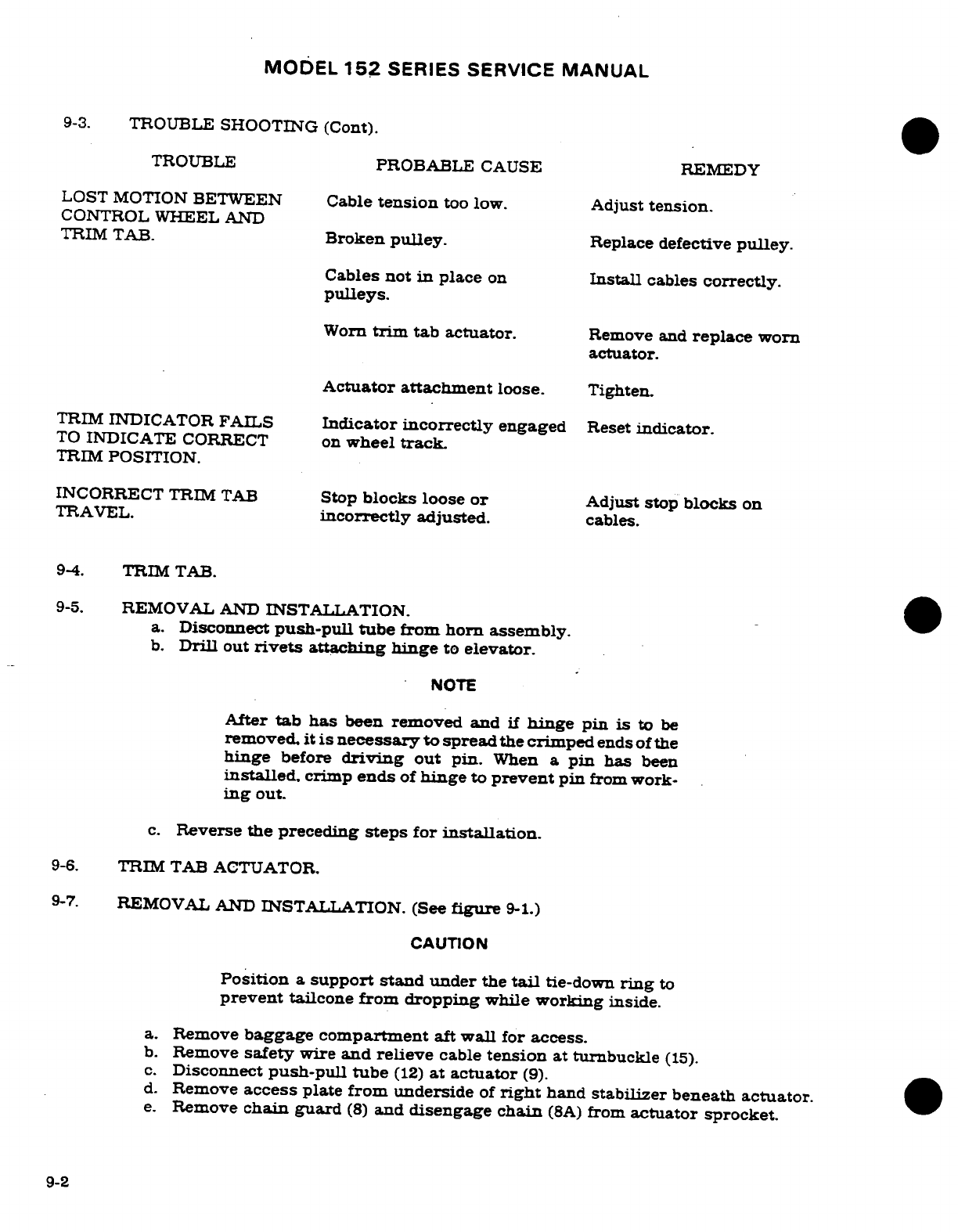
MODEL
152
SERIES
SERVICE
MANUAL
9-3.
TROUBLE
SHOOTING (Cont).
TROUBLE
PROBABLE
CAUSE
REMEDY
LOST MOTION
BETWEEN
Cable
tension
too
low.
Adjust
tension.
CONTROL
WHEEL AND
TRIM
TAB.
Broken
pulley.
Replace
defective
pulley.
Cables
not
in
place
on
Install
cables
correctly.
pulleys.
Worn
trim
tab
actuator.
Remove
and
replace
worn
actuator.
Actuator
attachment
loose. Tighten.
TRIM
INDICATOR
FAILS
Indicator incorrectly
engaged
Reset
indicator.
TO
INDICATE
CORRECT on
wheel
track
TRIM
POSITION.
INCORRECT
TRIM
TAB
Stop
blocks
loose
or
Adjust stop
blocks
on
TRAVEL.
incorrectly
adjusted.
cables.
9-4.
TRIM
TAB.
9-5.
REMOVAL
AND
INSTALLATION.
a.
Disconnect
push-pull
tube
from
horn
assembly.
b.
Drill
out
rivets
attaching
hinge
to
elevator.
NOTE
After
tab
has
been
removed
and
if
hinge
pin
is
to
be
removed,
it is
necessary
to spread
the
crimped
ends of
the
hinge
before
driving
out
pin.
When
a
pin
has
been
installed,
crimp
ends
of
hinge
to
prevent
pin
from
work-
ing
out.
c.
Reverse
the
preceding
steps
for
installation.
9-6.
TRIM
TAB
ACTUATOR.
9-7.
REMOVAL
AND
INSTALLATION.
(See
figure
9-1.)
CAUTION
Position
a
support
stand
under
the
tail
tie-down
ring
to
prevent
tailcone
from
dropping
while
working
inside.
a.
Remove
baggage
compartment
aft
wall
for
access.
b.
Remove
safety
wire
and
relieve
cable
tension
at
turnbuckle
(15).
c.
Disconnect
push-pull
tube
(12)
at
actuator
(9).
d.
Remove
access
plate
from
underside
of
right
hand
stabilizer
beneath
actuator.
e.
Remove
chain
guard
(8)
and
disengage chain
(8A)
from
actuator
sprocket.
9-2
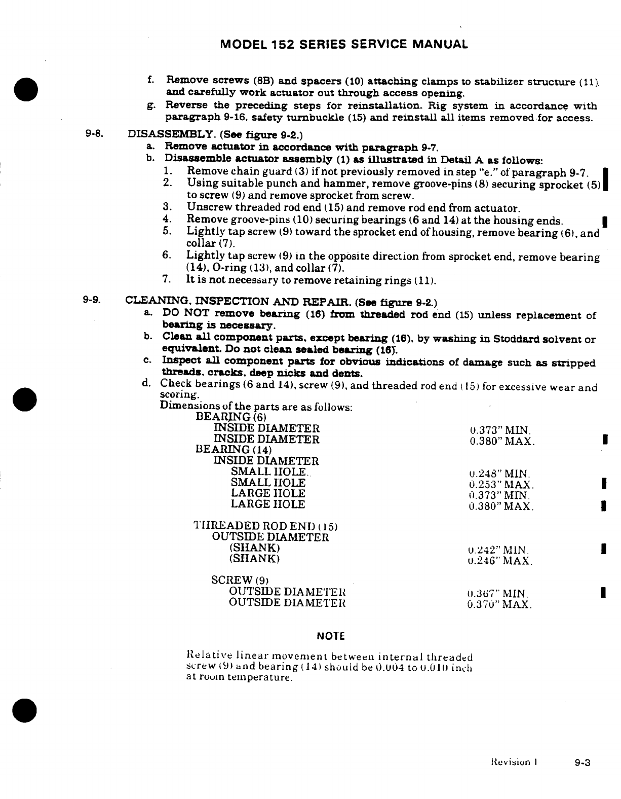
MODEL
152
SERIES SERVICE
MANUAL
f.
Remove
screws
(8B)
and
spacers
(10)
attaching
clamps
to
stabilizer
structure
(11)
and
carefully
work
actuator
out
through
access
opening.
g.
Reverse
the
preceding
steps
for
reinstallation.
Rig
system
in accordance
with
paragraph
9-16.
safety
turnbuckle
(15)
and
reinstall
all
items removed
for
access.
9-8.
DISASSEMBLY. (See
figure
9-2.)
a.
Remove
actuator
in
accordance
with
paragraph
9-7.
b.
Disassemble
actuator
assembly
(1)
as
illustrated
in
Detail
A
as
follows:
1.
Remove
chain
guard
(3)
if
not
previously
removed in
step
"e."
of
paragraph
9-7.
2.
Using
suitable
punch
and
hammer,
remove
groove-pins
(8)
securing
sprocket
(5)
to
screw
(9)
and
remove
sprocket
from
screw.
3.
Unscrew
threaded
rod
end
(15)
and
remove
rod
end
from
actuator.
4.
Remove
groove-pins
(10)
securing
bearings
(6
and
14)
at
the
housing
ends.
5.
Lightly
tap
screw
(9)
toward
the
sprocket
end
of
housing,
remove
bearing
(6),
and
collar
(7).
6.
Lightly
tap
screw
(9)
in
the
opposite
direction
from
sprocket
end,
remove
bearing
(14),
O-ring
(13),
and
collar
(7).
7.
It
is
not
necessary
to
remove
retaining
rings
(11).
9-9.
CLEANING.
INSPECTION
AND
REPAIR.
(See
figure
9-2.)
a.
DO
NOT
remove
bearing
(16)
from
threaded
rod
end
(15)
unless
replacement
of
bearing
is
necessary.
b.
Clean
all
component
parts,
except
bearing
(16),
by
washing
in
Stoddard
solvent
or
equivalent.
Do
not
clean
sealed
bearing
(16Y.
c.
Inspect
all
component
parts
for
obvious
indications
of
damage
such
as
stripped
threads.
cracks,
deep
nicks
and
dents.
d.
Check
bearings
(6
and
14),
screw
(9),
and
threaded
rod
end
(15)
for
excessive
wear
and
scoring.
Dimensions
of
the
parts
are
as
follows:
BEARING
(6)
INSIDE
DIAMETER
0.373"
MIN.
INSIDE
DIAMETER
0.380"
MAX.
BEARING
(14)
INSIDE
DIAMETER
SMALL
HOLE.
u.248"
MIN.
SMALL
HOLE
0.253"
MAX.
LARGE
HOLE
0.373"
MIN.
LARGE
HOLE
0.380"
MAX.
THREADED
ROD
END
(15)
OUTSIDE
DIAMETER
(SHANK)
0.242"
MIN.
(SHANK)
u.246"
MAX.
SCREW
(9)
OUTSIDE
DIAMETER
.367"
MIN.
OUTSIDE
DIAMETER
0.370"
MAX.
NOTE
Relative
linear
movement
between
internal
threaded
screw
(9)
and
bearing
(14)
should
be
0.004
to
0.010
inch
at
room
temperature.
Revision
1
9-3
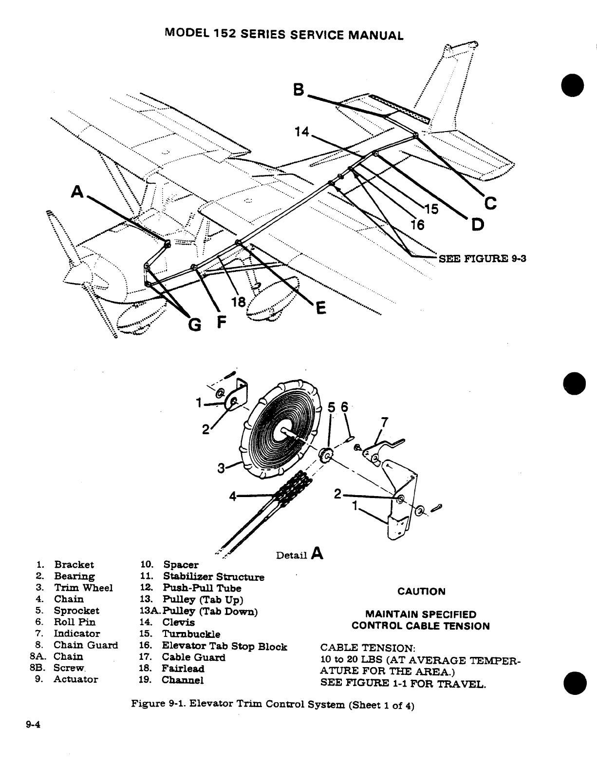
MODEL
152
SERIES
SERVICE
MANUAL
B
1.
Bracket
10.
Spacer
4
Chain
13.
Pulley
(Tab
Up)
5.
Sprocket
13A.Pulley
(Tab
Down)
MAINTAIN
SPECIFIED
6.
Roll
Pin
14.
Clevis
CONTROL
CABLE
TENSION
7.
Indicator
15.
Turnbuckle
8.
Chain
Guard
16.
Elevator
Tab
Stop
Block
CABLE
TENSION:
8A.
Chain
17.
Cable
Guard
10
to
20
LBS
(AT
AVERAGE
TEMPER-
8B.
Screw
18.
Fairlead
ATURE
FOR
THE
AREA.)
·
9.
Actuator
19.
Channel
SEE
FIGURE
1-1
FOR TRAVEL.
Figure
9-1.
Elevator
Trim
Control System (Sheet
1
of
4)
9-4
3.
Trim
Wheel
12·
Push-Pull
Tube
CAUTION
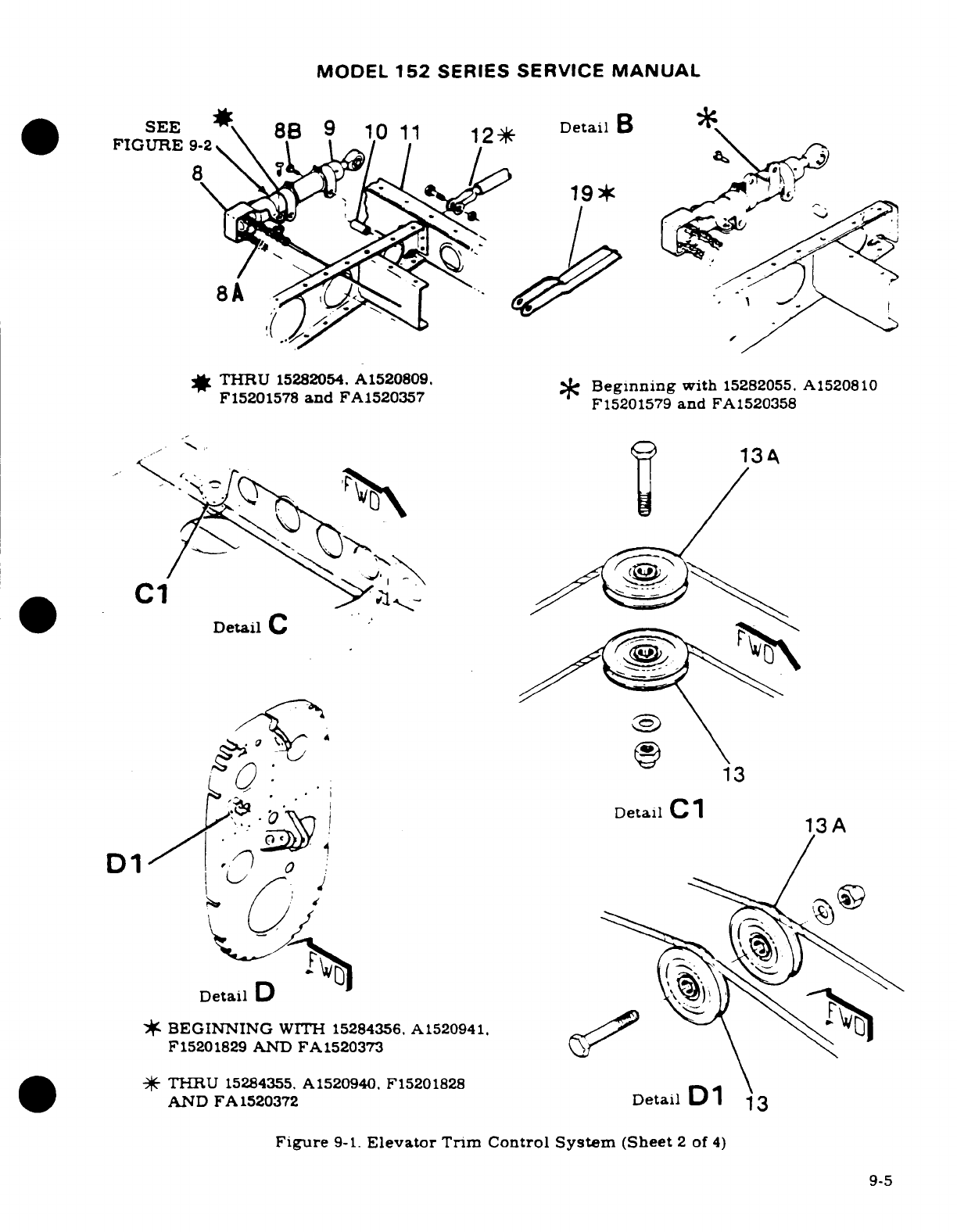
MODEL
152
SERIES
SERVICE
MANUAL
SEE
8B
9 10
11
12*
DetailB
FIGURE
9-2
8
'
19*
8A
*
THRU
15282054.
A1520809.
Beginning
with
15282055.
A1520810
F15201578
and
FA1520357
F15201579
and
FA1520358
9
134
C1
Detail
C
13
Detail
C1
13A
D1
Detail
D
*
BEGINNING
WITH
15284356.
A1520941.
F15201829
AND
FA1520373
#
THRU
15284355,
A1520940.
F15201828
AND
FA1520372
Detail
D
13
Figure
9-1.
Elevator
Trim
Control
System
(Sheet
2
of
4)
9-5
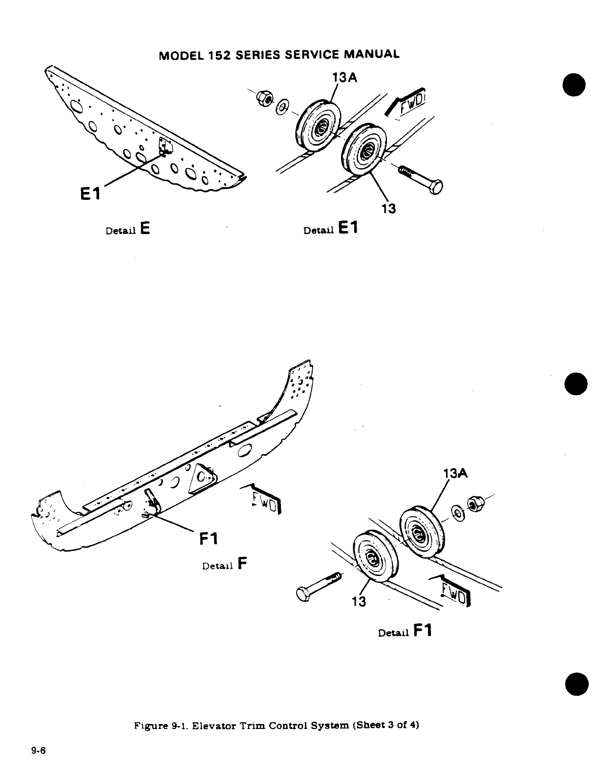
MODEL
152
SERIES
SERVICE
MANUAL
13A
El
13
Detail
E
Detail
El
13A
Detail
F1
Figure
9-1.
Elevator
Trim
Control
System
(Sheet
3
of
4)
9-6
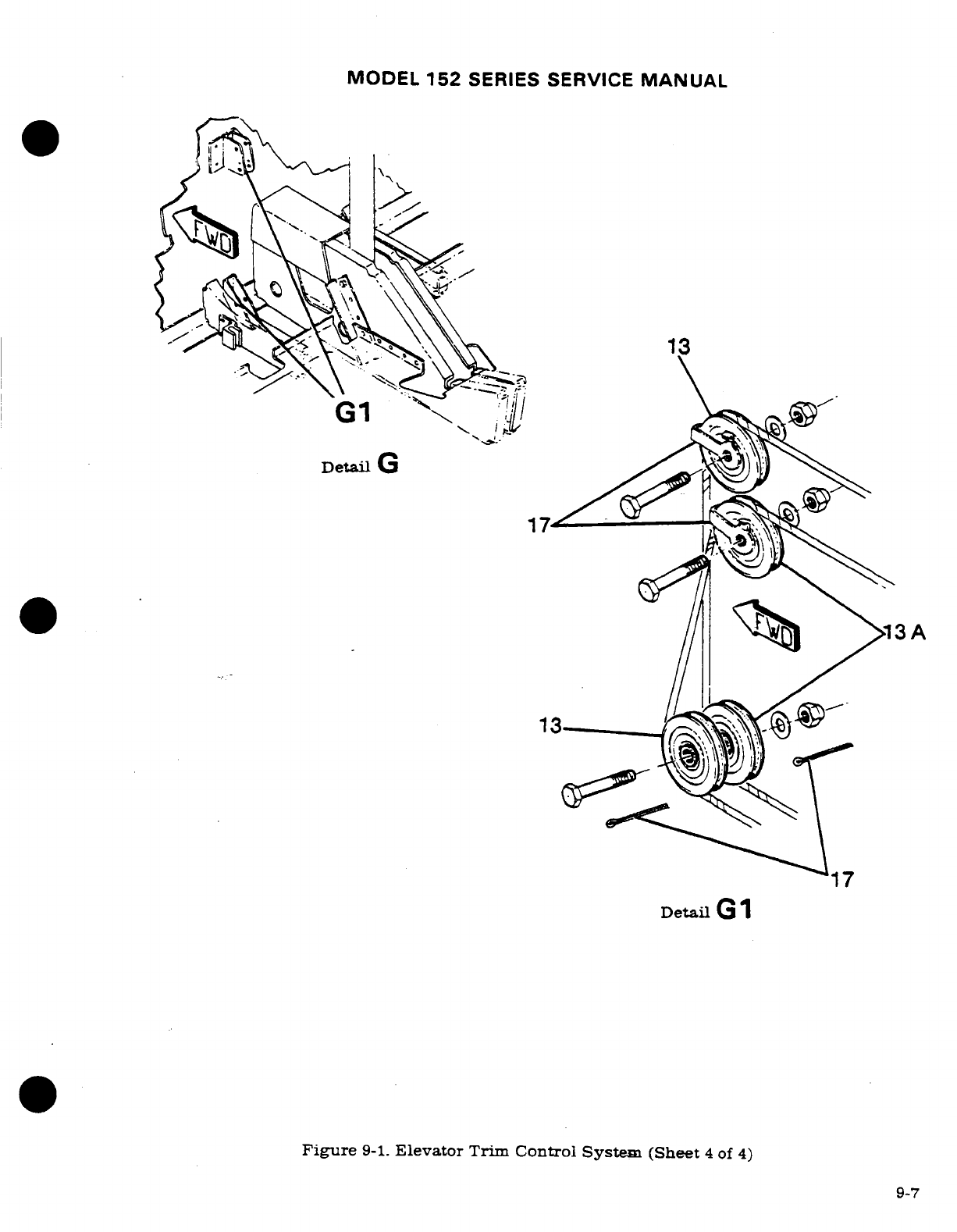
MODEL
152
SERIES SERVICE
MANUAL
17
Detail
G
1
Figure
9-1.
Elevator
Trim
Control
System (Sheet
4
of
4)
9-7
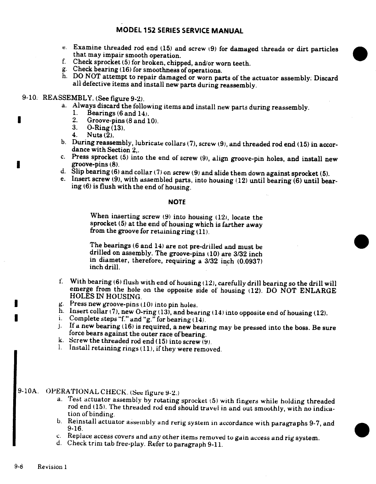
MODEL
152
SERIES
SERVICE
MANUAL
e.
Examine threaded
rod
end
(15)
and
screw
(9)
for
damaged
threads
or
dirt
particles
that
may
impair
smooth
operation.
f.
Check
sprocket
(5)
for
broken,
chipped,
and/or
worn
teeth.
g.
Check
bearing
(16)
for
smoothness
of
operations.
h.
DO
NOT
attempt
to
repair
damaged
or
worn
parts
of
the actuator
assembly. Discard
all
defective
items and
install
new
parts
during
reassembly.
9-10. REASSEMBLY.
(See
figure
9-2).
a.
Always
discard
the
following
items
and
install
new
parts
during reassembly.
1.
Bearings
(6
and
14).
2.
Groove-pins
(8
and
10).
3.
O-Ring(13).
4.
Nuts
(2).
b.
During
reassembly,
lubricate
collars
(7),
screw
(9),
and
threaded
rod end
(15)
in
accor-
dance
with
Section
2,.
c.
Press
sprocket
(5)
into
the
end
of
screw
(9),
align
groove-pin
holes,
and
install
new
groove-pins
(8).
d.
Slip
bearing
(6)
and
collar
(7)
on
screw
(9)
and
slide
them
down
against
sprocket
(5).
e.
Insert
screw
(9),
with
assembled
parts,
into
housing
(12)
until
bearing
(6)
until
bear-
ing
(6)
is
flush with
the
end
of
housing.
NOTE
When
inserting
screw
(9)
into housing
(12),
locate
the
sprocket
(5)
at
the
end
of
housing
which
is
farther
away
from
the
groove
for
retaining ring
(11).
The
bearings
(6
and
14)
are
not
pre-drilled and
must
be
drilled
on
assembly.
The
groove-pins
(10)
are
3/32
inch
in
diameter,
therefore,
requiring
a
3/32
inch
(0.0937)
inch
drill.
f.
With
bearing
(6)
flush
with
end
of
housing
(12),
carefully
drill
bearing
so
the
drill
will
emerge
from
the
hole
on
the
opposite
side
of
housing
(12).
DO
NOT
ENLARGE
HOLES
IN
HOUSING.
g.
Press
new
groove-pins
(10)
into
pin
holes.
h.
Insert
collar
(7),
new
O-ring
(13),
and
bearing
(14)
into opposite
end
of
housing
(12).
i.
Complete
steps
"f."
and
"g."
for
bearing
(14).
j.
If
a
new
bearing
(16)
is
required,
a
new
bearing
may
be
pressed
into
the
boss.
Be
sure
force
bears
against
the outer
race
of
bearing.
k.
Screw
the
threaded
rod
end
(15)
into
screw
(9).
1.
Install
retaining
rings
(11),
if
they
were
removed.
9-10A.
OPERATIONAL CHECK.
(See
Figure
9-2.)
a.
Test
actuator
assembly
by
rotating
sprocket
(5)
with fingers while
holding
threaded
rod
end
(15).
The
threaded
rod
end
should
travel
in
and
out smoothly,
with
no
indica-
tion
of
binding.
b.
Reinstall
actuator
assembly
and
rerig
system
in
accordance
with
paragraphs
9-7,
and
9-16.
c.
Replace
access
covers
and
any
other
items
removed
to
gain
access
and
rig system.
d.
Check
trim
tab
free-play.
Refer
to
paragraph
9-11.
9-8
Revision
1
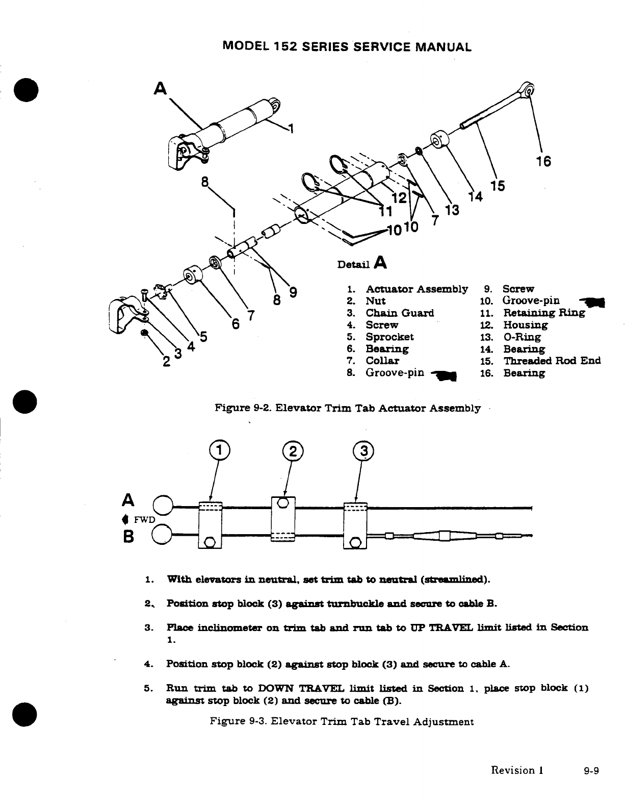
MODEL
152
SERIES
SERVICE
MANUAL
A
8
15
Detail
A
9
1.
Actuator
Assembly
9.
Screw
8
2.
Nut
10.
Groove-pin
7
3.
Chain Guard
11.
Retaining
Ring
6
4.
Screw
12.
Housing
5
5.
Sprocket
13.
O-Ring
3 4
6.
Bearing
14.
Bearing
7.
Collar
15.
Threaded
Rod
End
8.
Groove-pin
-
16.
Bearing
Figure
9-2.
Elevator
Trim
Tab
Actuator
Assembly
A
(3)
FWD
B
1.
With
elevators
in
neutral,
set
trim
tab
to
neutral
(streamlined).
2.
Position
stop
block
(3)
against
turnbuckle
and
secure
to
cable
B.
3.
Place
inclinometer on
trim
tab
and
run
tab
to
UP
TRAVEL
limit
listed
in
Section
1.
4.
Position
stop
block
(2)
against
stop
block
(3)
and
secure
to
cable
A.
5.
Run
trim
tab to
DOWN
TRAVEL
limit listed
in
Section
1,
place
stop
block
(1)
against
stop
block
(2)
and
secure
to
cable
(B).
Figure
9-3.
Elevator
Trim
Tab
Travel
Adjustment
Revision
1
9-9
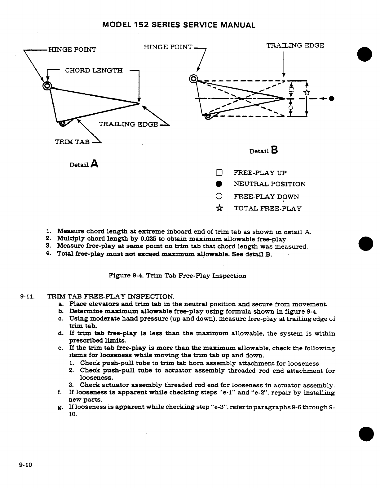
MODEL
152
SERIES
SERVICE
MANUAL
HINGE
POINT
TRAILING
EDGE
TRIM
TAB
Detail
A
FREE-PLAY
UP
*
NEUTRAL
POSITION
FREE-PLAY
DOWN
TOTAL
FREE-PLAY
1.
Measure
chord
length
at
extreme
inboard
end
of
trim
tab
as
shown
in
detail
A.
2.
Multiply
chord
length
by
0.025
to
obtain
maximum
allowable
free-play.
3.
Measure
free-play
at
same
point
on
trim
tab
that
chord
length
was
measured.
4.
Total
free-play
must
not
exceed
maximum
allowable.
See
detail
B.
Figure
9-4.
Trim
Tab
Free-Play
Inspection
9-11.
TRIM
TAB
FREE-PLAY INSPECTION.
a.
Place
elevators
and
trim
tab
in
the
neutral
position
and
secure
from
movement
b.
Determine
maximum
allowable
free-play
using
formula
shown
in
figure
9-4.
c.
Using
moderate
hand
pressure
(up
and
down),
measure
free-play
at
trailing
edge
of
trim
tab.
d.
If
trim
tab
free-play
is
less than the
maximum
allowable,
the
system
is
within
prescribed
limits.
e.
If
the
trim
tab
free-play
is
more
than
the maximum
allowable,
check
the
following
items
for
looseness
while moving
the
trim
tab
up
and
down.
1.
Check
push-pull
tube
to
trim
tab
horn
assembly
attachment
for
looseness.
2.
Check
push-pull
tube
to
actuator
assembly
threaded
rod end
attachment
for
looseness.
3.
Check
actuator
assembly
threaded
rod
end
for
looseness
in
actuator
assembly.
f.
If
looseness
is
apparent
while
checking steps
"e-1"
and
"e-2".
repair
by
installing
new
parts.
g.
If
looseness
is
apparent
while checking
step
"e-3".
refer
to
paragraphs
9-6
through
9-
10.
9-10
MODEL
152
SERIES SERVICE
MANUAL
9-12.
TRIM
TAB CONTROL
WHEEL.
(See
figure
9-1.)
9-13.
REMOVAL
AND
INSTALLATION.
a.
Relieve
cable
tension
at
turnbuckle
(15).
CAUTION
Position
a
support stand
under
the
tail
tie-down
ring
to
prevent
tailcone from
dropping
while
working
inside.
b.
Disengage
chain
from
sprocket
(5).
c.
Remove
cotter
pin
at each
end
of
trim
wheel
shaft.
d.
Slide shaft
assembly
into
either
bearing
(2)
as
far
as
possible.
e.
Carefully
deform
brackets
(1)
and
slide
shaft
assembly
free
of
bearings
(2).
f.
Reverse the
preceding
steps
for
installation.
Rig
system
in accordance
with
applica-
ble
paragraph
in
this
section,
safety
turnbuckle
and
reinstall
all
items
removed
for
access.
9-14.
CABLES
AND
PULLEYS.
(See
figure
9-1.)
9-15.
REMOVAL
AND
INSTALLATION.
a.
Remove
seats,
upholstery
and
access
plates
as
necessary.
b.
Disconnect
cables
at
turnbuckle
(15)
and
clevis
(14).
c.
Remove
fairlead,
cable
guards
and
pulleys
as
necessary
to
work
cables
free
of
aircraft.
NOTE
To
ease
routing
of
cables,
a
length
of
wire
may
be
attached
to
end
of
the
cable
before
being
withdrawn
from aircraft.
Leave
wire
in
place, routed
through
structure.
attach
cable
being
installed
and
pull
cable
into position.
d.
After
cable
is
routed
in
position,
install
pulleys
and
cable
guards.
Make
sure
cable
is
positioned
in
pulley
groove
before
installing
guards.
e.
Rig
system
in
accordance
with applicable
paragraph
in
this
section.
safety turn-
buckle
and
reinstall
all
items
removed
in
step
"a".
9-16.
RIGGING.
(See
figure
9-1.)
CAUTION
Position
a
support stand
under
the
tail
tie-down
ring
to
prevent
tailcone
from
dropping
while
working
inside.
a.
Remove
rear
baggage
compartment
panel
and
access plates
as necessary.
b.
Loosen
travel
stop
blocks
(16)
on
cables.
c.
Disconnect
actuator
(9)
from
push-pull
tube
(12).
d.
Check
cable
tension
and
readjust
turnbuckle
(15)
if
necessary.
9-11
MODEL
152
SERIES
SERVICE
MANUAL
NOTE
If
chains
and/or
cables
are
being
installed.
permit
actua-
tor
screw
to
rotate
freely
as
chains
and
cables
are
connected.
Set
cable
tension.
e.
Rotate
trim
control
wheel
(3)
full
forward
(nose
down).
Ensure
that indicator
(7)
does
not
restrict
wheel
movement.
If
necessary,
reposition indicator
using
a
thin
screw-
driver
to
pry
trailing
leg
of
indicator
out
of
groove.
NOTE
Full
forward
(nose
down)
position
of
trim
wheel
is
where
further
movement
is
prevented
by
chain
or
cable
ends
contacting
sprockets
or
pulleys.
f.
With
elevator
and
trim
tab
both
inneutral
(streamlined),
place
an
inclinometer
on
tab
and
set
to
zero.
NOTE
An
inclinometer
for
measuring
control
surface
travel
is
available
from
Cessna
Parts
Distribution
(CPD
2)
through
a
Cessna
Service
Station.
See
figure
6-4.
g.
Rotate
actuator
screw
in
or
out
as
required
to
place
tab
up
with
a
maximum
of
2°
overtravel.
with
actuator
screw
connected
to
Push-pull
tube
(12).
h.
Rotate
trim
wheel
to
position
trim
tab
up
and
down.
readjusting actuator
screw
as
required
to
obtain
overtravel
in
both
directions.
i.
Position
stop blocks
(16)
and
adjust as
illustrated
in
figure
9-3
to
limit
travel
to
the
degree specified
in
Section
1.
j.
Check
that trim
wheel
indicator
is
same
distance
from
ends
of
slot
in
cover.
|
Reposition
trailing
leg
of
indicator
if
necessary
(refer
to
step
"e.").
k.
Safety
turnbuckle
and
reinstall
all
items
removed
in
step
"a".
WARNING
Be
sure
trim
tab
moves
in
correct
direction
when
oper-
ated
by
the
trim
wheel.
Nose
down
trim
corresponds
to
tab
up
position.
9-12
Revision
1
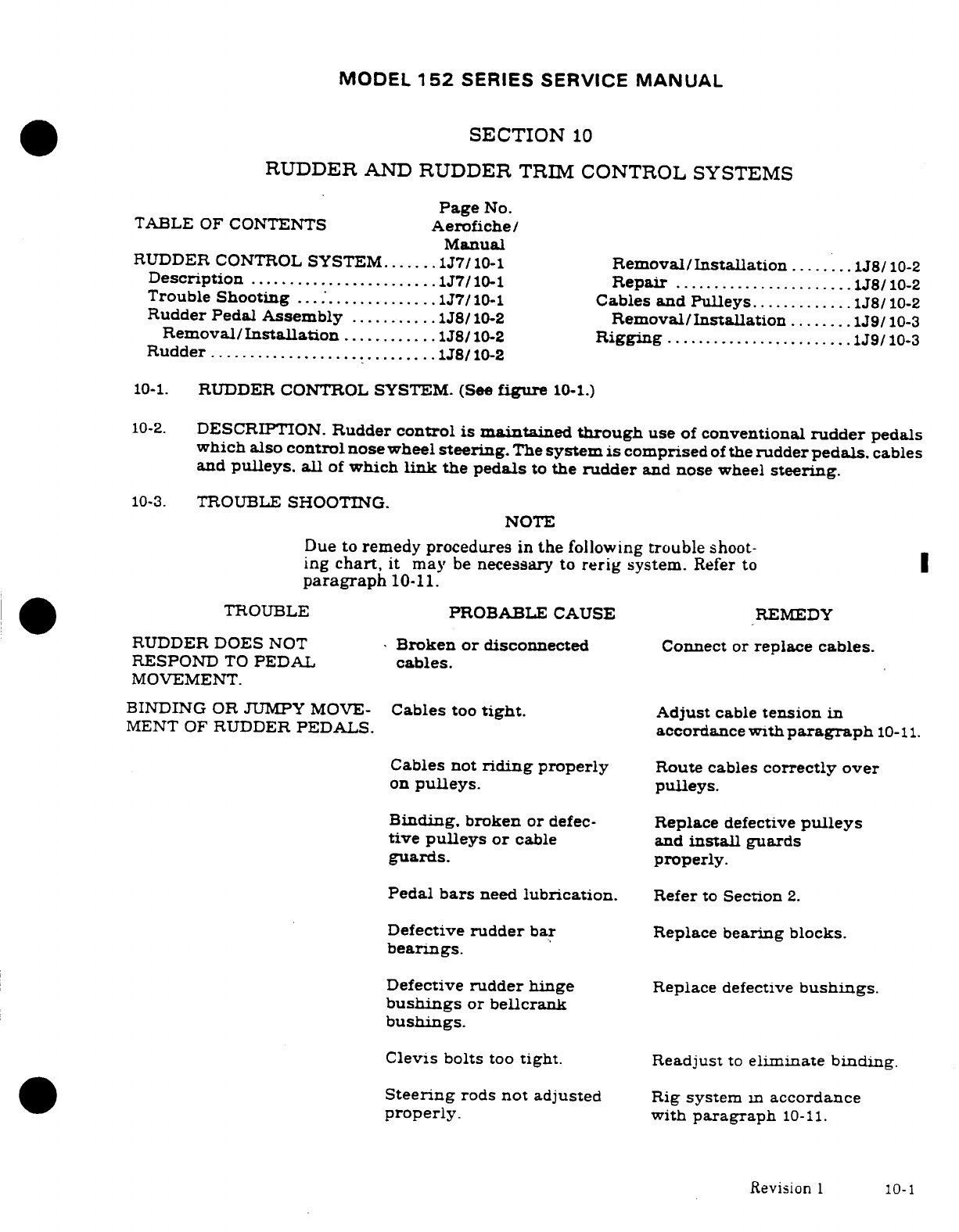
MODEL
152
SERIES
SERVICE
MANUAL
SECTION
10
RUDDER
AND
RUDDER
TRIM
CONTROL SYSTEMS
Page
No.
TABLE
OF
CONTENTS
Aerofiche/
Manual
RUDDER
CONTROL
SYSTEM.......1J7/10-1
Removal/Installation
........
1J8/10-2
Description
........................
1J7/10-1
Repair
.......................
1J8/10-2
Trouble
Shooting
.... ;.............
1J7/10-1
Cables
and
Pulleys.............
1J8/10-2
Rudder Pedal
Assembly
...........
1J8/10-2
Removal/Installation
........
1J9/10-3
Removal/Installation
............
1J8/10-2
Rigging
........................
1J9/10-3
Rudder
.............................
1J/10-2
10-1.
RUDDER CONTROL SYSTEM.
(See
figure
10-1.)
10-2.
DESCRIPTION.
Rudder
control
is
maintained
through
use
of
conventional
rudder
pedals
which
also
control
nose
wheel
steering.
The
system
is
comprised
of
the
rudder
pedals.
cables
and
pulleys,
all
of
which
link
the
pedals
to
the
rudder
and
nose
wheel
steering.
10-3.
TROUBLE
SHOOTING.
NOTE
Due
to
remedy procedures
in
the
following
trouble
shoot-
ing
chart,
it may
be
necessary
to
rerig
system.
Refer
to
paragraph
10-11.
TROUBLE
PROBABLE CAUSE
REMEDY
RUDDER DOES
NOT
Broken
or
disconnected
Connect
or
replace
cables.
RESPOND
TO
PEDAL
cables.
MOVEMENT.
BINDING
OR
JUMPY
MOVE-
Cables
too
tight.
Adjust
cable
tension
in
MENT
OF
RUDDER
PEDALS.
accordance
with
paragraph
10-11.
Cables
not
riding
properly
Route cables
correctly
over
on
pulleys.
pulleys.
Binding.
broken or
defec-
Replace
defective
pulleys
tive
pulleys
or
cable
and
install
guards
guards.
properly.
Pedal
bars
need
lubrication.
Refer
to
Section
2.
Defective
rudder
bar
Replace
bearing
blocks.
bearings.
Defective
rudder
hinge
Replace
defective
bushings.
bushings
or
bellcrank
bushings.
Clevis
bolts
too
tight.
Readjust
to
eliminate binding.
Steering
rods
not
adjusted
Rig
system
m
accordance
properly.
with
paragraph
10-11.
Revision
1
10-1
MODEL
152
SERIES
SERVICE
MANUAL
10-3.
TROUBLE
SHOOTING
(Cont.)
TROUBLE
PROBABLE
CAUSE REMEDY
LOST
MOTION
BETWEEN
Insufficient
cable
tension.
Adjust
cable
tension
in
RUDDER
PEDALS
accordance
with
para-
AND
RUDDER.
graph
10-11.
INCORRECT
RUDDER
Incorrect
rigging.
Rig
system
in
accordance
TRAVEL.
with
paragraph
10-11.
10-4.
RUDDER
PEDAL
ASSEMBLY.
(See
figure
10-2.)
10-5.
REMOVAL
AND
INSTALLATION.
a.
Remove
carpeting,
shields
and
soundproofing
from
pedal
and
tunnel areas
as
necessary.
b.
Disconnect
master
cylinders
(11)
at
pilot
rudder
pedals.
c.
Disconnect
parking
brake
cables
at
master
cylinders.
d.
Remove
rudder
pedals
(2)
and
brake
links
(12).
e.
Relieve
cable
tension at
clevises
(index
5,
figure
10-1).
f.
Disconnect
cables,
return
springs
and
steering
tubes
from
rudder
bars.
g.
Remove
bolts
securing
bearing
blocks
(15)
and
work
rudder
bars
out
of
tunnel
area.
NOTE
Rudder
bar
assemblies
should
be
checked
for
excessive
wear
before
installation.
The
bearing
blocks are
nylon
and
require
no
lubrication
unless
binding
occurs.
A
few
drops
of
general
purpose
oil should
eliminate
such
bind-
ing.
h.
Reverse the
preceding
steps
for
installation.
Rig
system
in
accordance
with
applica-
ble
paragraph
in
this
section,
safety
cevises
and
reinstall
all items
removed
in
step
"a".
10-6..
RUDDER.
(See
figure
10-3.)
10-7.
REMOVAL
AND
INSTALLATION.
a.
Disconnect
tail
navigation
light
quick-disconnect
(10).
b.
Relieve
cable
tension
at
clevises
(index
5.
figure
10-1)
and
disconnect
clevises
from
rudder
bellcrank
(8).
c.
With
rudder
supported,
remove
hinge
bolts
(4)
and
lift
rudder
free
of
vertical
fin
d.
Reverse
the preceding
steps
for
installation.
Rig
system
in accordance
with
applica-
ble
paragraph
in
this
section
and
safety
clevises.
10-8.
REPAIR.
Repair
may
be
accomplished
as
outlined
in
Section
17.
Hinge
bushings
may
be
replaced
as
necessary.
10-9.
CABLES AND
PULLEYS.
(See
figure
10-1.)
10-2
MODEL
152
SERIES SERVICE
MANUAL
10-10.
REMOVAL
AND
INSTALLATION.
a.
Remove
seats,
upholstery
and
access
plates
as necessary.
b.
Disconnect
cable
at
rudder
bar
(10)
and
bellcrank
(7).
c.
Remove
cable
guards,
pulleys
and
fairleads
as
necessary
to
work
cables
free
of
aircraft.
NOTE
To
ease
routing
of
cables,
a
length
of
wire
may
be
attached
to
end
of
the
cable before
being
withdrawn
from
aircraft.
Leave
wire
in
place,
routed
through
structure,
attach
cable
being installed,
and
pull
cable
into
position.
d.
After
cable
is
routed
in
position,
install
pulleys, fairleads
and
cable guards.
Ensure
cable
is
positioned
in
pulley groove
before
installing
guard.
e.
Rig
system
in
accordance
with
applicable
paragraph
in
this
section.
safety
clevises
and
reinstall
all
items
removed
in
step
"a".
10-11.
RIGGING.
(See
figure
10-1).
a.
Adjust
stop
screws
(8)
to
attain
travel
specified
in
Section
1.
Figure
10-4
illustrates
correct
travel
and
one
method
of
checking.
b.
Disconnect
nose
wheel
steering
tubes
(index
6.
figure
5-6)
from
nose
strut.
c.
Adjust
cables at
cevises
(5)
to
align
rudder
and
pedals
in
neutral position.
6.00
inches
from
firewall
and
pedal
pivot
shafts
(index
4.
figure
10-2).
This
step
automatically
determines
cable
tension
through
use
of
return
springs
(14).
* NOTE
Due
to
thickness
of
insulation
on
firewall.
it
is
recommended
that
a
piece
of
1/16
inch welding
rod
be
ground
to
a
sharp
point
and notched
at
the
6.00
inch
dimension.
Pierce
insulation
on
firewall
and
use
notch
to
measure
proper
dimension.
d.
Tie
down
or
weight
tail
to
raise
nose wheel
free
of
ground.
e.
Center
nose
gear
against
external
stop.
f.
Extend
steering
tubes
until
free
play
is
removed.
DO
NOT
COMPRESS
SPRINGS
g.
Adjust
steering
tube
rod
ends
to
1.25
inch
dimension
between
steering
arm
assembly
and
bolt
hole
as
illustrated
in
figure
5-9
and
tighten
jam
nuts.
h.
Adjust
steering
tube
clevises
to
align
with
rod
end
bearings.
NOTE
Extend
steering
tubes
to
seat
rods
against
internal
springs
but
do
not
attempt
to
preload
these
springs
by
shortening
rod end
devises
after
alignment.
Preload
is
built
into
steering
tubes.
i.
Install
clevises
on rod
ends.
10-3
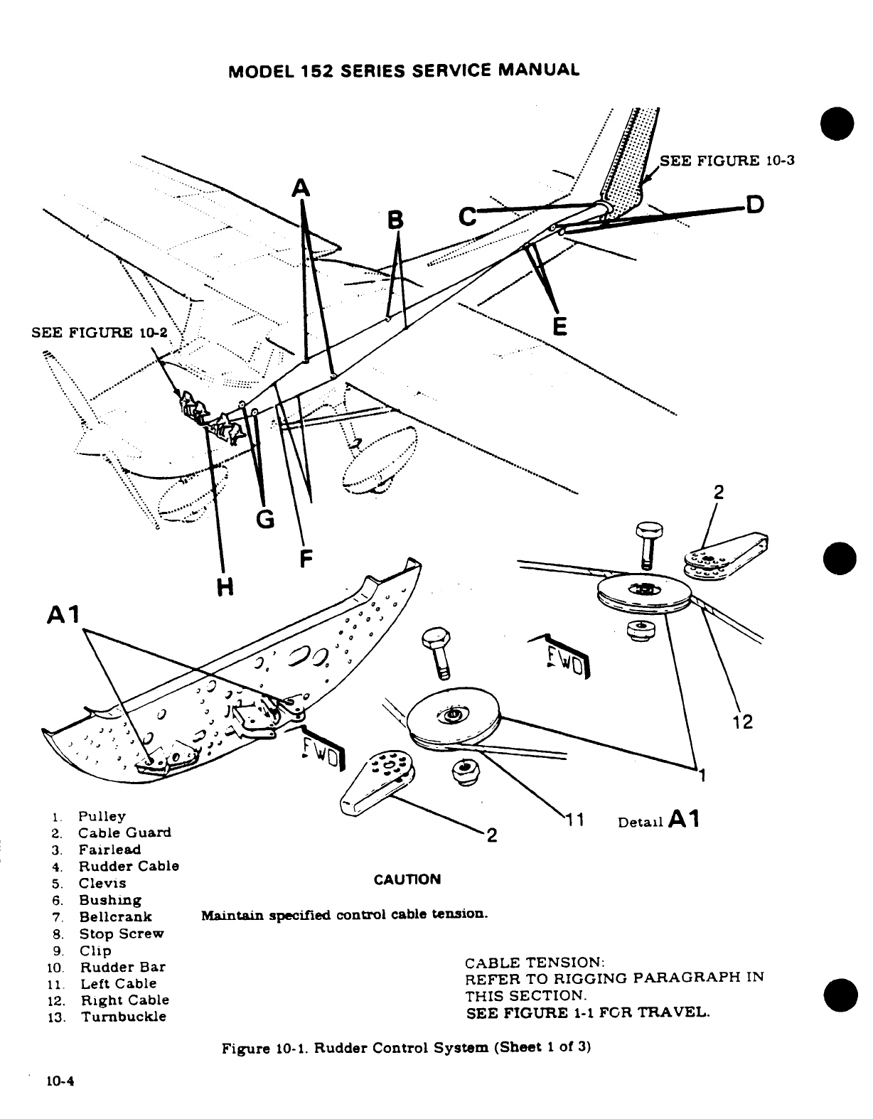
MODEL
152
SERIES
SERVICE
MANUAL
SEE
FIGURE
10-3
SEE
FIGURE
10-2
1.
Pulley
11
Detail
Al
2
2.
Cable
Guard
2
3.
Fairlead
4.
Rudder
Cable
5.
Clevis
CAUTION
6.
Bushing
7.
Bellcrank
Maintain specified
control
cable
tension.
8.
Stop
Screw
9.
Clip
10.
Rudder
Bar
CABLE
TENSION:
11.
Left
Cable
REFER
TO
RIGGING
PARAGRAPH
IN
12.
Right
Cable
THIS
SECTION.
13.
Turnbuckle
SEE FIGURE
l-1
FOR
TRAVEL.
Figure
10-1.
Rudder Control
System
(Sheet
1
of
3)
10-4
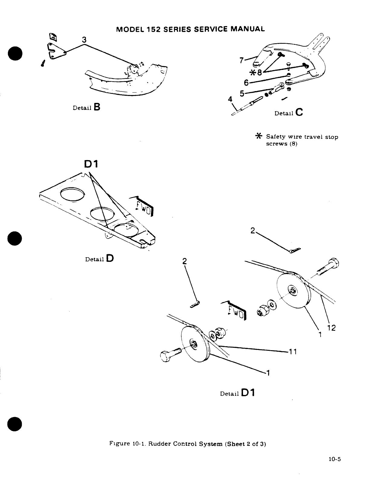
MODEL
152
SERIES
SERVICE
MANUAL
7
5
4
Detail
B
C
Detail
C
*
Safety
wire
travel
stop
screws
(8)
D1
2
Detail
D
2
12
11
Detail
D
1
Figure
10-1.
Rudder
Control
System
(Sheet
2
of
3)
10-5
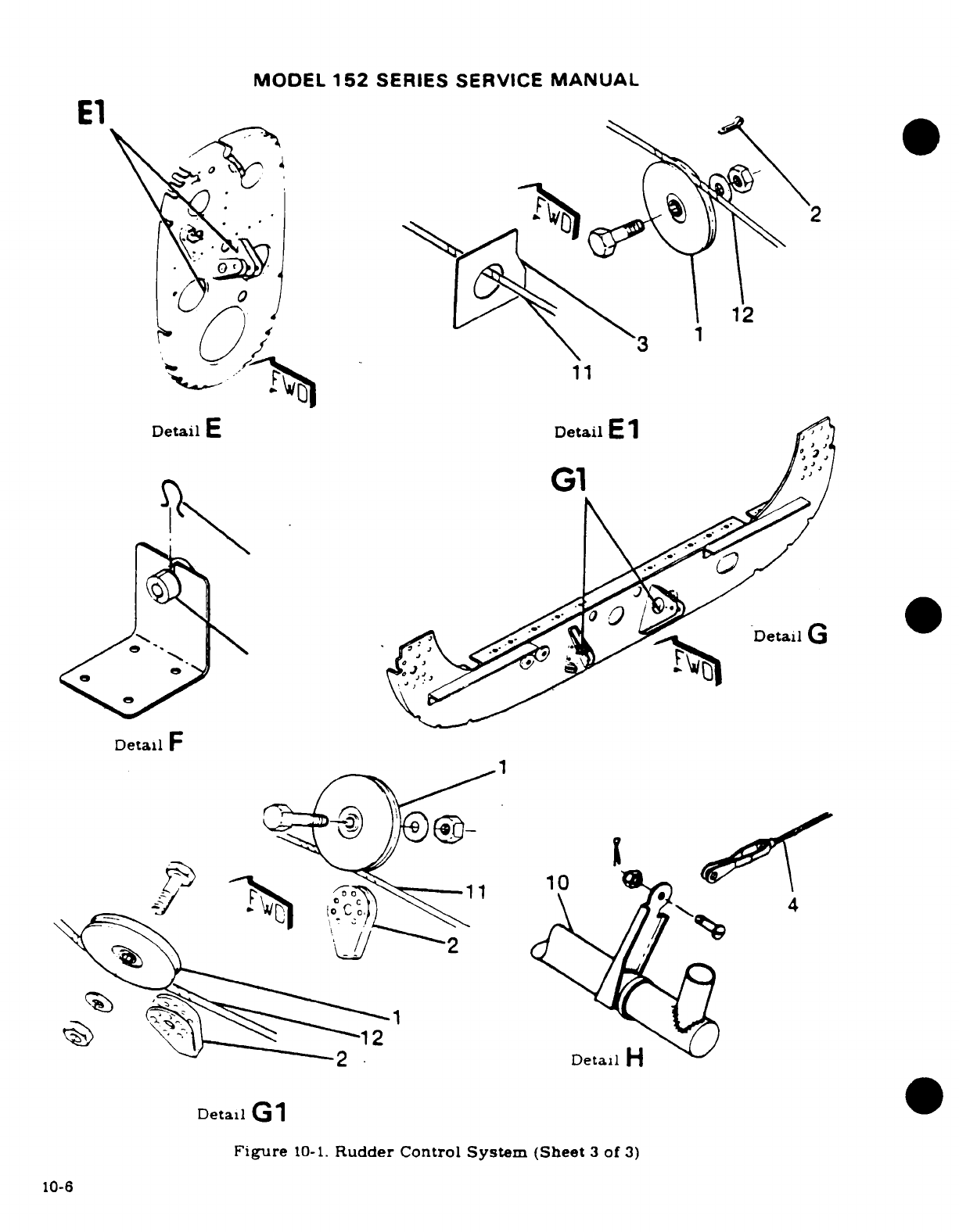
MODEL
152
SERIES SERVICE
MANUAL
u
Detail
G
Detail
F
2
Detail
Detal
G1
Figure
10-1.
Rudder Control
System
(Sheet
3
of
3)
10-6
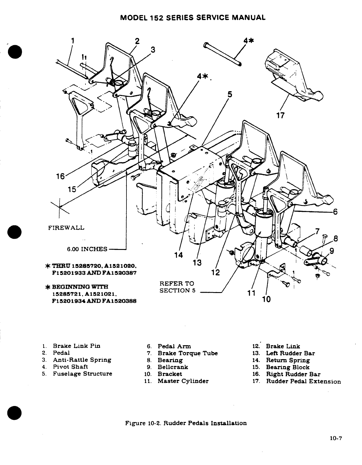
MODEL
152
SERIES SERVICE
MANUAL
4*
17
6.00
INCHES
THRU
15285720,
Al521020,
13
*
BEGINNING
WITH
REFER
TO
I
15285721,
A1521021.
F15201934
AND
FA1520388
10
1.
Brake Link
Pin
6.
Pedal Arm
12.
Brake
Link
2.
Pedal
7.
Brake Torque
Tube
13.
Left
Rudder
Bar
3.
Anti-Rattle
Spring
8.
Bearing
14.
Return
Spring
4.
Pivot
Shaft
9.
Bellcrank
15.
Bearing
Block
5.
Fuselage
Structure
10.
Bracket
16.
Right
Rudder
Bar
11.
Master
Cylinder
17.
Rudder
Pedal
Extension
Figure
10-2.
Rudder
Pedals
Installation
10-7
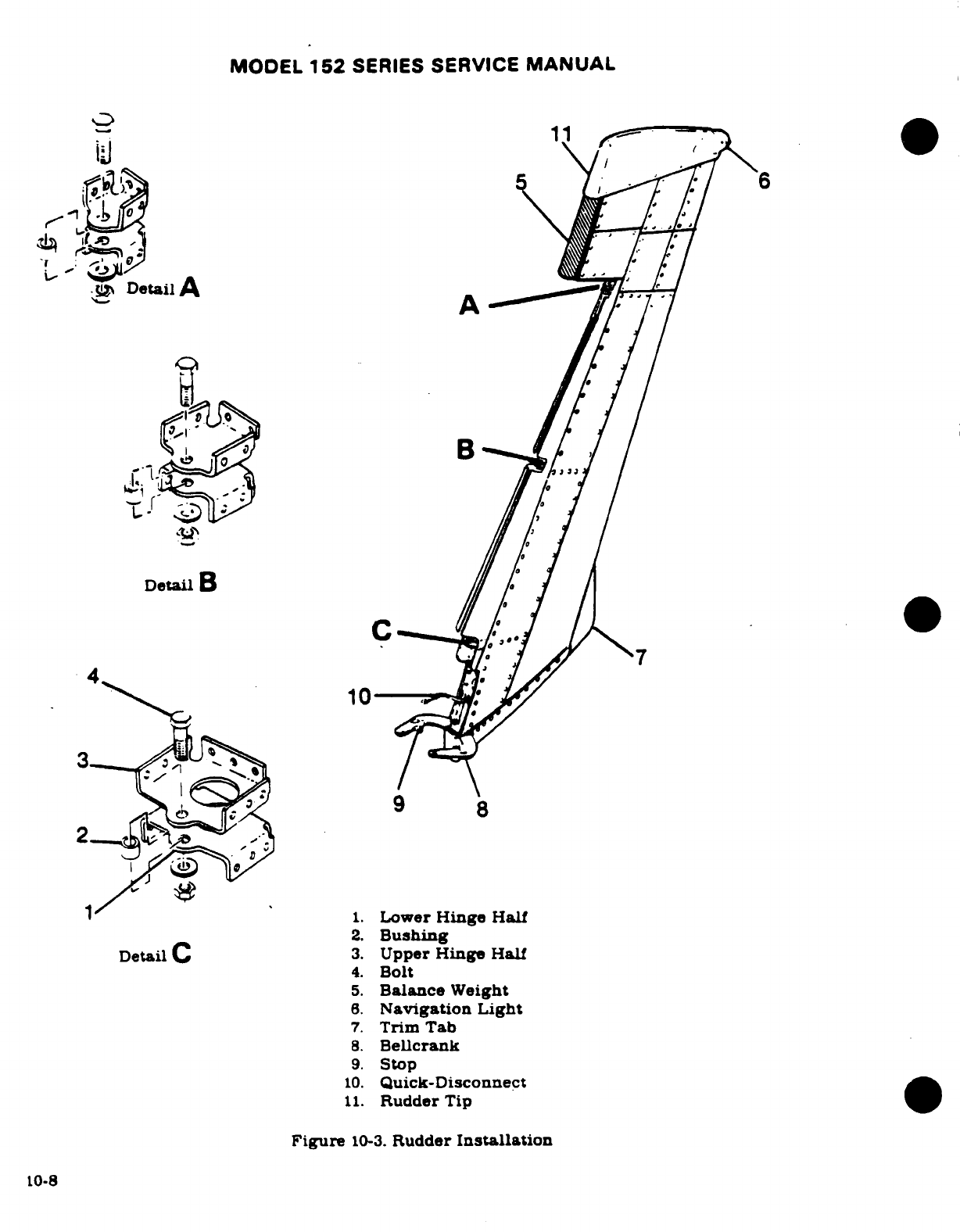
MODEL
152
SERIES
SERVICE
MANUAL
Detail
A
Detail
B
10
2.
Bushing
4.
Bolt
5.
Balance
Weight
6.
Navigation
Light
7.
Trim
Tab
8.
Bellcrank
9.
Stop
10.
Quick-Disconnect
11.
Rudder
Tip
Figure
10-3.
Rudder
Installation
10-8
MODEL
152
SERIES
SERVICE
MANUAL
NOTE
DO
NOT
adjust
rudder
trim
with
steering
tubes.
Degree
of
steering
travel
cannot
be
adjusted.
j.
Safety
cable
clevises
and
install
all
parts
removed
for
access.
NOTE
Flight
test
airplane
to
determine
if
ground
adjustment
of
fixed
trim
tab
is
necessary.
DO
NOT
rig
rudder
off-cen-
ter"
unless
trim
tab
does
not
provide
adequate
correction.
WARNING
Be
sure rudder
moves
in
correct direction
when
operated
by
pedals.
10-9
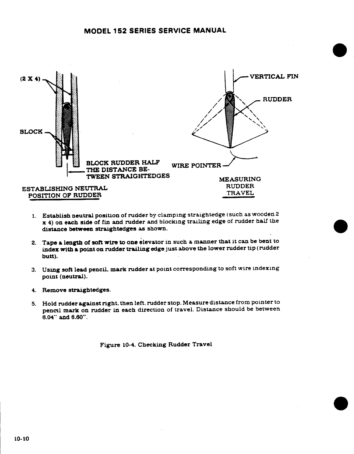
MODEL
152
SERIES SERVICE
MANUAL
(2
X
4)
VERTICAL
FIN
RUDDER
BLOCK
BLOCK
RUDDER
HALF
POINTER
THE
DISTANCE
BE-
WIRE
POINTER
TWEEN
STRAIGHTEDGES
MEASURING
ESTABLISHING
NEUTRAL
RUDDER
POSITION
OF
RUDDER
TRAVEL
1.
Establish
neutral
position
of
rudder
by
clamping
straightedge
(such
as wooden
2
x
4)
on
each
side
of
fin
and
rudder
and
blocking
trailing
edge
of
rudder half
the
distance
between
straightedges
as
shown.
2.
Tape
a
length
of
soft
wire
to
one
elevator
in
such
a
manner
that
it
can
be
bent
to
index
with
a
point
on
rudder
trailing
edge
just
above the
lower
rudder
tip (rudder
butt).
3.
Using
soft
lead
pencil.
mark
rudder
at
point
corresponding
to
soft
wire
indexing
point
(neutral).
4.
Remove
straightedges.
5.
Hold
rudder
against
right.
then
left.
rudder
stop.
Measure
distance
from
pointer
to
pencil
mark
on
rudder
in
each direction
of
travel.
Distance should
be
between
6.04"
and
6.60".
Figure
10-4.
Checking
Rudder
Travel
10-10
MODEL
152
SERIES
SERVICE
MANUAL
SECTION
11
ENGINE
WARNING
When
performing
any
inspection
or maintenance
that
re-
quires
turning
on
the
master
switch,
installing
a
battery,
or
pulling
the
propeller
through
by
hand,
treat
the prop-
eller
as
if
the
ignition
switch
were
ON.
Do
not
stand
nor
allow
any
one
else
to
stand,
within
the
are
of
the
propel-
lar,
since
a
loose or
broken
wire,
or
a
component
mal-
function,
ould
cause
the
propeller
to
rotate.
Page
No.
TABLE
OF
CONTENTS
Aerofiche/
Manual
OIL
SYSTEM
................
1K15/11-16A
ENGINE
COWLING
...........
1J20/11-2
Description
...............
1K15/11-16A
Description
.................
1J20/11-2
Trouble
Shooting
...........
IK17/11-17
Removal/Installation
........
1J20/11-2
Full-Flow
Oil
Filter
.........
1K19/11-19
Cleaning/Inspection
.........
1J20/11-2
Description
...............
1K19/11-19
Repair
.....................
1J20/11-2
Removal/Installation
......
1K20/11-20
ENGINE
......................
1J21/11-3
Filter
Adapter
..............
1K20/11-20
Description
.................
1J21/11-3
Removal
..................
1K20/11-20
Engine
Data
................
1J22/11-4
Disassembly, Inspection,
Time Between
Overhaul
(TBO)
1J23/11-5
and
Reassembly
.........
1K20/11-20
Overspeed
Limitations
.......
1J23/11-5
Installation
...............
1K20/11-20
Trouble
Shooting
.............
1J23/11-5
Oil
Cooler
..................
1K20/11-20
Locating
Oil
Leaks
..........
1K4/11-8
Description
...............
1K20/11-20
Removal
...................
1K4/11-8
ENGINE FUEL
SYSTEM
......
1K20/11-20
Cleaning
...................
1K6/11-10
Description
................
1K22/11-22
Accessories Removal
........
1K6/11-10
Carburetor
.................
1K22/11-22
Inspection
..................
1K7/11-10A
Removal/Installation
......
1K22/11-22
Overhaul
...................
1K7/11-10A
Idle
Speed
and Mixture
Buildup
....................
K9/11-11
Adjustments
.............
1K22/11-22
Installation
.................
1K9/11-11
INDUCTION
AIR
SYSTEM
....
1K23/11-23
Flexible
Fluid
Hoses
.........
1K11/11-13
Description
................
1K23/11-23
Leak
Test
.................
K/11-13
Removal/Installation
......
1K241
1-24
Replacement
..............
K1111-13
IGNITION
SYSTEM
..........
1K24/11-24
Static
Run
Up
Procedures
....
1K11/11-13
Description
................
1K24/11-24
Engine
Baffles
..............
1K12/11-14
Trouble Shooting
...........
1L1/11-24A
Description
................
1K12/11-14
Magneto
Removal
(4052)
....
1L2/11-24B
Cleaning/Inspection
........
1K14/11-16
Internal
Timing
............
1L2/11-24B
Removal/Installation
.......
1K14/11-16
ReplacementInterval
.......
1L2/11-24B
Repair
...........
.....
1K14/11-16
Magneto
Installation
and
EngineMount
..............
1K14/11-16
Timing
to
Engine
..........
1L2/11-24B
Description
................
1K14/11-16
Magneto
Check
.............
1L5/11-27
Removal/Installation
.......
1K14/11-16
Maintenance
...............
1L5/11-27
Repair
....................
1K14/11-16
Magnetos
(4281)
............
1L6/11-28
Painting
..................
1K14/11-16
Description
...............
1L6/11-28
Engine Shock-MountPads
...
1K14/11-16
Maintenance
..............
1L6/11-28
*
Reducing
Valve
Sticking
....
lK15/11-16A
Timingto
Engine
..........
1L6/11-28
Revision
1
11-1
MODEL
152
SERIES
SERVICE
MANUAL
Removal
...................
1L7/11-29
Carburetor Heat
Control
...
1L13/11-33
Disassembly
...............
1L7/11-29
STARTING SYSTEM
.........
1L14/11-34
Checking
Contact
Description ................
1L14/11-34
Assemblies
...............
1L7/11-29
Trouble
Shooting
...........
1L14/11-34
Points
.....................
1L7/11-29
Removal/Installation
.......
1L15/11-35
Carbon
Brush
..............
1L7/11-29
Primary
Maintenance
.......
1L15/11-35
High
Tension
Lead
..........
1L7/11-29
EXAUST
SYSTEM
..........
lL16/11-36
Impulse Coupling
Description ................
1L16/11-36
Shell
&
Hub
..............
1L7/11-29
Removal
...................
1L16/11-36
Cleaning/Inspection
........
1L7/11-29
Inspection
.................
1L16/11-36
Reassembly ................
1L8/11-30
Installation
.
...............
L16/11-36
Spark Plugs
................
1L8/11-30
EXTREME
WEATHER
ENGINE
CONTROLS
.........
1L9/11-30A
MAINTENANCE
...........
1L20/11-40
Description
................
1L9/11-30A Cold
Weather
.
.............
1L20/11-40
Rigging
....................
IL11/11-31
Dusty
Conditions
..........
1L21/11-41
Throttle
Control
...........
1L12/11-32
Seacoastand
Humid
Areas
..
1L21/11-41
Mixture
Control
...........
1L13/11-33
11-1.
ENGINE
COWLING.
11-2.
DESCRIPTION.
The
engine
cowling
is
comprised
of
upper
and
lower
cowl
segments
and
a
nose
cap.
A
large
access
door
on
the
right
side
of
the
upper
cowl
provides
access
to
fuel
strainer
drain
oil
filler
cap
and
dipstick.
A
small
access
door
on
the left
side
of
the
upper
cowl
permits
access
to
the
ground
service
receptacle.
Quick
release
fasteners
are
used
to
detach
the
upper
cowl
from
the
lower
cowl.
Screws
and
quick
release
fasteners
secure
the
lower
cowl
to
the
aircraft
structure.
11-3.
REMOVAL
AND
INSTALLATION.
Removal
and
installation
of
the
engine
cowl
is
accomp-
lished
by
releasing the
quick
release
fasteners
securing
the
upper
cowl
to
the
lower
cowl
and
firewalL
The
lower
cowl
removal
is
accomplished
by
releasing
the
quick
release
fasteners
at
the
air
box
inlet
and
byremoving
screws
at the
firewall
and
nose
cap.
Remove
landinglight
wires
from
brackets
on
the
left
side
of
the
cowl.
To
remove
the
nose
cap,
upper
and
lower
cowl
should
be
removed
and
wires
to
the
landing light
disconnected
Refer
to
Section
13
for
removal
of
the
propeller.
When
installing
the
cowling,
be
sure
to
connect
any
items
disconnected
during
removal
Make
sure
that
baffle
seals
are
turned
in
the
correct direction
to
confine
and direct
airflow
around
the
engine.
The
vertical installed
seals
fold
forward
and
the
side
seals
fold
upward.
11-4.
CLEANING
AND
INSPECTION.
Wipe
the
inner
surfaces
of
the cowling
segments
with
a
cloth
saturated
with
cleaning
solvent
(Federal Specification
PS-661
or
equivalent).
If
the
inside
surface
of
the
cowling
is
coated
heavily
with
oil
or
dirt,
allow
solvent
to
soak
until
foreign
material
can
be
removed.
Wash
painted
surfaces
of
the
cowling
with
a
solution
of
mild
soap
and
water
and
rinse
thoroughly.
After
washing,
a
coat
of
wax
applied
to
the
painted
surfaces.
is
recommended
to
prolong
paint
life.
After
cleaning,
inspect
cowling
for
dents.
cracks,
loose
rivets
or
spot
welds.
Repair
all
defects
to prevent
spread
of
damage.
11-5.
REPAIR.
If
cowling skins
are
extensively
damaged.
new
complete
section
of
the
cowling
should
be
installed.
Standard insert-type
patches may
be
used
for
repair
if
repair
parts
are
formed
to
fit
contour
of
cowling.
Small
cracks
may
be
stop-drilled
and
small
dents
straightened
if
they
are
reinforced
on
the
inner
surface
with
a doubler
of
the same
material
Damaged
reinforcement angles
should
be
replaced
with
new
parts.
Due
to
their
small
size.
new
reinforcement
angles
are
easier
to
install
than
to
repair
the damaged
part.
11-2
Revision
1
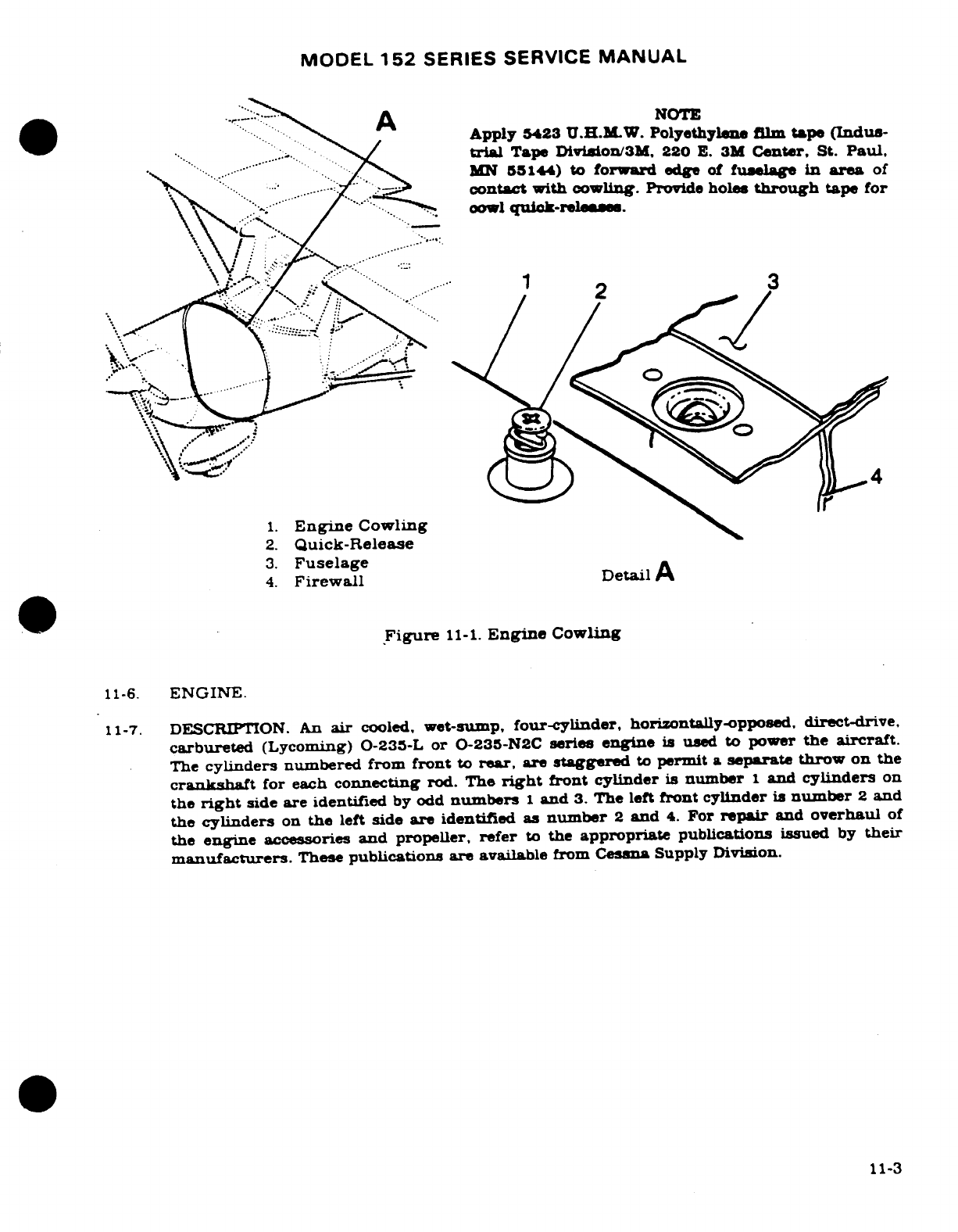
MODEL
152
SERIES SERVICE
MANUAL
A
NOTE
Apply
5423
U H M W
Polyethylene
film
tape
(Indus-
trial
Tape
Diviion/3M.
220
E.
3M
Center,
St.
Paul.
..... MN
55144)
to
forward
edge
of
fuselage
in
area
of
contact
with
cowling.
Provide
holes
through
tape
for
cowl
quick-releases
2
3
1.
Engine
Cowling
2.
Quick-Release
3.
Fuselage
4.
Firewall
Detail
A
Figure
11-1.
Engine
Cowling
11-6.
ENGINE.
11-7.
DESCRIPTION.
An
air
cooled,
wet-sump,
four-cylinder,
horizontally-opposed,
direct-drive,
carbureted
(Lycoming)
0-235-L
or 0-235-N2C
series
engine
is
used
to
power
the
aircraft.
The
cylinders
numbered
from
front
to
rear,
are
staggered
to
permit
a
separate
throw
on
the
crankshaft
for
each
connecting rod.
The
right
front
cylinder
is
number
1
and
cylinders
on
the
right
side
are
identified
by
odd
numbers
1
and
3.
The
left
front
cylinder
is
number
2
and
the
cylinders
on
the
left
side
are
identified
as
number
2
and
4.
For
repair
and
overhaul
of
the
engine
accessories
and
propeller,
refer
to
the
appropriate
publications
issued
by
their
manufacturers.
These
publications
are
available
from
Cessna
Supply
Division.
11-3
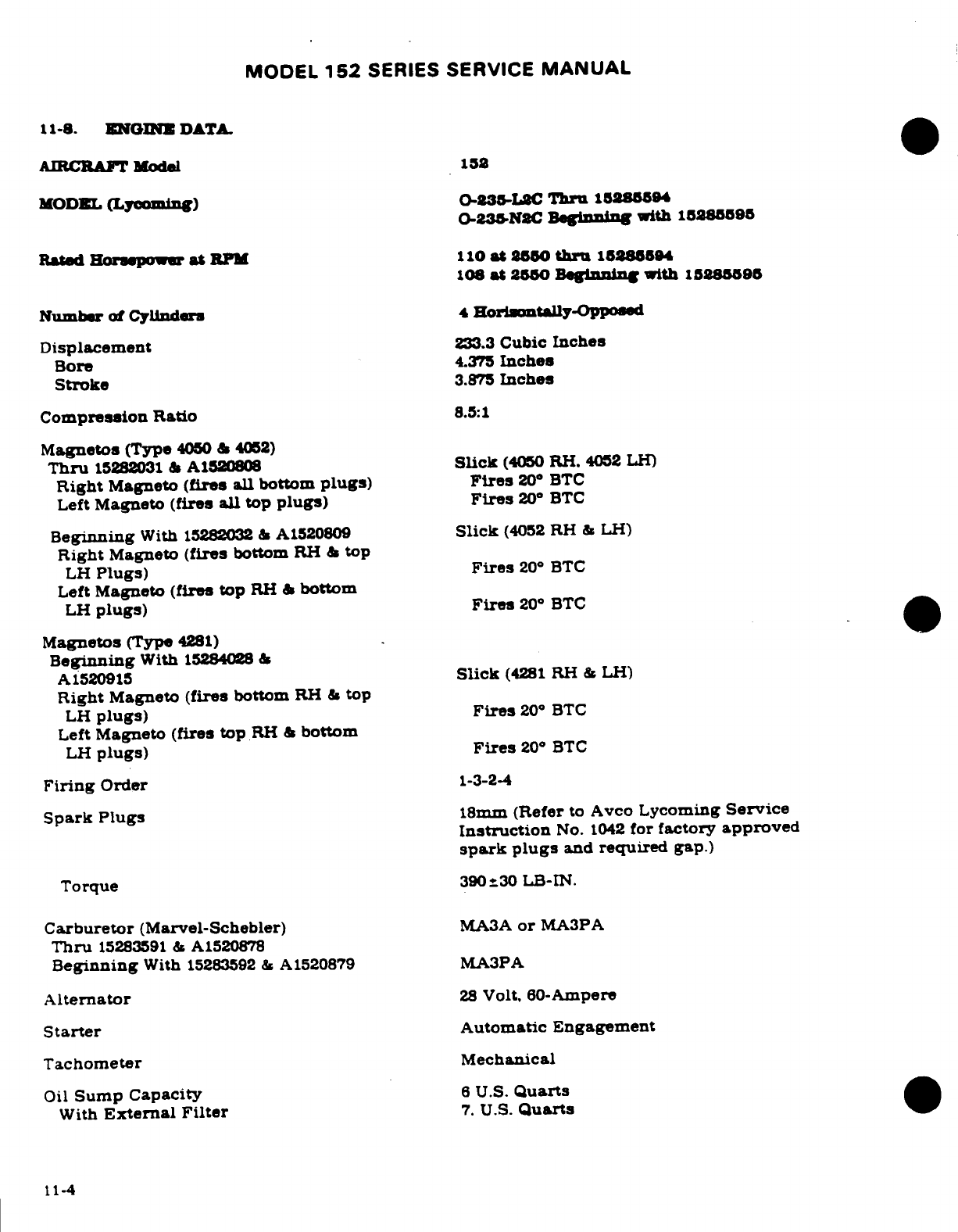
MODEL
152
SERIES
SERVICE
MANUAL
11-8.
ENGINE
DATA.
AIRCRAFf
Model
152
MODEL
(Lycoming)
0-2385L2C
Thru
15285094
0-235-N8C
Beginning
with 15285590
Rated
Horsepower
at
RPM
110
at
2550
thr
15285894
108
at
2550
Begnning
with
15280595
Number
of Cylinders
4
Horintally-Opposed
Displacement
233.3
Cubic
Inches
Bore
4.375
Inches
Stroke
3.875
Inches
Compression
Ratio
8.5:1
Magnetos
(Type
4050
&
4052)
Thru
15282031
&
A1520808
Slick
(4050
RH.
4052 LH)
Right
Magneto
(fires all
bottom
plugs)
Fires
20
°
BTC
Left
Magneto
(fires
all
top
plugs)
Fires
20°
BTC
Beginning
With
15282032
&
A1520809
Slick
(4052
RH
&
LH)
Right
Magneto
(fires
bottom
RH
&
top
LH
Plugs)
Fires
20
°
BTC
Left
Magneto
(fires
top
RH
&
bottom
LH
plugs)
Fires
20
°
BTC
Magnetos
(Type
4281)
Beginning
With
15284028
&
A1520915
Slick
(4281
RH
&
LH)
Right
Magneto
(fires
bottom
RH
&
top
LH
plugs)
Fires
20
°
BTC
Left
Magneto
(fires
top
RH
&
bottom
LH
plugs)
Fires
20
°
BTC
Firing
Order
1-3-2-4
Spark Plugs
18mm
(Refer
to
Avco
Lycoming
Service
Instruction
No.
1042
for
factory
approved
spark
plugs
and
required
gap.)
Torque
390
±30
LB-IN.
Carburetor
(Marvel-Schebler)
MA3A
or
MA3PA
Thru
15283591
&
A1520878
Beginning
With
15283592
&
A1520879
MA3PA
Alternator
28
Volt.
60-Ampere
Starter
Automatic
Engagement
Tachometer
Mechanical
Oil
Sump
Capacity
6
U.S.
Quarts
With
External
Filter
7.
U.S.
Quarts
11-4
MODEL
152
SERIES
SERVICE
MANUAL
11-8.
ENGINE
DATA
(Cont).
Oil
Pressure
(PSI)
Normal
60-90
Minimum
Idling
25
Maximum
(Cold Oil
Starting)
115
Oil
Temperature
Normal
Operating
Within
Green
Arc
Maximum
Red
Line
(245°F)
Cylinder
Head
Temperature
500°F
Maximum
(Not
Indicated)
Dry
Weight
-
With
Accessories
257
LB
(Weight
is
approximate
and
will
vary
with
optional accessories
installed.)
11-9.
TIME
BETWEEN
OVERHAUL
(TBO).
Avco
Lycoming recommends
engine overhaul
at
2000
hours
operating
time
for
the
0-235
Series engine
(2400
operating
hours
for
engines with
seri-
al
numbers
L-2423
1-
5
and
up;
remanufactured
engines
shipped
after March
20,
1986
[except
serial
numbers
RL-20600-15, RL-24190-15.
RL-24191-15,
and
RL-24203-15];
factory
over-
hauled
engines shipped
after
April
1,
1986;
and
engines
otherwise
modified
with
TBO-
Extension Kits.
Part
Number
05K19613
[Chrome
Cylinders]
or
Part
Number
05K19614
[Nitrided
Cylinders],
each
containing
increased
strength
piston,
Part
Number
LW-18729).
Refer
to
Avco
Lycoming
Service
Instruction
No.
1009X
and
to
any superseding
bulletins,
revi-
sions,
or
supplements
thereto
for
further
recommendations.
At
the
time
of
overhaul.
engine
accessories
should
be
overhauled.
11-10.
OVERSPEED
LIMITATIONS.
The
engine
must
not
be
operated
above
specified
maximum
continuous
RPM.
However.
should
inadvertent
overspeed
occur.
refer
to
Avco
Lycoming
0·t
Service
Bulletin
369D.
and
to
any
superseding
bulletins or
supplements
thereto.
for
further
recommendations.
11-11.
TROUBLE
SHOOTING.
TROUBLE
PROBABLE
CAUSE REMEDY
ENGINE
WILL
NOT
START.
Improper
use
of
starting
Refer
to
Pilot's
Operating
procedure.
Handbook.
Fuel
tanks
empty.
Visually
inspect
tanks.
Fill
with
proper
grade
and
quantity
of
gasoline.
Mixture
control
in
the
Move
control
to
the
full
IDLE
CUT-OFF
position.
RICH
position.
Fuel
shutoff
valve
in
Turn shutoff
valve
ON
OFF
position.
and
safety.
Defective
carburetor.
Repair
or
replace carburetor.
Carburetor
screen
or
fuel
Remove
carburetor
and
clean
strainer
plugged.
thoroughly.
Refer
to
para-
graph
11-47.
Revision
1
11-5
MODEL
152
SERIES
SERVICE
MANUAL
11-11.
TROUBLE
SHOOTING
(Cont).
TROUBLE
PROBABLE
CAUSE REMEDY
ENGINE
WILL
NOT
START
(Cont).
Engine
flooded.
Refer
to
Pilot's
Operating
Handbook.
Water
in
fuel
system.
Open
fuel
strainer
drain
and
check
for
water.
If
water
is
present,
drain
fuel
tank
sumps.
lines,
strainer,
carburetor
and
fuel
line
drain
tee.
Defective
magneto
switch
Check
continuity.
Repair
or
grounded
magneto leads.
or
replace
switch
or
leads.
Spark
plugs
fouled.
Remove,
clean
and
regap
plugs.
Test
harness
cables
to
persistently
fouled
plugs.
Replace
if defective.
ENGINE
STARTS
BUT
Idle
stop
screw
or
idle
mix-
Refer
to
paragraph
11-49.
DIES.
OR
WILL
NOT
IDLE.
ture
incorrectly
adjusted.
Carburetor
idling jet
Clean
carburetor
and
fuel
plugged. strainer.
Spark
plugs
fouled
or
im-
Remove,
clean
and
regap
properly
gapped.
plugs.
Replace if
defective.
Water
in
fuel
system.
Open
fuel
strainer
drain
and
check for
water.
If
water
is
present, drain
fuel
tank
sumps.
lines,
strainer,
carburetor
and
fuel
line
drain
tee.
Defective
ignition
system.
Refer
to
paragraph
11-53.
Induction
air
leaks.
Check
visually.
Correct
the
cause
of
leaks.
Manual
primer
leaking.
Disconnect
primer
outlet
line.
If
fuel
leaks
through
primer,
repair
or
replace
primer.
11-6
MODEL 152
SERIES
SERVICE
MANUAL
11-11.
TROUBLE
SHOOTING
(Cont).
TROUBLE
PROBABLE CAUSE
REMEDY
ENGINE
STARTS
BUT
Leaking
float
valve
or
float
Perform
an
idle
mixture
check.
DIES,
OR
WILL NOT
IDLE.
level
set
too
high.
Attempt
to
remove
any
rich
(Cont).
indication
with
the
idle
mixture
adjustment.
If
the
rich
indication
cannot
be
removed,
the
float
valve
is
leaking
or
the
float
level is
set
too
high.
Replace
defective
parts;
reset
float
level.
Defective
carburetor.
If
engine
will
start
when
primed
but
stops
when
priming
is
discontinued,
with
mixture
control in
full
RICI
position,
the
carburetor
is
defective.
Repair
or
replace
carburetor.
Defective
engine.
Check
compression.
Listen
for
unusual
engine
noises.
Engine
repair
is
required.
UNEXPLAINED Restricted
or clogged
air
Check
induction
air
system
for
REDUCTION
OF
STATIC
induction
system.
restrictions. Clean
or
replace
RPM
OR
UNEVEN
dirty;clugged
air
fi
ter.
ENGINE
OPERATION.
Leaky
alternate
air
Check
alternate air
induction
induction
(carburetor
heat).
system
for
leaks and
correct
as
Improperly
positioned
required.
Adjust
butterfly
as
carburetor
butterfly.
required.
Lack
of
full
throttle
and/or
Adjust
throttle
and
mixture
mixture
control
travel
at
controls as
required
for
full
carburetor.
control
Excessive
magneto
drop-off.
Check
magneto
at
2000
RPM.
Drop-off
should
not
exceed
175
RPM
(50
RPM
between
left
and
right
magnetos).
Retime
as
required.
Check,
clean
or
replace,
regap,
and
reinstall
spark
plugs
as
necessary.
Erroneous
magneto-to-
Check
magneto-to-engine
engine
timing.
timing;
retime
as
necessary.
Fouled
or
incorrectly gapped
Remove,
clean,
check.
regap,
spark
plugs.
and
reinstall
spark
plugs.
Revision
1
11-6A
MODEL
152
SERIES
SERVICE
MANUAL
11-11.
TROUBLE
SHOOTING
(Cont).
TROUBLE
PROBABLE
CAUSE
REMEDY
UNEXPLAINED
Over-rich
or
over-lean
Check
for
over-rich
carburetor.
REDUCTION
OF
STATIC
carburetor.
At maximum
static
RPM
(full
RPM
OR
UNEVEN
throttle),
slowly
pull mixture
ENGINE
OPERATION.
control toward
idle
cut-off
and
(Cont).
watch
for
RPM
increase.
A
rise
of
0
to
75
RPM is
normal.
A
rise
over
1000
RPM
will
result
in
power
loss
through
over-
richness.
If
no
rise
in
RPM
or
a
rapid
fall-off
of
RPM
is
noted,
apply
full
carburetor
heat
(to
enrich
mixture).
If
carburetor
heat
brings
an
RPM
rise,
the
carburetor
is
OVER-LEAN.
In
either
case,
correct
mixture
control as
required.
Excessive
wear
or
looseness
Check
valve
tappet
clearances.
of
ball
end
of
valve
tappets.
Clearances
should
be
0.007
to
0.009
inch
with
cold
engine
and
0.006
to
0.012
inch
with
hot
engine.
Compare
clearances
with
last
100
hour
inspection.
If
clearances
have
increased
0.015
inches
or
more
than
the
figures
at
100
hour
inspection, remove
push
rod
and
check
for
excessive
S
wear
or
looseness
of
ball
end
of
tappets.
Push
rods
should
be
11-
9/16
inches. Replace
push
rods
as
required.
NOTE
Engines
with
no
previous
recorded
100
hour
inspection
of
valve
tappet
clearance
will
use
0.019
inch
for
cold
engine
or
0.022
inch
for
hot
engine
to
determine
whether
to
inspect
the
push
rod.
Faulty
cylinder
compression. Check
cylinder
compression
and
correct
as
required.
Miscalibrated
tachometer.
Check
tachometer
and
re-
calibrate
as
required.
Propeller
is
too
long, out-of-
Check propeller
and,
if
possible,
balance,
or
has
incorrect correct
pitch
or
balance
as
pitch.
required.
Replace
propeller
if
necessary.
11-6B
Revision
1
MODEL
152
SERIES SERVICE
MANUAL
11-11.
TROUBLE
SHOOTING
(Cont).
TROUBLE
PROBABLE
CAUSE
REMEDY
ENGINE
RUNS ROUGHLY
Restriction
in
aircraft
fuel Refer to
Section
12.
OR
WILL
NOT
ACCEL-
system.
ERATE PROPERLY.
Worn
or
improperly
rigged
Check
visually.
Replace
throttle
or
mixture
control.
worn
linkage.
Rig
properly.
Spark
plugs
fouled
or
im-
Remove.
clean
and
regap
properly
gapped.
plugs.
Replace
if
defective.
Defective
ignition
system.
Refer
to
paragraph
11-53.
Defective
or
badly
adjusted
Check
setting
of
accelerator
accelerator
pump
in
carbu-
pump
linkage
and
adjust
as
retor.
necessary.
Float
level
set
too
low.
Check
and
reset
float
level.
Defective
carburetor. Repair
or
replace
carburetor.
Defective
engine.
Check
compression. Listen
for
unusual
engine
noises.
Engine
repair
is
required.
Restricted
carburetor
air
Check
visually.
Clean
in
filter.
accordance
with
Section
2.
Cracked
engine
mount. Inspect
and
repair
or
re-
place mount
as
required.
Defective
mounting
bushings.
Inspect
and
install
new
bushings
as
required.
POOR IDLE CUT-OFF.
Worn
or
improperly
rigged
Check
that
idle
cut-off
stop
mixture
control.
on
carburetor
is
contacted.
Replace
worn
linkage.
Rig
properly.
Manual
primer
leaking.
Disconnect
primer
outlet
line.
If
fuel
leaks
through
primer.
it is
defective.
Repair
or
replace
primer.
Defective
carburetor.
Repair
or
replace
carburetor.
Fuel
contamination.
Check
all
screens
in
fuel
system.
Drain
all
fuel and
flush
out
system.
Clean
all
screens.
lines.
strainer
and
carburetor.
Revision
1
11-7
MODEL
152
SERIES
SERVICE
MANUAL
11-11A.
LOCATING
OIL
LEAKS.
Oil
leaks,
especially
those
in
the
engine
compartment,
can be
elusive due
to
airflow
patterns.
One
method
to
consider
in
pin-pointing
these
leaks
is
to
a.
Clean
suspected
leak
areas
thoroughly
with
solvent
and
dry.
b.
Spray
the
suspected
area
with
dye
penetrant
developer.
c.
Reinstall
the
engine
cowling
and
other
removed
equipment
to
normal configuration
to
ensure
air
flow
for
cooling
and
leak
detection.
d.
Accomplish
a
short run-up,
preferably
to
static
RPM,
in
accordance
with
Pilot's
Op-
erating
Handbook.
e.
Dye
penetrant
developer
will
enhance
the
presence of
oil
leaks.
Most
leaks
are
very
apparent
against
the
white
background.
f.
After locating
the
leak
and
effecting
repairs,
thoroughly
clean
the area
sprayed
with
the
developer.
It
is
highly
corrosive.
11-12.
REMOVAL.
If
the
engine
isto
be
placed
in
storage
or
returned
to
the
manufacturer
for
overhaul,
proper
preparatory
steps
should
be
taken
prior
to
beginning
the
removal
procedure.
Refer
to
Indefinite
Storage
in
Section
2
for
preparation
of
the
engine
for
storage.
The
following engine
removal
procedure
is
based
upon
the engine
being removed
from
the
aircraft
with
the
engine mount attached
to
the
firewall
and
all
engine hose
and
lines
being
disconnected
at
the
firewall.
The
reason
for
engine
removal
will
determine
where
compo-
nents
are
to
be
disconnected.
NOTE
Tag
each
item
when disconnected
to
aid
in
identifying
wires,
hose.
lines
and
control
linkages
when
engine
is
installed.
Protect
openings,
exposed
as
a
result
of
remov-
ing
or
disconnecting
units, against
entry
of
foreign
material
by
installing
covers or
sealing
with
tape.
a.
Place
all
cabin
switches
rand
the
fuel
shutoff
valve
in
the
OFF
position.
b.
Remove
engine cowling.
(Refer
to
paragraph
11-3.)
c.
Open
battery
circuit
by
disconnecting
battery
cable(s)
at the
battery.
Insulate
cable
terminal(s)
as
a
safety
precaution.
d.
Disconnect
ignition
switch
primary
('P")
leads
at
the
magnetos.
11
-8
Revision
1
MODEL
152
SERIES
SERVICE
MANUAL
WARNING
The
magneto
is in a
SWITCH
ON
condition
when
the
switch
wire
is
disconnected.
Ground
the
magneto
points
or
remove
the
high tension
outlet plate
from
the magneto
or
disconnect
spark
plug
lead
wires
at
spark
plugs
to
prevent
accidental
firing
when
the
propeller
is
rotated.
e.
Drain
engine
oil
from
sump.
f.
Remove
propeller
and
spinner.
(Refer
to
Section
13.)
NOTE
During
the
following
procedures,
remove
any
clamps
which
secure
controls,
wires,
hose
or
lines
to
the
engine.
engine
mount,
or attached
brackets,
so they
will
not
interfere
with
removal
of
the
engine.
Omit
any
of
the
items
which are
not
present
on
a
particular
engine
installation.
g.
Disconnect
throttle
and
mixture
control
at
carburetor.
Pull
these
controls
free
of
engine
and
engine
mount,
using
care
not
to
damage
them
by
bending
too
sharply.
Note
position,
size
and
number
attaching
washers
and
spacers.
h.
Disconnect
carburetor
heat
control
from
arm
on
carburetor
air
intake
housing
assembly.
Remove
clamps
and
pull
control
aft
clear
of
the engine.
i.
Disconnect
wires
and
cables
as
follows:
CAUTION
When
disconnecting
starter
cable,
do
not
permit starter
terminal
bolt
to
rotate.
Rotation
of
the
bolt
could
break
the
conductor
between
terminal
and
field
coils
causing
the
starter
to
be
inoperative.
1.
Starter
electrical
cable
at
starter.
2.
Electrical
wires
and
wire
shielding
ground
at
alternator.
3.
Tachometer
drive
shaft
at adapter
on
engine.
4.
Remove
all
clamps
attaching
wires
and
cables
to
the engine
or
engine
mount.
Pull
all
wires
and
cables
aft
to
clear
the
engine.
j.
Disconnect
and
cap
or
plug lines
and
hose
as
follows:
1.
Vacuum
hose
at firewall.
WARNING
Residual
fuel
and
oil
draining
from
disconnected
lines
and
hose
is a
fire
hazard.
Use
care
to
prevent
accumula-
tion
of
such
fuel
and oil
when
lines or
hose
are
discon-
nected.
2.
Oil
pressure
hose
at
firewall.
3.
Oil
temperature
bulb
at
engine.
4.
Primer
line
to
engine at firewall.
5.
Fuel
hose
to
engine
at
fuel
strainer
on
firewall.
6.
Remove
all
clamps
attaching
lines
and
hose
to
engine
or
engine
mount which
interferes
with
engine
removal
from
engine
mount.
11-9
MODEL
152
SERIES
SERVICE
MANUAL
CAUTION
Attach
a
tail
stand
to
the
tail
tie-down
fitting
before
removing
the
engine.
The
loss
of
engine
weight
will
allow
the
tail
to
drop.
Do
not
raise
engine
higher than necessary
when
removing
engine-to-mount bolts.
Raising
the
engine
too
high
places
a
strain
on
the
attach bolts
and
hinders
their
removal.
k. Attach
a
hoist
to
the
lifting
lug
on top
of
the
engine and
take up
engine
weight
on
hoist.
1.
Remove
bolts
attaching
engine-to-mount.
Note
direction
of
bolt
installation
and
position
and
numbers
of
washers.
Balance
the
engine
by
hand
as
the
last
of
the
bolts
are
removed.
Remove
ground
straps
at
lower
mount legs
as
bolts
are
removed.
CAUTION
Hoist
engine
slowly
and
ascertain
that
all
items
attach-
ing
engine and
accessories
to
engine
mount
and
airframe
are
disconnected.
m.
Carefully
guide disconnected
components
out
of
engine
assembly.
11-13.
CLEANING.
Refer to
Setion
2
for
cleaning
procedure.
11-14.
ACCESSORIES
REMOVAL.
Removal
of
engine accessories
for
overhaul
or
for
engine
replacement
involves
stripping
the
engine
of
parts,
accessories,
and
components
to
reduce
the engine
asembly
to
the
bare
engine.
During
removal. carefully
examine removed
items
and
tag defective
parts
for
repair
or
replacement with
a
new
part.
NOTE
Items
easily
confused
with
similar
items should
be
tagged
to
provide
a
means
of
identification
when
being
installed
on
a
new engine.
All
openings
exposed
by
the
removal
of
an
item
should
be
closed
by
installing
a
suitable
cover
or
cap
over
the
opening.
This will
prevent
entry
of
foreign
particles.
If
suitable
covers are
not
available,
tape
may
be
used
to
cover
the
opening.
11-10
MODEL
152
SERIES
SERVICE
MANUAL
11-15.
INSPECTION.
For
specific
items
to
be
inspected,
refer
to
engine
Manufacturer's
Overhaul
and
Repair Manual.
a.
Visually
inspect
the
engine
for
loose
nuts,
bolts,
cracks, and
fin
damage.
b.
Inspect
baffles,
baffle
seals, and
brackets
for
cracks,
deterioration,
and
breakage.
c.
Inspect
all
hoses
for
internal
swelling,
chafing
through
protective plies,
cuts,
breaks,
stiffness,
damaged
threads,
and
loose
connections.
Excessive
heat
on
hoses
will
cause
them
to
become
brittle
and
easily
broken.
Hoses
and
lines
are
most
likely
to
crack
or
break near
the
end
of
fittings
and
support
points.
d.
Inspect
for color
bleaching
of
the
end
fittings
or
severe discoloration
of
the
hoses.
NOTE
Avoid
excessive
flexing
and
sharp
bends
when
examin-
ing
hoses
for
stiffness.
e.
Refer to
Section
2
for
replacement
intervals
for
flexible fluid
carrying
hoses
in
the
engine
compartment.
f.
Textron
Lycoming
Mandatory
Service
Bulletin
No.
388B,
Procedures
to
Determine
Exhaust
Valve
And
Guide
Condition,
dated
May
13,
1992,
requires
that
all
engine
exhaust
valves
and
guides
be
inspected
every
400
hours
of
operation
or
earlier
if
valve
sticking
is
suspected.
Failure
to comply
could
result
in
excessive
carbon
build-
up,
broken
exhaust
valves,
excessive guide
wear,
or
engine
failure.
Refer
to Textron
Lycoming
Mandatory
Service
Bulletin
No. 388B.
g.
For
major
engine
repairs,
refer
to
the
manufacturer's
overhaul
and
repair
manual.
11-15A.
OVERHAUL.
During
engine
overhaul,
it
is
mandatory
that
certain
parts
be
replaced,
re-
gardless
of
their
apparent
condition.
Refer
to
Textron
Lycoming
Mandatory
Service Bul-
letin
No.
240M
(or
later
revision)
(Cessna
Single
Engine
Service
Bulletin
SEB92-11).
Revision
1
11-l0A/11-10B
blank
MODEL
152
SERIES
SERVICE
MANUAL
11-16.
BUILDUP.
Engine
buildup
consists
of
installation
of
parts,
accessories,
and
components
to
the
basic
engine
to
build
up
an
engine
unit
ready
for
installation
in
the
aircraft.
All
safety
wire, lock-washers,
nuts,
gaskets,
and
rubber
connections
should
be
new
parts.
11-17.
INSTALLATION.
Before
installing
the
engine
on
the
aircraft,
install
any
items
which
were
removed
from
the engine or
aircraft
after
the engine was
removed.
NOTE
Remove
all
protective
covers.
plugs.
caps
and
identifica-
tion
tags
as
each
item
is
connected
or
installed.
a.
Hoist
the
engine
to
a
point
near
the
engine
mount.
b.
Install
engine shock-mount pads
as
illustrated
in
figure
11-2.
c.
Carefully
lower engine
slowly
into
place
on
the
engine
mount.
Route
controls. lines.
hoses
and
wires
in
place
as
the
engine
is
positioned
on
the
engine
mount.
d.
Install
engine
mount
bolts
in
the following
sequence:
1.
Install
the
upper right
hand
(looking
forward)
bolt.
washer
and
nut.
and
tighten
until
one
thread
of
the
bolt
is
visible
past
the
nut.
2.
Install
the
lower
right
hand bolt.
washer
and
nut
and torque
bolt
to
450-500
lb-in.
3.
Next
install
the
upper
left
hand
bolt.
washer
and
nut
and
tighten
until
one
thread
of
the
bolt
is visible
past
the
nut.
4.
The
lower
left
hand
bolt.
washer
and
nut
are
the
last
to
be
installed.
CAUTION
Care
must
be
taken
on
installation
of
the engine
mount
bolts
so
as
not
to
score the
inside
of
the
holes
in
the
engine
mount
foot.'
5.
Torque
bolts
mentioned
in
steps
1.
3
and
4
to
450-500
lb-in.
e.
Route
throttle.
mixture
and
carburetor
heat
controls
to
the
carburetor
and
airbox
and
connect.
Secure
controls
in
position
with
clamps.
Revision
1
11-11
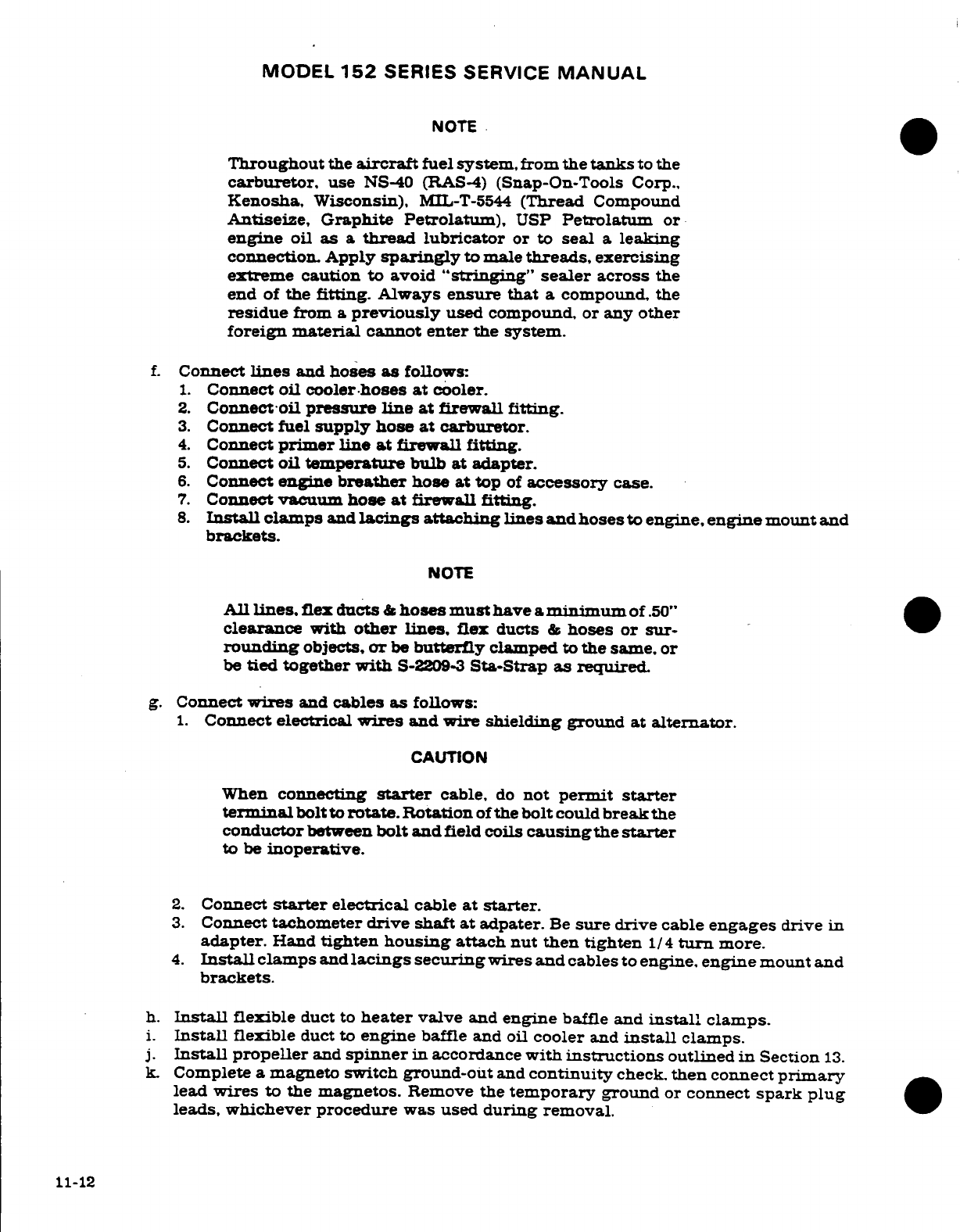
MODEL
152
SERIES SERVICE
MANUAL
NOTE
Throughout
the
aircraft
fuel
system,
from
the
tanks
to
the
carburetor,
use
NS-40
(RAS-4)
(Snap-On-Tools
Corp.,
Kenosha,
Wisconsin),
MIL-T-5544
(Thread
Compound
Antiseize,
Graphite
Petrolatum),
USP
Petrolatum
or
engine
oil
as
a
thread
lubricator
or
to
seal
a
leaking
connection.
Apply
sparingly
to male
threads,
exercising
extreme
caution to
avoid
"stringing" sealer
across
the
end
of
the
fitting.
Always ensure
that
a
compound.
the
residue
from
a
previously
used compound,
or
any other
foreign
material
cannot
enter
the
system.
f.
Connect
lines
and
hoses
as
follows:
1.
Connect
oil
cooler-hoses
at
cooler.
2.
Connect
oil
pressure
line
at
firewall
fitting.
3.
Connect
fuel
supply hose
at
carburetor.
4.
Connect
primer
line at
firewall
fitting.
5.
Connect
oil
temperature
bulb
at
adapter.
6.
Connect
engine
breather
hose
at
top
of
accessory
case.
7.
Connect
vacuum
hose
at
firewall
fitting.
8.
Install
clamps
and
lacings
attaching
lines
andhosesto
engine,
engine
mount
and
brackets.
NOTE
All
lines,
flex
ducts
&
hoses
must
have
a
minimum
of
.50"
clearance
with
other
lines,
flex ducts
&
hoses or
sur-
rounding
objects,
or
be
butterfly
clamped
to
the same,
or
be
tied
together
with
S-2209-3
Sta-Strap
as
required.
g.
Connect
wires
and
cables
as
follows:
1.
Connect
electrical
wires
and wire
shielding
ground
at
alternator.
CAUTION
When
connecting
starter
cable,
do
not
permit
starter
terminal
bolt
to
rotate.
Rotation
of
the
bolt
could
break the
conductor
between
bolt
and
field
coils
causing
the
starter
to
be
inoperative.
2.
Connect
starter
electrical
cable
at
starter.
3.
Connect
tachometer
drive
shaft
at
adpater.
Be
sure
drive
cable
engages
drive
in
adapter.
Hand
tighten
housing
attach nut
then
tighten
1/4
turn
more.
4.
Install
clamps
and
lacings
securing
wires
and
cables
to
engine,
engine
mount
and
brackets.
h.
Install
flexible
duct
to
heater
valve
and
engine
baffle
and
install
clamps.
i.
Install
flexible
duct to
engine
baffle and
oil
cooler
and
install
clamps.
j.
Install
propeller
and
spinner
in
accordance
with
instructions
outlined
in
Section
13.
k.
Complete
a magneto
switch ground-out
and
continuity
check,
then
connect
primary
lead
wires
to
the
magnetos.
Remove
the
temporary
ground
or
connect
spark
plug
leads,
whichever
procedure
was
used
during
removal.
11-12
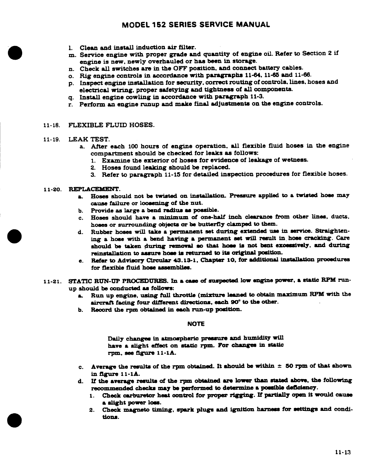
MODEL
152
SERIES
SERVICE
MANUAL
1.
Clean
and
install
induction
air
filter.
m.
Service engine
with
proper
grade and
quantity
of
engine
oil.
Refer
to
Section
2
if
engine
is
new,
newly
overhauled
or
has
been
in
storage.
n.
Check
all
switches
are
in
the
OFF
position,
and
connect battery cables.
o.
Rig
engine
controls in
accordance
with
paragraphs
11-64,
11-65
and
11-66.
p.
Inspect
engine
installation
for
security,
correct
routing
of
controls,
lines,
hoses
and
electrical
wiring,
proper safetying
and
tightness
of
all
components.
q.
Install
engine
cowling
in
accordance
with
paragraph
11-3.
r.
Perform
an
engine
runup
and
make
final
adjustments
on
the
engine
controls.
11-18.
FLEXIBLE
FLUID
HOSES.
11-19.
LEAK
TEST.
a.
After each
100
hours
of
engine
operation,
all
flexible
fluid
hoses
in
the engine
compartment
should
be
checked
for
leaks
as
follows:
1.
Examine
the
exterior
of
hoses
for
evidence
of
leakage
of
wetness.
2.
Hoses
found
leaking
should
be
replaced.
3.
Refer
to
paragraph
11-15
for
detailed
inspection
procedures
for
flexible
hoses.
11-20.
REPLACEMENT.
a.
Hoses
should
not
be
twisted on
installation Pressure
applied
to
a twisted
hose
may
cause
failure
or loosening of
the
nut.
b.
Provide
as
large
a
bend
radius
a
possible.
c.
Hoses
should
have a
minimum
of
one-half
inch
clearance
from
other
lines,
ducts,
hoses
or
surrounding
objects
or
be
butterfly
clamped
to
them.
d.
Rubber
hoses
will
take
a
permanent
set
during
extended
use
in
service.
Straighten-
ing a
hose
with
a
bend
having
a
permanent
set
will
result
in
hose
cracking.
Care
should
be
taken
during
removal so
that
how
is
not
bent
excssively,
and
during
reinstallation
to
assure
hose
is
returned
to
its
original
position.
e.
Refer
to Advisory
Crcular
43.13-1,
Chapter
10,
for
additional
installation
proedures
for
flexible
fluid
hose
asemblies.
11-21.
STATIC
RUN-UP PROCEDURES.
In
a
cue
of
suspected
low
engine
power,
a
static
RPM
run-
up should
be
conducted
a
follows:
a.
Run
up
engine,
using
full
throttle
(mixture
leaned
to
obtain
maximum
RPM
with
the
aircraft
facing
four
different
directions,
each
90
°
to
the
other.
b.
Record
the rpm
obtained
in
each
run-up
position.
NOTE
Daily
changes
in
atmospheric
pressure
and
humidity
will
have
a
slight
effect
on
static
rpm.
For
changes
in
static
rpm,
see
figure
11-lA.
c.
Average
the
results
of
the
rpm
obtained.
It
should
be
within
±
50
rpm
of
that
shown
in
figure
11-1A.
d.
If
the
average
results
of
the
rpm
obtained
are
lower
than
stated
above,
the
following
recommended
chcks
may
be
performed
to
determine
a
possible
deficiency.
1.
Check
carburtor
heat control
for
proper
rigging.
If
partially
open
it
would
cause
a
slight
power
loss.
2.
Check
magneto
timing,
spark plugs
and
ignition
harness
for
settings
and
condi-
tions.
11-13
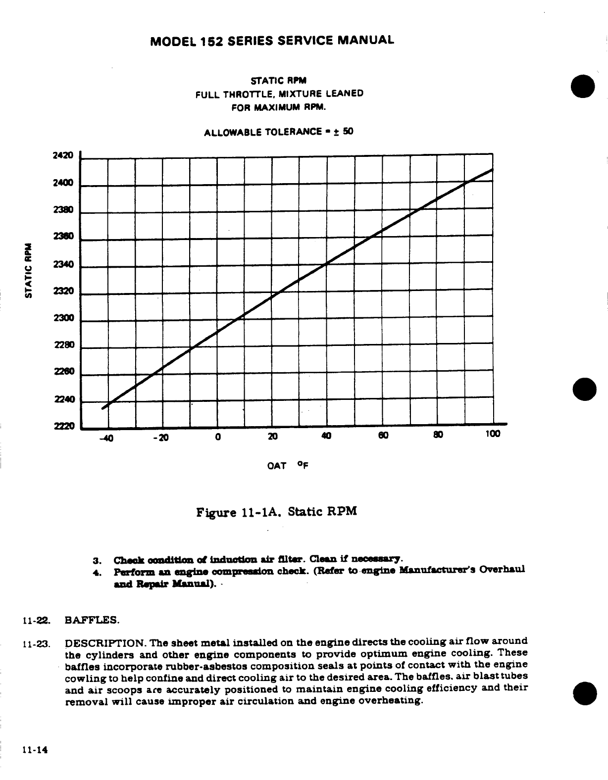
MODEL
152
SERIES
SERVICE
MANUAL
STATIC
RPM
FULL
THROTTLE, MIXTURE
LEANED
FOR
MAXIMUM
RPM.
ALLOWABLE
TOLERANCE
-+
50
2420
2400
2380
2340
2320
2300
2240
-40
-20
0 20
40
60
80
100
OAT
°F
Figure
11-1A.
Static
RPM
3.
Check
condition
of
induction
air
filter.
Clean
if
necessary
4.
Perform
an
engine
compression
check.
(Refer
to
engine
Manufactures
Overhaul
and
Repair
Manual).
11-22.
BAFFLES.
11-23.
DESCRIPTION.
The
sheet
metal
installed
on
the
engine
directs
the cooling
air
flow
around
the
cylinders
and
other engine
components
to
provide
optimum
engine
cooling.
These
baffles
incorporate
rubber-asbestos
composition
seals
at
points
of
contact
with the
engine
cowling
to
help
confine and
direct
cooling
air
to
the
desired
area.
The
baffles.
air
blast
tubes
and
air
scoops
are
accurately
positioned
to
maintain
engine
cooling
efficiency
and
their
removal
will
cause
improper
air
circulation
and
engine overheating.
11-14
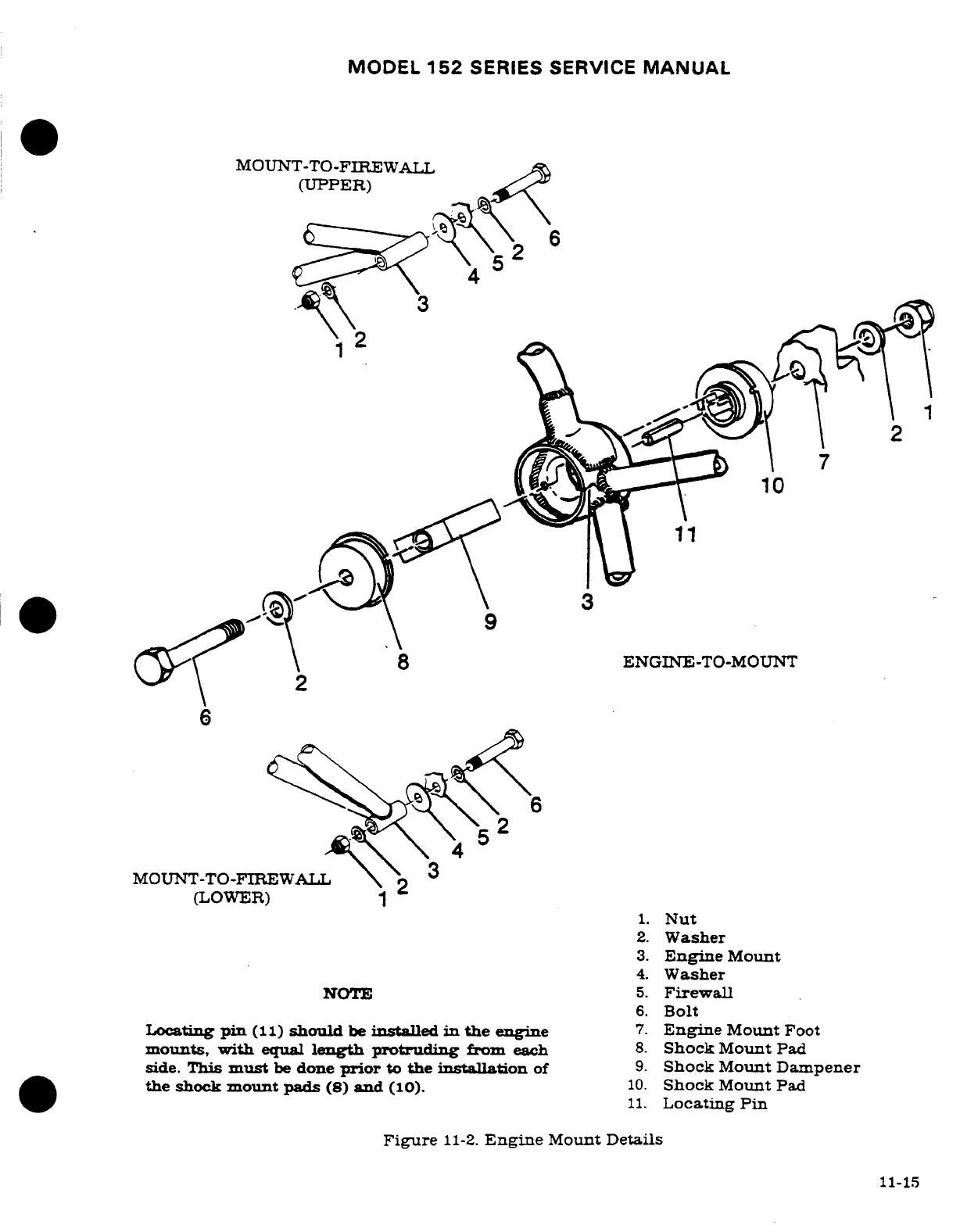
MODEL
152
SERIES
SERVICE
MANUAL
MOUNT-TO-FIREWALL
(UPPER)
1.
Nut
2.
Washer
ENGINE-TO-MOUNT
4.
Washer
NOTE
5.
Firewall
6.
Bolt
Locating
pin
(11)
should
be
installed
in
the
engine
7.
Engine
Mount
Foot
mounts,
with
equal
length
protruding
from
each
8.
Shock
Mount Pad
side.
This
must
be
done
prior
to
the
installation
of
9.
Shock
Mount
Dampener
the shock
mount
pads
(8)
and
(10).
10.
Shock
Mount
Pad
11.
Locating
Pin
Figure
11-2.
Engine
Mount
Details
11-15
MODEL
152
SERIES
SERVICE
MANUAL
11-24.
CLEANING
AND
INSPECTION.
Engine
baffles
should
be
cleaned
with
a
suitable
solvent
to
remove
dirt
and
oil.
NOTE
The
rubber-asbestos
seals are
oil
and
grease
resistant
but
should
not
be
soaked
in
solvent
for
long
periods.
Inspect
baffles
for
cracks
in
the
metal
and for
loose
and/or
torn seals.
Replace
defective
parts.
11-25.
REMOVAL AND
INSTALLATION.
Removal
and
installation
of the
various
baffle
segments
is
possible
with
the
cowling
removed.
Be
sure
that
any
replacement
baffles and
seals
are
installed
correctly
and
that they
seal
to
direct
the
cooling
air
in
the
correct direction.
11-26.
REPAIR.
Baffles
ordinarily
should
be
replaced
if
damaged
or
cracked.
However.
small
plate
reinforcements riveted
to
the
baffle
will
often
prove
satisfactory
both
to
the
strength
and
cooling
requirements
of
the
unit.
11-27.
ENGINE
MOUNT.
11-28.
DESCRIPTION.
The
engine
mount
is
composed
of
sections
of
steel
tubing
welded
together
and
reinforced with
gussets.
The
mount
is
fastened
to
the fuselage
at
four
points.
The
engine
is
attached
to
the
engine mount
with
shock-mount
assemblies
which absorb
engine
vibra-
tions.
11-29.
REMOVAL
AND INSTALLATION.
Removal
of
the
engine
mount
is
aocomplshed
by
remov-
ing
the
engine
as outlined
in
paragaph
11-12,
then
removing
the
engine
mount
from
the
firewall
On
reinstallation
torque
the
mount-to-firewll
bolts
to
160-190
lb-in
Torque
the
en-
gine-to-mount
bolts
to
450-500
lb-in.
11-30.
REPAIR.
Refer
to
Section
17
of
this
manual
for
repair
procedures.
11-31.
PAINTING.
Refer
to
Section
18
of
this
manual
for
painting
procedures.
11-32.
ENGINE
SHOCK-MOUNT
PADS.
(See
figure
11-2.)
The
bonded
rubber
and
metal
shock-
mounts are
designed
to
reduce
transmission
of
engine
vibrations
to the
airframe.
The
rubber
pads
should
be
wiped
clean
with
a
clean dry
cloth.
NOTE
Do
not
clean
the
rubber
pads
and
dampener
assembly
with
any
type
of
cleaning
solvent.
Inspect
the
metal
parts
for
cracks
and
excessive
wear
due
to
aging
and
deterioration.
Inspect
the
rubber pads
for
separation
between
the
pad
and
metal
backing.
swelling.
cracking
or
a
pronounced
set
of
the
pad.
Install
new
parts
for
all
parts
that
show
evidence
of
wear
or
damage.
11-16 Revision
1
MODEL
152
SERIES
SERVICE
MANUAL
11-32A.
REDUCING
VALVE
STICKING.
Field
experience
has
shown
that
engine
oil
contamina-
tion
increases
the
possibility
of
sticking
and/or
stuck
valves.
This
situation
occurs
when
contaminants
in
engine
lubrication
oil become
deposited
on
the
valve
stems,
restricting
valve movement,
and
resulting
in
intermittent
engine hesitation
or
miss.
Operating with
any
of
the
following
conditions
present
can
promote deposit
buildup
reducing
valve
guide
clearance
and
resulting
in
valve
sticking:
a.
Contaminated,
dirty engine
oil
supply.
b.
High
ambient
temperature.
c.
Slow
flight
with
reduced cooling.
d.
High
lead
content
of
fuel.
More
frequent
oil
and
filter
changes
(50
hour)
will
minimize
accumulation
of
harmful
con-
taminants,
the
prime
cause
of
valve
sticking.
When
the
aircraft
cannot
be
flown
frequently,
the
oil
and
filter
should
be
changed even
sooner.
Changing
oil
and
filter
every
25
hours
will
eliminate
moisture
and
acids
that
collect
in
oil
of
an
inactive
engine.
Operating
the
engine
with
a
clean
air filter
is
all
important
for
keeping
dirt
from
accumulating
in
the
oil
supply.
Therefore,
the
entire
air
induction system
should
be
sealed
to
prevent
the
entry
of
unfil-
tered
air.
It
is
important
that
cooling
air
baffles
and
batile
strips
be
in
good
condition
to
prevent
lo-
calized
overheating
problems.
In
addition,
exposing
the
engine
to
sudden
cool
down,
as in
a
rapid
descent
with
reduced
power or
shutting
down
the
engine
before
it
has
sufficiently
cooled
down,
can
also
induce
valve
sticking.
The
lead
salts
that
accumulate
in
lubricating
oil
from
the
use
of
leaded
fuels
contribute
to
deposit
buildup
in valve
guides.
They
are
mostly
eliminated
each
time
the
oil
and
filter
are
changed;
however,
regular
use
of
low-leaded
fuels
will
reduce
deposit
accumulation and
valve
sticking.
Refer
to
Section
2
for
valve
and
valve
guide
cleaning
procedures.
11-33.
ENGINE
OIL
SYSTEM.
11-34.
DESCRIPTION.
The
lubricating
system
is
of
the
full
pressure
wet
sump
type.
Refer
to
ap-
plicable
engine
manufacturer's
overhaul manual
for
specific
details
and
descriptions.
Revision
1
11-16A/(11-16B
blank)
MODEL
152
SERIES
SERVICE
MANUAL
11-35.
TROUBLE
SHOOTING.
TROUBLE
PROBABLE
CAUSE
REMEDY
NO
OIL
PRESSURE.
No
oil
in
sump.
Check
with
dipstick.
Fill
sump
with
proper
grade
and
quantity
of
oil.
Refer
to
Section
2.
Oil
pressure
line
broken.
Inspect
pressure
lines.
disconnected
or
pinched.
Replace
or
connect
lines
as
required.
Oil
pump
defective.
Remove
and
inspect.
Exam-
ine
engine.
Metal
particles
from damaged
pump
may
have
entered
engine
oil
passages.
Defective
oil
pressure
Check
with
a
known
good
gage. gage.
If
second
reading
is
normal.
replace
gage.
Oil
congealed
in
gage
line.
Disconnect
line
at
engine
and
gage:
flush
with kero-
sene.
Pre-fill
with
kerosene
and
install
Relief
valve
defective. Remove
and
check
for
dirty
or
defective
parts.
Clean
and
install; replace
valve
if
defective.
LOW
OIL
PRESSURE.
Low
oil
supply.
Check
with
dipstick.
Fill
sump
with
proper
grade
and
quantity
of
oil.
Refer
to
Section
2.
Low
viscosity
oil.
Drain
sump
and
refill
with
proper
grade
and
quantity
of
oil.
Oil
pressure
relief
valve
Remove
and
inspect
spring.
spring
weak
or
broken.
Replace
weak
or
broken
spring.
Defective
oil
pump.
Check
oil
temperature
and
oil
level.
If
temperature
is
higher
than
normal
and
oil
level
is
correct,
internal
failure
is
evident.
Remove
and
inspect.
Examine
engine.
Metal
particles
from
dam-
aged pump
may have
entered
oil
passages.
11-17
MODEL
152
SERIES SERVICE
MANUAL
11-35.
TROUBLE SHOOTING
(Cont).
TROUBLE PROBABLE CAUSE REMEDY
LOW
OIL
PRESSURE
Secondary
result
of
high
Observe
oil
temperature
(Cont).
oil
temperature.
gage
for
high indication.
Determine
and
correct
reason
for
high
oil
temperature.
Leak in
pressure
or
Inspect
gasket
between
suction
line.
accessory
housing
and
crank-
case.
Repair
engine
as
required.
Dirty
oil
screens.
Remove
and
clean
oil
screens.
HIGH
OIL
PRESSURE.
High
viscosity
oil.
Drain sump
and
refill
with
proper
grade
and
quantity
of
oil
Relief
valve
defective.
Remove
and
check
for
dirty
or
defective
parts.
Clean
and
install:
replace
valve
if
defective.
Defective
oil
pressure
gage.
Check
with
a
known
good
gage.
If
second
reading
is
normal,
replace
gage.
LOW
OIL
TEMPERATURE.
Defective
oil
temperature
Check
with
a
known
good
gage
or
temperature
bulb.
gage.
If
second
reading
is
normal,
replace
gage.
If
read-
ing
is
similar,
the
temperature
bulb
is
defective.
Replace
bulb.
Oil
cooler
thermostatic
Remove
valve
and
check
for
valve/bypass
valve
defec-
proper
operation.
Replace
tive
or stuck.
valve
if
defective.
HIGH
OIL
TEMPERATURE. Oil
cooler
air
passages
Inspect
cooler
core.
clogged. Clean
air
passages.
Oil
cooler oil
passages
Drain
oil
cooler.
Inspect
clogged.
for
sediment.
Remove
cooler
and
flush
thoroughly.
Thermostatic
valve
or
by-
Feel
front
of
cooler
core
pass
valve
damaged
or
held
with
hand.
If
core
is
cold.
open
by
solid
matter.
oil is
bypassing
cooler.
Remove
and clean
valve
and
seat.
If
still
inoperative.
replace.
11-18
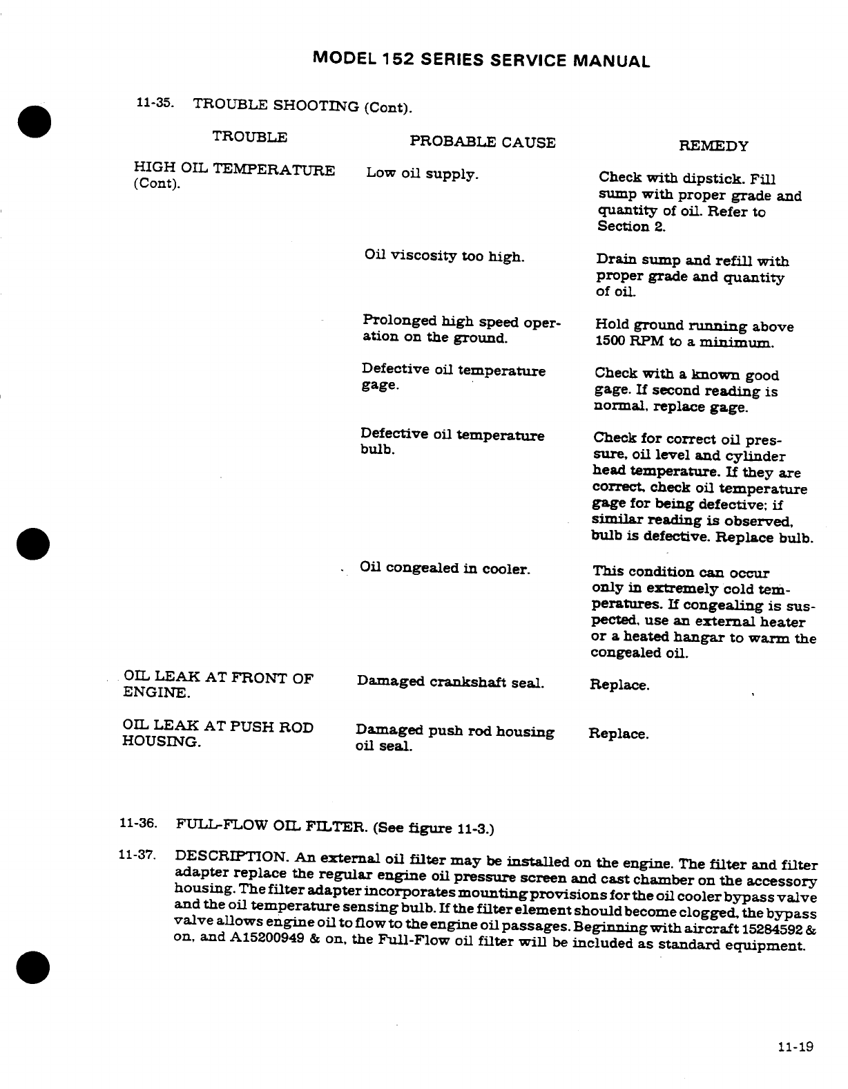
MODEL
152
SERIES
SERVICE
MANUAL
11-35.
TROUBLE
SHOOTING (Cont).
TROUBLE
PROBABLE
CAUSE REMEDY
HIGH
OIL
TEMPERATURE
Low
oil
supply.
Check
with
dipstick. Fill
(Cont).
sump
with
proper
grade
and
quantity
of
oil.
Refer
to
Section
2.
Oil
viscosity
too
high.
Drain
sump
and
refill
with
proper
grade
and
quantity
of
oil.
Prolonged high
speed
oper-
Hold
ground
running
above
ation
on
the ground.
1500
RPM
to
a
minimum.
Defective
oil
temperature
Check
with
a
known
good
gage.
gage.
If
second
reading
is
normal,
replace
gage.
Defective
oil
temperature
Check
for correct
oil
pres-
bulb.
sure,
oil
level
and
cylinder
head
temperature.
If
they
are
correct,
check oil
temperature
gage
for
being
defective: if
similar
reading
is
observed,
bulb
is
defective.
Replace
bulb.
Oil
congealed
in
cooler. This condition
can occur
only
in
extremely
cold
tem-
peratures.
If
congealing
is
sus-
pected,
use
an
external
heater
or
a
heated
hangar
to warm
the
congealed
oil.
OIL
LEAK
AT
FRONT
OF
Damaged
crankshaft
seal.
Replace.
ENGINE.
OIL
LEAK
AT
PUSH
ROD
Damaged
push
rod
housing
Replace.
HOUSING.
oil
seal.
11-36.
FULL-FLOW
OIL
FILTER. (See
figure
11-3.)
11-37.
DESCRIPTION.
An
external
oil
filter
may
be
installed
on
the
engine.
The
filter
and
filter
adapter replace
the
regular
engine
oil
pressure
screen
and
cast
chamber
on
the
accessory
housing.
The
filter
adapter
incorporates mounting
provisions
for
the
oil
cooler
bypass
valve
and
the oil
temperature sensing
bulb.
If
the
filter
element
should
become
clogged,
the
bypass
valve
allows
engine
oil
to
flow
to
the
engine oil
passages.
Beginning
with
aircraft
15284592
&
on,
and
A15200949
&
on,
the
Full-Flow
oil
filter will
be
included
as
standard
equipment.
11-19
MODEL
152
SERIES SERVICE
MANUAL
11-38.
REMOVAL
AND
INSTALATTION.
(See
figure
11-3.)
NOTE
Replacement
filters
are available
from
Cessna
Parts
Distribution
(CPD
2)
through
a
Cessna
Service
Station.
a.
Remove
engine
cowling
in
accordance
with
paragraph
11-3.
b.
Remove
safety
wire
from
filter.
c.
Unscrew
filter
from
adapter.
d.
Lightly
lubricate
gasket
with
engine
oil
only
prior
to
installations.
e.
Install
spin-on
filter
on
the
stud
and
torque
to
19-29
lb-ft
or
3/4
to
1
full
turn
after
gasket
makes
contact.
f.
Safety
wire
filter
to adapter.
g.
After
first
engine
run
check
for
oil
leaks.
11-39.
FILTER
ADAPTER.
11-40.
REMOVAL.
(See
figure
11-3.)
a.
Remove
filter
assembly
in
accordance
with
paragraph
11-36.
b.
Remove
oil
temperature
bulb
(5)
from
adapter
(3).
c.
Remove
the
three
bolts
and
washers attaching adapter
to
accessory
housing.
d.
Remove
nut
and
washers
attaching
the lower
left
corner
of
adapter
to
accessory
housing
and
remove
adapter.
e.
Remove
gasket
(2)
from
adapter
mounting
pad
and
discard.
11-41.
DISASSEMBLY,
INSPECTION
AND REASSEMBLY.
After removal
of
the
adapter
(3),
remove
thermostatic
bypass
valve
(8)
for
cleaiing.
Do
not
disassemble
the
valve.
Clean
adapter
and
thermostatic
valve
in
solvent
and
dry
with
compressed
air.
Ensure
that
all
passages
in
adap-
ter are
open.
Remove
any
gasket
material
that
may
have
adhered
to
the
adapter. Inspect
adapter
for cracks,
damaged
threads,
scratches
or
gouges
to
gasket
seats.
If
any
of
these
are
found,
install
a
new
adapter.
Using
a
new
gasket
install
thermostatic
bypass
valve
in adap-
ter.
11-42.
INSTALLATION.
a.
Using
a
good
grade gasket
sealant,
install
a
new
gasket
on
accessory
housing
adap-
ter
mount
pad
Note
that
one
side of
the
gasket
is
marked
'OIL
FILTER
SIDE".
b.
Install
adpter
on
mounting
pad
and install
bolts,
washers and
nut.
Use
lockwashers
next
to
bolt
heads and
nut.
c.
Tighten
bolts
and
nut
to
75
lb-in.
d.
Install
oil
tmperature
bulb
in
adapter.
e.
Install
filter
assembly
in
accordance
with
paragraph
11-38.
f.
Inatall
any
components
removed
for
access.
11-43.
OIL
COOLER.
11-44.
DESCRIPTION.
The
external
oil
cooler
is
mounted
on
the
left
forward
baffle.
Flexible
hoses
carry
the
oil
to
and
from
the
cooler.
Ram
air
passes
through
the
coil
cooler
and
is
dis-
charged
into
the
engine compartment.
A
capped tee
is
provided
for
draining
the
oil cooler.
11-45.
ENGINE
FUEL
SYSTEM.
11-20
Revision
1
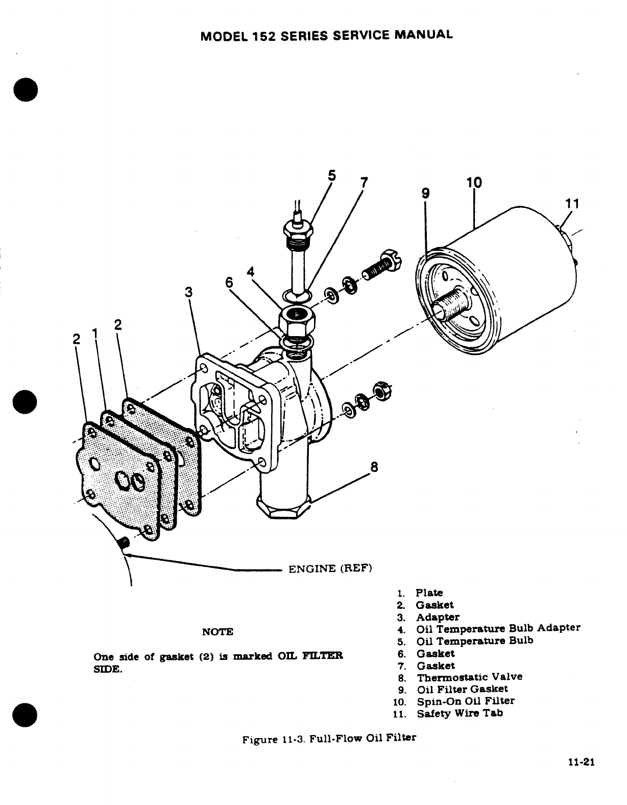
MODEL
152
SERIES SERVICE
MANUAL
57
6
4
21
ENGINE
(REF)
1.
Plate
2.
Gasket
3.
Adapter
NOTE
4.
Oil
Temperature
Bulb
Adapter
5.
Oil
Temperature
Bulb
One
side
of
gasket
(2)
is
marked
OIL
FILTER
6.
Gasket
SIDE.
7.
Gasket
8.
Thermostatic
Valve
9.
Oil
Filter
Gasket
10.
Spin-On
Oil
Filter
11.
Safety
Wire
Tab
Figure
11-3.
Full-Flow
Oil
Filter
11-21
MODEL
152
SERIES
SERVICE
MANUAL
11-4.
DECRPTION.
A
single
barrel
float-type
up-draft
carburetor
is
installed
on
the
engine.
The
carburetor
is
equipped
with
a
manual
mixtre
control
and
an
idle
cut-off.
Beginning
with
airraft
15283592
&
on,
and
A15283592
&
on,
carburetor
incorporates
an
accelerator
pump.
The
accelerator
pump
rod
must
be
attached
to
the
lowest
(shortest
stroke)
holo
of
the pump
actuating
lever.
For
repair
and
overhaul
of
the carburetor,
refer
to
the
manuufacturer's
over-
haul
and
repair
manuaL
11-47.
CARBURETOR
11-48.
REMOVAL
AND
INSTALLATION.
a.
Place
fuel
shut-off
valve
in
the
OFF
position.
b.
Remove
engine
cowling
in
accordance
with
paragraph
113.
c.
Drain
fuel
from
strainer
and
lines
with
strainer
drain
oontrol.
d.
Disconnect
throttle
and
mixture
controls
at
carburetor.
Note
the
EXACT
position,
size and
number
of
washers
and
spacers
for
reference
on
reinstallation.
.
Disconnect
and
cap
or plug
fuel
line
at
carburetor.
f.
Remove
induction
airbox
g.
Remove
nut
and
washer
attaching
carburetor
to
intake
manifold
and
remove
car-
buretor.
h.
Reverse
the
preceding
steps
for
reinstallion
Use
new
gaket
between
carburetor
and
intake
manifold
Check
carburetor
throttle
arm
to
idle
stop
arm
attachment
for
security
and
proper
safetying
at each
normal
engine
inspection
in
accordance
with
figure
11-4A.
11-49.
IDLE
SPEED
AND MIXTURE
ADJUSTMENTS.
Since
idle
RPM
may
be
affected
by
idle
mixture
adjustment,
it
may
be
necessary
to
readjust
idle
RPM
after
setting
the
idle
mixture.
a.
Start
and
run
engine
until
the oil
temperature
and oil
pressure
are
in
the
normal
operating
range.
b.
Check
the
magnetos
for
proper
operation
in
accordance
with
paragraph
11-53.
c.
Clear
the
engine
by
advancing
the
RPM
to
approximately
1000.
then
retard
the
throttle
to
the
idle
position.
The
engine
RPM
should
stabilize
at
600
*
25.
If
not.
adjust
the
idle
speed screw
IN
to
increase
and
OUT
to
decrease
RPM.
NOTE
An
engine
should
idle
smoothly.
without
excessive
vibrations.
The
idle
speed
should
be
high
enough
to
maintain
idling
oil
pressure
and
to
preclude
any
possibil-
ity
of
engine
stoppage
in
night
when
the
throttle
is
closed.
d.
After
the
idle
speed
has
stabilized
(600
t
25
RPM).
move
the
mixture
control
slowly
toward
the
IDLE
CUT-OFF
position
and observe
the
tachometer
for
any
minute
change
during
this
manual
leaning
procedure.
e.
Quickly
return
the
mixture
control
to
the
FULL
RICH
position
before
the
engine
stops.
f.
A
momentary increase
of
approximately
25
RPM
while
slowly
manually
leaning the
mixture
is
most
desirable,
an
increase
of
more
than
25
RPM
indicates
a
rich
idle
mixture
and
an
immediate
decrease
in
RPM
(if
not
preceded
by
a
momentary
increase)
indicates
a
lean
idle
mixture.
g.
If
the
idle
mixture
is
too
rich,
turn
the
idle
mixture adjustment
center
screw
one
or
two
notches
in
a
clockwise
direction
as
viewed from
the
aft
end
of
the
unit.
then
repeat
steps
"d"
through
"f".
11-22
MODEL
152
SERIES
SERVICE
MANUAL
NOTE
After
each
adjustment
to
the
idle
mixture,
run
engine
up
to
approximately
2000
RPM
to
clear
the
engine
of
excess
fuel
and
obtain
a
correct
idle
speed.
h.
If
the
idle
mixture
is
too
lean,
turn
the
idle
mixture
adjustment
center screw one
or
two
notches
in a
counterclockwise
direction
as
viewed
from
the
aft
end
of
the
unit.
then
repeat
steps
"d"
thru
"f'.
i.
This
method
of
adjustment
will give
the
desired
idle
RPM.
If
the
adjustments
do
not
remain
stable,
check
the
throttle
and
mixture
linkage
for
evidence
of
wear
and
improper
rigging.
Any
looseness
of
the
throttle
and
mixture
linkage
will
cause
erratic
idling.
In
all
cases,
allowance
should
be
made
for
the
effect
of
weather
condition
upon
idling adjustment.
The
relation
of
the
aircraft
to
the
prevailing
wind
direction will
have
an
effect on
the
propeller
load
and
engine
RPM.
It
is
advisable
to
make
idle
adjustments
with the
aircraft
crosswind.
11-50.
INDUCTION
AIR
SYSTEM.
11-51.
DESCRIPTION.
Ram
air
to
the
engine
enters
the
induction
airbox
through
an
opening
in
the
forward
part
of
the lower engine
cowling
nose
cap.
The
air
is
filtered
through
a
filter
which
is
located
at
the
opening
in
the
nose
cap.
From
the
induction
airbox
the
filtered
air
is
directed
to
the
inlet
of
the
carburetor,
mounted
on
the
lower
side
of
the
engine,
and
through
the
carburetor,
where
fuel
is
mixed
with
the
air,
to
the intake
manifold. From the
intake
manifold.
the
fuel-air
mixture
is
distributed
to
each
cylinder
by
separate
intake
pipes.
The
intake
pipes are attached
to
the
intake
manifold
with
hose
and
clamps
and
to
the
cylinder
with
a two
bolt
flange
which
is
sealed
with
a
gasket.
The
induction
airbox
contains
a
valve.
operated
by
the
carburetor
heat
control
in
the cabin.
which
permits
air
from
an
exhaust
heated
source
to
be
selected
in
the
event
carburetor
icing or filter
icing
should
be
encoun-
tered.
11-23
MODEL
152
SERIES
SERVICE
MANUAL
11-52.
REMOVAL AND
INSTALLATION.
a.
Remove
airbox
and
carburetor
as
outlined
in
paragraph
11-48.
b.
Remove
intake
pipes
by
disconnecting
hose
and
removing
nuts
and
washers
attaching
pipes
to
cylinders.
c.
Installation
of
the
system
is
the
reverse
of
the
preceding
steps.
Use
new
gaskets
at
installation.
11-53.
IGNITION
SYSTEM.
11-54.
DESCRIPTION. Sealed.
lightweight
Slick
magnetos
are
used
on
the
engine.
The
4052
magneto
is
equipped with
an
impulse
coupling.
The
magnetos
MUST
NOT
BE
DISAS-
SEMBLED.
Internal
timing
is
fixed
and the
breaker
points
are
not
adjustable.
Timing
marks
are
provided
on
the
distributor
gear
and
distributor
block.
visible
through
the
air
vent
holes.
for
timing
to
the
engine.
A
timing
hole
is
provided
in
the
bottom
of
the
magneto
adjacent
to
the
magneto
flange.
A
timing
pin (or
0.093
inch
6-penny
nail)
can
be
inserted
through
this
timing
hole
into
the
mating
hole
in
the
magneto
rotor shaft
to
lock
the
magneto
approxi-
mately
in
the
proper
firing
position.
Slick
lightweight
ignition
harness
is
used with
the
lightweight
magnetos.
For
ignition
harness
repair. refer
to
the
manufacturer's
Service
Manual.
WARNING
During
all
magneto
maintenance, always
take
proper
precautions
to
make
sure
the
engine
can
not
fire
or
start
when
the
propeller
is
moved.
11-24
MODEL
152
SERIES
SERVICE
MANUAL
11-54A. TROUBLE SHOOTING
-
IGNITION
SYSTEM.
TROUBLE
PROBABLE
CAUSE
REMEDY
ENGINE
FAILS
TO
START.
Defective
ignition
switch.
Check
switch
continuity.
Replace
if
defective.
Spark
plugs
defective,
im-
Clean,
regap and test
plugs.
properly
gapped
or
Replace
if
defective.
fouled
by
moisture
or
deposits.
Defective
ignition
harness.
If
no
defects
are
found
by
a
visual
inspection,
check
with
a
harness
tester.
Replace
defective
parts.
Magneto
"P"
lead
grounded.
Check
continuity.
"P"
lead
should
not
be
grounded
in
the
ON
position,
but should
be
grounded
in
OFF
position.
Repair or
replace
"P"
lead.
Failure
of
impulse
coupling.
Impulse coupling
pawls
should
engage
at
cranking
speeds.
Listen
for loud
clicks
as
impulse
couplings
operate.
Remove
magnetos
and
determine
cause.
Replace
defective
magneto(s).
Defective
magneto.
Refer
to
paragraph
11-54.
Broken
drive
gear.
Remove
magneto
and
check
magneto
and engine
gears.
Replace
defective
parts.
Make
sure
no
pieces
of
damaged
parts
remain
in
engine
or
engine
disassembly
will
be
required.
11-24A
MODEL
152
SERIES SERVICE
MANUAL
11-54A.
TROUBLE
SHOOTING
-
IGNITION
SYSTEM
(Cont).
ENGINE
WILL
NOT
IDLE
Spark
plugs
defective,
Clean.
regap
and
test
plugs.
IDLE OR
RUN
PROPERLY.
improperly
gapped
or
Replace
if
defective.
fouled
by
moisture
deposits.
Defective
ignition
harness
If
no
defects are
found
by
a
visual
inspection
check
with
a
harness tester.
Replace
defective
parts
Defective
magneto.
Refer
to
paragraph
11-54.
Impulse
coupling
pawls
Listen
for
loud
clicks
as
remain
engaged.
impulse
coupling operates.
Remove
magneto
and
determine
cause.
Replace
defective
magneto.
Spark
plugs
loose.
Check
and
install properly.
11-55.
MAGNETO REMOVAL. Remove
high-tension outlet
plate,
disconnect
primary
"P"
lead,
and
remove
nuts
and
washers
securing magneto
to
the engine.
Note
the
approximate
an-
gular
position
at
which
the
magneto
is
installed,
then
remove
the
magneto.
11-56.
INTERNAL TIMING.
Internal timing
is
accomplished
during
manufacture
of
the
magneto.
Since
these
magnetos
are
NOT
TO
BE
DISASSEMBLED
there
is
no
internal
timing
involved.
11-57.
REPLACEMENT
INTERVAL
These
magnetos
cannot
be
overhauled
in
the
field.
The
coil.
capacitor,
and
breaker
assembly
are
non-replacable.
As
a
good
maintenance
practice,
and
to
have
the
benefit
of
good
ignition
at
all
times,
it is
recommended
that
the magnetos
be
re-
moved
at
900 hours
of
magneto
time,
and install
new
exchange
magnetos.
11-58.
MAGNETO
INSTALLATION
AND
TIMING
TO
ENGINE.
The
magneto
must
be
installed
with its
timing
marks
correctly
aligned.
with
number
one
cylinder
on
its
compression
stroke.
and
with
the
number
one
piston
at
its
advanced
firing
position.
Refer
to
paragraph
11-8
for
the
advanced
firing
position
of
number
one
piston.
To
locate
the
compression stroke
of
the
number
one
cylinder,
remove
the
lower
spark
plug
from
number
two.
three,
and
four
cylinders
and
remove
the
upper spark plug
from
number
one
cylinder.
Place
the
thumb
of
one
hand
over
the
spark
plug
hole
of
number
one
cylinder
and rotate
crankshaft
in
the
direction
of
normal
rotation
until
the
compression
stroke
is
indicated
by
positive
pressure
inside
the
cylinder
lifting
the
thumb
off
the
spark
plug
hole.
After
the
compression stroke
is
obtained.
locate
number
one
piston
at
its
advanced
firing position.
Locating
the
advanced
firing
position
of
number
one
piston
may
be
obtained
by
rotating
the
crankshaft
in
direction
of
normal
rotation
until
No.
1
cylinder
is
on
the
compression
stroke
and
approximately
35
°
BTC.
Clamp
the
ignition
timing pointer
on
the advance
timing
mark
on
the
rear
of
the
starter
ring
gear.
The
starter
ring
gear may
be
marked
at
20
°
and
25
°.
Consult
engine
nameplate
for
correct
advance
timing
mark
to
use. Continue
rotating
the
crankshaft
until
the
timing
11-24B
Revision
1
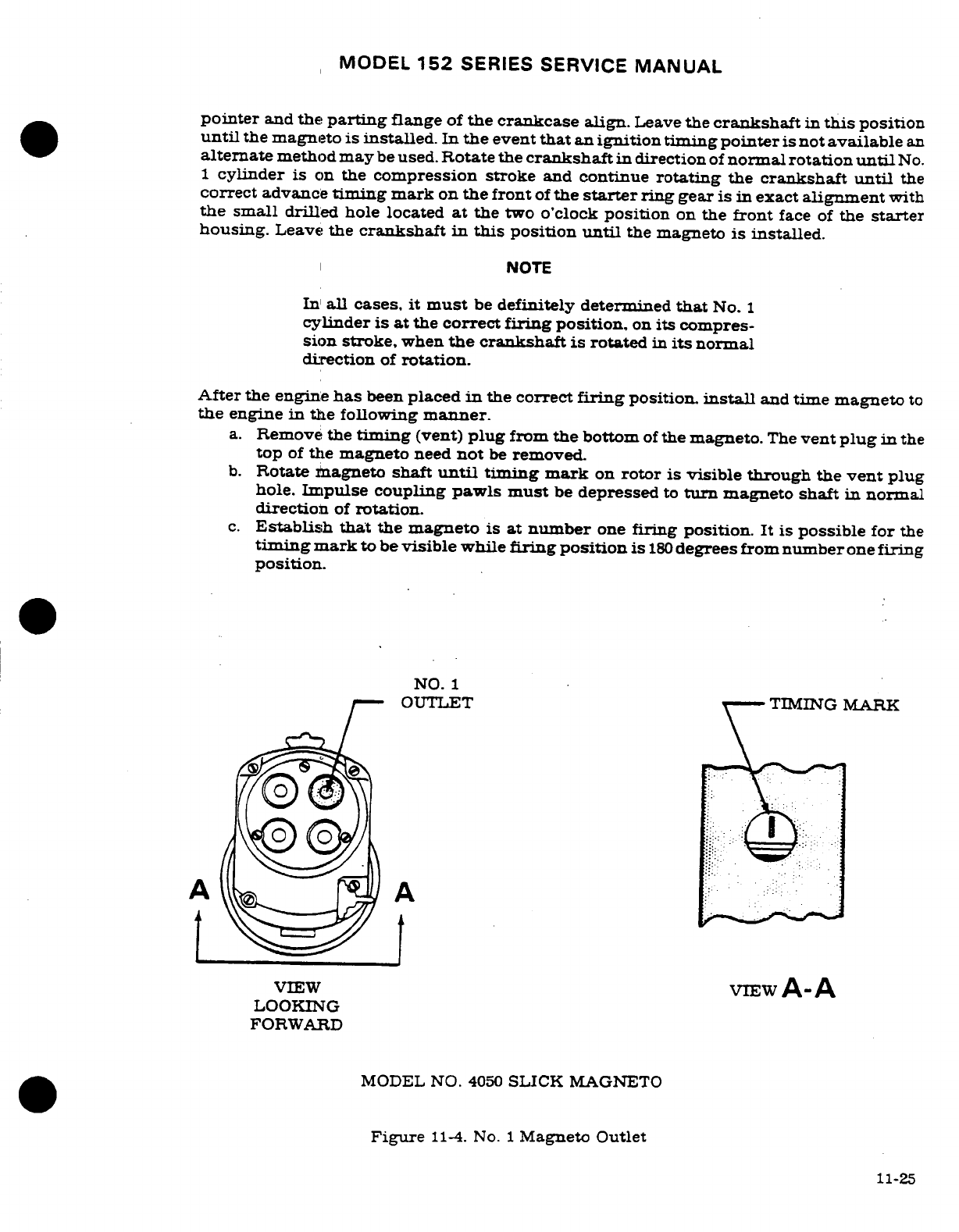
MODEL
152
SERIES SERVICE
MANUAL
pointer
and
the
parting
flange
of
the
crankcase
align.
Leave
the
crankshaft
in
this
position
until
the
magneto
is
installed.
In
the
event
that
an
ignition timing
pointer
is
not
available
an
alternate
method
may
be
used.
Rotate
the
crankshaft
in
direction
of
normal
rotation
until
No.
1
cylinder
is
on
the
compression
stroke
and
continue
rotating
the
crankshaft
until
the
correct
advance
timing
mark
on
the
front
of
the
starter
ring
gear
is in
exact
alignment
with
the small
drilled
hole located
at
the
two
o'clock
position
on
the
front
face
of
the
starter
housing.
Leave
the
crankshaft
in
this
position
until
the magneto
is
installed.
NOTE
In
all
cases,
it
must
be
definitely
determined
that
No.
1
cylinder
is
at
the
correct
firing
position,
on
its compres-
sion
stroke,
when
the
crankshaft
is
rotated
in
its
normal
direction
of
rotation.
After
the
engine
has
been
placed
in
the
correct
firing
position.
install
and
time magneto
to
the
engine
in
the
following
manner.
a.
Remove
the
timing (vent)
plug
from
the
bottom
of
the
magneto.
The
vent
plug
in
the
top
of
the
magneto
need
not
be
removed.
b.
Rotate
magneto
shaft
until
timing mark
on
rotor
is
visible
through
the
vent plug
hole.
Impulse
coupling
pawls must
be
depressed
to
turn
magneto shaft
in
normal
direction
of
rotation.
c.
Establish that
the
magneto
is
at
number
one
firing
position.
It is
possible
for
the
timing
mark
to
be
visible
while
firing position
is
180
degrees
from
number
one
firing
position.
NO.
1
OUTLET TIMING
MARK
VIEW
VIEW
A-A
LOOKING
FORWARD
MODEL
NO.
4050
SLICK
MAGNETO
Figure
11-4.
No.
1
Magneto Outlet
11-25
MODEL
152
SERIES
SERVICE
MANUAL
NOTE
It
is
necessary
to
"spark"
the
magneto
to
establish
the
cor-
rect
firing
position.
The
outlet
plate
with
spark
plug
leads
must
be
installed
on
the
magneto.
Hold
number
one
spark
plug
lead
close
to
magneto
case, or
ground
the
magneto
and
hold
the
number
one
spark
plug
lead
close
to a
good
ground.
Rotate impulse
coupling
in
normal
direction
of ro-
tation
until
a
spark
occurs
at
this
lead.
(Impulse
coupling
pawls
must
be
depressed
to
turn
magneto
shaft
in
normal
direction
of
rotation.) Turn
impulse coupling backward
a
few
degrees,
until
timing mark
on
rotor
is
centered
in
vent
plug
hole
and
install
timing
pin
(or
0.093
inch
6-penny
nail)
through
hole
in
bottom
of
magneto
next
to
the
flange
and
into
the
mating
hole
in
the
rotor
shaft.
This
locks
the
magneto
approximately
in
firing
position
while
installing
it
on
the
engine.
d.
Keep
timing
mark
centered
in
vent
plug
hole
during installation.
e.
Be
sure
magneto
gaskets
are
in
place
and
that
engine
isin
correct
firing
position,
then
install
magneto(s)
at
the
angle
noted
during
removal,
tighten
mount
nuts
finger
tight.
CAUTION
Remove
timing
pin
from
magneto,
if
installed.
Be
sure
to
remove
this
pin
before
rotating
crankshaft.
f.
Connect
one
lead
of
timing
light
to
the
capacitor
terminal
at
the
rear
of
the
magneto
and
ground
lead of
timing
light
to
a
good
ground.
g.
Rotate propeller
opposite
to
normal
direction
of
rotation
a
few
degrees
(approximately
5
degrees)
to
close
magneto
contact
points.
NOTE
Do
not
rotate
propeller
back
far
enough
to
engage impulse
coupling,
or
propeller
will
have
to
be
rotated
in
normal
di-
rection
of
rotation
until
impulse
coupling
releases,
then
backed
up
a
few
degrees
before
the firing
position.
h.
Slowly
advance
propeller
(tap
forward
with
minute
movements
as
firing
position
is
ap-
proached)
in
normal direction
of
rotation
until
timing
light
indicates
position
at
which
contact points
break.
The
contact
points
should
break
at
the
advanced
firing
position
of
number
one
cylinder.
Loosen
mounting
nuts
slightly
and
rotate
magneto
case
to
make
contact
points
break
at
the correct position.
Tighten
mounting
nuts.
CAUTION
To
prevent
possible
condenser
damage,
do
not
exceed
13-15
lb-in
torque
when
tightening
"P"
lead
nut
during
installa-
tion
of
Slick
magneto.
i.
After
tightening
magneto
mounting
nuts,
recheck
timing.
Make
sure
both
magnetos
are
set
to
fire
at
the
same
time.
Remove
timing
equipment
and connect
spark
plug
leads
and
ignitio
switch
leads.
11-26
Revision
I
MODEL
152
SERIES SERVICE
MANUAL
NOTE
Beginning
with
the
number
one
outlet. the magneto
fires
at
each
successive
outlet
in
a
counterclockwise direction.
looking
at
the
outlets.
Connect
number
one
magneto
outlet
to
number
one
cylinder
spark
plug
lead,
number
two
outlet
to
the
next
cylinder
to
fire,
etc.
Engine
firing
order
is
listed
in
paragraph
11-8.
11-59.
MAGNETO
CHECK.
Advanced
timing
settings
in
some
cases.
is
the
result
of
the
erroneous
practice
of
bumping magnetos
up
in
timing
in
order
to
reduce
RPM
drop
on
single ignition.
NEVER
ADVANCE TIMING
BEYOND
SPECIFICATIONS
IN
ORDER
TO
REDUCE
RPM
DROP.
Too
much
importance
is
being
attached
to
RPM
drop in
single
ignition.
RPM
drop
on
single
ignition
is
a
natural
characteristic
of
dual
ignition
design.
The
purpose
of
the
following
magneto
check
is
to
determine
that
all
cylinders
are
firing.
If
all
cylinders
are
not
firing,
the
engine
will
run
extremely
rough
and
cause
for
investigation
will
be
quite
apparent.
The
amount
of
RPM
drop
is
not
necessarily
significant
and
will
be
influenced
by
ambient
air
temperature,
humidity,
airport
altitude,
etc.
In
fact,
absence
of
RPM
drop
should
be
cause
for
suspicion
that
the
magneto
timing
has
been
bumped
up
and
is
set
in
advance
of
the
setting
specified.
Magneto
checks
should
be
performed
on a
comparative
basis
between
mdividual
right
and
left
magneto
performance.
a.
Start
and
run
engine
until
the
oil
and
cylinder
head
temperatures
are
in
normal
operating
ranges.
b.
Advance
engine
speed
to
1700
RPM.
c.
Turn
the
ignition
switch
to
the
"R"
position
and
note the
RPM
drop.
then
return
the
switch
to
the
"BOTH"
position
to
clear
the
opposite
set
of
plugs.
d.
Turn the
switch
to
the
"L"
position
and
note
the
RPM
drop.
then
return
the
switch
to
the
"BOTH"
position.
e.
The
RPM
drop
should
not
exceed
125
RPM
on
either
magneto
or
show
greater
than
50
RPM
differential
between
magnetos.
A
smooth
RPM
drop-off
past
normal
is
usually
a
sign
of
a
too
lean
or
too
rich
mixture.
A
sharp
RPM
drop-off
past
normal
is
usually
a
sign
of
a
fouled
plug,
a
defective
harness
lead
or
out
of
time.
If
there
is
doubt
concerning operation
of
the
ignition
system.
RPM
checks
at
a
leaner
mixture
setting
or
a
higher
engine
speeds
will
usually
confirm whether
a
deficiency
exists.
NOTE
An
absence
of
RPM
drop
may
be
an
indication
of
faulty
grounding
of
one
side
of
the
ignition
system.
a
discon-
nected
ground
lead
at
magneto
or
possibly
the
magneto
timing
is
set
too
far
in
advance.
11-60.
MAINTENANCE.
Magneto-to-engine
timing
should
be
checked at the
first
50
hours,
first
100
hours,
and
thereafter
at
each
200
hours.
If
timing
to
the
engine
is
not
within plus
zero
degrees
and
minus
two
degrees,
the
magneto
should
be
timed
to
the
engine.
NOTE
If
ignition
trouble should
develop,
spark
plugs
and
ignition
wiring
should
be
checked
first.
If
the
trouble
appears
definitely
to
be
associated with
a magneto.
the
following may
be
used
to
help
disclose
the
source
of
trouble.
11-27
MODEL
152
SERIES
SERVICE
MANUAL
a.
Remove
high-tension outlet
plate
and
check
distributor
block
for
moisture.
b.
If
any
moisture
is
evident,
lightly
wipe
with
a
soft,
dry.
lint-free
cloth.
Reinstall
outlet
plate.
NOTE
Since these
magnetos
MUST
NOT
BE
DISASSEMBLED.
new
magnetos
should
be
installed
if
the
moisture
check
does
not
remedy
the
trouble.
11-60A.
AIRCRAFT
MAGNETOS
(TYPE
4281).
11-60B.
DESCRIPTION.
Beginning
with
Serials
15284028
and
A1520915,
a
lightweight
Slick
4281
magneto
is
used
on
the
engine.
This
magneto
is
designed
for
use
with
light
aircraft
engines
and
is
a
completely self-contained
assembly.
The
rotor
revolves
on
two
ball
bearings
positioned
on
either
side
of
the
rotating
magnet.
The
rotor
and
bearing
assembly
is
contained within
the
drive
end
frame,
with
bearing
preloading
determined
by a
loading
spring,
eliminating the
need
for
selective
shimming.
Other components
contained
within
the
drive
end
frame
are
a
high
tension
coil.
retained
by
wedge-shaped
keys.
and
the contact
breaker
assembly,
secured
with
two
screws
to
the
inboard bearing
plate.
A
two-lobe
replaceable
cam
is
fitted
to
the
anti-drive
end of
the
rotor
shaft
and
a
two-pole
magnet
turns
at
crankshaft
speed,
producing
four
sparks
through
720
degrees
of
engine
crankshaft
rotation.
The
distributor
housing
contains
the
distributor
gear
and
electrode
assembly,
distributor
block,
bearing
bar.
and
condenser.
Spark
retarding,
to
assist
engine
starting,
is
provided
by
an
impulse
coupling
mounted
on
the drive
shaft.
At
engine
cranking
speed.
counterweighted
spring-loaded
pawls
engage
a
stop
pin
located
in
the
drive
end
frame
mounting
flange.
Pawl
engagement
with
the pin
retards
rotor
rotation
through
90
degrees,
at
which
point
the pawl
is
released
by
a
cam
on
the
impulse
shell.
Once
the
engine
starts
and
accelerates
beyond
cranking
speed,
the
pawl
counterweights
move
outward,
preventing
any
further
engagement
between
the
pin
and
pawls.
The
magnetos
can
be
disassembled
for
inspection
and
maintenance in
the
field.
11
-60C.
MAITENANCE
PROCEDURES.
NOTE
For
internal
timing
procedures,
refer
to
Slick
4200/6200
Series
Aircraft
Magnetos
Maintenance
and
Overhaul In-
structions.
11-60D.
MAGNETO-TO-ENGINE TIMING.
After
100
hours
of
operation
and
every
100
hours
thereafter,
or at
annual
inspection,
whichever
comes
first,
the magneto-to-engine timing
should
be
checked.
This
is
accomplished
in
the
following manner:
WARNING
Be
sure switch is
in
"OFF"
position
and
the
"P"
lead
is
grounded.
11-28
MODEL
152
SERIES
SERVICE
MANUAL
a.
Turn
the
engine
crankshaft
in
the
normal
direction
of
rotation
until
the
No.
1
cylinder
is in
the
full-advance
firing
position,
following
the
engine
manufacturer's
procedure
for
timing
of
magnetos.
b.
Loosen
the
magneto
mounting
bolts,
and
connect
a
standard
timing
light
between
engine
ground
and
the
magneto
condenser
terminal.
NOTE
Switch
must
be
"ON".
c.
Rotate
the
complete magneto
opposite
normal
rotation
of
the
magneto
on
the engine
mounting,
until
the
timing
light
indicates
the contact
breaker points
are
just
opening.
Secure
the
magneto
in
this
position.
WARNING
During
all
magneto
maintenance, always
take
proper
precautions
to
make
sure
the
engine can not
fire
or
start
when
the
propeller
is
moved.
TURN
SWITCH
"OFF".
11-60E-
MAGNETO REMOVAL.
Remove
high-tension
outlet
plate-
disconnect
primary
lead,
and
remove
nuts
and
washers
securing
magneto
to
the
engine.
Note
the
approximate
angular
position
at
which
the
magneto
is
installed,
then
remove
the
magneto.
11-60F.
DISASSEMBLY.
Refer
to
Slick
4200/6200
Series
Aircraft
Magnetos
Maintenance and
Overhaul
Instructions
Bulletin,
and
all
revisions
and
supplements
thereto,
for
disassembly
instructions.
11-60G.
CHECKING
CONTACT
ASSEMBLIES.
At
500
hour
intervals,
the
contact
assemblies
should
be
checked
for
burning
or
wear.
11-60H.
POINTS.
If
the
points
are
not
discolored
and have
a
white frosty surface
around
the
edges,
the
points
are
functioning
properly
and
should
not
be
touched.
Apply
M-1827
cam
grease
sparingly
to
each
lobe
of
the
cam
before
reassembly.
If
the
points are
blue
(indicating
excessive
arcing)
or
pitted,
they
should
be
discarded.
Replace
both
condenser
and
damnged
points.
11-60I.
CARBON
BRUSH.
At
500
hour
inspections,
it is
necessary
to
check
the
carbon
brush
in
the
distributor
gear
for
wear,
cracks
and
chipping.
Measure
carbon
brush
length
from
distribu-
tor
gear
shaft
to
end
of
brush.
Minimum
acceptable
length
is
1/32
inch.
If
worn,
cracked
or
chipped,
the
distributor
gear must
be
replaced.
Put
a
drop
of
SAE
#20
non-detergent
machine
oil
in
each
oilite
bearing
in
the
distributor
block and
bearing
bar.
11-60J.
HIGH
TENSION
LEAD.
Inspect
the
high
tension
lead
from
the
coil
to
make
sure
it
makes
contact
with
the
carbon
brush
on
the
distributor
gear
shaft.
11-60K.
IMPULSE COUPLING
SHELL
&
HUB.
At
500
hour
inspection,
visually
inspect
the impulse
coupling
shell
and
hub
for cracks. loose
rivets
or
rounded
pawls
that
may
slip
when
latching
up
on
the
pin.
If
any
of
these
conditions
are
evident,
the
coupling
should
be
replaced.
11-60L.
CLEANING AND
INSPECTION.
a.
Inspect
internal
and
external
threads
of
all
threaded
hardware.
Damaged
or
worn
parts
must
be
replaced.
11-29
MODEL
152
SERIES
SERVICE
MANUAL
b.
Inspect
the
bearing
plate
for
excessive wear
and
damage.
(Maximum bearing
bore
I.D.
to
be
1.5752
inch.)
c.
Check
the
rotor
for
damaged
or
worn keyway.
Check
the
rotor
bearing
surfaces
for
wear.
(Minimum
O.D;
to
be
0.6690
inch.)
d.
Inspect the
magneto
frame
and
distributor
housing
for
cracks
or
other
damage.
Check
the
bearing
bore
in
the
drive
end
frame
for
wear.
(Maximum
I.D.
to
be
1.5741
inch.)
e.
Clean
all
parts
thoroughly
with
a
grease
solvent
before
reassembly.
NOTE
No
structural
repairs
are permissable.
Replace
all
items
showing
wear or
damage,
or
that are
not
within
the
tolerances
specified.
11-60M.
REASSEMBLY.
Refer
to
Slick
4200/6200
Series Aircraft
Magnetos
Maintenance
and
Overhaul
Instructions Bulletin.
and
all
revisions
and supplements
thereto,
for
reassembly
instructions.
11-61.
SPARK
PLUGS.
Spark
plugs
should
be
rotated
from
top
to
bottom
on
a
25
hour
basis
and
serviced
on
a
100
hour
basis.
Depending
on
the
lead
content
of
the
fuel
and
the
type
of
op-
eration,
more
frequent cleaning
of
the
spark
plugs may
be
necessary.
NOTE
At
each
100
hour
inspection,
remove,
clean,
inspect
and
regap all
spark
plugs.
Install
lower
spark
plugs
in
upper
portion
of
cylinders
and
install
upper
spark
plugs
in
low-
er
portion
of
cylinders.
Since
deterioration
of
lower
spark
plugs
is
usually
more
rapid
than
that
of
the
upper
spark
plugs,
rotating
helps
prolong
spark
plug
life.
If
excessive
spark
plug
lead
fouling
occurs,
the
selection
of
a
hotter
plug,
from
the
approved
list
in
Avco
Lycoming
Service
Instruction
No. 1042
may
be
necessary;
however,
depending
on
the
type
of
lead deposit
formed,
a
colder
plug
from
the
approved
list
may
better
resolve
the
problem.
Where
the
majority
of
operation
is
at
lower
power,
such
as
patrol,
a
hotter
plug
would
be
advantageous.
Where
the
majority
of
operation
is
at
high
cruise
powers,
a
colder
plug
is
recommended.
The
problem
of
lead
fouling
arises
when
low
operating
temperatures
coupled
with
rich
mix-
ture
prevent
complete
vaporization
of
tetraethyl
lead
(TEL)
in
aviation
fuels.
The
following
operating
and
maintenance
recommendations
are
made
to
reduce
spark
plug
lead
fouling:
a.
Use
100 Low
Lead
(100LL)
fuel
in lieu
of
100
grade
fuel
whenever
possible.
b.
Swap
top
and
bottom
plugs
every
25
hours
at
minimum.
c.
Use
spark
plug
recommendation
charts.
Do
not
simply replace
existing
plugs.
d.
Do
not
accept
over-rich
carburetor
mixture.
Adjust
as
required.
e.
Keep
engine
operating
in
temperatures
in
normal,
not
lower
operating
range.
f. Use
oil
cooler
baffles
to
keep
oil
temperatures
up
in
winter.
g.
After
a
flooded
start,
slowly
advance
engine
to
high
power
to
burn
off
harmful lead
deposits,
then
reduce
to
normal
power.
11-30
Revision
I
MODEL
152
SERIES
SERVICE
MANUAL
11-62.
ENGINE
CONTROLS.
11-63.
DESCRIPTION.
The
throttle,
mixture
and
carburetor
heat
controls
are
of
the
push-pull type.
The
mixture
control
is
equipped
to
lock
in any
position
desired.
To
move
the
control,
the
spring-loaded
button,
located in
the
end
of
the
control
knob,
must
be
depressed.
When
the
button is
released,
the control
is
locked.
The
mixture
control also has
a
vernier
adjustment.
Turning
the
knob
in
either
direction
will
change the
control
setting.
The
vernier
is
primarily
for
precision
control
setting.
The
throttle
control
has
neither
a
locking
button
nor
a
vernier
advancement,
but
contains
a
knurled friction
knob
which
is
rotated
for
more
or
less
friction
as
desired,
The
friction
knob
prevents
vibration
induced
"creeping"
of
the
control.
The
carburetor
heat
control
has
no
locking
device.
Beginning
with
serials
15282032
&
On
and
A1520809
&
On.
the
throttle, mixture,
and
propeller
control
cable
ends
that
utilize
a
ball
bearing-type
rod
end.
are being secured
to
the
engine with
a
pre-drilled
AN
bolt,
washers.
castellated
nut, and
a
cotter
pin.
(See
figure
11-4A.)
Revision
1
11-30A/II
11-30B
blank)
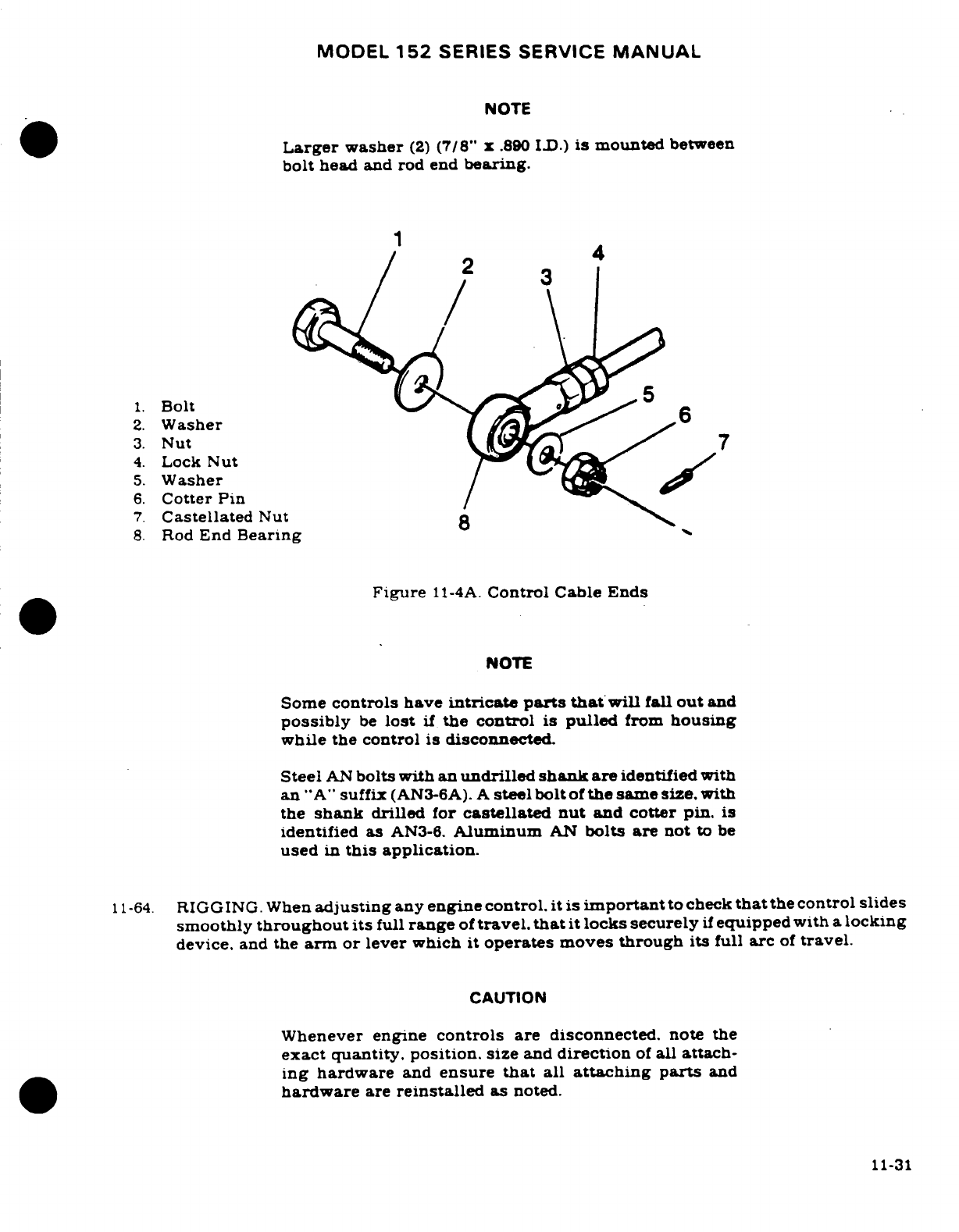
MODEL
152
SERIES
SERVICE
MANUAL
NOTE
Larger
washer
(2)
(7/8"
x
.890
ID.)
is
mounted
between
bolt
head
and rod
end
bearing.
4
1.
Bolt
5
2.
Washer
3.
Nut
7
4.
Lock
Nut
5.
Washer
6.
Cotter
Pin
7.
Castellated
Nut
8.
Rod
End
Bearing
Figure
11-4A.
Control Cable
Ends
NOTE
Some
controls
have
intricate
parts
that
will
fall
out
and
possibly
be
lost
if
the control
is
pulled
from
housing
while
the
control
is
disconnected.
Steel
AN
bolts with
an
undrilled
shank
are
identified
with
an
"A"
suffix
(AN3-6A).
A
steel
bolt
of
the
same size,
with
the
shank
drilled
for
castellated
nut
and
cotter
pin.
is
identified
as
AN3-6.
Aluminum
AN
bolts are
not
to
be
used
in
this
application.
11-64.
RIGGING.
When
adjusting
any
engine
control.
it is
important
to
check
that
the
control
slides
smoothly
throughout
its
full
range
of
travel.
that
it
locks
securely
if
equipped
with
a
locking
device,
and
the
arm or
lever
which
it
operates
moves
through
its
full
arc
of
travel.
CAUTION
Whenever
engine
controls
are
disconnected.
note
the
exact
quantity, position,
size
and
direction
of
all
attach-
ing hardware
and
ensure
that
all
attaching
parts
and
hardware
are
reinstalled
as
noted.
11-31
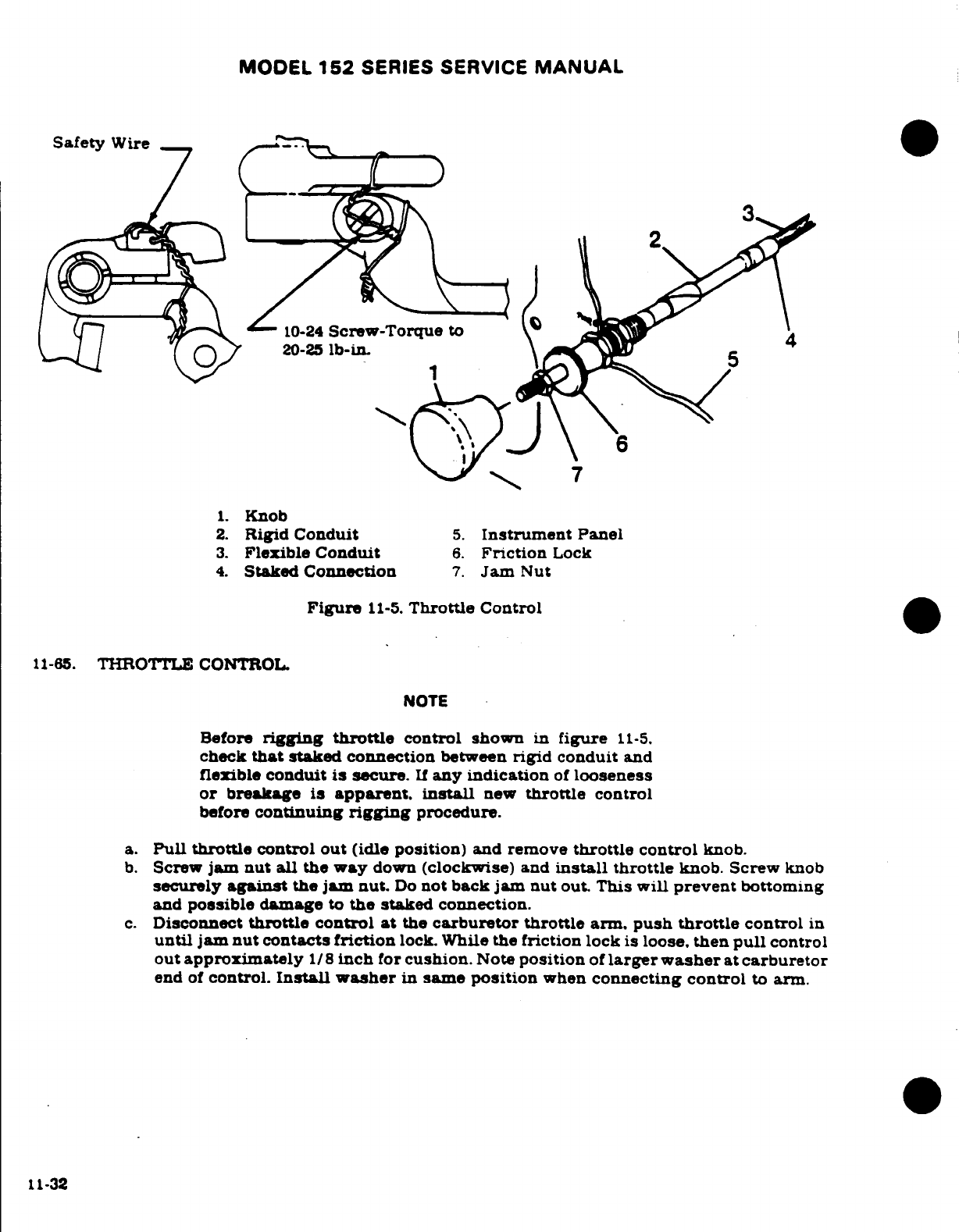
MODEL
152
SERIES
SERVICE
MANUAL
Safety
Wire
3
3
10-24
Screw-Torque
to
20-25
lb-in.
1.
Knob
2.
Rigid
Conduit
5.
Instrument
Panel
3.
Flexible
Conduit
6.
Friction
Lock
4.
Staked
Connection
7.
Jam
Nut
Figure
11-5.
Throttle
Control
11-65.
THROTTLE
CONTROL.
NOTE
Before
rigging
throttle
control
shown
in
figure
11-5.
check
that
staked
connection
between
rigid
conduit
and
flexible
conduit
is
secure.
If
any
indication
of
looseness
or breakage
is
apparent, install
new
throttle
control
before
continuing
rigging
procedure.
a.
Pull
throttle
control
out
(idle
position)
and
remove
throttle
control
knob.
b.
Screw
jam
nut all the
way
down
(clockwise)
and
install
throttle
knob.
Screw
knob
securely
against
the
jam
nut.
Do
not
back jam
nut
out.
This
will
prevent
bottoming
and
possible
damage
to
the
staked
connection.
c.
Disconnect
throttle
control
at
the
carburetor throttle
arm.
push
throttle
control
in
until jam
nut
contacts
friction
lock.
While
the
friction
lock
is
loose.
then
pull
control
out
approximately
1/8
inch
for
cushion.
Note
position
of
larger washer
at
carburetor
end
of
control.
Install washer
in
same
position
when
connecting
control
to
arm.
11-32
MODEL
152
SERIES SERVICE
MANUAL
d.
Tighten
friction
lock,
being
careful
not
to
change
position
of
the
throttle.
e. Move
throttle
arm
on
the
carburetor
to
full
open,
adjust
rod
end
at
end
of
throttle
control
to
fit,
and
connect
to
arm
on
carburetor.
f.
Release
friction
lock
and
check
full
travel
of
arm
on
carburetor.
If
further
adjustmer
is
required,
make
all adjustments
at
the
carburetor
end
of
control.
DO
NOT
change
jam
nut
setting.
g.
Tighten
rod
end
locknuts
at
carburetor
end
of
control.
Be
sure
to
maintain
sufficient
thread
engagement
between
rod
end and
control.
NOTE
Refer
to
the Inspection
Chart
in
Section
2
for
inspection.
lubrication
and/or
replacement
interval
for
the
throttle
control.
11-66.
MIXTURE CONTROL.
a.
Push
mixture
control
full
in
(RICH),
unlock then
pull
it
out
approximately
1/8
inch
for
cushion.
b.
Loosen
clamp
securing
the
control
housing
to
the
engine.
c.
Shift
the
control
housing
in
the
clamp
so
that
the
mixture
arm
on
the
carburetor
is
in
full
open
(RICH).
Tighten
clamp
in
this
position.
d.
Unlock
and
pull
mixture
control
full
out.
Check
that
mixture arm
on
carburetor
is
full
closed
(IDLE
CUT-OFF).
e.
Check
that
bolt
and
nut
at the
mixture
arm
on
the
carburetor
secures
the
control
wire
and
that
the bolt
will
swivel
in
the
arm.
f.
Bend
control
wire
tip
90
degrees
to
prevent
it
from
being
withdrawn
if
the
attaching
nut
should
become
loose.
g.
When
installing
a
new
control
assembly,
it
may
be
necessary
to
shorten the
wire
and/or
control
housing.
h.
The
mixture
arm
on
the
carburetor
must
contact
the
stops
in
each
direction,
and
the
control
should
have
approximately
1/8
inch
cushion
when
pushed
full
in
(RICH).
NOTE
Refer
to
the
Inspection Chart
in
Section
2
for inspection.
lubrication
and/or
replacement
interval
for
the
mixture
control.
11-67.
CARBURETOR
HEAT
CONTROL.
a.
Loosen
clamp
securing
the
control
to
the
bracket
on
the airbox.
b.
Push control
full
in.
then
pull
it
out
approximately
1/8
inch
from
panel
for
cushion.
c.
Shift
the
control
housing
in
its
clamp
so
that
the
valve
lever
is
full
forward.
with
valve
seating
inside
airbox.
Tighten
clamp
in
this
position.
d.
Pull
out
on
the
control
and check
that
the
air
valve
inside the
airbox
seats
in
the
opposite
direction.
e.
Check
that
bolt
and
nut
on
the
air
throttle
lever
secures
the
control
wire
and
that
the
bolt
will
swivel
in
the
lever.
f.
Bend
the
wire
tip
90
degrees
to
prevent
it
from
becoming
withdrawn
if
the
attaching
nut
should
become
loose.
NOTE
Refer
to
the
Inspection
Chart
in
Section
2
for
inspection.
lubrication
and/
or
replacement
interval
for the
carbure-
tor
heat
control.
11-33
MODEL
152
SERIES
SERVICE
MANUAL
11-68.
STARTING
SYSTEM.
11-69.
DESCRIPTION.
The
starting
system
employs
an
electrical
starter
motor
mounted
at
the
front
(propeller
end)
lower left
side
of
the
engine.
Beginning
with Aircraft
15283092
&
on.
and
A1520853
&
on.
a
Prestolite
Slower
Turning
starter
is
installed.
A
starter
solenoid
is
activated
by
the
ignition
switch
on
the
instrument
panel
When
the
solenoid
is
activated.
its
contacts
close
and
electrical
current
energizes
the
starter
motor.
Initial
rotation
of
the
starter
motor
engages the
starter
through an
overrunning
clutch
in
the
starter
adapter.
11-70.
TROUBLE
SHOOTING.
TROUBLE
PROBABLE
CAUSE
REMEDY
STARTER
WILL
NOT
Defective
master
switch
or
Install
new
switch or
wires.
OPERATE.
circuit.
Defective
starter
switch
or
Install
new
switch or
wires.
switch
circuit.
Defective
starter
motor.
Remove.
repair
or
install
new
starter
motor.
STARTER
MOTOR
RUNS.
Defective
overrunning
clutch
Install
new
starter
adapter.
BUT
DOES
NOT
TURN
or
drive.
CRANKSHAFT.
Starter
motor
shaft
broken.
Install
new
starter
motor.
STARTER
MOTOR
DRAGS.
Low
battery.
Charge or
install
new
battery.
Starter
switch
or
relay
con-
Install
servicable
unit.
tacts
burned
or
dirty.
Defective
starter
motor
Install
new
cable.
power
cable.
Loose
or dirty
connections.
Remove.
clean and
tighten
all
terminal
connections.
Defective
starter
motor.
Check
starter
motor
brushes.
brush
spring
tension.
thrown
solder
on
brush
cover.
Re-
pair
or install
new
starter
motor.
Dirty
or
worn
commutator.
Clean
and
turn
commutator.
11-34
MODEL
152
SERIES SERVICE
MANUAL
11-71.
REMOVAL
AND
INSTALLATION.
a.
Remove
cowling
as
required
for
access.
CAUTION
When
disconnecting
or
connecting the
starter
cable. do
not
permit
starter
terminal
bolt
to
rotate.
Rotation
of
the
terminal
bolt
could
break
the
conductor
between
terminal
and
field
coils
causing
the
starter
motor
to
be
inoperative.
b.
Disconnect
starter
power
cable
at starter.
Insulate
terminal
on
power
cable
to
prevent
accidental
shorting.
c.
Remove
three
nuts
and
washers
and
one
bolt
securing
starter
to
crankcase.
Work
starter
from
engine.
d.
To
install starter.
position
starter
on
mounting
pad.
aligning
dowel
pins
in
starter
mounting
pad
with
holes
in
mounting
pad
on engine.
e.
Secure
starter
with
washer.
lockwasher
and
nut
in
three
places
and
install
bolt
and
washers.
f.
Tighten
nuts
and
bolt
evenly
to
a
torque
value
of
150
lb-in.
g.
Connect
electrical
cable
to
starter
terminal
and
install
engine cowling.
11-72.
PRIMARY
MAINTENANCE. The
starting
circuit
should
be
inspected
at
regular
intervals.
the
frequency
of
which
should
be
determined
by
the
amount
of
service
and
conditions
under
which
the
equipment
is
operated.
Inspect
the
battery
and
wiring.
Check
battery
for
fully
charged condition.
proper
electrolyte
level
with
approved
water
and
terminals
for
cleanli-
ness.
Inspect
wiring
to
see
that
all
connections
are
clean
and
tight
and
that
the
wiring
insulation
is
sound.
Check
that
the
brushes
slide
freely
in
their
holders
and
make
full
contact
on
the
commutator.
When
brushes
are worn
to
one-half
of
their
original
length.
install
new
brushes
(compare
with
new
brushes).
Check
the
commutator
for
uneven
wear.
excessive
glazing
or
evidence
of
excessive arcing.
If
the
commutator
is
only
slightly
dirty,
glazed.
or
discolored.
it
may
be
cleaned
with
a
strip
of
No.
00
or
No.
000
sandpaper.
If
the commutator
is
rough
or
worn,
it
should
be
turned
in
a
lathe
and
the
mica undercut.
Inspect
the
armature
shaft
for
rough
bearing
surfaces.
New
brushes
should
be
properly
seated
when
installing
by
wrapping
a
strip
of
No.
00
sandpaper
around
the
commutator
(with
sanding
side
out)
1-1 /
4
to
1-1/2
times maximum.
Drop
brushes
on
sandpaper
covered
commutator
and
turn
armature
slowly
in
the
direction
of
normal rotation.
Clean
sanding
dust
from
motor
after
sanding
operations.
11-35
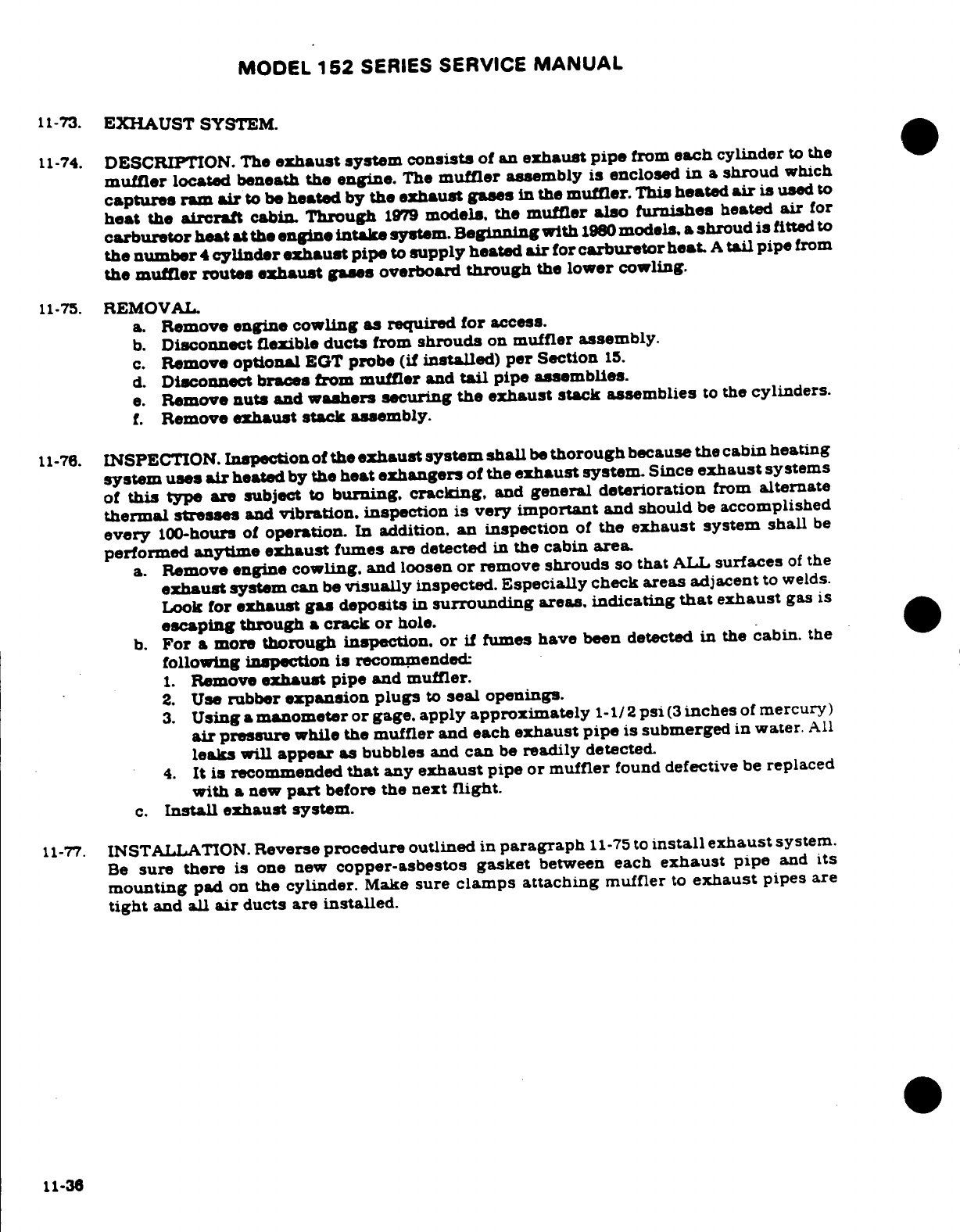
MODEL
152
SERIES
SERVICE
MANUAL
11-73.
EXHAUST
SYSTEM.
11-74.
DESCRIPTION.
The
exhaust
system
consists
of
an
exhaust
pipe
from
each
cylinder
to
the
muffler
located
beneath
the
engine.
The
muffler
assembly
is
enclosed
in
a
shroud
which
captures
ram
air
to be
heated
by
the
exhaust
gases
in
the
muffler.
This
heated
air
is
used
to
heat
the
aircraft
cabin.
Through
1979
models,
the
muffler
also
furnishes
heated
air
for
carburetor
heat
at
the
engine
intake
system.
Beginning
with
1980
models,
a
shroud
is
fitted
to
the
number
4
cylinder
exhaust
pipe
to
supply
heated
air
for
carburetor
heat.
A
tail
pipe
from
the
muffler routes
exhaust
gases
overboard
through
the
lower
cowling.
11-75.
REMOVAL.
a.
Remove
engine
cowling
as
required for
access.
b.
Disconnect
flexible
ducts
from
shrouds
on
muffler
assembly.
c.
Remove
optional
EGT
probe
(if
installed)
per
Section
15.
d.
Disconnect
braces
from
muffler
and
tail
pipe
assemblies.
e.
Remove
nuts
and
washers
securing the
exhaust
stack assemblies
to
the
cylinders.
f.
Remove
exhaust stack
assembly.
11-76.
INSPECTION.
Inspection
of
the
exhaust system
shall
be
thorough
because
the cabin
heating
system uses
air
heated
by
the
heat
exhangers
of
the
exhaust
system.
Since
exhaust
systems
of
this
type
are
subject
to
burning,
cracking,
and
general
deterioration
from
alternate
thermal
stresses
and
vibration,
inspection
is
very
important
and
should
be
accomplished
every
100-hours
of
operation.
In addition.
an
inspection
of
the
exhaust
system
shall
be
performed
anytime
exhaust
fumes
are
detected
in
the
cabin
area.
a.
Remove
engine
cowling,
and
loosen
or
remove
shrouds
so
that
ALL
surfaces
of
the
exhaust
system
can
be
visually
inspected.
Especially
check
areas adjacent
to
welds.
Look
for
exhaust
gas
deposits
in
surrounding
areas,
indicating
that
exhaust
gas is
escaping
through
a
crack or
hole.
b.
For
a
more
thorough
inspection,
or
if
fumes
have
been
detected
in
the
cabin. the
following
inspection is
recommended:
1.
Remove
exhaust
pipe
and
muffler.
2.
Use
rubber
expansion
plugs
to
seal
openings.
3.
Using
a
manometer
or
gage.
apply
approximately
1-1/2
psi
(3
inches
of
mercury)
air
pressure
while
the
muffler
and
each
exhaust
pipe
is
submerged
in
water.
All
leaks
will
appear
as
bubbles
and
can
be
readily
detected.
4.
It
is
recommended
that
any
exhaust
pipe
or
muffler
found
defective
be
replaced
with
a
new
part
before
the
next
flight.
c.
Install
exhaust system.
11-77.
INSTALLATION.
Reverse procedure
outlined
in
paragraph
11-75
to
install
exhaust
system.
Be
sure
there
is
one
new
copper-asbestos
gasket
between
each
exhaust
pipe
and
its
mounting
pad
on
the
cylinder.
Make
sure
clamps
attaching
muffler
to
exhaust
pipes
are
tight
and
all
air
ducts are
installed.
11-36
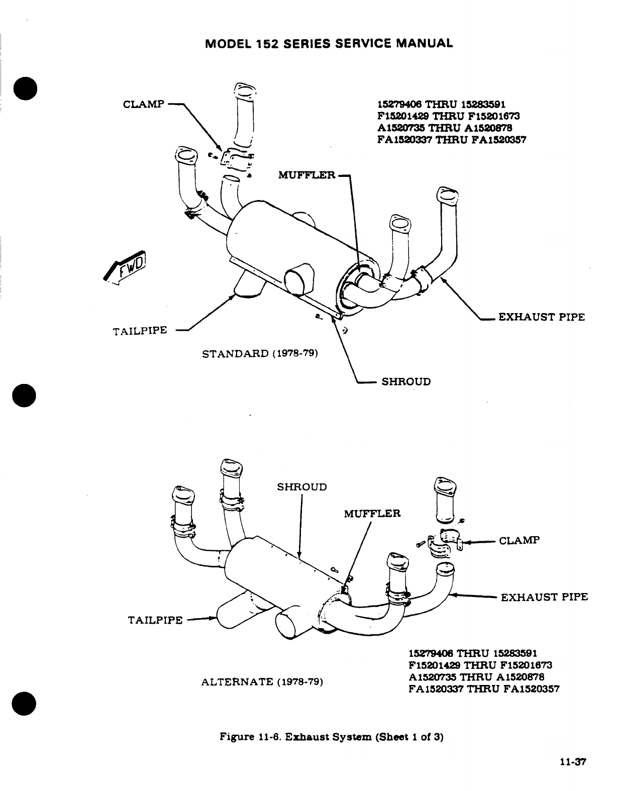
MODEL
152
SERIES SERVICE
MANUAL
CLAMP
15279406
THRU
15283591
F15201429
THRU
F15201673
A1520735
THRU
A1520878
FA1520337
THRU
FA1520357
|
MUFFLER-
EXHAUST
PIPE
TAILPIPE
STANDARD
(1978-79)
SHROUD
SHROUD
MUFFLER
CLAMP
EXHAUST
PIPE
TAILPIPE
15279406
THRU
15283591
F15201429
THRU
F15201673
ALTERNATE
(1978-79)
A1520337
THRU
A1520357
FA1520337
THRU
FA1520357
Figure
11-6.
Exhaust
System
(Sheet
1
of
3)
11-37
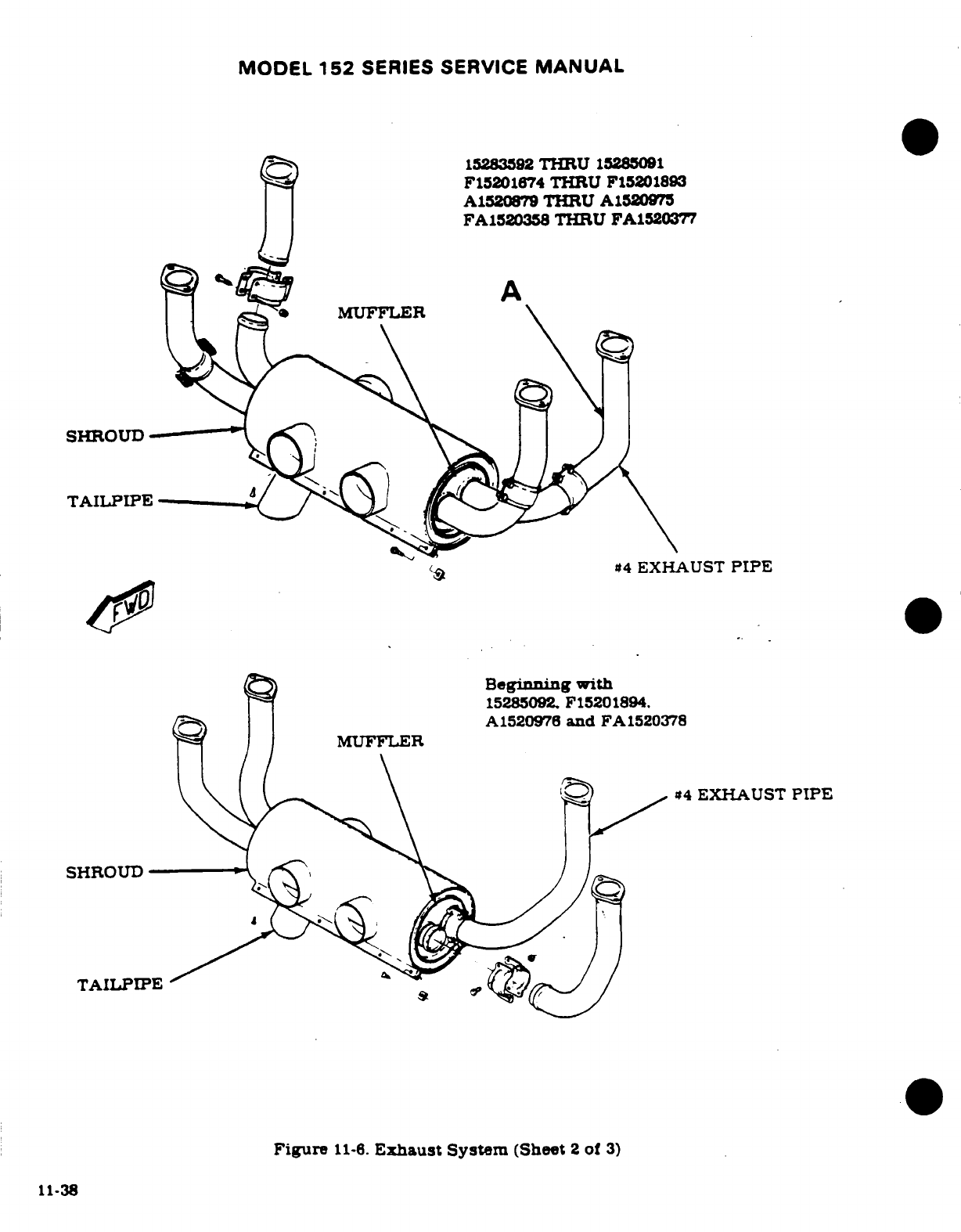
MODEL
152
SERIES
SERVICE
MANUAL
15283592
THRU
15285091
F15201874
THRU
F15201893
A1520879
THRU
A1520975
FA1520358
THRU
FA1520377
MUFFLER
SHROUD
TAILPIPE
4
EXHAUST
PIPE
Beginning
with
15285092 F15201894.
A1520976
and
FA1520378
MUFFLER
#4
EXHAUST
PIPE
SHROUD
TAILPIPE
Figure
11-6.
Exhaust
System
(Sheet
2
of
3)
11-38
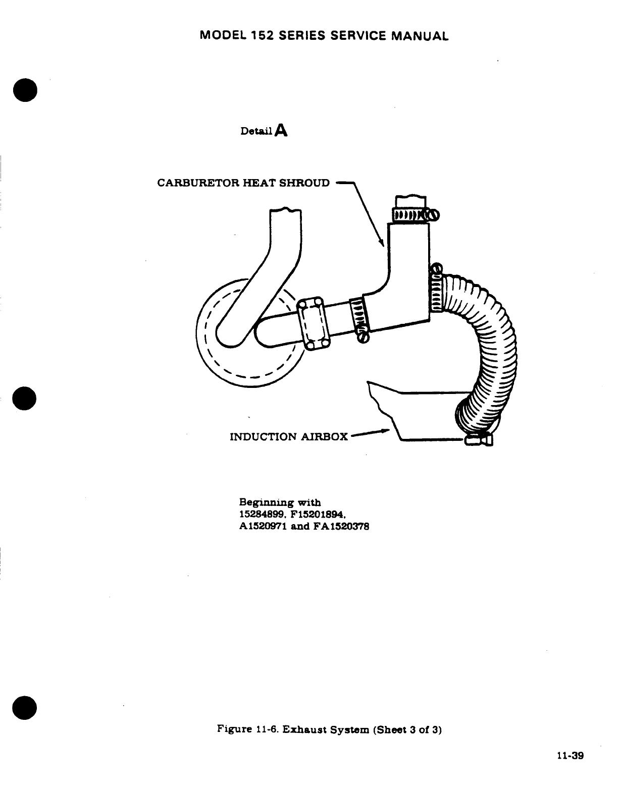
MODEL
152
SERIES
SERVICE
MANUAL
Detail
A
CARBURETOR
HEAT SHROUD
INDUCTION
AIRBOX
Beginning
with
15284899,
F15201894,
A1520971
and
FA1520378
Figure
11-6.
Exhaust
System
(Sheet
3
of
3)
11-39
MODEL
152
SERIES SERVICE
MANUAL
11-78.
EXTREME
WEATHER
MAINTENANCE.
NOTE
Refer
to
the
appropriat
Pilot's
Operating
Handbook
for
approd
starting
procedures.
11-79.
COLD
WkATHMR.
Cold
wather
starting
is
made
easier
with
the
installation
of
the
engine
primer
system
and
ground
service
receptacle.
The
primer
system
is a
manually
operated
typ.
Fuel
is
suppled
by
a
line
from
the
fuel
trainer
to
the
plunger
type
primer.
Operating
the
primer
plunger
in
the
cabin
forces
fuel
to
the
engine.
With
the
ground
service
receptacle
installed,
external
power
source
may
be
connected to
assist
in
cold
weather
or
low
battery
sarting.
Refer
to
Section
16
for
use
of
the
ground
service
receptacle.
The
followng
may
also
be
used
to
assist
engin
starting
in
extreme
cold
weather.
After
the
last
flight
of
the
day,
drain
the
engine
oil
into
a
clean
strainer
so
the
oil
can
be
preheated.
Cover
the
engine
to
prevent
Ice
or
snow
from
collecting
inside
the
cowling.
When
preparing
the
aircraft
for
flight or
engine
run-up
after
theo
conditions
have
been followed,
preheat
the
drained
oil
WARNING
Do
not
hat
oil
above
121°C
(250F).
A
flash
fire may re-
sult.
Before
pulling
the
propeller
through,
ascertain that
magneto switch
is in
OFF
position
to
prevent
the engine
frIm
firing.
After
preheating
the
oil.
gasoline
may
be
mied
with
the
heated
oil
in
a
ratio
of
1
part
gasoline
to
1
part
oil
beore
pouring
into
the
engine
oil
sump.
If
the free
air
temperature
is
below
-29C
(-20'),
the engine
Compartment
should
be
preheated
with
a
ground
heater.
Preheating
the
engine
ompartment
is
acomplaished
by
Inducing
heated
air
up
through
the
nose
gear
opening,
thus
hetig
both
the
oil
and
cylinders.
After
the
engine
compartment
has
been
preheated,
inspect
all
engine
drain
and
vent lines
for
presence
of
ice.
After
this
procedure
has
been
complied
with,
pull
propeller
through
several
revolutions
by
hand
before
starting
the
engine.
CAUTION
Due
to
the
desludging
effect
of
the
diluted
oil.
engine
operation
should
be
observed
closely
during
the
initial
warm
up
of
the
engine.
Engines
that
have accumulated
a
considerable amount
of
operational hours
since
their
last
dilution
period
may
be
seriously
affected
by
the
dilution
process.
This
is
caused
by
the
diluted
oil
dislodging
sludge
and
carbon
deposits
within
the
engine.
This
residue
wil
collect
in
the
oil
sump
and
possibly
clog
the
screened
inlet
to
the
oil
pump.
Small deposits
may
enter
the
oil
pump
and
be
trapped
by
the
pressure
oil
filter
screen.
Partial
or,
in
some
cases,
complete
loss
of
engine
11-40
MODEL
152
SERIES
SERVICE
MANUAL
lubrication
may
result
from
either
condition.
If
these
conditions
are anticipated after
oil
dilution.
the
engine
should
be
operated
for
several
minutes at
normal
operat-
ing
temperatures
and
then
stopped and inspected
for
evidence
of
sludge
and
carbon
deposits
in
the
oil sump
and
oil
filter
screen.
Future
occurrence
of
this
condition
can
be
prevented
by
diluting
the oil
prior
to
each
oil
change.
This
will
prevent
the
build-up
accumulation
of
the
sludge
and carbon
deposits
within
the
engine.
11-80.
DUSTY CONDITIONS.
Dust
inducted
into
the
intake
system
of
the
engine
is
probably
the
greatest
single
cause
of
early
engine
wear.
When
operating
under
high
dust
conditions,
the
induction
air
filter
should
be
serviced
daily
as
outlined
in
Section
2.
11-81.
SEACOAST
AND
HUMID
AREAS.
In
salt
water
areas,
special
care
should
be
taken
to
keep
the
engine
and
accessories
clean
to
prevent
oxidation.
In
humid areas,
fuel
and
oil
should
be
checked
frequently
and
drained
of
condensed
moisture.
11-41/(11-42
blank)
MODEL
152
SERIES
SERVICE
MANUAL
SECTION
12
FUEL
SYSTEM
Page
No.
TABLE
OF
CONTENTS
Aerofiche/
Manual
FUEL SYSTEM
..............
2A2/12-1
Strainer
.................
2A12/12-11
Description
...............
2A212-1 Description
.............
2A12/12-11
Precautions
...............
2A2/12-1
Disassembly/Assembly
.....
2A12/12-11
Trouble
Shooting
...........
2A3/12-2
Priming
Sytem
...........
2A14/12-13
Tanks
................. .
2A9/12-8
Description
............
2A14/12-13
Description
.............
2A9/12-8
Removal
................
2A14/12-13
Removal/Installation
.......
2A9/12-8
Inspection
..............
2A14/12-13
Quantity
Transmitters
.......
2A9/12-8
Installaton
.............
2A15/12-14
Vents
...... ...........
2A9/12-8
Vented
Fuel
Cap
...........
2A16/12-15
Description
.............
2A9/12-8
Description
.............
2A16/12-1
Checking
...............
2A9/12-8
Inspection
Cleaning,
and
Shutoff
Valve
.............
2A12/12-11
Repair
................
2A16/12-15
Description
............
2A12/12-11
Removal/Installation
.......
2A12/12-11
12-1.
FUEL SYSTEM.
12-2.
DESCRIPTION.
Fuel is
gravity
fed
from
the
metal
wing
tanks,
through
a shutoff
valve
and
a
fuel
strainer,
to
the
carburetor.
Positive
ventilation
is
provided
by
a
vent
line
and
a
check
valve
assembly
located
in
the
left
wing
tank,
a
crossover
line
connecting
the
two
tanks
together,
and
a
vented
fuel
cap
on
the
right
hand
tank.
The
vent
line
from the
check
valve
assembly
extends
overboard
through
the
lower
wing skin
adjacent
to
the
left
wing
strut.
A
fuel
drain
is
located
between
the
shutoff
valve
and the
strainer.
12-3.
PRECAUTIONS.
Common
sense as
well
as
certain general
precautions
should
be
followed
when
working
on
or around
fuel
systems.
Some
of
these
precautions
are:
a.
Always
GROUND
the
aircraft
to
a
suitable
ground
stake
to
prevent
electrostatic
build
up.
b.
Use
drip
pans
to
prevent
accumulation
of
drainage
from
lines, hoses, and
fittings.
because
accumulation
increases
the
fire
hazard.
c.
Cap
or
cover
all
open
lines
or
connections
to
prevent
damage
to
threads
and
entrance
of
foreign
materials.
NOTE
Use
NS-40
(RAS-4)
(Snap-On-Tools
Corp..
Kenosha.
Wisc.),
MIL-T-5544
(Thread
Compound
Antiseize,
Gra-
phite
Petrolatum).
USP
Petrolatum
or
engine
oil
as
a
thread
lubricant,
and
to
seal
fittings.
Apply
sparingly
to
male
threads,
and
avoid
stringing
across
openings.
Make
sure
no
foreign
material
can
enter
the
fuel
system.
12-1
MODEL
152
SERIES
SERVICE
MANUAL
12-4.
TROUBLE
SHOOTING.
TROUBLE
PROBABLE CAUSE
REMEDY
NO
FUEL
TO
CARBURETOR.
Fuel shutoff
valve
not
Turn
valve
on.
(Safety
in
turned
on.
ON
position.)
Fuel
tanks
empty.
Service
with
proper
grade
and
amount
of
fuel
Plugged
fuel
strainer.
Remove and
clean strainer
and screen.
Fuel
line
plugged.
Clean
out
or
replace
fuel
line.
Fuel
tank
outlet
strainers
Remove
and
clean
strainers
plugged. and
flush
out
fuel
tanks.
Inlet
elbow
or inlet
screen
Clean
and/or
replace.
in
carburetor
plugged.
Fuel
line
disconnected
or
Connect
or
repair
fuel
lines.
broken.
Defective
fuel
shutoff
valve. Replace
shutoff
valve.
FUEL
STARVATION
AFTER
Partial
fuel
flow
from
the
Use
the
preceding
remedies.
STARTING. preceding
caues.
Plugged
fuel
vent.
See
paragraph
12-11.
Water
in fuel.
Drain
fuel
tank
sumps.
fuel
lines
and
fuel
strainer.
NO
FUEL
QUANTITY
Fuel
tanks
empty. Service
with
proper
grade
INDICATION.
and
amount
of
fuel.
Blown
fuse.
Replace
blown
fuse.
Loose
connections
or
open
Tighten
connections:
repair
circuit.
or
replace
wiring.
Refer
to
Section
19.
Defective
fuel
quantity
indi-
Refer
to
Section
15.
cator
or
transmitter.
PRESSURIZED
FUEL TANK.
Plugged
bleed
hole in
fuel
Check
per
paragraph
12-11.
vent.
12-2
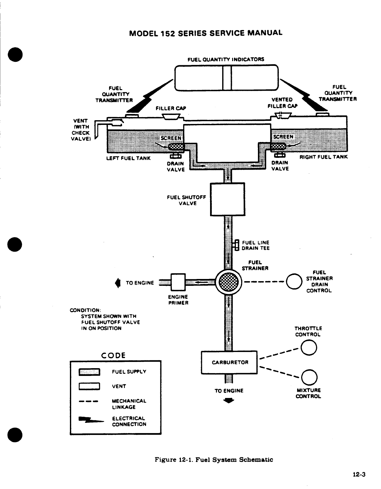
MODEL
152
SERIES
SERVICE
MANUAL
FUEL
QUANTITY
INDICATORS
FUEL
FUEL
QUANTITY
QUANTIT
TRANSMITTER
VENTED
TRANSMITTER
FILLER
CAP
FILLER
CAP
VENT
(WITH
CHECK
LEFT
FUEL
TANK
RIGHT FUEL
TANK
DRAIN
DRAIN
VALVE
VALVE
DRAIN
TEE
VALVE
FUEL
STRAINER
STRAINER
'-*-CONTROL
IN
ON
POSITION
THROTTLE
'CONTROL
CODE
CARBURETOR
FUEL
SUPPLY
I I
VENT
TO ENGINE
MIXTURE
MECHANICAL
CONTROL
LINKAGE
PRELECTRICAL
CONNECTION
Figure
12-1.
Fuel
Sytem
Schematic
12-3
12-3
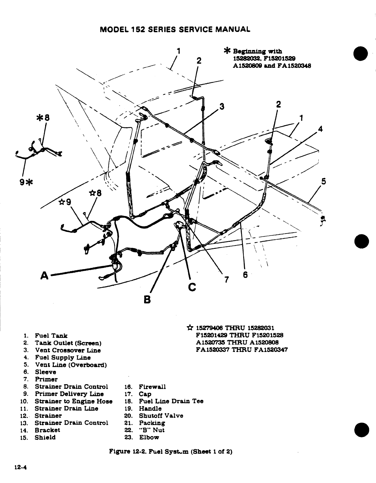
MODEL
152
SERIES
SERVICE
MANUAL
1
*
Beginning
with
B
*
15279406
THRU
15282031
1.
FuelTank
F15201429
THRU
F15201528
2.
Tank
Outlet
(Screen)
A1520735
THRU
A1520808
3.
Vent
Crossover
Line
FA1520337
THRU
FA1520347
4.
Fuel
Supply
Line
5.
Vent
Line
(Overboard)
6.
Sleeve
7.
Primer
8.
Strainer
Drain Control
16.
Firewall
9.
Primer
Delivery
Line
17.
Cap
10.
Strainer
to
Engine
Hose
18.
Fuel
Line
Drain
Tee
11.
Strainer
Drain
Line
19.
Handle
12.
Strainer
20.
Shutoff
Valve
13.
Strainer
Drain
Control
21.
Packing
14.
Bracket
22.
"B"
Nut
15.
Shield
23.
Elbow
Figure
12-2.
Fuel Systym (Sheet
1
of
2)
12-4
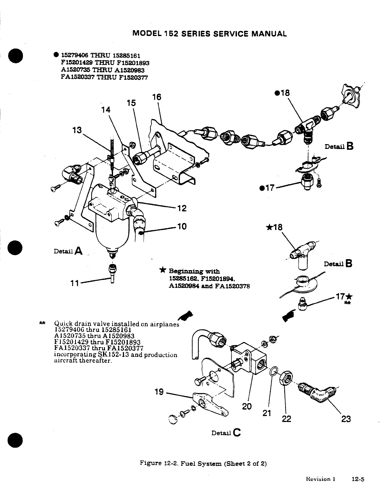
MODEL
152
SERIES
SERVICE
MANUAL
*
15279406
THRU
15285161
F15201429 THRU
F15201893
A1520735 THRU
A1520983
FA1520337
THRU
F1520377
*
18
15
16
14
13
DetailB
®17
12
10
*18
Detail
A
Detail
B
Beginning
with
15285162.
F15201894.
A1520984
and
FA1520378
17*
**
Quick
drain
valve
installed
on
airplanes
1527940G
thru
15285161
A
1520735
thru
A
1520983
F15201429
thru
F15201893
FA1520337
thru
FA1520377
incorporating
SK152-13
and
production
aircraft thereafter.
19
20
22
22
23
Detail
C
Figure
12-2.
Fuel
System (Sheet
2
of
2)
Revision
1
12-5
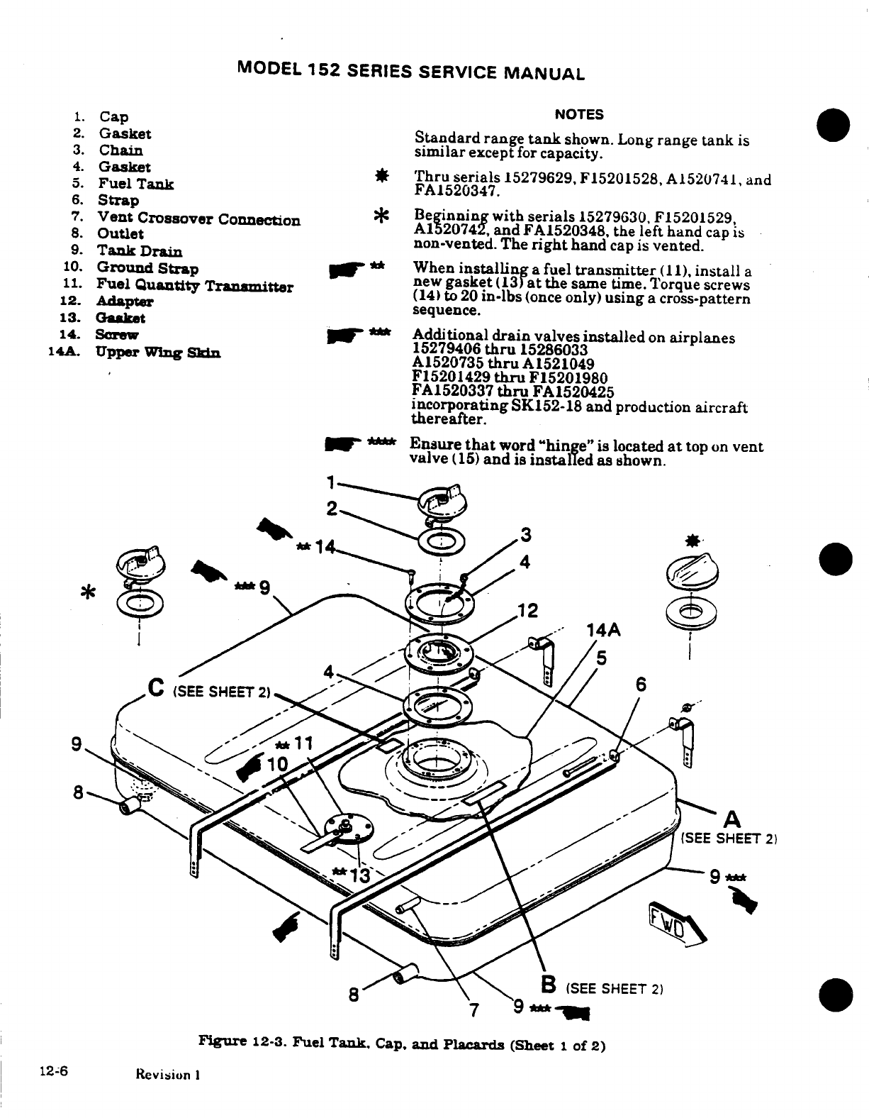
MODEL
152
SERIES
SERVICE
MANUAL
NOTES
1.
Cap
2.
Gasket
Standard
range
tank
shown. Long
range
tank
is
3.
Chain similar
except
for
capacity.
4.
Gasket
*
Thru
serials
15279629,
F15201528,
A1520741,
and
5.
FuelTank
FA1520347.
6.
Strap
7.
Vent
CrossoverConnection
Beginning
with
serials
15279630,
F15201529,
.
A1520742,
and
FA1520348,
the
left
hand
cap
is
8.
Outlet
non-vented.
The
right
hand
cap
is
vented.
9.
Tank Drain
10.
Ground
Strap
**
When
installing
a
fuel
transmitter
(11),
install
a
11.
Fuel
Quantity
Transmitter
new
gasket
(13)at
the
same
time.
Torque
screws
(14)
to
20
in-lbs
(once
only)
using
a
cross-pattern
12.
Adapter
sequence.
13.
Gasket
14.
Screw
*
Additional
drain
valves
installed
on
airplanes
14A.
Upper
Wing
Skin
15279406
thru
15286033
A1520735
thru
A1521049
F15201429
thru
F15201980
FA1520337
thru
FA1520425
incorporating
SK152-18
and
production
aircraft
thereafter.
Ensure
that
word
"hinge"
is
located
at
top
on
vent
valve
(15)
and
is
installed
as
shown.
C
(SEE
SE
2
6
.
(SEE
SHEET
2)
SEE
SHEET
2)
7 9**
Figure
12-3.
Fuel
Tank.
Cap,
and
Placards
(Sheet
1
of
2)
12-6
Revision
I
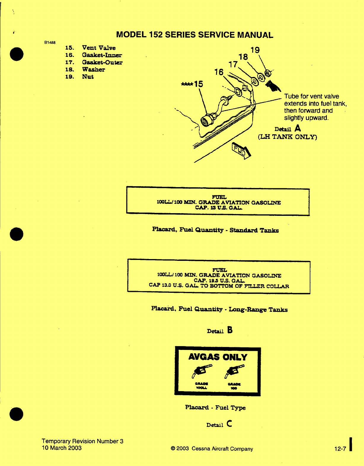
MODEL
152
SERIES
SERVICE
MANUAL
Vent
Valve
Gasket-Inner
Gasket-Outer
Washer
Nut
16
18
17
****15
Tube
for
vent
valve
extends
into
fuel
tank,
then
forward
and
slightly
upward.
A
NK
ONLY)
FUEL
100LL/100
MIN.
GRADE
AVIATION
GASOLINE
CAP.
13
US.
GAL.
Placard,
Fuel
Quantity
-
Standard
Tanks
FUEL
100LL/
100
MIN. GRADE
AVIATION
GASOLINE
CAP.
195
U.S.
GAL.
CAP
13.0
U.S.
GAL.
TO
BOTTOM
OF
FILLER
COLLAR
Placard,
Fuel
Quantity
-
Long-Range
Tanks
Detail
B
Placard
-
Fuel
Type
Detail
C
Temporary Revision
Number
3
10
March
2003
©
2003
Cessna
Aircraft Company
B1488
15.
16.
17.
18.
19.
AVGAS
ONLY
12-7
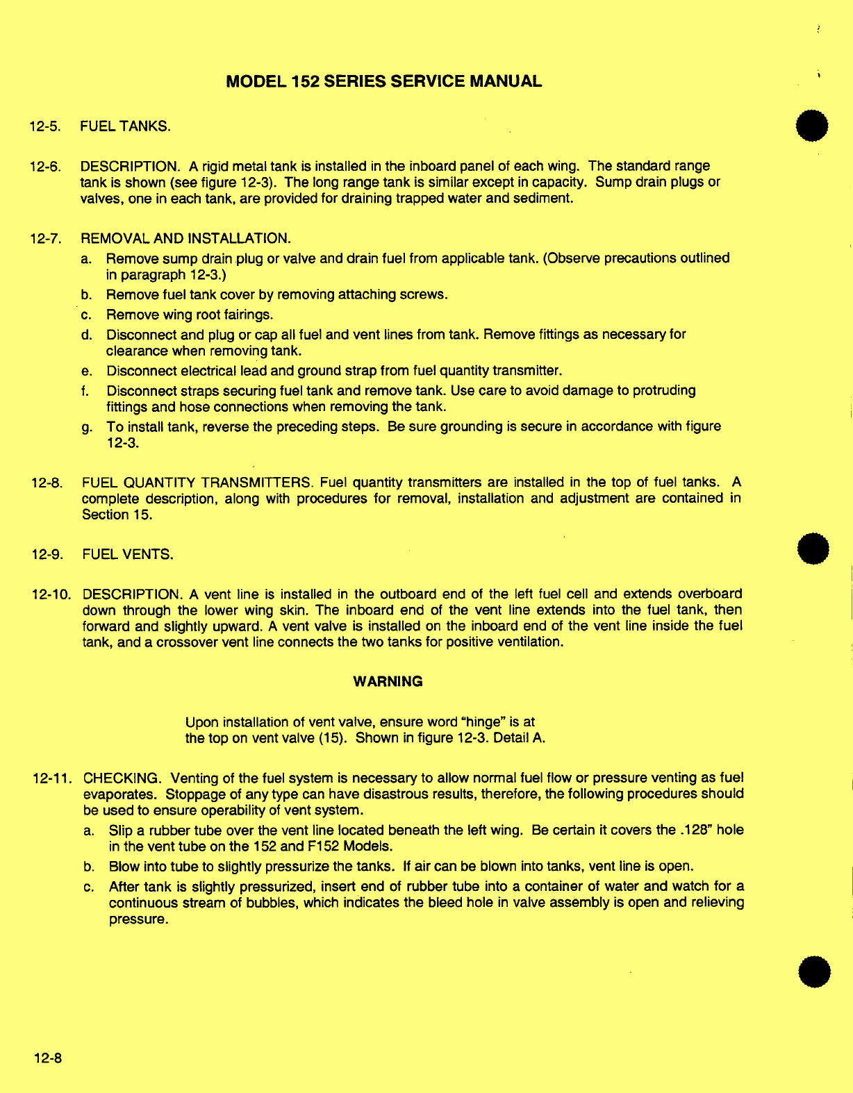
MODEL
152 SERIES
SERVICE
MANUAL
12-5.
FUEL
TANKS.
12-6.
DESCRIPTION.
A
rigid
metal
tank
is
installed
in
the
inboard panel of
each wing.
The
standard
range
tank
is
shown
(see
figure
12-3).
The
long
range
tank
is
similar
except
in
capacity.
Sump
drain plugs
or
valves,
one
in
each
tank,
are
provided
for draining trapped
water
and
sediment.
12-7.
REMOVAL AND INSTALLATION.
a.
Remove sump
drain
plug
or
valve
and
drain
fuel
from
applicable tank.
(Observe
precautions
outlined
in
paragraph
12-3.)
b.
Remove
fuel tank
cover
by
removing
attaching
screws.
c.
Remove
wing
root
fairings.
d.
Disconnect
and
plug
or
cap
all
fuel
and
vent
lines
from
tank.
Remove
fittings
as
necessary
for
clearance
when
removing
tank.
e.
Disconnect
electrical
lead
and
ground
strap
from fuel
quantity
transmitter.
f.
Disconnect straps
securing
fuel
tank
and remove
tank.
Use
care
to
avoid
damage
to protruding
fittings
and
hose
connections
when
removing
the
tank.
g.
To
install
tank,
reverse the preceding
steps.
Be
sure
grounding
is
secure
in
accordance
with
figure
12-3.
12-8. FUEL
QUANTITY
TRANSMITTERS.
Fuel
quantity
transmitters
are installed
in
the
top
of
fuel tanks.
A
complete
description,
along
with
procedures
for
removal,
installation
and
adjustment
are
contained
in
Section
15.
12-9. FUEL
VENTS.
12-10.
DESCRIPTION.
A
vent
line
is
installed
in
the
outboard
end
of
the
left
fuel
cell
and
extends
overboard
down
through the
lower wing
skin.
The
inboard end
of
the
vent
line
extends
into
the
fuel
tank, then
forward
and
slightly
upward.
A
vent
valve
is
installed
on
the inboard
end
of
the
vent
line
inside
the
fuel
tank,
and
a
crossover
vent
line
connects
the
two
tanks
for
positive
ventilation.
WARNING
Upon
installation
of
vent
valve,
ensure
word
"hinge"
is
at
the top
on
vent
valve
(15).
Shown
in
figure
12-3.
Detail
A.
12-11.
CHECKING.
Venting
of
the
fuel
system
is
necessary
to
allow
normal fuel
flow
or pressure
venting
as
fuel
evaporates.
Stoppage
of
any
type
can
have
disastrous
results,
therefore,
the
following
procedures
should
be
used
to
ensure
operability
of
vent
system.
a.
Slip
a
rubber tube
over
the
vent
line
located
beneath the
left wing.
Be
certain
it
covers the
.128"
hole
in
the
vent
tube
on
the
152
and
F152
Models.
b.
Blow
into
tube
to
slightly
pressurize
the
tanks.
If
air
can
be
blown into
tanks,
vent
line
is
open.
c.
After
tank
is
slightly
pressurized, insert
end
of
rubber tube
into
a
container
of
water
and
watch
for
a
continuous
stream of
bubbles,
which
indicates the
bleed hole
in
valve
assembly
is
open and
relieving
pressure.
12-8
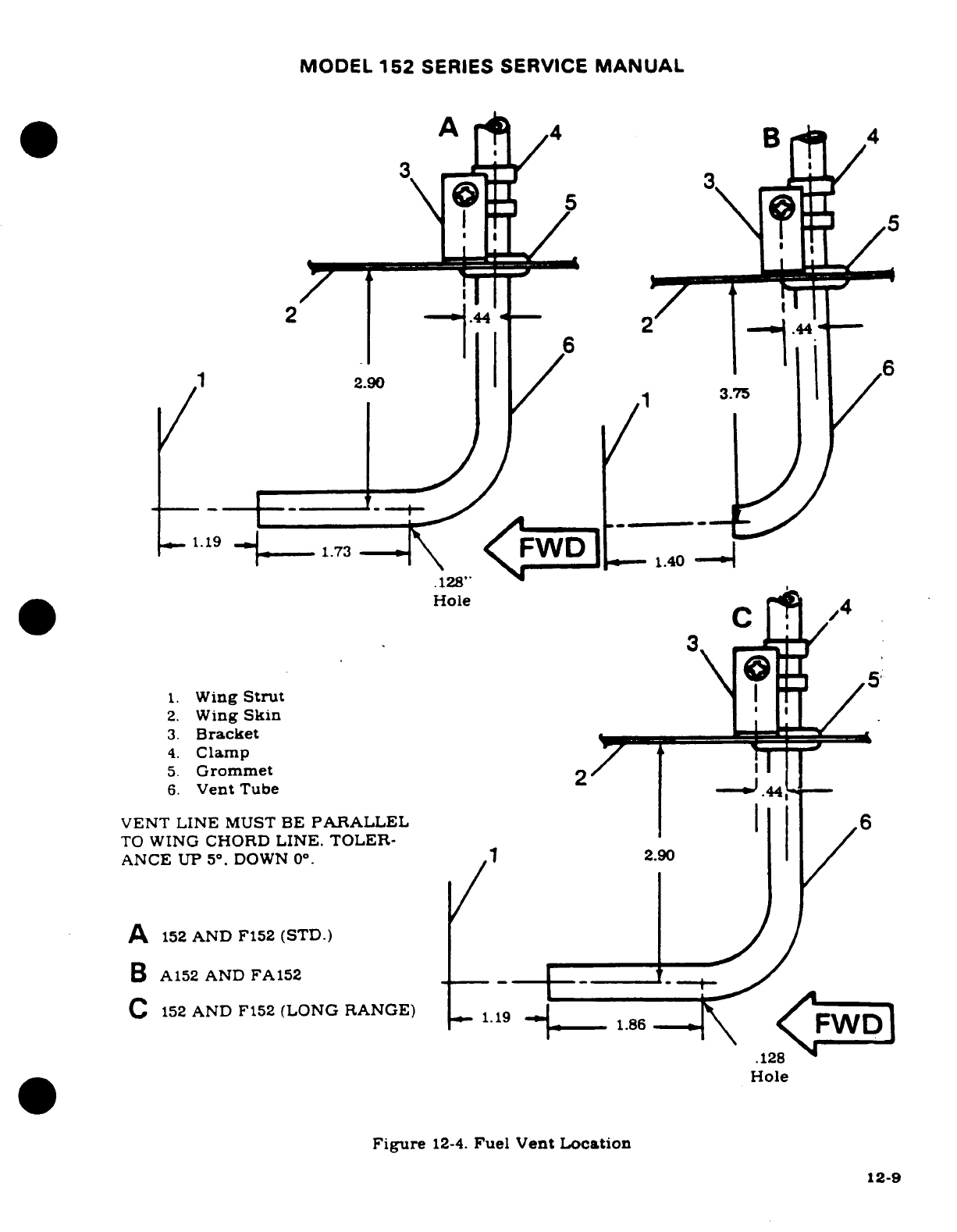
MODEL
152
SERIES SERVICE
MANUAL
A
4
B
4
1
3.
.128''
Hole
5
1.
Wing
Strut
2.
Wing
Skin
3.
Bracket
4.
Clamp
5.
Grommet
2
6.
Vent
Tube
44
VENT
LINE
MUST
BE
PARALLEL
6
TO
WING
CHORD
LINE. TOLER-
ANCE
UP
5° .
DOWN
0°.
1
2.90
A
152
AND
F152
(STD.)
B
A152
AND
FA152
C
152
AND
F152
(LONG RANGE)
1.19
.128
Hole
Figure
12-4.
Fuel
Vent
Location
12-9
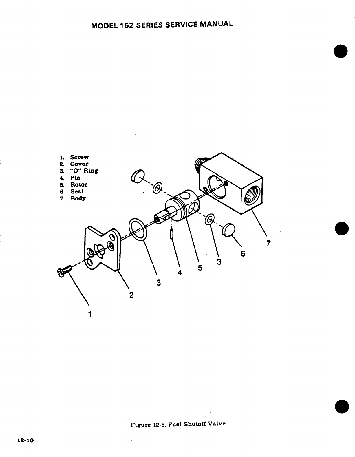
MODEL
152
SERIES
SERVICE
MANUAL
1.
Screw
2.
Cover
3.
"0"
Ring
4.
Pin
5.
Rotor
6.
Seal
7.
Body
6
3
3
1
Figure
12-5.
Fuel
Shutoff
Valve
12-10
MODEL
152
SERIES
SERVICE
MANUAL
d.
After
completion
of
step
"c",
blow
into
tube
again
to
slightly
pressurize
the
tank.
and
loosen,
but
do
not
remove
filler
cap
on
opposite
wing
to
check
tank crossover
line.
If
pressure
escapes
from
filler
cap,
crossover
line
is
open.
NOTE
A
plugged
vent
line
or
bleed
hole
can
cause
fuel
starva-
tion
or
fuel
tank
collapse
as fuel
is
drawn
out
of
tank.
Pressurization
of
tank
(possible
rupturing)
is
possible
due
to
fuel
expansion.
e.
Any
fuel
vent
found
plugged
or
restricted
must
be
corrected
prior
to
returning
aircraft
to
service.
WARNING
The
fuel
vent
line
protruding
beneath
the wing
near
the
wing
strut
must
be
correctly aligned
to
avoid
possible
icing
of
the
vent
tube.
Dimensions are
shown
in
figure
12-
4.
12-12.
FUEL
SHUTOFF
VALVE.
(See
figure
12-5.)
12-13.
DESCRIPTION.
The fuel
shutoff
valve
is a
two-position
ON-OFF
valve,
located
in
the
floor
area
between
the
pilot
and
copilot
seats.
The
handle
is
safety
wired
in
the
"ON"
position
with
.018"
diameter
mild
steel
wire
(tag
wire), which will
break
easily
if
the
handle
must
be
turned
"OFF"
in
an emergency.
The
manufacturer
recommends
replacement instead
of
repair
or
damaged,
worn.
or
inoperative
valves.
12-14.
REMOVAL AND
INSTALLATION.
a.
Completely
drain
all
fuel
from
wing
tanks,
fuel
lines,
strainer,
and
shutoff
valve.
(Observe
the
precautions
in
paragraph
12-3.)
b.
Remove
shutoff
valve
handle.
c.
Remove
copilot's seat
and
access plate
under
seat.
d.
Disconnect
and
cap
all
fuel
lines
at
shutoff
valve.
e.
Remove
bolts
attaching
shutoff
valve
and
remove
valve.
f.
Reverse
the
preceding
steps
for
installation.
Safety
wire
valve
handle
in "ON"
position.
12-15
FUEL
STRAINER.
(See
figure
12-6.)
12-16.
DESCRIPTION.
The
fuel
strainer
is
mounted at
the firewall
in
the
lower
engine
compart-
ment.
The
strainer
is
equipped
with
a
quick-drain
valve
which
provides
a
means
of
draining
trapped
water
and
sediment
from the
fuel
system.
The
quick-drain
control
is
located
adjacent
to
the
oil
dipstick
and
is
accessible
through
the
oil
dipstick
door.
NOTE
The
fuel
strainer
can
be
disassembled,
cleaned
and
reassembled without
removing
the
assembly
from
the
aircraft.
12-17.
DISASSEMBLY
AND
ASSEMBLY.
(See
figure
12-6.)
12-1
1
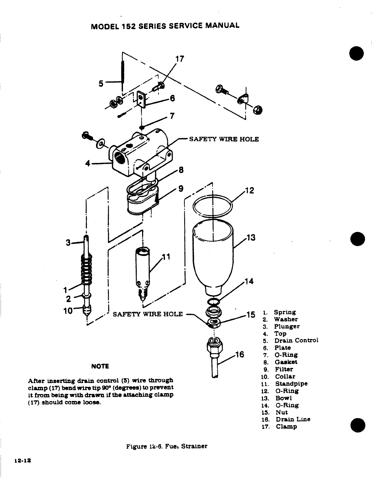
MODEL
152
SERIES
SERVICE
MANUAL
17
5
SAFETY
WIRE HOLE
12
SAFETY
WIRE
HOLE
15
'
Spring
2.
Washer
3.
Plunger
4.
Top
5.
Drain
Control
6.
Plate
16
7.
O-Ring
NOTE
8.
Gasket
9.
Filter
After
inserting
drain
control
(5)
wire
through
10.
Collar
clamp
(17)
bend
wire
tip
90o
(degrees)
to
prevent
11.
Standpipe
it
from
being
with
drawn
if
the
attaching
clamp
12.
O-Ring
(17)
should
come
loose.
13.
Bowl
14.
O-Ring
15.
Nut
16.
Drain
Line
17.
Clamp
Figure
12-6.
Fuel
Strainer
12-12
MODEL
152
SERIES
SERVICE
MANUAL
a.
Remove
drain
tube,
safety
wire,
nut
and
washer
at
bottom
of
filter
bowl.
and
remove
bowl.
b.
Carefully
unscrew
standpipe
and
remove.
c.
Remove
filter
screen
and
gasket.
Wash
filter
screen
and
bowl
with
solvent
(Federal
Specification
P-S-661,
or
equivalent)
and dry with
compressed
air.
d.
Using
a
new
gasket
between
filter
screen
and
top assembly,
install
screen
and
standpipe.
Tighten
standpipe
only
finger
tight.
e.
Using all
new
O-rings,
install
bowl.
Note
that
step-washer at
bottom
of
bowl
is
installed
so
that
step
seats
against
O-ring.
f.
Turn
shutoff
valve
to "ON"
position.
check for
leaks
and
proper operation.
and
safety
wire.
g.
Torque
bottom
nut
(15)
to
25-30
lb-in.,
and
safety
wire
to
top
assembly
of
strainer.
Wire
must
have right-hand
wrap.
at
least
45
degrees.
h.
Connect
drain
tube.
12-18.
PRIMING
SYSTEM.
(See
figure
12-2.)
12-19.
DESCRIPTION.
The
priming
system
is
comprised
of
a
manually-operated pump
located
on
the
instrument
panel.
and
lines
to
all
engine
cylinders.
Operation
of
the
pump
plunger
forces
fuel
directly
into
the engine
cylinders.
12-20.
REMOVAL.
(See
figure
12-7.)
NOTE
Removal
of
primer
from
instrument
panel
entails
disassembly
of
primer.
a.
Place
fuel
shutoff
valve
in
the
OFF
position.
b.
Spread
drip
cloth
under
left-hand
instrument
panel.
c.
Disconnect
and
cap
or
plug
primer
lines at
primer.
d.
Unlock
primer
knob
and
pull
aft
to
clear
packing
nut
(5).
e.
Unscrew
packing
nut
(5).
f.
Withdraw
primer
knob
and
piston
rod
from
instrument
panel.
g.
The
primer
barrel
can
now
be
worked
free
from
the
instrument
panel
on
the
firewall
side
of
the
panel.
12-21.
INSPECTION.
Visually inspect
primer
lines
for
crushed,
kinked
or
broken
condition.
Ensure
proper
clamping
to
prevent fatigue
due
to
vibration
or
chafing.
Ensure
barrel's
(9)
cylinder
wall
is
free
of
signs
of
pitting,
corrosion.
or
scoring
and
that
O-rings
(3)
are
in
good
condition.
NOTE
To
remove
O-rings
(3)
from
piston
rod
(8).
squeeze
O-
rings
in
grooves
of
piston
rod
with
thumb
and
index
finger.
Work
O-rings
over
end
of
piston
rod.
O-rings
can
be
refitted
to
their
grooves
on
piston
rod
(8)
in a
like
manner.
CAUTION
Do
not
damage
O-rings
(3).
12-13
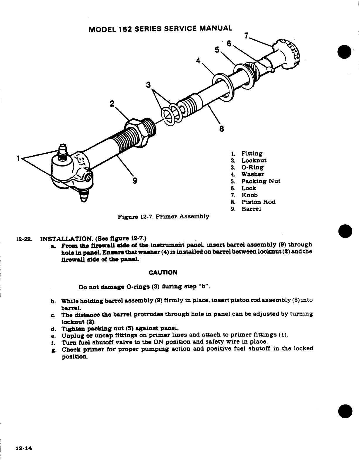
MODEL
152
SERIES
SERVICE
MANUAL
1
4.
Washer
9
5.
Packing
Nut
6.
Lock
7.
Knob
8.
Piston
Rod
9.
Barrel
Figure
12-7.
Primer
Assembly
12-22.
INSTALLATION.
(See
figure
12-7.)
a.
From
the
firewall
side
of
the
instrument
panel.
insert
barrel
assembly
(9)
through
hole
in
panel
Ensure
that
washer
(4)
is
installed
on
barrel
between
locknut
(2)
and
the
firewall
side
of
the
paneL
CAUTION
Do
not
damage O-rings
(3)
during
step
"b".
b.
While
holding
barrel
assembly
(9)
firmly
in
place,
insert
piston
rod
assembly
(8)
into
barrel.
c.
The
distance
the
barrel
protrudes through
hole
in
panel
can
be
adjusted
by
turning
locknut
(2).
d.
Tighten
packing nut
(5)
against
panel.
e.
Unplug
or
uncap
fittings
on
primer
lines
and
attach
to
primer
fittings
(1).
f.
Turn
fuel
shutoff
valve
to
the
ON
position
and
safety
wire
in
place.
g.
Check
primer
for
proper
pumping
action
and
positive
fuel
shutoff
in
the
locked
position.
12-14
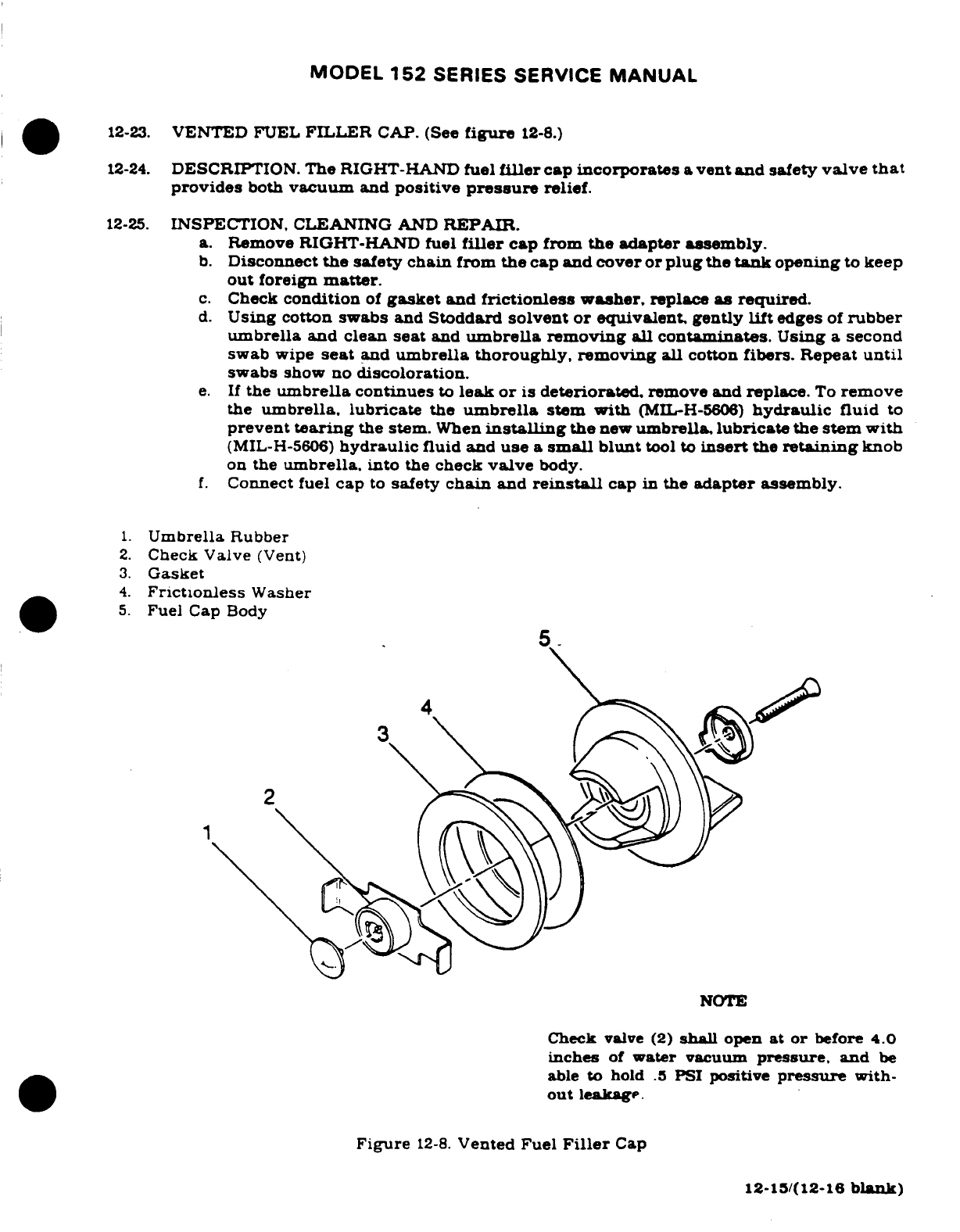
MODEL
152
SERIES
SERVICE
MANUAL
12-23.
VENTED
FUEL
FILLER
CAP.
(See
figure
12-8.)
12-24.
DESCRIPTION.
The
RIGHT-HAND
fuel
filler
cap
incorporates
a
vent and
safety
valve
that
provides
both
vacuum
and
positive
pressure
relief.
12-25.
INSPECTION.
CLEANING
AND
REPAIR.
a.
Remove
RIGHT-HAND
fuel
filler
cap
from
the adapter
assembly.
b.
Disconnect
the
safety chain
from
the
cap
and cover or
plug
the
tank
opening
to
keep
out
foreign
matter.
c.
Check
condition
of
gasket
and
frictionless
washer,
replace
as
required.
d.
Using
cotton
swabs
and
Stoddard
solvent or
equivalent,
gently
lift
edges
of
rubber
umbrella
and clean
seat
and
umbrella
removing all contaminates.
Using
a
second
swab
wipe
seat
and
umbrella
thoroughly,
removing
all
cotton
fibers. Repeat
until
swabs
show
no
discoloration.
e.
If
the
umbrella
continues
to
leak
or
is
deteriorated,
remove
and replace.
To
remove
the
umbrella,
lubricate
the
umbrella
stem
with
(MIL-H-5606)
hydraulic
fluid
to
prevent
tearing
the
stem.
When
installing
the
new
umbrella,
lubricate
the stem
with
(MIL-H-5606)
hydraulic
fluid
and
use
a
small
blunt
tool to
insert
the
retaining
knob
on
the
umbrella.
into
the
check
valve
body.
f.
Connect
fuel
cap
to
safety
chain
and
reinstall
cap
in
the
adapter
assembly.
1.
Umbrella
Rubber
2.
Check
Valve
(Vent)
3.
Gasket
4.
Frictionless
Washer
5.
Fuel
Cap
Body
1
NOTE
Check
valve
(2)
shall
open
at
or
before
4.0
inches
of
water
vacuum
pressure,
and
be
able
to
hold
.5
PSI
positive
pressure
with-
out
leakage.
Figure
12-8.
Vented
Fuel
Filler
Cap
12-15/(12-16
blank)
MODEL
152
SERIES
SERVICE
MANUAL
SECTION
13
PROPELLER
WARNING
When
performing any
inspection
or
maintenance
that
requires
turning
on
the
master
switch.
installing
a
battery,
or
pulling
the
propeller
through
by
hand.
treat
the
propeller
as
if
the
ignition
switch
were
ON.
Do
not
stand. nor
allow
anyone
else
to
stand,
within
the
arc
of
the
propeller.
since
a
loose
or
broken
wire. or
a
component
malfunction.
could
cause
the propeller
to
rotate.
Page
No.
TABLE
OF
CONTENTS
Aerofiche/
Manual
PROPELLER
.....................
2A20/13-1
Removal
.......................
2A20/13-1
Description
....................
2A20/
13-1
Installation
....................
2A21/13-2
Repair
.........................
2A20/13-1
13-1.
PROPELLER.
13-2.
DESCRIPTION.
An
all-metal.
fixed-pitch
propeller,
equipped
with
a
spinner,
is
used
on
the
aircraft.
13-3.
REPAIR.
Repair
of
metal
propeller
first
involves
evaluating
the
damage
and
determining
whether the
repair
is
to
be
a
major
or
minor
one.
Federal
Aviation Regulations,
Part
43
(FAR
43),
and
Federal
Aviation
Agency
Advisory
Circular
No.
43.13
(FAA
AC
No.
43.13),
define
major
and
minor
repairs,
alterations,
and
who
may
accomplish
them.
When
making
repairs
or
alterations
to
a
propeller,
FAR
43, FAR
AC
No.
43.13,
and
the
propeller
manufac-
turer's
instructions
must
be
observed.
The
propeller
manufacturer's
Service
Manual
may
be
obtained
from
Cessna
Parts
Distribution
(CPD
2)
through
a
Cessna
Service
Station.
13-4.
REMOVAL.
(See
figure
13-1.)
WARNING
Be
sure
that
magneto
is
grounded
before
turning
pro-
peller.
or
connecting
external
power.
a.
Remove
spinner
(1).
b.
Remove
safety
wire
from
mounting
bolt
heads
(3).
c.
Remove
bolts
and
washers
and
remove
forward
bulkhead
(5).
NOTE
The
aft
spinner
bulkhead
(7)
is
installed
between
pro-
peller
(6)
and
crankshaft
flange
(8).
and
is
removed
as
the
propeller
is
removed.
Revision
1
13-1
MODEL
152
SERIES
SERVICE
MANUAL
13-5.
INSTALLATION.
a.
Clean
mating
surfaces
of
propeller.
crankshaft
flange
and
spinner
bulkheads.
WARNING
Be
sure
that
magneto
is
grounded
before
turning
pro-
peller,
or
connecting
external
power.
NOTE
Ensure
that
nose
cap
is
installed
prior
to
completing
following steps.
b.
Position
aft
spinner
bulkhead
between
propeller
and
crankshaft
flange.
c.
Align
propeller
blade
with
t.c.
mark
on aft
side
of
ring
gear,
and
rotate
propeller
clockwise,
as
viewed
from
the
front,
to
first
bolt
hole.
d.
Install
forward
spinner
bulkhead
and
propeller
bolts.
e.
Tighten
bolts
evenly,
then
torque
to
300-320
lb.-in. or
25-26
lb-ft.
f.
Safety
wire
propeller
mount bolts,
ensuring
that
safety
wire is
around
bolt
heads
not
over
top.
g.
Install spinner.
13-2
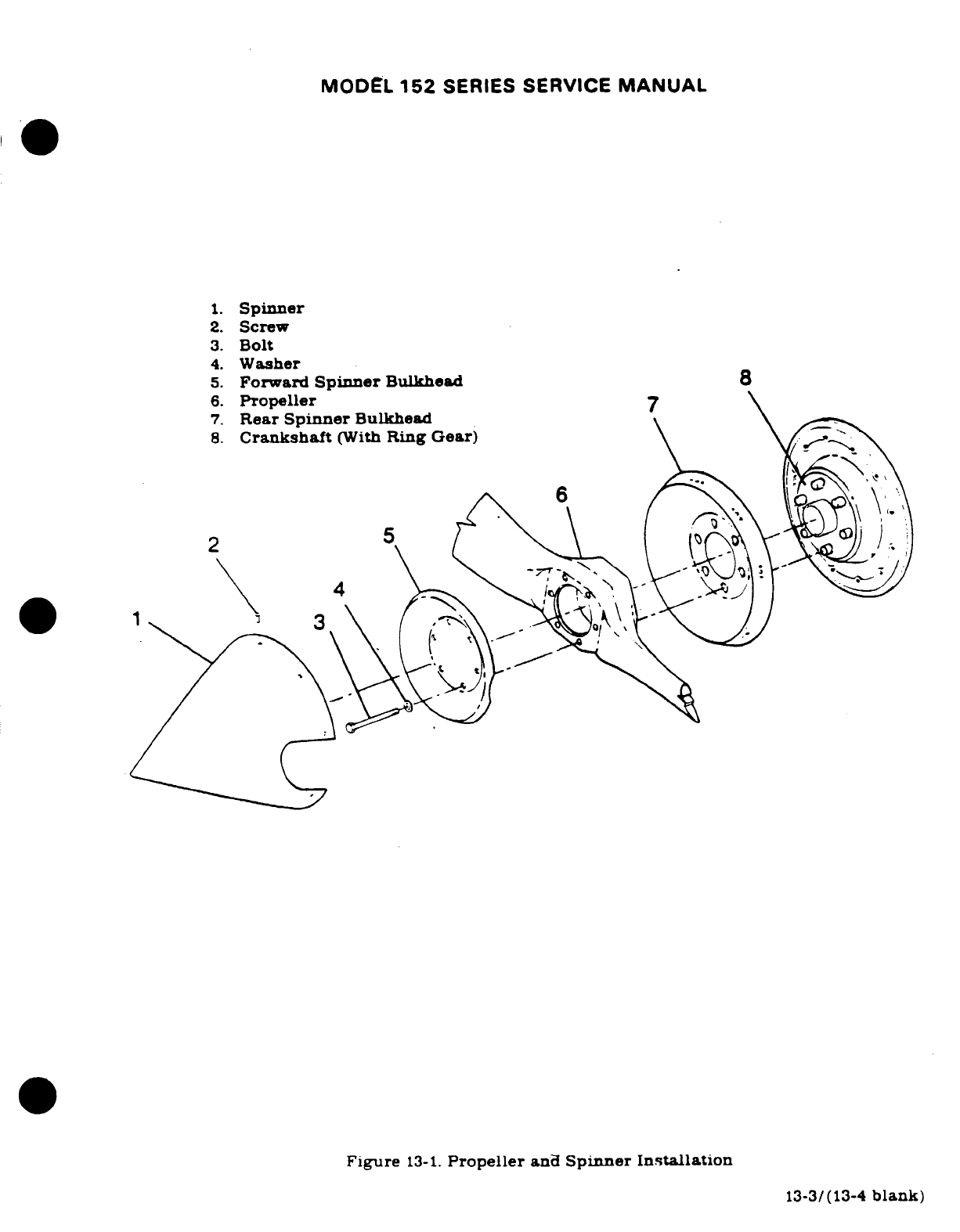
MODEL
152
SERIES
SERVICE
MANUAL
1.
Spinner
2.
Screw
3.
Bolt
4.
Washer
5.
Forward
Spinner
Bulkhead
8
6.
Propeller
7.
Rear
Spinner
Bulkhead
8.
Crankshaft
(With
Ring
Gear)
Figure
13-1.
Propeller
and
Spinner Installation
13-3/(13-4
blank)
MODEL
152
SERIES
SERVICE
MANUAL
SECTION
14
UTILITY
SYSTEMS
Page
No.
TABLE
OF
CONTENTS
Aerotiche/
Manual
UTILITY
SYSTEMS
................
2B5/14-1
Trouble
Shooting
...............
2B6/14-2
Heating
System
...................
2B5/14-1
Removal,
Repair
and
Description
.....................
2B5/14-1
Installation
....................
2B6/14-2
Operation
.......................
2B5/14-1
Ventilating
System
...............
2B6/14-2
Trouble
Shooting
...............
2B5/14-1
Description
.....................
2B6/14-2
Removal.
Repair
and
Operation
.......................
2B6/14-2
Installation
....................
2B5/14-1
Trouble
Shooting
...............
2B6/14-2
Defroster
System
.................
2B6/14-2
Removal.
Repair
and
Description
.....................
2B6/14-2
Installation
....................
2B6/14-2
Operation
..............
2B6/14-2
14-1.
UTILITY
SYSTEMS.
HEATING
SYSTEM.
14-3.
DESCRIPTION.
The
heating
system
is
comprised
of
the
heat
exchange
section
of
the
exhaust
muffler.
a
shut-off
valve
mounted
on
the
right
forward
side
of
the
firewall.
a
push-
pull
control
on
the
instrument
panel.
outlets
and
flexible
ducting
connecting
the
system.
14-4.
OPERATION.
Ram
air
is
ducted
through
an
engine
baffle
inlet
and
heat
exchange
section
of
the
exhaust
muffler,
to
the
shut-off
valve
at
the
firewall.
The heated
air
flows
from
the
shut-
off
valve
into
a
duct
across
the aft side
of
the
firewall,
where
it is
distributed
into
the
cabin.
The
shut-off
valve,
operated
by
a
push-pull
control
marked
"CABIN
HT".
located
on
the
instrument
panel,
regulates
the
volume
of
heated
air
entering
the
system.
Pulling
the
control
full
out,
supplies
maximum
flow
and
pushing
control
in.
gradually
decreases
flow.
shutting
off
flow
completely
when
the
control
is
pushed
full
in.
14-5.
TROUBLE SHOOTING.
Most
of
the
operational
troubles
in
the
heating.
defrosting
and
ventilating
systems
are
caused
by
sticking
or binding
air
valves
and
their
controls.
damaged
air
ducting
or
defects
in
the
exhaust
muffler.
In
most
cases,
valves
or
controls
can
be
freed
by
proper
lubrication.
(Refer
to
Section
2
of
this
manual
for
lubrication
informa-
tion.)
Damaged
or
broken
parts
must
be
repaired
or
replaced.
When
checking
controls.
ensure
valves
respond freely
to
control
movement,
that
they
move
in
the
correct
direction.
that
they
move
through
their
full
range
of
travel
and
seal
properly.
Check
that
hoses
are
properly
secured
and
replace
hoses
that
are burned.
frayed
or
crushed.
If
fumes
are
detected
in
the
cabin,
a
thorough inspection
of
the
exhaust
system
should
be
accomplished. Refer
to
applicable
paragraph
in
Section
11
for
this
inspection. Since
any
holes
or cracks may
permit
exhaust
fumes
to
enter
the cabin. replacement
of
defective
parts
is
imperative
because
fumes
constitute
an
extreme
danger.
Seal
any
gaps
in
the
shutoff
valves
at
the
firewall
with
Pro-Seal
#700
(Coast
Pro-Seal
Co..
Los
Angeles.
California)
compound. or
equivalent
compound.
14-6.
REMOVAL.
REPAIR
AND
INSTALLATION.
Figure
14-1
illustrates
the
heating.
defrosting
ventilating
systems.
and
may
be
used
as
a
guide
during
removal.
repair
and
installation
of
system components.
Burned,
frayed
or crushed
hose
must
be
replaced
with
new
hose.
cut
to
14-1
MODEL
152
SERIES SERVICE
MANUAL
length
and
installed
in
the
original
routing.
Trim
hose
winding
shorter
than
the
hose
to
allow
clamps
to
be
fitted.
Defective
air
valves
must
be
repaired
or
replaced.
Check
for
proper
operation
of
valves
and
their
controls
after
repair
or
replacement.
14-7.
DEFROSTER
SYSTEM.
14-8.
DESCRIPTION.
The
defrosting
system
is
comprised
of
the
duct
across
the aft
side
of
the
firewall,
a
defroster
outlet
mounted
on
the
left
side
of
the
cowl
deck.
immediately
aft
of
the
windshield,
and flexible
ducting
connecting the
system.
14-9.
OPERATION.
Air
from
the
duct
across
the
aft
side
of
the
firewall
flows
through
a
flexible
duct
to
the
defroster
outlet. The
temperature
and
volume
of
this
air
is
controlled
by
the
settings
of
the
heater
system
control.
14-10.
TROUBLE
SHOOTING.
Since
the
defrosting
system
depends
on
proper
operation
of
the
heating
system,
refer
to
paragraph
14-5
for
trouble shooting
the
heating
and
defrosting
systems.
14-11.
REMOVAL,
REPAIR
AND
INSTALLATION.
Figure
14-1
may
be
used
as
a
guide during
removal
repair
and
installation
of
defrosting
system
components.
Cut
hoses
to
length
and
install
in
the
original
routing.
Trim
hose
winding
shorter
than
the
hose
to
allow
clamps
to
be
fitted.
A
defective
defroster
outlet
must
be
repaired
or
replaced.
14-12.
VENTILATING
SYSTEM.
14-13.
DESCRIPTION.
The
ventilating
system
is
comprised
of
an
airscoop
mounted
in
the inboard
leading
edge
of
each
wing,
an
adjustable
ventilator
mounted
on
each
side
of
the
cabin
near
the
upper
corners
of
the
windshield,
a
fresh
air
scoop
door
mounted
on
the
right
side
of
the
fuselage,
a
control
knob
on
the
instrument
panel.
and
flexible
ducting
connecting
the
system.
14-14.
OPERATION.
Air
received
from
scoops
mounted
in
the
inboard
leading
edges
of
the
wings
is
ducted
to
the
adjustable
ventilators
mounted
on
each
side
of
the
cabin
near
the
upper
corners
of
the
windshield.
Forward cabin
ventilation
is
provided
by
a
fresh
air
scoop
door.
mounted
on
the
right
side
of
the
fuselage,
just
forward
of
the
copilot
seat.
The
scoop door
is
operated
by
a
control
in
the
instrument panel
marked
"CABIN
AIR."
Fresh
air
from
the
scoop
door
is
routed
to
the
duct
across
the
aft
side
of
the firewall,
where
it is
distributed
into
the
cabin.
As
long
as
the
"CABIN
HEAT'
control
is
pushed
in.
no
heated
air
can
enter
the
firewall
duct;
therefore.
when
the
"CABIN
AIR"
control
is
pulled
out.
only
fresh
air
from
the
scoop
will
flow
through
the
duct into
the
cabin.
As
the
"CABIN
HT'
control
is
gradually
pulled
out.
more
and
more
heated
air
will
blend
with the
fresh
air
from
the
scoop
and
be
distributed
into
the
cabin.
Either
one,
or
both
of
the
controls
may
be
set
at
any
position
from
full
open
to
full
closed.
14-15.
TROUBLE
SHOOTING.
Most
of
the
operational
troubles
in
the
ventilating
system
are
caused
by
sticking
or
binding
of
the inlet
scoop
door
or
its
controL
Check
filter
element
in
the
inlet
scoop
door.
The
element
may
be
removed
and
cleaned
or replaced.
Since
air
passing
through
the
filter
is
emitted
into
the
cabin,
do
not
use
a
cleaning
solution
which
would
contaminate
cabin
air.
The
filter
may
be
removed
to
increase
air
flow.
However.
the
removal
will
cause
a
slight
increase
in
noise
level.
14-16.
REMOVAL.
REPAIR
AND
INSTALLATION.
Figure
14-1
may
be
used
as
a
guide
for
removal.
repair
and
installation
of
ventilating
system
components.
A
defective
ventilator
or
scoop
door
must
be
repaired or
replaced.
Check
for
proper
operation
of
ventilating
controls
after
installation
or
repair.
14-2
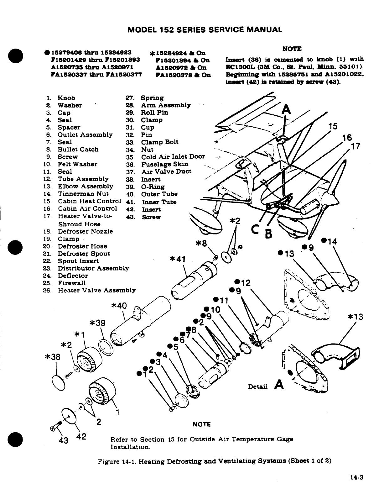
MODEL
152
SERIES
SERVICE
MANUAL
*1527940
thru
15284923
15284924
&
On
NOTE
F15201429
thru
F15201893
15201894
&
On
Insert
(38)
is
cemented
to
knob
(1)
with
A1520735
thru
A1580971
A1520972
&
On
EC1300L
(3M
Co.,
St.
Paul,
Minn.
55101).
FA1520337
thru
FA1520377
FA1520378
On
Beginning
with
15285751
and A15201022,
insert
(42)
is
retained
by
screw (43).
1.
Knob
27.
Spring
2.
Washer
28.
Arm
Assembly
3.
Cap
29.
Roll
Pin
4.
Seal
30.
Clamp
5.
Spacer
31.
Cup
.
15
6.
Outlet
Assembly
32.
Pin
7.
Seal
33.
Clamp
Bolt
16
8.
Bullet
Catch
34.
Nut
....
.
17
9.
Screw
35.
Cold
Air
Inlet
Door
10.
Felt
Washer
36.
Fuselage
Skin
11.
Seal
37.
Air
Valve
Duct
..
12.
Tube
Assembly
38.
Insert
13.
Elbow
Assembly
39.
O-Ring
14.
Tinnerman
Nut
40.
Outer
Tube
15.
Cabin
Heat
Control
41.
Inner
Tube
16.
Cabin
Air
Control
42.
Insert
17.
Heater
Valve-to-
43. Screw
Shroud
Hose
18.
Defroster
Nozzle
19.
Clamp
20.
Defroster
Hose
8
14
21.
Defroster
Spout
22.
Spout
Insert
*41
23.
Distributor
Assembly
24.
Deflector
25.
Firewall
12
26.
Heater
Valve
Assembly
*40
.10
*39
*38
Detail
A
2
NOTE
43
Refer
to
Section
15
for
Outside
Air
Temperature
Gage
Installation.
Figure
14-1.
Heating
Defrosting
and
Ventilating
Systems
(Sheet
1
of
2)
14-3
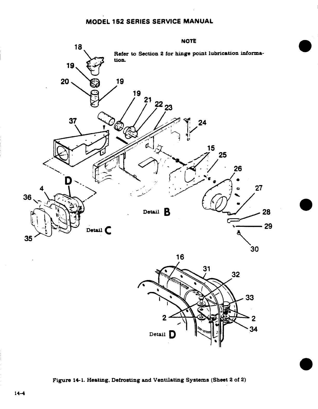
MODEL
152
SERIES SERVICE
MANUAL
NOTE
Detail
Figure
14-1.
Heating Defrosting
and
Ventilating
Systems
(Sheet
2
of
2)
14-4
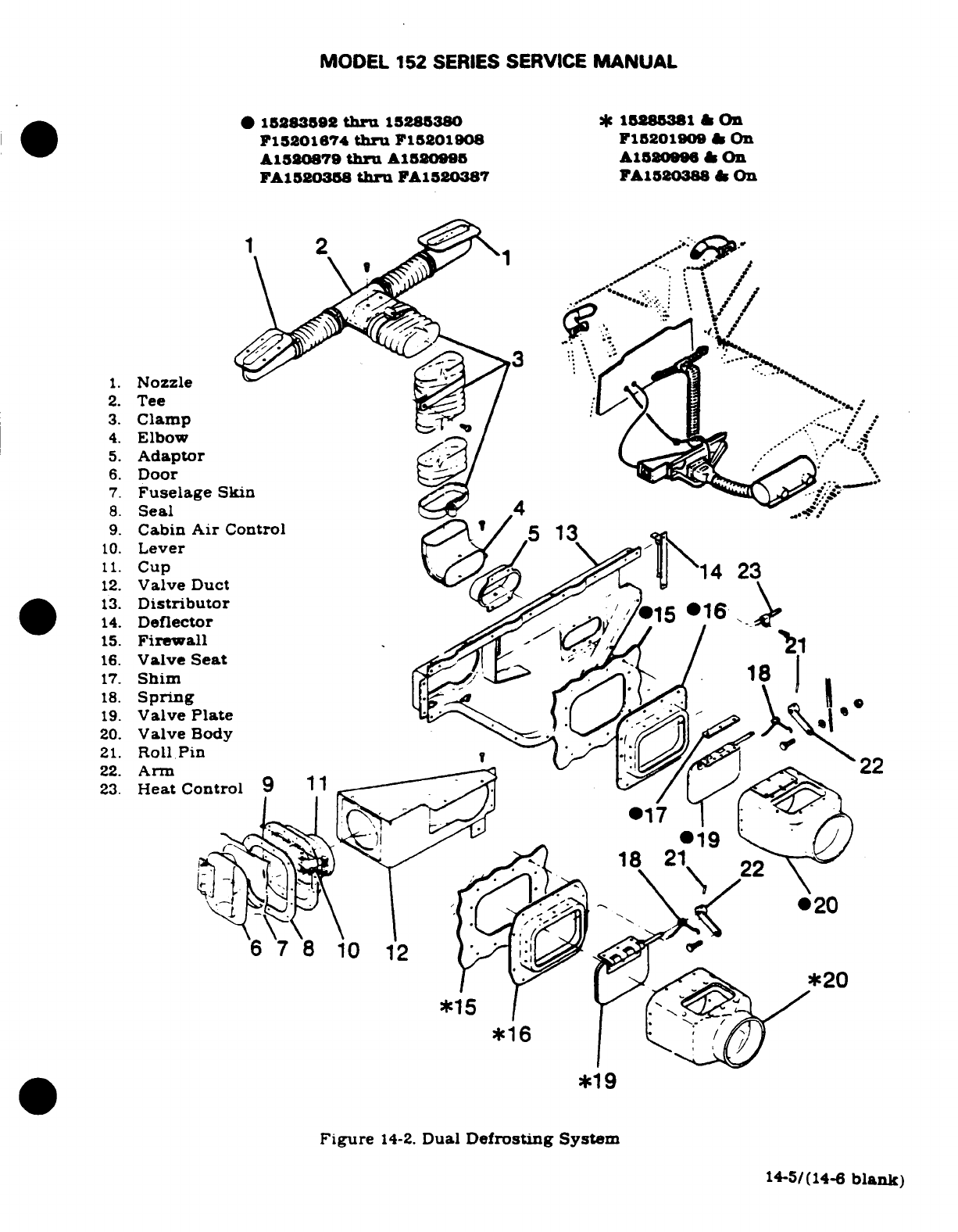
MODEL
152
SERIES
SERVICE
MANUAL
*
15283592
thru
15285380
1585381
&
On
F15201674
thru
F15201908
F15201909
&
On
A1520879
thru
A1520995
A15S2089
&
On
FA1520358
thru
FA1520387
FA1520388
&
On
1.
Nozzle
2.
Tee
3.
Clamp
4.
Elbow
5.
Adaptor
6.
Door
7.
Fuselage
Skin
8.
Seal
4
9.
Cabin
Air
Control
5 13
10.
Lever
11.
Cup
14 23
12.
Valve
Duct
13.
Distributor
15
16
14.
Deflector
15.
Firewall
16.
Valve
Seat
17.
Shim
18.
Spring
19.
Valve
Plate
20.
Valve
Body
21.
Roll Pin
22.
Arm
22
23.
Heat
Control
9
11
19
22
20
6
7
8
10
12
*20
*15
*16
*19
Figure
14-2.
Dual
Defrosting
System
14-5/(14-6
blank)
MODEL
152
SERIES
SERVICE
MANUAL
SECTION
15
INSTRUMENTS
AND
INSTRUMENT
SYSTEMS
Page
No.
TABLE
OF
CONTENTS
Aerofiche/
Standby
Vacuum
System
....
2C13/15-19
Manual
Description
...............
2C13/15-19
Trouble Shooting
..........
2C14/15-20
INSTRUMENTS/INSTRUMENT
Removal
..................
2C14/15-20
SYSTEMS
...................
2B16/15-2
Installation
...............
2C14/15-20
General
....................
2B16/15-2
Engine
Indicators
...........
2C18/15-20D
Instrument
Panel
...........
2B16/15-2
Tachometer
...............
2C18/15-20D
Description
................
2B16/15-2
Description
..............
2C18/15-20D
Removal/Installation
.......
2B16/15-2
Oil
Pressure
Gage
.........
2C18/15-20D
Shock-Mounts
.............
2B16/15-2
Description
..............
2C18/15-20D
Instruments
...............
2B16/15-2
Trouble Shooting
........
2C18/15-20D
Removal
.................
2B16/15-2 Oil
Temperature
Gage
.....
2C19/15-21
Installation
..............
2B20/15-4
Description
..............
2C19/15-21
Pitot
and
Static
Systems
.....
2B20/15-4
Economy
Mixture
Description
................
2B20/15-4
Indicator
(EGT)
..........
2C19/15-21
Maintenance
..............
2B20/15-4
Description..............
2C19/15-21
Static
System Inspection
Calibration
..............
2C19/15-21
and
Leakage
Test
.........
2B20/15-4
Removal/Installation
.....
2C20/15-22
Pitot
System Inspection
Trouble Shooting
........
2C20/15-22
and
Leakage
Test
.........
2B21/15-5
Fuel
Quantity
Indicating
Blowing
Out
Lines
.........
2B21/15-5
System
..................
2C20/15-22
Removal/Installation
.......
2B22/15-6
Description
..............
2C20/15-22
Trouble
Shooting
..........
2B22/15-6
Removal/Installation
.....
2C20/15-22
True
Airspeed
Indicator
....
2B22/15-6
Trouble
Shooting
........
2C22/15-24
Trouble
Shooting
.........
2C1/15-9
TransmitterAdjustment
..
2C23/15-25
Trouble
Shooting
-
Stewart
Warner
Gage
Altimeter
................
2C1/15-9
Calibration
...........
2C23/15-25
Trouble
Shooting
-
Vertical Rochester
Gage
Speed
Indicator
...........
2C3/15-11
Calibration
...........
2C23/15-25
Trouble
Shooting
-
Pitot
Hourmeter
...............
2C24/15-26
Tube
Heater
.............
2C4/15-12
Description
..............
2C24/15-26
Vacuum
System
.............
2C4/15-12
Magnetic
Compass
..........
2C24/15-26
Description
................
2C4/15-12
Description
...............
2C24/15-26
Trouble
Shooting
............
2C4/15-12
Accelerometer
..............
2C24/15-26
Trouble
Shooting-
Gyros
...
2C7/15-13
Description
...............
2C24/15-26
Trouble
Shooting- Pump
...
2C1I/15-17
Stall
Warning
System
.......
2D3/15-27
Maintenance
Practices
.....
2C11/15-17
Description
...............
2D3/15-27
Removal
of
Vacuum
Pump
..
2C12/15-18
Turn-and-Slip Indicator
.....
2D3/15-27
Mounting
Pad
Inspection
...
2C12/15-18
Description
...............
2D3/15-27
Installation
of
Vacuum
Trouble
Shooting
..........
2D3/15-27
Pump
...................
2C12/15-18
Turn
Coordinator
...........
2D5/15-29
Cleaning
..................
2C13/15-19
Description
...............
2D5/15-29
Low-Vacuum
Warning
Light
2C13/15-19
Trouble Shooting
..........
2D5/15-29
Vacuum
Relief
Valve
Outside Air
Temperature
Adjustment
..............
2C13/15-19
Gage
.....................
2D6/15-30
Revision
1
15-1
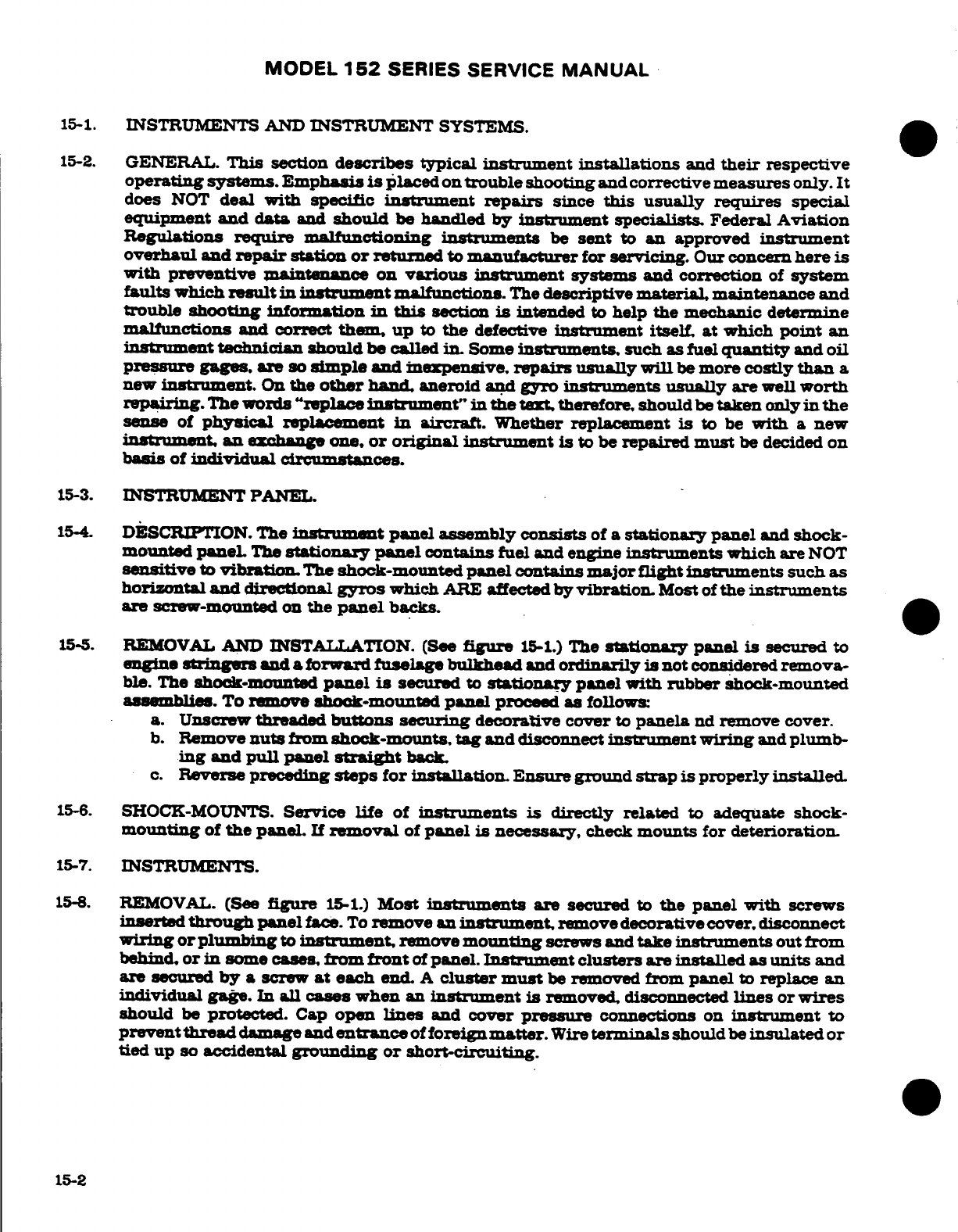
MODEL
152
SERIES SERVICE
MANUAL
15-1.
INSTRUMENTS
AND
INSTRUMENT
SYSTEMS.
15-2.
GENERAL.
This
section
describes
typical
instrument
installations
and
their
respective
operating
systems.
Emphasis
is
placed
on
trouble
shooting
and corrective
measures
only. It
does
NOT
deal
with specific
instrument
repairs
since
this
usually
requires
special
equipment
and
data
and
should
be
handled
by
instrument specialists
Federal
Aviation
Regulations
require
malfunctioning
instruments
be
sent
to
an
approved
instrument
overhaul
and
repair
station
or
returned
to
manufacturer
for
servicing.
Our
concern
here
is
with preventive maintenance on
various instrument
systems
and correction
of
system
faults
which
result
in
instrument
malfunctions.
The
descriptive
material, maintenance
and
trouble
shooting
information
in
this
section
is
intended
to
help
the
mechanic
determine
malfunctions
and correct
them,
up
to
the
defective
instrument
itself
at
which
point
an
instrument
technician
should
be
called
in.
Some
instruments,
such as
fuel
quantity
and
oil
pressure
gages are
so
simple
and
inexpensive,
repairs
usually
will
be
more
costly
than
a
new
instrument.
On
the
other
hand,
aneroid
and
gyro
instruments
usually
are
well
worth
repairing
The
words
"replace
instrument"
in the
text,
therefore,
should
be
taken
only
in
the
sense
of
physical
replacement
in
aircrat.
Whether
replacement
is
to
be
with
a
new
instrument,
an
exchange
one.
or
original instrument is
to
be
repaired
must
be
decided
on
basis
of
individual
circumstances.
15-3.
INSTRUMENT
PANEL.
15-4.
DESCRIPTION.
The
instrument
panel
assembly
consists
of
a
stationary panel
and
shock-
mounted
panel.
The
stationary
panel
contains
fuel
and
engine
instruments
which
are
NOT
sensitive
to
vibration.
The
shock-mounted
panel
contains
major flight
instruments
such
as
horizontal
and
directional
gyros
which
ARE
affected
by
vibration.
Most
of
the
instruments
are
screw-mounted
on
the
panel
backs.
15-5.
REMOVAL
AND
INSTALLATION. (See
figure
15-1.)
The
stationary
panel
is
secured
to
engine
stringes
and
a
forward
fuselage
bulkhead
and
ordinarily
is
not
considered
remova-
ble.
The
shock-mounted
panel
is
secured
to
stationary
panel
with rubber
shock-mounted
assemblies.
To
remove
shock-mounted
panel
proceed
as
follows:
a.
Unscrew
threaded
buttons securing
decorative
cover
to
panela
nd
remove
cover.
b.
Remove
nuts
from
shock-mounts,
tag
and
disconnect
instrument
wiring
and
plumb-
ing
and
pull
panel
straight
back.
c.
Reverse
preceding
steps for installation.
Ensure
ground
strap
is
properly
installed.
15-6.
SHOCK-MOUNTS.
Service life
of
instruments
is
directly
related
to
adequate
shock-
mounting
of
the panel.
If
removal
of
panel
is
necessary,
check
mounts
for
deterioration.
15-7.
INSTRUMENTS.
15-8.
REMOVAL.
(See
figure
15-1.)
Most
instruments
are
secured
to
the
panel
with
screws
inserted
through
panel
face.
To
remove
an
instrument,
remove decorative
cover, disconnect
wiring
or
plumbing
to
instrument,
remove
mounting
screws
and
take
instruments
out
from
behind,
or
in
some
cases,
from
front
of
panel.
Instrument clusters
are installed as units
and
are
secured
by
a screw
at
each
end.
A
cluster
must
be
removed
from
panel
to
replace an
individual
gage.
In
all
cases
when
an
instrument
is
removed,
disconnected
lines or
wires
should
be
protected.
Cap
open
lines
and
cover
pressure
connections
on
instrument
to
prevent
thread
damage
and
entrance
of
foreign
matter.
Wire
terminals
should
be
insulated
or
tied
up
so
accidental
grounding
or
short-circuiting.
15-2
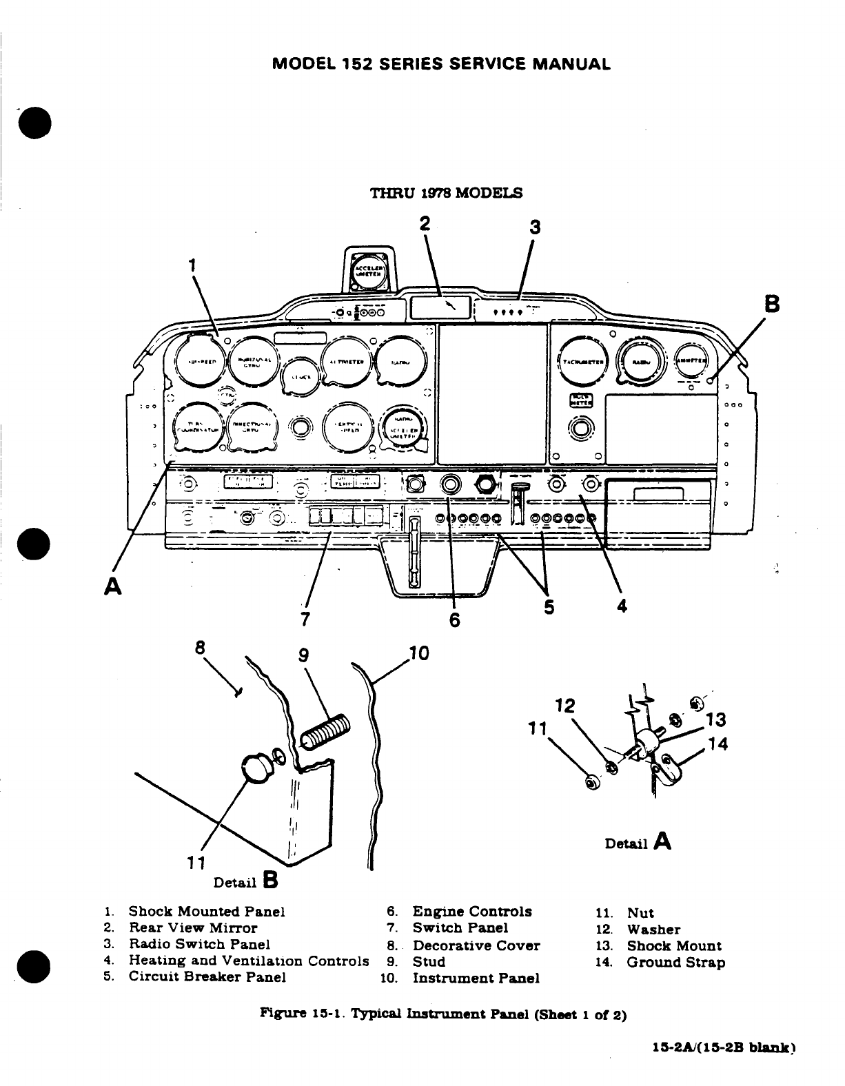
MODEL
152
SERIES
SERVICE
MANUAL
THRU
1978
MODELS
2
3
A
7
6
12
10
13
Detail
A
11
Detail
B
1.
Shock
Mounted
Panel
6.
Engine Controls
11.
Nut
2.
Rear
View
Mirror
7.
Switch
Panel
12.
Washer
3.
Radio
Switch
Panel
8.
Decorative Cover
13.
Shock
Mount
4.
Heating
and
Ventilation
Controls
9.
Stud
14.
Ground
Strap
5.
Circuit Breaker
Panel
10.
Instrument
Panel
Figure
15-1.
Typical
Instrument
Panel
(Sheet
1
of
2)
15-2A/(15-2B
blank)
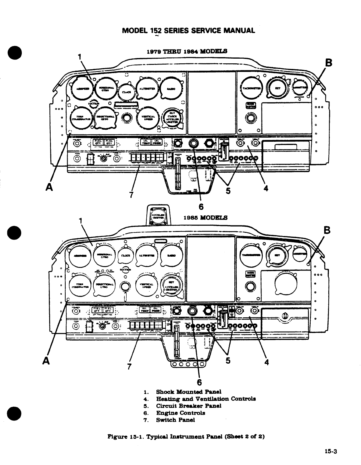
MODEL
152
SERIES
SERVICE
MANUAL
1979
THRU
1984
MODELS
B
1.
Shock
Mounted
Panel
4.
Heating and Ventilation
Controls
5.
Circuit Breaker
Panel
6.
Engine
Controls
7.
Switch
Panel
Figure
15-1.
Typical
Instrument
Panel
(Sheet
2
of
2)
15-3
MODEL
152
SERIES SERVICE
MANUAL
15-9.
INSTALLATION.
Generally.
Installation
procedure
is
the
reverse
of
removal
procedure.
Ensure mounting
screw
nuts
are
tightened
firmly,
but
do
not
over-tighten,
particularly
on
instruments
having
plastic
cases.
The
same
rule
applies
to
connecting
plumbing
and
wiring.
NOTE
All
instruments
(gages
and
indicators
requiring
a
thread
seal
or
lubricant
shall
be
installed
using
teflon
tape
on
male
fittings
only.
This
tape
available
through
the
Cessna
Supply
Division
When
replacing
an
electrical
gage
in
an
instrument
cluster
assembly.
avoid
bending
pointer
or
dial
plate.
Distortion
of
dial
or
back
plate
could change
calibration
of
gages.
15-10.
PITOT
AND
STATIC
SYSTEMS.
15-11.
DESCRIPTION.
(See
figure
15-2
The
pitot
system
conveys
ram
air
pressure
to
the
airspeed
indicator.
The
static system
ven
vertical
speed
indicator,
altimeter
and
airspeed
indicator
to
atmospheric
pressure
through
plastic
tubing
connected
to
a
static
port.
A
static
line
sump
is
installed
at source
button
to
collect
condensation
in
static system.
A
pitot
tube
heater
may
be
installed.
The
heating
element
is
controlled
by
a
switch
at
the
instrument
panel
and
powered
by
the
electrial
system.
15-12.
MAINTENANCE.
Proper maintenance
of
pitot
and
static
system
is
essential
for
proper
operation
of
altimeter.
vertical
speed
and
airspeed
indicators. Leaks,
moisture
and
obstruc-
tions
in
pitot
system
will
result
in false airspeed
indications,
while
static
system
malfunc-
tions will
affect
readings
of
all
three
instruments.
Under
instrument
flight
conditions,
these
instrument
errors
could
be
hazardous.
Cleanlines
and
security
are
the
principal
rules
for
system
maintenance The
pitot
tube
and
static
ports
MUST
be
kept
clean
and
unobstructed.
15-13.
STATIC
PRESSURE
SYSTEM
INSPECTION
AND
LEAKAGE TEST.
The
following
proce-
dure
outlines
inspection
and
testing
of
static
pressure
system.
assuming
altimeter
has
been
tested and
inspected
in
accordance with
current
Federal
Aviation
Regulations.
a.
Ensure static system
is
free
from
entrapped
moisture
and
restrictions.
b.
Ensure
no
alterations
or
deformations
of
airframe
surface
have
been
made
which
would
affect
the
relationship
between
air
pressure
in
static
pressure
system
and
true
ambient
static
air
pressure
for
any
flight
configuration.
c.
Attach
a
source
of
suction
to
static
pressure
source
opening.
Figure
15-3
shows
one
method
of
obtaining
suction.
d.
Slowly
apply
suction
until
altimeter
indicates
a
1000-foot
increase
in
altitude.
CAUTION
When
applying
or
releasing
suction,
do
not
exceed
range
of
vertical
speed
indicator
or airspeed
indicator.
e.
Cut
off
suction
source
to
maintain
a
"closed"
system
for
one
minute.
Leakage
shall
not
exceed
100
feet
of
altitude
loss
as
indicated
on
altimeter.
f.
If
leakage rate
is
within
tolerance,
slowly
release
suction
source.
15-4
MODEL
152
SERIES
SERVICE
MANUAL
NOTE
If
leakage
rate
exceeds
the
maximum
allowable,
first
tighten
all
connections,
then
repeat
leakage
test.
If
leakage
rate
still
exceeds
maximum
allowable, use
fol-
lowing
procedure.
g.
Disconnect
static
pressure
lines
from
airspeed
indicator
and
vertical
speed
indica-
tor.
Use
suitable
fittings
to
connect
lines
together
so
altimeter
is
the
only
instrument
still
connected
into
static pressure
system.
h.
Repeat
leakage
test
to
check
whether
static
pressure
system
or
the
bypassed
instruments
are
cause
of
leakage.
If
instruments
are
at
fault,
they
must
be
repaired
by
an
"appropriately
rated
rapair
station"
or
replaced.
If
static
pressure
system
is
at
fault,
use
following
procedure
to
locate leakage.
i.
Attach a
source
of
positive
pressure
to
static
source
opening.
Figure
15-3
shows
one
method
of
obtaining
positive
pressure.
CAUTION
Do
not
apply
positive
pressure
with
airspeed
indicator
or
vertical
speed
indicator
connected
to
static
pressure
system.
j.
Slowly
apply
positive
pressure
until
altimeter
indicates
a
500-foot
decrease
in
altitude
and
maintain
this
altimeter
indication
while checking
for leaks.
Coat
line
connections
and
static
source
flange
with
solution
of
mild
soap
and
water.
watching
for
bubbles
to
locate
leaks.
k.
Tighten
leaking
connections.
Repair or replace
parts
found
defective.
1.
Reconnect
airspeed.
and
vertical
speed
indicators
into
static
pressure
system
and
repeat
leakage
test
per
steps
"c"
thru
"f".
NOTE
Air
bulb
with
check
valves
may
be
obtained
locally
from
a
surgical supply
company.
This
is
the
type
used
in
measuring
blood
pressure.
15-14.
PITOT
SYSTEM
INSPECTION
AND
LEAKAGE
TEST.
To
check
pitot
system
for
leaks.
place
a
piece
of
tape over
small
hole
in
lower
aft
end
of
pitot
tube,
fasten a
piece
of
rubber
or
plastic
tubing over
pitot
tube. close
opposite
end
of
tubing
and
slowly
roll
up
tube
until
airspeed
indicator
registers
in
cruise
range.
Secure
tube
and
after
a
few
minutes
recheck
airspeed
indicator.
Any
leakage will
have reduced
the
pressure
in
system.
resulting
in
a
lower
airspeed
indication.
Slowly
unroll
tubing
before
removing
it.
so
pressure
is
reduced
gradually.
Otherwise
instrument
may
be
damaged.
If
test
reveals
a
leak
in
system.
check
all
connections
for
tightness.
15-15.
BLOWING
OUT
LINES.
Although the
pitot
system
is
designed
to
drain
down
to
pitot
tube
opening.
condensation
may
collect
at
other
points
in
system
and
produce
a
partial
obstruction.
To
clear
the
line.
disconnect
it
at
airspeed
indicator.
Using
low
pressure air.
blow
from
indicator
end
of
line
toward
the
pitot
tube.
CAUTION
Never
blow
through
pitot
or
static
lines
toward
the
instruments.
15-5
MODEL
152
SERIES SERVICE
MANUAL
Like
the
pitot
lines,
static
pressure lines
must
be
kept
clear
and
connections
tight
All
models
have
a
static
source
sump
which
collects moisture
and
keeps
system
clear.
However,
when
necessary,
disconnect
static
line
at
first
instrument
to
which
it
is
connected,
then
blow
line
clear
with
low-pressure
air.
Check
all
static
pressure
line
connections
for
tightness.
If
hose
or
hose
connctions
re
used.
check
for
general
condition
and
clamps
for
security.
Replace
hose
which
have
cracked,
hardened
or
show
other
signs
of
deterioration
15-16.
REMOVAL
AND
INSTALLATION OF
COMPONENTS.
(See
figure
15-2.)
To
remove
pitot
mast.
remove
four mounting screws
on
side
of
connector
(17)
and
pull
mast
out
of
connector
far
enough
to
disconnect
pitot line
(14).
Electrical
connections
to
heater
assembly
(if
installed)
may
be
disconnected
through
wing
access
opening
just
inboard
of
mast.
Pitot
and
static
lines
an
removed
in
the
usual
manner,
after
removing
wing
access
plates.
lower
wing
fairing
strip
and
upholstry
as
required.
Installation
of
tubing
will
be
simpler
if
a
guide
wire
is
drawn
in
as
tubing is
removed
from
wing.
The
tubing
may
be
removed
intact
by
drawing
it
out
through
cabin
and
right
door.
When
replacing
fittings
of
pitot
and
static pressure
lines.
use
anti-seise
compound
sparingly
on
male threads
of
both
metal
and
plastic
connections.
Avoid
excess
compound which
might enter
lines.
Tighten
connections
firmly.
but
avoid
overtightening
and
distorting
fittings.
If
twisting
of
plastic
tubing
is encountered
when
tightening
fittings,
VV-P236 (USP
Petrolatum).
may
be
applied
sparingly
between
tubing
and fittings.
NOTE
Do
not
overtighten screws
(6)
and
do
not
lubricate
any
part
Use
spacers
(10)
as required
for adequate
friction
on
ring
Assembly
(8).
15-17.
TROUBLE
SHOOTING-PITOT
STATIC
SYSTEM.
TROUBLE PROBABLE CAUSE
REMEDY
LOW
OR
SLUGGISH
AIR-
Pitot
tube
obstructed,
leak
Test
pitot
tube
and
line
for
SPEED
INDICATION.
(Nor-
or
obstruction
in
pitot
line.
leaks or obstructions.
Blow
mal
altimeter
and
vertical
out
tube
and
line.
repair
speed.)
or
replace
damaged
line.
INCORRECT
OR
SLUGGISH
Leaks
or
obstruction
in
Test
line
for
leaks
and
ob-
RESPONSE.
(All
three static
line.
structions.
Repair
or
replace
instruments.)
line.
blow
out
obstructed
line.
15-18.
TRUE
AIRSPEED
INDICATOR.
A
true
airspeed indicator
may
be
installed.
This
indicator.
equipped
with
a
conversion
ring.
may
be
rotated
until
pressure
altitude
is
aligned
with
outside
air
temperature,
then
airspeed
indicated
on
the
instrument
is
read
as
true airspeed
on
the
adjustable
ring.
Refer
to
figure
15-2
for removal
and
installation.
Upon
installation.
before
tightening
mounting
screws
(6).
calibrate
instrument
as
follows:
Rotate
ring
(8)
until
105K
on
the
adjustable
ring aligns
with
105K
on
indicator. Holding
this
setting,
move
retainer
(7)
until
60F
aligns
with
zero
pressure
altitude, then
tighten
mounting
screws
(6)
and
replace
decorative
cover
(5).
15-6
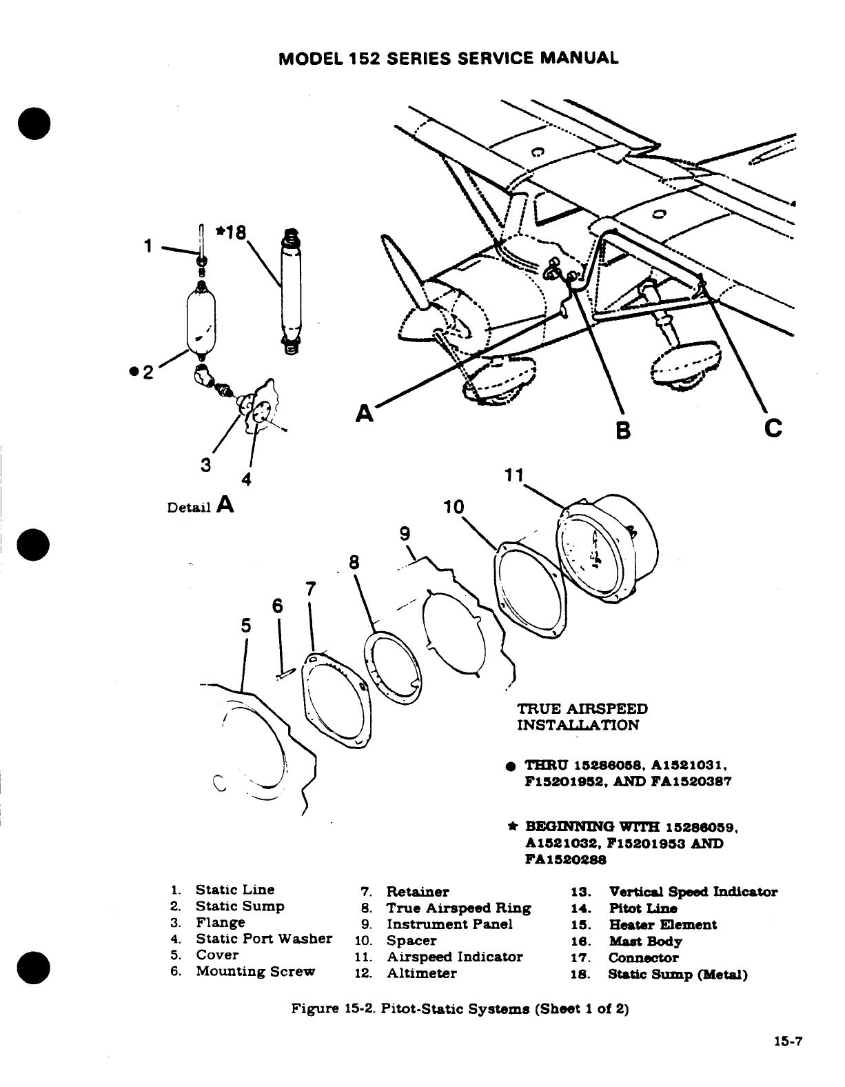
MODEL
152
SERIES
SERVICE
MANUAL
B
C
3
B
4
11
Detail
A
10
8
TRUE
AIRSPEED
INSTALLATION
*
THRU
15286058,
A1521031,
F15201952,
AND
FA1520387
BEGINNING
WITH
15286059,
A1521032, F15201953
AND
FA1520288
1.
Static
Line
7.
Retainer
13.
Vertical
Speed
Indicator
2.
Static
Sump
8.
True
Airspeed
Ring
14.
Pitot
Line
3.
Flange
9.
Instrument
Panel
15.
Heater Element
4.
Static
Port
Washer
10.
Spacer
16.
Mast
Body
5.
Cover
11.
Airspeed
Indicator
17.
Connector
6.
Mounting
Screw
12.
Altimeter
18.
Static
Sump
(Metal)
Figure
15-2.
Pitot-Static
Systems
(Sheet
1
of
2)
15-7
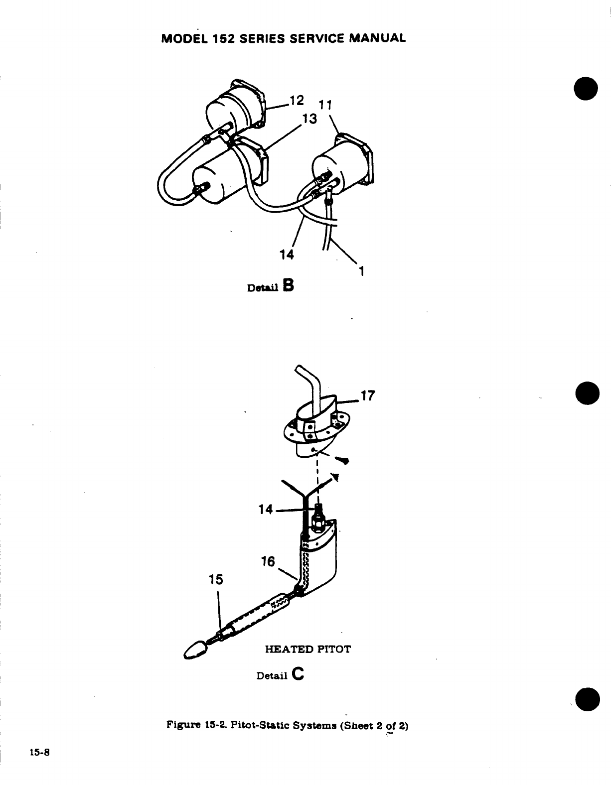
MODEL
152
SERIES
SERVICE
MANUAL
14
Detail
B
17
14
16
15
HEATED
PITOT
Detail
C
Figure
15-2.
Pitot-Static
Systems
(Sheet
2
of
2)
15-8
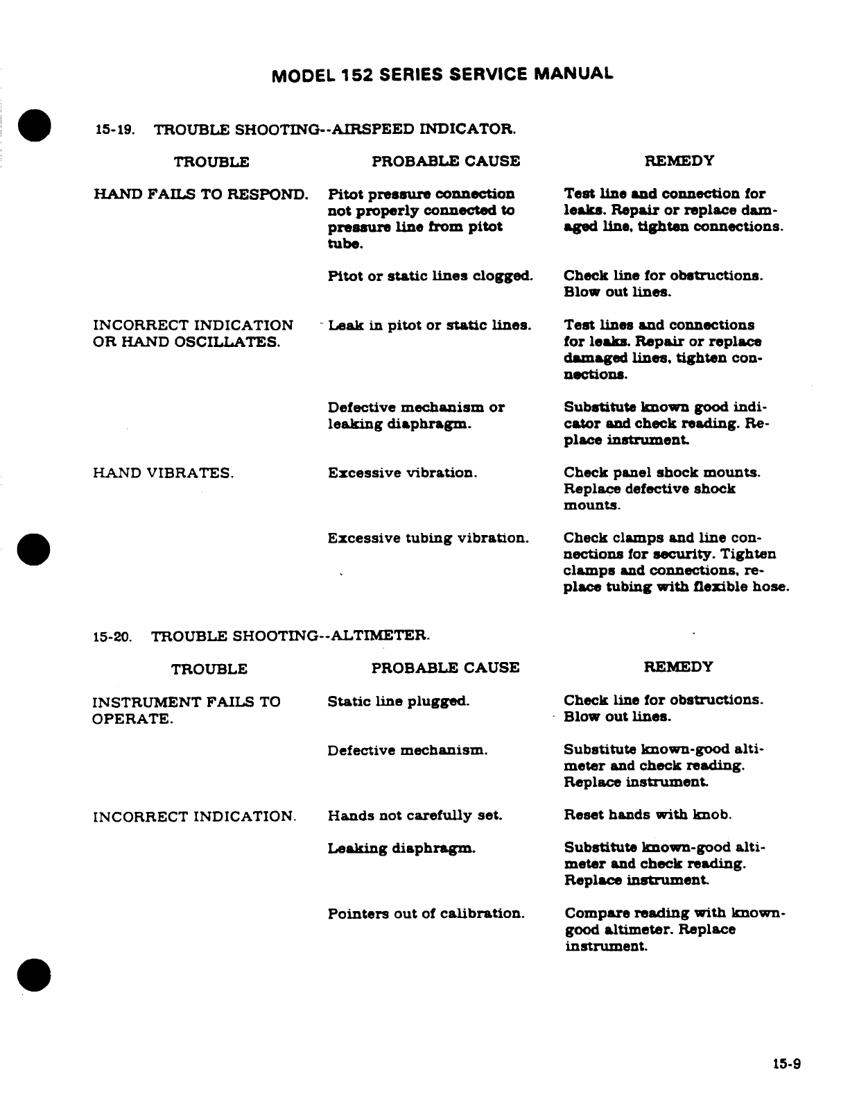
MODEL
152
SERIES
SERVICE
MANUAL
15-19.
TROUBLE
SHOOTING--AIRSPEED INDICATOR.
TROUBLE
PROBABLE CAUSE
REMEDY
HAND
FAILS
TO
RESPOND.
Pitot
pressure
connection
Test
line
and
connection
for
not
properly
connected
to
leaks.
Repair
or
replace
dam-
pressure
line
from
pitot
aged
line,
tighten
connections.
tube.
Pitot
or
static
lines
clogged.
Check
line
for
obstructions.
Blow
out
lines.
INCORRECT INDICATION
-Leak
in
pitot
or
static
lines.
Test
lines
and
connections
OR
HAND
OSCILLATES.
for
leaks.
Repair
or
replace
damaged
lines,
tighten
con-
nections.
Defective
mechanism
or
Substitute
known
good
indi-
leaking
diaphragm.
cator
and
check reading.
Re-
place
instrument.
HAND
VIBRATES.
Excessive
vibration.
Check
panel
shock
mounts.
Replace
defective
shock
mounts.
Excessive
tubing
vibration.
Check
clamps
and
line
con-
nections
for
security.
Tighten
clamps
and
connections,
re-
place
tubing
with
flexible
hose.
15-20.
TROUBLE
SHOOTING--ALTIMETER.
TROUBLE PROBABLE
CAUSE
REMEDY
INSTRUMENT
FAILS
TO
Static
line
plugged.
Check
line
for
obstructions.
OPERATE.
Blow
out
lines.
Defective
mechanism.
Substitute
known-good
alti-
meter
and
check reading.
Replace
instrument.
INCORRECT
INDICATION.
Hands
not
carefully
set.
Reset hands
with
knob.
Leaking
diaphragm.
Substitute
known-good
alti-
meter
and
check
reading.
Replace
instrument.
Pointers
out
of
calibration.
Compare
reading
with
known-
good
altimeter.
Replace
instrument.
15-9
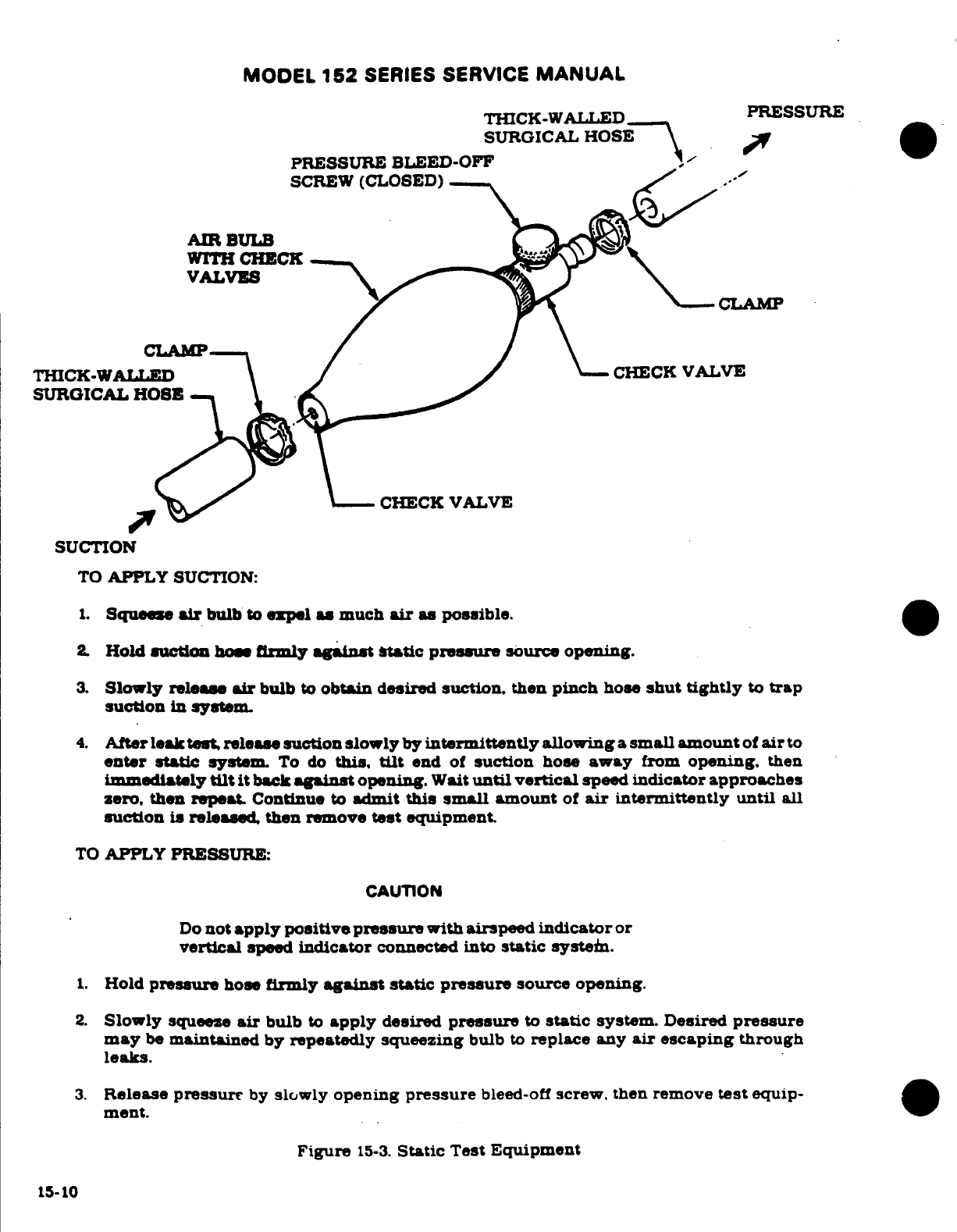
MODEL
152
SERIES
SERVICE
MANUAL
THICK-WALLED
PRESSURE
SURGICAL
HOSE
PRESSURE
BLEED-OFF
-
SCREW
(CLOSED)
.'
AIR
BULB
WITH
CHECK
VALVS
CLAMP
CLAMP
THICK-WALLED CHECK
VALVE
SURGICAL
HOSE
XCHECK
VALVE
SUCTION
TO
APPLY
SUCTION:
1.
Squees
air
bulb
to
expel a
much
air
as possible.
2
Hold
auction
hoes
firmly
against
static
pressure
source
opening.
3.
Slowly
release
air
bulb
to
obtain
desired
suction,
then
pinch
hose
shut
tightly
to
trap
suction
in
system.
4.
After
leak
test, release
suction
slowly
by
intermittently
allowing
a
small
amount
of
air
to
enter
static
system.
To
do
this,
tilt
end
of
suction
hose
away
from
opening,
then
immediately
tilt
it
back
against
opening.
Wait
until
vertical
speed
indicator approaches
zero,
then
repeat.
Continue
to
admit
this
small
amount
of
air
intermittently
until
all
suction
is
released,
then
remove
test
equipment.
TO
APPLY
PRESSURE:
CAUTION
Do
not
apply
positive
pressure
with
airspeed
indicator
or
vertical
speed
indicator
connected
into
static
systein.
1.
Hold
pressure
hose
firmly
against
static
pressure
source
opening.
2.
Slowly
squeeze
air
bulb
to
apply
desired
pressure
to
static
system.
Desired
pressure
may
be
maintained
by
repeatedly
squeezing
bulb
to
replace
any
air
escaping
through
leaks.
3.
Release
pressure
by
slowly
opening
pressure
bleed-off
screw,
then remove
test
equip-
ment.
Figure
15-3.
Static
Test
Equipment
15-10
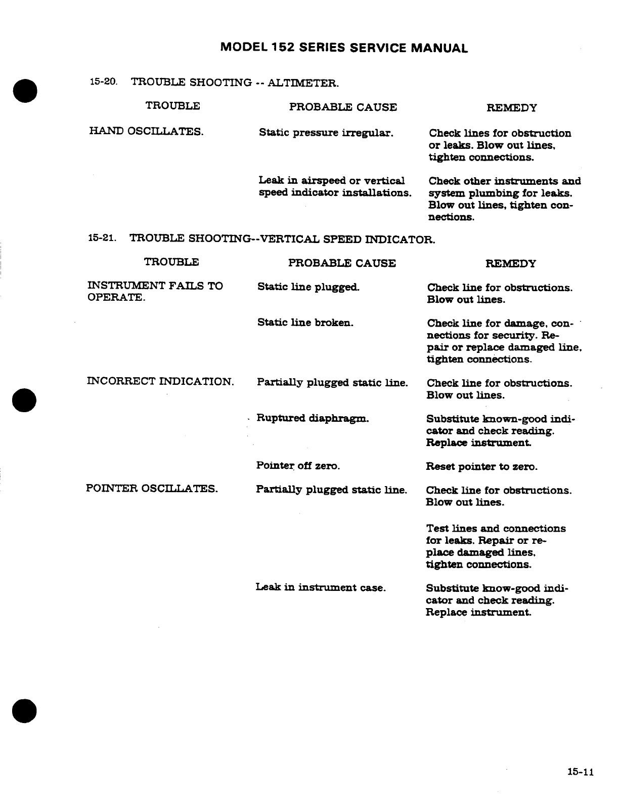
MODEL
152
SERIES
SERVICE
MANUAL
15-20.
TROUBLE
SHOOTING
--
ALTIMETER.
TROUBLE
PROBABLE
CAUSE
REMEDY
HAND
OSCILLATES.
Static
pressure
irregular.
Check
lines
for
obstruction
or
leaks.
Blow
out
lines,
tighten
connections.
Leak
in
airspeed
or
vertical
Check
other
instruments
and
speed
indicator
installations.
system
plumbing
for
leaks.
Blow
out
lines,
tighten
con-
nections.
15-21.
TROUBLE
SHOOTING--VERTICAL
SPEED
INDICATOR.
TROUBLE
PROBABLE
CAUSE
REMEDY
INSTRUMENT
FAILS
TO
Static
line
plugged.
Check
line for
obstructions.
OPERATE.
Blow
out
lines.
Static
line
broken.
Check
line for
damage,
con-
nections
for
security.
Re-
pair
or
replace
damaged
line,
tighten
connections.
INCORRECT
INDICATION.
Partially
plugged
static
line.
Check
line for
obstructions.
Blow
out
lines.
Ruptured diaphragm. Substitute
known-good
indi-
cator
and
check
reading.
Replace
instrument
Pointer
off
zero.
Reset
pointer
to
zero.
POINTER OSCILLATES.
Partially
plugged
static
line.
Check
line
for
obstructions.
Blow
out
lines.
Test
lines and
connections
for leaks.
Repair
or
re-
place
damaged
lines,
tighten
connections.
Leak
in
instrument
case.
Substitute
know-good
indi-
cator
and
check
reading.
Replace
instrument.
15-11
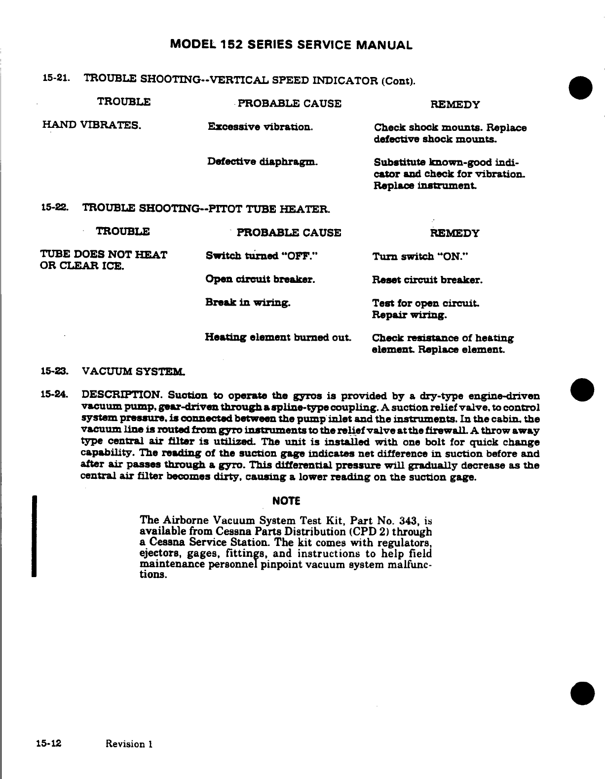
MODEL
152
SERIES SERVICE
MANUAL
15-21.
TROUBLE
SHOOTING--VERTICAL SPEED
INDICATOR
(Cont).
TROUBLE
PROBABLE
CAUSE
REMEDY
HAND
VIBRATES.
Excessive
vibration.
Check
shock
mounts.
Replace
defective
shock
mounts.
Defective
diaphragm. Substitute
known-good
indi-
cator
and
check
for vibration.
Replace
instrument.
15-22.
TROUBLE
SHOOTING--PITOT
TUBE
HEATER.
TROUBLE
PROBABLE
CAUSE
REMEDY
TUBE
DOES
NOT
HEAT
Switch
turned
"OFF."
Turn
switch
"ON."
OR
CLEAR
ICE.
Open
circuit
breaker.
Reset
circuit breaker.
Break
in
wiring.
Test
for
open
circuit.
Repair
wiring.
Heating
element
burned
out. Check
resistance
of
heating
element.
Replace
element.
15-23.
VACUUM
SYSTEM.
15-24.
DESCRIPTION.
Suction
to
operate
the
gyros
is
provided
by a dry-type
engine-driven
vacuum pump,
gear-driven
through
a
spline-type
coupling.
A
suction
relief
valve,
to
control
system
pressure,
is
connected
between
the
pump
inlet
and
the
instruments.
In the
cabin,
the
vacuum
line
is
routed
from
gyro
instruments
to
the
relief
valve
at
the
firewall.
A
throw
away
type
central
air
filter
is
utilized.
The
unit
is
installed
with
one
bolt
for
quick
change
capability.
The
reading
of
the
suction
gage
indicates
net
difference
in
suction
before
and
after
air
passes through
a
gyro.
This
differential
pressure
will
gradually
decrease
as
the
central
air
filter
becomes
dirty,
causing
a lower
reading
on
the suction
gage.
NOTE
The
Airborne
Vacuum
System
Test
Kit,
Part
No.
343,
is
available
from
Cessna
Parts
Distribution
(CPD
2)
through
a
Cessna
Service
Station.
The
kit
comes
with regulators,
ejectors,
gages,
fittings,
and
instructions
to
help
field
maintenance personnel
pinpoint
vacuum system
malfunc-
tions.
15-12
Revision
1
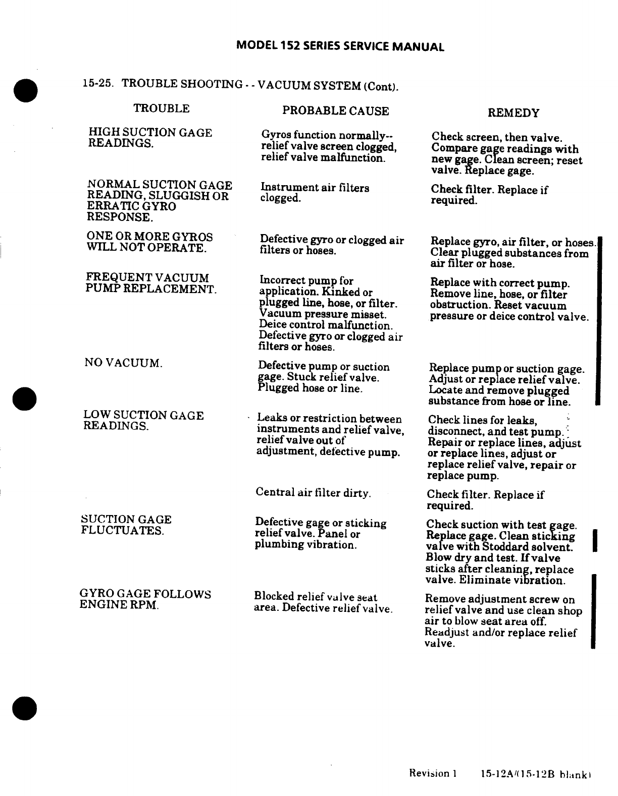
MODEL
152
SERIES
SERVICE
MANUAL
15-25.
TROUBLE SHOOTING-
-
VACUUM SYSTEM
(Cont).
TROUBLE
PROBABLE
CAUSE REMEDY
HIGH
SUCTION
GAGE
Gyros
function normally--
Check
screen,
then
valve.
READINGS.
relief
valve
screen
clogged,
Compare gage
readings
with
relief
valve
malfunction.
new
gage.
Clean
screen;
reset
valve.
Replace gage.
NORMAL
SUCTION
GAGE
Instrument
air
filters
Check
filter.
Replace
if
READING, SLUGGISH
OR
clogged.
required.
ERRATIC
GYRO
RESPONSE.
ONE
OR
MORE
GYROS
Defective
gyro
or
clogged
air
Replace
gyro,
air
filter,
or
hoses.
WILL
NOT
OPERATE.
filters
or hoses.
Clear
plugged
substances
from
air
filter
or
hose.
FREQUENT
VACUUM
Incorrect pump
for
Replace
with
correct
pump.
PUMP
REPLACEMENT.
application.
Kinked
or
Remove
line,
hose,
or
filter
plugged
line,
hose, or
filter.
obstruction.
Reset
vacuum
Vacuum
pressure
misset.
pressure
or
deice
control valve.
Deice
control
malfunction.
Defective gyro
or
clogged
air
filters or
hoses.
NO VACUUM.
Defective
pump
or
suction
Replace
pump
or
suction
gage.
gage.
Stuck
relief
valve.
Adjust
or
replace
relief
valve.
Plugged
hose
or
line.
Locate
and
remove
plugged
substance
from
hose
or
line.
LOW
SUCTION
GAGE
Leaks
or
restriction
between
Check
lines
for
leaks,
READINGS.
instruments
and
relief
valve,
disconnect,
and
test
pump.
relief
valve
out
of
Repair
or
replace
lines,
adjust
adjustment,
defective
pump.
or
replace
lines,
adjust
or
replace
relief
valve,
repair
or
replace
pump.
Central
air
filter
dirty. Check
filter.
Replace
if
required.
SUCTION
GAGE
Defective
gage
or
sticking
Check
suction
with
test
gage.
FLUCTUATES.
relief
valve.
Panel
or
Replace
gage.
Clean
sticking
plumbing vibration.
valve
with Stoddard
solvent.
Blow
dry
and
test.
If
valve
sticks
after
cleaning,
replace
valve.
Eliminate
vibration.
GYRO
GAGE
FOLLOWS
Blocked
relief
valve
seat
Remove
adjustment
screw
on
ENGINE
RPM.
area.
Defective
relief
valve.
relief
valve
and
use
clean
shop
air
to
blow
seat
area
off.
Readjust
and/or
replace
relief
valve.
Revision
1
15-12A/(15-12B
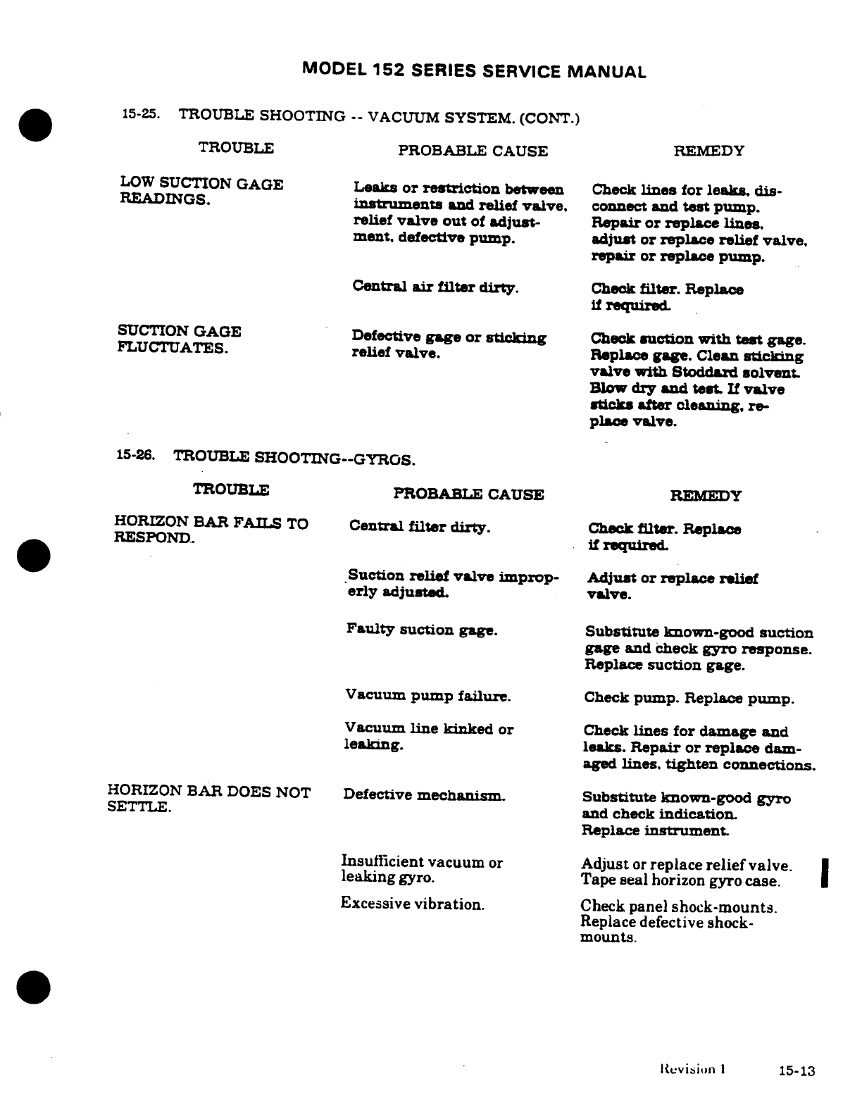
MODEL
152
SERIES
SERVICE
MANUAL
15-25.
TROUBLE
SHOOTING
--
VACUUM
SYSTEM.
(CONT.)
TROUBLE
PROBABLE CAUSE
REMEDY
LOW
SUCTION GAGE
Leaks
or
restriction
between
Check
lines
for
leaks,
dis-
READINGS.
instruments
and
relief
valve,
connect
and
test
pump.
relief
valve
out
of
adjust-
Repair
or
replace
lines.
ment.
defective
pump.
adjust
or
replace relief
valve.
repair
or
replace
pump.
Central
air
filter
dirty.
Check
filter.
Replace
if
required.
SUCTION
GAGE
Defective
gage
or
sticking
Check
suction
with
test
gage.
FLUCTUATES.
relief
valve.
Replace
gage.
Clean
sticking
valve
with
Stoddard
solvent.
Blow
dry
and
test
If
valve
sticks
after
cleaning,
re-
place
valve.
15-26.
TROUBLE
SHOOTING--GYROS.
TROUBLE
PROBABLE
CAUSE
REMEDY
HORIZON
BAR
FAILS
TO
Central
filter
dirty.
Check
filter.
Replace
RESPOND.
if
required.
Suction
relief
valve
improp-
Adjust
or
replace
relief
erly
adjusted
valve.
Faulty
suction
gage.
Substitute
known-good
suction
gage
and
check
gyro
response.
Replace
suction
gage.
Vacuum
pump
failure.
Check
pump.
Replace
pump.
Vacuum
line
kinked
or
Check
lines
for
damage
and
leaking. leaks.
Repair
or
replace
dam-
aged
lines.
tighten
connections.
HORIZON
BAR
DOES
NOT
Defective
mechanism.
Substitute
known-good
gyro
SETTLE.
and check
indication.
Replace
instrument.
Insufficient
vacuum
or
Adjust
or
replace
relief
valve.
leaking
gyro.
Tape
seal
horizon
gyro
case.
Excessive
vibration.
Check panel
shock-mounts.
Replace
defective
shock-
mounts.
Revision
1
15-13
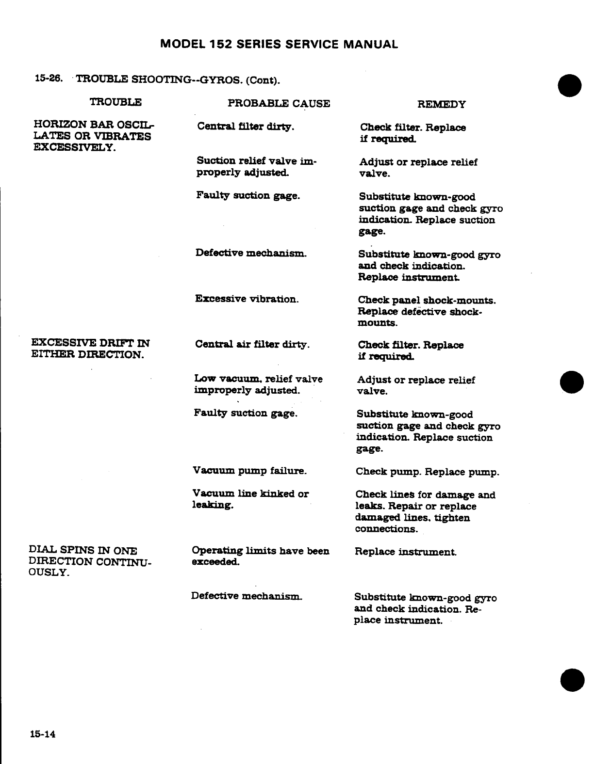
MODEL
152
SERIES
SERVICE
MANUAL
15-26.
TROUBLE
SHOOTING--GYROS.
(Cont).
TROUBLE
PROBABLE
CAUSE
REMEDY
HORIZON
BAR
OSCIL-
Central
filter dirty.
Check
filter.
Replace
LATES
OR
VIBRATES
if required.
EXCESSIVELY.
Suction
relief
valve
im-
Adjust
or
replace
relief
properly
adjusted,
valve.
Faulty
suction
gage.
Substitute
known-good
suction
gage and
check
gyro
indication.
Replace
suction
gage.
Defective
mechanism.
Substitute
known-good
gyro
and
check
indication.
Replace
instrument
Excessive
vibration.
Check
panel
shock-mounts.
Replace
defective
shock-
mounts.
EXCESSIVE
DRIFT
IN
Central
air
filter
dirty.
Check
filter.
Replace
EITHER
DIRECTION.
if
required
Low
vacuum,
relief
valve
Adjust
or
replace
relief
improperly
adjusted.
valve.
Faulty
suction
gage.
Substitute
known-good
suction
gage
and
check
gyro
indication.
Replace
suction
gage.
Vacuum
pump
failure.
Check
pump.
Replace
pump.
Vacuum
line
kinked
or
Check
lines
for
damage
and
leaking.
leaks.
Repair or
replace
damaged
lines,
tighten
connections.
DIAL
SPINS
IN
ONE
Operating
limits
have
been
Replace
instrument.
DIRECTION
CONTINU-
exceeded.
OUSLY.
Defective
mechanism.
Substitute
known-good
gyro
and
check
indication.
Re-
place
instrument.
15-14
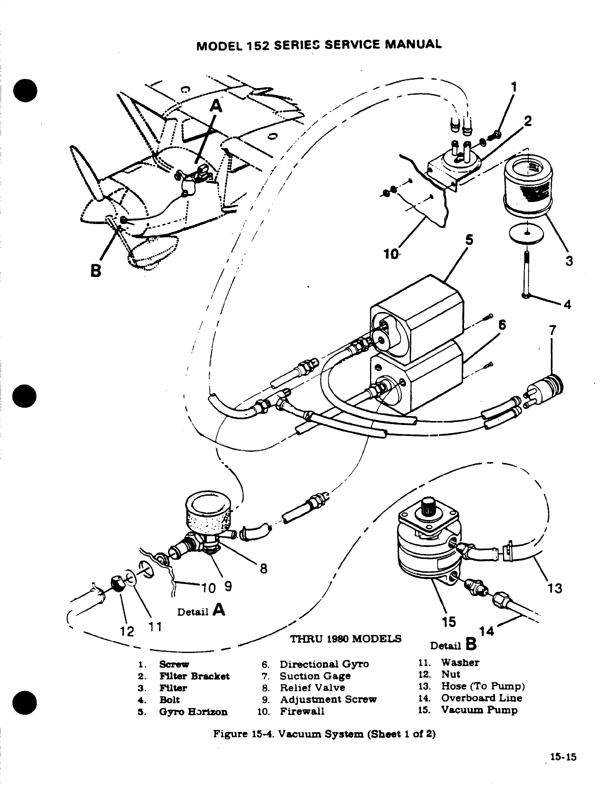
MODEL
152
SERIES
SERVICE
MANUAL
Detail
12
11
THRU
1980
MODELS
Detail
B
1.
Screw
6.
Directional
Gyro
11.
Washer
2.
Filter
Bracket
7.
Suction
Gage
12.
Nut
3.
Filter
8.
Relief
Valve
13.
Hose
(To
Pump)
4.
Bolt
9.
Adjustment
Screw
14.
Overboard
Line
5.
Gyro
Horizon
10.
Firewall
15.
Vacuum
Pump
Figure
15-4.
Vacuum
System (Sheet
1
of
2)
15-15
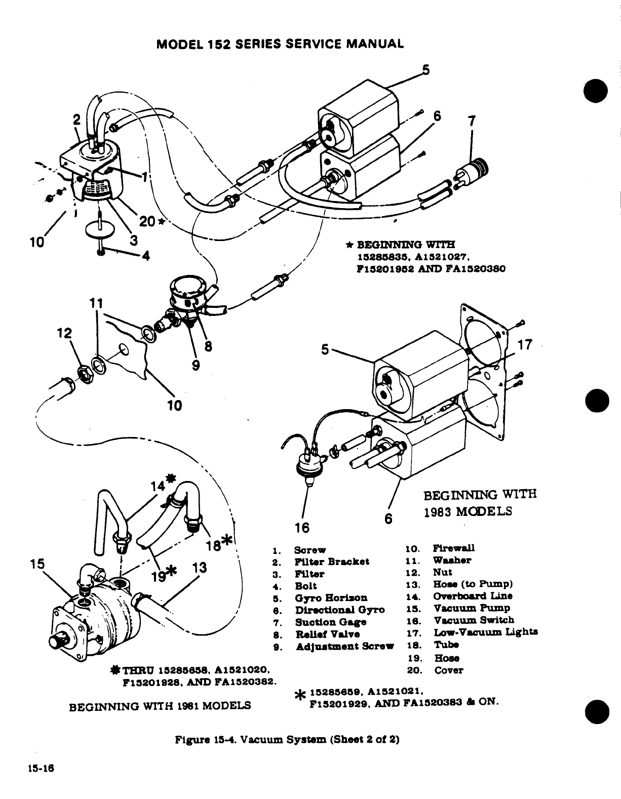
MODEL
152
SERIES
SERVICE
MANUAL
*
BEGINNING
WIrTH
15285835, A1521027.
F15201952
AND
FA1520380
10
14
BEGINNING
WITH
16
6
1983
MODELS
16
18,
1.
screw
10.
Firewall
15
13
2.
Filter
Bracket
11.
Washer
19
3.
Filter
12.
Nut
4.
Bolt
13.
Hose
(to
Pump)
5.
Gyro Horizon
14.
Overboard
Line
6.
Directional
Gyro
15.
Vacuum
Pump
7.
Suction
Gage
16.
Vacuum
Switch
8.
Relief
Valve
17.
Low-Vacuum
Lights
9.
Adjustment
Screw
18.
Tube
19.
Hose
*THRU
15285658,
A1521020,
20.
Cover
F15201928.
AND
FA1520382.
*
15285659, A1521021,
BEGINNING
WITH
1981
MODELS
F15201929,
AND
FA1520383
&
ON.
Figure
15-4.
Vacuum
System
(Sheet
2
of
2)
15-16
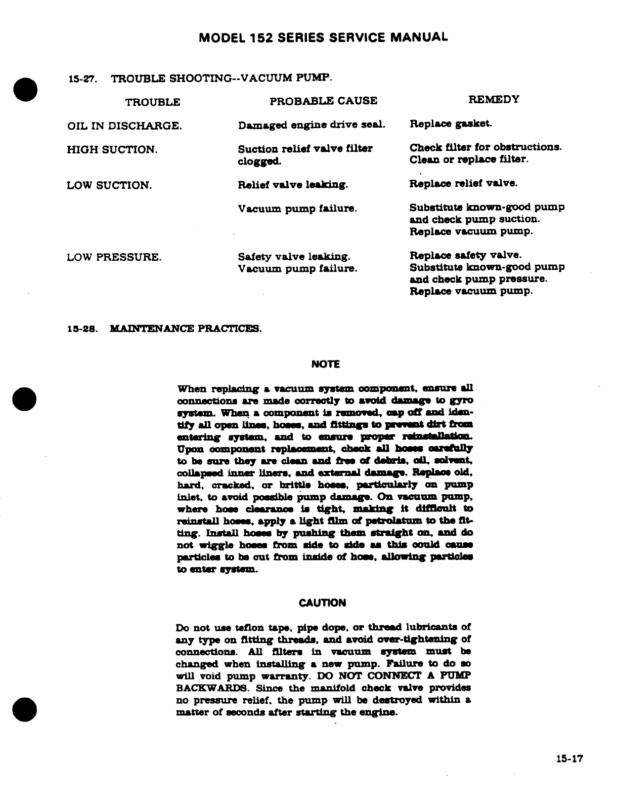
MODEL
152
SERIES SERVICE
MANUAL
15-27.
TROUBLE
SHOOTING--VACUUM
PUMP.
TROUBLE
PROBABLE
CAUSE REMEDY
OIL
IN
DISCHARGE.
Damaged
engine drive
seal.
Replace
gasket.
HIGH
SUCTION.
Suction
relief valve
filter
Check
filter
for
obstructions.
clogged.
Clean
or
replace
filter.
LOW
SUCTION.
Relief
valve
leaking.
Replace
relief
valve.
Vacuum
pump failure.
Substitute
known-good
pump
and
check
pump
suction.
Replace
vacuum
pump.
LOW
PRESSURE.
Safety
valve
leaking.
Replace
safety
valve.
Vacuum
pump
failure.
Substitute
known-good
pump
and
check
pump
pressure.
Replace
vacuum
pump.
15-28.
MAINTENANCE
PRACTICES.
NOTE
When
replacing
a
vacuum
system
component,
ensure
all
connections
are
made
corretly
to
avoid
damage
to
gyro
system
When
a
component
is
removed,
cap
off
and
iden-
tiy
all
open
lines
hoses
and
fittings
to
prevent
dirt
from
entering
system,
and
to
ensure
proper
reinstallation
Upon
component
replacement
check
all
hoses
carefully
to
be
sure
they are
clean
and
free
of
debris,
oil
solvent
collapsed
inner
liners,
ad
external
damage.
Replace
old,
hard,
cracked,
or
brittle
hoses
particularly
on
pump
inlet, to
avoid
possible
pump
damage.
On
vacuum pump,
where
hose
clearance
i
tight,
making
it
difficult
to
reinstall
hoses
apply
a
light
film
of
petrolatum
to
the
fit-
ting.
Install
hoses
by
pushing
them
straight
on, and
do
not
wiggle hoses
from
side
to
side
as
this
could cause
particles
to
be
out
from
inside
of
hose,
allowing
particles
to
enter
systm.
CAUTION
Do
not
use
teflon
tape,
pipe
dope,
or
thread
lubricants
of
any
type
on
fitting
threads,
and
avoid
over-tightening
of
connections.
All
filters
in
vacuum
system
must
be
changed
when
installing
a
new
pump.
Failure
to
do
so
will void
pump
warranty.
DO
NOT CONNECT
A
PUMP
BACKWARDS.
Since
the
manifold
check
valve
provides
no
pressure
relief,
the
pump
will
be
destroyed within
a
matter
of
seconds
after
starting
the
engine.
15-17
MODEL
152
SERIES SERVICE
MANUAL
13-28A.
REMOVAL
OF
VACUUM
PUMP.
a.
Remov
upper engine
Cowllng
in
accordance
with
procedure
in
Section
11.
b. Disconnect,
cap
off
and
identify
hose
on
inlet
side
of
vacuum
pump.
c.
Identify
and
disconnect
hose
on
oulet
side
of
vacuum
pump.
d.
Remove
nut,
lock
washers
and
flat
washers
scouring
vacuum pump
to
engine.
I.
Remove
vacuum
pump
fom
mounttng
studs
on
engine.
f.
Remove
elbow
from
pump
and
retain
if it is
reusable.
NOTE
Disard
any
twisted
fitting
or
nuts
with
rounded
oor-
nua
1-288.
MOUNTING
PAD
INSPECTION.
a.
Check
Condition
of
the
AND
20000
pad
seal
If
the
seal
shows
any
signs
of
oil
leak-
age,
replace
the
seal
Replace
seal
if
there
is
any
doubt
-
to
its servicability.
15-28C.
INTALLATION
OF
VACUUM
PUMP.
a.
Before
installing
a
new
vacuum
pump,
purge
all
lines
in
system
to
remove carbon
particles
or
other
pump
components
that
may
have
been
deposited
in
lines
by
previ-
ous pump.
NOTE
Before
installing
vacuum
pump
on
engine,
ensure
that
mating
surfaces
are
clean
and
free
of
any
old
gasket
ma-
terial.
b.
Conult
the
applicable
Part
Catalog,
the pump
vendor's
appliation
list,
or
the
PMA
label
on
the pump
box
to
veriy
that
the pump
is
the
correct
model
for
the
engine
and/or
aystem.
c.
Position
vacuum
pump
in
a
jaw-proteoted vise,
with
drive
coupling
downward.
CAUTION
Pump
housing
should
never
be
placed
directly
in
a
vise,
since
clamping
acrose
center
housing
will
cause
an
inter-
nal
failure
of
carbon
rotor.
Protect
pump
mounting
flange
with
soft
metal
or
wood.
NEVER
install
a
vacuum
pump
that
has
been
dropped.
NOTE
Do
not
use
teflon
tape,
pipe
dope,
or
thread
lubricants
of
any
type,
and
avoid
over-tightening
of
connections.
d.
Install
elbow
in
pump;
hand-tghten
only.
NOTE
Use
only
a
box
wrench
to
tighten
fittings
to
desired
posi-
tion.
Do
not
make
more
than
one
and
one
half
(1-1/2)
turns
beyond
hand-tighten
position.
15-18
MODEL 152
SERIES
SERVICE
MANUAL
e.
Position
new
mounting
pad
gasket
on
mounting
studs
on
engine.
f.
Position
vacuum
pump
on
mounting
studs.
g.
Secure
pump
to
engine
with
flat
washers,
new
lockwashers,
and
nuts.
CAUTION
Always
replace all
lockwashers
with
new
one
when
install-
ing
a
new
vacuum pump.
Tighten
all
four
mounting
nuts
(4)
to
50
to
70
pound-inches.
h.
Connect
hose
to
inlet
side
of
vacuum
pump.
NOTE
When
installing
hoses,
do
not
wiggle from
side
to
side.
This
practice
can
cause
particles
to
be
cut
from
inside
hose
that
could
damage
pump.
i.
Install
upper
engine
cowling
in
accordance
with
procedures
in
Section
11.
15-28D.
CLEANING.
In
general,
low
pressure,
dry
compressed
air
should
be
usd
in
cleaning
aum
system
components.
Suction
reef
valve
should
be
washed
with
Stoddard
solvent,
then
dried
with
low-pressre air
blast.
CAUTION
Never
apply
compresed
air
to
lines
or
components
instal-
led
in
airraft
The
excessive
pressures
will
damage
gyros.
If
an
obstructed
line
Is
to
be
blown
out,
disconnect
at
both ends
and
blow
from
instrument
panel
out.
15-28E.
LOW-VACUUM
WARNING
LIGHT.
A
red
low-vacuum
warning
light
is
installed
on
the
in-
strument
panel
The
light
is
controlled by
a
vacum
switch
mounted
on
the
back
of
the gyro
horizon.
The
switch
contacts
are
normally
closed.
The
light
may
be
checked
by
turning
ON
the
master
switch.
With
the
engine
running
the
light
should
illminate
when
the
vacuum
drops
below
3 =
.5
Inches
Hg.
15-29.
VACUUM
RELIEF
VALVE
ADJUSTMNT.
A
suction
gage
reading
of
5.3
inches of
mercuryl
is
desirable
for
gyro
instruments.
However,
a
range
of
4.6
to
5.4
inches
of
merury
is
ac-
ceptable.
To
adjust
relief
valve,
remove
central
air
filter,
run
engine
to
1900
RPM
on ground
and
adjust relief
valve
to
5.3
.1
inches
of
mercury.
CAUTION
Do
not
exceed
maimnum
engine temperature.
Be
sure
filter
element
is
clean
before
installing.
If
reading
drops
noticeably,
install
new
filter
element.
15-30.
STANDBY
VACUUM
SYSTEM
15-30A.
DESCRIPTION.
A
standby
vacuum
system
may
be
installed
in
the
airplane.
The
system
con-
sists
of
a
vacuum pump,
driven
by
an
electric
motor,
mounted
on
the
aft
side
of
the
firewall
and associated
hoses.
One
hose
is
the
vacuum
pump
vent
hose
and
the
other
connects
to
a
manifold
with
the
engine
driven
vacuum
pump,
just
prior
to
the
system relief
valve.
A
two
position
circuit
breaker
switch,
mounted
adjacent
to
the
cabin
air
control
on
the
instrument
panel,
controls
and
protect
the system.
Revision
1
15-19
MODEL
152
SERIES
SERVICE
MANUAL
15-30B.
TROUBLE
SHOOTING
- -
STANDBY
VACUUM SYSTEM.
TROUBLE
PROBABLE
CAUSE
REwEDY
NO
SUCTION
GAGE
Circuit breaker
switch
Reset
circuit
breaker
switch.
READING.
has
opened.
If
switch
reopens,
check
wire
from
switch
to
bus bar
for
short.
Repair
or
replace
wire.
Defective
motor.
Check voltage
input
wire
and
ground
wire.
Repair
or
replace
wires.
Defective
pump.
Check
pump
operation.
Replace
pump.
LOW
SUCTION GAGE
Leak
or
restriction
Check
hoses
and
connections
READING.
between
pump
and
for
leaks
and
obstructions.
suction
gage.
Install
new
clamps
at
connection,
clear
or
replace
hoses
Relief
valve
not
Adjust
relief
valve.
properly
adjusted.
Defective
pump.
Check
pump.
Replace
pump.
Central
air
filter
Replace
central
air
filter.
dirty.
15-30C.
REMOVAL. (See
figure
15-4A.)
a.
Release
claps
securing
hoes
(12)
and
(13)
to
pump
(15).
b.
Cap
hoses
(12),
(13)
and
pump
fittings
(14)
so
dirt
cannot
enter
system.
c.
Make
sure
circuit
breaker
switch
(1)
and battery
switch
are
off.
d. Disconnect
motor
voltage
input
wire
919)
and
ground
wire
(21).
e.
Remove
safety
from
bolts
(9).
f.
Support
pump
and
motor
assembly and
remove
bolts
(9).
g.
If
pump
is
to
be
removed
from
motor,
remove
nuts
(16)
and
washers
(17).
15-30D. INSTALLATION.
(See
figure
15-4A.)
a.
If
removed,
install
pump
(15)
on
motor
(18)
drive
studs
and
install
washers
(17)
and
nuts
(16).
b.
Position
pump
and
motor assembly
up
against
bracket
(22)
and
install
bolts
(9).
c.
Safety-wire
bolts
(9).
d.
Connect
motor
voltage
input
wire
(19)
and
ground
wire
(21).
e.
(See
figure
15-4B.)
For improved
wire
security,
install
ties
(4) (6)
around
motor
(5),
nipples
(8),
and
motor
wires
(3),
pull
red
motor
lead
tight,
and
seal
grommet
(7)
with
RTV
sealer.
f.
Remove
caps
from
hoses
(12),
(13),
and
fittings
(14)
then
install
hoses
and
clamps.
g.
Turn
on
battery
switch
and
close
circuit
breaker
(1),
then
check
suction
gage
to
see
that
system
is
operating
properly.
Then
turn
off
switches.
15-20
Revision
1
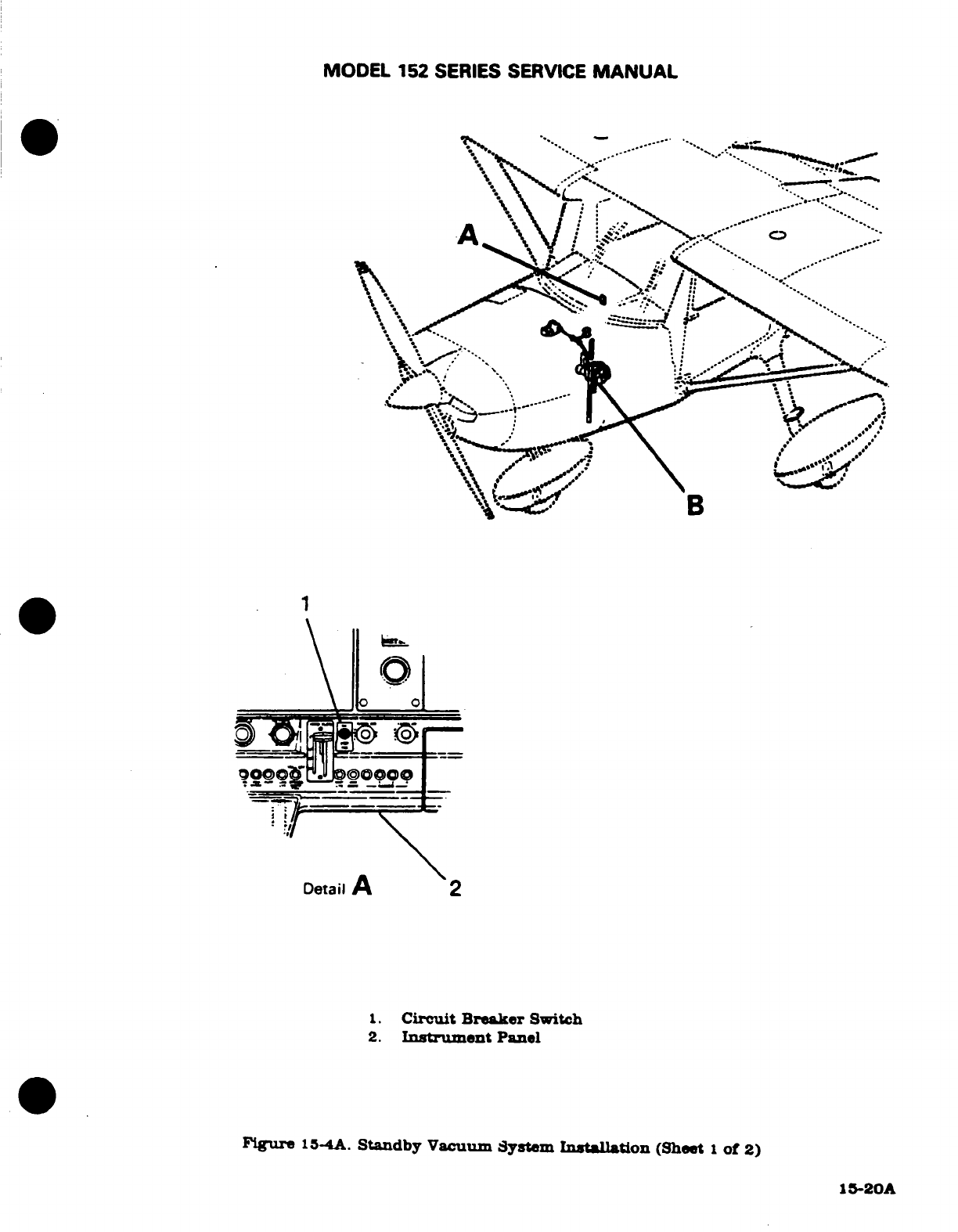
MODEL 152
SERIES
SERVICE
MANUAL
.
Detail
A
2
1.
Circuit
Breaker
Switch
2.
Instrument
Panel
Figure
15-4A
Standby
Vacuum
System
Installation
(Sheet
1
of
2)
15-20A
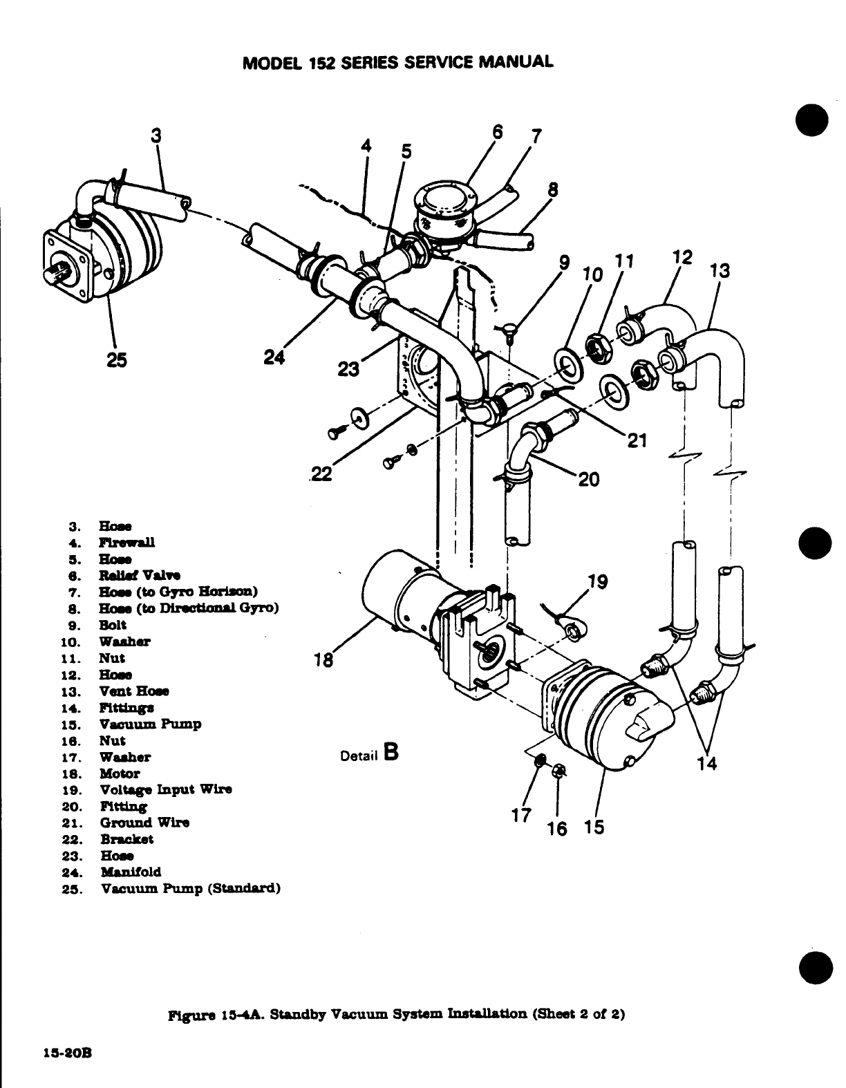
MODEL
152
SERIES
SERVICE
MANUAL
6
7
1
12
10
13
25
24 23
21
22
4. Firewall
5
Hose
6.
Relief
Valve
7.
How
(to
Gyro
Horion)
8.
Hose
(to
Directional
Gyro)
9.
Bolt
10.
Washer
11.
Nut
18
12.
Hose
13.
Vent
Hose
14.
Fittings
15.
Vacuum
Pump
16.
Nut
17.
Washer
DetailB
18.
Motor
19.
Voltage
Input
Wire
20.
Fitting
21.
Ground
Wire
1
22.
Bracket
16
15
23.
Hose
24. Manifold
23.
Vacuum
Pump
(Standard)
Figure
15-4A.
Standby
Vacuum System
Installation
(Sheet
2
of
2)
15-20B
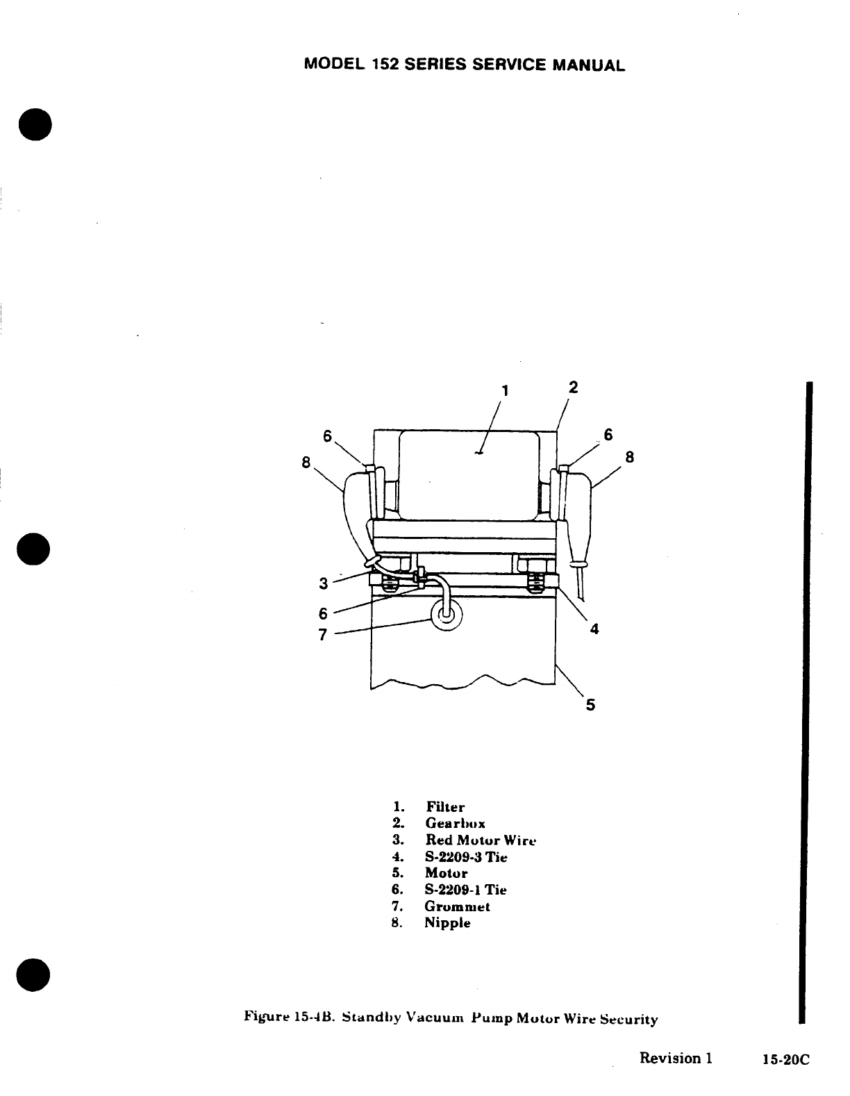
MODEL
152
SERIES
SERVICE
MANUAL
1
2
6\
8
4
5
1.
Filter
2.
Gearlox
3.
Red
Motor
Wire
4.
S-2209-3
Tie
5.
Motor
6.
S-2209-1
Tie
7.
Grommet
8.
Nipple
Figure
15-4B.
Standby
Vacuum
Pump
Motor
Wire
Security
Revision
1
15-20C
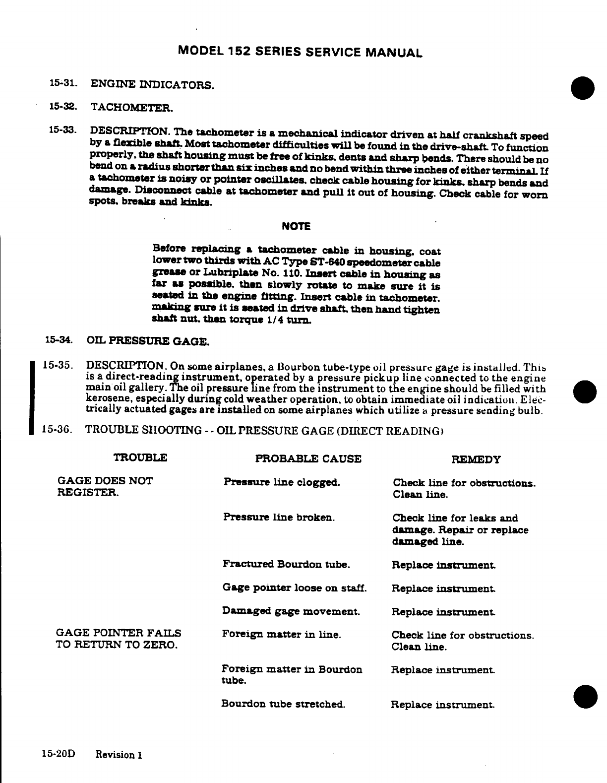
MODEL
152
SERIES SERVICE
MANUAL
15-31.
ENGINE INDICATORS.
15-32.
TACHOMETER.
15-33.
DESCRIPTION.
The
tachometer
is a
mechanical
indicator
driven at half
crankshaft
speed
by
a
flexible
shaft
Most
tachometer
difficulties
will
be
found
in
the drive-shaft
To
function
properly,
the
shaft
housing
must
be
free of
kinks,
dents
and
sharp
bends.
There
should
be
no
bend
on
a
radius
shorter than
si
inches
and
no
bend
within
three
inches
of
either
terminal
If
a
tachometer
is
noisy
or pointer
oscillates,
check cable
housing
for
kinks,
sharp
bends
and
damage.
Disconnect
cable
at tachometer
and
pull
it
out
of
housing.
Check
cable
for worn
spots.
breaks
and
kinks.
NOTE
Before
replacing
a
tachometer
cable
in
housing.
coat
lower
two
thirds with
AC
Type
ST-640
speedometer
cable
grease
or
Lubriplate
No.
110.
Insert
cable
in
housing
as
far
as possible, than
slowly
rotate
to
make
sure
it is
seated
in
the
engine
fitting.
Insert
cable
in
tachometer.
makng
sure
it is
seated
in
drive
shaft,
then
hand
tighten
shaft
nut,
then
torque
1/4
turn.
15-34.
OIL
PRESSURE
GAGE.
15-35.
DESCRIPTION.
On some
airplanes,
a
Bourbon
tube-type
oil
pressure
gage
is
installed.
This
is
a
direct-reading
instrument,
operated
by
a
pressure
pickup
line
connected
to
the engine
main
oil
gallery.
The
oil
pressure
line
from
the
instrument
to
the
engine
should
be
filled
with
kerosene, especially
during
cold
weather
operation,
to
obtain
immediate
oil
indication.
Elec-
trically
actuated
gages
are
installed
on
some
airplanes
which
utilize
a
pressure
sending
bulb.
15-36.
TROUBLE
SIIOOTING
- -
OIL
PRESSURE
GAGE
(DIRECT READING
TROUBLE
PROBABLE
CAUSE
REMEDY
GAGE
DOES
NOT
Pressure
line
clogged.
Check
line
for
obstructions.
REGISTER.
Clean
line.
Pressure
line
broken.
Check
line
for
leaks
and
damage.
Repair
or
replace
damaged
line.
Fractured
Bourdon
tube. Replace
instrument.
Gage
pointer
loose
on
staff.
Replace
instrument.
Damaged
gage
movement.
Replace
instrument.
GAGE POINTER
FAILS
Foreign
matter
in
line.
Check
line for
obstructions.
TO
RETURN
TO
ZERO.
Clean
line.
Foreign
matter
in
Bourdon
Replace
instrument.
tube.
Bourdon
tube
stretched.
Replace
instrument.
15-20D
Revision
1
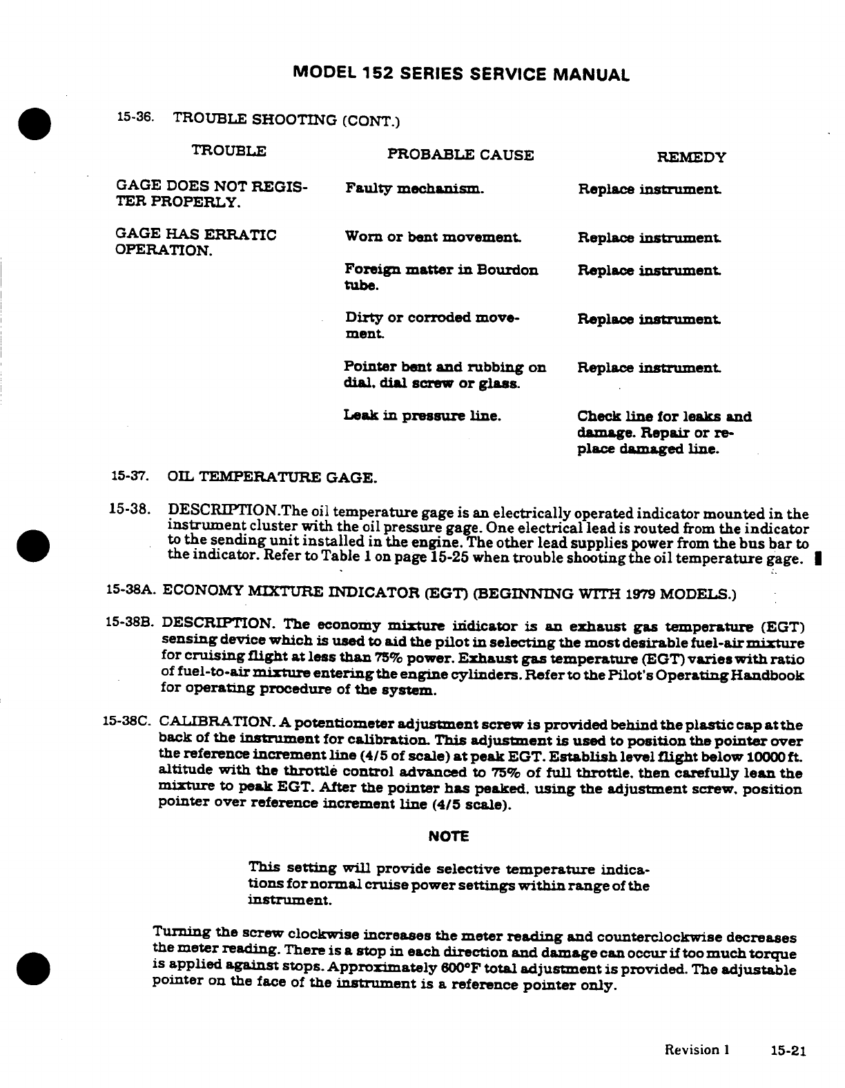
MODEL
152
SERIES
SERVICE
MANUAL
15-36.
TROUBLE
SHOOTING
(CONT.)
TROUBLE
PROBABLE
CAUSE REMEDY
GAGE
DOES
NOT
REGIS-
Faulty
mechanism.
Replace
instrument.
TER
PROPERLY.
GAGE
HAS
ERRATIC
Worn
or
bent
movement.
Replace
instrument
OPERATION.
Foreign
matter
in
Bourdon
Replace
instrument.
tube.
Dirty
or
corroded
move-
Replace
instrument.
ment.
Pointer
bent
and
rubbing
on
Replace
instrument.
dial, dial
screw
or
glass.
Leak
in
pressure
line.
Check
line for leaks
and
damage.
Repair
or
re-
place
damaged line.
15-37.
OIL
TEMPERATURE
GAGE.
15-38.
DESCRIPTION.The
oil
temperature
gage
is
an
electrically
operated
indicator
mounted
in
the
instrument
cluster
with
the
oil
pressure
gage.
One
electrical
lead
is
routed
from
the
indicator
to
the
sending
unit
installed
in
the
engine.
The
other
lead supplies
power
from
the
bus
bar
to
the
indicator.
Refer to Table
I
on
page
15-25
when
trouble
shooting
the
oil
temperature
gage.
15-38A.
ECONOMY
MIXTURE
INDICATOR
(EGT)
(BEGINNING
WITH
1979
MODELS.)
15-38B.
DESCRIPTION. The
economy
mixture
indicator
is
an
exhaust
gas
temperature
(EGT)
sensing
device
which
is
used
to
aid the
pilot
in
selecting
the
most
desirable fuel-air
mixture
for
cruising
flight
at
less
than
75%
power.
Exhaust
gas temperature
(EGT)
varies
with
ratio
of
fuel-to-air
mixture
entering
the
engine
cylinders.
Refer
to
the
Pilot's
Operating
Handbook
for
operating
procedure
of
the
system.
15-38C.
CALIBRATION.
A
potentiometer
adjustment
screw
is
provided
behind
the plastic
cap
at
the
back
of
the
instrument
for
calibration.
This
adjustment
is
used
to
position
the
pointer
over
the
reference
increment line
(4/5
of
scale)
at
peak
EGT.
Establish
level
flight
below
10000
ft.
altitude with
the
throttle
control
advanced
to
75%
of full
throttle,
then
carefully
lean
the
mixture
to
peak
EGT.
After
the
pointer
has
peaked.
using
the
adjustment
screw.
position
pointer
over reference increment line (4/5
scale).
NOTE
This
setting
will
provide
selective
temperature
indica-
tions
for
normal
cruise
power
settings
within
range
of
the
instrument.
Turning the
screw clockwise
increases
the
meter
reading
and counterclockwise
decreases
the
meter
reading.
There
is a
stop
in
each
direction
and
damage
can occur
if
too
much
torque
is
applied
against
stops. Approximately
600°F
total adjustment
is
provided.
The
adjustable
pointer
on
the
face
of
the
instrument
is a
reference
pointer
only.
Revision
1
15-21
MODEL
152
SERIES
SERVICE
MANUAL
15-38D.
REMOVAL
AND
INSTALLATION.
(See
figure
15-4A.)
a.
Indicator.
1.
Remove
instrument
panel
decorative
cover.
2.
Disconnect
EGT
indicator
leads.
3.
Remove
screws,
nuts
and
washers
securing
indicator
and
remove indicator.
4.
To
install
reverse
the
preceding
steps.
b.
Probe.
1.
Disconnect probe leads.
2.
Remove
clamp
and probe
assembly.
3.
When
installing
probe,
tighten
clamp
to
30-35
lb-in.
4. Coil
or
fold
excess
lead and
tie
in
a
covenient
out
of
the
way
location.
15-38E.
TROUBLE
SHOOTING.
TROUBLE
PROBABLE
CAUSE
REMEDY
GAGE
INOPERATIVE
Defective
gage,
probe
or
Repair
or
replace
defective
circuit
part.
INCORRECT
READING
Indicator
needs
calibrating
Calibrate
indicator
in
accord-
ance
with
paragraph
15-38C.
FLUCTUATING
READING
Loose,
frayed
or
broken Tighten
connection
and
lead,
permitting
alternate
repair
or
replace
defec-
make
and
break
of
circuit.
tive
leads.
15-39.
FUEL
QUANTITY
INDICATING
SYSTEM..
15-40.
DESCRIPTION.
The
magnetic
type
fuel
quantity
indicators
are
used
in
conjunction
with
a
float-operated
variable-resistance
transmitter
in
each
fuel
tank
The
full
position
of
float
produces
a
minimum
resistance
through
transmitter,
permitting
maximum
current
flow
through the
fuel
quantity
indicator
and
maximum
pointer
deflection
As
fuel
level
is
lowered,
resistance
in
the
transmitter
is
increased,
producing
a
decreased
current
flow
through
fuel
quantity
indicator
and
a
smaller
pointer
deflection.
15-41.
REMOVAL
AND
INSTALLATION
OF
FUEL
QUANTITY
TRANSMITTER.
a.
Drain
fuel
from
tank.
(Observe
precautions
in
Section
12)
b.
Remove
access
plate
above fuel
tank
for access
to
transmitter.
c.
Disconnect
electrical
lead and
ground
strap
from
transmitter.
d.
Remove
screws
attaching
transmitter
and
carefully
work
transmitter
from
tank.
DO
NOT
BEND FLOAT
ARM.
e.
Install
transmitter
by
reversing
preceding
steps,
using
new
gaskets
around
opening
in fuel
tank
and
under
screw
heads.
Be
sure
to
righten
screws
evenly.
f.
Service
fuel
tanks.
Check
for
leaks
and
correct
quantity
indication.
NOTE
Ensure
transmitter
is
properly
grounded
in accordance
with
Section
12.
15-22
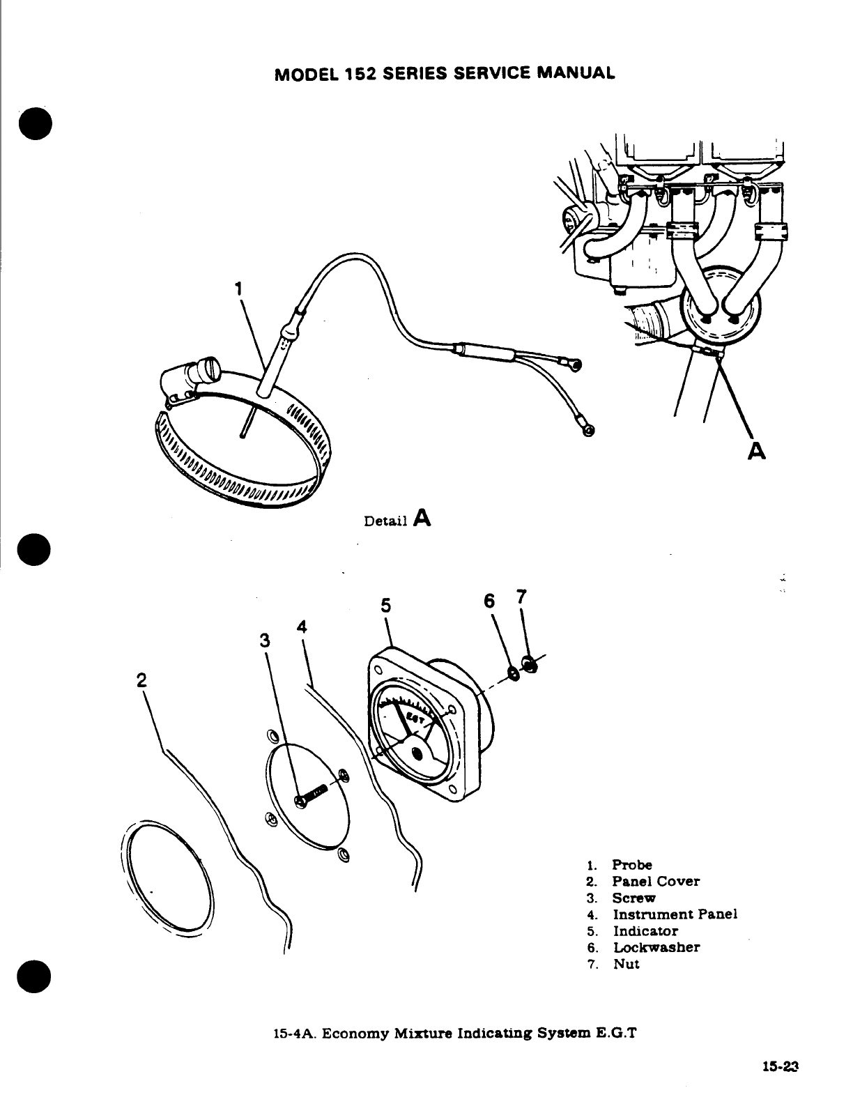
MODEL
152
SERIES SERVICE
MANUAL
A
Detail
A
5
6
7
3
1.
Probe
2.
Panel
Cover
3.
Screw
4.
Instrument
Panel
5.
Indicator
6.
Lockwasher
7.
Nut
15-4A.
Economy
Mixture
Indicating
System
E.G.T
15-23
MODEL
152
SERIES
SERVICE
MANUAL
15-42.
TROUBLE
SHOOTING.
TROUBLE PROBABLE CAUSE
REMEDY
FAILURE
TO
INDICATE.
No
power
to
indicator
or
Check
fuse
and
inspect
for
transmitter.
(Pointer
stays
open
circuit.
Replace
fuse.
below
E.)
repair
or
replace
defective
wire.
Grounded
wire.
(Pointer
Check
for
partial
ground
be-
stays
above
F.)
tween
transmitter
and gage.
Repair
or
replace
defective
wire.
Low
voltage.
Check
voltage
at
indicator.
Correct
voltage.
Defective
indicator.
Substitute
known-good indi-
cator.
Replace
indicator.
OFF
CALIBRATION.
Defective
indicator.
Substitute
known-good
trans-
mitter.
Recalibrate or
replace.
Low
or
high
voltage.
Check
voltage
at
indicator.
Correct
voltage.
STICKY
OR
SLUGGISH
Defective
indicator.
Substitute
known-good indi-
INDICATOR OPERATION.
cator. Replace
indicator.
Low
voltage.
Check
voltage
at
indicator.
Correct
voltage.
ERRATIC
READINGS.
Loose
or
broken
wiring
on
Inspect circuit
wiring.
Repair
indicator
or
transmitter.
or
replace
defective
wire.
Defective
indicator
or
trans-
Substitute
known-good
com-
mitter.
ponent.
Replace
indicator
or
transmitter.
Defective
master
switch.
Replace
switch.
15-24
MODEL
152
SERIES
SERVICE
MANUAL
15-43.
TRANSMITTER
ADJUSTMENT.
WARNING
Using
the
following
fuel
transmitter
calibration
proce-
dure
on
components
other
than
the
originally
installed
(Stewart
Warner)
components
will
result
in
a
faulty
fuel
quantity
reading.
15-43A.
STEWART
WARNER
GAGE
TRANSMITTER
CALIBRATION.
Chances
of
transmitter
calibration
changing
in
normal
service
is remote;
however,
it
is
possible
that
float
arm
or
float
arm
stops
may
become
bent
if
transmitter
is
removed
from cell.
Transmitter
calibration
is
obtained
by
adjusting
float
travel.
Float
travel
is
limited
by
float
arm
stops.
WARNING
Use
extreme
caution
while working
with
electrical
com-
ponents
of
the
fuel
system.
The
possibility
of
electrical
sparks
around
an
"empty"
fuel
cell
creates
a
hazardous
situation
and
could
potentially
cause
an
explosion.
Before
installing
transmitter,
attach
electrical
wires
and
place
master
switch
in
"ON"
position.
Al-
low
float
arm
to
rest against
lower
float
arm
stop
and
read
indicator.
The
pointer
should
be
on
E
(empty)
position.
Adjust
the
float
arm
against
lower
stop
so
pointer
indicator
is
on
E.
Raise
float
un-
til
arm
is
against
upper
stop
and
adjust
upper
stop
to
permit
indicator pointer
to
be
on
F
(full).
In-
stall
transmitter
in
accordance
with
paragraph
15-41.
15-43B.
ROCHESTER
GAGE TRANSMITTER.
Do
not
attempt
to
adjust
float
arm
or
stop.
No
ad-
justment
is
allowed.
Table
1
NOTE
Select
the
oil
temperature
sending
unit
part
number
that
is
used
in
your
aircraft
from
the
left
column
and
the
temperature
from
the
column
headings.
Read
the
ohms value
under
the
appropriate
temperature
column.
Part
Number
Type
72F
120F
165F
220F
250
F
S1630-1
Oil
Temp
46.4
1630-3
Oil Temp
620.0
52.4
S1630-4
Oil
Temp
620.0
52.4
S1630-5 Oil
Temp
192.0
S2335-1 Oil Temp
990.0
34.0
Revision
1
15-25
MODEL
152
SERIES
SERVICE
MANUAL
15-44.
HOURMETER.
15-45.
DESCRIPTION. The
hourmeter
is
electrically
operated
instrument
and
is
actuated
by
a
pressure
switch
in
the
oil
pressure
gage
line.
Electrical
power
is
supplied
through
a
one-
amp
fuse from the
electrical
clock
circuit
and
therefore,
will
operate
independent
of
the
master
switch.
NOTE
When
installing
the
hourmeter,
the
positive
(red)
wire
must
be
connected
to
the
white
+
terminal
Connecting
wires
incorrectly
will
damage
the
meter.
15-46.
MAGNETIC
COMPASS.
(See
figure
15-5A.)
15-47.
DESCRIPTION.
The
magnetic
compass
is
liquid-filled
with expansion
provisions
to
compen-
sate for
temperature
changes.
It is
equipped
with
compensating
mont
of
case.
The
compass
is
internally
lighted
controlled
by
the
panel
lights
rheostat
No
maintenance
is
required
on
the
compass
except
for
a
check
on
a
compass
rose
each
200
hours
for
adjustment
15-48.
ACCELEROMETER.
15-49.
DESCRIPTION.
The
Aerobat
offers
an
accelerometer
to
assist
pilot
in
performing
precision
aerobatics.
-The
accelerometer
continuously indicates
G
forces being
imposed
on
aircraft
The
dial
display
utilizes
three
pointers:
one
pointer
indicates
instanteous
acceleration.
another
records
maximum
positive
acceleration
and
the
third
records
maximum
negative
acceleration.
Maximum
instrument
markings
range
from
10G
to
5G.
A
"PUSH
TO
SET"
knob,
located
on
lower
left
corner
of
instrument,
is
used
to
reset
"Maximum
Positive"
and
"Maximum
Negative"
pointers.
If
dual
Nav/Coms
are
installed.
the accelerometer
is
installed
in
an
upper
radio
compartment
housing
above
instrument
panel
on
pilot's
side.
When
aircraft is
equipped
with single
Nav/Com. accelerometer
is
installed
in
the
vacant
Omni
indicator
instrument
space.
15-26
Revision
1
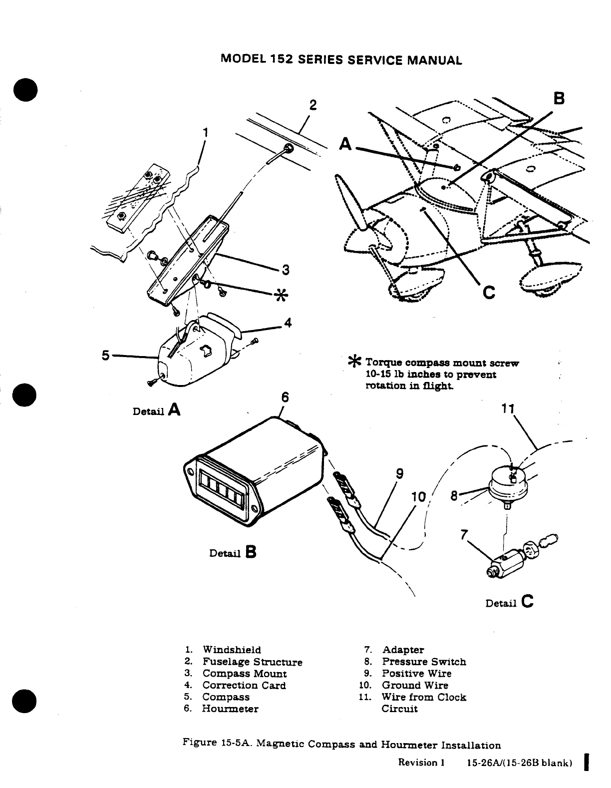
MODEL
152
SERIES
SERVICE
MANUAL
5
Torque
compass
mount
screw
10-15
lb
inches
to
prevent
rotation
in
flight.
Detail
A
10.
Ground
Wire
6.
Windsheld
7
Adapter
3.
Compass
Mount
9.
Positive
Wire
re
4.
Correction
Card
10.
Ground
Wire
5.
Compass
11.
Wire
from
Clock
6.
Hourmeter
Figure
15-5A.
Magnetic
Compass
andHourmeter
Installation
Revision
1
15-26A/(15-26B
blank)
MODEL
152
SERIES SERVICE
MANUAL
15-50.
STALL WARNING
SYSTEM. (See
figure
15-6
15-51.
DESCRIPTION
The
system
is
composed
of
an
ad
plate
on
left
ing
leading
edge.
connected
to
a
reed
type
horn
by
means
of
plastic
tubing.
The
horn
Is
actuated
approxi-
mately
5
to
10
knots
above
stalling
speed
as
a
negative
air
pressure
area at
wing
leading
edge
causes
a
reverse
flow
of
air
through
horn.
By
moving
adjustable
plate
(6)
up,
actuation
of
horn
will
occur
at
a
higher
speed
and
moving
plate
down
causes actuation
to
occur
at
a
slower
speed
Center adjustable
plate
opening
in
wing
leading
edge
upon
installation,
then
fight
test
aircraft,
observing
horn
actuation
during
stall- Readjust
plate
to
obtain
desired
results
if
necessary.
Approximatly
3/32
inch
adjustment
of
plate will
change
speed
at
which
horn
actuation
occurs
by
5
knots
To
test
horn
operation,
over
opening
in
plate
(6)
with
a
clean
cloth,
such
a
handkerchief
and
apply
a
slight
suction
by
mouth
to
draw
air
through
horn
15-52.
TURN-AND-SLIP
INDICATOR.
15-53.
DESCRIPTION.
The
turn-and-slip indicator
is
an
electrically
operated
instrument
powered
by
the
aircraft
electrical
system.
therefore,
operating
only
when
the
master
switch
is
ON.
15-54.
TROUBLE
SHOOTING.
TROUBLE
PROBABLE
CAUSE
REMEDY
INDICATOR
POINTER
FAILS
Internal
fuse
blown.
Check
wiring
for
continuity.
TO
RESPOND.
check
voltage
at
indicator.
Replace
fuse.
if
fuse
still
blows,
replace
instrument.
Master
switch
"OFF"
or
Check
switch
"ON."
Re-
switch
defective.
place
defective
switch.
Broken
or
grounded lead
to Check
circuit
wiring.
Repair
indicator.
or
replace
defective
wiring.
Indicator
not
grounded.
Check
ground
wire.
Repair
or
replace
defective
wire.
Defective
mechanism.
Replace
instrument.
HAND
SLUGGISH
IN
Defective
mechanism.
Replace
instrument
IN
RETURNING
TO
ZERO.
Low
voltage.
Check
voltage
at
indicator.
Correct voltage.
POINTER
DOES
NOT
INDI-
Defective
mechanism.
Replace
instrument.
CATE
PROPER
TURN.
HAND DOES
NOT
SIT
Gimbal
and
rotor
out
of
Replace
instrument.
ON
ZERO.
balance.
Hand
incorrectly
sits
on
rod. Replace
instrument
Sensitivity
spring
adjust-
Replace
instrument
ment
pulls
hand
off
zero.
15-27
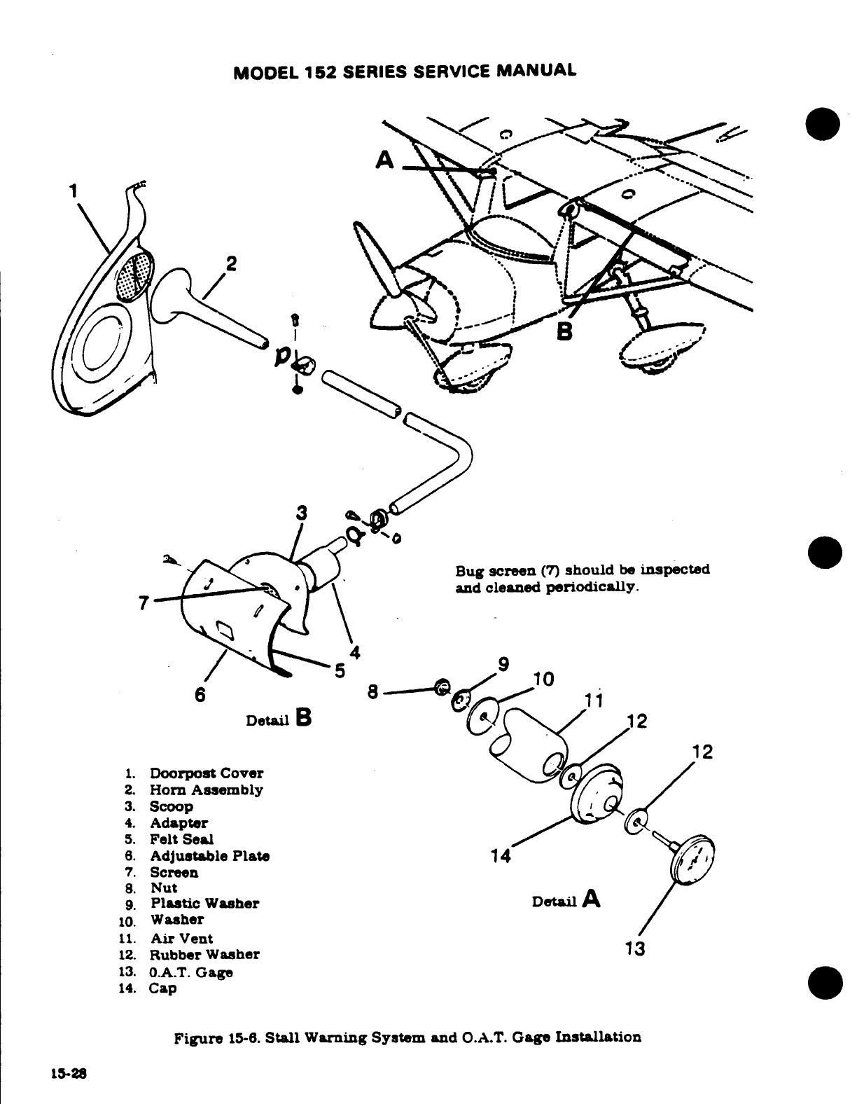
MODEL
152
SERIES
SERVICE
MANUAL
1
3
Bug
screen
(7)
should
be
inspected
and
cleaned
periodically.
6 12
10
Detail
B
12
1.
Doorpost Cover
/
2.
Horn
Assembly
3.
Scoop
4.
Adapter
5.
Felt
Seal
6.
Adjustable
Plate
14
7.
Screen
8.
Nut
9.
Plastic
Washer
Detail
A
10.
Washer
11.
Air
Vent
12.
Rubber
Washer
13
13.
O.A.T.
Gage
14.
Cap
Figure
15-6.
Stall
Warning
System
and
O.A.T.
Gage
Installation
15-28
MODEL
152
SERIES SERVICE
MANUAL
15-54.
TROUBLE
SHOOTING
(CONT.)
TROUBLE
PROBABLE
CAUSE
REMEDY
IN
COLD
TEMPERATURES.
Oil
in
indicator
becomes
too
Replace
instrument
HAND
FAILS
TO
RESPOND
thick.
OR IS
SLUGGISH.
Insufficient
bearing
end
play.
Replace
instrument
Low
voltage.
Check
voltage
at
indicator.
Correct
voltage.
NOISY
GYRO.
High
voltage.
Check
voltage
at
indicator.
Correct
voltage.
Loose
or
defective
rotor
Replace
instrument
bearings.
15-55.
TURN
COORDINATOR.
15-56.
DESCRIPTION.
The
turn
coordinator
is
an
electrically
operated, gyroscopic,
roll-rate
turn
indicator.
Its
gyro
simultaneously
senses
rate
of
motion
roll
and
yaw
axis
which
is
projected
on
a
single
indicator.
The
gyro
is a
non-tumbling
type
requiring
no
caging
mechanism
and
incorporates
an
a.c.
brushless
spin
motor
with
a
solid
state
inverter.
.
15-57.
TROUBLE
SHOOTING.
TROUBLE
PROBABLE CAUSE REMEDY
INDICATOR
DOES
NOT
Friction
cause
by
contam-
Replace
instrument
RETURN
TO
CENTER.
ination
in
the
indicator
dampening.
Friction
in
gimbal
assembly.
Replace
instrument.
DOES
NOT
INDICATE
A
Low
voltage.
Correct
voltage.
STANDARD RATE
TURN
(TOO
SLOW).
Inverter
frequency changed.
Replace
instrument
NOISY
MOTOR.
Faulty
bearings.
Replace
instrument
ROTOR
DOES
NOT
START.
Faulty
electrical
connec-
Correct voltage
or
replace
tion.
faulty
wire.
Inverter
malfunctioning.
Replace
instrument
Motor
shorted.
Replace
instrument
Bearings
frozen.
Replace
instrument
15-29
MODEL
152
SERIES
SERVICE
MANUAL
15-57.
TROUBLE SHOOTING
(CONT.)
TROUBLE
PROBABLE CAUSE
REMEDY
IN
COLD
TEMPERATURES.
Oil
indicator
becomes
Replace
instrument
HAND
PAILS
TO
RESPOND
too
thick.
OR
IS SLUGGISH.
Insufficient
bearing
end
Replace
instrument.
play.
Low
voltage.
Correct
voltage.
NOISY
GYRO.
High
voltage.
Check
voltage
to
instrument.
Correct
voltage.
Loose
or
defective
rotor
Replace
instrument.
bearings.
15-58.
OUTSIDE
AIR
TEMPERATURE
GAGE.
(Refer
to
figure
15-6.)
15-30
MODEL
152
SERIES
SERVICE
MANUAL
SECTION
16
ELECTRICAL
SYSTEM
WARNING
When
performing
any
inspection
or
maintenance
that
re-
quires
turning
on
the
master
switch,
installing
a
battery,
or
pulling
the
propeller
through
byhand,
treat
the
pro-
peller
as
if
the
ignition
switch
were
ON. Do
not
stand,
nor
allow
anyone
else
to
stand
within
the
arc
of
the
propeller
since
a
loose
or
broken
wire,
or
a
component
malfunction
could
cause
the
propeller
to
rotate.
Page
No.
Removal/Installation
....
2E2/16-16
TABLE
OF
CONTENTS
Aerofiche/
Alternator
Field
Manual Protection
............
2E2/16-16
Description
...........
2E2/16-16
ELECTRICAL SYSTEMS
......
2D10/16-2
Alternator
Reverse
General
....................
2D10/16-2
VoltageDamage
.......
2E2/16-16
Electrical
Power
Supply
Over-Voltage
Warning
System
...................
2D10/16-2
System
.................
2E2/1
16
Description
................
2D10/16-2
Description
.............
2E2/16-16
Bus
Bar
...................
2D10/16-2
Trouble Shooting
.........
2E6/16-20
Description
..............
2D10/16-2
Voltage
Regulator
.........
2E16/16-30
Removal/Installation
.....
2D10/16-2
Description
..............
2E16/16-30
Master
Switch
.............
2D10/16-2
Alternator
Control
Unit
...
2E16/16-30
Description
..............
2D10/16-2
Description
.......
.....
2E16/16-30
Ammeter
.................
2D13/16-5
Removal/Installation
2E16/16-30
Description
..............
2D13/16-5
AircraftLightingSystem
...
2E16/16-30
Battery
Power
System
.......
2D13/16-5
Description
..............
2E16/16-30
Trouble Shooting
..........
2D13/16-5
Trouble Shooting
.........
2E16/16-30
Battery
...................
2D14Y16-6
Landing
and
Taxi
Light
...
2E23/16-35
Description
................
2D14/16-6
Description
.............
2E23/16-35
Removal/Installation
.......
2D14/16-6
Removal/Installation
....
2E23/16-35
Cleaning
..................
2D15/16-7
Dual
Landing
and
Taxi
Adding
Electrolyte
or
Lights
.................
2E23/16-35
Water
...................
2D15/16-7
Description
.............
2E23/16-35
Testing
...................
2D16/16-8
Removal/Installation
....
2E23/16-35
Charging
.................
2D16/16-8
Landing
and
Taxi
Lights
..
2E24/16-36
Battery
Box
................
2D19/16-9
Wing-Mounted
.........
2E24/16-36
Description
................
2D19/16-9
Description
.............
2E24/16-36
Removal/Installation
.......
2D19/16-9
Removal/Installation
....
2E24/16-36
Maintenance
..............
2D19/16-9
Navigation
Lights
........
2E24/16-36
Battery
Contactor
...........
2D19/16-9
Description
.............
2E24/16-36
Description
................
2D19/16-9
Removal/Installation
.... 2F5/16-38A
Removal/Installation
.......
2D19116-9
Anti-Collision
Strobe
Battery
Contactor Closing
Lights
.................
2F516-38A
Circuit
.................
2D24/16-14
Description
............ 2F5/16-38A
Ground
Service
Receptacle
...
2D24/16-14
Removal/Installation
.... 2F5/16-38A
Description
................
2D24/16-14
Flashing
Beacon
Light
.... 2F5/16-38A
Removal/Installation
.......
2D24/16-14
Description
.............
2F5/16-38A
Alternator
Power
System
....
2D24/16-14
Removal/Installation
....
2F5/16-38A
Description
................
2D24/16-14
Instrument/Dome Lights
..
2F5/16-38A
Alternator
................
2E216-16
Description
.............
2F5/16-38A
Description
..............
2E2/16-16
Removal/Installation
.... 2F5/16-38A
Revision
1
16-1
MODEL
152
SERIES
SERVICE
MANUAL
Post
Lighting
.............
2F5/16-38A
Pitot
Heater
..............
2F22/16-50
Description
..............
2F5/16-38A
Description
..............
2F22/16-50
Removal/Installation
.....
2F14/16-46
Removal/Installation
.....
2F22/16-50
Trouble
Shooting
-
Post
Cigar
Lighter
.............
2F22/16-50
Lighting
...............
2F14/16-46
Description
..............
2F22/16-50
Trouble Shooting
Clock
....................
2F23,16-51
Transistor
Heat
Sink
....
2F15/16-46A
Description
..............
2F23,16-51
Transistorized
Light
Emergency
Locator
Dimming
................
2F15/16-46A
Transmitter
..............
2F23/16-51
Description
..............
2F15/16-46A
Description
...............
2F23/16-51
RemovalInstallation
.....
2F15/16*46A
Operation
................
2F23/16-51
Compass
and
Radio
Dial
Checkout
Interval
.........
2F24/16-52
Lighting
................
2F15/16-46A
Removal/Installation
Description
..............
2F15/16-46A
of
Antenna
..............
2F24/16-52
Control
Wheel
Map
Light
..
2F15/16-46A
Removal/Installation
Description
..............
2F15/16-46A
of
Transmitter
...........
2F24/16-52
Removal/Installation
.....
2F16/16-46B
Removal/Installation
Map
Light
................
2F16/16-46B
of
Battery
Pack
..........
2G4/16-56
Description
..............
2F16/16-46B
Trouble
Shooting
..........
2G6/16-58
Removal/Installation
.....
2F16/16-46B
Electrical
Load
Analysis
Chart
....................
2G7/16-59
16-1.
ELECTRICAL SYSTEMS.
16-2
GENERAL.
This section
contains
service information
necessary
to
maintain
the
Aircraft
Electrical
Power
Supply
System.
Battery
and
External
Power
Supply
System.
Alternator
Power
System
Aircraft
Lighting
System
Pitot
Heater.
Stall
Warning,
Cigar
Lighter
and
Electrical
Load
Analysis
16-3.
ELECTRICAL
POWER
SUPPLY-
SYSTEM.
16-4.
DESCRIPTION.
Electrical
energy
for
the aircraft
is
supplied
by
a
28-volt,
direct-current.
single
wire.
negative ground electrical
system.
A
24-volt
battery
supplies
power
for
starting
and
furnishes
a
reserve
source
of
power in
the
event
of
alternator
failure.
An
engine-driven
alternator
is
the
normal
source
of
power
during flight
and
maintains
a
battery
charge
controlled
by
a
voltage
regulator/alternator
control
unit.
An
external
power
source
receptacle
is
offered
as
optional
equipment
to
supplement
the
battery alternator
system
for
starting
and ground
operation.
16-5.
BUS
BAR.
16-6.
DESCRIPTION.
Electrical
power
for electrical
equipment
and
electronic
installations
is
supplied
through
the
split
bus
bar.
The
bus
bar
is
interconnected
by
a
jumper
wire
and
attached
to
the circuit
breaker
on
the
lower,
center
of
the
instrument
panel.
16-7.
REMOVAL
AND
INSTALLATION.
(See
figure
16-1.)
16-8.
MASTER
SWITCH.
16-9.
DESCRIPTION. The
master
switch
controls
the operation
of
the
battery
and
alternator
systems.
The
switch
is
an interlocking
split
rocker
with
the
battery
mode
on
the
right
hand
side
and
the
alternator
mode
on
the
left
hand
side. This
arrangement
allows
the
battery
to
be
on
the line without the
alternator,
however.
operation
of
the
alternator
without
the
battery
on
the
line
is
not
possible.
The
switch
is
labeled
"BAT"
and
"ALT"
below
the
switch
and
is
located
on
the
left-hand
side
of
the
switch
panel
16-2
Revision
I
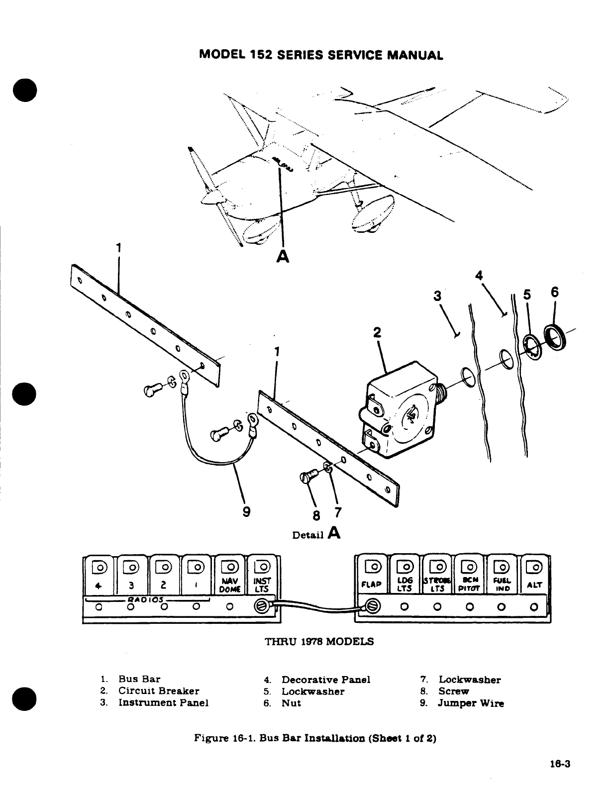
MODEL
152
SERIES
SERVICE
MANUAL
.
A
Detail
A
THRU
1978
MODELS
1.
Bus
Bar
4.
Decorative Panel
7.
Lockwasher
2.
Circuit
Breaker
5.
Lockwasher
8.
Screw
3.
Instrument
Panel
6.
Nut
9.
Jumper
Wire
Figure
16-1.
Bus
Bar
Installation
(Sheet
1
of
2)
16-3

MODEL
152
SERIES
SERVICE
MANUAL
1978
-
1980
MODELS
BEGINNING
WITH
1981
MODELS
2
1
Detail
A
Figure
16-1.
Bus
Bar
Installation
(Sheet
2
of
2)
16-4
MODEL
152
SERIES
SERVICE
MANUAL
16-10.
AMMETER.
16-11.
DESCRIPTION.
The
ammeter
is
connected between
the
battery contactor
and
the
bus
bar.
The
meter
indicates
the amount
of
current
flowing
either
to
or
from
the
battery.
With
a
low
battery
and
the
engine
operating
at cruise
speed
the
ammeter
will show
the
full
alternator
output
when
all
electrical
equipment
is
off.
When
the
battery
is
fully
charged
and
cruise
RPM
is
maintained
with
all
electrical equipment
off.
the ammeter
will
show
a
minimum
charging
rate.
The
ammeter
is
located
on
the
right
hand
side
of
the
instrument
panel.
16-12.
BATTERY POWER SYSTEM.
16-13.
TROUBLE
SHOOTING
THE BATTERY
POWER
SYSTEM.
TROUBLE
PROBABLE CAUSE
REMEDY
BATTERY
WILL
NOT
SUP-
Battery discharged.
1.
Measure
voltage
at
"BAT"
PLY
POWER
TO
BUS OR
IS
terminal
of
battery
contactor
INCAPABLE
OF
CRANKING
with
master
switch
and
a
suit-
ENGINE.
able
load
such
as
a
taxi
light
turned
on.
Normal
battery
will
indicate
23
volts
or
more.
If
voltage
is
low,
pro-
ceed
to step
2.
If
voltage
is
normal, proceed
to
step
3.
Battery
faulty.
2.
Check
fluid
level
in
cells
and
charge
battery
at
28-volts
for
approximately
30
minutes
or
until
the
battery
voltage
rises
to
28-volts
Check
bat-
tery
with
a
load
type tester.
If
tester
indicates
a
good
bat-
tery,
the
malfunction
may
be
assumed
to
be
a
discharged
battery.
If
the
tester
indi-
cates
a
faulty
battery.
re-
place
the
battery.
Faulty
contactor
or
wiring
3.
Measure
voltage
at
mas-
between
contactor
or
master
ter
switch
terminal
(smallest)
switch.
on
contactor
with
master
switch
closed.
Normal
indi-
cation
is
zero
volts.
If
voltage
reads
zero.
proceed
to
step
4.
If
a
voltage
reading
is
obtained
check
wiring
between
contactor
and
master
switch.
Also
check
master
switch.
16-5
MODEL
152
SERIES SERVICE
MANUAL
16-13.
TROUBLE SHOOTING
THE
BATTERY
POWER SYSTEM.
(CONT).
TROUBLE
PROBABLE CAUSE
REMEDY
BATTERY
WILL
NOT
SUP-
Open
coil
on
contactor.
4.
Check
continuity
between
PLY
POWER
TO
BUS OR
IS
"BAT"
terminal
and
master
INCAPABLE
OF
CRANKING
switch
terminal
of
contactor.
ENGINE.
(CONT).
Normal
indication
is
50
to
70
ohms
(Master
switch
open).
If
ohmmeter
indicates
an
open
coil
replace
contactor.
If
ohmmeter
indicates
a
good
coil,
proceed
to
step
5.
Faulty
contactor
contacts.
5.
Check
voltage
on
"BUS"
side
of
contactor
with
master
switch
closed.
Meter
normal-
ly
indicates
battery voltage.
If
voltage
is
zero
or intermit-
tant. replace
contactor.
If
volt-
age
is
normal.
proceed
to
step
6.
Faulty
wiring
between
con-
6.
Inspect
wiring
between
tactor
and
bus.
contactor
and
bus.
Repair
or
replace wiring.
16-14.
BATTERY.
16-15.
DESCRIPTION.
The
battery
is
24
volts
and
thru
15280459.
A1522759
and
FA1520346
a
14
ampere-hour
capacity
battery
is
installed
as standard,
a
17
ampere-hour
capacity battery
is
optional
Beginning with
15280460.
A1522760
and
FA1520347
the battery
is
24
volts
with
a
12.75
ampere-hour
capacity
as
standard
and
a
15.5
ampere-hour
capacity
battery
as
optional.
The
battery
is
mounted
on
the
forward
side
of
the firewall and
is
equipped
with
non-spill
caps.
16-16.
REMOVAL
AND
INSTALLATION
OF.
(See
figure
16-2.)
CAUTION
When
installing
or
removing battery
always
observe
the
proper
polarity
with
the
aircraft
electrical system
(negative
to
ground).
Reversing
the
polarity,
even
momentarily.
may
result
in
failure
of
semiconductor
devices
(alternator
diodes,
radio
protection
diodes
and
radio
transistors).
Always
remove
the
battery
ground
cable
first
and
replace
it
last
to
prevent
accidental
short
circuits.
16-6
MODEL
152
SERIES
SERVICE
MANUAL
a.
Thru
1979
Models.
1. Remove
top
half
of
cowl.
2.
Remove
the
battery
box
cover
and
side
panel.
3.
Disconnect
the
ground
cable
from
the
negative
battery
terminal.
4.
Disconnect
the
cable from
the
positive
terminal
of
the
battery.
5.
Lift
the
battery
out
of
the
battery
box.
6.
To
replace the battery,
reverse
this
procedure.
b.
Beginning
with
1980
Models.
1.
Remove
engine
cowl.
2.
Cut
sta-straps
and
remove
terminal
cover.
3.
Disconnect
drain
tube.
4.
Disconnect
negative
and positive
cables.
5.
Remove
battery
mounting
bolts
and
remove battery.
6.
To
install
reverse
the
preceding
steps
using
new
sta-straps
to
install
terminal
covers.
16-17.
CLEANING
THE
BATTERY.
For
maximum
efficiency
the
battery
and
connections
should
be
kept
clean
at
all
times.
a.
Remove
the
battery
and
connections
in
accordance
with
the
preceding
paragraph.
b.
Remove
battery
vent
plugs
and
check
electrolyte
levels
in
each
cell.
It
is
important
that
electrolyte
level
be
no
lower
than
top
of
separator
plates
but
not
higher
than
bot-
tom
of
split
ring.
c.
Replace
vent
plugs
and
secure
tightly
in
place,
making
sure
a
rubber
gasket
is
used
be-
tween
each
vent
plug
and
battery.
NOTE
A
good
seal
is
necessary
so
electrolyte levels cannot
leak
out
of
seals
and
create
an
acid
path
which
can
lead
to
self-
discharge.
The
application
of
a
silicone
grease
will
improve
seal
effectiveness.
d.
Tighten
battery
cell
filler
caps
to
prevent
the
cleaning
solution
from
entering the
cells.
e.
Wipe
battery
cable
ends,
battery
terminals,
and
entire
surface of
the
battery
with
a
clean
cloth
moistened with
a
solution
of
bicarbonate
of
soda
(baking
soda)
and
water.
f.
Rinse
with
clear
water,
wipe
off
excess
water,
and
thoroughly
dry.
g.
Brighten
up
cable
ends
and
battery
terminals
with
emery
cloth
or
a
wire
brush.
h.
Install
the
battery
according
to
the
preceding
paragraphs.
i.
Coat
the
battery
terminals
with
petroleum
jelly
or
an
ignition
spray
product
to
reduce
corrosion.
16-18.
ADDING
ELECTROLYTE
OR
WATER
TO
THE
BATTERY.
A
battery
being
charged
and
discharged
with
use
will
decompose
the
water
from
the
electrolyte
by
electrolysis.
When
the
water
is
decomposed,
hydrogen
and
oxygen
gases
are
formed
which
escape into
the
atmosphere
through
the
battery
vent
system.
The
acid
in
the
solution
chemically
combines
with
the
plates
of
the
battery
during
discharge
or
is
suspended
in
the electrolyte
solution
during
charge.
Unless
the electrolyte
has
been
spilled
from
a
battery,
acid
should
not
be
added
to
the
solution.
The
water,
however
will
decompose
into
gases and
should
be
replaced
regularly.
Add
distilled
water
as necessary
to
maintain
the
electrolyte
level
with
the
horizontal
baffle
plate
or
the
split
ring
on
the
filler
neck
inside
the
battery.
When
"dry
charged"
batteries
are put
into
service. fill
as
directed
with
electrolyte.
When
the
electrolyte
level
falls
below
normal
with
use.
add
only
distilled
water
to
maintain
the
proper
level
On
Aircraft
Serials
15279406
thru
15280459,
A15200735
thru
A15200759.
F1521429
thru
F1521538
and
FA1520337
thru
FA1520346
refer
to
Cessna
Single-engine
Service Letter.
SE78-6
Dated
February
13.
1978
when
filling
the
battery.
The
battery
electrolyte
contains
approximately
25%
sulphuric
acid
by
volume.
Any change
in
this
volume
will
hamper the
proper operation
of
the
battery.
Revision
1
16-7
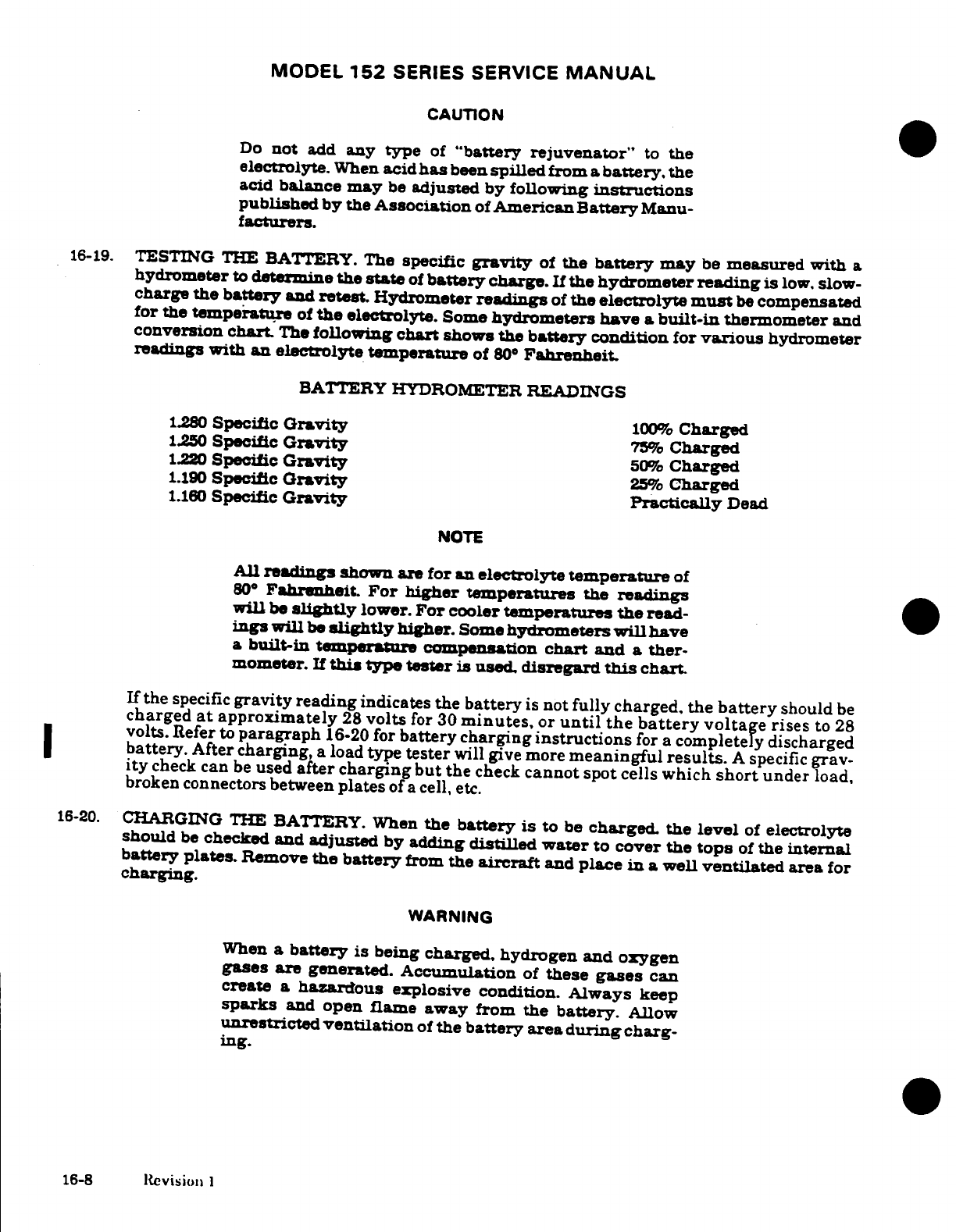
MODEL
152
SERIES
SERVICE
MANUAL
CAUTION
Do
not
add
any
type
of
"battery
rejuvenator"
to
the
electrolyte.
When
acid
has
been
spilled
from
a
battery.
the
acid
balance
may
be
adjusted
by
following instructions
published
by the
Association
of
American
Battery
Manu-
facturers.
16-19.
TESTING
THE
BATTERY.
The
specific
gravity
of
the
battery
may
be
measured
with
a
hydrometer
to
determine
the
state
of
battery
charge.
If
the
hydrometer
reading
is
low,
slow-
charge
the
battery
and
retest.
Hydrometer
readings
of
the
electrolyte
must
be
compensated
for
the
temperature
of
the
electrolyte.
Some
hydrometers
have
a
built-in
thermometer
and
conversion
chart.
The
following
chart
shows
the
battery
condition
for
various
hydrometer
readings
with
an
electrolyte
temperature
of
80
°
Fahrenheit.
BATTERY
HYDROMETER
READINGS
1.280
Specific
Gravity
100%
Charged
1.250
Specific
Gravity
75%
Charged
1.220
Specific
Gravity
50%
Charged
1.190
Specific
Gravity
25%
Charged
1.160
Specific
Gravity
Practically
Dead
NOTE
All
readings
shown
are
for
an
electrolyte
temperature
of
80
°
Fahrenheit.
For
higher temperatures
the
readings
will
be
slightly
lower.
For
cooler
temperatures
the
read-
ings
will
be
slightly
higher.
Some
hydrometers
will
have
a
built-in
temperature
compensation
chart
and
a ther-
mometer.
If
this
type
tester
is
used.
disregard
this
chart.
If
the
specific
gravity
reading
indicates the
battery
is
not
fully charged, the
battery
should
be
charged
at
approximately
28
volts
for
30
minutes,
or
until
the
battery
voltage
rises
to
28
volts.
Refer
to
paragraph
16-20
for
battery charging
instructions
for a
completely
discharged
battery.
After
charging,
a
load
type
tester
will
give
more
meaningful
results.
A
specific
grav-
ity
check
can
be
used
after charging
but
the
check
cannot
spot
cells
which
short
under
load,
broken
connectors between
plates
of
a
cell,
etc.
16-20.
CHARGING THE
BATTERY.
When
the
battery
is
to
be
charged.
the
level
of
electrolyte
should
be
checked
and
adjusted
by
adding
distilled
water
to
cover
the
tops
of
the
internal
battery
plates.
Remove
the
battery
from
the aircraft
and
place
in
a
well
ventilated
area
for
charging.
WARNING
When
a battery
is
being
charged,
hydrogen and oxygen
gases
are
generated.
Accumulation
of
these
gases
can
create
a
hazardous
explosive
condition.
Always
keep
sparks
and
open
flame
away from
the
battery.
Allow
unrestricted
ventilation
of
the
battery
area
during
charg-
ing.
16-8
Revision
I
MODEL
152
SERIES
SERVICE
MANUAL
Because
the battery
is
24
volts,
there
are
12
cells
connected
in
series
as
opposed
to
only
6
cells
in
12
volt
units.
There
is
a
greater
chance
for
cell
damage
to
occur
if
the battery
is
completely
discharged
by
leaving
some
electrical
system
on.
If
this
should
occur,
the
bat-
tery must
be
removed
from
the
aircraft,
placed
in
a
well
ventilated
area
during charging,
and given
a
supplemental
charge.
Charge
at
a
constant
current
rate
of
1.5
amps
until
the
terminal
charge
voltage
remains
constant
for
at
least
three
consecutive
hours.
If
a
constant
current
charger
is
not available,
a
constant
potential
charger
with
voltage
adjustment
ca-
pabilities
can
be
used.
With an
ammeter
in
series,
manually
adjust
voltage
of
charger
so
that
approximately
1.5
amps
are
flowing
at
all
times.
Frequent
adjustment
may
be neces-
sary
for
the
first
part
of
charge.
A
second
alternative
of
a
constant
potential
charge
of
28.8
volts
could
be
used; however,
the
charging
time
under
this
system
must
be
48
to
72
hours.
This
long,
slow
charge
will
tend
to
equalize
all
cells
and
bring
the
battery
back
to
a
useful
state.
Failure
to
utilize
this
charge
can
leave
the
battery
with
one
or
more
weak
cells
which
will
drastically
reduce
service
life.
WARNING
The
main
points
of
consideration
during
a
battery
charge
are
excessive
battery temperature
and
violent
gassing.
Cell
temperature
should
not rise
over
115°F.
Reduce
charging
rate
if
this
occurs.
Under
a
reasonable rate
of
charge gassing
should
not
be
so
violent
that
acid
is
blown
from
vents.
When
activating
new
dry
charged
batteries,
ensure
that
the
proper
strength
of
electrolyte
is
used.
The
specific
gravity
of
this
electrolyte
must
be
1.285
+0.005
when
measured
at
80°F
+
5°F.
The
battery
should
then
be
charged
as stated
on
the
installation instructions
supplied
with
the
battery.
When
installing
the
new
battery
into
the
aircraft,
the
cleaning
procedure
outlined
below
should
be
followed.
While
Cessna
aircraft
batteries
are
manufactured
with
lower
percentage
antimony
grids
than
that
used
in
the
past,
the
phenomenon
of
"local
action"
or self-discharge
still
occurs
in
these
newer
batteries.
This
is
normal
and
should be
expected in
any wet
lead
acid
battery.
To
maintain
a
battery
if
it
is
left
unused in
or
out
of
the aircraft
for
a
period
of
30
days,
the
maintenance
charge
should
be
equivalent
to
that
charge
defined
above
for
a
discharged
battery.
If
an
aircraft
is
to
be
setting
for
periods
of
time
exceeding
30
days,
the
battery
should
be
removed,
stored
in
a
cool,
dry
place,
and given
the
maintenance
charge
at
inter-
vals
not
exceeding
30
days.
Revision
1
16-8A.(16-8B
blank
MODEL
152
SERIES
SERVICE
MANUAL
16-21.
BATTERY
BOX.
(THRU
1979 MODELS.)
16-22.
DESCRIPTION.
The
battery
box
is
constructed
of
metal
and
painted
inside
and
out
with
acid-proof
paint.
The
box
is
attached
to
the
right
hand
side
of
the
firewall.
A
vent tube
is
at-
tached
to
the
bottom
of
the
box
and
extends
below
the
firewall
to
allow
gases
and
spilled
acid
to
be
vented
overboard.
16-23.
REMOVAL
AND
INSTALLATION.
(See
figure
16-2)
The
battery
box
is
not
considered
as
a
removable
item
except
for
replacement
purposes.
The
box
is
riveted
to
mounting
brackets
on
the
firewall.
Should
the
battery
box
be
removed,
on
installation
of
the
box
or
a
new
box,
all
rivets and
scratches
should
be
painted
with
acid-proof
lacquer,
available
from
Pratt
andI
Lambert
United
-
Performance
Coatings
Division,
P. 0.
Box
2153,
Wichita,
KS
67201.
16-24.
MAINTENANCE.
The
battery
box
should
be
inspected
and
cleaned
periodically.
The
box
and
cover
should
be cleaned
with
a
strong
solution
ofbicarbonate
of
soda
(baking
soda)
and
water.
Hard
deposits
may
be
removed
with
a
wire
brush.
When
all
corrosive
deposits
have
been
re-
moved from
the
box,
flush
it
thoroughly
with
clean
water.
WARNING
Do
not
allow
acid
deposits to
come
in
contact
with
skin
or
clothing.
Serious
acid
burs
may
result
unless
the
affected
area
is
washed
immediately
with
soap
and water.
Clothing
will
be
ruined
upon
contact
with
battery
acid.
Inspect
the
cleaned
box
and
cover
for
physical damage
and
for
areas
lacking proper
acid
proofing.
A
badly
damaged or
corroded
box
should be replaced.
If
the
box
or lid
require
acid
proofing,
paint
the area with
acid
proof
lacquer,
available
from
Pratt
and
Lambert United
-I
Performance
Coatings
Division,
P.
0.
Box
2153,
Wichita,
KS
67201.
16-25.
BATTERY CONTACTOR.
16-26.
DESCRIPTION.
The
battery
contactor
is
a
plunger
type
and
is
actuated
by
turning
on
the
master
switch.
The
contactor
is
bolted to
the
left
hand
side
of
the
firewalL
A
silicon
diode
is
installed
to
eliminate
spiking
of
transistorized
radio
equipment
when
the
contactor
is
closed.
Nylon
covers
are
installed
on
the
terminals
to
prevent
accidental
short
circuits.
16-27.
REMOVAL
AND INSTALLATION.
(See
figure
16-2.)
a.
Place
master
switch
in
the
OFF
position.
b.
Thru
1979
Models.
open
battery
box
and
disconnect
ground cable from
negative
battery
terminal.
Pull
cable
clear
of
battery
box.
c.
Beginning with
1980
Models.
disconnect
negative
battery
cable.
d.
Cut
sta-straps
and
remove nylon
covers from
terminals
on
contactor.
e.
Remove
nuts,
lockwashers
and
plain
washers
securing
the
battery
cables
to
the
contactor.
f.
Remove
nut, lockwasher
and
plain
washers securing
master
switch
wire
to
contactor.
g.
Remove
nuts.
washers.
and
bolts
securing
the
contactor
to
the
firewall
and
remove
contactor.
h.
To
install
battery
contactor. reverse
the
preceding
steps.
Revision
1
16-9
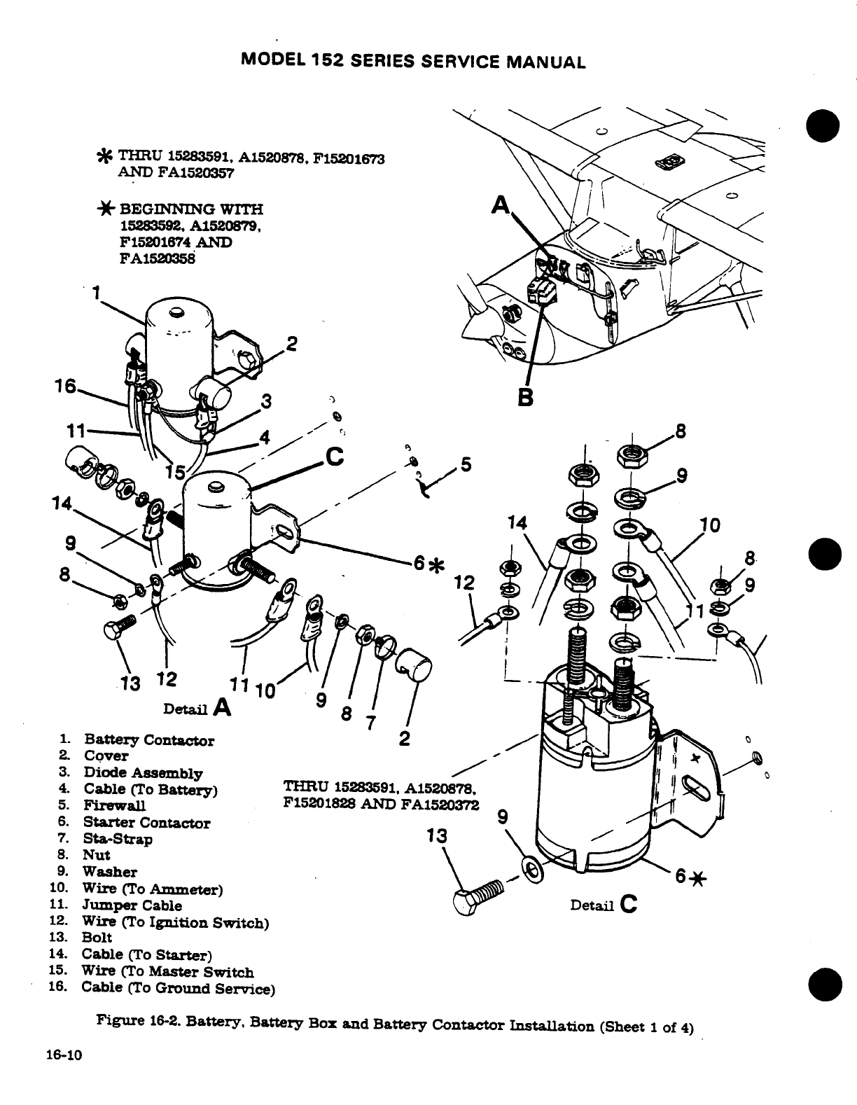
MODEL
152
SERIES
SERVICE
MANUAL
%
THRU
15283591,
A1520878,
F15201673
AND
FA1520357
*
BEGINNING
WITH
15283592,
A1520879,
F15201674
AND
FA1520358
11
Detail
A
7
1.
Battery
Contactor
2
2.
Cover
3.
Diode
Assembly
4.
Cable
(To
Battery
THRU
15283591
A1520878,
5.
Firewall
F15201828
AND
FA1520372
6.
Starter
Contactor
7.
Sta-Strap
13
8.
Nut
9.
Washer
10.
Wire
(To Amnmeter)
Detail
C
11.
Jumper
Cable
12.
Wire
(To
Ignition
Switch)
13.
Bolt
14.
Cable
(To
Starter)
15.
Wire
(To
Master Switch
16.
Cable
(To
Ground
Service)
Figure
16-2.
Battery,
Battery
Box
and
Battery
Contactor
Installation
(Sheet
1
of
4)
16-10
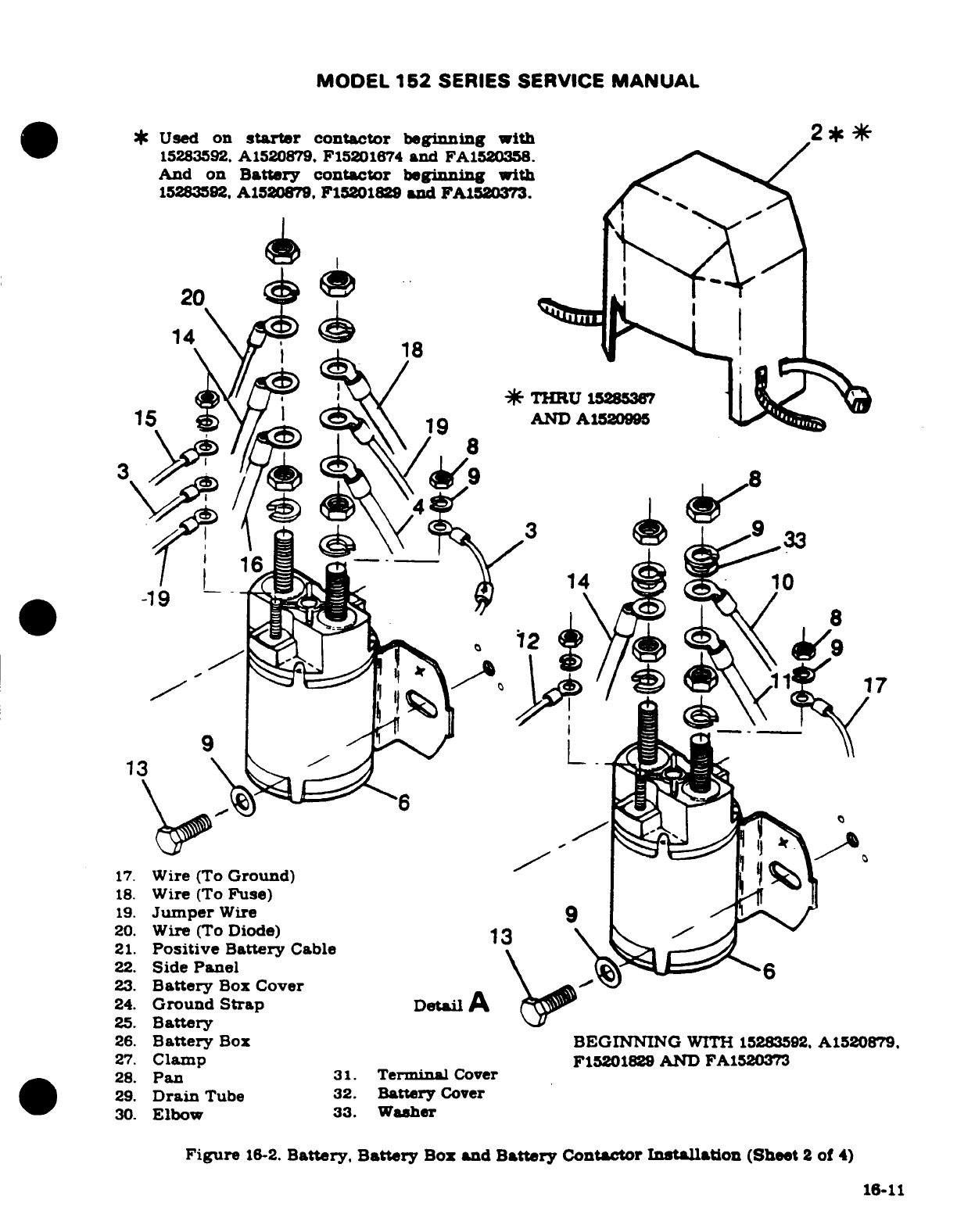
MODEL
152
SERIES SERVICE
MANUAL
Used
on
starter
contactor
beginning
with
2
2
15283592.
A1520879, F15201674
and
FA1520358.
And
on
Battery
contactor
beginning
with
15283592.
A1520879. F15201829
and
FA1520373.
20
14
18
15
9
AND
AI
12099
19.
Jumper
Wire
9
25.
Battery
9
26.
Battery
Box
BEGINNING
WITH
15283592.
A1520879.
27.
Clamp
F15201829
AND
FA1520373
20.
Wire
(To
Diode)
13
28.
SidePan
24.
Ground
Strap
25.
Battery
26.
Battery
Box
BEGINNING
WITH
15283592,
A1520879,
27.
Clamp
F15201829
AND
FA1520373
28.
Pan
31.
Terminal
Cover
29.
Drain
Tube
32.
Battery
Cover
30.
Elbow
33.
Washer
Figure
16-2.
Battery.
Battery
Box
and
Battery
Contactor
Installation
(Sheet
2
of
4)
16-11
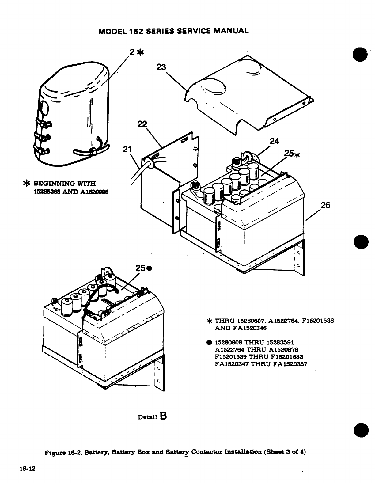
MODEL
152
SERIES
SERVICE
MANUAL
2*
23
22
24
*
BEGINNING
WITH
15285368
AND
A1520996
THRU
15280607.
A1522764.
F15201538
AND
FA1520346
*
15280608
THRU
15283591
A1522764
THRU
A1520878
F15201539
THRU
F15201683
FA1520347
THRU FA1520357
Detail
B
Figure
16-2.
Battery,
Battery
Box
and
Battery
Contactor
Installation
(Sheet
3
of
4)
16-12
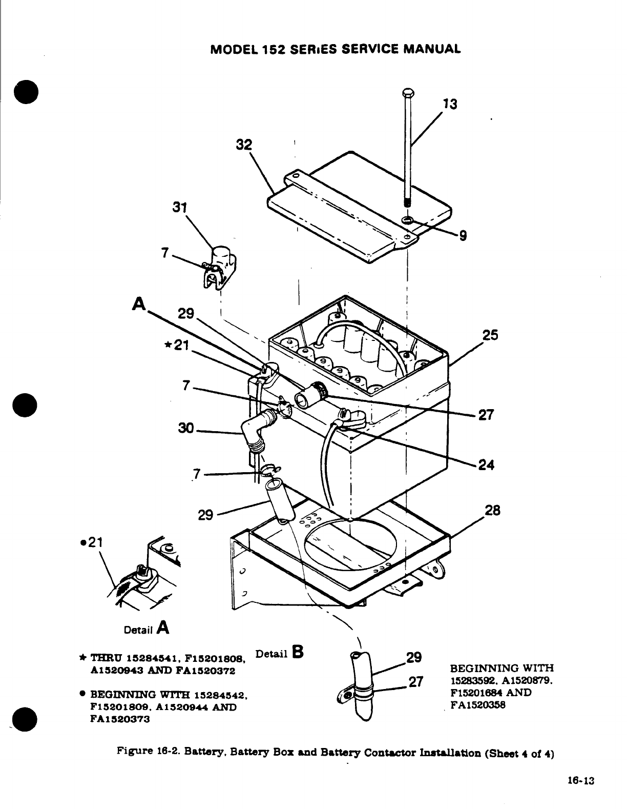
MODEL
152
SERIES
SERVICE
MANUAL
13
32
30
27
24
Detail
A
* THRU
15284541.
F15201808,
Detail
B29
A1520943
AND
FA1520372 BEGINNING
WITH
l27
15283592.
A1520879.
BEGINNING
WITH 15284542,
F15201684
AND
F15201809.
A1520944
AND
FA1520358
FA
1520373
Figure
16-2.
Battery, Battery
Box
and
Battery
Contactor
Installation
(Sheet
4
of
4)
16-13
MODEL
152
SERIES SERVICE
MANUAL
16-28.
BATTERY
CONTACTOR
CLOSING
CIRCUIT.
The
battery
contactor
closing
circuit
consists
of
a
5-amp
fuse.
a
resistor
and
a
diode
installed
across
the
battery
contactor.
This
serves
to
shunt
a
small
charge
around
the
battery
contactor
when
the
battery
is
too
dead to
energize
the contactor
by
itself
16-29.
GROUND
SERVICE
RECEPTACLE.
16-30.
DESCRIPTION.
A
ground
service
receptacle
may
be
installed
to
permit
the
use
of
external
power
for
cold
weather
starting
or
when
performing
lengthy
electrical
maintenance.
The
receptacle
is
mounted
on
the
left
hand
side
of
the
firewal
with
an
access
door in
the
engine
cowl.
NOTE
Before
connecting
an
external
power
source,
it is
impor-
tant
that
the
master
switch
be
turned
"ON".
This
will
close the
battery
contactor
and
enable
the
battery
to
absorb
transient
voltages
which
otherwise
might
dam-
age
the
electronic
equipment.
It
will
also
provide excita-
tion
of
the
alternator
field
in
the
event
that
the
battery
is
completely
dead.
NOTE
On
Aircraft
Serials
15279406
thru
15280898
and
A1520001
thru
A1520771
refer
to
Cessna Single-engine Service
Letter
SE78-19.
dated
March
27.
1978.
16-31.
REMOVAL AND
INSTALLATION.
(See
figure
16-3.)
a
Remove
engine
cowl
in
accordance
with
Section
11.
b.
Thru
1979
Models,
open
the
battery
box
and
disconnect
the
ground
cable
from
the
negative
terminal
of
the
battery
and
pull
cable
from the
battery
box.
c.
Beginning
with
1980
Models.
disconnect
negative
battery
cable.
d.
Remove
the
nuts.
washers
and ground
strap
from
the
terminals
of
the
receptacle
and
remove the
battery
cable.
e.
Remove
the
screws
and
nuts
securing
the
receptacle
to
the
mounting
bracket.
Remove
receptacle.
f.
To
install
ground
service
receptacle,
reverse
the
preceding
steps.
Be
sure
to
place the
ground
strap
on
the
negative
stud
of
the
receptacle.
16-32.
ALTERNATOR
POWER
SYSTEM.
16-33.
DESCRIPTION. The
alternator
system
consists
of
a
belt-driven
alternator,
a
voltage
regulator/
alternator
control
unit
mounted
on
the
left
hand
side
of
the
firewall
and
circuit
breaker
located
on
the
instrument
panel.
The
system
is
controlled
by
the
left
hand
portion
of
the
split
rocker,
master
switch
labeled
"ALT."
Thru
1978
models
an
over-voltage
sensor
switch
and
red
warning
light
labeled
"HIGH
VOLTAGE"
are
incorporated
to
protect
the
system.
Beginning with
1979
models,
over-voltage
and
under-voltage
switches
are
con-
tained
within
the
alternator
control unit
and
a
red
warning
light
labeled
"LOW
VOLTAGE"
is
installed
on
the
instrument
panel
(refer
to
paragraph
16-40).
The
aircraft
battery
supplies
the
source
of
power for
excitation
of
the
alternator.
16-14
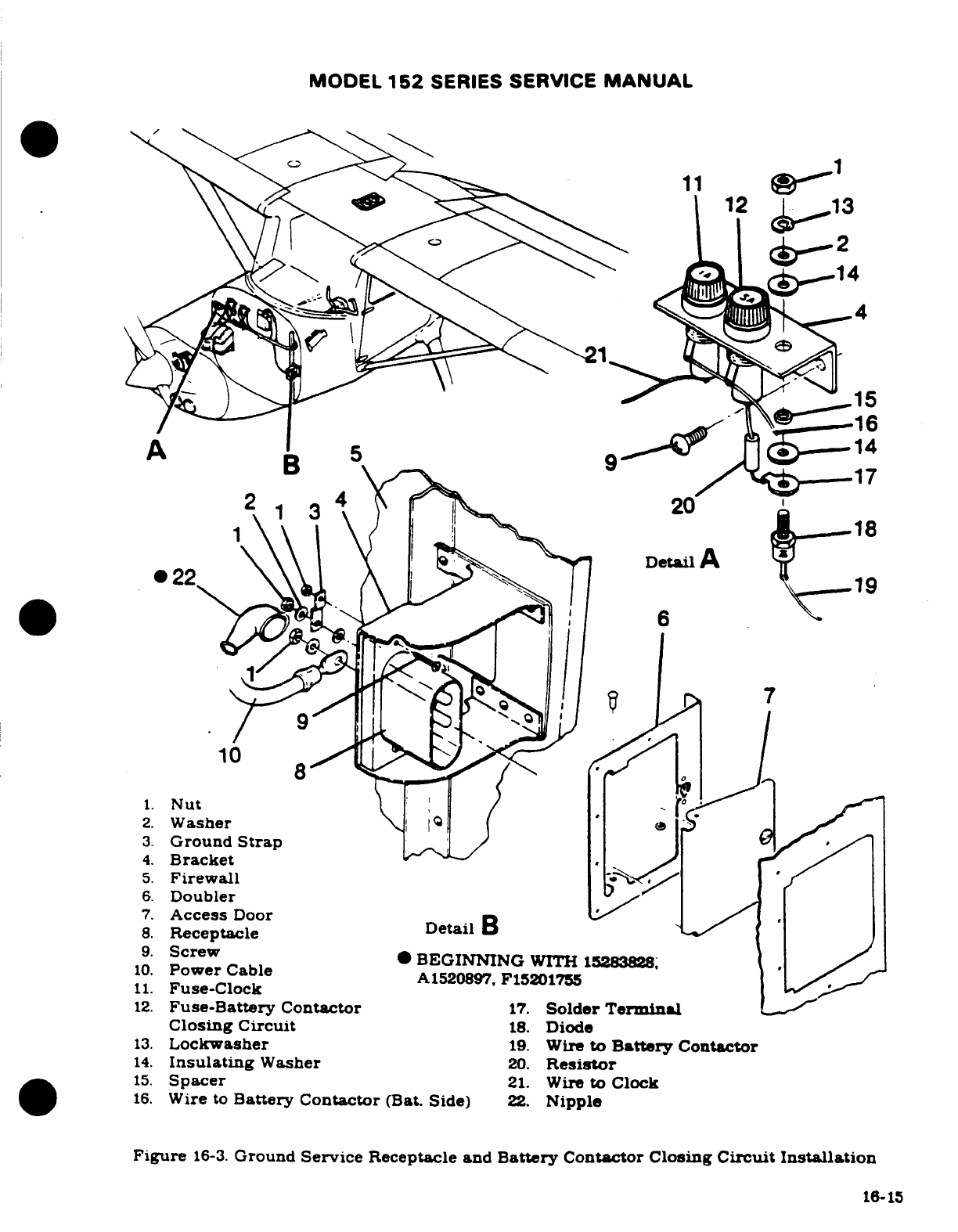
MODEL
152
SERIES
SERVICE
MANUAL
11
1
4
6
2.
Washer
3.
Ground
Strap
5.
Firewall
.
6.
Doubler
/
/
7.
Access
Door
9.
Screw
10.
Power
Cable
A1520897.
F15201755
11.
Fuse-Crackt
12.
Fuse-Battery
Contactor
17.
Solder
Terminal
Closing
Cir.
Diode
11
Fuse-Clock
8.
Receptacle
9.
Screw
·
BEGINNING
WITH
15283828;
14.
Insulating
Washer
Resistor
15.
Spacer
21.
WiretoClocklock
12.
Fuse-Battery
Contactor
17.
Solder
Terminal
Closing
Circuit
18.
Diode
13.
Lockwasher
19.
Wire
to
Battery
Contactor
14.
Insulating
Washer
20.
Resistor
15.
Spacer
21.
Wire
to
Clock
16.
Wire
to
Battery Contactor
(Bat.
Side)
22.
Nipple
Figure
16-3.
Ground
Service
Receptacle
and
Battery
Contactor Closing
Circuit
Installation
16-15
MODEL
152
SERIES SERVICE
MANUAL
16-34.
ALTERNATOR.
16-35.
DESCRIPTION.
The
alternator
is
three
phase.
delta
connected
with
integal
silicon
diode
rectifiers.
The
alternator is
rated at
28
volts
at
60
amperes
continuous output.
The
moving
center
part
of
the
alternator
(rotor)
consists
of
an
axial
winding
with
radial
interlocking
poles
which
surround
the
winding.
With
excitation
applied
to
the winding
through
slip rings
the
pole
pieces
assume magnetic
polarity.
The
rotor
is
mounted
in
bearings
and
rotates
inside
the
stator
which
contains
the
windings in
which
ac
is
generated
The
stator
windings
are
three-phase
each
of
which
contains
three silicon
diodes.
The
diode
plates
are connected
to
accomplish full-wave,
rectification
of
ac.
The
resulting
do
output
is
applied
to
the
aircraft
bus
and
sensed
by the
voltage regulator.
The
regualtor
controls
the
excitation
applied
to
the
alternator
field
thus
controlling
the
output
of
the
alternator.
16-36.
REMOVAL
AND
INSTALLATION.
(See
figure
16-4.)
a.
Ensure
that
master
switch
is
off
and the
negative
lead
is
disconnected
from
the
battery.
b.
Remove
propeller
in
accordance with
Section
13.
c.
Remove
nose cap
in
accordance
with
Section
11.
d.
Remove
wiring
from
alternator
and
lable.
e.
Remove
safety
wire
from
lower
adjustment
bolt
and
remove
bolt.
f.
Remove
the
locknut
from
the
alternator
mounting
bolt.
g.
Remove
the
alternator
drive
belt
and
the
alternator
mounting
bolt.
the
alternator
will
then
be
free
for
removal.
h.
To
replace the
alternator,
reverse
this
procedure.
i.
Apply
a
torque
wrench
to
the
nut
on
alternator
pully
and
adjust
the belt
tension
so
the
belt
slips
when
torque
is
applid,
see
figure
16-4.
16-37.
ALTERNATOR
FIELD
PROTECTION.
16-38.
DESCRIPTION.
A
5-amp
automatic
resetting
circuit
breaker
located
on
the
left
hand.
stationary
instrument
panel
stiffner.
is
provided
to
protect
the
alternator
field
circuit.
16-39.
ALTERNATOR
REVERSE
VOLTAGE
DAMAGE.
The
alternator
is
very susceptible
to
reverse
polarity
current
because
of
the
silicon
diodes.
The
diodes.
having
a
very
high
resistance
to
reverse
current
flow,
are
used
without
any
cutout relay
such
as
used
on
a
generator system.
The
alternator
diodes
are
arranged
with
their
cathodes connected
to
the
aircraft
bus
bar
which
is
positive
and
no
back
current
will
flow.
If
the
polarity
of
the
battery
is
reversed,
the
diodes
will
offer
no
resistance
to
the
current
flow.
The
current
rating
of
the
diodes
is
exceeded
and diode
failure
may
result.
16-40.
OVER-VOLTAGE
WARNING SYSTEM.
16-41.
DESCRIPTION.
Thru
1978
Models
the
over-voltage
system
consists
of
an
over-voltage
sensor switch
and
red
warning
light
labeled
"HIGH VOLTAGE". The
over-voltage
sensor
is
attached
to
the wire
bundle
behind the
instrument
panel
and
the
light is
located
on
the
right
hand
side
of
the
instrument
panel.
When
an
over-voltage tripoff
occurs
the
over-voltage
sensor
turns
off
the
alternator
system
and
the
red
warning
light
comes
on.
The
ammeter
will
show a
discharge.
Turn
off
both
sections
of
the
master
switch
to
recycle
the
over-voltage
sensor.
If
the
over-voltage
condition
was
transient.
the
normal
alternator charging
will
resume
and
no
further.
action
is
necessary.
If
the
over-voltage tripoff
recurs.
then
a
generating
system
malfunction
has
occurred
such
that
the
electrical
accessories must
be
16-16
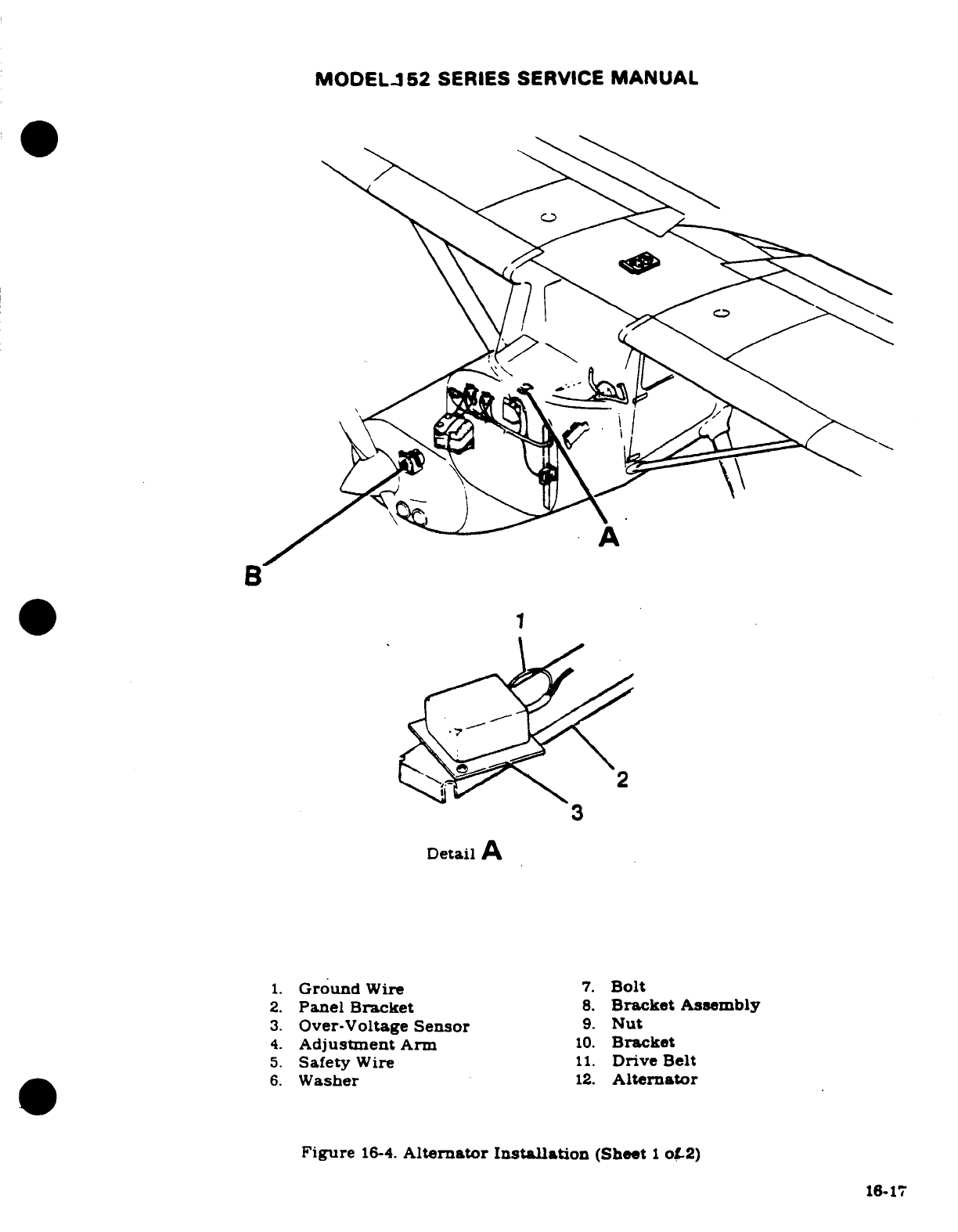
MODEL-
52
SERIES SERVICE
MANUAL
* 1
',=
Detail
A
1.
Ground
Wire
7.
Bolt
2.
Panel
Bracket
8.
Bracket
Assembly
3.
Over-Voltage
Sensor
9.
Nut
4.
Adjustment
Arm
10.
Bracket
5.
Safety
Wire
11.
Drive
Belt
6.
Washer
12.
Alternator
Figure
16-4.
Alternator
Installation
(Sheet
1
of
2
16-17
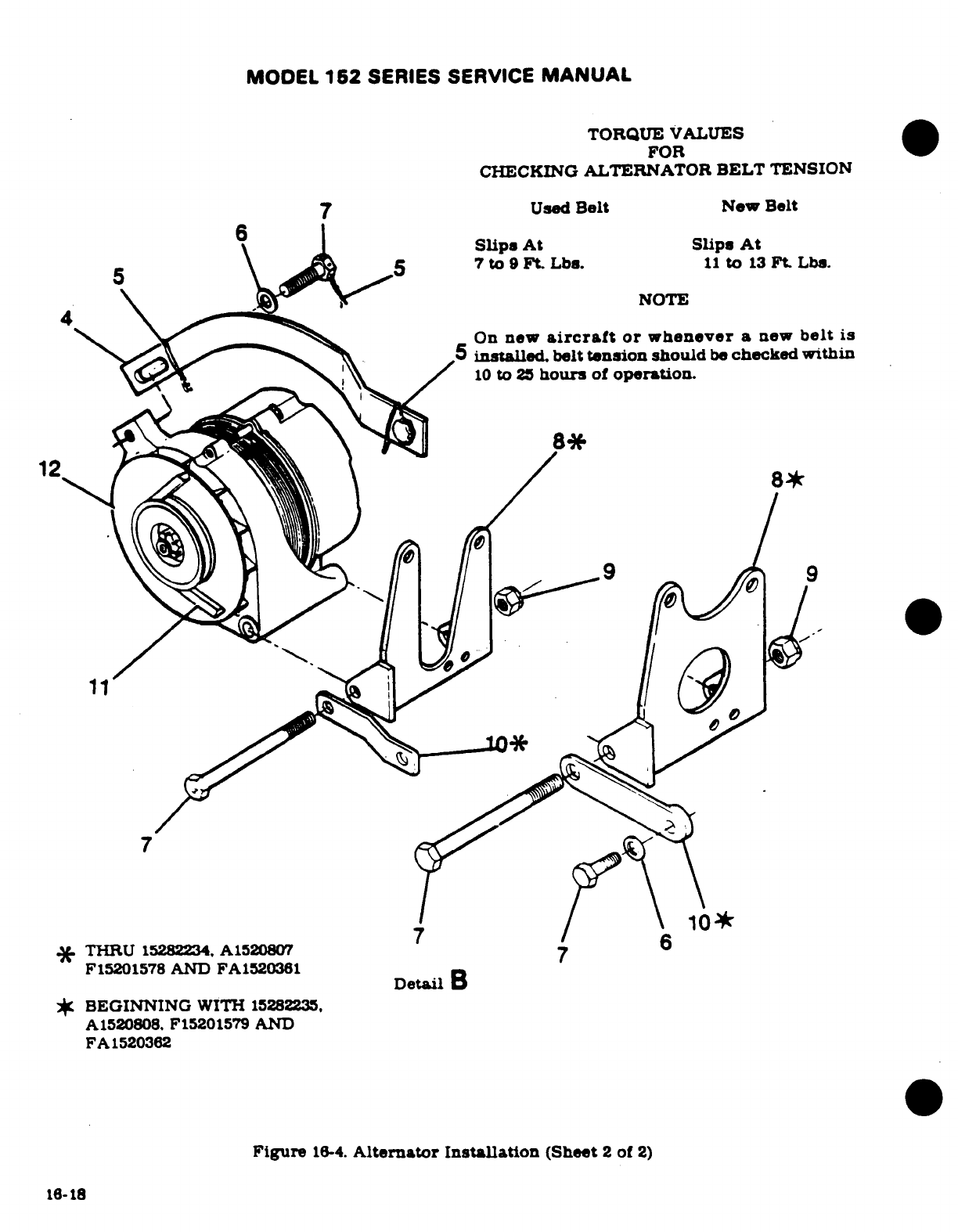
MODEL
162
SERIES
SERVICE
MANUAL
TORQUE
VALUES
FOR
CHECKING
ALTERNATOR
BELT
TENSION
7
Used
Belt
New
Belt
Slips
At
Slips
At
5 5
7
to
9
Ft
Lbs.
11
to
13
Ft.
Lbs.
NOTE
On
new
aircraft
or
whenever
a
new
belt
is
5
installed.
belt
tension
should
be
checked
within
10
to
25
hours
of
operation.
12
9*
A1520808. F15201579
AND
*
THRU
15282234.
A1520807
6
F15201578
AND
FA1520361
Detail
B
*
BEGINNING
WITH
15282235,
A
1520808.
F15201579
AND
FA
1520362
Figure
16-4.
Alternator
Installation
(Sheet
2
of
2)
16-18
MODEL
152
SERIES SERVICE
MANUAL
operated
from
the
aircraft
battery
only.
Conservation
of
electrical
energy
must
be
practiced
until
the
flight
can
be
terminated.
The
over-voltage
light
filament
may
be
tested
at
any
time
by
turning
off
the
"Alternator"
portion
of
the
master
switch
and
leaving
the
battery
portion
on.
This
test
does not induce
an
over-voltage
condition
on
the
electrical system.
NOTE
The
over-voltage
sensor
switch
contains
solid
state
devices.
Observe
proper
polarity
before
supplying
power.
Grounding
the orange
lead
or
interconnecting
orange
and
black
leads
will
destroy
the
device.
When
removal
is
required
for
replacement,
identify
(tag)
wir-
ing
and follow
the
wiring
diagram
in
Section
19
for
rewiring.
Beginning with
1979
Models
the over-voltage
sensor
is
contained
within
the
alternator
control
unit.
The
unit
also
contains
a
low-voltage
sensor.
A
red
warning
light
labeled
"LOW
VOLTAGE"
is
installed
on
the
instrument
panel.
When
an
over-voltage
condition
occurs
the
over-voltage
sensor
turns
off
the
alternator
and
the
voltage
in
the
system
drops.
When
system
voltage
drops
below
24.5
volts
the
low-voltage
sensor
turns
on
the
low-voltage
light
indicating
a
drain
on
the
battery
and the
ammeter
will
show
a
discharge.
Turn
off
both
sections
of
the master
switch
to
recycle
the
over-voltage
sensor.
If
the over-voltage
condition
was
transient
the
normal
alternator charging
will
resume
and no
further
action
is
necessary.
If
the over-voltage
tripoff
recurs,
then
a
generating system
malfunction
has
occurred
such
that
the
electrical
accessories
must
be
operated
from
the
aircraft
battery
only.
Conservation
of
electrical
energy
must
be
practiced
until
the
flight
can
be
terminated
The
over-voltage
light
filament may
be
tested
at
any
time
by
turning
off
the
"Alternator"
portion
of
the
master
switch
and
leaving
the
battery portion
on.
This
test
does
not
induce
an
over-
voltage
condition
on
the
electrical
system.
NOTE
To
support
the
newer
alternator
control
unit
(ACU),
Cessna has
designed
an
Alternator
Charging
System
Test
Box
Assembly,
Part
No.
9870005-1,
that
provides
ca-
pability
to
perform
all on-aircraft
checks
of
malfunction-
ing
alternator/ACU
systems.
This
new
test
box,
available
from
Cessna
Parts
Distribution
(CPI)
2)
through
a
Cess-
na
Service
Station,
is
complete
and
features:
a.
Isolation
of
six
separate
malfunctions:
1.
No
aircraft
battery
power
to
the
ACU.
2.
Shorted
regulator
(over-voltage
condition)
in
the
ACU.
3.
Open
regulator
(no
alternator
output)
in
the
ACU.
4.
Shorted
alternator
field
winding
or
wiring.
5.
Open
alternator
field
winding
or
wiring.
6.
Inoperative
low
voltage
circuit
in
the
ACU.
b.
Quick
and
simple
set-up.
c.
System
checks
without
running
the
engine.
Revision
1
16-19
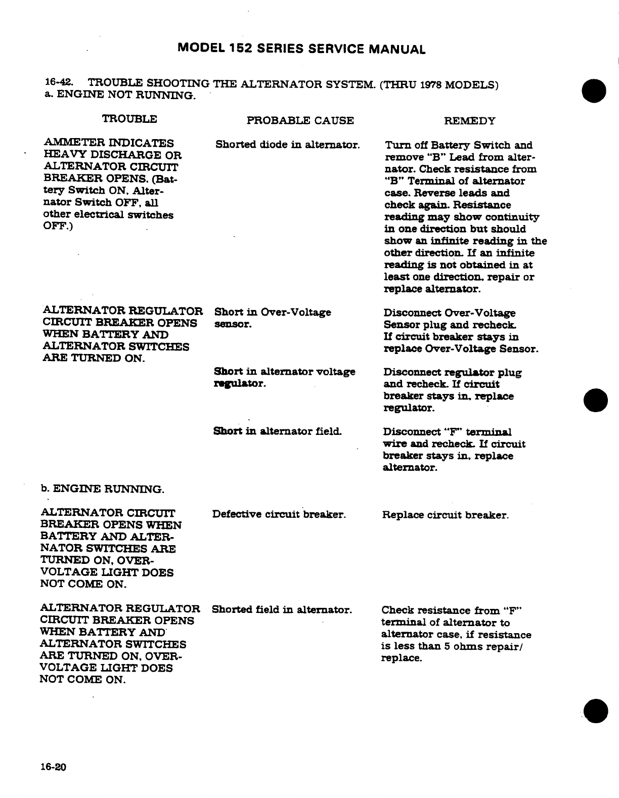
MODEL
152
SERIES SERVICE
MANUAL
16-42.
TROUBLE
SHOOTING
THE
ALTERNATOR
SYSTEM.
(THRU
1978
MODELS)
a.
ENGINE
NOT
RUNNING.
TROUBLE
PROBABLE
CAUSE
REMEDY
AMMETER
INDICATES
Shorted
diode
in
alternator.
Turn
off
Battery
Switch
and
HEAVY DISCHARGE
OR
remove
"B"
Lead
from
alter-
ALTERNATOR
CIRCUIT
nator.
Check
resistance
from
BREAKER
OPENS.
(Bat-
"B"
Terminal
of
alternator
tery
Switch
ON,
Alter-
case.
Reverse
leads
and
nator
Switch
OFF,
all
check
again.
Resistance
other electrical
switches
reading may
show
continuity
OFF.)
in
one
direction
but
should
show
an
infinite
reading
in
the
other
direction.
If
an
infinite
reading
is
not
obtained
in
at
least
one
direction,
repair
or
replace
alternator.
ALTERNATOR
REGULATOR
Short
in
Over-Voltage
Disconnect Over-Voltage
CIRCUIT
BREAKER OPENS
sensor.
Sensor
plug
and
recheck.
WHEN
BATTERY
AND
If
circuit
breaker
stays
in
ALTERNATOR
SWITCHES
replace
Over-Voltage
Sensor.
ARE TURNED
ON.
Short
in
alternator
voltage
Disconnect
regulator
plug
regulator.
and
recheck.
If
circuit
breaker
stays
in,
replace
regulator.
Short
in
alternator
field.
Disconnect
"F"
terminal
wire
and
recheck. If
circuit
breaker
stays in,
replace
alternator.
b.
ENGINE
RUNNING.
ALTERNATOR
CIRCUIT
Defective
circuit
breaker.
Replace
circuit
breaker.
BREAKER
OPENS
WHEN
BATTERY AND
ALTER-
NATOR
SWITCHES
ARE
TURNED
ON,
OVER-
VOLTAGE
LIGHT
DOES
NOT
COME
ON.
ALTERNATOR
REGULATOR
Shorted
field
in
alternator.
Check
resistance
from
"F"
CIRCUIT
BREAKER
OPENS
terminal
of
alternator
to
WHEN
BATTERY
AND
alternator
case,
if
resistance
ALTERNATOR
SWITCHES
is
less
than
5
ohms
repair/
ARE
TURNED
ON,
OVER-
replace.
VOLTAGE
LIGHT
DOES
NOT
COME
ON.
16-20
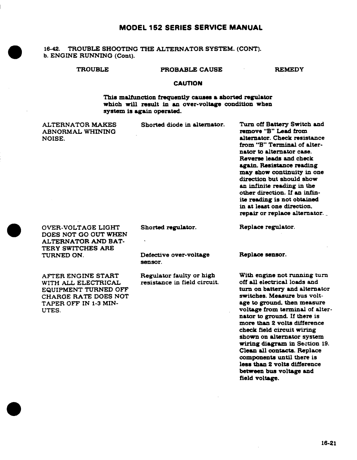
MODEL
152
SERIES
SERVICE
MANUAL
16-42.
TROUBLE
SHOOTING THE
ALTERNATOR
SYSTEM.
(CONT).
b.
ENGINE
RUNNING
(Cont).
TROUBLE
PROBABLE CAUSE
REMEDY
CAUTION
This malfunction frequently causes
a
shorted regulator
which
will
result
in
an
over-voltage condition
when
system
is
again
operated.
ALTERNATOR
MAKES
Shorted
diode
in
alternator.
Turn
off
Battery
Switch
and
ABNORMAL WHINING
remove
"B"
Lead
from
NOISE.
alternator.
Check
resistance
from
"B"
Terminal
of
alter-
nator
to
alternator
case.
Reverse
leads
and
check
again. Resistance
reading
may
show
continuity
in
one
direction
but
should
show
an
infinite
reading
in
the
other
direction.
If
an
infin-
ite
reading
is
not
obtained
in
at
least
one
direction,
repair
or
replace
alternator.
OVER-VOLTAGE
LIGHT
Shorted
regulator.
Replace
regulator.
DOES
NOT
GO
OUT WHEN
ALTERNATOR
AND BAT-
TERY SWITCHES
ARE
TURNED
ON.
Defective
over-voltage
Replace
sensor.
sensor.
AFTER
ENGINE
START
Regulator
faulty
or
high
With
engine
not
running
turn
WITH
ALL
ELECTRICAL
resistance
in
field
circuit.
off
all
electrical
loads
and
EQUIPMENT
TURNED
OFF
turn
on
battery
and
alternator
CHARGE
RATE
DOES
NOT
switches.
Measure
bus
volt-
TAPER OFF
IN
1-3
MIN-
age
to
ground.
then
measure
UTES.
voltage
from
terminal
of
alter-
nator
to
ground.
If
there
is
more
than
2
volts
difference
check
field
circuit
wiring
shown
on
alternator
system
wiring diagram
in
Section
19.
Clean
all
contacts.
Replace
components
until
there
is
less
than
2
volts
difference
between
bus
voltage
and
field
voltage.
16-21
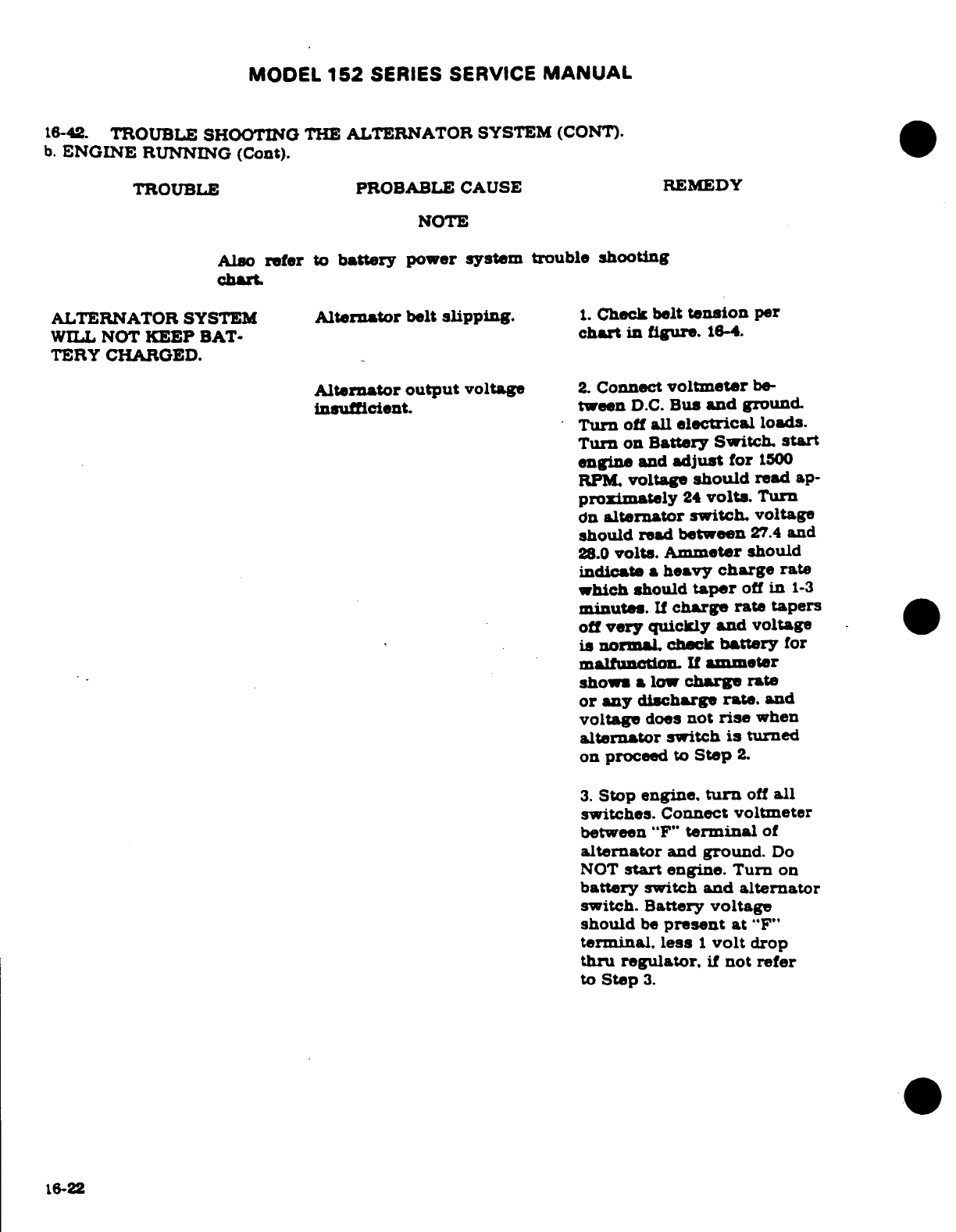
MODEL
152
SERIES
SERVICE
MANUAL
16-42.
TROUBLE
SHOOTING
THE
ALTERNATOR
SYSTEM
(CONT).
b.
ENGINE
RUNNING
(Cont).
TROUBLE
PROBABLE
CAUSE
REMEDY
NOTE
Also
refer
to
battery
power
system
trouble
shooting
chart
ALTERNATOR
SYSTEM
Alternator
belt
slipping.
1.
Check belt
tension
per
WILL
NOT
KEEP
BAT-
chart
in
figure.
16-4.
TERY
CHARGED.
Alternator output
voltage
2.
Connect
voltmeter
be-
insufficient.
tween
D.C.
Bus
and
ground.
Turn
off
all
electrical
loads.
Turn
on
Battery
Switch,
start
engine
and
adjust
for
1500
RPM,
voltage
should
read
ap-
proximately
24
volts.
Turn
on
alternator
switch,
voltage
should
read
between
27.4
and
28.0
volts. Ammeter
should
indicate
a
heavy
charge
rate
which should
taper
off
in
1-3
minutes.
If
charge
rate
tapers
off
very
quickly
and
voltage
is
normal
check
battery
for
malfunction
If
ammeter
show
a
low
charge
rate
or any discharge
rate.
and
voltage
does
not
rise
when
alternator
switch
is
turned
on
proceed
to
Step
2.
3.
Stop
engine,
turn
off
all
switches.
Connect
voltmeter
between
"F"
terminal
of
alternator
and
ground.
Do
NOT
start
engine.
Turn
on
battery
switch
and
alternator
switch.
Battery
voltage
should
be
present
at
"F"
terminal, less
1
volt
drop
thru
regulator,
if
not
refer
to
Step
3.
16-22
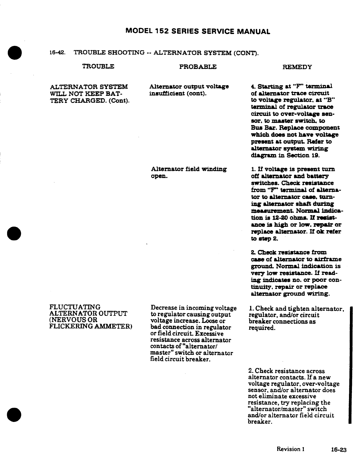
MODEL
152
SERIES
SERVICE
MANUAL
16-42.
TROUBLE
SHOOTING
--
ALTERNATOR
SYSTEM
(CONT).
TROUBLE
PROBABLE
REMEDY
ALTERNATOR
SYSTEM
Alternator
output
voltage
4.
Starting
at
"F"
terminal
WILL
NOT
KEEP
BAT-
insufficient
(cont).
of
alternator
trace
circuit
TERY
CHARGED.
(Cont). to
voltage
regulator,
at
"B"
terminal
of
regulator
trace
circuit
to
over-voltage
sen-
sor.
to
master
switch. to
Bus
Bar.
Replace
component
which
does
not
have
voltage
present
at
output.
Refer
to
alternator
system
wiring
diagram
in
Section
19.
Alternator
field
winding
1.
If
voltage
is
present
turn
open.
off
alternator
and
battery
switches.
Check
resistance
from
"F"
terminal
of
alterna-
tor to
alternator
case.
trn-
ing
alternator
shaft
during
measurement.
Normal
indica-
tion is
12-20
ohms. If
resit-
ance
is
high
or
low.
repair
or
replace
alternator.
If
ok
refer
to
step
2.
2
Check
resistance
from
case
of
alternator
to
airframe
ground.
Normal
indication
is
very
low
resistance.
If
read-
ing
indicates
no.
or
poor
con-
tinuity,
repair
or
replace
alternator
ground
wiring.
FLUCTUATING
Decrease
in
incoming
voltage
1.
Check
and
tighten
alternator,
ALTERNATOR
OUTPUT
to
regulator
causing
output
regulator,
and/or
circuit
(NERVOUS
OR
voltage
increase.
Loose
or
breaker
connections
as
FLICKERING
AMMETER)
bad
connection
in
regulator
required.
or
field
circuit.
Excessive
resistance
across
alternator
contacts
of
"alternator/
master"
switch
or
alternator
field
circuit
breaker.
2.
Check
resistance
across
alternator
contacts.
If
a
new
voltage
regulator,
over-voltage
sensor, and/or
alternator
does
not
eliminate
excessive
resistance,
try
replacing
the
"alternator/master"
switch
and/or
alternator
field
circuit
breaker.
Revision
1
16-23
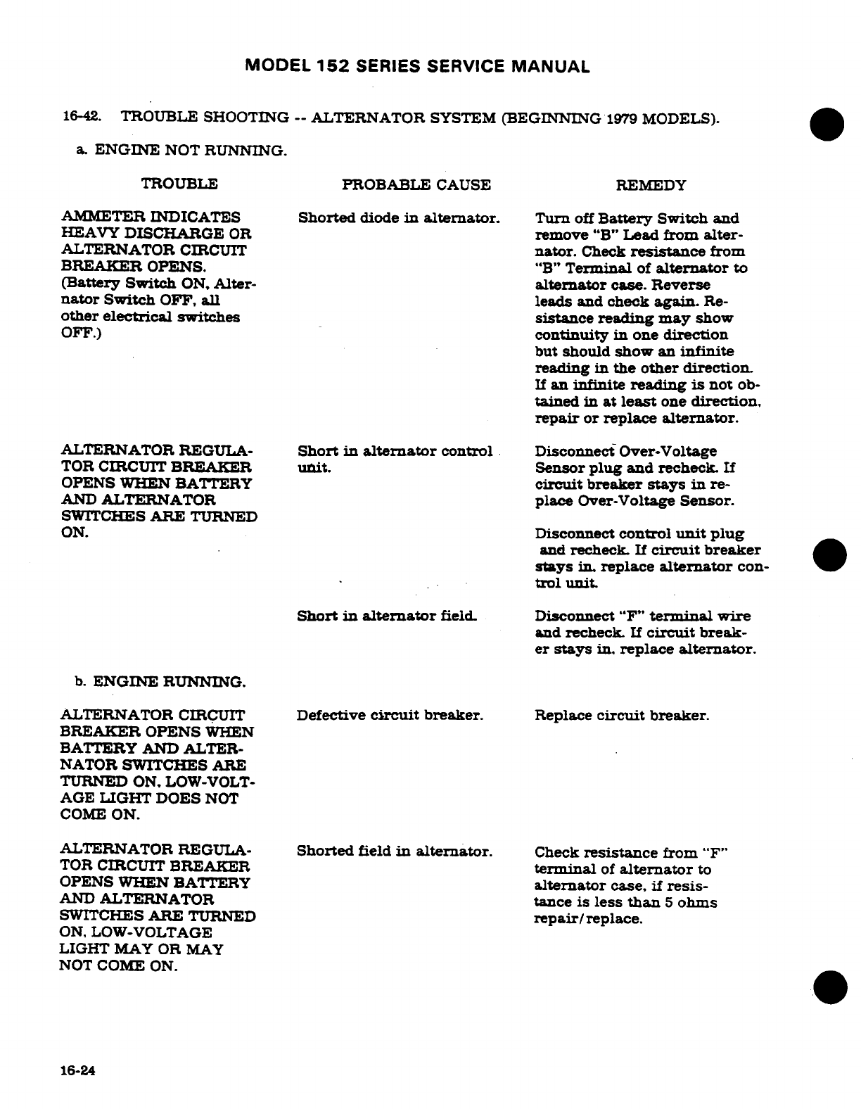
MODEL
152
SERIES SERVICE
MANUAL
16-42.
TROUBLE SHOOTING
--
ALTERNATOR
SYSTEM
(BEGINNING
1979
MODELS).
a.
ENGINE
NOT RUNNING.
TROUBLE
PROBABLE
CAUSE
REMEDY
AMMETER
INDICATES
Shorted
diode
in
alternator.
Turn
off
Battery
Switch
and
HEAVY
DISCHARGE
OR
remove
"B"
Lead
from
alter-
ALTERNATOR
CIRCUIT
nator.
Check
resistance
from
BREAKER
OPENS.
"B"
Terminal
of
alternator
to
(Battery Switch
ON,
Alter-
alternator
case.
Reverse
nator
Switch
OFF,
all
leads
and
check
again.
Re-
other
electrical
switches
sistance
reading
may
show
OFF.)
continuity
in
one
direction
but
should
show
an
infinite
reading
in
the
other
direction.
If
an infinite
reading
is
not
ob-
tained
in
at
least
one
direction,
repair
or
replace alternator.
ALTERNATOR
REGULA-
Short
in
alternator
control
Disconnect
Over-Voltage
TOR
CIRCUIT
BREAKER
unit.
Sensor
plug
and
recheck.
If
OPENS WHEN
BATTERY
circuit
breaker
stays in
re-
AND
ALTERNATOR
place
Over-Voltage
Sensor.
SWITCHES
ARE
TURNED
ON.
Disconnect
control
unit
plug
and
recheck.
If
circuit
breaker
stays
in.
replace
alternator
con-
0
trol
unit.
Short
in
alternator
field.
Disconnect
"F"
terminal
wire
and
recheck
If
circuit
break-
er
stays
in.
replace
alternator.
b.
ENGINE
RUNNING.
ALTERNATOR
CIRCUIT
Defective
circuit
breaker.
Replace
circuit
breaker.
BREAKER OPENS
WHEN
BATTERY
AND
ALTER-
NATOR
SWITCHES ARE
TURNED
ON,
LOW-VOLT-
AGE
LIGHT
DOES
NOT
COME
ON.
ALTERNATOR
REGULA-
Shorted
field
in
alternator.
Check
resistance
from
"F"
TOR
CIRCUIT
BREAKER
terminal
of
alternator
to
OPENS
WHEN
BATTERY
alternator
case,
if
resis-
AND
ALTERNATOR
tance
is
less
than
5
ohms
SWITCHES
ARE
TURNED
repair/replace.
ON,
LOW-VOLTAGE
LIGHT
MAY
OR MAY
NOT
COME
ON.
16-24
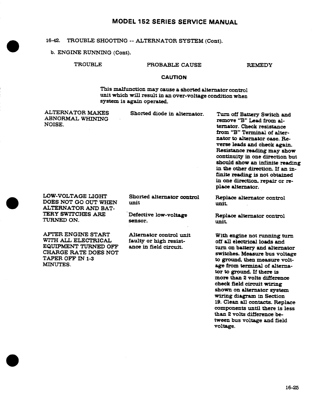
MODEL
152
SERIES
SERVICE
MANUAL
16-42.
TROUBLE
SHOOTING
--
ALTERNATOR
SYSTEM
(Cont).
b.
ENGINE
RUNNING
(Cont).
TROUBLE
PROBABLE CAUSE
REMEDY
CAUTION
This
malfunction
may
cause
a
shorted
alternator
control
unit
which
will
result
in
an
over-voltage
condition
when
system
is
again
operated.
ALTERNATOR MAKES
Shorted
diode
in
alternator.
Turn
off
Battery
Switch
and
ABNORMAL WHINING
remove
"B"
Lead
from
al-
NOISE.
ternator.
Check
resistance
from
"B"
Terminal
of
alter-
nator
to
alternator
case.
Re-
verse
leads
and check
again.
Resistance
reading
may
show
continuity
in
one
direction
but
should
show
an
infinite
reading
in
the
other
direction.
If
an
in-
finite
reading
is
not
obtained
in
one
direction,
repair
or
re-
place
alternator.
LOW-VOLTAGE
LIGHT
Shorted
alternator
control
Replace
alternator
control
DOES
NOT
GO OUT
WHEN
unit
unit.
ALTERNATOR
AND
BAT-
TERY
SWITCHES
ARE
Defective
low-voltage
Replace
alternator
control
TURNED
ON.
sensor.
unit.
AFTER
ENGINE
START
Alternator
control
unit
With
engine not
running
turn
WITH
ALL
ELECTRICAL
faulty or high
resist-
off
all
electrical
loads
and
EQUIPMENT
TURNED
OFF
ance
in
field
circuit.
turn
on
battery
and
alternator
CHARGE
RATE
DOES
NOT
switches.
Measure
bus
voltage
TAPER
OFF
IN
1-3
to
ground, then
measure
volt-
MINUTES.
age
from
terminal
of
alterna-
tor
to
ground.
If
there
is
more
than
2
volts
difference
check
field
circuit
wiring
shown
on
alternator system
wiring
diagram
in
Section
19.
Clean
all
contacts. Replace
components
until
there
is
less
than
2
volts
difference
be-
tween bus
voltage
and field
voltage.
16-25
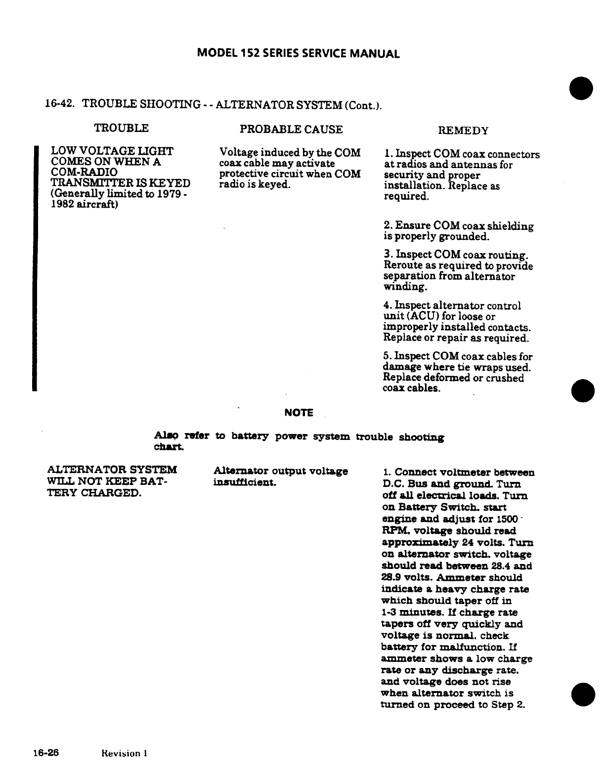
MODEL
152
SERIES
SERVICE
MANUAL
16-42.
TROUBLE
SHOOTING
- -
ALTERNATOR
SYSTEM
(Cont.).
TROUBLE
PROBABLE
CAUSE
REMEDY
LOW
VOLTAGE
LIGHT
Voltage
induced
by
the
COM
1.
Inspect
COM
coax connectors
COMES ON
WHEN
A
coax
cable
may
activate
at
radios
and
antennas
for
COM-RADIO
protective
circuit
when
COM
security
and
proper
TRANSMITTER
IS KEYED
radio
is
keyed.
installation.
Replace
as
(Generally
limited
to
1979
-
required.
1982
aircraft)
2.
Ensure
COM
coax
shielding
is properly
grounded.
3.
Inspect
COM
coax
routing.
Reroute
as required
to
provide
separation
from
alternator
winding.
4.
Inspect
alternator
control
unit
(ACU)
for
loose
or
improperly
installed
contacts.
Replace
or
repair
as
required.
5.
Inspect
COM
coax
cables
for
damage
where tie
wraps
used.
Replace
deformed
or
crushed
coax
cables.
NOTE
Also
refer
to
battery
power
system
trouble shooting
chart.
ALTERNATOR SYSTEM
Alternator
output
voltage
1.
Connect
voltmeter
between
WILL
NOT
KEEP
BAT-
insufficient.
D.C.
Bus
and
ground.
Turn
TERY
CHARGED.
off
all electrical
loads.
Turn
on
Battery
Switch.
start
engine and
adjust
for
1500
RPM,
voltage
should
read
approximately
24
volts.
Turn
on
alternator
switch.
voltage
should
read
between
28.4
and
28.9
volts.
Ammeter
should
indicate
a
heavy
charge
rate
which
should
taper
off
in
1-3
minutes.
If
charge
rate
tapers
off
very
quickly
and
voltage
is
normal.
check
battery
for
malfunction.
If
ammeter
shows
a
low
charge
rate
or
any discharge
rate.
and
voltage
does
not
rise
when
alternator
switch
is
turned
on
proceed
to
Step
2.
16-26 Revision
I
MODEL
152
SERIES SERVICE
MANUAL
16-42.
TROUBLE
SHOOTING
--
ALTERNATOR
SYSTEM
(Cont).
b.
ENGINE RUNNING
(Cont).
TROUBLE
PROBABLE
CAUSE
REMEDY
ALTERNATOR
SYSTEM
Alternator
output
voltage
2.
Stop
engine.
turn
off
all
WILL
NOT
KEEP
BAT-
insufficient
(cont).
switches.
Connect
voltmeter
TERY
CHARGED.
(Cont.)
between
"F"
terminal
of
alternator
and
ground.
Do
NOT
start
engine.
Turn
on
battery switch
and
alternator
switch.
Battery
voltage
should
be
present
at
"F"
terminal.
less
1
volt
drop
thru regulator.
if
not
refer
to
Step
3.
3.
Starting
at
"F"
terminal
of
alternator.
trace
circuit
to
alternator
control
unit
at
Pin
1
(Blue
Wire).
Trace
cir-
cuit
from
Pin
3
(Red
Wire)
to
master
switch.
to
Bus
Bar.
Trace
circuit
from
alternator
control
unit
Pin
2
(Orange
Wire)
to
alternator
"BAT"
terminaL
Check
connections
and
replace
component
which
does
not have
voltage
present
at
output.
Refer
to
alternator
system.
wiring diagram
in
Sec-
tion
19.
Alternator
field
winding
1.
If
voltage
is
present
turn
open.
off
alternator
and
battery
switches.
Check
resistance
from
"F"
terminal
of
alter-
nator
to
alternator
case.
turning alternator
shaft
dur-
ing
measurement.
Normal
indication
is
12-20
ohms.
If
resistance
is
high or
low,
repair
or
replace
alternator.
If
ok
refer
to
Step
2.
2.
Check
resistance
from
case
of
alternator
to
air-
frame
ground. Normal
indi-
cation
is
very
low
resistance.
If
reading
indicates
no,
or
poor
continuity,
repair
or
replace
alternator
ground
wiring.
Revision
1
16-27
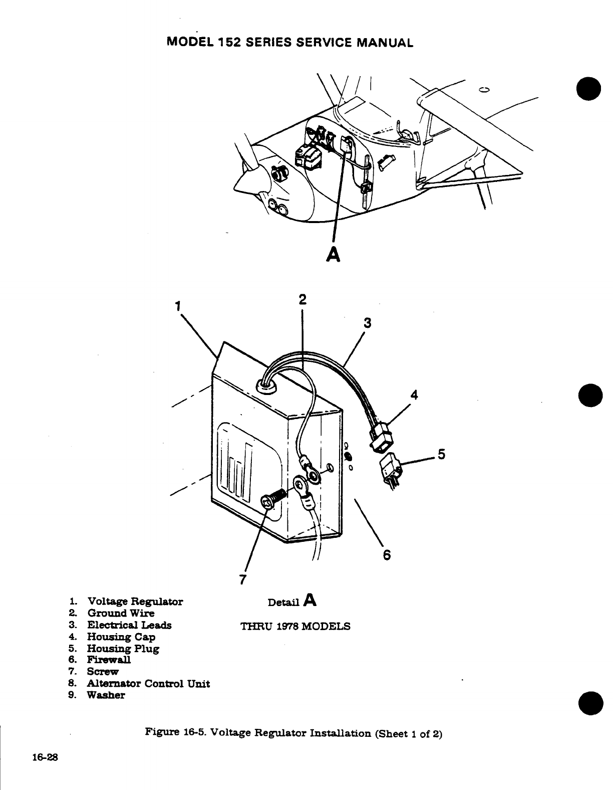
MODEL
152
SERIES
SERVICE
MANUAL
A
1
2
7
1.
Voltage
Regulator
Detail
A
2.
Ground
Wire
3.
Electrical
Leads
THRU
1978
MODELS
4.
Housing
Cap
5.
Housing
Plug
6.
Firewall
7.
Screw
8.
Alternator
Control
Unit
9.
Washer
Figure
16-5.
Voltage
Regulator
Installation
(Sheet
1
of
2)
16-28
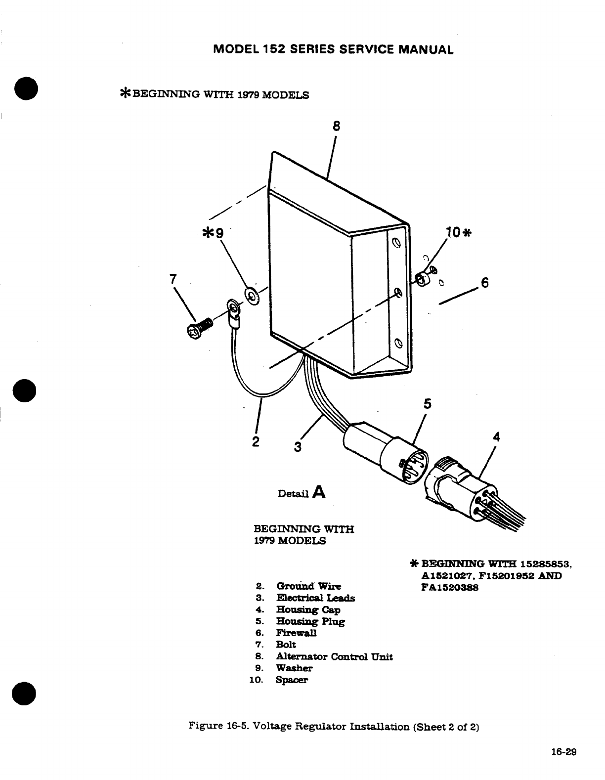
MODEL
152
SERIES
SERVICE
MANUAL
*
BEGINNING
WITH
1979
MODELS
8
7
Detail
A
BEGINNING
WITH
1979
MODELS
BEGINNING
WITH
15285853,
A1521027,
F15201952
AND
2.
Ground
Wire
FA1520388
3.
Electrical
Leads
4.
Housing
Cap
5.
Housing
Plug
6.
Firewall
7.
Bolt
8.
Alternator
Control
Unit
9.
Washer
10.
Spacer
Figure
16-5.
Voltage
Regulator
Installation
(Sheet
2
of
2)
16-29
MODEL
152
SERIES
SERVICE
MANUAL
16-43.
VOLTAGE
REGULATOR.
16-44.
DESCRIPTION.
The
voltage
regulator
is
a
solid
state regulator.
The
regulator
is
a
remove
and
replace
item
and
not
repairable
in
the
field.
For
adjustment. refer
to
the
Cessna
Alternator
Charging
Service/Parts
Manual.
16-45.
ALTERNATOR
CONTROL
UNIT.
16-46.
DESCRIPTION.
The
alternator
control
unit
is
a
solid
state
voltage
regulator
with
an
over-
voltage
sensor
and
low-voltage
sensor incorporated
in
the
unit.
The
control
unit
is
not
ad-
justable
and
is
a
remove-and-replace
item.
A
Cessna
Alternator
Charging
System
Test
Box
assembly
(PA9870005-1)
is
available
from
Cessna
Parts
Distribution
(CPD
2)
through
a
Cessna
Service
Station
for
use
in
isolating
failures
in
the
28-volt
alternator
control
units
(C611005-0101
and
C611005-0102)
and
the
28-volt
alternator.
NOTE
On
1979
thru
1982
models,
if the
alternator
low
voltage
light
comes
on
when
a
COM
radio
transmitter
is keyed,
refer
to
Cessna
Single Engine
Customer
Care Services
Information
Letter
SE82-17
dated
April
30,
1982.
Refer
also
to
Trouble
Shooting,
paragraph
16-42.
6-47.
REMOVAL
AND
INSTALLATION.
(See
figure
16-5).
a.
Remove
upper
half
of
engine
cowl.
b.
Make
sure
the
master
switch
is in
the
"OFF"
position.
c.
Disconnect
the
negative
lead
from the
battery
and
pull
lead
free
of
the battery
box.
d.
Disconnect
housing
plug
from
the
regulator/
alternator
control
unit.
e.
Remove
screws
securing
the
regulator/alternator
control
unit
to
the
firewall
f.
To
install
regulator/alternator
control
unit.
reverse
the
preceding
steps.
Be
sure the
connections
for
gounding
are
clean
and
bright
before
assembly.
Otherwise
faulty
voltage
regulation
and/or
excessive
radio
noise
may
result
16-48.
AIRCRAFT LIGHTING SYSTEM.
16-49.
DESCRIPTION.
The
aircraft
lighting
systems
consists
of
landing
and
taxi
lights.
naviga-
tion
lights.
anti-collision
strobe
lights,
flashing
beacon
light,
dome
and
instrument
lights.
control
wheel
map
light,
compass
and
radio
dial
lights.
16-50.
TROUBLE
SHOOTING.
TROUBLE
PROBABLE CAUSE
REMEDY
LANDING
AND
TAXI
Short
circuit
in wiring.
1.
Inspect
circuit
breaker.
LIGHT(S)
OUT.
If
open.
proceed
to
Step
2.
If
ok.
proceed
to
Step
3.
Defective
wiring.
2.
Test
each
circuit
sepa-
rately
until
short
is
located.
Repair
or
replace
wiring.
Defective
switch.
3.
Check
voltage
at
lights
with
master
and
landing
and
taxi
light
switches
ON.
Should read
battery
voltage.
Replace switch.
16-30
Revision
I
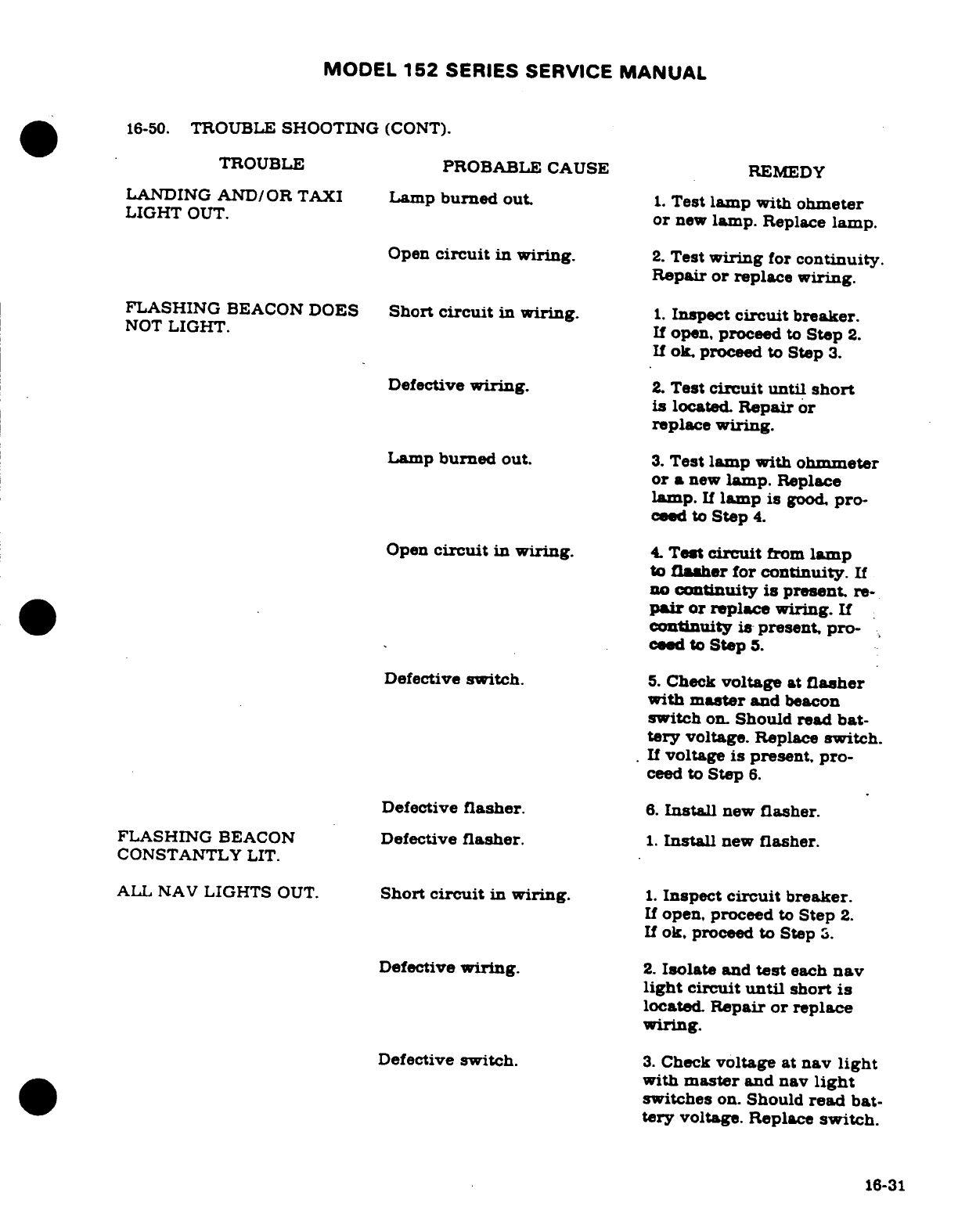
MODEL
152
SERIES
SERVICE
MANUAL
16-50.
TROUBLE
SHOOTING
(CONT).
TROUBLE
PROBABLE
CAUSE
REMEDY
LANDING
AND/OR
TAXI
Lamp
burned
out.
1.
Test
lamp
with
ohmeter
LIGHT
OUT.
or
new
lamp.
Replace
lamp.
Open
circuit
in wiring.
2.
Test
wiring
for
continuity.
Repair
or
replace
wiring.
FLASHING
BEACON
DOES
Short
circuit
in wiring.
1.
Inspect
circuit
breaker.
NOT
LIGHT.
If
open,
proceed
to
Step
2.
If
ok.
proceed
to
Step
3.
Defective
wiring.
2.
Test
circuit
until
short
is
located.
Repair
or
replace
wiring.
Lamp
burned
out.
3.
Test
lamp with
ohmmeter
or
a
new
lamp.
Replace
lamp.
If
lamp
is
good.
pro-
ceed
to
Step
4.
Open
circuit
in
wiring.
4.
Test
circuit
from
lamp
to
flasher
for
continuity.
If
no
continuity
is
present.
re-
pair
or
replace
wiring.
If
continuity is
present,
pro-
ceed
to
Step
5.
Defective
switch.
5.
Check
voltage
at
flasher
with
master
and
beacon
switch
on.
Should
read
bat-
tery
voltage.
Replace
switch.
If
voltage
is
present,
pro-
ceed
to
Step
6.
Defective
flasher.
6.
Install
new
flasher.
FLASHING
BEACON
Defective
flasher.
1.
Install
new
flasher.
CONSTANTLY
LIT.
ALL NAV
LIGHTS
OUT.
Short
circuit
in
wiring.
1.
Inspect
circuit
breaker.
If
open,
proceed
to
Step
2.
If
ok. proceed
to
Step
3.
Defective
wiring.
2.
Isolate
and
test
each
nav
light
circuit
until
short
is
located.
Repair
or
replace
wiring.
Defective
switch.
3.
Check
voltage
at
nav
light
with
master
and nav
light
switches
on.
Should
read
bat-
tery
voltage.
Replace
switch.
16-31
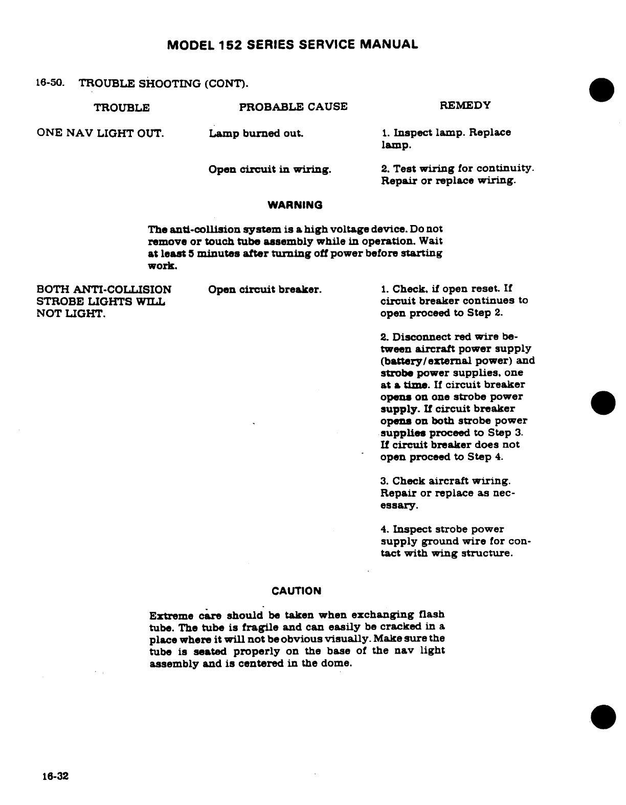
MODEL
152
SERIES
SERVICE
MANUAL
16-50.
TROUBLE
SHOOTING
(CONT).
TROUBLE
PROBABLE
CAUSE REMEDY
ONE
NAV
LIGHT
OUT.
Lamp
burned
out.
1.
Inspect
lamp.
Replace
lamp.
Open
circuit
in
wiring.
2.
Test
wiring
for
continuity.
Repair
or
replace
wiring.
WARNING
The
anti-collision
system
is a
high
voltage
device.
Do
not
remove
or
touch
tube assembly
while
in
operation.
Wait
at
least
5
minutes
after
turning
off
power
before
starting
work.
BOTH
ANTI-COLLISION
Open
circuit
breaker.
1.
Check,
if
open
reset.
If
STROBE
LIGHTS
WILL
circuit
breaker
continues
to
NOT
LIGHT.
open
proceed
to
Step
2.
2.
Disconnect
red
wire
be-
tween
aircraft
power
supply
(battery/external
power)
and
strobe
power
supplies.
one
at
a
time.
If
circuit
breaker
opens
on
one
strobe
power
supply.
If
circuit breaker
opens
on
both
strobe
power
supplies
proceed
to
Step
3.
If
circuit
breaker
does
not
open
proceed
to
Step
4.
3.
Check
aircraft
wiring.
Repair
or
replace
as
nec-
essary.
4.
Inspect
strobe
power
supply
ground
wire
for
con-
tact
with
wing
structure.
CAUTION
Extreme
care
should
be
taken
when
exchanging
flash
tube.
The
tube
is
fragile
and can
easily
be
cracked
in
a
place
where
it
will
not
be
obvious
visually.
Make
sure
the
tube
is
seated
properly
on
the
base
of
the
nav
light
assembly
and
is
centered
in
the
dome.
16-32
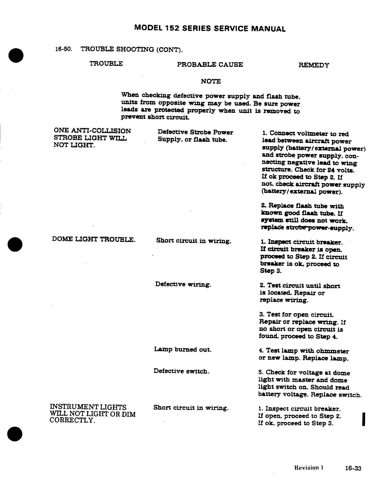
MODEL
152
SERIES SERVICE
MANUAL
16-50.
TROUBLE
SHOOTING
(CONT).
TROUBLE
PROBABLE
CAUSE
REMEDY
NOTE
When
checking
defective
power
supply
and
flash
tube.
units
from
opposite
wing may
be
used.
Be
sure
power
leads
are
protected
properly
when
unit
is
removed
to
prevent
short
circuit.
ONE
ANTI-COLLISION
Defective
Strobe
Power
1.
Connect
voltmeter
to
red
STROBE
LIGHT
WILL
Supply,
or
flash
tube.
lead
between
aircraft
power
NOT
LIGHT.
supply
(battery/external
power)
and strobe power
supply,
con-
necting
negative
lead
to
wing
structure.
Check
for
24
volts.
If
ok
proceed
to
Step
2.
If
not.
check
aircraft
power
supply
(battery/external
power).
2.
Replace
flash
tube
with
known
good
flash
tube.
If
system
still
does
not
work.
replace
strobe
power-supply.
DOME
LIGHT
TROUBLE.
Short
circuit
in
wiring.
1.
Inspect
circuit
breaker.
If
circuit
breaker
is
open.
proceed
to
Step
2.
If
circuit
breaker
is
ok.
proceed
to
Step
3.
Defective
wiring.
2.
Test
circuit
until
short
is
located.
Repair
or
replace
wiring.
3.
Test
for
open
circuit.
Repair
or
replace
wring.
If
no
short
or
open
circuit
is
found.
proceed
to
Step
4.
Lamp
burned
out.
4.
Test
lamp
with
ohmmeter
or
new
lamp.
Replace
lamp.
Defective
switch.
5.
Check
for
voltage
at
dome
light
with
master
and
dome
light
switch
on.
Should
read
battery
voltage.
Replace
switch.
INSTRUMENT
LIGHTS
Short
circuit
in
wiring.
1.
Inspect
circuit
breaker.
WILL
NOT
LIGIT
OR
DIM
If
open.
proceed
to
Step
2.
CORRECTLY.
If
ok.
proceed
to
Step
3.
Revision
1
16-33
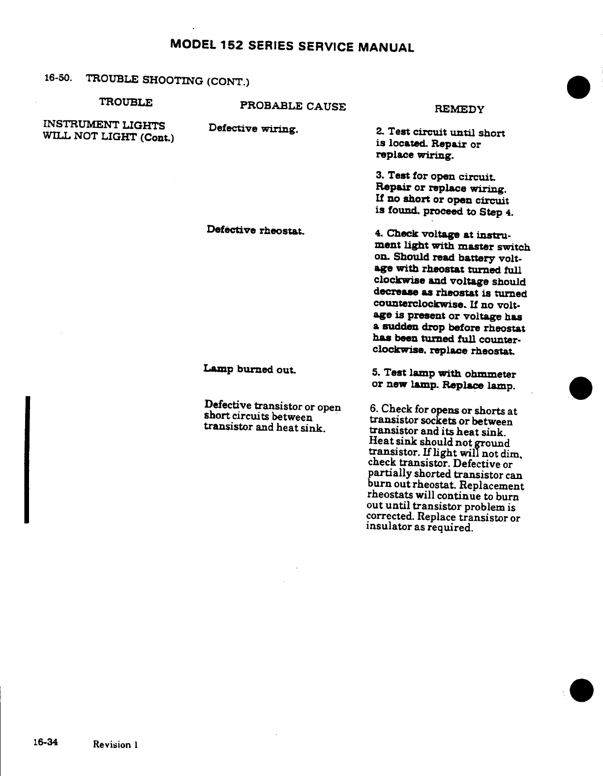
MODEL
152
SERIES
SERVICE
MANUAL
16-50.
TROUBLE
SHOOTING
(CONT.)
TROUBLE
PROBABLE CAUSE
REMEDY
INSTRUMENT
LIGHTS
Defective
wiring.
2.
Test
circuit
until
short
WILL
NOT
LIGHT
(Cont.)
is
located.
Repair
or
replace wiring.
3.
Test for
open
circuit.
Repair
or
replace
wiring.
If
no
short
or open
circuit
is
found,
proceed
to
Step
4.
Defective
rheostat.
4.
Check
voltage
at
instru-
ment
light
with
master
switch
on.
Should
read
battery
volt-
age with
rheostat
turned
full
clockwise
and
voltage
should
decrease
as
rheostat
is
turned
counterclockwise.
If
no
volt-
age
is
present
or
voltage
has
a
sudden
drop
before
rheostat
has
been
turned
full
counter-
clockwise.
replace
rheostat.
Lamp
burned
out.
5.
Test
lamp
with
ohmmeter
or
new
lamp. Replace
lamp.
Defective
transistor
or open
6.
Check for opens
or
shorts
at
short
circuits
between
transistor
sockets
or
between
transistor
and
heat
sink.
transistor
and
its
heat
sink.
Heat
sink
should
not
ground
transistor.
If
light
will
not
dim,
check
transistor.
Defective
or
partially
shorted
transistor
can
burn
out
rheostat.
Replacement
rheostats
will
continue
to
burn
out
until
transistor
problem
is
corrected.
Replace
transistor
or
insulator
as
required.
16-34
Revision
1
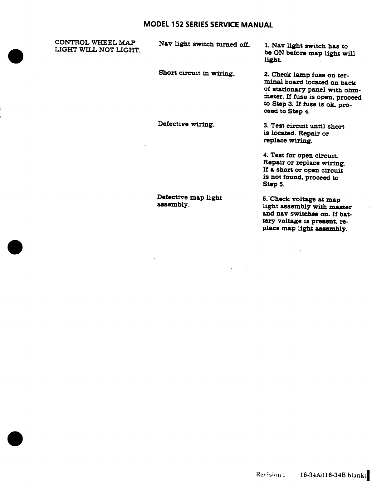
MODEL
152
SERIES
SERVICE
MANUAL
CONTROL
WHEEL
MAP
Nav
light
switch
turned
off.
1.
Nav
light
switch
has
to
LIGHT
WILL
NOT
LIGHT.
be
ON
before
map
light
will
light.
Short circuit
in
wiring.
2.
Check
lamp
fuse
on ter-
minal
board
located
on
back
of
stationary
panel
with
ohm-
meter.
If
fuse
is
open.
proceed
to
Step
3.
If
fuse
is
ok.
pro-
ceed
to
Step
4.
Defective
wiring.
3.
Test
circuit
until
short
is
located.
Repair
or
replace
wiring.
4.
Test
for
open
circuit.
Repair
or
replace
wiring.
If
a
short or
open
circuit
is
not
found, proceed
to
Step
5.
Defective
map
light
5.
Check
voltage
at
map
assembly.
light
assembly
with
master
and
nav
switches
on.
If
bat-
tery
voltage
is
present.
re-
place
map
light
assembly.
Revision
1
16-34./(16-34B
blank)
MODEL
152
SERIES
SERVICE
MANUAL
.
16-51
LANDING
AND
TAXI
LIGHT
(THRU
1528584.
A1521024,
Fl5201943,
and
FA1520387).
16-52.
DESCRIPTION.
The
landing
and
taxi
light
is
mounted
in
the
lower
half
of
the
engine
cowl.
This
position
facilitates
the
use
of
one
lamp or
both
a
landing
and
taxi
light.
A
light
cover
provides
weather protection
for the
lamp.
The
landing
and
taxi
light
is
controlled
by
a
rocker
type
switch
located
on
the
instrument
panel
A
circuit
breaker
is
used
to
protect
the
landing
and
taxi
light
circuit.
NOTE
With
the
aircraft
parked
3
feet
from
a
wall
or
any
suitable
light
reflecting
surface
(3
feet
as
measured
between
landing
light
and
wall),
and
with nose
gear
shock
strut
extended
2
inches,
the
center
of
the
landing light
beam
on
the
wall
should
be
30-7/8
inches
above
the
floor.
Adjustment
screws
(7)
are
used
for
this
adjustment.
be
sure
screws
(8)
are
tight
after
adjustment
is
made.
16-53.
REMOVAL
AND
INSTALLATION.
(See
figure
16-6).
a.
Remove
screws
(8)
and remove
bracket
(1).
b.
Pull
lamp
(2)
forward
and
disconnect electrical
leads,
the
remove
lamp
and
gasket
(3).
c.
To
install,
place
gasket
(3)
in
position.
d.
Connect
electrical
leads
to
lamp
(2)
and
place
in
position
securing
with
bracket
(1)
and
screws
(8).
16-54.
DUAL
LANDING
AND
TAXI LIGHTS (THRU
15285834,
A1521024,
F15201943,
and
FA1520387).
16-55.
DESCRIPTION.
The
landing
and
taxi
lights
are mounted
in
the
nose
cap
of
the
lower
half
of
the
engine
cowl.
The
left
lamp
is
used
for
taxiing
and
the
right
for
landing.
The
lamps
are
controlled
by
a
dual switch
assembly
with
individual
operating
rocker
type
switches
located
on
the
instrument
panel.
NOTE
With
the
aircraft
parked
3
feet
from
a
wall
or
any
suitable
light
reflecting
surface
(3
feet
as
measured
between
landing
light
and wall),
and
with
nose
gear
shock
strut
extended
2
inches,
the
center
of
the
landing
light
beam.
(right
hand)
on
the wall
should
be
29-5/8
inches
above the
floor.
The
center
of
the
taxi
light
beam.
(left
hand)
on
the
wall
should
be
31-3/8
inches
above
the
floor.
Adjustment
screws
(7)
are
used for
this
adjustment,
be
sure
screws
(8)
are
tight
after
adjustment
is
made.
16-56.
REMOVAL
AND
INSTALLATION.
(See
figure
16-6).
Either
lamp
may
be
removed
by
using
procedure outlined
in
paragraph
16-51.
16-35
MODEL
152
SERIES
SERVICE
MANUAL
16-56A.
LANDING AND
TAXI
LIGHTS
(WING
MOUNTED).
(BEGINNING
WITH
15283835.
A1521025. F15201944
AND
FA1520388.)
16-56B.
DESCRIPTION
This
landing
and
taxi
lights
are
mounted
in
the
leading
edge
of
the
left
wing.
A
clear
plastic
lens
and
retainer,
formed
to
the
curvature
of
the
wing
leading
edge,
provides
weather
protection
for
the
lamps.
The
outboard
lamp
is
used
for
taxi
and
the
in-
board
lamp
for
landing.
A
shield
is
installd
on
the
inboard
side
of
the
taxi
light
to
prevent
glare.
A
dual
rocket
switch assembly
on
the
instrument
panel
controls
the
lamps.
One
switch
is
for
landing
and the
other
for
taxi.
Power for
the
lights
provide
from
the
main
bus
bar
through
a
20-amp
circuit
breaker.
16-56C.
REMOVAL
AND
INSTALLATION
See
Figure
16-6).
a.
Remove
screws
securing
lens
retainer
(2)
and
remove
lens
and
retainer
assembly.
b.
Remove
screws(3)
securing
brackets
(4).
o.
Pull
lamp
(5)
forward
and
disconnect
electrial
leads
(8)
and
remove
lamps.
NOTE
If
plates
(7)
are
not
removed
it is
not
necessary
to
adjust
lights
after
installation
d.
Plates
(7)
may
be
removed
by
removing
screws
(6)
and
springs
(9).
e.
Install
springs
(9)
and
plates
(7)
using
screws
(6).
.
Connect
electrical
leads
(8)
to
lamps
(5).
then
position
lamps
(5)
in
plates
(7)
and
in-
stall
brackets
(4)
using
screws
(3).
g.
If
plates
(7)
were removed,
adjust
light
in
accordance
with
figure
16-6A.
h.
Install
lens
and retainer
assembly
16-57.
NAVIGATION
LIGHTS.
16-58.
DESCRIPTION.
The
navigation
lights
are
attached
to
the
wing
tips
and
the
aft
end
of
the
vertical
fin
tip.
The
lamps are
controlled
by
a
rocker
type
switch
located
on
the
instrument
panel.
A
circuit
breaker
is
installed
to
protect
the
circuit.
16-36
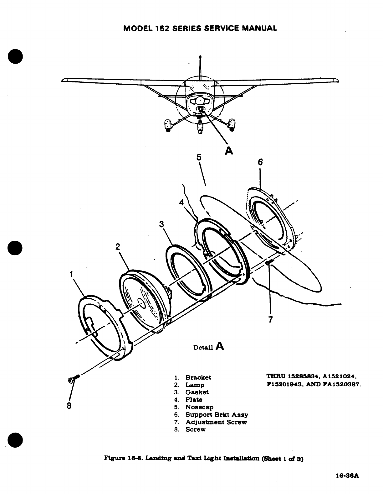
MODEL
152
SERIES
SERVICE
MANUAL
\
2.
Lamp
F15201943,
AND
FA1520387.
3.
Gasket
4.
Plate
8
5.
Nosecap
6.
Support
Bracket
Assy
7.
Adjustment
Screw
8.
Screw
Figure
16-6.
Landing
and
Taxi
Light
Installation
(Sheet
1
of 3)
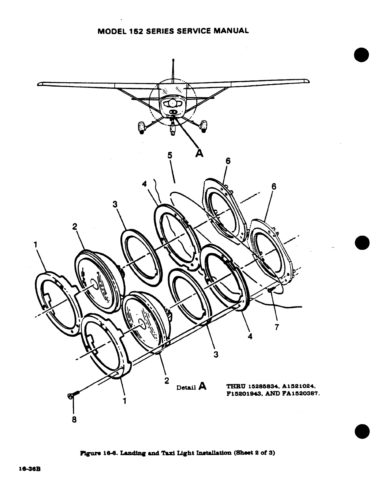
MODEL
162
SERIES
SERVICE
MANUAL
5
A
Detail
A
THRU
15285834,
A1521024,
F15201943,
AND
FA1520387.
8
Figure
16-6
Landing and
Taxi
Light
Installation
(Sheet
2
of
3)
16-36B
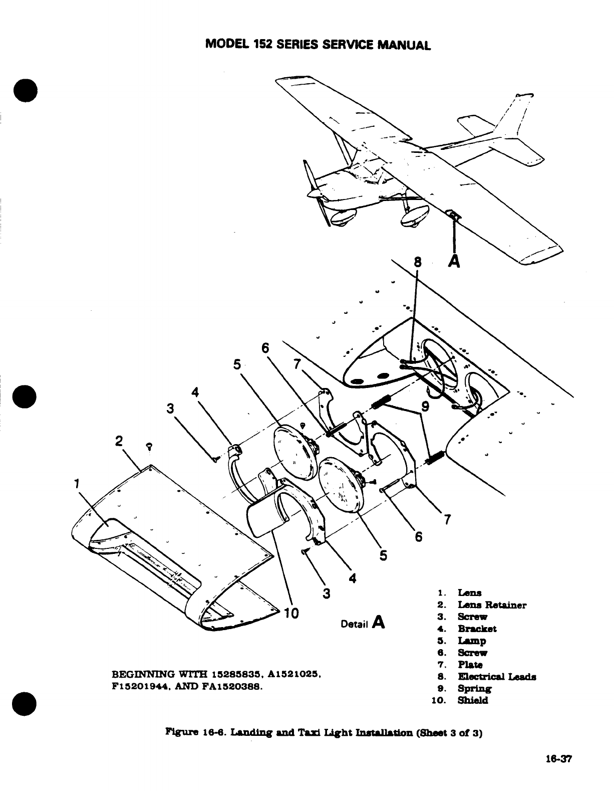
MODEL
152 SERIES
SERVICE
MANUAL
2.
Lens
Retainer
3.
Screw
10
Detail
A
4.
Bracket
5
Lamp
6. Screw
7.
Plate
BEGINNING
WITH
15285835,
A1521025,
8.
Electrical
Leads
F15201944.
AND
FA1520388.
9.
Spring
10.
Shield
Figure
16-6.
Landing
and
Taxi
Light
Installaton
(Sheet
3
of
3)
16-37
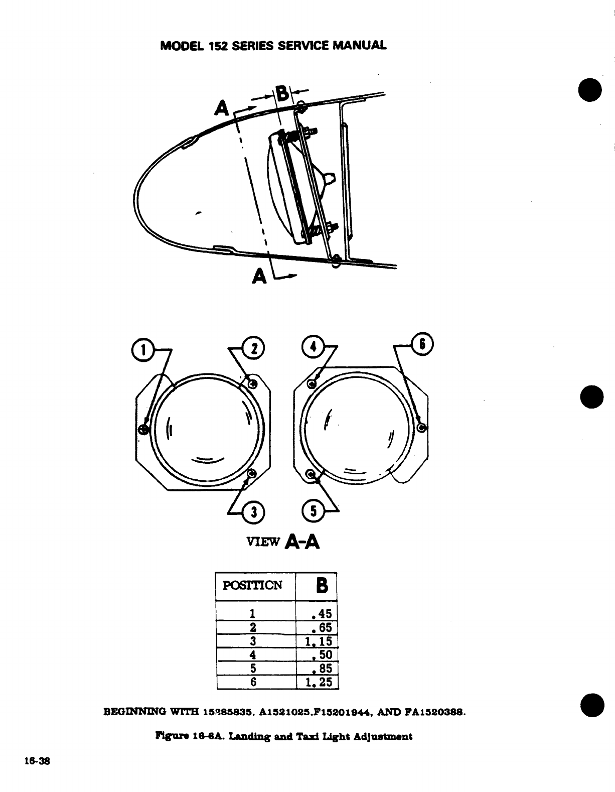
A\
viEW
A-A
16-38
MODEL
152
SERIES SERVICE
MANUAL
16-59.
REMOVAL
AND INSTALLATION.
For
removal
and
installation
of
the
navigation
lights,
see
figure
16-7.
16-60.
ANTI-COLLISION
STROBE LIGHTS.
16-61.
DESCRIPTION.
A
white
strobe
light
may
be
installed on
each
wing
tip
with
the
navigation
lights.
Strobe
lights
are
vibration
resistant
and
operate
on
the
principle
of
a
capacitor
dis-
charge
into
a
xenon
tube,
producing
an
extremely
high
intensity flash.
Energy
is
supplied
to
the
lights
from
individual
power
supplies
mounted
on
each
wing
tip
rib.
16-62.
REMOVAL AND
INSTALLATION.
For
removal
and
installation
of
strobe
light
and
power
supply,
see
figure
16-7.
WARNING
The
anti-collision
system
is
a
high
voltage
device.
Do
not
remove
or
touch
tube
assembly
while
n
operation.
Wait
at
least
5
minutes
after
turning
off power
before
starting
work.
16-63. FLASHING
BEACON.
16-64.
DESCRIPTION.
The
flashing
beacon
light
is
attached
to
the
vertical
fin
tip.
The
lamp
is
iodine-vapor
electrically
switched
by
a
solid-state
flasher
assembly
The
flasher
assembly
is
mounted
in
the
aft
section
of
the
tailcone.
The
switching
frequency of
the
flasher
assembly
operates
the
lamp
at
approximately
45
flashes
per
minute.
A
1.5
ohm,
75
watt
resistor
is in-
stalled
to
eliminate
a
pulsing
effect
on
the
cabin
lighting
and
ammeter
16-63.
REMOVAL
AND
INSTALLATION.
(See
figure
16-8
CAUTION
When
inserting
lamp
into
socket
always use
handker-
chief
or
tissue
to
prevent
getting
fingerprints
on
the
lamp.
Fingerprints
on
the
lamp
may
shorten
life
of
the
lamp.
16-66.
INSTRUMENT
AND
DOME
LIGHTS.
16-67.
DESCRIPTION.
The
instrument
flood
light
and
dome
light
are installed
in
the
overhead
con-
sole.
The
dome
light
consists
of
a
frosted lens
and
a
single
bulb
controlled
by
a
rocker
switch
on
the
instrument
panel. The
instrument
flood
light
consists
of
a
red
lens
and
a
single
bulb
controlled
by
a
rheostat
switch
located
on
the
instrument
panel
below
the
pilots
control
wheel.
16-68.
REMOVAL
AND
INSTALLATION.
(See
figure
16-9).
16-69.
INSTRUMENT
POST LIGHTING.
16-70.
DESCRIPTION.
Individual
post
lighting
may
be
installed
to
provide
non-glare
instrument
lighting.
The
post
light
consists
of
a
cap
and
a
clear
lamp
assembly
with
a
tinted lens
which
fits
into
a
socket
bonded
to
the
decorative
panel
covers.
The
intensity
of
the
post
lights
is
controlled
by
the
instrument
light-dimming
rheostat
on
the
instrument
panel.
16-38A/(16-38B
blank)
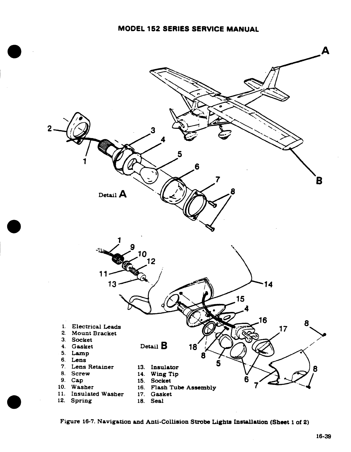
MODEL
152
SERIES
SERVICE
MANUAL
A
B
12
8
1.
Electrical
Leads
17
2.
Mount
Bracket
5.
Lamp
6.
Lens
7.
Lens
Retainer
13.
Insulator
8
8.
Screw
14.
Wing
Tip
9.
Cap
15.
Socket
10.
Washer
16.
Flash
Tube
Assembly
7
11.
Insulated
Washer
17.
Gasket
12.
Spring
18.
Seal
Figure
16-7.
Navigation
and
Anti-Collision Strobe
Lights
Installation
(Sheet
1
of
2)
16-39
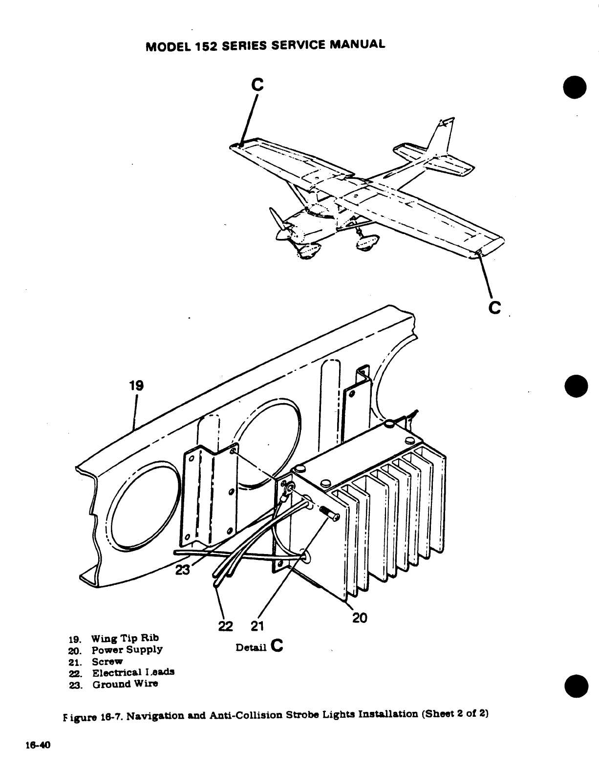
MODEL
152
SERIES SERVICE
MANUAL
x
22
21
19.
Wing
Tip
Rib
20.
Power
Supply
Detail
C
21.
Screw
22.
Electrical
Leads
23.
Ground
Wire
Figure
16-7.
Navigation
and
Anti-Collision
Strobe
Lights
Installation
(Sheet
2
of
2)
16-40
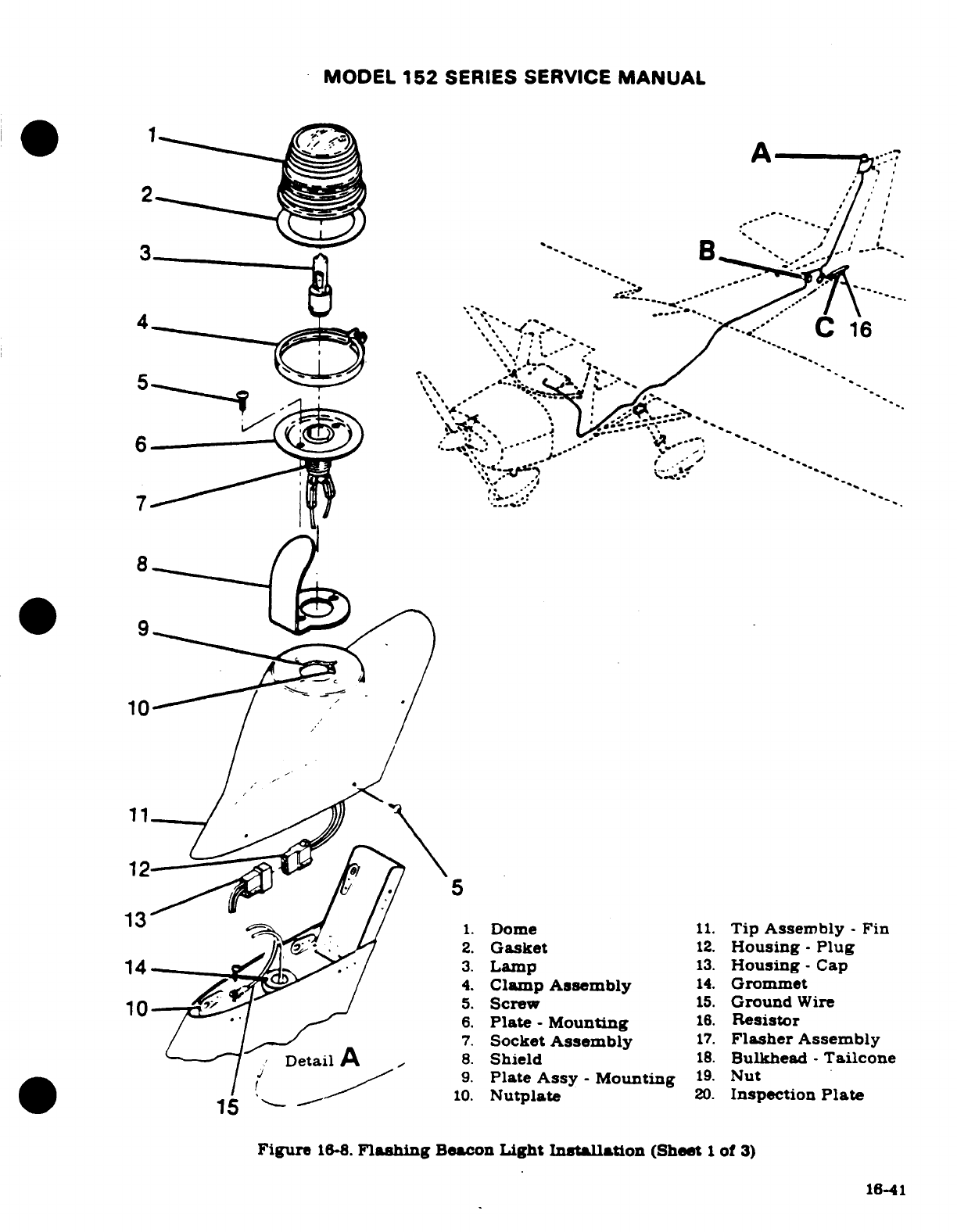
MODEL
152
SERIES
SERVICE
MANUAL
A
1.
Dome
11.
Tip
AssemBbly
-
Fin
-
10
5.
Screw
15.
Ground
Wire
6.
Plate
-
Mounting
16.
Resistor
4
Socket
Assembly
17.
Flasher
Assembly
-
Fin
2.
Gasket
12.
Housing-
Plug
14
3.
Lamp
13.
Housing-Cap
4.
Clamp
Assembly
14.
Grommet
6.
Plate
-
Mounting
16.
Resistor
7.
Socket
Assembly
17.
Flasher
Assembly
Detail
A
8.
Shield
18.
Bulkhead
-
Tailcone
9.
Plate
Assy
-
Mounting
19.
Nut
10.
Nutplate
20.
Inspection
Plate
15
Figure
16-8.
Flashing
Beacon
Light
Installation
(Sheet
1
of
3)
16-41
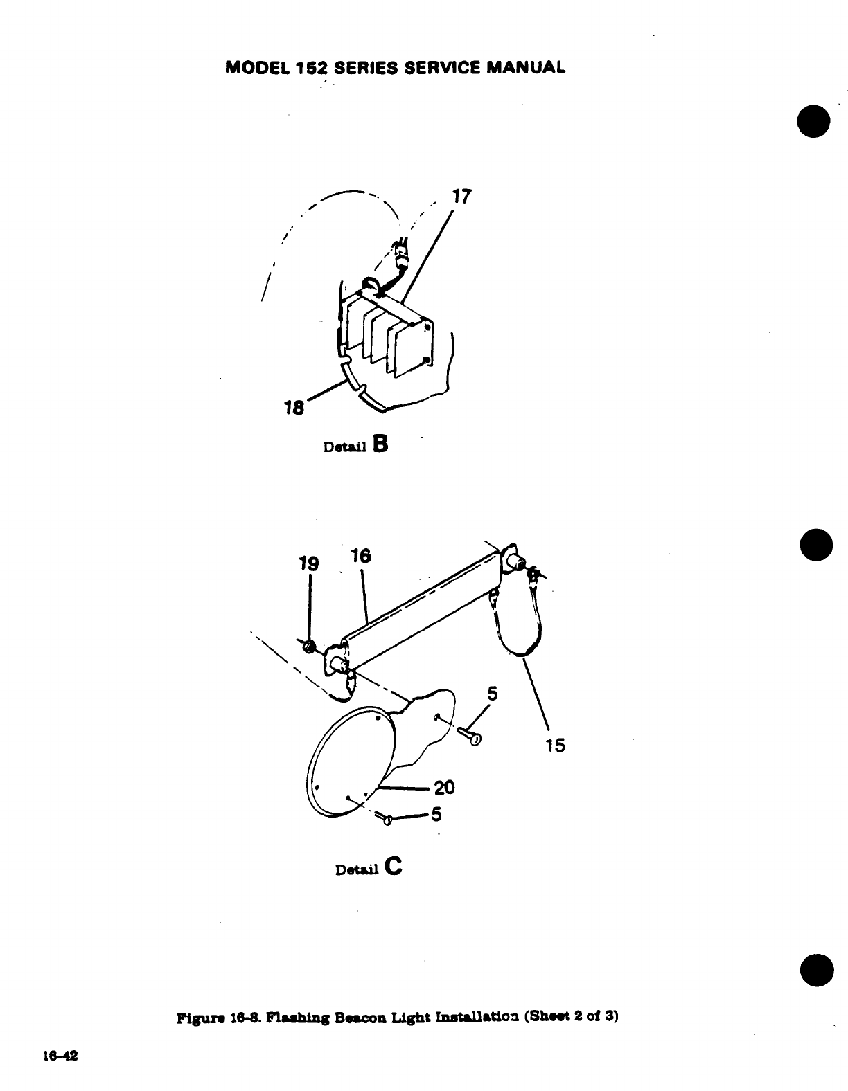
MODEL
152
SERIES
SERVICE
MANUAL
18
Detail
B
19
16
20
Detal
C
Figure
164.
Flashing
Beacon
Light
Installation
(Sheet
2
of
3)
16-42
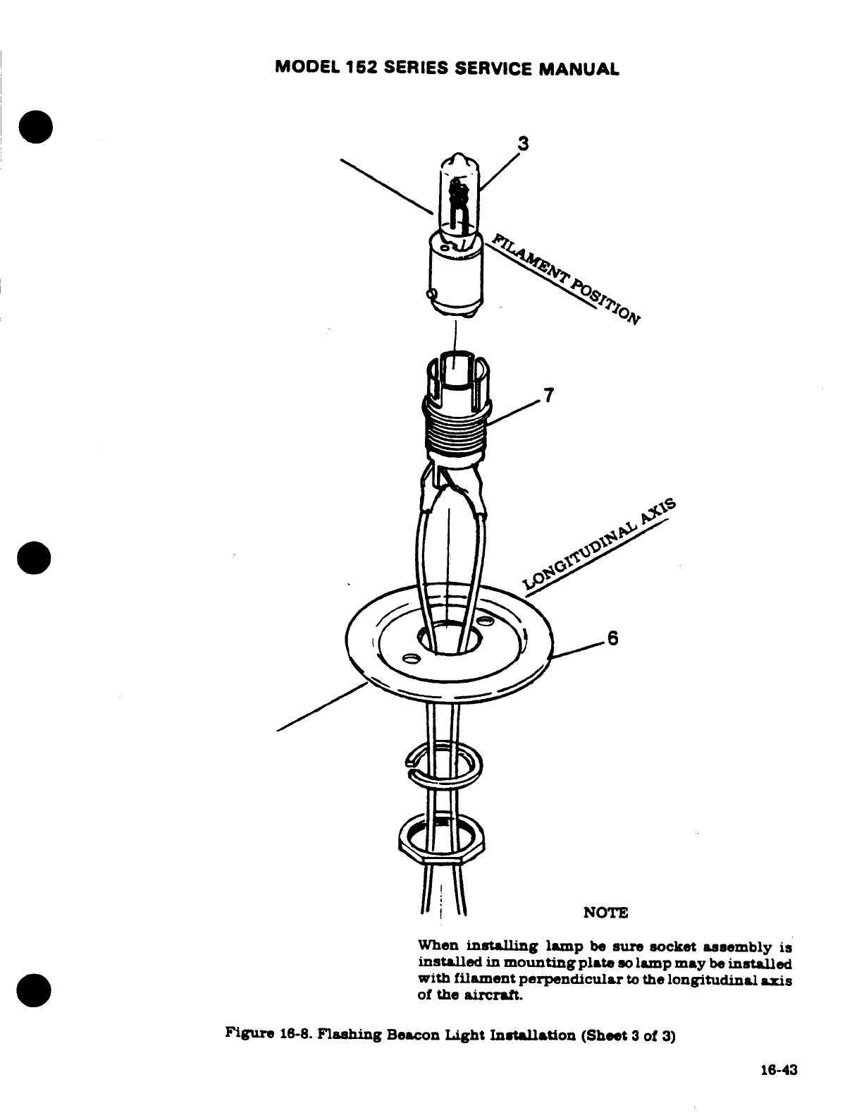
MODEL
152
SERIES SERVICE
MANUAL
3
7
NOTE
When
installing
lamp
be
sure
socket
assembly
is
installed
in
mounting
plate
so
lamp
may
be
installed
with
filament
perpendicular
to
the
longitudinal
axis
of
the
aircraft.
Figure
16-8.
Flashing
Beacon
Light
Installation
(Sheet
3
of
3)
16-43
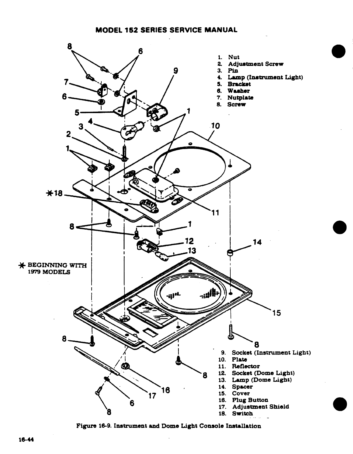
MODEL
152
SERIES
SERVICE
MANUAL
8.
Screw
5
1
3
4
10
*
BEGINNING
WITH
1979
MODELS
9.
Socket
(Instrument
Light)
10.
Plate
11.
Reflector
12.
Socket
(Dome
Light)
13.
Lamp (Dome
Light)
1.
Spacer
17
15.
Cover
16.
Plug
Button
17.
Adjustment
Shield
18.
Switch
Figure
16-9.
Instrument
and Dome
Light
Console
Installation
16-44
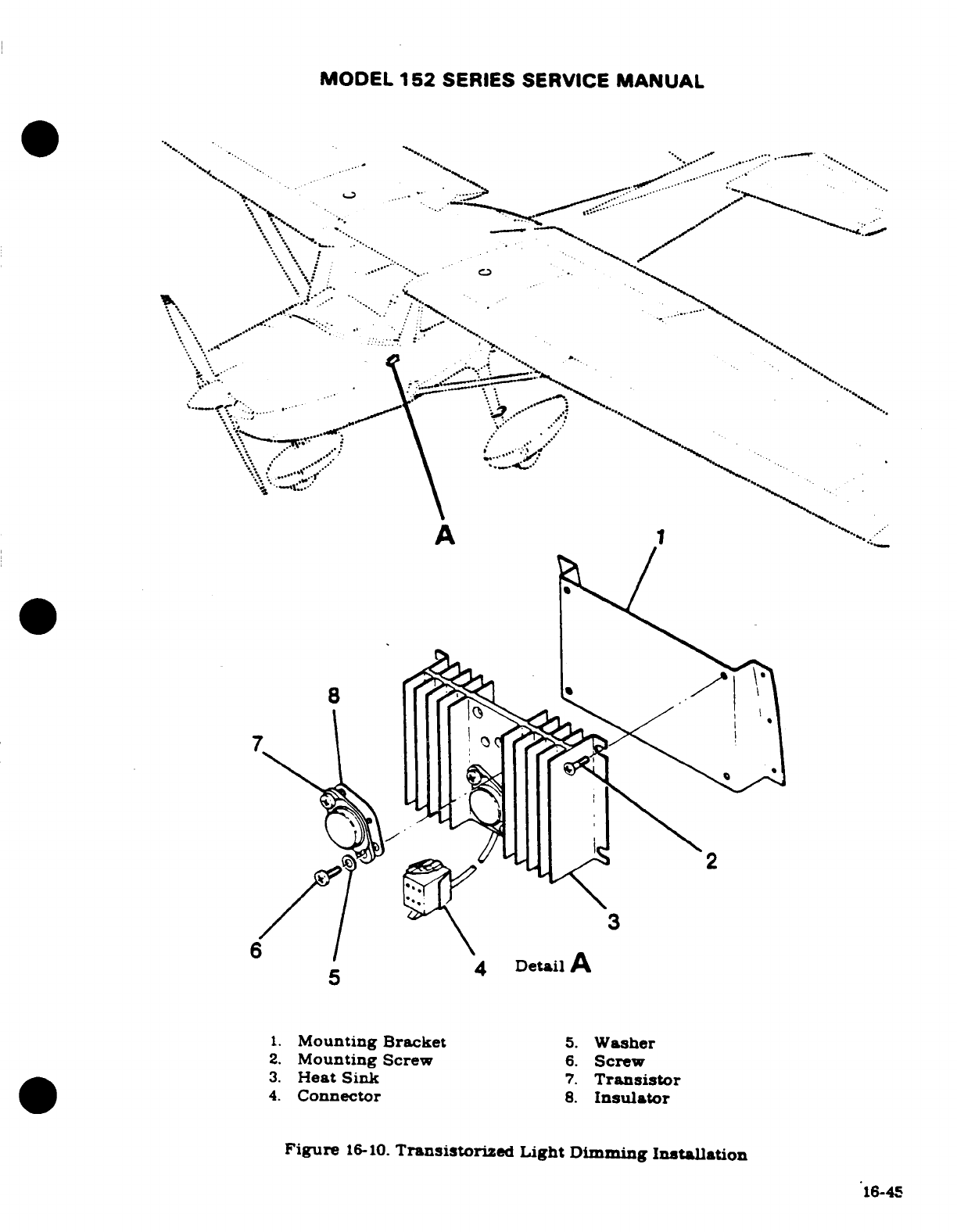
MODEL
152
SERIES SERVICE
MANUAL
5
4
Detail
A
1.
Mounting Bracket
5.
Washer
2.
Mounting
Screw
6.
Screw
16-45
1.
Mounting
Bracket
5.
Washer
2.
Mounting
Screw
6.
Screw
3.
Heat
Sink
7.
Transistor
4.
Connector
8.
Insulator
Figure
16-10.
Transistorized
Light
Dimming
Installation
16-45
MODEL
152
SERIES
SERVICE
MANUAL
NOTE
When
Installing
postlight
assemblies
shall
be
coated
with
RTV-102
General Electric,
Waterford,
New
York,
on
forward side
of
panel
where
postlight
could
come
in
contact
with
sheet
metal
subpanel
This
coating
shall
insulate
postlight
assembly
from
contact
with
airplane
structure.
Maximum
coating
thickness
to
be
.03.
16-71.
REMOVAL
AND
INSTALLATION.
For
removal
and
installation
of
post
lamp.
slide
the
cap
and
lens
assembly
from
the
soket.
Slide
the
lamp from
the
cap
assembly.
16-71A.
TROUBLE
SHOOTING
-
POSTLIGHTING
TROUBLE
PROBABLE
CAUSE
REMEDY
LAMP
WILL
NOT
LIGHT.
Defective
lamp.
1.
Test lamp
with
ohmmeter
or
replace
with
a
new
lamp.
If
lamp
is OK,
proceed
to
step
2.
Defective
socket
or
open
2.
Witch
switch
on,
test
socket.
If
circuit.
Replace
socket
or
wiring.
ONE
SECTION OF
LAMPS
Defective
connector.
1.
Test
for
voltage on lamp
WILL
NOT
LIGHT.
side
of
connector.
If
voltage
is
not
present,
check
opposite
side
of
connector. If
voltage
is
present,
replace
pins
and
sockets
necessary.
If
voltage
is
not
present
check
connections
at
terminal
block.
Defective
circuit
in
dimming
2.
Refer
to
paragraph
16-71B.
assembly.
Defective
rheostat.
3.
Check
voltage
at
output
side
of
rheostat
with
battery
switch
on.
Should
read
battery
voltage
with
rheostat
turned
full
clockwise.
Voltage
should
decrease
as
rheo-
stat
is
turned
counterclockwise.
If
no voltage
is
present
or
voltage
has
a
sudden
drop
before
rheostat
has
been
turned
full
counterclock-
wise
replace
rheostat.
16-46
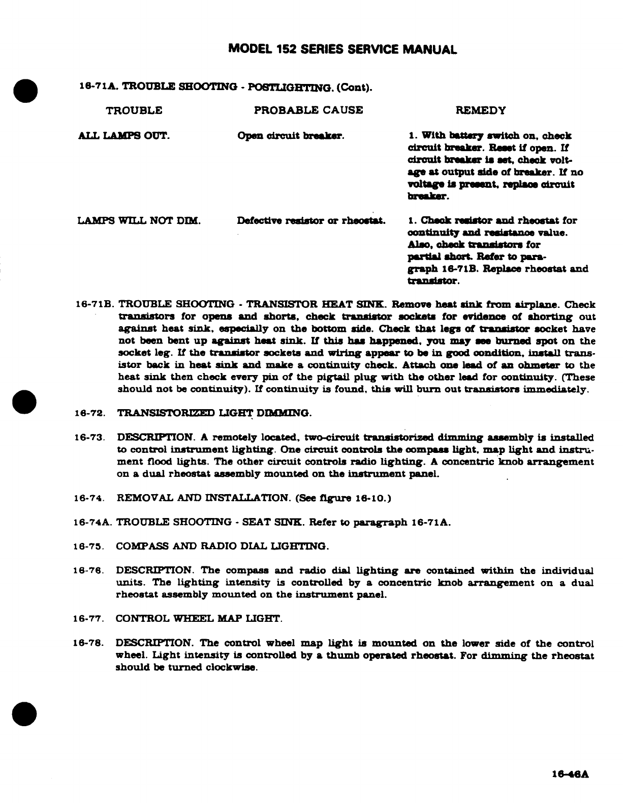
MODEL
152
SERIES
SERVICE
MANUAL
16-71A.
TROUBLE
SHOOTING
-
POSTLGHTING.
(Cont).
TROUBLE
PROBABLE
CAUSE
REMEDY
ALL
LAMPS
OUT.
Open
circuit
breaker.
1.
With
battery switch
on,
check
circuit
breaker.
Reset
if
open.
If
circuit
breaker
is
set,
check
volt-
age
at
output
side
of
breaker.
If
no
voltage
is
present
replace
circuit
breaker.
LAMPS
WILL
NOT
DIM.
Defective
resistor
or
rheosat.
1.
Check
resistor
and
rheostat
for
continuity
and
resistance
value.
Also,
check
transistors
for
partial
short
Refer
to
para-
graph
16-71B.
Replace
rheostat
and
transistor.
16-71B.
TROUBLE SHOOTING
-
TRANSISTOR
HEAT
SINK. Remove
heat
sink
from
airplane.
Check
transistors
for opens
and
shorts,
check
transistor
sockets for
evidence
of
shorting
out
against
heat
sink,
especially
on
the
bottom
side. Check
that
legs
of
transistor
socket
have
not
been
bent
up
against heat
sink.
If
this
has
happened,
you
may
see
burned
spot
on
the
socket
leg.
If
the
transistor
sockets
and wiring appear
to
be
in
good
condition,
install
trans-
istor
back
in
heat
sink
and
make
a
continuity
check.
Attach
one
lead
of
an
ohmeter
to
the
heat
sink
then
check
every
pin
of
the
pigtail
plug
with the
other
lead
for
continuity.
(These
should not
be
continuity).
If
continuity
is
found,
this
will
burn
out
transistors
immediately.
16-72.
TRANSISTORIZED
LIGHT
DIMMING
16-73.
DESCRIPTION.
A
remotely
located,
two-circuit
transistorized
dimming
assembly
is
installed
to
control
instrument
lighting.
One
circuit
controls
the
compass
light,
map
light
and
instru-
ment
flood
lights.
The
other
circuit
controls
radio
lighting.
A
concentric knob
arrangement
on
a
dual
rheostat
assembly
mounted
on
the
instrument
panel.
16-74.
REMOVAL
AND
INSTALLATION. (See
figure
16-10.)
16-74A.
TROUBLE
SHOOTING
-
SEAT
SINK.
Refer
to
paragraph
16-71A.
16-75.
COMPASS
AND
RADIO
DIAL
LIGHTING.
16-76. DESCRIPTION.
The compass
and radio
dial
lighting
are
contained
within
the
individual
units.
The
lighting
intensity
is
controlled
by
a
concentric
knob
arrangement
on
a
dual
rheostat
assembly
mounted
on
the
instrument
panel.
16-77.
CONTROL
WHEEL
MAP
LIGHT.
16-78. DESCRIPTION.
The
control
wheel
map
light
is
mounted
on
the
lower
side
of
the control
wheel.
Light
intensity
is
controlled
by
a
thumb
operated
rheostat.
For
dimming the
rheostat
should
be
turned
clockwise.
16-46A
MODEL
152
SERIES
SERVICE
MANUAL
16-79.
REMOVAL AND
INSTALLATION.
(See
figure
16-11.)
(THRU
15285634
AND
A1521019.)
a.
For
easy
access
to
the
map
light
assembly,
rotate
the
control
wheel
90°.
b.
Remove
screw
(9).
spacers
(8)
and
shield
(10).
c.
Remove
screws
(7),
inserts
(11)
and
shield
(12).
d.
Label
the
map
light
wires
at
the
terminal
block,
then
remove
screws
securing
wires
to
terminal
blok.
e.
For
reasembly
reverse
the preceding
steps.
16-79A. REMOVAL
AND INSTALLATION. (ee
figure
16-11.)
(BEGINNING
WITH
13285635
AND
A1521020.)
a.
For
easy
access
to
the
map
light
assembly,
rotate
the control
wheel
90
°.
b.
To
remove
lamp
press
in
and rotate
counterclockwise
o.
Loosen
setscrewz
(12)
and
remove
knob
(11).
d.
To
remove
rheostat
remove
screws
securing
bracket
(9).
e.
Disconnect
electrical
leads
from
rheostat
(7).
f.
For
reassembly
reverse
this
procedure.
16-80.
MAP
LIGHT.
16-81.
DESCRIPTION
White
map
lightng
and
red
non-glare
instrument
lighting
are
provided
by
an
adjustable
light
mounted on
the upper
forward part
of
the
left
door
post. The
switch
is
a
three
position
type with
red,
white
and
off
positions.
The
map
light
contains
a
white
bulb
for
general
purpose
lighting
and
a
red
bulb
for
adjustable
instrument
lghting.
The
intensity
of
the
red
bulb
is
controlled
by
the
dimming
rheostat
on
the
lower
left
side
of
the
instrument
panel
16-82.
REMOVAL AND
INSTALLATION.
(See
figure
16-12.)
For
replacement
of
defective
lamp
slide
the
hood
and
lens
from
the
map
light
assem-
bly.
16-46B
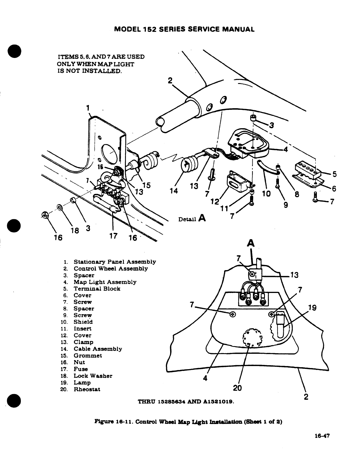
MODEL
152
SERIES SERVICE
MANUAL
ITEMS
5. 6.
AND
7
ARE
USED
ONLY
WHEN
MAP LIGHT
IS
NOT
INSTALLED.
2
15
13
Detail
7
18
3
16
17
A
1.
Stationary
Panel
Assembly
2.
Control
Wheel
Assembly
3.
Spacer
13.
Clamp
4.
Map
Light Assembly
5.
Terminal
Block
6.
Cover
7.
Screw
8.
Spacer
19
9.
Screw
10.
Shield
11.
Insert
12.
Cover
13.
Clamp
14.
Cable
Assembly
15.
Grommet
16.
Nut
17.
Fuse
18.
Lock
Washer
4
19.
Lamp
20.
Rheostat
20
THRU
15285634
AND
A1521019.
Figure
16-11.
Control
Wheel
Map
Light
Installation
(Sheet
1
of 2)
16-47
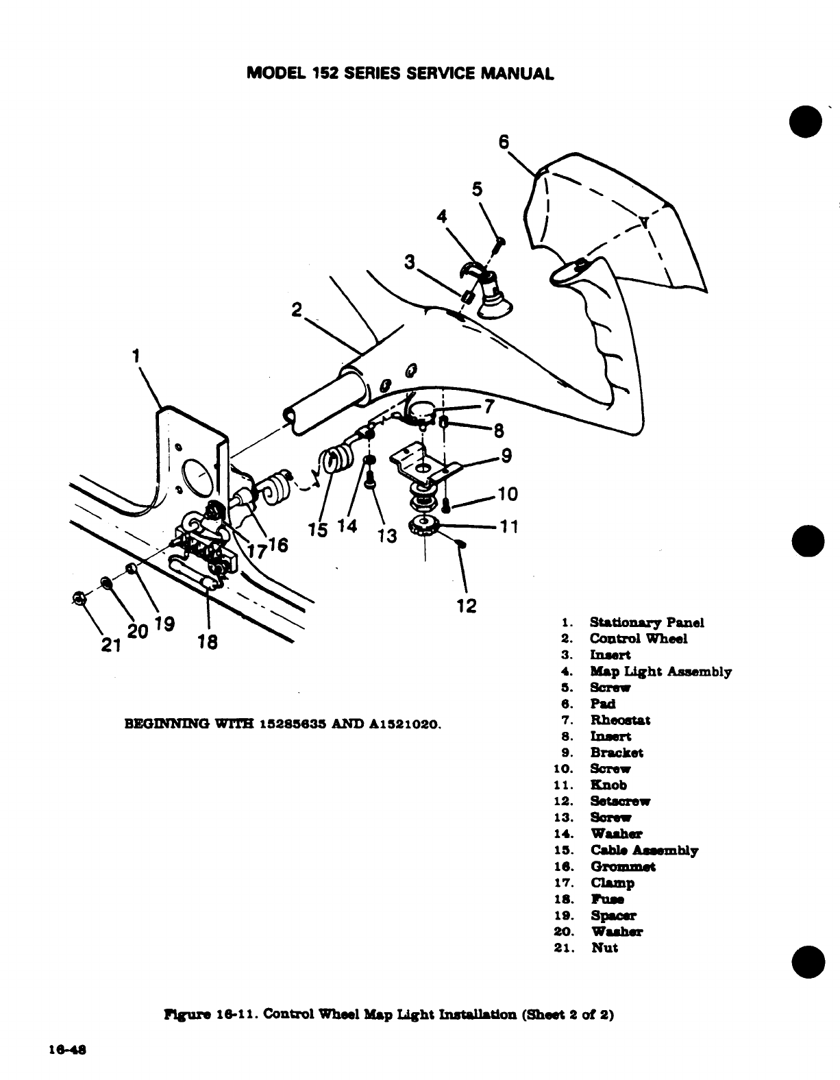
MODEL
152
SERIES
SERVICE
MANUAL
6
11
3.
Insert
4.
Map
Light
Assembly
5.
Screw
6.
Pad
BEGINNING
WITH
15285635
AND
A1521020.
7.
Rheostat
8.
Insert
9.
Bracket
10.
Screw
11.
Knob
12.
Setscrew
13.
Screw
14.
Washer
15.
Cable
Assembly
16.
Grommet
17.
Clamp
18. Fuse
19.
Spacer
20.
Washer
21.
Nut
Figure
16-11.
Control
Wheel
Map
Light
Installation
(Sheet
2
of
2)
1648
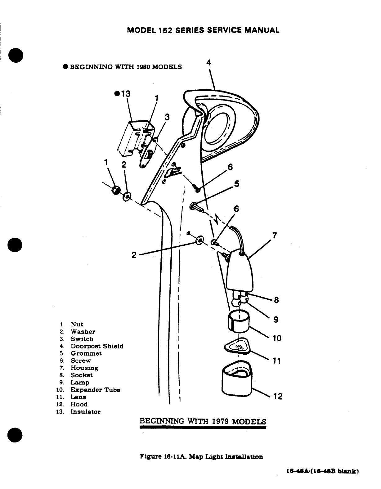
MODEL
152
SERIES SERVICE
MANUAL
*
BEGINNING
WITH
1980
MODELS
013
1
1
6
1.
Nut
2.
Washer
3.
Switch
4.
Doorpost Shield
5.
Grommet
6.
Screw
11
7.
Housing
8.
Socket
9.
Lamp
10.
Expander
Tube
11.
Lens
12
12.
Hood
13.
Insulator
BEGINNING
WITH
1979
MODELS
Figure
16-11A.
Map
Light
Intallation
16-48A/(16-48B
blank)
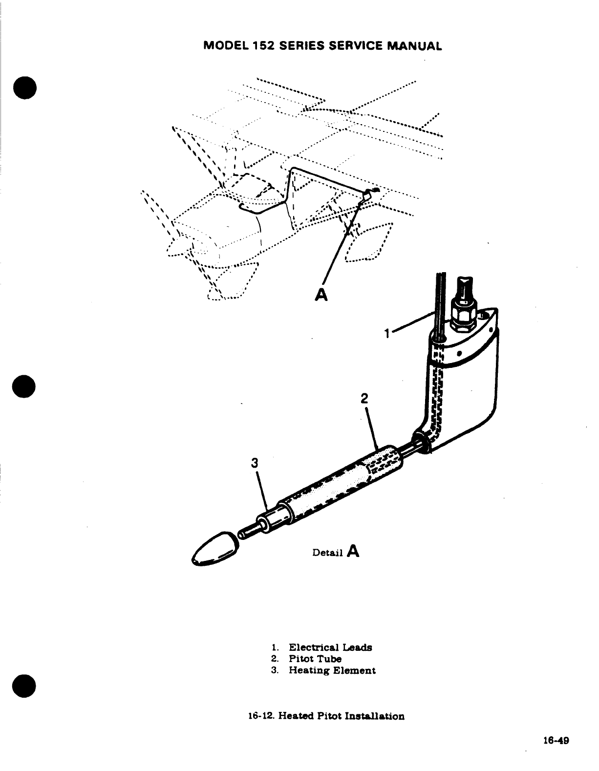
MODEL
152
SERIES
SERVICE
MANUAL
Detail
A
1.
Electrical
Leads
2.
Pitot
Tube
3.
Heating
Element
16-12.
Heated
Pitot
Installation
16-49
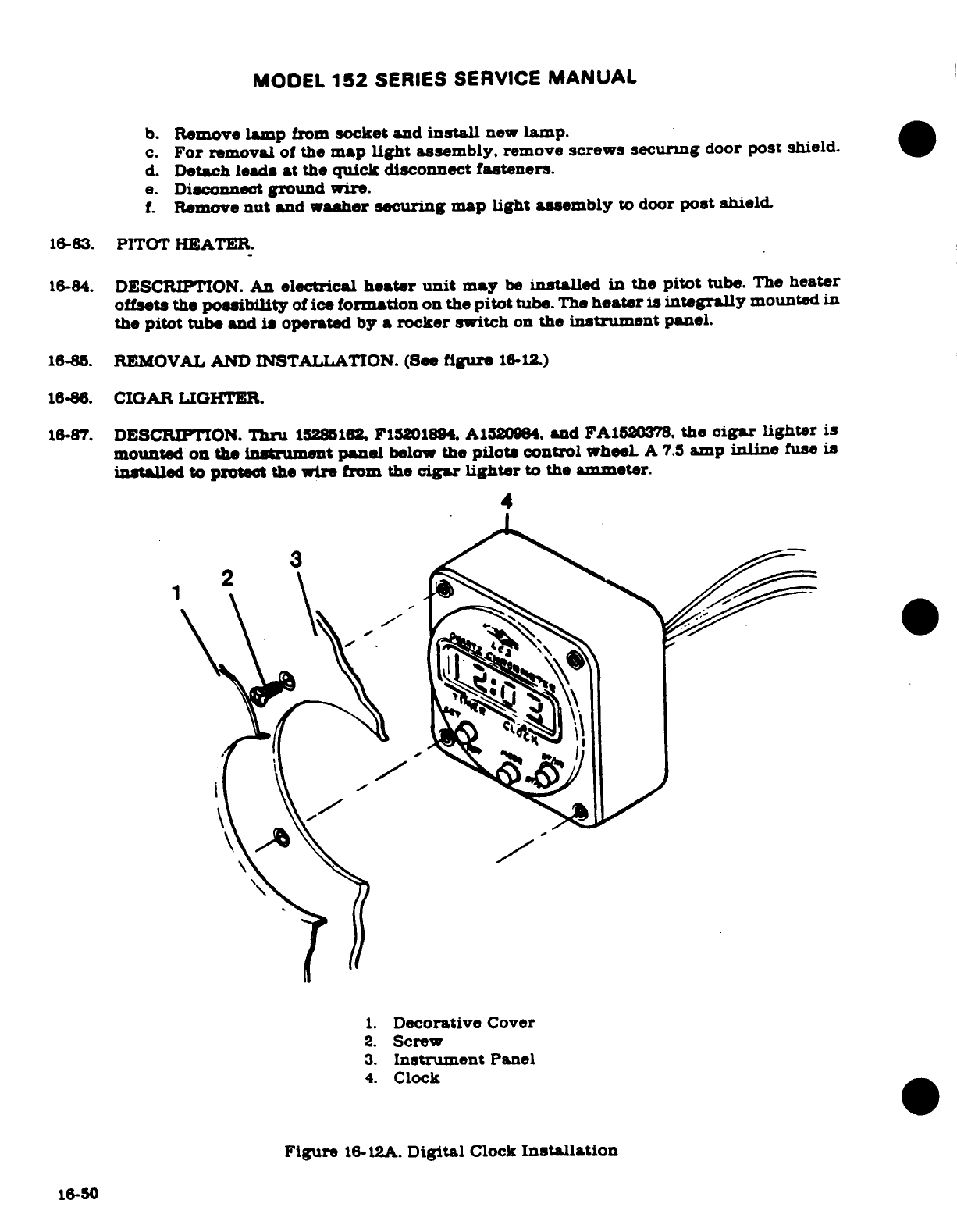
MODEL
152
SERIES SERVICE
MANUAL
b.
Remove
lamp
from
socket
and
install
new
lamp.
c.
For
removal
of
the
map
light
assembly,
remove
screws securing
door
post
shield.
d.
Detach
leads
at
the
quick
disconnect
fasteners.
e.
Disconnect
ground
wire.
f.
Remove
nut
and
washer
securing
map
light assembly
to
door
post
shield.
16-83.
PITOT
HEATER.
16-84.
DESCRIPTION.
An
electrical
heater
unit
may
be
installed
in
the
pitot
tube.
The
heater
offsets the
possibility
of
ice
formation
on
the
pitot
tube.
The
heater
is
integrally
mounted
in
the
pitot
tube
and
is
operated by a
rocker
switch
on
the
instrument
panel.
16-85.
REMOVAL
AND
INSTALLATION.
(See
figure
16.12.)
18-86.
CIGAR LIGHTER.
16-87.
DESCRIPTION.
Thru
15285162
F15201894.
A1520984.
and
FA1520378.
the
cigar
lighter
is
mounted
on the
instrument
panel
below
the
pilots
control
wheel
A
7.5
amp
inline
fuse
is
installed
to
protect
the
wire
from
the
cigar lighter
to
the
ammeter.
4
1.
Decorative
Cover
2.
Screw
3.
Instrument
Panel
4.
Clock
Figure
16-12A.
Digital
Clock
Installation
16-50
MODEL
152
SERIES
SERVICE
MANUAL
16-88.
CLOCK.
16-89.
DESCRIPTION.
Thru
1978
Models
an
electric clock
may
be
installed
in
the
aircraft.
During
the
1979
Models
a
digital
clock
may
be
installed.
The
digital
clock
has
the
capability
of
date
and
second
readout
as
well
as
time
Both
clocks
are
installed
in
the
instrument
panel
in
the
same
manner.
Refer
to
Pilot's
Operating
Handbook
for
operating
instructions.
Refer
to
fig-
ure
16-12A.
16-90.
EMERGENCY
LOCATOR
TRANSMITTER.
16-91.
DESCRIPTION.
The
ELT
is a
self-contained,
solid-state
unit,
having
its
own
power
supply,
with
an
externally
mounted
antenna.
The
unit
is
mounted
in
the
tailcone
aft
of
the
baggage
curtain
on
the
right-hand
side.
The
transmitters
are
designed
to
provide
a
broadcast
tone
that
is
audio-modulted
in a
swept
manner
over
the
range
of
1600
to
300
Hz
in a
distinct,
easily ognizable
distress
sigal
for
reception
by
search
and
rescue
personnel
and
others
monitoring
the
emergency
frequencies.
The
ELT
exhibits
line-of-sight
transmission
charac-
teristics
which
correspond approximately
to
100
miles
at
a
search
altitude
of
10,000
feet.
The C589511-0103
transmitter,
and the
C589511-0104
transmitter
on
aircraft
with
Cana-
dian
registry,
are
used
thru
15282031,
A1520808,
P15201528,
and
FA1520347.
The
C589511-0117
transmitter,
and the
C589511-0113
transmitter
on
aircraft
with
Canadian
re-
gistry,
are
used
15282032
thru
15285696, A1520809
thru
A1521019,
F15201529
thru
F15201928,
and
FA1520348
thru
FA120382.
Beginning
with
15285397, A1521020,
F15201929,
and
FA1520383,
the
C589512-0103
transmitter
is
used
on
all
aircraft.
The
C589511-0104
transmits
on
121.5
MHz
at
25
mw
rated
power
output
for
100
continuous
hours
in
the
temperature
range
of
-40'
to
+
131"F
-40
C
to
+
55°).
The
C589511-0113
transmits
on
121.5
MHz
at
25
mw
rated
power
output
for
100
continuous hours
in
the
tem-
perature
range
of
-4F
to
+
131
F
(-20°C
to
+
55C).
The
C589511-0103
transmits
on 121.5
and 243.0
MHz
simultaneously
at
5
mw
rated
power
output
for
48
continuous
hours
in
the
temperature
range
of
-40F
to
+
131F
(40°C
to
+
55°C).The
C589511-0117
and
C589512-
0103
transmits
on
121.5
and
343.0
MHz
at
75
mw
rated
power
output for
48
continuous
hours
in
the
temperature
range
of
-4F
to
+
131F
(-20C
to
+
55C).
Power
is
supplied
to
the
transmitter
by
a
battery-pack.
The
C589511-0104
and
C589511-
0103
ELT's
equipped
with
a
lithium
battery-pack
must
be
modified
by
SK185-20
as
outlined
in
Avionics
Service
Letter
AV78-31,
dated
20
November
1981,
to
incorporate
alkaline
battery-
packs.
The
C589511-0114
alkaline
battery-packs
have
the
service
life
of
the
battery-pck
stamped
on
the battery-pack,
on
the
end
of
the
transmitter
below
the
switch
and
on
top
of
the
trasmitter.
The
C589512-0107
alkaline
battery-packs
have
the
replacement
date
and
date
of
Installatin
on
the
battery-pack
and the
replacement date
on
the
top
of
the
transmit-
ter.
16-92.
OPERATION.
A
three
position
switch
on
the
forward
end
of
the
unit controls
operation.
Placing
the switch
in
the
ON
position will
energize
the
unit
to
start
transmitting
emergency
signals.
In
the
OFF
position,
the
unit
is
inoperative.
Placing
the
switch
in
the
ARM
position
will
set
the
unit
to
start
transmitting
emergency
signals
only
after
the
unit
has
received
a
5g
(tolerances
are
+2g
and
-Og)
impact
force,
for
a
duration
of
11-16
milliseconds.
CAUTION
Do
not
leave
the
emergency locator
transmitter
in
the
ON
position
longer
than
1
second
(3
sweeps
of
the
warble
tone)
or
you
may
activate
downed
aircraft
procedures
by
C.A.P.,
D.O.T.
or
F.A.A.
personnel.
16-51
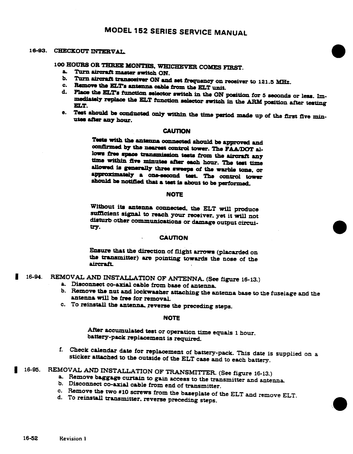
MODEL
152
SERIES
SERVICE
MANUAL
16-93.
CHECKOUT
INTERVAL.
100
HOURS
OR THREE
MONTHS,
WHICHEVER
COMES
FIRST.
a.
Turn
aircraft
master
switch
ON.
b.
Turn
aircraft
transeiver
ON
and
set
frequency
on
receiver
to
121.5
Mhz.
c.
Remove
the
ELTs
antenna
cable
from
the
ELT
unit.
d.
Place
the
ELs
function
selector
switch
in
the
ON
position
for
5
seconds
or
less.
Im-
mediately
replace
the
ELT
function
selector switch
in the
ARM
position
after
testing
ELT.
e.
Test
should
be
conducted
only
within
the
time
period
made
up
of
the
first
five
min-
utes
after
any
hour.
CAUTION
Tests
with the
antenna
connected
should
be
approved
and
confirmed
by
the
nearest
control
tower. The
FAA/DOT
al-
lows
free
space
trasmission
tests
from
the aircraft
any
time
within
five
minutes
after
each
hour.
The
test
time
alloweds
generally three
sweps
of
the
warble
tone,
or
approximately
a
one-seond
test.
The
control
tower
should
be
notified
that
a
test
is
about
to
be
performed
NOTE
Without
its antenna
connected
the
ELT
will
produce
sufficient
signal
to
reach
your
receiver,
yet
it
will
not
disturb
other
communications
or
damage
output circui-
try.
CAUTION
Ensure
that
the
direction
of
flight
arrows (placarded
on
the
transmitter)
are
pointing
towards
the
nose
of
the
aircraft.
16-94.
REMOVAL
AND
INSTALLATION
OF
ANTENNA.
(See
figure
16-13.)
a. Disconnect
co-axial
cable
from
base
of
antenna.
b.
Remove
the
nut
and
lockwasher
attaching
the
antenna
base
to the
fuselage
and
the
antenna
will
be
free
for
removal
c.
To
reinstall
the
antenna, reverse
the
preceding
steps.
NOTE
After
accumulated
test
or
operation
time
equals
1
hour.
battery-pack
replacement
is
required.
f.
Check
calendar
date
for
replacement
of
battery-pack.
This
date
is
supplied
on
a
sticker
attached
to
the
outside
of
the
ELT
case
and
to
each
battery.
16-95.
REMOVAL AND
INSTALLATION
OF TRANSMITTER.
(See
figure
16-13.)
a.
Remove
baggage
curtain
to
gain
access
to
the
transmitter
and
antenna.
b.
Disconnect
co-axial
cable
from
end
of
transmitter.
c.
Remove
the
two
#10
screws
from the
baseplate
of
the
ELT
and
remove
ELT.
d. To
reinstall
transmitter.
reverse
preceding
steps.
16-52
Revision
1
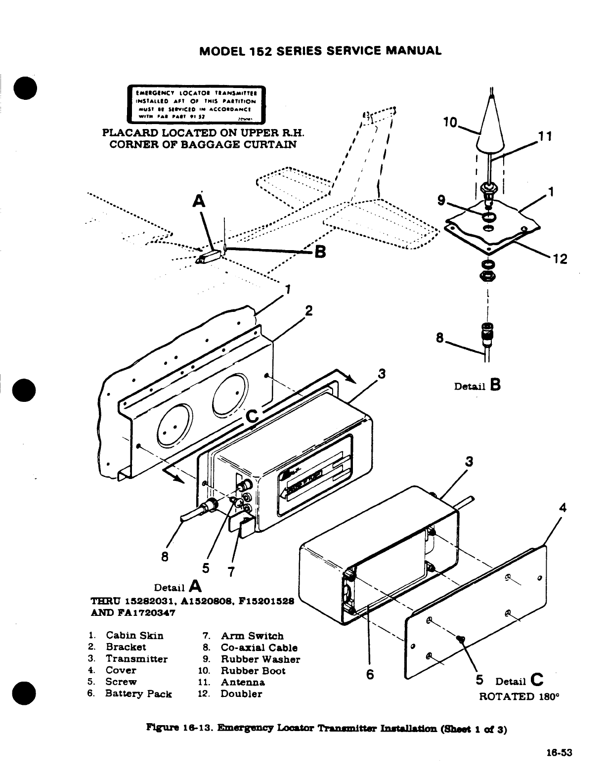
MODEL
152
SERIES
SERVICE
MANUAL
PLACARD
LOCATED
ON
UPPER
R.H.
CORNER
OF
BAGGAGE
CURTAIN
DetailD
THRU
15282031,
A1520808,
F15201528
AND
FA1720347
1.
Cabin
Skin
7.
Arm
Switch
2.
Bracket
8.
Co-axial
Cable
3.
Transmitter
9.
Rubber
Washer
4.
Cover
10.
Rubber
Boot
6
5.
Screw
11.
Antenna
Detail
C
6.
Battery
Pack
12.
Doubler
ROTATED
180°
Figure
16-13
Emergency
Locator
Transmitter
Installation
(Sheet
1
of
3)
16-53
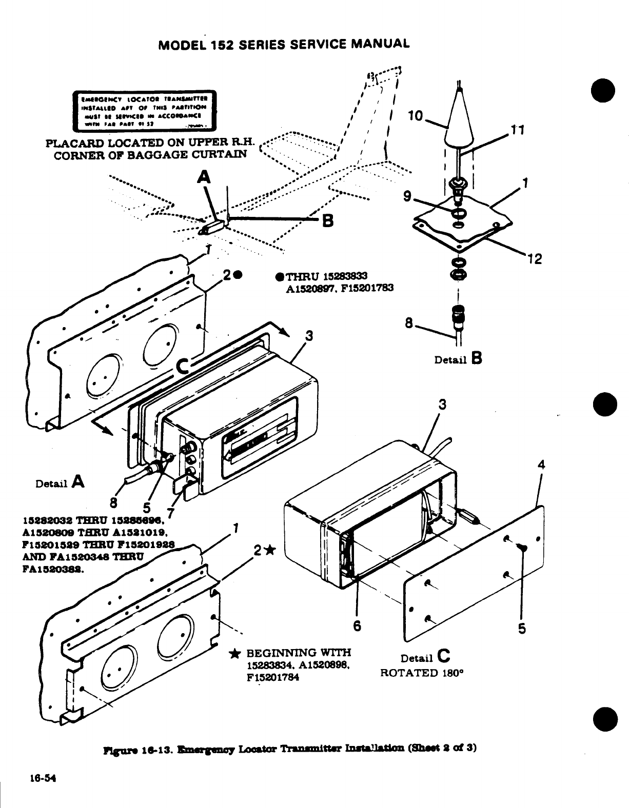
MODEL
152
SERIES SERVICE
MANUAL
CORNER
OF
BAGGAGE
CURTAIN
..
..
*
2-
*1THRU
15283833
15288032
THRU
15285696
A1520809
THRU
A1521019
F15201529
THRU
F15201928
AND
FA1520348
THRU
2*
FA1520382
.
*
BEGINNING
WTH
15283834.
A1520898,
Detail
F15201784
ROTATED
180°
Figure
16-13.
Emergency
Locator
Transmitter
Installation
(Sheet
2
of
3)
16-54
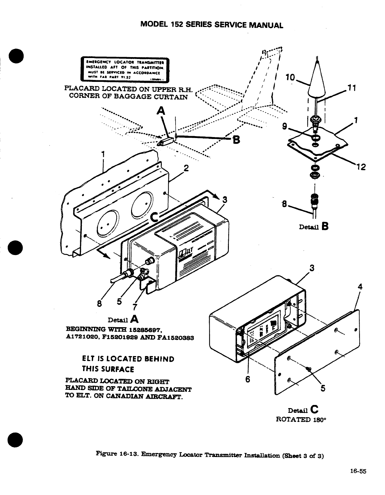
MODEL
152
SERIES
SERVICE
MANUAL
PLACARD
LOCATED ON-UPPER
CORNER
OF
BAGGAGE
CURTAIN
A
Detail
A
BEGINNING
WITH
15285697,
A1721020,
F15201929
AND
FA1520383
ELT
IS
LOCATED
BEHIND
THIS
SURFACE
PLACARD
LOCATED ON
RIGHT
HAND
SIDE
OF
TAILCONE
ADJACENT
TO
ELT.
ON
CANADIAN
AIRCRAFT.
Detail
C
ROTATED
180
°
Figure
16-13.
Emergency
Locator
Transmitter
Installation
(Sheet
3
of
3)
16-55
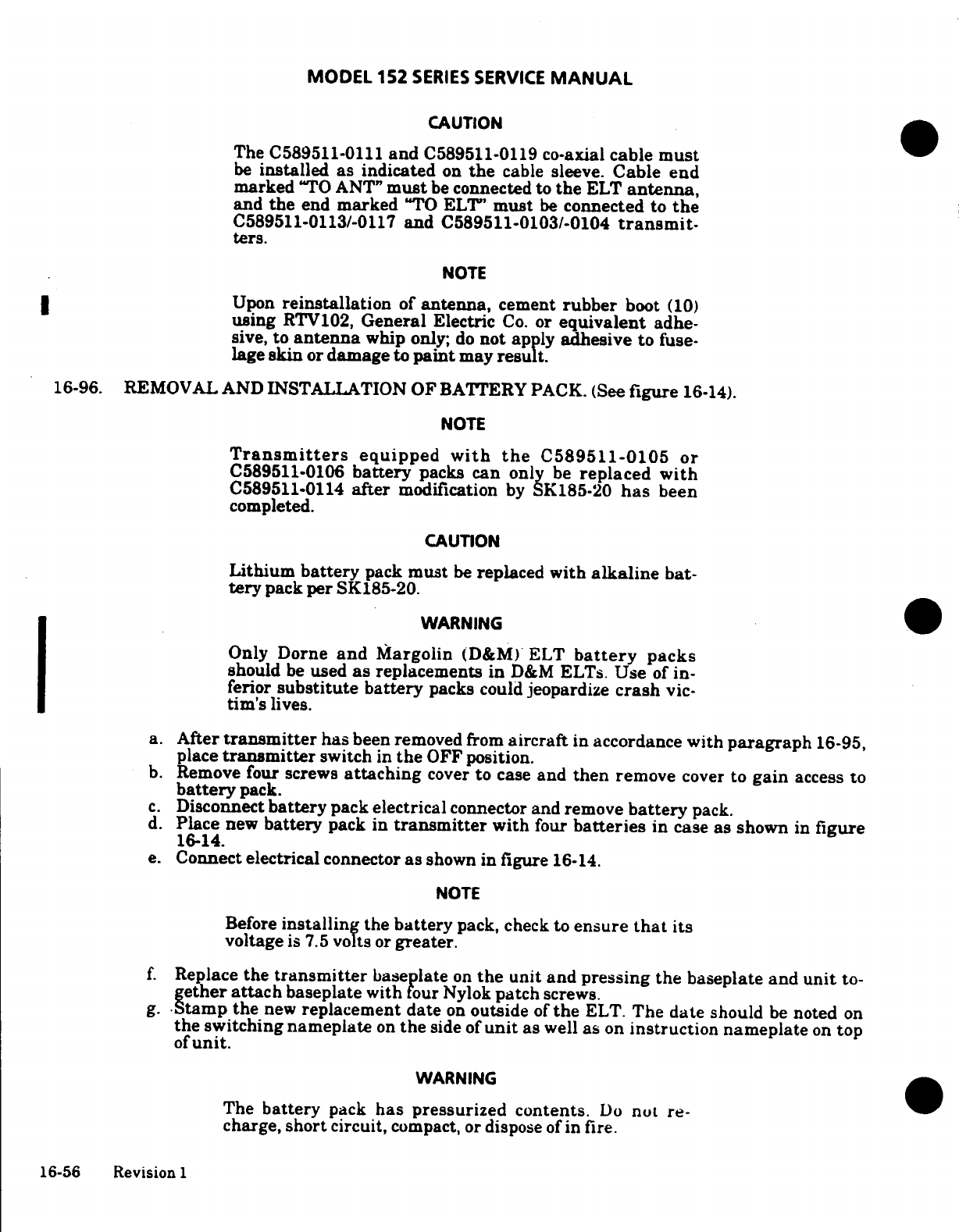
MODEL 152
SERIES
SERVICE
MANUAL
CAUTION
The
C589511-0111
and
C589511-0119
co-axial
cable
must
be
installed
as
indicated
on
the
cable
sleeve.
Cable end
marked
"TO
ANT"
must
be
connected
to
the
ELT
antenna,
and
the
end
marked
"TO
ELT'
must
be
connected
to
the
C589511-0113/-0117
and
C589511-0103/-0104
transmit-
ters.
NOTE
Upon
reinstallation
of
antenna,
cement
rubber
boot
(10)
using
RTV102,
General
Electric
Co.
or
equivalent
adhe-
sive,
to
antenna
whip
only;
do
not
apply
adhesive
to
fuse-
lage
skin
or
damage
to
paint
may
result.
16-96.
REMOVAL
AND INSTALLATION
OF
BATTERY
PACK.
(See
figure
16-14).
NOTE
Transmitters
equipped
with
the
C589511-0105
or
C589511-0106
battery
packs
can
only
be
replaced
with
C589511-0114
after
modification
by
SK185-20
has
been
completed.
CAUTION
Lithium
battery
pack
must
be
replaced
with
alkaline
bat-
tery
pack
per
SK185-20.
WARNING
Only
Dome
and
Margolin
(D&M)
ELT
battery
packs
should
be
used
as
replacements
in
D&M
ELTs.
Use
of
in-
ferior
substitute
battery
packs
could
jeopardize
crash
vic-
tim's
lives.
a.
After
transmitter
has
been
removed
from
aircraft
in
accordance
with
paragraph
16-95,
place
transmitter
switch
in
the
OFF
position.
b.
Remove
four
screws
attaching
cover
to
case
and
then
remove
cover
to
gain
access
to
battery
pack.
c.
Disconnect
battery
pack electrical
connector
and remove
battery
pack.
d.
Place
new
battery
pack in
transmitter
with
four
batteries
in
case
as
shown
in
figure
16-14.
e.
Connect
electrical
connector
as
shown
in
figure
16-14.
NOTE
Before
installing
the
battery
pack,
check
to
ensure
that
its
voltage
is
7.5
volts
or
greater.
f.
Replace
the
transmitter
baseplate
on
the
unit
and
pressing the
baseplate
and
unit
to-
gether
attach
baseplate with
four
Nylok
patch
screws.
g.
Stamp the
new
replacement
date
on
outside
of
the
ELT.
The
date
should
be
noted
on
the switching
nameplate
on
the
side of
unit
as
well
as
on
instruction
nameplate
on
top
of
unit.
WARNING
The
battery
pack
has
pressurized
contents.
Do
not
re-
charge,
short
circuit,
compact,
or
dispose
of in
fire.
16-56
Revision
1
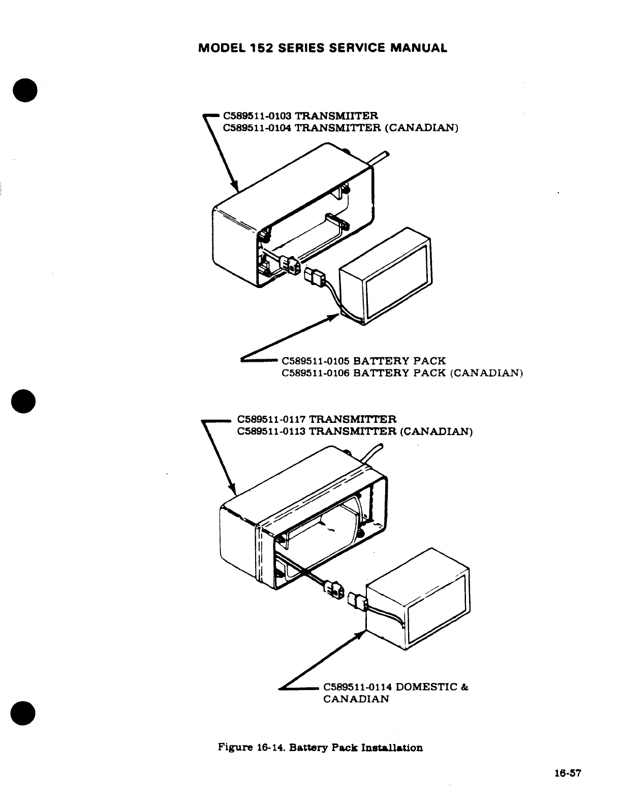
MODEL
152
SERIES
SERVICE
MANUAL
C589511-0103
TRANSMIITER
C589511-0104
TRANSMITTER
(CANADIAN)
C589511-0105
BATTERY
PACK
C589511-0106
BATTERY
PACK (CANADIAN)
C589511-0117
TRANSMITTER
C589511-0113
TRANSMITTER
(CANADIAN)
/-C589511-0114
DOMESTIC
&
CANADIAN
Figure
16-14.
Battery
Pack
Installation
16-57
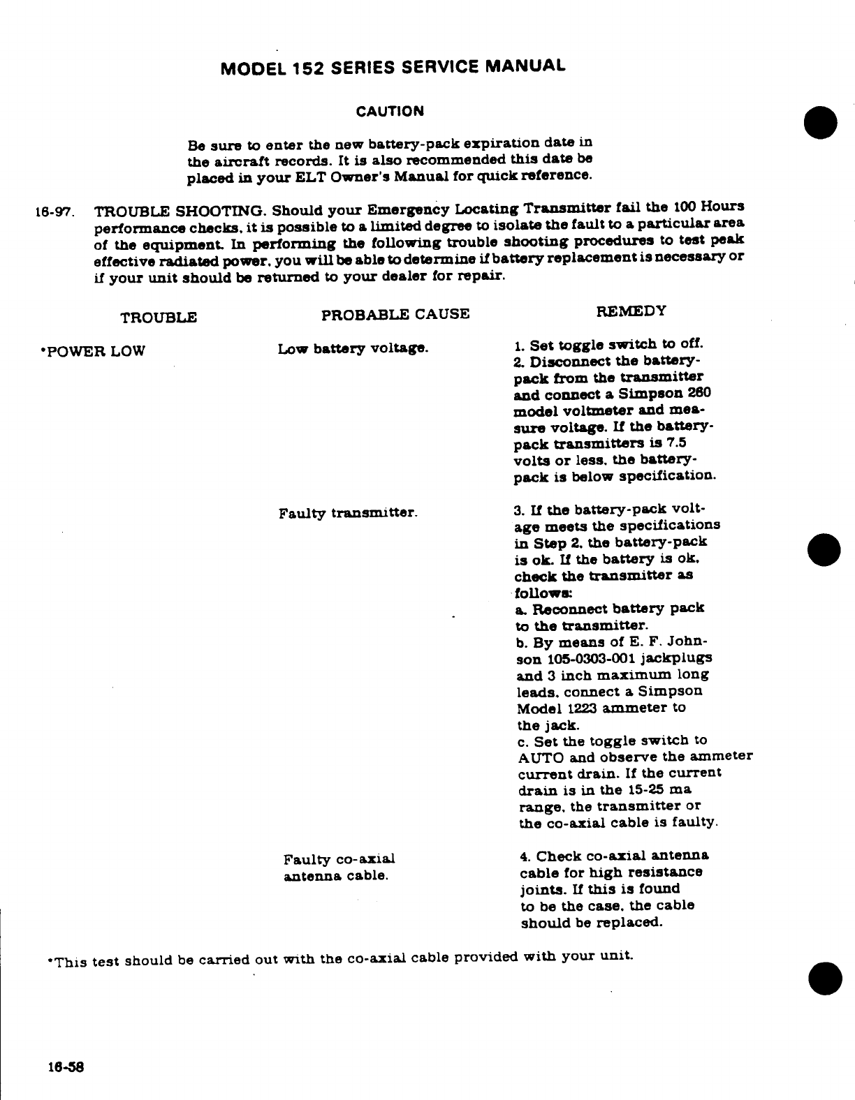
MODEL
152
SERIES
SERVICE
MANUAL
CAUTION
Be
sure
to
enter
the new
battery-pack
expiration
date
in
the
aircraft
records.
It
is
also
recommended
this
date
be
placed
in
your
ELT
Owner's Manual
for
quick
reference.
16-97.
TROUBLE
SHOOTING.
Should
your
Emergency
Locating
Transmitter
fail
the
100
Hours
performance
checks,
it is
possible
to
a
limited
degree
to
isolate
the
fault
to
a
particular
area
of
the
equipment.
In
performing
the
following
trouble
shooting
procedures
to
test
peak
effective
radiated
power,
you
will
be
able to
determine
if
battery
replacement
is
necessary
or
if
your
unit
should
be
returned
to
your
dealer
for
repair.
TROUBLE
PROBABLE
CAUSE REMEDY
*POWER
LOW
Low
battery
voltage.
1.
Set
toggle
switch
to
off.
2.
Disconnect
the
battery-
pack
from
the
transmitter
and
connect
a
Simpson
260
model
voltmeter
and
mea-
sure
voltage.
If
the
battery-
pack
transmitters
is
7.5
volts
or
less.
the
battery-
pack
is
below
specification.
Faulty
transmitter.
3.
If
the
battery-pack
volt-
age
meets the
specifications
in
Step
2.
the
battery-pack
is
ok.
If
the
battery
is
ok.
check
the
transmitter
as
follows:
a.
Reconnect
battery
pack
to
the
transmitter.
b.
By
means
of
E.
F.
John-
son
105-0303-001
jackplugs
and
3
inch
maximum
long
leads.
connect
a
Simpson
Model
1223
ammeter
to
the
jack.
c.
Set
the
toggle
switch
to
AUTO
and
observe
the
ammeter
current
drain.
If
the
current
drain
is
in
the
15-25
ma
range.
the
transmitter
or
the
co-axial
cable
is
faulty.
Faulty
co-axial
4.
Check
co-axial
antenna
antenna
cable.
cable
for
high
resistance
joints.
If
this
is
found
to
be
the
case,
the
cable
should
be
replaced.
'This
test
should
be
carried
out
with
the
co-axial
cable
provided
with
your
unit.
16-58
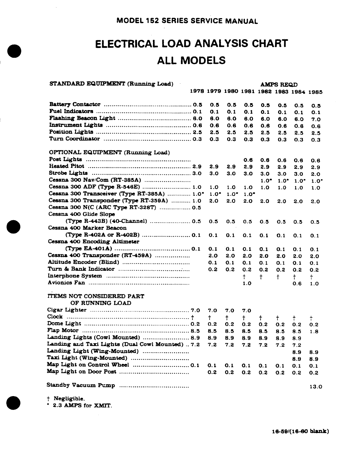
MODEL
152
SERIES SERVICE
MANUAL
ELECTRICAL
LOAD
ANALYSIS
CHART
ALL
MODELS
STANDARD
EQUIPMENT
(Running
Load)
AMPS
REQD
1978
1979
1980
1981
1982
1983
1984 1985
Battery
Contactor
.............................................
0.5
0.5
0.5
0.5 0.5
0.5
0.5
Fuel
Indicators
..................................................
0.1
0.1
0.1
0.
1
0.1
0.1
Flashing
Beacon
Light
......................................
6.0
6.0 6.0 6.0
6.0
6.0
6.0
7.0
Instrument
Lights
............................................
6
0.
0.6
0.6
0.6 0.6 0.6
0.6
Position
Lights
.................................................
2.5
2.5
2.5
2.5
2.5
2.5
2.5
2.5
Turn
Coordinator
............................................
0.3 0.3
0.3 0.3
0.3
0.3
0.3
0.3
OPTIONAL
EQUIPMENT
(Running
Load)
Post
Lights
....................................................
0.6
0.
0.
0.6
0.8
Heated
Pitot
.....................................................
2.9 2.9
2.9 2.9
2.9
2.9
2.9
2.9
Strobe
Lights
...................................................
3.0
3.0
3.0
3.0
3.0
3.0
3.0
2.0
Cessna
300
Nav/Com
(RT-385A)
........................
1.0*
1.0
1.0
1.0
Cessna 300
ADF
(Type
R-546E)
.........................
1.0
1.0
1.0
1.0
1.0
1.0
1.0 1.0
Cessna
300
Transceiver
(Type
RT-385A)
............
1.0'
1.0'
1.0'
1.0'
Cessna
300
Transponder
(Type
RT-359A)
..........
1.0
2.0
2.0
2.0
2.0
2.0
2.0
2.0
Cessna 300
N(C
(ARC
Type
RT-328T)
................
0.5
Cessna
400
Glide Slope
(Type
R-443B)
(40-Channel)
.....................
0.5
0.5 0.5
0.5
0.5 0.5 0.5
0.5
Cessna
400
Marker
Beacon
(Type
R-402A
or
R-402B)
.........................
0.1
0.1 0.1
0.1
0.1
0.1
0.1
0.1
Cessna
400
Encoding
Altimeter
(Type
EA-401A)
.......................................
0.1 0.1
0.1
0.1
0.1
0.1 0.1
0.1
Cessna
400
Transponder
(RT-459A)
..................
2.0 2.0 2.0
2.0 2.0
2.0
2.0
Altitude
Encoder
(Blind)
...................................
0.1
0.1
0.1
0.1
0.1
0.1
0.1
Turn
&
Bank
Indicator
.....................................
0.2
0.2
0.2
0.2 0.2
0.2
0.2
Interphone
System
.............................
...........
t t t
Avionics
Fan
....................................................
1.0
0.6
1.0
ITEMS
NOT
CONSIDERED
PART
OF
RUNNING
LOAD
Cigar
Lighter
...................................................
7.0 7.0
7.0
7.0
Clock
...............................................................
t t t t t t
Dom
e
Light
......................................................
0.2
0.2
0.2
0.2 0.2
0.2
0.2
0.2
Flap
Motor
........................................
8.5
8.5 8.5
8.5 8.5
8.5 8.5
1.8
Landing
Lights
(Cowl
Mounted)
........................
8.9
8.9 8.9 8.9 8.9 8.9
8.9
Landing
and
Taxi
Lights
(Dual
Cowl
Mounted)
..
7.2
7.2 7.2
7.2 7.2
7.2
7.2
Landing
Light
(Wing-Mounted)
........................
8.9
8.9
Taxi
Light
(Wing-Mounted)
..............................
8.9
8.9
Map
Light
on
Control
Wheel
.............................
0.1 0.1 0.1
0.1
0.1
0.1
0.1
0.1
Map
Light
on Door
Post
....................................
0.2 0.2 0.2
0.2
0.2 0.2
0.2
Standby
Vacuum
Pump
....................................
13.0
t
Negligible.
*
2.3
AMPS
for
XMIT.
16-59/(16-60
blank)
MODEL
152
SERIES
SERVICE
MANUAL
SECTION
17
STRUCTURAL
REPAIR
Page
No.
TABLE
OF
CONTENTS
Aerofiche/
Mannual
STRUCTURAL
REPAIR
........
2012/17-2
Wing
Leading
Edge
.......
2G15/17-5
Repair
Criteria
............
212/17-2
Negligible
Damage
......
2G1/17-
Equipment
and
Tools
........
212/17-2
Repairable
Damage
......
2G15/17-5
Support
Stands
...........
212/17-2
Damage
Necessitating
Fuselage
Repair
Jigs
......
2G12/17-2
Replacement
of
Parts
....
2G15/17-5
Wing
Jigs
.............
2012/17-2
Elevaors
and
Rudder
.......
2G15/17-5
Wing
Twist
and
Stabilizer
Negligible
Damage
........
2G15/17-5
Angle-of-Incidence
..........
2012/17-2 Repairable
Damage
........
2015/17-5
Repair
Materials
...........
212/17-2
Damage
Necesitating
Wing
................... 20117-3Replacement
of
Part
......
2015/17-5
Description
.............
2013/17-3
Elevator
and
Rudder
Wing
Skin
..............
2013/17-3
Balancing
.............
2G15/17-5
Negligible Damage
......
2013/17-3
Fin
and
Stabilizer
..........
2G16/17-6
Repairable
Damage
......
2G13/17-3
Negligible
Damage
........
2G16/17-6
Damage
Necessitating
Repairable
Damage
........
2G16/17-6
Replacement
of
Parts
....
2G13/17-3
Damage
Necessitating
WingStringers
..........
2013/17-3 Replacement
of
Parts
......
2016/17-6
Negligible Damage
......
2013/17-3
Fuselage
..............
216/17-6
Repairable Damage
...... 2G13/17-3Description .............
2G16/17-6
Damage
Necessitating
Negligible
Damage
........
2016/17-6
Replacement
of
Parts
.....
2G14/174
Repairable
Damage
........
217/17-7
Wing
Auxiliary
Spars
......
2G14/17-4
Damage
Necessitating
Negligible Damage
......
214/174
Replacement
of
Parts
......
217/17-7
Repairable
Damage
......
2G14/174
Bonded
Doors
.............
217/17-7
Damage
Necessitating Repairable
Damage
........
2G17/17-7
Replacement
of
Parts
....
214/17-4
Bulkheads
................
2G17/17-7
Wing
Ribs
..............
2G14/17-4
Landing ear
Bulkheads
...
2G17/17-7
Negligible Damage
......
2G14/17-4
Repair
After
Hard
Repairable Damage
......
2G14/17-4
Landing
..............
2G17/17-7
Damage
Necessitating
Firewall
Damage
.........
2G17/17-7
Replacement
of
Parts
....
2G14/17-4
Fasteners
...............
2G17/17-7
Wing
Spars
.............
2G14/17-4
Rivets
.................
2G18/17-8
Negligible Damage
......
2G14/17-4
Replacement
of
Repairable Damage
......
2G14/17-4
High
Shear
Rivets
........
2G18/17-8
Damage
Necessitating
Substitution
of
Rivets
......
2G18/17-8
Replacement
of
Parts
....
214/17-4
Engine
Mount
.............
2G22/17-12
Ailerons
................
2G14/17-4
Description
.............
222/17-12
Negligible
Damage
......
2G14/174
General
Considerations
.....
2G22/17-12
Repairable
Damage
......
2014/174
Engine
Mount
Radial
Damage
Necessitating
Support
Damage
.........
2G22/17-12
Replacement
of
Parts
....
2G14/17-4
Damage
to
Engine
Mounting
Aileron
Balancing
.......
2G15/17-5
Lugs
and
Mount
to
Wing
Flaps
.............
2G15/17-5
Fuselage
Attach
Fittings
...
2G22/17-12
Negligible Damage
......
2015/17-5
Baffles
..................
2G22/17-12
Repairable
Damage
......
2G15/17-5
Engine
Cowling
............
2G22/17-12
Damage
Necessitating Repair
of
Cowling Skins 2G22/17-12
Replacement
of
Parts
....
2015/17-5
17-1
MODEL
152
SERIES
SERVICE
MANUAL
Repair
of
Reinforcement
Corrosion
and
Corrosion
Angles
................
222/17-12
Control
.................
2G22/17-12
Repair
of
Glass-Fiber
Balancing
Procedure
.......
2H1/17-15
Constructed
Component
...
2G22/17-12
17-1.
STRUCTURAL
REPAIR.
17-2.
REPAIR
CRITERIA.
Although
this
section
outlines
repair
permissible
on
structure
of
the
aircraft,
the
decision
of
whether
to
repair
or
replace
a
major unit
of
structure
will
be
influenced
by
such
factors
as
time
and
labor
available,
and
by
a
comparison
of
labor
costs
with
the
price
of
replacement
assemblies.
Past
experience
indicates
that
replacement.
in
many
cases,
is
less
costly
than major
repair.
Certainly.
when the
aircraft
must
be
restored
to
its
airworthy
condition
in a
limited
length
of
time,
replacement
is
preferable.
Restoration
of
a
damaged
aircraft
to
its
original
design
strength.
shape,
and
alignment
involves
careful
evaluation
of
the
damage,
followed
by
exacting
workmanship
in
performing
the
repairs.
This section
suggests
the
extent
of
structural
repair
practicable
on
the
aircraft,
and
supplements
Federal
Aviation
Regulation.
Part
43.
Consult the
factory
when
in
doubt
about
a
repair
not
specifically
mentioned
here.
17-3.
EQUIPMENT
AND
TOOLS.
17-4.
SUPPORT
STANDS.
Padded, reinforced
sawhorse
or tripod
type
support
stands.
sturdy
enough
to
support any
assembly
placed
upon
them,
must
be
used
to
store
a
removed
wing
or
tailcone. Plans
for
local
fabrication
of
support
stands
are
contained
in
figure
17-1.
The
fuselage assembly,
from
the
tailcone
to
the
firewall,
must
NOT
be
supported
from
the
underside,
since
the
skin
bulkheads
are
not
designed
for
this
purpose. Adapt
support
stands
to
fasten
to
the
wing
attach
points
or
landing
gear attach
points
when
supporting
a
fuselage.
17-5.
FUSELAGE
REPAIR
JIGS.
Whenever
a
repair
is
to
be
made
which
could
affect
structural
alignment, suitable
jigs
must
be
used
to
assure
correct
alignment
of
major
attach points.
such
as
fuselage,
firewall,
wing
and
landing
gear.
These
fuselage
repair
jigs
are
obtainable
from
the
factory.
17-6.
WING
JIGS. These
jigs
serve
as
a
holding
fixture
during
extensive
repair
of
a
damaged
wing.
and locates
the
root rib,
leading
edge
and
tip rib
of
the
wing. These
jigs
are
also
obtainable
from
the factory.
17-7.
WING
TWIST
AND
STABILIZER
ANGLE-OF-INCIDENCE.
17-8.
Wing
twist
(washout)
and
horizontal
stabilizer
angle
of
incidence
are shown
below.
Stabilizers
do
not
have
twist.
Wings
have
no
twist
from
the
root
to
the
lift
strut
station.
All
twist
in
the
wing
panel
occurs
between
this
station
and
the tip
rib.
Refer
to
figure
17-2
for
wing
twist
measurement.
WING
STABILIZER
Twist
(Washout)
1°
Angle
of
Incidence
-3 °
17-9.
REPAIR
MATERIALS.
Thickness
of
a
material
on
which
a
repair
is
to
be
made
can
easily
be
determined
by
measuring
with
a
micrometer.
In
general,
material
used
in
Cessna
aircraft
covered
in
this
manual
is
made from
2024
aluminum
alloy,
heat
treated
to
a
-T3. -T4.
or
-T42
condition.
If
the
type
of
material
cannot
readily
be
determined,
2024-T3
may
be
used
in
making
repairs.
since the
strength
of
-T3
is
greater than
-T4
or
-T42
(-T4
and-T42
may
be
used
interchangeably,
but they
may
not
be
substituted
for
-TC).
When
necessary
to
form
a
part
17-2
MODEL
152
SERIES
SERVICE
MANUAL
with
a
smaller
bend
radius
than
the
standard
cold
bending
radius
for
2024-T4.
use
2024-0
and
heat
treat
to
2024-T42
after forming.
The
repair
material
used
in
making
a
repair
must
equal
the
gauge
of
the
material
being replaced
unless
otherwise
noted.
It
is
often
practical
to
cut
repair
pieces
from
service
parts
listed
in
the
Parts
Catalog.
A
few
components
(empennage
tips.
for
example)
are
fabricated
from
thermo-formed
plastic
or
glass-fiber
constructed
material.
17-10.
WING.
17-11.
DESCRIPTION.
The
wing
assemblies
are
a
semicantilever
type
employing
semimoncoque
type
of
structure.
Basically, the
internal structure consists
of
built-up
front
and
rear
spar
assemblies,
a
formed
auxiliary
spar
assembly
and
formed
sheet
metal
nose.
intermediate.
and
trailing
edge
ribs.
Stressed
skin,
riveted
to
the rib
and
spar
structures,
completes
the
rigid
structure.
Access
openings
(hand
holes with removable
cover
plates)
are
located
in
the
underside
of
the
wing
between
the
wing
root
and
tip
section.
These
openings
afford
access
to
aileron
bellcranks.
flap
bellcranks.
electrical
wiring,
strut
attach
fittings,
control
cables
and
pulleys,
and
control disconnect
points.
17-12.
WING
SKIN.
17-13.
NEGLIGIBLE
DAMAGE.
Any
smooth
dents
in
the
wing
skin
that
are
free
from
cracks.
abrasions
and
sharp
corners,
which
are not
stress
wrinkles
and
do
not
interfere with
any
internal
structure
or mechanism,
may
be
considered
as negligible
damage.
In
areas
of
low
stress
intensity, cracks,
deep
scratches,
or
deep.
sharp
dents,
which
after
trimming
or
stop-
drilling
can
be
enclosed
by
a
two-inch
circle,
can
be
considered
negligible
if
the
damage
area
is
at
least
one
diameter
of
the
enclosing
circle
away from
all
existing
rivet
lines
and
material
edges.
Stop
drilling
is
considered
a
temporary
repair
and
a
permanent
repair
must
be
made
as soon
as
practicable.
17-14.
REPAIRABLE
DAMAGE.
Figure
17-4
outlines
typical
repair
to
be
employed
in
patching
skin.
Before
installing
a
patch,
trim
the damaged
area
to
form
a
retangular
pattern,
leaving
at
least
a
one-half inch
radius
at
each
corner,
and
de-burr.
The
sides
of
the hole
should
lie
span-wise
or
chord-wise.
A
circular
patch
may
also
be
used.
If
the
patch
is
in
an
area
where
flush
rivets
are
used,
make
a
flush
patch
type
of
repair:
if
in
an
area where flush
rivets
are
not
used.
make
an
overlapping
type
of
repair.
Where
optimum
appearance
and
airflow
are
desired,
the
flush patch
may
be
used. Careful
workmanship
will
eliminate
gaps
at
butt-
joints;
however.
an
epoxy
type
filler
may
be
used
at
such
joints.
17-15.
DAMAGE
NECESSITATING
REPLACEMENT
OF
PARTS.
If
a
skin
is
badly
damaged.
repair
must
be
made
by
replacing
an
entire skin panel.
from
one
structural
member
to
the
next.
Repair
seams
must
be
made
to
lie
along
structural
members
and
each
seam
must
be
made
exactly
the
same
in
regard
to
rivet
size,
spacing
and
pattern
as
the
manufactured
seams
at
the
edges
of
the
original
sheet.
If
the
manufactured
seams
are
different,
the
stronger
must
be
copied.
If
the
repair
ends
at
a
structural
member
where
no
seam
is
used.
enough
repair
panel
must
be
used
to
allow
an
extra
row
of
staggered
rivets,
with
sufficient
edge
margin,
to
be
installed.
17-16.
WING
STRINGERS.
17-17.
NEGLIGIBLE
DAMAGE.
(Refer
to
paragraph
17-13.)
17-18.
REPAIRABLE
DAMAGE.
Figure
17-5
outlines
a
typical
wing
stringer
repair.
Two
such
repairs
may
be
used
to
splice
a
new
section
of
stringer
material
in
position.
without
the
filler
material.
17-3
MODEL
152
SERIES
SERVICE
MANUAL
17-19.
DAMAGE
NECESSITATING
REPLACEMENT
OF
PARTS.
If a
stringer
is
so
badly
damaged
that
more
than
one
section
must
be
spliced,
replacement
is
recommended.
17-20.
WING
AUXILIARY
SPARS.
17-21.
NEGLIGIBLE
DAMAGE.
(Refer
to
paragraph
17-13.)
17-22.
REPAIRABLE
DAMAGE.
Figure
17-8
illustrates
a
typical
auxiliary
spar
repair.
17-23.
DAMAGE
NECESSITATING
REPLACEMENT
OF
PARTS.
If
damage
to
an
auxiliary
spar
would
require
a
repair
which
could not
be
made
between
adjacent
ribs.
the
auxiliary
spar
must
be
replaced.
17-24.
WING
RIBS.
17-25.
NEGLIGIBLE
DAMAGE.
(Refer
to
paragraph
17-13.)
17-26.
REPAIRABLE
DAMAGE.
Figure
17-6
illustrates
a
typical
wing
rib
repair.
17-27.
DAMAGE
NECESSITATING
REPLACEMENT
OF
PARTS.
Leading
and
trailing
edge
ribs
that
are
extensively
damaged
can
be
replaced.
However,
due
to
the
necessity
of
unfastening
an
excessive amount
of
skin
in
order
to
replace
the rib,
they
should
be
repaired
if
practicable.
Center
ribs,
between
the
front
and
rear
spar
should
always
be
repaired
if
practicable.
17-28.
WING
SPARS.
17-29.
NEGLIGIBLE
DAMAGE.
Due
to
the
stress
which
wing
spars
encounter.
very
little
damage
can
be
considered
negligible.
All
cracks,
stress
wrinkles,
deep
scratches,
and
sharp
dents
must
be
repaired.
Smooth
dents,
light
scratches
and
abrasions
may
be
considered
negligible.
17-30.
REPAIRABLE
DAMAGE.
Figure
17-7,
illustrates
typical
spar
repairs.
It is
often
practical
to
cut
repair
pieces
from
service
parts
listed
in
the
Parts
Catalog.
Service Kits
are
available
for
certain
types
of
spar
repairs.
17-31.
DAMAGE
NECESSITATING
REPLACEMENT
OF
PARTS.
Damage
so
extensive
that
repair
is
not
practicable
requires
replacement
of
a
complete
wing
spar.
Also
refer
to
paragraph
17-2.
17-32.
AILERONS.
17-33.
NEGLIGIBLE DAMAGE.
(Refer
to
paragraph
17-13.)
17-34.
REPAIRABLE
DAMAGE.
The
repair
shown
in
figure
17-9
may
be
used
to
repair
damage
to
aileron
leading
edge
skins.
Figure
17-4
may
be
used to
repair
damage
to
flat
surface
between
corrugations,
when
damaged
area
includes
corrugations
refer
to
figure
17-13A.
It
is
recommended
that
material
used
for
repair
be
cut
from
spare
parts
of
the
same
gauge
and
corrugation
spacing.
Following
repair
the
aileron
must
be
balanced.
Refer
to
paragraph
17-
36
and
figure
17-3
for
balancing
the
aileron.
If
damage
would
require
a
repair
which
could not
be
made
between
adjacent ribs,
see
the
following
paragraph.
17-35.
DAMAGE
NECESSITATING REPLACEMENT
OF
PARTS.
If
the
damage
would
require
a
re-
pair
which
could
not
be
made
between
adjacent
ribs,
complete
skin
panels
must
be
replaced.
Ribs
and spars
may
be
repaired,
but
replacement
is
generally
preferable.
Where
extensive
damage
has
occurred,
replacement
of
the
aileron
assembly
is
recommended.
After
repair
and/or
replacement,
balance
aileron
in
accordance
with
paragraph
17-36
and
figure
17-3.
17-4
MODEL
152
SERIES
SERVICE
MANUAL
17-33A.
CRACKS
IN
CORRUGATED
AILERON
SKINS
(Continued
from
page
17-4)
1. It
is
permissible
to
stop
drill
crack(s) that
originate
at
the
trailing
edge
of
the control
surface
provided
the
crack
is
not more
than
2
inches
in
length.
2.
Stop drill
crack
using
a
#30
(.128
inch)
drill.
3.
A
crack
may
only
be
stop drilled
once.
NOTE:
A
crack
that passes
through
a
trailing
edge rivet
and does
not
extend
to
the
trailing
edge
of
the
skin
may
be
stop drilled
at
both ends
of
the
crack.
4.
Any
control
surface
that
has
a
crack
that progresses
past
a
stop
drilled hole shall
be
repaired.
Refer
to
paragraphs
17-33,
-34,
and
-35
as
applicable
for
repair
information.
5. A
control
surface that
has
any
of
the
following
conditions
shall
have
a
repair
made
as
soon
as
practicable:
A. A
crack
that
is
longer
than
2
inches.
B. A
crack
that
does
not
originate
from
the trailing
edge or
a
trailing edge
rivet.
C.
Cracks
in
more
than
six
trailing
edge
rivet
locations
per
skin.
Refer
to
paragraphs
17-33, -34,
and
-35
as
applicable
for
repair
information.
6.
Affected
control surfaces
with
corrugated skins
and
having
a
stop
drilled crack
that
does
not extend
past
the
stop
drilled
hole,
may remain
in
service
without additional
repair.
Temporary Revision Number
2
17-4A
7
January
2000
MODEL
152
SERIES
SERVICE
MANUAL
repair
and/or
replacement,
balance
aileron
in
accordance with
paragraph
17-36
and
figure
17-3.
17-36.
AILERON
BALANCING.
Following
repair, replacement
or
painting,
the aileron
must
be
ba-
lanced.
A
flight
control
surface
balancing
kit
is available
(P/N
5180002-1).
See
figure
17-3
for
procedure
pertaining
to the
use
of
this-kit.
17-37.
WING
FLAPS.
17-38.
NEGLIGIBLE
DAMAGE.
(Refer
to
paragraph
17-13.)
17-39.
REPAIRABLE
DAMAGE.
Flap
repairs
should
be
similar
to
aileron
repairs
discussed
in
paragraph
17-34.
A
flap
leading
edge
repair
is
shown
in
figure
17-10.
If
an
overlapping
patch
is
to
be
used,
be
sure
it
will
not
interfere
with
the
wing
during
flap
operation.
17-40.
DAMAGE
NECESSITATING
REPLACEMENT
OF
PARTS.
Flap
repairs
which
require
replacment
of
parts
should
be
similar
to
aileron
repairs
discussed
in
paragraph
17-35.
Since
the
flap
is
not
considered
a
movable control
surface,
no
balancing
is
required.
17-41.
WING
LEADING
EDGE.
17-42.
NEGLIGIBLE
DAMAGE.
(Refer
to
paragraph
17-13.)
17-43.
REPAIRABLE
DAMAGE.
A
typical
leading
edge
skin repair
is
shown
in
figure
17-9.
An
epoxy-type
filler
may
be
used
to
fill
gaps
at
butt-joints.
To
facilitate
repair,
extra
access
holes
may
be
installed
in
locations
noted
in
fugure
17-11.
If
the
damage
would
require
a
repair
which
could
not
be
made
between
adjacent
ribs,
refer
to
the
following
paragraph.
17-44.
DAMAGE
NECESSITATING
REPLACEMENT
OF
PARTS.
For extensive
damage,
com-
plete
leading
edge
skin
panels must
be
replaced.
To
faciliate
replacement,
extra
access
holes
may
be
installed
in
the
locations
noted
in
figure
17-11.
17-45.
ELEVATORS
AND
RUDDER.
17-46.
NEGLIGIBLE
DAMAGE.
Refer
to
paragraph
17-13.
The
exception
to
negligible damage
on
the
elevator surfaces
is
the
front
spar,
where
a
crack
appearing
in
the
web
at
the hinge
fittings
or
in
the
structure
which
supports
the
overhanging
balance
weight
is
not
considered
negligible. Cracks
in
the
overhanging
tip
rib.
in
the
area
at
the front
spar
intersection
with
the
web
of
the rib.
also
cannot
be
considered
negligible.
17-47.
REPAIRABLE
DAMAGE.
Skin
patches
illustrated
in
figure
17-4
may
be
used
to
repair
skin
damage
between
corrugations.
For
skin
damage which
includes
corrugations,
refer
to
figure
17-4.
Following
repair.
the
elevator/rudder must
be
balanced. Refer
to
figure
17-3
for
balancing.
If
damage
would
require
a
repair
which
could
not
be
made between
adjacent
ribs.
see
the
following
paragraph.
17-48.
DAMAGE
NECESSITATING
REPLACEMENT
OF PARTS.
If
the
damaged
area
would
require
a
repair
which
could
not
be
made
between
adjacent
ribs,
complete
skin
panels must
be
replaced.
Ribs
and
spars
may
be
repaired,
but
replacement
is
generally
preferable.
Where
extensive
damage
has
occurred,
replacement
of
the
entire
assembly
is
recommended.
After
repair and/or
replacement,
balance
elevators
and
rudder
in
accordance
with
paragraph
17-
49
and
figure
17-3.
1749.
ELEVATOR
AND
RUDDER
BALANCING.
Following
repair,
replacement
or
painting,
the
17-5
MODEL
152
SERIES
SERVICE
MANUAL
17-38A.
CRACKS
IN
CORRUGATED
FLAP
SKINS
(Continued from
page
17-5)
1. It
is
permissible
to
stop drill crack(s)
that
originate
at the
trailing
edge
of
the
control
surface
provided
the
crack
is
not
more
than
2
inches
in
length.
2.
Stop
drill
crack
using
a
#30
(.128
inch)
drill.
3. A
crack
may
only
be
stop
drilled
once.
NOTE:
A
crack
that
passes
through
a
trailing
edge
rivet
and
does
not
extend
to
the
trailing
edge
of
the
skin
may
be
stop
drilled
at
both
ends
of
the
crack.
4.
Any
control
surface
that
has
a
crack that
progresses
past
a
stop
drilled
hole shall be
repaired.
Refer
to
paragraphs
17-38,
-39,
and
-40
as
applicable
for
repair information.
5.
A
control
surface
that
has
any
of
the
following conditions
shall
have
a
repair made
as soon
as
practicable:
A. A
crack
that
is
longer
than
2
inches.
B.
A
crack that does
not
originate
from
the
trailing
edge
or
a
trailing
edge
rivet.
C.
Cracks
in
more
than six trailing
edge
rivet
locations
per
skin.
Refer
to
paragraphs 17-38,
-39,
and
-40
as
applicable for repair
information.
6.
Affected
control
surfaces
with
corrugated
skins
and
having
a
stop
drilled
crack
that
does
not
extend
past
the
stop
drilled
hole,
may
remain
in
service
without
additional
repair.
Temporary
Revision Number
2
17-6A
7
January
2000
MODEL
152
SERIES
SERVICE
MANUAL
elevators and
rudder
must
be
balanced.
A
fight
control
surface
balancing
kit
is
available (P/
N
5180002-1).
See
figure
17-3
for
procedures
pertaining
to
the
use
of
this kit.
17-50.
FIN
AND
STABILIZER.
17-51.
NEGLIGIBLE
DAMAGE.
(Refer
to
paragraph
17-13.)
17-52.
REPAIRABLE
DAMAGE.
Skin
patches
illustrated
in
figure
17-4
may
be
used
to
repair
skin
damage.
Access
to
the
dorsal area
of
the
fin
may
be
gained
by
removing
the
horizontal
closing
rib
at
the
bottom
of
the
fin.
Access
to
the
internal
fin
structure
is
best
gained
by
removing
skin
attaching rivets
on
one
side
of
the
rear
spar
and
ribs,
and
springing
back
the
skin.
Access
to
the
stabilizer structure
may
be
gained
by
removing
skin
attaching
rivets
on
one side
of
the
rear
spar
and
ribs,
and
springing
back
the
skin.
If
the
damaged
area
would
require
a
repair
which
could not
be
made
between
adjacent
ribs.
or
a
repair
would
be
located
in
an
area with
compound
curves,
see
the
following
paragraph.
17-53.
DAMAGE
NECESSITATING
REPLACEMENT
OF
PARTS.
If
the
damaged
area
would
require
a
repair
which
could
not
be
made between
adjacent
ribs,
or
the
repair
would
be
located
in
an
area
with compound
curves,
complete
skin panels must
be
replaced.
Ribs
and
spars
may
be
repaired,
but
replacement
is
generally
preferable.
Where
damage
is
extensive.
replacement
of
the
entire
assembly
is
recommended.
17-54.
FUSELAGE.
17-55.
DESCRIPTION.
The
fuselage
is
of
semimonocoque
construction.
consisting
of
formed
bulkheads,
longitudinal
stringers,
reinforcing
channels.
and
skin
panels.
17-56.
NEGLIGIBLE
DAMAGE.
Refer
to
paragraph
17-13.
Mild
corrosion
appearing
upon
alclad
surfaces
does
not
necessarily
indicate
incipient
failure
of
the
base
metal.
However.
corrosion
of
all
types
must
be
carefully
considered,
and
approved
remedial
action
taken.
Small
cans
appear
in
the
skin
structure
of
all
metal
aircraft.
It is
strongly
recommended
however,
that
wrinkles
which
appear
to
have
originated
from
other
sources. or
which
do
not
follow
the
general
appearance
of
the
remainder
of
the
skin
panels.
be
thoroughly
investi-
gated.
Except
in
the
landing
gear
bulkhead
areas,
wrinkles
occurring
over
stringers
which
disappear
when
the
rivet
pattern
is
removed.
may
be
considered
negligible.
However,
the
stringer
rivet
holes
may not
align
perfectly
with
the
skin
holes
because
of
a
permanent
'set"
in
the
stringer.
If
this
is
apparent.
replacement
of
the
stringer
will
usually
restore
the
original
strength
characteristics
of
the
area.
NOTE
Wrinkles
occurring
in
the
skin
of
the
main
landing
gear
bulkhead
areas must
not
be
considered
negligible.
The
skin
panel
must
be
opened
sufficiently
to
permit
tho-
rough
examination
of
the
lower
portion
of
the
landing
gear
bulkhead
and
its
tie-in
structure.
Wrinkles
occurring
in
open
areas
which
disappear
when
the
rivets
at
the
edge
of
the
sheet
are
removed. or
a
wrinkle
which
is
hand
removable. may
often
be
repaired
by
the
addition
of
a
1/2
1 /
2
·
060
inch
2024-T4
extruded
angle.
riveted
over
the
wrinkle
and
extended
to
within
1/16
to
1/8
inch
of
the
nearest structural
members.
Rivet
pattern
should
be
identical
to
existing
manufactured
seam at
edge
of
sheet.
Negligible
damage
to
stringers.
formed
skin
flanges.
bulkhead
channels,
and like
parts
is
similar
to
that
for the
wing
skin.
given
in
paragraph
17-13.
17-6
MODEL
152
SERIES SERVICE
MANUAL
.
17-57.
REPAIRABLE
DAMAGE.
Fuselage
skin
repairs
may
be
accomplished
in
the
same
manner
as
wing
akin
repairs
outlined
n
paragraph
17-14.
Stringers,
formed
skin
flanges,
bulkhead
channels
and
similar
parts
may
be
repaired
as
shown
in figure
17-5.
17-58.
DAMAGE
NECSITATING
REPLACEMET
OF
PARTS.
Fuselage
Sin
major
repairs
may
be
acoomplshed
in
the
same
manner
as
the
wing
repairs
outlined
in
paragraph
17-15.
Dam-
aged
fittings
must
be
replaced. Seat
rails
serve
as
sructural
parts
of
the
fuselage
and
must
be
replaced
If
damaged.
17-59.
BONDED
DOORS.
17-60.
REPAIRABLE
DAMAGE.
Bonded
doors
may
be
repaired
by
the
same
methods used
for
ri-
veted
structure.
Rivets
are
a
atisfactory
substitute
for
bonded
seams
on
these assemblies.
The
strength
of
the
bonded
seams
in
doors
may
be
replaced
by
a
single
3/32, 2117-AD
rivet
per
running
inch
of
bond
seam.
The
standard repair
procedures
outlined
in
AC43.13-1
are
also
applicable
to
bonded
doors.
17-41.
BULKHEADS.
17-62.
LANDING
GEAR
BULKEADS.
Since
these
bulkheads
are
highly
stressed
members,
irregu-
larly
formed
to
provide
clearance
for
control
cables,
fuel lines,
etc.,
the
patch-type
repairs
will
be,
for the
most
part,
impractical.
Minor
damage,
consisting
of
small
nicks
or
scratches,
may
be
repaired
by
dressing
out the
damaged
area,
or
by
replacement
of
rivets.
Any
other
damage
must
be
repaired
by
replacing
the
landing gear support
assembly
as
an
aligned
unit.
t
17-63.
REPAIR
AFTER
HARD
LANDING.
Buckled
skin
or
floorboards,
and
loose
or
sheared
rivets
in
the
area
of
the
main
gear
support
will give evidence
of
damage
to
the
structure
from
an
extremely
hard
landin.
When
such
evidence
is
present, the
entire
support
structure
must
be
examined,
and
all
support
forgings
must
be
checked
for
cracks,
usin
a
dye
penetrant
and proper
magnification.
Bulkheads
in
the
damaged
area
must
be
checked
for
alignment,
and
deformation
of
the
bulkhead
webs
must
be
determined
with
the
aid
of
a
straightedge.
Damaged
support
structure,
buckled
floorboards
and
skns,
and
damaged
or
questionable
forgings must
be
replaced.
17-64.
FIREWALL
DAMAGE.
Firewall
sheets
may
be
repaired
by
removing
the
damaged
material
(.018-inch Aluminized
iron
sheet
or
301,
302,
321
or
347
stainless
steel),
and
splicing
in a
new
section.
The
new
portion
must
be
lapped
over
the
old
material,
sealed
with
Pro-Seal
No.
700
(Coast
Pro-Seal
Co.,
Chemical
Division,
2235 Beverly
Blvd.,
Los
Angeles,
California),
compound
or
equivalent,
and
secured
with
steel
(MS20450)
rivets.
The
firewall
is
attached
to
the
firewall
with
MS20470
rivets.
Nutplates
are
attached
to
the
firewall
with
MS20426
rivets.
17-65.
FASTENERS.
Fasteners
used
in
the
aircraft
are
generally
solid
aluminum rivets,
blind
rivets,
and
steel-threaded
fasteners.
Usage
of
each
is
primarily
a
function
of
the
loads
to
be
carried,
accessibility,
and
frequency
of
removal.
Rivets
used
in
aircraft construction
are
uau-
ally
fabricated from
aluminum
alloys.
In
special
cases,
monel,
corrosion-resistant
steel
and
mild
steel,
copper,
and
iron
rivets
are
used.
17-7
MODEL
152
SERIES SERVICE
MANUAL
17-65A.
RIVETS.
Standard
solid-shank
MS
rivets
are
those
generally
used
in
aircraft
construction.
They
are
fabricated
in
the
following head
type:
roundhead,
flathead,
countersunk
head,
and
brazier
head.
Flathead
rivets
are
generally
used
in
the
aircraft
interior
where
head
clearance
is
required.
MS20426
countersunk
head
rivets
are
used
on
the
exterior
surface
of
the
air-
craft
to minimize
turbulent
airflow.
MS20470
brazier
head
rivets
are
used
on
the
exterior
surfaces
of
the aircraft
where
strength
requirements
necessitate
a
stronger
rivet
head
than
that
of
the
countersunk
head
rivet.
Both
the
brazier
head
and the
countersunk
head
rivets
are
used
on
the
exterior
of
the
aircraft
where head
clearance
is
required.
Hi-shear
rivets
are
special,
patented rivets
having
a
hi-shear
strength
equivalent
to
that
of
standard
AN
bolts.
They
are
used
in
special
case
in
locations
where
hi-shear
loads
are
present,
such
as
in
spars,
wings,
and
in
heavy
bulkhead
ribs.
This
rivet
consists
of
a
cadmium-plated
pin
of
alloy
steel.
Some have
a
collar
of
aluminum
alloy.
Some
of
these
rivets
can
be
readily
iden-
tified
by
the
presence
of
the
attached
collar
in
place
of
the
formed
head
on standard
rivets.
Blind
rivets
are
used,
where
strength
requirements permit,
where
one
side
of
the
structure
is inaccessible,
making
it
impossible
or
impractial
to
drive
standard
solid-shank
rivets.
17-65B.
REPLACEMENT
OF
HI-SHEAR
RIVETS.
Replacement
of
hi-shear
rivets
with
close-tolerance
bolts
or
other
commercial
fasteners
of
equivalent
strength
properties
is
permissible.
Holes
must
not
be
elongated
and the
hi-shear
substitute
must
be
a
smooth,
push-fit.
Field replace-
ment
of
main
landing
gear
forgings
on
bulkheads
may
be
accomplished by
using
the
follow-
ing
fasteners
a.
NAS464P-
bolt,
MS21042
nut
and
AN960-*
washer
in
place
of
Hi-shear rivets
for
forgings
with
machined
flat
surface
around
attachment
holes.
b.
NAS464P-*
bolt,
ESNA2935-
mating
base
washher
and
ESNA
RM52LH2935-
self-
aligning
nut
for forgings
(with
draft
angle
of
up
to
a
maximum
of
8
°)
without
machined
flat
surfaces
around attachment
holes.
*Dash
numbers
to
be
determind
according
to
the
side
of
the
holes
and
the
grip
lengths
re-
quired.
Bolt
grip
length
should
be
chosen so
that
no
threads
remain
in the
bearing
area
17-65C. SUBSTITUTION
OF RIVETS.
a.
Solid-shank
rivets
(MS20428AD
and
MS20470AD).
When
placing
rivets
in
install-
tions
which
require
raised
head
rivets,
it
is
desirable
to
use
rivets
identical
to
the
type
of
rivet
removed.
Countersunk-head
rivets
(MS20426)
are
to
be
replaced
by
rivets
of
the
same
type
and
degree
of
countersink.
When
rivet
holes
become
enlarged.
deformed,
or
otherwise
damaged,
use
the
next
larger
size
rivet
as
a
replacment.
Re-
placement
shal
not
be
made
with
rivets
of
lower
strength
material.
b.
Hi-shear
Rivets.
When
hi-shear
rivets
are
not
available.
replacement
of sizes
3/16-
inch
or
greater
rivets shall
be
made
with
bolts
of
equal
or
greater
strength
than
the
rivet being
replaced,
and
with
self-locking
nuts
of
the
same
diameter
c.
The
following
pages
contain
approved
solid-shank and
hi-shear
rivet
substitutions.
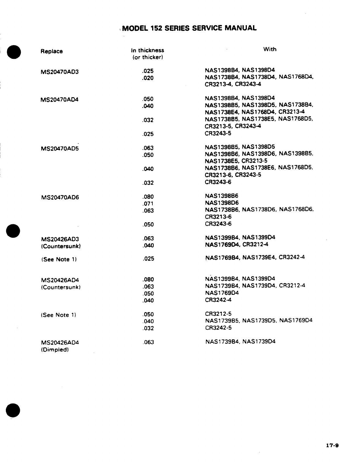
MODEL
152
SERIES
SERVICE
MANUAL
Replace
In
thickness With
(or
thicker)
MS20470AD3
.025
NAS1398B4,
NAS1398D4
.020
NAS1738B4,
NAS1738D4,
NAS176804,
CR3213-4,
CR3243-4
MS20470AD4
.050
NAS1398B4,
NAS1398D4
.040
NAS1398B5,
NAS1398D5,
NAS1738B4,
NAS1738E4,
NAS1768D4,
CR3213-4
.032
NAS1738B5,
NAS1738E5,
NAS1768D5,
CR3213-5,
CR3243-4
.025
CR3243-5
MS20470AD5
.063
NAS1398B5,
NAS1398D5
.050
NAS1398B6,
NAS1398D6,
NAS139885,
NAS1738E5.
CR3213-5
.040
NAS1738B6,
NAS1738E6,
NAS1768D5,
CR3213-6,
CR3243-5
.032
CR3243-6
MS20470AD6
.080
NAS1398B6
.071
NAS1398D6
.063
NAS1738B6,
NAS1738D6,
NAS1768D6.
CR3213-6
.050
CR3243-6
MS20426AD3
.063
NAS1399B4,
NAS1399D4
(Countersunk)
.040
NAS1769D4,
CR3212-4
(See
Note
1)
.025
NAS1769B4,
NAS1739E4,
CR32424
MS20426AD4
.080
NAS1399B4,
NAS1399D4
(Countersunk)
.063
NAS1739B4.
NAS1739D4,
CR3212-4
.050
NAS1769D4
.040
CR3242-4
(See
Note
1)
.050
CR3212-5
.040
NAS1739B5,
NAS1739D5,
NAS1769D4
.032
CR3242-5
MS20426AD4
.063
NAS1739B4, NAS1739D4
(Dimpled)
17-9
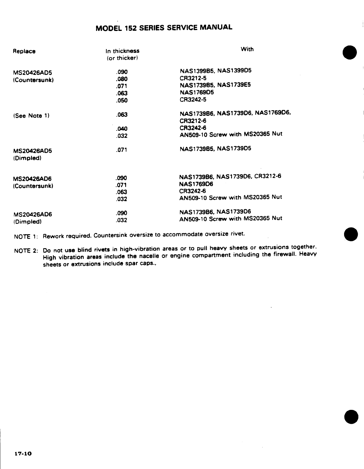
MODEL
152
SERIES
SERVICE
MANUAL
Replace
In
thickness
With
(or
thicker)
MS20426AD5
.090
NAS1399B5,
NAS139905
(Countersunk)
.080
CR3212-5
.071
NAS173965,
NAS1739E5
.063
NAS176905
.050
CR3242-5
(See
Note
1)
.063
NAS1739B6,
NAS173906,
NAS176906,
CR3212-6
.040
CR3242-6
.032
AN509-10
Screw
with
MS20365
Nut
MS20426A05
.071
NAS1739B5,
NAS173905
(Dimpled)
MS20426AD6
.090
NAS1739B6,
NAS1739D6,
CR3212-6
(Countersunk)
.071
NAS176906
.063 CR3242-6
.032
AN509-10
Screw
with
MS20365
Nut
MS20426AD6
.090
NAS1739B6,
NAS1739D6
(Dimpled)
.032
AN509-10
Screw
with
MS20365 Nut
NOTE
1:
Rework
required.
Countersink
oversize
to
accommodate
oversize
rivet.
NOTE
2:
Do
not
use
blind
rivets
in
high-vibration
areas
or to
pull
heavy
sheets
or
extrusions
together.
High
vibration
areas
include
the
nacelle
or engine
compartment including
the
firewall.
Heavy
sheets
or
extrusions
include spar
caps..
17-10
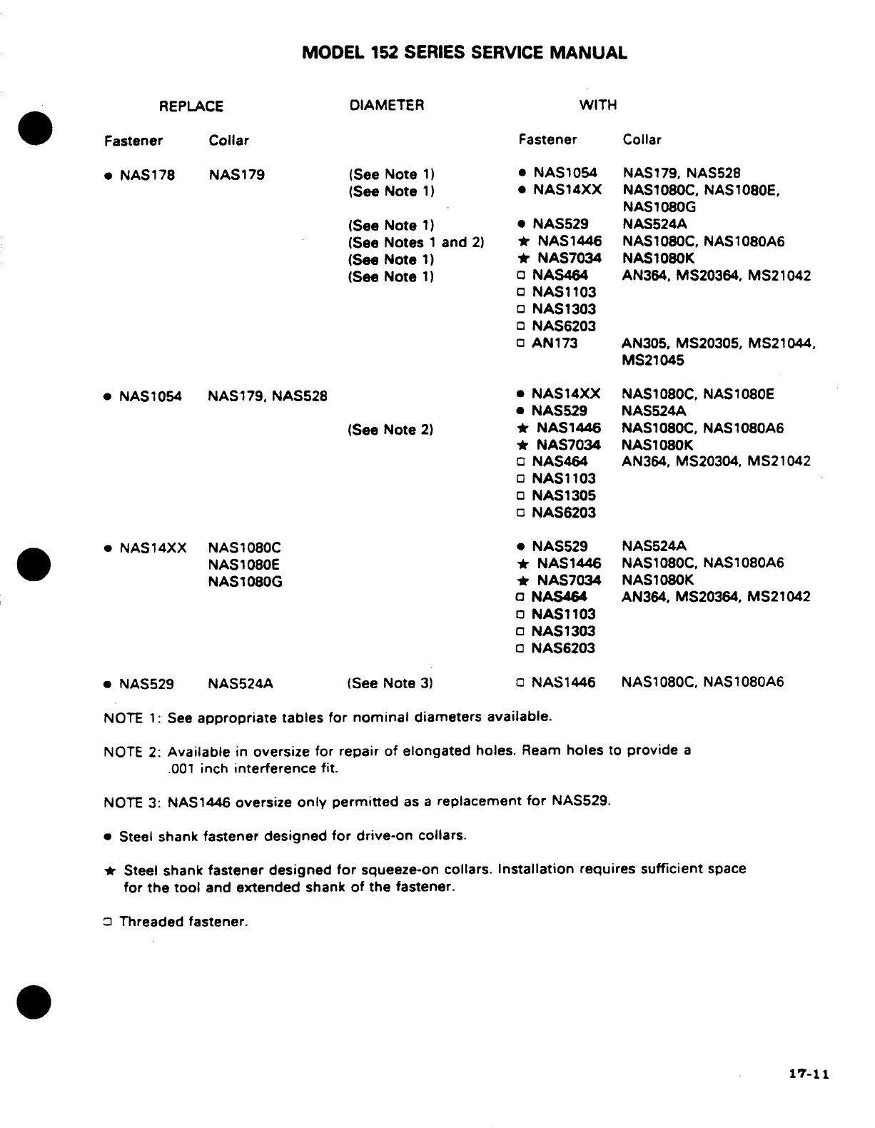
MODEL
152 SERIES
SERVICE
MANUAL
REPLACE
DIAMETER
WITH
Fastener
Collar
Fastener
Collar
* NAS178
NAS179
(See
Note
1) * NAS1054
NAS179, NAS528
(See
Note
1)
*
NAS14XX
NAS1080C, NAS1080E,
NAS
1080G
(See
Note
1) *
NAS529
NAS524A
(See
Notes
1
and
2)
*
NAS1446
NAS1080C,
NAS1080A6
(See
Note
1) *
NAS7034
NAS1080K
(See
Note
1)
NAS464
AN364,
MS20364,
MS21042
NAS1103
NAS1303
NAS6203
AN173
AN305,
MS20305,
MS21044,
MS21045
*
NAS1054
NAS179.
NAS528
*
NAS14XX
NAS1080C,
NAS1080E
*
NAS529
NAS524A
(See
Note
2)
*
NAS1446
NAS1080C.
NAS1080A6
*
NAS7034
NAS1080K
NAS464
AN364, MS20304,
MS21042
NAS1103
NAS1305
NAS6203
*
NAS14XX
NAS1080C
*
NAS529
NAS524A
NAS1080E
*
NAS1446
NAS1080C,
NAS1080A6
NAS1080G *
NAS7034
NAS1080K
NAS464
AN364,
MS20364,
MS21042
NAS1103
NAS1303
NAS6203
* NAS529
NAS524A
(See
Note
3)
NAS1446
NAS1080C,
NAS1080A6
NOTE
1:
See
appropriate
tables
for
nominal
diameters
available.
NOTE
2:
Available
in
oversize
for
repair of
elongated
holes.
Ream
holes
to
provide
a
.001
inch
interference
fit.
NOTE
3:
NAS1446
oversize
only
permitted
as
a
replacement
for
NAS529.
*
Steel
shank
fastener
designed
for
drive-on collars.
* Steel
shank
fastener designed
for
squeeze-on
collars.
Installation
requires
sufficient
space
for
the
tool
and
extended
shank
of
the fastener.
Threaded
fastener.
17-11
MODEL
152
SERIES
SERVICE
MANUAL
17-66.
ENGINE
MOUNT.
17-67.
DESCRIPTION.
The
"dynafocal"
type engine
mount
is
constructed
of
chrome-molybdenum
steel
tubing.
The
nose
gear
shock
strut
is
secured
to
the
tubular engine
mount.
Refer
to
Section
18
of
this
manual
for engine
mount
painting
procedures following
repair.
17-68.
GENERAL
CONSIDERATIONS.
All
welding
on
the
engine
mount
must
be
of
the highest
quality
since
the
tendency
of
vibration
is
to
accentuate
any
minor
defect
present
and
cause
fatigue
cracks.
Engine
mount
members
are preferably
repaired
by
using
a
larger
diameter
replacement
tube,
telescoped
over
the
stub
of
the
original
member
using
fishmouth
and
rosette-type
welds.
However.
reinforced
30-degree
scarf
welds
in
place
of
the
fishmouth
welds
are
considered
satisfactory
for
engine
mount
work. Refer
to
Section
18
for
engine
mount
painting.
17-69.
ENGINE
MOUNT
RADIAL
SUPPORT
DAMAGE.
Minor
damage
such
as
a
crack
adjacent
to
an engine
attaching
lug
may
be
repaired
by
rewelding
the
support
tube
and
extending
a
gusset past
the
damaged
area.
Extensively
damaged
parts
must
be
replaced.
17-70.
DAMAGE
INVOLVING
ENGINE
MOUNTING LUGS
AND
ENGINE
MOUNT
TO
FUSE-
LAGE
ATTACHING
FITTINGS.
Engine
mounting
lugs
and engine
mount-to-fuselage
attaching fittings
should
not
be
repaired
but
must
be
replaced.
17-71.
BAFFLES. Baffles
ordinarily
require
replacement
if
damaged
or
cracked.
However.
small
plate
reinforcements
riveted
to
the
baffle
will
often
prove
satisfactory
both
to
the
strength
and
cooling
requirements
of
the
unit.
17-72.
ENGINE
COWLING.
17-73.
REPAIR
OF
COWLING
SKINS.
If
extensively
damaged,
complete
sections
of
cowling
must
be
replaced.
Standard
insert-type
skin
patches,
however,
may
be
used
if
repair
parts
are
formed
to
fit. Small
cracks
may
be
stop-drilled
and
dents
straightened
if
they
are
reinforced
on
the
inner
side
with
a
doubler
of
the same
material.
Bonded
cowling
may
be
repaired
by
the
same
methods
used
for
riveted
structure.
Rivets
are
a
satisfactory
substitue
for
bonded
seams
on
these
assemblies.
The
strength
of
the
bonded
seams
in
cowling
may
be
replaced
by
a
single
3/32.
2117-AD
rivet per running
inch
of
bond
seam.
The
standard repair
procedures
outlined
in
AC43.13-1
are
also applicable
to
cowling.
17-74.
REPAIR
OF
REINFORCEMENT
ANGLES. Cowl
reinforcement angles.
if
damaged.
must
be
replaced.
Due
to
their small
size.
they
are
easier
to
replace
than
to
repair.
17-75.
REPAIR
OF GLASS-FIBER
CONSTRUCTED
COMPONENTS.
Glass-fiber
constructed
compo-
nents
on
the
aircraft
may
be
repaired
as
stipulated
in
instructions
furnished
in
Service
Kit
SK182-12.
Observe
the
resin
manufacturer's
recommendations
concerning
mixing
and
ap-
plication
of
the
resin.
Epoxy
resins
are
preferable
for
making
repairs,
since
epoxy
com-
pounds
are
usually
more stable
and
predictable
than
polyester
and,
in
addition,
give
better
adhesion.
In
addition,
repair
kits
are
also
available
for
the
repair
of
cracks
in
ABS,
PBC,
PVPC,
graphite
and
fiberglass
material.
These
kits
P/N's
51543
thru
51548,
are
available
from
Cessna Supply
Division.
17-76.
CORROSION
AND
CORROSION
CONTROL.
NOTE
For
information
on
corrosion
and
corrosion control
for
aircraft,
refer
to
FAA
Advisory
Circular
AC43-4.
17-12
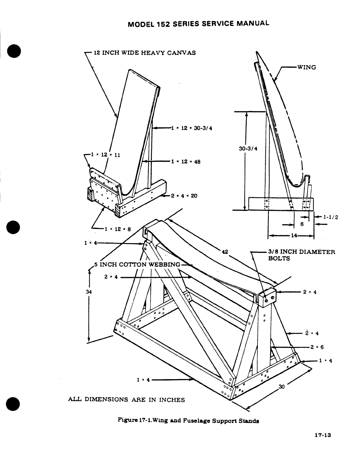
MODEL
152
SERIES
SERVICE
MANUAL
12
INCH
WIDE
HEAVY
CANVAS
-1
12
a
30-3/4
30-3/4
.-
*
3/8
INCH
DIAMETER
5
INCH
COTTON
WEBBING
ALL
DIMENSIONS
ARE
IN
INCHES
Figure
17-l.Wing
and
Fuselage
Support
Stands
30
A.T.
DIMENSIONS
ARE
IN
INCHES
Figure
17-1.Wing
and
Fuselage
Support
Stand
17-13
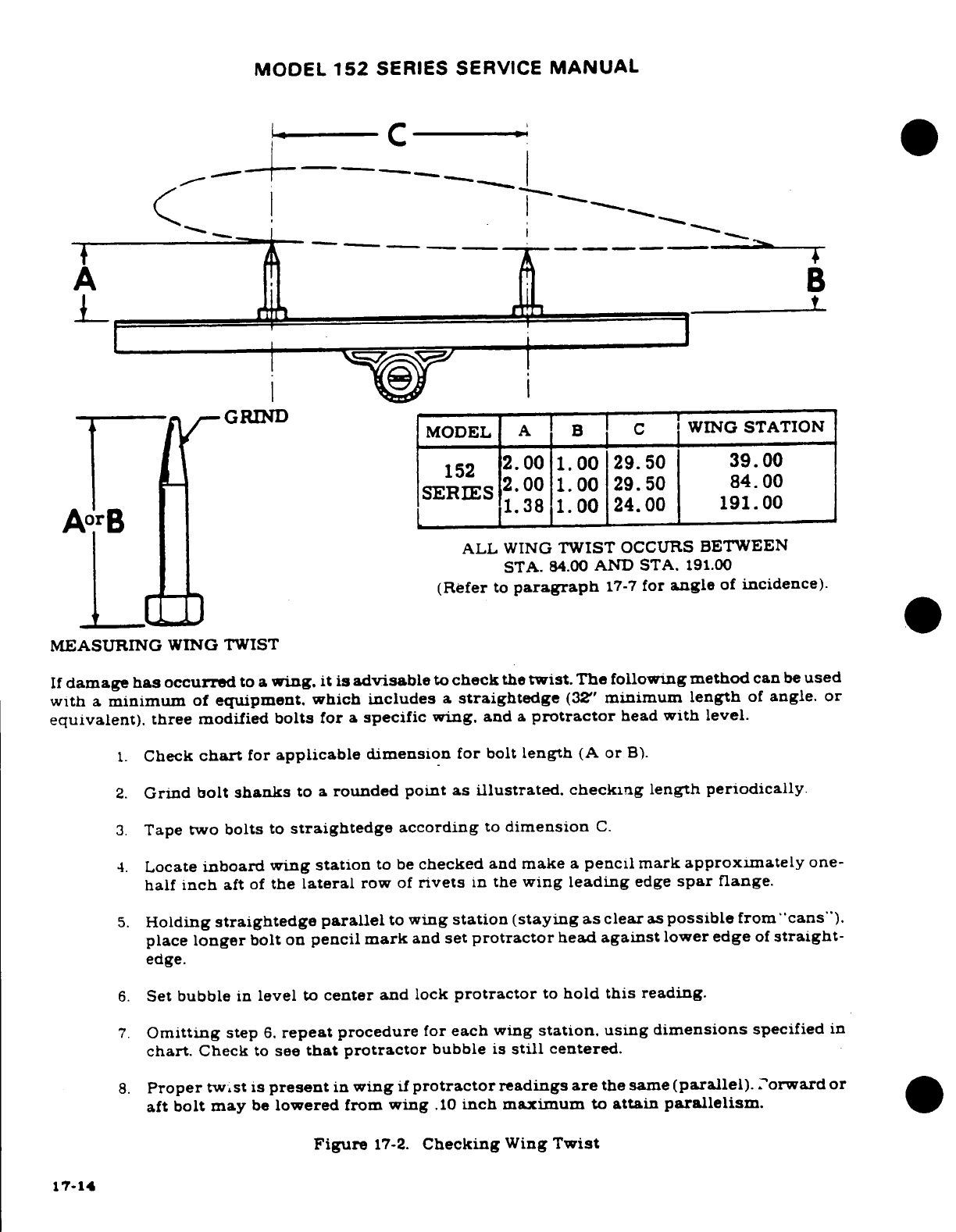
MODEL
152
SERIES
SERVICE
MANUAL
A
B
GRIND
MODEL
A
B
C
WING
STATION
152
2.00
1.00
29.50
39.00
SERIES
2.00
1.00
29.50
84.00
1.38
1.00
24.00
191.00
ALL
WING
TWIST
OCCURS
BETWEEN
STA.
84.00
AND STA.
191.00
(Refer
to
paragraph
17-7
for
angle
of
incidence).
MEASURING
WING
TWIST
If
damage
has
occurred
to
a
wing.
it is
advisable
to
check
the
twist.
The
following
method
can
be
used
with
a
minimum
of
equipment.
which
includes
a
straightedge
(32"
minimum
length
of
angle.
or
equivalent).
three
modified
bolts
for
a
specific wing.
and
a
protractor
head
with
level.
1.
Check
chart
for
applicable
dimension
for
bolt
length
(A
or
B).
2.
Grind
bolt
shanks
to a
rounded
point
as
illustrated. checking
length
periodically.
3.
Tape
two
bolts
to
straightedge
according
to
dimension
C.
4.
Locate
inboard wing
station
to
be
checked
and
make
a
pencil mark
approximately
one-
half
inch
aft
of
the
lateral
row
of
rivets
in
the
wing
leading
edge
spar
flange.
5.
Holding
straightedge
parallel
to
wing
station
(staying as
clear
as
possible
from
"cans").
place
longer
bolt
on
pencil
mark
and
set
protractor
head
against
lower
edge
of
straight-
edge.
6.
Set
bubble
in
level
to
center
and
lock
protractor
to
hold
this
reading.
7.
Omitting
step
6.
repeat
procedure
for
each
wing
station,
using
dimensions
specified
in
chart.
Check
to
see
that protractor
bubble
is
still
centered.
8.
Proper
twist
is
present
in
wing
if
protractor
readings
are
the
same
(parallel).
Forward
or
aft
bolt
may
be
lowered
from
wing
.10
inch
maximum
to
attain
parallelism.
Figure
17-2.
Checking
Wing
Twist
17-14
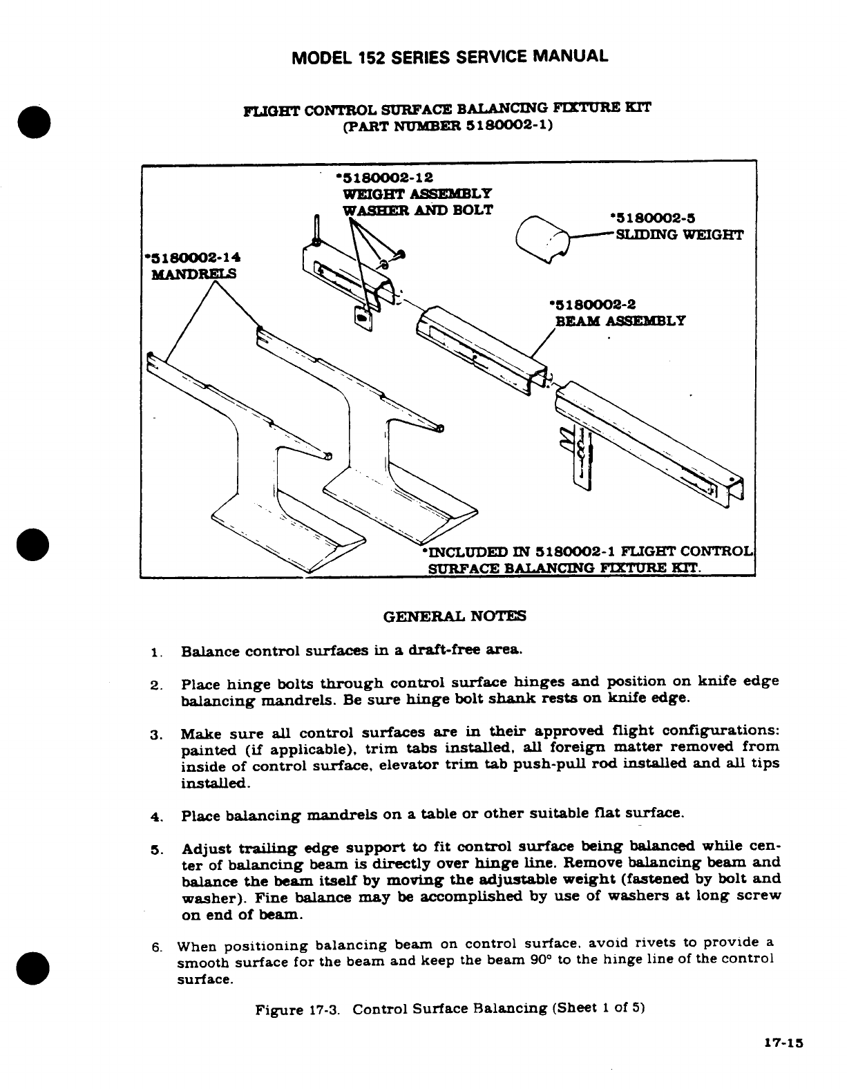
MODEL
152
SERIES SERVICE
MANUAL
FLIGHT
CONTROL
SURFACE
BALANCING
FIXTURE
KIT
(PART
NUMBER
5180002-1)
'5180002-12
WEIGHT
ASSEMBLY
WASHER
AND
BOLT
5180002-5
SLIDING
WEIGHT
*5180002-14
MANDRELS
*180002-2
BEAM
ASSEMBLY
INCLUDED
IN
5180002-1
FLIGHT
CONTROL
SURFACE
BALANCING
FIXTURE KIT.
GENERAL
NOTES
1.
Balance
control
surfaces
in a
draft-free
area.
2.
Place
hinge
bolts
through
control surface
hinges
and
position
on
knife
edge
balancing
mandrels.
Be
sure
hinge
bolt
shank
rests
on
knife
edge.
3.
Make
sure
all
control
surfaces
are
in
their
approved
flight configurations:
painted
(if
applicable),
trim
tabs
installed,
all
foreign
matter
removed
from
inside
of
control
surface,
elevator
trim
tab
push-pull
rod
installed
and
all
tips
installed.
4.
Place
balancing
mandrels
on
a
table
or
other
suitable
flat
surface.
5.
Adjust
trailing
edge
support
to
fit
control surface
being
balanced
while cen-
ter
of
balancing
beam
is
directly
over
hinge
line.
Remove
balancing
beam
and
balance
the
beam
itself
by
moving
the adjustable
weight
(fastened
by
bolt
and
washer).
Fine
balance
may
be
accomplished
by
use
of
washers
at
long
screw
on
end
of
beam.
6.
When
positioning
balancing
beam
on
control surface,
avoid
rivets
to
provide
a
smooth
surface
for the beam
and
keep
the
beam
90
°
to
the
hinge
line
of
the
control
surface.
Figure
17-3.
Control Surface
Balancing
(Sheet
1
of
5)
17-15
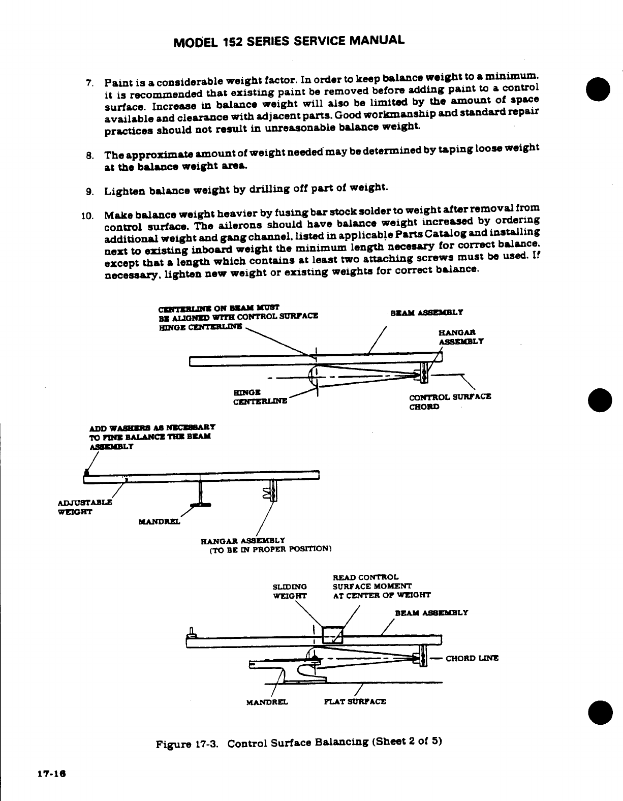
MODEL 152
SERIES
SERVICE
MANUAL
7.
Paint
is
a considerable
weight
factor.
In
order
to
keep
balance
weight
to
a
minimum.
it
is
recommended
that
existing
paint
be
removed before
adding
paint
to
a
control
surface. Increase
in
balance
weight will
also
be
limited
by
the
amount
of
space
available
and
clearance
with
adjacent
parts.
Good
workmanship
and standard
repair
practices
should
not
result
in
unreasonable
balance
weight.
8.
The
approximate amount
of
weight
needed
may
be
determined
by
taping
loose
weight
at
the
balance weight
area.
9.
Lighten balance
weight
by
drilling
off
part
of
weight.
10.
Make
balance
weight
heavier
by
fusing
bar
stock
solder
to
weight
after
removal
from
control
surface.
The
ailerons
should
have
balance
weight
increased
by
ordering
additional
weight
and
gang
channel.
listed
in
applicable
Parts
Catalog
and
installing
next
to
existing
inboard weight
the
minimum
length necesary
for
correct
balance.
except
that
a
length
which
contains at
least
two
attaching
screws
must
be
used.
If
necessary,
lighten
new
weight
or
existing
weights
for
correct
balance.
CENTERLINE
ON
BEAM
MUST
BE
ALIGNED
WITH
CONTROL
SURFACE
BEAM
ASEMBLY
CHORD
ADD
WASHERS
AS
NECESSARY
CENTERLINE
CONTROL
SURFACE
TO
FINE
BALANCE
THE
BEAM
ASSEMBLY
ADJUSTABLE
WEIGHT
WEIGHT
AT
CENTER
OF
WEIGHT
BEAM
ASSEMBLY
MANDREL
FLAT
SURFACE
Figure
17-3.
Control
Surface
Balancing (Sheet
2
of
5)
17-16
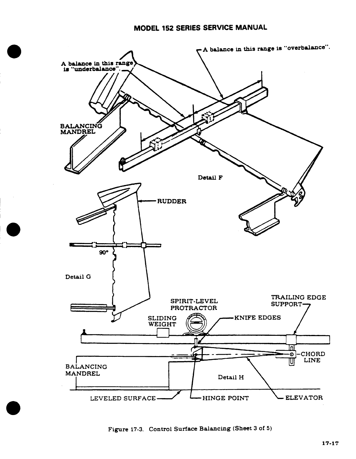
MODEL
152
SERIES
SERVICE
MANUAL
A
balance
in
this
range
is
"overbalance".
is
"underbalance".
BALANCING
MANDREL
Detail
F
RUDDER
90°
Detail
G
TRAILING
EDGE
SPIRIT-LEVEL
PROTRACTOR
SLIDING KNIFE
EDGES
WEIGHT
.
LINE
BALANCING
MANDREL
Detail
H
LEVELED
SURFACE---
HINGE
POINT
ELEVATOR
Figure
17-3.
Control
Surface
Balancing
(Sheet
3
of
5)
17-17
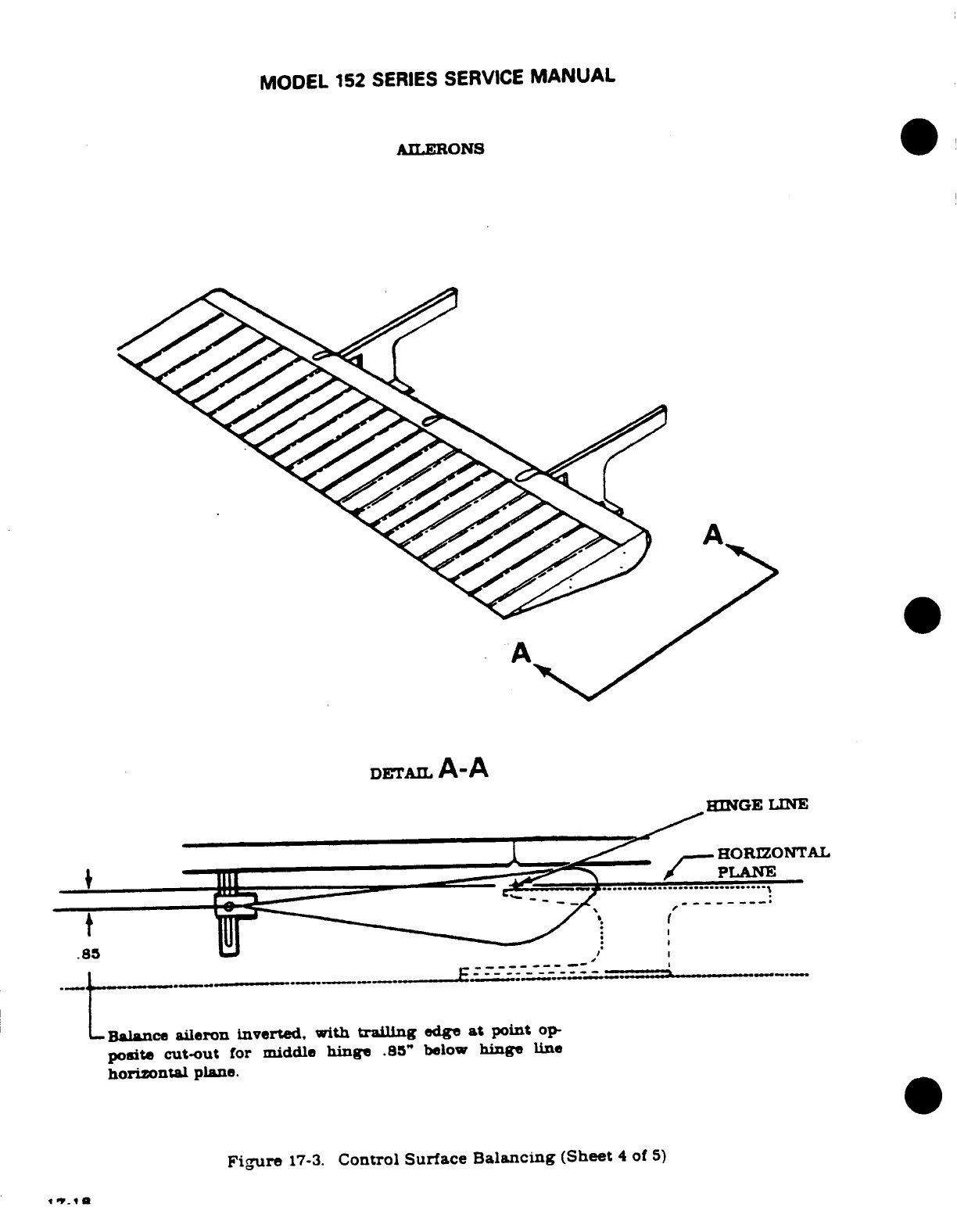
MODEL
152
SERIES
SERVICE
MANUAL
AILERONS
A
A
DETAIL
A-A
HINGE
LINE
HORIZONTAL
Balance
aileron
inverted,
with
trailing
edge
at
point
op-
posite
cut-out
for
middle
hinge
.85"
below
hinge
line
horizontal
plane.
Figure
17-3.
Control
Surface
Balancing
(Sheet
4
of
5)
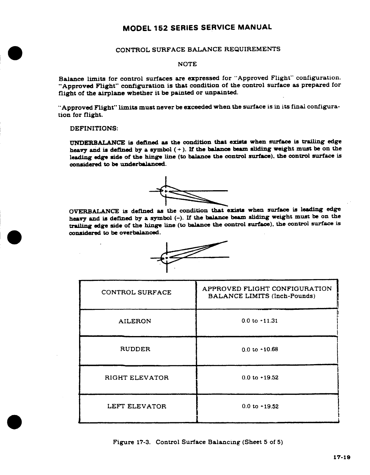
MODEL
152
SERIES
SERVICE
MANUAL
CONTROL
SURFACE
BALANCE REQUIREMENTS
NOTE
Balance
limits
for
control surfaces
are
expressed
for
"Approved
Flight"
configuration.
"Approved
Flight"
configuration
is
that
condition
of
the
control
surface
as
prepared
for
flight
of
the
airplane
whether
it
be
painted
or
unpainted.
"Approved
Flight"
limits must
never
be
exceeded
when
the
surface
is
in
its
final
configura-
tion
for
flight.
DEFINITIONS:
UNDERBALANCE
is
defined
as
the
condition
that
exists
when
surface
is
trailing
edge
heavy
and
is
defined
by
a
symbol
(+).
If
the
balance
beam
sliding
weight
must
be
on
the
leading
edge
side
of
the hinge
line
(to
balance
the
control
surface),
the
control
surface
is
considered
to
be
underbalanced.
OVERBALANCE
is
defined
as
the
condition
that
exists
when
surface
is
leading
edge
heavy
and is defined
by
a
symbol
(-). If
the
balance
beam
sliding
weight
must
be
on the
trailing
edge
side of
the hinge
line
(to
balance
the
control
surface),
the
control
surface
is
considered
to
be
overbalanced.
APPROVED FLIGHT
CONFIGURATION
BALANCE
LIMITS
(Inch-Pounds)
AILERON
0.0
to
-11.31
RUDDER
0.0
to
-10.68
RIGHT
ELEVATOR
0.0
to
-19.52
LEFT ELEVATOR
0.0
to
-19.52
Figure
17-3.
Control
Surface
Balancing
(Sheet
5
of
5)
17-19
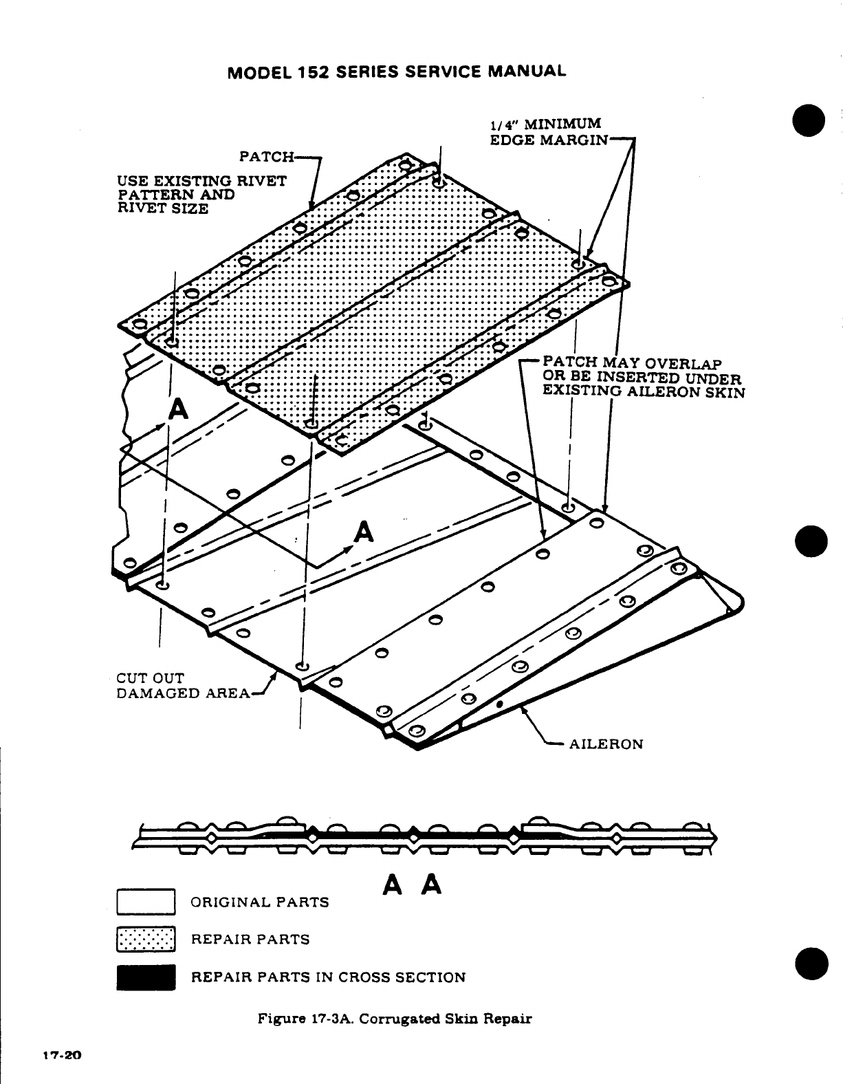
MODEL
152
SERIES
SERVICE
MANUAL
1/4"
MINIMUM
EDGE
MARGIN
PATCH.
USE
EXISTING
RIVET
PATTERN
AND
RIVET
SIZE
PATCH
MAY
OVERLAP
OR
BE
INSERTED
UNDER
EXISTING
AILERON
SKIN
CUT
OUT
DAMAGED
AREA
AILERON
ORIGINAL
PARTS
REPAIR
PARTS
REPAIR
PARTS
IN
CROSS
SECTION
Figure
17-3A.
Corrugated
Skin Repair
17-20
17-20
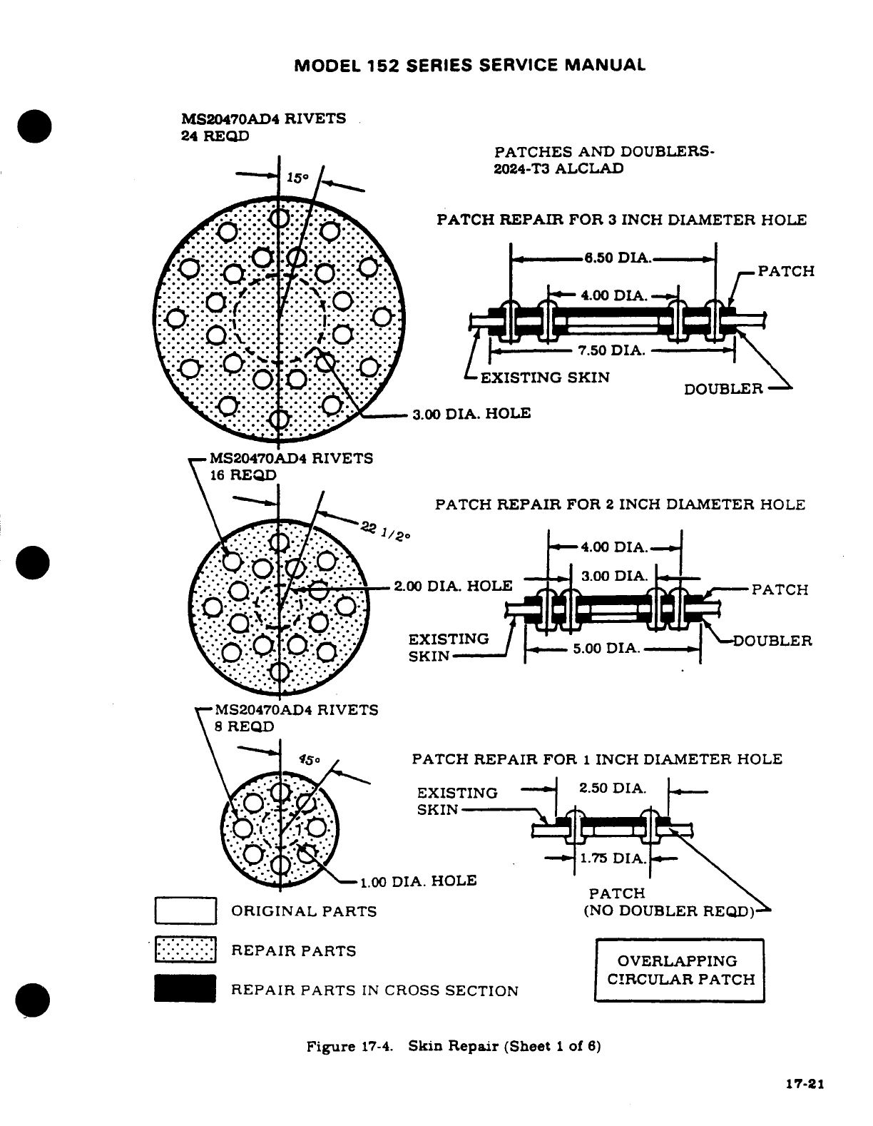
MODEL
152
SERIES SERVICE
MANUAL
MS20470AD4
RIVETS
24
REQD
PATCHES
AND
DOUBLERS-
2024-T3
ALCLAD
PATCH
REPAIR
FOR
3
INCH
DIAMETER HOLE
,. .,,
PATCH
4.00
.50
DIA.
EXISTING
SKIN
DOUBLER
3.00
DIA.
HOLE
MS20470AD4
RIVETS
16
REQD
PATCH
REPAIR
FOR
2
INCH
DIAMETER
HOLE
MS20470AD4
RIVETS
\
REQD
PATCH
REPAIR
FOR
1
INCH
DIAMETER
HOLE
EXISTING
2.50
DIA.
.00
DIA.
HOLE
PATCH
ORIGINAL
PARTS
(NO
DOUBLER
REPAIR
PARTS
OVERLAPPING
CIRCULAR
PATCH
REPAIR
PARTS
IN
CROSS
SECTION
Figure
17-4.
Skin
Repair
(Sheet
1
of
6)
17-21
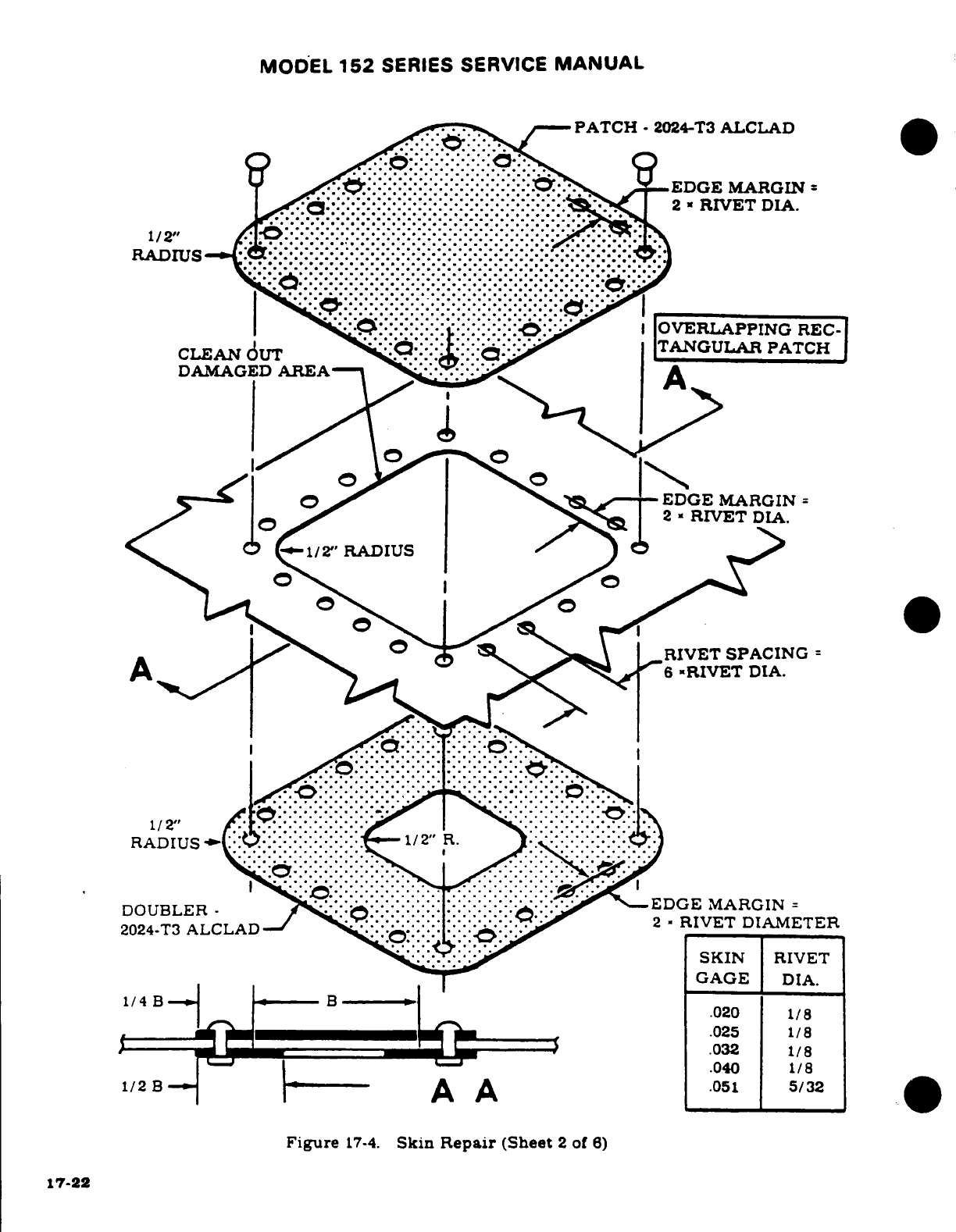
MODEL
152
SERIES SERVICE
MANUAL
-
PATCH
2024-T3
ALCLAD
SKIN
RIVET
GAGE
DIA.
Figure
17-4.
Skin
Repair
(Sheet
2
of
6)
17-22
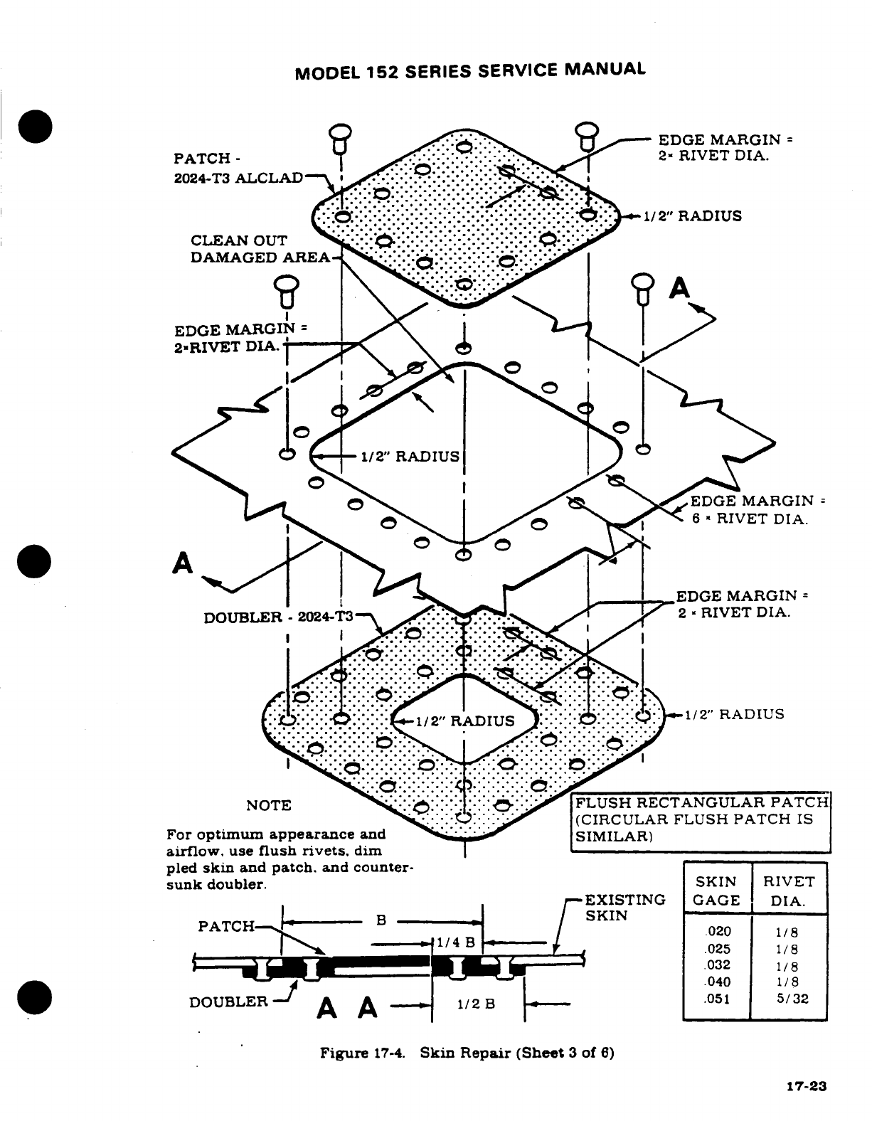
MODEL
152
SERIES
SERVICE
MANUAL
PATCH
-
RV
EDGE
MARGIN
2024-T3
ALCLAD
.
2"
RIVET
DIA.
CLEAN
OUT
.....
DAMAGED
AREA-
*
EDGE
MARGIN
2
RIVET
DIA.
1/2" RADIUS
EDGE
MARGIN
RIVET
DIA.
For
optimum
appearance
and
(CIRCULAR FLUSH PATCH
IS
airflow,
use
flush
rivets,
dim
SIMILAR)
pled
skin
and
patch,
and
counter-.
sunk
doubler.
SKIN
RIVET
PATCH
.
A
A
.040
1/8
Figure
17-4.
Skin
Repair
(Sheet
3
of
6)
17-23
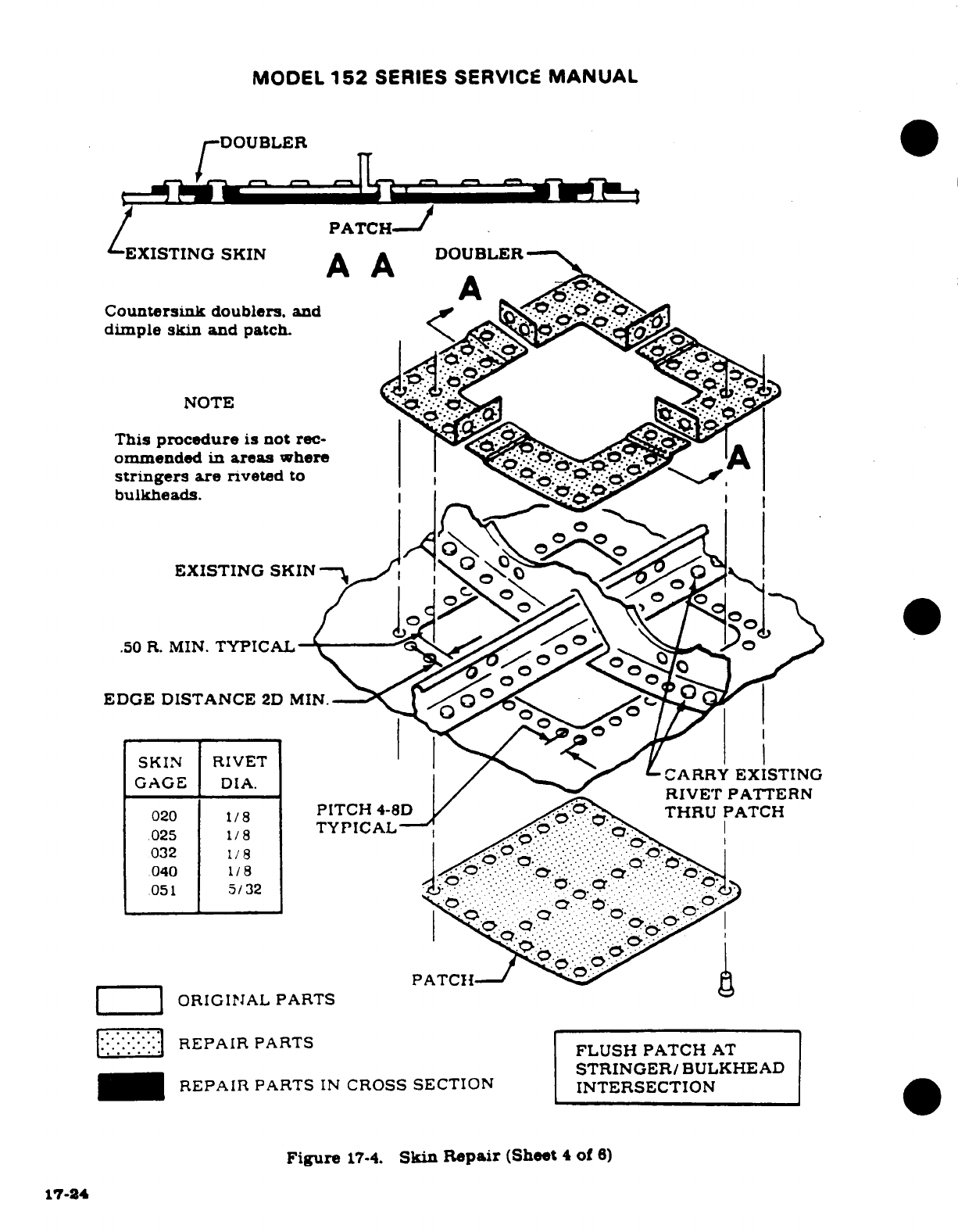
MODEL
152
SERIES SERVICE
MANUAL
DOUBLER
PATCH-
EXISTING
SKIN
A A
DOUBLER--
Countersink
doublers,
and
dimple
skin
and patch.
NOTE
This
procedure
is
not
rec-
ommended
in
areas
where
stringers
are
riveted
to
bulkheads.
EXISTING
SKIN
.50
R.
MIN.
TYPICAL
EDGE
DISTANCE
2D
MIN.
SKIN
RIVET
GAGE
DIA.
ARRY
EXISTING
RIVET
PATTERN
020
8
PITCH
4-8D
THRU
PATCH
025
1/8
032
1/8
040
1/8
051
5/32
PATCH--
ORIGINAL
PARTS
REPAIR
PARTS
FLUSH PATCH
AT
STRINGER/BULKHEAD
REPAIR
PARTS
IN
CROSS
SECTION
INTERSECTION
Figure
17-4.
Skin
Repair
(Sheet
4
of
6)
17-24
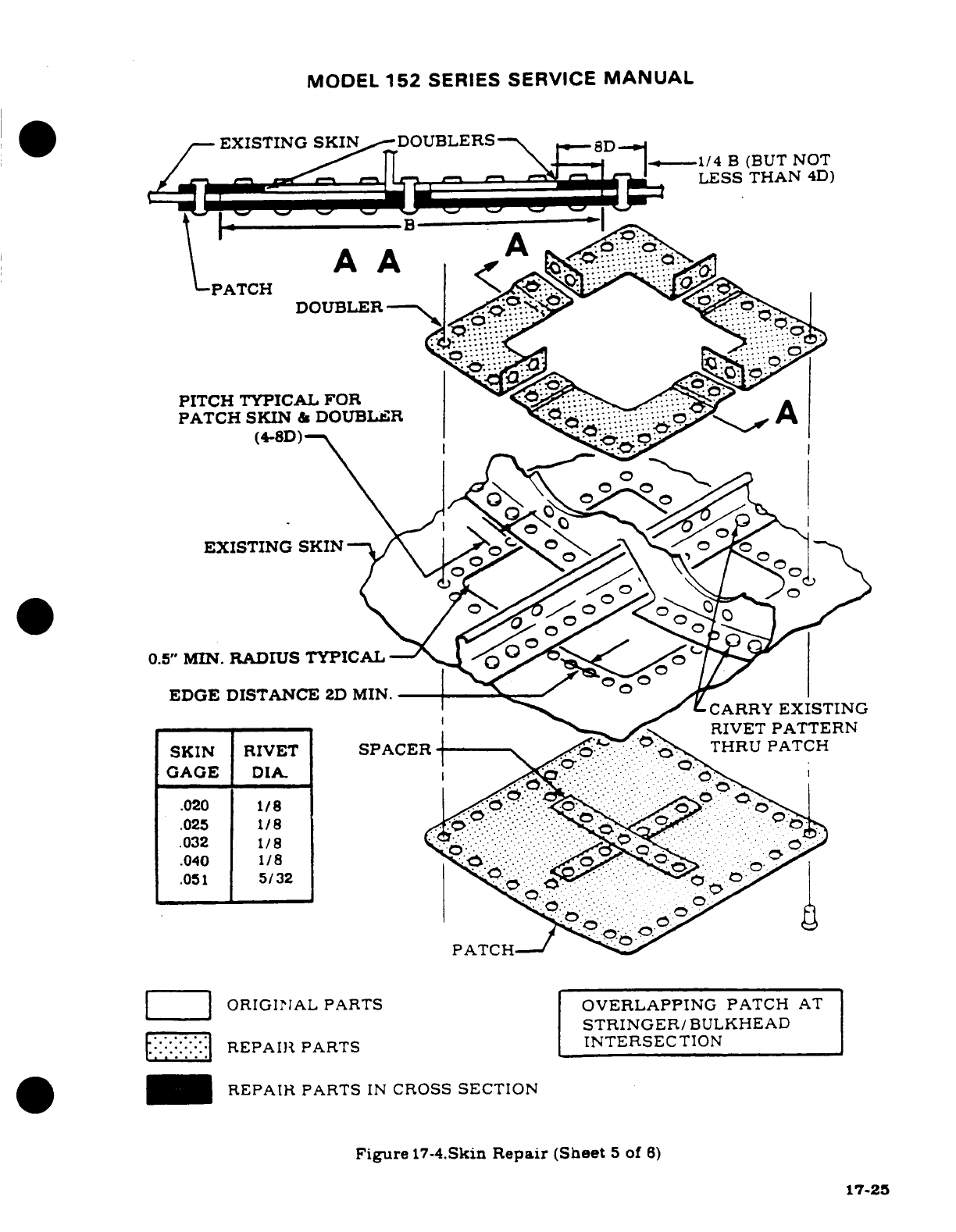
MODEL
152
SERIES
SERVICE
MANUAL
EXISTING
SKIN
DOUBLERS
1/4
B
(BUT
NOT
LESS
THAN
4D)
A
A
RPATCH
DOUBLER
PITCH TYPICAL
FOR
EXISTING
SKIN
//
0.5"
MIN.
RADIUS
TYPICAL
EDGE DISTANCE
2D
MIN.
CARRY
EXISTING
RIVET
PATTERN
SKIN
RIVET
SPACER-
THRU
PATCH
GAGE
DIA.
.020
1/8
.025
1/872
.032
1/8
.040
1/8
.051
5/32
PATCHal
ORIGINAL
PARTS
OVERLAPPING
PATCH
AT
STRINGER/BULKHEAD
REPAIR
PARTS
INTERSECTION
*
REPAIR PARTS
IN
CROSS
SECTION
Figure
17-4.Skin
Repair
(Sheet
5
of
6)
17-25
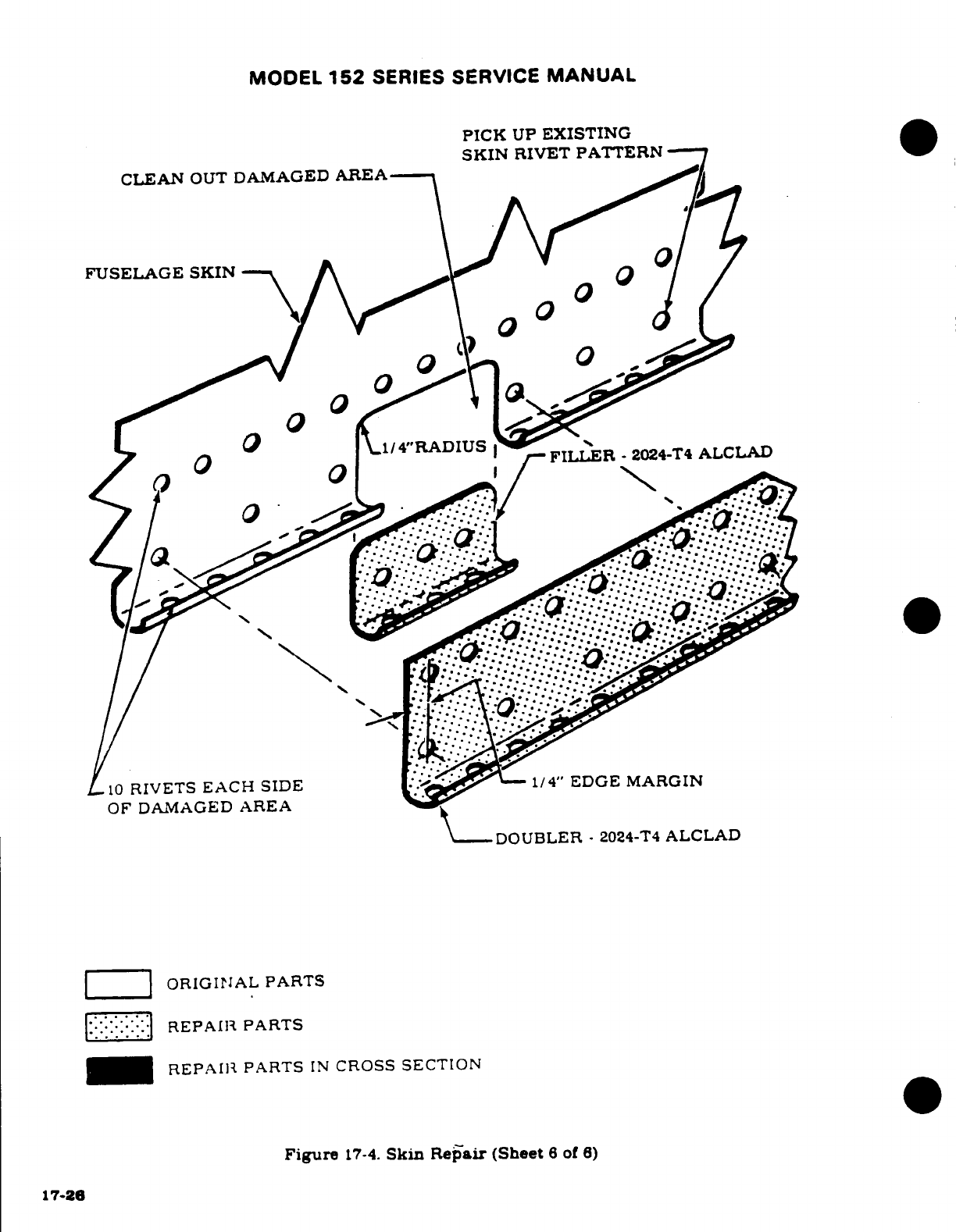
MODEL
152
SERIES
SERVICE
MANUAL
PICK
UP
EXISTING
SKIN
RIVET
PATTERN
CLEAN
OUT
DAMAGED
AREA
/ I h
FUSELAGE SKIN
ORIGINAL PARTS
REPAIR
PARTS
REPAIR
PARTS
IN
CROSS
SECTION
Figure
17-4.
Skin
Repair
(Sheet
6
of
6)
17-26
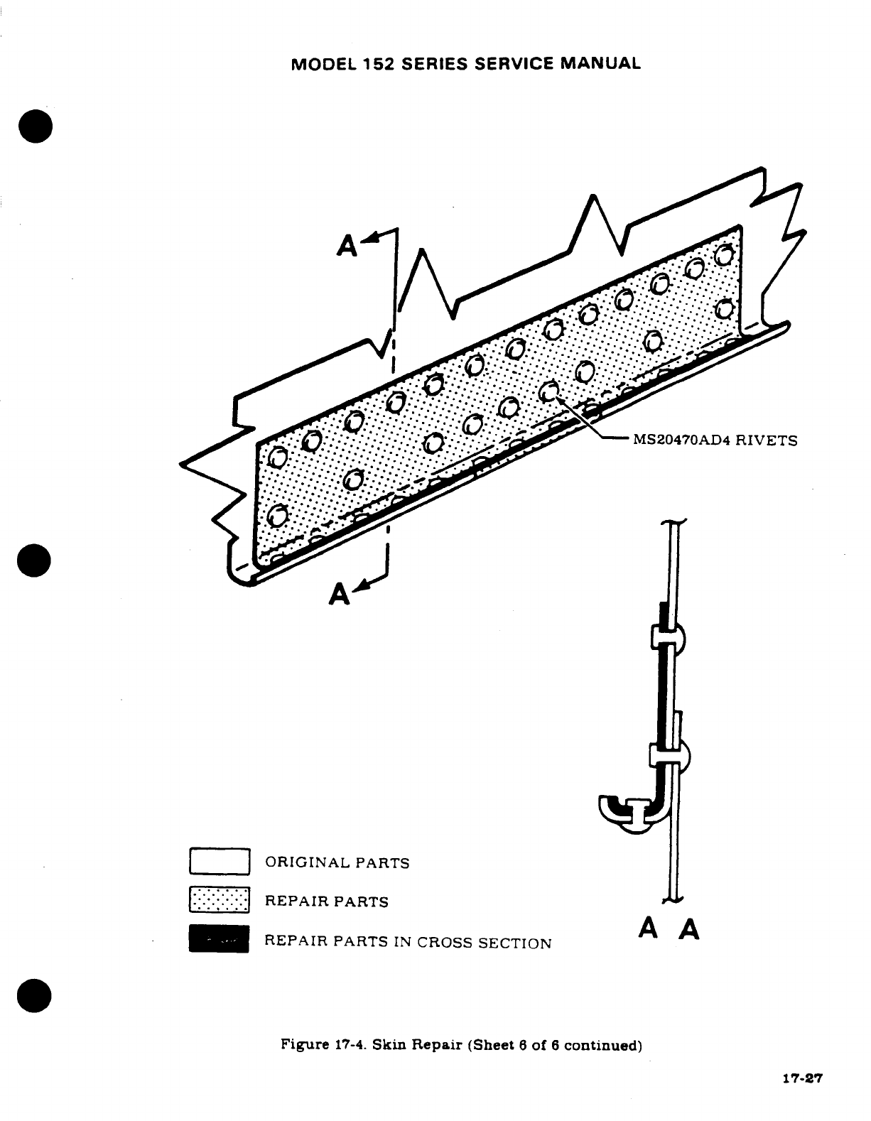
MODEL
152
SERIES SERVICE
MANUAL
ORIGINAL
PARTS
REPAIR
PARTS
A
A
REPAIR
PARTS
IN
CROSS SECTION
Figure
17-4.
Skin
Repair
(Sheet
6
of
6
continued)
17-27
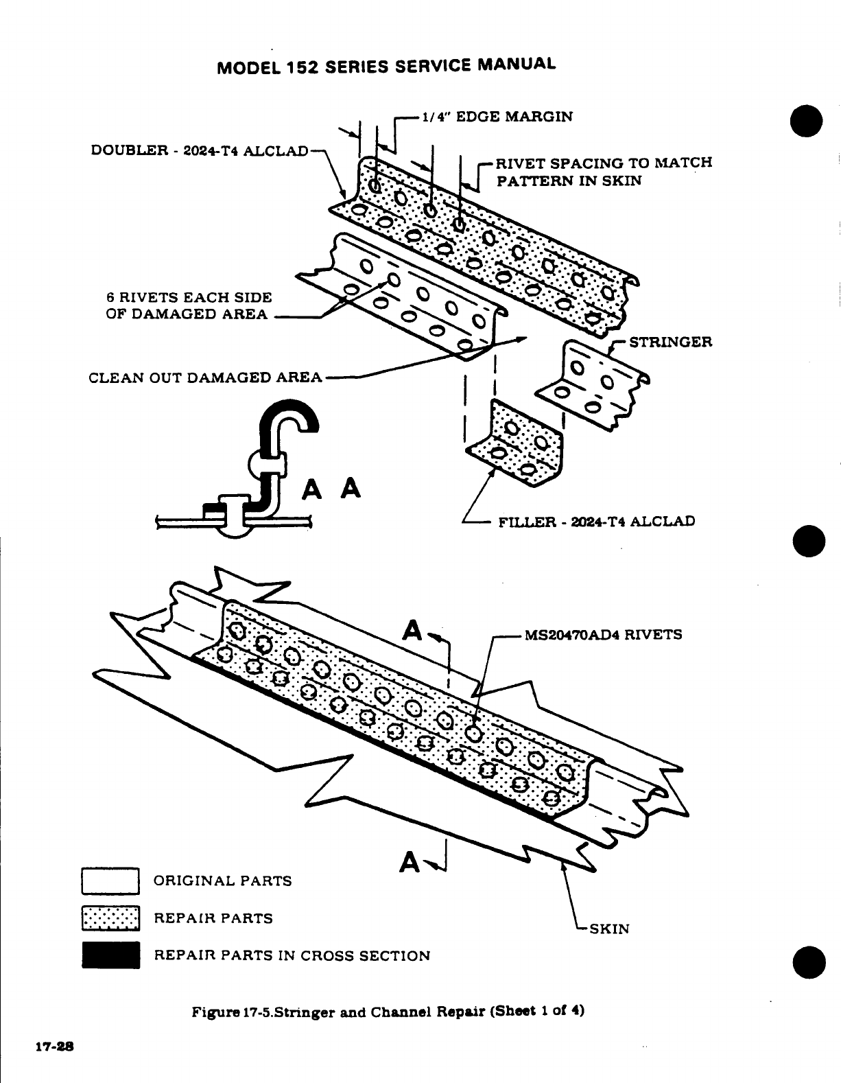
MODEL
152
SERIES
SERVICE
MANUAL
1/4"
EDGE
MARGIN
DOUBLER
-
2024-T4
ALCLAD
RIVET
SPACING
TO
MATCH
PATTERN
IN
SKIN
6
RIVETS
EACH
SIDE
OF
DAMAGED
AREA
STRINGER
CLEAN
OUT
DAMAGED
AREA
A
A
FILLER
-
2024-T4
ALCLAD
MS20470AD4
RIVETS
ORIGINAL
PARTS
REPAIR
PARTS
SKIN
REPAIR
PARTS
IN
CROSS SECTION
Figure
17-5.Stringer
and
Channel Repair (Sheet
1
of
4)
17-28
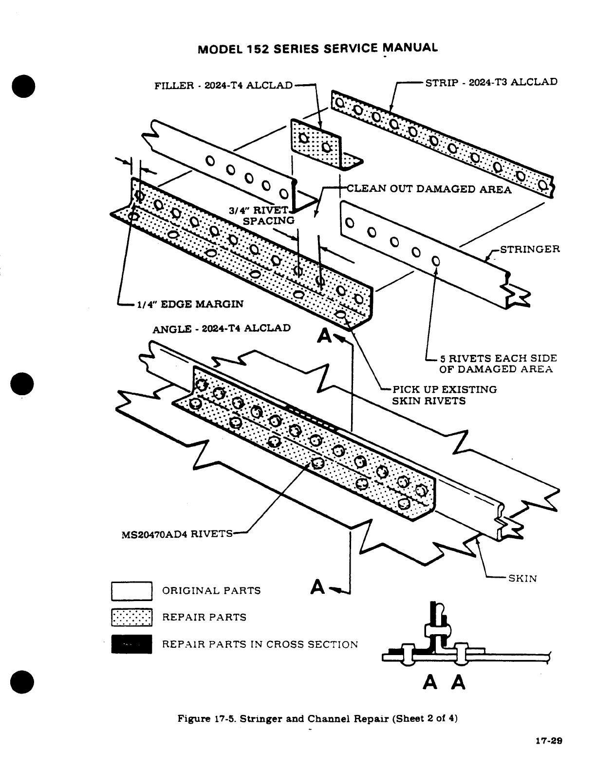
MODEL
152
SERIES
SERVICE
MANUAL
FILLER
-
2024-T4
ALCLAD
STRIP
-
2024-T3
ALCLAD
1/4"
EDGE
MARGIN
ANGL.E
-
2024-T4
ALCLAD
5
RIVETS
EACH
SIDE
DAMAGED
A
RE A
PICK
UP
EXISTING
RIVETS
RIVETS
EACH
SIDE
ORIGINAL
PARTS
A
REPAIR
PARTS
REPAIR
PARTS
IN
CROSS
SECTION
A
A
Figure
17-5.
Stringer
and
Channel
Repair
(Sheet
2
of
4)
17-29
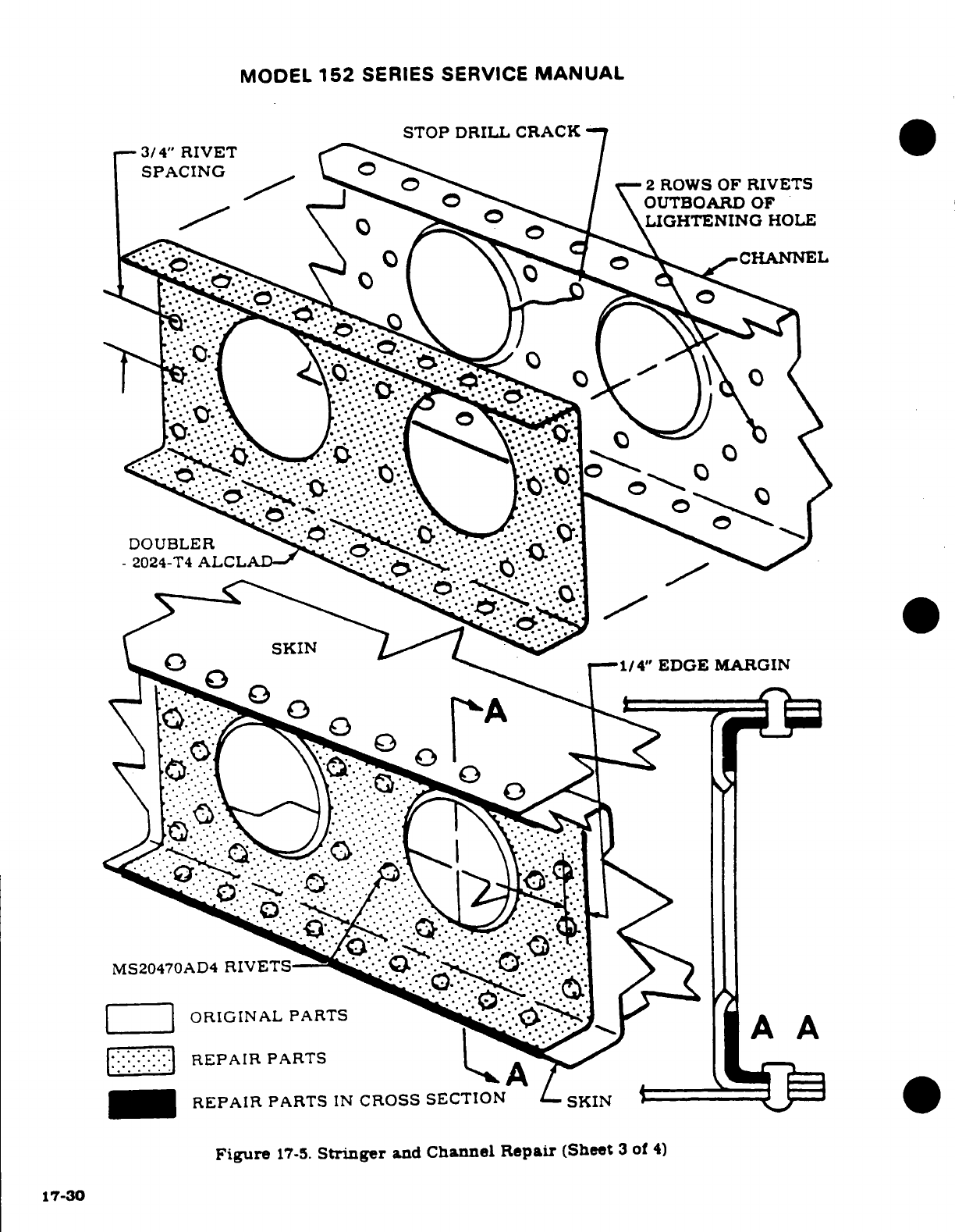
MODEL
152
SERIES
SERVICE
MANUAL
STOP DRILL CRACK
-3/4"
RIVET
SPACING
OUTBOARD
OF
LIGHTENING
HOLE
Figure
17-5.
Stringer
and
Channel
Repair
(Sheet
3
of
4)
17-30
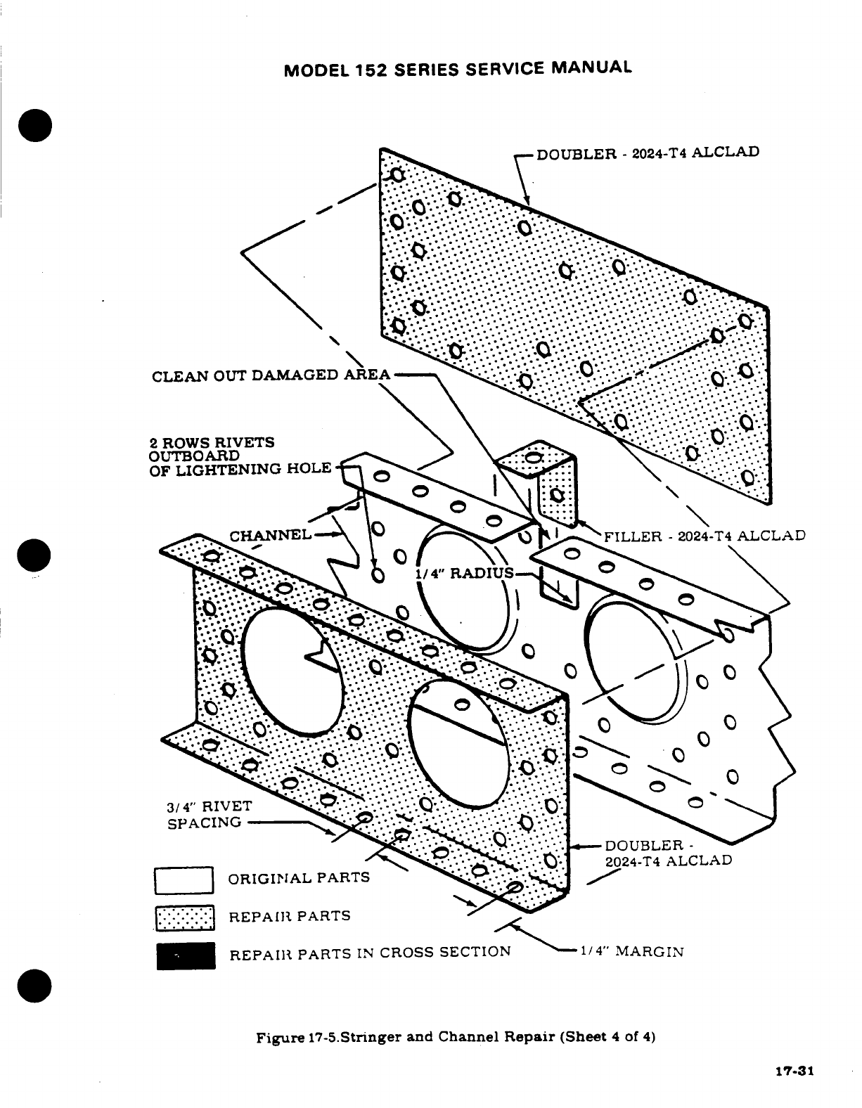
MODEL
152
SERIES
SERVICE
MANUAL
DOUBLER
-
2024-T4
ALCLAD
CLEAN
OUT
DAMAGED AREA
2
ROWS
RIVETS
OUTBOARD
OF
LIGHTENING
HOLEt
CHANNELA
FILLER
2024-T4
ALCLAD
1/4" RADIUS-
3/4'
RIVET
SPACING
DOUBLER
-
2024-T4
ALCLAD
ORIGINAL
PARTS
REPAIR
PARTS
REPAII
PARTS
IN
CROSS SECTION
-1/4"
MARGIN
Figure
17-5.Stringer
and
Channel
Repair
(Sheet
4
of
4)
17-31
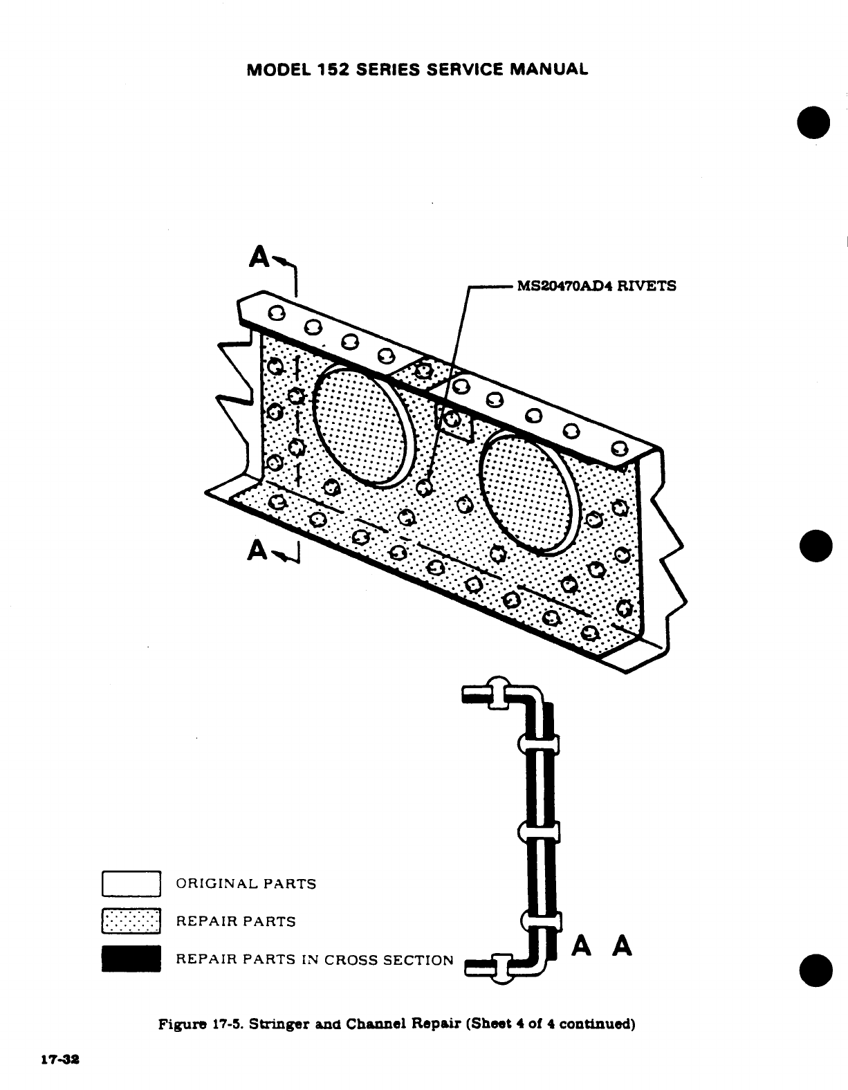
MODEL
152
SERIES
SERVICE
MANUAL
MS20470AD4 RIVETS
ORIGINAL
PARTS
REPAIR
PARTS
REPAIR
PARTS
IN
CROSS
SECTION
A
A
Figure
17-5.
Stringer
and
Channel
Repair
(Sheet
4
of
4
continued)
17-32
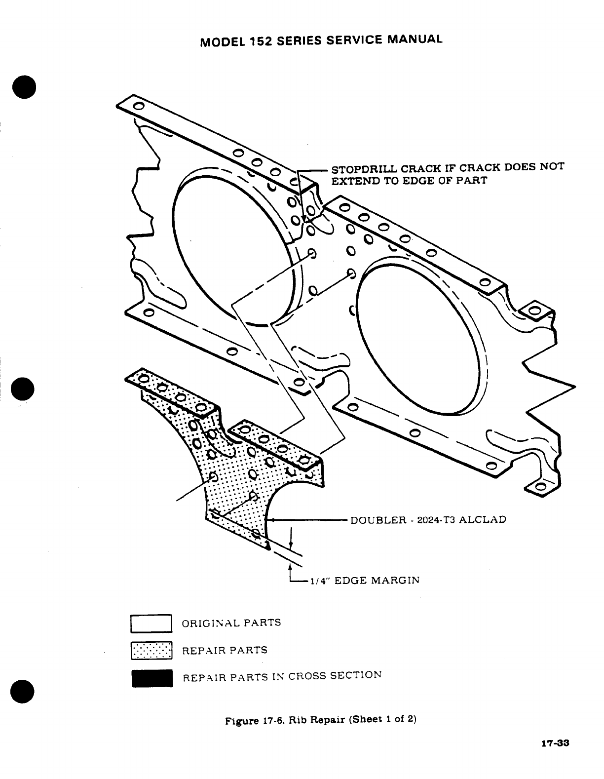
MODEL
152
SERIES
SERVICE
MANUAL
STOPDRILL
CRACK
IF
CRACK DOES
NOT
SEXTEND
TO
EDGE
OF
PART
DOUBLER
-
2024-T3
ALCLAD
1/4"
EDGE
MARGIN
ORIGINAL
PARTS
REPAIR
PARTS
REPAIR PARTS
IN
CROSS
SECTION
Figure
17-6.
Rib
Repair (Sheet
1
of
2)
17-33
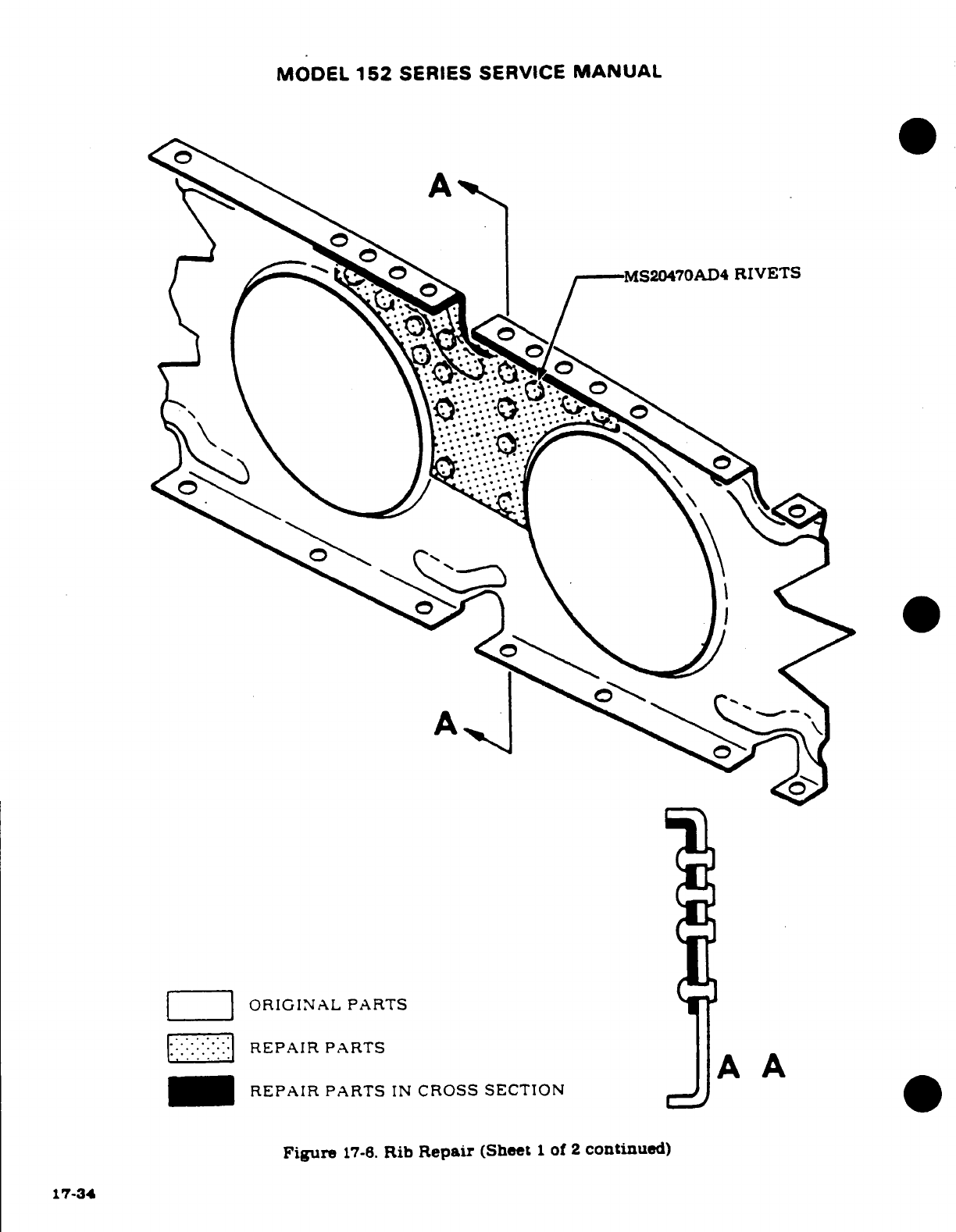
MODEL
152
SERIES
SERVICE
MANUAL
A
RIVETS
ORIGINAL
PARTS
REPAIR
PARTS
A
A
REPAIR
PARTS
IN
CROSS
SECTION
Figure
17-6.
Rib
Repair
(Sheet
1
of
2
continued)
17-34
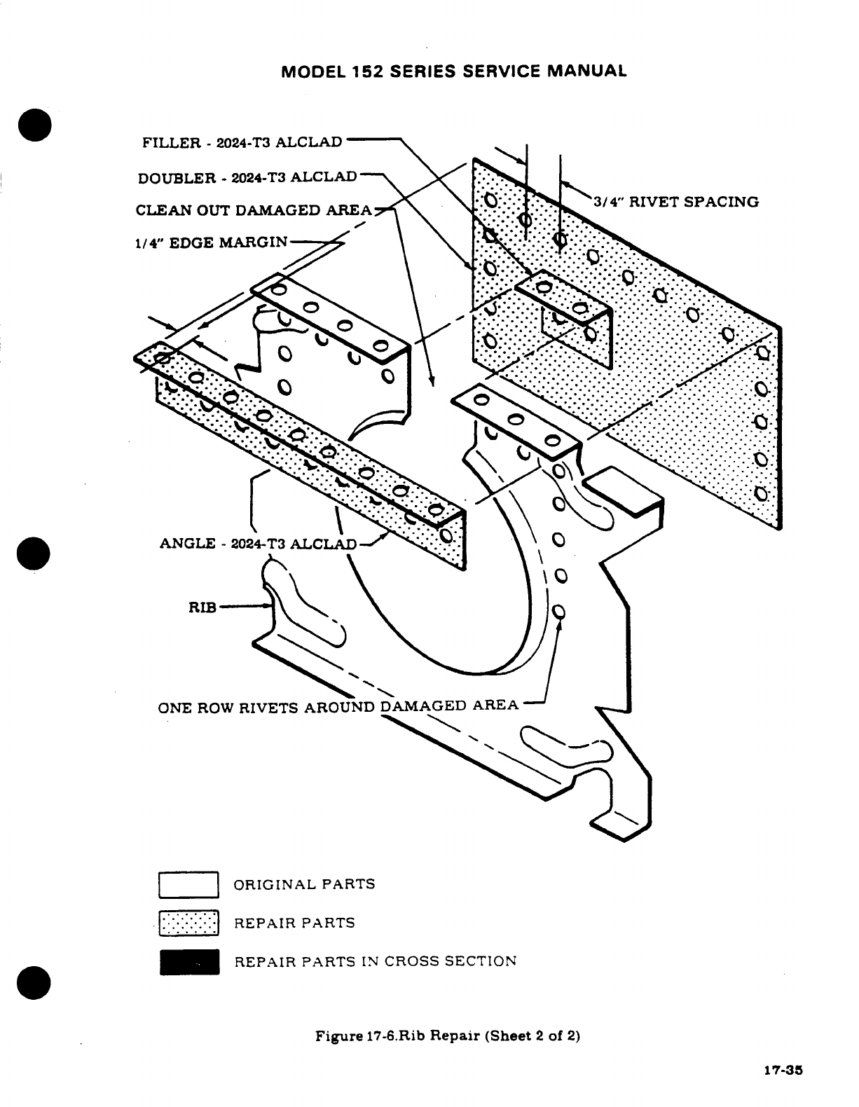
MODEL
152
SERIES
SERVICE
MANUAL
FILLER
-
2024-T3
ALCLAD
DOUBLER
-
2024-T3
ALCLAD
CLEAN
OUT
DAMAGED
AREA
34"
RIVET
SPACING
1/4"
EDGE
MARGIN----
ANGLE-
2024-T3
ONE
ROW
RIVETS
AROUND
DAMAGED
AREA
ORIGINAL
PARTS
REPAIR
PARTS
REPAIR PARTS
IN
CROSS
SECTION
Figure
17-6.Rib
Repair
(Sheet
2
of
2)
17-35
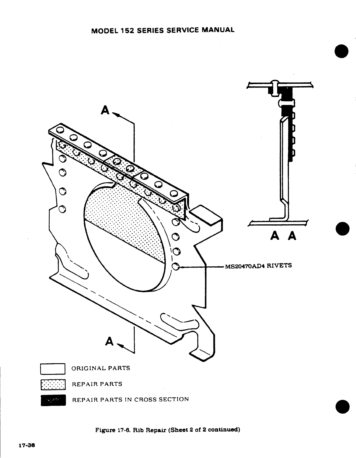
MODEL
152
SERIES SERVICE
MANUAL
A
MS20470AD4
RIVETS
ORIGINAL
PARTS
REPAIR
PARTS
REPAIR
PARTS
IN
CROSS
SECTION
Figure
17-6.
Rib
Repair
(Sheet
2
of
2
continued)
17-36
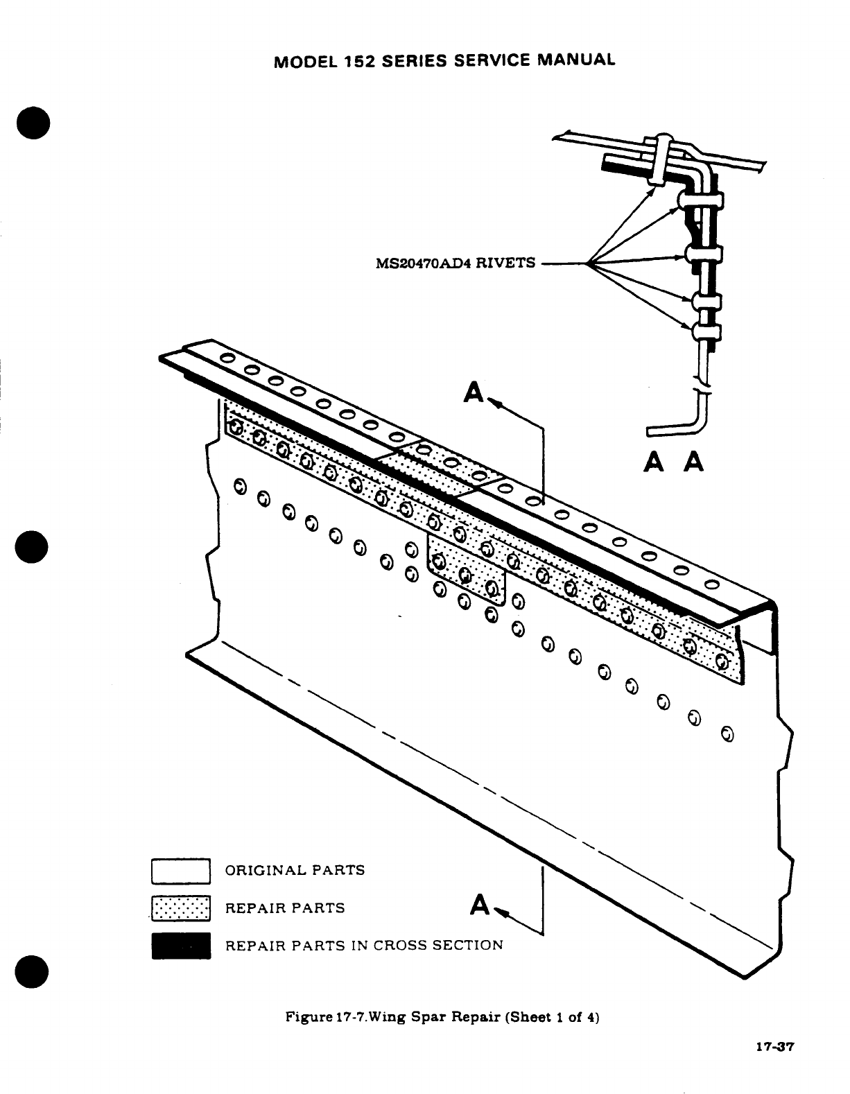
MODEL
152
SERIES
SERVICE
MANUAL
MS20470AD4
RIVETS---
A
A
ORIGINAL PARTS
REPAIR PARTS
A
REPAIR
PARTS
IN
CROSS SECTION
Figure
17-7.Wing
Spar
Repair
(Sheet
1
of
4)
17-37
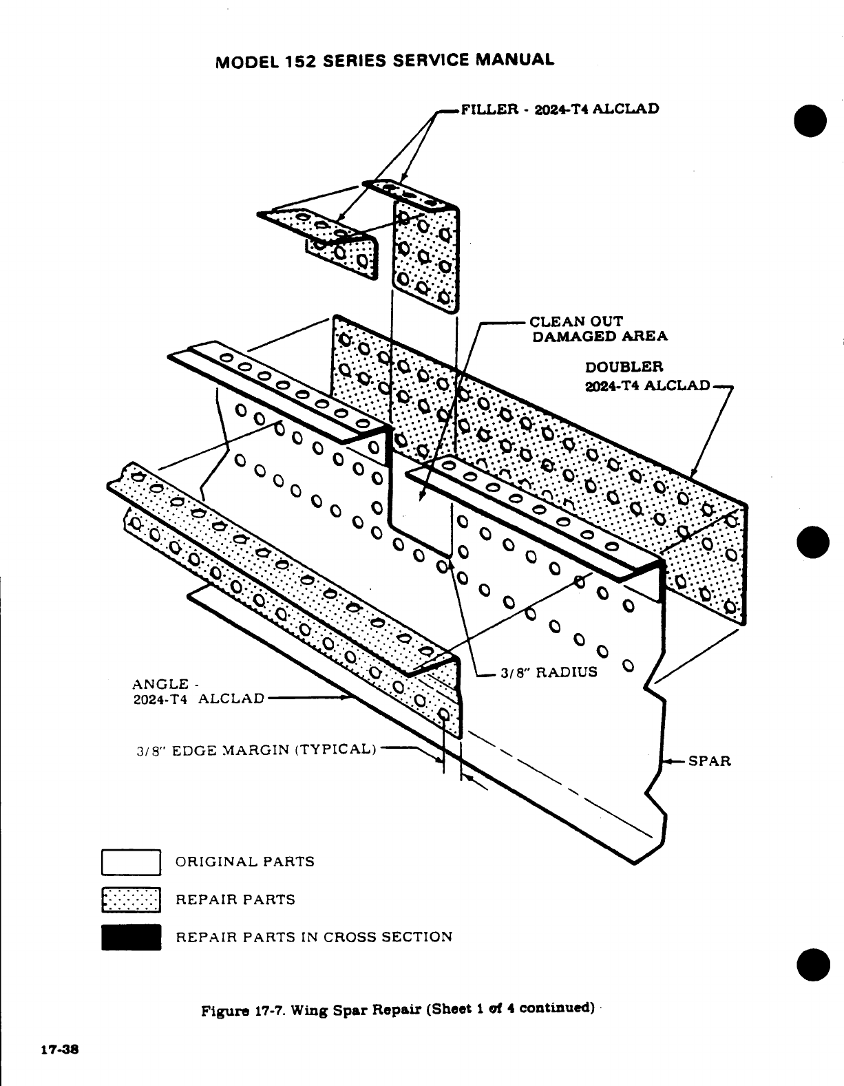
MODEL
152
SERIES
SERVICE
MANUAL
FILLER
-
2024-T4
ALCLAD
REPAIR
PARTS
IN
CROSS
SECTION
Figure
17-7.
Wing
Spar
Repair
(Sheet
1
of
4
continued)
17-38
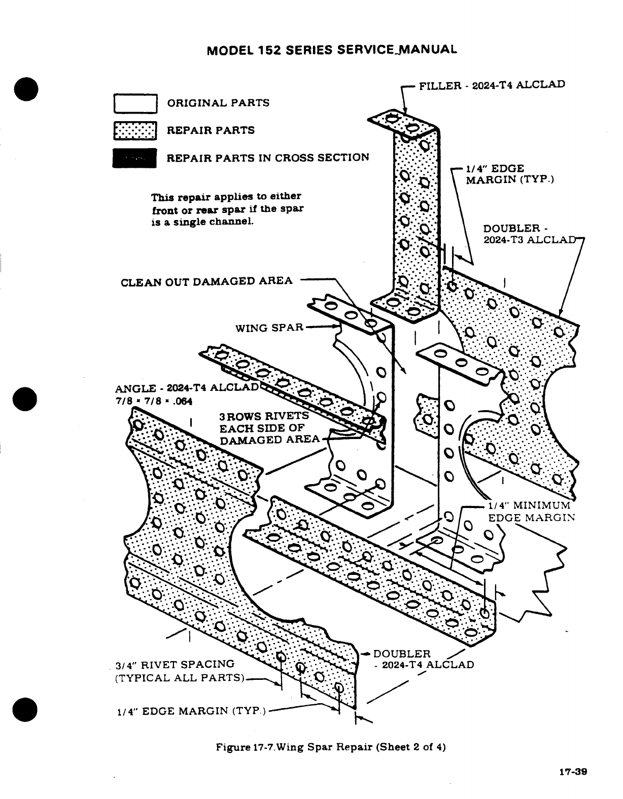
MODEL
152
SERIES
SERVICE
MANUAL
FILLER
-
2024-T4
ALCLAD
ORIGINAL
PARTS
REPAIR
PARTS
REPAIR
PARTS
IN
CROSS
SECTION
1/
4"
EDGE
MARGIN
(TYP.)
This
repair
applies
to
either
front
or
rear
spar
if
the
spar
is a
single
channel.
DOUBLER
DOUBLER
-
2024-T3
ALCLAD
CLEAN
OUT
DAMAGED
AREA
WING
SPAR
ANGLE
-
2024-T4
ALCLAD
7/8
7/8
.064
3
ROWS
RIVETS
EACH
SIDE
OF
DAMAGED
AREA
1/4"
MINIMUM
EDGE
MARGIN
DOUBLER
3/4"
RIVET
SPACING
-
2024-T4
ALCLAD
(TYPICAL
ALL
PARTS)
1/4"
EDGE MARGIN
(TYP.)
Figure
17-7.Wing
Spar
Repair
(Sheet
2
of
4)
17-39
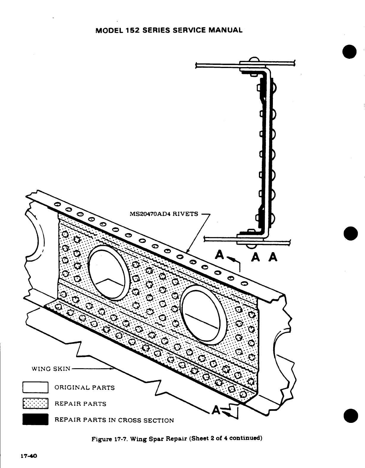
MODEL
152
SERIES
SERVICE
MANUAL
0
MS20470AD4
RIVETS
A
AA
ORIGINAL
PARTS
REPAIR
PARTS
REPAIR PARTS
IN
CROSS
SECTION
Figure
17-7.
Wing
Spar
Repair
(Sheet
2
of
4
continued)
17-40
l7-*0
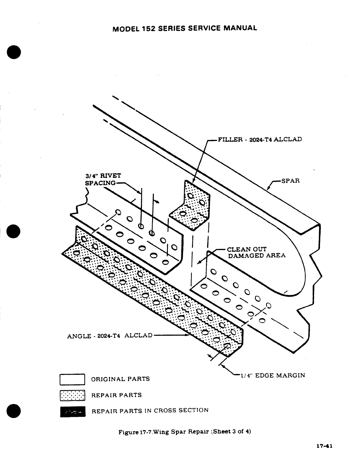
MODEL
152
SERIES
SERVICE
MANUAL
FILLER
-
2024-T4
ALCLAD
3/4"
RIVET
SPACIN
Figure
17-7.Wing
Spar
Repair
Sheet
3
of
4)
17-41
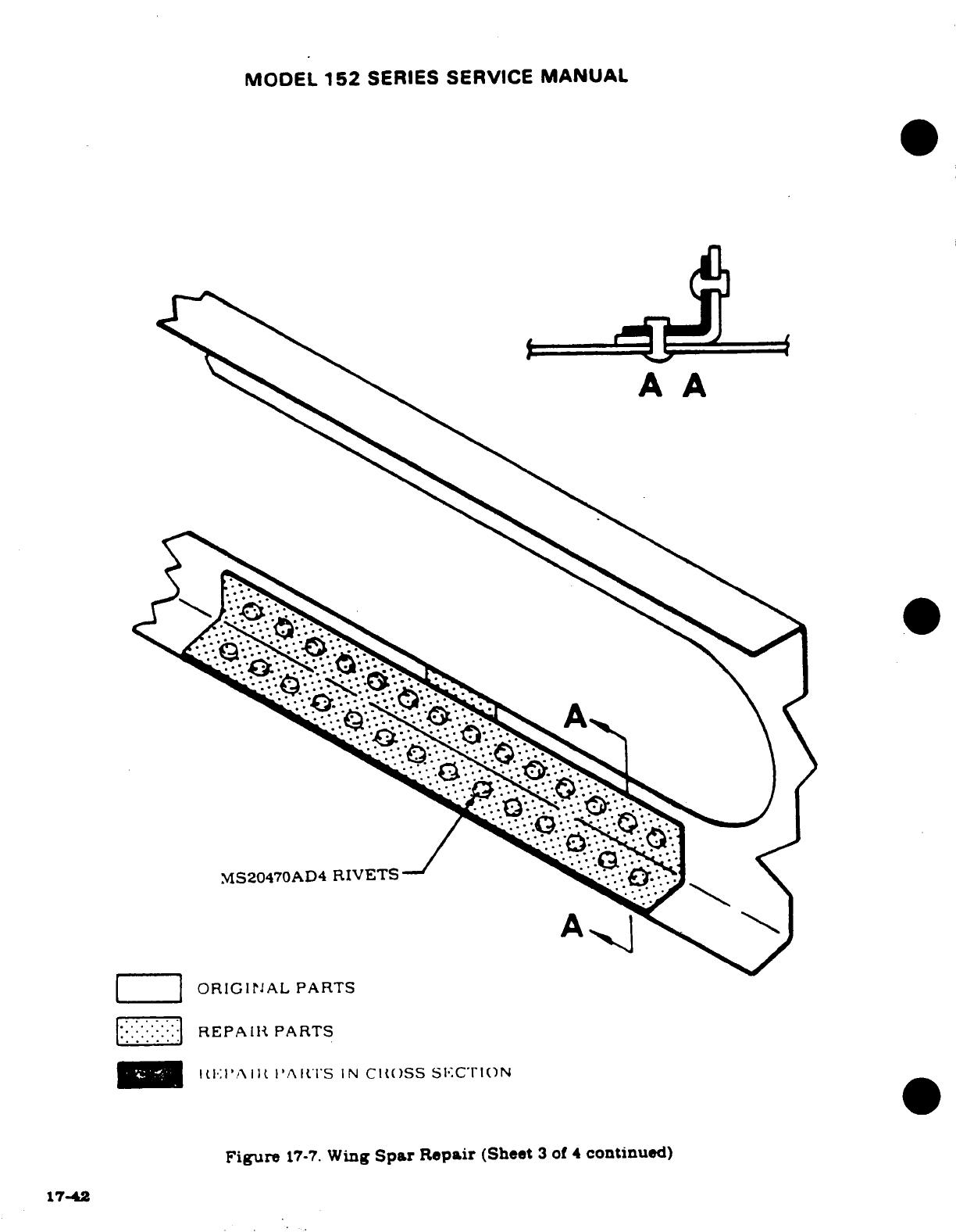
MODEL
152
SERIES
SERVICE
MANUAL
,MS20470AD4
RIVETS
REPAIR
PARTS
S
Figure
17-7.
Wing
Spar
Repair
(Sheet
3
of
4
continued)
17-42
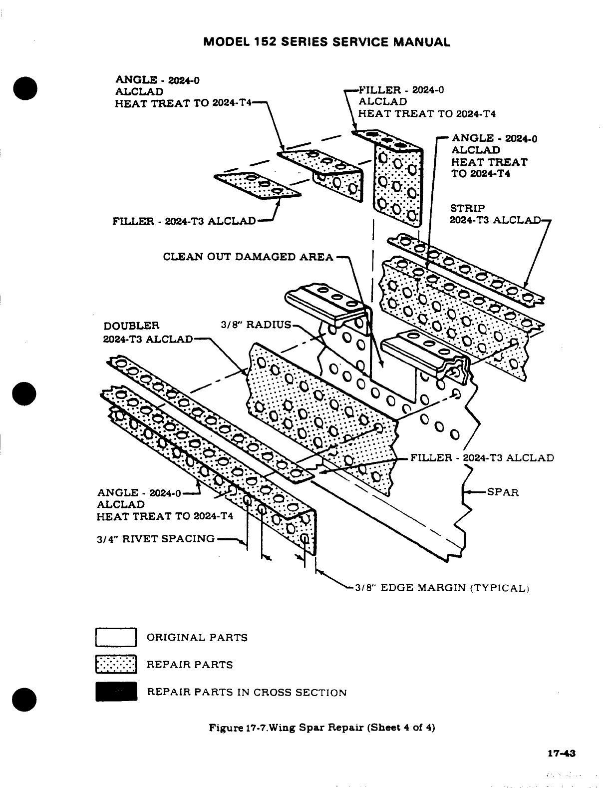
MODEL
152
SERIES SERVICE
MANUAL
ANGLE
-
2024-0
ALCLAD
T-FILLER
-
2024-0
HEAT
TREAT
TO
2024-T4
ALCLAD
HEAT
TREAT
TO
2024-T4
ANGLE
-
2024-0
ALCLAD
* 0
IHEAT
TREAT
TO
2024-T4
STRIP
FILLER
-
2024-T3
ALCLAD
2024-T3ALCLAD
FILLER
-
2024-T3
ALCLAD
2024-T3
ALCLAD
3/8'
EDGE
MARGIN
(TYPICAL)
REPAIR PARTS
REPAIR
PARTS
IN
CROSS
SECTION
Figure
17-7.Wing
Spar
Repair
(Sheet
4
of
4)
17-43
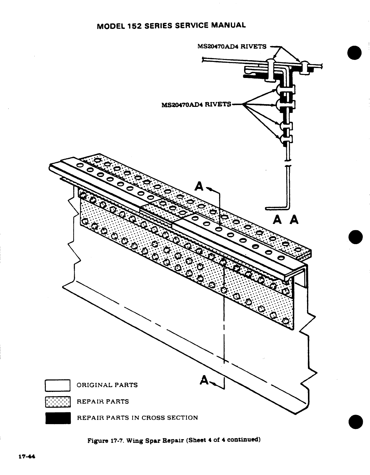
MODEL
152
SERIES SERVICE
MANUAL
MS20470AD4
RIVETS
MS20470AD4
RIVETS
lORIGINAL
PARTS
A
REPAIR
PARTS
REPAIR
PARTS
IN
CROSS SECTION
Figure
17-7.
Wing
Spar
Repair
(Sheet
4
of
4
continued)
17-44
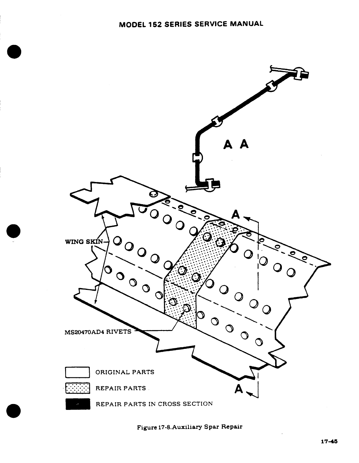
MODEL
152
SERIES
SERVICE
MANUAL
A
A
WING
SKIN
MS20470AD4
RIVETS
ORIGINAL PARTS
REPAIR
PARTS
REPAIR
PARTS
IN
CROSS
SECTION
Figure
17-8.Auxiliary
Spar
Repair
17-45
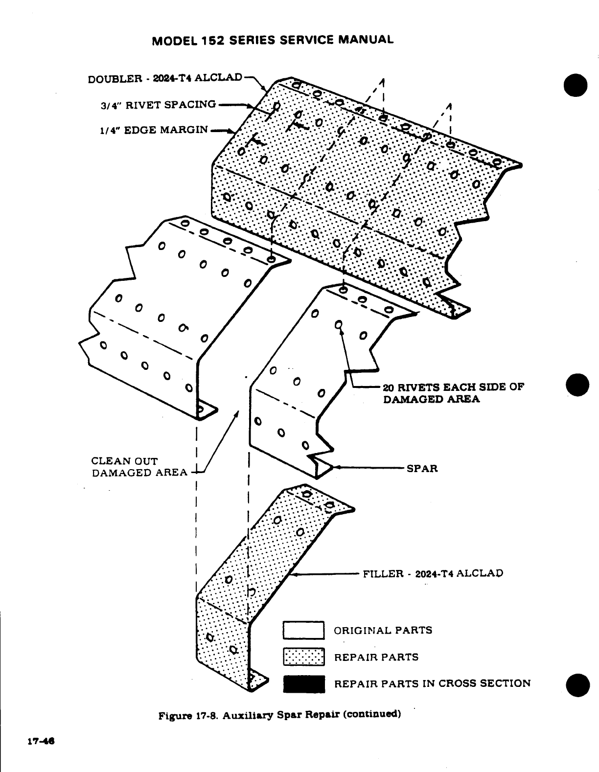
MODEL
152
SERIES
SERVICE
MANUAL
DOUBLER
-
2024-T4
ALCLAD
3/4"
RIVET
SPACING
20
RIVETS
EACH
SIDE
OF
DAMAGED
AREA
CLEAN
OUT
DAMAGEDE
-SPAR
FILLER
-
2024-T4
ALCLAD
REPAIR
PARTS
IN
CROSS
SECTION
Figure
17-8.
Auxiliary
Spar
Repair
(continued)
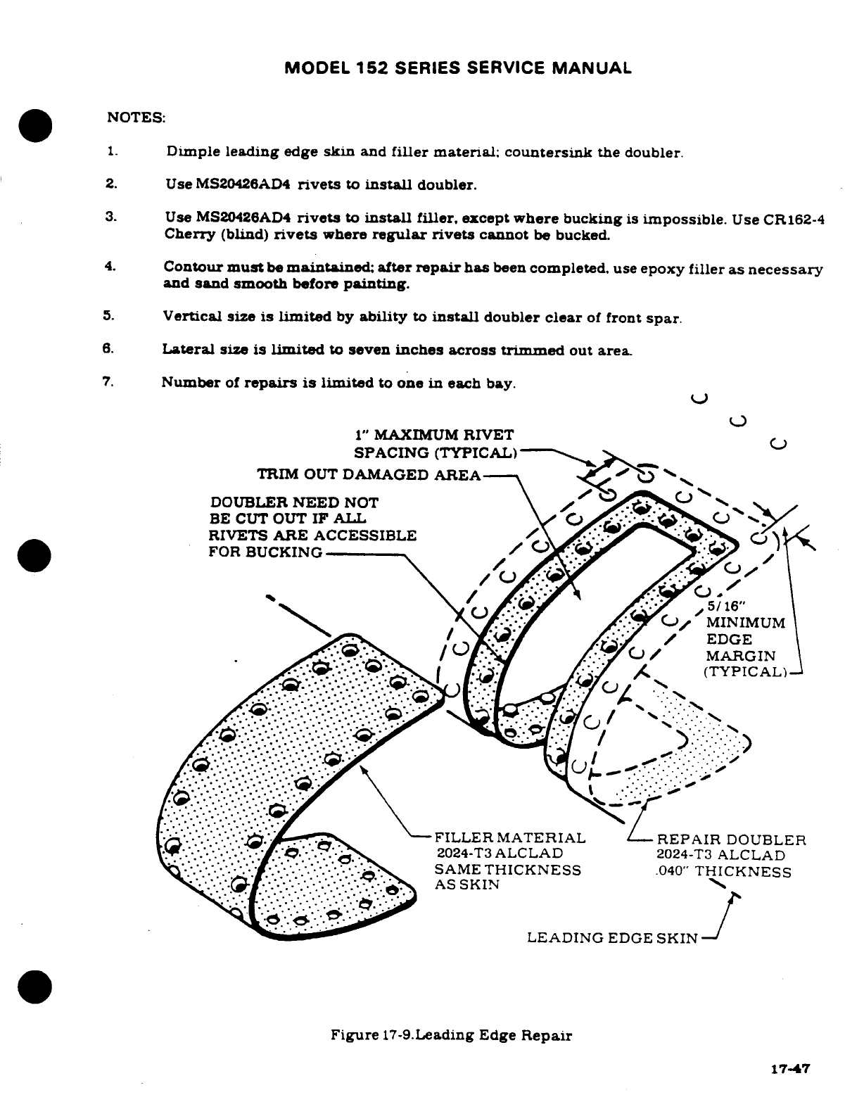
MODEL
152
SERIES SERVICE
MANUAL
NOTES:
1.
Dimple
leading
edge
skin
and
filler
material;
countersink
the
doubler.
2.
Use
MS20426AD4
rivets
to
install
doubler.
3.
Use
MS20426AD4
rivets
to
install
filler,
except
where
bucking
is
impossible.
Use
CR162-4
Cherry
(blind)
rivets
where
regular
rivets
cannot
be
bucked.
4.
Contour
must
be
maintained; after
repair
has
been
completed.
use
epoxy
filler as
necessary
and
sand
smooth
before
painting.
5.
Vertical
size
is
limited
by
ability
to
install
doubler
clear
of
front
spar.
6.
Lateral
size
is
limited
to
seven
inches
across
trimmed
out
area
7.
Number
of
repairs
is
limited
to
one
in
each bay.
1"
MAXIMUM
RIVET
SPACING
(TYPICAL)
TRIM OUT
DAMAGED
AREA
DOUBLER
NEED
NOT
BE
CUT
OUT
IF
ALL
RIVETS
ARE
ACCESSIBLE
FOR
BUCKING
5/16"
MINIMUM
EDGE
MARGIN
(TYPICAL)
FILLER
MATERIaL
REPAIR
DOUBLER
2024-T3ALCLAD
2024-T3
ALCLAD
SAME
THICKNESS
040"
THICKNESS
AS
SKIN
LEADING
EDGE
SKIN
Figure
17-9.Leading
Edge
Repair
17-47
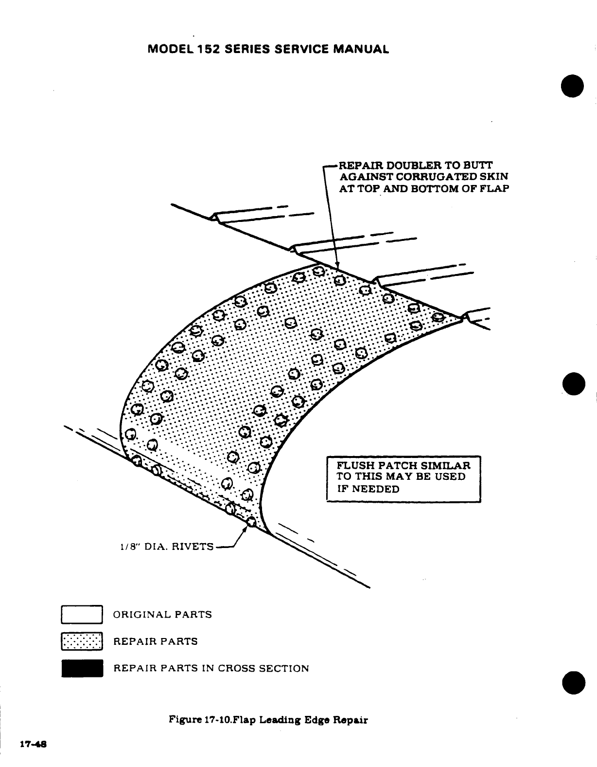
MODEL
152
SERIES SERVICE
MANUAL
REPAIR
DOUBLER
TO
BUTT
AGAINST
CORRUGATED
SKIN
AT
TOP
AND BOTTOM
OF
FLAP
ORIGINAL
PARTS
REPAIR
PARTS
REPAIR
PARTS
IN
CROSS
SECTION
Figure
17-10.Flap
Leading
Edge
Repair
17-48
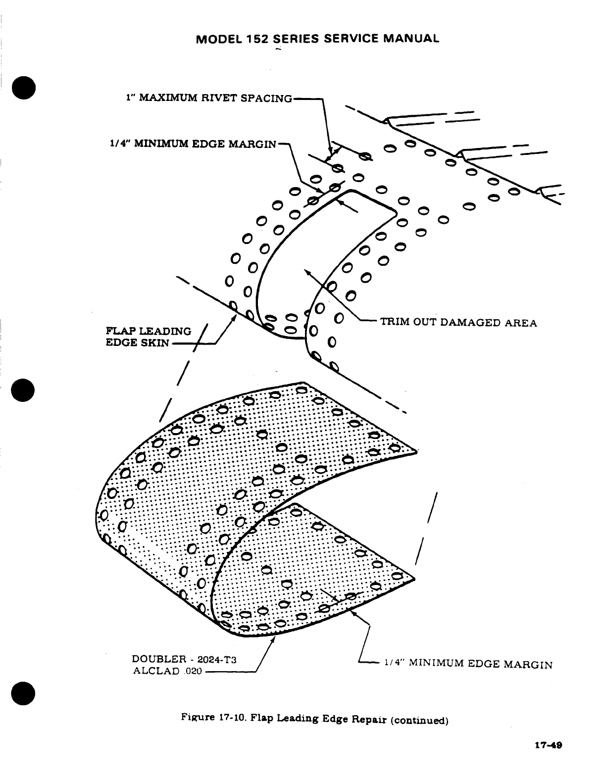
MODEL
152
SERIES
SERVICE
MANUAL
1"
MAXIMUM
RIVET SPACING
1/4"
MINIMUM
EDGE
MARGIN
TRIM
OUT
DAMAGED
AREA
ALCLAD
.020
EDGE
SKIN
Figure
17-10.
Flap
Leading
Edge
Repair
(continued)
17-49
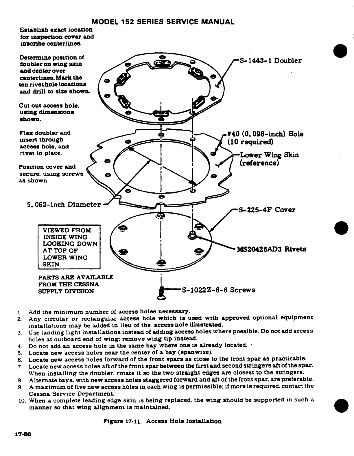
MODEL
152
SERIES
SERVICE
MANUAL
Establish
exact
location
for
inspection
cover
and
inscribe
centerlines.
Determine
position
of
doubler
on
wing
skin
S-
1443-1
Doubler
and
center
over
centerlines
Mark
the
ten
rivet
hole
locations
and
drill
to
size
shown.
Cut
out
access
hole,
using
dimensions
shown.
Flex
doubler
and
-#40
(0.098-inch)
Hole
insert
through
(10
required)
acces
hole.
and
rivet
in
place.
Lower
Wing
Skin
Position
cover
and
(reference)
secure.
using
screws
as
shown.
5.
062-inch
Diameter
S-225-4F
Cover
VIEWED
FROM
INSIDE
WING
LOOKING
DOWN
AT
TOP
OF
MS20426AD3
Rivets
LOWER WING
SKIN.
PARTS
ARE
AVAILABLE
FROM
THE
CESSNA
SUPPLY
DIVISION
g-S-1022Z-8-6
Screws
1.
Add
the
minimum
number
of
access
holes
necessary.
2.
Any
circular or
rectangular
access
hole
which
is
used
with
approved
optional
equipment
installations
may
be
added in
lieu
of
the
access
nole
illustrated.
3.
Use
landing
light
installations
instead
of
adding
access
holes
where
possible.
Do
not
add
access
holes at
outboard
end
of
wing. remove
wing
tip
instead.
4.
Do
not
add
an
access
hole
in
the
same
bay
where
one
is
already
located.
-
5.
Locate
new
access holes near
the
center
of
a
bay
(spanwise).
6.
Locate
new
access
holes
forward
of
the front
spars
as close
to
the
front
spar
as
practicable.
7.
Locate
new
access holes
aft
of
the front
spar
between
the
first
and
second
stringers
aft
of
the
spar.
When
installing
the
doubler,
rotate
it
so
the
two
straight
edges
are closest
to
the
stringers.
8.
Alternate bays.
with
new
access
holes
staggered
forward and
aft
of
the
front
spar.
are
preferable.
9.
A
maximum
of
five
new
access
holes
in
each
wing
is
permissible:
if
more
is
required.
contact
the
Cessna Service Department.
10.
When
a
complete
leading
edge
skin
is
being
replaced.
the
wing
should
be
supported
in
such
a
manner
so
that
wing
alignment
is
maintained.
Figure
17-11.
Access
Hole
Installation
17-50
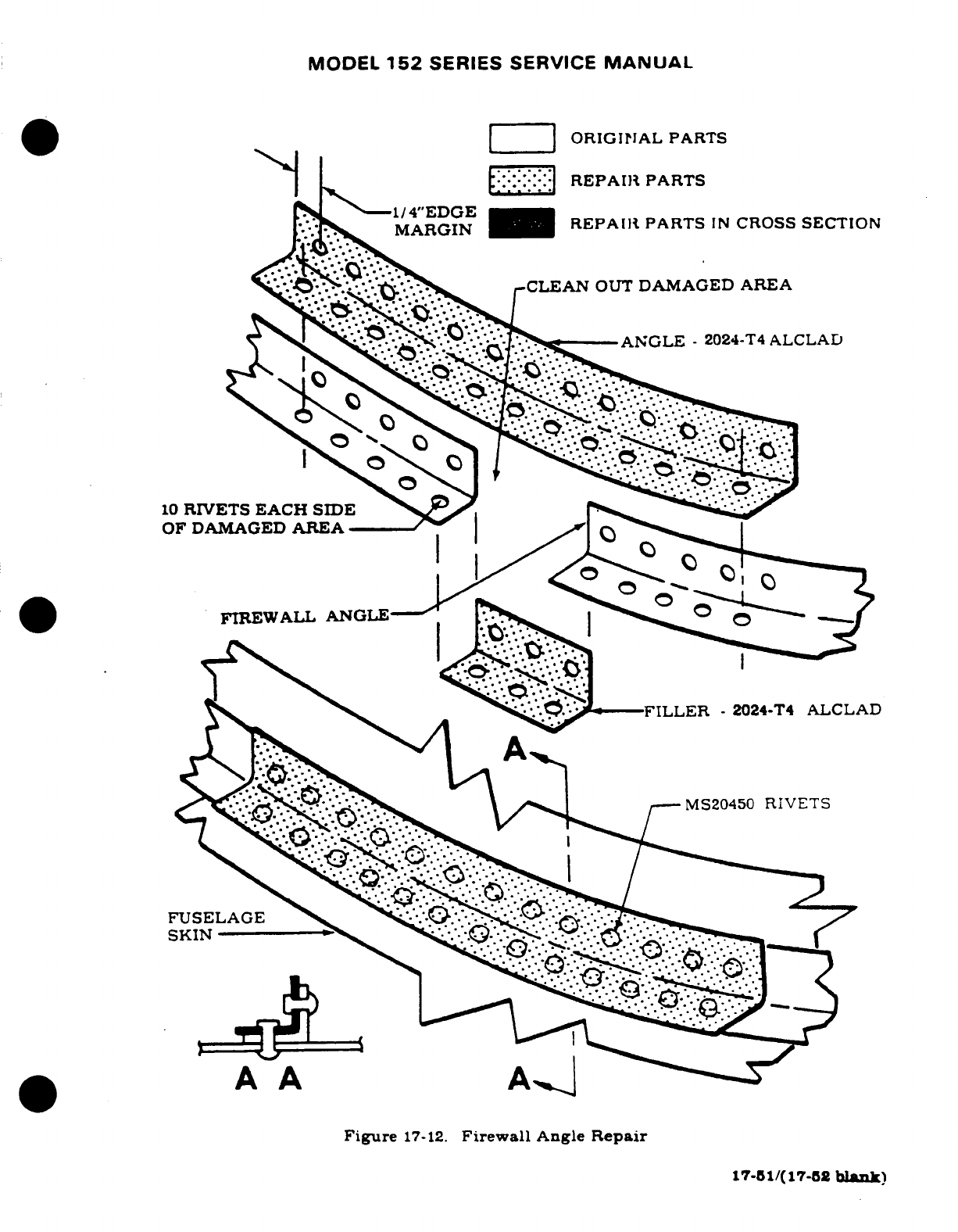
MODEL
152
SERIES
SERVICE
MANUAL
ORIGINAL
PARTS
REPAIR
PARTS
1/4"EDGE
MARGIN
REPAIR
PARTS
IN
CROSS
SECTION
-CLEAN
OUT
DAMAGED AREA
ANGLE
-
2024-T4
ALCLAD
10
RIVETS EACH
SIDE
OF DAMAGED
AREA
FIREWALL ANGLE
FUSELAGE
.
A
A
Figure
17-12.
Firewall
Angle
Repair
17-51/(17-52
blank)
MODEL
152
SERIES
SERVICE
MANUAL
SECTION
18
PAINT
Page
No.
TABLE
OF CONTENTS
Aerofiche/
Manual
MATERIALS
................
2I22/18-2
Prepriming
..............
2J2/18-6
Painting
ABS
... .........
2122/18-2
Priming
.................
2J2/18-6
Interior
Parts
............
2I22/18-2
Prepainting
...............
2J3/18-7
Exterior
Parts
.............
2123/18-3
Painting
.................
2J3/18-7
Engine
Mounts
...........
2I24/18-4
Masking
.............
2J3/18-7
MATERIALS
...............
2I24/18/4
Touch
Up
................
24/18-8
Facility
..................
2J1/18/5
Repair
of
Dents
............
2J4/18-8
Clean-Up
.................
2J1/18-5
NOTE
This
section
contains
a
listing
of
standard
factory
mate-
rials
and
areas
of
application.
For
paint
number
and
col-
or,
refer
to
Aircraft
Trim
Plate
and
Parts
Catalog.
In
all
cases
determine
the
type
of
paint
on
the
airplane,
be-
cause
some
types
of
paint
are
not compatible.
Contact
Cessna
Parts
Distribution
(CPD
2)
or
a
Cessna
Service
Station
for
materials
acquisition
information.
NOTE
Do
not
paint
pitot
tube,
fuel
caps.
aileron
gap
seals nor
antenna
covers
that
were
not
painted
at
the
factory.
NOTE
Control
surfaces.
except
for
wing
flaps.
require
balanc-
ing
after
painting.
Refer
to
Section
17
for balancing
procedures.
Revision
1
18-1
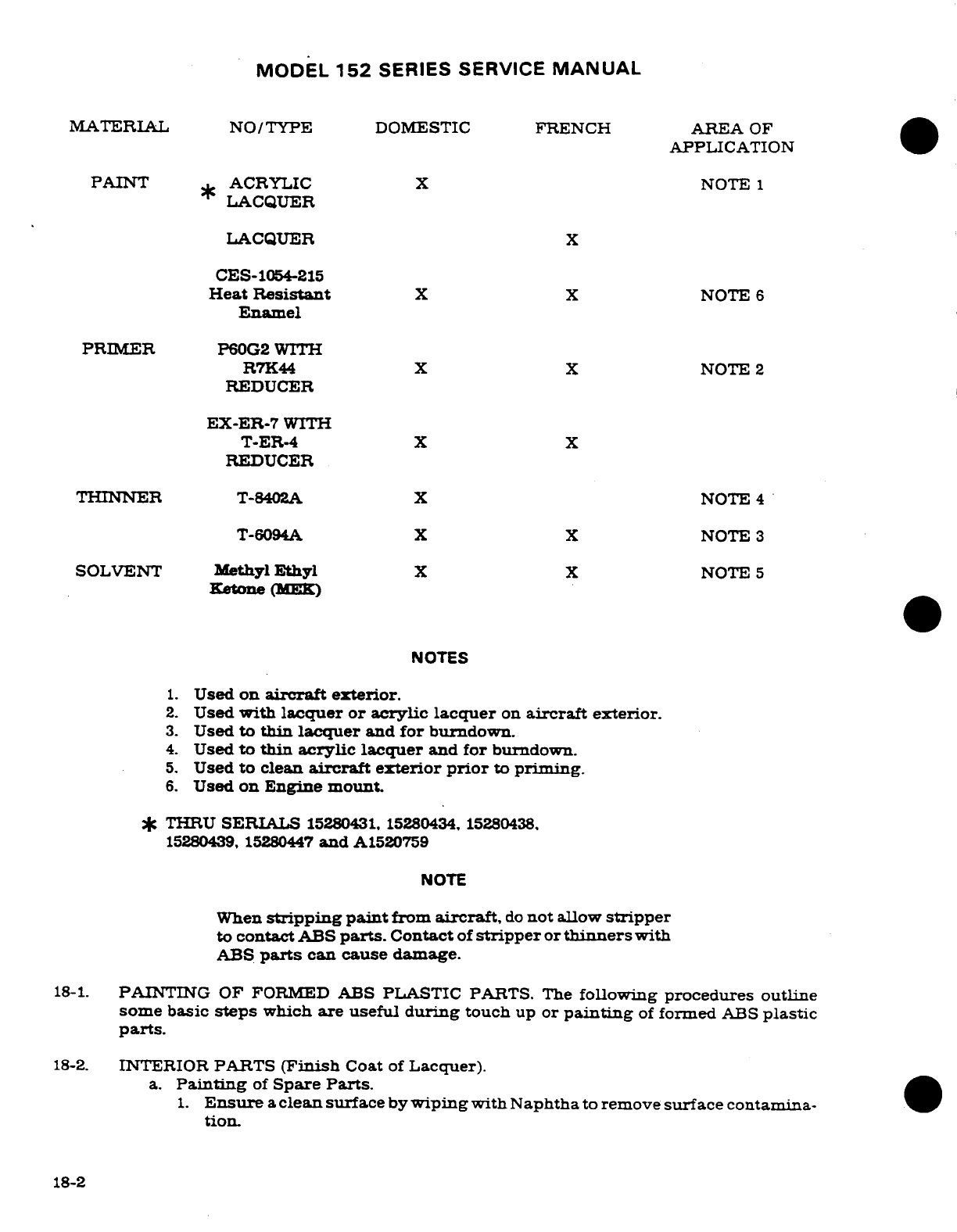
MODEL
152
SERIES SERVICE
MANUAL
MATERIAL
NO/TYPE
DOMESTIC
FRENCH
AREA
OF
APPLICATION
PAINT
ACRYLIC
X
NOTE
1
LACQUER
LACQUER
X
CES-1054-215
Heat
Resistant
X
X
NOTE
6
Enamel
PRIMER
P60G2
WITH
R7K44
X
X
NOTE
2
REDUCER
EX-ER-7
WITH
T-ER-4
X
X
REDUCER
THINNER
T-8402A
X
NOTE
4
T-6094A
X
X
NOTE
3
SOLVENT
Methyl
Ethyl
X X
NOTE
5
Ketone
(1EK)
NOTES
1.
Used
on
aircraft
exterior.
2.
Used
with
lacquer or acrylic
lacquer
on
aircraft
exterior.
3.
Used
to
thin
lacquer
and
for
burndown.
4.
Used
to
thin
acrylic lacquer
and
for
burndown.
5.
Used
to clean
aircraft exterior
prior
to
priming.
6.
Used
on
Engine
mount.
*
THRU
SERIALS
15280431. 15280434.
15280438.
15280439,
15280447
and
A1520759
NOTE
When
stripping
paint
from
aircraft,
do
not
allow
stripper
to
contact
ABS
parts.
Contact
of
stripper
or
thinners
with
ABS
parts
can cause
damage.
18-1.
PAINTING
OF FORMED
ABS
PLASTIC
PARTS. The
following
procedures
outline
some
basic
steps
which
are
useful
during
touch
up
or
painting
of
formed
ABS
plastic
parts.
18-2.
INTERIOR
PARTS
(Finish
Coat
of
Lacquer).
a.
Painting
of
Spare
Parts.
1.
Ensure
a
clean
surface
by
wiping
with
Naphtha
to
remove
surface
contamina-
0
tion.
18-2
MODEL
152
SERIES
SERVICE
MANUAL
CAUTION
Do
not
use
strong
solvents
such
as
Xylol. Toluol
or
Lacquer
Thinner
since
prolonged
exposure
can
soften
or
embrittle
ABS.
2.
After
the
part
is
thoroughly
dry
it is
ready
for
the
lacquer
topcoat
Paint
must
be
thinned
with
lacquer
thinner
and
applied
as
a
wet
coat
to
ensure
adhesion.
b.
Touch
Up
of
Previously
Painted
Parts.
1.
Light
sanding
is
acceptable
to
remove
scratches
and
repair
the
surface but
care
must
be
exercised
to
maintain
the
surface
texture
or
grain.
2.
Ensure
a
clean
surface
by
wiping
with
Naptha
to
remove
surface
contamination.
CAUTION
Do
not
use
strong
solvents
such
as
Xylol.
Toluol
or
Lacquer
Thinner
since
prolonged
exposure
can soften
or
embrittle
ABS.
3.
After
the
part
is
thoroughly
dry
it is
ready
for the
lacquer
topcoat.
Paint
must
be
thinned
with
lacquer
thinner
and
applied
as
a
wet
coat
to
ensure
adhesion.
NOTE
Lacquer
paints
can
be
successfully
spotted
in.
18-3-
EXTERIOR
PARTS
(Acrylic
Topcoat).
a.
Painting
of
Spare
Parts.
1.
Light
scuff
sand
to
remove
scratches
and
improve
adhesion.
2.
Ensure
a
clean
surface
by
wiping
with
Naphtha
to
remove
surface
contamina-
tion.
CAUTION
Do
not
use
strong
solvents
such as
Xylol. Toluol
or
Lacquer
Thinner
since
prolonged exposure
can soften
or
embrittle
ABS.
3.
After
the
part
is
thoroughly
dry
it is
ready
for
the
topcoat.
Paint
must
be
thinned
with
appropriate
acrylic
thinner
and
applied
as
a
wet
coat
to
ensure adhesion.
b.
Touch
Up
of
Previously
Painted
Parts.
1.
Lightly
scuff
sand
to
remove
scratches
and
improve adhesion.
2.
Ensure
a
clean
surface
by
wiping
with
Naphtha
to
remove
surface
contamina-
tion.
CAUTION
Do
not
use
strong solvents
such
as
Xylol. Toluol
or
lacquer Thinner
since
prolonged
exposure
can soften
or
embrittle
ABS.
3.
Apply
a
compatible
primer
-
surfacer
and
sealer.
18-3
MODEL
152
SERIES SERVICE
MANUAL
4.
After
the
part
is
thoroughly
dry
it is
ready
for
the
topcoat. Paint
must
be
thinned
0
and
applied
as
a
wet
coat
to
ensure
adhesion.
NOTE
Acrylic
topcoats can
be
successfully
spotted
in.
18-4.
REFINISHING
ENGINE
MOUNTS.
After
completing
a
repair
as
directed
in
Section
17.
refinish
with
P/N
CES
1054-215
Heat
Resistant
Enamel.
Black.
Degrease
and
scuff
sand
or
grit
blast
entire
area
to
bare
metal.
Spray
enamel
to
a
dry
film
thickness
of
0.001"
to
0.0013".
and
cure
at
250OF
for
15
minutes.
Part
can
be
handled
as
soon
as
cool
to
touch.
NOTE
BEGINNING
SERIALS
15280432.
15280433.
15280435.
15280436.
15280437.
15280440
THRU
15280446,
and
A1520760.
IMRON
MODIFIED
URETHANE
MATERIAL
NO/TYPE
AREA
OF
APPLICATION
PRIMER
WASH
PRIMER
P60G2
Used
to
prime
aircraft
for
Imron
Enamel
REDUCER
Catalyst
Reducer
R7K44
Used
to
reduce
P60G2
PAINT
Imron
Enamel
Used
as
corrosion
proof
topcoat
IMRON
192S
Activator
Catalyst
for
Imron
Enamel
THINNER
IMRON
Y8485S
Reducer
Used
to
thin
Imron
Enamel
NOTE
Do
not
paint
pitot
tube,
gas
caps. or
aileron
gap
seals.
Also
do
not
paint
antenna
covers
which
were
not
painted
at
the
factory.
18-4
18-4
MODEL
152
SERIES
SERVICE
MANUAL
REQUIRED
MATERIALS
MATERIAL
NO/TYPE
AREA
OF
APPLICATION
STRIPPER
Strypeeze
Stripper
Used
to
strip
primer overspray
CLEANER
DX440
Wax
and
Grease
Used
to
clean
aircraft
exterior
Remover
Imperial
Cleaner
Used
to
remove grease,
bug stains.
etc.
Klad
Polish
Used
to
clean aluminum
finish
808
Polishing
Compound
Used
to
rub
out
overspray
SOLVENT
(MEK)
Methyl
Ethyl
Ketone
Used
to
clean
aircraft
prior
to
topcoat
CLOTH
HEX
Wiping
Cloth
Used
to
clean
aircraft
exterior
FILLER
White
Streak
Used
to
fill
small
dents
MASKING
Class
A
Solvent
Proof
Paper
Used to
mask areas
not
to
be
painted
Tape
Y218
Used
for
masking
small
areas
Tape
Y231
Used
for
masking
small
areas
18-5.
FACILITY.
Painting facilities
must
include
the
ability
to
maintain
environmental control
to
a
minimum
temperature
of
65°F..
and
a
positive
pressure
inside
to
preclude
the
possibility
of
foreign
material
damage.
All
paint
equipment
must
be
clean,
and
accurate
measuring
containers
available
for
mixing
protective
coatings.
Modified
Urethane
has
a
pot
life
of
four
to
eight
hours.
depending
on
ambient
temperature
and
relative
humidity.
Use
of
approved
respirators
while
painting
is a
must,
for
personal
safety.
All
solvent
containers
should
be
grounded
to
prevent
static
build-up.
Catalyst
materials
are
toxic,
therefore.
breathing
fumes
or allowing
contact
with
skin
can
cause
serious
irritation.
Material
stock
should
be
rotated
to
allow
use
of
older
materials
first.
because
its
useful
life
is
limited.
All
supplies
should
be
stored
in
an
area
where
temperature
is
higher
than
50°F.,
but
lower
than
90°F.
Storage
at
90°
F.
is
allowable
for
no
more
than
sixty
days
providing
it is
returned
to
room
temperature
for
mixing
and
use.
Modified
urethane
paint
requires
a
minimum
of
seven
days
to
cure
under
normal conditions.
if
humidity
and
temperature
is
lower.
curing
time
will
be
extended
to
a
maximum
of
14
days.
During
the
curing
period,
indiscriminate
use
of
masking
tape,
abrasive
polishes.
or
cleaners
can
cause
damage
to
finish.
Desirable
curing
temperature
for
modified
urethane
is
60°F.
for
a
resulting
satisfactory finish.
18-6.
CLEAN
UP.
a.
Inspect
airplane
for any
surface
defects.
such
as
dents
or
unsatisfactory
previous
repairs.
and
correct according
to
Paragraph
18-13.
18-5
MODEL
152
SERIES
SERVICE
MANUAL
b.
Wipe
excess
sealer
from
around
windows
and
skin laps.
Mask
windows.
ABS
parts.
and
any
other
areas
not
to
be
primed, with
3M
tape and
Class
A
Solvent
Proof
Paper.
Care
must
be
exercised
to
avoid
cuts,
scratches
or
gouges
by
metal
objects
to
all
plexiglass
surfaces,
because
cuts
and
scratches
may
contribute
to
craing
and
failure
of
plexiglass
windows.
c.
Methyl
Ethyl
Ketone
(MEK)
solvent
should
be
used
for
final
cleaning
of
airplanes
prior
to
painting.
The
wiping
cloths
shall
be
contaminant
and
lint
tree
HEX.
Saturate
cloth
in
the
solvent
and
wring
out
so
it
does
not
drip.
Wipe
the
airplane
surface
with
the
solvent
saturated
cloth
in
one
hand.
and
immediately
dry with
a
clean
cloth
in
the
other
hand.
It is
important
to
wipe
dry
solvent
before
it
evaporates.
When
an
airplane
has
paint
or
zinc
chromate
overspray
on
the
exterior,
stripper
may
be
used
to
remove
the
overspray.
The
stripper
may
be
applied
by
brush
and
will
require
a
few
minutes
to
soften
the
overspray.
Heavy
coatings
may
require
more
than
one
application
of
the
stripper.
Use
extreme
care
to
prevent
stripper
from
running
into
faying
surfaces
on
corrosion
proofed
airplanes.
After
removal
of
the
overspray,
clean
the
airplane
with
Methyl
Ethyl
Ketone
(MEK)
solvent
in
the
prescribed manner.
NOTE
It is
imperative
that
clean
solvent
be
used
in
cleaning
airplanes.
Dispose
of
contaminated
solvent
immediately.
Fresh
solvent
should
be
used
on
each
airplane.
WARNING
Use
explosion
proof
containers
for
storing
wash
solvents
and
other
flammable
materials.
18-7.
PRE-PRIMING.
a.
For
all
standard
aircraft.
P60G2
primer shall
be
mixed
one
part primer
to
one and one
half
parts
R7K44
catalyst
by
volume,
mix
only
in
stainless
steel
or
lined
containers.
After
mixing,
allow
primer
to
set
for
thirty
minutes
before
spraying.
Pot
life
of
the
mixed
primer
is
six
hours.
All
mixed
material
should
be
discarded
if
not
used
within
this
time.
Pot
pressure during
spray
operation should
be
approximately
10t
1
psi.
Air
pressure
should
be
40
to
50
psi
at
the
gun.
Blow
loose
contaminant
off
the
airplane
with
a
jet
of
clean, dry
air.
Cover
the
flap
tracks,
nose
gear
strut
tube,
wheels,
and
shimmy dampener
rod
ends.
ABS
parts
and
other pre-primed
parts
do
not
receive
wash
primer.
WARNING
AIRCRAFT
SHOULD
BE
GROUNDED
PRIOR
TO
PAINTING
TO
PREVENT
STATIC
ELECTRICITY
BUILD-UP
AND
DISCHARGE.
18-8.
PRIMING.
a.
Apply
primer
in
one
wet
even coat.
Dry
film
thickness
to
be
.0003
to
.0005
inches.
Do
not
topcoat
until
sufficiently
cured.
When
scratching
with
firm
pressure
of
the
fingernail
does
not
penetrate
the
coating,
the
primer
is
cured.
Primer
should
be
topcoated
within four
hours
after
application.
18-6
MODEL
152
SERIES
SERVICE
MANUAL
18-9.
PREPAINTING.
a. On
standard
aircraft
mix
the
required
amount
of
Imron
with
Imron
192S
Activator
in
a
3
to
1
ratio.
Mix
thoroughly
(no
induction
time
required
before
spraying).
Imron
shall
be
thinned
with
Y8485S
Imron
Reducer
to
obtain
a
spraying
viscosity
of
18
to
22
seconds
on
a
No.
2
Zahn
Cup.
Viscosity
should
be
checked
after
4
hours
and
adjusted
if
necessary.
b.
When
applying
modified
urethane
finishes,
the
painter
should
wear
an
approved
respirator,
which
has
a
dust
filter
and
organic
vapor
cartridge,
or
an
air
supplied
respirator.
All
modified
urethane
finishes
contain
some
isocyanate,
which
may
cause
irritation
to
the
respiratory tract
or
an
allergic
reaction.
Individuals
may
become
sensitized
to
isocyanates.
c.
The
pot
life
of
the
mixture
is
approximately
6-8
hours at
75°F.
Pot
pressure
should
be
approximately
12
psi
during
application.
Air
pressure
at
the
gun
should
be
40
to
50
psi.
d.
Scuff
sand
the
primer
only
where
runs
or
dirt
particles
are
evident.
Minor
roughness
or
grit
may
be
removed
by
rubbing
the
surface with
brown
Kraft
paper
which
has
been
thoroughly
wrinkled.
Unmask
ABS
and
other
preprimed
parts
and
check
tapes.
Clean
surface with
a
jet
of
low
pressure-dry
air.
18-10.
PAINTING
ALL-OVER
WHITE
OR COLOR.
a.
Complete
painting
of
the
plane
should
be
done
with
2
or
3
wet,
even coats.
Dry
coats
will
not
reflow,
and
will
leave
a
grainy
appearance.
b.
Allow
5
minute
period
for
the
finish
to
flash
off
before
moving
aircraft
to
the
oven.
c.
Move
to
the
force
dry
oven
and
dry for
approximately
1
1/2
hours at
120°F
to
140°F.
d.
Dry
film
thickness
of
the
overall
color
should
be
approximately
2.0
mils.
Films
in
excess
of
3.0
mils
are
not
desirable.
18-11.
MASKING
FOR
STRIPES.
a.
Remove
airplane
from
the
oven.
Allow
airplane
to
cool
to
room
temperature
before
masking.
b.
Mask
stripe
area using
3M
Tape
Y231
or
3M
Tape
Y218
and
Class
A
solvent
proof
paper.
Double
tape all
skin
laps
to
prevent
blow
by.
c.
Airplanes
which
will
have
a
stripe
only configuration
shall
be
masked,
cleaned,
and
primed,
in
stripe
area
only.
d.
If
the
base
coat
is
not
over
72
hours
old,
the
stripe
area
does
not
require
sanding.
If
sanding
is
necessary
because
of
age
or
to
remove
surface
defects,
use
#400
or
#600
sandpaper.
Course
paper
will
leave
sand
marks
which
will
decrease
gloss
and
depth
of
gloss
of
the
finish.
The
use
of
power
sanders
should
be
held
to
a
minimum.
if
used.
exercise care
to
preclude
sanding
through
the
white
base
coat.
Wipe
surface
to
be
striped
with
a
tack
cloth
and
check
all tapes.
e.
Stripe
color
will
be
the
same
as
the
base
coat,
mix as
outlined
in
paragraph
18-9.
f.
Painting
of
the
stripe
should
be
done
with
2
or
3
wet,
even
coats.
Dry
coats
will
not
reflow.
and
will
leave
a
grainy
appearance.
Stripes
may
be
force
dried
or
air
dried.
Film
thickness
of
a
stripe
is
approximtely
1.5
mil
to
2.0
mils.
g.
Do
not
remove
masking
tape
and
paper
until
the
paint
has
dried
to a
"dry
to
touch"
condition.
Care
should
be
exercised
in
removal
of
the
masking
to
prevent
damage
to
the
finish.
h.
Modified
urethane
finishes
are
sensitive
to
moisture
and,
therefore,
should
be
stored
out
of
rain
until
cured.
18-7
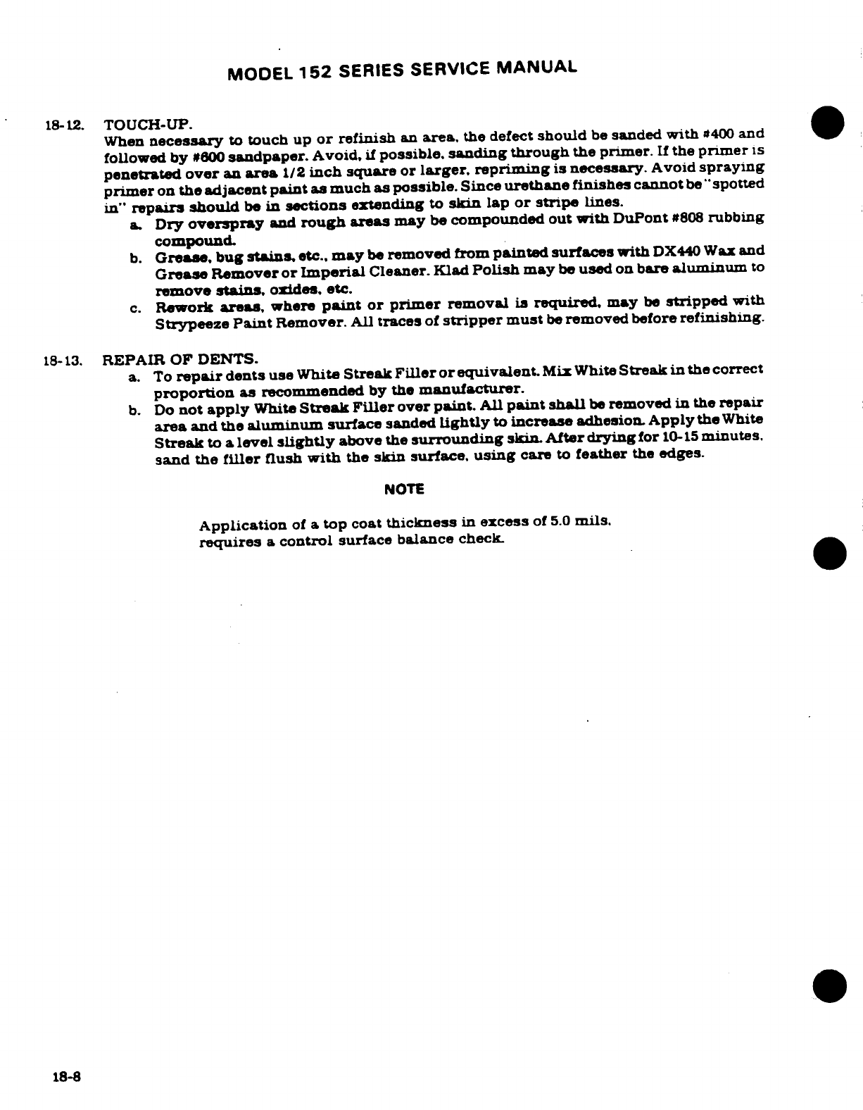
MODEL
152
SERIES
SERVICE
MANUAL
18-12.
TOUCH-UP.
When
necessary
to
touch
up
or
refinish
an
area,
the
defect
should
be
sanded
with
#400
and
followed by
#600
sandpaper.
Avoid,
if
possible,
sanding
through
the
primer.
If
the
primer
is
penetrated
over
an
area
1/2
inch
square
or
larger.
repriming
is
necessary.
Avoid
spraying
primer
on
the adjacent
paint
as
much
as
possible.
Since
urethane finishes
cannot
be
"spotted
in"
repairs
should
be
in
sections
extending
to
skin
lap
or
stripe
lines.
a.
Dry
overspray
and
rough areas
may
be
compounded out
with
DuPont
#808
rubbing
compound.
b.
Grease,
bug
stains,
etc.,
may
be
removed from
painted surfaces
with
DX440
Wax
and
Grease
Remover
or Imperial
Cleaner.
Klad
Polish
may
be
used
on
bare
aluminum
to
remove
stains,
oxides, etc.
c.
Rework
areas,
where
paint
or primer
removal
is
required,
may
be
stripped
with
Strypeeze
Paint
Remover.
All
traces
of
stripper
must
be
removed
before
refinishing.
18-13.
REPAIR
OF DENTS.
a.
To
repair
dents
use
White
Streak
Filler
or
equivalent.
Mix
White
Streak
in
the
correct
proportion
as
recommended
by
the
manufacturer.
b.
Do
not
apply
White
Streak Filler
over
paint.
All
paint
shall
be
removed
in
the
repair
area
and the
aluminum
surface
sanded
lightly
to
increase
adhesion.
Apply
the
White
Streak
to
a
level
slightly
above
the
surrounding
skin.
After
drying
for
10-15
minutes.
sand the
filler
flush
with
the
skin
surface,
using
care
to
feather
the
edges.
NOTE
Application
of
a
top coat
thickness
in
excess
of
5.0
mils.
requires
a
control
surface
balance
check.
18-8
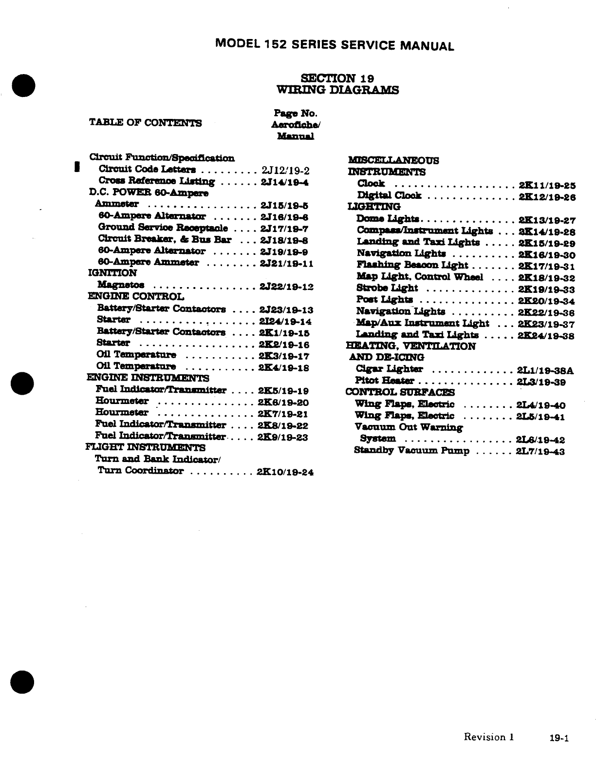
MODEL
152
SERIES SERVICE
MANUAL
SECTION
19
WIRING
DIAGRAMS
Page
No.
TABLE
OF
CONTENTS
Aerofiche/
Manual
Circuit
Function/Specification
MISCELLANEOUS
Circuit
Code
Letters
.........
2J1219-2
INSTRUMENTS
Cross
Referene
Listing
......
2J1419-4
Clock
...................
2K11/1-25
D.C.
POWER
60-Ampere
Digital
Clok
..............
2K12/19-26
Ammeter
.................
2J15/19
LIGHTING
60-Ampere
Alternator
.......
2J16/19-
Dome
Light
..............
2K13/19-27
Ground
Service
Receptacle
....
2J17/19-7
Compass/Instrument
Lights
...
2K14/19-28
Circuit
Breaker,
&
Bus
Bar
...
2J18/19-8
Landing
and Taxi
Lights
.....
2K15/19-29
60-Ampere
Alternator
.......
219/19-9
Navigation
Lights
..........
2K16/19-30
60-Ampere
Ammeter
.......
2J21/19-11
Flashing
Beacon
Light
.......
2K17/19-31
IGNITION
Map
Light,
Control
Wheel
....
2K18/19-32
Magnetos
..............
2J22/19-12
Strobe
Light
..............
2K19/19-33
ENGINE
CONTROL
Post
Light
...
2K20/19-34
Battery/Starter
Contactors
....
2J23/19-13
Navigation Lights
..........
2K22/19-3
Starter
2I24/19-14
Map/Aux
Instrument
Light
...
2K23/19-37
Battery/Starter
Contactors
....
21/19-15
Landing
and
Taxi
Lights
.....
.2K24/19-38
Starter
..................
2K2/19-16
HEATING,
VENTILATION
Oil
Temperature
...........
2K3/19-17
AND
DE-ICING
Oil
Temperature
...........
2K4/-18
Cigar
Lighter
.............
2L1/19-38A
ENGINE
INSTUMENTS
Pitot
Heater
...............
2L3/19-39
Fuel
Indicator/Transmitter
.. ...
2K5/19-19
CONTROL
SURFACES
Hourmeter
...............
2K6/19-20
Wing
Flaps,
Electric
........
2L4/19-40
Hourmeter
...............
2K7/19-21
Wing
Fla,
Eletric
........
2L/1-41
Fuel
Indicator/Transmitter
....
2K8/19-22
Vacuum
Out
Warning
Fuel
Indicator/Transmitter
....
2K9/19-23
System
.................
2L6/1942
FLIGHT
INSTRUMENTS
Standby
Vacuum
Pump
......
2L7119-43
Turn and
Bank
Indicator/
Turn
Coordinator
..........
210/19-24
Revision
1
19-1
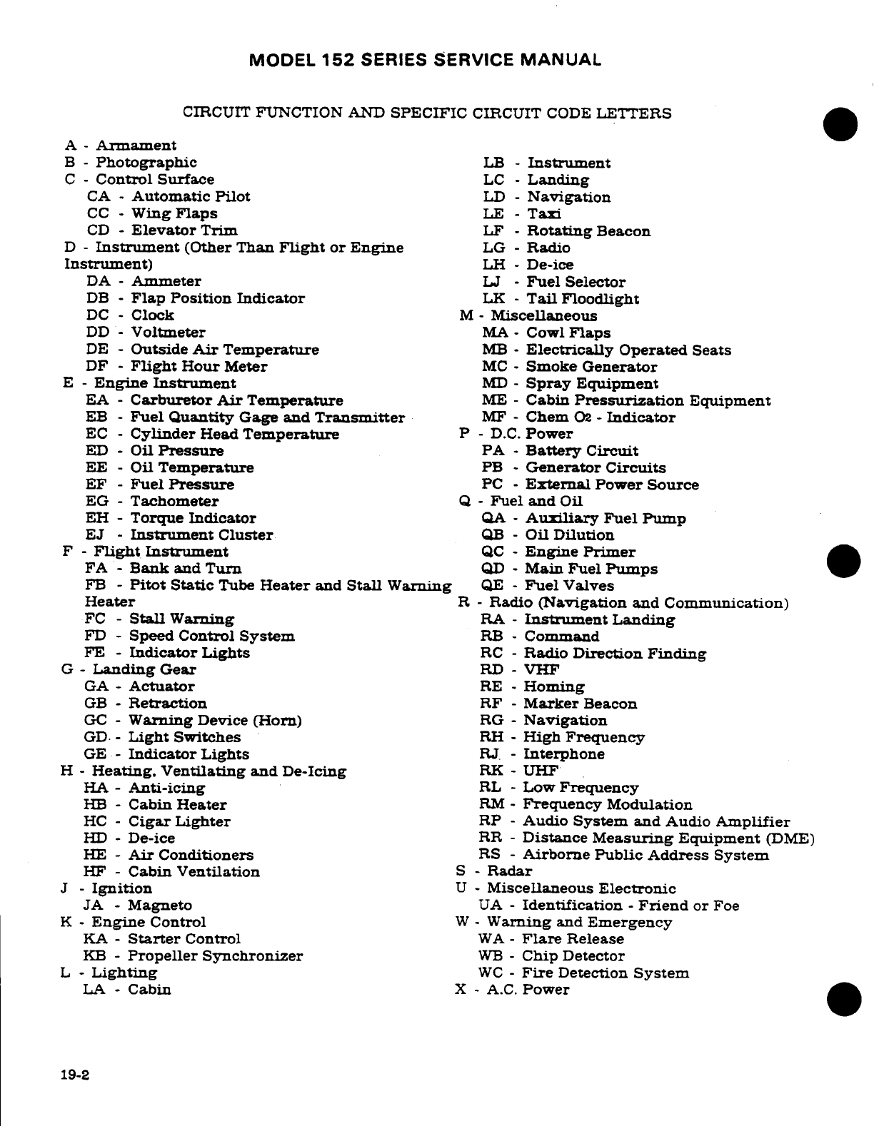
MODEL
152
SERIES
SERVICE
MANUAL
CIRCUIT
FUNCTION
AND
SPECIFIC
CIRCUIT
CODE
LETTERS
A
-
Armament
B -
Photographic
LB
-
Instrument
C
-
Control Surface
LC
-
Landing
CA
-
Automatic
Pilot
LD
-
Navigation
CC
-
Wing
Flaps
LE
-
Taxi
CD
-
Elevator
Trim
LF
-
Rotating
Beacon
D
-
Instrument
(Other
Than
Flight
or
Engine
LG
-
Radio
Instrument)
LH
-
De-ice
DA
-
Ammeter
LJ
-
Fuel
Selector
DB
-
Flap
Position
Indicator
LK
-
Tail
Floodlight
DC
-
Clock
M-
Miscellaneous
DD
-
Voltmeter
MA
-
Cowl
Flaps
DE
-
Outside
Air
Temperature
MB
-
Electrically
Operated
Seats
DF
-
Flight
Hour
Meter
MC
-
Smoke
Generator
E
-
Engine
Instrument
MD
-
Spray
Equipment
EA
-
Carburetor
Air
Temperature
ME
-
Cabin
Pressurization
Equipment
EB
-
Fuel
Quantity
Gage
and
Transmitter
MF
-
Chem
02
-
Indicator
EC
-
Cylinder
Head
Temperature
P -
D.C.
Power
ED
-
Oil
Pressure
PA
-
Battery
Circuit
EE
-
Oil
Temperature
PB
-
Generator
Circuits
EF
-
Fuel
Pressure
PC
-
External
Power
Source
EG
-
Tachometer
Q
-
Fuel
and
Oil
EH
-
Torque
Indicator
QA
-
Auxiliary
Fuel Pump
EJ
-
Instrument
Cluster
QB
-
Oil
Dilution
F
-
Flight
Instrument
QC
-
Engine
Primer
FA
-
Bank
and
Turn
QD
-
Main
Fuel
Pumps
FB
-
Pitot
Static
Tube
Heater
and
Stall
Warning
QE
-
Fuel
Valves
Heater
R
-
Radio
(Navigation
and
Communication)
FC
-
Stall
Warning
RA
-
Instrument
Landing
FD
-
Speed
Control
System
RB
-
Command
FE
-
Indicator
Lights
RC
-
Radio
Direction
Finding
G
-
Landing
Gear
RD
-
VHF
GA-
Actuator
RE
-
Homing
GB
-
Retraction
RF
-
Marker
Beacon
GC
-
Warning
Device
(Horn)
RG
-
Navigation
GD
-
Light
Switches
RH
-
High
Frequency
GE
-
Indicator Lights
RJ.
-
Interphone
H
-
Heating,
Ventilating
and
De-Icing
RK
-
UHF
HA
-
Anti-icing
RL
-
Low
Frequency
HB
-
Cabin
Heater
RM
-
Frequency
Modulation
HC
-
Cigar Lighter
RP
-
Audio
System
and
Audio
Amplifier
HD
-
De-ice
RR
-
Distance
Measuring
Equipment
(DME)
HE
-
Air
Conditioners
RS
-
Airborne
Public
Address
System
HF
-
Cabin
Ventilation
S
-
Radar
J
-
Ignition
U
-
Miscellaneous
Electronic
JA
-
Magneto
UA
-
Identification
-
Friend
or
Foe
K
-
Engine
Control
W
-
Warning
and
Emergency
KA
-
Starter
Control
WA
-
Flare
Release
KB
-
Propeller
Synchronizer
WB
-
Chip
Detector
L
-
Lighting
WC
-
Fire
Detection
System
LA
-
Cabin
X
-
A.C.
Power
19-2
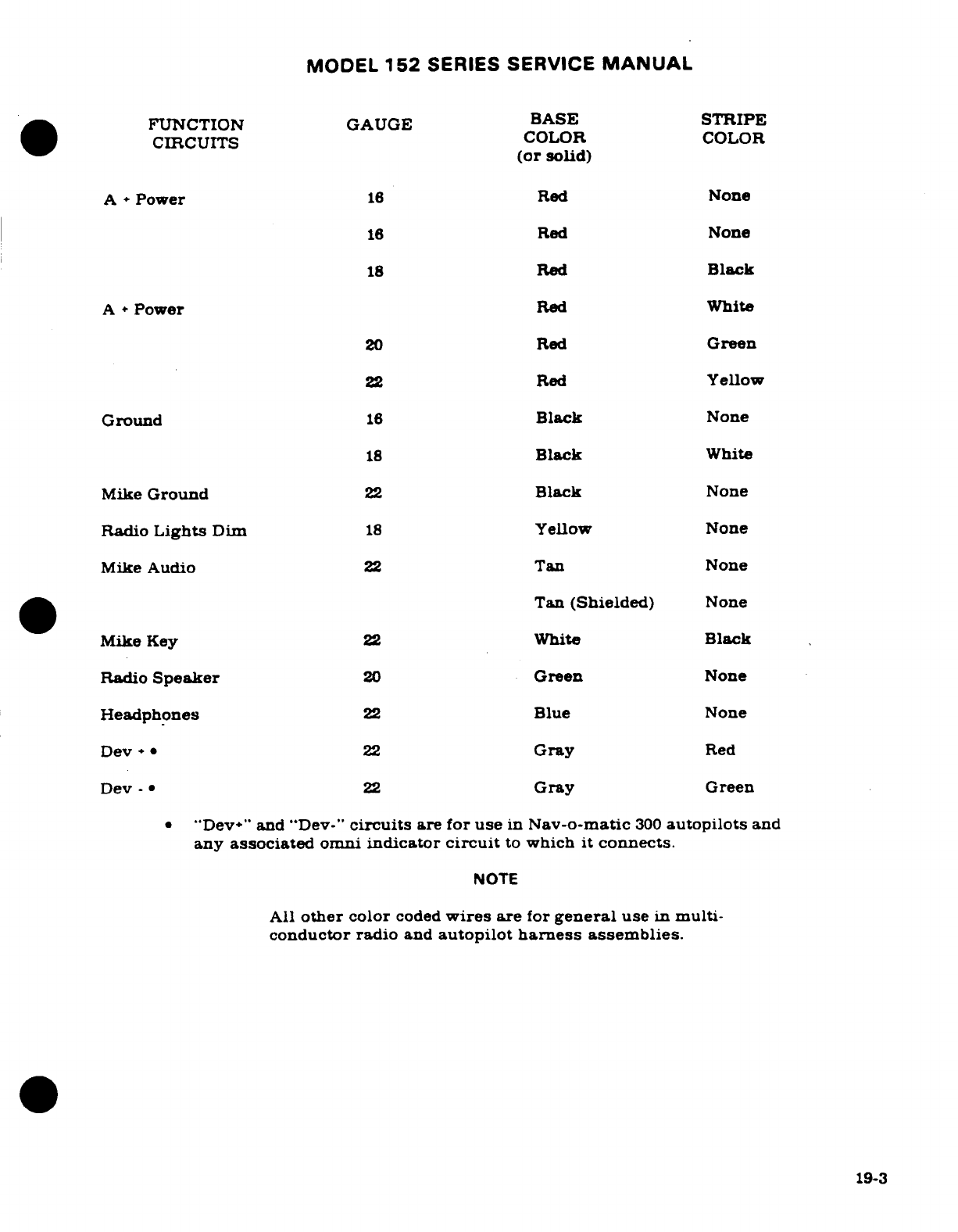
MODEL
152
SERIES
SERVICE
MANUAL
FUNCTION
GAUGE BASE
STRIPE
CIRCUITS
COLOR
COLOR
(or
solid)
A
*
Power
16
Red
None
16
Red
None
18
Red
Black
A
*
Power
Red
White
20
Red
Green
22
Red
Yellow
Ground
16
Black
None
18
Black
White
Mike
Ground
22
Black
None
Radio
Lights
Dim
18
Yellow
None
Mike
Audio
22
Tan
None
Tan
(Shielded)
None
Mike
Key
22
White
Black
Radio
Speaker
20
Green
None
Headphones
22
Blue
None
Dev+*
22
Gray
Red
Dev
-
22
Gray
Green
*
"Dev*"
and "Dev-"
circuits
are
for
use
in
Nav-o-matic
300
autopilots
and
any
associated
omni
indicator
circuit
to
which
it
connects.
NOTE
All
other
color
coded
wires
are
for
general
use
in
multi-
conductor radio
and
autopilot
harness
assemblies.
19-3
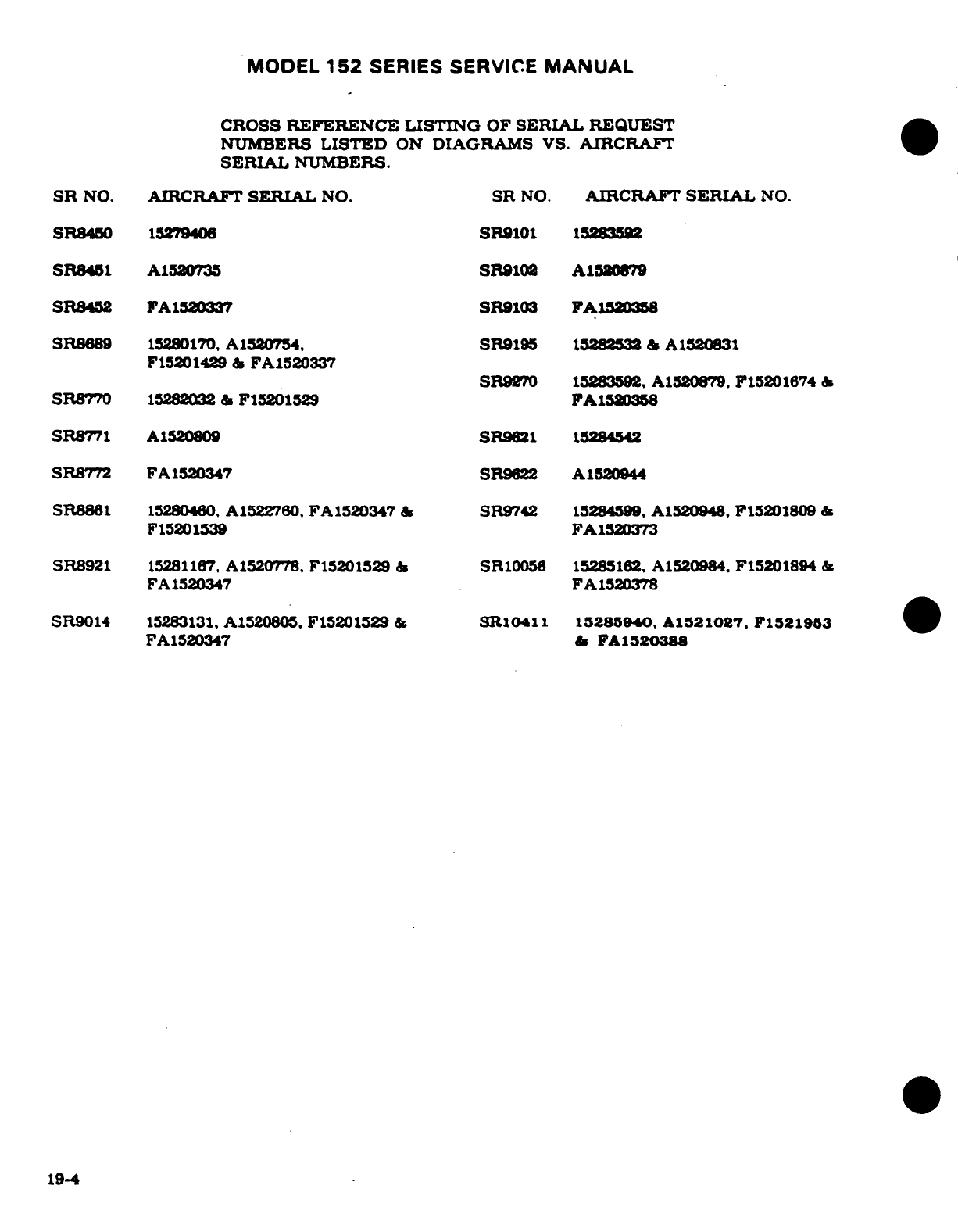
MODEL
152
SERIES
SERVICE
MANUAL
CROSS
REFERENCE
LISTING
OF
SERIAL
REQUEST
NUMBERS
LISTED
ON
DIAGRAMS
VS.
AIRCRAFT
SERIAL
NUMBERS.
SR
NO.
AIRCRAFT
SERIAL
NO.
SR
NO.
AIRCRAFT
SERIAL
NO.
SR8450
15279406
SR9101
15283592
SR8451
A1520735
SR9102
A152S79
SR8452
FA1520337
SR9103
FA1520356
SR8689
15280170,
A1520754.
SR9195
15282532
&
A1520831
F15201429
&
FA1520337
SR9270
15283592.
A1520879.
F15201674
&
SR8770
15282032
&
F15201529
FA1520358
SR8771
A1520809
SR9621
15284542
SR8772
FA1520347
SR9622
A1520944
SR8861
15280460.
A1522760.
FA1520347
&
SR9742
15284599,
A1520948.
F15201809
&
F15201539
FA1520373
SR8921
15281167.
A1520778.
F15201529
&
SR10056
15285162.
A1520984.
F15201894
&
FA1520347
FA1520378
SR9014
15283131.
A1520805,
F15201529
&
SR10411
15285940.
A1521027. F1521953
FA1520347
&
FA120388
19-4
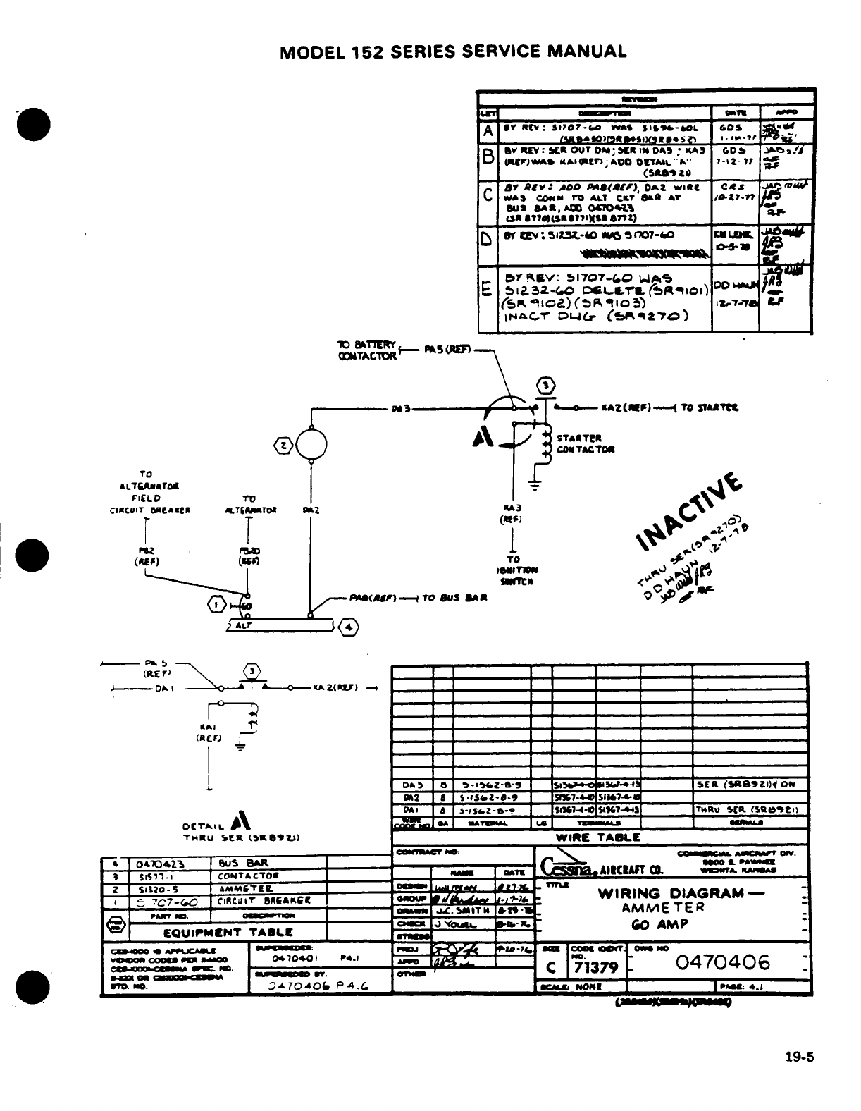
MODEL
152
SERIES
SERVICE
MANUAL
19-5
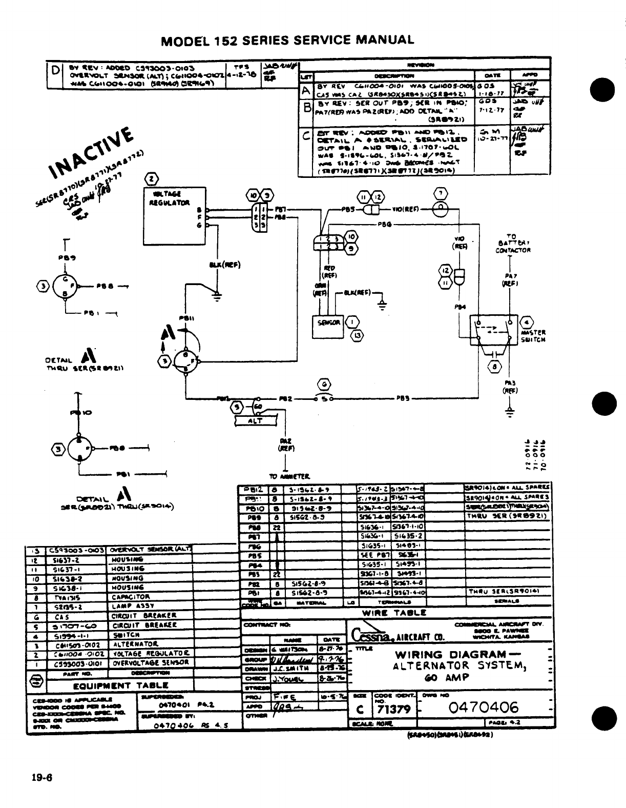
MODEL
152
SERIES
SERVICE
MANUAL
I 1
-*
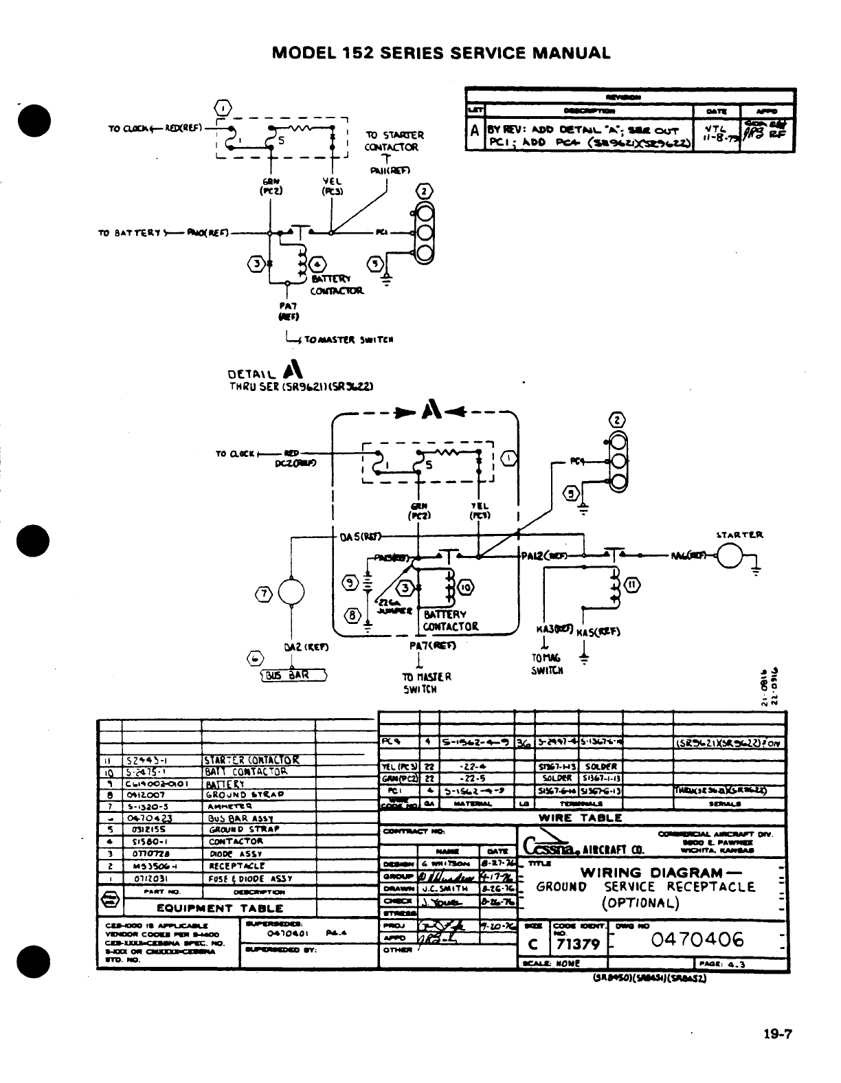
MODEL
152
SERIES
SERVICE
MANUAL
19-7
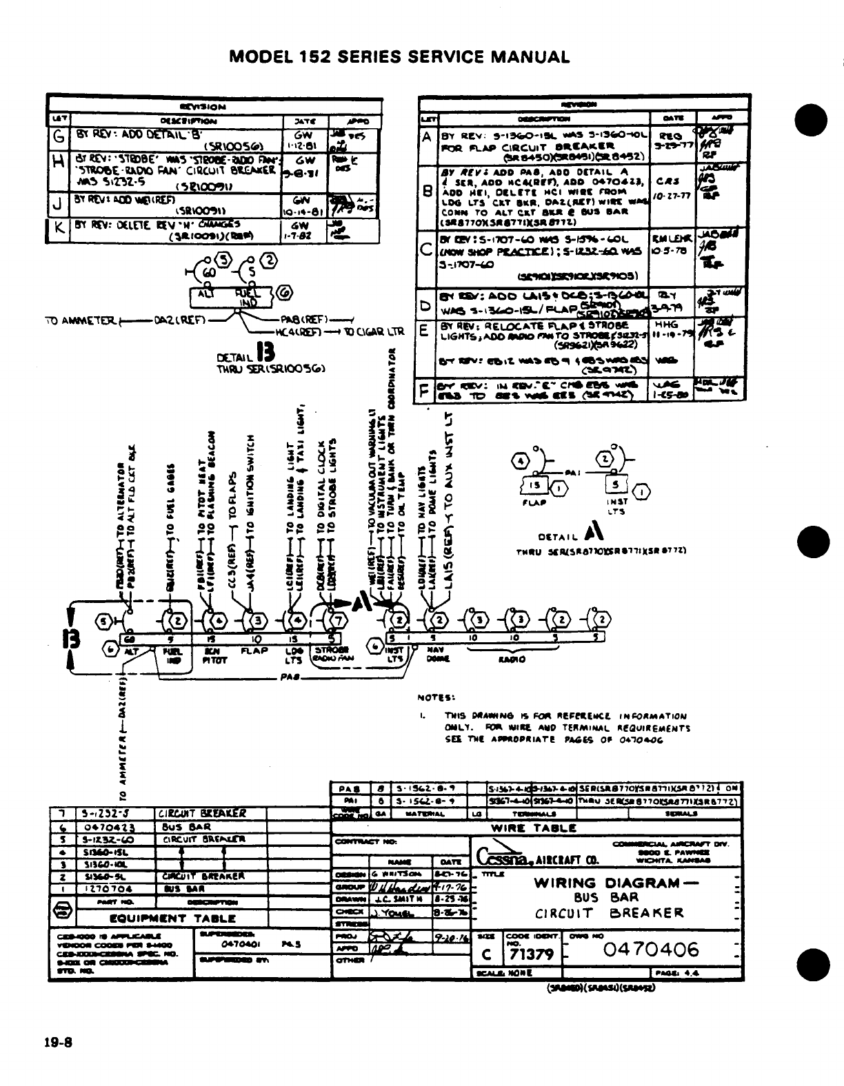
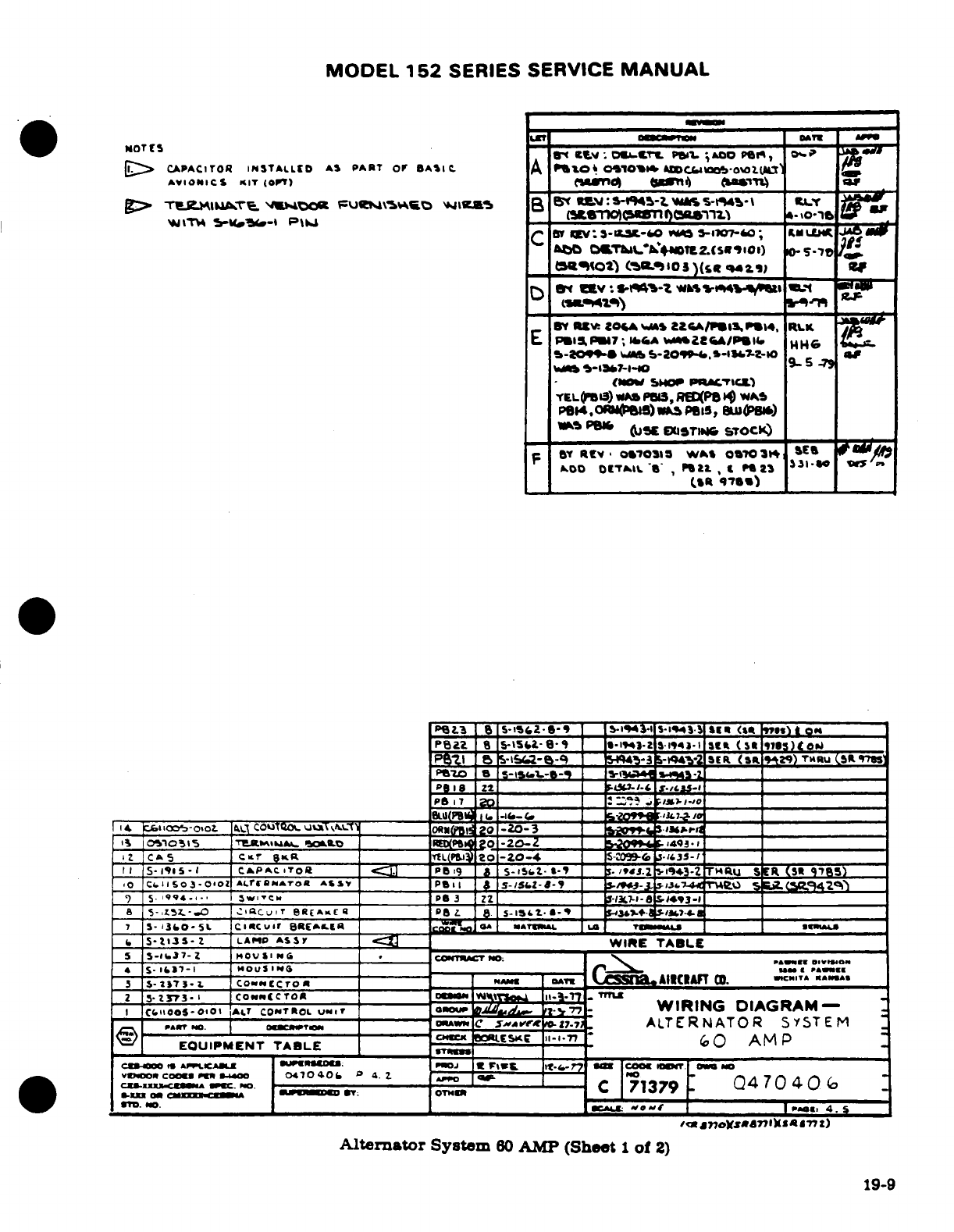
MODEL
152
SERIES SERVICE
MANUAL
19-9
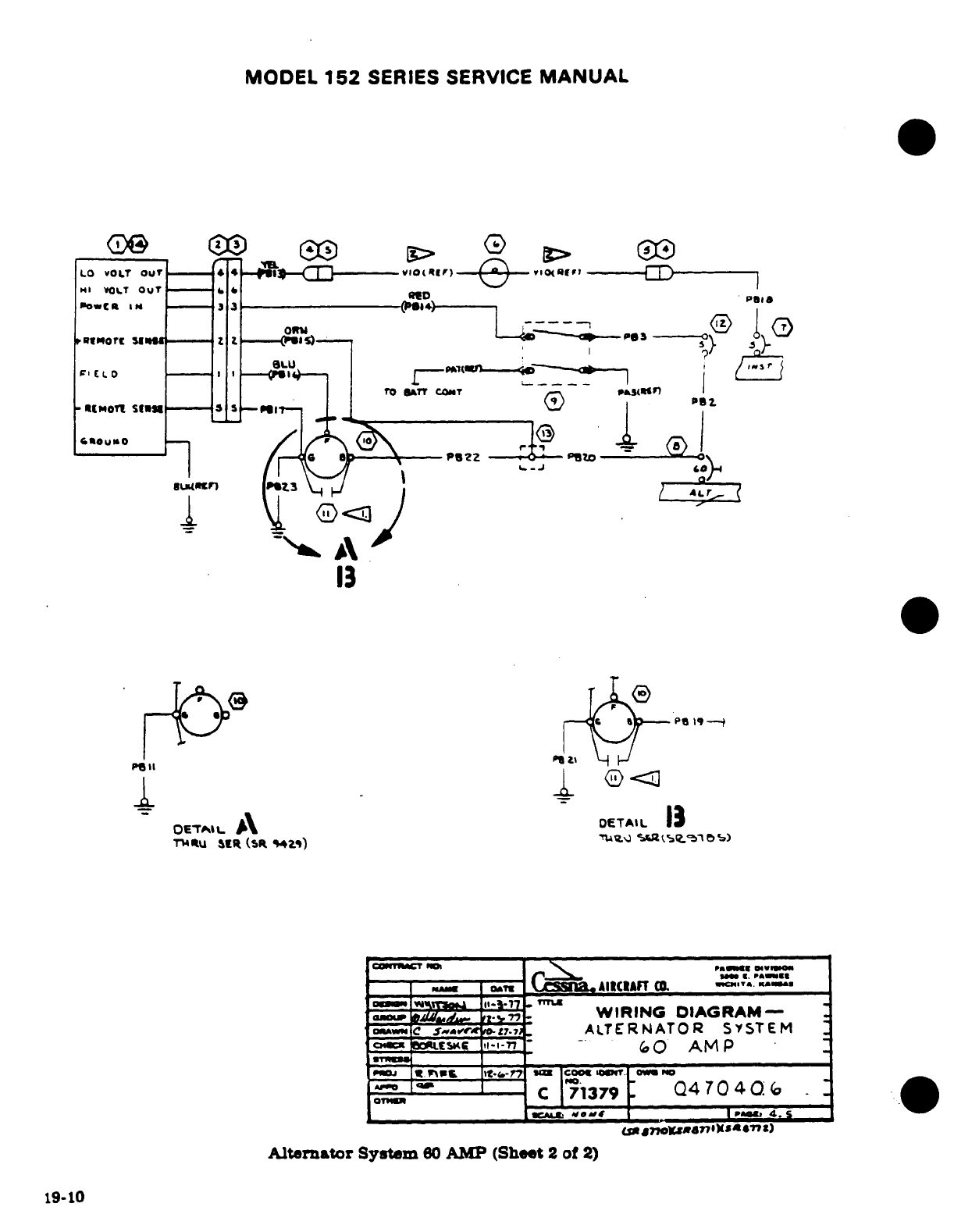
MODEL
152
SERIES SERVICE
MANUAL
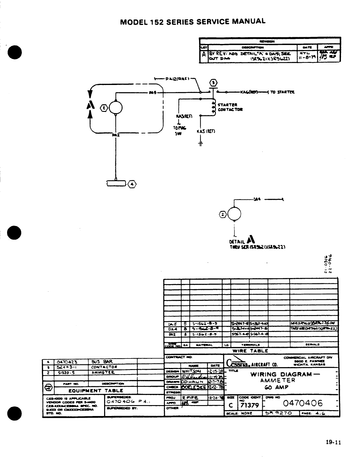
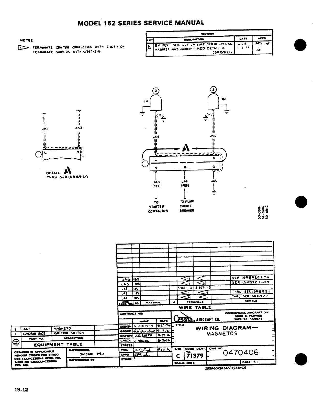
MODEL
152
SERIES
SERVICE
MANUAL
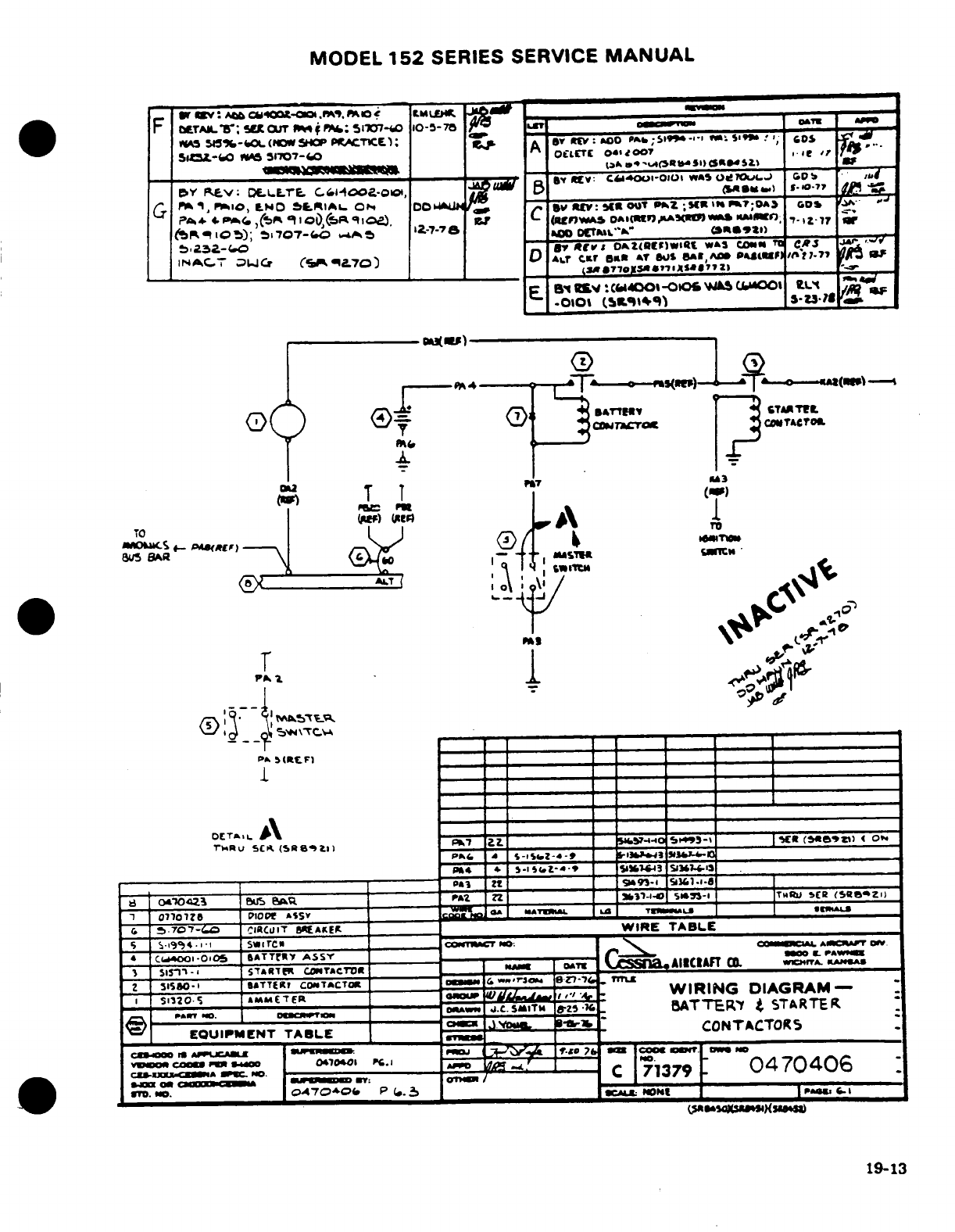
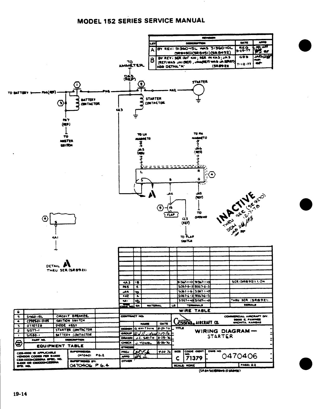
MODEL
152
SERIES
SERVICE
MANUAL
19-14
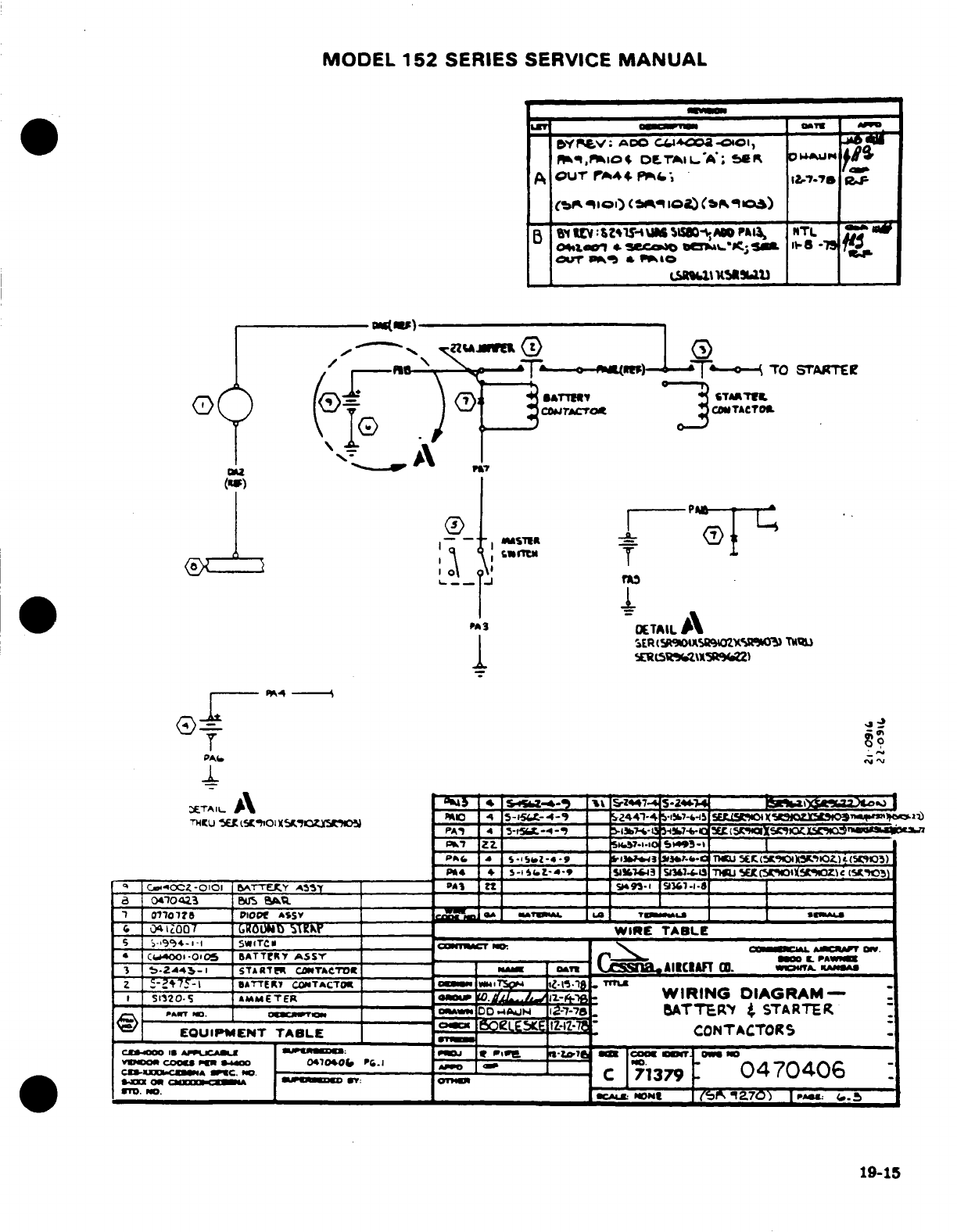
MODEL
152
SERIES
SERVICE
MANUAL
19-15
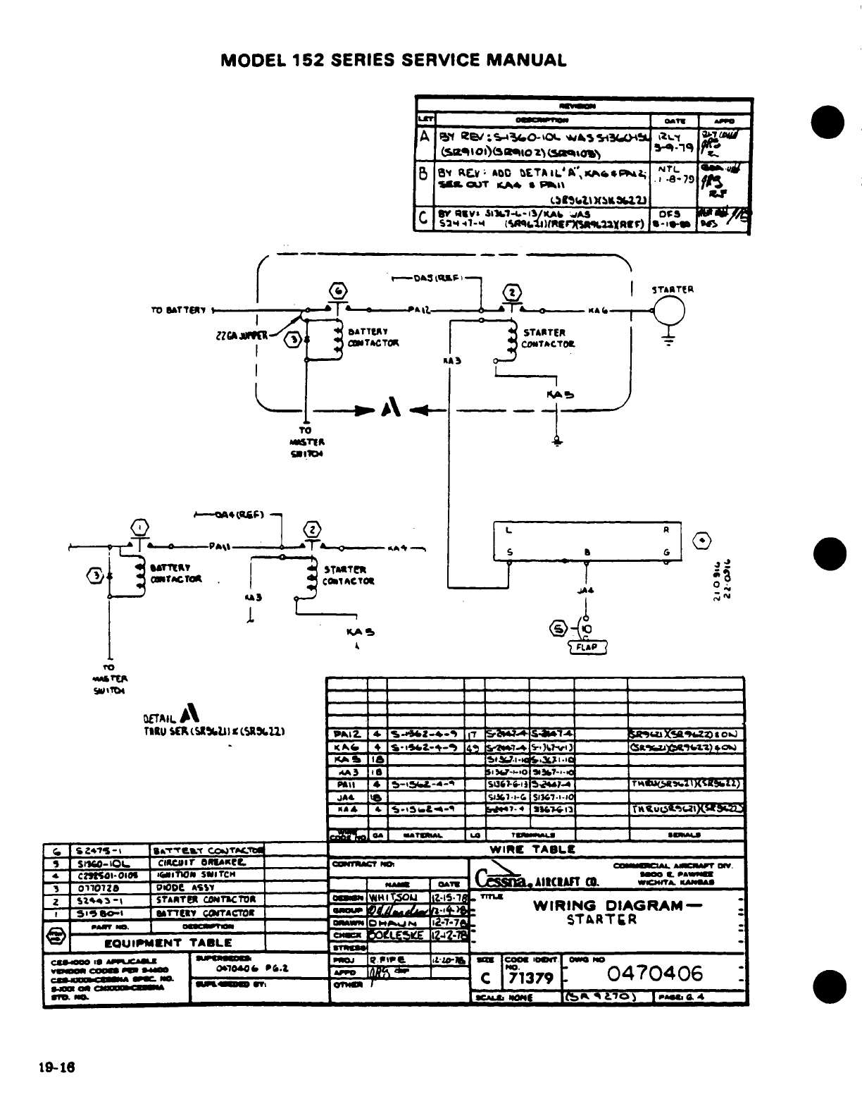
MODEL
152
SERIES
SERVICE
MANUAL
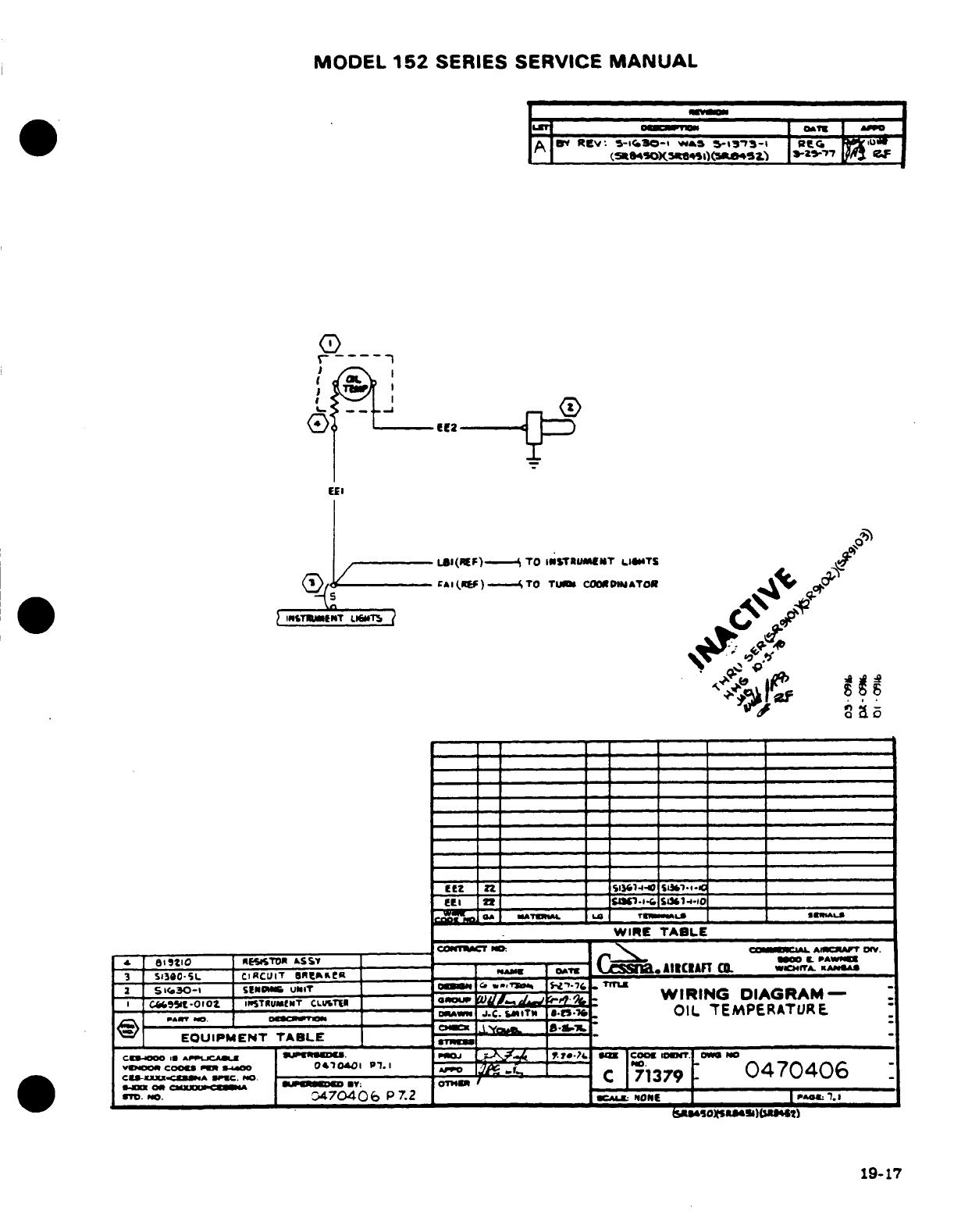
MODEL
152
SERIES
SERVICE
MANUAL
19-17
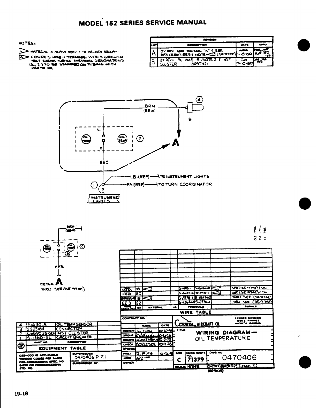
MODEL
152
SERIES SERVICE
MANUAL
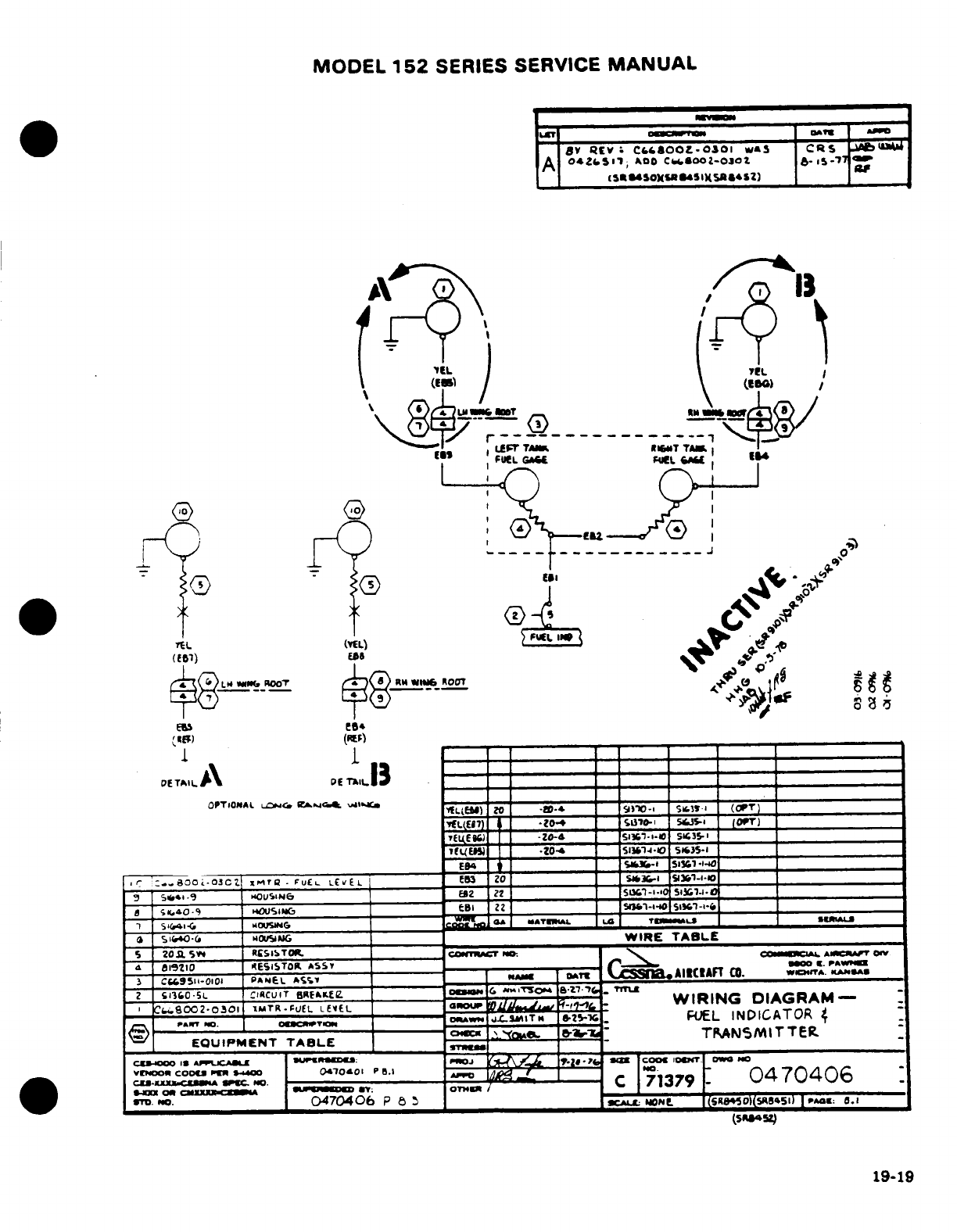
MODEL
152
SERIES SERVICE
MANUAL
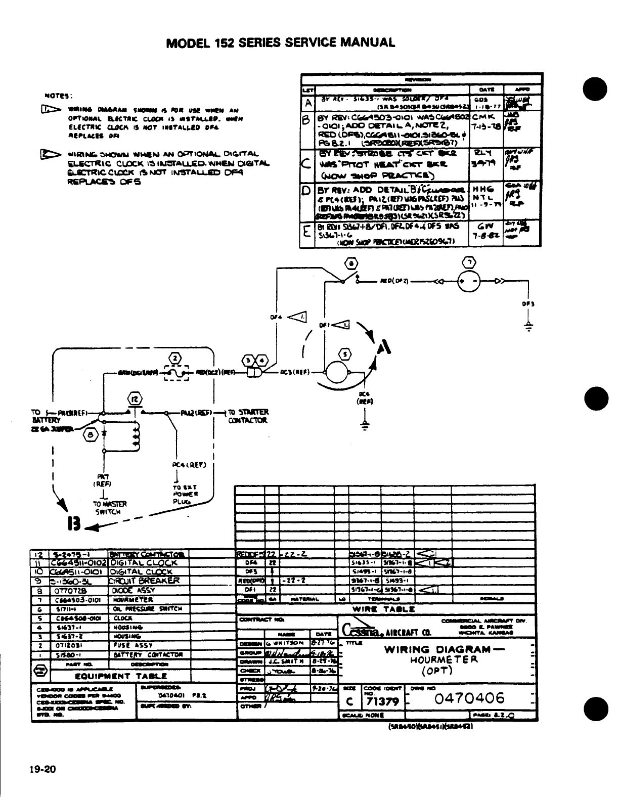
MODEL
152
SERIES
SERVICE
MANUAL
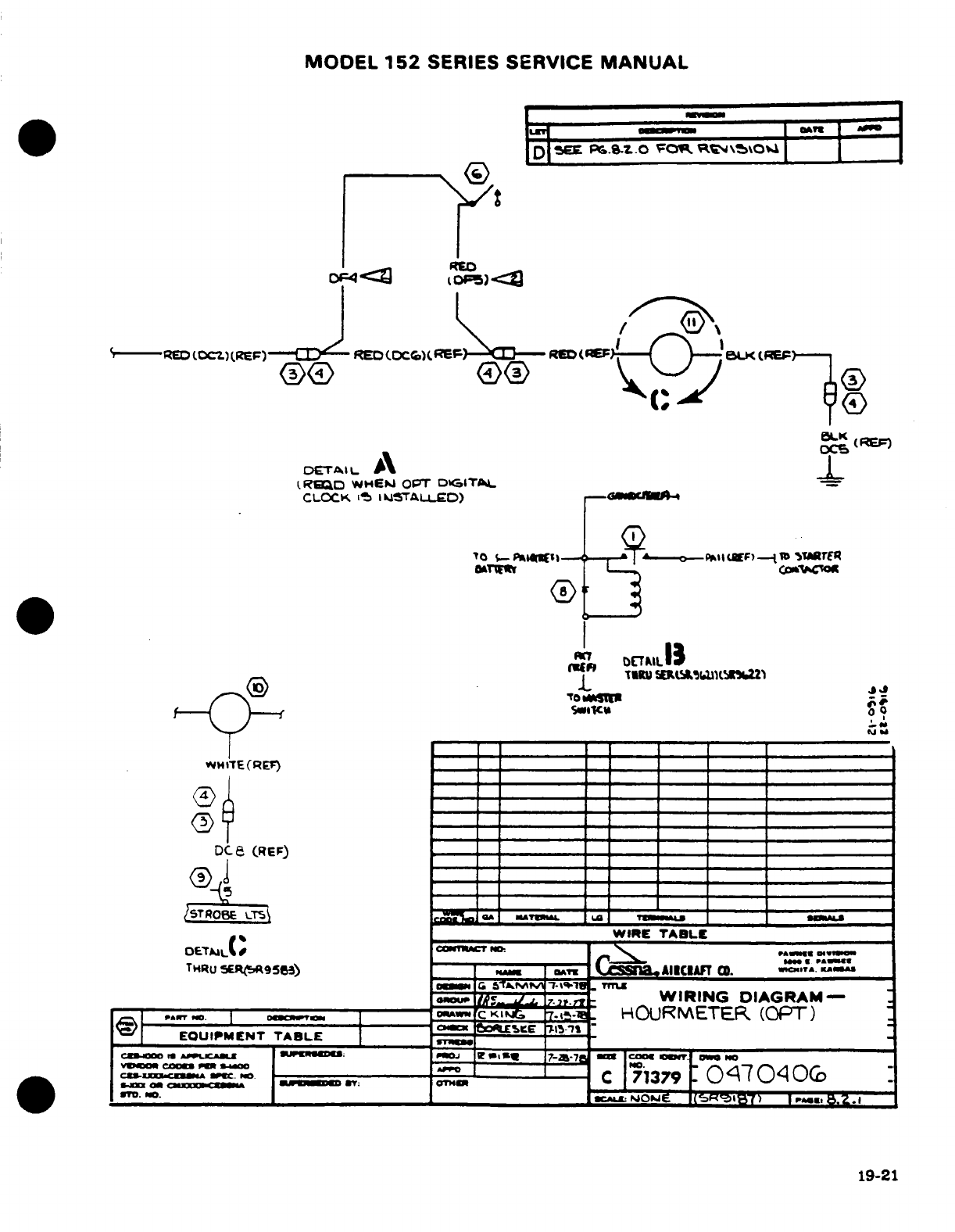
MODEL
152
SERIES
SERVICE
MANUAL
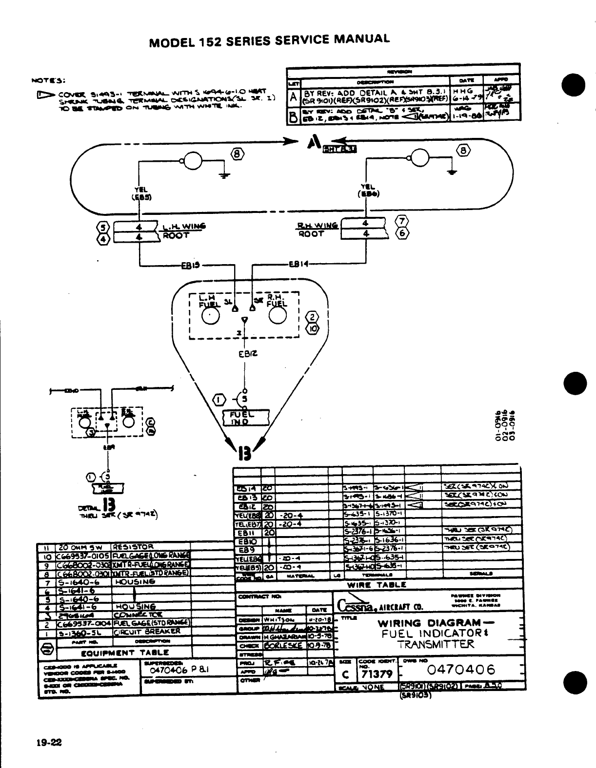
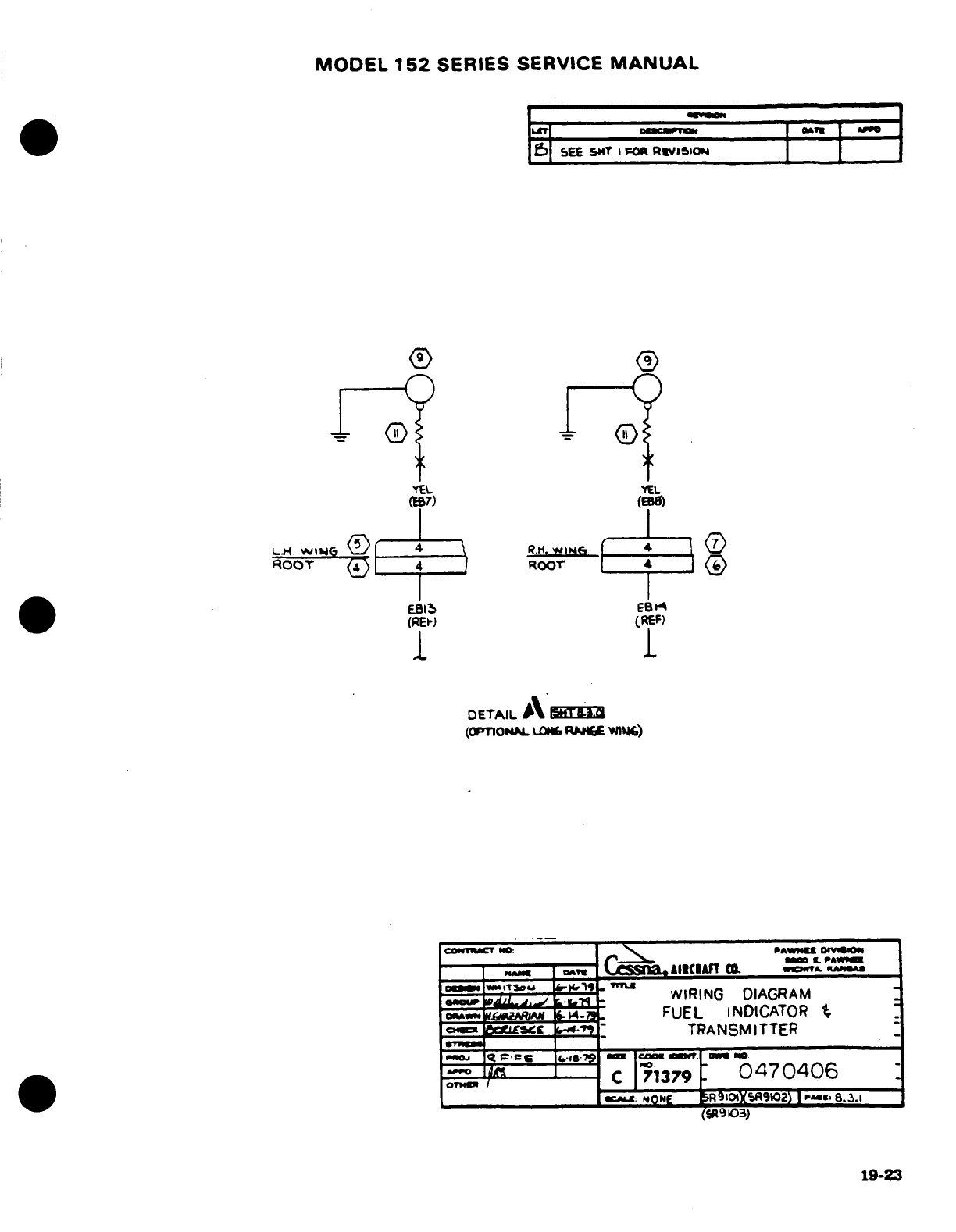
MODEL
152
SERIES
SERVICE
MANUAL
19-23
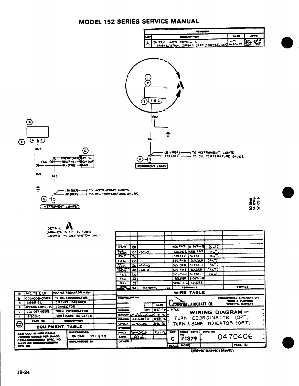
MODEL
152
SERIES
SERVICE
MANUAL
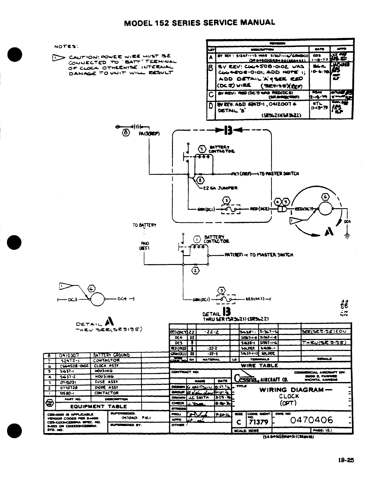
MODEL
152
SERIES
SERVICE
MANUAL
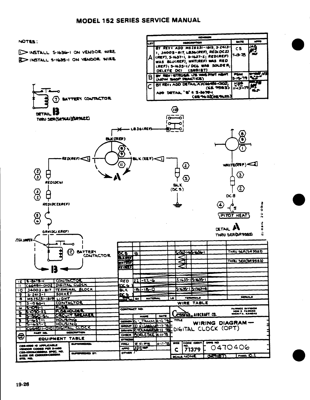
MODEL
152
SERIES SERVICE
MANUAL
19-26
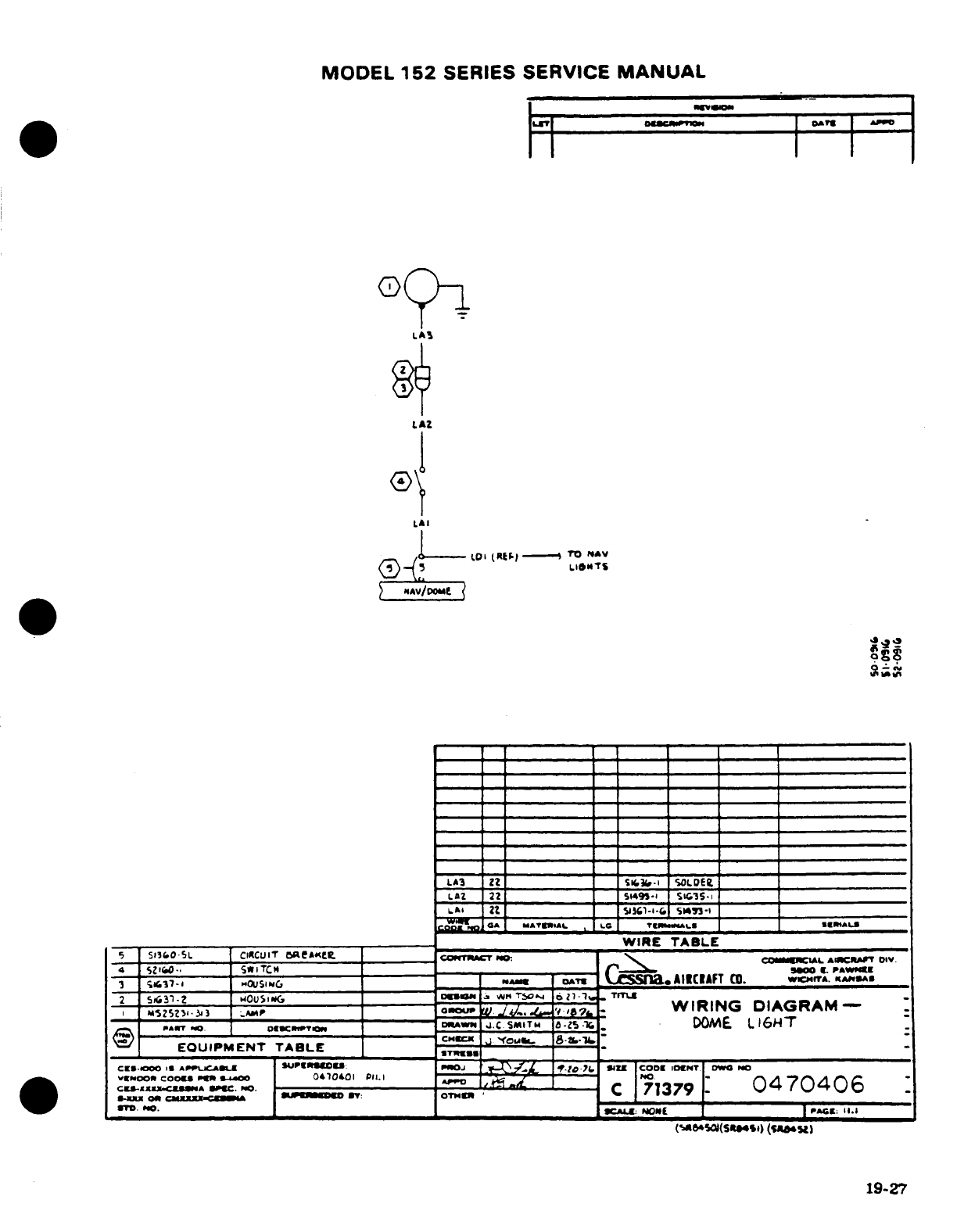
MODEL
152
SERIES SERVICE
MANUAL
19-27
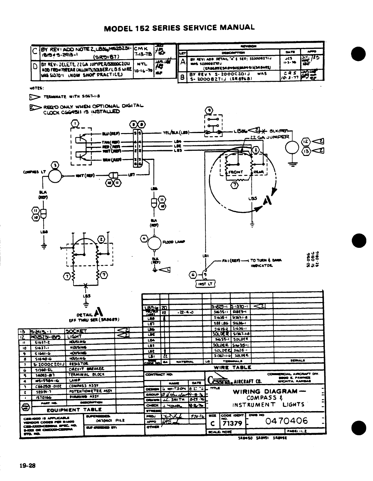
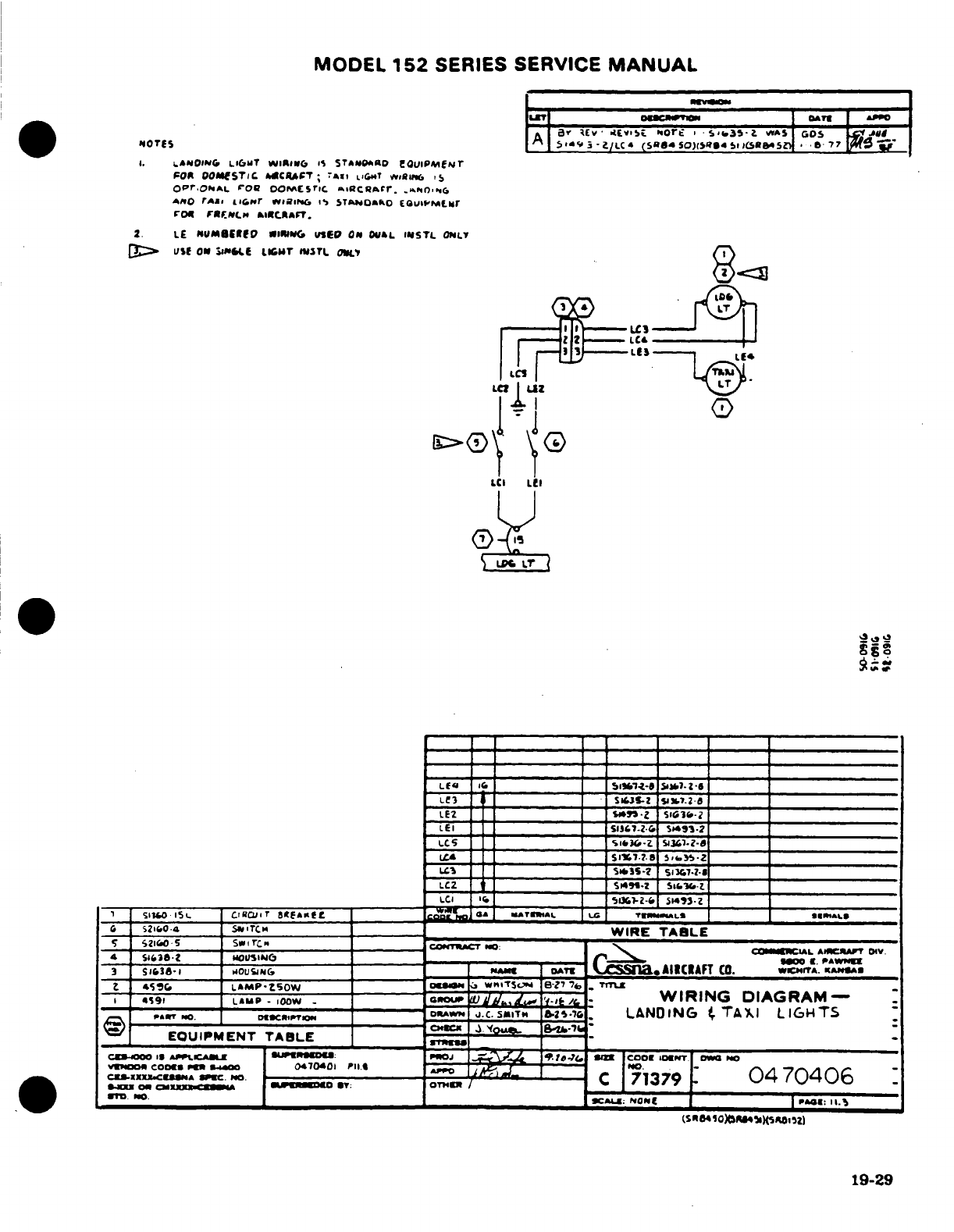
MODEL
152
SERIES SERVICE
MANUAL
19-29
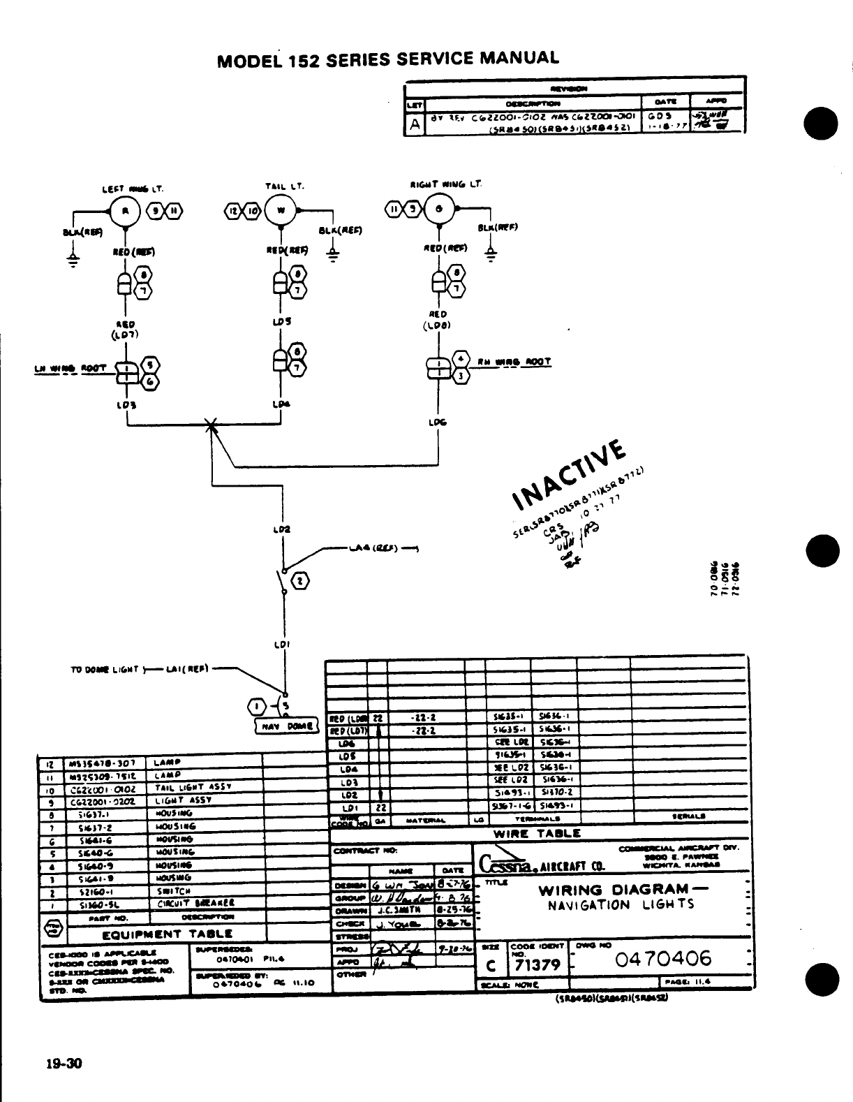
MODEL
152
SERIES
SERVICE
MANUAL
AsptD
~
~
LDS
RED
19-30
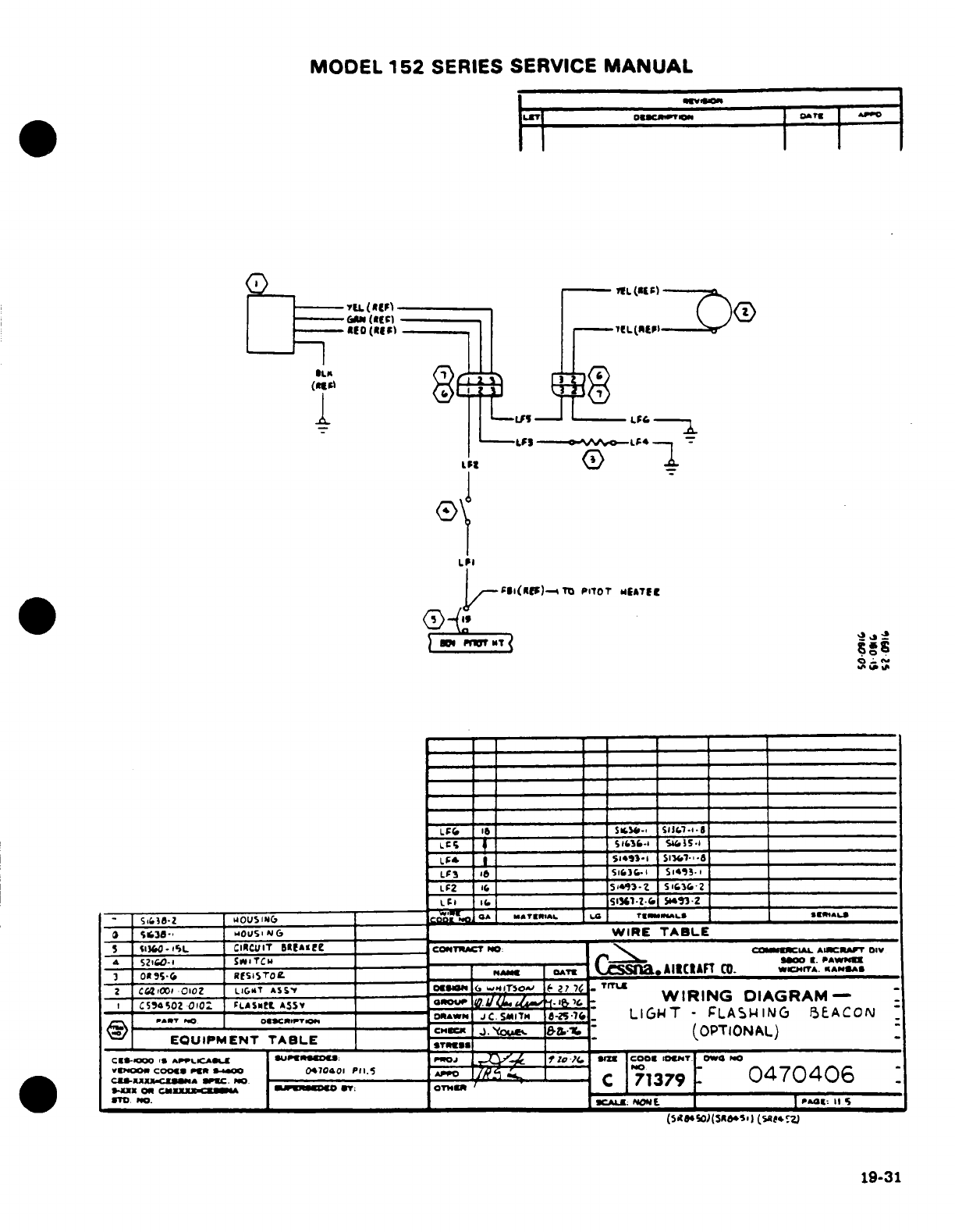
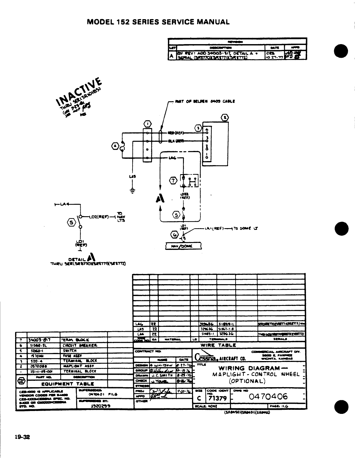
MODEL
152
SERIES
SERVICE
MANUAL
19-32
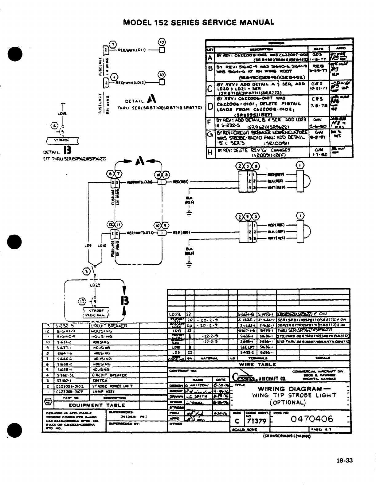
MODEL
152
SERIES
SERVICE
MANUAL
19-33
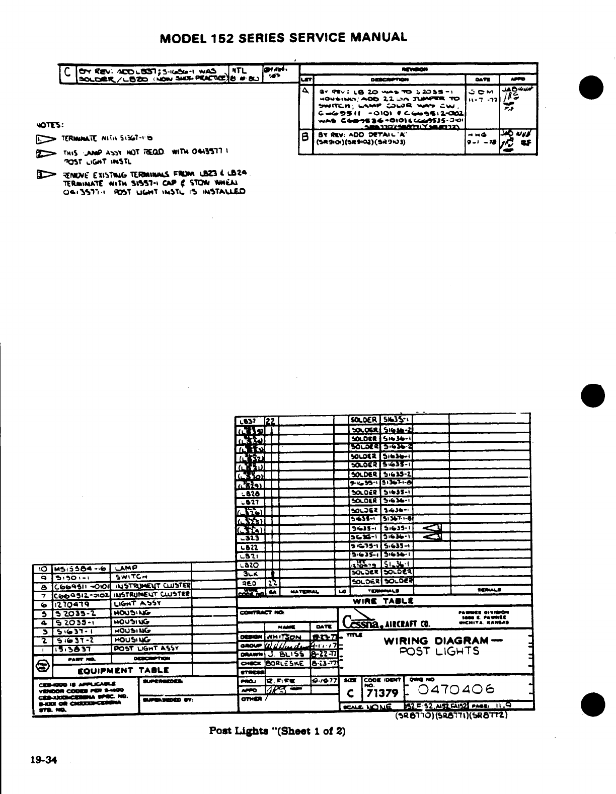
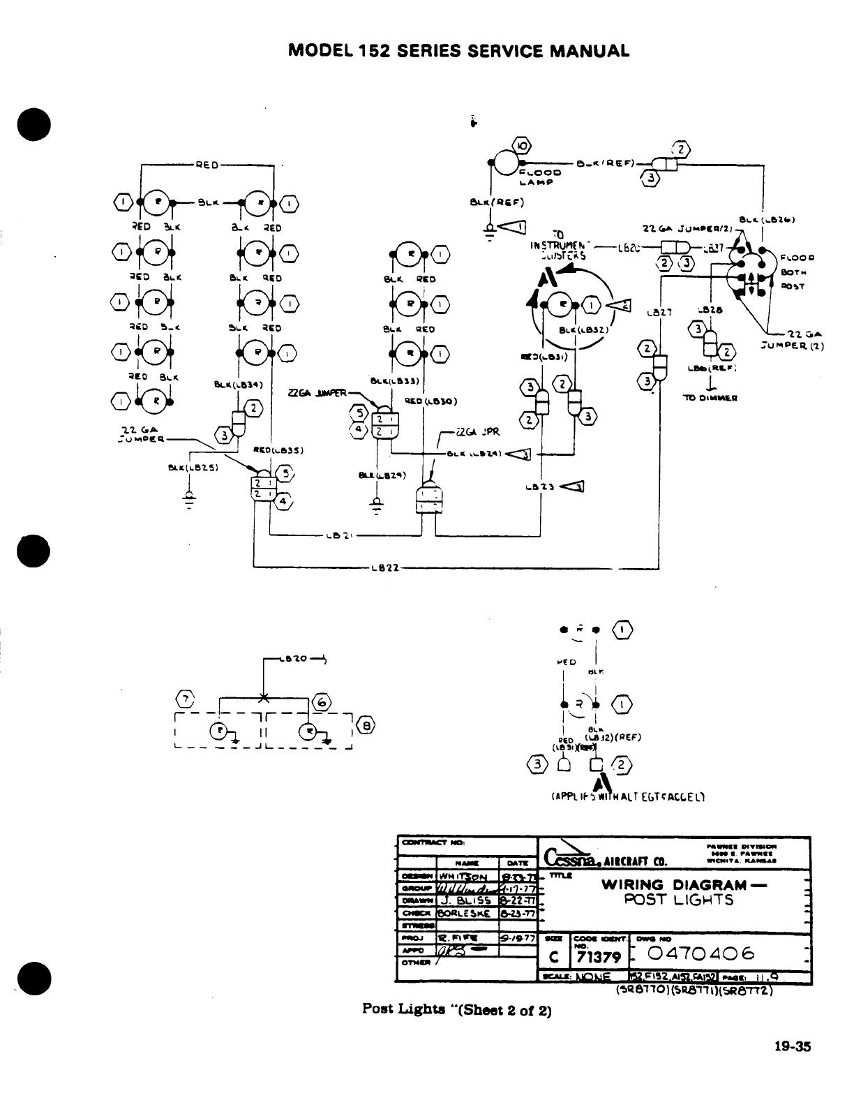
MODEL
152
SERIES
SERVICE
MANUAL
Post
Lights
"(Sheet
2
of
2)
19-35
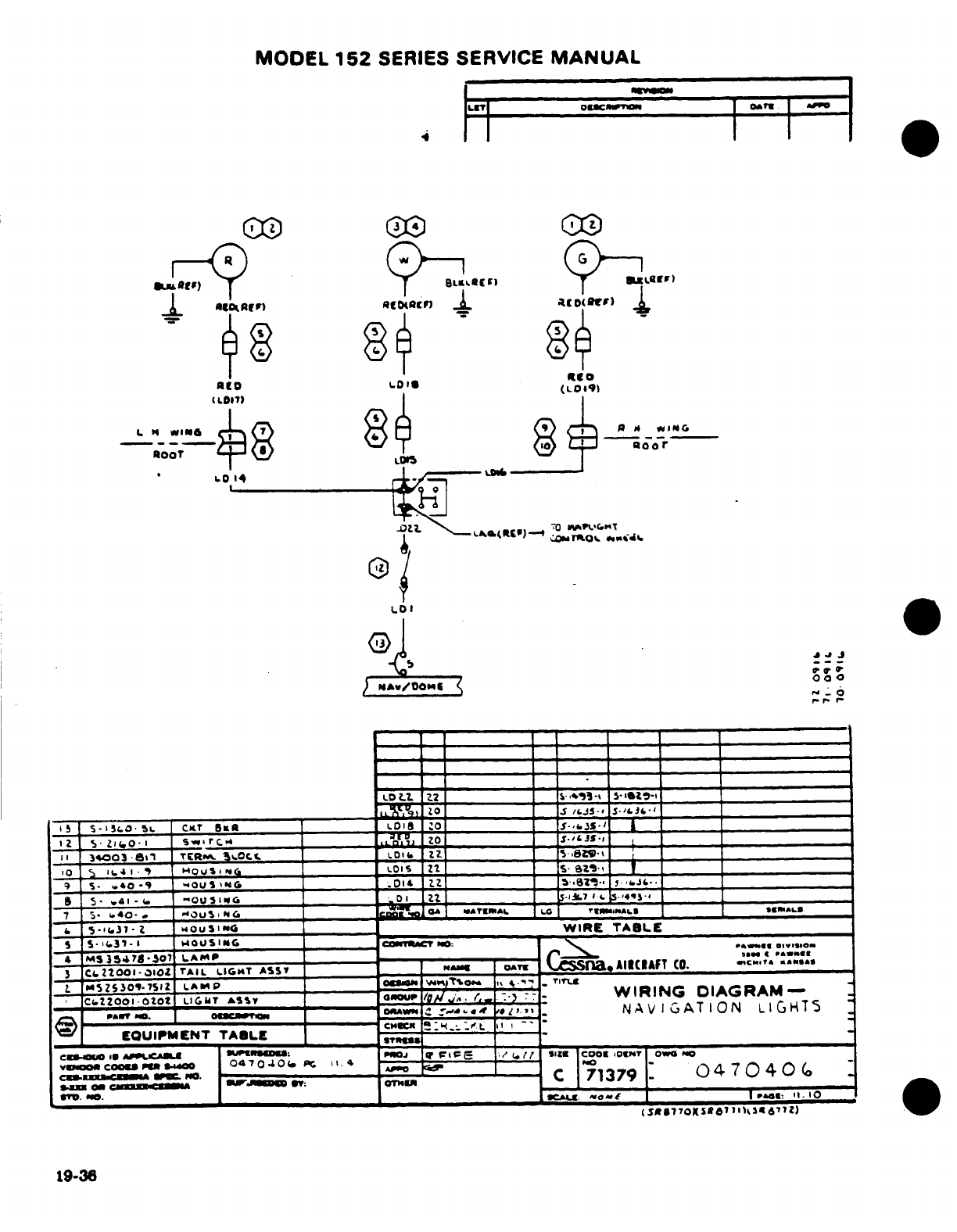
MODEL
152
SERIES
SERVICE
MANUAL
19-36
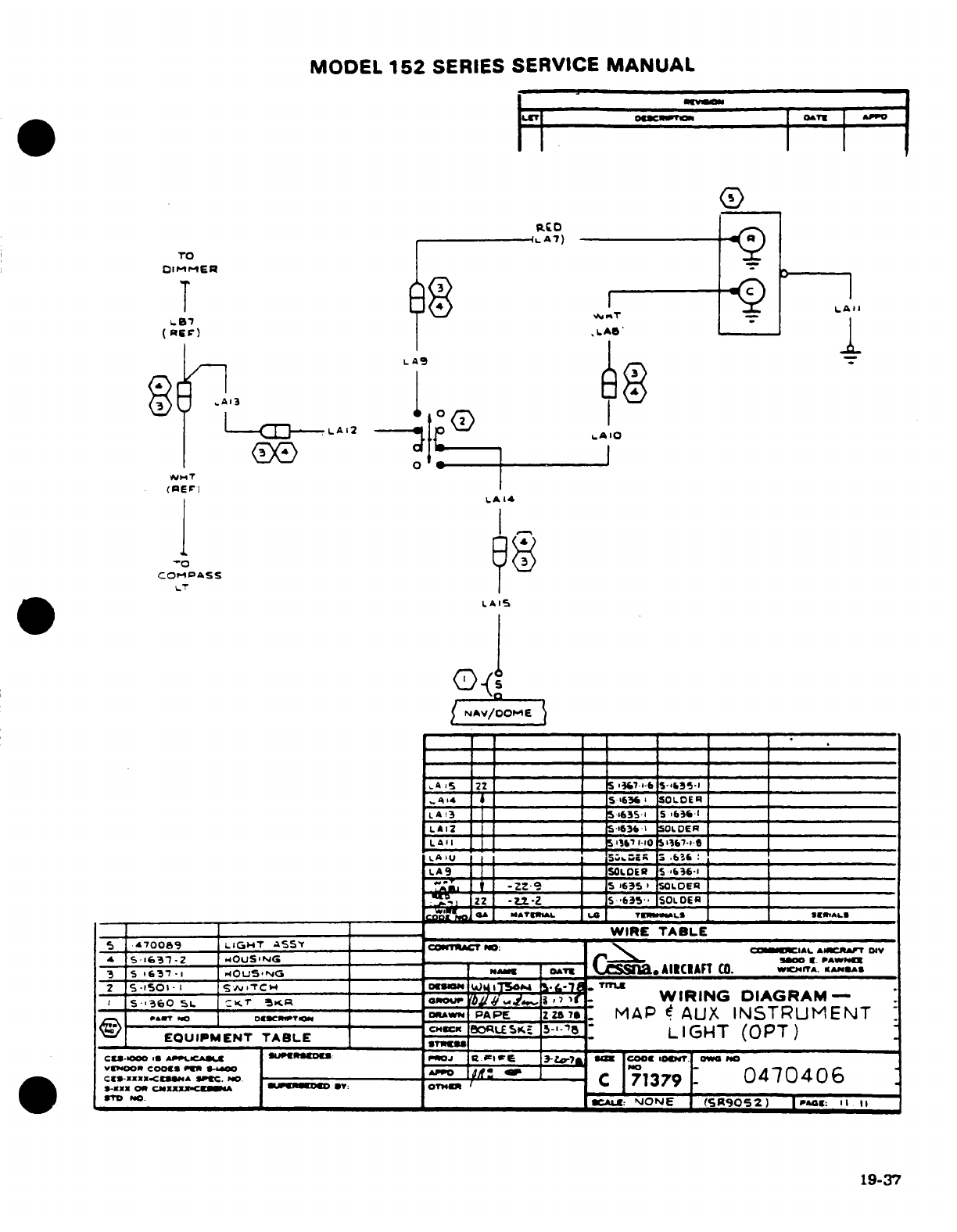
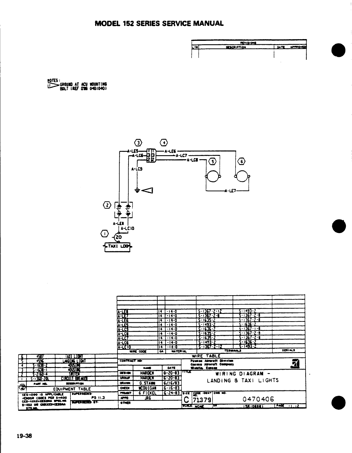
MODEL
152
SERIES
SERVICE
MANUAL
19-38
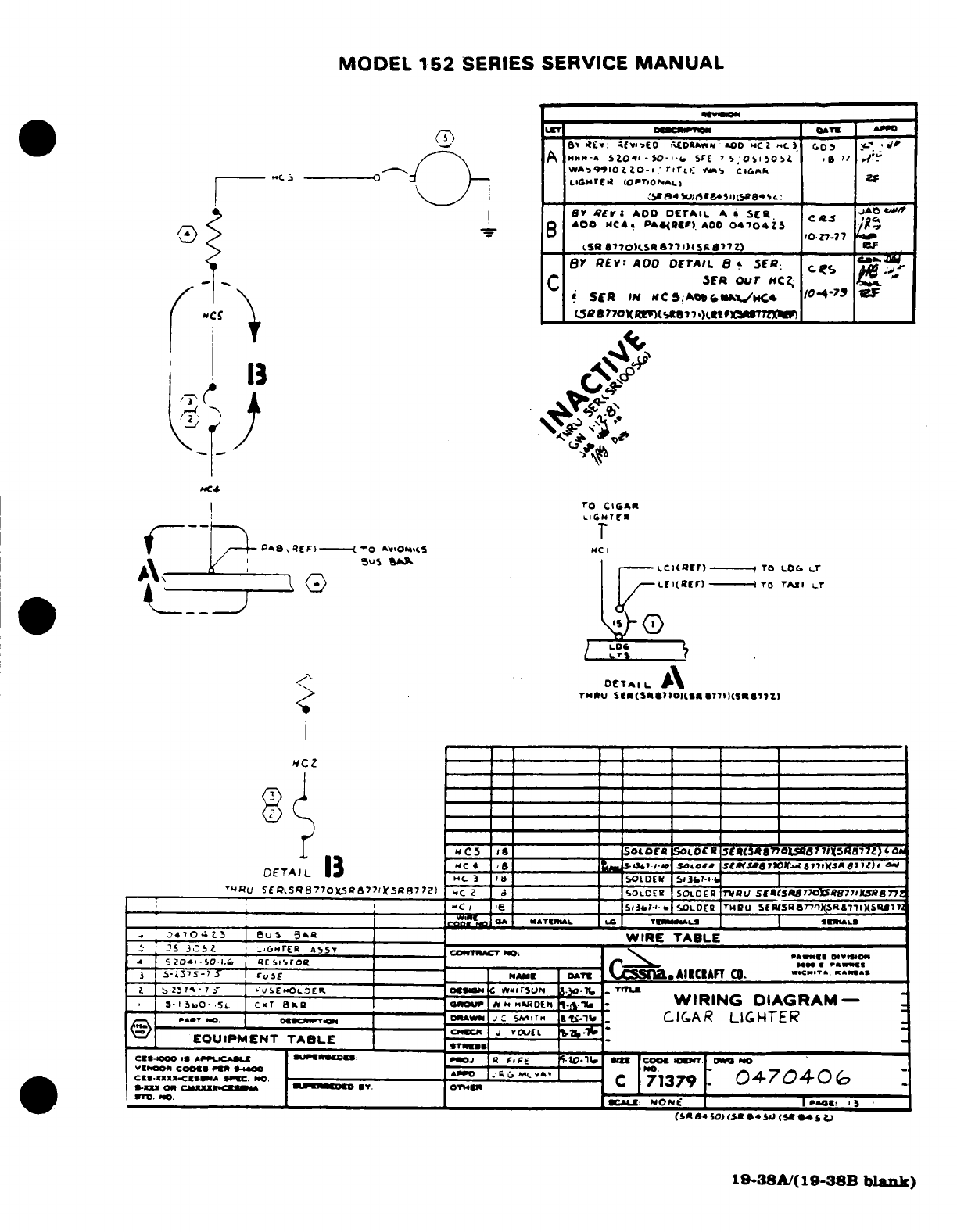
MODEL
152
SERIES SERVICE
MANUAL
19-38A/(19-38B
blank)
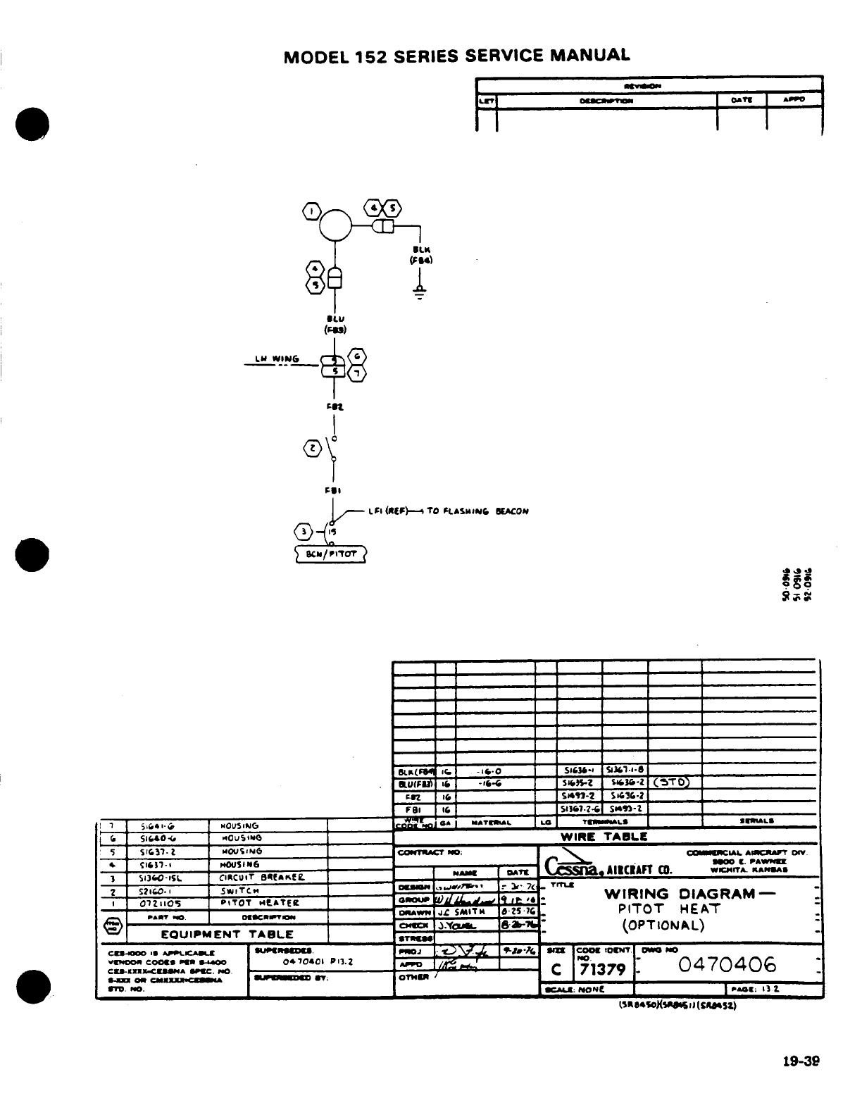
MODEL
152
SERIES
SERVICE
MANUAL
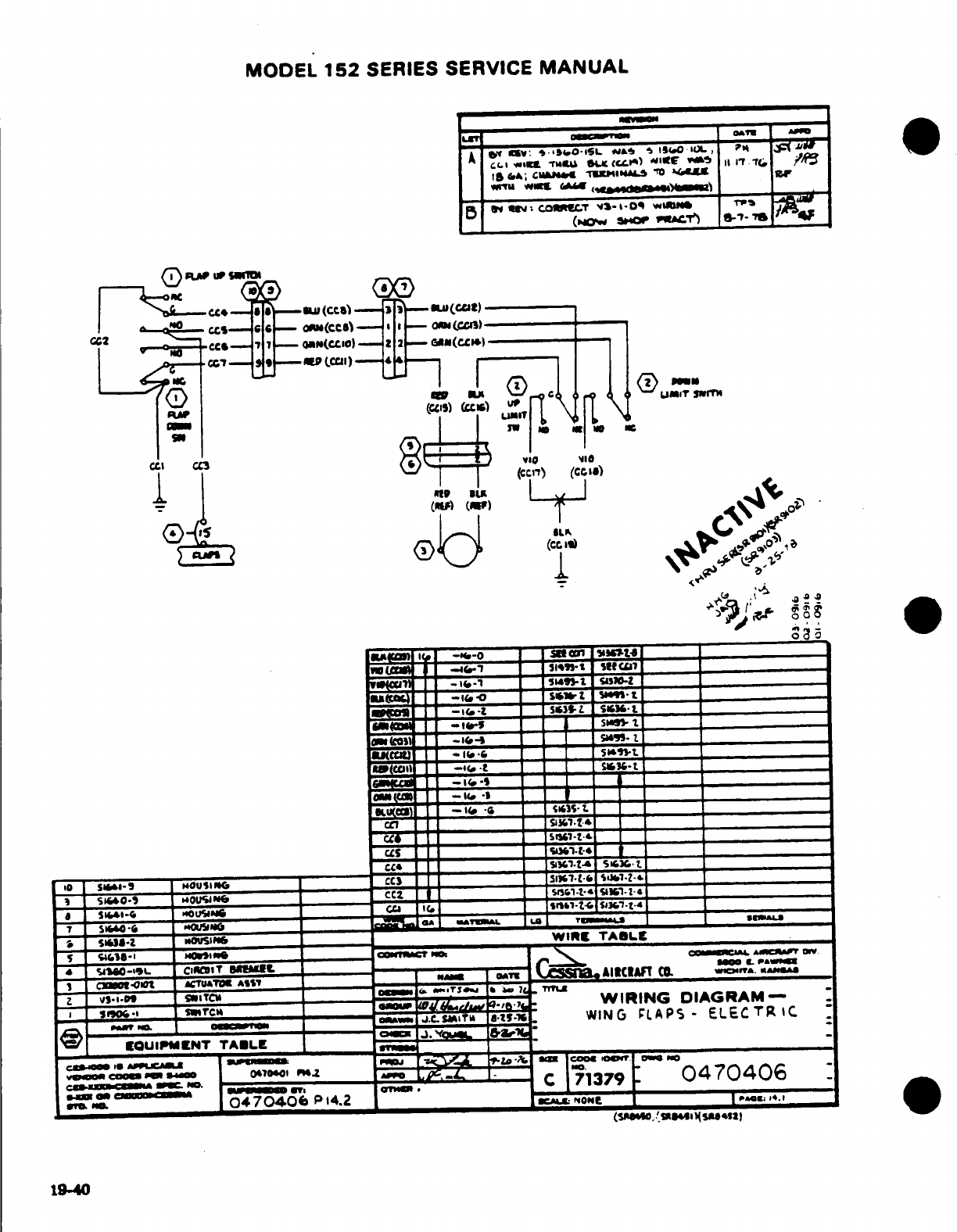
MODEL
152
SERIES
SERVICE
MANUAL
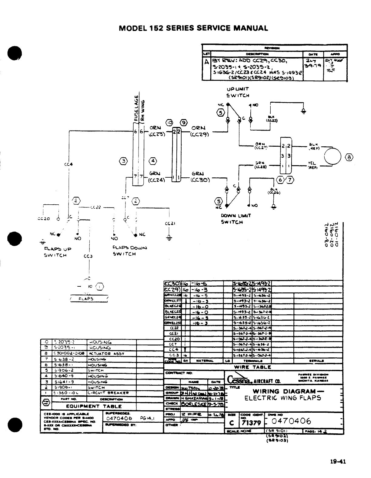
MODEL
152
SERIES SERVICE
MANUAL
U
SWITCH
--.
-
i
L
o_ ,_ _ _ _ _ _ _
_
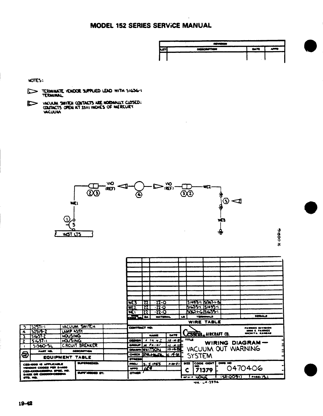
MODEL
152
SERIES
SERVICE
MANUAL
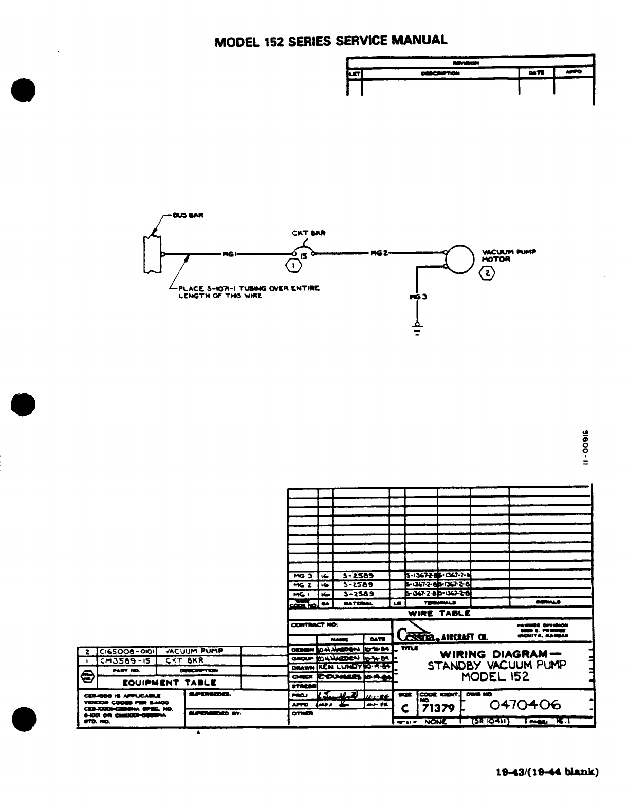
MODEL
152
SERIES
SERVICE
MANUAL
