Control Techniques CDE CDLE VFS Drives Manual
User Manual: Control-Techniques-CDE-CDLE-VFS-Drives-Manual Igor's of metalworking and electrical manuals
Open the PDF directly: View PDF ![]() .
.
Page Count: 100

User Guide
CDE, CDLE
Drives
Constant and variable torque
Variable Speed Drives
for induction motors
11kW to 90kW (Europe)
7.5HP to 150HP (USA)

Safety Information
Persons supervising and performing the electrical
installation or maintenance of a Drive and/or its external
Option Unit must be suitably qualified and competent in
these duties. They should be given the opportunity to
study and if necessary to discuss this User Guide before
work is started.
The voltages present in the Drive and external Option
Units are capable of inflicting a severe electric shock and
may be lethal. The Stop function of the Drive does not
remove dangerous voltages from the terminals of the
Drive and external Option Unit. Mains supplies should be
removed before any servicing work is performed.
The installation instructions should be adhered to. Any
questions or doubt should be referred to the supplier of
the equipment. It is the responsibility of the owner or
user to ensure that the installation of the Drive and
external Option Unit, and the way in which they are
operated and maintained complies with the requirements
of the Health and Safety at Work Act in the United
Kingdom and applicable legislation and regulations and
codes of practice in the UK or elsewhere.
The Drive software may incorporate an optional Auto-
start facility. In order to prevent the risk of injury to
personnel working on or near the motor or its driven
equipment and to prevent potential damage to
equipment, users and operators, all necessary precautions
must be taken if operating the Drive in this mode.
The Stop and Start inputs of the Drive should not be relied
upon to ensure safety of personnel. If a safety hazard
could exist from unexpected starting of the Drive, an
interlock should be installed to prevent the motor being
inadvertently started.
General Information
The manufacturer accepts no liability for any
consequences resulting from inappropriate, negligent or
incorrect installation or adjustment of the optional
operating parameters of the equipment or from
mismatching the Drive with the motor.
The contents of this User Guide are believed to be correct
at the time of printing. In the interests of a commitment
to a policy of continuous development and improvement,
the manufacturer reserves the right to change the
specification of the product or its performance, or the
contents of the User Guide, without notice.
All rights reserved. No part of this User Guide may be
reproduced or transmitted in any form or by any means,
electrical or mechanical including photocopying, recording
or by any information storage or retrieval system, without
permission in writing from the publisher.
Copyright © July 1995
Control Techniques Drives Ltd
Part Number: 0427–0006
Issue Code: CELU5
Issue Date: July 1995
S/W Version:
Machine Control V02.00.00
User Interface V02.xx.xx

Contents
1 Description 1-1
1.2 How best to use this User Guide 1-1
2 Data 2-1
2.1 Model range 2-1
2.2 Industrial and HVAC applications 2-1
2.3 Ingress protection (IP and NEMA 1) 2-1
2.4 AC supply 2-1
2.5 Drive output 2-1
2.6 Ambient temperature and humidity 2-1
2.7 Derating 2-1
2.8 Starts per hour 2-1
2.9 PWM switching frequencies 2-2
2.10 Vibration 2-2
2.11 Serial communications 2-2
2.12 Electromagnetic compatibility (EMC) 2-2
2.13 Frequency accuracy 2-2
2.14 Weights 2-2
2.15 Circuit-breaker 2-2
2.16 Fuse ratings 2-2
2.17 DC bus choke ratings 2-3
2.18 Power ratings 2-4
2.19 Losses and efficiency 2-7
3 Mechanical Installation 3-1
3.1 Hazardous areas 3-1
3.2 Mounting location 3-1
3.3 Control Keypad 3-1
3.4 Mounting the DC bus choke 3-2
3.5 Installing in a sealed enclosure 3-3
3.6 Installing in a ventilated enclosure 3-4
3.7 Mounting a DC braking resistor 3-4
3.8 Motor cooling 3-4
4 Electrical Installation 4-1
4.1 Cables 4-1
4.2 Grounding 4-1
4.3 Grounding terminals 4-1
4.4 Power connections 4-2
4.5 DC bus choke 4-2
4.6 External braking resistor 4-2
4.7 Control Keypad connections 4-2
4.8 Signal connections 4-3
5 Setting Jumpers 5-1
6 Control Keypad 6-1
6.1 Display 6-1
6.2 Keypad 6-2
6.3 Status indicators 6-2
6.4 Displays in Status Mode 6-3
6.5 Display in the event of a Trip 6-3
7 Programming Instructions 7-1
7.1 Menu structure 7-1
7.2 Types of parameters 7-1
7.3 Select a parameter for display
(Parameter mode) 7-1
7.4 Edit a parameter value (Edit mode) 7-2
7.5 Maximum and minimum values 7-2
7.6 Restore all parameters
to their default values 7-3
7.7 Save edited parameter values 7-3
7.8 Reset the Drive 7-3
8 Getting Started 8-1
8.1 Motor ratings 8-1
8.2 Operating in Terminal Mode 8-1
8.3 Operating in Keypad Mode 8-2
9 Trip codes 9-1
10 Security 10-1
10.1 Unlocking Standard Security 10-1
10.2 Unlocking User Security 10-1
10.3 Setting-up User Security 10-2
10.4 Locking Security 10-2
11 List of Parameters 11-1
11.1 Values and character strings 11-1
11.2 Parameter XX.00 11-1
11.3 List of menus 11-1
11.4 Codes used in the parameter lists 11-1
11.5 Menu 0 — User Menu 11-2
11.6 Menu 1 — Frequency reference,
limits and filters 11-4
11.7 Menu 2 — Ramps 11-8
11.8 Menu 3 — Frequency input
and output 11-12
11.9 Menu 4 — Current limits
and torque control 11-16
11.10 Menu 5 — Motor control 11-20
11.11 Menu 6 — Operational modes 11-24
11.12 Menu 7 — Analog inputs
and outputs 11-30
11.13 Menu 8 — Programmable
digital inputs 11-34
11.14 Menu 9 — Programmable
digital outputs 11-36
11.15 Menu 10 — Status logic
and diagnostic information 11-39
11.16 Menu 11 —
Miscellaneous parameters 11-42
11.17 Menu 12 —
Programmable thresholds 11-44
11.18 Menu 13 — Timer functions 11-45
11.19 Menu 14 — PID control loop,
Encoder feedback 11-46
12 Serial Communications 12-1
12.1 Introduction 12-1
12.2 Connecting the Drive 12-1
12.3 Message structure 12-1
12.4 Interrogate the Drive 12-3
12.5 Send a command to the Drive 12-3
12.6 Change a parameter value 12-3
12.7 Control the Drive 12-3
12.8 Messages from Drive to host 12-4
12.9 Reply to an interrogation 12-4
12.10 Acknowledge a command 12-4
12.11 Other messages from host to Drive 12-4
12.12 Summary of Serial
Communications messages 12-4
Control Techniques Worldwide Drive Centres
and Distributors
CDE, CDLE Drive 1-1
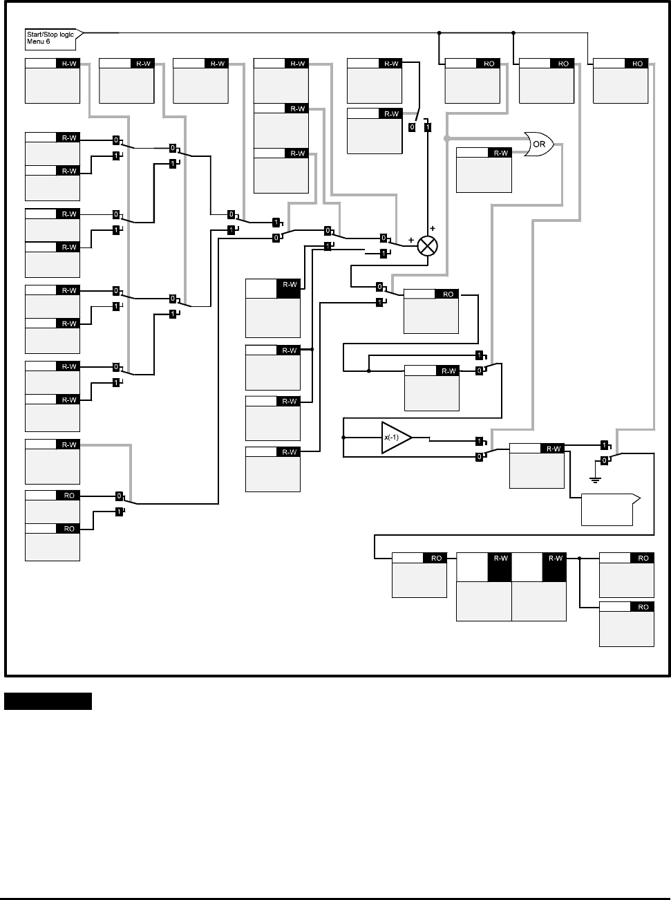
1 Description
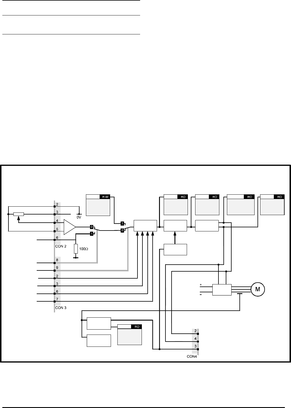
Controlling the Drive
Operation of the Drive is controlled by programming
a number of software parameters. These parameters
have default values that enable the Drive to be run
without initial programming. A diagram of the basic
structure of the control system is shown in Figure 1–1
below. (Refer to Chapter 11 List of Parameters for
details of the parameters.)
The Drive has two display panels and an eight-key
keypad which is located on the front panel of the
case. The display and keypad are used for the
following:
Change parameter values
Stop and start the Drive
Display the operating status of the Drive
1.2 How best to use this
User Guide
This User Guide is arranged logistically: reading from
beginning to end will take you in the correct order
through the basic steps of installing the Drive and
getting it running with a motor.
To make subsequent adjustments to the parameters,
refer to Chapter 11 List of Parameters.
The Table of Contents is organised in a simple way to
help guide you quickly to the required section.
+10V
Run / Stop
logic
Final
frequency
reference
p1.03
Ramps
Post-ramp
speed
reference
p2.01
Current
limits
Machine
control
IGBT
stage
Post-slip
compensation
frequency
p5.01
DC bus
Motor
voltage
p5.03
Motor voltage (0V to 10V)
Motor frequency (+/-10V)
Load current (+/-10V)
Current
feedback
p4.02
Current
monitor
Overload
detector
Local/remote
Keypad select
Stop
Run
Jog
Fwd/Rev
Keypad
reference /
Frequency
reference
p1.04
Figure 1–1 Basic structure of the control system

CDE, CDLE Drive
1-2

CDE, CDLE Drive 2-1
2 Data
2.1 Model range
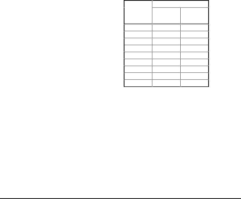
European models
Nine models in two model sizes cover the power
ratings for European applications as follows:
Model
AC supply
Model Power ratings
size code IND HVAC
1
Normal
voltage
CDE1100
CDE1500
CDE1850
CDE2200
CDE3000
11 kW
15 kW
18.5 kW
22 kW
30 kW
15 kW
18.5 kW
22 kW
30 kW
37 kW
2
Normal
voltage
CDE3700
CDE4500
CDE5500
CDE7500
37 kW
45 kW
55 kW
75 kW
45 kW
55 kW
75 kW
90 kW
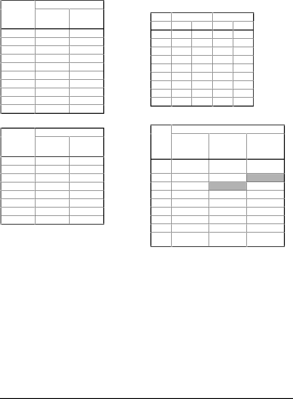
North American models
Eighteen models in two model sizes and two AC
supply voltages cover the power ratings for North
American applications as follows:
Model
AC supply
Model Power ratings
size code IND HVAC
1
Normal
voltage
CDE15HP
CDE20HP
CDE25HP
CDE30HP
CDE40HP
15 HP
20 HP
25 HP
30 HP
40 HP
20 HP
25 HP
30 HP
40 HP
50 HP
Low
voltage
CDLE7.5HP
CDLE10HP
CDLE15HP
CDLE20HP
7.5 HP
10 HP
15 HP
20 HP
10 HP
15 HP
20 HP
25 HP
2
Normal
voltage
CDE50HP
CDE60HP
CDE75HP
CDE125HP
50 HP
60 HP
75 HP
125 HP
60 HP
75 HP
100 HP
150 HP
Low
voltage
CDLE25HP
CDLE30HP
CDLE40HP
CDLE50HP
CDLE60HP
25 HP
30 HP
40 HP
50 HP
60 HP
30 HP
45 HP
50 HP
60 HP
Note
When a model is used for HVAC applications, its power
rating becomes equal to the industrial power rating of
the next larger model size. (The overload current
remains the same.)
2.2 Industrial and HVAC
applications
All models can be programmed by the user for
industrial or HVAC applications.
2.3 Ingress protection
(IP and NEMA 1)
European models
IP00 (in accordance with the IEC529)
North American models
NEMA 1
Cooling fans
IP20
2.4 AC supply
Balanced 3-phase
50Hz ±2Hz or 60Hz ±2Hz
CDE: 380V –10% to 480V +10%
CDLE: 200V –10% to 240V +10%
2.5 Drive output
Maximum frequency: 1kHz
Maximum output voltage:
Equal to the AC supply voltage
2.6 Ambient temperature
and humidity
Ambient temperature range:
–10°C to +50°C (14°F to 122°F) non-condensing.
Local heat sources (such as other equipment) that
raise the air temperature above +50°C (122°F) must
be removed.
2.7 Derating
Derate full load current by 1% for each additional
l00m (320ft) above 1000m (3200ft).
2.8 Starts per hour
Drive: 20 per hour
Motor: Refer to the motor manufacturer
CDE, CDLE Drive
2-2
2.9 PWM switching frequencies
Case size 1 — 3kHz or 6kHz
Case size 2 — 3kHz
2.10 Vibration
Conformance to the requirements of IEC 68–2–34
2.11 Serial communications
RS485 full duplex (RS422 can also be used)
Protocol: ANSI x 3.28–2.5–A4–N, positive logic
Timing
Write to the Drive:
25ms at 9600 Baud
l5ms at 19.2 kBaud
Read from the Drive:
30ms at 9600 Baud
16ms at 19.2 kBaud
2.12 Electromagnetic
compatibility (EMC)
Conducted emisions
Conducted emission requirements of EN50081–2 are
met when an optional RFI filter is used. Refer to the
supplier of the Drive for information on suitable
filters and installation requirements.
Immunity
In accordance with IEC801 without significant
disturbance to operation at the following level:
Part 4 (Transient Burst) Level 4
2.13 Frequency accuracy
Output frequency is within ±100ppm of the frequency
demand.
2.14 Weights
The maximum weight for each case size is as follows:
European case size 1: 22.3kg (49lb)
European case size 2: 56kg (123lb)
USA NEMA size 1: 36kg (81lb)
USA NEMA size 2: 90kg (201lb)
2.15 Circuit-breaker
Use a circuit-breaker having characteristic type K.
2.16 Fuse ratings
Fuses must satisfy the following:
IEC269 Parts 1 and 2, type gl characteristic
BS88 Parts 1 and 2, HRC fuses
An MCB or MCCB may be used instead of fuses if it is
equipped with adjustable thermal and magnetic trips.
Fuse ratings for European models
Recommended fuse ratings for AC supply = 400V
Model
Fuse rating
Industrial
applications
A
HVAC
applications
A
CDE1100 35
40
CDE1500 40
50
CDE1850 50
60
CDE2200 60
70
CDE3000 70
80
CDE3700 80
100
CDE4500 100
125
CDE5500 125
160
CDE7500 160
200
CDE, CDLE Drive 2-3
Fuse ratings for North American models
Recommended fuse ratings for AC supply = 480V
Model Fuse rating
Industrial
applications
A
HVAC
applications
A
CDE15HP 30 35
CDE20HP 35 40
CDE25HP 40 50
CDE30HP 50 60
CDE40HP 60 75
CDE50HP 75 80
CDE60HP 80 100
CDE75HP 100 140
CDE100HP 140 160
CDE125HP 160 200
Recommended fuse ratings for AC supply = 240V
Model Fuse rating
Industrial
applications
A
HVAC
applications
A
CDLE7.5HP 30 35
CDLE10HP 35 50
CDLE15HP 50 60
CDLE20HP 60 80
CDLE25HP 80 90
CDLE30HP 90 125
CDLE40HP 125 140
CDLE50HP 140 160
2.17 DC bus choke ratings
Ripple frequency = 6 × supply frequency
Ratings and values quoted are design minima
Value Current ratings
Weight
mH ARMS Apk kg lb
1.35 39 72 4.5 10
1.50 45 85 6.4 14
0.65 60 128 5.4 12
0.70 75 143 8.4 19
0.80 89 167 16.5 36
0.45 111 224 14.5 32
0.50 130 251 22.5 50
0.40 176 352 32.0 71
0.30 212 350 35.0 77
Application table
Application
Choke
value
mH
European
models North
American
models
North
American
Low voltage
models
1.35 CDE1100 CDE15HP
CDE20HP CDLE7.5HP
1.50 CDE1500 CDE25HP
0.65 CDE1850 CDLE10HP
0.70 CDE2200 CDE30HP CDLE15HP
0.80 CDE3000 CDE40HP CDLE20HP
0.45 CDE3700 CDE50HP CDLE25HP
0.50 CDE4500 CDE60HP CDLE30HP
0.40 CDE5500 CDE75HP CDLE40HP
0.30 CDE7500 CDE100HP
CDE125HP CDLE50HP
CDLE60HP
CDE, CDLE Drive
2-4
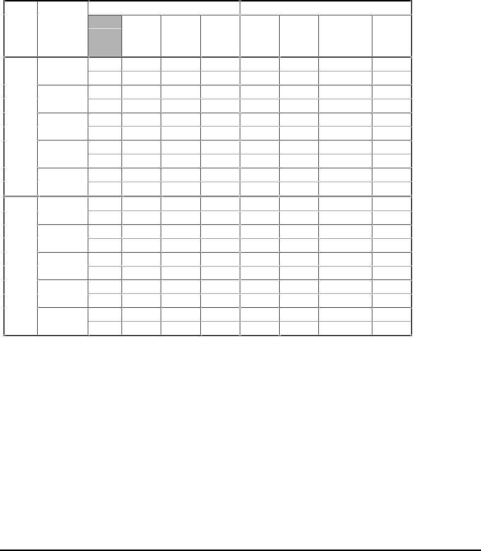
2.18 Power ratings
Note
The displacement factor (fundamental power factor)
presented to the AC supply closely approximates to
unity, but is dependent on the AC supply impedance.
CDE 11kW to 90kW — European models
Power ratings are for typical 3-phase 4-pole
motors.
Nominal supply voltage: 400V RMS
IND: Industrial application capable of 150%
overload for 60 seconds.
HVAC: Fan and pump applications capable of
120% overload for 60 seconds.
Model Model Output ratings AC supply
size Motor
rating
kW
100%
RMS
current
A
Current
overload
%
100%
RMS
current
A
100%
complex
power
kVA
100%
fundamental
current
A
100%
real
power
kW
1 CDE1100 IND 11 25 150 27 17 22 15
HVAC 15 32 120 32 21 28 19
CDE1500 IND 15 32 150 32 21 28 19
HVAC 18.5 38 120 35 23 32 21
CDE1850 IND 18.5 38 150 37 24 33 22
HVAC 22 46 120 49 32 41 27
CDE2200 IND 22 46 150 49 32 41 27
HVAC 30 62 120 61 40 55 36
CDE3000 IND 30 59 150 58 38 51 34
HVAC 37 70 120 68 45 62 41
2 CDE3700 IND 37 76 150 7 48 67 44
HVAC 45 91 120 91 60 80 52
CDE4500 IND 45 91 150 90 59 79 52
HVAC 55 110 120 106 70 97 64
CDE5500 IND 55 110 150 106 70 97 64
HVAC 75 144 120 139 91 127 84
CDE7500 IND 75 150 150 144 95 133 87
HVAC 90 180 120 173 114 158 106
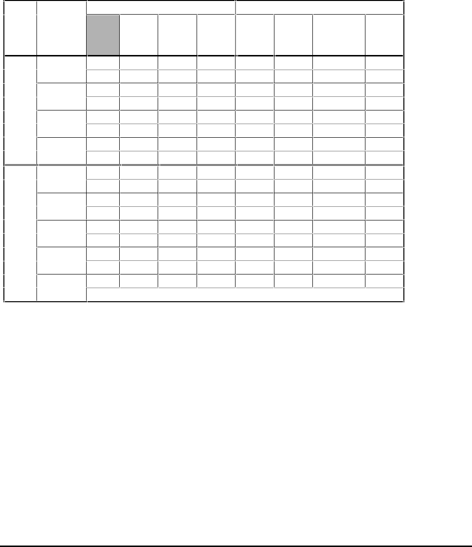
CDE, CDLE Drive 2-5
Power ratings are for standard NEMA motors
Nominal voltage: 440V to 480VRMS
IND: Industrial application capable of 150%
overload for 60 seconds.
HVAC: Fan and pump applications capable of
120% overload for 60 seconds.
CDE 15HP to 150HP — North American models
Model Model Output ratings AC supply
size Motor
rating
HP
100%
RMS
current
A
Current
overload
%
100%
RMS
current
A
100%
complex
power
kVA
100%
fundamental
current
A
100%
real
power
kW
1 CDE15HP IND 15 21 120 21 18 19 16
HVAC 20 27 150 27 22 24 20
CDE20HP IND 20 27 120 27 22 24 20
HVAC 25 34 150 34 28 30 25
CDE25HP IND 25 34 120 32 27 29 24
HVAC 30 40 150 37 29 34 27
CDE30HP IND 30 40 120 37 29 34 27
HVAC 40 52 150 51 42 45 37
CDE40HP IND 40 52 120 51 42 45 37
HVAC 50 65 150 63 52 57 48
2 CDE50HP IND 50 65 120 65 54 57 48
HVAC 60 77 150 77 64 68 56
CDE60HP IND 60 77 120 77 64 68 56
HVAC 75 96 150 96 80 84 70
CDE75HP IND 75 96 120 93 77 85 70
HVAC 100 124 150 119 99 109 91
CDE100HP IND 100 124 120 119 99 108 90
HVAC 125 156 150 150 125 137 114
CDE125HP IND 125 156 120 150 125 137 114
HVAC 150 180 150 173 144 157 131
CDE, CDLE Drive
2-6
Power ratings are for standard NEMA motors
Nominal voltage: 200V to 240VRMS
IND: Industrial application capable of 150%
overload for 60 seconds.
HVAC: Fan and pump applications capable of
120% overload for 60 seconds.
CDLE 7.5HP to 60HP — North American models
Model Model Output ratings AC supply
size Motor
rating
HP
100%
RMS
current
A
Current
overload
%
100%
RMS
current
A
100%
complex
power
kVA
100%
fundamental
current
A
100%
real
power
kW
1 CDLE7.5HP IND 7.5 22 120 22 9 19 8
HVAC 10 28 150 28 12 25 10
CDLE10HP IND 10 28 120 28 12 25 10
HVAC 15 42 150 45 19 37 15
CDLE15HP IND 15 42 120 42 17 37 15
HVAC 20 54 150 53 22 47 20
CDLE20HP IND 20 54 120 53 22 47 20
HVAC 25 68 150 68 28 62 26
2 CDLE25HP IND 25 68 120 66 27 58 24
HVAC 30 80 150 80 33 70 29
CDLE30HP IND 30 80 120 77 32 70 29
HVAC 40 104 150 100 42 91 38
CDLE40HP IND 40 104 120 100 42 91 38
HVAC 50 130 150 125 52 115 48
CDLE50HP IND 50 130 120 125 52 114 47
HVAC 60 145 150 139 58 129 53
CDLE60HP IND 60 145 120 140 58 127 53
No HVAC ratings

CDE, CDLE Drive 2-7
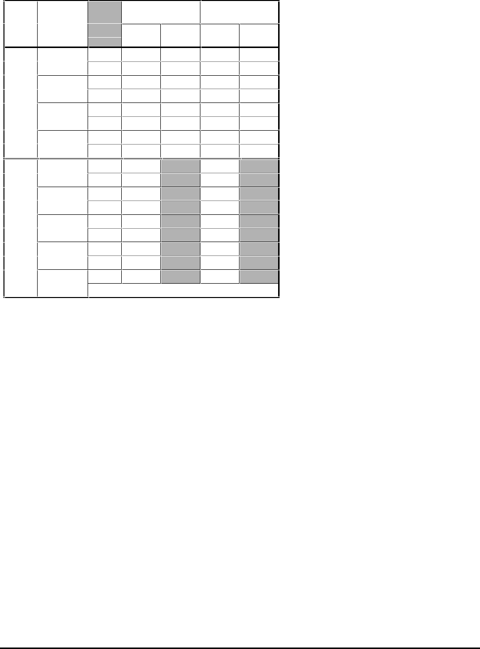
2.19 Losses and efficiency
Note
Figures quoted are at 100% output power.
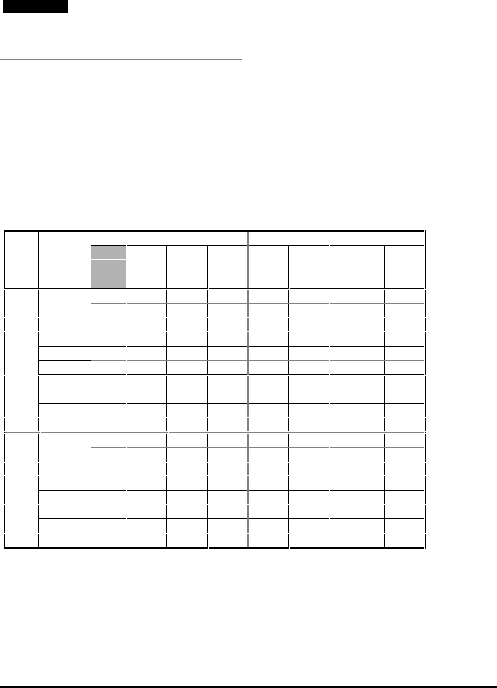
CDE 11kW to 90kW — European models
Model
size Model Total power loss Efficiency
(AC supply = 380V) Efficiency
(AC supply = 480V)
3kHz
W6kHz
W3kHz
%6kHz
%3kHz
%6kHz
%
1 CDE1100 IND 358 440 97.6 97.1 98.0 97.6
HVAC 442 544 97.7 97.2 98.1 97.6
CDE1500 IND 404 498 97.7 97.1 98.1 97.6
HVAC 491 606 97.7 97.2 98.1 97.7
CDE1850 IND 490 615 97.8 97.3 98.2 97.7
HVAC 593 742 97.8 97.3 98.2 97.8
CDE2200 IND 572 724 97.9 97.4 98.3 97.8
HVAC 761 961 97.9 97.4 98.3 97.8
CDE3000 IND 698 886 98.0 97.4 98.3 97.9
HVAC 834 1068 98.0 97.4 98.3 97.9
2 CDE3700 IND 934 97.9 98.3
HVAC 1124 97.9 98.3
CDE4500 IND 1106 97.9 98.3
HVAC 1357 97.9 98.3
CDE5500 IND 1322 98.0 98.3
HVAC 1774 97.9 98.2
CDE7500 IND 1897 97.9 98.2
HVAC 2323 97.8 98.2

CDE, CDLE Drive
2-8
CDE 15HP to 150HP — North American models
Model
size Model Total power loss Efficiency
(AC supply = 480V)
3kHz
W6kHz
W3kHz
%6kHz
%
1 CDE15HP IND 300 370 98.0 97.6
HVAC 373 459 98.1 97.6
CDE20HP IND 352 434 98.1 97.6
HVAC 439 542 98.1 97.7
CDE25HP IND 438 550 98.2 97.7
HVAC 490 613 98.2 97.8
CDE30HP IND 475 498 98.3 97.8
HVAC 638 806 98.3 97.8
CDE40HP IND 615 781 98.3 97.9
HVAC 744 992 98.3 97.9
2 CDE50HP IND 799 98.3
HVAC 951 98.3
CDE60HP IND 936 98.3
HVAC 1148 98.3
CDE75HP IND 1153 98.3
HVAC 1528 98.2
CDE100HP IND 1568 98.2
HVAC 2013 98.2
CDE125HP IND 1973 98.2
HVAC 2323 98.2
CDE, CDLE Drive 2-9
CDLE 7.5HP to 60HP — North American models
Model
size Model Total power loss Efficiency
(AC supply = 240V)
3kHz
W6kHz
W3kHz
%6kHz
%
1 CDLE7.5HP IND 303 374 96.2 95.3
HVAC 386 476 96.1 95.2
CDLE10HP IND 386 476 96.1 95.2
HVAC 541 677 96.4 95.5
CDLE15HP IND 564 651 96.2 95.7
HVAC 663 837 96.7 95.8
CDLE20HP IND 663 837 96.7 95.8
HVAC 810 1037 96.9 96.0
2 CDLE25HP IND 840 96.5
HVAC 988 96.6
CDLE30HP IND 987 96.6
HVAC 1253 96.6
CDLE40HP IND 1283 96.6
HVAC 1601 96.6
CDLE50HP IND 1677 96.4
HVAC 1786 96.6
CDLE60HP IND 1871 96.5
No HVAC ratings
CDE, CDLE Drive
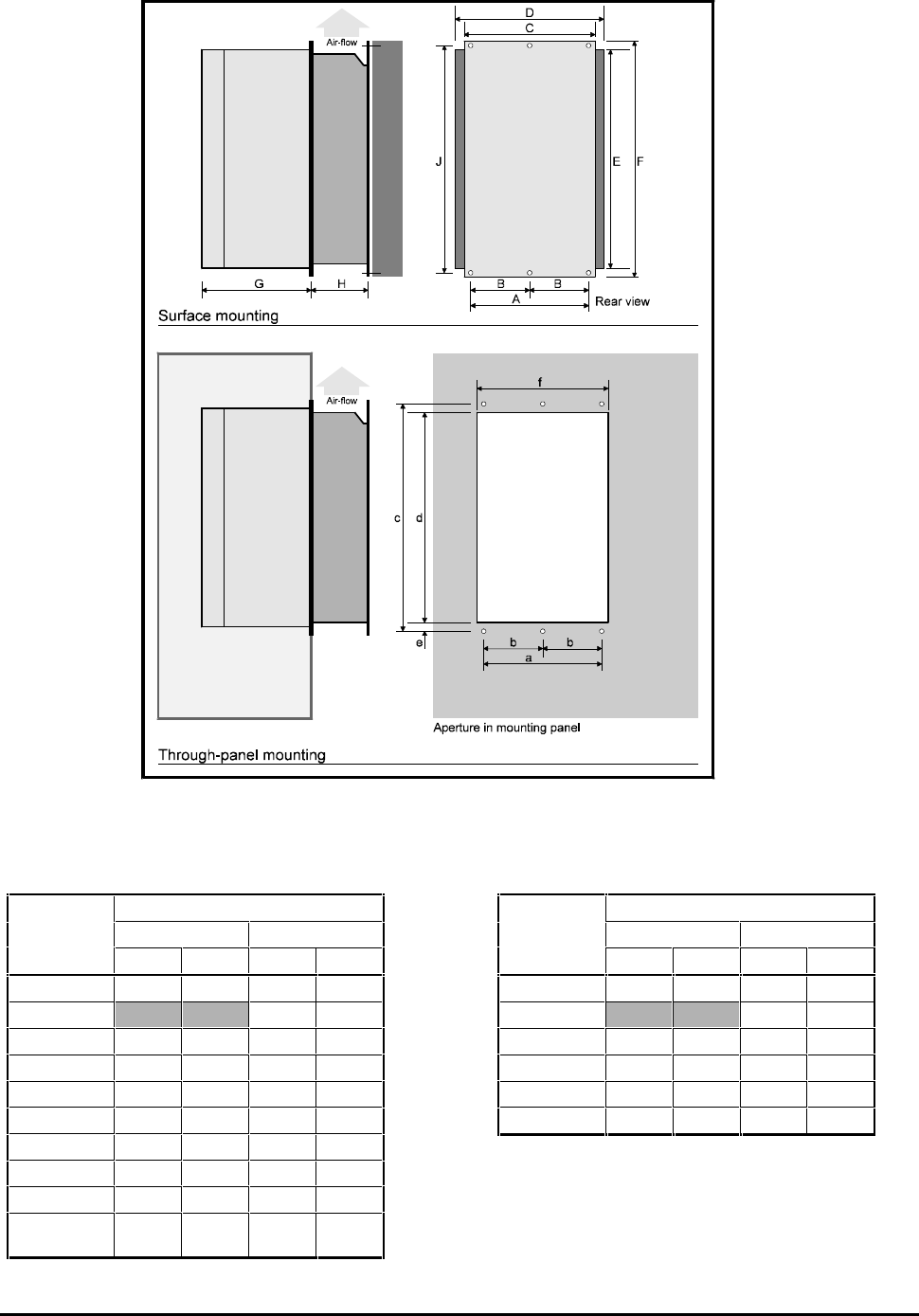
2-10
Figure 2–1 Dimensions of the Drive
Dimensions of the Drive
Dimension Case size
12
mm in mm in
A 248.0 95/8360.0 143/16
B180.0 71/16
C 295.2 115/8464.5 181/4
D 330.0 13 490.0 195/16
E 490.0 195/16 795.0 315/16
F 522.2 209/16 843.5 333/16
G 145.0 511/16 170.0 611/16
H 138.4 57/16 135.0 55/16
J 490.0 195/16 798.0 317/16
Mounting
screws M6 1/4
(clear) M8 5/16
(clear)
Mounting hole dimensions
Dimension Case size
1
2
mm in mm in
a 249.0 913/16 360.0 143/16
b180.0 71/16
c 502.0 193/4815.0 321/16
d 466.0 185/16 780.0 3011/16
e 21.0 13/16 25.0 1
f 296.0 115/8467.0 183/8
CDE, CDLE Drive 2-11
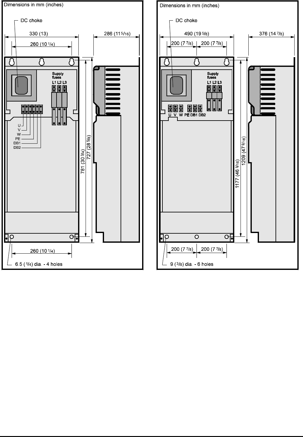
All terminals are compression type.
Cable entry is at the top of the case.
Figure 2–2 NEMA 1 case — Case size 1
All terminals are compression type.
Cable entry is at the top of the case.
Figure 2–3 NEMA 1 case — Case size 2

CDE, CDLE Drive
2-12
CDE, CDLE Drive 3-1
3 Mechanical Installation
3.1 Hazardous areas
The application of variable speed drives may
invalidate the hazardous area certification (Apparatus
Group and Temperature Class) of squirrel cage
induction motors. Approval and certification should
be obtained for the complete installation of motor
and Drive.
3.2 Mounting location
1. Choose a location that is free from excessive
dust, corrosive vapours, gases and all liquids,
including condensation of atmospheric moisture.
2. If condensation is likely to occur when the Drive
is not in use, install an anti-condensation heater.
This heater must be switched off when the Drive
is in use; automatic switching is recommended.
3. Do not locate the Drive in a classified hazardous
area, unless the Drive is installed in an approved
enclosure and the installation is certified.
4. Install the Drive vertically for best flow of
cooling air.
5. Observe the requirements for ambient
temperature if the Drive is to be mounted
directly above any heat generating equipment
(such as another Drive). The Drive has over-
temperature protection which trips the Drive
when the heatsink reaches 90°C (194°F).
6. If the Drive is to be installed directly beneath
other equipment (such as another variable speed
Drive), ensure the Drive does not cause the
ambient temperature requirements of the
equipment to be exceeded.
7. Leave a minimum clearance of 100mm (4in)
above and below the Drive when mounting it
close to other equipment.
8. If the Drive is not supplied in a NEMA 1 case and
when ingress protection higher than IP00 (IEC529)
is required, install the Drive in an enclosure and
ensure its location and means of access conform
to UK or appropriate safety regulations. The
Drive can be surface mounted or through-panel
mounted in a sealed or ventilated enclosure.
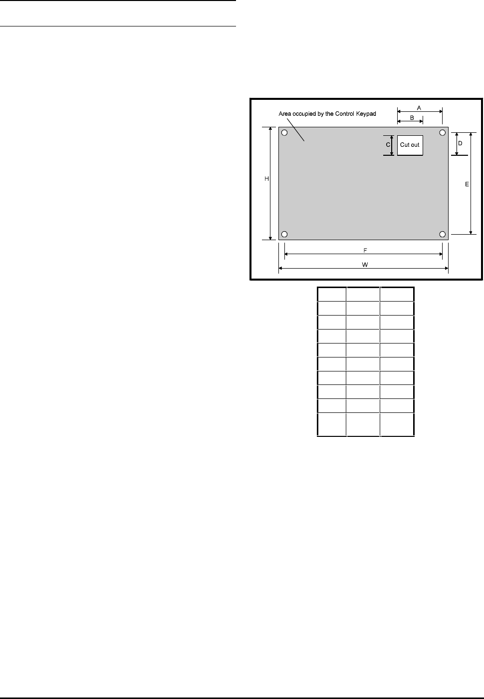
3.3 Control Keypad
The Control Keypad is a plug-in unit which can be
detached from the Drive for mounting in a panel.
Holes are required in the panel for the fixing studs and
connector which project from the rear of the Control
Keypad housing. Refer to Figure 3–1.
Dim.
mm
in
A
65.0
29/16
B
40.0
19/16
C
26.0
11/16
D
22.0
7/8
E
97.0
313/16
F
146.5
53/4
H
167
69/16
W
114
41/2
Hole
dia.
M4
3/16
Figure 3–1 Mounting screw holes and
dimensions of cut-out required for
remote mounting of the Control
Keypad
CDE, CDLE Drive
3-2
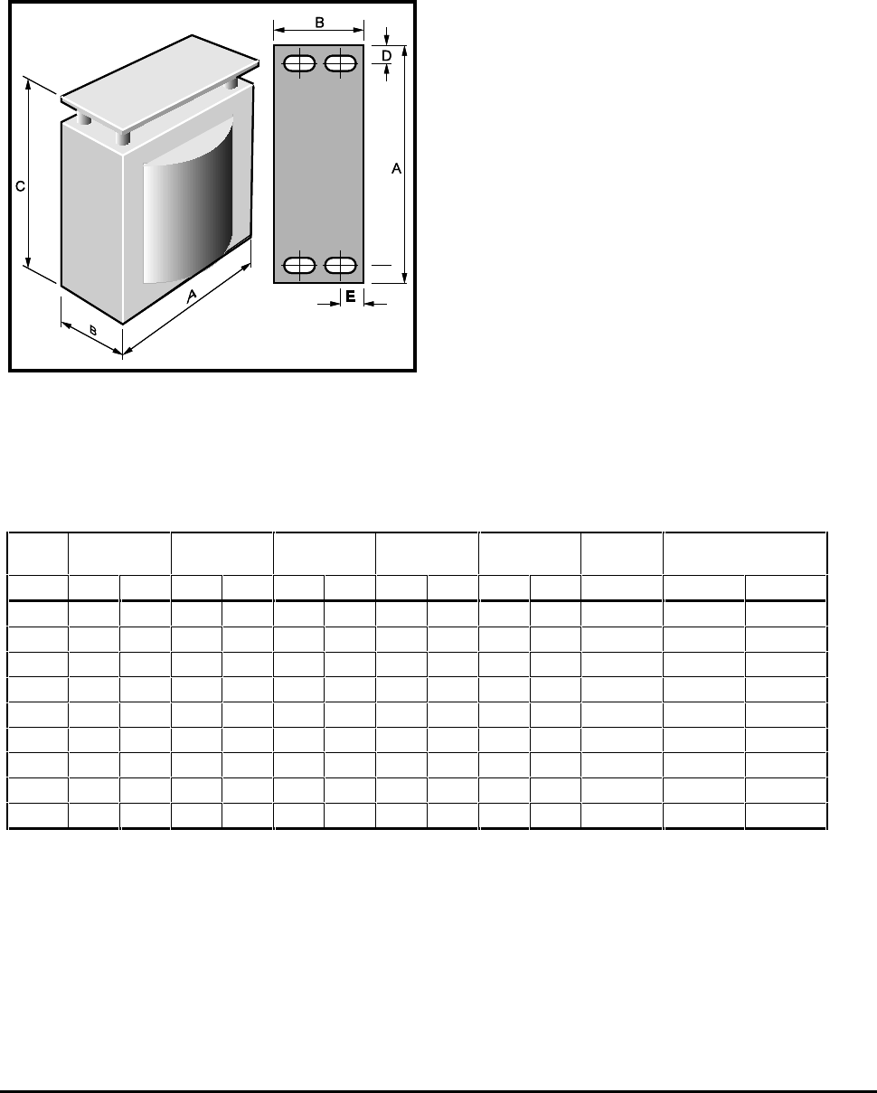
3.4 Mounting the DC bus choke
A choke (inductor) is required for the DC bus.
For Drives in an IP00 case, the DC bus choke is installed
externally to the Drive. For Drives in a NEMA 1 case,
the DC bus choke is installed internally.
Figure 3–2 Dimensions of the DC bus choke
Choke
value ABCD
E
Terminal
size
Weight
mH mm in. mm in. mm in. mm in.
mm
in. kg lb
1.35 118 45/882 31/4155 61/827 11/16
7
1/4M8 4.5 10
1.50 137 57/16 84 35/16 175 67/824 15/16
10
3/8M8 6.4 14
0.65 118 45/895 33/4155 61/827 11/16
7
1/4M8 5.4 12
0.70 137 57/16 116 49/16 175 67/824 15/16
10
3/8M8 8.4 19
0.80 167 65/8132 53/16 200 77/839 19/16
8
5/16 M8 16.5 36
0.65 167 65/8119 411/16 197 73/439 19/16
8
5/16 M8 14.5 32
0.50 195 711/16 138 57/16 230 91/16 46 113/16
11
7/16 M10 22.5 50
0.40 215 87/16 166 69/16 254 10 51 212/16
13
1/2M10 32.0 71
0.30 215 87/16 177 615/16 254 10 51 212/16
13
1/2M10 35.0 77
CDE, CDLE Drive 3-3
3.5 Installing in a
sealed enclosure
To maintain sufficient cooling of the Drive when it is
installed inside a sealed enclosure, heat generated by
all the equipment in the enclosure must be taken into
account and the enclosure must be of adequate size.
To calculate the minimum acceptable size of
enclosure, use the following procedure.
Calculate the minimum required surface area Ae for
the enclosure from:
(())
AP
kT T
e
iamb
==
−−
where:
Aee = Unobstructed heat-conducting area in m2
k = Heat Transmission coefficient of the enclosure
material in Watts/m2/°C
Ti = Maximum permissible operating temperature in
°C of the Drive
Tamb = Maximum external ambient temperature in °C
P = Power in Watts dissipated by all heat sources in
the enclosure
Example
To calculate the size of an enclosure for one CDE 1100
Drive. The following conditions are assumed:
The installation is to conform to IP54, requiring
the CDE Drive to be surface-mounted within a
sealed enclosure.
Only the top, front and two sides of the
enclosure are free to dissipate heat.
The enclosure is made of painted 2mm (3/32 inch)
sheet steel.
Maximum external ambient temperature: 25°C
(77°F).
Drive PWM frequency: 6kHz.
Insert the following values:
P = 440W (from Losses and Efficiency table)
Ti = 50°C (122°F)
Tamb = 25°C (77°F)
k = 5.5 (typical value for painted 2mm (1/16 inch)
sheet steel)
The minimum required heat conducting area is then:
(())
(())
Amft
e
==
−−
==
440
5 5 50 25 32 345
22
.
..
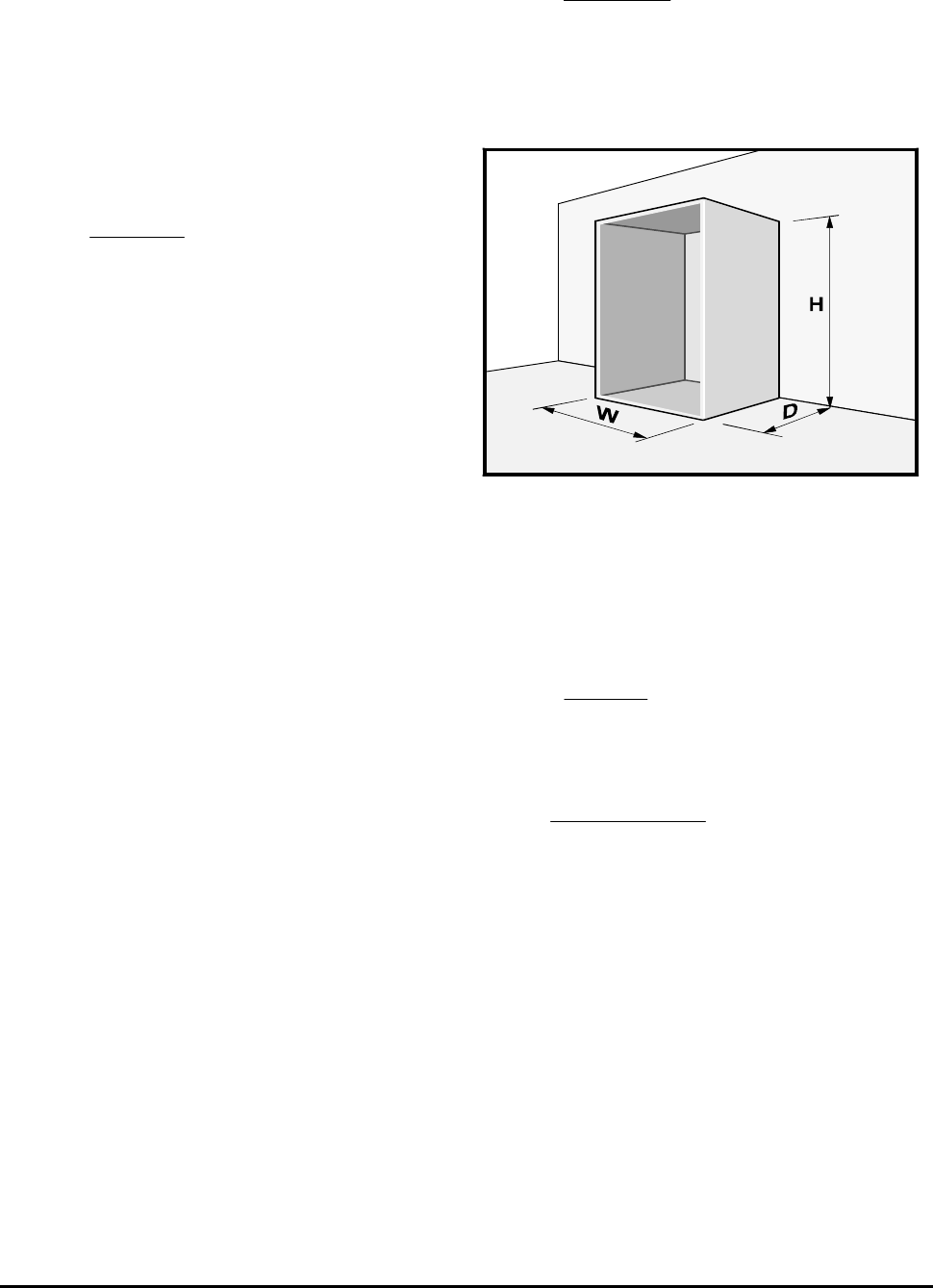
The unobstructed heat-conducting area of the
enclosure is:
A = 2HD + HW + DW
e
Figure 3–3 Enclosure having top, sides and
front surfaces free to dissipate
heat
Estimate two of the enclosure dimensions — the
height and depth, for instance. Calculate the
minimum width from:
WAHD
HD
e
== −−
++
2
Inserting H = 1.8 metres, D = 0.5 metre, obtain the
minimum width:
W metres approx== −−××××
++ ==
32 2 18 05
18 05 06
.( . .)
.. .
If possible, locate heat-generating equipment in the
lower part of the enclosure to encourage internal
convection. Otherwise, increase the height of the
enclosure or install ‘stirrer’ fans.

CDE, CDLE Drive
3-4
3.6 Installing in a
ventilated enclosure
If a high ingress factor is not required, a ventilated
enclosure may be used. This will be smaller than a
sealed enclosure.
To calculate the minimum required volume of
ventilating air, use the following formula:
VP
TT
iamb
==
××
−−
31.
where:
V = Air-flow in m3/hr
P = Power in Watts dissipated by all heat sources in
the enclosure
Ti = Maximum permissible operating temperature in
°C of the Drive
Tamb = Maximum external ambient temperature in °C
Example
To calculate the ventilation requirement for one
CDE1100 Drive:
Pl = 440W
Ti = 50°C
Tamb = 25°C
Then..
V m hr ft hr== ××
−− ====
31 440
50 25 55 1947
33
.
//
3.7 Mounting a DC braking
resistor
Refer to the manufacturer’s instructions for mounting
the DC braking resistor.
Mount the resistor as close as possible to the Drive,
but not in a position where air heated by it could
affect the Drive.
For Drives in an IP00 case, the DC braking resistor
should be installed externally to the Drive. For Drives
in a NEMA 1 case, the DC braking resistor should be
installed internally.
3.8 Motor cooling
When a motor is driven at low speed, its internal
cooling fan becomes less effective. If necessary,
provide it with additional cooling (such as forced
ventilation).
CDE, CDLE Drive 4-1
4 Electrical Installation
Warning
Electric shock risk
The voltages present in the following locations can
cause severe electric shock and may be lethal:
Supply cables
Output cables
Terminals
DC bus choke
Braking circuit
Certain parts of the Drive
If the Drive has been energized, the AC supply must be
isolated at least seven minutes before work may
continue. Refer to Safety Information on the inside
front cover.
4.1 Cables
For the following connections, use 3-core and 4-core
pvc-insulated steel-conduit covered cable with
copper conductors, laid in accordance with defined
conditions:
AC supply to the Drive
Drive to motor
DC bus choke to Drive
Drive to external braking resistor (if used)
Cable sizes must be selected for 100% of the RMS
currents.
This table is only a guide. Refer to local wiring
regulations for the correct size of cables.
Full Load Current Cable size
Amm
2
AWG
15 3.3 12
20 4.0 10
30 6.0 8
40 10 6
55 * 16 4
70 * 25 4
115 35 2
130 50 0
150 70 2/0
175 70 2/0
200 95 3/0
230 120 4/0
* For 75°C (167°F) rated cable you may use the next size smaller.
4.2 Grounding
Ground connections must be made in accordance
with Figure 4–1. Grounding cables must have at least
50% of the current rating of the supply cables.
Use the shortest possible wiring to connect the Drive
to system ground. The system ground must be
connected firmly to a ground point that cannot be
accidentally disconnected.
The impedance of the ground circuit must conform to
the requirements of Health and Safety Regulations
that may apply.
Inspect the grounding circuit at appropriate intervals.
Use screened (conduit-covered) cable to the motor.
Connect the screen to ground at the power
connector on the Drive.
Ground connections on the power input and power
output connectors are connected together in the
Drive, enabling the following connections to be made
through the Drive:
Motor frame ground to system ground
Motor frame ground to the machine ground
The Drives are suitable for grounded-delta installation
without alteration.
4.3 Grounding terminals
The size of external grounding terminals should be
appropriate to the size of the grounding cables.
CDE, CDLE Drive
4-2
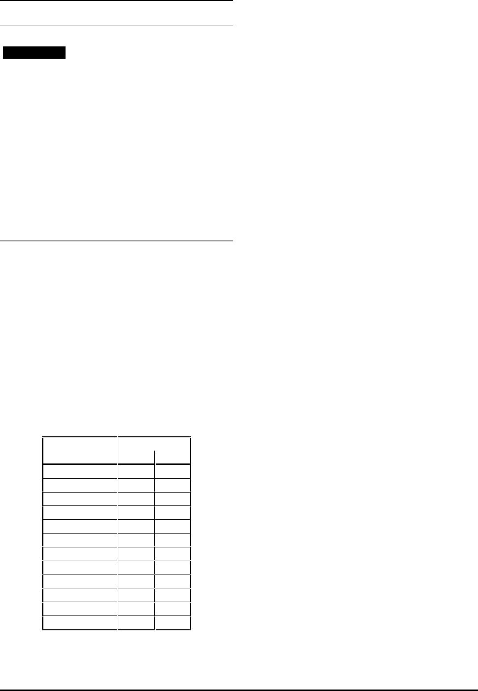
4.4 Power connections
Fuses and AC
supply isolator
Optional
RFI filter
Thermal-trip
relay
When an external braking resistor
is used, it is essential that resistor
over-temperature will cause the
supply to be tripped
Screened or
conduit-covered
cable
Drive
M
Figure 4–1 Power connections
To gain access to the connectors, remove the four
corner screws from the front cover of the Drive and
remove the cover.
Make the following connections using the size of
cable specified in para 4.1 Cables:
AC power to the Drive
Drive to the motor
DC bus choke to the Drive
External braking resistor to the Drive
The AC power should be applied through an isolator
and a fuse or circuit-breaker of the correct rating
(see Chapter 2 Data).
Unusually long cable runs between the Drive and the
motor may give rise to spurious tripping due to the
effect of cable capacitance. As a result, an over-
current fault would be indicated (OIAC). In this case,
output chokes may be required. In difficult cases,
consult the supplier of the Drive.
4.5 DC bus choke
Connect the DC bus choke to terminals L11 and L12 of
the Drive.
4.6 External braking resistor
When an external braking resistor is used, the isolator
must be equipped with an external trip input.
The Drive must be equipped with an optional IN42
Braking Card. Refer to the
IN42
Braking Card User Guide.
4.7 Control Keypad connections
When the Control Keypad is mounted remotely from
the Drive, use screened cable to connect the Control
Keypad to the Drive. (A 9-pin D-type connector is
used.) Connect the cable screen to an external
ground terminal which should be as close to the
Control Keypad as possible.
The connecting cable should have a maximum length
of 1.8m (6ft).
CDE, CDLE Drive 4-3
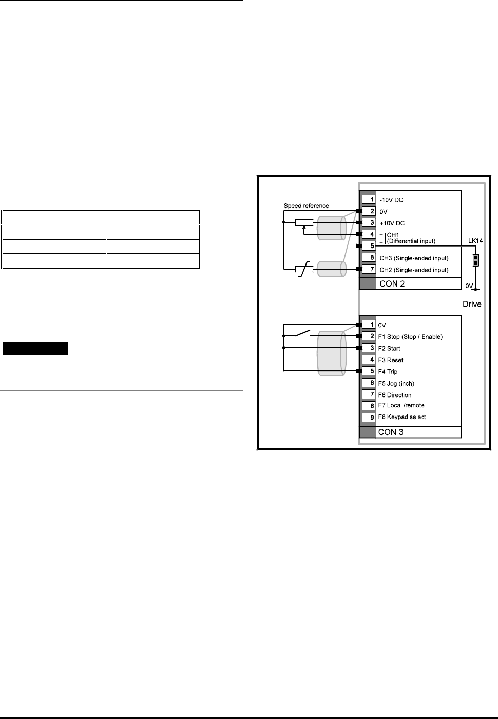
4.8 Signal connections
Note
The default configuration is shown in the connection
diagrams for programmable inputs and outputs.
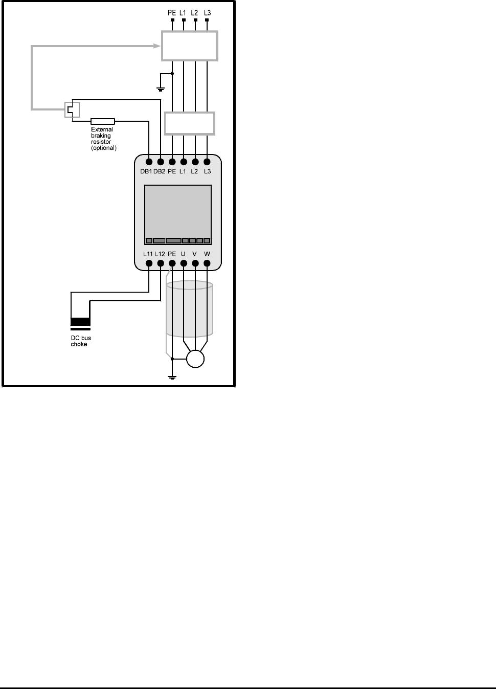
CON 1
Programmable relays
Relay ratings: 250V 7A AC
Figure 4–2 Programmable relays
CON 2
Programmable analog inputs
Terminal CON2
1 –10V reference at 10 mA
Internally protected.
2 0V common
3 +10V reference at 10 mA.
Internally protected
4
5Differential input
Input options:
–10V to +10V
4mA to 20mA (100Ω load)
0 to 20mA (100Ω load)
Resolution: 12-bit plus sign, self calibrating
6 Single-ended input (referenced to 0V common)
Input options:
–10V to +10V
4mA to 20mA (100Ω load)
20mA to 4mA (100Ω load)
0 to 20mA (100Ω load)
20mA to 0 (100Ω load)
Resolution: 10-bit plus-sign
7 Single-ended input (referenced to 0V common).
Input options:
–10V to +10V
4mA to 20 mA (100Ω load)
20mA to 4mA (100Ω load)
0 to 20mA (100Ω load)
20mA to 0 (100Ω load)
Open-circuit voltage for use with
motor thermal resistor: 2.0VDC
Resolution: 10-bit plus-sign
Motor thermal
resistor
Speed reference
Figure 4–3 Connections to the programmable
analog inputs
CDE, CDLE Drive
4-4
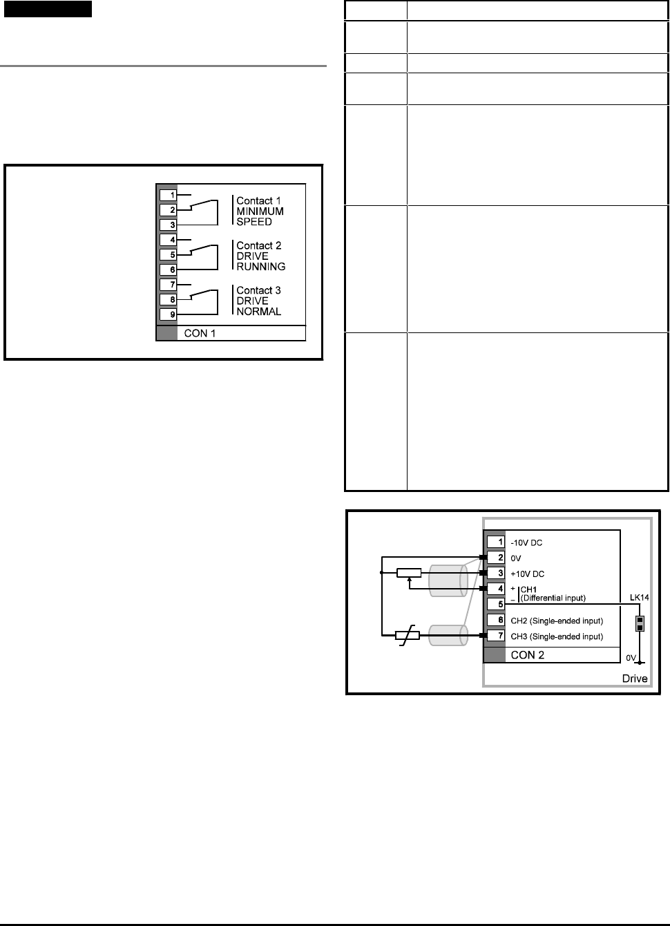
CON3
Programmable digital inputs
Terminal Function
1 0V common
2 Stop input signal
0V to +24V, configurable for positive or negative logic
3 to 9 Programmable digital inputs
0V to +24V, configurable for positive or negative logic
M = Momentary input, 16ms to latch
N = Non-latching input
Figure 4–4 Connections to the programmable
digital inputs
CON 4
Programmable analog outputs
Terminal Function
1 0V common
2, 3, 4 –10V to +10V at 10 mA
0 to 20 mA, or 4 to 20 mA, (referenced to 0V
common)
External load: 0Ω to 500Ω
Resolution: 10-bit plus-sign
Programmable analog outputs
Figure 4–5 Connections to the programmable
analog outputs
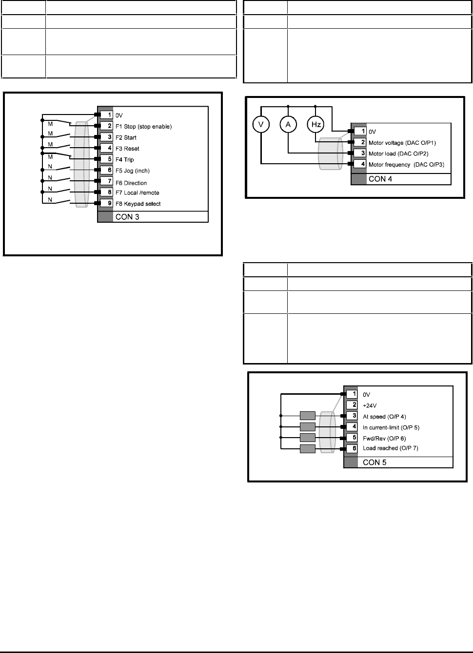
CON 5
Programmable digital outputs
Terminal Function-
1 0V common
2 +24V supply at 200mA
protected by internal current-trip
3 to 6 0V to +24V output configurable for positive or
negative logic
Source: 100mA max at +24V
Sink: 100mA max at 0V
Internal flywheel diodes for driving external relays.
Programmable digital outputs
Figure 4–6 Connections to the programmable
digital outputs
CDE, CDLE Drive 4-5
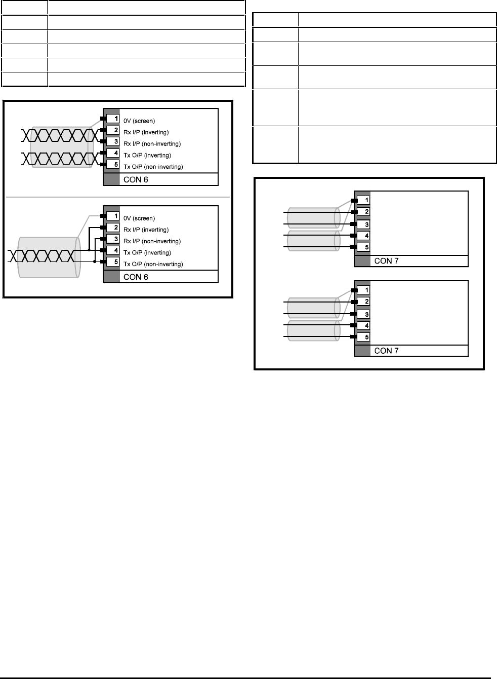
CON 6
Serial communications
Terminal Function
1 0V isolated common, referenced to serial comms lines
2 Receive input (inverting)
3 Receive input (non-inverting)
4 Transmit output (inverting)
5 Transmit output (non-inverting)
Connections for 4-wire mode
Connections for 2-wire mode
Figure 4–7 Serial communications connections
(RS485)
See parameter p11.26 for selecting2 wire operation.
CON 7
Frequency input and output /
Encoder quadrature input
Terminal Function
1 0V common
2 Frequency input (non-inverting)
or Quadrature input channel A (non-inverting)
3 Frequency input (inverting)
or Quadrature input channel A (inverting)
4 Programmable:
Frequency output (non-inverting)
or Quadrature input channel B (non-inverting)
5 Programmable:
Frequency output (inverting)
or Quadrature input channel B (inverting)
0V common
Frequency input (non-inverting)
Frequency input (inverting)
Frequency output (non-inverting)
Frequency output (inverting)
0V common
Quad input ch A (non-inverting)
Quad input ch A (inverting)
Quad input ch B (non-inverting)
Quad input ch B (inverting)
Figure 4–8 Connections for frequency input
and output signals, quadrature and
encoder input.

CDE, CDLE Drive
4-6
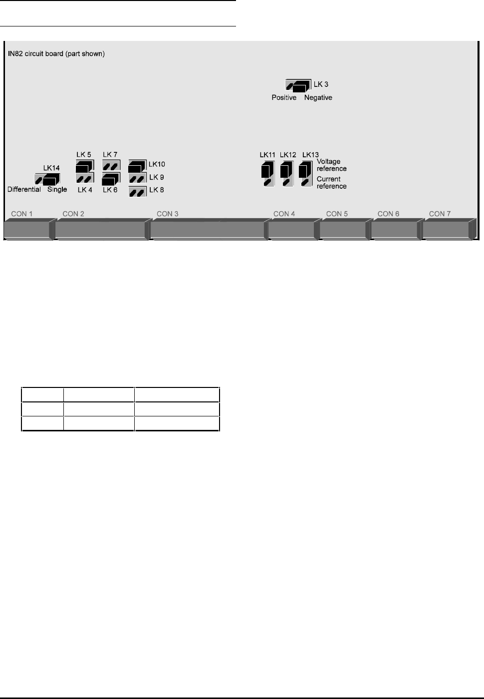
CDE, CDLE Drive 5-1
5 Setting Jumpers
Prior to operation of the Drive it may be necessary to
adjust the position of one or more of the jumpers on
the IN82 board. Their approximate locations are as
shown in Figure 4–1, which shows the default settings.
LK3
Selects positive or negative logic for the control
connections
Default: Negative logic
Link Logic 1 switched Logic 0 open circuit
Positive +24V Internal pull down
Negative 0V Internal pull up
LK4
LK5
Channel 1 analog speed reference input signal
selection, as follows:
LK4 selects current speed reference input signal
LK5 selects voltage speed reference input signal
Default: LK5 — Voltage input
LK6
LK7
Channel 2 analog speed reference input signal
selection, as follows:
LK6 selects current speed reference input signal
LK7 selects voltage speed reference input signal
Default: LK6 — Current input
LK8
LK9
LK10
Channel 3 analog input selection, as follows:
LK8 selects motor thermistor input signal
LK9 selects current speed reference input signal
LK10 selects voltage speed reference input signal
Default: LK10 — Voltage speed reference input
LK11
Channel 1 analog output
Selects voltage or current reference output
Default: Voltage output
LK12
Channel 2 analog output
Selects voltage or current reference output
Default: Voltage output
LK13
Channel 3 analog output
Selects voltage or current reference output
Default: Voltage output
LK14
Channel 1 analog input
Connected: Single ended input
Disconnected: Differential inputs
Figure 5–1 Approximate locations of the jumpers on the IN82 board

CDE, CDLE Drive
5-2
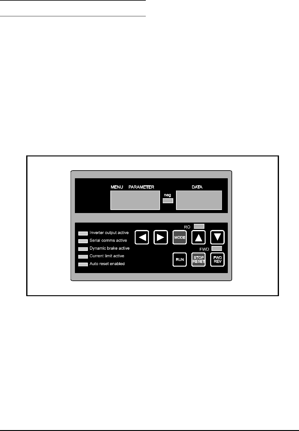
CDE, CDLE Drive 6-1
6 Control Keypad
The Control Keypad has a display area and a keypad.
The display is used for the following:
Reading values of parameters
Reading character strings held in certain
parameters instead of values
Reading status messages
Reading trip codes
The keypad is used for the following:
Programming the parameters
Controlling the motor
6.1 Display
The display has three modes of operation, as follows:
Status mode
This is the normal working mode of operation
Parameter mode
Allows a menu and parameter to be selected
using the keypad
Edit mode
Allows the selected parameter to be edited
(change the value or character string)
These modes are selected using the keypad.
Figure 6–1 Control Keypad
CDE, CDLE Drive
6-2
The display area has a MENU PARAMETER window
and a DATA window. The information that is
displayed in these windows depends on the mode of
operation of the Drive, as follows:
Mode MENU PARAMETER
window DATA
window
Status Status of the Drive Value or character string of
the last parameter that was
selected
Parameter Selected menu
Selected parameter `b’ is displayed when a bit
parameter is selected
Edit Selected menu
Selected parameter Value of the selected
parameter
(one digit flashes)
or
Character string of the
selected parameter
(whole string flashes)
When Edit mode is selected and the DATA window
displays a numerical value, one of the digits flashes to
show that it can be changed using the keypad. When
a character string is displayed, all the characters flash
to show that a different string can be selected.
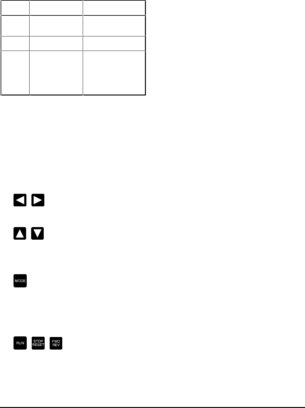
6.2 Keypad
The keys are arranged in two rows.
The functions of the keys in the top row are as
follows:
Display in Parameter mode: select a menu
Display in Edit mode: select a digit
Display in Parameter mode: select a parameter in
the selected menu
Display in Edit mode: change the value of the
selected parameter
Display in Parameter mode: selects Edit
Display in Edit mode: selects Parameter mode
When the display is in Status mode, pressing any one
of the keys in the top row selects Parameter mode
The keys in the bottom row are as follows:
When these keys are configured to be active (by
closing digital input F8), they can be used to control
the motor. (Refer to Menu 6 in Chapter 11 List of
Parameters.)
6.3 Status indicators
LED indicators on the Control Keypad indicate the
following:
NEG
Illuminates when the displayed data value is
negative.
Location: left of the DATA window
RO
Indicates that the displayed parameter is read-
only.
Location: above the MODE key
FWD
Illuminates when the Drive has received the
command to RUN in the forward direction.
Location: above the FWD REV key
Inverter output active
The Drive is controlling the motor (rotating or
stopped).
Serial comms active
The Drive is receiving or transmitting data using
serial communications. Parameter values can
then be remotely read and changed (the Control
Keypad can still be used).
Dynamic brake active
Indicates the motor is using the braking resistor
due to deceleration (when an IN42 Braking Card is
installed).
Current limit active
The Drive is operating in current limit.
Auto reset enabled
Warns that the Drive may be automatically reset
after a trip and re-start.

CDE, CDLE Drive 6-3
6.4 Displays in Status Mode
When the display is in Parameter mode, and no
Control Keypad keys have been pressed for at least
eight seconds, the display reverts to Status mode.
The MENU PARAMETER window then shows one of the
following:
rdY
The Drive is waiting for a command.
run
The Drive is operating. The DATA window shows
the value of the selected parameter.
StoP
A STOP command has been given. The Drive is
decelerating the motor. Note that the motor
may not stop immediately.
inh
The Drive is disabled, allowing the motor to turn
freely.
SCAN
The Drive is synchronising itself to a spinning
motor.
dc
DC injection braking being applied.
6.5 Display in the event of a Trip
triP
A Trip has occurred; the Drive is not controlling
the motor. The DATA window displays the Trip
Code.

CDE, CDLE Drive
6-4

CDE, CDLE Drive 7-1
7 Programming Instructions
7.1 Menu structure
The Drive is programmed by entering values into
parameters. The parameters are held in menus that
group the parameters according to their functions.
The first menu is Menu 0Menu 0 which is the User MenuUser Menu.
This contains the basic parameters that may be read
or adjusted for simple applications.
The remaining menus are the Advanced MenusAdvanced Menus.
These contain all the parameters that may be read or
adjusted for advanced applications.
The parameters in Menu 0 are duplicates of certain
parameters in the advanced menus; for example,
parameter p0.13p0.13 is a duplicate of p1.04 p1.04 (Keypad speed
reference).
7.2 Types of parameters
There are two types of parameter, as follows:
Bit parameters
Bit parameters can be set in either of two logic
states and are used as on/off or change-over
switches.
Bit parameters are prefixed with the letter b
(eg. b1..11).
Variable parameters
Variable parameters can be set at a value within a
specified range. They are used to set numerical
values, or to set the positions of switches having
more than two options.
Variable parameters are prefixed with the letter
p (eg. p1..25).
Certain parameters contain character strings instead
of numerical values. The character strings are
displayed on the Control Keypad in place of values.
When these parameters are accessed and edited using
serial communications, a numerical equivalent is
displayed on the host computer. The numerical
equivalent is used for programming these parameters.
Refer to Chapter 11 Serial Communications.
These operating instructions are based on the Drive
being in StatusStatus mode. (When AC power is applied to
the Drive, the display is automatically in Status
mode.)
Note
If the behaviour of the display does not appear as
described in the operating instructions, refer to
Chapter 10 Security.
7.3 Select a parameter for
display (Parameter mode)
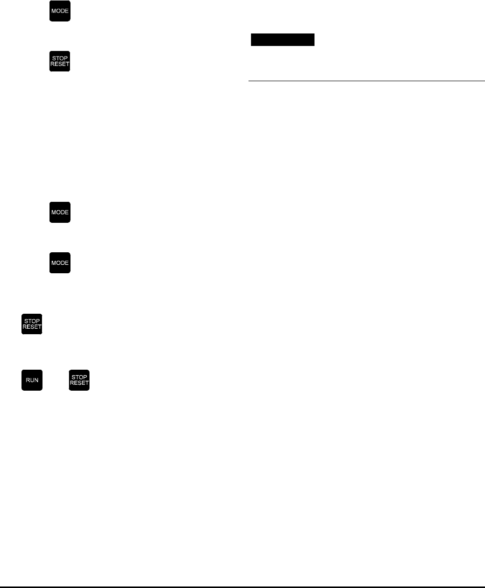
1. Press one of the following keys:
ParameterParameter mode is now selected.
2. The parameter that was last selected is displayed
in the MENU PARAMETER window. The value of
this parameter is displayed in the DATA window.
3. Press or to select the required
menu. The MENU window shows the menu
number.
Press or to select the required
parameter. The MENU PARAMETER window
shows the parameter number. The DATA window
shows the value or character string of the
selected parameter.
If no key is pressed for at least eight seconds, the
display returns automatically to StatusStatus mode.

CDE, CDLE Drive
7-2
7.4 Edit a parameter value
(Edit mode)
Note
Only read–write parameters can be edited.
Editing a parameter value entails using keypad keys to
scroll the displayed digits up or down in value. One
digit at a time can be selected to be scrolled; other
digits can be selected as required for scrolling.
1. Use the procedure in Select a parameter for
display (above) to select the parameter to be
edited.
2. Press
EditEdit mode is now selected.
3. The least significant digit in the DATA window
flashes to show that it is selected for editing. If a
character string is displayed, the whole string
flashes.
4. To change the value of the selected digit (or to
select a different character string), press:
or
Note
While you are changing a digit for a variable
parameter, the value of the parameter could fall
outside the permitted range. If this happens when
adjusting a digit other than the least significant digit,
the maximum or minimum value flashes in the DATA
window. For the options that now become available
for setting the value, refer below to Maximum and
minimum values.
5. To select a different digit, press:
or
6. To make the new value take effect, press
Note
New values given to parameters that require the Drive
to be reset do not take effect until the Drive is reset.
(See Reset the Drive.)
Parameter mode is now selected.
The display remains in Edit mode until is
pressed.
7.5 Maximum and
minimum values
Depending on which limit is exceeded, the maximum
or minimum value for the selected parameter flashes
on the display when the displayed value falls outside
the permitted range while one of the following keys is
pressed:
or
The options that are available for setting the value of
the parameter depend on when the key is released.
The options are as follows:
Enter the previous valid value
Within three seconds (before the display stops
flashing), release the key to set the parameter at
the last valid value that was entered.
Enter the maximum or minimum
value
Keep the key pressed for at least three seconds
(until the display stops flashing). Then release
the key to set the parameter at the maximum or
minimum value.
CDE, CDLE Drive 7-3
7.6 Restore all parameters
to their default values
1. Make sure the Drive is disabled and that the
motor is not being driven.
2. Select any menu.
3. Set the parameter number at 00.
4. Press
5. Set the DATA value at 255.
6. Press
7. The default values are entered into all the
parameters.
7.7 Save edited
parameter values
1. Select any menu.
2. Set the parameter number at 00.
3. Press
4. Set the DATA value at 001.
5. Press
6. If the Drive is not running or is operating in
Terminal Mode, press:
7. If the Drive is in Keypad Mode and is running,
press and hold at the same time:
and
All new parameter values are saved.
7.8 Reset the Drive
The Drive must be reset in order to perform the
following functions:
• To clear a trip
• To make new values active for certain
parameters
• To store parameters
• To load default parameters
• To start the magnetizing current
measurement (p0..14) (p5.16)
Note
When the Drive is reset in order to perform either of
the last two functions, the Drive must be stopped.
The Drive can be reset in the following ways:
• Applying a 0-to-1 signal transition to a
terminal that is programmed to control
parameter b10..24.
• Pressing the STOP/RESET key under either of
the following conditions:
The Drive is not running
The STOP switch is not enabled
(b6..16 set at 0)
• Pressing the RUN and STOP/RESET key when all
the following conditions occur:
The Drive is running
The STOP/RESET key is enabled
(b6..16 set at 1).
The STOP/RESET switch is pressed
• Using serial communications or an MD29
program. This is done by setting parameter
p10..30 at 70.

CDE, CDLE Drive
7-4
CDE, CDLE Drive 8-1
8 Getting Started
The Drive may be controlled in either of the following
modes:
Terminal mode
The motor is controlled by applying signals to the
START, STOP and SPEED REFERENCE inputs.
Keypad mode
The motor is controlled using the
Control Keypad.
8.1 Motor ratings
Enter the following data from the motor rating plate:
Data Enter into parameter...
Motor rated current p0.05
Motor rated voltage p0.09
Number of motor poles p0.18
To get the motor running, follow the appropriate
procedure below.
8.2 Operating in Terminal Mode
Warning
Before proceeding, disconnect AC power from the
Drive.
1. Make control connections as shown in Figure 8–1.
2. Ensure the following settings are made:
SPEED potentiometer is set at minimum
START switch is open
3. Connect AC power to the Drive.
4. Check the MENU and PARAMETER digits on the
control keypad display rdY.
5. Close the STOP switch.
6. Check that the Inverter output active LED is
illuminated.
7. Slowly adjust the SPEED potentiometer and
check that the motor speed increases and
reduces accordingly.
8. Set the SPEED potentiometer at maximum to run
the motor at full speed.
9. Display parameter 0.20 Speed Output frequency
and note the value.
10. Open the STOP switch and check the motor stops.
Motor thermal
resistor
Figure 8–1 Basic control connections for
operating the Drive in
Terminal Mode
CDE, CDLE Drive
8-2
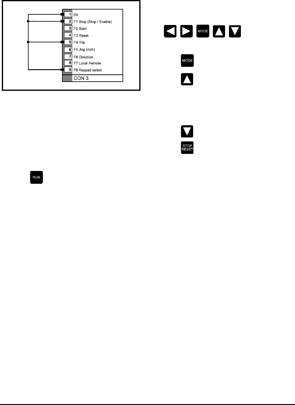
8.3 Operating in Keypad Mode
Figure 8–2 Connections for operating the Drive
in Keypad Mode
1. Connect together pins 1, 2, 5 and 9 of connector
CON 33 as shown in Figure 8–2.
2. Connect AC power to the Drive.
3. Check the MENU PARAMETER window displays
rdY.
4. Press
5. Check that the Inverter Active LED on the
Control Keypad is illuminated.
6. Check that the MENU PARAMETER window
displays run.
7. Press one of the following keys:
8. Select parameter p0.13 or p1.04.
9. Press
10. Press to increase the value of the selected
parameter (p0.13 or p1.04). Note that the
DATA window displays the frequency (speed)
reference of the Drive. Check the speed of the
motor increases while the key is pressed. Release
the key and check the speed remains constant.
11. Press and check the speed reduces.
12. Press
13. Check the MENU PARAMETER window displays
Stop. Check the motor decelerates and stops.
14. If required, set parameter p11.30 at 0.13 for the
display to show the Drive frequency (speed)
reference next time AC power is applied.
CDE, CDLE Drive 9-1
9 Trip codes
Trip codes automatically appear in the DATA
window.
cL1
Trip Code number: 1
Loss of current loop 1
When parameter p7.10 is set at 3 or 4, this trip
occurs when analog speed reference 1 current
input (4–20 mA or 20–4 mA) is less than 3.0mA.
Et
Trip Code number: 2
External trip contact has operated
A trip signal has been received on pin 5 of
connector CON 3. Refer to parameter p8.13 in
Menu 8 and b10.29 in Menu 10 in Chapter 11 List
of Parameters.
I.t
Trip Code number: 3
Integrating overload lxt
Actual motor current has exceeded the rated
current of the motor for an excessive period.
(Value of parameter p4.01 {current feedback}
105% of parameter p5.06 {motor rated
current}).
Oh
Trip Code number: 4
Heatsink over-temperature
The Drive heatsink has reached its upper working
temperature (parameter p7.04). On model 2
size Drives, this may also indicate that the inrush
contactor has failed to close.
OIAC
Trip Code number: 5
Instantaneous AC over-current trip
Excessive current in the output stage of the
Drive, possibly indicating an external short-
circuit.
OU
Trip Code number: 6
DC bus over-voltage
Over-voltage of the AC supply or motor
regeneration causing the DC bus to exceed the
following:
CDE 810V
CDLE 460V.
Ph
Trip Code number: 7
Supply-phase loss
Partial or complete loss of one or more AC supply
phases.
PS
Trip Code number: 8
Internal power supply fault
Consult the supplier of the Drive.
th
Trip Code number: 9
Motor thermal resistor trip
Indicates the value of the motor thermal resistor
connected to pin 7 of connector CON 2 is greater
than 3kΩ (parameter p7.16 set at 9 or 10
{thermal trip input}, and jumper 8 connected).
OIdC
Trip Code number: 10
Instantaneous DC over-current trip
Excessive current in the DC bus of the Drive,
possibly indicating an external short-circuit.
EPS
Trip Code number: 11
External power supply fault
Current overload trip on the +24V supply to
external devices.
CDE, CDLE Drive
9-2
thS
Trip Code number: 12
Motor thermal resistor short-circuit
Indicates the value of the motor thermal resistor
connected to pin 7 of connector CON 2 is less
than 100Ω (parameter p7.16 set at 9 {thermal
trip input}, and jumper 8 connected).
UU
Trip Code number: 13
DC bus under-voltage
CDE: The DC bus voltage is below 320V
CDLE: The DC bus voltage is below 210V.
SCL
Trip Code number: 14
Serial comms. Loss
Loss of data when serial communications in use
(p11.24 set at 2).
POdL
Trip Code number: 15
Loss of Control Keypad
Communications between the Drive and the
Control Keypad has failed (occurs only when the
STOP key is enabled and the Drive is running).
cL2
Trip Code number: 16
Loss of current loop 2
When parameter p7.13 is set at 3 or 4, this trip
occurs when analog speed reference 2 current
input (4–20 mA or 20–4 mA) is less than 3.0mA.
cL3
Trip Code number: 17
Loss of current loop 3
When parameter p7.16 is set at 3 or 4, this trip
occurs when analog speed reference 3 current
input(4–20 mA or 20–4 mA) is less than 3.0mA.
EEF
Trip Code number: 18
EEPROM fault
Consult the supplier of the Drive.
Prc2
Trip Code number: 19
Processor 2 fault
Indicates a malfunction of processor 2 (MD29), or
of the application software bus.
OA
Trip Code number: 20
Ambient over-temperature
Excessive air temperature for the logic circuits in
the Drive. At 80°C the Drive will trip and can
only be reset at 75°C.
rS
Trip Code number: 21
Stator resistance measurement failure
OUSP
Trip Code number: 22
Indicates the Drive is in regenerating current limit and
the speed has increased to maximum.
hFPP
Trip Code numbers: 26 to 39
Hardware fault
Consult the supplier of the Drive.
8.8.8.8.
I××t trip warning (flashing dots)
Actual motor current exceeds the rated current
of the motor. (Value of parameter p4.01
{current feedback} 5% greater than parameter
p5.06 {motor rated current}).

CDE, CDLE Drive 10-1
10 Security
Security operates at two levels to prevent
unauthorized editing of parameters:
Standard Security
When locked, Standard Security prevents reading
and editing of all the parameters in the
Advanced Menus, , but allows reading and
editing of the parameters in the User Menu
(Menu 0).
A fixed code number is used to unlock Standard
Security.
User Security
User Security operates only when it has been
set-up by the user. When locked, it prevents
editing of all parameters in all the menus except
for the following parameters:
• Parameters p0.13 / p1.04
(Keypad speed reference)
• Parameter 00 in the selected menu
(eg. 07.00). This is used to unlock Security.
The code number used to unlock User Security is
defined by the user. This gives protection
against unauthorized editing of parameters. The
code number can be read and edited only when
User Security has been unlocked.
When AC power is applied to the Drive, Standard
Security and User Security (when set-up) are
automatically locked.
10.1 Unlocking Standard Security
When AC power is applied to the Drive, Standard
Security is automatically locked. Only the parameters
in Menu 0 can be displayed on the Control Keypad for
reading and editing.
To read and edit parameters in the Advanced Menus,
Standard Security must first be unlocked. Use the
following procedure to unlock Standard Security.
1. Select parameter 00.00.
2. Press
3. Set the value at 149.
4. Press
All the parameters can then be read and edited unless
User Security has been set.
10.2 Unlocking User Security
When User Security has been set-up and AC power is
applied to the Drive, User Security is automatically
locked. Except for parameters 00.00 in each menu,
and p0.13 / p1.04, no parameters can be edited.
Use the following procedure to unlock User Security:
1. Select a menu. Parameter xx.00 in the selected
menu is displayed.
2. Press
3. Set the value at the required number for User
Security. (See Setting-up User Security.)
4. Press
All read–write parameters can now be edited.
(Standard security must be unlocked to enable read-
Write parameters in the advanced menus to be
edited.)

CDE, CDLE Drive
10-2
10.3 Setting-up User Security
The Drive is supplied without User Security having
been set-up. Consequently, when Standard Security
is unlocked using the fixed code number, all
parameters can be read and all read–write parameters
can be edited.
Use the following procedure to set-up User Security:
1. Unlock Standard Security.
2. Select parameter p11.29.
3. The default value 149 is displayed.
4. Press
5. Change the value to the required User Security
number (not 149).
6. Press
The displayed value reverts to149. This ‘hides’
the User Security number.
7. Follow the procedure in Save edited parameter
values.
User Security is now set-up.
10.4 Locking Security
When AC power is removed and subsequently
re-applied, Standard Security and User Security (when
set-up) are locked.
Use the following procedure to lock Security without
removing AC power:
1. Select a menu. Parameter xx.00 in the selected
menu is displayed.
2. Press
3. Set the value at 22.
4. Press
If User Security has not been set-up, the MENU
window now displays Menu 0. The parameters in
Menu 0 can be read or edited.
If User Security has been set-up, the PARAMETER
window now displays Menu 0. Only the following
parameters can now be edited:
• Parameters p0.13 / p1.04
(Keypad speed reference)
• Parameter 00 this is used to unlock Security
CDE, CDLE Drive 10-3
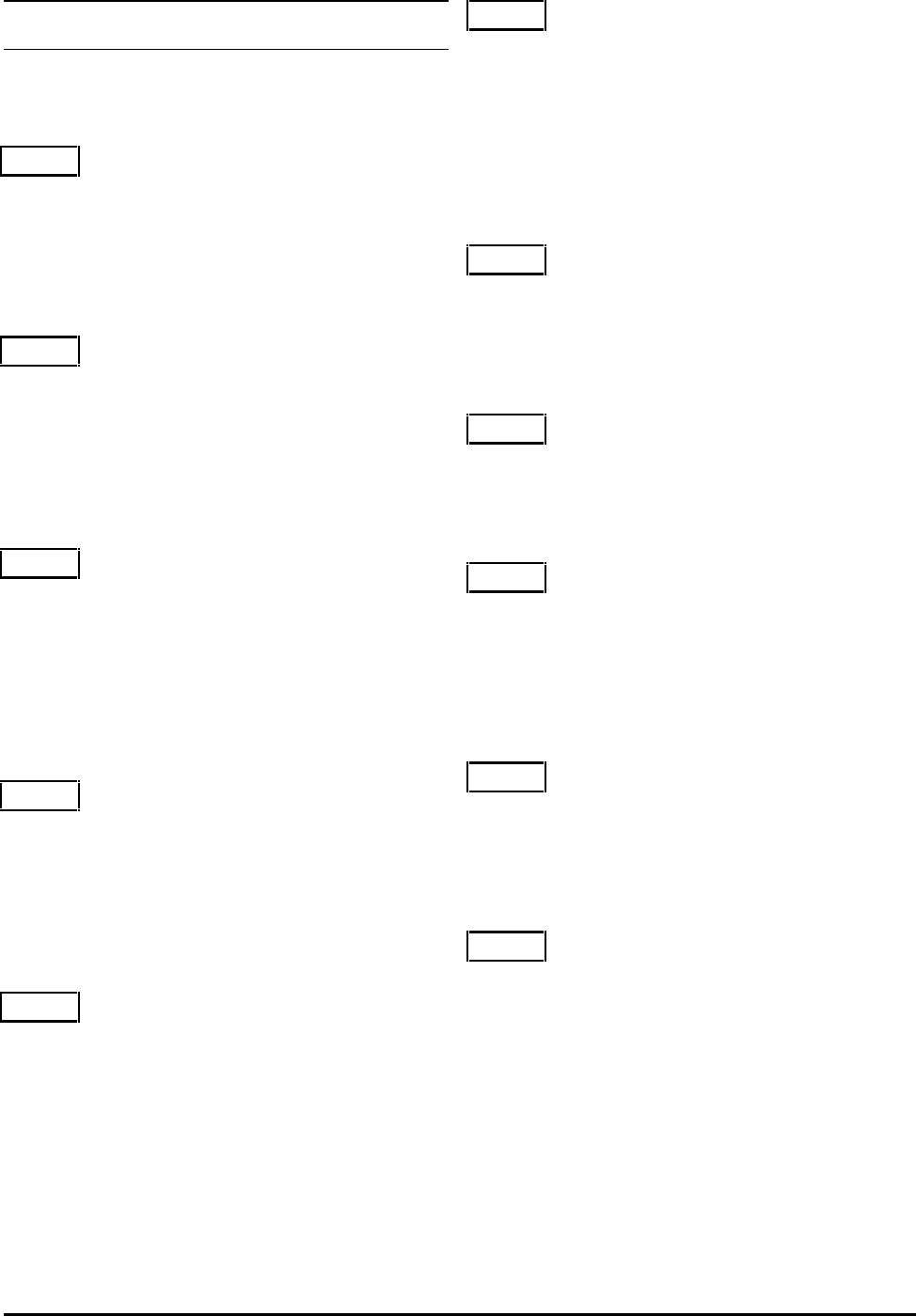
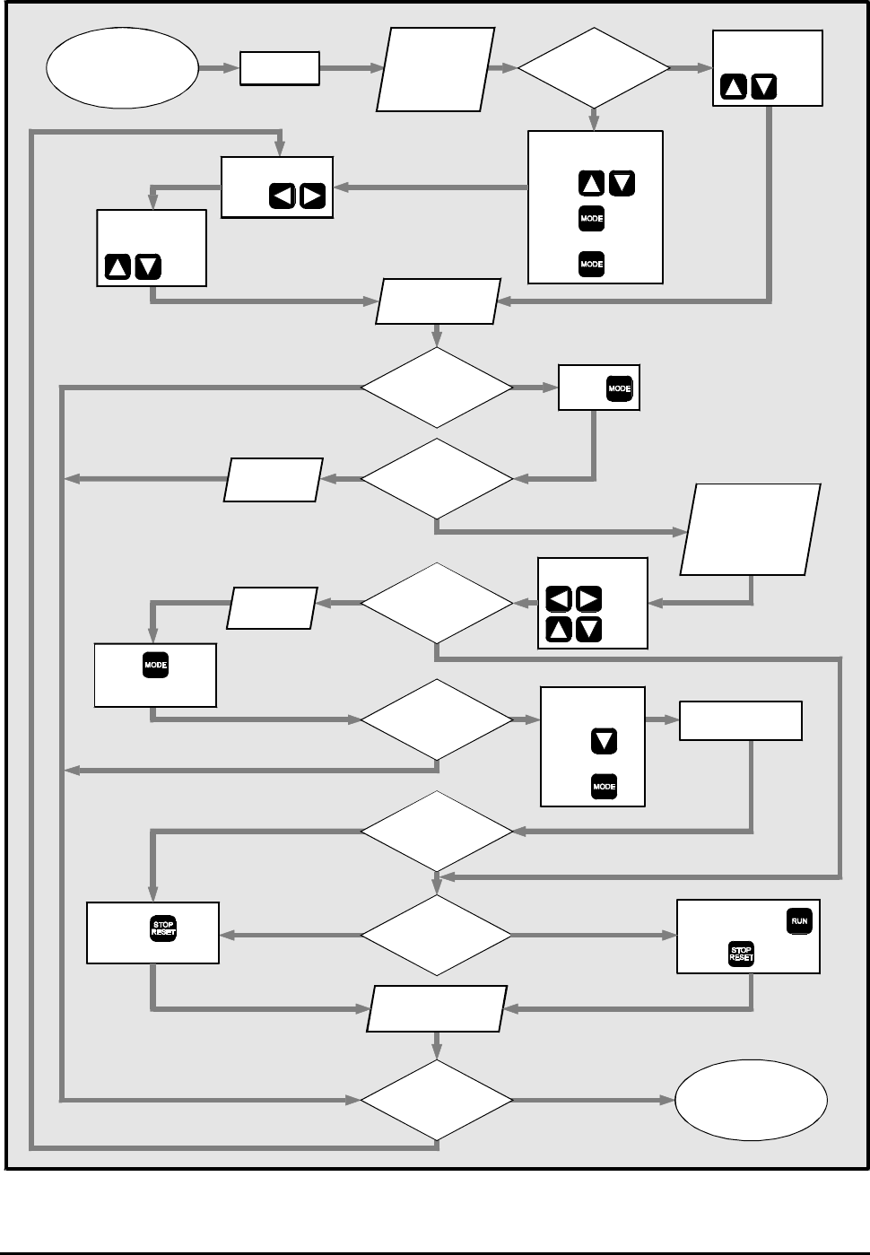
Start Yes
No
EditRead
No
Power on
Menu and
parameter
displays rdY
Data displays
value
Select required
parameter
Select required
menu
Data shows
parameter value
Read or edit
parameter?
Parameter is
accessible unless
controlled by
programmable
input
Change value
Set menu and
parameter at
xx.00
Press
Save new
parameter ?
Press to exit
Edit mode
Is Data
flashing ?
Set data at 1
Press and hold
Press
Press
All edited values
are saved (stored)
Press
New value
is active
Parameter
coded 'r' in
table ?
No
Yes
Unlock security.
Set parameter at
xx.00
Press
Set data at 149
Press
Select required
parameter
Is Drive
running ?
No Yes
Keypad
mode ?
Yes
No
Select another
parameter ?
No
Yes
No
Yes
Yes
End
New value is retained
for next power-up
All parameters coded 'r' are activated because
a reset is required to save parameters
Menu 0 ?
Parameter
is read-only
Figure 10–1 Editing, saving and security

CDE, CDLE Drive
10-4

CDE, CDLE Drive 11-1
11 List of Parameters
11.1 Values and character strings
For parameters containing character strings, the
following lists give the character strings as well as
their numeric equivalents. When these parameters
are accessed using serial communications, the numeric
equivalents are used.
Note
Some parameters have alternative default
values for certain versions of the Drive.
11.2 Parameter XX.00
Parameter 00 in each menu gives access to the
following:
Set at 1 to save parameter values
Set at 255 to restore parameters to default
values
Set at 149 to access standard security
11.3 List of menus
0 User Menu
1 Frequency reference selection, limits and filters
2 Ramps
3 Frequency input and output
4 Current limits and torque control
5 Machine control
6 Operational modes
7 Analog inputs and outputs
8 Digital inputs
9 Digital outputs
10 Status logic, and diagnostic information
11 Miscellaneous
12 Programmable thresholds
13 Timer functions
14 PID control loop, and encoder feedback
15 MD29 setup
16 Application menu 1
17 Application menu 2
11.4 Codes used in the
parameter lists
Parameter changing and saving
Parameters are automatically saved when AC power is
removed. New values given to parameters become
effective immediately. To save the new values
permanently, follow the procedure in Save edited
parameter values in Chapter 7 Programming Instructions.
Read–write and read-only parameters
Read–write parameters are shown as R–W.
Read-only parameters are shown as RO.
Europe and USA settings
Where applicable, the value for European versions is
marked (EUR); the value for USA versions is marked
(USA).
Default values
Default values are given for each parameter. The
equivalent values for serial communications are given
in square brackets.
CDE, CDLE Drive
11-2
11.5 Menu 0 — User Menu
For quick access to the parameters that may need to
be adjusted for simple applications, the parameters in
Menu 0 can be programmed without needing to
search through the advanced menus.
If different parameters are required in Menu 0, they
can be changed using parameters p11.01 to p11.20 in
Menu 11.
XX.00 Null parameter
p0.01
(p1.06)
Maximum frequency R–W
Range 0 to 999.9 Hz Default 50 (EUR)
60 (USA)
Defines absolute maximum output frequency.
See parameter b1.10.
p0.02
(p2.03)
Acceleration ramp R–W
Range 0.1 to 3276 s/100Hz Default 5
Acceleration ramp rate is expressed as the time in
seconds for the output frequency to increase by 100Hz.
p0.03
(p2.04)
Deceleration ramp R–W
Range 0.1 to 3276 s/100Hz Default 10
Deceleration ramp rate is expressed as the time in
seconds for the output frequency to decrease by 100Hz.
p0.04
(p4.11)
Symmetrical current limit R–W
Range 0 to
p
p
1135
506 100
.
.××
% of
FLC Default 150
Current limit for Motoring and Regenerating.
After having set the required value of rated motor
current in p0.05 (p5.06), you may increase or
decrease the percentage overload current using
p0.04 (p4.11). The maximum percentage that can
be set is limited by the overload current rating of the
Drive. The limit applies when motoring and
regenerating.
The value of p0.04 (p4.11) is automatically reduced
when the value of p0.05 (p5.06) is increased
beyond the default value.
p0.05
(p5.06)
Rated motor current R–W
Range 0 to p11.33p11.33
A
Default Rated
current of
the Drive
Enter the value of continuous rated motor current.
When the value is increased beyond the default value
of the Drive, the value of p0.04 (p4.11) is
automatically decreased.
Itorque = p0.05 x p5.13
The value entered affects the following:
Slip compensation
Dynamic V/f
Ixt detection level
p0.06
(p5.12)
Voltage control mode
selector
R–W
Range [0] to [4] Default Ur_I [3]
Auto [0] Auto boost
Fd [1] Fixed boost
Ur_S [2] Vector mode. Stator resistance is
measured at start
Ur_I [3] Vector mode. Stator resistance is
measured at power-up only
Ur [4] Vector mode. Stator resistance
is not measured
See parameter p5.12.
p0.07
(p5.07)
Rated motor RPM at full load R–W
Range 0 to 9999
RPM
Default 0
Enter the value from the motor rating plate. This is
used by the Drive to apply correct slip compensation.
If no slip compensation is required, set p0.07
(p5.07) at 0 (default).
p0.08
(p6.04)
Injection braking level R–W
Range 0 to p
p
1135
506 100
.
.××
% of
FLC
Default 150
If the injection braking level is set too low the Drive will
not stop. If a low injection level is required, use the
timed dc injection td.dc by setting p0.12 at td.dc [4].
p0.09
(p5.08)
Rated motor voltage R–W
Range 100 to 480
VRMS
Default 400 (EUR)
460 (USA)
Enter the value from the motor rating plate in order to
define the maximum output voltage of the Drive.
See parameter p5.12.
CDE, CDLE Drive 11-3
b0.10
(b4.07)
Select torque mode R–W
Range 0 or 1 Default 0
Set b0.10 at 0 to select speed reference.
Set b0.10 at 11 to select torque reference. The PID
controller uses the same P and I terms as the current
limits defined in p4.08 and p4.09.
It is possible to change between torque control and
frequency control when the Drive is running without
causing transient frequency changes.
p0.11
(p6.02)
Auto-start mode R–W
Range [0] to [2] Default dis [0]
dis [0] The Drive does not start when AC
power is applied
ALYS [1] The Drive always starts when AC
power is applied
Pd.dP [2] The Drive starts only if it had been
running when AC power was
previously removed.
See parameter p6.02.
p0.12
(p6.01)
Stop mode R–W
Range [0] to [4] Default rp [0]
rP [0] The Drive ramps to zero speed
inh [1] Inhibit (coast to stop)
dc [2] DC injection braking
rP.dc [3] Ramp + DC injection braking
td.dc [4] Timed DC injection braking
See parameter p6.01.
p0.13
(p1.04)
Keypad reference R–W
Range Bipolar: ±±p1.06p1.06
Unipolar:
p1.05 p1.05 to p1.06 p1.06
Hz Default 0
Saved at power-down.
Frequency reference when the Control Keypad is used
to control speed (see Menu 3).
Enter a value using the Control Keypad. Set p11.30 at
p0.13 (1.04)to display the parameter at power-up.
p0.14
(p5.16)
Magnetizing current test R–W
Range 0 to 9999 Default 0
Automatically saved.
Warning
The motor runs at half maximum speed while
this test is performed.
Ensure the stop switch is closed.
Set p0.14 (p5.16) at 255 to start the test.
Reset the Drive to enter the new value of power
function in p5.13.
b0.15
(b6.06)
Switching frequency R–W
Range [0] or [1] Default 3 [0]
3 [0] 3kHz
6 [1] 6kHz (Model size 1 only)
b0.16
(b6.24)
Catch spinning motor R–W
Range 0 or 1 Default 0
See parameter b6.24.
p0.17
(p1.14)
Jog reference R–W
Range 0 to 999.9
Hz
Default 1.5
Frequency reference for Jog.
p0.18
(p5.10)
Number of motor poles R–W
Range 2 poles [0]
4 poles [1]
6 poles [2]
8 poles [3]
Default 4p [1]
Enter the value from the motor rating plate for
correct slip compensation and RPM indication.
p0.19
(p4.02)
Current feedback (load) RO
Range 0 to ±p11.35
A
Default
Indicates the magnitude of the torque-producing
motor current.
p0.20
(p5.02)
Motor shaft RPM RO
Range 0 to 9999
RPM
Default
Indicates motor shaft RPM.
The number of poles must be entered correctly in
p0.18 (p5.10), and the slip correction must not be at
the maximum frequency limit [if the motor is to run at
50Hz, set p0.01 at a higher value to allow for slip
compensation].
CDE, CDLE Drive
11-4
Note
For controlling read–write parameters and for
displaying read-only parameters, refer to the
following:
Menu 7 — Analog inputs and outputs
Menu 8 — Programmable digital inputs
Menu 9 — Programmable digital outputs
Bit parameters are shown in default state
Pre-set
frequency 4
Pre-set
frequency 3
p1.27
p1.28
Pre-set
frequency 2
Pre-set
frequency 1
p1.26
p1.25
Pre-set
frequency
select bit 0
b1.22 Pre-set
frequebcy
select bit 1
b1.23 Pre-set
frequency
select bit 2
b1.24 Select
precision
reference
b1.09
Select
keypad
reference
b1.08
Select
pre-set
speeds
b1.07
Reference
offset
p1.15
Reference
offset
select
b1.16
Jog
reference
p1.14
p1.04
(p0.04)
Keypad
reference/
Frequency
reference
Precision
frequency
reference
p1.17
Precision
frequency
trim
p1.18
Jog
select
b1.13 Reverse
b1.12 Reference
on
b1.11
p1.01
Reference
selected
Minimum
frequency
p1.05
Maximum
frequency
p1.06
Current
limits
Menu 4
p1.02
Run
reference Skip
frequencies
1, 2 and 3
Skip
frequency
bands
1, 2 and 3
p1.33
p1.35
p1.37
p1.34
p1.36
p1.38
p1.39
In rejection
zone
p1.03
Final
frequency
reference
p1.20
Analog
reference 2
Analog
reference 1
p1.19
Analog
reference 2
select
b1.21
Pre-set
frequency 6
p1.30
Pre-set
frequency 5
p1.29
p1.32
Pre-set
frequency 8
Pre-set
frequency 7
p1.31
Bipolar
select
b1.10
11.6 Menu 1 — Frequency reference, limits and filters

CDE, CDLE Drive 11-5
p1.01 Reference selected RO
Range ±999.9 Hz Default
Indicates the frequency reference. This can be used
for setting up the system and fault finding.
p1.02 Run reference RO
Range ±p1.06p1.06 Hz Default 0.0
Indicates the run frequency reference.
This can be used for setting up the system and fault
finding.
p1.03 Final frequency reference RO
Range ±p1.06p1.06 Hz Default 0.0
Indicates the final frequency reference. This can be
used for setting up the system and fault finding.
p1.04 Keypad reference R–W
Range Bipolar: ±±p1.06p1.06
Unipolar:
p1.05 p1.05 to p1.06 p1.06
Hz Default 0
Saved at power down.
Frequency reference when the Control Keypad is used
to control speed (see Menu 3).
Enter a value using the Control Keypad. Set p11.30 at
p1.04 to display the parameter at power-up.
p1.05 Minimum frequency R–W
Range 0 to p1.06p1.06 Hz Default 0
Use in unipolar mode to define the minimum output
frequency of the Drive. This can be over-ridden by
p1.06 and is inactive during Jog.
p1.06 Maximum frequency R–W
Range 0 to 999.9 Hz Default 50 (EUR)
60 (USA)
Enter a value to define the absolute maximum output
frequency.
b1.07 Select pre-set speeds R–W
Range 0 or 1 Default 0
Set at 1 to select pre-set speeds.
b1.08 Select keypad reference R–W
Range 0 or 1 Default 0
Set at 1 to select control using the Control Keypad.
b1.09 Select precision reference R–W
Range 0 or 1 Default 0
Set at 1 for high resolution (0.001Hz) frequency
control.
Set at 0 for normal resolution (0.03Hz) frequency
control.
b1.10 Bipolar select R–W
Range 0 or 1 Default 0
Set at 1 to select bipolar speed reference signal.
Set at 0 to select unipolar speed reference signal.
Negative input signals are then treated as zero.
Analog operation
When b1.10 is set at 0,, any analog input programmed
to parameters p1.19 and p1.20 is scaled so that 100%
corresponds to the maximum set for p1.06, and 0%
corresponds to the minimum set for p1.05.
When b1.10 is set at 1, the analog input programmed
to p1.19 or p1.20 is scaled so that ±100%
corresponds to the maximum ± set for p1.06..
In addition, if an analog input programmed in voltage
mode is directed to one of these parameters and the
parameter is selected as the frequency reference, the
scan-rate of the analog input is increased.
Figure 11–1 Scaling of the analog speed
reference input
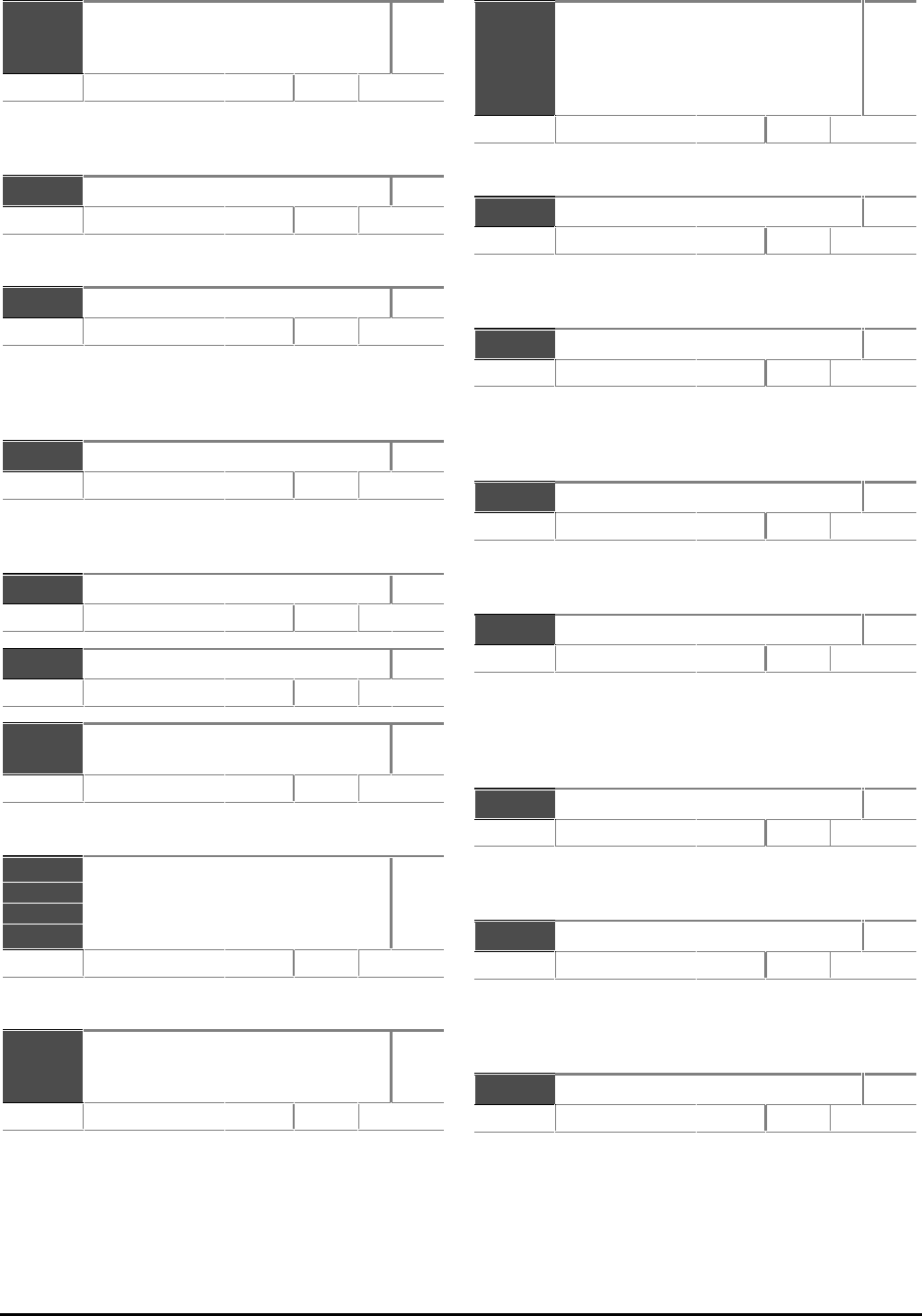
CDE, CDLE Drive
11-6
b1.11
b1.12
b1.13
Reference ON
Reverse
Jog select
RO
Range 0 or 1 Default 0.0
These parameters are controlled by the Drive
sequencer. See parameter p6.07.
p1.14 Jog reference R–W
Range 0 to 999.9 Hz Default 1.5
Frequency reference for Jog.
p1.15 Reference offset R–W
Range ±999.9 Hz Default 0
When b1.16 is set at 1, the value entered into p1.15 is
added to the selected reference parameter. It is used
to trim the selected parameter.
b1.16 Reference offset select R–W
Range 0 or 1 Default 0
Set at 1 to enable addition of the reference offset
(p1.15).
p1.17 Precision frequency reference R–W
Range ±999.9 Hz Default 0
p1.18 Precision frequency trim R–W
Range 0 to 0.099 Hz Default 0
p1.19
p1.20 Analog reference 1
Analog reference 2
RO
Range p1.06p1.06 Hz Default 0.0
See parameter b1.10
b1.21
b1.22
b1.23
b1.24
Analog reference 2 select
Pre-set frequency select bit 0
Pre-set frequency select bit 1
Pre-set frequency select bit 2
R–W
Range 0 or 1 Default 0
Select the required reference.
p1.25
p1.26
p1.27
Pre-set frequency 1
Pre-set frequency 2
Pre-set frequency 3
R–W
Range ±999.9 Hz Default 0
Normal pre-set frequency references.
p1.28
p1.29
p1.30
p1.31
p1.32
Pre-set frequency 4
Pre-set frequency 5
Pre-set frequency 6
Pre-set frequency 7
Pre-set frequency 8
R–W
Range ±999.9
Hz
Default 0
Normal pre-set frequency references.
p1.33 Skip frequency 1 R–W
Range 0 to 999.9
Hz
Default 0
Enter a value to avoid a frequency which induces
mechanical resonances.
p1.34 Skip frequency 1 band R–W
Range 0 to 5.0
Hz
Default 0.5
Enter a value to define the frequency range either side of
Skip frequency 1 over which frequencies are avoided.
The bandwidth is twice that entered into this parameter.
p1.35 Skip frequency 2 R–W
Range 0 to 999.9
Hz
Default 0
Enter a value to avoid a frequency which induces
mechanical resonances.
p1.36 Skip frequency 2 band R–W
Range 0 to 5.0
Hz
Default 0.5
Enter a value to define the frequency range either side
of Skip frequency 2 over which frequencies are
avoided. The bandwidth is twice that entered into
this parameter.
p1.37 Skip frequency 3 R–W
Range 0 to 999.9
Hz
Default 0
Enter a value to avoid a frequency which induces
mechanical resonances.
p1.38 Skip frequency 3 band R–W
Range 0 to 5.0
Hz
Default 0.5
Enter a value to define the frequency range either side of
skip frequency 3 over which frequencies are avoided.
The bandwidth is twice that entered into this parameter.
b1.39 In rejection zone RO
Range 0 or 1 Default 0.0
Indicates the selected reference is within one of the
skip frequency bands. The motor speed does not
match the demand.

CDE, CDLE Drive 11-7
This page is deliberately blank
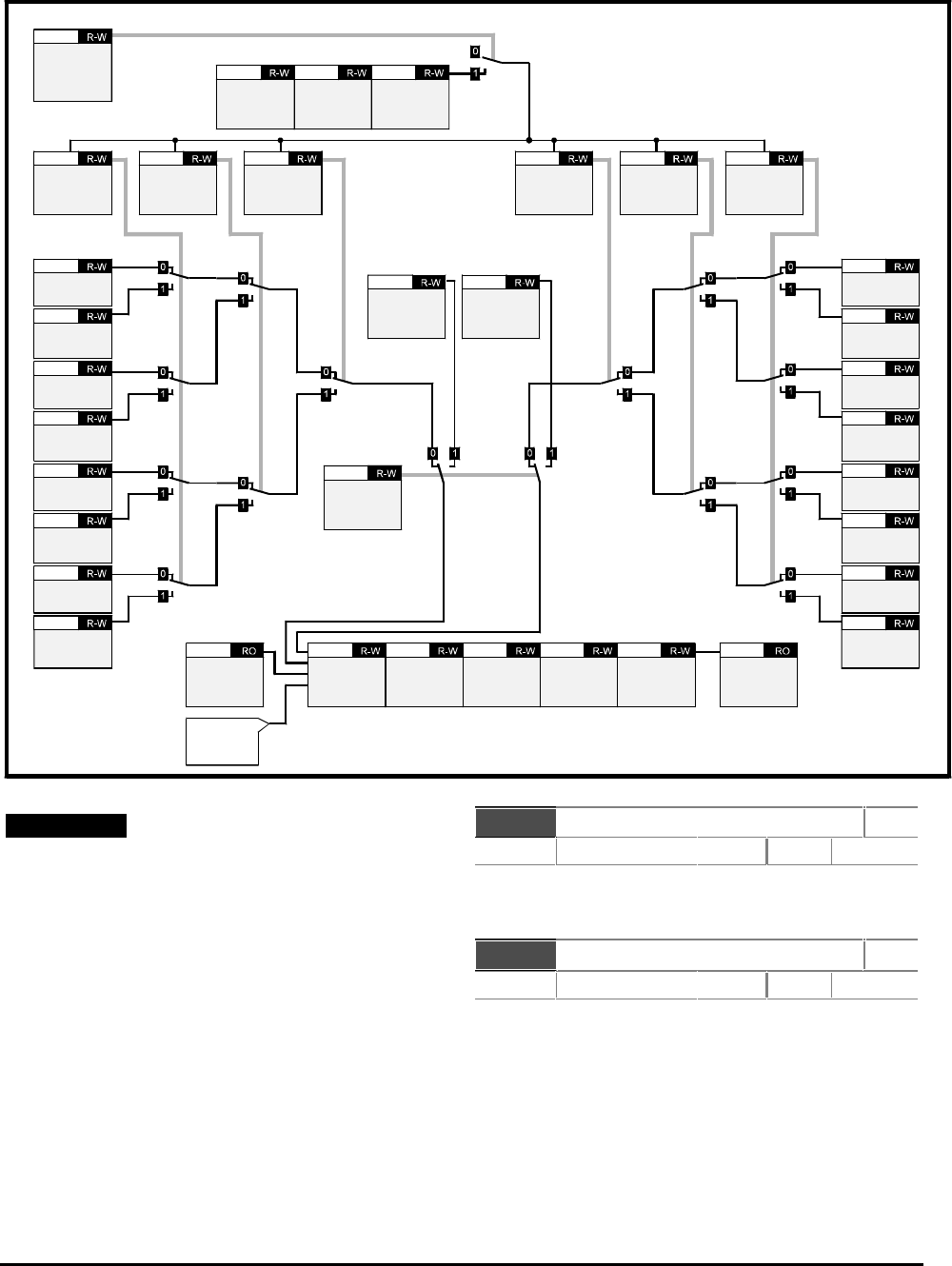
CDE, CDLE Drive
11-8
11.7 Menu 2 — Ramps
Note
For controlling read–write parameters and for
displaying read-only parameters, refer to the
following:
Menu 7 — Analog inputs and outputs
Menu 8 — Programmable digital inputs
Menu 9 — Programmable digital outputs
p2.01 Post-ramp reference RO
Range ±p1.06p1.06
Hz
Default 0.0
Frequency reference after the effects of ramps and
normal currents limits.
p2.02 Ramp mode R–W
Range [0] to [2] Default Std.C [2]
Select from:
Std.H [0] Standard hold
FAST [1] Fast
Std.C [2] Standard controlled
Bit parameters are shown in default state
p2.01
Post-ramp
reference
b2.07
Enable
pre-set speed
selection
of ramps
Acceleration
select bit 0
b2.08 Acceleration
select bit 1
b2.09 Acceleration
select bit 2
b2.10 Deceleration
select bit 2
b2.20 Deceleration
select bit 1
b2.19 Deceleration
select bit 0
b2.18
Acceleration
ramp 4
p2.13
Deceleration
ramp 4
p2.23
Jog
select
p1.13
Jog
acceleration
ramp
p2.05
Jog
deceleration
ramp
p2.06
Standard
ramp voltage
p2.28
Proportional
gain
DC bus
p2.29
Integral gain
DC bus
p2.30
Derivative
gain
DC bus
p2.31
Ramp mode
p2.02
p1.03
Final
frequency
reference
Current
control
Menu 4
Pre-set
frequency
select bit 0
b1.22 Pre-set
frequency
select bit 1
b1.23 Pre-set
frequency
select bit 2
b1.24
Acceleration
ramp 1
p2.03
Accleration
ramp 2
p2.11
Acceleration
ramp 3
p2.12
Acceleration
ramp 5
p2.14
Acceleration
ramp 7
p2.16
p2.17
Acceleration
ramp 8
Acceleration
ramp 6
p2.15
Deceleration
ramp 1
p2.04
Deceleration
ramp 2
p2.21
Deceleration
ramp 3
p2.22
Deceleration
ramp 5
p2.24
Deceleration
ramp 6
p2.25
Deceleration
ramp 7
p2.26
p2.27
Deceleration
ramp 8
CDE, CDLE Drive 11-9
Ramp modes
The Ramp Modes parameter p2.02 controls
deceleration ramps only. The settings are as follows:
Setting
Description
0
Std.H Standard-hold
1
FAST Fast
2
Std.C Standard-controlled
Mode 0 — Standard-hold mode
In Standard-hold mode, deceleration occurs in steps.
The control causes the deceleration ramp to be
‘frozen’ when the DC bus voltage rises above the
standard ramp voltage (set in p2.28). When the
voltage drops below the Standard-ramp voltage, the
ramp again begins to fall. Although this type of
control does not usually give smooth deceleration
especially if the motor is lightly loaded, it is easy to
set up. A high voltage of AC supply could cause the
Drive to trip on over-voltage due to transients that
could be produced in the Standard-hold mode.
Mode 1 — Fast mode
The ramp falls at the programmed deceleration rate
subject only to the current limits programmed.
This mode is normally used when a braking resistor is used.
The dynamic break becomes active at a DC bus level of 780V
Mode 2 — Standard-controlled mode
The PID controller is used to modify the ramp so that
the DC bus voltage is held at the Standard-ramp
voltage (set in p2.28). This gives smoother control
than Standard-hold mode, but it may be necessary to
use an oscilloscope to set up the PI gains.
Care should be taken in choosing the Standard-ramp
voltage (using p2.28), because, if this is lower than
the nominal DC bus voltage produced by the AC
supply, the DC bus controller will accelerate the
motor up to the maximum frequency (set in p1.06) in
an attempt to reduce the DC bus voltage.
See p2.28 — Standard ramp voltage.
The Standard-controlled mode is useful in
applications where smooth deceleration is required,
particularly with lightly-loaded machines, or where
the AC supply voltage is high.
Caution
The D term operates in Standard-controlled
mode and under AC supply loss. Care must be
taken not to have instability in either case
due to an excessively high gain
p2.03 Acceleration ramp 1 R–W
Range 0.1 to 3276
s/100Hz
Default 5
Acceleration ramp rate is expressed as the time for
the output frequency to increase by 100Hz.
For example, a programmed ramp time of 5 seconds
causes the frequency to increase or decrease by 50Hz
in 2.5 seconds.
p2.04 Deceleration ramp 1 R–W
Range 0.1 to 3276
s/100Hz
Default 10
Deceleration ramp rate is expressed as the time for
the output frequency to decrease by 100Hz.
p2.05 Jog acceleration ramp R–W
Range 0.1 to 3276
s/100Hz
Default 0.2
Acceleration ramp rate is expressed as the time for
the output frequency to increase by 100Hz.
p2.06 Jog deceleration ramp R–W
Range 0.1 to 3276
s/100Hz
Default 0.2
Deceleration ramp rate is expressed as the time for
the output frequency to decrease by 100Hz.
b2.07 Enable pre-set speed
selection of ramps
R–W
Range 0 or 1 Default 0
When b2.07 is set at 1, p2.08 to p2.10 & p2.18 to
p2.20 are updated from the pre-set frequency select
parameters p1.22 to p1.24. This allows pre-set
acceleration and deceleration to change automatically
with preselected speeds.
b2.08
b2.09
b2.10
Acceleration select bit 0
Acceleration select bit 1
Acceleration select bit
R–W
Range 0 or 1 Default 0
Binary coded selection of the required acceleration
ramp to be used. (eg. to select p2.13 – Acceleration
ramp 4, set b2.08 and b2.09 at 1.)

CDE, CDLE Drive
11-10
p2.11
p2.12
p2.13
p2.14
p2.15
p2.16
p2.17
Acceleration ramp 2
Acceleration ramp 3
Acceleration ramp 4
Acceleration ramp 5
Acceleration ramp 6
Acceleration ramp 7
Acceleration ramp 8
R–W
Range 0.1 to 3276 s/100Hz Default 5
Acceleration ramp rate is expressed as the time for
the output frequency to increase by 100Hz.
b2.18
b2.19
b2.20
Deceleration select bit 0
Deceleration select bit 1
Deceleration select bit 2
R–W
Range 0 or 1 Default 0
Binary coded selection of the required deceleration
ramp to be used. (eg. to select p2.23 – Deceleration
ramp 4, set b2.18 and b2.19 at 1.)
p2.21
p2.22
p2.23
p2.24
p2.25
p2.26
p2.27
Deceleration ramp 2
Deceleration ramp 3
Deceleration ramp 4
Deceleration ramp 5
Deceleration ramp 6
Deceleration ramp 7
Deceleration ramp 8
R–W
Range 0.1 to 3276 s/100Hz Default 10
Deceleration ramp rate is expressed as the time for
the output frequency to decrease by 100Hz
p2.28 Standard-ramp voltage R–W
Range 0 to 800 V Default 700 (EUR)
775 (USA)
390
(CDLE)
This parameter is used for Standard-hold and
Standard-controlled modes.
The minimum level for the Standard-ramp voltage
should be greater than the voltage produced on the
DC bus by the highest AC supply voltage (normally
RMS AC supply voltage x √2).
When Standard-hold mode is used and the Standard-
ramp voltage is set too low, the Drive will not stop.
If the Standard-ramp voltage is set too high and no
braking resistor is used, the Drive may trip on over-
voltage.
When Standard-controlled mode is used and the
voltage is set too low, the motor will accelerate to
maximum frequency. (AC supply loss uses a fixed
control voltage that is dependent on the voltage
rating of the Drive.)
p2.29 Proportional gain R–W
Range 0 to 99.99
% of
max.
Default 1.00
Enter a value of proportional gain for the PID
controller.
This is used to control the DC bus voltage during
Standard-ramp deceleration and loss of AC supply.
p2.30 lntegral gain R–W
Range 0 to 99.99
% of
max
Default 4.00
Enter a value of integral gain for the PID controller.
This is used to control the DC bus voltage during
Standard-ramp deceleration and loss of AC supply.
p2.31 Derivative gain R–W
Range 0 to 99.99
% of
max.
Default 0.00
Enter a value of Derivative gain for the PID controller.
This is used to control the DC bus voltage during
Standard-ramp deceleration and loss of AC supply.
The D term operates in Standard-controlled mode and
under AC supply loss. Care must be taken not to allow
instability in either case due to an excessively high gain.
p2.32 S-Ramp band R–W
Range 0 to p1.06p1.06
Hz
Default 0
Enter a value to define the frequency band for the
curve at each end of the S-ramp. Time taken for
acceleration or deceleration on the curve is double
that for a straight ramp.
If the ramp time changes during a change of speed,
the S-ramp does not give stepless acceleration or
deceleration. For example:
If different ramp rates are used for acceleration
and deceleration, and the Drive passes through
zero speed.
If the ramp rates are changed using the
acceleration or deceleration select bits.

CDE, CDLE Drive 11-11
This page is deliberately blank

CDE, CDLE Drive
11-12
Note
For controlling read–write parameters and for
displaying read-only parameters, refer to the
following:
Menu 7 — Analog inputs and outputs
Menu 8 — Programmable digital inputs
Menu 9 — Programmable digital outputs
p3.01 Frequency reference RO
Range ±100.0 % Default
p3.02 Frequency output RO
Range ±999.9 Hz Default
b3.03 Select frequency output R–W
Range 0 or 1 Default 0
When p3.03 is set at 1, p3.04 is enabled.
b3.04 Frequency output ratio select R–W
Range 0 or 1 Default x192 (0)
Set at 0 for showing (x192).
Set at 1 monitoring ( x1).
Enables the Frequency output terminal to produce a
frequency of x1 or x192 the fundamental frequency.
If b3.04 is changed from 1 to 0 while the Drive is
running, the Frequency output signal will cease until
the Drive is re-started. This does not occur if b3.04 is
changed from 0 to 1
Frequency slaving
When used in a frequency-slaving system, the Drive
can be set up as a Master, Slave or both. Frequency-
slaving, parameter b3.04 should be set at 0 to select
x192 frequency ratio.
When a Drive is not required to operate as a Slave, the
frequency input terminals can be used to accept a
frequency pulse train (from a plc for example), or
quadrature signals from an encoder.
Bit parameters are shown in default state
Frequency output (Master)
Frequency input (Slave)
Frequency
reference
p3.01
Frequency reference / Encoder input
Post-slip
compensation
frequency
p5.01
Enable
frequency
input slaving
b3.05
Keypad
reference/
Frequency
input
reference
p1.04
Quadrature
detect
Enable
quadrature
input
b3.08
Ratio
x 3.06
3.07
Maximum
frequency
adjustment
x 3.06
3.07
Select
frequency
input
reference
b3.09
Select
frequency
output
b3.03 Frequency
output ratio
select
b3.04
x 192
Frequency
output
p3.02
Post-slip
compensation
frequency
p5.01
x 1
192
Ratio
x 3.06
3.07
11.8 Menu 3 — Frequency input and output
CDE, CDLE Drive 11-13
b3.05 Enable frequency input
slaving
R–W
Range 0 or 1 Default 0
Set at 1 to enable frequency slaving. The output
frequency follows the reference frequency at an exact
ratio set in p3.06 and p3.07.
p3.06 Frequency input ratio
numerator
R–W
Range 0 to 2.000 Default 1.000
Enter a value for the numerator of the required
slaving ratio. The ratio cannot be greater than 2:1.
The numerator p3.06 may be changed without losing
lock.
It is recommended to keep p3.07 at the default
setting.
p3.07 Frequency input ratio
denominator
R–W
Range 0 to 1.000 Default 1.000
Enter a value for the denominator of the required
slaving ratio. The ratio cannot be greater than 2:1.
If p3.07 is changed while the Drive is running,
frequency locking between the Drives will not be
maintained, and the Slave Drive may trip on OIAC.
It is good practice to stop the Drive first.
It is recommended to keep p3.07 at the default
setting.
Refer to the example on the previous page for
correctly setting up the ratio.
b3.08 Enable quadrature input R–W
Range 0 or 1 Default 0
Set at 1 to enable encoder quadrature input.
This is not available when p3.03 or p3.05 are set at 1.
Quadrature input is not available if frequency output
is required, since the B channel encoder input shares
terminals with the frequency output.
The pulse-train frequency can be monitored by the
Drive, and the measured frequency used to derive the
frequency demand for the Drive. In either case,
parameters p3.06 and p3.07 (frequency input ratio)
must be set up to scale the input measurement so
that read-only parameter p3.01 indicates 100.0%
when maximum input frequency is demanded.
The following equations should be used to calculate
the scale factor required for different motor speeds
and encoder lines:
(RPM = maximum motor speed
N = Number of encoder lines)
Encoder with Quadrature
Counting enabled
Scale = 464 916
RPM N××
Encoder without Quadrature Counting
(no direction information)
Scale = 929 832
RPM N××
Frequency pulse-train input
Scale = 15 497
Fmax
It is recommended that parameter p3.07 is left at its
default value of 1.000 and the result of the above
calculations entered into parameter p3.06. If the
result of the calculation is very low, the difference in
top speed values becomes very coarse. If this occurs,
adjust p3.07 to finely tune the maximum measured
input frequency.
Example
A 2048 quadrature encoder is fitted to a 3000 RPM
motor
Scale =
464 916
3000 2048 007567
×× == .
Only 0.075 can be entered in parameter p3.06. This
value equates to a maximum speed of 3027 RPM.
A value for parameter p3.07 can be calculated as
follows:
p3.07 = p
Scale
306 0075
0 07567 0991
..
..====
Parameter p3.01 can then be used either as an input
to the PID software or a MD29 application program. If
parameter b3.09 is set at 1, p3.01 can be used as a
frequency reference for the Drive. In this case the
100.0% maximum in parameter p3.01 is automatically
scaled to give maximum frequency reference (p1.06)
in the Control Keypad reference parameter.
CDE, CDLE Drive
11-14
Resolution
When the frequency reference input is used to control
frequency demand (ie. slaving is not being used), the
resolution of the reference is dependent on the
maximum input frequency. It is not possible to
obtain a higher resolution than 0.03Hz or a resolution
from 0 to maximum frequency of greater than 1/4000
(or 0.025%). Subject to these limits, the resolution
may be improved with higher quadrature count rates.
Since the input pulses are counted over a gate period
of 16.132ms, the resolution can be calculated using the
following equations:
Encoder with Quadrature
Counting enabled
Resolution = 92 983 2. %
RPM N××
Encoder without Quadrature Counting
(no direction information)
Resolution = 371 933
RPM N×× %
Frequency pulse train input
Resolution = 619 888
Fmax
%
Example
A 1024 quadrature encoder on a 1500 RPM motor
would give a resolution of:
92983 2
1500 1024 006%
..
×× ==
b3.09 Select frequency reference R–W
Range 0 or 1 Default 0
Set at 1 to select frequency reference applied to pin 4 of
CON 2.
This disables the RUN, STOP and FWD/REV keys.

CDE, CDLE Drive 11-15
This page is deliberately blank
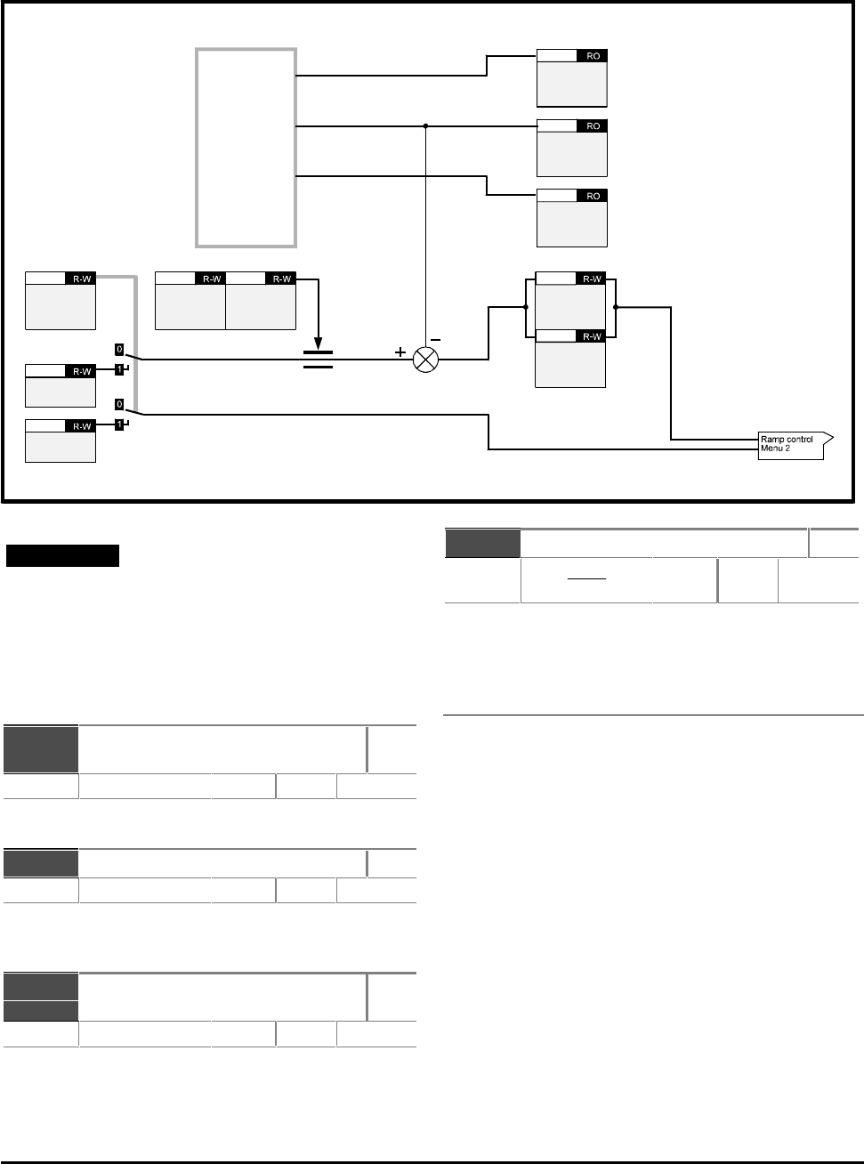
CDE, CDLE Drive
11-16
Note
For controlling read–write parameters and for
displaying read-only parameters, refer to the
following:
Menu 7 — Analog inputs and outputs
Menu 8 — Programmable digital inputs
Menu 9 — Programmable digital outputs
p4.01 Current feedback
(magnitude)
RO
Range 0 to ±p11.35 A Default
Indicates the magnitude of the total motor current.
p4.02 Current feedback (load) RO
Range 0 to ±p11.35 A Default
Indicates the magnitude of the torque-producing
motor current.
p4.03 Current feedback
(magnetizing)
RO
Range 0 to ±p11.35 A Default
Indicates the magnitude of the magnetizing motor
current.
p4.04 Motoring current limit R–W
Range 0 to p
p
11 35
506 100
.
.××
%
Default 150
Normal current limit.
See parameter p5.06.
Current control and scaling
Current levels in the Drive are as follows:
OIAC
The trip level for instantaneous over-current
(trip OIAC) is equivalent to the full-scale feedback
level. The maximum RMS value of a sine-wave that
could be produced without causing a trip would be:
Full scale ÷ √2
This is approximately twice the maximum current
limit for the Drive.
11.9 Menu 4 — Current limits and torque control
Bit parameters are shown in default state
Select
torque mode
b4.07 Motoring
current
limit
p4.04 Regenerating
current
limit
p4.05
Torque
demand
p4.06
Maximum
frequency
p1.06
Current
measurement
Normal ILIMIT
proportional
gain
p4.08
Normal ILIMIT
integral gain
p4.09
p4.01
Current
feedback
(magnitude)
p4.02
Current
feedback
(load)
4.03
Current
feedback
(magnetising)
Magnitude
Load
Magnetizing
CDE, CDLE Drive 11-17
Peak limit
The peak limit prevents transient peaks in motor
current (torque-producing and magnetizing) from
exceeding a specific level.
The Drive accomodates transient peaks in current by
modifying the output voltage. This occurs only when
the output voltage is below the maximum for the
Drive.
The maximum RMS value of a sinusoidal output
current that should occur with the peak limit
operating is given by:
OIAC x (2000 / 2660) ÷ √2
(This is approximately 1.5 times the maximum current
limit for the Drive).
Normal current limit
The normal current limit modifies the output
frequency of the Drive in order to control the output
current level. This operates at a lower level than the
peak limit and is not as fast as the peak limit.
When the Drive is operating correctly, the normal
current limit should normally be sufficient to control
the Drive current, and the peak limit should rarely
operate.
The maximum current limit is defined in parameter
p11.35. The normal current limit controls only the
torque-producing current in the motor and not the
magnetizing current.
Rated torque-producing current
This is nominally the motor rated current × cosφ. The
Drive can deliver a torque-producing current of 1.2 or
1.5 times the rated level before the normal current
limit operates.
p4.05 Regenerating current limit R–W
Range 0 to p
p
11 35
506 100
.
.×× % Default 150
Normal current limit.
See parameter p5.06.
p4.06 Torque demand R–W
Range 0 to p
p
11 35
506 100
.
.××
%
Default 0
Defines bipolar torque demand.
In torque-control mode, the torque produced by the
motor is controlled by modification of the Drive
output frequency using the PI controller. This
controller uses the same P and I terms as the current
limits set in parameters p4.08 and p4.09.
Below rated frequency, the torque demand is
converted to torque-producing current.
Above rated frequency, the current is increased (to a
maximum of 4 times) to compensate for the
reduction of flux in the motor.
p4.06 is subject to normal current limits.
When the torque controller is used above rated
frequency, set lower gains. Lower motor flux levels
cause a larger change in torque-producing current for
a given change of frequency.
See parameter p5.06.
b4.07 Select torque mode R–W
Range 0 or 1 Default 0
Set b4.07 at 0 for speed control mode.
When b4.07 is set at 1, the torque reference is
applied to the current controller. The PID controller
uses the same P and I terms as the current limits
defined in p4.08 and p4.09.
It is possible to change between torque control and
frequency control when the Drive is running without
causing transient frequency changes.

CDE, CDLE Drive
11-18
p4.08 Normal llimit Proportional gain R–W
Range 0 to 99.99 % of
max. Default 0.40
The current limits operate when torque-producing
current is above the current limits entered in p4.04
and p4.05.
The PI controller attempts to change the output
frequency to reduce torque-producing current. If a
motoring load overloads the motor, it will stall. If the
motor is overloaded with a regenerative load, it will
accelerate to maximum frequency.
The ramp time will have an effect. The gains of the PI
controller must be sufficiently high to cancel the
effects of the ramps. Shorter ramp times will require
higher gains.
Normally, only the P term is necessary for satisfactory
operation.
p4.09 Normal Ilimit Integral gain R–W
Range 0 to 99.99 % of
max. Default 0.00
The current limits operate when torque-producing
current is above the current limits entered in p4.04
and p4.05
The PI controller attempts to change the output
frequency to reduce torque-producing current. If a
motoring load overloads the motor, it will stall. If the
motor is overloaded with a regenerative load, it will
accelerate to maximum frequency.
The ramp time will have an effect. The gains of the PI
controller must be sufficiently high to cancel the
effects of the ramps. Shorter ramp times will require
higher gains.
Normally, only the P term is necessary for satisfactory
operation.
p4.10 Torque output RO
Range Max p5.06p5.06
% of
max
Default
Indicates torque in the motor as % of rated torque.
Below rated frequency, the torque output is equal to
the torque-producing current relative to itorq rated.
Above rated frequency, the torque is compensated to
allow for the reducing flux in the motor.
p4.11 Symmetrical current limit R–W
Range 0 to p
p
11 35
506 100
.
.××
%
Default 150
Symetrical current limit works in Motoring and
regenerating. The lowest value of p4.04, p4.05 and
p4.11 will be the effective value.
After having set the required value of maximum
current in p5.06, you may increase or decrease the
percentage overload current using p4.11. The
maximum percentage that can be set is limited by the
overload current rating of the Drive. The limit applies
when motoring and regenerating.
The value of p4.11 is automatically reduced when the
value of p5.06 is increased beyond the default value.

CDE, CDLE Drive 11-19
This page is deliberately blank
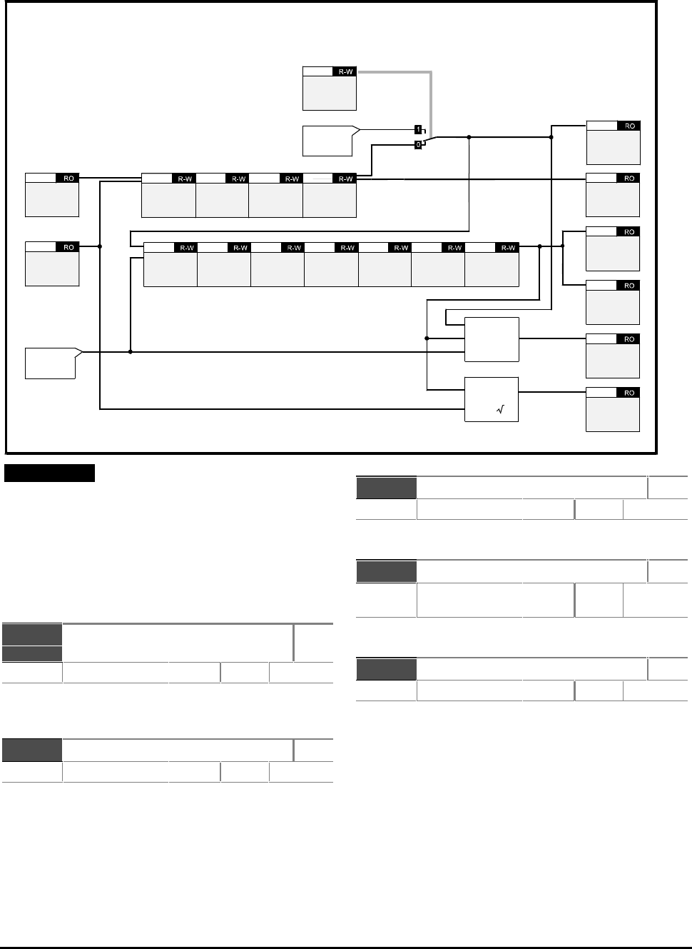
CDE, CDLE Drive
11-20
11.10 Menu 5 — Motor control
Note
For controlling read–write parameters and for
displaying read-only parameters, refer to the
following:
Menu 7 — Analog inputs and outputs
Menu 8 — Programmable digital inputs
Menu 9 — Programmable digital outputs
p5.01 Post-slip compensation
frequency
RO
Range ±p1.06p1.06 Hz Default
Final frequency applied to the motor after the effects
of current limits and slip compensation.
p5.02 Motor shaft RPM RO
Range 0 to 9999 RPM Default
Indicates motor shaft RPM.
The number of poles must be entered correctly in
p0.18 (p5.10) and the slip compensation correction
must not be at the maximum frequency limit (if the
motor is to run at 50Hz, set p1.06 at a higher value to
allow for slip compensation).
p5.03 Motor voltage RO
Range ±0 to p5.08p5.08
VRMS
Default
Indicates the RMS voltage applied to the motor
p5.04 DC bus voltage RO
Range 0 to 810 (CDE)
0 to 460 (CDLE)
V
Default
Indicates the DC bus voltage.
p5.05 Motor power RO
Range
kW
Default
Indicates the real component of the power output
(VIcosφ).
Bit parameters are shown in default state
p2.01
Post ramp
reference
p4.02
Current
feedback
(load)
Motor rated
current
p5.06 Motor rated
RPM at full
load
p5.07 Number of
poles
p5.10 Power
factor
p5.13
Operational
modes
Menu 6
Motor rated
voltage
p5.08 Motor rated
frequency
p5.09 Normal
voltage
boost
p5.11 Voltage
control mode
selector
p5.12 Jog voltage
boost
p5.14 Stator
resistance
p5.15 Magnetization
current test
p5.16
Modulation
Enable
frequency
input slaving
p3.05
Frequency
slaving
Menu 3
Power
calculation
V x I x 3
Post-slip
compensation
frequency
p5.01
p5.17
Voltage
offset
p5.02
Motor shaft
RPM
p5.03
Motor voltage
p5.04
DC bus
voltage
p5.05
Motor power
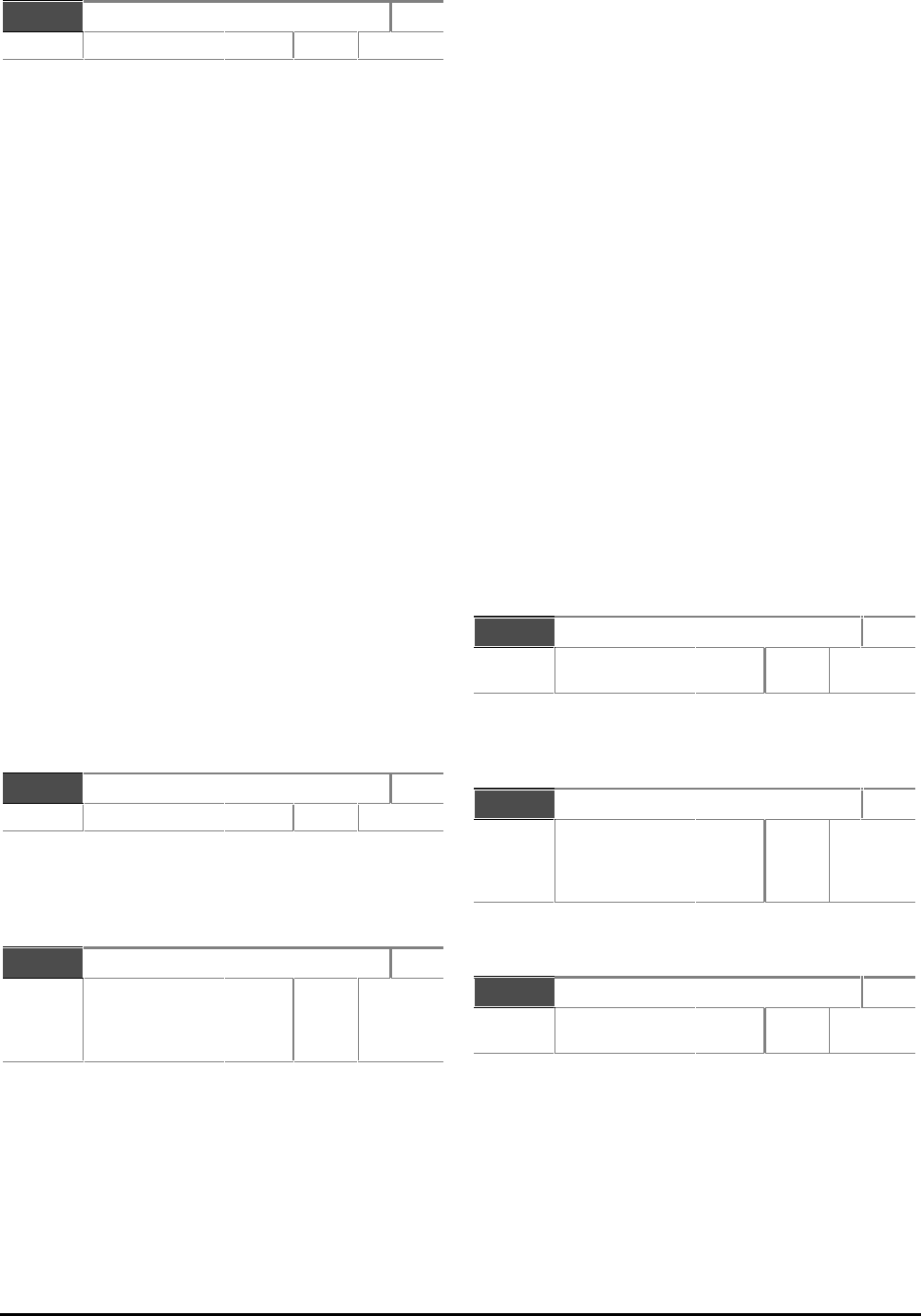
CDE, CDLE Drive 11-21
p5.06 Motor rated current R–W
Range 0 to p11.33p11.33 A Default 11.33
Parameters p5.06 (motor rated current) and p5.13
(power factor) are used by the Drive to determine the
rated torque producing current (itorq rated) for the Drive.
When parameter p5.06 is set at a value lower than the
default rating of the Drive, the maximum current of the
Drive can be greater than 1.5 times the motor rating.
Consequently, the maximum value of current limit and
torque parameters (p4.04, p4.05, p4.06, p4.11,and
p6.04) can be increased proportionately.
For example, if a 110 Amp Drive has parameter p5.06 set
at 55 Amps, the maximum values of parameters p4.04,
p4.05, p4.11 and p6.04 can be 300% (2 × 150%). This
allows larger Drives to be used for a high starting torque.
When the value is increased beyond the default value of
p5.06, the value of p4.11 is automatically decreased.
Itorque = p5.06 x p5.13
The value entered affects the following:
Slip compensation
Dynamic V/f
Ixt detection level
Industrial and HVAC applications
Industrial applications benefit from a higher
percentage of overload current, but have a lower
nominal current. HVAC applications benefit from a
higher nominal current, but have a lower percentage
of overload current (typically 120%). The overload
current has the same value in each case.
See parameter p5.18.
p5.07 Motor rated RPM at full load R–W
Range 0 to 9999 rpm Default 0
Enter the value from the motor rating plate. This is
used by the Drive to apply correct slip compensation.
If no slip compensation is required, set p5.07 at 0
(default).
p5.08 Motor rated voltage R–W
Range 100 to 480 VRMS Default 400 (EUR)
240
(CDLE)
460 (USA)
Enter the value from the motor rating plate in order
to define the maximum output voltage of the Drive.
Parameter p5.08 must be programmed with the value
given on the motor rating plate. This informs the
Drive of the maximum voltage that should be applied to
the motor.
The Drive controls the output voltage to give a linear
voltage-to-frequency characteristic from 0Hz to the
motor rated frequency, and from 0V to the motor
rated voltage. (This characteristic can be modified
by voltage boost or stator resistance compensation.)
Since the Drive compensates for variations in DC bus
voltage, the resulting voltage from the voltage-to-
frequency characteristics does not change with DC
bus voltage (ie. there is no change when the Drive is
braking).
Note that, even with a perfect supply, it is not
possible to obtain an output voltage greater than the
supply voltage when motoring.
When the required voltage exceeds the maximum
possible output level (dependent on the supply) or
the rated voltage (set by the user), the frequency can
still be increased, but the motor enters the
constant-power or field-weakening region.
Whatever value of motor rated voltage is entered,
the Drive output will contain high frequency
switching components having peak voltage levels
related to the DC bus voltage level, not to the motor
rated voltage. Consequently, when a motor of low
voltage is used, the high-frequency switching
components at the Drive output may stress the
windings.
p5.09 Motor rated frequency R–W
Range 10.0 to 999.9
Hz
Default 50 (EUR)
60 (USA)
Enter a value of frequency at which the rated voltage
is to be applied to the motor. The motor then enters
the constant-power or field-weakening region.
p5.10 Number of poles R–W
Range 2p [0] (2 poles)
4p [1] (4 poles)
6p [2] (6 poles)
8p [3] (8 poles)
Default 4p [1]
Enter the value from the motor rating plate for
correct slip compensation and RPM indication
p5.11 Normal voltage boost R–W
Range 0 to 25.5
% of
p5.08p5.08
Default 3.0
The voltage boost defines the nominal level of boost
at 0Hz as a percentage of the rated voltage (p5.08).
Voltage boost is applied only when one of the boost
modes is selected (see parameter p5.12). The figure
below shows fixed boost.

CDE, CDLE Drive
11-22
p5.12 Voltage control
mode selector
R–W
Range 0 to 4 Default Ur_I [3]
Auto [0] Auto boost
Fd [1] Fixed boost
Ur_S [2] Vector mode. Stator resistance is
measured at power-up or start
Ur_I [3] Vector mode. Stator resistance is
measured at power-up only
Ur [4] Vector mode. Stator resistance
is not measured
Above 25% of rated frequency, a linear voltage-to-
frequency characteristic normally produces sufficient
torque. Below this frequency, voltage boost may be
required in order to maintain the torque.
The voltage control mode selector is used to select
the required type of voltage boost at low
frequencies and the conditions for measuring stator
resistance.
Mode 0 — Auto boost
Auto boost automatically controls the voltage boost
with load. If the level is set too high, the motor can
become over-fluxed, and the boost can become
‘latched’ at a high level.
With high inertia loads at low speed, the Drive may
trip when decelerating the motor to a stop. This will
result in the motor coasting to a stop.
The level of boost is determined from the value in
parameter p5.11 (voltage boost) which is then
modified so that:
Auto boost = Voltage boost × itorq / itorq rated
Mode 1 — Fixed boost
Fixed boost can give high levels of current when
starting and stopping, but can result in over-fluxing of
the motor on light loads.
Mode 2 —
Vector mode with stator resistance
measurement at start
Mode 3 —
Vector mode with stator resistance
measurement at power up
Mode 4 —
Vector mode with no stator resistance
measurement
Vector mode is intended for operation with a single
motor and gives reasonable control of the motor flux
with different loads, since the voltage-to-frequency
characteristic is modified according to the load
inertia. (Closed-loop current control is not used.)
The voltage-to-frequency characteristic is based on
the following motor parameters:
Magnetizing current
Stator resistance
Good control of the magnetizing current (and hence
motor flux) extends down to:
Rated frequency ÷ 50
(ie. value of parameter p5.09 ÷ 50)
The parameters required for this mode can be derived by
the Drive during the magnetizing current measurement.
Measuring stator resistance
This measurement can be performed
automatically under the following conditions:
• When AC power is connected to the Drive
(Ur_I mode)
• When a START command is given to the Drive
(Ur_S mode)
The second condition (Ur_S) is recommended
because stator resistance can change with
temperature.
The measured value is stored in parameter p5.15,
along with a voltage offset related to the IGBT
voltage drops and other effects in the Drive
(p5.17).
When AC power is disconnected from the Drive, the
power factor and stator resistance are automatically
stored.
When Ur_I mode is selected, the voltage is based on
previously measured values (in Ur_I mode, the stator
resistance is not measured). The voltage offset (which is
usually quite small) is not saved when AC power is
removed, so this fine correction of the voltage applies
only when Ur_S or Ur_I modes are used.
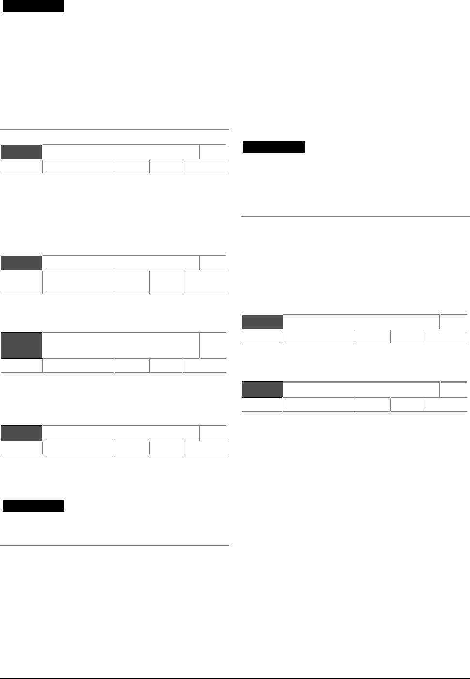
CDE, CDLE Drive 11-23
Note
The results of the stator resistance
measurement (but not the magnetizing
current measurement) are to some extent
dependent on the switching frequency and
modulation technique being used. Good
control at low speed can be maintained only
when the switching frequency and space
vector modulation (see Menu 6) are not
changed after the stator resistance has been
measured.
p5.13 Power factor R–W
Range 0.30 to 1.00 cos φDefault 0.85
Saved at power down.
Refer to p5.16 for automatic calculation of power
factor. Refer also to the warning.
p5.13 is used with p5.06 to calculate the conversion
level between current and torque producing current.
itorque rated = p5.06 x p5.13
p5.14 Jog voltage boost R–W
Range 0 to 25.5 % of
p5.08p5.08 Default 3.0
Enter a different percentage boost for Jog when
p5.11 is used.
p5.15 Stator resistance
measurement
R–W
Range 0 to 9.999 ΩDefault 0
Saved at power down.
This is used for Vector mode compensation. See
parameter p5.12.
p5.16 Magnetizing current test R–W
Range 0 to 9999 Default 0
Automatically saved.
Measuring the magnetizing current
Warning
The motor runs at half maximum speed while
this measurement is performed.
This measurement can be carried out with the
motor on- or off-load. If the measurement is to be
carried out on-load, a reasonable estimate of the
power factor of the motor (which relates to the
magnetisng current) must first be given to the
Drive. In most cases, the default value will be
sufficiently close to that of the motor. If it is not,
enter in parameter p5.13 the figure for the power
factor of the motor.
Use the following procedure:
1. Ensure the Drive is stopped.
2. Set p5.16 at 255.
3. Ensure that a trip is not active.
4. Apply a continuous signal to the STOP input
(Do not activate the START input).
5. Press the STOP–RESET button or apply a
momentary signal to the RESET input
(pin 4 of CON 3) to reset the Drive.
Note
The measurement should now be carried out.
If it is not carried out (eg. because the STOP
input is not active) the measurement is
cancelled. To try again, repeat the
preceeding instructions.
6. The power factor parameter p5.13 is now
updated with the value calculated during the
measurement.
Ensure the stop switch is closed.
Set 5.16 at 255 to start the test.
Reset the Drive to enter the new value of power
function in p5.13.
p5.17 Voltage offset RO
Range 0 to 1536 Default
Indicates the voltage offset measured during stator
resistance measurement.
p5.18 Overload time R–W
Range 0 to 60
s
Default 60
Enter a value for the required duration of maximum
overload current.
When the Drive is used with motors having a relatively
low power rating, the motor could be damaged by the
overload current of the Drive. To protect such motors,
the value of parameter p5.18 can be reduced to reduce
the time that the overload current is produced. The
default value of p5.18 is 60 seconds.
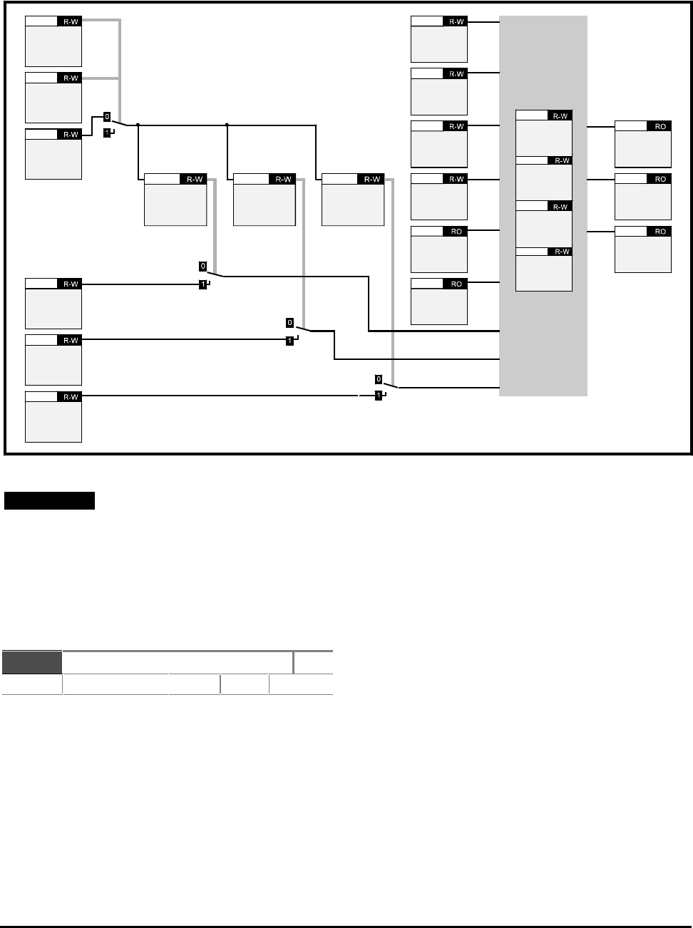
CDE, CDLE Drive
11-24
Note
For controlling read–write parameters and for
displaying read-only parameters, refer to the
following:
Menu 7 — Analog inputs and outputs
Menu 8 — Programmable digital inputs
Menu 9 — Programmable digital outputs
p6.01 Stop mode R–W
Range [0] to [4] Default rp [0]
rP [0] The Drive ramps to zero speed
inh [1] Inhibit (coast to stop)
dc [2] DC injection braking
rP.dc [3] Ramp +
DC injection braking
td.dc [4] Timed
DC injection braking
Parameter p6.01 controls the stopping mode.
Stopping occurs in two phases, as follows:
Phase 1: Decelerating to stop
Phase 2: Drive stopped
The settings are as follows:
Mode [0] — Ramp mode
The Drive ramps to zero speed during the first phase,
and then waits for one second in the second phase to
ensure the motor has completely stopped before
disabling the output.
Mode [1] — Inhibit mode
The output is disabled as soon as a STOP command is
received, and the motor coasts to rest. The first phase
consists of a two-second delay before the Drive can be
restarted. There is no activity in the second phase.
Mode [2] — DC injection braking
Mode [3] — Ramp plus DC injection
braking
Mode [4] — Timed DC injection braking
In all these modes, the second phase consists of injection
of DC current for at least one second at the level entered
in parameter p6.04. This ensures the motor is
completely at rest before the Drive output is disabled.
The first phase of Mode [3] is the same as that for
Mode [0].
11.11 Menu 6 — Operational modes
Bit parameters are shown in default state
Keypad
select
b1.08
Select
frequency
input
reference
b3.09
Disable auto
keypad
switch
selection
b6.18
Keypad
FWD/REV
b6.14
Keypad
STOP
b6.13
Keypad
START
b6.12
Enable
keypad
FWD/REV
b6.17
Enable
keypad
STOP
b6.16
Enable
keypad run
b6.15 Auto-start
mode
p6.02
Stop mode
p6.01
Sequencing
mode
p6.07
AC supply
loss mode
p6.03
Sequencing
bit 0
b6.08
Sequencing
bit 3
b6.11
Sequencing
bit 2
b6.10
Sequencing
bit 1
b6.09
F1 Stop input
p8.01
AC power
loss
10.12
Reference on
b1.11
Reverse
b1.12
Jog select
b1.13
CDE, CDLE Drive 11-25
In Modes [2 ]and [4], injection braking uses low-
frequency current at a level programmed in parameter
p6.04 during the deceleration phase. In Mode [2]
this allows the Drive to detect when the motor has
reached a low speed, so the injection time is adjusted
automatically to suit the motor and the load. In
Mode [4], the time for decelerating to a stop must be
programmed in parameter p6.05.
In Mode [2] only, when a stop is initiated, the Drive
monitors the motor to detect when the speed reaches
5Hz so phase 2 can be initiated. If the injection
current is too low, the detection system does not
operate and the motor rotates continuously at a low
frequency.
The minimum level of current required is normally
between 70% and 80% of the rated current of the
motor.
Once stopping in Mode [2] or [4] has begun, it can be
terminated by the motor stopping, or the occurrence
of a trip. In this case, the Drive must be stopped
before it can be re-started.
p6.02 Auto-start mode R–W
Range [0] to [2] Default diS [0]
diS [0] The Drive does not start when AC
power is applied
ALYS [1] The Drive always starts when AC
power is applied
Pd.dP [2] The Drive starts only if it had been
running when AC power was previously removed.
The Auto-start modes are as follows:
The Auto-start modes define the behaviour of the
Drive when AC power is applied.
Mode [0] — Disabled
The Drive will not automatically start when AC power
is applied.
Mode [1] — Always
The Drive always starts irrespective of the state
before AC power was removed. The STOP input
switch must be closed.
Mode [2] — Power-down dependent
The Drive starts only if it had been running when
AC power was removed. The STOP input switch must
be closed.
p6.03 AC supply loss mode R–W
Range [0] to [2] Default rd.th [2]
dis [0] Disabled
Stop [1] Stop when AC supply is lost
rd.th [2] Ride-through short interruptions
The AC supply loss modes are as follows:
Mode [0] — Disabled
Loss of AC power is not detected. The Drive
continues to operate unchanged only while the DC bus
remains within specification. When the voltage is
below specification, the Drive ceases to control the
motor.
Mode [1] — Stop mode
Mode [2] — Ride-through mode
When loss of AC power is detected, the Drive
decelerates at a rate to return sufficient power from
the motor to the DC bus in order to supply the control
circuits. Since the PID loop for the Standard-
controlled ramp (see parameter p2.02) is used for
this function, adjustment of the PID gains (p2.29 to
p2.31) may be necessary for the feature to operate
correctly. In this case, the PID controller attempts to
force the DC bus voltage to 700V for the CDE models
(380V for the CDLE models) and then hold it constant
by changing the Drive output frequency.
Normally, the DC bus voltage can be held at a fixed
level with a PI controller. If the motor is heavily
loaded when AC power is lost, the frequency must be
reduced quickly to prevent the DC bus voltage from
reducing below specification.
The D term will operate for 250ms after loss of AC
power in order to improve the response. The D term
is stopped after this point, since it can make the
control loop unstable if it continues in operation.
The ramp rate is controlled by the PID controller, and
is at least as fast as the deceleration ramp for a
normal stop.
In order to help reduce the frequency quickly, slip
compensation is disabled when loss of AC power is
detected (this will have no effect if no slip
compensation has been programmed).
When AC power is restored and Stop mode is
selected, the Drive continues to decelerate until the
machine stops. When Ride-through mode is selected,
the motor accelerates to its normal running speed.
CDE, CDLE Drive
11-26
p6.04 Injection braking level R–W
Range 0 to p
p
1135
506 100
.
.×× % of
FLC Default 150
If the injection braking level is set too low the Drive
will not stop. If a low injection level is required, use
the timed DC injection td.dc by setting p0.12 at [4]
p6.05 Injection braking time R–W
Range 0.5 to 25.5 Default 5.0
When p6.01 is set at 4, enter the required
deceleration time.
p6.06 Switching frequency R–W
Range [0] or [1] Default 3kHz [0]
3 [0] 3kHz
6 [1] 6kHz (Model size 1 only)
p6.07 Sequencing mode R–W
Range [0] to [3] Default [0]
CD type interface [0]
Mentor type interface [1]
Wire-proof interface [2]
PLC interface [3]
b6.08
b6.09
b6.10
b6.11
Sequencing bit [0]
Sequencing bit [1]
Sequencing bit [2]
Sequencing bit [3]
R–W
Range 0 or 1 Default 0
CD type sequencing mode [0]
CON 3
default pin
number
Sequencing bit 0
Run (latching) 3
Sequencing bit 1
Jog 6
Sequencing bit 2
Reverse 7
Sequencing bit 3
Not used
When Keypad mode is enabled, sequencing bit 0 can
be over-ridden by the RUN key and sequencing bit 2
can be over-ridden by the FWD–REV key.
Mentor type sequencing mode [1]
CON 3
default pin
number
Sequencing bit 0
Run forward
(latching)
3
Sequencing bit 1
Jog forward
6
Sequencing bit 2
Run reverse
(latching)
7
Sequencing bit 3
Jog reverse
When Keypad mode is enabled, the RUN key can also
start the Drive, and the FWD–REV key can change the
direction (unless one of the sequencing bit signal is
being held, in which case the sequencing bits have
priority). Jog states always over-ride Run.
Wire-proof mode sequencing mode [2]
CON 3
default pin
number
Sequencing bit 0
Run forward
3
Sequencing bit 1
Jog
6
Sequencing bit 2
Run reverse
7
Sequencing bit 3
Not used
For the Drive to run, parameter p10.24 (Drive reset),
parameter p8.01 (Stop input), and sequencing bit 0
or 2 must be set at 1. When p10.24 is set at 0, the
Drive is disabled.
To Jog forward or reverse, the Jog sequencing bit
must be set at 1, together with the appropriate
direction sequencing bit. Pressing the RUN, STOP and
FWD–REV keys has no effect.
PLC mode sequencing mode [3]
CON 3
default pin
number
Sequencing bit 0
Run
3
Sequencing bit 1
Jog
6
Sequencing bit 2
reverse
7
Sequencing bit 3
Not used
Read-only parameter b8.01 (Stop input) indicates
that the Drive is enabled or disabled. When
b8.01 = 0, the Drive is disabled.
Sequencing bit 0 must be set at 1 for the Drive to run.
When sequencing bit 0 is set at 0 the Drive stops.
Because this mode requires signals to be continuously
applied to the control signal terminals for the Drive to
run, the run, stop, and fwd/rev keys are inactive.
CDE, CDLE Drive 11-27
b6.12
b6.13
b6.14
Keypad START
Keypad STOP
Keypad FWD/REV
R–W
Range 0 or 1 Default 0
When a key is pressed the related parameter is set at 1.
b6.15
b6.16
b6.17
Enable Keypad RUN
Enable Keypad STOP
Enable Keypad FWD/REV
R–W
Range 0 or 1 Default 0
Use these parameters to enable or disable individual
keys of the Control Keypad.
When p6.18 is set at 0 and b1.08 (Keypad reference)
is set at 1, these parameters are automatically set at 1.
The Control Keypad is disabled when b3.09 is set at 1.
b6.18 Disable auto keypad switch
selection
R–W
Range 0 or 1 Default 0
Set at 1 to disable control using the Control Keypad.
b6.19 Dynamic V/f R–W
Range 0 or 1 Default 0
Set p6.19 at 1 for the rated frequency to change
depending on Drive load current.
Rated frequency = p5.09 x (2 – (|itorq |/0.7itorq rated))
for |itorq| < 0.7itorq rated
(p5.09 = = Motor rated frequency)
where iitorqtorq is the value of torque-producing current
and iitorq_ratedtorq_rated is the rated level of torque-producing
current derived from p5.06 (motor rated current)
and p5.13 (power factor).
itorq_rated = p5.06 × p5.13
b6.20 Enable high-stability space
vector modulation
R–W
Range 0 or 1 Default 0
Set at 0 for normal space vector modulation.
Set at 1 for high-stability space vector modulation.
This is a special case of space vector modulation
which results in each phase being clamped to one or
other of the DC bus rails in the Drive for 1/6th of a cycle
of the fundamental output. This gives the following
advantages:
Lightly-loaded 50Hz induction motors supplied
by variable speed drives can go unstable at
frequencies between 10Hz and 30Hz. High-
stability space vector modulation prevents this
instability.
At the transition to pulse-dropping (see b6.21),
instability can be caused especially on lightly-
loaded machines. High-stability space vector
modulation reduces this effect.
High-stability space vector modulation has the
disadvantage that unwanted voltage components
result in more acoustic noise than when using other
techniques.
For normal and high-stability types of modulation,
dead-time compensation is used. This should help to
reduce instability when normal space vector
modulation is used in the 10Hz to 30Hz range.
b6.21 Enable quasi-square wave
output
R–W
Range 0 or 1 Default 0
When b6.21 is set at 1, p5.08 still defines the V/f
characteristic but the voltage will continue to rise
above the motor rated voltage. The Drive becomes
over-modulated until pulse-dropping occurs and a
square-wave is produced. The resultant harmonics
can produce high peak currents and cause high levels
of acoustic noise in the motor.
b6.22 Disable forward rotation R–W
Range 0 or 1 Default 0
Set at 1 to prevent the Drive producing forward
rotation of the motor (except when frequency
slaving).
b6.23 Disable reverse rotation R–W
Range 0 or 1 Default 0
Set at 1 to prevent the Drive producing reverse
rotation of the motor (except when frequency
slaving).
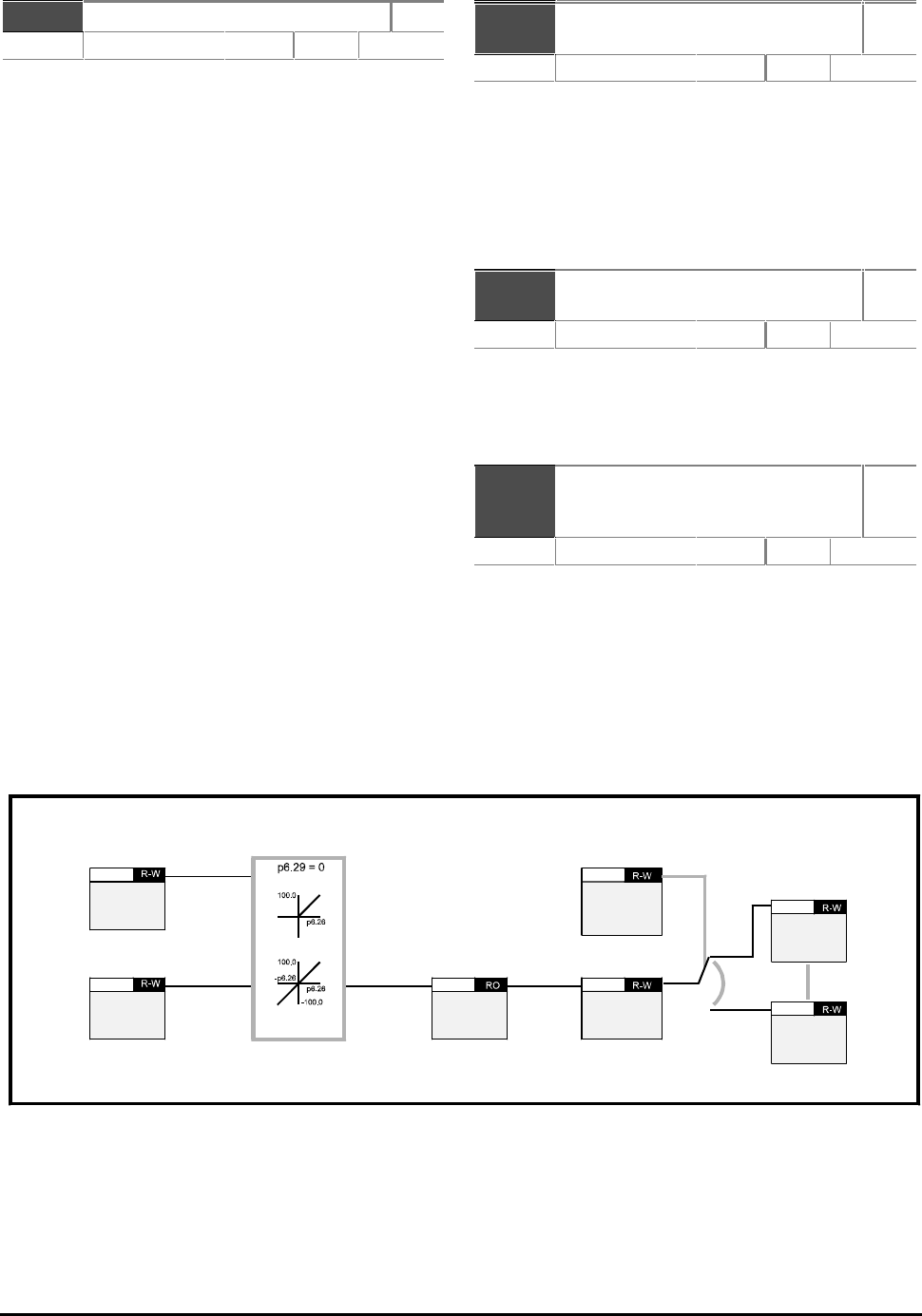
CDE, CDLE Drive
11-28
b6.24 Catch spinning motor R–W
Range 0 or 1 Default 0
Set b b6.24 at 1 to select this feature.
The Drive performs a sequence of tests to determine
the motor frequency before attempting to apply full
voltage to the motor. To limit the motor current, the
tests are carried out at a reduced voltage set in
p6.34 of the required voltage.
The Drive frequency is first set at maximum (set in
p1.06) in the direction in which the Drive last ran.
The frequency is then ramped to zero over a peroid
entered in p6.33 and compared with the motor
frequency.
If the motor frequency is not detected, the frequency
is set at maximum in the other direction and the test
is repeated. When the frequency is detected, the test
is stopped and the Drive starts at the detected
frequency and takes control of the motor.
If the motor frequency is not detected at all, the
Drive starts at 0Hz.
If the Drive is powered-down, the previous direction
of rotation is not stored, so the test begins in the
forward direction.
p6.25 Enable motorized
potentiometer zero start
R–W
Range 0 or 1 Default 0
When p6.25 is set at 1, and AC power is applied to the
Drive, the motorized potentiometer output is set at
zero.
When p6.25 is set at 0, and AC power is applied to
the Drive, the motorized potentiometer output
returns to the level that existed when AC power was
previously removed.
p6.26 Motorized potentiometer
rate
R–W
Range 5 to 255
s/ 100%
Default 20
The value in parameter p6.26 defines the time taken
for the motorized potentiometer function to ramp
from 0 to 100.0%. Twice this time will be taken to
adjust the output from –100.0% to +100.0%.
p6.27
p6.28 Motorized potentiometer up
Motorized potentiometer
down
R–W
Range 0 or 1 Default 0
To control these motorized potentiometer
parameters, two digital inputs must be programmed.
Apply signals to these inputs to control the up and
down functions.
Motorized
potentiometer
destination
p6.31
Motorized
potentiometer
scale factor
p6.30
Motorized
potentiometer
output
p6.32
Motorized
potentiometer
up
b6.27
Motorized
potentiometer
down
b6.28
Any
read-write
parameter
??.??
Any
read-write
parameter
??.??
Figure 11–2 Motorized potentiometer logic diagram
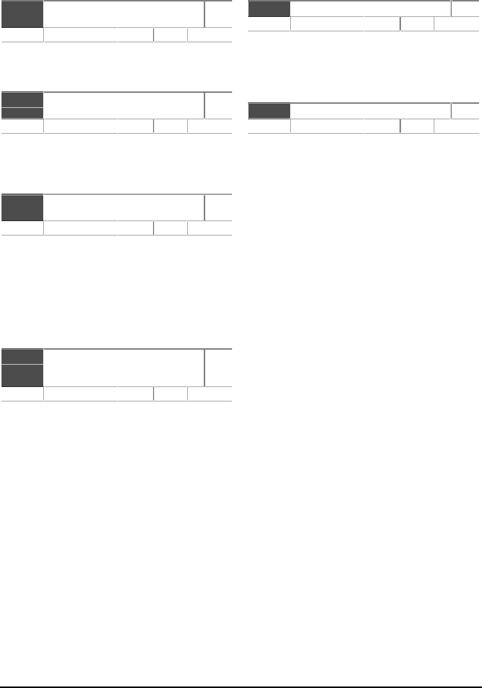
CDE, CDLE Drive 11-29
p6.29 Bipolar motorized
potentiometer
R–W
Range 0 or 1 Default 0
Set p6.29 at 1 to allow the motorized potentiometer
to go negative, otherwise the output remains positive
only.
p6.30 Motorized potentiometer
scale factor
R–W
Range 0.000 to 9.999 Default 1.000
This parameter can be used to restrict the output of
the motorized potentiometer to operate over a
reduced range so that it can be used as a trim, for
example.
p6.31 Motorized potentiometer
destination
R–W
Range 0.00 to 17.50 Default 0
Reset the Drive to make active.
Program the destination parameter that the
motorized potentiometer is to control. If the
motorized potentiometer is to control speed, it is
suggested that one of the preset speed parameters is
entered in p6.31. If the motorized potentiometer is
to trim speed, it is suggested that p1.15 (offset
parameter) is entered in p6.31.
p6.32 Motorized potentiometer
output
RO
Range ±100.00 % Default
Saved at power down.
This parameter indicates the current level of the
motorized potentiometer. The value is saved when
AC power is removed from the Drive.
p6.33 Spin start ramp time R–W
Range 2.0 to 25.5
secs
Default 10
Time taken to ramp down from maximum frequency
(p1.06) to 0 Hz while the Drive attempts to
synchronize itself with a spinning motor. Change the
value for applications that require the Drive to be
caught in a shorter or longer time.
p6.34 Spinning motor scan voltage R–W
Range 0 to 100
%
Default 25
When the Drive is in normal operation, the rated
motor voltage varies with frequency. When the Drive
is attempting to synchronize itself to a spinning
motor, a percentage of this varying voltage is applied
to the motor. The value entered in parameter p6.34
determines this percentage.
If the value is too low, the motor may not be
detected during the scan. If the value is too high, the
Drive may trip on OIAC or OV.

CDE, CDLE Drive
11-30
p7.01 Analog input I RO
Range ±100% for voltage
input. % Default
Displays the amplitude of the signal applied to Analog
input 1.
Resolution: 12-bit plus sign
Updated every 5.3ms
p7.02 Analog Input 2 RO
Range ±100% for voltage
input.
0 to100% for
current input.
% Default
Displays the amplitude of the signal applied to Analog
input 2.
Resolution: 10-bit plus sign
Updated every 5.3ms
p7.03 Analog input 3 RO
Range ±100% for voltage
input.
0 to100% for
current input
%
Default
Displays the amplitude of the signal applied to Analog
input 3.
Resolution: 10-bit plus sign
Updated every 5.3ms
p7.04 Stack temperature RO
Range 0 to 94
°C
Default
Indicates the temperature of the heatsink.
At 94°C, the Drive will trip on over-temperature.
The Drive can be reset when the temperaturefalls to
90°C.
11.12 Menu 7 — Analog inputs and outputs
Analog to
digital
converter
Analog input
p7.02 CH2
p7.03 CH3
Calibrate
reference
full scale
p7.26 CH2
p7.27 CH3
Analog
input scaling
p7.14 CH2
p7.17 CH3
Analog
input
destination
p7.15 CH2
p7.18 CH3
DAC output
source
p7.07 CH1
p7.08 CH2
p7.09 CH3
DAC scale
factor
p7.20 CH1
p7.22 CH2
p7.24 CH3
Analog
input 1 mode
p7.10
Analog
input 1
scaling
p7.11
Voltage to
frequency
converter
Analog
input 1
p7.01
Calibrate
reference 1
full scale
p7.25
DAC mode
p7.19 mode 1
p7.21 mode 2
p7.23 mode 3
Analog
input mode
p7.13 mode 2
p7.16 mode 3
Analog
input 1
destination
p7.12
Bit parameters are shown in default state
Any
read-write
parameter
??.??
Any
read-write
parameter
??.??
Any
read-write
parameter
??.??
Any
read-write
parameter
??.??
Any
read-write
parameter
??.??
Any
read-write
parameter
??.??
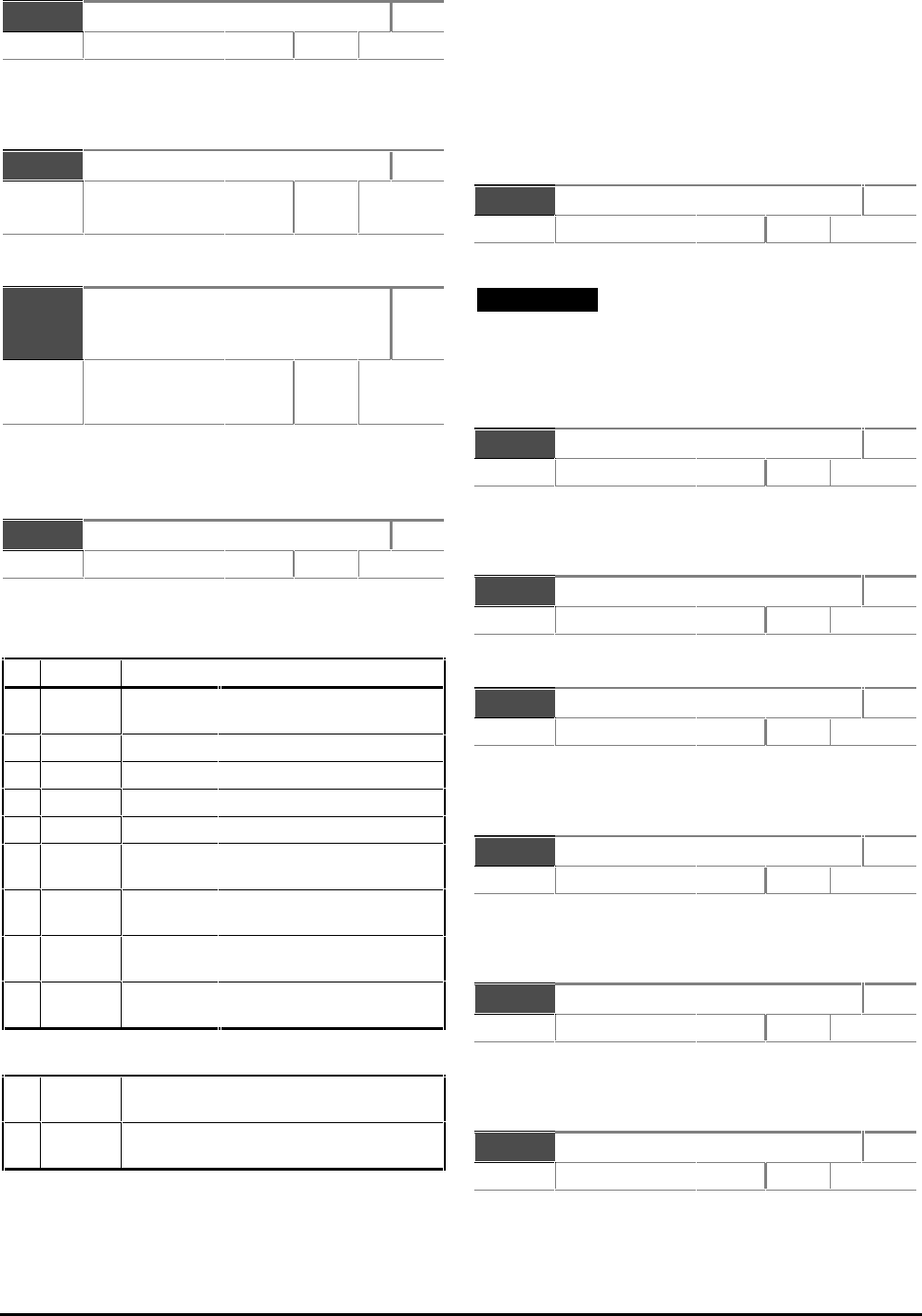
CDE, CDLE Drive 11-31
p7.05 Ambient temperature RO
Range 0 to 80 °C Default 80
At 80°C, the Drive will trip.
The Drive can be reset when the temperature falls to 75°C.
p7.06 AC supply voltage RO
Range 340 to 530 (CDE)
200 to 260 (CDLE)
VRMS Default
Indicates RMS voltage of the AC supply.
p7.07
p7.08
p7.09
Analog output 1 source
Analog output 2 source
Analog output 3 source
R–W
Range p0.00 p0.00 to p17.50p17.50 XX.XX Default p5.03p5.03
p4.02p4.02
p5.01p5.01
Enter the parameter number that is required to supply
a value to Analog output 1. A bit parameter cannot
be programmed to appear on this analog output.
p7.10 Analog input 1 mode R–W
Range [0] to [8] Default Voltage
Reset the Drive to make active.
Refer to Chapter 5 Setting Jumpers for selecting
voltage and current input and output signals.
Set
Display
Mode
[0]
VOLT
Voltage
input
[1]
0
–
20
0 – 20 mA
[2]
20
–
0
20 – 0 mA
[3]
4
–
20
4 – 20 mA Trip on current loop loss
[4]
20
–
4
20 – 4 mA Trip on current loop loss
[5]
4
–
20.
4 – 20 mA Min speed on current loop
loss
[6]
20
–
4.
20 – 4 mA Min speed on current loop
loss
[7]
4
–
2.0
4 – 20 mA Last speed on current loop
loss
[8]
20
–
.4
20 – 4 mA Last speed on current loop
loss
p7.16 has the following additional mode settings:
[9]
th
Thermistor with trip on detection of short-
circuit
[10]
th
Thermistor without detection of short-
circuit
In 4–20mA and 20–4mA operation, the threshold for
current-loop loss is 3mA.
Analog inputs are sampled every 5.3ms except in the
special case where a voltage input is programmed to one
of the analog reference parameters p1.19 and p1.20,
and that parameter is selected as the reference. In this
case, the sample rate is increased to 750Hz.
Bit parameters, read-only parameters and some other
sensitive parameters cannot be controlled using the
analog inputs.
p7.11 Analog input 1 scaling R–W
Range 0 to 9.999 Default 1.000
Enter a value to scale Analog input 1.
Note
In most cases, adjustment of p7.11, p7.14 and p7.17
is not necessary since the inputs are automatically
scaled so that 100% input signal sets the destination
parameter at maximum.
p7.12 Analog input 1 destination R–W
Range p0.00 p0.00 to p17.50p17.50
XX.XX
Default p1.19p1.19
Reset the Drive to make active.
Enter the parameter that Analog input 1 is to control.
p7.13 Analog input 2 mode R–W
Range [0] to[ 8] Default 4 to 20
Reset the Drive to make active. See parameter p7.10.
p7.14 Analog input 2 scaling R–W
Range 0 to 9.999 Default 1.000
Enter a value to scale Analog input 2.
See parameter p7.11.
p7.15 Analog input 2 destination R–W
Range p0.00 p0.00 to p17.50p17.50
XX.XX
Default p1.20p1.20
Reset the Drive to make active.
Enter the parameter that Analog input 2 is to control.
p7.16 Analog input 3 mode R–W
Range [0] to [10] Default VOLT [0]
Reset the Drive to make active.
See parameter p7.10.
p7.17 Analog input 3 scaling R–W
Range 0 to 9.999 Default 1.000
Enter a value to scale Analog input 3.
See parameter p7.11.
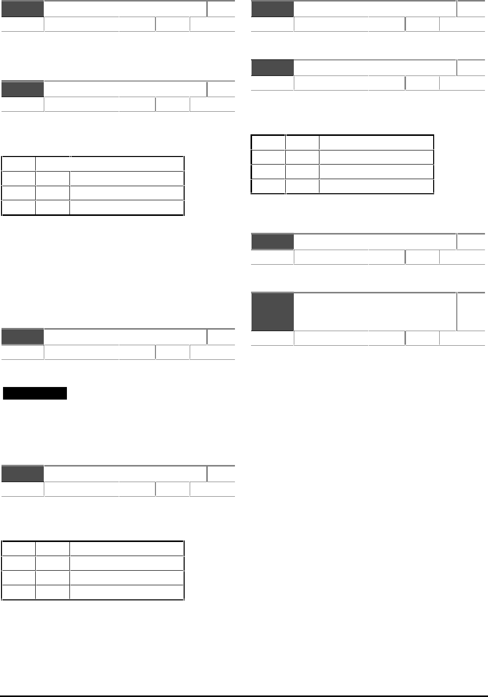
CDE, CDLE Drive
11-32
p7.18 Analog input 3 destination R–W
Range p0.00p0.00 to p17.50 p17.50 XX.XX Default 0
Reset the Drive to make active.
Enter the parameter that Analog input 3 is to control.
p7.19 Analog output 1 mode R–W
Range [0] to [2] Default Volt [0]
Parameter p7.19 together with jumper LK11 on the
IN82 circuit board can be used to configure Analog
output 1 in three modes as follows:
Mode
[0]
VOLT
Output range: ±10V
[1]
0
–
20
Output range: 0 – 20 mA
[2]
4
–
20
Output range: 4 – 20 mA
In Modes 1 and 2, negative values in the source
parameter are treated as zero.
Analog outputs are derived from PWM signals having a
carrier frequency of 2kHz. The PWM signals are
passed through a second-order filter with a corner
frequency of 50Hz.
The analog outputs are updated every 16ms.
p7.20 Analog output 1 scale factor R–W
Range 0 to 9.999 Default 1.000
Enter a value to scale Analog output 1.
Note
In most cases, adjustment of p7.20, p7.22 and
p7.24 is not necessary since the output is
automatically scaled so that 100% output signal is
produced when the source parameter is at maximum.
p7.21 Analog output 2 mode R–W
Range [0] to [2] Default Volt [0]
Parameter p7.21 together with jumper LK12 on the
IN82 circuit board can be used to configure Analog
output 2 in three modes as follows:
Mode
[0]
VOLT
Output range: ±10V
[1]
0
–
20
Output range: 0 – 20 mA
[2]
4
–
20
Output range: 4 – 20 mA
In Modes 1 and 2, negative values in the source
parameter are treated as zero.
p7.22 Analog output 2 scale factor R–W
Range 0 to 9.999 Default 1.000
Enter a value to scale Analog output 2.
p7.23 Analog output 3 mode R–W
Range [0] to [2] Default Volt [0]
Parameter p7.23 together with jumper LK13 on the
IN82 circuit board can be used to configure Analog
output 1 in three modes as follows:
Mode
[0] VOLT
Output range: ±10V
[1] 0–20
Output range: 0
–
20 mA
[2] 4–20
Output range: 4
–
20 mA
In Modes [1] and [2], negative values in the source
parameter are treated as zero.
p7.24 Analog output 3 scale factor R–W
Range 0 to 9.999 Default 1.000
Enter a value to scale Analog output 3.
b7.25
b7.26
b7.27
Calibrate reference 1 full scale
Calibrate reference 2 full scale
Calibrate reference 3 full scale
R–W
Range 0 or 1 Default 0
Set at 1 when the full scale signal applied to Analog
input 1, 2 or3 is less than 10V. The Drive then
automatically adjusts the scale factor.
b7.25, b7.26, b7.27 is reset to 0 when the
calibration is complete.

CDE, CDLE Drive 11-33
This page is deliberately blank
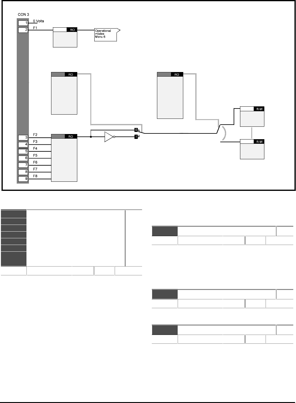
CDE, CDLE Drive
11-34
b8.01
b8.02
b8.03
b8.04
b8.05
b8.06
b8.07
b8.08
Fl Stop input
F2 programmable input
F3 programmable input
F4 programmable input
F5 programmable input
F6 programmable input
F7 programmable input
F8 programmable input
RO
Range 0 or 1 Default
Bit parameters b8.01 to b8.08 indicate the logic
states of the programmable digital inputs F1 to F8 as
follows:
0 = Inactive (logic 0)
1 = Active (logic 1)
The input destination parameters (b8.09, etc)
define the parameter that the related programmable
input (F2, etc) is to control.
The invert parameters (b8.10, etc) can be used to
invert the logic state of the destination parameter.
The programmable digital inputs are sampled every
10.6ms.
Variable parameters, read-only parameters and
Keypad control parameters (p6.12 to p6.14) cannot
be controlled by the programmable digital inputs.
p8.09 F2 input destination R–W
Range p0.00 to p17.50p0.00 to p17.50
XX.XX
Default 6.08
Reset the Drive to make active.
Enter the parameter number to use as the destination
for input F2.
Default: Sequencing bit 0 (run).
b8.10 F2 invert R–W
Range 0 or 1 Default 0
Set at 1 to invert the logic sense of F2.
p8.11 F3 input destination R–W
Range p0.00 to p17.50p0.00 to p17.50
XX.XX
Default 10.24
Reset the Drive to make active.
Enter the parameter number to use as the destination
for input F3.
Default: Reset.
11.13 Menu 8 — Programmable digital inputs
F1 stop
input
b8.01
Fx invert bits
b8.10
b8.12
b8.14
b8.16
b8.18
b8.20
b8.22
F2
F3
F4
F5
F6
F7
F8
Programmable
inputs
b8.02
b8.03
b8.04
b8.05
b8.06
b8.07
b8.08
F2
F3
F4
F5
F6
F7
F8
Input
destination
b8.09
b8.11
b8.13
b8.15
b8.17
b8.19
b8.21
F2
F3
F4
F5
F6
F7
F8
Bit parameters are shown in default state
Any
read-write
parameter
??.??
Any
read-write
parameter
??.??
CDE, CDLE Drive 11-35
b8.12 F3 invert R–W
Range 0 or 1 Default 0
Set at 1 to invert the logic sense of F3.
p8.13 F4 input destination R–W
Range p0.00 to p17.50p0.00 to p17.50 XX.XX Default 10.29
Reset the Drive to make active.
Enter the parameter number to use as the destination
for input F4.
Default: Trip Et.
b8.14 F4 invert R–W
Range 0 or 1 Default 0
Set at 1 to invert the logic sense of F4.
p8.15 F5 input destination R–W
Range p0.00 to p17.50p0.00 to p17.50 XX.XX Default 6.09
Reset the Drive to make active.
Enter the parameter number to use as the destination
for input F5.
Default: Sequencer bit 1 (Jog).
b8.16 F5 invert R–W
Range 0 or 1 Default 0
Set at 1 to invert the logic sense of F5.
p8.17 F6 input destination R–W
Range p0.00 to p17.50p0.00 to p17.50 XX.XX Default 6.10
Reset the Drive to make active.
Enter the parameter number to use as the destination
for input F6.
Default: Sequencer bit 2 (Reverse).
b8.18 F6 invert R–W
Range 0 or 1 Default 0
Set at 1 to invert the logic sense of F6.
p8.19 F7 input destination R–W
Range p0.00 to p17.50p0.00 to p17.50
XX.XX
Default 1.21
Reset the Drive to make active.
Enter the parameter number to use as the destination
for input F7.
Default: Analog reference 2 select (Remote).
b8.20 F7 invert R–W
Range 0 or 1 Default 0
Set at 1 to invert the logic sense of F7.
p8.21 F8 input destination R–W
Range p0.00 to p17.50p0.00 to p17.50
XX.XX
Default p1.08
Reset the Drive to make active.
Enter the parameter number to use as the destination
for input F7.
Default: Control Keypad select.
b8.22 F8 invert R–W
Range 0 or 1 Default 0
Set at 1 to invert the logic sense of F8.
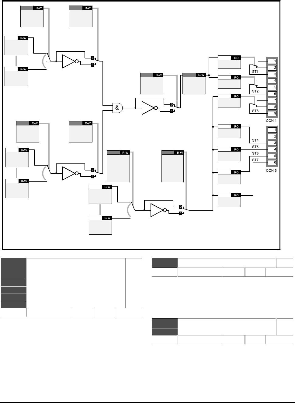
CDE, CDLE Drive
11-36
b9.01
b9.02
b9.03
b9.04
b9.05
b9.06
b9.07
Status output 1 (relay)
Status output 2 (relay)
Status output 3 (relay)
Status output 4
Status output 5
Status output 6
Status output 7
RO
Range 0 or 1 Default 0
The Status output parameters monitor the logic
states of the seven Status outputs. The outputs and
these parameters are updated every 10.6ms.
Variable parameters cannot be used as a source for
the Status outputs.
(If variable parameters need to be used see
Programmable thresholds Menu 12.)
p9.08 Status output 1, Source 1 R–W
Range p0.00 p0.00 to p17.50 p17.50
XX.XX
Default b10.04b10.04
Enter the bit parameter number to be used as Source 1
for Status output 1.
The default setting indicates when the Drive is at or
below minimum frequency.
b9.09 Status output 1, Source 1
invert
R–W
Range 0 or 1 Default 0
Set at 1 to invert the logic state of Source 1 of Status
output 1.
Bit parameters are shown in default state
Status output
source
p9.20
p9.22
p9.24
p9.26
p9.28
ST3
ST4
ST5
ST6
ST7
Status output
invert bit
b9.21
b9.23
b9.25
b9.27
b9.29
ST3
ST4
ST5
ST6
ST7
Status output
source 1
p9.08
p9.14 ST1
ST2
Status output
invert bit
b9.09
b9.15 ST1
ST2
Status output
source 2
p9.10
p9.16 ST1
ST2
Status output
invert bit
b9.11
b9.17 ST1
ST2
Invert status
output
b9.12
b9.18 ST1
ST2
Status output
delay
b9.13
b9.19 ST1
ST2
Status
output 1
b9.01
Status
output 2
b9.02
Status
output 3
b9.03
Status
output 4
b9.04
Status
output 5
b9.05
Status
output 6
b9.06
Status
output 7
b9.07
Any
read-write
parameter
??.??
Any
read-write
parameter
??.??
Any
read-write
parameter
??.??
Any
read-write
parameter
??.??
Any
read-write
parameter
??.??
Any
read-write
parameter
??.??
11.14 Menu 9 — Programmable digital outputs
CDE, CDLE Drive 11-37
p9.10 Status output 1 source 2 R–W
Range p0.00 p0.00 to p17.50 p17.50 XX.XX Default 0
Enter the bit parameter number to be used as Source
2 for Status output 1.
b9.11 Status output 1, Source 2
invert
R–W
Range 0 or 1 Default 0
Set at 1 to invert the logic state of Source 2 of Status
output 1.
b9.12 Status output 1 Invert R–W
Range 0 or 1 Default 0
Set at 1 to invert the logic state of Status output 1.
b9.13 Status output 1 delay R–W
Range 0 to 25.5 s Default 0
Enter a value for the required delay for Status
output 1 to become active (logic 1). The delay is used
to ensure that the output condition is genuine by
being present for a period of time.
The delay does not operate when the state changes
to logic 0.
p9.14 Status output 2, Source 1 R–W
Range p0.00 p0.00 to p17.50 p17.50 XX.XX Default b10.02b10.02
Enter the bit parameter number to be used as Source 1
for Status output 2.
The default setting indicates when the Drive is in the
RUN state.
b9.15 Status output 2, Source 1
invert
R–W
Range 0 or 1 Default 0
Set at 1 to invert the logic state of Source 1 of Status
output 2.
p9.16 Status output 2, Source 2 R–W
Range p0.00 p0.00 to p17.50 p17.50 XX.XX Default 0
Enter the bit parameter number to be used as Source
2 for Status output 2.
b9.17 Status output 2, Source 2
invert
R–W
Range 0 or 1 Default 0
Set at 1 to invert the logic state of Source 2 of Status
output 2.
b9.18 Status output 2 Invert R–W
Range 0 or 1 Default 0
Set at 1 to invert the logic state of Status output 2.
p9.19 Status output 2 delay R–W
Range 0 or 25.5
s
Default 0
Enter a value for the required delay for Status
output 2 to become active (logic 1). The delay is used
to ensure that the output condition is genuine by
being present for a period of time.
The delay does not operate when the state changes
to logic 0.
p9.20 Status output 3, Source R–W
Range p0.00 p0.00 to p17.50 p17.50
XX.XX
Default b10.01b10.01
Enter the bit parameter number to be used as the
source for Status output 3.
The default setting indicates Drive normal.
b9.21 Status output 3 invert R–W
Range 0 or 1 Default 0
Set at 1 to invert the logic state of Status output 3.
p9.22 Status output 4, Source R–W
Range p0.00 p0.00 to p17.50 p17.50
XX.XX
Default b10.05b10.05
Enter the bit parameter number to be used as the
source for Status output 4.
The default setting indicates when the Drive is
At speed.
b9.23 Status output 4 invert R–W
Range 0 or 1 Default 0
Set at 1 to invert the logic state of Status output 4.
CDE, CDLE Drive
11-38
p9.24 Status output 5, Source R–W
Range p0.00 p0.00 to p17.50 p17.50 XX.XX Default b10.08b10.08
Enter the bit parameter number to be used as the
source for Status output 5.
The default setting indicates when the Drive is in
Current limit
b9.25 Status output 5 invert R–W
Range 0 or 1 Default 0
Set at 1 to invert the logic state of Status output 5.
p9.26 Status output 6 source R–W
Range p0.00 p0.00 to p17.50 p17.50 XX.XX Default b10.13b10.13
Enter the bit parameter number to be used as the
source for Status output 6.
The default setting indicates when Forward
direction is demanded.
b9.27 Status output 6 invert R–W
Range 0 or 1 Default 0
Set at 1 to invert the logic state of Status output 6.
p9.28 Status output 7 source R–W
Range p0.00 p0.00 to p17.50 p17.50 XX.XX Default b10.06b10.06
Enter the bit parameter number to be used as the
source for Status output 7.
The default setting indicates load reached.
b9.29 Status output 7 invert R–W
Range 0 or 1 Default 0
Set at 1 to invert the logic state of Status output 7.
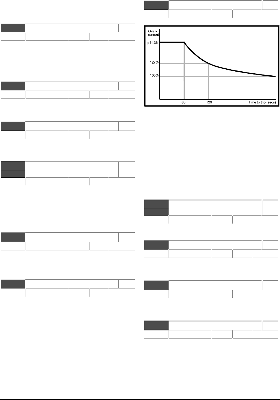
CDE, CDLE Drive 11-39
11.15 Menu 10 — Status logic and
diagnostic information
b10.01 Drive normal RO
Range 0 or 1 Default 0
b10.01 = 0 indicates the Drive is tripped.
b10.01 = indicates the Drive is normal (not tripped),
or if b10.28 = 1 the Drive is tripped but an auto-reset
is going to occur.
b10.02 Drive running RO
Range 0 or 1 Default 0
b10.02 = 1 indicates the output bridge of the Drive is
active.
b10.03 Zero frequency or stopped RO
Range 0 or 1 Default
b10.03 = 1 indicates the ramp output is between
–1Hz and +1Hz.
b10.04 Running at or below minimum
frequency
RO
Range 0 or 1 Default
In bipolar mode (b1.10 set at 1), b10.04 is in the
same state as b10.03 (zero frequency).
In unipolar mode (b1.10 set at 0), b10.04 = 1 when
the Drive is running and the ramp output is between:
[+min freq.+ 1Hz] or [–min freq.–1Hz].
b10.05 At speed RO
Range 0 or 1 Default
When the Drive is running b10.05 = 1 indicates the
ramp output is within 1Hz of the selected speed
reference.
b10.06 Load reached RO
Range 0 or 1 Default 0
b10.06 = 1 indicates:
Load current ≥ Rated load current
itorq_rated = p5.06 x p5.13
b10.07 Alarm RO
Range 0 or 1 Default 105%
Figure 11–3 Time to trip is dependent on the
extent of current overload
b10.07 = 1 indicates that motor current is greater
than 105% of the programmed motor rated current.
If the current is not reduced, the Drive will trip on Ixt
overload after a period of time that depends on the
extent of the overload. For example:
Motor current = p11.35 — Time to trip =
60 secs maximum
Motor current =
(())
p11 35 105%
2
.−− — Time to trip = 120 secs maximum
b10.08 Drive output is at current
limit
RO
Range 0 or 1 Default 0
b10.08 = 1 indicates the normal current limit is active.
b10.09 Motor regenerating RO
Range 0 or 1 Default 0
b10.09 = 1 indicates the output bridge is transferring
power from the motor to the DC bus.
b10.10 Dynamic brake active RO
Range 0 or 1 Default 0
b10.10 = 1 indicates power is being dissipated in the
optional DC braking resistor (if fitted).
b10.11 Serial communications active RO
Range 0 or 1 Default 0
b10.11 = 1 indicates successful communication is
taking place.
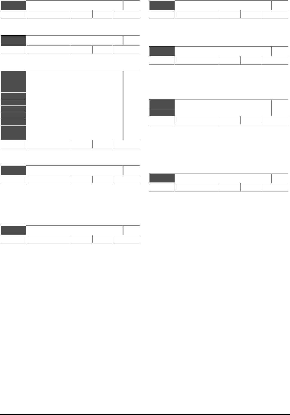
CDE, CDLE Drive
11-40
b10.12 Loss of AC power RO
Range 0 or 1 Default 0
b10.12 = 1 indicates loss of AC power to the Drive.
b10.13 Forward rotation commanded RO
Range 0 or 1 Default 0
b10.13 = 1 indicates the pre-ramp reference is positive.
p10.14
p10.15
p10.16
p10.17
p10.18
p10.19
p10.20
p10.21
p10.22
p10.23
Last trip
Last trip but 1
Last trip but 2
Last trip but 3
Last trip but 4
Last trip but 5
Last trip but 6
Last trip but 7
Last trip but 8
Last trip but 9
RO
Range Default
These parameters indicate previous Trip codes.
b10.24 Drive reset R–W
Range 0 or 1 Default 0
Set at 1 to reset the Drive.
If the Drive is to be reset by an input signal, a
programmable digital input must be programmed to
control this parameter.
b10.25 Enable auto-reset R–W
Range 0 or 1 Default 0
Set b10.25 at 1 for the Drive to be automatically
reset when tripped after a programmed delay set in
p10.26. The reset can be repeated to a maximum
number of times programmed in p10.27.
p10.26 Reset delay R–W
Range 0 to 25.5
s
Default 1.0
When the programmed value of p10.27 is reached,
any further trips of the same type will not cause a
reset. A trip of a different type will cause a reset.
p10.27 Number of reset attempts R–W
Range 0 to 5 Default 0
If no trip has occured for 10 minutes, the reset count
is cleared.
Auto reset will not occur on External trip (Et).
b10.28 Hold Drive Normal until
last attempt
R–W
Range 0 or 1 Default 0
Set at 0 to reset b10.01 (Drive normal indication)
every time the Drive trips, regardless of auto-resets.
Set at 1 for the Drive normal indication to remain
set when a trip occurs and an auto-reset is going to
occur.
b10.29 External trip R–W
Range 0 or 1 Default 1
When an external trip signal is required to control this
parameter, use a programmable digital input and
ensure that the input state is at logic 1 to prevent the
Drive tripping.
When b10.29 = 0 the Drive will trip.
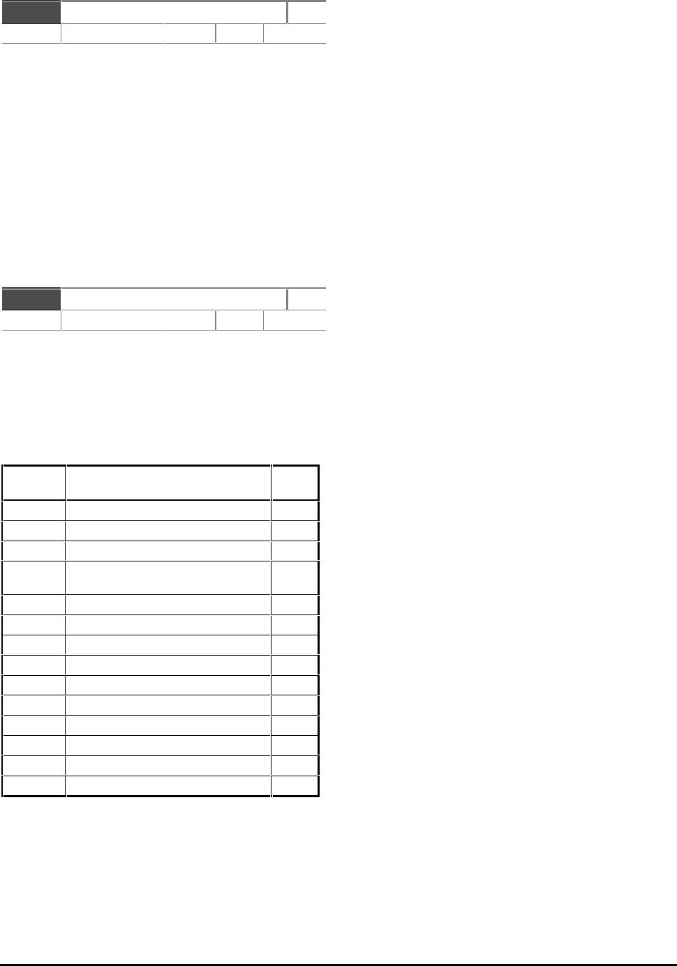
CDE, CDLE Drive 11-41
p10.30 Processor 2 trip R–W
Range 0 to 70 Default 0
When a user-defined trip occurs and causes a
command from an expansion card or serial
communications to be sent to the Drive, parameter
p10.30 can be used to trip the Drive and display a
relevant trip code.
The expansion card should enter a valid trip code into
p10.30. Valid codes are 40 to 69. The display will
then show tr40 to tr69 accordingly. The Trip log
will also show these codes.
If a standard Trip code is entered in p10.30, the Trip
code will be shown and the Drive tripped accordingly.
The Drive can be reset by setting p10.30 at 70.
p10.31 Status word RO
Range 0 to 32761 Default 0
Parameter p10.31 contains a binary coded number.
This indicates the current state of the read-only
parameters that indicate the status of the Drive. The
coded number can be used to control indicators on a
separate display panel.
The binary codes that are produced when the
parameters are at logic 1 are as follows:
Paramet
er Description Binar
y No.
b10.01b10.01 Drive normal 20
b10.02b10.02 Drive running 21
b10.03b10.03 Zero frequency or stopped 22
b10.04b10.04 Running at or below minimum
frequency 23
b10.05b10.05 At speed 24
b10.06b10.06 Load reached 25
b10.07b10.07 Alarm 26
b10.08b10.08 Drive output is at current limit 27
b10.09b10.09 Motor regenerating 28
b10.10b10.10 Dynamic brake active 29
b10.11b10.11 Serial communications active 210
b10.12b10.12 Loss of AC power 211
b10.13b10.13 Forward rotation commanded 212
b10.25b10.25 Enable Auto-reset 213
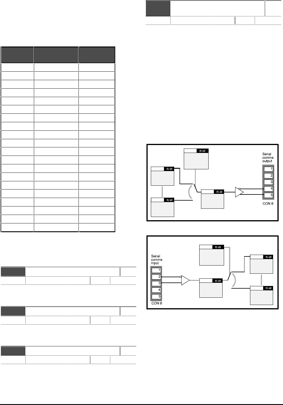
CDE, CDLE Drive
11-42
11.16 Menu 11 —
Miscellaneous parameters
Use the Menu 11 parameters in the following table to
assign parameters in the Advanced menus to the User
menu (Menu 0). The default assignments are shown.
The Menu 11 parameters in the table are read–write.
ParameterParameter
numbernumber Menu 0Menu 0
User parameterUser parameter DefaultDefault
assignmentassignment
p11.01p11.01 p0.01p0.01 p1.06p1.06
p11.02p11.02 p0.02p0.02 p2.03p2.03
p11.03p11.03 p0.03p0.03 p2.04p2.04
p11.04p11.04 p0.04p0.04 p4.11p4.11
p11.05p11.05 p0.05p0.05 p5.06p5.06
p11.06p11.06 p0.06p0.06 p5.12p5.12
p11.07p11.07 p0.07p0.07 p5.07p5.07
p11.08p11.08 p0.08p0.08 p6.04p6.04
p11.09p11.09 p0.09p0.09 p5.08p5.08
p11.10p11.10 p0.10p0.10 p4.07p4.07
p11.11p11.11 p0p0.1111 p6.02p6.02
p11.12p11.12 p0p0.1212 p6.01p6.01
p11.13p11.13 p0p0.1313 p1.04p1.04
p11.14p11.14 p0p0.1414 p5.16p5.16
p11.15p11.15 p0p0.1515 p6.06p6.06
p11.16p11.16 p0.16p0.16 p6.24p6.24
p11.17p11.17 p0.17p0.17 p1.14p1.14
p11.18p11.18 p0.18p0.18 p5.10p5.10
p11.19p11.19 p0.19p0.19 p4.02p4.02
p11.20p11.20 p0.20p0.20 p5.02p5.02
For read-only parameters programmed into p11.19
and p11.20, a scale factor can be applied using p11.21
and p11.22 in order to indicate some meaningful unit
such as cans-per-hour.
p11.21 Scale factor for p0.19 R–W
Range 0.0 to 9.999 Default 1.000
Enter a value to scale p0.19 to represent a meaningful
unit, such as cans per hour.
p11.22 Scale factor for p0.20 R–W
Range 0.0 to 9.999 Default 1.000
Enter a value to scale p0.20 to represent a
meaningful unit, such as cans per hour.
p11.23 Serial address R–W
Range 11 to 99 Default 11
Enter an address for serial communications.
Numbers ending in zero should not be used since
these are used for groups of Drives.
p11.24 Serial mode
[Reset drive to make active]
R–W
Range [0] to [2] Default ANSI [0]
Select the required mode of operation for serial
communications.
AnSI [0] ANSI protocol, half-duplex serial
communications
outP [1] Output variable defined by p11.31
inP [2] Input variable to parameter defined
by p11.31.
Parameter p11.24 selects the serial communications
mode. Modes 1 and 2 are used for transfer of data from
one Drive to another. In both these cases, data is
transferred at a rate of 200Hz. Although the data rate is
slightly slower than that for a Mentor II Drive, the
protocol and Baud rate are identical. It is possible to
connect a CDE Drive to a Mentor II Drive for data transfer
in either direction.
Reset the Drive after selecting a different mode, in order
to make the new selection active.
Serial comms
programmable
source/
destination
p11.31
Serial
scaling
p11.32
Any
read-write
parameter
??.??
Any
read-write
parameter
??.??
Figure 11–4 Mode 1 — Sending a parameter
value to another Drive
Serial comms
programmable
source/
destination
p11.31
Serial
scaling
p11.32
Any
read-write
parameter
??.??
Any
read-write
parameter
??.??
Figure 11–5 Mode 2 — Receiving a parameter
value from another Drive
In the event of the Drive tripping, a value of zero is
transmitted.
Once data has been received in Mode 2, a serial-
communications-loss trip will occur if serial
communications are lost and the last data received is
not zero.
CDE, CDLE Drive 11-43
p11.25 Baud rate R–W
Range [0] to [2] Default 4800 [0]
4,800 baud [0]
9,600 baud [1]
19.2 kbaud [2]
p11.26 2-wire mode R–W
Range 0 or 1 Default 0
Set at 1 to allow 2-wire serial communications.
Set at 0 for 4-wire serial communications.
p11.27 Software version RO
Range XX.XX Default
Indicates version of software in the Drive.
p11.28 Processor 2 software version RO
Range XX.XX Default
Indicates software version present on any optional
card fitted.
p11.29 Level 3 security code R–W
Range 0 to 255 Default 149
Enter a number other than 149 to apply Level 3
security.
See Chapter 10 Security.
p11.30 Parameter to be displayed
when AC power is applied
R–W
Range p0.00 p0.00 to p0.20 p0.20 XX.XX Default 0.20
Enter the number of the parameter that is to be
displayed when AC power is applied.
p11.31 Serial communications
programmable
source/destination
R–W
Range p0.00 p0.00 to p17.50 p17.50
XX.XX
Default 0
Reset the Drive to make active.
Enter the number of the parameter to be sent or
received using serial communications Modes [1] and
[2] respectively.
In Mode [2], reset the Drive to make a new selection
active.
See parameter p11.24.
p11.32 Serial scaling R–W
Range 0.0 to 9.999 Default 1.000
Enter a scaling value for data sent or received in serial
communications Modes [1] and [2] respectively.
In most cases, it is not necessary to apply scaling since
input and output values are automatically scaled.
p11.33 Current rating RO
Range Default
Indicates maximum continuous current rating in Amps
of the Drive.
p11.34 Voltage rating RO
Range 0 to 1 Default
Indicates the voltage rating of the Drive.
cdLE (CDLE) [0] Low voltage range
cdE (CDE) [1] Standard voltage range.
p11.35 Overload rating RO
Range 21 to 2880 Default
Indicates maximum overload current in Amps of the
Drive.
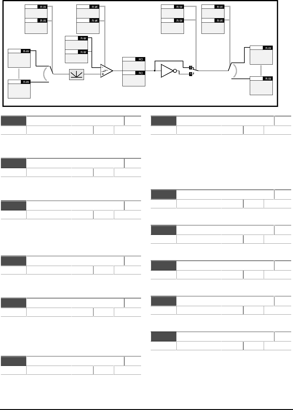
CDE, CDLE Drive
11-44
b12.01 Threshold 1 exceeded RO
Range [0] or [1] Default
b12.01 = 1 indicates input variable is above Threshold 1
b12.01 = 0 indicates input variable is below Threshold 1
b12.02 Threshold 2 exceeded RO
Range [0] or [1] Default
b12.02 = 1 indicates input variable is above Threshold 2
b12.02 = 0 indicates input variable is below Threshold 2
p12.03 Threshold 1 source R–W
Range p0.00 p0.00 to p17.50 p17.50 XX.XX Default 0
Enter the number of the parameter to be used as the
source for threshold 1. The absolute value of the source
is taken as the input to the Threshold comparator. Reset
the Drive to make active.
p12.04 Threshold 1 level R–W
Range 0.0 to 100.0 % Default 0
User-defined threshold 1 level entered as a percentage
of the source maximum.
p12.05 Threshold 1 hysteresis R–W
Range 0 to 25.5 % Default 0
Defined band where no change will occur to the
comparator output.
Upper limit for switching: Level + [hyst ÷ 2]
Lower limit: Level – [hyst ÷ 2]
b12.06 Threshold 1 output invert R–W
Range [0] or [1] Default 0
Set at 1 to invert threshold comparator 1 output.
p12.07 Threshold 1 destination R–W
Range p0.00 p0.00 to p17.50 p17.50
XX.XX
Default 0
Reset the Drive to make active
Define the destination of threshold comparator 1
output. The destination must be a R–W bit
parameter.
Reset the Drive to make active a new value entered in
p12.07.
p12.08 Threshold 2 source R–W
Range p0.00 p0.00 to p17.50 p17.50
XX.XX
Default 0
Refer to the notes for p12.03 to p12.07.
p12.09 Threshold 2 level R–W
Range 0.0 to 100.0
%
Default 0
Refer to the notes for p12.03 to p12.07.
p12.10 Threshold 2 hysteresis R–W
Range 0 to 25.5
%
Default 0
Refer to the notes for p12.03 to p12.07.
p12.11 Threshold 2 output invert R–W
Range [0] or [1] Default 0
Refer to the notes for p12.03 to p12.07..
p12.12 Threshold 2 destination R–W
Range p0.00 p0.00 to p17.50 p17.50
XX.XX
Default 0
Reset the Drive to make active
Refer to the notes for p12.03 to p12.07..
Bit parameters are shown in default state
Threshold 1
source
p12.03
p12.08
Threshold 2
source
Threshold 1
level
p12.04
p12.09
Threshold 2
level
p12.10
Threshold 2
hysteresis
Threshold 1
hysteresis
p12.05
b12.11
Threshold 2
output invert
Threshold 1
output invert
b12.06
p12.12
Threshold 2
destination
Threshold 1
destination
p12.07
b12.02
Threshold 2
exceeded
Threshold 1
exceeded
b12.01
Any
read-write
parameter
??.??
Any
read-write
parameter
??.??
Any
read-write
parameter
??.??
Any
read-write
parameter
??.??
11.17 Menu 12 — Programmable thresholds
CDE, CDLE Drive 11-45
11.18 Menu 13 — Timer functions
p13.01 Run-time log RO
Range 0.000 to 9.364 y.ddd Default
Saved at power down.
Indicates years and days of the total running time of
the Drive
p13.02 Run-time log RO
Range 00.00 to 23.59 hh.mm Default
Saved at power down.
Indicates the hours and minutes of the total running
time of the Drive
p13.03 Energy consumption
measurement
RO
Range 0 to 9999 MWh Default
Saved at power down.
Indicates MWH of energy consumed.
p13.04 Energy consumption
measurement
RO
Range 000.0 to 999.9 kWh Default
Saved at power down.
Indicates kWh of energy consumed.
p13.05 Running cost RO
Range 0 to XXXX p13.08p13.08/
hDefault
Continuously indicates the running cost/hour.
Requires the correct value to be entered in p13.08.
p13.06 Time remaining until filter
change due
R–W
Range 0 to 9999 h Default
Saved at power down.
Indicates running time remaining before the system
requires a change of filter.
p13.07 Time remaining until
lubrication due
RO
Range 0 to 9999
h
Default
Saved at power down.
Indicates running time remaining before the system or
mechanical system requires lubrication.
p13.08 Electricity cost per kWh R–W
Range 00.00 to 99.99
Currency
Default 0
Enter electricity cost for use by p13.05.
b13.09 Reset Energy Consumption
meter
R–W
Range 0 or 1 Default 0
Set at 1 to reset p13.03 and p13.04.
p13.10 Time interval between filter
changes
R–W
Range 0 to 9999
h
Default 0
Enter the running time the motor must operate
between filter changes.
b13.11 Filter change done R–W
Range 0 or 1 Default 1
b13.11 is automatically set at 1 when
p13.06 = 0. Set b13.11 at 0 when the filter is
changed. This causes p13.06 to be loaded with the
value of p13.10.
p13.12 Time interval between
lubrication
R–W
Range 0 to 9999
h
Default 0
Defines the running time the machine must operate
between lubrication.
b13.13 Lubrication done R–W
Range 0 or 1 Default 1
b13.13 is automatically set at 1 when
p13.07 = 0. Set b13.13 at 0 when lubrication is
carried out. This causes p13.07 to be loaded with
the value of p13.12.

CDE, CDLE Drive
11-46
11.19 Menu 14 — PID control loop, Encoder feedback
Bit parameters are shown in default state
Main
reference
source
p14.02
PID
reference
source
p14.03
PID
feedback
source
p14.04
Optional PID
enable
source
p14.09
Invert
reference
b14.05
Invert
feedback
b14.06
PID
reference
slew rate
limit
p14.07
Proportional
gain
p14.10
Integral
gain
p14.11
Derivative
gain
p14.12
PID high limit
p14.13
PID low limit
p14.14
PID
output
p14.01 PID
output
scaling
p14.15
PID
output
destination
p14.16
Any
read-write
parameter
??.??
Any
read-write
parameter
??.??
Any
read-write
parameter
??.??
Any
read-write
parameter
??.??
Any
read-write
parameter
??.??
Any
read-write
parameter
??.??
Any
read-write
parameter
??.??
Any
read-write
parameter
??.??
PID enable
b14.08
Drive
running
b10.02
Any
read-write
parameter
??.??
Any
read-write
parameter
??.??
CDE, CDLE Drive 11-47
p14.01 PID output RO
Range ±100.0 % Default
The inputs to the PID controller are automatically
scaled to the range ±100.0%. The PID controller
output is also within this range.
Although it would appear that the variables have only
10-bit resolution, internal calculations are made at a
higher resolution for greater accuracy. The displayed
values are scaled versions of the internal variables.
After the final addition to the main reference, the
output is automatically scaled again to match the
range of the destination parameter.
Gain parameters are actual units, as follows:
PID output = Pe + Ie/s + Des
where:
P, I and D are the programmed gains
e is the input error to the PID controller
s is the Laplace identifier
p14.02 Main reference source R–W
Range p0.00 p0.00 to p17.50 p17.50 XX.XX Default 0.00
Reset the Drive to make active.
See parameter p14.01.
p14.03 PID reference source R–W
Range p0.00 p0.00 to p17.50 p17.50 XX.XX Default
Reset the Drive to make active.
See parameter p14.01.
p14.04 PID feedback source R–W
Range p0.00 p0.00 to p17.50 p17.50 XX.XX Default 0.00
Reset the Drive to make active.
See parameter p14.01.
b14.05 Invert reference R–W
Range [0] or [1] Default 0
See parameter p14.01.
b14.06 Invert feedback R–W
Range [0] or [1] Default 0
See parameter p14.01.
b14.07 PID reference slew rate limit R–W
Range 0.1 to 3276 Default 0.1
See parameter p14.01.
b14.08 PID enable R–W
Range [0] or [1] Default 0
See parameter p14.01.
p14.09 Optional PID enable source R–W
Range p0.00 p0.00 to p17.50 p17.50
XX.XX
Default 0.00
Reset the Drive to make active.
See parameter p14.01.
p14.10 Proportional gain R–W
Range 0 to 9.999 Default 1.000
See parameter p14.01.
p14.11 Integral gain R–W
Range 0 to 9.999 Default 0.500
See parameter p14.01.
p14.12 Derivative gain R–W
Range 0 to 9.999 Default 0
See parameter p14.01.
p14.13 PID high limit R–W
Range 0 to 100.0
%
Default 100.0
See parameter p14.01.
p14.14 PID low limit R–W
Range –100.0 to +100.0
%
Default –100.0
See parameter p14.01.
p14.15 PID output scaling R–W
Range 0.000 to 9.999 Default 1.000
See parameter p14.01.
p14.16 PID output destination R–W
Range p0.00 p0.00 to p17.50 p17.50
XX.XX
Default 0.00
Reset the Drive to make active.
See parameter p14.01.

CDE, CDLE Drive
11-48
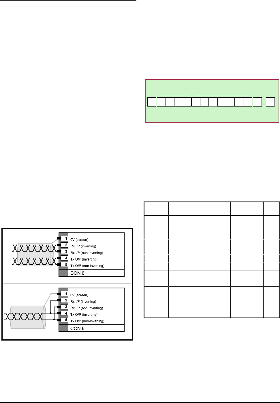
CDE, CDLE Drive 12-1
12 Serial Communications
12.1 Introduction
Serial communications can be used by a host
computer or PLC to perform the following:
Read and edit the values of parameters
Control the Drive
One host computer may control up to 81 Drives when
line buffers are used or 32 Drives without line buffers.
The serial communications format is RS485 which is a
differential link that ensures a high level of immunity
to noise. It also withstands high common-mode
rejection. The protocol is the following industry
standard:
ANSI x 3.28 − 2.5 − A4
The data format is as follows:
7 data bits
1 start bit
1 stop bit
Even parity
12.2 Connecting the Drive
Two- wire or four-wire mode may be used (refer to
Figure 12–1).For best reliability use screened twisted
pair cable.
Connections for 4-wire mode
Connections for 2-wire mode
Figure 12–1 Serial communications connections
(four-wire and two-wire modes)
12.3 Message structure
Messages consist of the following:
Control characters
Serial address code
Parameter identifier
Data field
Block checksum (BCC)
The message structure is shown below.
01 2 5 ETX
Parameter identifier Control
character
STX
(Ctrl B)
047. 6
Data field
(Ctrl C)
3
Block
checksum
(BCC)
7 characters if decimal place
6 characters if no dec. place
− 0
Control
character
Figure 12–2 Structure of Serial Communications
messages
Control characters
If a message is initiated from a keyboard, control
characters may be entered by holding down the CtrlCtrl
key while pressing the key given in the last column of
the table below:
Character
Purpose
ASCII code
(HEX) Key
EOT
Reset
Message begins
End of transmission
04 D
ENQ
Enquiry
Interrogating the Drive
05 E
STX
Start of text
02 B
ETX
End of text
03 C
ACK
Acknowledge
(Message accepted)
06 F
BS
Backspace
(Go to previous parameter)
08 H
NAK
Negative acknowledge
(Message not understood)
15 U
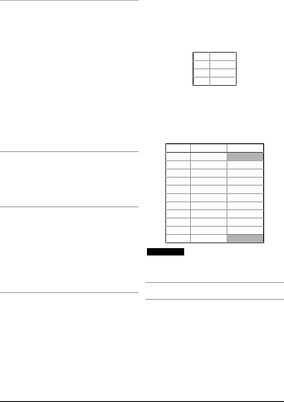
CDE, CDLE Drive
12-2
Serial address code
Each Drive on a serial communications link, must have
an individual address code. The required serial
address code should be entered in p11.23. The code
must have two digits, and the number 0 must not be
used. The first digit defines the group (1 to 9); the
second digit defines the Drive number in the group
(1 to 9).
The code for an individual Drive should be sent by the
host as in this example:
Drive address code: 2 8
Address code to be sent by host: 2 2 8 8
To address all the Drives in Group 2, the host would
need to send:
2 2 0 0
To address all Drives on the serial comms link, the
host would need to send:
0 0 0 0
Parameter identifier
To address an individual parameter, the host needs to
send a code that relates to the parameter number.
For example:
To address: p0.01
Send: 0001
Data field
Data are sent as numerical values with a negative
polarity sign and decimal point when appropriate.
The data field is of variable length, with a maximum
of seven characters including the decimal point. The
state of bit parameters is sent as numerical value 1 or
0 . For variable (p) parameters, having a series of
options defined by character strings on the display
(eg. p7.10), the first option (std.H = 0) is set by
sending 0, the second option (Fast = 1) by sending 1,
etc.
Block checksum
The block checksum character (BCC) is used to check
that each message has not been corrupted when
being sent. The BCC is a value that is calculated from
the ASCII codes of the characters in the parameter and
data fields.
The following example shows how the BCC is
calculated.
A message for parameter p1.25 contains the value −−
47.6. The parameter identifier is 0125 and the data
field contains −−47.6.
The Binary codes (for the parameter identifier) are as
follows:
0
0011 0000
1
0011 0001
2
0011 0010
5
0011 0101
The first and second ASCII codes are compared in an
XOR function. The result is 0000 0001.
This result is compared with the third ASCII code
(0011 0010) which produces the result 0011 0011.
This number is then compared with the next ASCII
code. The process is repeated until the final digit in
the data field is reached, as shown below:
Character
Binary code XOR
0
011 0000
1
011 0001 0000 0001
2
011 0010 0011 0011
5
011 0101 0000 0110
−
010 1101 0010 1011
4
011 0100 0001 1111
7
011 0111 0010 1000
.
010 1110 0000 0110
6
011 0110 0011 0000
ETX
000 0011 0011 0011
3
011 0011
Note
If the decimal value is less than 32, then 32 must be
added. The resulting code is then used to derive the
BCC.
Messages from host to Drive
Messages from the host to the Drive are used to:
Interrogate the Drive for values or states of
parameters
Send a command to the Drive
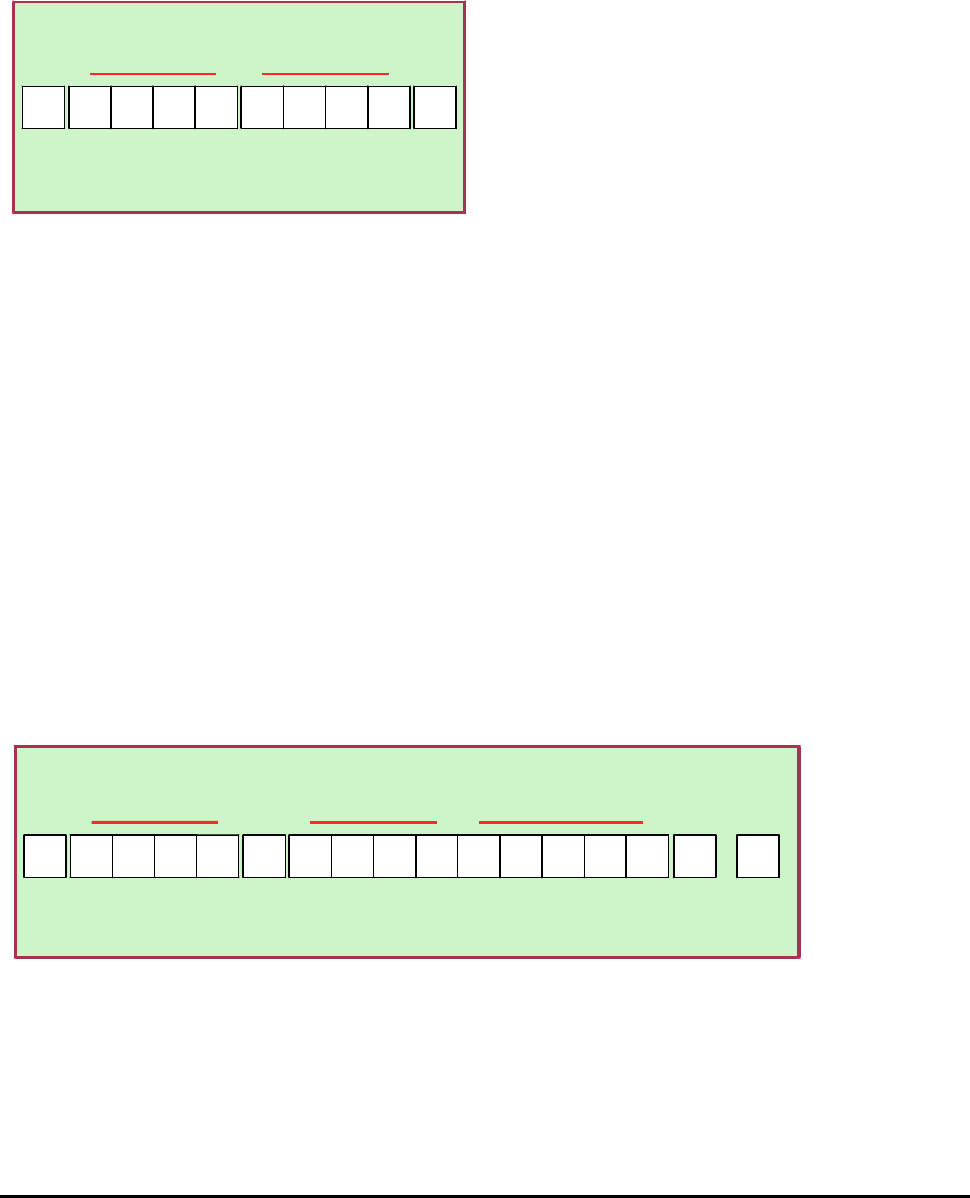
CDE, CDLE Drive 12-3
12.4 Interrogate the Drive
To find the value of a parameter, the host should send
a message that is structured as shown below.
The data field is not used. The final control character
should be: ENQ (Ctrl E)
EOT 0 1 2 5 ENQ
Control
character Address code Parameter identifier Control
character
(Ctrl D) (Ctrl E)
Figure 12–3 Message from host to interrogate
the Drive
12.5 Send a command
to the Drive
Commands are used to:
Change the value of a parameter
Control the operation of the Drive
To send a command, the message structure shown
below should be used.
Figure 12–4 Sending a command to the Drive
12.6 Change a parameter value
To change a parameter, the message should contain
the relevant parameter identifier. The data field
should contain the required value.
For example, to set parameter p1.25 at −−47.6Hz,
send:
Parameter identifier 0125
Data field −−47.6
To set b1.10 at 1, send:
Parameter identifier 0110
Data field 1
12.7 Control the Drive
To control the Drive using serial communications, no
input terminals should be programmed to control the
sequencing bits (b6.08 to b6.11). They should be
programmed using serial communications. It is
suggested that Sequencing mode 3 3 (PLC interface)
is used for this.
To control operation of the Drive, the message should
contain the relevant control parameter identifier.
The data field should contain the value relating to the
required control state. For example, to start the
Drive, b6.08 must be set at 1.
Send:
Parameter identifier 0608
Data field 1
To stop the Drive, send:
Parameter identifier 0608
Data field 0
EOT 0 1 2 5 ETX
Control
character Address code Parameter identifier Control
character
(Ctrl D)
STX
(Ctrl B)
−47. 6
Data field
(Ctrl C)
3
Block
checksum
(BCC)
7 characters maximum with
or without decimal point
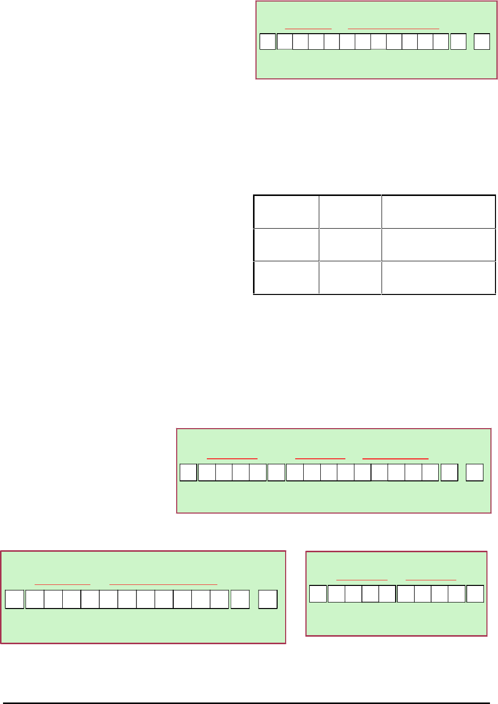
CDE, CDLE Drive
12-4
12.8 Messages from Drive to host
Messages from the Drive to the host are used to:
Reply to an interrogation (send a message
containing the value of the parameter specified
by the host)
Acknowledge a command from the host
12.9 Reply to an interrogation
When the Drive is interrogated for the value of a
parameter, the Drive sends a message in reply that
contains the parameter identifier and, in the data
field, the value of the parameter.
The structure of reply messages is shown opposite.
12.10 Acknowledge a command
When a message has been sent by the host, the Drive
responds by sending an acknowledgement.
If the message was a command, the Drive sends the
reply message: ACK
If a command from the host is not understood, the
Drive sends the reply message: NAK
A message can be misunderstood because:
Transmission was corrupted
Message was incorrectly structured
Requested value was out of range
If the specified parameter number is not recognised
by the Drive, the Drive sends the reply message: EOT
01 2 5 ETX
Parameter identifier Control
character
STX
(Ctrl B)
047. 6
Data field
(Ctrl C)
3
Block
checksum
(BCC)
7 characters if decimal place
6 characters if no dec. place
− 0
Control
character
Figure 12–5 Drive replying to an interrogation
12.11 Other messages
from host to Drive
Time can be saved by sending the control codes given
below:
NAK (Ctrl U) Repeat enquiry Interrogate the Drive repeatedly
for the current value of the last
specified parameter.
ACK (Ctrl F) Next parameter Interrogate the Drive for the
value of the next parameter in
the list.
BS (Ctrl H) Previous
parameter Interrogate the Drive for the
value of the previous parameter
in the list.
To ensure that the correct Drive answers, a valid full-
length read or write must occur before these codes
will work.
12.12 Summary of Serial
Communications messages
EOT 0 1 2 5 ETX
Control
character Address code Parameter identifier Control
character
(Ctrl D)
STX
(Ctrl B)
−47. 6
Data field
(Ctrl C)
3
Block
checksum
(BCC)
7 characters maximum with
or without decimal point
Figure 12–6 Sending a command to the Drive
01 2 5 ETX
Parameter identifier Control
character
STX
(Ctrl B)
047. 6
Data field
(Ctrl C)
3
Block
checksum
(BCC)
7 characters if decimal place
6 characters if no dec. place
− 0
Control
character
Figure 12–7 Drive replying to an interrogation
EOT 0 1 2 5 ENQ
Control
character Address code Parameter identifier Control
character
(Ctrl D) (Ctrl E)
Figure 12–8 Message from host to
interrogate the Drive

CDE, CDLE Drive 13-1
13 Control Techniques
Worldwide Drive Centres
and Distributors
Names and addresses are listed on the following
pages.

CDE, CDLE Drive
13-2
