Cooper O Technical Reference 3 Phase
User Manual: Cooper-O-Technical Reference-3-phase
Open the PDF directly: View PDF ![]() .
.
Page Count: 30

Page
NEMA Configurations O-2
15A & 20A Straight Blade . . . . . . . . . . . . . . . . . . . . . . . . . . O-2
30A, 50A, & 60A Straight Blade . . . . . . . . . . . . . . . . . . . . . O-3
15A, 20A & 30A Locking . . . . . . . . . . . . . . . . . . . . . . . O-4–O-6
10A-30A Non-NEMA Locking . . . . . . . . . . . . . . . . . . . . . . . O-7
50A Non-NEMA Locking . . . . . . . . . . . . . . . . . . . . . . . . . . . O-7
Pin & Sleeve Configurations O-8
20A Watertight Pin & Sleeve . . . . . . . . . . . . . . . . . . . . . . . . O-8
30A Watertight Pin & Sleeve . . . . . . . . . . . . . . . . . . . . . . . . O-8
60A Watertight Pin & Sleeve . . . . . . . . . . . . . . . . . . . . . . . . O-9
100A Watertight Pin & Sleeve . . . . . . . . . . . . . . . . . . . . . . . O-9
Horsepower Ratings O-10
For NEMA Configurations (Plugs & Receptacles Only) . . . O-10
Common Industry Information O-11
Organization Abbreviations Glossary . . . . . . . . . . . . . . . . O-11
Common Industry Organization Acronyms . . . . . . . . . . . . O-12
UL & CSA Standards For Wiring Devices . . . . . . . . . . . . . O-12
General Purpose Wiring Device Definitions . . . . . . . . . . . O-13
Select NEC®Requirements for Wiring Devices. . . . . . . . . O-14
Wire & Cable Information O-15
Wire & Cable Abbreviations. . . . . . . . . . . . . . . . . . . . . . . . O-15
Diameter Ranges of Jacketed Cord, per UL62. . . . . . . . . O-15
Wiring Diagrams O-16
By NEMA: 2-Pole, 2-Wire Non-Grounding . . . . . . . . . . . . O-16
By NEMA: 2-Pole, 3-Wire Grounding . . . . . . . . . . . . . . . . O-16
By NEMA: 3-Pole, 3-Wire Non-Grounding . . . . . . . . . . . . O-16
By NEMA: 3-Pole, 4-Wire Grounding . . . . . . . . . . . O-16–O-17
By NEMA: 4-Pole, 4-Wire Non-Grounding . . . . . . . . . . . . O-17
By NEMA: 4-Pole, 5-Wire Grounding . . . . . . . . . . . . . . . . O-17
Receptacles & GFCI . . . . . . . . . . . . . . . . . . . . . . . . . . . . . O-18
Combination Devices . . . . . . . . . . . . . . . . . . . . . . . . . . . . O-18
Switches . . . . . . . . . . . . . . . . . . . . . . . . . . . . . . . . . . . . . . O-19
Manual Contactors & Disconnect Switches . . . . . . . . . . . O-20
Manual Contactors & Disconnect Switches,
by Motor Variations . . . . . . . . . . . . . . . . . . . . . . . . . . . . . . O-20
Page
Dimensional Data O-21
Switch Dimensional Data . . . . . . . . . . . . . . . . . . . . . . . . . O-21
Enclosure Dimensional Data . . . . . . . . . . . . . . . . . . . . . . . O-22
Snap-In Receptacle Panel Cutouts . . . . . . . . . . . . . . . . . . O-23
Attachon Lampholder Panel Cutouts . . . . . . . . . . . . . . . . O-23
Switch Applications O-24
Test Requirements. . . . . . . . . . . . . . . . . . . . . . . . . . . . . . . O-24
Maximum Loads . . . . . . . . . . . . . . . . . . . . . . . . . . . . . . . . O-25
Chemical Resistance of Materials O-26
Properties of Common Materials in Wiring Devices . . . . . O-26
NEMA & IP Enclosures O-27
Enclosure Ratings . . . . . . . . . . . . . . . . . . . . . . . . . . . . . . . O-27
Enclosure Type Cross Reference:
NEMA/UL/CSA . . . . . . . . . . . . . . . . . . . . . . . . . . . . O-28–O-29
NAFTA Compliant O-30
NAFTA Compliant Criteria . . . . . . . . . . . . . . . . . . . . . . . . . O-30
Table of Contents
www.arrowhart.com Section O
O
SECTION
http://waterheatertimer.org/How-to-wire-240-volt-outlets.html
http://waterheatertimer.org/How-to-wire-3-phase-electric.html
www.arrowhart.com
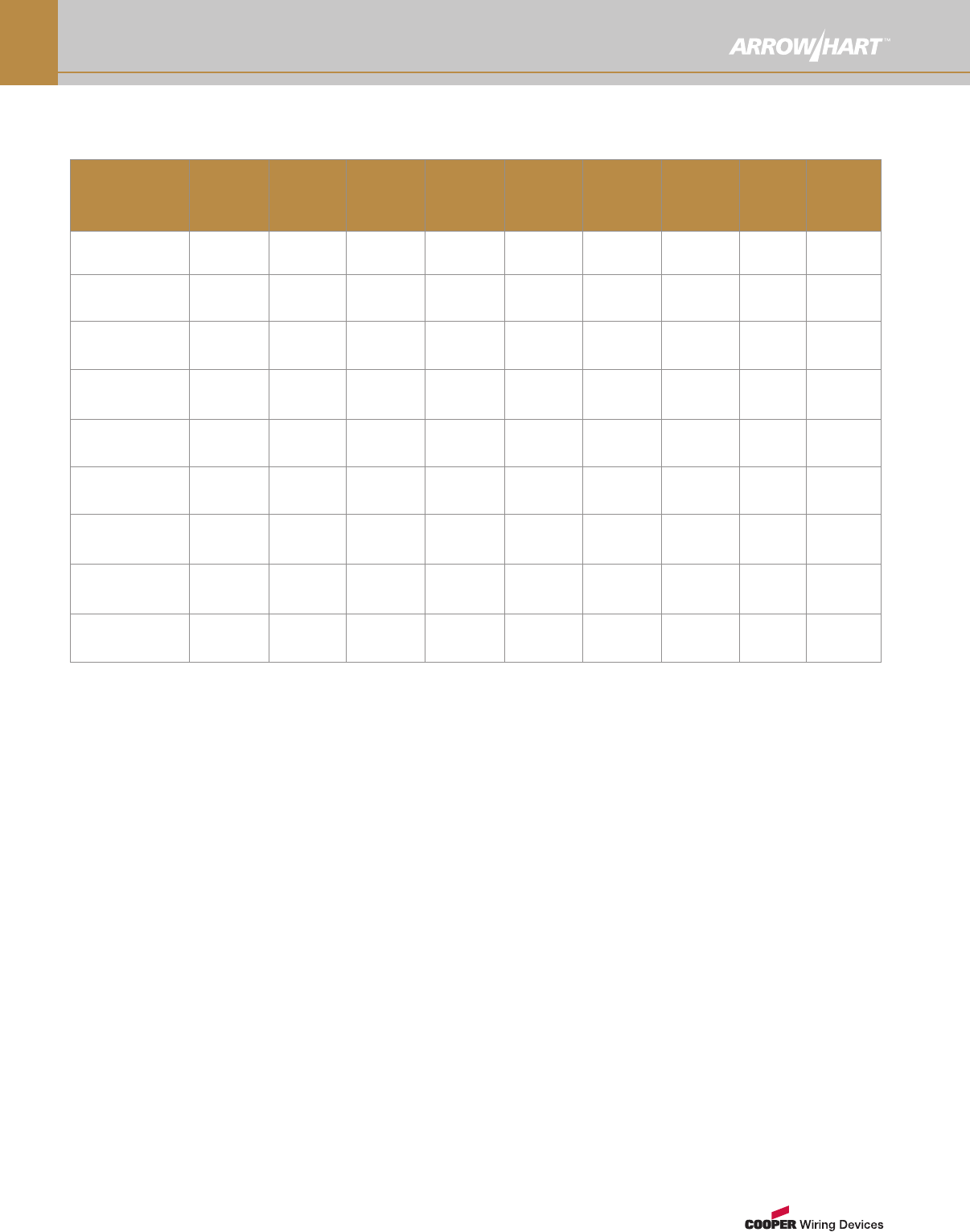
O-2
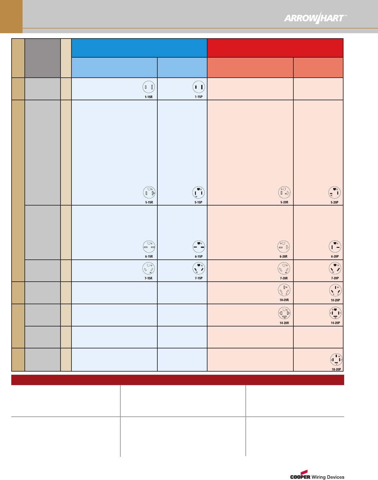
NEMA Configurations For Select Devices
Poles, Wires
Rating
NEMA Prefix
15A Straight Blade 20A Straight Blade
Receptacle, Connector
& Flanged Outlet
Plug &
Flanged Inlet
Receptacle, Connector
& Flanged Outlet
Plug &
Flanged Inlet
2-Pole,
2-Wire
125V/AC 14882 ★4862 ◆
2-Pole, 3-Wire Grounding
125V/AC 5
AH5262 ■M5269N ★NC
5252 ■5279C ●
6262 ■D5969BLK ★O
IG5262 ■IM 6269 ★L
5261 ✚M
VGF15 ■GM 4887 ★
BR15 ■
TRBR15 ■R
CR15 ■
TRVGF15 ■RGM
5262 ■M
AH8200 ■M5269NHG ★N
8200 ■HM 6269HG ★L
8210 ✚M
IG8200 ■IM
TR8200 ■RM
VGFH15 ■GM
TRVGFH15 ■RGM
5266N ◆NC
5278C ▲
6266 ◆
4867 ◆
5266NHG ◆N
6266HG ◆L
8115GY ◆O
AH5362 ■M5369N ★NC
5352 ■M5779C ●
6362 ■DM 6769 ★L
IG5362 ■IM
5361 ✚M
VGF20 ■GM 4228 ★
BR20 ■
TRBR20 ■R
CR20 ■
TRVGF20 ■RGM
5362 ■M
AH8300 ■M5369NHG ★N
8300 ■M6769HG ★L
8310 ✚M
IG8300 ■IM
TR8300 ■RM
VGFH20 ■GM
TRVGFH20 ■RGM
5366N ◆NC
5778C ▲
6766 ◆L
4409 ◆
5366NHG ◆N
6766HG ◆L
250V/AC 6
AH5662 ■M5669N ★N
5661 ✚5679C ●
IG5662 ■I6669 ★L
6662 ■D
826 ■
816 ✚4227 ★
5662C ■
AH8600 ■M8610 ✚
5666N ◆N
5678C ▲
6666 ◆
4866 ◆
6665HG ◆L
AH5462 ■M5469N ★N
5461 ✚5879C ●
IG5462 ■I6869 ★L
6462 ■D
815 ■4229 ★
5462C ■
AH8400 ■M8410 ✚
IG8400 ■I
5466N ◆N
5878C ▲
6866 ◆L
4509 ◆
6865HG ◆AL
277V/AC 7
5302 ■7624N ◆L
3-Pole,
3-Wire
125/250V/AC 10
805 ✚9151N ◆L
2836 ◆
3-Pole, 4-Wire
Grounding
125/250V/AC 14
5759 ✚
3Ø 250V/AC 15
4-Pole,
4-Wire
3ØY
120/208V/AC 18
7251N ◆L
HOW TO USE THIS CHART:
Core catalog number color indicates a
devices’ grade:
BLACK = Industrial Specification Grade
BLUE = Commercial Specification Grade
ORANGE = Construction Specification Grade
GREEN = Hospital Specification Grade
A suffix combining a RED shape
and alpha letter indicate a
device's body, type and
available options.
Device type:
AAngled
DDecorator
GGFCI
HCompact
IIsolated Ground
Device body:
■Duplex
Receptacle
✚Single
Receptacle
◆Plug
★Connector
▲Flanged Inlet
●Flanged Outlet
Device options available:
CCorrosion Resistant
MArrowLink™Modular
LSafety Grip™
NAutoGrip™
OQuickGrip™
RTamper Resistant
SSurface
Straight Blade Legend
Due to spatial constraints not all products are shown on this page. For additional product options in these configurations consult sections A, B, G, H & I.
www.arrowhart.com O-3
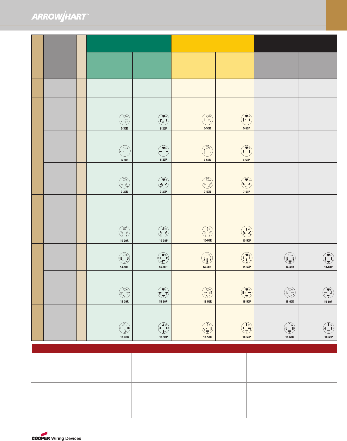
NEMA Configurations For Select Devices
Poles, Wires
Rating
NEMA Prefix
30A Straight Blade 50A Straight Blade 60A Straight Blade
Receptacle,
Connector &
Flanged Outlet
Plug &
Flanged Inlet
Receptacle,
Connector &
Flanged Outlet
Plug &
Flanged Inlet
Receptacle,
Connector &
Flanged Outlet
Plug &
Flanged Inlet
2-Pole,
2-Wire
125V/AC 1
2-Pole, 3-Wire Grounding
125V/AC 5
6716N ★N
1233 ✚
5716N ✚
5717AN ◆AN
5717N ◆N
5717NFI ▲N
S41 ◆A
6711N ★N
1253 ✚
5712AN ◆AN
5712N ◆N
5712NFI ▲N
S41 ◆A
250V/AC 6
6700N ★N
5700N ✚
1232 ✚S
1234 ✚
5701AN ◆AN
5701N ◆N
5701NFI ▲N
S42 ◆A
6709N ★N
5709N ✚
1252 ✚S
1254 ✚
5710AN ◆AN
5710N ◆N
5710NFI ▲N
S42 ◆A
277V/AC 7
6795N ★N
5795N ✚
5703AN ◆AN
5703N ◆N
5703NFI ▲N
6796N ★N5705AN ◆AN
5705N ◆N
5705NFI ▲N
3-Pole, 3-Wire
125/250V/AC 10
9341N ★N
38B ✚
125 ✚S
9352AN ◆AN
9337N ◆N
9337NFI ▲N
S80 ◆A
4526N ★N
7985N ✚
32B ✚
112 ✚S
122B ✚
4524N ◆N
4524NFI ▲N
7952AN ◆AN
S80 ◆A
3-Pole, 4-Wire
Grounding
125/250V/AC 14
5744N ✚
1225 ✚S
1257 ✚
5732AN ◆AN
5746N ◆N
S21 ◆A
5754N ✚
1212 ✚S
1258 ✚
5752AN ◆AN
5745N ◆N
S21 ◆A
9460N ✚9462AN ◆AN
9462N ◆N
S20 ◆AN
3Ø 250V/AC 15
8430N ✚8432AN ◆AN
8432N ◆N
8450N ✚8452AN ◆AN
8452N ◆N
8460N ✚
AH8462AN
◆AN
AH8462N ◆N
4-Pole, 4-Wire
3ØY
120/208V/AC 18
8332AN ◆AN
8332N ◆N
8352AN ◆AN
8352N ◆N
5515N ✚4516AN ◆N
5517N ◆N
S19 ◆A
HOW TO USE THIS CHART:
Core catalog number color indicates a
devices’ grade:
BLACK = Industrial Specification Grade
BLUE = Commercial Specification Grade
ORANGE = Construction Specification Grade
GREEN = Hospital Specification Grade
A suffix combining a RED shape
and alpha letter indicate a
device's body, type and
available options.
Device type:
AAngled
DDecorator
GGFCI
HCompact
IIsolated Ground
Device body:
■Duplex
Receptacle
✚Single
Receptacle
◆Plug
★Connector
▲Flanged Inlet
●Flanged Outlet
Device options available:
CCorrosion Resistant
MArrowLink™Modular
LSafety Grip™
NAutoGrip™
OQuickGrip™
RTamper Resistant
SSurface
Straight Blade Legend
Due to spatial constraints not all products are shown on this page. For additional product options in these configurations consult sections A, B, G, H & I.
www.arrowhart.com
O-4
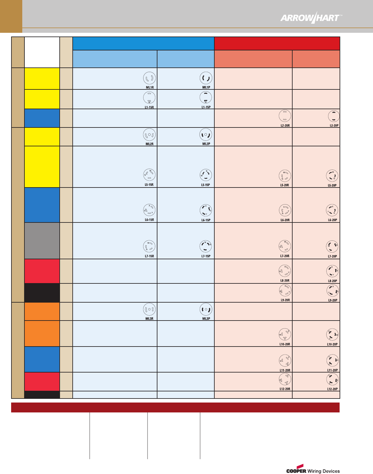
NEMA Configurations For Select Devices
Device type:
AAngled
CCorrosion Resistant
IIsolated Ground
LSafety Grip™
NAutoGrip™
Poles,
Wires
Rating
NEMA
Prefix
15A Locking 20A Locking
Receptacle, Connector
& Flanged Outlet
Plug &
Flanged Inlet
Receptacle, Connector
& Flanged Outlet
Plug &
Flanged Inlet
2-Pole, 2-Wire
125V/AC ML1
7464N ★
7427N ★
7468 ●
7465N ◆7466 ▲
7428N ◆7467 ▲
7479N ◆
7429N ◆
125V/AC L1
CWL115FO ●
CWL115R ✚
7506 ★
7540 ■
CWL115FI ▲
7546 ◆
7548 ◆
250V/AC L2
CWL220C ★L
CWL220FO ●
CWL220R ✚
CWL220P ◆L
CWL220P-6 ◆ZL
2-Pole, 3-Wire Grounding
125V/AC ML2
7593 ★
7596 ●
7596N ●
7594 ◆
7595 ▲
7595N ▲
125V/AC L5
CWL515C ★LCWL515CAN ★AL
CWL515FO●CWL515R ✚
IG4700 ■IIGL515R ✚I
25W47 ★W2547 ★Y
65W47 ✚W65W47DPLX ■W
CR4700 ■C4700 ■
4731N ★N5792 ■
4731NCR ★CN CR5792 ■C
CWL515FI ▲
CWL515P ◆L
CWL515PAN ◆AL
24W47 ◆W
2447 ◆Y
4721N ◆N
4721NCR ◆CN
CWL520C ★LCWL520CBK ★L
CWL520FO ●CWL520R ✚
IGL520R ✚I
L520CW ★W
L520CY ★Y
L520RW ✚W
CRL520C ★CL
CRL520R ✚C
CWL520FI ▲
CWL520P ◆L
CWL520PBK ◆L
L520PW ◆W
L520PY ◆Y
CRL520P ◆CL
250V/AC L6
CWL615C ★LCWL615FO ●
CWL615R ✚25W49 ★W
IGL615R ✚I65W49 ✚W
2549 ★Y
65W49DPLX ■W
6566N ★N
6580 ■
CWL615FI ▲
CWL615P ◆L
24W49 ◆W
2449 ◆Y
6565N ◆N
CWL620C ★LCWL620FO ●
CWL620R ✚IGL620R ✚I
L620CW ★WL620CY ★Y
L620RW ✚W
CRL620R ✚C
CRL620C ★CL
CWL620FI▲
CWL620P ◆L
L620PW ◆W
L620PY ◆Y
CRL620P ◆C
277V/AC L7
CWL715C ★CWL715FO ●
CWL715R ✚65W34DPLX ■W
25W34 ★W4750 ■
65W34 ✚W2534 ★Y
4772N ★N
CWL715FI ▲
CWL715P ◆L
24W34 ◆W
2434 ◆Y
4771N ◆N
CWL720C ★L
CWL720FO ●
CWL720R ✚
IGL720R ✚I
L720CW ★W
L720CY ★Y
L720RW ✚W
CWL720FI▲
CWL720P ◆L
L720PW ◆W
L720PY ◆Y
480V/AC L8
CWL820C ★LCWL820FO ●
CWL820R ✚IGL820R ✚I
L820CW ★W
L820CY ★Y
L820RW ✚W
CWL820FI ▲
CWL820P ◆L
L820PW ◆W
L820PY ◆Y
600V/AC L9
CWL920C ★
CWL920FO ●
CWL920R ✚
CWL920FI ▲
CWL920P ◆
3-Pole, 3-Wire
125/250V/AC ML3
7484 ★
7487 ●
7487N ●
7485 ◆
7486 ▲
7486N ▲
125/250V/AC L10
CWL1020C ★LCWL1020FO ●
CWL1020R ✚
L1020CY ★Y
L1020RW ✚W
L1020CW ★W
CWL1020FI ▲
CWL1020P ◆L
L1020PW ◆W
L1020PY ◆Y
3Ø 250V/AC L11
CWL1120C ★LCWL1120FO ●
CWL1120R ✚L1120CW ★W
L1120CY ★Y
L1120RW ✚W
CWL1120FI ▲
CWL1120P ◆L
L1120PW ◆W
L1120PY ◆Y
3Ø 480V/AC L12
CWL1220C ★
CWL1220FO ●
CWL1220R ✚
CWL1220FI ▲
CWL1220P ◆
3Ø 600V/AC L13
Device body:
■Duplex Receptacle
✚Single Receptacle
◆Plug
★Connector
▲Flanged Inlet
●Flanged Outlet
HOW TO USE THESE
CHARTS:
Core catalog number
color indicates the type
of use a device is
designed for:
BLACK = Industrial Use
A suffix combining a
RED shape and alpha
letter indicate a device’s
body and type.
PPro-Grip™Nylon
WWatertight
YSever Duty Insulated
ZWith Lid or Cover
Locking Device Legend
www.arrowhart.com O-5
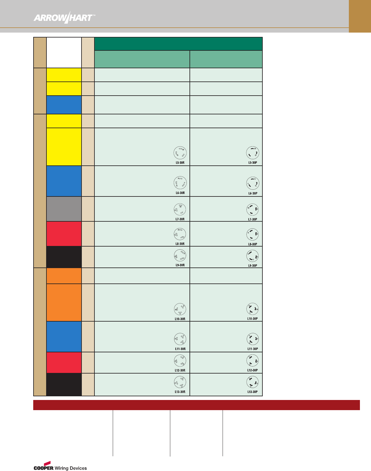
NEMA Configurations For Select Devices
Poles,
Wires
Rating
NEMA
Prefix
30A Locking
Receptacle, Connector,
& Flanged Outlet Plug & Flanged Inlet
2-Pole, 2-Wire
125V/AC ML1
125V/AC L1
250V/AC L2
2-Pole, 3-Wire Grounding
125V/AC ML2
125V/AC L5
CWL530FO ●CWL530C ★
L
CWL530R ✚IGL530R ✚I
L530CW ★WL530CY ★Y
L530RW ✚W
CRL530C ★C
L
CRL530R ✚C
CWL530FI ▲
CWL530P ◆
L
IGL530P ◆I
L
L530PW ◆W
L530PY ◆Y
CRL530P ◆C
L
250V/AC L6
CWL630C ★
L
CWL630FO ●
CWL630R ✚CIGL630R ✚I
L630CW ★WL630CY ★Y
L630RW ✚W
CRL630C ★C
L
CRL630R ✚C
CWL630FI ▲
CWL630P ◆
L
L630PW ◆W
L630PY ◆Y
CRL630P ◆C
L
277V/AC L7
CWL730C ★
L
CWL730FO ●
CWL730R ✚IGL730R ✚I
L730CW ★W
L730CY ★Y
L730RW ✚W
CWL730FI ▲
CWL730P ◆
L
L730PW ◆W
L730PY ◆Y
480V/AC L8
CWL830C ★
L
CWL830FO ●
CWL830R ✚IGL830R ✚I
L830CW ★W
L830CY ★Y
L830RW ✚W
CWL830FI ▲
CWL830P ◆
L
L830PW ◆W
L830PY ◆Y
600V/AC L9
CWL930C ★
CWL930FO ●
CWL930R ✚
CWL930FI ▲
CWL930P ◆
3-Pole, 3-Wire
125/250V/AC ML3
125/250V/AC L10
CWL1030C ★
L
CWL1030R ✚
L1030CW ★W
L1030CY ★Y
L1030RW ✚W
CWL1030FO ●
CWL1030FI ▲
CWL1030P ◆
L
L1030PW ◆W
L1030PY ◆Y
3Ø 250V/AC L11
CWL1130C ★
CWL1130R ✚
L1130CW ★W
L1130CY ★Y
L1130RW ✚W
CWL1130FO ●
CWL1130FI ▲
CWL1130P ◆
L
L1130PW ◆W
L1130PY◆Y
3Ø 480V/AC L12
CWL1230C ★
CWL1230FO ●
CWL1230R ✚
CWL1230FI ▲
CWL1230P ◆
3Ø 600V/AC L13
CWL1330C ★
CWL1330FO ●
CWL1330R ✚
CWL1330FI ▲
CWL1330P ◆
Device type:
AAngled
CCorrosion Resistant
IIsolated Ground
LSafety Grip™
NAutoGrip™
Device body:
■Duplex Receptacle
✚Single Receptacle
◆Plug
★Connector
▲Flanged Inlet
●Flanged Outlet
HOW TO USE THESE
CHARTS:
Core catalog number
color indicates the type
of use a device is
designed for:
BLACK = Industrial Use
A suffix combining a
RED shape and alpha
letter indicate a device’s
body and type.
WWatertight
YSevere Duty Insulated
Locking Device Legend
For NEMA Configurations L-14
through L-24, see page O-6
www.arrowhart.com
O-6
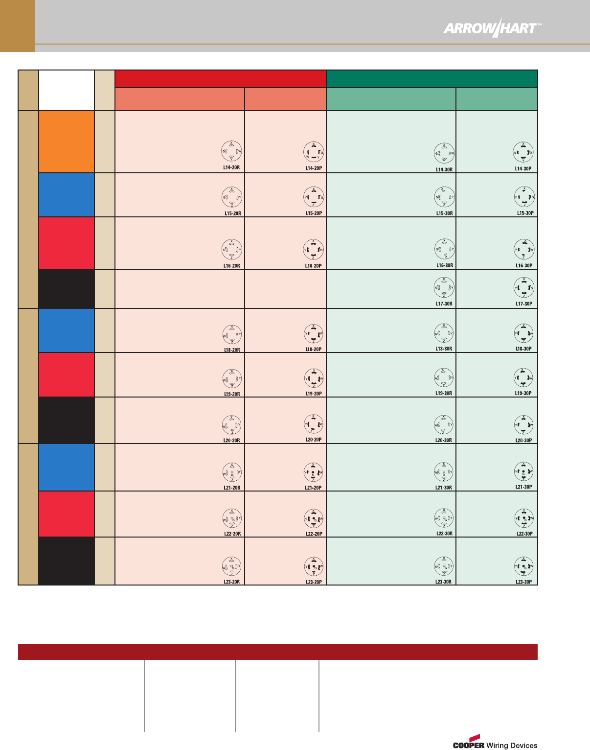
NEMA Configurations
Poles,
Wires
Rating
NEMA
Prefix
20A Locking 30A Locking
Receptacle, Connector
& Flanged Outlet
Plug &
Flanged Inlet
Receptacle, Connector,
& Flanged Outlet
Plug &
Flanged Inlet
3-Pole, 4-Wire Grounding
125/250V/AC L14
CWL1420C ★LCWL1420CBK ★L
CWL1420FO ●CWL1420R ✚
IGL1420R ✚IL1420CY ★Y
L1420CW ★WL1420RW ✚W
CRL1420C ★CL
CRL1420R ✚C
6406BK ●
CWL1420FI ▲
CWL1420P ◆L
CWL1420PBK ◆L
L1420PW ◆W
L1420PY ◆Y
CRL1420P ◆CL
6405BK ▲
CWL1430C ★LCWL1430FO ●
CWL1430R ✚IGL1430R ✚I
L1430CW ★W
L1430CY ★Y
L1430RW ✚W
CRL1430C ★CL
CRL1430R ✚C
CWL1430FI ▲
CWL1430P ◆L
L1430PW ◆W
L1430PY ◆Y
CRL1430P ◆CL
6512BK ◆
3Ø 250V/AC L15
CWL1520C ★LCWL1520FO ●
CWL1520R ✚IGL1520R ✚I
L1520CW ★WL1520CY ★Y
L1520RW ✚W
CRL1520C ★CL
CRL1520R ✚C
CWL1520FI ▲
CWL1520P ◆L
L1520PW ◆W
L1520PY ◆Y
CRL1520P ◆CL
CWL1530C ★LCWL1530FO ●
CWL1530R✚IGL1530R ✚I
L1530CW ★W
L1530CY ★Y
L1530RW ✚W
CRL1530C ★CL
CWL1530FI ▲
CWL1530P ◆L
L1530PW ◆W
L1530PY ◆Y
CRL1530P ◆CL
3Ø 480V/AC L16
CWL1620C ★LCWL1620CBK ★L
CWL1620FO ●CWL1620R ✚
IGL1620R ✚I
L1620CW ★W
L1620CY ★Y
L1620RW ✚W
CRL1620C ★CL
CWL1620P ◆L
CWL1620PBK ◆L
L1620PW ◆W
L1620PY ◆Y
CRL1620P ◆CL
CWL1620FI ▲
CWL1630C ★L
CWL1630FO ●
CWL1630R ✚
L1630CW ★W
L1630CY ★Y
L1630RW ✚W
CWL1630FI ▲
CWL1630P ◆L
L1630PW ◆W
L1630PY ◆Y
CRL1630P ◆CL
3Ø 600V/AC L17
CWL1730C ★LCWL1730FO ●
CWL1730R ✚
L1730CW ★W
L1730CY ★Y
L1730RW ✚W
CWL1730FI ▲
CWL1730P ◆L
L1730PW ◆W
L1730CY ◆Y
4-Pole, 4-Wire
3ØY
120/208V/AC L18
CWL1820C ★LCWL1820FO ●
CWL1820R ✚
L1820CW ★W
L1820CY ★Y
L1820RW ✚W
CWL1820FI ▲
CWL1820P ◆L
L1820PW ◆W
L1820PY ◆Y
CWL1830C ★LCWL1830FO ●
CWL1830R ✚
L1830CW ★W
L1830CY ★Y
L1830RW ✚W
CWL1830FI ▲
CWL1830P ◆L
L1830PW ◆W
L1830PY ◆Y
3ØY
277/480V/AC L19
CWL1920C ★LCWL1920FO ●
CWL1920R ✚
L1920CW ★W
L1920CY ★W
L1920RW ✚W
CWL1920FI ▲
CWL1920P ◆L
L1920PW ◆W
L1920PY ◆Y
CWL1930C ★LCWL1930FO ●
CWL1930R ✚
L1930CW ★W
L1930CY ★Y
L1930RW ✚W
CWL1930FI ▲
CWL1930P ◆
L1930PW ◆W
L1930PY ◆Y
3ØY
347/600V/AC L20
CWL2020C★LCWL2020FO ●
CWL2020R✚
L2020CW ★W
L2020CY ★Y
L2020RW ✚W
CWL2020FI ▲
CWL2020P◆L
L2020PW ◆W
L2020PY ◆Y
CWL2030C ★LCWL2030FO ●
CWL2030R ✚
L2030CW ★W
L2030CY ★Y
L2030RW ✚W
CWL2030FI ▲
CWL2030P ◆L
L2030PW ◆W
L2030PY ◆Y
4-Pole, 5-Wire
Grounding
3ØY
120/208V/AC L21
CWL2120C ★LCWL2120CBK ★L
CWL2120FO ●CWL2120R ✚
IGL2120R ✚IL2120CF ★L
L2120CW ★W
L2120CY ★Y
L2120RW ✚W
CWL2120FI ▲
CWL2120P◆L
CWL2120PBK ◆L
L2120PW ◆W
L2120PY ◆Y
L2120PF ◆L
CWL2130C ★LCWL2130FO ●
CWL2130R✚IGL2130R ✚I
L2130CW ★W
L2130CY ★W
L2130RW ✚W
L2130CF ★L
CWL2130FI ▲
CWL2130P ◆L
L2130PW ◆W
L2130PY ◆Y
L2130PF ◆L
3ØY
277/480V/AC L22
CWL2220C ★LCWL2220FO ●
CWL2220R ✚
IGL220R ✚I
L2220CW ★W
L2220CY ★Y
L2220RW ✚W
CWL2220FI ▲
CWL2220P ◆L
L2220PW ◆W
L2220PY ◆Y
CWL2230C ★LCWL2230FO ●
CWL2230R ✚L22230CF ★L
IGL2230R ✚I
L2230CW ★W
L2230CY ★Y
L2230RW ✚W
CWL2230FI ▲
CWL2230P ◆L
L2230PW ◆W
L2230PY ◆Y
L2230PF ◆L
3ØY
347/600V/AC L23
CWL2320C ★LCWL2320FO ●
CWL2320R ✚
IGL2320R ✚I
L2320CW ★W
L2320CY ★Y
L2320RW ✚W
CWL2320FI ▲
CWL2320P ◆L
L2320PW ◆W
L2320PY ◆Y
CWL2330C ★LCWL2330FO ●
CWL2330R ✚
IGL2330R ✚I
L2330CW ★W
L2330CY ★Y
L2330RW ✚W
CWL2330FI ▲
CWL2330P ◆L
L2330PW ◆W
L2330PY ◆Y
Device type:
AAngled
CCorrosion Resistant
IIsolated Ground
LSafety Grip™
NAutoGrip™
Device body:
■Duplex Receptacle
✚Single Receptacle
◆Plug
★Connector
▲Flanged Inlet
●Flanged Outlet
HOW TO USE THESE
CHARTS:
Core catalog number
color indicates the type
of use a device is
designed for:
BLACK = Industrial Use
A suffix combining a
RED shape and alpha
letter indicate a device’s
body and type.
WWatertight
YSevere Duty Insulated
Locking Device Legend
www.arrowhart.com O-7
NEMA Configurations
Poles,
Wires
Rating
50A Non-NEMA Locking
Receptacle &
Connector
Plug, Flanged Inlets
& Hull Inlet
2-Pole, 3-Wire Grounding
125V/AC
Marine
Corrosion
Resistant
63CR60EX ★P
63CR60 ★T
63CR70 ✚
63CR61EX ◆P
63CR61 ◆T
125V/AC
California
Standard
CS6360EX ★P
CS6360 ★T
CS6370 ✚
CS6361EX ◆P
CS6361 ◆T
CS6377 ▲
CS6378 ▲Z
250V/AC
California
Standard
CS8264EX ★P
CS8264 ★T
CS8269 ✚
CS8265EX ◆P
CS8265 ◆T
CS8275 ▲
CS8277 ▲Z
250V/DC
600V/AC
3762EX ★P
3762 ★T
3771 ✚
3763EX ◆P
3763 ◆T
3777 ▲
3767 ▲Z
480V/AC
California
Standard
CS8464EX ★P
CS8464 ★T
CS8469 ✚
CS8465EX ◆P
CS8465 ◆T
CS8475 ▲
CS8477 ▲Z
3-Pole, 4-Wire Grounding
125/250V/AC
Marine
Corrosion
Resistant
63CR64EX ★P
63CR64 ★T
63CR69 ✚
63CR65EX ◆P
63CR65 ◆T
125/250V/AC
California
Standard
CS6364EX ★P
CS6364 ★T
CS6369 ✚
CS6365EX ◆P
CS6365 ◆T
CS6375 ▲
CS6376 ▲Z
3Ø 250V/AC
California
Standard
CS8364EX ★P
CS8364 ★T
CS8369 ✚
CS8365EX ◆P
CS8365 ◆T
CS8375 ▲
CS8377 ▲Z
250V/DC
600V/AC
3764EX ★P
3764 ★T
3769 ✚
3765EX ◆P
3765 ◆T
3775 ▲
3768 ▲Z
250V/DC
600V/AC
7764EX ★P
7764 ★T
7379 ✚
7765EX ◆P
7765 ◆T
7958 ▲
7968 ▲Z
3Ø 480V/AC
California
Standard
CS8164EX ★P
CS8164 ★T
CS8169 ✚
CS8165EX ◆P
CS8165 ◆T
CS8175 ▲
CS8177 ▲Z
Plug
Non-NEMA
5
G
Receptacle
Non-NEMA
5
G
Plug
Non-NEMA
5
W
G
Receptacle
Non-NEMA
5
W
G
Plug
Non-NEMA
5
X
G
Y
Recptacle
Non-NEMA
X
GY
Plug
Non-NEMA
5
G
XY
Receptacle
Non-NEMA
5
G
X
Y
Plug
Non-NEMA
5
X
G
Y
Receptacle
Non-NEMA
5
X
G
Y
Plug
Non-NEMA
5
GWX
Y
Receptacle
Non-NEMA
G
W
X
Y
Plug
Non-NEMA
5
GWX
Y
Receptacle
Non-NEMA
5
G
W
X
Y
Plug
Non-NEMA
5
GZX
Y
Receptacle
Non-NEMA
5
G
Z
X
Y
Plug
Non-NEMA
5
X
Y
Z
G
Receptacle
Non-NEMA
X
Y
ZG
Plug
Non-NEMA
5
XY
Z
G
Receptacle
Non-NEMA
X
Y
Z
G
Plug
Non-NEMA
G
XY
Z
Receptacle
Non-NEMA
G
X
Y
Z
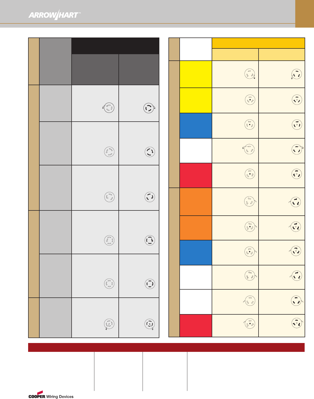
Poles, Wires
Rating
10A - 30A
Non-NEMA Locking
Receptacle,
Connector,
& Flanged Outlet
Plug &
Flanged Inlet
3-Pole, 3-Wire
10/15A
125/250V/AC
4755 ★L
7565N ★N
7580 ■
7582 ✚
4767 ◆L
4767AN ◆AL
7567N ◆N
20A
125/250V/AC
7310B ✚
7314C ★L
7314CW ★W
7314CY ★Y
7314RW ✚W
7328N ●
7327N ▲
9965C ◆L
9965PW ◆W
9965PY ◆Y
30A
125/250V/AC
3330-2 ✚
3333CW ★W
3333CY ★Y
3333RW ✚W
3333N ★L
3336N ●
3331N ◆L
3331PW ◆W
3331PY ◆Y
3337N ▲
4-Pole, 4-Wire
20A 3Ø
120/208V/AC
7409N ●
7410B ✚
7413C ★L
7413CW ★W
7413CY ★Y
7413RW ✚W
7408N ▲
7411C ◆L
7411PW ◆W
7411PY ◆Y
30A 3Ø
120/208V/AC
3430 ✚
3433CW ★W
3433CY ★Y
3433N ★L
3433RW ✚W
3436N ●
3431N ◆L
3431PW ◆W
3431PY ◆Y
3434N ▲
4-P, 5-W
Grounding
20/10A
250/600V/AC
3523BK ★L
3525BK ●
3521BK ◆L
3524BK ▲
Plug
Non-NEMA
CU G
Receptacle
Non-NEMA
CU
G
Plug
Non-NEMA
Y
W
X
Receptacle
Non-NEMA
Y
W
X
Plug
Non-NEMA
Y
W
X
Receptacle
Non-NEMA
Y
W
X
Plug
Non-NEMA
YW
X
Z
Receptacle
Non-NEMA
Y
W
X
Z
Plug
Non-NEMA
YW
X
Z
Receptacle
Non-NEMA
Y
W
X
Z
Plug
Non-NEMA
Y
W
Z
X
G
Receptacle
Non-NEMA
Y
W
Z
X
G
Device type:
AAngled
CCorrosion Resistant
LSafety Grip™
NAutoGrip™
Device body:
■Duplex Receptacle
✚Single Receptacle
◆Plug
★Connector
▲Flanged Inlet
●Flanged Outlet
◗Hull Inlet
HOW TO USE THESE
CHARTS:
Core catalog number
color indicates the type
of use a device is
designed for:
BLACK = Industrial Use
A suffix combining a
RED shape and alpha
letter indicate a device’s
body and type.
PPro-Grip™Nylon
TArmored Body
WWatertight
YSevere Duty Insulated
ZWith Lid or Cover
Locking Device Legend
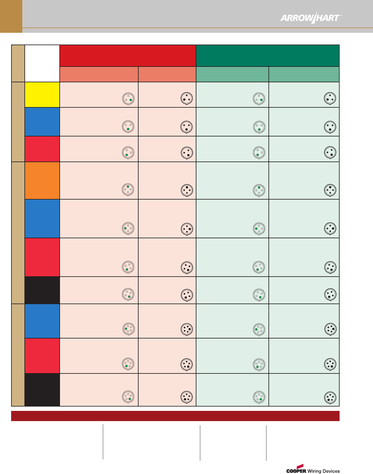
Pin & Sleeve Configurations
www.arrowhart.com
O-8
Locking Device LEGEND
Poles, Wires
Rating
20A Watertight
Pin & Sleeve
30A Watertight
Pin & Sleeve
Receptacle, Connector
& Mechanical Interlocks Plug & Inlet Receptacle, Connector
& Mechanical Interlocks Plug & Inlet
2-Pole, 3-Wire Grounding
125V
CD320HMI4W ➤QX
CD320R4W ✚
CD320C4W ★
CD320P4W ◆
CD320B4W ▲
CD330MI4W ➤Q
CD330R4W ✚
CD330C4W ★
CD330P4W ◆
CD330B4W ▲
250V
CD320HMI6W ➤QX
CD320R6W ✚
CD320C6W ★
CD320P6W ◆
CD320B6W ▲
CD330MI6W ➤Q
CD330MIF6W ➤E
CD330R6W ✚
CD330C6W ★
CD330P6W ◆
CD330B6W ▲
480V/AC
CD320HMI7W ➤QX
CD320R7W ✚
CD320C7W ★
CD320P7W ◆
CD320B7W ▲
CD330MI7W ➤Q
CD330R7W ✚
CD330C7W ★
CD330P7W ◆
CD330B7W ▲
3-Pole, 4-Wire Grounding
125/250V/AC
CD420HMI12W ➤QX
CD420MIB12W ➤F
CD420MICB12W ➤B
CD420R12W ✚
CD420C12W ★
CD420P12W ◆
CD420B12W ▲
CD430MI12W ➤Q
CD430MIB12W ➤F
CD430MICB12W ➤B
CD430MIF12W ➤E
CD430R12W ✚
CD430C12W ★
CD430P12W ◆
CD430B12W ▲
3Ø 250V/AC
CD420HMI9W ➤QX
CD420MIB9W ➤F
CD420MICB9W ➤B
CD420R9W ✚
CD420C9W ★
CD420P9W ◆
CD420B9W ▲
CD430MI9W ➤Q
CD430MIB9W ➤F
CD430MICB9W ➤B
CD430MIF9W ➤E
CD430R9W ✚
CD430C9W ★
CD430P9W ◆
CD430B9W ▲
3Ø 480V/AC
CD420HMI7W ➤QX
CD420MIB7W ➤F
CD420MICB7W ➤B
CD420R7W ✚
CD420C7W ★
CD420P7W ◆
CD420B7W ▲
CD430MI7W ➤Q
CD430MIB7W ➤F
CD430MICB7W ➤B
CD430MIF7W ➤E
CD430R7W ✚
CD430C7W ★
CD430P7W ◆
CD430B7W ▲
3Ø 600V/AC
CD420HMI5W ➤QX
CD420R5W ✚
CD420C5W ★
CD420P5W ◆
CD420B5W ▲
CD430MI5W ➤Q
CD430MIF5W ➤E
CD430R5W ✚
CD430C5W ★
CD430P5W ◆
CD430B5W ▲
4-Pole, 5-Wire Grounding
3ØY
120/208V/AC
CD520HMI9W ➤QX
CD520R9W ✚
CD520C9W ★
CD520P9W ◆
CD520B9W ▲
CD530MI9W ➤Q
CD530MIB9W ➤F
CD530MICB9W ➤B
CD530R9W ✚
CD530C9W ★
CD530P9W ◆
CD530B9W ▲
3ØY
277/480V/AC
CD520R7W ✚
CD520C7W ★
CD520P7W ◆
CD520B7W ▲
CD530MI7W ➤Q
CD530MIB7W ➤F
CD530MICB7W ➤B
CD530R7W ✚
CD530C7W ★
CD530P7W ◆
CD530B7W ▲
3ØY
347/600V/AC
CD520R5W ✚
CD520C5W ★
CD520P5W ◆
CD520B5W ▲
CD530MI5W ➤Q
CD530MIB5W ➤F
CD530MICB5W ➤B
CD530R5W ✚
CD530C5W ★
CD530P5W ◆
CD530B5W ▲
Device body:
✚Single Receptacle
◆Plug
★Connector
▲Flanged Inlet
➤Mechanical Interlock
Device type:
BCircuit Breaker Option
EFusible
FFuse Option
QNon-Fusible
XHorizontal
HOW TO USE THESE CHARTS:
Core catalog number color indicates the type
of use a device is designed for:
BLACK = Industrial Use
A suffix combining a RED shape and alpha
letter indicate a device's body and type.
Pin & Sleeve Configurations
www.arrowhart.com O-9
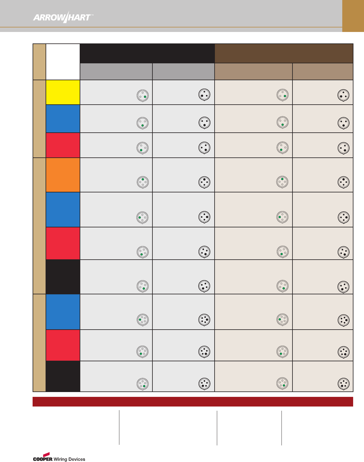
Poles, Wires
Rating
60A Watertight
Pin & Sleeve
100A Watertight
Pin & Sleeve
Receptacle, Connector &
Mechanical Interlocks Plug & Inlet Receptacle, Connector &
Mechanical Interlocks Plug & Inlet
2-Pole, 3-Wire Grounding
125V
CD360R4W ✚
CD360C4W ★
CD360P4W ◆
CD360B4W ▲
CD3100MI4W ➤Q
CD3100R4W ✚
CD3100C4W ★
CD3100P4W ◆
CD3100B4W ▲
250V
CD360MI6W ➤Q
CD360MIF6W ➤E
CD360R6W ✚
CD360C6W ★
CD360P6W ◆
CD360B6W ▲
CD3100MI6W ➤Q
CD3100R6W ✚
CD3100C6W ★
CD3100P6W ◆
CD3100B6W ▲
480V/AC
CD360MI7W ➤Q
CD360R7W ✚
CD360C7W ★
CD360P7W ◆
CD360B7W ▲
CD3100MI7W ➤Q
CD3100R7W ✚
CD3100C7W ★
CD3100P7W ◆
CD3100B7W ▲
3-Pole, 4-Wire Grounding
125/250V/AC
CD460MI12W ➤Q
CD460MIB12W ➤F
CD460MICB12W ➤B
CD460MIF12W ➤E
CD460R12W ✚
CD460C12W ★
CD460P12W ◆
CD460B12W ▲
CD4100MI12W ➤Q
CD4100R12W ✚
CD4100C12W ★
CD4100P12W ◆
CD4100B12W ▲
3Ø 250V/AC
CD460MI9W ➤Q
CD460MIB9W ➤F
CD460MICB9W ➤B
CD460MIF9W ➤E
CD460R9W ✚
CD460C9W ★
CD460P9W ◆
CD460B9W ▲
CD4100MI9W ➤Q
CD4100R9W ✚
CD4100C9W ★
CD4100P9W ◆
CD4100B9W ▲
3Ø 480V/AC
CD460MI7W ➤Q
CD460MIB7W ➤F
CD460MICB7W ➤B
CD460MIF7W ➤E
CD460R7W ✚
CD460C7W ★
CD460P7W ◆
CD460B7W ▲
CD4100MI7W ➤Q
CD4100R7W ✚
CD4100C7W ★
CD4100P7W ◆
CD4100B7W ▲
3Ø 600V/AC
CD460MI5W ➤Q
CD460MIB5W ➤F
CD460MICB5W ➤B
CD460MIF5W ➤E
CD460R5W ✚
CD460C5W ★
CD460P5W ◆
CD460B5W ▲
CD4100MI5W ➤Q
CD4100R5W ✚
CD4100C5W ★
CD4100P5W ◆
CD4100B5W ▲
4-Pole, 5-Wire Grounding
3ØY
120/208V/AC
CD560MI9W ➤Q
CD560MIB9W ➤F
CD560MICB9W ➤B
CD560MIF9W ➤E
CD560R9W ✚
CD560C9W ★
CD560P9W ◆
CD560B9W ▲
CD5100MI9W ➤Q
CD5100R9W ✚
CD5100C9W ★
CD5100P9W ◆
CD5100B9W ▲
3ØY
277/480V/AC
CD560MI7W ➤Q
CD560MIB7W ➤F
CD560MICB7W ➤B
CD560MIF7W ➤E
CD560R7W ✚
CD560C7W ★
CD560P7W ◆
CD560B7W ▲
CD5100MI7W ➤Q
CD5100R7W ✚
CD5100C7W ★
CD5100P7W ◆
CD5100B7W ▲
3ØY
347/600V/AC
CD560MI5W ➤Q
CD560MIF5W ➤E
CD560R5W ✚
CD560C5W ★
CD560P5W ◆
CD560B5W ▲
CD5100MI5W ➤Q
CD5100R5W ✚
CD5100C5W ★
CD5100P5W ◆
CD5100B5W ▲
Locking Device LEGEND
Device body:
✚Single Receptacle
◆Plug
★Connector
▲Flanged Inlet
➤Mechanical Interlock
Device type:
BCircuit Breaker Option
EFusible
FFuse Option
QNon-Fusible
XHorizontal
HOW TO USE THESE CHARTS:
Core catalog number color indicates the
type of use a device is designed for:
BLACK = Industrial Use
A suffix combining a RED shape and alpha
letter indicate a device's body and type.
www.arrowhart.com
O-10
Horsepower Ratings
Horsepower Ratings for NEMA Configurations
(Plugs & Receptacles Only)
Straight Blade Configurations
NEMA AC HP Rating Rating
1-15 0.5 15A-125V
2-15 1.5* 15A-250V
2-20 2* 20A-250V
2-30 2* 30A-250V
5-15 0.5 15A-125V
5-20 1 20A-125V
5-30 2 30A-125V
5-50 2 50A-125V
6-15 1.5* 15A-250V
6-20 2* 20A-250V
6-30 2* 30A-250V
6-50 3* 50A-250V
7-15 2 15A-277V/AC Only
7-20 2 20A-277V/AC Only
7-30 3 30A-277V/AC Only
7-50 5 50A-277V/AC Only
10-20 2L-L*/1 L-N 20A-125/250V
10-30 2 L-L*/2 L-N 30A-125/250V
10-50 3 L-L*/2 L-N 50A-125/250V
11-15 2 15A-3Ø 250V
11-20 3 20A-3Ø 250V
11-30 3 30A-3Ø 250V
11-50 7.5 50A-3Ø 250V
14-15 1.5 L-L*/0.5 L-N 15A-125/250V
14-20 2 L-L*/1 L-N 20A-125/250V
14-30 2 L-L*/2 L-N 30A-125/250V
14-50 3 L-L*/2 L-N 50A-125/250V
14-60 3 L-L*/2 L-N 60A-125/250V
15-15 2 15A-3Ø 250V
15-20 3 20A-3Ø 250V
15-30 3 30A-3Ø 250V
15-50 7.5 50A-3Ø 250V
15-60 10 60A-3Ø 250V
18-15 2 15A-3ØY 120/208V
18-20 2 20A-3ØY 120/208V
18-30 3 30A-3ØY 120/208V
18-50 7.5 50A-3ØY 120/208V
18-60 7.5 60A-3ØY 120/208V
L-L denotes phase-to-phase HP rating
L-N denotes phase-to-neutral HP rating
*Suitable for 208V motor applications at HP rating
Locking Configurations
NEMA AC HP Rating Rating
L1-15 0.5 15A-125V
L2-20 2* 20A-250V
L5-15 0.5 15A-125V
L5-20 1 20A-125V
L5-30 2 30A-125V
L6-15 1.5* 15A-250V
L6-20 2* 20A-250V
L6-30 2* 30A-250V
L7-15 2 15A-277V/AC Only
L7-20 2 20A-277V/AC Only
L7-30 3 30A-277V/AC Only
L8-20 3 20A-480V/AC Only
L8-30 5 30A-480V/AC Only
L9-20 NA 20A-600V/AC Only
L9-30 NA 30A-600V/AC Only
L10-20 2 L-L*/1 L-N 20A-125/250V
L10-30 2 L-L*/2 L-N 30A-125/250V
L11-15 2 15A-3Ø 250V
L11-20 3 20A-3Ø 250V
L11-30 3 30A-3Ø 250V
L12-20 5 20A-3Ø 480V
L12-30 10 30A-3Ø 480V
L13-30 NA 30A-3Ø 600V
L14-20 2L-L*/1 L-N 20A-125/250V
L14-30 2 L-L*/2 L-N 30A-125/250V
L15-20 3 20A-3Ø 250V
L15-30 3 30A-3Ø 250V
L16-20 5 20A-3Ø 480V
L16-30 10 30A-3Ø 480V
L17-30 NA 30A-3Ø 600V
L18-20 2 20A-3ØY 120/208V
L18-30 3 30A-3ØY 120/208V
L19-20 5 20A-3ØY 277/480V
L19-30 10 30A-3ØY 277/480
L20-20 NA 20A-3ØY 347/600V
L20-30 NA 30A-3ØY 347/600V
L21-20 2 20A-3ØY 120/208V
L21-30 3 30A-3ØY 120/208V
L22-20 5 20A-3ØY 277/480V
L22-30 10 30A-3ØY 277/480V
L23-20 NA 20A-3ØY 347/600V
L23-30 NA 30A-3ØY 347/600V
L-L denotes phase-to-phase HP rating
L-N denotes phase-to-neutral HP rating
*Suitable for 208V motor applications at HP rating
www.arrowhart.com O-11
Common Industry Information
ANSI
American National Standards Institute, Inc.
ANSI is a private, non-profit organization that administers
and coordinates the U.S. voluntary standardization and
conformity assessment system. The Institute’s mission is to
enhance both the global competitiveness of U.S. business
and the U.S. quality of life by promoting and facilitating
voluntary consensus standards and conformity assessment
systems, and safeguarding their integrity. www.ansi.org
CSA
Canadian Standards Association
The Canadian Standards Association is a not-for-profit,
membership-based association that conducts product
safety testing, and issues certifications. www.csa.org
GSA
General Services Administration Federal Supply Service
GSA’s Federal Supply Service provides federal customers
with a specific list of manufacturer’s products that have
been approved to meet stated requirements. The most
frequently cited Federal Specifications regarding electrical
wiring devices are those for Electrical Power Connector,
Plug, Receptacle and Cable Outlet (Fed. Spec. W-C 596)
and for Toggle and Lock, Flush Mounted Switches (Fed.
Spec. W-S 896). www.gsa.gov
NEC®
National Electrical Code®
Published by the NFPA (see listing) as NFPA 70,
the National Electrical Code
This publication, renewed every 3 years under the auspices
of ANSI, provides for the adequate protection of life and
property from dangers associated with the use of
electricity. It is now adopted and enforced in all 50 states in
the United States, and is also the basis for electrical codes
in several other countries. www.nfpa.org
NEMA
National Electrical Manufacturers Association
Comprised of electrical manufacturers, NEMA provides a
forum for the standardization and testing of electrical
equipment, enabling consumers to select from a range of
safe, effective, and compatible electrical products. NEMA-
standards of testing is frequently required by both
government and third-party endorsees such as UL and
CSA prior to their approval. www.nema.org
NFPA
National Fire Protection Association
The mission of the international non-profit NFPA is to
reduce the worldwide burden of fire and other hazards on
the quality of life by providing and advocating scientifically
based consensus codes and standards, research, training
and education. The NFPA authors the NEC®and NPPA 70E
electrical safety in the workplace. www.nfpa.org
NOM
Normas Officials de Mexico
(Official Mexican Standards)
The Official Mexican Standards (referred to as Normas or
NOMs) augment the Mexican Hazardous Materials Land
Transportation Regulation and provide information relative
to importing and exporting hazardous materials from and
to Mexico.
OSHA
Occupational Health and Safety Administration,
U.S. Department of Labor
OSHA’s mission is to assure safe and healthful working
conditions for working men and women (having been
authorized to enforce standards first created under the
Occupational Health and Safety Act of 1970 and since
evolved), by assisting and encouraging the States in their
efforts to assure safe and healthful working conditions.
www.osha.gov
UL
Underwriters Laboratories
Underwriters Laboratories Inc. (UL) is an independent,
not-for-profit product safety testing and certification
organization. www.ul.com
NSF
NSF International
NSF International helps protect people by certifying
products and writing standards for consumer goods. As
an independent, not-for-profit organization, NSF works
toward allowing everyone to live safer. www.nsf.org
Common abbreviations for organizations often referred to in the electrical industry, and also noted throughout
the Arrow Hart catalog:
Organization Abbreviations Glossary
Common Industry Information
Common Industry Organization Acronyms
Standards Development Organizations
ANSI American National Standards Institute
ASME American Society of Mechanical Engineers
CANENA Consejo de Armonizacion de Normas Electrotecnicas de Norte
America (Council for Harmonization of Electrotechnical
Standardization of North America)
IEC International Electrotechnical Commission
IEEE Institute of Electrical and Electronics Engineers
ISA Instrument Society of America
ISO International Standards Organization
NFPA National Fire Protection Agency
NSF NSF International
SAE Society of Automotive Engineers
SME Society of Manufacturing Engineers
Codes and Standards
CEC Canadian Electrical Code
CEE European Electrotechnical Committee
NEC National Electrical Code®
NMX Normas Mexicanas
NOM Normas Oficiales de Mexicanas (Official Mexican Standard)
Certification Agencies
ANCE National Association of Normalization and Certification of the
Electrical Sector (Mexico)
BSI British Standards Institute
CI European Compliance (This is not a certification agency, but
CE is the European Compliance Mark)
CSA Canadian Standards Association
cUL Certified to CSA Standards by Underwriters Laboratories
cULus Meets Canadian & US UL requirements
DESC Defense Electronic Supply Center
ETL Electrical Testing Laboratories
FCC Federal Communications Commission
FM Factory Mutual
IAPA Independent Accident and Protection Association (Canada)
LEED Leadership in Energy and Environmental Design
NRTL National Recognized Testing Laboratories
OSHA Occupational Safety and Health Administration
TUV TUV Rheinland of N.A., Inc.
VDE Verband Deutscher Elektrotechniker (Germany)
UL Underwriters Laboratories
Industry Associations
ABYC American Boat and Yacht Council
BICSI Building Industry Consulting Services International
BOMA Building Owners Management Association
CANAME Camara Nacional de Manufacturas Electricas (Mexico)
CEMRA Canadian Electrical Manufacturers Representatives
Association
ECOC Electrical Contractors of Canada
EFI Electro-Federation Incorporated
EIA Electronics Industry Association
EPRI Electric Power Research Institute
IAEI International Association of Electrical Inspectors
IBI Intelligent Building Institute
IECA Independent Electrical Contractors Association
IFMA International Facilities Management Association
NAED National Association of Electrical Distributors
NAW National Association of Wholesalers
NECA National Electrical Contractors Association
NEMA National Electrical Manufacturers Association
NEMRA National Electrical Manufacturers Representative Association
NMDA National Marine Distributor Association
NMRA National Marine Representative Association
SEMI Semi-Conductor Equipment and Material International
TIA Telecommunications Industry Association
USGBC US Green Building Council
CSA Standards Pertaining to Arrow Hart Products
C22.2 No. 0.17 Polymeric materials
C22.2 No. 12 Night Lights
C22.2 No. 42 General-use receptacles, attachment plugs
C22.2 No. 55 Special-use switches
C22.2 No. 111 General-use switches
C22.2 No. 144 GFCI
C22.2 No. 182.1 Industrial-type, special-use attachment plugs,
receptacles and connectors. Pin and sleeve devices.
C22.2 No. 182.2 Industrial locking type
UL Standards Pertaining to Arrow Hart Products
UL 20 General-use switches
UL 50 Enclosures for electrical equipment
UL 94 Flammability testing for materials, plastic
UL 486E Equipment and wiring terminals
UL 496 Lampholders
UL 498 Plugs, connectors, receptacles, inlets, outlets
UL 498A Taps and adapters
UL 508 Industrial equipment (including motor control switches)
UL 514A Metallic boxes/covers/wallplates
UL 514D Nonmetallic boxes/covers/wallplates
UL 817 Cord sets
UL 943 GFCIs
UL 1054 Special use switches
UL 1363 Temporary power taps
UL 1436 Outlet circuit testers
UL 1449 Surge suppression devices
UL 1472 Dimmers
UL 1567 Switches and receptacles used with AL wire
UL 1699 Arc fault circuit interrupters
Common UL & CSA Standards For Wiring Devices
UL Standards Pertaining to Arrow Hart Products
UL 1786 Night-lights
UL 1863 Communications circuit accessories
UL 1917 Solid state fan speed control
FSWC596 Fed. Spec. receptacles
FSWS896 Fed. Spec. switches
www.arrowhart.com
O-12
www.arrowhart.com O-13
Common Industry Information
General Purpose Wiring Device Definitions from NEMA Standard WD-1
NEMA Standards Pertaining to Arrow Hart Products (in accordance with NEMA Standard WD-1)
WD 1-1.10 Receptacle
This device features female contacts, and is installed primarily
at an outlet or on equipment meant to establish electrical
connection with an inserted plug.
NEMA Standard 7-1-1967
WD 1-1.11 Slant Symbol (/)
As it applies to wiring device ratings, the “slant” line( /) indicates
that there’s more than one voltage potential present between
different terminals of a wiring device.
NEMA Standard 7-1-1967
WD 1-1.12 Switch
There are several different types of switches available for
making, breaking, or changing electrical circuit connections,
including:
A. Single-Pole Switch (Single-Pole, Single-Throw), which
makes or breaks the connection of a single conductor.
B. Double-Pole Switch (Double-Pole, Single-Throw), which
makes or breaks the connection of two conductors on a
single branch circuit.
C. Three-Way Switch (Single-Pole, Double-Throw), which
changes the connection of a single conductor and is
most often utilized in tandem to better control one piece
of equipment from two locations.
D. Four-Way Switch (Double-Pole, Double-Throw
Reversing) is a double-pole switch used with two three-
way switches to control a single piece of equipment from
more than two locations.
NEMA Standard 7-13-1967
WD 1-1.13 Terminal (on a Wiring Device)
A terminal is a fixed location on a wiring device where a
conductor is designated for connection.
NEMA Standard 7-13-1967
WD 1-1.14 Wire (Plugs and Receptacles)
As it applies in designating plugs and receptacles, the term
“wire” stands for the number of either regularly current-carrying
or equipment grounding connected conductors.
NEMA Standard 7-13-1967
For answers to technical questions, or for more information
on UL, CSA, and NEMA standards pertaining to Cooper Wiring
Devices’ products, call our toll free number:
1-866-853-4293. Or, visit our website at
www.cooperwiringdevices.com.
WD 1-1.01 Cord Connector
A portable receptacle with means for attachment to a flexible
cord, the cord connector is not intended for permanent
mounting.
NEMA Standard 7-13-1967
WD 1-1.02 Grounded Conductor (System Ground)
This is a usually current-carrying circuit conductor that’s
purposely connected to earth ground, and is identified as the
white conductor.
NEMA Standard 7-13-1967
WD 1-1.03 Grounding Conductor
(Equipment Ground)
Unlike the System Ground version, this conductor connects
non-current-carrying metallic equipment parts to earth ground,
providing a specific path for fault current to ground. It can be
bare or covered, in which case it is identified as the green
conductor, or green with yellow stripes.
NEMA Standard 7-13-1967
WD 1-1.04 Lampholder
Lampholders mechanically support an electric lamp, and
electrically connect it to a circuit.
NEMA Standard 7-13-1967
WD 1-1.05 Male Base (Inlet)
Designed for flush or surface mounting on an appliance or other
equipment, male-based plugs serve to connect utilization
equipment to a connector.
NEMA Standard 7-13-1967
WD 1-1.06 Outlet
An outlet is a point on the wiring system at which current is
taken to supply utilization equipment.
NEMA Standard 7-13-1967
WD 1-1.07 Plug
The male blades of our plugs serve to connect the conductors
of the attached, flexible cord with those of the female
receptacle.
NEMA Standard 7-1-1967
WD 1-1.08 Polarization (Plugs and Receptacles)
Polarization assures the correct positioning for proper mating of
plugs and receptacles of the same rating.
NEMA Standard 7-1-1967
WD 1-1.09 Pole
When used to designate plugs and receptacles, “pole” refers to
a terminal that is connected to a regularly current-carrying
circuit conductor. In switches, the number of poles indicates
how many conductors are being controlled.
NEMA Standard 7-1-1967
Common Industry Information
www.arrowhart.com
O-14
Article 210 — Branch Circuits
210.8 Ground-Fault Circuit-Interrupter Protection for Personnel
210.21 Branch Circuit Ratings, Outlet Devices
210.24 Branch Circuit Requirements - Summary
210.50 Required Outlets, General
210.60 Required Outlets, Guest Rooms, Guest Suites, Dormitories
and Similar Occupancies
210.62 Required Outlets, Show Windows
210.70 Lighting Outlets Required
Article 404 — Switches
404.2 Installation, Switch Connections
404.3 Installation, Enclosure
404.4 Installation, Damp or Wet Locations
404.9 Installation, Provisions for General-Use Snap Switches
404.14 Rating and Use of Snap Switches
404.15 Construction Specifications, Marking
Article 406 — Receptacles, Cord Connectors and
Attachment Plugs (Caps)
406.2 Receptacle Rating and Type
406.3 General Installation Requirements
406.4 Receptacle Mounting
406.5 Receptacle Faceplates (Cover Plates)
406.6 Attachment Plugs, Cord Connectors and Flanged
Surface Devices
406.7 Noninterchangeability
406.8 Receptacles in Damp or Wet Locations
406.9 Grounding-Type Receptacles, Adapters, Cord
Connectors and Attachment Plugs
406.11 Tamper-Resistant Receptacles in Dwelling Units
Article 430 — Motors, Motor Circuits and Controllers
430.8 Marking on Controllers
430.81 Motor Controllers, General
430.82 Motor Controllers, Controller Design
430.83 Motor Controllers, Ratings
430.90 Combination Fuseholder and Switch as Controller
430.102 Disconnecting Means, Location
430.109 Disconnecting Means, Type
Article 517 — Health Care Facilities
517.2 Definitions
517.10 Wiring and Protection, Applicability
517.13 Grounding of Receptacles and Fixed Electrical Equipment
in Patient Care Areas
517.14 Panelboard Bonding
517.16 Receptacles with Insulated Grounding Terminals
517.17 Ground-Fault Protection
517.18 Wiring and Protection, General Care Areas
517.19 Wiring and Protection, Critical Care Areas
517.20 Wiring and Protection, Wet Procedure Locations
517.21 Ground-Fault-Circuit-Interrupter Protection for Personnel
517.30 Essential Electrical Systems for Hospitals
517.31 Emergency System
517.35 Sources of Power
517.40 Essential Electrical Systems for Nursing Homes and
Limited Care Facilities
517.41 Essential Electrical Systems (Nursing Homes, etc.)
517.45 Essential Electrical Systems for Other Health Care Facilities
517.61 Inhalation Anesthetizing Locations, Wiring and Equipment
517.62 Inhalation Anesthetizing Locations, Grounding
517.63 Grounded Power Systems in Anesthetizing Locations
517.64 Inhalation Anesthetizing Locations, Low-Voltage
Equipment and Instruments
517.71 X-Ray Installations Connection to Supply Circuit
517.72 X-Ray Installations Disconnecting Means
517.160 Isolated Power Systems
Article 555 — Marinas and Boatyards
555.1 Scope
555.13 Wiring Methods and Installations
555.19 Receptacles (including GFCI)
Article 590 — Temporary Installations
590.4 General (including Receptacles and GFCI)
Article 604 — Manufactured Wiring Systems
604.2 Definition
604.6 Construction (including Receptacles and Connectors)
Article 630 — Electric Welders
630.13 Arc Welders, Disconnecting Means
630.33 Resistance Welders, Disconnecting Means
Article 647 — Sensitive Electronic Equipment
647.7 Receptacles (including Isolated Ground Receptacles)
Article 660 — X-Ray Equipment
660.4 Connection to Supply Circuit
660.5 Disconnecting Means
Article 700 — Emergency Systems
700.26 Overcurrent Protection, Ground-Fault Protection of
Equipment
Selected Articles, National Electric Code (NEC®) Requirements for Wiring
Devices From NFPA 70™, NEC®2008 Edition
www.arrowhart.com O-15
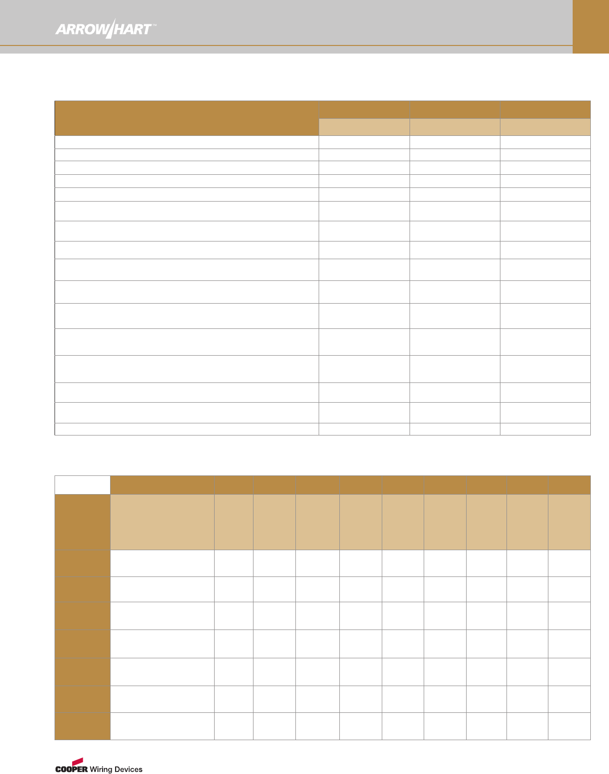
Wire and Cable Information
Diameter Ranges of Jacketed Cord in Accordance with
Standard UL62
Type of Cord Avg. Size 2-Conductor 3-Conductor 4-Conductor 5-Conductor
SV, SVO, SVT, 18 0.22"-0.26" 0.23"-0.27" — —
SVTO (5.6mm-6.6mm) (5.8mm-6.9mm)
SJ, SJO, SJT, 18 0.28"-0.32" 0.30"-0.34" 0.33"-0.37" —
SJTO (7.1mm-8.1mm) (7.6mm-8.6mm) (8.4mm-9.4mm)
16 0.31"-0.34" 0.33"-0.36" 0.35"-0.40" —
(7.9mm-8.6mm) (8.4mm-9.1mm) (8.9mm-10.2mm)
14 0.34"-0.38" 0.36"-0.40" 0.39"-0.44" —
(8.6mm-9.7mm) (9.1mm-10.2mm) (9.9mm-11.2mm)
12 0.41"-0.46" 0.43"-0.48" 0.47"-0.52" —
(10.4mm-11.7mm) (10.9mm-12.2mm) (11.9mm-13.2mm)
10 0.54"-0.61" 0.57"-0.64" 0.63"-0.70" —
(13.7mm-15.5mm) (14.5mm-16.3mm) (16.0mm-17.8mm)
S, SO, ST, STO 18 0.34"-0.39" 0.36"-0.40" 0.39"-0.43" 0.46"-0.51"
(8.6mm-9.9mm) (9.1mm-10.2mm) (9.9mm-10.9mm) (11.7mm-13.0mm)
16 0.37"-0.41" 0.39"-0.43" 0.41"-0.46" 0.49"-0.55"
(9.4mm-10.4mm) (9.9mm-10.9mm) (10.4mm-11.7mm) (12.4mm-14.0mm)
14 0.50"-0.55" 0.52"-0.58" 0.56"-0.62" 0.63"-0.71"
(12.7mm-14.0mm) (13.2mm-14.7mm) 14.2mm-15.7mm) (16.0mm-18.0mm)
12 0.57"-0.63" 0.59"-0.66" 0.64"-0.71" 0.70"-0.77"
(14.5mm-16.0mm) (15.0mm-16.8mm) (16.3mm-18.0mm) (17.8mm-19.6mm)
10 0.62"-0.69" 0.65"-0.72" 0.70"-0.78" 0.76"-0.84"
(15.7mm-17.5mm) (16.5mm-18.3mm) (17.8mm-19.8mm) (19.3mm-21.3mm)
8 0.78"-0.88" 0.83"-0.93" 0.93"-1.05" 1.00"-1.15"
(19.8mm-22.4mm) (21.1mm-23.6mm) 23.6mm-26.7mm) (25.4mm-29.2mm)
6 0.92"-1.05" 0.97"-1.10" 1.05"-1.20" 1.18"-1.33"
(23.4mm-26.7mm) (24.6mm-27.9mm) (26.7mm-30.5mm) (30.0mm-33.8mm)
4 1.06"-1.21" 1.13"-1.28" 1.25"-1.45" —
(26.9mm-30.7mm) (28.7mm-32.5mm) (31.8mm-3.8mm)
2 1.21"-1.40" 1.30"-1.50" 1.45"-1.65" —
(30.7mm-35.6mm) 33.0mm-38.1mm) (36.8mm-41.9mm)
Acceptable Range for Overall Diameter of Jacketed Cord
■SPT-2: Same as SPT-1, but heavier construction (18-16 gauge).
■SPT-3: Same as SPT-2, but heavier construction (18-10 gauge).
■SRDT: Portable range or dryer cable, 3-conductor parallel type or 4
insulated conductors, jacketed. All thermoplastic construction. 300V,
maximum temperature of 60ºC.
■HPN: Two-conductor, neoprene-insulated heater cord. Parallel
construction. For use in damp locations. 300V, 90ºC.
■SJT: Hard usage thermoplastic rubber-insulated conductors
and overall thermoplastic jacket. 300V, 60ºC to 105ºC.
■SJTW: Hard usage thermoplastic or rubber-insulated
conductors and overall thermoplastic jacket. 300V, 60ºC to
105ºC. Weather resistant for outdoor use.
■SPT-1: All thermoplastic construction, parallel jacketed. 300V,
60ºC to 105ºC, 2 or 3-conductor (18 gauge).
KEY:
S= Service W= Weather Approved
J= Junior P= Parallel
T= Thermoplastic/Vinyl
Wire & Cable Type Abbreviations
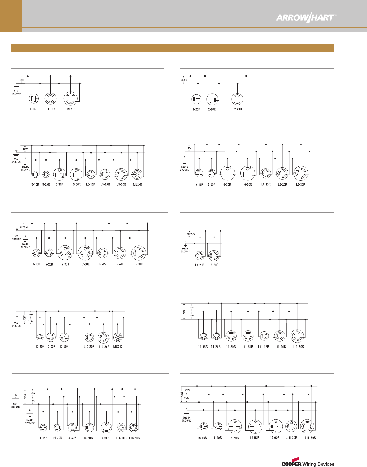
Wiring Diagrams
www.arrowhart.com
O-16
2-Pole, 2-Wire Non-Grounding: 125V 2-Pole, 2-Wire Non-Grounding: 250V
2-Pole, 3-Wire Grounding: 125V 2-Pole, 3-Wire Grounding: 250V
Wiring Diagrams by NEMA Configurations
2-Pole, 3-Wire Grounding: 277V AC 2-Pole, 3-Wire Grounding: 480V AC
3-Pole, 3-Wire Non-Grounding: 125/250V 3-Pole, 3-Wire Non-Grounding: 3Ø 250V
3-Pole, 4-Wire Grounding: 125/250V 3-Pole, 4-Wire Grounding: 3Ø 250V
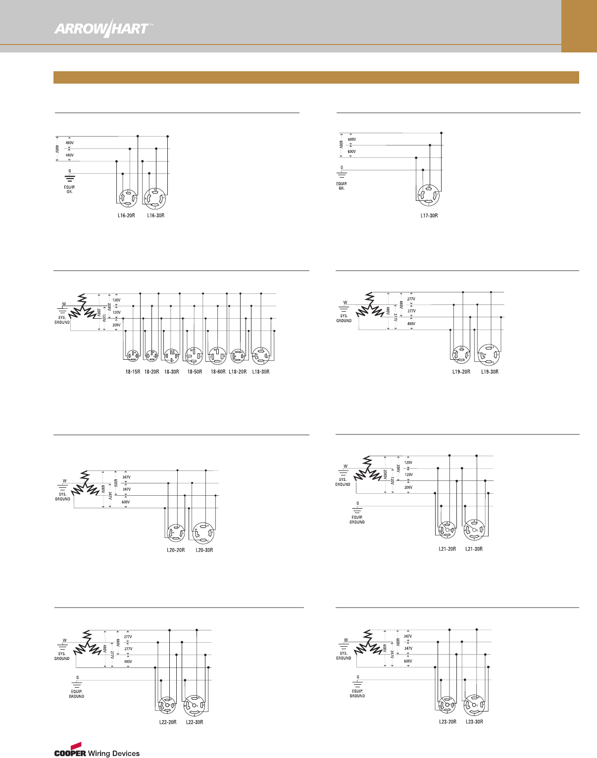
Wiring Diagrams
www.arrowhart.com O-17
4-Pole, 4-Wire Non-Grounding: 3Ø 120/208V 4-Pole, 4-Wire Non-Grounding: 3Ø 277/480V
4-Pole, 4-Wire Non-Grounding: 3Ø 347/600V 4-Pole, 5-Wire Grounding: 3Ø 120/208V
4-Pole, 5-Wire Grounding: 3Ø 277/480V 4-Pole, 5-Wire Grounding: 3Ø 347/600V
Wiring Diagrams by NEMA Configurations
3-Pole, 4-Wire Grounding: 3Ø 480V 3-Pole, 4-Wire Grounding: 3Ø 600V
www.arrowhart.com
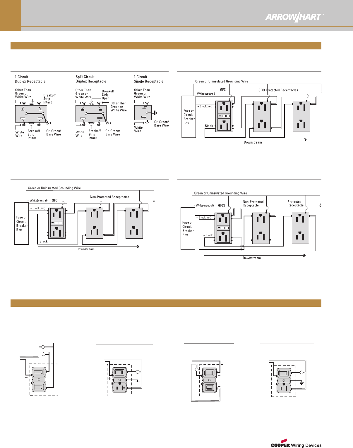
O-18
Wiring Diagrams
15A-125V
GFCI: Feed-Through Installation with Protection
Provided Downstream
GFCI: Feed-Through Installation with Non-Protected
Receptacles Downstream
GFCI: Feed-Through Installation with Both Protected and
Non-Protected Receptacles Downstream
Receptacles
2 Single-Pole
Switches
Single-Pole Switch and
2-Pole, 3-Wire 20A U
Grounding Receptacle
Single-Pole
Switch and
Neon Pilot Light
Single-Pole Switch
and 2-Pole, 3-Wire U
Grounding Receptacle
Combination Devices
www.arrowhart.com O-19
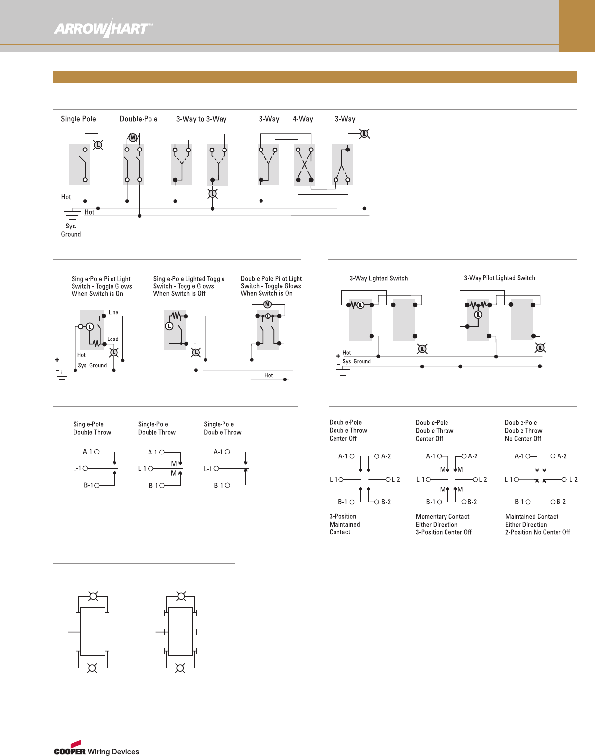
Wiring Diagrams
AC Switches & Standard Switches
Pilot Light Switch & Lighted Switch, Single and Double Pole Pilot Light Switch & Lighted Switch, 3-Way
Maintained
Contact
3-Position,
2-Circuit
Center “Off”
Momentary
Contact Either
Direction
3-Position,
Center “Off”
Maintained
Contact Either
Direction
2-Position,
No Center “Off”
Maintained & Momentary Contact, Single-Pole Maintained & Momentary Contact, Double-Pole
Switches
AH4361,AH4371 DPDT
Momentary Contact,
2-Circuit WithCenter
“Off” Switch
On–Off–On
2-Phase Circuit
L1L2
L
L
1T11
T2
2T12
T2
AH4361,AH4371 DPDT
MomentaryContact,
2-Circuit WithCenter
“Off” Switch
On–Off–On
Single Phase Circuit
L1N
L
L
Manual Contactors & Disconnect Switches
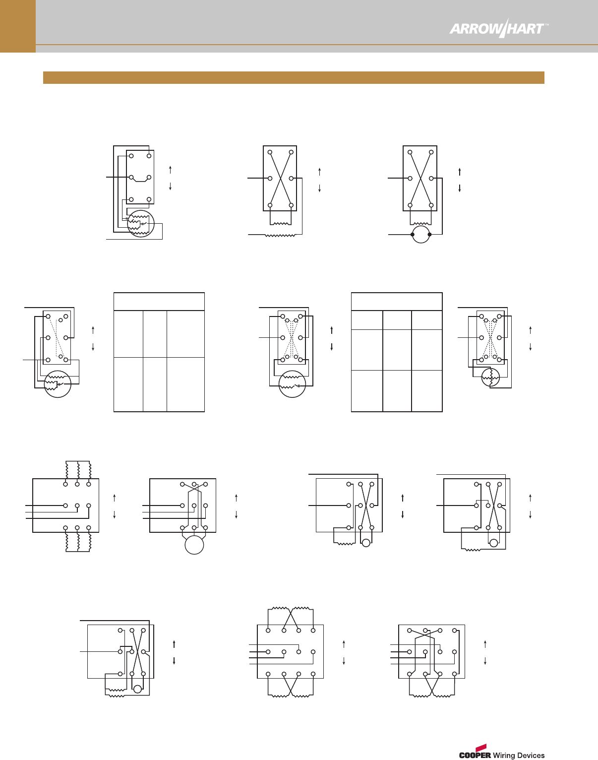
Wiring Diagrams
www.arrowhart.com
O-20
Capacitor Two Windings
Diagram 1
L1
T2T4
T1T3
L1L2
L2
HIGH
OFF
LOW
FORWARD
OFF
REVERSE
Repulsion Induction
Diagram 2
L1
L2
T2T4
T1T3
L1L2
T8T5
T1T4
FORWARD
OFF
REVERSE
Series
Diagram 3
L1
L2
T2T4
T1T3
L1L2
A2A1
S1S2
Capacitor Consequent Pole
Diagram 4
L1
T2T4
T1T3
L1L2
L2
HIGH
OFF
LOW
T4
T2
T5
T2
T1
Diagram 4 Internal Connections
HIGH
LOW
L1
T2
&
L1
T1
&
L2& T3
&
T4
L2to T2
&
T3
Capacitor
Diagram 5
L1
T2T4
T1T3
L1L2
L2
FORWARD
OFF
REVERSE
T4
T1
T8
T5
Diagram 5 & 6
Internal Connections
REVERSE
FORWARD
T1
T2
&
T3
T4
&
T1
T4
&
T3
T2
&
L1L2
Split Phase
Diagram 6
L1
T2T4
T1T3
L1L2
L2
FORWARD
OFF
REVERSE
T4
T1
T8
T5
3-Phase Separate Winding
Diagram 7
L1
L2
L3
HIGH
OFF
LOW
T2T3
T1
T12 T13
T11
3-Phase Induction
Diagram 8
L1
L2
L3
FORWARD
OFF
REVERSE
T2
T3
T1
Series DC
Diagram 9
L1
L2
FORWARD
OFF
REVERSE
S2
S1A1A2
Shunt DC
Diagram 10
L1
L2
FORWARD
OFF
REVERSE
F2
F1
A1A2
Compound DC
Diagram 11
L1
L2
FORWARD
OFF
REVERSE
F2
F1
A1A2
S1S2
2-Phase Separate Winding
Diagram 12
L1
L2
L4
L3
HIGH
OFF
LOW
T1T2T3T4
T11 T12 T13 T14
A
B
Ø
Ø
2-Phase Induction
Diagram 13
L1
L2
L4
L3
FORWARD
OFF
REVERSE
T1T2T3T4
A
B
Ø
Ø
Manual Contacts & Disconnect Switches, by Motor Variations
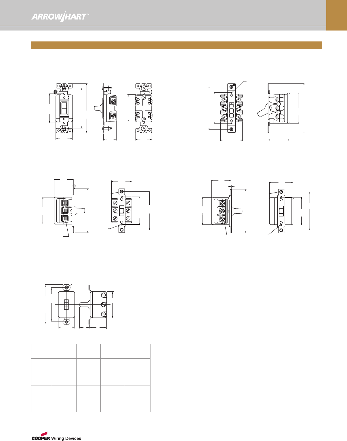
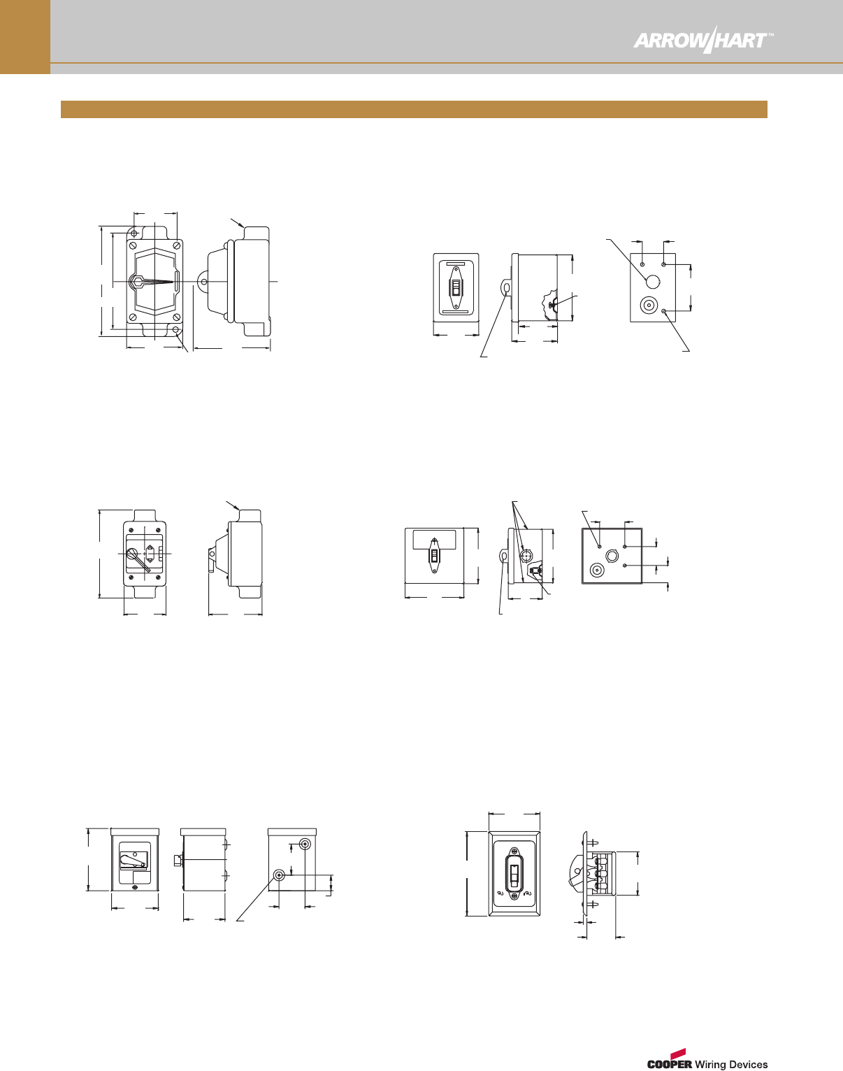
Dimensional Data
www.arrowhart.com O-21
.06"
Clamps Accept
#8-#14 Wire
2.31"
1.66"
2.38"
(2)#6/32 Tap
OFF
ON
3.28"
Mtg. Holes
(2).22" Dia.
2.23"
3.75"
(42.2mm)
(1.5mm)
(58.7mm) (95.3mm)
(5.6mm)
(56.6mm)
(83.3mm)
(60.5mm)
.06"
#4-#14 Wire
Box Lugs Accept
2.31"
1.66"
Mtg. Holes
(2)#6/32"Tap
ON
OFF 3.28"
2.38"
(2).22 Dia.
1.74"
3.75"
(58.7mm) (95.3mm)
(42.2mm)
(1.5mm)
(44.2mm)
(60.5mm)
(83.3mm)
(5.6mm)
(4.8mm)
Tap
#6/32"
OFF
2.38"
3.28"
1.69"
2.31"
3.81"
1.75"
(42.9mm) (44.5mm)
(96.8mm)
(83.3mm)
(60.4mm)
(4.7mm)
(58.7mm)
3.78"
3.28"
Holes
ACB
D
(2) .20"
(96.0mm)
(83.3mm)
(5.1mm)
ON
1.38" 1.04" 1.31"
2.22"
3.28"
4.06"
2.38"
(60.4mm)
(35.0mm)
(83.3mm)
(103.1mm)
(26.4mm)
(56.4mm)
(33.3mm)
AHMC240L, AHMC340L, AHMC260L,
AHMC360L
AH6810U, AH7810UD
AH6808UDAC, AH6808UCO
AHMC240C, AHMC340C
A B C D
AH4361 1.59"
(40.4mm)
1.66"
(42.2mm)
0.66"
(16.8mm)
2.50"
(63.5mm)
AH4371 1.81"
(46.0mm)
1.98"
(50.3mm)
1.22"
(31.0mm)
2.88"
(73.2mm)
AH4361, AH4371
Switch Dimensional Data
www.arrowhart.com
O-22
Dimensional Data
4.67"
OFF
Shroud Accepts up to
5/16" Dia. (7.9mm) Lock Shank
#14-#4
Ground Lug
'A'
4.42" 4.25"
1.37"
1.50" (38.1mm)
(3).25 (6.4mm) Mtg. Hole
Conduit (5 Plc.'s)
Knockouts for
.75 - 1.00
2.00" (50.8mm)
(118.6mm)
(112.3mm)
(108.0mm)
(34.8mm)
(19.05-25.4mm)
AH7810GDB, AHN1GD2 AHN1GD2D
Dim A=2.63" (66.80mm) Dim A=3.87" (98.30mm)
MANUAL MOTOR CONTROLLER
C
OFF
1.68"
.19"
2.31"
2.75"
4.50"
(114.3mm)
(69.9mm)
(58.7mm)
(42.7mm)
(4.8mm)
AH6808FDAC (plate only, no toggle guard)
AH7810FD
AHMC360L-1, AHMC260L-1, AH781OGD, AHMC340C-1,
AHMC340L-1, AH6808GDAC, AH6810G, AHMC240C-1,
AHMC240L-1, AH27940G, AHN1GD
ON
OFF
3.43"
2.75"
5.81"
.75" Hub
(147.6mm)
(69.9mm) (87.1mm)
(19.1mm)
(2).25" (6.35mm) Dia.
Embossed Mtg. Hole
2.50" 1.50"
3.00"
(76.2mm)
(38.10mm)
(63.50
mm)
4.00"
(101.60mm)
ON
F
MANUAL MOTOR CONTROLLER
4.50"
6.00"
(152.4mm)
(114.3mm)
1/2" (12.70mm) Conduit KO Centered on Back
2.50"
Shroud Accepts up to
5/16" (7.9mm) Dia. Lock Shank
2.63"
3.00"
4.25"
(3).25" (6.4mm) Dia. Hole
Ground Screw
1.38"(35.1mm)
MANUAL MOTOR STARTER
2.92"
OFF
(74.2mm)
(108.0mm)
(63.5mm)
(66.8mm)
(76.2mm)
6.75"
2.63"
5.88"
3.50" 4.75"
.34"
.75" Hub
(120.7mm)
(8.6mm)
(88.9mm)
(171.5mm)
(66.8mm)
(19.1mm)
(149.4mm)
AH6810E, AH7810ED
AH6808WDAC
AHN3WD, AH6808WDAC, AH6810W,
AHMC240C-3, AHMC240L-2, AHMC260L-3,
AHMC340C-3, AHMC340L-2, AHMC360L-2
Enclosure Dimensional Data
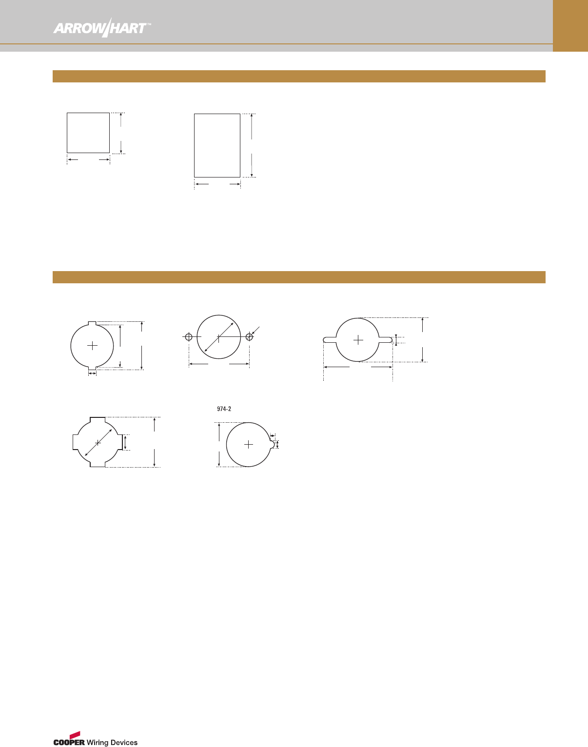
www.arrowhart.com O-23
Panel Cutout
732-3
0.34"
(8.6mm)
1.41"
(35.8mm)
1.53"
(38.86mm)
734
1.8"
(46.0mm)
1.38"
(34.8mm)
Dia.
0.188"
(4.8mm)
Diam.
Panel Cutout
Dimensional Data
Panel Thickness 0.032'' – 0.070''
Panel Cutout
67
1.07"
(27.2mm)
0.77"
(19.6mm)
(0.81mm – 1.78mm)
0.968"
(24.6mm)
0.968"
(24.6mm)
Panel Cutout
49
Panel Thickness 0.032'' ñ 0.070''
(0.81mm ñ 1.78mm)
0.90"
(22.8mm)
Dia.
1.03"
(26.0mm)
0.425"
(10.8mm)
0.82"
(20.8mm)
0.063"
(1.6mm)
0.125"
(3.2mm)
Panel Cutout
731-2, 731-3
Panel Cutout
4734-2
2.13"
(54.1mm)
0.188"
(4.8mm) 1.38"
(34.8mm)
Panel Cutout
Snap-In Receptacle Panel Cutouts
Attachon Lampholder Cutouts
www.arrowhart.com
O-24
Switch Applications
Test Requirements - Switches* General Use - AC Only
Rating Standard*
Overload Endurance Resistance
Cycles 1.0
pf. †
Inductive
Cycles
.75 to .8 pf. †
Tungsten
Cycles 1,0
pf. †
Amps Volts Power
Factor Cycles Amps Volts
(Max)
15A,
120V/AC
UL 20 &
NEMA G.D. 72 120 AC .4 to .5 100 15 120 AC 10,000 10,000 10,000
WS 896 &
NEMA H.D. 72 120 AC .4 to .5 100 15 120 AC 10,000 50,000 50,000
15A
120/277
277V/AC
UL 20 &
NEMA G.D. 72 277 AC .4 to .5 100 15 277 AC 10,000 10,000 10,000
WS 896 &
NEMA H.D. 72 277 AC .4 to .5 100 15 277 AC 10,000 50,000 50,000
20A,
120/277
277V/AC
UL 20 &
NEMA G.D. 96 277 AC .4 to .5 100 20 277 AC 10,000 10,000 10,000
WS 896 &
NEMA H.D. 96 277 AC .4 to .5 100 20 277 AC 10,000 50,000 50,000
20A,
120/277
277V/AC
UL 20 &
NEMA G.D. 144 277 AC .4 to .5 100 30 277 AC 10,000 10,000 10,000
WS 896 &
NEMA H.D. 144 277 AC .4 to .5 100 30 277 AC 10,000 50,000 50,000
The maximum permitted load for which a switch is suitable depends on the switch rating and the nature of the load. Proper
selection of switches is determined by test standards and requirements of the National Electrical Code®, Articles 380, 430,
and 600.
General Use AC switches are suitable for use at full rated current and voltage on loads of fluorescent and incandescent
lighting and for other inductive or resistance loads. Our switches are rated for motor loads at 80% of their rated current.
Special Use AC switches may be used at full rating on resistance or inductive loads, including fluorescent. For
incandescent (tungsten) lighting loads, they must carry an “L” rating. For motor loads they require an “HP” (horsepower)
rating.
To ensure safety and reliability, Arrow Hart switches are tested, rated and marked according to various standards. The
following charts indicate both the required performance tests specified by industry standards for switches with standard
ratings, and the loads they may control.
*NEMA G.D. is NEMA Standard WD-1 General Duty.
NEMA H.D. is NEMA Standard WD-1 Heavy Duty.
WS896 is current Federal Specification.
All switches are subjected to Resistive Endurance, Inductive
Endurance, Tungsten Endurance and then verified that they meet
less than a 86ºF (30ºC) temperature rise at rated current and
voltage, followed by a dielectric test at 1500 VAC for 1 minute.
† Power Factor
Test Requirements - Switches Special Use - AC Only
Rating Standard*
Overload Endurance Horse Power “L” Tungsten
Amps Volts Power
Factor Cycles Amps Volts Power
Factor Cycles Amps Volts Power
Factor Cycles Amps Volts Cycles
8A, 120V/AC UL 1054 12 120
AC .4-.5 50 8 120
AC .75-.8 6000 – – – – – – –
15A, 120V/AC
10A, 240V/AC
3/4 HP,
120-240V/AC
UL 1054 15 240
AC .4-.5 50 10 240
AC .75-.8 6000
82.8 120
AC .4-.5 50
– – –
41.4 240
AC .4-.5 50
15A,
125-250V/AC
3/4 HP,
120-240V/AC
UL 1054 22.5 250
AC .4-.5 50 15 250
AC .75-.8 6000
82.8 120
AC .4-.5 50
– – –
41.4 240
AC .4-.5 50
20A, 125V/AC “L”
20A, 250V/AC
1 HP,
120-240V/AC
UL 1054 30 240
AC .4-.5 50 20 250
AC .75-.8 6000
96 120
AC .4-.5 50
20 125
AC 6000
48 240
AC .4-.5 50
Test Requirements
www.arrowhart.com O-25
Switch Applications
Maximum Loads - Switches - General Use - AC Only
Switch Rating
Incandescent Inductive (Fluorescent) Resistance Motors
Volts Amps Volts Amps Volts Amps Volts HP Amps
15A, 120V/AC 120 AC 15 120 AC 15 120 AC 15 120 AC 1/2 12
20A, 120V/AC 120 AC 20 120 AC 20 120 AC 20 120 AC 1 16
15A, 120/277V/AC 120 AC 15 277 AC 15 277 AC 15 120 AC 1/2 12
240 AC 1 12
20A, 120/277V/AC 120 AC 20 277 AC 20 277 AC 20 120 AC 1 16
240 AC 2 16
30A, 120/277V/AC 120 AC 30 277 AC 30 277 AC 30 120 AC 2 24
240 AC 2 24
Maximum Loads - Switches - Special Use - AC Only
Switch Rating
Incandescent Inductive (Fluorescent) Resistance Motors
Volts Amps Volts Amps Volts Amps V/AC HP Amps
8A, 120V/AC
15A, 120V/AC Not Suitable
120 AC 8 120 AC 8
Not Suitable
120 AC 15 120 AC 15
10A, 240V/AC
3/4HP, 120/240V/AC Not Suitable 250 AC 10 240 AC 10 240V/AC 3/4 12
15A, 120-240V/AC
3/4HP, 120/240V/AC Not Suitable 250 AC 15 250 AC 15 240V/AC 3/4 12
20A,120V/AC “L”
20A, 250V/AC
1HP, 120/240V/AC
125 AC 20 250 AC 20 250 AC 20 240V/AC 1 12
Maximum Loads
Switch Applications or Materials
www.arrowhart.com
O-26
Chemical Resistant Properties of Common Materials in Wiring Devices
Acids Alcohol Caustic
Bases Gasoline Grease Kerosene Oil Solvents Water
Nylon
(Thermoplastic) 3 1 1 111 1 1 1
Polycarbonate
(Thermoplastic) 2 1 3 2 2 2 2 3 1
302/304
Stainless Steel 2 1 3 1 1 1 1 2 1
Polyvinyl
Chloride (PVC) 1 1 1 1 1 1 1 3 1
Polypropylene
(Thermoplastic) 1 1 1 1 1 1 1 2 1
Polyester 1 1 2 1 1 1 1 2 1
Rubber
(Thermoplastic) 2 2 3 2 2 1 1 3 2
Phenolic
(Thermoset) 2 1 2 1 1 1 1 1 1
ABS
(Thermoplastic) 2 2 1 1 1 2 2 3 1
Chemical resistance factor
1 – Completely resistant — Good to excellent for general use when exposed to these factors.
2 – Resistance is fair to good — Recommended for limited service when exposed to these factors.
3 – Slow attack. Not recommended for use when exposed to these factors.
*The chemical resistance factor represents general applications. Additional testing is required to determine resistance to chemicals in specific environments.
Terms describing material enhancements
Thermoplastic: Material treated for UV stability to increase tensile strength and decrease discoloration when exposed to UV radiation.
Manufactured by injection molding. Superior resistance to impacts, chemical and solvent attack.
Thermoset: Flame resistant material with dimensional stability. Manufactured by compression molding.
Glass Filled: Glass-filled material (most commonly nylon) yields increased material rigidity and permits operation at a higher temperature.
Nickel-Plated: Plating of steel or brass with nickel to increase the corrosion-resistant properties of the metal component.
Zinc-Plated: Plating of cold-rolled steel with zinc to increase the corrosion-resistant properties of the metal component or casing.
Material
NEMA & IP Enclosures
www.arrowhart.com O-27
NEMA Enclosure Ratings
Protection From Device Locations
Indoors Indoors or
Outdoors
Outdoors with external
mechanisms
Limited amounts of falling dirt NEMA Type 1
Limited amounts of falling dirt and dripping water NEMA Type 2
Rain, sleet, falling dirt, windblown dust, damage from ice formation NEMA Type 3
Rain, sleet, falling dirt, damage from ice formation NEMA Type 3R
Rain, sleet, windblown dust, ice laden operation possible NEMA Type 3S
Windblown dust and rain, splashing water, hose-directed water,
damage from ice formation NEMA Type 4
Corrosion, windblown dust and rain, splashing water, hose-directed water,
damage from ice formation NEMA Type 4X
Falling dirt and settling airborn dust, lint, fibers and dripping non-corrosive liquids NEMA Type 5
Hose-directed water, entry of water during occasional short-term
limited depth submersion, damage from ice formation NEMA Type 6
Hose-directed water, entry of water during long-term limited depth submersion,
damage from ice formation NEMA Type 6P
Class I, Division 1, groups A,B,C or D hazardous locations
(as defined by NEC®, NFPA 70)
NEMA Type 7
(commonly referred to
as explosion-proof)
Class I, Division 1, groups A,B,C or D hazardous locations
(as defined by NEC®, NFPA 70)
NEMA Type 8
(commonly referred to
as oil-immersed)
Class II, Division 1, groups E, F and G hazardous locations
(as defined by NEC®, NFPA 70)
NEMA Type 9
(commonly referred to
as dust-ignition-proof)
Meets applicable requirements of the Mine Safety & Health Administration,
30 CFR, Part 18 NEMA Type 10
Circulating dust, falling dirt, dripping non-corrosive liquids NEMA Type 12
NEMA Type 12K
Dust, spraying of water, oil and non-corrosive coolant NEMA Type 13
IP Enclosure Ratings
Second Digit -protection
against penetration of liquids IP_0 IP_1 IP_2 IP_3 IP_4 IP_5 IP_6 IP_7 IP_8
First Digit -
protection against
persons -
touching &
ingress of solid
objects
Non-
protected
Vertical
falling of
water drops
Falling of
water drops
at angle up
to 15º from
vertical
Spraying
water (rain)
at angle up
to 60º from
vertical
Splashing
water
from any
direction
(360º)
Water jets
from any
direction
(360º)
Power
jetting
water
Temporary
immersion
in water
Continuous
immersion
in water
IP0_ Without protection IP00
IP1_ Touching with hand & solid
objects > 50mm dia. IP10 IP11 IP12
IP2_ Touching with finger & solid
objects > 12mm dia. IP20 IP21 IP22 IP23
IP3_
Touching with tools, wires, etc.
> 2.5mm thick & solid objects
> 2.5mm dia.
IP30 IP31 IP32 IP33 IP34
IP4_
Touching with tools, wires, etc.
> 1mm thick & solid objects
> 1mm dia.
IP40 IP41 IP42 IP43 IP44
IP5_
Unlimited protection against
contact with live parts &
damaging dust deposits
IP50 IP54 IP55
IP6_
Unlimited protection against
contact with live parts & any
dust penetration
IP60 IP65 IP66 IP67 IP68

www.arrowhart.com
O-28
NEMA & IP Enclosures
CANADIAN STANDARDS
ASSOCIATION
CAN/CSA C22.2 No. 94-M91
Special Purposes Enclosures
Intended Use and Description
Enclosures are constructed to protect
against specific environmental conditions,
as well as accidental contact with the
equipment enclosed within.
Type 1 - (There is no CSA equivalent.)
Type 2 - Enclosures are designed to provide
protection, primarily indoors, against
dripping and small amounts of splashing of
non-corrosive liquids, and dirt.
Type 3 - Enclosures, designed for both
indoor and outdoor use, protect against rain
and snow, and remain undamaged by the
external formation of ice.
Type 3R - Enclosures used both indoors and
out for protection against rain and snow,
remaining undamaged by exterior ice
formation.
Type 3S - Enclosures used both indoors and
out for protection against rain, snow, and
airborne dust, and enable external
mechanisms to operate efficiently even when
ice laden.
Type 4 - Enclosures used both indoors and
out for protection against rain, snow,
airborne dust, and both splashing and hose-
directed water, remaining undamaged by
exterior ice.
NATIONAL ELECTRICAL
MANUFACTURERS ASSOCIATION
NEMA Standards Publication No.
250-1991, Enclosures for Electrical
Equipment (1000V max.)
Intended Use and Description
An enclosure is a surrounding case that
provides personnel with protection against
incidental contact with enclosed equipment,
and simultaneously protects enclosed
equipment against specific environmental
conditions.
Type 1 - Enclosures are intended for indoor
use primarily to protect against limited
amounts of falling dirt.
Type 2 - Enclosures provide a degree of
protection, mainly indoors, against limited
amounts of dripping water or falling dirt.
Type 3 - Enclosures, intended primarily for
use outdoors, protect against rain, sleet,
wind-blown dust, and damage from external
ice formation.
Type 3R - Enclosures provide protection
primarily against rain, sleet, and damage
from external ice formation.
Type 3S - Enclosures protect primarily
against rain, sleet, and wind-blown dust, and
enable external mechanisms to operate
efficiently even when ice laden.
Type 4 - Enclosures provide protection, both
indoors and out, against wind-blown dust
and rain, splashing or hose-directed water,
and ice damage.
UNDERWRITERS LABORATORIES UL50
Standard for Enclosures for
Electrical Equipment (10th Edition)
Intended Use and Description
An enclosure is a surrounding case that
protects equipment enclosed within against
incidental contact, as well as specific
environmental conditions. A complete
enclosure shall be provided for all live parts
that may be housed in it. Such an enclosure
shall be tight and come with a means for
mounting, unless it’s designed for a special
installation, for example, a cast metal
junction or pull-box intended for installation
in poured concrete.
Type 1 - Enclosures are intended for
indoor use primarily to protect
against limited amounts of falling dirt.
Type 2 - Enclosures provide a degree of
protection, mainly indoors, against limited
amounts of dripping water or falling dirt.
Type 3 - Enclosures, intended primarily for
use outdoors, protect against rain, sleet,
wind-blown dust, and damage from external
ice formation.
Type 3R - Used primarily outdoors for
protection against rain, sleet, and exterior
damage caused by the formation of ice.
Type 3S - Used primarily outdoors for
protection against rain, sleet, and wind-
blown dust, and to enable exterior
mechanisms to operate when ice laden.
Type 4 - For indoor and outdoor use to
protect against wind-blown dust and rain,
splashing or hose-directed water, and
damage caused by exterior ice formation.
Enclosure Type Cross Reference: NEMA/UL/CSA
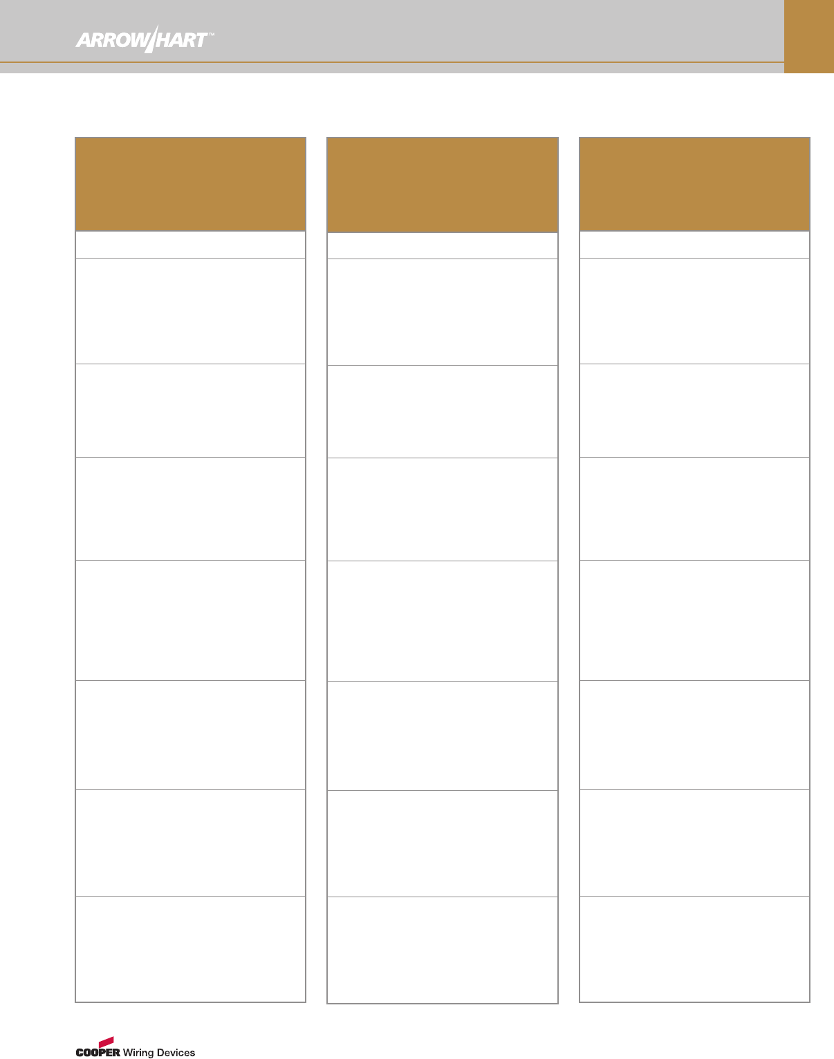
www.arrowhart.com O-29
NEMA & IP Enclosures
CANADIAN STANDARDS
ASSOCIATION
CAN/CSA C22.2 No. 94-M91
Special Purposes Enclosures
Intended Use and Description
Type 4X - Enclosures used both indoors and
out for protection against rain, snow,
airborne dust, and both splashing and hose-
directed water, remaining undamaged by
exterior ice formation.
Type 5 - Enclosures exclusively for indoor
use, providing protection against dripping
and light splashing of non-corrosive liquids,
as well as airborne dust, lint, fibers, and
filings.
Type 6 - Enclosures used both indoors and
out for protection against water entry during
occasional short-term submersion at low-
pressure depths, remaining undamaged by
exterior ice formation.
Type 6P - Enclosures for use both indoors
and out for protection against water entry
during long-term submersion at low-pressure
depths. In addition, it provides corrosion
resistance over extended periods of time
and remains undamaged by exterior ice
formation.
Type 12 - Enclosures exclusively for indoor
use, providing protection against airborne
dust, lint, fibers, and filings, as well as
dripping and light splashing of non-corrosive
liquids. These enclosures are not provided
with knockouts.
Type 12K - Enclosures provided with
knockouts and used exclusively indoors for
protection against airborne dust, lint, fibers,
and filings, as well as dripping and light
splashing of non-corrosive liquids.
Type 13 - Enclosures exclusively for indoor
use, providing protection against airborne
dust, lint, fibers, and filings, as well as from
seepage and spraying of non-corrosive
liquids, including oils and coolants.
NATIONAL ELECTRICAL
MANUFACTURERS ASSOCIATION
NEMA Standards Publication No.
250-1991, Enclosures for Electrical
Equipment (1000V max.)
Intended Use and Description
Type 4X - Enclosures used both indoors and
out to protect against corrosion, wind-blown
dust and rain, splashing or hose-directed
water, and damage caused by exterior ice
formation.
Type 5 - Enclosures used primarily indoors
to provide protection against airborne dust
and dirt, and non-corrosive liquids.
Type 6 - Enclosures provide protection both
indoors and out against hose-directed water,
water entry during occasional short-term
submersion at low-pressure depths, and
damage caused by exterior ice formation.
Type 6P - Enclosures protect both indoors
and out against hose-directed water, water
entry during long-term submersion at low-
pressure depths, and ice damage.
Type 12 - Enclosures used primarily indoors
to protect against airborne dust or dirt, and
non-corrosive liquids.
Type 12K - Enclosures with knockouts are
used primarily indoors for protection against
airborne dust and dirt, and non-corrosive
liquids.
Type 13 - Enclosures used primarily indoors
to protect against dust, as well as accidental
spraying by water, oil, or non-corrosive
coolants.
UNDERWRITERS LABORATORIES UL50
Standard for Enclosures for Electrical
Equipment (10th Edition)
Intended Use and Description
Type 4X - For protection indoors and out
from corrosion, wind-blown dust and rain,
splashing or hose-directed water, and
damage caused by exterior ice formation.
Type 5 - Used primarily indoors for
protection against airborne dust or dirt, and
non-corrosive liquids.
Type 6 - For protection indoors and out
against hose-directed water, water entry
during occasional short-term submersion at
low-pressure depths, and damage caused
by exterior ice formation.
Type 6P - For protection indoors and out
against hose-directed water, water entry
during long-term submersion at low-pressure
depths, and damage caused by exterior ice
formation.
Type 12 - Used primarily indoors to protect
against airborne dust and dirt, and non-
corrosive liquids.
Type 12K - Used primarily indoors to protect
against dust and dirt, and non-corrosive
liquids.
Type 13 - Used primarily indoors to protect
against dust, as well as accidental spraying
by water, oil, or non-corrosive coolants.
Enclosure Type Cross Reference: NEMA/UL/CSA
(con't) (con't) (con't)
Products that are identified as NAFTA compliant may qualify under the Buy
American Act or ARRA program guidelines. Consult specific project guidelines
and compliance requirements to assure suitability for your project needs.
Buy American Act (US Code, Title 41, Section 10 (a-d))
The Buy American Act (often BAA, not to be confused with the Buy America (no
"n") Act) applies to all U.S. federal government agency purchases of goods over
certain contract thresholds. The BAA restricts purchases of supplies and
construction materials to domestic products, unless an exception or waiver
applies. Unmanufactured products must be mined or produced in the United
States. There is a two-part test for manufactured articles: (1) article must be
manufactured in the United States, and (2) cost of U.S. components must exceed
50% of the cost of all components in the item. Note: this calculation does not
include labor and overhead for final assembly in the United States. The
component cost test is waived for commercial-off-the-shelf (COTS) items.
(FAR 25.001(c)(1). BAA waivers may be available, often at the discretion of the
contracting officer.
Buy American Provision, American Recovery and
Reinvestment Act (ARRA) (Section 1605)
ARRA Section 1605 establishes requirements for federal
government projects funded with stimulus monies: “None
of the funds appropriated or otherwise made available by
[the ARRA] may be used for a project for the construction,
alteration, maintenance, or repair of a public building or
public work unless all of the iron, steel, and manufactured
goods used in the project are produced in the United
States.” Iron and steel used as components or
subcomponents of other manufactured construction
materials do not need to be produced in the United
States. There is no requirement that components and
subcomponents be U.S.-origin provided the manufactured
construction material is “produced in the United States.”
(FAR 25.001(c)(4)) Section 1605 does not contain a
domestic cost requirement. However, the government has
not defined “produced” for purposes of the ARRA Buy
American provision. Many commentators have adopted
the “substantial transformation” test to determine whether
a manufactured article is “produced” in the United States
for purposes of Section 1605. Section 1605 contains a
requirement that the Buy American provision be applied in
a manner consistent with U.S. obligations under
international agreements. As a result, national treatment is
extended to products from countries with which the
United States has entered a free trade agreement (e.g.,
Canada, Mexico, Bahrain, Chile, etc.) and to products
from countries that have signed the WTO Government
Procurement Agreement. National treatment is also
extended to least developed countries (LDCs) (e.g.,
Bhutan, Mali, Zambia, etc.) but not to Caribbean basin
countries (e.g., Belize, Haiti, Bahamas, etc.).
NAFTA compliant products meet specifications at time of print. Product listing subject to change. For specific product details visit
www.arrowhart.com or email cwdmarketing@cooperindustries.com.
NAFTA Compliant
www.arrowhart.com
O-30
