Crane Project Valves Catalogue
User Manual: Crane Project Valves Catalogue
Open the PDF directly: View PDF ![]() .
.
Page Count: 87

WATER |HEATING |VENTILATION |AIR CON |GAS
PROJECT VALVES
CATALOGUE
OUR GENIUS IS VALVES
ISSUE ONE

2TECHNICAL HELPLINE: +44 (0)1473 277400
www.cranefs.com
CRANE FLUID SYSTEMS PROJECT VALVES CATALOGUE
Balancing
Valves
Introduction
Dominator
CommPac
Differential
Pressure
Control
Valves
Contents
FULL TECHNICAL DATA AVAILABLE ON
WWW.CRANEFS.COM
Balancing -
Static 7
Balancing -
Automatic 4
3
4
19
22
21
Pressure
Independent
Control
Valve
24
Valve Family
Globe Valves
Check
Valves
Gate Valves
Butterfly
Valves 35
Ball Valves 25
25
Typical Kv values 82
39
Public Health
Pressure
Reducing
Valves
Thermostatic
Mixing Valves 78
Thermal
Balancing
Valves 76
76
Quality Control 83
Project Gallery 84
Index of Figure Numbers 86
80
65
46
Strainers 71
3
TECHNICAL HELPLINE: +44 (0)1473 277400
www.cranefs.com
Introduction
History
In 1906 James E. Bennett set up a business in London as
a Coppersmith. He soon recognised a growing interest in
the trade for the latest American pipe fittings and valves,
and turned his attention to importing. Amongst the
products he introduced to British Industry were those of
Crane Co, a thriving American company founded in the
mid 19th century.
Crane soon realised that a manufacturing
unit in this country would help expand
their international business.
In 1919, Crane Co. purchased the
assets of the English company and
changed its name to Crane-Bennett
Limited with the intention of making
products in England.
Today as part of Crane Building
Services & Utilities, Crane Fluid
Systems is joined by an
array of complimentary
building services brands
including NABIC, Brownall,
Wade, Rhodes and IAT.
Today & Tomorrow
Crane Co was founded on the 5th July 1855 by
Richard Teller Crane who made the following resolution:
“I am resolved to conduct my business in the strictest
honesty and fairness; to avoid all deception and trickery;
to deal fairly with both customers and competitors; to be
liberal and just towards employees; and to put my whole
mind upon the business.”
The essence of this resolution is the business policy of
Crane Co today.
Richard Teller Crane
Crane Fluid Systems - Our Genius is Valves
Crane Fluid Systems offers a full range of traditional ball,
butterfly, check, gate and globe valves along with the
ProBalance range of static and dynamic balancing valves
as well as flow management modules. Widely specified in
the HVAC industry, product quality, reliability and technical
expertise enable Crane Fluid Systems to remain at the
forefront of the building services market.
Our Corporate Vision is to be the leading provider of
valves, pipe fittings and engineered products for fluid
handling applications in building services and general
industrial markets. We aim to be our customers preferred
supplier by offering products which provide best value
together with a service that exceeds customers'
expectations.
Crane Fluid Systems is a leading brand of Crane Building
Services & Utilities which forms part of the Fluid Handling
Group, a division of the parent company Crane Co.
4TECHNICAL HELPLINE: +44 (0)1473 277400
www.cranefs.com
BALANCING - AUTOMATIC
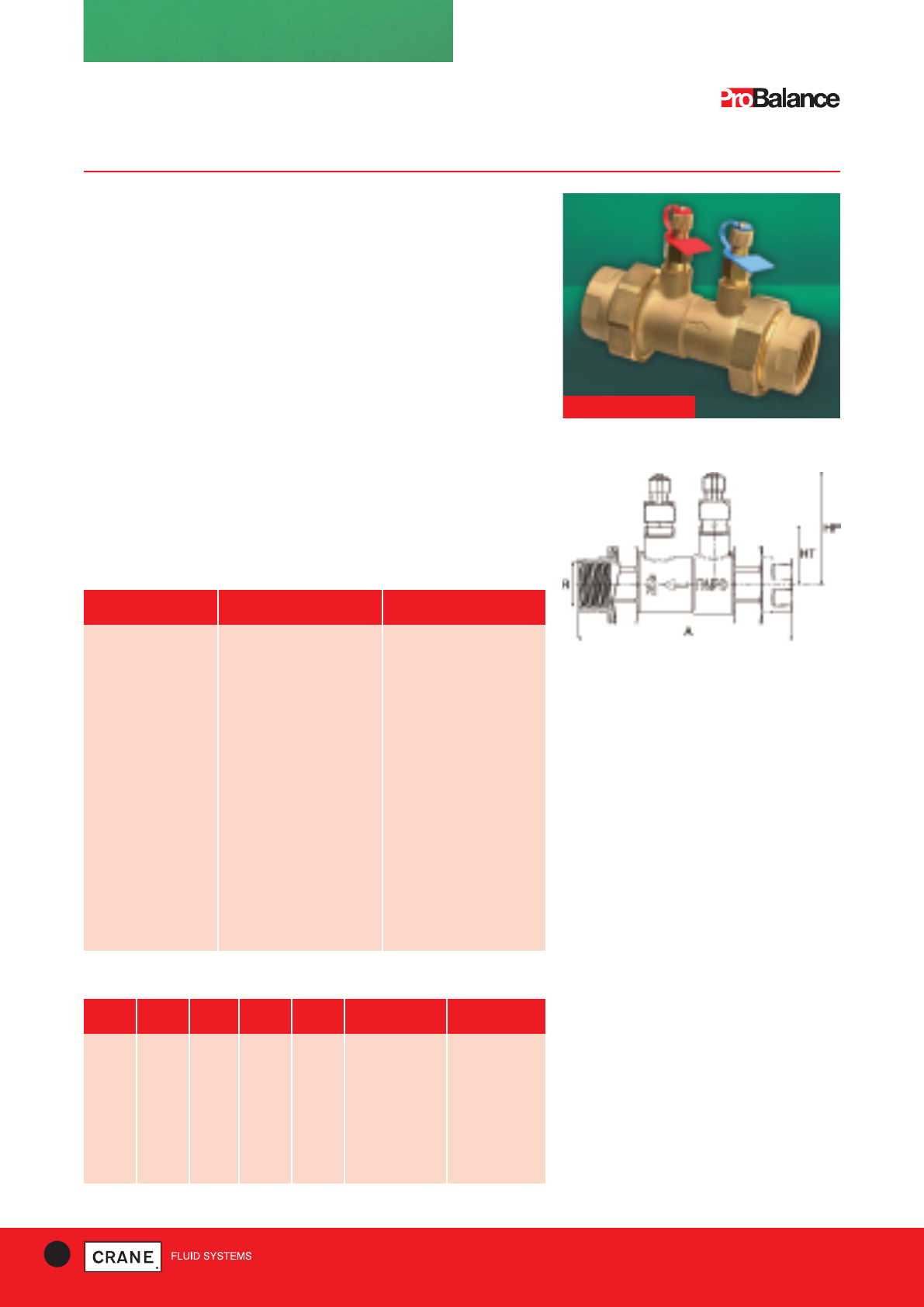
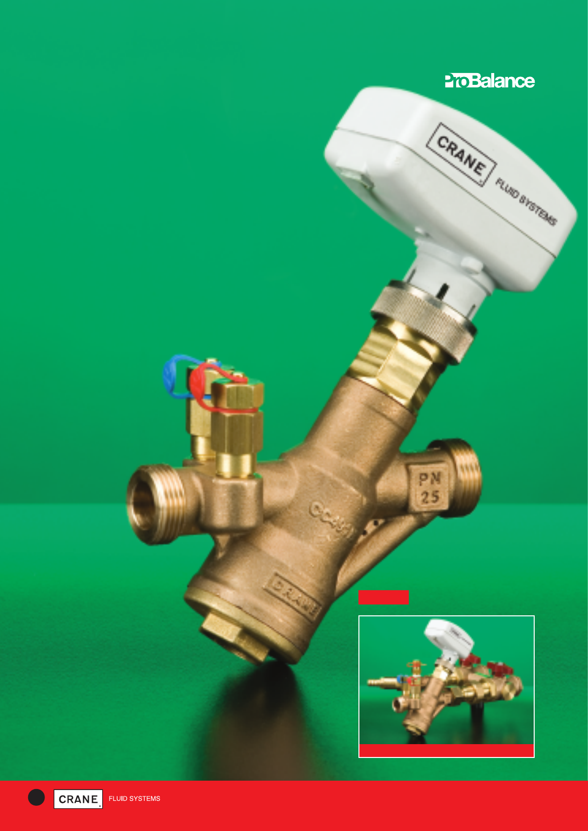
D9601
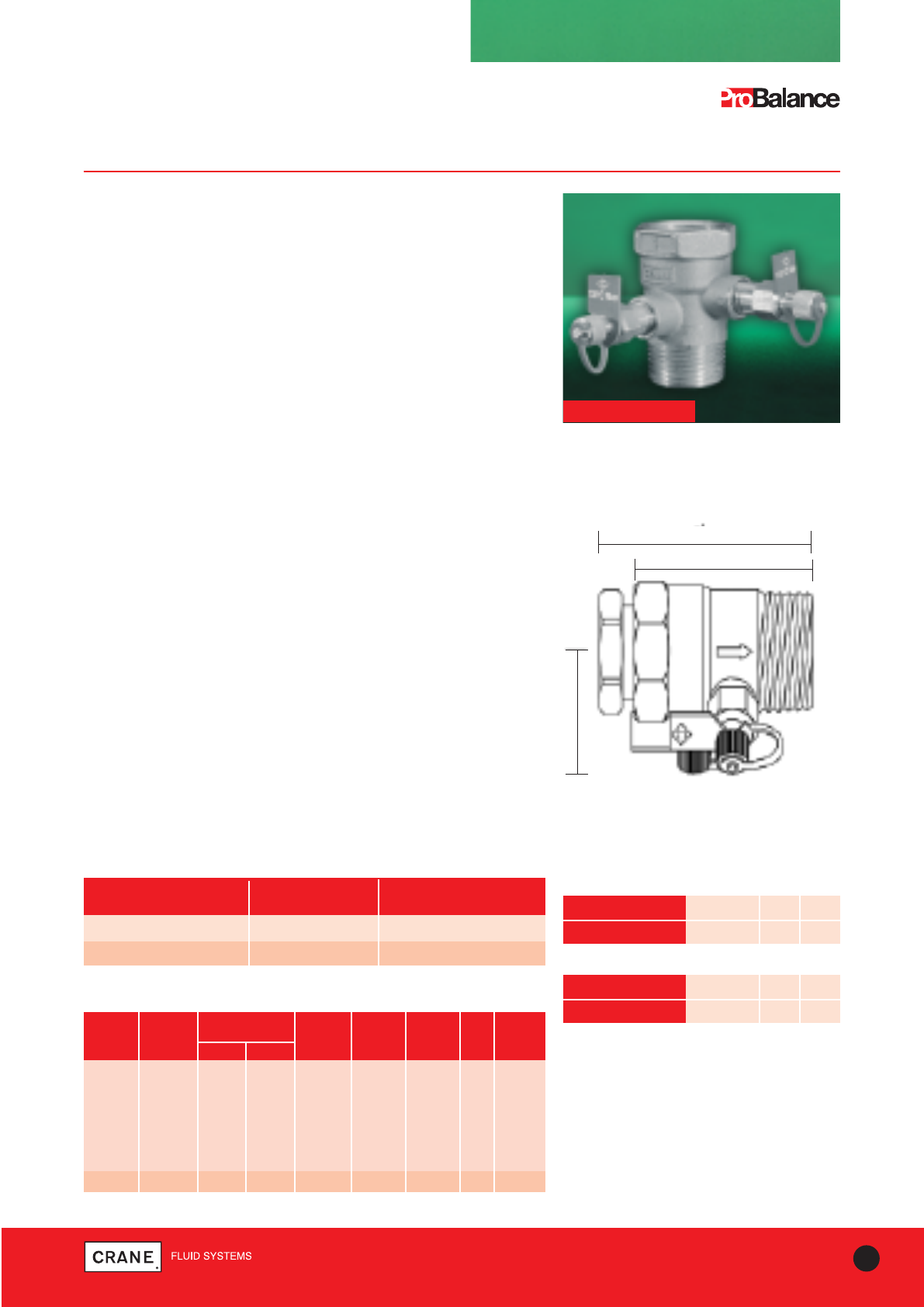
Automatic Balancing Valve (ABV)
Automatically maintains flow at the specified rate
regardless of fluctuations in system pressure.
Features & Benefits
• Selection of the appropriate cartridge provides design flow rate.
• Compact size.
• Energy efficient, preventing overflows or excess flow rates.
• Design changes can be easily made by selection of the appropriate
cartridge, eliminating the need for recommissioning.
• Male threaded body comes complete with female adaptors which
allows for easy installation and removal of cartridge for flushing.
• Can be installed in any pipework configuration - does not require
straight lengths of pipe.
• Dynamic flow-limiting characteristics permit variable volume systems to
function correctly.
• Tamperproof.
• Also available without test points -(D9600).
• Also available with American threads - (D9600AT without test points) &
(D9601AT with test points).
D9601
Dimensional Drawing
Materials
PART MATERIAL SPECIFICATION
Union nut Brass BS EN 12165 CW617N
Union DZR Brass BS EN 12165 CW602N
Union O-ring EPDM Perox -
Distance ring DZR Brass BS EN 12164 CW602N
Body DZR Brass BS EN 12165 CW602N
Plug gasket Copper -
Plug DZR Brass BS EN 12164 CW602N
Cartridge plug POM* -
Shaped opening Stainless steel -
Cartridge body POM* -
Cartridge spring Stainless steel -
Cartridge O-ring EPDM Perox -
Test point DZR Brass BS EN 12164 CW602N
Tie Polyp. (blue/red) -
DN R A HT HP VALVE CARTRIDGE
(mm) (mm) (mm) WEIGHT (kg)* WEIGHT (kg)
15 1/2|| 111 35 67 0.42/0.52 0.04
20 3/4|| 117 35 67 0.47/0.53 0.04
25 1|| 123 35 67 0.48/0.55 0.04
32 11/4|| 159 43 75 1.36/1.43 0.10
40 11/2|| 159 43 75 1.47/1.53 0.10
50 2|| 241 60 92 3.00/3.06 0.40
65 21/2|| 241 60 92 3.98/4.05 0.40
80 3|| 292 60 92 4.78/4.85 0.40
Dimensions and Weights
*Without test points/with test points
*PA66/30G for DN<25
Every effort has been made to ensure that the information contained in this publication is accurate at the time of publishing. Crane Ltd assumes no responsibility or liability for typographical errors or omissions or for
any misinterpretation of the information within the publication and reserves the right to change without notice.
5
TECHNICAL HELPLINE: +44 (0)1473 277400
www.cranefs.com
BALANCING - AUTOMATIC
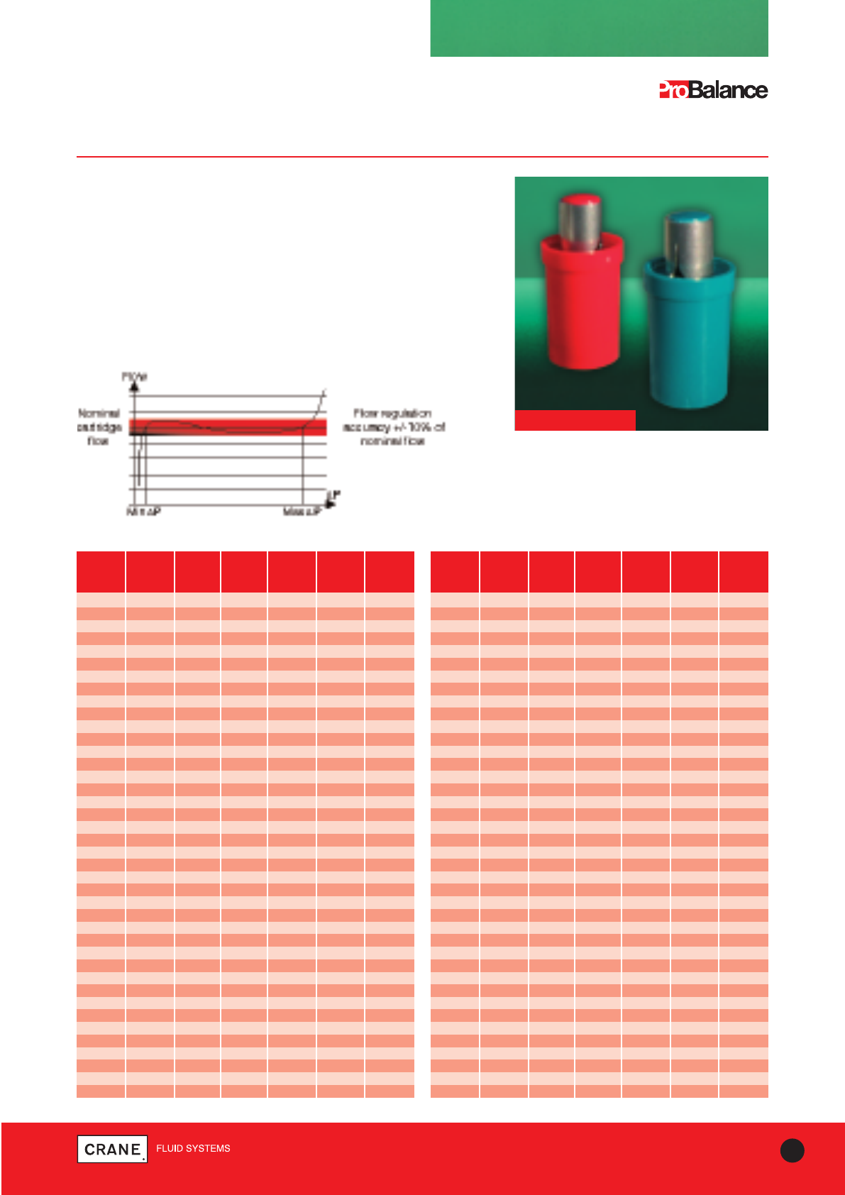
C960
ABV Cartridges
Cartridges
Cartridges are available in 6 ranges of working differential pressure.
Cartridge colour allows easy identification of each:
• White 15- 85 kPa (Wcode) • Gray 55-380kPa (Ocode)
• Blue 32-180kPa (Bcode) • Black 60-480kPa (Acode)
• Red 45-280kPa (Rcode) • Green 65-580kPa (Gcode)
A numeric code is stamped on each cartridge, this together with the
colour codes, identifies each cartridge.
Example:
White 15=15-85 kPa - 0.076 l/s | Red 17=45-280 kPa - 0.165 l/s
C960
FLOW WHITE BLUE RED GREY BLACK GREEN
l/s 15-85 32-180 45-280 55-380 60-480 65-580
kPa kPa kPa kPa kPa kPa
0.076 15
0.095 15
0.103 17
0.105 13
0.107 15
0.111 13
0.117 13
0.129 23
0.141 25
0.151 17
0.162 21
0.165 17
0.169 17
0.170 29
0.191 21
0.194 25
0.196 23
0.206 31
0.210 23
0.213 25
0.216 33
0.227 23
0.236 21
0.242 23
0.253 31
0.255 25
0.256 29
0.258 35 25
0.262 29
0.272 37
0.278 39
0.287 33
0.291 23
0.295 29
0.302 31
0.313 29
0.323 35
0.329 43
0.336 44
0.341 31
1⁄2" to 1" Cartridges
FLOW WHITE BLUE RED GREY BLACK GREEN
l/s 15-85 32-180 45-280 55-380 60-480 65-580
kPa kPa kPa kPa kPa kPa
0.353 29
0.359 33
0.363 31
0.364 37
0.368 49 39 31
0.371 45
0.374 41
0.391 35
0.396 44
0.400 51
0.404 43
0.410 33
0.420 33
0.430 45
0.433 39
0.435 53
0.436 37
0.452 35
0.458 33
0.465 55
0.469 35
0.475 37
0.479 37
0.495 41
0.497 49 43
0.500 37
0.515 39
0.526 41
0.528 44
0.545 39
0.569 51
0.570 53
0.573 39
0.589 43
0.590 49
0.591 41
0.619 45
0.623 43
0.635 55
0.651 51
Test points allow
verification of differential
pressure range
Every effort has been made to ensure that the information contained in this publication is accurate at the time of publishing. Crane Ltd assumes no responsibility or liability for typographical errors or omissions or for
any misinterpretation of the information within the publication and reserves the right to change without notice.
6TECHNICAL HELPLINE: +44 (0)1473 277400
www.cranefs.com
BALANCING - AUTOMATIC
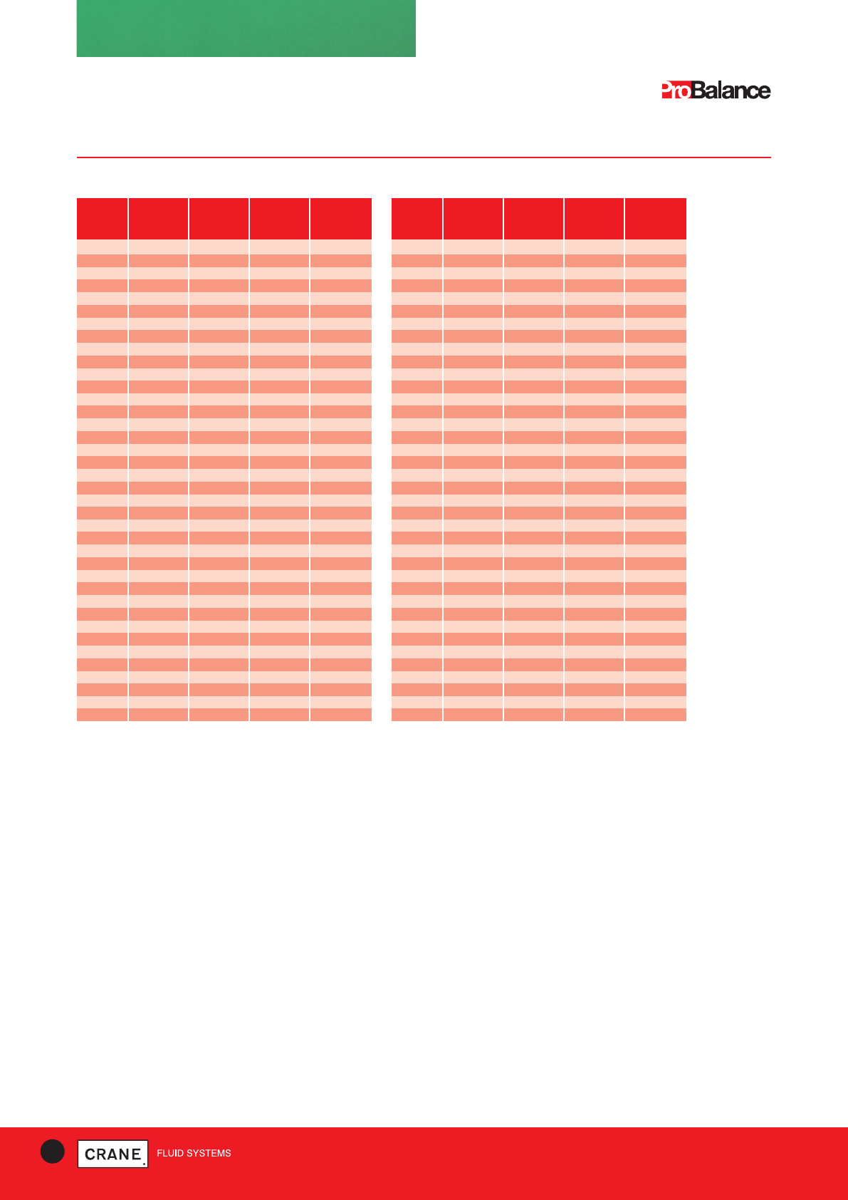
C960
ABV Cartridges
11⁄4" to 11⁄2" Cartridges
FLOW WHITE BLUE RED ORANGE
l/s 15-85 22-180 32-280 45-380
kPa kPa kPa kPa
0.209 100
0.244 105
0.281 100
0.303 110
0.324 105
0.361 115
0.363 105
0.385 110
0.392 110
0.439 120
0.450 115
0.458 125
0.521 130
0.525 110
0.550 135
0.561 120
0.583 115
0.596 140
0.619 125
0.636 145
0.666 150
0.713 155
0.720 120
0.732 125
0.735 130
0.755 135
0.771 140
0.796 160
0.800 145
0.829 125
0.838 130
0.878 130
0.892 150
0.900 170
0.903 135
0.908 135
0.944 155
0.964 175
FLOW WHITE BLUE RED ORANGE
l/s 15-85 22-180 32-280 45-380
kPa kPa kPa kPa
0.981 145
1.011 180
1.018 140
1.033 160
1.067 185
1.086 145
1.097 140
1.119 190 150
1.133 150
1.161 195
1.169 155 155
1.210 200
1.225 170
1.242 175
1.247 160
1.262 160
1.306 205
1.333 210
1.382 170
1.383 170
1.400 180
1.439 175
1.440 215
1.470 185
1.494 190
1.561 180
1.572 195
1.600 185
1.632 200
1.646 175
1.660 190
1.742 195
1.751 180
1.763 205
1.800 210
1.910 200
1.917 185
1.958 205
2’’ to 3’’ cartridge information is available on request
Every effort has been made to ensure that the information contained in this publication is accurate at the time of publishing. Crane Ltd assumes no responsibility or liability for typographical errors or omissions or for
any misinterpretation of the information within the publication and reserves the right to change without notice.
7
TECHNICAL HELPLINE: +44 (0)1473 277400
www.cranefs.com
BALANCING VALVES - STATIC
Flow Measurement Device (FMD)
D901/D902 PN25
D901
Specification
D901 & D902
Flow Measurement Devices have square edged entrance orifice plates
with tappings for P84 insertion style test points. Flow measurement
accuracy of ±3%.
D901 - Sizes 1/2|| to 2||
Inlet - BS EN 10226 formerly BS21 (ISO 7 ) taper female
Outlet - BS EN 10226 formerly BS21 (ISO 7) taper male
D901/D902 - Sizes 1/2||
Inlet - (ISO 228) parallel female supplied with compression adaptor to suit
15mm BS EN 1057: Half hard R250 copper tube.
Outlet - BS EN 10226 formerly BS21 (ISO 7) taper male. Discard adaptor
if connecting steel pipe.
Application
D901 Flow Measurement Devices are suitable for systems where pipes
have been sized on the basis that pipe frictional losses lie in the range
100 to 400 Pa/m.
D902 Flow Measurement Device (1/2||/15mm size only) is suitable for the
measurement of ultra low flows in the range 0.015 to 0.06 l/s e.g. flows
to fan coil units.
Please note: The fitting of P82 test points will give an increased
temperature rating of 180°C.
Conforms to BS7350*: 1990
TEMPERATURE (°C) -10 to 100 110 120
PRESSURE (BAR) 25 23.4 21.8
Threaded
Pressure/Temperature Ratings
TEMPERATURE (°C) -10 to 30 65 120
PRESSURE (BAR) 16 10 5
Compression
Intermediate pressure ratings shall be determined by
interpolation
Maximum temperature 120°C
Note: In line with BS EN 1254/2, the maximum pressure
must not exceed 16 bar when using compression
adaptors.
*Except pressure rating exceeds BS.
Dimensional Drawing
CAT. NO. NOM. END TO CENTRE- FLOW HEAD Kvs WEIGHT
SIZE END TO-TOP LOSS
A (mm) A1 (mm) B (mm) (Kv) (K) (kg)
D901 1/2|| DN15 57 66 55 2.8 13.5 2.2 0.29
3/4|| DN20 58 - 61 6.1 9.1 4.7 0.30
1|| DN25 66 - 65 11.9 6.1 8.6 0.40
11/4|| DN32 72 - 71 23.4 4.8 16.6 0.50
11/2|| DN40 72 - 73 36.2 3.7 24.5 0.54
2|| DN50 82 - 79 71.6 2.4 46.1 0.77
D902 1/2|| DN15 57 66 55 0.57 333 0.54 0.29
Dimensions, Coefficients and Weights
Materials
PART MATERIAL SPECIFICATION
Body and Integral orifice DZR copper alloy BS EN 12165 CW602N
P84 Pressure test point DZR copper alloy BS EN 12164 CW602N
A
A1
B
Every effort has been made to ensure that the information contained in this publication is accurate at the time of publishing. Crane Ltd assumes no responsibility or liability for typographical errors or omissions or for
any misinterpretation of the information within the publication and reserves the right to change without notice.
BALANCING VALVES - STATIC
Flow Measurement Device (FMD)
DM900 PN25
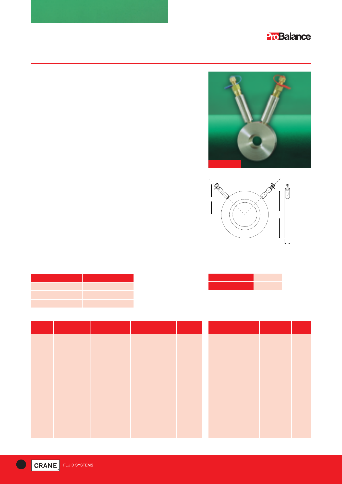
Specification
DM900 is a stainless steel orifice plate which has a square edged
entrance. The two stainless steel extension tubes are fitted with Crane
P84 pressure test points. Accuracy of flow measurement at normal
velocities is ±3%.
Application
DM900 can be used as a single unit or close coupled to other regulating
or isolating valves to provide accurate flow measurement.
Suitable for use with PN10. PN16, or PN25 flanges or flanged valves with
ratings detailed in the appropriate flange or valve product standard.
When fitted with P84 pressure test points, the DM900 is limited to 120°C
max. For use at temperatures above 120°C, suitable alternative pressure
test points should be fitted. For temperatures between 120-180°C,
replace P84 with P82. Please consult Crane Fluid Systems’ technical
team for more information.
Installation
The DM900 can be mounted between valve and/or pipe flanges to
BS EN 1092-1+2 with PN10, PN16 or PN25 ratings. The outside diameter
ensures a proper alignment when installed between PN10/16 flanges and
PN25 flanges up to 80mm size. When assembling between PN25 flanges
sized 100mm and larger, ensure the device has been correctly centered
with the mating flanges.
Conforms to BS7350: 1990*
DM900
8TECHNICAL HELPLINE: +44 (0)1473 277400
www.cranefs.com
TEMPERATURE (°C) -10 to 120
PRESSURE (BAR) 25.0
Pressure/Temperature Ratings
PART MATERIAL
Orifice and carrier Stainless steel
Extension tubes Stainless steel
Pressure test points (P84) DZR
Materials
B
CC
AA
Dimensional Drawing
A
C
B
DN FACE-TO-FACE CENTRE-TO-TOP OUTSIDE DIAMETER WEIGHT
A (mm) B (mm) C (mm) (kg)
20 18 116 63 0.7
25 18 119 73 0.8
32 18 124 84 1.0
40 18 127 94 1.1
50 18 131 109 1.4
65 18 114 129 1.5
80 18 120 144 1.8
100 18 127 164 2.2
125 18 137 194 2.6
150 18 147 220 3.0
200 18 167 275 4.4
250 18 187 331 5.7
300 18 207 386 7.1
350 21 216 444 12.4
400 21 235 495 14.5
450 21 256 555 18.0
500 21 278 617 22.1
600 25 319 734 36.1
DN FLOW HEADLOSS KVS
(Kv) (K)
20 6.0 9.6 4.7
25 11.6 6.6 8.6
32 23 5.1 16.6
40 35 4.0 24.5
50 72 2.5 46.1
65 154 1.5 90
80 220 1.4 120
100 373 1.4 220
125 570 1.4 342
150 789 1.5 468
200 1383 1.6 792
250 2122 1.7 1224
300 3116 1.6 1800
350 2754 2.6 1795
400 3573 2.6 2334
450 4583 2.6 2981
500 5686 2.6 3700
600 8229 2.6 4491
Dimensions and Weights Coefficients
*Larger sizes available on application. *Except pressure rating exceeds BS.
Every effort has been made to ensure that the information contained in this publication is accurate at the time of publishing. Crane Ltd assumes no responsibility or liability for typographical errors or omissions or for
any misinterpretation of the information within the publication and reserves the right to change without notice.
9
TECHNICAL HELPLINE: +44 (0)1473 277400
www.cranefs.com
BALANCING VALVES - STATIC
Double Regulating Valve (DRV)
D921/D923 PN25
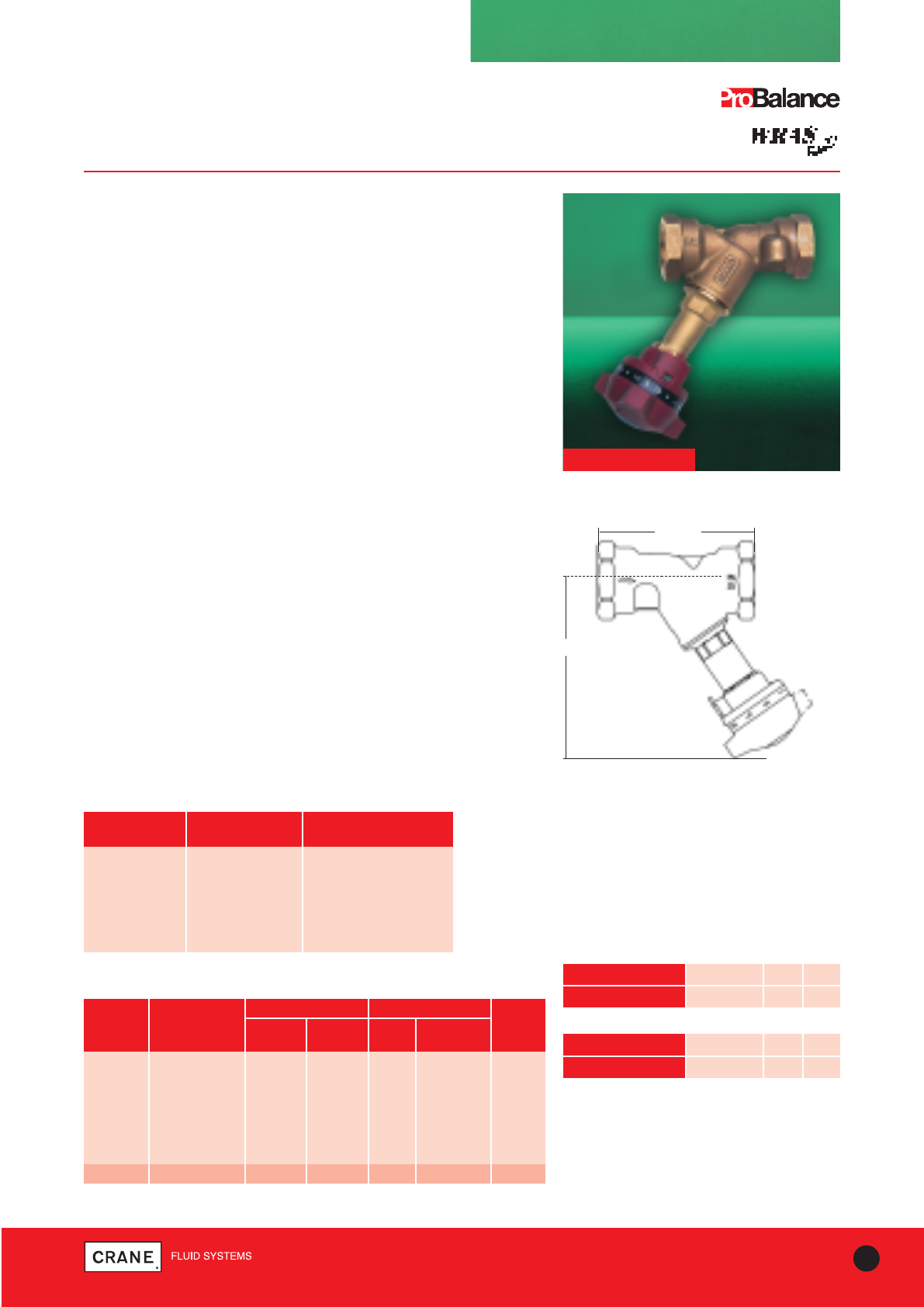
Specification
The Double Regulating Valve offers an accuracy of ± 5% on all settings,
for precise flow regulation.
They are Y-pattern globe valves with characterised throttling disc tending
towards equal percentage performance. Double regulating feature allows
valve opening to be set with an Allen key. Operation of the valve is by
means of the Microset hand wheel.
WRAS Approved.
End Connection
Sizes 1|| to 2|| taper threaded to BS EN 10226-2 (ISO 7-1) formerly BS 21.
Sizes 1/2|| & 3/4|| DN15 & DN20 parallel threaded to BS EN ISO 228-1
(formerly BS 2779).
Adaptor kits for use with copper tube also available.
Also available threaded to ANSI B1.20.1. Please add suffix AT to denote
American Thread i.e. D921AT/D923AT
Application
In two unit systems, the D921 has sufficient authority to give effective
regulation over the range of flows covered by matching flow
measurement devices/valves.
In particular, the D923 low flow regulating valve has an authority matched
to the range of ultra low flows covered by the D902 flow measurement
device.
Conforms to BS 7350* : 1990
D921
Pressure/Temperature Ratings
FIG. NO. NOM. SIZE FLOW HEAD LOSS WEIGHT
A B (Kv) (K) (kg)
D921 1/2|| DN15 87 105 2.14 23.11 0.54
3/4|| DN20 96 106 3.61 26.14 0.58
1|| DN25 100 127 6.37 21.45 0.88
1 1/4|| DN32 114 128 12.30 17.42 1.05
1 1/2|| DN40 125 143 21.30 10.66 1.43
2|| DN50 146 144 31.30 12.63 1.88
D923 1/2|| DN15 87 105 2.26 20.72 0.54
Dimensions, Coefficients and Weights TEMPERATURE (°C) -10 to 100 110 120
PRESSURE (BAR) 25 23.4 21.8
Threaded
TEMPERATURE (°C) -10 to 30 65 120
PRESSURE (BAR) 16 10 5
Compression
Intermediate pressure ratings shall be determined by
interpolation.
Maximum temperature 120°C
Note: In line with BS EN 1254/2 the maximum pressure
must not exceed 16 bar when using compression
adaptors
*Except pressure rating which exceeds BS
FULLY OPEN
A
(all sizes)
B
Materials
Dimensional Drawing
DIMENSIONS (mm)
PART MATERIAL SPECIFICATION
Body Bronze BS EN 1982 CC491K
Bonnet DZR copper alloy BS EN 12165 CW602N
Stem DZR copper alloy BS EN 12165 CW602N
Disc DZR copper alloy BS EN 12165 CW602N
'O' Ring Seal EPDM Rubber
Hand Wheel Plastic
Every effort has been made to ensure that the information contained in this publication is accurate at the time of publishing. Crane Ltd assumes no responsibility or liability for typographical errors or omissions or for
any misinterpretation of the information within the publication and reserves the right to change without notice.
PART MATERIAL SPECIFICATION
Body Bronze BS EN 1982 CC491K
Bonnet DZR copper alloy BS EN 12165 CW602N
Stem DZR copper alloy BS EN 12164 CW602N
Disc DZR copper alloy BS EN 12164/5 CW602N
‘O’ Ring Seal EPDM Rubber
Orifice Insert DZR copper alloy BS EN 12164 CW602N
P84 test valve DZR copper alloy BS EN 12164 CW602N
Hand Wheel Plastic
Materials
BALANCING VALVES - STATIC
Fixed Orifice Double Regulating Valve (FODRV)
D931/D933/D934 PN25
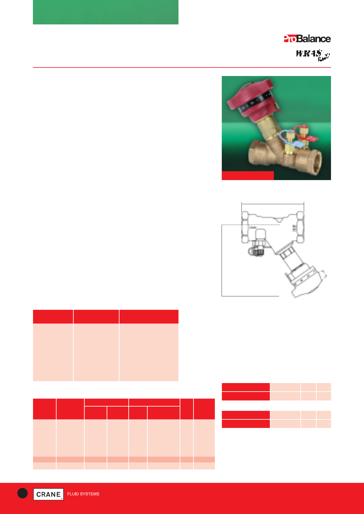
Specification
The Double Regulating Valve, with its integral fixed orifice design, offers
an accuracy of ± 5% on all settings, for precise flow regulation and
measurement.
They are Y-pattern globe valves having characterised throttling disc
tending towards equal percentage performance. Integral square edged
entrance orifice plate and P84 insertion test points fitted. Double
regulating feature allows valve opening to be set with an Allen key.
Operation of the valve is by means of the Microset hand wheel.
The Double Regulating feature allows the valve to be used for isolation
and to be re-opened to its pre-set position to maintain required flow rate.
End Connection
Sizes 1|| to 2|| taper threaded to BS EN 10226-2 (ISO 7-1) formerly BS 21.
Sizes 1/2|| & 3/4|| DN15 & DN20 BS 2779 (ISO 228) parallel
Adaptor kits for use with copper tube also available
Also available threaded to ANSI B1.20.1AT
Order code D931AT/D933AT/D934AT
Application
D933 size 1/2|| low flow FODRV combines the functions of regulation and
flow measurement in a unit of high authority making it particularly suitable
for low flow applications in the range of 0.03 to 0.07 I/s.
D934 size 1/2|| ultra low flow FODRV combines the functions of regulation
and flow measurement in a unit of high authority making it particularly
suitable for ultra low flow applications in the range of 0.016 to 0.04 I/s.
Conforms to BS 7350* : 1990
D931
10 TECHNICAL HELPLINE: +44 (0)1473 277400
www.cranefs.com
Pressure/Temperature Ratings
TEMPERATURE (°C) -10 to 100 110 120
PRESSURE (BAR) 25 23.4 21.8
Threaded
TEMPERATURE (°C) -10 to 30 65 120
PRESSURE (BAR) 16 10 5
Compression
Intermediate pressure ratings shall be determined by
interpolation.
Maximum temperature 120°C
Note: In line with BS EN 1254/2, the maximum pressure
must not exceed 16 bar when using compression
adaptors
*Except pressure rating exceeds BS
FIG. NO. NOM. SIZE FLOW HEAD LOSS KVs WEIGHT
A B (Kv) (K) (kg)
D931 1/2|| DN15 87 105 1.87 30.27 2.2 0.61
3/4|| DN20 96 106 3.14 34.55 4.7 0.65
1|| DN25 100 127 5.59 27.85 8.6 0.95
11/4|| DN32 114 128 10.80 22.60 16.6 1.13
11/2|| DN40 125 143 18.10 14.76 24.5 1.52
2|| DN50 146 144 29.10 14.62 46.1 1.98
D933 1/2|| DN15 87 105 1.06 94.20 1.1 0.61
D934 1/2|| DN15 87 105 0.57 325.8 0.58 0.61
Dimensions, Coefficients and Weights
FULLY OPEN
B
A
Dimensional Drawing
DIMENSIONS (mm)
Every effort has been made to ensure that the information contained in this publication is accurate at the time of publishing. Crane Ltd assumes no responsibility or liability for typographical errors or omissions or for
any misinterpretation of the information within the publication and reserves the right to change without notice.
11
TECHNICAL HELPLINE: +44 (0)1473 277400
www.cranefs.com
BALANCING VALVES - STATIC
Fixed Orifice Double Regulating Valve (FODRV)
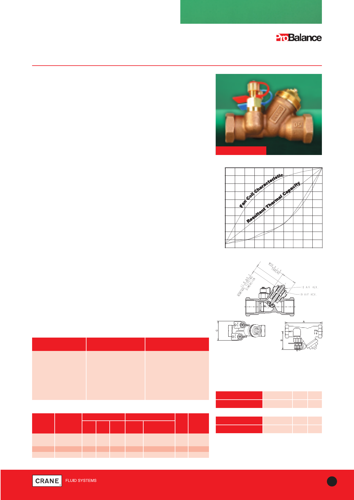
MotoBalance D981P/D983P/D984P PN16
D981P
Pressure/Temperature Ratings
The maximum static pressure is 16 bar, the maximum
differential pressure is 1.2 bar.
Maximum working temperature: 120°C
Minimum working temperature: -10°C
TEMPERATURE (°C) -10 to 100 110 120
PRESSURE (BAR) 16.0 14.8 13.5
Threaded
TEMPERATURE (°C) -10 to 30 65 120
PRESSURE (BAR) 16 10 5
Compression
Intermediate pressure ratings shall be determined by
interpolation.
Note: In line with BS EN 1254/2 the maximum pressure
must not exceed 16 bar when using compression
adaptors
FIG. NO. NOM. SIZE FLOW HEAD LOSS KVs WEIGHT
A C B (Kv) (K) (kg)
D981P 1/2|| DN15 87 50 46 1.245 30.27 2.2 0.41
3/4|| DN20 96 51 51 2.300 34.55 4.7 0.45
D983P 1/2|| DN15 87 50 46 0.667 90.42 1.1 0.41
D984P 1/2|| DN15 87 50 46 0.587 325.80 0.58 0.41
Dimensions, Coefficients and Weights
FULLY OPEN
PART MATERIAL SPECIFICATION
Body Bronze BS EN 1982 CC491K
Bonnet DZR copper alloy BS EN 12165 CW602N
Stem DZR copper alloy BS EN 12165 CW602N
Disc EPDM rubber
‘O’ Ring Seal EPDM rubber BS 4518 0056-024
Orifice Insert DZR copper alloy BS EN 12165 CW602N
P84 Test Point DZR copper alloy BS EN 12165 CW602N
Materials
D981 DN20 MotoBalance
0
10
20
30
40
50
60
70
80
90
100
0 10 20 30 40 50 60 70 80 90 100
Valve % Open Position
Flow % Kv
D981 DN20
Theoretical (k=20)
RTC
Fan Coil
Characteristics
DIMENSIONS (mm)
Specification
Y-pattern globe valve.
Integral square edged entrance orifice plates and P84 insertion test points
fitted.
Double regulating feature allows valve opening to be manually set.
Operation of the valve is by means of motorised actuator.
MotoBalance should be fitted with a suitable actuator. These include
thermal actuators for on/off control specified ‘normally open or normally
closed’ with either 24V or 230V supply. Alternatively use with a fully
modulating control actuator that requires a 24V supply and a control signal
0-10V.
The Double Regulating feature allows the valve to be used for isolation
and to be re-opened to its pre-set position to maintain required flow rate.
End Connection
Sizes 1/2|| and 3/4|| DN15 & DN20 parallel threaded to BS EN ISO 228-1
(formerly BS 2779).
All sizes also available threaded ANSI B1.20.1. Please add suffix AT to
denote American Thread.
Application
The MotoBalance valve is designed for installation in circuits where
combined functions of actuated regulation and flow measurement are
required. Accuracy of flow measurement is ± 5% across all drive settings.
D981P - The 1/2|| MotoBalance has a flow range of 0.061 to 0.132 l/s.
The 3/4|| MotoBalance has a flow range of 0.131 to 0.289 l/s.
D983P - 1/2|| low flow MotoBalance is particularly suitable for low flow
applications in the range of 0.03 to 0.07 l/s.
D984P - 1/2|| ultra low flow MotoBalance is particularly suitable for ultra low
flow applications in the range of 0.016 to 0.04 l/s.
Suitable for actuation
Profiled disc gives equal percentage flow control
Every effort has been made to ensure that the information contained in this publication is accurate at the time of publishing. Crane Ltd assumes no responsibility or liability for typographical errors or omissions or for
any misinterpretation of the information within the publication and reserves the right to change without notice.
DN FACE-TO-FACE CENTRE-TO-TOP WEIGHT
A (mm) B (mm) (kg)
65 290 262 15.8
80 310 267 19.5
100 350 300 28.0
125 400 325 37.5
150 480 340 50.5
200 600 525 123.0
250 730 575 192.0
300 850 645 251.0
Dimensions and Weights
DN FLOW HEADLOSS
(Kv) (K)
65 85 4.9
80 111 5.5
100 146 9.2
125 250 7.3
150 380 6.5
200 600 7.8
250 1211 4.6
300 1521 6.0
Coefficients*
BALANCING VALVES - STATIC
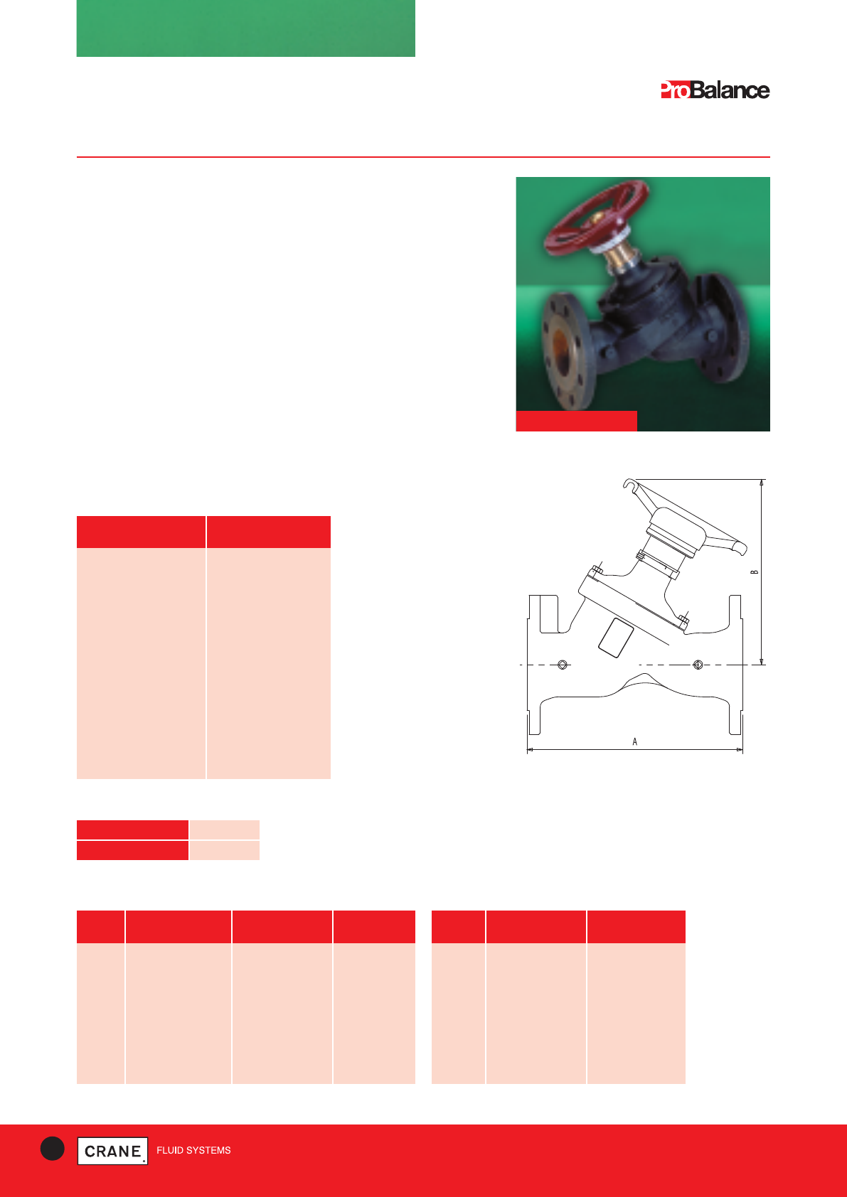
Double Regulating Valve (DRV)
DM921 PN16
Specification
Y-pattern globe valve with a characterised throttling disc and ends
flanged to BS EN 1092-2 PN16.
The valve opening may be set to control flow at a pre-determined rate.
Operation of the valve is by means of a hand wheel incorporating a
micrometer device.
The Double Regulating feature allows the valve to be used for isolation
and to be re-opened to its pre-set position to maintain required flow rate.
Application
In two unit systems, the DM921 has sufficient authority to regulate flow in
circuits incorporating a flow measurement device.
Fitted with 2 x 1/4|| BSPT plugs for conversion to DM931 if required.
Conform to BS 7350 : 1990*
DM921
TEMPERATURE (°C) -10 to 120
PRESSURE (BAR) 16.0
Pressure/Temperature Ratings
Ratings align with BS EN 1092-2 PN16 (formerly BS4504)
PART MATERIAL
Body Ductile Iron
Bonnet Ductile Iron
Bonnet gasket Non-asbestos
Disc (All sizes) EPDM
Coated Cast Iron
Disc Bush Bronze
Stem 410 SS
Gland (65 to 150mm) Brass
Gland (200 to 300mm) Cast Iron
Gland nut Brass
Packing Non-asbestos
Seat ring Bronze
Materials
* Fully open position
Dimensional Drawing
12 TECHNICAL HELPLINE: +44 (0)1473 277400
www.cranefs.com
* Except pressure rating exceeds BS
Every effort has been made to ensure that the information contained in this publication is accurate at the time of publishing. Crane Ltd assumes no responsibility or liability for typographical errors or omissions or for
any misinterpretation of the information within the publication and reserves the right to change without notice.
13
TECHNICAL HELPLINE: +44 (0)1473 277400
www.cranefs.com
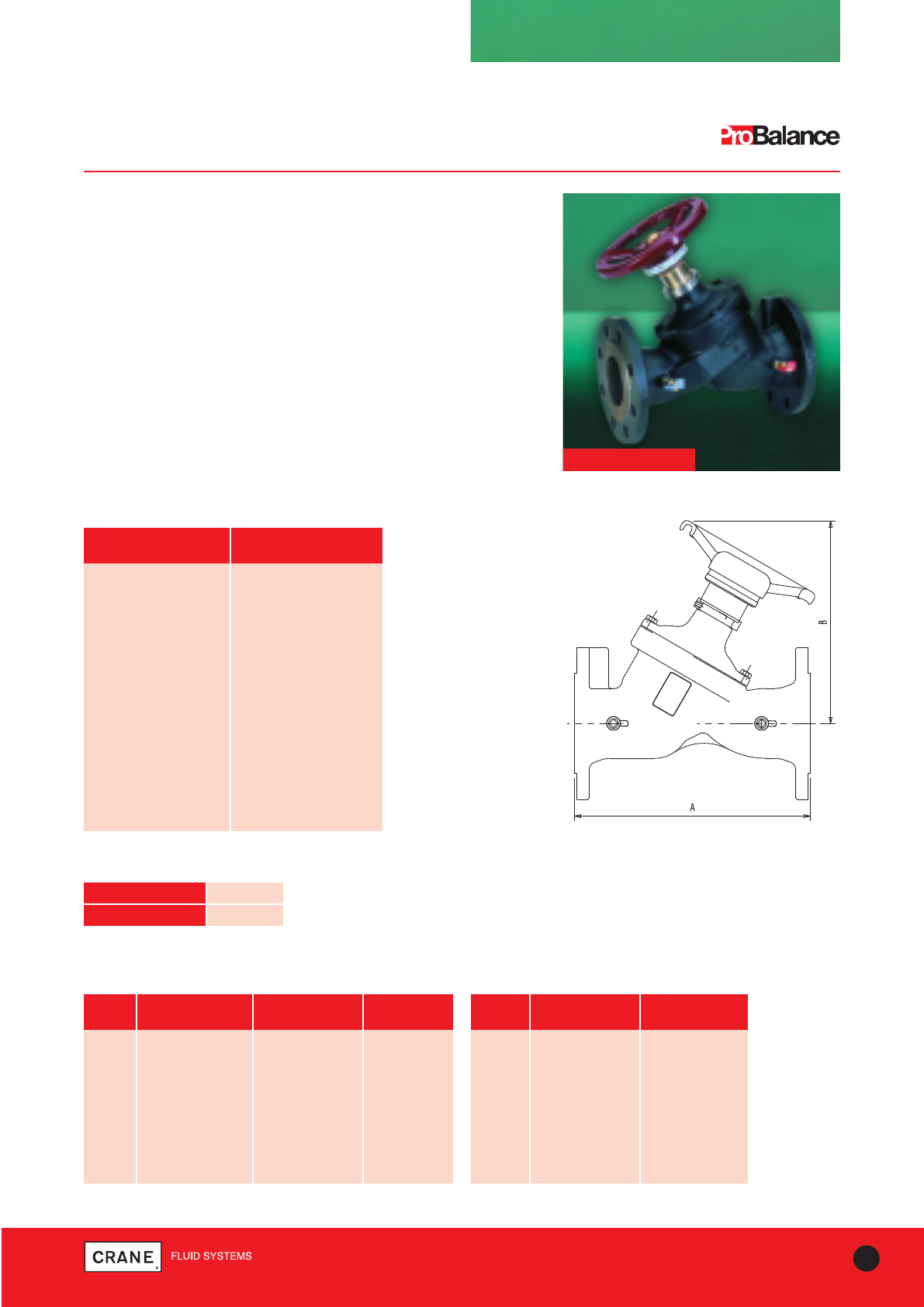
BALANCING VALVES - STATIC
Variable Orifice Double Regulating Valve (VODRV)
DM931 PN16 DA931 Class 125
Specification
These are Y-pattern globe valves supplied with two pressure test points
P84 to provide flow measurement, regulation and isolation. Valves
conform to requirements of BS 7350: 1990 and ends are flanged to
BS EN 1092-2 (formerly BS 4504).
Application
Primarily used in injection or other circuits requiring a double regulating
valve for system balancing. Accuracy of flow measurement is ±10% at
the full open position of the valve. Some reduction in accuracy occurs at
partial openings of the valve in accordance with BS 7350.
The Double Regulating feature allows the valve to be used for isolation
and to be re-opened to its pre-set position to maintain required flow rate. DM931
Materials
TEMPERATURE (°C) -10 to 120
PRESSURE (BAR) 16.0
Pressure/Temperature Ratings
Ratings align with BS EN 1092-2 PN16 (formerly BS4504)
PART MATERIAL
Body Ductile Iron
Bonnet Ductile Iron
Bonnet gasket Non-asbestos
Disc (All sizes) EPDM Coated Cast iron
Disc Bush Bronze
Stem 410 SS
Gland (65 to 150mm) Brass
Gland (200 to 300mm) Cast Iron
Gland nut Brass
Packing Non-asbestos
Seat ring Bronze
DN FACE-TO-FACE CENTRE-TO-TOP WEIGHT
A (mm) B (mm) (kg)
65 290 262 15.8
80 310 267 19.5
100 350 300 28.0
125 400 325 37.5
150 480 340 50.5
200 600 525 123.0
250 730 575 192.0
300 850 645 251.0
Dimensions and Weights
DN FLOW HEADLOSS
(Kv) (K)
65 85 4.9
80 111 5.5
100 146 9.2
125 250 7.3
150 380 6.5
200 600 7.8
250 1211 4.6
300 1521 6.0
Coefficients*
* Fully open position
Dimensional Drawing
Every effort has been made to ensure that the information contained in this publication is accurate at the time of publishing. Crane Ltd assumes no responsibility or liability for typographical errors or omissions or for
any misinterpretation of the information within the publication and reserves the right to change without notice.
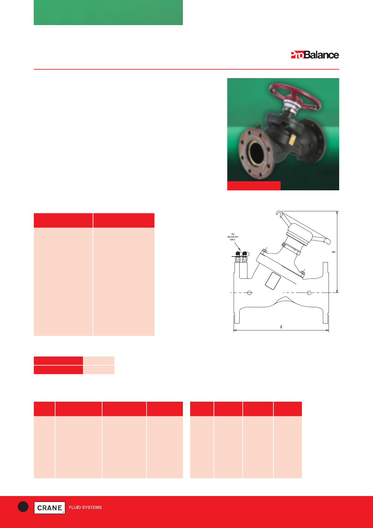
BALANCING VALVES - STATIC
Fixed Integral Orifice Double Regulating Valve (FODRV)
DM941 PN16 DA941 Class 125
Specification
Single unit Y-pattern globe valves incorporating an integral orifice plate to
form a fixed orifice flow measurement unit with regulation and isolation
capacity. Valves conform to requirements of BS 7350: 1990 and ends are
flanged to BS EN 1092-2 (formerly BS 4504).
Application
Primarily used in injection or other circuits requiring a double regulating
valve for system balancing. Accuracy of flow measurement is ±5% at all
open positions of the valve in accordance with BS 7350 : 1990.
The Double Regulating feature allows the valve to be used for isolation
and to be re-opened to its pre-set position to maintain required flow rate. DM941
14 TECHNICAL HELPLINE: +44 (0)1473 277400
www.cranefs.com
TEMPERATURE (°C) -10 to 120
PRESSURE (BAR) 16.0
Pressure/Temperature Ratings
Ratings align with BS EN 1092-2 PN16 (formerly BS4504)
Materials
PART MATERIAL
Body Ductile Iron
Bonnet Ductile Iron
Bonnet gasket Non-asbestos
Disc (All sizes) EPDM Coated Cast Iron
Disc Bush Bronze
Stem 410 SS
Gland (65 to 150mm) Brass
Gland (200 to 300mm) Cast Iron
Gland nut Brass
Packing Non-asbestos
Seat ring Bronze
DN FACE-TO-FACE CENTRE-TO-TOP WEIGHT
A (mm) B (mm) (kg)
65 290 262 16.3
80 310 267 20.0
100 350 300 28.5
125 400 325 38.0
150 480 340 51.0
200 600 525 124.0
250 730 575 194.0
300 850 645 254.0
Dimensions and Weights
DN FLOW HEADLOSS Kvs
(Kv) (K)
65 93 6.9 90
80 99 6.8 120
100 136 12.7 220
125 229 8.7 342
150 342 8.9 468
200 550 10.3 792
250 1052 6.0 1224
300 1367 7.8 1800
Coefficients*
* Fully open position
Dimensional Drawing
Every effort has been made to ensure that the information contained in this publication is accurate at the time of publishing. Crane Ltd assumes no responsibility or liability for typographical errors or omissions or for
any misinterpretation of the information within the publication and reserves the right to change without notice.
15
TECHNICAL HELPLINE: +44 (0)1473 277400
www.cranefs.com
Dimensional
Drawing
Dimensional Drawing
B
H
A
FG
D
C DIA.
BALANCING VALVES - STATIC
Gearbox Operated Double Regulating Valve
DM925G PN16 DM925L PN16
DN WEIGHT A B C D F G H I J K L
(kg) (mm) (mm) (mm) (mm) (mm) (mm) (mm) (mm) (mm) (mm) (mm)
50 8.6 162 80 150 42 45 54 158 195 83 260 44
65 9.1 175 89 150 45 45 54 158 207 95 260 48
80 11.8 181 95 150 45 45 54 158 213 102 260 48
100 17.2 200 144 150 52 45 54 158 232 124 260 54
125 18.1 213 127 200 54 45 54 148 245 137 260 57
150 19.5 225 139 200 56 45 54 148 256 150 266 57
200 29.5 260 175 300 61 78 81 226 – – – –
250 39.9 292 203 300 66 78 81 226 – – – –
300 54.9 337 242 300 77 78 81 226 – – – –
350 61.0 406 260 300 78 78 81 226 – – – –
400 94.0 447 290 450 86 120 130 277 – – – –
Materials
Pressure/Temperature Ratings
Dimensions and Weights
TEMPERATURE (°C) -10 to 130
PRESSURE (BAR) 16.0
PART MATERIAL SIZES
Body Ductile Iron ASTM A536 65-45-12 All
Disc Aluminium Bronze All
Seat EPDM All
Shaft Stainless Steel ASTM A532 Type 416 All
Taper Pin Stainless Steel ASTM A276 Type 316 All
Key Carbon Steel All
‘O’ Ring Nitrile (Buna) All
Shaft Bushing PTFE or Bronze All
DN FLOW HEADLOSS
(Kv) (K)
50 100 1.216
65 170 0.856
80 261 0.856
100 519 0.650
125 884 0.553
150 1142 0.483
200 1873 0.367
250 2900 0.315
300 5079 0.266
350 10274 0.129
400 14129 0.116
Coefficients*
* Fully open position
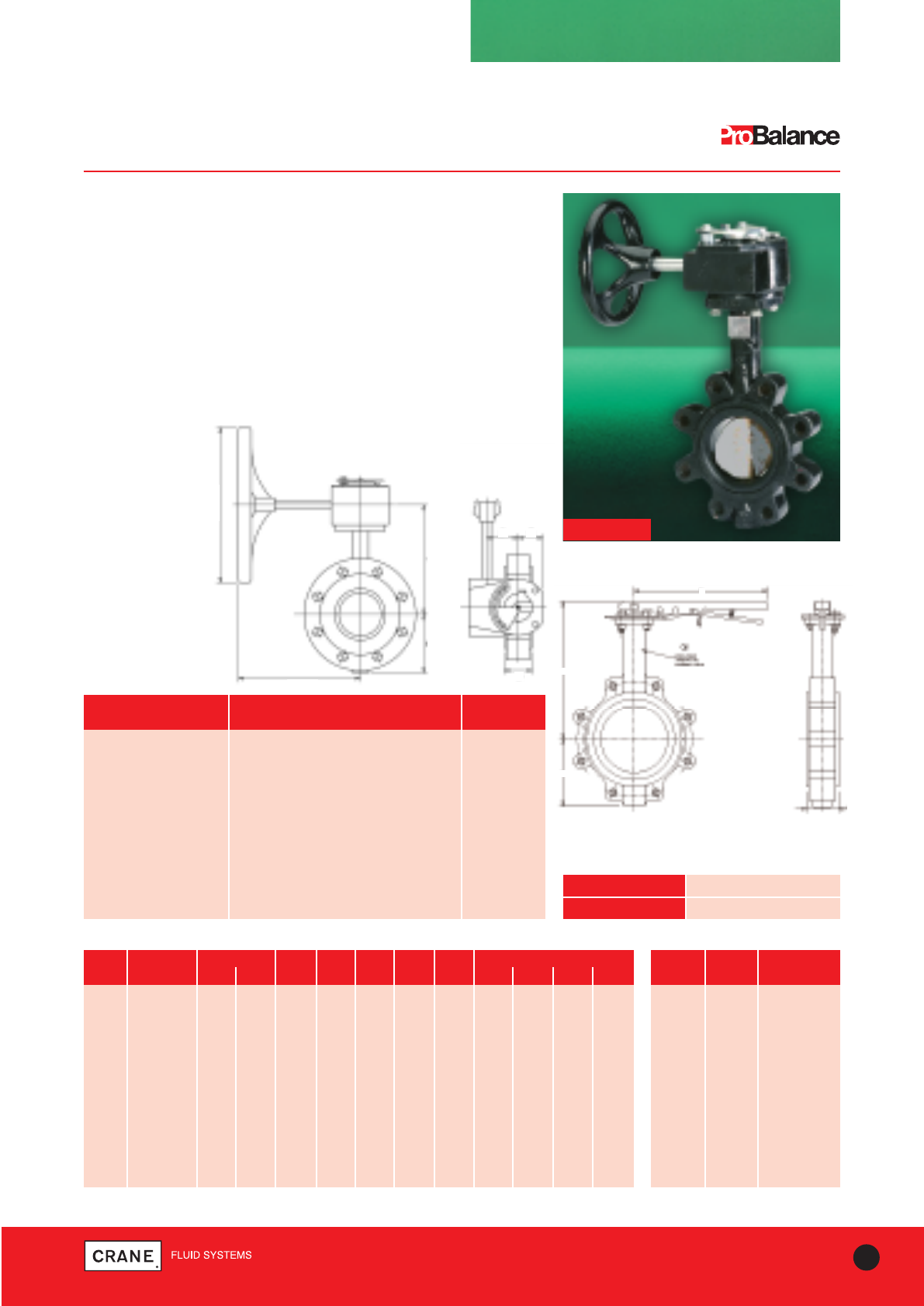
Specification
The DM925G and DM925L Double Regulating Valves consist of a fully
lugged, EPDM liner butterfly valve with a Double Regulating Gearbox or
Lever. The gearbox Double Regulating feature allows the valve to be
used to isolate and to be re-opened to its pre-set position.
The Double Regulating feature allows the valve to be used for isolation
and to be re-opened to its pre-set position to maintain required flow rate.
Installation
As an alternative to the DM921, the DM925G and DM925L can be used
in conjunction with a flow measurement device to measure flow.
DM925G
I
J
L
K
Every effort has been made to ensure that the information contained in this publication is accurate at the time of publishing. Crane Ltd assumes no responsibility or liability for typographical errors or omissions or for
any misinterpretation of the information within the publication and reserves the right to change without notice.
Dimensional Drawing
Dimensional
Drawing
A
BF
G
D
BALANCING VALVES - STATIC
Gearbox Operated Flow Measurement & Regulating Valve
DM950G PN16 DM950L PN16
16 TECHNICAL HELPLINE: +44 (0)1473 277400
www.cranefs.com
DM950G
Pressure/Temperature Ratings
TEMPERATURE (°C) -10 to 120
PRESSURE (BAR) 16
SIZE WEIGHT A B C D F G H I J K L
(kg) (mm) (mm) (mm) (mm) (mm) (mm) (mm) (mm) (mm) (mm) (mm)
50 19.7 162 80 150 158 45 54 158 194 83 260 132
65 20.8 175 89 150 161 45 54 158 95 206 150 260
80 23.4 181 95 150 171 45 54 158 213 102 260 165
100 32.5 200 114 150 181 45 54 158 232 124 260 192
125 38.4 213 127 200 190 45 54 148 244 137 260 219
150 47.1 225 139 200 232 45 54 148 257 150 260 246
200 67.8 260 175 300 287 78 81 226 – – – –
250 89.2 292 203 300 345 78 81 226 – – – –
300 124.2 337 242 300 404 78 81 226 – – – –
350 170 406 260 300 451 78 81 226 – – – –
400 250 447 290 450 511 120 130 277 – – – –
Dimensions and Weights
DN FLOW HEADLOSS Kvs
(Kv) (K)
50 58 3.4 46.1
65 114 2.6 90
80 168 2.3 120
100 303 2.0 220
125 479 1.8 342
150 649 1.8 468
200 1113 1.6 792
250 1713 1.6 1224
300 2656 1.5 1800
350 2754 1.3 1795
400 3573 1.3 2334
Coefficients*
Materials
PART MATERIAL SIZES
Extension piece Steel DIN 17100 150-400mm
R.St.37.2/ASTM A53.Gr.A
Extension piece Steel DIN 17100 R.St. 37.2 50-125mm
P84 Test Valve See Fig No P84 All
Orifice Plate Retain Steel DIN 17100 R.St. 37.2 All
Orifice Plate Stainless steel BS970 316S31 All
Orifice Plate Gasket Asbestos free All
Flange Bolts Steel BS3692 Gr. 8.8 All
DM925G See Fig No DM925G Gear Operated All
Test Point Extension DZR Brass BS EN 12164 CW602N All
Test Point Adaptor DZR Brass BS EN 12164 CW602N 50-125mm
Socket Head Cap Screw Steel BS4168 Gr. 12.9 All Note:
350mm and 400mm limited to 110°C
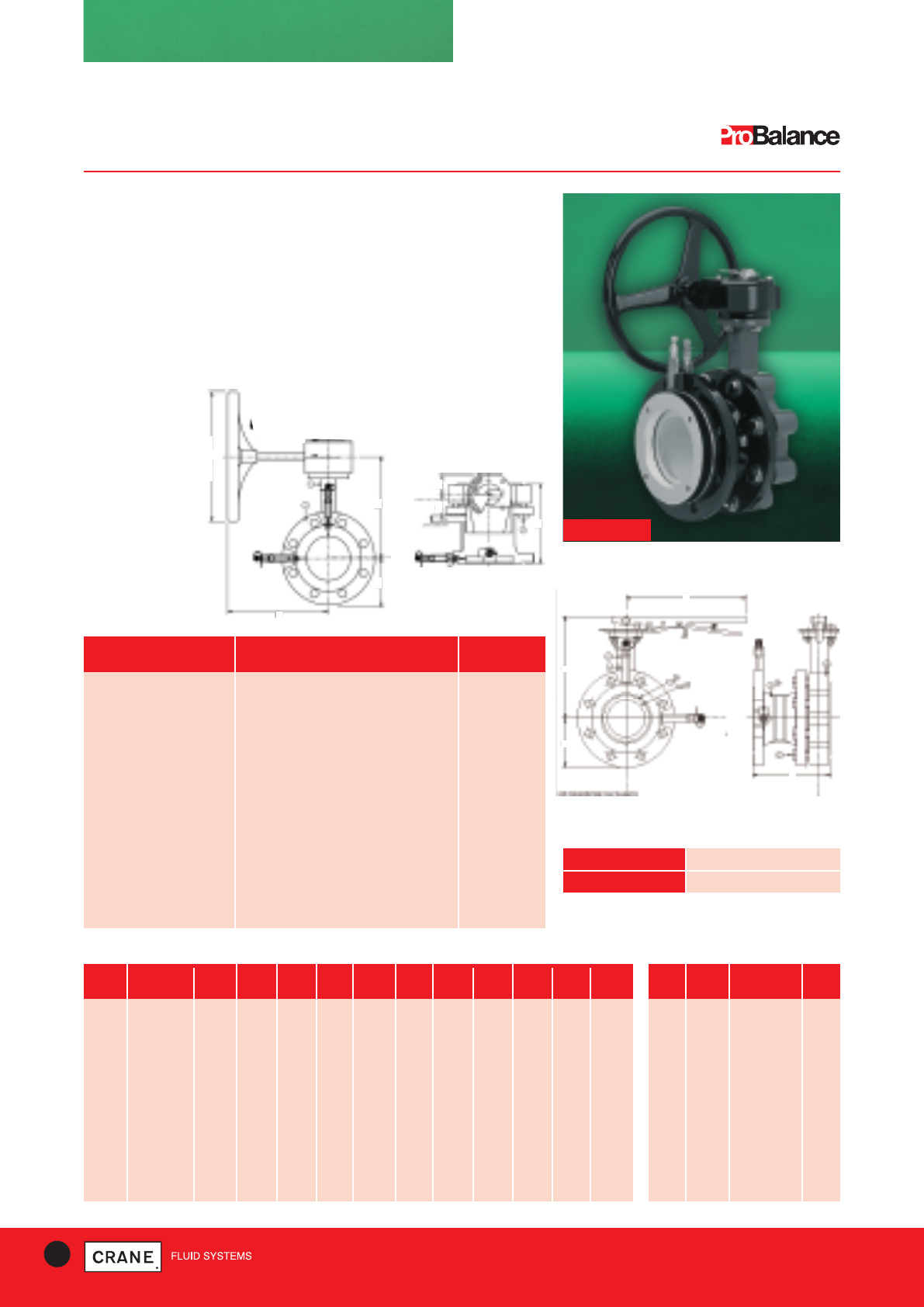
Specification
The DM950G and DM950L consist of a DM925G/L coupled with a fixed
orifice flow measurement device using a spool piece connector, to form a
fixed orifice flow measurement unit with regulation and isolation
capability. Test points are supplied loose.
Installation
The DM950G and DM950L is supplied ready assembled to site. Suitable
gasket and bolting should be provided by the contractor/installer.
IJ
L
K
H
C DIA.
Every effort has been made to ensure that the information contained in this publication is accurate at the time of publishing. Crane Ltd assumes no responsibility or liability for typographical errors or omissions or for
any misinterpretation of the information within the publication and reserves the right to change without notice.
17
TECHNICAL HELPLINE: +44 (0)1473 277400
www.cranefs.com
BALANCING VALVES - STATIC
Gearbox Operated Double Regulating Valve
DM975G PN25 to BS EN 593 : 2009
ITEM PART MATERIAL
1 Body Ductile Iron -
BS EN 12563 EN GJS 500/7
2 Plug Carbon Steel
3 Liner EPDM
4 Shaft (Lower) Steel - AISI 431
5 Disc Stainless Steel - SS304
6 Shaft (Upper) Steel - AISI 431
7 O Ring EPDM
8 Lock Plate Brass - ASTM B16 C36000
9 Snap Ring Carbon Steel
10 Gearbox
Materials
Dimensions and Weights
DM975G
Pressure/Temperature Ratings
TEMPERATURE (°C) -10 to 120
PRESSURE (BAR) 25
DN FLOW HEADLOSS
(Kv) (K)
50 85 1.86
65 204 0.95
80 370 0.50
100 820 0.29
125 982 0.37
150 1353 0.43
200 2923 0.31
250 3374 0.56
300 6350 0.33
Coefficients*
* Fully open position
Also available with lever version
SIZE WEIGHT A B H D E L K N-M H1
(kg) (mm) (mm) (mm) (mm) (mm) (mm) (mm) (mm) (mm)
50 10.0 140 68 35 90 43 160 125 4-M16 172.5
65 10.8 152 76 35 90 45 160 145 8-M16 184.5
80 11.0 160 85 35 90 46 160 160 8-M16 192.5
100 13.0 180 100 35 90 51.5 160 190 8-M20 212.5
125 16.0 191 120 35 90 56 160 220 8-M24 223.5
150 18.5 202 132 35 90 56.5 160 250 8-M24 234.5
200 29.8 241 160 45 125 60 238 310 8-M24 278.0
250 40.0 274 200 45 125 68.5 238 370 12-M27 311.0
300 53.0 315 230 45 125 79.5 238 430 16-M27 366.0
Dimensional Drawing
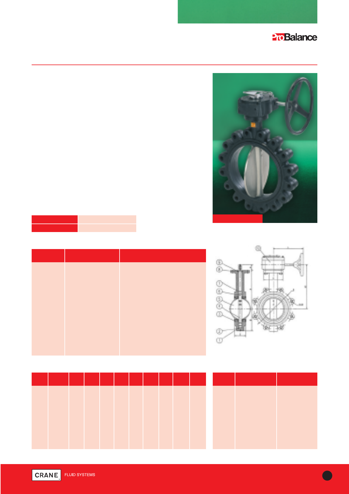
Specification
The DM975G Double Regulating Butterfly Valves consist of:
• A fully lugged butterfly valve for use with PN25 flanges.
• High temperature EPDM liner for applications up to 120°C.
• A Double Regulating Gearbox as standard.
The Double Regulating feature allows the valve to be used for isolation
and to be re-opened to its pre-set position to maintain required flow rate.
Installation
The DM975G can be used in conjunction with a flow measurement
device DM900 to regulate and measure flow.
Every effort has been made to ensure that the information contained in this publication is accurate at the time of publishing. Crane Ltd assumes no responsibility or liability for typographical errors or omissions or for
any misinterpretation of the information within the publication and reserves the right to change without notice.
BALANCING VALVES - STATIC
Pressure Test Valve P82/
Extension Tube P83 / Pressure Test Point P84
Extension Tube P83
Taper threaded to BS EN 10226-2 (ISO 7-1) formerly BS 21
P83 pressure test point extension tubes allow
Crane valves to be insulated to a thickness of
2|| without the test points being covered.
P83
P82
PART MATERIAL SPECIFICATION
Cap DZR copper alloy BSEN12164 CW602N
Cap Washer EPDM
Body DZR copper alloy BSEN12164 CW602N
Tie Polypropylene
Seal EPDM
Retaining Ring DZR copper alloy BSEN12164 CW602N
Materials
PART MATERIAL SPECIFICATION
P83 DZR copper alloy BSEN12164 CW602N
Materials
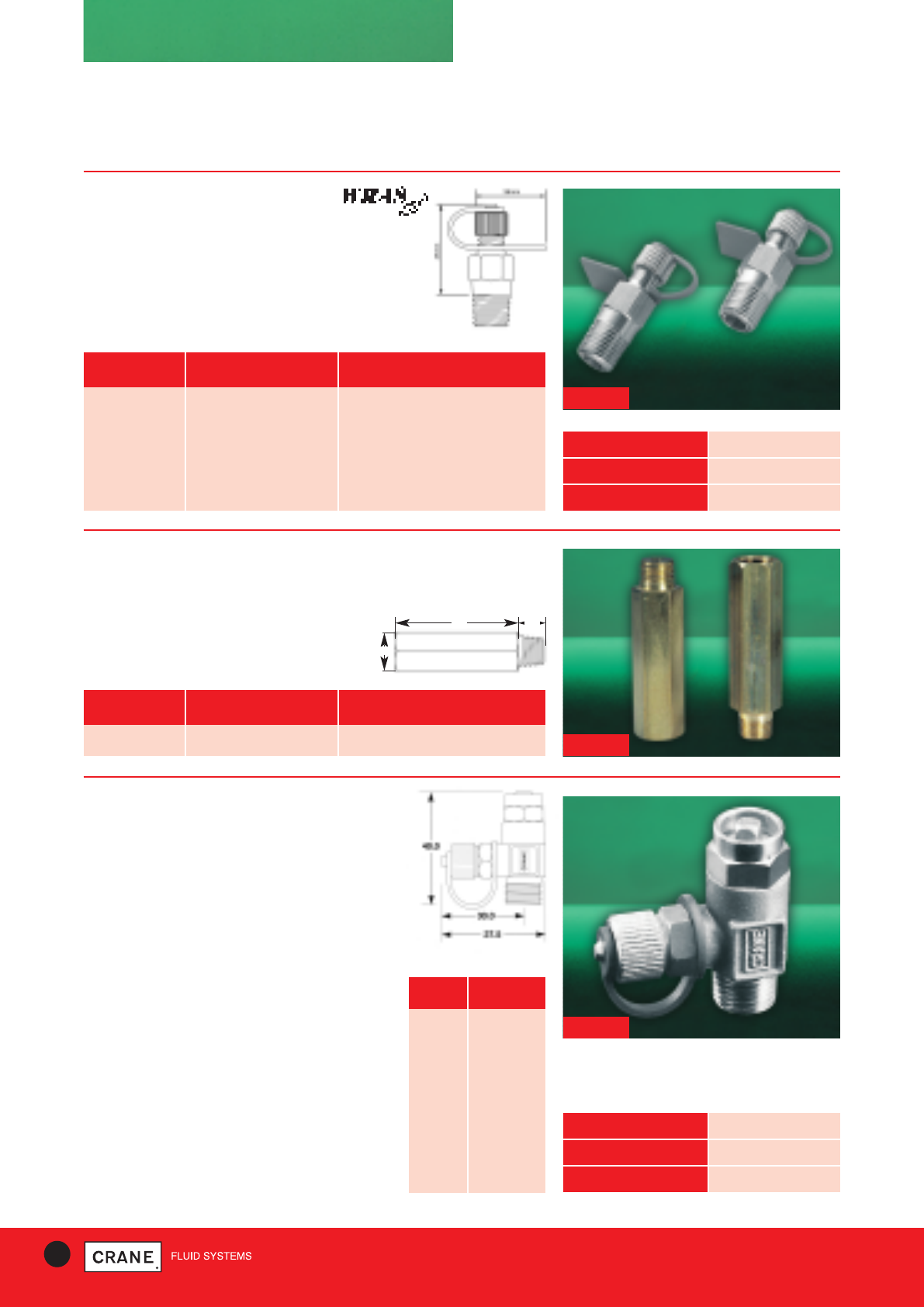
Pressure test valve P82 is suitable for use in LTHW
and MTHW systems. A conventional needle valve,
operated by a standard radiator aircock key, is
backed by a spring loaded self-sealing ball unit to
provide double sealing. The double sealing facility
offers maximum operational safety in accordance
with the Health & Safety at Work legislation. It also
makes it possible, with the valve closed to pipeline
pressure, to clear the ball seat of any pipeline debris.
Although P82 is also suitable for use in HTHW
systems it should not be operated while such a
system is ‘live’. For ‘live’ HTHW systems copper
bleed tubes should be taken from the valves
and terminated in needle valves, e.g. Crane D71 or
D72.
The manometer connection on the valve accepts a
Mechseal adaptor. When not in use a screw cap
protects the connection from dust.
11.3
66.5
17
WEIGHT 0.07kg
PRESSURE RATING PN40
MAX. TEMP. 182°C
WEIGHT 0.025kg
PRESSURE RATING PN25
MAX. TEMP. 120°C
Pressure Test Valve P82
Taper threaded to BS EN 10226-2
(ISO 7-1) formerly BS 21
Materials
PART MATERIAL
Body DZR
Stem DZR
Shield Brass
‘O’ Ring Viton
Adaptor DZR
Ball Stainless
Steel
Spring Stainless
Steel
Dust Cap Brass
Pressure Test Points P84
Taper threaded to BS EN 10226-2
(ISO 7-1) formerly BS 21
P84 insertion style pressure test
points are fitted as standard to Crane flow
measurement and regulation valves.
P84
18 TECHNICAL HELPLINE: +44 (0)1473 277400
www.cranefs.com
Every effort has been made to ensure that the information contained in this publication is accurate at the time of publishing. Crane Ltd assumes no responsibility or liability for typographical errors or omissions or for
any misinterpretation of the information within the publication and reserves the right to change without notice.
19
TECHNICAL HELPLINE: +44 (0)1473 277400
www.cranefs.com
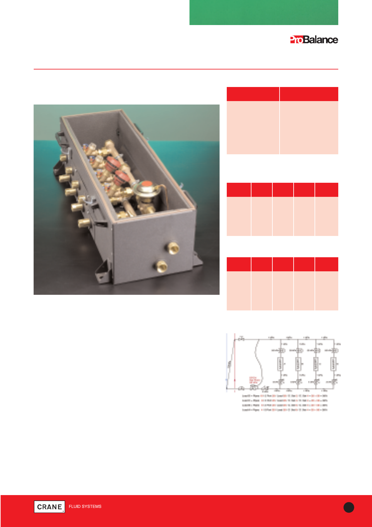
OUTLETS LENGTH HEIGHT WIDTH WEIGHT
& INLETS (mm) (mm) (mm) (kg)
6x6 1120 250 290 40
5x5 1120 250 290 38
4x4 880 250 290 36
3x3 880 250 290 34
2x2 640 250 290 30
Dimensions & Weights
COMMPAC
CommPac
Manifold Commissioning System
Materials
PART MATERIAL
H – Body Bronze (Z3000)
Strainer Bronze (D297)
Manifolds Bronze
Isolation Valves DZR Brass (D171A)
Regulation Valves Bronze
(D931 or D981P Series)
Maximum pressure 16 bar
Temperature rating -10 to 100°C
Units with outlets and inlets on same side
OUTLETS LENGTH HEIGHT WIDTH WEIGHT
& INLETS (mm) (mm) (mm) (kg)
6x6 1120 200 400 40
5x5 1120 200 400 38
4x4 880 200 400 36
3x3 880 200 400 34
2x2 640 200 400 30
Dimensions & Weights
Units with outlets and inlets on opposite side
Typical Schematic
Crane CommPac provides one easy access point for
commissioning and maintenance of multiple
heating/chilled water terminal units.
On large projects, significant time and cost can be eliminated by enabling
commissioning at convenient locations. Ends of corridors, or accessible
cupboards can be used, which would also eliminate disruption to
occupiers during maintenance works.
The CommPac is an exceptionally robust, efficient, practical and
versatile system:
•Depending on flow rates, up to six terminals can be served from a
single CommPac unit.
•All units are custom built to suit site specification.
•All site connections can be made without the need to access the
internal components.
•CommPac is suitable for variable flow or constant flow systems.
•All connections are BSPT Female, enabling standard pipe or specialist
adapters to be used.
•Fan coil units can be flushed, vented and balanced without the time-
consuming 'looping out' procedure. This can be carried out by one
commissioning engineer instead of a team.
•A single strainer serves all circuits, eliminating the need for individual
strainers.
•All systems can be flushed through the unique Dominator ‘H’ body.
•The single DPCV maintains constant differential pressure between
manifolds.
Every effort has been made to ensure that the information contained in this publication is accurate at the time of publishing. Crane Ltd assumes no responsibility or liability for typographical errors or omissions or for
any misinterpretation of the information within the publication and reserves the right to change without notice.
COMMPAC
CommPac
Manifold Commissioning System
20 TECHNICAL HELPLINE: +44 (0)1473 277400
www.cranefs.com
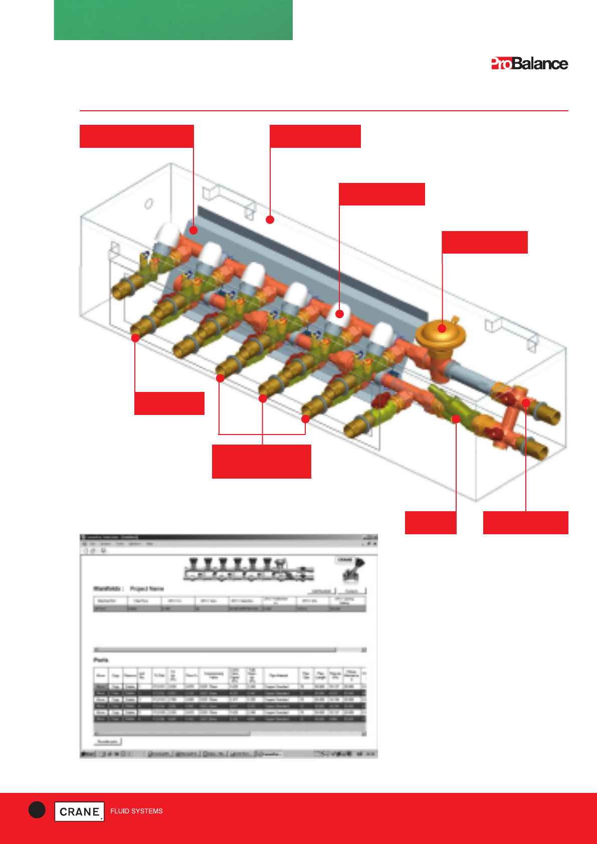
DPCV for Variable
flow systems
Return Balancing
Valves
Insulated box for
Heating or Chilled
Mounting plate for
manifold
All connections
accessible without
entering box
Flow Isolation
Valves
Strainer Unique H-Body
for flushing
CommPac modules are built to suit
individual project design requirements.
Correct selection of balancing valves and
differential pressure control valves is
essential to ensure comfort control and
system efficiency.
To streamline this selection process we
have developed software that allows all
variables to be considered and best valve
options selected. The selection programme
is used by Crane Sales/Technical staff to
input customer information throughout the
design process and ensure that the
optimum design is achieved.
Every effort has been made to ensure that the information contained in this publication is accurate at the time of publishing. Crane Ltd assumes no responsibility or liability for typographical errors or omissions or for
any misinterpretation of the information within the publication and reserves the right to change without notice.
21
TECHNICAL HELPLINE: +44 (0)1473 277400
www.cranefs.com
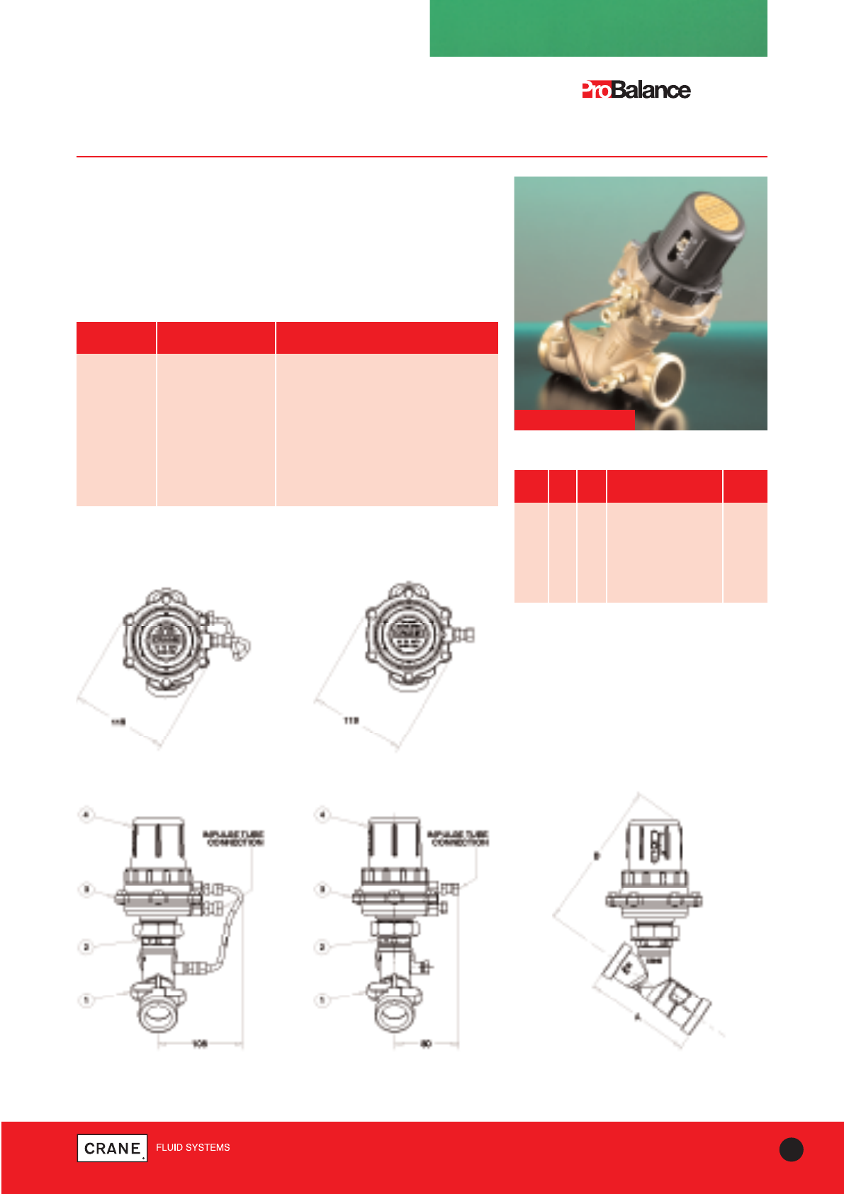
DPCV
Differential Pressure Control Valves
DPAF951 Flow DPAR951 Return
DPCV
ITEM DESCRIPTION MATERIAL
1 Body Bronze BS EN 1982 (CC491K)
2 Bonnet Bronze BS EN 1982 (CC491K)
3 Chamber Bronze BS EN 1982 (CC491K)
4 Adjuster Nylon Grade PA6
INT Stem / Piston Stainless Steel BS EN 10088 - 1: 2005
INT Diaphragm Rubber EPM
INT O-Ring Seals Rubber EPDM SIZE A B END CONNECTION WEIGHT
(mm) (mm) (kg)
DN15 90 175
3/4|| BSP Parallel Male 2.34
DN20 96 175 1|| BSP Parallel Male 2.39
DN25 114 185 1
1/4|| BSP Parallel Male 2.62
DN32 132.5 190 1
1/2|| BSP Parallel Male 2.76
DN40 150.5 195 1
3/4|| BSP Parallel Male 3.07
DN50 184 205 2
3/8|| BSP Parallel Male 3.57
Materials
Dimensions and Weights
Dimensional Drawing
See diagrams for item numbers
INT denotes an internal component not visible on these drawings
Male and female tailpieces are available - please contact
Crane Fluid Systems
To meet the growing use of variable speed pumps for HVAC applications,
Crane Fluid Systems has launched a range of Differential Pressure
Control Valves (DPCV) specifically aimed at optimising system
performance. Extremely efficient, the DPCV is set to a maximum
differential pressure which ensures flow cannot exceed a desired rate. It
therefore helps reduce energy consumption, the risk of noise and
simplifies the commissioning process.
Flow Configuration
Front View
Flow & Return Configuration
Side View
Return Configuration
Front View
Flow Configuration
Top View
Return Configuration
Top View
Every effort has been made to ensure that the information contained in this publication is accurate at the time of publishing. Crane Ltd assumes no responsibility or liability for typographical errors or omissions or for
any misinterpretation of the information within the publication and reserves the right to change without notice.

22 TECHNICAL HELPLINE: +44 (0)1473 277400
www.cranefs.com
DOMINATOR®
Dominator®Z3000 PN16
Flow Management system for terminal units
DESCRIPTION MATERIAL
Bypass valve Bronze to BS EN 1982 CC491K
D931 Refer to page 5
D299P strainer Bronze to BS EN 1982 CC491K
Union Brass to BS EN 12165 CW617N
P84 test points DZR to BS EN 12164 CW602N
Drain cock DZR to BS EN 12164 CW614
Materials
The Z3000 is a prefabricated unit combining the essential control
components and connecting pipework associated with terminal units,
into one compact, fully assembled unit ready for simple and fast on-
site connection.
Features and Benefits
The Dominator is compact and lightweight
•The complete unit is factory tested
•80mm supply/return centres allow for ease of lagging
•Easy to install
The unique bypass valve unit comprising two T-ported ball valves
•Allows easy back flushing, forward flushing and isolation
•The position of the T-handle gives clear indication of flow/bypass mode
•Designed around 3/4|| full bore ball for optimum flow
•Can be adapted to 1/2||, 3/4|| and 1|| end connections
•Simple attachment to existing hangers
The strainer unit has an integral drain cock and pressure test point
•Enabling measurement of pressure drop across load
•Allowing for flushing of strainer and coil without need to remove basket
Benefits for Design Engineers
•minimal design involvement
•all the necessary components supplied as one tested unit
•no risk of a component being omitted from a system at installation
•known performance of the entire unit
•saves time, reduces specification risks and provides maximum value to
the client
•reduces envelope space
Benefits for Installing Contractors
•Significant reduction in site labour and installation costs
•fast connection of one complete assembly
•standardised components with guaranteed tested performance
•less purchase orders, minimal administration
•simple on-site connection
Taper threaded to BS EN 10226-2 (ISO 7-1) formerly BS 21.
TEMPERATURE (°C) -10 to 120
PRESSURE (BAR) 16.0
Pressure/Temperature Ratings
TEMPERATURE (°C) -10 to 30 65 120
PRESSURE (BAR) 16 10 5
Compression
Maximum temperature 120°C
Z3000
Threaded
Every effort has been made to ensure that the information contained in this publication is accurate at the time of publishing. Crane Ltd assumes no responsibility or liability for typographical errors or omissions or for
any misinterpretation of the information within the publication and reserves the right to change without notice.
23
TECHNICAL HELPLINE: +44 (0)1473 277400
www.cranefs.com
DOMINATOR®
Dominator®Z3000 PN16
Flow Management system terminal coil units
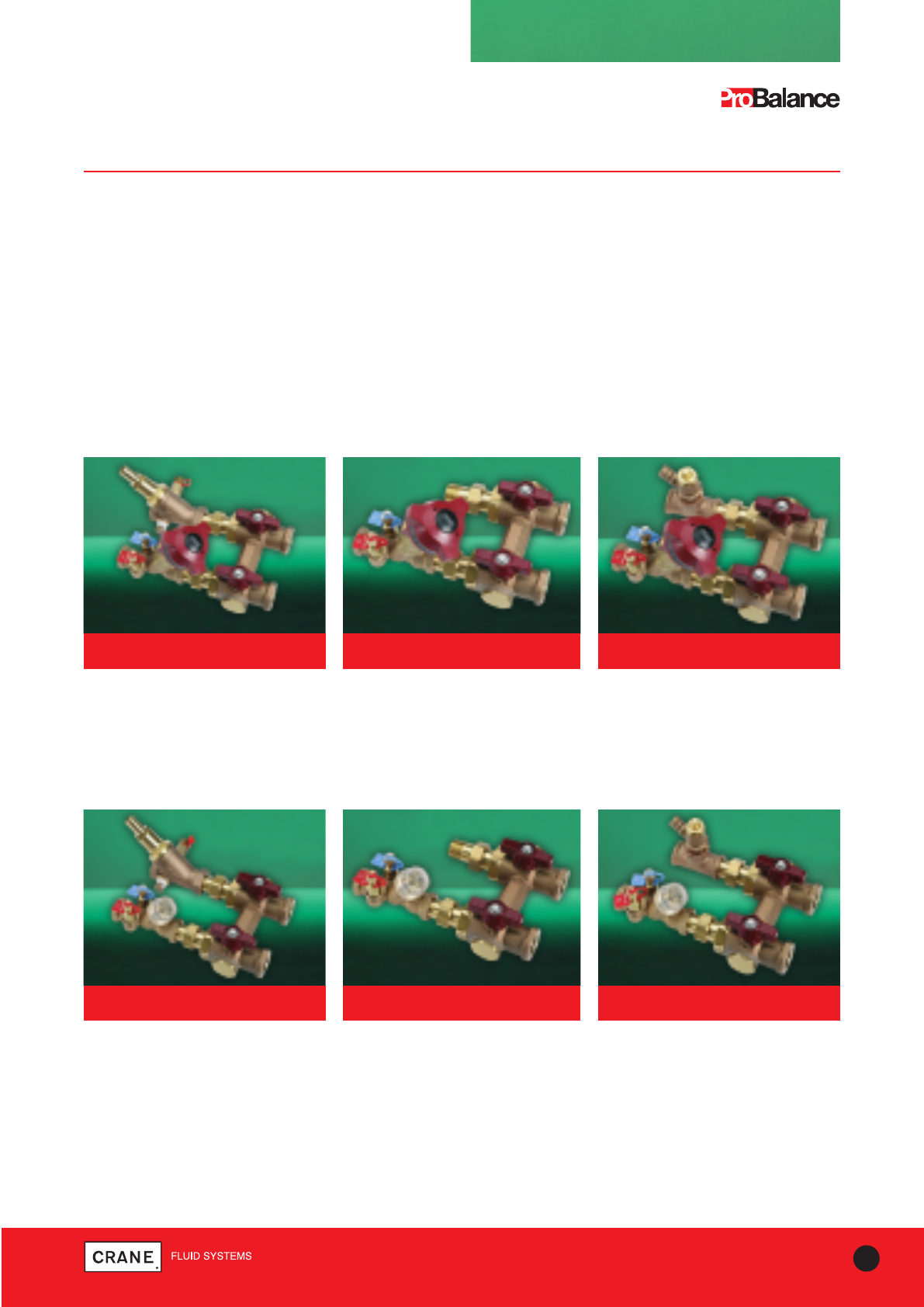
The Dominator range consists of three series:
Z3000 series features the Crane ProBalance Fixed Orifice Double Regulating valve D931.
Z3900 series features the Crane MotoBalance Fixed Orifice Double Regulating valve D981P, suitable for use with
actuator.
Z3300 series features the Crane Pressure Independent Control Valve- see page 22 for details.
Both series provide versions for heated and chilled water systems and combinations with and without drains and
strainers.The versions for chilled water systems include extension stems (EXS) on the ball valve
T-handles to allow for lagging. The Z3000 series also includes low flow and ultra low flow versions.
Z3000 Series comprises the three variants as shown below.
This series utilises the Crane bronze commissioning valves D931, D933 or D934 depending on flow rate required.
All selections are made by Crane and each unit is tagged with individual fan coil reference numbers to assist contractors
with site installation. Extension stems are fitted to isolation ball valves for chilled water applications.
Z3900 Series comprises the three variants as shown below.
This series utilises the Crane motorised commissioning valves D981P, D983P or D984P depending on flow rate required.
The MotoBalance offers on/off or modulating control with equal percentage characteristics.
All selections are made by Crane and each unit is tagged with individual fan coil reference numbers to assist contractors
with site assembly. Extension stems are fitted to isolation ball valves for chilled water applications.
Z3000 with drain and strainer Z3010 without drain and strainer Z3020 with drain but without
strainer
Z3900 with drain and strainer Z3910 without drain and strainer Z3920 with drain but without
strainer
Every effort has been made to ensure that the information contained in this publication is accurate at the time of publishing. Crane Ltd assumes no responsibility or liability for typographical errors or omissions or for
any misinterpretation of the information within the publication and reserves the right to change without notice.
24 TECHNICAL HELPLINE: +44 (0)1473 277400
www.cranefs.com
Combines all required functions - flow
regulation & measurement, as well as
2 port & differential pressure control
for terminal units
• Unique flow measurement for accurate
commissioning and trouble shooting
• Pre-set flow rates
• Reacts to system changes to maintain
stable low rates
• Equal % control characteristic ensures
improved system control
• Removable cartridge for flushing, complies
with CIBSE & BSRIA recommendation
• Also available
as part of the
Dominator flow
management
system
Dominator with DPIC991*
*PICV and Actuator sold separately
Details available on request
Pressure Independent
Control Valves
DPIC991*
25
TECHNICAL HELPLINE: +44 (0)1473 277400
www.cranefs.com
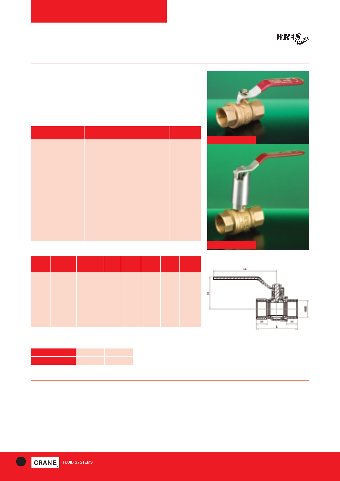
BALL VALVES
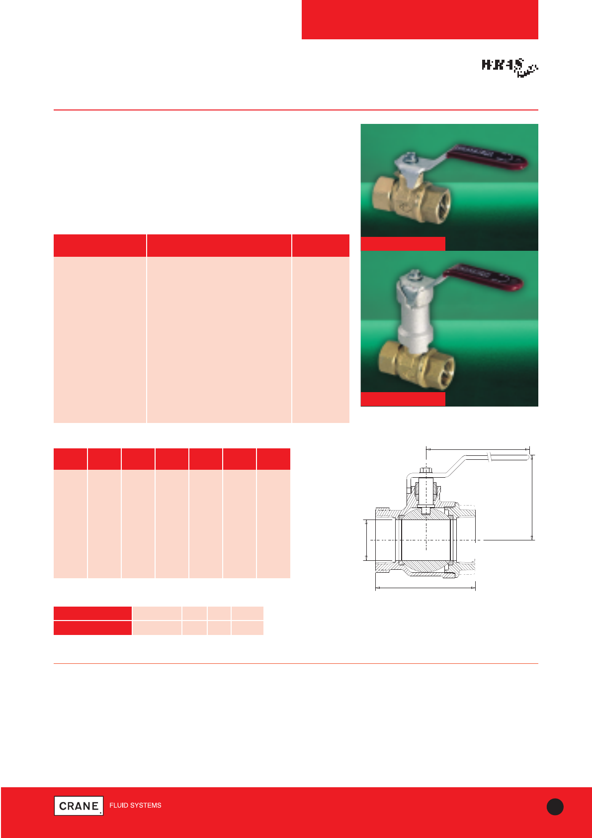
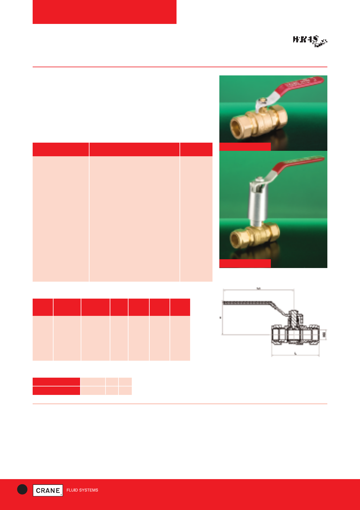
D171 / D171EXS
PN25
D171 Bronze Ball Valve
D171EXS Extended Stem Bronze Ball Valve
Crane D171 Ball Valves are light, compact units which are easy to install
and operate, yet their robust construction ensures long, trouble free
service life.
In addition the D171 and D171EXS are WRAS approved.
D171
D171EXS
PART MATERIAL SIZES
Body Bronze BS EN 1982 CC491K All
Seat Retainer Bronze BS EN 1982 CC491K All
Ball DZR Brass BS EN 12165 CW602N All
Seat Ring PTFE All
Stem DZR Brass BS EN 12164 CW602N All
Packing PTFE All
Gland Nut DZR Brass BS EN 12164 CW602N 1/4- 2||
Lever Mild Steel (Zinc Plated) All
Screw Mild Steel (Zinc Plated) All
Lever Cover P.V.C. All
Extension Housing Aluminium D171EXS
Extension Stem Brass BS EN 12164 CW602N D171EXS
Materials
A
B BOE
D
C
C1
SCEED BSEN1
BS1 TAE
O ANSI B1..1 TAE
Dimensions and Weights Dimensional Drawing
PRESSURE RATING: PN25
UK END CONNECTION: Taper threaded to BS EN 10226-2 (ISO 7-1)
formerly BS 21
US END CONNECTION: ANSI B1.20.1 (please add suffix AT to denote
American Thread)
OPERATOR: Lever
SPECIFICATION:
Quarter Turn, Tight Shut-Off
This valve is not suitable for use on group 1 gasses or unstable fluids, as
defined by the Pressure Equipment Directive 97/23/EC.
Temperature operating range: -10 to 186°C
SIZE WEIGHT A B C C1 (mm) D
(kg) (mm) (mm) (mm) D171EXS (mm)
1/4|| 0.15 46 10 39 - 81
3/8|| 0.15 46 10 39 - 81
1/2|| 0.22 57 15 52 97 92
3/4|| 0.45 67 20 58 98 92
1|| 0.69 77 25 66 118 127
11/4|| 1.12 91 32 72 124 127
11/2|| 1.67 103 40 82 142 142
2|| 2.93 122 50 90 149 142
21/2|| 4.98 153 65 117 - 202
3|| 8.75 179 80 132 - 282
TEMPERATURE (°C) -10 to 100 110 120 186
PRESSURE (BAR) 25.0 23.4 21.8 10.5
Intermediate pressure ratings shall be determined by
interpolation
Pressure/Temperature Ratings
Every effort has been made to ensure that the information contained in this publication is accurate at the time of publishing. Crane Ltd assumes no responsibility or liability for typographical errors or omissions or for
any misinterpretation of the information within the publication and reserves the right to change without notice.
26 TECHNICAL HELPLINE: +44 (0)1473 277400
www.cranefs.com
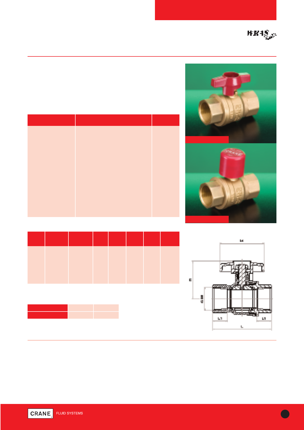
BALL VALVES
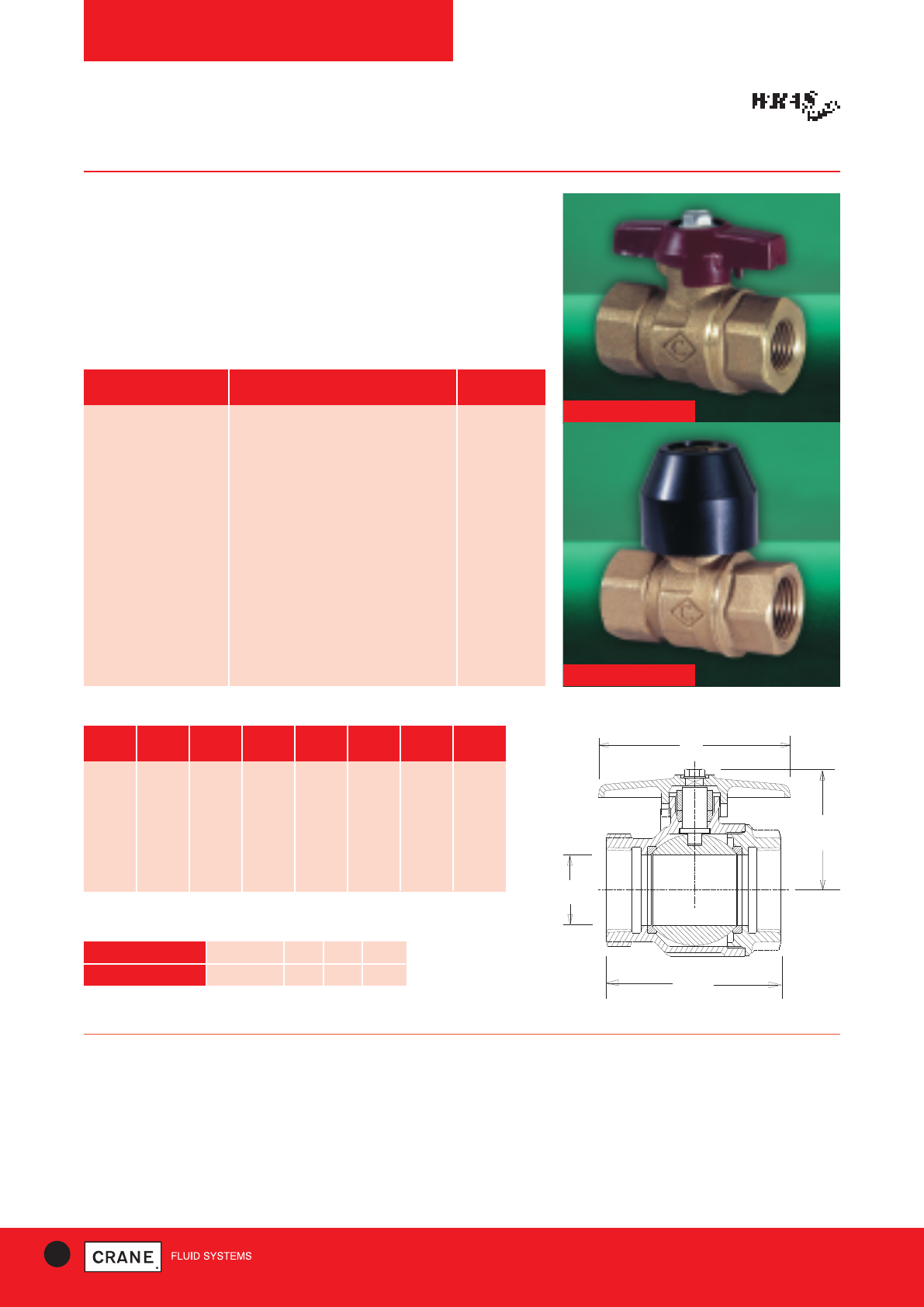
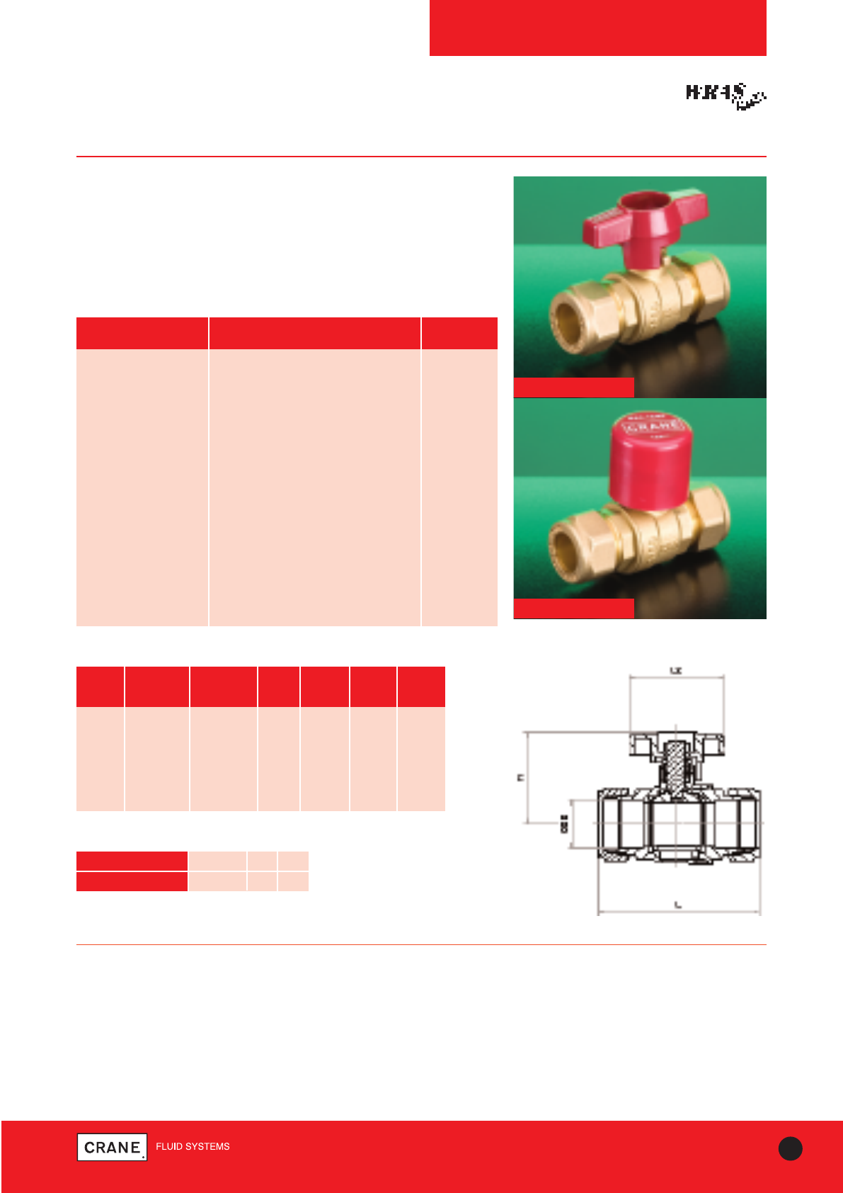
D171T / D171LS
PN25
D171T T-Handle Bronze Ball Valve
D171LS Lockshield Bronze Ball Valve
Crane D171 Ball Valves are light, compact units which are easy to install
and operate, yet their robust construction ensures long, trouble free
service life.
In addition the D171T and D171LS are WRAS approved.
PART MATERIAL SIZES
Body Bronze BS EN 1982 CC491K All
Seat Retainer Bronze BS EN 1982 CC491K All
Ball DZR Brass BS EN 12165 CW602N All
Seats PTFE All
Stem DZR Brass BS EN 12164 CW602N All
Packing PTFE All
Gland Nut DZR Brass BS EN 12164 CW602N All
‘T’ Handle Aluminium D171T
Screw Steel (Zinc Plated) D171T
Lockshield Cap Brass BS EN 12164 CW617N D171LS
Screw Mild Steel D171LS
Lockshield Cover Nylon 6 D171LS
Materials
Dimensions and Weights
PRESSURE RATING: PN25
UK END CONNECTION: Taper threaded to BS EN 10226-2 (ISO 7-1)
formerly BS 21
US END CONNECTION: ANSI B1.20.1 (please add suffix AT to denote
American Thread)
OPERATOR: T-Handle / Allen key
SPECIFICATION:
End Entry, Quarter Turn, Tight Shut-Off
This valve is not suitable for use on group 1 gasses or unstable fluids, as
defined by the Pressure Equipment Directive 97/23/EC.
Temperature operating range: -10 to 186°C.
SIZE WEIGHT A B C C1 (mm) D D1 (mm)
(kg) (mm) (mm) (mm) D171LS (mm) D171LS
3/8|| 0.13 46 10 31 - 38 -
1/2|| 0.2 57 15 40 48 55 36
3/4|| 0.41 67 20 43 51 55 36
1|| 0.64 77 25 53 58 83 39
11/4|| 1.07 91 32 58 63 83 39
11/2|| 1.57 103 40 73 76 108 49
2|| 2.83 122 50 80 84 108 49
A
B
C
C1
D
D1
Dimensional Drawing
B
B
D171T
D171LS
TEMPERATURE (°C) -10 to 100 110 120 186
PRESSURE (BAR) 25.0 23.4 21.8 10.5
Intermediate pressure ratings shall be determined by
interpolation
Pressure/Temperature Ratings
Every effort has been made to ensure that the information contained in this publication is accurate at the time of publishing. Crane Ltd assumes no responsibility or liability for typographical errors or omissions or for
any misinterpretation of the information within the publication and reserves the right to change without notice.
27
TECHNICAL HELPLINE: +44 (0)1473 277400
www.cranefs.com
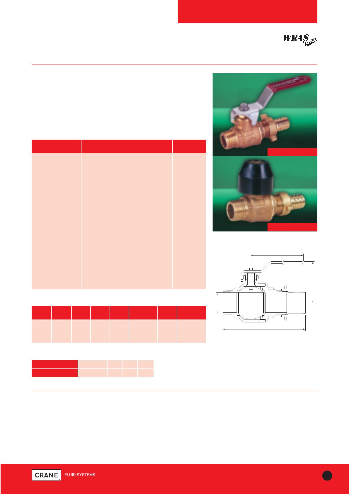
D171MHU / D171MHULS
PN25
D171MHU Bronze Draw-Off Valve
D171MHULS Bronze Draw-Off Ball Valve with Lockshield
Crane D171MHU / D171MHULS Ball Valves are light, compact units
which are easy to install and operate, yet their robust construction
ensures long, trouble free service life.
In addition the D171MHU and D171MHULS are WRAS approved.
PART MATERIAL SIZES
Body Bronze BS EN 1982 CC491K All
Seat Retainer Bronze BS EN 1982 CC491K All
Ball DZR Brass BS EN 12165
CW602N-Chrome Plated All
Seat PTFE All
Stem DZR Brass BS EN 12164 CW602N All
Packing PTFE All
Gland Nut Brass BS EN 12164 CW617N All
Lever Mild Steel (Zinc Plated) D171MHU
Lever Screw Mild Steel (Zinc Plated) D171MHU
Lever Cover PVC D171MHU
Hose Connector Brass BS EN 12164 CW617N All
Hose Union Nut Brass BS EN 12165 CW617N All
Washer PTFE All
Lockshield Cap Brass BS EN 12164 CW617N D171MHULS
Lockshield Cover Nylon 6 D171MHULS
Materials
A
B BOE
D
D1
C
C1
Dimensional Drawing
BALL VALVES
PRESSURE RATING: PN25
UK END CONNECTION: Taper threaded to BS EN 10226-2 (ISO 7-1)
formerly BS 21
US END CONNECTION: Not Specified
OPERATOR: Lever / Allen key
SPECIFICATION:
End Entry, Quarter Turn, Tight Shut-Off
Male x hose union outlet
This valve is not suitable for use on Group 1 gasses and unstable fluids
as defined by the Pressure Equipment Directive 97/23/EC.
Temperature operating range: -10 to 186°C.
Dimensions and Weights
SIZE WEIGHT A B C C1 (mm) D D1 (mm)
(kg) (mm) (mm) (mm) D171MHULS (mm) D171MHULS
1/2|| 0.27 104 15 40 47 82 36
3/4|| 0.55 124 20 58 51 92 36
1|| 0.88 147 25 65 58 127 39
D171MHU
D171MHULS
TEMPERATURE (°C) -10 to 100 110 120 186
PRESSURE (BAR) 25.0 23.4 21.8 10.5
Intermediate pressure ratings shall be determined by interpolation
Pressure/Temperature Ratings
Every effort has been made to ensure that the information contained in this publication is accurate at the time of publishing. Crane Ltd assumes no responsibility or liability for typographical errors or omissions or for
any misinterpretation of the information within the publication and reserves the right to change without notice.
28 TECHNICAL HELPLINE: +44 (0)1473 277400
www.cranefs.com
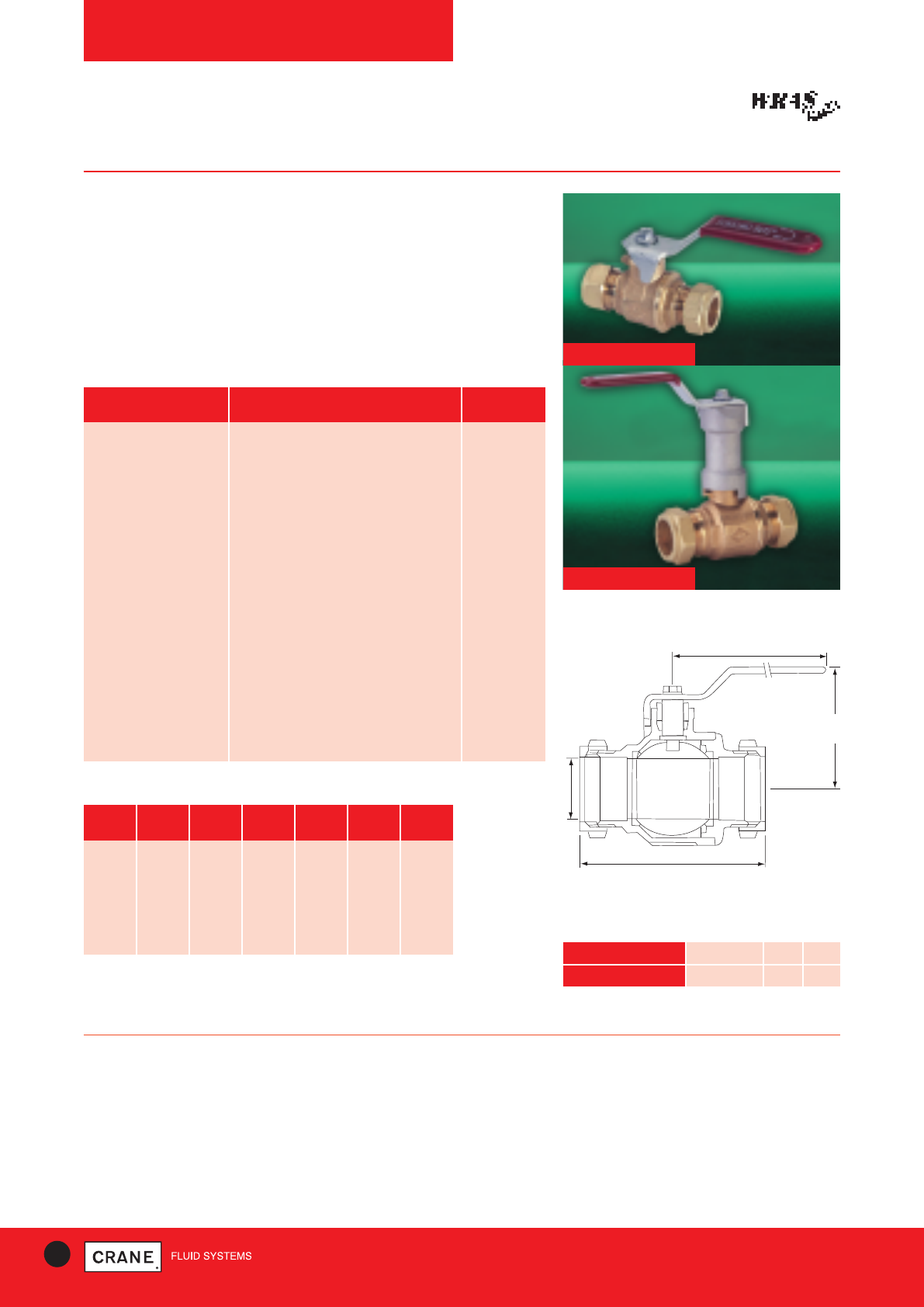
D171CEXS
BALL VALVES
D171C / D171CEXS
PN16
D171C Compression Ended Bronze Ball Valve
D171CEXS Compression Ended Bronze Ball Valve with
Extension Stem
Crane D171C / D171CEXS Ball Valves are light, compact units which are
easy to install and operate, yet their robust construction ensures long,
trouble free service life.
In addition the D171C and D171CEXS are WRAS approved.
PART MATERIAL SIZES
Body Bronze BS EN 1982 CC491K All
Seat Retainer Bronze BS EN 1982 CC491K All
Ball DZR Brass BS EN 12165 CW602N
(Chrome plated) All
Seat Ring PTFE All
Stem DZR Brass BS EN 12164 CW602N All
Packing PTFE All
Gland Nut Brass BS EN 12164 CW617N All
Lever Mild Steel (Zinc Plated) D171C
Screw Mild Steel (Zinc Plated) D171C
Lever Cover PVC D171C
Compression Olive Brass BS EN 12449 CW505L/CW507L All
Compression Nut DZR Brass BS EN 12165 CW617N All
Extension Housing Aluminium D171CEXS
Extension Stem DZR Brass BS EN 12164 CW602N D171CEXS
Materials
PRESSURE RATING: PN16
UK END CONNECTION: Compression end to suit BS EN 1057: Half
Hard R250 copper tube
OPERATOR: Lever
SPECIFICATION:
Quarter Turn, Tight Shut-Off
This valve is intended for Group 2 liquids only, as defined by the Pressure
Equipment Directive 97/23/EC.
Temperature Operating Range: -10 to 120°C
Dimensions and Weights
SIZE WEIGHT A B C C1 (mm) D
(kg) (mm) (mm) (mm)
D171CEXS
(mm)
15mm 0.27 80 15 52 97 92
22mm 0.51 84 20 58 98 92
28mm 0.78 95 25 65 118 127
35mm 1.19 111 32 70 124 127
42mm 1.82 124 40 83 142 142
54mm 3.28 149 50 91 149 142 TEMPERATURE (°C) -10 to 30 65 120
PRESSURE (BAR) 16 10 5
Compression
Intermediate pressure ratings shall be determined by
interpolation
Pressure/Temperature Ratings
A
B
C
C1
D
Dimensional Drawing
D171C
Every effort has been made to ensure that the information contained in this publication is accurate at the time of publishing. Crane Ltd assumes no responsibility or liability for typographical errors or omissions or for
any misinterpretation of the information within the publication and reserves the right to change without notice.
29
TECHNICAL HELPLINE: +44 (0)1473 277400
www.cranefs.com
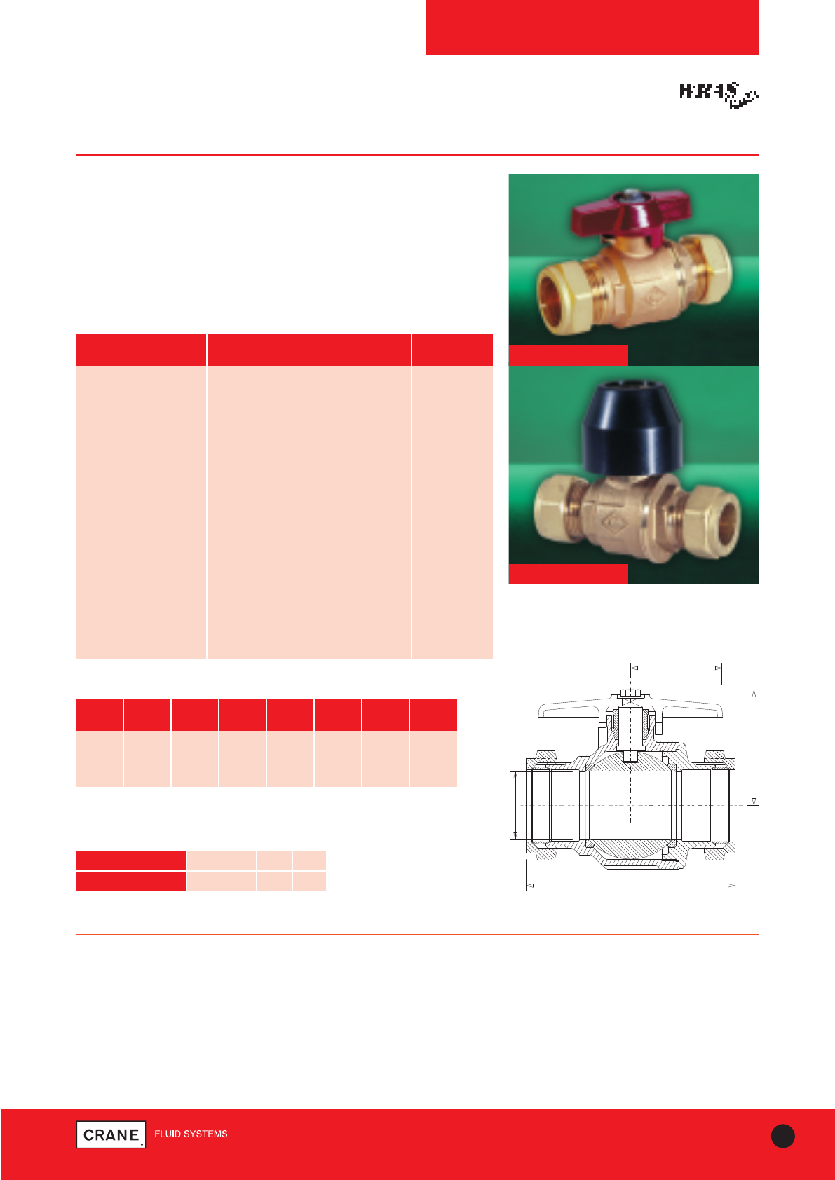
BALL VALVES
D171CT / D171CLS
PN16
D171CT Compression Ended T-Handle Ball Valve
D171CLS Compression Ended Lockshield Ball Valve
Crane D171CT / D171CLS Ball Valves are light, compact units which are
easy to install and operate, yet their robust construction ensures long,
trouble free service life.
In addition the D171CT and D171CLS are WRAS approved.
PART MATERIAL SIZES
Body Bronze BS EN 1982 CC491K All
Seat Retainer Bronze BS EN 1982 CC491K 15mm - 28mm
Seat Retainer Bronze BS EN 1982 CC491K 35mm - 54mm
Ball DZR Brass BS EN 12165 CW602N All
Seat PTFE All
Stem DZR Brass BS EN 12164 CW602N All
Packing PTFE All
Gland Nut Brass BS EN 12164 CW617N All
‘T’ Handle Aluminium D171CT
Screw Steel (Zinc Plated) D171CT
Compression Olive Brass BS EN 12449 CW505L/CW507L All
Compression Nut DZR Brass BS EN 12165 CW617N All
Lockshield Brass BS2872 D171CLS
Lockshield Cover Nylon 6 D171CLS
Materials
PRESSURE RATING: PN16
UK END CONNECTION: Compression ends to suit BS EN 1057: Half
hard R250 copper tube.
OPERATOR: T-Handle / Allen Key
SPECIFICATION:
Quarter Turn, Tight Shut-Off
This valve is intended for Group 2 liquids as defined by the Pressure
Equipment Directive 97/23/EC.
Temperature Operating Range: -10 to 120°C
Dimensions and Weights
TEMPERATURE (°C) -10 to 30 65 120
PRESSURE (BAR) 16 10 5
Compression
Intermediate pressure ratings shall be determined by
interpolation
Pressure/Temperature Ratings
D171CLS
(MIN. HANDTIGHT CONDITION)
A
B
D
D1
C
C1
Dimensional Drawing
D171CT
SIZE WEIGHT A B C C1 (mm) D D1(mm)
(kg) (mm) (mm) (mm) D171LCS (mm) D171CLS
15mm 0.25 80 15 42 48 55 29
22mm 0.47 84 20 43 51 55 36
28mm 0.73 95 25 53 58 83 39
Every effort has been made to ensure that the information contained in this publication is accurate at the time of publishing. Crane Ltd assumes no responsibility or liability for typographical errors or omissions or for
any misinterpretation of the information within the publication and reserves the right to change without notice.
30 TECHNICAL HELPLINE: +44 (0)1473 277400
www.cranefs.com
BALL VALVES
D171A / D171AEXS
PN25
D171A
D171AEXS
PART MATERIAL QUANTITY
Hex-Nut Steel Plated 1
Lever Steel Dacromet Plated 1
Sleeve Maroon PVC 1
Packing Nut Brass CW617N 1
Packing Gland PTFE WRAS Approved 1
Body DZR Brass CW602N 1
Seats PTFE WRAS Approved 2
Ball DZR Brass CW602N Chrome Plated 1
O-Ring Rubber EPDM WRAS Approved 1
Bonnet DZR Brass CW602N 1
Stem DZR Brass CW602N 1
Extension Stem Outer Aluminium 1
Extension Stem Inner Steel Plated 1
Materials
SIZE WEIGHT WEIGHT L L1 L2 H H
(kg) (kg) (mm) (mm) (mm) (mm) (mm)
A AEXS A A AEXS
1/4|| 152 - 45.3 12 89 41 -
3/8|| 136 - 45.3 12 89 41 -
1/2|| 205 270 58.5 15.5 98.5 48 103
3/4|| 302 366 67 17 98.5 51 107
1|| 511 589 80.5 21 125 62 116
11/4|| 890 1009 94 23 140 77.5 129
11/2|| 1292 1410 102 23 140 83.5 135
2|| 2238 2283 124 26.5 165 97.5 150
Dimensions and Weights
Dimensional Drawing
PRESSURE RATING: PN25
UK END CONNECTION: Taper threaded to BS EN 10226-2 (ISO 7-1)
formerly BS 21
US END CONNECTION: ANSI B1.20.1:1983 (please add suffix AT to
denote American Thread)
OPERATOR: Lever
SPECIFICATION:
Quarter Turn
Temperature Operating Range: -10 to 120°C
TEMPERATURE (°C) -10 to 100 120
PRESSURE (BAR) 25 21.8
Threaded
Intermediate pressure ratings shall be determined by
interpolation
Pressure/Temperature Ratings
D171A Threaded DZR Ball Valve
D171AEXS Threaded DZR Ball Valve with Extension Stem
Designed to be light, compact and easy to install and operate, Crane's next
generation DZR ball valve is WRAS approved and features improved leak
resistance and reduced risk of damage from over tightening.
All dimensions are nominal.
Every effort has been made to ensure that the information contained in this publication is accurate at the time of publishing. Crane Ltd assumes no responsibility or liability for typographical errors or omissions or for
any misinterpretation of the information within the publication and reserves the right to change without notice.
31
TECHNICAL HELPLINE: +44 (0)1473 277400
www.cranefs.com
Dimensional Drawing
D171ATH
D171ALS
BALL VALVES
D171ATH / D171ALS
PN25
PART MATERIAL QUANTITY
Hex-Nut Steel Plated 1
T-Handle Aluminium AL-46100 Maroon 1
Packing Nut Brass CW617N 1
Packing Gland PTFE WRAS Approved 1
Body DZR Brass CW602N 1
Seats PTFE WRAS Approved 2
Ball DZR Brass CW602N Chrome Plated 1
O-Ring Rubber EPDM WRAS Approved 1
Bonnet DZR Brass CW602N 1
Stem DZR Brass CW602N 1
Lockshield Brass CW617N 1
Lockshield Cover Polypropelene Maroon 1
Materials
SIZE WEIGHT WEIGHT L L1 L2 H H
(kg) (kg) (mm) (mm) (mm) (mm) (mm)
ATH ALS ATH ATH ALS
1/2|| 183 207 59 15.5 50 40 42
3/4|| 277 302 67 17 50 43 45
1|| 470 506 80.5 21 55 54 58
11/4|| 809 867 94 23 82 61 67
11/2|| 1210 1269 102 23 82 67 73.5
2|| 2106 2166 124 26.5 110 80.5 86.5
Dimensions and Weights
PRESSURE RATING: PN25
UK END CONNECTION: Taper threaded to BS EN 10226-2 (ISO 7-1)
formerly BS 21.
US END CONNECTION: ANSI B1.20.1:1983 (please add suffix AT to
denote American Thread)
OPERATOR: T-Handle / Spanner or Socket
SPECIFICATION:
Quarter Turn
Temperature Operating Range: -10 to 120°C
TEMPERATURE (°C) -10 to 100 120
PRESSURE (BAR) 25 21.8
Threaded
Intermediate pressure ratings shall be determined by
interpolation
Pressure/Temperature Ratings
D171ATH Threaded DZR Ball Valve with T-Handle
D171ALS Threaded DZR Ball Valve with Lockshield
Designed to be light, compact and easy to install and operate, Crane's
next generation DZR ball valve is WRAS approved and features improved
leak resistance and reduced risk of damage from over tightening.
All dimensions are nominal.
Every effort has been made to ensure that the information contained in this publication is accurate at the time of publishing. Crane Ltd assumes no responsibility or liability for typographical errors or omissions or for
any misinterpretation of the information within the publication and reserves the right to change without notice.
32 TECHNICAL HELPLINE: +44 (0)1473 277400
www.cranefs.com
BALL VALVES
D171AC / D171ACEXS
PN16
PRESSURE RATING: PN16
UK END CONNECTION: Compression ends to suit BS EN 1057: Half
hard R250 copper tube.
OPERATOR: Lever
SPECIFICATION:
Quarter Turn
Temperature Operating Range: -10 to 120°C
D171AC
Dimensional Drawing
D171ACEXS
D171AC Compression DZR Ball Valve
D171ACEXS Compression DZR Ball Valve with Extension
Stem
Designed to be light, compact and easy to install and operate, Crane's
next generation DZR ball valve is WRAS approved and features improved
leak resistance and reduced risk of damage from over tightening.
PART MATERIAL QUANTITY
Hex-Nut Steel Plated 1
Lever Steel Dacromet Plated 1
Handle Sleeve Maroon PVC 1
Packing Nut Brass CW617N 1
Packing Gland PTFE WRAS Approved 1
Body DZR Brass CW602N 1
Seats PTFE WRAS Approved 2
Ball DZR Brass CW602N Chrome Plated 1
Bonnet DZR Brass CW602N 1
Compression Olive Brass BS EN 12449 CW505L/CW507L 2
Compression Nut DZR Brass BS EN 12165 CW617N 2
Stem DZR Brass CW602N 1
Extension Stem Outer Aluminium 1
Extension Stem Inner Steel Plated 1
Materials
SIZE WEIGHT WEIGHT L L2 H H
(kg) (kg) (mm) (mm) (mm) (mm)
AC ACEXS AC AC AC ACEXS
15mm 212 275 66.5 98.5 47 103
22mm 368 429 80 98.5 51 107
28mm 608 682 92.5 125 62 116
35mm 1007 1125 104.5 140 77.5 129
42mm 1549 1667 122 140 83 135
54mm 2538 2683 141 165 97.5 150
Dimensions and Weights
Intermediate pressure ratings shall be determined by interpolation
Pressure/Temperature Ratings
TEMPERATURE (°C) -10 to 30 65 120
PRESSURE (BAR) 16 10 5
All dimensions are nominal.
Every effort has been made to ensure that the information contained in this publication is accurate at the time of publishing. Crane Ltd assumes no responsibility or liability for typographical errors or omissions or for
any misinterpretation of the information within the publication and reserves the right to change without notice.
33
TECHNICAL HELPLINE: +44 (0)1473 277400
www.cranefs.com
BALL VALVES
D171ACTH / D171ACLS
PN16
PART MATERIAL QUANTITY
Hex-Nut Steel Plated 1
T-Handle Aluminium AL-46100 Maroon 1
Packing Nut Brass CW617N 1
Packing Gland PTFE WRAS Approved 1
Body DZR Brass CW602N 1
Seats PTFE WRAS Approved 2
Ball DZR Brass CW602N Chrome Plated 1
Bonnet DZR Brass CW602N 1
Compression Olive Brass BS EN 12449 CW505L/CW507L 2
Compression Nut DZR Brass BS EN 12165 CW617N 2
Stem DZR Brass CW602N 1
Lockshield Brass CW617N 1
Lockshield Cover Polypropelene Maroon 1
Materials
PRESSURE RATING: PN16
UK END CONNECTION: Compression ends to suit BS EN 1057: Half
hard R250 copper tube.
OPERATOR: T-Handle / Spanner or Socket
SPECIFICATION:
Quarter Turn
Temperature Operating Range: -10 to 120°C
D171ACLS
D171ACTH
Dimensional Drawing
SIZE WEIGHT WEIGHT L L2 H H
(kg) (kg) (mm) (mm) (mm) (mm)
ACTH ACLS ACTH ACTH ACLS
15mm 187 220 66.5 50 40 42
22mm 343 376 80 50 43 47
28mm 567 614 92.5 55 54 59.5
35mm 977 1039 104.5 82 61 67
42mm 1487 1549 122 82 67 73.5
54mm 2634 2437 141 110 80.5 87.5
Dimensions and Weights
Intermediate pressure ratings shall be determined by interpolation
Pressure/Temperature Ratings
TEMPERATURE (°C) -10 to 30 65 120
PRESSURE (BAR) 16 10 5
All dimensions are nominal.
D171ACTH Compression DZR Ball Valve with T-Handle
D171ACLS Compression DZR Ball Valve with Lockshield
Designed to be light, compact and easy to install and operate, Crane's
next generation DZR ball valve is WRAS approved and features improved
leak resistance and reduced risk of damage from over tightening.
Every effort has been made to ensure that the information contained in this publication is accurate at the time of publishing. Crane Ltd assumes no responsibility or liability for typographical errors or omissions or for
any misinterpretation of the information within the publication and reserves the right to change without notice.
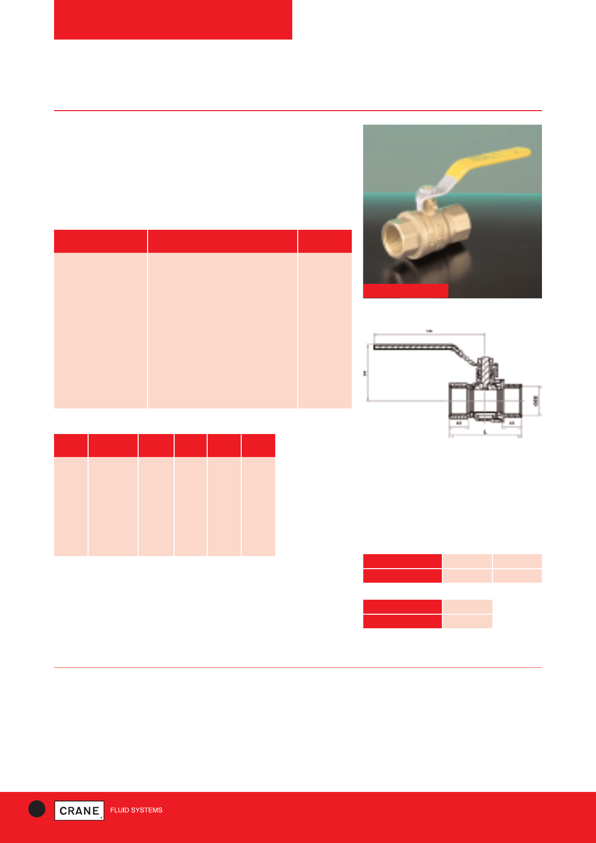
34 TECHNICAL HELPLINE: +44 (0)1473 277400
www.cranefs.com
BALL VALVES
D191
PN25
PRESSURE RATING: PN25
UK END CONNECTION: Taper threaded to BS EN 10226-2 (ISO 7-1)
formerly BS 21
US END CONNECTION: ANSI B1.20.1:1983 (please add suffix AT to
denote American Thread)
OPERATOR: Lever
SPECIFICATION:
Quarter Turn, PTFE seats and stem seal.
Tested by BSI and complies with the essential requirements of BS EN 331:
1998
Temperature Operating Range: Non Gas -10 to 110°C, Gas -20 to 60°C
D191
Dimensional Drawing
PART MATERIAL QUANTITY
Hex-Nut Dacromet Plated Steel 1
Handle Sleeve PVC Yellow 1
Handle Dacromet Plated Steel 1
Packing Nut Brass CW617N 1
Packing Gland PTFE 1
Body DZR Brass CW602N 1
Ball DZR Brass CW602N 1
Seats PTFE 2
O-Ring NBR with BS EN 549 approval 1
Bonnet DZR Brass CW602N 1
Stem DZR Brass CW602N 1
Materials
SIZE WEIGHT L L1 L2 H
(kg) (mm) (mm) (mm) (mm)
1/4152 46 12 89 41
3/8|| 136 46 12 89 41
1/2|| 205 59 15.5 98.5 48
3/4|| 302 67 17 98.5 51
1|| 511 80.5 21 125 63
11/4|| 890 94 23 140 78
11/2|| 1292 102 23 140 83.5
2|| 2238 124 26.5 165 97.5
Dimensions and Weights
TEMPERATURE (°C) -10 to 100 110
PRESSURE (BAR) 25 23.5
Non Gas Application
TEMPERATURE (°C) -20 to 60
PRESSURE (BAR) 5
Gas Application
Intermediate pressure ratings shall be determined by
interpolation
Gas approved to BS EN 331: 1998
Pressure/Temperature Ratings
D191 Threaded DZR Ball Valve for Gas Applications
Designed to be light, compact and easy to install and operate, Crane's
next generation DZR ball valve features improved leak resistance and
reduced risk of damage from over tightening. The D191 is tested by
BSI and complies with essential requirements of
BS EN 331 :1998
All dimensions are nominal.
Every effort has been made to ensure that the information contained in this publication is accurate at the time of publishing. Crane Ltd assumes no responsibility or liability for typographical errors or omissions or for
any misinterpretation of the information within the publication and reserves the right to change without notice.
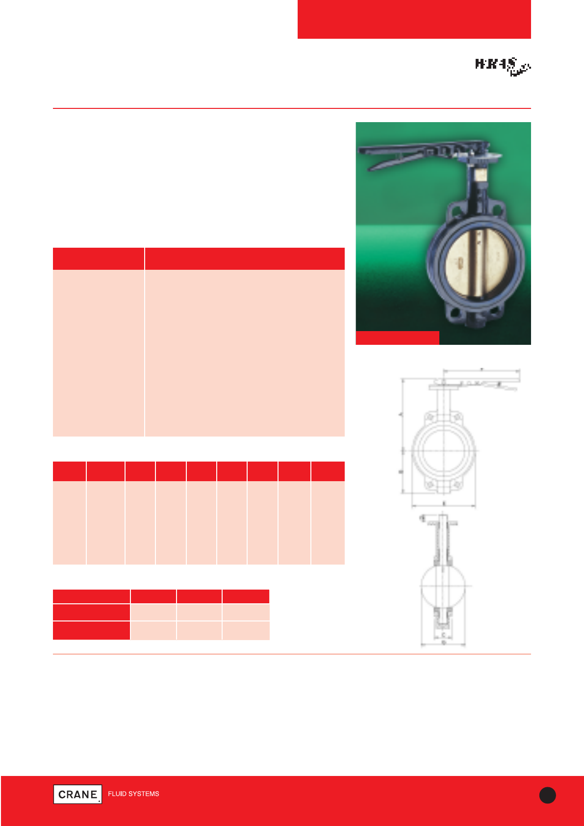
35
TECHNICAL HELPLINE: +44 (0)1473 277400
www.cranefs.com
BUTTERFLY VALVES
F611, F621, F626
PN16
PART MATERIAL
Body Ductile Iron ASTM A536 (Epoxy Paint)
Disc Aluminium Bronze
Liner (F611) Nitrile Temp. -10 to 90°C
Liner (F621) EPDM (WRAS Approved) Temp. -10 to 100°C
Liner (F626) EPDM (High Temperature) Temp. -10 to 130°C
Shaft Stainless Steel Type 410
Taper Pin Stainless Steel Type 316
Key Carbon Steel
O Ring Buna-N
Bushing PTFE
Lever & Screw Carbon Steel (Epoxy Paint)
Stop Plate Carbon Steel (Zn Plated)
Materials
PRESSURE RATING: PN16 / ANSI Class 125
END CONNECTION: Semi Lugged
OPERATOR: Trigger lever
SPECIFICATION:
F611 - Suitable for Group 1 and 2 gases and Group 1 and 2 liquids as
defined by the Pressure Equipment Directive 97/23/EC.
F621 - Suitable for Group 2 liquids only as defined by the Pressure
Equipment Directive 97/23/EC and these valves are WRAS Approved.
F626 - Suitable for Group 1 and 2 gases and Group 1 and 2 liquids as
defined by the Pressure Equipment Directive 97/23/EC.
F611
Dimensions and Weights
SIZE WEIGHT A B C D E F G
(kg) (mm) (mm) (mm) (mm) (mm) (mm) (mm)
50mm 3.5 195 83 44 32 102 260 32
65mm 4 207 95 48 32 121 260 46
80mm 5.4 213 102 48 32 130 260 64
100mm 6.7 232 124 54 32 171 260 90
125mm 9 245 136 57 32 197 260 111
150mm 9.9 257 150 57 32 219 260 145
200mm 16.4 305 197 63 44 268 356 193
F611 F621 F626
TEMPERATURE (°C) -10 to 90 -10 to 100 -10 to 130
PRESSURE (BAR) 16 16 16
Pressure/Temperature Ratings
F621
Dimensional Drawing
Semi-Lugged Lever Operated Butterfly Valves to
BS EN 593: 2009
Key Features:
• Aluminium Bronze disc
• Stainless steel shaft
• Trigger lever
• Valves are suitable for use with flanges conforming to BSEN1092-2
PN10 or PN16 and ANSI B16.1 Class 125
Every effort has been made to ensure that the information contained in this publication is accurate at the time of publishing. Crane Ltd assumes no responsibility or liability for typographical errors or omissions or for
any misinterpretation of the information within the publication and reserves the right to change without notice.
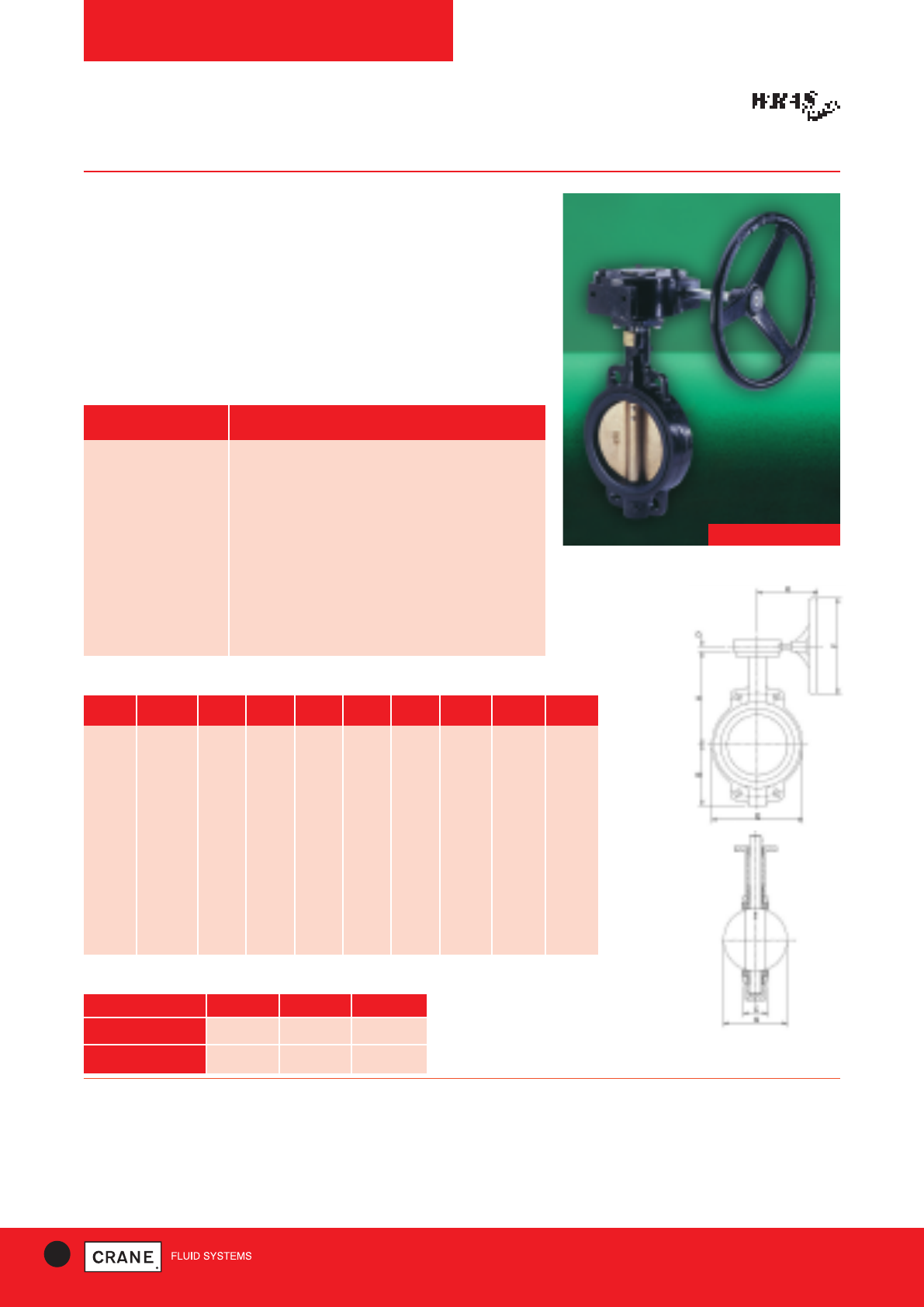
36 TECHNICAL HELPLINE: +44 (0)1473 277400
www.cranefs.com
BUTTERFLY VALVES
F612, F622, F627
PN16
Semi-Lugged Gearbox Operated Butterfly Valves to
BS EN 593: 2009
PRESSURE RATING: PN16 / ANSI Class 125
END CONNECTION: Semi-Lugged
OPERATOR: Gearbox
SPECIFICATION:
F612 - Suitable for Group 1 and 2 gases and Group 1 and 2 liquids as
defined by the Pressure Equipment Directive 97/23/EC.
F622 - Suitable for Group 2 liquids only as defined by the Pressure
Equipment Directive 97/23/EC and these valves are WRAS Approved.
F627 - Suitable for Group 1 and 2 gases and Group 1 and 2 liquids as
defined by the Pressure Equipment Directive 97/23/EC.
F612
Dimensions and Weights
SIZE WEIGHT A B C D E F G K
(kg) (mm) (mm) (mm) (mm) (mm) (mm) (mm) (mm)
50mm 15 162 83 44 42 102 150 32 240
65mm 15.5 175 95 48 42 121 150 46 240
80mm 16.9 181 102 48 42 130 150 64 240
100mm 18.2 200 124 54 42 171 150 90 240
125mm 20.5 213 136 57 42 197 300 111 240
150mm 21.4 225 150 57 42 219 300 145 240
200mm 29 260 197 63 40 268 300 193 230
250mm 33.5 292 210 70 40 332 300 241 230
300mm 45.8 337 248 79 40 410 300 290 230
350mm 56.2 368 279 79 40 435 300 325 230
400mm 88.4 400 305 89 – 508 450 380 277
450mm 110.2 422 381 108 – 543 450 427 277
500mm 160.5 479 381 133 – 592 450 474 321
600mm 260 562 457 156 – 708 450 574 335
Dimensional Drawing
F622
Sizes 50-300mm
F612 F622 F627
TEMPERATURE (°C) -10 to 90 -10 to 100 -10 to 130
PRESSURE (BAR) 16 16 16
Pressure/Temperature Ratings
Key Features:
• Aluminium Bronze disc
• Stainless steel shaft
• Gearbox operated
• Valves 50-300mm are suitable for use with flanges conforming to
BS EN 1092-2 PN10 or PN16 and ANSI B16.1 Class 125
• Sizes 350mm to 600mm are only PN16 flanges
PART MATERIAL
Body Ductile Iron ASTM A536 (Epoxy Paint)
Disc Aluminium Bronze
Liner (F612) Nitrile Temp. -10 to 90°C
Liner (F622) EPDM (WRAS Approved) Temp. -10 to 100°C
Liner (F627) EPDM (High Temperature) Temp. -10 to 130°C
Shaft Stainless Steel Type 410
Taper Pin Stainless Steel Type 316
Key Carbon Steel
O Ring Buna-N
Bushing PTFE
Materials
Every effort has been made to ensure that the information contained in this publication is accurate at the time of publishing. Crane Ltd assumes no responsibility or liability for typographical errors or omissions or for
any misinterpretation of the information within the publication and reserves the right to change without notice.
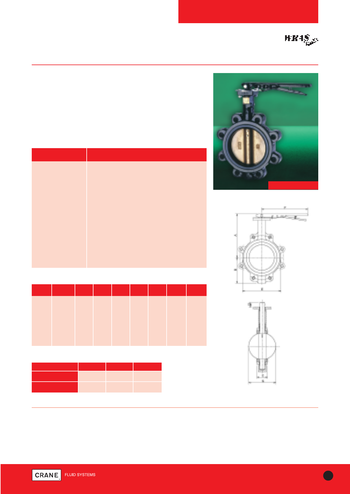
37
TECHNICAL HELPLINE: +44 (0)1473 277400
www.cranefs.com
BUTTERFLY VALVES
F614, F624, F628
PN16
Fully-Lugged Lever Operated Butterfly Valves to
BS EN 593: 2009
Key Features:
• Aluminium Bronze discs
• Stainless steel shaft
• Trigger lever
• Valves are suitable for use with flanges conforming to
BS EN 1092-2 PN10 or PN16
PART MATERIAL
Body Ductile Iron ASTM A536 (Epoxy Paint)
Disc Aluminium Bronze
Liner (F614) Nitrile Temp. -10 to 90°C
Liner (F624) EPDM (WRAS Approved) Temp. -10 to 100°C
Liner (F628) EPDM (High Temperature) Temp. -10 to 130°C
Shaft Stainless Steel Type 410
Taper Pin Stainless Steel Type 316
Key Carbon Steel
O Ring Buna-N
Bushing PTFE
Lever & Screw Carbon Steel (Epoxy Paint)
Stop Plate Carbon Steel (Zn Plated)
Materials
PRESSURE RATING: PN16
END CONNECTION: Lugged
OPERATOR: Trigger lever
SPECIFICATION:
F614 - Suitable for Group 1 and 2 gases and Group 1 and 2 liquids as
defined by the Pressure Equipment Directive 97/23/EC.
F624 - Suitable for Group 2 liquids only as defined by the Pressure
Equipment Directive 97/23/EC and these valves are WRAS Approved.
F628 - Suitable for Group 1 and 2 gases and Group 1 and 2 liquids as
defined by the Pressure Equipment Directive 97/23/EC.
F614
Dimensional Drawing
Dimensions and Weights
SIZE WEIGHT A B C D E F G
(kg) (mm) (mm) (mm) (mm) (mm) (mm) (mm)
50mm 4 195 83 44 32 102 260 32
65mm 4.5 207 95 48 32 121 260 46
80mm 7.2 213 102 48 32 130 260 64
100mm 12.6 232 124 54 32 171 260 90
125mm 13.5 245 136 57 32 197 260 111
150mm 14.9 257 150 57 32 219 260 145
200mm 24.1 305 197 63 44 268 356 193
F624
F614 F624 F628
TEMPERATURE (°C) -10 to 90 -10 to 100 -10 to 130
PRESSURE (BAR) 16 16 16
Pressure/Temperature Ratings
Every effort has been made to ensure that the information contained in this publication is accurate at the time of publishing. Crane Ltd assumes no responsibility or liability for typographical errors or omissions or for
any misinterpretation of the information within the publication and reserves the right to change without notice.
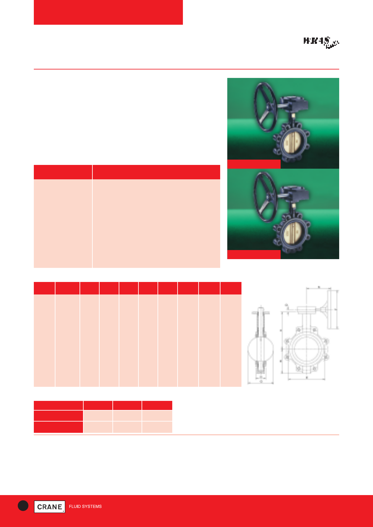
F629
38 TECHNICAL HELPLINE: +44 (0)1473 277400
www.cranefs.com
BUTTERFLY VALVES
F615, F625, F629
PN16
Fully-Lugged Gearbox Operated Butterfly Valves to BS EN
593: 2009
Key Features:
• Aluminium Bronze disc
• Stainless steel shaft
• Gearbox operated
• Valves are suitable for use with flanges conforming to BS EN 1092-2
PN10 or PN16 - Sizes 65-200mm
• BS EN 1092-2 PN16 flanges only - Sizes 250-600mm PN16 only
F625
PART MATERIAL
Body Ductile Iron ASTM A536 (Epoxy Paint)
Disc Aluminium Bronze
Liner (F615) Nitrile Temp. -10 to 90°C
Liner (F625) EPDM (WRAS Approved) Temp. -10 to 100°C
Liner (F629) EPDM (High Temperature) Temp. -10 to 130°C
Shaft Stainless Steel Type 410
Taper Pin Stainless Steel Type 316
Key Carbon Steel
O Ring Buna-N
Bushing PTFE
Materials
PRESSURE RATING: PN16
END CONNECTION: Lugged
OPERATOR: Gearbox
SPECIFICATION:
F615 - Suitable for Group 1 and 2 gases and Group 1 and 2 liquids as
defined by the Pressure Equipment Directive 97/23/EC.
F625 - Suitable for Group 2 liquids only as defined by the Pressure
Equipment Directive 97/23/EC and these valves are WRAS Approved.
F629 - Suitable for Group 1 and 2 gases and Group 1 and 2 liquids as
defined by the Pressure Equipment Directive 97/23/EC.
Dimensional Drawing
Dimensions and Weights
SIZE WEIGHT A B C D E F G K
(kg) (mm) (mm) (mm) (mm) (mm) (mm) (mm) (mm)
50mm 15.5 162 83 44 42 102 150 32 240
65mm 16 175 95 48 42 121 150 46 240
80mm 18.7 181 102 48 42 130 150 64 240
100mm 24.1 200 124 54 42 171 150 90 240
125mm 25 213 136 57 42 197 300 111 240
150mm 26.4 225 150 57 42 219 300 145 240
200mm 36.7 260 197 63 40 268 300 193 230
250mm 47.1 292 210 70 40 332 300 241 230
300mm 62.1 337 248 79 40 410 300 290 230
350mm 84.9 368 279 79 40 435 300 325 230
400mm 123.8 400 305 89 – 508 450 380 277
450mm 139.7 422 381 108 – 543 450 427 277
500mm 215.5 479 381 133 – 592 450 474 321
600mm 337.3 562 457 156 – 708 450 574 335
Sizes
50-300mm
F615 F625 F629
TEMPERATURE (°C) -10 to 90 -10 to 100 -10 to 130
PRESSURE (BAR) 16 16 16
Pressure/Temperature Ratings
Every effort has been made to ensure that the information contained in this publication is accurate at the time of publishing. Crane Ltd assumes no responsibility or liability for typographical errors or omissions or for
any misinterpretation of the information within the publication and reserves the right to change without notice.
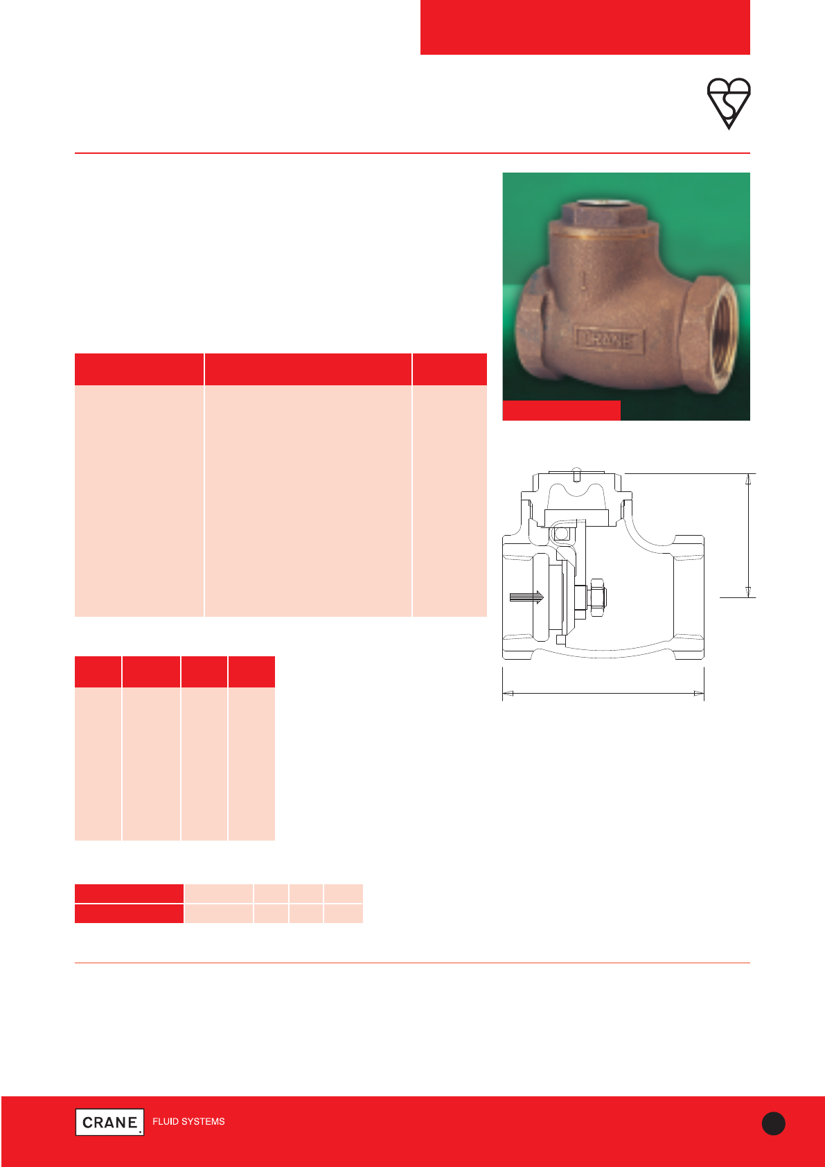
39
TECHNICAL HELPLINE: +44 (0)1473 277400
www.cranefs.com
CHECK VALVES
D138
PN25
Bronze Swing Check Valve with Metal Disc
Check valves permit flow in one direction only, and close automatically if
flow reverses. They are entirely automatic in action, depending upon
pressure and velocity of flow within the line to perform their functions of
opening and closing.
The Crane D138 Bronze check valve is of the swing variety.
This valve carries the British Standards Institution kitemark - your
assurance of exacting quality.
D138
PART MATERIAL SIZES
Body Bronze BS EN 1982 CC491K All
Cap Bronze BS EN 1982 CC491K All
Disc Brass BS EN 12164 CW614N 3/8- 1
Disc Bronze BS EN 1982 CC491K 11/4- 3
Hinge Bronze BS EN 1982 CC491K All
Hinge Pin Stainless Steel 3/8- 2
Hinge Pin Stainless Steel ASTM A182 Gr.F316 21/2& 3
Hinge Nut Brass BS EN 12164 CW614N All
ID. Plate Aluminium All
Drive Pin Steel - Electro Brassed All
Hinge Pin Plug Brass BS EN 12164 CW614N 21/2& 3
Materials
A
B
Dimensions and Weights
SIZE WEIGHT A B
(kg) (mm) (mm)
3/8|| 0.19 48 33
1/2|| 0.32 58 38
3/4|| 0.43 66 42
1|| 0.61 80 49
11/4|| 1.01 89 56
11/2|| 1.34 95 65
2|| 2.12 108 76
21/2|| 4.08 155 98
3|| 5.76 190 99
Dimensional Drawing
PRESSURE RATING: PN25
UK END CONNECTION: Taper threaded to BS EN 10226-2 (ISO 7-1)
formerly BS 21
US END CONNECTION: ANSI B1.20.1 (please add suffix AT to
denote American Thread)
OPERATOR: Swing Type Check Valve
SPECIFICATION:
Metal Disc, Screwed in Cap, BSI Kitemark Approved.
Valves are manufactured in accordance with BS5154:1991 PN25 for Series
B ratings.
This valve is not suitable for use on group 1 gasses or unstable fluids, as
defined by the Pressure Equipment Directive 97/23/EC.
Temperature operating range: -10 to 186°C.
TEMPERATURE (°C) -10 to 100 110 120 186
PRESSURE (BAR) 25.0 23.4 21.8 10.5
Intermediate pressure ratings shall be determined by
interpolation
Pressure/Temperature Ratings
Every effort has been made to ensure that the information contained in this publication is accurate at the time of publishing. Crane Ltd assumes no responsibility or liability for typographical errors or omissions or for
any misinterpretation of the information within the publication and reserves the right to change without notice.
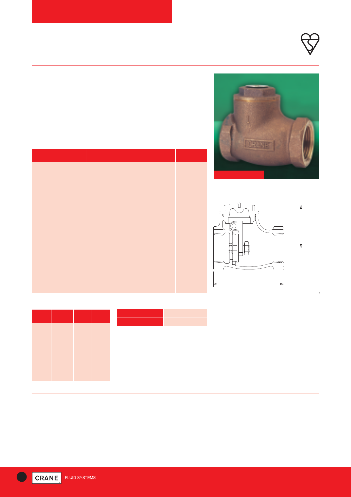
40 TECHNICAL HELPLINE: +44 (0)1473 277400
www.cranefs.com
CHECK VALVES
D140 Bronze
PN25
Bronze Swing Check Valve with Resilient Disc
Check valves permit flow in one direction only, and close automatically if
flow reverses. They are entirely automatic in action, depending upon
pressure and velocity of flow within the line to perform their functions of
opening and closing.
The Crane D140 Bronze check valve is of the swing variety.
This valve carries the British Standards Institution kitemark - your
assurance of exacting quality standards.
D140
PART MATERIAL SIZES
Body Bronze BS EN 1982 CC491K All
Cap Bronze BS EN 1982 CC491K All
Disc Holder Brass BS EN 12164 CW614N 1/2- 1
Disc Holder Bronze BS EN 1982 CC491K 11/4- 3
Disc Nitrile Rubber All
Disc Retaining Nut Brass BS EN 12164 CW614N 1/2- 21/2
Disc Retaining Nut Bronze BS EN 1982 CC491K 3 only
Washer Brass BS EN 12164 CW614N 1/2- 21/2
Hinge Bronze BS EN 1982 CC491K All
Hinge Pin Stainless Steel 1/2- 2
Hinge Pin Brass BS EN 12164 CW614N 21/2& 3
Hinge Pin Plug Brass BS EN 12164 CW614N 21/2& 3
Hinge Nut Brass BS EN 12164 CW614N All
I.D. Plate Aluminium All
Drive Pin Steel-electro brassed All
Materials
B
A
THEADED TO BSEN1
BS1 (ISO 7) TAE.
O ANSI B1..1 TAE
Dimensional Drawing
Dimensions and Weights
SIZE WEIGHT A B
(kg) (mm) (mm)
1/2|| 0.33 58 38
3/4|| 0.43 66 42
1|| 0.63 80 49
11/4|| 1.01 89 56
11/2|| 1.34 95 65
2|| 2.12 108 76
21/2|| 4.2 153 98
3|| 6.02 188 98
PRESSURE RATING: PN25
UK END CONNECTION: Taper threaded to BS EN 10226-2 (ISO 7-1)
formerly BS 21
US END CONNECTION: ANSI B1.20.1 (please add suffix AT to
denote American Thread)
OPERATOR: Swing Type Check Valve
SPECIFICATION:
Valves are manufactured in accordance with BS 5154: 1991 PN25 for
Series B ratings but are limited to 100 degrees celsius maximum
temperature.
This valve is not suitable for use on group 1 gasses or unstable fluids, as
defined by the Pressure Equipment Directive 97/23/EC.
Temperature operating range: -10 to 100°C.
TEMPERATURE (°C) -10 to 100
PRESSURE (BAR) 25
Pressure/Temperature Ratings
Every effort has been made to ensure that the information contained in this publication is accurate at the time of publishing. Crane Ltd assumes no responsibility or liability for typographical errors or omissions or for
any misinterpretation of the information within the publication and reserves the right to change without notice.
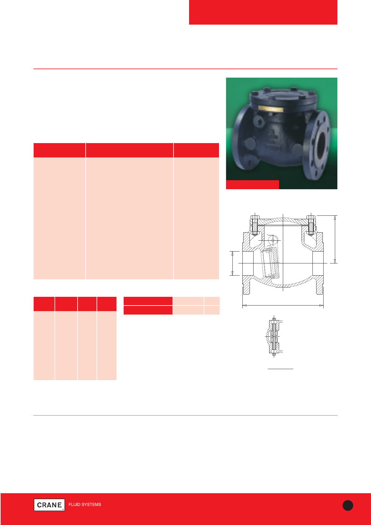
41
TECHNICAL HELPLINE: +44 (0)1473 277400
www.cranefs.com
CHECK VALVES
FM492
PN16
Cast Iron Check Valve
Check valves permit flow in one direction only, and close automatically if
flow reverses. They are entirely automatic in action, depending upon
pressure and velocity of flow within the line to perform their functions of
opening and closing.
Swing pattern, metal faced disc.
FM492
PART MATERIAL SIZES
Body Cast Iron BS EN 1561 GJL-250 All
Cap Cast Iron BS EN 1561 GJL-250 All
Disc Cast Iron BS EN 1561 GJL-250 All
Body Seat Ring Bronze BS EN 1982 CC491K All
Disc Ring Bronze BS EN 1982 CC491K All
Hinge Pin Bush Bronze BS EN 1982 CC491K All
Hinge Pin Plug Bronze BS EN 1982 CC491K All
Hinge Pin Stainless Steel Type 304 50mm - 100mm
Hinge Pin 13% Cr.Steel AISI Type 410 125mm - 300mm
Cap Bolts Steel BS3692 Gr.8.8 All
Cap Bolt Nuts Steel BS3692 Gr.8 All
Gasket Asbestos Free All
Body Plate Aluminium All
Materials
XX
E
A
NOM SIZE
FLANGED
BS454 N1
/ BSEN19-
SECTION X-X
Dimensional Drawing
PRESSURE RATING: PN16
UK END CONNECTION: Flanged BS EN 1092-2
OPERATOR: Swing Type Check Valve
SPECIFICATION:
Valves are manufactured in accordance with BS EN 12334: 2001. End
flanges conform to BS EN 1092-2 with raised face and are normally
supplied drilled.
This valve is not suitable for use on group 1 gasses or unstable fluids, as
defined by the Pressure Equipment Directive 97/23/EC.
Temperature operating range: -10 to 220°C.
Dimensions and Weights
SIZE WEIGHT A E
(kg) (mm) (mm)
50mm 11.3 203 113
65mm 15.6 216 126
80mm 19.3 241 136
100mm 26.6 292 153
125mm 44 330 186
150mm 55.5 356 207
200mm 119 495 250
250mm 175 622 352
300mm 263 698 397
TEMPERATURE (°C) -10 to 100 220
PRESSURE (BAR) 16 12.1
Intermediate pressure ratings shall be
determined by interpolation
Pressure/Temperature Ratings
Every effort has been made to ensure that the information contained in this publication is accurate at the time of publishing. Crane Ltd assumes no responsibility or liability for typographical errors or omissions or for
any misinterpretation of the information within the publication and reserves the right to change without notice.
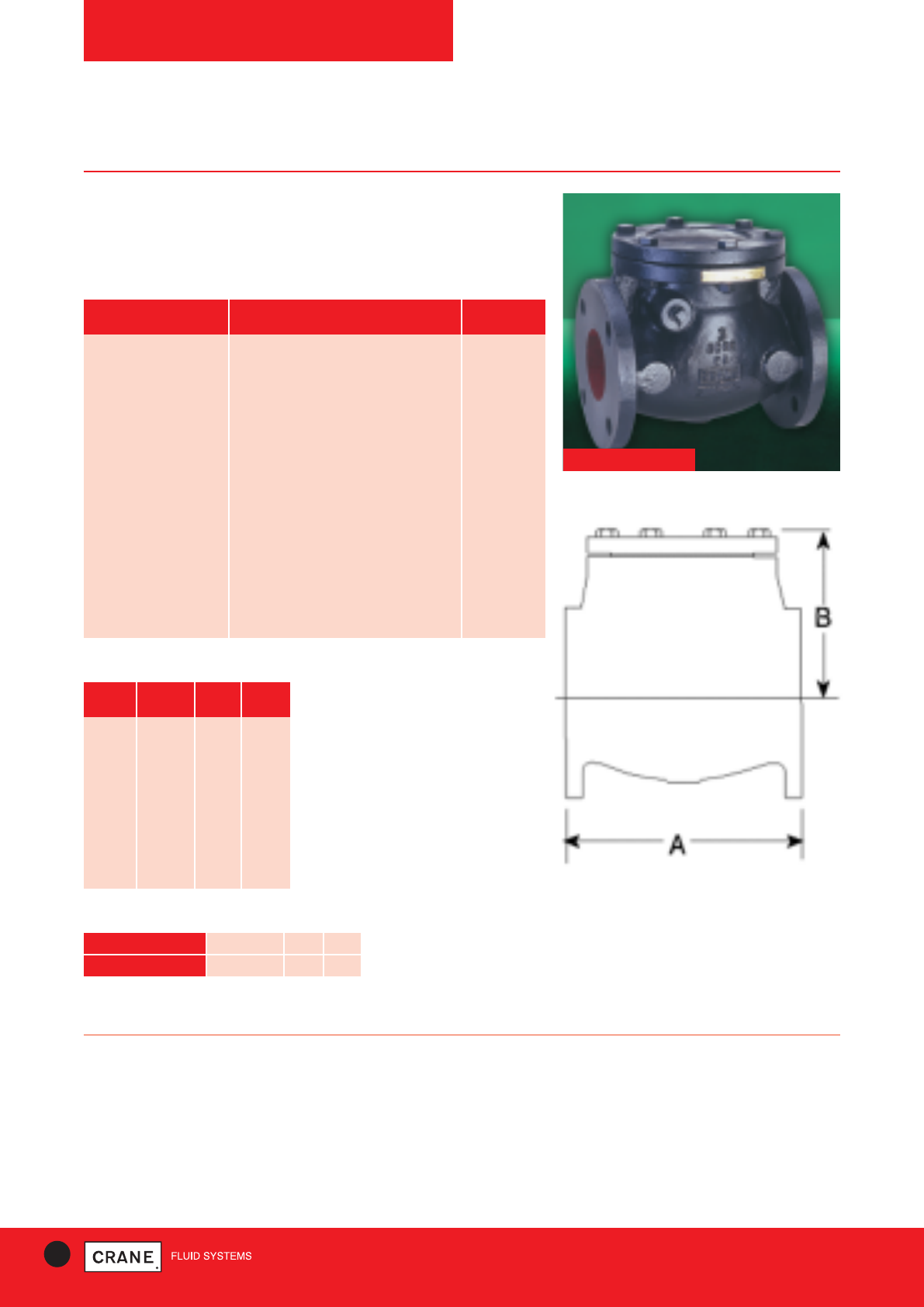
42 TECHNICAL HELPLINE: +44 (0)1473 277400
www.cranefs.com
CHECK VALVES
F493
Class 125
Cast Iron Check Valve
The F493 is a swing check valve with a Bronze trim.
Each valve is manufactured to BS 5153:1974
F493
PART MATERIAL SIZES
Body Cast Iron BS EN 1561 GJL-250 All
Cap Cast Iron BS EN 1561 GJL-250 All
Disc Cast Iron BS EN 1561 GJL-250 All
Body Seat Ring Bronze BS EN 1982 CC491K All
Disc Ring Bronze BS EN 1982 CC491K All
Hinge Pin Bush Bronze BS EN 1982 CC491K All
Hinge Pin Plug Bronze BS EN 1982 CC491K All
Hinge Pin Stainless Steel Type 304 2 - 4
Hinge Pin 13% Cr.Steel AISI Type 410 5 - 12
Cap Bolts Steel BS3692 Gr.8.8 All
Cap Bolts Nuts Steel BS3692 Gr.8 All
Gasket Asbestos Free All
Body Plate Aluminium All
Materials
Dimensional Drawing
PRESSURE RATING: Class 125
US END CONNECTION: ANSI Class 125
OPERATOR: Swing Check Valve
SPECIFICATION:
Valves are manufactured in accordance with BS 5153: 1974 and also meet
the requirements of MSS.SP-71. End flanges conform to BS 1560.
Section 3.2/ANSI B16.1 Class 125 with flat face and are normally supplied
drilled.
This valve is not suitable for use on group 1 gasses or unstable fluids, as
defined by the Pressure Equipment Directive 97/23/EC.
Temperature operating range: -10 to 230°C.
Dimensions and Weights
SIZE WEIGHT A B
(kg) (mm) (mm)
2|| 11.3 203 113
21/2|| 15.6 216 126
3|| 19.3 241 136
4|| 26.6 292 153
5|| 44 330 186
6|| 55.5 356 207
8|| 119 495 250
10|| 175 622 352
12|| 263 698 397
TEMPERATURE (°C) -10 to 65 150 230
PRESSURE (BAR) 13.8 11.4 8.6
Intermediate pressure ratings shall be determined by
interpolation
Pressure/Temperature Ratings
Every effort has been made to ensure that the information contained in this publication is accurate at the time of publishing. Crane Ltd assumes no responsibility or liability for typographical errors or omissions or for
any misinterpretation of the information within the publication and reserves the right to change without notice.
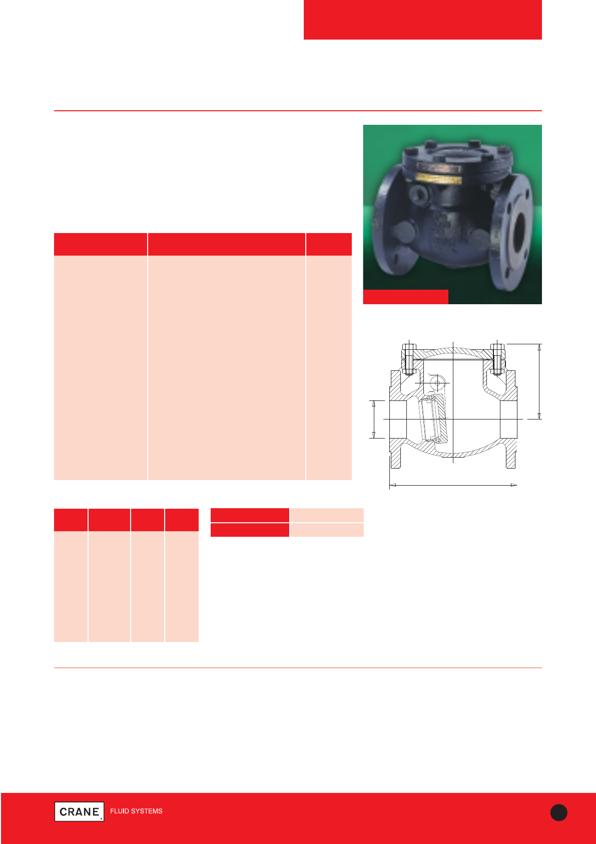
43
TECHNICAL HELPLINE: +44 (0)1473 277400
www.cranefs.com
CHECK VALVES
FM469
PN16
Cast Iron Check Valve
Check valves permit flow in one direction only, and close automatically if
flow reverses. They are entirely automatic in action, depending
upon pressure and velocity of flow within the line to perform their
functions of opening and closing.
Swing pattern, bronze trim, resilient seated.
FM469
PART MATERIAL SIZES
Body Cast Iron BS EN 1561 GJL-250 All
Cap Cast Iron BS EN 1561 GJL-250 All
Disc Cast Iron BS EN 1561 GJL-250 All
Body Seat Ring Bronze BS EN 1982 CC491K All
Disc Ring Nitrile Rubber All
Hinge Pin Bush Bronze BS EN 1982 CC491K All
Hinge Pin Plug Bronze BS EN 1982 CC491K All
Hinge Pin Stainless Steel Type 304 50 - 80
Hinge Pin 13% Cr.Steel AISI Type 410 100 - 300
Cap Bolts Steel BS3692 Gr.8.8 All
Cap Bolt Nuts Steel BS3692 Gr.8 All
Gasket Asbestos Free All
Body Plate Aluminium All
Disc Ring Ret’g Nut Cast Iron BS EN 1561 GJL-250 All
Retaining Nut Pin Steel All
Materials
XX
E
A
NOM SIZE
FLANGED
BS4504 PN10
/ BSEN1092-2
Dimensional Drawing
PRESSURE RATING: PN16
UK END CONNECTION: Flanged BS EN 1092-2 PN16
OPERATOR: Swing check valve
SPECIFICATION:
Valves are manufactured in accordance with BS EN 12334: 2001. End
flanges conform to BS EN 1092-2 Section 3.2 Table 11 with raised face
and are normally supplied drilled.
This valve is not suitable for use on group 1 gasses or unstable fluids, as
defined by the Pressure Equipment Directive 97/23/EC.
Temperature operating range: -10 to 65°C.
Dimensions and Weights
SIZE WEIGHT A E
(kg) (mm) (mm)
50mm 11.3 203 113
65mm 15.6 216 126
80mm 19.3 241 136
100mm 26.6 292 153
125mm 44 330 186
150mm 55.5 356 207
200mm 119 495 250
250mm 175 622 352
300mm 263 698 397
TEMPERATURE (°C) -10 to 65
PRESSURE (BAR) 16
Intermediate pressure ratings shall be
determined by interpolation
Pressure/Temperature Ratings
Every effort has been made to ensure that the information contained in this publication is accurate at the time of publishing. Crane Ltd assumes no responsibility or liability for typographical errors or omissions or for
any misinterpretation of the information within the publication and reserves the right to change without notice.
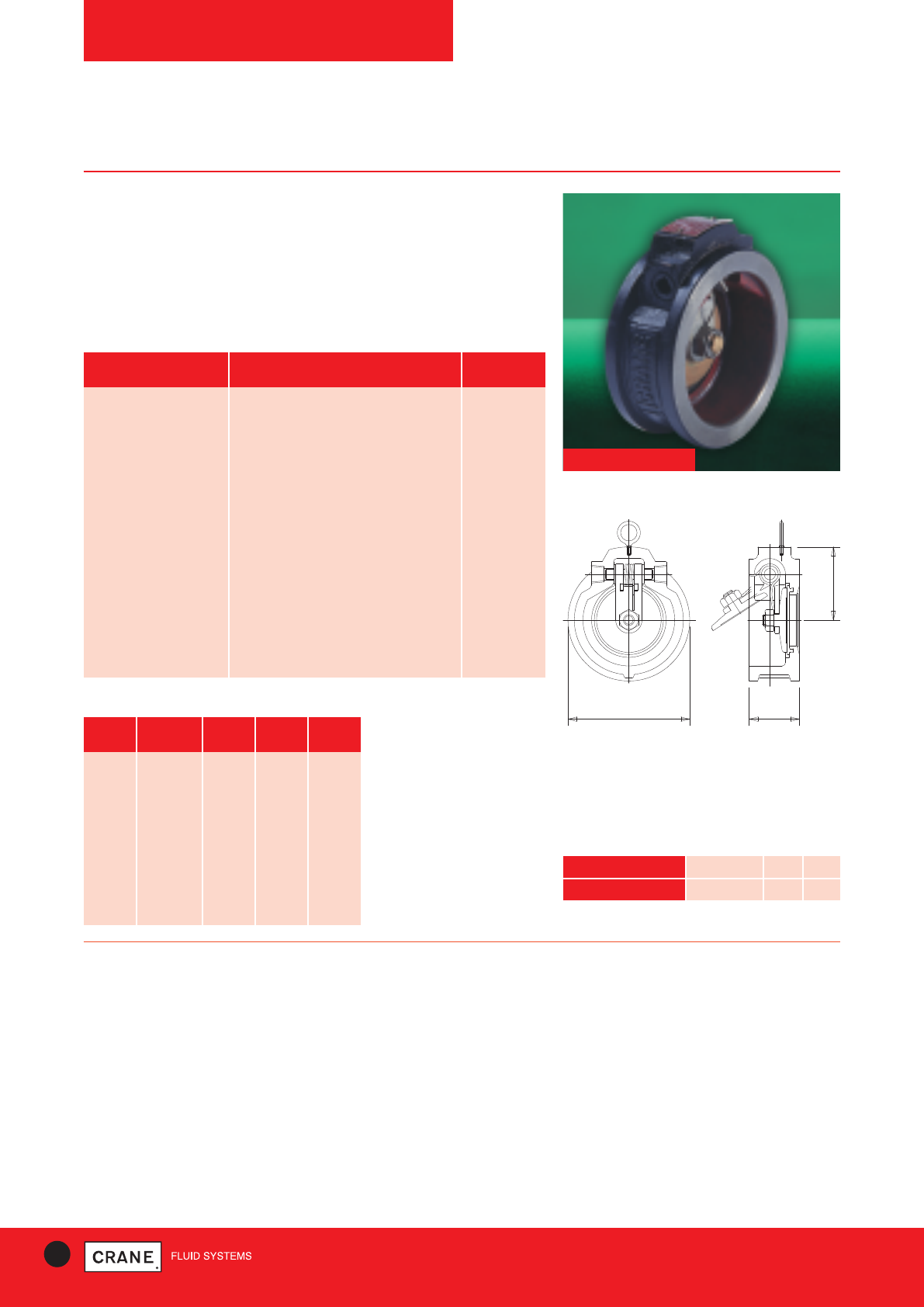
44 TECHNICAL HELPLINE: +44 (0)1473 277400
www.cranefs.com
CHECK VALVES
FM450/FM451 Wafer
PN16
Cast Iron Wafer Check Valve
Check valves permit flow in one direction only, and close automatically if
flow reverses. They are entirely automatic in action, depend-
ing upon pressure and velocity of flow within the line to perform their
functions of opening and closing.
Swing Pattern, Metal Faced Disc (FM450) Resilient Seated (FM451)
FM450-F451
PART MATERIAL SIZES
Body Cast Iron BS EN 1561 GJL-250 All
Disc SG Cast Iron BS2789 100 - 300
Disc Ring Bronze BS EN 1982 CC491K 100 - 300
Disc Bronze BS EN 1982 CC491K 50 - 80
Hinge Stainless Steel Type 304 All
Hinge Pin Stainless Steel Type 304 All
Spacer PTFE (Glass Filled) All
Spring Stainless Steel Type 304 or 316 All
Plug Bronze BS EN 1982 CC491K All
Hinge Nut Stainless Steel Type 304 All
Eye Bolt Steel (Zinc Plated) 150 - 300
Body Seat Ring Bronze BS EN 1982 CC491K FM450
Body Seat Ring Ethylene Propylene Diene Monomer FM451
Materials
B A
C
Dimensions and Weights
Dimensional Drawing
PRESSURE RATING: PN16
UK END CONNECTION: Wafer style one piece flangeless cast iron
body. Suitable for use between flanges drilled in accordance with BS EN
1092-2 PN10 and PN16, BS10 Table D or E and ANSI 125
US END CONNECTION: BS 1560, ANSI B16-1, ANSI B16-5
OPERATOR: Swing type check.
SPECIFICATION:
Face to Face dimensions conform to ISO 5752.
Suitable for installation in vertical and horizontal pipelines. When installed in
vertical pipelines the flow must be in an upward direction.
This valve is suitable for use on group 2 liquids only, as defined by the
Pressure Equipment Directive 97/23/EC.
Temperature operating range: -10 to 230°C (FM450) -10 to 120°C (FM451).
SIZE WEIGHT A B C
(kg) (mm) (mm) (mm)
50mm 1.3 43 99 57
65mm 1.8 46 111 67
80mm 2.6 49 130 73
100mm 4.7 56 162 88
125mm 7 64 194 102
150mm 9.8 70 216 168
200mm 15 71 273 194
250mm 20 76 330 227
300mm 30 83 380 255
TEMPERATURE (°C) -10 to 65 150 230
PRESSURE (BAR) 13.8 11.4 8.6
Intermediate pressure ratings shall be determined by
interpolation
Pressure/Temperature Ratings
Every effort has been made to ensure that the information contained in this publication is accurate at the time of publishing. Crane Ltd assumes no responsibility or liability for typographical errors or omissions or for
any misinterpretation of the information within the publication and reserves the right to change without notice.
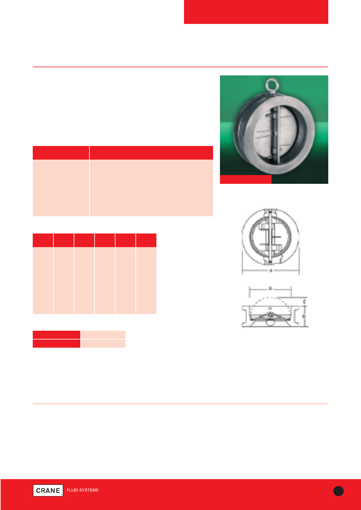
45
TECHNICAL HELPLINE: +44 (0)1473 277400
www.cranefs.com
CHECK VALVES
FM455 Wafer
PN25
Ductile Iron Wafer Check valve
Check valves permit flow in one direction only, and close automatically if
flow reverses. They are entirely automatic in operation,
depending upon pressure and velocity of flow within the pipeline to
perform their opening and closing functions.
The FM455 is a Double Door wafer pattern valve, spring loaded to assist
closing, and with an EPDM seat for quiet operation.
FM455
PART MATERIAL
Body Ductile Iron - BS EN 1561 EN-JL1030
Discs Stainless Steel SS316
Shaft Stainless Steel 10088-1 X10CrNil8-10
Stop Pin Stainless Steel 10088-1 X10CrNil8-10
Seat EPDM
Springs Stainless Steel 10088-1 X10CrNil8-10
Materials
Dimensions and Weights
SPECIFICATION:
Face to Face dimensions conform to BS EN 558-1. Suitable for fitting between flanges conforming to BS EN 1092-2 PN25
Suitable for mounting in horizontal and vertical pipelines.
When installed in vertical pipelines the flow must be in an upward direction.
This valve is suitable for use on group 2 liquids only as defined by the pressure equipment directive and 97/23/EC.
Temperature operating range: -10 to 120°C.
SIZE WEIGHT A B C D
(kg) (mm) (mm) (mm) (mm)
50 2.5 105 54 8 60
65 3.5 124 54 14 73
80 4.5 137 57 16 89
100 8.0 168 64 25 114
125 10.0 194 70 34 141
150 13.0 222 76 43 168
200 28.0 276 95 61 219
250 45.0 340 108 80 273
300 68.0 400 143 102 324
Dimensional Drawing
TEMPERATURE (°C) -10 to 120
PRESSURE (BAR) 25
Pressure/Temperature Ratings
Every effort has been made to ensure that the information contained in this publication is accurate at the time of publishing. Crane Ltd assumes no responsibility or liability for typographical errors or omissions or for
any misinterpretation of the information within the publication and reserves the right to change without notice.
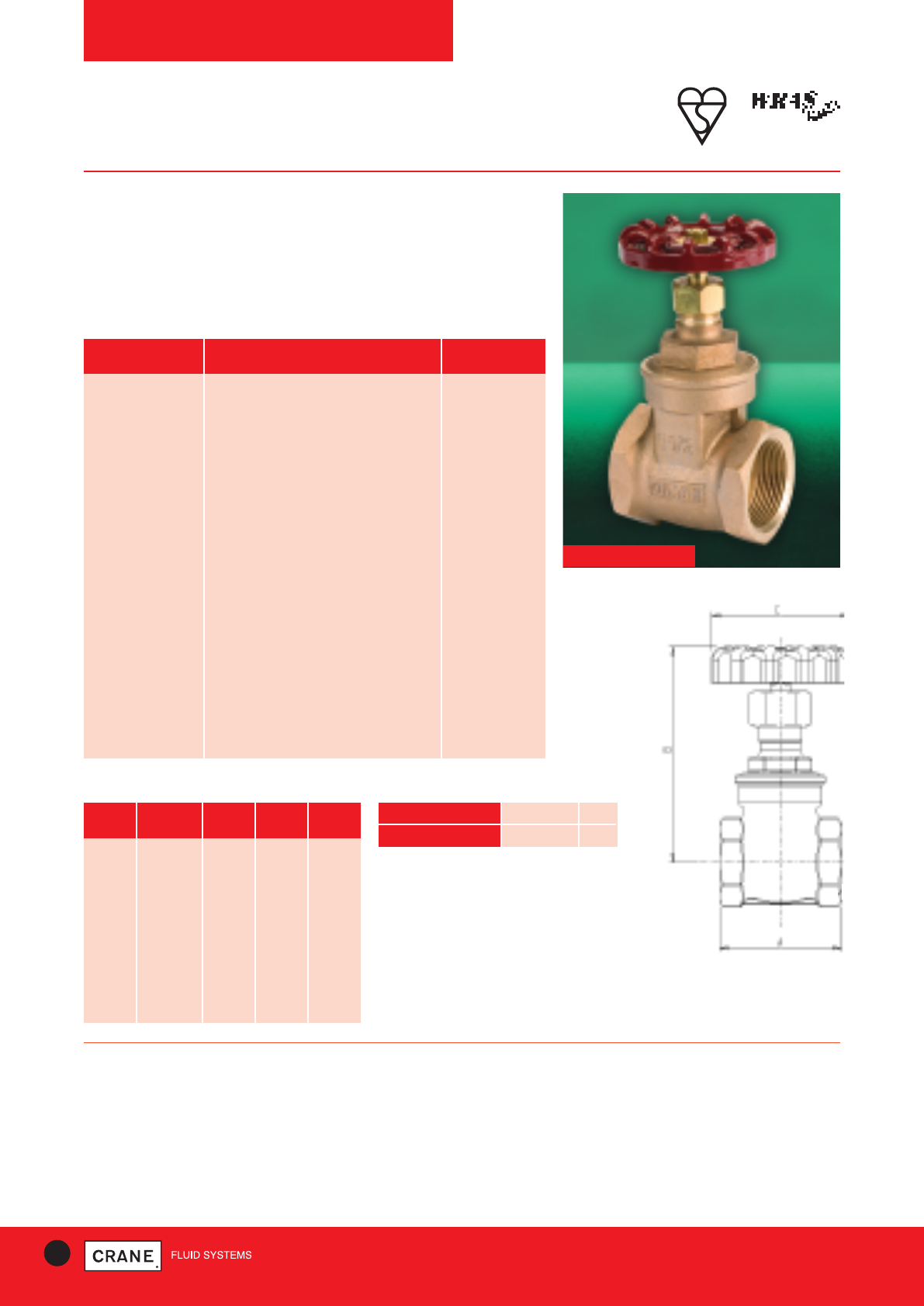
46 TECHNICAL HELPLINE: +44 (0)1473 277400
www.cranefs.com
PRESSURE RATING: PN20
UK END CONNECTION: Taper threaded to BS EN 10226-2 (ISO 7-1)
formerly BS 21
US END CONNECTION: ANSI B1.20.1 (please add suffix AT to
denote American Thread)
OPERATOR: Hand Wheel
Gate valves are best for services that require infrequent valve operation,
and where the disc is kept either fully opened or fully closed.
They are not practical for throttling.
SIZE WEIGHT A B C
(kg) (mm) (mm) (mm)
1/4|| 0.27 46 75 45
3/8|| 0.26 46 75 45
1/2|| 0.269 50 73 52.5
3/4|| 0.384 54 84 60
1|| 0.593 62 104 65
11/4|| 0.844 71 113 70
11/2|| 1.266 77.5 130 78
2|| 1.881 87.5 153 92
21/2|| 4.37 96 219 103
3|| 6.4 105 259 121
4|| 19.7 162 366 203
Dimensions and Weights
GATE VALVES
D151
PN20
Bronze Gate Valve
Crane gate valves offer the ultimate in dependable service wherever
minimum pressure drop is important. The D151 carries the British
Standards Institution kitemark - your assurance of exacting quality
standards. In addition the D151 is WRAS approved.
D151
PART MATERIAL SIZES
Body Bronze BS EN 1982 CC491K All
Bonnet Bronze BS EN 1982 CC491K All
Stem DZR Brass BS EN 12164 CW602N 1/4- 3
Stem Manganese Bronze 4
Disc Bronze BS EN 1982 CC491K All
Stem Retainer DZR Brass BS EN 12164 CW602N 1/2- 2
Stuffing Box DZR Brass BS EN 12164 CW602N 1/4, 3/8, 21/2& 3
Stuffing Box Bronze BS EN 1982 CC491K 4
Packing Asbestos Free All
Packing Gland Brass BS EN 12164 CW614N 1/4, 3/8, 1 - 3
Packing Gland Nut Brass BS EN 12164 CW614N 1/2& 3/4
Packing Gland Bronze BS EN 1982 CC491K 4
Packing Nut Brass BS EN 12164 CW614N 1/4- 3
Packing Nut Bronze BS EN 1982 CC491K 4
Hand Wheel Aluminium 1/4- 3
Hand Wheel Malleable Iron BS EN 1562 GJMB-300-6 4
ID. Plate Aluminium All
Hand Wheel Nut Brass BS EN 12164 CW614N All
Gasket Asbestos Free 3 - 4
Materials
SPECIFICATION:
Solid wedge disc, non-rising stem, screwed in bonnet.
Valves are manufactured in accordance with BS EN 12288: 2010 PN20
series B and are BSI Kitemark approved.
This valve is not suitable for use on group 1 gasses or unstable fluids, as
defined by the Pressure Equipment Directive 97/23/EC.
Temperature operating range: -10 to 180°C.
Dimensional Drawing
TEMPERATURE (°C) -10 to 100 180
PRESSURE (BAR) 20 9
Intermediate pressure ratings shall be determined
by interpolation
Pressure/Temperature Ratings
Every effort has been made to ensure that the information contained in this publication is accurate at the time of publishing. Crane Ltd assumes no responsibility or liability for typographical errors or omissions or for
any misinterpretation of the information within the publication and reserves the right to change without notice.
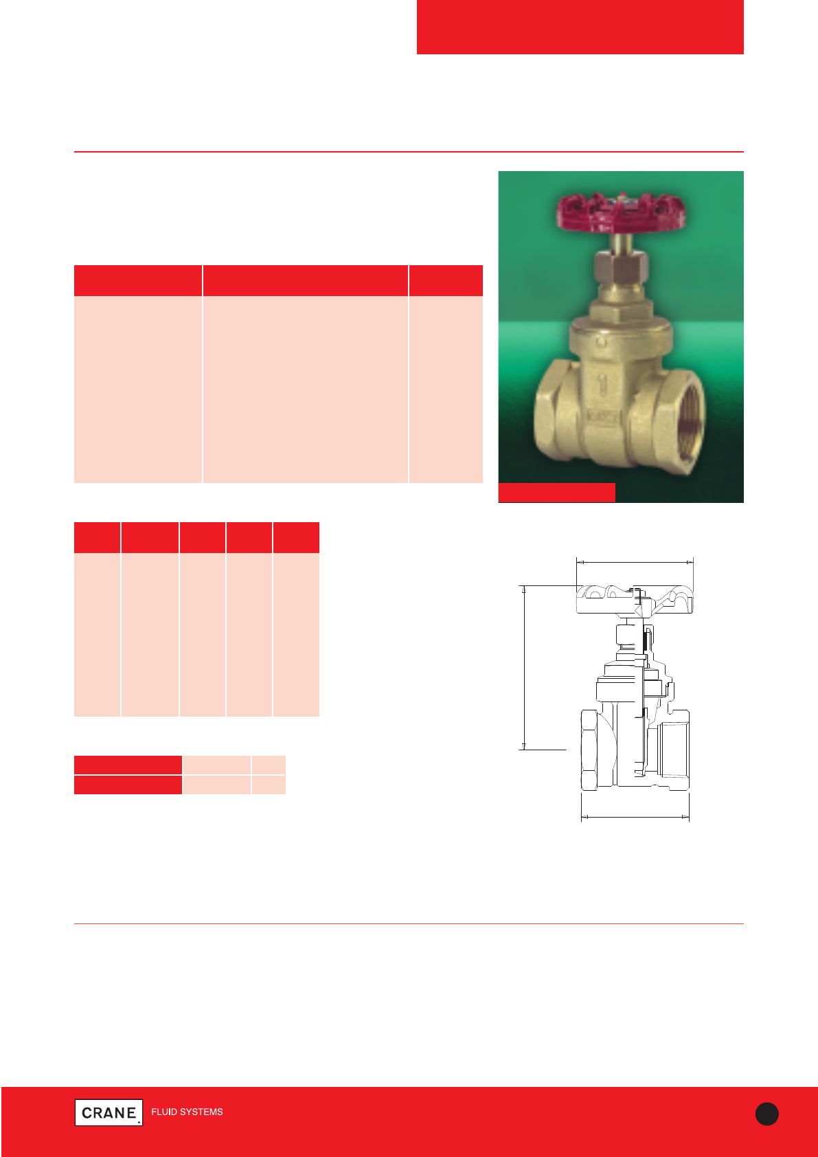
47
TECHNICAL HELPLINE: +44 (0)1473 277400
www.cranefs.com
GATE VALVES
D151A
PN20
DZR Gate Valve
Crane gate valves offer the ultimate in dependable service wherever
minimum pressure drop is important.
D151A
PRESSURE RATING: PN20
END CONNECTION: Taper threaded to BS EN 10226-2 (ISO 7-1)
formerly BS 21
OPERATOR: Hand Wheel
Gate valves are best for services that require infrequent valve operation,
and where the disc is kept either fully opened or fully closed.
They are not practical for throttling.
SPECIFICATION:
Valves are manufactured in accordance with BS EN 12288: 2010 PN20 for
Series B ratings.
Non Rising Stem
This valve is not suitable for use on group 1 gasses or unstable fluids, as
defined by the Pressure Equipment Directive 97/23/EC.
Temperature operating range: -10 to 180°C.
PART MATERIAL SIZES
Body DZR Brass BS EN 12165 CW602N All
Bonnet DZR Brass BS EN 12165 CW602N All
Stem DZR Brass BS EN 12164 CW602N All
Packing Nut Brass BS EN 12164 CW614N All
Packing PTFE All
Stem Bush DZR Brass BS EN 12164 CW602N All
Disc DZR Brass BS EN 12165 CW602N All
Hand Wheel Aluminium All
Hand Wheel Nut Steel (Zinc Plated) All
Materials
Dimensions and Weights
C DIA.
B
A
SIZE WEIGHT A B C
(kg) (mm) (mm) (mm)
1/4|| 0.2 43 69 45
3/8|| 0.19 43 69 45
1/2|| 0.23 50 69 45
3/4|| 0.36 54 79 52
1|| 0.5 62 92 52
11/4|| 0.82 70 108 65
11/2|| 1.08 72 125 70
2|| 1.83 82 150 92
21/2|| 2.9 97 176 103
3|| 3.97 111 204 120
Dimensional Drawing
TEMPERATURE (°C) -10 to 100 180
PRESSURE (BAR) 20 9
Intermediate pressure ratings shall be determined
by interpolation
Pressure/Temperature Ratings
Every effort has been made to ensure that the information contained in this publication is accurate at the time of publishing. Crane Ltd assumes no responsibility or liability for typographical errors or omissions or for
any misinterpretation of the information within the publication and reserves the right to change without notice.
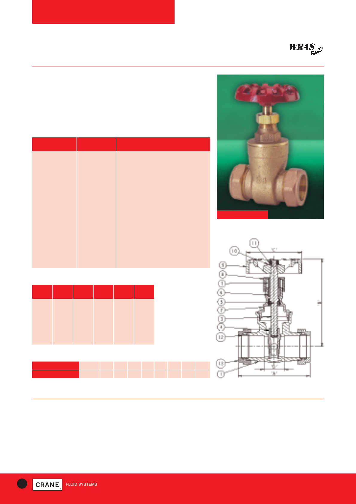
48 TECHNICAL HELPLINE: +44 (0)1473 277400
www.cranefs.com
GATE VALVES
D155C
PN16
Features & Benefits
• Robust and high quality bronze body with integral seating surfaces
• Offers the ultimate in dependable service wherever minimum pressure
drop is important
• WRAS Approved for use with potable water
• Inside screw pattern with non-rising stem
D155C
PART MATERIAL SPECIFICATION
Body Bronze BS EN 1982 (CC491K)
Bonnet Bronze BS EN 1982 (CC491K)
Stem DZR Brass BS EN 12164 CW602N
Disc Bronze BS EN 1982 (CC491K)
Stem Retainer DZR Brass BS EN 12164 CW602N
Packing Ring Asbestos Free
Gland (28-54 only) Brass BS EN 12164 CW614N
Packing Nut Brass BS EN 12164 CW614N
Handwheel Aluminium -
Identification Plate Aluminium -
Handwheel Nut Brass BS EN 12164 CW614N
Compression Olive Brass BS EN 12449:1999 CW505L OR CW507L
Compression Nut Brass BS EN 12165 CW617N
Materials
PRESSURE RATING: PN16
UK END CONNECTION: Compression ends to BS EN 1057: 2006:
Half hard R250
OPERATING INSTRUCTIONS: Handwheel. Gate valves are best for
services that require infrequent valve operation and where the disk is kept
either fully open or closed. They are not practical for throttling.
SPECIFICATION:
Valves are manufactured in accordance with BS EN 12288: 2010 (formerly
BS 5154) PN20 for Series B ratings, but are limited to the
pressure/temperature ratings detailed in BS EN 1057: 2006 for
compression end fittings. This valve is to be used on Group 2 liquids only,
as defined by the Pressure Equipment Directive 97/23/EC.
SIZE WEIGHT A B C D
(kg) (mm) (mm) (mm) (mm)
15 0.34 69 74 53 26.5
22 0.50 75 86 59 23.5
28 0.70 86 105 65 25.5
35 .95 100 110 70 30.5
42 1.45 111 131 78 34.5
54 2.50 133 152 93 37
Dimensions and Weights
Dimensional Drawing
TEMPERATURE (°C) 16.0 14.3 12.6 10.0 8.7 7.8 6.9 6.0 5.0
PRESSURE (BAR) -10 to 30 40 50 65 80 90 100 110 120
Pressure/Temperature Ratings
Intermediate pressure ratings shall be determined by interpolation
Every effort has been made to ensure that the information contained in this publication is accurate at the time of publishing. Crane Ltd assumes no responsibility or liability for typographical errors or omissions or for
any misinterpretation of the information within the publication and reserves the right to change without notice.
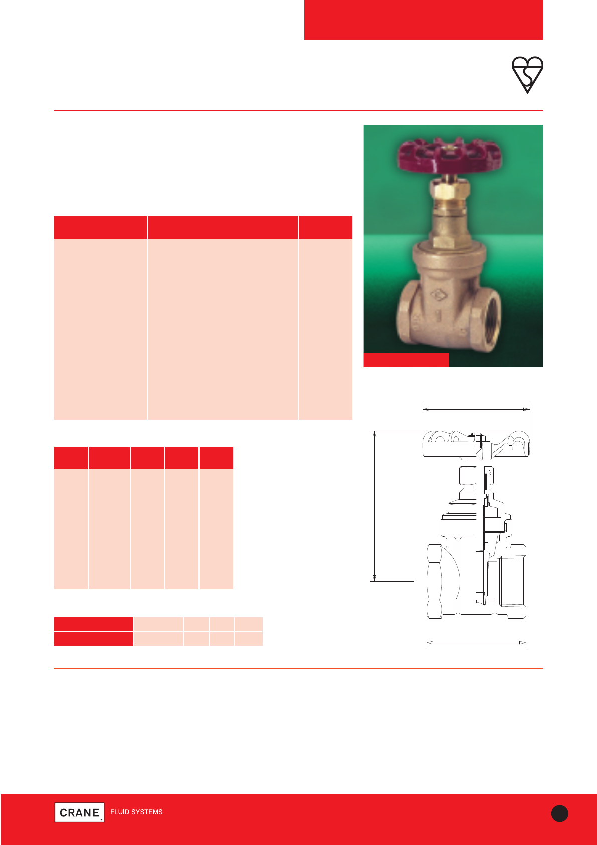
49
TECHNICAL HELPLINE: +44 (0)1473 277400
www.cranefs.com
GATE VALVES
D151X
PN25
Bronze Gate Valve
Crane gate valves offer the ultimate in dependable service wherever
minimum pressure drop is important.
This valve carries the British Standards Institution kitemark - your
assurance of exacting quality.
PRESSURE RATING: PN25
UK END CONNECTION: Taper threaded to BS EN 10226-2 (ISO 7-1)
formerly BS 21
US END CONNECTION: ANSI B1.20.1 (please add suffix AT to
denote American Thread)
OPERATOR: Hand Wheel
Gate valves are best for services that require infrequent valve operation,
and where the disc is kept either fully opened or fully closed.
They are not practical for throttling.
SPECIFICATION:
Valves are manufactured in accordance with BS EN 12288: 2010 PN25 for
series B ratings.
All Sizes BSI Kitemarked.
Non Rising Stem
This valve is not suitable for use on group 1 gasses or unstable fluids, as
defined by the Pressure Equipment Directive 97/23/EC.
Temperature operating range: -10 to 186°C.
Dimensions and Weights
SIZE WEIGHT A B C
(kg) (mm) (mm) (mm)
1/4|| 0.27 46 75 45
3/8|| 0.26 46 75 45
1/2|| 0.35 51 82 52
3/4|| 0.55 55 95 65
1|| 0.84 63 118 70
11/4|| 1.18 71 144 79
11/2|| 1.66 73 166 92
2|| 2.55 83 190 103
21/2|| 4.56 105 220 103
3|| 6.38 111 259 121
D151X
C DIA.
B
A
Dimensional Drawing
TEMPERATURE (°C) -10 to 100 110 120 186
PRESSURE (BAR) 25.0 23.4 21.8 10.5
Intermediate pressure ratings shall be determined by
interpolation
Pressure/Temperature Ratings
PART MATERIAL SIZES
Body Bronze BS EN 1982 CC491K All
Bonnet Bronze BS EN 1982 CC491K All
Stem DZR Brass BS EN 12164 CW602N All
Disc Bronze BS EN 1982 CC491K All
Stuffing Box DZR Brass BS EN 12164 CW602N 1/4- 2
Stem Bushing DZR Brass BS EN 12164 CW602N 21/2& 3 only
Packing Asbestos Free All
Gland Brass BS EN 12164 CW614N All
Packing Nut Brass BS EN 12164 CW614N All
Hand Wheel Aluminium All
ID. Plate Aluminium All
Hand Wheel Nut Brass BS EN 12164 CW614N All
Gasket Asbestos Free 3 only
Materials
Every effort has been made to ensure that the information contained in this publication is accurate at the time of publishing. Crane Ltd assumes no responsibility or liability for typographical errors or omissions or for
any misinterpretation of the information within the publication and reserves the right to change without notice.
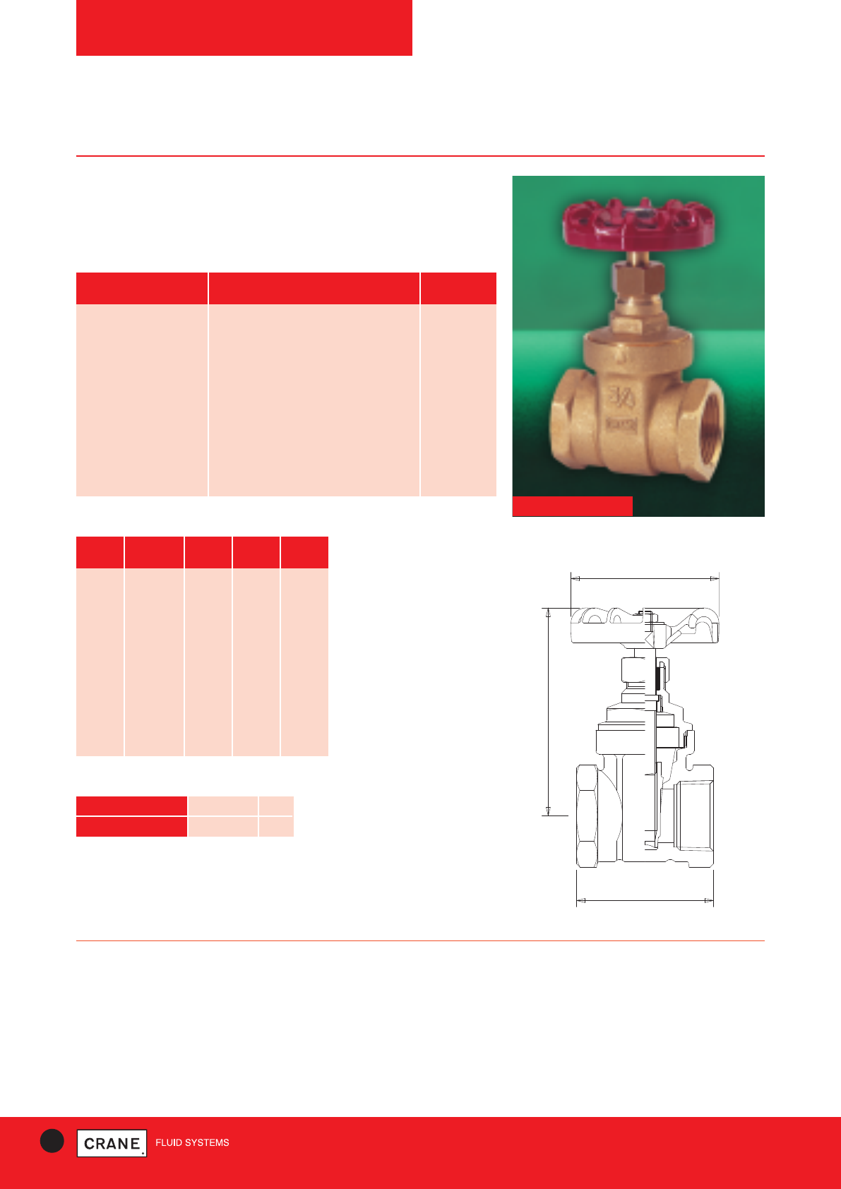
50 TECHNICAL HELPLINE: +44 (0)1473 277400
www.cranefs.com
GATE VALVES
D156
PN16
Brass Gate Valve
Crane gate valves offer the ultimate in dependable service wherever
minimum pressure drop is important.
D156
PART MATERIAL SIZES
Body Brass BS EN 12165 CW617N All
Bonnet Brass BS EN 12165 CW617N All
Stem Brass BS EN 12164 CW617N All
Packing Nut Brass BS EN 12165 CW617N All
Packing Asbestos Free All
Stem Bush Brass BS EN 12164 CW617N All
Disc Brass BS EN 12165 CW617N All
Hand Wheel Aluminium All
Hand Wheel Nut Steel (Zinc Plated) All
Materials
PRESSURE RATING: PN16
UK END CONNECTION: Taper threaded to BS EN 10226-2 (ISO 7-1)
formerly BS 21
US END CONNECTION: ANSI B1.20.1 (please add suffix AT to
denote American Thread)
OPERATOR: Hand Wheel.
Gate valves are best for services that require infrequent valve operation,
and where the disc is kept either fully opened or fully closed.
They are not practical for throttling.
SPECIFICATION:
Valves 1/4|| to 2|| are manufactured in accordance with BS EN 12288: 2010
PN16 for Series B ratings.
Non rising stem
This valve is not suitable for use on group 1 gasses or unstable fluids, as
defined by the Pressure Equipment Directive 97/23/EC.
Temperature operating range: -10 to 170°C.
AVAILABLE OPTIONS:
P150 locking device.
C DIA.
B
A
Dimensions and Weights
SIZE WEIGHT A B C
(kg) (mm) (mm) (mm)
1/4|| 0.2 41 69 44
3/8|| 0.2 41 69 44
1/2|| 0.22 48 69 44
3/4|| 0.35 54 79 52
1|| 0.52 62 92 52
11/4|| 0.77 68 108 65
11/2|| 1.02 72 125 70
2|| 1.75 82 150 92
21/2|| 2.77 97 176 103
3|| 3.9 111 204 120
4|| 6.35 131 262 152
Dimensional Drawing
TEMPERATURE (°C) -10 to 100 170
PRESSURE (BAR) 16 7
Intermediate pressure ratings shall be determined
by interpolation
Pressure/Temperature Ratings
Every effort has been made to ensure that the information contained in this publication is accurate at the time of publishing. Crane Ltd assumes no responsibility or liability for typographical errors or omissions or for
any misinterpretation of the information within the publication and reserves the right to change without notice.
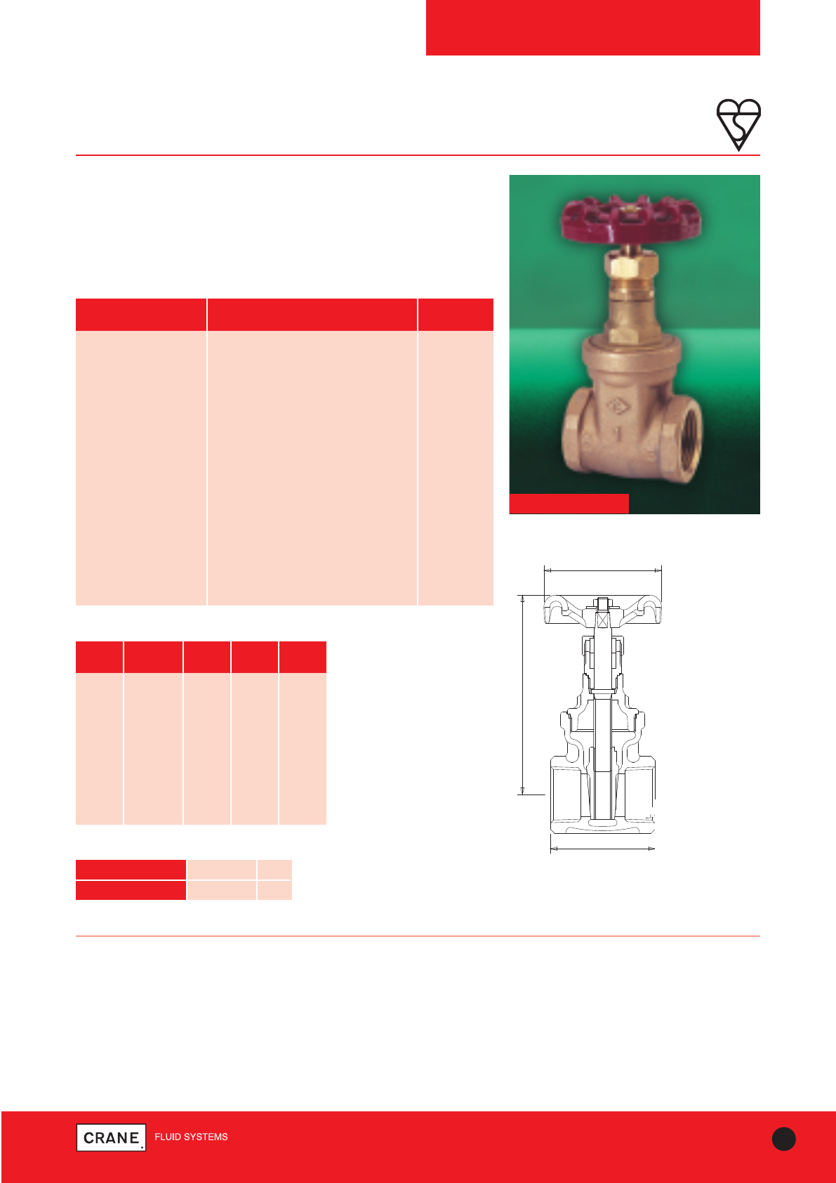
51
TECHNICAL HELPLINE: +44 (0)1473 277400
www.cranefs.com
GATE VALVES
D159
PN32
Bronze Gate Valve
Crane gate valves offer the ultimate in dependable service wherever
minimum pressure drop is important.
This valve carries the British Standards Institution kitemark - your
assurance of exacting quality.
D159
PART MATERIAL SIZES
Body Bronze BS EN 1982 CC491K All
Bonnet Bronze BS EN 1982 CC491K 1/4- 3
Stem DZR Brass BS EN 12164 CW602N 1/4- 2
Stem Bronze BS EN 1982 CC491K 21/2& 3
Disc Bronze BS EN 1982 CC491K All
Stuffing Box DZR Brass BS EN 12164 CW602N 1/4- 2
Stuffing Box Bronze BS EN 1982 CC491K 21/2& 3
Packing Asbestos Free All
Gland Brass BS EN 12164 CW614N All
Packing Nut Brass BS EN 12164 CW614N All
Hand Wheel Aluminium All
ID. Plate Aluminium All
Hand Wheel Nut Brass BS EN 12164 CW614N All
Gasket Asbestos Free 3 only
Materials
PRESSURE RATING: PN32
UK END CONNECTION: Taper threaded to BS EN 10226-2 (ISO 7-1)
formerly BS 21
US END CONNECTION: ANSI B1.20.1 (please add suffix AT to
denote American Thread)
OPERATOR: Hand Wheel
Gate valves are best for services that require infrequent valve operation,
and where the disc is kept either fully opened or fully closed.
They are not practical for throttling.
SPECIFICATION:
Valves are manufactured in accordance with BS EN 12288: 2010 PN32 for
series B ratings.
Non Rising Stem.
This valve is not suitable for use on group 1 gasses or unstable fluids, as
defined by the Pressure Equipment Directive 97/23/EC.
Temperature operating range: -10 to 198°C.
THREADED BSEN10226
FORMERLY BS21 TAPER
OR ANSI B1.20.1 TAPER
B
C
A
Dimensions and Weights
SIZE WEIGHT A B C
(kg) (mm) (mm) (mm)
1/4|| 0.36 46 75 45
3/8|| 0.35 46 75 45
1/2|| 0.47 51 82 52
3/4|| 0.6 55 95 65
1|| 0.92 63 118 70
11/4|| 1.41 71 144 79
11/2|| 1.92 73 166 92
2|| 2.72 83 190 103
21/2|| 5.62 105 232 103
3|| 7.89 111 264 121
Dimensional Drawing
TEMPERATURE (°C) -10 to 100 198
PRESSURE (BAR) 32 14
Intermediate pressure ratings shall be determined
by interpolation
Pressure/Temperature Ratings
Every effort has been made to ensure that the information contained in this publication is accurate at the time of publishing. Crane Ltd assumes no responsibility or liability for typographical errors or omissions or for
any misinterpretation of the information within the publication and reserves the right to change without notice.
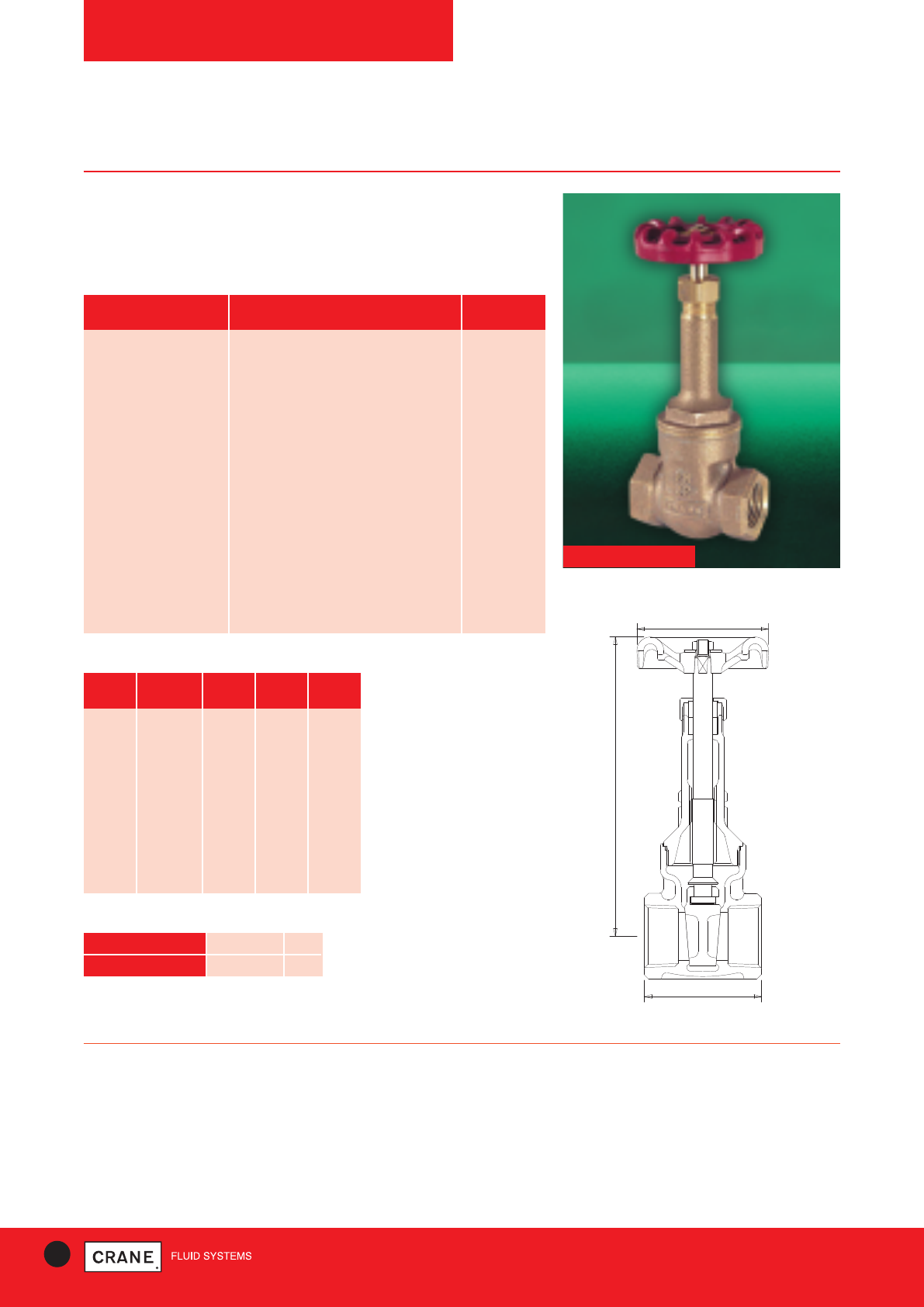
52 TECHNICAL HELPLINE: +44 (0)1473 277400
www.cranefs.com
D166
PN32
Bronze Gate Valve
Crane gate valves offer the ultimate in dependable service wherever
minimum pressure drop is important.
D166
PART MATERIAL SIZES
Body Bronze BS EN 1982 CC491K All
Bonnet Bronze BS EN 1982 CC491K All
Stem Bronze BS EN 1982 CC491K 1/4- 2
Stem Aluminium Bronze BS EN 12163
CW301G 21/2
Stem Manganese Bronze 3
Disc Bronze BS EN 1982 CC491K All
Packing Asbestos Free All
Gland Brass BS EN 12164 CW614N All
Packing Nut Brass BS EN 12164 CW614N 1/4- 2
Packing Nut Bronze BS EN 1982 CC491K 21/2& 3
Hand Wheel Aluminium All
ID. Plate Aluminium All
Hand Wheel Nut Brass BS EN 12164 CW614N All
Materials
PRESSURE RATING: PN32
UK END CONNECTION: Taper threaded to BS EN 10226-2 (ISO 7-1)
formerly BS 21
US END CONNECTION: ANSI B1.20.1 (please add suffix AT to
denote American Thread)
OPERATOR: Hand Wheel
Gate valves are best for services that require infrequent valve operation,
and where the disc is kept either fully opened or fully closed.
They are not practical for throttling.
SPECIFICATION:
Valves are manufactured in accordance with BS EN 12288: 2010 PN32 for
series B ratings.
Rising stem
This valve is not suitable for use on group 1 gasses or unstable fluids, as
defined by the Pressure Equipment Directive 97/23/EC.
Temperature operating range: -10 to 198°C.
B OPEN
C
A
Dimensions and Weights
SIZE WEIGHT A B C
(kg) (mm) (mm) (mm)
1/4|| 0.32 46 126 45
3/8|| 0.31 46 126 45
1/2|| 0.46 51 129 52
3/4|| 0.72 55 159 65
1|| 1.1 63 189 70
11/4|| 1.5 71 219 78
11/2|| 2.25 73 246 92
2|| 3.2 83 301 92
21/2|| 5.8 108 369 134
3|| 8.52 117 416 134
Dimensional Drawing
GATE VALVES
TEMPERATURE (°C) -10 to 100 198
PRESSURE (BAR) 20 9
Intermediate pressure ratings shall be determined
by interpolation
Pressure/Temperature Ratings
Every effort has been made to ensure that the information contained in this publication is accurate at the time of publishing. Crane Ltd assumes no responsibility or liability for typographical errors or omissions or for
any misinterpretation of the information within the publication and reserves the right to change without notice.
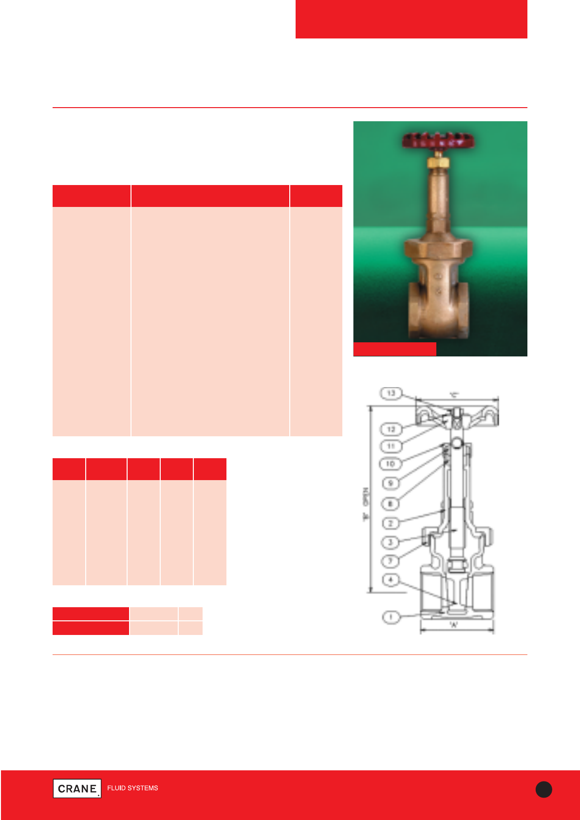
53
TECHNICAL HELPLINE: +44 (0)1473 277400
www.cranefs.com
GATE VALVES
D180
PN32
Bronze Gate Valve
Crane gate valves offer the ultimate in dependable service wherever
minimum pressure drop is important.
D180
PART MATERIAL SIZES
Body Bronze BS EN 1982 CC491K All
Bonnet Bronze BS EN 1982 CC491K All
Stem Bronze BS EN 1982 CC491K 1/4- 2
Stem Brass BS EN 12164 CW721R 21/2& 3
Disc Bronze BS EN 1982 CC491K All
Union Ring Bronze BS EN 1982 CC491K 1/4- 2 only
Packing Asbestos Free All
Gland Brass BS EN 12164 CW614N All
Packing Nut Brass BS EN 12164 CW614N 1/4- 2
Packing Nut Bronze BS EN 1982 CC491K 21/2& 3
Hand Wheel Aluminium 1/4- 2
Hand Wheel Malleable Iron BS EN 1562 GJMB-300-6 21/2& 3
ID. Plate Aluminium All
Hand Wheel Nut Brass BS EN 12164 CW614N All
Stud Steel BS970 070M20 21/2& 3 only
Stud Nut Steel BS4190 Gr.4 21/2& 3 only
Gasket Asbestos Free 21/2& 3 only
Materials
PRESSURE RATING: PN32
UK END CONNECTION: Taper threaded to BS EN 10226-2 (ISO 7-1)
formerly BS 21
US END CONNECTION: ANSI B1.20.1 (please add suffix AT to
denote American Thread)
OPERATOR: Hand Wheel
Gate valves are best for services that require infrequent valve operation,
and where the disc is kept either fully opened or fully closed.
They are not practical for throttling.
SPECIFICATION:
Valves are manufactured in accordance with BS EN 12288: 2010 PN32 for
series A ratings.
Rising Stem
Sizes 1/4|| to 2|| have a union bonnet; sizes 2.1/2|| and 3|| have a bolted
bonnet.
This valve is not suitable for use on group 1 gasses or unstable fluids, as
defined by the Pressure Equipment Directive 97/23/EC.
Temperature operating range: -10 to 260°C.
Dimensional Drawing
Dimensions and Weights
SIZE WEIGHT A B C
(kg) (mm) (mm) (mm)
1/4|| 0.32 46 126 45
3/8|| 0.31 46 126 45
1/2|| 0.46 51 129 52
3/4|| 0.72 55 159 65
1|| 1.1 63 189 70
11/4|| 1.5 71 219 78
11/2|| 2.3 73 246 92
2|| 3.2 83 301 92
21/2|| 5.8 108 369 134
3|| 8.5 117 416 134
TEMPERATURE (°C) -10 to 120 260
PRESSURE (BAR) 32 14
Intermediate pressure ratings shall be determined
by interpolation
Pressure/Temperature Ratings
Every effort has been made to ensure that the information contained in this publication is accurate at the time of publishing. Crane Ltd assumes no responsibility or liability for typographical errors or omissions or for
any misinterpretation of the information within the publication and reserves the right to change without notice.
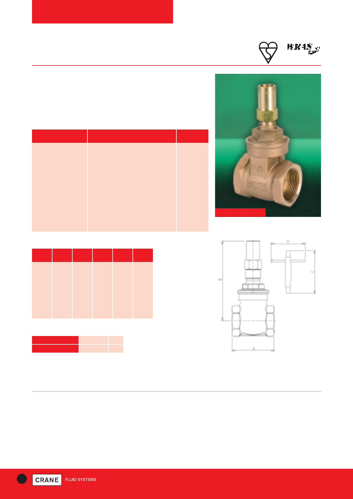
54 TECHNICAL HELPLINE: +44 (0)1473 277400
www.cranefs.com
GATE VALVES
D237
PN20
Bronze Gate Valve with Lockshield
Crane gate valves offer the ultimate in dependable service wherever
minimum pressure drop is important. The D237 carries the British
Standards Institution Kitemark - your assurance of exacting quality
standards. In addition the D237 is WRAS approved.
D237
PRESSURE RATING: PN20
END CONNECTION: Taper threaded to BS EN 10226-2 (ISO 7-1)
formerly BS 21
OPERATOR: Lockshield
Gate valves are best for services that require infrequent valve operation,
and where the disc is kept either fully opened or fully closed.
They are not practical for throttling.
SPECIFICATION:
Solid wedge disc, non-rising stem, screwed in bonnet.
Valves are manufactured in accordance with BS EN 12288: 2010 PN20
series B and are BSI Kitemark approved.
This valve is not suitable for use on group 1 gasses or unstable fluids, as
defined by the Pressure Equipment Directive 97/23/EC.
Temperature operating range: -10 to 180°C.
AVAILABLE OPTIONS:
P103 lockshield key 1/2|| - 2||
P100 lockshield key 21/2|| - 3||
PART MATERIAL SIZES
Body Bronze BS EN 1982 CC491K 1/2- 3
Bonnet Bronze BS EN 1982 CC491K 1/2- 3
Disc Bronze BS EN 1982 CC491K 1/2- 3
Stem DZR Brass BS EN 12164 CW602N 1/2- 3
Stuffing Box DZR Brass BS EN 12164 CW602N 21/2& 3
Stem Retainer DZR Brass BS EN 12164 CW602N 1/2- 2
Gland Brass BS EN 12164 CW614N 1 - 3
Packing Asbestos Free 1/2- 3
Lockshield Brass BS EN 12164 CW614N 1/2- 3
Box Spanner Mild Steel 1/2- 3
Materials
SIZE WEIGHT A B C D
(kg) (mm) (mm) (mm) (mm)
1/2|| 0.276 50 78 90 100
3/4|| 0.389 54 87 90 100
1|| 0.593 62 106 125 100
11/4|| 0.831 71 116 125 100
11/2|| 1.248 77.5 132 125 100
2|| 1.882 87.5 156 125 100
21/2|| 4.15 96 218 - -
3|| 6.24 105 253 - -
Dimensions and Weights
Dimensional Drawing
TEMPERATURE (°C) -10 to 100 180
PRESSURE (BAR) 20 9
Intermediate pressure ratings shall be determined
by interpolation
Pressure/Temperature Ratings
Every effort has been made to ensure that the information contained in this publication is accurate at the time of publishing. Crane Ltd assumes no responsibility or liability for typographical errors or omissions or for
any misinterpretation of the information within the publication and reserves the right to change without notice.
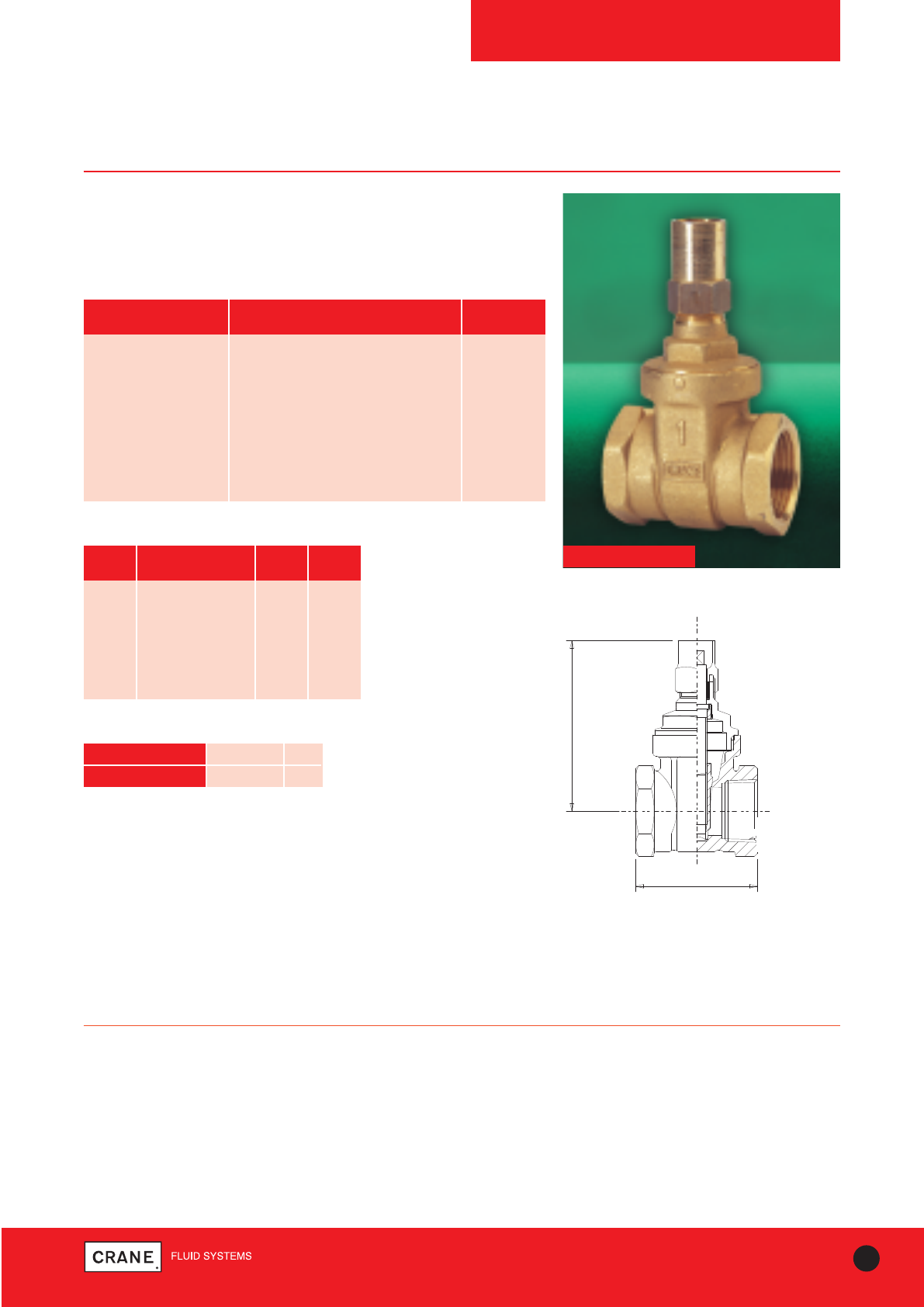
55
TECHNICAL HELPLINE: +44 (0)1473 277400
www.cranefs.com
GATE VALVES
D237A
PN20
Lockshield Operated DZR Gate Valve
Crane gate valves offer the ultimate in dependable service wherever
minimum pressure drop is important.
D237A
PART MATERIAL SIZES
Body DZR Brass BS EN 12165 CW602N All
Bonnet DZR Brass BS EN 12165 CW602N All
Stem DZR Brass BS EN 12164 CW602N All
Lockshield Brass BS EN 12164 CW614N All
Packing Asbestos Free All
Stem Bush DZR Brass BS EN 12164 CW602N All
Disc DZR Brass BS EN 12165 CW602N All
Materials
PRESSURE RATING: PN20
UK END CONNECTION: Taper threaded to BS EN 10226-2 (ISO 7-1)
formerly BS 21
OPERATOR: Lockshield
Gate valves are best for services that require infrequent valve operation,
and where the disc is kept either fully opened or fully closed.
They are not practical for throttling.
SPECIFICATION:
Valves are manufactured in accordance with BS EN 12288: 2010 for
Series B ratings.
Non Rising Stem
This valve is not suitable for use on group 1 gasses or unstable fluids, as
defined by the Pressure Equipment Directive 97/23/EC.
Temperature operating range: -10 to 180°C.
AVAILABLE OPTIONS:
P103 Lockshield key
THREADED TO BSEN10226
formerly BS 21 (ISO 7) TAPER
B
A
Dimensions and Weights
SIZE WEIGHT A B
(kg) (mm) (mm)
1/2|| 0.23 50 65
3/4|| 0.36 54 75
1|| 0.5 62 81
1 1/4|| 0.82 70 105
1 1/2|| 1.08 72 122
2|| 1.83 82 149
Dimensional Drawing
TEMPERATURE (°C) -10 to 100 180
PRESSURE (BAR) 20 9
Intermediate pressure ratings shall be determined
by interpolation
Pressure/Temperature Ratings
Every effort has been made to ensure that the information contained in this publication is accurate at the time of publishing. Crane Ltd assumes no responsibility or liability for typographical errors or omissions or for
any misinterpretation of the information within the publication and reserves the right to change without notice.
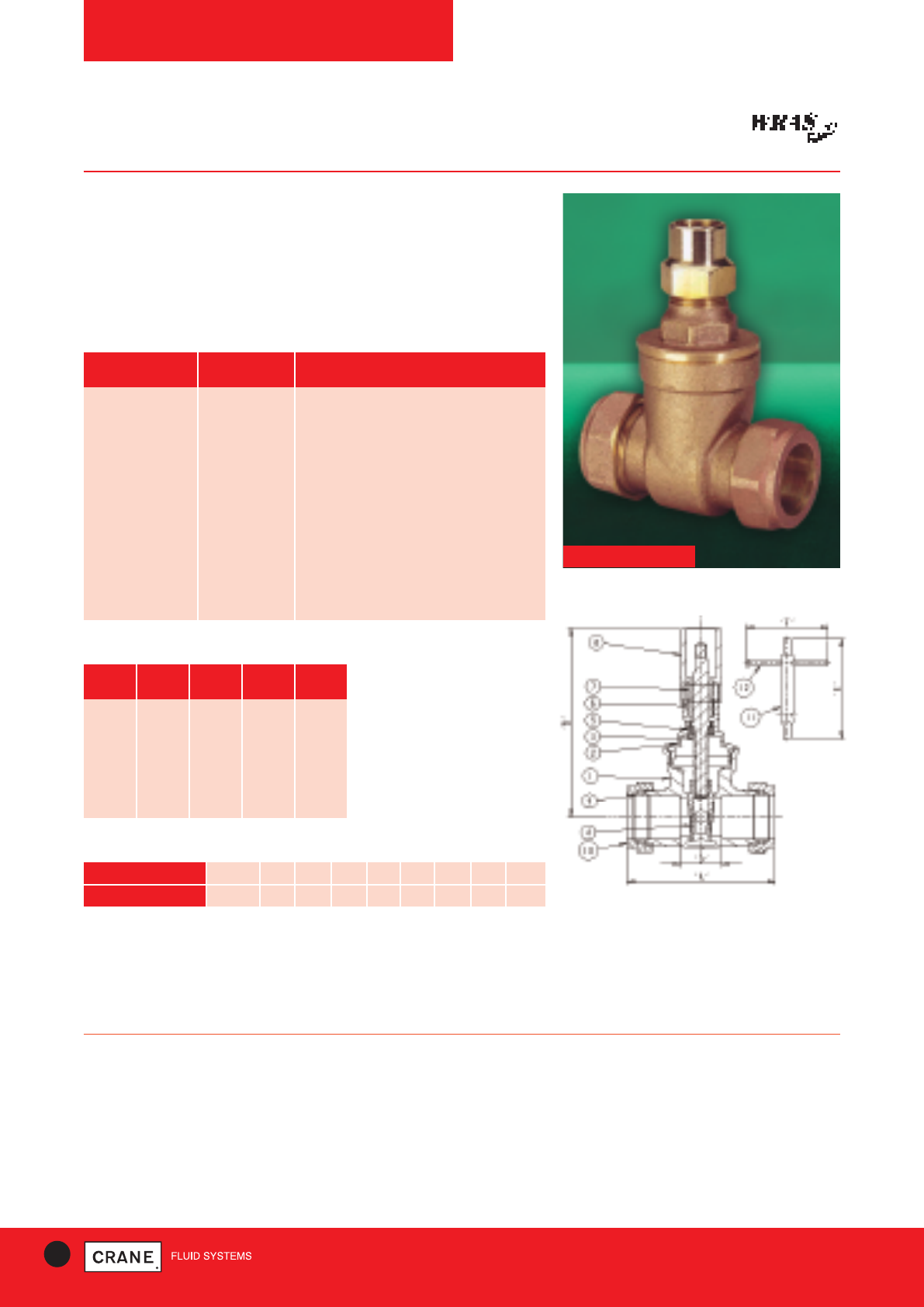
56 TECHNICAL HELPLINE: +44 (0)1473 277400
www.cranefs.com
GATE VALVES
D255C
PN16
D255C
PRESSURE RATING: PN16
UK END CONNECTION: Compression ends to BS EN 1057: 2006:
Half hard R250
OPERATING INSTRUCTIONS: Lockshield. Gate valves are best for
services that require infrequent valve operation, and where the disk is kept
either fully opened or fully closed. They are not practical for throttling
SPECIFICATION:
Valves are manufactured in accordance with BS EN 12288: 2010 (formerly
BS 5154) PN20 for Series B ratings, but are limited to the
pressure/temperature ratings detailed in BS EN 1057: 2006 for
compression end fittings. This valve is to be used on Group 2 liquids only,
as defined by the Pressure Equipment Directive 97/23/EC.
AVAILABLE OPTIONS:
P100 and P102 Lockshield Keys
Features & Benefits
• Robust and high quality bronze body with integral seating surfaces
• Offers the ultimate in dependable service wherever minimum pressure
drop is important
• WRAS Approved for use with potable water
• Inside screw pattern with non-rising stem
PART MATERIAL SPECIFICATION
Body Bronze BS EN 1982 (CC491K)
Bonnet Bronze BS EN 1982 (CC491K)
Stem DZR Brass BS EN 12164 CW602N
Disc Bronze BS EN 1982 (CC491K)
Stem Retainer DZR Brass BS EN 12164 CW602N
Packing Ring Asbestos Free
Gland (28-54 only) Brass BS EN 12164 CW614N
Locksheild Brass BS EN 12164 CW614N
Compression Olive Brass BS EN 12449:1999 CW505L OR CW507L
Compression Nut Brass BS EN 12165 CW617N
Materials
SIZE WEIGHT A B D
(kg) (mm) (mm) (mm)
15 0.34 69 78 26.5
22 0.50 75 90 23.5
28 0.70 86 110 25.5
35 0.95 100 115 30.5
42 1.45 111 136 34.5
54 2.50 133 160 37
Dimensions and Weights
Dimensional Drawing
TEMPERATURE (°C) 16.0 14.3 12.6 10.0 8.7 7.8 6.9 6.0 5.0
PRESSURE (BAR) -10 to 30 40 50 65 80 90 100 110 120
Pressure/Temperature Ratings
Intermediate pressure ratings shall be determined by interpolation
Every effort has been made to ensure that the information contained in this publication is accurate at the time of publishing. Crane Ltd assumes no responsibility or liability for typographical errors or omissions or for
any misinterpretation of the information within the publication and reserves the right to change without notice.
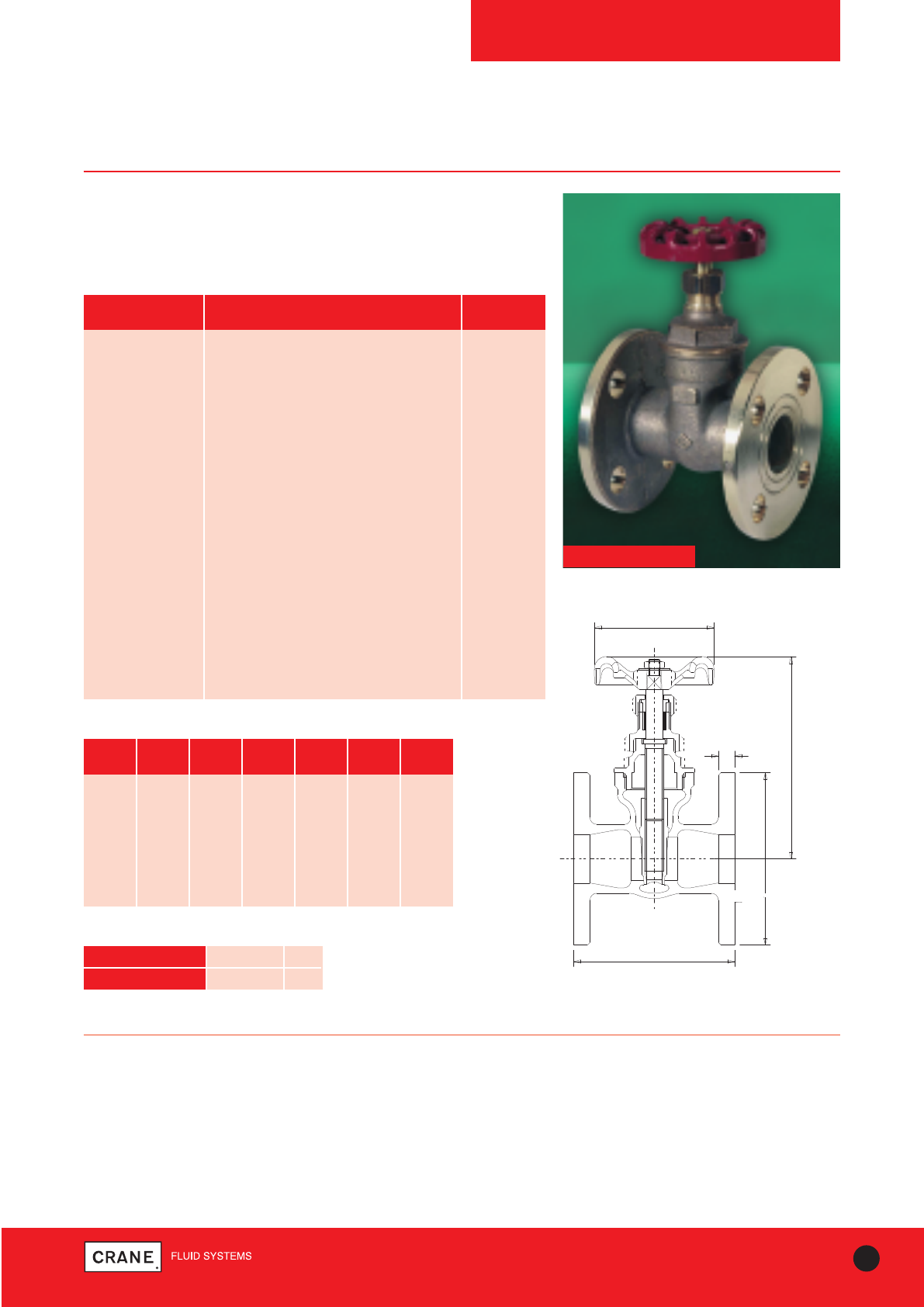
57
TECHNICAL HELPLINE: +44 (0)1473 277400
www.cranefs.com
GATE VALVES
DM160
PN16 Series B
Bronze Gate Valve
Crane gate valves offer the ultimate in dependable service wherever
minimum pressure drop is important.
DM160
PART MATERIAL SIZES
Body Bronze BS EN 1982 CC491K All
Bonnet Bronze BS EN 1982 CC491K All
Disc Bronze BS EN 1982 CC491K All
Stem Bronze BS EN 1982 CC491K 21/2& 3
Stem DZR Brass BS EN 12164 CW602N 3/4- 2
Packing Asbestos Free All
Gland Brass BS EN 12164 CW614N All
Packing Nut Brass BS EN 12164 CW614N All
Stuffing Box DZR Brass BS EN 12164 CW602N 11/4& 11/2
Stuffing Box Brass BS EN 12164 CW614N 2 only
Stuffing Box Bronze BS EN 1982 CC491K 21/2& 3
Stem Bush Aluminium Bronze BS EN 12163 CW301G 3/4 & 1
Hand Wheel Malleable Iron BS EN 1562 GJMB-300-6 3 only
Hand Wheel Aluminium 3/4- 21/2
Hand Wheel Nut Brass BS EN 12164 CW614N All
ID. Plate Aluminium All
Gasket Asbestos Free 3 only
Materials
PRESSURE RATING: PN16
END CONNECTION: Flanged BS EN 1092-3 (formerly BS4504)
OPERATOR: Hand Wheel
Gate valves are best for services that require infrequent valve operation,
and where the disc is kept either fully opened or fully closed.
They are not practical for throttling.
AVAILABLE OPTIONS:
Flanges undrilled, P150 Locking device.
SPECIFICATION:
Valves are manufactured in accordance with BS5154: 1991 PN16 for
Series B ratings, having ‘short’ face to face dimensions.
Non Rising Stem
End flanges conform to BS EN 1092-3 with flat face and are normally
supplied drilled.
This valve is not suitable for use on group 1 gasses or unstable fluids, as
defined by the Pressure Equipment Directive 97/23/EC.
Temperature operating range: -10 to 170°C.
B
A
C DIA
FLANGED TO
BS 4504 PN16
D DIA
E
Dimensional Drawing
Dimensions and Weights
SIZE WEIGHT A B C D E
(kg) (mm) (mm) (mm) (mm) (mm)
20mm 1.57 89 105 65 105 6
25mm 2.5 99 116 70 115 8
32mm 3.38 110 141 92 140 8
40mm 4.93 120 168 92 150 9
50mm 5.54 135 189 103 165 11
65mm 8.39 165 232 103 185 13
80mm 12.25 185 264 121 200 13
TEMPERATURE (°C) -10 to 100 170
PRESSURE (BAR) 16 7
Intermediate pressure ratings shall be determined
by interpolation
Pressure/Temperature Ratings
Every effort has been made to ensure that the information contained in this publication is accurate at the time of publishing. Crane Ltd assumes no responsibility or liability for typographical errors or omissions or for
any misinterpretation of the information within the publication and reserves the right to change without notice.

58 TECHNICAL HELPLINE: +44 (0)1473 277400
www.cranefs.com
A
E DIA
D
C DIA
F DIA
A
B
FOR SIZES 50 TO 150MM
VIEW FROM ARROW A
GATE VALVES
FM52
PN6
Cast Iron Gate Valve
Crane cast iron gate valves offer the ultimate in dependable service
wherever minimum pressure drop is important.
Complete with Bronze trim.
Each valve is hydrostatically tested to BS EN 12266-1: 2003
Manufactured in accordance with BS EN 1171: 2002
FM52
PART MATERIAL SIZES
Body Cast Iron BS EN 1561 GJL-250 All
Bonnet Cast Iron BS EN 1561 GJL-250 All
Bonnet Gasket Asbestos Free All
Disc Cast Iron BS EN 1561 GJL-250 All
Stem Brass BS EN 12163 CW721R All
Stuffing Box Cast Iron BS EN 1561 GJL-250 All
Gland Cast Iron BS EN 1561 GJL-250 All
Stuffing Box Gasket Asbestos Free All
Packing Asbestos Free All
Hand Wheel Cast Iron All
Body Seat Ring Bronze BS EN 1982 CC491K All
Disc Stem Nut Bronze BS EN 1982 CC491K All
Disc Ring Bronze BS EN 1982 CC491K All
Materials
PRESSURE RATING: PN6
UK END CONNECTION: Flanged BS EN 1092-2 PN6
OPERATOR: Hand Wheel
Gate valves are best for services that require infrequent valve operation, and
where the disc is kept either fully opened or fully closed.
They are not practical for throttling.
SPECIFICATION:
Wedge Disc, Non-Rising Stem, Inside Screw and Yoke
This valve is not suitable for use on group 1 gasses or unstable fluids, as
defined by the Pressure Equipment Directive 97/23/EC.
Temperature operating range: - 10 to 150°C.
AVAILABLE OPTIONS:
Flanges undrilled.
Dimensions and Weights
SIZE WEIGHT A B C D E F
(kg) (mm) (mm) (mm) (mm) (mm) (mm)
50mm 14 150 16 140 277 140 90
65mm 16 170 16 160 296 140 110
80mm 20 180 18 190 337 152 128
100mm 27 190 18 210 369 203 148
125mm 39 200 20 240 429 229 178
150mm 44 210 20 265 470 229 202
200mm 82 292 22 320 600 305 258
250mm 123 330 24 375 722 356 312
300mm 174 356 24 440 818 406 365
Dimensional Drawing
TEMPERATURE (°C) -10 to 120 150
PRESSURE (BAR) 6 5.4
Intermediate pressure ratings shall be determined
by interpolation
Pressure/Temperature Ratings
Every effort has been made to ensure that the information contained in this publication is accurate at the time of publishing. Crane Ltd assumes no responsibility or liability for typographical errors or omissions or for
any misinterpretation of the information within the publication and reserves the right to change without notice.
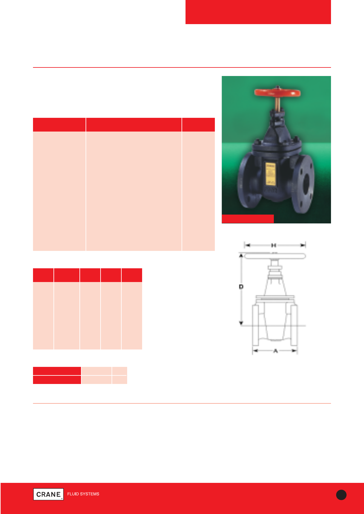
59
TECHNICAL HELPLINE: +44 (0)1473 277400
www.cranefs.com
GATE VALVES
F53
Class 125
Cast Iron Gate Valve
Crane cast iron gate valves offer the ultimate in dependable service
wherever minimum pressure drop is important.
F53
PART MATERIAL SIZES
Body Cast Iron BS EN 1561 GJL-250 All
Bonnet Cast Iron BS EN 1561 GJL-250 All
Bonnet Gasket Asbestos Free All
Disc Cast Iron BS EN 1561 GJL-250 All
Stem Brass BS EN 12164 CW721R All
Stuffing Box Cast Iron BS EN 1561 GJL-250 All
Gland Cast Iron BS EN 1561 GJL-250 All
Stuffing Box Gasket Asbestos Free All
Packing Asbestos Free All
Hand Wheel Cast Iron All
Body Seat Ring Bronze BS EN 1982 CC491K All
Disc Stem Nut Bronze BS EN 1982 CC491K All
Disc Ring Bronze BS EN 1982 CC491K All
Materials
PRESSURE RATING: Class 125
US END CONNECTION: ANSI Class 125
OPERATOR: Hand Wheel
Gate valves are best for services that require infrequent valve operation, and
where the disc is kept either fully opened or fully closed.
They are not practical for throttling.
SPECIFICATION:
Valves are manufactured in accordance with BS5150:1990. End flanges
conform to BS1560 Section 3.2/ANSI B16.1 Class 125 with flat face and
are normally supplied drilled.
Wedge disc, non-rising stem, inside screw, bronze trim.
This valve is not suitable for use on group 1 gasses or unstable fluids, as
defined by the Pressure Equipment Directive 97/23/EC.
Temperature operating range: -10 to 230°C.
AVAILABLE OPTIONS:
Flanges undrilled
Dimensions and Weights
SIZE WEIGHT A D H
(kg) (mm) (mm) (mm)
2|| 12.7 178 277 140
21/2|| 15.8 190 296 140
3|| 19.5 203 337 152
4|| 29.3 229 369 203
5|| 39.5 254 429 229
6|| 45.8 267 470 229
8|| 84 292 600 305
10|| 148 330 722 356
12|| 198 356 818 406
Dimensional Drawing
TEMPERATURE (°C) -10 to 65 230
PRESSURE (BAR) 13.8 8.6
Intermediate pressure ratings shall be determined
by interpolation
Pressure/Temperature Ratings
Every effort has been made to ensure that the information contained in this publication is accurate at the time of publishing. Crane Ltd assumes no responsibility or liability for typographical errors or omissions or for
any misinterpretation of the information within the publication and reserves the right to change without notice.
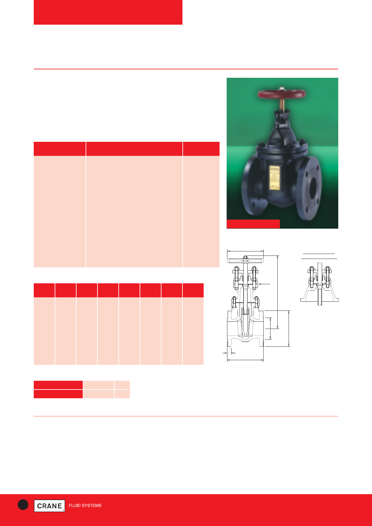
60 TECHNICAL HELPLINE: +44 (0)1473 277400
www.cranefs.com
GATE VALVES
FM57
PN10
Cast Iron Gate Valve
Crane cast iron gate valves offer the ultimate in dependable service
wherever minimum pressure drop is important.
Complete with Bronze trim.
Each valve is hydrostatically tested to BS EN 12266-1: 2003.
Manufactured in accordance with BS EN 1171: 2002.
FM57
PART MATERIAL SIZES
Body Cast Iron BS EN 1561 GJL-250 All
Bonnet Cast Iron BS EN 1561 GJL-250 All
Bonnet Gasket Asbestos Free All
Disc Cast Iron BS EN 1561 GJL-250 All
Stem Brass BS2874 CZ114 All
Stuffing Box Cast Iron BS EN 1561 GJL-250 All
Gland Cast Iron BS EN 1561 GJL-250 All
Stuffing Box Gasket Asbestos Free All
Packing Asbestos Free All
Hand Wheel Cast Iron All
Body Seat Ring Bronze BS EN 1982 CC491K All
Disc Stem Nut Bronze BS EN 1982 CC491K All
Disc Ring Bronze BS EN 1982 CC491K All
Materials
PRESSURE RATING: PN10
UK END CONNECTION: Flanged BS EN 1092-2: PN10
OPERATOR: Hand Wheel
Gate valves are best for services that require infrequent valve operation,
and where the disc is kept either fully opened or fully closed.
They are not practical for throttling.
SPECIFICATION:
Long face to face, Wedge Disc, Non-rising stem.
Valves are manufactured in accordance with BS EN 1171: 2002. End
flanges conform to BSEN1092-2 PN10 with raised face and are normally
supplied drilled.
This valve is not suitable for use on group 1 gasses or unstable fluids, as
defined by the Pressure Equipment Directive 97/23/EC.
Temperature operating range: - 10 to 180°C.
AVAILABLE OPTIONS:
Flanges undrilled, P50 locking device.
A
E DIA
D
C DIA
F DIA
A
B
FOR SIZES 50 TO 150MM
VIEW FROM ARROW A
Dimensions and Weights
SIZE WEIGHT A B C D E F
(kg) (mm) (mm) (mm) (mm) (mm) (mm)
50mm 14 178 20 165 277 140 102
65mm 17 190 20 185 296 140 122
80mm 22 203 22 200 337 152 138
100mm 30 229 24 220 369 203 158
125mm 41 254 26 250 429 229 188
150mm 47 267 26 285 470 229 212
200mm 85 292 26 340 600 305 268
250mm 146 330 28 395 722 356 320
300mm 188 356 28 445 818 406 370
Dimensional Drawing
TEMPERATURE (°C) -10 to 100 180
PRESSURE (BAR) 10 8.4
Intermediate pressure ratings shall be determined
by interpolation
Pressure/Temperature Ratings
Every effort has been made to ensure that the information contained in this publication is accurate at the time of publishing. Crane Ltd assumes no responsibility or liability for typographical errors or omissions or for
any misinterpretation of the information within the publication and reserves the right to change without notice.
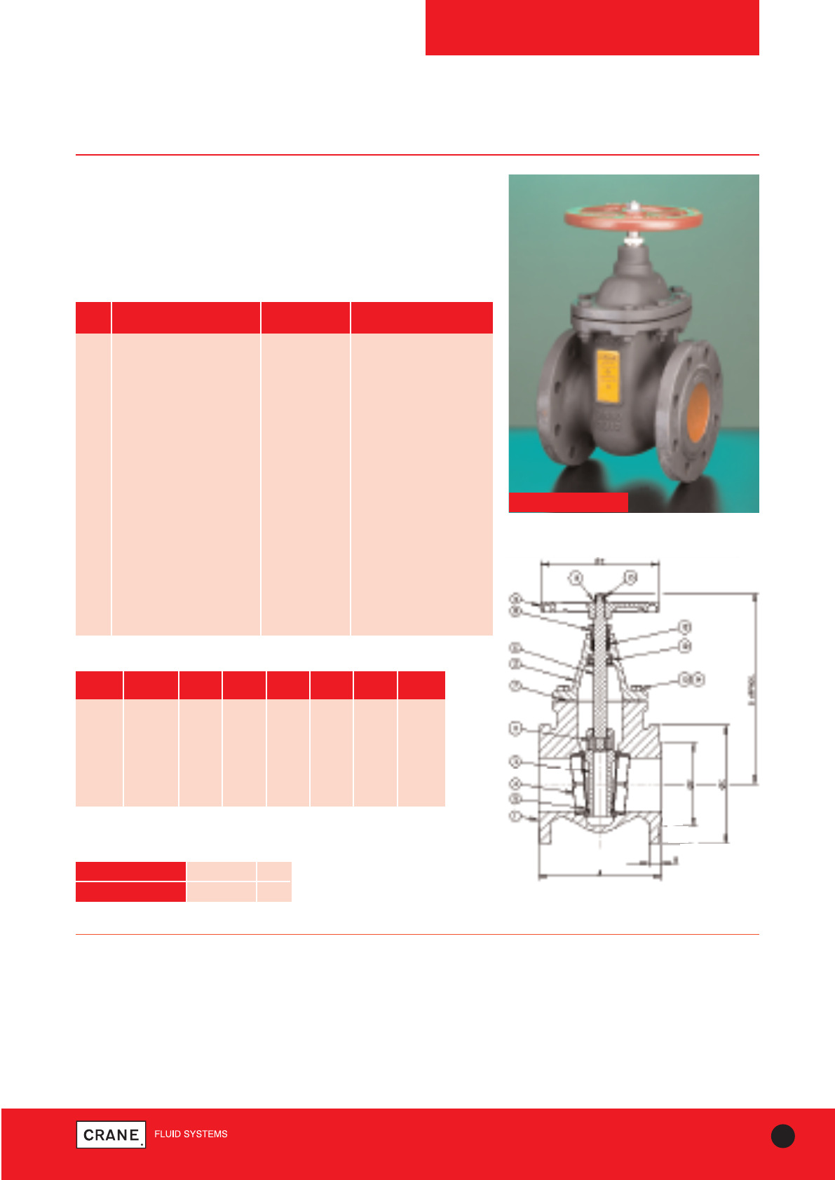
61
TECHNICAL HELPLINE: +44 (0)1473 277400
www.cranefs.com
GATE VALVES
FM63
PN16
Cast Iron Gate Valve
Crane cast iron gate valves offer the ultimate in dependable service
wherever minimum pressure drop is important.
Each valve is manufactured in accordance with BS EN 1171: 2002 and
hydrostatically tested to BS EN 12266-1: 2003.
FM63
ITEM DESCRIPTION MATERIAL MATERIAL SPEC
NO
1 Body Grey Iron BS EN 1561 GJL-250
2 Bonnet Grey Iron BS EN 1561 GJL-250
3 Disc Grey Iron BS EN 1561 GJL-250
4 Body Seat Ring Bronze BS EN 1982 (CC491K)
5 Disc Seat Ring Bronze BS EN 1982 (CC491K)
6 Stem Stainless Steel BS970: 410S21
7 Gasket Graphite Graphite (Asbestos Free)
8 Gland Packing Nut Stainless Steel BS970: 304S31
9 Handwheel Grey Iron BS EN 1561 EN-GJL-250
10 Stem Retaining Ring Stainless Steel BS970: 304S31
11 Disc Stem Nut Bronze BS EN 1982 (CC491K)
12 Packing Ring Graphite Graphite (Asbestos Free)
13 Body/Bonnet Bolt Steel BS 3692 GR 8.8
14 Body/Bonnet Nut Steel BS 3692 GR 8
15 Handwheel Retaining Nut Steel BS 4190 GR 4
16 Handwheel Washer Steel BS4320
17 Body I.D. Plate (Not Shown) Aluminium -
Materials
PRESSURE RATING: PN16
UK END CONNECTION: Flanged BS EN 1092-2: PN16
PRESSURE/ TEMPERATURE OPERATING RANGE:
-10 to 120°C at 16 bar, 200°C at 12.8 bar
SPECIFICATION:
Wedge Disk, Non-Rising Stem, Inside Screw, Hand Wheel Operated. This
valve is not suitable for use on group 1 gasses or unstable fluids, as
defined by the Pressure Equipment Directive 97/23/EC.
AVAILABLE OPTIONS:
Flanges undrilled, P139 Stem Adapter.
Dimensions and Weights
SIZE WEIGHT A B C D E F
(mm) (kg) (mm) (mm) (mm) (mm) (mm) (mm)
65 18.7 190 20 185 262 190 118
80 23.9 203 22 200 286 190 132
100 37.6 229 24 220 356 220 156
125 50.7 254 26 250 426 300 184
150 63.8 267 26 285 463 300 211
200 104.3 292 30 340 578 350 266
250 194.5 330 32 405 773 406 319
300 275.5 356 32 460 860 457 370
Dimensional Drawing
All dimensions are nominal.
Please note size 50mm is also available, please refer to the website.
TEMPERATURE (°C) -10 to 120 200
PRESSURE (BAR) 16 12.8
Intermediate pressure ratings shall be determined
by interpolation
Pressure/Temperature Ratings
Every effort has been made to ensure that the information contained in this publication is accurate at the time of publishing. Crane Ltd assumes no responsibility or liability for typographical errors or omissions or for
any misinterpretation of the information within the publication and reserves the right to change without notice.
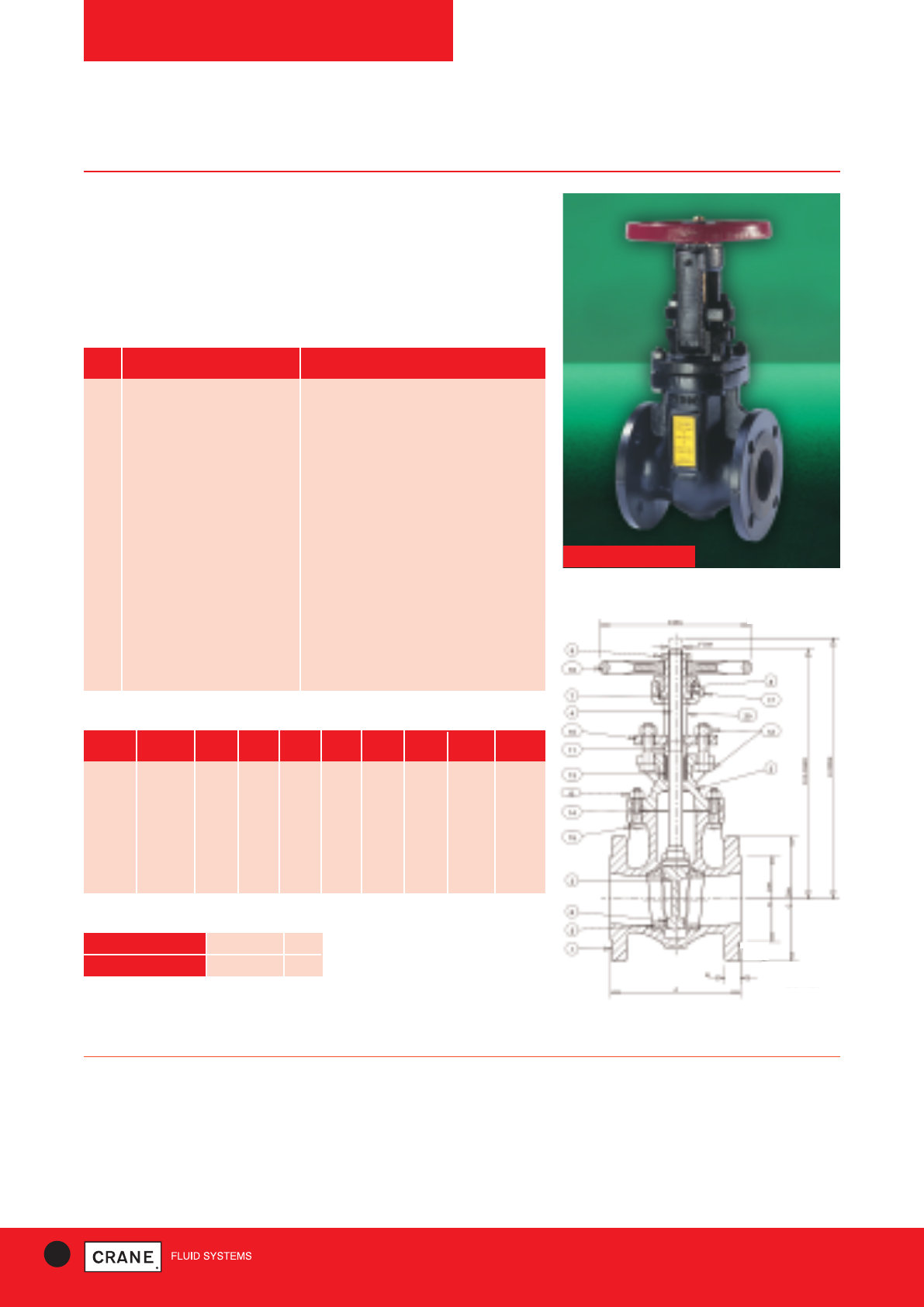
62 TECHNICAL HELPLINE: +44 (0)1473 277400
www.cranefs.com
GATE VALVES
FM82
PN16
Cast Iron Gate Valve
Crane cast iron gate valves offer the ultimate in dependable service
wherever minimum pressure drop is important.
Each valve is hydrostatically tested to BS EN 12266-1: 2003.
Manufactured in accordance with BS EN 1171: 2002.
FM82
PRESSURE RATING: PN16
UK END CONNECTION: Flanged BS EN 1092-2 PN16
OPERATOR: Hand Wheel
Gate valves are best for services that require infrequent valve operation,
and where the disc is kept either fully opened or fully closed.
They are not practical for throttling.
AVAILABLE OPTIONS:
Flanges undrilled.
SPECIFICATION:
Valves are manufactured in accordance with BS EN 1171: 2002. End
flanges conform to BSEN1092-2 with raised face and are normally supplied
drilled. Bronze trim, rising stem.
This valve is not suitable for use on group 1 gasses or unstable fluids, as
defined by the Pressure Equipment Directive 97/23/EC.
Temperature operating range: - 10 to 200°C.
Dimensional Drawing
Dimensions and Weights
SIZE WEIGHT A B C D E F G H
(kg) (mm) (mm) (mm) (mm) (mm) (mm) (mm) (mm)
50mm 22.5 178 20 165 334 399 19 203 102
65mm 26.4 190 20 185 354 432 19 203 122
80mm 31 203 22 200 375 469 19 203 135
100mm 44.3 229 24 220 449 566 22 229 155
125mm 72.3 254 26 254 575 714 28.5 305 185
150mm 88.1 267 26 279 649 813 28.5 305 212
200mm 140 292 30 340 800 1013 34.9 356 248
250mm 225 330 32 405 984 1257 39.7 406 320
300mm 314 356 32 460 1127 1454 39.7 457 378
NO PART MATERIAL
1 Body Cast Iron BS EN 1561 GJL-250
2 Bonnet/Yoke Cast Iron BS EN 1561 GJL-250
2 Bonnet Cast Iron BS EN 1561 GJL-250
3 Disc Cast Iron BS EN 1561 GJL-250
4 Stem Stainless Steel 410 S21
5 Body Seat Ring Bronze BS EN 1982 (CC491K)
6 Disc Seat Ring Bronze BS EN 1982 (CC491K)
7 Yoke Sleeve Bronze BS EN 1982 (CC491K)
8 Yoke Sleeve Retg Nut Ductile Iron ASTM A536 65-45-12
9 Yoke Sleeve Nut Malleable Iron BS EN 1562 GJMB 300-6
10 Gland Flange Malleable Iron BS EN 1562 GJMB 300-6
11 Gland (2||-4||) Brass BS EN 12164 CW721R
11 Gland (5||-12||) Malleable Iron BS EN 1562 GJMB-300-6
13 Packing Graphite
14 Bonnet Gasket Graphite wrapped with SS304
16 Hand Wheel Malleable Iron BS EN 1562 GJMB-300-6
18 Body Plate Aluminium
20 Yoke Cast Iron BS EN 1561 GJL-250
Materials
TEMPERATURE (°C) -10 to 120 200
PRESSURE (BAR) 16 12.8
Intermediate pressure ratings shall be determined
by interpolation
Pressure/Temperature Ratings
Every effort has been made to ensure that the information contained in this publication is accurate at the time of publishing. Crane Ltd assumes no responsibility or liability for typographical errors or omissions or for
any misinterpretation of the information within the publication and reserves the right to change without notice.
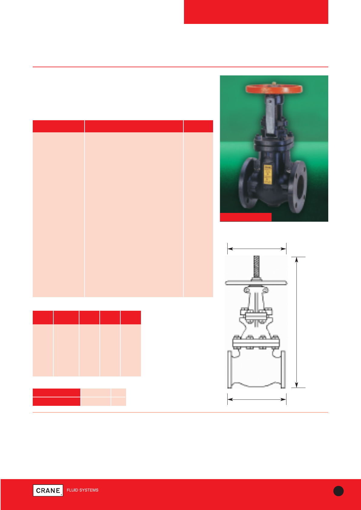
63
TECHNICAL HELPLINE: +44 (0)1473 277400
www.cranefs.com
GATE VALVES
F84
Class 125
Dimensions and Weights
SIZE WEIGHT A B H
(kg) (mm) (mm) (mm)
2|| 21.5 178 399 203
21/2|| 24.8 190 432 203
3|| 29.5 203 469 203
4|| 42.7 229 566 229
5|| 72.3 254 714 305
6|| 88.1 267 813 305
8|| 140 292 1013 356
10|| 225 330 1257 406
12|| 314 356 1454 457
Cast Iron Gate Valve
Crane cast iron gate valves offer the ultimate in dependable service
wherever minimum pressure drop is important.
Each valve is manufactured in accordance with BS 5150: 1990.
Materials
PART MATERIAL SIZES
Body Cast Iron BS EN 1561 GJL-250 All
Bonnet Cast Iron BS EN 1561 GJL-250 All
Disc Bronze BS EN 1982 CC491K 2 - 4
Disc Cast Iron BS EN 1561 GJL-250 5 - 12
Stem Brass BS EN 12163 CW721R 2 - 4
Stem Brass JIS - H3250 Gr.6872 5 - 12
Body Seat Ring Bronze BS EN 1982 CC491K All
Disc Ring Bronze BS EN 1982 CC481K 5 - 12
Yoke Cast Iron BS EN 1561 GJL-250 5 - 12
Yoke Hub Bolts/Nuts Steel BS4190 Gr.4.6/4 5 - 12
Yoke Pad Bolts/Nuts Steel BS4190 Gr.4.6/4 5 - 12
Yokesleeve Manganese Bronze ASTM B584-C86400 2 - 4
Yokesleeve Bronze BS EN 1982 CC491K 5 - 12
Yokesleeve Ret’g Nut Malleable Iron BS EN 1562 GJMB-300-6 2 - 4
Yokesleeve Nut Malleable Iron BS EN 1562 GJMB-300-6 2 - 4
Yokesleeve Nut Ductile Iron ASTM A536 65-45-12 5 - 12
Gland Malleable Iron BS EN 1562 GJMB-300-6 2 - 4
Gland Cast Iron BS EN 1561 GJL-250 5 - 12
Gland Flange Ductile Iron ASTM A536 65-45-12 5 - 12
Packing Asbestos Free All
Gasket Asbestos Free All
Hand Wheel Malleable Iron BS EN 1562 GJMB-300-6 All
Body Plate Aluminium All
A
H
B Open
Dimensional Drawing
F84
TEMPERATURE (°C) -10 to 65 230
PRESSURE (BAR) 13.8 8.6
Intermediate pressure
ratings shall be
determined by
interpolation
Pressure/Temperature Ratings
PRESSURE RATING: Class 125
US END CONNECTION: ANSI Flanged
OPERATOR: Hand Wheel
Gate valves are best for services that require infrequent valve operation,
and where the disc is kept either fully opened or fully closed.
They are not practical for throttling.
AVAILABLE OPTIONS:
Flanges Undrilled.
SPECIFICATION:
Valves meet the requirements of MSS.SP-70: 1998. End flanges conform to
BS1560 Section 3.2/ANSI B16.1.
Class 125 with flat face and are normally supplied drilled.
Wedge Disc, Rising Stem, Outside Screw and Yoke.
This valve is not suitable for use on group 1 gasses or unstable fluids, as
defined by the Pressure Equipment Directive 97/23/EC.
Temperature Operating Range: -10 to 230°C
Valves tested in accordance with BS EN 12266-1: 2003
Every effort has been made to ensure that the information contained in this publication is accurate at the time of publishing. Crane Ltd assumes no responsibility or liability for typographical errors or omissions or for
any misinterpretation of the information within the publication and reserves the right to change without notice.
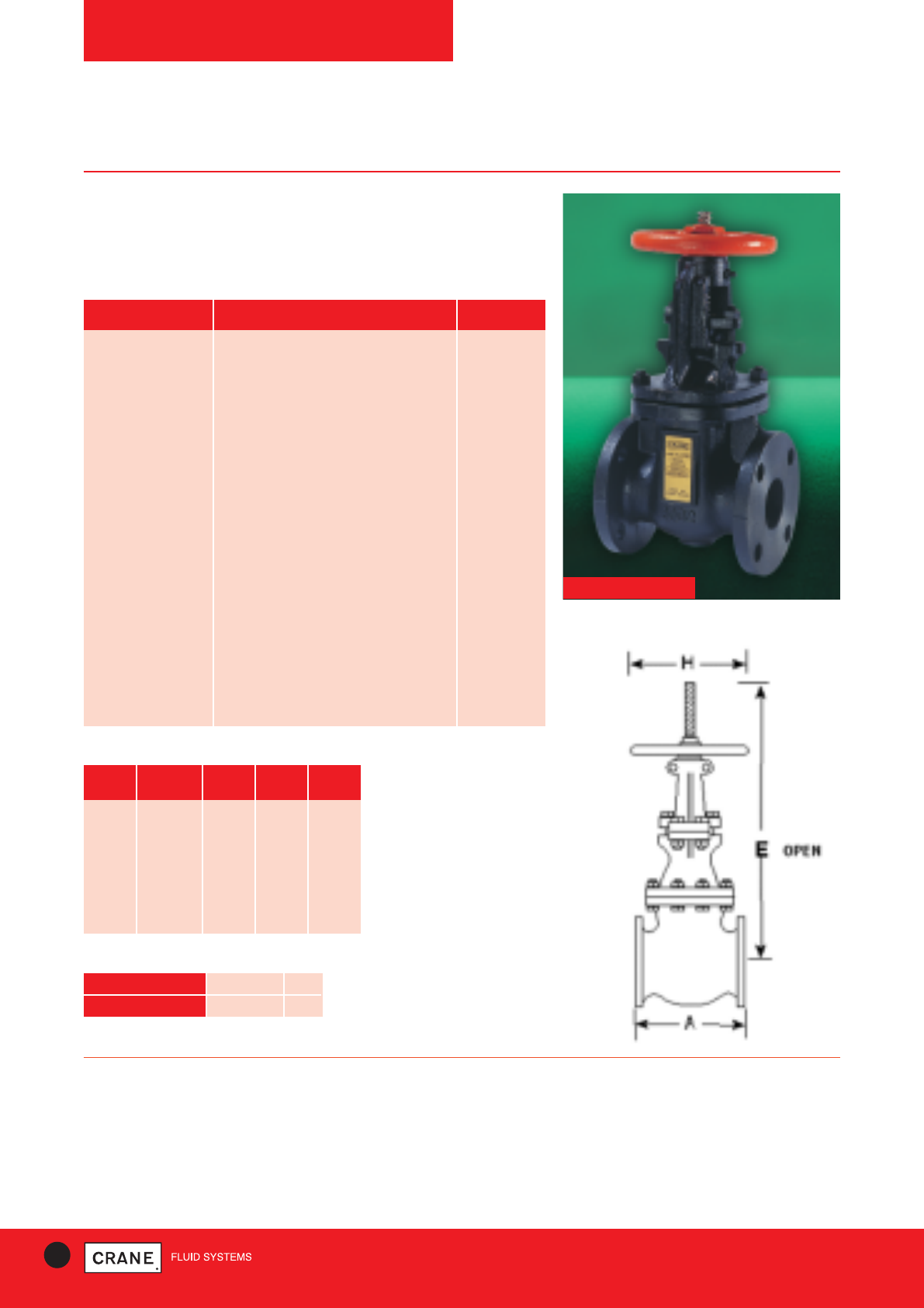
64 TECHNICAL HELPLINE: +44 (0)1473 277400
www.cranefs.com
GATE VALVES
F58
Class 125
Cast Iron Gate Valve
Crane cast iron gate valves offer the ultimate in dependable service
wherever minimum pressure drop is important.
F58
PRESSURE RATING: Class 125
US END CONNECTION: ANSI Class 125
OPERATOR: Hand Wheel
Gate valves are best for services that require infrequent valve operation,
and where the disc is kept either fully opened or fully closed.
They are not practical for throttling.
AVAILABLE OPTIONS:
Flanges Undrilled. P50 Locking Device
SPECIFICATION:
Valves are manufactured in accordance with BS 5150: 1990. End flanges
conform to BS 1560 section 3.2/ANSI B16.1 Class 125 with flat face and
are normally supplied drilled.
Wedge disc, Rising Stem, Outside Screw and Yoke
This valve is not suitable for use on group 1 gasses or unstable fluids, as
defined by the Pressure Equipment Directive 97/23/EC.
Temperature operating range: -10 to 230°C.
Materials
PART MATERIAL SIZES
Body Cast Iron BS EN 1561 GJL-250 All
Bonnet Cast Iron BS EN 1561 GJL-250 All
Disc Cast Iron BS EN 1561 GJL-250 All
Stem
13% Cr.Steel BS970 Pt.1 410S21 or 431S29
All
Body Seat Ring Bronze BS EN 1982 CC491K All
Disc Ring Bronze BS EN 1982 CC491K All
Yokesleeve Bronze BS EN 1982 CC491K All
Yokesleeve Nut Ductile Iron ASTM A536 65-45-12 2, 3, 5, 8 & 10
Yokesleeve Nut Cast Iron BS EN 1561 GJL-250 21/2, 4, 6 & 12
Yokesleeve Ret’g Nut Ductile Iron ASTM A536 65-45-12 2, 3, & 5
Yokesleeve Ret’g Nut Cast Iron BS EN 1561 GJL-250 21/2, 4, 6 & 12
Disc Stem Nut Bronze BS EN 1982 CC491K All
Gland Cast Iron BS EN 1561 GJL-250 All
Packing Asbestos Free All
Gasket Asbestos Free All
Yoke Cast Iron BS EN 1561 GJL-250 8, 10 & 12
Hand Wheel Malleable Iron BS EN 1562 GJMB-300-6 All
Dimensional Drawing
TEMPERATURE (°C) -10 to 65 230
PRESSURE (BAR) 13.8 8.6
Intermediate pressure ratings shall be determined
by interpolation
Pressure/Temperature Ratings
Dimensions and Weights
SIZE WEIGHT A B H
(kg) (mm) (mm) (mm)
2|| 17 178 365 152
21/2|| 20 190 448 152
3|| 28 203 481 203
4|| 38 229 622 229
5|| 56 254 672 254
6|| 60 267 835 254
8|| 112 292 989 305
10|| 185 330 1208 356
12|| 242 356 1469 406
Every effort has been made to ensure that the information contained in this publication is accurate at the time of publishing. Crane Ltd assumes no responsibility or liability for typographical errors or omissions or for
any misinterpretation of the information within the publication and reserves the right to change without notice.
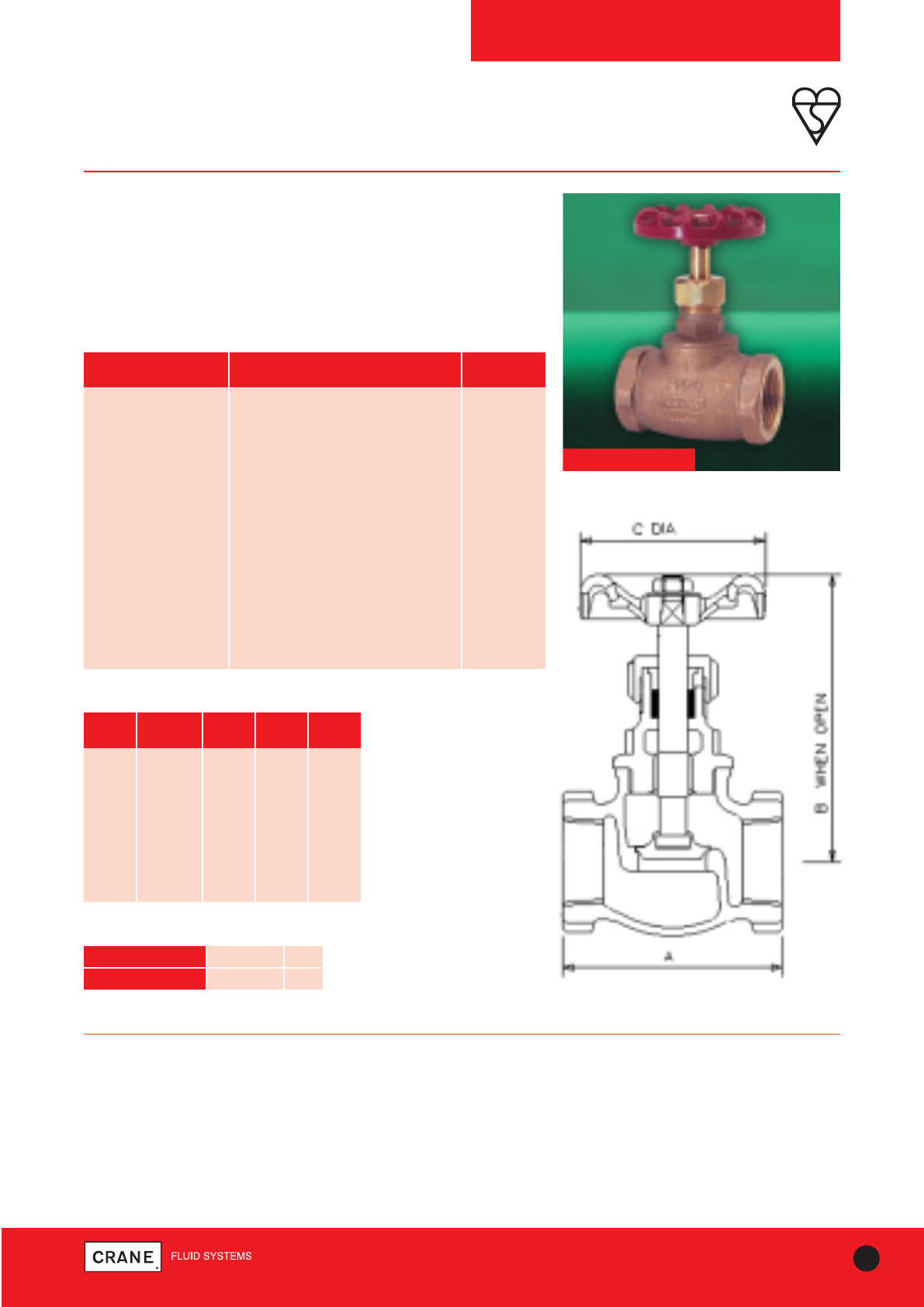
65
TECHNICAL HELPLINE: +44 (0)1473 277400
www.cranefs.com
GLOBE VALVES
D4
PN20 Series B
Bronze Globe Valve
Crane Bronze globe valves are highly efficient for throttling because seat
and disc designs provide flow characteristics with proportionate
relationships between valve lift and flow rate.
This valve carries the British Standards Institution kitemark - your
assurance of exacting quality.
D4
PART MATERIAL SIZES
Body Bronze BS EN 1982 CC491K All
Bonnet Bronze BS EN 1982 CC491K All
Disc Brass BS EN 12164 CW614N 1/4- 11/2
Disc Bronze BS EN 1982 CC491K 2
Stem Brass BS EN 12164 CW614N All
Packing Asbestos Free All
Gland Brass BS EN 12164 CW614N All
Packing Nut Brass BS EN 12164 CW614N All
Disc Stem Ring Mang.Bronze BS EN 12164 CW721R 2 only
Hand Wheel Aluminium All
Hand Wheel Nut Brass BS EN 12164 CW614N All
ID. Plate Aluminium All
Materials
PRESSURE RATING: PN20
UK END CONNECTION: Taper threaded to BS EN 10226-2 (ISO 7-1)
formerly BS 21.
US END CONNECTION: ANSI B1.20.1 (please add suffix AT to
denote American Thread)
OPERATOR: Hand Wheel
SPECIFICATION:
Valves are manufactured in accordance with BS5154: 1991 PN20 for Series
B ratings. Body seat is integral and is a narrow contact angled type.
Sizes 1/4|| to 2|| taper threaded to BS EN 10226-2 (ISO 7-1) formerly BS 21.
versions BSI Kitemarked.
Metal disc, screwed bonnet
This valve is not suitable for use on group 1 gasses or unstable fluids, as
defined by the Pressure Equipment Directive 97/23/EC.
Temperature operating range: -10 to 180°C.
Dimensions and Weights
SIZE WEIGHT A B C
(kg) (mm) (mm) (mm)
1/4|| 0.23 44 75 52
3/8|| 0.22 44 75 52
1/2|| 0.31 55 82 52
3/4|| 0.42 63 89 52
1|| 0.71 77 102 65
11/4|| 1.12 91 118 70
11/2|| 1.5 98 134 78
2|| 2.48 118 171 103
Dimensional Drawing
TEMPERATURE (°C) -10 to 100 180
PRESSURE (BAR) 20 9
Intermediate pressure ratings shall be determined
by interpolation
Pressure/Temperature Ratings
Every effort has been made to ensure that the information contained in this publication is accurate at the time of publishing. Crane Ltd assumes no responsibility or liability for typographical errors or omissions or for
any misinterpretation of the information within the publication and reserves the right to change without notice.
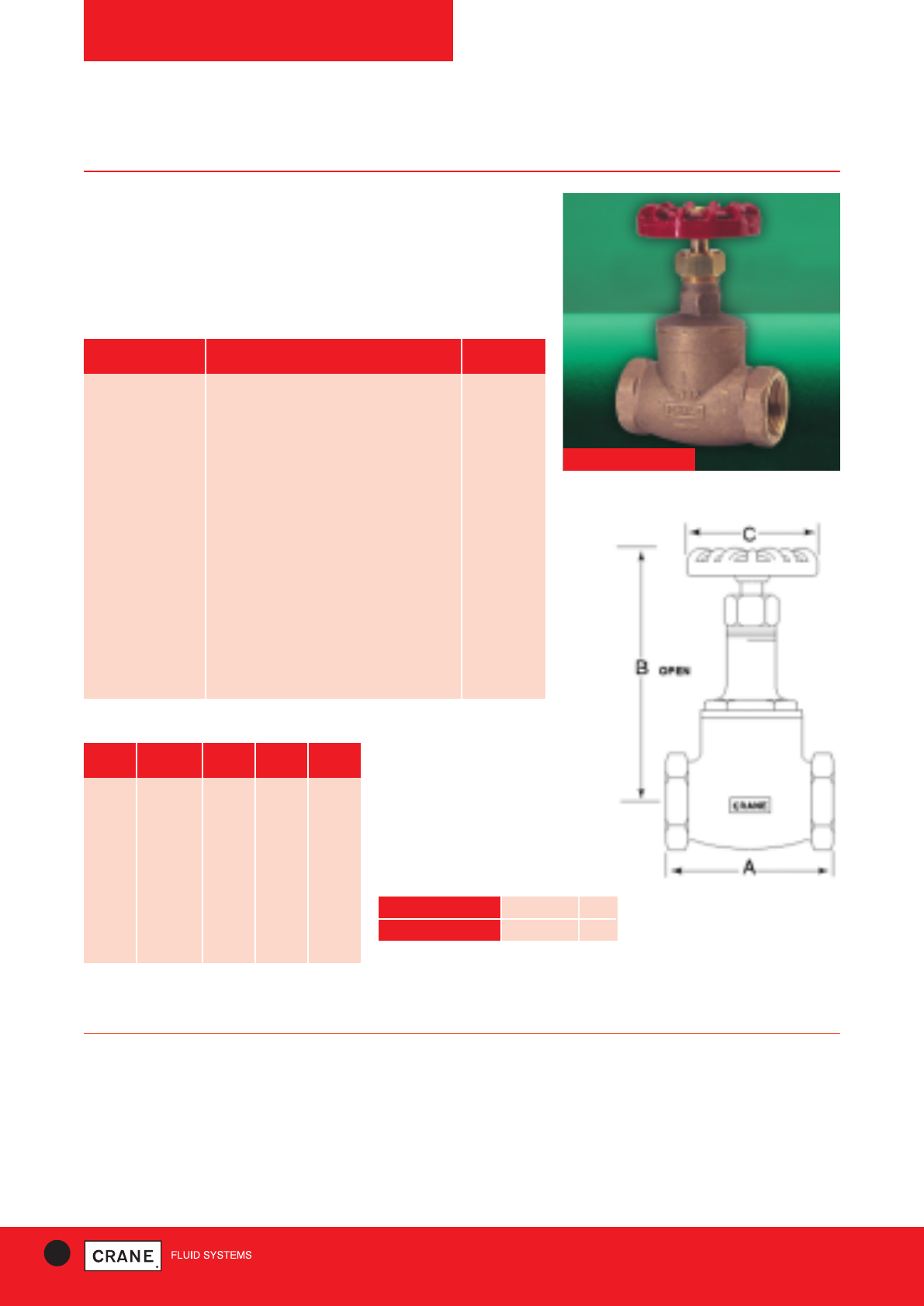
66 TECHNICAL HELPLINE: +44 (0)1473 277400
www.cranefs.com
GLOBE VALVES
D14
PN32* Series A
PN32* Bronze Globe Valve
Crane Bronze globe valves are highly efficient for throttling because seat
and disc designs provide flow characteristics with proportionate
relationships between valve lift and flow rate.
* Sizes 2 1/2& 3 rated PN25
D14
PART MATERIAL SIZES
Body Bronze BS EN 1982 CC491K All
Bonnet Bronze BS EN 1982 CC491K All
Disc Stem Ring Brass BS EN 12163 CW721R All
Disc Bronze BS EN 1982 CC491K All
Stem Manganese Bronze BS EN 12163 CW721R All
Gland Brass BS EN 12164 CW614N All
Packing Asbestos Free All
Packing Nut Brass BS EN 12164 CW614N 1/4- 21/2
Packing Nut Bronze BS EN 1982 CC491K 3 only
Hand Wheel Aluminium 1/4- 21/2
Hand Wheel Malleable Iron BS EN 1562 GJMB-300-6 3 only
Hand Wheel Nut Brass BS EN 12164 CW614N All
ID. Plate Aluminium All
Gasket Asbestos Free 21/2- 3
Materials
PRESSURE RATING: PN32
UK END CONNECTION: Taper threaded to BS EN 10226-2 (ISO 7-1)
formerly BS 21.
US END CONNECTION: ANSI B1.20.1 (please add suffix AT to
denote American Thread)
OPERATOR: Hand Wheel
SPECIFICATION:
Valves are manufactured in accordance with BS5154:1991 series A, PN32
for sizes 1/4to 2 and PN25 for sizes 21/2and 3.
Design incorporates a bronze 35 degree wide angle disc retained on stem
by a threaded ring; body seat is integral of the narrow contact angled type.
This valve is not suitable for use on group 1 gasses or unstable fluids, as
defined by the Pressure Equipment Directive 97/23/EC.
Temperature operating range: -10 to 260°C.
Dimensions and Weights
SIZE WEIGHT A B C
(kg) (mm) (mm) (mm)
1/4|| 0.39 52 100 52
3/8|| 0.38 52 100 52
1/2|| 0.54 62 101 52
3/4|| 0.65 74 115 52
1|| 0.9 90 125 70
11/4|| 1.58 100 150 70
11/2|| 2.06 115 159 92
2|| 3.31 136 191 103
21/2|| 5.9 166 220 121
3|| 10.3 190 255 152
Dimensional Drawing
TEMPERATURE (°C) -10 to 100 260
PRESSURE (BAR) 32 14
Intermediate pressure ratings shall be determined
by interpolation
Pressure/Temperature Ratings
Every effort has been made to ensure that the information contained in this publication is accurate at the time of publishing. Crane Ltd assumes no responsibility or liability for typographical errors or omissions or for
any misinterpretation of the information within the publication and reserves the right to change without notice.
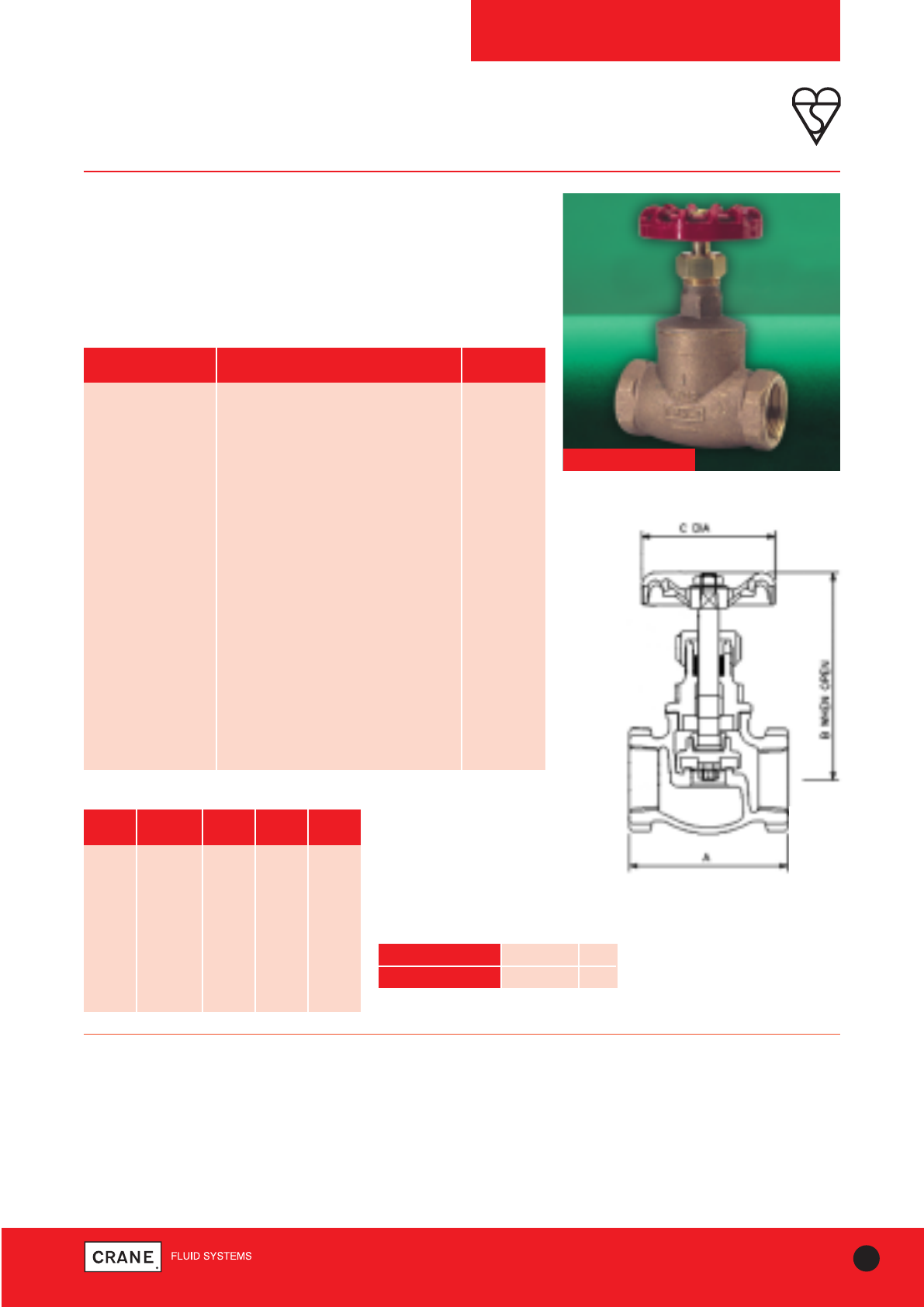
67
TECHNICAL HELPLINE: +44 (0)1473 277400
www.cranefs.com
GLOBE VALVES
D15
PN32* Series B
Bronze Globe Valve
The Crane D15 Bronze Globe Valve is highly efficient for throttling
service.
* Sizes 21/2|| and 3|| are rated at PN25.
This valve carries the British Standards Institution kitemark - your
assurance of exacting quality.
PRESSURE RATING: PN32
UK END CONNECTION: Taper threaded to BS EN 10226-2 (ISO 7-1)
formerly BS 21.
US END CONNECTION: ANSI B1.20.1 (please add suffix AT to
denote American Thread)
OPERATOR: Hand Wheel
SPECIFICATION:
Valves are manufactured in accordance with BS5154: 1991 series B, PN32
for sizes 1/4|| to 2|| and PN25 for sizes 21/2|| and 3||
Sizes 1/4|| to 3|| Taper threaded to BS EN 10226-2 (ISO 7-1) formerly BS 21
BSI Kitemarked.
Design incorporates a disc holder retained on stem by a threaded ring;
body seat is integral of the semi-crown type.
This valve is not suitable for use on group 1 gasses or unstable fluids, as
defined by the Pressure Equipment Directive 97/23/EC.
Temperature operating range: -10 to 198°C.
PART MATERIAL SIZES
Body Bronze BS EN 1982 CC491K All
Bonnet Bronze BS EN 1982 CC491K All
Disc Stem Ring Brass BS EN 12163 CW721R All
Disc PTFE (25% Glass Filled) All
Disc Holder Bronze BS EN 1982 CC491K 11/4- 3
Disc Holder Brass BS EN 12165 CW617N 1/4- 1
Disc Retaining Nut Brass BS EN 12164 CW614N 1/4- 2
Disc Retaining Nut Bronze BS EN 1982 CC491K 21/2& 3
Washer Brass BS EN 12164 CW614N 1/4- 2 only
Stem Brass BS EN 12163 CW721R 1/4- 2
Stem Manganese Bronze 21/2& 3
Gland Brass BS EN 12164 CW614N All
Packing Asbestos Free All
Packing Nut Brass BS EN 12164 CW614N 1/4- 2
Packing Nut Bronze BS EN 1982 CC491K 21/2- 3
Hand Wheel Aluminium 1/4- 21/2
Hand Wheel Malleable Iron BS EN 1562 GJMB-300-6 3 only
Hand Wheel Nut Brass BS EN 12164 CW614N All
ID. Plate Aluminium All
Gasket Asbestos Free 21/2only
Gasket Stainless Steel 3 only
Bill of Materials
Dimensions and Weights
SIZE WEIGHT A B C
(kg) (mm) (mm) (mm)
1/4|| 0.4 52 100 52
3/8|| 0.39 52 100 52
1/2|| 0.54 62 101 52
3/4|| 0.65 74 115 52
1|| 0.81 90 125 70
11/4|| 1.55 100 150 70
11/2|| 2.01 115 159 92
2|| 3.08 136 191 103
21/2|| 6.1 166 220 121
3|| 10.5 190 255 152
Dimensional Drawing
D15
TEMPERATURE (°C) -10 to 100 198
PRESSURE (BAR) 32 14
Intermediate pressure ratings shall be determined
by interpolation
Pressure/Temperature Ratings
Every effort has been made to ensure that the information contained in this publication is accurate at the time of publishing. Crane Ltd assumes no responsibility or liability for typographical errors or omissions or for
any misinterpretation of the information within the publication and reserves the right to change without notice.
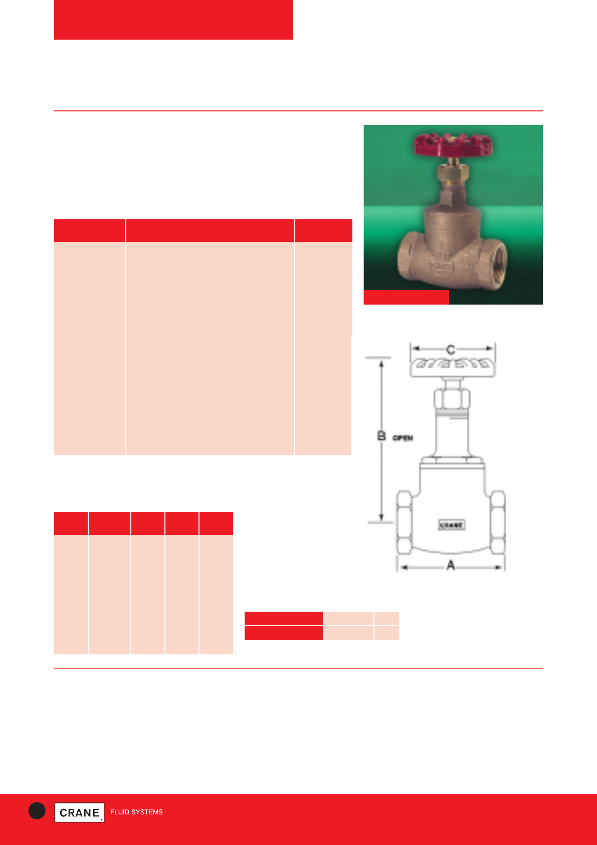
68 TECHNICAL HELPLINE: +44 (0)1473 277400
www.cranefs.com
GLOBE VALVES
D16
PN32* Series A
Bronze Globe Valve
Crane Bronze globe valves are highly efficient for throttling because seat
and disc designs provide flow characteristics with proportionate
relationships between valve lift and flow rate.
* Please note Sizes 21/2|| and 3|| are rated at PN25
PART MATERIAL SIZES
Body Bronze BS EN 1982 CC491K All
Bonnet Bronze BS EN 1982 CC491K All
Body Seat Ring 13% Cr.Steel BS970 Pt.1 410S21 or 431S29 All
Disc Stem Ring Brass BS EN 12163 CW721R All
Disc 13% Cr.Steel BS970 Pt.1 410S21 or 431S29 1/2- 2
Disc Nickel Alloy 1/4, 3/8, 21/2& 3
Stem Manganese Bronze BS EN 12163 CW721R All
Gland Brass BS EN 12164 CW614N All
Packing Asbestos Free All
Packing Nut Brass BS EN 12164 CW614N 1/4- 21/2
Packing Nut Bronze BS EN 1982 CC491K 3 only
Hand Wheel Aluminium 1/4- 21/2
Hand Wheel Malleable Iron BS EN 1562 GJMB-300-6 3 only
Hand Wheel Nut Brass BS EN 12164 CW614N All
ID. Plate Aluminium All
Gasket Asbestos Free 21/2- 3
Materials
Dimensions and Weights
Dimensional Drawing
PRESSURE RATING: PN32
UK END CONNECTION: Taper threaded to BS EN 10226-2 (ISO 7-1)
formerly BS 21
US END CONNECTION: ANSI B1.20.1 (please add suffix AT to
denote American Thread)
OPERATOR: Hand Wheel
SPECIFICATION:
Valves are manufactured in accordance with BS 5154: 1991 Series A, PN32
for sizes 1/4|| to 2|| and PN25 for sizes 2.1/2|| and 3||. Design incorporates a
nickel alloy plug type disc retained on the stem by a threaded ring; body
seat is a screwed-in stainless steel ring.
This valve is not suitable for use on group 1 gasses or unstable fluids, as
defined by the Pressure Equipment Directive 97/23/EC.
Temperature operating range: -10 to 260°C.
SIZE WEIGHT A B C
(kg) (mm) (mm) (mm)
1/4|| 0.33 52 100 52
3/8|| 0.31 52 100 52
1/2|| 0.8 62 101 52
3/4|| 1.24 74 115 52
1|| 1.5 90 125 70
11/4|| 1.7 100 150 70
11/2|| 2.16 115 159 92
2|| 3.67 136 191 103
21/2|| 6 166 220 121
3|| 10.9 190 255 178
D16
TEMPERATURE (°C) -10 to 100 260
PRESSURE (BAR) 32 14
Intermediate pressure ratings shall be determined
by interpolation
Pressure/Temperature Ratings
Every effort has been made to ensure that the information contained in this publication is accurate at the time of publishing. Crane Ltd assumes no responsibility or liability for typographical errors or omissions or for
any misinterpretation of the information within the publication and reserves the right to change without notice.
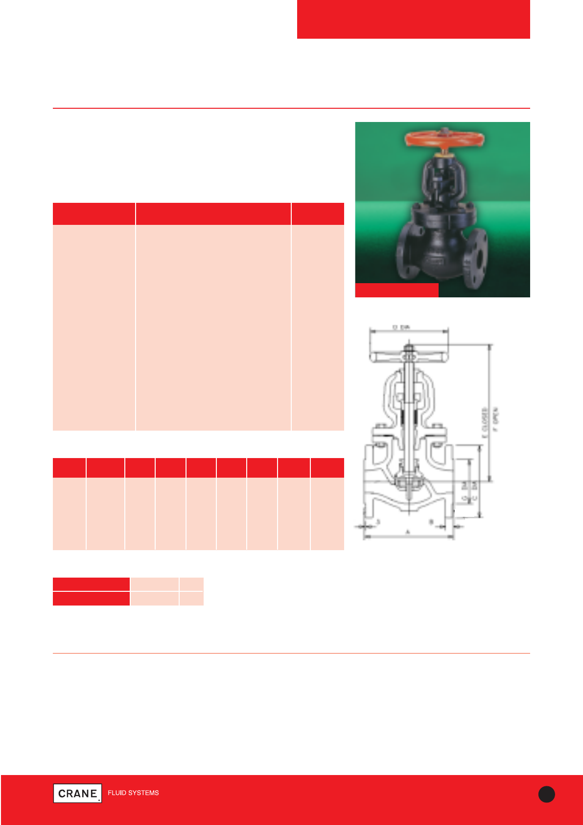
69
TECHNICAL HELPLINE: +44 (0)1473 277400
www.cranefs.com
GLOBE VALVES
FM369
PN16
Cast Iron Globe Valve
Crane cast iron globe valves are highly efficient for throttling because
seat and disc designs provide flow characteristics with proportionate
relationships between valve lift and flow rate.
FM369
PART MATERIAL SIZES
Body Cast Iron BS EN 1561 GJL-250 All
Bonnet Cast Iron BS EN 1561 GJL-250 All
Disc Guide Pin Brass BS EN 12164 CW721R 125 - 150
Gland Brass BS EN 12164 CW614N All
Gland Flange Malleable Iron BS EN 1562 GJMB-300-6 All
Gasket Asbestos Free All
Disc Stem Ring Brass BS EN 12164 CW721R All
Lockwasher Brass BS EN 1652 All
Disc Bronze BS EN 1982 CC491K All
Body Seat Ring Bronze BS EN 1982 CC491K All
Stem Brass BS EN 12164 CW721R All
Packing Asbestos Free All
Yoke Bushing Brass BS EN 12164 CW721R All
Hand Wheel Malleable Iron BS EN 1562 GJMB-300-6 All
Materials
Dimensional Drawing
PRESSURE RATING: PN16
UK END CONNECTION: Flanged BS EN 1092-2 PN16
OPERATOR: Hand Wheel
AVAILABLE OPTIONS:
Flanges Undrilled
SPECIFICATION:
Valves are manufactured in accordance with BS EN 13789:2010. End
flanges conform to BS EN 1092-2 PN16 with raised face.
Valves are normally supplied drilled.
This valve is not suitable for use on group 1 gasses or unstable fluids, as
defined by the Pressure Equipment Directive 97/23/EC.
Temperature operating range: - 10 to 220°C.
Dimensions and Weights
SIZE WEIGHT A B C D E F G
(kg) (mm) (mm) (mm) (mm) (mm) (mm) (mm)
50mm 24.2 203 20 165 203 310 335 102
65mm 29 216 20 185 203 330 356 122
80mm 36.9 241 22 200 229 362 392 138
100mm 56 292 24 220 254 416 446 158
125mm 72.3 330 26 250 305 457 489 188
150mm 98.8 356 26 285 305 476 516 212
TEMPERATURE (°C) -10 to 100 220
PRESSURE (BAR) 16 12.1
Intermediate pressure ratings shall be determined
by interpolation
Pressure/Temperature Ratings
Every effort has been made to ensure that the information contained in this publication is accurate at the time of publishing. Crane Ltd assumes no responsibility or liability for typographical errors or omissions or for
any misinterpretation of the information within the publication and reserves the right to change without notice.
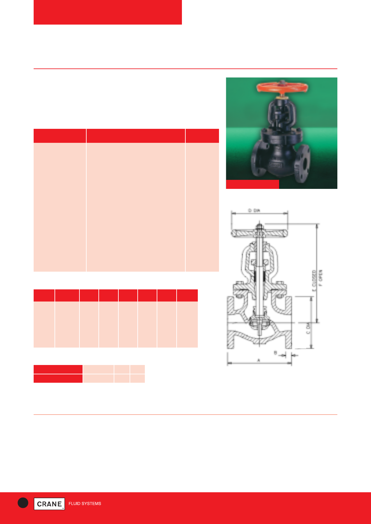
70 TECHNICAL HELPLINE: +44 (0)1473 277400
www.cranefs.com
GLOBE VALVES
F372
Class 125
Cast Iron Globe Valve
Crane cast iron globe valves are highly efficient for throttling because
seat and disc designs provide flow characteristics with proportionate
relationships between valve lift and flow rate.
F372
Dimensional Drawing
PRESSURE RATING: Class 125
US END CONNECTION: ANSI Class 125
OPERATOR: Hand Wheel
AVAILABLE OPTIONS:
Flanges undrilled.
SPECIFICATION:
Valves are manufactured in accordance with BS5152: 1974 and also meet
the requirements of MSS.SP-85: 2002. End flanges conform to BS1560
Section 3.2/ANSI B16.1 Class 125 with Flat Face and are normally supplied
drilled. Valves detailed on this page are dimensioned in metric terms.
This valve is not suitable for use on group 1 gasses or unstable fluids, as
defined by the Pressure Equipment Directive 97/23/EC.
Temperature operating range: -10 to 230°C.
Dimensions and Weights
SIZE WEIGHT A B C D E F
(kg) (mm) (mm) (mm) (mm) (mm) (mm)
2|| 23.1 203 16 152 203 310 335
21/2|| 27.2 216 17 178 203 330 356
3|| 34.5 241 19 191 229 362 392
4|| 54.4 292 24 229 254 416 446
5|| 70.8 330 24 254 305 457 489
6|| 95.3 356 25 279 305 476 516
TEMPERATURE (°C) -10 to 65 150 230
PRESSURE (BAR) 13.8 11.4 8.6
Intermediate pressure ratings shall be determined
by interpolation
Pressure/Temperature Ratings
PART MATERIAL SIZES
Body Cast Iron BS EN 1561 GJL-250 All
Bonnet Cast Iron BS EN 1561 GJL-250 All
Disc Guide Pin Brass BS EN 12164 CW721R 5 & 6
Gland Brass BS EN 12164 CW614N All
Gland Flange Malleable Iron BS EN 1562 GJMB-300-6 All
Gasket Asbestos Free All
Disc Stem Ring Brass BS EN 12164 CW721R All
Lockwasher Brass BS EN 1652 All
Disc Bronze BS EN 1982 CC491K All
Body Seat Ring Bronze BS EN 1982 CC491K All
Stem Brass BS EN 12164 CW721R All
Packing Asbestos Free All
Yoke Bushing Brass BS EN 12164 CW721R All
Hand Wheel Malleable Iron BS EN 1562 GJMB-300-6 All
Materials
Every effort has been made to ensure that the information contained in this publication is accurate at the time of publishing. Crane Ltd assumes no responsibility or liability for typographical errors or omissions or for
any misinterpretation of the information within the publication and reserves the right to change without notice.
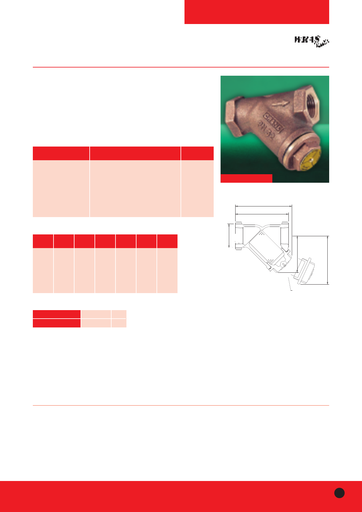
71
TECHNICAL HELPLINE: +44 (0)1473 277400
www.cranefs.com 71CRANE FLUID SYSTEMS
STRAINERS
D297
PN32
Bronze Strainer
Scale and dirt in piping systems cause endless trouble and frequently
serious damage to pipeline equipment. Installation of Crane
strainers will help eliminate the problems caused by foreign matter within
piping systems.
The Crane D297 features: Perforated stainless steel screen, Robust
design, Low flow resistance, High Quality Materials, WRAS approved.
D297
PART MATERIAL SIZES
Body Bronze BS EN 1982 CC491K All
Cap Bronze BS EN 1982 CC491K All
Gasket Asbestos Free (WRAS) All
ID. Plate Aluminium All
Pin Steel - Electro Brassed All
Screen Stainless Steel Type 304 All
Materials
PRESSURE RATING: PN32
UK END CONNECTION: Taper threaded to BS EN 10226-2 (ISO 7-1)
formerly BS 21
US END CONNECTION: ANSI B1.20.1 (please add suffix AT to
denote American Thread)
SPECIFICATION:
Strainers fitted with stainless steel perforated strainer element with 0.75mm
diameter holes.
Screens fitted into Crane Strainers conform to the high standards of
materials and workmanship associated with all Crane products.
This strainer is not suitable for use on group 1 gasses or unstable fluids, as
defined by the Pressure Equipment Directive 97/23/EC.
Temperature operating range: -10 to 200°C.
WITHDRAWAL DISTANCE
THREADED BSEN10226
formerly BS 21 (ISO 7) TAPER
OR ANSI B1.20.1 TAPER
A
B
C A/F HEX
E APPROX.
D
OPTIONAL BSP TAPPING
Dimensional Drawing
Dimensions and Weights
SIZE WEIGHT A B C D E
(kg) (mm) (mm) (mm) (mm) (mm)
1/2|| 0.38 71 79 30 51 61
3/4|| 0.63 86 96 38 64 77
1|| 0.96 101 110 47 72 92
11/4|| 1.81 134 144 56 100 128
11/2|| 2.43 148 157 65 109 139
2|| 4.13 176 183 79 126 160
TEMPERATURE (°C) -10 to 100 200
PRESSURE (BAR) 32 14
Intermediate pressure ratings shall be determined
by interpolation
Pressure/Temperature Ratings
Every effort has been made to ensure that the information contained in this publication is accurate at the time of publishing. Crane Ltd assumes no responsibility or liability for typographical errors or omissions or for
any misinterpretation of the information within the publication and reserves the right to change without notice.
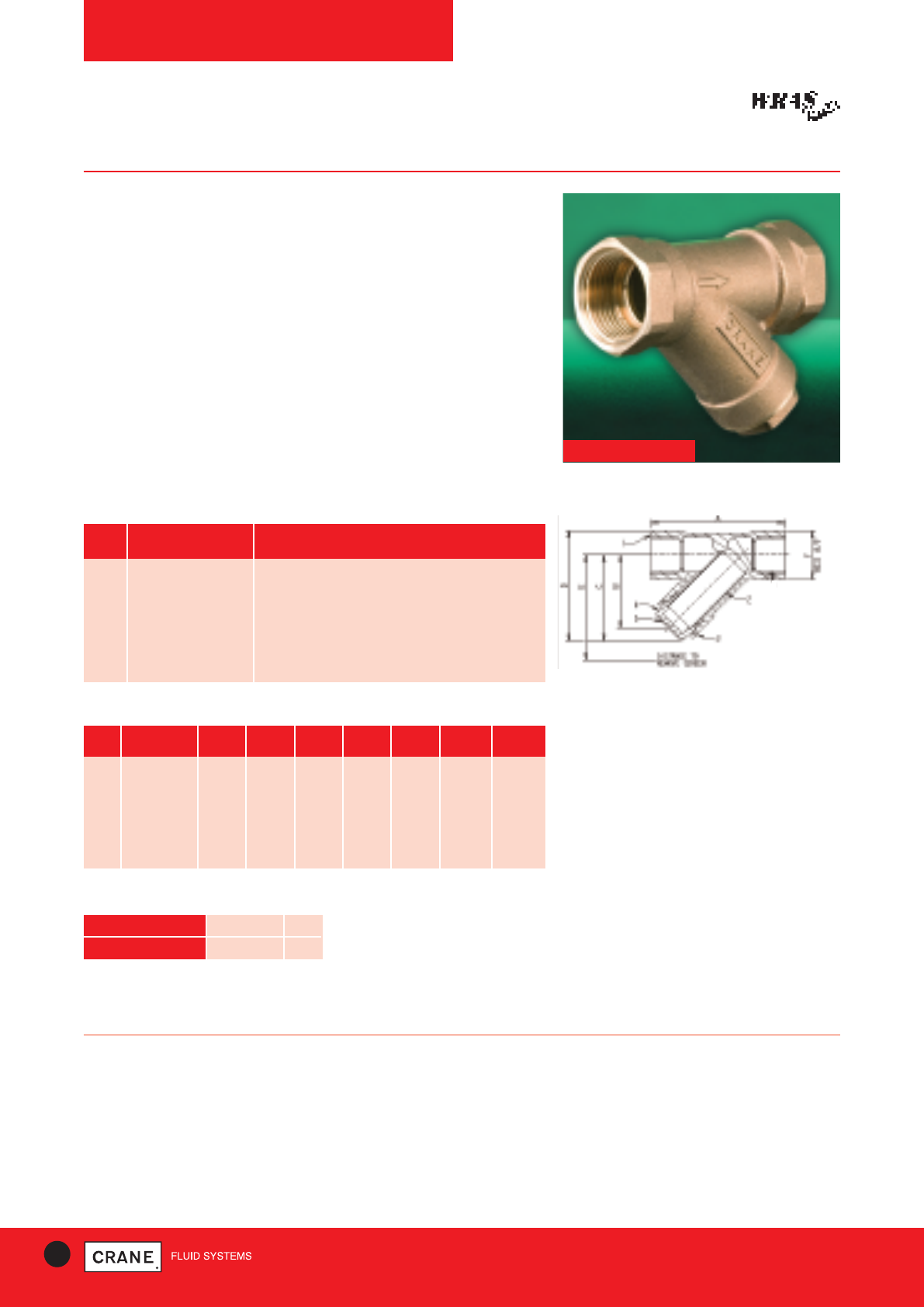
STRAINERS
D298
PN16
Features
•Robust design
•Threaded ends
•Low flow resistance
•High quality materials
Application
A generous use of pipeline strainers will make a significant contribution
to the reliability of a piping system and to optimise performance of the
equipment - pumps, valves, flow measuring devices, traps etc.
Strainers are a low cost investment for any piping system and result in
reduced maintenance costs as well as minimising ‘downtime’ by
protecting the circuit from damage by foreign matter.
D298
NO PART MATERIAL
1 Body Bronze to BS EN 1982 CC491K
2 Mesh Stainless Steel to A.I.S.I. Type 304
3 Cap Seal P.T.F.E.
4 Cap Bronze to BS EN 1982 CC491K
5 ID Plate Aluminium
Materials
72 TECHNICAL HELPLINE: +44 (0)1473 277400
www.cranefs.com
PRESSURE RATING: PN16
16 bar -10° to 100°C
7 bar at 170°C
TEST PRESSURE: 24 bar hydraulic
SPECIFICATION:
Bronze body
Screen 304 stainless steel
End connections threaded to BS EN 10266 (BS21 Taper ISO R7)
& B1.20.1 ANSI
Dimensional Drawing
Dimensions and Weights
DN MESH HOLE A B C D E F MASS
Ø (mm) (mm) (mm) (mm) (mm) (mm) (mm) (kg)
15 0.75 58 33 40 55 62 27 0.1875
20 0.75 70 42 54 69 80 33 0.3045
25 0.75 88 48 60 80 93 39 0.4260
32 0.75 96 55 69 95 108 49 0.7437
40 0.75 107 61 76 107 118 55 1.0075
50 0.75 126 79 99 135 153 67 1.4600
D = withdrawal distance for the screen
TEMPERATURE (°C) -10 to 100 170
PRESSURE (BAR) 16 7
Intermediate pressure ratings shall be determined
by interpolation
Pressure/Temperature Ratings
Every effort has been made to ensure that the information contained in this publication is accurate at the time of publishing. Crane Ltd assumes no responsibility or liability for typographical errors or omissions or for
any misinterpretation of the information within the publication and reserves the right to change without notice.
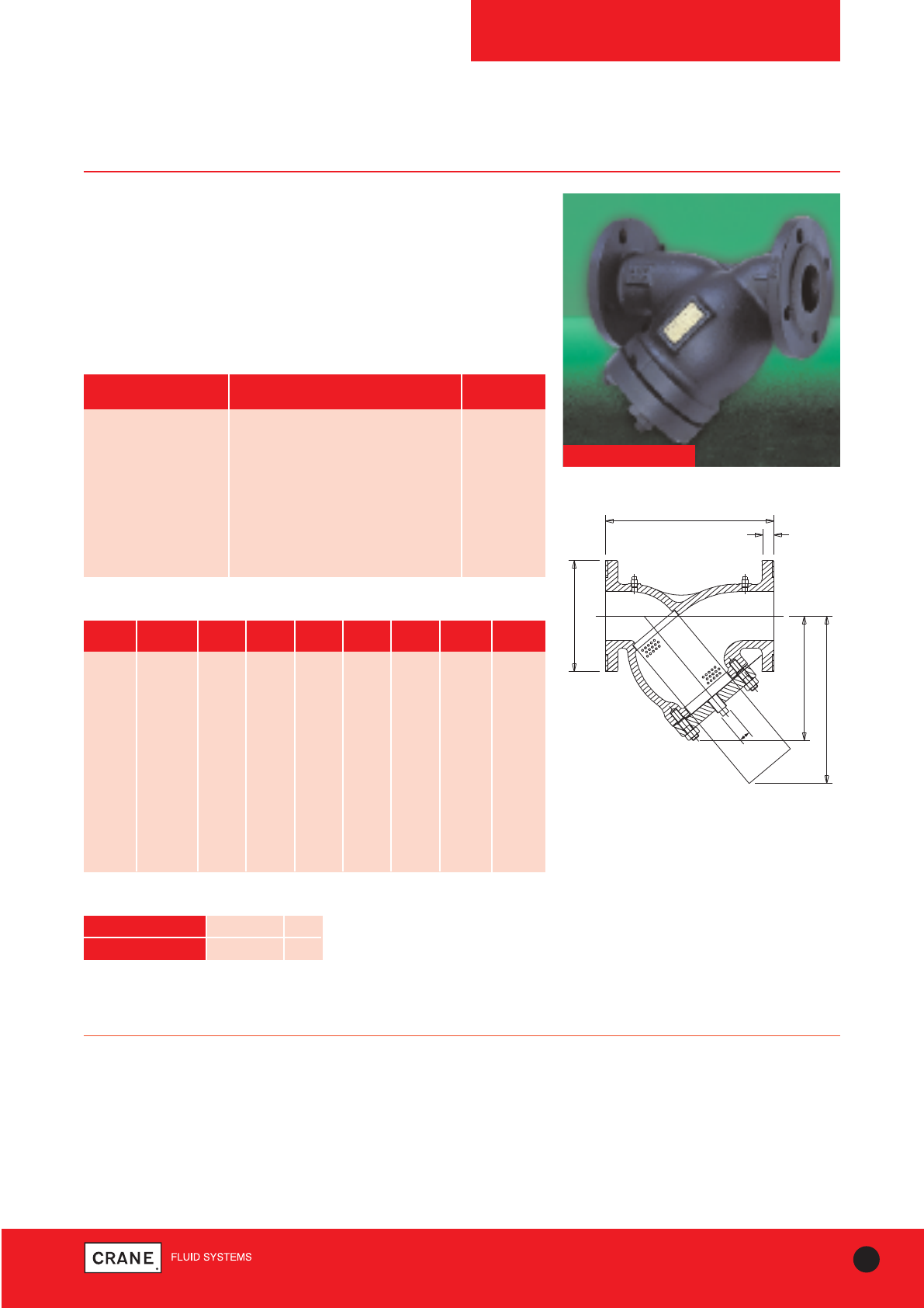
STRAINERS
FM276
PN16
Cast Iron Strainer
Scale and dirt in piping systems cause endless trouble and frequently
serious damage to pipeline equipment. Installation of Crane
strainers will help eliminate the problems caused by foreign matter within
piping systems.
The FM276 offers the integrity of manufacture, quality and reliability
which are the hallmarks of all Crane products.
FM276
PART MATERIAL SIZES
Body Cast Iron BS EN 1561 GJL-250 All
Cap Cast Iron BS EN 1561 EN-GJL-250 50 - 200
Cap Ductile Iron BS EN 1563 EN GJS 500/7 250-300
Gasket Asbestos Free All
Screen Stainless Steel AISI Type 304 All
Drain Plug Malleable Iron All
Test Point Plug Rc 1/4Malleable Iron All
Materials
73
TECHNICAL HELPLINE: +44 (0)1473 277400
www.cranefs.com
PRESSURE RATING: PN16
UK END CONNECTION: Flanged BS EN 1092-2: PN16
SPECIFICATION:
End flanges conform to BS EN 1092-2 PN16 Section 3.2 table 11 with
raised face and are normally supplied drilled. Strainers are normally.
supplied with a stainless steel perforated strainer element having 1.5mm
diameter holes.
This product is not suitable for use on group 1 gasses or unstable fluids, as
defined by the Pressure Equipment Directive 97/23/EC.
Temperature operating range: - 10 to 200°C.
Bosses drilled, tapped and plugged.
E
B
AØ
F
L
A
NI
M
O NG
H
GU
L
PN
I
AR
D
R
EP
ATPSB
EC
N
ATSIDLAW
A
RDHTIW
PRESSURE TAPPINGS
1/4 Rc (BSP TAPER)
Dimensional Drawing
Dimensions and Weights
SIZE WEIGHT A B C D E F G
(kg) (mm) (mm) (mm) (mm) (mm) (mm) (mm)
50mm 13 165 20 102 3 226 142 193
65mm 23 185 20 122 3 290 216 272
80mm 30 200 122 138 3 306 226 272
100mm 43 220 24 158 3 350 264 330
125mm 71 250 26 188 3 399 320 406
150mm 93 285 26 212 3 480 356 457
200mm 161 340 30 268 3 600 442 577
250mm 266 405 32 320 3 686 495 696
300mm 397 460 32 378 4 757 579 828
350mm 359 520 36 438 4 946 688 988
400mm 480 580 38 490 4 1076 743 1108
450mm 630 640 40 550 4 1172 990 1410
TEMPERATURE (°C) -10 to 120 200
PRESSURE (BAR) 16 12.8
Intermediate pressure ratings shall be determined
by interpolation
Pressure/Temperature Ratings
Every effort has been made to ensure that the information contained in this publication is accurate at the time of publishing. Crane Ltd assumes no responsibility or liability for typographical errors or omissions or for
any misinterpretation of the information within the publication and reserves the right to change without notice.
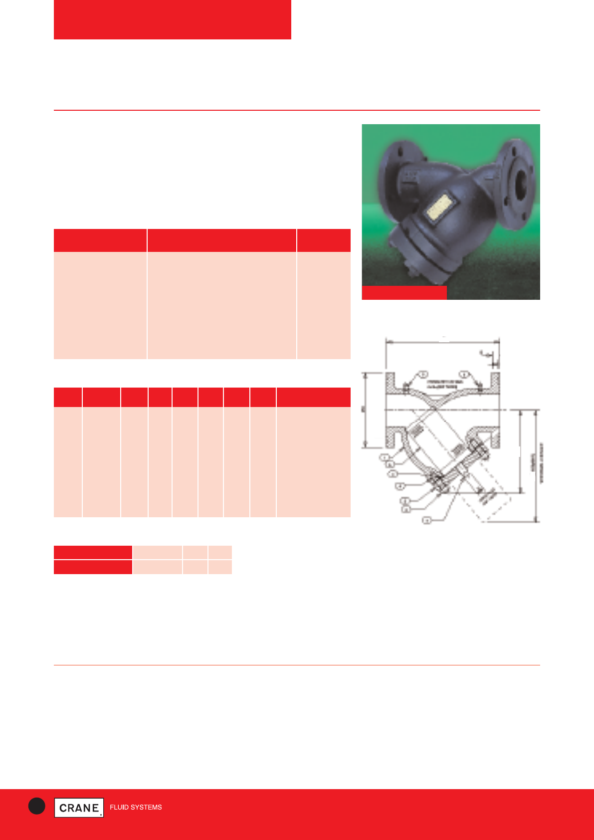
STRAINERS
F277
Class 125
Cast Iron Strainer
Scale and dirt in piping systems cause endless trouble and frequently
serious damage to pipeline equipment.
Installation of Crane strainers will help eliminate the problems caused by
foreign matter within piping systems.
Stainless Steel strainer element.
FM277
74 TECHNICAL HELPLINE: +44 (0)1473 277400
www.cranefs.com
PRESSURE RATING: Class 125
US END CONNECTION: ANSI Class 125
SPECIFICATION:
End flanges conform to BS1560 - Section 3.2/ANSI B16.1 with flat face
and are normally supplied drilled.
This strainer is supplied with a stainless steel perforated element having
1.5mm diameter holes.
This product is not suitable for use on group 1 gasses or unstable fluids, as
defined by the Pressure Equipment Directive 97/23/EC.
Temperature operating range: -10 to 230°C.
Dimensional Drawing
Dimensions and Weights
SIZE WEIGHT A B C D E H SCREEN AREA
(kg) (mm) (mm) (mm) (mm) (mm) (Rc) cm2
2|| 13 152 15.9 230 156 213 1|| 213
21/2|| 23 178 17.5 290 210 298 11/4|| 343
3|| 30 191 19.1 310 215 301 11/4|| 388
4|| 43 229 23.8 350 245 350 11/4|| 575
5|| 71 254 23.8 400 297 430 11/2|| 884
6|| 93 279 25.4 480 333 484 11/2|| 1174
8|| 161 342 28.6 600 416 611 2|| 1999
10|| 266 406 30.2 686 534 788 2|| 3213
12|| 397 483 31.8 759 624 928 2|| 4559
C
D
E
TEMPERATURE (°C) -10 to 65 150 230
PRESSURE (BAR) 13.8 11.4 8.6
Intermediate pressure ratings shall be determined
by interpolation
Pressure/Temperature Ratings
PART MATERIAL SIZES
Body Cast Iron BS EN 1561 GJL-250 All
Cap Cast Iron BS EN 1561 EN-GJL-250 50 - 200
Cap Ductile Iron BS EN 1563 EN GJS 500/7 250-300
Gasket Asbestos Free All
Screen Stainless Steel AISI Type 304 All
Drain Plug Malleable Iron All
Test Point Plug Rc 1/4Malleable Iron All
Materials
Every effort has been made to ensure that the information contained in this publication is accurate at the time of publishing. Crane Ltd assumes no responsibility or liability for typographical errors or omissions or for
any misinterpretation of the information within the publication and reserves the right to change without notice.
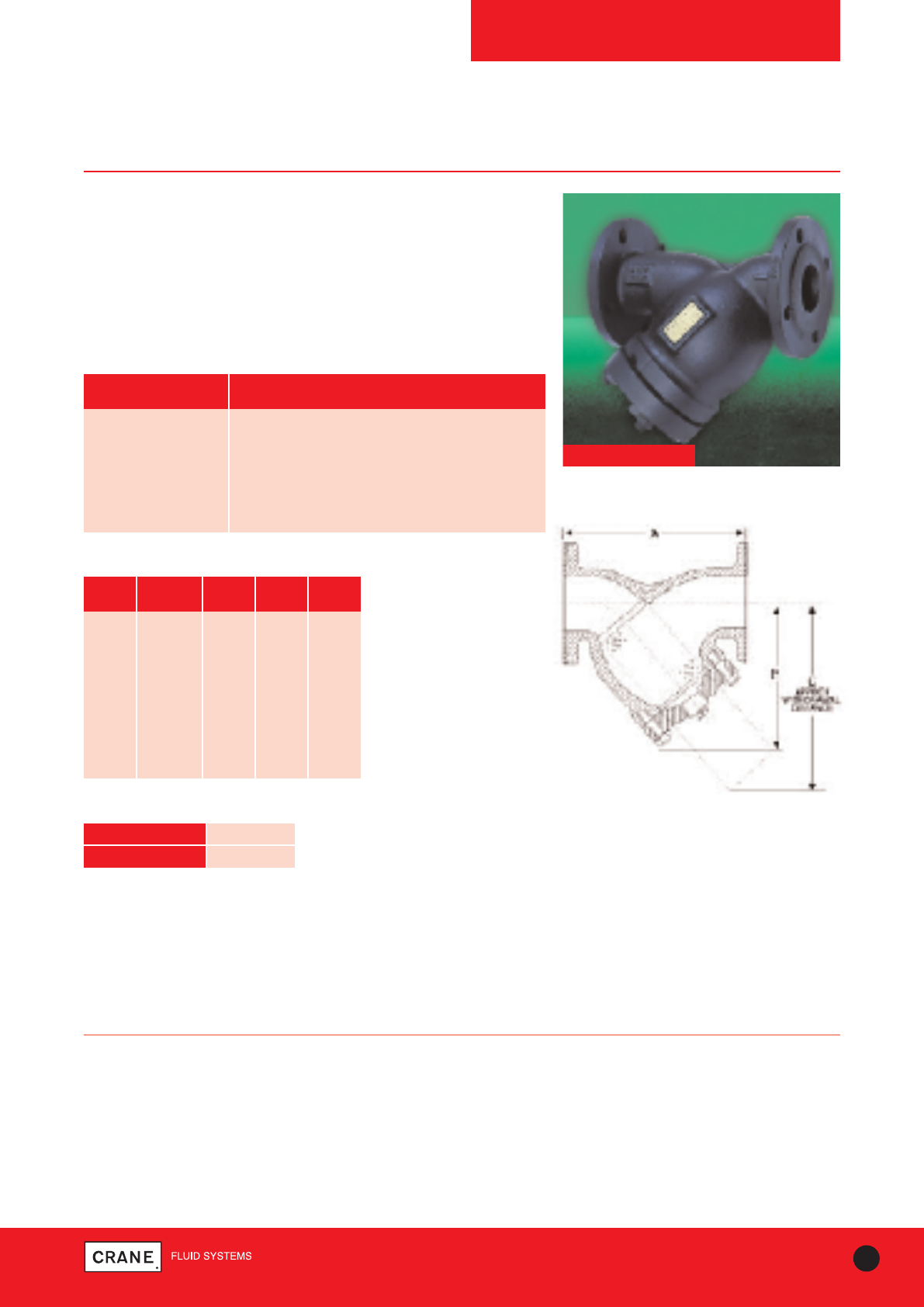
STRAINERS
FM278
PN25
PN25 Ductile Iron Strainer
Scale and dirt in piping systems causes endless trouble and
frequent serious damage to pipeline equipment. Installation of
Crane strainers will help eliminate the problems caused by
foreign matter with piping systems.
The FM278 offers the integrity of manufacture, quality and
reliability which are the hallmarks of Crane products.
FM278
75
TECHNICAL HELPLINE: +44 (0)1473 277400
www.cranefs.com
PART MATERIAL
Body Ductile Iron - BS EN 1563 EN GJS 500/7
Cap Ductile Iron - BS EN 1563 EN GJS 500/7
Gasket Asbestos Free
Plug Ductile Iron - BS EN 1563 EN GJS 500/7
Screen 304 Stainless Steel
Materials
PRESSURE RATING: PN25
END CONNECTION: Flanged to BS EN 1092-2 PN25
SPECIFICATION:
Flanges conform to BS EN 1092-2 PN25 Section 3.2 table 11 with raised
face. Strainers are supplied with a stainless steel perforated strainer
element having 1.6mm diameter holes.
This product is suitable for use on Group 2 liquids only, as defined by the
Pressure equipment Directive 97/23/EC.
Dimensional Drawing
Dimensions and Weights
SIZE WEIGHT A B C
(kg) (mm) (mm) (mm)
50 12.0 230 146 193
65 25.0 273 174 272
80 33.0 295 198 272
100 43.0 352 232 330
125 73.0 416 285 406
150 97.0 470 305 457
200 164.0 543 401 577
250 270.0 660 473 696
300 400.0 770 554 828
TEMPERATURE °C -10 to 120
PRESSURE (BAR) 25
Pressure/Temperature Ratings
Every effort has been made to ensure that the information contained in this publication is accurate at the time of publishing. Crane Ltd assumes no responsibility or liability for typographical errors or omissions or for
any misinterpretation of the information within the publication and reserves the right to change without notice.
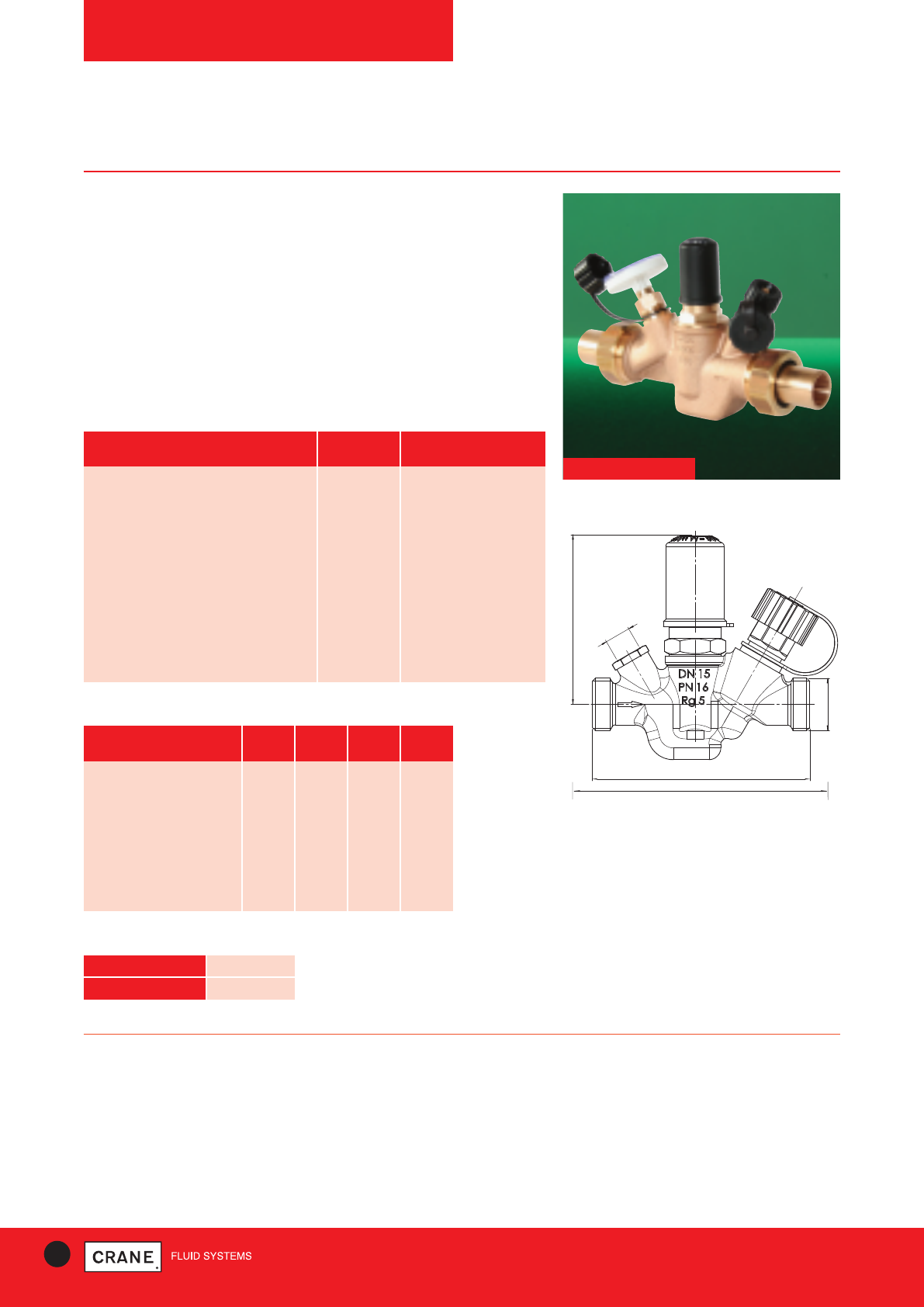
76 TECHNICAL HELPLINE: +44 (0)1473 277400
www.cranefs.com
76 TECHNICAL HELPLINE: +44 (0)1473 277400
www.cranefs.com
THERMAL BALACING VALVES
Fig. 1900
Multi-Therm PN16
Fig. 1900
PART MATERIAL SPECIFICATION
Body Bronze BS EN 1982 CC491K
Upper part Bronze BS EN 1982 CC491K
Valve stem Bronze BS EN 1982 CC491K
Valve cone Bronze BS EN 1982 CC491K
Upper part seal, valve stem seal EPDM 70 EPDM
Closing upper part valve cone seal PTFE Teflon
Drain plug Bronze BS EN 1982 CC491K
Closing handle Plastic Polyacetal (PA)
Plate / clamping band Plastic Polyacetal (PA)
Materials
PRESSURE RATING: PN16
OPERATING INSTRUCTIONS: When the set point is preset to 57°C,
the valve remains completely open up to a valve temperature of 52°C.
Between 52°C and the preset set point of 57°C, the valve starts to close.
When the set point temperature has been reached, a minimum volume flow
is continuously flowing through the circulation system.
If the storage temperature is further increased to temperatures greater than
70°C to effect disinfection, the valve increases the flow.Nom
A 1
L 1
H 1
G1/4
L 2
NOM
INSIDE DIA mm 15 20 25
Height (H1) mm 85 85 95
Length (L1) mm 110 123 133
Length (L2) Copper Tails mm 176 186 200
Length (L2) Mappress Copper mm 172 174 182
Length (L2) Mepla mm 174 178 186
Weight kg 0.7 0.9 1.2
Flow Kv cmb/h 0.92 1.70 2.71
Drain Valve (G) BSP 1/41/41/4
Dimensions and Weights
Dimensional Drawing
Features & Benefits
• Ideal for domestic hot water systems to assist with protection against
Legionella
• Provides self-balancing, thermostatically controlled regulation of flow
and disinfection
• Suitable for circuits greater than 10 metres in length
• Thermostatically controlled regulation of the volume flow -self-balancing
• Assists with disinfection at temperatures above 70°C by increasing the
flow automatically
• Has an accuracy of +/- 1°C
TEMPERATURE °C 90
PRESSURE (BAR) 16
Pressure/Temperature Ratings
Every effort has been made to ensure that the information contained in this publication is accurate at the time of publishing. Crane Ltd assumes no responsibility or liability for typographical errors or omissions or for
any misinterpretation of the information within the publication and reserves the right to change without notice.
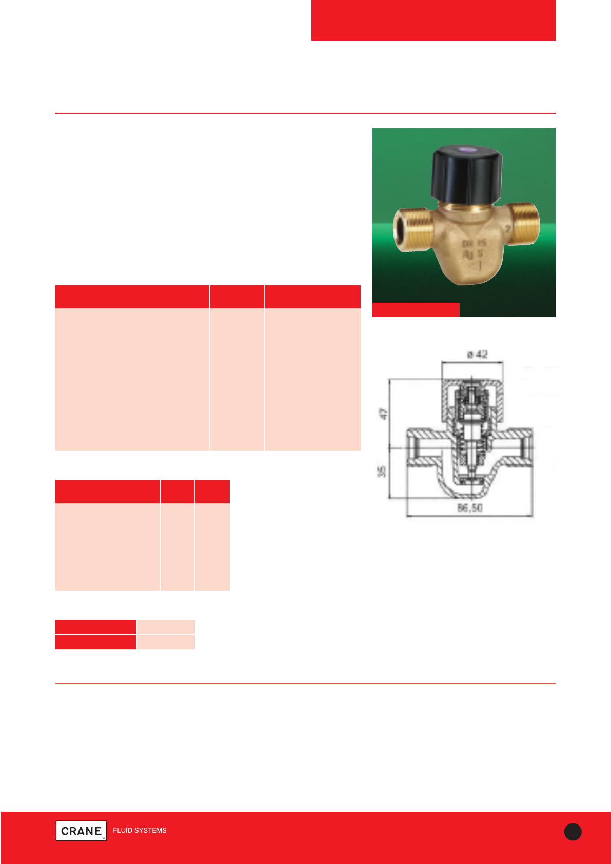
77
TECHNICAL HELPLINE: +44 (0)1473 277400
www.cranefs.com
THERMAL BALACING VALVES
Fig. 1910
Eta-Therm
PRESSURE RATING: PN16
OPERATING INSTRUCTIONS: When the set point is preset to 57°C,
the valve remains completely open up to a valve temperature of 52°C.
Between 52°C and the preset set point of 57°C, the valve starts to close.
When the set point temperature has been reached, a minimum volume flow
is continuously flowing through the circulation system.
If the storage temperature is further increased to temperatures greater than
70°C to effect disinfection, the valve increases the flow.
Fig. 1910
PART MATERIAL SPECIFICATION
Body Bronze BS EN 1982 CC491K
Upper part Bronze BS EN 1982 CC491K
Valve stem Bronze BS EN 1982 CC491K
Valve cone Bronze BS EN 1982 CC491K
Upper part seal, valve stem seal EPDM 70 EPDM
Closing upper part valve cone seal PTFE Teflon
Drain plug Bronze BS EN 1982 CC491K
Closing handle Plastic Polyacetal (PA)
Plate / clamping band Plastic Polyacetal
Materials
NOM
INSIDE DIA mm 15
Height mm 47
Length mm 86.5
Length Copper Tails mm 152
Length Mappress mm 148
Length Mepla mm 150
Weight kg 0.4
Flow Kv - 0.92
Dimensions and Weights
Dimensional Drawing
Features & Benefits
• Ideal for domestic hot water systems to assist with protection against
Legionella
• Provides self-balancing, thermostatically controlled regulation of flow
and disinfection
• Suitable for circuits less than 10 metres in length •Thermostatically
controlled regulation of the volume flow –self-balancing
• Assists with disinfection at temperatures above 70°C by increasing the
flow automatically
• Has an accuracy of +/- 1°C
TEMPERATURE °C 90
PRESSURE (BAR) 16
Pressure/Temperature Ratings
Every effort has been made to ensure that the information contained in this publication is accurate at the time of publishing. Crane Ltd assumes no responsibility or liability for typographical errors or omissions or for
any misinterpretation of the information within the publication and reserves the right to change without notice.
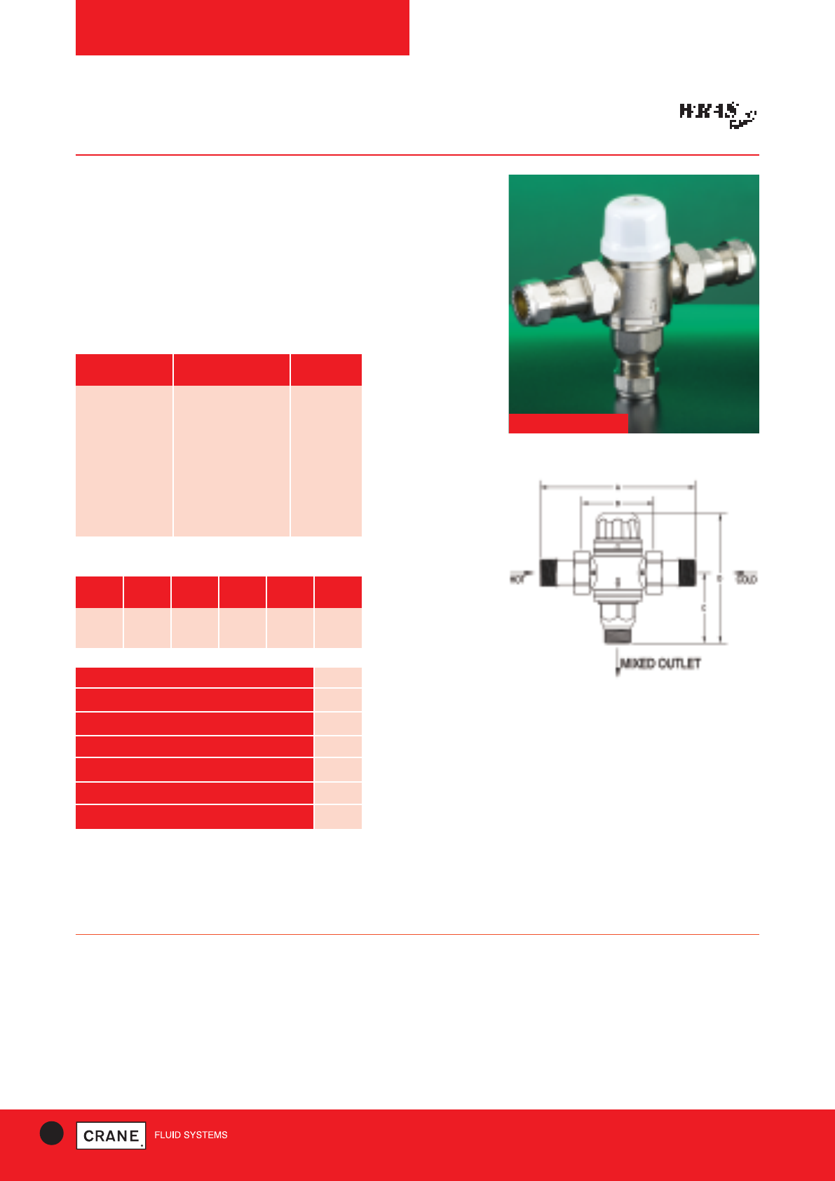
78 TECHNICAL HELPLINE: +44 (0)1473 277400
www.cranefs.com
THERMOSTATIC MIXING VALVES
D1088
TMV 3
Features & Benefits
• Blends hot and cold water to ensure constant, controlled safe outlet
temperature
• Fulfils the 'duty of care' requirements against scalding
• Ideal for healthcare, schools, workplace & domestic environments
• Flat face union ensures easy removal for maintenance
• Integral strainers and check valves
• Tamper proof adjustment
D1088 TMV 3
PART MATERIAL QUANTITY
O-Ring EPDM Rubber 7
1.5 Strainer Stainless Steel 304 2
Reduction Union DZR Brass CW602N 2
Element Vernet 0304 1
Spring Stainless Steel 304 1
Top DZR Brass CW602N 1
Valve Body DZR Brass CW602N 1
Materials
PRESSURE RATING: PN10
OPERATOR: Lockshield
SPECIFICATION:
The D1088 has been independently tested and certified as meeting the
requirements of the D08 specification under the TMV 3 scheme. Crane
products are designed for installation and use within suitably designed
systems reflecting CIBSE, BSRIA and HVAC guidelines.
SIZE WEIGHT A B C D
(kg) (mm) (mm) (mm) (mm)
15mm 0.6 122 58 55 102
22mm 0.8 145 58 70 117
Dimensions and Weights
Dimensional Drawing
FACTORY SETTING 38°C
TEMPERATURE SETTING RANGE 35-46°C
MINIMUM HOT TO MIX TEMPERATURE 10°C
TEMPERATURE STABILITY ±2°C
MAXIMUM WORKING PRESSURE 10 Bar
KV 1.26
MINIMUM FLOW PRESSURE 0.2 Bar
Every effort has been made to ensure that the information contained in this publication is accurate at the time of publishing. Crane Ltd assumes no responsibility or liability for typographical errors or omissions or for
any misinterpretation of the information within the publication and reserves the right to change without notice.
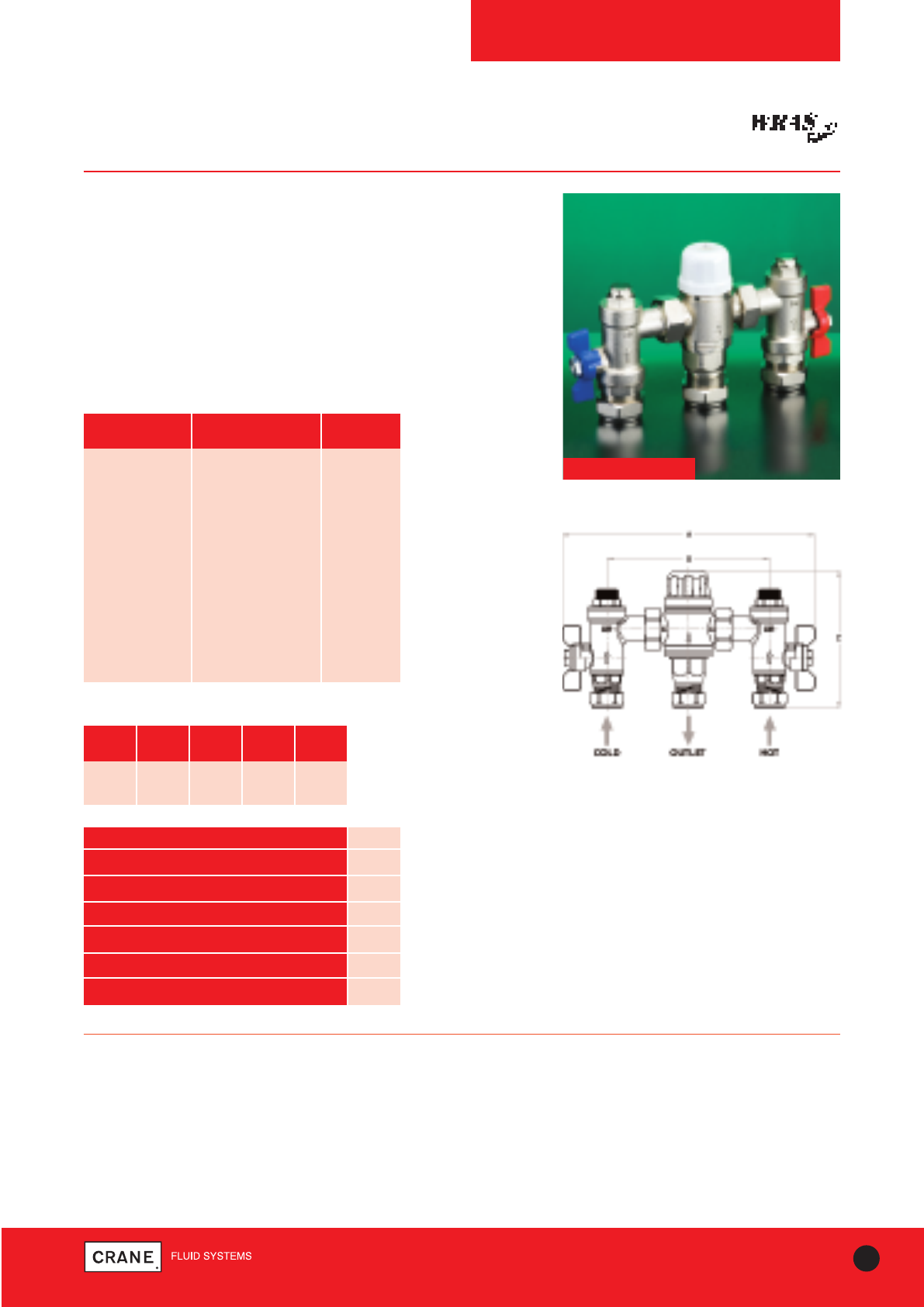
79
TECHNICAL HELPLINE: +44 (0)1473 277400
www.cranefs.com
THERMOSTATIC MIXING VALVES
D1089
TMV 3
Features & Benefits
• Blends hot and cold water to ensure constant, controlled safe outlet
temperature
• Fulfils the 'duty of care' requirements against scalding
• Ideal for healthcare, schools, workplace & domestic environments
• Flat face union ensures easy removal for maintenance
• Integral strainers and check valves
• Tamper proof adjustment
• Includes ball valves for isolation
D1089 TMV 3
PRESSURE RATING: PN10
OPERATOR: Lockshield
SPECIFICATION:
The D1089 has been independently tested and certified as meeting the
requirements of the D08 specification under the TMV 3 scheme. Crane
products are designed for installation and use within suitably designed
systems reflecting CIBSE, BSRIA and HVAC guidelines.
Dimensional Drawing
PART MATERIAL QUANTITY
O-Ring EPDM Rubber 12
1.5 Strainer Stainless Steel 304 2
Reduction Union DZR Brass CW602N 2
Element Vernet 0304 1
Spring Stainless Steel 304 1
Top DZR Brass CW602N 1
Valve Body DZR Brass CW602N 1
Ball DZR Brass CW602N 1
T Handle Al Alloy 1
Ball Seal PTFE 2
Materials
SIZE WEIGHT A B C
(kg) (mm) (mm) (mm)
15mm 1.1 200 128 110
22mm 1.3 200 128 110
Dimensions and Weights
FACTORY SETTING 38°C
TEMPERATURE SETTING RANGE 35-46°C
MINIMUM HOT TO MIX TEMPERATURE 10°C
TEMPERATURE STABILITY ±2°C
MAXIMUM WORKING PRESSURE 10 Bar
KV 1.26
MINIMUM FLOW PRESSURE 0.2 Bar
Every effort has been made to ensure that the information contained in this publication is accurate at the time of publishing. Crane Ltd assumes no responsibility or liability for typographical errors or omissions or for
any misinterpretation of the information within the publication and reserves the right to change without notice.
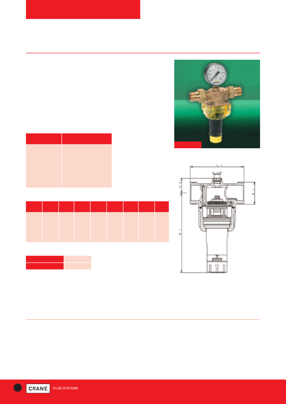
80 TECHNICAL HELPLINE: +44 (0)1473 277400
www.cranefs.com
PRESSURE REDUCING VALVES
Fig. 430
PN16
Features & Benefits
• PRVs enable control of pressure from boosted cold water supplies to
match site requirements
• Simple to install
• Recommend that isolation valves are fitted upstream and downstream
of the valve to enable isolation for cleaning of filter
• WRAS approved
• Manufactured in accordance with BS EN 1567
• Fig.430 must be fitted with adjustable cartridge element pointing
downwards
PART MATERIAL
Body Bronze
Disc Bronze
Cartridge Stainless Steel
Bronze
Filter Stainless Steel
Gaskets Nitrile
Materials
PRESSURE RATING: PN16
SPECIFICATION:
Suitable for:
• Water
• Compressed Air
NOM mm 15 20 25 32 40 50 GAUGE
SIZE FIG 440 440 440 440 440 440 445
L1 mm 90 90 100 105 130 140 All
H1 mm 150 150 150 225 225 225 All
H2 mm 25 25 25 38 38 38 All
A1 mm G3/4G1 G11/4G11/2G13/4G23/8All
Weight kg 0.90 0.93 1.00 2.20 2.30 2.50 0.25
Dimensions and Weights
Dimensional Drawing
TEMPERATURE °C 60
PRESSURE (BAR) 16
Pressure/Temperature Ratings
Fig 430
Every effort has been made to ensure that the information contained in this publication is accurate at the time of publishing. Crane Ltd assumes no responsibility or liability for typographical errors or omissions or for
any misinterpretation of the information within the publication and reserves the right to change without notice.
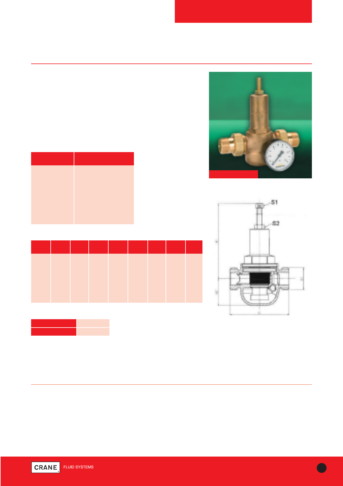
81
TECHNICAL HELPLINE: +44 (0)1473 277400
www.cranefs.com
PRESSURE REDUCING VALVES
Fig. 440
PN25
Features & Benefits
• PRVs enable control of pressure from boosted cold water supplies to
match site requirements
• Simple to install
• Recommend that isolation valves are fitted upstream and downstream
of the valve to enable isolation for cleaning of filter
• WRAS approved
• Manufactured in accordance with BS EN 1567
• 440 can be installed horizontally or vertically
PART MATERIAL
Body Bronze
Cover Bronze
Insert Stainless Steel
Bronze
Filter Stainless Steel
Spring Stainless Steel
Disc Brass
Materials
PRESSURE RATING: PN25
SPECIFICATION:
Suitable for:
• Water
• Compressed Air
NOM mm 15 20 25 32 40 50 GAUGE
SIZE FIG 440 440 440 440 440 440 445
L1 mm 75 92 98 98 128 148 All
H1 mm 110 110 150 160 190 265 All
H2 mm 30 42 46 46 52 75 All
S1 mm 10 10 12 12 12 13 All
S2 mm 13 13 17 17 17 19 All
A1 mm G3/4G1 G11/4G11/2G13/4G23/8All
Weight kg 0.80 1.30 1.70 1.90 3.60 6.70 0.25
Dimensions and Weights
Dimensional Drawing
TEMPERATURE °C 90
PRESSURE (BAR) 25
Pressure/Temperature Ratings
Fig 440
Every effort has been made to ensure that the information contained in this publication is accurate at the time of publishing. Crane Ltd assumes no responsibility or liability for typographical errors or omissions or for
any misinterpretation of the information within the publication and reserves the right to change without notice.
82 TECHNICAL HELPLINE: +44 (0)1473 277400
www.cranefs.com
TYPICAL Kv VALUES
Typical Kv Values
Typical Kv values for various valves to enable Pressure Drop calculations to be made.
For other pipe specifications, valve sizes and valve types, please refer to Crane Fluid Systems.
SIZE (mm)
Kv
GATE VALVES (Schedule 40 Pipe)
15 20 25 32 40 50 65 80 100 125 150 200 250 300
21.32 38.88 65.69 116.23 161.93 280.6 411.33 635.13 1125.41 1823.03 2718.96 4873.47 7681.73 11315.64
SIZE (mm)
Kv
GLOBE VALVES (Schedule 40 Pipe)
15 20 25 32 40 50 65 80 100 125 150 200 250 300
3.27 5.96 10.08 17.83 24.84 43.04 63.1 97.42 172.63 279.64 417.07 747.56 1178.32 1735 .74
SIZE (mm)
Kv
BUTTERFLY VALVES
15 20 25 32 40 50 65 80 100 125 150 200 250 300
-– -– -– -– -– 133 240 410 655 900 1800 3550 7350 9100
SIZE (mm)
Kv
BALL VALVES
8 10 15 20 25 32 40 50 65 80
9 11 20 47 77 1412 198 338 593 82
SIZE (mm)
Kv
CHECK VALVES (Schedule 40 Pipe)
15 20 25 32 40 50 65 80 100 125 150 200 250 300
8.53 15.55 26.27 46.49 64.77 112.24 164.53 254.05 450.16 729.21 1087.59 1949.39 3072.69 4526.25
SIZE (mm)
Kv
STRAINERS (Flanged) (BS1387 Medium Grade Steel Pipe)
15 20 25 32 40 50 65 80 100 125 150 200 250 300
-– -– -– -– 33 57 91 131 232 372 544 952 1470 2151
SIZE (mm)
Kv
STRAINERS (Threaded) (BS1387 Medium Grade Steel Pipe)
15 20 25 32 40 50
4.8 8.8 16.1 25.5 36 68
SIZE (mm)
Kv
COMMISSIONING VALVES: (Fixed Orifice Double Regulating Valve - Crane DM941)
65 80 100 125 150 200 250 300
72 100 124 229 324 525 1058 1329
SIZE (mm)
Kv
COMMISSIONING VALVES: (Fixed Orifice Double Regulating Valve - Crane D931)
15 20 25 32 40 50
1.87 3.14 5.59 10.8 18.1 29.1
Please do not hesitate to contact us if you require further information,
Technical Helpline Tel: +44 (0) 1473 277400
Every effort has been made to ensure that the information contained in this publication is accurate at the time of publishing. Crane Ltd assumes no responsibility or liability for typographical errors or omissions or for
any misinterpretation of the information within the publication and reserves the right to change without notice.

QUALITY CONTROL
Customer Service
The satisfaction of customer requirements is the defining
philosophy of Crane Fluid Systems. The position we hold
in our markets is built on the foundations of product
availability from our network of distributors and providing
expert technical support to users of valves and pipe
fittings.
Customers’ orders are received via EDI, fax or telephone
by our Customer Service Administrators. Using our state-
of-the-art computer-based Enterprise Resource Planning
System, we are able to immediately confirm product
availability and price. Our computers ensure orders are
seamlessly transmitted to our Production Managers who
regularly review factory plans to ensure customer
requirements are satisfied on time.
Comprehensive product selection and application advice
is just a phone call away. Our Internal Sales Engineers
are equipped to deal with complex valve application
needs, receiving customers’ drawings and producing
comprehensive valve schedules that will satisfy the
design parameters of the heating and ventilating system.
Our customers have come to regard this team as one of
the most reliable sources of technical support.
Quality Assurance
Rigid quality control and inspection at all stages of
manufacture ensure that Crane products are fully suitable
for their intended application and will give reliable
service. Every valve and pipe fitting is individually tested
in accordance with the relevant product standard.
Crane Fluid Systems is an approved manufacturer under
various independent quality schemes, including the
British Standards Institution (BSI) Kitemark, and is
ISO9001 accredited. In addition, the company has been
approved and/or listed by various user organisations
including the United Kingdom Water Fittings Bye Laws
Sheme (WRAS approved).
Health and Safety at Work Act
Every effort is made to ensure that when properly used,
in accordance with stated recommendations, goods
supplied are safe and without risk to health.
Should the purchaser be uncertain as to the suitability for
uses other than those stated, he/she should check with
the distributor or Crane Fluid Systems' technical team.
Control of Substances Hazardous to Health
Material supplied by Crane Fluid Systems does not
constitute “substances” as defined in the approved code
of practice of COSHH but complies with the
requirements of the Health and Safety at Work Act
(1974).
Material supplied by Crane may be handled and stored in
complete safety.
Crane products are safe to use provided they are utilised
for their intended function and used within the limitations
specified by Crane.
Note: Material is defined as equipment, supplies and
spares that form the subject of a contract (ref. BS 4778).
Pressure Equipment Directive
All Crane Fluid Systems products have been assessed in
accordance with the Pressure Equipment Directive (PED)
97/23/EC and the Pressure Equipment Regulations 1999
No. 2001. Each product has been classified into a
conformity assessment category based on the intended
fluid contents – gas or liquid, the classification of the
intended fluid contents – Group 1 or Group 2, the
maximum allowable pressure and the nominal size (DN).
Crane products fall into either the “Sound Engineering
Practice” (SEP), Category 1, Category 2 or Category 3.
According to the directive, products classified as “SEP”
shall not be CE marked. Category 1 products will bear
the CE mark and those products classified as Categories
2 and 3 will bear the CE mark plus the number 0086. The
number 0086 is that of the British Standards Institute
who Crane have chosen as their “Notified Body” to
monitor their quality assurance system as required by the
directive.
83
TECHNICAL HELPLINE: +44 (0)1473 277400
www.cranefs.com

Project Gallery
84 TECHNICAL HELPLINE: +44 (0)1473 277400
www.cranefs.com
Emirates Football Stadium, London
7-10 Old Bailey, London Domino’s Pizza HQ, Milton Keynes
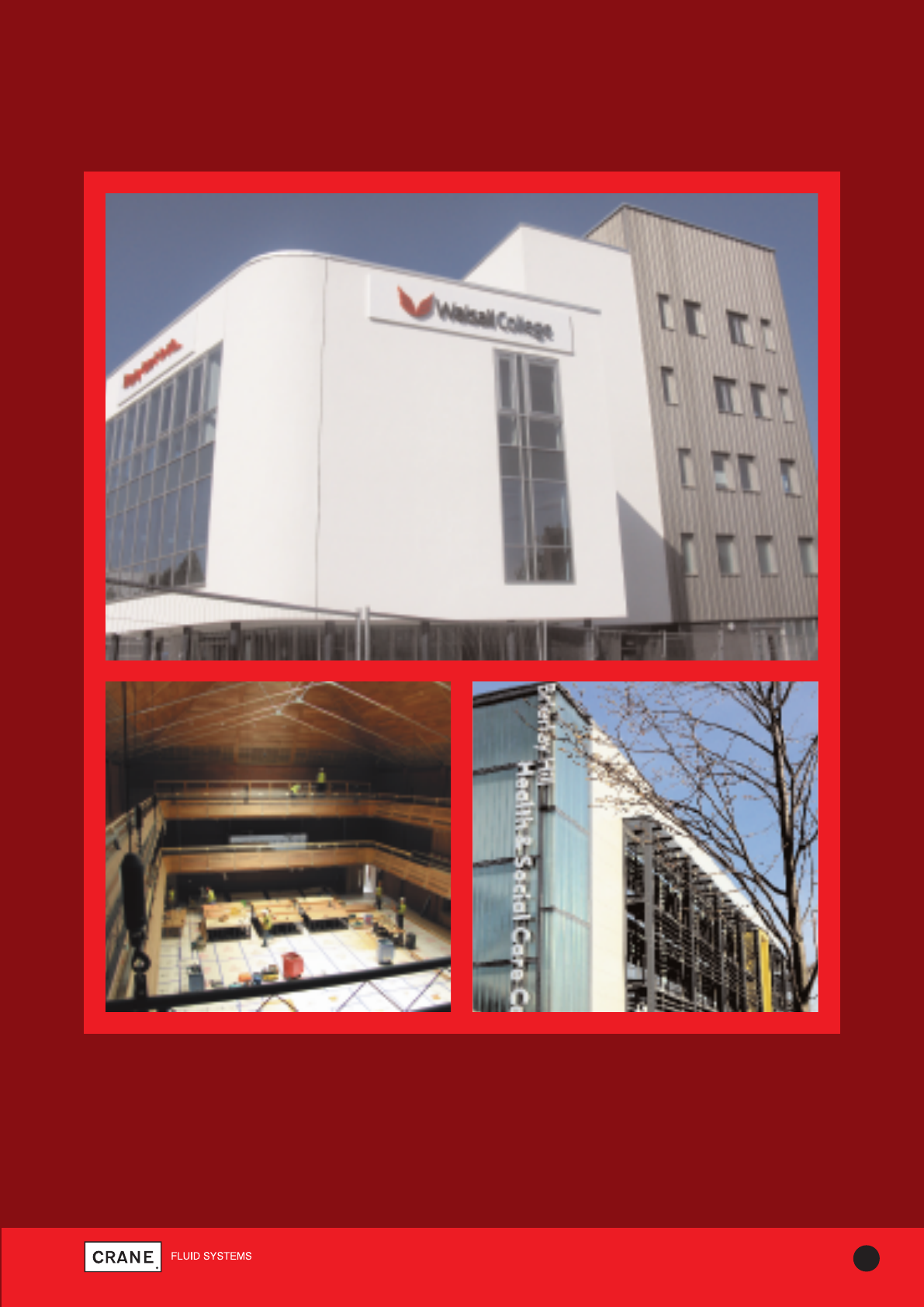
Project Gallery
85
TECHNICAL HELPLINE: +44 (0)1473 277400
www.cranefs.com
Walsall College, Walsall
The Apex, Bury St Edmunds Brierley Hill Health & Social Care Centre, Midlands

86 TECHNICAL HELPLINE: +44 (0)1473 277400
www.cranefs.com
INDEX
Index of Figure Numbers
430 80
440 81
1900 76
1910 77
C960 5-7
CommPac 19-20
D4 65
D14 66
D15 67
D16 68
D138 39
D140 40
D151 46
D151A 47
D151X 49
D155C 48
D156 50
D159 51
D166 52
D171 25
D171A 30
D171AC 32
D171ACEXS 32
D171ACLS 33
D171ACTH 33
D171AEXS 30
D171ALS 31
D171ATH 31
D171C 28
D171CEXS 28
D171CLS 29
D171CT 29
D171EXS 25
D171LS 26
D171MHU 27
D171MHULS 27
D171T 26
D180 53
D191 34
D237 54
D237A 55
D255C 56
D297 71
D298 72
D901 7
D902 7
D921 9
D923 9
D931 10
D933 10
D934 10
D981P 11
D983P 11
D984P 11
D1088 78
D1089 79
D9601 4
DA931 13
DA941 14
DM160 57
DM900 8
DM921 12
DM925G 15
DM925L 15
DM931 13
DM941 14
DM950G 16
DM950L 16
DM975G 17
DPAF951 21
DPAR951 21
F53 59
F58 64
F84 63
F277 74
F372 70
F493 42
F611 35
F612 36
F614 37
F615 38
F621 35
F622 36
F624 37
F625 38
F626 35
F627 36
F628 37
F629 38
FM52 58
FM57 60
FM63 61
FM82 62
FM276 73
FM278 75
FM369 69
FM450 44
FM451 44
FM455 45
FM469 43
FM492 41
P82 18
P83 18
P84 18
Z3000 22-23
Z3010 22-23
Z3020 22-23
Z3900 22-23
Z3910 22-23
Z3920 22-23
Z3300 22-23
FIG NO. PAGE NO. FIG NO. PAGE NO.FIG NO. PAGE NO.
Every effort has been made to ensure that the information contained in this publication is accurate at the time of publishing. Crane Ltd assumes no responsibility or liability for typographical errors or omissions or for
any misinterpretation of the information within the publication and reserves the right to change without notice.

CRANE HOUSE, EPSILON TERRACE
WEST ROAD, IPSWICH
SUFFOLK IP3 9FJ
TELEPHONE: +44 (0)1473 277300
FAX: +44 (0)1473 277301
EMAIL: enquiries@cranefs.com
www.cranefs.com
Every effort has been made to ensure that the information contained in this publication is accurate at the time of publishing. Crane Ltd assumes no responsibility or liability for typographical errors or omissions or for any
misinterpretation of the information within the publication and reserves the right to change without notice.
FM311
ISO 9001
www.cranebsu.com
ISSUE ONE
•Designed and manufactured under quality management systems
in accordance with BS EN ISO 9001:2008
•We hope our communications have an impact on you - but not
the environment - we have taken steps to ensure this brochure
is printed on Forestry Stewardship Council material and the
paper is made by a totally chlorine free process.
Visit www.flowoffluids.com to order your
copy of the New Technical Paper 410
