Cybex 790T, GO Monitor
User Manual: Cybex 790T, Cybex GO Monitor
Open the PDF directly: View PDF ![]() .
.
Page Count: 90
- Table of Contents
- FCC Compliance Information
- Safety
- Assembly
- Operation
- Intended Use
- Terms Used
- User Control Symbols Used
- CardioTouch Symbols Used
- CardioTouch Screen and User Controls
- Cybex GO Console and User Controls
- Cybex GO Console Log In or Sign Up
- Quick Operation Guide
- Detailed Operation Guide
- Stopping the Treadmill
- Safety Sentry
- Workout Selection
- Control During Operation
- Data Readouts
- Heart Rate Indicator
- Meaning of % Grade
- Fan Control
- iPod/iPhone Functions
- Maintenance
- Customer Service
- Appendix - Workout Overviews

Cybex Treadmill
Product Number 790T, Cybex GO Monitor
Owner’s Manual
Cardiovascular Systems
Part Number LT-24933-4 C
www.cybexintl.com

Cybex Owner’s Manual
2
Table of Contents
FCC Compliance Information..............3
Safety
Important Voltage Information .............4
Grounding Instructions ...................4
Important Safety Instructions . . . . . . . . . . . . . .5
Warning Decals ........................7
Label Placement........................9
Emergency Stop Key (e-stop) ............10
Assembly
Specications .........................12
Choosing and Preparing a Site ...........13
Electrical Power Requirements ...........14
790T Assembly........................14
Power Cord Management ...............28
Cybex GO Setup ......................30
Equipment Setup ......................37
A/V Conguration ......................39
Testing Operation ......................40
Operation
Intended Use .........................41
Terms Used ..........................41
User Control Symbols Used..............42
CardioTouch Symbols Used..............43
CardioTouch Screen and User Controls.....45
Cybex GO Console and User Controls .....46
Cybex GO Console Log In or Sign Up ......47
Quick Operation Guide..................48
Detailed Operation Guide................49
Stopping the Treadmill . . . . . . . . . . . . . . . . . .51
Safety Sentry .........................51
Workout Selection .....................52
Control During Operation ................53
Data Readouts ........................53
Heart Rate Indicator ....................54
Meaning of % Grade ...................54
Fan Control...........................55
iPod/iPhone Functions ..................55
Maintenance
Warnings ............................56
Preventive Maintenance Activities .........57
Cleaning Your Treadmill .................57
Running Belt Maintenance ...............59
Other Preventive Maintenance............61
Cybex GO monitor . . . . . . . . . . . . . . . . . . . . .61
Service Wheel (optional) ................62
Service Schedule ......................63
Customer Service
Product Registration....................65
Contacting Service .....................65
Ordering Parts ........................65
Return Material Authorization (RMA) . . . . . . .66
Damaged Parts .......................66
Appendix - Workout Overviews
Speed Bump..........................67
Rollers ..............................68
Hills.................................69
Peaks ...............................70
Hill Interval 1:1 . . . . . . . . . . . . . . . . . . . . . . . .71
Hill Interval 1:2 . . . . . . . . . . . . . . . . . . . . . . . .72
Hill Interval 1:3 . . . . . . . . . . . . . . . . . . . . . . . .73
Interval Plus . . . . . . . . . . . . . . . . . . . . . . . . . .74
Heart Rate Control .....................75
Gerkin Protocol........................77
Army................................78
Air Force.............................79
Navy < 5K............................82
Navy > 5K............................84
Marines Sea Level . . . . . . . . . . . . . . . . . . . . .86
Marines > 4.5K ........................87
One Mile Test .........................88
Cybex® and the Cybex logo are registered trademarks of Cybex International, Inc. Polar® is a registered trademark of Polar Electro Inc.
iPod and iPhone are trademarks of Apple Inc., registered in the U.S. and other countries.
DISCLAIMER: Cybex International, Inc., makes no representations or warranties regarding the contents of this manual. We reserve the right to revise
this document at any time or to make changes to the product described within it without notice or obligation to notify any person of such revisions or
changes.
© Copyright 2014, Cybex International, Inc. All rights reserved. Printed in the United States of America.
10 Trotter Drive Medway, MA 02053 • 508-533-4300 • FAX 508-533-5183 • www.cybexintl.com • LT-24933-4 C • September 2014

Cybex Owner’s Manual
3
FCC Compliance Information
Changes or modications to this unit not expressly approved by the party responsible for compliance
could void the user’s authority to operate the equipment.
This equipment has been tested and found to comply with the limits for a Class A digital device,
pursuant to part 15 of the FCC Rules. These limits are designed to provide reasonable protection
against harmful interference when the equipment is operated in a commercial environment. This
equipment generates, uses, and can radiate radio frequency energy and, if not installed and used in
accordance with the instruction manual, may cause harmful interference to radio communications.
Operation of this equipment in a residential area is likely to cause harmful interference in which case
the user will be required to correct the interference at his own expense.
Cybex Owner’s Manual
4
Safety
Read all instructions and warnings before using.
Important Voltage Information
Before plugging the power cord into an electrical outlet, verify that the voltage requirements for the
site match the voltage of the treadmill that has been received. The power requirements for the Cybex
790T Treadmill include a grounded, dedicated circuit, rated for one of the following:
• 100 VAC, 50/60 Hz, 20A
• 115 VAC, 50/60 Hz, 20A
• 208 VAC, 60 Hz, 15A
• 220 VAC, 60 Hz, 15A
• 230 VAC, 50 Hz, 13A, UK
See the front warning decal for the voltage requirements of the treadmill.
Grounding Instructions
This treadmill must be grounded. If it should malfunction or break down, grounding provides a path of
least resistance for electric current to reduce the risk of electric shock. This product is equipped with
a cord having an equipment-grounding conductor and a grounding plug. The plug must be plugged
into an appropriate outlet that is properly installed and grounded in accordance with all local codes
and ordinances.
WARNING: Shock and electrocution hazard.
• Connect unit to a grounded outlet.
• Do not use voltage adapter or extension cord.
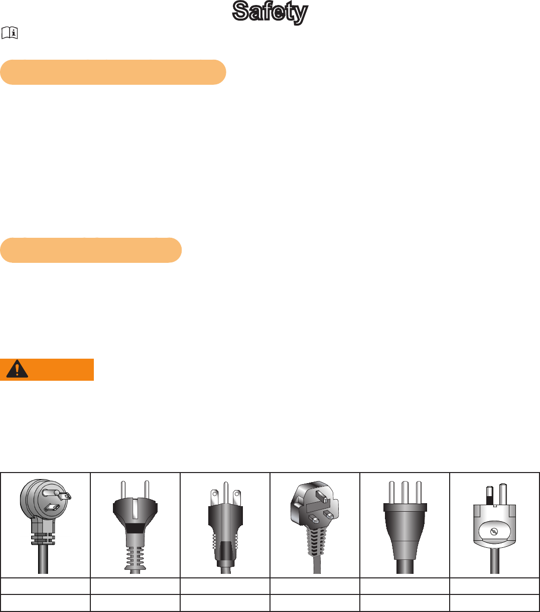
This treadmill is for use on a grounded, dedicated circuit. Make sure that the treadmill is connected to
an outlet having the same conguration as the plug. Do not use a ground plug adapter to adapt the
power cord to a non-grounded outlet.
115 VAC Euro Plug 220 VAC UK Danish Australia
NEMA 5-20 CEE 7/7 NEMA 6-15 230 VAC 107-2-D1 AS/NZS 3112
Cybex Owner’s Manual
5
Important Safety Instructions
(Save These Instructions)
WARNING: Shock and electrocution hazard.
• Unplug unit and let sit 10 minutes before cleaning or performing maintenance.
• Electrical charge can remain in unit after unplugging.
• Keep water and liquids away from electrical parts.
User Safety Precautions
Prior to use:
• Obtain a medical exam before beginning any exercise program.
• Obtain instruction before using.
• Read and understand warning labels.
• Read and understand emergency stop procedures.
• Maximum user weight is 400 lbs. (180 kg).
• Inspect unit. If damaged, notify oor staff. DO NOT USE.
• Place your feet on the two top steps when starting or stopping the treadmill.
• Clip E-STOP lanyard to clothing.
• Do not remove this label. Replace if damaged or illegible.
During use:
• Do not use for stretching and do not attach straps or other devices.
• Do not allow children 12 or younger to be on or near machine.
• Stop exercise if feeling faint, dizzy, or have pain.
• Use the handrails for support and to maintain balance.
• Keep all body parts, clothing, and accessories, clear of moving parts.
• Wait until running belt comes to a complete stop before getting off.
Facility Safety Precautions
It is the sole responsibility of the user/owner or facility operator to ensure that regular maintenance is
performed.
• Enforce all user and safety precautions.
• Read and understand the Owner’s Manual completely before assembling, servicing or using unit.
• Verify all users are properly trained on using the equipment.
• Do not use unit outdoors.
• Verify that each unit is setup, leveled and operated on a solid level surface. Do not install
equipment on an uneven surface. Do not operate in recessed areas or on plush carpet.
• Verify there is enough room for safe access and operation of unit.
• Instruct all users on how to clip the e-stop clip onto their clothing and carefully test it prior to using
the treadmill.
• Instruct all users to use caution when mounting and dismounting the treadmill.
• Use a dedicated line when operating the treadmill. A dedicated line requires one circuit breaker per
unit.
• Connect the treadmill to a properly grounded outlet only.
• DO NOT operate electrically powered treadmills in damp or wet locations.
Cybex Owner’s Manual
6
• Keep the running belt clean and dry at all times.
• DO NOT leave the treadmill unattended when plugged in and running. NOTE: Before leaving the
treadmill unattended, always wait until the treadmill comes to a complete stop and is level. Then,
turn all controls to the STOP or OFF position and remove the plug from the outlet. Remove the
e-stop key from the treadmill.
• Immobilize the treadmill (when not in use) by removing the e-stop key.
• Inspect the treadmill for worn or loose components before each use. Do not use until worn or
damaged parts are replaced.
• Stop and place the treadmill at 0 degrees incline (level) after each use.
• Maintain and replace worn parts regularly. Refer to “Preventive Maintenance” section of Owner’s
Manual.
• DO NOT operate the treadmill if: (1) the cord is damaged; (2) the treadmill is not working properly
or (3) if the treadmill has been dropped or damaged. Seek service from a qualied technician.
• DO NOT place the cord near heated surfaces or sharp edges.
• DO NOT use the treadmill outdoors.
• DO NOT operate the treadmill around or where aerosol (spray) or where oxygen products are
being used.
• Ensure all users wear proper footwear on or around all Cybex equipment.
• Disconnect power before servicing.
• DO NOT attempt repairs, electrical or mechanical. Seek qualied repair personnel when servicing.
If you live in the USA, contact Cybex Customer Service at 888-462-9239. If you live outside the
USA, contact Cybex Customer Service at 508-533-4300.
• Use Cybex factory parts when replacing parts on the treadmill.
• DO NOT modify the treadmill in any way.
• DO NOT use attachments unless recommended for the treadmill by Cybex.
Cybex Owner’s Manual
7
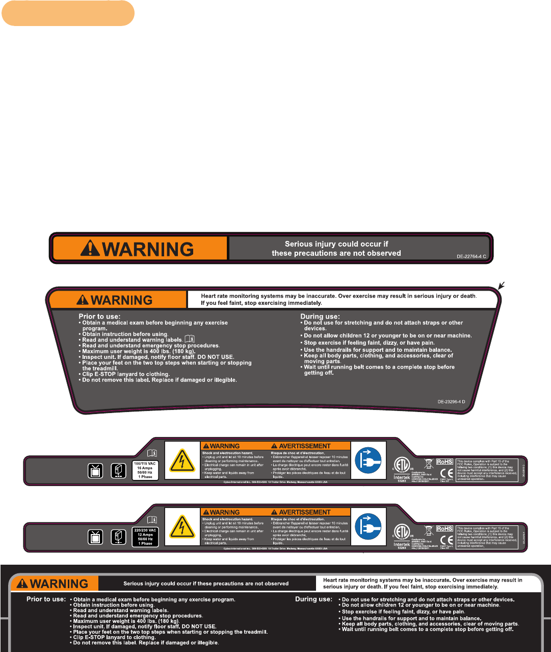
Warning Decals
To replace any worn or damaged decals do one of the following: Visit www.cybexintl.com to shop
for parts online, fax orders to 508-533-5183 or contact Cybex Customer Service at 888-462-9239. If
you are located outside of the USA, call 508-533-4300. For location or part number of labels, see the
parts list and exploded-view diagram on the Cybex web site at www.cybexintl.com.
Warning decals indicate a potentially hazardous situation which, if not avoided, could result in death
or serious injury.
Carefully read and understand the following caution and warning labels before using the unit.
Caution decals indicate a potentially hazardous situation, which if not avoided, may result in minor
or moderate injury. There are no caution decals used on this unit. However, there are caution
statements listed in this manual.
DE-23296-4
BD
BGarber
5 OF 10
REVISIONS
DESCRIPTION
See sheet 1
ECO
REV DATE APPROVAL
BY
10 TROTTER DRIVE
MEDWAY, MA
REV.
SHEET
SIZE
APPROVALS
DRAWN BY
MATERIAL
FINISH
ADOBE GENERATED DRAWING
DO NOT MANUALLY UPDATE
CHECKED
RESP ENG
MFG ENG
QUAL ENG
DATE
DWG. NO.
UNLESS OTHERWISE SPECIFIED
DIMENSIONS ARE IN INCHES
TOLERANCES ARE:
.XX ± .02
.XXX ± .010
ANGULAR = ± 1°
FINISH = 125 RMS
FRACTIONS = ± 1/64”
SCALE: 1=1 THIS FILE IS IN ADOBE ILLUSTRATOR
DO NOT SCALE DRAWING
THE INFORMATION CONTAINED IN THIS DRAWING IS THE SOLE PROPERTY OF CYBEX.
ANY REPRODUCTION IN PART OR WHOLE WITHOUT
THE WRITTEN PERMISSION OF CYBEX IS PROHIBITED.
SEE NOTES, Page 1
SEE NOTES, Page 1
..
.
1/6/14 LABEL, WARNING,
LOWER CONSOLE, W/O USB,
ENGLISH
8.82”W X 2.41”H
DIELINE “CutContour” DO NOT PRINT
Black
White
Orange - Pantone 152C
Gray - Pantone 425C
DE-22910
B F1
BGarber
2 OF 2
REVISIONS
DESCRIPTION
ECOREV DATE APPROVALBY
10 TROTTER DRIVE
MEDWAY, MA
REV.
SHEET
SIZE
APPROVALS
DRAWN BY
MATERIAL
FINISH
ADOBE GENERATED DRAWING
DO NOT MANUALLY UPDATE
CHECKED
RESP ENG
MFG ENG
QUAL ENG
DATE
DWG. NO.
UNLESS OTHERWISE SPECIFIED
DIMENSIONS ARE IN INCHES
TOLERANCES ARE:
FRACTIONS DECIMALS ANGLES
± .XX ± .02 ± 1
.XXX ± .005
FINISH: 125 RMS
SCALE: 1=1 THIS FILE IS IN ADOBE ILLUSTRATOR
DO NOT SCALE DRAWING
THE INFORMATION CONTAINED IN THIS DRAWING IS THE SOLE PROPERTY OF CYBEX.
ANY REPRODUCTION IN PART OR WHOLE WITHOUT
THE WRITTEN PERMISSION OF CYBEX IS PROHIBITED.
See sheet 1.
.
.
.. ..
.
.. . .
.
. . . .
.
Do not print an outline. For reference only.
See Solidworks drawing for additional details.
Artwork scaled to 80%
See above artboard for actual size
WARNING, LABEL,
MOTOR COVER,
115 VAC
6/2/14
DIELINE “CutContour” DO NOT PRINT
Black
White
Orange - Pantone 152C
Gray - Pantone 425C
Yellow - Pantone 108C
Blue - Pantone 2945C
DE-23079
B E1
BGarber
2 OF 2
REVISIONS
DESCRIPTION
ECOREV DATE APPROVALBY
10 TROTTER DRIVE
MEDWAY, MA
REV.
SHEET
SIZE
APPROVALS
DRAWN BY
MATERIAL
FINISH
ADOBE GENERATED DRAWING
DO NOT MANUALLY UPDATE
CHECKED
RESP ENG
MFG ENG
QUAL ENG
DATE
DWG. NO.
UNLESS OTHERWISE SPECIFIED
DIMENSIONS ARE IN INCHES
TOLERANCES ARE:
FRACTIONS DECIMALS ANGLES
± .XX ± .02 ± 1
.XXX ± .005
FINISH: 125 RMS
SCALE: 1=1 THIS FILE IS IN ADOBE ILLUSTRATOR
DO NOT SCALE DRAWING
THE INFORMATION CONTAINED IN THIS DRAWING IS THE SOLE PROPERTY OF CYBEX.
ANY REPRODUCTION IN PART OR WHOLE WITHOUT
THE WRITTEN PERMISSION OF CYBEX IS PROHIBITED.
See sheet 1.
.
.
.. ..
.
.. . .
.
. . . .
.
Do not print an outline. For reference only.
See Solidworks drawing for additional details.
Artwork scaled to 80%
See above artboard for actual size
WARNING, LABEL,
MOTOR COVER, 230 VAC,
ENGLISH
6/2/14
Black
White
Orange - Pantone 152C
Gray - Pantone 425C
Yellow - Pantone 108C
Blue - Pantone 2945C
DIELINE “CutContour” DO NOT PRINT
DE-23080-4
BB1
BGarber
3 OF 3
REVISIONS
DESCRIPTION
ECOREV DATE APPROVALBY
10 TROTTER DRIVE
MEDWAY, MA
REV.
SHEET
SIZE
APPROVALS
DRAWN BY
MATERIAL
FINISH
ADOBE GENERATED DRAWING
DO NOT MANUALLY UPDATE
CHECKED
RESP ENG
MFG ENG
QUAL ENG
DATE
DWG. NO.
UNLESS OTHERWISE SPECIFIED
DIMENSIONS ARE IN INCHES
TOLERANCES ARE:
FRACTIONS DECIMALS ANGLES
± .XX ± .02 ± 1
.XXX ± .005
FINISH: 125 RMS
SCALE: 1=1 THIS FILE IS IN ADOBE ILLUSTRATOR
DO NOT SCALE DRAWING
THE INFORMATION CONTAINED IN THIS DRAWING IS THE SOLE PROPERTY OF CYBEX.
ANY REPRODUCTION IN PART OR WHOLE WITHOUT
THE WRITTEN PERMISSION OF CYBEX IS PROHIBITED.
See sheet 1.
.
.
.. ..
.
.. ..
.
. . ..
.
Do not print the outline. For die cut reference only.
See Solidworks drawing for additional details.
LABEL, UPPER DISPLAY,
LED, ENGLISH-CANADA
1/10/14
ARTWORK SCALED TO 75%
SEE ABOVE ARTBOARD FOR SCALED ARTWORK
Black
White
Chrome
Orange - Pantone 152C
Pink - Dead Front Smoke PT-3396
Cybex Owner’s Manual
8
REVISIONS
DESCRIPTION
See sheet 1
ECO
REV DATE APPROVAL
BY
10 TROTTER DRIVE
MEDWAY, MA
REV.
SHEET
SIZE
APPROVALS
DRAWN BY
MATERIAL
FINISH
ADOBE GENERATED DRAWING
DO NOT MANUALLY UPDATE
CHECKED
RESP ENG
MFG ENG
QUAL ENG
DATE
DWG. NO.
UNLESS OTHERWISE SPECIFIED
DIMENSIONS ARE IN INCHES
TOLERANCES ARE:
.XX ± .02
.XXX ± .010
ANGULAR = ± 1°
FINISH = 125 RMS
FRACTIONS = ± 1/64”
SCALE: 1=1 THIS FILE IS IN ADOBE ILLUSTRATOR
DO NOT SCALE DRAWING
THE INFORMATION CONTAINED IN THIS DRAWING IS THE SOLE PROPERTY OF CYBEX.
ANY REPRODUCTION IN PART OR WHOLE WITHOUT
THE WRITTEN PERMISSION OF CYBEX IS PROHIBITED.
SEE NOTES, Page 1
SEE NOTES, Page 1
..
.
2”W X 3.25”H X 0.19”R
BLACK
RED - CMYK (19, 97, 97, 9)
WHITE
DIELINE “CutContour” DO NOT PRINT
ORANGE PMS 152C
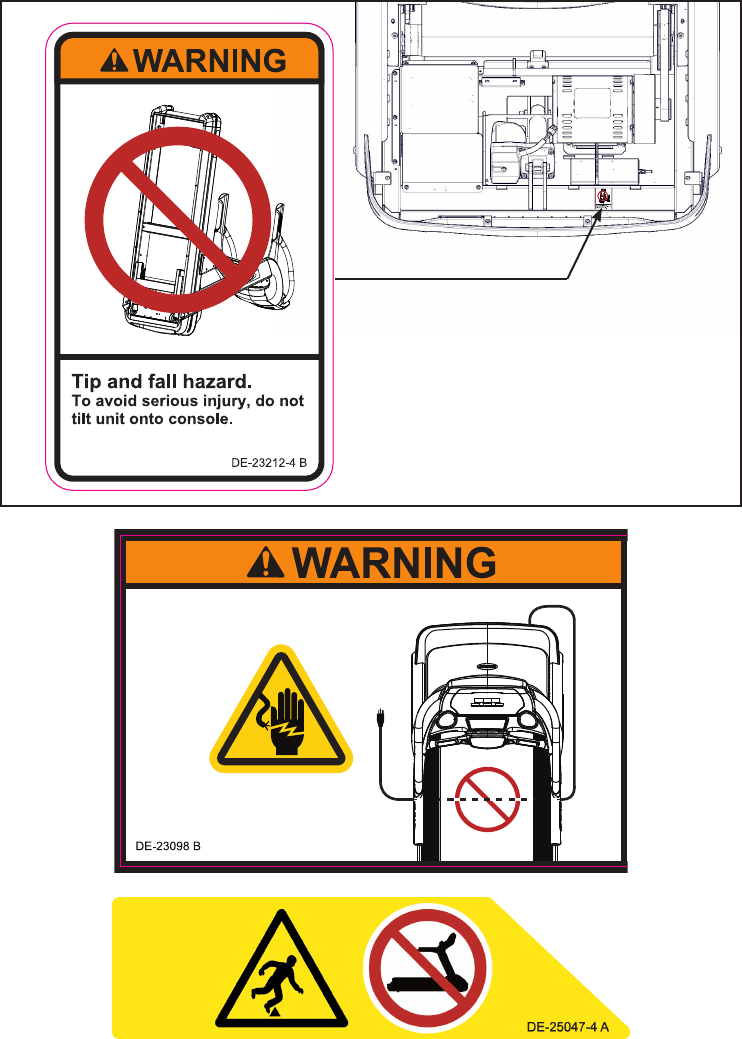
LABEL, WARNING,
DO NOT TILT
DE-23212-4
BA1
BGarber
2 OF 2
6/10/13
REVISIONS
DESCRIPTION
See sheet 1
ECO
REV DATE APPROVAL
BY
10 TROTTER DRIVE
MEDWAY, MA
REV.
SHEET
SIZE
APPROVALS
DRAWN BY
MATERIAL
FINISH
ADOBE GENERATED DRAWING
DO NOT MANUALLY UPDATE
CHECKED
RESP ENG
MFG ENG
QUAL ENG
DATE
DWG. NO.
UNLESS OTHERWISE SPECIFIED
DIMENSIONS ARE IN INCHES
TOLERANCES ARE:
.XX ± .02
.XXX ± .010
ANGULAR = ± 1°
FINISH = 125 RMS
FRACTIONS = ± 1/64”
SCALE: 1=1 THIS FILE IS IN ADOBE ILLUSTRATOR
DO NOT SCALE DRAWING
THE INFORMATION CONTAINED IN THIS DRAWING IS THE SOLE PROPERTY OF CYBEX.
ANY REPRODUCTION IN PART OR WHOLE WITHOUT
THE WRITTEN PERMISSION OF CYBEX IS PROHIBITED.
SEE NOTES, Page 1
SEE NOTES, Page 1
..
.
2”W X 3.25”H X 0.19”R
BLACK
RED - CMYK (19, 97, 97, 9)
WHITE
DIELINE “CutContour” DO NOT PRINT
ORANGE PMS 152C
LABEL, WARNING,
DO NOT TILT
DE-23212-4
BA1
BGarber
2 OF 2
6/10/13
REVISIONS
DESCRIPTION
See sheet 1
ECO
REV DATE APPROVAL
BY
10 TROTTER DRIVE
MEDWAY, MA
REV.
SHEET
SIZE
APPROVALS
DRAWN BY
MATERIAL
FINISH
ADOBE GENERATED DRAWING
DO NOT MANUALLY UPDATE
CHECKED
RESP ENG
MFG ENG
QUAL ENG
DATE
DWG. NO.
UNLESS OTHERWISE SPECIFIED
DIMENSIONS ARE IN INCHES
TOLERANCES ARE:
.XX ± .02
.XXX ± .010
ANGULAR = ± 1°
FINISH = 125 RMS
FRACTIONS = ± 1/64”
SCALE: 1=1 THIS FILE IS IN ADOBE ILLUSTRATOR
DO NOT SCALE DRAWING
THE INFORMATION CONTAINED IN THIS DRAWING IS THE SOLE PROPERTY OF CYBEX.
ANY REPRODUCTION IN PART OR WHOLE WITHOUT
THE WRITTEN PERMISSION OF CYBEX IS PROHIBITED.
SEE NOTES, Page 1
SEE NOTES, Page 1
..
.
8.75” W X 2.3” H
BLACK
WHITE
RED CMYK (C19, M97, Y97, K9)
ORANGE PMS 152C
YELLOW PMS 108C
Cord
Wrap
Area
DIELINE “CutContour” DO NOT PRINT
LABEL WARNING,
POWER CORD,
TREADMILL
DE-23098
BA1
BGarber
2 OF 2
6/5/13
Cybex Owner’s Manual
9
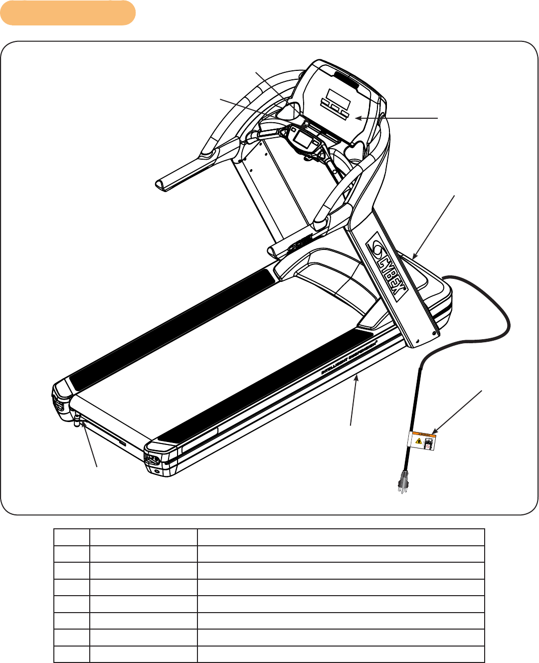
Label Placement
1
2
5
7
4
6
3
1DE-22764-4 Decal, Warning upper, console
2DE-23296 Decal, Warning lower, console
3DE-23080-4 Decal, Warning, Upper Display, Canada
4DE-22910 Decal, Motor Cover, 115 VAC
4DE-23079 Decal, Motor Cover, 230 VAC
5DE-23212-4 Label, Warning, Do not tilt
6DE-23098 Decal, Power Cord
7DE-25047-4 Decal, lever, service wheel
Cybex Owner’s Manual
10
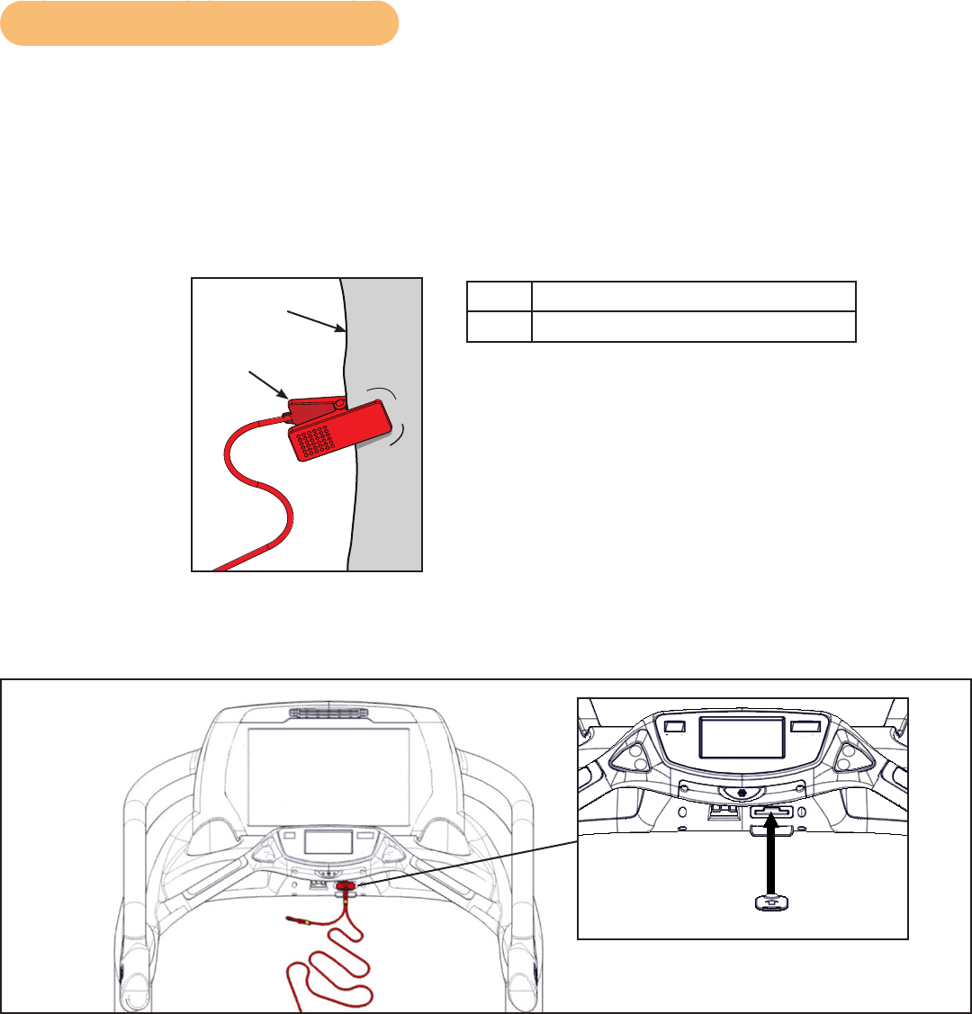
Emergency Stop Key (e-stop)
The e-stop key functions as an emergency stop. In an emergency situation, the e-stop key
disengages from the console and the treadmill will come to a stop. Before using the treadmill, clip the
e-stop key as described below.
1. Compress the spring and clip the e-stop clamp to your clothing. Ensure the clip engages
enough clothing so it does not fall off in an emergency situation. Be sure the string is free of
knots and has enough slack for you to workout comfortably with the e-stop key in place.
2
1
1Clothing
2Clip
2. Without falling off the treadmill, carefully step backward until the e-stop pulls out of the
console. If the e-stop clip falls off your clothing then the test has failed. Reclip the e-stop clip to
your clothing and repeat this step.
3. Replace the e-stop key.
4. The treadmill is now ready to be used. Ensure the e-stop clip is secured to your clothing at all
times during use.
Cybex Owner’s Manual
11
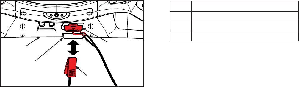
5. After use, remove the e-stop key from the treadmill.
The e-stop key can be removed to help prevent unauthorized use. Refer to the Stopping the Treadmill
section in the Operation chapter for more information about the e-stop key.
When not in use store the e-stop clip on the storage tab located on the lower cover.
3
4
2
1
1Lower cover
2Storage tab
3E-Stop clip
4E-Stop
Cybex Owner’s Manual
12
Assembly
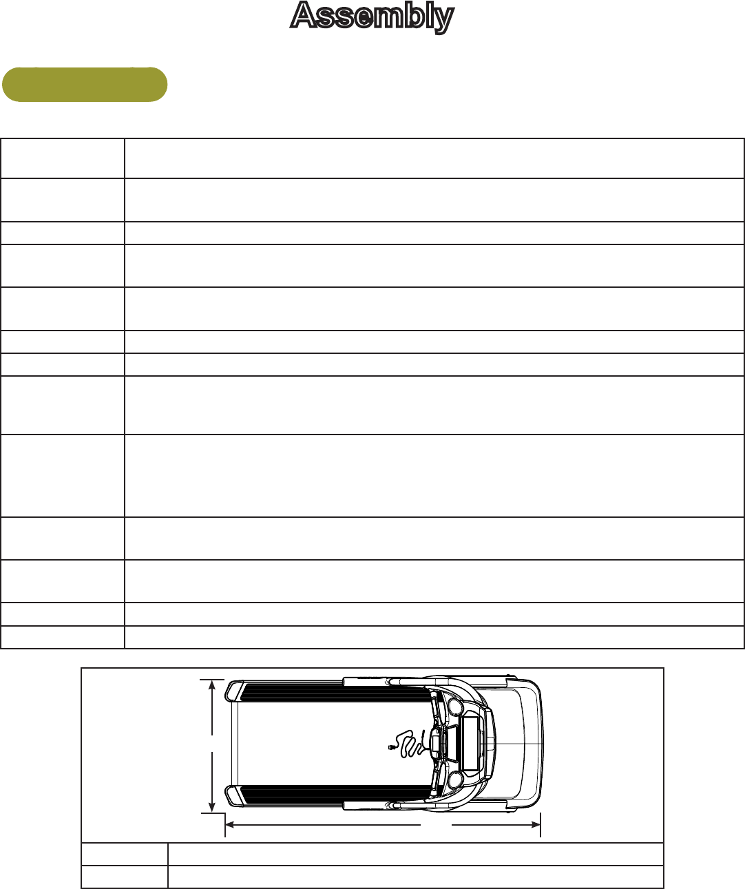
Specifications
Assembled
Length 84” (213 cm).
Assembled
Width 35.6” (90.5 cm)
Height: 62.5”(159 cm)
Weight of
Product 410 lbs. (186 kg)
Shipping
Weight 440 lbs. (200 kg)
Incline Range 0 to 20% grade.
Speed Range 0.5 to 15.6 mph (0.8 to 25 kph) in 0.1 mph or 0.1 kph increments.
Workouts
Quick Start and nine workouts with user orientated goal (Time, Distance or
Calories). Advanced programming includes, Gerkin protocol and all Military
Protocols.
Console
Features
Upper console: Cybex GO monitor.
Displays - BPM, Calories, Cal/Hr, Distance, MET, Pace, Time, and Watt.
Lower console: Two numeric displays for incline and speed. Accessory trays and
water bottle holder.
Heart Rate
Features
Built-in 5KHz wireless heart rate receiver (transmitter not included) and contact
heart rate monitoring.
Maximum User
Weight 400 lbs. (181 kg).
Power Rating 115 VAC 50/60 Hz. or 208/230 VAC 50/60 Hz.
Options iPod/iPhone compatibility.
1
2
135.6” (90.5 cm)
284” (213 cm)
Cybex Owner’s Manual
13
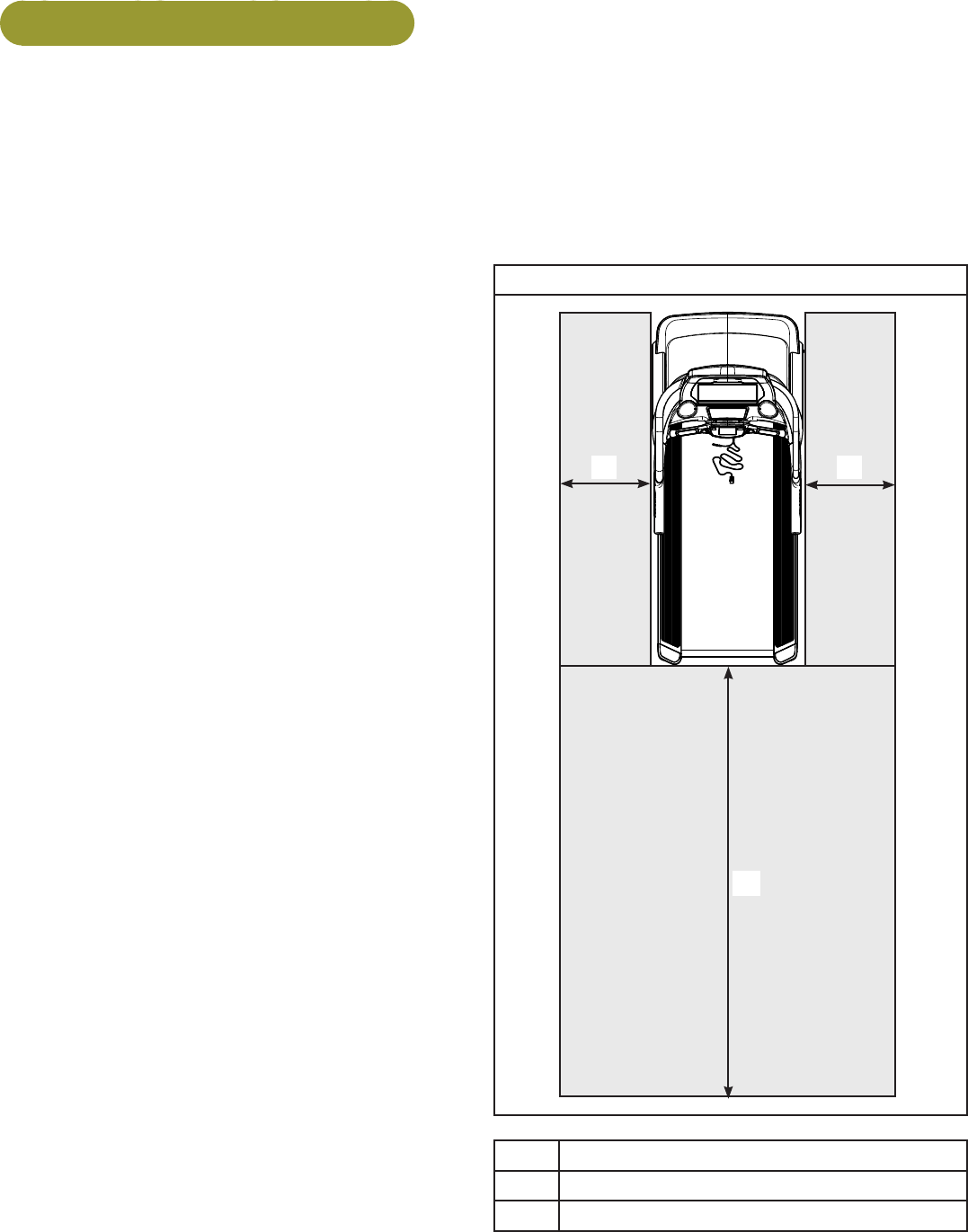
Choosing and Preparing a Site
Before assembling the unit, verify the chosen site meets the following criteria:
• Area is well lit and well ventilated.
• Surface is structurally sound and properly leveled.
• Free area for access to unit and emergency dismount. Minimum clearance is 19.7 inches (0.5
meters) on the sides of the unit and 78.7 inches (2.0 meters) behind the unit.
• Adjacent units may share the free area.
It is the responsibility of the facility owner/
owner of the equipment to ensure that there is
appropriate clearance around each machine to
allow for safe use and passage.
In compliance with the ADA (American
Disabilities Act) there must be clear oor space
of at least 30 by 48 inches and be served by an
accessible route for at least one of each type
of exercise equipment. If the clear space is
enclosed on three sides (e.g., by walls or the
equipment itself), the clear space must be 36 by
48 inches.
All other machines must have a clear oor space
of 23” for all access point on the machine.
The dimensions stated in the assembly
instructions of this manual include the maximum
foot print (in use) dimensions.
• Area is not in the vicinity of high humidity,
such as in the vicinity of a steam room, sauna,
indoor pool or outdoors. This unit is designed
to function normally in an environment with a
relative humidity range of 30% to 75%.
Exposure to extensive water vapor, chlorine and/
or bromine could adversely affect the electronics
as well as other parts of the unit.
• Area maintains an ambient temperature range
of 50° F (10° C) to 104° F (40° C) degrees.
790T
1 1
2
Free area
119.7”, 0.5m
278.7”, 2.0m

Cybex Owner’s Manual
14
Electrical Power Requirements
The power requirements for this treadmill are a grounded, dedicated circuit rated for one of the
following:
• 100 VAC, 50/60 Hz, 20A
• 115 VAC, 50/60 Hz, 20A
• 208 VAC, 60 Hz, 15A
• 220 VAC, 60 Hz, 15A
• 230 VAC, 50 Hz, 13A, UK
Contact a qualied electrician to ensure the power supply complies with local building codes.
WARNING: Shock and electrocution hazard.
• Connect unit to a grounded outlet.
• Do not use voltage adapter or extension cord.
790T Assembly
The words “left” and “right” denote the treadmill user’s orientation.
Read and understand all instructions thoroughly before assembling the treadmill.
Verify you have received the correct package
1. Read box label to verify the model number and voltage (optional) match what was ordered.
2. Lift and remove cardboard sleeve surrounding unit.
3. Verify paint color matches what was ordered.
Tools Required
• Phillips screwdriver
• Long 3/8” drive socket extension
• 3/4” Open end wrench
• 7/32” Allen wrench (included)
• 9/16” Open end wrench
• 14 mm Socket wrench
Two people will be required for this procedure. It is the responsibility of the facility owner/owner of the
equipment to ensure that there is appropriate clearance around each machine to allow for safe use
and passage.
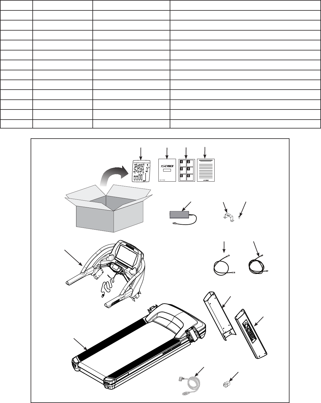
Unpack and verify the contents of the boxes
See content listing and diagram below for carton contents. See Customer Service for contact
information if any parts are missing.
Item Quantity Part Number Description
1 1 Varies Base assembly
2 1 Varies Console assembly
3 1 FM-22900 Upright, Left
Cybex Owner’s Manual
15
Item Quantity Part Number Description
4 1 FM-22901 Upright, Right
5 1 Varies Power Cord
6 1 CN-24895 Coupler, Ethernet
7 1 Varies Power Supply
8 2 FS-23044 Clamp
9 2 HS-21672 Screw, #8-32 x 1/2”
10 1 AX-23019 Hardware pack
11 1 LT-24920-4 Owner’s Manual
12 1 LT-25033 Assembly poster
13 1 LT-23016-4 Warranty sheet
14 1 AW-23836 Cable, 6’, Coax
15 1 AW-24892 Cable, 7’, Ethernet
1
2
3
10 11 12 13
4
5
789
6
14 15
Cybex Owner’s Manual
16
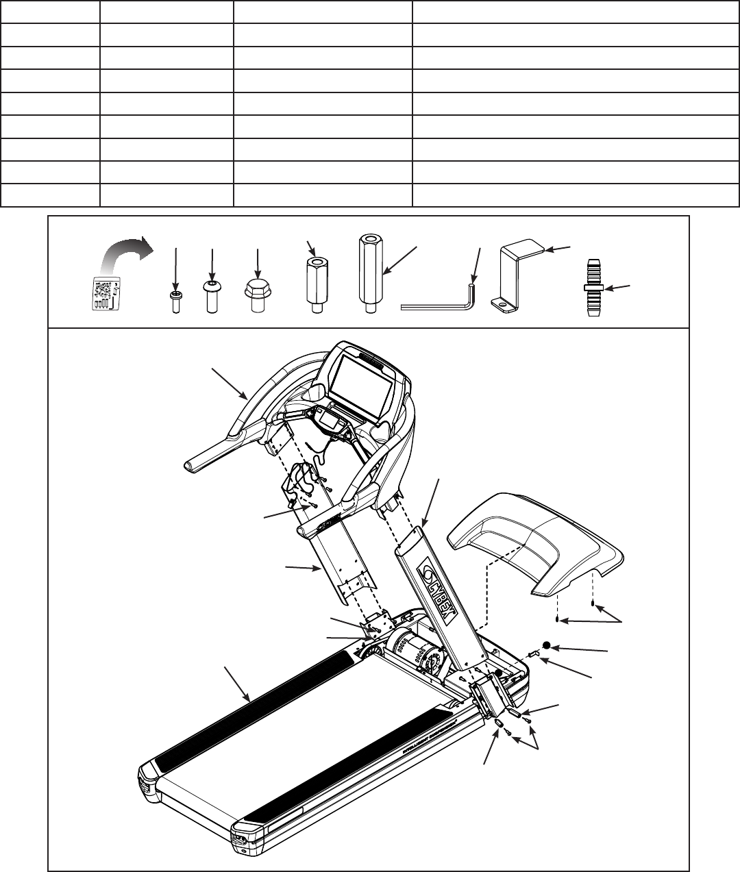
Hardware
Item Quantity Part Number Description
9 1 HS-21672 Screw, #8-32 x 1/2”
16 16 HS-22651 Bolt, 3/8-16 .75”, BHCS, ZN
17 4 HS-16929 Bolt, Whiz Lock, 3/8-16 x .625”, HXHD
18 2 FM-22778 Standoff, M-F, 3/8-16” Thread, Short
19 2 FM-22779 Standoff, M-F, 3/8-16” Thread, Long
20 1 HX-00440 Allen wrench, 7/32”
21 1 FS-23071 Bracket, Power Cord
22 4 HX-21519 Connector, Plastic
1
16
18
16
4
9 16 17 18 20 21
22
19
2
19
21
9
22
3
16
17
Cybex Owner’s Manual
17
WARNING: Heavy equipment.
• At least two people must lift, move or assemble unit.
• Use safe lifting methods.
Lift and move the treadmill
Take note of doorway widths in facility before assembly. The base is 32.5” (83 cm) wide. With uprights
installed the width is 35.6” (90.5 cm).
At least two people should lift and move the treadmill to a level location where you intend to leave it.
Use proper lifting methods.
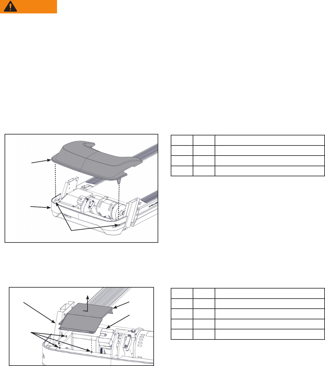
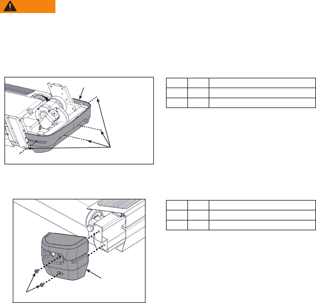
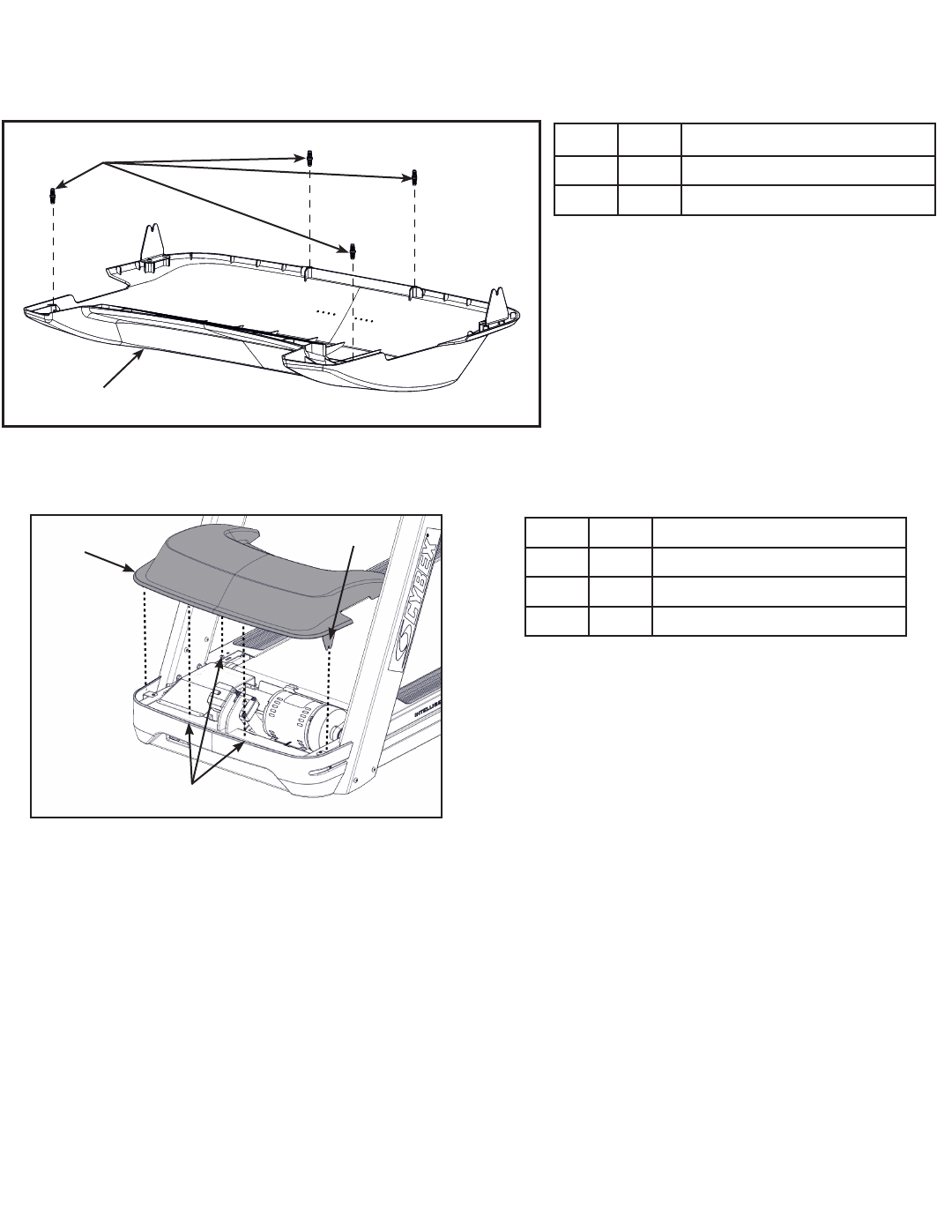
Remove shield
1. Loosen but do not remove the two front cover screws securing the motor cover using a Phillips
screwdriver.
3
1
2
Item Description
1Motor cover
2Front cover
3Screws (2)
2. Remove motor cover by lifting vertically.
3. Remove the ground wire screw securing the inline motor ground wire to the base using a
Phillips screwdriver.
2
3
4
1
Item Description
1Base
2Screws (7)
3Shield
4Screw, ground wire
4. Loosen but do not remove the seven screws securing the sheild to the base using a Phillips
screwdriver.
5. Remove shield by sliding sideways and then vertically off of base.
Cybex Owner’s Manual
18
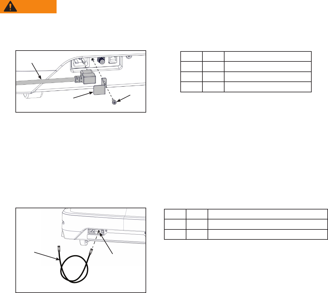
Install power cord
Decide whether you will plug the power cord into a power outlet near the front of the treadmill or the
back of the treadmill. Follow the corresponding routing procedure below. Do not plug the power cord
into a power outlet at this time.
WARNING: Shock and electrocution hazard.
• Route power cord so it does not become damaged.
• Do not allow cord to be pinched or interfere with movement of treadmill.
Front routing: Skip to page 25, section “Install the uprights”
Back routing:
1. Remove the four screws securing the front cover to the base using a Phillips screwdriver.
2
1
Item Description
1Front cover
2Screws (4)
2. Remove front cover.
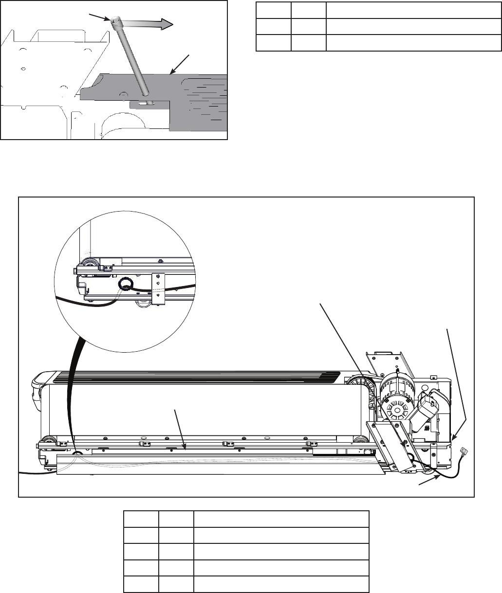
3. Remove the two screws securing the right end cap using a Phillips screwdriver.
2
1
Item Description
1Screws (2)
2Right end cap
Cybex Owner’s Manual
19
4. Remove the right top step by inserting a long 3/8” drive socket extension into the right top step
and prying backwards.
2
1
Item Description
13/8” Drive Socket Extension
2Right Top Step
5. Remove the right top step.
6. Route the power cord through the hole in the upright support and behind the lower cover.
2
1
4
3
Item Description
1Hole in Upright Support
2Power Cord Inlet
3Lower Cover
4Power Cord
7. Adjust the power cord length entering the frame to allow for the power cord to be plugged into
the power cord inlet. Do not plug the power cord in at this time.
Cybex Owner’s Manual
20
8. Adjust the power cord length exiting the rear of the frame. Store extra power cord behind lower
cover.
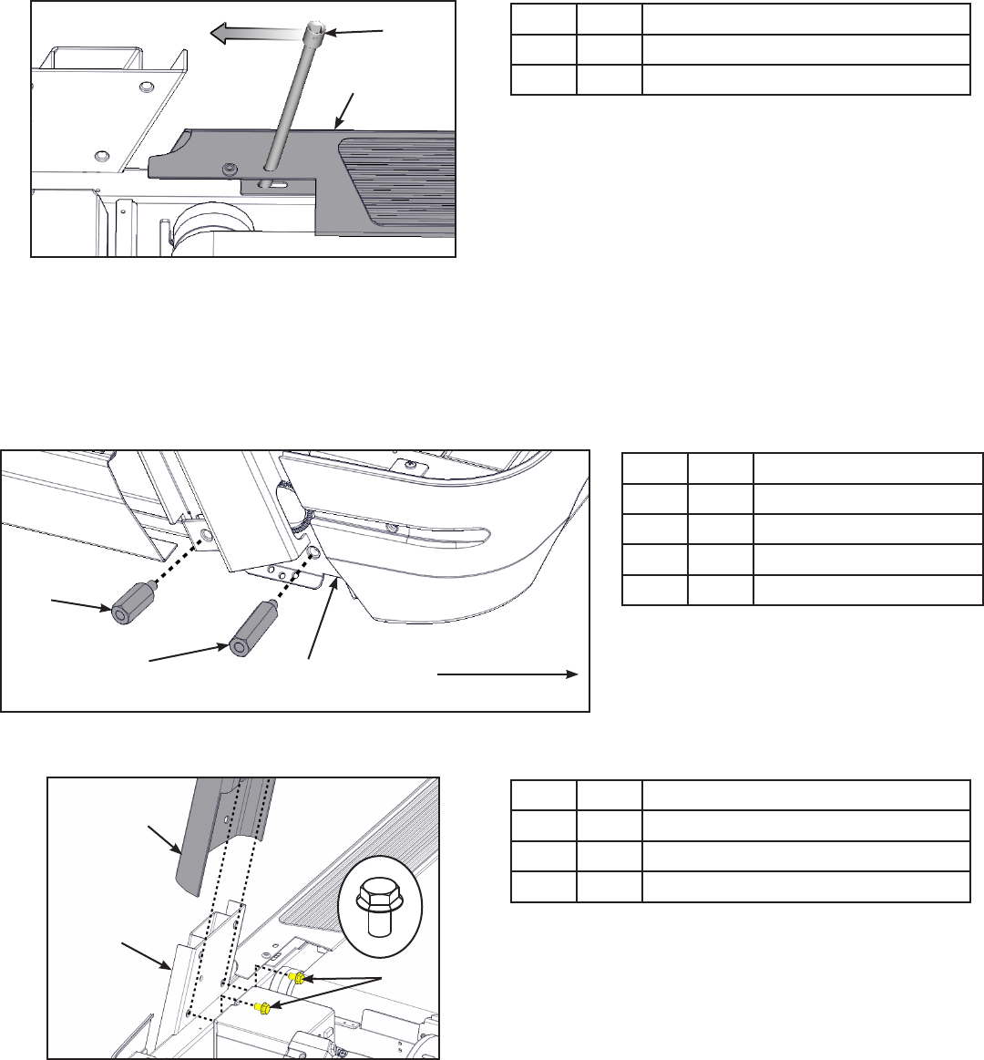
9. Install the right top step by placing in position and inserting a long 3/8” drive socket extension
into the right top step.
2
1
Item Description
13/8” Drive Socket Extension
2Right Top Step
10. Pry the long 3/8” drive socket extension forwards to secure the right top step.
11. Using a Phillips screwdriver, install the two screws securing the right end cap.
Install the uprights
1. Install the short and long standoffs to the right side of the base using a 3/4” open end wrench.
1
234
Item Description
117 Standoff, short
218 Standoff, long
3Base
4Front of unit
2. Thread two bolts into the base by hand. Do not fully thread bolts into the base.
3
1
2
Item Description
14 Upright (Right shown)
2Base
316 Bolt, Whiz lock (2)
3. Place the right upright onto the base assembly and the bolts installed in the previous step.
Cybex Owner’s Manual
21
4. Thread four bolts into the right upright by hand.
1
22
Item Description
14 Upright (Right shown)
215 Bolt (4)
5. Repeat steps 1 through 4 for the left upright.
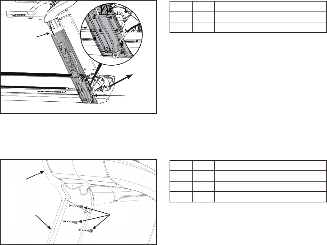
Install the console assembly to the uprights
1. Thread one bolt, into the top back hole for each side of the console assembly by hand. Do not
fully thread bolts into the console assembly.
3
1
4
2
5
Item Description
12 Console
24 Upright (Right shown)
315 Bolt
4Display cable, Coax cable, and
ethernet cable
5Front of unit
Do not pinch or damage display cable, coax cable, or ethernet cable when installing console
assembly.
Cybex Owner’s Manual
22
Two people are required for the following two steps.
2. Insert the display cable, coax cable, or Cat6 cable into the top of the right upright until they exit
the hole at the base of the right upright.
1
2
Item Description
1Insert display cable here
2Hole
3. Place the console assembly in position on the bolts installed in step 1 in the left and right
uprights.
4. Thread six bolts into the remaining holes of the right upright and left upright.
3
2
1
Item Description
12 Console
24 Upright (Right shown)
315 Bolt
5. Tighten all of the bolts using a 7/32” Allen wrench and 9/16” open end wrench.
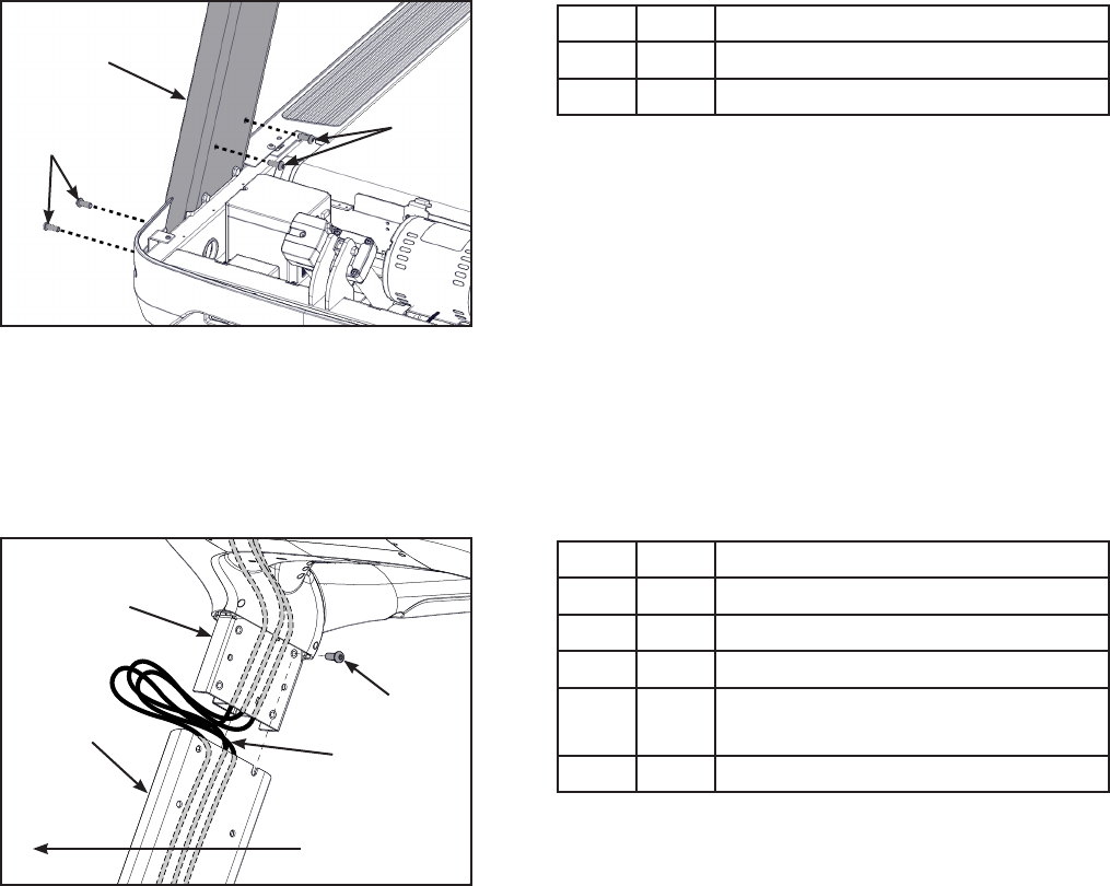
Connect the Display Cable
The display cable and ethernet cable have similar connectors. The display cable is black, the ethernet
cable has a metal connector. The ethernet cable and coax cable are wire tied together.
1. Route the cables under all other cables and towards the base plate.
Cybex Owner’s Manual
23
2. Plug the display cable, located at the bottom of the upright assembly into the communication
port of the controller.
3
4
5
6
2
1
Item Description
1Controller
2Communication port
3Display cable, Black
4Ethernet cable, metal connector
5Coax cable
6Power supply cable
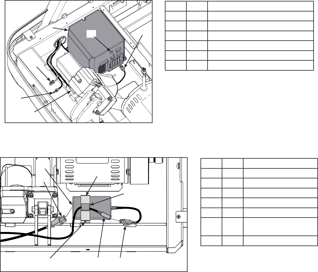
Install the Power Supply
1. Install the power supply to the base using clamp and screw.
6
2
7
4
3
1
5
Item Description
1Power Cord
27 Power Supply Inlet
38 Clamp
48 Gray Cable Clip
59 Screw
6Console Cable DIN
Connector
7Power Supply Output
2. Plug the power cord into the power supply inlet. Do not plug power cord into power outlet.
3. Route console cable through the gray cable clip.
4. Connect the console cable’s DIN connector to the power supply output. Make sure the two
connectors snap rmly together and can not be pulled apart without pulling the sleeve back to
release it.
Cybex Owner’s Manual
24
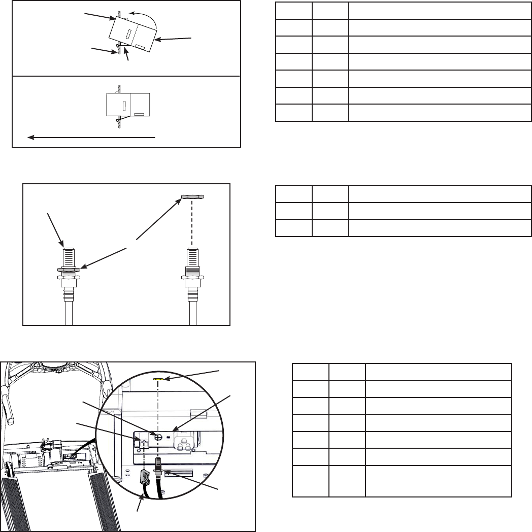
Install Coax and Ethernet cables
1. Insert the ethernet coupler into the mounting plate by hooking the lower tab into the mounting
plate and snapping in the upper tab.
2
1
4
3
5
6
Item Description
1Upper tab
2Mounting plate
36 Ethernet coupler
4Lower tab
5Installed
6Front of unit
2. Unthread the nut at the end of the coax cable.
1
2
Item Description
1Coax cable
2Nut
3. Insert the coax cable into the D-shaped hole in the mounting plate on the front of the unit.
5
6
3
4
1
2
Item Description
1Coax cable hole
26 Ethernet coupler
3Nut
4Mounting plate
5Coax cable
6Ethernet cable, metal
connector
4. Thread the nut removed in step 2 onto the coax cable by hand.
5. Install the coax cable to the mounting plate on the front of the unit using a 14 mm socket
wrench. Do not overtighten.
6. Plug the ethernet cable into the ethernet coupler on the front of the unit.
Cybex Owner’s Manual
25
Install shield
1. Tighten the seven screws securing the shield to the base using a Phillips screwdriver.
2
3
1
Item Description
1Base
2Screws (7)
3Shield
2. Install the ground wire screw securing the inline motor ground wire to the base using a Phillips
screwdriver.
Install the front cover
Perform this step if you removed the front cover. If not, skip to next step.
Install, but do not fully tighten the four screws securing the front cover to the base using a Phillips
screwdriver.
12
Item Description
1Front cover
2Screws (4)
Cybex Owner’s Manual
26
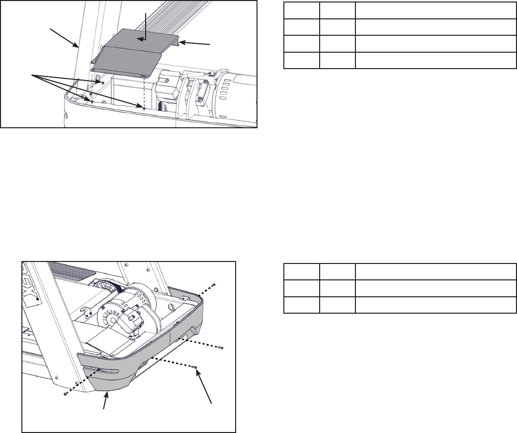
Install motor cover
1. Place motor cover on carpeting or other soft surface. Do not scratch top of hood cover.
2. Insert the four plastic connectors into the motor cover.
1
2
Item Description
121 Plastic connectors (4)
2Motor cover
3. Place the motor cover into position vertically by aligning the two tabs and four plastic
connectors.
3
12
Item Description
1Motor cover
2Tabs (2)
321 Plastic connectors
If motor cover top does not t properly, loosen the side screws on the front cover as needed.
4. Tighten the two front cover screws using a Phillips screwdriver. Be sure the screws are
securing the motor cover’s tabs.
Cybex Owner’s Manual
27
Install power cord
WARNING: Shock and electrocution hazard.
• Route power cord so it does not become damaged.
• Do not allow cord to be pinched or interfere with movement of treadmill.
1. Plug the power cord into the base of the unit.
1
2
3
Item Description
15 Power cord
220 Bracket
39 Screw
2. Secure the power cord with the mounting bracket and mounting screw using a Phillips
screwdriver.
Level the treadmill
Conrm that the treadmill is on a level surface.
Install coax cable
Install 6’ coax cable to the coax cable connector in base of unit. Do not install if facility provides coax
cable to base of unit.
12
Item Description
114 6’ Coax Cable
2Coax Cable Connector
Cybex Owner’s Manual
28
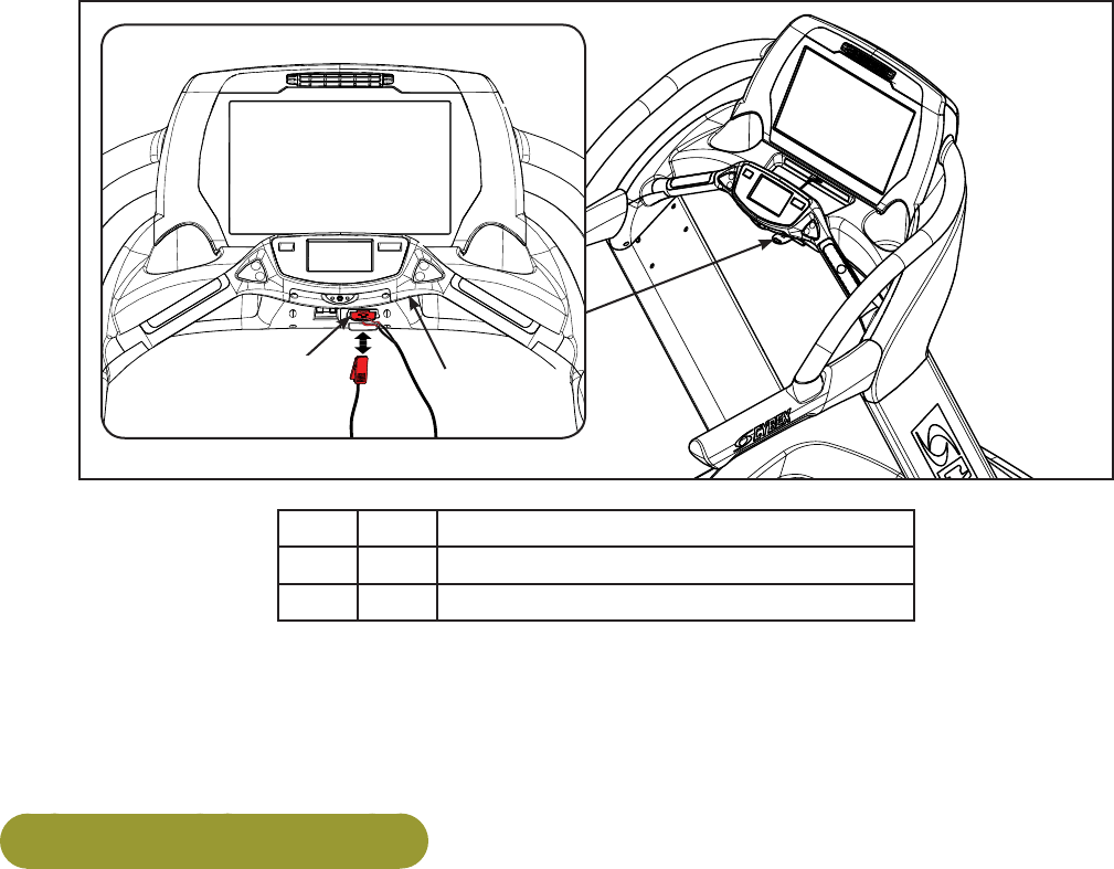
Attach emergency stop key
Conrm that the emergency stop key is in place in the bottom of the console handrail. The treadmill will
not run without the key in place.
2
1
Item Description
1Emergency Stop Key
2Console Handrail
When not in use store the e-stop clip on the storage tab located under the console handrail.
Visually inspect the treadmill
Examine the treadmill to ensure that the assembly is correct and complete.
Power Cord Management
Power cord retaining brackets are located under the front end of the unit. This allows any extra length
of the power cord to be stored under the front end of the unit.
Tools Required
Wire tie (2)
Elevate treadmill
1. Connect the main power cord into the power outlet.
2. Press Quick Start and raise the elevation to maximum incline.

Cybex Owner’s Manual
29
3. Toggle the on/off (I/O) power switch to the off (O) position.The on/off (I/O) power switch is
located under the front end of the unit, or on the front right side panel.
1
2
Description
1Front right side panel
location
2Under the front end
location
4. Unplug the main power cord from the power outlet.
WARNING: Shock and electrocution hazard.
• Route power cord so it does not become damaged.
• Do not allow cord to be pinched or interfere with movement of treadmill.
5. Wrap the power cord around the outer power cord retaining brackets to desired length.
1
2
3
Description
1Power cord
2Power cord retaining
bracket, Inner
3Power cord retaining
brackets, Outer
The power cord can be routed with full or half wraps around power cord retaining brackets. The
power cord can then exit to the left or right of the treadmill.
Description
1Power cord
2Half wrap
3Full wrap
4Exit left or right
6. Plug the main power cord into the power outlet.
7. Toggle the on/off (I/O) power switch to the on (I) position.
8. Press Quick Start and operate the elevation through full incline. If power cord is too short or
interferes with the movement of the treadmill, change the wrap of the power cord.
Cybex Owner’s Manual
30
9. Secure the power cord with two wire ties.
1
2
Description
1Power cord
2Wire ties (2)
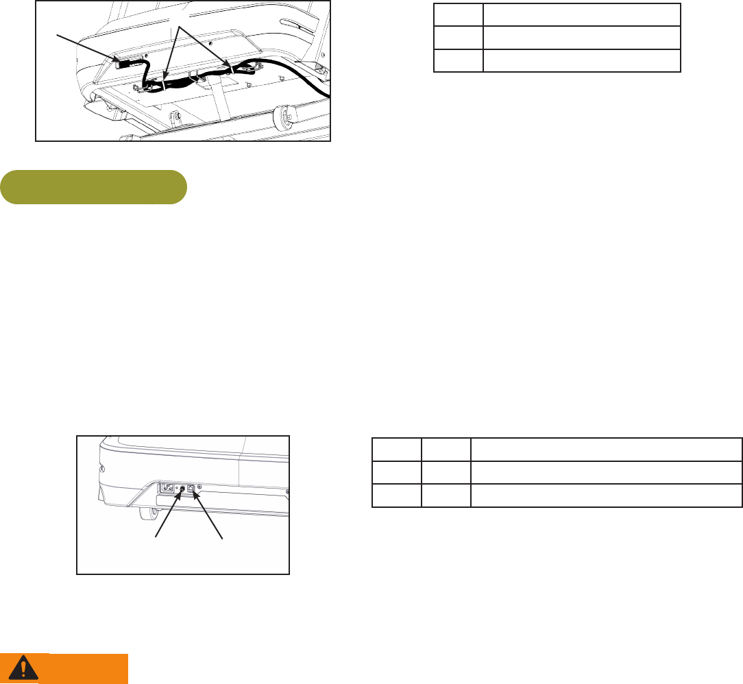
Cybex GO Setup
Prerequisites:
• Coax cable with TV signal
• Netpulse Gateway installed and running, providing the connection via:
Ethernet – Ethernet cable is connected to the Cybex equipment through a network switch to the
Gateway.
Wireless – Gateway has been installed in the facility using a unique wireless access point.
Cybex GO Monitor will not connect to any other routers in the area.
• Power to the Cybex Equipment.
1. Install coax cable to the coax cable connector in base of unit.
12
Item Description
1Coax cable connector
215 Ethernet coupler
2. Install ethernet cable to the ethernet coupler in base of unit.
Use the following instructions to setup the unit.
WARNING: Falling hazard.
When starting unit
• Stand on two top steps.
• Do not stand on belt.
Cybex recommends that the treadmill be unplugged or the on/off (I/O) power switch turned off (O)
when it is not in use.
1. Without anyone on the treadmill, plug the power cord into a power outlet from a grounded,
dedicated circuit as described under Electrical Requirements in this chapter.
Ensure the power cord is not being pinched under the front of the treadmill.
2. Toggle the on/off (I/O) power switch to the on (I) position.The on/off (I/O) power switch is
located under the front end of the unit, or on the front right side panel.
Cybex Owner’s Manual
31
3. The control panel will light up.
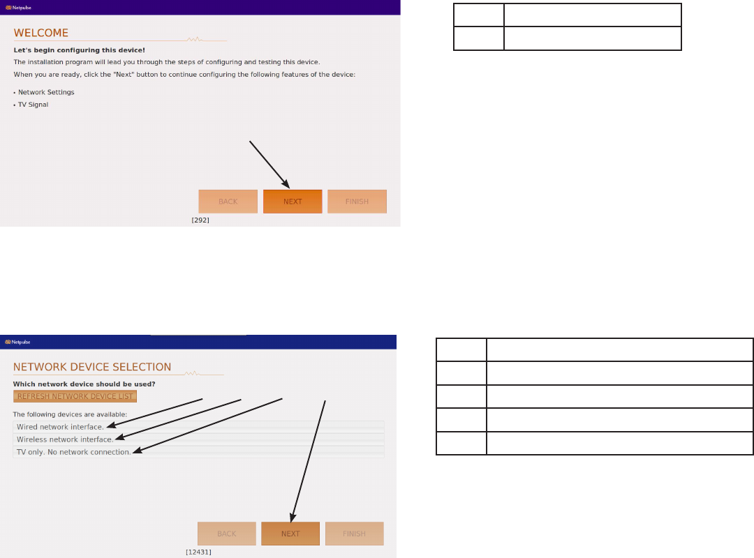
Cybex GO installer
The Cybex GO installer only occurs during the initial installation of the unit. Once complete, refer to
Initial setup.
1. Tap “NEXT” to begin conguration.
1
Description
1NEXT
2. Select one of the three network devices.
• Wired network interface.
• Wireless network interface.
• TV only. No network connection.
1 32 4
Description
1Wired network interface
2Wireless network interface
3TV only. No network connection
4NEXT
Follow the procedure for one of the three selected networks below:
Wired network interface
1. Tap Wired network interface.
2. Tap NEXT to conrm selection.
3. Go to Test network.
Cybex Owner’s Manual
32
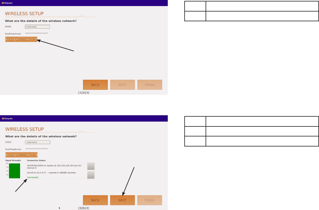
Wireless network interface
1. Tap Wireless network interface.
2. Tap NEXT to conrm selection.
1. Tap TEST CONNECTION. This may take up to ve minutes to complete. If test fails, retry.
1
Description
1TEST CONNECTION
2. Tap NEXT after test passes and displays “Connected!”.
1
2
Description
1Connected!
2NEXT
3. Tap OK after alert window displays “Wireless network congured!”.
4. Go to Test network.
Cybex Owner’s Manual
33
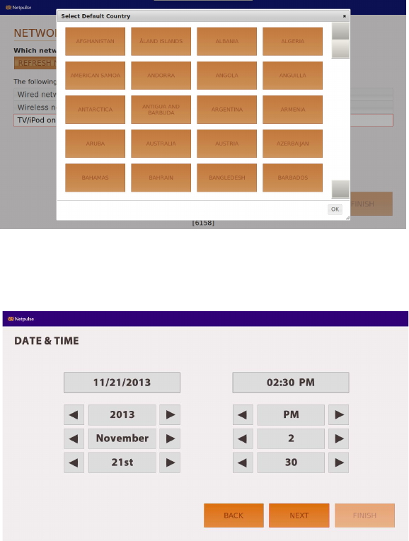
TV only
1. Tap TV only. No network connection.
2. Select Default Country.
3. Tap OK
4. Set Date and Time.
5. Tap NEXT.
6. Go to Channel conguration.
Cybex Owner’s Manual
34
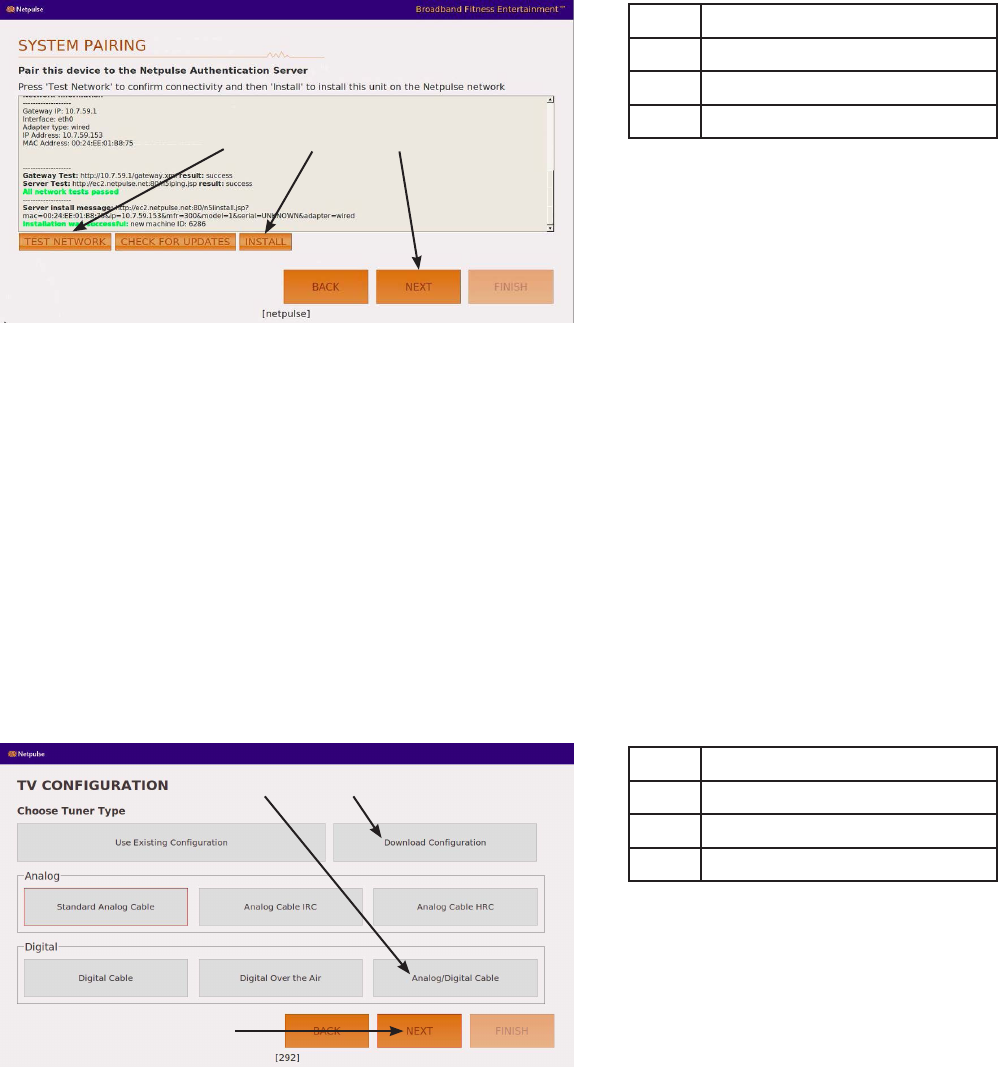
Test network
1. Tap TEST NETWORK.
1 2 3
Description
1TEST NETWORK
2INSTALL
3NEXT
2. When network test passes, tap INSTALL. If network test fails, check the network connections
and retry.
3. Tap NEXT.
TVconguration
The TV conguration only needs to be performed on the rst unit installed. Congure the rst unit
completely, save the conguration, then assemble and congure all other units.
1. Select Analog/Digital Cable and tap NEXT. This will scan for all available channels. The scan
can take 20 minutes to complete.
If scan was previously congured and stored, choose DownloadConguration and tap NEXT to
congure other units. Go to Test Cybex GO Monitor.
1 2
3
Description
1Analog/Digital Cable
2Download Conguration
3NEXT
Cybex Owner’s Manual
35
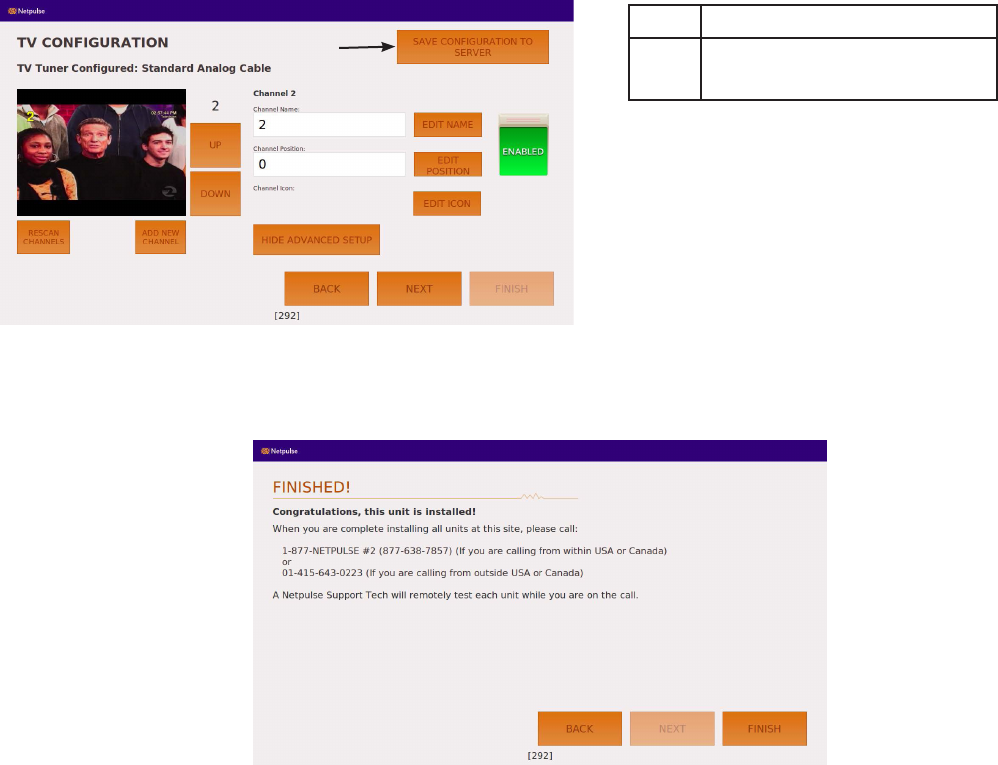
2. Tap SAVE CONFIGURATION TO SERVER.
1
Description
1SAVE CONFIGURATION
TO SERVER
To congure each of the channels see Channel conguration.
3. Tap FINISH to complete installation. Cybex GO monitor will reset. Do not call Netpulse.
Cybex Owner’s Manual
36
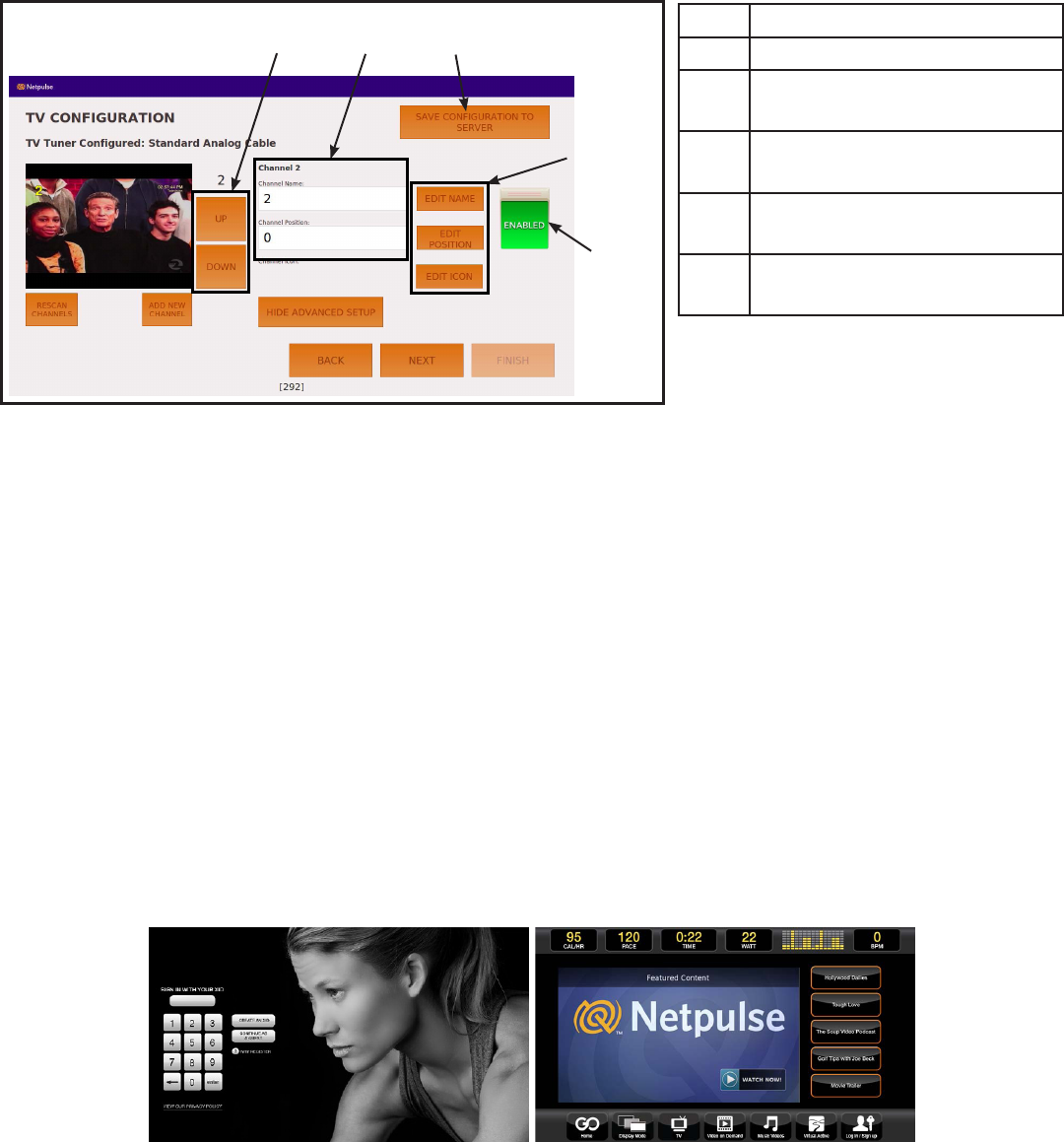
Channelconguration
Each channels name, position, and icon can be edited. Channels not needed or channels with poor
signals can be disabled.
1 2
4
3
5
Description
1Channel Up/Channel Down
2Channel name and position
number
3SAVE CONFIGURATION
TO SERVER
4EDIT NAME, EDIT
POSITION, and EDIT ICON
5Channel ENABLED or
DISABLED
1. Tap SHOW ADVANCED SETUP, if edit icons are not visable.
2. Tap the Channel Up or Channel Down icons to select channel to edit.
3. Tap EDIT NAME. A keyboard is displayed to edit the channel name. Tap SAVE when done.
4. Tap EDIT POSITION. A keypad is displayed to edit the channel position. Tap SAVE when
done.
5. Tap EDIT ICON. Icons are displayed to edit the channels icon. Tap SAVE when done.
6. Tap the ENABLED or DISABLED icon to toggle the viewing of each channel.
The channel conguration only needs to be performed on the rst unit installed. Congure the rst
unit completely, save the conguration, then assemble and congure all other units.
Test Cybex GO monitor
Test Cybex GO monitor by tapping CONTINUE AS GUEST at home screen. Select from TV or Videos
to test Cybex GO monitor
Cybex Owner’s Manual
37
Equipment Setup
Units and Power setup
Initial setup only occurs during the installation of the unit. Once complete, refer to Setup Options.
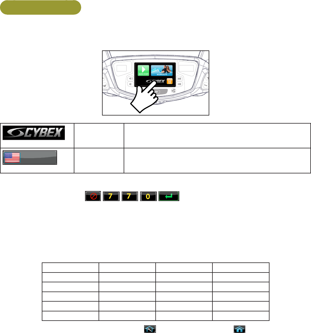
CYBEX
LOGO
Press and hold Cybex logo for 6 seconds to access Screen
Lock and Toolbox. See Preventive Maintenance section.
ENGLISH LANGUAGE
ICON
Press and hold language logo for 6 seconds to access
Screen Lock and Toolbox.
1. Tap the Access Toolbox icon to display the Access to Toolbox login screen.
2. Enter the sequence: .
3. Tap the Setup icon to display the setup menu.
4. Tap the Units & Power icon to select the Set units preference screen.
5. Select the unit preferences from the following options:
Record your actual line voltage here. Line frequency is usually specic to your country or location.
Distance Units Weight Units Line Frequency Line Voltage
Miles Lbs. 50 Hz 110v
Km Kg 60 Hz 115v
Stone 208v
220v
230v
Exit Set Up Mode by tapping the Toolbox icon , then tap the Home icon . The screen will
refresh.
Cybex Owner’s Manual
38
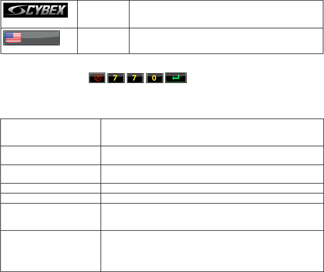
Setup options
Enter setup options.
CYBEX
LOGO
Press and hold Cybex logo for 6 seconds to access Screen
Lock and Toolbox. See Preventive Maintenance section.
ENGLISH LANGUAGE
ICON
Press and hold language logo for 6 seconds to access
Screen Lock and Toolbox.
1. Tap the Access Toolbox icon to display the Access to Toolbox login screen.
2. Enter the sequence: .
3. Tap the Setup icon to display the setup menu.
The Setup options are:
Units and Power Select distance units. MI - Miles or KM - Kilometers.
Select weight units. LBS - Pounds, KG - Kilograms or Stone -
Stones.
A/VCong Perform Touch Calibration, Network Setup, or Channel Setup. See
A/V Conguration.
Workout times Set Default and Max workout times. Default choices are 20, 30, or
60 minutes. Max choices are 20, 30, 60, or OFF.
Limits Set Min Speed, Max Speed, and Max Incline.
Pause Set Pause time. Choices are OFF, 1:00, 5:00, or 10:00 minutes.
Sound Select console beeper settings. Console Beeper - On or Off.
Headphone Beeper - Off, Some, or All. Default Volume - 1 to 30,
default is 10.
Language Select default language to display on the console. Toolbox is only
available in English.
Include Optional Languages. Select optional languages to display on
the console. Choices are Include or Off.
Cybex Owner’s Manual
39
A/V Configuration
Access Setup Screen
CYBEX
LOGO
Press and hold Cybex logo for 6 seconds to access Screen
Lock and Toolbox. See Preventive Maintenance section.
ENGLISH LANGUAGE
ICON
Press and hold language logo for 6 seconds to access
Screen Lock and Toolbox.
1. Tap the Access Toolbox icon to display the Access to Toolbox login screen.
2. Enter the sequence: .
3. Tap the Setup icon to display the setup menu.
4. Tap the A/VCongicon.
Touch calibration Perform the touch calibration for the Cybex GO monitor. Touch the
center of each indicator on the Cybex GO monitor.
Network setup Connect the Cybex GO monitor to the network. See Cybex GO
installer.
Channel setup Setup the channels available from the cable TV provider.
5. Exit Set Up Mode by tapping the Toolbox icon , then tap the Home icon . The screen
will refresh.
Setup Complete
Your treadmill is now ready for use. Proceed to Testing the Treadmill Operation. Follow the
instructions in the Operation chapter to learn how to operate the treadmill. You should begin with
walking speeds rst, to be sure everything is functioning properly.

Cybex Owner’s Manual
40
Testing Operation
Use the following instructions to test the full speed and incline range of the treadmill and to check the
belt for proper operation.
WARNING: Falling hazard.
When starting unit
• Stand on two top steps.
• Do not stand on belt.
1. Plug the power cord into a power outlet from a grounded, dedicated circuit as described under
Electrical Requirements in this chapter without anyone on the treadmill.
Ensure the power cord is not being pinched under the front of the treadmill.
2. Toggle the on/off (I/O) power switch to the on (I) position.The on/off (I/O) power switch is
located under the front end of the unit, or on the front right side panel.
3. Press the Quick Start key. The treadmill begins a countdown “3...2...1” and sounds a tone
for each count. After it reaches one (1), the treadmill gives a longer tone and then begins
accelerating the belt to reach 0.5 mph (0.8 kph). The lower left display will show the incline and
the lower right display will show the actual speed.
4. Press and hold down the Speed + key until the treadmill reaches a speed of approximately 4
mph (6.4 kph), as indicated on the display.
Observe the belt to see that it is running properly; it should stay centered in the middle of the deck. If
you have problems with the running belt operation, see Running Belt Adjustments in the Maintenance
chapter.
5. Run the treadmill through its full speed range. First press the Speed + key until the treadmill
reaches its highest speed. Then press the Speed - key until the treadmill is back to 0.5 mph
(0.8 kph).
Pressing the Incline ▲▼ or Speed + - keys will show the set incline or speed on the displays.
When the treadmill reaches the set incline and speed, the displays will remain steadily illuminated to
indicate that the desired settings have been reached.
6. Run the treadmill through its full % grade range. Press the Incline ▲ key until the treadmill
reaches its highest grade (20%). Then press the Incline ▼ key until the treadmill reaches 0%
grade.
7. Press the Stop key once to stop the running belt and enter Review Mode. Press the Stop key
again to exit Review Mode and return the display to the opening screen.

Cybex Owner’s Manual
41
Operation
Intended Use
The intended commercial use of this machine is to aid exercise and improve general physical tness.
Terms Used
This section lists some of the common terms and symbols used in this chapter. Other terms and
symbols are listed in this chapter as appropriate. For setup options see Setup in the Assembly and
Setup chapter.
Active Mode — Active Mode is when the running belt is moving. Before Active Mode begins, a three
second countdown and “3...2...1” is displayed. Active Mode continues until the preset time limit is
reached, the e-stop key is pulled out or the STOP key is pressed.
CardioTouch Screen — The CardioTouch Screen is the touch screen located in the handset area.
Cool Down — A reduction of work load for a short duration allows user to gently reduce heart rate.
Cool Down occurs two minutes prior to completion of the workout-controlled workout sessions.
Dormant Mode — Occurs when unit is plugged in and not in use.
Manual Mode — In this active mode the user sets a goal for Time. The user controls speed and
incline. Manual Mode continues until the goal is reached. Manual Mode is only available during Active
Mode.
Pause Mode — Occurs only if the Pause feature is enabled and user selects the STOP key from
Active Mode.
Quick Start — This begins by tapping the Quick Start icon. Quick Start enters Active Mode at
minimum speed and 0% elevation with time counting up from 0:00.
Workout Review — Review of the accumulated workout data will happen at the end of each workout
session.
Cybex Owner’s Manual
42
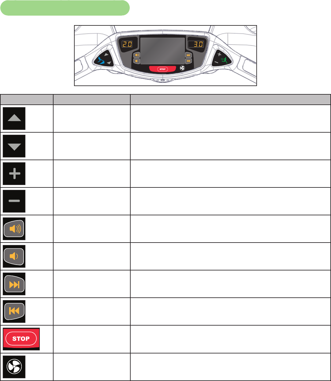
User Control Symbols Used
Control Control Name Description
INCLINE UP Adjust Incline up.
INCLINE DOWN Adjust Incline down.
SPEED UP Adjust Speed up.
SPEED DOWN Adjust Speed down.
VOLUME UP Adjust Volume up.
VOLUME DOWN Adjust Volume down.
CHANNEL/TRACK
CONTROL
Cybex GO - Channel UP
iPod/iPhone - NEXT track (option)
CHANNEL/TRACK
CONTROL
Cybex GO - Channel DOWN
iPod/iPhone - PREVIOUS track (option)
STOP Press STOP once to end the workout session and start
the Workout Review. Press STOP again to exit to Dormant
Mode.
FAN Press the FAN key to control fan speed. Choices are OFF,
LOW and HI. Default speed is OFF during active mode.
Cybex Owner’s Manual
43
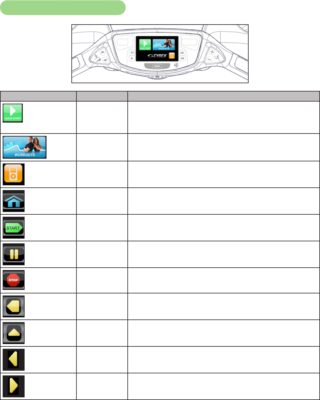
CardioTouch Symbols Used
Icon Icon Name Description
QUICK
START
Quick Start enters Active Mode at the default resistance
with time counting up from 0:00.
WORKOUTS Tap Workouts icon to enter workout group selection.
iPOD Tap iPod icon to enter iPod control menu. If iPod is not
connected, icon will be grayed out.
HOME Return to opening screen.
START Enter Active Mode.
PAUSE If pause feature is enabled, pause icon is shown. Press
pause icon once to enter pause mode.
STOP If pause feature is disabled, stop icon is shown. Press stop
icon or STOP button once to enter “Workout review”.
BACK Return to previous or opening screen.
UP LEVEL Go up one level or return to iPod screen.
SHIFT LEFT Shift the screen left to view more options.
SHIFT RIGHT Shift the screen right to view more options.
Cybex Owner’s Manual
44
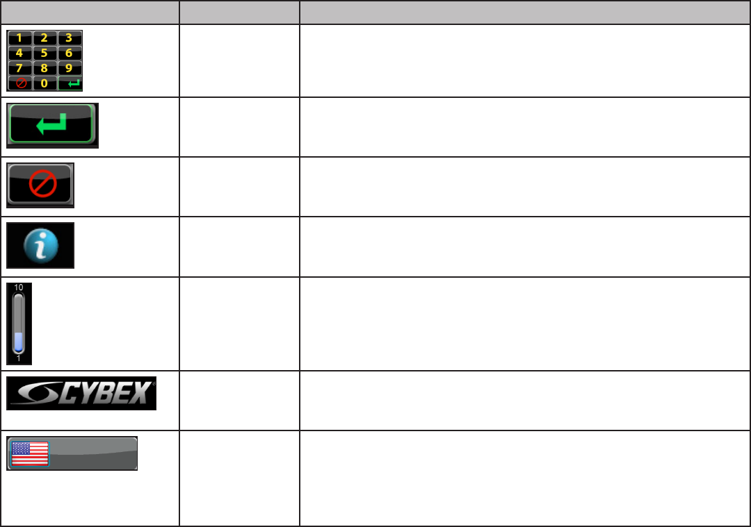
Icon Icon Name Description
KEYPAD Numeric keypad for entering data.
ENTER Accepts the value shown.
CLEAR Clear any values selected.
INFO Select to provide more information and details.
SCALE Displays current value in the minimum and maximum
range.
CYBEX
LOGO
Press and hold Cybex logo for 6 seconds to access Screen
Lock and Toolbox. See Preventive Maintenance section.
ENGLISH LANGUAGE
ICON
Tap language icon to select available languages. Set
languages available in Setup Options section.
Press and hold language logo for 6 seconds to access
Screen Lock and Toolbox.
Cybex Owner’s Manual
45
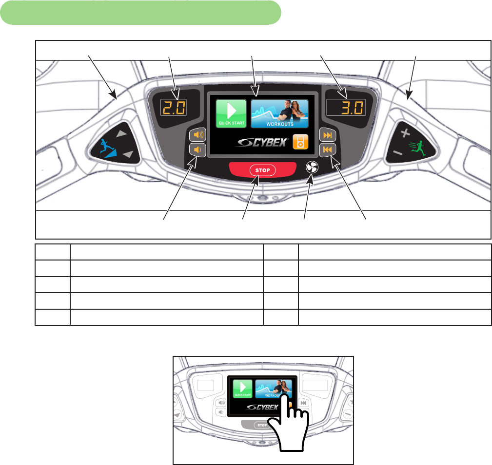
CardioTouch Screen and User Controls
1 2 3 4 5
6 7 8 9
1Incline keys 6Volume Keys
2Incline display 7STOP Key
3CardioTouch screen 8Fan Key
4Speed display 9Channel/Track Keys
5Speed Keys
CardioTouch Screen — Tap the icons to make selections.
Cybex Owner’s Manual
46
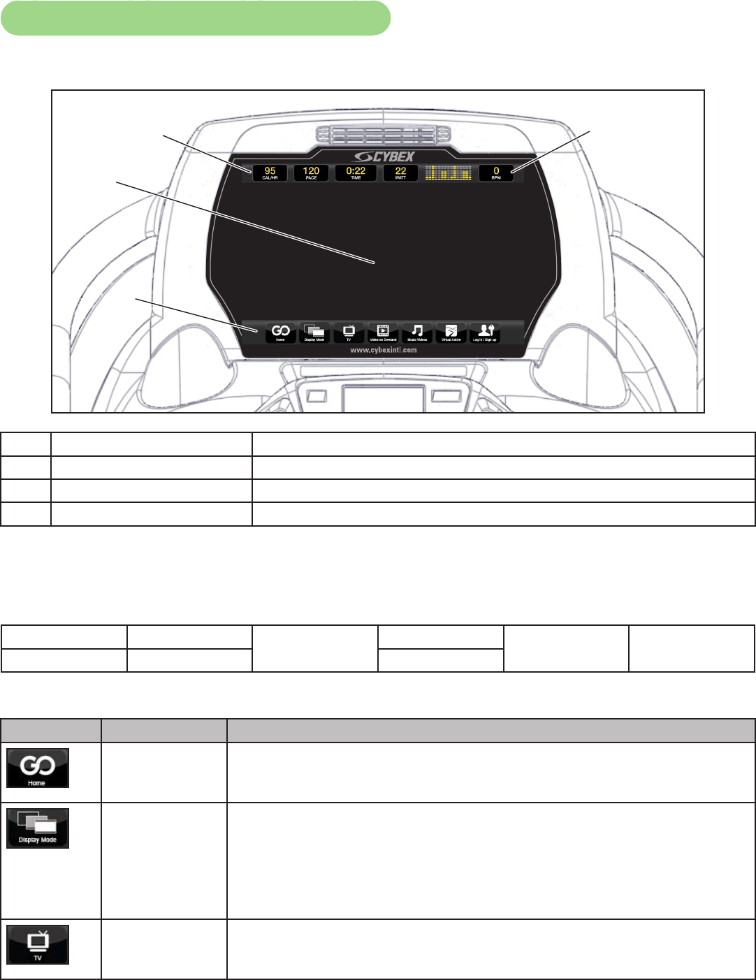
Cybex GO Console and User Controls
Cybex GO Console
2
1
3
4
1Data bar Displays messages and workout data.
2Video display area Displays video, data, or blank.
3Menu bar Menu icons for Cybex GO options.
4Heart rate indicator Display heart rate and multi color indicator.
Data bar
Tap data icons to toggle the data displayed. TIME and BPM do not toggle. See Heart rate indicator for
more information about BPM (Beats Per Minute).
DISTANCE CALORIES TIME MET Graph or
message BPM
CAL/HR PACE WATT
Menu bar
Icon Icon Name Description
Home Main landing page with content tailored to each user.
Display Mode Tap Display Mode icon to toggle between 4 display modes:
TV + Data - Display video with data at top of screen
TV Only - Display video only, no data
Data Only - Display data only, no video
Blank - Screen is blank, video and data are not displayed
TV Select from available TV channels. Channels available are based on
the local cable TV provider.
Cybex Owner’s Manual
47
Video on
Demand
Watch videos on demand. Various content categories (TV Shows,
Movie Trailers, Classic TV, etc) are grouped into channels.
Music Videos Watch available music videos. Playlists are organized by music
genre. Create your own playlist.
Virtual Active The Virtual Active attraction features videos, shot from rst person
perspective, through beautiful landscapes, cityscapes and events
from around the world.
Log in/Sign
up
Sign up as a new user or login with existing account.
History Review workout history if logged in.
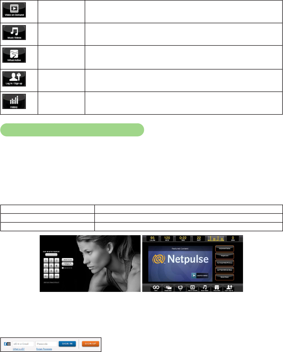
Cybex GO Console Log In or Sign Up
XID is a universal network that allows you to log into connected tness equipment.
An XID account allows you to:
• Create playlists for your favorite audio and video tracks
• Track your workouts
• Join in group challenges
At the opening screen there are three options available.
Sign-in with XID Enter an existing XID account number.
CREATE ACCOUNT Create a new XID account.
CONTINUE AS GUEST Skip the log in process. Some functions will be limited.
To log in or create an account online:
• Visit one.netpulse.com
• To create an account, click Sign Up. Select your club from the dropdown list
• To Sign In, enter your XID number and passcode.
If your club has their own custom URL, log into ClubName.netpulse.com.
Cybex Owner’s Manual
48
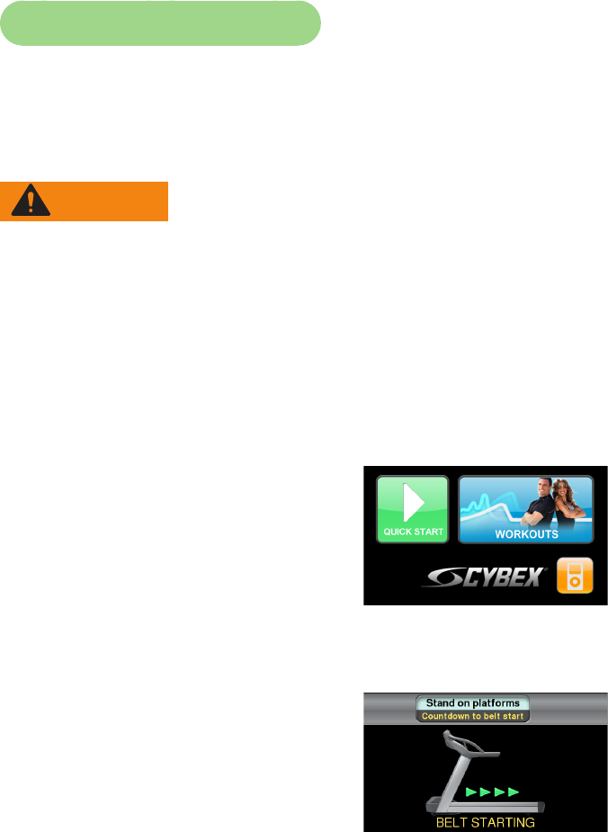
Quick Operation Guide
Maximum user weight is 400 lbs. (181 kg).
The following is a quick overview of the operation of the treadmill. For more information read Detailed
Operation Guide in this chapter.
WARNING: Falling hazard.
When starting unit
• Stand on two top steps.
• Do not stand on belt.
1. Place your feet on the two top steps located on each side of the running belt.
2. Clip the e-stop clip onto your clothing and test it as described under Emergency Stop in the
Safety chapter.
3. Tap QUICK START on the CardioTouch screen.
The treadmill begins a countdown, “3...2...1,” after which it accelerates to the minimum starting speed,
typically 0.5 mph (0.8 kph) and enters Active Mode.
4. Hold the handrails while you step onto the running belt and begin walking.
5. Press the Speed + – keys to change the belt speed at any time. The right display will show
speed.
6. Press the Incline ▲▼ keys to change the incline at any time. The left display will show incline.
7. Press the Stop key at any time to stop the running belt. “Workout Review” is displayed and the
incline returns to 0%.
Cybex Owner’s Manual
49
Detailed Operation Guide
Maximum user weight is 400 lbs. (181 kg).
WARNING: Falling hazard.
When starting unit
• Stand on two top steps.
• Do not stand on belt.
1. Place your feet on the two top steps located on each side of the running belt.
2. Clip the e-stop clip onto your clothing and carefully test the e-stop key to ensure it will activate
in case of an emergency. See Emergency Stop Key (e-stop) in the Safety Chapter for properly
testing the e-stop key. Also, see Stopping the Treadmill in this chapter for further information
about the e-stop key. Be sure the string is free of knots and has enough slack for you to run
comfortably with the e-stop key in place.
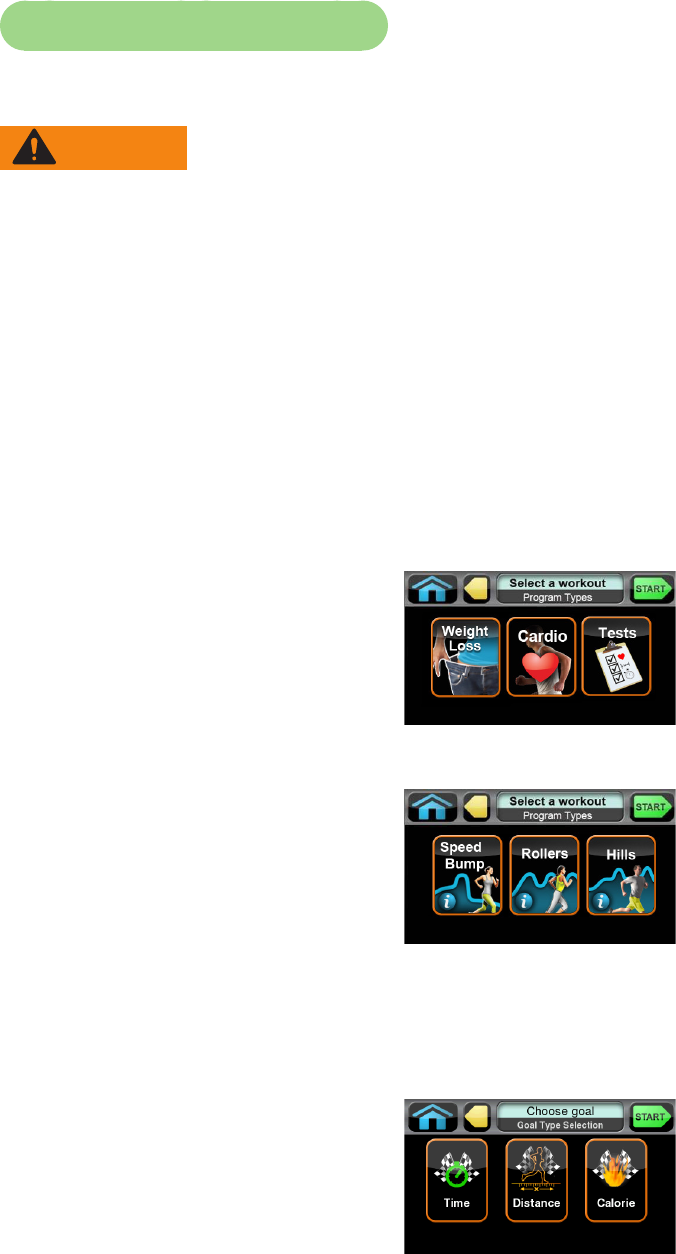
3. Select QUICK START or WORKOUTS.
To select a workout category, tap one of the workout category icons from the workout options screen.
To select a workout, tap one of the workout icons from the workouts screen.
Upon entering a workout the display will guide you through the appropriate settings. This is referred to
as Workout Setup Mode. If the Start key is pressed now, all defaults for that workout will be accepted.
After 10 seconds, if no key has been pressed, the rst default will be accepted. After another 10
seconds the second default will be accepted and so on until the last default.
For the most accurate resistance and calorie count, you must set your correct weight before
beginning your workout (including clothing).
When selecting a workout you must tap the Enter icon after each adjustment of Time, Level or
Weight.
Cybex Owner’s Manual
50
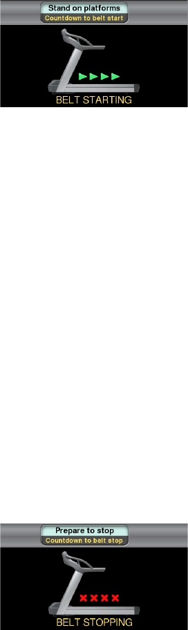
4. Press the Start key.
The treadmill begins a countdown, “3...2...1” and sounds a tone for each count. When it reaches one
(1) the treadmill gives a longer tone and then starts accelerating the belt. In Manual Mode the belt will
begin accelerating to 0.5 mph (0.8 kph) and the incline will remain at zero percent. In a workout the
belt will begin accelerating and the incline will change to the corresponding speed and incline of the
workout and level you selected.
5. Hold the handrails while you step onto the running belt and begin walking.
6. Observe the Cybex GO monitor for workout information. The Bar Graph display shows a
graphical representation of the relative workout intensity or incline changes. The workout data
will be displayed in the data bar and can be individually toggled to show alternative data to
customize your display.
Heart rate will be displayed if a valid heart rate is available from a wireless chest strap (not included)
or by holding the contact heart rate grips.
When you adjust incline in a workout, the change will affect only the current segment. The program
control will resume starting with the next segment. To increase or decrease overall intensity, adjust
the speed and/or the program level.
7. Press the Speed + – keys to change the belt speed at any time. The right display will show the
set speed.
8. Press the Incline ▲▼ keys to change the incline at any time. The left display will show the set
incline.
9. Press the Stop key at any time to stop the workout. “Workout Review” is displayed and the
incline returns to 0%.
If the e-stop key is removed during a workout, the drive motor power shuts off immediately, causing
the belt to stop. “Emergency Stop!” is displayed. Replacement of the e-stop key causes Workout
Review to begin.
When a program is complete the treadmill begins a countdown, “3...2...1” and sounds a tone for each
count. The belt slows to a stop, the incline returns to 0% and Workout Review is displayed for the
preset time or until you press the Home key.
The treadmill returns to Dormant Mode.
Cybex Owner’s Manual
51
Stopping the Treadmill
Press Stop once to end the workout session and start the Workout Review. The treadmill will perform
a controlled belt stop and bring the incline to 0%. The accumulated data or the results of the Fitness
Test will be displayed for the duration congured in Setup for Review Time. Press Stop again to exit
to Dormant.
The function of the immobilization method: The purpose of immobilizing the treadmill is to prevent
unauthorized use. This can be accomplished by removing the e-stop key from the treadmill, un-
clipping it from the cord and putting it in a non-accessible place.
STEPS
DISTANCE CALORIES CAL / HR BPMPACE TIMEMETs
COOL
INCLINE
END
PAUSE
SCAN
SHIFT
DOWN
FIT TEST
MANUAL
PROGRAMS 31 2
WEIGHT
CLEAR ALT
LEVEL
7
4
SPEED
ENTER
9
0
8
5 6
TIME SAVE
FAN OFF
FAN LO
FAN HI
START
QUICK
The emergency dismount: Follow the steps listed below if you experience pain, feel faint or need to
stop your treadmill in an emergency situation:
1. Grip handrails for support.
2. Step onto the top steps.
3. Pull the e-stop key off the console.
The function of the emergency stop: The e-stop key functions as the emergency stop. In an
emergency situation, remove the e-stop key from the treadmill and the running belt will come to a
stop.
Safety Sentry
WARNING: Falling hazard
• Place your feet on the two top steps when starting or stopping the treadmill.
• Wear the e-stop clip at all times.
The treadmill uses sensors to determine if you are on the running belt. When using the treadmill,
exercise in the center of the running belt, and between the end of the handrails and the console. If
you step off of the treadmill during a workout, the treadmill is designed to detect your absence and if
a user is not detected, the console will beep twice and display “Are you there? Touch the screen to
continue”. If there is no response in 20 seconds, the treadmill will exit Active Mode and the running
belt will stop.

Cybex Owner’s Manual
52
An unattended, running treadmill can create an unsafe environment for a user. The Safety Sentry
feature is intended to allow the treadmill to stop the running belt when the treadmill is unattended. To
avoid the treadmill running unattended, follow these steps:
• At the end of your workout, verify that the running belt is stopped by visually checking the Cybex
logo on the running belt, it should not be moving.
• If the belt is moving, place feet on both sides of the top step and press “Stop” or remove the e-stop
key from the treadmill.
Workout Selection
Quick Start
Press Quick Start. Control speed and incline.
Workout Choices:
Name Levels Settings Results
Weight Loss
Speed Bump 10 Choose goal - Time, distance, or calorie.
Rollers 10 Choose goal - Time, distance, or calorie.
Hills 10 Choose goal - Time, distance, or calorie.
Peaks 10 Choose goal - Time, distance, or calorie.
Cardio
Hill Interval 1:1 10 Choose goal - Time, distance, or calorie.
Hill Interval 1:2 10 Choose goal - Time, distance, or calorie.
Hill Interval 1:3 10 Choose goal - Time, distance, or calorie.
Interval Plus 10 Choose goal - Time, distance, or calorie.
Heart Rate Control N/A Choose goal - Time, distance, or calorie.
Tests
Gerkin Protocol Walk/run Weight, age, and gender. VO2 max
Army PFT 2 mile/3.2 k run Weight, age, gender, and starting speed. Points
Air Force PFT 1.5 mile/2.4 k run Weight, age, gender, and starting speed. Points
Navy <5K PRT 1.5 mile/2.4 k run
under 5000 feet
Weight, age, gender, and starting speed. Points
Navy >5K PRT 1.5 mile/2.4 k run
over 5000 feet
Weight, age, gender, and starting speed. Points
Marines PRT 3 mile/4.8 k run sea
level
Weight, age, gender, and starting speed. Points
Marines 4500 PRT 3 mile/4.8 k run
4500 feet
Weight, age, gender, and starting speed. Points
One Mile Test 1 mile/1.6 k walk Weight, age, gender, and starting speed. VO2 max
PFT means Physical Fitness Test, PRT means Physical Readiness Test.
See Appendix for workout details

Cybex Owner’s Manual
53
Control During Operation
Control keys are usable during operation and may be pressed at any time to make adjustments in
speed, elevation or data readouts. The Speed and Incline keys are located near the hand grips,
allowing for thumb adjustments without removing your hands from the hand grips.
Changing Speed — Press the Speed + – keys to change the speed in increments of 0.1 mph or 0.1
kph. Minimum to maximum speed is from 0.5 - 15.6 mph (0.8 - 25 kph).
Changing Incline — Press the Incline keys to change the elevation in increments of ½%
increments up to 10%, then 1% up to 20%. Press multiple times to change incline setting or hold the
key to auto-repeat. Elevation is dened as the ratio of rise or fall over run of the treadmill deck.
Changing between active mode or workouts — You can make changes during your workout.
Press WORKOUTS to select another workout, Manual to select Manual Mode, or Goal to change
your Time, Distance, or Calorie Goal. Follow screen prompts to begin the new workout.
Data Readouts
As you exercise, the treadmill keeps track of the following data:
BPM (Beats Per Minute) — Your current heart rate. Heart rate will appear when a signal is
introduced. Use the hand grips for Contact Heart rate or wear a Polar® compatible heart rate chest
strap.
Calories — The total accumulated calories burned during your workout. Your weight must be
correctly set before beginning your workout for this measurement to be most accurate.
Calories Per Hour — Calculation of present workload’s energy exertion in Calories per Hour.
Distance — The total accumulated distance, in miles or kilometers, during your workout. Depending
on the defaults you’ve chosen this measurement will show in English or Metric.
Metabolic Equivalent (MET) — Relates to the user’s energy expenditure. A MET is a basic unit of
measurement that is used to compare relative work between individuals and activities. ‘One MET’ is
the amount of oxygen consumed at rest. For example, two MET would be twice that amount. If an
individual were working at four MET he/she would be consuming oxygen at a rate equal to four times
their resting consumption. MET can be used to compare walking on a grade with running or even to
cycling and other activities.
Pace — At your current speed, how long it would take to cover a mile (or kilometer), displayed in
minutes:seconds.
Time — The total time you’ve been working out or time remaining. Display time as hours:minutes.
Watts — Present workload energy exertion.

Cybex Owner’s Manual
54
Heart Rate Indicator
Contact Heart Rate — Lightly hold hand grips on the handlebar ensuring that hands are clean and
contact both the front and back sensors of each grip. A heart rate will display in typically 30 seconds
or less.
Factors that interfere with heart rate signal:
• hand lotions
• oils or body powder
• excessive dirt
• excessive movement
• body composition
• hydration
• too loose grip
• too tight grip
• resting or leaning on grips
Wireless Heart Rate — To use this feature, a Polar® compatible heart rate transmitter belt (not
included) must be worn.
Once the actual heart rate is determined, the LED is blinking to the displayed BPM and the Heart LED lights
up. The color of the light represents a scale of low to high target heart rate.
Blue 0 – 69 BPM
Green 70 – 93 BPM
Yellow 94 – 119 BPM
Dark Orange 120 – 169
Magenta 170 and higher
Meaning of % Grade
A 1% grade is not the same as a 1 degree incline. The % grade is the relationship of the
measurement of rise over the measurement of run (also called slope). For example, a 1 foot (meter)
rise in height over a length of 100 feet (meters) is a 1% grade. Expressed as a mathematical formula,
the grade is calculated as follows: 1 ft. (m) / 100 ft. (m) = 0.01 = 1%
With respect to treadmills, the percent grade is roughly equal to the increase in height (rise) of the
treadmill divided by the length (run) of the treadmill.
The degree of incline can be related to % grade by taking the Arctangent of the grade. For instance,
15% grade is equal to 8.53 Degrees (ArcTan(.15)=8.53º). The opposite is true to determine % Grade
from Degree of incline (Tan (8.53º)=.15).

Cybex Owner’s Manual
55
Fan Control
The fan defaults to the “OFF” setting. The user can change to “Fan Low”, “Fan High”, or “Fan Off”
setting by pressing the appropriate control key.
iPod/iPhone Functions
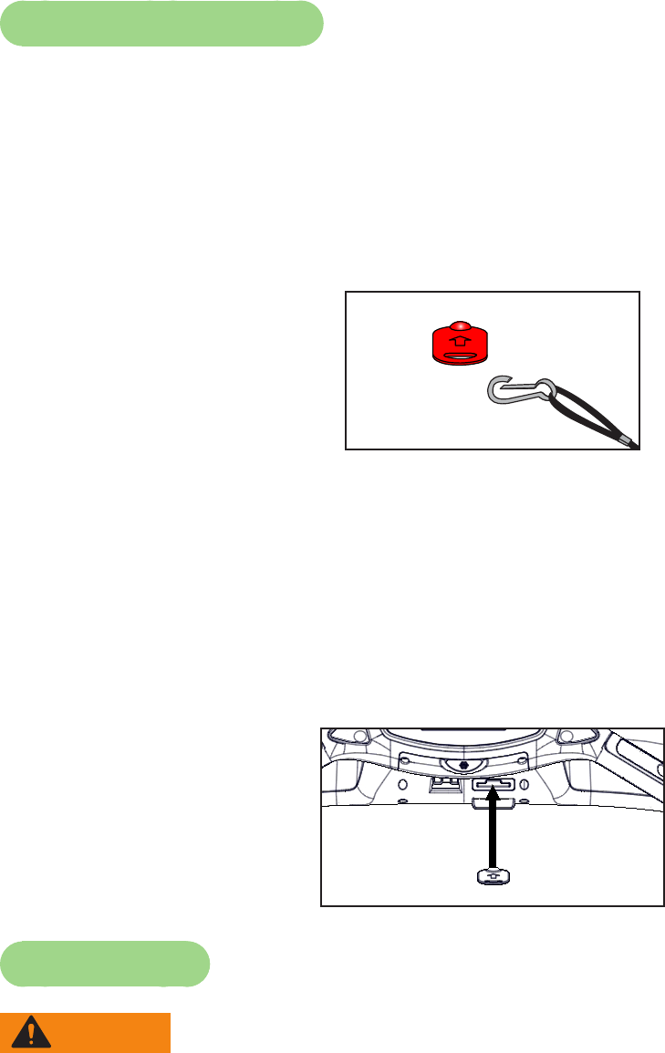
Connecting iPod/iPhone — Connecting an iPod/iPhone allows some control through the keypad.
The iPod/iPhone will not be charged while connected.
1. Connect iPod/iPhone (not supplied) into the 30 pin connector.
2. Place iPod/iPhone onto the accessory tray.
iPod/iPhone Playlist — Select the iPod/iPhone icon to display the iPod/iPhone navigation screen.
• If iPod/iPhone is already playing use the standard iPod/iPhone controls.
• If iPod/iPhone is Dormant make a selection from the iPod/iPhone Menu.
• Once a selection is made from the iPod/iPhone menu, make further selections until the desired
media is found.
Cybex Owner’s Manual
PB 56
Maintenance
All preventive maintenance activities must be performed on a regular basis. Performing routine
preventive maintenance actions can aid in providing safe, trouble-free operation of all Cybex Strength
Systems equipment.
Cybex is not responsible for performing regular inspection and maintenance actions for your
machines. Instruct all personnel in equipment inspection and maintenance actions and also in
accident reporting/recording. Cybex representatives are available to answer any questions that you
may have.
Warnings
Read all warnings in this chapter.
WARNING: For maintenance, service and repair:
• Must be performed by trained service personnel only
• Use only Cybex replacement parts
• Unplug unit before working on it
• Keep water and liquids away from electrical parts.
Observe the following warnings:
DANGER: Electrocution hazard.
To avoid death or serious injury unplug unit when not in use or when performing
maintenance.
WARNING: Equipment hazard.
To avoid serious injury or death replace worn or damaged components immediately
and keep the equipment out of use until repair is completed.

Cybex Owner’s Manual
57
Preventive Maintenance Activities
Perform regular preventive maintenance to ensure normal operation of unit. Keep a log of all
maintenance actions to assist in staying current with all preventive maintenance activities.
Cybex is not responsible for performing regular inspection and maintenance actions for your unit.
Instruct all personnel in equipment inspection and maintenance actions and also in accident reporting/
recording. Contact Cybex Customer Service at 888-462-9239 or 508-533-4300 for any preventive
maintenance or service concerns.
Read and understand warnings listed in this chapter and in the Safety Section. Read and
understand all instructions in this section.
During maintenance, disconnect the power cord.
For some maintenance activities it will be necessary to remove and replace the motor cover.
Tool Required
Phillips screwdriver
Cleaning Your Treadmill
When cleaning your treadmill spray a mild cleaning agent, such as a water and dishsoap solution,
on a clean cloth rst and then wipe the treadmill with the damp cloth. Do not spray cleaning solution
directly on the treadmill. Direct spraying could cause damage to the electronics and may void the
warranty.
WARNING: Shock and electrocution hazard.
• Unplug unit and let sit 10 minutes before cleaning or performing maintenance.
• Electrical charge can remain in unit after unplugging.
• Keep water and liquids away from electrical parts.
After Each Use — Wipe up any liquid spills immediately. After each workout, use a cloth to wipe up
any remaining perspiration from the handrails and painted surfaces.
Be careful not to spill or get excessive moisture between the edge of the display panel and the
console, as this might create an electrical hazard or cause failure of the electronics.
As Needed — Vacuum any dust or dirt that might accumulate under or around the treadmill. Motors
are especially susceptible to dust and dirt, and restricted airow can prevent adequate cooling that
could shorten motor life. Cleaning this area should be done as often as indicated in the Service
Schedule.
To clean the motor components, you must loosen the two Phillips head screws that hold the motor
cover in place. Lift the cover straight up; the screws will stay in place. Use a vacuum attachment
or hand vacuum to clean the exposed elevation assembly, drive motor, lower electronics and the
surrounding areas.
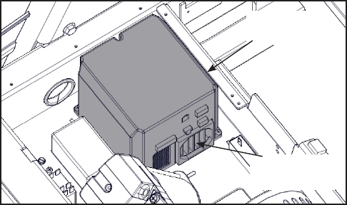
Cybex Owner’s Manual
57 58
Fan and Heat Sink — Vacuum the fan and heat sink area of the motor controller.
Motor
Controller
Fan and
Heatsink
Also use a dry cloth for the areas that you can not reach with the vacuum cleaner. If the machine has
not been used for some time or is excessively dirty, use a dry cloth to wipe all exposed areas.
Carefully raise the rear of the treadmill and roll it back from its present position to vacuum the oor
area underneath the unit. When nished, return the treadmill to its normal position.
Contact Heart Rate Grips — Contaminants, such as hand lotions, oils or body powder, may come
off on the contact heart rate grips. These can reduce sensitivity and interfere with the heart rate
signal. It is recommended that the user have clean hands when using the contact heart rate. Clean
the grips using a cloth dampened with a cleaning solution containing rubbing alcohol.
CardioTouch Screen — While in Dormant Mode press the Cybex logo icon to access the Lock
and Toolbox options. Press the Lock screen for cleaning icon to lock the screen for 10 seconds.
The CardioTouch screen will stay locked for 10 seconds to prevent any key presses from being
processed. Clean the CardioTouch screen using a soft cloth dampened with a cleaning solution
containing rubbing alcohol.
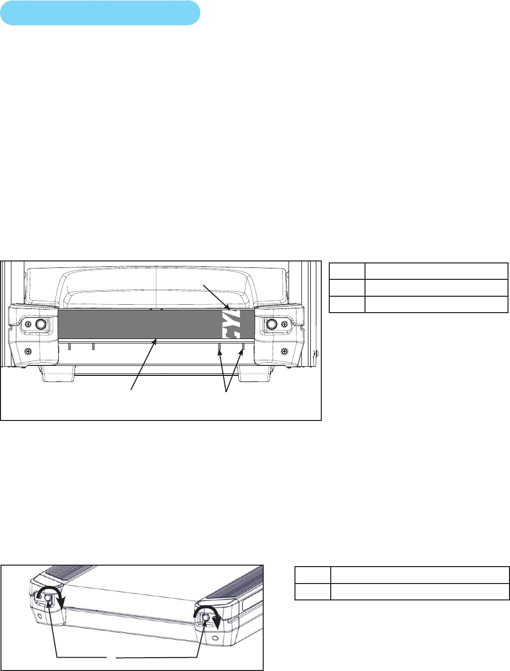
Cybex Owner’s Manual
59
Running Belt Maintenance
Center and tension the running belt
1. Plug the power cord into the power outlet.
2. Turn the main power switch to the on (I) position.
3. Press the Quick Start icon.
4. Press the Speed + to bring the speed up to 5 mph (8 kph). Allow the treadmill to run for a
minute.
The lateral position of the running belt is correctly centered when the Cybex logo is centered between
the inside edges of the two belt tracking slots. If the Cybex logo is not centered between the belt
tracking slots, center the running belt with the following procedure.
5. Observe the Cybex logo position relative to the belt tracking slots with the treadmill running at
5 mph (8 kph).
1
23
1Cybex logo
2Running belt
3Belt tracking slots
While centering the running belt choose one bolt to adjust. Do not adjust both bolts.
6. Tighten the rear roller bolt on the side of the treadmill toward which the running belt is
moving using a 3/4” socket wrench. For example: If the running belt moves to the right of the
belt tracking slots, tighten the bolt on the right side of the frame, tighten about 1/2 of a turn
(clockwise) and wait 30 seconds. If the running belt does not move back to the center of the
belt tracking slots, make another adjustment to the same bolt. Once the running belt has been
adjusted closer to the center of the belt tracking slots, use about 1/4 of a turn until the running
belt has been stabilized.
1
Description
1Rear roller bolts
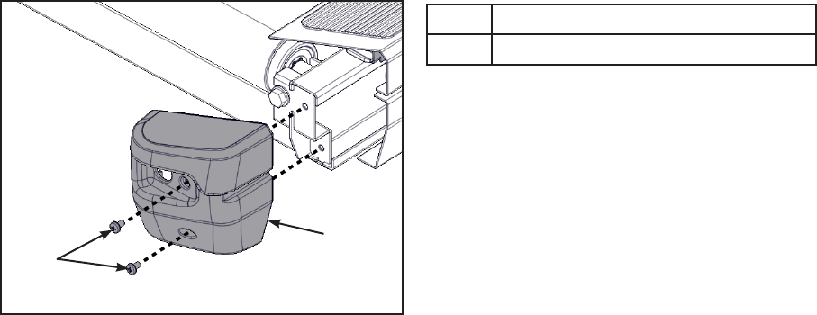
Cybex Owner’s Manual
59 60
7. Check the belt tension after the running belt has been centered. Make sure the running belt
tension is tight enough so that the running belt does not slip or hesitate when stepped on.
Walk on the treadmill at 3.5 - 4 mph (5.6 - 6.4 kph) and every 4th to 5th step throw your weight
into your step to feel if the running belt is slipping. If slipping is felt, conrm it is the running
belt slipping and not the drive belt. With the hood cover removed, observe movement at the
drive belt and front roller.
Do not over tighten the running belt. Over tightening the running belt can cause the belt to stretch
and require replacement. Continue procedure until running belt stops slipping.
8. Check running belt for centering position. If running belt is not centered, perform steps 5 and
6.
Checking the Running Belt and Deck Surfaces — The running belt and deck should be checked
periodically for any excessive wear. In an effort to make sure that the running belt operates properly,
visually inspect the belt often to make sure that there are no tears or fraying in the belt material. The
running belt should be replaced every 15,000 miles (24,140 km). The running deck should be ipped
every 15,000 miles (24,140 km) and replaced every 30,000 miles (48,280 km). A service prompt will
appear at this interval and the parts will need to be replaced.
Inspect the edges of the belt as described below.
Tools Required
• Phillips screwdriver
Disconnect the external power source
1. Toggle the on/off (I/O) power switch to the off (O) position.The on/off (I/O) power switch is
located under the front end of the unit, or on the front right side panel.
2. Unplug the treadmill from the power outlet.
Check the running belt condition
1. Remove the two screws securing the right end cap using a Phillips screwdriver.
2
1
1Screws (2)
2Right end cap
2. Repeat step 1 for the left end cap.
3. Inspect the top surface, seam, and edges of the running belt while you roll it by hand. If the

Cybex Owner’s Manual
61
belt has any rips or looks excessively worn the belt needs to be replaced.
If the running belt and deck need replacement refer to a qualied service technician.
4. Install the screws securing the end caps removed in steps 1 and 2 using a Phillips screwdriver.
Other Preventive Maintenance
Other preventive maintenance activities must be completed by a qualied service technician at the
recommended intervals listed in the Service Schedule at the end of this chapter. These activities
include:
• Flipping or replacing the running deck
• Replacing the running belt
Elevation Motor Lubrication — In time the elevation motor pivot points or tube nut may develop a
squeak. Lubricate the upper and lower bolts and the spacers with a small amount of lithium grease.
You can buy lithium grease at an auto parts store.
Static Electricity — Depending upon where you live, you may experience dry air, causing a
common experience of static electricity. This may be especially true in the winter time. You may
notice a static build-up just by walking across a carpet and then touching a metal object. The same
can hold true while working out on your treadmill. You may experience a shock due to the build-
up of static electricity on your body and the discharge path of the treadmill. If you experience this
type of situation, you may want to increase the humidity to a comfortable level through the use of a
humidier.
Cybex GO monitor
Cleaning
1. Clean with a dust free cloth. For further cleaning, use a soft cloth or paper towel dampened
with water. To avoid damage to the surface of the monitor, do not use abrasive or chemical
cleaning agents.
2. Disinfecting: to avoid damage to the surface, test a small portion of the monitor’s cabinet with
any disinfectant to verify that the disinfectant will not discolor or soften the enclosure.
Storage or Long Non-Use Periods
When not using product for an extended period of time the product should be disconnected from the
Power Supply, TV/Cable Signal Feed, and any Peripheral Devices.
Pixels
Very small red, blue, white or green spots may be visible or may appear on the screen. This is a
characteristic of liquid crystal display panels and is not considered a defect for replacement. The
liquid crystal panel is built with very high precision technology giving ne picture details. Occasionally,
a few non-active pixels may appear on the screen as a xed point. This does not affect the
performance of monitor or merit a warranty claim.
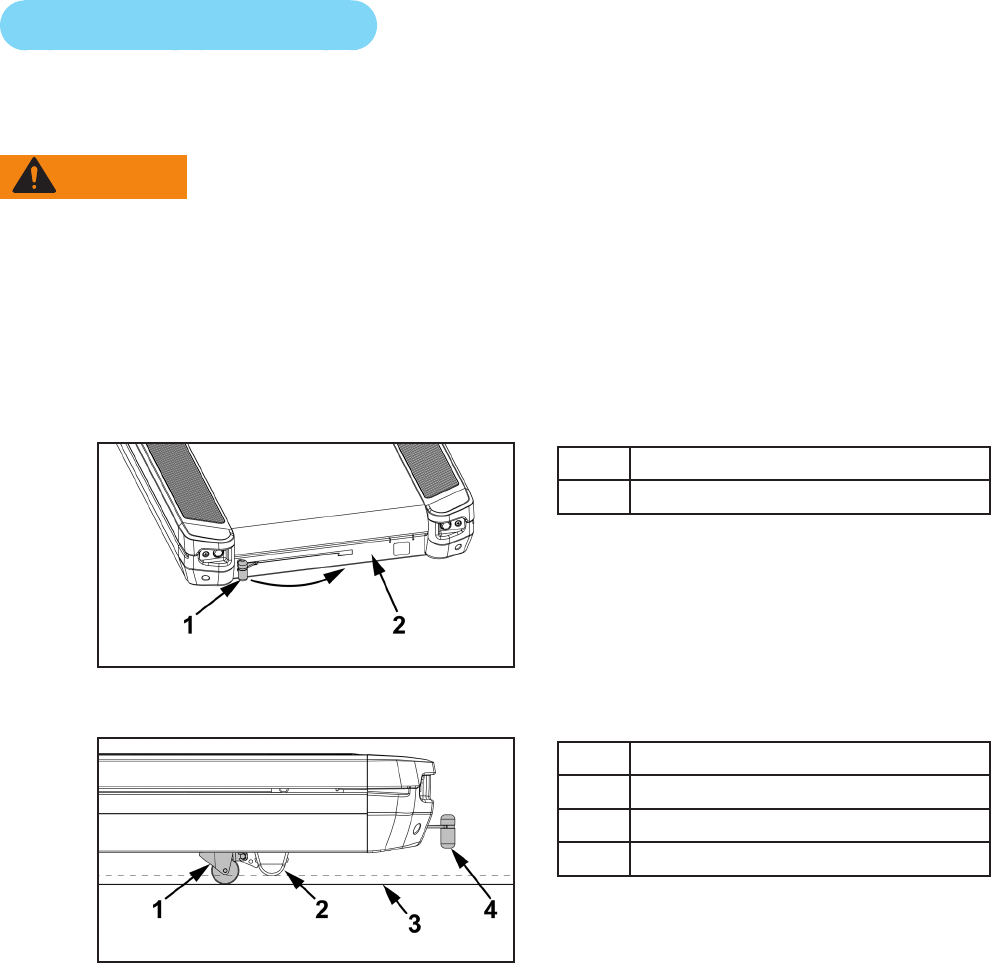
Cybex Owner’s Manual
61 62
Maintenance
• It is very important to have the unit regularly examined by a qualied technician to ensure the prod-
uct is t for use.
• If the unit malfunctions, please refer to a qualied technician for repair or replacement of defective
parts immediately. Do not attempt to use the monitor until it has been inspected and repaired by a
qualied technician.
• For inspection, installation and servicing, please consult qualied technician.
• Failure to use a manufacturer approved repair technician may void any warranty claims.
Service Wheel (optional)
A service wheel lever is located at the rear end of the unit. This lever will engage a wheel and elevate
the rear end of the unit. The treadmill can then be easliy moved for cleaning or servicing.
WARNING: Shock and electrocution hazard.
• Unplug unit and let sit 10 minutes before cleaning or performing maintenance.
• Electrical charge can remain in unit after unplugging.
• Keep water and liquids away from electrical parts.
Engage service wheel
1. Unplug power cord from power outlet.
2. Grasp the service wheel lever and slide to the right and down to lock in place.
1Service wheel lever
2Frame
The service wheel will lower and raise the rear foot off the oor.
1Service wheel
2Rear foot
3Floor
4Service wheel lever
3. Move treadmill as needed.
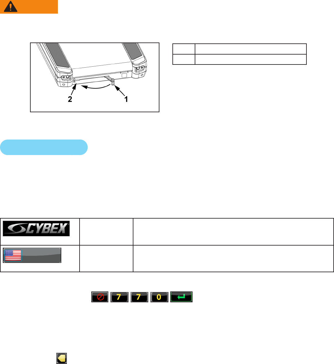
Cybex Owner’s Manual
63
Disengage service wheel
WARNING: Trip and fall hazard.
To avoid injury, make sure service wheel lever is not engaged proir to use.
1. Grasp the service wheel lever and slide to the right, lift up, and slide to the left.
1Service wheel lever
2Frame
2. Plug the power cord into the power outlet.
Service Schedule
All maintenance activities shall be performed by qualied personnel. Failure to do so could result in
serious injury.
This is the minimum recommended service.
Determine distance
CYBEX
LOGO
Press and hold Cybex logo for 6 seconds to access Screen
Lock and Toolbox. See Preventive Maintenance section.
ENGLISH LANGUAGE
ICON
Press and hold language logo for 6 seconds to access
Screen Lock and Toolbox.
1. Press the Access Toolbox icon to access the Toolbox login screen.
2. Enter the sequence: .
3. Press the Statistics icon to access the Recorded Statistics screen.
4. Locate and tap the icon tor Treadmill Totals.
5. Record Distance.
6. Press the arrow to return to the Recorded Statistics screen.
7. Locate and tap the icon for Belt or Deck.
8. Record Distance.
9. If replacing the running belt, tap the Belt icon, then tap the New Belt Reset icon to reset
odometer.

Cybex Owner’s Manual
63 64
10. If replacing the running deck, tap the Deck icon, then tap the New Deck Reset icon to reset
odometer.
11. Exit Set Up Mode by tapping the Toolbox icon , then tap the Home icon . The screen
will refresh.
First 500 miles (800 km).
• Check running belt tension and tracking.
Every 5,000 miles (8,000 km).
• Check running belt tension and tracking.
• Vacuum the fan and heat sink area of the motor controller.
• Move treadmill and vacuum underneath.
• Raise elevation to 15%, carefully roll the treadmill backwards to clean underneath with a dry cloth
and vacuum. Return to normal position when done.
Every 15,000 miles (24,140 km).
• Replace running belt and ip deck.
• Check elevation assembly and replace worn parts.
• Lubricate elevation pivot points.
Every 30,000 miles (48,280 km).
• Replace running belt and deck.

65
Cybex Owner’s Manual
Customer Service
Product Registration
To register product do the following:
1. Visit www.cybexintl.com.
2. Locate Product Registration in the Support section.
3. Fill out form completely.
4. Click the Submit button to register product.
Contacting Service
Hours of phone service are Monday through Friday from 8:30 a.m. to 6:00 p.m. Eastern Standard
Time.
For Cybex customers living in the USA, contact Cybex Customer Service at 888-462-9239.
For Cybex customers living outside the USA, contact Cybex Customer Service at 508-533-4300 or
fax 508-533-5183. Email address internationaltechhelp@cybexintl.com
Find information on the web at www.cybexintl.com.
To contact us online go to www.cybexintl.com.
Ordering Parts
To order parts online go to www.cybexintl.com.
To speak with a customer service representative, call 888-462-9239 (for customers living within the
USA) or 508-533-4300 (for customers outside the USA).
The following information located on the serial number decal will assist our Cybex representatives in
serving you.
• Unit Serial Number, Product Name and Model Number
• Part Description and Part Number if you have it. All parts can be found on the web at
www.cybexintl.com
• Shipping Address
• Contact Name
• Include a description of the problem.
In addition to your shipping address and contact name, your account number is helpful but not
required. You may also fax orders to 508-533-5183.

Cybex Owner’s Manual
66 PB
Return Material Authorization (RMA)
The Return Material Authorization (RMA) system is used when returning material for placement,
repair or credit. The system assures that returned materials are properly handled and analyzed.
Follow the following procedures carefully.
Contact your authorized Cybex dealer on all warranty-related matters. Your local Cybex dealer will
request a RMA from Cybex, if applicable. Under no circumstances will defective parts or equipment
be accepted by Cybex without proper RMA and an Automated Return Service (ARS) label.
Please contact Cybex Customer Service for the return of any item that is defective.
Provide the technician with a detailed description of the problem you are having or the defect in the
item you wish to return. Provide the model and serial number of your Cybex equipment.
At Cybex’s discretion, the technician may request that you return the problem part(s) to Cybex for
evaluation and repair or replacement. The technician will assign you a RMA number and will send
you an ARS label. The ARS label and the RMA numbers must be clearly displayed on the outside of
the package that contains the item(s) to be returned. Include the description of the problem, the serial
number of the equipment and the name and address of the owner in the package along with the
part(s).
Merchandise returned without an RMA number on the outside of the package or shipments sent COD
will not be accepted by the Cybex receiving department.
Damaged Parts
Materials damaged in shipment should not be returned for credit. Shipping damages are the
responsibility of the carrier (UPS, Federal Express, trucking companies, etc.)
Apparent Damage
Upon receipt of your shipment, check all items carefully. Any damage seen with a visual check must
be noted on the freight bill and signed by the carrier’s agent. Failure to do so will result in the carriers
refusal to honor your damage claim. The carrier will provide you with the required forms for ling such
claims.
Concealed Damage
Damage not seen with a visual check upon receipt of a shipment but notices later must be reported
to the carrier as soon as possible. Upon discovery of the damage, a written or phone request to
the carrier asking them to perform an inspection of the materials must be made within ten days of
the delivery date. Keep all shipping containers and packing materials as they will be needed in the
inspection process. The carrier will provide you with an inspection report and the necessary forms for
ling a concealed damage claim. Concealed damage claim is the carrier’s responsibility.
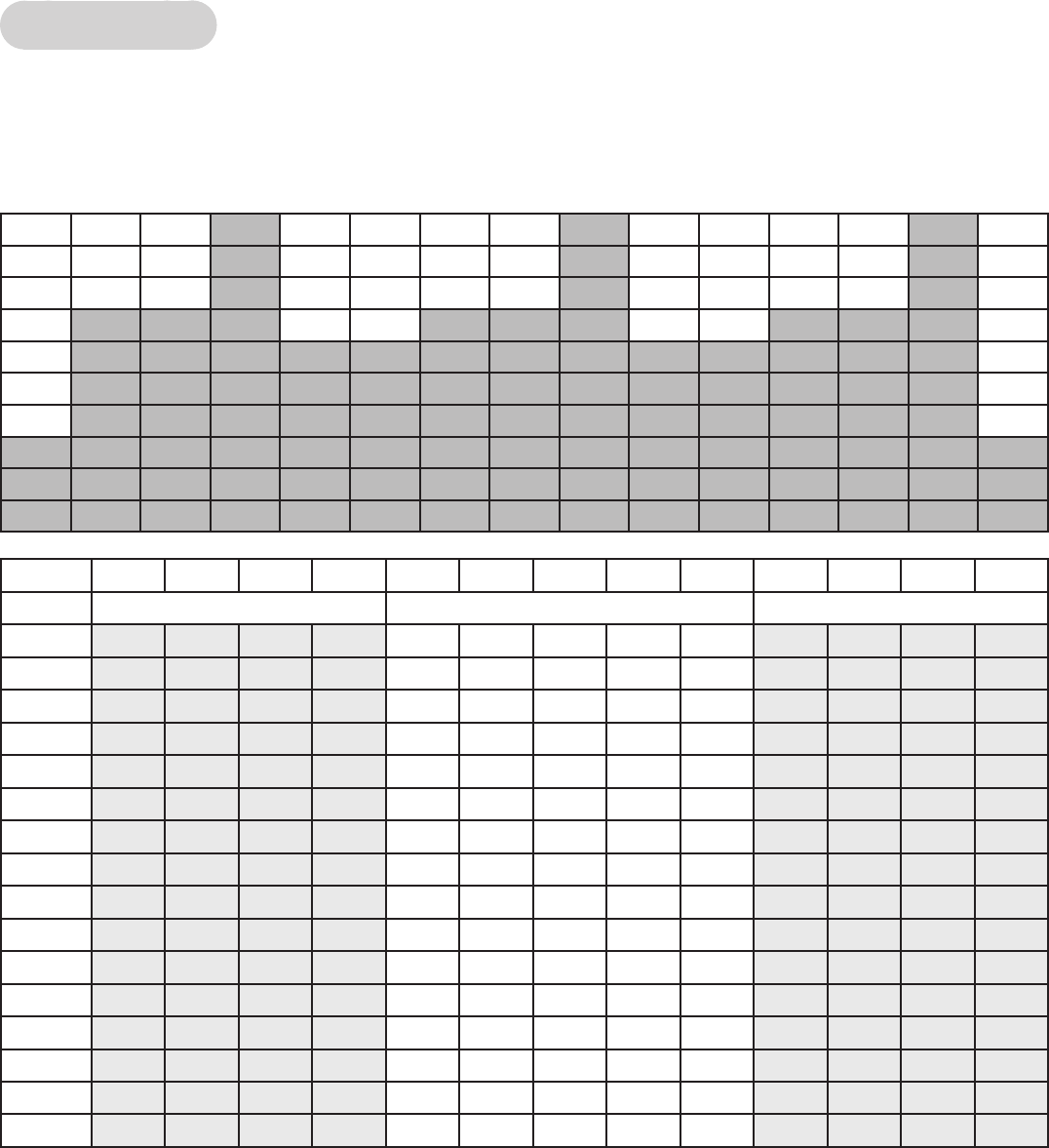
Cybex Owner’s Manual
67
Appendix - Workout Overviews
Speed Bump
The Weight Loss program uses a series of relatively minor changes in its ve-minute core to add
an incremental demand. The ve-minute core utilizes a baseline incline for two minutes and then
increases the incline for added demand and then provides a slightly lower Incline for two-minutes for
recovery.
Time :30 :30 :30 :30 1:00 1:00 1:00 1:00 1:00 :30 :30 :30 :30
Warm Up Core Segments Cool Down
Incline 1 2 3 4 1 2 3 4 5 1 2 3 4
15 5 5 6 8 15 15 20 14 14 0 0 0 0
14 4 5 5 7 14 14 18 13 13 0 0 0 0
13 4 5 5 7 13 13 17 12 12 0 0 0 0
12 3 4 4 6 12 12 16 11 11 0 0 0 0
11 344611 11 15 10 10 0 0 0 0
10 2 3 3 5 10 10 14 9 9 0 0 0 0
923359912880000
822348810770000
72234779660000
61223667550000
51223556440000
41122445330000
31122334220000
21112223110000
11112112000000
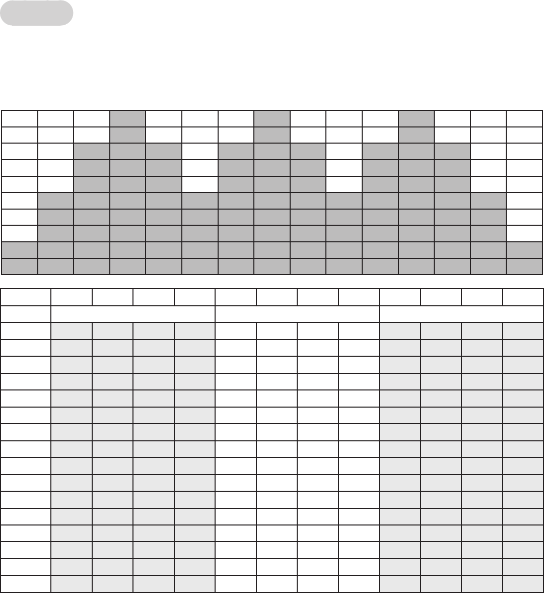
68
Cybex Owner’s Manual
69
Rollers
The Rolling Hills program uses an eight-minute core intended to mimic variety in terrain that might
be found on a hilly outdoor run. The eight-minute core is composed of four segments. The baseline
segment is two –minutes in length and is followed by two two-minute segments of increase Incline
before returning to the intermediate incline for two-minutes.
Time :30 :30 :30 :30 2:00 2:00 2:00 2:00 :30 :30 :30 :30
Warm Up Core Segments Cool Down
Incline 1 2 3 4 1 2 3 4 1 2 3 4
15 1234611 14 12 0 0 0 0
14 1 2 3 4 6 10 12 10 0 0 0 0
13 1 2 3 3 5 9 10 8 0 0 0 0
12 1 2 3 3 5 8 9 7 0 0 0 0
11 1 2 2 3 4 7 9 6 0 0 0 0
10 1 2 2 3 4 6 8 6 0 0 0 0
91 1 2 2 3 6 8 5 0 0 0 0
81 1 2 2 3 5 8 5 0 0 0 0
71 1 1 2 2 5 7 4 0 0 0 0
61 1 1 2 2 4 7 4 0 0 0 0
50 0 1 1 1 4 7 3 0 0 0 0
40 0 1 1 1 3 6 3 0 0 0 0
30 0 0 0 0 3 6 3 0 0 0 0
20 0 0 0 0 2 6 2 0 0 0 0
10 0 0 0 0 2 5 2 0 0 0 0
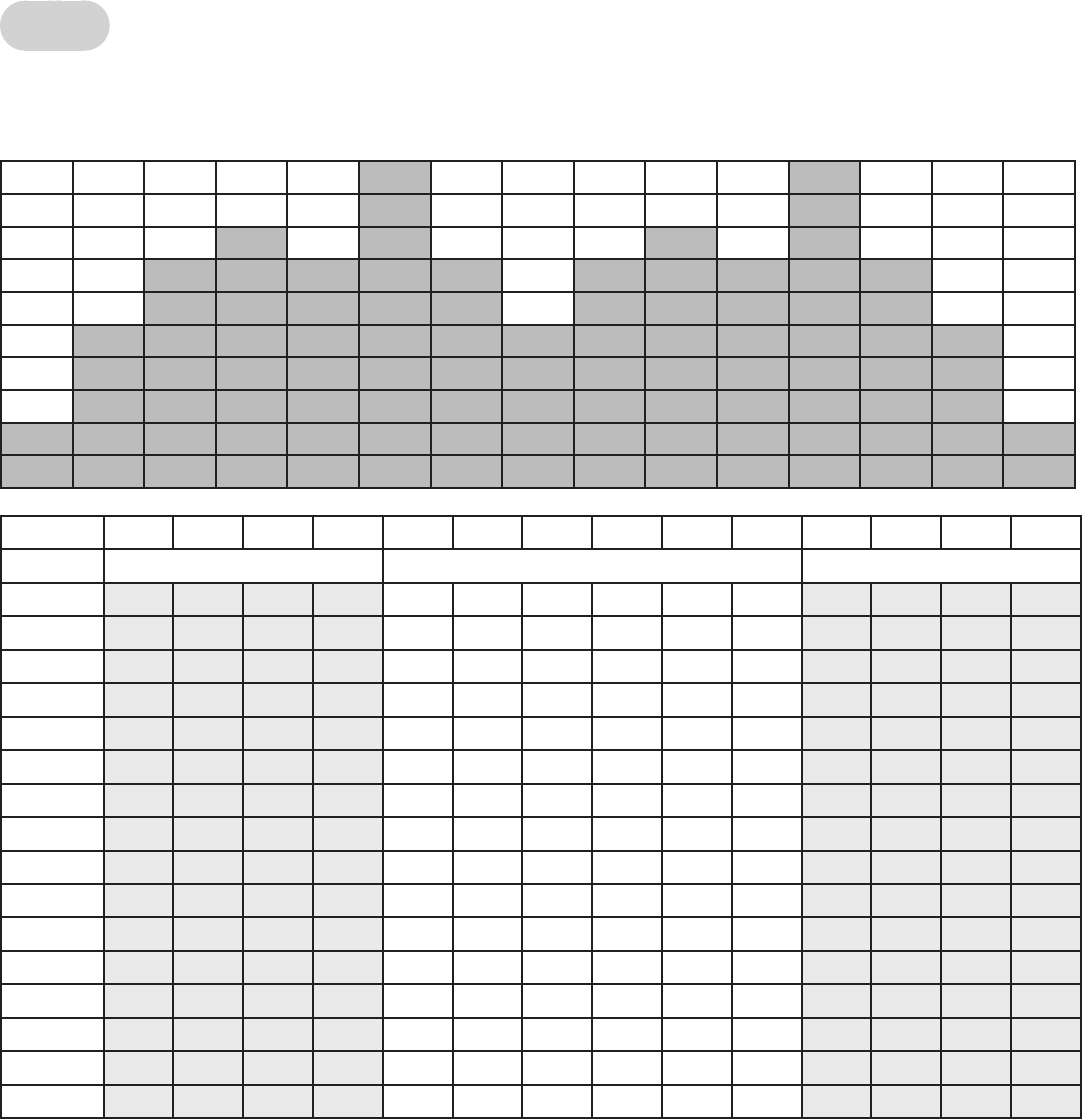
Cybex Owner’s Manual
69
Hills
The Hills program uses a six-minute core utilizing one minute segments with mild Incline changes and
two relative peak segments followed by relative rest segments.
Time :30 :30 :30 :30 1:00 1:00 1:00 1:00 1:00 1:00 :30 :30 :30 :30
Warm Up Core Segments Cool Down
Incline 1 2 3 4 1 2 3 4 5 6 1 2 3 4
15 5 6 7 8 13 15 20 15 20 15 0 0 0 0
14 4 5 6 7 12 14 18 14 19 14 0 0 0 0
13 4 5 6 7 11 13 16 13 18 13 0 0 0 0
12 3 4 5 7 10 12 14 12 17 12 0 0 0 0
11 3 4 5 6 9 11 13 11 16 11 0 0 0 0
10 3 3 5 6 8 10 12 10 15 10 0 0 0 0
92 3 4 5 7 9 12 9 14 9 0 0 0 0
82 3 3 5 6 8 11 8 13 8 0 0 0 0
72 2 3 4 5 7 10 7 12 7 0 0 0 0
61 2 2 3 4 6 9 6 11 60000
51 1 2 2 3 5 8 5 10 5 0 0 0 0
411122474940000
300111363830000
200000253730000
100000242620000
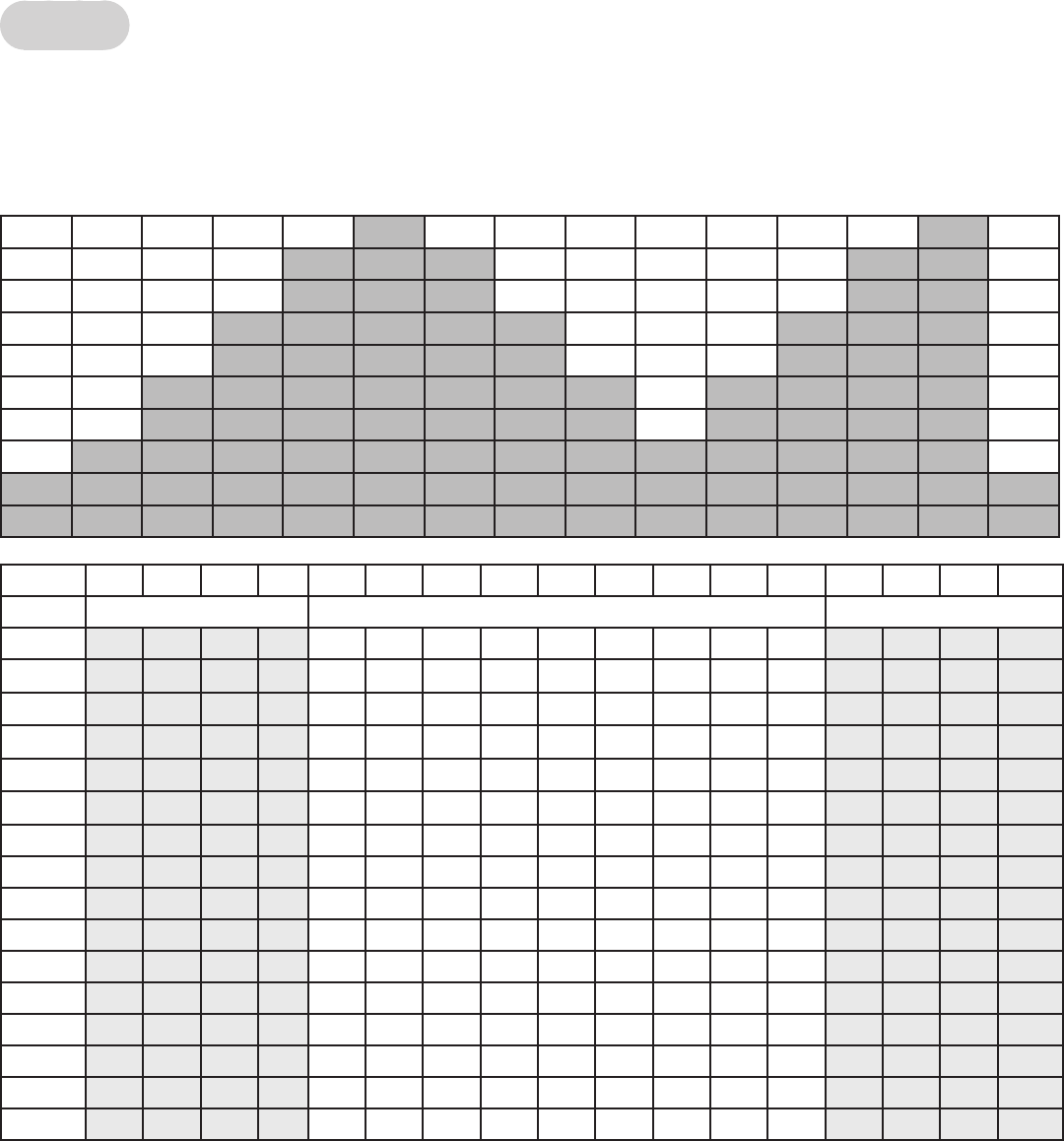
70
Cybex Owner’s Manual
71
Peaks
Pikes Peak uses a nine-minute core where the incline increases every minute for the rst ve
minutes. After the fth minute of the core program, the incline is reduced each minute. This program
uses continuous and gradual changes to give the user time to acclimate to demand and recover
without large perceived changes in the effort required.
Time :30 :30 :30 :30 1:00 1:00 1:00 1:00 1:00 1:00 1:00 1:00 1:00 :30 :30 :30 :30
Warm Up Core Segments Cool Down
Incline 1 2 3 4 1 2 3 4 5 6 7 8 9 1 2 3 4
15 2 3 4 5 7 13 16 18 20 18 16 13 10 0 0 0 0
14 2 3 4 4 7 12 15 17 19 17 15 12 9 0 0 0 0
13 2 3 3 4 6 11 14 16 18 16 14 11 8 0 0 0 0
12 2 2 3 4 6 10 13 15 17 15 13 10 7 0 0 0 0
11 2 2 3 4 5 9 12 14 16 14 12 9 6 0 0 0 0
10 2 2 3 4 5 8 11 13 15 13 11 8 5 0 0 0 0
91 2 2 3 4 7 10 12 14 12 10 7 4 0 0 0 0
8122346911 13 11 964000 0
71 1 2 2 3 5 8 10 12 10 8 5 3 0 0 0 0
61122357911 9 7 5 3 0 0 0 0
51 1 1 2 2 4 6 8 10 8 6 4 2 0 0 0 0
41112235797532000 0
31112234686432000 0
20011123575321000 0
10000012464210000 0
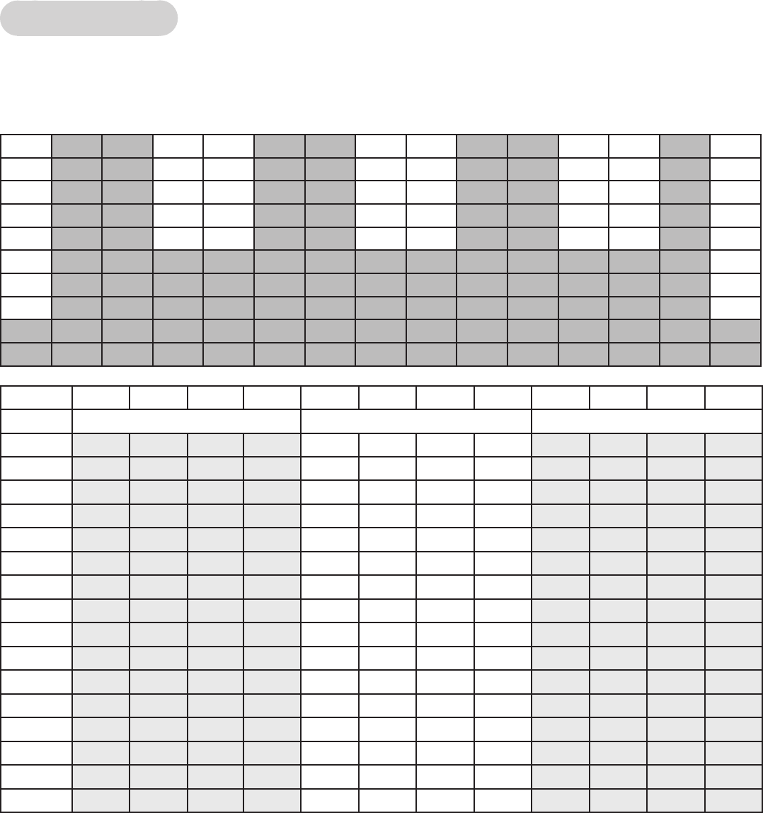
Cybex Owner’s Manual
71
Hill Interval 1:1
This program is designed for to increase capability by alternating two minute work segments with two
minutes of relative rest. The intensity of rest periods is greater here than in Hill Interval 1:2 as is the
duration of the work interval making this program more demanding than Hill Interval 1:2.
Time :30 :30 :30 :30 1:00 1:00 1:00 1:00 :30 :30 :30 :30
Warm Up Core Segments Cool Down
Incline 1 2 3 4 1 2 3 4 1 2 3 4
15 5 7 10 12 20 20 12 12 0 0 0 0
14 4 6 8 10 17 17 9 9 0 0 0 0
13 4 6 8 10 15 15 8 8 0 0 0 0
12 4 6 7 9 13 13 7 7 0 0 0 0
11 4 5 7 9 12 12 6 6 0 0 0 0
10 3 5 6 8 11 11 660000
93 4 6 8 10 10 5 5 0 0 0 0
8345799550000
7335688440000
6234577440000
5233566330000
4223455330000
3122344220000
2112233220000
1111222110000
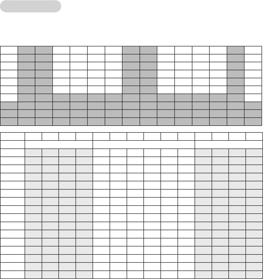
72
Cybex Owner’s Manual
73
Hill Interval 1:2
This program is designed for to through a one-minute work interval at a high incline followed by a two
minute rest interval at a substantially lower incline. Given the lower incline and longer rest intervals
this program is less intense than Hill Interval 1:1.
Time :30 :30 :30 :30 :30 :30 :30 :30 :30 :30 :30 :30 :30 :30
Warm Up Core Segments Cool Down
Incline 1 2 3 4 1 2 3 4 5 6 1 2 3 4
15 5 7 10 11 20 20 15 15 15 15 0 0 0 0
14 5 7 8 10 18 18 12 12 12 12 0 0 0 0
13 4 6 8 10 16 16 9 9 9 9 0 0 0 0
12 4 6 7 9 14 14 8 8 8 8 0 0 0 0
11 4 6 7 9 12 12 6 6 6 6 0 0 0 0
10 3 5 6 8 11 11 4 4 4 4 0 0 0 0
93 4 6 8 10 10 3 3 3 3 0 0 0 0
834579933330000
733568833330000
623457722220000
523356622220000
422345522220000
312234411110000
211223311110000
111122211110000
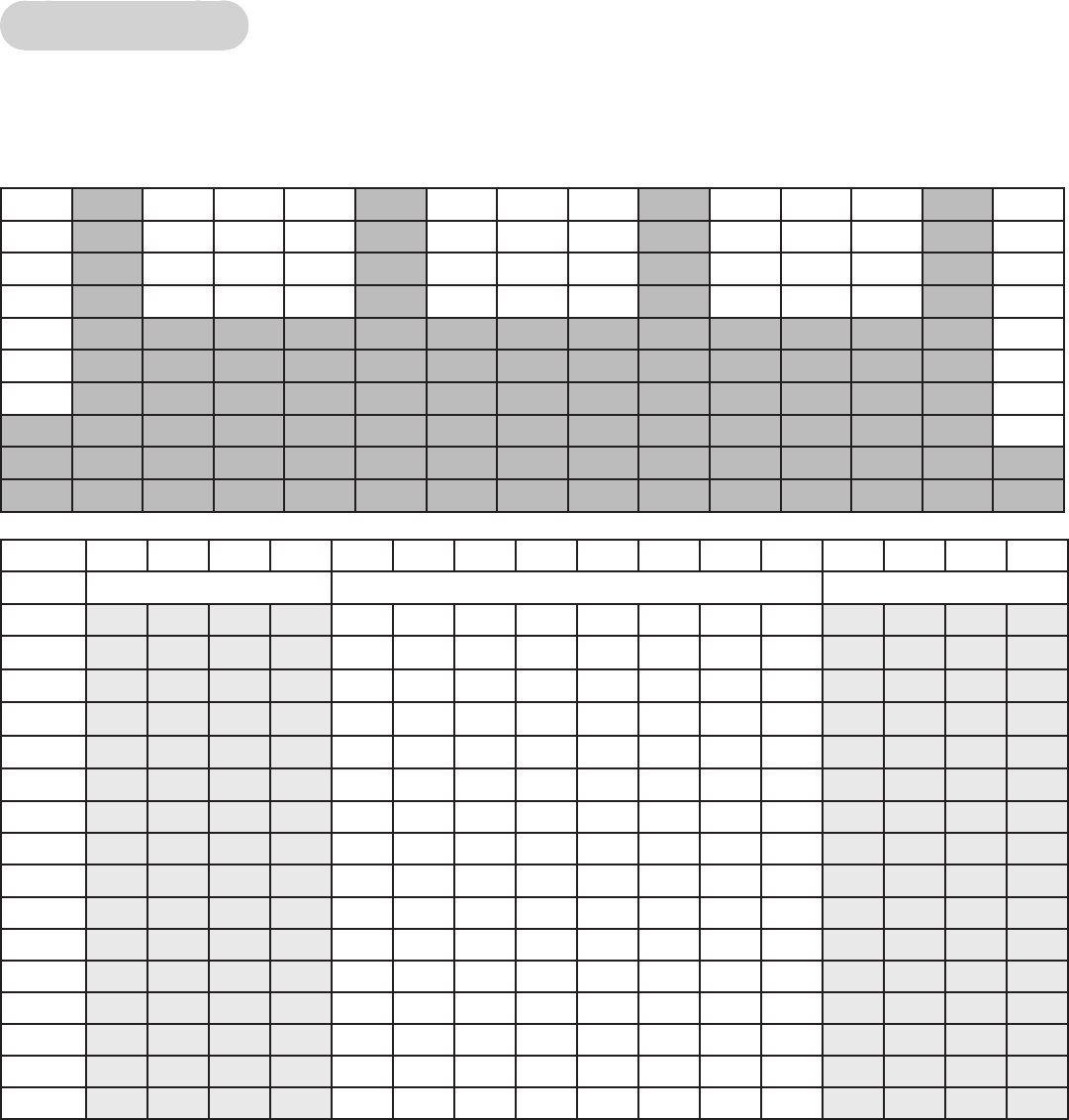
Cybex Owner’s Manual
73
Hill Interval 1:3
Hill Interval 1:3 utilizes a one-minute work interval followed by a three-minute rest interval. The rest
intervals are of a higher incline that those found in the other Hill Interval programs, and therefore
require a longer recovery period.
Time :30 :30 :30 :30 1:00 1:00 1:00 1:00 1:00 1:00 1:00 1:00 :30 :30 :30 :30
Warm Up Core Segments Cool Down
Incline1234123456781234
15 5 7 10 12 16 11 11 11 16 11 11 11 0000
14 57911 15 10 10 10 15 10 10 10 0 0 0 0
13 46811 14 10 10 10 14 10 10 10 0 0 0 0
12 4 6 8 10 13 8 8 8 13 8 8 8 0 0 0 0
11 457912888128880000
10 3 5 6 8 11 77711 7770000
93 4 6 8 10 7 7 7 10 7 7 7 0 0 0 0
83457966696660000
73356855585550000
62345755575550000
52335644464440000
42234533353330000
31223433343330000
21122322232220000
11112211121110000
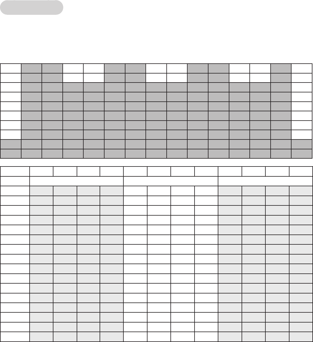
74
Cybex Owner’s Manual
75
Interval Plus
The Cardio program is designed to maintain a high total demand using two four-minute segments of
alternating incline. This allows prolonged intervals that take advantage of long-term energy systems
and total aerobic capability when associated with speeds that require a high sustained cardiovascular
demand.
Time :30 :30 :30 :30 2:00 2:00 2:00 2:00 :30 :30 :30 :30
Warm Up Core Segments Cool Down
Incline 1 2 3 4 1 2 3 4 1 2 3 4
15 3 5 6 8 20 20 17 17 0 0 0 0
14 3 4 5 7 17 17 14 14 0 0 0 0
13 3 4 5 7 15 15 12 12 0 0 0 0
12 3 4 4 6 13 13 11 11 0000
11 3 3 4 6 12 12 10 10 0 0 0 0
10 2 3 3 5 11 11 990000
92 3 3 5 10 10 8 8 0 0 0 0
8233599770000
7223488660000
6223477550000
5223466440000
4223455330000
3122344220000
2001233110000
1000022000000

Cybex Owner’s Manual
75
Heart Rate Control
Note: This workout requires the user to wear a Polar or compatible Heart Rate transmitter belt. The
Heart Rate Control Workout (HRCP) cannot be selected on the control console unless the treadmill
detects a Heart Rate signal. The HRCP will not work with the cardio touch contact Heart Rate system.
After selecting the HRCP, the treadmill will prompt you for workout time, weight, age, and target Heart
Rate. Your age is required to estimate the proper range of Heart Rates. The target Heart Rate is
calculated by the formula 220 minus your age times 75%. You will then have the option of adjusting
the suggested target Heart Rate selected either up or down. Select a target Heart Rate which will
allow you to exercise comfortably and safely while at the same time allowing you to reach your
training goals. If you are unsure of what to select as your target, consult your physician or a physical
training professional, After starting the HRCP, the treadmill will attempt raise your Heart Rate to your
target within 3 to 5 minutes. The treadmill will emphasize using elevation of the treadmill deck rst to
achieve higher workloads and thus higher Heart Rates; this is done to maximize the use of a walking
gait, which is safer and more comfortable for many users. As a result, many users will spend nearly
the entire workout at elevation up to 12% grade. After reaching your target, the treadmill will attempt
to keep you there within 5 beats per min. As you tire, the treadmill will compensate by reducing
elevation, speed or both. A two-minute cool-down is built in at the end of the workout.
Method of HRCP:
User selects Heart Rate target in the initial start of workout or accepts the suggested target of 75%
of 220 minus age. This target Heart Rate is extremely important for more reasons than just the
establishment of the target itself. It also makes an assumption of the general tness level and controls
several aspects of how quickly the elevation and speed will be adjusted. As an example, the starting
speed for a selected target of 120 bpm (beats per minute) will be 2 mph. The starting speed for a
selected target of 140 bpm will be 3.5 mph. In between those selected targets the starting speed will
be proportional to the difference between 2 to 3.5. The integral gain constants will also be modied
depending on what the selected target is at the start of the workout. This means someone with a
higher selected target will get faster changes in speed and grade than someone with a lower target.
This has the effect of getting the more t user to their selected target faster without overshooting the
target for someone with a lower tness level. After the starting speed is attained by the treadmill, it will
then increase the elevation every 15 seconds up to 12% grade or until the computer senses that the
user is getting close to approaching their target Heart Rate. Since the control is somewhat predictive
in nature, it will leave ample room for the user’s Heart Rate to catch up to the increasing load. If the
target Heart Rate is not attained at the load level of the start speed at 12% grade, then the treadmill
will start increasing speed every 15 seconds up to 4 mph or until the computer senses that the user
is getting close to approaching their target Heart Rate. If the user is still not at the target, the treadmill
will increase speed to 5 mph and drop the elevation down to 8% grade. This is done because the
speeds between 4 and 5 are difcult for the user because it is too slow to jog and too fast for many
to walk. The drop in elevation compensates somewhat for the larger increase in speed. The system
will then increase the speed of the belt every 15 seconds up to the maximum speed of the treadmill or
until the computer senses that the user is getting close to approaching their target Heart Rate. At any
time if the users Heart Rate exceeds the target, the load will be decreased in the same order it was
increased to ensure that the rate is stabilized at or below the target. When the time period is reached
that is two minutes before the selected total time of the workout, the system will go into the cool
down mode. This cool down will be similar to the cool down protocols in all the other workouts on the
treadmill.
76
Cybex Owner’s Manual
77
During the control period, the user has limited control over speed and elevation. Within the initial
elevation climb segment up to 12 % grade, the users may vary elevation but not speed. Within the
other segments the user can vary speed but not elevation. The user’s selections are not persistent,
however. At the next 15-second mark, the controller as described above will generally choose a new
speed or elevation. The user is in fact advancing or retarding the action of the servo.
If at any time the Heart Rate signal is lost, the system will make no changes in load until such time
as the HR signal is regained. If the Heart Rate signal continues to be lost (no stable HR) for a time
period exceeding one minute, then start the cool down prole regardless of what the time period is.

Cybex Owner’s Manual
77
Gerkin Protocol
Workout Overview
This workout was designed to predict the VO2 max using the Gerkin protocol. This test is used by the
International Association of Fireghters to evaluate tness level.
The speed range of the workout includes walking speeds at 3 MPH then increases to 4.5 MPH or
more during the middle stages. It returns to 3 MPH during the cool down session.
Elevation is used during the second stage of the test. It starts at a 2% grade and can increase from
there.
Input information:
Age
Weight
Gender
Heart rate (Polar® compatible wireless chest strap required)
Test procedure:
1. 3 minute warm-up at 0% grade, 3 mph.
2. Stage 1 – 1 minute, 0% grade, 4.5 mph. Walk or run. Heart rate is recorded during the last 15
seconds of each stage.
3. Stage 2 – 1 minute, 2% grade, 4.5 mph.
• Speed and grade increases now alternate. At odd numbered stages, speed increases by 0.5
mph. At even numbered stages, grade increases 2%.
• If heart rate is 85% or above, the stage is recorded, but the test continues for another 15
seconds with no increase in grade or speed.
• If heart rate remains above 85%, the test is terminated, and the last stage number is entered.
• If heart rate falls to or below 85%, speed or gradient is increased on the next minute
boundary.
• Once the 85% threshold is exceeded or makes it to the 11th minute, the evaluation is ended
and the nal stage is entered
4. 3 minute Cool-down – 0% grade, 3 mph.
5. Take heart rate and record one minute after the end of the test. (Taken as a nal reading and
to monitor HR stabilizing).

78
Cybex Owner’s Manual
79
Army
Workout Overview
This workout was designed by the Army to test, evaluate, and measure tness levels. The goal is
to complete the set distance of 2.0 miles (3.2 km) in the least amount of time. The user controls the
speed as needed to reach the goal. A point value will be given at the completion of the test.
Input information:
Age
Weight
Gender
Starting Speed
Male
Score
Age 100 90 80 70 60 50 40 30 20 10
17-21 13:00 13:42 14:24 15:12 15:54 16:36 17:18 18:06 18:48 19:30
22-26 13:00 13:54 14:48 15:42 16:36 17:30 18:24 19:18 20:12 21:06
27-31 13:18 14:12 15:06 16:06 17:00 17:54 18:48 19:48 20:42 21:36
32-36 13:18 14:24 15:30 16:36 17:42 18:48 19:54 21:00 22:06 23:12
37-41 13:36 14:48 16:00 17:06 18:18 19:30 20:42 21:48 23:00 48:12
42-46 14:06 15:12 16:24 17:36 18:42 19:48 21:00 22:06 23:18 24:24
47-51 14:24 15:42 16:54 18:12 19:30 20:48 22:00 23:18 24:36 25:54
52-56 14:42 16:00 16:54 18:30 19:48 21:00 22:18 23:36 24:54 26:12
57-61 15:18 16:24 17:36 18:42 19:54 21:06 22:12 23:18 24:30 25:36
62+ 15:42 16:48 17:48 18:54 20:00 21:06 22:12 23:12 24:18 25:24
Female
Score
Age 100 90 80 70 60 50 40 30 20 10
17-21 15:36 16:24 17:12 18:06 18:54 19:42 20:30 21:24 22:12 23:00
22-26 15:36 16:36 17:36 18:36 19:36 20:36 21:36 22:36 23:36 24:36
27-31 15:48 17:00 18:06 19:18 20:30 21:42 22:48 24:00 25:12 26:24
32-36 15:54 17:18 18:48 20:12 21:42 23:06 24:36 26:00
37-41 17:00 18:24 19:54 21:18 22:42 24:06 25:30
42-46 17:24 18:54 20:30 22:06 23:42 25:12
47-51 17:36 19:12 20:48 22:24 24:00 25:36
52-56 19:00 20:18 21:42 23:00 24:24 25:48
57-61 19:42 21:00 22:18 23:30 24:48 26:06
62+ 20:00 21:18 22:30 23:42 25:00 26:12

Cybex Owner’s Manual
79
Air Force
Workout Overview
This workout was designed by the Air Force to test, evaluate, and measure tness levels. The goal is
to complete the set distance of 1.5 miles (2.4 km) in the least amount of time. The user controls the
speed as needed to reach the goal. A point value will be given at the completion of the test.
Input information:
Age
Weight
Gender
Starting Speed
Male
Males <25 and Males 25-29 Males 30-34 and Males 35-39 Males 40-44 and Males 45-49
1.5 Mile Run
Time (min.)
VO2 (ml/
kg/min)
Submaximal
Estimates
Component
Points
1.5 Mile Run
Time (min.)
VO2 (ml/
kg/min)
Submaximal
Estimates
Component
Points
1.5 Mile Run
Time (min.)
VO2 (ml/
kg/min)
Submaximal
Estimates
Component
Points
<9:36 >54 50.00 <9:48 53 50.00 <10:24 >50 50.00
9:36 54 50.00 9:48 53 50.00 10:24 50 50.00
9:37-9:48 53 47.50 9:49-10:12 51-52 47.50 10:25-10:36 49 47.50
9:49-10:12 51-52 45.00 10:13-10:24 50 45.00 10:37-10:54 48 45.00
10:13-10:36 49-50 43.50 10:25-10:54 48-49 43.50 10:55-11:24 46-47 43.50
10:37-11:06 47-48 42.00 10:55-11:24 46-47 42.00 11:25-11:54 44-45 42.00
11:07-11:36 45-46 40.50 11:25-11:54 44-45 40.50 11:55-12:30 42-43 40.50
11:37-12:12 43-44 39.00 11:55-12:30 42-43 39.00 12:31-13:12 40-41 39.00
12:13-12:54 41-42 37.50 12:31-12:54 41 37.50 13:13-13:36 39 37.50
12:55-13:36 39-40 36.00 12:55-13:36 39-40 36.00 13:37-14:24 37-38 36.00
13:37-14:24 37-38 34.00 13:37-14:24 37-38 34.00 14:25-15:18 35-36 34.00
14:25-14:54 36 32.00 14:25-14:54 36 32.00 15:19-15:48 34 32.00
14:55-15:18 35 30.00 14:55-15:18 35 30.00 15:49-16:24 33 30.00
15:19-15:48 34 27.00 15:19-15:48 34 27.00 16:25-16:54 32 27.00
15:49-16:24 33 24.00 15:49-16:24 33 24.00 16:55-17:36 31 24.00
16:25-16:54 32 21.00 16:25-16:54 32 21.00 17:37-18:12 30 21.00
16:55-17:36 31 18.00 16:55-17:36 31 18.00 18:13-18:54 29 18.00
17:37-18:12 30 15.00 17:37-18:12 30 15.00 18:55-19:42 28 15.00
18:13-18:54 29 12.00 18:13-18:54 29 12.00 19:43-20:36 27 12.00
18:55-19:42 28 9.00 18:55-19:42 28 9.00 20:37-21:30 26 9.00
19:43-20:36 27 6.00 19:43-20:36 27 6.00 21:31-22:30 25 6.00
20:37-21:30 26 3.00 20:37-21:30 26 3.00 22:31-23:36 24 3.00
>21:30 <26 0.00 >21:30 <26 0.00 >23:36 <24 0.00
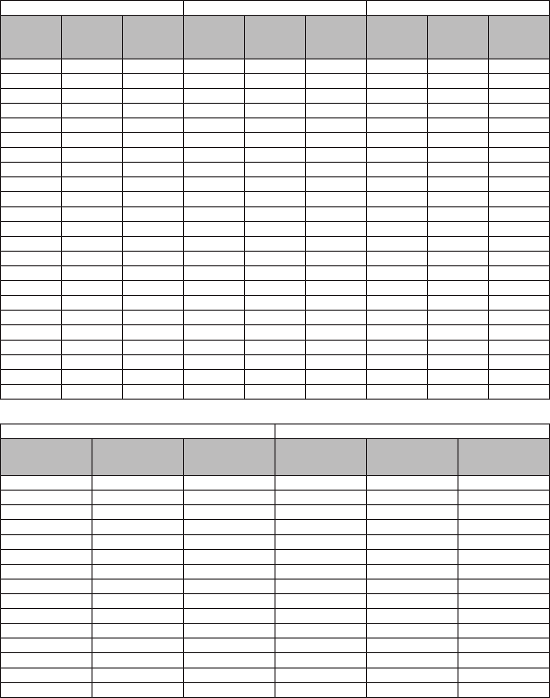
80
Cybex Owner’s Manual
81
Males 50-54 and Males 55+ Males 40-44 and Males 45-49 Males 50-54 and Males 55+
1.5 Mile Run
Time (min.)
VO2 (ml/
kg/min)
Submaximal
Estimates
Component
Points
1.5 Mile Run
Time (min.)
VO2 (ml/
kg/min)
Submaximal
estimates
Component
Points
1.5 Mile Run
Time (min.)
VO2 (ml/
kg/min)
Submaximal
Estimates
Component
Points
>11:06 >47 50.00 <10:24 >50 50.00 >11:06 >47 50.00
11:06 47 50.00 10:24 50 50.00 11:06 47 50.00
11:07-11:24 46 47.50 10:25-10:36 49 47.50 11:07-11:24 46 47.50
11:25-11:36 45 45.00 10:37-10:54 48 45.00 11:25-11:36 45 45.00
11:37-12:12 43-44 43.50 10:55-11:24 46-47 43.50 11:37-12:12 43-44 43.50
12:13-12:54 41-42 42.00 11:25-11:54 44-45 42.00 12:13-12:54 41-42 42.00
12:55-13:36 39-40 40.50 11:55-12:30 42-43 40.50 12:55-13:36 39-40 40.50
13:37-14:24 37-38 39.00 12:31-13:12 40-41 39.00 13:37-14:24 37-38 39.00
14:25-15:18 35-36 37.50 13:13-13:36 39 37.50 14:25-15:18 35-36 37.50
15:19-15:48 34 36.00 13:37-14:24 37-38 36.00 15:19-15:48 34 36.00
15:49-16:54 32-33 34.00 14:25-15:18 35-36 34.00 15:49-16:54 32-33 34.00
16:55-17:36 31 32.00 15:19-15:48 34 32.00 16:55-17:36 31 32.00
17:37-18:12 30 30.00 15:49-16:24 33 30.00 17:37-18:12 30 30.00
18:13-18:54 29 27.00 16:25-16:54 32 27.00 18:13-18:54 29 27.00
18:55-19:42 28 24.00 16:55-17:36 31 24.00 18:55-19:42 28 24.00
19:43-20:36 27 21.00 17:37-18:12 30 21.00 19:43-20:36 27 21.00
20:37-21:30 26 18.00 18:13-18:54 29 18.00 20:37-21:30 26 18.00
21:31-22:30 25 15.00 18:55-19:42 28 15.00 21:31-22:30 25 15.00
22:31-23:36 24 12.00 19:43-20:36 27 12.00 22:31-23:36 24 12.00
23:37-24:48 23 9.00 20:37-21:30 26 9.00 23:37-24:48 23 9.00
24:49-26:06 22 6.00 21:31-22:30 25 6.00 24:49-26:06 22 6.00
26:07-27:36 21 3.00 22:31-23:36 24 3.00 26:07-27:36 21 3.00
>27:36 <21 0.00 >23:36 <24 0.00 >27:36 <21 0.00
Female
Females <25 Females 25-29
1.5 Mile Run
Time (min.)
VO2 (ml/kg/min
Submaximal
Estimates
Component
Points
1.5 Mile Run
Time (min.)
VO2 (ml/kg/min)
Submaximal
Estimates
Component
Points
<11:06 >47 50.00 <11:24 >46 50.00
11:06 47 50.00 11:24 46 50.00
11:07-11:36 45-46 47.50 11:25-11:36 45 47.50
11:37-11:54 44 45.00 11:37-11:54 44 45.00
11:55-12:30 42-43 43.50 11:55-12:30 42-43 43.50
12:31-13:12 40-41 42.00 12:31-13:12 40-41 42.00
13:13-14:00 38-39 40.50 13:13-14:00 38-39 40.50
14:01-14:54 36-37 39.00 14:01-14:54 36-37 39.00
14:55-15:18 35 37.50 14:55-15:18 35 37.50
15:19-15:48 34 36.00 15:19-15:48 34 36.00
15:49-16:24 33 34.00 15:49-16:24 33 34.00
16:25-16:54 32 32.00 16:25-16:54 32 32.00
16:55-17:36 31 30.00 16:55-17:36 31 30.00
17:37-18:12 30 27.00 17:37-18:12 30 27.00
18:13-18:54 29 24.00 18:13-18:54 29 24.00

Cybex Owner’s Manual
81
Females <25 Females 25-29
1.5 Mile Run
Time (min.)
VO2 (ml/kg/min
Submaximal
Estimates
Component
Points
1.5 Mile Run
Time (min.)
VO2 (ml/kg/min)
Submaximal
Estimates
Component
Points
18:55-19:42 28 21.00 18:55-19:42 28 21.00
19:43-20:36 27 18.00 19:43-20:36 27 18.00
20:37-21:30 26 15.00 20:37-21:30 26 15.00
21:31-22:30 25 12.00 21:31-22:30 25 12.00
22:31-23:36 24 9.00 22:31-23:36 24 9.00
23:37-24:48 23 6.00 23:37-24:48 23 6.00
24:49-26:06 22 3.00 24:49-26:06 22 3.00
>26:06 <22 0.00 >26:06 <22 0.00
Females 30-34 and Females 35-39 Females 40-44 and Females 45-49 Females 50-54 and Females 55+
1.5 Mile Run
Time (min.)
VO2 (ml/
kg/min)
Submaximal
Estimates
Component
Points
1.5 Mile Run
Time (min.)
VO2 (ml/
kg/min)
Submaximal
Estimates
Component
Points
1.5 Mile Run
Time (min.)
VO2(ml/
kg/min)
Submaximal
Estimates
Component
Points
<11:54 >44 50.00 <12:30 >42 50.00 <14:24 >37 50.00
11:54 44 50.00 12:30 42 50.00 14:24 37 50.00
11:55-12:30 42-43 47.50 12:31-12:54 41 47.50 14:25-14:54 36 47.50
12:31-12:54 41 45.00 12:55-13:12 40 45.00 14:55-15:18 35 45.00
12:55-13:12 40 43.50 13:13-14:00 38-39 43.50 15:19-16:24 33-34 43.50
13:13-13:36 39 42.00 14:01-14:54 36-37 42.00 16:25-16:54 32 42.00
13:37-14:24 37-38 40.50 14:55-15:48 34-35 40.50 16:55-17:36 31 40.50
14:25-14:54 36 39.00 15:49-16:24 33 39.00 17:37-18:12 30 39.00
14:55-15:18 35 37.50 16:25-16:54 32 37.50 18:13-18:54 29 37.50
15:19-15:48 34 36.00 16:55-17:36 31 36.00 18:55-19:42 28 36.00
15:49-16:24 33 34.00 17:37-18:12 30 34.00 19:43-20:36 27 34.00
16:25-16:54 32 32.00 18:13-18:54 29 32.00 20:37-21:30 26 32.00
16:55-17:36 31 30.00 18:55-19:42 28 30.00 21:31-22:30 25 30.00
17:37-18:12 30 27.00 19:43-20:36 27 27.00 22:31-23:36 24 27.00
18:13-18:54 29 24.00 20:37-21:30 26 24.00 23:37-24:48 23 24.00
18:55-19:42 28 21.00 21:31-22:30 25 21.00 24:49-26:06 22 21.00
19:43-20:36 27 18.00 22:31-23:36 24 18.00 26:07-27:36 21 18.00
20:37-21:30 26 15.00 23:37-24:48 23 15.00 27:37-29:18 20 15.00
21:31-22:30 25 12.00 24:49-26:06 22 12.00 29:19-31:12 19 12.00
22:31-23:36 24 9.00 26:07-27:36 21 9.00 31:13-33:18 18 9.00
23:37-24:48 23 6.00 27:37-29:18 20 6.00 33:19-35:48 17 6.00
24:49-26:06 22 3.00 29:19-31:12 19 3.00 35:49-38:36 16 3.00
>26:06 <22 0.00 >31:12 <19 0.00 >38:36 <16 0.00

82
Cybex Owner’s Manual
83
Navy < 5K
Workout Overview
This workout was designed by the Navy to test, evaluate, and measure tness levels. The goal is
to complete the set distance of 1.5 miles (2.4 km) in the least amount of time. The user controls the
speed as needed to reach the goal. A point value will be given at the completion of the test.
Use this workout when performing the test at altitudes below 5,000 feet (1,524 meters).
Input information:
Age
Weight
Gender
Starting Speed
Male
17-19 20-24 25-29 30-34
Category Level Component
Points
1.5 Mile Run
Time (min.)
1.5 Mile Run
Time (min.)
1.5 Mile Run
Time (min.)
1.5 Mile Run
Time (min.)
Outstanding High 100 8:15 8:30 8:55 9:20
Outstanding Medium 95 8:45 9:00 9:23 9:45
Outstanding Low 90 9:00 9:15 9:38 10:00
Excellent High 85 9:15 9:45 10:15 10:30
Excellent Medium 80 9:30 10:00 10:30 11:00
Excellent Low 75 9:45 10:30 10:52 11:15
Good High 70 10:00 10:45 11:23 12:00
Good Medium 65 10:30 11:30 12:15 13:00
Good Low 60 11:00 12:00 12:53 13:45
Satisfactory High 55 12:00 12:45 13:23 14:00
Satisfactory Medium 50 12:15 13:15 13:45 14:15
Probationary 45 12:30 13:30 14:00 14:30
35-39 40-44 45-49 50-54 55-59 60-64 65+
1.5 Mile Run
Time (min.)
1.5 Mile Run
Time (min.)
1.5 Mile Run
Time (min.)
1.5 Mile Run
Time (min.)
1.5 Mile Run
Time (min.)
1.5 Mile Run
Time (min.)
1.5 Mile Run
Time (min.)
9:25 9:30 9:33 9:35 10:42 11:21 11:41
9:53 10:00 10:08 10:15 11:09 11:48 12:13
10:08 10:15 10:30 10:45 11:25 12:04 12:43
10:38 10:45 11:08 11:30 11:57 12:40 13:20
11:08 11:15 11:38 12:00 12:29 13:16 13:57
11:23 11:45 12:08 12:30 13:12 13:53 14:34
12:23 12:45 13:00 13:15 14:13 15:00 15:47
13:23 13:45 14:08 14:30 15:14 16:07 17:00
14:08 14:30 14:53 15:15 16:15 17:14 18:13
14:23 14:45 15:15 15:45 16:33 17:47 19:00
14:45 15:15 15:45 16:15 16:51 18:20 19:47
15:00 15:30 16:08 16:45 17:09 18:52 20:35

Cybex Owner’s Manual
83
Female
17-19 20-24 25-29 30-34
Category Level Component
Points
1.5 Mile Run
Time (min.)
1.5 Mile Run
Time (min.)
1.5 Mile Run
Time (min.)
1.5 Mile Run
Time (min.)
Outstanding High 100 9:29 9:47 10:17 10:46
Outstanding Medium 95 11:15 11:15 11:30 11:45
Outstanding Low 90 11:30 11:30 11:45 12:00
Excellent High 85 11:45 12:15 12:30 12:45
Excellent Medium 80 12:00 12:45 13:00 13:15
Excellent Low 75 12:30 13:15 13:23 13:30
Good High 70 12:45 13:30 14:00 14:30
Good Medium 65 13:00 13:45 14:30 15:15
Good Low 60 13:30 14:15 14:53 15:30
Satisfactory High 55 14:15 15:00 15:23 15:45
Satisfactory Medium 50 14:45 15:15 15:45 16:15
Probationary 45 15:00 15:30 16:08 16:45
35-39 40-44 45-49 50-54 55-59 60-64 65+
1.5 Mile Run
Time (min.)
1.5 Mile Run
Time (min.)
1.5 Mile Run
Time (min.)
1.5 Mile Run
Time (min.)
1.5 Mile Run
Time (min.)
1.5 Mile Run
Time (min.)
1.5 Mile Run
Time (min.)
10:51 10:56 10:58 11:00 12:23 13:34 14:45
11:53 12:00 12:08 12:15 13:39 14:50 16:01
12:08 12:15 12:30 12:45 13:57 15:08 16:19
12:53 13:00 13:15 13:30 14:25 15:34 16:43
13:23 13:30 13:45 14:00 14:53 16:00 17:07
13:45 14:00 14:08 14:15 15:20 16:25 17:30
14:38 14:45 15:00 15:15 16:09 17:17 18:18
15:30 15:45 15:53 16:00 16:58 18:06 19:06
15:53 16:15 16:30 16:45 17:48 18:51 19:54
16:15 16:45 16:53 17:00 18:03 19:08 20:13
16:38 17:00 17:08 17:15 18:18 19:25 20:31
17:00 17:15 17:23 17:30 18:34 19:43 20:52

84
Cybex Owner’s Manual
85
Navy > 5K
Workout Overview
This workout was designed by the Navy to test, evaluate, and measure tness levels. The goal is
to complete the set distance of 1.5 miles (2.4 km) in the least amount of time. The user controls the
speed as needed to reach the goal. A point value will be given at the completion of the test.
Use this workout when performing the test at altitudes above 5,000 feet (1,524 meters).
Input information:
Age
Weight
Gender
Starting Speed
Male
17-19 20-24 25-29 30-34
Category Level Component
Points
1.5 Mile Run
Time (min.)
1.5 Mile Run
Time (min.)
1.5 Mile Run
Time (min.)
1.5 Mile Run
Time (min.)
Outstanding High 100 9:00 9:15 9:43 10:10
Outstanding Medium 95 9:30 9:50 10:15 10:40
Outstanding Low 90 9:50 10:05 10:30 10:55
Excellent High 85 10:05 10:40 11:13 11:45
Excellent Medium 80 10:20 10:55 11:28 12:00
Excellent Low 75 10:40 11:25 11:50 12:15
Good High 70 10:55 11:45 12:25 13:05
Good Medium 65 11:25 12:30 13:20 14:10
Good Low 60 12:00 13:05 14:03 15:00
Satisfactory High 55 13:05 13:55 14:35 15:15
Satisfactory Medium 50 13:20 14:25 14:58 15:30
Probationary 45 13:40 14:45 15:18 15:50
35-39 40-44 45-49 50-54 55-59 60-64 65+
1.5 Mile Run
Time (min.)
1.5 Mile Run
Time (min.)
1.5 Mile Run
Time (min.)
1.5 Mile Run
Time (min.)
1.5 Mile Run
Time (min.)
1.5 Mile Run
Time (min.)
1.5 Mile Run
Time (min.)
10:15 10:20 10:23 10:25 11:46 12:29 12:51
10:48 10:55 11:03 11:10 12:16 12:59 13:26
11:03 11:10 11:28 11:45 12:34 13:16 13:59
11:45 11:45 12:08 12:30 13:09 13:56 14:40
12:08 12:15 12:40 13:05 13:44 14:36 15:21
12:33 12:50 13:15 13:40 14:31 15:16 16:01
13:30 13:55 14:10 14:25 15:38 16:30 17:22
14:35 15:00 15:25 15:50 16:45 17:44 18:42
15:25 15:50 16:15 16:40 17:53 18:57 20:02
15:40 16:05 16:38 17:10 18:12 19:34 20:54
16:05 16:40 17:13 17:45 18:32 20:10 21:46
16:23 16:55 17:35 18:15 18:52 20:45 22:39

Cybex Owner’s Manual
85
Female
17-19 20-24 25-29 30-34
Category Level Component
Points
1.5 Mile Run
Time (min.)
1.5 Mile Run
Time (min.)
1.5 Mile Run
Time (min.)
1.5 Mile Run
Time (min.)
Outstanding High 100 10:20 10:40 11:13 11:45
Outstanding Medium 95 12:15 12:15 12:33 12:50
Outstanding Low 90 12:30 12:30 12:48 13:05
Excellent High 85 12:50 13:20 13:38 13:55
Excellent Medium 80 13:05 13:55 14:10 14:25
Excellent Low 75 13:40 14:25 14:35 14:45
Good High 70 13:55 14:45 15:18 15:50
Good Medium 65 14:10 15:00 15:50 16:40
Good Low 60 14:45 15:30 16:13 16:55
Satisfactory High 55 15:30 16:20 16:45 17:10
Satisfactory Medium 50 16:05 16:40 17:13 17:45
Probationary 45 16:20 16:55 17:35 18:15
35-39 40-44 45-49 50-54 55-59 60-64 65+
1.5 Mile Run
Time (min.)
1.5 Mile Run
Time (min.)
1.5 Mile Run
Time (min.)
1.5 Mile Run
Time (min.)
1.5 Mile Run
Time (min.)
1.5 Mile Run
Time (min.)
1.5 Mile Run
Time (min.)
11:50 11:55 11:58 12:00 13:37 14:55 16:14
12:58 13:05 13:13 13:20 15:01 16:19 17:37
13:13 13:20 13:38 13:55 15:21 16:39 17:57
14:03 14:10 14:28 14:45 15:52 17:07 18:23
14:35 14:45 15:00 15:15 16:22 17:36 18:50
15:00 15:15 15:23 15:30 16:52 18:04 19:15
15:58 16:05 16:23 16:40 17:46 19:01 20:08
16:55 17:10 17:18 17:25 18:40 19:55 21:01
17:20 17:45 18:00 18:15 19:35 20:44 21:53
17:43 18:15 18:23 18:30 19:51 21:03 22:14
18:08 18:30 18:40 18:50 20:08 21:22 22:34
18:33 18:50 18:58 19:05 20:25 21:41 22:57
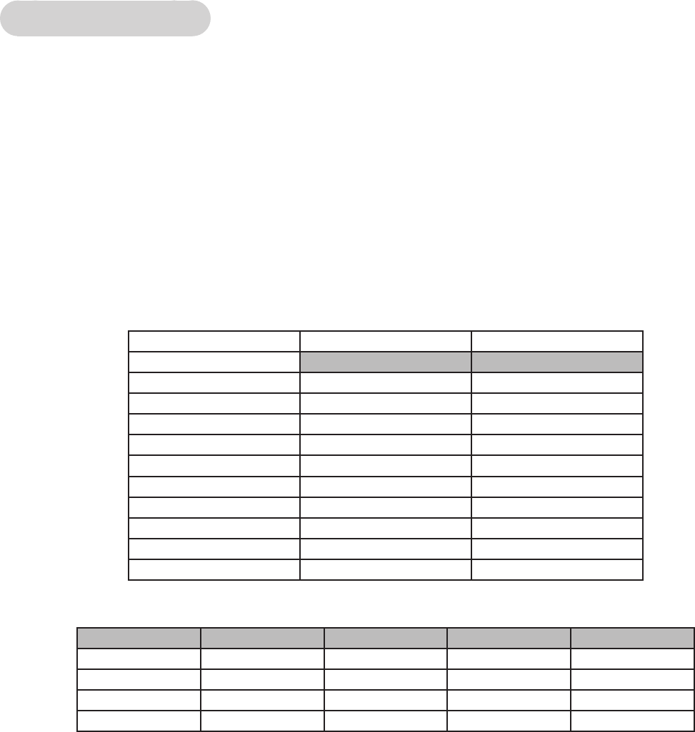
86
Cybex Owner’s Manual
87
Marines Sea Level
Workout Overview
This workout was designed by the Marines to test, evaluate, and measure tness levels. The goal is
to complete the set distance of 3.0 miles (4.8 km) in the least amount of time. The user controls the
speed as needed to reach the goal. A point value will be given at the completion of the test.
Use this workout when performing the test at altitudes below 4,500 feet (1,372 meters).
Input information:
Age
Weight
Gender
Starting Speed
Points Male Female
3 mile run no altitude 3 mile run no altitude
100 18:00 21:00
90 19:40 22:40
80 21:20 24:20
70 23:00 26:00
60 24:40 27:40
50 26:20 29:20
40 28:00 31:00
30 29:40 32:40
20 31:20 34:20
10 33:00 36:00
Required minimum score
Age Unsatisfactory 3rd Class 2nd Class 1st Class
17-26 0-134 135 175 225
27-39 0-109 110 150 200
40-45 0-87 88 125 175
46+ 0-64 65 100 150
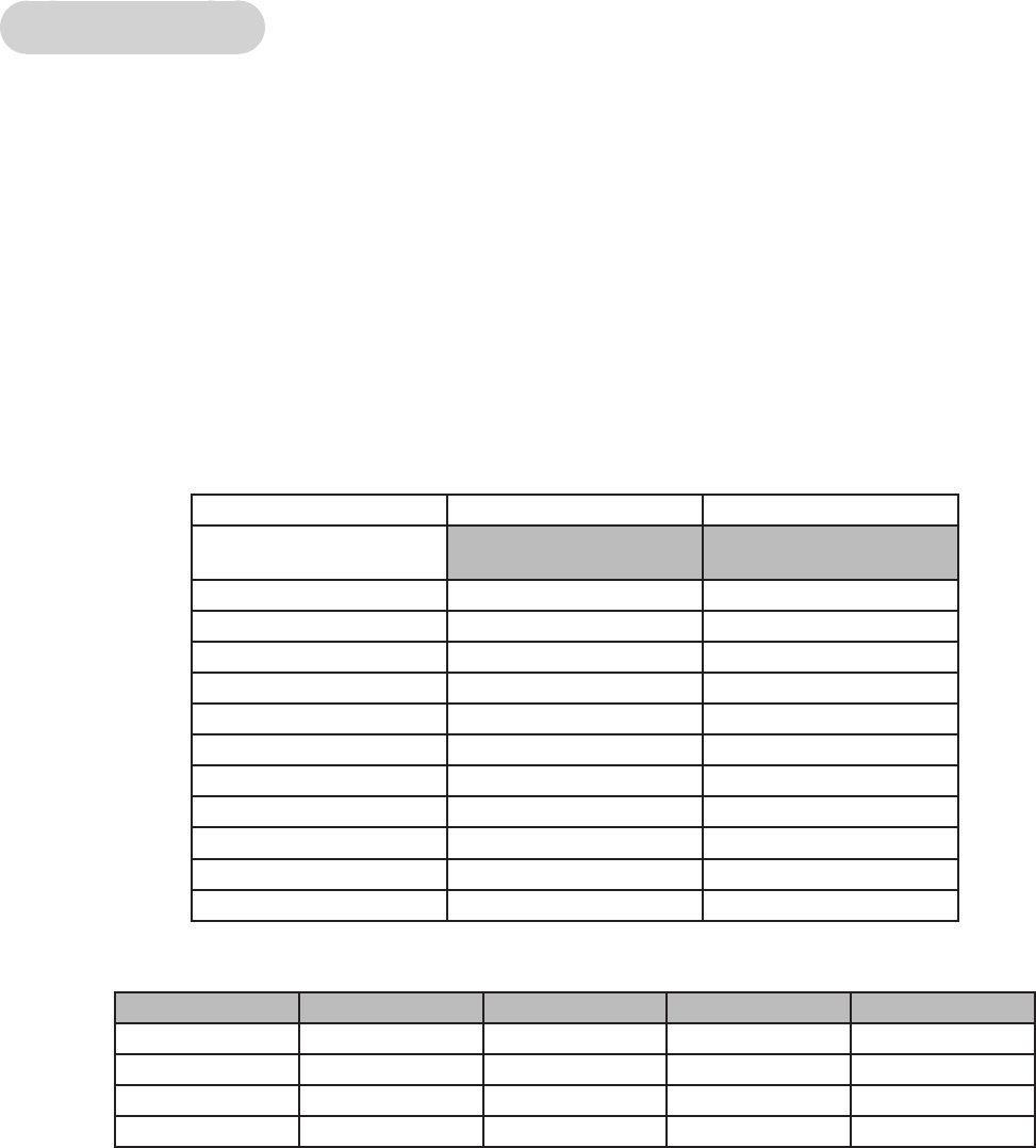
Cybex Owner’s Manual
87
Marines > 4.5K
Workout Overview
This workout was designed by the Marines to test, evaluate, and measure tness levels. The goal is
to complete the set distance of 3.0 miles (4.8 km) in the least amount of time. The user controls the
speed as needed to reach the goal. A point value will be given at the completion of the test.
Use this workout when performing the test at altitudes above 4,500 feet (1,372 meters).
Input information:
Age
Weight
Gender
Starting Speed
Points Male Female
3 mile run 4,500 feet
above sea level
3 mile run 4,500 feet
above sea level
100 19:30 22:30
90 21:10 24:10
80 22:50 25:50
70 24:30 27:30
60 26:10 29:10
50 27:50 30:50
40 29:30 32:30
30 31:10 34:10
20 32:50 35:50
10 34:30 37:30
136:00 39:00
Required minimum score
Age Unsatisfactory 3rd Class 2nd Class 1st Class
17-26 0-134 135 175 225
27-39 0-109 110 150 200
40-45 0-87 88 125 175
46+ 0-64 65 100 150

88
Cybex Owner’s Manual
89
One Mile Test
Workout Overview
The objective of this test is to monitor the development of the athlete’s VO2 max.
Input information:
Age
Weight
Gender
Starting Speed
Heart rate
Heart Rate Requirements:
Wireless heart rate transmitter
Test procedure:
1. Record your weight
2. Walk one mile (1,609 metres) as fast as possible
3. Record the time to complete the one mile walk
4. Immediately on nishing the walk record your heart rate (beats per minute)
5. Determine your VO2 max
The formula used to calculate VO2 max is:
132.853 - (0.0769 * Weight) - (0.3877 * Age) + (6.315 * Gender) - (3.2649 * Time) - (0.1565 * Heart
rate)
Input values are:
Weight is in pounds (lbs)
Age is in years
Gender Male = 1 and Female = 0
Time is expressed in minutes and 100ths of minutes
Heart rate is in beats/min

Cybex Owner’s Manual
89
Analysis of VO2 max scores
Male (values in ml/kg/min)
Age Very Poor Poor Fair Good Excellent Superior
13-19 <35.0 35.0 - 38.3 38.4 - 45.1 45.2 - 50.9 51.0 - 55.9 >55.9
20-29 <33.0 33.0 - 36.4 36.5 - 42.4 42.5 - 46.4 46.5 - 52.4 >52.4
30-39 <31.5 31.5 - 35.4 35.5 - 40.9 41.0 - 44.9 45.0 - 49.4 >49.4
40-49 <30.2 30.2 - 33.5 33.6 - 38.9 39.0 - 43.7 43.8 - 48.0 >48.0
50-59 <26.1 26.1 - 30.9 31.0 - 35.7 35.8 - 40.9 41.0 - 45.3 >45.3
60+ <20.5 20.5 - 26.0 26.1 - 32.2 32.3 - 36.4 36.5 - 44.2 >44.2
Female (values in ml/kg/min)
Age Very Poor Poor Fair Good Excellent Superior
13-19 <25.0 25.0 - 30.9 31.0 - 34.9 35.0 - 38.9 39.0 - 41.9 >41.9
20-29 <23.6 23.6 - 28.9 29.0 - 32.9 33.0 - 36.9 37.0 - 41.0 >41.0
30-39 <22.8 22.8 - 26.9 27.0 - 31.4 31.5 - 35.6 35.7 - 40.0 >40.0
40-49 <21.0 21.0 - 24.4 24.5 - 28.9 29.0 - 32.8 32.9 - 36.9 >36.9
50-59 <20.2 20.2 - 22.7 22.8 - 26.9 27.0 - 31.4 31.5 - 35.7 >35.7
60+ <17.5 17.5 - 20.1 20.2 - 24.4 24.5 - 30.2 30.3 - 31.4 >31.4
90
Cybex Owner’s Manual
PB
