Publication D39712880 Edwards TIC Instruction Manual
User Manual:
Open the PDF directly: View PDF ![]() .
.
Page Count: 46
- Contents
- Illustrations
- Tables
- 1 Introduction
- 2 Technical data
- 3 Installation
- 4 Operation
- 4.1 Front panel description
- 4.2 Menu structure
- 4.3 Navigating the menu
- 4.4 The view screen
- 4.5 Turning pumps and relays on/off
- 4.6 Changing list items
- 4.7 Changing numerical values
- 4.8 Turbo setup
- 4.9 Backing setup
- 4.10 Alarms
- 4.11 The main menu
- 4.12 Turbo status
- 4.13 Backing status
- 4.14 Parameters/units
- 4.15 Relay setpoint outputs
- 4.16 Service information
- 4.17 Electrical supply failure
- 5 Maintenance
- 6 Storage and disposal
- 7 Service, spares and accessories
D397-12-880
Issue L
Instruction Manual
Turbo Controller
Description Item Number
TIC Turbo Controller 100 W D397-11-000
TIC Turbo Controller 200 W D397-12-000
Original Instructions
This page has been intentionally left blank.

Declaration of Conformity
We, Edwards,
Innovation Drive,
Burgess Hill,
West Sussex,
RH15 9TW, UK
declare under our sole responsibility, as manufacturer and person within the EU authorised
to assemble the technical file, that the product(s)
TIC Instrument Controller D397-00-000
TIC Instrument Controller 6-Gauge D397-01-000
TIC Instrument Controller 6-Gauge Capacitance Manometer D397-02-000
TIC Turbo Controller 100W D397-11-000
TIC Turbo Controller 200W D397-12-000
TIC Turbo & Instrument Controller 100W D397-21-000
TIC Turbo & Instrument Controller 200W D397-22-000
to which this declaration relates is in conformity with the following standard(s) or other
normative document(s)
EN61010-1:2010 Safety Requirements for Electrical Equipment for
Measurement, Control and Laboratory Use – Part 1: General
Requirements
EN61326-1:2013 Electrical Equipment for Measurement Control and Laboratory
(Class B Emissions, Use – EMC Requirements. General requirements
Industrial Immunity)
CAN/CSA-C22.2 Safety requirements for electrical equipment for
No.61010-1-04 measurement, Control and laboratory use – Part 1: General
requirements
UL61010-1, 2nd Edition Safety requirements for electrical equipment for
measurement, Control and laboratory use – Part 1: General
requirements
and fulfils all the relevant provisions of
2014/35/EU Low Voltage Directive
2014/30/EU Electromagnetic Compatibility (EMC) Directive
2012/19/EU Waste from Electrical and Electronic Equipment (WEEE)
Directive
2011/65/EU Restriction of Certain Hazardous Substances (RoHS) Directive
Note: This declaration covers all product serial numbers from the date this Declaration was
signed onwards.
20.09.2016, Eastbourne
Larry Marini, Senior Technical Manager Date and Place
P200-03-140 Issue G
This product has been manufactured under a quality management system certified to ISO 9001:2008
P200-10-044
Issue A
Material Declaration
In accordance with the requirements of the Chinese regulatory requirement on the Management Methods for the
Restriction of the Use of Hazardous Substances in Electrical and Electronic Products Order No. 32 (also known as
‘China RoHS2’) and SJ/T 11364 Marking for the Restricted Use of Hazardous Substances in Electronic and Electrical
Products:
Product Product Label Meaning
D39700000 TIC Instrument Controller
D39701000 TIC Instrument Controller 6 Gauge
D39702000 TIC Instrument Controller 6 Gauge
Capacitance Manometer
D39711000 TIC Turbo Controller 100 W
D39712000 TIC Turbo Controller 200 W
D39721000 TIC Turbo and Instrument
Controller 100 W
D39722000 TIC Turbo and Instrument
Controller 200 W
This product contains hazardous substances in at
least one of the homogeneous materials used
which are above the limit requirement in GB/T
26572 as detailed in the declaration table below.
These parts can safely be used for the
environmental protection use period as
indicated.
材料成分声明
Materials Content Declaration
部件名称
Part name
有害物质
Hazardous Substances
铅
Lead
(Pb)
汞
Mercury
(Hg)
镉
Cadmium
(Cd)
六价铬
Hexavalent
Chromium
(Cr VI)
多溴联苯
Polybrominated
biphenyls (PBB)
多溴二苯醚
Polybrominated
diphenyl ethers
(PBDE)
印刷电路组件 (PCA)
Printed Circuit
Assembly (PCA)
X O X O O O
电缆/电线/连接器
Cable/wire/connector
X O O O O O
机械部件
Mechanical Components X O O O O O
O: 表示该有害物质在该部件的所有均质材料中的含量低于 GB/T 26572 标准规定的限量要求。
O: Indicates that the hazardous substance contained in all of the homogeneous materials for this part is
below the limit requirement in GB/T 26572.
X: 表示该有害物质在该部件的至少一种均质材料中的含量超出 GB/T26572 标准规定的限量要求。
X: Indicates that the hazardous substance contained in at least one of the homogeneous materials used for
this part is above the limit requirement of GB/T26572.
NOTE: These products are EU RoHS compliant, the following Exemptions apply:
6(b)
Lead
as an alloying element in aluminium containing up to 0.4% by weight
6(c) Copper alloy containing up to 4%
lead
by weight
7(a)
Lead
in in high melting temperature type solder (i.e. lead based alloys containing 85% by or more)
7(b)
Lead
in solders for servers, storage and storage array systems, network infrastructure equipment for switching, signalling,
transmission, and network management for telecommunications
7(c) I Electrical and electronic components containing
lead
in a glass or ceramic other than dielectric ceramic in capacitors, e.g.
piezoelectronic devices, or in a glass or ceramic matrix compound
7(c) II
Lead
in dielectric ceramic in capacitors for a rated voltage of 125 V AC or 250 V DC or higher
8(b)
Cadmium
and its compounds in electrical contacts
15
Lead
in solders to complete a viable electrical connection between semiconductor die and carrier within integrated circuit flip
chip packages
34
Lead
in cermet-based trimmer potentiometer elements

© Edwards Limited 2016. All rights reserved. Page i
Edwards and the Edwards logo are trademarks of Edwards Limited.
Contents
D397-12-880 Issue L
Contents
Section Page
1 Introduction .......................................................................................1
1.1 Scope and definitions ................................................................................................... 1
1.2 Product description ...................................................................................................... 1
2 Technical data ....................................................................................3
2.1 Electrical data ............................................................................................................ 3
2.2 Operating and storage data ............................................................................................ 3
2.3 Mechanical data .......................................................................................................... 3
2.4 Connections ............................................................................................................... 4
2.4.1 Turbo pump connector .................................................................................................. 4
2.4.2 Backing pump connector ............................................................................................... 5
2.4.3 Auxiliary terminals ...................................................................................................... 6
2.4.4 Logic interface ...........................................................................................................7
2.4.5 Serial communications .................................................................................................. 8
3 Installation .........................................................................................9
3.1 Unpack and inspect ...................................................................................................... 9
3.2 Fitting the controller .................................................................................................... 9
3.3 Controller electrical connections ....................................................................................12
3.3.1 Connecting the electrical supply .....................................................................................12
3.3.2 Additional earth bonding ..............................................................................................12
3.3.3 Connecting a turbo pump ..............................................................................................13
3.3.4 Connecting a backing pump ...........................................................................................13
3.3.5 Connecting a vent valve ...............................................................................................13
3.3.6 Connecting an air cooler ...............................................................................................13
3.3.7 Connecting the logic interface .......................................................................................13
3.3.8 Connecting the serial interface .......................................................................................15
4 Operation ........................................................................................ 17
4.1 Front panel description ................................................................................................17
4.2 Menu structure ..........................................................................................................18
4.3 Navigating the menu ...................................................................................................20
4.4 The view screen .........................................................................................................20
4.5 Turning pumps and relays on/off .....................................................................................20
4.6 Changing list items .....................................................................................................21
4.7 Changing numerical values ............................................................................................21
4.8 Turbo setup ..............................................................................................................21
4.8.1 Introduction .............................................................................................................21
4.8.2 Default turbo setup options ...........................................................................................22
4.8.3 Additional setup options using a DX or nEXT pump ................................................................23
4.9 Backing setup ............................................................................................................25
4.10 Alarms ....................................................................................................................26
4.11 The main menu ..........................................................................................................26
4.12 Turbo status .............................................................................................................26
4.13 Backing status ...........................................................................................................27
4.14 Parameters/units .......................................................................................................28
4.15 Relay setpoint outputs .................................................................................................28
4.16 Service information .....................................................................................................28
4.17 Electrical supply failure ...............................................................................................29
mv/06/14

D397-12-880 Issue L
Page ii © Edwards Limited 2016. All rights reserved.
Edwards and the Edwards logo are trademarks of Edwards Limited.
Contents
5 Maintenance ..................................................................................... 31
5.1 Safety .....................................................................................................................31
5.2 Fault finding .............................................................................................................31
5.3 Cleaning the controller ................................................................................................31
5.4 Software updates .......................................................................................................32
5.5 Factory defaults .........................................................................................................32
6 Storage and disposal ........................................................................... 33
6.1 Storage ...................................................................................................................33
6.2 Disposal ...................................................................................................................33
7 Service, spares and accessories .............................................................. 35
7.1 Introduction .............................................................................................................35
7.2 Service ....................................................................................................................35
7.3 Spares .....................................................................................................................35
7.4 Accessories ...............................................................................................................35
For return of equipment, complete the HS Forms at the end of this manual.
Illustrations
Figure Page
1 Pin connections for a 15-way sub-miniature ‘D’ type socket ..................................................... 4
2 Pin connections for a 15-way sub-miniature ‘D’ type socket ..................................................... 5
3 4-way screw terminal block ............................................................................................ 6
4 Pin connections for a 25-way sub-miniature ‘D’ type socket ..................................................... 7
5 Pin connections for a 9-way sub-miniature ‘D’ type socket ...................................................... 8
6 Bench mounted TIC dimensions (mm) ...............................................................................10
7 Front panel removal ....................................................................................................10
8 Rack mounting of a TIC ................................................................................................11
9 Panel cutout drawing ..................................................................................................11
10 Rear panel connections ................................................................................................12
11 IBM PC RS232 interface - 9-way ......................................................................................15
12 IBM PC RS232 interface - 25-way .....................................................................................16
13 RS485 TIC network ......................................................................................................16
14 Front panel display .....................................................................................................17
15 View screen shortcuts ..................................................................................................18
16 Menu structure ..........................................................................................................19
17 Pump status ..............................................................................................................20
18 Changing numerical values ............................................................................................21
19 Turbo setup screen .....................................................................................................22

© Edwards Limited 2016. All rights reserved. Page iii
Edwards and the Edwards logo are trademarks of Edwards Limited.
Contents
D397-12-880 Issue L
Tables
Table Page
1 Compatible equipment for the TIC range ............................................................................ 2
2 Turbo pump connector pin-out ........................................................................................ 4
3 Backing pump connector pin-out ...................................................................................... 6
4 Auxiliary connector pin-out ............................................................................................ 7
5 Logic interface connector pin-out .................................................................................... 7
6 Serial communications connector pin-out ........................................................................... 8
7 Checklist of components ................................................................................................ 9
8 Front panel symbols and their functions ............................................................................17
9 Default turbo setup options ...........................................................................................22
10 Error/diagnostic monitoring, pumps .................................................................................23
11 Turbo pump vent setup differences .................................................................................23
12 Turbo pump vent options ..............................................................................................24
13 Turbo pump vent type .................................................................................................24
14 DX, nEXT and nXDS pump setup options .............................................................................24
15 Error/diagnostic monitoring, DX, nEXT and nXDS pumps .........................................................24
16 Default Backing setup options ........................................................................................25
17 nXDS pump setup options ..............................................................................................25
18 nEXT Service Screen ....................................................................................................26
19 nEXT Service Reset Screen ............................................................................................27
20 nXDS Service Screen ....................................................................................................27
21 nXDS Service Reset Screen ............................................................................................28
22 Fault finding .............................................................................................................31
23 Factory default settings ...............................................................................................32
24 Accessories ...............................................................................................................35

This page has been intentionally left blank.
D397-12-880 Issue L
Page iv © Edwards Limited 2016. All rights reserved.
Edwards and the Edwards logo are trademarks of Edwards Limited.
© Edwards Limited 2016. All rights reserved. Page 1
Edwards and the Edwards logo are trademarks of Edwards Limited.
Introduction
D397-12-880 Issue L
1Introduction
1.1 Scope and definitions
This manual provides Installation, Operation and Maintenance instructions for the Edwards Turbo Controller. The
controller must be used as specified in this manual. Read this manual before installing and operating the controller.
Important safety information is highlighted as WARNING and CAUTION instructions; these instructions must be
obeyed. The use of WARNINGS and CAUTIONS is defined below.
CAUTION
Cautions are given where failure to observe the instruction could result in damage to the equipment, associated
equipment and process.
The units used throughout this manual conform to the SI international system of units of measurement.
The following warning labels are on the controller:
1.2 Product description
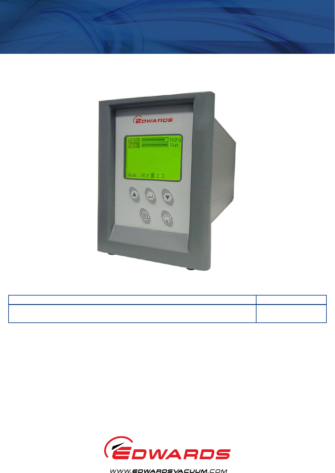
There are two variants of the Turbo Controller, both of which are provided with a large clear graphics display, easy-
to-use control interface via a touch sensitive keypad, an RS232/485 interface for control and data monitoring on a
remote PC and a logic interface for interface with associated system hardware.
The compatible pumps/accessories that can be used with the Turbo Controller are listed in Table 1.
WARNING
Warnings are given where failure to observe the instruction could result in injury or death to
people.
Warning - refer to accompanying documentation.
Edwards offer European customers a recycling service.
WARNING
Improper use of the equipment could cause damage to it or injury to people. The user is
responsible for the safe operation and monitoring of the equipment. Hazardous voltages should not
be connected to this unit except where specified.

D397-12-880 Issue L
Page 2 © Edwards Limited 2016. All rights reserved.
Edwards and the Edwards logo are trademarks of Edwards Limited.
Introduction
Table 1 - Compatible equipment for the TIC range
TIC variant Compatibility
TIC Turbo Controller 100 W EXT75DX - fast ramp
EXT255DX - slow ramp
nEXT240/300/400 family - slow ramp
nEXT85 family - fast ramp
EXT70H + EXDC80 - fast ramp
EXT255H + EXDC80 - slow ramp
Mains backing pumps, XDS scroll, up to RV12 (via an
optional relay box)
Air Cooler, ACX70 and ACX250
Vent Valve, TAV5 and TAV6
Bakeout band (via an optional relay box)
24 V backing line valves, LCPV16EKA and LCPV25EKA (via
an optional relay box)
TIC Turbo Controller 200 W Same as the 100 W version plus the following:
24 V backing pump
EXT255H + EXDC160 - fast ramp
EXT255DX - fast ramp
nEXT family - fast ramp

© Edwards Limited 2016. All rights reserved. Page 3
Edwards and the Edwards logo are trademarks of Edwards Limited.
Technical data
D397-12-880 Issue L
2Technical data
2.1 Electrical data
2.2 Operating and storage data
2.3 Mechanical data
Connector type CEE/IEC 320
Electrical supply 100 - 240 V a.c. 50/60 Hz
Power consumption
TIC Turbo Controller 100 W 215 VA maximum (D397-11-000)
TIC Turbo Controller 200 W 350 VA maximum (D397-12-000)
Peak inrush current
11 A at 110 V a.c
23 A at 240 V a.c D397-11-000
D397-12-000
Fuse The unit is self-protecting and has no user-replaceable fuse.
The unit will recover once any overload is removed.
Overvoltage category 2
Earth Stud M4
Ambient operating temperature range 0 °C to 40 °C
Ambient storage temperature range -30 °C to 70 °C
Maximum ambient operating humidity Max 90% RH non condensing at 40 °C
Maximum operating altitude 3000 m max
IP rating 20
Pollution degree 2
Indoor use only
Weight
TIC Turbo Controller 100 W 1.8 kg
TIC Turbo Controller 200 W 1.9 kg

D397-12-880 Issue L
Page 4 © Edwards Limited 2016. All rights reserved.
Edwards and the Edwards logo are trademarks of Edwards Limited.
Technical data
2.4 Connections
2.4.1 Turbo pump connector
Figure 1 - Pin connections for a 15-way sub-miniature ‘D’ type socket
Connector type 15-way sub-miniature ‘D’ type socket (refer to Figure 1)
Power supply 24 V d.c.
Maximum output power
100 W TIC 80 W continuous, 120 W peak
200 W TIC 160 W continuous, 240 W peak (combined total power of the
24 V turbo and backing pumps)
Input voltage range -0.5 V to 15 V
Output ID current 33 µA, 0 V to 13 V
Control output
active <1.1 V d.c. (Iout 20 mA max)
<0.8 V d.c. (Iout <2 mA)
inactive open (<24 V d.c. externally applied)
Control input
low <4.0 V d.c. (Iout<160 µA)
high 7.0 V to 24 V d.c. (internally pulled up to 24 V)
RS232 transmit
disabled open
enabled 0: > +8 V (Iout max: 8 mA)
1: < -8 V (Iout max: -8 mA)
RS232 receive
mark <4.0 V d.c. (Iout < 160 µA)
space 7.0 V to 24 V d.c. (internal pull up to 24 V)
Maximum cable length 7 m
Table 2 - Turbo pump connector pin-out
Pin Allocation
1 Power supply positive
2 Signal common
3 /Start signal output
4RS232 Tx
5 /Serial enable output
6 Power supply positive
7RS232 Rx
8Power supply common
9 Speed signal input

© Edwards Limited 2016. All rights reserved. Page 5
Edwards and the Edwards logo are trademarks of Edwards Limited.
Technical data
D397-12-880 Issue L
2.4.2 Backing pump connector
Note: Only applicable to the 200 W TIC
Figure 2 - Pin connections for a 15-way sub-miniature ‘D’ type socket
10 Screen
11 Power supply positive
12 Screen
13 Power supply common
14 Power supply common
15 Normal signal input
Connector type 15-way sub-miniature ‘D’ type socket (refer to Figure 2)
Power supply 24 V d.c.
Maximum output power 160 W continuous, 240 W peak (combined total power of the
24 V turbo and backing pumps)
Output voltage range
Stop 0 V
Start 10 V (5 mA maximum)
Output ID current 33 µA, 0 V to 13 V
Control output
active <1.1 V d.c. (Iout < 20 mA)
<0.8 V d.c. (Iout < 2 mA)
inactive open (<24 V d.c. externally applied)
Control input
low <4.0 V d.c. (Iout<160 µA)
high 7.0 to 24 V d.c. (internally pulled up to 24 V)
RS232 transmit
disabled open
enabled 0: > +8 V (Iout max: 8 mA)
1: < -8 V (Iout max: -8 mA)
RS232 receive
mark <4.0 V d.c. (Iout < 160 µA)
space 7.0 V to 24 V d.c. (internal pull up to 24 V)
Maximum cable length 7 m
Table 2 - Turbo pump connector pin-out (continued)
Pin Allocation
D397-12-880 Issue L
Page 6 © Edwards Limited 2016. All rights reserved.
Edwards and the Edwards logo are trademarks of Edwards Limited.
Technical data
2.4.3 Auxiliary terminals
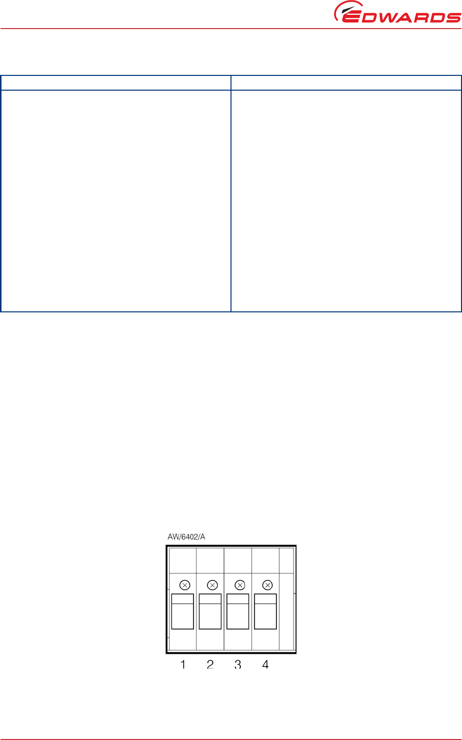
Figure 3 - 4-way screw terminal block
Table 3 - Backing pump connector pin-out
Pin Allocation
1 Power supply positive
2 Signal common
3 /Start signal output
4RS232 Tx
5 /Serial enable output
6 Power supply positive
7RS232 Rx
8Power supply common
9 Speed signal input
10 Screen
11 Power supply positive
12 Screen
13 Power supply common
14 Power supply common
15 Normal signal input
Connector type 4-way screw terminal block (refer to Figure 3)
Wire size 1.5 mm2 max
Power supply 24 V d.c.
Maximum output power
Fan 3 W max
Vent valve 2 W max
Control output
active <1.5 V d.c.
inactive open
Maximum cable length 10 m

© Edwards Limited 2016. All rights reserved. Page 7
Edwards and the Edwards logo are trademarks of Edwards Limited.
Technical data
D397-12-880 Issue L
2.4.4 Logic interface
Figure 4 - Pin connections for a 25-way sub-miniature ‘D’ type socket
Table 4 - Auxiliary connector pin-out
Pin Allocation
1 Fan control output
2Fan 24 V
3 Vent control output
4Vent 24 V
Connector type 25-way sub-miniature ‘D’ type socket (refer to Figure 4)
Power supply 24 V d.c.
Maximum output power 5 W
Control output
active <1.1 V d.c. (Iout < 20 mA)
<0.8 V d.c. (IIout < 2 mA)
inactive open
Control input
low <2.0 V d.c. (IIout<160 µA)
high 3.5 V to 24 V d.c. (internal pull up to 24 V)
Analogue output 0 to 10 V (5 mA max)
50 mV resolution
Table 5 - Logic interface connector pin-out
Pin Allocation
1Screen
2 Analogue output signal
3Setpoint 1 output
4 Vent control output
5 Bakeout band control output
6N/C
7Power supply common
8 Backing pump control output
9N/C
10 Power supply common
11 Power supply positive
12 Power supply common
13 Power supply common
14 Analogue output common
15 Setpoint 2 output
16 Setpoint 3 output
17 Turbo normal output
D397-12-880 Issue L
Page 8 © Edwards Limited 2016. All rights reserved.
Edwards and the Edwards logo are trademarks of Edwards Limited.
Technical data
2.4.5 Serial communications
Figure 5 - Pin connections for a 9-way sub-miniature ‘D’ type socket
18 Alarm output
19 Air cooler output
20 N/C
21 N/C
22 Backing pump enable input
23 Turbo stand-by control input
24 Turbo pump enable input
25 System interlock input (SYSI)
Connector type 9-way sub-miniature ‘D’ type socket (refer to Figure 5)
RS232 transmit
mark < - 8 V (Iout max: -8 mA)
space > +8 V (Iout max: -8 mA)
RS232 receive
mark < +1.0 V (Iin max: -2.0 mA)
space >+2.0 V (Iin max: +2.0 mA)
maximum input ±12 V
RS232 protocol 9600 baud, 1 stop bit, 8 data bits, no parity
RS485
Output differential >1.5 V (Iout max: 25 mA)
Input differential threshold > 0.2 V (Iin max: 1 mA)
Maximum input -7.0 V to +12 V
Bus load The TIC applies one unit load to the RS485 bus.
Table 6 - Serial communications connector pin-out
Pin Allocation
1N/C
2RS232 transmit
3RS232 receive
4N/C
5RS232 common
6N/C
7N/C
8RS485 data A
9RS485 data B
Table 5 - Logic interface connector pin-out (continued)
Pin Allocation
© Edwards Limited 2016. All rights reserved. Page 9
Edwards and the Edwards logo are trademarks of Edwards Limited.
Installation
D397-12-880 Issue L
3 Installation
3.1 Unpack and inspect
Remove all of the packaging material and check the controller. If the controller is damaged, follow the Edwards
return of equipment procedures that are laid out in the back of this manual. Do not use the controller if it is damaged.
Check that the package contains the items that are listed in Table 7. If any of these items are missing, notify the
supplier in writing within three days. If the controller is not to be used immediately, store the controller in suitable
conditions as described in Section 6.1.
3.2 Fitting the controller
CAUTION
Rubber feet must be fitted (Figure 6, item 1) so that there are correct clearances for air circulation. If not, the
performance of the controller may be affected at high operating temperatures.
The controller can be used on a bench top or can be fitted in a rack or cabinet. Figure 6 shows the dimensions of the
TIC that are required for bench top use.
Note: If the interlocks are not used, the logic interface adaptor must be fitted to the 25-way connector.
Table 7 - Checklist of components
Quantity Description Check ()
1 Controller
1 Quick Guide and Health and Safety Information
1TIC CD
2 Rear non-slip feet
1 Logic interface plug
WARNING
If access to the IEC connector is restricted an additional isolation device should be provided, which
will be easily accessible by an operator.
D397-12-880 Issue L
Page 10 © Edwards Limited 2016. All rights reserved.
Edwards and the Edwards logo are trademarks of Edwards Limited.
Installation
Figure 6 - Bench mounted TIC dimensions (mm)
If a controller is fitted in a rack, cabinet or panel, follow the directions given in Figure 7, 8 and 9.
CAUTION
Allow 150 mm at the rear for cables. Allow 50 mm top and bottom and 15 mm to the sides for sufficient air
circulation. Do not cover any of the ventilation holes.
CAUTION
This unit is IP20 rated. Please ensure that the unit is not installed where fluids can enter into the controller.
CAUTION
The unit must be supported at the rear.
Figure 7 - Front panel removal
WARNING
Ensure that all electrical wiring is safely secured so that people cannot trip on them.
1. Rubber foot
1. Bench top adaptor
2. Fixing screw and washer
© Edwards Limited 2016. All rights reserved. Page 11
Edwards and the Edwards logo are trademarks of Edwards Limited.
Installation
D397-12-880 Issue L
-Remove the bench top adaptor (Figure 7, item 1) by removing the four screws (Figure 7, item 2).
-Slide the controller into the 19" rack or panel cut out. The use of 19" rack guide rails (Figure 8, item 2) and
support at the rear of the controller is recommended as shown in Figure 8. The panel cut out information is
defined in Figure 9.
-Fix the controller in place using the four screws removed previously (Figure 8, item 1).
Figure 8 - Rack mounting of a TIC
Figure 9 - Panel cutout drawing
1. Fixing screw and washer
2. 19" rack guide rails
D397-12-880 Issue L
Page 12 © Edwards Limited 2016. All rights reserved.
Edwards and the Edwards logo are trademarks of Edwards Limited.
Installation
3.3 Controller electrical connections
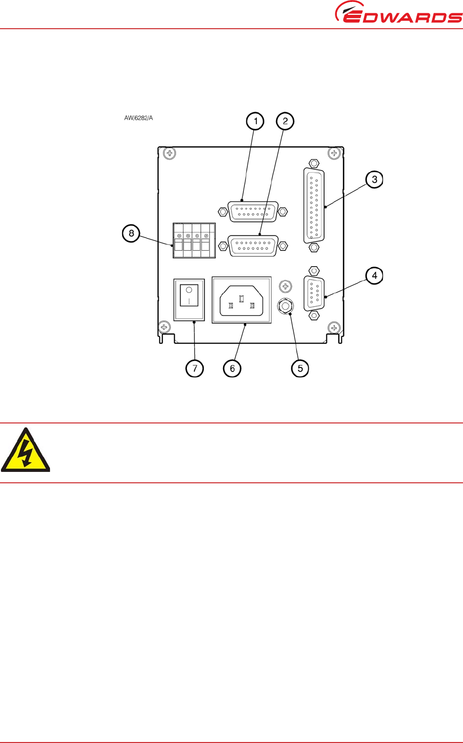
Figure 10 - Rear panel connections
3.3.1 Connecting the electrical supply
Ensure that the electrical supply switch is set to ‘off’ and then connect the controller to the electrical supply with
an appropriate supply cable.
3.3.2 Additional earth bonding
The electrical supply cable normally provides protective earthing for electrical safety. If this is not the case, or if
additional earth bonding is required, then the earth stud on the rear of the controller (Figure 10, item 5) should be
connected to the vacuum system earth.
The earth connection of any vent valves or air coolers should also be connected to this earth stud to ensure that they
are adequately earthed.
Connect a suitably earthed cable between the two nuts fitted to the earth stud on the rear of the TIC.
Note: Do not remove the bottom nut from the earth stud.
WARNING
High voltages exist in the controller when it is operating. Ensure that the controller is earthed and
observe all appropriate safety precautions for the safe installation and handling of electrical
equipment. If not, there will be a danger of injury or death to people by electric shock.
1. Backing pump (200 W only)
2. Turbo pump connection
3. Logic interface
4. Serial communications port
5. Earth stud
6. Mains input
7. Mains on/off
8. Auxiliary terminals

© Edwards Limited 2016. All rights reserved. Page 13
Edwards and the Edwards logo are trademarks of Edwards Limited.
Installation
D397-12-880 Issue L
3.3.3 Connecting a turbo pump
CAUTION
Pumps are not hot swap safe unless explicitly stated in their manual. Before connecting or disconnecting a pump
to the TIC turn the power off. Failure to do so may damage the pump.
The TIC will only identify the pump connected at power on.
A suitable turbo pump can be connected to the TIC turbo pump connector on the rear panel.
Connect the pump to the lower of the two 15 way ‘D’ connectors and tighten the locking screws to ensure the
connector cannot come loose.
3.3.4 Connecting a backing pump
Both the 100 W and 200 W TICs can control a mains backing pump via the logic interface. For details of this, refer to
Section 3.3.7.3.
The 200 W TIC can also drive a suitable backing pump from its second rear panel pump connector.
Connect the pump to the upper of the two 15 way ‘D’ connectors and tighten the locking screws to ensure the
connector cannot come loose.
Note: To control an XDD1 24 V backing pump, the pump must be configured for ‘analogue speed control’. Refer
to the pump instruction manual for details on how to configure the pump for this operating mode.
3.3.5 Connecting a vent valve
A vent valve can be driven from either the auxiliary terminals on the rear of the TIC, or from the logic interface. For
details of using the logic interface to control a vent valve, see Section 3.3.7.3.
Note: If a DX or nEXT pump is to be used, it is recommended that the vent valve is connected to the pump, not
the TIC Controller. If two vent valves are required, both the DX and TIC vent outputs can be used at the
same time. (Refer to Table 12).
Connect the positive lead of the vent valve to the terminal marked ‘Vent +’, connect the negative lead of the vent
valve to the terminal marked ‘Vent –’ and clamp the earth wire between the earth stud locking nuts on the rear of
the controller. Ensure the screws and the earth terminal locking nut are all firmly tightened.
3.3.6 Connecting an air cooler
An air cooler can be driven from either the auxiliary terminals on the rear of the TIC, or from the logic interface. For
details of using the logic interface to control an air cooler, refer to Section 3.3.7.3.
Connect the positive lead of the air cooler to the terminal marked ‘Fan +’, connect the negative lead of the air cooler
to the terminal marked ‘Fan –’ and clamp the earth wire between the earth stud locking nuts on the rear of the
controller. Ensure the screws and the earth terminal locking nut are all firmly tightened.
3.3.7 Connecting the logic interface
3.3.7.1 Introduction
Note: In most applications, it will be preferable not to earth the logic interface power supply common to prevent
earth loops inadvertently occurring.
CAUTION
Do not connect voltages greater than 24 V to the logic interface.
The logic interface provides a number of signals that can be used for monitoring the status of the vacuum system and
for controlling certain aspects of its operation. These signals can be broadly divided into three groups, control inputs,
control outputs and status outputs.
D397-12-880 Issue L
Page 14 © Edwards Limited 2016. All rights reserved.
Edwards and the Edwards logo are trademarks of Edwards Limited.
Installation
3.3.7.2 Using control inputs
Control inputs provide a means of controlling the operation of the TIC and the associated vacuum system from
external sources.
Turbo Stand-by: To cause the turbo pump to run at stand-by speed, link ‘Turbo Stand-by’ to 0 V. To return the pump
to full speed, disconnect ‘Turbo Stand-by’ from 0 V. Note that only pumps having stand-by speed capability will
respond to this input.
Turbo Enable: The turbo enable input can be used to control the operation of the turbo pump. If turbo enable is open,
the turbo pump cannot be started and will stop if it is running. If turbo enable is connected to 0 V when power is
applied to the TIC, the pump is able to start when commanded to do so. If turbo enable is connected to 0 V while
the controller is operating, the turbo pump will start, as long as SYSI and the software configuration allow it to do so.
Backing Pump Enable: The backing pump enable input can be used to control the operation of the backing pump. If
backing pump enable is open, the backing pump cannot start and will stop if it is running. If backing pump enable is
connected to 0 V when power is applied to the TIC, the pump is able to start when commanded to do so. If backing
pump enable is connected to 0 V while the controller is operating, the backing pump will start, as long as ‘SYSI’ and
the software configuration allow it to do so.
SYSI: The System interlock input can be used to interlock the TIC to a system fail or control signal. When ‘SYSI’ is
open, all pumps will stop and the vent valve will be opened. The TIC will also trip into the fail condition. To clear
the system interlock and allow the pumps and gauges to start, connect ‘SYSI’ to 0 V.
3.3.7.3 Using control outputs
Control outputs provide a means for the TIC to control external resources.
Vent valve control: The vent valve output can be used to control the operation of a vent valve. The ‘Vent Valve’
signal will be driven low to energise the valve when required. Connect the positive lead of the vent valve to ‘24 V’
and the negative lead to ‘Vent Valve Control’. The vent valve earth lead must be connected to ‘Screen’ or a suitable
alternative earth point.
CAUTION
The vent valve output on the logic interface will not be maintained in the event of a power failure. If venting of
the turbo pump while it is running at high speed is undesirable, use the vent valve output from the auxiliary
terminals. This output will be maintained during a power failure.
Bakeout band control: The bakeout band control can be used to switch a relay that can apply power to the band. The
relay box has a relay built in for this purpose and provides connectors to allow power to be applied to the bakeout
band. Refer to the relay box instruction manual for further information on driving a bakeout band.
To drive a relay without a relay box, connect the coil of a suitable 24 V d.c. relay between ‘Bakeout Band Control
Output’ (negative) and ‘Power Supply Positive’ (positive).
Backing pump control: The backing pump control can be used to switch a relay that can apply power to a mains
backing pump. The relay box has a relay built in for this purpose and provides a connector that will switch the pump
on and off. Refer to the relay box instructions for further information on driving a backing pump.
To drive a relay without a relay box, connect the coil of a suitable 24 V d.c. relay between ‘Backing Pump Output’
(negative) and ‘Power Supply Positive’ (positive).
Air cooler: The air cooler output can be used to control the operation of an air cooler. The air cooler signal will be
driven low to energise the cooler when required. Connect the positive lead of the cooler to the power supply positive
and the negative lead to ‘Air Cooler Control’. The air cooler earth lead must be connected to ‘Screen’ or a suitable
alternative earth point.
WARNING
‘SYSI’ is not fail safe and should not be relied upon for safety critical applications.
© Edwards Limited 2016. All rights reserved. Page 15
Edwards and the Edwards logo are trademarks of Edwards Limited.
Installation
D397-12-880 Issue L
3.3.7.4 Using status outputs
Status outputs provide a means for external systems to react based upon the current state of the TIC.
Analogue output: The analogue output provides a 0 V to 10 V signal that can be configured to represent system
pressure, pump speed etc. Refer to Section 4.8 for how to configure this output.
To connect this output to an external system, connect the ‘Analogue Output Signal’ to the positive input of the
system and ‘Analogue Output Common’ to the negative side.
Relay setpoint: The setpoint outputs can be used to interface to external logic or can be used to drive relays. Each
output can be configured in software to activate at pump speed. Refer to Section 4.15 for how to configure these
outputs. Each relay can be manually controlled. Refer to Section 4.5.
The relay box has built-in relays that can switch external loads and provides a connector to interface to an external
system. Refer to the relay box instructions for further information on using the setpoint outputs.
To drive a relay without a relay box, connect the coil of a suitable 24 V d.c. relay between ‘Setpoint Output’
(negative) and ‘Power Supply Positive’ (positive).
Turbo normal speed: Turbo normal speed can be used to interface to external logic or can be used to drive a relay.
This output is normally inactive and will become active when the turbo pump has reached its defined ‘Normal’ speed.
To drive a relay, connect the coil of a suitable 24 V d.c. relay between ‘Turbo Normal Output’ (negative) and ‘Power
Supply Positive’ (positive).
Alarm: Alarm can be used to interface to external logic or can be used to drive a relay. This output is normally active
and will become inactive in the event of an alarm condition.
To drive a relay, connect the coil of a suitable 24 V d.c. relay between ‘Alarm Output’ (negative) and ‘Power Supply
Positive’ (positive).
3.3.8 Connecting the serial interface
The TIC has two serial communications protocols built in, RS232 and RS485. RS232 is the simplest interface and can
be used to allow a host PC to control the TIC. RS485 allows a host PC to control a small network of TICs.
3.3.8.1 Connecting RS232
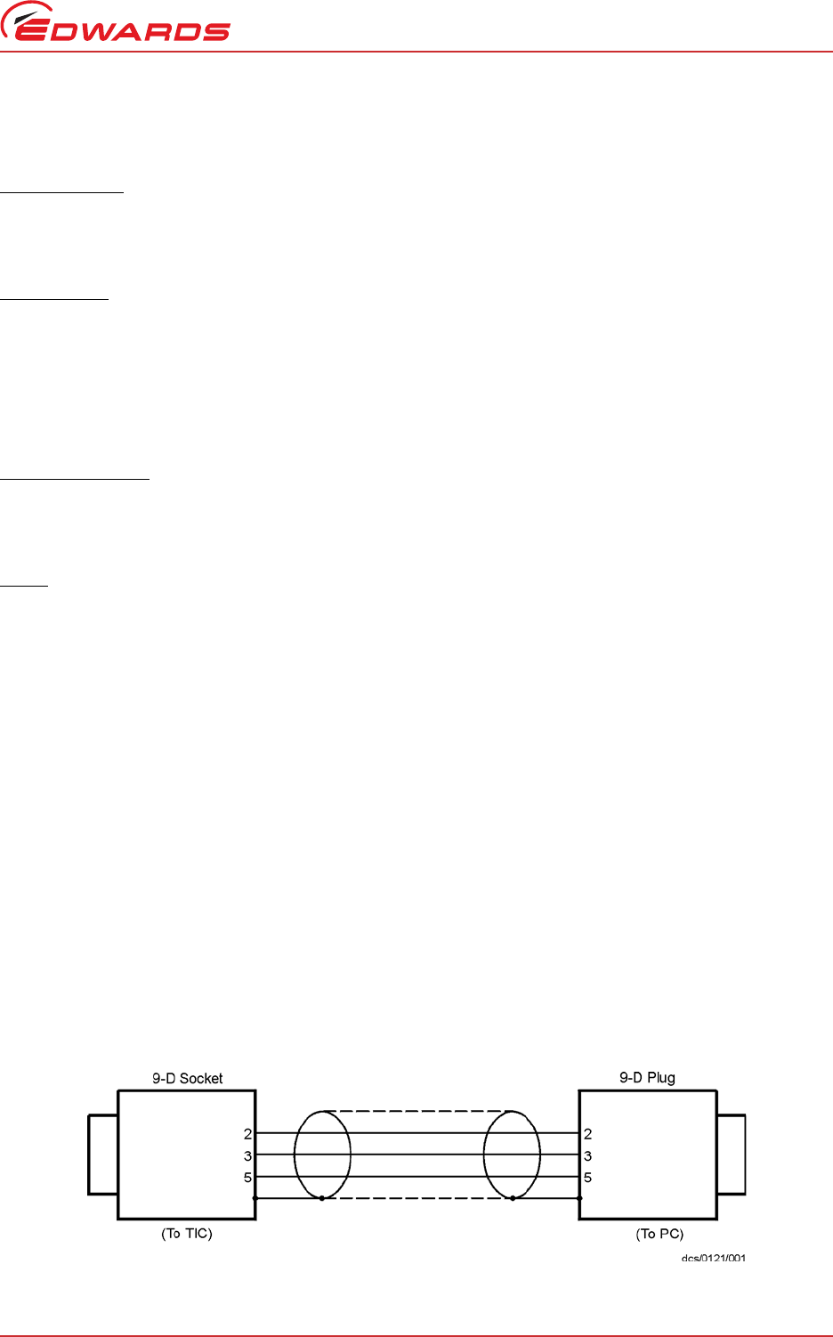
The TIC is fitted with a 9-way ‘D’ type socket on the rear panel. The interface uses two lines for data transfers and
an additional line as a signal common. Hardware handshaking is not implemented.
If connecting to an IBM compatible PC fitted with a 9-way ‘D’ type socket then a ‘straight through’ male-female
9-way extension cable can be used to connect the TIC to the computer as shown in Figure 11. Connection to an IBM
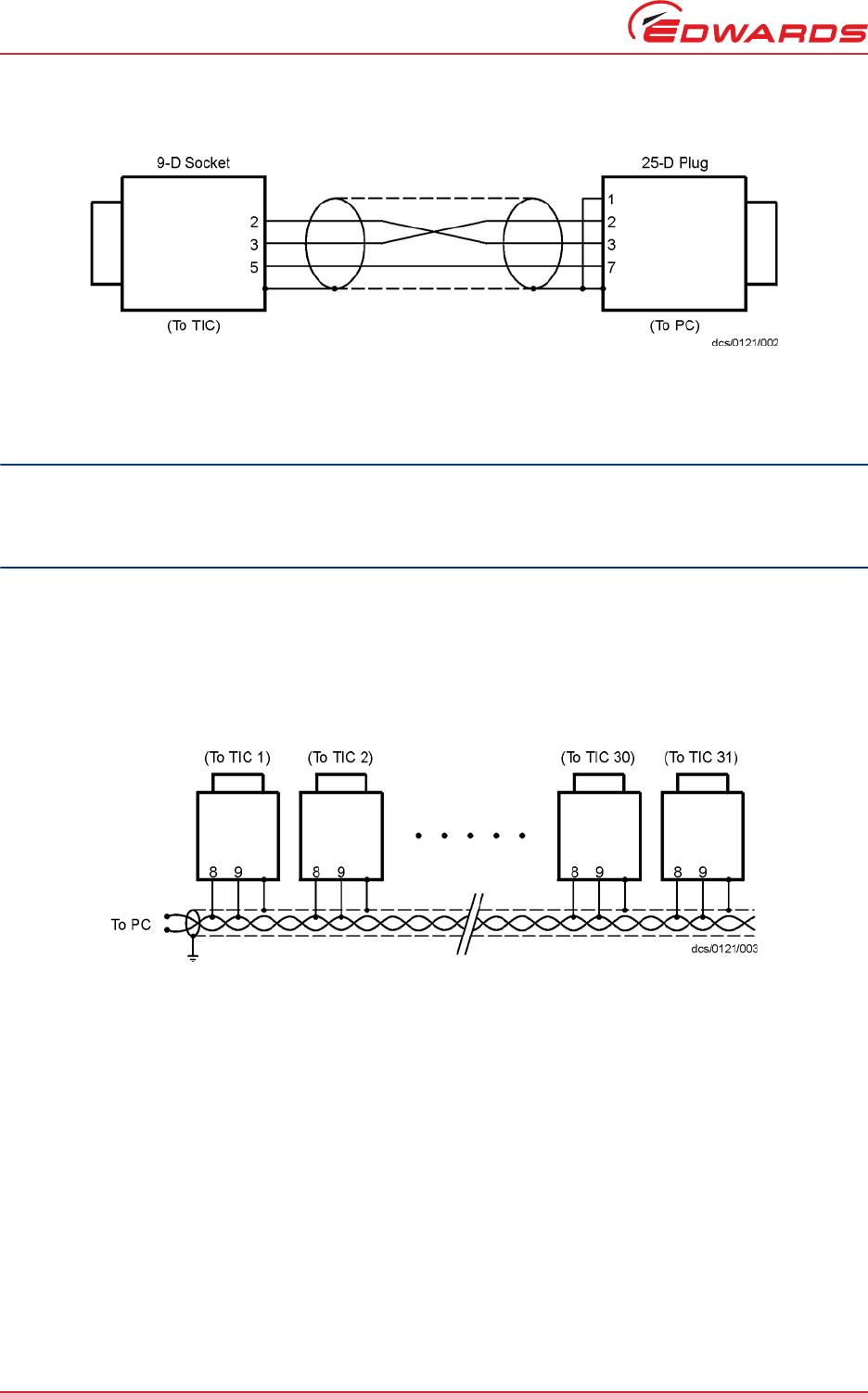
PC fitted with a 25-way serial connector should be made as shown in Figure 12.
Use shielded cable for the interface to reduce interference problems and limit the length of the RS232 link to less
than 10 metres. For longer links, either install line drivers or use RS485.
Figure 11 - IBM PC RS232 interface - 9-way
D397-12-880 Issue L
Page 16 © Edwards Limited 2016. All rights reserved.
Edwards and the Edwards logo are trademarks of Edwards Limited.
Installation
Figure 12 - IBM PC RS232 interface - 25-way
3.3.8.2 Connecting RS485
RS485 provides the TIC with the capability to be networked with other TICs and a host PC as shown in Figure 13.
CAUTION
All of the ground connections are tied together. If differences exist in the local ground voltage, damage could
occur. If the TICs being networked are liable to experience different ground potentials, a suitable RS485 isolator
should be connected between them.
Use shielded cable for the interface to reduce interference problems and limit the length of the RS485 link to less
than 1000 metres.
Long links may require the addition of 120 terminating resistors at each end of the link to improve communications
reliability.
Figure 13 - RS485 TIC network
© Edwards Limited 2016. All rights reserved. Page 17
Edwards and the Edwards logo are trademarks of Edwards Limited.
Operation
D397-12-880 Issue L
4 Operation
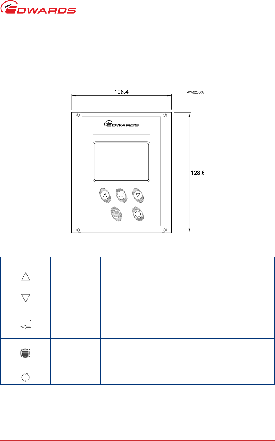
4.1 Front panel description
Figure 14 - Front panel display
Table 8 - Front panel symbols and their functions
Symbol Name Function
UP Move up through a menu.
Cycle selected numerical values up.
Cycle a selected list item upwards.
DOWN Move down through a menu.
Cycle selected numerical values down.
Cycle a selected list item downwards.
SELECT Enter the highlighted sub-menu.
Edit the highlighted list or numerical item.
Move to the next digit of a numerical value.
Jump to the setup screen for the highlighted gauge.
MENU Switch between the default view screen and the main menu.
Exit the current sub-menu or setup screen.
Abort edit of a selected list item.
Move to the previous digit of a numerical value.
CYCLE Turn a highlighted gauge on or off.
D397-12-880 Issue L
Page 18 © Edwards Limited 2016. All rights reserved.
Edwards and the Edwards logo are trademarks of Edwards Limited.
Operation
4.2 Menu structure
Figures 15 and 16 show the view screen shortcuts and menu structure for the TIC. They also give an indication as to
what buttons will lead where within the menu layout.
Figure 15 - View screen shortcuts
* As applicable, see Section 4.8.3 for more information.
RELAY CONTROL
Relays
SYSTEM CONTROL
System
Backing pump
Turbo
Turbo standby
Heater
TURBO SETUP
Turbodrive
ZĂŵƉͲƵƉƟŵĞƌ
ƌŽŽƉƟŵĞƌ
,ĞĂƚĞƌƟŵĞ
Start delay
System on
^LJƐƚĞŵŽī
Air cooler
TIC vent opt
Backing opt
Turbo vent opt*
Vent type*
Normal
Standby speed
Braking
Max power
Service opt
BACKING SETUP
Back drive
Start delay
System ON
System OFF
Air cooler
TIC vent opt
Backing opt
Normal
Standby speed
Autorun
Service opt
GAUGE SETUP
Gauge
Gas type
Filter
Range
Set zero
Display
Degas
Calibrate
Name
ALARMS
No alarm or warnings
RELAY SELECT
Relays
SYSTEM START MENU
Turbo
Backing
Gauges
Relay
SYSTEM STOP MENU
Turbo
Backing
Gauges
Relay
Cycle
Select
Menu
Turbo
Back
Gauge 1 type/name
Gauge 2 type/name
Gauge 3 type/name
Alarm
Units R1 R2 R3
CONTROL SETUP
CS/1352/A
To main menu
© Edwards Limited 2016. All rights reserved. Page 19
Edwards and the Edwards logo are trademarks of Edwards Limited.
Operation
D397-12-880 Issue L
Figure 16 - Menu structure
* nEXT85 family only, see Section 4.12 for more information.
SYSTEM CONTROL
System
Backing pump
Turbo
Turbo standby
Heater
TURBO STATUS
Turbo
Turbo pump
Backing pump
Turbo power
Turbo speed
TIC int temp
Turbo drive
Turbo pump
Turbo rotor*
LJĐůĞƟŵĞ
TIC vent
BACKING STATUS
Back
Turbo pump
Backing pump
Turbo power
Turbo speed
TIC int temp
Turbo drive
Turbo pump
LJĐůĞƟŵĞ
TIC vent
ALARMS
No alarm or warnings
CONTROLLER SETUP
Control object
Controlled by -- >
Controlling object
Units
KīƐĞƚƉŶƚ
On setpnt
Setpoint
Cycle
Select
Menu
MAIN MENU
Alarms
Cycle
Turbo status
Back status
Link gauges/ pumps
Parameters/ units
^ĐƌĞĞŶŽƉƟŽŶƐ
Relay setpoints
^ĞƌǀŝĐĞŝŶĨŽƌŵĂƟŽŶ
CS/1353/A
To normal screen
CONTROLLED ITEM
Gge1
Gge2
Gge3
Trbo
PARAMETERS/UNITS
Units
Setup lock
Panel lock
0-10 V O/ P
Disp contrast
Protocol
Comms address
dDW/ůĞƌƚŽī
DW/ůĞƌƚŽī
SCREEN OPTIONS
Show all items
Show three gauges
Set three gauge order
Show one gauge
Set one gauge order
Show turbo only
Show one gauge and turbo
RELAY SELECT
Relay 1
Relay 2
Relay 3
SERVICE INFORMATION
5/W issue
Serial num
Analogue O/P
Turbo run
Reset DX
Reset TIC

D397-12-880 Issue L
Page 20 © Edwards Limited 2016. All rights reserved.
Edwards and the Edwards logo are trademarks of Edwards Limited.
Operation
4.3 Navigating the menu
This section summarises the display navigation method for the TIC. There are 4 buttons for menu navigation and
configuration tasks. A fifth button is used for switching pumps ON and OFF. In most configuration tasks there are no
more than three menu levels.
Refer to Table 8 for a description of the functions that the buttons on the front panel perform.
4.4 The view screen
The view screen can be set to various view options. The following describes the view screen that shows ‘all’. (Refer
to Figure 17).
The top portion of the view screen shows the status of the vacuum pumps; the top line shows the pump speed as a
bar chart. In the top right-hand corner the status of the turbo pump is shown as follows:
The second line provides the basic status of the turbo pump and backing pump under TIC command.
The status of the setpoint relays is shown at the bottom line of the view screen. Relays that are on are shown in
reverse video.
Figure 17 - Pump status
4.5 Turning pumps and relays on/off
Pressing the ‘Cycle’ ( ) button whilst the turbo/backing status line is highlighted will display a menu of switchable
items.
Note: If SYSI is opened during the vacuum cycle, all connected controllable components will be switched OFF.
If the selected item is the relay status line, a list of the relays will appear. Scroll to the required relay and use the
‘cycle’ ( ) button to switch the item. When the relay is activated, the annunciator on the view screen will change
to reverse video.
Off. The turbo pump is off.
>>>. The turbo pump is accelerating.
<<<. The turbo pump is decelerating.
Run. The turbo pump is above 50% speed.
Norm. The turbo pump is at or above ‘normal
speed’.
Strt. The turbo pump is enabled to start,
but will not run until the start delay
has run down.
Flt. An error has occurred. Select the
alarms screen.
© Edwards Limited 2016. All rights reserved. Page 21
Edwards and the Edwards logo are trademarks of Edwards Limited.
Operation
D397-12-880 Issue L
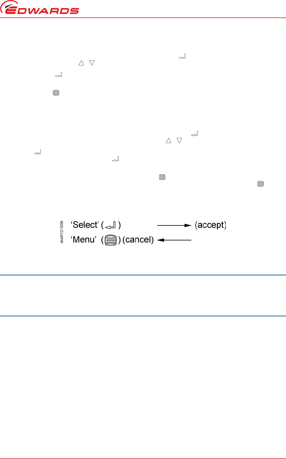
4.6 Changing list items
To change a list item, scroll to the required line and press the ‘Select’ ( ) button. The list can then be scrolled
using the up and down arrows ( / ).
Pressing the ‘Select’ ( ) button will accept the adjustment and return the highlight to the row item, allowing
another item to be selected for adjustment.
Pressing the ‘Menu’ ( ) button will cancel the adjustment and return the highlight to the row item, allowing
another item to be selected for adjustment.
4.7 Changing numerical values
To change a numerical item, scroll to the required line and press the ‘Select’ ( ) button. The first number will then
be highlighted and can be changed using the up and down arrows ( / ).
The ‘Select’ ( ) button will move the highlight to the next digit with each successive press, allowing the complete
number to be entered. Pressing the ‘Select’ ( ) button with the last digit selected will accept the adjustment and
return the highlight to the row item, allowing another item to be selected for adjustment.
At any time, mistakes can be corrected by pressing the ‘Menu’ ( ) button. This will move the highlight to the
previous digit with each successive button press, allowing corrections to be made. Pressing the ‘Menu’ ( ) button
with the first digit selected will cancel the adjustment and return the highlight to the row item, allowing another
item to be selected for adjustment.
Figure 18 - Changing numerical values
4.8 Turbo setup
CAUTION
All setups in the TIC are held in non-volatile memory. Non-volatile memory has a limit on the number of times
its content can be changed. Current minimum lifetime is 100,000 changes on a particular section. This equates
to more than 1 change per hour every hour for 10 years. If the number of changes is exceeded, random data
may be stored, leading to unexpected system behaviour.
4.8.1 Introduction
The TIC can be used to configure the EXT, DX and nEXT pump ranges. The menu screen shows differing functionality
depending on the pump attached. The TIC will recognise the pump attached, which will be seen on the pump setup
and pump status screen. (Refer to Figure 19).
D397-12-880 Issue L
Page 22 © Edwards Limited 2016. All rights reserved.
Edwards and the Edwards logo are trademarks of Edwards Limited.
Operation
Figure 19 - Turbo setup screen
4.8.2 Default turbo setup options
Table 9 - Default turbo setup options
Menu option Description
Ramp Up Timer The user can set the ramp up timer from 1 to 30 minutes. This timer will
generate an alarm if the pump speed does not rise above 50% speed after the
set time.
Droop Timer The user can set the droop time from 1 to 30 minutes. This timer will generate
an alarm if the pump speed drops below 50% speed for longer than the
specified time.
Heater time The user can set the time that the heater band bakes out the turbo pump from
0 to 35 hrs. The heater will come on for the set time, once the pump reaches
'normal speed'. If the pump drops below 'normal speed', the heater band will
switch off and the timer will be reset.
Once the heater band is operating, the user can interrupt and restore heater
band operation through the serial interface or the TIC front panel.
Start delay The start delay enables the user to delay the start of the turbo pump from 0 to
99 minutes.
System ON Allows the user to define the components of the system that are to be turned
on when the 'system' is cycled on.
System OFF Allows the user to define the components of the system that are to be turned
off, when the 'system' is cycled off.
Note: The system ON and OFF commands provide manual control of the items
listed. Where possible, it will override settings such as backing options
and gauge linking.
Note: If the backing pump option has been set to 50% or on stop, 'seq’ will be
indicated showing the backing pump is sequenced to one of the
options.
Air cooler The user can set when an Edwards air cooler will operate. The air cooler can be
set to 'ON' (on permanently) or 'Turbo' (on when the turbo pump is running).
TIC vent options A vent valve attached to the TIC can be operated in the following ways:
'On stop' to open the vent valve 2 seconds after the stop command or '50%' to
open the vent valve when the pump slows to 50% speed.

© Edwards Limited 2016. All rights reserved. Page 23
Edwards and the Edwards logo are trademarks of Edwards Limited.
Operation
D397-12-880 Issue L
Refer to Table 10 for error and diagnostic information for pumps.
CAUTION
If an Edwards 24 V backing pump is connected, it is recommended that the overall power used does not exceed
that specified in Section 2.
4.8.3 Additional setup options using a DX or nEXT pump
The TIC allows the user to set up additional functionality available within a DX, nEXT or nXDS pump.
CAUTION
Read the DX or nEXT pump manual before using the TIC to set up the DX, nEXT or nXDS pump.
Turbo venting can be set for different pump families as per Table 11. The user may also use the TIC vent option to
enable an extra vent valve to be connected to a vacuum system.
Backing pump options A backing pump attached to the TIC or via a relay box can be operated in the
following way:
None: The backing pump is not sequenced to the turbo
pump
50%: The backing pump will turn off after 2 seconds,
once the turbo speed has dropped to 50% of its
speed. The delay allows detritus to be removed
from the system on stop.
On stop: The backing pump will turn off 4 seconds after the
Turbo off command has been sent. The 4-second
delay allows shutting of a valve and then removal
of detritus from the system.
Table 10 - Error/diagnostic monitoring, pumps
Diagnostic messages Description
RampUp Timeout Check whether the pump is too hot or whether the inlet pressure is too high.
Check that the backing pump is operational.
Check the vacuum system for leaks.
Droop Timeout Check whether the pump is too hot or whether the inlet pressure is too high.
Check that the backing pump is operational.
Check the vacuum system for leaks.
Table 11 - Turbo pump vent setup differences
Pump Family Turbo vent
option (1) Turbo vent
option 2 Turbo vent
type 1 Turbo vent
type 2
DX X
nEXT85 XXXX
nEXT240/300/400 X
Table 9 - Default turbo setup options (continued)
Menu option Description

D397-12-880 Issue L
Page 24 © Edwards Limited 2016. All rights reserved.
Edwards and the Edwards logo are trademarks of Edwards Limited.
Operation
Please refer to Table 15 for the error and diagnostic information for DX, nEXT and nXDS pumps.
Table 12 - Turbo pump vent options
On screen Description
50% Vent valve opens fully below 50% full rotational speed for both Stop command or Fail
Note: This is the default factory setting.
50%CvV Controlled venting from 100% - 50% full rotational speed;
Vent valve opens fully below 50% for both Stop command or Fail
STP50% Vent valve opens fully immediately Stop command is received;
Vent valve opens fully below 50% full rotational speed if Fail
STPCnV Vent valve opens fully immediately Stop command is received;
Controlled venting from 100% - 50% full rotational speed then vent valve opens fully
below 50% if Fail
FLT50% Vent valve opens fully immediately if Fail;
Vent valve opens fully below 50% full rotational speed if Stop
FLTCnV Vent valve opens fully immediately if Fail;
Controlled venting from 100% - 50% full rotational speed then vent valve opens fully
below 50% if Stop command received
STPFLT Vent valve opens fully immediately for both Stop command or Fail
FLTSTP Vent valve opens fully immediately for both Stop command or Fail
FAN Vent is Permanently Enabled and can be used to provide power to an Edwards air
cooler; This option cannot be set if the pump is above 50% full rotational speed
OPT 9 Do not use
OPT 10 Do not use
Table 13 - Turbo pump vent type
On screen Description
N/O Output configured for a normally open vent valve; this cannot be changed if the pump
is above 50% full rotational speed
N/C Output configured for a normally closed vent valve; this cannot be changed if the
pump is above 50% full rotational speed
Table 14 - DX, nEXT and nXDS pump setup options
Menu option Description
Normal The TIC allows ‘normal speed’ to be set as a percentage of full speed.
Standby speed The user can set the standby speed as a percentage of full speed.
Max power The user can set the maximum power a DX pump can use.
Braking Off/Enabled. The user can utilise this function to slow the turbo pump at a quicker
rate.
Service opt nEXT service indication options. Podule flashing LED, fail line, both, none.
Table 15 - Error/diagnostic monitoring, DX, nEXT and nXDS pumps
Diagnostic messages Description
Serial ID Fail A DX, nEXT, nXDS or serial pump is connected, however the type has not been
recognised. Please check the leads are connected.
Turbo Fault Review the flashing error codes on the pump podule, and refer to the DX, nEXT or
nXDS instruction manual.

© Edwards Limited 2016. All rights reserved. Page 25
Edwards and the Edwards logo are trademarks of Edwards Limited.
Operation
D397-12-880 Issue L
4.9 Backing setup
SC Interlock Serial enable to the DX, nEXT or nXDS pump was lost while it was running. This could
be caused by a temporary loss of power or a broken wire. It is recommended to stop
the pump and then restart it. If the alarm does not clear, cycle the controller and then
try again.
Uload Timeout Check that the pump is correctly connected, then try to upload again.
Dload Failed Check that the pump is correctly connected, then try to download again.
nEXT Service due warning One of the nEXT items has exceeded its service interval. See nEXT Service screen for
details. Contact Edwards for a suitable service kit or to arrange a service by Edwards.
nXDS Service due warning One of the nXDS items has exceeded its service interval. See nXDS Service screen for
details. Contact Edwards for a suitable service kit or to arrange a service by Edwards.
Table 16 - Default Backing setup options
Menu option Description
Start delay The start delay enables the user to delay the start of the turbo pump from 0 to 99 minutes.
System ON Allows the user to define the components of the system that are to be turned on when the
'system' is cycled on.
System OFF Allows the user to define the components of the system that are to be turned off when the
'system' is cycled off.
Note: The system ON and OFF commands provide manual control of the items listed.
Where possible it will override settings such as backing options and gauge linking.
Note: If the backing pump option has been set to 50% or on stop, ‘seq’ will be indicated
showing the backing pump is sequenced to one of the options.
Air cooler The user can set when an Edwards air cooler should operate. The air cooler can be set to
'ON' (on permanently) or 'Turbo' (on when the turbo pump is running).
TIC vent options A vent valve attached to the TIC can be operated in the following ways:
'On stop' to open the vent valve 2 seconds after the stop command or '50%' to open the vent
valve when the pump slows to 50% speed.
Backing pump options A backing pump attached to the TIC or via a relay box can be operated in the following
way:
None: The backing pump is not sequenced to the Turbo pump
50%: The backing pump will turn off after 2 seconds, once the turbo speed has dropped to
50% of its speed. The delay allows detritus to be removed from the system.
On stop: The backing pump will turn off 4 seconds after the Turbo off command has been
sent. The 4 second delay allows shutting of a valve and then removal of detritus from the
system.
Table 17 - nXDS pump setup options
Menu option Description
Normal The TIC allows ‘normal speed’ of the backing pump to be set as a percentage of full speed.
Standby speed The user can set the standby speed of the backing pump as a percentage of full speed.
Autorun Sets the nXDS to start when power is turned on
Service opt nXDS service indication options. Podule flashing LED, fail line, both, none.
Table 15 - Error/diagnostic monitoring, DX, nEXT and nXDS pumps
Diagnostic messages Description

D397-12-880 Issue L
Page 26 © Edwards Limited 2016. All rights reserved.
Edwards and the Edwards logo are trademarks of Edwards Limited.
Operation
4.10 Alarms
If an Alarm occurs, an ‘Alarms’ warning will begin flashing in the lower half of the view screen. Refer to Figure 17.
The Alarm can then be selected by moving the cursor over it and pressing the ‘Select’ ( ) button. This action will
lead to the Alarms screen. Alternatively, the Alarms screen can be accessed through the main menu.
The Alarm will stop flashing when it has been acknowledged and will disappear when the alarm situation no longer
exists. An alarm is acknowledged by pressing the ‘Select’ ( ) button whilst the flashing alarm is highlighted.
To clear an alarm, refer to the fault finding guide in Section 5 of this instruction manual. This guide gives information
of what the alarm is and the possible solutions for clearing the alarm.
In a similar way, a warning can appear. To clear it, take the same actions as for alarms above.
4.11 The main menu
The main menu can be accessed by pressing the ‘Menu’ ( ) button on the view screen (Figure 14). From here the
following sub-menus can be accessed.
4.12 Turbo status
This screen allows the user to view the current status of the turbo and backing pumps. Basic information such as:
-Whether the turbo pump is ON or OFF and a graph of its speed.
-The state of the turbo pump that the user has requested.
-Whether the backing pump is ON or OFF.
-The power that the turbo pump is using.
-The speed of the turbo pump as a percentage of full speed.
-The temperature of the turbo drive. (Only on DX and nEXT pumps).
-The temperature of the Turbo pump/motor. (Only on DX and nEXT pumps).
-The temperature of the Turbo rotor. (Only on nEXT85 family pumps).
-The cycle time is the run time of the current cycle. (Only on DX and nEXT pumps).
-Whether the TIC vent valve is ‘on/off’.
-Service menu - enter, press enter to move to the nEXT Service screen.
Table 18 - nEXT Service Screen
nEXT Service Description
Service due Indicates which service is due - None, Oil, Bearing, Turbo, Controller. Shows
only initial letters if multiple services are due - O B T C.
Oil run Hours run since last service.
Oil until Hours left to run until next service.
Bearing run Hours run since last service.
Bear until Hours left to run until next service.
Turbo run Hours run since last service.
Turbo until Hours left to run until next service.

© Edwards Limited 2016. All rights reserved. Page 27
Edwards and the Edwards logo are trademarks of Edwards Limited.
Operation
D397-12-880 Issue L
Table 19 - nEXT Service Reset Screen
4.13 Backing status
This screen allows the user to view the current status of the turbo and backing pumps. Basic information such as:
-Whether the backing pump is ON or OFF and a graph of its speed.
-The state of the turbo pump that the user has requested.
-Whether the backing pump is ON or OFF.
-The power that the backing pump is using.
-The speed of the backing pump as a percentage of full speed.
-The temperature of the backing drive. (Only on nXDS pumps).
-The cycle time is the run time of the current cycle. (Only on nXDS pumps).
-Whether the TIC vent valve is 'on/off'.
-Service menu - enter, press enter to move to the nXDS Service screen.
Contlr run Stress adjusted hours controller has been powered since last service. Stress
adjustment - hours can advance slower or faster than real time depending
on temperature and load.
Cntlr until Stress adjusted hours controller is powered left until next service.
Turbo cycle Start/stop cycles run since last service.
Cycle until Start/stop cycles left to run until next service.
Knock count Backup bearing contacts since last service.
Reset Service Due ... Press enter to move to the nEXT Service Reset screen.
nEXT Service Reset Description
Select line below and press enter
after servicing Instructions to follow
Reset oil due Press enter key to reset only the oil service due
Reset bearing due Press enter key to reset only the bearing service due
Table 20 - nXDS Service Screen
nXDS Service Description
Service due Indicates which service is due - None, Tip Seal, Bearing, Backing, Controller. Shows only
initial letters if multiple services are due - O B T C.
TipSeal run Hours run since last service.
TipSeal til Hours left to run until next service.
Bearing run Hours run since last service.
Bear until Hours left to run until next service.
Back run Hours run since last service.
Cntlr run Stress adjusted hours controller has been powered since last service.
Stress adjustment - hours can advance slower or faster than real time depending on
temperature and load.
Back cycle Start/stop cycles run since last service.
Reset Service Due ... Press enter to move to the nXDS Service Reset screen.
nEXT Service Description

D397-12-880 Issue L
Page 28 © Edwards Limited 2016. All rights reserved.
Edwards and the Edwards logo are trademarks of Edwards Limited.
Operation
4.14 Parameters/units
This screen allows the user to change the units that are displayed and other parameters such as:
-Setup lock - When the 3 digit lock code is entered, the lock is enabled and an operator will not be able to
change any of the setups, however the operator is still able to scroll through the menus and start and stop
pumps. The lock is disabled by entering the 3-digit unlock code. Lock - 501, unlock - 147.
-Panel Lock - This function completely locks the front panel. An operator will only be able to see the view
screen. Lock - 509, unlock - 824.
-The 0 - 10 V analogue output on the logic interface can be set to follow the turbo speed.
-Display contrast allows the user to change the contrast of the display.
-Protocol shows whether RS232 or RS485 is being used.
-Comms address - To set the comms address of the TIC.
-TMPI Alert off - To disable/enable the warning when using TMPI line to start the turbo pump.
-BMPI Alert off - To disable/enable the warning when using BMPI line to start the backing pump.
4.15 Relay setpoint outputs
The relay setpoints option allows the setpoint outputs on the logic interface to be linked to turbo speed. When
selected, a summary of the current setting is displayed. The default setting for the three relays is ‘Not Linked’.
Set up the links as follows:
1. Select the controlled relay. Scroll to the relay that is to be controlled and press the ‘Select’ ( ) button.
2. Select the controlling item. The top highlighted line is used to select the controlling item. The controlling item
can either be ‘Not Linked’ or ‘Turbo Speed’ (%). Press the ‘Select’ ( ) button to confirm the choice.
3. Enter the required setpoint. The ‘On’ and ‘Off’ setpoints can be adjusted to suit the application. For pumps, the
unit used is ‘Turbo Speed’ (%).
Note: For pumps, the ‘Off’ setpoint is less than or equal to the ‘On’ setpoint.
4. Enable the setpoint. Once configured, the setpoint should be enabled by changing the bottom ‘Setpoint’ line
from ‘OFF’ to ‘ENABLED’.
4.16 Service information
Service information contains the following information:
-Software Issue - This is the issue of the currently installed software. This will change when new software is
downloaded to the TIC in the future.
-Serial Number - The serial number of the TIC is used when contacting Edwards about the product.
Table 21 - nXDS Service Reset Screen
nXDS Service Reset Description
Select line below and press enter after servicing Instructions to follow
Reset Tip Seal due Press enter key to reset only the oil service due
Reset bearing due Press enter key to reset only the bearing service due

© Edwards Limited 2016. All rights reserved. Page 29
Edwards and the Edwards logo are trademarks of Edwards Limited.
Operation
D397-12-880 Issue L
-Analogue O/P - The analogue output value (internal units) is used when contacting Edwards about the
product.
-PSU Temp - Temperature of PSU.
-TIC Temp - Temperature of TIC.
-Turbo run - Number of hours the turbo pump has been run (DX and nEXT pumps only).
-Upload Turbo - The TIC can store one set of the pump’s configuration. This function will upload the current
configuration from the attached pump (DX and nEXT pump only).
-Download Turbo - The TIC can download one set of configurations to DX and nEXT pumps, once a
configuration has been uploaded. This function will download the stored configuration to the attached pump
(DX and nEXT pump only).
-Reset Trbo - Reset the turbo pump to its factory defaults (DX and nEXT pumps only).
-Reset TIC - Resets the TIC to its factory default configuration and can be used to quickly undo all user
settings (relay setpoints, units, etc.).
4.17 Electrical supply failure
If the electrical supply to the controller fails while the turbo pump is rotating at high speed, the pump begins acting
like a generator, maintaining operation of the pump electronics and supporting operation of any accessories
connected directly to the pump such as a vent valve or fan.
Additionally, certain turbo pumps can make power available to a TIC to maintain the operation of vent valves
connected to the TIC.
Where power is returned to the TIC it is not made available to the gauges, the logic interface or the air cooler. All
of these will stop operating until power is restored.
Once the turbo pump speed falls below 50%, the vent valve will open and the TIC will shut down.
Refer to the individual pump instruction manuals for availability of this feature.
Turbo Pump Power to TIC
EXT75DX Supported
nEXT240/300/400 family Not supported
nEXT85 family Supported if option enabled

D397-12-880 Issue L
Page 30 © Edwards Limited 2016. All rights reserved.
Edwards and the Edwards logo are trademarks of Edwards Limited.
This page has been intentionally left blank.

© Edwards Limited 2016. All rights reserved. Page 31
Edwards and the Edwards logo are trademarks of Edwards Limited.
Maintenance
D397-12-880 Issue L
5Maintenance
5.1 Safety
There are no serviceable parts on the TIC. Do not open. Return to the nearest Edwards Service Centre for repairs.
The Edwards return of equipment forms can be found at the rear of this manual.
5.2 Fault finding
5.3 Cleaning the controller
If necessary, use a soft dry cloth to clean the exterior of the controller. Do not clean with harsh abrasives or liquids.
If the interior of the controller requires cleaning, Edwards recommends returning the controller to the supplier or
the nearest Edwards Service Centre.
WARNING
Obey the safety instructions in this Section and take note of appropriate precautions. Failure to
observe these instructions may result in injury to people and damage to equipment.
Table 22 - Fault finding
Diagnostic messages Description
Pump
RampUp Timeout Refer to Table 10
Droop Timeout Refer to Table 10
DX and nEXT
Serial ID Fail Refer to Table 15
Turbo Fault Refer to Table 15
SC Interlock Refer to Table 15
Uload Timeout Refer to Table 15
Dload Failed Refer to Table 15
nEXT Service Due Refer to Table 15
General
SYSI Inhibit The system interlock has been disconnected. Check that the logic interface
plug is connected correctly or check the status of the system interlocks.
Ext Inhibit Enable lines have been disconnected. Check the turbo or backing pump
enable lines.
No Reading An object has not received a value update from its source within a given
time and is flagging that its value is now old. Check connections to
components of system.
No Message
Brownout/Short
An object has not received a reply to a message it sent within a given time.
Check logic interface connections are correctly attached to the TIC.
Either the loading on the TIC outputs exceeds a certain current level or
there was a brownout of the mains power while a turbo was spinning and
could provide some regen power. Remove the short or high load and then
accept the error; the TIC will then re-attempt to drive the output. If a
brownout occurs, wait for it to pass and then accept the error.

D397-12-880 Issue L
Page 32 © Edwards Limited 2016. All rights reserved.
Edwards and the Edwards logo are trademarks of Edwards Limited.
Maintenance
5.4 Software updates
The software within the controller and the TIC PC monitor program will be updated as part of Edwards ongoing
development program. The updates and associated instruction manual can be found by visiting
www.upgrades.edwardsvacuum.com.
5.5 Factory defaults
The following is a list of factory default settings for the TIC:
Table 23 - Factory default settings
Menu option Default
Pump and relay slaving - not slaved
Turbo pump start delay = 0
EXDC Ramp time = 8
EXDC Droop time = 8
Analogue out slaved = NONE
TIC vent = 50%
Heater band = 0 hrs
Air Cooler = Turbo
Setup lock = Off
Panel lock = Off
Display contrast = 5
PC comms = RS232
Multi-drop address = 0
Default screen = All
System On = Backing
System Off = Turbo
Backing option = None
© Edwards Limited 2016. All rights reserved. Page 33
Edwards and the Edwards logo are trademarks of Edwards Limited.
Storage and disposal
D397-12-880 Issue L
6 Storage and disposal
6.1 Storage
Store the controller in clean dry conditions in accordance with the technical specifications. Refer to Section 2.
6.2 Disposal
Dispose of the controller and any components safely in accordance with all local and national safety and
environmental requirements.
Alternatively, the controller and/or cables may be able to be recycled. Contact Edwards or the supplier for advice.
The controller and associated cables are within the scope of the European Directive on Waste Electrical and
Electronic Equipment, 2002/96/EC. Edwards offer European customers a recycling service for the controller/cables
at the end of the product’s life. Contact Edwards for advice on how to return the controller/cables for recycling.
WARNING
Do not incinerate the controller. If the controller is heated to very high temperatures, dangerous
gases may be emitted and internal components may explode.

D397-12-880 Issue L
Page 34 © Edwards Limited 2016. All rights reserved.
Edwards and the Edwards logo are trademarks of Edwards Limited.
This page has been intentionally left blank.

© Edwards Limited 2016. All rights reserved. Page 35
Edwards and the Edwards logo are trademarks of Edwards Limited.
Service, spares and accessories
D397-12-880 Issue L
7 Service, spares and accessories
7.1 Introduction
Edwards products, spares and accessories are available from Edwards companies in Belgium, Brazil, China, France,
Germany, Israel, Italy, Japan, Korea, Singapore, United Kingdom, U.S.A and a world-wide network of distributors.
The majority of these centres employ Service Engineers who have undergone comprehensive Edwards training
courses.
When maintaining this product, Edwards recommends using only Edwards maintenance and service kits.
Order spare parts and accessories from the nearest Edwards company or distributor. When ordering, please state for
each part required:
-Model and Item Number of the equipment
-Serial number
-Item Number and description of the part
7.2 Service
Edwards products are supported by a world-wide network of Edwards Service Centres. Each Service Centre offers a
wide range of options including: equipment decontamination; service exchange; repair; rebuild and testing to factory
specifications. Equipment which has been serviced, repaired or rebuilt is returned with a full warranty.
Local Service Centres can also provide Edwards engineers to support on-site maintenance, service or repair of the
equipment.
For more information about service options, contact the nearest Service Centre or other Edwards company.
7.3 Spares
Note: This assembly is suitable for customers who have electrical and electronic repair expertise and possess a
portable appliance tester. If the customer is unable to carry out this repair, the controller should be
returned to Edwards for a full repair and safety re-test.
7.4 Accessories
Table 24 shows the range of accessories that can be purchased.
Spare Item Number
TIC Front Bezel Kit D397-00-803
TIC Logic Interface D397-00-850
Front Panel Assembly D397-00-822
Table 24 - Accessories
Product Description Ordering Information
TIC Controllers
TIC Profibus Module D397-50-000
Turbo Pumps and Controllers
EXT70H range

D397-12-880 Issue L
Page 36 © Edwards Limited 2016. All rights reserved.
Edwards and the Edwards logo are trademarks of Edwards Limited.
Service, spares and accessories
(EXDC80 Control Module required with above Turbo Pumps) D396-45-000
EXT255H range
(EXDC160 Control Module required with above Turbo Pumps) D396-46-000
EXT75DX range
EXT255DX range
nEXT range
Extension Cables DX/EXDC and 24 V backing pumps
1 m DX/EXDC extension cable (16/0.2) D397-00-835
3 m DX/EXDC extension cable (16/0.2) D397-00-836
5 m DX/EXDC extension cable (16/0.2) D397-00-837
Air Cooler
ACX70 B580-53-050
ACX250 B580-53-150
Vent Valves
TAV5
TAV6 B580-66-010
B580-66-020
Examples of compatible 24 V backing pumps
XDD1 24 V d.c. Diaphragm pump A746-01-991
Examples of compatible mains backing pumps
XDS10 220-240 V 50 Hz 1-phase A726-01-903
XDS10 115-120 V 60 Hz 1-phase A726-01-906
nXDS6i 100-127/200-240 V 50/60 Hz 1-phase A735-01-983
nXDS10i 100-127/200-240 V 50/60 Hz 1-phase A736-01-983
nXDS15i 100-127/200-240 V 50/60 Hz 1-phase A737-01-983
nXDS20i 100-127/200-240 V 50/60 Hz 1-phase A738-01-983
E2M1.5 220-240 V 50/60 Hz 1-phase A371-22-919
E2M1.5 115-120 V 50/60 Hz 1-phase A371-22-902
RV12 110-120 V 60 Hz or 220-240 V 50 Hz 1-phase A655-01-903
E2M28 220-240 V 50 Hz or 230-240 V 60 Hz 1-phase A373-15-903
E2M28 115/230 V 60 Hz 1-phase A373-15-981
Bakeout band (via optional relay box)
BX70 240 V 30 W (EXT70H & EXT75DX) B580-52-060
BX70 110 V 30 W (EXT70H & EXT75DX) B580-52-040
BX250 240 V 60 W (EXT255H) B580-52-061
BX250 110 V 60 W (EXT255H) B580-52-041
24 V backing line valves (via optional relay box)
LCPV16EKA 24 V a.c./d.c. C417-51-200
LCPV25EKA 24 V a.c./d.c. C417-52-200
Relay Boxes
TIC Relay box 3 x 240 V 3 A D397-00-804
TIC Relay box D397-11-805
Table 24 - Accessories (continued)
Product Description Ordering Information

© Edwards Limited 2016. All rights reserved. Page 37
Edwards and the Edwards logo are trademarks of Edwards Limited.
Service, spares and accessories
D397-12-880 Issue L
TIC Relay box comb D397-21-806
Interface cables
2 m Logic interface cable D397-00-833
2 m RS232 interface cable D397-00-834
Mains cables (Suitable for TIC controllers)
2 m UK plug D400-13-025
2 m USA plug D400-13-120
2 m Northern European plug D400-13-120
Other accessories and supporting products
TIC software upgrade www.upgrades.edwardsvacuum.com
Table 24 - Accessories (continued)
Product Description Ordering Information

D397-12-880 Issue L
Page 38 © Edwards Limited 2016. All rights reserved.
Edwards and the Edwards logo are trademarks of Edwards Limited.
This page has been intentionally left blank.
