DE2Bot User's Manual Users V6
DE2BotUsersManual_v6
User Manual:
Open the PDF directly: View PDF ![]() .
.
Page Count: 14
DE2Bot User’s Manual
Georgia Institute of Technology ECE2031
Kevin Johnson
Updated October 29, 2018

2
Introduction
This document is intended for the end-user of the DE2Bot: students in ECE2031. It provides an overview of the
hardware, a walkthrough of the built-in self-test program, and a programming guide for use with the version of
SCOMP provided during the final design project.
Table of Contents
1–DE2Bot Hardware Overview ...................................................................................................................................3
1.1 Main Feature Descriptions .............................................................................................................................4
2–Self-test Operation .................................................................................................................................................6
2.1 Power-up Tests ..............................................................................................................................................6
2.2 Automated Self-test .......................................................................................................................................6
2.3 Manual Tests ..................................................................................................................................................7
3–Programming Guide ...............................................................................................................................................9
3.1 Changes to SCOMP .........................................................................................................................................9
3.2 SCOMP Peripheral Interrupt System ..............................................................................................................9
3.3 IO Device Quick Reference .......................................................................................................................... 10
3.4 Detailed Description of Select Devices ....................................................................................................... 11
XIO ................................................................................................................................................................ 11
Sonar Sensors ............................................................................................................................................... 11
Wheel Position, Velocity, and Velocity Commands ..................................................................................... 11
Odometry ..................................................................................................................................................... 12
I2C Controller and Battery Voltage ............................................................................................................... 13
Configurable Timer Interrupt Source ........................................................................................................... 13
Tone Generator ............................................................................................................................................ 13
3.5 Movement API ............................................................................................................................................ 13
Movement Control Description ................................................................................................................... 13
Enabling and Disabling the Movement Control ........................................................................................... 14
3.6 Good Practices for Robot Programming ..................................................................................................... 14
3
1–DE2Bot Hardware Overview
The DE2Bot is comprised of the commercially-available AmigoBot with its electronics removed and replaced
with custom hardware and an Altera DE2 FPGA development board. This configuration allows complete control
of the robot hardware using custom digital circuits created within the FPGA.
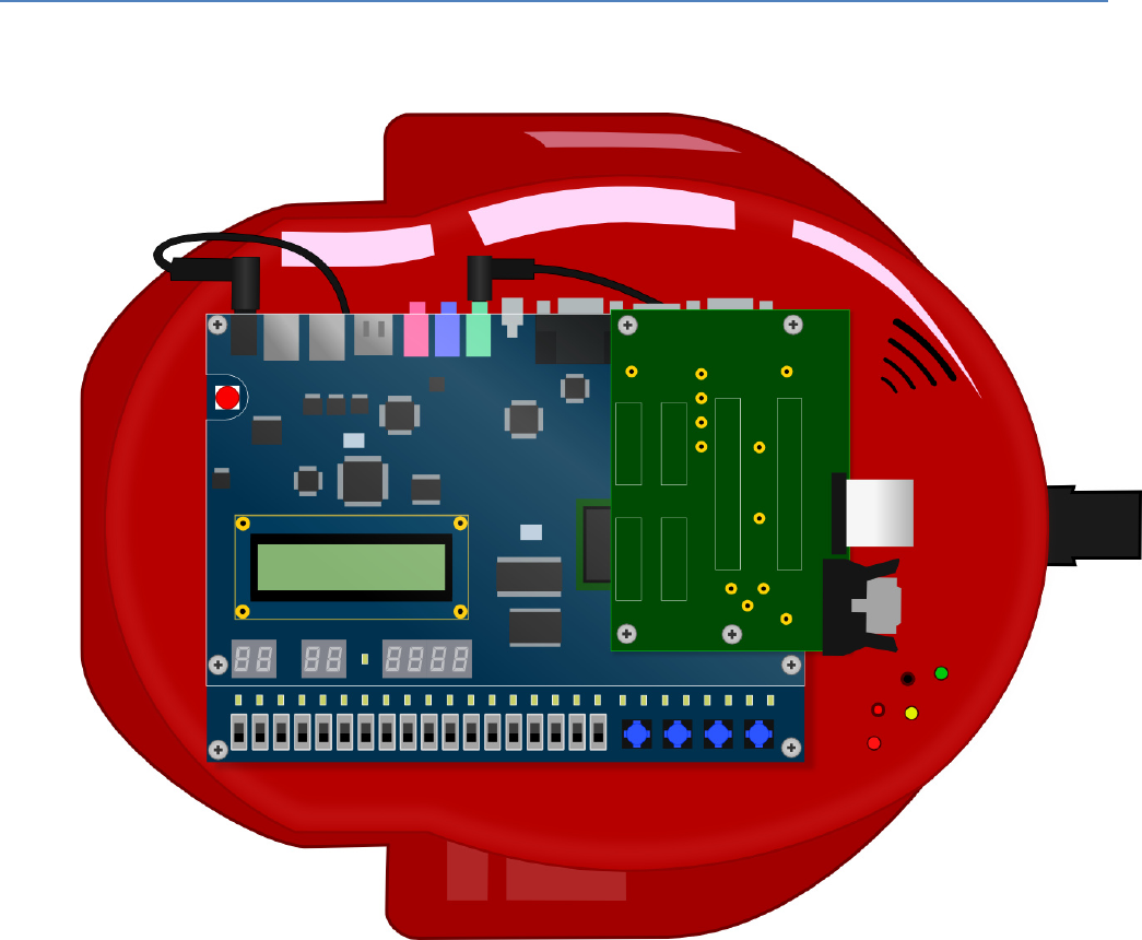
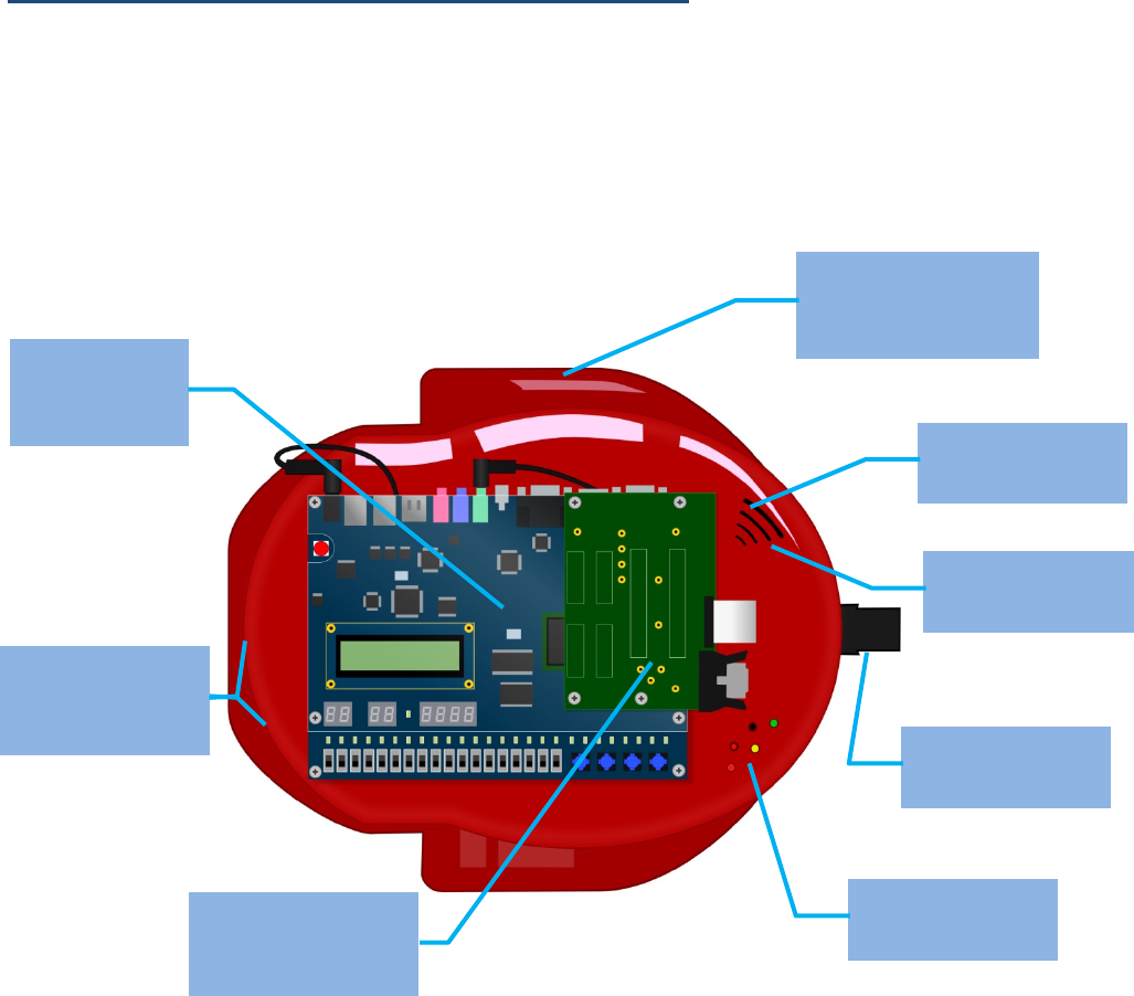
Locations of important features are shown below in Figure 1.
Figure 1. Locations of important DE2Bot features.
Charging port
(under robot)
Power switch
(under robot)
Drive wheels with
high-resolution
encoders
Rear caster
Status LEDs
Interface board
between DE2 and
robot internals
DE2 FPGA
development
board
Sonar sensors
(total of 8 around
robot)
Sonar sensors
(total of 8 around
robot)
4
1.1 Main Feature Descriptions
DE2 Development Board
The Altera DE2 board provides access to a Cyclone II FPGA as well as various I/O, including:
• 18 slide switches
• four push buttons
• 27 LEDs
• a 16x2-character LCD
• eight 7-segment displays
• audio in and out with ADC/DAC
• VGA video output
• an RS-232 serial port
• SD card slot.
The DE2 on the DE2Bot connects to the robot’s internal circuitry through its GPIO ports, allowing direct digital
control of all robot functions.
Note that the DE2’s power button (red button at top left of board) should not be used. Leave the DE2 ON and
use the robot’s main power switch to turn the DE2Bot on and off.
Sonar Distance Sensors
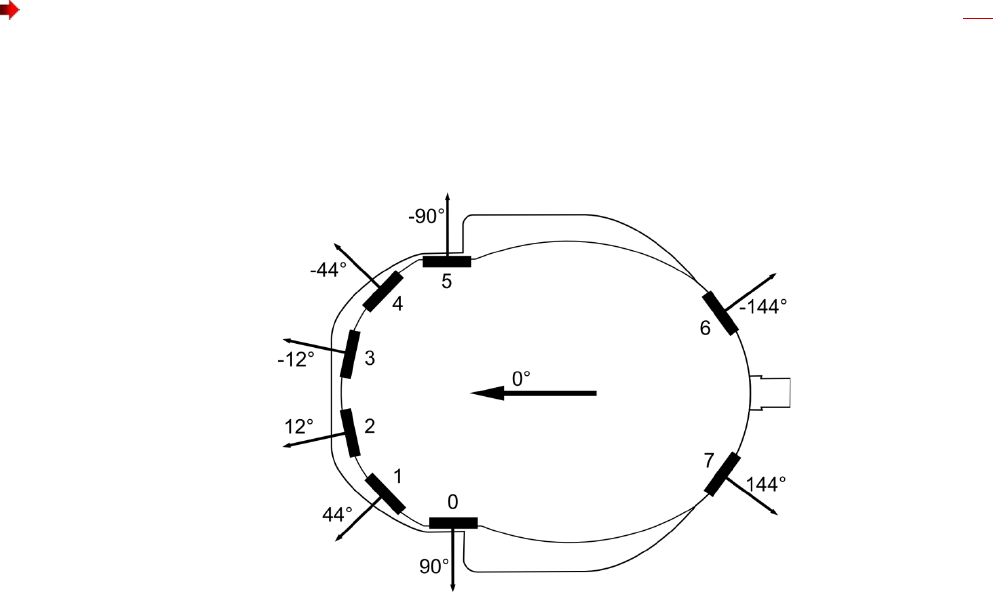
The DE2Bot is equipped with eight ultrasonic transducers that can be used to measure distances to objects. The
sensors are arranged around the robot as shown in Figure 2 and numbered clockwise starting with Sonar 0,
which is facing left (from the robot’s forward orientation; down in the figure).
Figure 2. Sonar sensor numbering, positions, and directions.
The sonar sensors can measure distances from 15cm up to 5m or more depending on the properties of the
object. The default resolution of the sensors is 1mm, though accuracy may vary ±1cm, or more at longer ranges.
See the relevant section of the programming guide for specific interface information.

5
Wheels and Encoders
The DE2Bot has two drive wheels, one on each side, allowing it to use differential steering to move around
smooth or dense-carpeted surfaces. A rear caster wheel helps to support the robot without interfering with
movement. The drive wheels are powered by DC motors through a reduction gearbox.
Each motor is equipped with a quadrature encoder which can be used to keep track of relative angular wheel
position and thereby calculate velocity and acceleration. The addition of specialized hardware within the FPGA
enables dead reckoning estimation of robot position using odometry calculations.
The control circuitry for the motors includes a watchdog timer that disables the motors if no ‘alive’ signal is
received for approximately half a second. In the default Quartus project for ECE2031, an additional safety
mechanism blocks the ‘alive’ signal until SW17 has been toggled (both up and down) after power-up or reset.
This ensures that the robot does not move immediately after being programmed, and guarantees that the robot
will stop when PB0 is pressed.
Battery and Charge Port
The DE2Bot contains a 5.5 Ah rechargeable LiPo battery, enabling several hours of ‘idle’ use or approximately an
hour of continuous running between charges. A charge port underneath the robot provides easy attachment of
an external charger.
Note that when the robot’s main power switch is ON, the charging port is disconnected from the battery.
In order to charge, the power switch must be in the OFF position.
Care should be taken to never discharge the battery below 14V. Doing so will reduce the life of the battery and
may cause permanent damage. To ensure this never happens, the batteries themselves, and the robot’s
internal controller board, both contain under-voltage protection circuitry, and software running on the DE2
board can also monitor the battery voltage using the internal A/D converter.

6
2–Self-test Operation
On power-up, a self-test program is automatically loaded from non-volatile memory. This program enables the
user to quickly test for proper operation of the DE2Bot hardware.
Note: the self-test program uses PB0 as RESET. Press PB0 to restart the program at any time.
2.1 Power-up Tests
As soon as the DE2Bot is turned on (or when the self-test is restarted with PB0):
• The DE2Bot beeps briefly
• An approximate battery percentage remaining is displayed (in decimal) on the HEX5 and HEX4 seven-
segment displays
• The battery percentage is displayed as a bar graph on red LEDs 0-14
o A fully-charged battery will light all LEDs 0-14. A dead battery will light only LED 0.
• Green LEDs 0, 1, and 2 light, mirroring the inactive state of pushbuttons 1, 2, and 3 respectively
o Pressing a PB will turn off the respective green LED.
• The LCD displays a menu prompting the user to choose “Self Test” or “Troubleshoot”
Power-up Errors
If the battery is too low to safely operate the DE2Bot, the user is warned with beeps, flashes, and a written
warning on the LCD. In this case, turn off the DE2Bot and plug it in to a charger.
If nothing happens when the DE2Bot is turned on, there is likely a problem with the battery or power circuitry.
Turn the DE2Bot switch to the OFF position and notify an administrator.
2.2 Automated Self-test
At the LCD prompt after power-up, pressing PB1 will begin a mostly-automated self-test routine.
The LCD will provide prompts that allow the user to execute the automated self-test without this document, but
detailed information is provided here for first-time users or in the case of errors.
1) Battery Check
The current battery voltage is displayed in decimal on the LCD screen. Battery voltage should be 14-17V for
proper robot operation.
2) Sonar Test
Each of the eight sonar sensors is tested, starting with Sonar0 (left-facing sonar) and proceeding clockwise. Each
sonar is polled until either a valid reading is obtained, or 5 seconds elapse.
If the test pauses on a particular sonar, move an object (such as your hand) in front of that sonar so that a
reading can be obtained. The current sonar is indicated on the red LEDs, or you can listen for the characteristic
‘clicking’ sound.
Once all sonar sensors are tested and working, the message “All sonars are working” is displayed on the LCD,
and the program automatically proceeds to the next test.
Sonar Errors
If a sonar does not return a valid reading within 5 seconds, it is assumed to be defective. At the end of the sonar
test, the green LEDs display which sonar(s) are not working. Note the number(s), and return the DE2Bot to an
administrator.

7
3) Encoder Test
Warning: The test immediately following this test may cause the robot to move under its own power. Ensure
that the DE2Bot is either on the floor in a clear area, or its wheels are raised off of the supporting surface.
Continuing this test with the robot on a table can cause it to fall when the following test begins.
Once the sonar test is complete, the LCD will display “Rotate left wheel 30+ degrees”. At this prompt, manually
rotate the left wheel in either direction until the LCD changes to “Rotate right wheel 30+ degrees”, then repeat
the rotation with the right wheel.
During this test, the current encoder position value is displayed on HEX3-0.
Encoder Errors
If no wheel motion is detected within 10 seconds, the test fails and an error is displayed on the LCD. Inform an
administrator.
4) Motor Test
Immediately after the encoder test completes, the motor test begins. If the safety switch (SW17) has not been
toggled since reset, the LCD will prompt “Toggle SW17”, at which point you should raise and lower SW17. Once
the safety is disabled, the left wheel will begin turning forwards and the LCD will display “Left wheel turning?
2-N/1-Y”. If the wheel is turning, press PB1. If not, press PB2. The test will then repeat with the right wheel.
Motor Errors
If either wheel does not turn when expected:
If previous tests indicated that the battery was below 30%, the battery might be too low to operate the motors.
Turn the DE2Bot off and plug it in to a charger.
If the battery is well charged, there is likely a problem with the motors or supporting electronics. Notify an
administrator.
Self-test Finish
Once the motor test is complete, the LCD will display “Self Test Finish PB1 – Main Menu”. If any errors
occurred during the self-test, a red LED will be lit as follows:
• LED0-7 indicate sonar 0-7 errors
• LED8 and LED9 indicate left and right encoder errors
• LED9 and LED10 indicate left and right motor errors
Press PB1 to return to the main menu.
2.3 Manual Tests
From the main menu, pressing PB2 will enter manual-test (troubleshooting) mode, where specific hardware can
be tested more thoroughly.
Entering Tests
Once in the troubleshooting main menu, raising a switch and pressing PB1 will enter the corresponding test - see
Table 1 below. If multiple switches are up, the lowest-indexed test is selected. While in a test, pressing PB2 and
PB3 together will return to the troubleshooting test selection mode. Use PB0 to return to the main menu.

8
TABLE 1
MANUAL TEST SELECTION
Switch Raised
Hardware Tested
SW0
Battery
SW1
Speaker
SW2
Switches and Pushbuttons
SW3
Sonars
SW4
LEDs, 7-segment displays, LCD
SW5
Wheel encoders
SW6
Motors
SW7
UART
Battery Test (SW0)
The battery voltage is continuously read and displayed on the LCD (in decimal) and 7-segment display (in hex).
Speaker (SW1)
The robot emits a stream of beeps with 0.15s on and 0.5s off. The LEDs light when the beep should be on.
Switches and Pushbuttons (SW2)
Switches 0-16 are reflected on red LEDs 0-16. The pushbuttons are reflected on the green LEDs 0-2.
Sonars (SW3)
Switches 0-7 will individually enable sonars 0-7. The value returned by the sonar is displayed on the 7-segment
display in hexadecimal. If more than one sonar is enabled, only the lowest-indexed one’s value is displayed.
LEDs, 7-segment displays, LCD (SW4)
All LEDs flash at 1Hz. The 7-segment displays alternate between 0x1111 and 0xEEEE (exercising all segments).
The LCD alternates between blank and black.
Wheel Encoders (SW5)
SW0 up/down selects between the left and right wheels. The selected wheel’s current position value is
displayed on HEX3-0 and the immediate velocity on HEX7-4.
Motors (SW6)
Hold PB1 to power the right motor and PB2 to power the left motor. Raise SW0 to reverse the right motor, and
SW1 to reverse the left motor.
UART (SW7)
The UART begins sending one byte every second, starting at 0x01 and incrementing each time. The transmitted
value is displayed on SSEG1. If a byte is received through the UART, it is displayed on SSEG2 and the robot
beeps.

3–Programming Guide
At the beginning of the final project in ECE2031, students are provided with a Quartus project containing the
SCOMP processor and many IO devices which interface with the DE2 and DE2Bot hardware. Each of these
devices is assigned an IO address in the SCOMP system as detailed in the Quick Reference section below.
3.1 Changes to SCOMP
SCOMP and its Quartus project have been modified from lab 8 in the following ways:
• Central IO_DECODER device replaces AND/NAND decoders for each peripheral.
• IO_CYCLE and IO_WRITE operation slightly modified to improve stability.
• SCOMP program memory doubled to 2048 words.
o A side effect of this is that the operand is now 11 bits, so immediate instructions (like ADDI) can
now use 11-bit numbers (±1023).
• SCOMP subroutine stack depth increased to 10.
• SHIFT instruction changed from “logical” to “arithmetic” to better support mathematical operations.
• All SCOMP instructions in Table 7.1 of the lab manual implemented.
• Additional SCOMP instructions added:
o LOADI - load immediate (immediate value is limited to 11-bit 2's complement)
o SEI, CLI, and RETI - used for new interrupt system, as described below
3.2 SCOMP Peripheral Interrupt System
Interrupts are disabled by default, and will not interfere with normal operation if left unused. This section is
safe to ignore if you do not plan on using interrupts. This section assumes some prior knowledge of interrupts.
Four external pins, PCINT[3..0], have been added to SCOMP, each of which can cause an interrupt, and each of
which has a dedicated interrupt vector. Table 2 shows the default source for each of the interrupt pins. For
more information about each source, refer to that device’s description in section 3.4.
TABLE 2
INTERRUPT DEVICES, PINS, AND VECTORS
PCINT Pin
Connected Device
Description
Interrupt Vector
PCINT[0]
Sonar Alarms
Sonar detected an object closer than alarm distance
0x001
PCINT[1]
Configurable Timer
Periodic interrupts at intervals of 10ms-5min
0x002
PCINT[2]
UART Data Ready
Data has been received from the UART
0x003
PCINT[3]
Stall Warning
Indicates that one or both motors have been stalled.
0x004
Enabling and Disabling Interrupts
At reset, all interrupt pins are disabled and cannot cause interrupts. Each pin can be individually enabled using
the SEI (SEt Interrupts) instruction, which takes a 4-bit mask specifying which interrupts to enable: a '1' in the
mask will enable that interrupt, while a '0' will have no effect (even if that interrupt is already enabled). For
example, SEI &B1111 will enable all interrupts. SEI &B1001 will enable interrupts 0 and 3, while leaving 1 and 2
unmodified. SEI &B0000 has no effect. CLI (CLear Interrupts) is similarly used to disable interrupts: CLI &B1111
will disable all interrupts, while CLI &B0000 will have no effect.
Interrupt Service Routines
When an interrupt event (a rising edge on an interrupt pin) occurs, SCOMP execution is redirected to the
memory locations described in Table 2. These locations must contain either a RETI instruction (if that interrupt
is not being used) or a JUMP instruction to the appropriate interrupt service routine (ISR).

3.3 IO Device Quick Reference
TABLE 3
SCOMP QUARTUS PROJECT I/O DEVICE DESCRIPTIONS
Name
IO Address
IN/OUT
Description
SWITCHES
0x00
IN
Read DE2 switches SW15-S0.
LEDS
0x01
OUT
Write to DE2 LEDs LEDR15-LEDR0.
TIMER
0x02
IN/OUT
Read 10Hz timer count. Write anything to reset to 0.
XIO*
0x03
IN
Read PB3-PB1, SW16, SAFETY signal, and some GPIO.
SSEG1
0x04
OUT
Write to left 4-digit seven-segment display.
SSEG2
0x05
OUT
Write to right 4-digit seven-segment display.
LCD
0x06
OUT
Write to LCD (16-bit hexadecimal).
XLEDS
0x07
OUT
Write to DE2 LEDs LEDG7-LEDG0 and LEDR17/LEDR16
BEEP*
0x0A
OUT
Variable pitch and duration tone generator.
CTIMER*
0x0C
OUT
Configurable timer for periodic interrupts
LPOS*
0x80
IN
Read the current position of the left wheel encoder; 1.05mm/tick.
LVEL*
0x82
IN
Read the current velocity of the left wheel; 1.05mm/s.
LVELCMD*
0x83
OUT
Write the desired velocity of the left wheel; 1.05mm/s.
RPOS*
0x88
IN
Read the current position of the right wheel encoder; 1.05mm/tick.
RVEL*
0x8A
IN
Read the current velocity of the right wheel; 1.05mm/s.
RVELCMD*
0x8B
OUT
Write the desired velocity of the right wheel; 1.05mm/s.
I2C_CMD*
0x90
OUT
Write configuration information to the I2C controller.
I2C_DATA*
0x91
IN/OUT
Read or write data from/to the I2C controller.
I2C_RDY*
0x92
IN/OUT
Begin I2C transaction or check transaction status.
UART_DAT
0x98
IN/OUT
Read or write one byte (low-byte of AC) from/to the UART.
UART_RDY
0x99
IN
Read the status of the UART controller.
DIST0 - DIST7*
0xA8 - 0xAF
IN
Read the measured distance from Sonar0 - Sonar7.
SONALARM*
0xB0
IN/OUT
Write the alarm distance; read the alarm register.
SONARINT*
0xB1
OUT
Write bits 0-7 to enable interrupts from sonar0 - sonar7.
SONAREN*
0xB2
OUT
Write bits 0-7 to enable sonar0 - sonar7.
XPOS*
0xC0
IN/OUT
Read or set dead reckoning X position estimation; 1.05mm/count.
YPOS*
0xC1
IN/OUT
Read or set dead reckoning Y position estimation; 1.05mm/count.
THETA*
0xC2
IN/OUT
Read or set dead reckoning angle estimation in degrees; always [0,359].
RESETPOS
0xC3
OUT
Reset dead-reckoning odometer: X,Y,θ = 0,0,0.
IR_HI
0xD0
IN/OUT
High word of IR code. Write to reset entire code to 0.
IR_LO
0xD1
IN/OUT
Low word of IR code. Write to reset entire code to 0.
* additional details in following sections
3.4 Detailed Description of Select Devices
XIO
The value read from XIO contains the following signals:
• XIO[15..5] : GPIO pins on the DE2 header
• XIO[4] : SAFETY signal, which indicates whether or not SW17 has been toggled
• XIO[3] : SW16
• XIO[2..0] : Pushbuttons PB3 - PB1 (PB0 is global reset and cannot be read)
Note that the pushbuttons are active-low: a pressed pushbutton will appear as a ‘0’ in XIO.
Sonar Sensors
Each sonar sensor can be independently enabled through the SONAREN register. Bits 0-7 of this register
correspond to sonars 0-7; e.g. writing 0b11000000 will enable only Sonar6 and Sonar7, and writing 0b11111111
will enable all sonars.
Each enabled sonar provides its measurement at the corresponding register DIST0-DIST7. This value is in mm
and has a resolution of 1mm, but its accuracy (both linearity and offset) is undefined and typically varies ±1cm.
The minimum typical readable distance is approximately 15cm and the maximum is 6m, though distant objects
may not return sufficient ping be detected depending on their shape, size, and material.
If no ping is returned (usually because either nothing is in front of the sonar, or the object is angled such that the
ping bounces in another direction), the measurement value is set to the maximum positive value of 0x7FFF.
Sonars update in a round-robin fashion at 16 Hz, skipping any that are not enabled. If all sonars are enabled,
each measurement will update at 2 Hz (16 Hz/8). If only one sonar is enabled, it will update at the full 16 Hz.
Thus, it is beneficial to only enable the sonars that you plan to read values from.
Sonar Interrupts
If not using interrupts, this information is not needed.
The value written to IO location SONALARM is used as an alarm distance by the sonar module: if any enabled
sonar measures an object closer than that distance, a bit is set in an alarm register, which can then be read from
the same SONALARM IO address. A '1' in any bit 0-7 of the returned value indicates that the corresponding
sonar (0-7) detected something too close during its previous measurement.
This system can also cause an interrupt in SCOMP on the relevant pin. By default, any enabled sonar that
measures a close object will cause an interrupt; however, a mask can be written to IO location SONARINT: any
'0' bit in that mask will disable interrupts from that sonar. For example, writing &B00100001 will only allow the
two side sonars (0 and 5) to cause interrupts.
Note that a sonar must still be enabled through the SONAREN register in order to cause interrupts. Also, the
SONARINT mask does not affect the alarm register read from SONALARM; any enabled sonar can always cause
bits to be set in SONALARM.
The sonar module will cause an interrupt with each new measurement that fits the alarm condition, so be aware
that it might cause interrupts at up to 25Hz (the read rate of the sonars). Interrupts can be disabled at any time
by configuring either the sonar module (through SONARINT) or SCOMP (using CLI).
Wheel Position, Velocity, and Velocity Commands
The values read from LPOS and RPOS provide the wheel encoder counts since reset. The encoders provide 304
ticks/revolution, which corresponds to linear movement of approximately 1.05mm/count. LVEL and RVEL
provide approximations of wheel velocity by sampling the position every 0.1s and providing the difference
multiplied by 10; the units are thus approximately 1.05mm/s.
LVELCMD and RVELCMD accept values in the same units as LVEL and RVEL, and attempt to control the wheel
velocities to match that value. Be aware that very low speeds (usually <50mm/s) may have difficulty
overcoming the static friction of the motors, gearboxes, axles, and wheels, and so may result in no movement or
spurious movement. However, once moving, the lower bits of LVELCMD and RVELCMD do provide additional
resolution to the speed.
The values sent to LVELCMD and RVELCMD should not exceed ±511. If a value outside that range is provided,
the motor controller will interpret it as 0 (stopped). Sending any value to RESETPOS will reset the positions to
0, as well as stop the robot
The acceleration (including deceleration) of each wheel is limited to 512 units/s to reduce stress on the axles.
An important side effect of this is that overshoot can be approximated and accounted for. In general, the
distance required to change velocity is
, so, simplified and applied to this robot, the distance required to
stop can be estimated by 1024
(where both VEL and the resulting distance are in robot units). Extending
this to rotations, assuming in-place rotations with equal but opposite wheel velocities , overshoot (in
degrees) can be estimated as 2030
.
Odometry
The Quartus DE2Bot project contains a device that performs dead reckoning odometry: continuously integrating
the movement of the wheels to maintain an estimate of the robot’s position and heading. This estimation can
be read from IO registers XPOS, YPOS, and THETA. The units for the XPOS and YPOS are 1.05mm/count – the
same as the resolution of LPOS and RPOS. THETA is in degrees.
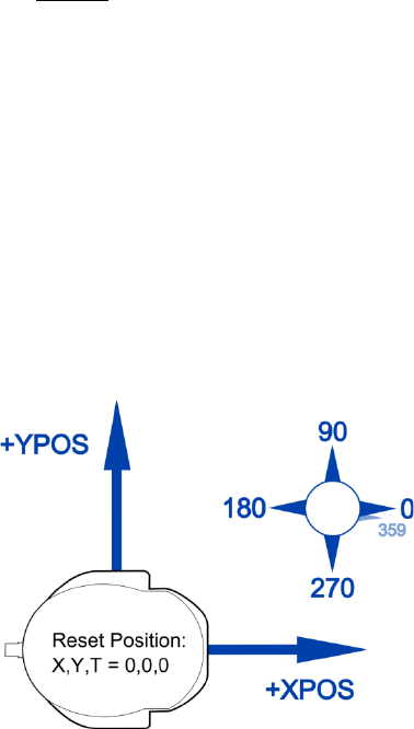
At power-up or reset, the position of the robot defaults to X,Y,θ=0,0,0. The coordinate system is shown in
Figure 3: the reset orientation is defined as facing the positive X direction, with positive Y to the left, and theta
following the normal right-handed convention (with Z upwards).
Figure 3. Coordinate system used for DE2Bot odometry.
The value of THETA will always be [0,359]; rotating counterclockwise past 359 will roll over to 0, and rotating
clockwise past 0 will roll over to 359.
Writing a value to XPOS, YPOS, or THETA will set that value within the odometry device. This can be used to,
for example, change the initial orientation, or realign the odometry to a known real-world posture.
Writing any value to the RESETPOS register will reset all position registers – XPOS, YPOS, THETA, LPOS, and
RPOS – to 0, as well as stop the robot (set LVELCMD and RVELCMD to 0).

Dead reckoning is highly susceptible to accumulated error from wheel slippage, wheel-size and wheel-base
errors, mathematical rounding, and other sources. The odometry values will likely contain significant error after
as little as a few meters of travel or one rotation of the robot, and much of the error will not be systematic (i.e.
there is no way to correct for it). Frequent turning generally exacerbates this problem, as turns cause the most
wheel slippage, and angular errors result in increasing linear errors.
I2C Controller and Battery Voltage
The DE2Bot contains an I2C bus, which is currently used to communicate with the A/D converter that measures
the battery voltage. SCOMP interfaces with the I2C bus through a controller with three I/O registers:
• I2C_CMD: write-only; contains configuration information for the controller.
o bits 15-12: number of bytes to write (0, 1, or 2)
o bits 11-9: number of bytes to read (0, 1, or 2)
o bits 8-1: 7-bit I2C address of device to communicate with; excludes RnW bit
o bit 0: ignored; the RnW bit is set on the fly according to the current operation
• I2C_DATA: read/write; data to send, and data received.
o If transmitting or receiving one byte, bits 7-0 are used
o If transmitting or receiving two bytes, bits 15-9 are the first byte, then bits 7-0
• I2C_RDY: read/write; status indicator
o Writing to I2C_RDY begins an I2C transaction; set up I2C_CMD and I2C_DATA first.
o Reading I2C_RDY will return zero if the controller is idle, or non-zero if a communication is in
progress. Do not modify I2C_CMD or I2C_DATA while I2C_RDY reads as non-zero.
Configurable Timer Interrupt Source
If not using interrupts, this information is not needed.
The CTIMER (configurable timer) device can cause periodic interrupts in SCOMP. Writing to the CTIMER IO
location sets the period of the interrupts, in increments of 10ms. “0” disables the interrupts, and “1” is invalid,
so the possible interrupt periods are from 20ms (“2”, 50Hz) to almost 11 minutes (“0xFFFF”).
Writing to CTIMER automatically resets the internal counter, but the first increment of the counter could occur
at any time within the following 10ms; thus, the first interrupt will actually occur between N and N-1 intervals
(of 10ms). Thereafter, interrupts will occur at the correct intervals.
Tone Generator
The robot contains a speaker which is driven from an audio DAC on the DE2 board. The SCOMP interface
generates sine-wave tones at varying frequencies, with an optional duration.
• Low byte : frequency in multiples of 15.6Hz. Recommended values are 0x10 (250Hz) to 0x40 (1kHz).
Send 0 to stop the beep.
• High byte : duration in multiples of 1/8 s. Send 0 to beep forever (until manually stopped).
3.5 Movement API
The DE2Bot Quartus project files include example assembly code that, among other functions, offers a
convenient way to control the robot.
Movement Control Description
The programmer interfaces with the movement control code through two values: the desired forward velocity
and the desired heading. These are stored in variables DVel and DTheta, respectively. The robot will set the
cumulative wheel speed to the desired velocity and then calculate and apply a differential wheel speed
proportional to the heading error in order to reduce that error.
Enabling and Disabling the Movement Control
The movement control code uses the configurable timer interrupt to periodically check the robot’s speed and
heading and apply corrections. The interrupt rate is not very important, but a recommended frequency is 10 Hz.
To enable the movement control code, the following are required:
• Interrupt jump table configured to call the movement code on timer interrupts.
• Configurable timer interrupt peripheral set to 10 Hz.
• Interrupt source 1 (timer) enabled.
To disable the movement control code, disable any of the above.
3.6 Good Practices for Robot Programming
This section details some recommended practices for safe and effective use of the DE2Bot.
At Program Start
As soon as the program starts or is reset, the following should be done in order:
1. Immediately stop the robot by writing 0 to LVELCMD and RVELCMD
2. Check the battery voltage, and prevent execution if it is below 13V
3. Wait for the safety switch (SW17) to be toggled
4. Wait for some form of user input (e.g. pressing a PB)
Testing Values
Two points must be kept in mind when making decisions based on values obtained from LPOS/RPOS, odometry,
sonars, or any other real-world measurement:
• There is no guarantee that a particular value will occur, so never test for an exact value. Instead, always
test for a range.
o Example1: polling LPOS while the robot is moving might return 0xFE at one sample and 0x100 at
the next sample, so testing for 0xFF will never pass.
Testing for ≥0xFF would correctly trigger even if 0xFF itself never occurs.
o Example2: many values are impossible to obtain from peripherals because of limited range or
resolution. For example, LVEL and RVEL only have a resolution of 10 units, so testing for exactly
15 will never pass.
• Be aware of edge conditions, which can erroneously cause tests to pass or fail.
o Example 1: Ideally THETA will be 0 after reset, but any small turn clockwise will change it to 359,
in which case a test for theta>X (intended to check if the robot has turned a certain amount
counterclockwise) will immediately pass.
Modularity
Code is much easier to debug, maintain, and extend if it is designed "bottom-to-top"; i.e. basic functionality
written first, which is used to perform larger but still basic tasks, which are then used to complete the overall
function of the code. It is easier to find errors in a small function tested independently than in a monolithic
does-all piece of software.
