DEC 11 OPUGA A D PDL Operator's Guide
DEC-11-OPUGA-A-D PDL Operator's Guide DEC-11-OPUGA-A-D PDL Operator's Guide
User Manual: DEC-11-OPUGA-A-D PDL Operator's Guide
Open the PDF directly: View PDF ![]() .
.
Page Count: 78
.)
Ci
',
..
. t
~
Order
addi
tiona!
copies
as
directed.
on.
the
Softwa.i;:s
Information
page
at
the
back
of
thi~~pcument.
:
.....
;"';"
:
~
,
digital equipment corporation-
niQYnar~~,massachu~~tts
.
First
Printing,
June
1975
The.
information
in
this
document
is
subject
to
change
without
notice
and
should
not
be
construed
as
a
commitment
by
Digital
Equipment
Corporation.
Digital
Equipment
Corporation
assumes
no
responsibility
for
any
errors
that
may
appear
in
this
manual.
The
software
described
in
thi.s
document
is
furnished
to
the
purchaser
under
a
license
for
use
on
a
single
computer
system
and
can
be
copied
(with
inclusion
of
DIGITAL's
copyright
notice)
only
for
use
in
such
system,
except
as
may
otherwise
be
provided
in
writing
by
DIGITAL.
Digital
Equipment
Corporation
assumes
no
responsibility
for
the
use
or
reliability
of
its
software
on
equipment
that
is
not
supplied
by
.
DIGITAL.
Copyright
C§)
1975,
by
Digital
Equipment
Corporation
The.HOW
TO
OBTAIN
SOFTWARE
INFORMATION
page,
located
at
the
back
of
this
document,
explains
the
various
services
available
to
DIGITAL
software
users.
The
postage
prepaid
READER'S
COMMENTS
form
on
the
last
page
of
this
document
requests
the
user's
critical
evaluation
to
assist
us
in
preparing
future
documentation.
The
following
are
trademarks
of
Digital
Equipment
Corporation:
COP
COMPUTER
LAB
COMSYST
COMTEX
DDT
DEC
DECCOMM
DECTAPE
DIBOL
DIGITAL
DNC
EDGRIN
EDUSYSTEM
FLIP
CHIP
FOCAL
GLC-8
IDAC
IDACS
INDAC
KAIO
LAB-8
LAB-8/e
LAB-K
OMNIBUS
OS/8
PDP
PHA
psiS
QUICKPOINT
RAD-8
RSTS
RSX
RTM
RT-ll
SABR
TYPESET 8
UNIBUS
(
(
PREFACE
The
PDL
system
is
primarily
a
system
designed
for
data
acquisition
and
analysis.
It
will
collect,
record
and
process
data
from
15
instruments
such
as
Autoanalyzers,
SMA's
or
Coulter
model
"s"
while
simultaneously
doing
calculations
with
the
data
being
collected
or
perform
any
other
services
of
BASIC.
,
The
PDL
operators
guide
provides
the
USer
with
information
on
system
usage,
initialization
of
instrument
parameters,
cassette
manipulation,
software
interfacing,
report
generating,
sample
programs,
error
condi-
tions
and
error
procedures..
Also
included
is
an
introduction
to
the
BASIC CAPS
language.
These
chapters
are
structured
in
the
logical
fashion
to
orient
you
with
the
system
from
installation
to
daily
opera-
tion.
The
following
manuals
·provide
the
PDL
user
with
additional
information.
PDL
Programmers
Manual
DEC-II-OPPMA-A-D
BASIC
Language
Reference
Manual
DEC-II-LIBBA-A-D
CAPS
11
Users
Guide
DEC-II-OTUGA-A-D
CAPS/BASIC
Users
Manual
DEC-l1-LIBCA-A-D

iii
(
\
CONTENTS
(Cont.)
(
Pa'}e
CHAPTER
6 BASIC
LANGUAGE
INTRODUCTION
6
•.
1
BASIC
CAPABILITIES
6-1
;>
6.2
IMMEDIATE
MODE
6-2
6.3
PROGRAMMED
MODE
6-2
i"'''
6.3.1
Statements
6-2
6.4
MATHEMATICAL
OPERATIONS.
6-3
6.4.1
Relational
Operation
6-3
(
6.4.2
Evaluation
of
Expressions
6-3
6.4.3
Character
Strings
6-4
'
..
6.4.4
Variable
6-4
CHAPTER
7
REPORT
GENERATORS
7.1
SUBROUTINES
USED
7~2
7.1.1
INTL
Subroutine
7-2
7.1.2
RDBF
Subroutine
7-3
7.1.3
BFST
Subroutine
7-4
(
7.1.4
STAT
Subroutine
7-5
7.2
SAMPLE
PROGRAM
7-5
~
APPENDIX
A
BASIC
STATEMENTS,
COMMANDS,
FUNCTIONS
A-I
APPENDIX
B
BASIC
ERROR
MESSAGES
B-1
iv
(
':
.(
(
c·
(
CHAPTER
1
INTRODUCTION
1.1
OVERVIEW
The
PDL
Operator's
Guide
provides
an
overview
of
the
PDL
system,
its
function,
and
its
overall
operating
procedures.
The
chapters
include
information
on
system
usages,
initialization,
cassette
manipulation,
software
interfacing,
report
generating,
and
error
procedures.
Also
included
is
an
introduction
to
the
BASIC-CAPS
language
•
The
information
is
set
forth
in
a
logical
fashion
to
increase
familiarity
with
PDL
and
to
simplify
system
use
on
a
daily
basis.
1.2
INTENDED
USE
PDL
(Programmable
Data
Logger)
has
been
developed
specifically
for
use
with
clinical
laboratory
instruments.
PDL's
primary
functions
are
to
aquiredata
from
such
instruments
as
Autoanalyzers,
SMAs,
and
coulter
model
ItS','
counters,
to
manipulate
the
data
mathematically,
and
to·
produce
formatted
repo~ts.
(The
reports
are
printedOti
the
Console
terminal
or
any
other
designated
printing
device.)
PDL
may
also
be
used
as
a
programmable
calculator,
tailored
to
allow
individual
~odification
within
the
laboratory.
1.2.1
The
System
PDL
is
buH
t
around
the
PDP-:-ll/lO
processor.
The
.PDL.
system
includes
such
features
as
dual
cassette
drives
(drives
0
and
1),
aconsole
terminal
(a
DECwriter),
and
24K
.(lK
=
1024
words)
of
core
memory_
Local
operator.
console
terminals
are
provided
for
each
laboratory
instrument
interface..
.
Input/Output
(I/O)
devices
connect
local
operator
terminals,
clinical
instruments,
and
the
central
processor.
For
such
clinical
instruments
as
the
coulter,
the
I/O
devices
are
digital~
for
autoanalyzers
or
SMAs,
analog/digital
converters
are
provided.
Clinical
instruments
must
be
connected
to
the
computer
by
cable
to
a
screw
terminal.
1-1
INTRODUCTION_
1.2.2
The
Console
The
console
contains
switches
through
which
information
necessary
to
the
computer
operation
may
be
directly
inserted
to
the
programs.
This
is
a
convenient
manual
method
of
updating
and
controlling
the
status
of
the
operations.
A
complete
explanation
of
the
console
switches
and
their
use
will
be
found
in
the
CAPS-II
USERS
GUIDE.
However
the
running
of
PDL
does
not
require
the
uSe
of
these
console
switches.
1.3
THE
DECWRITER
The
DECwriter
(LA36)
with
its
printer
and
keyboard
acts
as
the
computer
typewriter.
It
prints
both
the
input
data
typed
by
the
USer
and
the
data
output
from
the
computer,
at
a
rate
of
30
charactets
per
second.
The
DECwriter
keyboard
resembles
the
keyboard
of
a
typewriter,
with
several
additional
keys
that
Serve
specifically
as
communications
control
keys.
The
carriage
return
key
(whose
use
is
indicated
in
this
manual
by
the
notation
<CR»
is
pressed
to
tell
the
computer
that
the
current
line
of
typed
input
is
complete.
This
action
automatically
moves
the
print
head
to
the
left
margin
to
await
further
input.
Cartiage
return
is
pressed
at
the
end
of
each
line
of
operator
dialogue.
The
line
feed
key
(indicated
as
LF
in
this
manual)
returns
the
print
head
to
the
left
margin
but
does
not
tell
the
computer
that
the
current
line
of
inpu~
is
complete.
This
allows
for
continuation
of
a
long
input
line
on
the
next
typing
line.
The
ALT-MODE
key
(indicated
by
ALT)
may
appear
on
the
keyboard
as
the
ESCape
key.
It
has
many
functions
which
are
not
described
here
because
PDL
does
not
use
this
key.
The
RUBOUT
key
erases
characters,
one
by
one,
in
reverse
order.
Press
the
RUBOUT
key
once
for
each
character
to
be
erased,
then type
the
correct
characters.
To
erase
a
complete
line,
hold
down
the
CTRL
(control)
key
and
type
the
U
key.
Then
resume
typing
the
correct
input.
1.3.1
Special
Switches
on
the
LA36
Terminal
The
baud
switch
controls
the
speed
at
which
the
terminal
can
receive
and
send
characters.
When
PDL
is
being
used,
the
Baud
switch
must
be
set
at
300.
Information
on
all
bf
ihese
fun6tions
and
a
complete
description
of
the
DECwriter
will
be
f6und
in
the
CAPS-II
Users
Guide
(DEC-l~-OTUGA-A-D)
.
1.4
LOCAL
OPERATOR'S
CONSOLE
The
local
operator's
console
looks
like
a
small
black
box.
Such
a
box
is
attached
to
every
laboratory
instrument.
The
local
operator's
console
is
the
means
through
which
the
laboratory
instruments
1-2
(
(
(
(
(
(
(
(
(
..
/
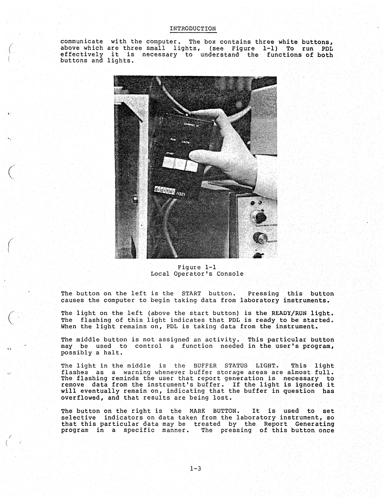
communicate
above
which
effectively
buttons
and
INTRODUCTION
with
the
computer.
The box
contains
three
white
buttons,
are
three
small
lights,
(see
Figure
1.-1)
To
run
PDL
it
is
necessary
to
understand
the
functions
of
both
lights.
Figure
1-1
Local
Operator'~
Console
The
button
on
the
left
is
the
START
button.
Pressing
this
button
causes
the
computer
to
begin
taking
data
from
laboratory
instruments.
The
light
.oIl
the
left
(above
the
start
button)
is
the
READY/RUN
light.
The
flashing
of
this
light
indicates
that.
PDL
·is
ready
to
be
started.
When
the
light
remains
on,
PDL
is
taking
data
from
the
instrument.·
The
middle
button
is
not
assigned
an
activity
•.
This
particular
button
may
be
used
to
control
a
function
needed
in
the
user's
program,
possibly
a
halt.
The
light
in
the
middle
is
the
BUFFER
STATUS
. LIGHT.
This
light
flashes
as
a
warning
whenever
buffer
storage
areas
are
almost
fUll.
The
flashing
reminds
the
user
that
report
generation
is
necessary
to
remove
data
from
the
instrument's
buffer.
If
the
light
is
ignored
it
will
eventually
remain
on,
indicating
that
the
buffer
in
question
has
overflowed~
and
that
results
are
being
lost.
The
button
on
the
right
is
the
MARK
BUTTON.
It
is
used
to
set
selective
indicators
on
data
taken
from
the
laboratory
instrument,
so
that
this
particular
data
may
be
treated
by
the
Report
Generating
program
in
a
specific
manner.
The
pressing
of
this
button
once
1-3
INTRODOCTION
initiates
this
action.
A
second
pressing
of
the
button
cancels
the
action.
An
example
of
the
use
of
this
feature
is
to
indicate
the
separation
of
several
samples
of
watet
so
that
they
are
not
..
included
in
a
calculation.
The
right
hand
light
indicates
the
status
of
the
MARK
BUT'rON.
If
the
light
is
on,
the
MARK
function
is
in
use.
The
local
operator's
con,ole
enables
the
user
to
remotely
control
the
computer's
interaction
with
a
particular
laboratory
instrument,
the
transfer
of
data
to
the
computer,
and
the
monitoring
of
the
whole
procedure.
1.5
CASSETTE
SYSTEM
POL
is
tailored
to
the
cassette
system.
The
choice
of
cassettes
for
use
with
this
system
contributes
to
the
ease,
directness,
and
simplicity
of
approach
that
is·
inherent
in
the
system.
Loading,
unloading,
and
general
manipulation
are
greatly
simplified
because
of
this
feature.
The
small,
sturdy
cassette
is
capable
of
carrying
large
quantities
of
data
and
is
easy
to
handle.
Storage
problems
are
nonexistent;
many
cassettes
may
be
stored
in
a
relatively
small
area.
Cassettes
ar~
inexpensive
to
buy.
Therefbre,
their
use
as
backup
storage,
for
important
data,
is
both
efficient
and
economical.
Advantage
should
be
taken
of
the
back-up
storage
feature
in
.
both
the
BASIC
CAPS
system
and
the
POL
system.
Furthl;!r
informatio.n
on
cassettes
will
be
found
in
Chapter
2.
NOTE
Do
not
use
audio
cassettes
on
this
system.
Use
only
computer
cassettes.
1.6
BASIC
LANGUAGE
OVERVIEW
BASIC
is
the
language
chosen
for
use
with
the
POL
system.
BAStC
is
a
high
level,
English-like
language
that
can
be
l~arned
quickly
and
easily.
It
is,
perhaps,
the
simplest
of
all
programming
languages
to
use.
The
small
number
of
powerful
statements
and
commands
that
are
necessary
to
produce
good
results,
together
with
the
ease
of
problem
solving,
make
BASIC
ideal
for
use
with
POL
Although
BASIC
is
similar
to
other
high-level
programming
languages,
its
conversational
nature
makes
it
a
canvenient
language
for
use
with
PDL. A
conversational
language
allows
two-way
communication
between
the
programmer
and
the
language
processor.
The
typing
of
-input
data
onto
the
terminal
invokes
a
reciprocal
response
from
the
computer,
which
results
in
output
data
being
printed
an
the
terminal.
Use
of
BASIC
in
the
cassette
enviranment
is
referred
to.
as
BASIC/CAPS.
BASIC-CAPS
facilitates
the
easy
writing
af
repart
generating
pragrams.
Data
acquisitian
and
processing
actians
cantinue
while
the
user
is
.
writing
ar
testing
pragrams,
ar
atherwise
using
BASIC
as
a
calculatar.
See
Repart
Generatars,
Chapter
7.
1-4
(
l
.1
(
c
':
",
c··
~
<.0.
'
f
'.
CHAPTER
2
THE
COMPU'!'ERCASSETTE
The
computer
cassette
is
a
convenient
magnetic
tape
device
used
simplify
the
manipulation
of
data
within
a
computer
environment.
size,
shape,
and
construction,
the
computer
cassette
is
similar
to
popular
cassette
commonly
used
for
home
tape
recording.
However "
computer
cassette
is
structured
specifically
for'
use
'with
computer.
to
In
the
the
the
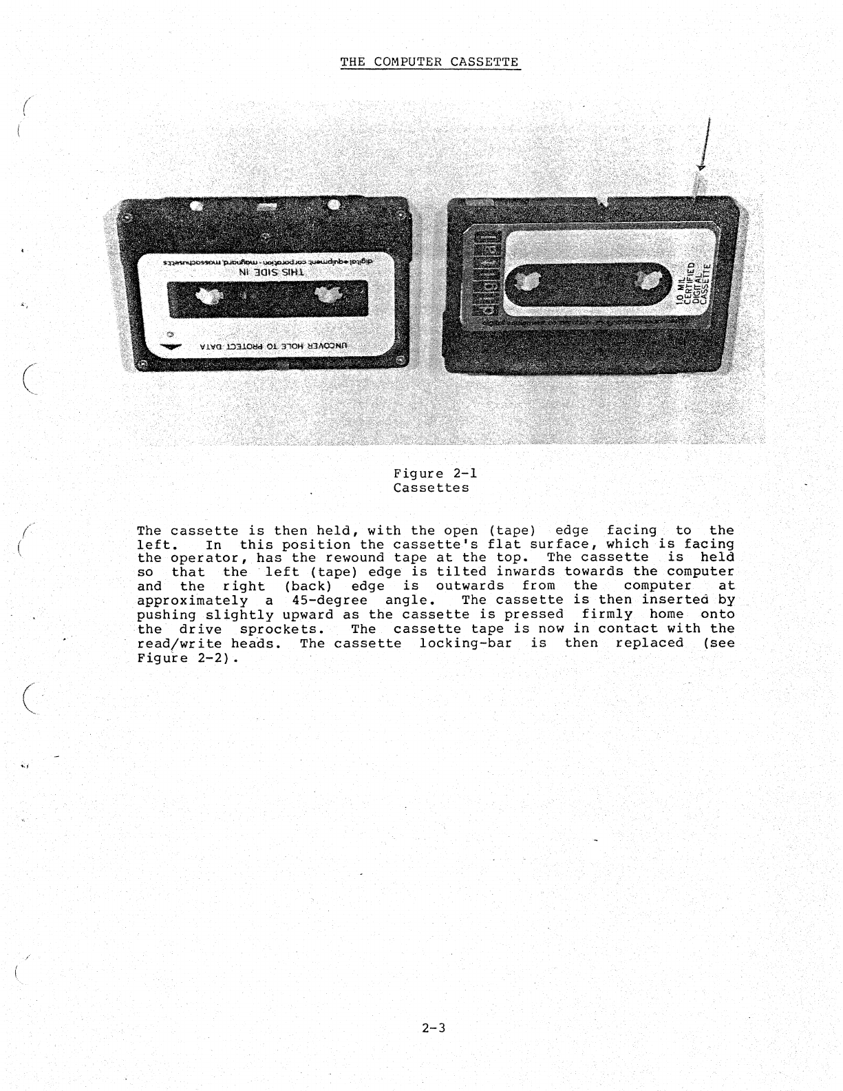
On
one
edge
of
the
cassette
there
are
two
flexible,
plastic
orange
tabs.
They
are
called
'WRITE
PROTECT
TABS'.
They
are
situated
one
at
each
end
of
the
cassette
where
they
can
govern
the
write
capability
on
the
tape.
Unlike
home
tape
cassettes,'
the
computer
cassette
is
us'ed
to
record
information
in
one
direction
only.
Ther~fore
only
one
orange
tab
(the
one
marked
with
an
arrow
on
the
cassette
label)
need
t)e
used.
(See
Figure
2-1.)
When
the
orange
t,ab
is
pulled
over:
toward
the
middle
of
the
cassette
(i.e.,
the
hole
is
uncovered),
the
tape
is
consid~red
to
be
in
WRITE-LOCK
position.
WRITE-LOCK
means
that
data
cannot
be
written
onto
the
tape.
This
simple
protection
device
ha~
proven
~
very
useful
"
tool.If
an
attempt
i~
made
to
write
onto
a
cassette
which
WRITE-LOCK,
an
error
message
(WRT
LOCK)
will
result.
is
in
Pushing
the
orange
tab
to
the
outside
of
the
cassette
.(i.~.,
co~ering
.the·hole)
makes
the
tape
WRITE-ENABLED.
WRITE-ENABLED
means
that
data
may
be
written
onto
the
tape.
The
orange
tab,
while
controlling
the
cassette's
ability
to
receive
data,
does
not
affect
the
tape's
ability
to
be
read.
Thus,
the
cassette
tape
may
be
read,
regardless
of
the
position
0'£
the
tab.
As a
safeguard
against
abrasion,
both
ends
of
the
tape
consist
of
clear
plastic.
The
~lear
plastic
is
either
leader
(or
trailer
tape).
Magnetic
tape
is
quite
susceptible
to
dust,
grit,
and
fingerprints.
Therefore-
the
clear
plastic
leader
protects
the
tape
during
handling
and
storage.
To
ensure
proper
use
of
this
protect
f~ature
the
tape
should
be
rewoundtb
its
beginning
(plastic
leader)
at
all
times
other
than
when
the
cassette
is
actually
in
use.
2-1
THE
COMPUTER
CASSETTE
2.1
RECORD
FORMATTING
The
computer
cassette
tape
contains
data
in
the
form
of
files
and
records.
A
file
is
defined
as
the
largest
f;elf-contained
unit
of
data
on
the
tape.
A
file
consists
of
one
or
more
records.
A
record
is
defined
as
the
smallest
self-contained
unit
of
data
on
the
tape;
It
is
the
only
type
of
unit
within
a
file.
The
size
of
a
data~file
is
determined
by
the
amount
of
data
it
encompasses.
There
are
no
set·
number
of
files
on
a
cassette
tape.
There
may
be
as
few
as
one
file
or
the~e
may
be
many
files,
each
containing
one
or
more
small
data
records.
A
file
may
not
extend
over
more
than
one
cassette
tape.
Each
file
on
the
cassette
tape
is
separated
from
its
neighbor
by.
an
inter-file
gap.
The
inter~fil~
gap
is
one
quarter
inch
long.
tts
purpose
is
both
to
separate
the
individual
fileS
and
to
serve
as
a
point
of
reference
for
any
program
that
is
seeking
a
given
file.
Therefore,
it
is
important
that
such
a
gap
also
appear
before
the
first
file
on
the
tape.
The
seeking
program
will
ignore
any
data
it
finds
ahead
of
the
first
inter-file
gap.
.
The
data-record
is
~tructured
in
the
Same
manner
as
thefile~
Because
there
are.
often
many
records
within
a
file;
each
record
is
separated
from
the
next,by
an
inter-record
gap.
Within
a
file,
each
record
must
be
in
both
logical
and
physical
sequence.
The
record's
number,
its
position
in
the
file,
and
general
information
controlling
its
fun6ti6ti,
are
present.
together
with
the
file
name,
file
type,
and
file
length,
1n
the
first
record
of
that
partictilar
file.
This
record
is
called
the
header
record.
2.2
USING
THE
CASSETTE
Before
mounting
the
cassette
on
the
cassette
drive,
the
should
be
set
to
the
desired
position
(WRITE~LOCK
or
WRITE
locking-bar
(a
protect
feature
on
the
cassette
drive)
is
pushing
(sliding)
it
to
the
right,
away
from
the
drive
2-1).
2-2
orange
tab
ENABLE
1
The
..
removed
by
(see
Figure
.•.
"
(
((
(
(
";::,
(
, '
/
THE
COMPUTER
CASSETTE
Figure
2-1
Cassettes
The
cassette
is
then
held,
with
the
open
(tape)
edge
facing
'to
the
left.
In
this
position
the
cassette's
flat
surface,
which
is
facing
the
operator,
has
the
rewound
tape
at
the
top.
The
cassette
is
held
so
that
the
'left
(tape)
edge
is
tilted
inwards
towards
the
computer
and
the
right
(back)
edge
is
outwards
from
the
computer
at,
approxi~ately
a
45-degree
angle.
The
cassette
is
then
insert~d
by
pushing
slightly
upward
as
the
cassette
is
pressed
firmly
home
onto
the
drive
sprockets.
The
cassette
tape
is
now
in
contact
with
the
read/write
heads.
The
cassette
locking-bar
is
then
replaced
(see
Figure
2-2).
'
2-3
THE
COMPUTER
CASSETTE
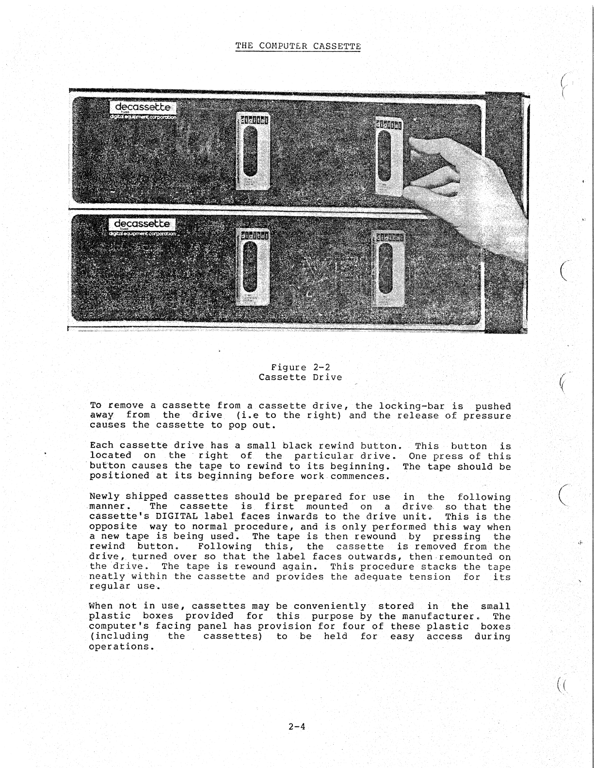
Figure
2-2
Cassette
Drive
To
remove
a
cassette
from
a
cassette
drive,
the
locking-bar
is
pushed
away
from
thedri-ve
(i.e
to
the
right)
and
the
release
of
pressure
causes
the
cassett.e
to
pop
out.
Each
cassette
drive
has
a
small
black
rewind
button.
located
on
the
right
of
the
particular
drive.
·bufton
causes
the
tape
to
rewind
to
its
beginning.
positioned
at
its
beg.inning
before
work
commences.
This
button
is
One
press
of
this
The
tape
should
be
Newly
shipped
cassettes
should
be
prepared
for
use
in
the
following
manner.
The
cassette
is
first
mounted
on
a
driva
so
that
the
cassette's
DIGITAL
label
faces
inwards
to
the
drive
unit.
This
is
the
opposite
way
to
normal
procedure,
and
is
only
performed
this
way
when
a
new
tape
is
being
used.
The
tape
is
then
rewound
by
pressing
the
rewind
button.
Following
this,
the
cassette
is
re~oved
f~om
the
drive,
turned
over
so
that
the
label
faces
outwards,
then·remounted
on
the
drive.
The
tape
is
rewound
again.
·This
procedure
stacks
the
tape
neat~y
within
th~
cassette
and
proVides
the
adeguate
tension
for
its
regular
use.
When
not
in
use,
cassettes
may
be
conveniently
stored
in
the
small
plastic
boxes
provided
for
this
purpose
by
the
manufacturer.
The
computerfs
facing
panel
has
provision
for
four
of
thes~
plastic
boxes
(including
the
cassettes)
to
be
held
for
easy
access
during
operations.
2-4
. ((
/
(
,',
2.3
THE
COMPUTER
CASSETTE
,
NOTE
As
mentioned
earlier
it
is
a good
practice
to
keep
tapes
in
their
rewound
state
and
in
their
plastic
cases
at
all
times
other
than
when
they
are
actually
in
use.
'
THE
SYSTEMS
CASSETTE
Each programming
system
is
contained
on a
single
cassette.
This
cassette
is
called
the
system
cassette.
It
contains
the
programs
that
govern
the
loading
and
the
running
of
all
of
the
systems
programs.'
NOTE
As
the
systems
cassette
is
not
normally
written
upon,
it
is
advisable
to
make
sure
that
the
orange
protect
tab,
is
always,
in
WRITE-LOCK.
Because
of
its
obvious
importance
to
the
system,
the
information
contained
on
the
systems
cassette
should
be
copied
onto
a
spare
cassette
at
the
earliest
opportunity.
In
the
event"
that
the
system
cassette
information
is
destroyed,
such
a
back-up
saves
time,
money,
anc,1
frustration.
To
make
copies
of
system
cassette,
refer
to
.
the
section
on
copying
cassettes.
2.4
LOADING
PROGRAMS
FROM
A
CASSETTE
'1'0
operate
the
systems
pr09rams,
it
is
necessary
to
have
them
in
the'
c,emputer'
s
memory~·
The'
loading
of
these
program'S
into
memory
is,
effected
by
the
BOOTSTRAP
PI'ogratn.
The
BOOTSTRAP
prog.ram
is
a
self-loading
program:
a
series
of
instructions
(residing
on
the
beginning
of
the
system
tape)
enable
the
system
progrems
to
be
,transferted
into
memory.' Once
loaded,the'
JlOOTSTRAP
program
is
able
to
accept
commands
(from
,the
console
,terminal
keyboard)
directing
it
to
load
the
programs
which
"follow
on
the
systems
tap.,.
'
There
are
three
systems
cassettes
provided
with
the
PDL
system.
are:
CAPS-II System (CAPS-II)
BASIC
CAPS-II
System,
(BASIC)
nOGRAMMAB'LE
DATA
LOGGER
{POL}
They
The
1oadingprocedure
for
any
of
the
above
systems
consists
of
the
following
steps:
1.
Be
sure
both
computer
and
console
terminal
are
on
line.
Turn
power key
ON.
2-5,
THE
COMPUTER
CASSETTE
2.
Place
the
specific
systems
cassette
onto
cassette
drive
O.
3.
Drive
0
must
always
be
used
for
the
system
cassette.
This
drive
is
found
on
the
left-hand
side.
NOTE
There
are
two
cassette
drives
on
the
console:
drive
0
and
drive
1.
It
is
important
to
remember
that
drive
0
is
on
the
left.
There
are
a
number
(see
Figure
2-3).
in
LOCK
position.
upward
into
the
programming
action
wor
k)
.
of
switches
on
the
front
of
the
computer
Make
sure
that
the
power
key
is
Dn
and
not
Press
the
HALT
switch
downward
and
then
ENABLE
position.
(This
cancels
previous
and
prepares
the
console
for
further
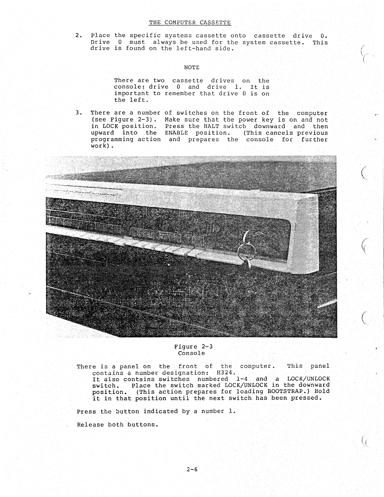
Figure
2-3
Console
There
is
a
panel
on
the
front
of
the
computer.
This
panel
contains
a
number
designation:
H32~.
It
also
contains
switches
numbered
1-4
and
a LOCK/UNLOCK
switch.
Place
the
switch
marked
LOCK/UNLOCK
in
the
downward
position.
(This
action
prepares
for
loading
BOOTSTRAP.)
Hold
it
in
that
position
until
the
next
switch
has
been
pressed.
Press
the
button
indicated
by
a
number
1.
Release
both
buttons.
2-6
(
(
'.-
",
(
("
,
.'
(
THE
COMPUTER
CASSETTE
NOTE
At
this
point,
the
run
lamp
is
on
,~hd
the
systems
cassette
tape
begins
to
move.
The
system
is
being
loaded.
The
system
cassette
tape
comes
to
a
halt
when
the
system
has
been
loaded.
If
CAPS-II
system
has
been
used,
proof
of
loading
is
seen
when
the
identification
line
shown
below
is
automatically
printed
on
the
terminal.
CAPS-ll
VOI-02
A
drit
is
also
printed
at
the
terminal's
left
margin.
This
dot
is
the
indication
that
the
system
is
in
the
ready
state
(i.e.,
awaiting
a
command
from
,the
terminal).
NOTE
If
a
loading
error
occurs,
the
systems
cassette
tape
stops
moving
and
the
computer
halts.
This
situation
requires
a
restart
of
the
whole
procedure~
The
system
must
be
REBOOTED
(i.e.,
the
BOOTSTRAP
must
be
reloaded).
If
the
error
reoccurs,
refer
to
the
error
procedures
in
Appendix
C
in
the
CAPS-II
User's
Guide
DEC-II-OTUGA-A-D.
,When
in
the
ready
state,
as
indicated
by
the
dot
printed
at
the
left
margin
of
the
terminal
printer,
the
system
accepts
any
of-the
following
eight
commands:
DATE
ZERO
SENTINAL
DIRECTORY
RUN
LO~O
START
VERSION
A
complete
desc,ription
of
the
cQmmands,
together
with
their
uses,
can
be
found
in
the
CAPS-II
User's
Guide
(DEC-ll-OTUGA-A-D)
Section
3.3.
2.5
ZEROING
A
CASSETTE
One
of
the
most
useful
commands
available
in
the
CAPS
system
is
the
Z.ERO
command.
The
command
deletes
(erases)
any
data
or
files
present
on
a
given
cassette.
ThiS
is
done
by
writing
a
Sentinel
'file
at
beginning
'of
tape.
Refer
to
CAPS-II
Useu
Manual
on
definition
of
Sentinel'
file.
The
purpose
of
this
procedure
is
to
'enable
a
previously
used
cassette
to
be
reused
without
the
possibility
of
previous
data
and
present
data
inadvertently
being
mixed.
'
2-7
THE
COMPUTER
CASSETTE
The
procedure
for
zeroing
a
cassette
tape
is
shown
below:
1.
Place
cassette
to
be
zeroed
on
drive
1.
2.
In
response
to
the
dot
on
the
terminal
type
the
letters
ZER,
followed
by
the
drive
number,
followed
by
a
colon.
Example:
to
zero
the
tape
on
drive
1
type:
ZERI:<CR)
The
tape
is
now
automatically
zeroed.
NOTE
All
new
cassettes
should
be
zeroed
to
ensure
proper
operati6n.
Unzeroed
cassettes
can
not
be
written
on.
When
zeroing
previously
used
cassettes,
care
should
be
used
so
that
important
data
are
never
accidently
removed.
2.6
COPYING
A CASSETTE
The
copying
of
a
cassette
tape
is
a
function
that
will
often
be
performed.
Copying
a
cassette
is
aided
by
the
.
(PIP)
•
PIP
is
a
useful
utility
deleting,
zeroing,
and
multiple
Information
regarding
each
of
these
Users
~anual.
Peripheral
Interchange
program
which
allows.
copying
of
cassette
features
is
found
in
the
Program
copying,
tapes.
CAPS-ll
PIP
resides
on
the
CAPS-II
systems
cassette.
The
CAPS
system
tape
is
booted.
This
results
in
a
dot
appearing
on
the
left
margin
of
·the
terminal
printer.
In
response
to
the
dot
the
PIP
program
is.
called
by
typing
the
following
statement
on
the
terminal.
R
PIP
<CR)
PIP
is
automatically
loaded
into
memory.
An
asterisk
printed
on
the
left
margin
of
the
tet:minal
printer,
is
PIP's
response.
The
system
is
ready
for
the
next
command
which
in
this
case
is
a
string
command
(Leo,
it
contains
several
actions)
in
the
format
shown
below.
CTi:
=
CTi:/OPTION
In
the
above
symbolic
statement
CT.:
number,
and
OPTION
refers
to
the
perform.
refers
to
type
of
the
ca~sette
drive
action
that
PIP
is
to
For
copying,
only
one
input
and
only
one
output
device
are
required.
Therefore
the
command
to
be.
typed
would
be:
. I
:=0:
<CR)
where
1
is
the
output
drive,
0
is
the
input
drive,
and
C
means
copy.
2-8
(
(
"
(
,
/
(
THE
COMPUTER
CASSETTE
The
output
cassette
(on
drive
1)
is
automatically
zeroed.
The
contents
of
the'cassette
on
drive
0
are
then
copied
onto
the
cassette
on
drive
1.
NOTE
The
protect
tab
should
be
in
WRITE-LOCK
position
on
the
input
tape
(the
tape
being
copied);
the
tab
should
be
in
ENABLE
position
on
the
output
tape
(the.
blank
or
zeroed
tape).
To
copy
the
BASIC-CAPS-ll
systems
tape
or
the
PDL
systems
tape,_
place
the
systems
tape
on
drive
0
and
a
receiving
tape
on
drivel.
In
response
to
the
*,
type:
1:=0:
<CR)
Further
information
on
PIP
may
be
found
in
CAPS-II
User's
Guide
(DEC-ll-OTUGA-A-D)
Section
8-2.
2-9

(
(
(
(
CHAPTER
3
PDL
INITIALIZATION
The
initialization
routine
allows
the
user
to
tailor
the
PDL
software
to
the
unique
characteristics
of
specific
labaratory
instruments.
This
routine
is
a
communication
between
the
user
and
the
computer,
which,
through
a
series
of
questions
and
answers,
allows
individualized
configuration
of
the
system.
Initialization
of
the
system
with
a
particular
instrument
configuration
is
normally
required
only
once.
This
usually
is
when
the
system
is
installed.
From
then
on,
the
specified
instruments
may
be
used
with
the
PDL
system
on
a
daily
basis.
Once
the
desired
parameters
have
been
incorporated
into
the
PDL
system,
reinitialization
is
necessary
only
when a
configuration
change
is
required.
To
proceed
with
the
initialization
routine
it
is
necessary
to
know
the
following:
1.
The
laboratory
instrument
timing
2.
The
number
of
tests
to
be
reported
on
a
given
channel
for
one
sample
3.
The
buffer
size
of
each
channel
4.
The
physical
channels
to
which
the
instruments
are
connected
and
to
which
the
local
operator's
box
is
attached.
NOTE
At
the
end
of
each
user
communication
with
the
computer,
the
carriage
return
key
<CR)
must
be
pressed.
This
signifies
the
end
of
that
particular
dialogue
and
positions
the
printer
for
the
ne~t
communication.
3.1
CONSOLE
PROCEDURES
To
initialize
the
PDL
system
follow
the
procedure
below.
1.
Mount
the
PDL
systems
cassette
on
unit
O~
3-1
PDL
INITIALIZATION
2.
Press
down
the
halt
switch,
then
raise
it
to
the
ENABLE
(up)
position.
3.
Pre~s
the
UNLOCK
LOCK
switch
on
the
BOOT
panel
downward
and
hold
it
there.
4.
Press
switch
number
I
5.
Release
both
switches
A
line
of
text
now
appears
on
the
console
terminal:
BASIC
VOI-Ol
indicating
that
POL
utilizes
BASIC
as
its
base
language.
3.1.1
Option
Routine
NOTE
Asa
documentation
convention
in
this
manual,
the
system
or
computer
or
peripheral
device
"prints"
output
whereas
the
user
"types"
input.
Both
output
and
input
arephysica11yprinted
on
the
'same
device.
The
s~cond
line
of
dialogue
printed
is:
OPT
FNB
OPT FNS
is
an
abbreviation
for
"optional
functions"~
All
available
optional'
functions
have
been
incorporated
into
the
PDL
system"as
a
default.
However,
at
the
appearance
of
the
line
OPT
FNS
the
user
has
the
option
to
accept,
reject,
or
selectively
incorporate
this
feature.
(Refer
to
Appendix
A
fora
list
of
these
functions.)
To
"accept
the
system
with
a11
Press
the
carriage
return
key.
optional
functions
To.
selectively
accept
optional
Type
I
functions
To
accept
an
optional
function
Type
A
or
just
a
carriage
return
To
reject
an
optional
function
Type
N
If
the
user
types
I,
the
system
prints
the
jndividual
optional
functions
for
the
user
to
accept
or
reject.
After
'each
choice
~s
indicated
by
the
user's
typing
an
A
or
an
N,
pressing
the
carriage
return
key
causes
the
syste~.
to
PI"
int
the
next
optional
function.
NOTE
Elimination
of
optional
functions
increases
program
space.
However,
make
3-2
"
C
,-.
(
(
(
\"
"
I
PDL
INITIALIZATION
sure
that
any
function
deleted
is
not
required
in
future
programs.
3.2
USER
FUNCTIONS
The
next
line
to
be
printed
is:
USER
FNS
LOADED
USER
FNS
is
an
abbreviation
for
"user
functions".
indicates
that
PDL
routines
have
been
loaded.
3.2.1
TERM
When
the
system
prints:
TERM:
This
message
the
user
types
in
the
number
that
designates
the
type
of
terminal
used.
PDL
uses
a
terminal
which
runs
at
300
baud
and
is
designated
by
a
1.
l<CR>
3.2.2
DATE
Next,
the
system
prints:
DATE:
The
correct
response
mmm=mon
th,
and
yy=year.
09-JUN-75
is
in
the
form
dd-mmm-yy,
A
typical
response
would
be:
where
dd=day,
If
the
date
is
not
typed
in
this
format,
the
system
prints
BAD
DATE,
and
requests
the
user
to
try
again~
After
the
correct
response,
the
system
prints:
READY
which
indicates
that
the
system
is
successfully
loaded.
PDL
is
now
awaiting
a
response
in
the
form
of
a
command,
a
program
line,
or
a
'name.
3-3
The
user
types:
If
the
BASIC
fail)
power
RUN
SETUP
PDL
INITIALIZATION
NOTE
computer
is
turned
off
while
is
oper<l,ting,
the
?PWF.
(power
error
message
is
printed
when
the
is
turned
on
again.
The
initialization
program
is
called
SETUP.
SETUP now
prints
out
the
namer:the
date,
and
the
BASIC.
version
number.
~he
initialization
program
has
begun.
The
computer
at
this
time
prints
first-time-initialization.
The
configuration
of
the
system.
The
system
then
prints:
out
questions
referring
to
user
is
asked
to
provide
the.
the
FIRST
TIME INITIALIZATION
PROGRAM.
PLEASE.
SPECIFY IN
RESPONSE
TO
THE
QUESTIONS
TYPED
HERE
THE
CONFIGURATION.
OF
YOUR
SYSTEM.
YOU
WILL
HAVE
TO
KNOW
THE
PHYSICAL
CHANNELS
TO
WHICH
YOUR
INSTRUMENTS
AND
H321
ARE
ATTACHED,
INSTRUMENT
TIMING,
THE
NUMBER
OF
TESTS
REPORTED
ON
A
CHANNEl.
FOR
ONE
SAMPLE
AND
THE
BUFFER
SIZE
FOR
EACH
CHANNEL.
ARE
YOU
READY
(YES
OR
NO)?
The
reSponse
to
this
is
Y
or
YES
for
yes..
If
NO
is
typed,
the
computer
prints:
THEN
START
ME
WHEN
YOU
ARE
.•
When
you'
are
ready
to
restart
this
sequence,
type
RUN
SETUP.
If
Y
is
typed,
the
system
requests
further
information
about
the
first
instrument
to
be
used.
The
computer
prints:
PLEASE GIVE
THE
INFORMATION
FOR
INSTRUMENT
NUMBER
1
TONHICH
PHYSICAL
CHANNEL
HAS
THE
INSTRUMENT
BEEN
CONNECTED.'
The
system
is
asking
for
the'
channelto
which
the
instrument
has
been
connected.
The
physical
channel
number
is
given
in
response:
o
<CR>
If
the
respOnse
to
the
question
is
a
number
between
0-15
the
system
prints:
THIS
IS
AN
ANALOG
CHANNEL.
If
the
response
is
16-31
the
system
prints:
THIS
IS
A DIGITAL
CHANNEL.
3-4
.,
(
.,
((
(
r,
(
/
I
(
(
(
PDL
INITIALIZATION
NOTE
~hannels
are
either
digital
or
analog,
depending
upon
the
instrument.
If
analog,
they
are
assigned
a
number
between
0-15.
Digital
channels
are
numbered
16
through
31.
The
incorrect
assignment
of
a
channel
will
result
in
an
error
message.
The
next
question
from
the
system
asks
which
channel
is
connected
to
the
local
operator
console~
The
answer
to
this
is
the
number
of
the
physical
channel
on
H322
distribution
panel.
Whenever
possible
it
should
be
the
same
as
the
channel
specified
for
the
instrument.
o
<CR>
The
system
asks
that
the
user
check
the
connection
of
the
H321
LOC
to
the
H322
distribution
panel.
The
message
printed
is:
CHECK
THAT
YOU
ARE
CONNECTED
TO
LOC
DR-II
(EITHER
0,1,
OR
2)
AND
THAT
YOU
ARE
USING TERMINALS * - i
Next
the
computer
asks
for
the
type
of
instrument
in
use.
The
answer
to
this
is
one
of
the
following:
AA
indicating
Autoanalzer
SMA
indicating
SMA
6/60
or
12/60
CS
indicating
Coulter
Counter
Model
S
bTHER
indicating
instrument
type
is
not
one
of
the
above.
The
next
question
is:
HOW
MANY.
TESTS
ARE
MADE
ON
EACH
SAMPLE
.•
The
appropriate
response
to
this
is
the
number
of
results
per
sample.
For
example,
on
the
,SMA
6/60
there
are
six
results
per
sample.
On
the
coulter
model
S,
the
proper
response
is
10.
because
the
data
is
cycled
twice.
Then:
HOW
MANY
SAMPLES
ARE
PROCESSED PER
HOUR.
If
the
user
is
running
at
60
per.
hour,
the
response
would
be
60.
If
the
instrument
is
a
coulter
the
response
is:
WHAT
DELAY
DO
YOU
WANT
IN
SECONDS
EXPRESSED
TO
THE
NEAREST
0.01
SECOND.
The
delay
specified
should
be
between
40
and
120
miliseconds.We
recommend
use
of
100·
miliseconds
for
the
Coulter
"S",
so
you
would
type
0.10.
3-5

PDL
INITIALIZATION
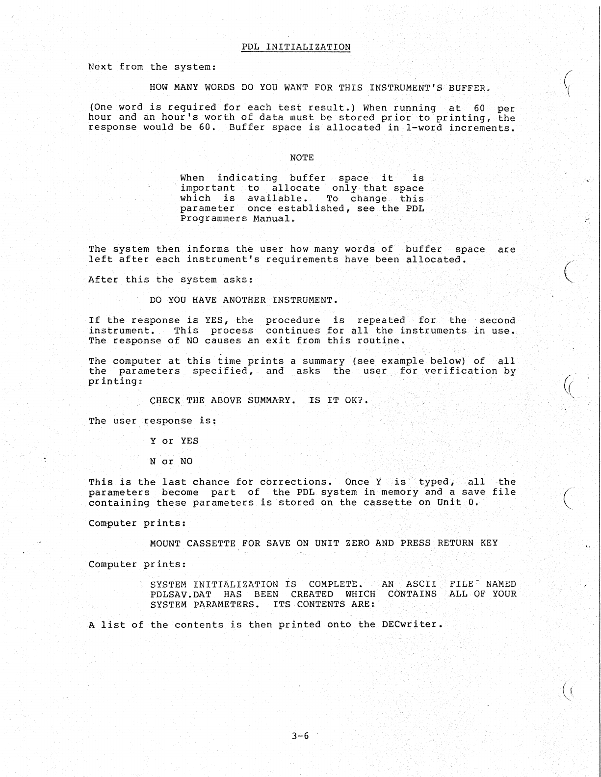
Next
from
the
system:
HOW
MANY
WORDS
DO
YOU
WANT
FOR
THIS INSTRUMENT'S BUFFER.
(One
word
is
required
for
each
test
result.)
When
running
at
60
per
hour
and
an
hour's
worth
of
data
must
be
stored
prior
to
printing,
the
response
would
be
60.
Buffer
space
is
allocated
in
l~WOId
increments.
NOTE
When
indicating
buffer
space
it
ia
important
to
.'.
allocate
only
that
space
which
is
available.
To
change
this
parameter
once
established,
see
the
PDL
Programmers
Manual.
The
system
then
informs
the
useI
how
many
words
of
buffer
space
are
left
after
each
instrument's
requirements
have
been
allocated.
After
this
the
system
asks:
DO
YOU
HAVE
ANOTHER
INSTRUMENT.
If
the
response
is
YES,
the
procedure
is
repeated
for
the
second
instrument.
This
process
continues
for
a.1,l
the
instruments
in
use.
Theresp6nse
of
NO
causes
an
exit
from
this
routine.
The
computer
at
this
time
prints
a
summary
(see
example
below)'
of
all
the
parameters
specified,
and
asks
the
user
for
verification
by
printing:
CHECK
THE
ABOVE
SU~MARY.
IS
IT
OK?
The
user
response
is:
Y
or
YES
N
or
NO
This
is
the
last
chance
for
corrections.
Once
Y ..
is
typed,
all
the
parameters
become
part
of
the
.PDL
.system
in
memory
and
a
save
file
containing
these
parameters
is
stored
on
the
cassette
on
Unit
O.
Computer
prints:
MOUNT
CASSETTE
FOR
SAVE
ON
UNIT
ZERO
AND
PRESS
RETURN.
KEY
Computer
prints:
SYSTEM
INITIALIZATION
IS
COMPLETE.
AN
ASCII
FILE
NAMED
PDLSAV.DAT
HAS
BEEN
CREATED
WHICH
CONTAINS
ALL
OF
YOUR
SYSTEM
PARAMETERS.
ITS
CONTENTS
ARE:
A
list
of
the
contents
is
tben
printed
onto
the
DECwritet.
3-6
(
'(
(
'~'
(~
"
<,
(
(
PDL
INITIALIZATION
NOTE
~hannels
are
either
digital
or
analog,
depending
upon
the
instrument.
If
analog,
they
are
assigned
a
number
between
0-15.
Digital
channels
are
numbered
16
through
31.
The
incorrect
assignment
of
a
channel
will
result
in
an
error
message.
The
next
question
from
the
system
asks
which
channel
is
connected
to
the
local
operator
console.
The
answer
to
this
is
the
number
of
the
physical
channel
on
H322
distribution
panel.
Whenever
possible
it
should
be
the
same
as
the
channel
specified
for
the
instrument.
o
<CR>
The
system
asks
that
the
user
check
the
connection
of
the
H32l
LOC
to
the
H322
distribution
panel.
The
message
printed
is:
CHECK
THAT
YOU
ARE
CONNECTED
TO
LOC
DR-ll
(EITHER
0,1,
OR
2)
AND
THAT
YOU
ARE
USING
TERMINALS
# - #
Next
the
computer
asks
for
the
type
of
instrument
in
use.
The
answer
to
this
is
one
of
the
following:
AA
indicating
Autoanalzer
SMA
indicating
SMA
6/60
or
12/60
CS
indicating
Coulter
Counter
Model
S
OTHER
indicating
..
instrument
type
is
not
one
of
the
above.
The
next
question
is:
HOW
MANY
TESTS
ARE
MADE
ON
EACH
SAMPLE.
The
appropriate
response
to
this
is
the
number
of
results
per
sample.
For
example,
on
the
SMA
6/60
there
are
six
results
per
sample.
On
the
coulter
model
S,
the
proper
response
is
10~
because
the
data
is
cycled
twice.
Then:
HOW
MANY
SAMPLES
ARE
PROCESSED PER
HOUR.
If
the
user
is
running
at
60
per.
hour,
the
response
would
be
60.
If
the
instrument
is
a
coulter
the
response
is:
WHAT
DELAY
DO
YOU
WANT
IN
SECONDS
EXPRESSED
TO
THE
NEAREST
0.01
SECOND.
The
delay
specified
should
be
between
40
and
120
recommend
use
of
100
miliseconds
for
the
Coulter
type
0.10.
3-5
miliseconds.
We
"8",
so
you
would
PDL
INITIALIZATION
Next
from
the
system:
HOW
MANY
WORDS
DO
YOU
WANT
FOR
THIS INSTRUMENT'S BUFFERt
(One
word
is
required
for
each
test
result.)
When
running
at
60
per
hour
and
an
hour's
worth
of
data
must
be
stored
prior
to
printing,
the
response
would
be
60.
Buffer
space
is
allocated
in
l~word
increments.
NOTE
When
indicating
buffer
space
it
is
important
to
allocate
only
that
space
which
is
available.
To
change
this
parameter
once
established,
see
the
PD'L
Programmers
Manual.
The
system
then
informs
the
USer
how
many
words
of
buffer
space
are
left
after
each
instrument's
requirements
have
been
allocated.
After
this
the
system
asks:
DO
YOU
HAVE
ANOTHER
INSTRUMENT.
If
the
response
is
YES,
the
procedure
is
repeated
for
the
second
instrument.
This
process
continues
for
all
the
instruments
in
use.
The
response
of
NO
causes
an
exit
from
this
routine.
The
computer
at
this
time
prints
a
summary
(see
example
below)
of
all
the
parameters
specified,
and
asks
the
user
..
for
verification
by
pr
inting:
CHECK
THE
ABOVE
SUMMARY.
IS
IT
OK?
The
user
response
is:
Y
or
YES
N
or
NO
This
is
the
last
chance
for
corrections.
OnceY
is
typed,
all
the
parameters
b~come
part
of
the
PDL
system
in
memory
and
a
save
file
containing
these
parameters
is
stored
on
the
cassette
on
Unit
O.
Computer
prints:
MOUNT
CASSETTE
FOR
SAVE
ON
UNIT
ZERO
AND
PRESS
RETURN
KEY
Computer
pr
ints:
SYSTEM
INITIALIZATION
IS
COMPLETE.
PDLSAV.DAT
HAS
BEEN
CREATED
WHICH
SYSTEM
PARAMETERS.
ITS
CONTENTS
ARE:
AN
ASCII
FILE-
NAMED
CONTAINS 'ALL
OF
YOUR
A
list
of
the
contents
is
then
printed
onto
the
DECwriter.
3-6
((
.'-..
-,
(
t·
>,
(
(
\
c·
/
(
\.
PDL
INITIA.LIZATTON
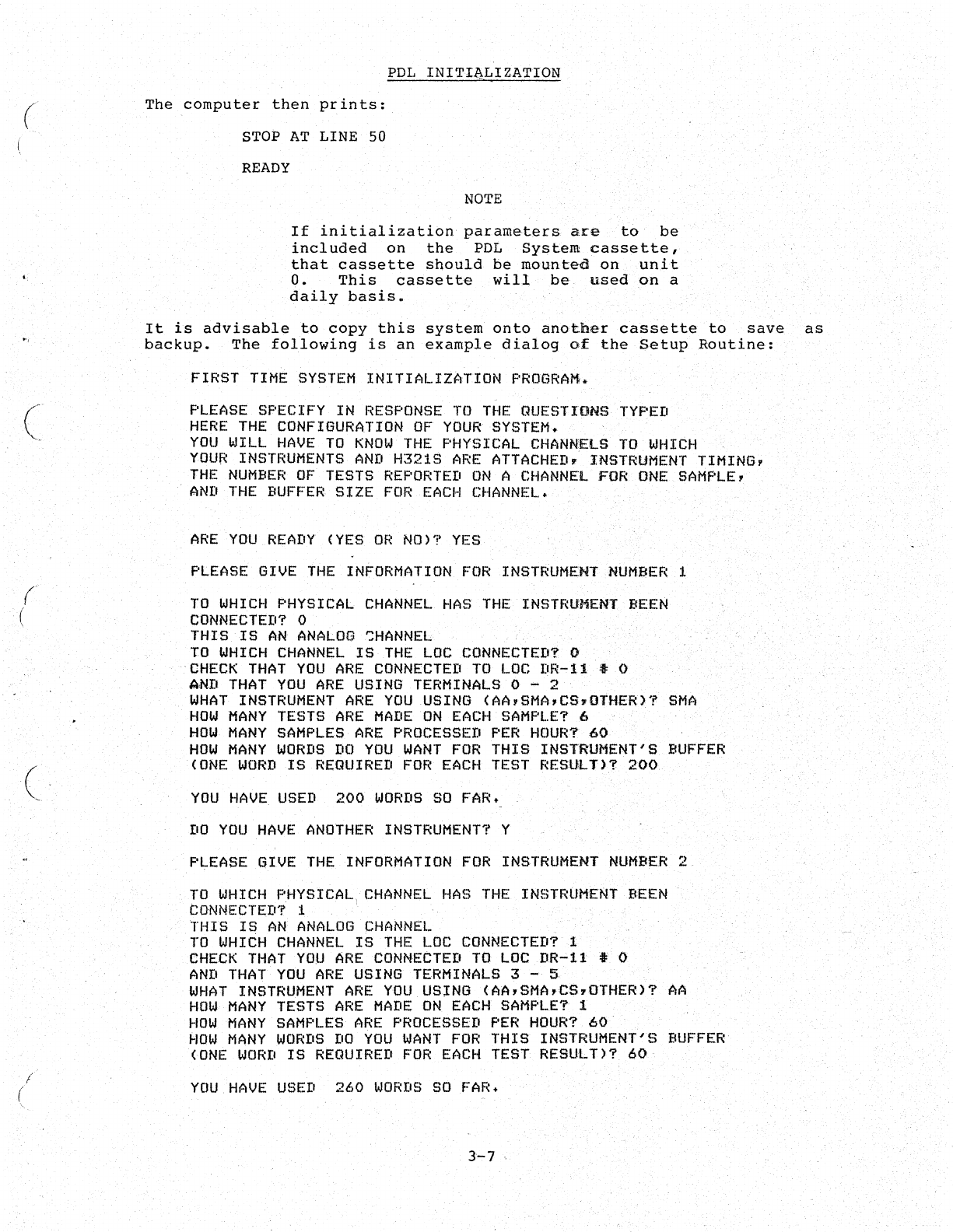
The
computer
then
prints:
STOP
AT
LINE 50
READY
NOTE
If
initialization
parameters.
are
to
be
included
on
the
PDL
System
cassette,
that
cassette
should
be
mounted
on
unit
o.
This
cassette
will
be
used
on
a
daily
basis.
It
is
advisable
to
copy
this
system
onto
another
cassette
to
save
as
backup.
The
following
is
an
example
dialog
of
the
Setup
Routine:
FIRST
TIME
SYSTEM
INITIALIZATION
PROGRAM
..
PLEASE
SPECIFY
IN
RESPONSE
TO
THE
QUESTIONS
TYPED
HERE
THE
CONFIGURATION
OF
YOUR
SYSTEM.
YOU
WILL
HAVE
TO
KNOW
THE
PHYSICAL
CHANNELS
TO
WHICH
YOUR
INSTRUMENTS
AND
H321S
ARE
ATTACHEDr
INSTRUMENT
~IMING,
THE
NUMBER
OF
TESTS
REPORTED
ON
A
CHANNEL
FOR
ONE
SAMPLE,
AND
THE
BUFFER
SIZE
FOR
EACH
CHANNEL.
.
ARE
YOU
READY
(YES
OR
NO)
1>
YES
PLEASE
GIVE
THE
INFORMATION
FOR
INSTRUMENT
NUMf.fER
1
TO
WHICH
PHYSICAL
CHANNEL
HAS
THE
INSTRUMENT
BEEN
CONNECTErl?
0
THIS
IS
AN
ANALOG
SHANNEL
TO
WHICH
CHANNEL
IS
THE
LOC
CONNECTED?
0
CHECK
THAT
YOU
ARE
CONNECTED
TO
LOC
DR...,11
" 0
AND
THAT
YOU
ARE
USING
TERMINALS
0 - 2
WHAT
INSTRUMENT
ARE
YOU
.USING
(AA,SMA,CS"OTHER)?
SMA
HOW
MANY
TESTS
ARE
MADE
ON
EACH
SAMPLE?
6
HOW
MANY
SAMPLES
ARE
PROCESSED
PER
HOUR?
60
HOW
MANY
WORDS
DO
YOU
WANT
FOR
THIS
INSTRUMENT'S
BUFFER
(ONE
WORD
IS
REQUIRErl
FOR
EACH
TEST
RESULD?
200
YOU
HAVE
USED
200
WORDS
SO
FAR.
DO
YOU
HAVE
ANOTHER
INSTRUMENT?
Y
PLEASE
GIVE
THE
INFORMATION
FOR
INSTRUMENT
NUMBER
2
TO
WHICH
PHYSICAL)
CHANNEL
HAS
THE
INSTRUMEIitT
BEEN
CONNECTED?
1 .
THIS
IS
AN
ANALOG
CHANNEL
TO
WHI~H
CHANNEL
IS
THE
LOC
CONNECTED?
I
CHECK
THAT
YOU
ARE
CONNECTED
TO
LOC
DR-ll
:J 0
AND
THAT
YOU
ARE
USING
TERMINALS
3
_.
5
WHAT
INSTRUMENT
ARE
YOU
USlNG
(AA,SMA,CS"OTHER)?
AA
HOW
MANY
TESTS
ARE
MADE
ON
EACH
SAMPLE?
1
HOW
MANY
SAMPLES
ARE
PROCESSED
PER
HOUR?
60
How
MANY
WORDS
DO
YOU
WANT
FOR
THIS
INSTRUMENT'S
BUFFER
(ONE
WCJRD
IS
REQUIRED
FOR
EACH
TEST
RESUL
n?
60·.
YOU
HAVE
USED
260
WORDS
SO
FAR.
3-7
.
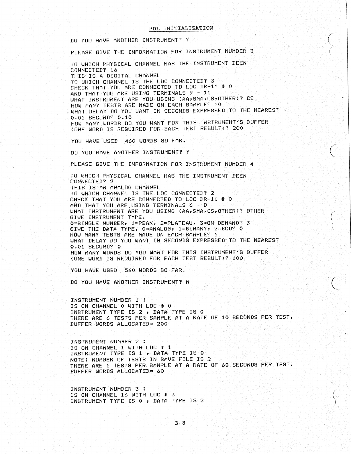
PDL
INITIALIZATION
DO
YOU
HAVE
ANOTHER
INSTRUMENT?
Y
PLEASE
GIVE
THE
INFORMATION
FOR
INSTRUMENT
NUMBER
3
TO
WHICH
PHYSICAL
CHANNEL
HAS
THE
INSTRUMENT
BEEN
CONNECTED?
16
THIS
IS
A DIGITAL
CHANNEL
TO
WHICH
CHANNEL
IS
THE
LOC
CONNECTED?
3
CHECK
THAT
YOU
ARE
CONNECTED
TO
LOC
DR-11 • 0
AND
THAT
YOU
ARE
USING
TERMINALS
9 - 11
WHAT
INSTRUMENT
ARE
YOU
USING
(AA,SMA,CS,OTHER)?
CS
HOW
MANY
TESTS
ARE
MADE
ON
EACH
SAMPLE?
10
.
WHAT
DELAY
DO
YOU
WANT
IN
SECONDS
EXPRESSED
TO
THE
NEAREST
0.01
SECOND?
0.10
HOW
MANY
WORDS
DO
YOU
WANT
FOR
THIS
INSTRUMENT'S
BUFFER
(ONE
WORD
IS
REQUIRED
FOR
EACH
TEST
RESULT)?
200
YOU
HAVE
USED
460
WORDS
SO
FAR.
DO
YOU
HAVE
ANOTHER
INSTRUMENT?
Y
PLEASE
GIVE
THE
INFORMATION
FOR
INSTRUMENT
NUMBER
4
TO
WHICH
PHYSICAL
CHANNEL
HAS
THE
INSTRUMENT
BEEN
CONNECTED?
2
THIS
IS
AN
ANALOG
CHANNEL
TO
WHICH
CHANNEL
IS
THE
LOC
CONNECTED?
2
CHECK
THAT
YOU
ARE
CONNECTED
TO
LOC
DR-l1
:ft:
0
AND
THAT
YOU
ARE.
USING
TERMINALS
6 - 8
WHAT
INSTRUMENT
ARE
YOU
USING
(AA,SMA,CS,OTHER)?
OTHER
GIVE
INSTRUMENT
TYPE.
O=SINGLE
NUMBER,
l=PEAK,
2=PLATEAU,
3=ON
DEMAND?
3
GIVE
THE
DATA
TYPE.
O=ANALOG,
l=BINARY,
2=BCD?
0
HOW
MANY
TESTS
ARE
MADE
ON
EACH
SAMPLE?
1
WHAT
DELAY
DO
YOU
WANT
IN
SECONDS
EXPRESSED
TO
THE
NEAREST
0.01
SECOND?
0
HOW
MANY
WORDS
DO
YOU
WANT
FOR
THIS
INSTRUMENT'S
BUFFER
(ONE
WORD
IS
REQUIRED
FOR
EACH
TEST
RESULT)?
100
YOU
HAVE
USED
560
WORDS
SO
FAR.
DO
YOU
HAVE
ANOTHER
INSTRUMENT?
N
INSTRUMENT
NUMBER
1 :
IS
ON
CHANNEL
0
WITH
LOC
i 0
INSTRUMENT
TYPE
IS
2 ,
DATA
TYPE
IS
0
THERE
ARE
6
TESTS
PER
SAMPLE
AT
A
RATE
BUFFER
WORDS
ALLOCATED=
200
OF
10
SECONDS
PER
TEST.
INSTRUMENT
NUMBER
2 :
IS
ON
CHANNEL
1
WITH
LOC
• 1
INSTRUMENT
TYPE
IS
1 ,
DATA
TYPE
IS
0
NOTE:
NUMBER
OF
TESTS
IN
SAVE
FILE
IS
2
THERE
ARE
1
TESTS
PER
SAMPLE
AT
A
RATE
OF
BUFFER
WORDS
ALLOCATED=
60
INSTRUMENT
NUMBER
3 :
IS
ON
CHANNEL
16
WITH
LOC
i 3
INSTRUMENT
TYPE
IS
0 ,
DATA
TYPE
IS
2
3-8
60
SECONDS
PER
TEST.
(
(
(
(/
\.
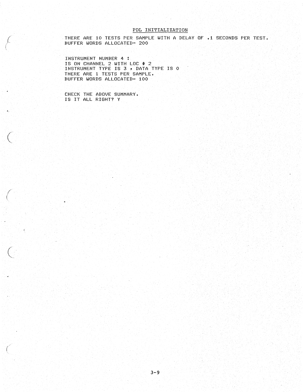
{
(
(
(
c
PDL
INITIALIZATION
THERE
ARE
10
TESTS
PER
SAMPLE
WITH
A
DELAY
OF
.1
SECONDS
PER
TEST.
BUFFER
WORDS
ALLOCATED~
200
INSTRUMENT
NUMBER
4 :
IS
ON
CHANNEL
2
WITH
LOC
t 2
INSTRUMENT
TYPE
IS
3 ,
DATA
TYPE
IS
0
THERE
ARE
1
TESTS
PER
SAMPLE.
BUFFER
WORDS
ALLOCATED=
100
CHECK
THE
ABOVE
SUMMAR~.
IS
IT
ALL
RIGHT?
Y
3-9

(,'"
-.
C
•·
"
'.
l
CHAPTER
4
USING
PDL
Once
the
installation
and
initialization
of
the
system
are
completed,
the
system
may
be
run
on
a
daily
basis.
Each
daily
procedure
requires
the
same
fixed
dialogue.
NOTE
Use
the
cassette
that
contains
the
PDL
system
and
the
save
files.
To
10adPDL,
and
the
configuration
save
files,
and
also
to
start
the
system,
follow
the
instructions
below.
1.
Place
PDL
system
cassette
on
unit
o.
,This
cassette
should
contain
the
initialization
file.
2.
Hold
down
the
LOCK/UNLOCK
switch
in
the
unlock
position
and
press
the
switch
marked
1.
The
tape
begins
to
move ,and
copies
PDL
into
memory.
When
it
completes
this
,task,
the
computer
responds
wi
th
the
system
identification
and
version
number:
BASIC/CAPS
VOl
The
computer
then
prints:
OPT
FNS
To
which
the
user
replies
with
a
carriage
return,
unless
other
options
are
to
be
specified.
Refer
to
optional
functions
in
the
CAPS/BASIC
Users
Guide.
<CR)
NOTE
IfNis
"typed,
no
options
are
included
and
the
available
program
space
is
increased
by
approximately
600
words.
'
The
computer
prints:
USR
,FNS
LOADED
4-1
USING
PDL
This
allows
insertion
of
user
functions.
followed
by
a
carriage
return.
The
next
.question
is
which
terminal:
TERM:
The
answer
to
this
is:
1
<CR>
The
response
to
this
is
This
indicates
that
the
terminal
is
running
at
300
baud
(see
Section
1.3.1).
The
computer's
next
request
is:
DATE:
The
reply
is
as
before,dd-mmm-yy,
where
dd=the
day,
mmm=the
month
and
yy=the
year,
Example:
l2,...OCT-75<CR>
The
system
is
now
successfully
loaded.
It
prints:
READY
The
user
now
types:
PDL
<Ca.>
This
response
loads
the
PDL
system
save
file
(the
instrument
parameters),
turils
on
all
applicable
LOC
box
lights,
and
initializes
all
instrument
channels
for
the
daily
run.
The
comput.er
is
ready
to
accept
data
from
the
user's
analyzer
•.
A
flashing
light
oil a
local
console
box
indicates
that
the
associated
channel
is
ready
to··
receive
information.
It
is
good
practice
to
remove
thePDL
save
cassette
so
that
it
cannot
be
written
on.
NOTE
If
t.he
instrument
in
use
is
a
peak
or
plateau
devic~(i~e.~
an
autoanaly~er
or
an
SMA),
the
recorder
must
be
adj
usted
.
to
zero
baseline
after
appropriate
warmup-and
calibration
procedures.
It
is
important
that
all
baselines
are
at
zero·
before
the
start
button
on
LOC
is
pressed.
When
the
start
button
is
pressed,
data
acquisition
begins
at
the
first
.significant
pen
rise.
The
data
is
transferred
to
a
temporary
storage
area.
When
the
buffer
area
becomes
75%
full,
the
middle
light
on
the
local
operator
IS·
console-
(H321)
begins
to
flash.
Until
the
light
starts
flashing
the
user
can:
1.
Do
calculation
in
the
immediate
mode.
4-2
(
.-
(
c
(
(
(.
(
USING
PDL
2.
Develop
new
programs
in
BASIC.
3.
Execute
previously
written
programs.
A
previously
written
user
program
(a
report
generator)
may
be
used
to
take
stored
data
and
write
it
out
in
the
form
of
a
report.
This
may
be
done
at
any
time
and
is
at
the
user's
discretion.
However,
when
the
buffer
becomes
75%
full
the
middle
warning
light
on
the
Local
Operator's
Console
begins
to
flash.
It
is
time
to
empty
the
buffer.
Failure
to
do
this
at
this
time
results
in
a
buffer
overflow.
A
buffer
overflow
caus~s
the
middle
light
to
become
steady.
At
this
time
no
further
data
will
be
moved
into
the
buffer.
Time
elapses
between
the
beginning
of
the
flashing
(warning)
light
and
the
buffer
overflow
and
is
approximately
a
quarter
of
the
time
required
to
fill
up
the
buffer.
.Regular
use
of
the
Report
Generation
program
prevents
buffer
overflow.
.
NOTE
If
buffer
overflow
has
occurred,
it
is
necessary
to
stop
the
instrument,
run
the
report
generator
program
and
restart
the
instruments
at
baseline.
The
procedure
to
run
report
generator
program
or
any
other
previously
written
BASIC
program
is
as
follows:
when
the
terminal
is
sitting·
idle
and
has
typed
READY,
place
the
cassette
containing
the
desired
program
on
unit
1.
Type
the
RUN
command
followed
by
the
name
of
the
program
which
will
report
patient
data.
Example:
for
a
program
namedRGEN,
type
the
following:
RUNl:RGEN(CR)
The
information
in
the
buffer
(i.e.,
patient
data)
will
then
be
printed
on
the
console
terminal.
When
this
has
been
completed
the
terminal
responds
with
READY
and
another
program
can
be
run.
.
NOTES
1.
If
the
results
produced
during
instrument
checkout
or
calibration
are
not
to
be
stored
in
memory,
they
should
be
perfomed
prior
to
pressing
the
start
button.
Caution:
be
sure
the
instrument
is
back
to
baseline
before
starting
acquisition.
2,
During
the
time
that
PDL
is
acquiring
data
from
the
user's
instruments,
the
computer
c.an
be
used
for
calculating,
for
quality
control,
or
to
run
any
other
program
wr
itten
in
BASIC.
4-3

(
(
(
(
CHAPTER
5
PDL
ERROR
MESSAGES
An
error
message
is
produced
whenever
PDL
encounters
a
condition
which
conflicts
with
the
program's
normal
functional
procedure.
The
purpose
of
an
error
message
is
to
advise
the
programmer
of
a
problem
and
suggest
suitable
corrective
action.
Under
such
circumstances,
the
execution
of
the
erroneous
command
or
statement
is
either
terminated"
or
suspended,
depending
on
the
severity
of
the
error.
The
appropriate
error
message
is
then
printed
on
the
console
terminal.
Errors
fall
into
two
categories:
Fatal
errors
Nonfatal
errors
A
fatal
error
cancels
all
work
in
progress.
The
corresponding
fatal
error
message
is
printed
and
PDL
then
returns
to
the
ready
state,
awaiting
further
instructions.
Although
a
fatal
error
does
not
stop
data
acquisition
it
does
cause
loss
of
data.
Therefore,
after
the
error
has
been
corrected,
the
program
must
be
restarted
from
the
beginning.
"A
nonfatal
error
has
less
drastic
results.
An
error
message
is
printed
out
while
the
particular
statement
or
command,
which
caused
the
fault,
is
merely
suspended
pending
corrective
action
by
the
programmer.
Data
is
retained
during
this
procedure,
PDL
continues
with
the
program
as
if
it
had
not
been
interrupted.
Error
messages
appear"
in
one
of
two
formats:
Format
one:
?xxx
(Immediate
Mode)
where
xxx
consists
of
an
abbreviation
(for
example,
?FNO:
file
not
open)
denoting
the
error
condition.
Format
two:
message
at
line
nnnn
where
nnnn
is
the
line
number
of
the
statement
causing
the
error.
The
following
error
conditions
apply
specifically
to
PDL. Any
error
condition
not
found
in
this
section
may
be
considered
to
be
a
BASIC-CAPS-II
error
condition.
A
list
of
BASIC
CAPS-II
error
conditions,
together
with
their
corresponding
remedial
actions,
is
contained
in
Appendix
B.
PDL
ERROR
CONDITIONS:
5-1
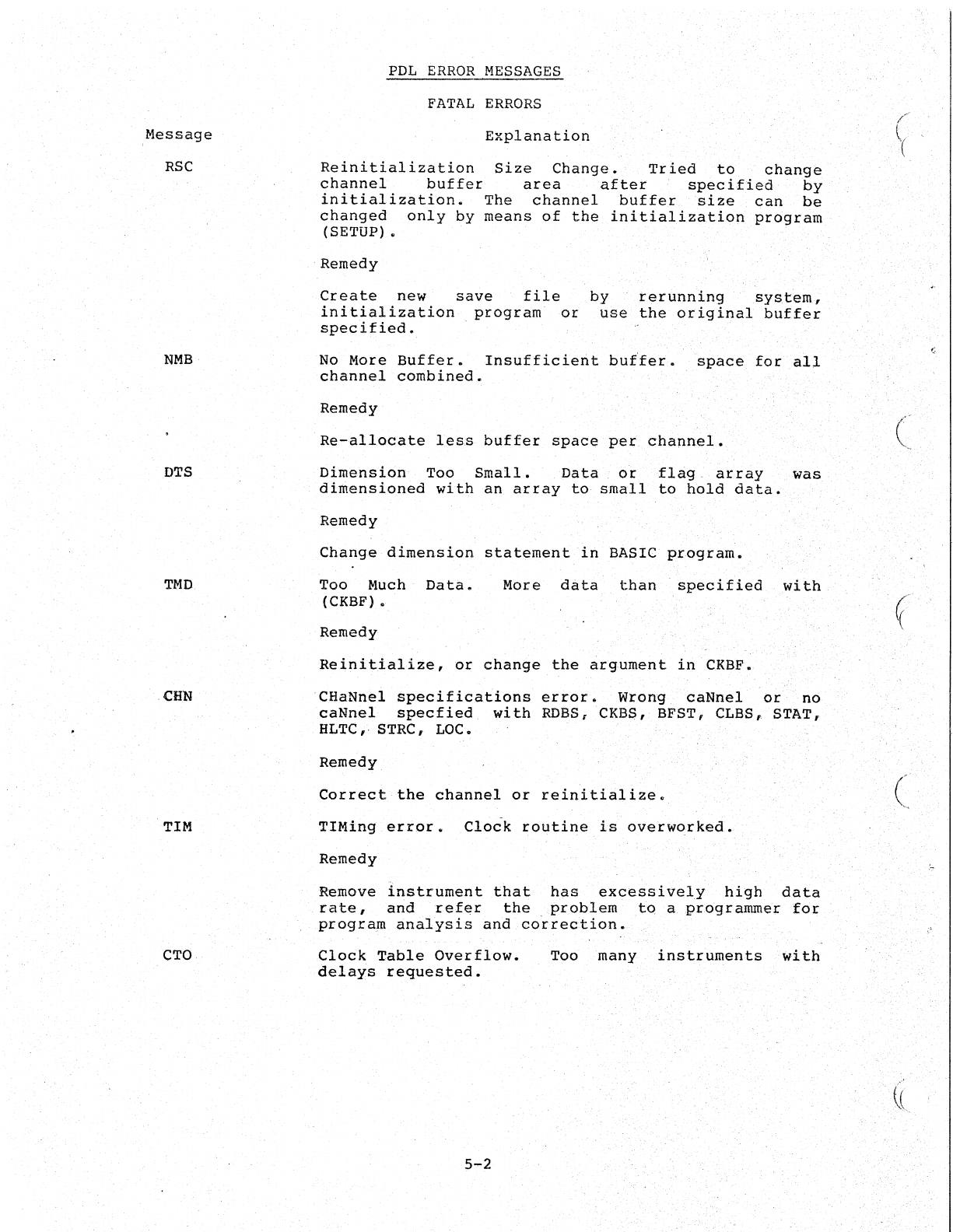
Message
RSC
NMB
DTS
TMD
CHN
TIM
CTO
PDL
ERROR
MESSAGES
FATAL
ERRORS
Explanation
Reinitialization
Size
Change.
Tried
to
change
channel
buffer
area
after
specified
by
initialization.
The
channel
buffer
size
can
be
changed
only
by
means
of
the
initialization
program
(SETUP) •
Remedy
Create
new
save
file
initialization.
program
or
specified.
by
rerunning
system~
use
the
original
buffer
No
More
Buffer.
Insufficierit
butfer.
space
for
all
channel
combined.
Remedy
Re-allocate
less
buffer
space
per
channel.
Dimension
Too
Small.
Data
or
flag
array
was
dimensioned
with
an
array
to
small
to
hold
data~
Remedy
Change
dimension
statement
in
BASIC
program.
Too Much
Data.
(CKBF). More
data
than'
specified
with
Remedy
Reinitialiie,
or
change
the
argument
in
CKBF.
'CHaNnel
specifications
error.
Wrong
caNnel
or
no
caNnel
specfied
with
ROBS
t
eKBS,
BFST, CLBS" STAT,
HLTC,· STRC,
LOC.
Remedy
Correct
the
channel
or
reinitialize.
TIMing
error.
Clock
routine
is
overworked.
Remedy
Remove
instrument
that
has
excessively
high
data
rate,
and
refer
the
problem
to
a
programmer
for
program
an~lysis
and
correction.
Clock
Table
Overflow.
delays
requested.
5-2
Too
many
instruments
with
(
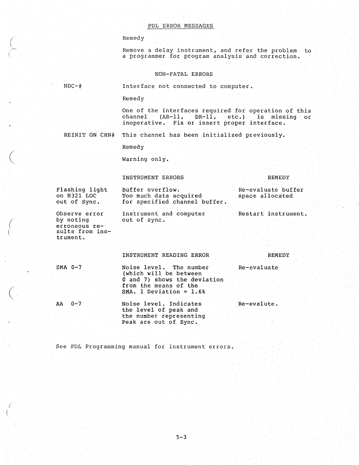
(
(
(
(
/
(
NDC-#
PDL
ERROR
MESSAGES
Remedy
Remove
a
delay
instrument,
and
refer
the
problem
to
a
programmer
for
program
analysis
and
correction.
NON-FATAL
ERRORS
Interface
not
connected
to
computer.
Remedy
One
of
the
interfaces
required
for
operation
of
this
channel
(AR-ll,
DR-II,
etc.)
is
missing
or
inoperative.
Fix
or
insert
proper
interface.
REINITON
CHN#
This
channel
has
been
initialized
previously.
Flashing
light
on
H321
LOC
out
of
Sync.
Observe
error
by
noting
erroneous
re-
sults
from
ins-
trument.
SMA
0-7
AA
0-7
Remedy
warning
only.
INSTRUMENT ERRORS
Buffer
overflow.
Too
much
data
acquired
for
specified
channel
buffer.
Instrument
and
computer
out
of
sync.
INSTRUMENT READING
ERROR
Noise
level.
The
number
(which
will
be
between
o
and
7)
shows
the
deviation
from
the
means
of
the
SMA. 1
Deviation
=
1.6%
Noise
level.
Indicates
the
level
of
peak
and
the
number
representing
Peak
are
out
of
Sync.
See
PDL
Programming
manual
for
instrument
errors.
5-3
REMEDY
Re-evaluate
buffer
space
allocated
Restart
instrument.
REMEDY
Re-evaluate
Re-evalute.

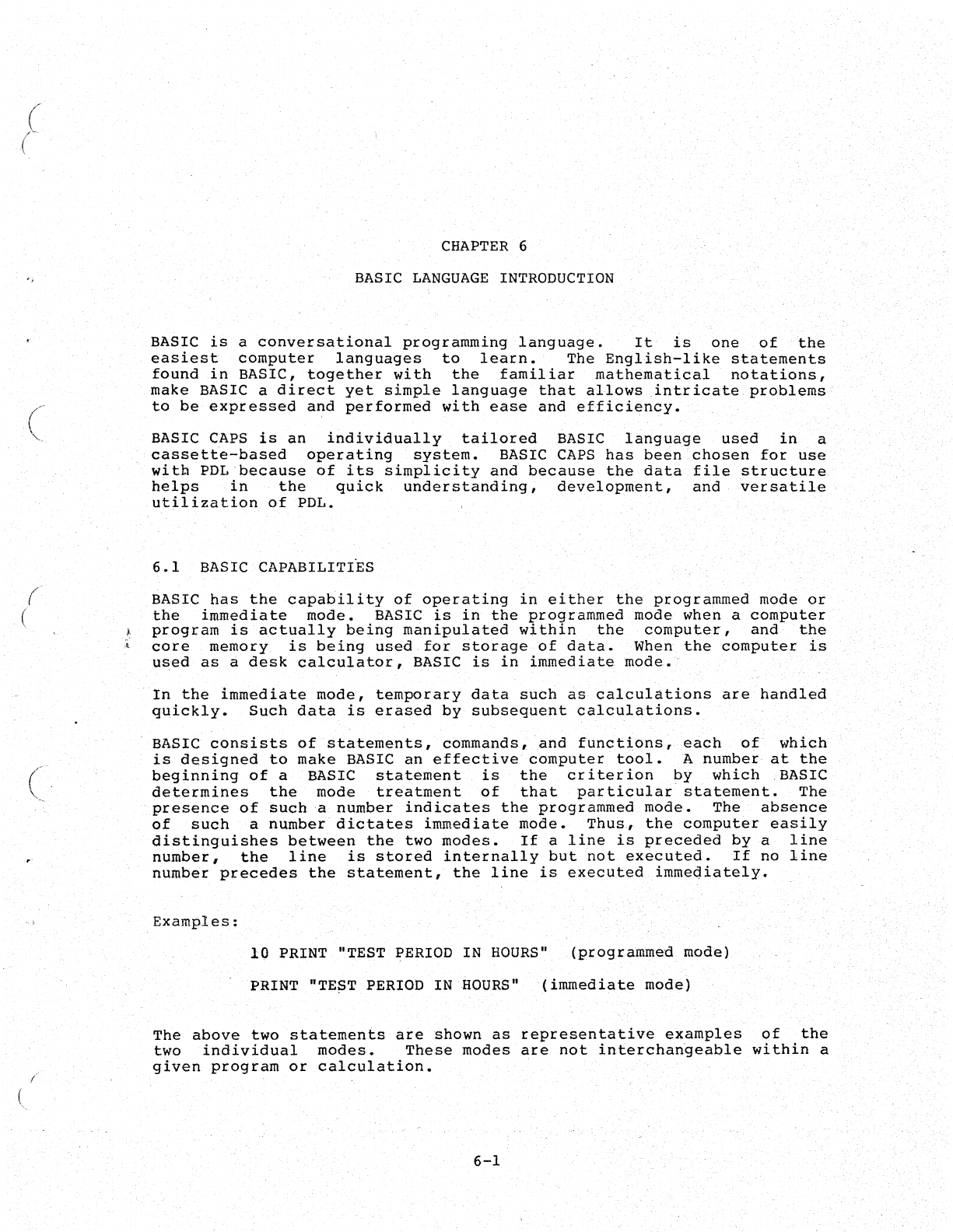
(
'-,
(
(
(
(
CHAPTER
6
BASIC
LANGUAGE
INTRODUCTION
BASIC
is
a
conversational
programming
language.
It
is
one
of
the
easiest
computer
languages
to
learn.
The
English-like
statements
found
in
BASIC,
together
with
the
familiar
mathematical
notations,
make
BASIC a
direct
yet
simple
language
that
allows
intricate
problems
to
be
expressed
and
performed
with
ease
and
efficiency.
BASIC CAPS
is
an
individually
tailored
BASIC
language
used
in
a
cassette-based
operating
system.
BASIC
CAPS
has
been
chosen
for
use
witb
PDL
because
of
its
simplicity
and
because
the
data
file
structure
helps
in
the
quick
understanding,
development,
and
versatile
utilization
of
PDL.
6.1
BASIC
CAPABILITI~S
BASIC
has
the
capability
of
operating
in
either
the
programmed
mode
or
the
immediate
mode.
BASIC
is
in
the
programmed
mode
when
a
computer
program
is
actually
being
manipulated
within
the
computer,
and
the
core
memory
is
being
used
for
storage
of
data.
When
the
computer
is
used
as
a
desk
calculator,
BASIC
is
in
immediate
mode.
In
the
immediate
mode,
temporary
data
such
as
calcula.tions
are
handled
quickly.
Such
data
is
erased
by
subsequent
calculations.
BASIC
consists
of
statements,
commands,
and
functions,
each
of
which
is
designed
to
make
BASIC
an
effective
computer
tool.
A
number
at
the
beginning
of
a BASIC
statement
is
the
criterion
by
which
,BASIC
determines
the
mode
treatment
of
that
particular
statement.
The
presence
of
such
a
number
indicates
the
programmed
mode.
The
absence
of
such
a
number
dictates
immediate
mode.
Thus,
the
computer
easily
distinguishes
between
the
two
modes.
If
a
line
is
preceded
by
a
line
number,
the
line
is
stored
internally
but
not
executed.
If
no
line
number
precedes
the
statement,
the
line
is
executed
immediately.
Examples:
10
PRINT "TEST PERIOD IN
HOURS"
(programmed
mode)
PRINT "TEST PERIOD IN
HOURS"
(immediate
mode)
The
above
two
statements
are
shown
as
representative
examples
of
the
two
individual
modes.
These
modes
are
not
interchangeable
within
a
given
program
or
calculation.
6-1
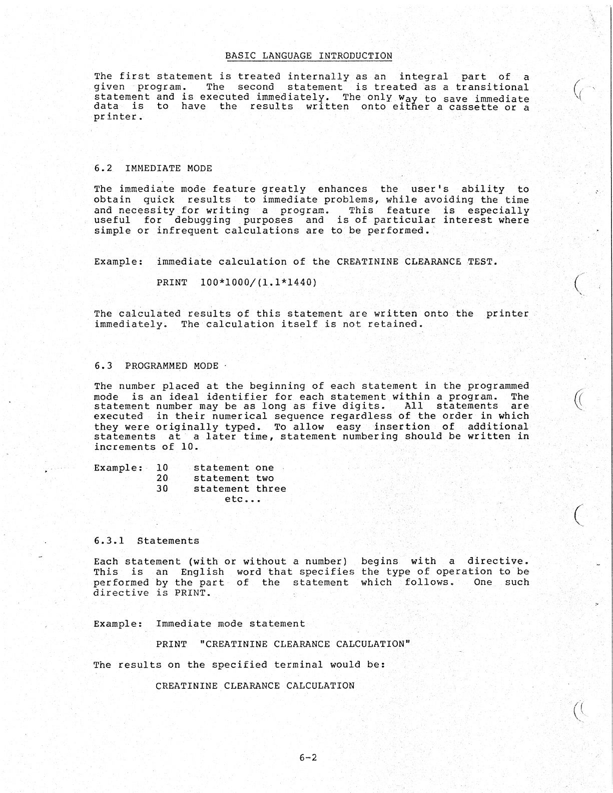
. '
BASIC
LANGUAGE
INTRODUCTION
The
first
statement
is
treated
internally
as
an
integral
part
of
a
given
"program.
The
second
statement
is
treated
as
a
transitional
(,'('
"',
statement
and
is
executed
immediately.
The
only
Way
to
save
immediate
data
is
to
have
the
results
written
onto
either
a
cassette
or
a
printer.
6.2
IMMEDIATE
MODE
The
immediate
mode
feature
greatly
enhances
the
user's
ability
to
obtain
quick
results
to
immediate
problems,
while
avoiding
the
time
and
nec$ssity
for
writing
a
program.
This
feature
is
especially
useful
for
debugging
purposes
and
is
of
particular
interest
where
simple
or
infrequent
calculations
are
to
be
performed
•.
Example:
immediate
calculation
of
the
CREATININE
CLEARANCE
TEST.
PRINT
100*1000/(1.1*1440)
The
calbu1ated
res~l
ts
of
this
statement
are'
wr i
tten
onto
the
printer,'
immediately.
The
calculation
itself
is
not
retained.
6.3
PROGRAMMED
MODE
(
The
number
placed
at
the
beginning
of
each
statement
in
the
programmed
mode
is
an
ideal
identifier
for
each
statement
within
a
program.
The
«
statement
number
may
be
as
long
as
five
digits.
All
statements
are
~,
executed
in
their
numerical
sequence
regardless,
of
the
orde,r
in
which
they
were
originally
typed.
To
allow
easy,
insertion
of
additional
statements
at
a
later
time,
statement
numbering
should
be
written
in
increments
of
10.
'
Example:
10
20
30
statement
one
statement
two
statement
three
etc
•••
6.3.1
Statements
Each
statement
(with
or
without
a
number)
begins
with
a
directive.
This
is
an
English
word
that
specifies
the
type
of
operation
to
be
performed
by
the
part
of
the
statement
which
follows.
One
such
directive
is
PRINT.
Example:
Immediate
mode
statement
PRINT "CREATININE
CLEARANCE
CALCULATION"
The
results
on
the
specified
terminal
would
be:
CREATININE
CLEARANCE
CALCULATION
6-2
(
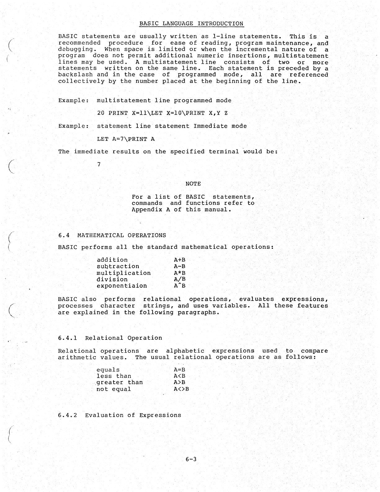
(
(
(
(
BASIC
LANGUAGE
INTRODUCTION
BASIC
statements
are
usually
written
as
I-line
statements.
This
is
a
recommended
procedure
for
ease
of
reading,
program
maintenance,
and
d2bugging.
When
space
is
limited
or
when
the
incremental
nature
of
a
program
does
not
permit
additional
numeric
insertions,
multistatement
lines
may
be
used.
A
multistatement
line
consists
of
two
or
more
statements
written
on
the
same
line.
Each
statement
is
preceded
by
a
backslash
and
in
the
case
of
programmed
mode,
all
are
referenced
collectively
by
the
number
placed
at
the
beginning
of
the
line.
Example:
I11ultistatement
line
programmed
mode
20
PRINT
X=II\LET
X=IO\PRINT
X,Y Z
Example:
statement
line
statement
Immediate
mode
LET
A=7\PRINT
A
The
immediate
results
on
the
specified
terminal
~ould
be:
7
NOTE
Fora
list
of
BASIC
statements,
commands
and
functions
refer
to
Appendix
A
of
this
manual.
6.4
MATHEMATICAL
OPERATIONS
BASIC
performs
all
the
standard
mathematical
operations:
addition
A+B
sUQtraction
A-B
multiplication
A*B
division
A/B
exponentiaion
A~B
BASIC
also
performs
relational
operations,
evaluates
expressions,
processes
character
strings,
and
uses
variables.
All
these
features
are
explained
in
the
following
paragraphs.
6.4.1
Relational
Operation
Relational
operations
are
alphabetic
expressions
used
to
compare
arithmetic
values.
The
usual
relational
operations
are
as
follows:
equals
less
than
.greater
than
not
equal
A=B
A(B
A)B
A<>B
6.4.2
Evaluation
of
Expressions
6-3
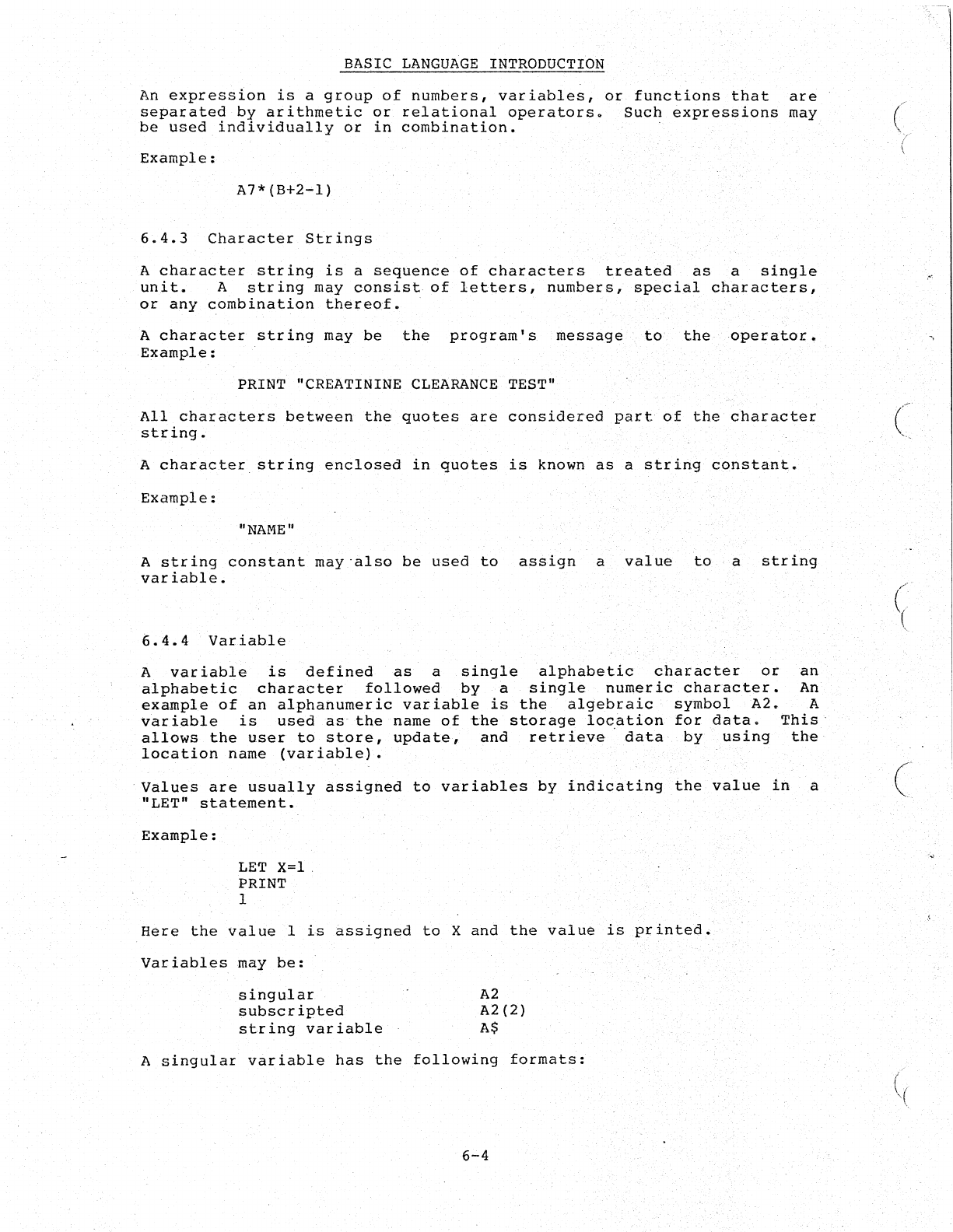
BASIC
LANGUAGE
INTRODUCTION
An
expression
is
a
group
of
numbers,
variables,
or
functions
that
are
separated
by
arithmetic
or
relational
operators.
Such
expressions
may
be
used
individually
or
in
combination.
Example:
A7*(B+2-1)
6.4.3
Character
Strings
A
character
string
is
a
sequence
of
characters
treated
as
a
single
unit.
A
string
may
consist
of
letters,
numbers,
special
characters,
or
any
combination
thereo£.
A
character
string
may
be
the
program's
message
to
the
operator.
Example:
PRINT "CREATININE
CLEARANCE
TEST"
All
characters
between
the
quotes
are
considered
part
of
the
character
string.
A
character
string
enclosed
in
quotes
is
known
as
a
string
constant.
Example:
"NAME"
A
string
constant
maY'also
be
used
to
assign
a
value
to
a
string
variable.
().
4.4
Variable
A
variable
is
defined
as
a
single
alphabetic
character
or
an
alphabetic
character
followed
by
a
single
numeric
character.
An
example
of
an
alphanumeric
variable
is
the
algebraic
symbol
A2.
A
variable
is
used
as
the
name
of
the
storage
location
for
data.
This··
allows
the
user
to
store,
update,
and
retrieve·
data
by
using
the
location
name
(variable).
Values
are
usually
assigned
to
variables
by
indicating
the
value
in
.a
"LET"
statement.
Example:
LET
X=l.
PRINT
1
Here
the
value
I
is
~ssigned
to
X
and
the
value
is
printed.
Variables
may
be:
singular
subscripted
string
variable
A2
A2(2)
A$
A
singular
variable
has
the
following
formats:
6-4
(
(
(
(~
-,
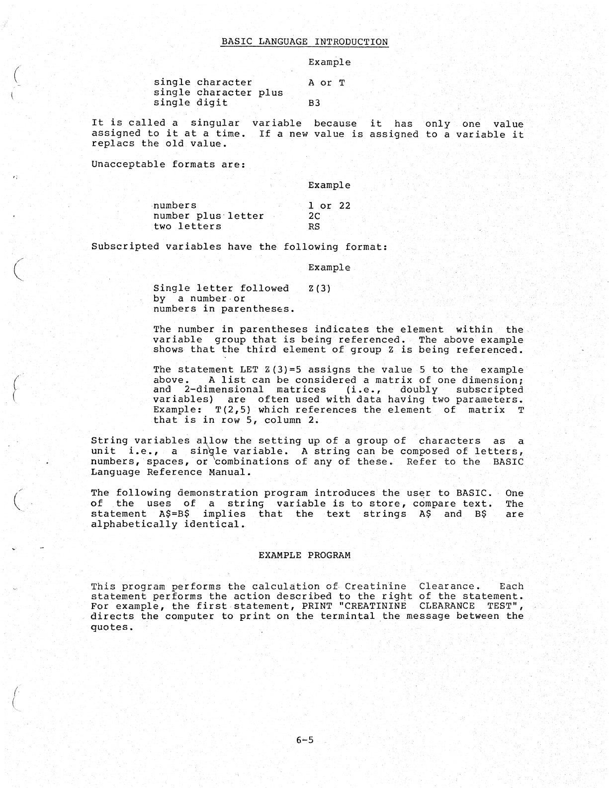
(
BASIC
LANGUAGE
INTRODUCTION
single
character
single
character
plus
single
digit
Example
A
or
T
B3
It
is
called
a
singular
assigned
to
it
at
a
time.
replacs
the
old
value.
variable
because
it
has
Ohly.
one
value
If
a
new
value
is
assigned
to
a
variable
it
Unacceptable
formats
are:
numbers
number
plus'
letter
two
letters
Example
I
or
22
2C
RS
Subscripted
variables
have
the
following
format:
(
Example
(.
(
(
Single
letter
followed
Z(3)
by
a
number·or
numbers
in
parenthes&s.
The
number
in
parentheses
indicates
the
element
w~thin
the
variable
group
that
is
being
referenced.
The
above'
example
shows
that
the
third
element
of
group
2
is
being
referepced.
The
statement
LET
Z(3)=5
assigns
the
value
5
to
the
example·
above.
A
list
can
be
considered
a
matrix
of
one
di~ension:
and
2-dimensional
matrices
(i.e.,
doubly
subscripted
variables)
are
often
used
with
data
having
two
parameters.
Example:
T(2,5)
which
references
the
element
of
matrix
T
that
is
in
row
5,
column
2.
String
variables
a\low
the
setting
up
of
a
group
of
characters
as
a
unit
Le.,
a
si~~le
variable.
A
string
cah
be
composed
of
letters,
numbers,
spaces,
or
combinations
of
any
of
the~e.
Refer
to
the
BASIC
Language
Reference
Manual.
The
following
demonstration
program
introduces
the
us~r
to
BASIC.
of
the
uses
of
a
string
variable
is
to
store,
compare
text.
statement
A$=B$
implies
that
the
text
strings
A$
and
B$
alphabetically
identical.
EXAMPLE
PROGRAM
One
The
are
This
program
performs
the
calculation
of.
Creatinine
Clearance.
Each
statement
performs
the
action
described
to
the
rig~t
of
the
statement.
For
example,
the
first
statement,
PRINT "CREATININE
CLEARANCE
TEST",
directs
the
computer
to
print
on
the
term
in
tal
.themessage
between
the
quotes.
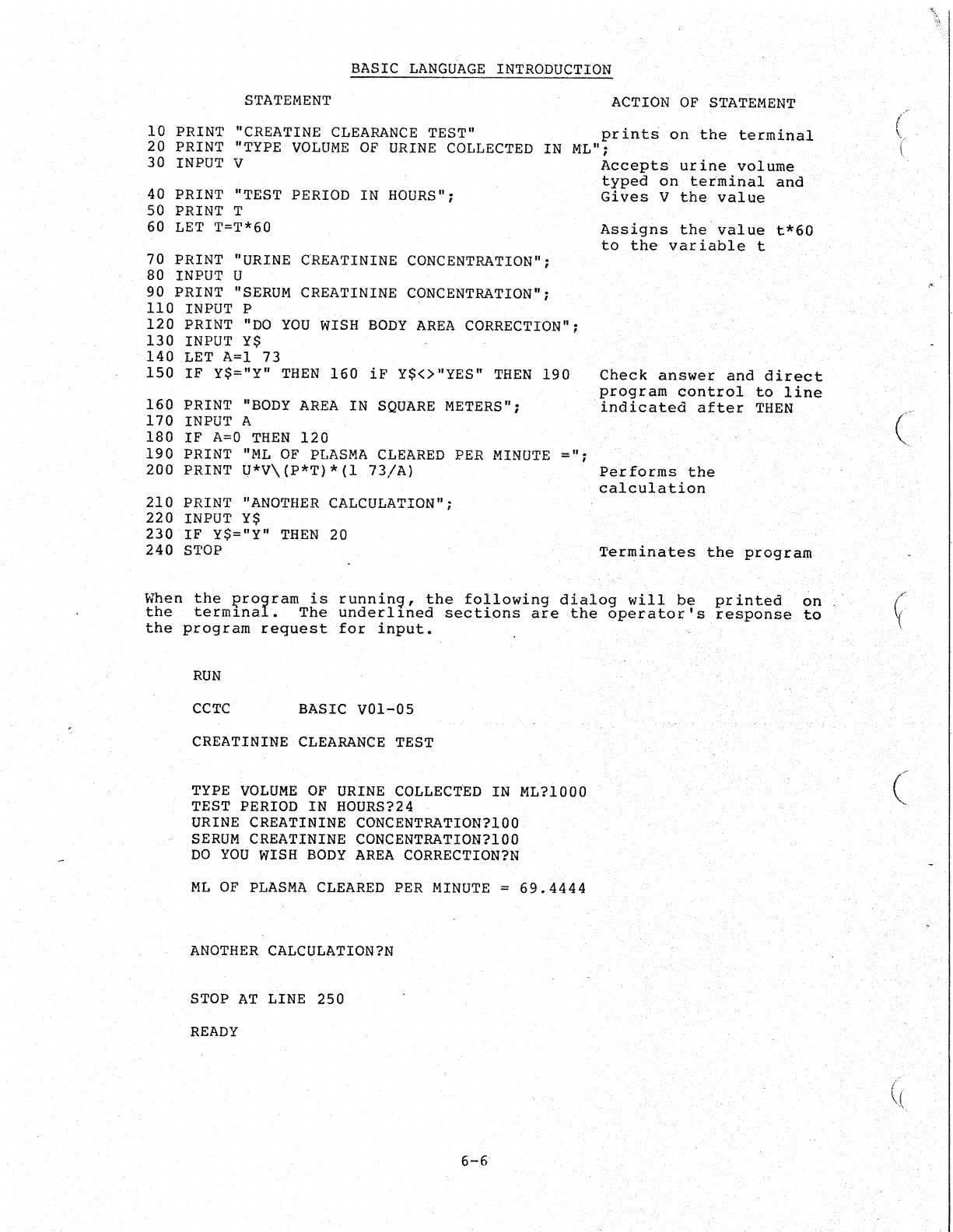
BASIC
LANGUAGE
INTRODUCTION
STATEMENT
ACTION
OF
STATEMENT
10
PRINT
"CREATINE
CLEARANCE
TEST"
print~
on
the
terminal
20 PRINT
"TYPE
VOLUME
OF
URINE
COLLECTED
IN
30
INPUT
V ML"; .
40 PRINT "TEST PERIOD IN
HOURS";
50 PRINT T
60
LET
T=T*60
70 PRINT
"URINE
CREATININE
CONCENTRATION";
.80
INPUT
U
90 PRINT
"SERUM
CREATININE
CONCENTRATION"';
110
INPUT
P
120
PRINT
"DO
YOU
WISH
BODY
AREA
CORRECTION";
130
INPUT
Y$
.
140
LET
A=l 73
150
IF
Y$="Y"
THEN
160
iF
Y$<>"YES"
THEN
190
160
PRINT
"BODY
AREA
IN
SQUARE
METERS";
170
INPUT
A
180
IF
A=O
THEN
120
190
PRINT
"ML
OF
PLASMA
CLEARED
PER
MINUTE
=";
200 PRINT
Q*V\(P*T)*(l
73/A)
210 PRINT
"ANOTHER
CALCULATION";
220
INPUT
Y$
230
IF
Y$="Y"
THEN
20
240
STOP
Accepts
ur
ine
vol
ume
typed
on
terminal
and
Gives
V
the
value
Assigns
th~value
t*60
to
the
variable
t
Check
answer
and
direct
program
cont.rol
to
line
indicated
after
THEN
Per
forms
the
calculation
Terminates
the
program
Wh.
en
the
I?rogram
is
runnin9,
the
following
dialog
willbe
printed
on
the
term~nal.
The
underl~ned
sections
are
the
operator's
response
to
the
program
request
for
input.
RUN
CCTC
BASIC
VOl-OS
CREATININE
CLEARANCE
TEST
TYPE
VOLUME
OF
URINE
COLLECTED
IN ML?1000
TEST
PERIOD
IN
HOURS?24
URINE
CREATININE
CONCENTRATION?100
SERUM
CREATININE
CONCENTRATION?lOO
DO
YOU
WISH
BODY
AREA
CORRECTION?N
ML
OF
PLASMA
CLEARED
PER
MINUTE
=
69.4444
ANOTHER
CALCULATION?N
STOP
AT
LINE 250
READY
6-6
(
((

(
(
(
/
(
\;'
..
BASIC
LANGUAGE
INTRODUCTION
NOTE
All
numbers
within
BASIC
to
be
decimal
numbers.
point
is
not
shown,
it
·follow
the
last
digit.
6-7
are
considered
If
the
decimal
is
assumed
to

(
(
CHAPTER
7
REPORT
GENER~TORS
.'
.
This
chapter
presents
examples
of
report
generation
programs,
explains
how
these
programs
interact
with
the
POL
system,
provides
an
overview
of
the
associated
subroutines,
and
gives
directions
for
incorporating
report
generation
into
the
system.
.
Chapters
3
and
5
discussed
initialization
(SETUP)'
and
the
operation
of
POL
on
a
daily
basis.
It
has
been
stated
that
POL
takes
data
from
the
laboratory
instruments
and
stores
it
temporarily
in
specific
core
areas
(i.e.,
buffers}.
The
user
needs
to
access
this
data
to
print
a
report
on
the
terminal.
This
is
achieved
by
a BASIC
program'
called
the
REPORT
GENERATOR.
The
REPORT
GE~ERATOR
locates
the
data,
associates
it
with
a
specific
laboratory
instrument,
formats
the
results,
scales.
the
clinical
units,
and
then
prints
the
data
on
a
OECwriter
or
sends
it.to
another
computer.
.
Report
generation
programs
are
user
written.
To
simplify
the
writing
procedure,
a
set
of
subroutines
has
been
provided.
These
subroutines
perform
such
functions
as
reading
the
data
from
temporary
locations,
initializing
channels,
and
performing
the
various
housekeeping
and
checking
tasks.
These
subroutines
are
described
in
the
POL
Programming
Manual
under
.BASIC
subroutines.
A
sample
program
containing
the
subroutines
is
written
in
Section
7.2
as
an
example
to
provide
the
user
with
a
general
understanding
of
the
relationship
between
a
program
and
its
subroutines
and
also
to
..
show
thei~"
normal
functions.
A
program
is
merely
a
list
of
instructions
that
direct
the
computer
to
perform
a
job.
The
program
performs
this
job
in
much
the
same
manner
as
Laboratory
personnel
perform
their
jobs.
In
other
words,
laboratory
personnel
must
go
through
a
set
procedure
to
achieve
a
given
goal.
If
the
procedure
is
altered,
the
results
are
different.
Similarly,
the
instructions
within
a
program
are
perf6rmed
in
sequence
to
achieve
the
desired
result.
Changes
to
the
program
instruction
will
alter
the
sequence
and
results
of
that
program.
Just
as
laboratory
personnel
find
it
necessary
to
break
their
jobs
into
individual
tasks
(i.e~,test
on
patients,
samp'les,preparationof
reagents,
reporting
of
results,
etc.)
the
program
has
its
job
broken
into
smaller
tasks
called
subroutines.
A
subroutine
defines
a
small
number
of
instructions
which
have
been
selected
and
placed
together
to
be
used
for
a
specific
task
within
the
programs.
A
subroutine
may
be
an
integral
part
of
the
program
or
it
may
be
stored
elsewhere
in
memory,
awaiting
a
call
from
the
main
progr.am.
Whichever
the
case,
all
sections
of
a
program
(whether
they
are
used
or
not)
are
organized
so
that
when
required,
they
will
do
their
part
in
producing
the
desired
results.
7-1
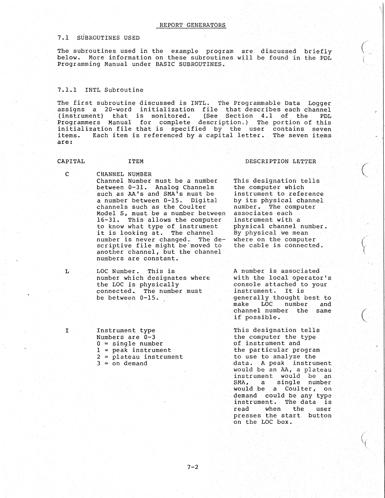
REPORT
GENERATORS
7.1
SUBROUTINES
USED
The
subroutines
used
in
the
~xample
program
are
discussed
briefly
below.
More
information
on
these
subroutines
will
be
found
in
the
PDL
Programming
Manual
under
BASIC SUBROUTINES.
7.1.1
INTL
Subroutine
The
first
subroutine
discussed
is
INTL.
The
Programmable
Data
Logger
assigns
a
20-word
initialization
file
that
describes
each
channel
(instrument)
that
is
moni
tored.
(See
Section
4.1
of
the
.
PDL
Programmers
Manual
for
complete
description.)
The
portion
of
this
initialization
file
that
is
specified
by
th~
user
contains
seven
items.
Each
item
is
referenced
by
a
capital
letter.
The
seven
items
are:
CAPITAL
C
L
I
ITEM
CHANNEL
NUMBER
Channel
Number
must
be
a
number
between
0-31.
Analog
Channels
such
as
M'S
and
SMA's
must
be
a
number
between
0-15.
Digital
channels
such
as
the
Coulter
Model
S,
must
be
a
number
between
16-31.
This
allows
the
computer
to
know
what
type
of
instrument
it
is
looking
at.
The
channel
number
is
never
changed.
Th~
de-
scriptive
file
might
be"moved
to
another
channel,
but
the
channel
numbers
are
constant.
LOC
Number.
This
is
number
which
designates
where
the
LOC
is
physically
connected.
The
number
must
be
between
0-15.
Instrument
type
Numbers
are
0-3
0 =
single
number
1 =
peak
instrument
2 =
plateau
instrument
3 =
on
demand
7-2
DESCRIPTION LETTER
This
designation
tells
the.
computer
which
instrument
to
reference
by
its
physical
channel'
number.
The
computer
associates
each
instrument
with
a
physical
channel
number.
By
physical
we
mean
where
on
the
computer
the
cable
is
connected
•
A
number
is
associated
with
the
local
operator's
console
attached
to
your
instrument.
It
is
generally
thought
best
to
make
LOC
number
and
channel
number
the
same
if
possible.
This
designation
tells
the
computer.
the
type
of
instrument
and
the
particular
program
to
use
to
analyze
the
data.
Apeak
instrument
would
be
an
AA,
a
plateau
instrument
would
be
an
SMA,
a
single
number
would
be
a
Coulter,
on
deIlland
could
be
any
type
instrument.
The
data
is
read
when
the
user
presses
the
start
button
on
the
..
LOC
box.
(
(
~
•..
(
/
\'
C
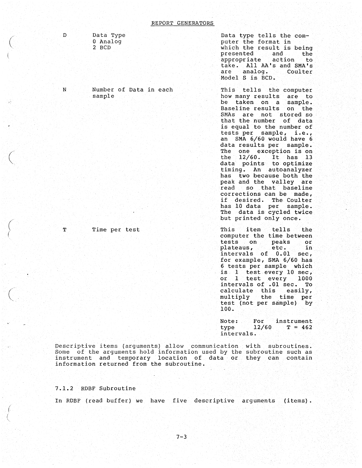
(
(
(
(
(
(
D
N
T
Data
Type
o
Analog
2
BCD
REPORT
GENERATORS
Number
of
Data
in
each
sample
Time
per
test
Data
type
tells
the
com-
puter
the
format
in
which
the
result
is
being
presented
and
the
appropriate
action
to
take.
All
AA's
and
SMA's
are
analog
•
,Coulter
Model
S
is
BCD.
This
,tells
the
computer
how
many
results
are
to
be
taken
on
a
"sample.
Baseline
results
on
the
SMAs
are
not
stored
so
that
the
number
of
data
is
equal
to
the
number
of
tests
per
sample,
i.e.,
an
SMA
6/60
would
have
6
data
results
per
sample.
The
one
exception
is
on
the
12/60.
It
has
13
data
points
to
optimize
timing.
An
autoanalyzer
has
two
because
both
the
peak
and
the
valley
are
read
so
,that'
baseline
corrections
can
be
made,
if
desired.
The
Coul
ter
has
10
data
per
sample.
The
data
is'
cycled
twice
but
printed
only
once.
This
item
tells
the
computer
the
time
between
tests
on
peaks
or
'plateaus,
,etc.
in
intervals
of
0.01
sec,
for
example,
SMA
6/60
has
6
tests
per
sample
which
is
1
test
every
10
sec,
or
I
test
every
1000
intervals
of
.01
sec.
To
calculate
this
easily
,
multiply
the
time
per
test
(not
per
sample)
by
100.
Note:
For
'
type
12/60
intervals.
instrument
T =
462
Descriptive
items
(arguments)
allow
communication
with
subroutines.
Some
of
the
arguments
hold
information
used
by
the
subroutine
such
as
instiument
and
temporary
location
of
data
or
they
can
contain
information
returned
from
the
subroutine.
7.1.2
RDBF
Subroutine
In
RDBF
(read
buffer)
we
have
five
descriptive
arguments
'(items).
7-3
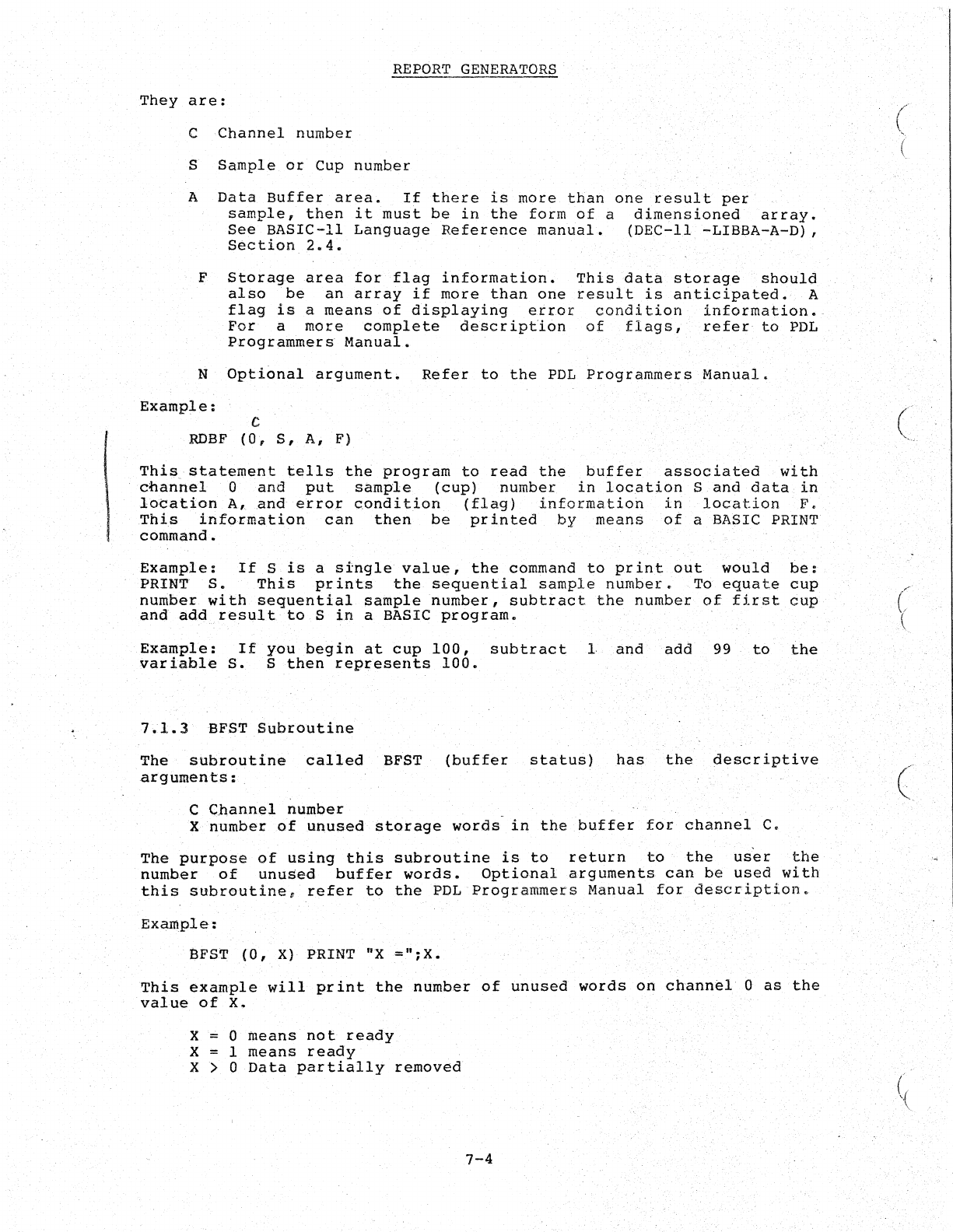
\
REPORT
GENERATORS
They
are:
C
Channel
number
S
Sample
or
Cup
number
A
Data
Buffer
area.
If
there
is
more
than
one
result
per
sample,
then
it
must
be
in
the
form
of
a
dimensioned
array.
See
BASIC-II
Language
Reference
manual.
(DEC-II
-LIBBA-A-D),
Section
2.4.
F
Storage
area
for
flag
information.
This
data
storage
should
also
be
an
array
if
more
than
one
result
is
anticipated.
A
flag
is
a
means
of
displaying
error
condition
information.
For
a
more
complete
description
of
flags,
refer
to
PDL
Programmers
Manual.
N
Optional
argument~
Refer
to
the
PDL
Programmers
Manual.
Example:
C
RDBF
(0,
S,
A,
F)
This
statement
tells
the
program
to
read
the
buffer
associated
with
channel
0
and
put
sample
(cup)
number
in
location
S
and
data
in
location
A,and
error
condition
(flag)
information
in
location
F,
This
information
can
then
be
printed
by
means
of
a BASIC PRINT
command.
Example:
If
S
is
a
single
value,
the
command
to
print
out
would
be:
PRINT
S.
This
prints
the
sequential
sample
number.
To
equate
cup
number
with
sequential
sample
number,
subtract
the
number
of
first
cup
and add
result
to
S
in
a BASIC
program.
Example:
If
you
begin
at
cup
100,
subtract
I
and add
99
to
the
variable
S.
S
then
represents
100.
7.1.3
BFST
Subroutine
The
subroutine
called
BFST
(buffer
status)
has
the
descriptive
arguments:
C
Channel
number
X
number
of
unused
storage
words
in
the
buffer
for
channel
C.
The
purpose
of
using
this
subroutine
is
to
return
to
the
user
the
number
of
unused
buffer
words.
Optional
arguments
can
be
used
with
this
subroutine,
refer
to
the
PDL
Programmers
Manual
for
description.
Example:
eFST
(0,
X)
PRINT
"X
="~X.
This
example
will
print
the
number
of
unused
words
on
chann~l
0
as
the
value
of
X.
X 0
means
not
ready
X 1
means
ready
X > 0
Data
partially
removed
7-4
(
c
(
(
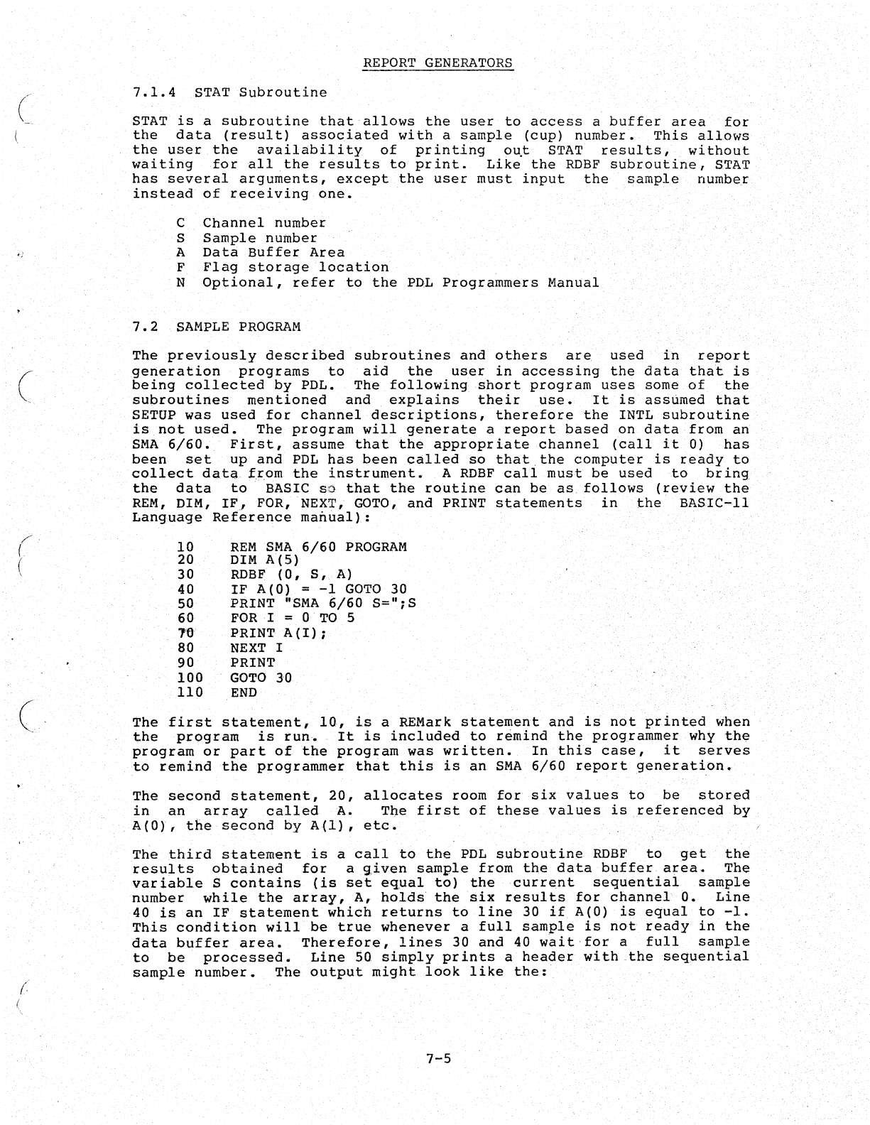
(
i-;
c
(
(
REPORT
GENERATORS
7.1.4
STAT
Subroutine
STAT
is
a
subroutine
that
allows
the
user
to
access
a
buffer
area
for
the
data
(result)
associated
with
a
sample
(cup)
number.
This
allows
the
user
the
availabil
i
ty
of
pr
inting
ou.t
STAT
results
I
without
waiting
for
all
the
results
to
print.
Like
the
RDBF
subroutine,
STAT
has
several
arguments,
except
the
user
must
input
the
sample
number
instead
of
receiving
one.
C
Channel
number
S
Sample
number
A
Data
Buffer
Area
F
Flag
storage
location
N
Optional,
refer
to
the
PDL
Programmers
Manual
7.2
SAMPLE
PROGRAM
The
previously
described
subroutines
and
others
are
used
in
report
generation
programs
to
aid
the
user
in
accessing
the
data
that
is
being
collected
by
PDL.
The
following
short
program
uses
some
of
the
subroutines
mentioned
and
explains
their
use.
It
is
assumed
that
SETUP
was
used
for
channel
descriptions,
therefore
the
INTL
subroutine
is
not
used.
The
program
will
generate
a
report
based
on
data
from
an
SMA
6/60.
First,
assume
that
the
appropriate
channel
(call
it
0)
has
been
set
up
and
PDL
has
been
called
so
that.the
computer
is
ready
to
collect
data
trom
the
instrument.
A
RDBF
call
must
be
used
to
bring
the
data
to
BASIC
so
that
the
routine
can
be
as
follows
(review
the
REM,
DIM,
IF,
FOR, NEXT, GOTO,
and
PRINT
statements
in
the
BASIC-II
Language
Ref~rence
ma~ual):
10
20
30
40
50
60
16
80
90
100
110
REM
SMA
6/60
PROGRAM
DIM
A(S)
RDBF
(0,
S,
A)
IF
A(O)
=
-1
GOTO
30
PRINT
"SMA
6/60
S=";S
FOR·I
= 0
TO
S
PRINT
A{I);
NEXT
I
PRINT
GOTO
30
END
The
first
statement,
10,
is
a REMark
statement
and
is
not
printed
when
the
program
is
run.
It
is
included
to
remind
the
programmer
why
the
program
or
part
of
the
program
was
written.
In
this
case,
it
serves
to
remind
the
programmer
that
this
is
an
SMA
6/60
report
generation.
The
second
statement,
20,
allocates
room
for
six
values
to
be
stored
in
an
array
called
A.
The
first
of
these
values
is
referenced
by
A(O},
the
second
by
A(l),
etc.
The
third
statement
is
a
call
to
the
PDL
subroutine
RDBF
to
get
the
results
obtained
for
a
given
sample
from
the
data
buffer
area.
The
variable
S
contains
(is
set
equal
to)
the
current
sequential
sample
number
while
the
array,
A,
holds
the
six
results
for
channel
O.
Line
40
is
an
IF
statement
which
returns
to
line
30
if
A(O)
is
equal
to
-1.
This
condition
will
be
true
whenever
a
full
sample
is
not
ready
in
the
data
buffer
area.
Therefore,
lines
30
and
40
wait
for
a
full
sample
to
be
processed.
Line
50
simply
prints
a
header
with
the
sequential
sample
number.
The
output
might
look
like
the:
7-5
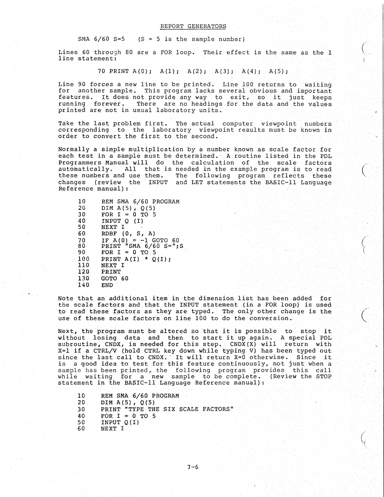
REPORT
GENERATORS
SMA
6/60
S=5 (S = 5
is
the
sample
number)
Lines
60
through
80
are
a
FOR
loop.
Their
effebt
is
the
same
as
the
1
line
statement:
70
PRINT
A(O);
A(l);
A(2);
A(3);
A(4);
A(5};
Line
90
forces
a
new
line
to
be
printed.
Line
100
returns
to
waiting
for
another
sample.
This
program
lacks
several
obvious
and
important
features.
It
does
not
provide
any
way
to
exit,
so
it
just
keeps
running
forever.
There
are
no
headings
for
the
data
and
the
va,.lues
printed
are
not
in
usual.
laboratory
units.
Take
the
last
problem
first.
The
actual
computer
viewpoint
number~
corresponding
to
the
laboratory
viewpoint
results
must
be
known
in
order
to
convert
the
first
to
the
second.
Normally
a
simple
multiplication
by
a
number
known
as
scale
factor
for
each
test
in
a
sample
must
be
determined.'
A
routine
listed
in
the
PDL
Programmers
Manual
will
do
the
calculation
of
the
scale
factors
automatically.
All
that
is
needed
in
the
example
program
is
to
read
these
numbers
and
use
them.
The
following
program
reflects
these
changes
(review
the
INPUT
and
LET
statements
the
BASIC-II
Language
Reference
manual):
.
10
20
30
40
50
60
70
80
90
100
110
120
130
140
REM
SMA
6/60
PROGRAM
DIM
A(5),
0(5)
FOR
I = 0
TO
5
INPUT
0
(I)
NEXT
I
RDBF
(0,
5,
A)
IF
A(O) =
~l
GOTO
60
PRINT
"SMA
6/60
S=";S
FOR
1=
0
TO
5 .
PRINT
A(l)
*
Q11);
NEXT
t
PRINT
GOTO
60
END
·Note
that
an
additional
item
in
the
dimension
list
has
been
added
for
the
scale
factors
and
th*tthe
INPUT
statement
(in
a
FOR
loop)
is
used
to
read
these
facto·rs
as
they
are
typed.
The
only
other
change
is
the
use
of
these
scale
factors
6n
line
100
to
do
t6e
conversion.
.
Next,
the
program
must
be
altered
so
-
that
it
is
possible
to
stop
it
without
losing
data
and
then
to
start
it
up
again.
A
special
POL
subroutine;CNDX,
is
needed
for
this
step.
CNDX(X)
will
return
with
X=l
if
a CTRL/V
(hold
CTRL
key
down
while
typing
V)
has
been
typed
ou.t
since
the
last
call
to
CNDX.-
It
will
return
x=o
otherwise.
Since
it
is
a
good
idea
to
test
for
this
feature
continuously,
not
just·
~hena
sample
has
been
pr
inted,-
the
following
program
provides
this
call
while
waitinSl
.for
a
new
sample
to
be
complete.
(Review
the
STOP
statement
in
the
BASIC-II
Language
Reference
manual):
10
REM
SMA
6/60
PROGRAM
20
DIMA(5),0(S)
30
PRINT "TYPE-THE
SIX
SCALE
FACTORS"
40
FOR
I = 0
TO
5
50
INPUT
O{I)
60
NEXT
I
7-6
(-
(
-,'
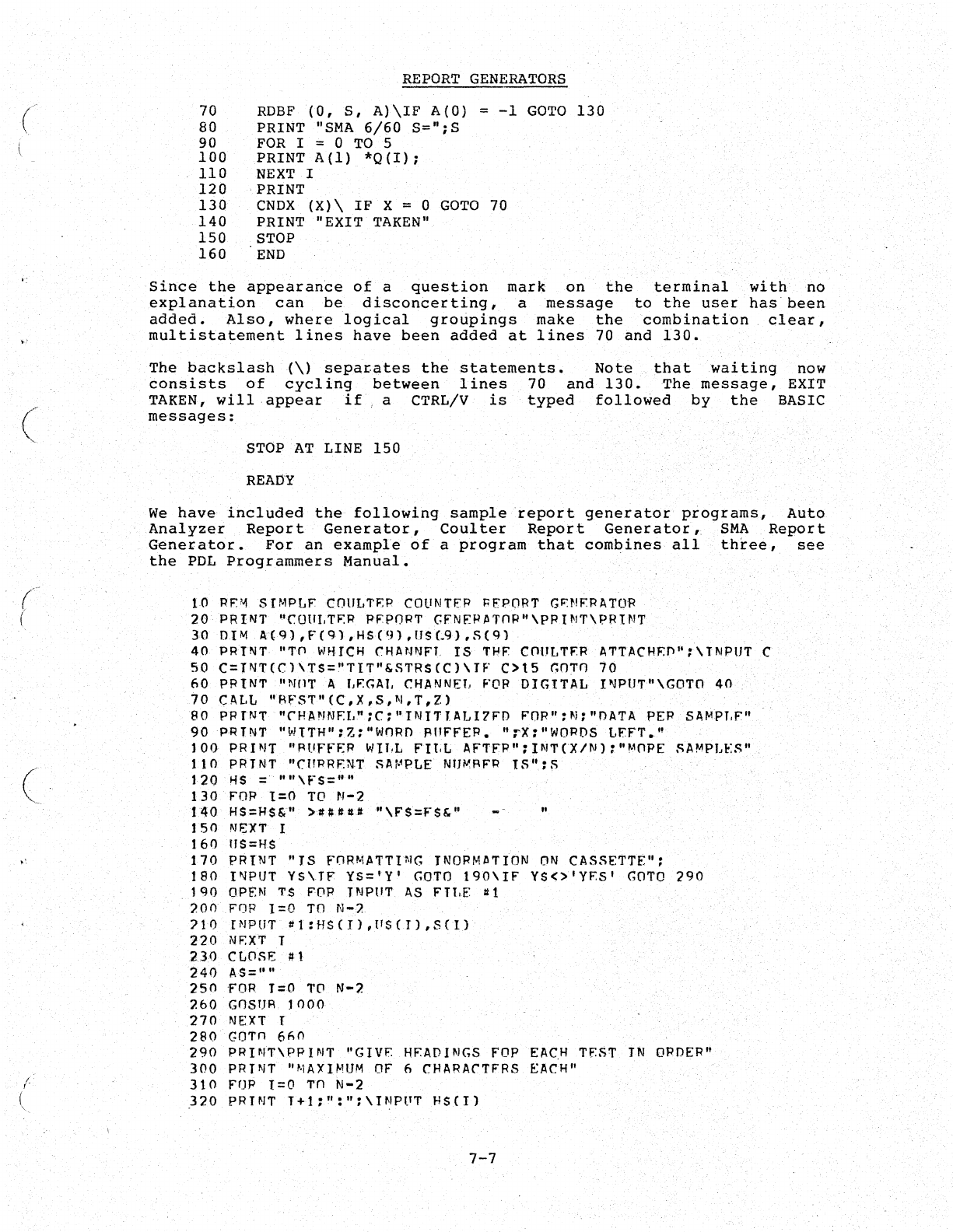
(
(
(
(
I
!.
REPORT
GENERATORS
70
80
90
100
110
120
130
140
150
160
RDBF
(0,
S,
A)\IF
A(O)
=
-1
GOTO
130
PRINT
"SMA
6/60
S=";S
FOR
I = 0
TO
5
PRINT
A(l)
*Q(I);
NEXT
I
.
PRINT
CNDX
(X)\
IF
X = 0
GOTO
70
PRINT
"EXIT
TAKEN"
STOP
END
Since
the
appearance
of
a
question
mark
on
the
terminal
with
no
explanation
can
be
disconcerting,
a
message
to
the
user
has
been
added.
Also,
where
logical
groupings
make
the
combination
clear,
multistatement
lines
have
been
added
at
lines
70
and
130.
The
backslash
(\)
separates
the
statements.
Note
that
waiting
now
consists
of
cycling
between
lines
70
and
130.
The
message,
EXIT
TAKEN,
will·
appear
if
a CTRL/V
is
typed
followed
by
the
BASIC
messages:
STOP
AT
LINE
150
READY
We
have
included
the
following
sample
report
generator
programs,
Auto
Analyzer
Report
Generator,
Coulter
Report
Generator,
SMA
Report
Generator.
For
an
example
of
a
program
that
combines
all
three,
see
the
PDL
Programmers
Manual.
10
PF'-l
Sr~,p[JF
COUI,TF.P
COliNTER
;;E'PORT
G~NF:RII.TOf<
20
PR
INT
'·COULTF.P
PEPORT
GFNEP
IITOP"\PP
I
NT\PRINT
30
DIM
A(9)
,F(9)
,HS(9)
,US(.9)
.~(9)
40
PRTNT
"Til WHICH CHIINNFl
IS
THF cnllLTFR IITTACHFfl";\TNPUT C
50
C=TNr(Cl\TS="TIT"&~TRS(C)\IF
C>15
GOTO
70
60
PRINT
"NflT
A f,FGAT. CHANNEL, FOP
DIGITAL
PJPIJT"\GOTO
40
70
CALL
"RFST"(C,X,S,N,T,Z)
80
PPINT
"CHANNF.L";C:"TNTTIALI7FO
FOP":N:"DATII.
PEP
SA~PT.F"
90
PRINT
"WTTH":Z:"I.-IORO
fHJFF'EP.
"rX:"WOPDS
LEFT."
100
PRINT
"RI-'FfER
I.-IH,L
F'It,L
AFTFP":INTeX/N)
:"MOPE
SAMPJ,ES"
110
PRINT
"CHt:1RF:N·T
SAr·1PLE
NIJ~RFP
IS":S
120
HS
=
""\fS=""
130
FOR
1=0
TO
N-2
tAO HS=HS&"
>.###~
"\FI=FS&"
"
150
NEXT
I
160
II$=HS
170
PRINT
"IS
FORMATTI~G
INORMnTION
ON
CASSETTE":
180
I~PUT
YS\TF
¥5='¥'
GOTO
190\IF
YS<>'YFS'
GOTO
290
lQO
OPEN
1'$
FOR
TNPIIT
~S
FTl.E~
Itl
?on
FOR
1=0
TO
N-?
710
PJPUT
1I1:HS(Il,t1s(J),S(l)
220
NF:XT
T
;no
CLOSE
/I
1
240
AS= ....
250
FOR
T=O
TO
N-2
7.60
GnSHR
loon
270
NEXT
r
280
Gorn
6F.O
290
PPINT\PPINT
"GIVE
HFADINGS
FOP
EACH
TF.ST
TN
ORDER"
300
PRINT
"MAXIMUM
OF 6
CHARACTFRS
EACH"
310
FOP
1=0
Tn
N-2
320
PRINT
T+l:":";\INPPT
HS(I)
7-7
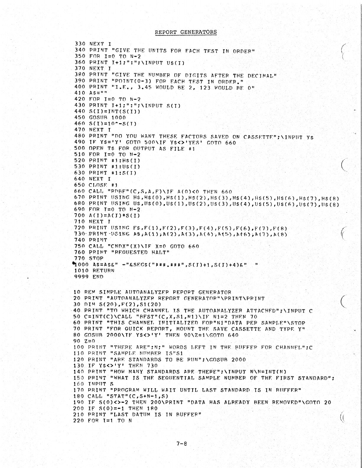
REPORT
GENERATORS
330
NEXT
I
340
PRINT "GIVE
THE
UNITS
FOR
FJCH TEST
IN
ORDER"
350
FOR
1=0
TO
N-2
360
PRINT
I+l:":":\INPUT
U$(I)
370
NEXT
I
3AO
PRTNT
"GIVE
THE
NUMBER
OF
DIGITS
AFTER
THE
DECIMAL"
390
PRINT
"POTNT(0-3)
FOP
EACH
TEST
IN
ORDER."
400
PRINT
"I.E.,
3.45
WOULD
BE
2,
123
WOULD
AF
0"
410
AS:::""
420
FOR
1=0
TO
N-2
430
PRINT
I+l:":"f\INPUT
SCTl
440
SCI}=JNT(SCI»
450
GOSUR
1000
460
S([1=10--5(T)
470
NEXT
I
480
PRINT
"DO
YOU
WANT
THESF:
F.IICTORS
SAVED
ON
C.IISSETTF"~\INPtlT
YS
490
IF
YS='Y'
GOTO
500\11"
YS<>'YES'
GnTO
660
500
OPEN
TS
FOR
OUTPUT
AS
FILE
'1
510
FOR
1=0
TO
N-2
520
PRI~T
~1:HS(I)
530
PRINT
~l:US(I)
630
PRINT
#1:S(I)
640
NEXT
I
650
CI,nSE
111
660
CALL
flpnSF"(C,S,A.F)\JF
.11(0)<0
THFN
660
670
PRINT !JSING
HS,HS(0),HS(I),HS(2),HS(3),HS(4),~${5)~HS(6),H$(7),H$(B)
68'0 PRINT t1SING US,IJSCO)
,USC
1)
.lJS(2)
,tlS(3)
,US(4)
,US(5)
,lJS(f;),lJS(7)
,IIS(8)
~90
FOR
1=0
TO
N-2 . .
700
ACI)=A(J)*S(I)
710
NEXT
J
7,,)0
PRINT
USTNG
FS,F(1),F(2),F(3),F(4).F'(S),F(6).,F(7),f'(8)
':U
\}-
.PR 1 M T -
\I
f·
I'~(;"
S i A
{1
} ;
11
(
'2)
•
A.
{3
) ,
1>.
(
4-
),
t,
t5o)
,
1:1
ttl
~
;
~
t1
) •
1:1
t 8 )
740
PRINT
T50
CAI,L
"CNnX"(X)\TF
X=O
GO
TO
660
760
PRINT "RFOllESTED
HAI.T"
770
STOP
..
aoo
AS=AS&"
-"&5EGS("I/U.IIU",S(J)+1,S(J)+4)&"
"
1010
RETURN
9999
END
10
RE~
SIMPLE
AUTnANALYZFP
PEPORT
GENERATOR
20
PRIfIlT "AU'WANAI,YZrp
REPORT
GFNERATnp"\PRINT\PRINT
30
DIM
S(20),F(2),st(20)
·40.
PH
HIT
"TO
WHICH
CHANNFL
IS
THE
AtlTOANAJ,YZER
AT'f'ACHFD"
.:\INPllT
C
50
C=INT(C)\CALL
"RFST"(C,X,Sl,Nt)\IF
1'11=2
THF.~
70
·60
PRINT
"THIS
CHANNEl;
I1\tITTALTZFO
FopnNl
"DATA
PEP SAMPI.F."\STOP
70
PRINT
"FOR
QUICK
REPORT,
MOUNT
THE
fiAVE
CASSETTE
AND
TYPE
Y"
90
GOSlIR
2000\
TF'
Y$<>
Iy
I
THEN
90\Z=1
\GOTn
640
90
Z=o
100
PRINT
"THF.RE
ARE":N;"
WORDS
J,EFT
IN
THE
EH1FFFP
F'OR.CHANNFI.":C
no
PRIN'r
"SAMPI,F.
]I)[!~1FIEP
IS"S1
120
PRINT
"ARE
STANDARDS
TO
BE
PUN"
:\GOSUR
2000
130
IF
YS<>'Y'
THEN
730
140
PP1JIIT·IIHOW
MaNY
StANDARDS
j:\PF:THEPF":\INPUT JII\N=INTHJ)
t50
PRINT
""'IHAT
IS
.THF.
SEQUENTIAl.
S.IIMPLF.
NUMBER
OF
THE
FIRST STl\NDARD":
160
TNPHT
S
170
PRINT
"PRnGRAM
WILL
WA
IT
UNTIL
LAST
STANDARD
TS
1111
AHFFP.R"
180
CALL
"STAT"(C,S+N-t,S)
190
IF
5(0)<>-2
THEN
200\PRINT
"DATA
HAS
ALRF.ADY
BEEN
REMOVF:D"\GOTO
20
200
IF
5(0)=-1
THEN
lRO
210
PRINT "LAST
DATUM
IS
IN
RUFFER"
220
FOR
1=1.
TO
N
7-8
(
'(
(
c
(~
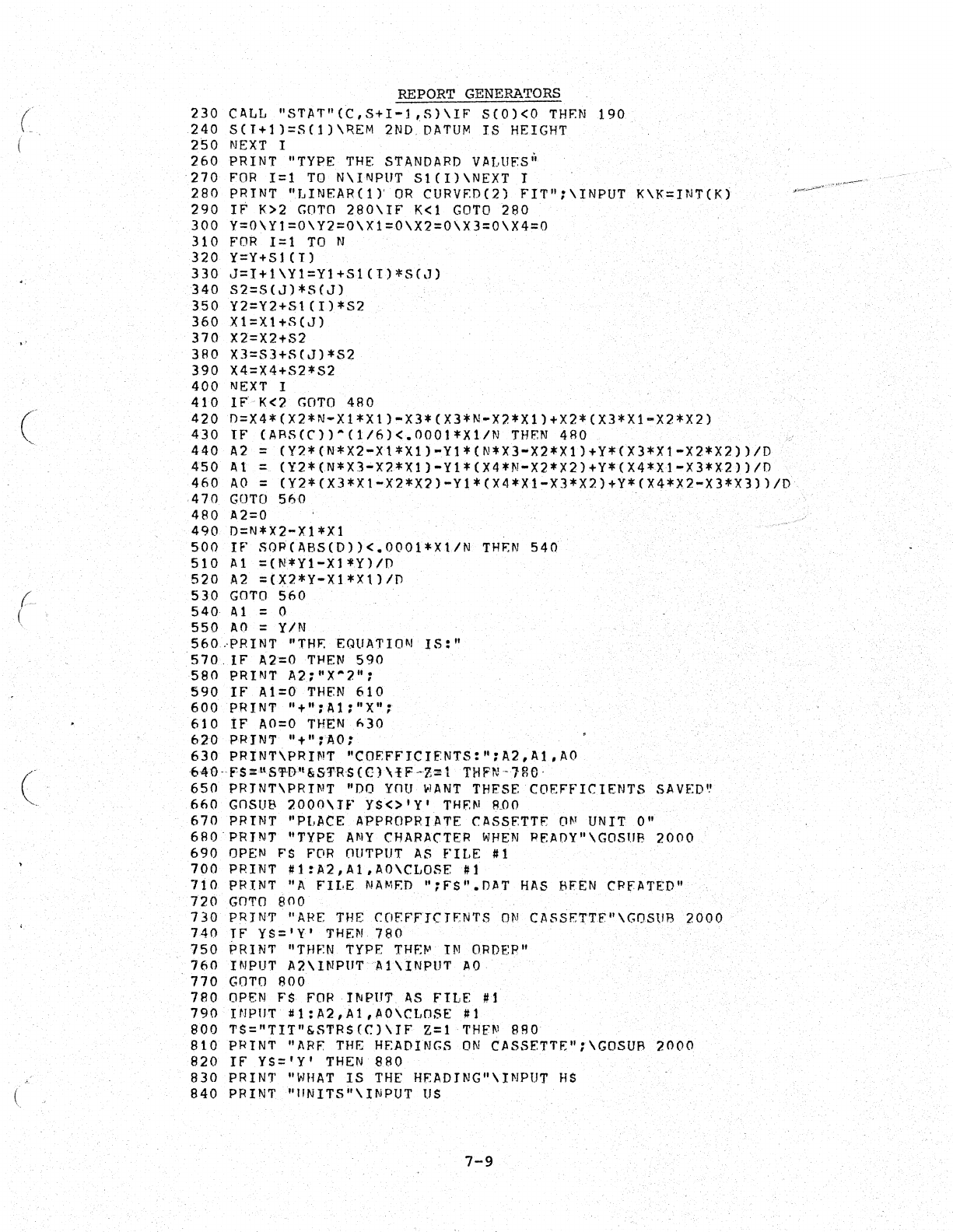
(
,.
(
~,
(
(
REPORT
GENE~~TORS
230
CALL
"STAT"(C,S+I-l,S)\IP
S(O)<O
TH~N
190
240
S(T+l)=S(l)\REM
2ND.
DATUM
IS
HEIGHT
250
NEXT
I
260
PRINT
"TYPE
THE
STANDARD
VALUES i
270
POR
1=1
TO
N\INPUT
Sl(I)\NEXT
I
280
PRINT
"LINEAR(1),
OR
CURV~D(2)
FI'l''':\INPUT
K\I<=INTCIO
290
IF
1<>2
GO
Tn
280\IF
K<l
GOTD
280
300
Y=0\Yl=0\Y2=0\Xl=D\X2=O\X3=0\X4=0
310
FOR
1=1
TO
N
320
y=Y+SICI)
330
J=I+l\Yl=Yl+S1{I)*S(J)
340
S2=5(J)*S(J)
350
Y2=Y2+S1(1)*52
360
Xl=X1+S(J)
370
X2=X2+S2
380
X3=S3+seJ)*S2
390
X4=X4+S2*S2
400
NEXT
I
410
IFK<2
GO
TO
480
420
D=X4*(X2*N-X1*XI)-X3*(X3*N-X2*Xl)+X2*(X3*Xl-X2*X2)
430
IF
(ARS(C))-Cl/6)<.OOOt*Xl/N
THFN
480
440
A2
=
(Y2*(N*X2-Xl*Xl)-Yl*(N*X3~X2*Xl)+Y*(X3*X1-X2*X2))/D
450
At
=
(Y2*(N*X3~X2*Xl)-Yl*(X4*N-X2*X2)+Y*(X4*Xl-X3*X2))/D
460
AD
=
(Y2*(X3*XI-X2*X2)-Yl*(X4*Xl-X3*X2)+Y*(X4*X2-X3*X3))/D
470
GOTO
560
480
A2=0
490
0=N*X2-xt*Xl
500
IF
SQR(ABS(O))<.OOOl*Xl/N
THEN
540
510
Al
=(N*YI-Xl*Yl/D
520
A2
=(X2*Y-Xl*xl1/D
530
GOTO
560
540
Al = 0
550
AO
= YIN
560,PRINT
"TH~
EQUATION
IS:"
570.
IF
A2=OTHEN
590
580
PRINT
A2f"X~2";
590
IF
Al=O
THEN
610
600
PRINT
"+":Al:"X":
610
IF
AO=O
THEN
h30
620
PRINT
"+";AO:
630
PRINT\PRINT
"COFFFICIFNTS:":A2'Al,AO
640-FS%llS'I'-f)"&5'fRS
(C)
\l
F
-Z~l
THPN-
'Hl6·
650
PRINT\PRINT
"~O
YOU
WANT
THESE
COEFFICIENTS
SAVED~
660
GOSUB
200n\JF
YS<>'Y'
THEN
ROO
670
PRINT
"PLACE APPROPRIATE CASSETTE
ON
UNIT
0"
6f!0·PRTNT
"TYPE
ANY
CHARACTER
WHEN
PEAOY"\GOSUB
2000
690
OPEN
FS
FOR
nUTPUT
AS
FILE
#1
700
PRINT
#1:A2,Al,AO\CLOSE
#1
710
PRINT
"A
FII,E
NAMED
":ES".OAT
HAS 'f\I'EN CRFATED"
720
GOTO
800
730
PRINT
"ARE
THE
COF.PFTCTFNTS
ON
CASSETTF"\GOStlB
2000
740
If
YS='Y'
THEN
780
750
PRINT
"THEN TYPE
THE~
IN ORDEP"
160
INPUT
A2\INPllTA1\INPtJT
AO
770
GOTO
BOO
780
OPEN
FS
FOR
INPlJT
AS
FILE
#1
790
HIPIIT
#1:A2,Al,AO\Ct,OSE
#1
800
TS="TIT"&STRS(C)\IF
Z=l
THEN
880
810
PRINT
"ARE
THE
HEADINGS
ON
CASSETTE";\GOSUB
2~OO
820
IF
YS='Y'
THEN
RBO
830
PRINT
"WHAT
IS
THE
HEADING"\INPUT
HS
840
PRINT
"IINITS"\INPUT
US
7-9
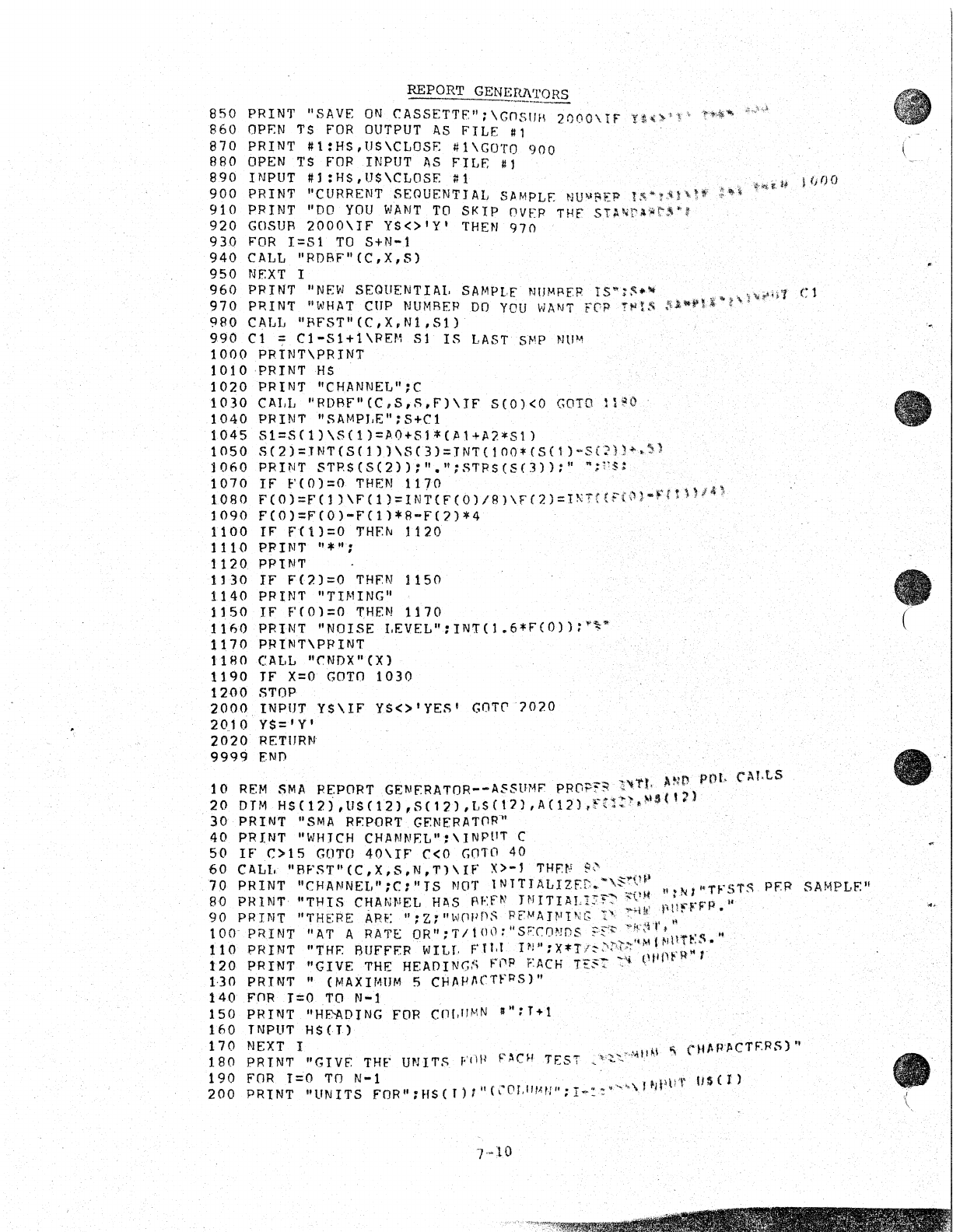
REPORT
GENE~TORS
850
PRINT
"SAVE
ON
CASSETTE":
\GnStlH
2000\
IF
!~(»'r~
,!,~"'h'''''
860
OPEN
TS
fOR
OUTPUT
AS
FILE
#1
870
PRINT
#t:HS,US\CLOSE
#l\GOTO
900
BBO
OPEN
TS
FOR
INPUT
AS
FILE
#1
890
INPUT
#l:HS,US\CLOSE#l~~~M
I~QO
900
PRINT
IICURRENT
SEQUENT! AL SJlMPLE
NUI,I!<EP
l""'t-~!"tt
~
.. \ . -
910
PRINT
liDO
YOU
WANT
TO
SKIP
OVER
THE
ST.MrA'~J·'
920
GaSUR
2000\If
YS<>'Y'
THEN
970
930
FOR
1=51
TO
S+N-l
940
CALL IIRDBFII(C,X,S)
950
NEXT
I
960
PRINT "NEW
SEQUENTIAL
SAMPLE'
NIJMRER
tS"':~.-
1'1
Cl
970
PRINT
"WHAT
CUP
NUMREP
DO YOU WANT FC'?
'!'t'llt{
$~.ni"f"
,~io";
,
980
CALL
"BFST"(C,X,NI,Sl)
990
Cl
::;:
Cl-S1+1
\PEf1
51
IS
LASTS/-IP
NUM
1000
PRINT\PRINT
1010PRINTHS
1020
PRINT
"CHANNEL";C
1030
CA!.IJ
"RDRF"(C,S,.c;,F')\IF
5(0)<0
GOTO
n~()
1040
PRINT
"SAMPJ.E":5+Cl
1045
Sl=S(I)\S(1)=AO+51*(Jll+A2*SI)
1050
S(2)=JNT[SC1))\SC3)=JNT{IOO'(S(I)-S(2)164~)
1060.
PRINT
STP.S(S(2)):".n:S1'pS(S(3)):
....
:1~S:
10.10 IF'
f'(O)=O.
THEN
1170
..
..
\
1080
F(0)=F'Cl}\F(1)=INT(F(b)/B)\F(2)=INT((Ftn)~Frl))'"
1090
F{O)=FCO)-FC11*B-F£1)*4
1100
IF
ft1)=0
THfN 1120.
1110
PRINT
"*":
1120..
PP'[N"
1]30
IF
1"(2)=0
THfN
1150
1140
PRINT
"TIMING"
1150
IF
FC01:0
THEN
1170
1160
PRINT
"Non;E
LEVEL":INT(1.6*f(0»;"""
1170
PRINT\PPINT
1180
CALL
"~NDX»(X)
1190
IF
X=~
GOTn
1030
1200
STOP-
2000
INPUT
Y$\IF
YS<>'YES'
GOTr-1020
20..10.
Y$='
Y'
2020
:RETIIRN
9999
EN))
. _
...
~'If,.t
••
nrpOL
("1It.ts
10
REM
SMA
REPORT
GENfRATOR--ASSUMF
PRGPr~'·
::.
"
20
DTM
HS(12j,US(12),S[12),LS[12),A(12)~Fr2:~.~.('·
30
PR
I
NT
"SM
A REPORT
GP.NER
AT()fP'
..
40.
PRItJ"
"WHICH
CHANNP.L":\INP!lT
C
50
IF
C>15
GOTO
40\11"
C<O
Goro
40
60
CALL
"RFST"(C,X,S,N,T)\IF
X>-J
THEN
8~
_.,._.
70.
PRINT
"CHANNEL"rC:"TS
NOT
INTTIALIZfn.·\~·?~
".~I~TFST~
p~p
SAMPLf"
8Q
PRINT-
"THIS
Cf:lANfllEL
HAS
f\E~N
!NITIAL~;;~:-
:;'~
~;n.~rF"p.
If
90
PRINT
"THERE
ARE:
";Z~"~~(wn"
RtIolAH'l"lb
.i.),
....
llf}"
100
PR.INT
"AT
A.RATE
OR":T/Hl\):"SF:rONDS?E<",,"::~~I·jlln~5."
..
110
PRINT
"THF.
fHJFFF.R WILT.
F'tl.t
IN"
:X*TI~')i'-I~
,
tlf~.!"R"'·
120
PRINT
"GIVE
THE
HEAOING:~
n-'p
EACH
Tt:~t
:'i
~\tl
1-30
PRINT"
CMAxnmM
5 CtlJI/-IIICTFPSJ
It
140
FOR
r=01'O
N-l
150
PRINT
"HF.-ADJNG
FOR
cnf.lfMN
.":
1+ 1
160
TNPUT
HSn)
170
NEXT
I~;:l'~>'MI,I~1
".
\H~P"CTf.R5)"
180
PRINT
"GIVf.
THF
UNITS
F'fW
~'ACHTEST
• _
--
190
FOR
1::0
TO
N-l
~.
_ ....... "
nl'ur
IJsn)
200
PRINT
"UNITS
FOR":HS(T)I"(,OLIIHII";l-.=
. \ I
7-10
•
•
C
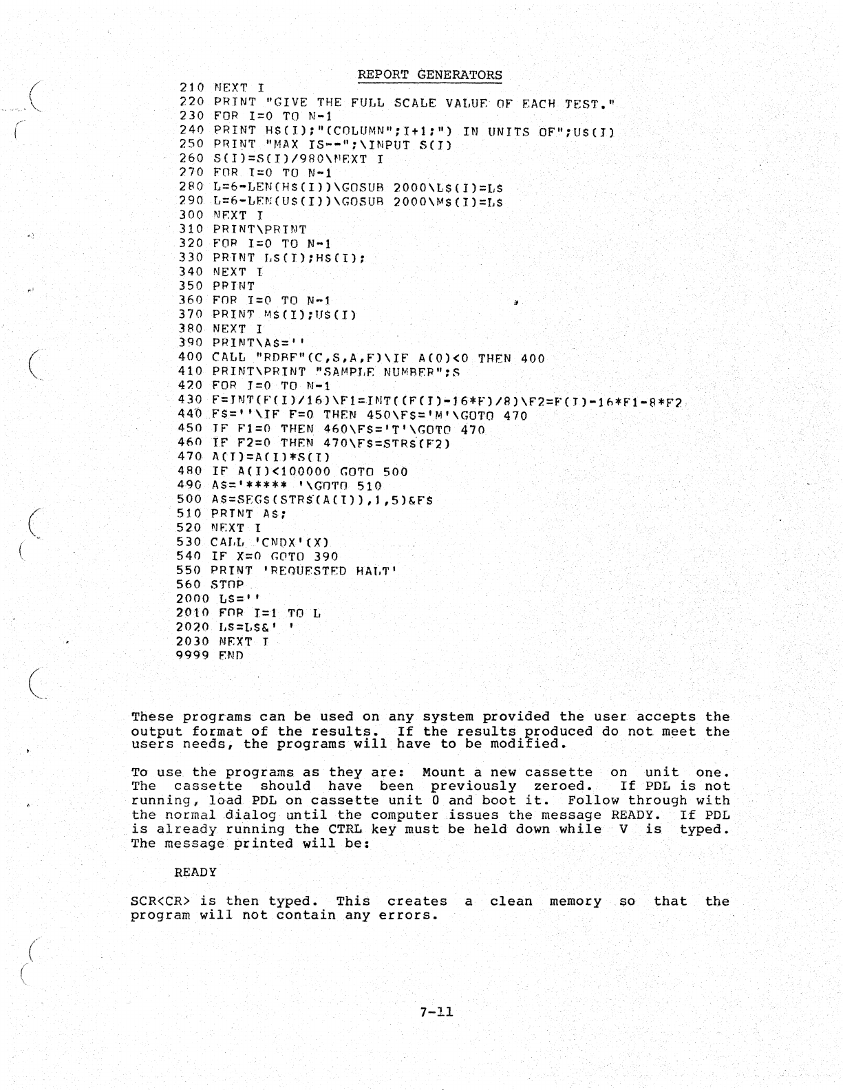
(
(
(
(
,~-
-
(
\
(
REPORT
GENERATORS
210
NEXT.
I
220
PRINT
"GIVE
THE
FULL SCALE
VALUE
OF
EACH
TEST."
230
FOR
1=0
TO
N-l
240
PRINT
H$(I);"CCOLUMN";Itl:")
IN UNITS
OF":US(I)
250
PRINT
"MAX
IS--":\INPUT
SCI)
260
S(I)=S(I)/9RO\~RXT
I
770
FOR
1=0
TO
N-l
280
L=6-LEN(HS(1))\GOSUB
2000\LS(I)=LS
290
L=6-LFN(U$(I))\GOSUR
2000\MS(I)=LS
300
NP.XT
I
310
PRINT\PRTNT
320
FOR
1=0
TO
N-l
330
PRINT
LS(I):HS(I);
340
NEXT
I
350
PRINT
360
FOR
1=0
TO
N-l
370
PRINT
MS(l);US{I)
380
NEXT
I
3QO
PRINT\AS='
I
400
CALL
"RDRF"(C,S.A,F)\IF
A(O)<O
THEN
400
410
PRINT\PRIN1'
"SA~APr.E
NUMRP'P":S
420
FOR
J=O
TO
N-l
430
F=JNT(P(IJ/l&)\Fl:IN1'((FCI)-16*F)/B)\F2=F(J)-lh*Fl-B*F2
440
F$='
'\IF
F=O
THEN
450\FS='M'\GOTO
470
450
IF
Fl=O
THEN
460\FS='T'\GOTO
470
460
IF
F2=O
THEN
470\FS=STRiCF2)
470
ACT)=A(Il*S(1)
480
IF
A(I)<100000
GOTO
500
490
AS='*****
'\GOTO
510
500
AS=SEGS(STR«ACI)),),5)&FS
510
PRINT AS;
520
NF.XT
I
530
CAT,I,
'eNOX'
(X)
540
IF
X=O
GOTO
390
550
PRINT I
REQUESTED
HAT,T
I
560
STnp.
2000
LS= I ,
2010
FnR
1=1
TO
L
2020
r.S=l,$&'
,
2030
NEXT
I
9999
P.ND
These
programs
can
be
used
on
any
system
provided
the
user
accepts
the
output
format
of
the
results.
If
the
results
produced
do
not
meet
the
users
needs,
the
programs
will
have
to
be
modified.
To
use
the
programs
as
they
are:
Mount
a
new
cassette
on
unit
one.
The
cassette
should
have
been
previously
zeroed.
If
PDL
is
not
running,
load
PDL
on
cassette
unit
0
and
boot
it.
Follow
through
with
the
normal
dialog
until
the
computer
issues
the
message
READY.
If
PDL
is
already
running
the
CTRL
key
must
be
held
down
while
V
is
typed.
The
message
printed
will
be:
READY
SCR<CR)
is
then
typed.
This
creates
a
clean
memory
SO
that
the
program
will
not
contain
any
errors.
7-11
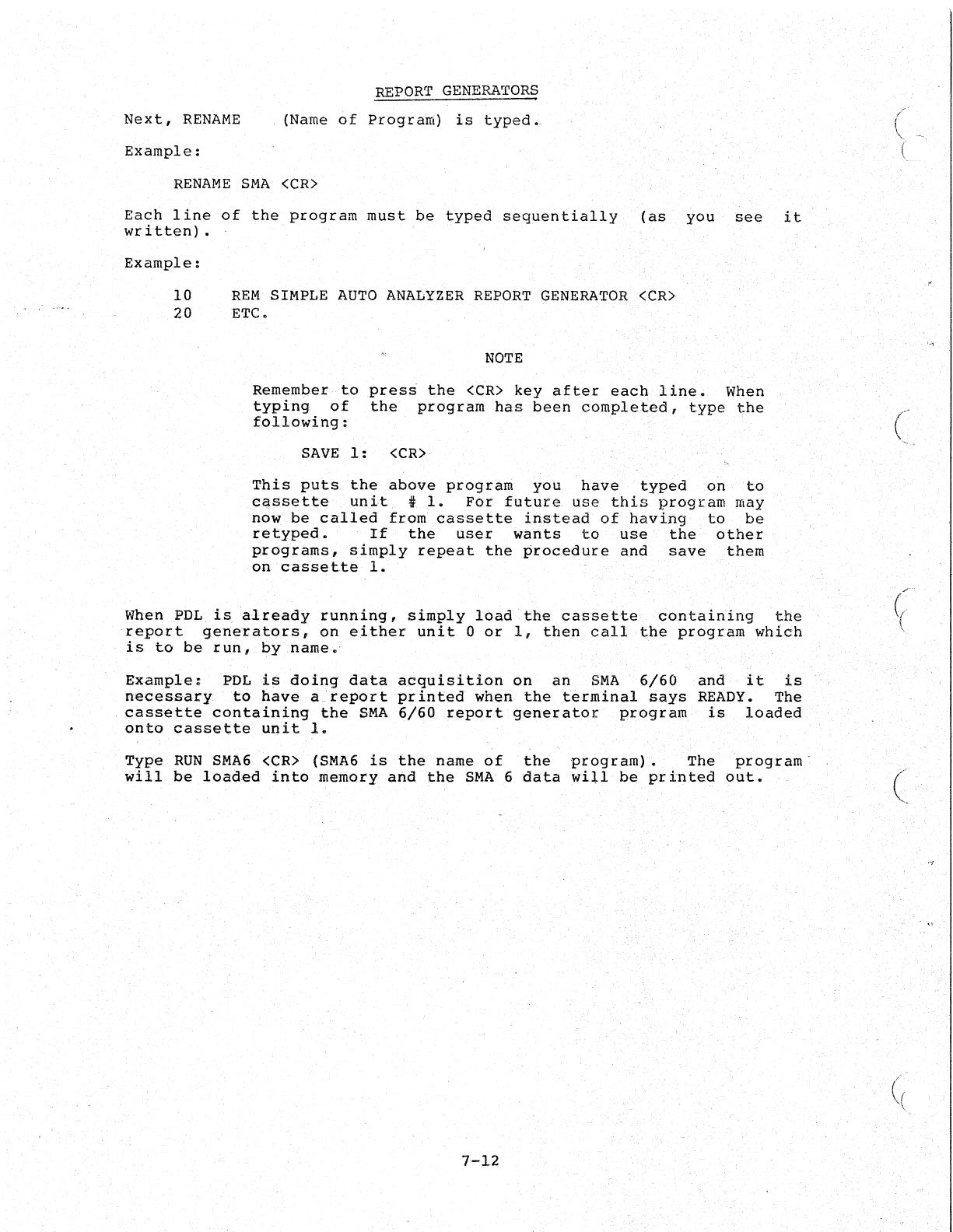
Next,
RENAME
Example:
REPORT
GENERATORS
(Name
of
Program)
is
typed.,
RENAME
SMA
<CR)
Each
line
of
the
program
must
be
typed
sequentially
(as
you
see
it
written)
•
Example:
10
REM
SIMPLE
AUTO
ANALYZER
REPORT
GENERATOR
<CR)
20
ETC.
NOTE
Remember
to
press
the
<CR)
key
after
each
line.
When
typing
of
the
program
has
been
completed,
type
the
following:
SAVE
1:
<CR)
This
puts
the
above
program
you
have
typed
on
to
c~ssette
unit
t
1.
For
future
use
this
program
may
now
be
called
from
cassette
instead
of
having
to
be
retyped.
If
the
user
wants
to
use
the
other
programs,
simply
repeat
the
procedure
and
save
them
on
cassette
1.
When
PDL
is
already
running,
simply
load
the
cassette
containing
the
report
generator,s,
on
either
unit
0
or
1,
then
call
the
program
which
is
to
be
run
I
by
name.'
Example:
PDL
is
doing
data
acquisition
on
an
SMA
6/60
and
it
is
necessary,
to
have
a_report
pr
inted
when
the
terminal
says
READY.
The
cassette
containing
the
SMA
6/60
report
generator
program
is
loaded
onto
cassette
unit
1.
Type
RUN
SMA6
<CR)
(SMA6
is
the
name
of
the
program)
•
The
program
will
be
loaded
into
memory
and
the
SMA
6
dat,a
wiU
be
printecl
out.
7-12
c-
(
(,
"(
('
(' ,
"
'~'
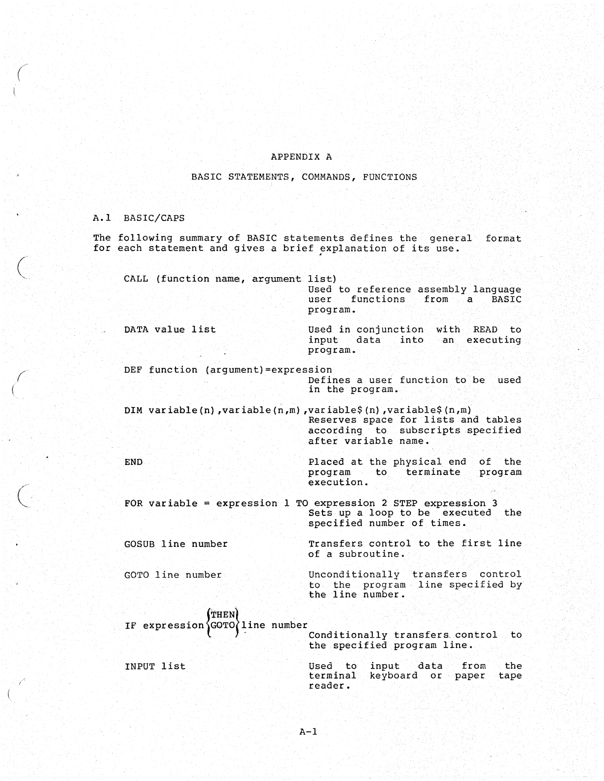
(
(
(
(
APPENDIX A
BASIC STATEMENTS,
COMMANDS,
FUNCTIONS
A.I
BASIC/CAPS
The
following
summary
of
BASIC
statements
defines
the
general
format
for
each
statement
and
gives
a
brief
~xplanation
of
its
use.
CALL
(function
name,
argument
list)
DATA
v.al
ue
1
is
t
Used
to
reference
assembly
language
user
functions
from
a BASIC
program.
Used
in
conjunction
input
data
into
program.
with
READ
to
an
executing
DEF
function
(argument)=expression
Defines
a
usei
function
to
be
USed
in
the
program.
DIM
variable(n)
,variable(n,m)
,variable$(n)
,variable$(n,m)
Reserves
space
for
lists
and
tables
according
to
subscripts
specified
after
variable
name.
END
Placed
at
the
physical
end
of
the
program
to
terminate
program
execution.
FOR
variable
=
expression
1
TO
expression
2 STEP
expression
3
Sets
up
a
loop
to
be
executed
the
specified
number
of
times.
GOSUS
line
number
GO
TO
line
number
IF
expression
{·~~~~}~ine
number
INPUT
list
Transfers
control
to
the
first
line
of
a
subroutine.
Uncond
i
tionally
to
the
program
the
line
number.
transfers
control
line
specified
by
Conditionally
transfers.
control
to
the
specified
program
line.
Used
to
terminal
reader.
input
data
keyboard
or
from
paper
the
tape
A-I
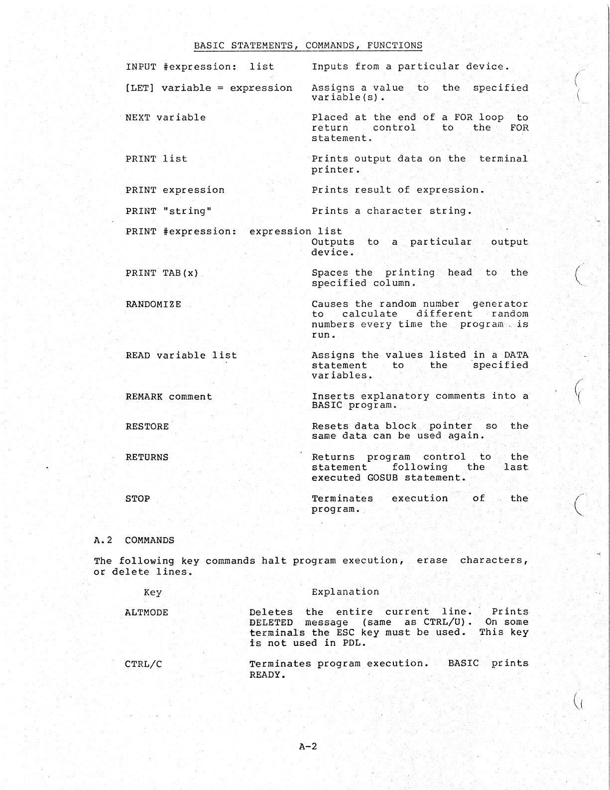
BASIC STATEMENTS,
COMMANDS,
FUNCTIONS
INPUT
#expression:
list
Inputs
from
a
particular
device.
[LET}
variable
=
expression
Assigns
a
value
to
the
specified
variable(s)
•
NEXT
variable
PRINT
list
PRINT
expression
PRINT
"string"
Placed
at
the
end
of
a
FOR
loop
to
return
control
to
the
FOR
statement.
Prints
output
data
on
the
terminal
printer.
Prints
result
of
expression.
Prints
a
character
string.
PRINT
#expression:
expression
list
PRINT
TAB(x)
RANDOMIZE
aEAD
variable
list
REMARK
cornmEm
t
RESTORE·
RETURNS
STOP
A.
2
COMMANDS
Outputs
toa
particular
device.
output.
Spaces
the
printing
bead.
to
the
specified
column.
Causes.
the
random
number
generator
to
calculate
different
·random
numbers
every
time
the
program.
is
run.
Assigns
the
values
listed
ih
a
DATA
statement
to
the
specified
variables.
Inserts
explanatory
comments
into
a
BASIC
pro9ram.
Resets
data
block
pointer
so
the
same
data
can
be
used
again.
Returns
program
contiol
to
the
statement
following
the
-last
executed
GOSUB
statement.
Terminates
program.
execution
of
the
The
following
key
commands
halt
program
execution,
erase
characters,
or
delete
lines.
Key
ALTM{)DE
CTRL/C
Explanation
Deletes
the
entire
current
line.
DELETED
message
(s'ame
as
CTRL/U).
terminals
the
ESC
key
must
be
used.
is
not
used
in
POL.
Prints
On
some
This
key
Terminates
program
execution.
READY. BASIC
prints
A-2
(
(
(
((
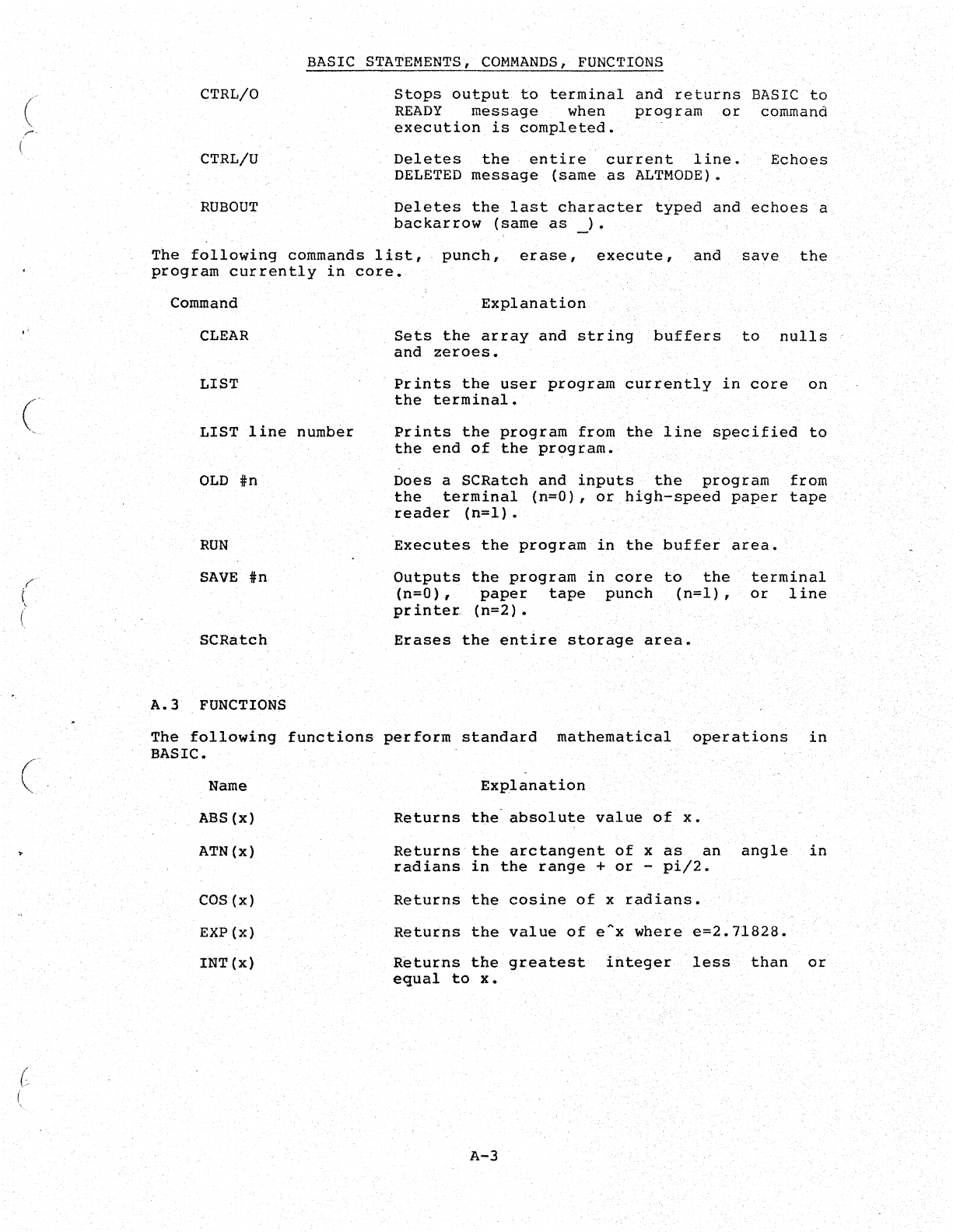
(
r'
(
"
(
""':
C',
BASIC STATEMENTS,
COMMANDS,
FUNCTIONS
CTRLIO
CTRLIU
RUBOUT
Stops
output
to
terminal
and
returns
BASIC
to
READY
message
when
program
or
command
execution
is
completed.
Deletes
the
entire
current
line.
Echoes
DELETED
message
(same
as
ALTMODE).
Deletes
the
last
character
typed
and
echoes
a
backarrow
(same
as
_).
The
following
commands
list,
punch,
erase,
execute,
and
save
the
program
currently
in
core.
Command
CLEAR
LIST
LIST
line
number
OLD
in
RUN
SAVE
in
SCRatch
A.3
FUNCTIONS
Explanation
Sets
the
array
and
string
buffers
to
nulls
and
zeroes.
Prints
the
user
program
currently
in
core
on
the
terminal.
Prints
the
program
from
the
line
specified
to
the
end
of
the
program.,
Does
a
SCRatch
and
inputs
the
program
from
the
terminal
(n=O),or
high-speed
paper
tape
reader
(n=l).
Executes
the
program
in
the
buffer
area.
Outputs
the
program
in
core
to
the'
terminal
(n=O),
paper
tape
punch
(n=l)
,
or
line
printer,
(n=2).
Erases
the
entire
storage
area.
The
following
functions
perform
standard
mathematical
BASIC.
operations
in
Name
.ABS(x)
ATN(x)
COS
(x)
EXP(x)
INT(x)
Explanati.on
Returns
the
absolute
value
of
x •
Returns
the
arctangent
of
x
as
an
angle
in
radians
in
the
range
+
or
-
pi/2.
Returns
the
cosine
of
x
radians.
Returns
the
value
ofeAx
where
e=2.71828.
Returns
the
greatest
integer
'less'
than
or
equal
to
x.
A-3
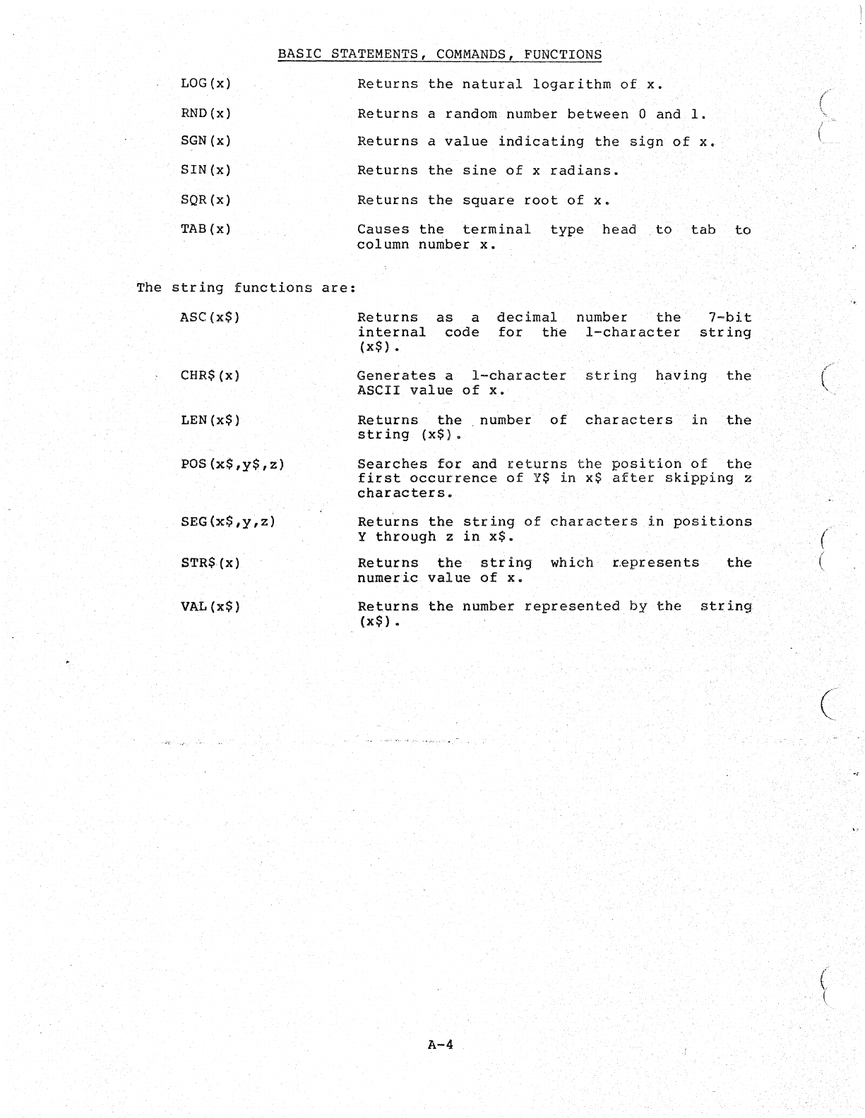
BASIC
STATEMENTS,
COMMANDS,
FUNCTIONS
LOG
(x)
RND(x)
SGN(x)
SIN
(x)
SQR{x)
TAB
(x)
The
string
functions
are:
ASC(x$)
CHR$(x)
LEN(x$)
POS(X$,y$,z)
SEG(X$,y,Z)
STR$(x)
VAL
(X$)
Returns
the
natural
logarithm
of
x.
Returns
a
random
number
between
0
and
1.
Returns
a
value
indicating
the
sign
of
X.
Returns
the
sine
of
x
radians.
Returns
the
square
root
of
x.
Causes
the
terminal
type
head
..
to
tab
to
column
number
x.
Returns
as
a
decimal
number
the
internal
code
for
the
I-character
(x$)
•
7-bit
string
Generates
a
I-character
string
having
the
ASCII
value
of
x.
Returns
the.
number
of
characters
in
the
string
(x$).
Searches
for
and
teturns
the
position
of
the
first
occurrence
of
Y$
in
x$
after
skipping
z
characters.
Retu'rns
the
string
of
characters
in
positions
y
through
z
in
x$.
Returns
the
str
ing
which
r:epresents
the
numeric
value
of
x.
Returns
the
number
represented
by
the
string
(x$)
•
A-4
c_
(
(
(
(.
{
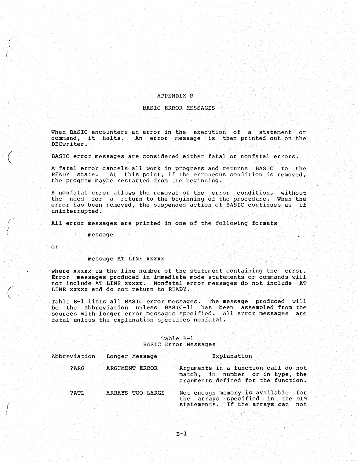
(
"
(
('
(
(
(
I
\.
APPENDIX
B
BASIC
ERROR
MESSAGES
When
BASIC
encounters
an
error
in
the
execution
of
a,
statement
or
command,
it
halts.
An
error
message
is
then
printed
out
on
the
DECwriter.
BASIC
error
messag~s
are
considered,
either
fatal
or
nonfatal
errors.
A
fatal
erro~
cancel~
all
work
in
progress
and
returns
BASIC
to
the
READY
state.
At
thj.-s
point,
if
the
erroneous
condition
is
removed,
the
program
maybe
restarted
from
the
beginning.
A
nonfatal
error
allows
the
removal
of
the
error
condition,
without
the
need
for
a'
return
to
the
beginning
of
the
procedure.
When
the
error
has
been
removed,
the,
suspended
action
of
BASIC
continues
as
1f
uninterrupted.
All
error
messages
are
pr
in
ted
in
one
of
the
following
formats
messag,e
or
tftessage
AT,
LINE
xxxxx
where
xxxxxis
the
line'number
of
the
statement
containing
the
error.
Error
messages
'produced
in
immediate
mode
statements
or
commands'
will
not
include
AT
LINE
xxxxx.
Nonfatal
error
messages
do
not
include
AT
LINE
xxxxx
and
do
not
return
to
READY.,
Table
a-I,lists
all
BASIC
error
messages.'
The
message
produced
will
be
the
abbreviation
unless
'SASIC-ll
has
been
assembled
from
the
sources
with
longer'error
messages
specified.
All
error
messages
are
fatal
unless
the
explanation
specifies
nonfatal~
Table
B-1
BASIC
Error
Messages
Abbreviation
Longer
Message
?ARGARGUMENT
ERROR
?ATL
ARRA
YS
TOO
LARGE
Explanation
Ar'guments
in
a
function
call
do
not
match,
in
number
or
in
type,
the
arguments
defined
for
the
function.
Not
enough
memory
is
available
for
the
arrays
specified
in
the
DIM
statements.
If
the
arrays
can
not
B-1
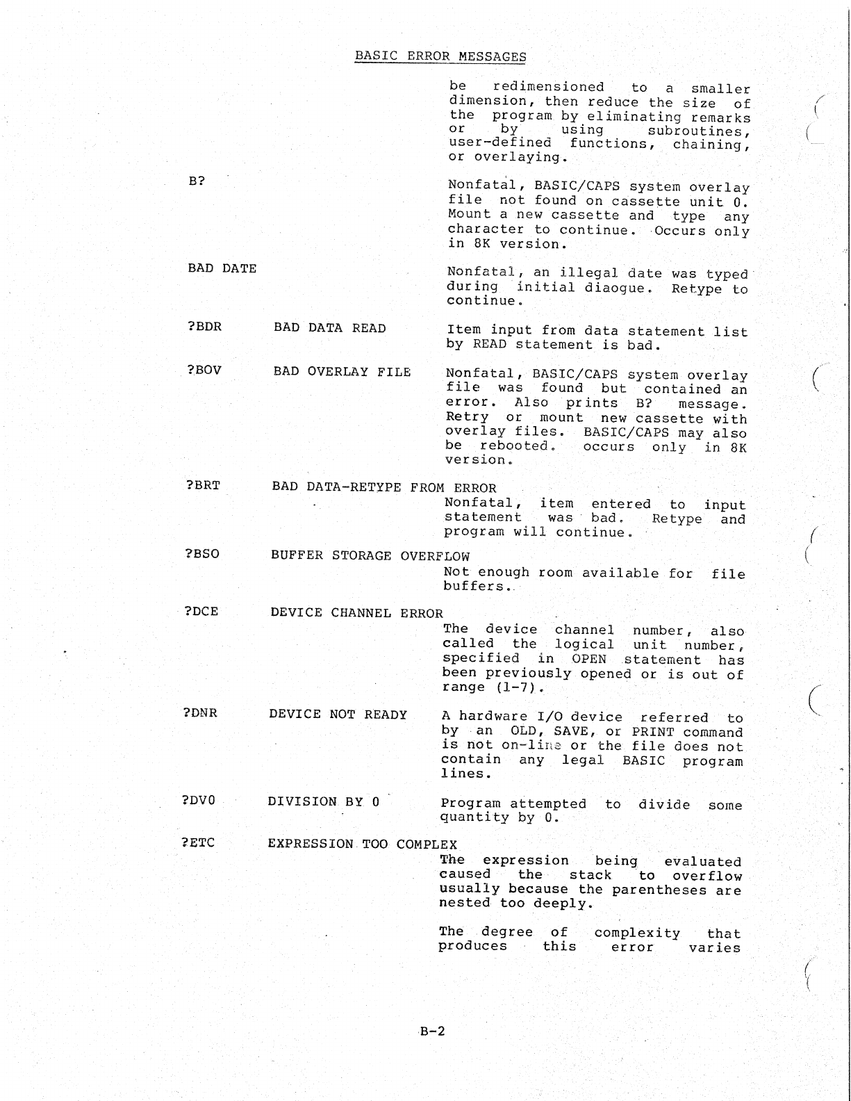
B?
BAD
DATE
?BDR
?BOV
?BRT
18S0
?DCE
?DNR
?DVO
?ETC
BASIC
ERROR
MESSAGES
BAD
DATA
READ
BAD
OVERLAY
FILE
be
redimensioned
to
a
smaller
dimension,
then
reduce
the
size
of
the
program
by
eliminating
remarks
or
by
using
subroutines,
user-defined
functions,
chaining,
or
overlaying.
Nonfatal,
BASIC/CAPS
system
overlay
file
not
found
on
cassette
unit
O.
Mount
anew
cassette
and
type
any
character
to
continue.
Occurs
only
in
8K
version.
Nonfatal,
an
illegal
date
was
typed·
during
initial
diaogue.
Retype
to
continue.
Item
input
frbm
data
statement
list
by
READ
statement
is
bad.
Nonfatal,
BASIC/CAPS
system
overlay
file
was
found
but
contained
an
error.
Also
prints
B?
message.
Retry
or
mount
new
cassette
with
overlay
files.
BASIC/CAPS may
also
be
rebooted.
occurs
only
inSK
version.
BAD
DATA-RETYPE
FROM
ERROR
Nonfatal,
item
entered
to
input
statement
was
bad.
Retype
and
program
will
continue
•.
BUFFER
STORAGE
OVERFLOW
Not
enough
room
available
for
buffers
•.
file
DEVICE
CHANNEL
ERROR
DEVICE
NOT
READY
D:(VISION
BY
0
The
device
channel
number,
also
called
the
logical
unit
number,
specified
in
OPEN
statement
has
been
previously
opened
or
is
out
of
range
(1-7).
A
hardware
I/O
device
referred
to
by
·an
OLD, SAVE,
or
PRINT command
is
nbt
on-line
or
the
file
does
not
contain
.
any
legal
BASIC
program
lines.
Program
attempted
to
divide
some
quan
tHy
by
O.
EXPRESSION
TOO
COMPLEX
The
expression
bein~l
evaluated
caused
.the·
stack
to
overflow
usually
because
the
parentheses
are
nested
too
deeply.
The
.degree
of
produces
this
complexity
that
error
varies
B-2
(
(
(
(
(
/
'(
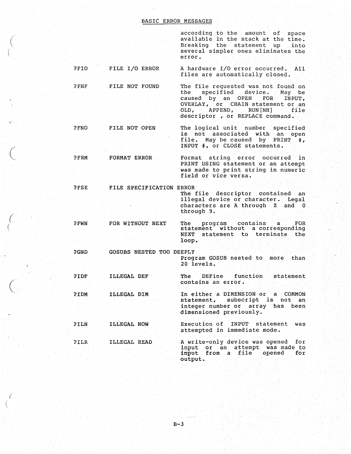
(
,"
(
(
(
(
f
(
?FIO
?FNF
?FNO
?FRM
?FSE
?FWN
?GND
?IDF
?IDM
?ILN
?ILR
BASIC
ERROR
MESSAGES
FILE
I/O
ERROR
FILE
NOT
FOUND
according
to
the
amount
of
space
available
in
the
stack
at
the
time.
Breaking
the
statement
up
into
several
simpler
ones
eliminates
the
error.
A
hardware
I/O
error
occurred.
All
files
are
automatically
closed.
The
file
requested
was
not
found
on
the
specified
device.
May
be
caused
by
an
OPEN
FOR
INPUT,
OVERLAY,
or
CHAIN
statement
or
an
OLD, APPEND,
RUN
[NH]
file
descriptor,
or
REPLACE
command.
FILE
NOT
OPEN
The
logical
unit
number
specified
is
not
associated
with
an
open
file.
May
be
caused
by
PRINT
#,
INPUT
#,
or
CLOSE
statements.
FORMAT
ERROR
Format
string
error
occurred
in
PRINT USING
statement
or
an
attempt
was
made
to
print
string
in
numeric
field
or
vice
versa.
FILE
SPECIFICATION
ERROR
The
file
descriptor
contained
an
illegal
device
or
character.
Legal
characters
are
A
through
Z
and
0
through
9.
FOR
WITHOUT
NEXT
The
program
contains
a
FOR
statement
without
a
corresponding
NEXT
statement
to
terminate
the
loop.
GOSUBS
NESTED
TOO
DEEPLY
ILLEGAL
DEF
ILLEGAL
DIM
ILLEGAL
NOW
ILLEGAL
READ
program
GOSUB
nested
to
more
than
20
levels.
The
DEFine
function
contains
an
error.
statement
In
either
a DIMENSION
or
a
COMMON
statement,
subscript
is
hot
an
integer
number
or
array
has
been
dimensioned
previously.
Execution
of
INPUT
statement
was
attempted
in
immediate
mode.
A
write-only
device
was
opened
for
input
or
an
attempt
was
made
to
input
from
a
file
opened
for
outpu.t.
B-3
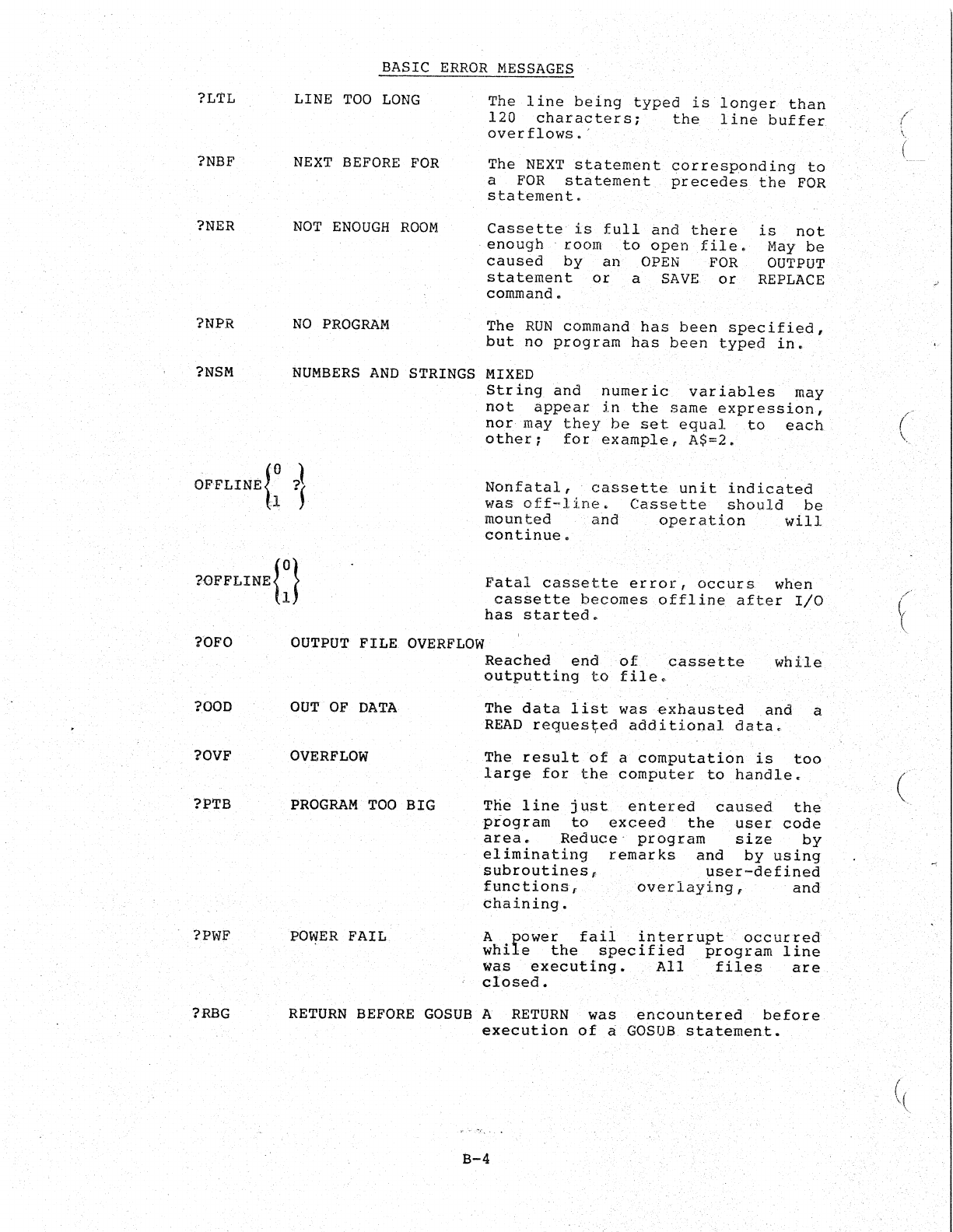
?LTL
?NBF
?NER
?NPR
?NSM
?OFO
?OOD
?OVF
?l>TB
?PWF
?RBG
BASIC
ERROR
MESSAGES
LINE
TOO
LONG
The
line
being
typed
is
longer
than
120
characters;
the
line
buffer
over
flows.
'
NEXT
BEFORE
FOR
The
NEXT
statement
corresponding
to
a
FOR
statement
precedes
the
FOR
statement.
NOT
ENOUGH
ROOM
Cassette
is
full
and
there
is
not
.
enough
.
room
to
open
.
file
•
May
be
caused
by
an
OPEN
FOR
OUTPUT
statement
or
a
SAVE
or
REPLACE
command.
NO
PROGRAM
The
RUN
command
has
been
specified,
but
no
program
has
been
typed
in.
NUMBERS
AND
STRINGS
MIXED
String
and
numeric
variables
may
not
appear
in
the
same
expression
T
nor
may
they
be
set
equal
to
each
other;
for
example,
A$=2.
Nonfatal,
cassette
unit
indicated
was
off~line.
Cassette
should
be
mounted
and
operation
will
continue.
Fatal
cassette
error,
occurs
wheri
cassette
becomes
offline
after
I/O
has
started.
OUTPUT
FILE
OVERFLOW
OUT
OF
DATA
OVERFLOW
PROGRAM
TOO
BIG
POWER
FAIL
Reached
end
of
cassette
outputting
to
file.
while
The
data
list
was
exhausted
and
a
READ
requestredadditional
data~
The
result
of
a
computation
is
too
large
for
the
computer
to
handle.
Ttie
line
just
entered
caused
the
program
to
exceed
the
user
code
area.
Reduce'
program
size
by
eliminating
remarks
and
by
using
subroutines,
user-defined
functions,
overlaying,
and
chaining.
A
power
fail
interrupt
occurred
while
the
specified
program
line
was
executing.
All
files
are
closed.
RETURN
BEFORE
GOSUB
A
RETURN
was
encountered
before
execution
of
a
GOSUB
statemen.t.
,.'-
......
,.
B-4
I
~
\
(
.;;
(
\
((
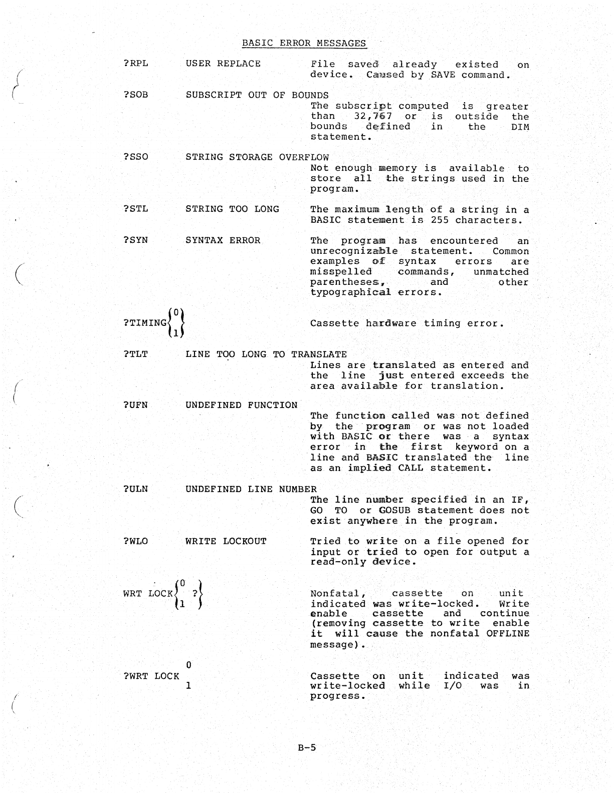
/
"
(
(
(
f
(
?RPL
?SOB
?SSO
?STL
?SYN
BASIC
ERROR
l-lESSAGES
USER
REPLACE
SUBSCRIPT
OUT
OF
File
sa~ed
~lready
existed
on
device.
Caused
by
SAVE
command.
BOUNDS
The
subscript
computed
than
32,167
oi'
is
bounds
d~fined
in
statement.
'is
greater
outside
the
the
DIM
STRING
STORAGE
OVERFLOW
STRING
TOO
LONG
SYNTAX
ERROR
Not
enough
store
all
,
program.
Demory
is
availaple'
to
th~
strings
used
in
the
The
maximum
length
of
a
string
in
a
BASIC
statemaentis
255
characters.
The
prog.raa
has
encountered
an
unrecognizable
statement.
Common
examples
of
syntax
errors
are
misspelled
commands
I
unmatched
parentheses"
and
other
typographical
errors.
,?TIMING{:t
Cassette
hardware
timing
error.
?TLT LINE
TOO
LONG
TO
TRANSLATE
?UFN
UNDEFINED
FUNCTION,
Lines
are,i:ranslatedasentered
and
the
line
just
entered
exceeds
the
area
available
for
translation.
The
function
called
was
not
defined
py
the
'program
or
was
not
loaded
wi
th
BASIC
Qr
th,ere
was,
a
syntax
error
in
the
first
keyword
on
a
'line
and
BASIC
translated
the
line
,
as
an,
impl.ied
CALL
s
ta
temen
t.
?ULN
UNDEFINED
LINE
NUMBER
?WLO
WRITE
LOCKOUT
WRT
L~CK}O
?l
"
'h
J
?WRT
LOCK
o
I
The
line
number
specified
in
an
IF,
GO
TO
or
GOSUB
statement
does
not
exist
anywhere
in
the
program.
Tried
to
write
on
a
file
opened
for
input
or
tried
to
open
for
output
a
read~only
device.
Nonfatal,
,
cassette
on
unit
indicated
was
write-locked.
Write
enable
cassette
and
continue
(removing
ca,ssetteto
write
enable
it
will
cause
the
nonfatal
OFFLINE
message)
•
Cassette
on
unit
indicated
was
write-locked
while
I/O
was
in
progress.
B-5
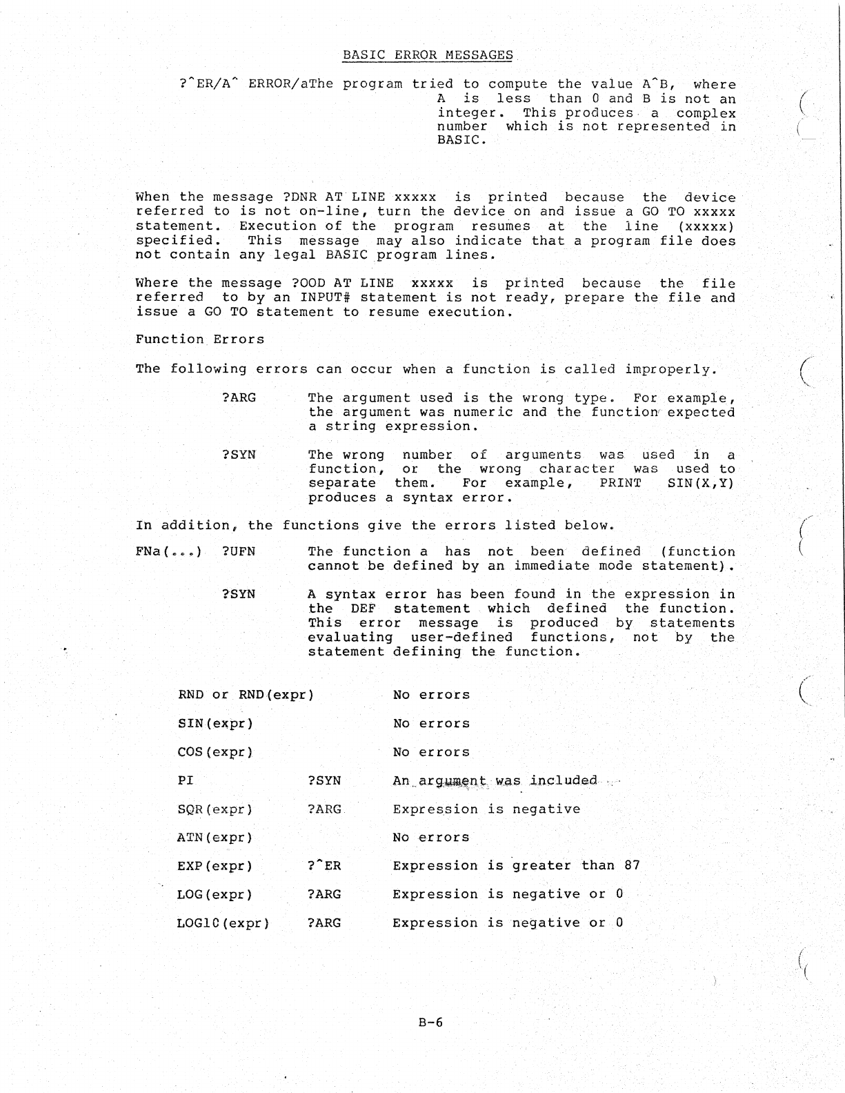
BASIC
ERROR
NESSAGES
?~ER/A~
ERROR/aThe
program
tried
to
compute
the
value
A~B,
where
A
is
less
than
0
and
B
is
not
an
integer.
This
produces
a
complex
number
which
is
not
represented
in
BASIC.
When
the
message
?DNR
ATLINExxxxx
is
printed
because
the
device
referred
to
is
not
on-line,
turn
the
device
on
and
issue
a
GO
TO
XXXXX
statement.
Execution
of
the
program
resumes
at
the
11ne
(xxxxx)
specified.
This
message
may
also
indicate
that
a
program
file
does
not
contain
any
legal
BASIC
program
lines.
Where
the
message
?OOD
AT
LINE
xxxxx
is
printed
because
the
file
referred
to
by
an
INPUT'
statement
is
not
ready,
prepare
the
file
and
issue
a
GO
TO
statement
to
resume
execution.
Function
Errors
The
following
errors
can
occur
when a
function
is
called
improperly.
?ARG
?SYN
The
argument
used
is
the
wrong
type.
For
example,
the
argument
was
numeric
and
the
functiow
expected
a
string
expression.
The
wrong
number
of
arguments
was
used
in
a
function.,
or
the
wrong
character
was
used
to
separate
them.
For
example,
PRINT
SIN(X,Y)
produces
a
syntax
error.
In
addition,
the
functions
give
the
errors
listed
below.
FNa
(
•••
)
?UFN
?SYN
The
function
a
has
not
been
defined
(function
cannot
be
defined
by
an
immediate
mode
statement).
A
syntax
error
has
been
found
in
the
expression
in
the
DEF
statement
which
defined
the
function.
This
error
message
is
produced
by
statements
evaluating
user-defined
functions,
not
by
the
statement
defining
the
function.
RND
or
RND(expr)
No
errors
SIN (e.l!;pr)
COS
(expr)
PI
SQR(expr)
ATN(expr)
EXP
(expr)
LOG{expr)
LOGIC
(expr)
?SYN
?ARG
?ARG
?ARG
No
errors
No
errors
An
.
arg,1J4i!'~n.t
was
lncI
uded
Expression
is
negative
No
errors
Expression
is
greater
than
87
Expression
is
negative
or
0
Expression
is
negative
or
0
B-6
(
'~
(
(
(
(
\
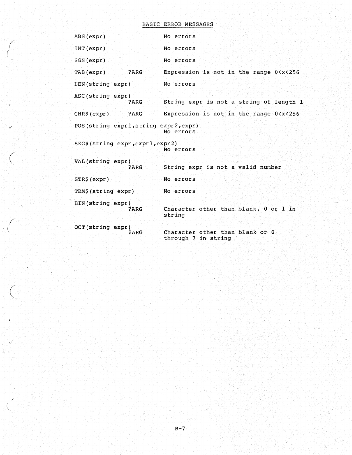
B-7

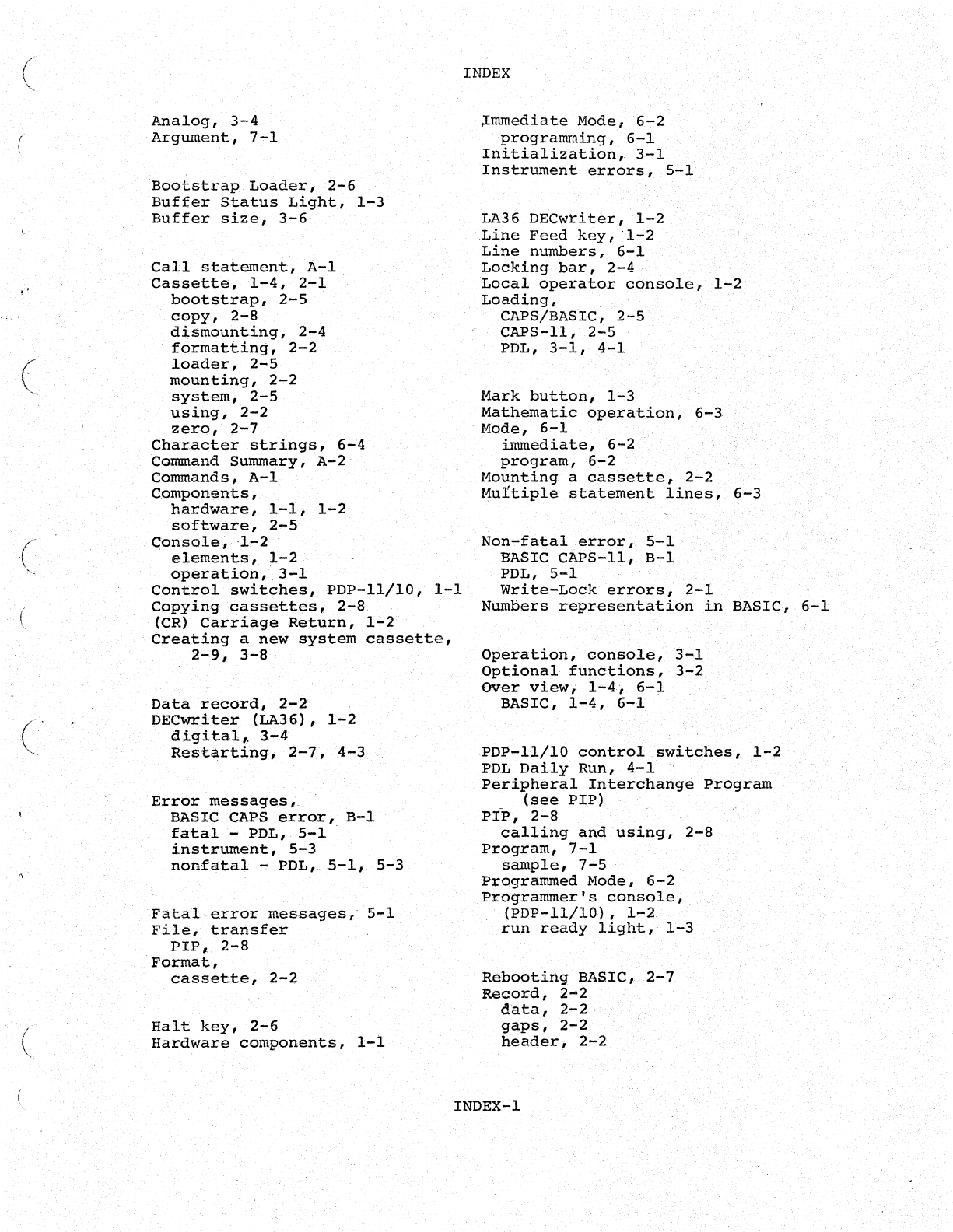
"
(
C'
(
Analog,
3-4
Argument,
7-1
Bootstrap
Loader,
2-6
Buffer
Status
Light,
1-3
Buffer
size,
3-6
Call
statement,
A-I
Cassette,
1-4,
2-1
bootstrap,
2-5
copy,
2-8
dismounting,
2-4
formatting,
2-2
loader,
2-5
mounting,
2-2
system,
2-5
using,
2-2
zero,
2-7
Character
strings,
6-4
Command
Summary,
A-2
Commands,
A-l
Components,
hardware,
1-1,
1-2
software,
2-5
Console,
1-2
elements,
1-2
operation,
.
3-1
Control
switches,
PDP-ll/IO,
1-1
Copying
cassettes,
2-8
(CR)
Carriage
Return,
1-2
Creating
a
new
system
cassette,
2-9,
3-8
Data
record,
2-2-
DECwriter
(LA36),
1-2
digital"
3-4
Restarting,
2-7,
4-3
Error
messages,
BASIC. CAPS
error,
B-1
fatal
-
PDL,
5-1
.
instrument,
5-3
nonfatal
.~
PDL,
5-1,
5-3
F a
tal
error
messages
I·
5-1
File,
transfer
PIP,
2-B
Format,
cassette,
2-2
Halt
key,
2-6
Hardware
components,
1-1
INDEX
~mmediate
Mode,
6-2
programming,
6-1
Initialization,
3-1
Instrument
errors,
5-1
LA36
DECwriter,
1-2
Line
Feed
key,
·1-2
Line
numbers,
6-1
Locking
bar,
2-4
Local
operator
console,
1-2
Loading,
CAPS/BASIC,
2-5
CAPS-ll,
2-5
PDL,
3-1,
4-1
Mark
button,
1-3
Mathematic
operation,
6-3
Mode,
6-1
immediate,
6-2
program,
6-2
Mounting
a
cassette,
2-2
Hultiple
statement
lines,
6-3
Non-fatal
error,
5-1
BASIC
CAPS-II,
B-1
PDL,
5-1
Write-Lock
errors,
2-1
Numbers
representation
in
BASIC,
6-1
Operation,
console,
3-1
Optional
functions,
3-2
OVer
view,
1-4,
6-1
BASIC,
1-4,
6-1
PDP-ll/IO
control
switches,
1-2
PDL
Daily
Run,
4-1
Peripheral
Interchange
Program
(see
PIP)
ptp,
2-B
calling
and
using,
2-B
Program,
7-1
sample,
7-5
Programmed
Hode,
6-2
Programmerts
console,
(PDP-ll/IO),
1-2
run
ready
light,
1-3
Rebooting
BASIC,
2-7
Record,
2
....
2
data,
2-2
gaps,
2-2
header,
2-2
INDEX-I
Record
(cant.),
length,
2-2
Relational
operation,
6-3
Removing
a
cassette,
2~4
Report
Generator,
7-1
AA;
7-7
Coulter,
7-7
SMA,
7-5
Rewind
button,
2-4
Transferring
files,
PIP,
2-8
Variables,
6-4
subscripted,
6-.5
Write-Lock,
2-1
Write..,.Protect
tabs,
2-1
Sample
program,
7-5
Zeroing
a
cassette,
2-7
Set
up,
3-4
Special
characters
and
commands,
1-2,
A-I
CTRL!U, .
A-3
rubout,
1-2,
A-3
Start
button,
1-3
Starting
a
program,
4-1
STAT r
7-5
Statements,
BASIC,
6-3
Strings
in
BASIC,
6-1
Subroutines,
7-1
general
interface,
7-2
Subscripted,
6-1
System
cassette,
2-5
INDEX-2
(
(
\,
(
J
c....:.
.
.
-,
I'
(
,/
(
(.
"
(
HOW
TO
OBTAIN
SOFTWARE
INFORMATION
SOFTWARE
NEWSLETTERS,
MAILING
LIST
The
Software
Communications
Group,
located
at
corporate
headquarters
in
Maynard,
publishes
software
newsletters
for
the
various
DIGITAL
products.
Newsletters
are
published
monthly,
and
keep
the
user
informed
about
cus-
tomer
software
problems
and
solutions,
new
software
products,documenta-
tion
corrections,
as
well
as
programming
notes
and
techniques.
.
There
are
two
similar
levels
of
service:
The
Software
Dispatch
The
Digital
Software
News
The
Software.
Dispatch
is
part
of
the
Software
Maintenance
Service.
This
service
applies
to
the
following
software
products:
PDP-9/15
RSX-IID
DOS/BATCH
RSTS-E
DECsystem-lO
A
Digital
Software
News
for
the
PDP-II
and
a
Digital
Software
News
far
the
PDP.,..8/12
are
available
to
any
customer
who
has.
purchased
PDP-II
or
PDP-8/12
software.
A
collection
of
existing
problems
and
solutions
for
a
given
software
system
is
published
periodically.
A
customer
receives
this
publication
with
his
initial
software
kit
with
the
delivery
of
his
system.
This·
collection
would
be
either
a
Software
Dispatch
Review
or
Software
Per-
formance
Summary
depending
on
the
system
ordered.
A
mailing
list
of
users
who
receive
software
newsletters
is
also
main-
tained
by
Software
Communications.
Users
must
sign-up
for
the
news~
l.etter
they
desire.
This
can
be
done
by
either
completing
the
form
sup-
plied
with
the
Revi~w
or
Summ~y
or
by
writing
to:
SOFTWARE
PROBLEMS
Software
Communications
P.O.
Box F
Maynard,
Massachusetts
01754·
Questions
or
problems
relating
to
DIGITAL's
software
should
be
reported
as
follOWS:
North
and
South
American
Submitters:
Upon
completion
of
Software
Performance
Report
(SPR)
form
remove
last
copy
and
send
remainder
to:
Software
communications
P.O.
Box F
Maynard,
Massachusetts
01754
The
acknowled~ent
copy
will
be
returned
along
with
a
blank
SPR"form
upon
receipt.
The
acknowledgement
will
contain
a DIGITAL
assigned
SPR
number.
The
SPR nUmber
or
the
preprinted
number
should
be
referenced
in
any
future
correspondence.
Additional
SPR
forms
may
be
obtained
from
the
above
address;.
All
International
Submitters:
Upon
completion
of·theSPR
form,
reserve
the
last
copy
and
send
the
re-
mainder
to
the
SPR
Center
in
the
nearest
DIGITAL
office.
SPR
forms
are
.also
available
from
our
SPR
Centers.
PROGRAMS
AND
MANUALS
Software
and
manuals
should
be
ordered
by
title
and
order
number.
In
the
United
States,
send
orders
to
the
nearest
distribution
center.
Digital
Equipment
Corporation
Software
Distribution
Center
146
Main
Street
Digital
Equipment
Corporation
Software
Distribution
Center
1400
Terra
Bella
Maynard,
Massachusetts
01754
Mountain
View,
California
94043
Outside
of
the
united
States,
Digital
Field
Sales
Office
or
orders
should
be
directed
to
the
nearest
representative.
USERS
SOCIETY
DECUS,
Digital
Equipment
Computers
Users
Society,
maintains
a
user
ex-
change
center
for
user~written
programs
and
technical
application
infor-
mation.
The
Library
contains
approximately
1,900
programs
for
all
DIGITAL
computer
lines.
Executive
routines,
editors,
debuggers,
special
functions,game.s,
maintenance
and
various
other
classes
of
programs
are
available.
DECUS.
Prog.ram
Library
Catalogs.
are
routinely
updated
and
contain
lists.
and
abstracts
of
all
programs
according
to
computer
line:
PDP-8,
FOCAL-8, .BASIC-8, PDP-12
PDP-7/9,
9,
15
PDP-II,
RSTS-II
PDP-6/10,
10
Forms
and
information
on
acquiring
and
submitting
programs
to
the.
DEeUS
Library
may
be
obtained
from
the
DECUS
office.
In
addition
to
the
catalogs,
DECUSalso
publishes
the
following:
DECUSCOPE
PROCEEDINGS
OF
TaE DIGITAh.
EQUIPMENT.
USERS
SOCIETY
MINUTES
OF
THE
DECsystem-lO
SESSIONS
COPY-N-Mail
LUG/SIG
-The
Society's
technical
newsletter,
published
bi-monthly,
aimed
at
facilitating
the
interchange
of
technical
in-
formation
among
users
of
DIGITAL.
computers
and
at
dis-
seminating
news
items
concerning
the
Society.
Circula-
tion
reached
19,000
in
May,
1974.
~Contains
technical
papers
presented
at
DECUS
Symposia
held
twice
a
year
in
the
United
States,
once
a
year
in
Europe,
Australia,
and
Canada.
-l\.
report
of
the
DECsystem-lO
sessions
held
at
the
two
United
States
DECUS
Symposia.
-A
monthly
mailed
communique among
DECsystem-IO
users.
-Mailingo·f
Local
User
Group
(LUG)
and
SpeciaL
Interest
Group
(SIG)
communique,
aimed
at
providing
closer
communication
among
users
of
a
specific
product
or
application.
Further
information
on
the'DECUS
Library,
publications,
and
other
DECUS
activities
is
available
from
the
DECUS
offices
listed
below:
DECUS-
Digital
Equipment
Corporation
146
Main
Street
Maynard,
Massachusetts
01754
DECUS
EUROPE
Digital
Equipment
Corp.
International
(Europe)
P.O.
Box
340
121lGeneva
26
switzerland
(
\ (
(
l
~
..
(
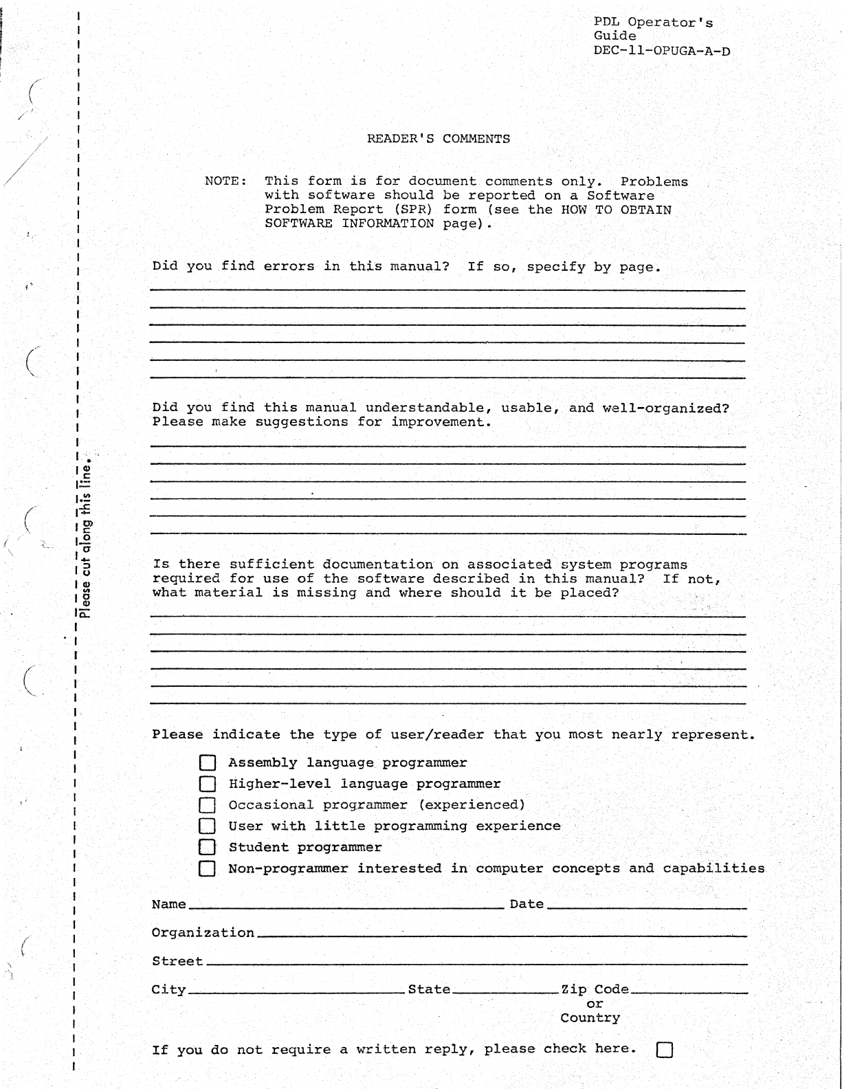
(
/
./
,/
f \
t".
.i'l
c
(
c .
,;
/
\
I
I
I
I
I
I
I
I
f
,
,
I
,
1
,
I
I
I
,
,
I
f
I
.•
l~
1=
t.!'!
,-£
Ig>
l~
J~
16
I
~
I g
10::
,
I
I
I
. 1
I
I,
I
I
I
J
,
,
I
I
,
I
,
,
f
I
I
I
I
I
I
I
I
I
I'
I
1
READER'S
COMMENTS
PDL
Operator's
Guide
DEC-ll....;OPUGA-A~D
NOTE:
This
form
is
for
document
comments
only.
Problems
with
software
should
be
reported
on
a
Software
Problem
Report
(SPR)
form
(see
the
HOW
TO
OBTAIN
SOFTWARE
INFORMATION
page).
Did
you·
find
errors
in
.this
manual?
If
so,
specify
by
page.
,
.'
Did
you
find
this
manual
understandable,
usable,
.and
well~organized?
Please
niake
suggestions
for
improvement.
Is
there
sufficient
documentation
on
associated
~ystemprograms
required
for
use
of
the.
software
described
in
t:his
manual?'
If
not,
what
material
is
missing
and
where
shoul.d
it
be
pl.aced?
.
Please
indicate
the
type
of
user/reader
that
YOll
most
nearly'
represent.
o
Assembly
language
programmer
[J
Higher-level
language
programmer
o
Occasional
prog..rammer(experienced)
o
User
with
little
programming
experience
o
Student
pro-grammer
o Non-proCi1rammer
interested
in
computer
concepts
and
capabilities
Name
Date
_______________________ _
Organi2ation
____
~
________________________
--------
__
------------~
__
~--~
Street
__________
------
__
----------~----------
______
--
__
-------------------
City....,...-
____
----------
State
________
Zip
Code
______
_
or
Country
If
you
do
not
require
a
written
reply,
please
check
here.
[]

