R51(DLN) DLN
User Manual: DLN
Open the PDF directly: View PDF ![]() .
.
Page Count: 468 [warning: Documents this large are best viewed by clicking the View PDF Link!]
- QUICK REFERENCE INDEX
- Table of Contents
- TRANSFER: ATX14B
- BASIC INSPECTION
- FUNCTION DIAGNOSIS
- 4WD SYSTEM
- System Diagram
- System Description
- CONTROL SYSTEM
- TRANSFER CONTROL UNIT
- TRANSFER SHIFT HIGH AND LOW RELAYS
- TRANSFER SHUT OFF RELAY
- 4WD SHIFT SWITCH AND INDICATOR LAMPS
- 4WD WARNING LAMP
- ATP WARNING LAMP
- LINE PRESSURE SWITCH
- CLUTCH PRESSURE SWITCH
- WAIT DETECTION SWITCH
- ATP SWITCH
- NEUTRAL-4LO SWITCH
- TRANSFER FLUID TEMPERATURE SENSOR
- TRANSFER MOTOR
- CLUTCH PRESSURE SOLENOID VALVE
- 2-4WD SHIFT SOLENOID VALVE
- TRANSFER CONTROL DEVICE
- Component Parts Location
- CAN Communication
- Cross-Sectional View
- Power Transfer
- DIAGNOSIS SYSTEM (TRANSFER CONTROL UNIT)
- NOISE, VIBRATION AND HARSHNESS (NVH) TROUBLESHOOTING
- 4WD SYSTEM
- COMPONENT DIAGNOSIS
- P1811 POWER SUPPLY CIRCUIT FOR TRANSFER CONTROL UNIT
- P1802 - P1804, P1809 TRANSFER CONTROL UNIT
- P1807 VEHICLE SPEED SENSOR (A/T)
- P1808 VEHICLE SPEED SENSOR (ABS)
- P1810 NEUTRAL-4LO SWITCH
- P1813 4WD SHIFT SWITCH
- P1814 WAIT DETECTION SWITCH
- P1816 PNP SWITCH
- P1817 ACTUATOR MOTOR
- P1818 ACTUATOR POSITION SWITCH
- P1819 TRANSFER CONTROL DEVICE
- P1820 ENGINE SPEED SIGNAL
- P1822 CLUTCH PRESSURE SOLENOID
- P1823 2-4 SOLENOID
- P1824 TRANSFER MOTOR
- P1826 TRANSFER FLUID TEMPERATURE
- P1827 CLUTCH PRESSURE SWITCH
- P1828 LINE PRESSURE SWITCH
- P1829 THROTTLE POSITION SIGNAL (ECM)
- P1830 ABS OPERATION SIGNAL (ABS)
- P1831 VDC OPERATION SIGNAL (ABS)
- P1832 TCS OPERATION SIGNAL (ABS)
- ECU DIAGNOSIS
- SYMPTOM DIAGNOSIS
- 4WD SYSTEM SYMPTOMS
- 4WD SHIFT INDICATOR LAMP AND 4LO INDICATOR LAMP DO NOT TURN ON
- 4WD WARNING LAMP DOES NOT TURN ON
- 4WD SHIFT INDICATOR LAMP OR 4LO INDICATOR LAMP DO NOT CHANGE
- ATP WARNING LAMP DOES NOT TURN ON
- 4WD SHIFT INDICATOR LAMP KEEPS FLASHING
- 4WD WARNING LAMP FLASHES RAPIDLY
- 4WD WARNING LAMP FLASHES SLOWLY
- HEAVY TIGHT-CORNER BRAKING SYMPTOM OCCURS
- ATP SWITCH
- 4WD SYSTEM DOES NOT OPERATE
- PRECAUTION
- PREPARATION
- ON-VEHICLE MAINTENANCE
- ON-VEHICLE REPAIR
- REMOVAL AND INSTALLATION
- DISASSEMBLY AND ASSEMBLY
- SERVICE DATA AND SPECIFICATIONS (SDS)
- TRANSFER: TX15B
- BASIC INSPECTION
- FUNCTION DIAGNOSIS
- 4WD SYSTEM
- System Diagram
- System Description
- Component Parts Location
- CAN Communication
- Cross-Sectional View
- Power Transfer
- DIAGNOSIS SYSTEM (TRANSFER CONTROL UNIT)
- NOISE, VIBRATION AND HARSHNESS (NVH) TROUBLESHOOTING
- 4WD SYSTEM
- COMPONENT DIAGNOSIS
- P1801, P1811 POWER SUPPLY CIRCUIT FOR TRANSFER CONTROL UNIT
- P1802 - P1804, P1809 TRANSFER CONTROL UNIT
- P1807 VEHICLE SPEED SENSOR (A/T)
- P1808 VEHICLE SPEED SENSOR (ABS)
- P1810 4 LO SWITCH
- P1813 4WD SHIFT SWITCH
- P1814 WAIT DETECTION SWITCH
- P1816 PNP SWITCH
- P1817 ACTUATOR MOTOR
- P1818 ACTUATOR POSITION SWITCH
- P1819 TRANSFER CONTROL DEVICE
- P1820 ENGINE SPEED SIGNAL
- ECU DIAGNOSIS
- SYMPTOM DIAGNOSIS
- PRECAUTION
- PREPARATION
- ON-VEHICLE MAINTENANCE
- ON-VEHICLE REPAIR
- REMOVAL AND INSTALLATION
- DISASSEMBLY AND ASSEMBLY
- SERVICE DATA AND SPECIFICATIONS (SDS)
- PROPELLER SHAFT: 2F1310
- PROPELLER SHAFT: 2S1330
- PROPELLER SHAFT: 2S1350
- FRONT FINAL DRIVE: R180A
- PRECAUTION
- PREPARATION
- FUNCTION DIAGNOSIS
- ON-VEHICLE MAINTENANCE
- ON-VEHICLE REPAIR
- REMOVAL AND INSTALLATION
- DISASSEMBLY AND ASSEMBLY
- SERVICE DATA AND SPECIFICATIONS (SDS)
- FRONT FINAL DRIVE: M205
- PRECAUTION
- PREPARATION
- FUNCTION DIAGNOSIS
- ON-VEHICLE MAINTENANCE
- ON-VEHICLE REPAIR
- REMOVAL AND INSTALLATION
- DISASSEMBLY AND ASSEMBLY
- SERVICE DATA AND SPECIFICATIONS (SDS)
- REAR FINAL DRIVE: R200
- PRECAUTION
- PREPARATION
- FUNCTION DIAGNOSIS
- ON-VEHICLE MAINTENANCE
- ON-VEHICLE REPAIR
- REMOVAL AND INSTALLATION
- DISASSEMBLY AND ASSEMBLY
- SERVICE DATA AND SPECIFICATIONS (SDS)
- REAR FINAL DRIVE: R230 (4WD)
- PRECAUTION
- PREPARATION
- FUNCTION DIAGNOSIS
- ON-VEHICLE MAINTENANCE
- ON-VEHICLE REPAIR
- REMOVAL AND INSTALLATION
- DISASSEMBLY AND ASSEMBLY
- SERVICE DATA AND SPECIFICATIONS (SDS)
- TRANSFER: ATX14B
- POWER SUPPLY ROUTING CIRCUIT
- FUSE BLOCK JUNCTION BOX (J/B)
- FUSE AND FUSIBLE LINK BOX
- FUSE AND RELAY BOX

DLN-1
TRANSMISSION & DRIVELINE
C
E
F
G
H
I
J
K
L
M
SECTION DLN A
B
DLN
N
O
P
CONTENTS
DRIVELINE
TRANSFER: ATX14B
BASIC INSPECTION .................................... 8
DIAGNOSIS AND REPAIR WORKFLOW .......... 8
Work Flow .................................................................8
Preliminary Check .....................................................9
FUNCTION DIAGNOSIS ..............................12
4WD SYSTEM ....................................................12
System Diagram ......................................................12
System Description .................................................13
Component Parts Location ......................................18
CAN Communication ...............................................19
Cross-Sectional View ..............................................19
Power Transfer ........................................................19
DIAGNOSIS SYSTEM (TRANSFER CON-
TROL UNIT) ........................................................22
CONSULT-III Function (ALL MODE AWD/4WD) ....22
NOISE, VIBRATION AND HARSHNESS
(NVH) TROUBLESHOOTING ............................26
NVH Troubleshooting Chart ....................................26
COMPONENT DIAGNOSIS .........................27
P1811 POWER SUPPLY CIRCUIT FOR
TRANSFER CONTROL UNIT ............................27
Description ..............................................................27
DTC Logic ...............................................................27
Diagnosis Procedure ...............................................27
Component Inspection ............................................28
P1802 – P1804, P1809 TRANSFER CON-
TROL UNIT .........................................................29
Description ..............................................................29
DTC Logic ...............................................................29
Diagnosis Procedure ...............................................29
P1807 VEHICLE SPEED SENSOR (A/T) ..........31
Description ...............................................................31
DTC Logic ................................................................31
Diagnosis Procedure ...............................................31
P1808 VEHICLE SPEED SENSOR (ABS) .......32
Description ...............................................................32
DTC Logic ................................................................32
Diagnosis Procedure ...............................................32
P1810 NEUTRAL-4LO SWITCH .......................33
Description ...............................................................33
DTC Logic ................................................................33
Diagnosis Procedure ...............................................33
Component Inspection .............................................35
P1813 4WD SHIFT SWITCH .............................36
Description ...............................................................36
DTC Logic ................................................................36
Diagnosis Procedure ...............................................36
Component Inspection .............................................38
P1814 WAIT DETECTION SWITCH .................40
Description ...............................................................40
DTC Logic ................................................................40
Diagnosis Procedure ...............................................40
Component Inspection .............................................42
P1816 PNP SWITCH .........................................43
Description ...............................................................43
DTC Logic ................................................................43
Diagnosis Procedure ...............................................43
P1817 ACTUATOR MOTOR .............................44
Description ...............................................................44
DTC Logic ................................................................44
Diagnosis Procedure ...............................................44
Component Inspection .............................................48
P1818 ACTUATOR POSITION SWITCH ..........50
Description ...............................................................50
DTC Logic ............................................................
....50
Diagnosis Procedure ...............................................50
Revision: October 2008
2009 Pathfinder

DLN-2
Component Inspection ............................................ 52
P1819 TRANSFER CONTROL DEVICE ........... 53
Description .............................................................. 53
DTC Logic ............................................................... 53
Diagnosis Procedure .............................................. 53
P1820 ENGINE SPEED SIGNAL ...................... 57
Description .............................................................. 57
DTC Logic ............................................................... 57
Diagnosis Procedure .............................................. 57
P1822 CLUTCH PRESSURE SOLENOID ......... 58
Description .............................................................. 58
DTC Logic ............................................................... 58
Diagnosis Procedure .............................................. 58
Component Inspection ............................................ 60
P1823 2-4 SOLENOID ....................................... 62
Description .............................................................. 62
DTC Logic ............................................................... 62
Diagnosis Procedure .............................................. 62
Component Inspection ............................................ 65
P1824 TRANSFER MOTOR .............................. 66
Description .............................................................. 66
DTC Logic ............................................................... 66
Diagnosis Procedure .............................................. 66
Component Inspection ............................................ 70
P1826 TRANSFER FLUID TEMPERATURE .... 72
Description .............................................................. 72
DTC Logic ............................................................... 72
Diagnosis Procedure .............................................. 72
Component Inspection ............................................ 73
P1827 CLUTCH PRESSURE SWITCH ............. 75
Description .............................................................. 75
DTC Logic ............................................................... 75
Diagnosis Procedure .............................................. 75
Component Inspection ............................................ 76
P1828 LINE PRESSURE SWITCH .................... 78
Description .............................................................. 78
DTC Logic ............................................................... 78
Diagnosis Procedure .............................................. 78
Component Inspection ............................................ 80
P1829 THROTTLE POSITION SIGNAL (ECM)
... 81
Description .............................................................. 81
DTC Logic ............................................................... 81
Diagnosis Procedure .............................................. 81
P1830 ABS OPERATION SIGNAL (ABS) ........ 82
Description .............................................................. 82
DTC Logic ............................................................... 82
Diagnosis Procedure .............................................. 82
P1831 VDC OPERATION SIGNAL (ABS) ........ 83
Description .............................................................. 83
DTC Logic ............................................................... 83
Diagnosis Procedure ............................................... 83
P1832 TCS OPERATION SIGNAL (ABS) ......... 84
Description .............................................................. 84
DTC Logic ............................................................... 84
Diagnosis Procedure ............................................... 84
ECU DIAGNOSIS ....................................... 85
TRANSFER CONTROL UNIT ........................... 85
Reference Value ..................................................... 85
Wiring Diagram ....................................................... 93
DTC Index .............................................................102
SYMPTOM DIAGNOSIS ...........................107
4WD SYSTEM SYMPTOMS .............................107
Symptom Table .....................................................107
4WD SHIFT INDICATOR LAMP AND 4LO IN-
DICATOR LAMP DO NOT TURN ON ..............108
Description ............................................................108
Diagnosis Procedure .............................................108
4WD WARNING LAMP DOES NOT TURN ON ..111
Description ............................................................111
Diagnosis Procedure .............................................111
4WD SHIFT INDICATOR LAMP OR 4LO INDI-
CATOR LAMP DO NOT CHANGE ...................114
Description ............................................................114
Diagnosis Procedure .............................................114
ATP WARNING LAMP DOES NOT TURN ON ..116
Description ............................................................116
Diagnosis Procedure .............................................116
4WD SHIFT INDICATOR LAMP KEEPS
FLASHING ........................................................118
Description ............................................................118
Diagnosis Procedure .............................................118
4WD WARNING LAMP FLASHES RAPIDLY ..119
Description ............................................................119
Diagnosis Procedure .............................................119
4WD WARNING LAMP FLASHES SLOWLY ..120
Description ............................................................120
Diagnosis Procedure .............................................120
HEAVY TIGHT-CORNER BRAKING SYMP-
TOM OCCURS ..................................................121
Description ............................................................121
Diagnosis Procedure .............................................121
ATP SWITCH ....................................................123
Description ............................................................123
Diagnosis Procedure .............................................123
4WD SYSTEM DOES NOT OPERATE ............125
Description ............................................................125
Revision: October 2008
2009 Pathfinder

DLN-3
C
E
F
G
H
I
J
K
L
M
A
B
DLN
N
O
P
Diagnosis Procedure ............................................. 125
PRECAUTION ............................................126
PRECAUTIONS ................................................126
Precaution for Supplemental Restraint System
(SRS) "AIR BAG" and "SEAT BELT PRE-TEN-
SIONER" ............................................................... 126
Precaution for Transfer Assembly and Transfer
Control Unit Replacement ..................................... 126
Precaution Necessary for Steering Wheel Rota-
tion After Battery Disconnect ................................. 126
Precaution ............................................................. 127
Service Notice ....................................................... 127
PREPARATION .........................................129
PREPARATION ................................................129
Special Service Tool ............................................. 129
Commercial Service Tool ...................................... 132
ON-VEHICLE MAINTENANCE ..................133
TRANSFER FLUID ...........................................133
Replacement ......................................................... 133
Inspection .............................................................. 133
TRANSFER OIL FILTER ..................................134
Removal and Installation ....................................... 134
ON-VEHICLE REPAIR ............................... 136
TRANSFER CONTROL UNIT ..........................136
Removal and Installation ....................................... 136
FRONT OIL SEAL ............................................137
Removal and Installation ....................................... 137
REAR OIL SEAL ..............................................139
Removal and Installation ....................................... 139
SIDE OIL SEAL ................................................141
Removal and Installation ....................................... 141
TRANSFER CONTROL DEVICE .....................142
Removal and Installation ....................................... 142
AIR BREATHER HOSE ....................................143
Removal and Installation ....................................... 143
TRANSFER MOTOR ........................................148
Removal and Installation ....................................... 148
REMOVAL AND INSTALLATION .............149
TRANSFER ASSEMBLY .................................149
Removal and Installation ....................................... 149
DISASSEMBLY AND ASSEMBLY ............150
TRANSFER ASSEMBLY .................................150
Disassembly and Assembly .................................. 150
SERVICE DATA AND SPECIFICATIONS
(SDS) ..........................................................187
SERVICE DATA AND SPECIFICATIONS
(SDS) ............................................................... 187
General Specification ............................................187
Inspection and Adjustment ....................................187
TRANSFER: TX15B
BASIC INSPECTION .................................189
DIAGNOSIS AND REPAIR WORKFLOW ...... 189
Work Flow ..............................................................189
FUNCTION DIAGNOSIS ............................191
4WD SYSTEM ................................................. 191
System Diagram ....................................................191
System Description ................................................192
Component Parts Location ....................................194
CAN Communication .............................................195
Cross-Sectional View ............................................195
Power Transfer ......................................................196
DIAGNOSIS SYSTEM (TRANSFER CON-
TROL UNIT) ....................................................198
CONSULT-III Function (ALL MODE AWD/4WD) ..198
NOISE, VIBRATION AND HARSHNESS
(NVH) TROUBLESHOOTING ......................... 201
NVH Troubleshooting Chart ..................................201
COMPONENT DIAGNOSIS .......................202
P1801, P1811 POWER SUPPLY CIRCUIT
FOR TRANSFER CONTROL UNIT ................ 202
Description .............................................................202
DTC Logic ..............................................................202
Diagnosis Procedure .............................................202
Component Inspection ...........................................204
P1802 – P1804, P1809 TRANSFER CON-
TROL UNIT ...................................................... 205
Description .............................................................205
DTC Logic ..............................................................205
Diagnosis Procedure .............................................205
P1807 VEHICLE SPEED SENSOR (A/T) ....... 207
Description .............................................................207
DTC Logic ..............................................................207
Diagnosis Procedure .............................................207
P1808 VEHICLE SPEED SENSOR (ABS) ..... 208
Description .............................................................208
DTC Logic ..............................................................208
Diagnosis Procedure .............................................208
P1810 4 LO SWITCH ......................................209
Description .............................................................209
DTC Logic ..............................................................209
Diagnosis Procedure .............................................209
Revision: October 2008
2009 Pathfinder

DLN-4
Component Inspection ...........................................211
P1813 4WD SHIFT SWITCH ...........................212
Description .............................................................212
DTC Logic ..............................................................212
Diagnosis Procedure .............................................212
Component Inspection ...........................................214
P1814 WAIT DETECTION SWITCH ................215
Description .............................................................215
DTC Logic ..............................................................215
Diagnosis Procedure .............................................215
Component Inspection ...........................................217
P1816 PNP SWITCH .......................................218
Description .............................................................218
DTC Logic ..............................................................218
Diagnosis Procedure .............................................218
P1817 ACTUATOR MOTOR ...........................219
Description .............................................................219
DTC Logic ..............................................................219
Diagnosis Procedure .............................................219
Component Inspection ...........................................224
P1818 ACTUATOR POSITION SWITCH ........226
Description .............................................................226
DTC Logic ..............................................................226
Diagnosis Procedure .............................................226
P1819 TRANSFER CONTROL DEVICE .........229
Description .............................................................229
DTC Logic ..............................................................229
Diagnosis Procedure .............................................229
P1820 ENGINE SPEED SIGNAL ....................232
Description .............................................................232
DTC Logic ..............................................................232
Diagnosis Procedure .............................................232
ECU DIAGNOSIS .......................................233
TRANSFER CONTROL UNIT ..........................233
Reference Value ....................................................233
Wiring Diagram ......................................................238
DTC Index .............................................................245
SYMPTOM DIAGNOSIS ............................248
4WD SYSTEM SYMPTOMS ............................248
Symptom Table .....................................................248
4WD WARNING LAMP DOES NOT TURN ON .249
Description .............................................................249
Diagnosis Procedure .............................................249
4WD SHIFT INDICATOR LAMP AND 4LO IN-
DICATOR LAMP DO NOT TURN ON .............251
Description .............................................................251
Diagnosis Procedure .............................................251
4WD SHIFT INDICATOR LAMP OR 4LO INDI-
CATOR LAMP DO NOT CHANGE ...................253
Description ............................................................253
Diagnosis Procedure .............................................253
ATP WARNING LAMP DOES NOT TURN ON ..255
Description ............................................................255
Diagnosis Procedure .............................................255
4WD SHIFT INDICATOR LAMP KEEPS
FLASHING ........................................................257
Description ............................................................257
Diagnosis Procedure .............................................257
4WD WARNING LAMP FLASHES SLOWLY ..258
Description ............................................................258
Diagnosis Procedure .............................................258
ATP SWITCH ....................................................259
Description ............................................................259
Diagnosis Procedure .............................................259
Component Inspection ..........................................260
PRECAUTION ...........................................262
PRECAUTIONS ................................................262
Precaution for Supplemental Restraint System
(SRS) "AIR BAG" and "SEAT BELT PRE-TEN-
SIONER" ...............................................................262
Precaution for Transfer Assembly and Transfer
Control Unit Replacement .....................................262
Precaution Necessary for Steering Wheel Rota-
tion After Battery Disconnect ................................263
Precaution .............................................................264
Service Notice .......................................................265
PREPARATION .........................................266
PREPARATION ................................................266
Special Service Tool .............................................266
Commercial Service Tool ......................................268
ON-VEHICLE MAINTENANCE .................270
TRANSFER FLUID ...........................................270
Replacement .........................................................270
Inspection ..............................................................270
ON-VEHICLE REPAIR ..............................271
TRANSFER CONTROL UNIT ..........................271
Removal and Installation .......................................271
FRONT OIL SEAL ............................................272
Removal and Installation .......................................272
REAR OIL SEAL ..............................................274
Removal and Installation .......................................274
TRANSFER CONTROL DEVICE .....................276
Removal and Installation .......................................276
Revision: October 2008
2009 Pathfinder

DLN-5
C
E
F
G
H
I
J
K
L
M
A
B
DLN
N
O
P
AIR BREATHER HOSE ....................................278
Removal and Installation ....................................... 278
REMOVAL AND INSTALLATION .............280
TRANSFER ASSEMBLY .................................280
Removal and Installation ....................................... 280
DISASSEMBLY AND ASSEMBLY ............281
TRANSFER ASSEMBLY .................................281
Disassembly and Assembly .................................. 281
PLANETARY CARRIER ...................................297
Disassembly and Assembly .................................. 297
FRONT DRIVE SHAFT .....................................301
Disassembly and Assembly .................................. 301
SHIFT CONTROL .............................................303
Disassembly and Assembly .................................. 303
SERVICE DATA AND SPECIFICATIONS
(SDS) ..........................................................305
SERVICE DATA AND SPECIFICATIONS
(SDS) ................................................................305
General Specification ............................................ 305
Inspection and Adjustment .................................... 305
PROPELLER SHAFT: 2F1310
PREPARATION .........................................306
PREPARATION ................................................306
Commercial Service Tool ...................................... 306
FUNCTION DIAGNOSIS ............................ 307
NOISE, VIBRATION, AND HARSHNESS
(NVH) TROUBLESHOOTING ..........................307
NVH Troubleshooting Chart .................................. 307
ON-VEHICLE REPAIR ............................... 308
PROPELLER SHAFT .......................................308
On-Vehicle Service ............................................... 308
REMOVAL AND INSTALLATION .............309
PROPELLER SHAFT .......................................309
Removal and Installation ....................................... 309
DISASSEMBLY AND ASSEMBLY ............311
PROPELLER SHAFT .......................................311
Disassembly and Assembly .................................. 311
SERVICE DATA AND SPECIFICATIONS
(SDS) ..........................................................313
SERVICE DATA AND SPECIFICATIONS
(SDS) ................................................................313
General Specification ............................................313
Snap Ring ..............................................................313
PROPELLER SHAFT: 2S1330
PREPARATION .........................................314
PREPARATION ...............................................314
Commercial Service Tool ......................................314
FUNCTION DIAGNOSIS ............................315
NOISE, VIBRATION, AND HARSHNESS
(NVH) TROUBLESHOOTING ......................... 315
NVH Troubleshooting Chart ..................................315
ON-VEHICLE REPAIR ...............................316
PROPELLER SHAFT ...................................... 316
On-Vehicle Service ................................................316
REMOVAL AND INSTALLATION .............317
PROPELLER SHAFT ...................................... 317
Removal and Installation .......................................317
DISASSEMBLY AND ASSEMBLY ............319
PROPELLER SHAFT ...................................... 319
Disassembly and Assembly ...................................319
SERVICE DATA AND SPECIFICATIONS
(SDS) ..........................................................321
SERVICE DATA AND SPECIFICATIONS
(SDS) ............................................................... 321
General Specification ............................................321
Snap Ring ..............................................................322
PROPELLER SHAFT: 2S1350
PREPARATION .........................................323
PREPARATION ...............................................323
Commercial Service Tool ......................................323
FUNCTION DIAGNOSIS ............................324
NOISE, VIBRATION, AND HARSHNESS
(NVH) TROUBLESHOOTING ......................... 324
NVH Troubleshooting Chart ..................................324
ON-VEHICLE REPAIR ...............................325
PROPELLER SHAFT ...................................... 325
On-Vehicle Service ................................................325
REMOVAL AND INSTALLATION .............326
PROPELLER SHAFT ...................................... 326
Removal and Installation .......................................326
DISASSEMBLY AND ASSEMBLY ............328
PROPELLER SHAFT ...................................... 328
Revision: October 2008
2009 Pathfinder

DLN-6
Disassembly and Assembly ...................................328
SERVICE DATA AND SPECIFICATIONS
(SDS) ..........................................................330
SERVICE DATA AND SPECIFICATIONS
(SDS) ................................................................330
General Specification ............................................330
Snap Ring ..............................................................330
FRONT FINAL DRIVE: R180A
PRECAUTION ............................................331
PRECAUTIONS ...............................................331
Precaution for Servicing Front Final Drive .............331
PREPARATION ..........................................332
PREPARATION ...............................................332
Special Service Tool ..............................................332
Commercial Service Tool ......................................334
FUNCTION DIAGNOSIS ............................336
NOISE, VIBRATION AND HARSHNESS
(NVH) TROUBLESHOOTING ..........................336
NVH Troubleshooting Chart ..................................336
DESCRIPTION .................................................337
Cross-Sectional View ............................................337
ON-VEHICLE MAINTENANCE ..................338
DIFFERENTIAL GEAR OIL .............................338
Changing Differential Gear Oil ...............................338
Checking Differential Gear Oil ...............................338
ON-VEHICLE REPAIR ...............................339
FRONT OIL SEAL ...........................................339
Removal and Installation .......................................339
SIDE OIL SEAL ...............................................341
Removal and Installation .......................................341
CARRIER COVER ...........................................342
Removal and Installation .......................................342
REMOVAL AND INSTALLATION ..............343
FRONT FINAL DRIVE ASSEMBLY ................343
Removal and Installation .......................................343
DISASSEMBLY AND ASSEMBLY ............345
FRONT FINAL DRIVE .....................................345
Disassembly and Assembly ...................................345
SERVICE DATA AND SPECIFICATIONS
(SDS) ..........................................................364
SERVICE DATA AND SPECIFICATIONS
(SDS) ................................................................364
General Specification ............................................364
Inspection and Adjustment ....................................364
FRONT FINAL DRIVE: M205
PRECAUTION ...........................................366
PRECAUTIONS ................................................366
Precaution for Servicing Front Final Drive ............366
PREPARATION .........................................367
PREPARATION ................................................367
Special Service Tool .............................................367
Commercial Service Tool ......................................369
FUNCTION DIAGNOSIS ...........................370
NOISE, VIBRATION AND HARSHNESS
(NVH) TROUBLESHOOTING ...........................370
NVH Troubleshooting Chart ..................................370
ON-VEHICLE MAINTENANCE .................371
DIFFERENTIAL GEAR OIL ..............................371
Changing Differential Gear Oil ..............................371
Checking Differential Gear Oil ..............................371
ON-VEHICLE REPAIR ..............................372
SIDE OIL SEAL ................................................372
Removal and Installation .......................................372
FRONT OIL SEAL ............................................373
Removal and Installation .......................................373
CARRIER COVER ............................................375
Removal and Installation .......................................375
REMOVAL AND INSTALLATION .............376
FRONT FINAL DRIVE ......................................376
Removal and Installation .......................................376
DISASSEMBLY AND ASSEMBLY ...........378
FRONT FINAL DRIVE ......................................378
Disassembly and Assembly ..................................378
SERVICE DATA AND SPECIFICATIONS
(SDS) .........................................................395
SERVICE DATA AND SPECIFICATIONS
(SDS) ................................................................395
General Specification ............................................395
Inspection and Adjustment ....................................395
REAR FINAL DRIVE: R200
PRECAUTION ...........................................397
PRECAUTIONS ................................................397
Revision: October 2008
2009 Pathfinder

DLN-7
C
E
F
G
H
I
J
K
L
M
A
B
DLN
N
O
P
Precaution for Servicing Rear Final Drive ............. 397
PREPARATION .........................................398
PREPARATION ................................................398
Special Service Tool ............................................. 398
Commercial Service Tool ...................................... 401
FUNCTION DIAGNOSIS ............................ 402
NOISE, VIBRATION AND HARSHNESS
(NVH) TROUBLESHOOTING ..........................402
NVH Troubleshooting Chart .................................. 402
DESCRIPTION .................................................403
Cross-Sectional View ............................................ 403
ON-VEHICLE MAINTENANCE ..................404
DIFFERENTIAL GEAR OIL ..............................404
Changing Differential Gear Oil .............................. 404
Checking Differential Gear Oil ............................... 404
ON-VEHICLE REPAIR ............................... 405
FRONT OIL SEAL ............................................405
Removal and Installation ....................................... 405
SIDE OIL SEAL ................................................407
Removal and Installation ....................................... 407
CARRIER COVER ............................................409
Removal and Installation ....................................... 409
REMOVAL AND INSTALLATION .............410
REAR FINAL DRIVE ........................................410
Removal and Installation ....................................... 410
DISASSEMBLY AND ASSEMBLY ............413
REAR FINAL DRIVE ........................................413
Disassembly and Assembly .................................. 413
SERVICE DATA AND SPECIFICATIONS
(SDS) ..........................................................432
SERVICE DATA AND SPECIFICATIONS
(SDS) ................................................................432
General Specification ............................................ 432
Inspection and Adjustment .................................... 432
REAR FINAL DRIVE: R230 (4WD)
PRECAUTION ............................................434
PRECAUTIONS ...............................................434
Precaution for Servicing Rear Final Drive .............434
PREPARATION .........................................435
PREPARATION ...............................................435
Special Service Tool ..............................................435
Commercial Service Tool ......................................438
FUNCTION DIAGNOSIS ............................439
NOISE, VIBRATION AND HARSHNESS
(NVH) TROUBLESHOOTING ......................... 439
NVH Troubleshooting Chart ..................................439
DESCRIPTION ................................................ 440
Cross-Sectional View ............................................440
ON-VEHICLE MAINTENANCE ..................441
DIFFERENTIAL GEAR OIL ............................ 441
Changing Differential Gear Oil ...............................441
Checking Differential Gear Oil ...............................441
ON-VEHICLE REPAIR ...............................442
FRONT OIL SEAL ........................................... 442
Removal and Installation .......................................442
SIDE OIL SEAL ............................................... 444
Removal and Installation .......................................444
CARRIER COVER ........................................... 446
Removal and Installation .......................................446
REMOVAL AND INSTALLATION .............447
REAR FINAL DRIVE .......................................447
Removal and Installation .......................................447
DISASSEMBLY AND ASSEMBLY ............450
REAR FINAL DRIVE .......................................450
Disassembly and Assembly ...................................450
SERVICE DATA AND SPECIFICATIONS
(SDS) ..........................................................467
SERVICE DATA AND SPECIFICATIONS
(SDS) ............................................................... 467
General Specification ............................................467
Inspection and Adjustment ....................................467
Revision: October 2008
2009 Pathfinder
DLN-8
< BASIC INSPECTION > [TRANSFER: ATX14B]
DIAGNOSIS AND REPAIR WORKFLOW
BASIC INSPECTION
DIAGNOSIS AND REPAIR WORKFLOW
Work Flow INFOID:0000000003937184
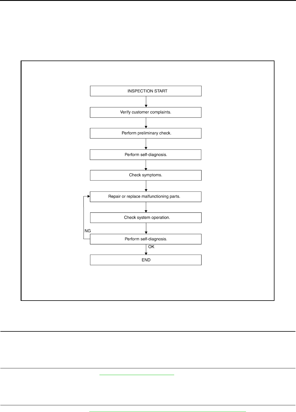
WORK FLOW
DETAILED FLOW
1.CUSTOMER INFORMATION
Interview the customer to obtain detailed information about the symptom.
>> GO TO 2
2.PRELIMINARY CHECK
Perform preliminary check. Refer to DLN-9, "Preliminary Check".
>> GO TO 3
3.SELF-DIAGNOSIS
Perform self-diagnosis. Refer to DLN-22, "CONSULT-III Function (ALL MODE AWD/4WD)".
AWNIA1592G
B
Revision: October 2008
2009 Pathfinder
DIAGNOSIS AND REPAIR WORKFLOW
DLN-9
< BASIC INSPECTION > [TRANSFER: ATX14B]
C
E
F
G
H
I
J
K
L
M
A
B
DLN
N
O
P
>> GO TO 4
4.SYMPTOM
Check for symptoms. Refer to DLN-107, "Symptom Table".
>> GO TO 5
5.MALFUNCTIONING PARTS
Repair or replace the applicable parts.
>> GO TO 6
6.SYSTEM OPERATION
Check system operation.
>> GO TO 7
7.SELF-DIAGNOSIS
Perform self-diagnosis.
Are any DTC's displayed?
YES >> GO TO 5
NO >> Inspection End
Preliminary Check INFOID:0000000003937185
TRANSFER FLUID CHECK
Check for leaks and fluid level. Refer to DLN-133, "Inspection".
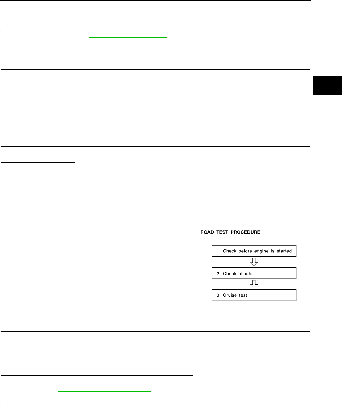
PREPARATION FOR ROAD TEST
The purpose of the test is to determine overall performance of trans-
fer case and analyze causes of malfunctions.
When a malfunction is found in any part of transfer, perform the road
test to locate the malfunction area and repair the malfunction parts.
The road test consists of the following three parts.
1. CHECK BEFORE ENGINE IS STARTED
2. CHECK AT IDLE
3. CRUISE TEST
CHECK BEFORE ENGINE IS STARTED
1.CHECK 4WD SHIFT INDICATOR LAMP
1. Park vehicle on flat surface.
2. Turn ignition switch to OFF position.
3. Move A/T selector lever to P position.
4. Set 4WD shift switch to 2WD position.
5. Turn ignition switch to ON position. (Do not start engine.)
Does 4WD shift indicator lamp turn ON for approximately 1 second?
YES >> GO TO 2.
NO >> GO TO DLN-108, "Diagnosis Procedure".
2.CHECK 4WD WARNING LAMP
1. Turn ignition switch to OFF position.
2. Move A/T selector lever to P position.
3. Set 4WD shift switch to 2WD position.
4. Turn ignition switch to ON position. (Do not start engine.)
SMT089D
Revision: October 2008
2009 Pathfinder
DLN-10
< BASIC INSPECTION > [TRANSFER: ATX14B]
DIAGNOSIS AND REPAIR WORKFLOW
Does 4WD warning lamp turn ON?
YES >> GO TO CHECK AT IDLE.
NO >> GO TO DLN-111, "Diagnosis Procedure".
CHECK AT IDLE
1.CHECK 4WD SHIFT INDICATOR LAMP
1. Park vehicle on flat surface and engage the parking brake.
2. Turn ignition switch to OFF position.
3. Move A/T selector lever to P position.
4. Set 4WD shift switch to 2WD position.
5. Start engine.
Does 4WD shift indicator lamp turn ON?
YES >> GO TO 3.
NO >> GO TO 2.
2.CHECK 4WD WARNING LAMP
Check 4WD warning lamp state.
Is 4WD warning lamp turned ON?
YES >> Perform the self-diagnosis. Refer to DLN-22, "CONSULT-III Function (ALL MODE AWD/4WD)".
NO >> Refer to DLN-114, "Diagnosis Procedure".
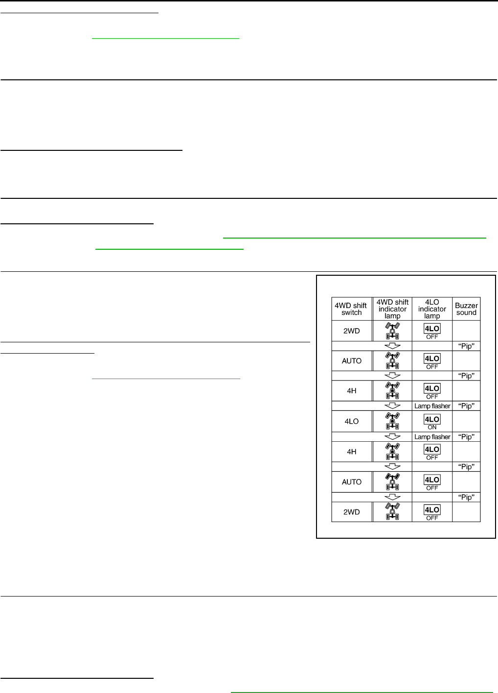
3.CHECK 4WD SHIFT INDICATOR AND 4LO INDICATOR OPERATION
1. Brake pedal depressed.
2. Move A/T selector lever to N position.
3. Set 4WD shift switch to 2WD, AUTO, 4H, 4LO, 4H, AUTO and
2WD in order. (Stay at each switch position for at least 1 sec-
ond.)
Do 4WD shift indicator and 4LO indicator lamps change properly?
Does buzzer sound?
YES >> GO TO CRUISE TEST.
NO >> GO TO DLN-114, "Diagnosis Procedure".
CRUISE TEST
1.CHECK INPUT SIGNAL
1. Warm up engine to normal operating temperature.
2. Park vehicle on flat surface.
3. Move A/T selector lever to P position.
4. Set 4WD shift switch to AUTO position.
5. Start engine.
6. Drive vehicle for at least 30 seconds at a speed higher than 20 km/h (12 MPH).
Is 4WD warning lamp turned ON?
On steady>>Perform the self-diagnosis. Refer to DLN-22, "CONSULT-III Function (ALL MODE AWD/4WD)".
WDIA0136E
Revision: October 2008
2009 Pathfinder

DIAGNOSIS AND REPAIR WORKFLOW
DLN-11
< BASIC INSPECTION > [TRANSFER: ATX14B]
C
E
F
G
H
I
J
K
L
M
A
B
DLN
N
O
P
Flash rapidly>>Refer to DLN-119, "Diagnosis Procedure".
Flash slowly>>Refer to DLN-120, "Diagnosis Procedure".
NO >> GO TO 2.
2.CHECK TIGHT CORNER BRAKING SYMPTOM (1)
1. Set 4WD shift switch to AUTO position.
2. Drive vehicle at speed lower than 20 km/h (12 MPH) with steering wheel fully turned.
Does tight corner braking symptom occur?
YES >> GO TO DLN-121, "Diagnosis Procedure".
NO >> GO TO 3.
3.CHECK TIGHT CORNER BRAKING SYMPTOM (2)
1. Set 4WD shift switch to 4HI position.
2. Drive vehicle at speed lower than 20 km/h (12 MPH) with steering wheel fully turned.
Does tight corner braking symptom occur?
YES >> Inspection End.
NO >> GO TO DLN-125, "Diagnosis Procedure".
Revision: October 2008
2009 Pathfinder
DLN-12
< FUNCTION DIAGNOSIS > [TRANSFER: ATX14B]
4WD SYSTEM
FUNCTION DIAGNOSIS
4WD SYSTEM
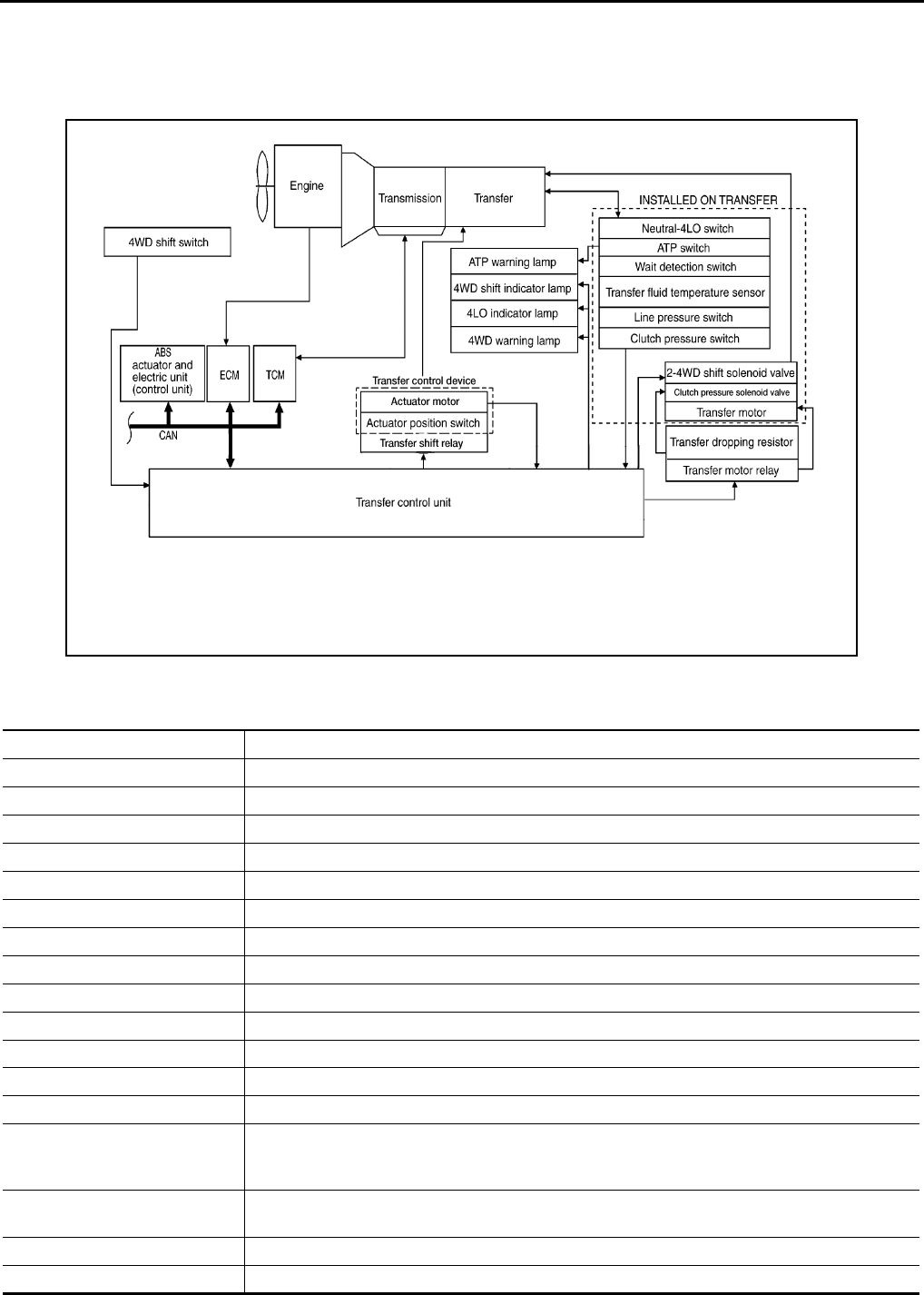
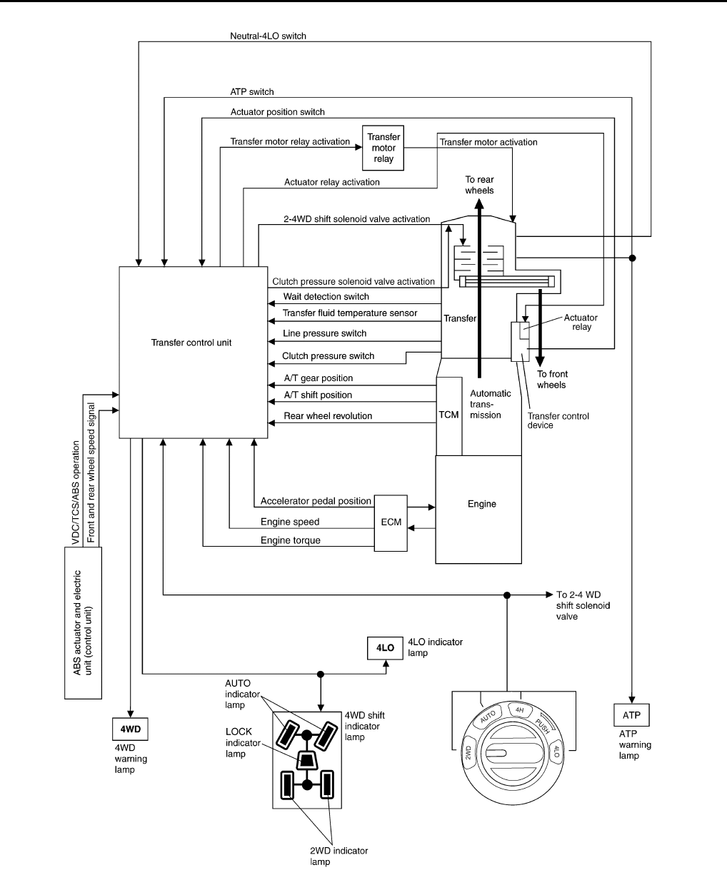
System Diagram INFOID:0000000003937186
COMPONENT DESCRIPTION
WDIA0164E
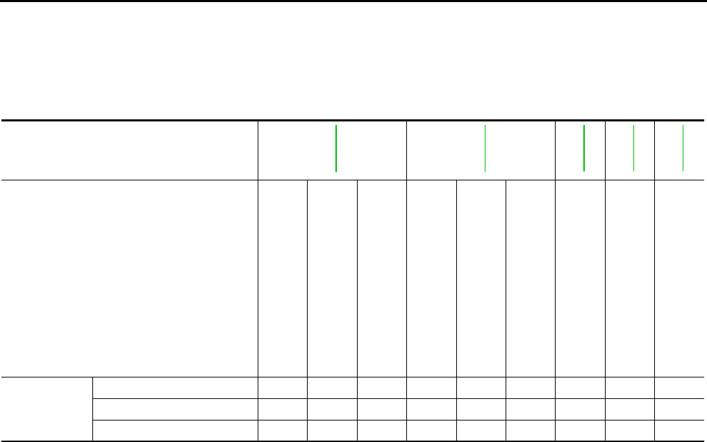
Components Function
Transfer control unit Controls transfer control device, control valves and shifts between 2WD/4WD and 4H/4LO.
Transfer control device Integrates actuator motor and actuator position switch.
2-4WD shift solenoid valve Controls oil pressure and allows shifting between 2WD and 4WD.
Clutch pressure solenoid valve Controls oil pressure and distributes torque between front and rear tires.
Line pressure switch Detects line pressure.
Clutch pressure switch Detects clutch pressure.
Transfer fluid temperature sensor Detects transfer fluid temperature.
Actuator motor Moves shift rods when signaled by transfer control unit.
Actuator position switch Detects actuator motor position.
Wait detection switch Detects whether or not 4WD lock gear is locked.
4LO switch Detects if transfer case is in 4LO.
ATP switch Detects if transfer case is in neutral.
4WD shift switch Allows driver to select from 2WD/4WD, 4H/4LO and AUTO.
4WD warning lamp • Illuminates if malfunction is detected in 4WD system.
• Flashes (1 flash / 2 seconds) if large difference in diameter of front and rear tires.
• Flashes (2 flashes / 1 second) if high transfer fluid temperature is detected.
ATP warning lamp Indicates that A/T parking mechanism does not operate when A/T selector lever is in P position
because transfer case is in neutral.
4WD shift indicator lamp Displays driving range selected by 4WD shift switch.
4LO indicator lamp Displays 4LO range.
Revision: October 2008
2009 Pathfinder

4WD SYSTEM
DLN-13
< FUNCTION DIAGNOSIS > [TRANSFER: ATX14B]
C
E
F
G
H
I
J
K
L
M
A
B
DLN
N
O
P
System Description INFOID:0000000003937187
CONTROL SYSTEM
ABS actuator and electric unit
(control unit) Transmits vehicle speed signal via CAN communication to transfer control unit.
TCM
Transmits the following signal via CAN communication to transfer control unit.
• Output shaft revolution signal
• A/T position indicator signal (PNP switch signal)
ECM Transmits the following signals via CAN communication to transfer control unit.
• Engine speed signal
• Accelerator pedal position signal
Components Function
Revision: October 2008
2009 Pathfinder
DLN-14
< FUNCTION DIAGNOSIS > [TRANSFER: ATX14B]
4WD SYSTEM
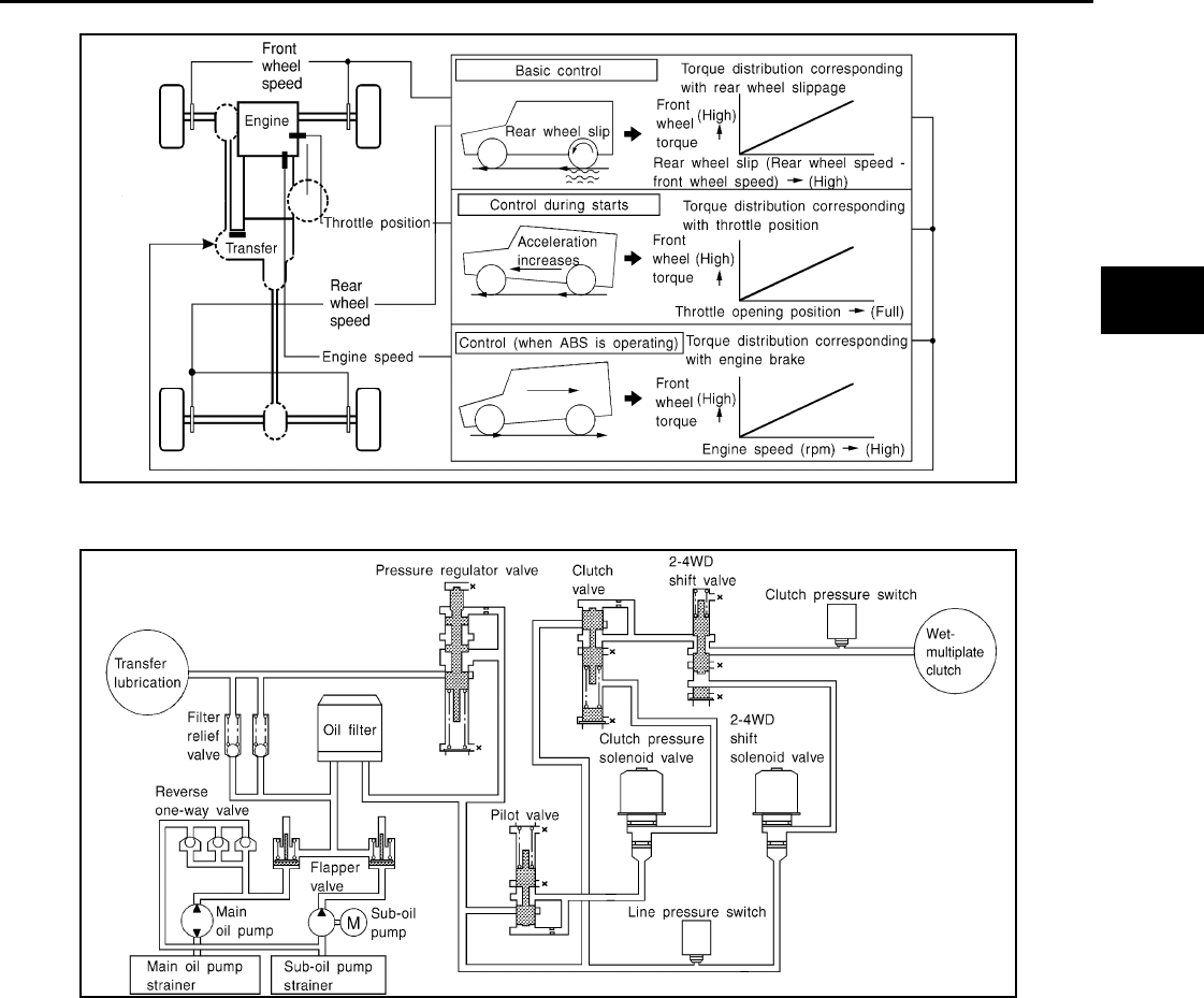
ALL-MODE 4WD Transfer Basic Control
SDIA3396E
Revision: October 2008
2009 Pathfinder
4WD SYSTEM
DLN-15
< FUNCTION DIAGNOSIS > [TRANSFER: ATX14B]
C
E
F
G
H
I
J
K
L
M
A
B
DLN
N
O
P
Hydraulic Control Circuits
TRANSFER CONTROL UNIT
• Transfer control unit controls transfer control device and it directs shifts from 4H-4LO and 2WD-4WD.
• Self-diagnosis can be done.
TRANSFER SHIFT HIGH AND LOW RELAYS
Transfer shift high and low relays apply power supply to transfer control device (actuator motor).
TRANSFER SHUT OFF RELAY
Transfer shut off relay applies power supply to transfer motor relay.
4WD SHIFT SWITCH AND INDICATOR LAMPS
4WD Shift Switch
Able to select from 2WD, AUTO, 4H or 4LO.
4WD Shift Indicator Lamp
• Displays driving conditions selected by 4WD shift switch with 2WD, AUTO and 4H indicators while engine is
running. (When 4WD warning lamp is turned on, all 4WD shift indicator lamps are turned off.)
• Turns ON for approximately 1 second when ignition switch is turned ON, for purpose of lamp check.
4LO Indicator Lamp
LDIA0055E
WDIA0163E
Revision: October 2008
2009 Pathfinder

DLN-16
< FUNCTION DIAGNOSIS > [TRANSFER: ATX14B]
4WD SYSTEM
• Displays 4LO condition while engine is running. 4LO indicator lamp flashes if transfer gear does not shift
completely under 2WD, AUTO, 4H⇔4LO. (When 4WD warning lamp is turned on, 4LO indicator lamp is
turned off.)
• Turns ON for approximately 1 second when ignition switch is turned ON, for purpose of lamp check.
4WD WARNING LAMP
Turns on or flashes when there is a malfunction in 4WD system.
Also turns on when ignition switch is turned ON, for purpose of lamp check. Turns OFF approximately 1 sec-
ond after the engine starts if system is normal.
4WD Warning Lamp Indication
ATP WARNING LAMP
When the A/T selector lever is in P position, the vehicle may move if the transfer case is in neutral. ATP warn-
ing lamp is turned on to indicate this condition to the driver.
LINE PRESSURE SWITCH
• With the transfer system design, control of the oil pressure provides the transmission of drive torque to the
front wheels. The main pressure to control the oil pressure is referred to as the line pressure.
• The line pressure switch determines whether or not adequate line pressure has built up under different oper-
ating conditions.
• The line pressure switch closes when line pressure is produced.
• The line pressure switch senses line pressure abnormalities and turns the 4WD warning lamp ON.
CLUTCH PRESSURE SWITCH
• The clutch pressure switch determines whether or not adequate clutch pressure has built up under different
operating conditions.
• The clutch pressure switch closes when clutch pressure is produced.
• The clutch pressure switch senses clutch pressure abnormalities and turns the 4WD warning lamp ON.
WAIT DETECTION SWITCH
• The wait detection switch operates when there is circulating torque produced in the propeller shaft (L→H) or
when there is a phase difference between 2-4 sleeve and clutch drum (H→L). After the release of the circu-
lating torque, the wait detection switch helps provide the 4WD lock gear (clutch drum) shifts. A difference
may occur between the operation of the 4WD shift switch and actual drive mode. At this point, the wait
detection switch senses an actual drive mode.
• The wait detection switch operates as follows.
- 4WD lock gear (clutch drum) locked: ON
- 4WD lock gear (clutch drum) released: OFF
• The wait detection switch senses an actual drive mode and the 4WD shift indicator lamp indicates the vehi-
cle drive mode.
ATP SWITCH
ATP switch detects if transfer case is in neutral by the position of the L-H shift fork.
NOTE:
Transfer case may be in neutral when shifting between 4H-4LO.
NEUTRAL-4LO SWITCH
The neutral-4LO switch detects that transfer gear is in neutral or 4LO (or shifting from neutral to 4LO) condi-
tion by L-H shift fork position.
Condition 4WD warning lamp
System normal OFF
Lamp check Turns ON when ignition switch is turned ON.
Turns OFF after engine start.
4WD system malfunction ON
During self-diagnosis Flashes malfunction mode.
Large difference in diameter of front/
rear tires
Flashes slow (1 flash / 2 seconds)
(Continues to flash until the ignition switch is turned OFF)
High fluid temperature in transfer case Flashes rapidly (2 flashes / 1 second)
(Continues to flash until fluid temperature returns to normal)
Revision: October 2008
2009 Pathfinder
4WD SYSTEM
DLN-17
< FUNCTION DIAGNOSIS > [TRANSFER: ATX14B]
C
E
F
G
H
I
J
K
L
M
A
B
DLN
N
O
P
TRANSFER FLUID TEMPERATURE SENSOR
The transfer fluid temperature sensor detects the transfer fluid temperature and sends a signal to the transfer
control unit.
TRANSFER MOTOR
• The transfer motor drives the sub-oil pump to provide proper lubrication and oil pressure control when the
vehicle is at standstill, during low-speed operations or is being driven in reverse.
• The main oil pump is operated by the driving force of the mainshaft. In other words, sufficient oil pressure
buildup does not occur when the vehicle is at standstill or during low-speed operations. While the vehicle is
being driven in reverse, the main oil pump rotates in the reverse direction. Therefore the main oil pump does
not discharge oil pressure. During any of the above vehicle operations, the transfer motor drives the sub-oil
pump to compensate for insufficient oil pressure.
• The transfer motor operates as follows:
- The motor relay turns OFF in the 2WD mode.
- The motor relay operates as described in the table below in modes other than the 2WD mode.
• 4WD shift switch, PNP switch, Neutral-4LO switch, vehicle speed sensor and throttle position sensor are
used in conjunction with the transfer motor.
Transfer Motor Relay Operation
*: After 2.5 seconds have elapsed.
CLUTCH PRESSURE SOLENOID VALVE
The clutch pressure solenoid valve distributes front and rear torque in AUTO mode.
2-4WD SHIFT SOLENOID VALVE
The 2-4WD shift solenoid valve operates to apply oil pressure to the wet-multiplate clutch, depending on the
drive mode. The driving force is transmitted to the front wheels through the clutch so the vehicle is set in the
4WD mode. Setting the vehicle in the 2WD mode requires no pressure buildup. In other words, pressure force
applied to the wet-multiplate clutch becomes zero.
TRANSFER CONTROL DEVICE
Integrates actuator motor and actuator position switch.
4WD shift switch A/T selector lever position Vehicle speed
(VSS) Accelerator pedal position Motor relay drive
command
2WD — — — OFF
4H (LOCK) and 4LO
N position 0 — ON
P position 0
0 - 0.07/8 OFF*
0.07/8 - 1/8 HOLD
1/8 - MAX ON
Other than R position
0 < VSS ≤ 50 km/h (31 MPH)
—
ON
50 km/h (31 MPH) < VSS < 55
km/h (34 MPH) HOLD
55 km/h (34 MPH) ≤ VSS OFF
R position — — ON
R position — — ON
AUTO
P or N position
0
0 - 0.07/8 OFF*
0.07/8 - 1/8 HOLD
1/8 - MAX ON
0 < VSS ≤ 50 km/h (31 MPH)
—
ON
50 km/h (31 MPH) < VSS < 55
km/h (34 MPH) HOLD
55 km/h (34 MPH) ≤ VSS OFF
Other than R, P and N posi-
tion
0 < VSS ≤ 50 km/h (31 MPH)
—
ON
50 km/h (31 MPH) < VSS < 55
km/h (34 MPH) HOLD
55 km/h (34 MPH) ≤ VSS OFF
Revision: October 2008
2009 Pathfinder
DLN-18
< FUNCTION DIAGNOSIS > [TRANSFER: ATX14B]
4WD SYSTEM
Actuator Motor
Moves shift rods when signaled by transfer control unit.
Actuator Position Switch
Detects actuator motor position and then sends signal to transfer control unit.
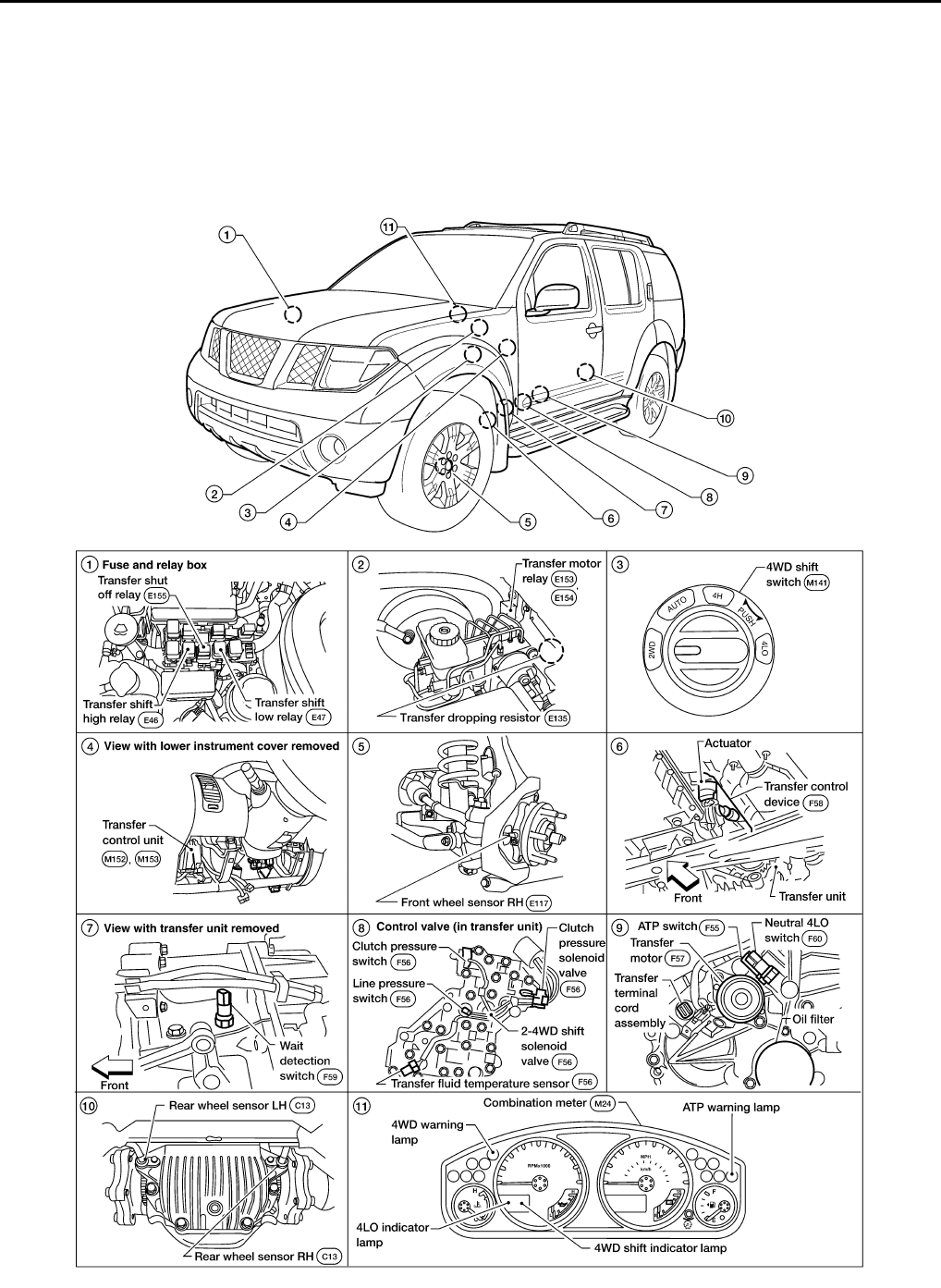
Component Parts Location INFOID:0000000003937188
WDIA0124E
Revision: October 2008
2009 Pathfinder
4WD SYSTEM
DLN-19
< FUNCTION DIAGNOSIS > [TRANSFER: ATX14B]
C
E
F
G
H
I
J
K
L
M
A
B
DLN
N
O
P
CAN Communication INFOID:0000000003937189
Refer to LAN-57, "CAN System Specification Chart".
Cross-Sectional View INFOID:0000000004404656
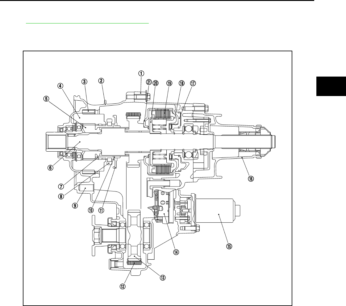
Power Transfer INFOID:0000000004404657
POWER TRANSFER DIAGRAM
1. Center case 2. Front case 3. Internal gear
4. Planetary carrier assembly 5. Sun gear assembly 6. Main shaft
7. L-H sleeve 8. L-H fork 9. Shift rod
10. 2-4 sleeve 11. 2-4 fork 12. Drive chain
13. Front drive shaft 14. Control valve assembly 15. Transfer motor
16. Rear case 17. Clutch piston 18. Press flange
19. Multiple disc clutch 20. Clutch hub assembly 21. Clutch drum assembly
WDIA0202E
Revision: October 2008
2009 Pathfinder
DLN-20
< FUNCTION DIAGNOSIS > [TRANSFER: ATX14B]
4WD SYSTEM
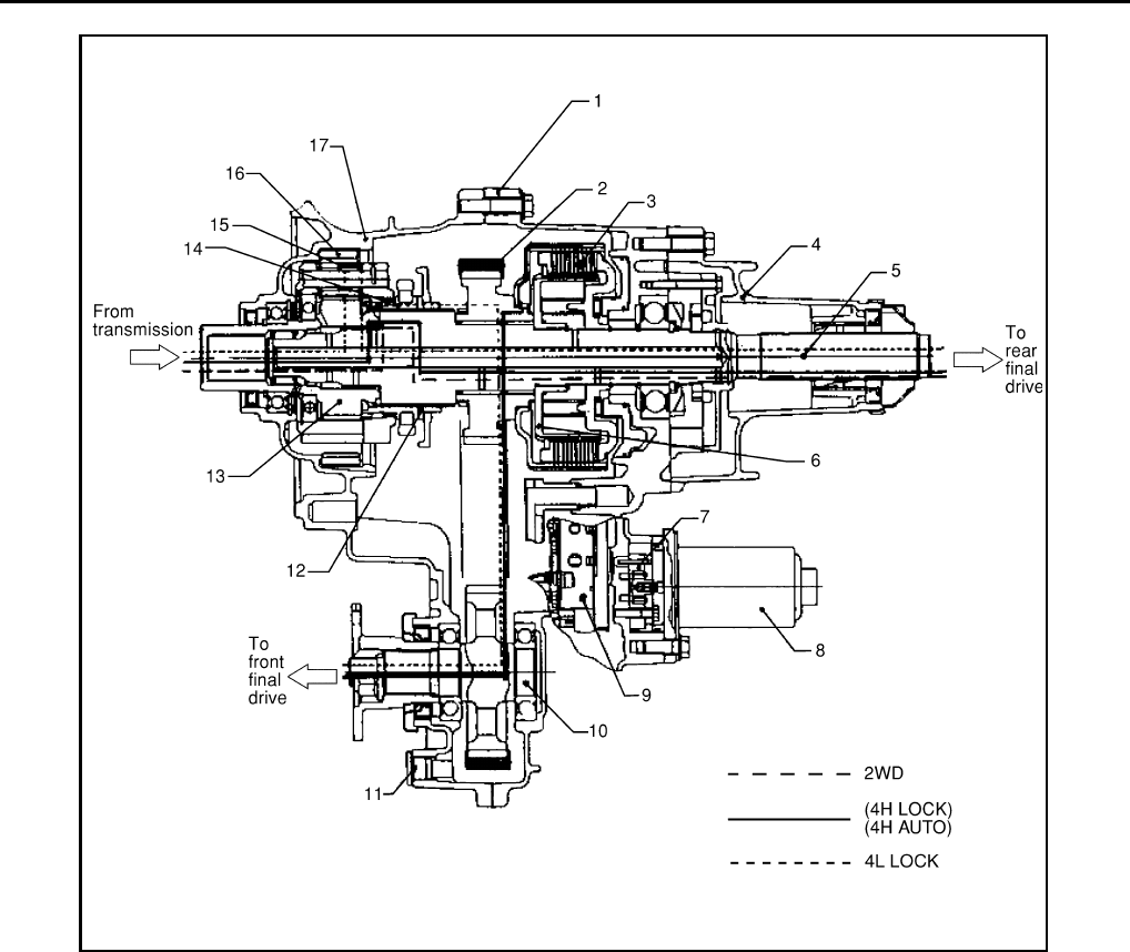
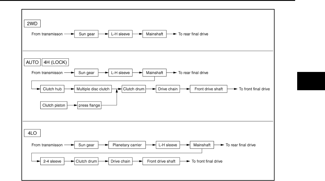
POWER TRANSFER FLOW
1. Center case 2. Chain 3. Multiple disc clutch
4. Rear case 5. Mainshaft 6. Clutch hub assembly
7. Sub oil pump 8. Transfer motor 9. Control valve
10. Front drive shaft 11. Drain plug 12. 2-4 sleeve
13. Sun gear assembly 14. L-H sleeve 15. Planetary carrier assembly
16. Internal gear 17. Front case
LDIA0053E
Revision: October 2008
2009 Pathfinder
4WD SYSTEM
DLN-21
< FUNCTION DIAGNOSIS > [TRANSFER: ATX14B]
C
E
F
G
H
I
J
K
L
M
A
B
DLN
N
O
P
SDIA3327E
Revision: October 2008
2009 Pathfinder

DLN-22
< FUNCTION DIAGNOSIS > [TRANSFER: ATX14B]
DIAGNOSIS SYSTEM (TRANSFER CONTROL UNIT)
DIAGNOSIS SYSTEM (TRANSFER CONTROL UNIT)
CONSULT-III Function (ALL MODE AWD/4WD) INFOID:0000000003937190
FUNCTION
CONSULT-III can display each diagnostic item using the diagnostic test modes shown following.
SELF-DIAG RESULT MODE
Operation Procedure
1. Connect CONSULT-III.
2. With engine at idle, touch SELF-DIAG RESULTS.
Display shows malfunction experienced since the last erasing operation.
NOTE:
The details for TIME are as follows:
• 0: Error currently detected with transfer control unit.
• Except for 0: Error detected in the past and memorized with transfer control unit.
Detects frequency of driving after DTC occurs (frequency of turning ignition switch ON/OFF).
How to Erase Self-diagnostic Results
1. Perform applicable inspection of malfunctioning item and then repair or replace.
2. Start engine and select SELF-DIAG RESULTS mode for ALL MODE AWD/4WD with CONSULT-III.
3. Touch ERASE on CONSULT-III screen to erase DTC memory.
CAUTION:
If memory cannot be erased, perform applicable diagnosis.
SELF-DIAGNOSTIC PROCEDURE (WITHOUT CONSULT-III)
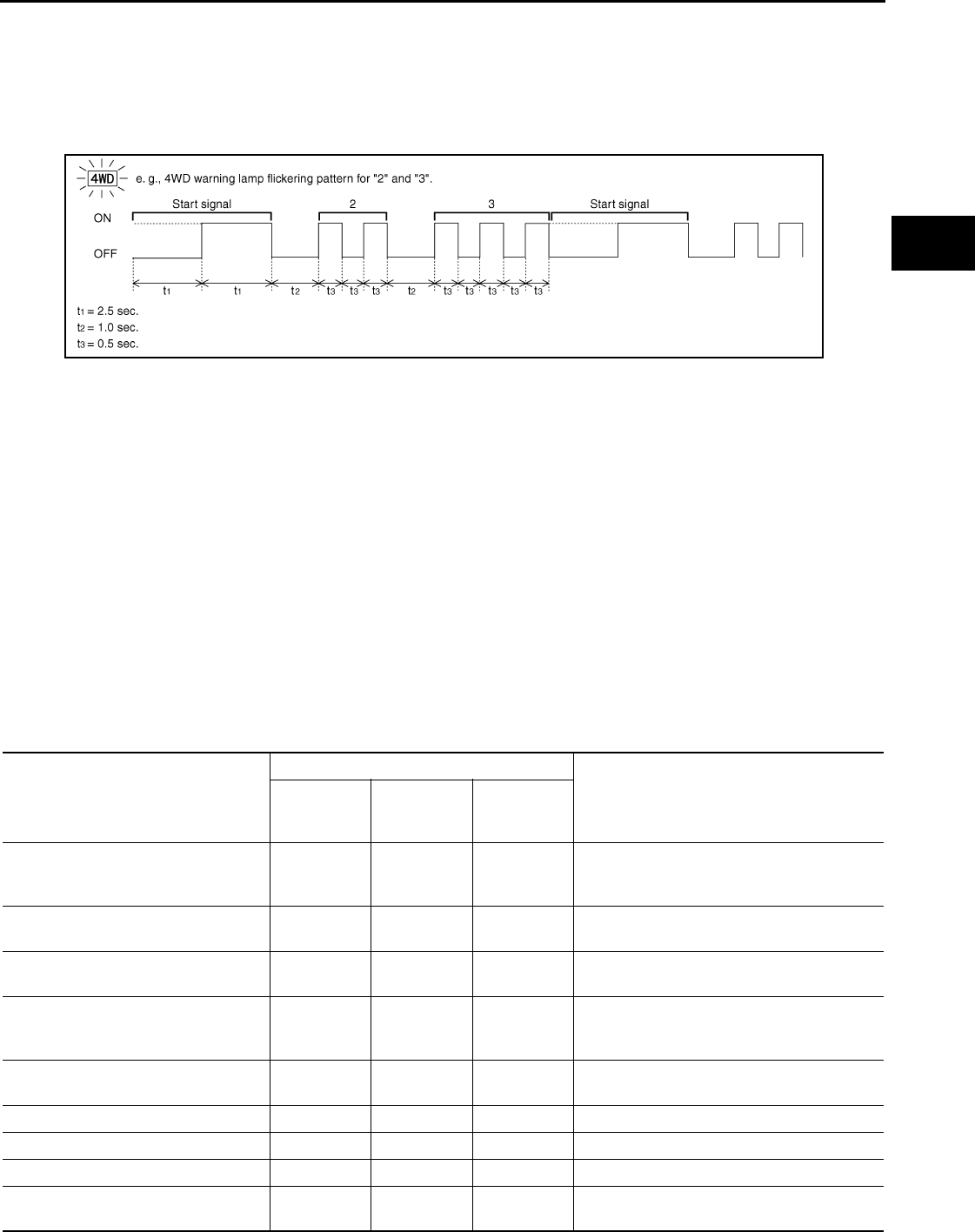
Description
If the engine starts when there is a malfunction in the 4WD system, the 4WD warning lamp turns ON or flickers
in the combination meter. When the system functions properly, the warning lamp turns ON when the ignition
switch is turned to ON, and it turns OFF after engine starts. To locate the cause of a malfunction, start the self-
diagnosis function. The 4WD warning lamp in the combination meter will indicate the malfunction area by
flashing according to the self-diagnostic results. Refer to DLN-102, "DTC Index".
Diagnostic Procedure
1. Warn up engine.
2. Move A/T selector lever to P position.
3. Turn 4WD shift switch to 2WD position.
4. Turn ignition switch ON and OFF at least twice, and then turn ignition switch OFF.
5. Turn 4WD shift switch to AUTO position.
6. Turn ignition switch ON. (Do not start engine.)
7. 4WD warning lamp ON.
8. Move A/T selector lever to R position.
9. Turn 4WD shift switch to 2WD, AUTO and 2WD in order.
10. Move A/T selector lever to D position.
11. Turn 4WD shift switch to 4H, AUTO and 4H in order.
ALL MODE AWD/4WD diagnostic mode Description
SELF-DIAG RESULTS Displays transfer control unit self-diagnosis results.
DATA MONITOR Displays transfer control unit input/output data in real time.
WORK SUPPORT
Supports inspections and adjustments. Commands are transmitted to the transfer control
unit for setting the status suitable for required operation, input/output signals are received
from the transfer control unit and received data is displayed.
CAN DIAG SUPPORT MNTR The results of transmit/receive diagnosis of CAN communication can be read.
ECU PART NUMBER Transfer control unit part number can be read.
Revision: October 2008
2009 Pathfinder
DIAGNOSIS SYSTEM (TRANSFER CONTROL UNIT)
DLN-23
< FUNCTION DIAGNOSIS > [TRANSFER: ATX14B]
C
E
F
G
H
I
J
K
L
M
A
B
DLN
N
O
P
12. Move A/T selector lever to N position.
13. Turn 4WD shift switch to AUTO position.
14. Move A/T selector lever to P position.
15. Read the flickering of 4WD warning lamp.
Self-diagnosis example
ERASE SELF-DIAGNOSIS
• In order to make it easier to find the cause of hard-to-duplicate malfunctions, malfunction information is
stored into the control unit as necessary during use by the user. This memory is not erased no matter how
many times the ignition switch is turned ON and OFF.
• However, this information is erased by turning ignition switch OFF after performing self-diagnostics or by
erasing the memory using the CONSULT-III.
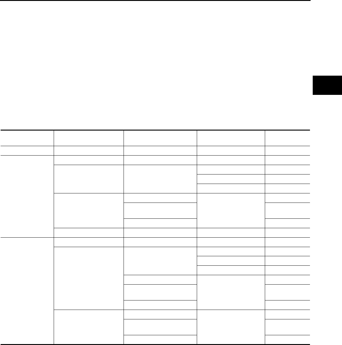
DATA MONITOR MODE
Operation Procedure
1. Connect CONSULT-III.
2. Touch DATA MONITOR.
3. Select from SELECT MONITOR ITEM, screen of data monitor mode is displayed.
NOTE:
When malfunction is detected, CONSULT-III performs REAL-TIME DIAGNOSIS.
Also, any malfunction detected while in this mode will be displayed at real time.
Display Item List
×: Standard –: Not applicable
PDIA0227E
Monitored item (Unit)
Monitor item selection
Remarks
ECU INPUT
SIGNALS
MAIN
SIGNALS
SELEC-
TION FROM
MENU
VHCL/S SEN·FR [km/h] or [mph] ×–×
Wheel speed calculated by ABS actuator and
electric unit (control unit).
Signal input with CAN communication line.
VHCL/S SEN·RR [km/h] or [mph] ×–×Wheel speed calculated by TCM.
Signal input with CAN communication line.
ENGINE SPEED [rpm] ×–×Engine speed calculated by ECM.
Signal input with CAN communication line.
THRTL POS SEN [V] ×–×
Accelerator pedal position (APP) sensor sig-
nal voltage is displayed.
Signal input with CAN communication line.
FLUID TEMP SE [V] ×–×Transfer fluid temperature sensor signal volt-
age is displayed.
BATTERY VOLT [V] ×–×Power supply voltage for transfer control unit.
2WD SWITCH [ON/OFF] ×–×4WD shift switch status is displayed.
AUTO SWITCH [ON/OFF] ×–×4WD shift switch status is displayed.
LOCK SWITCH [ON/OFF] ×–×4WD shift switch status is displayed.
(LOCK means 4H of 4WD shift switch.)
Revision: October 2008
2009 Pathfinder

DLN-24
< FUNCTION DIAGNOSIS > [TRANSFER: ATX14B]
DIAGNOSIS SYSTEM (TRANSFER CONTROL UNIT)
4L SW [ON/OFF] ×–×4WD shift switch status is displayed.
(4L means 4LO of 4WD shift switch.)
N POSI SW TF [ON/OFF] ×–×Neutral-4LO switch signal status is displayed.
ATP SWITCH [ON/OFF] ×–×ATP switch signal status is displayed.
WAIT DETCT SW [ON/OFF] ×–×Wait detection switch status is displayed.
LINE PRES SW [ON/OFF] ×–×Line pressure switch status is displayed.
CL PRES SW [ON / OFF] ×–×Clutch pressure switch status is displayed.
N POSI SW AT [ON/OFF] ×–×
N position signal of A/T PNP switch status is
displayed.
Signal input with CAN communication line.
R POSI SW AT [ON/OFF] ×–×
R position signal of A/T PNP switch status is
displayed.
Signal input with CAN communication line.
P POSI SW AT [ON/OFF] ×–×
P position signal of A/T PNP switch status is
displayed.
Signal input with CAN communication line.
ABS OPER SW [ON/OFF] ×–×ABS operation signal status is displayed.
Signal input with CAN communication line.
VDC OPER SW [ON/OFF] ×–×VDC operation signal status is displayed.
Signal input with CAN communication line.
TCS OPER SW [ON/OFF] ×–×TCS operation signal status is displayed.
Signal input with CAN communication line.
THROTTLE POSI [0.0/8] – ××
Thottle position status is displayed.
Signal input with CAN communication line.
4WD MODE [AUTO/LOCK/2WD/4L] – ××
Control status of 4WD recognized by transfer
control unit. (AUTO, 4H, 2WD or 4LO)
VHCL/S COMP [km/h] or [mph] – ××
Vehicle speed recognized by transfer control
unit.
COMP CL TORQ [kgm] – ××
Calculated torque recognized by transfer con-
trol unit.
DUTY SOLENOID [%] – ××Control value of clutch pressure solenoid.
2-4WD SOL [ON/OFF] – ××Output condition to 2-4WD solenoid.
2-4WD SOL MON [ON/OFF] – – ×Check signal for transfer control unit signal
output.
MOTOR RELAY [ON/OFF] – ××
Transfer motor relay signal status is dis-
played.
MOTOR RELAY MON [ON/OFF] – – ×Check signal for transfer control unit signal
output.
4WD FAIL LAMP [ON/OFF] – ××
Control status of 4WD warning lamp is dis-
played.
2WD IND [ON/OFF] – – ×Control status of 4WD shift indicator lamp
(2WD indicator lamp) is displayed.
AUTO IND [ON/OFF] – – ×Control status of 4WD shift indicator lamp
(2WD and AUTO indicator lamp) is displayed.
LOCK IND [ON/OFF] – – ×Control status of 4WD shift indicator lamp
(2WD, AUTO and Lock indicator) is displayed.
4L IND [ON/OFF] – – ×Control status of 4LO indicator lamp is dis-
played.
Monitored item (Unit)
Monitor item selection
Remarks
ECU INPUT
SIGNALS
MAIN
SIGNALS
SELEC-
TION FROM
MENU
Revision: October 2008
2009 Pathfinder

DIAGNOSIS SYSTEM (TRANSFER CONTROL UNIT)
DLN-25
< FUNCTION DIAGNOSIS > [TRANSFER: ATX14B]
C
E
F
G
H
I
J
K
L
M
A
B
DLN
N
O
P
WORK SUPPORT
When there is no malfunction with transfer and 4WD system, the following symptoms in AUTO mode may be
claimed by a customer: vibration when accelerating on a low µ road (snow-covered or icy road) or a slight
shock is felt at a few hertz as if it were being pushed lightly from behind.
It is possible to deal with these symptoms by changing the CLUTCH FORCE RELEASE LIMIT VALUE. How-
ever, be careful when changing the value because it may adversely affect driving performance.
Operation Procedure
1. Connect CONSULT-III.
2. Touch WORK SUPPORT.
3. Select from CLUTCH/F RLS LIM ADJ, screen of data monitor mode is displayed.
Clutch Force Release Limit Adjustment
1. Initial CLUTCH FORCE RELEASE LIMIT value 0.3 kgm appears under CONDITION SETTING on CON-
SULT-III display.
2. Touch 1.2 on the display.
3. Display changes to NOW ADJUSTING in a short time.
4. When clutch force release limit value is set to 1.2 kgm, current value 0.3 kgm shown on display will be
replaced by 1.2 kgm and ADJUSTMENT COMPLETE will appear at the same time. Clutch force release
limit value setting is now complete.
ATP IND [ON/OFF] – – ×Control status of ATP warning lamp is dis-
played.
SHIFT POS SW1 [ON/OFF] ×–×Actuator position switch 1 (Low) signal status
is displayed.
SHIFT POS SW2 [ON/OFF] ×–×Actuator position switch 2 (high) signal status
is displayed.
SHIFT ACT1 [ON/OFF] – ××Output condition to actuator motor (clockwise)
SHIFT AC MON1 [ON/OFF] ×–×Check signal for transfer control unit signal
output
SHIFT ACT2 [ON/OFF] – ××
Output condition to actuator motor (counter-
clockwise)
SHIFT AC MON2 [ON/OFF] ×–×Check signal for transfer control unit signal
output
T/F F SPEED [km/h] or [mph] ×–×Displayed, but do not use.
A/T R SPEED [km/h] or [mph] ×–×
Output shaft revolution signal (Revolution
sensor) calculated by TCM.
Signal input with CAN communication line.
AT GEAR POSI [1/2/3/4/5] ×–×A/T actual gear position is displayed.
Monitored item (Unit)
Monitor item selection
Remarks
ECU INPUT
SIGNALS
MAIN
SIGNALS
SELEC-
TION FROM
MENU
1.2 kg-m : Tight corner braking symptom is alleviated.
However, vibration may occur when acceler-
ating on a low µ road (icy road, etc.).
0.3 kg-m : Initial set value.
0.2 kg-m : Do not set to this value because the tight
corner braking symptom will get worse.
Revision: October 2008
2009 Pathfinder
DLN-26
< FUNCTION DIAGNOSIS > [TRANSFER: ATX14B]
NOISE, VIBRATION AND HARSHNESS (NVH) TROUBLESHOOTING
NOISE, VIBRATION AND HARSHNESS (NVH) TROUBLESHOOTING
NVH Troubleshooting Chart INFOID:0000000003937191
Use the chart below to help you find the cause of the symptom. The numbers indicate the order of the inspec-
tion. If necessary, repair or replace these parts.
Reference page
DLN-133
DLN-150
DLN-150
DLN-150
DLN-150
SUSPECTED PARTS
(Possible cause)
TRANSFER FLUID (Level low)
TRANSFER FLUID (Wrong)
TRANSFER FLUID (Level too high)
LIQUID GASKET (Damaged)
O-RING (Worn or damaged)
OIL SEAL (Worn or damaged)
SHIFT FORK (Worn or damaged)
GEAR (Worn or damaged)
BEARING (Worn or damaged)
Symptom
Noise 1 2 3 3
Transfer fluid leakage 31222
Hard to shift or will not shift 1 1 2
Revision: October 2008
2009 Pathfinder
P1811 POWER SUPPLY CIRCUIT FOR TRANSFER CONTROL UNIT
DLN-27
< COMPONENT DIAGNOSIS > [TRANSFER: ATX14B]
C
E
F
G
H
I
J
K
L
M
A
B
DLN
N
O
P
COMPONENT DIAGNOSIS
P1811 POWER SUPPLY CIRCUIT FOR TRANSFER CONTROL UNIT
Description INFOID:0000000003937192
Power supply to transfer control unit is abnormally low while driving.
DTC Logic INFOID:0000000003937193
DTC DETECTION LOGIC
DTC CONFIRMATION PROCEDURE
1.DTC CONFIRMATION PROCEDURE
1. Turn ignition switch ON.
2. Perform self-diagnosis.
Is DTC P1811 detected?
YES >> Perform diagnosis procedure. Refer to DLN-27, "Diagnosis Procedure".
NO >> Inspection End.
Diagnosis Procedure INFOID:0000000003937194
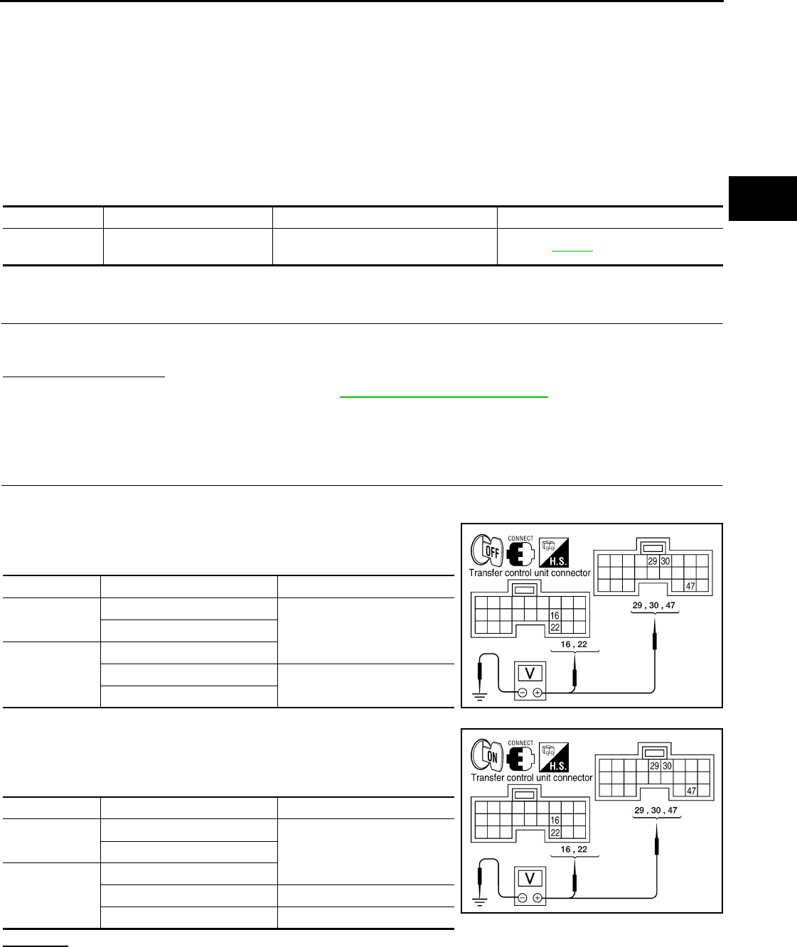
1.CHECK POWER SUPPLY
1. Turn ignition switch “OFF”. (Stay for at least 5 seconds.)
2. Connect transfer control unit harness connector.
3. Check voltage between transfer control unit harness connector
terminals and ground.
4. Turn ignition switch “ON”. (Do not start engine.)
5. Check voltage between transfer control unit harness connector
terminals and ground.
OK or NG
OK >> GO TO 2.
NG >> Check the following. If any items are damaged, repair or replace damaged parts.
• 40A fusible link (No. j, located in the fuse and fusible link box).
DTC CONSULT-III Diagnostic item is detected when... Reference
[P1811] BATTERY VOLTAGE Power supply voltage for transfer control
unit is abnormally low while driving. Refer to DLN-27.
Connector Terminal Voltage (Approx.)
M152 16 - Ground
0V22 - Ground
M153
29 - Ground
30 - Ground Battery voltage
47 - Ground WDIA0165E
Connector Terminal Voltage (Approx.)
M152 16 - Ground
Battery voltage22 - Ground
M153
29 - Ground
30 - Ground 0V
47 - Ground Battery voltage WDIA0166E
Revision: October 2008
2009 Pathfinder
DLN-28
< COMPONENT DIAGNOSIS > [TRANSFER: ATX14B]
P1811 POWER SUPPLY CIRCUIT FOR TRANSFER CONTROL UNIT
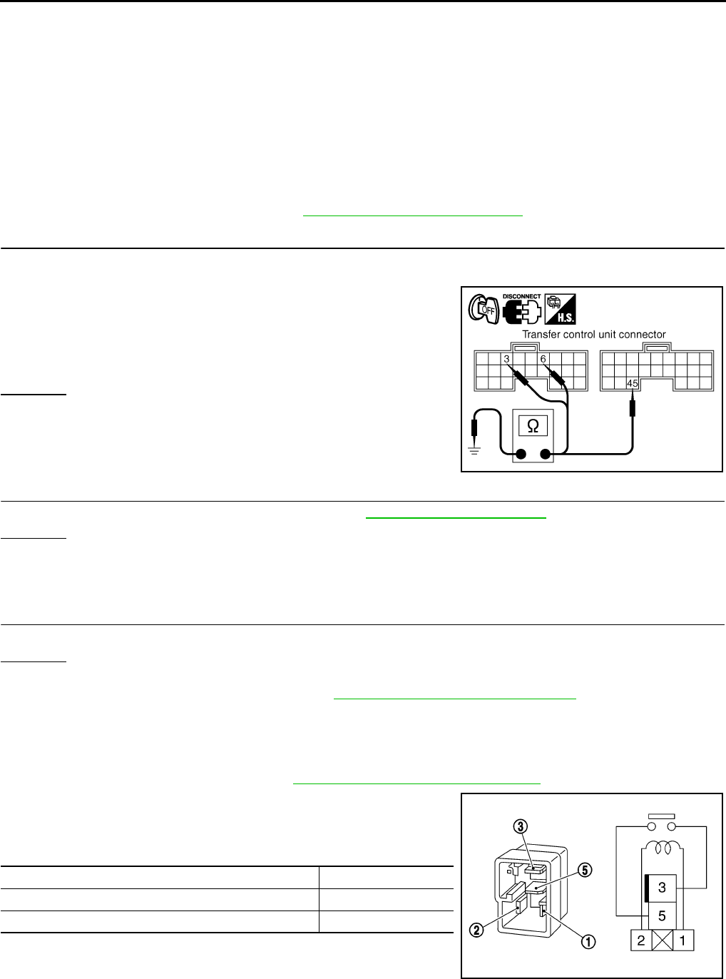
• 10A fuses [No. 21 located in fuse block (J/B)] and No. 59 (located in the fuse and relay box).
• Harness for short or open between battery and transfer control unit harness connector M153
terminals 47.
• Harness for short or open between ignition switch and transfer control unit harness connector
M153 terminal 29.
• Harness for short or open between battery and transfer shut off relay harness connector E155
terminal 1 and 3.
• Harness for short or open between transfer shut off relay harness connector E155 terminal 2
and transfer control unit harness connector M153 terminal 30.
• Harness for short or open between transfer shut off relay harness connector E155 terminal 5
and transfer control unit harness connector M152 terminals 16 and 22.
• Battery and ignition switch.
• Transfer shut off relay. Refer to DLN-28, "Component Inspection".
2.CHECK GROUND CIRCUIT
1. Turn ignition switch “OFF”. (Stay for at least 5 seconds.)
2. Disconnect transfer control unit harness connector.
3. Check continuity between transfer control unit harness connec-
tor M152 terminals 3, 6, M153 terminal 45 and ground.
Also check harness for short to power.
OK or NG
OK >> GO TO 3.
NG >> Repair open circuit or short to power in harness or con-
nectors.
3.CHECK TRANSFER CONTROL UNIT
Check transfer control unit input/output signal. Refer to DLN-85, "Reference Value".
OK or NG
OK >> GO TO 4.
NG >> Check transfer control unit pin terminals for damage or loose connection with harness connector.
If any items are damaged, repair or replace damaged parts.
4.CHECK DTC
Perform the self-diagnosis, after driving a vehicle for a while.
OK or NG
OK >> Inspection End.
NG >> Replace transfer control unit. Refer to DLN-136, "Removal and Installation".
Component Inspection INFOID:0000000003937195
1. Turn ignition switch OFF. (Stay for at least 5 seconds.)
2. Remove transfer shut off relay. Refer to DLN-18, "Component Parts Location".
3. Apply 12V direct current between transfer shut off relay termi-
nals 1 and 2.
4. Check continuity between relay terminals 3 and 5.
5. If inspection results are abnormal replace the transfer shut off
relay.
Continuity should exist.
SDIA2691E
Condition Continuity
12V direct current supply between terminals 1 and 2 Yes
OFF No
SCIA1245E
Revision: October 2008
2009 Pathfinder
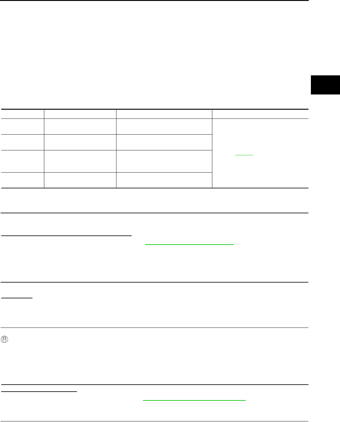
P1802 – P1804, P1809 TRANSFER CONTROL UNIT
DLN-29
< COMPONENT DIAGNOSIS > [TRANSFER: ATX14B]
C
E
F
G
H
I
J
K
L
M
A
B
DLN
N
O
P
P1802 – P1804, P1809 TRANSFER CONTROL UNIT
Description INFOID:0000000003937196
The transfer control unit controls the transfer control device which controls shifts between AUTO, 4H and 4LO
and between 2WD and 4WD. A DTC may set when any of the following occur:
• Malfunction is detected in the memory (RAM) system of transfer control unit.
• Malfunction is detected in the memory (ROM) system of transfer control unit.
• Malfunction is detected in the memory (EEPROM) system of transfer control unit.
• AD converter system of transfer control unit is malfunctioning.
DTC Logic INFOID:0000000003937197
DTC DETECTION LOGIC
DTC CONFIRMATION PROCEDURE
1.DTC CONFIRMATION PROCEDURE
1. Turn ignition switch ON.
2. Perform self-diagnosis.
Are DTC's P1802 - P1804 or P1809 detected?
YES >> Perform diagnosis procedure. Refer to DLN-29, "Diagnosis Procedure".
NO >> Inspection End.
Diagnosis Procedure INFOID:0000000003937198
1.INSPECTION START
Do you have CONSULT-III?
YES or NO
YES >> GO TO 2.
NO >> GO TO 3.
2.PERFORM SELF-DIAGNOSIS (WITH CONSULT-III)
With CONSULT-III
1. Turn ignition switch ON. (Do not start engine.)
2. Select SELF-DIAG RESULTS mode for ALL MODE AWD/4WD with CONSULT-III.
3. Touch ERASE.
4. Turn ignition switch OFF and wait at least 10 seconds.
5. Perform the self-diagnosis again.
Is the CONTROL UNIT 1 [P1802], CONTROL UNIT 2 [P1803], CONTROL UNIT 3 [P1804] or CONTROL
UNIT 4 [P1809] displayed?
YES >> Replace transfer control unit. Refer to DLN-136, "Removal and Installation".
NO >> Inspection End.
3.PERFORM SELF-DIAGNOSIS (WITHOUT CONSULT-III)
DTC CONSULT-III Diagnostic item is detected when... Reference
[P1802] CONTROL UNIT 1 Malfunction is detected in the memory
(RAM) system of transfer control unit.
Refer to DLN-29.
[P1803] CONTROL UNIT 2 Malfunction is detected in the memory
(ROM) system of transfer control unit.
[P1804] CONTROL UNIT 3
Malfunction is detected in the memory
(EEPROM) system of transfer control
unit.
[P1809] CONTROL UNIT 4 AD converter system of transfer control
unit is malfunctioning.
Revision: October 2008
2009 Pathfinder

DLN-30
< COMPONENT DIAGNOSIS > [TRANSFER: ATX14B]
P1802 – P1804, P1809 TRANSFER CONTROL UNIT
Without CONSULT-III
1. Perform the self-diagnosis and then erase self-diagnostic results. Refer to DLN-22, "CONSULT-III Func-
tion (ALL MODE AWD/4WD)".
2. Perform the self-diagnosis again.
Do the self-diagnostic results indicate AD converter?
YES >> Replace transfer control unit.
NO >> Inspection End.
Revision: October 2008
2009 Pathfinder
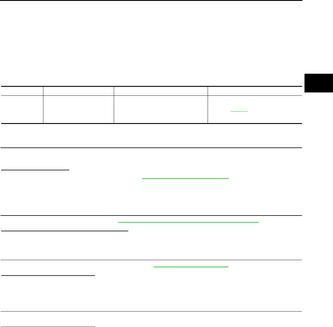
P1807 VEHICLE SPEED SENSOR (A/T)
DLN-31
< COMPONENT DIAGNOSIS > [TRANSFER: ATX14B]
C
E
F
G
H
I
J
K
L
M
A
B
DLN
N
O
P
P1807 VEHICLE SPEED SENSOR (A/T)
Description INFOID:0000000003937199
The transmission control module (TCM) transmits the output shaft revolution signal via CAN communication to
Transfer control unit. DTC P1807 will set when a malfunction is detected in the output shaft revolution signal
or an improper signal is input while driving.
DTC Logic INFOID:0000000003937200
DTC DETECTION LOGIC
DTC CONFIRMATION PROCEDURE
1.DTC CONFIRMATION PROCEDURE
1. Turn ignition switch ON.
2. Perform self-diagnosis.
Is DTC P1807 detected?
YES >> Perform diagnosis procedure. Refer to DLN-31, "Diagnosis Procedure".
NO >> Inspection End.
Diagnosis Procedure INFOID:0000000003937201
1.CHECK DTC WITH TCM
Perform self-diagnosis with TCM. Refer to TM-36, "CONSULT-III Function (TRANSMISSION)".
Is any malfunction detected by self-diagnosis?
YES >> Check the malfunctioning system.
NO >> GO TO 2.
2.CHECK TRANSFER CONTROL UNIT
Check transfer control unit input/output signal. Refer to DLN-85, "Reference Value".
Are the inspection results normal?
YES >> GO TO 3.
NO >> Check transfer control unit pin terminals for damage or loose connection with harness connector.
If any items are damaged, repair or replace damaged parts.
3.CHECK DTC
Drive the vehicle and then perform self-diagnosis.
Are the inspection results normal?
YES >> Inspection End.
NO >> Perform self-diagnosis with TCM again.
DTC CONSULT-III Diagnostic item is detected when... Reference
[P1807] VHCL SPEED SEN·AT
• Malfunction is detected in output shaft
revolution signal that is output from
TCM through CAN communication.
• Improper signal is input while driving.
Refer to DLN-31.
Revision: October 2008
2009 Pathfinder

DLN-32
< COMPONENT DIAGNOSIS > [TRANSFER: ATX14B]
P1808 VEHICLE SPEED SENSOR (ABS)
P1808 VEHICLE SPEED SENSOR (ABS)
Description INFOID:0000000003937202
The ABS actuator and electric unit (control unit) transmits a vehicle speed signal via CAN communication to
the transfer control unit. DTC P1808 sets when a malfunction is detected in the vehicle speed signal that is
output from the ABS actuator and electric unit (control unit) or an improper signal is input while driving.
DTC Logic INFOID:0000000003937203
DTC DETECTION LOGIC
DTC CONFIRMATION PROCEDURE
1.DTC CONFIRMATION PROCEDURE
1. Turn ignition switch ON.
2. Perform self-diagnosis.
Is DTC P1808 displayed?
YES >> Perform diagnosis procedure. Refer to DLN-32, "Diagnosis Procedure".
NO >> Inspection End.
Diagnosis Procedure INFOID:0000000003937204
1.CHECK DTC WITH ABS ACTUATOR AND ELECTRIC UNIT (CONTROL UNIT)
Perform self-diagnosis with ABS actuator and electric unit (control unit). Refer to BRC-153, "CONSULT-III
Function (ABS)".
Is any malfunction detected by self-diagnosis?
YES >> Check the malfunctioning system.
NO >> GO TO 2.
2.CHECK TRANSFER CONTROL UNIT
Check transfer control unit input/output signal. Refer to DLN-85, "Reference Value".
Are the inspection results normal?
YES >> GO TO 3.
NO >> Check transfer control unit pin terminals for damage or loose connection with harness connector.
If any items are damaged, repair or replace damaged parts.
3.CHECK DTC
Perform the self-diagnosis, after driving a vehicle for a while.
Are the inspection results normal?
YES >> Inspection End.
NO >> Perform self-diagnosis with ABS actuator and electric unit (control unit) again.
DTC CONSULT-III Diagnostic item is detected when... Reference
[P1808] VHCL SPEED SEN·ABS
• Malfunction is detected in vehicle
speed signal that is output from ABS
actuator and electric unit (control unit)
through CAN communication.
• Improper signal is input while driving.
Refer to DLN-32.
Revision: October 2008
2009 Pathfinder
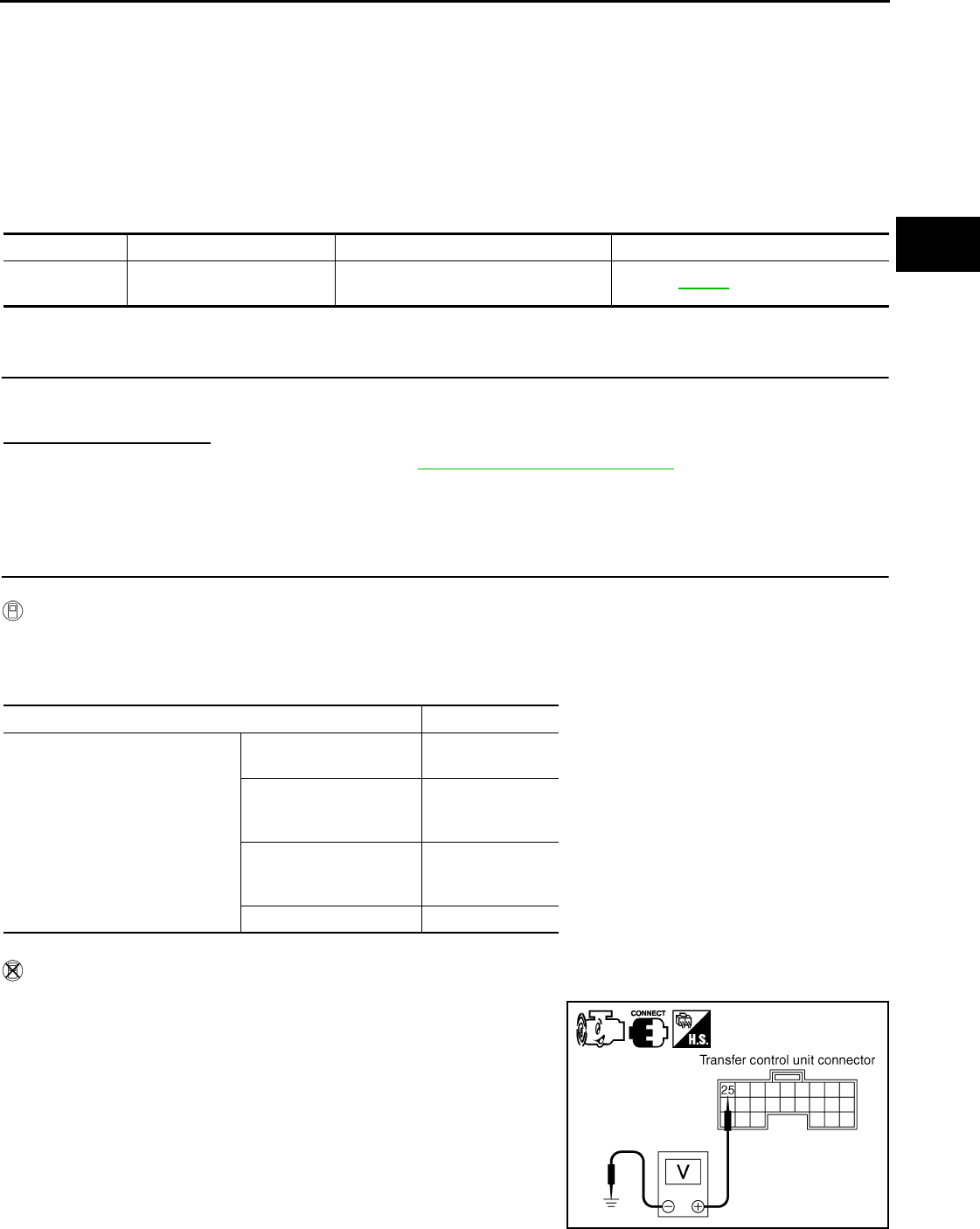
P1810 NEUTRAL-4LO SWITCH
DLN-33
< COMPONENT DIAGNOSIS > [TRANSFER: ATX14B]
C
E
F
G
H
I
J
K
L
M
A
B
DLN
N
O
P
P1810 NEUTRAL-4LO SWITCH
Description INFOID:0000000003937205
The neutral-4LO switch detects that the transfer case is in neutral or 4LO range. DTC P1810 will set when an
improper signal from the neutral-4LO switch is input due to an open or short circuit.
DTC Logic INFOID:0000000003937206
DTC DETECTION LOGIC
DTC CONFIRMATION PROCEDURE
1.DTC CONFIRMATION PROCEDURE
1. Turn ignition switch ON.
2. Perform self-diagnosis.
Is DTC P1810 displayed?
YES >> Perform diagnosis procedure. Refer to DLN-33, "Diagnosis Procedure".
NO >> Inspection End.
Diagnosis Procedure INFOID:0000000003937207
1.CHECK 4LO POSITION SWITCH SIGNAL
With CONSULT-III
1. Start engine.
2. Select DATA MONITOR mode for ALL MODE AWD/4WD with CONSULT-III.
3. Read out the value of N POSI SW TF.
Without CONSULT-III
1. Start engine.
2. Check voltage between transfer control unit harness connector
terminal and ground.
DTC CONSULT-III Diagnostic item is detected when... Reference
[P1810] 4L POSI SW TF Improper signal from neutral-4LO switch
is input due to open or short circuit. Refer to DLN-33.
Condition Display value
• Vehicle stopped
• Engine running
• A/T selector lever N position
• Brake pedal depressed
4WD shift switch: 2WD,
AUTO or 4H OFF
4WD shift switch: 4H to
4LO (While actuator mo-
tor is operating.) OFF → ON
4WD shift switch: 4LO to
4H (While actuator motor
is operating.)
ON → OFF
4WD shift switch: 4LO ON
SDIA2693E
Revision: October 2008
2009 Pathfinder
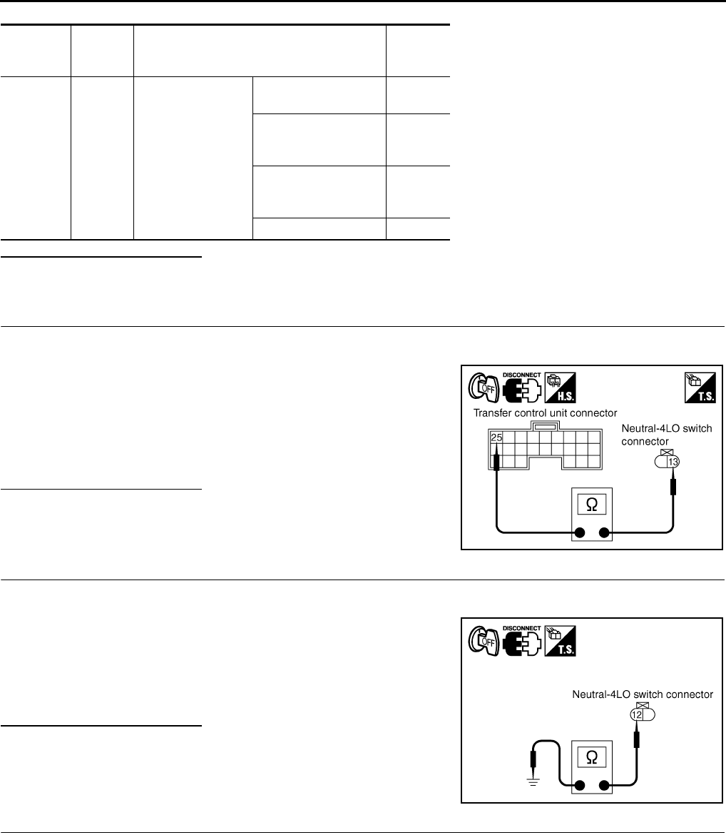
DLN-34
< COMPONENT DIAGNOSIS > [TRANSFER: ATX14B]
P1810 NEUTRAL-4LO SWITCH
Are inspection results normal?
YES >> GO TO 5.
NO >> GO TO 2.
2.CHECK HARNESS BETWEEN TRANSFER CONTROL UNIT AND NEUTRAL-4LO SWITCH
1. Turn ignition switch OFF. (Stay for at least 5 seconds.)
2. Disconnect transfer control unit harness connector and the neutral-4LO switch harness connector.
3. Check continuity between transfer control unit harness connec-
tor M153 terminal 25 and neutral-4LO switch harness connector
F60 terminal 13.
Also check harness for short to ground and short to power.
Are inspection results normal?
YES >> GO TO 3.
NO >> Repair or replace damaged parts.
3.CHECK GROUND CIRCUIT
1. Turn ignition switch OFF. (Stay for at least 5 seconds.)
2. Disconnect neutral-4LO switch harness connector.
3. Check continuity between neutral-4LO switch harness connec-
tor F60 terminal 12 and ground.
Also check harness for short to ground and short to power.
Are inspection results normal?
YES >> GO TO 4.
NO >> Repair open circuit or short to ground or short to power
in harness or connectors.
4.CHECK 4LO SWITCH
1. Turn ignition switch OFF.
2. Disconnect neutral-4LO switch harness connector.
3. Remove neutral-4LO switch.
Connector Te rm in al
(Wire col-
or)
Condition Voltage
(Approx.)
M153 25 -
Ground
• Vehicle stopped
• Engine running
• A/T selector lever
N position
• Brake pedal de-
pressed
4WD shift switch:
2WD, AUTO or 4H
Battery
voltage
4WD shift switch: 4H to
4LO (While actuator
motor is operating.)
Battery
voltage
→ 0V
4WD shift switch: 4LO
to 4H (While actuator
motor is operating.)
0V →
Battery
voltage
4WD shift switch: 4LO 0V
Continuity should exist.
SDIA2694E
Continuity should exist.
SDIA2695E
Revision: October 2008
2009 Pathfinder
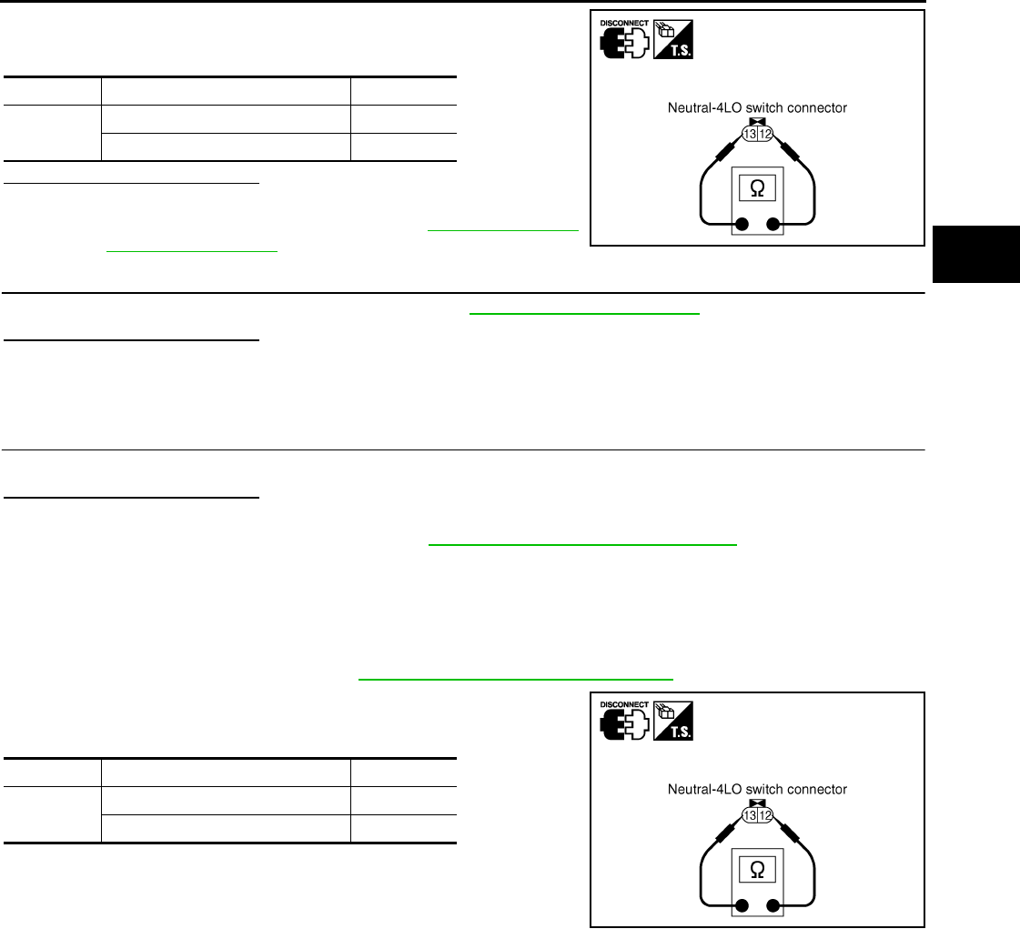
P1810 NEUTRAL-4LO SWITCH
DLN-35
< COMPONENT DIAGNOSIS > [TRANSFER: ATX14B]
C
E
F
G
H
I
J
K
L
M
A
B
DLN
N
O
P
4. Push and release neutral-4LO switch and check continuity
between neutral-4LO switch terminals 12 and 13.
Are inspection results normal?
YES >> GO TO 5.
NO >> Replace neutral-4LO switch. Refer to DLN-18, "Compo-
nent Parts Location".
5.CHECK TRANSFER CONTROL UNIT
Check transfer control unit input/output signal. Refer to DLN-85, "Reference Value".
Are inspection results normal?
YES >> GO TO 6.
NO >> Check transfer control unit pin terminals for damage or loose connection with harness connector.
If any items are damaged, repair or replace damaged parts.
6.CHECK DTC
Drive the vehicle and then perform self-diagnosis.
Are inspection results normal?
YES >> Inspection End.
NO >> Replace transfer control unit. Refer to DLN-136, "Removal and Installation".
Component Inspection INFOID:0000000003937208
1. Turn ignition switch OFF. (Stay for at least 5 seconds.)
2. Disconnect neutral-4LO switch harness connector.
3. Remove neutral-4LO switch. Refer to DLN-18, "Component Parts Location".
4. Push and release neutral-4LO switch and check continuity
between neutral-4LO switch terminals 12 and 13.
5. If the inspection results are abnormal replace the neutral-4LO
switch.
Terminal Condition Continuity
12 - 13 Push neutral-4LO switch Yes
Release neutral-4LO switch No
SDIA2696E
Terminal Condition Continuity
12 - 13 Push neutral-4LO switch Yes
Release neutral-4LO switch No
SDIA2696E
Revision: October 2008
2009 Pathfinder
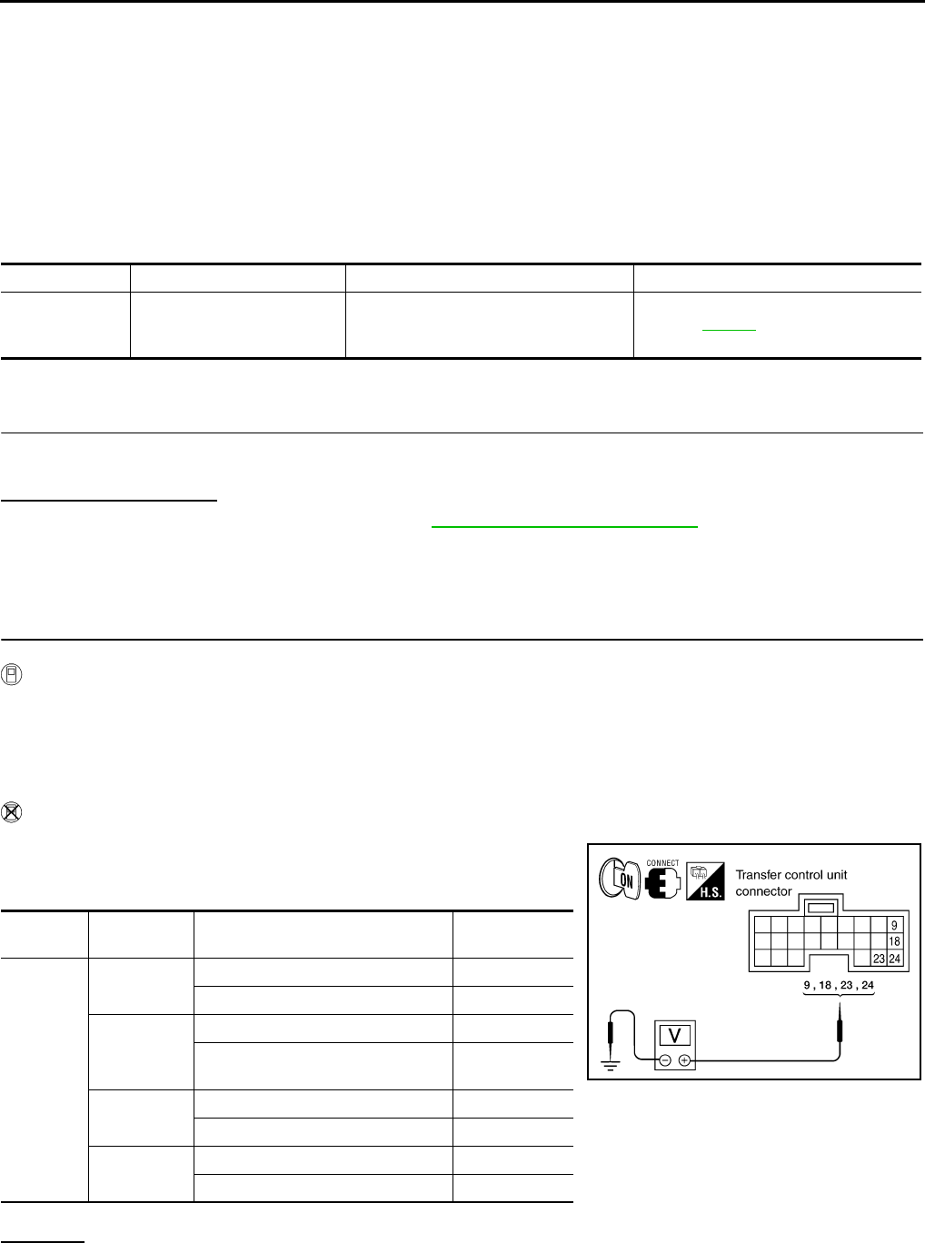
DLN-36
< COMPONENT DIAGNOSIS > [TRANSFER: ATX14B]
P1813 4WD SHIFT SWITCH
P1813 4WD SHIFT SWITCH
Description INFOID:0000000003937209
The 4WD shift switch allows the driver to select AUTO, 2WD or 4WD and 4H or 4LO. DTC P1813 will set if
more than two switch inputs are simultaneously detected by the transfer control unit due to a short circuit in the
4WD shift switch.
DTC Logic INFOID:0000000003937210
DTC DETECTION LOGIC
DTC CONFIRMATION PROCEDURE
1.DTC CONFIRMATION PROCEDURE
1. Turn ignition switch ON.
2. Perform self-diagnosis.
Is DTC P1813 displayed?
YES >> Perform diagnosis procedure. Refer to DLN-36, "Diagnosis Procedure".
NO >> Inspection End.
Diagnosis Procedure INFOID:0000000003937211
1.CHECK 4WD SHIFT SWITCH SIGNAL
With CONSULT-III
1. Turn ignition switch “ON”. (Do not start engine.)
2. Select “DATA MONITOR” mode for “ALL MODE AWD/4WD” with CONSULT-III.
3. Read out ON/OFF switching action of the “2WD SWITCH”, “AUTO SWITCH”, “LOCK SWITCH” and “4L
SWITCH” while operating 4WD shift switch.
Without CONSULT-III
1. Turn ignition switch “ON”. (Do not start engine.)
2. Check voltage between transfer control unit harness connector
terminals and ground.
OK or NG
OK >> GO TO 5.
NG >> GO TO 2.
DTC CONSULT-III Diagnostic item is detected when... Reference
[P1813] 4WD MODE SW More than two switch inputs are simulta-
neously detected due to short circuit of
4WD shift switch.
Refer to DLN-36.
Connector Terminal Condition Voltage (Ap-
prox.)
M152
9 - ground 4WD shift switch: 2WD Battery voltage
4WD shift switch: AUTO, 4H or 4LO 0V
18 - ground
4WD shift switch: 4H Battery voltage
4WD shift switch: 2WD, AUTO or
4LO 0V
23 - ground 4WD shift switch: 4LO Battery voltage
4WD shift switch: 2WD, AUTO or 4H 0V
24 - ground 4WD shift switch: AUTO Battery voltage
4WD shift switch: 2WD, 4H or 4LO 0V
WDIA0167E
Revision: October 2008
2009 Pathfinder
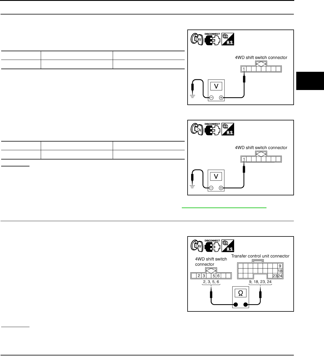
P1813 4WD SHIFT SWITCH
DLN-37
< COMPONENT DIAGNOSIS > [TRANSFER: ATX14B]
C
E
F
G
H
I
J
K
L
M
A
B
DLN
N
O
P
2.CHECK 4WD SHIFT SWITCH POWER SUPPLY CIRCUIT
1. Turn ignition switch “OFF”. (Stay for at least 5 seconds.)
2. Disconnect 4WD shift switch harness connector.
3. Check voltage between 4WD shift switch harness connector ter-
minal 1 and ground.
4. Turn ignition switch “ON”. (Do not start engine.)
5. Check voltage between 4WD shift switch harness connector ter-
minal 1 and ground.
OK or NG
OK >> GO TO 3.
NG >> Check the following. If any items are damaged, repair
or replace damaged parts.
• Harness for short or open between transfer shut off
relay harness connector E155 terminal 5.
• Power suppy circuit for transfer control unit. Refer to DLN-27, "Diagnosis Procedure".
3.CHECK HARNESS BETWEEN 4WD SHIFT SWITCH AND TRANSFER CONTROL UNIT
1. Turn ignition switch “OFF”. (Stay for at least 5 seconds.)
2. Disconnect transfer control unit harness connector and the 4WD shift switch harness connector.
3. Check continuity between the following terminals.
- Transfer control unit harness connector M152 terminal 9 and
4WD shift switch harness connector M141 terminal 2.
- Transfer control unit harness connector M152 terminal 18 and
4WD shift switch harness connector M141 terminal 5.
- Transfer control unit harness connector M152 terminal 23 and
4WD shift switch harness connector M141 terminal 6.
- Transfer control unit harness connector M152 terminal 24 and
4WD shift switch harness connector M141 terminal 3.
Also check harness for short to ground and short to power.
OK or NG
OK >> GO TO 4.
NG >> Repair or replace damaged parts.
4.CHECK 4WD SHIFT SWITCH
1. Turn ignition switch “OFF”. (Stay for at least 5 seconds.)
2. Disconnect 4WD shift switch harness connector.
Connector Terminal Voltage (Approx.)
M141 1 - Ground 0V
WDIA0183E
Connector Terminal Voltage (Approx.)
M141 1 - Ground Battery voltage
WDIA0184E
Continuity should exist. WDIA0185E
Revision: October 2008
2009 Pathfinder
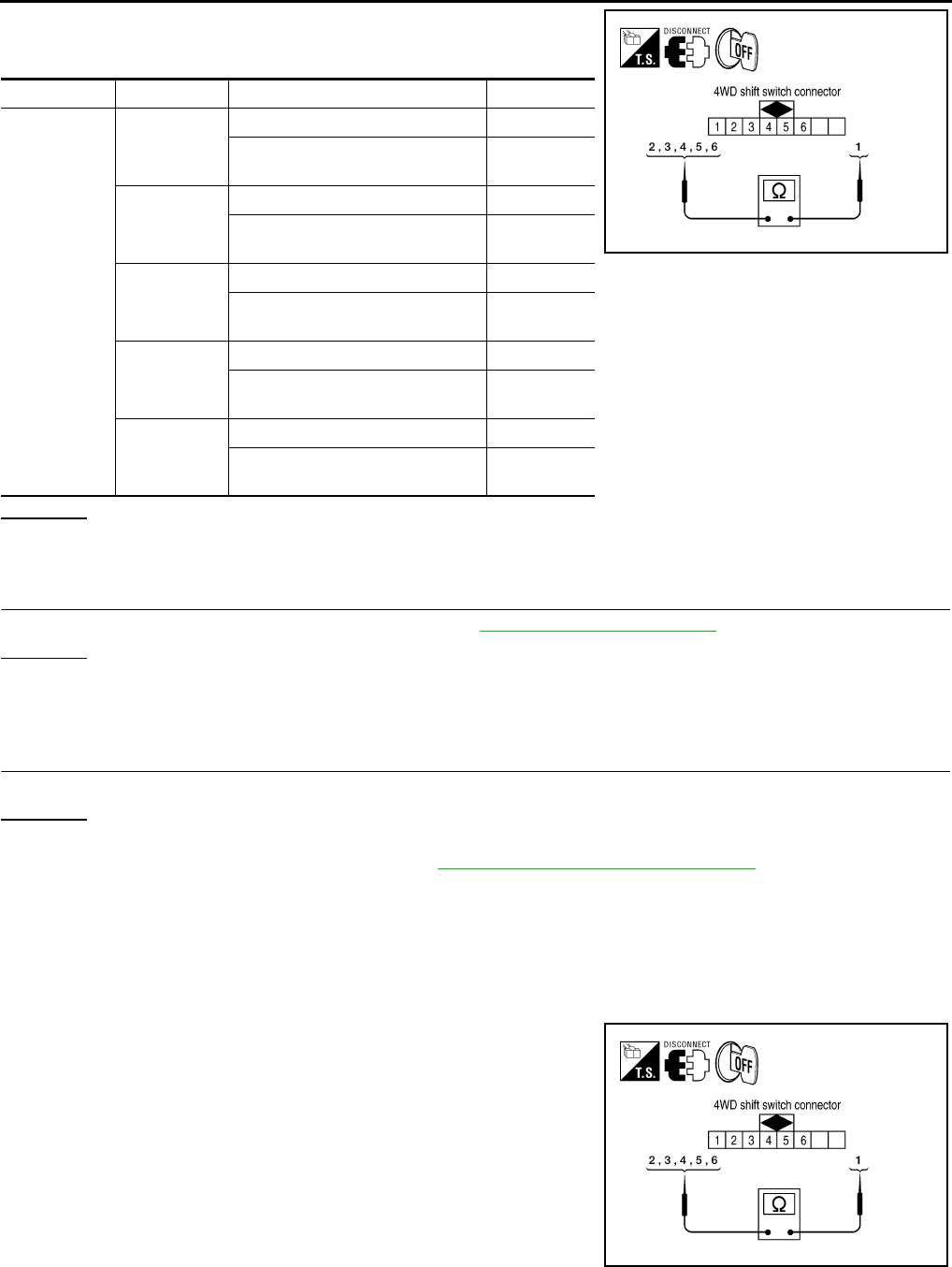
DLN-38
< COMPONENT DIAGNOSIS > [TRANSFER: ATX14B]
P1813 4WD SHIFT SWITCH
3. Operate 4WD shift switch and check continuity between 4WD
shift switch terminals.
OK or NG
OK >> GO TO 5.
NG >> Replace 4WD shift switch.
5.CHECK TRANSFER CONTROL UNIT
Check transfer control unit input/output signal. Refer to DLN-85, "Reference Value".
OK or NG
OK >> GO TO 6.
NG >> Check transfer control unit pin terminals for damage or loose connection with harness connector.
If any items are damaged, repair or replace damaged parts.
6.CHECK DTC
Perform the self-diagnosis, after driving a vehicle for a while.
OK or NG
OK >> Inspection End.
NG >> Replace transfer control unit. Refer to DLN-136, "Removal and Installation".
Component Inspection INFOID:0000000003937212
4WD SHIFT SWITCH
1. Turn ignition switch “OFF”. (Stay for at least 5 seconds.)
2. Disconnect 4WD shift switch harness connector.
3. Operate 4WD shift switch and check continuity between 4WD
shift switch terminals.
Connector Terminal Condition Continuity
M141
1 - 2
4WD shift switch: 2WD Yes
4WD shift switch: AUTO, 4H and
4LO No
1 - 3
4WD shift switch: AUTO Yes
4WD shift switch: 2WD, 4H and
4LO No
1 - 4
4WD shift switch: 2WD No
4WD shift switch: AUTO, 4H and
4LO Yes
1 - 5
4WD shift switch: 4H Yes
4WD shift switch: 2WD, AUTO,
and 4LO No
1 - 6
4WD shift switch: 4LO Yes
4WD shift switch: 2WD, AUTO and
4H No
WDIA0168E
WDIA0168E
Revision: October 2008
2009 Pathfinder

P1813 4WD SHIFT SWITCH
DLN-39
< COMPONENT DIAGNOSIS > [TRANSFER: ATX14B]
C
E
F
G
H
I
J
K
L
M
A
B
DLN
N
O
P
4. If NG, replace the 4WD shift switch.
Connector Terminal Condition Continuity
M141
1 - 2
4WD shift switch: 2WD Yes
4WD shift switch: AUTO, 4H and
4LO No
1 - 3
4WD shift switch: AUTO Yes
4WD shift switch: 2WD, 4H and
4LO No
1 - 4
4WD shift switch: 2WD No
4WD shift switch: AUTO, 4H and
4LO Yes
1 - 5
4WD shift switch: 4H Yes
4WD shift switch: 2WD, AUTO,
and 4LO No
1 - 6
4WD shift switch: 4LO Yes
4WD shift switch: 2WD, AUTO and
4H No
Revision: October 2008
2009 Pathfinder
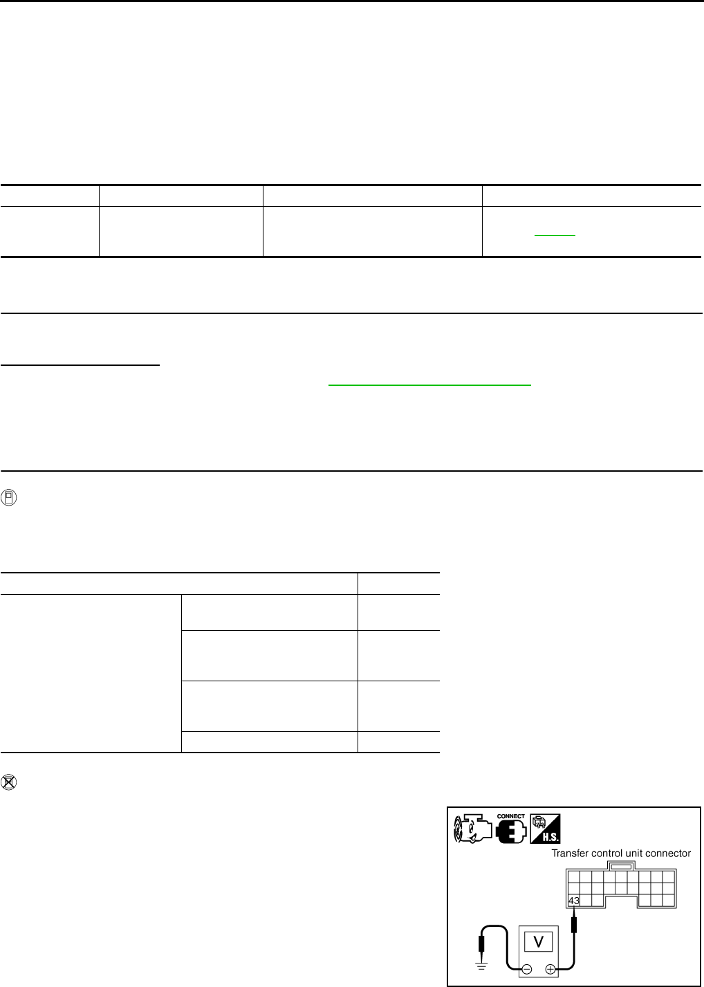
DLN-40
< COMPONENT DIAGNOSIS > [TRANSFER: ATX14B]
P1814 WAIT DETECTION SWITCH
P1814 WAIT DETECTION SWITCH
Description INFOID:0000000003937213
The wait detection switch detects if the transfer case is in 4WD. DTC P1814 will set if an improper signal from
the wait detection switch is input due to open or short circuit.
DTC Logic INFOID:0000000003937214
DTC DETECTION LOGIC
DTC CONFIRMATION PROCEDURE
1.DTC CONFIRMATION PROCEDURE
1. Turn ignition switch ON.
2. Perform self-diagnosis.
Is DTC P1814 detected?
YES >> Perform diagnosis procedure. Refer to DLN-40, "Diagnosis Procedure".
NO >> Inspection End.
Diagnosis Procedure INFOID:0000000003937215
1.CHECK WAIT DETECTION SWITCH SIGNAL
With CONSULT-III
1. Start engine.
2. Select “DATA MONITOR” mode for “ALL MODE AWD/4WD” with CONSULT-III.
3. Read out the value of “WAIT DETCT SW”.
Without CONSULT-III
1. Start engine.
2. Check voltage between transfer control unit harness connector
terminal and ground.
DTC CONSULT-III Diagnostic item is detected when... Reference
[P1814] 4WD DETECT SWITCH
Improper signal from wait detection
switch is input due to open or short cir-
cuit. Refer to DLN-40.
Condition Display value
• Vehicle stopped
• Engine running
• A/T selector lever “N” position
• Brake pedal depressed
4WD shift switch: 2WD, AUTO
or 4H OFF
4WD shift switch: 4H to 4LO
(While actuator motor is operat-
ing.)
OFF → ON
4WD shift switch: 4LO to 4H
(While actuator motor is operat-
ing.) ON → OFF
4WD shift switch: 4LO ON
SDIA2701E
Revision: October 2008
2009 Pathfinder
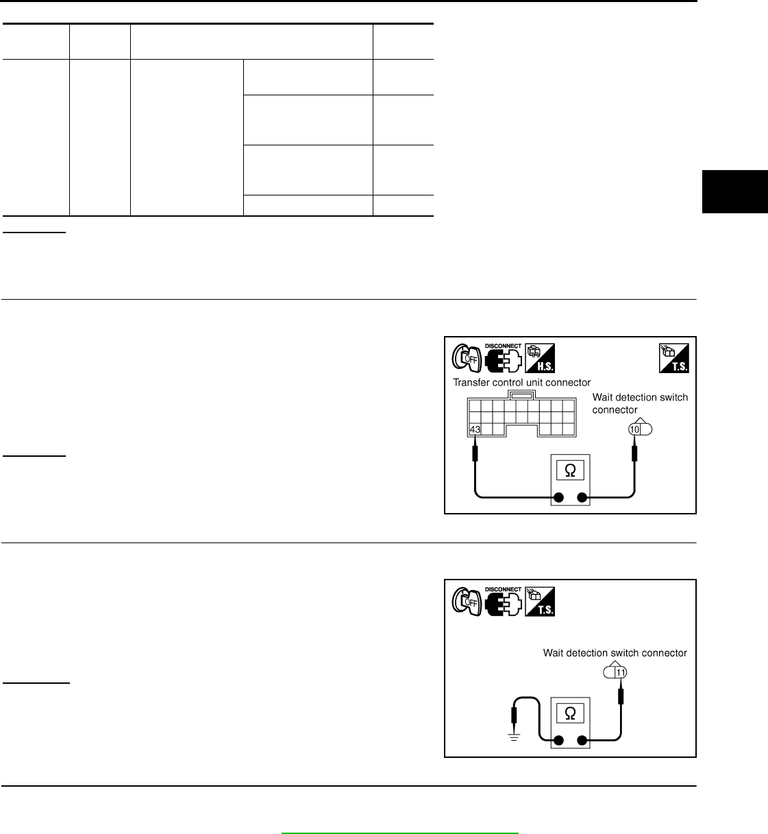
P1814 WAIT DETECTION SWITCH
DLN-41
< COMPONENT DIAGNOSIS > [TRANSFER: ATX14B]
C
E
F
G
H
I
J
K
L
M
A
B
DLN
N
O
P
OK or NG
OK >> GO TO 5.
NG >> GO TO 2.
2.CHECK HARNESS BETWEEN TRANSFER CONTROL UNIT AND WAIT DETECTION SWITCH
1. Turn ignition switch “OFF”. (Stay for at least 5 seconds.)
2. Disconnect transfer control unit harness connector and the wait detection switch harness connector.
3. Check continuity between transfer control unit harness connec-
tor M153 terminal 43 and wait detection switch harness connec-
tor F59 terminal 10.
Also check harness for short to ground and short to power.
OK or NG
OK >> GO TO 3.
NG >> Repair or replace damaged parts.
3.CHECK GROUND CIRCUIT
1. Turn ignition switch “OFF”. (Stay for at least 5 seconds.)
2. Disconnect wait detection switch harness connector.
3. Check continuity between wait detection switch harness con-
nector F59 terminal 11 and ground.
Also check harness for short to power.
OK or NG
OK >> GO TO 4.
NG >> Repair open circuit or short to power in harness or con-
nectors.
4.CHECK WAIT DETECTION SWITCH
1. Turn ignition switch “OFF”. (Stay for at least 5 seconds.)
2. Disconnect wait detection switch harness connector.
3. Remove wait detection switch. Refer to DLN-18, "Component Parts Location".
Connector Terminal Condition Voltage
(Approx.)
M153 43 -
Ground
• Vehicle stopped
• Engine running
• A/T selector lever
“N” position
• Brake pedal de-
pressed
4WD shift switch:
2WD, AUTO or 4H
Battery
voltage
4WD shift switch: 4H to
4LO (While actuator
motor is operating.)
Battery
voltage
→ 0V
4WD shift switch: 4LO
to 4H (While actuator
motor is operating.)
0V →
Battery
voltage
4WD shift switch: 4LO 0V
Continuity should exist.
SDIA2702E
Continuity should exist.
SDIA2703E
Revision: October 2008
2009 Pathfinder
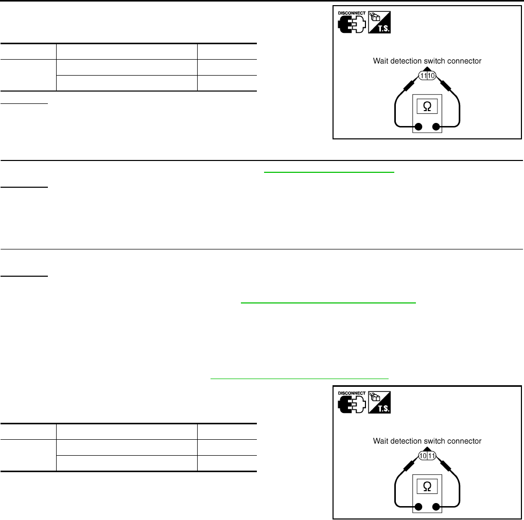
DLN-42
< COMPONENT DIAGNOSIS > [TRANSFER: ATX14B]
P1814 WAIT DETECTION SWITCH
4. Push and release wait detection switch and check continuity
between wait detection switch terminals 10 and 11.
OK or NG
OK >> GO TO 5.
NG >> Replace wait detection switch.
5.CHECK TRANSFER CONTROL UNIT
Check transfer control unit input/output signal. Refer to DLN-85, "Reference Value".
OK or NG
OK >> GO TO 6.
NG >> Check transfer control unit pin terminals for damage or loose connection with harness connector.
If any items are damaged, repair or replace damaged parts.
6.CHECK DTC
Perform the self-diagnosis, after driving a vehicle for a while.
OK or NG
OK >> Inspection End.
NG >> Replace transfer control unit. Refer to DLN-136, "Removal and Installation".
Component Inspection INFOID:0000000003937216
1. Turn ignition switch OFF. (Stay for at least 5 seconds.)
2. Disconnect wait detection switch harness connector.
3. Remove wait detection switch. Refer to DLN-18, "Component Parts Location".
4. Push and release wait detection switch and check continuity
between wait detection switch terminals 10 and 11.
5. If the inspection results are abnormal replace the wait detection
switch.
Terminal Condition Continuity
10 - 11 Push wait detection switch Yes
Release wait detection switch No
WDIA0186E
Terminal Condition Continuity
10 - 11 Push wait detection switch Yes
Release wait detection switch No
SDIA2704E
Revision: October 2008
2009 Pathfinder
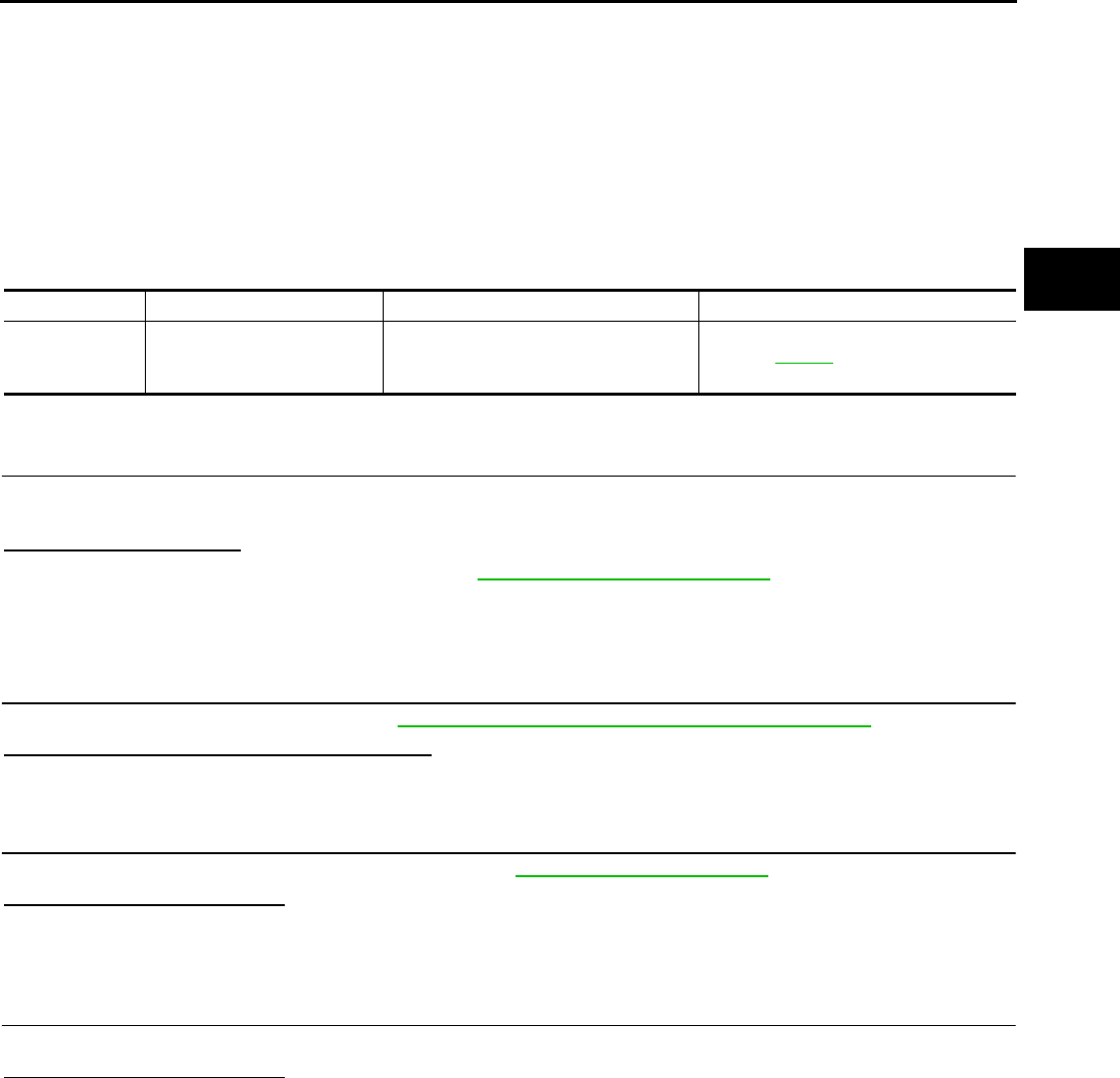
P1816 PNP SWITCH
DLN-43
< COMPONENT DIAGNOSIS > [TRANSFER: ATX14B]
C
E
F
G
H
I
J
K
L
M
A
B
DLN
N
O
P
P1816 PNP SWITCH
Description INFOID:0000000003937217
The A/T PNP switch transmits the A/T position indicator signal (PNP switch signal) via CAN communication to
the transfer control unit. DTC P1816 will set when the A/T PNP switch signal is malfunctioning or there is a
communication error.
DTC Logic INFOID:0000000003937218
DTC DETECTION LOGIC
DTC CONFIRMATION PROCEDURE
1.DTC CONFIRMATION PROCEDURE
1. Turn ignition switch ON.
2. Perform self-diagnosis.
Is DTC P1816 displayed?
YES >> Perform diagnosis procedure. Refer to DLN-43, "Diagnosis Procedure".
NO >> Inspection End.
Diagnosis Procedure INFOID:0000000003937219
1.CHECK DTC WITH TCM
Perform self-diagnosis with TCM. Refer to TM-36, "CONSULT-III Function (TRANSMISSION)".
Is any malfunction detected by self-diagnosis?
YES >> Check the malfunctioning system.
NO >> GO TO 2.
2.CHECK TRANSFER CONTROL UNIT
Check transfer control unit input/output signal. Refer to DLN-85, "Reference Value".
Are inspection results normal?
YES >> GO TO 3.
NO >> Check transfer control unit pin terminals for damage or loose connection with harness connector.
If any items are damaged, repair or replace damaged parts.
3.CHECK DTC
Drive the vehicle and then perform self-diagnosis.
Are inspection results normal?
YES >> Inspection End.
NO >> Perform self-diagnosis with TCM again.
DTC CONSULT-III Diagnostic item is detected when... Reference
[P1816] PNP SW/CIRC When A/T PNP switch signal is malfunc-
tion or communication error between the
control units.
Refer to DLN-43.
Revision: October 2008
2009 Pathfinder

DLN-44
< COMPONENT DIAGNOSIS > [TRANSFER: ATX14B]
P1817 ACTUATOR MOTOR
P1817 ACTUATOR MOTOR
Description INFOID:0000000003937220
The actuator motor receives signals from the transfer control unit and controls shift rods which shift the trans-
fer case. DTC P1817 will set when any of the following occur:
• Motor does not operate properly due to open or short circuit in actuator motor.
• Malfunction is detected in the actuator motor. (When 4WD shift switch is operated and actuator motor does
not operate)
• Malfunction is detected in transfer shift high relay or transfer shift low relay.
DTC Logic INFOID:0000000003937221
DTC DETECTION LOGIC
DTC CONFIRMATION PROCEDURE
1.DTC CONFIRMATION PROCEDURE
1. Turn ignition switch ON.
2. Perform self-diagnosis.
Is DTC P1817 detected?
YES >> Perform diagnosis procedure. Refer to DLN-44, "Diagnosis Procedure".
NO >> Inspection End.
Diagnosis Procedure INFOID:0000000003937222
1.CHECK ACTUATOR MOTOR SIGNAL
With CONSULT-III
1. Start engine.
2. Select “DATA MONITOR” mode for “ALL MODE AWD/4WD” with CONSULT-III.
3. Read out the value of “SHIFT ACT1”, “SHIFT AC MON1”, “SHIFT ACT2” and “SHIFT AC MON2”.
DTC CONSULT-III Diagnostic item is detected when... Reference
[P1817] SHIFT ACTUATOR
• Motor does not operate properly due
to open or short circuit in actuator mo-
tor.
• Malfunction is detected in the actuator
motor. (When 4WD shift switch is op-
erated and actuator motor is not oper-
ated)
• Malfunction is detected in transfer shift
high relay and transfer shift low relay.
Refer to DLN-44.
Monitored
item Condition Display
value
SHIFT ACT1
• Vehicle stopped
• Engine running
• A/T selector lever “N” posi-
tion
• Brake pedal depressed
4WD shift switch: 4H
to 4LO (“Wait” func-
tion is operating.)
ON
Except the above OFF
SHIFT AC
MON1
• Vehicle stopped
• Engine running
• A/T selector lever “N” posi-
tion
• Brake pedal depressed
4WD shift switch: 4H
to 4LO (“Wait” func-
tion is operating.) ON
Except the above OFF
Revision: October 2008
2009 Pathfinder
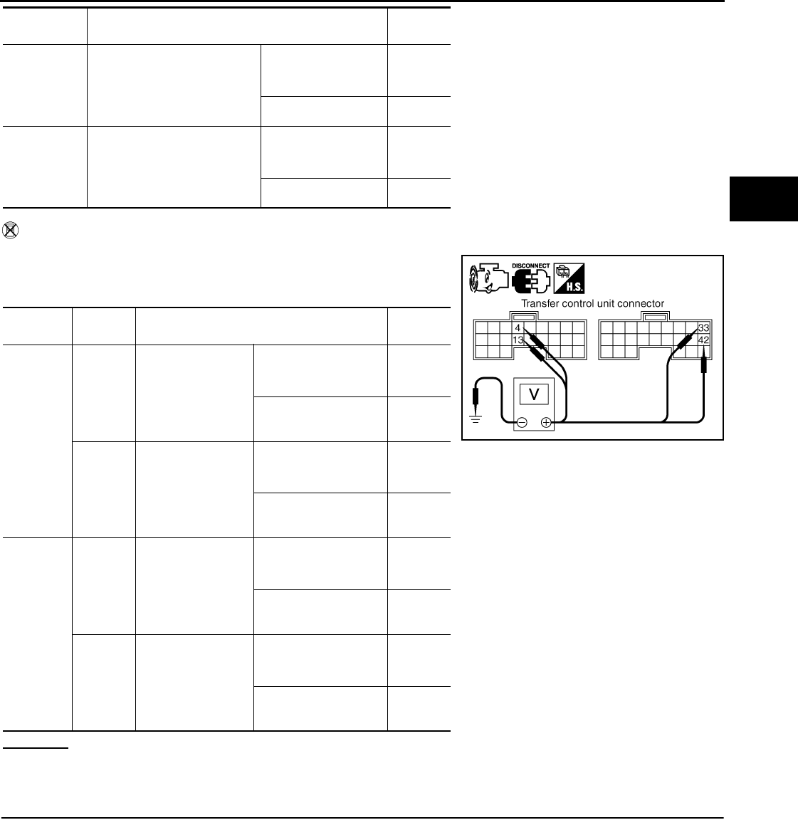
P1817 ACTUATOR MOTOR
DLN-45
< COMPONENT DIAGNOSIS > [TRANSFER: ATX14B]
C
E
F
G
H
I
J
K
L
M
A
B
DLN
N
O
P
Without CONSULT-III
1. Start engine.
2. Check voltage between transfer control unit harness connector
terminal and ground.
OK or NG
OK >> GO TO 7.
NG >> GO TO 2.
2.CHECK ACTUATOR MOTOR POWER SUPPLY CIRCUIT
1. Turn ignition switch “OFF”. (Stay for at least 5 seconds.)
2. Remove transfer shift high relay and transfer shift low relay.
SHIFT ACT2
• Vehicle stopped
• Engine running
• A/T selector lever “N” posi-
tion
• Brake pedal depressed
4WD shift switch:
4LO to 4H (“Wait”
function is operating.)
ON
Except the above OFF
SHIFT AC
MON2
• Vehicle stopped
• Engine running
• A/T selector lever “N” posi-
tion
• Brake pedal depressed
4WD shift switch:
4LO to 4H (“Wait”
function is operating.) ON
Except the above OFF
Connector Terminal Condition Voltage
(Approx.)
M152
4 -
Ground
• Vehicle stopped
• Engine running
• A/T selector lever
“N” position
• Brake pedal de-
pressed
4WD shift switch: 4H to
4LO (“Wait” function is
operating.)
Battery
voltage
Except the above 0V
13 -
Ground
• Vehicle stopped
• Engine running
• A/T selector lever
“N” position
• Brake pedal de-
pressed
4WD shift switch: 4LO
to 4H (“Wait” function
is operating.)
Battery
voltage
Except the above 0V
M153
33 -
Ground
• Vehicle stopped
• Engine running
• A/T selector lever
“N” position
• Brake pedal de-
pressed
4WD shift switch: 4H to
4LO (“Wait” function is
operating.)
Battery
voltage
Except the above 0V
42 -
Ground
• Vehicle stopped
• Engine running
• A/T selector lever
“N” position
• Brake pedal de-
pressed
4WD shift switch: 4LO
to 4H (“Wait” function
is operating.)
Battery
voltage
Except the above 0V
Monitored
item Condition Display
value
SDIA2705E
Revision: October 2008
2009 Pathfinder
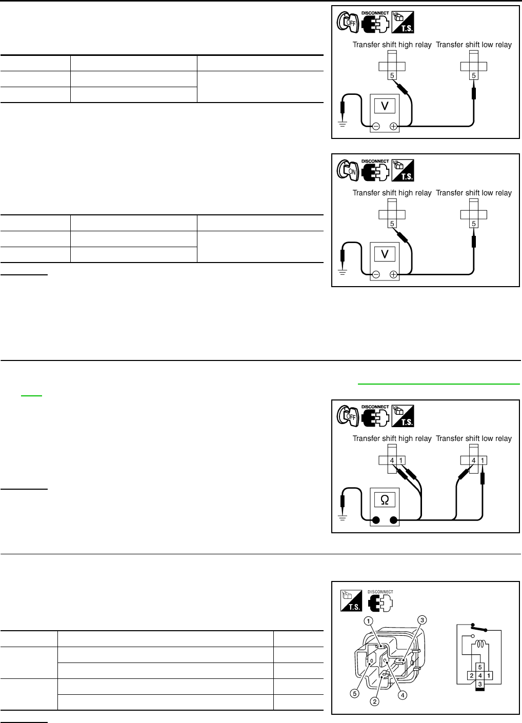
DLN-46
< COMPONENT DIAGNOSIS > [TRANSFER: ATX14B]
P1817 ACTUATOR MOTOR
3. Check voltage between transfer shift high relay harness connec-
tor E46 terminal 5, transfer shift low relay harness connector
E47 terminal 5 and ground.
4. Turn ignition switch “ON”. (Do not start engine.)
5. Check voltage between transfer shift high relay harness connec-
tor E46 terminal 5, transfer shift low relay harness connector
E47 terminal 5 and ground.
OK or NG
OK >> GO TO 3.
NG >> Check the following. If any items are damaged, repair or replace damaged parts.
• 20A fuse (No. 58, located in the fuse and relay box).
• Harness for short or open between battery, transfer shift high harness connector terminal 5 and
transfer shift low harness connector terminal 5.
3.CHECK ACTUATOR MOTOR GROUND CIRCUIT
1. Turn ignition switch “OFF”. (Stay for at least 5 seconds.)
2. Remove transfer shift high relay and transfer shift low relay. Refer to DLN-18, "Component Parts Loca-
tion".
3. Check continuity between transfer shift high relay harness con-
nector E46 terminals 1 and 4, and transfer shift low relay har-
ness connector E47 terminals 1 and 4 and ground.
Also check harness for short to power.
OK or NG
OK >> GO TO 4.
NG >> Repair open circuit or short to power in harness or con-
nectors.
4.CHECK TRANSFER SHIFT RELAYS
1. Turn ignition switch “OFF”.
2. Remove transfer shift high relay and transfer shift low relay.
3. Apply 12V direct current between transfer shift relay terminals 1
and 2.
4. Check continuity between relay terminals 3 and 4, 3 and 5.
OK or NG
Connector Terminal Voltage (Approx.)
E46 5 - Ground Battery voltage
E47 5 - Ground
SDIA2707E
Connector Terminal Voltage (Approx.)
E46 5 - Ground Battery voltage
E47 5 - Ground
SDIA2706E
Continuity should exist.
SDIA2708E
Terminal Condition Continuity
3 - 4 12V direct current supply between terminals 1 and 2 No
OFF Yes
3 - 5 12V direct current supply between terminals 1 and 2 Yes
OFF No
LDIA0099E
Revision: October 2008
2009 Pathfinder
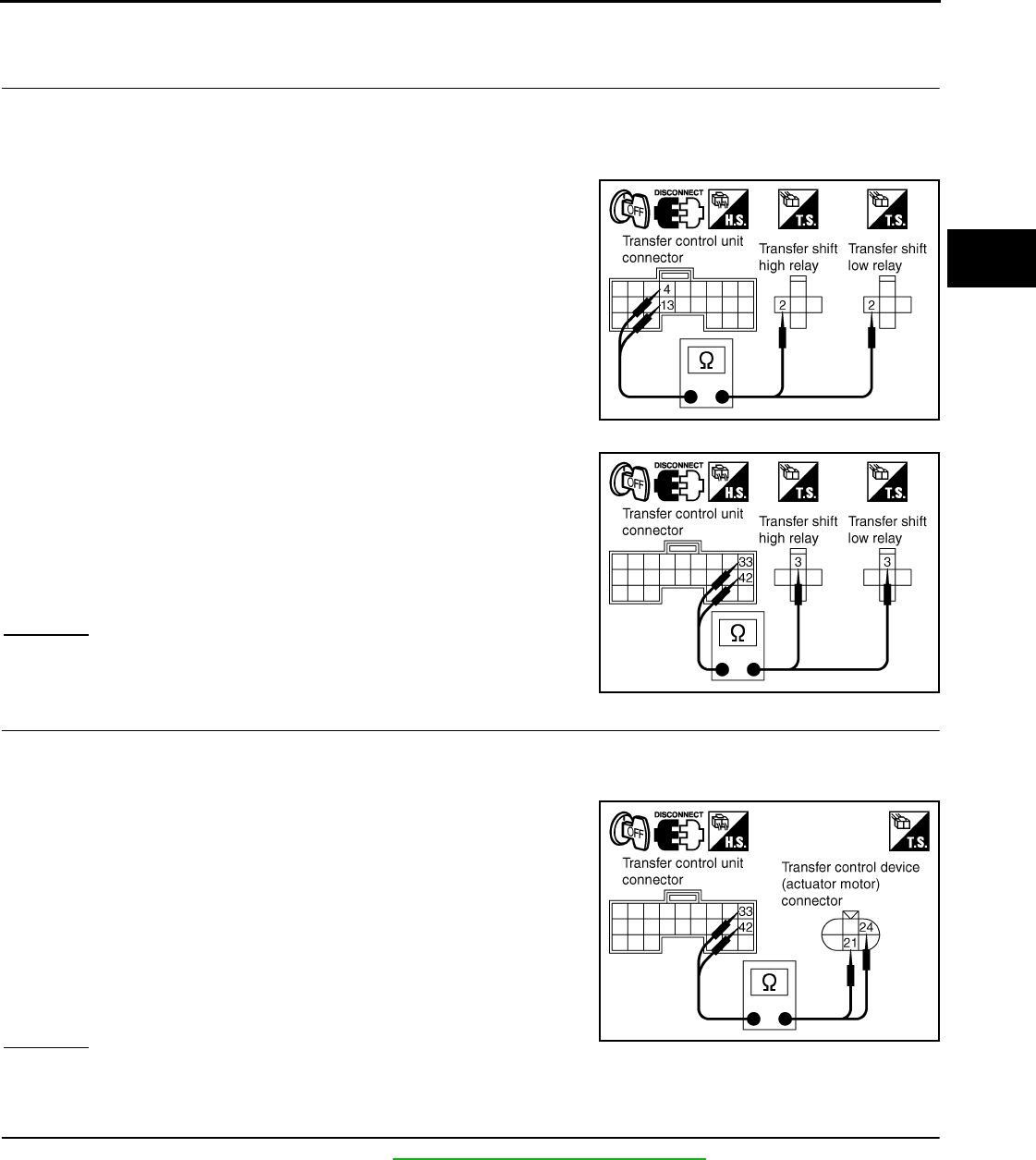
P1817 ACTUATOR MOTOR
DLN-47
< COMPONENT DIAGNOSIS > [TRANSFER: ATX14B]
C
E
F
G
H
I
J
K
L
M
A
B
DLN
N
O
P
OK >> GO TO 5.
NG >> Replace the transfer shift relay.
5.CHECK HARNESS BETWEEN TRANSFER CONTROL UNIT AND TRANSFER SHIFT RELAY
1. Turn ignition switch “OFF”. (Stay for at least 5 seconds.)
2. Disconnect transfer control unit harness connector and the transfer control device (actuator motor) har-
ness connector.
3. Remove transfer shift high relay and transfer shift low relay.
4. Check continuity between the following terminals.
- Transfer control unit harness connector M152 terminal 4 and
transfer shift high relay harness connector E46 terminal 2.
- Transfer control unit harness connector M152 terminal 13 and
transfer shift low relay harness connector E47 terminal 2.
- Transfer control unit harness connector M153 terminal 33 and
transfer shift high relay harness connector E46 terminal 3.
- Transfer control unit harness connector M153 terminal 42 and
transfer shift low relay harness connector E47 terminal 3.
Also check harness for short to ground and short to power.
OK or NG
OK >> GO TO 6.
NG >> Repair or replace damaged parts.
6.CHECK HARNESS BETWEEN TRANSFER CONTROL UNIT AND ACTUATOR MOTOR
1. Turn ignition switch “OFF”. (Stay for at least 5 seconds.)
2. Disconnect transfer control unit harness connector and the transfer control device (actuator motor) har-
ness connector.
3. Check continuity between the following terminals.
- Transfer control unit harness connector M153 terminal 33 and
transfer control device (actuator motor) harness connector F58
terminal 21.
- Transfer control unit harness connector M153 terminal 42 and
transfer control device (actuator motor) harness connector F58
terminal 24.
Also check harness for short to ground and short to power.
OK or NG
OK >> GO TO 7.
NG >> Repair or replace damaged parts.
7.CHECK ACTUATOR MOTOR
1. Remove transfer control device. Refer to DLN-142, "Removal and Installation".
SDIA2711E
Continuity should exist.
SDIA2712E
Continuity should exist.
SDIA2710E
Revision: October 2008
2009 Pathfinder
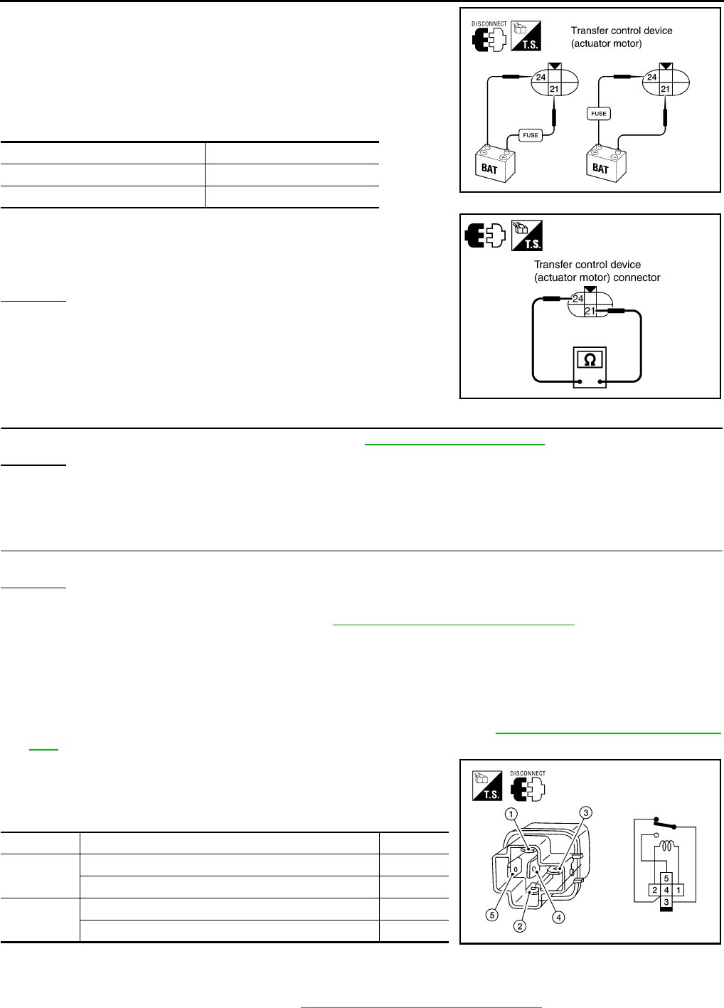
DLN-48
< COMPONENT DIAGNOSIS > [TRANSFER: ATX14B]
P1817 ACTUATOR MOTOR
2. Check operation by applying battery voltage to transfer control
device (actuator motor) terminals 21 and 24.
CAUTION:
• Do not operate actuator motor for more than 1 second.
• Change the actuator motor position to “HIGH” when
installing.
• Be careful not to overheat the harness.
3. Check resistance between transfer control device (actuator
motor) terminals 21 and 24.
OK or NG
OK >> GO TO 8.
NG >> Replace transfer control device (actuator motor).
8.CHECK TRANSFER CONTROL UNIT
Check transfer control unit input/output signal. Refer to DLN-85, "Reference Value".
OK or NG
OK >> GO TO 9.
NG >> Check transfer control unit pin terminals for damage or loose connection with harness connector.
If any items are damaged, repair or replace damaged parts.
9.CHECK DTC
Perform the self-diagnosis, after driving a vehicle for a while.
OK or NG
OK >> Inspection End.
NG >> Replace transfer control unit. Refer to DLN-136, "Removal and Installation".
Component Inspection INFOID:0000000003937223
TRANSFER SHIFT RELAY
1. Turn ignition switch “OFF”. (Stay for at least 5 seconds.)
2. Remove transfer shift high relay and transfer shift low relay. Refer to DLN-18, "Component Parts Loca-
tion".
3. Apply 12V direct current between transfer shift relay terminals 1
and 2.
4. Check continuity between relay terminals 3 and 4, 3 and 5.
5. If NG, replace transfer shift relay.
TRANSFER CONTROL DEVICE
1. Remove transfer control device. Refer to DLN-142, "Removal and Installation".
Terminal Actuator motor
21 (Battery voltage) - 24 (Ground) Clockwise rotate
24 (Battery voltage) - 21 (Ground) Counterclockwise rotate
21 - 24 : Approx. 0.2 Ω
WDIA0224E
SDIA3252E
Terminal Condition Continuity
3 - 4 12V direct current supply between terminals 1 and 2 Yes
OFF No
3 - 5 12V direct current supply between terminals 1 and 2 Yes
OFF No LDIA0099E
Revision: October 2008
2009 Pathfinder
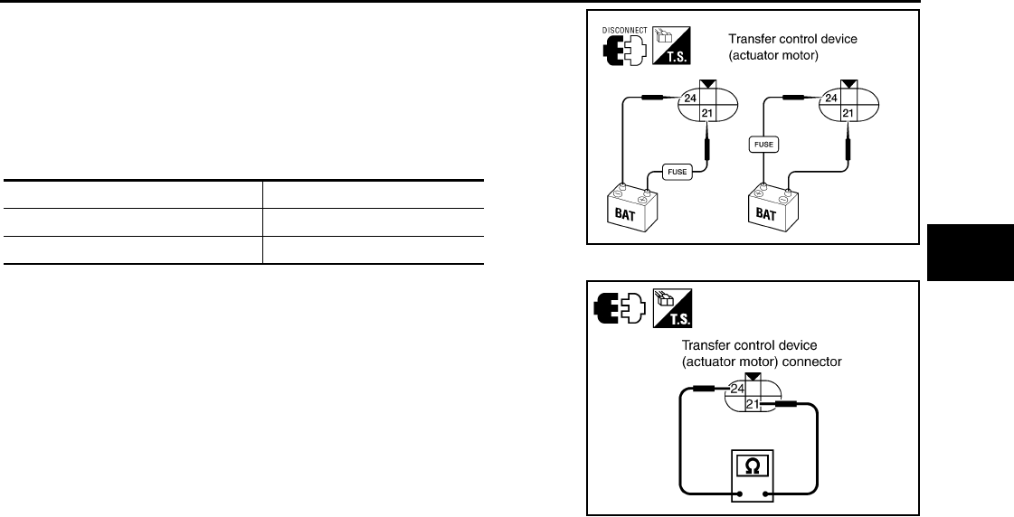
P1817 ACTUATOR MOTOR
DLN-49
< COMPONENT DIAGNOSIS > [TRANSFER: ATX14B]
C
E
F
G
H
I
J
K
L
M
A
B
DLN
N
O
P
2. Check operation by applying battery voltage to transfer control
device (actuator motor) terminals 21 and 24.
CAUTION:
• Do not operate actuator motor for more than 1 second.
• Change the actuator motor position to “HIGH” when
installing.
• Be careful not to overheat the harness.
3. Check resistance between transfer control device (actuator
motor) terminals 21 and 24.
4. If NG, replace transfer control device (actuator motor).
Terminal Actuator motor
21 (Battery voltage) - 24 (Ground) Clockwise rotate
24 (Battery voltage) - 21 (Ground) Counterclockwise rotate WDIA0224E
21 - 24 : Approx. 0.2 Ω
SDIA3252E
Revision: October 2008
2009 Pathfinder

DLN-50
< COMPONENT DIAGNOSIS > [TRANSFER: ATX14B]
P1818 ACTUATOR POSITION SWITCH
P1818 ACTUATOR POSITION SWITCH
Description INFOID:0000000003937224
The actuator position switch detects the current actuator motor range. DTC P1818 will set if either of the fol-
lowing occur:
• Improper signal from actuator position switch is input due to open or short circuit.
• Malfunction is detected in actuator position switch.
DTC Logic INFOID:0000000003937225
DTC DETECTION LOGIC
DTC CONFIRMATION PROCEDURE
1.DTC CONFIRMATION PROCEDURE
1. Turn ignition switch ON.
2. Perform self-diagnosis.
Is DTC P1818 detected?
YES >> Perform diagnosis procedure. Refer to DLN-50, "Diagnosis Procedure".
NO >> Inspection End.
Diagnosis Procedure INFOID:0000000003937226
1.CHECK ACTUATOR POSITION SWITCH SIGNAL
With CONSULT-III
1. Start engine.
2. Select “DATA MONITOR” mode for “ALL MODE AWD/4WD” with CONSULT-III.
3. Read out the value of “SHIFT POS SW1” and “SHIFT POS SW2”.
Without CONSULT-III
1. Start engine.
DTC CONSULT-III Diagnostic item is detected when... Reference
[P1818] SHIFT ACT POSI SW
• Improper signal from actuator position
switch is input due to open or short cir-
cuit.
• Malfunction is detected in the actuator
position switch.
Refer to DLN-50.
Monitored item Condition Display value
SHIFT POS SW1
• Vehicle stopped
• Engine running
• A/T selector lever
“N” position
• Brake pedal de-
pressed
4WD shift switch: 4LO ON
4WD shift switch:
2WD, AUTO or 4H OFF
SHIFT POS SW2
• Vehicle stopped
• Engine running
• A/T selector lever
“N” position
• Brake pedal de-
pressed
4WD shift switch: 4H,
AUTO or 2WD ON
4WD shift switch: 4LO OFF
Revision: October 2008
2009 Pathfinder
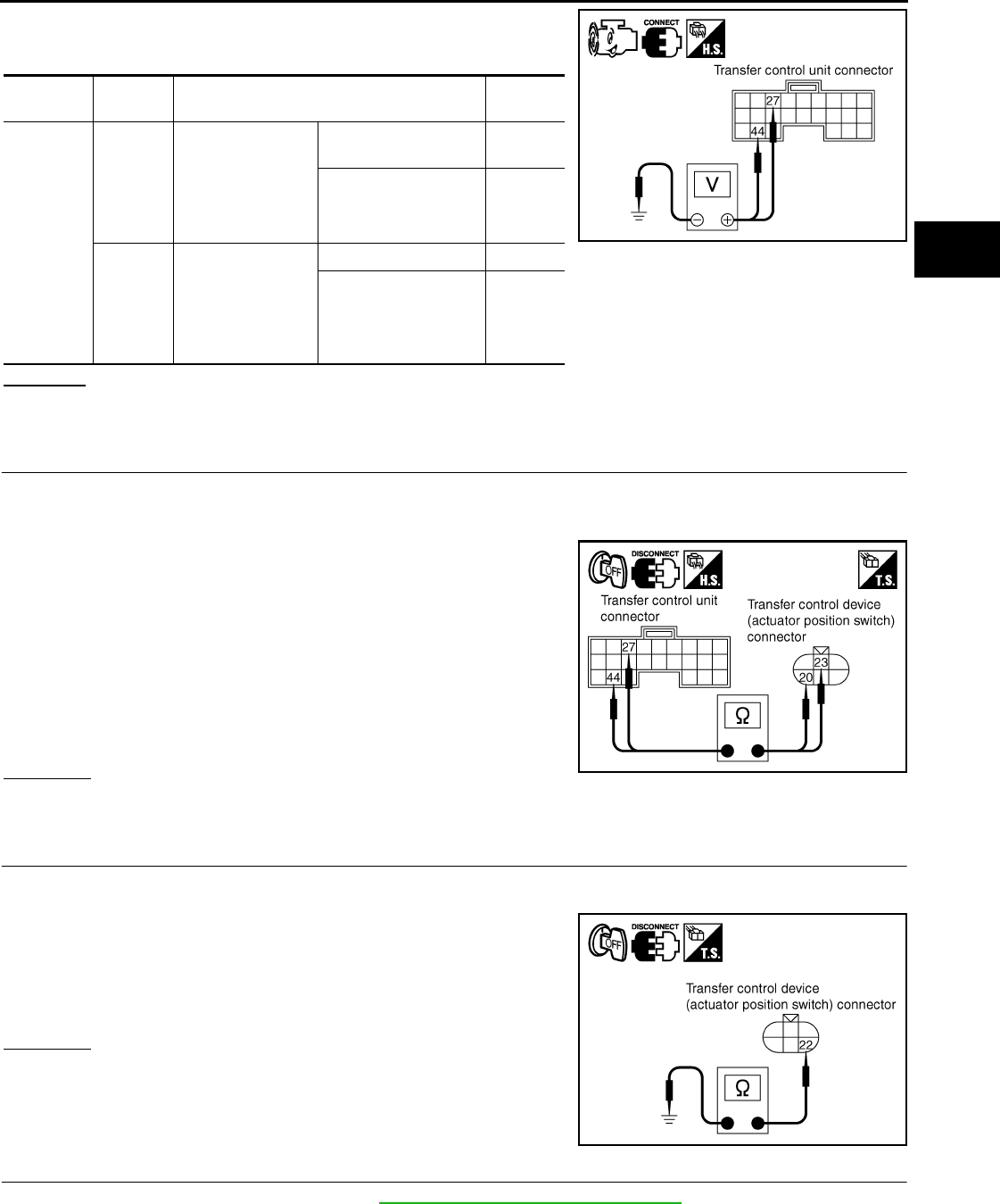
P1818 ACTUATOR POSITION SWITCH
DLN-51
< COMPONENT DIAGNOSIS > [TRANSFER: ATX14B]
C
E
F
G
H
I
J
K
L
M
A
B
DLN
N
O
P
2. Check voltage between transfer control unit harness connector
terminal and ground.
OK or NG
OK >> GO TO 5.
NG >> GO TO 2.
2.CHECK HARNESS BETWEEN TRANSFER CONTROL UNIT AND ACTUATOR POSITION SWITCH
1. Turn ignition switch “OFF”. (Stay for at least 5 seconds.)
2. Disconnect transfer control unit harness connector and the transfer control device (actuator position
switch) harness connector.
3. Check continuity between the following terminals.
- Transfer control unit harness connector M153 terminal 27 and
transfer control device (actuator position switch) harness con-
nector F58 terminal 23.
- Transfer control unit harness connector M153 terminal 44 and
transfer control device (actuator position switch) harness con-
nector F58 terminal 20.
Also check harness for short to ground and short to power.
OK or NG
OK >> GO TO 3.
NG >> Repair or replace damaged parts.
3.CHECK GROUND CIRCUIT
1. Turn ignition switch “OFF”. (Stay for at least 5 seconds.)
2. Disconnect transfer control device (actuator position switch) harness connector.
3. Check continuity between transfer control device (actuator posi-
tion switch) harness connector F58 terminal 22 and ground.
Also check harness for short to power.
OK or NG
OK >> GO TO 4.
NG >> Repair open circuit or short to power in harness or con-
nectors.
4.CHECK ACTUATOR POSITION SWITCH
1. Remove transfer control device. Refer to DLN-142, "Removal and Installation".
Connector Terminal Condition Voltage
(Approx.)
M153
27 -
Ground
• Vehicle stopped
• Engine running
• A/T selector le-
ver “N” position
• Brake pedal de-
pressed
4WD shift switch: 4H,
AUTO or 2WD 0V
4WD shift switch: 4LO Battery
voltage
44 -
Ground
• Vehicle stopped
• Engine running
• A/T selector le-
ver “N” position
• Brake pedal de-
pressed
4WD shift switch: 4LO 0V
4WD shift switch:
2WD, AUTO or 4H Battery
voltage
SDIA2715E
Continuity should exist.
SDIA2716E
Continuity should exist.
SDIA2717E
Revision: October 2008
2009 Pathfinder
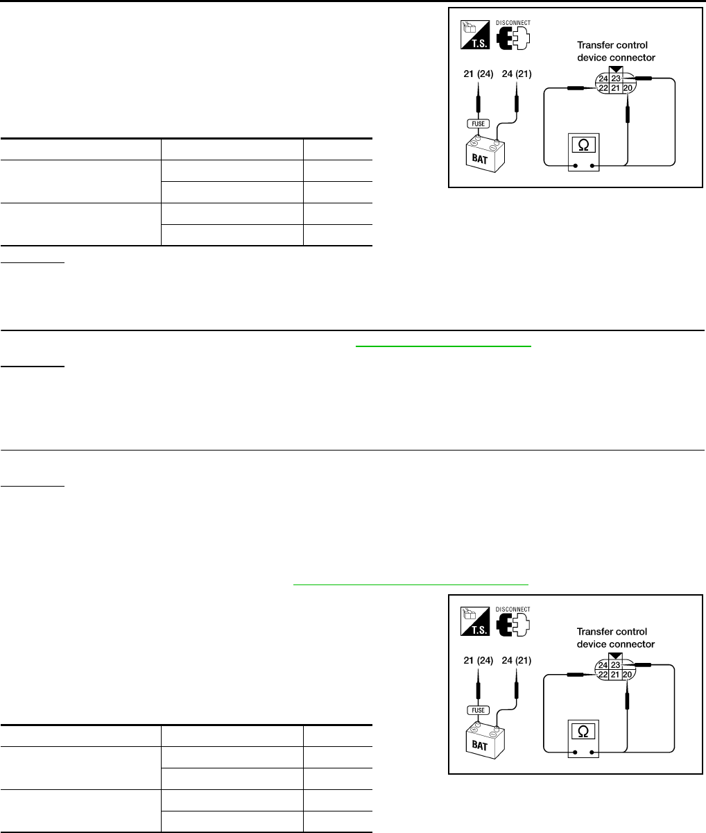
DLN-52
< COMPONENT DIAGNOSIS > [TRANSFER: ATX14B]
P1818 ACTUATOR POSITION SWITCH
2. Check operation by applying battery voltage to transfer control
device (actuator motor) terminals 21 and 24.
CAUTION:
• Do not operate actuator motor for more than 1 second.
• Change the actuator motor position to “HIGH” when
installing.
• Be careful not to overheat the harness.
OK or NG
YES >> GO TO 5.
NO >> Replace transfer control device.
5.CHECK TRANSFER CONTROL UNIT
Check transfer control unit input/output signal. Refer to DLN-85, "Reference Value".
OK or NG
OK >> GO TO 6.
NG >> Check transfer control unit pin terminals for damage or loose connection with harness connector.
If any items are damaged, repair or replace damaged parts.
6.CHECK DTC
Perform the self-diagnosis, after driving a vehicle for a while.
OK or NG
OK >> Inspection End.
NG >> Replace transfer control device.
Component Inspection INFOID:0000000003937227
1. Remove transfer control device. Refer to DLN-142, "Removal and Installation".
2. Check operation by applying battery voltage to transfer control
device (actuator motor) terminals 21 and 24.
CAUTION:
• Do not operate actuator motor for more than 1 second.
• Change the actuator motor position to HIGH when install-
ing.
• Be careful not to overheat the harness.
3. If the inspection results are abnormal replace transfer control device (actuator motor).
Terminal Continuity Continuity
24 (Battery voltage) - 21
(Ground)
20 - 22 YES
22 - 23 NO
21 (Battery voltage) - 24
(Ground)
22 - 23 YES
20 - 22 NO
LDIA0101E
Terminal Continuity Continuity
24 (Battery voltage) - 21
(Ground)
20 - 22 Yes
22 - 23 No
21 (Battery voltage) - 24
(Ground)
22 - 23 Yes
20 - 22 No
LDIA0101E
Revision: October 2008
2009 Pathfinder
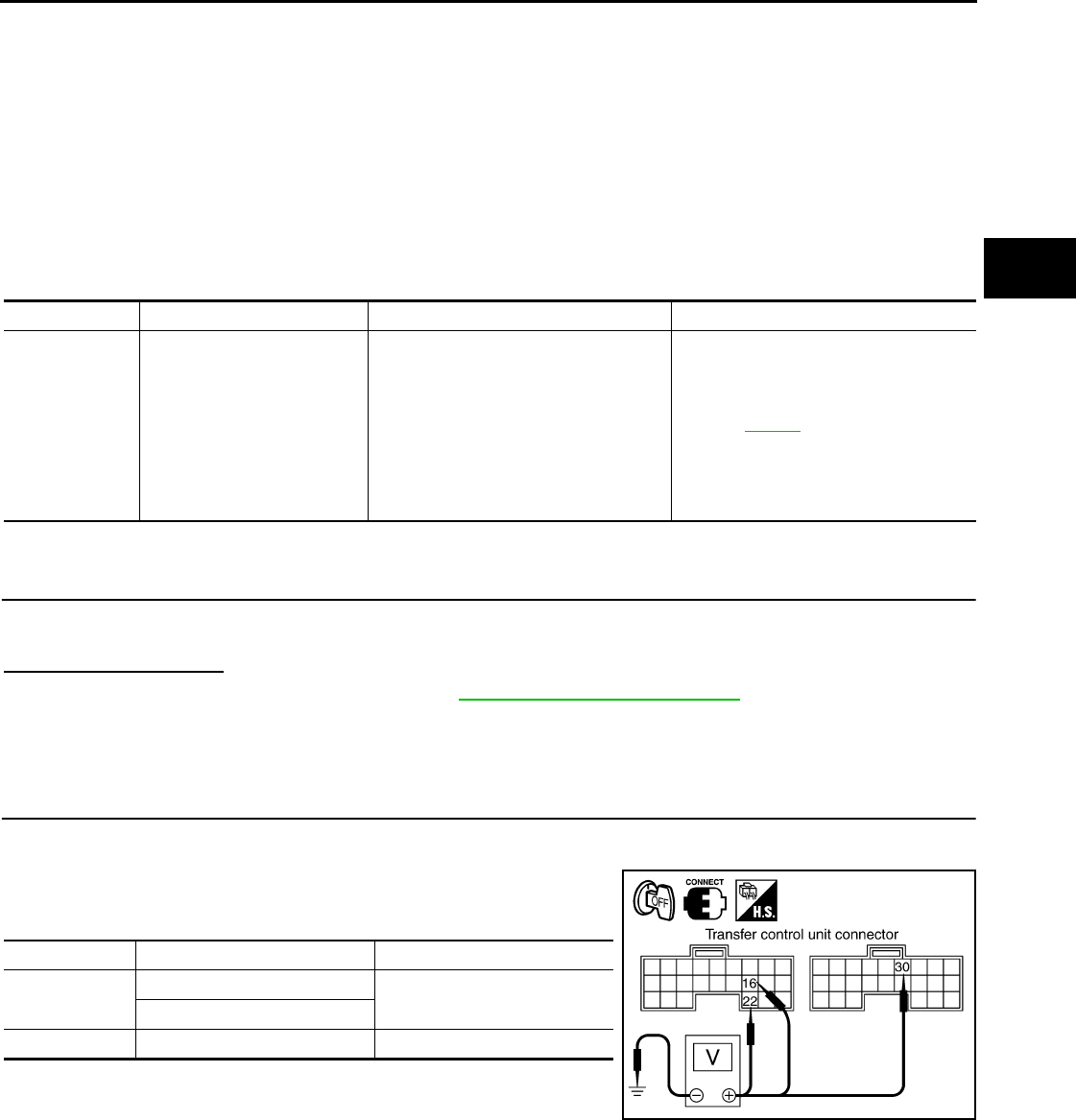
P1819 TRANSFER CONTROL DEVICE
DLN-53
< COMPONENT DIAGNOSIS > [TRANSFER: ATX14B]
C
E
F
G
H
I
J
K
L
M
A
B
DLN
N
O
P
P1819 TRANSFER CONTROL DEVICE
Description INFOID:0000000003937228
The transfer control device integrates the actuator motor and actuator position switch. DTC P1819 will set if
either of the following conditions exist:
• Malfunction occurs in transfer control device actuator circuit.
• Malfunction is detected in the transfer shut off relay.
DTC Logic INFOID:0000000003937229
DTC DETECTION LOGIC
DTC CONFIRMATION PROCEDURE
1.DTC CONFIRMATION PROCEDURE
1. Turn ignition switch ON.
2. Perform self-diagnosis.
Is DTC P1819 detected?
YES >> Perform diagnosis procedure. Refer to DLN-53, "Diagnosis Procedure".
NO >> Inspection End.
Diagnosis Procedure INFOID:0000000003937230
1.CHECK POWER SUPPLY
1. Turn ignition switch “OFF”. (Stay for at least 5 seconds.)
2. Connect transfer control unit harness connector.
3. Check voltage between transfer control unit harness connector
terminal and ground.
DTC CONSULT-III Diagnostic item is detected when... Reference
[P1819] SHIFT ACT CIR
• Transfer control device actuator circuit
is shorted or open. (Malfunctions are
detected when transfer shift relay cir-
cuit is open/shorted or relay monitor
circuit is open/shorted.)
• Malfunction occurs in transfer control
device drive circuit.
• Malfunction is detected in transfer
shut off relay.
Refer to DLN-53.
Connector Terminal Voltage (Approx.)
M152 16 - Ground 0V
22 - Ground
M153 30 - Ground Battery voltage
SDIA2834E
Revision: October 2008
2009 Pathfinder
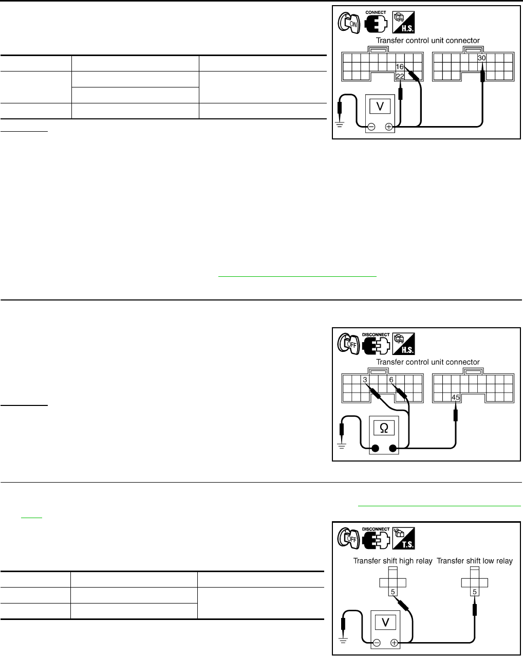
DLN-54
< COMPONENT DIAGNOSIS > [TRANSFER: ATX14B]
P1819 TRANSFER CONTROL DEVICE
4. Turn ignition switch “ON”. (Do not start engine.)
5. Check voltage between transfer control unit harness connector
terminals and ground.
OK or NG
OK >> GO TO 2.
NG >> Check the following. If any items are damaged, repair or replace damaged parts.
• 10A fuse (No. 59, located in the fuse and relay box).
• Harness for short or open between battery and transfer shut off relay harness connector E155
terminal 1.
• Harness for short or open between transfer shut off relay harness connector E155 terminal 2
and transfer control unit harness connector terminal 30.
• Harness for short or open between battery and transfer shut off relay harness connector E155
terminal 3.
• Harness for short or open between transfer shut off relay harness connector E155 terminal 5
and transfer control unit harness connector 22.
• Transfer shut off relay. Refer to DLN-28, "Component Inspection".
2.CHECK GROUND CIRCUIT
1. Turn ignition switch “OFF”. (Stay for at least 5 seconds.)
2. Disconnect transfer control unit harness connector.
3. Check continuity between transfer control unit harness connec-
tor M152 terminals 3, 6 and M153 terminal 45 and ground.
Also check harness for short to power.
OK or NG
OK >> GO TO 3.
NG >> Repair open circuit or short to power in harness or con-
nectors.
3.CHECK ACTUATOR MOTOR POWER SUPPLY CIRCUIT
1. Turn ignition switch “OFF”. (Stay for at least 5 seconds.)
2. Remove transfer shift high relay and transfer shift low relay. Refer to DLN-18, "Component Parts Loca-
tion".
3. Check voltage between transfer shift high relay harness connec-
tor E46 terminal 5, transfer shift low relay harness connector
E47 terminal 5 and ground.
Connector Terminal Voltage (Approx.)
M152 16 - Ground Battery voltage
22 - Ground
M153 30 - Ground 0V
SDIA2835E
Continuity should exist.
SDIA2691E
Connector Terminal Voltage (Approx.)
E46 5 - Ground Battery voltage
E47 5 - Ground
SDIA2707E
Revision: October 2008
2009 Pathfinder
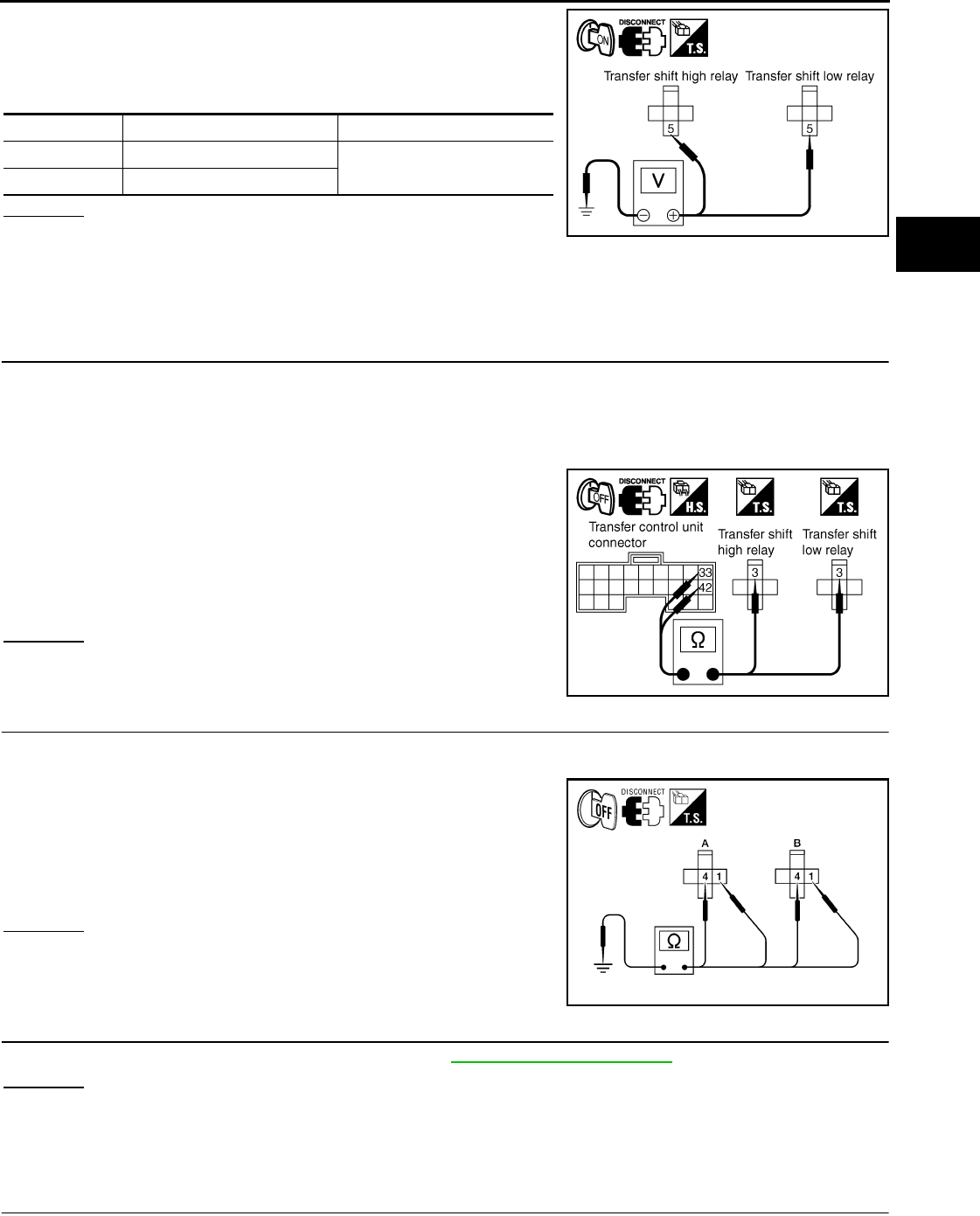
P1819 TRANSFER CONTROL DEVICE
DLN-55
< COMPONENT DIAGNOSIS > [TRANSFER: ATX14B]
C
E
F
G
H
I
J
K
L
M
A
B
DLN
N
O
P
4. Turn ignition switch “ON”. (Do not start engine.)
5. Check voltage between transfer shift high relay harness connec-
tor E46 terminal 5, transfer shift low relay harness connector
E47 terminal 5 and ground.
OK or NG
OK >> GO TO 4.
NG >> Check the following. If any items are damaged, repair or replace damaged parts.
• 20A fuse [No. 58, located in the fuse and relay box].
• Harness for short or open between battery, transfer shift high harness connector E46 terminal 5
and transfer shift low harness connector E47 terminal 5.
4.CHECK HARNESS BETWEEN TRANSFER CONTROL UNIT AND TRANSFER SHIFT RELAY
1. Turn ignition switch “OFF”. (Stay for at least 5 seconds.)
2. Disconnect transfer control unit harness connector and transfer control device (actuator motor) harness
connector.
3. Remove transfer shift high relay and transfer shift low relay.
4. Check continuity between the following terminals.
- Transfer control unit harness connector M153 terminal 33 and
transfer shift high relay harness connector E46 terminal 3.
- Transfer control unit harness connector M153 terminal 42 and
transfer shift low relay harness connector E47 terminal 3.
Also check harness for short to ground and short to power.
OK or NG
OK >> GO TO 5.
NG >> Repair or replace damaged parts.
5.CHECK TRANSFER SHIFT RELAY GROUND CIRCUIT
1. Turn ignition switch “OFF”. (Stay for at least 5 seconds.)
2. Remove transfer shift high relay and transfer shift low relay.
3. Check continuity between transfer shift high relay harness con-
nector E46 (A) terminals 1 and 4 and transfer shift low relay har-
ness connector E47 (B) terminals 1 and 4 and ground.
Also check harness for short to power.
OK or NG
OK >> GO TO 6.
NG >> Repair open circuit or short to power in harness or con-
nectors.
6.CHECK TRANSFER CONTROL UNIT
Check transfer control unit input/output signal. Refer to DLN-85, "Reference Value".
OK or NG
OK-1 >> With CONSULT-III: GO TO 7.
OK-2 >> Without CONSULT-III: GO TO 8.
NG >> Check transfer control unit pin terminals for damage or loose connection with harness connector.
If any items are damaged, repair or replace damaged parts.
7.PERFORM SELF-DIAGNOSIS (WITH CONSULT-III)
Connector Terminal Voltage (Approx.)
E46 5 - Ground Battery voltage
E47 5 - Ground
SDIA2706E
Continuity should exist.
SDIA2712E
Continuity should exist.
AWDIA0619Z
Z
Revision: October 2008
2009 Pathfinder

DLN-56
< COMPONENT DIAGNOSIS > [TRANSFER: ATX14B]
P1819 TRANSFER CONTROL DEVICE
With CONSULT-III
1. Turn ignition switch “ON”. (Do not start engine.)
2. Select “SELF-DIAG RESULTS” mode for “ALL MODE AWD/4WD” with CONSULT-III.
3. Touch “ERASE”.
4. Turn ignition switch “OFF” and wait at least 10 seconds.
5. Perform the self-diagnosis again.
Is the “SHIFT ACT CIR [P1819]” displayed?
YES >> Replace transfer control unit. Refer to DLN-136, "Removal and Installation".
NO >> Inspection End.
8.PERFORM SELF-DIAGNOSIS (WITHOUT CONSULT-III)
Without CONSULT-III
1. Perform the self-diagnosis and then erase self-diagnostic results. Refer to DLN-22, "CONSULT-III Func-
tion (ALL MODE AWD/4WD)".
2. Perform the self-diagnosis again.
Do the self-diagnostic results indicate transfer control device?
YES >> Replace transfer control unit.
NO >> Inspection End.
Revision: October 2008
2009 Pathfinder

P1820 ENGINE SPEED SIGNAL
DLN-57
< COMPONENT DIAGNOSIS > [TRANSFER: ATX14B]
C
E
F
G
H
I
J
K
L
M
A
B
DLN
N
O
P
P1820 ENGINE SPEED SIGNAL
Description INFOID:0000000003937231
The ECM transmits the engine speed signal via CAN communication to the transfer control unit. DTC P1820
will set when either of the following occur:
• Malfunction is detected in engine speed signal that is output from the ECM.
• Improper signal is input while driving.
DTC Logic INFOID:0000000003937232
DTC DETECTION LOGIC
DTC CONFIRMATION PROCEDURE
1.DTC CONFIRMATION PROCEDURE
1. Turn ignition switch ON.
2. Perform self-diagnosis.
Is DTC P1820 detected?
YES >> Perform diagnosis procedure. Refer to DLN-57, "Diagnosis Procedure".
NO >> Inspection End.
Diagnosis Procedure INFOID:0000000003937233
1.CHECK DTC WITH ECM
Perform self-diagnosis with ECM. Refer to EC-546, "CONSULT-III Function (ENGINE)".
Is any malfunction detected by self-diagnosis?
YES >> Check the malfunctioning system.
NO >> GO TO 2.
2.CHECK TRANSFER CONTROL UNIT
Check transfer control unit input/output signal. Refer to DLN-85, "Reference Value".
Are the inspection results normal?
YES >> GO TO 3.
NO >> Check transfer control unit pin terminals for damage or loose connection with harness connector.
If any items are damaged, repair or replace damaged parts.
3.CHECK DTC
Drive the vehicle and then perform self-diagnosis.
Are the inspection results normal?
YES >> Inspection End.
NO >> Perform self-diagnosis with ECM again.
DTC CONSULT-III Diagnostic item is detected when... Reference
[P1820] ENGINE SPEED SIG
• Malfunction is detected in engine
speed signal that is output from ECM
through CAN communication.
• Improper signal is input while driving.
Refer to DLN-57.
Revision: October 2008
2009 Pathfinder
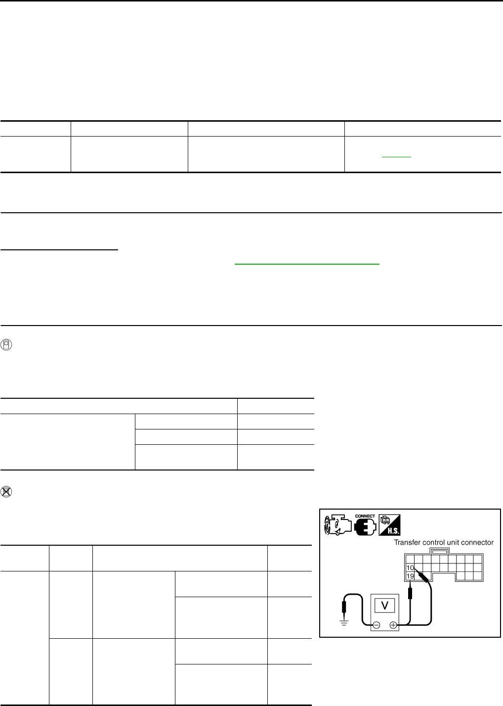
DLN-58
< COMPONENT DIAGNOSIS > [TRANSFER: ATX14B]
P1822 CLUTCH PRESSURE SOLENOID
P1822 CLUTCH PRESSURE SOLENOID
Description INFOID:0000000003937234
Proper voltage is not applied to the clutch pressure solenoid valve due to open or short circuit.
DTC Logic INFOID:0000000003937235
DTC DETECTION LOGIC
DTC CONFIRMATION PROCEDURE
1.DTC CONFIRMATION PROCEDURE
1. Turn ignition switch ON.
2. Perform self-diagnosis.
Is DTC P1822 displayed?
YES >> Perform diagnosis procedure. Refer to DLN-58, "Diagnosis Procedure".
NO >> Inspection End.
Diagnosis Procedure INFOID:0000000003937236
1.CHECK CLUTCH PRESSURE SIGNAL
With CONSULT-III
1. Start engine.
2. Select DATA MONITOR mode for ALL MODE AWD/4WD with CONSULT-III.
3. Read out the value of DUTY SOLENOID.
Without CONSULT-III
1. Start engine.
2. Check voltage between transfer control unit harness connector
terminal and ground.
DTC CONSULT-III Diagnostic item is detected when... Reference
[P1822] DUTY SOLENOID
Proper voltage is not applied to clutch
pressure solenoid valve due to open or
short circuit.
Refer to DLN-58.
Condition Display value
• Vehicle stopped
• Engine running
• A/T selector lever N position
• Brake pedal depressed
4WD shift switch: 2WD 4%
4WD shift switch: AUTO 96 - 4%
4WD shift switch: 4H or
4LO 4%
Connector Terminal Condition Voltage
(Approx.)
M152
10 -
Ground
• Vehicle stopped
• Engine running
• A/T selector lever
N position
• Brake pedal de-
pressed
4WD shift switch:
AUTO 4 - 14V
4WD shift switch:
2WD, 4H or 4LO Less than
1V
19 -
Ground
• Vehicle stopped
• Engine running
• A/T selector lever
N position
• Brake pedal de-
pressed
4WD shift switch:
AUTO 1.5 - 3V
4WD shift switch:
2WD, 4H or 4LO
Less than
1V
SDIA2719E
Revision: October 2008
2009 Pathfinder
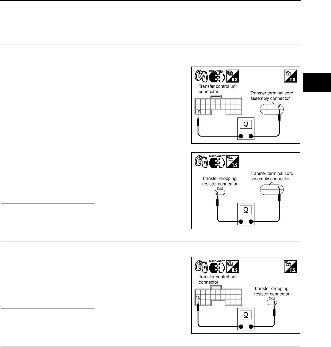
P1822 CLUTCH PRESSURE SOLENOID
DLN-59
< COMPONENT DIAGNOSIS > [TRANSFER: ATX14B]
C
E
F
G
H
I
J
K
L
M
A
B
DLN
N
O
P
Are the inspection results normal?
YES >> GO TO 7.
NO >> GO TO 2.
2.CHECK HARNESS BETWEEN TRANSFER CONTROL UNIT AND CLUTCH PRESSURE SOLENOID
VALVE
1. Turn ignition switch OFF. (Stay for at least 5 seconds.)
2. Disconnect transfer control unit harness connector, transfer terminal cord assembly harness connector
and transfer dropping resistor.
3. Check continuity between transfer control unit harness connec-
tor M152 terminal 19 and transfer terminal cord assembly har-
ness connector F56 terminal 6.
4. Check continuity between transfer dropping resistor harness
connector E135 terminal 2 and transfer terminal cord assembly
harness connector F56 terminal 6.
Also check harness for short to ground and short to power.
Are the inspection results normal?
YES >> GO TO 3.
NO >> Repair or replace damaged parts.
3.CHECK HARNESS BETWEEN TRANSFER CONTROL UNIT AND TRANSFER DROPPING RESISTOR
1. Turn ignition switch OFF. (Stay for at least 5 seconds.)
2. Disconnect transfer control unit harness connector and transfer dropping resistor harness connector.
3. Check continuity between transfer control unit harness connec-
tor M152 terminal 10 and transfer dropping resistor harness
connector E135 terminal 1.
Also check harness for short to ground and short to power.
Are the inspection results normal?
YES >> GO TO 4.
NO >> Repair or replace damaged parts.
4.CHECK GROUND CIRCUIT
1. Turn ignition switch OFF. (Stay for at least 5 seconds.)
2. Disconnect transfer terminal cord assembly harness connector.
Continuity should exist.
SDIA2720E
Continuity should exist.
SDIA2721E
Continuity should exist.
SDIA2722E
Revision: October 2008
2009 Pathfinder
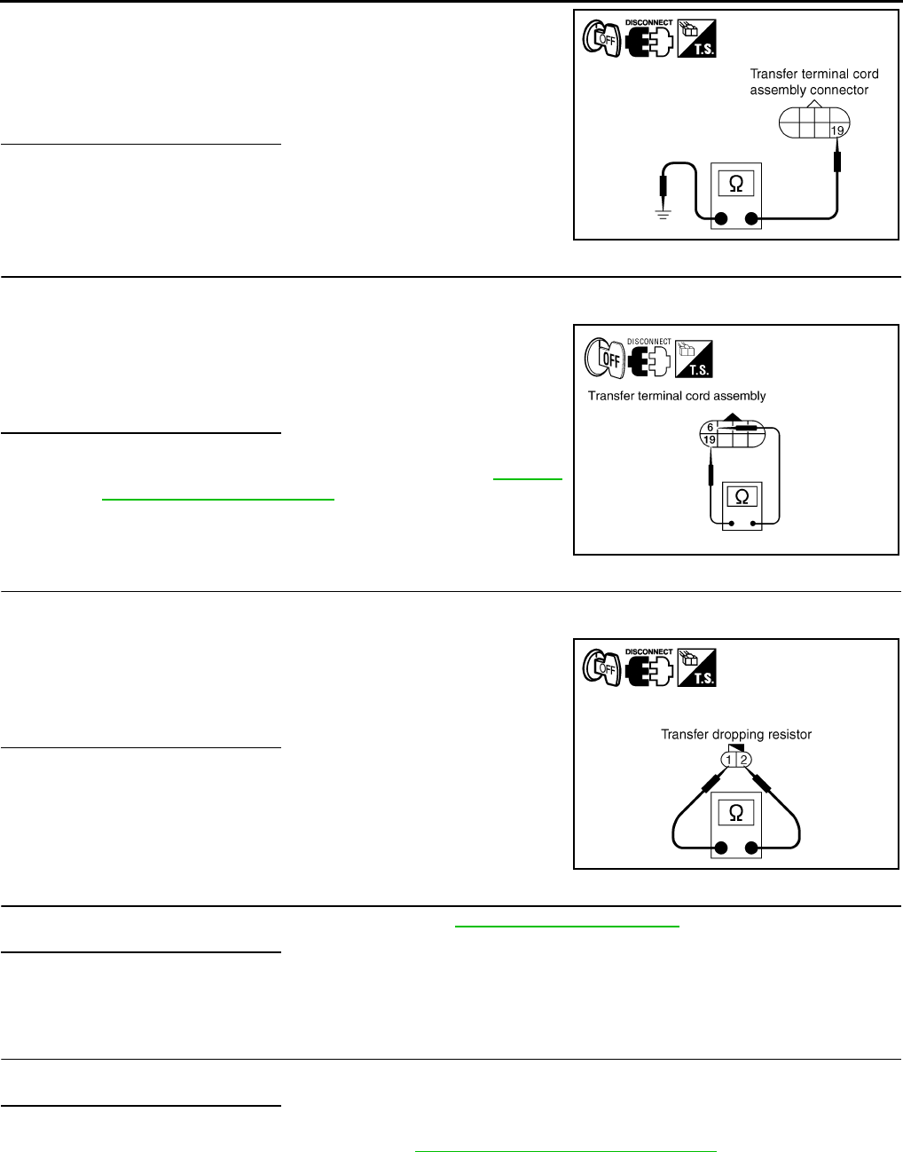
DLN-60
< COMPONENT DIAGNOSIS > [TRANSFER: ATX14B]
P1822 CLUTCH PRESSURE SOLENOID
3. Check continuity between transfer terminal cord assembly har-
ness connector F56 terminal 19 and ground.
Also check harness for short to ground and short to power.
Are the inspection results normal?
YES >> GO TO 5.
NO >> Repair open circuit or short to ground or short to power
in harness or connectors.
5.CHECK CLUTCH PRESSURE SOLENOID
1. Turn ignition switch OFF. (Stay for at least 5 seconds.)
2. Disconnect transfer terminal cord assembly harness connector.
3. Check resistance between transfer terminal cord assembly har-
ness connector F56 terminals 6 and 19.
Are the inspection results normal?
YES >> GO TO 6.
NO >> Replace clutch pressure solenoid. Refer to DLN-18,
"Component Parts Location".
6.CHECK TRANSFER DROPPING RESISTOR
1. Turn ignition switch OFF. (Stay for at least 5 seconds.)
2. Disconnect transfer dropping resistor harness connector.
3. Check resistance between transfer dropping resistor terminals 1
and 2.
Are the inspection results normal?
YES >> GO TO 7.
NO >> Replace transfer dropping resistor.
7.CHECK TRANSFER CONTROL UNIT
Check transfer control unit input/output signal. Refer to DLN-85, "Reference Value".
Are the inspection results normal?
YES >> GO TO 8.
NO >> Check transfer control unit pin terminals for damage or loose connection with harness connector.
If any items are damaged, repair or replace damaged parts.
8.CHECK DTC
Drive the vehicle and then perform self-diagnosis.
Are the inspection results normal?
YES >> Inspection End.
NO >> Replace transfer control unit. Refer to DLN-136, "Removal and Installation".
Component Inspection INFOID:0000000003937237
CLUTCH PRESSURE SOLENOID
1. Turn ignition switch OFF. (Stay for at least 5 seconds.)
Continuity should exist.
SDIA2723E
6 - 19 : Approx. 3.0 - 3.4 Ω
WDIA0225E
1 - 2 : Approx. 11.2 - 12.8 Ω
SDIA2725E
Revision: October 2008
2009 Pathfinder
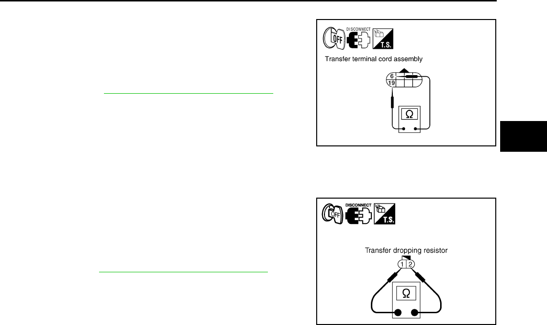
P1822 CLUTCH PRESSURE SOLENOID
DLN-61
< COMPONENT DIAGNOSIS > [TRANSFER: ATX14B]
C
E
F
G
H
I
J
K
L
M
A
B
DLN
N
O
P
2. Disconnect transfer terminal cord assembly harness connector.
3. Check resistance between transfer terminal cord assembly ter-
minals 6 and 19.
4. If the inspection results are abnormal replace clutch pressure
solenoid. Refer to DLN-18, "Component Parts Location".
TRANSFER DROPPING RESISTOR
1. Turn ignition switch OFF. (Stay for at least 5 seconds.)
2. Disconnect transfer dropping resistor harness connector.
3. Check resistance between transfer dropping resistor terminals 1
and 2.
4. If the inspection results are abnormal replace transfer dropping
resistor. Refer to DLN-18, "Component Parts Location".
6 - 19 : Approx. 3.0 - 3.4 Ω
WDIA0225E
1 - 2 : Approx. 11.2 - 12.8 Ω
SDIA2725E
Revision: October 2008
2009 Pathfinder
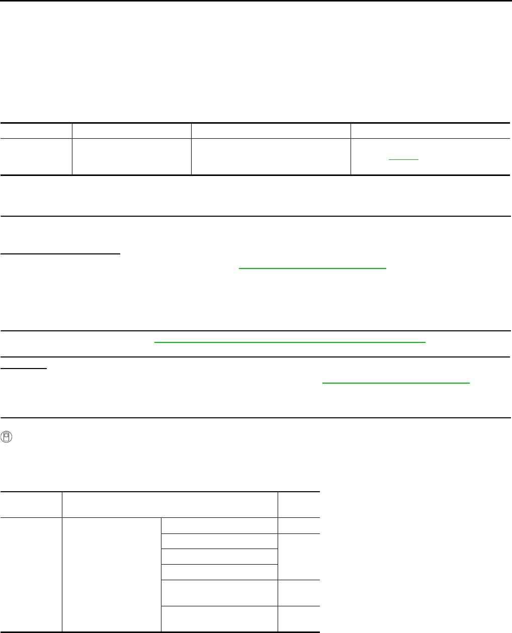
DLN-62
< COMPONENT DIAGNOSIS > [TRANSFER: ATX14B]
P1823 2-4 SOLENOID
P1823 2-4 SOLENOID
Description INFOID:0000000003937238
Proper voltage is not applied to the 2-4WD solenoid valve due to an open or short circuit.
DTC Logic INFOID:0000000003937239
DTC DETECTION LOGIC
DTC CONFIRMATION PROCEDURE
1.DTC CONFIRMATION PROCEDURE
1. Turn ignition switch ON.
2. Perform self-diagnosis.
Is DTC P1823 displayed?
YES >> Perform diagnosis procedure. Refer to DLN-62, "Diagnosis Procedure".
NO >> Inspection End.
Diagnosis Procedure INFOID:0000000003937240
1.CHECK 4WD SHIFT SWITCH SYSTEM
Perform self-diagnosis. Refer to DLN-22, "CONSULT-III Function (ALL MODE AWD/4WD)".
Is the "4WD MOD SW [P1814]" (with CONSULT-III) or "Flickering pattern:16" (without CONSULT-III)
detected?
YES >> Perform trouble diagnosis for 4WD shift switch. Refer to DLN-36, "Diagnosis Procedure".
NO >> GO TO 2
2.CHECK 2-4WD SHIFT SOLENOID SIGNAL
With CONSULT-III
1. Start engine.
2. Select “DATA MONITOR” mode for “ALL MODE AWD/4WD” with CONSULT-III.
3. Read out the value of “2-4WD SOL” and “2-4WD SOL MON”.
DTC CONSULT-III Diagnostic item is detected when... Reference
[P1823] 2-4WD SOLENOID
Proper voltage is not applied to 2-4WD
solenoid valve due to open or short cir-
cuit.
Refer to DLN-62.
Monitored
item Condition Display
value
2-4WD SOL
• Vehicle stopped
• Engine running
• A/T selector lever “N”
position
• Brake pedal de-
pressed
4WD shift switch: 2WD OFF
4WD shift switch: AUTO
ON4WD shift switch: 4H
4WD shift switch: 4LO
4WD shift switch: AUTO
(“Wait” function is operating.) OFF
4WD shift switch: 4H (“Wait”
function is operating.) OFF
Revision: October 2008
2009 Pathfinder
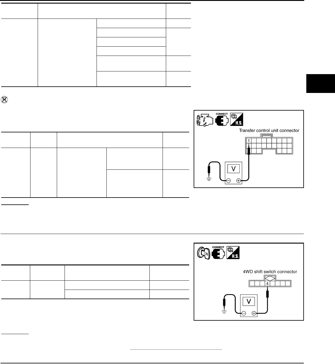
P1823 2-4 SOLENOID
DLN-63
< COMPONENT DIAGNOSIS > [TRANSFER: ATX14B]
C
E
F
G
H
I
J
K
L
M
A
B
DLN
N
O
P
Without CONSULT-III
1. Start engine.
2. Check voltage between transfer control unit harness connector
terminal and ground.
OK or NG
OK >> GO TO 7.
NG >> GO TO 3.
3.CHECK 4WD SHIFT SWITCH SIGNAL
1. Turn ignition switch “ON”. (Do not start engine.)
2. Check voltage between transfer control unit harness connector
terminals and ground.
OK or NG
OK >> GO TO 4.
NG >> Check 4WD shift switch. Refer to DLN-38, "Component Inspection".
4.CHECK HARNESS BETWEEN 4WD SHIFT SWITCH AND TRANSFER TERMINAL CORD ASSEMBLY
1. Turn ignition switch “OFF”. (Stay for at least 5 seconds.)
2. Disconnect 4WD shift switch harness connector and transfer terminal cord assembly harness connector.
2-4WD SOL
MON
• Vehicle stopped
• Engine running
• A/T selector lever “N”
position
• Brake pedal de-
pressed
4WD shift switch: 2WD OFF
4WD shift switch: AUTO
ON4WD shift switch: 4H
4WD shift switch: 4LO
4WD shift switch: AUTO
(“Wait” function is operating.) OFF
4WD shift switch: 4H (“Wait”
function is operating.) OFF
Monitored
item Condition Display
value
Connector Terminal Condition Voltage
(Approx.)
M152 1 -
Ground
• Vehicle stopped
• Engine running
• A/T selector lever
“N” position
• Brake pedal de-
pressed
4WD shift switch: 2WD 0V
4WD shift switch: AU-
TO, 4H or 4LO Battery
voltage SDIA2728E
Connector Terminal Condition Voltage (Ap-
prox.)
M141 4 - ground 4WD shift switch: AUTO, 4H or 4LO Battery voltage
4WD shift switch: 2WD 0V
SDIA2729E
Revision: October 2008
2009 Pathfinder
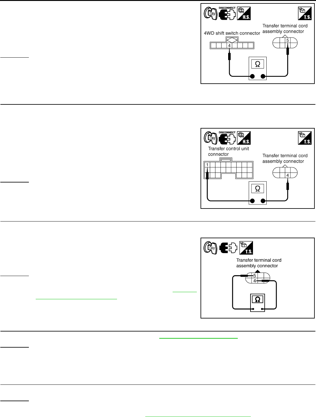
DLN-64
< COMPONENT DIAGNOSIS > [TRANSFER: ATX14B]
P1823 2-4 SOLENOID
3. Check continuity between 4WD shift switch harness connector
M141 terminal 4 and transfer terminal cord assembly harness
connector F56 terminal 5.
Also check harness for short to ground and short to power.
OK or NG
OK >> GO TO 5.
NG >> Repair or replace damaged parts.
5.CHECK HARNESS BETWEEN TRANSFER CONTROL UNIT AND TRANSFER TERMINAL CORD AS-
SEMBLY
1. Turn ignition switch “OFF”. (Stay for at least 5 seconds.)
2. Disconnect transfer control unit harness connector and transfer terminal cord assembly harness connec-
tor.
3. Check continuity between transfer control unit harness connec-
tor M152 terminal 1 and transfer terminal cord assembly har-
ness connector F56 terminal 4.
Also check harness for short to ground and short to power.
OK or NG
OK >> GO TO 6.
NG >> Repair or replace damaged parts.
6.CHECK 2-4WD SOLENOID
1. Turn ignition switch “OFF”. (Stay for at least 5 seconds.)
2. Disconnect transfer terminal cord assembly harness connector.
3. Check resistance between transfer terminal cord assembly ter-
minals 4 and 5.
OK or NG
OK >> GO TO 7.
NG >> 2-4WD solenoid is malfunctioning. Refer to DLN-18,
"Component Parts Location".
7.CHECK TRANSFER CONTROL UNIT
Check transfer control unit input/output signal. Refer to DLN-85, "Reference Value".
OK or NG
OK >> GO TO 8.
NG >> Check transfer control unit pin terminals for damage or loose connection with harness connector.
If any items are damaged, repair or replace damaged parts.
8.CHECK DTC
Perform the self-diagnosis, after driving a vehicle for a while.
OK or NG
OK >> Inspection End.
NG >> Replace transfer control unit. Refer to DLN-136, "Removal and Installation".
Continuity should exist.
SDIA2731E
Continuity should exist.
SDIA2732E
4 - 5 : Approx. 22.8 - 25.2 Ω
SDIA3253E
Revision: October 2008
2009 Pathfinder
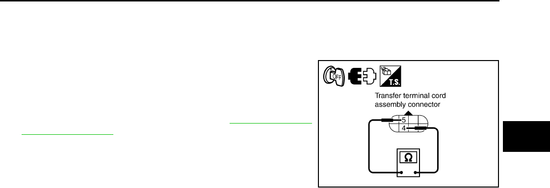
P1823 2-4 SOLENOID
DLN-65
< COMPONENT DIAGNOSIS > [TRANSFER: ATX14B]
C
E
F
G
H
I
J
K
L
M
A
B
DLN
N
O
P
Component Inspection INFOID:0000000003937241
1. Turn ignition switch “OFF”. (Stay for at least 5 seconds.)
2. Disconnect transfer terminal cord assembly harness connector.
3. Check resistance between transfer terminal cord assembly ter-
minals 4 and 5.
4. If NG, replace the 2-4WD solenoid. Refer to DLN-18, "Compo-
nent Parts Location".
4 - 5 : Approx. 22.8 - 25.2 Ω
SDIA3253E
Revision: October 2008
2009 Pathfinder

DLN-66
< COMPONENT DIAGNOSIS > [TRANSFER: ATX14B]
P1824 TRANSFER MOTOR
P1824 TRANSFER MOTOR
Description INFOID:0000000003937242
Motor does not operate properly due to open or short circuit in transfer motor or transfer motor relay.
DTC Logic INFOID:0000000003937243
DTC DETECTION LOGIC
DTC CONFIRMATION PROCEDURE
1.DTC CONFIRMATION PROCEDURE
1. Turn ignition switch ON.
2. Perform self-diagnosis.
Is DTC P1824 displayed?
YES >> Perform diagnosis procedure. Refer to DLN-66, "Diagnosis Procedure".
NO >> Inspection End.
Diagnosis Procedure INFOID:0000000003937244
1.CHECK TRANSFER MOTOR RELAY SIGNAL
With CONSULT-III
1. Start engine.
2. Select “DATA MONITOR” mode for “ALL MODE AWD/4WD” with CONSULT-III.
3. Read out the value of “MOTOR RELAY” and “MOTOR RELAY MON”.
DTC CONSULT-III Diagnostic item is detected when... Reference
[P1824] MOTOR RELAY
Motor does not operate properly due to
open or short circuit in transfer motor or
transfer motor relay.
Refer to DLN-66.
Monitored
item Condition Display value
(Approx.)
MOTOR
RELAY
• Accelerator ped-
al depressed
• Vehicle stopped
• Engine running
• Brake pedal de-
pressed
4WD shift switch: 2WD OFF
4WD shift switch: AUTO or
4LO (A/T selector lever “P” or
“N” position)
OFF
("ON" for ap-
prox. 2 sec. af-
ter shifting to
“P” and “N”.)
4WD shift switch: AUTO or
4LO (Except for A/T selector
lever “P” or “N” position)
ON
4WD shift switch: 4H (A/T se-
lector lever “P” position)
OFF
("ON" for ap-
prox. 2 sec. af-
ter shifting to
“P”.)
4WD shift switch: 4H (Except
for A/T selector lever “P” posi-
tion)
ON
Revision: October 2008
2009 Pathfinder
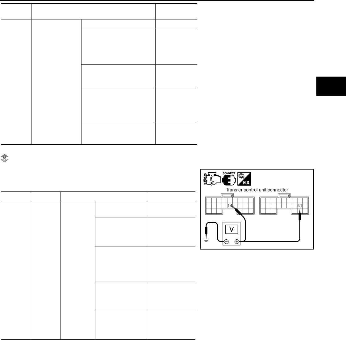
P1824 TRANSFER MOTOR
DLN-67
< COMPONENT DIAGNOSIS > [TRANSFER: ATX14B]
C
E
F
G
H
I
J
K
L
M
A
B
DLN
N
O
P
Without CONSULT-III
1. Start engine.
2. Check voltage between transfer control unit harness connector
terminal and ground.
MOTOR
RELAY
MON
• Accelerator ped-
al depressed
• Vehicle stopped
• Engine running
• Brake pedal de-
pressed
4WD shift switch: 2WD OFF
4WD shift switch: AUTO or
4LO (A/T selector lever “P” or
“N” position)
OFF
("ON" for ap-
prox. 2 sec. af-
ter shifting to
“P” and “N”.)
4WD shift switch: AUTO or
4LO (Except for A/T selector
lever “P” or “N” position) ON
4WD shift switch: 4H (A/T se-
lector lever “P” position)
OFF
("ON" for ap-
prox. 2 sec. af-
ter shifting to
“P”.)
4WD shift switch: 4H (Except
for A/T selector lever “P” posi-
tion) ON
Monitored
item Condition Display value
(Approx.)
Connector Terminal Condition Voltage (Approx.)
M152 14 -
Ground
• Accelera-
tor pedal
depressed
•Vehicle
stopped
•Engine
running
•Brake
pedal de-
pressed
4WD shift switch:
2WD Battery voltage
4WD shift switch:
AUTO or 4LO (A/T
selector lever “P” or
“N” position)
Battery voltage
(0V for approx. 2
sec. after shifting
to “P” and “N”.)
4WD shift switch:
AUTO or 4LO (Ex-
cept for A/T selector
lever “P” or “N” posi-
tion)
0V
4WD shift switch: 4H
(A/T selector lever
“P” position)
Battery voltage
(0V for approx. 2
sec. after shifting
to “P”.)
4WD shift switch: 4H
(Except for A/T se-
lector lever “P” posi-
tion)
0V
SDIA2735E
Revision: October 2008
2009 Pathfinder
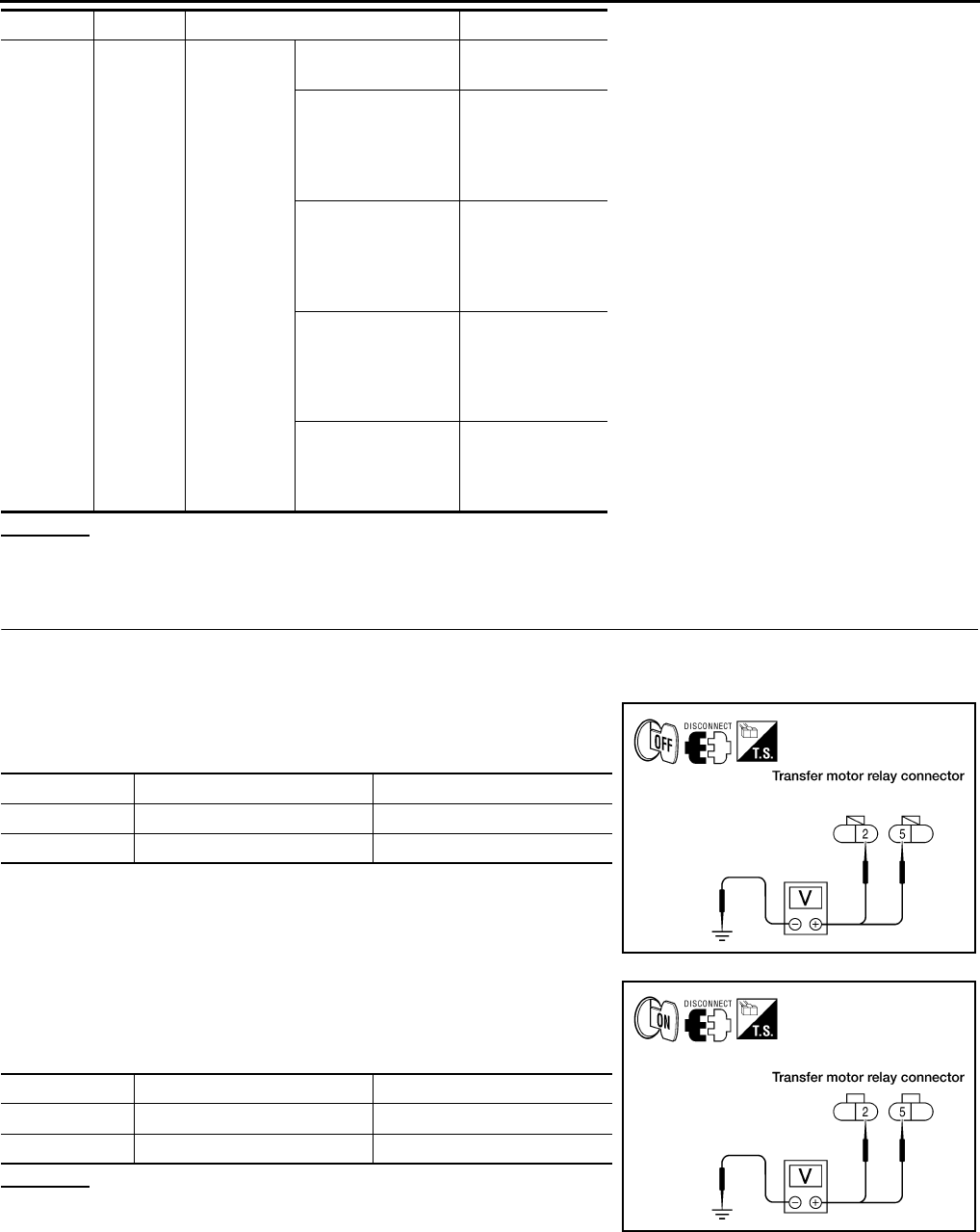
DLN-68
< COMPONENT DIAGNOSIS > [TRANSFER: ATX14B]
P1824 TRANSFER MOTOR
OK or NG
OK >> GO TO 8.
NG >> GO TO 2.
2.CHECK TRANSFER MOTOR RELAY POWER SUPPLY CIRCUIT
1. Turn ignition switch “OFF”. (Stay for at least 5 seconds.)
2. Connect transfer control unit harness connector.
3. Disconnect transfer motor relay.
4. Check voltage between transfer motor relay harness connector
terminals and ground.
5. Turn ignition switch “ON”. (Do not start engine.)
6. Check voltage between transfer motor relay harness connector
terminals and ground.
OK or NG
OK >> GO TO 3.
NG >> Check the following. If any items are damaged, repair
or replace damaged parts.
• 20A fuse (No. 57, located in the fuse and relay box).
• 10A fuse (No. 59, located in the fuse and relay box).
• Harness for short or open between battery and transfer motor relay harness connector E154 ter-
minals 5.
M153 41 -
Ground
• Accelera-
tor pedal
depressed
• Vehicle
stopped
•Engine
running
•Brake
pedal de-
pressed
4WD shift switch:
2WD 0V
4WD shift switch:
AUTO or 4LO (A/T
selector lever “P” or
“N” position)
0V
(Battery voltage
for approx. 2 sec.
after shifting to “P”
and “N”.)
4WD shift switch:
AUTO or 4LO (Ex-
cept for A/T selector
lever “P” or “N” posi-
tion)
Battery voltage
4WD shift switch: 4H
(A/T selector lever
“P” position)
0V
(Battery voltage
for approx. 2 sec.
after shifting to
“P”.)
4WD shift switch: 4H
(Except for A/T se-
lector lever “P” posi-
tion)
Battery voltage
Connector Terminal Condition Voltage (Approx.)
Connector Terminal Voltage (Approx.)
E153 2 - Ground 0V
E154 5 - Ground Battery voltage
WDIA0169E
Connector Terminal Voltage (Approx.)
E153 2 - Ground Battery voltage
E154 5 - Ground Battery voltage
WDIA0170E
Revision: October 2008
2009 Pathfinder
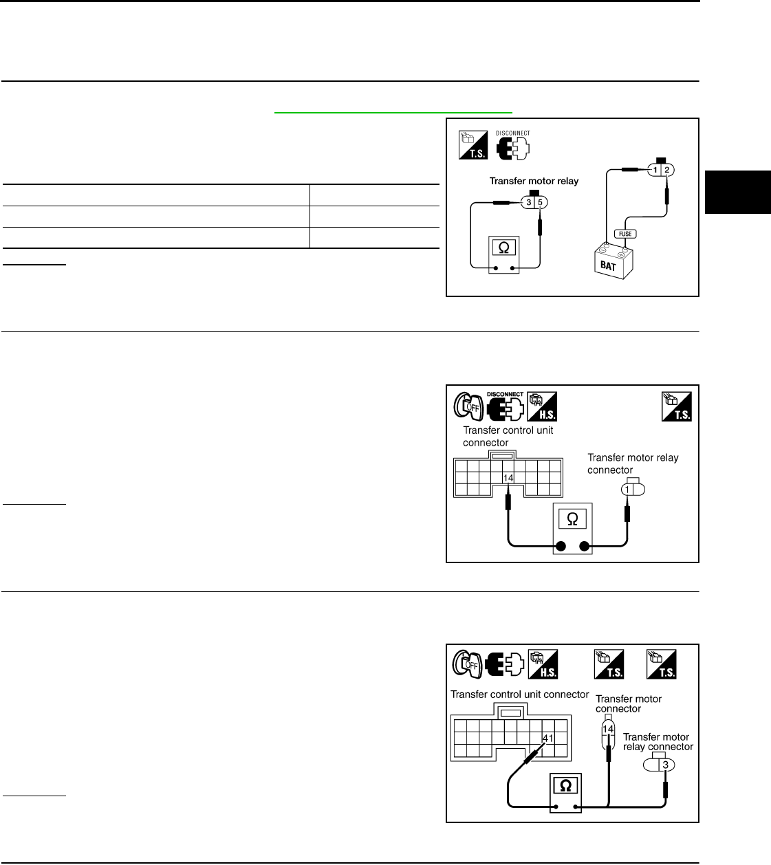
P1824 TRANSFER MOTOR
DLN-69
< COMPONENT DIAGNOSIS > [TRANSFER: ATX14B]
C
E
F
G
H
I
J
K
L
M
A
B
DLN
N
O
P
• Harness for short or open between transfer shut off relay harness connector E155 terminal 5
and transfer motor relay harness connector E153 terminal 2.
• Battery and ignition switch.
3.CHECK TRANSFER MOTOR RELAY
1. Turn ignition switch “OFF”. (Stay for at least 5 seconds.)
2. Remove transfer motor relay. Refer to DLN-18, "Component Parts Location".
3. Apply 12V direct current between transfer motor relay terminals
1 and 2.
4. Check continuity between relay terminals 3 and 5.
OK or NG
OK >> GO TO 4.
NG >> Replace the transfer motor relay.
4.CHECK HARNESS BETWEEN TRANSFER CONTROL UNIT AND TRANSFER MOTOR RELAY
1. Turn ignition switch “OFF”. (Stay for at least 5 seconds.)
2. Disconnect transfer control unit harness connector.
3. Remove transfer motor relay.
4. Check continuity between the following terminals.
- Transfer control unit harness connector M152 terminal 14 and
transfer motor relay harness connector E154 terminal 1.
Also check harness for short to ground and short to power.
OK or NG
OK >> GO TO 5.
NG >> Repair or replace damaged parts.
5.CHECK TRANSFER MOTOR POWER SUPPLY CIRCUIT
1. Turn ignition switch “OFF”. (Stay for at least 5 seconds.)
2. Disconnect transfer control unit harness connector and transfer motor harness connector.
3. Remove transfer motor relay.
4. Check continuity between the following terminals.
- Transfer control unit harness connector M153 terminal 41 and
transfer motor relay harness connector E154 terminal 3.
- Transfer control unit harness connector M153 terminal 41 and
transfer motor harness connector F57 terminal 14.
Also check harness for short to ground and short to power.
OK or NG
OK >> GO TO 6.
NG >> Repair or replace damaged parts.
6.CHECK TRANSFER MOTOR GROUND CIRCUIT
1. Turn ignition switch “OFF”. (Stay for at least 5 seconds.)
2. Disconnect transfer motor harness connector.
Condition Continuity
12V direct current supply between terminals 1 and 2 Yes
OFF No
LDIA0098E
Continuity should exist.
SDIA2738E
Continuity should exist.
SDIA3254E
Revision: October 2008
2009 Pathfinder
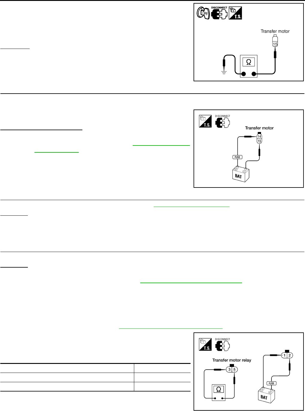
DLN-70
< COMPONENT DIAGNOSIS > [TRANSFER: ATX14B]
P1824 TRANSFER MOTOR
3. Check continuity between transfer motor harness connector F57
terminal 15 and ground.
Also check harness for short to power.
OK or NG
OK >> GO TO 7.
NG >> Repair open circuit or short to power in harness or con-
nectors.
7.CHECK TRANSFER MOTOR
1. Turn ignition switch “OFF”. (Stay for at least 5 seconds.)
2. Disconnect transfer motor harness connector.
3. Apply 12V direct current between transfer motor terminals 14
and 15.
Does transfer motor operate?
YES >> GO TO 8.
NO >> Replace transfer motor. Refer to DLN-148, "Removal
and Installation".
8.CHECK TRANSFER CONTROL UNIT
Check transfer control unit input/output signal. Refer to DLN-85, "Reference Value".
OK or NG
OK >> GO TO 9.
NG >> Check transfer control unit pin terminals for damage or loose connection with harness connector.
If any items are damaged, repair or replace damaged parts.
9.CHECK DTC
Perform the self-diagnosis, after driving a vehicle for a while.
OK or NG
OK >> Inspection End.
NG >> Replace transfer control unit. Refer to DLN-136, "Removal and Installation".
Component Inspection INFOID:0000000003937245
TRANSFER MOTOR RELAY
1. Turn ignition switch OFF. (Stay for at least 5 seconds.)
2. Remove transfer motor relay. Refer to DLN-18, "Component Parts Location".
3. Apply 12V direct current between transfer motor relay terminals
1 and 2.
4. Check continuity between relay terminals 3 and 5.
5. If inspection results are abnormal replace transfer motor relay.
TRANSFER MOTOR
Continuity should exist.
SDIA2740E
LDIA0097E
Condition Continuity
12V direct current supply between terminals 1 and 2 Yes
OFF No
LDIA0098E
Revision: October 2008
2009 Pathfinder
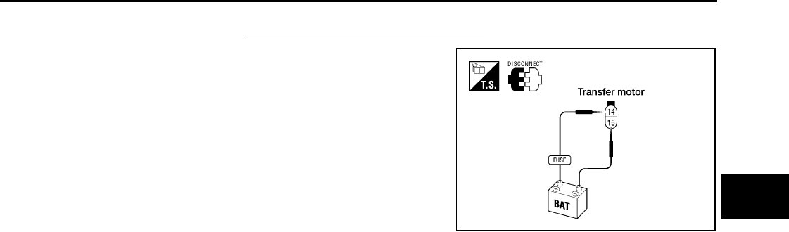
P1824 TRANSFER MOTOR
DLN-71
< COMPONENT DIAGNOSIS > [TRANSFER: ATX14B]
C
E
F
G
H
I
J
K
L
M
A
B
DLN
N
O
P
1. Turn ignition switch OFF. (Stay for at least 5 seconds.)
2. Remove transfer motor. Refer to DLN-148, "Removal and Installation".
3. Apply 12V direct current between transfer motor terminals 14
and 15.
4. If transfer motor does not operate, replace transfer motor.
LDIA0097E
Revision: October 2008
2009 Pathfinder
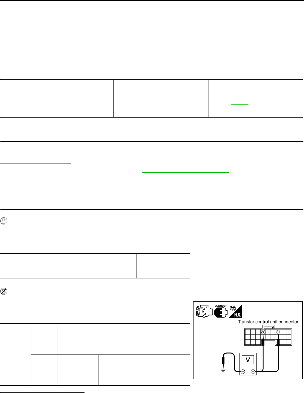
DLN-72
< COMPONENT DIAGNOSIS > [TRANSFER: ATX14B]
P1826 TRANSFER FLUID TEMPERATURE
P1826 TRANSFER FLUID TEMPERATURE
Description INFOID:0000000003937246
Signal voltage from the transfer fluid temperature sensor is abnormally high (Transfer fluid temperature is
abnormally low) while driving.
DTC Logic INFOID:0000000003937247
DTC DETECTION LOGIC
DTC CONFIRMATION PROCEDURE
1.DTC CONFIRMATION PROCEDURE
1. Turn ignition switch ON.
2. Perform self-diagnosis.
Is DTC P1826 displayed?
YES >> Perform diagnosis procedure. Refer to DLN-72, "Diagnosis Procedure".
NO >> Inspection End.
Diagnosis Procedure INFOID:0000000003937248
1.CHECK TRANSFER FLUID TEMPERATURE SENSOR SIGNAL
With CONSULT-III
1. Start engine.
2. Select DATA MONITOR mode for ALL MODE AWD/4WD with CONSULT-III.
3. Read out the value of FLUID TEMP SE.
Without CONSULT-III
1. Start engine.
2. Check voltage between transfer control unit harness connector
terminals and ground.
Are inspection results normal?
YES >> GO TO 4.
NO >> GO TO 2.
2.CHECK HARNESS BETWEEN TRANSFER CONTROL UNIT AND TRANSFER TERMINAL CORD AS-
DTC CONSULT-III Diagnostic item is detected when... Reference
[P1826] OIL TEMP SEN
Signal voltage from transfer fluid temper-
ature sensor is abnormally high (Trans-
fer fluid temperature is abnormally low)
while driving.
Refer to DLN-72.
Condition Display value
(Approx.)
Transfer fluid temperature approx. 20 - 80°C (68 - 176°F) 1.1 - 0.3V
Connector Terminal Condition Data
(Approx.)
M153
28 -
Ground Always 0V
31 -
Ground
Ignition switch:
ON
Transfer fluid temperature
approx. 20°C (68°F) 1.1V
Transfer fluid temperature
approx. 80°C (176°F) 0.3V SDIA2742E
Revision: October 2008
2009 Pathfinder
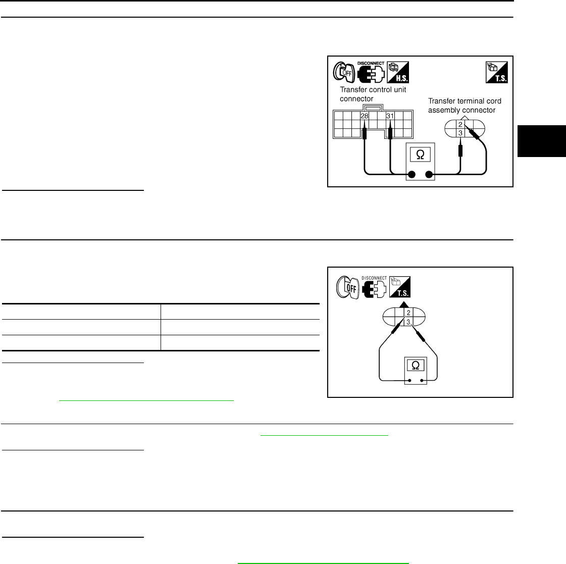
P1826 TRANSFER FLUID TEMPERATURE
DLN-73
< COMPONENT DIAGNOSIS > [TRANSFER: ATX14B]
C
E
F
G
H
I
J
K
L
M
A
B
DLN
N
O
P
SEMBLY
1. Turn ignition switch OFF. (Stay for at least 5 seconds.)
2. Disconnect transfer control unit harness connector and transfer terminal cord assembly harness connec-
tor.
3. Check continuity between the following terminals.
- Transfer control unit harness connector M153 terminal 28 and
transfer terminal cord assembly harness connector F56 terminal
3 .
- Transfer control unit harness connector M153 terminal 31 and
transfer terminal cord assembly harness connector F56 terminal
2.
Also check harness for short to ground and short to power.
Are inspection results normal?
YES >> GO TO 3.
NO >> Repair or replace damaged parts.
3.CHECK TRANSFER FLUID TEMPERATURE SENSOR
1. Turn ignition switch OFF. (Stay for at least 5 seconds.)
2. Disconnect transfer terminal cord assembly harness connector.
3. Check resistance between transfer terminal cord assembly ter-
minals 2 and 3.
Are inspection results normal?
YES >> GO TO 4.
NO >> Replace transfer fluid temperature sensor. Refer to
DLN-18, "Component Parts Location".
4.CHECK TRANSFER CONTROL UNIT
Check transfer control unit input/output signal. Refer to DLN-85, "Reference Value".
Are inspection results normal?
YES >> GO TO 5.
NO >> Check transfer control unit pin terminals for damage or loose connection with harness connector.
If any items are damaged, repair or replace damaged parts.
5.CHECK DTC
Drive the vehicle and then perform self-diagnosis.
Are inspection results normal?
YES >> Inspection End.
NO >> Replace transfer control unit. Refer to DLN-136, "Removal and Installation".
Component Inspection INFOID:0000000003937249
1. Turn ignition switch OFF. (Stay for at least 5 seconds.)
2. Disconnect transfer terminal cord assembly harness connector.
Continuity should exist.
SDIA2743E
Temperature °C (°F) Resistance (Approx.)
20 (68) 2.5 kΩ
80 (176) 0.3 kΩ
WDIA0188E
Revision: October 2008
2009 Pathfinder
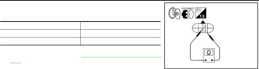
DLN-74
< COMPONENT DIAGNOSIS > [TRANSFER: ATX14B]
P1826 TRANSFER FLUID TEMPERATURE
3. Check resistance between transfer terminal cord assembly ter-
minals 2 and 3.
4. If the inspection results are abnormal replace the transfer fluid
temperature sensor. Refer to DLN-18, "Component Parts Loca-
tion".
Temperature °C (°F) Resistance (Approx.)
20 (68) 2.5 kΩ
80 (176) 0.3 kΩ
WDIA0188E
Revision: October 2008
2009 Pathfinder
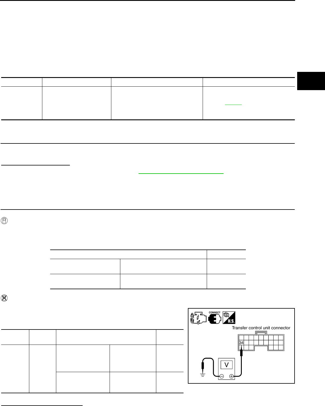
P1827 CLUTCH PRESSURE SWITCH
DLN-75
< COMPONENT DIAGNOSIS > [TRANSFER: ATX14B]
C
E
F
G
H
I
J
K
L
M
A
B
DLN
N
O
P
P1827 CLUTCH PRESSURE SWITCH
Description INFOID:0000000003937250
Improper signal from the clutch pressure switch is input due to open or short circuit. Also, a malfunction may
have occured in clutch pressure switch or hydraulic circuit.
DTC Logic INFOID:0000000003937251
DTC DETECTION LOGIC
DTC CONFIRMATION PROCEDURE
1.DTC CONFIRMATION PROCEDURE
1. Turn ignition switch ON.
2. Perform self-diagnosis.
Is DTC P1827 displayed?
YES >> Perform diagnosis procedure. Refer to DLN-75, "Diagnosis Procedure".
NO >> Inspection End.
Diagnosis Procedure INFOID:0000000003937252
1.CHECK CLUTCH PRESSURE SWITCH SIGNAL
With CONSULT-III
1. Start engine.
2. Select DATA MONITOR mode for ALL MODE AWD/4WD with CONSULT-III.
3. Read out ON/OFF switching action of the CL PRES SW while operating 4WD shift switch.
Without CONSULT-III
1. Start engine.
2. Check voltage between transfer control unit harness connector
terminals and ground.
Are inspection results normal?
DTC CONSULT-III Diagnostic item is detected when... Reference
[P1827] CLUTCH PRES SW
• Improper signal from clutch pressure
switch is input due to open or short cir-
cuit.
• Malfunction occurs in clutch pressure
switch or hydraulic circuit.
Refer to DLN-75.
Condition Display value
• Ignition switch: ON
• A/T selector lever D position 4WD shift switch: AUTO or 4H (Wait
function is not operating.) ON
Ignition switch: ON 4WD shift switch: 2WD (Wait function
is not operating.) OFF
Connector Terminal Condition Voltage
(Approx.)
M153 34 -
Ground
• Ignition switch: ON
• A/T selector lever D
position
4WD shift switch:
AUTO or 4H (Wait
function is not op-
erating.)
0V
Ignition switch: ON
4WD shift switch:
2WD (Wait function
is not operating.)
Battery
voltage SDIA2746E
Revision: October 2008
2009 Pathfinder
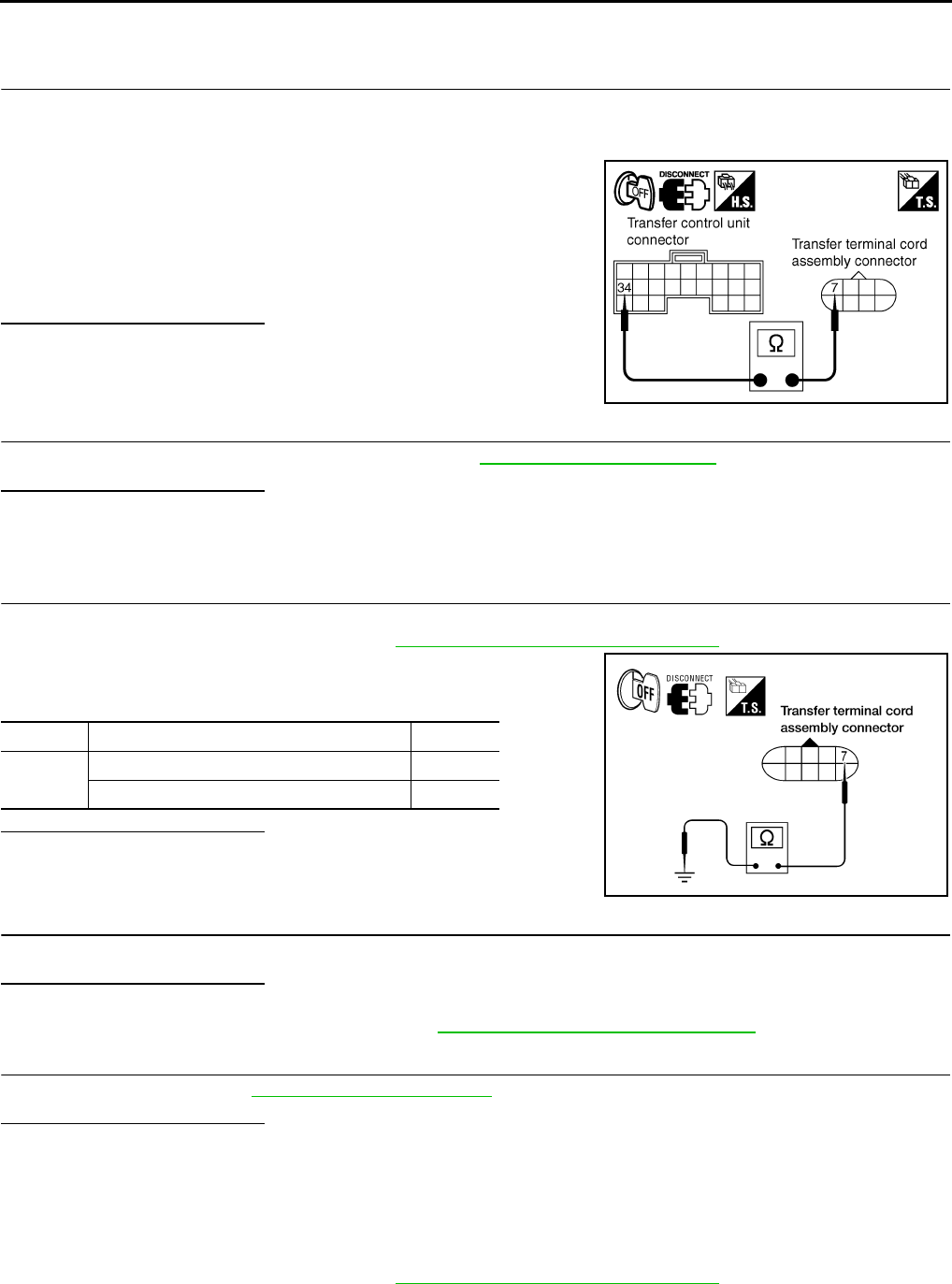
DLN-76
< COMPONENT DIAGNOSIS > [TRANSFER: ATX14B]
P1827 CLUTCH PRESSURE SWITCH
YES >> GO TO 5.
NO >> GO TO 2.
2.CHECK HARNESS BETWEEN TRANSFER CONTROL UNIT AND CLUTCH PRESSURE SWITCH
1. Turn ignition switch OFF. (Stay for at least 5 seconds.)
2. Disconnect transfer control unit harness connector and the transfer terminal cord assembly harness con-
nector.
3. Check continuity between transfer control unit harness connec-
tor M153 terminal 34 and transfer terminal cord assembly har-
ness connector F56 terminal 7
Also check harness for short to ground and short to power.
Are inspection results normal?
YES >> GO TO 3.
NO >> Repair or replace damaged parts.
3.CHECK TRANSFER CONTROL UNIT
Check transfer control unit input/output signal. Refer to DLN-85, "Reference Value".
Are inspection results normal?
YES >> GO TO 4.
NO >> Check transfer control unit pin terminals for damage or loose connection with the harness connec-
tor. If any items are damaged, repair or replace damaged parts.
4.CHECK CLUTCH PRESSURE SWITCH
1. Turn ignition switch OFF. (Stay for at least 5 seconds.)
2. Remove clutch pressure switch. Refer to DLN-18, "Component Parts Location".
3. Push and release clutch pressure switch and check continuity
between terminal 7 and ground.
Are inspection results normal?
YES >> GO TO 5.
NO >> Replace clutch pressure switch.
5.CHECK DTC
Perform the self-diagnosis, after driving a vehicle for a while.
Are inspection results normal?
YES >> GO TO 6.
NO >> Replace transfer control unit. Refer to DLN-136, "Removal and Installation".
6.CRUISE TEST
Perform cruise test. Refer to DLN-9, "Preliminary Check".
Are inspection results normal?
YES >> Inspection End.
NO >> Perform the applicable trouble diagnosis.
Component Inspection INFOID:0000000003937253
1. Turn ignition switch OFF. (Stay for at least 5 seconds.)
2. Remove clutch pressure switch. Refer to DLN-18, "Component Parts Location".
Continuity should exist.
SDIA2747E
Terminal Condition Continuity
7 -
Ground
Push clutch pressure switch Yes
Release clutch pressure switch No
WDIA0171E
Revision: October 2008
2009 Pathfinder
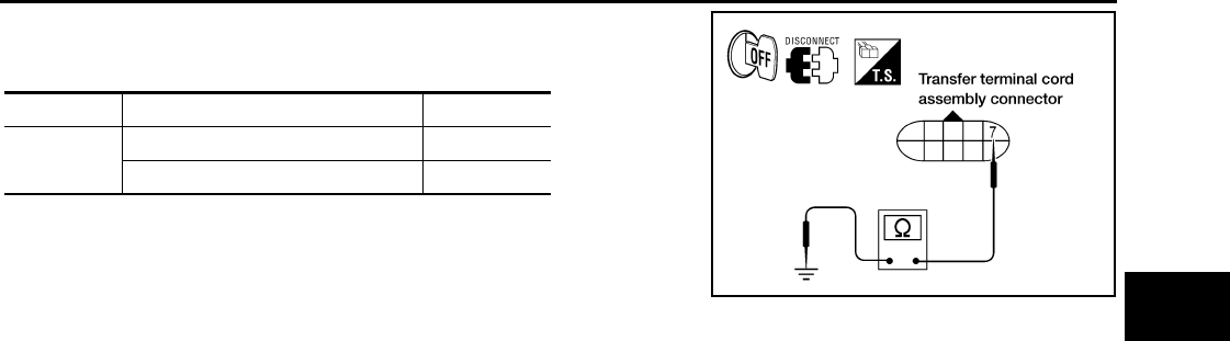
P1827 CLUTCH PRESSURE SWITCH
DLN-77
< COMPONENT DIAGNOSIS > [TRANSFER: ATX14B]
C
E
F
G
H
I
J
K
L
M
A
B
DLN
N
O
P
3. Push and release clutch pressure switch and check continuity
between terminal 7 and ground.
4. If the inspection results are abnormal replace the clutch pres-
sure switch.
Terminal Condition Continuity
7 - Ground Push clutch pressure switch Yes
Release clutch pressure switch No
WDIA0171E
Revision: October 2008
2009 Pathfinder
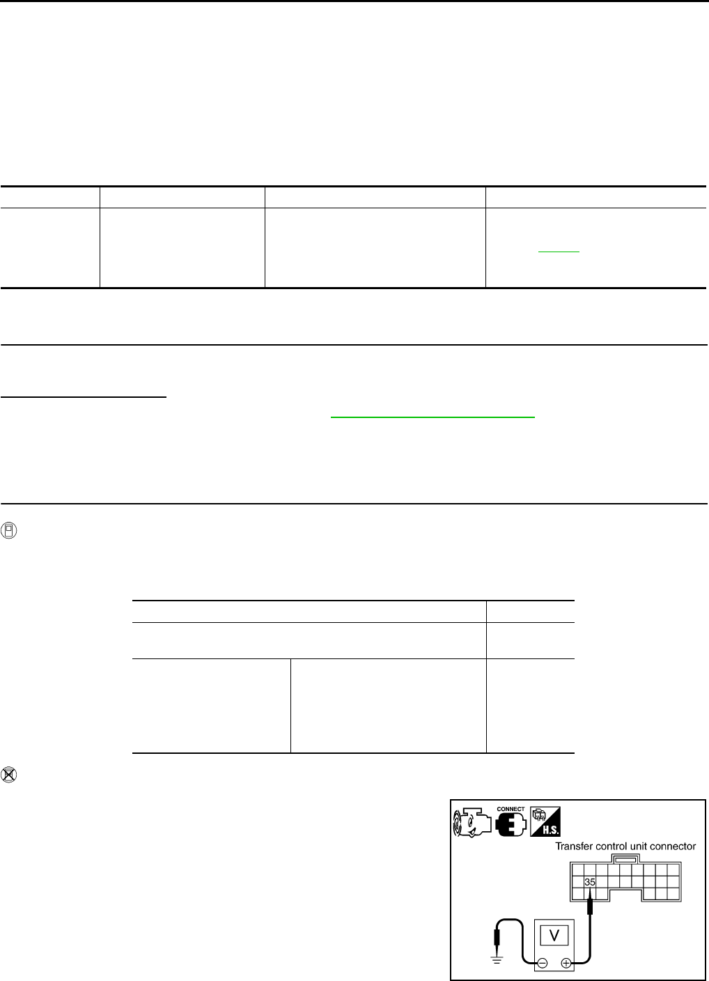
DLN-78
< COMPONENT DIAGNOSIS > [TRANSFER: ATX14B]
P1828 LINE PRESSURE SWITCH
P1828 LINE PRESSURE SWITCH
Description INFOID:0000000003937254
Improper signal from line pressure switch is input due to open or short circuit. Also, a malfunction may have
occured in the line pressure switch or hydraulic circuit.
DTC Logic INFOID:0000000003937255
DTC DETECTION LOGIC
DTC CONFIRMATION PROCEDURE
1.DTC CONFIRMATION PROCEDURE
1. Turn ignition switch ON.
2. Perform self-diagnosis.
Is DTC P1828 displayed?
YES >> Perform diagnosis procedure. Refer to DLN-78, "Diagnosis Procedure".
NO >> Inspection End.
Diagnosis Procedure INFOID:0000000003937256
1.CHECK LINE PRESSURE SWITCH SIGNAL
With CONSULT-III
1. Start engine.
2. Select DATA MONITOR mode for ALL MODE AWD/4WD with CONSULT-III.
3. Read out ON/OFF switching action of LINE PRES SW while operating 4WD shift switch.
Without CONSULT-III
1. Start engine.
2. Check voltage between transfer control unit harness connector
terminals and ground.
DTC CONSULT-III Diagnostic item is detected when... Reference
[P1828] LINE PRES SW
• Improper signal from line pressure
switch is input due to open or short cir-
cuit.
• Malfunction occurs in line pressure
switch or hydraulic circuit.
Refer to DLN-78.
Condition Display value
• A/T selector lever D position
• 4WD shift switch: AUTO ON
• Except the above
• The vehicle has been left
at room temperature for 5
minutes and more with ig-
nition switch in OFF posi-
tion.
• Ignition switch: ON
• A/T selector lever: P or N position
• 4WD shift switch: other than
AUTO
OFF
SDIA2751E
Revision: October 2008
2009 Pathfinder
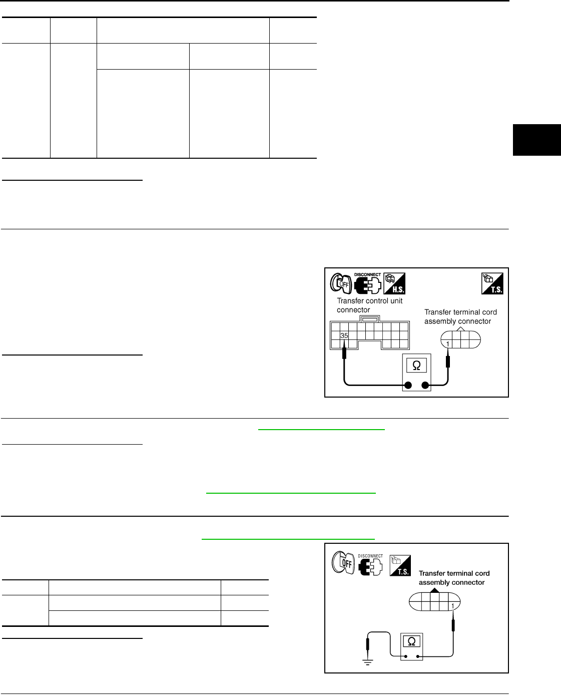
P1828 LINE PRESSURE SWITCH
DLN-79
< COMPONENT DIAGNOSIS > [TRANSFER: ATX14B]
C
E
F
G
H
I
J
K
L
M
A
B
DLN
N
O
P
Are inspection results normal?
YES >> GO TO 5.
NO >> GO TO 2.
2.CHECK HARNESS BETWEEN TRANSFER CONTROL UNIT AND LINE PRESSURE SWITCH
1. Turn ignition switch OFF. (Stay for at least 5 seconds.)
2. Disconnect transfer control unit harness connector and the transfer terminal cord assembly harness con-
nector.
3. Check continuity between transfer control unit harness connec-
tor M153 terminal 35 and transfer terminal cord assembly har-
ness connector F56 terminal 1.
Also check harness for short to ground and short to power.
Are inspection results normal?
YES >> GO TO 3.
NO >> Repair or replace damaged parts.
3.CHECK TRANSFER CONTROL UNIT
Check transfer control unit input/output signal. Refer to DLN-85, "Reference Value".
Are inspection results normal?
YES >> GO TO 4.
NO >> Check the following. If any items are damaged, repair or replace damaged parts.
• Transfer control unit pin terminals for damage or loose connection with harness connector.
• Transfer control unit. Refer to DLN-136, "Removal and Installation".
4.CHECK LINE PRESSURE SWITCH
1. Turn ignition switch OFF. (Stay for at least 5 seconds.)
2. Remove line pressure switch. Refer to DLN-18, "Component Parts Location".
3. Push and release line pressure switch and check continuity
between terminal 1 and ground.
Are inspection results normal?
YES >> GO TO 5.
NO >> Replace line pressure switch.
5.CHECK DTC
Perform the self-diagnosis, after driving a vehicle for a while.
Connector Terminal Condition Voltage
(Approx.)
M153 35 -
Ground
• A/T selector lever D
position
4WD shift switch:
AUTO 0V
• Except the above
• The vehicle has
been left at room
temperature for 5
minutes and more
with ignition switch
in OFF position.
• Ignition switch:
ON
• A/T selector le-
ver: P or N posi-
tion
• 4WD shift
switch: other
than AUTO
Battery
voltage
Continuity should exist.
SDIA2752E
Terminal Condition Continuity
1 -
Ground
Push line pressure switch Yes
Release line pressure switch No
WDIA0172E
Revision: October 2008
2009 Pathfinder
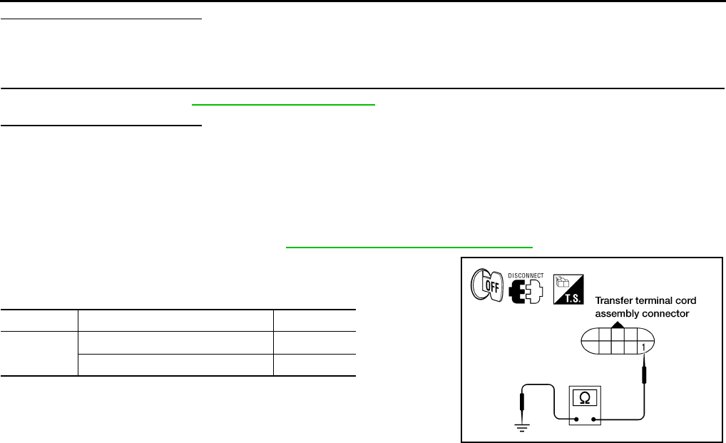
DLN-80
< COMPONENT DIAGNOSIS > [TRANSFER: ATX14B]
P1828 LINE PRESSURE SWITCH
Are inspection results normal?
YES >> GO TO 6.
NO >> Replace transfer control unit.
6.CRUISE TEST
Perform cruise test. Refer to DLN-9, "Preliminary Check".
Are inspection results normal?
YES >> Inspection End.
NO >> Perform the applicable trouble diagnosis.
Component Inspection INFOID:0000000003937257
1. Turn ignition switch OFF. (Stay for at least 5 seconds.)
2. Remove line pressure switch. Refer to DLN-18, "Component Parts Location".
3. Push and release line pressure switch and check continuity
between terminal 1 and ground.
4. If the inspection results are abnormal, replace the line pressure
switch.
Terminal Condition Continuity
1 - Ground Push line pressure switch Yes
Release line pressure switch No
WDIA0172E
Revision: October 2008
2009 Pathfinder

P1829 THROTTLE POSITION SIGNAL (ECM)
DLN-81
< COMPONENT DIAGNOSIS > [TRANSFER: ATX14B]
C
E
F
G
H
I
J
K
L
M
A
B
DLN
N
O
P
P1829 THROTTLE POSITION SIGNAL (ECM)
Description INFOID:0000000003937258
Malfunction is detected in accelerator pedal position signal that is output from ECM through CAN communica-
tion. Also, the signal voltage from accelerator pedal position sensor may be abnormally high or low.
DTC Logic INFOID:0000000003937259
DTC DETECTION LOGIC
DTC CONFIRMATION PROCEDURE
1.DTC CONFIRMATION PROCEDURE
1. Turn ignition switch ON.
2. Perform self-diagnosis.
Is DTC P1829 displayed?
YES >> Perform diagnosis procedure. Refer to DLN-81, "Diagnosis Procedure".
NO >> Inspection End.
Diagnosis Procedure INFOID:0000000003937260
1.CHECK DTC WITH ECM
Perform self-diagnosis with ECM. Refer to EC-546, "CONSULT-III Function (ENGINE)".
Is any malfunction detected by self-diagnosis?
YES >> Check the malfunctioning system.
NO >> GO TO 2.
2.CHECK TRANSFER CONTROL UNIT
Check transfer control unit input/output signal. Refer to DLN-85, "Reference Value".
Are inspection results normal?
YES >> GO TO 3.
NO >> Check transfer control unit pin terminals for damage or loose connection with harness connector.
If any items are damaged, repair or replace damaged parts.
3.CHECK DTC
Perform the self-diagnosis, after driving a vehicle for a while.
Are inspection results normal?
YES >> Inspection End.
NO >> Perform self-diagnosis with ECM again.
DTC CONSULT-III Diagnostic item is detected when... Reference
[P1829] THROTTLE POSI SEN
• Malfunction is detected in accelerator
pedal position signal that is output
from ECM through CAN communica-
tion.
• Signal voltage from accelerator pedal
position sensor is abnormally high or
low.
Refer to DLN-81.
Revision: October 2008
2009 Pathfinder

DLN-82
< COMPONENT DIAGNOSIS > [TRANSFER: ATX14B]
P1830 ABS OPERATION SIGNAL (ABS)
P1830 ABS OPERATION SIGNAL (ABS)
Description INFOID:0000000003937261
Malfunction is detected in ABS operation signal that is output from ABS actuator and electric unit (control unit)
through CAN communication.
DTC Logic INFOID:0000000003937262
DTC DETECTION LOGIC
DTC CONFIRMATION PROCEDURE
1.DTC CONFIRMATION PROCEDURE
1. Turn ignition switch ON.
2. Perform self-diagnosis.
Is DTC P1830 displayed?
YES >> Perform diagnosis procedure. Refer to DLN-82, "Diagnosis Procedure".
NO >> Inspection End.
Diagnosis Procedure INFOID:0000000003937263
1.CHECK DTC WITH ABS ACTUATOR AND ELECTRIC UNIT (CONTROL UNIT)
Perform self-diagnosis with ABS actuator and electric unit (control unit). Refer to BRC-153, "CONSULT-III
Function (ABS)".
Is any malfunction detected by self-diagnosis?
YES >> Check the malfunctioning system.
NO >> GO TO 2.
2.CHECK TRANSFER CONTROL UNIT
Check transfer control unit input/output signal. Refer to DLN-85, "Reference Value".
Are the inspection results normal?
YES >> GO TO 3.
NO >> Check transfer control unit pin terminals for damage or loose connection with harness connector.
If any items are damaged, repair or replace damaged parts.
3.CHECK DTC
Perform the self-diagnosis, after driving a vehicle for a while.
Are the inspection results normal?
YES >> Inspection End.
NO >> Perform self-diagnosis with ABS actuator and electric unit (control unit) again.
DTC CONSULT-III Diagnostic item is detected when... Reference
[P1830] ABS OP SIG
Malfunction is detected in ABS operation
signal that is output from ABS actuator
and electric unit (control unit) through
CAN communication.
Refer to DLN-82.
Revision: October 2008
2009 Pathfinder
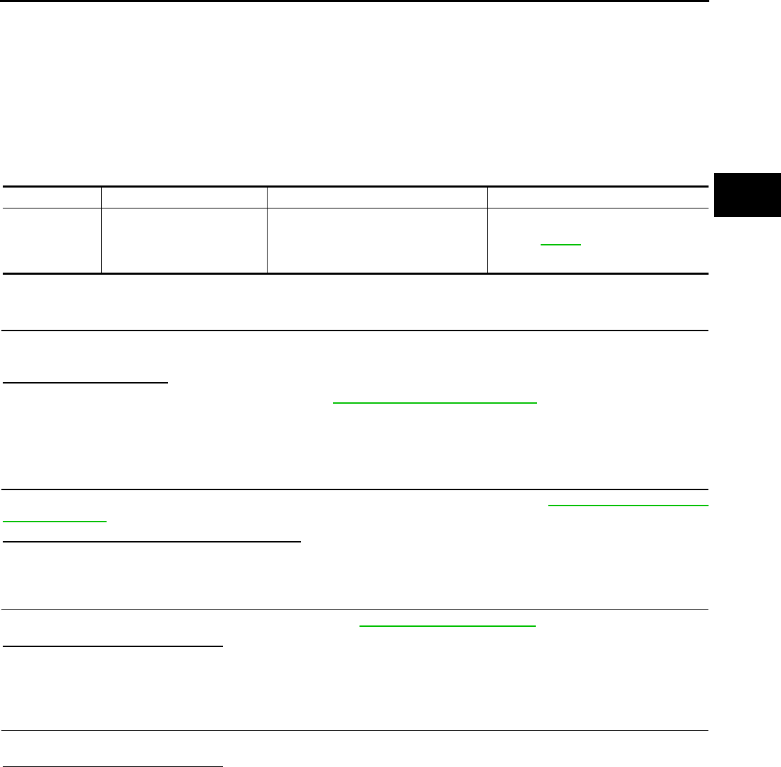
P1831 VDC OPERATION SIGNAL (ABS)
DLN-83
< COMPONENT DIAGNOSIS > [TRANSFER: ATX14B]
C
E
F
G
H
I
J
K
L
M
A
B
DLN
N
O
P
P1831 VDC OPERATION SIGNAL (ABS)
Description INFOID:0000000003937264
Malfunction is detected in the VDC operation signal that is output from ABS actuator and electric unit (control
unit) through CAN communication.
DTC Logic INFOID:0000000003937265
DTC DETECTION LOGIC
DTC CONFIRMATION PROCEDURE
1.DTC CONFIRMATION PROCEDURE
1. Turn ignition switch ON.
2. Perform self-diagnosis.
Is DTC P1831 displayed?
YES >> Perform diagnosis procedure. Refer to DLN-83, "Diagnosis Procedure".
NO >> Inspection End.
Diagnosis Procedure INFOID:0000000003937266
1.CHECK DTC WITH ABS ACTUATOR AND ELECTRIC UNIT
Perform self-diagnosis with ABS actuator and electric unit (control unit). Refer to BRC-153, "CONSULT-III
Function (ABS)".
Is any malfunction detected by self-diagnosis?
YES >> Check the malfunctioning system.
NO >> GO TO 2.
2.CHECK TRANSFER CONTROL UNIT
Check transfer control unit input/output signal. Refer to DLN-85, "Reference Value".
Are the inspection results normal?
YES >> GO TO 3.
NO >> Check transfer control unit pin terminals for damage or loose connection with harness connector.
If any items are damaged, repair or replace damaged parts.
3.CHECK DTC
Perform the self-diagnosis, after driving a vehicle for a while.
Are the inspection results normal?
YES >> Inspection End.
NO >> Perform self-diagnosis with ABS actuator electric unit (control unit) again.
DTC CONSULT-III Diagnostic item is detected when... Reference
[P1831] VDC OP SIG
Malfunction is detected in VDC opera-
tion signal that is output from ABS actu-
ator and electric unit (control unit)
through CAN communication.
Refer to DLN-83.
Revision: October 2008
2009 Pathfinder

DLN-84
< COMPONENT DIAGNOSIS > [TRANSFER: ATX14B]
P1832 TCS OPERATION SIGNAL (ABS)
P1832 TCS OPERATION SIGNAL (ABS)
Description INFOID:0000000003937267
Malfunction is detected in TCS operation signal that is output from ABS actuator and electric unit (control unit)
through CAN communication.
DTC Logic INFOID:0000000003937268
DTC DETECTION LOGIC
DTC CONFIRMATION PROCEDURE
1.DTC CONFIRMATION PROCEDURE
1. Turn ignition switch ON.
2. Perform self-diagnosis.
Is DTC P1832 displayed?
YES >> Perform diagnosis procedure. Refer to DLN-84, "Diagnosis Procedure".
NO >> Inspection End.
Diagnosis Procedure INFOID:0000000003937269
1.CHECK DTC WITH ABS ACTUATOR AND ELECTRIC UNIT
Perform self-diagnosis with ABS actuator and electric unit (control unit). Refer to BRC-153, "CONSULT-III
Function (ABS)".
Is any malfunction detected by self-diagnosis?
YES >> Check the malfunctioning system.
NO >> GO TO 2.
2.CHECK TRANSFER CONTROL UNIT
Check transfer control unit input/output signal. Refer to DLN-85, "Reference Value".
Are the inspection results normal?
YES >> GO TO 3.
NO >> Check transfer control unit pin terminals for damage or loose connection with harness connector.
If any items are damaged, repair or replace damaged parts.
3.CHECK DTC
Perform the self-diagnosis, after driving a vehicle for a while.
Are the inspection results normal?
YES >> Inspection End.
NO >> Perform self-diagnosis with ABS actuator electric unit (control unit) again.
DTC CONSULT-III Diagnostic item is detected when... Reference
[P1832] TCS OP SIG
Malfunction is detected in TCS operation
signal that is output from ABS actuator
and electric unit (control unit) through
CAN communication.
Refer to DLN-84.
Revision: October 2008
2009 Pathfinder

TRANSFER CONTROL UNIT
DLN-85
< ECU DIAGNOSIS > [TRANSFER: ATX14B]
C
E
F
G
H
I
J
K
L
M
A
B
DLN
N
O
P
ECU DIAGNOSIS
TRANSFER CONTROL UNIT
Reference Value INFOID:0000000003937270
VALUE ON THE DIAGNOSIS TOOL
CONSULT-III data monitor item
Monitored item [Unit] Content Condition Display value
VHCL/S SEN·FR [km/h]
or [mph]
Wheel speed (Front
wheel)
Vehicle stopped 0 km/h (0 mph)
Vehicle running
CAUTION:
Check air pressure of tire under standard condition.
Approximately
equal to the indica-
tion on speedome-
ter (Inside of
±10%)
VHCL/S SEN·RR [km/h]
or [mph] Wheel speed (Rear
wheel)
Vehicle stopped 0 km/h (0 mph)
Vehicle running
CAUTION:
Check air pressure of tire under standard condition.
Approximately
equal to the indica-
tion on speedome-
ter (Inside of
±10%)
ENGINE SPEED [rpm] Engine speed
Engine stopped
(Engine speed: Less than 400 rpm) 0 rpm
Engine running
(Engine speed: 400 rpm or more)
Approximately
equal to the indica-
tion on tachometer
THRTL POS SEN [V] Accelertor pedal position
(APP) sensor signal volt-
age
Accelerator pedal: Released Approx. 0.5V
Accelerator pedal: Fully depressed Approx. 4.0V
FLUID TEMP SE [V] Transfer fluid tempera-
ture signal voltage Transfer fluid temperature approx. 20 - 80°C (68 - 176°F) Approx. 1.1 - 0.3V
BATTERY VOLT [V] Power supply voltage for
transfer control unit Ignition switch: ON Battery voltage
2WD SWITCH [ON/OFF] Input condition from 4WD
shift switch
4WD shift switch: 2WD ON
4WD shift switch: AUTO, 4H or 4LO OFF
AUTO SWITCH [ON/
OFF]
Input condition from 4WD
shift switch
4WD shift switch: AUTO ON
4WD shift switch: 2WD, 4H or 4LO OFF
LOCK SWITCH [ON/
OFF]
Input condition from 4WD
shift switch
4WD shift switch: 4H ON
4WD shift switch: 2WD, AUTO or 4LO OFF
4L SWITCH [ON/OFF] Input condition from 4WD
shift switch
4WD shift switch: 4LO ON
4WD shift switch: 2WD, AUTO or 4H OFF
N POSI SW TF [ON/
OFF] Condition of neutral-4LO
switch
• Vehicle stopped
• Engine running
• A/T selector lever N posi-
tion
• Brake pedal depressed
4WD shift switch: 2WD,
AUTO or 4H OFF
4WD shift switch: 4H to
4LO (While actuator mo-
tor is operating.) OFF→ON
4WD shift switch: 4LO to
4H (While actuator motor
is operating.)
ON→OFF
4WD shift switch: 4LO ON
Revision: October 2008
2009 Pathfinder

DLN-86
< ECU DIAGNOSIS > [TRANSFER: ATX14B]
TRANSFER CONTROL UNIT
ATP SWITCH [ON/OFF] Condition of ATP switch
• Vehicle stopped
• Engine running
• A/T selector lever N posi-
tion
• Brake pedal depressed
4WD shift switch
: 4H to 4LO or 4LO to 4H
(While actuator motor is
operating.)
ON
Except the above OFF
WAIT DETCT SW [ON/
OFF]
Condition of wait detec-
tion switch
• Vehicle stopped
• Engine running
• A/T selector lever N posi-
tion
• Brake pedal depressed
4WD shift switch: 2WD,
AUTO or 4H OFF
4WD shift switch: 4H to
4LO (While actuator mo-
tor is operating.)
OFF→ON
4WD shift switch: 4LO to
4H (While actuator motor
is operating.)
ON→OFF
4WD shift switch: 4LO ON
LINE PRES SW [ON/
OFF] Condition of line pres-
sure switch
• A/T selector lever D position
• 4WD shift switch: AUTO ON
• Except the above
• The vehicle has been left at
room temperature for 5
minutes and more with ig-
nition switch in OFF posi-
tion.
• Ignition switch: ON
• A/T selector lever: P or
N position
• 4WD shift switch: other
than AUTO
OFF
CL PRES SW [ON / OFF] Condition of clutch pres-
sure switch
• Vehicle stopped
• Engine running
• A/T selector lever D position
• 4WD shift switch: AUTO or 4H (Wait function is not op-
erating.)
ON
• Vehicle stopped
• Engine running
• 4WD shift switch: 2WD (Wait function is not operating.)
OFF
N POSI SW AT [ON/
OFF]
Input condition from A/T
PNP switch
• Vehicle stopped
• Engine running
• Brake pedal depressed
A/T selector lever posi-
tion: N ON
Except the above OFF
R POSI SW AT [ON/
OFF] Input condition from A/T
PNP switch
• Vehicle stopped
• Engine running
• Brake pedal depressed
A/T selector lever posi-
tion: R ON
Except the above OFF
P POSI SW AT [ON/OFF] Input condition from A/T
PNP switch
• Vehicle stopped
• Engine running
• Brake pedal depressed
A/T selector lever posi-
tion: P ON
Except the above OFF
ABS OPER SW [ON/
OFF]
Condition of ABS operat-
ing
ABS is operating. ON
ABS is not operating. OFF
VDC OPER SW [ON/
OFF]
Condition of VDC operat-
ing
VDC is operating. ON
VDC is not operating. OFF
TCS OPER SW [ON/
OFF]
Condition of TCS operat-
ing
TCS is operating. ON
TCS is not operating. OFF
THROTTLE POSI [0.0/8] Condition of throttle
opening
When depressing accelerator pedal
(Value rises gradually in response to throttle position.) 0.0/8 - 8.0/8
4WD MODE [AUTO/
LOCK/2WD/4L]
Control status of 4WD
(Output condition of 4WD
shift indicator lamp and
4LO indicator lamp)
• Vehicle stopped
• Engine running
• A/T selector lever N posi-
tion
• Brake pedal depressed
4WD shift switch: 2WD 2WD
4WD shift switch: AUTO AUTO
4WD shift switch: 4H LOCK
4WD shift switch: 4LO 4L
Monitored item [Unit] Content Condition Display value
Revision: October 2008
2009 Pathfinder

TRANSFER CONTROL UNIT
DLN-87
< ECU DIAGNOSIS > [TRANSFER: ATX14B]
C
E
F
G
H
I
J
K
L
M
A
B
DLN
N
O
P
VHCL/S COMP [km/h] or
[mph] Vehicle speed
Vehicle stopped 0 km/h (0 mph)
Vehicle running
CAUTION:
Check air pressure of tire under standard condition.
Approximately
equal to the indica-
tion on speedome-
ter (Inside of
±10%)
COMP CL TORQ [kgm] Condition of control
torque
• Vehicle stopped
• Engine running
• A/T selector lever N posi-
tion
• Brake pedal depressed
4WD shift switch: 2WD 0 kg-m
4WD shift switch: AUTO
39 - 1,353 N·m
(4 - 138 kg-m, 29 -
998 ft-lb)
4WD shift switch: 4H or
4LO
1,353 N·m
(138 kg-m, 998 ft-
lb)
DUTY SOLENOID [%] Condition of clutch pres-
sure solenoid
• Vehicle stopped
• Engine running
• A/T selector lever N posi-
tion
• Brake pedal depressed
4WD shift switch: 2WD 4%
4WD shift switch: AUTO 96 - 4%
4WD shift switch: 4H or
4LO 4%
2-4WD SOL [ON/OFF] Condition of 2-4WD shift
solenoid valve
• Vehicle stopped
• Engine running
• A/T selector lever N posi-
tion
• Brake pedal depressed
4WD shift switch: 2WD OFF
4WD shift switch: AUTO
ON4WD shift switch: 4H
4WD shift switch: 4LO
4WD shift switch: AUTO
(Wait function is operat-
ing.)
OFF
4WD shift switch: 4H
(Wait function is operat-
ing.) OFF
2-4WD SOL MON [ON/
OFF]
Check signal for transfer
control unit signal output
• Vehicle stopped
• Engine running
• A/T selector lever N posi-
tion
• Brake pedal depressed
4WD shift switch: 2WD OFF
4WD shift switch: AUTO
ON4WD shift switch: 4H
4WD shift switch: 4LO
4WD shift switch: AUTO
(Wait function is operat-
ing.)
OFF
4WD shift switch: 4H
(Wait function is operat-
ing.) OFF
MOTOR RELAY [ON/
OFF] Condition of transfer mo-
tor relay
• Accelerator pedal de-
pressed
• Vehicle stopped
• Engine running
• Brake pedal depressed
4WD shift switch: 2WD OFF
4WD shift switch: AUTO
or 4LO (A/T selector lever
P or N position)
OFF
(ON for approx. 2
sec. after shifting
to P and N.)
4WD shift switch: AUTO
or 4LO (Except for A/T se-
lector lever P or N posi-
tion)
ON
4WD shift switch: 4H (A/T
selector lever P position)
OFF
(ON for approx. 2
sec. after shifting
to P.)
4WD shift switch: 4H (Ex-
cept for A/T selector lever
P position)
ON
Monitored item [Unit] Content Condition Display value
Revision: October 2008
2009 Pathfinder

DLN-88
< ECU DIAGNOSIS > [TRANSFER: ATX14B]
TRANSFER CONTROL UNIT
MOTOR RELAY MON
[ON/OFF]
Check signal for transfer
control unit signal output
• Accelerator pedal de-
pressed
• Vehicle stopped
• Engine running
• Brake pedal depressed
4WD shift switch: 2WD OFF
4WD shift switch: AUTO
or 4LO (A/T selector lever
P or N position)
OFF
(ON for approx. 2
sec. after shifting
to P and N.)
4WD shift switch: AUTO
or 4LO (Except for A/T se-
lector lever P or N posi-
tion)
ON
4WD shift switch: 4H (A/T
selector lever P position)
OFF
(ON for approx. 2
sec. after shifting
to P.)
4WD shift switch: 4H (Ex-
cept for A/T selector lever
P position)
ON
4WD FAIL LAMP [ON/
OFF] Condition of 4WD warn-
ing lamp
4WD warning lamp: ON ON
4WD warning lamp: OFF OFF
2WD IND [ON/OFF]
Condition of 4WD shift in-
dicator lamp (2WD indi-
cator lamp)
2WD indicator lamp of 4WD shift indicator lamp: OFF OFF
2WD indicator lamp of 4WD shift indicator lamp: ON ON
AUTO IND [ON/OFF]
Condition of 4WD shift in-
dicator lamp (AUTO indi-
cator lamp)
AUTO indicator lamp of 4WD shift indicator lamp: OFF OFF
AUTO indicator lamp of 4WD shift indicator lamp: ON ON
LOCK IND [ON/OFF] Condition of 4WD shift in-
dicator lamp (Lock indi-
cator lamp)
Lock indicator lamp of 4WD shift indicator lamp: OFF OFF
Lock indicator lamp of 4WD shift indicator lamp: ON ON
4L IND [ON/OFF] Condition of 4LO indica-
tor lamp condition
4LO indicator lamp: OFF OFF
4LO indicator lamp: ON ON
ATP IND [ON/OFF] Condition of ATP indica-
tor lamp
ATP indicator lamp: ON ON
ATP indicator lamp: OFF OFF
SHIFT POS SW1 [ON/
OFF]
Condition of actuator po-
sition switch 1
(Low)
• Vehicle stopped
• Engine running
• A/T selector lever N posi-
tion
• Brake pedal depressed
4WD shift switch: 4LO ON
4WD shift switch: 2WD,
AUTO or 4H OFF
SHIFT POS SW2 [ON/
OFF]
Condition of actuator po-
sition switch 2
(High)
• Vehicle stopped
• Engine running
• A/T selector lever N posi-
tion
• Brake pedal depressed
4WD shift switch: 4H,
AUTO or 2WD ON
4WD shift switch: 4LO OFF
SHIFT ACT1 [ON/OFF] Output condition to actu-
ator motor (High)
• Vehicle stopped
• Engine running
• A/T selector lever N posi-
tion
• Brake pedal depressed
4WD shift switch: 4H to
4LO (Wait function is op-
erating.)
ON
Except the above OFF
SHIFT AC MON1 [ON/
OFF]
Check signal for transfer
control unit signal output
• Vehicle stopped
• Engine running
• A/T selector lever N posi-
tion
• Brake pedal depressed
4WD shift switch: 4H to
4LO (Wait function is op-
erating.)
ON
Except the above OFF
SHIFT ACT2 [ON/OFF] Output condition to actu-
ator motor (Low)
• Vehicle stopped
• Engine running
• A/T selector lever N posi-
tion
• Brake pedal depressed
4WD shift switch: 4LO to
4H (Wait function is oper-
ating.) ON
Except the above OFF
Monitored item [Unit] Content Condition Display value
Revision: October 2008
2009 Pathfinder
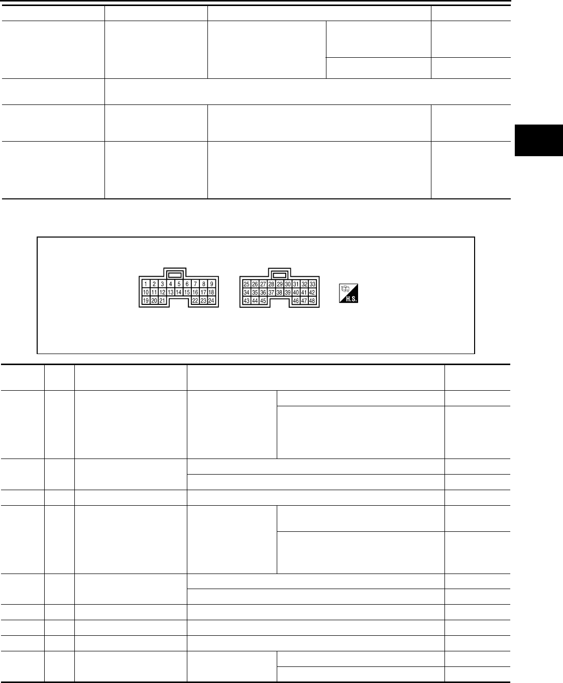
TRANSFER CONTROL UNIT
DLN-89
< ECU DIAGNOSIS > [TRANSFER: ATX14B]
C
E
F
G
H
I
J
K
L
M
A
B
DLN
N
O
P
PHYSICAL VALUES
Terminal Layout
SHIFT AC MON2 [ON/
OFF] Check signal for transfer
control unit signal output
• Vehicle stopped
• Engine running
• A/T selector lever N posi-
tion
• Brake pedal depressed
4WD shift switch: 4LO to
4H (Wait function is oper-
ating.)
ON
Except the above OFF
T/F F SPEED [km/h] or
[mph] Displayed, but do not use.
A/T R SPEED [km/h] or
[mph]
Condition of vehicle
speed sensor A/T (Revo-
lution sensor) During driving
Approximately
matches the out-
put shaft speed.
AT GEAR POSI [1/2/3/4/
5]
Condition of A/T selector
lever position Displays actual A/T gear position.
1
2
3
4
5
Monitored item [Unit] Content Condition Display value
WDIA0384E
Terminal Wire
color Item Condition Data (Approx.)
1 GR 2-4WD shift solenoid valve
• Vehicle stopped
• Engine running
• A/T selector lever
“N” position
• Brake pedal de-
pressed
4WD shift switch: 2WD 0V
4WD shift switch: AUTO, 4H or 4LO Battery voltage
2V
4WD shift indicator lamp
(2WD indicator lamp)
2WD indicator lamp: OFF Battery voltage
2WD indicator lamp: ON 0V
3 B Ground Always 0V
4 SB Transfer shift high relay
• Vehicle stopped
• Engine running
• A/T selector lever
“N” position
• Brake pedal de-
pressed
4WD shift switch: 4H to 4LO (“Wait” func-
tion is operating.) Battery voltage
Except the above 0V
5GR4WD warning lamp 4WD warning lamp: ON 0V
4WD warning lamp: OFF Battery voltage
6 B Ground Always 0V
7 L CAN-H — —
8 P CAN-L — —
9G
4WD shift switch
(2WD) Ignition switch: ON 4WD shift switch: 2WD Battery voltage
4WD shift switch: AUTO, 4H or 4LO 0V
Revision: October 2008
2009 Pathfinder

DLN-90
< ECU DIAGNOSIS > [TRANSFER: ATX14B]
TRANSFER CONTROL UNIT
10 P Transfer dropping resistor
• Vehicle stopped
• Engine running
• A/T selector lever
“N” position
• Brake pedal de-
pressed
4WD shift switch: AUTO 4 - 14V
4WD shift switch: 2WD, 4H or 4LO Less than 1V
11 BR 4WD shift indicator lamp
(Lock indicator lamp)
Lock indicator lamp of 4WD shift indicator lamp: OFF Battery voltage
Lock indicator lamp of 4WD shift indicator lamp: ON 0V
12 O 4LO indicator lamp 4LO indicator lamp: OFF Battery voltage
4LO indicator lamp: ON 0V
13 G Transfer shift low relay
• Vehicle stopped
• Engine running
• A/T selector lever
“N” position
• Brake pedal de-
pressed
4WD shift switch: 4LO to 4H (“Wait” func-
tion is operating.) Battery voltage
Except the above 0V
14 V Transfer motor relay
• Accelerator pedal
depressed
• Vehicle stopped
• Engine running
• Brake pedal de-
pressed
4WD shift switch: 2WD Battery voltage
4WD shift switch: AUTO or 4LO (A/T selec-
tor lever “P” or “N” position)
Battery voltage
(0V for approx.
2 sec. after
shifting to “P”
and “N”.)
4WD shift switch: AUTO or 4LO (Except for
A/T selector lever “P” or “N” position) 0V
4WD shift switch: 4H (A/T selector lever
“P” position)
Battery voltage
(0V for approx.
2 sec. after
shifting to “P”.)
4WD shift switch: 4H (Except for A/T selec-
tor lever “P” position) 0V
15 LG ATP warning lamp ATP indicator lamp: ON 0V
ATP indicator lamp: OFF Battery voltage
16 Y Power supply
Ignition switch: ON Battery voltage
Ignition switch: OFF
(5 seconds after ignition switch is turned OFF) 0V
18 O 4WD shift switch
(4H) Ignition switch: ON 4WD shift switch: 4H Battery voltage
4WD shift switch: 2WD, AUTO or 4LO 0V
19 R Clutch pressure solenoid
valve
• Vehicle stopped
• Engine running
• A/T selector lever
“N” position
• Brake pedal de-
pressed
4WD shift switch: AUTO 1.5 - 3V
4WD shift switch: 2WD, 4H or 4LO Less than 1V
21 B 4WD shift indicator lamp
(AUTO indicator lamp)
AUTO indicator lamp of 4WD shift indicator lamp: OFF Battery voltage
AUTO indicator lamp of 4WD shift indicator lamp: ON 0V
22 GR Power supply
Ignition switch: ON Battery voltage
Ignition switch: OFF
(5 seconds after ignition switch is turned OFF) 0V
23 W 4WD shift switch
(4LO) Ignition switch: ON 4WD shift switch: 4LO Battery voltage
4WD shift switch: 2WD, AUTO or 4H 0V
24 LG 4WD shift switch
(AUTO) Ignition switch: ON 4WD shift switch: AUTO Battery voltage
4WD shift switch: 2WD, 4H or 4LO 0V
Terminal Wire
color Item Condition Data (Approx.)
Revision: October 2008
2009 Pathfinder

TRANSFER CONTROL UNIT
DLN-91
< ECU DIAGNOSIS > [TRANSFER: ATX14B]
C
E
F
G
H
I
J
K
L
M
A
B
DLN
N
O
P
25 Y Neutral-4LO switch
• Vehicle stopped
• Engine running
• A/T selector lever
“N” position
• Brake pedal de-
pressed
4WD shift switch: 2WD, AUTO or 4H Battery voltage
4WD shift switch: 4H to 4LO (While actua-
tor motor is operating.)
Battery voltage
→ 0V
4WD shift switch: 4LO to 4H (While actua-
tor motor is operating.)
0V → Battery
voltage
4WD shift switch: 4LO 0V
27 W Actuator position switch 2
(High)
• Vehicle stopped
• Engine running
• A/T selector lever
“N” position
• Brake pedal de-
pressed
4WD shift switch: 4H, AUTO or 2WD 0V
4WD shift switch: 4LO Battery voltage
28 P Sensor ground Always 0V
29 W/G Ignition switch monitor Ignition switch: ON Battery voltage
Ignition switch: OFF 0V
30 V Shut off relay
Ignition switch: ON 0V
Ignition switch: OFF
(5 seconds after ignition switch is turned OFF) Battery voltage
31 G Transfer fluid temperature
sensor Ignition switch: ON
Transfer fluid temperature approx. 20°C
(68°F) 1.1V
Transfer fluid temperature approx. 80°C
(176°F) 0.3V
33 GR Transfer shift high relay
monitor
• Vehicle stopped
• Engine running
• A/T selector lever
“N” position
• Brake pedal de-
pressed
4WD shift switch: 4H to 4LO (“Wait” func-
tion is operating.) Battery voltage
Except the above 0V
34 BR Clutch pressure switch
• Vehicle stopped
• Engine running
• A/T selector lever
“D” position
4WD shift switch: AUTO or 4H (“Wait” func-
tion is not operating.) 0V
• Vehicle stopped
• Engine running
4WD shift switch: 2WD (“Wait” function is
not operating.) Battery voltage
35 L Line pressure switch
• Ignition switch: ON
• A/T selector lever “D” position
• 4WD shift switch: AUTO
0V
• After the vehicle
has been left at
room temperature
for 5 minutes and
more with ignition
switch in “OFF” po-
sition.
• Ignition switch: ON
• A/T selector lever: “P” or "N" position
• 4WD shift switch: other than AUTO Battery voltage
40 R ATP switch
• Vehicle stopped
• Engine running
• A/T selector lever
“N”
• Brake pedal de-
pressed
4WD shift switch: 4H to 4LO or 4LO to 4H
(While actuator motor is operating.) 0V
Except the above Battery voltage
Terminal Wire
color Item Condition Data (Approx.)
Revision: October 2008
2009 Pathfinder

DLN-92
< ECU DIAGNOSIS > [TRANSFER: ATX14B]
TRANSFER CONTROL UNIT
CAUTION:
When using a circuit tester to measure voltage for inspection, be sure not to extend forcibly any connector terminals.
NOTE:
Data are reference value and are measured between each terminal and ground.
41 SB Transfer motor relay moni-
tor
• Accelerator pedal
depressed
• Vehicle stopped
• Engine running
• Brake pedal de-
pressed
4WD shift switch: 2WD 0V
4WD shift switch: AUTO or 4LO (A/T selec-
tor lever “P” or “N” position)
0V
(Battery volt-
age for approx.
2 sec. after
shifting to “P”
and “N”.)
4WD shift switch: AUTO or 4LO (Except for
A/T selector lever “P” or “N” position) Battery voltage
4WD shift switch: 4H (A/T selector lever
“P” position)
0V
(Battery volt-
age for approx.
2 sec. after
shifting to “P”.)
4WD shift switch: 4H (Except for A/T selec-
tor lever “P” position) Battery voltage
42 Y Transfer shift low relay
monitor
• Vehicle stopped
• Engine running
• A/T selector lever
“N” position
• Brake pedal de-
pressed
4WD shift switch: 4LO to 4H (“Wait” func-
tion is operating.) Battery voltage
Except the above 0V
43 O Wait detection switch
• Vehicle stopped
• Engine running
• A/T selector lever
“N” position
• Brake pedal de-
pressed
4WD shift switch: 2WD, AUTO or 4H Battery voltage
4WD shift switch: 4H to 4LO (While actua-
tor motor is operating.)
Battery voltage
→ 0V
4WD shift switch: 4LO to 4H (While actua-
tor motor is operating.) 0V → Battery
voltage
4WD shift switch: 4LO 0V
44 LG Actuator position switch 1
(Low)
• Vehicle stopped
• Engine running
• A/T selector lever
“N” position
• Brake pedal de-
pressed
4WD shift switch: 4LO 0V
4WD shift switch: 2WD, AUTO or 4H Battery voltage
45 B Ground Always 0V
47 B Power supply
(Memory back-up)
Ignition switch: ON Battery voltage
Ignition switch: OFF Battery voltage
Terminal Wire
color Item Condition Data (Approx.)
Revision: October 2008
2009 Pathfinder
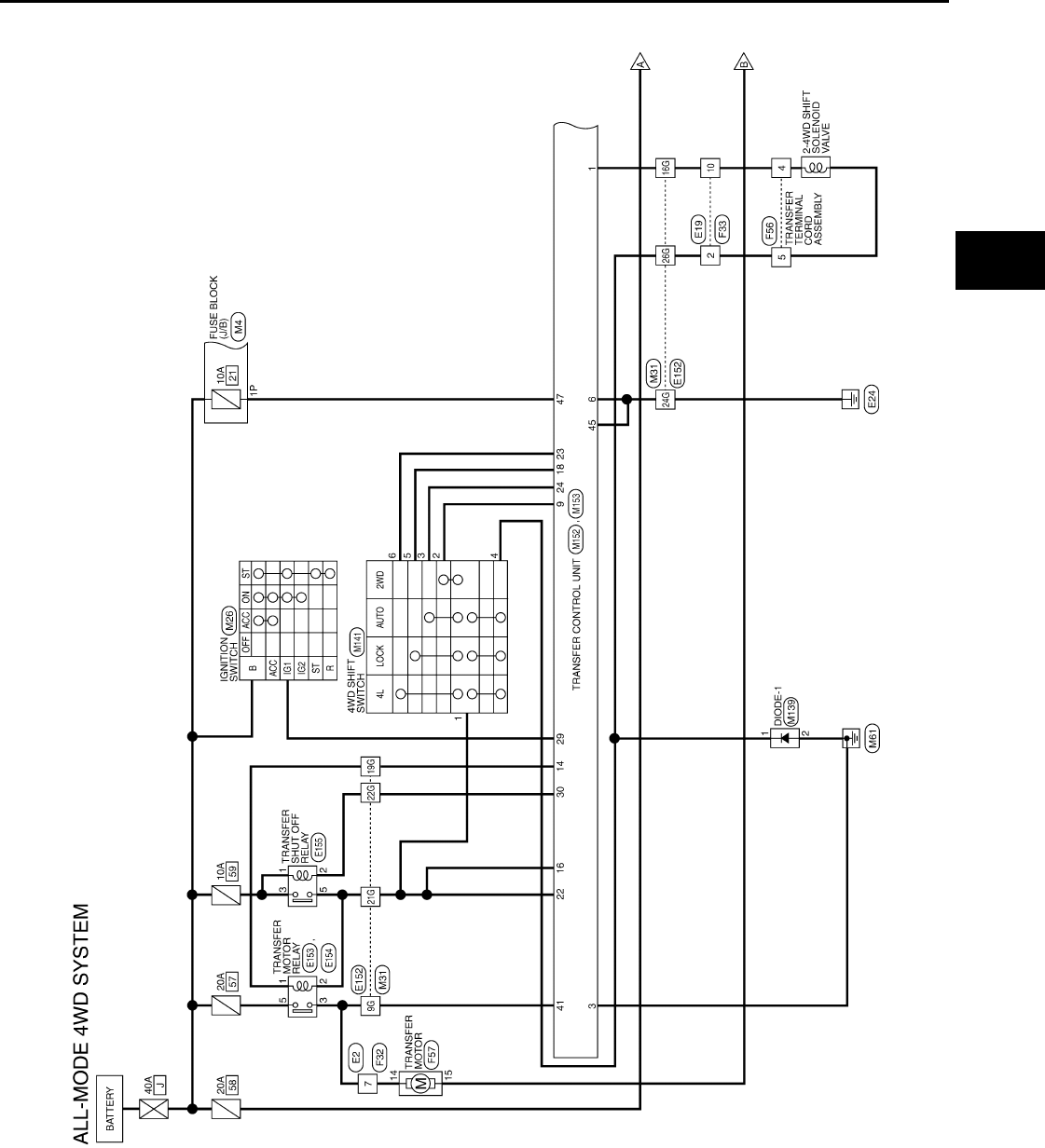
TRANSFER CONTROL UNIT
DLN-93
< ECU DIAGNOSIS > [TRANSFER: ATX14B]
C
E
F
G
H
I
J
K
L
M
A
B
DLN
N
O
P
Wiring Diagram INFOID:0000000003937271
ABDWA0048G
B
Revision: October 2008
2009 Pathfinder
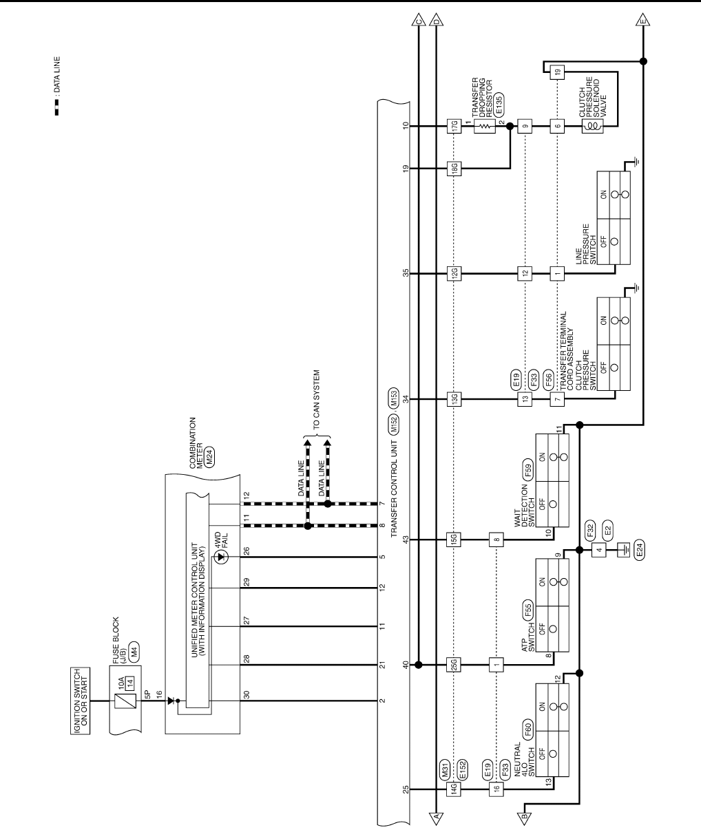
DLN-94
< ECU DIAGNOSIS > [TRANSFER: ATX14B]
TRANSFER CONTROL UNIT
ABDWA0049G
B
Revision: October 2008
2009 Pathfinder
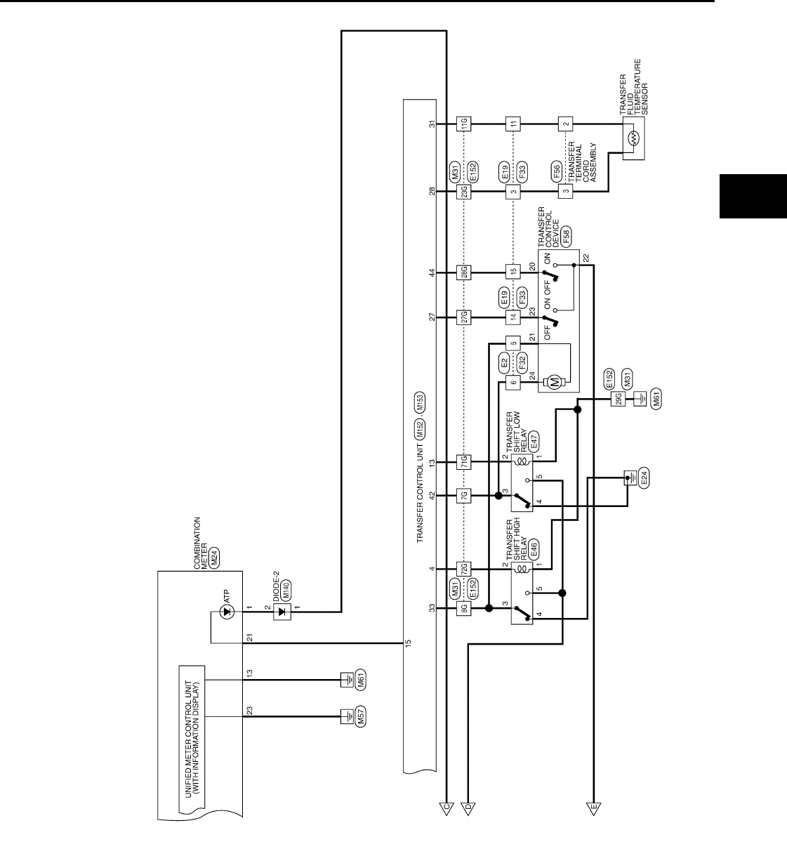
TRANSFER CONTROL UNIT
DLN-95
< ECU DIAGNOSIS > [TRANSFER: ATX14B]
C
E
F
G
H
I
J
K
L
M
A
B
DLN
N
O
P
ABDWA0050G
B
Revision: October 2008
2009 Pathfinder
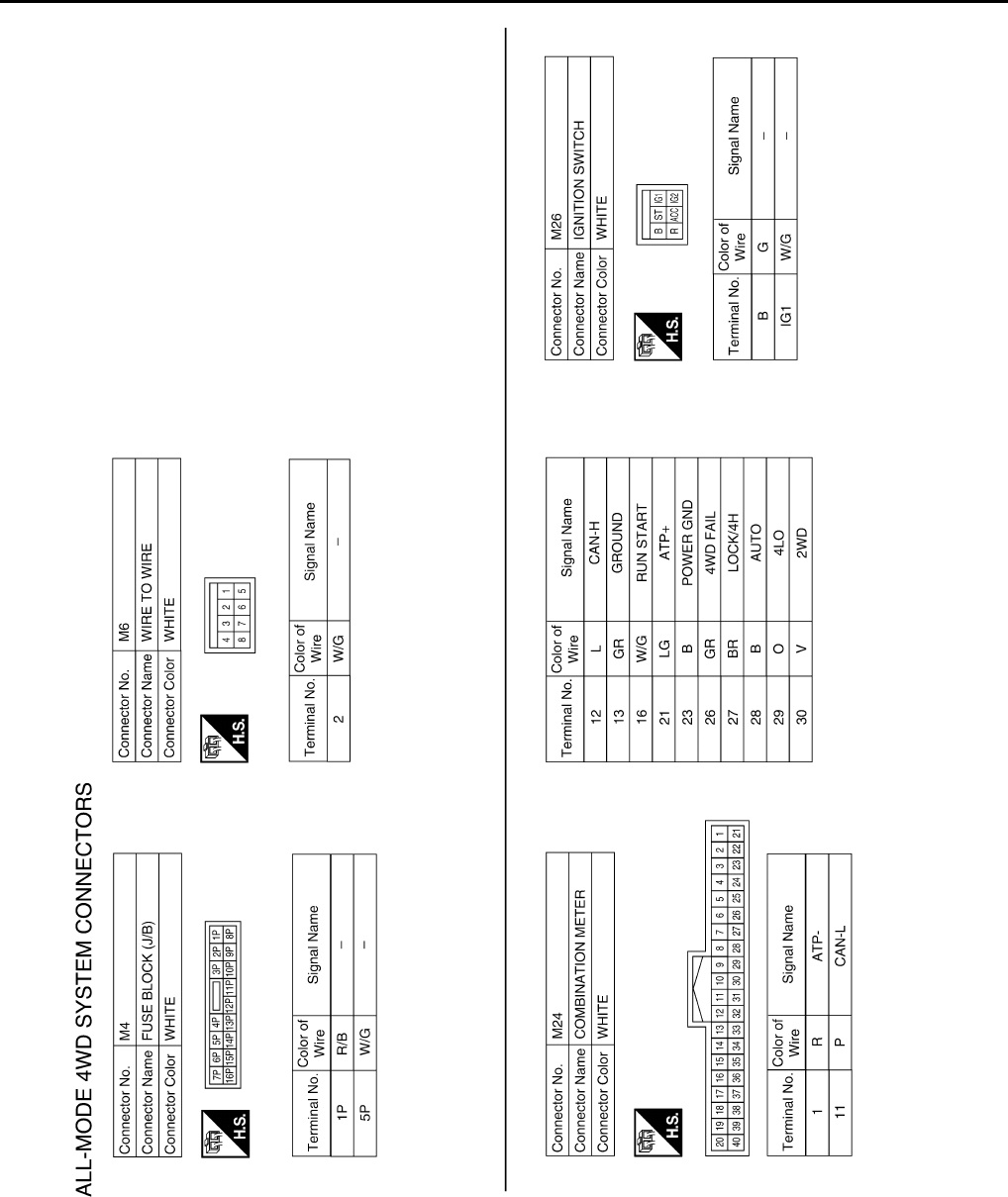
DLN-96
< ECU DIAGNOSIS > [TRANSFER: ATX14B]
TRANSFER CONTROL UNIT
ABDIA0122G
B
Revision: October 2008
2009 Pathfinder
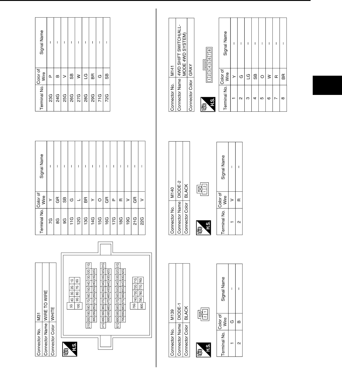
TRANSFER CONTROL UNIT
DLN-97
< ECU DIAGNOSIS > [TRANSFER: ATX14B]
C
E
F
G
H
I
J
K
L
M
A
B
DLN
N
O
P
ABDIA0123G
B
Revision: October 2008
2009 Pathfinder
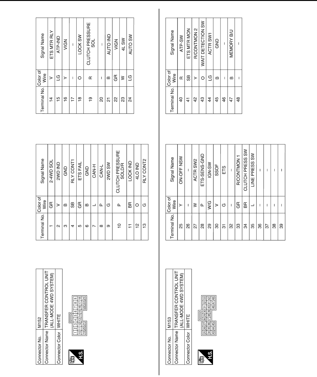
DLN-98
< ECU DIAGNOSIS > [TRANSFER: ATX14B]
TRANSFER CONTROL UNIT
ABDIA0124G
B
Revision: October 2008
2009 Pathfinder
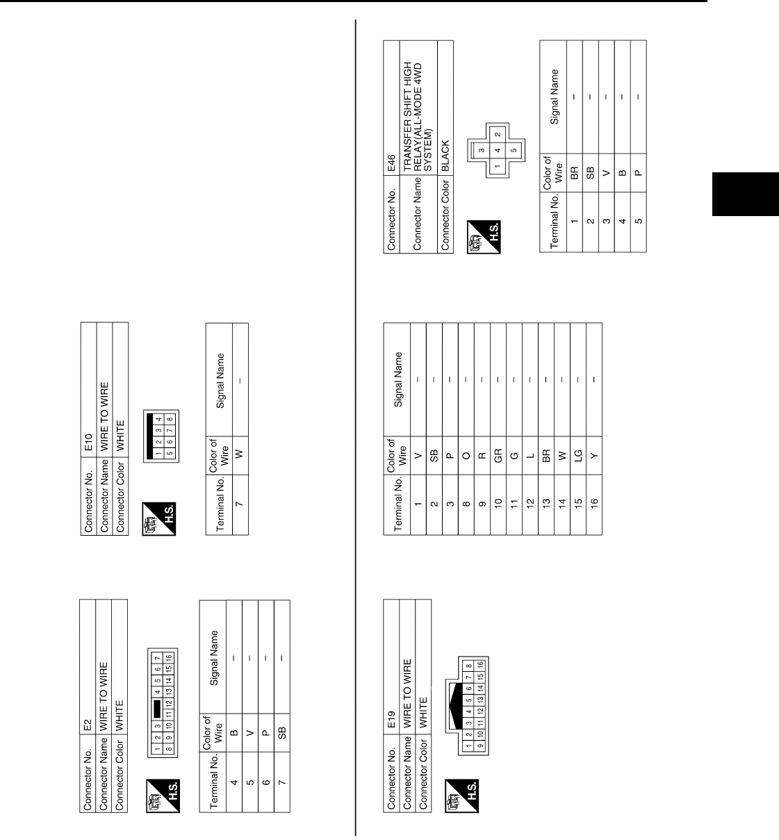
TRANSFER CONTROL UNIT
DLN-99
< ECU DIAGNOSIS > [TRANSFER: ATX14B]
C
E
F
G
H
I
J
K
L
M
A
B
DLN
N
O
P
ABDIA0125G
B
Revision: October 2008
2009 Pathfinder
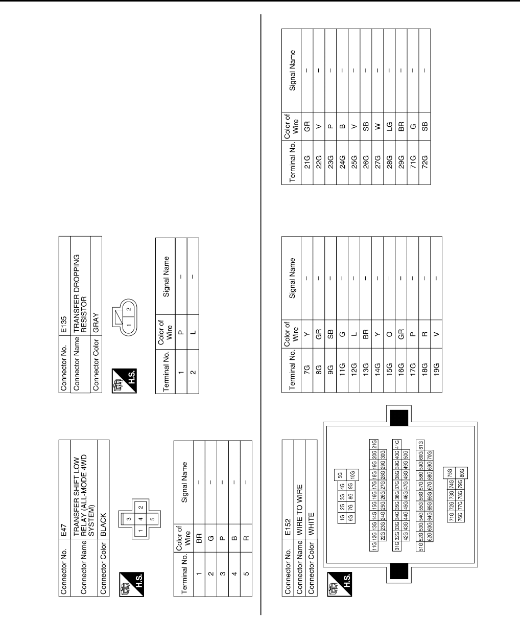
DLN-100
< ECU DIAGNOSIS > [TRANSFER: ATX14B]
TRANSFER CONTROL UNIT
ABDIA0126G
B
Revision: October 2008
2009 Pathfinder
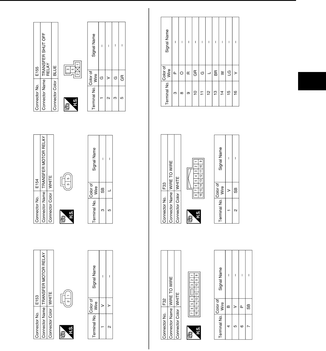
TRANSFER CONTROL UNIT
DLN-101
< ECU DIAGNOSIS > [TRANSFER: ATX14B]
C
E
F
G
H
I
J
K
L
M
A
B
DLN
N
O
P
ABDIA0127G
B
Revision: October 2008
2009 Pathfinder
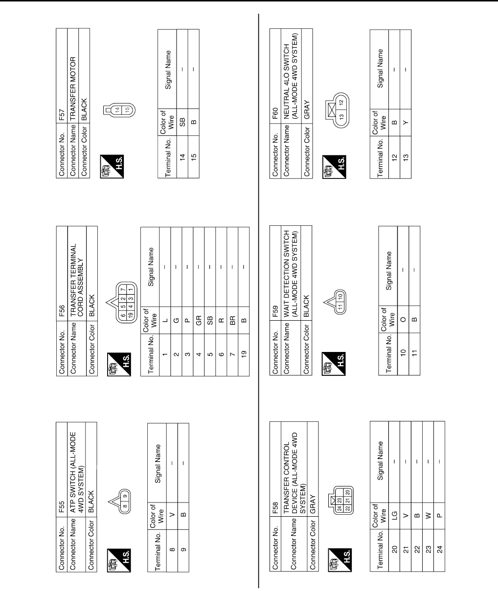
DLN-102
< ECU DIAGNOSIS > [TRANSFER: ATX14B]
TRANSFER CONTROL UNIT
DTC Index INFOID:0000000003937272
DTC CHART
ABDIA0128G
B
Revision: October 2008
2009 Pathfinder

TRANSFER CONTROL UNIT
DLN-103
< ECU DIAGNOSIS > [TRANSFER: ATX14B]
C
E
F
G
H
I
J
K
L
M
A
B
DLN
N
O
P
DTC CONSULT-III Diagnostic item is detected when... Reference
[P1802] CONTROL UNIT 1 Malfunction is detected in the memory (RAM) sys-
tem of transfer control unit.
Refer to DLN-29.[P1803] CONTROL UNIT 2 Malfunction is detected in the memory (ROM) sys-
tem of transfer control unit.
[P1804] CONTROL UNIT 3 Malfunction is detected in the memory (EEPROM)
system of transfer control unit.
[P1807] VHCL SPEED SEN·AT
• Malfunction is detected in output shaft revolution
signal that is output from TCM through CAN com-
munication.
• Improper signal is input while driving.
Refer to DLN-31.
[P1808] VHCL SPEED SEN·ABS
• Malfunction is detected in vehicle speed signal
that is output from ABS actuator and electric unit
(control unit) through CAN communication.
• Improper signal is input while driving.
Refer to DLN-32.
[P1809] CONTROL UNIT 4 AD converter system of transfer control unit is mal-
functioning. Refer to DLN-29.
[P1810] 4L POSI SW TF Improper signal from neutral-4LO switch is input due
to open or short circuit. Refer to DLN-33.
[P1811] BATTERY VOLTAGE Power supply voltage for transfer control unit is ab-
normally low while driving. Refer to DLN-27.
[P1813] 4WD MODE SW More than two switch inputs are simultaneously de-
tected due to short circuit of 4WD shift switch. Refer to DLN-36.
[P1814] 4WD DETECT SWITCH Improper signal from wait detection switch is input
due to open or short circuit. Refer to DLN-40.
[P1816] PNP SW/CIRC When A/T PNP switch signal is malfunction or com-
munication error between the control units. Refer to DLN-43.
[P1817] SHIFT ACTUATOR
• Motor does not operate properly due to open or
short circuit in actuator motor.
• Malfunction is detected in the actuator motor.
(When 4WD shift switch is operated and actuator
motor is not operated)
• Malfunction is detected in transfer shift high relay
and transfer shift low relay.
Refer to DLN-44.
[P1818] SHIFT ACT POSI SW
• Improper signal from actuator position switch is in-
put due to open or short circuit.
• Malfunction is detected in the actuator position
switch.
Refer to DLN-50.
[P1819] SHIFT ACT CIR
• Transfer control device actuator circuit is shorted
or open. (Malfunctions are detected when transfer
shift relay circuit is open/shorted or relay monitor
circuit is open/shorted.)
• Malfunction occurs in transfer control device drive
circuit.
• Malfunction is detected in transfer shut off relay.
Refer to DLN-53.
[P1820] ENGINE SPEED SIG
• Malfunction is detected in engine speed signal
that is output from ECM through CAN communi-
cation.
• Improper signal is input while driving.
Refer to DLN-57.
[P1822] DUTY SOLENOID Proper voltage is not applied to clutch pressure so-
lenoid valve due to open or short circuit. Refer to DLN-58.
[P1823] 2-4WD SOLENOID Proper voltage is not applied to 2-4WD solenoid
valve due to open or short circuit. Refer to DLN-62.
[P1824] MOTOR RELAY Motor does not operate properly due to open or
short circuit in transfer motor or transfer motor relay. Refer to DLN-66.
Revision: October 2008
2009 Pathfinder

DLN-104
< ECU DIAGNOSIS > [TRANSFER: ATX14B]
TRANSFER CONTROL UNIT
CAUTION:
• If CAN COMM CIRCUIT [U1000] or CONTROL UNIT (CAN) [U1010] are displayed with other DTCs, first perform the trouble
diagnosis for CAN communication line.
• If ABS OP SIG [P1830], VDC OP SIG [P1831] or TCS OP SIG [P1832] is displayed, first perform the trouble diagnosis for ABS
system.
• If VHCL SPEED SEN·AT [P1807] is displayed, first perform the trouble diagnosis for A/T system.
NOTE:
• If SHIFT ACT POSI SW [P1818] or SHIFT ACT CIR [P1819] is displayed, first erase self-diagnostic results. (SHIFT ACT POSI SW
[P1818] or SHIFT ACT CIR [P1819] may be displayed after installing transfer control unit or transfer assembly.)
• If CL PRES SW [P1827] or LINE PRES SW [P1828] is displayed only while driving in reverse, check the continuity of R position on A/
T PNP switch. When there is no malfunction found in the electrical system, check the hydraulic system.
FLASH CODE CHART
[P1826] OIL TEMP SEN Signal voltage from transfer fluid temperature sen-
sor is abnormally high (Transfer fluid temperature is
abnormally low) while driving.
Refer to DLN-72.
[P1827] CLUTCH PRES SW
• Improper signal from clutch pressure switch is in-
put due to open or short circuit.
• Malfunction occurs in clutch pressure switch or
hydraulic circuit.
Refer to DLN-75.
[P1828] LINE PRES SW
• Improper signal from line pressure switch is input
due to open or short circuit.
• Malfunction occurs in line pressure switch or hy-
draulic circuit.
Refer to DLN-78.
[P1829] THROTTLE POSI SEN
• Malfunction is detected in accelerator pedal posi-
tion signal that is output from ECM through CAN
communication.
• Signal voltage from accelerator pedal position
sensor is abnormally high or low.
Refer to DLN-81.
[P1830] ABS OP SIG Malfunction is detected in ABS operation signal that
is output from ABS actuator and electric unit (control
unit) through CAN communication.
Refer to DLN-82.
[P1831] VDC OP SIG
Malfunction is detected in VDC operation signal that
is output from ABS actuator and electric unit (control
unit) through CAN communication. Refer to DLN-83.
[P1832] TCS OP SIG
Malfunction is detected in TCS operation signal that
is output from ABS actuator and electric unit (control
unit) through CAN communication.
Refer to DLN-84.
DTC CONSULT-III Diagnostic item is detected when... Reference
Flashing pattern Item Diagnostic item is detected when... Reference
2Vehicle speed signal
(from A/T)
• Malfunction is detected in output shaft revolution signal
that is output from TCM through CAN communication.
• Improper signal is input while driving.
Refer to DLN-31.
3Clutch pressure sole-
noid signal
Proper voltage is not applied to clutch pressure solenoid
valve due to open or short circuit. Refer to DLN-58.
4 2-4WD solenoid signal Proper voltage is not applied to 2-4WD solenoid valve due
to open or short circuit. Refer to DLN-62.
5 Transfer motor Transfer motor does not operate properly due to open or
short circuit in transfer motor or transfer motor relay. Refer to DLN-66.
6Vehicle speed signal
(from ABS)
• Malfunction is detected in vehicle speed signal that is out-
put from ABS actuator and electric unit (control unit)
through CAN communication.
• Improper signal is input while driving.
Refer to DLN-32.
7 CAN communication Malfunction has been detected from CAN communication
line. Refer to DLN-19
8 AD converter AD converter system of transfer control unit is malfunction-
ing. Refer to DLN-29.
Revision: October 2008
2009 Pathfinder

TRANSFER CONTROL UNIT
DLN-105
< ECU DIAGNOSIS > [TRANSFER: ATX14B]
C
E
F
G
H
I
J
K
L
M
A
B
DLN
N
O
P
9Transfer fluid tempera-
ture
Signal voltage from transfer fluid temperature sensor is ab-
normally high (Transfer fluid temperature is abnormally low)
while driving.
Refer to DLN-72.
10 Neutral-4LO switch Improper signal from neutral-4LO switch is input due to
open or short circuit. Refer to DLN-33.
11 Clutch pressure switch • Improper signal is input due to open or short circuit.
• Malfunction occurs in clutch pressure switch or hydraulic
circuit.
Refer to DLN-75.
12 Line pressure switch
• Improper signal is input due to open or short circuit.
• Malfunction occurs in line pressure switch or hydraulic
circuit. Refer to DLN-78.
13 Engine speed signal
(from ECM)
• Malfunction is detected in engine speed signal that is out-
put from ECM through CAN communication.
• Improper signal is input while driving.
Refer to DLN-57.
14
Accelerator pedal posi-
tion sensor (from
ECM)
• Malfunction is detected in accelerator pedal position sig-
nal that is output from ECM through CAN communication.
• Signal voltage from accelerator pedal position sensor is
abnormally high or low.
Refer to DLN-81.
15 Power supply Power supply voltage for transfer control unit is abnormally
low while driving. Refer to DLN-27.
16 4WD shift switch More than two switch inputs are simultaneously detected
due to short circuit of 4WD shift switch. Refer to DLN-36.
17 ABS operation signal
(from ABS)
Malfunction is detected in ABS operation signal that is out-
put from ABS actuator and electric unit (control unit)
through CAN communication. Refer to DLN-82.
18 Wait detection switch Improper signal from wait detection switch is input due to
open or short circuit. Refer to DLN-40.
19 Actuator motor
• Motor does not operate properly due to open or short cir-
cuit in actuator motor.
• Malfunction is detected in the actuator motor. (When
4WD shift switch is operated and actuator motor is not
operated)
• Malfunction is detected in transfer shift high relay and
transfer shift low relay.
Refer to DLN-44.
20 Actuator position
switch
• Improper signal from actuator position switch is input due
to open or short circuit.
• Malfunction is detected in the actuator position switch.
Refer to DLN-50.
21 Actuator circuit
• Transfer control device actuator circuit is shorted or open.
(Malfunctions are detected when motor relay circuit is
open/shorted or relay transfer shift circuit is open/short-
ed.)
• Malfunction occurs in transfer control device drive circuit.
Refer to DLN-53.
22 VDC operation signal
(from VDC)
Malfunction is detected in VDC operation signal that is out-
put from ABS actuator and electric unit (control unit)
through CAN communication.
Refer to DLN-83.
23 TCS operation signal
(from TCS)
Malfunction is detected in TCS operation signal that is out-
put from ABS actuator and electric unit (control unit)
through CAN communication.
Refer to DLN-84.
24 PNP switch signal
(from TCM)
When A/T PNP switch signal is malfunction or communica-
tion error between the vehicles. Refer to DLN-43.
Repeats flickering
every 2 to 5 sec. — System normal. —
Repeats flickering
every 0.25 sec. Data erase display • Power supply failure of memory back-up.
• Battery performance is poor. Refer to DLN-27.
No flickering PNP switch or 4WD
shift switch PNP switch or 4WD shift switch circuit is shorted or open. Refer to DLN-43 or
DLN-36.
Flashing pattern Item Diagnostic item is detected when... Reference
Revision: October 2008
2009 Pathfinder

DLN-106
< ECU DIAGNOSIS > [TRANSFER: ATX14B]
TRANSFER CONTROL UNIT
CAUTION:
• If CAN communication is displayed with other DTCs, first perform the trouble diagnosis for CAN communication line.
• If ABS operation signal, VDC operation signal or TCS operation signal is displayed, first perform the trouble diagnosis for
ABS system.
• If Output shaft revolution signal is displayed, first perform the trouble diagnosis for A/T system.
NOTE:
• If actuator position switch or actuator circuit is displayed, first erase self-diagnostic results. (Actuator position switch or actuator circuit
may be displayed after installing transfer control unit or transfer assembly.)
• If clutch pressure switch or line pressure switch is displayed only while driving in reverse, check the continuity of R position on A/T
PNP switch. When there is no malfunction found in the electrical system, check the hydraulic system.
Revision: October 2008
2009 Pathfinder

4WD SYSTEM SYMPTOMS
DLN-107
< SYMPTOM DIAGNOSIS > [TRANSFER: ATX14B]
C
E
F
G
H
I
J
K
L
M
A
B
DLN
N
O
P
SYMPTOM DIAGNOSIS
4WD SYSTEM SYMPTOMS
Symptom Table INFOID:0000000003937273
If 4WD warning lamp turns ON, perform self-diagnosis. Refer to DLN-22, "CONSULT-III Function (ALL MODE AWD/4WD)".
NOTE:
• Light tight-corner braking symptom may occur depending on driving conditions in AUTO mode. This is not a
malfunction.
• Heavy tight-corner braking symptom occurs when vehicle is driven in the following conditions: 4WD shift
switch is 4H or 4LO, steering wheel is turned fully to either side.
Symptom Condition Reference page
4WD shift indicator lamp and 4LO indicator lamp do not turn ON
(4WD shift indicator lamp and 4LO indicator lamp check) Ignition switch: ON DLN-108
4WD warning lamp does not turn ON
(4WD warning lamp check) Ignition switch: ON DLN-111
4WD shift indicator lamp or 4LO indicator lamp does not change Engine running DLN-114
ATP warning lamp does not turn ON Engine running DLN-116
4WD shift indicator lamp keeps flashing Engine running DLN-118
4WD warning lamp flashes rapidly (2 times/second) While driving DLN-119
4WD warning lamp flashes slowly
(1 time/2 seconds) While driving DLN-120
Heavy tight-corner braking symptom occurs
(See NOTE.)
• While driving
•AUTO mode
• Steering wheel is turned fully
to either side
DLN-121
ATP switch does not operate Engine running DLN-123
4WD system does not operate While driving DLN-125
Revision: October 2008
2009 Pathfinder
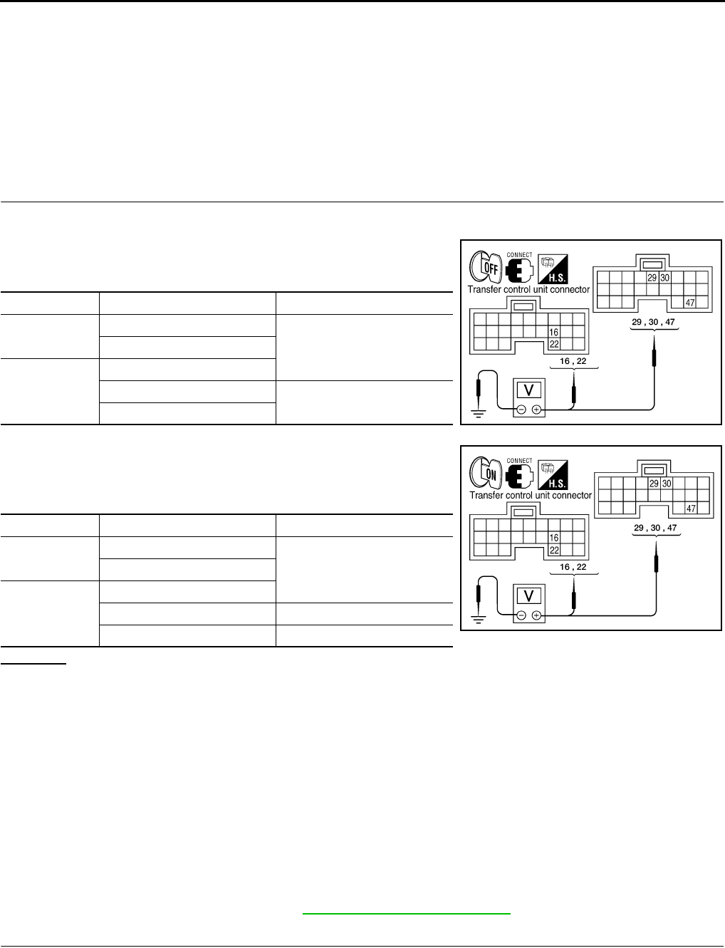
DLN-108
< SYMPTOM DIAGNOSIS > [TRANSFER: ATX14B]
4WD SHIFT INDICATOR LAMP AND 4LO INDICATOR LAMP DO NOT TURN ON
4WD SHIFT INDICATOR LAMP AND 4LO INDICATOR LAMP DO NOT
TURN ON
Description INFOID:0000000003937274
4WD shift indicator lamp and 4LO indicator lamp do not turn ON for approx. 1 second when turning ignition
switch to ON.
Diagnosis Procedure INFOID:0000000003937275
1.CHECK TRANSFER CONTROL UNIT POWER SUPPLY CIRCUIT
1. Turn ignition switch “OFF”. (Stay for at least 5 seconds.)
2. Connect transfer control unit harness connector.
3. Check voltage between transfer control unit harness connector
terminals and ground.
4. Turn ignition switch “ON”. (Do not start engine.)
5. Check voltage between transfer control unit harness connector
terminals and ground.
OK or NG
OK >> GO TO 2.
NG >> Check the following. If any items are damaged, repair or replace damaged parts.
• 10A fuses [No. 21 located in fuse block (J/B) and No. 59 (located in the fuse and relay box)].
• Harness for short or open between battery and transfer control unit harness connector M153
terminals 47.
• Harness for short or open between ignition switch and transfer control unit harness connector
M153 terminal 29.
• Harness for short or open between battery and transfer shut off relay harness connector E155
terminal 1 and 3.
• Harness for short or open between transfer shut off relay harness connector E155 terminal 2
and transfer control unit harness connector M153 terminal 30.
• Harness for short or open between transfer shut off relay harness connector E155 terminal 5
and transfer control unit harness connector M152 terminals 16 and 22.
• Battery and ignition switch.
• Transfer shut off relay. Refer to DLN-27, "Diagnosis Procedure".
2.CHECK TRANSFER CONTROL UNIT GROUND CIRCUIT
1. Turn ignition switch “OFF”. (Stay for at least 5 seconds.)
2. Disconnect transfer control unit harness connector.
Connector Terminal Voltage (Approx.)
M152 16 - Ground
0V22 - Ground
M153
29 - Ground
30 - Ground Battery voltage
47 - Ground WDIA0165E
Connector Terminal Voltage (Approx.)
M152 16 - Ground
Battery voltage22 - Ground
M153
29 - Ground
30 - Ground 0V
47 - Ground Battery voltage WDIA0166E
Revision: October 2008
2009 Pathfinder
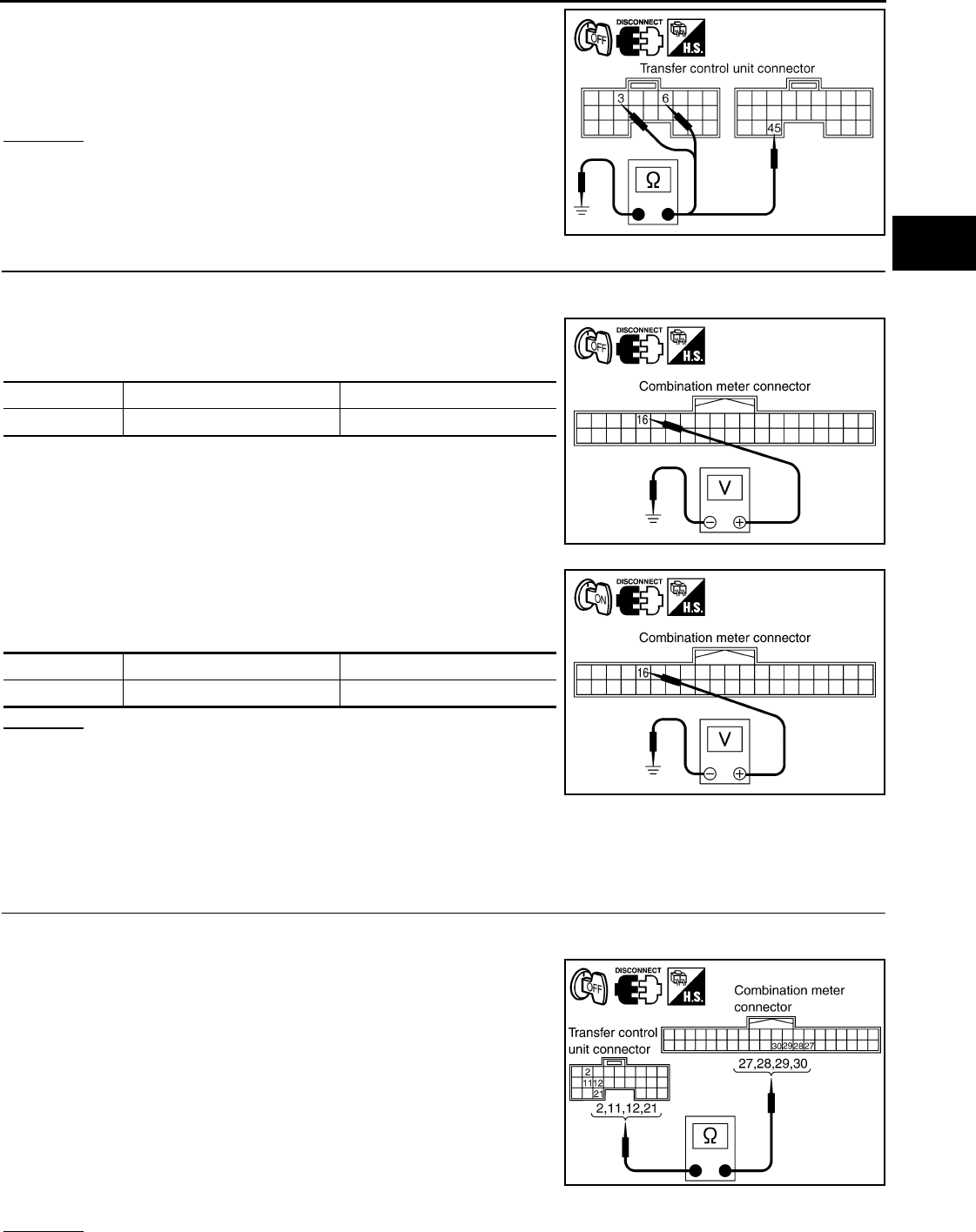
4WD SHIFT INDICATOR LAMP AND 4LO INDICATOR LAMP DO NOT TURN ON
DLN-109
< SYMPTOM DIAGNOSIS > [TRANSFER: ATX14B]
C
E
F
G
H
I
J
K
L
M
A
B
DLN
N
O
P
3. Check continuity between transfer control unit harness connec-
tor M152 terminals 3 and 6, and M153 terminal 45 and ground.
Also check harness for short to power.
OK or NG
OK >> GO TO 3.
NG >> Repair open circuit or short to power in harness or con-
nectors.
3.CHECK COMBINATION METER POWER SUPPLY CIRCUIT
1. Turn ignition switch “OFF”. (Stay for at least 5 seconds.)
2. Disconnect transfer control unit harness connector.
3. Check voltage between combination meter harness connector
terminal and ground.
4. Turn ignition switch “ON”. (Do not start engine.)
5. Check voltage between combination meter harness connector
terminal and ground.
OK or NG
OK >> GO TO 4.
NG >> Check the following. If any items are damaged, repair
or replace damaged parts.
• 10A fuse [No. 14, located in the fuse block (J/B)].
• Harness for short or open between ignition switch and combination meter harness connector
M24 terminal 16.
• Ignition switch.
4.CHECK HARNESS BETWEEN TRANSFER CONTROL UNIT AND COMBINATION METER
1. Turn ignition switch “OFF”. (Stay for at least 5 seconds.)
2. Disconnect transfer control unit harness connector and combination meter harness connector.
3. Check continuity between the following terminals.
- Transfer control unit harness connector M152 terminal 2 and
combination meter harness connector M24 terminal 30.
- Transfer control unit harness connector M152 terminal 11 and
combination meter harness connector M24 terminal 27.
- Transfer control unit harness connector M152 terminal 12 and
combination meter harness connector M24 terminal 29.
- Transfer control unit harness connector M152 terminal 21 and
combination meter harness connector M24 terminal 28.
Also check harness for short to ground and short to power.
OK or NG
Continuity should exist.
SDIA2691E
Connector Terminal Voltage (Approx.)
M24 16 - Ground 0V
SDIA2762E
Connector Terminal Voltage (Approx.)
M24 16 - Ground Battery voltage
SDIA2763E
Continuity should exist. SDIA2771E
Revision: October 2008
2009 Pathfinder
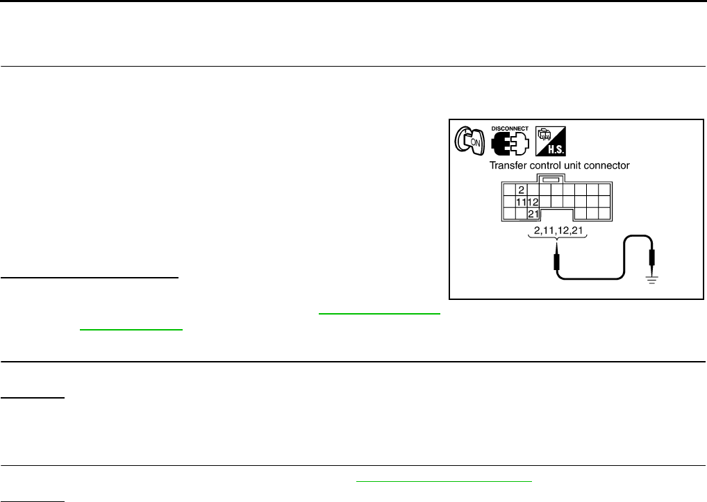
DLN-110
< SYMPTOM DIAGNOSIS > [TRANSFER: ATX14B]
4WD SHIFT INDICATOR LAMP AND 4LO INDICATOR LAMP DO NOT TURN ON
OK >> GO TO 5.
NG >> Repair or replace damaged parts.
5.CHECK INDICATOR LAMP CIRCUIT
1. Connect combination meter harness connector.
2. Disconnect transfer control unit harness connector.
3. Turn ignition switch “ON”.
4. Ground the following terminals using suitable wiring.
- Transfer control unit harness connector M152 terminal 2 and
ground.
- Transfer control unit harness connector M152 terminal 11 and
ground.
- Transfer control unit harness connector M152 terminal 12 and
ground.
- Transfer control unit harness connector M152 terminal 21 and
ground.
Do indicator lamps turn on?
OK >> GO TO 6.
NG >> Replace combination meter. Refer to MWI-94, "Removal
and Installation".
6.SYMPTOM CHECK
Check again.
OK or NG
OK >> Inspection End.
NG >> GO TO 7.
7.CHECK TRANSFER CONTROL UNIT
Check transfer control unit input/output signal. Refer to DLN-85, "Reference Value".
OK or NG
OK >> Inspection End.
NG >> Check transfer control unit pin terminals for damage or loose connection with harness connector.
If any items are damaged, repair or replace damaged parts.
SDIA2772E
Revision: October 2008
2009 Pathfinder
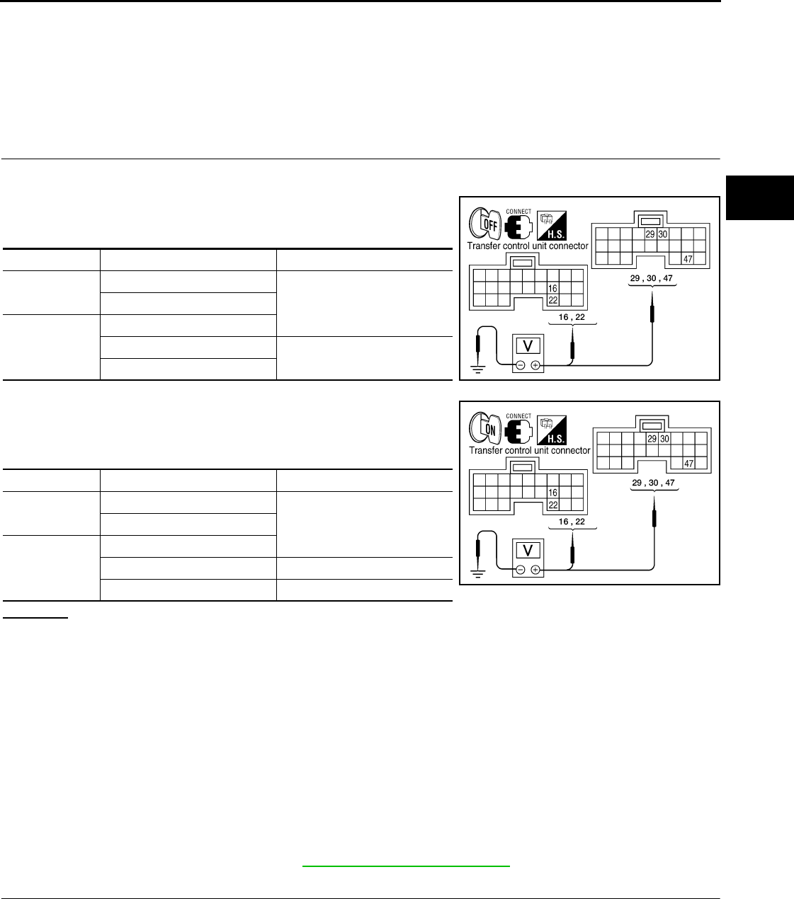
4WD WARNING LAMP DOES NOT TURN ON
DLN-111
< SYMPTOM DIAGNOSIS > [TRANSFER: ATX14B]
C
E
F
G
H
I
J
K
L
M
A
B
DLN
N
O
P
4WD WARNING LAMP DOES NOT TURN ON
Description INFOID:0000000003937276
4WD warning lamp does not turn ON when turning ignition switch to ON.
Diagnosis Procedure INFOID:0000000003937277
1.CHECK TRANSFER CONTROL UNIT POWER SUPPLY CIRCUIT
1. Turn ignition switch “OFF”. (Stay for at least 5 seconds.)
2. Connect transfer control unit harness connector.
3. Check voltage between transfer control unit harness connector
terminals and ground.
4. Turn ignition switch “ON”. (Do not start engine.)
5. Check voltage between transfer control unit harness connector
terminals and ground.
OK or NG
OK >> GO TO 2.
NG >> Check the following. If any items are damaged, repair or replace damaged parts.
• 10A fuses [No. 21 located in fuse block (J/B) and No. 59 (located in the fuse and relay box)].
• Harness for short or open between battery and transfer control unit harness connector M153
terminals 47.
• Harness for short or open between ignition switch and transfer control unit harness connector
M153 terminal 29.
• Harness for short or open between battery and transfer shut off relay harness connector E155
terminal 1 and 3.
• Harness for short or open between transfer shut off relay harness connector E155 terminal 2
and transfer control unit harness connector M153 terminal 30.
• Harness for short or open between transfer shut off relay harness connector E155 terminal 5
and transfer control unit harness connector M152 terminals 16 and 22.
• Battery and ignition switch.
• Transfer shut off relay. Refer to DLN-27, "Diagnosis Procedure" .
2.CHECK TRANSFER CONTROL UNIT GROUND CIRCUIT
1. Turn ignition switch “OFF”. (Stay for at least 5 seconds.)
2. Disconnect transfer control unit harness connector.
Connector Terminal Voltage (Approx.)
M152 16 - Ground
0V22 - Ground
M153
29 - Ground
30 - Ground Battery voltage
47 - Ground WDIA0165E
Connector Terminal Voltage (Approx.)
M152 16 - Ground
Battery voltage22 - Ground
M153
29 - Ground
30 - Ground 0V
47 - Ground Battery voltage WDIA0166E
Revision: October 2008
2009 Pathfinder
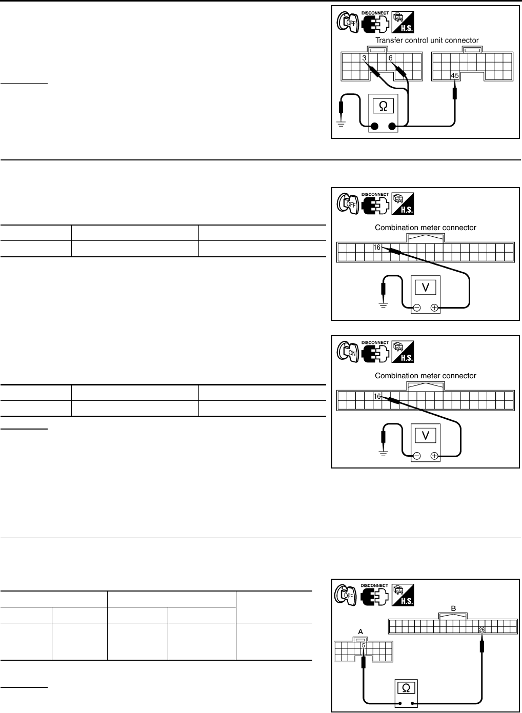
DLN-112
< SYMPTOM DIAGNOSIS > [TRANSFER: ATX14B]
4WD WARNING LAMP DOES NOT TURN ON
3. Check continuity between transfer control unit harness connec-
tor M152 terminals 3 and 6, and M153 terminal 45 and ground.
Also check harness for short to power.
OK or NG
OK >> GO TO 3.
NG >> Repair open circuit or short to power in harness or con-
nectors.
3.CHECK COMBINATION METER POWER SUPPLY CIRCUIT
1. Turn ignition switch “OFF”. (Stay for at least 5 seconds.)
2. Disconnect transfer control unit harness connector.
3. Check voltage between combination meter harness connector
terminal and ground.
4. Turn ignition switch “ON”. (Do not start engine.)
5. Check voltage between combination meter harness connector
terminal and ground.
OK or NG
OK >> GO TO 4.
NG >> Check the following. If any items are damaged, repair
or replace damaged parts.
• 10A fuse [No. 14, located in the fuse block (J/B)].
• Harness for short or open between ignition switch and combination meter harness connector
M24 terminal 16.
• Ignition switch.
4.CHECK HARNESS BETWEEN TRANSFER CONTROL UNIT AND COMBINATION METER
1. Turn ignition switch “OFF”. (Stay for at least 5 seconds.)
2. Disconnect transfer control unit harness connector and combination meter harness connector.
3. Check continuity between transfer control unit and combination meter.
- Also check harness for short to ground and short to power.
OK or NG
OK >> GO TO 5.
NG >> Repair or replace damaged parts.
Continuity should exist.
SDIA2691E
Connector Terminal Voltage (Approx.)
M24 16 - Ground 0V
SDIA2762E
Connector Terminal Voltage (Approx.)
M24 16 - Ground Battery voltage
SDIA2763E
AB
Continuity
Connector Terminal Connector Terminal
Transfer
control
unit: M152
5Combination
meter: M24 26 Yes
WDIA0293E
Revision: October 2008
2009 Pathfinder
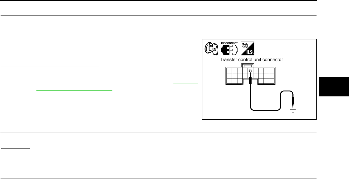
4WD WARNING LAMP DOES NOT TURN ON
DLN-113
< SYMPTOM DIAGNOSIS > [TRANSFER: ATX14B]
C
E
F
G
H
I
J
K
L
M
A
B
DLN
N
O
P
5.CHECK INDICATOR LAMP CIRCUIT
1. Connect combination meter harness connector.
2. Disconnect transfer control unit harness connector.
3. Turn ignition switch “ON”. (Do not start engine.)
4. Ground the following terminal using suitable wiring.
- Transfer control unit harness connector M152 terminal 5 and
ground.
Does 4WD warning lamp turn on?
OK >> GO TO 6.
NG >> Replace combination meter. Refer to MWI-94,
"Removal and Installation".
6.SYMPTOM CHECK
Check again.
OK or NG
OK >> Inspection End
NG >> GO TO 7.
7.CHECK TRANSFER CONTROL UNIT
Check transfer control unit input/output signal. Refer to DLN-85, "Reference Value".
OK or NG
OK >> Inspection End.
NG >> Check transfer control unit pin terminals for damage or loose connection with harness connector.
If any items are damaged, repair or replace damaged parts.
SDIA2774E
Revision: October 2008
2009 Pathfinder

DLN-114
< SYMPTOM DIAGNOSIS > [TRANSFER: ATX14B]
4WD SHIFT INDICATOR LAMP OR 4LO INDICATOR LAMP DO NOT CHANGE
4WD SHIFT INDICATOR LAMP OR 4LO INDICATOR LAMP DO NOT
CHANGE
Description INFOID:0000000003937278
4WD shift indicator lamp or 4LO indicator lamp do not change when switching the 4WD shift switch.
Diagnosis Procedure INFOID:0000000003937279
1.CONFIRM THE SYMPTOM
Confirm 4WD shift indicator lamp and 4LO indicator lamp turn on when ignition switch is turned to ON.
Do 4WD shift indicator lamp and 4LO indicator lamp turn on?
YES >> GO TO 2.
NO >> Refer to DLN-108, "Diagnosis Procedure".
2.CHECK SYSTEM FOR 4WD SHIFT SWITCH
Perform trouble diagnosis for 4WD shift switch system. Refer to DLN-36, "Diagnosis Procedure".
Are the inspection results normal?
YES >> GO TO 3.
NO >> Repair or replace damaged parts.
3.CHECK SYSTEM FOR WAIT DETECTION SWITCH
Perform trouble diagnosis for wait detection switch system. Refer to DLN-40, "Diagnosis Procedure".
Are the inspection results normal?
YES >> GO TO 4.
NO >> Repair or replace damaged parts.
4.CHECK SYSTEM FOR NEUTRAL-4LO SWITCH
Perform trouble diagnosis for neutral-4LO switch system. Refer to DLN-33, "Diagnosis Procedure".
Are the inspection results normal?
YES >> GO TO 5.
NO >> Repair or replace damaged parts.
5.CHECK SYSTEM FOR ATP SWITCH
Perform trouble diagnosis for ATP switch system. Refer to DLN-123, "Diagnosis Procedure".
Are the inspection results normal?
YES >> GO TO 6.
NO >> Repair or replace damaged parts.
6.CHECK SYSTEM FOR 2-4WD SOLENOID
Perform trouble diagnosis for 2-4WD solenoid system. Refer to DLN-62, "Diagnosis Procedure".
Are the inspection results normal?
YES >> GO TO 7.
NO >> Repair or replace damaged parts.
7.CHECK SYSTEM FOR TRANSFER CONTROL DEVICE
Perform trouble diagnosis for transfer control device system. Refer to DLN-53, "Diagnosis Procedure".
Are the inspection results normal?
YES >> GO TO 8.
NO >> Repair or replace damaged parts.
8.CHECK SYSTEM FOR ACTUATOR MOTOR
Perform trouble diagnosis for actuator motor system. Refer to DLN-44, "Diagnosis Procedure".
Are the inspection results normal?
YES >> GO TO 9.
NO >> Repair or replace damaged parts.
Revision: October 2008
2009 Pathfinder

4WD SHIFT INDICATOR LAMP OR 4LO INDICATOR LAMP DO NOT CHANGE
DLN-115
< SYMPTOM DIAGNOSIS > [TRANSFER: ATX14B]
C
E
F
G
H
I
J
K
L
M
A
B
DLN
N
O
P
9.CHECK SYSTEM FOR ACTUATOR POSITION SWITCH
Perform trouble diagnosis for actuator position switch system. Refer to DLN-50, "Diagnosis Procedure".
Are the inspection results normal?
YES >> GO TO 10.
NO >> Repair or replace damaged parts.
10.SYMPTOM CHECK
Check again.
Are the inspection results normal?
YES >> Inspection End.
NO >> GO TO 11.
11.CHECK TRANSFER CONTROL UNIT
Check transfer control unit input/output signal. Refer to DLN-85, "Reference Value".
Are the inspection results normal?
YES >> GO TO 12.
NO >> Check transfer control unit pin terminals for damage or loose connection with harness connector.
If any items are damaged, repair or replace damaged parts.
12.CHECK TRANSFER INNER PARTS
1. Disassemble transfer assembly. Refer to DLN-150, "Disassembly and Assembly".
2. Check transfer inner parts.
Are the inspection results normal?
YES >> Inspection End.
NO >> Repair or replace damaged parts.
Revision: October 2008
2009 Pathfinder
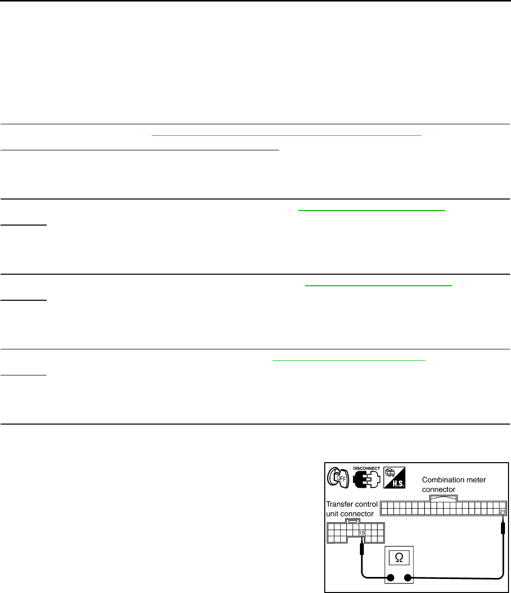
DLN-116
< SYMPTOM DIAGNOSIS > [TRANSFER: ATX14B]
ATP WARNING LAMP DOES NOT TURN ON
ATP WARNING LAMP DOES NOT TURN ON
Description INFOID:0000000003937280
ATP warning lamp does not turn ON when the transfer case is switched in or out of 4LO with the A/T selector
lever in N position.
Diagnosis Procedure INFOID:0000000003937281
1.CHECK SYSTEM FOR CAN COMMUNICATION LINE
Perform self-diagnosis. Refer to DLN-22, "CONSULT-III Function (ALL MODE AWD/4WD)".
Do the self-diagnostic results indicate CAN communication?
YES >> Perform trouble diagnosis for CAN communication line.
NO >> GO TO 2.
2.CHECK SYSTEM FOR 4WD SHIFT SWITCH
Perform trouble diagnosis for 4WD shift switch system. Refer to DLN-36, "Diagnosis Procedure".
OK or NG
OK >> GO TO 3.
NG >> Repair or replace damaged parts.
3.CHECK SYSTEM FOR PNP SWITCH SIGNAL
Perform trouble diagnosis for PNP switch signal system. Refer to DLN-43, "Diagnosis Procedure".
OK or NG
OK >> GO TO 4.
NG >> Repair or replace damaged parts.
4.CHECK SYSTEM FOR ATP SWITCH
Perform trouble diagnosis for ATP switch system. Refer to DLN-123, "Diagnosis Procedure".
OK or NG
OK >> GO TO 5.
NG >> Repair or replace damaged parts.
5.CHECK HARNESS BETWEEN TRANSFER CONTROL UNIT AND COMBINATION METER
1. Turn ignition switch “OFF”. (Stay for at least 5 seconds.)
2. Disconnect transfer control unit harness connector and combination meter harness connector.
3. Check continuity between the following terminals.
- Transfer control unit harness connector M152 terminal 15 and
combination meter harness connector M24 terminal 21.
Continuity should exist.
SDIA2768E
Revision: October 2008
2009 Pathfinder
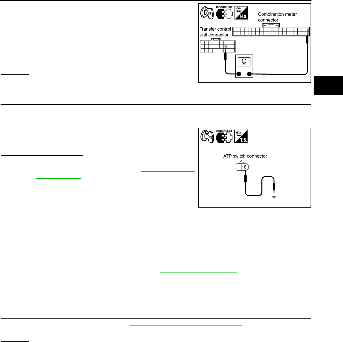
ATP WARNING LAMP DOES NOT TURN ON
DLN-117
< SYMPTOM DIAGNOSIS > [TRANSFER: ATX14B]
C
E
F
G
H
I
J
K
L
M
A
B
DLN
N
O
P
- Transfer control unit harness connector M153 terminal 40 and
combination meter harness connector M24 terminal 1.
Also check harness for short to ground and short to power.
OK or NG
OK >> GO TO 6.
NG >> Repair or replace damaged parts.
6.CHECK ATP WARNING LAMP CIRCUIT
1. A/T selector lever "P" position.
2. Connect combination meter harness connector and transfer control unit harness connector.
3. Disconnect ATP switch harness connector.
4. Ground the following terminal using suitable wiring.
5. Turn ignition switch “ON”. (Do not start engine.)
- ATP switch harness connector F55 terminal 8 and ground.
Does indicator lamp turn on?
OK >> GO TO 7.
NG >> Replace combination meter. Refer to MWI-94, "Removal
and Installation".
7.SYMPTOM CHECK
Check again.
OK or NG
OK >> Inspection End.
NG >> GO TO 8.
8.CHECK TRANSFER CONTROL UNIT
Check transfer control unit input/output signal. Refer to DLN-85, "Reference Value".
OK or NG
OK >> GO TO 9.
NG >> Check transfer control unit pin terminals for damage or loose connection with harness connector.
If any items are damaged, repair or replace damaged parts.
9.CHECK TRANSFER INNER PARTS
1. Disassemble transfer assembly. Refer to DLN-150, "Disassembly and Assembly".
2. Check transfer inner parts.
OK or NG
OK >> Inspection End.
NG >> Repair or replace damaged parts.
40 TO 1: Continuity should
not exist.
1 to 40: Continuity should
exist.
SDIA2770E
SDIA2769E
Revision: October 2008
2009 Pathfinder

DLN-118
< SYMPTOM DIAGNOSIS > [TRANSFER: ATX14B]
4WD SHIFT INDICATOR LAMP KEEPS FLASHING
4WD SHIFT INDICATOR LAMP KEEPS FLASHING
Description INFOID:0000000003937282
The 4WD shift indicator lamp keeps flashing.
Diagnosis Procedure INFOID:0000000003937283
1.CONFIRM THE SYMPTOM
1. Set 4WD shift switch to 2WD.
2. Move vehicle forward and backward, or drive straight increasing or decreasing under 20 km/h (12 MPH).
Dose 4WD shift indicator lamp keep flashing?
YES >> GO TO 2.
NO >> Inspection End.
2.CHECK SYSTEM FOR WAIT DETECTION SWITCH
Perform trouble diagnosis for wait detection switch system. Refer to DLN-40, "Diagnosis Procedure".
Are the inspection results normal?
YES >> GO TO 3.
NO >> Repair or replace damaged parts.
3.CHECK SYSTEM FOR NEUTRAL-4LO SWITCH
Perform trouble diagnosis for neutral-4LO switch system. Refer to DLN-33, "Diagnosis Procedure".
Are the inspection results normal?
YES >> GO TO 4.
NO >> Repair or replace damaged parts.
4.SYMPTOM CHECK
Check again.
Are the inspection results normal?
YES >> Inspection End.
NO >> GO TO 5.
5.CHECK TRANSFER CONTROL UNIT
Check transfer control unit input/output signal. Refer to DLN-85, "Reference Value".
Are the inspection results normal?
YES >> GO TO 6.
NO >> Check transfer control unit pin terminals for damage or loose connection with harness connector.
If any items are damaged, repair or replace damaged parts.
6.CHECK TRANSFER INNER PARTS
1. Disassemble transfer assembly. Refer to DLN-150, "Disassembly and Assembly".
2. Check transfer inner parts.
Are the inspection results normal?
YES >> Inspection End.
NO >> Repair or replace damaged parts.
Revision: October 2008
2009 Pathfinder

4WD WARNING LAMP FLASHES RAPIDLY
DLN-119
< SYMPTOM DIAGNOSIS > [TRANSFER: ATX14B]
C
E
F
G
H
I
J
K
L
M
A
B
DLN
N
O
P
4WD WARNING LAMP FLASHES RAPIDLY
Description INFOID:0000000003937284
The 4WD warning lamp flashes quickly while driving (2 times / second). The lamp continues to flash until the
ignition switch is turned OFF.
Diagnosis Procedure INFOID:0000000003937285
1.CHECK TIRE
Check the following.
• Tire pressure
• Wear condition
• Longitudinal tire size (There is no difference between longitudinal tires.)
Are the inspection results normal?
YES >> GO TO 2.
NO >> Repair or replace damaged parts.
2.CHECK 4WD WARNING LAMP
Stop the vehicle and allow it to idle for a short period of time.
Does flashing stop?
YES >> Inspection End.
NO >> GO TO 3.
3.CHECK TRANSFER FLUID TEMPERATURE
Perform trouble diagnosis for transfer fluid temperature system. Refer to DLN-72, "Diagnosis Procedure".
Are the inspection results normal?
YES >> GO TO 4.
NO >> Repair or replace damaged parts.
4.SYMPTOM CHECK
Check again.
Are the inspection results normal?
YES >> Inspection End.
NO >> GO TO 5.
5.CHECK TRANSFER CONTROL UNIT
Check transfer control unit input/output signal. Refer to DLN-85, "Reference Value".
Are the inspection results normal?
YES >> Inspection End.
NO >> Check transfer control unit pin terminals for damage or loose connection with harness connector.
If any items are damaged, repair or replace damaged parts.
Revision: October 2008
2009 Pathfinder

DLN-120
< SYMPTOM DIAGNOSIS > [TRANSFER: ATX14B]
4WD WARNING LAMP FLASHES SLOWLY
4WD WARNING LAMP FLASHES SLOWLY
Description INFOID:0000000003937286
The 4WD warning lamp flashes slowly while driving (1 time / 2 seconds). The lamp continues to flash until the
ignition switch is turned OFF.
Diagnosis Procedure INFOID:0000000003937287
1.CHECK TIRE
Check the following.
• Tire pressure
• Wear condition
• Longitudinal tire size (There is no difference between longitudinal tires.)
OK or NG
OK >> GO TO 2.
NG >> Repair or replace damaged parts.
2.CHECK TRANSFER FLUID TEMPERATURE
Perform trouble diagnosis for transfer fluid temperature system. Refer to DLN-72, "Diagnosis Procedure".
Are the inspection results normal?
YES >> GO TO 3.
NO >> Repair or replace damaged parts.
3.CHECK CLUTCH PRESSURE SWITCH
Perform trouble diagnosis for clutch pressure switch system. Refer to DLN-75, "Diagnosis Procedure".
Are the inspection results normal?
YES >> GO TO 4.
NO >> Repair or replace damaged parts.
4.SYMPTOM CHECK
Check again.
Are the inspection results normal?
YES >> Inspection End.
NO >> GO TO 5.
5.CHECK TRANSFER CONTROL UNIT
Check transfer control unit input/output signal. Refer to DLN-85, "Reference Value".
Are the inspection results normal?
YES >> Inspection End.
NO >> Check transfer control unit pin terminals for damage or loose connection with harness connector.
If any items are damaged, repair or replace damaged parts.
Revision: October 2008
2009 Pathfinder

HEAVY TIGHT-CORNER BRAKING SYMPTOM OCCURS
DLN-121
< SYMPTOM DIAGNOSIS > [TRANSFER: ATX14B]
C
E
F
G
H
I
J
K
L
M
A
B
DLN
N
O
P
HEAVY TIGHT-CORNER BRAKING SYMPTOM OCCURS
Description INFOID:0000000003937288
This symptom occurs when the vehicle is accelerating in 4WD and the steering wheel is turned fully either
direction. It may feel like a bump or being pushed from behind. A small amount of this bumping feeling is
acceptable under certain road conditions. The transfer case may be adjusted using the CONSULT-III to com-
pensate for this condition.
Diagnosis Procedure INFOID:0000000003937289
DIAGNOSTIC PROCEDURE
NOTE:
• Light tight-corner braking symptom may occur depending on driving conditions in AUTO mode. This is not a
malfunction.
• Heavy tight-corner braking symptom occurs when vehicle is driven in the following conditions: 4WD shift
switch is 4H or 4LO, steering wheel is turned fully to either side.
1.CHECK SYSTEM FOR CAN COMMUNICATION LINE
Perform self-diagnosis. Refer to DLN-22, "CONSULT-III Function (ALL MODE AWD/4WD)".
Is CAN COMM CIRCUIT [U1000] displayed?
YES >> Perform trouble diagnosis for CAN communication line.
NO >> GO TO 2.
2.CHECK SYSTEM FOR 4WD SHIFT SWITCH
Perform trouble diagnosis for 4WD shift switch system. Refer to DLN-36, "Diagnosis Procedure".
Are the inspection results normal?
YES >> GO TO 3.
NO >> Repair or replace damaged parts.
3.CHECK ACCELERATOR PEDAL POSITION SIGNAL CIRCUIT
Perform self diagnosis for ECM. Refer to EC-546, "CONSULT-III Function (ENGINE)".
Is any malfunction deteced by self-diagnosis?
YES >> Check the malfunctioning system.
NO >> GO TO 4.
4.CHECK SYSTEM FOR CLUTCH PRESSURE SOLENOID
Perform trouble diagnosis for clutch pressure solenoid system. Refer to DLN-58, "Diagnosis Procedure".
Are the inspection results normal?
YES >> GO TO 5.
NO >> Repair or replace damaged parts.
5.SYMPTOM CHECK
Check again.
Are the inspection results normal?
YES >> Inspection End.
NO >> GO TO 6.
6.CHECK TRANSFER CONTROL UNIT
Check transfer control unit input/output signal. Refer to DLN-85, "Reference Value".
Are the inspection results normal?
YES >> GO TO 7.
NO >> Check transfer control unit pin terminals for damage or loose connection with harness connector.
If any items are damaged, repair or replace damaged parts.
7.CHECK TRANSFER INNER PARTS
1. Disassemble transfer assembly. Refer to DLN-150, "Disassembly and Assembly".
2. Check transfer inner parts.
Revision: October 2008
2009 Pathfinder

DLN-122
< SYMPTOM DIAGNOSIS > [TRANSFER: ATX14B]
HEAVY TIGHT-CORNER BRAKING SYMPTOM OCCURS
Are the inspection results normal?
YES >> Inspection End.
NO >> Repair or replace damaged parts.
Revision: October 2008
2009 Pathfinder
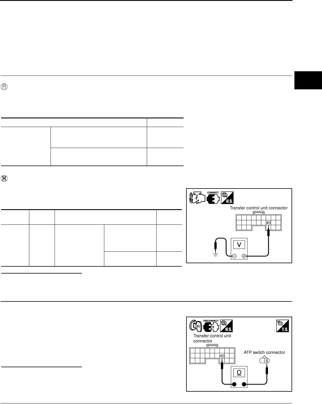
ATP SWITCH
DLN-123
< SYMPTOM DIAGNOSIS > [TRANSFER: ATX14B]
C
E
F
G
H
I
J
K
L
M
A
B
DLN
N
O
P
ATP SWITCH
Description INFOID:0000000003937290
The ATP indicator is ON when the transfer case is not in neutral.
Diagnosis Procedure INFOID:0000000003937291
DIAGNOSTIC PROCEDURE
1.CHECK ATP SWITCH SIGNAL
With CONSULT-III
1. Start engine.
2. Select DATA MONITOR mode for ALL MODE AWD/4WD with CONSULT-III.
3. Read out the value of ATP SWITCH.
Without CONSULT-III
1. Start engine.
2. Check voltage between transfer control unit harness connector
terminal and ground.
Are inspection results normal?
YES >> GO TO 5.
NO >> GO TO 2.
2.CHECK HARNESS BETWEEN TRANSFER CONTROL UNIT AND ATP SWITCH
1. Turn ignition switch OFF. (Stay for at least 5 seconds.)
2. Disconnect transfer control unit harness connector and the ATP switch harness connector.
3. Check continuity between transfer control unit harness connec-
tor M153 terminal 40 and ATP switch harness connector F55
terminal 8.
Also check harness for short to ground and short to power.
Are inspection results normal?
YES >> GO TO 3.
NO >> Repair or replace damaged parts.
3.CHECK GROUND CIRCUIT
Condition Display value
• Vehicle stopped
• Engine running
• A/T selector lever
N
• Brake pedal de-
pressed
4WD shift switch
: 4H to 4LO or 4LO to 4H
(While actuator motor is operating.)
ON
Except the above OFF
Connector Terminal Condition Voltage
(Approx.)
M153 40 -
Ground
• Vehicle stopped
• Engine running
• A/T selector lever
N
• Brake pedal de-
pressed
4WD shift switch: 4H
to 4LO or 4LO to 4H
(While actuator motor
is operating.)
0V
Except the above Battery
voltage SDIA2755E
Continuity should exist.
SDIA2756E
Revision: October 2008
2009 Pathfinder
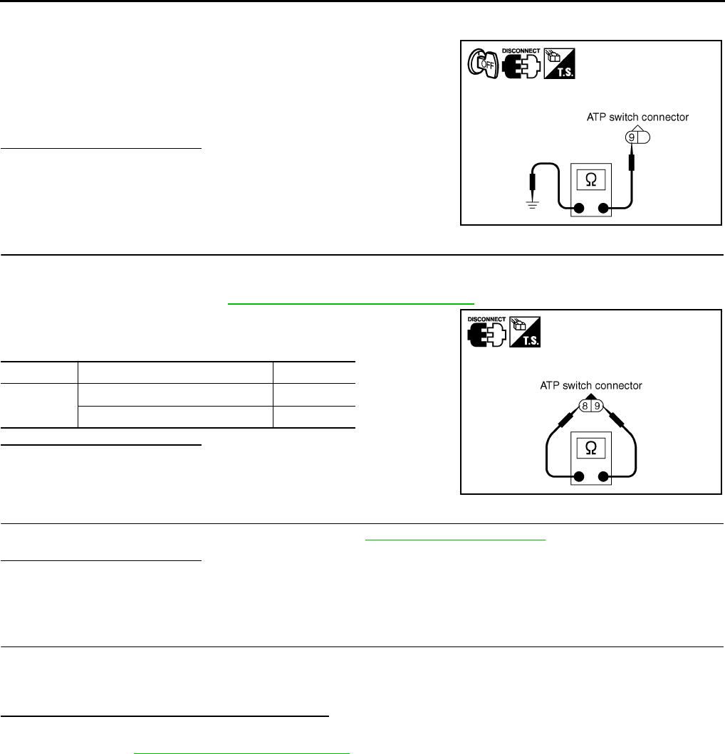
DLN-124
< SYMPTOM DIAGNOSIS > [TRANSFER: ATX14B]
ATP SWITCH
1. Turn ignition switch OFF. (Stay for at least 5 seconds.)
2. Disconnect ATP switch harness connector.
3. Check continuity between ATP switch harness connector F55
terminal 9 and ground.
Also check harness for short to ground and short to power.
Are inspection results normal?
YES >> GO TO 4.
NO >> Repair open circuit or short to ground or short to power
in harness or connectors.
4.CHECK ATP SWITCH
1. Turn ignition switch OFF. (Stay for at least 5 seconds.)
2. Disconnect ATP switch harness connector.
3. Remove ATP switch. Refer to DLN-18, "Component Parts Location".
4. Push and release ATP switch and check continuity between ATP
switch terminals 8 and 9.
Are inspection results normal?
YES >> GO TO 5.
NO >> Replace ATP switch.
5.CHECK TRANSFER CONTROL UNIT
Check transfer control unit input/output signal. Refer to DLN-85, "Reference Value".
Are inspection results normal?
YES >> GO TO 6.
NO >> Check transfer control unit pin terminals for damage or loose connection with harness connector.
If any items are damaged, repair or replace damaged parts.
6.CHECK ATP WARNING LAMP
1. Turn ignition switch ON. (Do not start engine.)
2. Move A/T selector lever to P position.
3. Set 4WD shift switch from 4H to 4LO or 4LO to 4H.
Does ATP warning lamp turn ON while switching?
YES >> Inspection End.
NO >> GO TO DLN-116, "Diagnosis Procedure".
Continuity should exist.
SDIA2394E
Terminal Condition Continuity
8 - 9 Push ATP switch Yes
Release ATP switch No
SDIA2757E
Revision: October 2008
2009 Pathfinder

4WD SYSTEM DOES NOT OPERATE
DLN-125
< SYMPTOM DIAGNOSIS > [TRANSFER: ATX14B]
C
E
F
G
H
I
J
K
L
M
A
B
DLN
N
O
P
4WD SYSTEM DOES NOT OPERATE
Description INFOID:0000000003937292
The vehicle can not be put into 4WD mode. (Possible hydraulic malfunction)
Diagnosis Procedure INFOID:0000000003937293
1.CHECK SYSTEM FOR 4WD SHIFT SWITCH
Perform trouble diagnosis for 4WD shift switch system. Refer to DLN-36, "Diagnosis Procedure".
Are the inspection results normal?
YES >> GO TO 2.
NO >> Repair or replace damaged parts.
2.CHECK SYSTEM FOR CLUTCH PRESSURE SWITCH
Perform trouble diagnosis for clutch pressure switch system. Refer to DLN-75, "Diagnosis Procedure".
Are the inspection results normal?
YES >> GO TO 3.
NO >> Repair or replace damaged parts.
3.SYMPTOM CHECK
Check again.
Are the inspection results normal?
YES >> Inspection End.
NO >> GO TO 4.
4.CHECK TRANSFER CONTROL UNIT
Check transfer control unit input/output signal. Refer to DLN-85, "Reference Value".
Are the inspection results normal?
YES >> GO TO 5.
NO >> Check transfer control unit pin terminals for damage or loose connection with harness connector.
If any items are damaged, repair or replace damaged parts.
5.CHECK TRANSFER INNER PARTS
1. Disassemble transfer assembly. Refer to DLN-150, "Disassembly and Assembly".
2. Check transfer inner parts.
Are the inspection results normal?
YES >> Inspection End.
NO >> Repair or replace damaged parts.
Revision: October 2008
2009 Pathfinder

DLN-126
< PRECAUTION > [TRANSFER: ATX14B]
PRECAUTIONS
PRECAUTION
PRECAUTIONS
Precaution for Supplemental Restraint System (SRS) "AIR BAG" and "SEAT BELT
PRE-TENSIONER" INFOID:0000000003937294
The Supplemental Restraint System such as “AIR BAG” and “SEAT BELT PRE-TENSIONER”, used along
with a front seat belt, helps to reduce the risk or severity of injury to the driver and front passenger for certain
types of collision. This system includes seat belt switch inputs and dual stage front air bag modules. The SRS
system uses the seat belt switches to determine the front air bag deployment, and may only deploy one front
air bag, depending on the severity of a collision and whether the front occupants are belted or unbelted.
Information necessary to service the system safely is included in the SR and SB section of this Service Man-
ual.
WARNING:
• To avoid rendering the SRS inoperative, which could increase the risk of personal injury or death in
the event of a collision which would result in air bag inflation, all maintenance must be performed by
an authorized NISSAN/INFINITI dealer.
• Improper maintenance, including incorrect removal and installation of the SRS, can lead to personal
injury caused by unintentional activation of the system. For removal of Spiral Cable and Air Bag
Module, see the SR section.
• Do not use electrical test equipment on any circuit related to the SRS unless instructed to in this
Service Manual. SRS wiring harnesses can be identified by yellow and/or orange harnesses or har-
ness connectors.
Precaution for Transfer Assembly and Transfer Control Unit Replacement INFOID:0000000003937295
When replacing transfer assembly or transfer control unit, check the 4WD shift indicator lamp as follows.
1. Turn ignition switch ON.
2. Check 4WD shift indicator lamp is turned ON for approximately 1 second.
• If OK, the position between transfer assembly and transfer control unit is correct.
• If NG, the position is different between transfer assembly and transfer control unit.
Adjust the position between transfer assembly and transfer control unit. See METHOD FOR POSITION
ADJUSTMENT that follows.
METHOD FOR POSITION ADJUSTMENT
1. Start engine. Run the engine for at least 10 seconds.
2. Stop vehicle and move A/T selector lever to N position with brake pedal depressed. Stay in N for at least 2
seconds.
3. Turn 4WD shift switch to 2WD position. Stay in 2WD for at least 2 seconds.
4. Turn ignition switch OFF.
5. Start engine.
6. Erase self-diagnosis. Refer to DLN-22, "CONSULT-III Function (ALL MODE AWD/4WD)".
7. Check 4WD shift indicator lamp. Refer to DLN-9, "Preliminary Check".
If 4WD shift indicator lamp does not indicate 2WD, install new transfer control unit and retry the above
check.
Precaution Necessary for Steering Wheel Rotation After Battery Disconnect
INFOID:0000000004468086
NOTE:
• This Procedure is applied only to models with Intelligent Key system and NATS (NISSAN ANTI-THEFT SYS-
TEM).
• Remove and install all control units after disconnecting both battery cables with the ignition knob in the
″LOCK″ position.
• Always use CONSULT-III to perform self-diagnosis as a part of each function inspection after finishing work.
If DTC is detected, perform trouble diagnosis according to self-diagnostic results.
For models equipped with the Intelligent Key system and NATS, an electrically controlled steering lock mech-
anism is adopted on the key cylinder.
Revision: October 2008
2009 Pathfinder
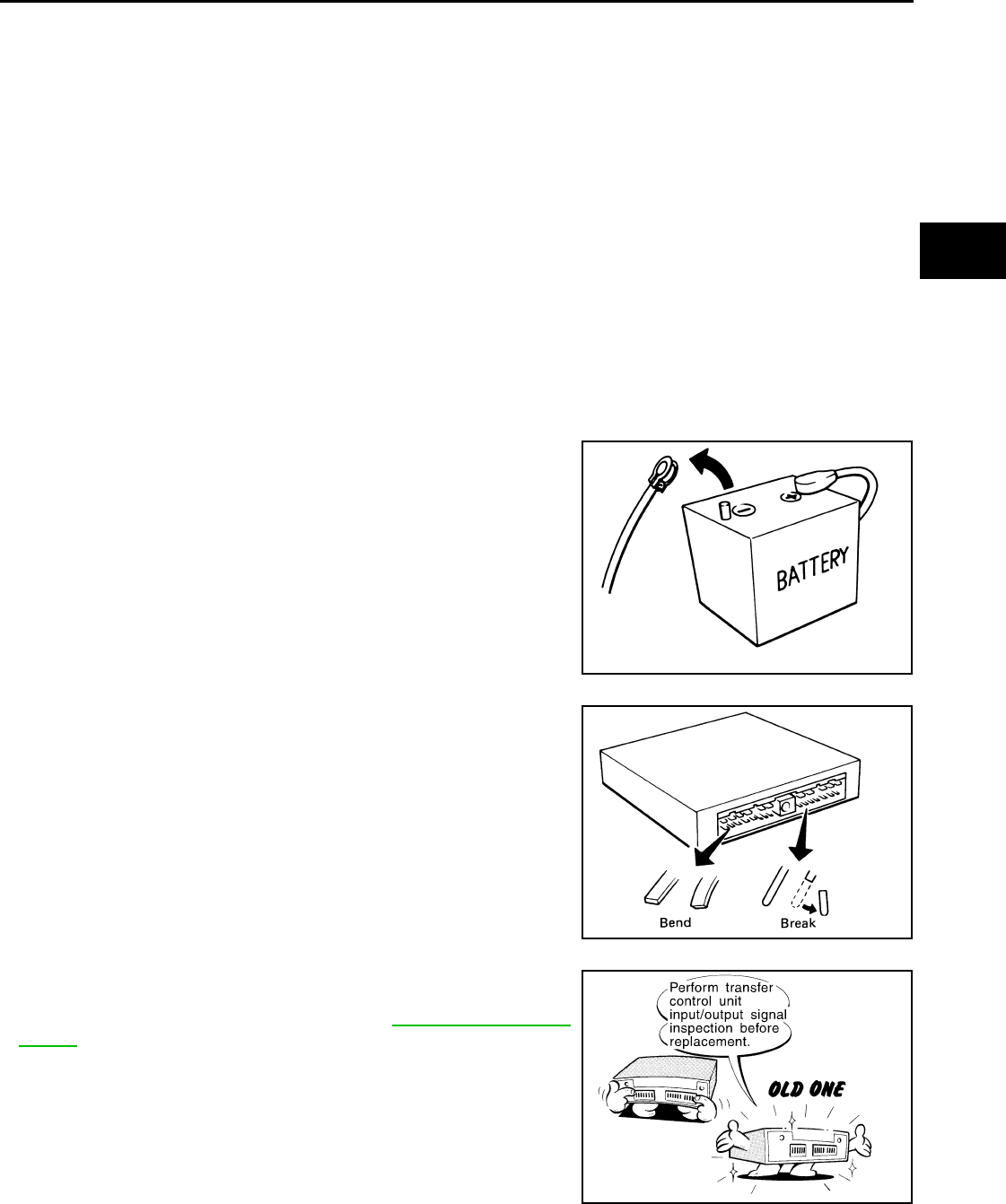
PRECAUTIONS
DLN-127
< PRECAUTION > [TRANSFER: ATX14B]
C
E
F
G
H
I
J
K
L
M
A
B
DLN
N
O
P
For this reason, if the battery is disconnected or if the battery is discharged, the steering wheel will lock and
steering wheel rotation will become impossible.
If steering wheel rotation is required when battery power is interrupted, follow the procedure below before
starting the repair operation.
OPERATION PROCEDURE
1. Connect both battery cables.
NOTE:
Supply power using jumper cables if battery is discharged.
2. Use the Intelligent Key or mechanical key to turn the ignition switch to the ″ACC″ position. At this time, the
steering lock will be released.
3. Disconnect both battery cables. The steering lock will remain released and the steering wheel can be
rotated.
4. Perform the necessary repair operation.
5. When the repair work is completed, return the ignition switch to the ″LOCK″ position before connecting
the battery cables. (At this time, the steering lock mechanism will engage.)
6. Perform a self-diagnosis check of all control units using CONSULT-III.
Precaution INFOID:0000000003937296
•Before connecting or disconnecting the transfer control unit
harness connector, turn ignition switch “OFF” and disconnect
battery cables. Failure to do so may damage the transfer con-
trol unit. Battery voltage is applied to transfer control unit
even if ignition switch is turned “OFF”.
•When connecting or disconnecting pin connectors into or
from transfer control unit, take care not to damage pin termi-
nals (bend or break).
When connecting pin connectors make sure that there are not
any bends or breaks on transfer control unit pin terminals.
•Before replacing transfer control unit, perform transfer con-
trol unit input/output signal inspection and make sure transfer
control unit functions properly. Refer to DLN-85, "Reference
Value".
Service Notice INFOID:0000000003937297
• After overhaul refill the transfer with new transfer fluid.
SEF289H
SEF291H
MEF040DB
Revision: October 2008
2009 Pathfinder

DLN-128
< PRECAUTION > [TRANSFER: ATX14B]
PRECAUTIONS
• Check the fluid level or replace the fluid only with the vehicle parked on level ground.
• During removal or installation, keep inside of transfer clear of dust or dirt.
• Disassembly should be done in a clean work area.
• Before proceeding with disassembly, thoroughly clean the transfer. It is important to prevent the internal
parts from becoming contaminated by dirt or other foreign matter.
• Check for the correct installation status prior to removal or disassembly. If matchmarks are required, be cer-
tain they do not interfere with the function of the parts when applied.
• All parts should be carefully cleaned with a general purpose, non-flammable solvent before inspection or
reassembly.
• Check appearance of the disassembled parts for damage, deformation, and unusual wear. Replace them
with new ones if necessary.
• Gaskets, seals and O-rings should be replaced any time the transfer is disassembled.
• In principle, tighten bolts or nuts gradually in several steps working diagonally from inside to outside. If tight-
ening sequence is specified, use it.
• Observe the specified torque when assembling.
• Clean and flush the parts sufficiently and blow-dry them.
• Be careful not to damage sliding surfaces and mating surfaces.
• Use lint-free cloth or towels for wiping parts clean. Common shop rags can leave fibers that could interfere
with the operation of the transfer.
Revision: October 2008
2009 Pathfinder
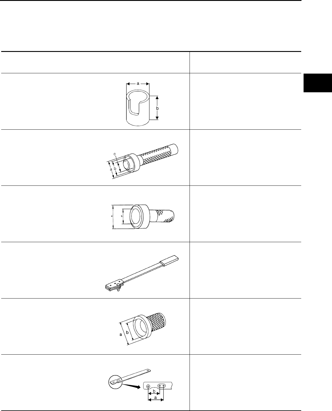
PREPARATION
DLN-129
< PREPARATION > [TRANSFER: ATX14B]
C
E
F
G
H
I
J
K
L
M
A
B
DLN
N
O
P
PREPARATION
PREPARATION
Special Service Tool INFOID:0000000003937298
The actual shapes of Kent-Moore tools may differ from those of special service tools illustrated here.
Tool number
(Kent-Moore No.)
Tool name
Description
KV31103300
(—)
Drift
• Removing press flange snap ring
• Installing press flange snap ring
• Installing carrier bearing
a: 76.3 mm (3.004 in) dia.
b: 130 mm (5.12 in)
KV38100300
(J-25523)
Drift
• Removing mainshaft rear bearing
a: 54 mm (2.13 in) dia.
b: 46 mm (1.81 in) dia.
c: 32 mm (1.26 in) dia.
KV38100500
(—)
Drift
• Installing front oil seal
a: 80 mm (3.15 in) dia.
b: 60 mm (2.36 in) dia.
KV38108300
(J-44195)
Companion flange tool
• Removing and installing companion flange
KV40100621
(J-25273)
Drift
• Installing front drive shaft front bearing
• Installing front drive shaft rear bearing
a: 76 mm (2.99 in) dia.
b: 69 mm (2.72 in) dia.
KV40104000
(—)
Flange wrench
• Removing self-lock nut
• Installing self-lock nut
a: 85 mm (3.35 in)
b: 65 mm (2.56 in)
NT668
ZZA1046D
ZZA0811D
NT771
NT086
NT659
Revision: October 2008
2009 Pathfinder
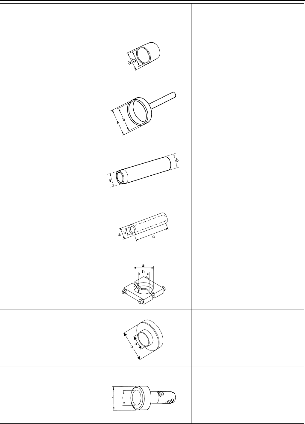
DLN-130
< PREPARATION > [TRANSFER: ATX14B]
PREPARATION
KV40105310
(—)
Drift
• Installing dust cover
a: 89 mm (3.50 in) dia.
b: 80.7 mm (3.17 in) dia.
ST15310000
(J-25640-B)
Drift
• Installing mainshaft rear bearing
a: 96 mm (3.78 in) dia.
b: 84 mm (3.31 in) dia.
ST22360002
(J-25679-01)
Drift
• Installing side oil seal
a: 23 mm (0.91 in) dia.
b: 32 mm (1.26 in) dia.
ST22452000
(J-34335)
Drift
• Removing press flange snap ring
• Installing press flange snap ring
a: 45 mm (1.77 in) dia.
b: 36 mm (1.42 in) dia.
c: 400 mm (15.76 in) dia.
ST30031000
(—)
Puller
• Removing carrier bearing
• Removing front drive shaft front bearing
• Removing front drive shaft rear bearing
a: 90 mm (3.54 in) dia.
b: 50 mm (1.97 in) dia.
ST30032000
(J-26010-01)
Base
• Installing front drive shaft front bearing
• Installing front drive shaft rear bearing
a: 38 mm (1.50 in) dia.
b: 80 mm (3.15 in) dia.
ST30720000
(J-25405)
Drift
• Installing rear oil seal
• Installing input bearing
• Installing input oil seal
a: 77 mm (3.03 in) dia.
b: 55.5 mm (2.185 in) dia.
Tool number
(Kent-Moore No.)
Tool name
Description
ZZA1003D
ZZA0908D
ZZA1091D
NT117
NT411
NT660
ZZA0811D
Revision: October 2008
2009 Pathfinder
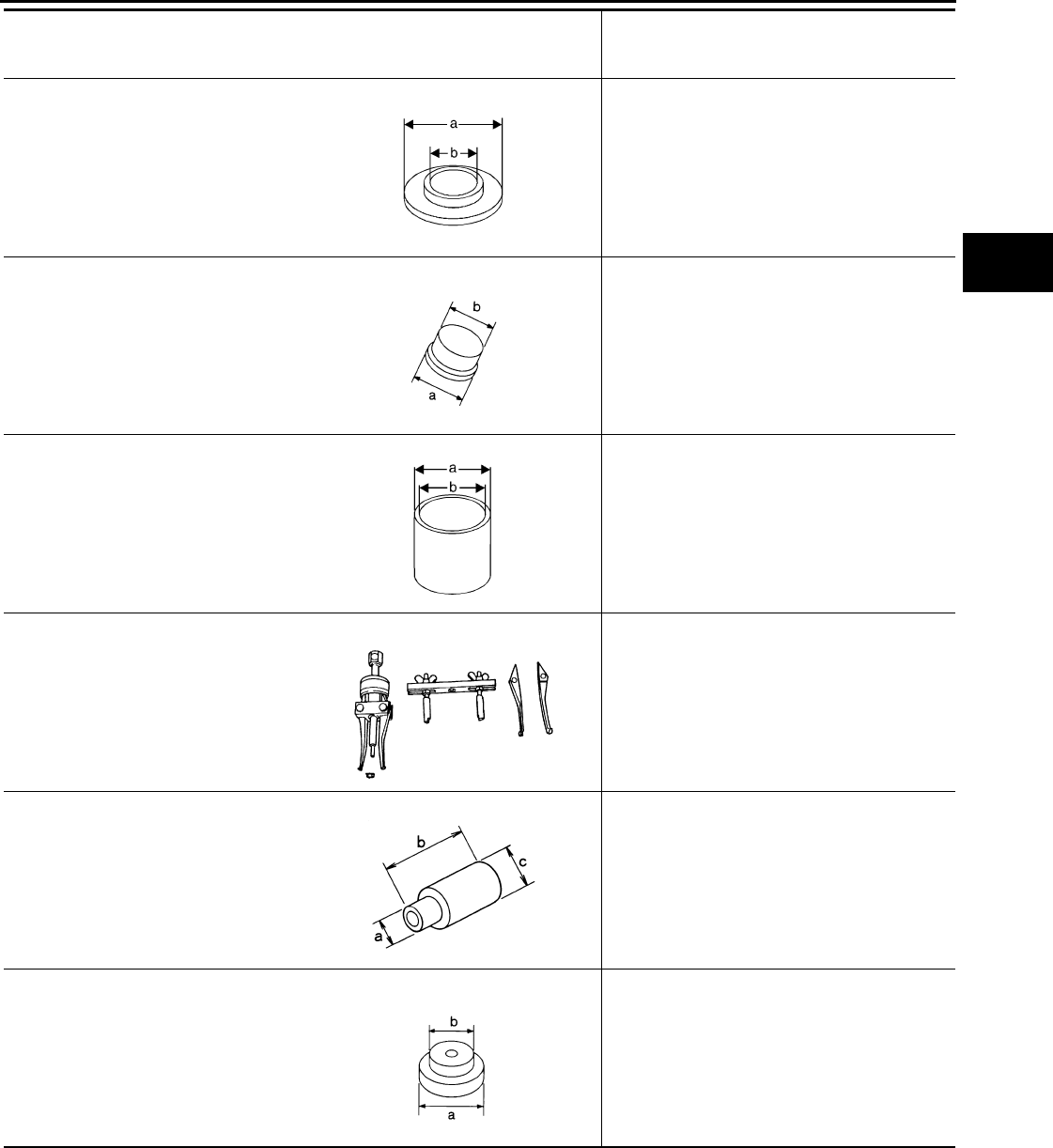
PREPARATION
DLN-131
< PREPARATION > [TRANSFER: ATX14B]
C
E
F
G
H
I
J
K
L
M
A
B
DLN
N
O
P
ST30911000
(—)
Puller
• Removing press flange snap ring
• Installing press flange snap ring
• Installing mainshaft
• Installing carrier bearing
a: 98 mm (3.86 in) dia.
b: 40.5 mm (1.594 in) dia.
ST33052000
(—)
Adapter
• Removing front drive shaft front bearing
• Removing front drive shaft rear bearing
• Installing mainshaft
a: 28 mm (1.10 in) dia.
b: 22 mm (0.87 in) dia.
ST33200000
(J-26082)
Drift
• Removing input bearing
• Installing sun gear assembly and planetary
carrier assembly
• Installing input oil seal
a: 74.5 mm (2.933 in) dia.
b: 62.5 mm (2.461 in) dia.
ST33290001
(J-34286)
Puller
• Removing front oil seal
• Removing rear oil seal
• Removing metal bushing
ST33710000
(—)
Drift
• Removing needle bearing
• Removing metal bushing
a: 24 mm (0.94 in) dia.
b: 89 mm (3.5 in)
c: 30 mm (1.18 in) dia.
ST35300000
(—)
Drift
• Removing sun gear assembly and planetary
carrier assembly
• Removing carrier bearing
• Installing metal bushing
a: 59 mm (2.32 in) dia.
b: 45 mm (1.77 in) dia.
Tool number
(Kent-Moore No.)
Tool name
Description
NT664
NT431
NT661
ZZA0601D
ZZA1057D
NT073
Revision: October 2008
2009 Pathfinder
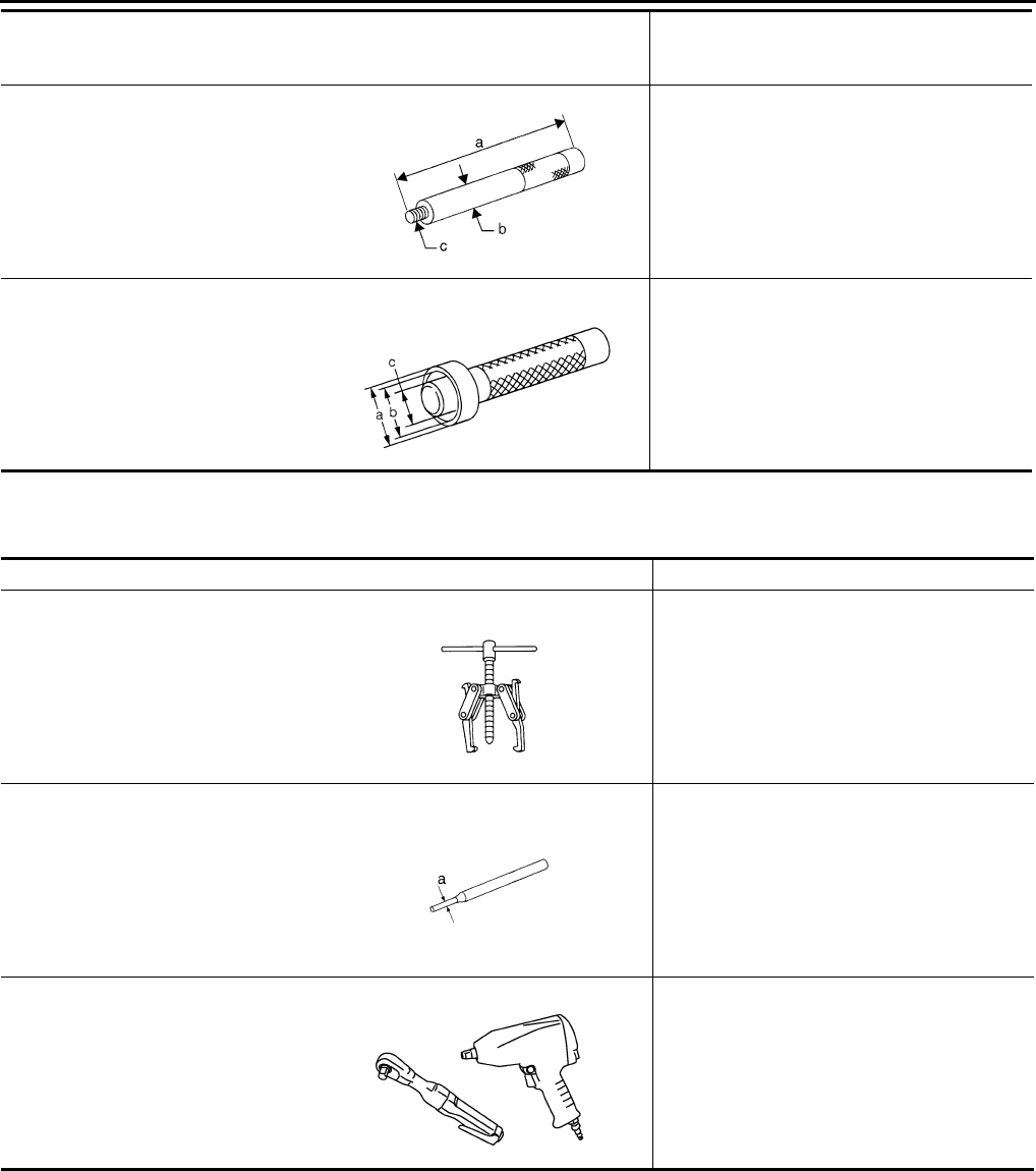
DLN-132
< PREPARATION > [TRANSFER: ATX14B]
PREPARATION
Commercial Service Tool INFOID:0000000003937299
ST35325000
(—)
Drift bar
• Removing metal bushing
a: 215 mm (8.46 in)
b: 25 mm (0.98 in) dia.
c: M12 × 1.5P
ST3322000
(—)
Drift
• Installing needle bearing
a: 37 mm (1.46 in) dia.
b: 31 mm (1.22 in) dia.
c: 22 mm (0.87 in) dia.
Tool number
(Kent-Moore No.)
Tool name
Description
NT663
ZZA1046D
Tool name Description
Puller • Removing companion flange
Pin punch • Removing retainer pin
• Installing retainer pin
a: 6 mm (0.24 in) dia.
Power tool • Removing transfer case assembly
NT077
NT410
PBIC0190E
Revision: October 2008
2009 Pathfinder
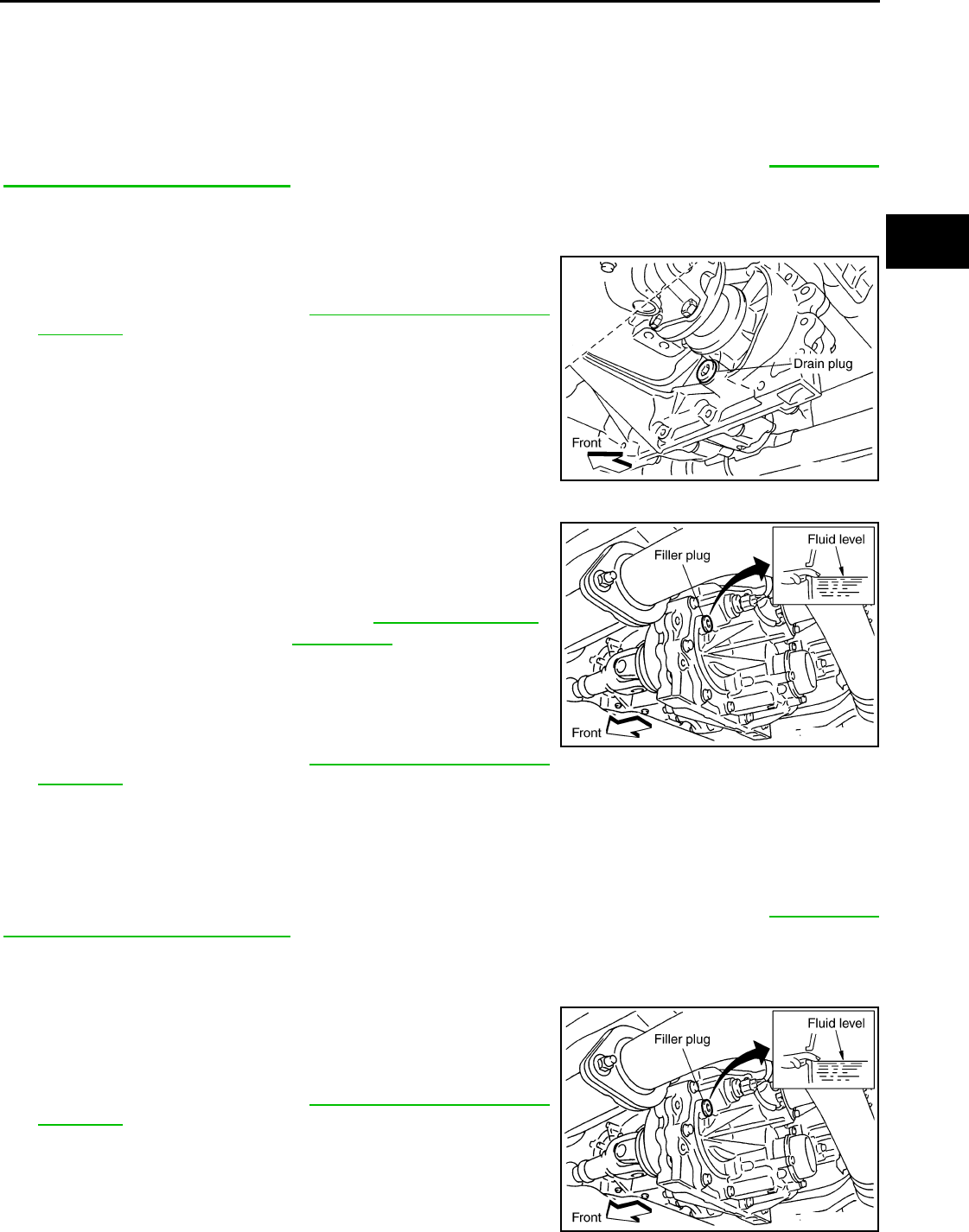
TRANSFER FLUID
DLN-133
< ON-VEHICLE MAINTENANCE > [TRANSFER: ATX14B]
C
E
F
G
H
I
J
K
L
M
A
B
DLN
N
O
P
ON-VEHICLE MAINTENANCE
TRANSFER FLUID
Replacement INFOID:0000000003937300
CAUTION:
If using the vehicle for towing, the transfer fluid must be replaced as specified. Refer to MA-7, "Intro-
duction of Periodic Maintenance".
DRAINING
1. Stop engine.
2. Remove the drain plug and gasket and drain the fluid.
3. Install the drain plug with a new gasket to the transfer. Tighten to
the specified torque. Refer to DLN-150, "Disassembly and
Assembly".
CAUTION:
Do not reuse gasket.
FILLING
1. Remove the filler plug and gasket.
2. Fill the transfer with new fluid until the fluid level reaches the
specified limit near the filler plug hole.
CAUTION:
Carefully fill fluid. (Fill up for approx. 3 minutes.)
3. Leave the vehicle for 3 minutes, and check fluid level again.
4. Install the filler plug with a new gasket to the transfer. Tighten to
the specified torque. Refer to DLN-150, "Disassembly and
Assembly".
CAUTION:
Do not reuse gasket.
Inspection INFOID:0000000003937301
CAUTION:
If using the vehicle for towing, the transfer fluid must be replaced as specified. Refer to MA-7, "Intro-
duction of Periodic Maintenance".
FLUID LEAKAGE AND FLUID LEVEL
1. Make sure that fluid is not leaking from the transfer assembly or around it.
2. Check fluid level from the filler plug hole as shown.
CAUTION:
Do not start engine while checking fluid level.
3. Install the filler plug with a new gasket to the transfer. Tighten to
the specified torque. Refer to DLN-150, "Disassembly and
Assembly".
CAUTION:
Do not reuse gasket.
SDIA3208E
Fluid grade and capacity : Refer to MA-12, "Fluids and
Lubricants".
SDIA3209E
SDIA3209E
Revision: October 2008
2009 Pathfinder
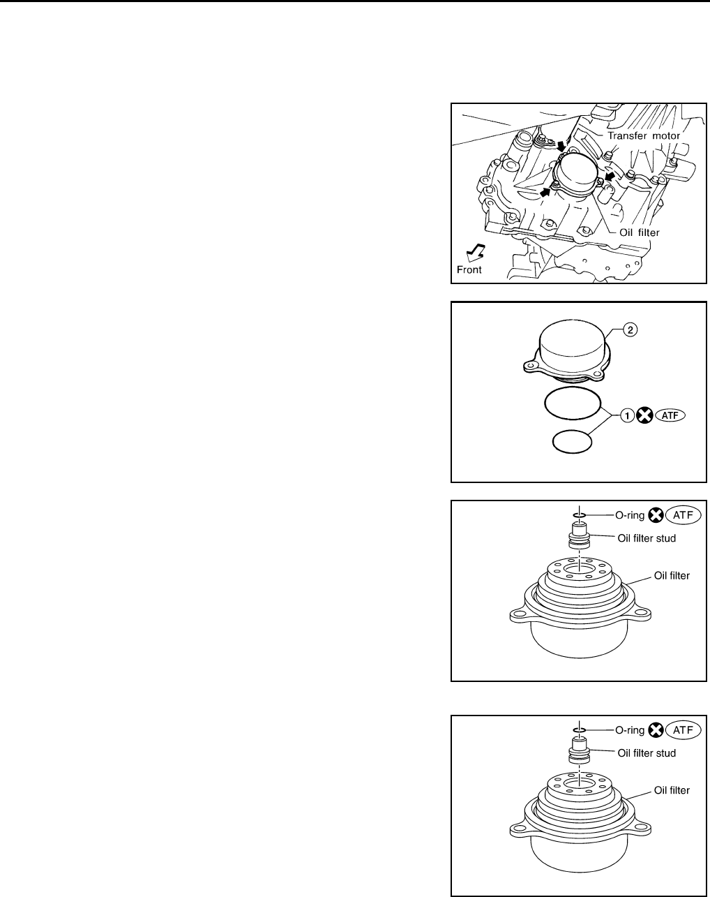
DLN-134
< ON-VEHICLE MAINTENANCE > [TRANSFER: ATX14B]
TRANSFER OIL FILTER
TRANSFER OIL FILTER
Removal and Installation INFOID:0000000003937302
REMOVAL
1. Remove the oil filter bolts and oil filter.
CAUTION:
• Do not damage center case or oil filter.
• Loosen bolts and detach oil filter evenly.
2. Remove the O-rings (1) from the oil filter (2).
3. Remove the oil filter stud from the oil filter.
4. Remove the O-ring from the oil filter stud.
INSTALLATION
1. Apply ATF to the new O-ring, and install it on the oil filter stud.
CAUTION:
Do not reuse O-ring.
2. Install the oil filter stud to the oil filter.
SMT875C
WDIA0285E
SDIA3180E
SDIA3180E
Revision: October 2008
2009 Pathfinder
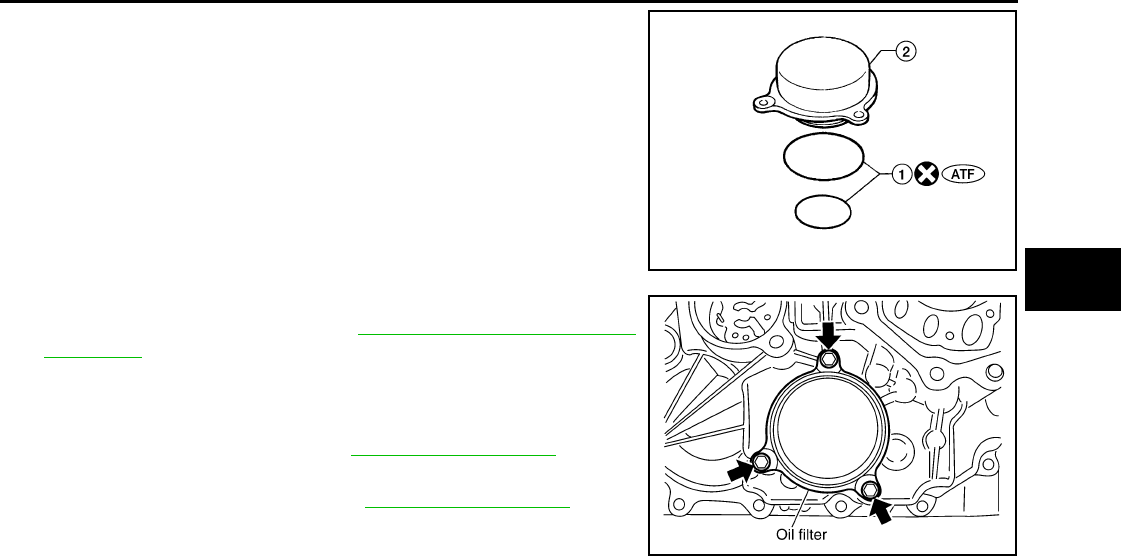
TRANSFER OIL FILTER
DLN-135
< ON-VEHICLE MAINTENANCE > [TRANSFER: ATX14B]
C
E
F
G
H
I
J
K
L
M
A
B
DLN
N
O
P
3. Apply ATF to the two new O-rings (1), and install them on the oil
filter (2).
CAUTION:
Do not reuse O-rings.
4. Install the oil filter to the transfer assembly. Tighten the bolts to
the specified torque. Refer to DLN-150, "Disassembly and
Assembly".
CAUTION:
• Do not damage oil filter.
• Attach oil filter and tighten bolts evenly.
5. Check the transfer fluid. Refer to DLN-133, "Inspection".
6. Start the engine for one minute. Then stop the engine and
recheck the transfer fluid. Refer to DLN-133, "Inspection".
WDIA0285E
SDIA2136E
Revision: October 2008
2009 Pathfinder
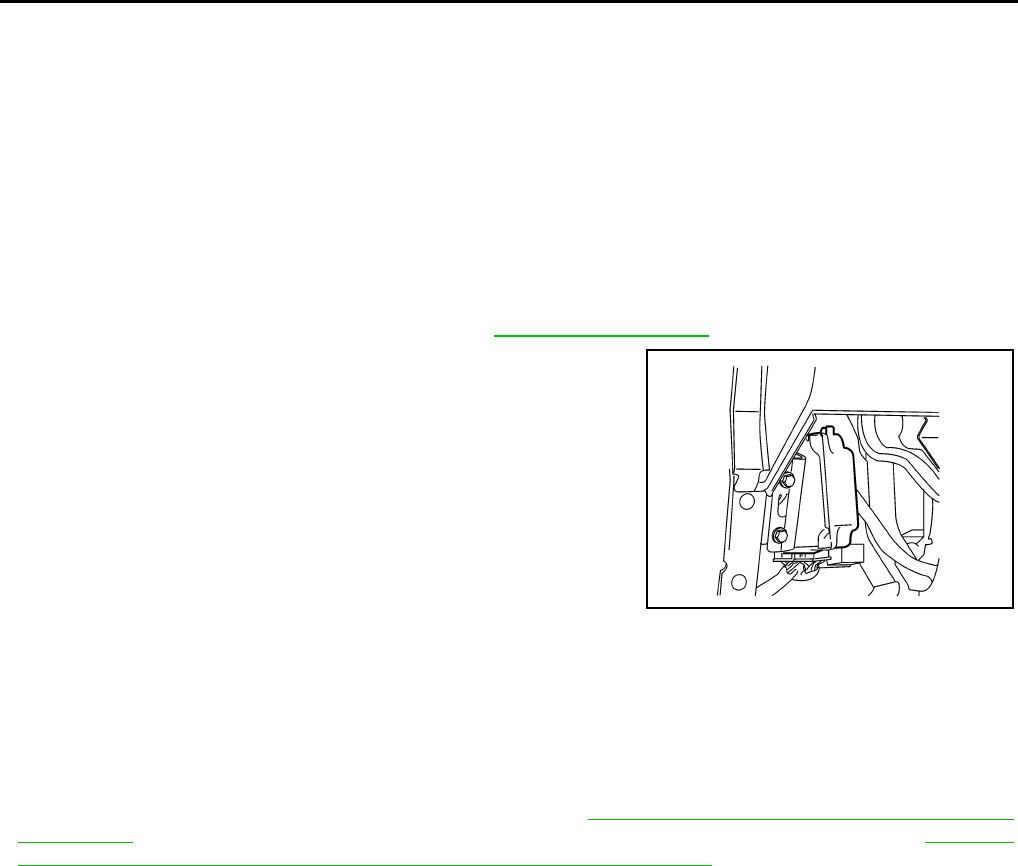
DLN-136
< ON-VEHICLE REPAIR > [TRANSFER: ATX14B]
TRANSFER CONTROL UNIT
ON-VEHICLE REPAIR
TRANSFER CONTROL UNIT
Removal and Installation INFOID:0000000003937303
REMOVAL
1. Set transfer state as 2WD when 4WD shift switch is at 2WD, or as AUTO when 4WD shift switch is at
AUTO.
CAUTION:
When removing transfer control unit, transfer state must be at 2WD or AUTO.
2. Turn the ignition switch OFF and disconnect negative battery terminal.
3. Remove the lower instrument panel LH. Refer to IP-10, "Exploded View".
4. Disconnect the two transfer control unit connectors.
5. Remove the transfer control unit bolts.
6. Remove the transfer control unit.
INSTALLATION
Installation is in the reverse order of removal.
• When installing the transfer control unit, tighten bolts to the specified torque.
CAUTION:
Do not connect harness connector to transfer control unit when 4WD shift switch is at 4LO.
• After the installation, check perform self-diagnosis. Refer to DLN-22, "CONSULT-III Function (ALL MODE
AWD/4WD)". If NG, adjust position between transfer assembly and transfer control unit. Refer to DLN-126,
"Precaution for Transfer Assembly and Transfer Control Unit Replacement".
LDIA0168E
Transfer control unit bolts : 3.4 N·m (0.35 kg-m, 30 in-lb)
Revision: October 2008
2009 Pathfinder
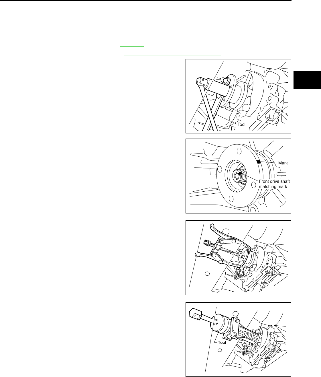
FRONT OIL SEAL
DLN-137
< ON-VEHICLE REPAIR > [TRANSFER: ATX14B]
C
E
F
G
H
I
J
K
L
M
A
B
DLN
N
O
P
FRONT OIL SEAL
Removal and Installation INFOID:0000000003937304
REMOVAL
1. Partially drain the transfer fluid. Refer to DLN-133.
2. Remove the front propeller shaft. Refer to DLN-309, "Removal and Installation".
3. Remove the companion flange self-lock nut using Tool.
4. Put a matching mark on top of the front drive shaft in line with
the mark on the companion flange.
CAUTION:
Use paint to make the matching mark on the front drive
shaft. Do not damage the front drive shaft.
5. Remove the companion flange using suitable tool.
6. Remove the front oil seal from the front case using Tool.
CAUTION:
Do not damage front case.
INSTALLATION
Tool number : KV40104000 ( — )
SDIA2657E
SDIA2658E
WDIA0193E
Tool number : ST33290001 (J-34286)
LDIA0144E
Revision: October 2008
2009 Pathfinder
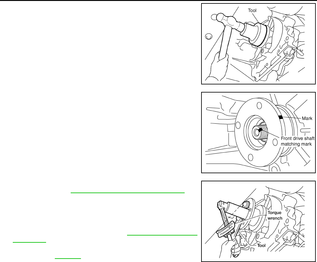
DLN-138
< ON-VEHICLE REPAIR > [TRANSFER: ATX14B]
FRONT OIL SEAL
1. Install the new front oil seal until it is flush with the end face of
the front case using Tool.
CAUTION:
• Do not reuse oil seal.
• Apply petroleum jelly to oil seal.
2. Align the matching mark of the front drive shaft with the match-
ing mark of the companion flange, then install the companion
flange.
3. Install the new self-lock nut. Tighten to the specified torque
using Tool. Refer to DLN-150, "Disassembly and Assembly".
CAUTION:
Do not reuse self-lock nut.
4. Install the front propeller shaft. Refer to DLN-309, "Removal and
Installation".
5. Refill the transfer with fluid and check for fluid leakage and fluid
level. Refer to DLN-133.
Tool number : KV38100500 ( — )
SDIA2662E
SDIA2658E
Tool number : KV40104000 ( — )
LDIA0147E
Revision: October 2008
2009 Pathfinder
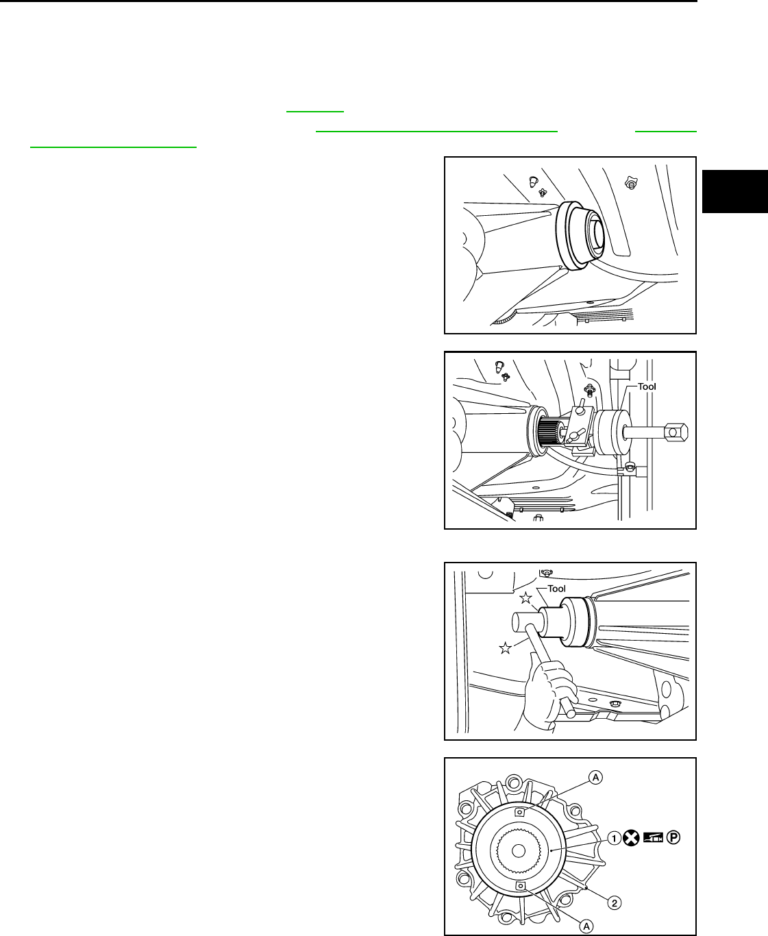
REAR OIL SEAL
DLN-139
< ON-VEHICLE REPAIR > [TRANSFER: ATX14B]
C
E
F
G
H
I
J
K
L
M
A
B
DLN
N
O
P
REAR OIL SEAL
Removal and Installation INFOID:0000000003937305
REMOVAL
1. Partially drain the transfer fluid. Refer to DLN-133.
2. Remove the rear propeller shaft. Refer to DLN-317, "Removal and Installation" (2S1330), DLN-326,
"Removal and Installation" (2S1350).
3. Remove the dust cover from the rear case.
CAUTION:
Do not damage the rear case.
4. Remove the rear oil seal from the rear case using Tool.
CAUTION:
Do not damage the rear case.
INSTALLATION
1. Install the new rear oil seal until it is flush with the end face of the
rear case using Tool.
CAUTION:
• Do not reuse oil seal.
• Apply petroleum jelly to oil seal.
2. Apply petroleum jelly to the circumference of the new dust cover.
Position the new dust cover as shown.
CAUTION:
• Do not reuse dust cover.
• Position the identification mark at the position shown.
• 1: Dust cover
• 2: Rear case assembly
• A: Protrusions
WDIA0127E
Tool number : ST33290001 (J-34286)
LDIA0139E
Tool number : ST30720000 (J-25405)
LDIA0140E
AWDIA0550G
B
Revision: October 2008
2009 Pathfinder
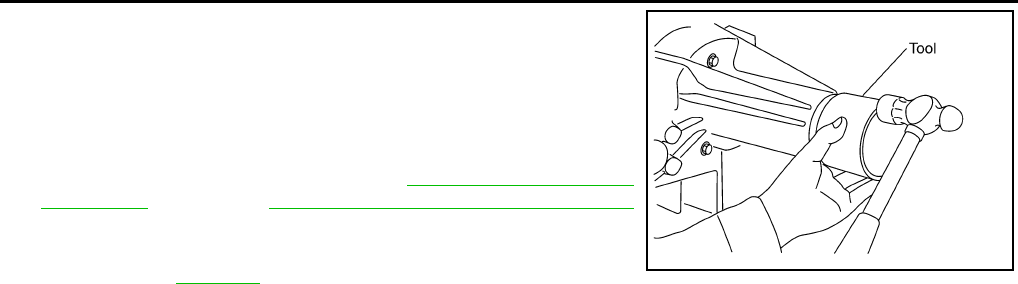
DLN-140
< ON-VEHICLE REPAIR > [TRANSFER: ATX14B]
REAR OIL SEAL
3. Install the new dust cover to the rear case using Tool.
CAUTION:
• Do not reuse dust cover.
• Apply petroleum jelly to dust cover.
4. Install the rear propeller shaft. Refer to DLN-317, "Removal and
Installation" (2S1330), DLN-326, "Removal and Installation"
(2S1350).
5. Refill the transfer with fluid and check for fluid leakage and fluid
level. Refer to DLN-133.
Tool number : KV40105310 ( — )
PDIA0116E
Revision: October 2008
2009 Pathfinder
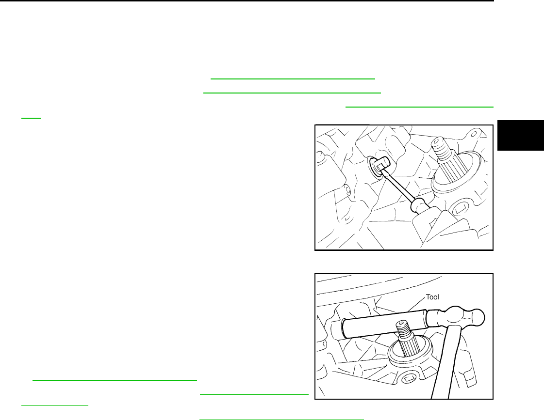
SIDE OIL SEAL
DLN-141
< ON-VEHICLE REPAIR > [TRANSFER: ATX14B]
C
E
F
G
H
I
J
K
L
M
A
B
DLN
N
O
P
SIDE OIL SEAL
Removal and Installation INFOID:0000000003937306
REMOVAL
1. Remove the front propeller shaft. Refer to DLN-309, "Removal and Installation".
2. Remove the companion flange. Refer to DLN-281, "Disassembly and Assembly".
3. Remove the transfer control device from the transfer assembly. Refer to DLN-276, "Removal and Installa-
tion".
4. Remove the side oil seal using suitable tool.
CAUTION:
Do not damage shift cross.
INSTALLATION
1. Install the new side oil seal until it is flush with the end face of
case using Tool.
CAUTION:
• Do not reuse oil seal.
• Apply petroleum jelly to oil seal.
2. Install the transfer control device to the transfer assembly. Refer
to DLN-276, "Removal and Installation".
3. Install the companion flange. Refer to DLN-281, "Disassembly
and Assembly".
4. Install the front propeller shaft. Refer to DLN-309, "Removal and Installation".
SDIA2666E
Tool number : ST22360002 (J-25679-01)
SDIA2665E
Revision: October 2008
2009 Pathfinder
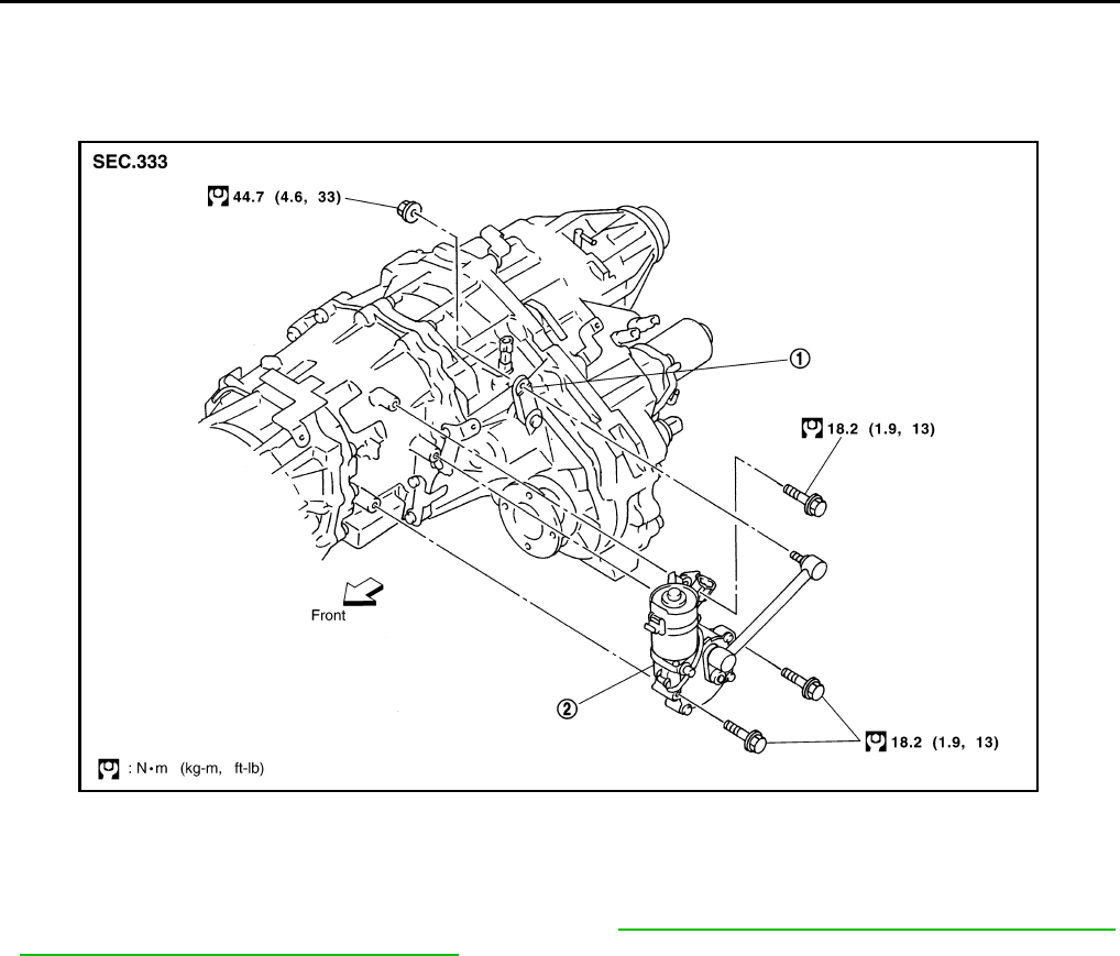
DLN-142
< ON-VEHICLE REPAIR > [TRANSFER: ATX14B]
TRANSFER CONTROL DEVICE
TRANSFER CONTROL DEVICE
Removal and Installation INFOID:0000000003937307
CAUTION:
• Change vehicle state to 2WD, and then remove and install transfer control device.
• Check 4WD shift indicator after installation. Refer to DLN-126, "Precaution for Transfer Assembly
and Transfer Control Unit Replacement".
1. Shift lever 2. Actuator
SDIA2654E
Revision: October 2008
2009 Pathfinder
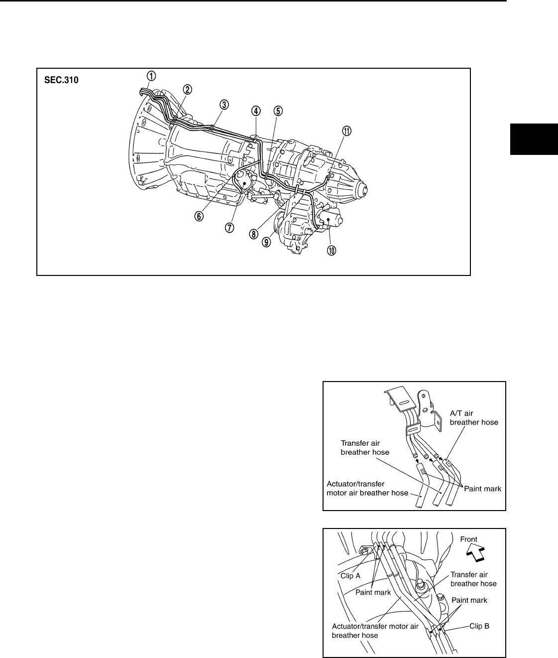
AIR BREATHER HOSE
DLN-143
< ON-VEHICLE REPAIR > [TRANSFER: ATX14B]
C
E
F
G
H
I
J
K
L
M
A
B
DLN
N
O
P
AIR BREATHER HOSE
Removal and Installation INFOID:0000000003937308
VQ40DE
CAUTION:
• Make sure there are no pinched or restricted areas on each air breather hose caused by folding or
bending when installing it.
• Install each air breather hose into the breather tube (metal
connector) until the hose end reaches the end of the curve
section. Set each air breather hose with paint mark facing
upward.
• Install actuator/transfer motor air breather hose and transfer
air breather hose on clip A with the paint mark facing upward.
SDIA3339E
1. Breather tube 2. Clip A 3. Clip B
4. Clip C 5. Clip D 6. Clip E
7. Actuator 8. Air breather hose clamp 9. Clip F
10. Transfer motor 11. Breather tube (transfer)
SDIA3340E
SDIA3342E
Revision: October 2008
2009 Pathfinder
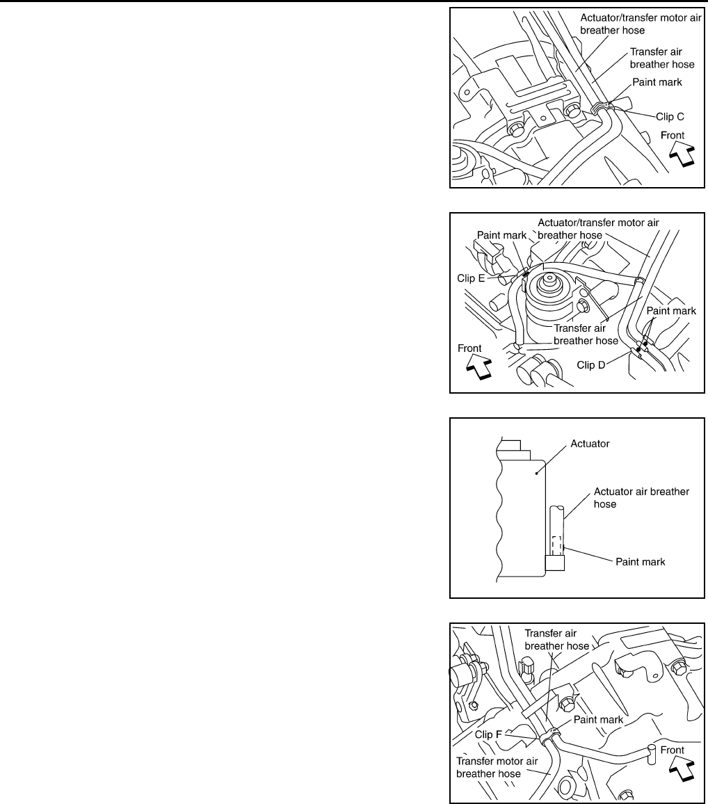
DLN-144
< ON-VEHICLE REPAIR > [TRANSFER: ATX14B]
AIR BREATHER HOSE
• Install clip C on actuator/transfer motor air breather hose and
transfer air breather hose with the paint mark matched.
• Install actuator/transfer motor air breather hose and transfer
air breather hose on clip D and clip E with the paint mark fac-
ing upward.
• Install the actuator air breather hose into the actuator (case
connector) until the hose end reaches the base of the tube.
Set actuator air breather hose with paint mark facing leftward.
• Install clip F on transfer motor air (control device) breather
hose and transfer air breather hose with the paint mark
matched.
SDIA3343E
SDIA3344E
SDIA3226E
SDIA3345E
Revision: October 2008
2009 Pathfinder
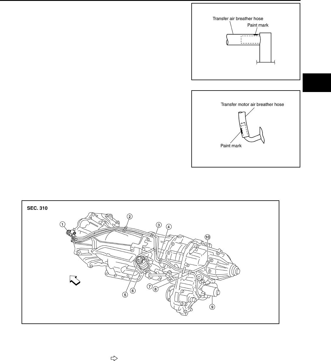
AIR BREATHER HOSE
DLN-145
< ON-VEHICLE REPAIR > [TRANSFER: ATX14B]
C
E
F
G
H
I
J
K
L
M
A
B
DLN
N
O
P
• Install the transfer air breather hose into the breather tube
(transfer, metal connector) until the hose end reaches the
base of the tube. Set transfer air breather hose with paint
mark facing upwards.
• Install the transfer motor air breather hose into the transfer
motor (case connector) until the hose end reaches the end of
the curved section. Set transfer motor air breather hose with
paint mark facing leftward.
Removal and Installation
VK56DE
CAUTION:
• Make sure there are no pinched or restricted areas on each air breather hose caused by folding or
bending when installing it.
SDIA3196E
SDIA3194E
AWDIA0010Z
Z
1. Breather tube 2. Clip A 3. Clip B
4. Clip C 5. Clip D 6. Actuator
7. Air breather hose clamp 8. Clip E 9. Transfer motor
10. Breather tube (transfer) Vehicle front
Revision: October 2008
2009 Pathfinder
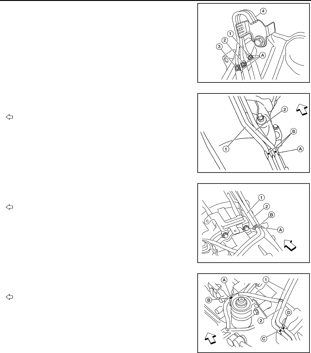
DLN-146
< ON-VEHICLE REPAIR > [TRANSFER: ATX14B]
AIR BREATHER HOSE
• Install each air breather hose into the breather tube (4). Set
each air breather hose with paint mark facing upward.
- A: Paint marks
- 1: A/T breather hose
- 2: Transfer air breather hose
- 3: Actuator/transfer motor air breather hose
• Install actuator/transfer motor air breather hose (1) and trans-
fer air breather hose (2) on clip (A) with the paint mark (B) fac-
ing upward.
: Front
• Install clip (A) on actuator/transfer motor air breather hose (1)
and transfer air breather hose (2) with the paint mark (B)
matched.
: Front
• Install actuator/transfer motor air breather hose (1) and trans-
fer air breather hose (2) on clip (C) and clip (B) with the paint
mark (A) and (D) facing upward.
: Front
ALDIA0110ZZ
ALDIA0111ZZ
AWDIA0011Z
Z
AWDIA0012Z
Z
Revision: October 2008
2009 Pathfinder
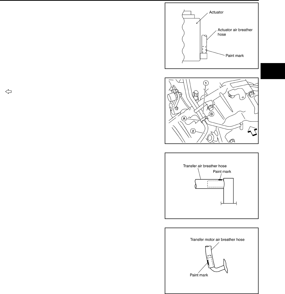
AIR BREATHER HOSE
DLN-147
< ON-VEHICLE REPAIR > [TRANSFER: ATX14B]
C
E
F
G
H
I
J
K
L
M
A
B
DLN
N
O
P
• Install the actuator air breather hose into the actuator (case
connector) until the hose end reaches the base of the tube.
Set actuator air breather hose with paint mark facing leftward.
• Install clip (A) on transfer motor air breather hose (2) and
transfer air breather hose (1) with the paint mark (B) matched.
: Front
• Install the transfer air breather hose into the breather tube
(transfer, metal connector) until the hose end reaches the
base of the tube. Set transfer air breather hose with paint
mark facing upwards.
• Install the transfer motor air breather hose into the transfer
motor (case connector) until the hose end reaches the end of
the curved section. Set transfer motor air breather hose with
paint mark facing leftward.
SDIA3226E
AWDIA0013Z
Z
SDIA3196E
SDIA3194E
Revision: October 2008
2009 Pathfinder
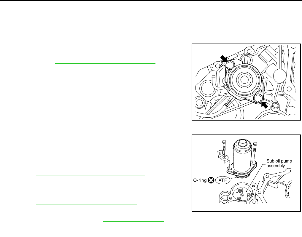
DLN-148
< ON-VEHICLE REPAIR > [TRANSFER: ATX14B]
TRANSFER MOTOR
TRANSFER MOTOR
Removal and Installation INFOID:0000000003937309
REMOVAL
1. Disconnect the transfer motor connector.
2. Remove the transfer motor air breather hose from the transfer
motor. Refer to DLN-143, "Removal and Installation".
3. Remove the transfer motor bolts.
4. Remove the transfer motor.
INSTALLATION
1. Apply ATF to the new O-ring and install it to the transfer motor.
CAUTION:
Do not reuse O-rings.
2. Fit the double-flat end of the transfer motor shaft into the slot of
the sub-oil pump assembly. Then tighten to the specified torque.
Refer to DLN-150, "Disassembly and Assembly".
CAUTION:
Be sure to install connector bracket.
3. Install the transfer motor air breather hose to the transfer motor.
Refer to DLN-143, "Removal and Installation".
4. Connect the transfer motor connector.
5. Check the transfer fluid. Refer to DLN-133, "Inspection".
6. Start the engine for one minute. Then stop the engine and recheck the transfer fluid. Refer to DLN-133,
"Inspection".
SDIA2133E
SDIA2787E
Revision: October 2008
2009 Pathfinder
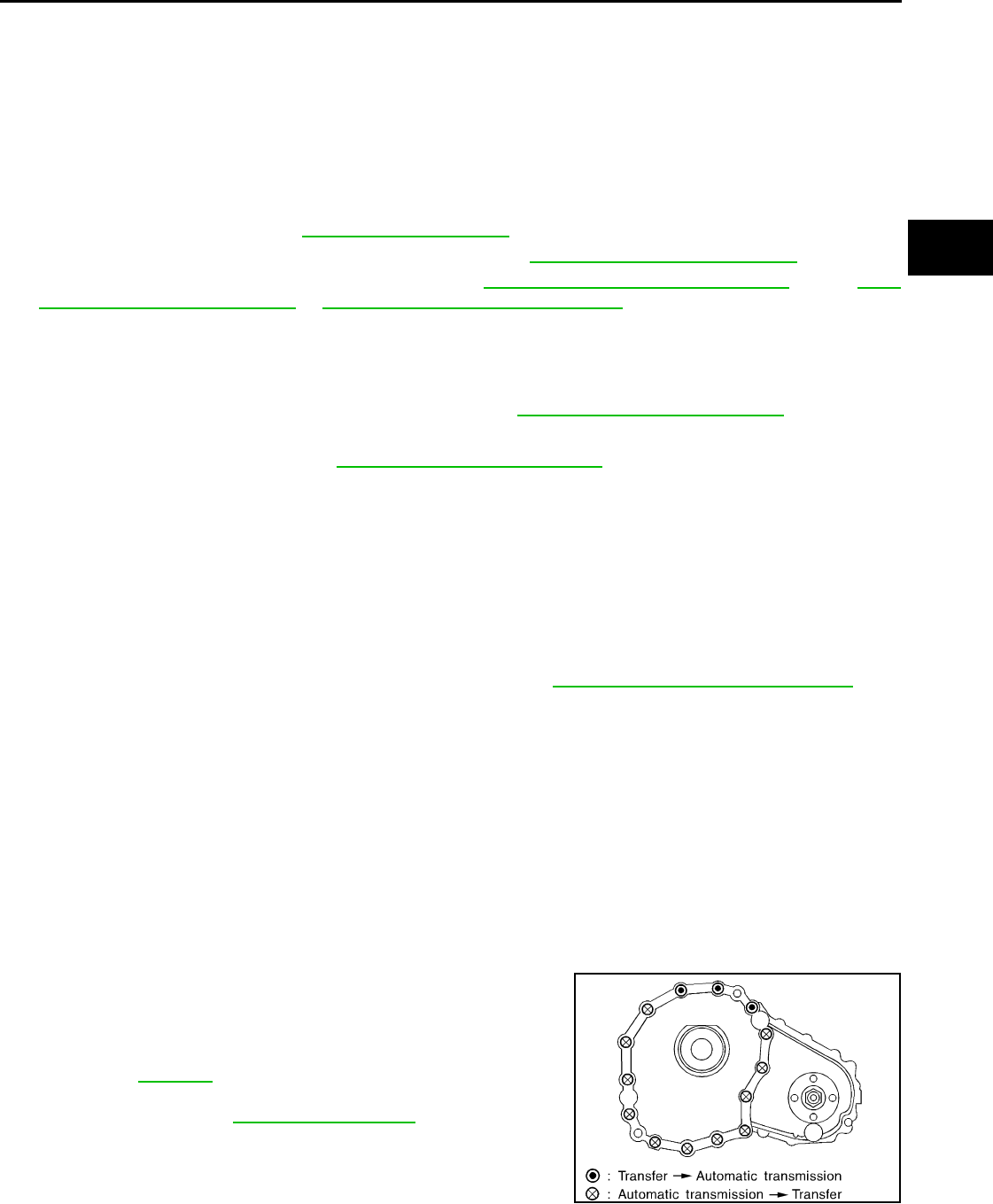
TRANSFER ASSEMBLY
DLN-149
< REMOVAL AND INSTALLATION > [TRANSFER: ATX14B]
C
E
F
G
H
I
J
K
L
M
A
B
DLN
N
O
P
REMOVAL AND INSTALLATION
TRANSFER ASSEMBLY
Removal and Installation INFOID:0000000003937310
REMOVAL
1. Set transfer state as 2WD when 4WD shift switch is at 2WD.
2. Remove the undercovers using power tool.
3. Drain the transfer fluid. Refer to DLN-133, "Replacement".
4. Remove the center exhaust tube and main muffler. Refer to EX-6, "Removal and Installation".
5. Remove the front and rear propeller shafts. Refer to DLN-309, "Removal and Installation" (front), DLN-
317, "Removal and Installation" or DLN-326, "Removal and Installation" (rear).
CAUTION:
Do not damage spline, sleeve yoke and rear oil seal when removing rear propeller shaft.
NOTE:
Insert a plug into the rear oil seal after removing the rear propeller shaft.
6. Remove the A/T nuts from the A/T crossmember. Refer to TM-217, "4WD : Exploded View".
7. Position two suitable jacks under the A/T and transfer assembly.
8. Remove the crossmember. Refer to TM-217, "4WD : Exploded View".
WARNING:
Support A/T and transfer assembly using two suitable jacks while removing crossmember.
9. Disconnect the electrical connectors from the following:
• ATP switch
• Neutral 4LO switch
• Wait detection switch
• Transfer motor
• Transfer control device
• Transfer terminal cord assembly
10. Disconnect each air breather hose from the following. Refer to DLN-143, "Removal and Installation".
• Actuator
• Breather tube (transfer)
• Transfer motor
11. Remove the transfer control device from the extension housing.
12. Remove the transfer to A/T and A/T to transfer bolts.
13. Remove the transfer assembly.
WARNING:
Support transfer assembly with suitable jack while removing it.
CAUTION:
Do not damage rear oil seal (A/T).
INSTALLATION
Installation is in the reverse order of removal.
• Tighten the bolts to specification.
• Fill the transfer with new fluid and check for fluid leakage and fluid
level. Refer to DLN-133.
• Start the engine for one minute. Then stop the engine and recheck
the transfer fluid. Refer to DLN-133, "Inspection".
Transfer bolt torque : 36 N·m (3.7 kg-m, 27 ft-lb)
SMT872C
Revision: October 2008
2009 Pathfinder
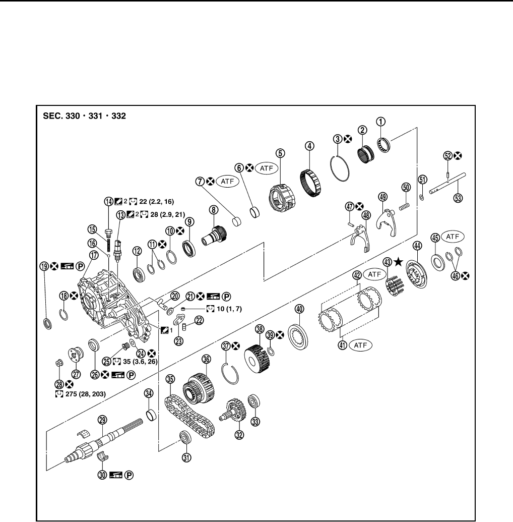
DLN-150
< DISASSEMBLY AND ASSEMBLY > [TRANSFER: ATX14B]
TRANSFER ASSEMBLY
DISASSEMBLY AND ASSEMBLY
TRANSFER ASSEMBLY
Disassembly and Assembly INFOID:0000000003937311
COMPONENTS
1. 2-4 sleeve 2. L-H sleeve 3. Snap ring
4. Internal gear 5. Planetary carrier assembly 6. Metal bushing
7. Needle bearing 8. Sun gear 9. Carrier bearing
10. Snap ring 11. Snap ring 12. Input bearing
13. Wait detection switch 14. Check plug 15. Check spring
16. Check ball 17. Front case 18. Snap ring
19. Input oil seal 20. Shift cross 21. Side oil seal
22. Lock pin 23. Shift lever 24. Gasket
25. Drain plug 26. Front oil seal 27. Companion flange
28. Self-lock nut 29. Mainshaft 30. Needle bearing
31. Front bearing 32. Front drive shaft 33. Rear bearing
34. Spacer 35. Drive chain 36. Clutch drum
37. Snap ring 38. Clutch hub 39. Snap ring
AWDIA0014G
B
Revision: October 2008
2009 Pathfinder
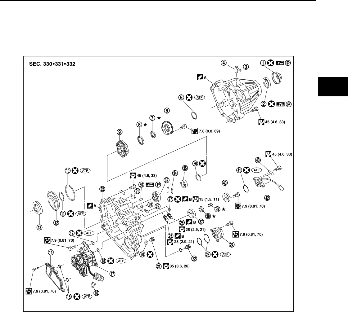
TRANSFER ASSEMBLY
DLN-151
< DISASSEMBLY AND ASSEMBLY > [TRANSFER: ATX14B]
C
E
F
G
H
I
J
K
L
M
A
B
DLN
N
O
P
40. Retaining plate 41. Driven plate (10 sheet) 42. Drive plate (10 sheet)
43. Return spring assembly 44. Press flange 45. Thrust needle bearing
46. Snap ring 47. Retaining pin 48. L-H fork
49. 2-4 fork 50. Shift fork spring 51. Fork guide
52. Retainer pin 53. Shift rod
1. Dust cover 2. Rear oil seal 3. Rear case
4. Breather tube 5. Seal ring 6. Main oil pump cover
7. Inner gear 8. Outer gear 9. Main oil pump housing
10. D-ring 11. D-ring 12. Clutch piston
13. Thrust needle bearing race 14. Oil strainer 15. O-ring
16. Snap ring 17. Control valve assembly 18. Lip seal (large 5 pieces)
19. Lip seal (small 2 pieces) 20. Gasket 21. Filler plug
22. Oil filter stud 23. O-ring 24. Oil filter
25 ATP switch 26. Neutral-4LO switch 27. Oil pressure check plug
28. Harness bracket 29. Air breather hose clamp 30. Stem bleeder
31. Harness bracket 32. Center case 33. Mainshaft rear bearing
34. C-ring 35. Washer holder 36. Snap ring
37. Sub oil pump housing 38. Outer gear 39. Inner gear
WDIA0302E
Revision: October 2008
2009 Pathfinder
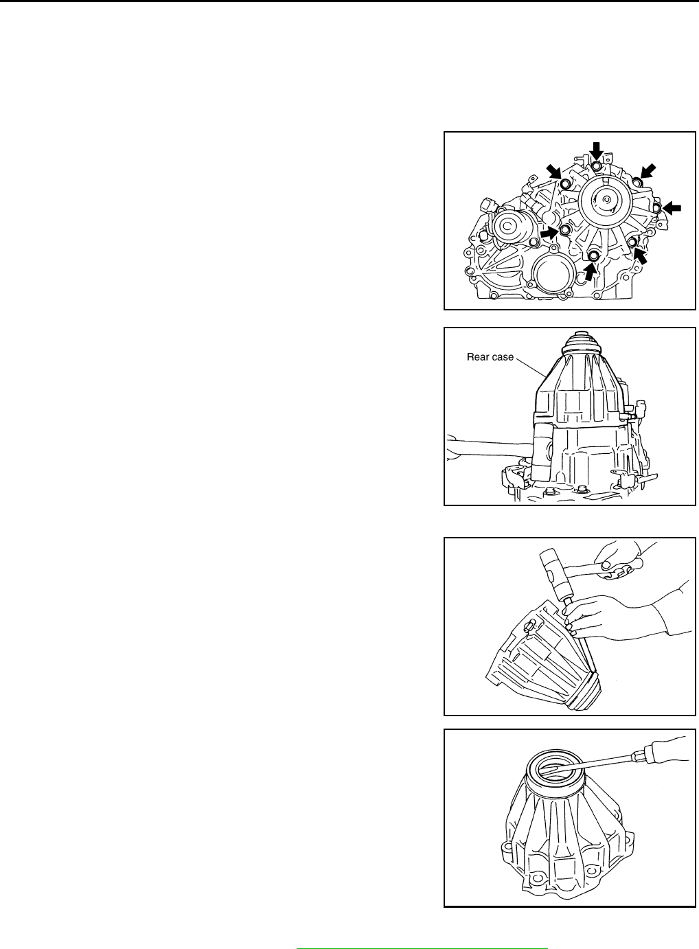
DLN-152
< DISASSEMBLY AND ASSEMBLY > [TRANSFER: ATX14B]
TRANSFER ASSEMBLY
DISASSEMBLY
Rear Case
1. Remove the rear case bolts.
2. Remove the rear case from the center case.
3. Remove the dust cover using suitable tool.
4. Remove the rear oil seal using suitable tool.
CAUTION:
Do not damage rear case.
5. Remove the breather tube.
Front Case
1. Remove the rear case assembly. Refer to DLN-150, "Disassembly and Assembly".
2. Remove the lock pin nut.
40. Sub oil pump cover 41. O-ring 42. Transfer motor
43. Connector bracket A. Apply Genuine Anaerobic Liquid
Gasket, Three Bond TB1133C or
equivalent.
B. Apply Genuine Liquid Gasket,
Three Bond TB1215 or equiva-
lent.
SDIA2092E
SDIA2093E
SDIA2094E
SDIA2095E
Revision: October 2008
2009 Pathfinder
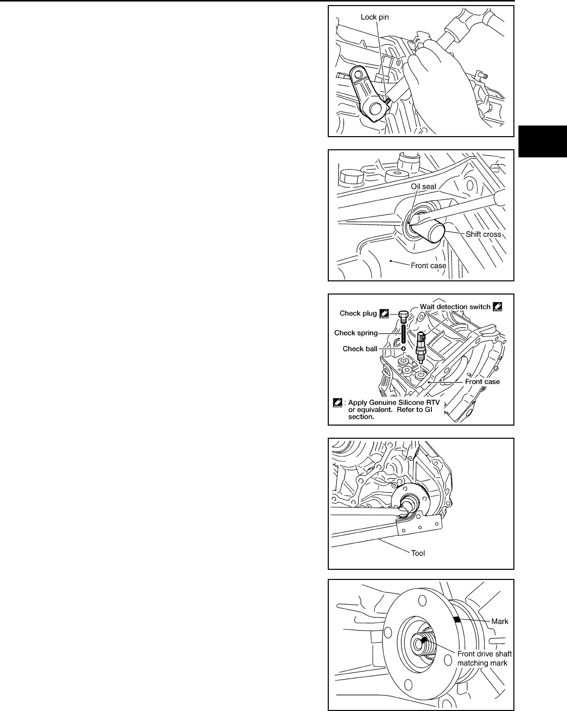
TRANSFER ASSEMBLY
DLN-153
< DISASSEMBLY AND ASSEMBLY > [TRANSFER: ATX14B]
C
E
F
G
H
I
J
K
L
M
A
B
DLN
N
O
P
3. Remove the lock pin using suitable tool.
4. Remove the shift lever.
5. Remove the side oil seal from the front case using suitable tool.
CAUTION:
Do not damage front case or shift cross.
6. Remove the check plug, check spring and check ball.
7. Remove the wait detection switch.
8. Remove the self-lock nut from the companion flange using Tool.
9. Put a matching mark on top of the front drive shaft thread in line
with the mark on the companion flange.
CAUTION:
Use paint to make the matching mark on the front drive
shaft thread. Never damage the front drive shaft.
SDIA2150E
SDIA2166E
WDIA0196E
Tool number : KV38108300 (J-44195)
SDIA2841E
SDIA2779E
Revision: October 2008
2009 Pathfinder
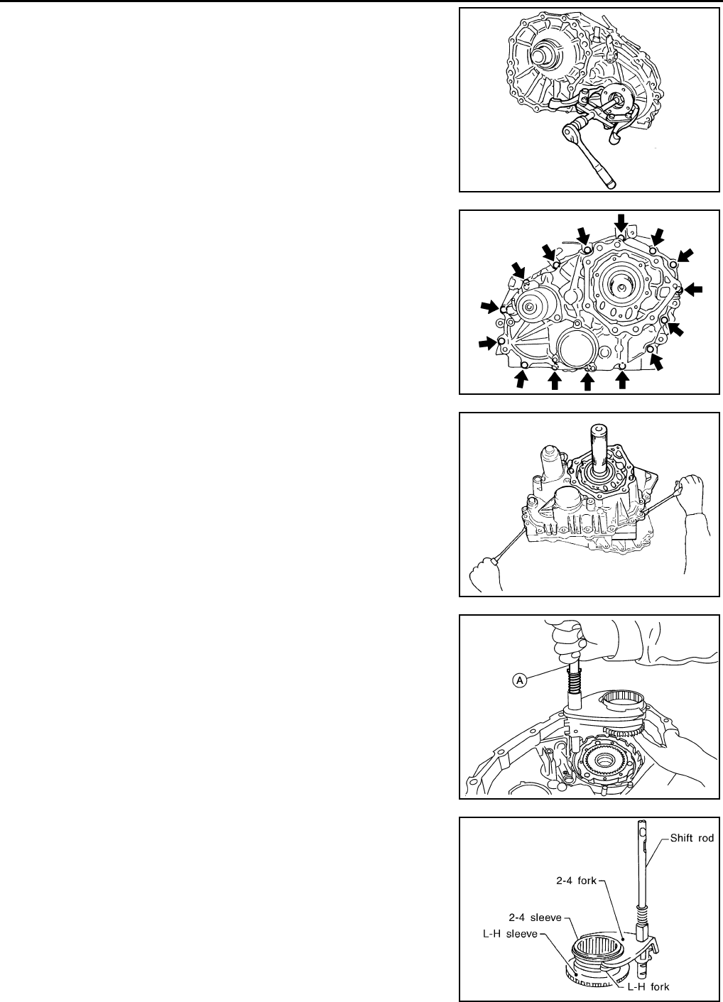
DLN-154
< DISASSEMBLY AND ASSEMBLY > [TRANSFER: ATX14B]
TRANSFER ASSEMBLY
10. Remove the companion flange using suitable tool.
11. Remove the center case bolts, harness bracket and air breather.
12. Remove the filler plug and gasket.
13. Separate the center case from the front case. Then remove the
center case from the front case by prying it up using suitable
tool.
CAUTION:
Do not damage the mating surfaces.
14. Remove the shift rod components together with the 2-4 sleeve
and L-H sleeve.
15. Remove the shift cross from the front case, using shift rod (A).
16. Remove the 2-4 sleeve and L-H sleeve from the 2-4 fork and L-
H fork respectively.
WDIA0133E
SDIA2100E
SDIA2101E
AWDIA0015Z
Z
SMT992C
Revision: October 2008
2009 Pathfinder
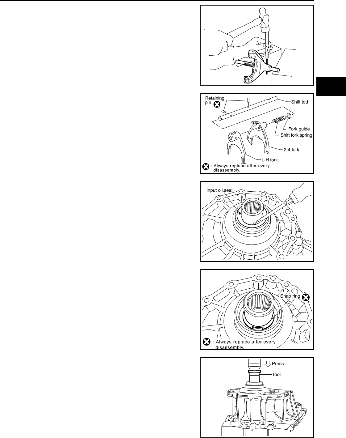
TRANSFER ASSEMBLY
DLN-155
< DISASSEMBLY AND ASSEMBLY > [TRANSFER: ATX14B]
C
E
F
G
H
I
J
K
L
M
A
B
DLN
N
O
P
17. Drive out the retaining pin from the shift rod using suitable tool.
18. Remove the L-H fork, 2-4 fork, shift fork spring and fork guide
from the shift rod.
19. Remove the input oil seal from the front case using suitable tool.
CAUTION:
Do not damage front case or sun gear.
20. Remove the snap ring from the sun gear.
CAUTION:
Do not damage front case or sun gear.
21. Remove the sun gear assembly and planetary carrier assembly
from the front case using Tool.
WDIA0134E
SDIA2142E
SDIA3382E
SDIA2144E
Tool munber : ST35300000 ( — )
SDIA2145E
Revision: October 2008
2009 Pathfinder
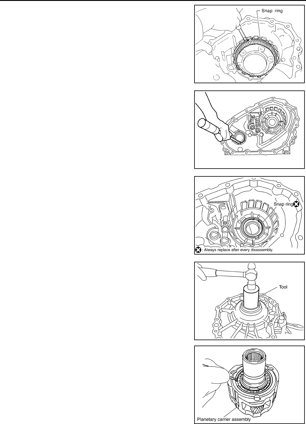
DLN-156
< DISASSEMBLY AND ASSEMBLY > [TRANSFER: ATX14B]
TRANSFER ASSEMBLY
22. Remove the snap ring and internal gear using suitable tool.
23. Remove the front oil seal using suitable tool.
CAUTION:
Do not damage front case.
24. Remove the snap ring from the front case.
25. Remove the input bearing from the front case using Tool.
26. Remove the snap ring from the planetary carrier assembly using
suitable tool.
SMT004D
SDIA2170E
SDIA2171E
Tool number : ST33200000 (J-26082)
SDIA2178E
SDIA2792E
Revision: October 2008
2009 Pathfinder
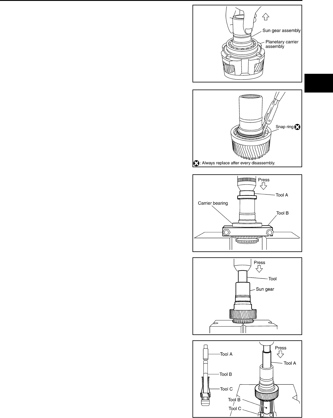
TRANSFER ASSEMBLY
DLN-157
< DISASSEMBLY AND ASSEMBLY > [TRANSFER: ATX14B]
C
E
F
G
H
I
J
K
L
M
A
B
DLN
N
O
P
27. Remove the sun gear assembly from the planetary carrier
assembly.
28. Remove the snap ring from the sun gear assembly using suit-
able tool.
29. Remove the carrier bearing from the sun gear using Tools.
30. Remove the needle bearing from the sun gear using Tool.
31. Remove the metal bushing from the sun gear using Tools.
SDIA2147E
SDIA2148E
Tool number A: ST35300000 ( — )
B: ST30031000 ( — )
SDIA2149E
Tool number : ST33710000 ( — )
SDIA2354E
Tool number A: ST33710000 ( — )
B: ST35325000 ( — )
C: ST3329000 (J-34286)
SDIA2168E
Revision: October 2008
2009 Pathfinder
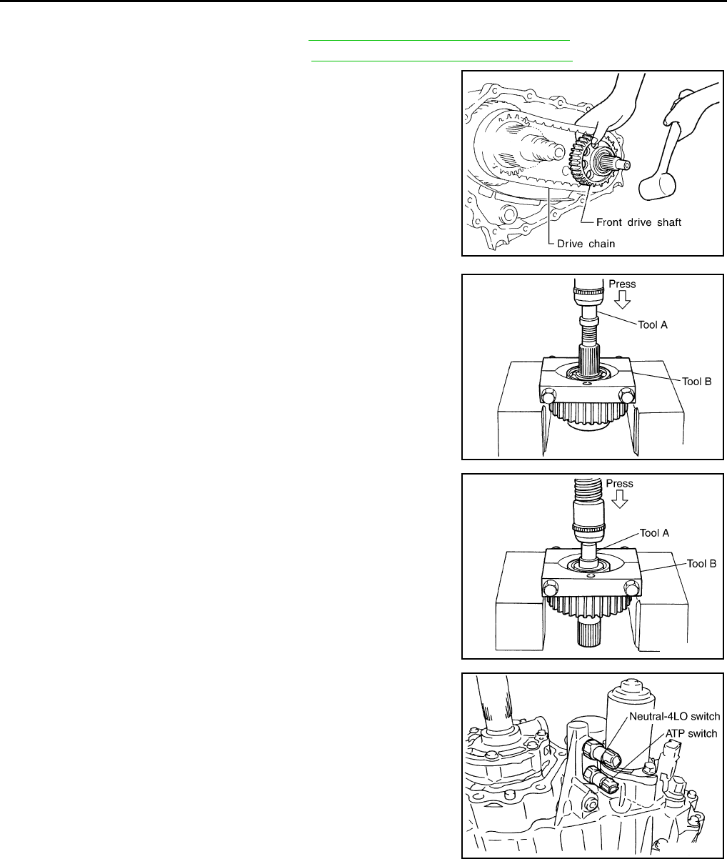
DLN-158
< DISASSEMBLY AND ASSEMBLY > [TRANSFER: ATX14B]
TRANSFER ASSEMBLY
Center Case
1. Remove the rear case assembly. Refer to DLN-150, "Disassembly and Assembly".
2. Remove the front case assembly. Refer to DLN-150, "Disassembly and Assembly".
3. Hold the front drive shaft with one hand and tap to remove the
front drive shaft with the drive chain.
CAUTION:
Do not tap drive chain.
4. Remove the front drive shaft front bearing using Tools.
5. Remove the front drive shaft rear bearing using suitable tools.
6. Remove the neutral-4LO and ATP switches.
SMT900C
Tool number A: ST33052000 ( — )
B: ST30031000 ( — )
SDIA2106E
Tool number A: ST33052000 ( — )
B: ST30031000 ( — )
SDIA2107E
SDIA2096E
Revision: October 2008
2009 Pathfinder
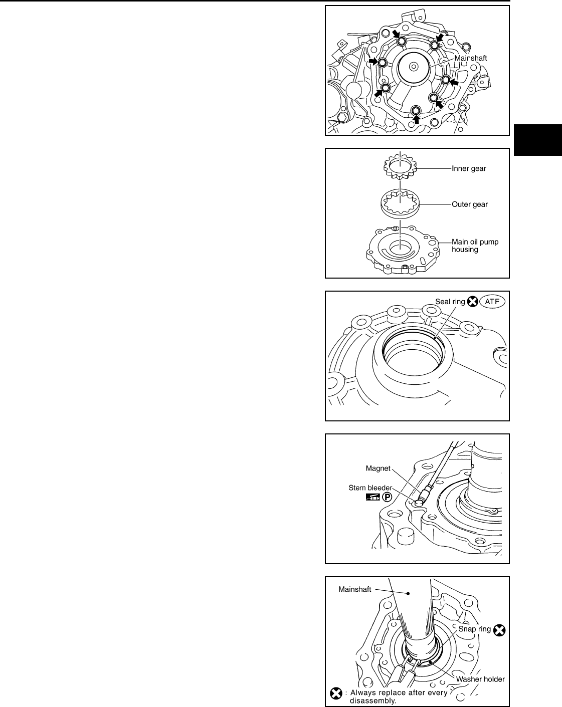
TRANSFER ASSEMBLY
DLN-159
< DISASSEMBLY AND ASSEMBLY > [TRANSFER: ATX14B]
C
E
F
G
H
I
J
K
L
M
A
B
DLN
N
O
P
7. Remove the bolts and main oil pump cover.
8. Remove the outer gear, inner gear and main oil pump housing
from the center case.
9. Remove the seal ring from the main oil pump cover.
10. Remove the stem bleeder from the bleed hole.
11. Remove the snap ring and washer holder from the mainshaft.
SDIA2130E
SDIA2131E
SDIA2783E
SDIA2780E
SDIA2104E
Revision: October 2008
2009 Pathfinder
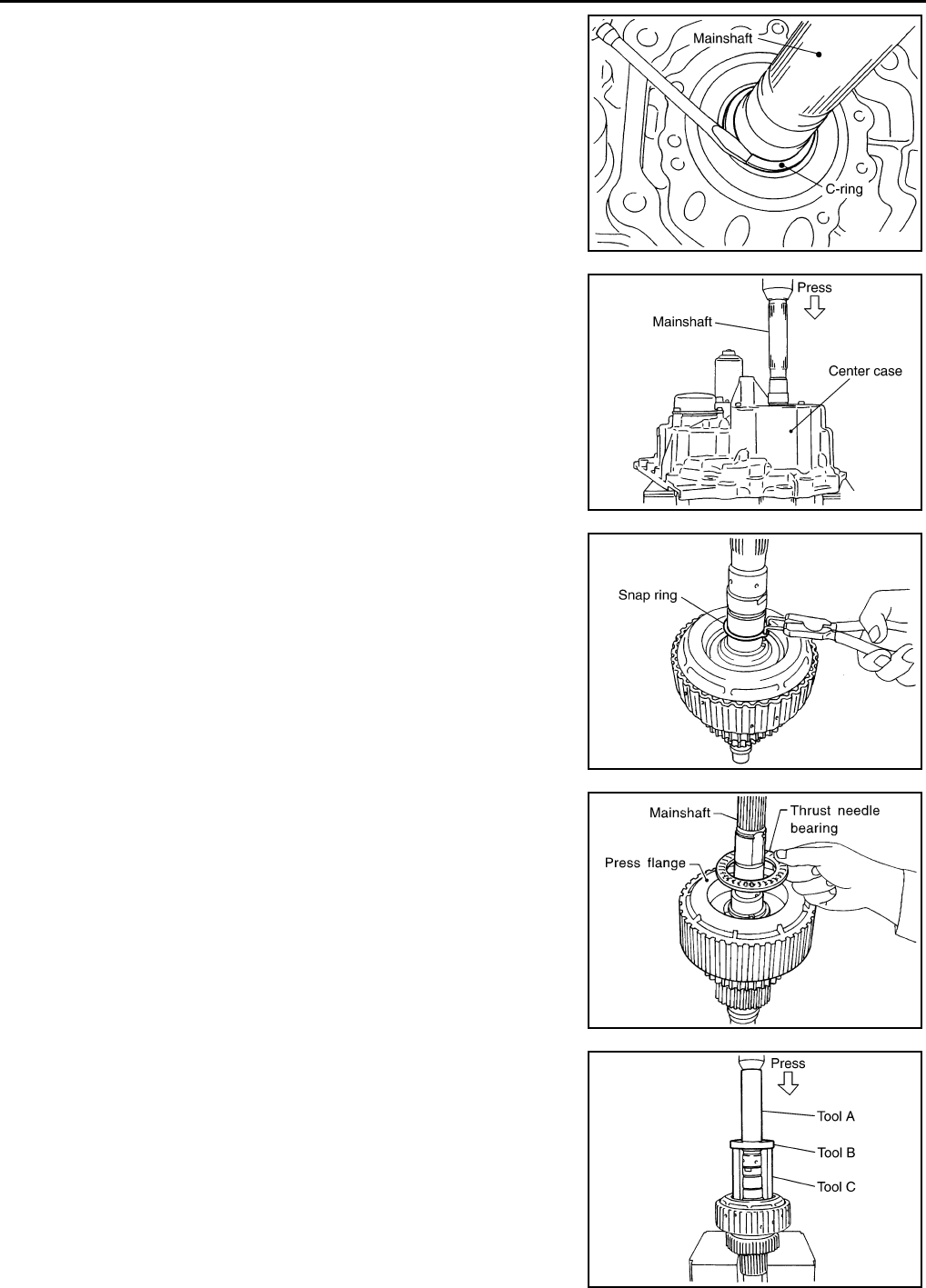
DLN-160
< DISASSEMBLY AND ASSEMBLY > [TRANSFER: ATX14B]
TRANSFER ASSEMBLY
12. Remove the C-rings from the mainshaft using suitable tool.
13. Set the center case on the press stand. Remove the mainshaft
from the center case.
14. Remove the snap ring from the mainshaft using suitable tool.
15. Remove the thrust needle bearing from the press flange.
16. Press the press flange until the snap ring is out of place using
Tools.
SDIA2105E
SDIA2108E
SDIA2110E
SDIA2109E
Tool number A: ST22452000 (J-34335)
B: ST30911000 ( — )
C: KV31103300 ( — )
SDIA2111E
Revision: October 2008
2009 Pathfinder
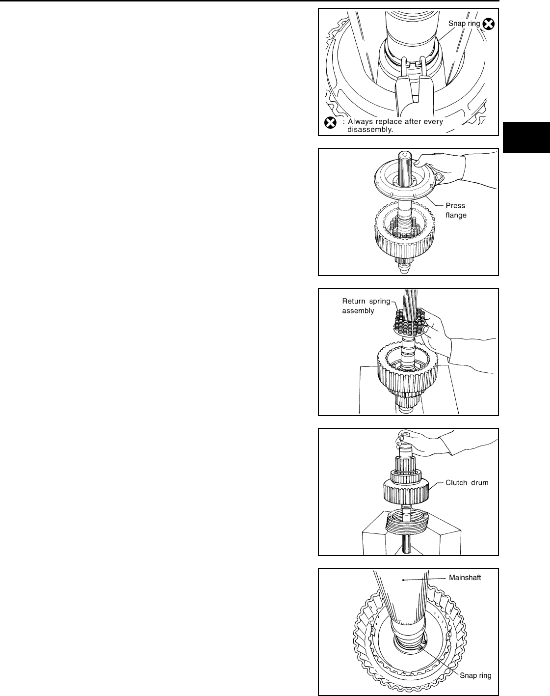
TRANSFER ASSEMBLY
DLN-161
< DISASSEMBLY AND ASSEMBLY > [TRANSFER: ATX14B]
C
E
F
G
H
I
J
K
L
M
A
B
DLN
N
O
P
17. Remove the snap ring from the mainshaft using suitable tool.
18. Remove the press flange from the mainshaft.
19. Remove the return spring assembly from the clutch hub.
20. Remove each plate from the clutch drum.
21. Remove the snap ring from the mainshaft.
SDIA2112E
SMT910C
SMT911C
SMT912C
SDIA2113E
Revision: October 2008
2009 Pathfinder
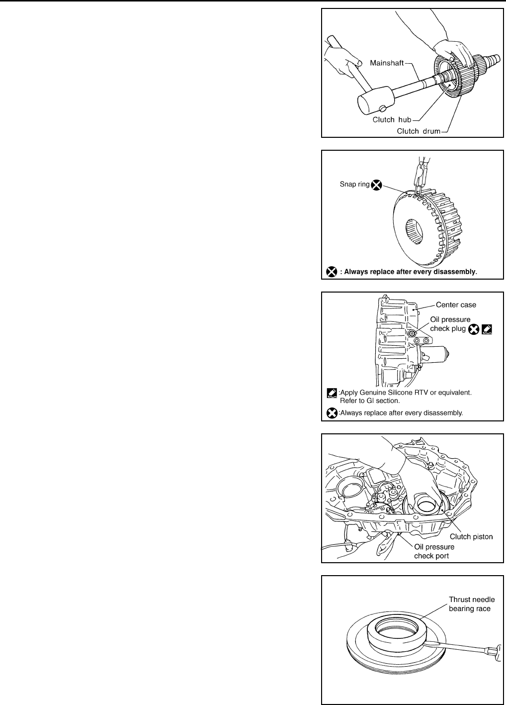
DLN-162
< DISASSEMBLY AND ASSEMBLY > [TRANSFER: ATX14B]
TRANSFER ASSEMBLY
22. Remove the mainshaft from the clutch drum and clutch hub
using suitable tool.
23. Remove the needle bearing and spacer from the mainshaft.
24. Remove the snap ring from the clutch hub using suitable tool.
25. Remove the oil pressure check plug from the oil pressure check
port.
26. Apply air gradually from the oil pressure check port, and remove
the clutch piston assembly from the center case.
27. Remove the thrust needle bearing race from the clutch piston by
hooking a edge into 3 notches of the thrust needle bearing race
using suitable tool.
CAUTION:
Do not damage clutch piston or thrust needle bearing race.
SMT914C
WDIA0101E
WDIA0227E
SDIA2116E
SDIA2118E
Revision: October 2008
2009 Pathfinder
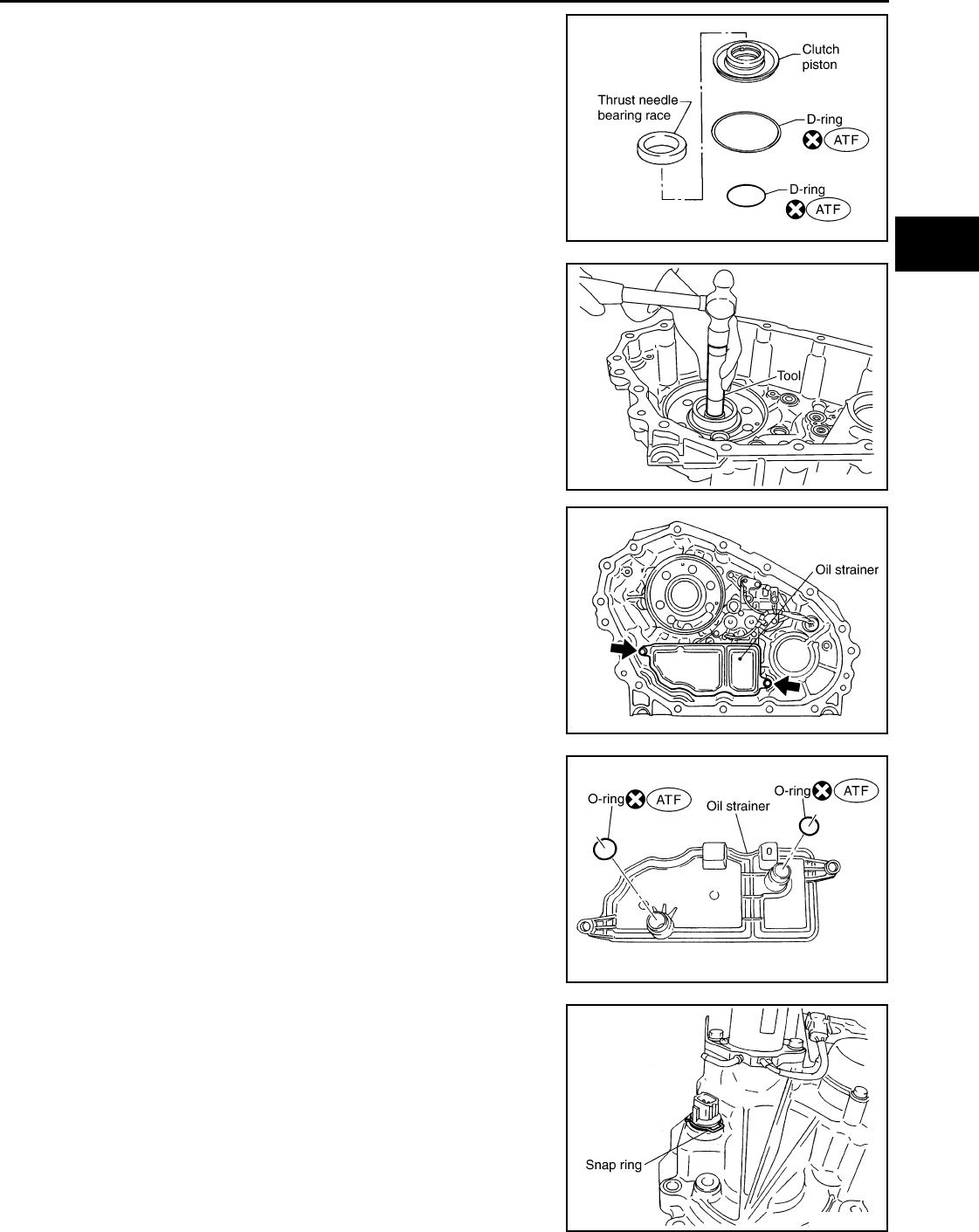
TRANSFER ASSEMBLY
DLN-163
< DISASSEMBLY AND ASSEMBLY > [TRANSFER: ATX14B]
C
E
F
G
H
I
J
K
L
M
A
B
DLN
N
O
P
28. Remove the two D-rings from the clutch piston.
29. Remove the mainshaft rear bearing from the center case using
Tool.
30. Remove the two bolts and oil strainer.
31. Remove the two O-rings from the oil strainer.
32. Remove the snap ring. Then push the connector assembly into
the center case to remove the control valve assembly.
SDIA2781E
Tool number : KV38100300 (J-25523)
SDIA2129E
SDIA2119E
SDIA2782E
SDIA2122E
Revision: October 2008
2009 Pathfinder
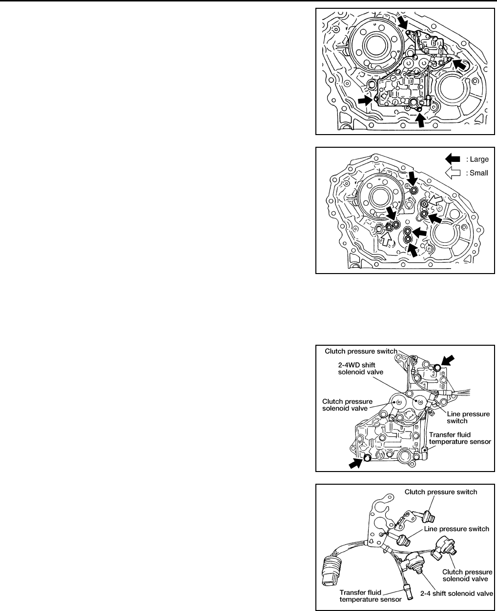
DLN-164
< DISASSEMBLY AND ASSEMBLY > [TRANSFER: ATX14B]
TRANSFER ASSEMBLY
33. Remove the control valve assembly bolts.
34. Remove the control valve assembly.
CAUTION:
• Do not reuse any part that has been dropped or damaged.
• Make sure valve is assembled in the proper direction.
• Do not use a magnet because residual magnetism stays
during disassembly.
35. Remove the lip seals from the center case.
CAUTION:
There are two kinds of lip seals (lip seal of large inner diam-
eter: 5 pieces, lip seal of small inner diameter: 2 pieces).
Confirm the position before disassembly.
36. Disassemble the control valve assembly with the following procedure.
CAUTION:
• Do not reuse any part that has been dropped or damaged.
• Make sure valve is assembled in the proper direction.
• Do not use a magnet because residual magnetism stays during disassembly.
a. Remove all the bolts except for the two shown.
b. Remove the following from the control valve assembly:
• Clutch pressure solenoid valve
• Clutch pressure switch
• 2-4WD shift solenoid valve
• Line pressure switch
• Transfer fluid temperature sensor
c. Remove the O-rings from each solenoid valve, switch and termi-
nal body.
SDIA2121E
SDIA2123E
WDIA0198E
WDIA0199E
Revision: October 2008
2009 Pathfinder
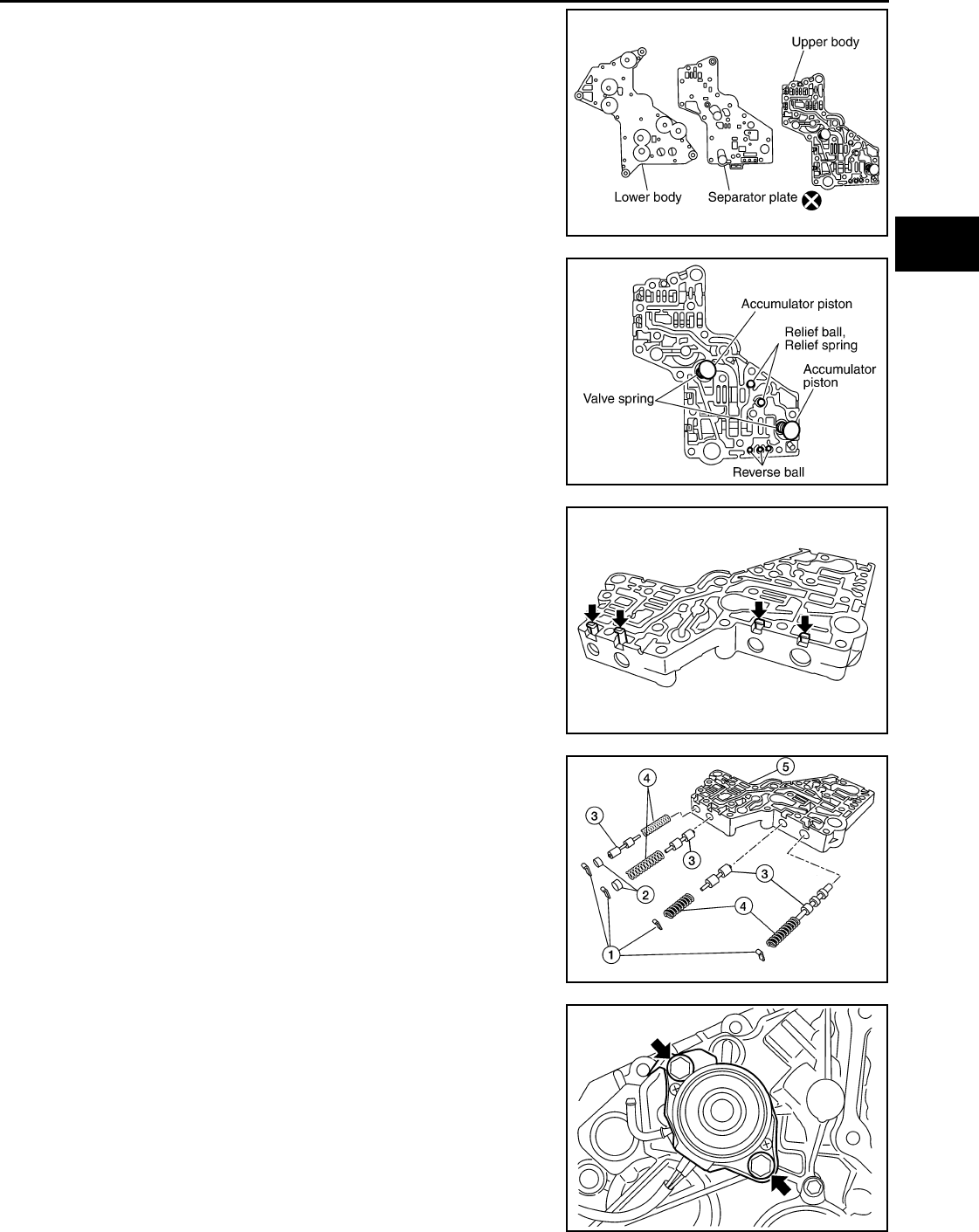
TRANSFER ASSEMBLY
DLN-165
< DISASSEMBLY AND ASSEMBLY > [TRANSFER: ATX14B]
C
E
F
G
H
I
J
K
L
M
A
B
DLN
N
O
P
d. Place the control valve with the lower body facing up. Remove
the two bolts, and then remove the lower body and separator
plate from the upper body.
CAUTION:
Do not drop relief balls. Detach lower body carefully.
e. Make sure the reverse balls, relief balls, relief springs, accumu-
lator pistons and valve springs are securely installed as shown,
and remove them.
f. Remove the retainer plates.
g. Remove each retainer plate (1), plug (2), control valve (3) and
spring (4) from the upper body (5).
37. Remove the transfer motor bolts and motor from the center
case. Then remove the O-ring from the transfer motor.
WDIA0200E
SDIA2126E
SDIA2127E
WDIA0284E
SDIA2133E
Revision: October 2008
2009 Pathfinder
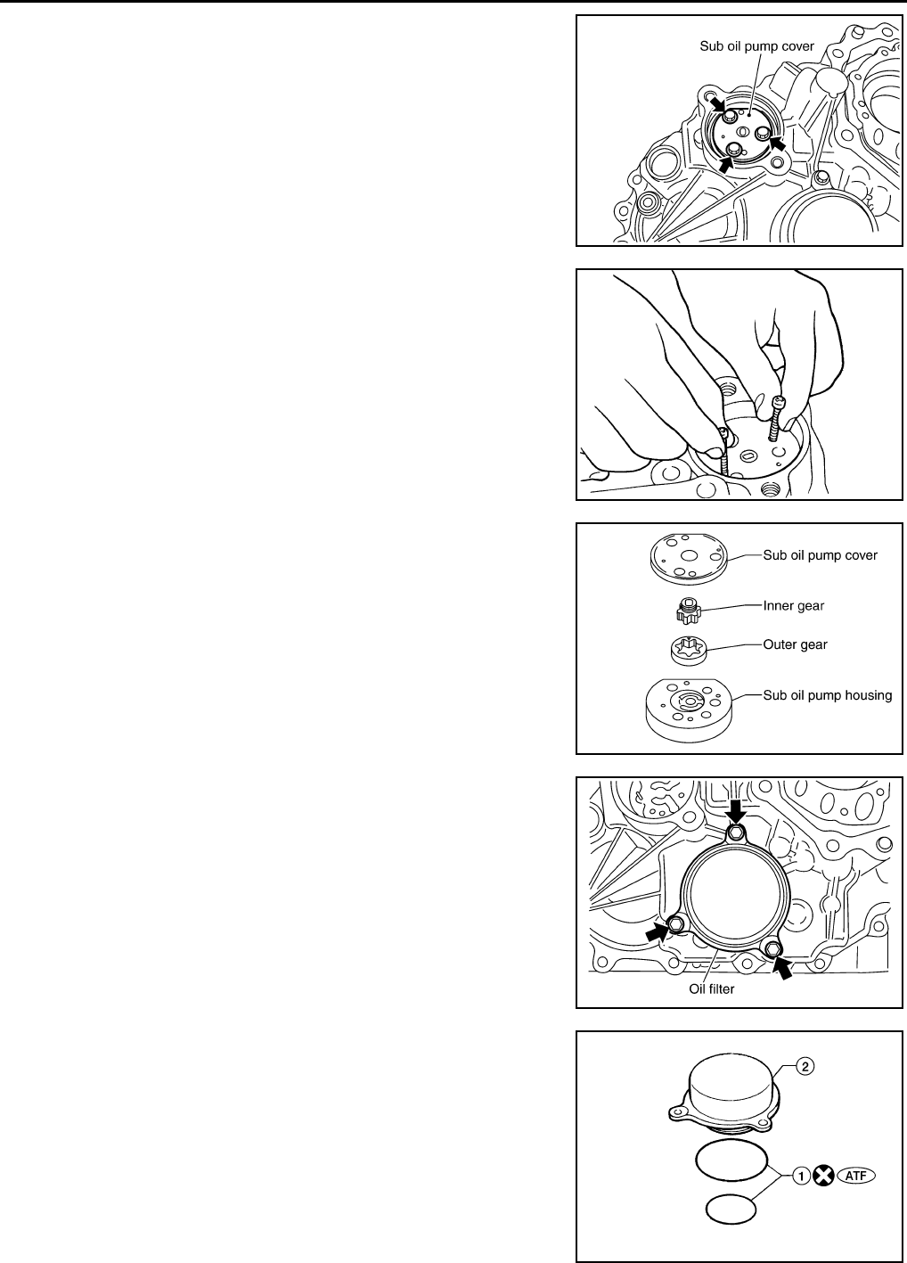
DLN-166
< DISASSEMBLY AND ASSEMBLY > [TRANSFER: ATX14B]
TRANSFER ASSEMBLY
38. Remove the sub oil pump cover bolts.
39. Thread two bolts (M4 x 0.8) into the holes of sub oil pump cover
as shown, and pull out to remove the sub oil pump assembly.
40. Remove the outer gear and inner gear from the sub oil pump
housing.
41. Remove the oil filter bolts and oil filter.
CAUTION:
• Do not damage center case and oil filter.
• Loosen bolts and detach oil filter evenly.
42. Remove the O-rings (1) from the oil filter (2).
SDIA2134E
SMT934C
SDIA2135E
SDIA2136E
WDIA0285E
Revision: October 2008
2009 Pathfinder
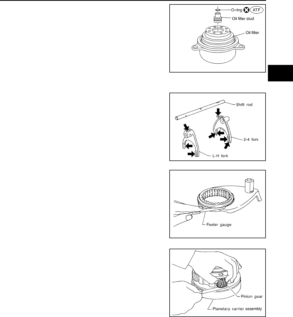
TRANSFER ASSEMBLY
DLN-167
< DISASSEMBLY AND ASSEMBLY > [TRANSFER: ATX14B]
C
E
F
G
H
I
J
K
L
M
A
B
DLN
N
O
P
43. Remove the oil filter stud from the oil filter.
44. Remove the O-ring from the oil filter stud.
INSPECTION AFTER DISASSEMBLY
Shift Rod Components
• Check the working face of the shift rod and fork for wear, partial
wear, bending and other abnormality. If any is found, replace with a
new one.
• Measure the clearance between the shift fork and sleeve. If it is out
of specification, replace it with a new one.
Planetary Carrier
• Measure the end play of each pinion gear. If it is out of specifica-
tion, replace the planetary carrier assembly with a new one.
• Check the working face of each gear and bearing for damage,
burrs, partial wear, dents and other abnormality. If any is found,
replace the planetary carrier assembly with a new one.
Sun Gear
SDIA3180E
SMT009D
Specification : Less than 0.36 mm (0.0142 in)
SMT010D
Pinion gear end play : 0.1 - 0.7 mm (0.004 - 0.028 in)
PDIA0185E
Revision: October 2008
2009 Pathfinder
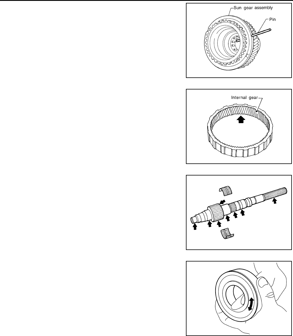
DLN-168
< DISASSEMBLY AND ASSEMBLY > [TRANSFER: ATX14B]
TRANSFER ASSEMBLY
• Check if the oil passage of the sun gear assembly is clogged. For
this, try to pass a 3.6 mm (0.142 in) dia. pin through the oil pas-
sage as shown.
• Check the sliding and contact surface of each gear and bearing for
damage, burrs, partial wear, dents, and other abnormality. If any is
found, replace the sun gear assembly with a new one.
Internal Gear
• Check the internal gear teeth for damage, partial wear, dents and
other abnormality. If any is found, replace the internal gear with a
new one.
Gears and Drive Chain
• Check the gear faces and shaft for wear, cracks, damage, and sei-
zure.
• Check the surfaces which contact the sun gear, clutch drum, clutch
hub, press flange, clutch piston and each bearing for damage,
peel, partial wear, dents, bending, or other abnormal damage. If
any is found, replace with a new one.
Bearing
• Make sure the bearings roll freely and are free from noise, pitting
and cracks.
Main Oil Pump
PDIA0186E
SMT008D
SMT944C
SDIA2175E
Revision: October 2008
2009 Pathfinder
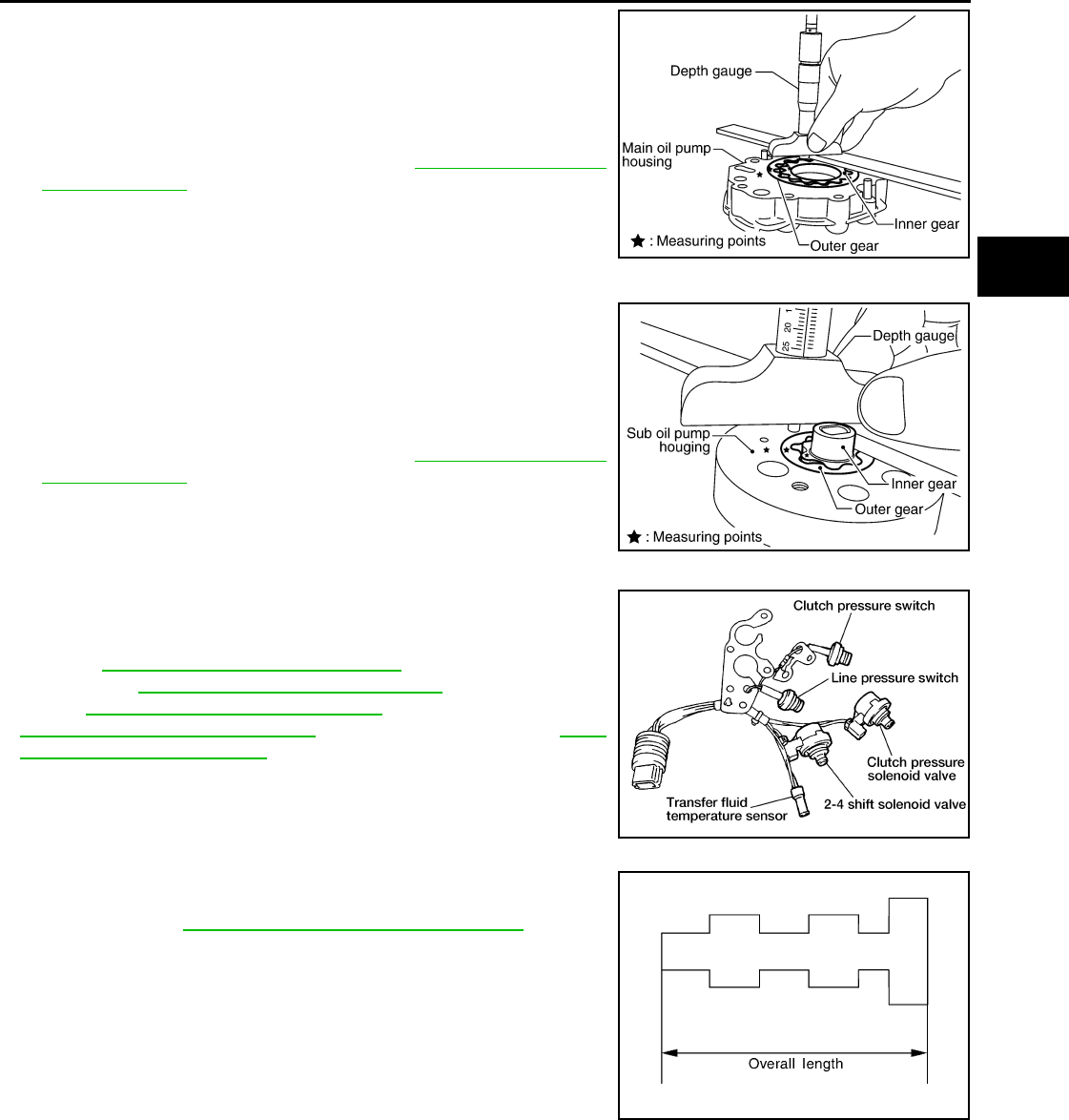
TRANSFER ASSEMBLY
DLN-169
< DISASSEMBLY AND ASSEMBLY > [TRANSFER: ATX14B]
C
E
F
G
H
I
J
K
L
M
A
B
DLN
N
O
P
1. Check the inner and outer circumference, tooth face, and side-
face of the inner and outer gears for damage or abnormal wear.
2. Measure the side clearance between the main oil pump housing
edge and the inner and outer gears.
3. Make sure the side clearance is within specification. If the mea-
surement is out of specification, replace the inner and outer
gears with new ones as a set. Refer to DLN-187, "Inspection
and Adjustment".
Sub-oil Pump
1. Check the inner and outer circumference, tooth face, and side-
face of the inner and outer gears for damage or abnormal wear.
2. Measure the side clearance between the sub oil pump housing
edge and the inner and outer gears.
3. Make sure the side clearance is within specification. If the mea-
surement is out of specification, replace the inner and outer
gears with new ones as a set. Refer to DLN-187, "Inspection
and Adjustment".
Control Valve
• Check resistance between the terminals of the clutch pressure
solenoid valve, 2-4WD shift solenoid valve, clutch pressure switch,
line pressure switch and the transfer fluid temperature sensor.
Refer to DLN-60, "Component Inspection" (clutch pressure sole-
noid valve), DLN-65, "Component Inspection" (2-4WD solenoid
valve), DLN-76, "Component Inspection" (clutch pressure switch),
DLN-80, "Component Inspection" (line pressure switch) and DLN-
73, "Component Inspection" (transfer fluid temperature sensor).
• Check the sliding faces of the control valves and plugs for abnor-
mality. If any is found, replace the control valve assembly with a
new one. Refer to DLN-187, "Inspection and Adjustment".
CAUTION:
Replace control valve body together with clutch return spring
as a set.
Specification : 0.015 - 0.035 mm (0.0006 - 0.0014 in) SDIA2174E
Specification : 0.015 - 0.035 mm (0.0006 - 0.0014 in) SDIA2173E
WDIA0199E
SMT947C
Revision: October 2008
2009 Pathfinder
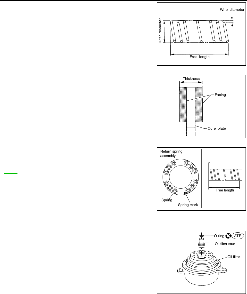
DLN-170
< DISASSEMBLY AND ASSEMBLY > [TRANSFER: ATX14B]
TRANSFER ASSEMBLY
• Check each control valve spring for damage or distortion. Also
check its free length, outer diameter and wire diameter. If any dam-
age or fatigue is found, replace the control valve body with a new
one. Refer to DLN-187, "Inspection and Adjustment".
CAUTION:
Replace control valve body together with clutch return spring
as a set.
Clutch
• Check the drive plate facings and driven plate for damage, cracks
or other abnormality. If any abnormalities are found, replace with a
new one.
• Check the thickness of the drive plate facings and driven plate.
Refer to DLN-187, "Inspection and Adjustment".
CAUTION:
• Measure facing thickness at 3 points to take an average.
• Check all drive and driven plates.
• Check return spring for damage or deformation.
• Do not remove spring from plate.
Return Spring
• Check the stamped mark shown. Then, check that the free lengths,
(include thickness of plate) are within specifications. If any abnor-
mality is found, replace with a new return spring assembly of the
same stamped number. Refer to DLN-187, "Inspection and Adjust-
ment".
ASSEMBLY
Center Case
1. Apply ATF to the new O-ring, and install it on the oil filter stud.
CAUTION:
Do not reuse O-rings.
2. Install the oil filter stud to the oil filter.
SMT948C
SMT949C
SDIA2176E
SDIA3180E
Revision: October 2008
2009 Pathfinder
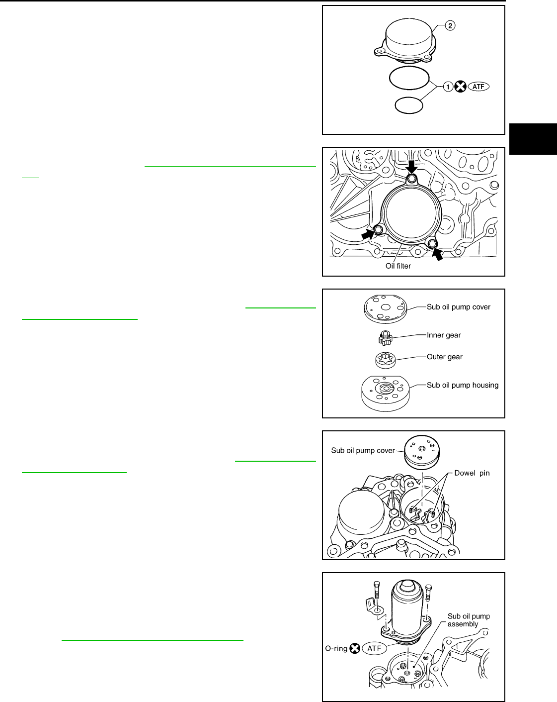
TRANSFER ASSEMBLY
DLN-171
< DISASSEMBLY AND ASSEMBLY > [TRANSFER: ATX14B]
C
E
F
G
H
I
J
K
L
M
A
B
DLN
N
O
P
3. Apply ATF to the two new O-rings (1), and install them on the oil
filter (2).
CAUTION:
Do not reuse O-rings.
4. Install the oil filter to the center case. Tighten the bolts to the
specified torque. Refer to DLN-150, "Disassembly and Assem-
bly".
CAUTION:
• Do not damage oil filter.
• Attach oil filter and tighten bolts evenly.
5. Install the outer gear and inner gear into the sub oil pump hous-
ing, and measure the side clearance. Refer to "DLN-150, "Dis-
assembly and Assembly".
6. Align the dowel pin hole and bolt hole of the sub oil pump
assembly with the center case. Install the sub oil pump cover.
Then tighten to the specified torque. Refer to DLN-150, "Disas-
sembly and Assembly"
7. Apply ATF to the new O-ring and install it to the transfer motor.
CAUTION:
Do not reuse O-rings.
8. Fit the double-flat end of the transfer motor shaft into the slot of
the sub-oil pump assembly. Then tighten to the specified torque.
Refer to DLN-150, "Disassembly and Assembly"
CAUTION:
Be sure to install connector bracket.
WDIA0285E
SDIA2136E
SDIA2135E
SDIA2328E
SDIA2787E
Revision: October 2008
2009 Pathfinder
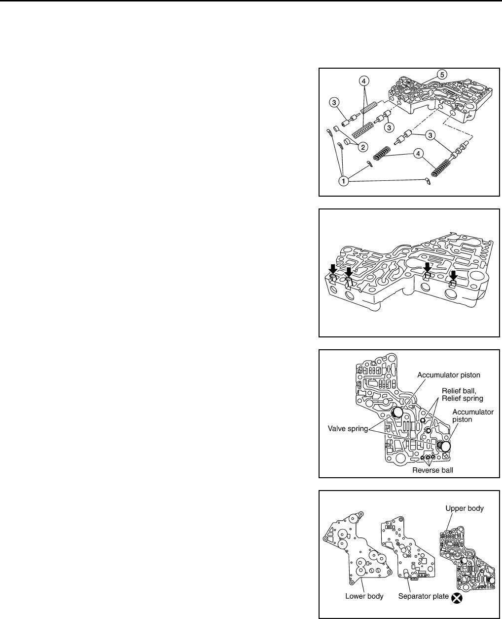
DLN-172
< DISASSEMBLY AND ASSEMBLY > [TRANSFER: ATX14B]
TRANSFER ASSEMBLY
9. Assemble the control valve assembly with the following procedure.
CAUTION:
• Do not reuse any part that has been dropped or damaged.
• Make sure valve is assembled in the proper direction.
• Do not use a magnet because residual magnetism stays during assembly.
a. Clean the upper body (5), control valves (3) and springs (4) with
cleaning agent, and dry with compressed air.
b. Dip the control valves in ATF, and apply ATF to the valve-mount-
ing area of the upper body.
c. Install each control valve (3), springs (4), and plugs (2) to the
upper body (5), and install retainer plates (1) to hold them in
place.
CAUTION:
• To insert control valves into upper body, place upper
body on a level surface in order to prevent flaw or dam-
age.
• Make sure each control valve is smoothly inserted.
d. Install the reverse balls, relief balls and relief springs, accumula-
tor pistons and valve springs to the upper body.
e. Install the lower body and separator plate to the upper body.
CAUTION:
Do not reuse separator plates.
WDIA0284E
SDIA2127E
SDIA2126E
WDIA0200E
Revision: October 2008
2009 Pathfinder
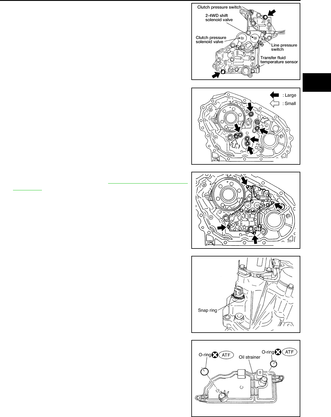
TRANSFER ASSEMBLY
DLN-173
< DISASSEMBLY AND ASSEMBLY > [TRANSFER: ATX14B]
C
E
F
G
H
I
J
K
L
M
A
B
DLN
N
O
P
f. With the lower body down, tighten the two bolts shown.
g. Apply ATF to the new O-rings, and install them to each solenoid
valve, switch and terminal body.
CAUTION:
Do not reuse O-rings.
h. Install the following to the control valve assembly:
• Clutch pressure solenoid valve
• Clutch pressure switch
• 2-4WD shift solenoid valve
• Line pressure switch
• Transfer fluid temperature sensor
10. Apply ATF to the new lip seals, and install them to the center
case.
CAUTION:
• Do not reuse lip seals.
• There are 2 kinds of lip seals (lip seal of large inner diam-
eter: 5 pieces, lip seal of small inner diameter: 2 pieces).
Confirm their position for installation.
11. Install the control valve assembly to the center case, and tighten
to the specified torque. Refer to DLN-150, "Disassembly and
Assembly".
CAUTION:
• Do not reuse any part that has been dropped or damaged.
• Make sure valve is assembled in the proper direction.
• Do not use a magnet because residual magnetism stays
during assembly.
12. Install the connector assembly into the center case, and secure
with a snap ring.
13. Apply ATF to the new O-rings, and install them on the oil
strainer.
CAUTION:
Do not reuse O-rings.
14. Install the oil strainer to the control valve assembly.
WDIA0198E
SDIA2123E
SDIA2121E
SDIA2122E
SDIA2782E
Revision: October 2008
2009 Pathfinder
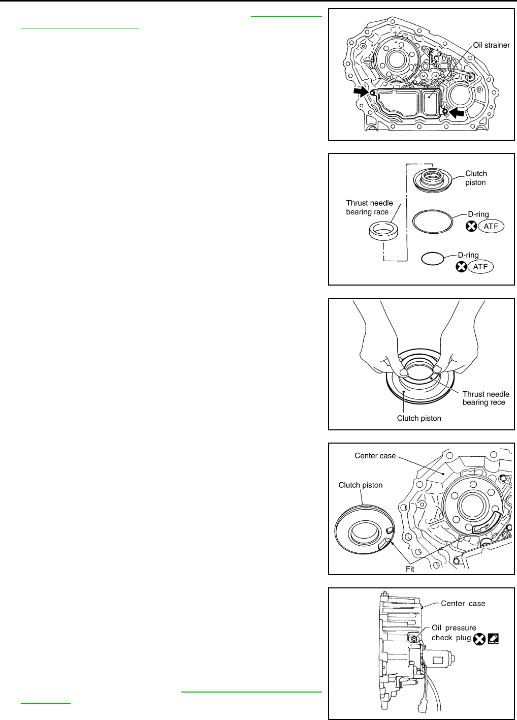
DLN-174
< DISASSEMBLY AND ASSEMBLY > [TRANSFER: ATX14B]
TRANSFER ASSEMBLY
15. Tighten the bolts to the specified torque. Refer to DLN-150, "Dis-
assembly and Assembly".
16. Apply ATF to the new D-rings, and install them to the clutch pis-
ton.
CAUTION:
Do not reuse D-rings.
17. Install the thrust needle bearing race to the clutch piston.
18. Install the clutch piston to the center case as shown.
CAUTION:
Install so the fitting protrusion of clutch piston aligns with
the dent of center case.
19. Remove all the sealant from the oil pressure check port and
inside the center case.
CAUTION:
Remove old sealant adhering to mating surfaces. Also
remove any moisture, oil, or foreign material adhering to
application and mating surfaces.
20. Thread the new oil pressure check plug in 1 or 2 pitches and
apply sealant to the oil pressure check plug threads. Tighten to
the specified torque. Refer to DLN-150, "Disassembly and
Assembly".
SDIA2119E
SDIA2781E
SDIA2189E
SDIA2190E
SDIA3188E
Revision: October 2008
2009 Pathfinder
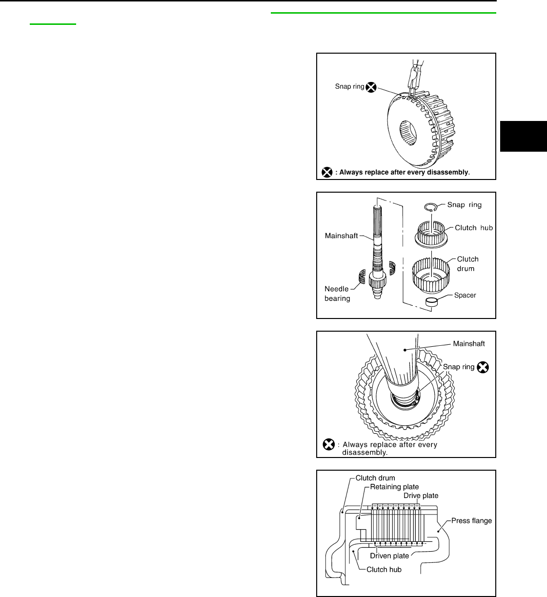
TRANSFER ASSEMBLY
DLN-175
< DISASSEMBLY AND ASSEMBLY > [TRANSFER: ATX14B]
C
E
F
G
H
I
J
K
L
M
A
B
DLN
N
O
P
•Use Genuine Silicone RTV or equivalent. Refer to GI-26, "Recommended Chemical Products and
Sealants".
CAUTION:
Do not reuse oil pressure check plug.
21. Install the new snap ring to the clutch hub using suitable tool.
CAUTION:
Do not reuse snap ring.
22. Apply petroleum jelly to the needle bearing, and install the nee-
dle bearing, spacer, clutch drum and clutch hub to the main-
shaft.
23. Install the new snap ring to the mainshaft.
CAUTION:
Do not reuse snap rings.
24. Apply ATF each plate, then install them into the clutch drum as
shown.
WDIA0101E
WDIA0129E
SDIA2192E
SDIA2193E
Revision: October 2008
2009 Pathfinder
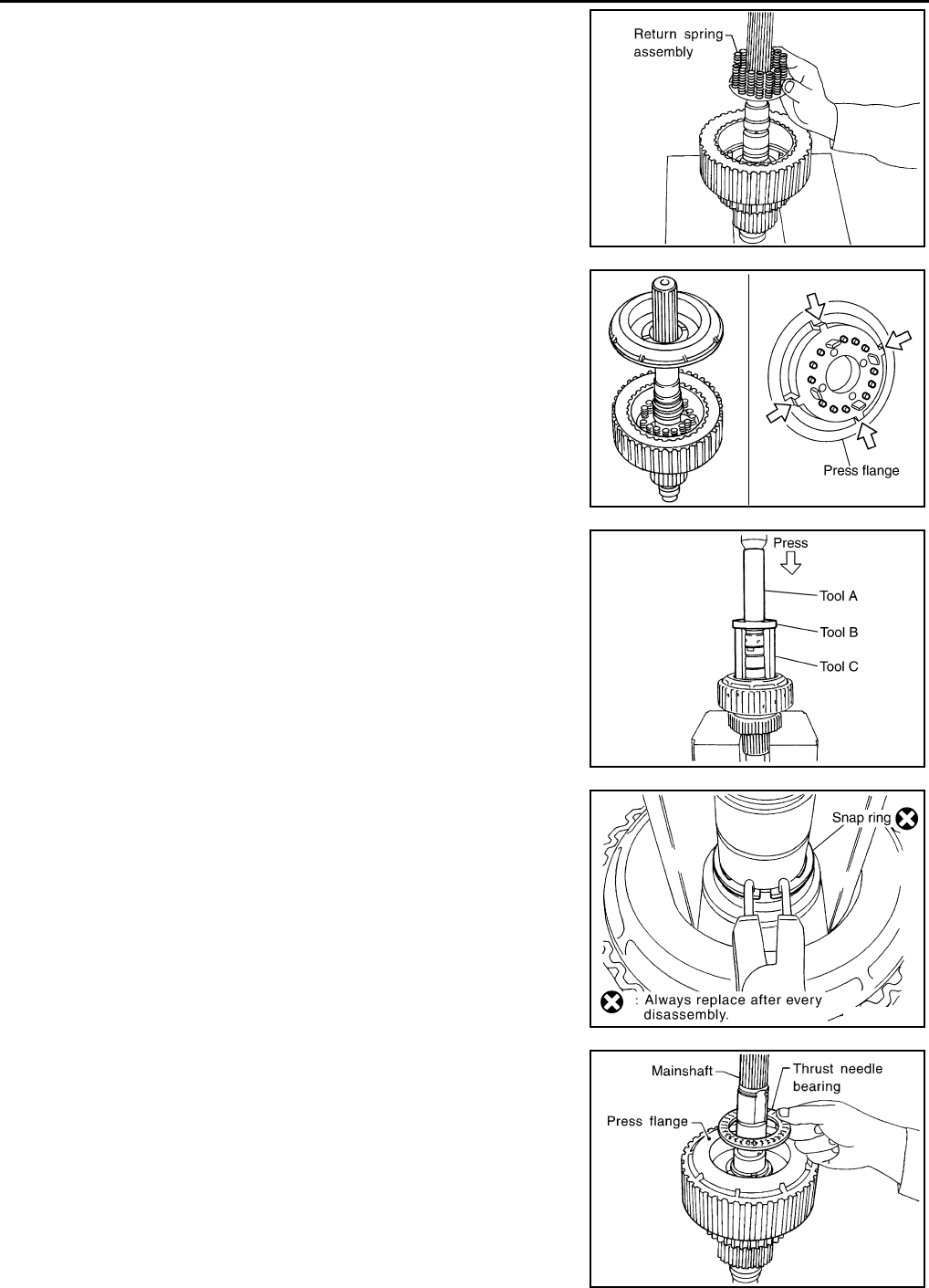
DLN-176
< DISASSEMBLY AND ASSEMBLY > [TRANSFER: ATX14B]
TRANSFER ASSEMBLY
25. Install the return spring assembly into the clutch hub.
26. Install the press flange by aligning the notches to the clutch hub
as shown.
27. Press the press flange to install the new snap ring into snap ring
groove on mainshaft using Tools.
CAUTION:
Do not reuse snap ring.
28. Install the new snap ring to the mainshaft using suitable tool.
CAUTION:
Do not reuse snap ring.
29. Apply ATF to the thrust needle bearing and install it on the press
flange.
SMT911C
SDIA2194E
Tool number A: ST22452000 (J-34335)
B: ST30911000 ( — )
C: KV31103300 ( — )
SDIA2111E
SDIA2112E
SDIA2109E
Revision: October 2008
2009 Pathfinder
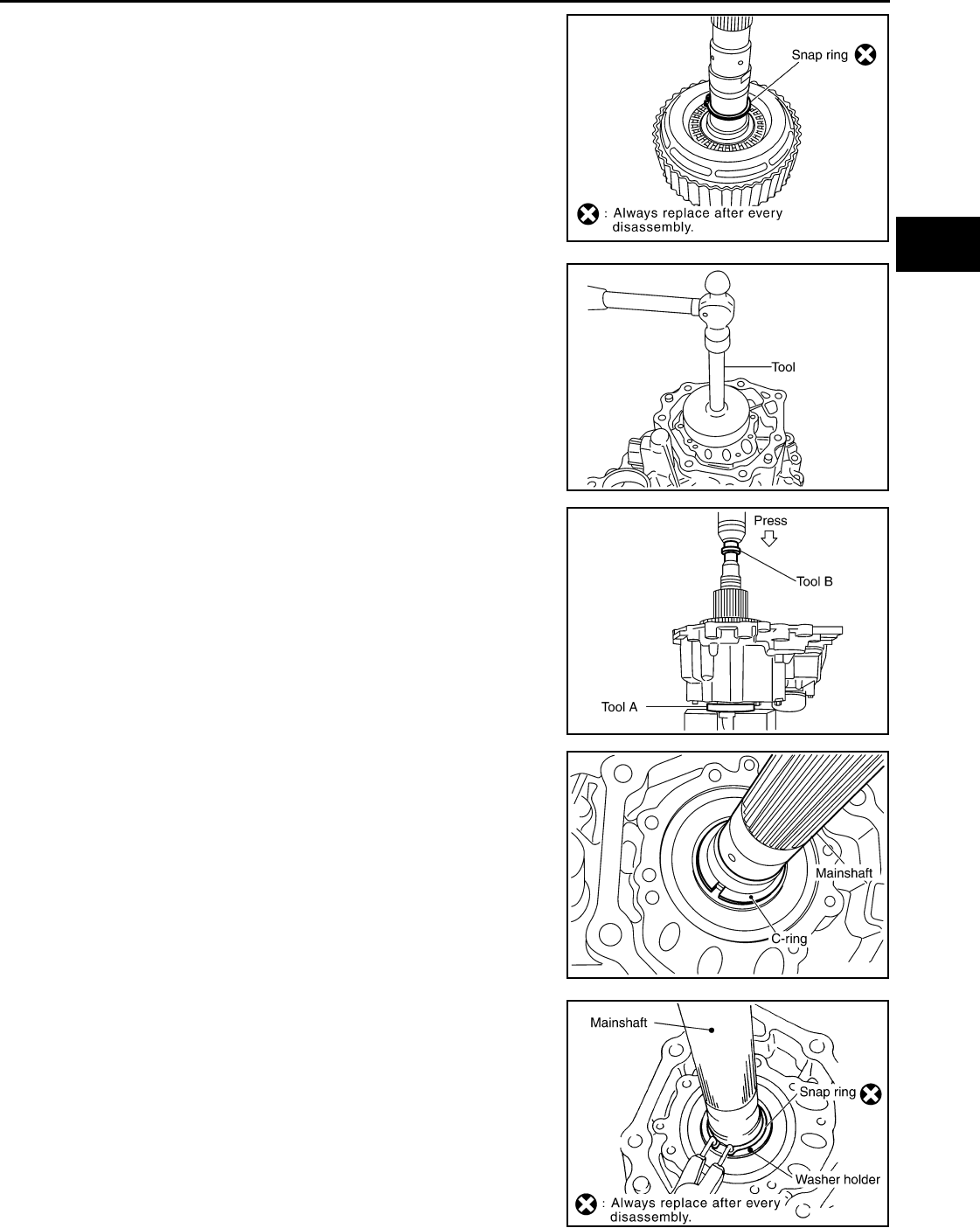
TRANSFER ASSEMBLY
DLN-177
< DISASSEMBLY AND ASSEMBLY > [TRANSFER: ATX14B]
C
E
F
G
H
I
J
K
L
M
A
B
DLN
N
O
P
30. Install the new snap ring to the main shaft.
CAUTION:
Do not reuse snap ring.
31. Install the mainshaft rear bearing to the center case using Tool.
32. Install the mainshaft assembly using a press.
• Press the mainshaft into the center case using Tools.
33. Install the C-rings to the mainshaft.
34. Set the washer holder on the mainshaft, and secure it with a
new snap ring.
CAUTION:
Do not reuse snap ring.
SDIA2195E
Tool number : ST15310000 (J-25640-B)
SDIA2196E
Tool number A: ST30911000 ( — )
B: ST35300000 ( — )
SDIA2197E
SDIA2201E
SDIA2104E
Revision: October 2008
2009 Pathfinder
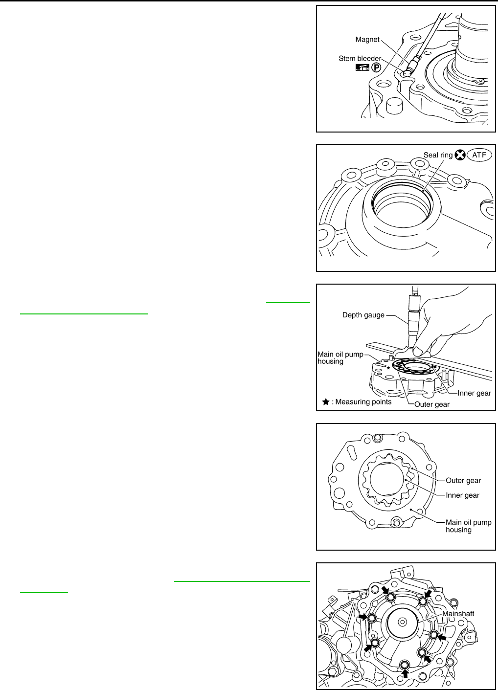
DLN-178
< DISASSEMBLY AND ASSEMBLY > [TRANSFER: ATX14B]
TRANSFER ASSEMBLY
35. Apply petroleum jelly to the stem bleeder and install it to the cen-
ter case.
36. Apply ATF to the new seal ring and install it to the main oil pump
cover.
CAUTION:
Do not reuse seal ring.
37. Install the inner gear and outer gear in the main oil pump hous-
ing. Then, measure the side clearance. Refer to DLN-187,
"Inspection and Adjustment".
38. Install the main oil pump housing, outer gear and inner gear to
the center case.
39. Install the main oil pump cover to the center case, and tighten to
the specified torque. Refer to DLN-150, "Disassembly and
Assembly".
SDIA2780E
SDIA2783E
SDIA2174E
SDIA2188E
SDIA2130E
Revision: October 2008
2009 Pathfinder
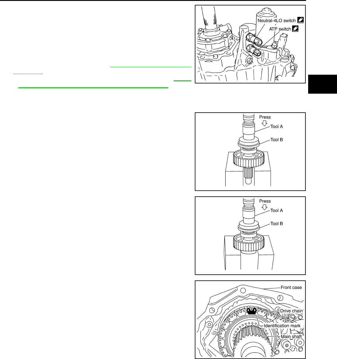
TRANSFER ASSEMBLY
DLN-179
< DISASSEMBLY AND ASSEMBLY > [TRANSFER: ATX14B]
C
E
F
G
H
I
J
K
L
M
A
B
DLN
N
O
P
40. Remove all the sealant from the switch location area and inside
the center case.
CAUTION:
Remove old sealant adhering to mounting surfaces. Also
remove any moisture, oil, or foreign material adhering to
application and mounting surfaces.
41. Thread the ATP switch and neutral-4LO switch in one to two
pitches and apply sealant to the threads of the switches. Tighten
to the specified torque. Refer to DLN-150, "Disassembly and
Assembly".
•Use Genuine Silicone RTV or equivalent. Refer to GI-26,
"Recommended Chemical Products and Sealants".
NOTE:
• Neutral-4LO switch harness connector is gray.
• ATP switch harness connector is black.
42. Install the front drive shaft rear bearing using Tools.
43. Install the front drive shaft to the front bearing using Tools.
44. Install the drive chain to the front drive shaft and clutch drum.
CAUTION:
Install drive chain by aligning identification marks to the
rear as shown.
Tool number A: KV40100621 (J-25273)
B: ST30032000 (J-26010-01)
SDIA3435E
SDIA2198E
Tool number A: KV40100621 (J-25273)
B: ST30032000 (J-26010-01)
SDIA2199E
SDIA2200E
Revision: October 2008
2009 Pathfinder
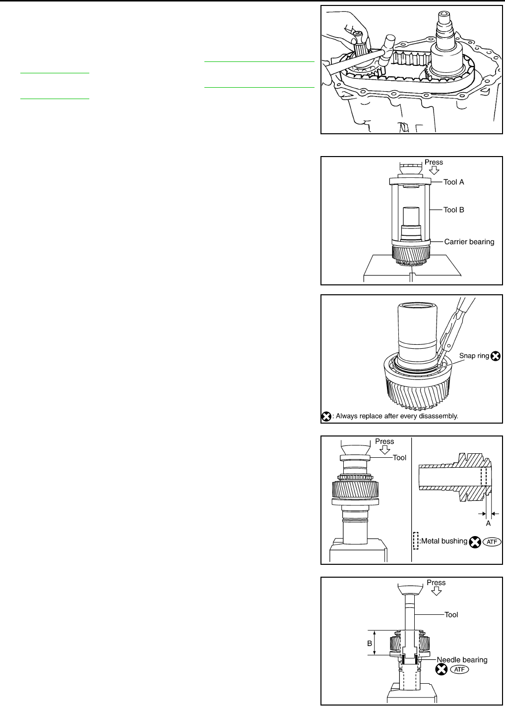
DLN-180
< DISASSEMBLY AND ASSEMBLY > [TRANSFER: ATX14B]
TRANSFER ASSEMBLY
45. Tap the front drive shaft while keeping it upright and press-fit the
front drive shaft rear bearing.
CAUTION:
Do not tap drive chain.
46. Install the front case assembly. Refer to DLN-150, "Disassembly
and Assembly".
47. Install the rear case assembly. Refer to DLN-150, "Disassembly
and Assembly".
Front Case
1. Install the carrier bearing to the sun gear using Tools.
2. Install the new snap ring to the sun gear assembly using suitable
tool.
CAUTION:
Do not reuse snap ring.
3. Apply ATF to the circumference of the new metal bushing and
install it to the sun gear assembly using suitable tool.
CAUTION:
• Do not reuse metal bushing.
• Apply ATF to metal bushing before installing.
4. Apply ATF to the new needle bearing and install it to the sun
gear assembly using Tool.
CAUTION:
• Do not reuse needle bearing.
• Apply ATF to needle bearing before installing.
SMT988C
Tool number A: ST30911000 ( — )
B: KV31103300 ( — )
SDIA2179E
SDIA2148E
Dimension A : 7.7 - 8.3 mm (0.303 - 0.327 in)
SDIA3189E
Tool number : ST33220000 ( — )
Dimension B : 62.5 - 63.1 mm (2.461 - 2.484 in)
SDIA3190E
Revision: October 2008
2009 Pathfinder
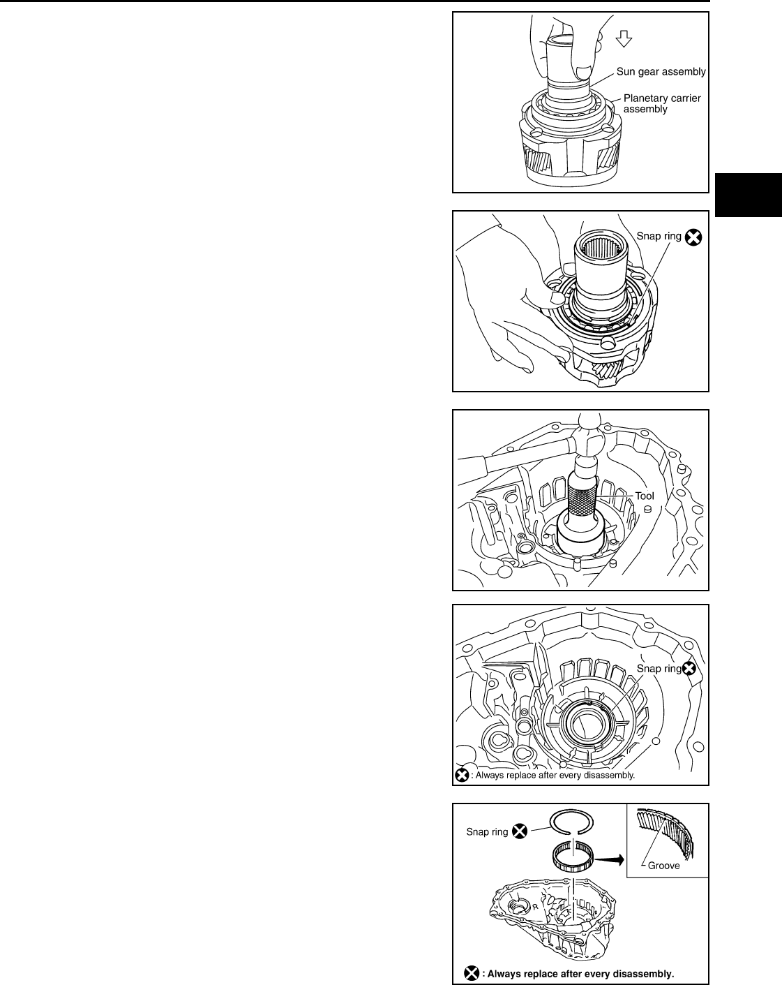
TRANSFER ASSEMBLY
DLN-181
< DISASSEMBLY AND ASSEMBLY > [TRANSFER: ATX14B]
C
E
F
G
H
I
J
K
L
M
A
B
DLN
N
O
P
5. Install the sun gear assembly to the planetary carrier assembly.
6. Install the new snap ring to the planetary carrier assembly.
CAUTION:
Do not reuse snap ring.
7. Set the input bearing into the front case and install using Tool.
8. Install the new snap ring into the front case.
CAUTION:
Do not reuse snap ring.
9. Install the internal gear with its groove facing the snap ring into
the front case. Then secure it with the new snap ring.
CAUTION:
Do not reuse snap ring.
SDIA2180E
SDIA2794E
Tool number : ST30720000 (J-25405)
SDIA2172E
SDIA2171E
WDIA0100E
Revision: October 2008
2009 Pathfinder
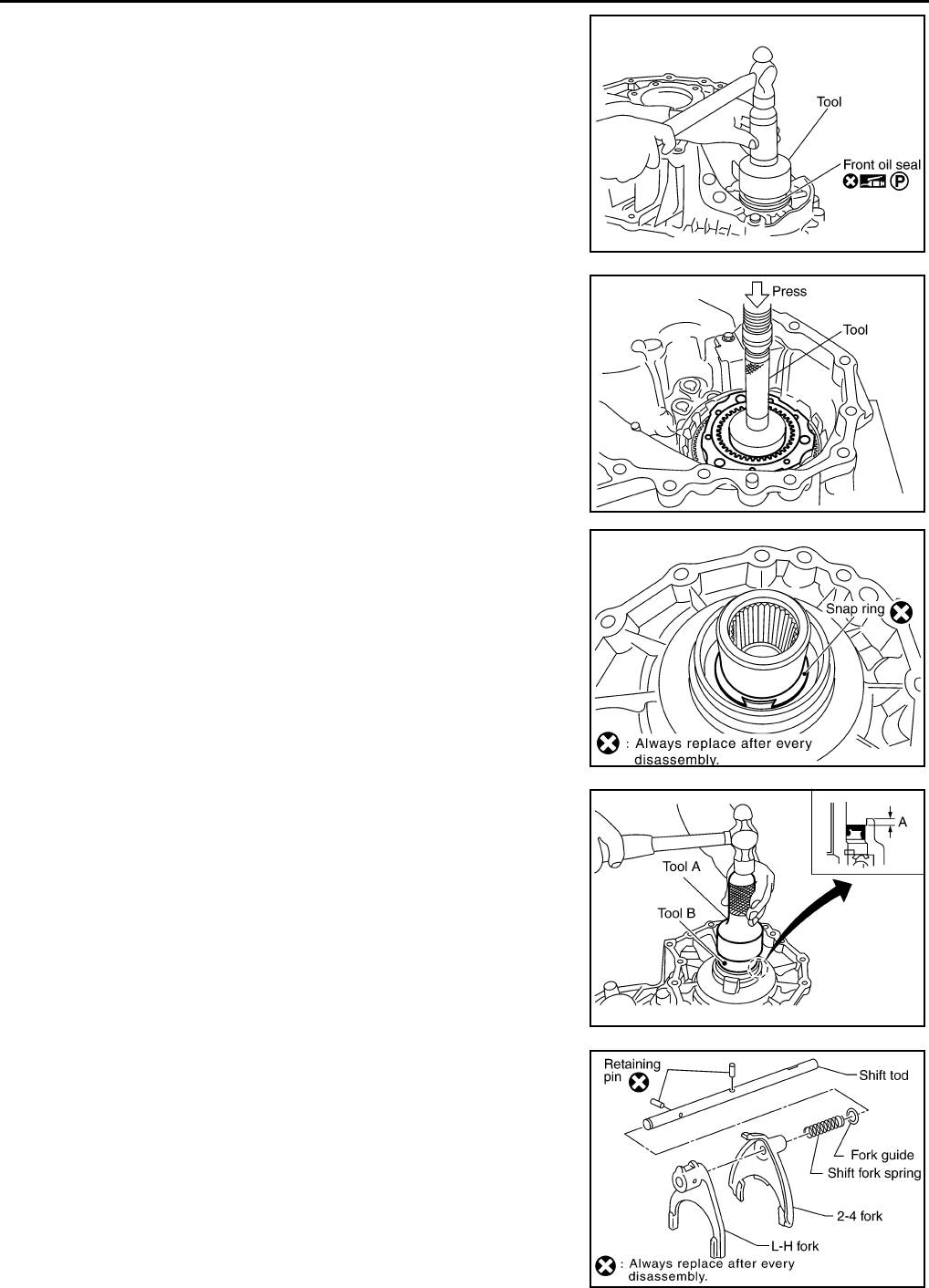
DLN-182
< DISASSEMBLY AND ASSEMBLY > [TRANSFER: ATX14B]
TRANSFER ASSEMBLY
10. Install the new front oil seal until it is seated flush with the end
face of the front case using Tool.
CAUTION:
• Do not reuse oil seal.
• Apply petroleum jelly to oil seal lip before installing.
11. Install the planetary carrier assembly and sun gear assembly to
the front case using Tool.
12. Install the new snap ring to the sun gear.
CAUTION:
Do not reuse snap ring.
13. Apply petroleum jelly to the circumference of the new oil seal,
and install it to the front case using Tools.
CAUTION:
• Do not reuse oil seal.
• Apply petroleum jelly to oil seal.
14. Install the fork guide, shift fork spring, 2-4 fork, and L-H fork to
the shift rod, and secure them with new retaining pins.
CAUTION:
Do not reuse retaining pins.
Tool number : KV38100500 ( — )
SDIA3383E
Tool number : ST33200000 (J-26082)
SDIA2791E
SDIA2144E
Tool numbers A: ST30720000 (J-25405)
B: ST33200000 (J-26802)
Dimension (A) : 4.0 - 4.6 mm (0.157 - 0.181 in)
SDIA3191E
SDIA2142E
Revision: October 2008
2009 Pathfinder
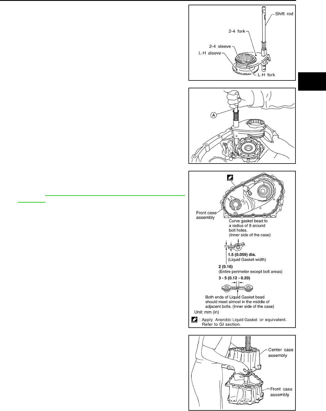
TRANSFER ASSEMBLY
DLN-183
< DISASSEMBLY AND ASSEMBLY > [TRANSFER: ATX14B]
C
E
F
G
H
I
J
K
L
M
A
B
DLN
N
O
P
15. Install the 2-4 sleeve and L-H sleeve to each fork.
16. Install the shift cross to the front case.
17. While aligning the L-H sleeve with the planetary carrier, install
the shift rod assembly (A) to the front case.
18. Apply liquid gasket to the entire center case mating surface of
the front case assembly as shown.
•Use Genuine Anaerobic Liquid Gasket or equivalent.
Refer to GI-26, "Recommended Chemical Products and
Sealants".
CAUTION:
Remove all foreign materials such as water, oil and grease
from center case and front case mating surfaces.
19. Install the center case assembly to the front case assembly.
CAUTION:
Do not damage mainshaft end.
20. Tap the center case lightly and press-fit the front drive shaft
bearing into the front case.
SMT992C
AWDIA0015Z
Z
WDIA0157E
SDIA2138E
Revision: October 2008
2009 Pathfinder
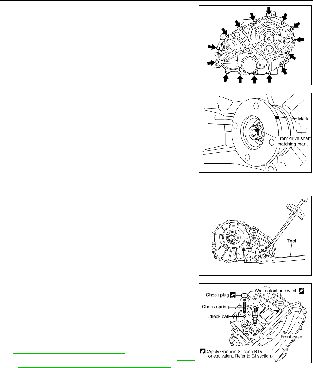
DLN-184
< DISASSEMBLY AND ASSEMBLY > [TRANSFER: ATX14B]
TRANSFER ASSEMBLY
21. Tighten the front case bolts to the specified torque. Refer to
DLN-150, "Disassembly and Assembly".
CAUTION:
Be sure to install air breather hose clamp, connector
bracket and harness clip.
22. Install the drain plug with a new gasket.
CAUTION:
Do not reuse gasket.
23. Align the matching mark on the front drive shaft with the mark on
the companion flange, then install the companion flange.
24. Install a new companion flange self-lock nut. Tighten to the specified torque using Tool. Refer to DLN-150,
"Disassembly and Assembly".
CAUTION:
Do not reuse self-lock nut.
25. Remove all the sealant from the check plug, switch and front
case.
CAUTION:
Remove old sealant adhering to mating surfaces. Also
remove any moisture, oil, or foreign material adhering to
application and mounting surfaces.
26. Install the check ball and check spring to the front case. Apply
sealant to the check plug and wait detection switch and install
them to the front case. Tighten to the specified torque. Refer to
DLN-150, "Disassembly and Assembly".
•Use Genuine Silicone RTV or equivalent. Refer to GI-26,
"Recommended Chemical Products and Sealants".
NOTE:
Wait detection switch harness connector is black.
SDIA2100E
SDIA2779E
Tool number : KV38108300 (J-44195)
WDIA0219E
WDIA0158E
Revision: October 2008
2009 Pathfinder
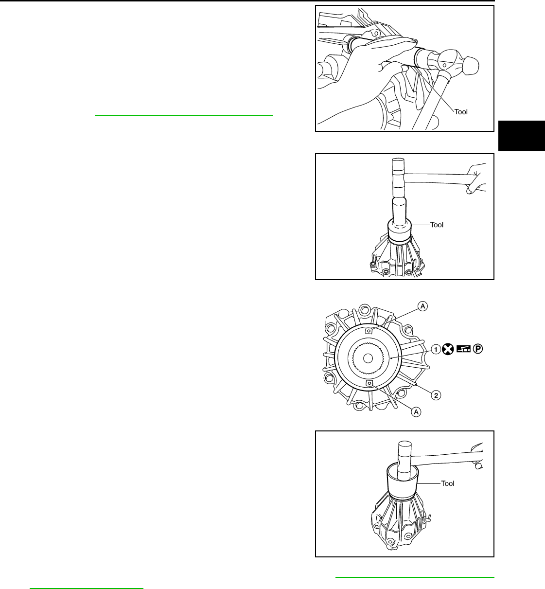
TRANSFER ASSEMBLY
DLN-185
< DISASSEMBLY AND ASSEMBLY > [TRANSFER: ATX14B]
C
E
F
G
H
I
J
K
L
M
A
B
DLN
N
O
P
27. Install the new oil seal in the front case using Tool.
CAUTION:
• Do not reuse oil seal.
• Apply petroleum jelly to seal lip before installing.
28. Install the shift lever to the shift cross.
29. Install the lock pin and lock pin nut. Tighten to the specified
torque. Refer to DLN-150, "Disassembly and Assembly".
Rear Case
1. Apply petroleum jelly to the circumference of the new rear oil
seal. Install the new rear oil seal so that it is flush with the case
tip face using Tool.
CAUTION:
• Do not reuse oil seal.
• Apply petroleum jelly to seal lip before installing.
2. Apply petroleum jelly to the circumference of the new dust cover
(1). Position the new dust cover with protrusions (A) as shown.
• 2: Rear case assembly
CAUTION:
• Do not reuse dust cover.
• Position the identification mark at the position shown.
3. Install the new dust cover using Tool.
4. Install the air breather into the rear case.
5. Remove all the sealant from the rear case to center case mating
surfaces.
CAUTION:
Remove all foreign materials such as water, oil, and grease
from center case and rear case mating surfaces.
6. Apply liquid gasket to the entire rear case mating surface of the
center case.
•Use Genuine Anaerobic Liquid Gasket or equivalent. Refer to GI-26, "Recommended Chemical
Products and Sealants".
CAUTION:
Do not to allow Liquid Gasket to enter stem bleeder hole.
Tool number : ST22360002 (J-25679-01)
SDIA2182E
Tool number : ST30720000 (J-25405)
SDIA2204E
AWDIA0550G
B
Tool number : KV40105310 ( — )
SDIA2205E
Revision: October 2008
2009 Pathfinder
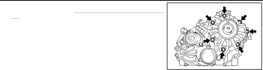
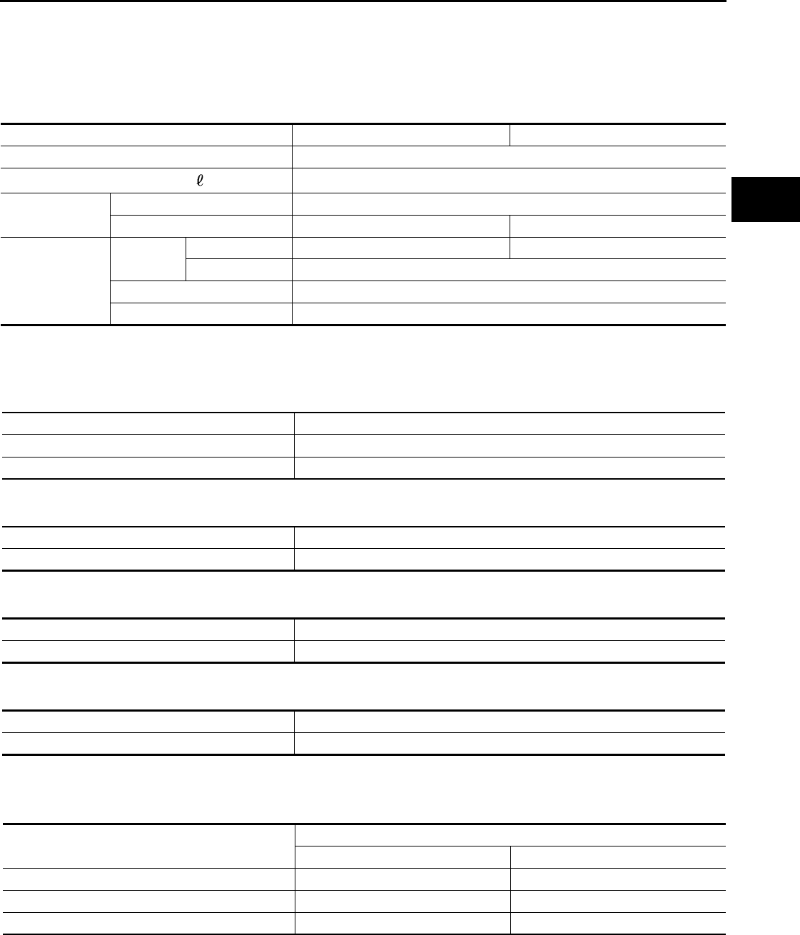
SERVICE DATA AND SPECIFICATIONS (SDS)
DLN-187
< SERVICE DATA AND SPECIFICATIONS (SDS) [TRANSFER: ATX14B]
C
E
F
G
H
I
J
K
L
M
A
B
DLN
N
O
P
SERVICE DATA AND SPECIFICATIONS (SDS)
SERVICE DATA AND SPECIFICATIONS (SDS)
General Specification INFOID:0000000003937312
Inspection and Adjustment INFOID:0000000003937313
CLEARANCE BETWEEN INNER GEAR AND OUTER GEAR
Unit: mm (in)
CLUTCH
Unit: mm (in)
PINION GEAR END PLAY
Unit: mm (in)
CLEARANCE BETWEEN SHIFT FORK AND SLEEVE
Unit: mm (in)
SELECTIVE PARTS
Sub-oil Pump
Unit: mm (in)
*: Always check with the Parts Department for the latest parts information.
Main Oil Pump
Applied model VQ40DE VK56DE
Transfer model ATX14B
Fluid capacity (Approx.) (US qt, lmp qt) 3.0 (3-1/8, 2-5/8)
Gear ratio High 1.000
Low 2.596 2.625
Number of teeth
Planetary
gear
Sun gear 57 56
Internal gear 91
Front drive sprocket 38
Front drive shaft 38
Item Specification
Sub-oil pump 0.015 - 0.035 (0.0006 - 0.0014)
Main oil pump 0.015 - 0.035 (0.0006 - 0.0014)
Item Limit value
Drive plate 1.4 (0.055)
Item Standard
Pinion gear end play 0.1 - 0.7 (0.004 - 0.028)
Item Standard
Shift fork and sleeve Less than 0.36 (0.0142)
Gear thickness Part number*
Inner gear Outer gear
9.27 - 9.28 (0.3650 - 0.3654) 31346 0W462 31347 0W462
9.28 - 9.29 (0.3654 - 0.3657) 31346 0W461 31347 0W461
9.29 - 9.30 (0.3657 - 0.3661) 31346 0W460 31347 0W460
Revision: October 2008
2009 Pathfinder

DLN-188
< SERVICE DATA AND SPECIFICATIONS (SDS) [TRANSFER: ATX14B]
SERVICE DATA AND SPECIFICATIONS (SDS)
Unit: mm (in)
*: Always check with the Parts Department for the latest parts information.
Control Valve
Unit: mm (in)
*: Always check with the Parts Department for the latest parts information.
Control Valve Spring
Unit: mm (in)
*: Always check with the Parts Department for the latest parts information.
Return Spring
Unit: mm (in)
*: Always check with the Parts Department for the latest parts information.
Gear thickness Part number*
Inner gear Outer gear
8.27 - 8.28 (0.3256 - 0.3260) 31346 7S112 31347 7S112
8.28 - 8.29 (0.3260 - 0.3264) 31346 7S111 31347 7S111
8.29 - 8.30 (0.3264 - 0.3268) 31346 7S110 31347 7S110
Mounting position
(Part name) Part number* Outer dia. Overall length
L1
(2-4 shift valve) 31772 21X00 8.0 (0.315) 38.5 (1.516)
L2
(Clutch valve) 31772 80X11 10.0 (0.394) 40.0 (1.575)
L4
(Pilot valve) 31772 80X11 10.0 (0.394) 40.0 (1.575)
L5
(Regulator valve) 31741 0W410 12.0 (0.472) 68.0 (2.677)
Mounting position
(Part name) Part number* Free length Outer dia. Overall length
L1
(2-4 shift valve spring) 31742 2W500 31.85 (1.2539) 7.0 (0.276) 0.6 (0.024)
L2
(Clutch valve spring) 31742 2W505 40.6 (1.598) 8.9 (0.350) 0.7 (0.028)
L4
(Pilot valve spring) 31742 0W410 28.1 (1.106) 9.0 (0.354) 1.2 (0.047)
L5
(Regulator valve spring) 31742 2W515 39.7 (1.563) 11.0 (0.433) 1.3 (0.051)
Stamped mark Part number* Free length
1 31521 7S111 42.7 (1.168)
2 31521 7S112 43.1 (1.697)
3 31521 7S113 43.6 (1.717)
4 31521 7S114 44.0 (1.731)
Revision: October 2008
2009 Pathfinder
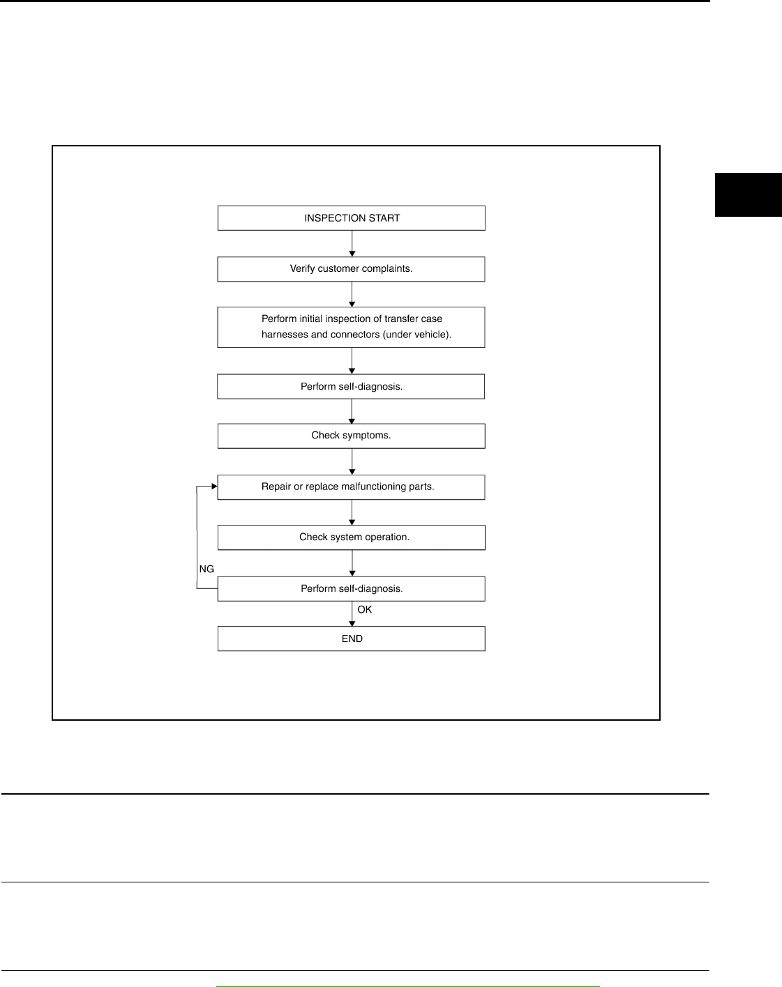
DIAGNOSIS AND REPAIR WORKFLOW
DLN-189
< BASIC INSPECTION > [TRANSFER: TX15B]
C
E
F
G
H
I
J
K
L
M
A
B
DLN
N
O
P
BASIC INSPECTION
DIAGNOSIS AND REPAIR WORKFLOW
Work Flow INFOID:0000000003937314
WORK FLOW
DETAILED FLOW
1.CUSTOMER INFORMATION
Interview the customer to obtain detailed information about the symptom.
>> GO TO 2
2.INITIAL INSPECTION
Perform an initial inspection of all accessible transfer case harnesses and connectors under the vehicle.
>> GO TO 3
3.SELF-DIAGNOSIS
Perform self-diagnosis. Refer to DLN-198, "CONSULT-III Function (ALL MODE AWD/4WD)".
AWDIA0028G
B
Revision: October 2008
2009 Pathfinder

DLN-190
< BASIC INSPECTION > [TRANSFER: TX15B]
DIAGNOSIS AND REPAIR WORKFLOW
>> GO TO 4
4.SYMPTOM
Check for symptoms. Refer to DLN-248, "Symptom Table".
>> GO TO 5
5.MALFUNCTIONING PARTS
Repair or replace the applicable parts.
>> GO TO 6
6.SYSTEM OPERATION
Check system operation.
>> GO TO 7
7.SELF-DIAGNOSIS
Perform self-diagnosis.
Are any DTC's displayed?
YES >> GO TO 5
NO >> Inspection End
Revision: October 2008
2009 Pathfinder
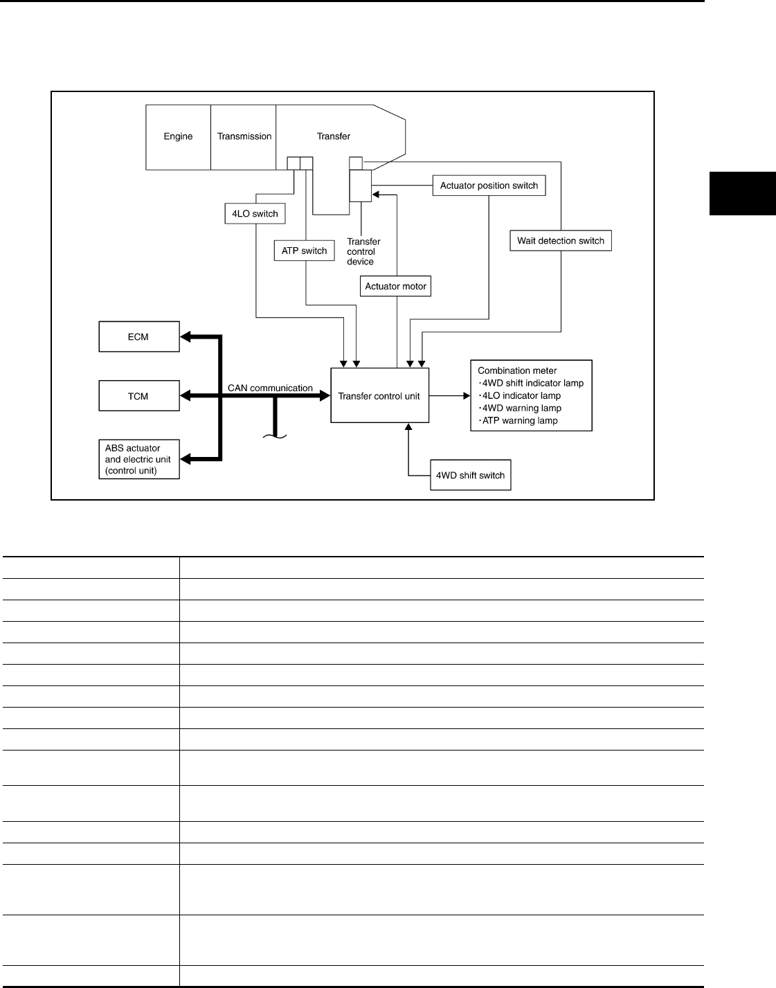
4WD SYSTEM
DLN-191
< FUNCTION DIAGNOSIS > [TRANSFER: TX15B]
C
E
F
G
H
I
J
K
L
M
A
B
DLN
N
O
P
FUNCTION DIAGNOSIS
4WD SYSTEM
System Diagram INFOID:0000000003937315
COMPONENT DESCRIPTION
PDIA0152E
Components Function
Transfer control unit Controls transfer control device and controls shifts between 2WD/4WD and 4H/4LO.
Transfer control device Integrates actuator motor and actuator position switch.
Actuator motor Moves shift rods when signaled by transfer control unit.
Actuator position switch Detects actuator motor position.
Wait detection switch Detects if transfer case is in 4WD.
4LO switch Detects if transfer case is in 4LO.
ATP switch Detects if transfer case is in neutral.
4WD shift switch Allows driver to select from 2WD/4WD and 4H/4LO.
4WD warning lamp • Illuminates if malfunction is detected in 4WD system.
• Flashes (1 flash / 2 seconds) if rotation difference of front wheels and rear wheels is large.
ATP warning lamp Indicates that A/T parking mechanism does not operate when A/T selector lever is in “P” position be-
cause transfer case is in neutral.
4WD shift indicator lamp Displays driving range selected by 4WD shift switch.
4LO indicator lamp Displays 4LO range.
ABS actuator and electric unit
(control unit)
Transmits the following signals via CAN communication to transfer control unit.
• Vehicle speed signal
• Stop lamp switch signal (brake signal)
TCM
Transmits the following signal via CAN communication to transfer control unit.
• Output shaft revolution signal
• A/T position indicator signal (PNP switch signal)
ECM Transmits engine speed signal via CAN communication to transfer control unit.
Revision: October 2008
2009 Pathfinder
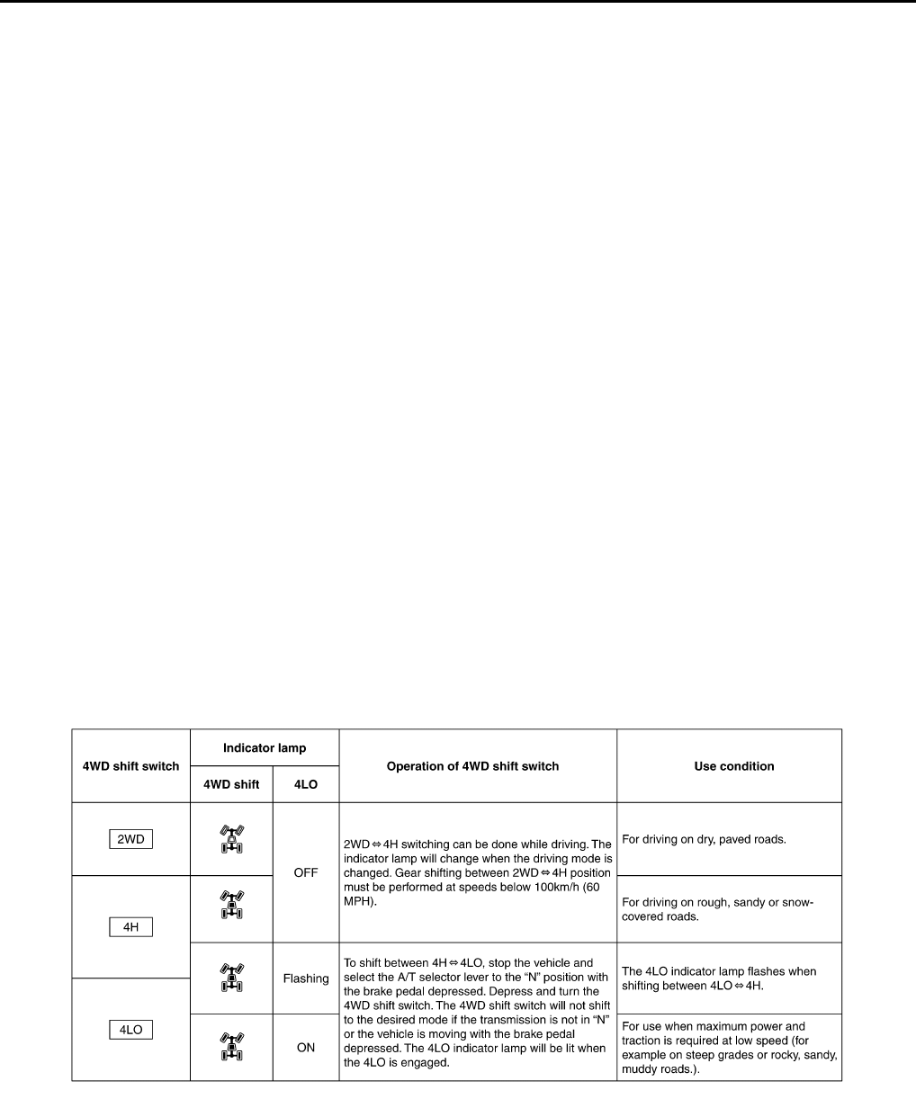
DLN-192
< FUNCTION DIAGNOSIS > [TRANSFER: TX15B]
4WD SYSTEM
System Description INFOID:0000000003937316
TRANSFER CONTROL DEVICE
Integrates actuator motor and actuator position switch.
Actuator Motor
Moves shift rods when signaled by transfer control unit.
Actuator Position Switch
Detects actuator motor position and then sends signal to transfer control unit.
WAIT DETECTION SWITCH
Detects if transfer case is in 4WD by the 2-4 shift fork position.
NOTE:
If 4WD shift switch is switched to 4H or 4LO and the transfer case is not in 4WD completely, the wait detection
system will operate.
4LO SWITCH
4LO switch detects if the transfer case is in 4LO by the position of the L-H shift fork.
ATP SWITCH
ATP switch detects if transfer case is in neutral by the position of the L-H shift fork.
NOTE:
Transfer case may be in neutral when shifting between 4H-4LO.
TRANSFER CONTROL UNIT
• Transfer control unit controls transfer control device and it directs shifts from 4H-4LO and 2WD-4WD.
• Self-diagnosis can be done.
TRANSFER SHIFT HIGH AND LOW RELAYS
Transfer shift high and low relays apply power supply to transfer control device (actuator motor).
TRANSFER SHUT OFF RELAYS
Transfer shut off relays 1 and 2 apply power supply to transfer control unit.
4WD SHIFT SWITCH AND INDICATOR LAMP
4WD Shift Switch
4WD shift switch is able to select from 2WD, 4H or 4LO.
4WD Shift Indicator Lamp
• Displays driving conditions selected by the 4WD shift switch while engine is running. When the 4WD warn-
ing lamp is turned on, all 4WD shift indicator lamps will turn off.
• Turns ON when ignition switch is turned ON, for purpose of lamp check. Turns OFF approximately for 1 sec-
ond after the engine starts if system is normal.
WDIA0138E
Revision: October 2008
2009 Pathfinder

4WD SYSTEM
DLN-193
< FUNCTION DIAGNOSIS > [TRANSFER: TX15B]
C
E
F
G
H
I
J
K
L
M
A
B
DLN
N
O
P
4LO Indicator Lamp
• Displays 4LO while engine is running. 4LO indicator lamp flashes if transfer gear does not shift completely
into 4H⇔4LO. In this condition, the transfer case may be in neutral and the A/T parking mechanism may not
operate.
• Turns ON when ignition switch is turned ON, for purpose of lamp check. Turns OFF approximately for 1 sec-
ond after the engine starts if system is normal.
4WD WARNING LAMP
Turns on or flashes when there is a malfunction in 4WD system.
Also turns on when ignition switch is turned ON, for purpose of lamp check. Turns OFF approximately for 1
second after the engine starts if system is normal.
4WD Warning Lamp Indication
ATP WARNING LAMP
When the A/T selector lever is in “P” position, the vehicle may move if the transfer case is in neutral. ATP
warning lamp is turned on to indicate this condition to the driver.
Condition 4WD warning lamp
System normal OFF
Lamp check Turns ON when ignition switch is turned ON.
Turns OFF after engine start.
4WD system malfunction ON
During self-diagnosis Flashes malfunction mode.
Large difference in diameter of front/
rear tires
Flashes slow (1 flash / 2 seconds)
(Continues to flash until the ignition switch is turned OFF)
Revision: October 2008
2009 Pathfinder
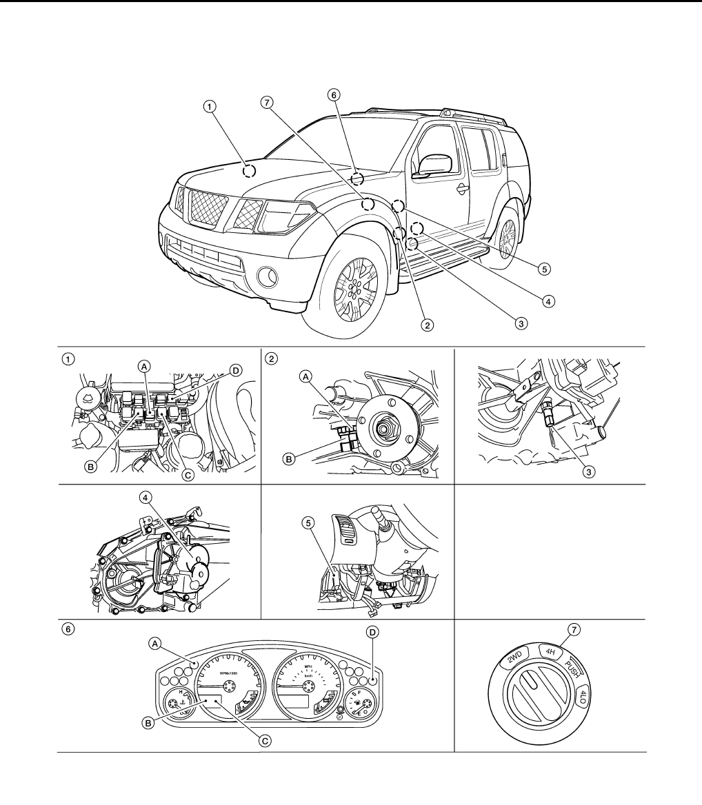
DLN-194
< FUNCTION DIAGNOSIS > [TRANSFER: TX15B]
4WD SYSTEM
Component Parts Location INFOID:0000000003937317
1. Fuse and relay box
A: Transfer shut off relay 1 E156
B: Transfer shift high relay E44
C: Transfer shift low relay E43
D: Transfer shut off relay 2 E157
2. A: ATP switch F71
B: 4 LO switch F74
(View with front propeller shaft re-
moved.)
3. Wait detection switch F73
WDIA0337E
Revision: October 2008
2009 Pathfinder
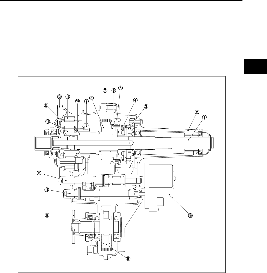
4WD SYSTEM
DLN-195
< FUNCTION DIAGNOSIS > [TRANSFER: TX15B]
C
E
F
G
H
I
J
K
L
M
A
B
DLN
N
O
P
CAN Communication INFOID:0000000003937318
Refer to LAN-65, "DTC Index".
Cross-Sectional View INFOID:0000000003937319
4. Transfer control device F72 5. Transfer control unit M165, M166
(View with lower instrument cover re-
moved.)
6. Combination meter M24
A: 4WD warning lamp
B: 4LO indicator lamp
C: 4WD shift indicator lamp
D: ATP warning lamp
7. 4WD shift switch M138
1. Mainshaft 2. Rear case 3. Oil pump assembly
4. Clutch gear 5. 2-4 shift fork 6. 2-4 sleeve
7. Drive chain 8. Sprocket 9. L-H shift fork
10. L-H sleeve 11. Internal gear 12. Front case
13. Planetary carrier assembly 14. Sun gear assembly 15. L-H shift rod
16. Control shift rod 17. Companion flange 18. Front drive shaft
19. Transfer control device
WDIA0222E
Revision: October 2008
2009 Pathfinder
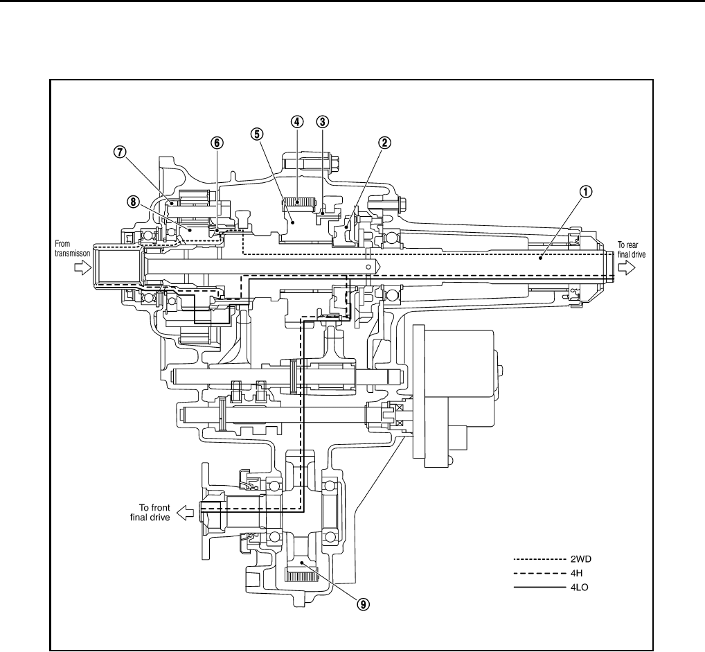
DLN-196
< FUNCTION DIAGNOSIS > [TRANSFER: TX15B]
4WD SYSTEM
Power Transfer INFOID:0000000003937320
POWER TRANSFER DIAGRAM
POWER TRANSFER FLOW
1. Mainshaft 2. Clutch gear 3. 2-4 sleeve
4. Drive chain 5. Sprocket 6. L-H sleeve
7. Planetary carrier assembly 8. Sun gear assembly 9. Front drive shaft
WDIA0223E
Revision: October 2008
2009 Pathfinder
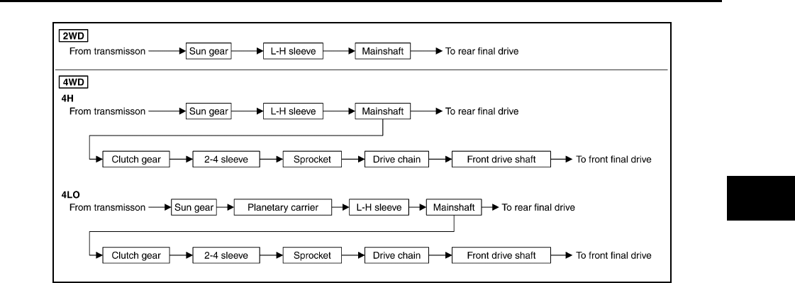
4WD SYSTEM
DLN-197
< FUNCTION DIAGNOSIS > [TRANSFER: TX15B]
C
E
F
G
H
I
J
K
L
M
A
B
DLN
N
O
P
SDIA2213E
Revision: October 2008
2009 Pathfinder

DLN-198
< FUNCTION DIAGNOSIS > [TRANSFER: TX15B]
DIAGNOSIS SYSTEM (TRANSFER CONTROL UNIT)
DIAGNOSIS SYSTEM (TRANSFER CONTROL UNIT)
CONSULT-III Function (ALL MODE AWD/4WD) INFOID:0000000003937321
FUNCTION
CONSULT-III can display each diagnostic item using the diagnostic test modes shown following.
SELF-DIAG RESULT MODE
Operation Procedure
1. Connect “CONSULT-III”.
2. With engine at idle, touch “SELF-DIAG RESULTS”.
Display shows malfunction experienced since the last erasing operation.
NOTE:
The details for "TIME" are as follows:
• "0": Error currently detected with transfer control unit.
• Except for "0": Error detected in the past and memorized with transfer control unit.
Detects frequency of driving after DTC occurs (frequency of turning ignition switch "ON/OFF").
How to Erase Self-diagnostic Results
1. Perform applicable inspection of malfunctioning item and then repair or replace.
2. Start engine and select “SELF-DIAG RESULTS” mode for “ALL MODE AWD/4WD” with CONSULT-III.
3. Touch “ERASE” on CONSULT-III screen to erase DTC memory.
CAUTION:
If memory cannot be erased, perform applicable diagnosis.
SELF-DIAGNOSTIC PROCEDURE (WITHOUT CONSULT-III)
Description
If the engine starts when there is something wrong with the 4WD system, the 4WD warning lamp turns ON or
flickers in the combination meter. When the system functions properly, the warning lamp turns ON when the
ignition switch is turned to “ON”, and it turns OFF after engine starts. To locate the cause of a problem, start
the self-diagnosis function. The 4WD warning lamp in the combination meter will indicate the problem area by
flickering according to the self-diagnostic results. Refer to DLN-245, "DTC Index".
Diagnostic Procedure
1. Warn up engine.
2. Turn ignition switch “ON” and “OFF” at least twice, and then turn ignition switch “OFF”.
3. Move A/T selector lever to “P” position.
4. Turn 4WD shift switch to “2WD” position.
5. Turn ignition switch “ON”. (Do not start engine.)
6. 4WD warning lamp ON.
If 4WD warning lamp does not turn ON, refer to DLN-249, "Diagnosis Procedure".
7. Move A/T selector lever to “R” position.
8. Turn 4WD shift switch to “2WD”, “4H” and “2WD” in order.
9. Move A/T selector lever to “P” position.
10. Turn 4WD shift switch to “4H”, “2WD” and “4H” in order.
11. Move A/T selector lever to “N” position.
12. Turn 4WD shift switch to “2WD” position.
13. Move A/T selector lever to “P” position.
ALL MODE AWD/4WD diagnostic mode Description
SELF-DIAG RESULTS Displays transfer control unit self-diagnosis results.
DATA MONITOR Displays transfer control unit input/output data in real time.
CAN DIAG SUPPORT MNTR The results of transmit/receive diagnosis of CAN communication can be read.
ECU PART NUMBER Transfer control unit part number can be read.
Revision: October 2008
2009 Pathfinder

DIAGNOSIS SYSTEM (TRANSFER CONTROL UNIT)
DLN-199
< FUNCTION DIAGNOSIS > [TRANSFER: TX15B]
C
E
F
G
H
I
J
K
L
M
A
B
DLN
N
O
P
14. Read the flickering of 4WD warning lamp.
Self-diagnosis example
DATA MONITOR MODE
Operation Procedure
1. Connect “CONSULT-III.”
2. Touch “DATA MONITOR”.
3. Select from “SELECT MONITOR ITEM”, screen of data monitor mode is displayed.
NOTE:
When malfunction is detected, CONSULT-III performs REAL-TIME DIAGNOSIS.
Also, any malfunction detected while in this mode will be displayed at real time.
Display Item List
×: Standard –: Not applicable
PDIA0227E
Monitored item (Unit)
Monitor item selection
Remarks
ECU INPUT
SIGNALS
MAIN
SIGNALS
SELECTION
FROM MENU
VHCL/S SEN·FR [km/h] or [mph] ×–×
Wheel speed calculated by ABS actuator
and electric unit (control unit).
Signal input with CAN communication line.
VHCL/S SEN·RR [km/h] or [mph] ×–×Wheel speed calculated by TCM.
Signal input with CAN communication line.
ENGINE SPEED [rpm] ×–×Engine speed is displayed.
Signal input with CAN communication line.
BATTERY VOLT [V] ×–×Power supply voltage for transfer control
unit.
2WD SWITCH [ON/OFF] ×–×
4WD shift switch signal status is displayed.
(4L means 4LO of 4WD shift switch.)
4H SWITCH [ON/OFF] ×–×
4L SWITCH [ON/OFF] ×–×
4L POSI SW [ON/OFF] ×–×4LO switch signal status is displayed.
ATP SWITCH [ON/OFF] ×–×ATP switch signal status is displayed.
WAIT DETCT SW [ON/OFF] ×–×Wait detection switch signal status is dis-
played.
4WD MODE [2H/4H/4L] – ××
Control status of 4WD recognized by trans-
fer control unit. (2WD, 4H or 4LO)
VHCL/S COMP [km/h] or [mph] – ××
Vehicle speed recognized by transfer con-
trol unit.
SHIFT ACT 1 [ON/OFF] – ××
Output condition to actuator motor (clock-
wise)
SHIFT AC MON 1 [ON/OFF] – – ×Check signal for transfer control unit signal
output
SHIFT ACT 2 [ON/OFF] – ××
Output condition to actuator motor (coun-
terclockwise)
Revision: October 2008
2009 Pathfinder

DLN-200
< FUNCTION DIAGNOSIS > [TRANSFER: TX15B]
DIAGNOSIS SYSTEM (TRANSFER CONTROL UNIT)
SHIFT AC MON 2 [ON/OFF] – – ×Check signal for transfer control unit signal
output
SFT ACT/R MON [ON/OFF] – – ×Operating condition of actuator motor relay
(integrated in transfer control unit)
SHIFT POS SW 1 [ON/OFF] ×–×Condition of actuator position switch 1
SHIFT POS SW 2 [ON/OFF] ×–×Condition of actuator position switch 2
SHIFT POS SW 3 [ON/OFF] ×–×Condition of actuator position switch 3
SHIFT POS SW 4 [ON/OFF] ×–×Condition of actuator position switch 4
4WD FAIL LAMP [ON/OFF] – ××
Control status of 4WD warning lamp is dis-
played.
2WD IND [ON/OFF] – – ×Control status of 4WD shift indicator lamp
(rear) is displayed.
4H IND [ON/OFF] – – ×Control status of 4WD shift indicator lamp
(front and center) is displayed.
4L IND [ON/OFF] – – ×Control status of 4LO indicator lamp is dis-
played.
Monitored item (Unit)
Monitor item selection
Remarks
ECU INPUT
SIGNALS MAIN
SIGNALS SELECTION
FROM MENU
Revision: October 2008
2009 Pathfinder

NOISE, VIBRATION AND HARSHNESS (NVH) TROUBLESHOOTING
DLN-201
< FUNCTION DIAGNOSIS > [TRANSFER: TX15B]
C
E
F
G
H
I
J
K
L
M
A
B
DLN
N
O
P
NOISE, VIBRATION AND HARSHNESS (NVH) TROUBLESHOOTING
NVH Troubleshooting Chart INFOID:0000000003937322
Use the chart below to help you find the cause of the symptom. The numbers indicate the order of the inspec-
tion. If necessary, repair or replace these parts.
Reference page
DLN-270
DLN-281
DLN-303
DLN-281
DLN-297
SUSPECTED PARTS
(Possible cause)
TRANSFER FLUID (Level low)
TRANSFER FLUID (Wrong)
TRANSFER FLUID (Level too high)
LIQUID GASKET (Damaged)
O-RING (Worn or damaged)
OIL SEAL (Worn or damaged)
SHIFT FORK (Worn or damaged)
GEAR (Worn or damaged)
BEARING (Worn or damaged)
Symptom
Noise 1 2 3 3
Transfer fluid leakage 31222
Hard to shift or will not shift 1 1 2
Revision: October 2008
2009 Pathfinder
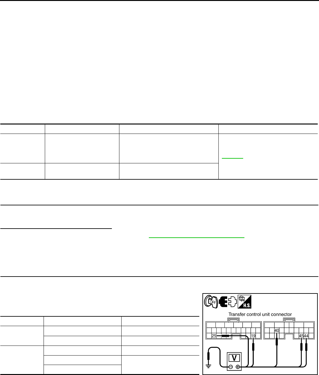
DLN-202
< COMPONENT DIAGNOSIS > [TRANSFER: TX15B]
P1801, P1811 POWER SUPPLY CIRCUIT FOR TRANSFER CONTROL UNIT
COMPONENT DIAGNOSIS
P1801, P1811 POWER SUPPLY CIRCUIT FOR TRANSFER CONTROL
UNIT
Description INFOID:0000000003937323
The transfer control unit controls the transfer control device which controls shifts between 4H and 4LO and
between 2WD and 4WD. When the vehicle battery is removed, the power supply to the transfer control unit is
interupted, and self-diagnosis memory function is suspended. These DTC's may also set when the power
supply voltage for the transfer control unit is abnormally low while driving.
DTC Logic INFOID:0000000003937324
DTC DETECTION LOGIC
DTC CONFIRMATION PROCEDURE
1.DTC CONFIRMATION PROCEDURE
1. Turn ignition switch ON.
2. Perform self-diagnosis.
Are DTC's “P1801 or P1811 detected?
YES >> Perform diagnosis procedure. Refer to DLN-202, "Diagnosis Procedure".
NO >> Inspection End.
Diagnosis Procedure INFOID:0000000003937325
1.CHECK POWER SUPPLY
1. Turn ignition switch “OFF”. (Stay for at least 5 seconds.)
2. Disconnect transfer control unit harness connector.
3. Check voltage between transfer control unit harness connector
terminals and ground.
DTC CONSULT-III Diagnostic item is detected when... Reference
[P1801] *INITIAL START*
Due to removal of battery which cuts off
power supply to transfer control unit,
self-diagnosis memory function is sus-
pended. DLN-202
[P1811] BATTERY VOLTAGE Power supply voltage for transfer control
unit is abnormally low while driving.
Connector Terminal Voltage (Approx.)
M165 19 - Ground Battery voltage
25 - Ground 0V
M166
40 - Ground Battery voltage
44 - Ground 0V
45 - Ground SDIA3360E
Revision: October 2008
2009 Pathfinder
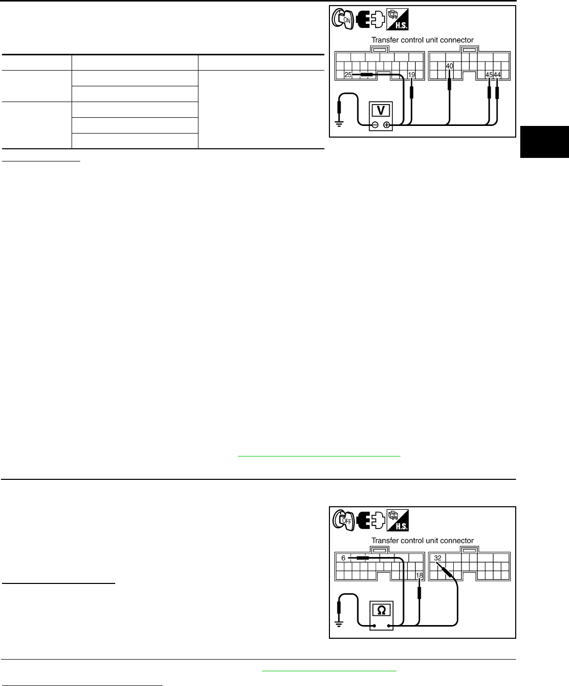
P1801, P1811 POWER SUPPLY CIRCUIT FOR TRANSFER CONTROL UNIT
DLN-203
< COMPONENT DIAGNOSIS > [TRANSFER: TX15B]
C
E
F
G
H
I
J
K
L
M
A
B
DLN
N
O
P
4. Turn ignition switch “ON”. (Do not start engine.)
5. Check voltage between transfer control unit harness connector
terminals and ground.
Is there voltage?
YES >> GO TO 2.
NO >> Check the following. If any items are damaged, repair or replace damaged parts.
• 40A fuse (No. j, located in the fuse and fusible link box).
• 10A fuses (No. 21, located in the fuse block (J/B) and Nos. 60 and 61 located in the fuse and
relay box).
• Harness for short or open between battery and transfer control unit harness connector M165
terminal 19.
• Harness for short or open between battery and transfer shut off relay 2 harness connector E157
terminal 1 and 3.
• Harness for short or open between battery and transfer shut off relay 1 harness connector E156
terminal 3.
• Harness for short or open between ignition switch and transfer control unit harness connector
M165 terminal 25.
• Harness for short or open between ignition switch and transfer shut off relay 1 harness connec-
tor E156 terminal 1.
• Harness for short or open between transfer shut off relay 2 harness connector E157 terminal 5
and transfer control unit harness connector M166 terminals 44, 45.
• Harness for short or open between transfer shut off relay 1 harness connector E156 terminal 5
and transfer control unit harness connector M166 terminals 44, 45.
• Harness for short or open between transfer shut off relay 2 harness connector E157 terminal 2
and transfer control unit harness connector M166 terminal 40.
• Harness for open between transfer shut off relay 1 harness connector E156 terminal 2 and
ground.
• Battery and ignition switch.
• Transfer shut off relay 1, 2. Refer to DLN-204, "Component Inspection".
2.CHECK GROUND CIRCUIT
1. Turn ignition switch “OFF”.
2. Disconnect transfer control unit harness connector.
3. Check continuity between transfer control unit harness connec-
tor M165 terminals 6 and 18, and M166 terminal 32 and ground.
Also check harness for short to power.
Do you have continuity?
YES >> GO TO 3.
NO >> Repair open circuit or short to power in harness or con-
nectors.
3.CHECK TRANSFER CONTROL UNIT
Check transfer control unit input/output signal. Refer to DLN-233, "Reference Value".
Are the inspection results normal?
YES >> GO TO 4.
Connector Terminal Voltage (Approx.)
M165 19 - Ground
Battery voltage
25 - Ground
M166
40 - Ground
44 - Ground
45 - Ground SDIA3361E
Continuity should exist.
SDIA3362E
Revision: October 2008
2009 Pathfinder
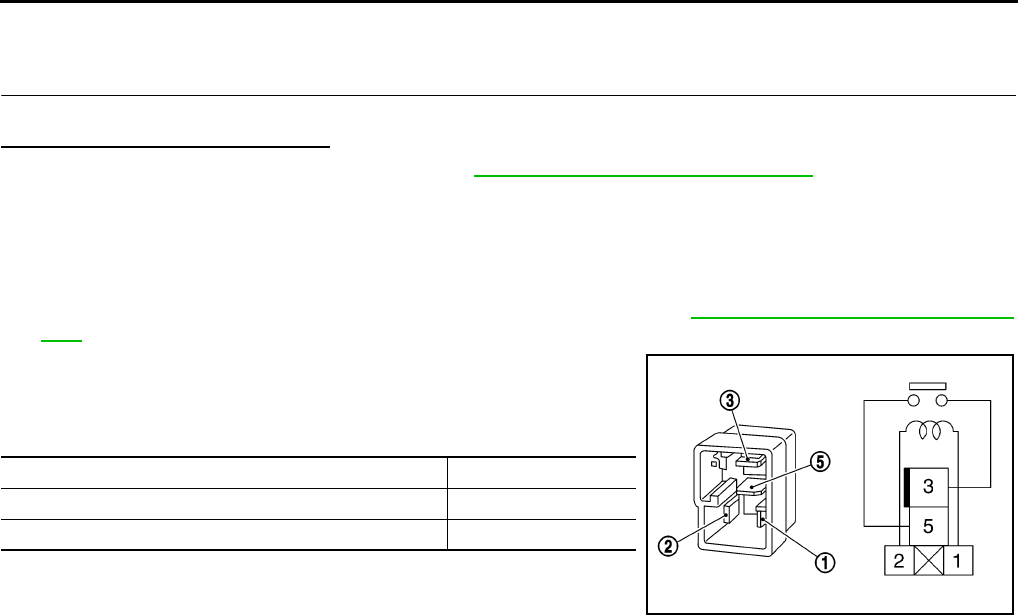
DLN-204
< COMPONENT DIAGNOSIS > [TRANSFER: TX15B]
P1801, P1811 POWER SUPPLY CIRCUIT FOR TRANSFER CONTROL UNIT
NO >> Check transfer control unit pin terminals for damage or loose connection with harness connector.
If any items are damaged, repair or replace damaged parts.
4.CHECK DTC
Drive vehicle and then perform Self-diagnosis.
Do DTC's P1801 or P1811 display?
YES >> Replace transfer control unit. Refer to DLN-271, "Removal and Installation".
NO >> Inspection End.
Component Inspection INFOID:0000000003937326
1. Turn ignition switch “OFF”. (Stay for at least 5 seconds.)
2. Remove transfer shut off relay 1 and transfer shut off relay 2. Refer to DLN-194, "Component Parts Loca-
tion".
3. Apply 12V direct current between transfer shut off relay termi-
nals 1 and 2.
4. Check continuity between relay terminals 3 and 5.
5. If inspection results are not normal, replace the transfer shut off
relay 1 or 2.
Condition Continuity
12V direct current supply between terminals 1 and 2 Yes
OFF No
SCIA1245E
Revision: October 2008
2009 Pathfinder

P1802 – P1804, P1809 TRANSFER CONTROL UNIT
DLN-205
< COMPONENT DIAGNOSIS > [TRANSFER: TX15B]
C
E
F
G
H
I
J
K
L
M
A
B
DLN
N
O
P
P1802 – P1804, P1809 TRANSFER CONTROL UNIT
Description INFOID:0000000003937327
The transfer control unit controls the transfer control device which controls shifts between 4H and 4LO and
between 2WD and 4WD. A DTC may set when any of the following occur:
• Malfunction is detected in the memory (RAM) system of transfer control unit.
• Malfunction is detected in the memory (ROM) system of transfer control unit.
• Malfunction is detected in the memory (EEPROM) system of transfer control unit.
• AD converter system of transfer control unit is malfunctioning.
DTC Logic INFOID:0000000003937328
DTC DETECTION LOGIC
DTC CONFIRMATION PROCEDURE
1.DTC CONFIRMATION PROCEDURE
1. Turn ignition switch ON.
2. Perform self-diagnosis.
Are DTC's “P1802 - P1804 or P1809 detected?
YES >> Perform diagnosis procedure. Refer to DLN-205, "Diagnosis Procedure".
NO >> Inspection End.
Diagnosis Procedure INFOID:0000000003937329
1.INSPECTION START
Do you have CONSULT-III?
YES or NO
YES >> GO TO 2.
NO >> GO TO 3.
2.PERFORM SELF-DIAGNOSIS (WITH CONSULT-III)
1. Turn ignition switch “ON”.
2. Select “SELF-DIAG RESULTS” mode for “ALL MODE AWD/4WD” with CONSULT-III.
3. Touch “ERASE”.
4. Turn ignition switch “OFF” and wait at least 10 seconds.
5. Perform the self-diagnosis again.
Is the “CONTROL UNIT 1 [P1802]”, “CONTROL UNIT 2 [P1803]”, “CONTROL UNIT 3 [P1804]” or CONTROL
UNIT 4 [P1809]” displayed?
YES >> Replace transfer control unit. Refer to DLN-271, "Removal and Installation".
NO >> Inspection End.
3.PERFORM SELF-DIAGNOSIS (WITHOUT CONSULT-III)
1. Perform the self-diagnosis and then erase self-diagnostic results. Refer to DLN-198, "CONSULT-III Func-
tion (ALL MODE AWD/4WD)".
2. Perform the self-diagnosis again.
DTC CONSULT-III Diagnostic item is detected when... Reference
[P1802] CONTROL UNIT 1 Malfunction is detected in the memory
(RAM) system of transfer control unit.
DLN-205
[P1803] CONTROL UNIT 2 Malfunction is detected in the memory
(ROM) system of transfer control unit.
[P1804] CONTROL UNIT 3
Malfunction is detected in the memory
(EEPROM) system of transfer control
unit.
[P1809] CONTROL UNIT 4 AD converter system of transfer control
unit is malfunctioning.
Revision: October 2008
2009 Pathfinder

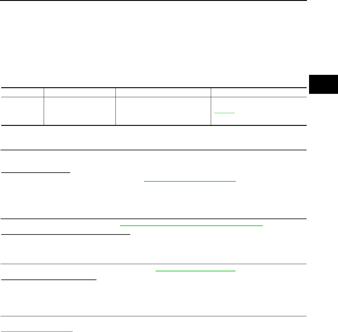
P1807 VEHICLE SPEED SENSOR (A/T)
DLN-207
< COMPONENT DIAGNOSIS > [TRANSFER: TX15B]
C
E
F
G
H
I
J
K
L
M
A
B
DLN
N
O
P
P1807 VEHICLE SPEED SENSOR (A/T)
Description INFOID:0000000003937330
The transmission control module (TCM) transmits the output shaft revolution signal via CAN communication to
Transfer control unit. DTC P1807 will set when a malfunction is detected in the output shaft revolution signal
or an improper signal is input while driving.
DTC Logic INFOID:0000000003937331
DTC DETECTION LOGIC
DTC CONFIRMATION PROCEDURE
1.DTC CONFIRMATION PROCEDURE
1. Turn ignition switch ON.
2. Perform self-diagnosis.
Is DTC P1807 detected?
YES >> Perform diagnosis procedure. Refer to DLN-207, "Diagnosis Procedure".
NO >> Inspection End.
Diagnosis Procedure INFOID:0000000003937332
1.CHECK DTC WITH TCM
Perform self-diagnosis with TCM. Refer to TM-36, "CONSULT-III Function (TRANSMISSION)".
Is any malfunction detected by self-diagnosis?
YES >> Check the malfunctioning system.
NO >> GO TO 2.
2.CHECK TRANSFER CONTROL UNIT
Check transfer control unit input/output signal. Refer to DLN-233, "Reference Value".
Are the inspection results normal?
YES >> GO TO 3.
NO >> Check transfer control unit pin terminals for damage or loose connection with harness connector.
If any items are damaged, repair or replace damaged parts.
3.CHECK DTC
Drive vehicle and then perform Self-diagnosis.
Is DTC P1807 displayed?
YES >> Perform self-diagnosis with TCM again.
NO >> Inspection End.
DTC CONSULT-III Diagnostic item is detected when... Reference
[P1807] VHCL SPEED SEN·AT
• Malfunction is detected in output shaft
revolution signalthat is output from
TCM through CAN communication.
• Improper signal is input while driving.
DLN-207
Revision: October 2008
2009 Pathfinder

DLN-208
< COMPONENT DIAGNOSIS > [TRANSFER: TX15B]
P1808 VEHICLE SPEED SENSOR (ABS)
P1808 VEHICLE SPEED SENSOR (ABS)
Description INFOID:0000000003937333
The ABS actuator and electric unit (control unit) transmits a vehicle speed signal via CAN communication to
the transfer control unit. DTC P1808 sets when a malfunction is detected in the vehicle speed signal that is
output from the ABS actuator and electric unit (control unit) or an improper signal is input while driving.
DTC Logic INFOID:0000000003937334
DTC DETECTION LOGIC
DTC CONFIRMATION PROCEDURE
1.DTC CONFIRMATION PROCEDURE
1. Turn ignition switch ON.
2. Perform self-diagnosis.
Is DTC “P1808 displayed?
YES >> Perform diagnosis procedure. Refer to DLN-208, "Diagnosis Procedure".
NO >> Inspection End.
Diagnosis Procedure INFOID:0000000003937335
1.CHECK DTC WITH ABS ACTUATOR AND ELECTRIC UNIT (CONTROL UNIT)
Perform self-diagnosis with ABS actuator and electric unit (control unit) for specific BRC system type.
Is any malfunction detected by self-diagnosis?
YES >> Check the malfunctioning system.
NO >> GO TO 2.
2.CHECK TRANSFER CONTROL UNIT
Check transfer control unit input/output signal. Refer to DLN-233, "Reference Value".
Are the inspection results normal?
YES >> GO TO 3.
NO >> Check transfer control unit pin terminals for damage or loose connection with harness connector.
If any items are damaged, repair or replace damaged parts.
3.CHECK DTC
Drive vehicle and then perform Self-diagnosis.
Is DTC P1808 displayed?
YES >> Perform self-diagnosis with ABS actuator and electric unit (control unit) for specific BRC system
type.
NO >> Inspection End.
DTC CONSULT-III Diagnostic item is detected when... Reference
[P1808] VHCL SPEED SEN·ABS
• Malfunction is detected in vehicle
speed signal that is output from ABS
actuator and electric unit (control unit)
through CAN communication.
• Improper signal is input while driving.
DLN-208
Revision: October 2008
2009 Pathfinder
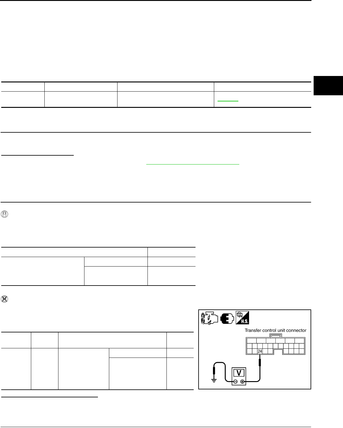
P1810 4 LO SWITCH
DLN-209
< COMPONENT DIAGNOSIS > [TRANSFER: TX15B]
C
E
F
G
H
I
J
K
L
M
A
B
DLN
N
O
P
P1810 4 LO SWITCH
Description INFOID:0000000003937336
The 4LO switch detects that the transfer case is in 4LO range. DTC P1810 will set when an improper signal
from the 4LO switch is input due to an open or short circuit.
DTC Logic INFOID:0000000003937337
DTC DETECTION LOGIC
DTC CONFIRMATION PROCEDURE
1.DTC CONFIRMATION PROCEDURE
1. Turn ignition switch ON.
2. Perform self-diagnosis.
Is DTC P1810 displayed?
YES >> Perform diagnosis procedure. Refer to DLN-209, "Diagnosis Procedure".
NO >> Inspection End.
Diagnosis Procedure INFOID:0000000003937338
1.CHECK 4LO POSITION SWITCH SIGNAL
With CONSULT-III
1. Start engine.
2. Select “DATA MONITOR” mode for “ALL MODE AWD/4WD” with CONSULT-III.
3. Read out the value of “4L POSI SW”.
Without CONSULT-III
1. Start engine.
2. Check voltage between transfer control unit harness connector
terminal and ground.
Are the inspection results normal?
YES >> GO TO 5.
NO >> GO TO 2.
2.CHECK HARNESS BETWEEN TRANSFER CONTROL UNIT AND 4LO SWITCH
1. Turn ignition switch “OFF”. (Stay for at least 5 seconds.)
DTC CONSULT-III Diagnostic item is detected when... Reference
[P1810] 4L POSI SW TF Improper signal from 4LO switch is input
due to open or short circuit. DLN-209
Condition Display value
• Vehicle stopped
• Engine running
• A/T selector lever “N” position
• Brake pedal depressed
4WD shift switch: 4LO ON
Except the above OFF
Connector Terminal Condition Voltage
(Approx.)
M165 24 -
Ground
• Vehicle stopped
• Engine running
• A/T selector lever
“N” position
• Brake pedal de-
pressed
4WD shift switch: 4LO 0V
Except the above Battery
voltage
SDIA3363E
Revision: October 2008
2009 Pathfinder
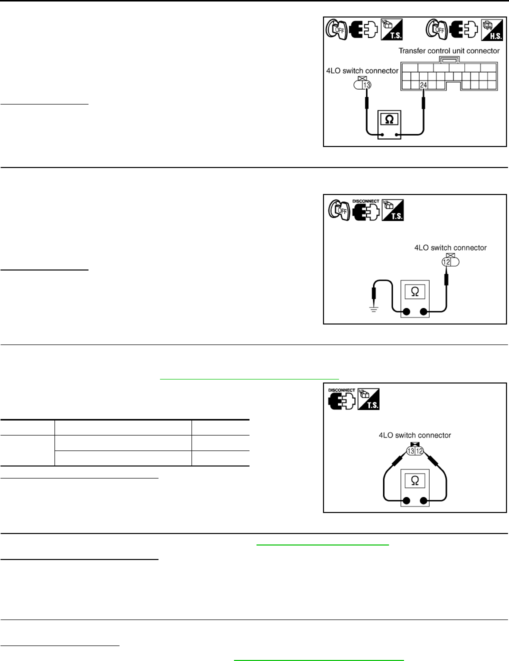
DLN-210
< COMPONENT DIAGNOSIS > [TRANSFER: TX15B]
P1810 4 LO SWITCH
2. Disconnect transfer control unit harness connector and the 4LO switch harness connector.
3. Check continuity between transfer control unit harness connec-
tor M165 terminal 24 and 4LO switch harness connector F74
terminal 13.
Also check harness for short to ground and short to power.
Is there continuity?
YES >> GO TO 3.
NO >> Repair or replace damaged parts.
3.CHECK GROUND CIRCUIT
1. Turn ignition switch “OFF”. (Stay for at least 5 seconds.)
2. Disconnect 4LO switch harness connector.
3. Check continuity between 4LO switch harness connector F74
terminal 12 and ground.
Also check harness for short to power.
Is there continuity?
YES >> GO TO 4.
NO >> Repair open circuit or short to power in harness or con-
nectors.
4.CHECK 4LO SWITCH
1. Turn ignition switch “OFF”. (Stay for at least 5 seconds.)
2. Disconnect 4LO switch harness connector.
3. Remove 4LO switch. Refer to DLN-194, "Component Parts Location".
4. Push and release 4LO switch and check continuity between
4LO switch terminals 12 and 13.
Are the inspection results normal?
YES >> GO TO 5.
NO >> Replace 4LO switch.
5.CHECK TRANSFER CONTROL UNIT
Check transfer control unit input/output signal. Refer to DLN-233, "Reference Value".
Are the inspection results normal?
YES >> GO TO 6.
NO >> Check transfer control unit pin terminals for damage or loose connection with harness connector.
If any items are damaged, repair or replace damaged parts.
6.CHECK DTC
Drive the vehicle and then perform self-diagnosis.
Is DTC P1810 displayed?
YES >> Replace transfer control unit. Refer to DLN-271, "Removal and Installation".
NO >> Inspection End.
Continuity should exist.
SDIA3364E
Continuity should exist.
PDIA0203E
Terminal Condition Continuity
12 - 13 Push 4LO switch Yes
Release 4LO switch No
PDIA0204E
Revision: October 2008
2009 Pathfinder
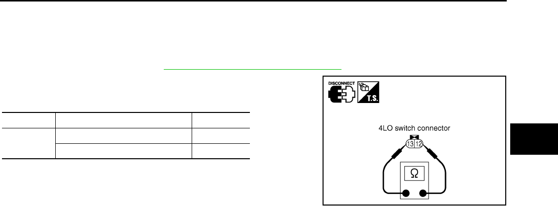
P1810 4 LO SWITCH
DLN-211
< COMPONENT DIAGNOSIS > [TRANSFER: TX15B]
C
E
F
G
H
I
J
K
L
M
A
B
DLN
N
O
P
Component Inspection INFOID:0000000003937339
1. Turn ignition switch “OFF”. (Stay for at least 5 seconds.)
2. Disconnect 4LO switch harness connector.
3. Remove 4LO switch. Refer to DLN-194, "Component Parts Location".
4. Push and release 4LO switch and check continuity between
4LO switch terminals 12 and 13.
5. If the inspection results are not normal replace the 4LO switch.
Terminal Condition Continuity
12 - 13 Push 4LO switch Yes
Release 4LO switch No
PDIA0204E
Revision: October 2008
2009 Pathfinder
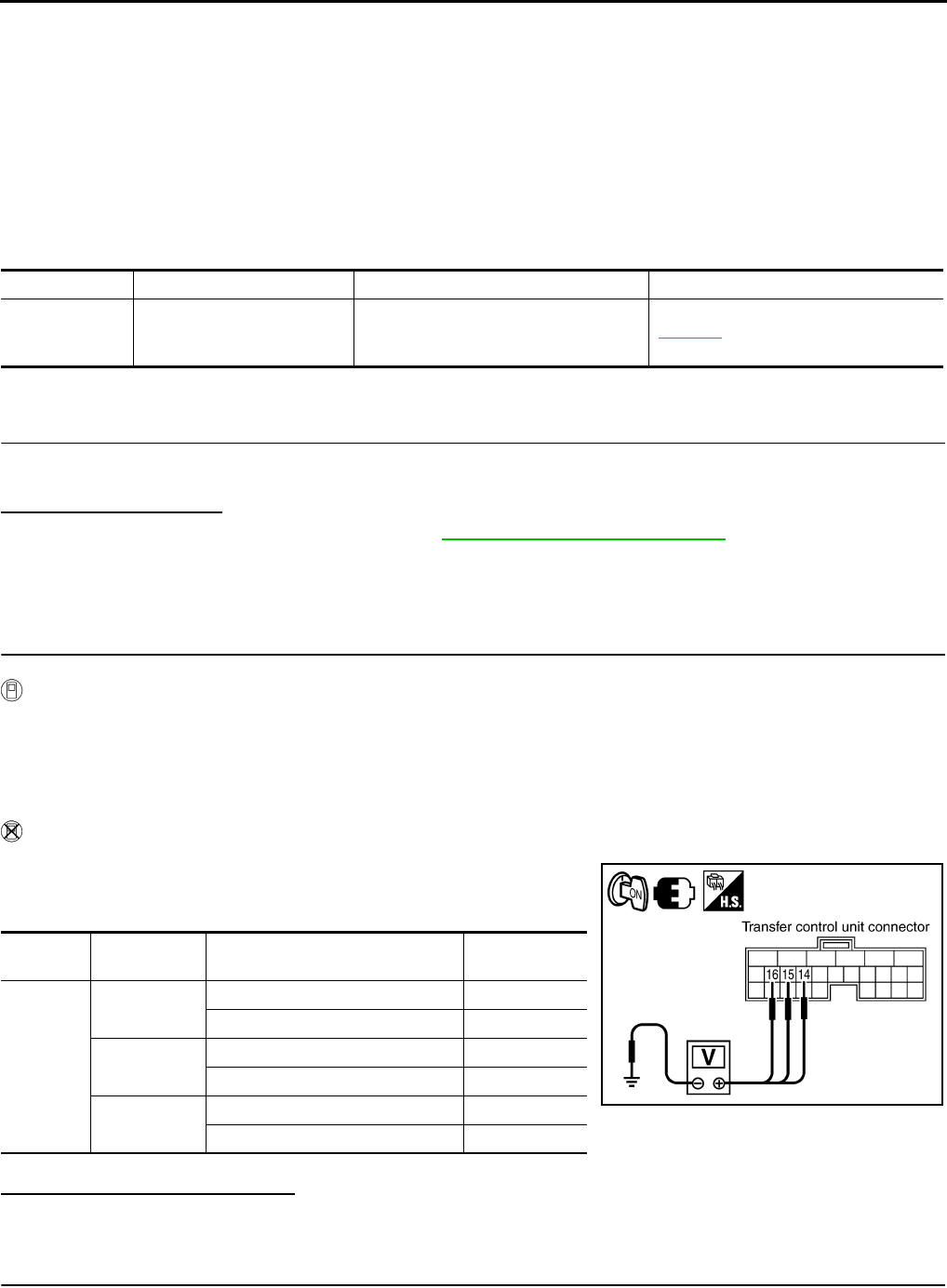
DLN-212
< COMPONENT DIAGNOSIS > [TRANSFER: TX15B]
P1813 4WD SHIFT SWITCH
P1813 4WD SHIFT SWITCH
Description INFOID:0000000003937340
The 4WD shift switch allows the driver to select 2WD or 4WD and 4H or 4LO. DTC P1813 will set if more than
two switch inputs are simultaneously detected by the transfer control unit due to a short circuit in the 4WD shift
switch.
DTC Logic INFOID:0000000003937341
DTC DETECTION LOGIC
DTC CONFIRMATION PROCEDURE
1.DTC CONFIRMATION PROCEDURE
1. Turn ignition switch ON.
2. Perform self-diagnosis.
Is DTC P1813 displayed?
YES >> Perform diagnosis procedure. Refer to DLN-212, "Diagnosis Procedure".
NO >> Inspection End.
Diagnosis Procedure INFOID:0000000003937342
1.CHECK 4WD SHIFT SWITCH SIGNAL
With CONSULT-III
1. Turn ignition switch “ON”.
2. Select “DATA MONITOR” mode for “ALL MODE AWD/4WD” with CONSULT-III.
3. Read out ON/OFF switching action of the “2WD SWITCH”, “4H SWITCH”, “4L SWITCH” with operating
4WD shift switch.
Without CONSULT-III
1. Turn ignition switch “ON”.
2. Check voltage between transfer control unit harness connector
terminals and ground.
Are the inspection results normal?
YES >> GO TO 5.
NO >> GO TO 2.
2.CHECK 4WD SHIFT SWITCH POWER SUPPLY CIRCUIT
1. Turn ignition switch “OFF”. (Stay for at least 5 seconds.)
DTC CONSULT-III Diagnostic item is detected when... Reference
[P1813] 4WD MODE SW More than two switch inputs are simulta-
neously detected due to short circuit of
4WD shift switch.
DLN-212
Connector Terminal Condition Voltage (Ap-
prox.)
M165
14 - Ground 4WD shift switch: 2WD Battery voltage
4WD shift switch: 4H and 4LO 0V
15 - Ground 4WD shift switch: 4H Battery voltage
4WD shift switch: 2WD and 4LO 0V
16 - Ground 4WD shift switch: 4LO Battery voltage
4WD shift switch: 2WD and 4H 0V
SDIA3365E
Revision: October 2008
2009 Pathfinder
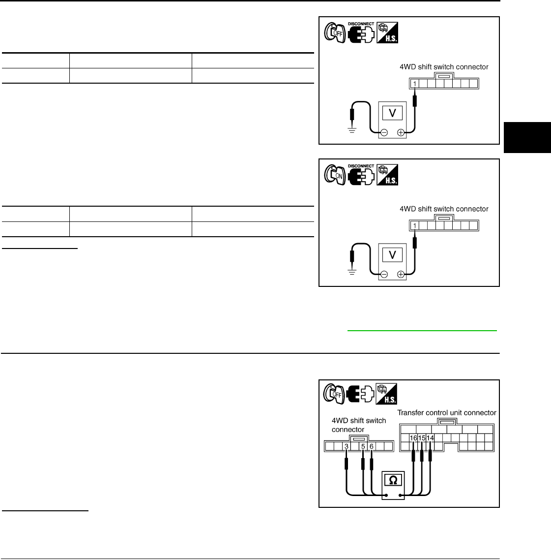
P1813 4WD SHIFT SWITCH
DLN-213
< COMPONENT DIAGNOSIS > [TRANSFER: TX15B]
C
E
F
G
H
I
J
K
L
M
A
B
DLN
N
O
P
2. Disconnect 4WD shift switch harness connector.
3. Check voltage between 4WD shift switch harness connector ter-
minal 1 and ground.
4. Turn ignition switch “ON”. (Do not start engine.)
5. Check voltage between 4WD shift switch harness connector ter-
minal 1 and ground.
Is there voltage?
YES >> GO TO 3.
NO >> 1. Check harness for short or open between 4WD shift
switch harness connector terminal 1 and transfer
shut off relay 2 harness connector E157 terminal 5
and 10A fuse (No. 61 located in the fuse block). If any items are damaged, repair or replace
damaged parts.
2. Perform trouble diagnosis for power supply circuit. Refer to DLN-202, "Diagnosis Procedure".
3.CHECK HARNESS BETWEEN 4WD SHIFT SWITCH AND TRANSFER CONTROL UNIT
1. Turn ignition switch “OFF”. (Stay for at least 5 seconds.)
2. Disconnect transfer control unit harness connector and the 4WD shift switch harness connector.
3. Check continuity between the following terminals.
- Transfer control unit harness connector M165 terminal 14 and
4WD shift switch harness connector M138 terminal 3.
- Transfer control unit harness connector M165 terminal 15 and
4WD shift switch harness connector M138 terminal 5.
- Transfer control unit harness connector M165 terminal 16 and
4WD shift switch harness connector M138 terminal 6.
Also check harness for short to ground and short to power.
Is there continuity?
YES >> GO TO 4.
NO >> Repair or replace damaged parts.
4.CHECK 4WD SHIFT SWITCH
1. Turn ignition switch “OFF”. (Stay for at least 5 seconds.)
2. Remove 4WD shift switch harness connector.
Connector Terminal Voltage (Approx.)
M138 1 - Ground 0V
SDIA2803E
Connector Terminal Voltage (Approx.)
M138 1 - Ground Battery voltage
SDIA2802E
Continuity should exist.
SDIA3366E
Revision: October 2008
2009 Pathfinder
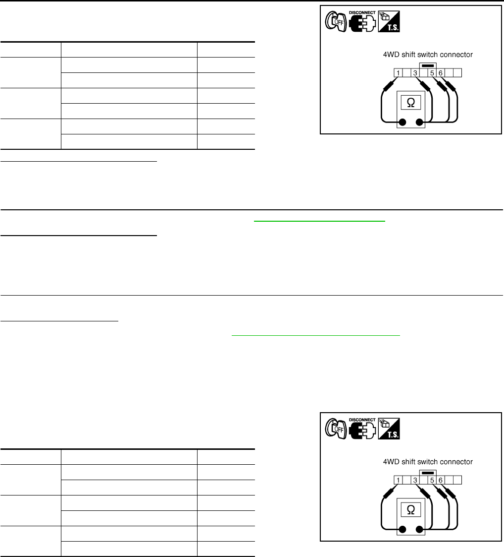
DLN-214
< COMPONENT DIAGNOSIS > [TRANSFER: TX15B]
P1813 4WD SHIFT SWITCH
3. Operate 4WD shift switch and check continuity between 4WD
shift switch terminals.
Are the inspection results normal?
YES >> GO TO 5.
NO >> Replace 4WD shift switch.
5.CHECK TRANSFER CONTROL UNIT
Check transfer control unit input/output signal. Refer to DLN-233, "Reference Value".
Are the inspection results normal?
YES >> GO TO 6.
NO >> Check transfer control unit pin terminals for damage or loose connection with harness connector.
If any items are damaged, repair or replace damaged parts.
6.CHECK DTC
Drive the vehicle and then perform self-diagnosis.
Is DTC P1813 displayed?
YES >> Replace transfer control unit. Refer to DLN-271, "Removal and Installation".
NO >> Inspection End.
Component Inspection INFOID:0000000003937343
1. Turn ignition switch “OFF”. (Stay for at least 5 seconds.)
2. Remove 4WD shift switch harness connector.
3. Operate 4WD shift switch and check continuity between 4WD
shift switch terminals.
4. If the inspection results are abnormal replace the 4WD shift switch.
Terminal Condition Continuity
1 - 3 4WD shift switch: 2WD Yes
4WD shift switch: 4H and 4LO No
1 - 5 4WD shift switch: 4H Yes
4WD shift switch: 2WD and 4LO No
1 - 6 4WD shift switch: 4LO Yes
4WD shift switch: 2WD and 4H No
SDIA2805E
Terminal Condition Continuity
1 - 3 4WD shift switch: 2WD Yes
4WD shift switch: 4H and 4LO No
1 - 5 4WD shift switch: 4H Yes
4WD shift switch: 2WD and 4LO No
1 - 6 4WD shift switch: 4LO Yes
4WD shift switch: 2WD and 4H No
SDIA2805E
Revision: October 2008
2009 Pathfinder
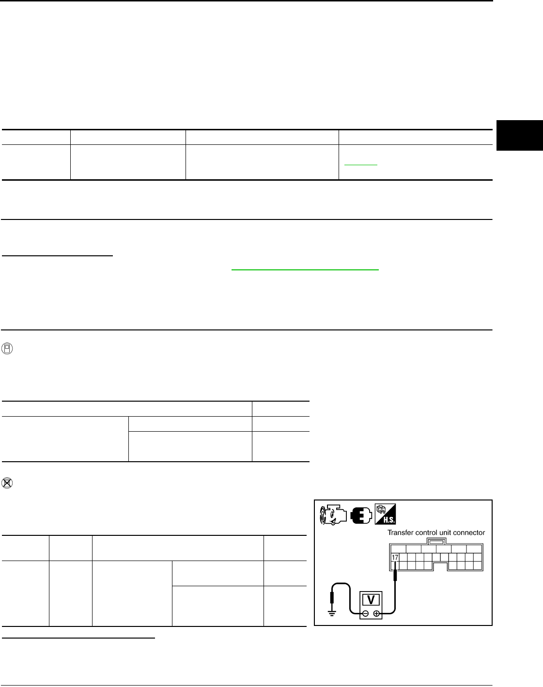
P1814 WAIT DETECTION SWITCH
DLN-215
< COMPONENT DIAGNOSIS > [TRANSFER: TX15B]
C
E
F
G
H
I
J
K
L
M
A
B
DLN
N
O
P
P1814 WAIT DETECTION SWITCH
Description INFOID:0000000003937344
The wait detection switch detects if the transfer case is in 4WD. DTC P1814 will set if an improper signal from
the wait detection switch is input due to open or short circuit.
DTC Logic INFOID:0000000003937345
DTC DETECTION LOGIC
DTC CONFIRMATION PROCEDURE
1.DTC CONFIRMATION PROCEDURE
1. Turn ignition switch ON.
2. Perform self-diagnosis.
Is DTC P1814 detected?
YES >> Perform diagnosis procedure. Refer to DLN-215, "Diagnosis Procedure".
NO >> Inspection End.
Diagnosis Procedure INFOID:0000000003937346
1.CHECK WAIT DETECTION SWITCH SIGNAL
With CONSULT-III
1. Start engine.
2. Select “DATA MONITOR” mode for “ALL MODE AWD/4WD” with CONSULT-III.
3. Read out the value of “WAIT DETCT SW”.
Without CONSULT-III
1. Start engine.
2. Check voltage between transfer control unit harness connector
terminal and ground.
Are the inspection results normal?
YES >> GO TO 5.
NO >> GO TO 2.
2.CHECK HARNESS BETWEEN TRANSFER CONTROL UNIT AND WAIT DETECTION SWITCH
DTC CONSULT-III Diagnostic item is detected when... Reference
[P1814] 4WD DETECT SWITCH
Improper signal from wait detection
switch is input due to open or short cir-
cuit. DLN-215
Condition Display value
• Vehicle stopped
• Engine running
• A/T selector lever “N” position
• Brake pedal depressed
4WD shift switch: 4H and 4LO ON
4WD shift switch: 2WD OFF
Connector Terminal Condition Voltage
(Approx.)
M165 17 -
Ground
• Vehicle stopped
• Engine running
• A/T selector lever
“N” position
• Brake pedal de-
pressed
4WD shift switch
: 4H and 4LO 0V
4WD shift switch: 2WD Battery
voltage
SDIA3367E
Revision: October 2008
2009 Pathfinder
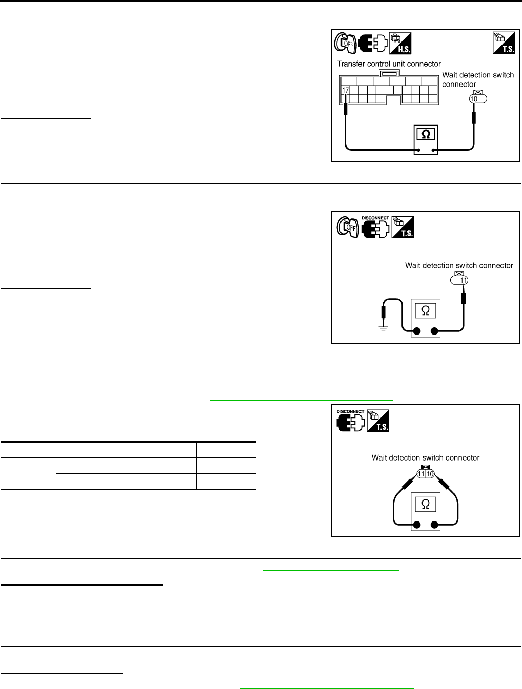
DLN-216
< COMPONENT DIAGNOSIS > [TRANSFER: TX15B]
P1814 WAIT DETECTION SWITCH
1. Turn ignition switch “OFF”. (Stay for at least 5 seconds.)
2. Disconnect transfer control unit harness connector and the wait detection switch harness connector.
3. Check continuity between transfer control unit harness connec-
tor M165 terminal 17 and wait detection switch harness connec-
tor F73 terminal 10.
Also check harness for short to ground and short to power.
Is there continuity?
YES >> GO TO 3.
NO >> Repair or replace damaged parts.
3.CHECK GROUND CIRCUIT
1. Turn ignition switch “OFF”. (Stay for at least 5 seconds.)
2. Disconnect wait detection switch harness connector.
3. Check continuity between wait detection switch harness con-
nector F73 terminal 11 and ground.
Also check harness for short to power.
Is there continuity?
YES >> GO TO 4.
NO >> Repair open circuit or short to power in harness or con-
nectors.
4.CHECK WAIT DETECTION SWITCH
1. Turn ignition switch “OFF”. (Stay for at least 5 seconds.)
2. Disconnect wait detection switch harness connector.
3. Remove wait detection switch. Refer to DLN-194, "Component Parts Location".
4. Push and release wait detection switch and check continuity
between wait detection switch terminals 10 and 11.
Are the inspection results normal?
YES >> GO TO 5.
NO >> Replace wait detection switch.
5.CHECK TRANSFER CONTROL UNIT
Check transfer control unit input/output signal. Refer to DLN-233, "Reference Value".
Are the inspection results normal?
YES >> GO TO 6.
NO >> Check transfer control unit pin terminals for damage or loose connection with harness connector.
If any items are damaged, repair or replace damaged parts.
6.CHECK DTC
Drive the vehicle and then perform self-diagnosis.
Is DTC P1814 displayed?
YES >> Replace transfer control unit. Refer to DLN-271, "Removal and Installation".
NO >> Inspection End.
Continuity should exist.
SDIA3368E
Continuity should exist.
PDIA0207E
Terminal Condition Continuity
10 - 11 Push wait detection switch Yes
Release wait detection switch No
PDIA0208E
Revision: October 2008
2009 Pathfinder
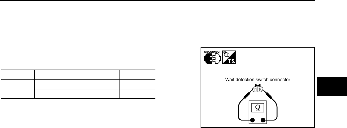
P1814 WAIT DETECTION SWITCH
DLN-217
< COMPONENT DIAGNOSIS > [TRANSFER: TX15B]
C
E
F
G
H
I
J
K
L
M
A
B
DLN
N
O
P
Component Inspection INFOID:0000000003937347
1. Turn ignition switch “OFF”. (Stay for at least 5 seconds.)
2. Disconnect wait detection switch harness connector.
3. Remove wait detection switch. Refer to DLN-194, "Component Parts Location".
4. Push and release wait detection switch and check continuity
between wait detection switch terminals 10 and 11.
5. If the inspection results are abnormal replace the wait detection
switch.
Terminal Condition Continuity
10 - 11 Push wait detection switch Yes
Release wait detection switch No
PDIA0208E
Revision: October 2008
2009 Pathfinder

DLN-218
< COMPONENT DIAGNOSIS > [TRANSFER: TX15B]
P1816 PNP SWITCH
P1816 PNP SWITCH
Description INFOID:0000000003937348
The A/T PNP switch transmits the A/T position indicator signal (PNP switch signal) via CAN communication to
the transfer control unit. DTC P1816 will set when the A/T PNP switch signal is malfunctioning or there is a
communication error.
DTC Logic INFOID:0000000003937349
DTC DETECTION LOGIC
DTC CONFIRMATION PROCEDURE
1.DTC CONFIRMATION PROCEDURE
1. Turn ignition switch ON.
2. Perform self-diagnosis.
Is DTC P1816 displayed?
YES >> Perform diagnosis procedure. Refer to DLN-218, "Diagnosis Procedure".
NO >> Inspection End.
Diagnosis Procedure INFOID:0000000003937350
1.CHECK DTC WITH TCM
Perform self-diagnosis with TCM. Refer to TM-36, "CONSULT-III Function (TRANSMISSION)".
Is any malfunction detected by self-diagnosis?
YES >> Check the malfunctioning system.
NO >> GO TO 2.
2.CHECK TRANSFER CONTROL UNIT
Check transfer control unit input/output signal. Refer to DLN-233, "Reference Value".
Is the inspection result normal?
YES >> GO TO 3.
NO >> Check transfer control unit pin terminals for damage or loose connection with harness connector.
If any items are damaged, repair or replace damaged parts.
3.CHECK DTC
Drive the vehicle and then perform self-diagnosis.
Is DTC P1816 displayed?
YES >> Perform self-diagnosis with TCM again.
NO >> Inspection End.
DTC CONSULT-III Diagnostic item is detected when... Reference
[P1816] PNP SW/CIRC When A/T PNP switch signal is malfunc-
tion or communication error between the
vehicles.
DLN-218
Revision: October 2008
2009 Pathfinder

P1817 ACTUATOR MOTOR
DLN-219
< COMPONENT DIAGNOSIS > [TRANSFER: TX15B]
C
E
F
G
H
I
J
K
L
M
A
B
DLN
N
O
P
P1817 ACTUATOR MOTOR
Description INFOID:0000000003937351
The actuator motor receives signals from the transfer control unit and controls shift rods which shift the trans-
fer case. DTC P1817 will set when any of the following occur:
• Motor does not operate properly due to open or short circuit in actuator motor.
• Malfunction is detected in the actuator motor. (When 4WD shift switch is operated and actuator motor does
not operate)
• Malfunction is detected in transfer shift high relay or transfer shift low relay.
DTC Logic INFOID:0000000003937352
DTC DETECTION LOGIC
DTC CONFIRMATION PROCEDURE
1.DTC CONFIRMATION PROCEDURE
1. Turn ignition switch ON.
2. Perform self-diagnosis.
Is DTC P1817 detected?
YES >> Perform diagnosis procedure. Refer to DLN-219, "Diagnosis Procedure".
NO >> Inspection End.
Diagnosis Procedure INFOID:0000000003937353
1.CHECK ACTUATOR MOTOR SIGNAL
With CONSULT-III
1. Start engine.
2. Select “DATA MONITOR” mode for “ALL MODE AWD/4WD” with CONSULT-III.
3. Read out the value of “SHIFT ACT1”, “SHIFT AC MON1”, “SHIFT ACT2”, “SHIFT AC MON2”.
DTC CONSULT-III Diagnostic item is detected when... Reference
[P1817] SHIFT ACTUATOR
• Motor does not operate properly due
to open or short circuit in actuator mo-
tor.
• Malfunction is detected in the actuator
motor. (When 4WD shift switch is op-
erated and actuator motor is not oper-
ated)
• Malfunction is detected in transfer shift
high relay or transfer shift low relay.
DLN-219
Revision: October 2008
2009 Pathfinder
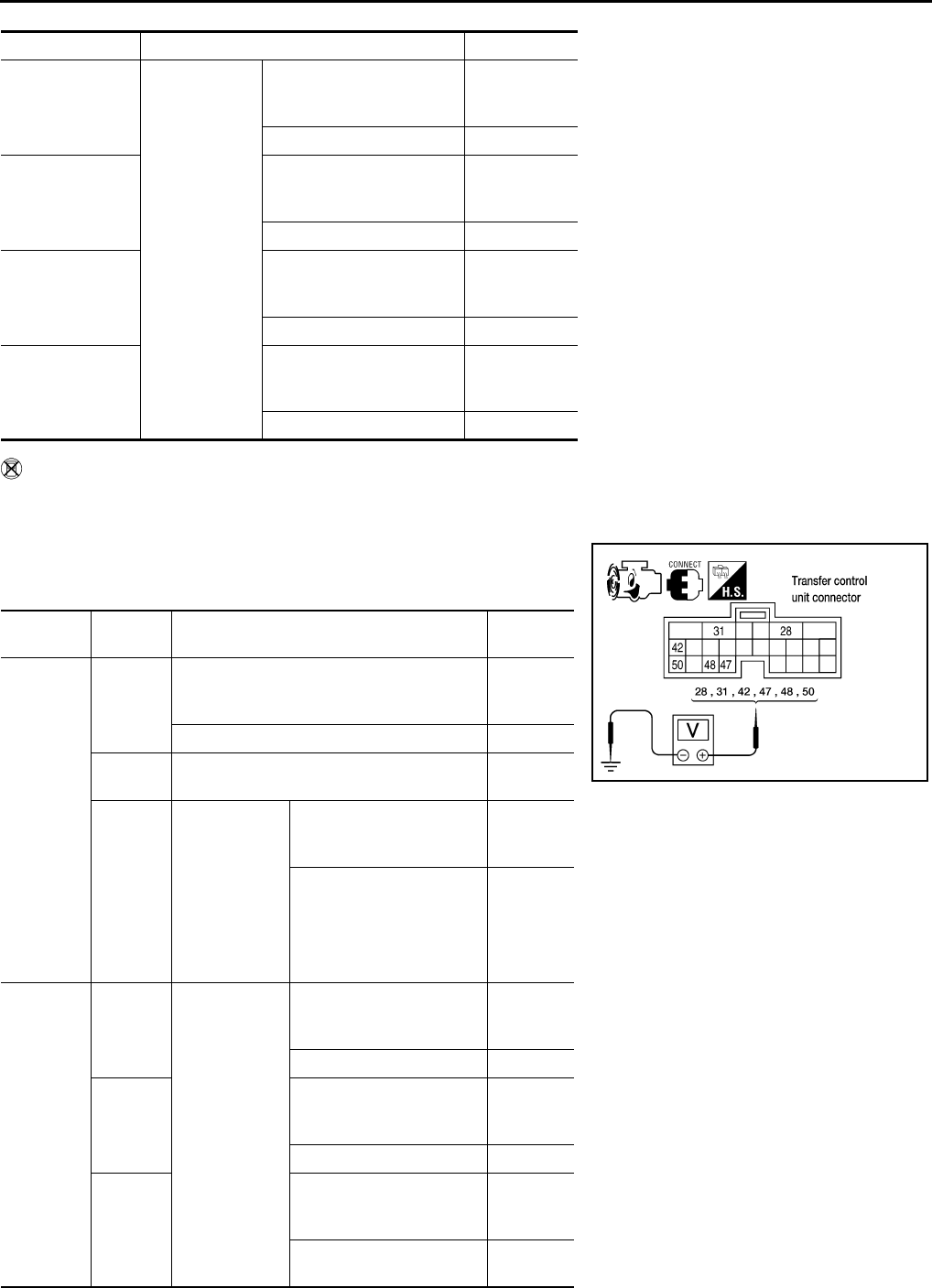
DLN-220
< COMPONENT DIAGNOSIS > [TRANSFER: TX15B]
P1817 ACTUATOR MOTOR
Without CONSULT-III
1. Start engine.
2. Depress brake pedal and stop vehicle.
3. Set A/T selector lever to "N" position.
4. Check voltage between transfer control unit harness connector
terminal and ground.
Monitored item Condition Display value
SHIFT ACT1
• Vehicle
stopped
• Engine run-
ning
•A/T selector
lever “N” po-
sition
• Brake pedal
depressed
4WD shift switch: 2WD to
4H or 4H to 4LO or 2WD to
4LO
ON
Except the above OFF
SHIFT AC MON1
4WD shift switch: 2WD to
4H or 4H to 4LO or 2WD to
4LO ON
Except the above OFF
SHIFT ACT2
4WD shift switch: 4LO to
4H or 4H to 2WD or 4LO to
2WD
ON
Except the above OFF
SHIFT AC MON2
4WD shift switch: 4LO to
4H or 4H to 2WD or 4LO to
2WD
ON
Except the above OFF
Connector Terminal Condition Voltage
(Approx.)
M165
28 -
Ground
When 4WD shift switch is operated (While
actuator motor is operating.)
Battery
voltage →
0V
When 4WD shift switch is not operated 0V
31 -
Ground Always 0V
42 -
Ground
• Vehicle
stopped
• Engine run-
ning
• A/T selector
lever “N” po-
sition
• Brake pedal
depressed
4WD shift switch: 2WD to
4H or 4H to 4LO or 2WD to
4LO
0V
Except the above Battery
voltage
M165
47 -
Ground • Vehicle
stopped
• Engine run-
ning
• A/T selector
lever “N” po-
sition
• Brake pedal
depressed
4WD shift switch: 2WD to
4H or 4H to 4LO or 2WD to
4LO
Battery
voltage →
0V
Except the above 0V
48 -
Ground
4WD shift switch: 4LO to
4H or 4H to 2WD or 4LO to
2WD
Battery
voltage →
0V
Except the above 0V
50 -
Ground
4WD shift switch: 4LO to
4H or 4H to 2WD or 4LO to
2WD
0V
Except the above Battery
voltage
WDIA0144E
Revision: October 2008
2009 Pathfinder
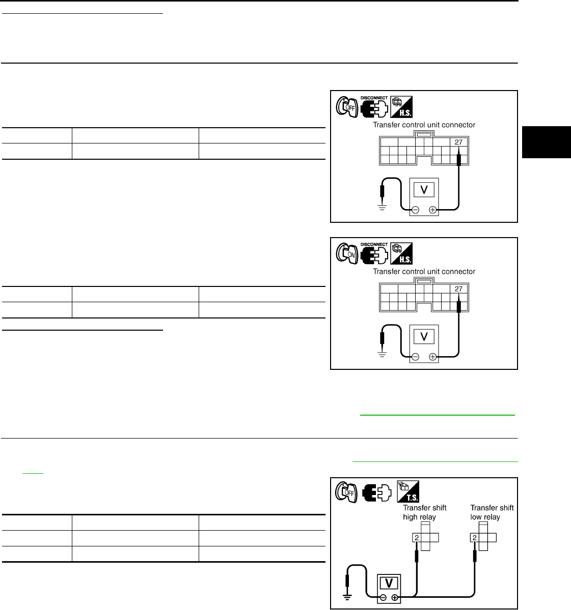
P1817 ACTUATOR MOTOR
DLN-221
< COMPONENT DIAGNOSIS > [TRANSFER: TX15B]
C
E
F
G
H
I
J
K
L
M
A
B
DLN
N
O
P
Are the inspection results normal?
YES >> GO TO 9.
NO >> GO TO 2.
2.CHECK ACTUATOR MOTOR POWER SUPPLY CIRCUIT
1. Turn ignition switch “OFF”. (Stay for at least 5 seconds.)
2. Disconnect transfer control unit harness connector.
3. Check voltage between transfer control unit harness connector
terminal 27 and ground.
4. Turn ignition switch “ON”.
5. Check voltage between transfer control unit harness connector
terminal 27 and ground.
Are the inspection results normal?
YES >> GO TO 3.
NO >> 1. Check harness for short or open between transfer
control unit harness connector M165 terminal 27
and transfer shut off relay 2 harness connector
E157 terminal 5 and 10A fuse (No. 57, located in the fuse and relay block). If any items are
damaged, repair or replace damaged parts.
2. Perform trouble diagnosis for power supply circuit. Refer to DLN-202, "Diagnosis Procedure".
3.CHECK TRANSFER RELAY POWER SUPPLY CIRCUIT
1. Turn ignition switch “OFF”. (Stay for at least 5 seconds.)
2. Remove transfer shift high relay and transfer shift low relay. Refer to DLN-194, "Component Parts Loca-
tion".
3. Check voltage between transfer control unit harness connector
terminal and ground.
Connector Terminal Voltage (Approx.)
M165 27 - Ground 0V
SDIA2808E
Connector Terminal Voltage (Approx.)
M165 27 - Ground Battery voltage
SDIA2807E
Connector Terminal Voltage (Approx.)
E44 2 - Ground 0V
E43 2 - Ground 0V
SDIA3384E
Revision: October 2008
2009 Pathfinder
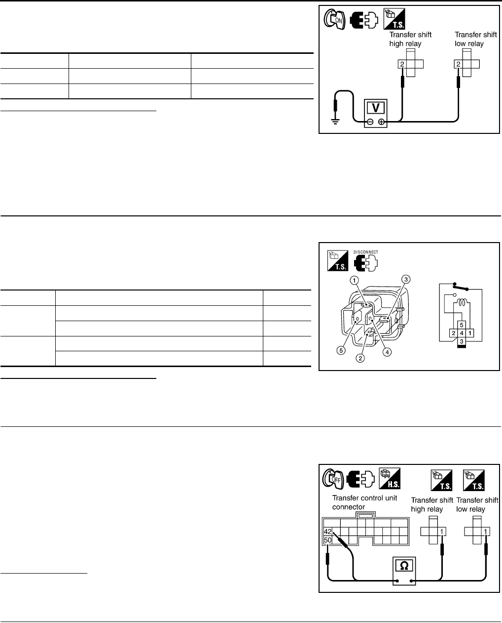
DLN-222
< COMPONENT DIAGNOSIS > [TRANSFER: TX15B]
P1817 ACTUATOR MOTOR
4. Turn ignition switch “ON”. (Do not start engine.)
5. Check voltage between transfer control unit harness connector
terminal and ground.
Are the inspection results normal?
YES >> GO TO 4.
NO >> Check the following. If any items are damaged, repair
or replace damaged parts.
• Harness for short or open between transfer control unit harness connector terminal 27 and
transfer shift high relay harness connector E44 terminal 2.
• Harness for short or open between transfer control unit harness connector terminal 27 and
transfer shift low relay harness connector terminal E43 terminal 2.
4.CHECK TRANSFER RELAY
1. Turn ignition switch “OFF”. (Stay for at least 5 seconds.)
2. Remove transfer shift high relay and transfer shift low relay.
3. Apply 12V direct current between transfer shift high and low
relay terminals 1 and 2.
4. Check continuity between relay terminals 3 and 4, 3 and 5.
Are the inspection results normal?
YES >> GO TO 5.
NO >> Replace the transfer shift high or low relay.
5.CHECK (1): HARNESS BETWEEN TRANSFER CONTROL UNIT AND TRANSFER SHIFT RELAY
1. Turn ignition switch “OFF”. (Stay for at least 5 seconds.)
2. Disconnect transfer control unit harness connector.
3. Remove transfer shift high relay and transfer shift low relay.
4. Check continuity between the following terminals.
- Transfer control unit harness connector M165 terminal 42 and
transfer shift high relay harness connector E44 terminal 1.
- Transfer control unit harness connector M165 terminal 50 and
transfer shift low relay harness connector E43 terminal 1.
Also check harness for short to ground and short to power.
Is there continuity?
YES >> GO TO 6.
NO >> Repair or replace damaged parts.
6.CHECK (2): HARNESS BETWEEN TRANSFER CONTROL UNIT AND TRANSFER SHIFT RELAY
1. Turn ignition switch “OFF”. (Stay for at least 5 seconds.)
2. Disconnect transfer control unit harness connector.
3. Remove transfer shift high relay and transfer shift low relay.
Connector Terminal Voltage (Approx.)
E44 2 - Ground Battery voltage
E43 2 - Ground Battery voltage
SDIA3385E
Terminal Condition Continuity
3 - 4 12V direct current supply between terminals 1 and 2 No
OFF Yes
3 - 5 12V direct current supply between terminals 1 and 2 Yes
OFF No
LDIA0099E
Continuity should exist.
SDIA3386E
Revision: October 2008
2009 Pathfinder
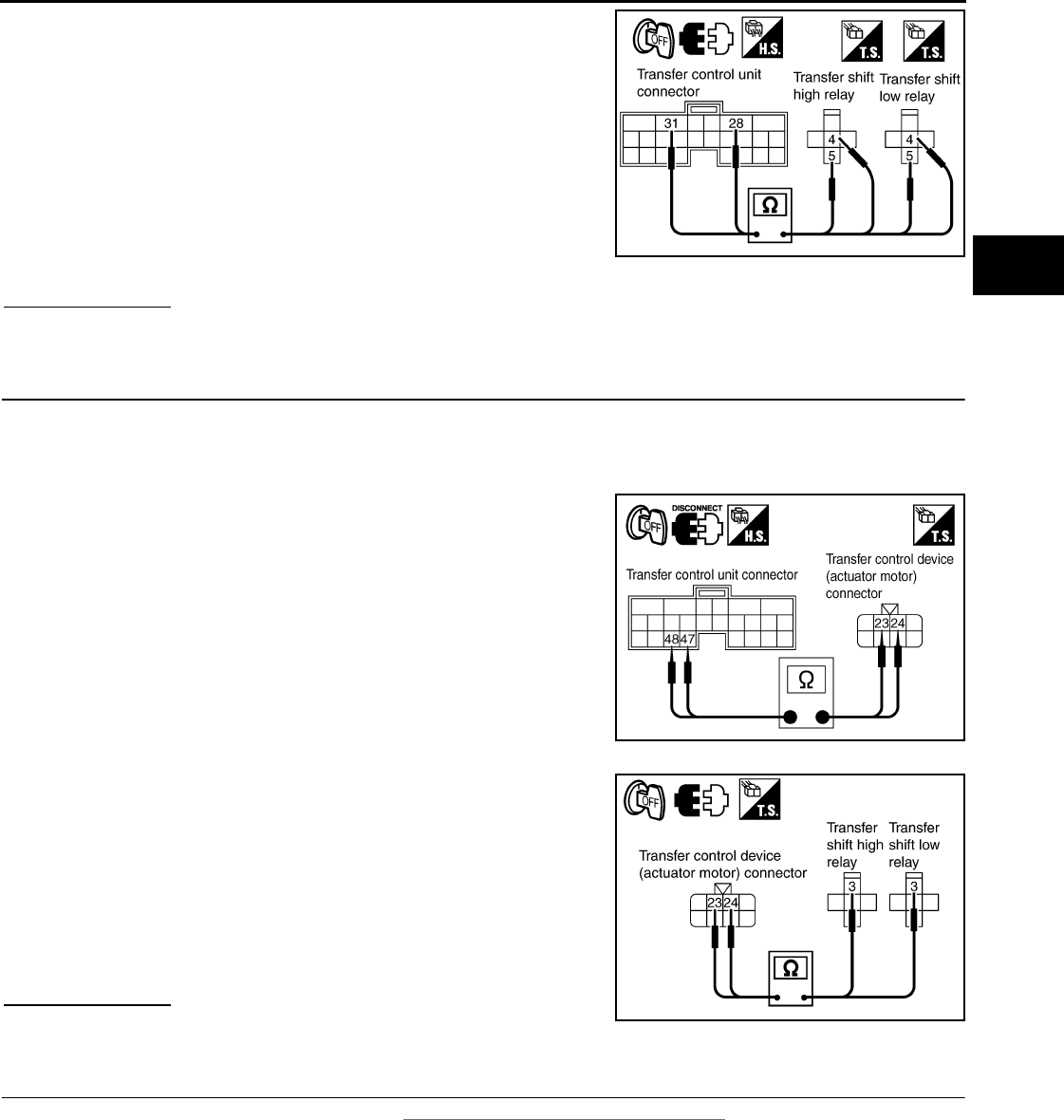
P1817 ACTUATOR MOTOR
DLN-223
< COMPONENT DIAGNOSIS > [TRANSFER: TX15B]
C
E
F
G
H
I
J
K
L
M
A
B
DLN
N
O
P
4. Check continuity between the following terminals.
- Transfer control unit harness connector M165 terminal 28 and
transfer shift high relay harness connector E44 terminal 5.
- Transfer control unit harness connector M165 terminal 28 and
transfer shift low relay harness connector E43 terminal 5.
- Transfer control unit harness connector M165 terminal 31 and
transfer shift high relay harness connector E44 terminal 4.
- Transfer control unit harness connector M165 terminal 31 and
transfer shift low relay harness connector E43 terminal 4.
Also check harness for short to ground and short to power.
Is there continuity?
YES >> GO TO 7.
NO >> Repair or replace damaged parts.
7.CHECK ACTUATOR MOTOR OPERATION CIRCUIT
1. Turn ignition switch “OFF”. (Stay for at least 5 seconds.)
2. Disconnect transfer control unit harness connector and the transfer control device (actuator motor) har-
ness connector.
3. Check continuity between the following terminals.
- Transfer control unit harness connector M165 terminal 47 and
transfer control device (actuator motor) harness connector F72
terminal 23.
- Transfer control unit harness connector M165 terminal 48 and
transfer control device (actuator motor) harness connector F72
terminal 24.
- Transfer control device (actuator motor) harness connector F72
terminal 24 and transfer shift high relay harness connector E44
terminal 3.
- Transfer control device (actuator motor) harness connector F72
terminal 23 and transfer shift low relay harness connector E43
terminal 3.
Also check harness for short to ground and short to power.
Is there continuity?
YES >> GO TO 8.
NO >> Repair or replace damaged parts.
8.CHECK ACTUATOR MOTOR
1. Remove transfer control device. Refer to DLN-276, "Removal and Installation".
Continuity should exist. SDIA3387E
SDIA2811E
Continuity should exist.
SDIA3394E
Revision: October 2008
2009 Pathfinder
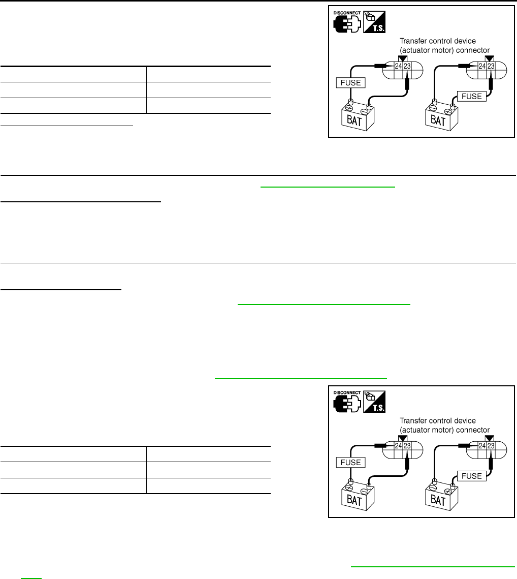
DLN-224
< COMPONENT DIAGNOSIS > [TRANSFER: TX15B]
P1817 ACTUATOR MOTOR
2. Check operation by applying battery voltage to transfer control
device (actuator motor) terminals 23 and 24.
CAUTION:
Be careful not to overheat the harness.
Does actuator motor rotate?
YES >> GO TO 9.
NO >> Replace transfer control device (actuator motor).
9.CHECK TRANSFER CONTROL UNIT
Check transfer control unit input/output signal. Refer to DLN-233, "Reference Value".
Are the inspection results normal?
YES >> GO TO 10.
NO >> Check transfer control unit pin terminals for damage or loose connection with harness connector.
If any items are damaged, repair or replace damaged parts.
10.CHECK DTC
Perform the self-diagnosis, after driving a vehicle for a while.
Is DTC P1817 displayed?
YES >> Replace transfer control unit. Refer to DLN-271, "Removal and Installation".
NO >> Inspection End.
Component Inspection INFOID:0000000003937354
ACTUATOR MOTOR
1. Remove transfer control device. Refer to DLN-276, "Removal and Installation".
2. Check operation by applying battery voltage to transfer control
device (actuator motor) terminals 23 and 24.
CAUTION:
Be careful not to overheat the harness.
3. If the inspection results are abnormal replace the transfer control
device (actuator motor).
TRANSFER RELAY
1. Turn ignition switch “OFF”. (Stay for at least 5 seconds.)
2. Remove transfer shift high relay and transfer shift low relay 2. Refer to DLN-194, "Component Parts Loca-
tion".
3. Apply 12V direct current between transfer shift high and low relay terminals 1 and 2.
Terminal Actuator motor
24 (Battery voltage) - 23 (Ground) Clockwise rotate
23 (Battery voltage) - 24 (Ground) Counterclockwise rotate
SDIA2386E
Terminal Actuator motor
24 (Battery voltage) - 23 (Ground) Clockwise rotate
23 (Battery voltage) - 24 (Ground) Counterclockwise rotate
SDIA2386E
Revision: October 2008
2009 Pathfinder
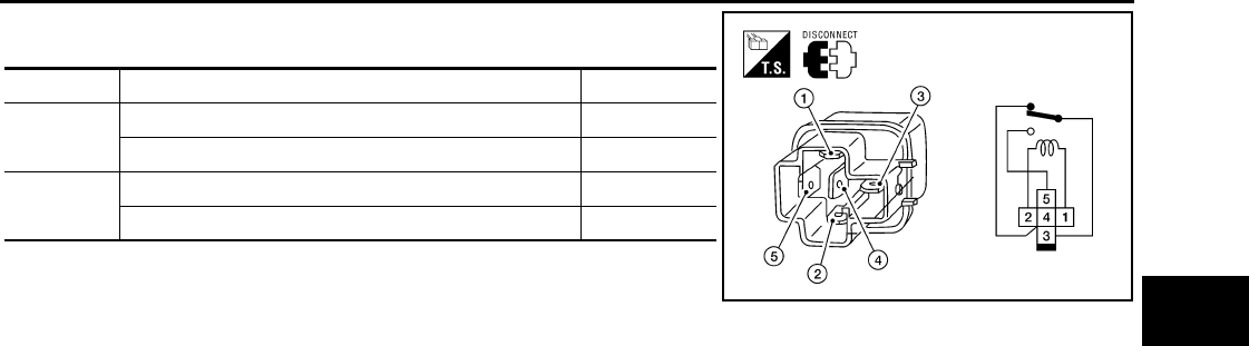
P1817 ACTUATOR MOTOR
DLN-225
< COMPONENT DIAGNOSIS > [TRANSFER: TX15B]
C
E
F
G
H
I
J
K
L
M
A
B
DLN
N
O
P
4. Check continuity between relay terminals 3 and 4, and 3 and 5.
5. If the inspection results are abnormal replace the transfer shift
high or low relay.
Terminal Condition Continuity
3 - 4 12V direct current supply between terminals 1 and 2 No
OFF Yes
3 - 5 12V direct current supply between terminals 1 and 2 Yes
OFF No
LDIA0099E
Revision: October 2008
2009 Pathfinder
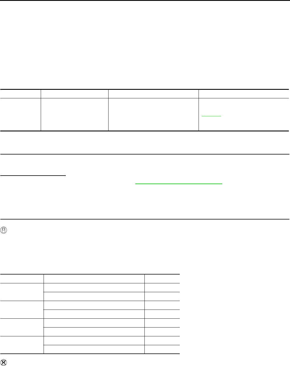
DLN-226
< COMPONENT DIAGNOSIS > [TRANSFER: TX15B]
P1818 ACTUATOR POSITION SWITCH
P1818 ACTUATOR POSITION SWITCH
Description INFOID:0000000003937355
The actuator position switch detects the current actuator motor range. DTC P1818 will set if either of the fol-
lowing occur:
• Improper signal from actuator position switch is input due to open or short circuit.
• Malfunction is detected in actuator position switch.
DTC Logic INFOID:0000000003937356
DTC DETECTION LOGIC
DTC CONFIRMATION PROCEDURE
1.DTC CONFIRMATION PROCEDURE
1. Turn ignition switch ON.
2. Perform self-diagnosis.
Is DTC P1818 detected?
YES >> Perform diagnosis procedure. Refer to DLN-226, "Diagnosis Procedure".
NO >> Inspection End.
Diagnosis Procedure INFOID:0000000003937357
1.CHECK ACTUATOR POSITION SWITCH SIGNAL
With CONSULT-III
1. Start engine.
2. Depress brake pedal and stop vehicle.
3. Set A/T selector lever to "N" position.
4. Select “DATA MONITOR” mode for “ALL MODE AWD/4WD” with CONSULT-III.
5. Read out the value of “SHIFT POS SW1”, “SHIFT POS SW2”, “SHIFT POS SW3”, “SHIFT POS SW4”.
Without CONSULT-III
1. Start engine.
2. Depress brake pedal and stop vehicle.
3. Set A/T selector lever to "N" position.
DTC CONSULT-III Diagnostic item is detected when... Reference
[P1818] SHIFT ACT POSI SW
• Improper signal from actuator position
switch is input due to open or short cir-
cuit.
• Malfunction is detected in actuator po-
sition switch.
DLN-226
Monitored item Condition Display value
SHIFT POS SW1 4WD shift switch: 2WD and 4LO ON
4WD shift switch: 4H OFF
SHIFT POS SW2 4WD shift switch: 4LO ON
4WD shift switch: 2WD and 4H OFF
SHIFT POS SW3 4WD shift switch: 2WD and 4H ON
4WD shift switch: 4LO OFF
SHIFT POS SW4 4WD shift switch: 4H and 4LO ON
4WD shift switch: 2WD OFF
Revision: October 2008
2009 Pathfinder
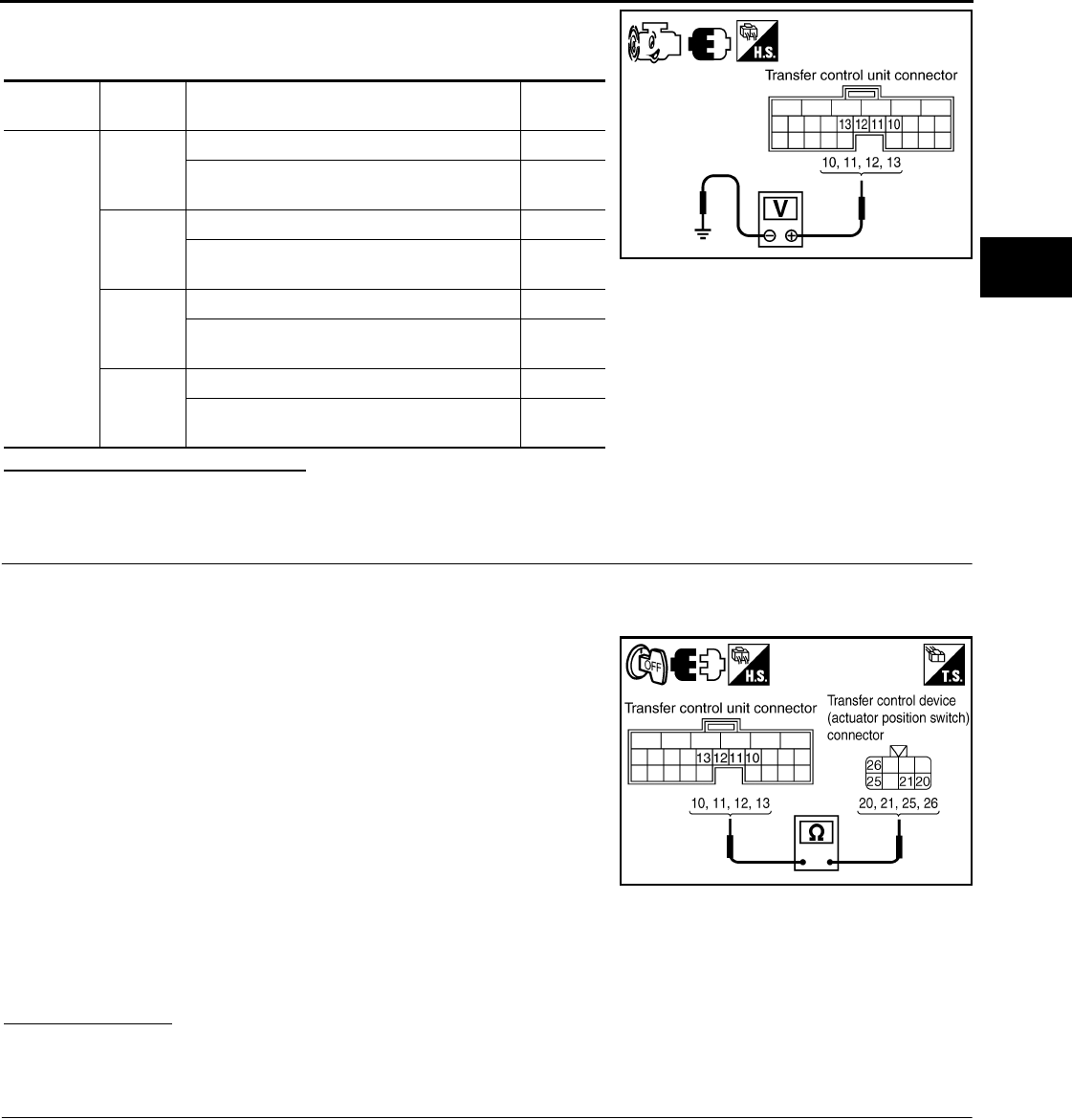
P1818 ACTUATOR POSITION SWITCH
DLN-227
< COMPONENT DIAGNOSIS > [TRANSFER: TX15B]
C
E
F
G
H
I
J
K
L
M
A
B
DLN
N
O
P
4. Check voltage between transfer control unit harness connector
terminal and ground.
Are the inspection results normal?
YES >> GO TO 4.
NO >> GO TO 2.
2.CHECK HARNESS BETWEEN TRANSFER CONTROL UNIT AND ACTUATOR POSITION SWITCH
1. Turn ignition switch “OFF”. (Stay for at least 5 seconds.)
2. Disconnect transfer control unit harness connector and the transfer control device (actuator position
switch) harness connector.
3. Check continuity between the following terminals.
- Transfer control unit harness connector M165 terminal 10 and
transfer control device (actuator position switch) harness con-
nector F72 terminal 26.
- Transfer control unit harness connector M165 terminal 11 and
transfer control device (actuator position switch) harness con-
nector F72 terminal 20.
- Transfer control unit harness connector M165 terminal 12 and
transfer control device (actuator position switch) harness con-
nector F72 terminal 21.
- Transfer control unit harness connector M165 terminal 13 and
transfer control device (actuator position switch) harness con-
nector F72 terminal 25.
Also check harness for short to ground and short to power.
Is there continuity?
YES >> GO TO 3.
NO >> Repair or replace damaged parts.
3.CHECK GROUND CIRCUIT
1. Turn ignition switch “OFF”. (Stay for at least 5 seconds.)
Connector Terminal Condition Voltage
(Approx.)
M165
10 -
Ground
4WD shift switch: 2WD and 4LO 0V
4WD shift switch: 4H Battery
voltage
11 -
Ground
4WD shift switch: 4LO 0V
4WD shift switch: 2WD and 4H Battery
voltage
12 -
Ground
4WD shift switch: 2WD and 4H 0V
4WD shift switch: 4LO Battery
voltage
13 -
Ground
4WD shift switch: 4H and 4LO 0V
4WD shift switch: 2WD Battery
voltage
SDIA3369E
Continuity should exist.
SDIA3370E
Revision: October 2008
2009 Pathfinder
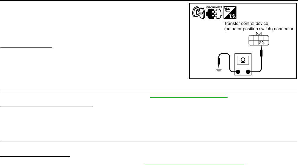
DLN-228
< COMPONENT DIAGNOSIS > [TRANSFER: TX15B]
P1818 ACTUATOR POSITION SWITCH
2. Check continuity between transfer control device (actuator posi-
tion switch) harness connector F72 terminal 22 and ground.
Also check harness for short to power.
Is there continuity?
YES >> GO TO 4.
NO >> Repair open circuit or short to power in harness or con-
nectors.
4.CHECK TRANSFER CONTROL UNIT
Check transfer control unit input/output signal. Refer to DLN-233, "Reference Value".
Are the inspection results normal?
YES >> GO TO 5.
NO >> Check transfer control unit pin terminals for damage or loose connection with harness connector.
If any items are damaged, repair or replace damaged parts.
5.CHECK DTC
Perform the self-diagnosis, after driving a vehicle for a while.
Is DTC P1818 displayed?
YES >> Replace transfer control device. Refer to DLN-271, "Removal and Installation".
NO >> Inspection End.
Continuity should exist.
SDIA2815E
Revision: October 2008
2009 Pathfinder
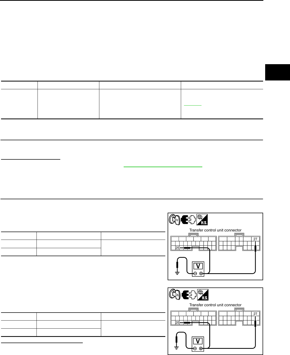
P1819 TRANSFER CONTROL DEVICE
DLN-229
< COMPONENT DIAGNOSIS > [TRANSFER: TX15B]
C
E
F
G
H
I
J
K
L
M
A
B
DLN
N
O
P
P1819 TRANSFER CONTROL DEVICE
Description INFOID:0000000003937358
The transfer control device integrates the actuator motor and actuator position switch. DTC P1819 will set if
either of the following conditions exist:
• Malfunction occurs in transfer control device drive circuit.
• Malfunction is detected in transfer shut off relay 1 and transfer shut off relay 2.
DTC Logic INFOID:0000000003937359
DTC DETECTION LOGIC
DTC CONFIRMATION PROCEDURE
1.DTC CONFIRMATION PROCEDURE
1. Turn ignition switch ON.
2. Perform self-diagnosis.
Is DTC P1819 detected?
YES >> Perform diagnosis procedure. Refer to DLN-229, "Diagnosis Procedure".
NO >> Inspection End.
Diagnosis Procedure INFOID:0000000003937360
1.CHECK POWER SUPPLY
1. Turn ignition switch “OFF”. (Stay for at least 5 seconds.)
2. Disconnect transfer control unit harness connector.
3. Check voltage between transfer control unit harness connector
terminal and ground.
4. Turn ignition switch “ON”. (Do not start engine.)
5. Check voltage between transfer control unit harness connector
terminals and ground.
Are the inspection results normal?
YES >> GO TO 2.
NO >> Check the following. If any items are damaged, repair
or replace damaged parts.
• 10A fuse (No. 57, located in the fuse and relay box).
DTC CONSULT-III Diagnostic item is detected when... Reference
[P1819] SHIFT ACT CIR
• Malfunction is detected in transfer
shut off relay 1 and transfer shut off re-
lay 2.
• Malfunction occurs in transfer control
device drive circuit.
DLN-229
Connector Terminal Voltage (Approx.)
M165 25 - Ground 0V
M166 27 - Ground
SDIA3371E
Connector Terminal Voltage (Approx.)
M165 25 - Ground Battery voltage
M166 27 - Ground
SDIA3372E
Revision: October 2008
2009 Pathfinder
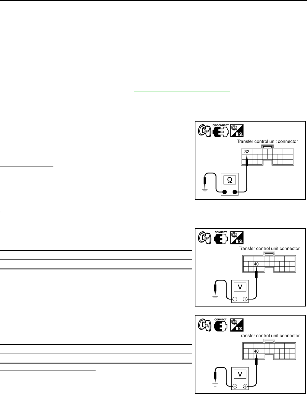
DLN-230
< COMPONENT DIAGNOSIS > [TRANSFER: TX15B]
P1819 TRANSFER CONTROL DEVICE
• 40A fuse (No. J, located in the fuse and fusible link box).
• Harness for short or open between battery and transfer shut off relay 1 harness connector E156
terminal 3.
• Harness for short or open between transfer control unit harness connector M166 terminal 27
and transfer shut off relay 1 harness connector E156 terminal 5.
• Harness for short or open between ignition switch and transfer shut off relay 1 harness connec-
tor E156 terminal 1.
• Harness for short or open between transfer shut off relay 1 harness connector E156 terminal 2
and ground.
• Harness for short or open between ignition switch and transfer control unit harness connector
M165 terminal 25.
• Battery and ignition switch.
• Transfer shut off relay 1. Refer to DLN-204, "Component Inspection".
2.CHECK GROUND CIRCUIT
1. Turn ignition switch "OFF".
2. Disconnect transfer control unit harness connector.
3. Check continuity between transfer control unit harness connec-
tor M166 terminal 32 and ground.
Also check harness for short to power.
Is there continuity?
YES >> GO TO 3.
NO >> Repair open circuit or short to power in harness or con-
nectors.
3.CHECK POWER SUPPLY SIGNAL
1. Turn ignition switch “OFF”. (Stay for at least 5 seconds.)
2. Connect transfer control unit harness connector.
3. Check voltage between transfer control unit harness connector
terminal and ground.
4. Turn ignition switch “ON”. (Do not start engine.)
5. Check voltage between transfer control unit harness connector
terminal and ground.
Are the inspection results normal?
YES >> GO TO 4.
NO >> Check the following. If any items are damaged, repair
or replace damaged parts.
• Harness for short or open between battery and trans-
fer shut off relay 2 harness connector E157 terminal 1.
• Harness for short or open between transfer shut off relay 2 harness connector E157 terminal 2
and transfer control unit harness connector M166 terminal 40.
• Transfer shut off relay 2.
Continuity should exist.
SDIA2818E
Connector Terminal Voltage (Approx.)
M166 40 - Ground Battery voltage
SDIA2819E
Connector Terminal Voltage (Approx.)
M166 40 - Ground 0V
SDIA2820E
Revision: October 2008
2009 Pathfinder

P1819 TRANSFER CONTROL DEVICE
DLN-231
< COMPONENT DIAGNOSIS > [TRANSFER: TX15B]
C
E
F
G
H
I
J
K
L
M
A
B
DLN
N
O
P
4.CHECK TRANSFER CONTROL UNIT
Check transfer control unit input/output signal. Refer to DLN-233, "Reference Value".
Are the inspection results normal?
YES >> GO TO 5 (With CONSULT-III) or GO TO 6 (Without CONSULT-III).
NO >> Check transfer control unit pin terminals for damage or loose connection with harness connector.
If any items are damaged, repair or replace damaged parts.
5.PERFORM SELF-DIAGNOSIS (WITH CONSULT-III)
With CONSULT-III
1. Turn ignition switch “ON”. (Do not start engine.)
2. Select “SELF-DIAG RESULTS” mode for “ALL MODE AWD/4WD” with CONSULT-III.
3. Touch “ERASE”.
4. Turn ignition switch “OFF” and wait at least 10 seconds.
5. Perform the self-diagnosis again.
Is the “SHIFT ACT CIR [P1819]” displayed?
YES >> Replace transfer control unit. Refer to DLN-271, "Removal and Installation".
NO >> Inspection End.
6.PERFORM SELF-DIAGNOSIS (WITHOUT CONSULT-III)
Without CONSULT-III
1. Perform the self-diagnosis and then erase self-diagnostic results. Refer to DLN-198, "CONSULT-III Func-
tion (ALL MODE AWD/4WD)".
2. Perform the self-diagnosis again.
Do the self-diagnostic results indicate transfer control device?
YES >> Replace transfer control unit. Refer to DLN-271, "Removal and Installation".
NO >> Inspection End.
Revision: October 2008
2009 Pathfinder

DLN-232
< COMPONENT DIAGNOSIS > [TRANSFER: TX15B]
P1820 ENGINE SPEED SIGNAL
P1820 ENGINE SPEED SIGNAL
Description INFOID:0000000003937361
The ECM transmits the engine speed signal via CAN communication to the transfer control unit. DTC P1820
will set when either of the following occur:
• Malfunction is detected in engine speed signal that is output from the ECM.
• Improper signal is input while driving.
DTC Logic INFOID:0000000003937362
DTC DETECTION LOGIC
DTC CONFIRMATION PROCEDURE
1.DTC CONFIRMATION PROCEDURE
1. Turn ignition switch ON.
2. Perform self-diagnosis.
Is DTC P1820 detected?
YES >> Perform diagnosis procedure. Refer to DLN-232, "Diagnosis Procedure".
NO >> Inspection End.
Diagnosis Procedure INFOID:0000000003937363
1.CHECK DTC WITH ECM
Perform self-diagnosis with ECM. Refer to EC-73, "CONSULT-III Function (ENGINE)".
Is any malfunction detected by self-diagnosis?
YES >> Check the malfunctioning system.
NO >> GO TO 2.
2.CHECK TRANSFER CONTROL UNIT
Check transfer control unit input/output signal. Refer to DLN-233, "Reference Value".
Are the inspection results normal?
YES >> GO TO 3.
NO >> Check transfer control unit pin terminals for damage or loose connection with harness connector.
If any items are damaged, repair or replace damaged parts.
3.CHECK DTC
Perform the self-diagnosis, after driving a vehicle for a while.
Is DTC P1820 displayed?
YES >> Perform self-diagnosis with ECM again.
NO >> Inspection End.
DTC CONSULT-III Diagnostic item is detected when... Reference
[P1820] ENGINE SPEED SIG
• Malfunction is detected in engine
speed signal that is output from ECM
through CAN communication.
• Improper signal is input while driving.
DLN-232
Revision: October 2008
2009 Pathfinder

TRANSFER CONTROL UNIT
DLN-233
< ECU DIAGNOSIS > [TRANSFER: TX15B]
C
E
F
G
H
I
J
K
L
M
A
B
DLN
N
O
P
ECU DIAGNOSIS
TRANSFER CONTROL UNIT
Reference Value INFOID:0000000003937364
VALUE ON THE DIAGNOSIS TOOL
CONSULT-III data monitor item
Monitored item [Unit] Content Condition Display value
VHCL/S SEN·FR [km/h]
or [mph] Wheel speed (Front wheel)
Vehicle stopped 0 km/h (0 mph)
Vehicle running
CAUTION:
Check air pressure of tire under standard condi-
tion.
Approximately
equal to the indica-
tion on speedome-
ter (Inside of ±10%)
VHCL/S SEN·RR [km/h]
or [mph] Wheel speed (Rear wheel)
Vehicle stopped 0 km/h (0 mph)
Vehicle running
CAUTION:
Check air pressure of tire under standard condi-
tion.
Approximately
equal to the indica-
tion on speedome-
ter (Inside of ±10%)
ENGINE SPEED [rpm] Engine speed
Engine stopped
(Engine speed: Less than 400 rpm) 0 rpm
Engine running
(Engine speed: 400 rpm or more)
Approximately
equal to the indica-
tion on tachometer
BATTERY VOLT [V] Power supply voltage for
transfer control unit Ignition switch: ON Battery voltage
2WD SWITCH [ON/OFF] Input condition from 4WD
shift switch
4WD shift switch: 2WD ON
4WD shift switch: 4H and 4LO OFF
4H SWITCH [ON/OFF] Input condition from 4WD
shift switch
4WD shift switch: 4H ON
4WD shift switch: 2WD and 4LO OFF
4L SWITCH [ON/OFF] Input condition from 4WD
shift switch
4WD shift switch: 4LO ON
4WD shift switch: 2WD and 4H OFF
4L POSI SW [ON/OFF] Condition of 4LO switch
• Vehicle stopped
• Engine running
• A/T selector lever “N”
position
• Brake pedal depressed
4WD shift switch: 4LO ON
Except the above OFF
ATP SWITCH [ON/OFF] Condition of ATP switch
• Vehicle stopped
• Engine running
• A/T selector lever “N”
position
• Brake pedal depressed
4WD shift switch
: 4H to 4LO or 4LO to 4H
(While actuator motor is
operating.)
ON
Except the above OFF
WAIT DETCT SW [ON/
OFF] Condition of wait detection
switch
• Vehicle stopped
• Engine running
• A/T selector lever “N”
position
• Brake pedal depressed
4WD shift switch
: 4H and 4LO ON
4WD shift switch: 2WD OFF
4WD MODE [2H/4H/4L]
Control status of 4WD
(Output condition of 4WD
shift indicator lamp and
4LO indicator lamp)
4WD shift switch
(Engine running)
2WD 2H
4H 4H
4LO 4L
Revision: October 2008
2009 Pathfinder

DLN-234
< ECU DIAGNOSIS > [TRANSFER: TX15B]
TRANSFER CONTROL UNIT
PHYSICAL VALUES
VHCL/S COMP [km/h] or
[mph] Vehicle speed
Vehicle stopped 0 km/h (0 mph)
Vehicle running
CAUTION:
Check air pressure of tire under standard condi-
tion.
Approximately
equal to the indica-
tion on speedome-
ter (Inside of ±10%)
SHIFT ACT 1 [ON/OFF] Output condition to actua-
tor motor (clockwise)
• Vehicle stopped
• Engine running
• A/T selector lever “N”
position
• Brake pedal depressed
4WD shift switch
: 2WD to 4H or 4H to 4LO
or 2WD to 4LO
ON
Except the above OFF
SHIFT AC MON1 [ON/
OFF]
Check signal for transfer
control unit signal output
• Vehicle stopped
• Engine running
• A/T selector lever “N”
position
• Brake pedal depressed
4WD shift switch
: 2WD to 4H or 4H to 4LO
or 2WD to 4LO
ON
Except the above OFF
SHIFT ACT 2 [ON/OFF] Output condition to actua-
tor motor (counterclock-
wise)
• Vehicle stopped
• Engine running
• A/T selector lever “N”
position
• Brake pedal depressed
4WD shift switch
: 4LO to 4H or 4H to 2WD
or 4LO to 2WD ON
Except the above OFF
SHIFT AC MON2 [ON/
OFF] Check signal for transfer
control unit signal output
• Vehicle stopped
• Engine running
• A/T selector lever “N”
position
• Brake pedal depressed
4WD shift switch
: 4LO to 4H or 4H to 2WD
or 4LO to 2WD
ON
Except the above OFF
SHIFT ACT/R MON [ON/
OFF]
Operating condition of ac-
tuator motor relay (integrat-
ed in transfer control unit)
• Vehicle stopped
• Engine running
• A/T selector lever “N”
position
• Brake pedal depressed
When 4WD shift switch is
operated ON
When 4WD shift switch is
not operated OFF
SHIFT POS SW1 [ON/
OFF]
Condition of actuator posi-
tion switch 1
• Vehicle stopped
• Engine running
• A/T selector lever “N”
position
• Brake pedal depressed
4WD shift switch: 2WD
and 4LO ON
4WD shift switch: 4H OFF
SHIFT POS SW2 [ON/
OFF] Condition of actuator posi-
tion switch 2
4WD shift switch: 4LO ON
4WD shift switch: 2WD
and 4H OFF
SHIFT POS SW3 [ON/
OFF] Condition of actuator posi-
tion switch 3
4WD shift switch: 2WD
and 4H ON
4WD shift switch: 4LO OFF
SHIFT POS SW4 [ON/
OFF]
Condition of actuator posi-
tion switch 4
4WD shift switch: 4H and
4LO ON
4WD shift switch: 2WD OFF
4WD FAIL LAMP [ON/
OFF] 4WD warning lamp condi-
tion
4WD warning lamp: ON ON
4WD warning lamp: OFF OFF
2WD IND [ON/OFF] Rear indicator of 4WD shift
indicator lamp condition
Rear indicator of 4WD shift indicator lamp: ON ON
Rear indicator of 4WD shift indicator lamp: OFF OFF
4H IND [ON/OFF]
Front and center indicator
of 4WD shift indicator lamp
condition
Front and center indicator of 4WD shift indicator lamp
: ON ON
Front and center indicator of 4WD shift indicator lamp
: OFF OFF
4L IND [ON/OFF] 4LO indicator lamp condi-
tion
4LO indicator lamp: ON ON
4LO indicator lamp: OFF OFF
Monitored item [Unit] Content Condition Display value
Revision: October 2008
2009 Pathfinder
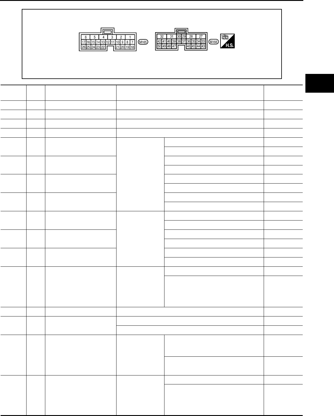
TRANSFER CONTROL UNIT
DLN-235
< ECU DIAGNOSIS > [TRANSFER: TX15B]
C
E
F
G
H
I
J
K
L
M
A
B
DLN
N
O
P
Terminal Layout
AWDIA0620Z
Z
Terminal Wire
color Item Condition Data (Approx.)
1 L CAN-H – –
2 P CAN-L – –
3 SB K-LINE (CONSULT-III signal) – –
6 B Ground Always 0V
10 LG Actuator position switch 1
• Vehicle stopped
• Engine running
• A/T selector le-
ver “N” position
• Brake pedal de-
pressed
4WD shift switch: 2WD and 4LO 0V
4WD shift switch: 4H Battery voltage
11 W Actuator position switch 2 4WD shift switch: 4LO 0V
4WD shift switch: 2WD and 4H Battery voltage
12 BR Actuator position switch 3 4WD shift switch: 2WD and 4H 0V
4WD shift switch: 4LO Battery voltage
13 L Actuator position switch 4 4WD shift switch: 4H and 4LO 0V
4WD shift switch: 2WD Battery voltage
14 G 4WD shift switch (2WD)
Ignition switch: ON
4WD shift switch: 2WD Battery voltage
4WD shift switch: 4H and 4LO 0V
15 O 4WD shift switch (4H) 4WD shift switch: 4H Battery voltage
4WD shift switch: 2WD and 4LO 0V
16 W 4WD shift switch (4LO) 4WD shift switch: 4LO Battery voltage
4WD shift switch: 2WD and 4H 0V
17 O Wait detection switch
• Vehicle stopped
• Engine running
• A/T selector le-
ver “N” position
• Brake pedal de-
pressed
4WD shift switch: 4H and 4LO 0V
4WD shift switch: 2WD Battery voltage
18 B Ground Always 0V
19 R Power supply
(Memory back-up)
Ignition switch: ON Battery voltage
Ignition switch: OFF Battery voltage
23 R ATP switch
• Vehicle stopped
• Engine running
• A/T selector le-
ver “N”
• Brake pedal de-
pressed
4WD shift switch
: 4H to 4LO or 4LO to 4H
(While actuator motor is operating.)
0V
Except the above Battery voltage
24 Y 4LO switch
• Vehicle stopped
• Engine running
• A/T selector le-
ver “N” position
• Brake pedal de-
pressed
4WD shift switch: 4LO 0V
Except the above Battery voltage
Revision: October 2008
2009 Pathfinder

DLN-236
< ECU DIAGNOSIS > [TRANSFER: TX15B]
TRANSFER CONTROL UNIT
25 W/G Ignition switch monitor Ignition switch: ON Battery voltage
Ignition switch: OFF 0V
27 L Actuator motor power supply
Ignition switch: ON Battery voltage
Ignition switch: OFF (5 seconds after ingnition switch is turned
OFF) 0V
28 SB Actuator motor (+) • Vehicle stopped
• Engine running
• A/T selector le-
ver “N” position
• Brake pedal de-
pressed
When 4WD shift switch is operated (while
actuator motor is operating)
Battery voltage
→ 0V
When 4WD shift switch is not operated 0V
31 G Actuator motor (-) Always 0V
32 B Ground Always 0V
35 V 4WD shift indicator lamp
(Rear indicator)
Engine running
Rear indicator of 4WD shift indicator lamp
: ON 0V
Rear indicator of 4WD shift indicator lamp
: OFF Battery voltage
36 BR 4WD shift indicator lamp
(Front and center indicator)
Front and center indicator of 4WD shift in-
dicator lamp: ON 0V
Front and center indicator of 4WD shift in-
dicator lamp: OFF Battery voltage
37 O 4LO indicator lamp 4LO indicator lamp: ON 0V
4LO indicator lamp: OFF Battery voltage
38 GR 4WD warning lamp 4WD warning lamp: ON 0V
4WD warning lamp: OFF Battery voltage
39 LG ATP warning lamp
• Vehicle stopped
• Engine running
• A/T selector le-
ver “P” position
• Brake pedal de-
pressed
4WD shift switch: 4H to 4LO or 4LO to 4H
(While actuator motor is operating.) Battery voltage
Except the above 0V
40 V Transfer shut off relay
Ignition switch: ON 0V
Ignition switch: OFF (5 seconds after ingnition switch is turned
OFF) Battery voltage
42 LG Transfer shift high relay
• Vehicle stopped
• Engine running
• A/T selector le-
ver “N” position
• Brake pedal de-
pressed
4WD shift switch: 2WD to 4H or 4H to 4LO
or 2WD to 4LO 0V
Except the above Battery voltage
44 Y Power supply
Ignition switch: ON Battery voltage
Ignition switch: OFF (5 seconds after ingnition switch is turned
OFF) 0V
45 GR Power supply
Ignition switch: ON Battery voltage
Ignition switch: OFF (5 seconds after ingnition switch is turned
OFF) 0V
Terminal Wire
color Item Condition Data (Approx.)
Revision: October 2008
2009 Pathfinder

TRANSFER CONTROL UNIT
DLN-237
< ECU DIAGNOSIS > [TRANSFER: TX15B]
C
E
F
G
H
I
J
K
L
M
A
B
DLN
N
O
P
CAUTION:
When using a circuit tester to measure voltage for inspection, be sure not to extend forcibly any connector terminals.
NOTE:
Data are reference value and are measured between each terminal and ground.
47 O Transfer shift high relay moni-
tor
• Vehicle stopped
• Engine running
• A/T selector le-
ver “N” position
• Brake pedal de-
pressed
4WD shift switch: 2WD to 4H or 4H to 4LO
or 2WD to 4LO (while actuator motor is op-
erating)
Battery voltage
→ 0V
Except the above 0V
48 R Transfer shift low relay moni-
tor
4WD shift switch: 4LO to 4H or 4H to 2WD
or 4LO to 2WD (while actuator motor is op-
erating)
Battery voltage
→ 0V
Except the above 0V
50 Y Transfer shift low relay
4WD shift switch: 4LO to 4H or 4H to 2WD
or 4LO to 2WD 0V
Except the above Battery voltage
Terminal Wire
color Item Condition Data (Approx.)
Revision: October 2008
2009 Pathfinder
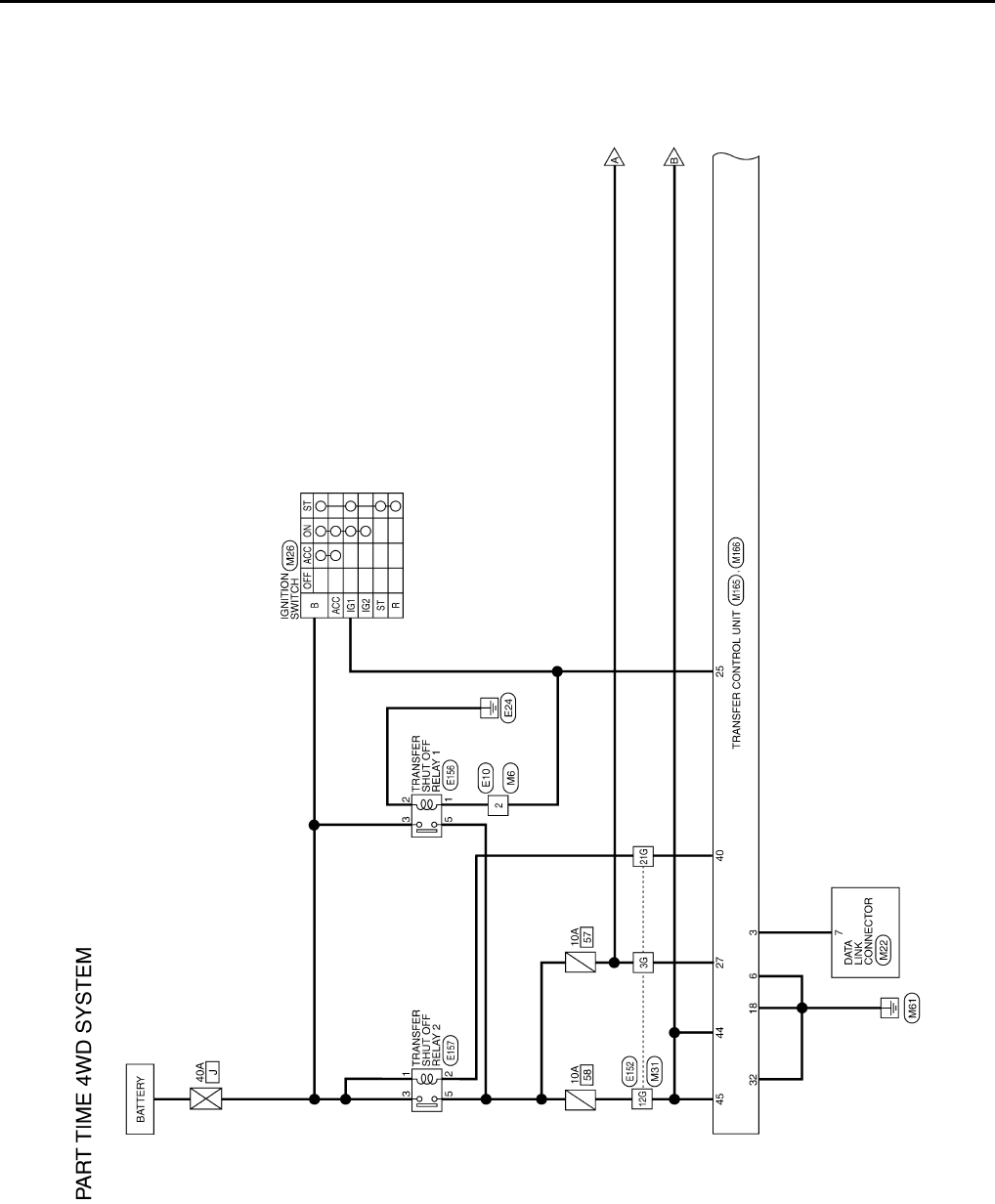
DLN-238
< ECU DIAGNOSIS > [TRANSFER: TX15B]
TRANSFER CONTROL UNIT
Wiring Diagram INFOID:0000000003937365
ABDWA0045G
B
Revision: October 2008
2009 Pathfinder
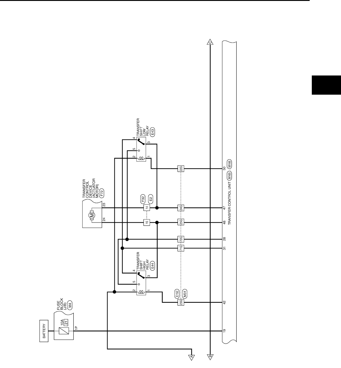
TRANSFER CONTROL UNIT
DLN-239
< ECU DIAGNOSIS > [TRANSFER: TX15B]
C
E
F
G
H
I
J
K
L
M
A
B
DLN
N
O
P
ABDWA0046G
B
Revision: October 2008
2009 Pathfinder
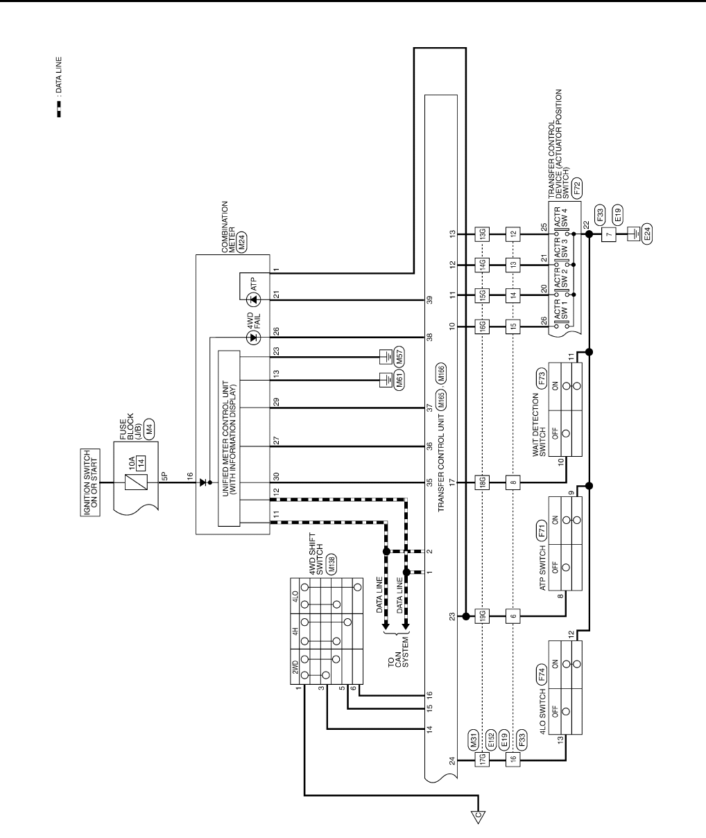
DLN-240
< ECU DIAGNOSIS > [TRANSFER: TX15B]
TRANSFER CONTROL UNIT
ABDWA0047G
B
Revision: October 2008
2009 Pathfinder
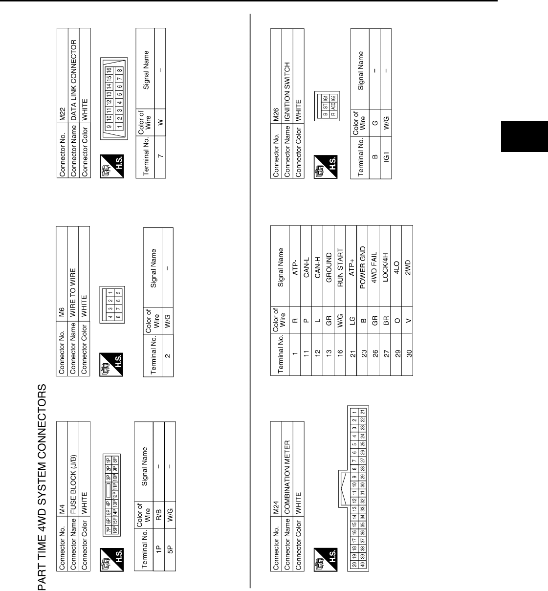
TRANSFER CONTROL UNIT
DLN-241
< ECU DIAGNOSIS > [TRANSFER: TX15B]
C
E
F
G
H
I
J
K
L
M
A
B
DLN
N
O
P
ABDIA0117G
B
Revision: October 2008
2009 Pathfinder
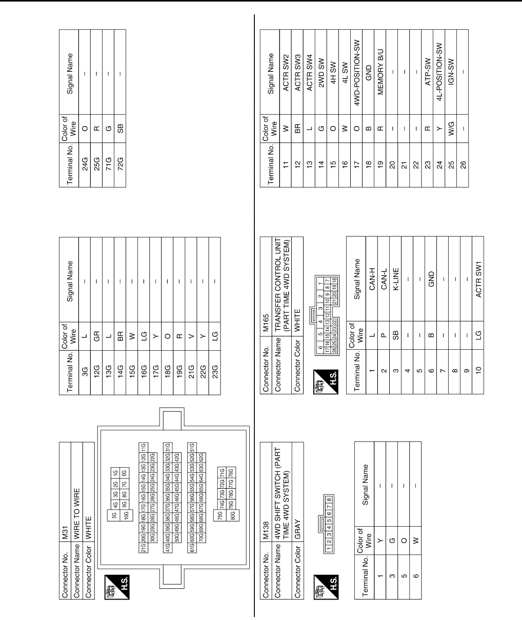
DLN-242
< ECU DIAGNOSIS > [TRANSFER: TX15B]
TRANSFER CONTROL UNIT
ABDIA0118G
B
Revision: October 2008
2009 Pathfinder
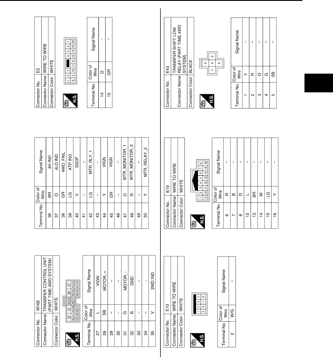
TRANSFER CONTROL UNIT
DLN-243
< ECU DIAGNOSIS > [TRANSFER: TX15B]
C
E
F
G
H
I
J
K
L
M
A
B
DLN
N
O
P
ABDIA0119G
B
Revision: October 2008
2009 Pathfinder
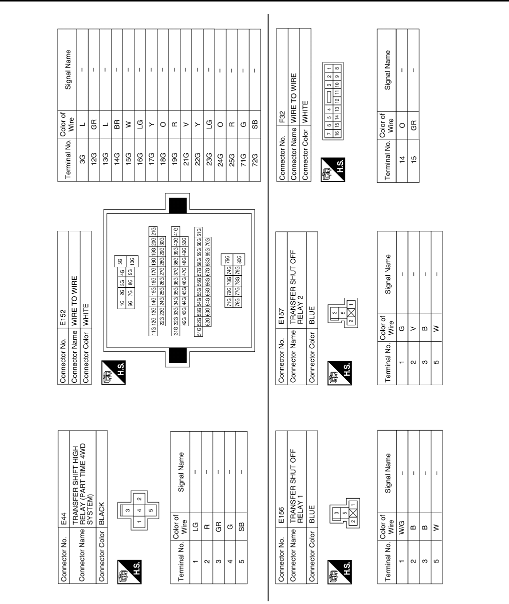
DLN-244
< ECU DIAGNOSIS > [TRANSFER: TX15B]
TRANSFER CONTROL UNIT
ABDIA0120G
B
Revision: October 2008
2009 Pathfinder
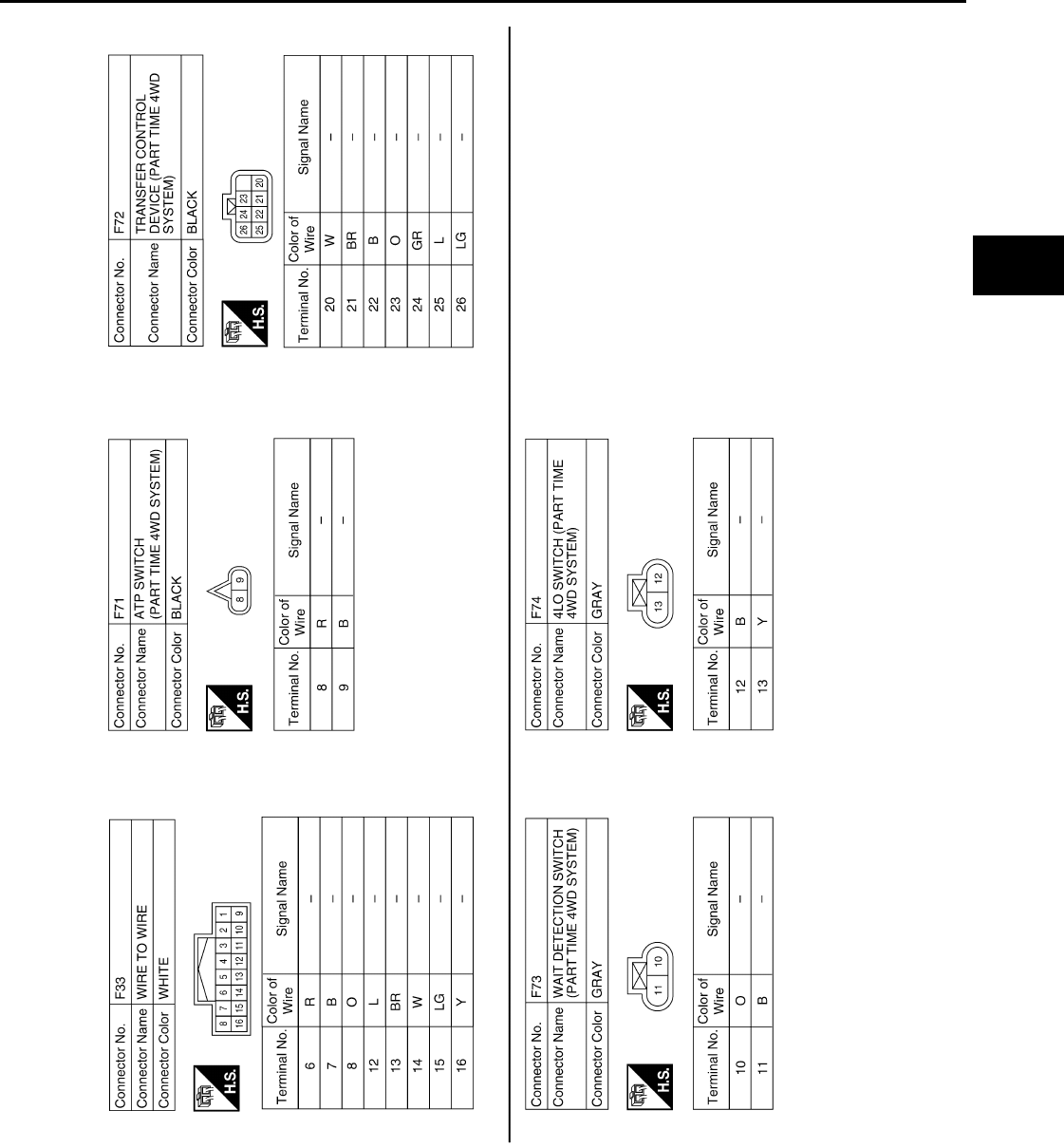
TRANSFER CONTROL UNIT
DLN-245
< ECU DIAGNOSIS > [TRANSFER: TX15B]
C
E
F
G
H
I
J
K
L
M
A
B
DLN
N
O
P
DTC Index INFOID:0000000003937366
DTC CHART
ABDIA0121G
B
Revision: October 2008
2009 Pathfinder

DLN-246
< ECU DIAGNOSIS > [TRANSFER: TX15B]
TRANSFER CONTROL UNIT
NOTE:
If “SHIFT ACT POSI SW [P1818]” or “SHIFT ACT CIR [P1819]” is displayed, first erase self-diagnostic results. (“SHIFT ACT POSI SW
[P1818]” or “SHIFT ACT CIR [P1819]” may be displayed after installing transfer control unit or transfer assembly.)
FLASH CODE CHART
DTC CONSULT-III Diagnostic item is detected when... Reference
[P1801] *INITIAL START*
Due to removal of battery which cuts off power sup-
ply to transfer control unit, self-diagnosis memory
function is suspended. DLN-202
[P1802]
CONTROL UNIT (1,2,3)
Malfunction is detected in the memory (RAM) sys-
tem of transfer control unit.
DLN-205
[P1803] Malfunction is detected in the memory (ROM) sys-
tem of transfer control unit.
[P1804] Malfunction is detected in the memory (EEPROM)
system of transfer control unit.
[P1807] VHCL SPEED SEN·AT
• Malfunction is detected in output shaft revolution
signal that is output from TCM through CAN
communication.
• Improper signal is input while driving.
DLN-207
[P1808] VHCL SPEED SEN·ABS
• Malfunction is detected in vehicle speed signal
that is output from ABS actuator and electric unit
(control unit) through CAN communication.
• Improper signal is input while driving.
DLN-208
[P1809] CONTROL UNIT 4 AD converter system of transfer control unit is mal-
functioning. DLN-205
[P1810] 4L POSI SW TF Improper signal from 4LO switch is input due to
open or short circuit. DLN-209
[P1811] BATTERY VOLTAGE Power supply voltage for transfer control unit is ab-
normally low while driving. DLN-202
[P1813] 4WD MODE SW More than two switch inputs are simultaneously de-
tected due to short circuit of 4WD shift switch. DLN-212
[P1814] 4WD DETECT SWITCH Improper signal from wait detection switch is input
due to open or short circuit. DLN-215
[P1816] PNP SW/CIRC When A/T PNP switch signal is malfunction or com-
munication error between the vehicles. DLN-218
[P1817] SHIFT ACTUATOR
• Motor does not operate properly due to open or
short circuit in actuator motor.
• Malfunction is detected in the actuator motor.
(When 4WD shift switch is operated and actuator
motor is not operated)
• Malfunction is detected in transfer shift high relay
or transfer shift low relay.
DLN-219
[P1818] SHIFT ACT POSI SW
• Improper signal from actuator position switch is
input due to open or short circuit.
• Malfunction is detected in actuator position
switch.
DLN-226
[P1819] SHIFT ACT CIR
• Malfunction is detected in transfer shut off relay
1 and transfer shut off relay 2.
• Malfunction occurs in transfer control device
drive circuit.
DLN-229
[P1820] ENGINE SPEED SIG
• Malfunction is detected in engine speed signal
that is output from ECM through CAN communi-
cation.
• Improper signal is input while driving.
DLN-232
Revision: October 2008
2009 Pathfinder

TRANSFER CONTROL UNIT
DLN-247
< ECU DIAGNOSIS > [TRANSFER: TX15B]
C
E
F
G
H
I
J
K
L
M
A
B
DLN
N
O
P
NOTE:
If actuator position switch” or transfer control device” is displayed, first erase self-diagnostic results. (They may be displayed after install-
ing transfer control unit or transfer assembly.)
Flashing pattern Item Diagnostic item is detected when... Reference
2Output shaft revolution
signal (from TCM)
• Malfunction is detected in output shaft revo-
lution signal that is output from TCM through
CAN communication.
• Improper signal is input while driving.
DLN-207
3Vehicle speed signal
(from ABS)
• Malfunction is detected in vehicle speed sig-
nal that is output from ABS actuator and
electric unit (control unit) through CAN com-
munication.
• Improper signal is input while driving.
DLN-208
4 CAN communication Malfunction has been detected from CAN
communication. DLN-195
5 AD converter AD converter system of transfer control unit is
malfunctioning. DLN-205
64LO switch Improper signal from 4LO switch is input due
to open or short circuit. DLN-209
7 Engine speed signal
• Malfunction is detected in engine speed sig-
nal that is output from ECM through CAN
communication.
• Improper signal is input while driving.
DLN-232
8 Power supply Power supply voltage for transfer control unit is
abnormally low while driving. DLN-202
9 4WD shift switch
More than two switch inputs are simultaneous-
ly detected due to short circuit of 4WD shift
switch.
DLN-212
10 Wait detection switch Improper signal from wait detection switch is
input due to open or short circuit. DLN-215
11 Actuator motor
• Motor does not operate properly due to open
or short circuit in actuator motor.
• Malfunction is detected in the actuator mo-
tor. (When 4WD shift switch is operated and
actuator motor is not operated.)
• Malfunction is detected in transfer shift high
relay or transfer shift low relay.
DLN-219
12 Actuator position
switch
• Improper signal from actuator position
switch is input due to open or short circuit.
• Malfunction is detected in the actuator posi-
tion switch.
DLN-226
13 Transfer control device
• Malfunction is detected in transfer shut off
relay 1 and transfer shut off 2.
• Malfunction occurs in transfer control device
drive circuit.
, DLN-229
14 PNP switch signal When A/T PNP switch signal is malfunction or
communication error between the vehicles. DLN-218
Repeats flickering
every 0.25 sec. Data erase display
• Power supply failure of memory back-up.
• Battery is disconnected for a long time.
• Battery performance is poor.
DLN-202
Repeats flickering
every 2 to 5 sec. —Circuits that the self-diagnosis covers have no
malfunction. —
No flickering PNP switch or 4WD
shift switch
PNP switch or 4WD shift switch circuit is short-
ed or open. DLN-218 or DLN-212
Revision: October 2008
2009 Pathfinder

DLN-248
< SYMPTOM DIAGNOSIS > [TRANSFER: TX15B]
4WD SYSTEM SYMPTOMS
SYMPTOM DIAGNOSIS
4WD SYSTEM SYMPTOMS
Symptom Table INFOID:0000000003937367
Symptom Condition Reference page
4WD shift indicator lamp and 4LO indicator lamp do not turn ON (lamp check) Ignition switch: ON DLN-251
4WD warning lamp does not turn ON (lamp check) DLN-249
4WD shift indicator lamp or 4LO indicator lamp does not change
Engine running
DLN-253
ATP warning lamp does not turn ON DLN-255
ATP switch is malfunctioning DLN-259
4WD shift indicator lamp repeats flashing While driving DLN-257
4WD warning lamp flashes slowly (1 time/2 seconds) DLN-258
Revision: October 2008
2009 Pathfinder
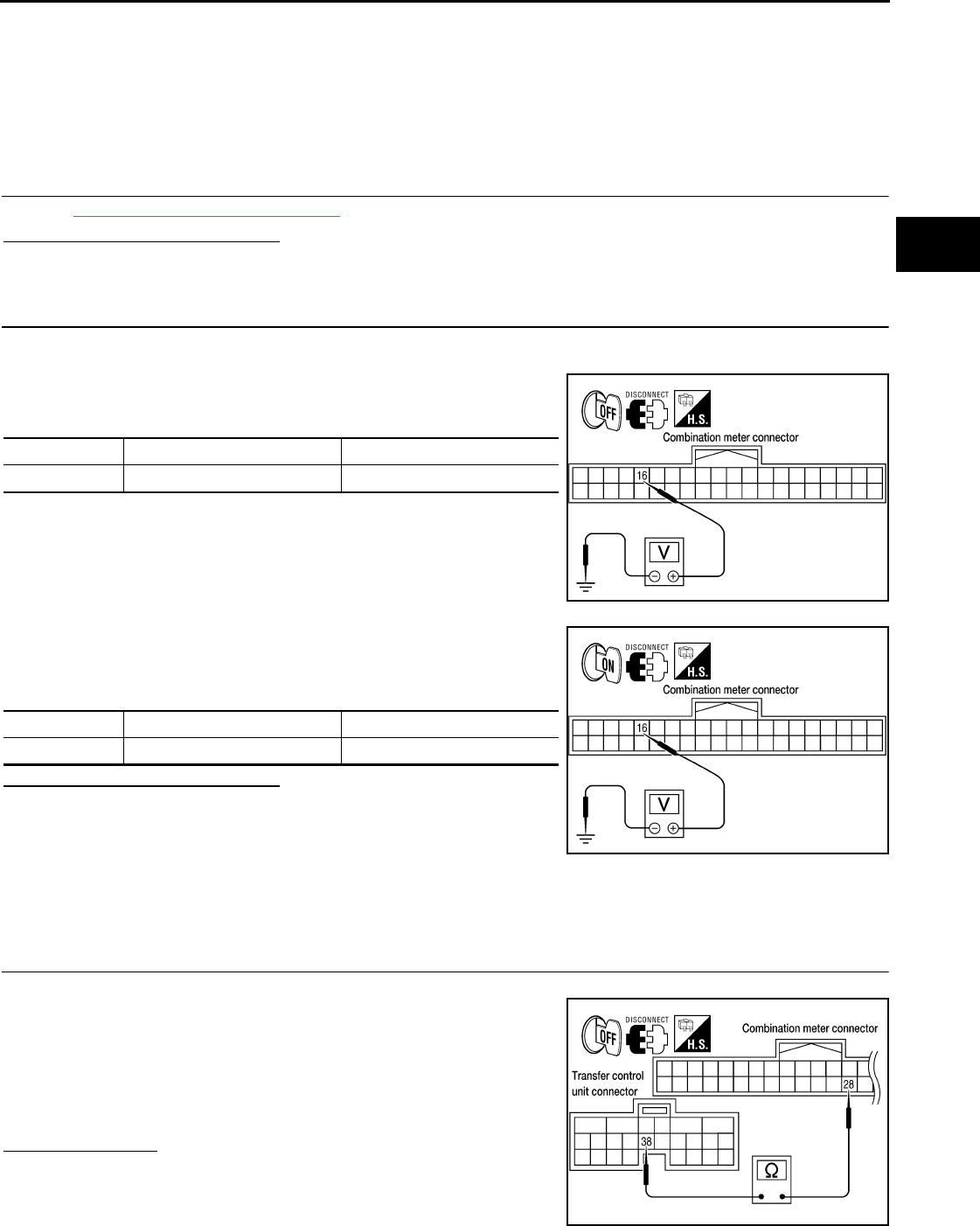
4WD WARNING LAMP DOES NOT TURN ON
DLN-249
< SYMPTOM DIAGNOSIS > [TRANSFER: TX15B]
C
E
F
G
H
I
J
K
L
M
A
B
DLN
N
O
P
4WD WARNING LAMP DOES NOT TURN ON
Description INFOID:0000000003937368
4WD warning lamp does not turn ON when turning ignition switch to ON.
Diagnosis Procedure INFOID:0000000003937369
1.CHECK TRANSFER CONTROL UNIT POWER SUPPLY AND GROUND CIRCUITS
Refer to DLN-202, "Diagnosis Procedure".
Are the inspection results normal?
YES >> GO TO 2.
NO >> Perform repairs as necessary.
2.CHECK COMBINATION METER POWER SUPPLY CIRCUIT
1. Turn ignition switch “OFF”. (Stay for at least 5 seconds.)
2. Disconnect combination meter harness connector.
3. Check voltage between combination meter harness connector
terminals and ground.
4. Turn ignition switch “ON”. (Do not start engine.)
5. Check voltage between combination meter harness connector
terminals and ground.
Are the inspection results normal?
YES >> GO TO 3.
NO >> Check the following. If any items are damaged, repair
or replace damaged parts.
• 10A fuse [No. 14, located in the fuse block (J/B)] or
ignition switch.
• Harness for short or open between ignition switch and combination meter harness connector
terminal 16
3.CHECK HARNESS BETWEEN TRANSFER CONTROL UNIT AND COMBINATION METER
1. Turn ignition switch “OFF”. (Stay for at least 5 seconds.)
2. Check continuity between transfer control unit harness connec-
tor M166 terminal 38 and combination meter harness connector
M24 terminal 28.
Also check harness for short to ground and short to power.
Is there continuity?
YES >> GO TO 4.
NO >> Repair or replace damaged parts.
Connector Terminal Voltage (Approx.)
M24 16 - Ground 0V
WDIA0178E
Connector Terminal Voltage (Approx.)
M24 16 - Ground Battery voltage
WDIA0179E
Continuity should exist.
WDIA0180E
Revision: October 2008
2009 Pathfinder
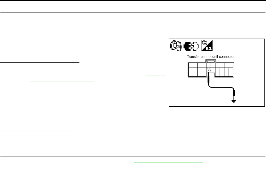
DLN-250
< SYMPTOM DIAGNOSIS > [TRANSFER: TX15B]
4WD WARNING LAMP DOES NOT TURN ON
4.CHECK INDICATOR LAMP CIRCUIT
1. Turn ignition switch “OFF”. (Stay for at least 5 seconds.)
2. Connect combination meter harness connector.
3. Disconnect transfer control unit harness connector.
4. Turn ignition switch "ON". (Do not start engine.)
5. Ground the following terminal using suitable wiring.
- Transfer control unit harness connector M166 terminal 38 and
ground.
Does the indicator lamp turn on?
YES >> GO TO 5.
NO >> Replace the combination meter. Refer to MWI-94,
"Removal and Installation".
5.SYMPTOM CHECK
Check again.
Does the symptom still occur?
YES >> GO TO 6.
NO >> Inspection End.
6.CHECK TRANSFER CONTROL UNIT
Check transfer control unit input/output signal. Refer to DLN-233, "Reference Value".
Are the inspection results normal?
YES >> Inspection End.
NO >> Check transfer control unit pin terminals for damage or loose connection with harness connector.
If any items are damaged, repair or replace damaged parts.
SDIA3452E
Revision: October 2008
2009 Pathfinder
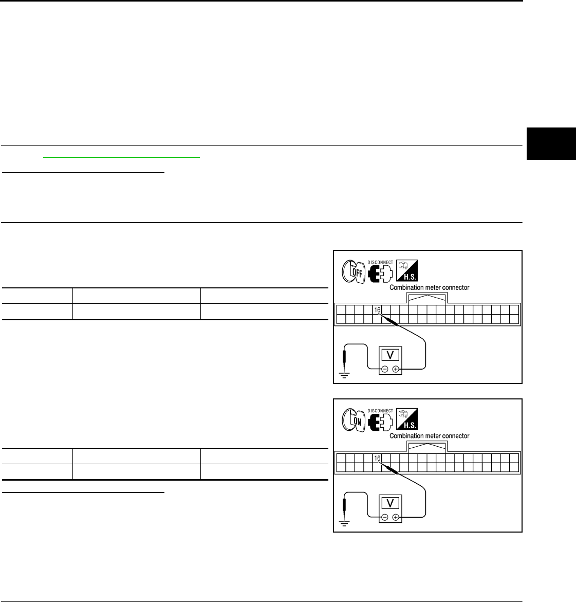
4WD SHIFT INDICATOR LAMP AND 4LO INDICATOR LAMP DO NOT TURN ON
DLN-251
< SYMPTOM DIAGNOSIS > [TRANSFER: TX15B]
C
E
F
G
H
I
J
K
L
M
A
B
DLN
N
O
P
4WD SHIFT INDICATOR LAMP AND 4LO INDICATOR LAMP DO NOT
TURN ON
Description INFOID:0000000003937370
4WD shift indicator lamp and 4LO indicator lamp do not turn ON for approx. 1 second when turning ignition
switch to ON.
Diagnosis Procedure INFOID:0000000003937371
1.CHECK TRANSFER CONTROL UNIT POWER SUPPLY AND GROUND CIRCUITS
Refer to DLN-202, "Diagnosis Procedure".
Are the inspection results normal?
YES >> GO TO 2.
NO >> Perform repairs as necessary.
2.CHECK COMBINATION METER POWER SUPPLY CIRCUIT
1. Turn ignition switch “OFF”. (Stay for at least 5 seconds.)
2. Disconnect combination meter harness connector.
3. Check voltage between combination meter harness connector
terminals and ground.
4. Turn ignition switch “ON”. (Do not start engine.)
5. Check voltage between combination meter harness connector
terminals and ground.
Are the inspection results normal?
YES >> GO TO 3.
NO >> Check the following. If any items are damaged, repair
or replace damaged parts.
• 10A fuse [No. 14, located in the fuse block (J/B) or]
ignition switch.
• Harness for short or open between ignition switch and combination meter harness connector
terminal 16
3.CHECK HARNESS BETWEEN TRANSFER CONTROL UNIT AND COMBINATION METER
1. Turn ignition switch “OFF”. (Stay for at least 5 seconds.)
Connector Terminal Voltage (Approx.)
M24 16 - Ground 0V
WDIA0178E
Connector Terminal Voltage (Approx.)
M24 16 - Ground Battery voltage
WDIA0179E
Revision: October 2008
2009 Pathfinder
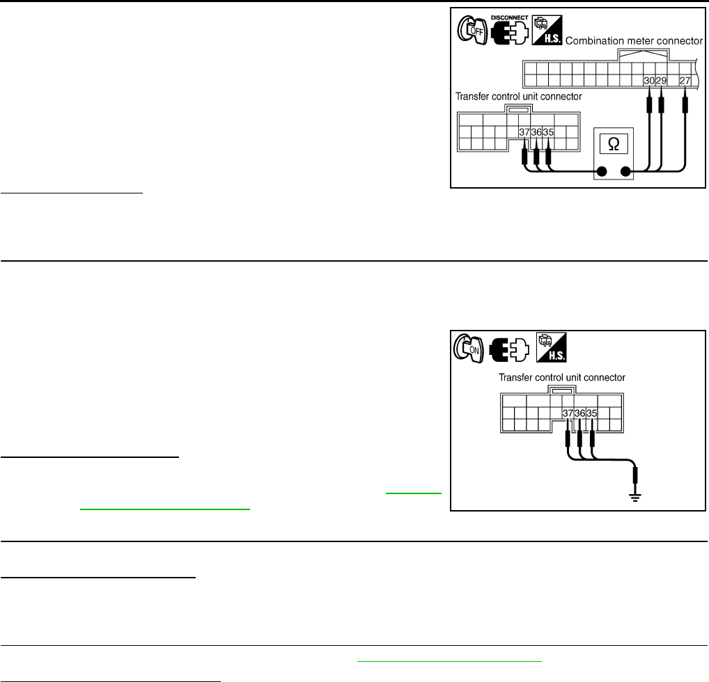
DLN-252
< SYMPTOM DIAGNOSIS > [TRANSFER: TX15B]
4WD SHIFT INDICATOR LAMP AND 4LO INDICATOR LAMP DO NOT TURN ON
2. Check continuity between the following terminals.
- Transfer control unit harness connector M166 terminal 35 and
combination meter harness connector M24 terminal 30.
- Transfer control unit harness connector M166 terminal 36 and
combination meter harness connector M24 terminal 27.
- Transfer control unit harness connector M166 terminal 37 and
combination meter harness connector M24 terminal 29.
Also check harness for short to ground and short to power.
Does continuity exist?
YES >> GO TO 4.
NO >> Repair or replace damaged parts.
4.CHECK INDICATOR LAMP CIRCUIT
1. Turn ignition switch “OFF”. (Stay for at least 5 seconds.)
2. Connect combination meter harness connector.
3. Disconnect transfer control unit harness connector.
4. Turn ignition switch "ON". (Do not start engine.)
5. Ground the following terminals using suitable wiring.
- Transfer control unit harness connector M166 terminal 35 and
ground.
- Transfer control unit harness connector M166 terminal 36 and
ground.
- Transfer control unit harness connector M166 terminal 37 and
ground.
Do indicator lamps turn on?
YES >> GO TO 5.
NO >> Replace the combination meter. Refer to MWI-94,
"Removal and Installation".
5.SYMPTOM CHECK
Check again.
Does the symptom still occur?
YES >> GO TO 6.
NO >> Inspection End.
6.CHECK TRANSFER CONTROL UNIT
Check transfer control unit input/output signal. Refer to DLN-233, "Reference Value".
Are the inspection results normal?
YES >> Inspection End.
NO >> Check transfer control unit pin terminals for damage or loose connection with harness connector.
If any items are damaged, repair or replace damaged parts.
Continuity should exist.
SDIA2823E
SDIA3451E
Revision: October 2008
2009 Pathfinder

4WD SHIFT INDICATOR LAMP OR 4LO INDICATOR LAMP DO NOT CHANGE
DLN-253
< SYMPTOM DIAGNOSIS > [TRANSFER: TX15B]
C
E
F
G
H
I
J
K
L
M
A
B
DLN
N
O
P
4WD SHIFT INDICATOR LAMP OR 4LO INDICATOR LAMP DO NOT
CHANGE
Description INFOID:0000000003937372
4WD shift indicator lamp or 4LO indicator lamp do not change when switching the 4WD shift switch.
Diagnosis Procedure INFOID:0000000003937373
1.CONFIRM THE SYMPTOM
Confirm 4WD shift indicator lamp and 4LO indicator lamp when ignition switch is turned to ON.
Do 4WD shift indicator lamp and 4LO indicator lamp turn on?
YES >> GO TO 2.
NO >> Go to DLN-251, "Diagnosis Procedure".
2.CHECK SYSTEM FOR 4WD SHIFT SWITCH
Perform trouble diagnosis for 4WD shift switch system. Refer to DLN-212, "Diagnosis Procedure".
Are the inspection results normal?
YES >> GO TO 3.
NO >> Repair or replace damaged parts.
3.CHECK SYSTEM FOR WAIT DETECTION SWITCH
Perform trouble diagnosis for wait detection switch system. Refer to DLN-215, "Diagnosis Procedure".
Are the inspection results normal?
YES >> GO TO 4.
NO >> Repair or replace damaged parts.
4.CHECK SYSTEM FOR 4LO SWITCH
Perform trouble diagnosis for 4LO switch system. Refer to DLN-209, "Diagnosis Procedure".
Are the inspection results normal?
YES >> GO TO 5.
NO >> Repair or replace damaged parts.
5.CHECK SYSTEM FOR ATP SWITCH
Perform trouble diagnosis for ATP switch system. Refer to DLN-259, "Diagnosis Procedure".
Are the inspection results normal?
YES >> GO TO 6.
NO >> Repair or replace damaged parts.
6.SYMPTOM CHECK
Check again.
Does the symptom still occur?
YES >> GO TO 7.
NO >> Inspection End
7.CHECK TRANSFER CONTROL UNIT
Check transfer control unit input/output signal. Refer to DLN-233, "Reference Value".
Are the inspection results normal?
YES >> GO TO 8.
NO >> Check transfer control unit pin terminals for damage or loose connection with harness connector.
If any items are damaged, repair or replace damaged parts.
8.CHECK TRANSFER INNER PARTS
1. Disassemble transfer assembly. Refer to DLN-281, "Disassembly and Assembly".
2. Check transfer inner parts.
Are the inspection results normal?
Revision: October 2008
2009 Pathfinder

DLN-254
< SYMPTOM DIAGNOSIS > [TRANSFER: TX15B]
4WD SHIFT INDICATOR LAMP OR 4LO INDICATOR LAMP DO NOT CHANGE
YES >> Inspection End.
NO >> Repair or replace damaged parts.
Revision: October 2008
2009 Pathfinder
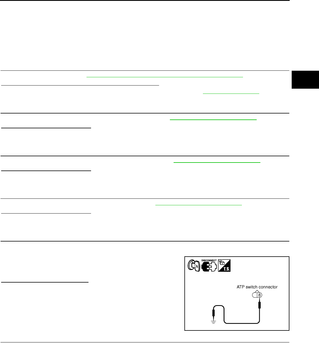
ATP WARNING LAMP DOES NOT TURN ON
DLN-255
< SYMPTOM DIAGNOSIS > [TRANSFER: TX15B]
C
E
F
G
H
I
J
K
L
M
A
B
DLN
N
O
P
ATP WARNING LAMP DOES NOT TURN ON
Description INFOID:0000000003937374
ATP warning lamp does not turn ON when the transfer case is switched in or out of 4LO with the A/T selector
lever in N position.
Diagnosis Procedure INFOID:0000000003937375
1.CHECK SYSTEM FOR CAN COMMUNICATION LINE
Perform self-diagnosis. Refer to DLN-198, "CONSULT-III Function (ALL MODE AWD/4WD)".
Do the self-diagnostic results indicate CAN communication?
YES >> Perform trouble diagnosis for CAN communication line. Refer to LAN-65, "DTC Index".
NO >> GO TO 2.
2.CHECK SYSTEM FOR 4WD SHIFT SWITCH
Perform trouble diagnosis for 4WD shift switch system. Refer to DLN-212, "Diagnosis Procedure".
Are the inspection results normal?
YES >> GO TO 3.
NO >> Repair or replace damaged parts.
3.CHECK SYSTEM FOR PNP SWITCH SIGNAL
Perform trouble diagnosis for PNP switch signal system. Refer to DLN-218, "Diagnosis Procedure".
Are the inspection results normal?
YES >> GO TO 4.
NO >> Repair or replace damaged parts.
4.CHECK SYSTEM FOR ATP SWITCH
Perform trouble diagnosis for ATP switch system. Refer to DLN-259, "Diagnosis Procedure".
Are the inspection results normal?
YES >> GO TO 5.
NO >> Repair or replace damaged parts.
5.CHECK ATP WARNING LAMP CIRCUIT
1. Disconnect ATP switch harness connector.
2. Turn ignition switch “ON”. (Do not start engine.)
3. Ground terminal 8 on ATP switch connector F71 using suitable
wiring.
4. Turn ignition switch “OFF”. (Stay for at least 5 seconds.)
Does ATP warning lamp turn on?
YES >> GO TO 9.
NO >> GO TO 6.
6.CHECK HARNESS BETWEEN TRANSFER CONTROL UNIT AND COMBINATION METER
1. Turn ignition switch “OFF”. (Stay for at least 5 seconds.)
2. Disconnect transfer control unit harness connector and combination meter harness connector.
SDIA2832E
Revision: October 2008
2009 Pathfinder
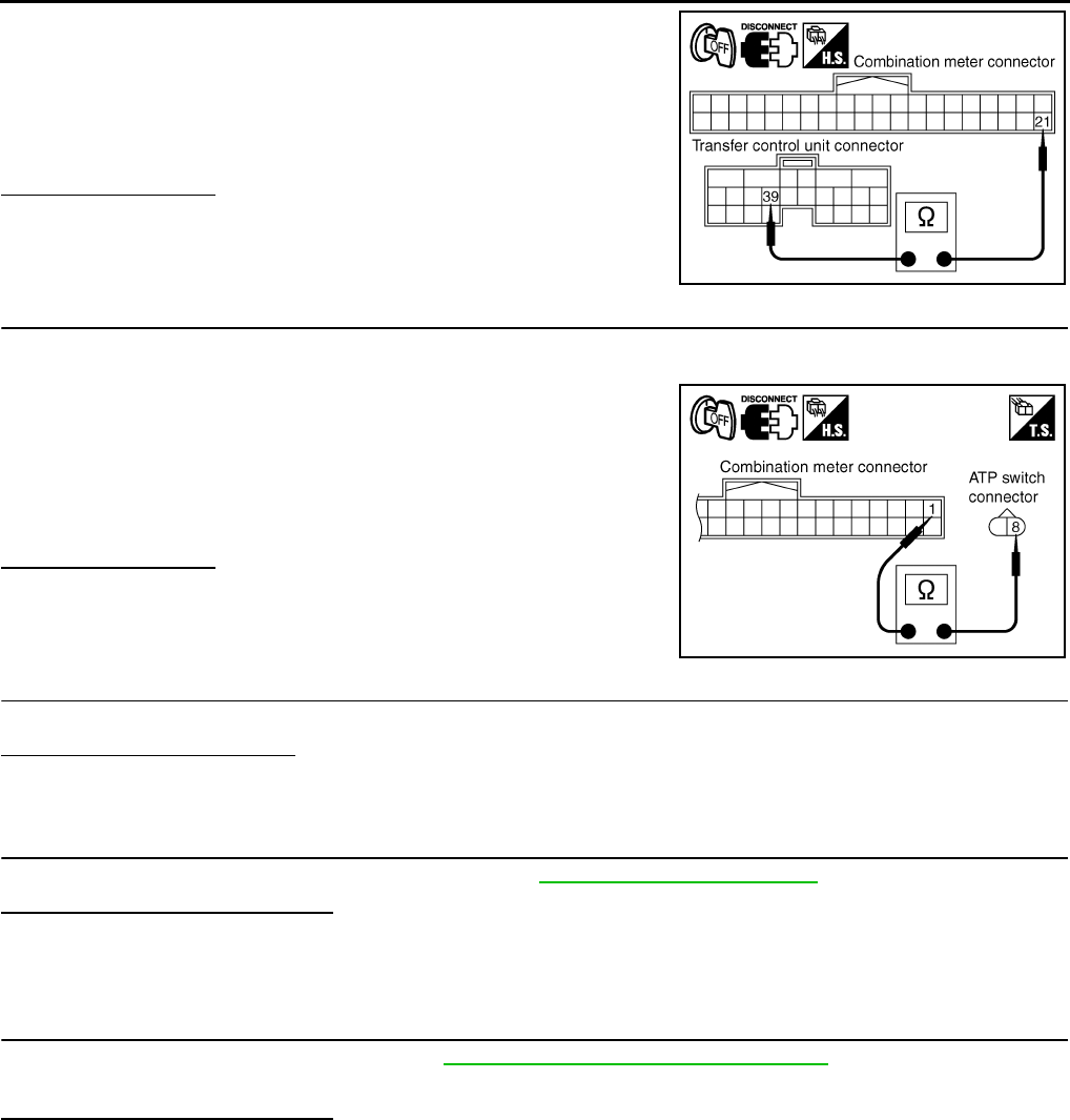
DLN-256
< SYMPTOM DIAGNOSIS > [TRANSFER: TX15B]
ATP WARNING LAMP DOES NOT TURN ON
3. Check continuity between transfer control unit harness connec-
tor M166 terminal 39 and combination meter harness connector
M24 terminal 21.
Also check harness for short to ground and short to power.
Does continuity exist?
YES >> GO TO 7.
NO >> Repair or replace damaged parts.
7.CHECK HARNESS BETWEEN COMBINATION METER AND ATP SWITCH
1. Turn ignition switch “OFF”. (Stay for at least 5 seconds.)
2. Disconnect ATP switch harness connector.
3. Check continuity between combination meter harness connector
M24 terminal 1 and ATP switch harness connector F71 terminal
8.
Also check harness for short to ground and short to power.
Does continuity exist?
YES >> GO TO 8.
NO >> Repair or replace damaged parts.
8.SYMPTOM CHECK
Check again.
Does the symptom still occur?
YES >> GO TO 9.
NO >> Inspection End.
9.CHECK TRANSFER CONTROL UNIT
Check transfer control unit input/output signal. Refer to DLN-233, "Reference Value".
Are the inspection results normal?
YES >> GO TO 10.
NO >> Check transfer control unit pin terminals for damage or loose connection with harness connector.
If any items are damaged, repair or replace damaged parts.
10.CHECK TRANSFER INNER PARTS
1. Disassemble transfer assembly. Refer to DLN-281, "Disassembly and Assembly".
2. Check transfer inner parts.
Are the inspection results normal?
YES >> Inspection End.
NO >> Repair or replace damaged parts.
Continuity should exist.
SDIA2825E
Continuity should exist.
SDIA2833E
Revision: October 2008
2009 Pathfinder

4WD SHIFT INDICATOR LAMP KEEPS FLASHING
DLN-257
< SYMPTOM DIAGNOSIS > [TRANSFER: TX15B]
C
E
F
G
H
I
J
K
L
M
A
B
DLN
N
O
P
4WD SHIFT INDICATOR LAMP KEEPS FLASHING
Description INFOID:0000000003937376
The 4WD shift indicator lamp keeps flashing.
Diagnosis Procedure INFOID:0000000003937377
1.CONFIRM THE SYMPTOM
1. Set 4WD shift switch to “2WD”.
2. Drive the vehicle straight forward and backward keeping speed under 20 km/h (12 MPH).
Does 4WD shift indicator lamp keep flashing?
YES >> GO TO 2.
NO >> Inspection End.
2.CHECK SYSTEM FOR WAIT DETECTION SWITCH
Perform trouble diagnosis for wait detection switch system. Refer to DLN-215, "Diagnosis Procedure".
Are the inspection results normal?
YES >> GO TO 3.
NO >> Repair or replace damaged parts.
3.CHECK SYSTEM FOR 4LO SWITCH
Perform trouble diagnosis for 4LO switch. Refer to DLN-209, "Diagnosis Procedure".
Are the inspection results normal?
YES >> GO TO 4.
NO >> Repair or replace damaged parts.
4.SYMPTOM CHECK
Check again.
Does the symptom still occur?
YES >> GO TO 5.
NO >> Inspection End.
5.CHECK TRANSFER CONTROL UNIT
Check transfer control unit input/output signal. Refer to DLN-233, "Reference Value".
Are the inspection results normal?
YES >> GO TO 6.
NO >> Check transfer control unit pin terminals for damage or loose connection with harness connector.
If any items are damaged, repair or replace damaged parts.
6.CHECK TRANSFER INNER PARTS
1. Disassemble transfer assembly. Refer to DLN-281, "Disassembly and Assembly".
2. Check transfer inner parts.
Are the inspection results normal?
YES >> Inspection End.
NO >> Repair or replace damaged parts.
Revision: October 2008
2009 Pathfinder

DLN-258
< SYMPTOM DIAGNOSIS > [TRANSFER: TX15B]
4WD WARNING LAMP FLASHES SLOWLY
4WD WARNING LAMP FLASHES SLOWLY
Description INFOID:0000000003937378
The 4WD warning lamp flashes slowly while driving (1 time / 2 seconds). The lamp continues to flash until the
ignition switch is turned OFF.
Diagnosis Procedure INFOID:0000000003937379
1.CHECK TIRES
Check the following. Refer to WT-52, "Tire".
•Tire size
• Tire wear
• Tire pressure
Are the inspection results normal?
YES >> GO TO 2.
NO >> Repair or replace damaged parts.
2.SYMPTOM CHECK
Check again.
Does the symptom still occur?
YES >> GO TO 3.
NO >> Inspection End.
3.CHECK TRANSFER CONTROL UNIT
Check transfer control unit input/output signal. Refer to DLN-233, "Reference Value".
Are the inspection results normal?
YES >> Inspection End.
NO >> Check transfer control unit pin terminals for damage or loose connection with harness connector.
If any items are damaged, repair or replace damaged parts.
Revision: October 2008
2009 Pathfinder
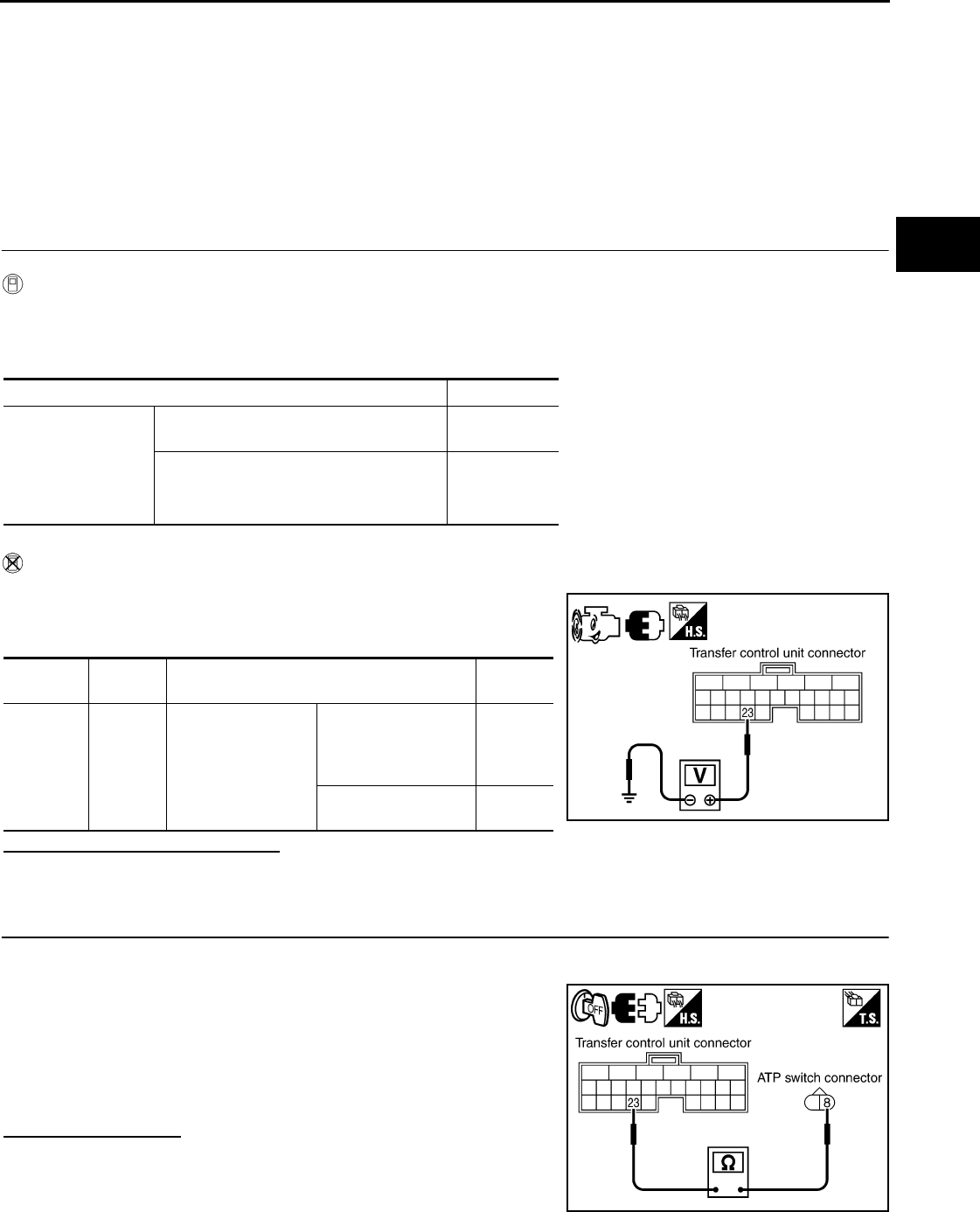
ATP SWITCH
DLN-259
< SYMPTOM DIAGNOSIS > [TRANSFER: TX15B]
C
E
F
G
H
I
J
K
L
M
A
B
DLN
N
O
P
ATP SWITCH
Description INFOID:0000000003937380
The ATP indicator does not come on when the transfer is in neutral and the A/T lever is in neutral or, the ATP
indicator stays on when the transfer case is not in neutral.
Diagnosis Procedure INFOID:0000000003937381
DIAGNOSTIC PROCEDURE
1.CHECK ATP SWITCH SIGNAL
With CONSULT-III
1. Start engine.
2. Select “DATA MONITOR” mode for “ALL MODE AWD/4WD” with CONSULT-III.
3. Read out the value of “ATP SWITCH”.
Without CONSULT-III
1. Start engine.
2. Check voltage between transfer control unit harness connector
terminal and ground.
Are the inspection results normal?
YES >> GO TO 5.
NO >> GO TO 2.
2.CHECK HARNESS BETWEEN TRANSFER CONTROL UNIT AND ATP SWITCH
1. Turn ignition switch “OFF”. (Stay for at least 5 seconds.)
2. Disconnect transfer control unit harness connector and the ATP switch harness connector.
3. Check continuity between transfer control unit harness connec-
tor M165 terminal 23 and ATP switch harness connector F71
terminal 8.
Also check harness for short to ground and short to power.
Does continuity exist?
YES >> GO TO 3.
NO >> Repair or replace damaged parts.
Condition Display value
• Vehicle stopped
• Engine running
• A/T selector lever
“N” position
• Brake pedal de-
pressed
4WD shift switch: 4H to 4LO or 4LO to 4H
(While actuator motor is operating.) ON
Except the above OFF
Connector Terminal Condition Voltage
(Approx.)
M165 23 -
Ground
• Vehicle stopped
• Engine running
• A/T selector lever
“N” position
• Brake pedal de-
pressed
4WD shift switch: 4H
to 4LO or 4LO to 4H
(While actuator motor
is operating.)
0V
Except the above Battery
voltage SDIA3375E
Continuity should exist.
SDIA3376E
Revision: October 2008
2009 Pathfinder
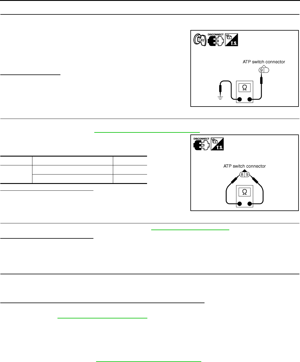
DLN-260
< SYMPTOM DIAGNOSIS > [TRANSFER: TX15B]
ATP SWITCH
3.CHECK GROUND CIRCUIT
1. Turn ignition switch “OFF”. (Stay for at least 5 seconds.)
2. Disconnect ATP switch harness connector.
3. Check continuity between ATP switch harness connector F71
terminal 9 and ground.
Also check harness for short to power.
Does continuity exist?
YES >> GO TO 4.
NO >> Repair open circuit or short to power in harness or con-
nectors.
4.CHECK ATP SWITCH
1. Turn ignition switch “OFF”. (Stay for at least 5 seconds.)
2. Remove ATP switch. Refer to DLN-194, "Component Parts Location".
3. Push and release ATP switch and check continuity between ATP
switch terminals 8 and 9.
Are the inspection results normal?
YES >> GO TO 5.
NO >> Replace ATP switch.
5.CHECK TRANSFER CONTROL UNIT
Check transfer control unit input/output signal. Refer to DLN-233, "Reference Value".
Are the inspection results normal?
YES >> GO TO 6.
NO >> Check transfer control unit pin terminals for damage or loose connection with harness connector.
If any items are damaged, repair or replace damaged parts.
6.CHECK ATP WARNING LAMP
1. Turn ignition switch “ON”. (Do not start engine.)
2. A/T selector lever “N” position and engage the parking brake.
3. Switch 4WD shift switch from 4H to 4LO or 4LO to 4H.
Does the ATP warning lamp turn ON while the actuator motor is operating?
YES >> Inspection End.
NO >> Refer to DLN-255, "Diagnosis Procedure".
Component Inspection INFOID:0000000003937382
1. Turn ignition switch “OFF”. (Stay for at least 5 seconds.)
2. Disconnect ATP switch harness connector.
3. Remove ATP switch. Refer to DLN-194, "Component Parts Location".
Continuity should exist.
SDIA2394E
Terminal Condition Continuity
8 - 9 Push ATP switch Yes
Release ATP switch No
SDIA2395E
Revision: October 2008
2009 Pathfinder
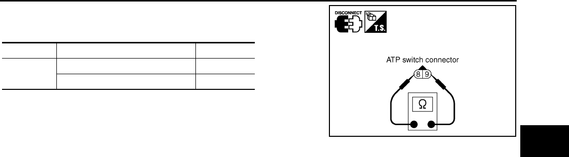
ATP SWITCH
DLN-261
< SYMPTOM DIAGNOSIS > [TRANSFER: TX15B]
C
E
F
G
H
I
J
K
L
M
A
B
DLN
N
O
P
4. Push and release ATP switch and check continuity between ATP
switch terminals 8 and 9.
5. If the inspection results are abnormal replace the ATP switch.
Terminal Condition Continuity
8 - 9 Push ATP switch Yes
Release ATP switch No
SDIA2395E
Revision: October 2008
2009 Pathfinder
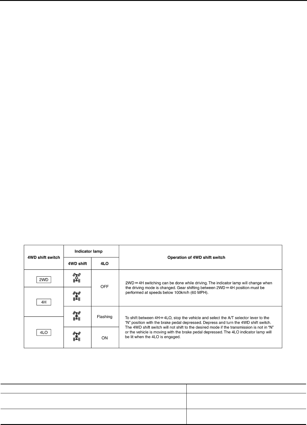
DLN-262
< PRECAUTION > [TRANSFER: TX15B]
PRECAUTIONS
PRECAUTION
PRECAUTIONS
Precaution for Supplemental Restraint System (SRS) "AIR BAG" and "SEAT BELT
PRE-TENSIONER" INFOID:0000000003937383
The Supplemental Restraint System such as “AIR BAG” and “SEAT BELT PRE-TENSIONER”, used along
with a front seat belt, helps to reduce the risk or severity of injury to the driver and front passenger for certain
types of collision. This system includes seat belt switch inputs and dual stage front air bag modules. The SRS
system uses the seat belt switches to determine the front air bag deployment, and may only deploy one front
air bag, depending on the severity of a collision and whether the front occupants are belted or unbelted.
Information necessary to service the system safely is included in the SR and SB section of this Service Man-
ual.
WARNING:
• To avoid rendering the SRS inoperative, which could increase the risk of personal injury or death in
the event of a collision which would result in air bag inflation, all maintenance must be performed by
an authorized NISSAN/INFINITI dealer.
• Improper maintenance, including incorrect removal and installation of the SRS, can lead to personal
injury caused by unintentional activation of the system. For removal of Spiral Cable and Air Bag
Module, see the SR section.
• Do not use electrical test equipment on any circuit related to the SRS unless instructed to in this
Service Manual. SRS wiring harnesses can be identified by yellow and/or orange harnesses or har-
ness connectors.
Precaution for Transfer Assembly and Transfer Control Unit Replacement INFOID:0000000003937384
When replacing transfer assembly or transfer control unit, check the 4WD shift indicator pattern and adjust-
ment of the position between transfer assembly and transfer control unit if necessary.
CHECK 4WD SHIFT INDICATOR PATTERN
1. Set 4WD shift switch to “2WD”, “4H”, “4LO”, “4H” and “2WD” in order. Stay at each switch position for at
least 2 seconds.
2. Confirm 4WD shift indicator lamp and 4LO indicator lamp are changed properly as follows.
• If OK, the position between transfer assembly and transfer control unit is correct.
• If NG, the position is different between transfer assembly and transfer control unit.
Adjust the position between transfer assembly and transfer control unit. Refer to pattern table below.
Transfer position adjustment pattern
WDIA0137E
4WD shift switch condition Refer procedure
4WD shift switch is under “2WD” condition when engine is being stopped. "METHOD FOR ADJUSTMENT WITH 4WD SHIFT
SWITCH AT “2WD”"
4WD shift switch is under “4H” or “4LO” condition when engine is being stopped. "METHOD FOR ADJUSTMENT WITH 4WD SHIFT
SWITCH AT “4H” OR “4LO”"
Revision: October 2008
2009 Pathfinder

PRECAUTIONS
DLN-263
< PRECAUTION > [TRANSFER: TX15B]
C
E
F
G
H
I
J
K
L
M
A
B
DLN
N
O
P
NOTE:
Method of adjustment can be chosen voluntarily, according to location of 4WD shift switch.
METHOD FOR ADJUSTMENT WITH 4WD SHIFT SWITCH AT “2WD”
Select Adjustment Pattern
1. Start engine. Run engine for at least 10 seconds.
2. Check 4WD shift indicator lamp and 4LO indicator lamp.
Pattern A
1. Stop vehicle and move A/T selector lever to “N” position with brake pedal depressed. Stay in "N" for at
least 2 seconds.
2. Turn 4WD shift switch to “4LO” position. Stay in "4LO" for at least 2 seconds.
3. Turn ignition switch “OFF”.
4. Start engine.
5. Erase self-diagnosis. Refer to DLN-198, "CONSULT-III Function (ALL MODE AWD/4WD)".
6. Check 4WD shift indicator lamp and 4LO indicator lamp again. Refer to "CHECK 4WD SHIFT INDICATOR
PATTERN".
If 4WD shift indicator lamp and 4LO indicator lamp do not indicate proper pattern, install new transfer con-
trol unit and retry the above check.
Pattern B
1. Stop vehicle and move A/T selector lever to “N” position with brake pedal depressed. Stay in "N" for at
least 2 seconds.
2. Turn ignition switch “OFF”.
3. Start engine.
4. Erase self-diagnosis. Refer to DLN-198, "CONSULT-III Function (ALL MODE AWD/4WD)".
5. Check 4WD shift indicator lamp and 4LO indicator lamp again. Refer to "CHECK 4WD SHIFT INDICATOR
PATTERN".
If 4WD shift indicator lamp and 4LO indicator lamp do not indicate proper pattern, install new transfer con-
trol unit and retry the above check.
METHOD FOR ADJUSTMENT WITH 4WD SHIFT SWITCH AT “4H” OR “4LO”
1. Start engine. Run the engine for at least 10 seconds.
2. Stop vehicle and move A/T selector lever to “N” position with brake pedal depressed. Stay in "N" for at
least 2 seconds.)
3. Turn 4WD shift switch to “2WD” position. Stay in "2WD" for at least 2 seconds.
4. Turn ignition switch “OFF”.
5. Start engine.
6. Erase self-diagnosis. Refer to DLN-198, "CONSULT-III Function (ALL MODE AWD/4WD)".
7. Check 4WD shift indicator lamp and 4LO indicator lamp again. Refer to "CHECK 4WD SHIFT INDICATOR
PATTERN".
If 4WD shift indicator lamp and 4LO indicator lamp do not indicate proper pattern, install new transfer con-
trol unit and retry the above check.
Precaution Necessary for Steering Wheel Rotation After Battery Disconnect
INFOID:0000000004468087
NOTE:
• This Procedure is applied only to models with Intelligent Key system and NATS (NISSAN ANTI-THEFT SYS-
TEM).
• Remove and install all control units after disconnecting both battery cables with the ignition knob in the
″LOCK″ position.
Indicator lamp condition Refer procedure
When 4WD shift indicator lamp or 4LO indicator lamp is flashing. "Pattern A"
Except for above. "Pattern B"
Revision: October 2008
2009 Pathfinder
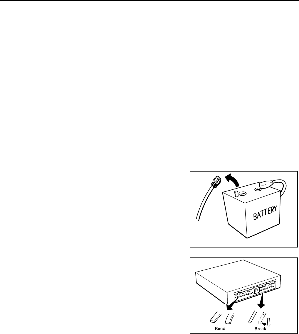
DLN-264
< PRECAUTION > [TRANSFER: TX15B]
PRECAUTIONS
• Always use CONSULT-III to perform self-diagnosis as a part of each function inspection after finishing work.
If DTC is detected, perform trouble diagnosis according to self-diagnostic results.
For models equipped with the Intelligent Key system and NATS, an electrically controlled steering lock mech-
anism is adopted on the key cylinder.
For this reason, if the battery is disconnected or if the battery is discharged, the steering wheel will lock and
steering wheel rotation will become impossible.
If steering wheel rotation is required when battery power is interrupted, follow the procedure below before
starting the repair operation.
OPERATION PROCEDURE
1. Connect both battery cables.
NOTE:
Supply power using jumper cables if battery is discharged.
2. Use the Intelligent Key or mechanical key to turn the ignition switch to the ″ACC″ position. At this time, the
steering lock will be released.
3. Disconnect both battery cables. The steering lock will remain released and the steering wheel can be
rotated.
4. Perform the necessary repair operation.
5. When the repair work is completed, return the ignition switch to the ″LOCK″ position before connecting
the battery cables. (At this time, the steering lock mechanism will engage.)
6. Perform a self-diagnosis check of all control units using CONSULT-III.
Precaution INFOID:0000000003937385
•Before connecting or disconnecting the transfer control unit
harness connector, turn ignition switch “OFF” and disconnect
the battery cables. Battery voltage is applied to transfer con-
trol unit even if ignition switch is turned “OFF”.
•When connecting or disconnecting pin connectors into or
from transfer control unit, take care not to damage pin termi-
nals (bend or break).
When connecting pin connectors make sure that there are not
any bends or breaks on transfer control unit pin terminals.
SEF289H
SEF291H
Revision: October 2008
2009 Pathfinder
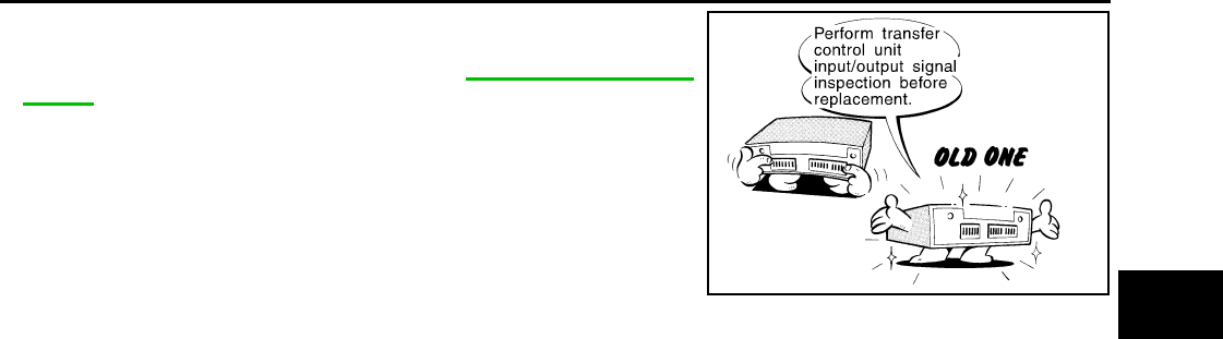
PRECAUTIONS
DLN-265
< PRECAUTION > [TRANSFER: TX15B]
C
E
F
G
H
I
J
K
L
M
A
B
DLN
N
O
P
•Before replacing transfer control unit, perform transfer con-
trol unit input/output signal inspection and make sure transfer
control unit functions properly. Refer to DLN-233, "Reference
Value".
Service Notice INFOID:0000000003937386
• After overhaul refill the transfer with new transfer fluid.
• Check the fluid level or replace the fluid only with the vehicle parked on level ground.
• During removal or installation, keep inside of transfer clear of dust or dirt.
• Disassembly should be done in a clean work area.
• Before proceeding with disassembly, thoroughly clean the transfer. It is important to prevent the internal
parts from becoming contaminated by dirt or other foreign matter.
• Check for the correct installation status prior to removal or disassembly. If matchmarks are required, be cer-
tain they do not interfere with the function of the parts when applied.
• All parts should be carefully cleaned with a general purpose, non-flammable solvent before inspection or
reassembly.
• Check appearance of the disassembled parts for damage, deformation, and unusual wear. Replace them
with a new ones if necessary.
• Gaskets, seals and O-rings should replaced any time the transfer is disassembled.
• In principle, tighten bolts or nuts gradually in several steps working diagonally from inside to outside. If tight-
ening sequence is specified, use it.
• Observe the specified torque when assembling.
• Clean and flush the parts sufficiently and blow-dry them.
• Be careful not to damage sliding surfaces and mating surfaces.
• Use lint-free cloth or towels for wiping parts clean. Common shop rags can leave fibers that could interfere
with the operation of the transfer.
MEF040DB
Revision: October 2008
2009 Pathfinder
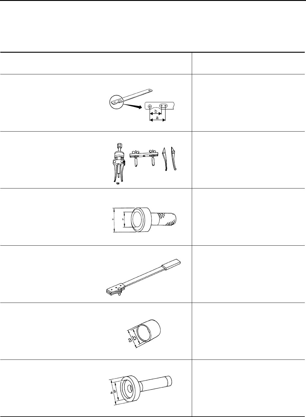
DLN-266
< PREPARATION > [TRANSFER: TX15B]
PREPARATION
PREPARATION
PREPARATION
Special Service Tool INFOID:0000000003937387
The actual shapes of Kent-Moore tools may differ from those of special service tools illustrated here.
Tool number
(Kent-Moore No.)
Tool name
Description
KV40104000
(—)
Flange wrench
• Removing self-lock nut
• Installing self-lock nut
a: 85 mm (3.35 in)
b: 65 mm (2.56 in)
ST33290001
(J-34286)
Puller
• Removing front oil seal
• Removing rear oil seal
• Removing metal bushing
KV38100500
(—)
Drift
• Installing front oil seal
• Installing rear oil seal
• Installing rear bearing
• Installing front bearing
a: 80 mm (3.15 in) dia.
b: 60 mm (2.36 in) dia.
KV38100300
(J-44195)
Companion flange wrench
• Removing and installing companion flange
KV40105310
(—)
Drift
• Installing dust cover
a: 89 mm (3.50 in) dia.
b: 80.7 mm (3.17 in) dia.
KV38100200
(—)
Drift
• Removing sun gear assembly and planetary
carrier assembly
• Removing input bearing
• Installing sun gear assembly and planetary
carrier assembly
a: 65 mm (2.56 in) dia.
b: 49 mm (1.93 in) dia.
NT659
ZZA0601D
ZZA0811D
NT771
ZZA1003D
ZZA1143D
Revision: October 2008
2009 Pathfinder
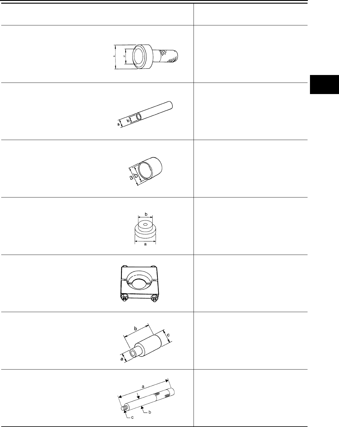
PREPARATION
DLN-267
< PREPARATION > [TRANSFER: TX15B]
C
E
F
G
H
I
J
K
L
M
A
B
DLN
N
O
P
ST30720000
(J-25405)
Drift
• Installing input bearing
• Installing input oil seal
• Installing carrier bearing
a: 77 mm (3.03 in) dia.
b: 55 mm (2.17 in) dia.
KV32102700
(—)
Drift
• Installing mainshaft rear bearing
a: 48 mm (1.89 in) dia.
b: 41 mm (1.61 in) dia.
KV40104830
(—)
Drift
• Installing input oil seal
a: 70 mm (2.76 in) dia.
b: 63.5 mm (2.50 in) dia.
ST35300000
(—)
Drift
• Removing carrier bearing
• Installing metal bushing
• Removing front bearing
a: 59 mm (2.32 in) dia.
b: 45 mm (1.77 in) dia.
ST30021000
(J-22912-01)
Puller
• Removing carrier bearing
• Removing front bearing
• Removing rear bearing
ST33710000
(—)
Drift
• Removing needle bearing
• Removing metal bushing
• Removing rear bearing
a: 89 mm (3.5 in)
b: 30 mm (1.18 in) dia.
c: 24 mm (0.94 in) dia.
ST35325000
(—)
Drift bar
• Removing metal bushing
a: 215 mm (8.46 in)
b: 25 mm (0.98 in) dia.
c: M12 × 1.5P
Tool number
(Kent-Moore No.)
Tool name
Description
ZZA0811D
ZZA0534D
ZZA1003D
NT073
ZZA0537D
ZZA1057D
NT663
Revision: October 2008
2009 Pathfinder
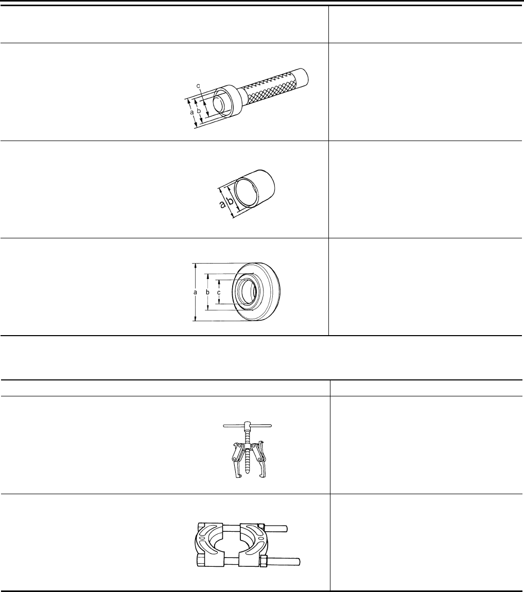
DLN-268
< PREPARATION > [TRANSFER: TX15B]
PREPARATION
Commercial Service Tool INFOID:0000000003937388
ST33220000
(—)
Drift
• Installing needle bearing
a: 37 mm (1.46 in) dia.
b: 31 mm (1.22 in) dia.
c: 22 mm (0.87 in) dia.
ST27863000
(—)
Drift
• Installing carrier bearing
a: 75 mm (2.95 in) dia.
b: 62 mm (2.44 in) dia.
ST30901000
(J-26010-01)
Drift
• Installing rear bearing
• Installing front bearing
a: 79 mm (3.11 in) dia.
b: 45 mm (1.77 in) dia.
c: 35.2 mm (1.38 in) dia.
Tool number
(Kent-Moore No.)
Tool name
Description
ZZA1046D
ZZA1003D
ZZA0978D
Tool name Description
Puller • Removing companion flange
• Removing mainshaft rear bearing
Puller • Removing mainshaft rear bearing
NT077
ZZB0823D
Revision: October 2008
2009 Pathfinder

PREPARATION
DLN-269
< PREPARATION > [TRANSFER: TX15B]
C
E
F
G
H
I
J
K
L
M
A
B
DLN
N
O
P
Pin punch • Removing retaining pin
a: 6 mm (0.24 in) dia.
Power tool • Loosening bolts and nuts
Tool name Description
NT410
PBIC0190E
Revision: October 2008
2009 Pathfinder
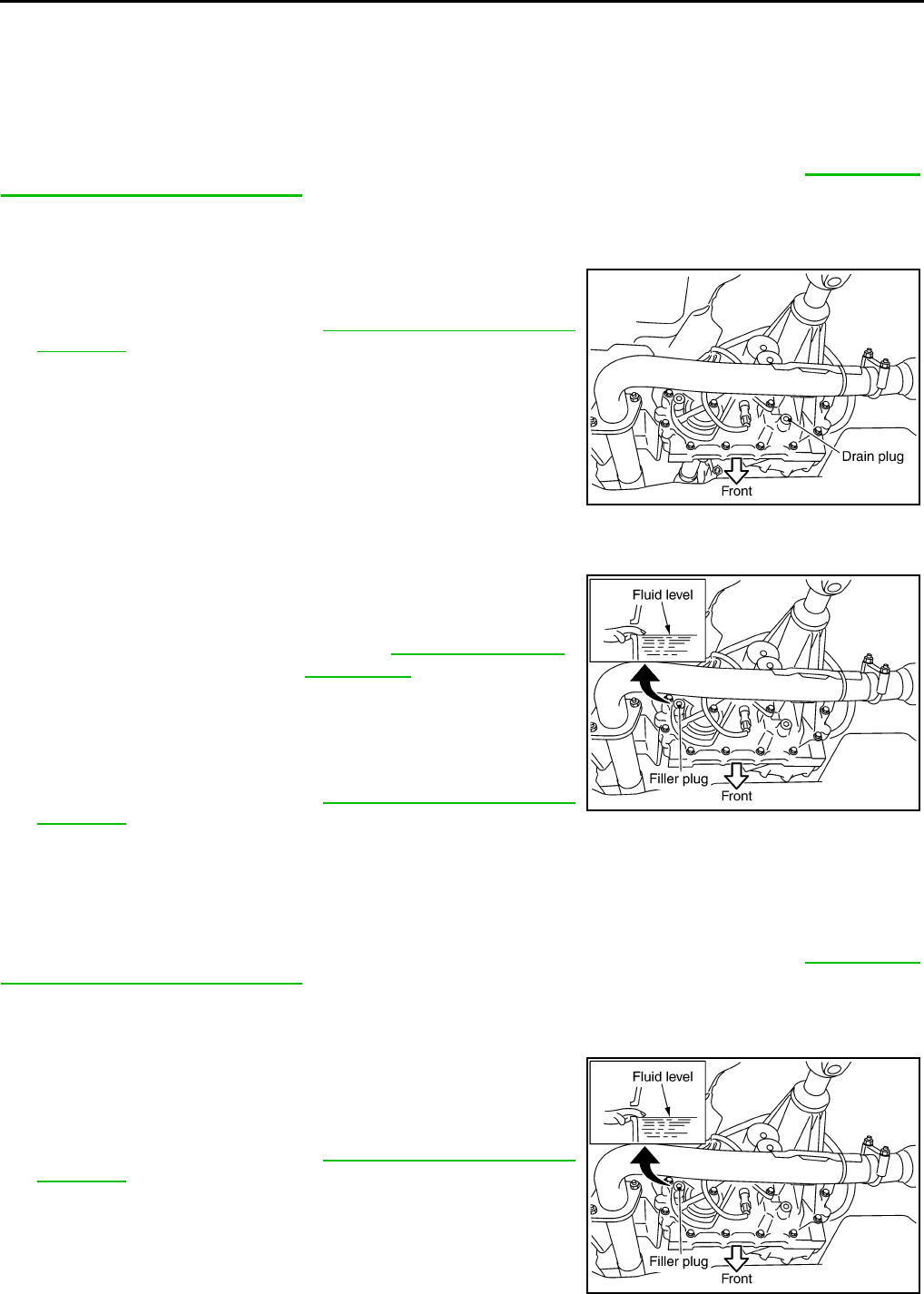
DLN-270
< ON-VEHICLE MAINTENANCE > [TRANSFER: TX15B]
TRANSFER FLUID
ON-VEHICLE MAINTENANCE
TRANSFER FLUID
Replacement INFOID:0000000003937389
CAUTION:
If using the vehicle for towing, the transfer fluid must be replaced as specified. Refer to MA-7, "Intro-
duction of Periodic Maintenance".
DRAINING
1. Stop engine.
2. Remove the drain plug and gasket and drain the fluid.
3. Install the drain plug with a new gasket to the transfer. Tighten to
the specified torque. Refer to DLN-281, "Disassembly and
Assembly".
CAUTION:
Do not reuse gasket.
FILLING
1. Remove the filler plug and gasket.
2. Fill the transfer with new fluid until the fluid level reaches the
specified limit near the filler plug hole.
CAUTION:
Carefully fill fluid. (Fill up for approx. 3 minutes.)
3. Leave the vehicle for 3 minutes, and check fluid level again.
4. Install the filler plug with a new gasket to the transfer. Tighten to
the specified torque. Refer to DLN-281, "Disassembly and
Assembly".
CAUTION:
Do not reuse gasket.
Inspection INFOID:0000000003937390
CAUTION:
If using the vehicle for towing, the transfer fluid must be replaced as specified. Refer to MA-7, "Intro-
duction of Periodic Maintenance".
FLUID LEAKAGE AND FLUID LEVEL
1. Make sure that fluid is not leaking from the transfer assembly or around it.
2. Check fluid level from the filler plug hole as shown.
CAUTION:
Do not start engine while checking fluid level.
3. Install the filler plug with a new gasket to the transfer. Tighten to
the specified torque. Refer to DLN-281, "Disassembly and
Assembly".
CAUTION:
Do not reuse gasket.
SDIA3286E
Fluid grade and capacity : Refer to MA-12, "Fluids and
Lubricants".
SDIA3287E
SDIA3287E
Revision: October 2008
2009 Pathfinder
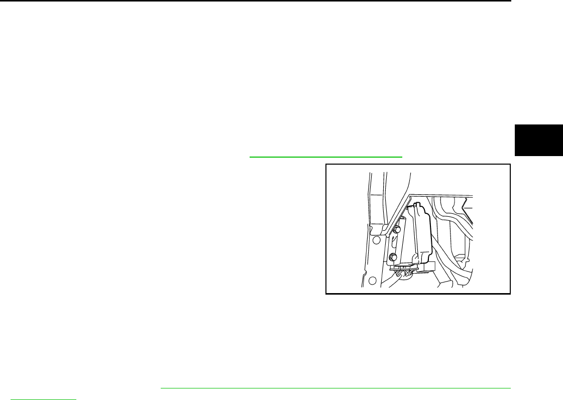
TRANSFER CONTROL UNIT
DLN-271
< ON-VEHICLE REPAIR > [TRANSFER: TX15B]
C
E
F
G
H
I
J
K
L
M
A
B
DLN
N
O
P
ON-VEHICLE REPAIR
TRANSFER CONTROL UNIT
Removal and Installation INFOID:0000000003937391
REMOVAL
1. Switch 4WD shift switch to 2WD and set transfer assembly to 2WD.
CAUTION:
When removing transfer control unit, transfer state must be at 2WD.
2. Turn the ignition switch OFF and disconnect negative battery terminal.
3. Remove the lower instrument panel LH. Refer to IP-11, "Removal and Installation".
4. Disconnect the two transfer control unit connectors.
5. Remove the transfer control unit bolts.
6. Remove the transfer control unit.
INSTALLATION
Installation is in the reverse order of removal.
• When installing the transfer control unit, tighten bolts to the specified torque.
• After the installation, check 4WD shift indicator pattern. If NG, adjust position between transfer assembly and
transfer control unit. Refer to DLN-262, "Precaution for Transfer Assembly and Transfer Control Unit
Replacement".
LDIA0168E
Transfer control unit bolts : 3.4 N·m (0.35 kg-m, 30 in-lb)
Revision: October 2008
2009 Pathfinder
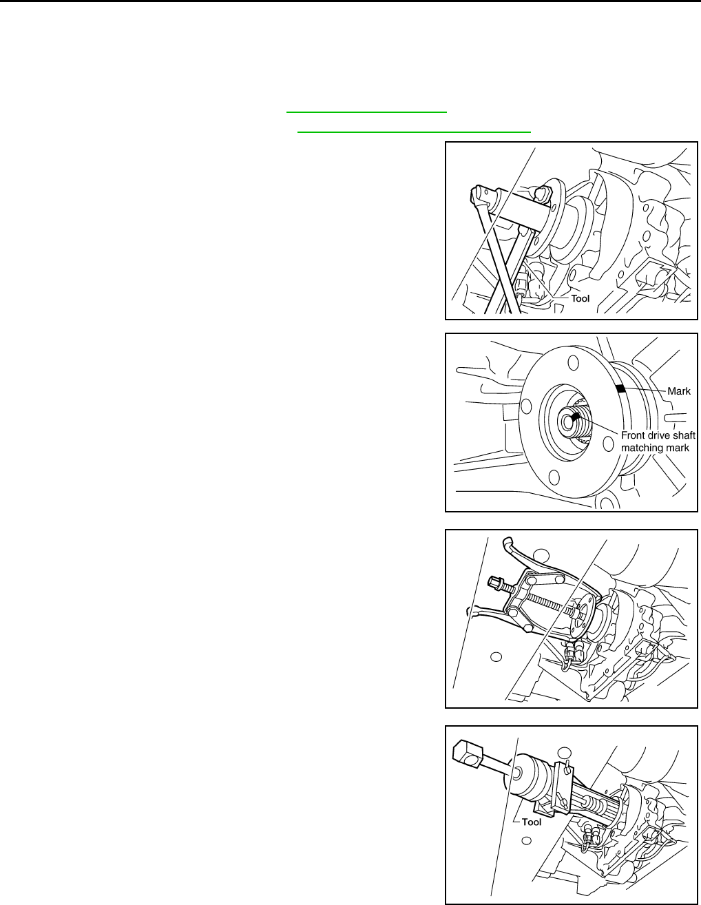
DLN-272
< ON-VEHICLE REPAIR > [TRANSFER: TX15B]
FRONT OIL SEAL
FRONT OIL SEAL
Removal and Installation INFOID:0000000003937392
REMOVAL
1. Partially drain the transfer fluid. Refer to DLN-270, "Replacement".
2. Remove the front propeller shaft. Refer to DLN-309, "Removal and Installation".
3. Remove the companion flange self-lock nut using Tool.
4. Put a matching mark on top of the front drive shaft in line with
the mark on the companion flange.
CAUTION:
Use paint to make the matching mark on the front drive
shaft. Do not damage the front drive shaft.
5. Remove the companion flange using suitable tool.
6. Remove the front oil seal from the front case using Tool.
CAUTION:
Do not damage front case.
INSTALLATION
Tool number : KV40104000 ( — )
LDIA0142E
SDIA2779E
WDIA0193E
Tool number : ST33290001 (J-34286)
LDIA0144E
Revision: October 2008
2009 Pathfinder
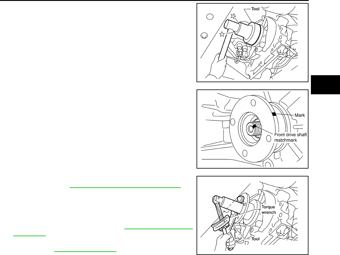
FRONT OIL SEAL
DLN-273
< ON-VEHICLE REPAIR > [TRANSFER: TX15B]
C
E
F
G
H
I
J
K
L
M
A
B
DLN
N
O
P
1. Install the new front oil seal until it is flush with the end face of
the front case using Tool.
CAUTION:
• Do not reuse oil seal.
• Apply petroleum jelly to oil seal.
2. Align the matching mark of the front drive shaft with the match-
ing mark of the companion flange, then install the companion
flange.
3. Install the new self-lock nut and tighten to the specified torque
using Tool. Refer to DLN-281, "Disassembly and Assembly".
CAUTION:
Do not reuse self-lock nut.
4. Install the front propeller shaft. Refer to DLN-309, "Removal and
Installation".
5. Refill the transfer with fluid and check for fluid leakage and fluid
level. Refer to DLN-270, "Inspection".
Tool number : KV38100500 ( — )
LDIA0145E
SDIA2214E
Tool number : KV40104000 ( — )
LDIA0147E
Revision: October 2008
2009 Pathfinder
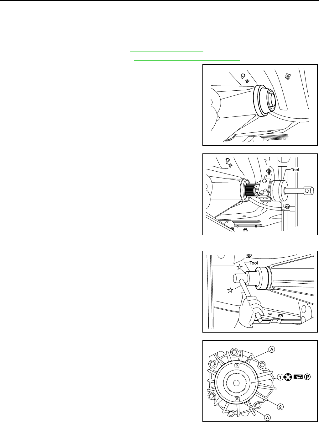
DLN-274
< ON-VEHICLE REPAIR > [TRANSFER: TX15B]
REAR OIL SEAL
REAR OIL SEAL
Removal and Installation INFOID:0000000003937393
REMOVAL
1. Partially drain the transfer fluid. Refer to DLN-270, "Replacement".
2. Remove the rear propeller shaft. Refer to DLN-317, "Removal and Installation".
3. Remove the dust cover from the rear case.
CAUTION:
Do not damage the rear case.
4. Remove the rear oil seal from the rear case using Tool.
CAUTION:
Do not damage the rear case.
INSTALLATION
1. Install the new rear oil seal until it is flush with the end face of the
rear case using Tool.
CAUTION:
• Do not reuse oil seal.
• Apply petroleum jelly to oil seal.
2. Apply petroleum jelly to the circumference of the new dust cover.
Position the new dust cover as shown.
CAUTION:
• Do not reuse dust cover.
• Position the identification mark at the position shown.
• 1: Dust cover
• A: Protrusions
• 2: Rear case assembly
WDIA0127E
Tool number : ST33290001 (J-34286)
LDIA0139E
Tool number : KV38100500 ( — )
LDIA0140E
AWDIA0550G
B
Revision: October 2008
2009 Pathfinder
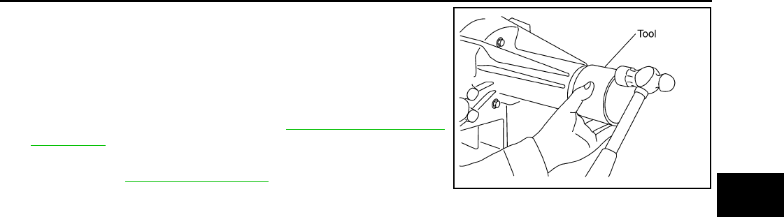
REAR OIL SEAL
DLN-275
< ON-VEHICLE REPAIR > [TRANSFER: TX15B]
C
E
F
G
H
I
J
K
L
M
A
B
DLN
N
O
P
3. Install the new dust cover to the rear case using Tool.
CAUTION:
• Do not reuse dust cover.
• Apply petroleum jelly to dust cover.
4. Install the rear propeller shaft. Refer to DLN-317, "Removal and
Installation".
5. Refill the transfer with fluid and check for fluid leakage and fluid
level. Refer to DLN-270, "Inspection".
Tool number : KV40105310 ( — )
PDIA0116E
Revision: October 2008
2009 Pathfinder
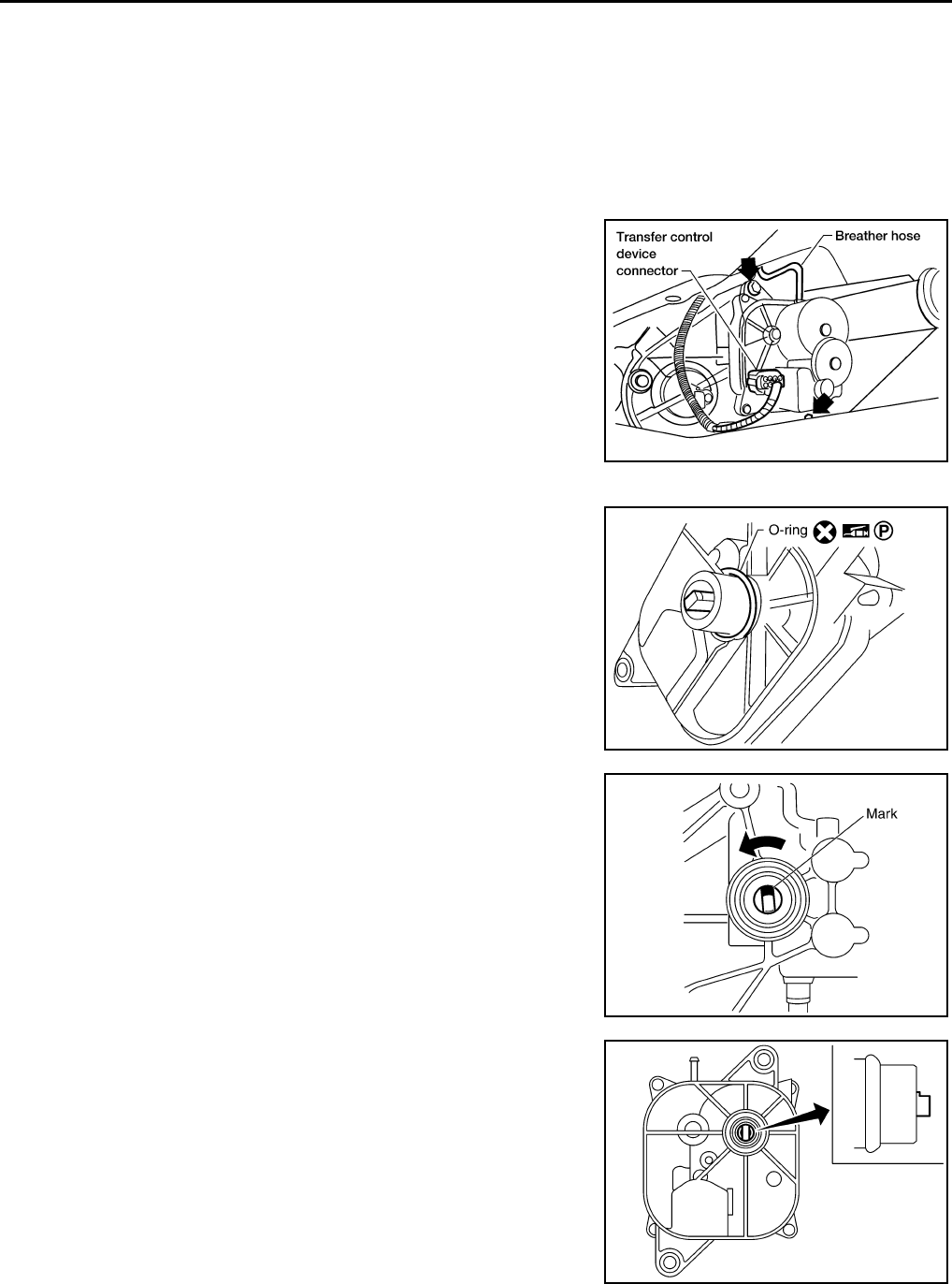
DLN-276
< ON-VEHICLE REPAIR > [TRANSFER: TX15B]
TRANSFER CONTROL DEVICE
TRANSFER CONTROL DEVICE
Removal and Installation INFOID:0000000003937394
REMOVAL
1. Switch the 4WD shift switch to 2WD and set the transfer assembly to 2WD.
2. Disconnect the transfer control device connector.
3. Remove the breather hose from the transfer control device.
4. Remove the bolts and detach the transfer control device.
INSTALLATION
1. Install the new O-ring to the transfer control device.
CAUTION:
• Do not reuse O-ring.
• Apply petroleum jelly to O-ring.
2. Install the transfer control device.
a. Turn the control shift rod fully counterclockwise using a flat-
bladed screwdriver, and then put a mark on the control shift rod.
b. Align the transfer control device shaft cutout with the mark on
the control shift rod, and install.
NOTE:
Turn the transfer control device when the transfer control device
connection does not match.
LDIA0136E
SDIA3378E
PDIA0119E
PDIA0120E
Revision: October 2008
2009 Pathfinder
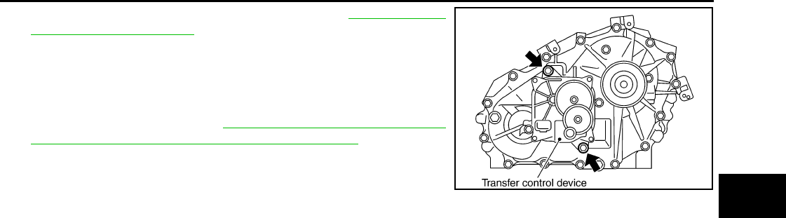
TRANSFER CONTROL DEVICE
DLN-277
< ON-VEHICLE REPAIR > [TRANSFER: TX15B]
C
E
F
G
H
I
J
K
L
M
A
B
DLN
N
O
P
c. Tighten the bolts to the specified torque. Refer to DLN-281, "Dis-
assembly and Assembly".
3. Install the breather hose to the transfer control device.
4. Connect the transfer control device connector.
5. After the installation, check the 4WD shift indicator pattern. If
NG, adjust the position between the transfer assembly and
transfer control unit. Refer to DLN-262, "Precaution for Transfer
Assembly and Transfer Control Unit Replacement".
SDIA2212E
Revision: October 2008
2009 Pathfinder
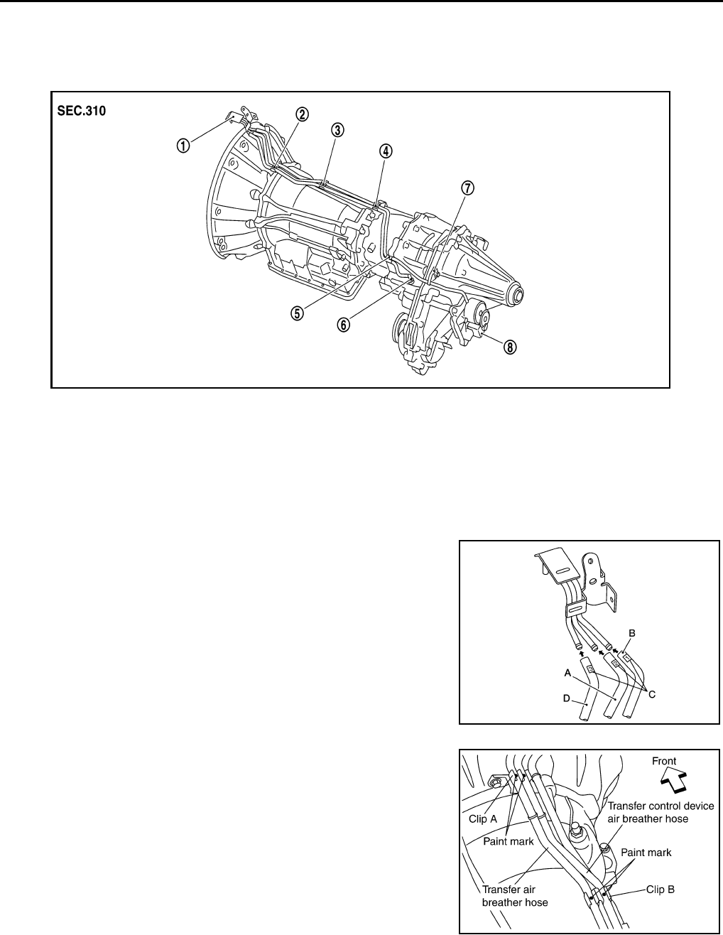
DLN-278
< ON-VEHICLE REPAIR > [TRANSFER: TX15B]
AIR BREATHER HOSE
AIR BREATHER HOSE
Removal and Installation INFOID:0000000003937395
CAUTION:
• Make sure there are no pinched or restricted areas on each air breather hose caused by folding or
bending when installing it.
• Install each air breather hose into the breather tube (metal
connector) until the hose end reaches the end of the curved
section. Set each air breather hose with paint mark facing
upward.
• Install transfer control device air breather hose and transfer
air breather hose on clip A and clip B with the paint mark fac-
ing upward.
1. Breather tube 2. Clip A 3. Clip B
4. Clip C 5. Clip D 6. Breather tube (transfer)
7. Air breather hose clamp 8. Transfer control device A. Transfer control device air breaher hose
B. A/T breather hose C. Paint marks D. Transfer air breather hose
SDIA3351E
AWDIA0628G
B
SDIA3353E
Revision: October 2008
2009 Pathfinder
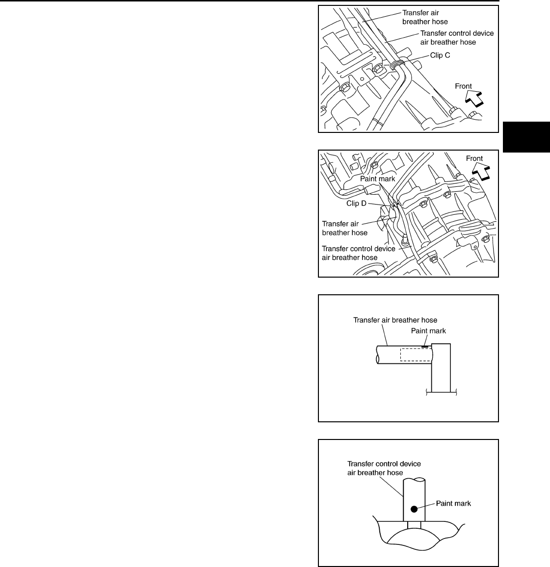
AIR BREATHER HOSE
DLN-279
< ON-VEHICLE REPAIR > [TRANSFER: TX15B]
C
E
F
G
H
I
J
K
L
M
A
B
DLN
N
O
P
• Install clip C on transfer control device air breather hose and
transfer air breather hose with the paint mark matched.
• Install transfer control device air breather hose and transfer
air breather hose on clip D with the paint mark facing upward.
• Install transfer air breather hose into the breather tube (trans-
fer, metal connector) until the hose end reaches the base of
the tube. Set transfer air breather hose with paint mark facing
upward.
• Install transfer control device air breather hose into transfer
control device (case connector) until the hose end reaches
the base of the tube. Set transfer control device air breather
hose with paint mark facing forward.
SDIA3354E
SDIA3355E
SDIA3196E
SDIA3300E
Revision: October 2008
2009 Pathfinder
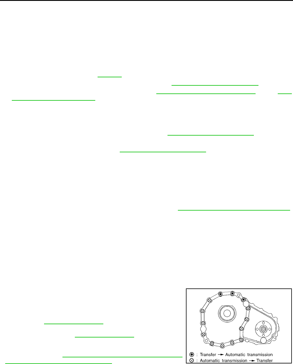
DLN-280
< REMOVAL AND INSTALLATION > [TRANSFER: TX15B]
TRANSFER ASSEMBLY
REMOVAL AND INSTALLATION
TRANSFER ASSEMBLY
Removal and Installation INFOID:0000000003937399
REMOVAL
1. Switch 4WD shift switch to 2WD and set transfer assembly to 2WD.
2. Remove the undercovers using power tool.
3. Drain the transfer fluid. Refer to DLN-270.
4. Remove the center exhaust tube and main muffler. Refer to EX-6, "Removal and Installation".
5. Remove the front and rear propeller shafts. Refer to DLN-309, "Removal and Installation" (front), DLN-
317, "Removal and Installation" (rear).
CAUTION:
Do not damage spline, sleeve yoke and rear oil seal when removing rear propeller shaft.
NOTE:
Insert a plug into the rear oil seal after removing the rear propeller shaft.
6. Remove the A/T nuts from the A/T crossmember. Refer to TM-217, "4WD : Exploded View".
7. Position two suitable jacks under the A/T and transfer assembly.
8. Remove the A/T crossmember. Refer to TM-217, "4WD : Exploded View".
WARNING:
Support A/T and transfer assembly using two suitable jacks while removing A/T crossmember.
9. Disconnect the electrical connectors from the following:
•ATP switch
• 4LO switch
• Wait detection switch
• Transfer control device
10. Disconnect each air breather hose from the following. Refer to TM-210, "4WD : Removal and Installation".
• Transfer control device
• Breather tube (transfer)
11. Remove the transfer to A/T and A/T to transfer bolts.
12. Remove the transfer assembly.
WARNING:
support transfer assembly with suitable jack while removing it.
CAUTION:
Do not damage rear oil seal (A/T).
INSTALLATION
Installation is in the reverse order of removal.
• Tighten the bolts to specification.
• Fill the transfer with new fluid and check for fluid leakage and fluid
level. Refer to DLN-270, "Inspection".
• Start the engine for one minute. Then stop the engine and recheck
the transfer fluid. Refer to DLN-270, "Inspection".
• After the installation, check the 4WD shift indicator pattern. If NG,
adjust the position between the transfer assembly and transfer
control unit. Refer to DLN-262, "Precaution for Transfer Assembly
and Transfer Control Unit Replacement".
Tightening torque : 36 N·m (3.7kg-m, 27 ft-lb)
SMT872C
Revision: October 2008
2009 Pathfinder
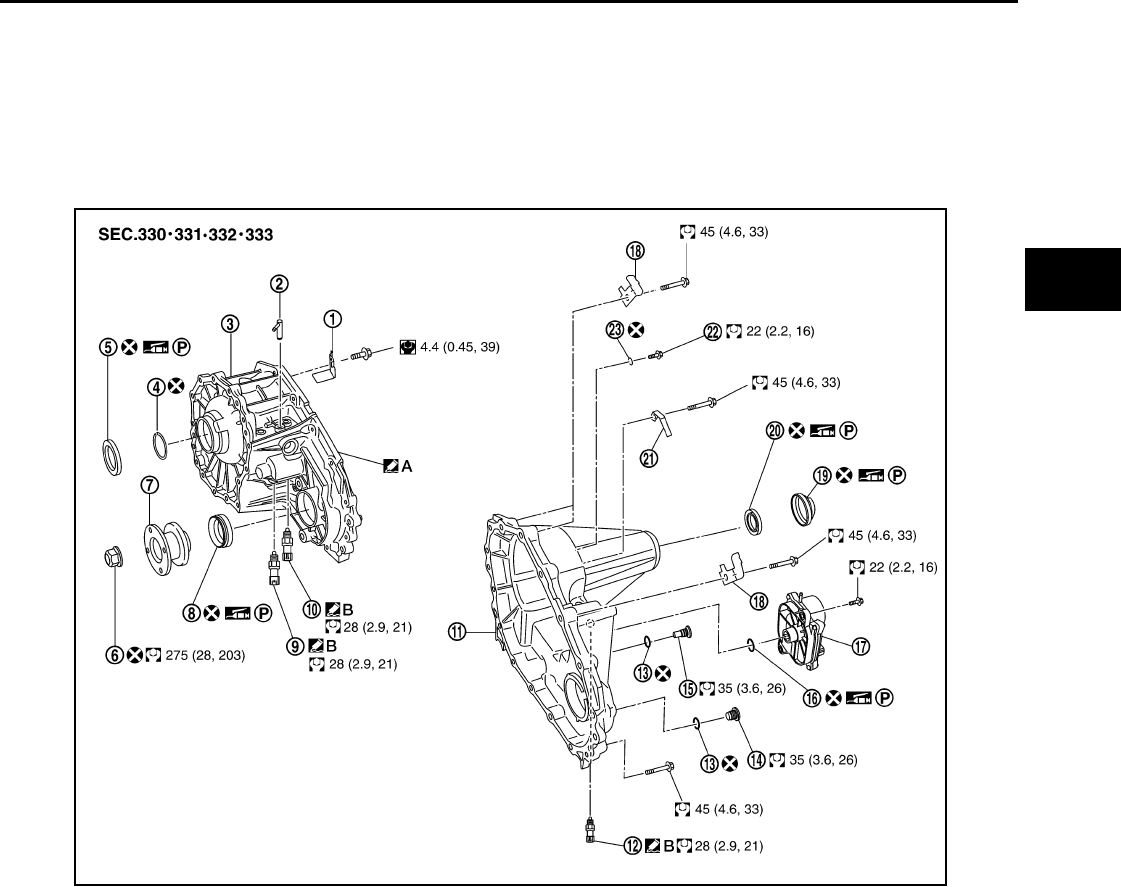
TRANSFER ASSEMBLY
DLN-281
< DISASSEMBLY AND ASSEMBLY > [TRANSFER: TX15B]
C
E
F
G
H
I
J
K
L
M
A
B
DLN
N
O
P
DISASSEMBLY AND ASSEMBLY
TRANSFER ASSEMBLY
Disassembly and Assembly INFOID:0000000003937400
COMPONENTS
1. Baffle plate 2. Breather tube 3. Front case
4. Snap ring 5. Input oil seal 6. Self-lock nut
7. Companion flange 8. Front oil seal 9. 4LO switch (gray with green
paint)
10. ATP switch (black) 11. Rear case 12. Wait detection switch (gray)
13. Gasket 14. Filler plug 15. Drain plug
16. O-ring 17. Transfer control device 18. Harness bracket
19. Dust cover 20. Rear oil seal 21. Air breather hose clamp
22. Retainer bolt 23. Gasket A. Apply Genuine Anaerobic Liquid
Gasket or equivalent.
B. Apply Genuine Silicone RTV or
equivalent.
WDIA0385E
Revision: October 2008
2009 Pathfinder
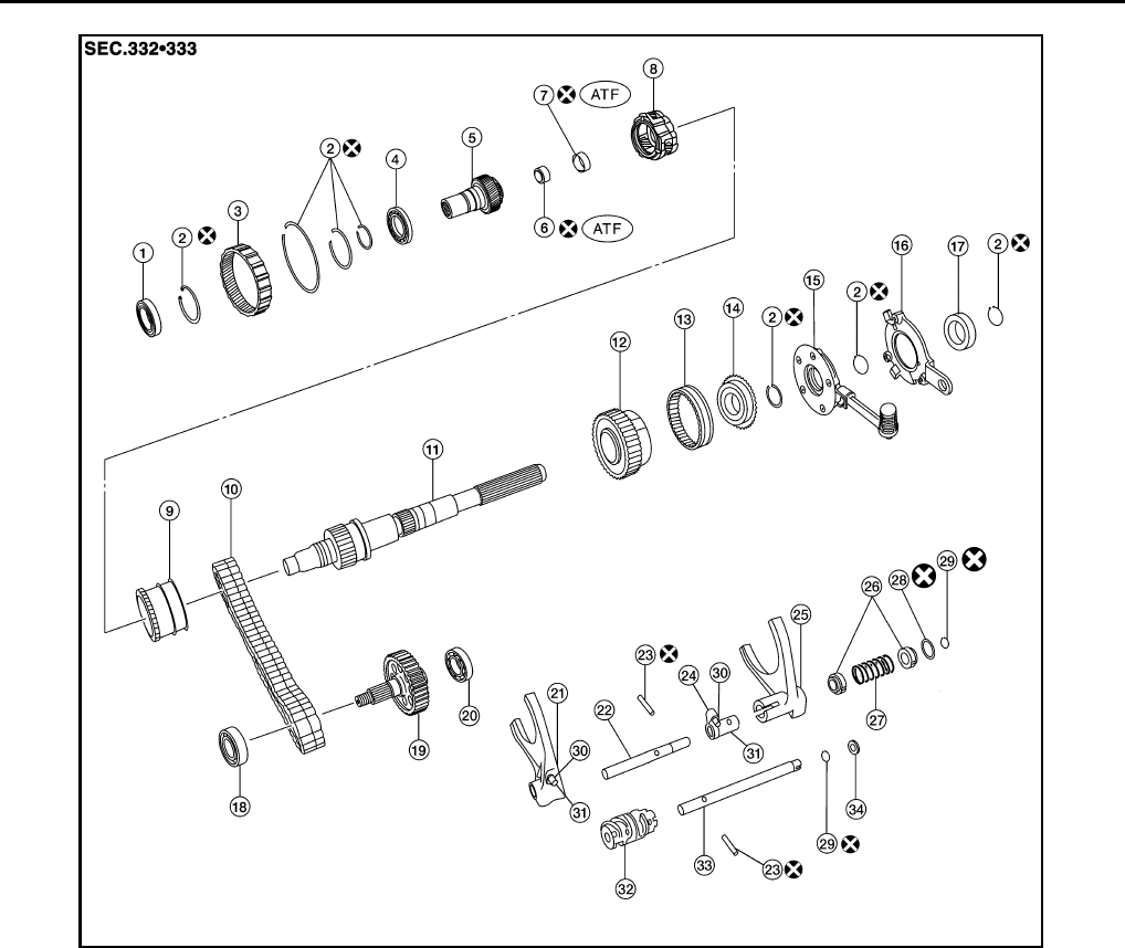
DLN-282
< DISASSEMBLY AND ASSEMBLY > [TRANSFER: TX15B]
TRANSFER ASSEMBLY
DISASSEMBLY
1. Remove the drain plug and filler plug.
1. Input bearing 2. Snap ring 3. Internal gear
4. Carrier bearing 5. Sun gear 6. Needle bearing
7. Metal bushing 8. Planetary carrier assembly 9. L-H sleeve
10. Drive chain 11. Mainshaft 12. Sprocket
13. 2-4 sleeve 14. Clutch gear 15. Oil pump assembly
16. Retainer 17. Mainshaft rear bearing 18. Front bearing
19. Front drive shaft 20. Rear bearing 21. L-H shift fork
22. L-H shift rod 23. Retaining pin 24. 2-4 shift bracket
25. 2-4 shift fork 26. Fork guide collar 27. 2-4 shift fork spring
28. Retaining ring 29. Snap ring 30. Shift collar
31. Clevis pin 32. Drum cam 33. Control shift rod
34. Spacer
AWDIA0016G
B
Revision: October 2008
2009 Pathfinder
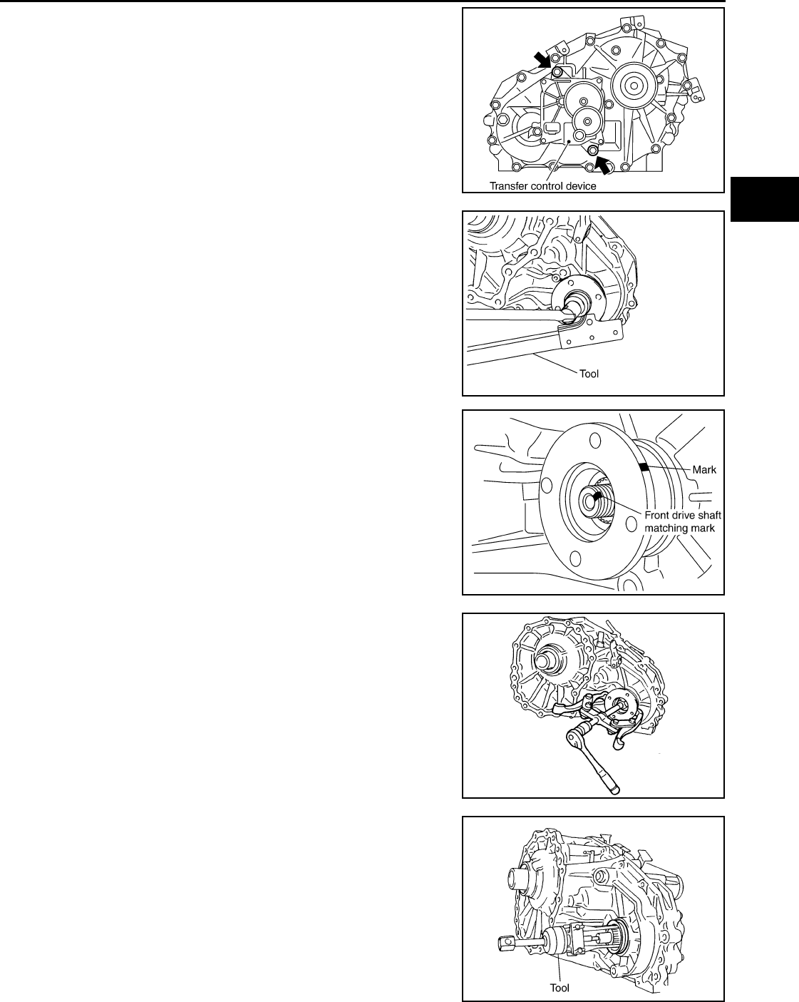
TRANSFER ASSEMBLY
DLN-283
< DISASSEMBLY AND ASSEMBLY > [TRANSFER: TX15B]
C
E
F
G
H
I
J
K
L
M
A
B
DLN
N
O
P
2. Remove the transfer control device from the rear case.
3. Remove the O-ring from the transfer control device.
4. Remove the self-lock nut from the companion flange using Tool.
5. Put a matching mark on top of the front drive shaft in line with
the mark on the companion flange.
CAUTION:
Use paint to make the matching mark on the front drive
shaft. Do not damage the front drive shaft.
6. Remove the companion flange using suitable tool.
7. Remove the front oil seal from the front case using Tool.
CAUTION:
Do not damage front case or front drive shaft.
SDIA2212E
Tool number : KV38108300 (J-44195)
SDIA2841E
SDIA2779E
WDIA0133E
Tool number : ST33290001 (J-34286)
SDIA2423E
Revision: October 2008
2009 Pathfinder
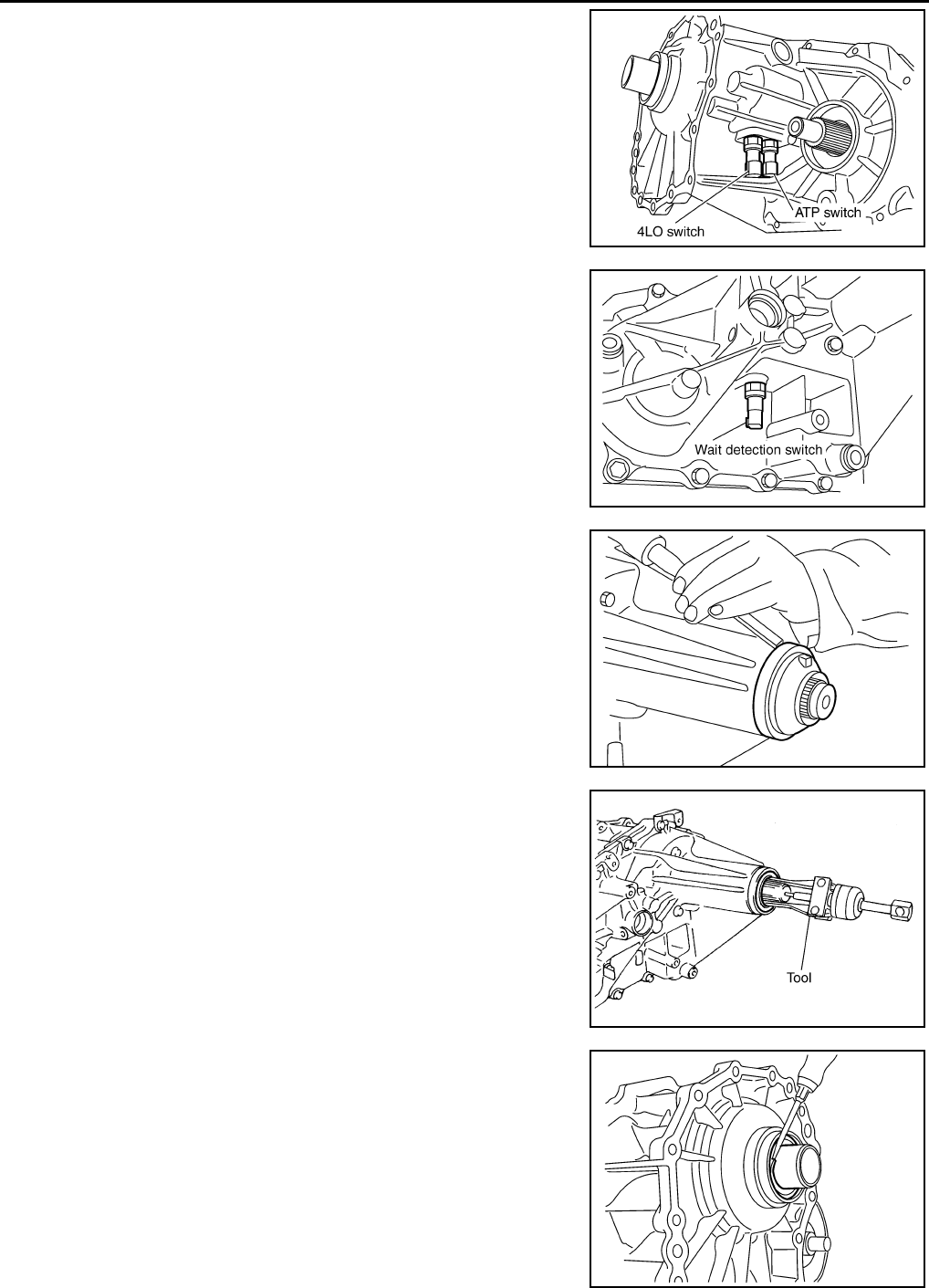
DLN-284
< DISASSEMBLY AND ASSEMBLY > [TRANSFER: TX15B]
TRANSFER ASSEMBLY
8. Remove the 4LO switch [gray (with green paint)] and ATP switch
(black) from the front case.
9. Remove the wait detection switch (gray) from the rear case.
10. Remove the dust cover from the rear case using suitable tool.
CAUTION:
Do not damage rear case.
11. Remove the rear oil seal from the rear case using Tool.
CAUTION:
Do not damage rear case or mainshaft.
12. Remove the input oil seal from the front case using suitable tool.
CAUTION:
Do not damage front case, sun gear or input bearing.
PDIA0090E
PDIA0091E
PDIA0092E
Tool number : ST33290001 (J-34286)
SDIA2424E
PDIA0094E
Revision: October 2008
2009 Pathfinder
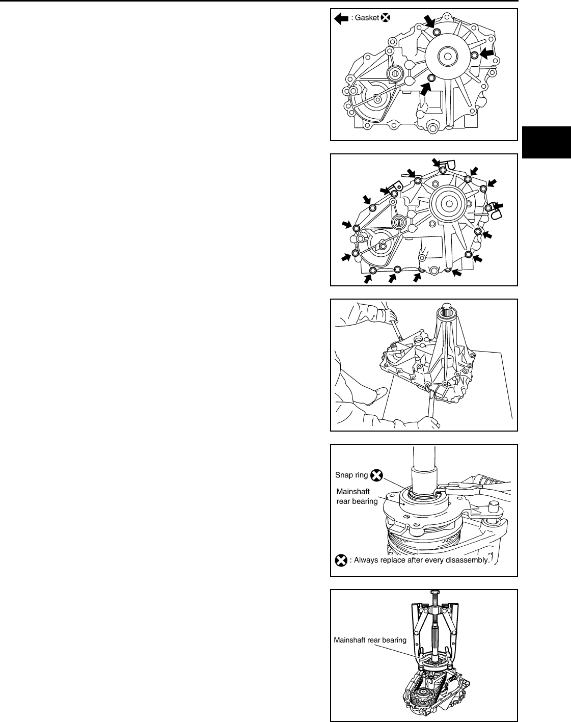
TRANSFER ASSEMBLY
DLN-285
< DISASSEMBLY AND ASSEMBLY > [TRANSFER: TX15B]
C
E
F
G
H
I
J
K
L
M
A
B
DLN
N
O
P
13. Remove the retainer bolts and gaskets.
14. Remove the rear case bolts, harness bracket and air breather
hose clamp from the rear case.
15. Separate the front case from the rear case. Then remove the
rear case by prying it up using suitable tool.
CAUTION:
Do not damage the mating surface.
16. Remove the spacer from the control shift rod.
CAUTION:
Do not drop spacer.
17. Remove the snap ring from the mainshaft using suitable tool.
18. Remove the mainshaft rear bearing from the mainshaft using
suitable tools.
19. Remove the retainer from the mainshaft.
SDIA2789E
SDIA3422E
PDIA0096E
SDIA2430E
WDIA0135E
Revision: October 2008
2009 Pathfinder
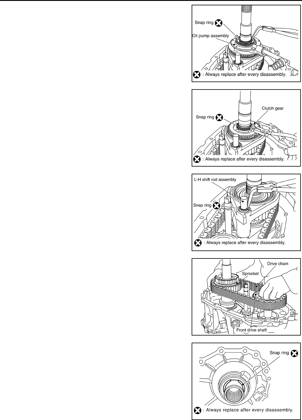
DLN-286
< DISASSEMBLY AND ASSEMBLY > [TRANSFER: TX15B]
TRANSFER ASSEMBLY
20. Remove the snap ring from the mainshaft using suitable tool.
21. Remove the oil pump assembly from the mainshaft.
22. Remove the snap ring from the mainshaft using suitable tool.
23. Remove the clutch gear from the mainshaft.
24. Remove the snap ring from the L-H shift rod assembly using
suitable tool.
25. Remove the 2-4 sleeve and 2-4 shift fork assembly from the
mainshaft.
26. Remove the drive chain together with the sprocket and front
drive shaft from the front case.
27. Remove the mainshaft from the sun gear assembly.
28. Remove the L-H shift rod assembly and control shift rod assem-
bly from the front case.
29. Remove the L-H sleeve together with the L-H shift fork from the
planetary carrier assembly.
30. Remove the snap ring from the sun gear.
CAUTION:
Do not damage sun gear or input bearing.
SDIA2461E
SDIA2462E
SDIA2463E
SDIA2464E
PDIA0099E
Revision: October 2008
2009 Pathfinder
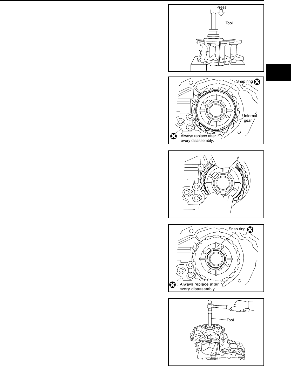
TRANSFER ASSEMBLY
DLN-287
< DISASSEMBLY AND ASSEMBLY > [TRANSFER: TX15B]
C
E
F
G
H
I
J
K
L
M
A
B
DLN
N
O
P
31. Press the sun gear assembly and planetary carrier assembly
from the front case using Tool.
32. Remove the snap ring from the front case.
33. Remove the internal gear from the front case.
34. Remove the snap ring from the front case.
35. Remove the input bearing from the front case using Tool.
Tool number : KV38100200 ( — )
PDIA0100E
PDIA0101E
PDIA0305E
PDIA0103E
Tool number : KV38100200 ( — )
PDIA0104E
Revision: October 2008
2009 Pathfinder
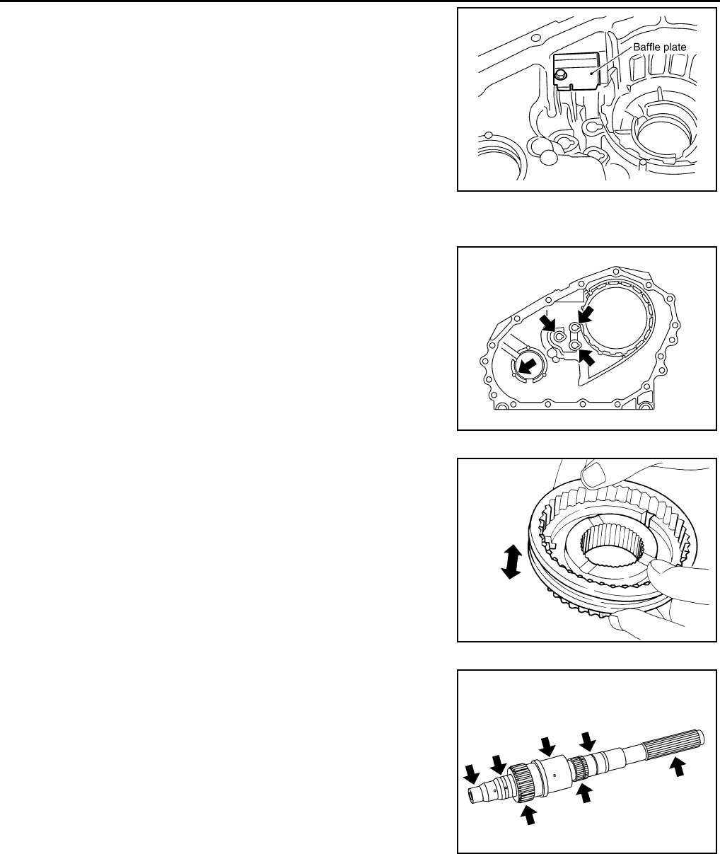
DLN-288
< DISASSEMBLY AND ASSEMBLY > [TRANSFER: TX15B]
TRANSFER ASSEMBLY
36. Remove the baffle plate from the front case.
37. Remove the breather tube from the front case.
INSPECTION AFTER DISASSEMBLY
Case
Check the contact surfaces of the shift rod and bearing for wear and
damage. If any is found, replace with a new one.
Sleeve
Check the items below. If necessary, replace them with new ones.
• Damage and excessive wear of the contact surfaces of the
sprocket, mainshaft and sleeve.
• Sleeve must move smoothly.
Gear, Shaft and Drive Chain
Check the items below. If necessary, replace them with new ones.
• Damage, peeling, uneven wear and bending of the shaft.
• Excessive wear, damage and peeling of the gear.
Bearing
PDIA0105E
PDIA0145E
PDIA0136E
SDIA2790E
Revision: October 2008
2009 Pathfinder
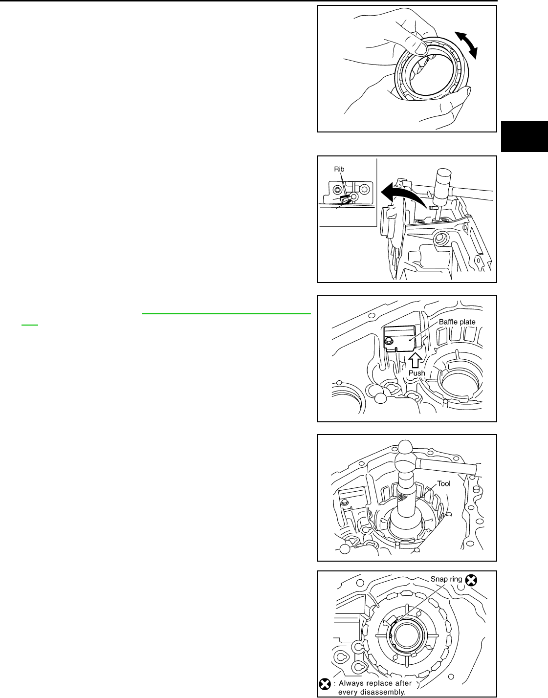
TRANSFER ASSEMBLY
DLN-289
< DISASSEMBLY AND ASSEMBLY > [TRANSFER: TX15B]
C
E
F
G
H
I
J
K
L
M
A
B
DLN
N
O
P
Check the bearing for damage and rough rotation. If necessary,
replace it with a new one.
ASSEMBLY
1. Install the breather tube.
CAUTION:
Install breather tube in the direction shown.
2. Install the baffle plate to the front case. Tighten the bolt to the
specified torque. Refer to DLN-281, "Disassembly and Assem-
bly".
CAUTION:
Install baffle plate by pushing it in the direction shown
while tightening the bolt.
3. Install the input bearing to the front case using Tool.
4. Install the new snap ring to the front case.
CAUTION:
Do not reuse snap ring.
MTF0041D
PDIA0107E
SDIA2479E
Tool number : ST30720000 (J-25405)
PDIA0108E
PDIA0103E
Revision: October 2008
2009 Pathfinder
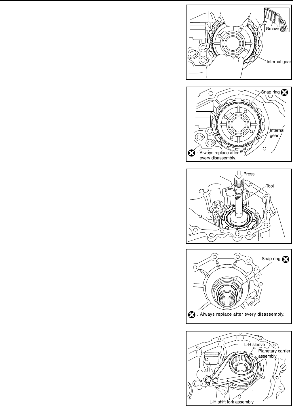
DLN-290
< DISASSEMBLY AND ASSEMBLY > [TRANSFER: TX15B]
TRANSFER ASSEMBLY
5. Install the internal gear with the groove facing up into the front
case.
6. Install the new snap ring to the front case.
CAUTION:
Do not reuse snap ring.
7. Install the planetary carrier assembly and sun gear assembly to
the front case using Tool.
8. Install the new snap ring to the sun gear.
CAUTION:
• Do not reuse snap ring.
• Do not damage sun gear.
9. Set the L-H sleeve together with the L-H shift fork assembly onto
the planetary carrier assembly.
PDIA0102E
PDIA0101E
Tool number : KV38100200 ( — )
SDIA2791E
PDIA0099E
SDIA2438E
Revision: October 2008
2009 Pathfinder
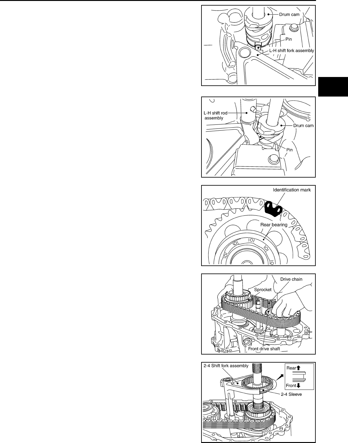
TRANSFER ASSEMBLY
DLN-291
< DISASSEMBLY AND ASSEMBLY > [TRANSFER: TX15B]
C
E
F
G
H
I
J
K
L
M
A
B
DLN
N
O
P
10. Install the control shift rod assembly to the front case.
CAUTION:
Set pin of L-H shift fork assembly into the groove of drum
cam.
11. Turn the control shift rod assembly fully counterclockwise.
12. Install the L-H shift rod assembly through the L-H shift fork
assembly opening to the front case.
CAUTION:
Set pin of L-H shift rod assembly into the groove of drum
cam.
13. Install the mainshaft to the sun gear assembly.
14. Install the drive chain to the front drive shaft and sprocket.
CAUTION:
Install with the Identification mark of drive chain on the side
of the rear bearing of front drive shaft.
15. Install the drive chain together with the front drive shaft and
sprocket to the front case.
16. Install the 2-4 sleeve and 2-4 shift fork assembly to the main-
shaft.
CAUTION:
• Install with proper orientation of 2-4 sleeve.
• Install 2-4 shift fork with engaging the grooves of 2-4 shift
fork in the retaining pin of 2-4 shift bracket.
WDIA0215E
WDIA0216E
PDIA0110E
SDIA2464E
SDIA2467E
Revision: October 2008
2009 Pathfinder
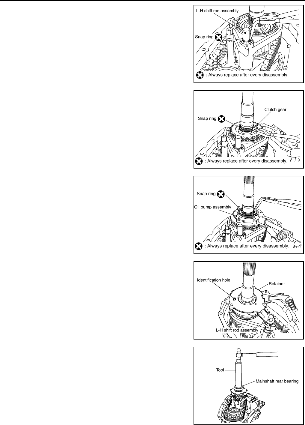
DLN-292
< DISASSEMBLY AND ASSEMBLY > [TRANSFER: TX15B]
TRANSFER ASSEMBLY
17. Install the new snap ring to the L-H shift rod assembly using suit-
able tool.
CAUTION:
Do not reuse snap ring.
18. Install the clutch gear to the mainshaft.
19. Install the new snap ring to the mainshaft using suitable tool.
CAUTION:
Do not reuse snap ring.
20. Install the oil pump assembly to the mainshaft.
21. Install the new snap ring to the mainshaft using suitable tool.
CAUTION:
Do not reuse snap ring.
22. Install the retainer to the mainshaft.
CAUTION:
Set the projection of oil pump assembly to the identification
hole, and then align locating hole of retainer to the L-H shift
rod assembly.
23. Install the mainshaft rear bearing to the mainshaft using Tool.
CAUTION:
Do not push too hard in order to avoid snap rings becoming
dislodged from mainshaft.
SDIA2463E
SDIA2462E
SDIA2461E
SDIA2468E
Tool number : KV32102700 ( — )
SDIA2469E
Revision: October 2008
2009 Pathfinder
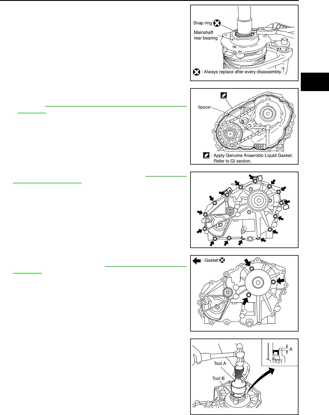
TRANSFER ASSEMBLY
DLN-293
< DISASSEMBLY AND ASSEMBLY > [TRANSFER: TX15B]
C
E
F
G
H
I
J
K
L
M
A
B
DLN
N
O
P
24. Install the new snap ring to the mainshaft using suitable tool.
CAUTION:
Do not reuse snap ring.
25. Install the spacer to the control shift rod.
26. Apply liquid gasket to the mating surface of the front case.
•Use Genuine Anaerobic Liquid Gasket or equivalent.
Refer to GI-26, "Recommended Chemical Products and
Sealants".
CAUTION:
Remove old sealant adhering to mating surfaces. Also
remove any moisture, oil, or foreign material adhering to
application and mating surfaces.
27. Install the rear case to the front case.
28. Tighten the bolts to the specified torque. Refer to DLN-281, "Dis-
assembly and Assembly".
CAUTION:
Be sure to install the harness brackets and air breather
hose clamp.
29. Install the retainer bolts with new gaskets. Tighten the bolts to
the specified torque. Refer to DLN-281, "Disassembly and
Assembly".
CAUTION:
• Do not reuse gasket.
• Tighten them to the specified torque again.
30. Apply petroleum jelly to the circumference of the new oil seal,
and install it to the front case using Tools.
CAUTION:
• Do not reuse oil seal.
• Apply petroleum jelly to oil seal.
SDIA2430E
WDIA0217E
SDIA3422E
SDIA2789E
Tool number A: ST30720000 (J-25405)
B: KV40104830 ( — )
Dimension A : 4.0 - 4.6 mm (0.157 - 0.181 in)
SDIA3191E
Revision: October 2008
2009 Pathfinder
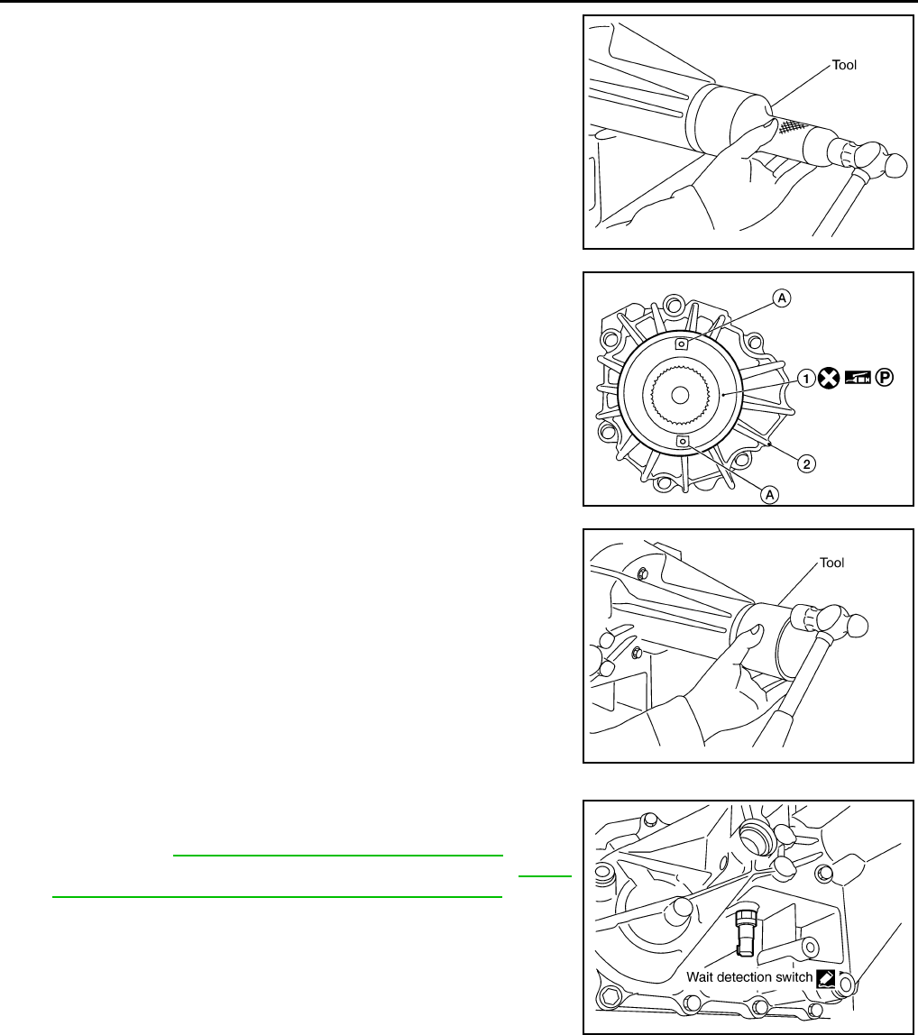
DLN-294
< DISASSEMBLY AND ASSEMBLY > [TRANSFER: TX15B]
TRANSFER ASSEMBLY
31. Install the new rear oil seal until it is flush with the end face of the
rear case using Tool.
CAUTION:
• Do not reuse oil seal.
• Apply petroleum jelly to oil seal.
32. Apply petroleum jelly to the circumference of the new dust cover
(1). Position the new dust cover (A) as shown.
• 2: Rear case assembly
CAUTION:
• Do not reuse dust cover.
• Position the identification mark at the position shown.
33. Install the new dust cover to the rear case using Tool.
CAUTION:
• Do not reuse dust cover.
• Apply petroleum jelly to dust cover.
34. Apply sealant to the threads of the wait detection switch (gray).
Then install it to the rear case and tighten to the specified
torque. Refer to DLN-281, "Disassembly and Assembly".
•Use Genuine Silicone RTV or equivalent. Refer to GI-26,
"Recommended Chemical Products and Sealants".
CAUTION:
Remove old sealant and oil adhering to threads.
Tool number : KV38100500 ( — )
PDIA0115E
AWDIA0550G
B
Tool number : KV40105310 ( — )
PDIA0116E
SDIA3389E
Revision: October 2008
2009 Pathfinder
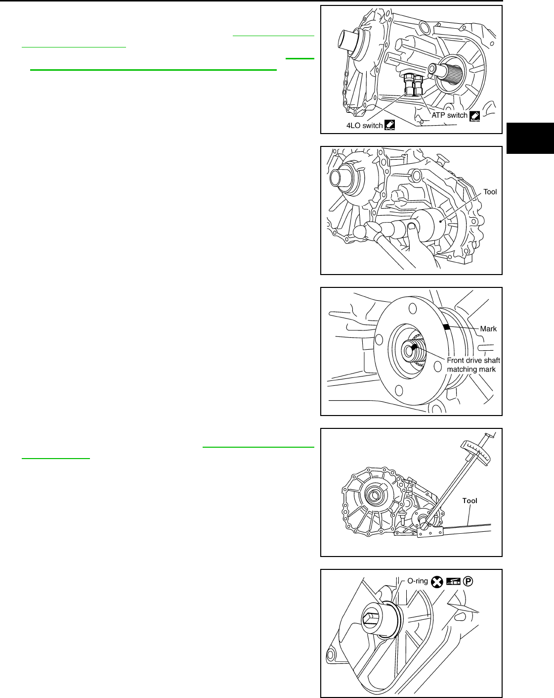
TRANSFER ASSEMBLY
DLN-295
< DISASSEMBLY AND ASSEMBLY > [TRANSFER: TX15B]
C
E
F
G
H
I
J
K
L
M
A
B
DLN
N
O
P
35. Apply sealant to the threads of the 4LO switch (gray with green
paint) and ATP switch (black). Then install them to the front case
and tighten to the specified torque. Refer to DLN-281, "Disas-
sembly and Assembly".
•Use Genuine Silicone RTV or equivalent. Refer to GI-26,
"Recommended Chemical Products and Sealants".
CAUTION:
Remove old sealant and oil adhering to threads.
36. Install the new front oil seal until it is flush with the end face of
the front case using Tool.
CAUTION:
• Do not reuse oil seal.
• Apply petroleum jelly to oil seal.
37. Align the matching mark on the front drive shaft with the mark on
the companion flange, then install the companion flange.
38. Install the new companion flange self-lock nut. Tighten to the
specified torque using Tool. Refer to DLN-281, "Disassembly
and Assembly".
CAUTION:
Do not reuse self-lock nut.
39. Install the new O-ring to the transfer control device.
CAUTION:
• Do not reuse O-ring.
• Apply petroleum jelly to O-ring.
SDIA3390E
Tool number : KV38100500 ( — )
PDIA0117E
SDIA2779E
Tool number : KV38108200 (J-44195)
WDIA0219E
SDIA3378E
Revision: October 2008
2009 Pathfinder
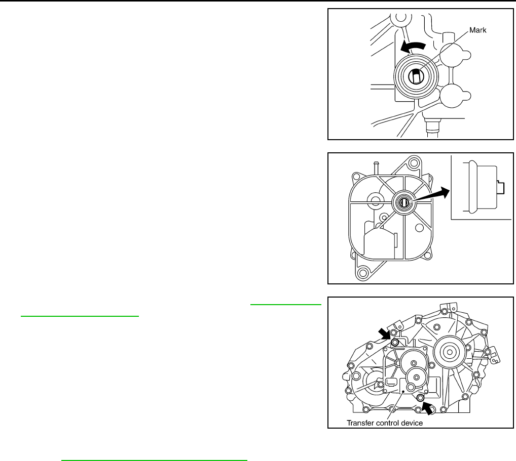
DLN-296
< DISASSEMBLY AND ASSEMBLY > [TRANSFER: TX15B]
TRANSFER ASSEMBLY
40. Install the transfer control device to the rear case.
a. Turn the control shift rod fully counterclockwise using a flat-
bladed screwdriver, and then put a mark on the control shift rod.
b. Align the transfer control device shaft cutout with the mark on
the control shift rod, and install it.
NOTE:
Turn the transfer control device when the transfer control device
connection does not match.
c. Tighten the bolts to the specified torque. Refer to DLN-281, "Dis-
assembly and Assembly".
41. Install the drain plug and filler plug with new gaskets to the rear case. Tighten to the specified torque.
Refer to DLN-281, "Disassembly and Assembly".
CAUTION:
Do not reuse gaskets.
PDIA0119E
PDIA0120E
SDIA2212E
Revision: October 2008
2009 Pathfinder
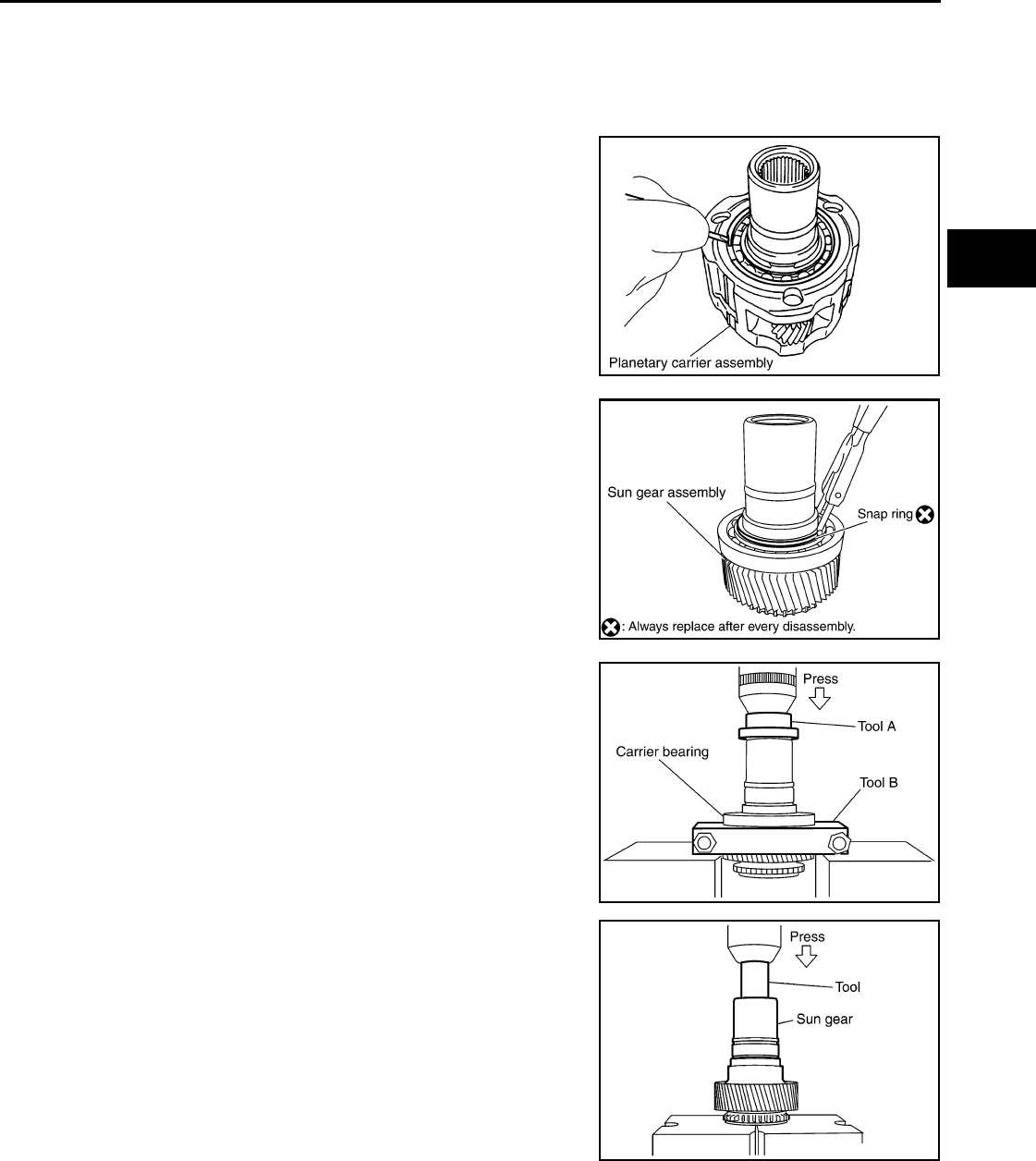
PLANETARY CARRIER
DLN-297
< DISASSEMBLY AND ASSEMBLY > [TRANSFER: TX15B]
C
E
F
G
H
I
J
K
L
M
A
B
DLN
N
O
P
PLANETARY CARRIER
Disassembly and Assembly INFOID:0000000003937396
DISASSEMBLY
1. Remove the snap ring.
2. Remove the sun gear assembly from the planetary carrier
assembly using suitable tool.
3. Remove the snap ring from the sun gear assembly using suit-
able tool.
4. Remove the carrier bearing from the sun gear using Tools.
5. Remove the needle bearing from the sun gear using Tool.
SDIA2792E
SDIA2353E
Tool number A: ST35300000 ( — )
B: ST30021000 (J-22912-01)
SDIA2149E
Tool number : ST33710000 ( — )
SDIA2354E
Revision: October 2008
2009 Pathfinder
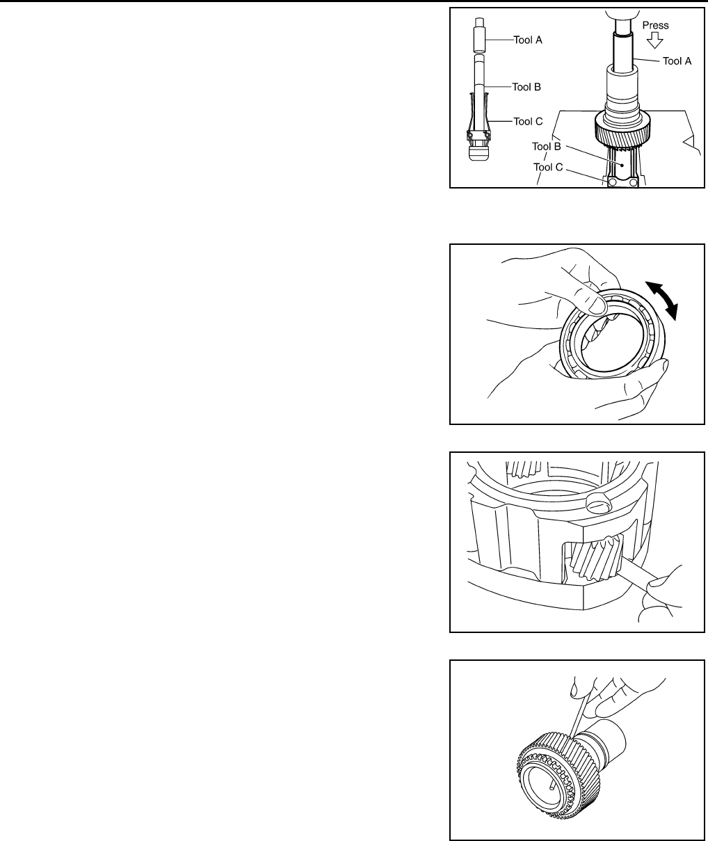
DLN-298
< DISASSEMBLY AND ASSEMBLY > [TRANSFER: TX15B]
PLANETARY CARRIER
6. Remove the metal bushing from the sun gear using Tools.
INSPECTION AFTER DISASSEMBLY
Bearing
Check the bearing for damage and rough rotation. If necessary,
replace the bearing with a new one.
Planetary Carrier
• Measure the end play of each pinion gear. If it is out of specifica-
tion, replace the planetary carrier assembly with new one.
• Check the working face of each gear and bearing for damage,
burrs, partial wear, dents and other abnormality. If any is found,
replace the planetary carrier assembly with a new one.
Sun Gear
• Check if the oil passage of the sun gear assembly is clogged. For
this, try to pass a 3.6 mm (0.142 in) dia. wire through the oil pas-
sage as shown.
• Check the sliding and contact surface of each gear and bearing for
damage, burrs, partial wear, dents and other abnormality. If any is
found, replace the sun gear assembly with a new one.
Internal Gear
Tool number A: ST33710000 ( — )
B: ST35325000 ( — )
C: ST33290001 (J-34286)
SDIA2168E
MTF0041D
Pinion gear end play : 0.1 - 0.7 mm (0.004 - 0.028 in)
PDIA0146E
PDIA0147E
Revision: October 2008
2009 Pathfinder
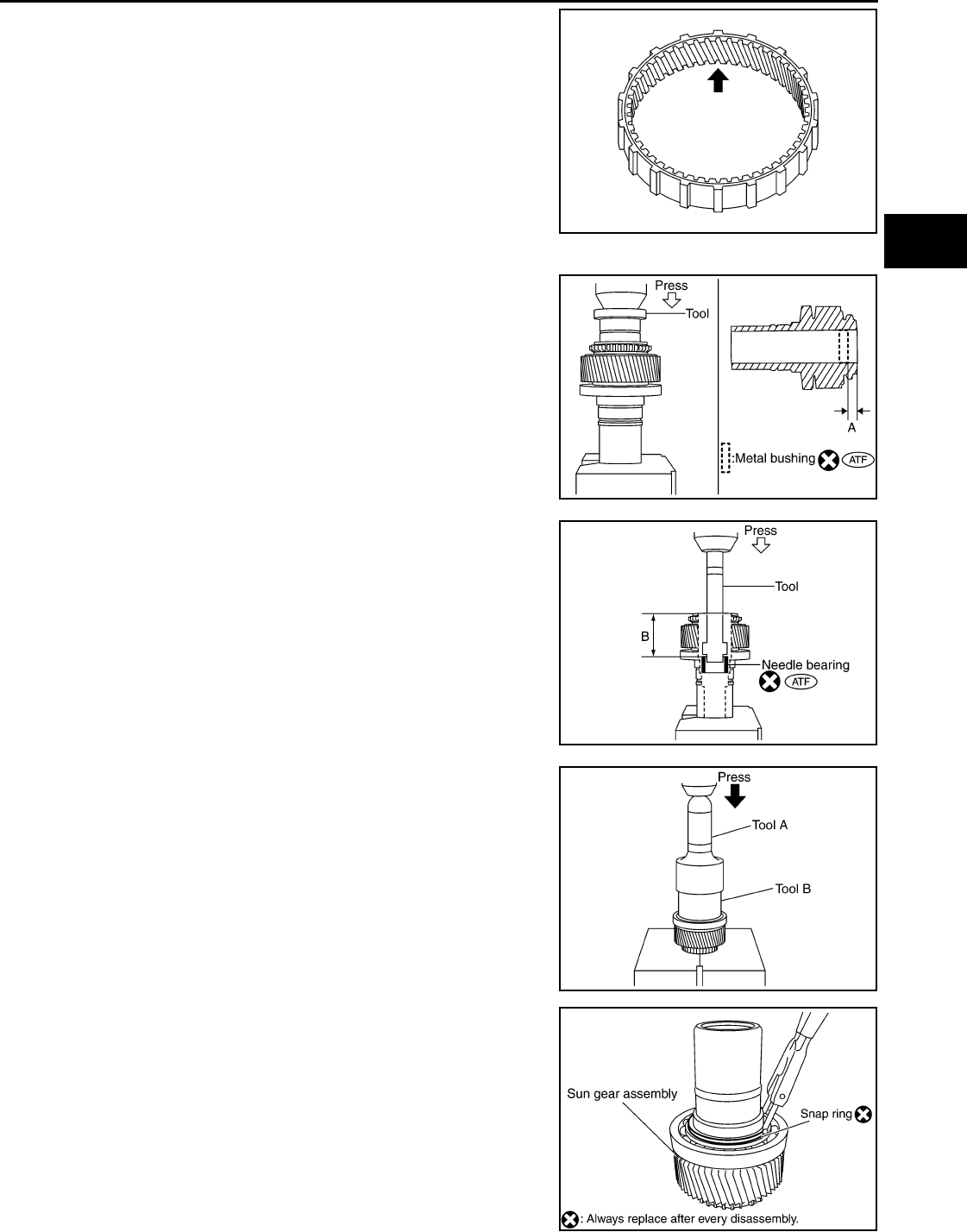
PLANETARY CARRIER
DLN-299
< DISASSEMBLY AND ASSEMBLY > [TRANSFER: TX15B]
C
E
F
G
H
I
J
K
L
M
A
B
DLN
N
O
P
Check the internal gear teeth for damage, partial wear, dents or
other abnormality. If any is found, replace the internal gear with a
new one.
ASSEMBLY
1. Apply ATF to the new metal bushing, then install the new metal
bushing until it becomes “Dimension A” using Tool.
CAUTION:
Do not reuse metal bushing.
2. Apply ATF to the new needle bearing, then install the new nee-
dle bearing until it becomes “Dimension B” using Tool.
CAUTION:
Do not reuse needle bearing.
3. Install the carrier bearing to the sun gear using Tools.
4. Install the new snap ring to the sun gear assembly using suitable
tool.
CAUTION:
Do not reuse snap ring.
PDIA0157E
Tool number : ST35300000 ( — )
Dimension A : 7.7 - 8.3mm (0.303 - 0.327in)
SDIA3189E
Tool number : ST33220000 ( — )
Dimension B : 62.5 - 63.1mm (2.461 - 2.484in)
SDIA3190E
Tool number A: ST30720000 (J-25405)
B: ST27863000 ( — )
PDIA0149E
SDIA2353E
Revision: October 2008
2009 Pathfinder
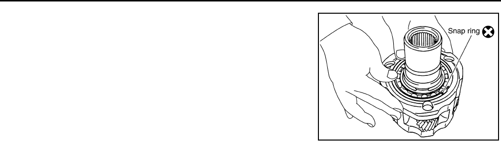
DLN-300
< DISASSEMBLY AND ASSEMBLY > [TRANSFER: TX15B]
PLANETARY CARRIER
5. Install the sun gear assembly to the planetary carrier assembly.
6. Install the new snap ring to the planetary carrier assembly.
CAUTION:
Do not reuse snap ring.
SDIA2794E
Revision: October 2008
2009 Pathfinder
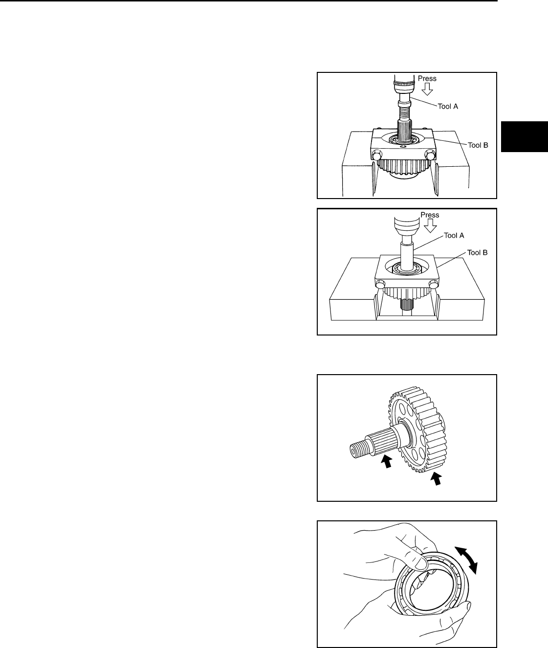
FRONT DRIVE SHAFT
DLN-301
< DISASSEMBLY AND ASSEMBLY > [TRANSFER: TX15B]
C
E
F
G
H
I
J
K
L
M
A
B
DLN
N
O
P
FRONT DRIVE SHAFT
Disassembly and Assembly INFOID:0000000003937397
DISASSEMBLY
1. Remove the front bearing using Tools.
2. Remove the rear bearing using Tools.
INSPECTION AFTER DISASSEMBLY
Front Drive Shaft
Check the items below. If necessary, replace them with new ones.
• Damage, peeling, dent, uneven wear and bending of the shaft.
• Excessive wear, damage and peeling of the gear.
Bearing
Check the bearing for damage and rough rotation. If necessary,
replace the bearing with a new one.
ASSEMBLY
Tool number A: ST35300000 ( — )
B: ST30021000 (J-22912-01)
SDIA2106E
Tool number A: ST33710000 ( — )
B: ST30021000 (J-22912-01)
PDIA0153E
PDIA0154E
MTF0041D
Revision: October 2008
2009 Pathfinder
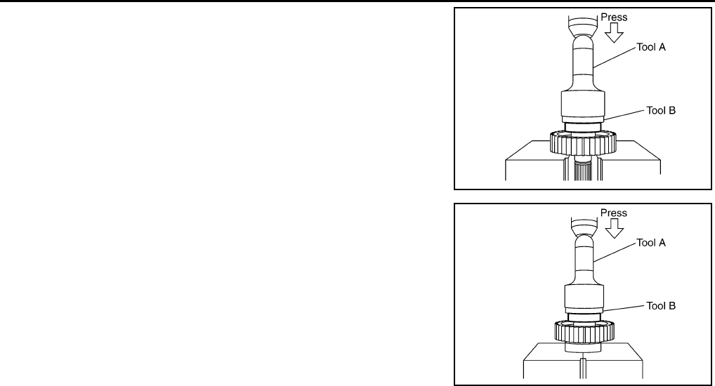
DLN-302
< DISASSEMBLY AND ASSEMBLY > [TRANSFER: TX15B]
FRONT DRIVE SHAFT
1. Install the rear bearing using Tools.
2. Install the front bearing using Tools.
Tool number A: KV38100500 ( — )
B: ST30901000 (J-26010-01)
PDIA0155E
Tool number A: KV38100500 ( — )
B: ST30901000 (J-26010-01)
PDIA0156E
Revision: October 2008
2009 Pathfinder
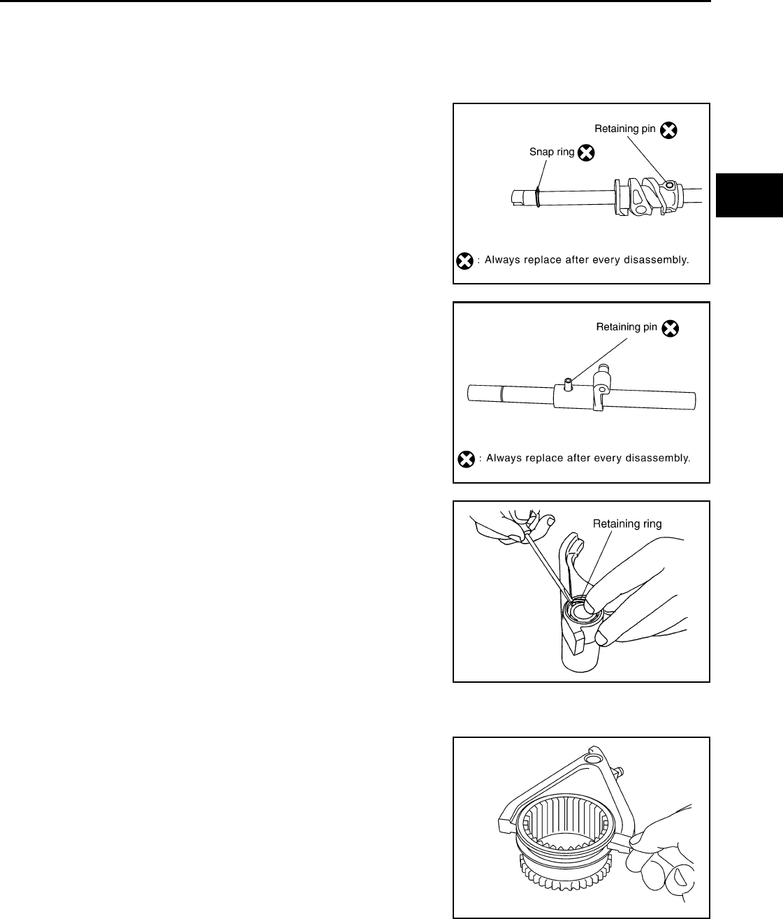
SHIFT CONTROL
DLN-303
< DISASSEMBLY AND ASSEMBLY > [TRANSFER: TX15B]
C
E
F
G
H
I
J
K
L
M
A
B
DLN
N
O
P
SHIFT CONTROL
Disassembly and Assembly INFOID:0000000003937398
DISASSEMBLY
1. Remove the snap ring.
2. Remove the retaining pin.
3. Remove the drum cam from the control shift rod.
4. Remove the retaining pin from the L-H shift rod.
5. Remove the 2-4 shift bracket.
6. Remove the retaining ring from the 2-4 shift fork using suitable
tool.
7. Remove the fork guide collar and 2-4 shift fork spring from the 2-
4 shift fork.
INSPECTION AFTER DISASSEMBLY
Shift Fork
• Measure the clearance between the shift fork and sleeve. If it is out
of specification, replace it with a new one.
Shift Rod and Fork Components
PDIA0122E
PDIA0125E
WDIA0226E
Standard value
2-4 : Less than 0.46 mm (0.018 in)
L-H : Less than 0.46 mm (0.018 in)
PDIA0134E
Revision: October 2008
2009 Pathfinder
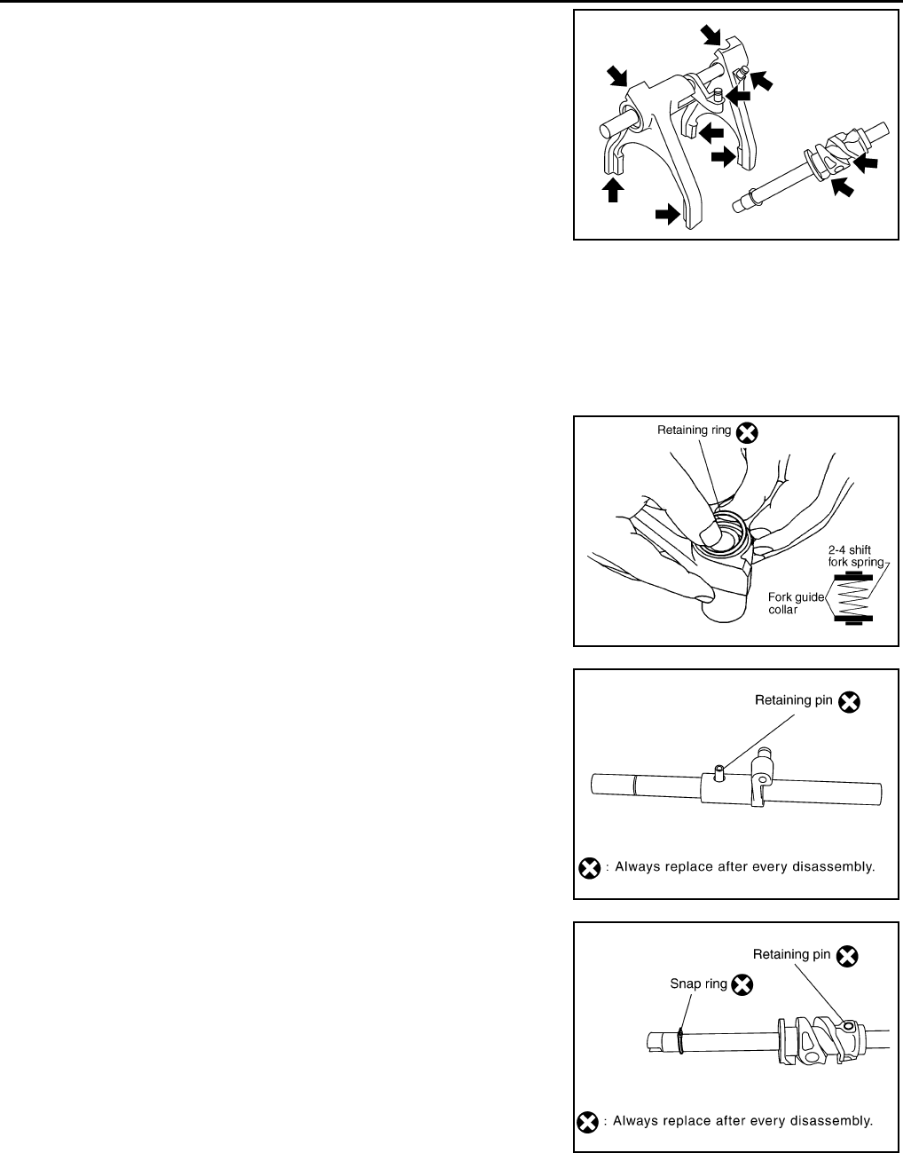
DLN-304
< DISASSEMBLY AND ASSEMBLY > [TRANSFER: TX15B]
SHIFT CONTROL
• Check the working face of the shift rod and fork for wear, partial
wear, abrasion, bending and other abnormality. If any is found,
replace with a new one.
ASSEMBLY
1. Install clevis pin and shift collar to L-H shift fork after assembling them.
CAUTION:
Use caution when installing L-H shift fork, clevis pin or shift collar.
2. Install clevis pin and shift collar to 2-4 shift bracket after assembling them.
CAUTION:
Use caution when installing 2-4 shift bracket.
3. Install guide fork collar and 2-4 shift fork spring to the 2-4 shift
fork, and then secure it with the new retaining ring.
CAUTION:
• Do not reuse retaining ring.
• Be careful with orientation.
4. Install the 2-4shift bracket to the L-H shift rod.
5. Install the new retaining pin evenly to the L-H shift rod.
CAUTION:
Do not reuse retaining pin.
6. Install the drum cam to the control shift rod, and then secure it
with the new retaining pin.
CAUTION:
Do not reuse retaining pin.
7. Install the new snap ring to the control shift rod.
CAUTION:
Do not reuse snap ring.
PDIA0135E
SDIA3391E
PDIA0125E
PDIA0122E
Revision: October 2008
2009 Pathfinder
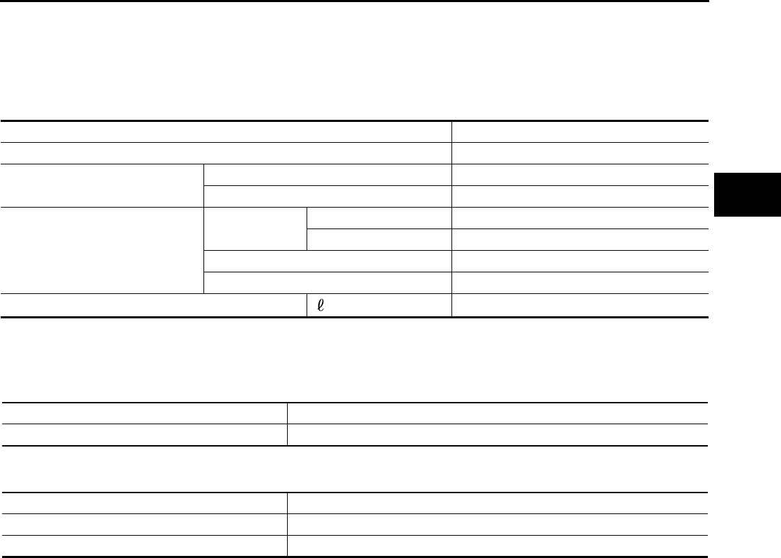
SERVICE DATA AND SPECIFICATIONS (SDS)
DLN-305
< SERVICE DATA AND SPECIFICATIONS (SDS) [TRANSFER: TX15B]
C
E
F
G
H
I
J
K
L
M
A
B
DLN
N
O
P
SERVICE DATA AND SPECIFICATIONS (SDS)
SERVICE DATA AND SPECIFICATIONS (SDS)
General Specification INFOID:0000000003937401
Inspection and Adjustment INFOID:0000000003937402
PINION GEAR END PLAY
Unit: mm (in)
CLEARANCE BETWEEN SHIFT FORK AND SLEEVE
Unit: mm (in)
Applied model VQ40DE
Transfer model TX15B
Gear ratio High 1.000
Low 2.625
Number of teeth
Planetary gear Sun gear 56
Internal gear 91
Front drive sprocket 38
Front drive shaft 38
Fluid Capacity (Approx) (US qt, Imp qt) 2.0 (2 1/8, 1 3/4)
Item Standard
Pinion gear end play 0.1 - 0.7 (0.004 - 0.028)
Item Standard
2-4 shift fork to 2-4 sleeve Less than 0.46 (0.018)
L-H shift fork to L-H sleeve Less than 0.46 (0.018)
Revision: October 2008
2009 Pathfinder
DLN-306
< PREPARATION > [PROPELLER SHAFT: 2F1310]
PREPARATION
PREPARATION
PREPARATION
Commercial Service Tool INFOID:0000000003937403
Tool name Description
Power tool Loosening bolts and nuts
PBIC0190E
Revision: October 2008
2009 Pathfinder
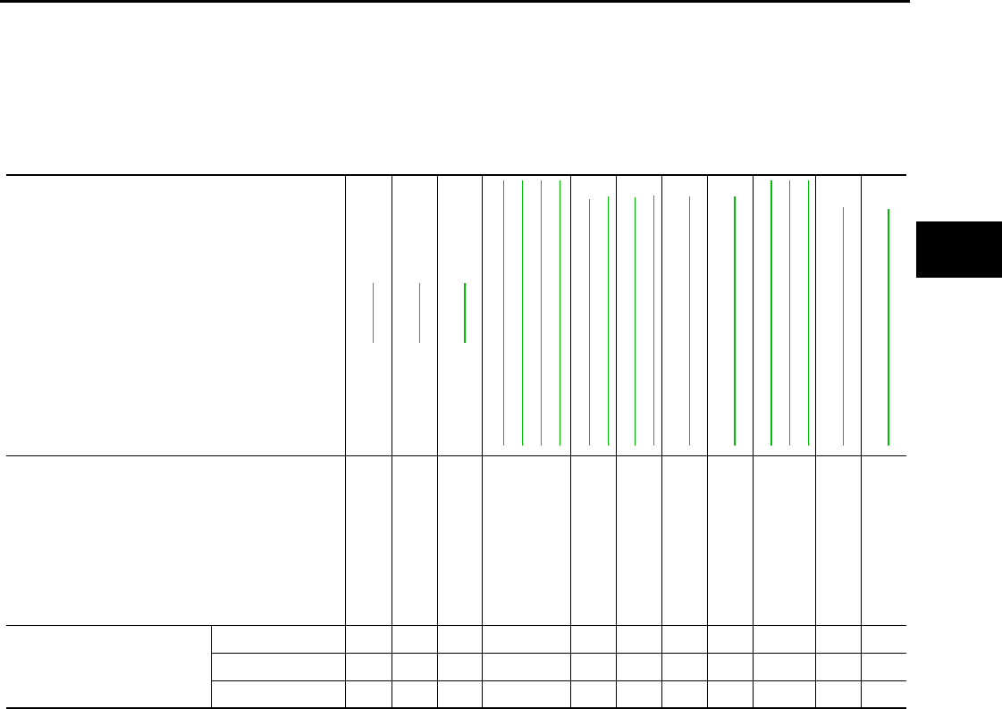
NOISE, VIBRATION, AND HARSHNESS (NVH) TROUBLESHOOTING
DLN-307
< FUNCTION DIAGNOSIS > [PROPELLER SHAFT: 2F1310]
C
E
F
G
H
I
J
K
L
M
A
B
DLN
N
O
P
FUNCTION DIAGNOSIS
NOISE, VIBRATION, AND HARSHNESS (NVH) TROUBLESHOOTING
NVH Troubleshooting Chart INFOID:0000000003937404
Use the chart below to help you find the cause of the symptom. If necessary, repair or replace these parts.
×: Applicable
Reference page
DLN-308
DLN-308
DLN-308
DLN-336, "NVH Troubleshooting Chart"
DLN-370, "NVH Troubleshooting Chart"
DLN-402, "NVH Troubleshooting Chart"
DLN-439, "NVH Troubleshooting Chart"
FAX-4, "NVH Troubleshooting Chart"
RAX-4, "NVH Troubleshooting Chart"
FSU-5, "NVH Troubleshooting Chart"
RSU-5, "NVH Troubleshooting Chart"
WT-45, "NVH Troubleshooting Chart"
WT-45, "NVH Troubleshooting Chart"
DLN-307, "NVH Troubleshooting Chart"
DLN-315, "NVH Troubleshooting Chart"
DLN-324, "NVH Troubleshooting Chart"
BR-6, "NVH Troubleshooting Chart"
ST-9, "NVH Troubleshooting Chart"
Possible cause and suspected parts
Uneven rotation torque
Rotation imbalance
Excessive run out
Differential
Axle
Suspension
Tires
Road wheel
Drive shaft
Brakes
Steering
Symptom
Noise ××× × ×××× × ××
Shake ×××× × ××
Vibration ××× ××× × ×
Revision: October 2008
2009 Pathfinder
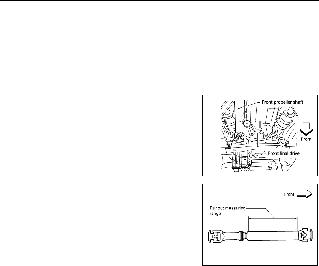
DLN-308
< ON-VEHICLE REPAIR > [PROPELLER SHAFT: 2F1310]
PROPELLER SHAFT
ON-VEHICLE REPAIR
PROPELLER SHAFT
On-Vehicle Service INFOID:0000000003937405
APPEARANCE AND NOISE INSPECTION
• Check the propeller shaft tube surface for dents or cracks. If damaged, replace the propeller shaft assembly.
• Check the bearings for noise and damage. Repair or replace the bearings as necessary.
PROPELLER SHAFT VIBRATION
If a vibration is present at high speed, inspect the propeller shaft runout first.
1. Measure the runout of the propeller shaft tube at several points
by rotating the final drive companion flange with your hands.
Refer to DLN-313, "General Specification".
2. If the runout exceeds specifications, disconnect the propeller
shaft at the final drive companion flange; then rotate the com-
panion flange 90°, 180° and 270° and reconnect the propeller
shaft.
3. Check the runout again. If the runout still exceeds specifications,
replace the propeller shaft assembly.
4. After installation, check for vibration by driving the vehicle.
LDIA0160E
LDIA0118E
Revision: October 2008
2009 Pathfinder
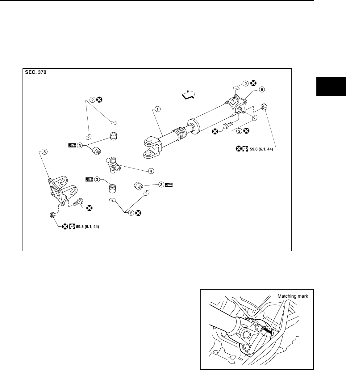
PROPELLER SHAFT
DLN-309
< REMOVAL AND INSTALLATION > [PROPELLER SHAFT: 2F1310]
C
E
F
G
H
I
J
K
L
M
A
B
DLN
N
O
P
REMOVAL AND INSTALLATION
PROPELLER SHAFT
Removal and Installation INFOID:0000000003937406
COMPONENTS
Model 2F1310
REMOVAL
1. Put matching marks on the front propeller shaft flange yoke and
the front final drive companion flange as shown.
CAUTION:
For matching marks, use paint. Never damage the flange
yoke and companion flange of the front final drive.
2. Put matching marks on the front propeller shaft flange yoke and
the transfer companion flange.
CAUTION:
For matching marks, use paint. Never damage the flange
yoke and companion flange of the front final drive.
3. Remove the bolts and then remove the front propeller shaft from
the front final drive and transfer.
INSPECTION
WDIA0304E
1. Propeller shaft tube 2. Snap ring 3. Journal bearing
4. Journal 5. Flange yoke ⇐:Front
SDIA2046E
Revision: October 2008
2009 Pathfinder
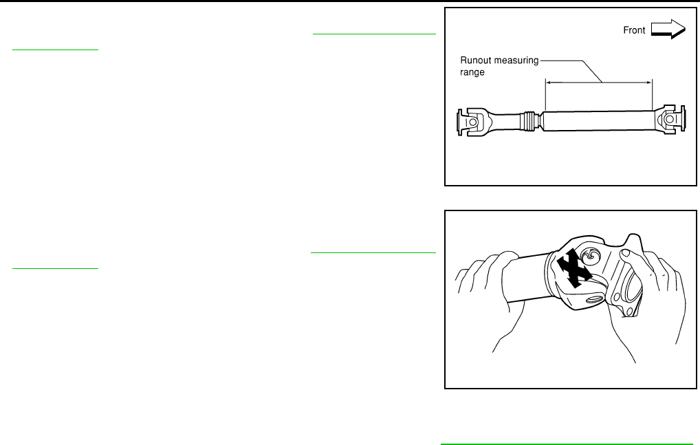
DLN-310
< REMOVAL AND INSTALLATION > [PROPELLER SHAFT: 2F1310]
PROPELLER SHAFT
• Inspect the propeller shaft runout. If runout exceeds the limit,
replace the propeller shaft assembly. Refer to DLN-313, "General
Specification".
• While holding the flange yoke on one side, check axial play of the
joint as shown. If the journal axial play exceeds the specification,
repair or replace the journal parts. Refer to DLN-313, "General
Specification".
• Check the propeller shaft tube surface for dents or cracks. If dam-
age is detected, replace the propeller shaft assembly.
INSTALLATION
Installation is in the reverse order of removal.
• After installation, check for vibration by driving the vehicle. Refer to DLN-324, "NVH Troubleshooting Chart".
CAUTION:
Do not reuse the bolts and nuts. Always install new ones.
LDIA0118E
LDIA0117E
Revision: October 2008
2009 Pathfinder
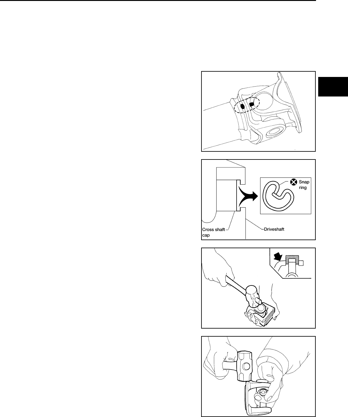
PROPELLER SHAFT
DLN-311
< DISASSEMBLY AND ASSEMBLY > [PROPELLER SHAFT: 2F1310]
C
E
F
G
H
I
J
K
L
M
A
B
DLN
N
O
P
DISASSEMBLY AND ASSEMBLY
PROPELLER SHAFT
Disassembly and Assembly INFOID:0000000003937407
DISASSEMBLY
Journal
1. Put matching marks on the front propeller shaft and flange yoke
as shown.
CAUTION:
For matching marks, use paint. Never damage the front pro-
peller shaft or flange yoke.
2. Remove the snap rings.
3. Push out and remove the journal bearings by lightly tapping the
flange yoke with a hammer, taking care not to damage the jour-
nal or flange yoke hole.
NOTE:
Put marks on the disassembled parts so that they can be rein-
stalled in their original positions from which they were removed.
4. Push out and remove the remaining journal bearings at the
opposite side by lightly tapping the flange yoke with a hammer,
taking care not to damage the journal or flange yoke hole.
NOTE:
Put marks on the disassembled parts so that they can be rein-
stalled in their original positions from which they were removed.
ASSEMBLY
SPD128
APD011
SPD732
SPD131
Revision: October 2008
2009 Pathfinder
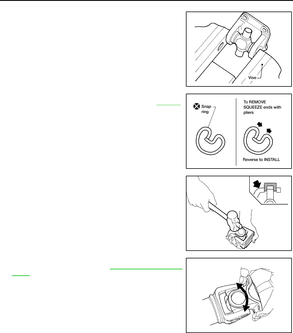
DLN-312
< DISASSEMBLY AND ASSEMBLY > [PROPELLER SHAFT: 2F1310]
PROPELLER SHAFT
Journal
1. Assemble the journal bearings. Apply multipurpose grease on
the bearing inner surface.
NOTE:
During assembly, use caution so that the needle bearings do not
fall down.
2. Select new snap rings that will provide the specified play in an
axial direction of the journal, and install them. Refer to DLN-313.
CAUTION:
Do not reuse snap rings
NOTE:
Select snap rings with a difference in thickness at both sides
within 0.02 mm (0.0008 in).
3. Adjust the thrust clearance between the bearing and snap ring
to zero by tapping the yoke.
4. Make sure that the journal moves smoothly and is below the
joint flex effort specification. Refer to DLN-313, "General Specifi-
cation".
WPD019
APD012
SPD732
LDIA0119E
Revision: October 2008
2009 Pathfinder
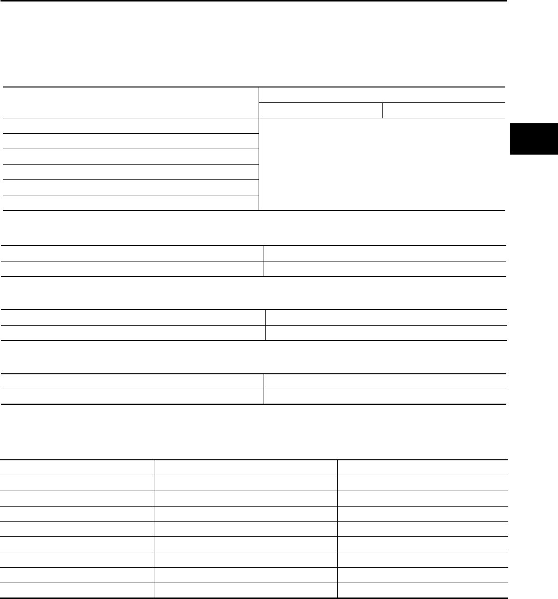
SERVICE DATA AND SPECIFICATIONS (SDS)
DLN-313
< SERVICE DATA AND SPECIFICATIONS (SDS) [PROPELLER SHAFT: 2F1310]
C
E
F
G
H
I
J
K
L
M
A
B
DLN
N
O
P
SERVICE DATA AND SPECIFICATIONS (SDS)
SERVICE DATA AND SPECIFICATIONS (SDS)
General Specification INFOID:0000000003937408
Unit: mm (in)
Propeller Shaft Runout
Unit: mm (in)
Propeller Shaft Joint Flex Effort
N·m (kg-m, in-lb)
Journal Axial Play
Unit: mm (in)
Snap Ring INFOID:0000000003937409
Model 2F1310 (4WD)
Unit: mm (in)
*Always check with the Parts Department for the latest parts information.
Applied model 4WD
VQ40DE VK56DE
A/T
2F1310
2
Flange type
Flange type
696 mm (27.40 in)
63.5 mm (2.5 in)
Propeller shaft model
Number of joints
Coupling method with front final drive
Coupling method with transfer
Shaft length (Spider to spider)
Shaft outer diameter
Item Limit
Propeller shaft runout 0.6 mm (0.024 in)
Item Limit
Propeller shaft joint flex effort 2.26 (0.23 , 20 ) or less
Item Limit
Journal axial play 0.02 mm (0.0008 in) or less
Thickness Color Part Number*
1.99 (0.0783) White 37146-C9400
2.02 (0.0795) Yellow 37147-C9400
2.05 (0.0807) Red 37148-C9400
2.08 (0.0819) Green 37149-C9400
2.11 (0.0831) Blue 37150-C9400
2.14 (0.0843) Light brown 37151-C9400
2.17 (0.0854) Black 37152-C9400
2.20 (0.0866) No paint 37153-C9400
Revision: October 2008
2009 Pathfinder

DLN-314
< PREPARATION > [PROPELLER SHAFT: 2S1330]
PREPARATION
PREPARATION
PREPARATION
Commercial Service Tool INFOID:0000000003937410
Tool name Description
Power tool Loosening bolts and nuts
PBIC0190E
Revision: October 2008
2009 Pathfinder
NOISE, VIBRATION, AND HARSHNESS (NVH) TROUBLESHOOTING
DLN-315
< FUNCTION DIAGNOSIS > [PROPELLER SHAFT: 2S1330]
C
E
F
G
H
I
J
K
L
M
A
B
DLN
N
O
P
FUNCTION DIAGNOSIS
NOISE, VIBRATION, AND HARSHNESS (NVH) TROUBLESHOOTING
NVH Troubleshooting Chart INFOID:0000000003937411
Use the chart below to help you find the cause of the symptom. If necessary, repair or replace these parts.
×: Applicable
Reference page
DLN-316
DLN-316
DLN-321
DLN-336, "NVH Troubleshooting Chart"
DLN-370, "NVH Troubleshooting Chart"
DLN-402, "NVH Troubleshooting Chart"
FAX-4, "NVH Troubleshooting Chart"
FAX-4, "NVH Troubleshooting Chart"
RAX-4, "NVH Troubleshooting Chart"
FSU-5, "NVH Troubleshooting Chart"
RSU-5, "NVH Troubleshooting Chart"
WT-45, "NVH Troubleshooting Chart"
WT-45, "NVH Troubleshooting Chart"
DLN-307, "NVH Troubleshooting Chart"
DLN-315, "NVH Troubleshooting Chart"
DLN-324, "NVH Troubleshooting Chart"
BR-6, "NVH Troubleshooting Chart"
ST-9, "NVH Troubleshooting Chart"
Possible cause and suspected parts
Uneven rotation torque
Rotation imbalance
Excessive run out
Differential
Axle
Suspension
Tires
Road wheel
Drive shaft
Brakes
Steering
Symptom
Noise ××× × ×××× × ××
Shake ×××× × ××
Vibration ××× ×××××
Revision: October 2008
2009 Pathfinder
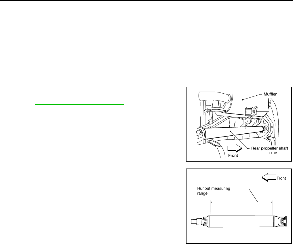
DLN-316
< ON-VEHICLE REPAIR > [PROPELLER SHAFT: 2S1330]
PROPELLER SHAFT
ON-VEHICLE REPAIR
PROPELLER SHAFT
On-Vehicle Service INFOID:0000000003937412
APPEARANCE AND NOISE INSPECTION
• Check the propeller shaft tube surface for dents or cracks. If damaged, replace the propeller shaft assembly.
• Check the bearings for noise and damage. Repair or replace the bearings as necessary.
PROPELLER SHAFT VIBRATION
If a vibration is present at high speed, inspect the propeller shaft runout first.
1. Measure the runout of the propeller shaft tube at several points
by rotating the final drive companion flange with your hands.
Refer to DLN-321, "General Specification".
2. If the runout exceeds specifications, disconnect the propeller
shaft at the final drive companion flange; then rotate the com-
panion flange 90°, 180° and 270° and reconnect the propeller
shaft.
3. Check the runout again. If the runout still exceeds specifications,
replace the propeller shaft assembly.
4. After installation, check for vibration by driving vehicle.
LDIA0161E
LDIA0121E
Revision: October 2008
2009 Pathfinder
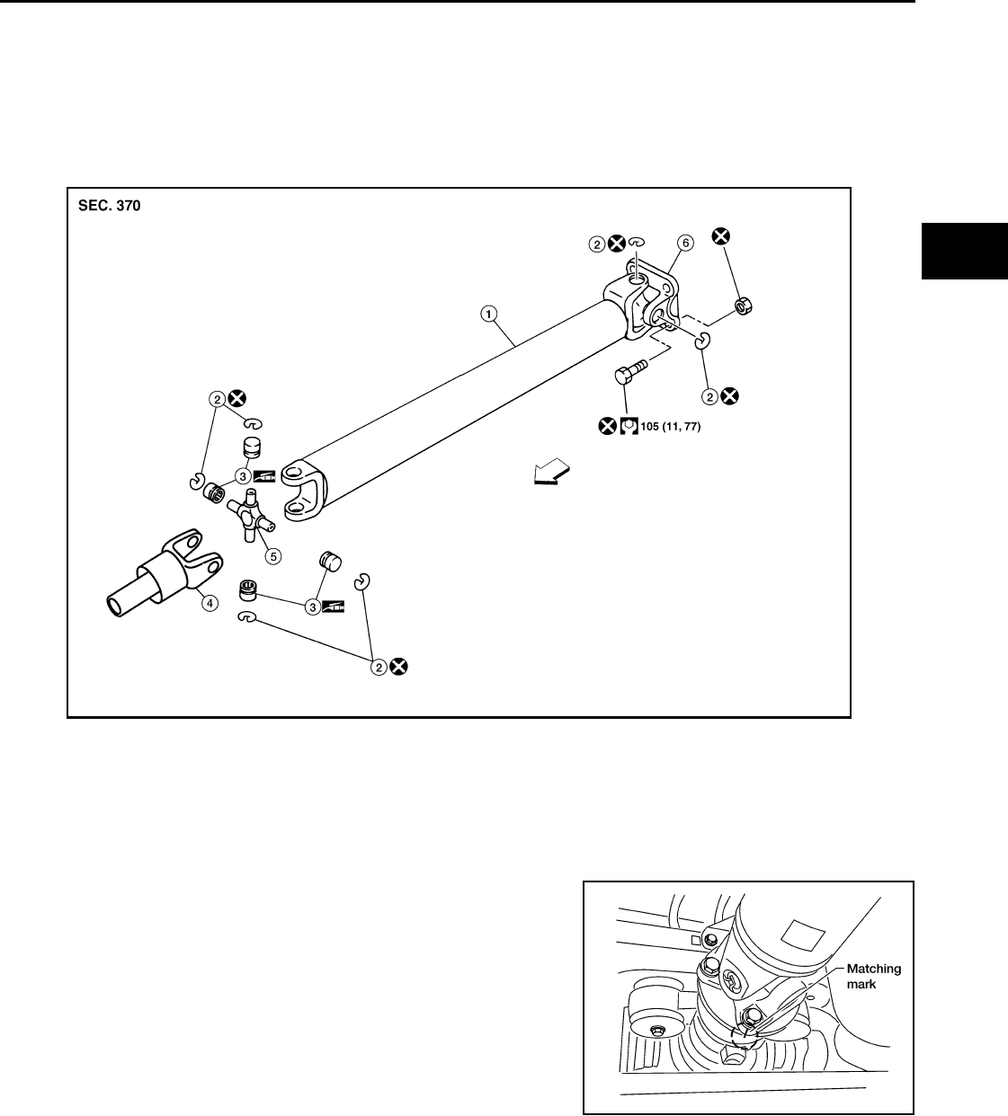
PROPELLER SHAFT
DLN-317
< REMOVAL AND INSTALLATION > [PROPELLER SHAFT: 2S1330]
C
E
F
G
H
I
J
K
L
M
A
B
DLN
N
O
P
REMOVAL AND INSTALLATION
PROPELLER SHAFT
Removal and Installation INFOID:0000000003937413
COMPONENTS
REMOVAL
1. Move the A/T select lever to the N position and release the parking brake.
2. Put matching marks on the rear propeller shaft flange yoke and
the rear final drive companion flange as shown.
CAUTION:
For matching marks, use paint. Never damage the rear pro-
peller shaft flange yoke or the companion flange.
3. Remove the bolts, then remove the propeller shaft from the rear
final drive and A/T or transfer.
INSPECTION
1. Propeller shaft tube 2. Snap ring 3. Journal bearing
4. Sleeve yoke 5. Journal 6. Flange yoke
⇐: Front
AWDIA0017Z
Z
WDIA0049E
Revision: October 2008
2009 Pathfinder
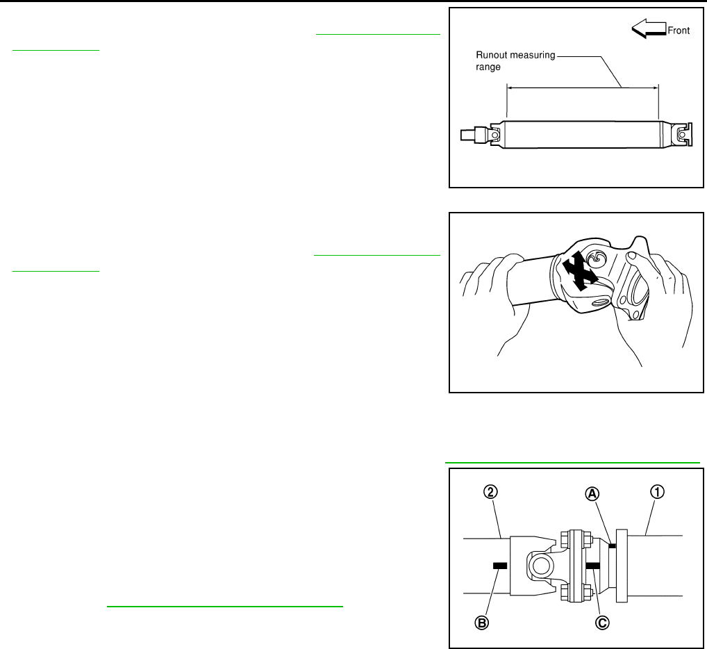
DLN-318
< REMOVAL AND INSTALLATION > [PROPELLER SHAFT: 2S1330]
PROPELLER SHAFT
• Inspect the propeller shaft runout. If runout exceeds the limit,
replace the propeller shaft assembly. Refer to DLN-321, "General
Specification".
• While holding the flange yoke on one side, check axial play of the
joint as shown. If the journal axial play exceeds the specification,
repair or replace the journal parts. Refer to DLN-321, "General
Specification".
• Check the propeller shaft tube for dents or cracks. If damage is
detected, replace the propeller shaft assembly.
INSTALLATION
Installation is in the reverse order of removal.
• After installation, check for vibration by driving the vehicle. Refer to DLN-324, "NVH Troubleshooting Chart".
• If propeller shaft assembly or final drive assembly has been
replaced,connect them as follows:
- Face companion flange mark (A) of the final drive (1) upward. With
the mark (A) faced upward, couple the propeller shaft and the final
drive so that the matching mark (B) of the propeller shaft (2) can be
positioned as closest as possible with the matching mark (C) of the
final drive companion flange.
- Tighte propeller shaft and final drive bolts and nuts to specifica-
tions. Refer to DLN-317, "Removal and Installation".
CAUTION:
Do not reuse the bolts and nuts. Always install new ones.
LDIA0121E
LDIA0117E
PDIA0892J
Revision: October 2008
2009 Pathfinder

PROPELLER SHAFT
DLN-319
< DISASSEMBLY AND ASSEMBLY > [PROPELLER SHAFT: 2S1330]
C
E
F
G
H
I
J
K
L
M
A
B
DLN
N
O
P
DISASSEMBLY AND ASSEMBLY
PROPELLER SHAFT
Disassembly and Assembly INFOID:0000000003937414
DISASSEMBLY
Journal
1. Put matching marks on the rear propeller shaft and flange yoke
as shown.
CAUTION:
For matching marks use paint. Never damage the rear pro-
peller shaft or flange yoke.
2. Remove the snap rings.
3. Push out and remove the journal bearings by lightly tapping the
flange yoke with a hammer, taking care not to damage the jour-
nal or flange yoke hole.
NOTE:
Put marks on the disassembled parts so that they can be rein-
stalled in their original positions from which they were removed.
4. Push out and remove the remaining journal bearings at the
opposite side by lightly tapping the flange yoke with a hammer,
taking care not to damage the journal or flange yoke hole.
NOTE:
Put marks on the disassembled parts so that they can be rein-
stalled in their original positions from which they were removed.
ASSEMBLY
SPD128
APD011
SPD732
SPD131
Revision: October 2008
2009 Pathfinder
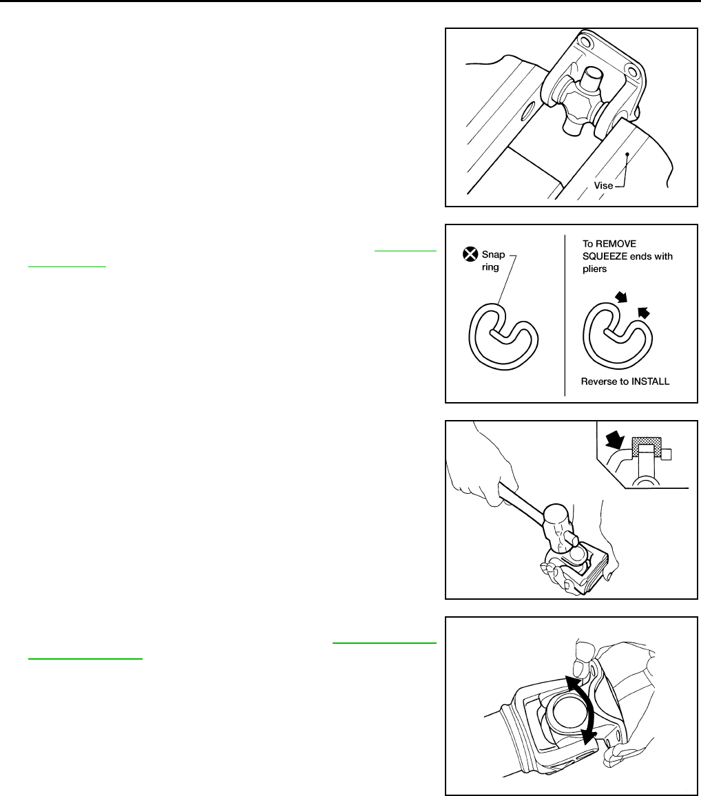
DLN-320
< DISASSEMBLY AND ASSEMBLY > [PROPELLER SHAFT: 2S1330]
PROPELLER SHAFT
Journal
1. Assemble the journal bearings. Apply multipurpose grease on
the bearing inner surface.
NOTE:
During assembly, use caution so that the needle bearings do not
fall down.
2. Select new snap rings that will provide the specified play in an
axial direction of the journal, and install them. Refer to DLN-322,
"Snap Ring".
CAUTION:
Do not reuse snap rings
NOTE:
Select snap rings with a difference in thickness at both sides
within 0.02 mm (0.0008 in).
3. Adjust the thrust clearance between the bearing and snap ring
to zero by tapping the yoke.
4. Make sure that the journal moves smoothly and is below the
propeller joint flex effort specification. Refer to DLN-321, "Gen-
eral Specification".
WPD019
APD012
SPD732
LDIA0119E
Revision: October 2008
2009 Pathfinder

SERVICE DATA AND SPECIFICATIONS (SDS)
DLN-321
< SERVICE DATA AND SPECIFICATIONS (SDS) [PROPELLER SHAFT: 2S1330]
C
E
F
G
H
I
J
K
L
M
A
B
DLN
N
O
P
SERVICE DATA AND SPECIFICATIONS (SDS)
SERVICE DATA AND SPECIFICATIONS (SDS)
General Specification INFOID:0000000003937415
2WD models
Propeller Shaft Runout
Propeller Shaft Joint Flex Effort
Journal Axial Play
4WD models
Propeller Shaft Runout
Propeller Shaft Joint Flex Effort
Applied model
2WD
VQ40DE
A/T
Propeller shaft model 2S1330 (aluminum tube)
Number of joints 2
Coupling method with rear final drive Flange type
Coupling method with transmission Sleeve type
Shaft length (Spider to spider) 1395.2 mm (54.93 in)
Shaft outer diameter 127.6 mm (5.02 in)
Item Limit
Propeller shaft runout 1.02 mm (0.0402 in) or less
Item Limit
Propeller shaft joint flex effort 2.26 N·m (0.23 kg-m, 20 in-lb) or less
Item Limit
Journal axial play 0.02 mm (0.0008 in) or less
Applied model
4WD
Part time Full time
VQ40DE
A/T
Propeller shaft model 2S1330 (steel tube)
Number of joints 2
Coupling method with front final drive Flange type
Coupling method with transfer Sleeve type
Shaft length (Spider to spider) 952.8 mm (37.51 in) 890.8 mm (35.07 in)
Shaft outer diameter 76.2 mm (3.00 in)
Item Limit
Propeller shaft runout 0.6 mm (0.024 in) or less
Revision: October 2008
2009 Pathfinder
DLN-322
< SERVICE DATA AND SPECIFICATIONS (SDS) [PROPELLER SHAFT: 2S1330]
SERVICE DATA AND SPECIFICATIONS (SDS)
Journal Axial Play
Snap Ring INFOID:0000000003937416
Model 2S1330 (4WD)
Unit: mm (in)
*Always check with the Parts Department for the latest parts information.
Model 2S1330 (2WD)
Unit: mm (in)
*Always check with the Parts Department for the latest parts information.
Item Limit
Propeller shaft joint flex effort 2.26 N·m (0.23 kg-m, 20 in-lb) or less
Item Limit
Journal axial play 0.02 mm (0.0008 in) or less
Thickness Color Part Number*
1.99 (0.0783) White 37146-C9400
2.02 (0.0795) Yellow 37147-C9400
2.05 (0.0807) Red 37148-C9400
2.08 (0.0819) Green 37149-C9400
2.11 (0.0831) Blue 37150-C9400
2.14 (0.0843) Light brown 37151-C9400
2.17 (0.0854) Black 37152-C9400
2.20 (0.0866) No paint 37153-C9400
Thickness Color Part Number*
1.600 - 1.638 (0.0630 - 0.0645) Black 37146-EA500
1.549 - 1.588 (0.0610 - 0.0625) Black 37147-EA500
1.524 - 1.562 (0.0600 - 0.0615) Black 37148-EA500
1.499 - 1.537 (0.0590 - 0.0605) Black 37149-EA500
Revision: October 2008
2009 Pathfinder

PREPARATION
DLN-323
< PREPARATION > [PROPELLER SHAFT: 2S1350]
C
E
F
G
H
I
J
K
L
M
A
B
DLN
N
O
P
PREPARATION
PREPARATION
Commercial Service Tool INFOID:0000000003937417
Tool name Description
Power tool Loosening bolts and nuts
PBIC0190E
Revision: October 2008
2009 Pathfinder
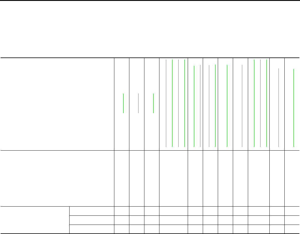
DLN-324
< FUNCTION DIAGNOSIS > [PROPELLER SHAFT: 2S1350]
NOISE, VIBRATION, AND HARSHNESS (NVH) TROUBLESHOOTING
FUNCTION DIAGNOSIS
NOISE, VIBRATION, AND HARSHNESS (NVH) TROUBLESHOOTING
NVH Troubleshooting Chart INFOID:0000000003937418
Use the chart below to help you find the cause of the symptom. If necessary, repair or replace these parts.
×: Applicable
Reference page
DLN-325
DLN-325
DLN-330
DLN-336, "NVH Troubleshooting Chart"
DLN-370, "NVH Troubleshooting Chart"
DLN-402, "NVH Troubleshooting Chart"
DLN-439, "NVH Troubleshooting Chart"
FAX-4, "NVH Troubleshooting Chart"
RAX-4, "NVH Troubleshooting Chart"
FSU-5, "NVH Troubleshooting Chart"
RSU-5, "NVH Troubleshooting Chart"
WT-45, "NVH Troubleshooting Chart"
WT-45, "NVH Troubleshooting Chart"
DLN-307, "NVH Troubleshooting Chart"
DLN-315, "NVH Troubleshooting Chart"
DLN-324, "NVH Troubleshooting Chart"
BR-6, "NVH Troubleshooting Chart"
ST-9, "NVH Troubleshooting Chart"
Possible cause and suspected parts
Uneven rotation torque
Rotation imbalance
Excessive run out
Differential
Axle
Suspension
Tires
Road wheel
Drive shaft
Brakes
Steering
Symptom
Noise ××× × ×××× × ××
Shake ×××× × ××
Vibration ××× ×××××
Revision: October 2008
2009 Pathfinder
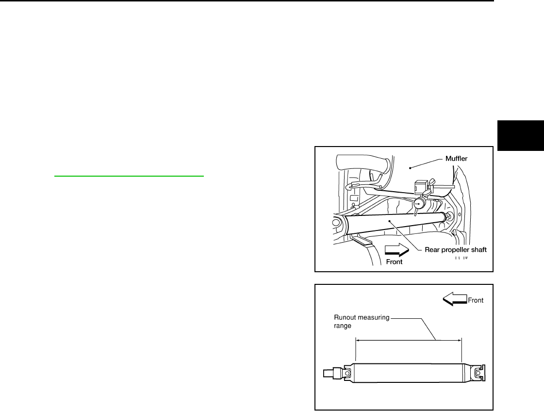
PROPELLER SHAFT
DLN-325
< ON-VEHICLE REPAIR > [PROPELLER SHAFT: 2S1350]
C
E
F
G
H
I
J
K
L
M
A
B
DLN
N
O
P
ON-VEHICLE REPAIR
PROPELLER SHAFT
On-Vehicle Service INFOID:0000000003937419
APPEARANCE AND NOISE INSPECTION
• Check the propeller shaft tube surface for dents or cracks. If damaged, replace the propeller shaft assembly.
• Check the bearings for noise and damage. Repair or replace the bearings as necessary.
PROPELLER SHAFT VIBRATION
If a vibration is present at high speed, inspect the propeller shaft runout first.
1. Measure the runout of the propeller shaft tube at several points
by rotating the final drive companion flange with your hands.
Refr to DLN-330, "General Specification".
2. If the runout exceeds specifications, disconnect the propeller
shaft at the final drive companion flange; then rotate the com-
panion flange 90°, 180° and 270° and reconnect the propeller
shaft.
3. Check the runout again. If the runout still exceeds specifications,
replace the propeller shaft assembly.
4. After installation, check for vibration by driving vehicle.
LDIA0161E
LDIA0121E
Revision: October 2008
2009 Pathfinder
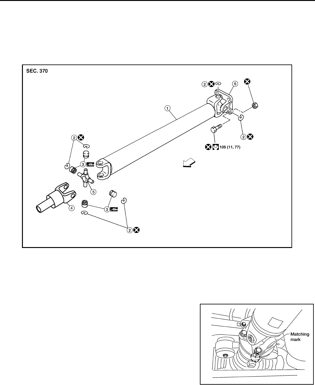
DLN-326
< REMOVAL AND INSTALLATION > [PROPELLER SHAFT: 2S1350]
PROPELLER SHAFT
REMOVAL AND INSTALLATION
PROPELLER SHAFT
Removal and Installation INFOID:0000000003937420
COMPONENTS
REMOVAL
1. Move the A/T select lever to the N position and release the parking brake.
2. Put matching marks on the rear propeller shaft flange yoke and
the rear final drive companion flange as shown.
CAUTION:
For matching marks, use paint. Never damage the rear pro-
peller shaft flange yoke or the companion flange.
3. Remove the bolts, then remove the propeller shaft from the rear
final drive and A/T or transfer.
INSPECTION
1. Propeller shaft tube 2. Snap ring 3. Journal bearing
4. Sleeve yoke 5. Journal 6. Flange yoke
⇐:Front
AWDIA0017Z
Z
WDIA0049E
Revision: October 2008
2009 Pathfinder
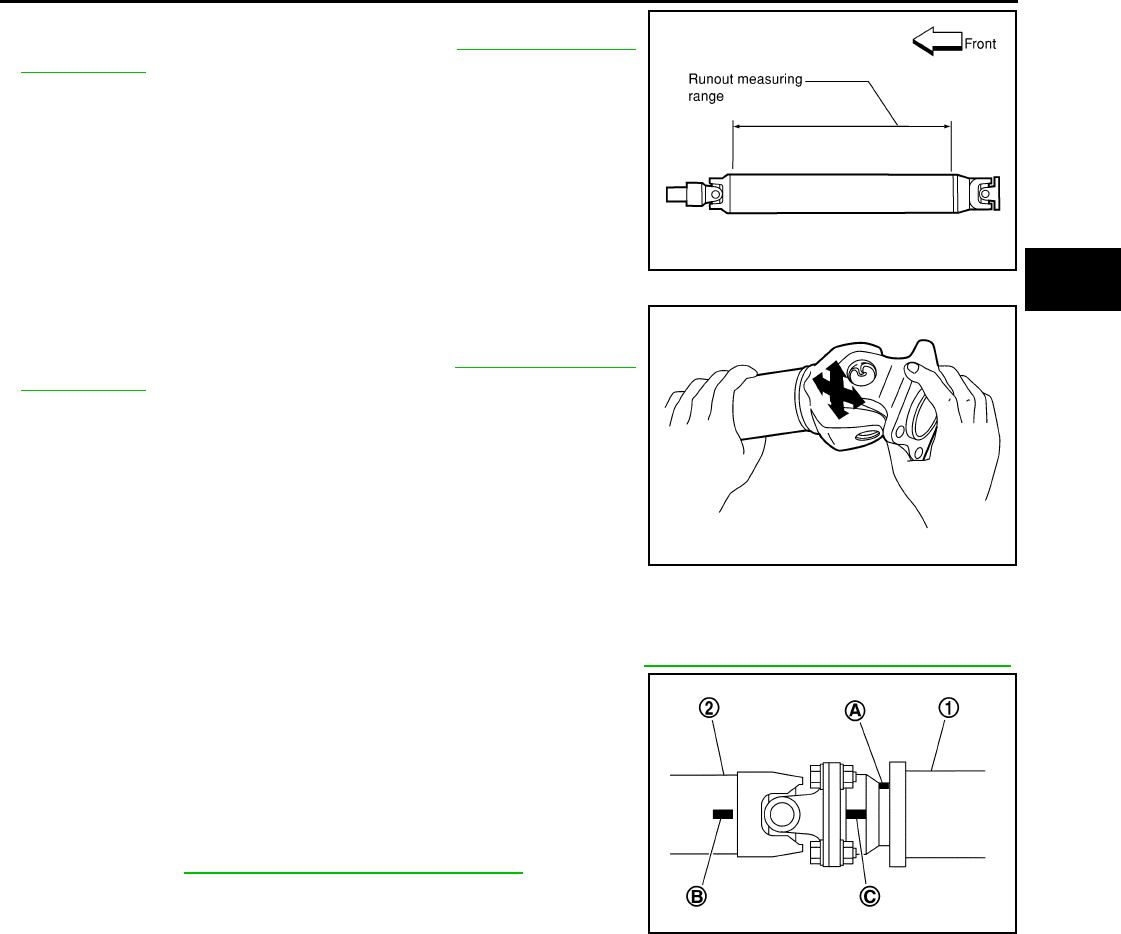
PROPELLER SHAFT
DLN-327
< REMOVAL AND INSTALLATION > [PROPELLER SHAFT: 2S1350]
C
E
F
G
H
I
J
K
L
M
A
B
DLN
N
O
P
• Inspect the propeller shaft runout. If runout exceeds the limit,
replace the propeller shaft assembly. Refer to DLN-330, "General
Specification".
• While holding the flange yoke on one side, check axial play of the
joint as shown. If the journal axial play exceeds the specification,
repair or replace the journal parts. Refer to DLN-330, "General
Specification".
• Check the propeller shaft tube for dents or cracks. If damage is
detected, replace the propeller shaft assembly.
INSTALLATION
Installation is in the reverse order of removal.
• After installation, check for vibration by driving the vehicle. Refer to DLN-324, "NVH Troubleshooting Chart".
• If propeller shaft assembly of final drive assembly has been
replaced, connect them as follows:
- Face companion flange mark (A) of the final drive (1) upward. With
the mark (A) faced upward, couple the propeller shaft and the final
drive so that the matching mark (B) of the propeller shaft (2) can be
positioned as close as possible with the matching mark (C) of the
final drive companion flange.
- Tighten propeller shaft and final drive bolts and nuts of the to spec-
ification. Refer to DLN-326, "Removal and Installation".
CAUTION:
Do not reuse the bolts and nuts. Always install new ones.
LDIA0121E
LDIA0117E
PDIA0892J
Revision: October 2008
2009 Pathfinder
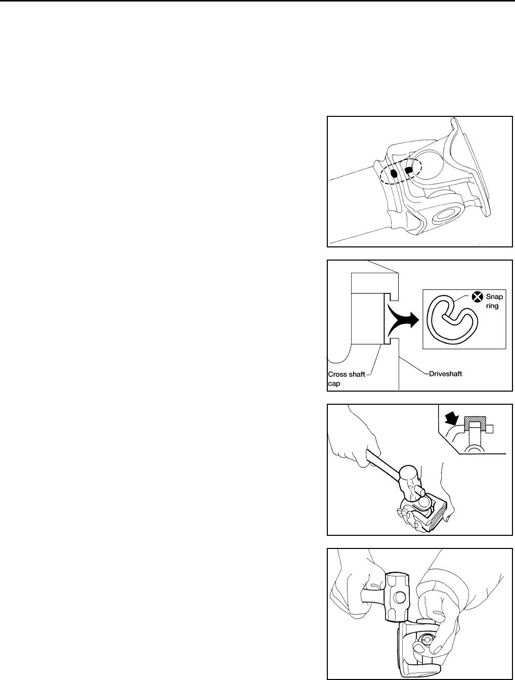
DLN-328
< DISASSEMBLY AND ASSEMBLY > [PROPELLER SHAFT: 2S1350]
PROPELLER SHAFT
DISASSEMBLY AND ASSEMBLY
PROPELLER SHAFT
Disassembly and Assembly INFOID:0000000003937421
DISASSEMBLY
Journal
1. Put matching marks on the rear propeller shaft and flange yoke
as shown.
CAUTION:
For matching marks use paint. Never damage the rear pro-
peller shaft or flange yoke.
2. Remove the snap rings.
3. Push out and remove the journal bearings by lightly tapping the
flange yoke with a hammer, taking care not to damage the jour-
nal or flange yoke hole.
NOTE:
Put marks on the disassembled parts so that they can be rein-
stalled in their original positions from which they were removed.
4. Push out and remove the remaining journal bearings at the
opposite side by lightly tapping the flange yoke with a hammer,
taking care not to damage the journal or flange yoke hole.
NOTE:
Put marks on the disassembled parts so that they can be rein-
stalled in their original positions from which they were removed.
ASSEMBLY
SPD128
APD011
SPD732
SPD131
Revision: October 2008
2009 Pathfinder
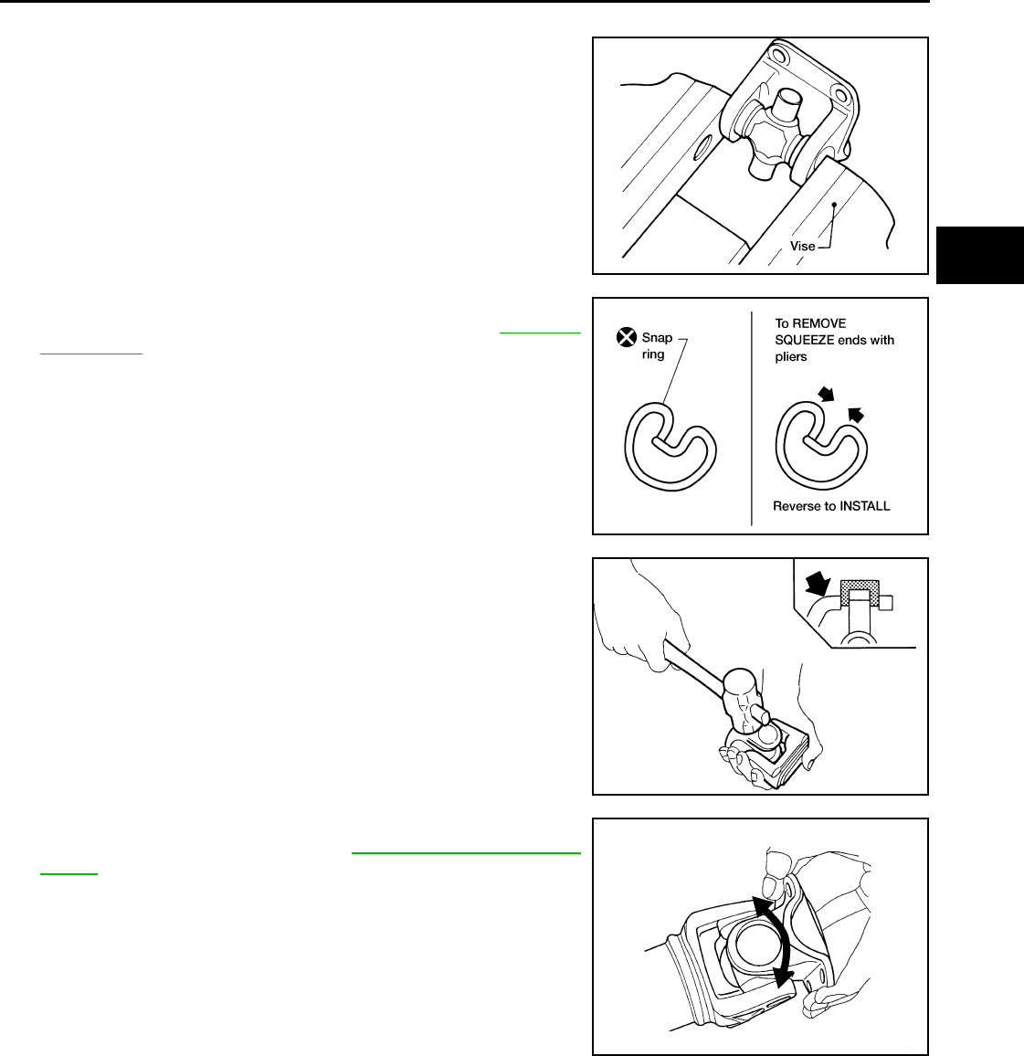
PROPELLER SHAFT
DLN-329
< DISASSEMBLY AND ASSEMBLY > [PROPELLER SHAFT: 2S1350]
C
E
F
G
H
I
J
K
L
M
A
B
DLN
N
O
P
Journal
1. Assemble the journal bearings. Apply multipurpose grease on
the bearing inner surface.
NOTE:
During assembly, use caution so that the needle bearings do not
fall down.
2. Select new snap rings that will provide the specified play in an
axial direction of the journal, and install them. Refer to DLN-330,
"Snap Ring".
CAUTION:
Do not reuse snap rings
NOTE:
Select snap rings with a difference in thickness at both sides
within 0.02 mm (0.0008 in).
3. Adjust the thrust clearance between the bearing and snap ring
to zero by tapping the yoke.
4. Make sure that the journal moves smoothly and is below the
joint flex effort specification. Refer to DLN-330, "General Specifi-
cation".
WPD019
APD012
SPD732
LDIA0119E
Revision: October 2008
2009 Pathfinder

DLN-330
< SERVICE DATA AND SPECIFICATIONS (SDS) [PROPELLER SHAFT: 2S1350]
SERVICE DATA AND SPECIFICATIONS (SDS)
SERVICE DATA AND SPECIFICATIONS (SDS)
SERVICE DATA AND SPECIFICATIONS (SDS)
General Specification INFOID:0000000003937422
4WD models
Unit: mm (in)
Propeller Shaft Runout
Unit: mm (in)
Propeller Shaft Joint Flex Effort
Unit: N·m (kg-m, in-lb)
Journal Axial Play
Unit: mm (in)
Snap Ring INFOID:0000000003937423
Unit: mm (in)
*Always check with the Parts Department for the latest parts information.
Applied model
4WD
VK56DE
A/T
Propeller shaft model 2S1350 (aluminum tube)
Number of joints 2
Coupling method with rear final drive Flange type
Coupling method with transfer Sleeve type
Shaft length (Spider to spider) 850.7 (33.49)
Shaft outer diameter 102.5 (4.04)
Item Limit
Propeller shaft runout 0.6 (0.024) or less
Item Limit
Propeller shaft joint flex effort 2.26 (0.23, 20 ) or less
Item Limit
Journal axial play 0.02 (0.0008) or less
Thickness Color Part Number*
1.99 (0.0783) White 37146-C9400
2.02 (0.0795) Yellow 37147-C9400
2.05 (0.0807) Red 37148-C9400
2.08 (0.0819) Green 37149-C9400
2.11 (0.0831) Blue 37150-C9400
2.14 (0.0843) Light brown 37151-C9400
2.17 (0.0854) Black 37152-C9400
2.20 (0.0866) No paint 37153-C9400
Revision: October 2008
2009 Pathfinder

PRECAUTIONS
DLN-331
< PRECAUTION > [FRONT FINAL DRIVE: R180A]
C
E
F
G
H
I
J
K
L
M
A
B
DLN
N
O
P
PRECAUTION
PRECAUTIONS
Precaution for Servicing Front Final Drive INFOID:0000000003937424
• Before starting diagnosis of the vehicle, understand the symptoms well. Perform correct and systematic
operations.
• Check for the correct installation status prior to removal or disassembly. When matching marks are required,
be certain they do not interfere with the function of the parts they are applied to.
• Overhaul should be done in a clean work area, a dust proof area is recommended.
• Before disassembly, completely remove sand and mud from the exterior of the unit, preventing them from
entering into the unit during disassembly or assembly.
• Always use shop paper for cleaning the inside of components.
• Avoid using cotton gloves or a shop cloth to prevent the entering of lint.
• Check appearance of the disassembled parts for damage, deformation, and abnormal wear. Replace them
with new ones if necessary.
• Gaskets, seals and O-rings should be replaced any time the unit is disassembled.
• Clean and flush the parts sufficiently and blow them dry.
• Be careful not to damage sliding surfaces and mating surfaces.
• When applying sealant, remove the old sealant from the mating surface; then remove any moisture, oil, and
foreign materials from the application and mating surfaces.
• In principle, tighten nuts or bolts gradually in several steps working diagonally from inside to outside. If a
tightening sequence is specified, observe it.
• During assembly, observe the specified tightening torque.
• Add new differential gear oil, petroleum jelly, or multi-purpose grease, as specified.
Revision: October 2008
2009 Pathfinder
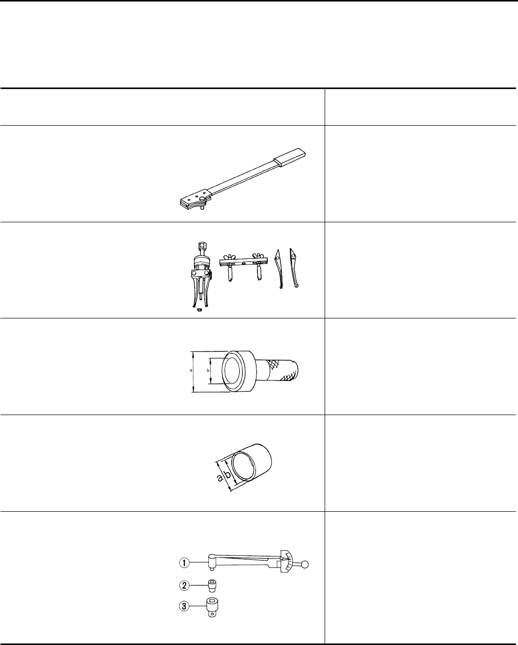
DLN-332
< PREPARATION > [FRONT FINAL DRIVE: R180A]
PREPARATION
PREPARATION
PREPARATION
Special Service Tool INFOID:0000000003937425
The actual shapes of Kent-Moore tools may differ from those of special service tools illustrated here.
Tool number
(Kent-Moore No.)
Tool name
Description
KV38108300
(J-44195)
Flange wrench
Removing and installing drive pinion lock nut
KV381054S0
(J-34286)
Puller
Removing front oil seal
ST30720000
(J-25405)
Drift
• Installing front oil seal
• Installing side oil seal
a: 77 mm (3.03 in) dia.
b: 55.5 mm (2.185 in) dia.
ST27863000
(—)
Drift
• Installing front oil seal
• Installing side oil seal
a: 74.5 mm (2.933 in) dia.
b: 62.5 mm (2.461 in) dia.
ST3127S000
(J-25765-A)
Preload gauge
1: GG91030000
(J-25765)
Torque wrench
2: HT62940000
(—)
Socket adapter (1/2″)
3: HT62900000
(—)
Socket adapter (3/8″)
Measuring drive pinion bearing preload torque
and total preload torque
NT771
ZZA0601D
ZZA0811D
ZZA1003D
NT124
Revision: October 2008
2009 Pathfinder
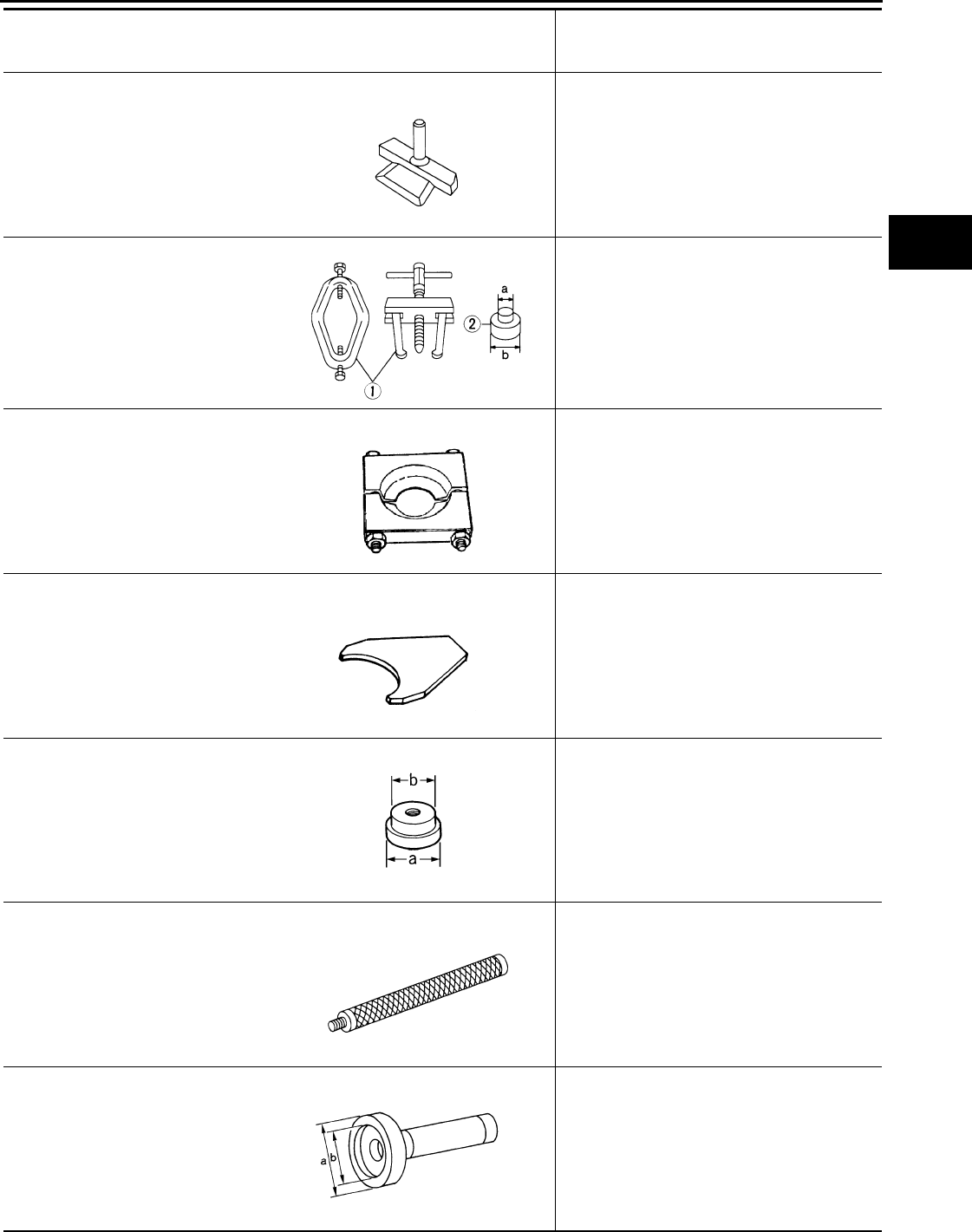
PREPARATION
DLN-333
< PREPARATION > [FRONT FINAL DRIVE: R180A]
C
E
F
G
H
I
J
K
L
M
A
B
DLN
N
O
P
KV10111100
(J-37228)
Seal cutter
Removing carrier cover
ST3306S001
(—)
Differential side bearing puller set
1: ST33051001
(J-22888-20)
Puller
2: ST33061000
(J-8107-2)
Base
Removing and installing side bearing inner
race
a: 28.5 mm (1.122 in) dia.
b: 38 mm (1.50 in) dia.
ST30031000
(J-22912-01)
Replacer
Removing drive pinion rear bearing inner race
KV38100600
(J-25267)
Drift
Installing side bearing adjusting washer
ST30613000
(J-25742-3)
Drift
Installing drive pinion rear bearing outer race
a: 72 mm (2.83 in) dia.
b: 48 mm (1.89 in) dia.
ST30611000
(J-25742-1)
Drift bar
Installing drive pinion rear bearing outer race
(Use with ST30613000)
KV38100200
(J-26233)
Drift
Installing drive pinion front bearing outer race
a: 65 mm (2.56 in) dia.
b: 49 mm (1.93 in) dia.
Tool number
(Kent-Moore No.)
Tool name
Description
S-NT046
NT072
ZZA0700D
SDIA0429J
ZZA1000D
S-NT090
ZZA1143D
Revision: October 2008
2009 Pathfinder
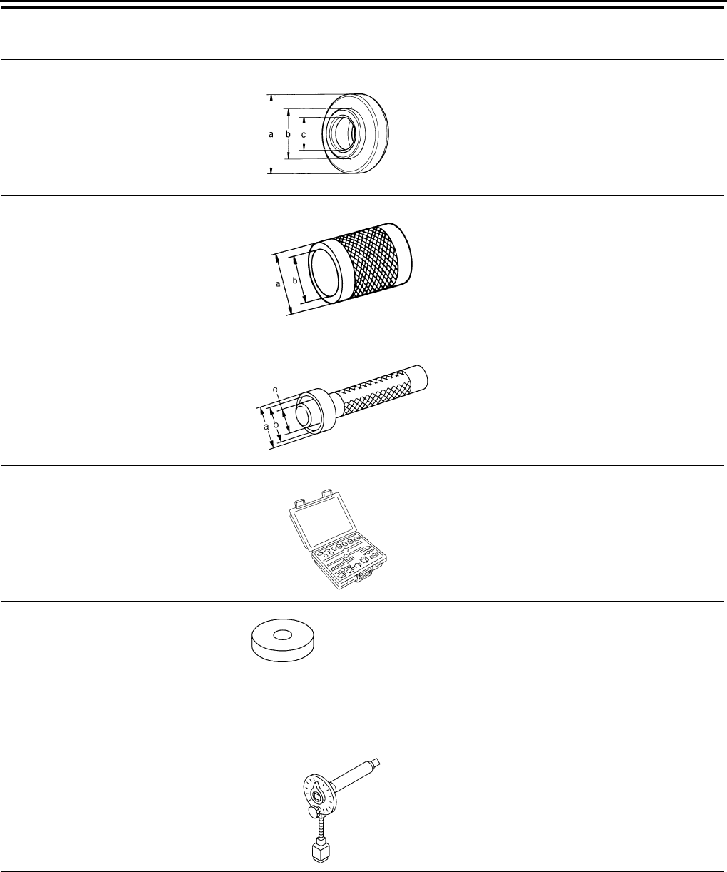
DLN-334
< PREPARATION > [FRONT FINAL DRIVE: R180A]
PREPARATION
Commercial Service Tool INFOID:0000000003937426
ST30901000
(J-26010-01)
Drift
Installing drive pinion rear bearing inner race
a: 79 mm (3.11 in) dia.
b: 45 mm (1.77 in) dia.
c: 35.2 mm (1.386 in) dia.
ST33200000
(J-26082)
Drift
Installing drive pinion front bearing inner race
a: 60 mm (2.36 in) dia.
b: 44.5 mm (1.752 in) dia.
ST33230000
(J-35867)
Drift
Installing side bearing inner race
a: 51 mm (2.01 in) dia.
b: 41 mm (1.61 in) dia.
c: 28 mm (1.10 in) dia.
(—)
(J-34309)
Differential shim selector tool
Adjusting bearing preload and drive pinion
height
(—)
(J-25269-18)
Side bearing disc (2 Req'd)
Selecting drive pinion height adjusting washer
KV10112100
(BT-8653-A)
Angle wrench
Tightening bolts for drive gear
Tool number
(Kent-Moore No.)
Tool name
Description
ZZA0978D
ZZA1002D
ZZA1046D
NT134
NT135
NT014
Revision: October 2008
2009 Pathfinder

PREPARATION
DLN-335
< PREPARATION > [FRONT FINAL DRIVE: R180A]
C
E
F
G
H
I
J
K
L
M
A
B
DLN
N
O
P
Tool name Description
Power tool Loosening nuts and bolts
PBIC0190E
Revision: October 2008
2009 Pathfinder
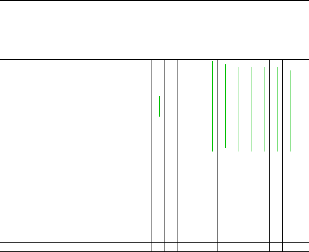
DLN-336
< FUNCTION DIAGNOSIS > [FRONT FINAL DRIVE: R180A]
NOISE, VIBRATION AND HARSHNESS (NVH) TROUBLESHOOTING
FUNCTION DIAGNOSIS
NOISE, VIBRATION AND HARSHNESS (NVH) TROUBLESHOOTING
NVH Troubleshooting Chart INFOID:0000000003937427
Use the chart below to help you find the cause of the symptom. If necessary, repair or replace these parts.
×: Applicable
Reference page
DLN-345
DLN-345
DLN-345
DLN-345
DLN-345
DLN-338
DLN-324, "NVH Troubleshooting Chart"
FAX-4, "NVH Troubleshooting Chart"
FSU-5, "NVH Troubleshooting Chart"
WT-45, "NVH Troubleshooting Chart"
WT-45, "NVH Troubleshooting Chart"
RAX-4, "NVH Troubleshooting Chart"
BR-6, "NVH Troubleshooting Chart"
ST-9, "NVH Troubleshooting Chart"
Possible cause and SUSPECTED PARTS
Gear tooth rough
Gear contact improper
Tooth surfaces worn
Backlash incorrect
Companion flange excessive runout
Gear oil improper
PROPELLER SHAFT
FRONT AXLE
FRONT SUSPENSION
TIRES
ROAD WHEEL
DRIVE SHAFT
BRAKES
STEERING
Symptom Noise ××××××××××××××
Revision: October 2008
2009 Pathfinder
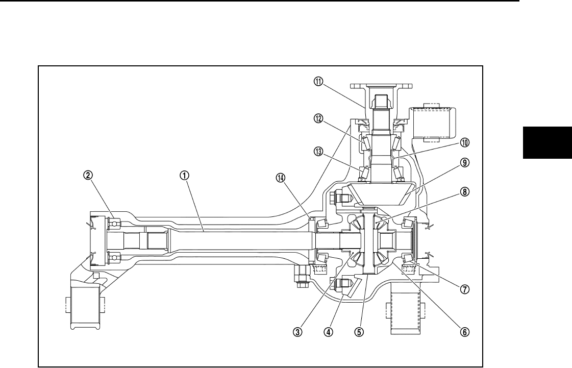
DESCRIPTION
DLN-337
< FUNCTION DIAGNOSIS > [FRONT FINAL DRIVE: R180A]
C
E
F
G
H
I
J
K
L
M
A
B
DLN
N
O
P
DESCRIPTION
Cross-Sectional View INFOID:0000000003937428
1. Differential side shaft 2. Differential side shaft bearing 3. Side gear
4. Drive gear 5. Pinion mate shaft 6. Differential case
7. Side bearing 8. Pinion mate gear 9. Drive pinion
10. Collapsible spacer 11. Companion flange 12. Drive pinion front bearing
13. Drive pinion rear bearing 14. Housing spacer
PDIA0695E
Revision: October 2008
2009 Pathfinder
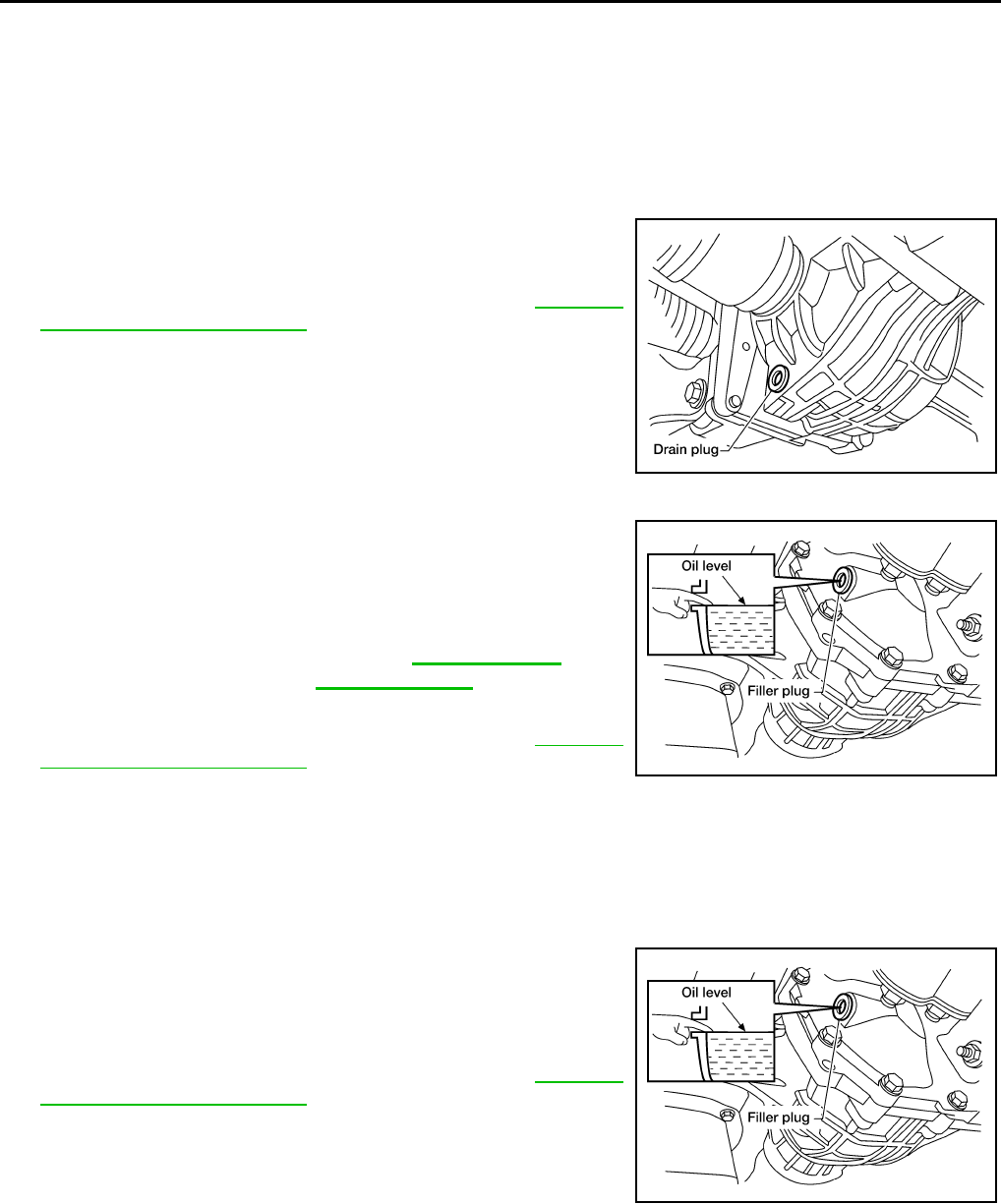
DLN-338
< ON-VEHICLE MAINTENANCE > [FRONT FINAL DRIVE: R180A]
DIFFERENTIAL GEAR OIL
ON-VEHICLE MAINTENANCE
DIFFERENTIAL GEAR OIL
Changing Differential Gear Oil INFOID:0000000003937429
DRAINING
1. Stop the engine.
2. Remove the drain plug and gasket from the front final drive
assembly to drain the differential gear oil.
3. Install the drain plug with a new gasket to the front final drive
assembly. Tighten to the specified torque. Refer to DLN-345,
"Disassembly and Assembly".
CAUTION:
Do not reuse gasket.
FILLING
1. Remove the filler plug and gasket from the front final drive
assembly.
2. Fill the front final drive assembly with new differential gear oil
until the level reaches the specified level near the filler plug hole.
3. Install the filler plug with a new gasket on it to the front final drive
assembly. Tighten to the specified torque. Refer to DLN-345,
"Disassembly and Assembly".
CAUTION:
Do not reuse gasket.
Checking Differential Gear Oil INFOID:0000000003937430
DIFFERENTIAL GEAR OIL LEAKAGE AND LEVEL
1. Make sure that differential gear oil is not leaking from the front final drive assembly or around it.
2. Check the differential gear oil level from the filler plug hole as
shown.
CAUTION:
Do not start engine while checking differential gear oil level.
3. Install the filler plug with a new gasket on it to the front final drive
assembly. Tighten to the specified torque. Refer to DLN-345,
"Disassembly and Assembly".
CAUTION:
Do not reuse gasket.
LDIA0175E
Differential gear oil
grade and capacity : Refer to MA-12, "Fluids
and Lubricants".
LDIA0176E
LDIA0176E
Revision: October 2008
2009 Pathfinder
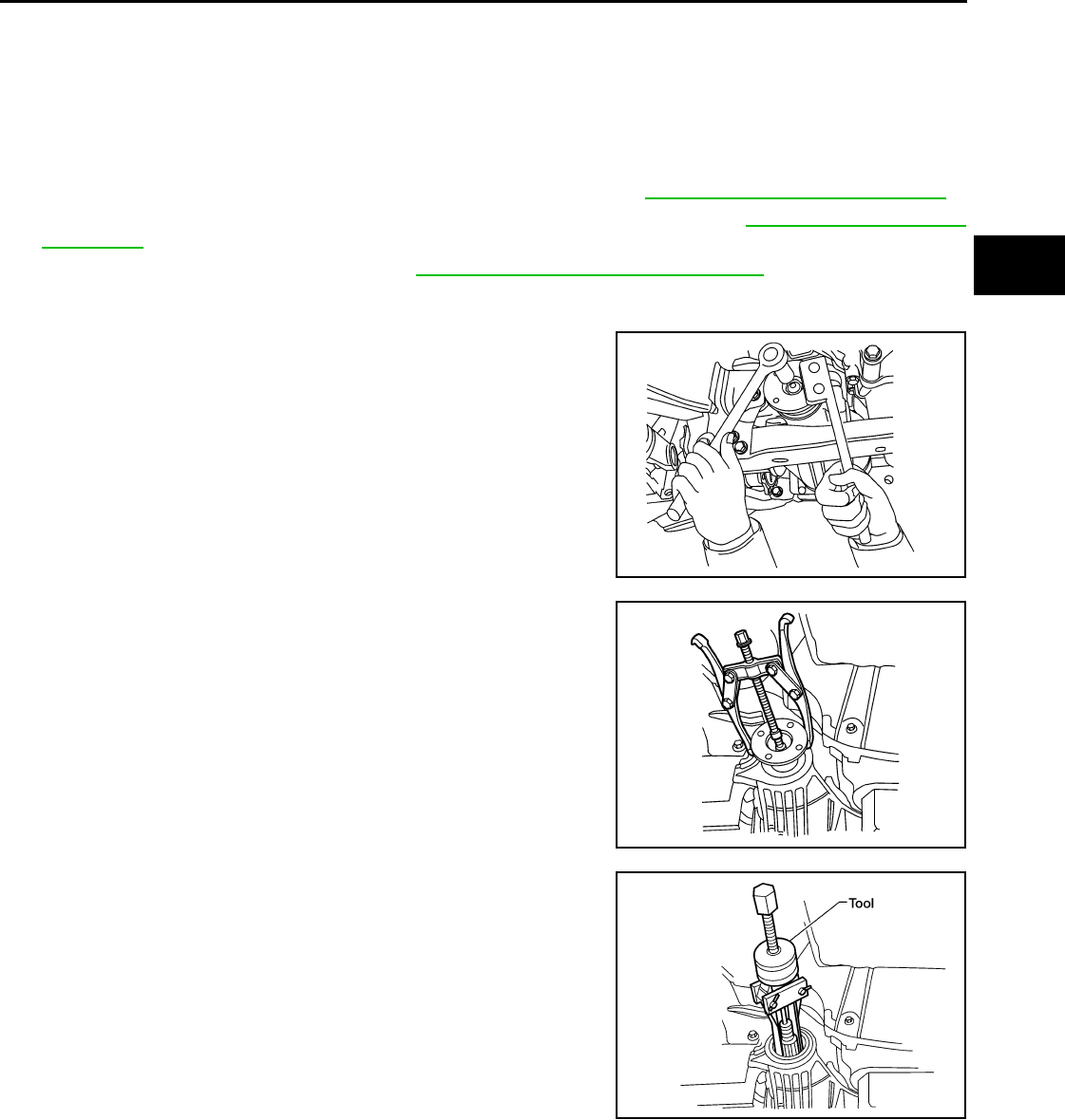
FRONT OIL SEAL
DLN-339
< ON-VEHICLE REPAIR > [FRONT FINAL DRIVE: R180A]
C
E
F
G
H
I
J
K
L
M
A
B
DLN
N
O
P
ON-VEHICLE REPAIR
FRONT OIL SEAL
Removal and Installation INFOID:0000000003937431
REMOVAL
1. Remove the drive shafts from the front final drive assembly. Refer to RAX-9, "Removal and Installation".
2. Remove the front propeller shaft from the front final drive assembly. Refer to DLN-309, "Removal and
Installation".
3. Measure the total preload torque. Refer to DLN-345, "Disassembly and Assembly".
NOTE:
Record the total preload torque measurement.
4. Remove the drive pinion lock nut using Tool.
5. Put matching marks on the companion flange and drive pinion
using paint.
CAUTION:
Use paint to make the matching marks. Do not damage the
companion flange or drive pinion.
6. Remove the companion flange using suitable tool.
7. Remove the front oil seal using Tool.
INSTALLATION
Tool number : KV38108300 ( — )
BDIA0001E
LDIA0171E
Tool number : KV381054S0 (J-34286)
LDIA0172E
Revision: October 2008
2009 Pathfinder
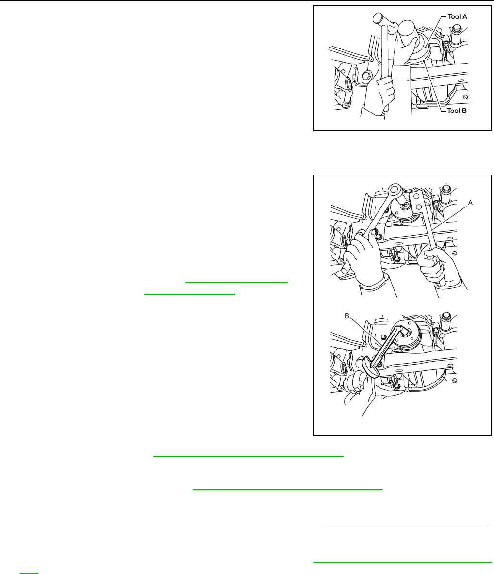
DLN-340
< ON-VEHICLE REPAIR > [FRONT FINAL DRIVE: R180A]
FRONT OIL SEAL
1. Apply multi-purpose grease to the lips and differential gear oil to
the circumference of the new front oil seal. Then drive the new
front oil seal in evenly until it becomes flush with the gear carrier
using Tools.
CAUTION:
• Do not reuse front oil seal.
• Do not incline the new front oil seal when installing.
• Apply multi-purpose grease to the lips and differential
gear oil to the circumference of the new front oil seal.
2. Install the companion flange to the drive pinion while aligning the matching marks.
3. Apply anti-corrosive oil to the threads of the drive pinion and the
seating surface of the new drive pinion lock nut. Then adjust the
drive pinion lock nut tightening torque using Tool A, and check
the total preload torque using Tool B.
• The total preload torque should be within the total preload
torque specification. When not replacing the collapsible
spacer, it should also be equal to the measurement taken dur-
ing removal plus an additional 0.56 N·m (0.06 Kg-m, 5 in-lb).
• If the total preload torque is low, tighten the drive pinion lock
nut in 6.8 N·m (0.69 Kg-m, 5ft-lb) increments until the total pre-
load torque is met.
CAUTION:
• Do not reuse drive pinion lock nut.
• Apply anti-corrosive oil to the threads of the drive pinion
and the seating surface of the new drive pinion lock nut.
• Adjust the drive pinion lock nut tightening torque to the
lower limit first. Do not exceed the drive pinion lock nut
specified torque. Refer to DLN-345, "Disassembly and Assembly".
• Do not loosen drive pinion lock nut to adjust the total preload torque. If the drive pinion lock nut
torque or the total preload torque exceeds the specifications, replace the collapsible spacer and
tighten it again to adjust. Refer to DLN-345, "Disassembly and Assembly".
• After adjustment, rotate drive pinion back and forth 2 to 3 times to check for unusual noise, rota-
tion malfunction, and other malfunctions.
4. Install new side oil seals into the front final drive assembly. Refer to DLN-341, "Removal and Installation".
5. Installation of the remaining components is in the reverse order of removal.
CAUTION:
Check the differential gear oil level after installation. Refer to DLN-338, "Checking Differential Gear
Oil".
Tool number A: ST30720000 (J-25405)
B: ST27863000 ( — )
WDIA0147E
Tool number A: KV38108300 ( — )
B: ST3127S000 (J-25765-A)
Total preload torque: Refer to DLN-345, "Disassem-
bly and Assembly".
WDIA0381E
Revision: October 2008
2009 Pathfinder
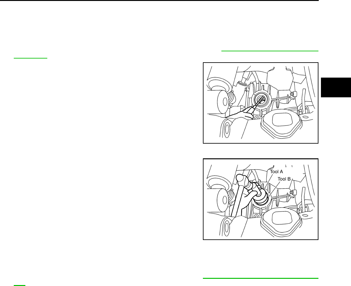
SIDE OIL SEAL
DLN-341
< ON-VEHICLE REPAIR > [FRONT FINAL DRIVE: R180A]
C
E
F
G
H
I
J
K
L
M
A
B
DLN
N
O
P
SIDE OIL SEAL
Removal and Installation INFOID:0000000003937432
REMOVAL
1. Remove the drive shafts from the front final drive assembly. Refer to FAX-6, "VQ40DE : Removal and
Installation".
2. Remove the side oil seal using suitable tool.
CAUTION:
Do not reuse the side oil seal.
INSTALLATION
1. Apply multi-purpose grease to the lips and differential gear oil to
the circumference of the new side oil seal. Then drive the new
side oil seal in evenly until it becomes flush with the gear carrier
using Tools.
CAUTION:
• Do not reuse side oil seal.
• Do not incline the new side oil seal when installing.
• Apply multi-purpose grease to the lips and differential
gear oil to the circumference of the new side oil seal.
2. Installation of the remaining components is in the reverse order of removal.
CAUTION:
Check the differential gear oil level after installation. Refer to DLN-338, "Checking Differential Gear
Oil".
LDIA0173E
Tool number A: ST30720000 (J-25405)
B: ST27863000 ( — )
PDIA0826E
Revision: October 2008
2009 Pathfinder
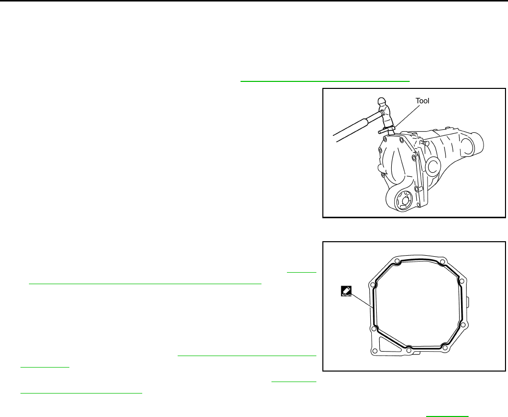
DLN-342
< ON-VEHICLE REPAIR > [FRONT FINAL DRIVE: R180A]
CARRIER COVER
CARRIER COVER
Removal and Installation INFOID:0000000003937433
REMOVAL
1. Remove the front final drive assembly. Refer to DLN-343, "Removal and Installation".
2. Remove the carrier cover bolts and separate the carrier cover
from the gear carrier using Tool.
CAUTION:
• Do not damage the mating surface.
• Do not insert flat-bladed screwdriver, this will damage the
mating surface.
INSTALLATION
1. Apply a 3 mm (0.12 in) bead of sealant to the mating surface of
the carrier cover as shown.
• Use Genuine Silicone RTV or equivalent. Refer to GI-26,
"Recommended Chemical Products and Sealants".
CAUTION:
Remove any old sealant adhering to the mating surfaces.
Also remove any moisture, oil, or foreign material adhering
to the application and mating surfaces.
2. Install the carrier cover to the gear carrier. Tighten the bolts to
the specified torque. Refer to DLN-345, "Disassembly and
Assembly".
3. Install the front final drive assembly. Refer to DLN-343,
"Removal and Installation".
CAUTION:
Fill the front final drive assembly with recommended differential gear oil. Refer to DLN-338.
Tool number : KV10111100 (J-37228)
PDIA0699E
PDIA0712E
Revision: October 2008
2009 Pathfinder
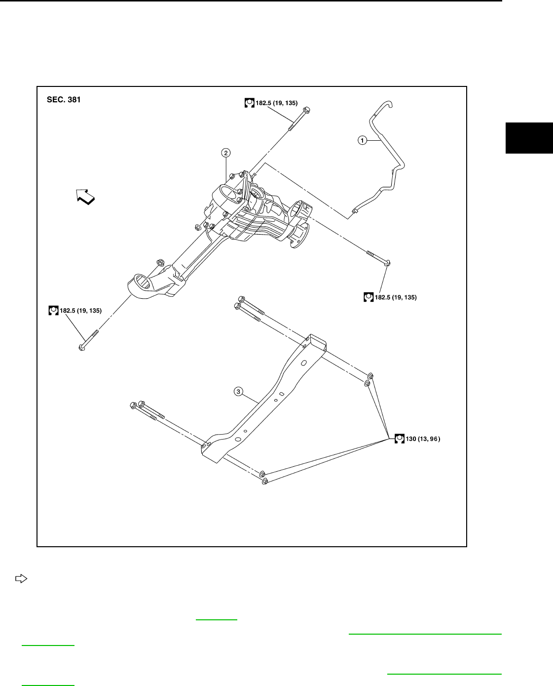
FRONT FINAL DRIVE ASSEMBLY
DLN-343
< REMOVAL AND INSTALLATION > [FRONT FINAL DRIVE: R180A]
C
E
F
G
H
I
J
K
L
M
A
B
DLN
N
O
P
REMOVAL AND INSTALLATION
FRONT FINAL DRIVE ASSEMBLY
Removal and Installation INFOID:0000000003937434
REMOVAL
1. Drain the differential gear oil. Refer to DLN-338.
2. Remove the drive shafts from the front final drive assembly. Refer to FAX-6, "VQ40DE : Removal and
Installation".
3. Remove the front crossmember.
4. Remove the front propeller shaft from the front final drive assembly. Refer to DLN-309, "Removal and
Installation".
5. Disconnect the vent hose from the front final drive assembly.
1. Breather hose 2. Front final drive assembly 3. Front crossmember
Vehicle front
AWDIA0018G
B
Revision: October 2008
2009 Pathfinder

DLN-344
< REMOVAL AND INSTALLATION > [FRONT FINAL DRIVE: R180A]
FRONT FINAL DRIVE ASSEMBLY
6. Support the front final drive assembly using a suitable jack.
7. Remove the front final drive assembly bolts, then remove the
front final drive assembly.
CAUTION:
Support the front final drive assembly while removing using
a suitable jack.
INSTALLATION
Installation is in the reverse order of removal.
• Install new side oil seals into the front final drive assembly. Refer to DLN-341, "Removal and Installation".
CAUTION:
• Make sure there are no pinched or restricted areas on the breather hose caused by folding or bend-
ing when installing it.
• Fill the front final drive assembly with differential gear oil after installation. Refer to DLN-338.
WDIA0145E
Revision: October 2008
2009 Pathfinder
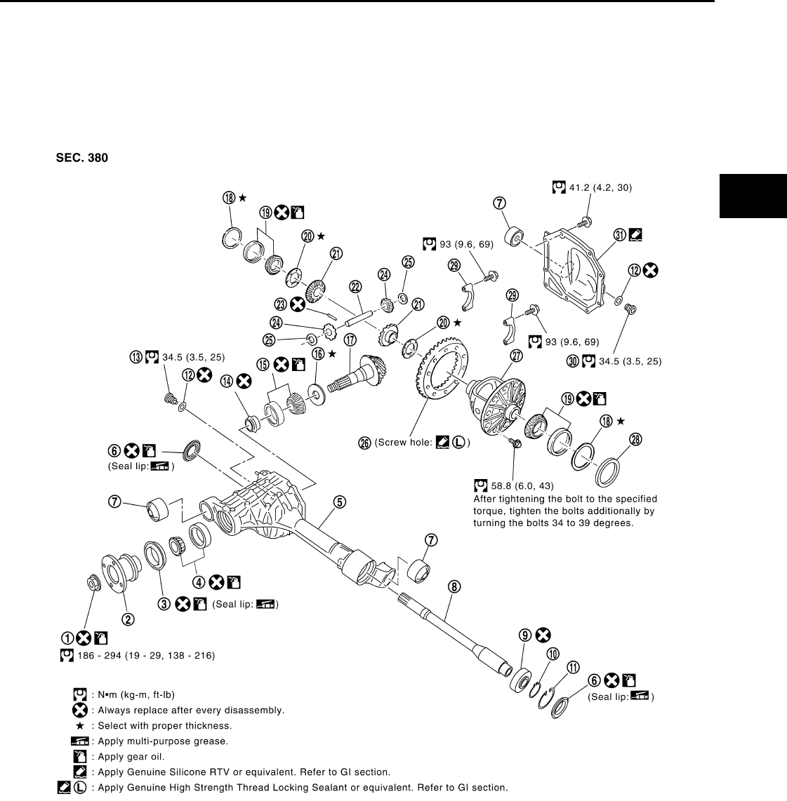
FRONT FINAL DRIVE
DLN-345
< DISASSEMBLY AND ASSEMBLY > [FRONT FINAL DRIVE: R180A]
C
E
F
G
H
I
J
K
L
M
A
B
DLN
N
O
P
DISASSEMBLY AND ASSEMBLY
FRONT FINAL DRIVE
Disassembly and Assembly INFOID:0000000003937435
COMPONENTS
1. Drive pinion lock nut 2. Companion flange 3. Front oil seal
4. Drive pinion front bearing 5. Gear carrier 6. Side oil seal
7. Bushing 8. Differential side shaft 9. Differential side shaft bearing
10. Snap ring 11. Snap ring 12. Gasket
13. Drain plug 14. Collapsible spacer 15. Drive pinion rear bearing
16. Drive pinion height adjusting washer 17. Drive pinion 18. Side bearing adjusting washer
19. Side bearing 20. Side gear thrust washer 21. Side gear
22. Pinion mate shaft 23. Lock pin 24. Pinion mate gear
25. Pinion mate thrust washer 26. Drive gear 27. Differential case
WDIA0265E
Revision: October 2008
2009 Pathfinder
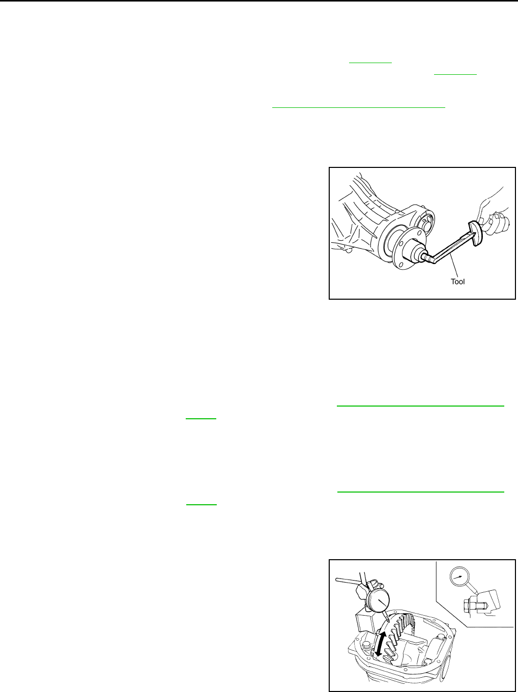
DLN-346
< DISASSEMBLY AND ASSEMBLY > [FRONT FINAL DRIVE: R180A]
FRONT FINAL DRIVE
ASSEMBLY INSPECTION AND ADJUSTMENT
• Drain the differential gear oil before inspection and adjustment. Refer to DLN-338.
• Remove and install the carrier cover as necessary for inspection and adjustment. Refer to DLN-342.
Total Preload Torque
1. Install the differential side shaft if necessary. Refer to DLN-341, "Removal and Installation".
CAUTION:
The differential side shaft must be installed in order to measure total preload torque.
2. Rotate the drive pinion back and forth 2 to 3 times to check for unusual noise and rotation malfunction.
3. Rotate the drive pinion at least 20 times to check for smooth operation of the bearings.
4. Measure total preload torque using Tool.
NOTE:
Total preload torque = Drive pinion bearing preload torque +
Side bearing preload torque
• If the measured value is out of the specification, check and adjust each part. Adjust the drive pinion
bearing preload torque first, then adjust the side bearing preload torque.
CAUTION:
Select a side bearing adjusting washer for right and left individually.
Drive Gear Runout
1. Fit a dial indicator to the drive gear back face.
2. Rotate the drive gear to measure runout.
• If the runout is outside of the limit, check the condition of the drive
gear assembly. Foreign material may be caught between the drive
gear and differential case, or the differential case or drive gear may
be deformed.
CAUTION:
Replace drive gear and drive pinion as a set.
Tooth Contact
28. Housing spacer 29. Side bearing cap 30. Filler plug
31. Carrier cover
Tool number : ST3127S000 (J-25765-A)
Total preload torque:
1.67 - 2.74 N·m (0.17 - 0.27 kg-m, 15 - 24 in-lb)
PDIA0697E
If the total preload torque is greater than specification
On drive pinion bearings: Replace the collapsible spacer.
On side bearings: Use thinner side bearing adjusting washers by the same
amount on each side. Refer to DLN-364, "Inspection and Adjust-
ment".
If the total preload torque is less than specification
On drive pinion bearings: Tighten the drive pinion lock nut.
On side bearings: Use thicker side bearing adjusting washers by the same
amount on each side. Refer to DLN-364, "Inspection and Adjust-
ment".
Runout limit: 0.08 mm (0.0031 in) or less
SPD886
Revision: October 2008
2009 Pathfinder
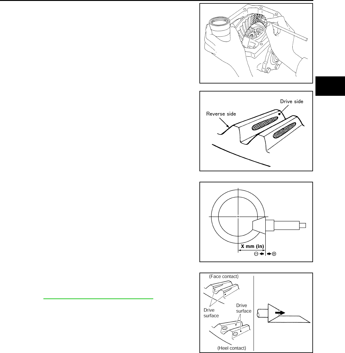
FRONT FINAL DRIVE
DLN-347
< DISASSEMBLY AND ASSEMBLY > [FRONT FINAL DRIVE: R180A]
C
E
F
G
H
I
J
K
L
M
A
B
DLN
N
O
P
1. Apply red lead to the drive gear.
NOTE:
Apply red lead to both faces of three to four gears, at four loca-
tions evenly spaced on the drive gear.
2. Rotate the drive gear back and forth several times. Then check
for correct drive pinion to drive gear tooth contact as shown.
CAUTION:
Check tooth contact on drive side and reverse side.
• If the tooth contact is improperly adjusted, adjust the drive pin-
ion height (dimension X).
- If the tooth contact is near the face (face contact), or near the
heel (heel contact), use a thicker drive pinion height adjusting
washer to move drive pinion closer to the drive gear.
Refer to DLN-364, "Inspection and Adjustment".
SPD357
SDIA0570E
SDIA0517E
PDIA0440E
Revision: October 2008
2009 Pathfinder
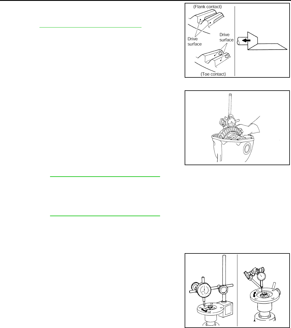
DLN-348
< DISASSEMBLY AND ASSEMBLY > [FRONT FINAL DRIVE: R180A]
FRONT FINAL DRIVE
- If the tooth contact is near the flank (flank contact), or near the
toe (toe contact), use a thinner drive pinion height adjusting
washer to move the drive pinion farther from the drive gear.
Refer to DLN-364, "Inspection and Adjustment".
Backlash
1. Fit a dial indicator to the drive gear face to measure the back-
lash.
• If the backlash is outside of the specification, change the thick-
ness of the side bearing adjusting washers.
CAUTION:
Do not change the total thickness of side bearing adjusting washers as it will change the side
bearing preload torque.
Companion Flange Runout
1. Rotate companion flange and check for runout on the compan-
ion flange face (inner side of the bolt holes) and companion
flange inner side (socket diameter) using suitable tool.
2. If the runout is outside the runout limit, follow the procedure
below to adjust.
a. Rotate the companion flange on the drive pinion by 90°, 180°
and 270° while checking for the position where the runout is
minimum.
b. If the runout is still outside of the runout limit after the companion
flange has been rotated on the drive pinion, possible cause could be an assembly malfunction of drive pin-
ion and drive pinion bearing or a malfunctioning drive pinion bearing.
c. If the runout is still outside of the runout limit after repair of the assembly of drive pinion and drive pinion
bearing or drive pinion bearing, replace the companion flange.
DISASSEMBLY
Differential side shaft
1. Drain the differential gear oil if necessary.
PDIA0441E
Backlash: 0.10 - 0.15 mm (0.0039 - 0.0059 in)
If the backlash is greater than specification:
Make side bearing adjusting washer thicker on drive
gear back side, and side bearing adjusting washer
thinner on drive gear tooth side by the same amount.
Refer to DLN-364, "Inspection and Adjustment".
If the backlash is less than specification:
Make side bearing adjusting washer thinner on drive
gear back side, and side bearing adjusting washer
thicker on drive gear tooth side by the same amount.
Refer to DLN-364, "Inspection and Adjustment".
SPD513
Runout limit: 0.1 mm (0.004 in) or less
SDIA2078E
Revision: October 2008
2009 Pathfinder
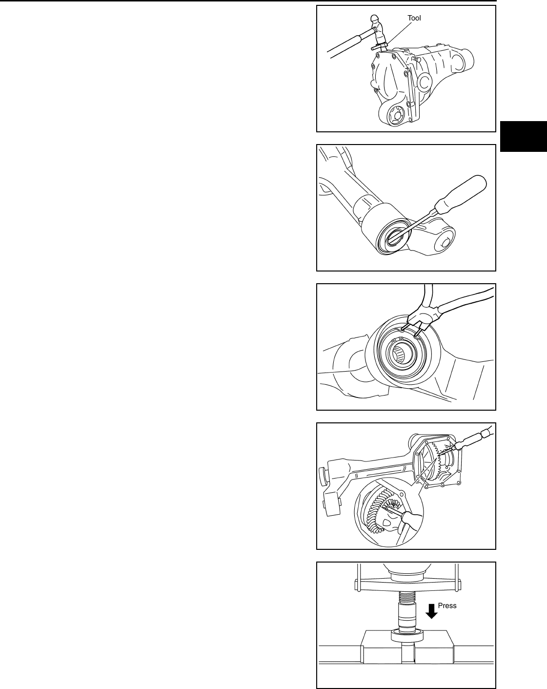
FRONT FINAL DRIVE
DLN-349
< DISASSEMBLY AND ASSEMBLY > [FRONT FINAL DRIVE: R180A]
C
E
F
G
H
I
J
K
L
M
A
B
DLN
N
O
P
2. Remove the carrier cover bolts and separate the carrier cover
from the gear carrier using Tool.
CAUTION:
• Do not damage the mating surface.
• Do not insert flat-bladed screwdriver, this will damage the
mating surface.
3. Remove side oil seal.
CAUTION:
Do not damage gear carrier.
4. Remove snap ring (hole side) using suitable tool.
5. Remove differential side shaft assembly out of gear carrier using
suitable tool.
NOTE:
Tap on differential side shaft assembly from side gear side.
6. Remove snap ring (differential side shaft side).
7. Press differential side shaft out of differential side shaft bearing.
CAUTION:
Do not drop differential side shaft.
Tool number : KV10111100 (J-37228)
PDIA0699E
PDIA0713E
PDIA0714E
PDIA0715E
PDIA0718E
Revision: October 2008
2009 Pathfinder
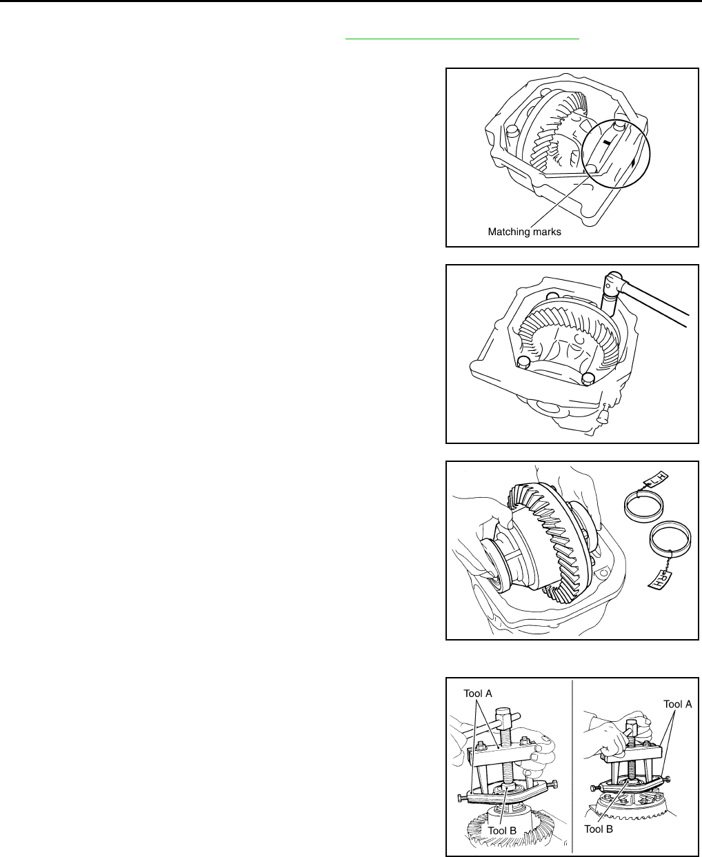
DLN-350
< DISASSEMBLY AND ASSEMBLY > [FRONT FINAL DRIVE: R180A]
FRONT FINAL DRIVE
Differential Assembly
1. Remove differential side shaft assembly. Refer to DLN-341, "Removal and Installation".
2. Remove side seal from gear carrier using suitable tool.
3. For proper reinstallation, paint matching marks on one side of
the side bearing cap and gear carrier.
CAUTION:
• For matching marks, use paint. Do not damage side bear-
ing cap or gear carrier.
• Side bearing caps are line-board during manufacture. The
matching marks are used to reinstall them in their original
positions.
4. Remove the side bearing caps.
5. Lift the differential case assembly out of the gear carrier.
CAUTION:
• Keep side bearing outer races together with side bearing
inner races. Do not mix them up.
• Keep side bearing adjusting washers together with side
bearings.
6. Remove housing spacer.
7. Remove side bearing inner race using Tools as shown.
CAUTION:
• Do not remove side bearing inner race unless it is being
replaced.
• Place copper plates between the vise and the side bearing
inner race and drive gear to prevent damage.
PDIA0700E
PDIA0701E
SPD919
Tool number A: ST33051001 (J-22888-20)
B: ST33061000 (J-8107-2)
PDIA0827E
Revision: October 2008
2009 Pathfinder
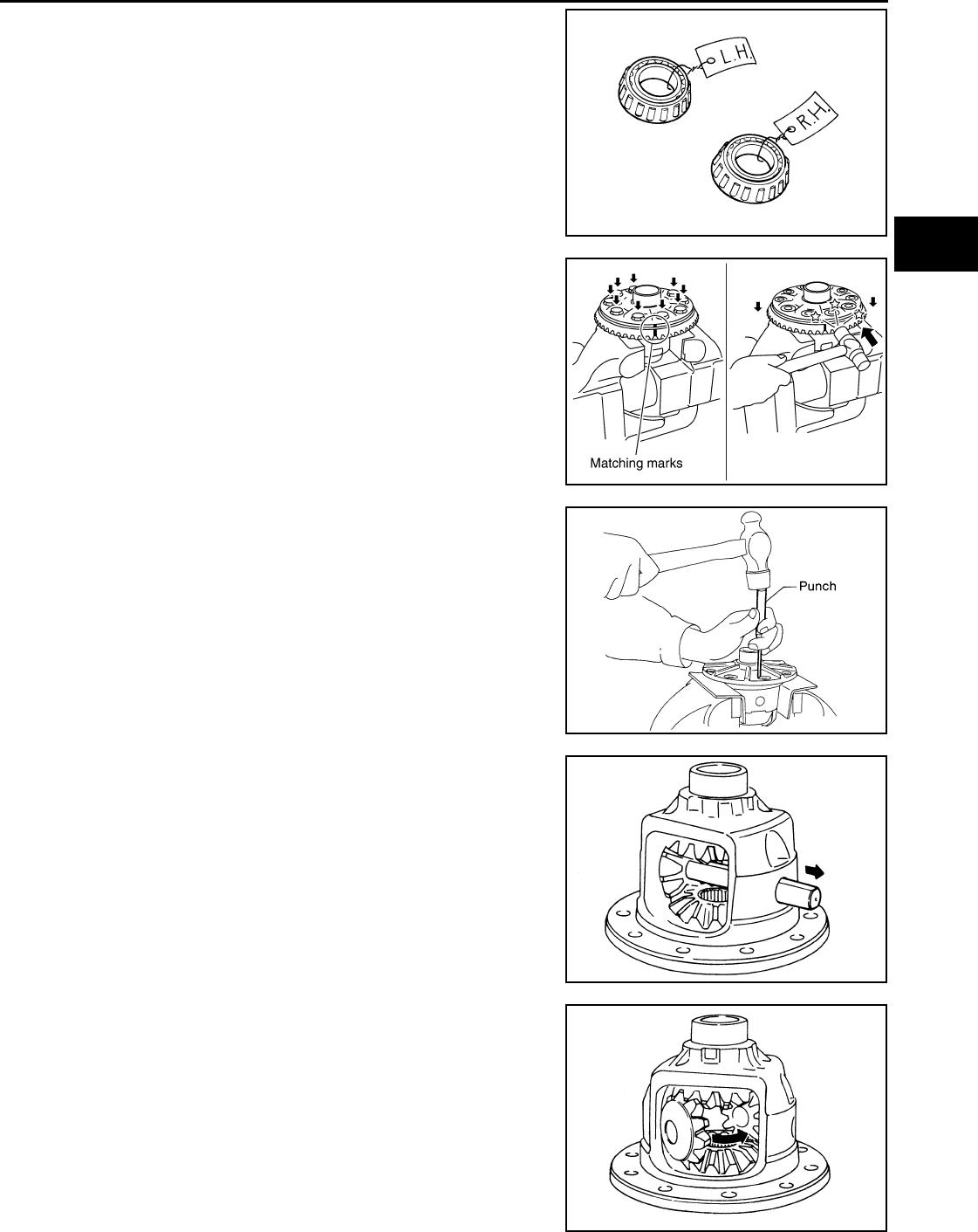
FRONT FINAL DRIVE
DLN-351
< DISASSEMBLY AND ASSEMBLY > [FRONT FINAL DRIVE: R180A]
C
E
F
G
H
I
J
K
L
M
A
B
DLN
N
O
P
• Keep side bearing outer races together with side bearing
inner races. Do not mix them up.
8. For proper reinstallation, paint matching marks on the differential
case and drive gear.
CAUTION:
Use paint for matching marks. Do not damage differential
case or drive gear.
9. Remove the drive gear bolts.
10. Tap the drive gear off the differential case using suitable tool.
CAUTION:
Tap evenly all around to keep drive gear from bending.
11. Remove the lock pin of the pinion mate shaft from the drive gear
side using suitable tool.
12. Remove the pinion mate shaft.
13. Turn the pinion mate gear, then remove the pinion mate gear,
pinion mate thrust washer, side gear and side gear thrust
washer from the differential case.
SPD022
PDIA0496E
SPD025
SDIA0031J
SDIA0032J
Revision: October 2008
2009 Pathfinder
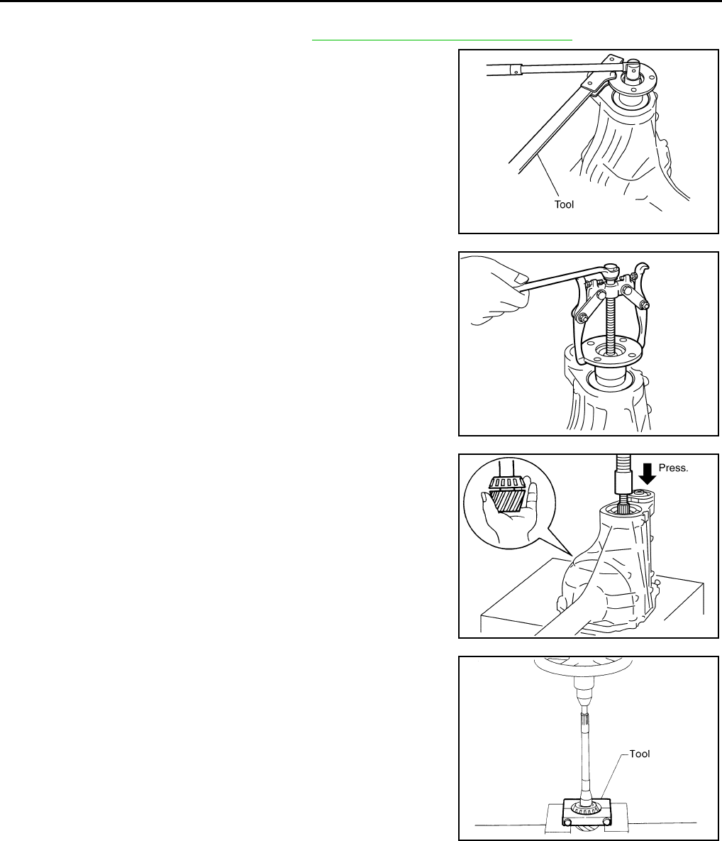
DLN-352
< DISASSEMBLY AND ASSEMBLY > [FRONT FINAL DRIVE: R180A]
FRONT FINAL DRIVE
Drive Pinion Assembly
1. Remove the differential assembly. Refer to DLN-345, "Disassembly and Assembly".
2. Remove the drive pinion lock nut using Tool.
3. Put matching marks on the companion flange and drive pinion
using paint.
CAUTION:
Use paint to make the matching marks. Do not damage the
companion flange or drive pinion.
4. Remove the companion flange using suitable tool.
5. Press the drive pinion assembly (with rear inner bearing race
and collapsible spacer) out of the gear carrier.
CAUTION:
Do not drop drive pinion assembly.
6. Remove the drive pinion rear bearing inner race and drive pinion
height adjusting washer using Tool.
Tool number : KV38108300 (J-44195)
PDIA0702E
PDIA0703E
PDIA0704E
Tool number : ST30031000 (J-22912-01)
S-PD179
Revision: October 2008
2009 Pathfinder
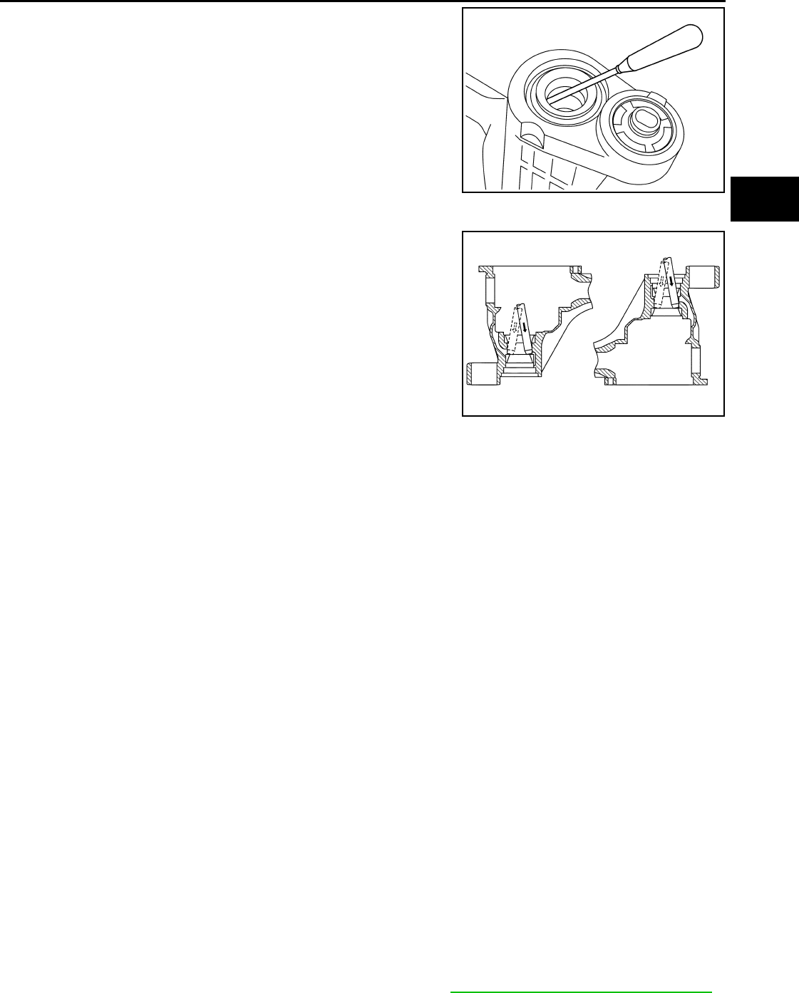
FRONT FINAL DRIVE
DLN-353
< DISASSEMBLY AND ASSEMBLY > [FRONT FINAL DRIVE: R180A]
C
E
F
G
H
I
J
K
L
M
A
B
DLN
N
O
P
7. Remove the front oil seal using suitable tool.
CAUTION:
Do not damage gear carrier.
8. Remove the drive pinion front bearing inner race.
9. Remove the drive pinion front and rear bearing outer races by
tapping them uniformly using suitable tool.
CAUTION:
Do not damage gear carrier.
INSPECTION AFTER DISASSEMBLY
Clean the disassembled parts. Then inspect the parts for wear or damage. If wear or damage are found, follow
the measures below.
Drive Pinion and Drive Gear
• If the drive pinion and drive gear teeth do not mesh or line-up correctly, determine the cause and adjust,
repair, or replace as necessary.
• If the drive pinion or drive gear are worn, cracked, damaged, pitted or chipped (by friction) noticeably,
replace with new drive pinion and drive gear.
• Drive pinion and drive gear are supplied in matched sets only. Matching numbers on both drive pinion and
drive gear are etched for verification. If a new drive pinion and drive gear set are being used, verify the num-
bers of each drive pinion and drive gear before proceeding with assembly.
Bearing
• If bearings are chipped (by friction), pitted, worn, rusted, scratched, or unusual noise is coming from bearing,
replace with new bearing assembly (as a new set).
• Bearing must be replaced with a new one whenever disassembled.
Side Gear and Pinion Mate Gear
• If any cracks or damage are found on the surface of the teeth, replace with new one.
• If any worn or chipped marks are found on the side of the side gear and pinion mate gear which contact the
thrust washer, replace with new one.
• Replace both side gear and pinion mate gear as a set when replacing side gear or pinion mate gear.
Side Gear Thrust Washer and Pinion Mate Thrust Washer
• If any chips (by friction), damage, or unusual wear are found, replace with new one.
Gear Carrier
• If any wear or cracks are found on the contact sides of gear carrier, replace with new one.
Companion Flange
• If any chips (about 0.1mm, 0.004 in) or other damage on the companion flange surface which contacts the
front oil seal lips are found, replace with new one.
ADJUSTING AND SELECTING WASHERS
Side Gear Back Clearance
• Assemble the differential parts if they are disassembled. Refer to "DLN-345, "Disassembly and Assembly".
PDIA0716E
PDIA0705E
Revision: October 2008
2009 Pathfinder
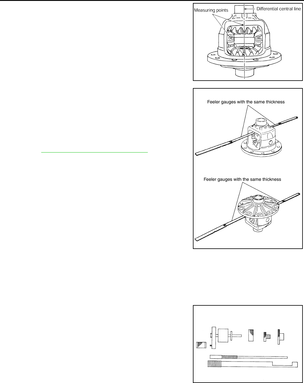
DLN-354
< DISASSEMBLY AND ASSEMBLY > [FRONT FINAL DRIVE: R180A]
FRONT FINAL DRIVE
1. Place the differential case straight up so that the side gear to be
measured is upward.
2. Using feeler gauges, measure the clearance between the side
gear back and differential case at three different points, while
rotating the side gear. Average the three readings to calculate
the clearance. (Measure the clearance of the other side as well.)
• If the side gear back clearance is outside of the specification,
use a thicker or thinner side gear thrust washer to adjust.
Refer to DLN-364, "Inspection and Adjustment".
CAUTION:
• Insert feeler gauges with the same thickness on both
sides to prevent side gear from tilting.
• Each gear should rotate smoothly without excessive
resistance during differential motion.
• Select a side gear thrust washer for right and left individu-
ally.
NOTE:
Side gear back clearance is clearance between side gear and differential case for adjusting side gear
backlash.
Drive Pinion Height
1. Make sure all parts are clean and that the bearings are well lubricated.
2. Assemble the drive pinion bearings onto the Tool.
PDIA0460E
Side gear back clearance: 0.1 mm (0.004 in) or less.
If the side gear back clearance is greater than
specification:
Use a thicker side gear thrust washer.
If the side gear back clearance is less than spec-
ification:
Use a thinner side gear thrust washer.
PDIA0576E
Tool number : — (J-34309)
SPD769
Revision: October 2008
2009 Pathfinder
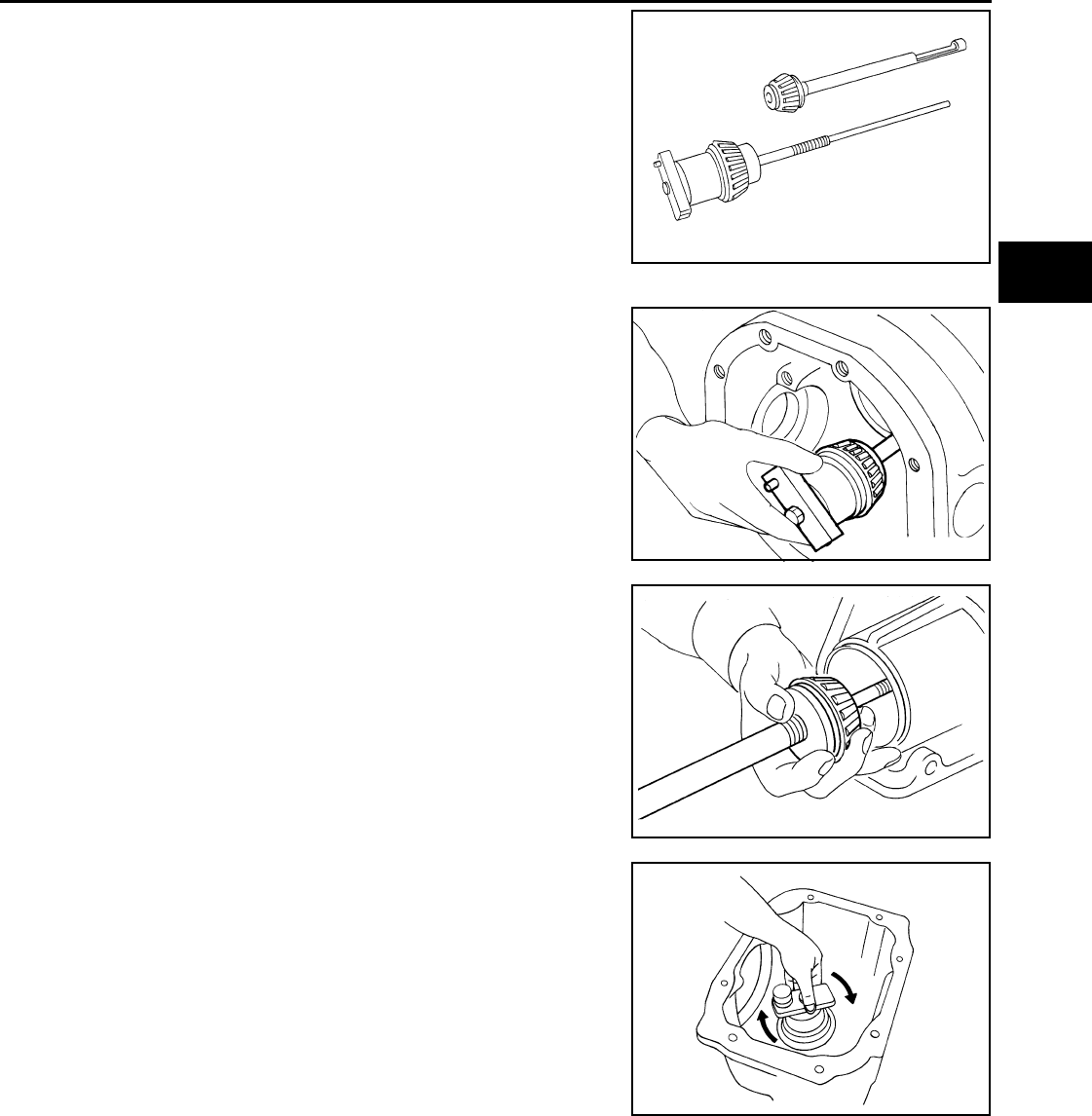
FRONT FINAL DRIVE
DLN-355
< DISASSEMBLY AND ASSEMBLY > [FRONT FINAL DRIVE: R180A]
C
E
F
G
H
I
J
K
L
M
A
B
DLN
N
O
P
•Drive pinion front bearing; make sure the J-34309-3 drive
pinion front bearing seat is secured tightly against the J-
34309-2 gauge anvil. Then turn the J-34309-7 drive pinion
front bearing pilot to secure the drive pinon front bearing in its
proper position.
•Drive pinion rear bearing; the J-34309-8 drive pinion rear
bearing pilot is used to center the drive pinion rear bearing
only. The J-34309-4 drive pinion rear bearing locking seat is
used to lock the drive pinion rear bearing to the assembly.
•Installation of J-34309-9 and J-34309-16; place a suitable
2.5 mm (0.098 in) thick plain washer between J-34309-9 and
J-34309-16. Both surfaces of J-34309-9 and J-34309-16 must
be parallel with a clearance of 2.5 mm (0.098 in).
3. Install the drive pinion rear bearing inner race into the gear car-
rier. Then insert the drive pinion height adjusting washer selec-
tor tool, J-34309-1, gauge screw assembly.
4. Assemble the drive pinion front bearing inner race and the J-
34309-2 gauge anvil. Assemble them together with the J-34309-
1 gauge screw in the gear carrier. Make sure that the drive pin-
ion height gauge plate, J-34309-16, will turn a full 360°. Tighten
the two sections together by hand.
5. Turn the assembly several times to seat the drive pinon bear-
ings.
SPD197A
SPD893
SPD199A
SPD770
Revision: October 2008
2009 Pathfinder
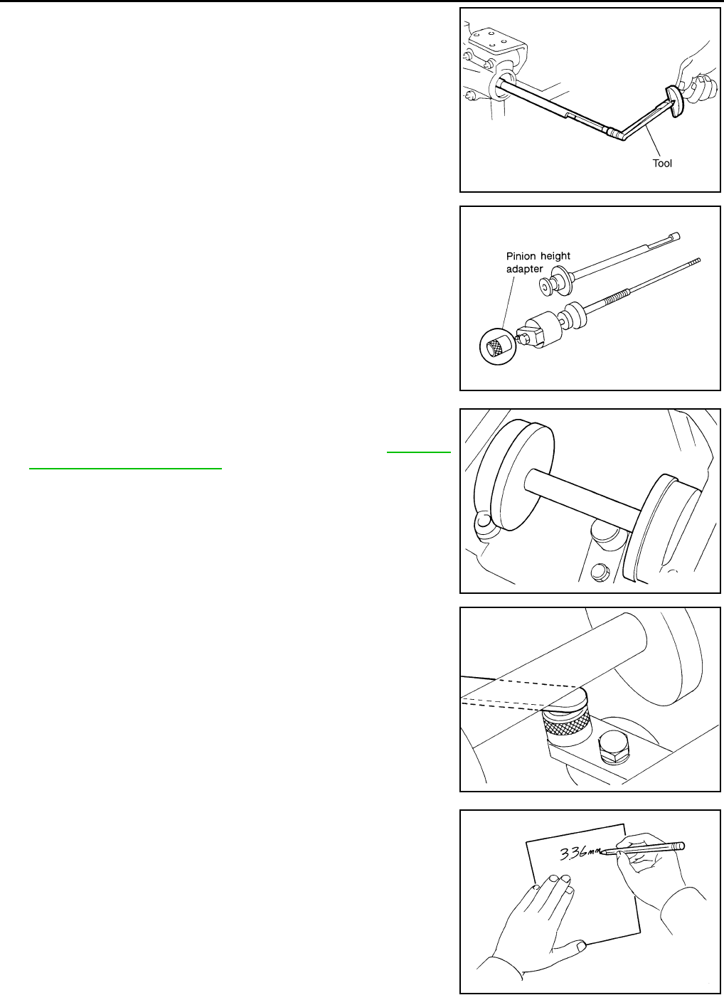
DLN-356
< DISASSEMBLY AND ASSEMBLY > [FRONT FINAL DRIVE: R180A]
FRONT FINAL DRIVE
6. Measure the turning torque at the end of the J-34309-2 gauge
anvil using Tool.
7. Place the J-34309-10 “R180A” drive pinion height adapter onto
the gauge plate and tighten it by hand.
CAUTION:
Make sure all machined surfaces are clean.
8. Position the side bearing discs, Tool, and arbor firmly into the
side bearing bores. Install the side bearing caps and tighten the
side bearing cap bolts to the specified torque. Refer to DLN-345,
"Disassembly and Assembly".
9. Select the correct standard drive pinion height adjusting washer
thickness. Select by using a standard gauge of 3 mm (0.12 in)
and your J-34309-101 feeler gauge. Measure the distance
between the J-34309-10 drive pinion height adapter, including
the standard gauge and the arbor.
10. Write down the exact measurement (the value of feeler gauge).
Tool number : ST3127S000 (J-25765- A)
Turning torque specification:
1.0 - 1.6 N·m (0.11 - 0.16 kg-m, 9 - 14 in-lb)
PDIA0566E
SPD208A
Tool number : — (J-25269-18)
SPD211A
SPD204A
SPD775
Revision: October 2008
2009 Pathfinder
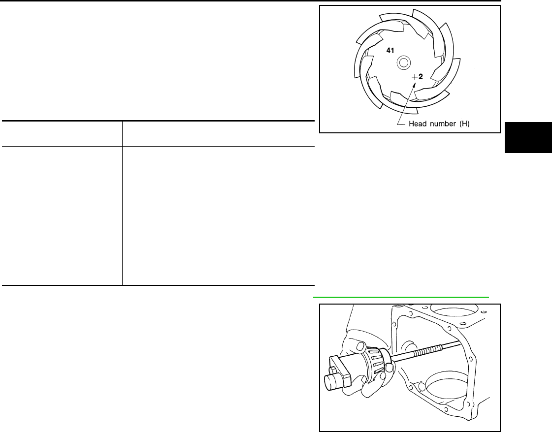
FRONT FINAL DRIVE
DLN-357
< DISASSEMBLY AND ASSEMBLY > [FRONT FINAL DRIVE: R180A]
C
E
F
G
H
I
J
K
L
M
A
B
DLN
N
O
P
11. Correct the drive pinion height adjusting washer size by referring
to the drive pinion “head number”.
There are two numbers painted on the drive pinion. The first
one refers to the drive pinion and drive gear as a matched
set. This number should be the same as the number on the
drive gear. The second number is the drive pinion “head
number”. It refers to the ideal drive pinion height from stan-
dard for quietest operation. Use the following chart to
determine the correct drive pinion height adjusting washer.
12. Select the correct drive pinion height adjusting washer. Refer to DLN-364, "Inspection and Adjustment".
13. Remove the Tool from the gear carrier and disassemble to
retrieve the drive pinion bearings.
ASSEMBLY
Drive Pinion Assembly
Head number Add or remove from the standard drive pinion
height adjusting washer thickness measurement
- 6
- 5
- 4
- 3
- 2
- 1
0
+1
+2
+3
+4
+5
+6
Add 0.06 mm (0.0024 in)
Add 0.05 mm (0.0020 in)
Add 0.04 mm (0.0016 in)
Add 0.03 mm (0.0012 in)
Add 0.02 mm (0.0008 in)
Add 0.01 mm (0.0004 in)
Use the selected washer thickness
Subtract 0.01 mm (0.0004 in)
Subtract 0.02 mm (0.0008 in)
Subtract 0.03 mm (0.0012 in)
Subtract 0.04 mm (0.0016 in)
Subtract 0.05 mm (0.0020 in)
Subtract 0.06 mm (0.0024 in)
Tool number : — (J-34309)
SPD542
SPD205A
Revision: October 2008
2009 Pathfinder
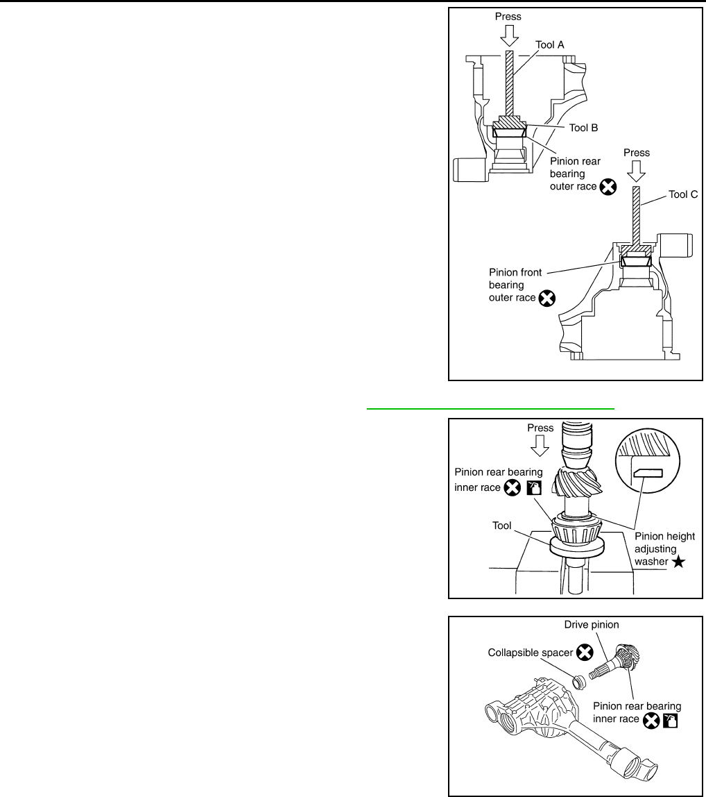
DLN-358
< DISASSEMBLY AND ASSEMBLY > [FRONT FINAL DRIVE: R180A]
FRONT FINAL DRIVE
1. Install drive pinion rear bearing outer race and drive pinion front
bearing outer race using Tools.
CAUTION:
• First tap the drive pinion bearing outer race until it
becomes flush with the gear carrier.
• Do not reuse drive pinion front and rear bearing outer
race.
2. Select drive pinion height adjusting washer. Refer to DLN-364, "Inspection and Adjustment".
3. Install the selected drive pinion height adjusting washer to the
drive pinion. Press the drive pinion rear bearing inner race to it
using Tool.
CAUTION:
• Install the drive pinion height adjusting washer in the
proper direction as shown.
• Do not reuse drive pinion rear bearing inner race.
4. Install the collapsible spacer to the drive pinion.
CAUTION:
Do not reuse collapsible spacer.
5. Apply differential gear oil to the drive pinion rear bearing, and
install the drive pinion assembly to the gear carrier.
6. Apply differential gear oil to the drive pinion front bearing, and
install the drive pinion front bearing inner race to the drive pinion
assembly.
CAUTION:
Do not reuse drive pinion front bearing inner race.
Tool number A: ST30611000 (J-25742-1)
B: ST30613000 (J-25742-3)
C: KV38100200 (J-26233)
PDIA0707E
Tool number : ST30901000 (J-26010-01)
SDIA0048E
PDIA0708E
Revision: October 2008
2009 Pathfinder
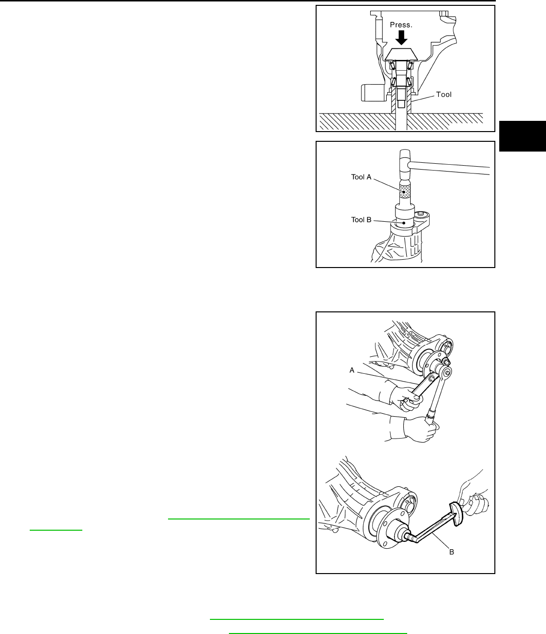
FRONT FINAL DRIVE
DLN-359
< DISASSEMBLY AND ASSEMBLY > [FRONT FINAL DRIVE: R180A]
C
E
F
G
H
I
J
K
L
M
A
B
DLN
N
O
P
7. Press the drive pinion front bearing inner race to the drive pinion
as far as drive pinion lock nut can be tightened using Tool.
8. Apply multi-purpose grease to the lips and differential gear oil to
the circumference of the new front oil seal. Then drive the new
front oil seal in evenly until it becomes flush with the gear carrier
using Tools.
CAUTION:
• Do not reuse front oil seal.
• Do not incline the new front oil seal when installing.
• Apply multi-purpose grease to the lips and differential
gear oil to the circumference of the new front oil seal.
9. Install the companion flange to the drive pinion while aligning the matching marks.
10. Apply anti-corrosive oil to the threads of the drive pinion and the
seating surface of the new drive pinion lock nut. Then adjust the
drive pinion lock nut tightening torque using Tool A, and check
the drive pinion bearing preload torque using Tool B.
CAUTION:
• Do not reuse drive pinion lock nut.
• Apply anti-corrosive oil to the threads of the drive pinion
and the seating surface of the new drive pinion lock nut.
• Adjust the drive pinion lock nut tightening torque to the
lower limit first. Do not exceed the drive pinion lock nut
specified torque. Refer to DLN-345, "Disassembly and
Assembly".
• If the drive pinion bearing preload torque exceeds the
specified value, replace collapsible spacer and tighten it
again to adjust. Do not loosen drive pinion lock nut to
adjust the drive pinion bearing preload torque.
• After adjustment, rotate drive pinion back and forth 2 to 3
times to check for unusual noise, rotation malfunction, and other malfunctions.
11. Check companion flange runout. Refer to DLN-364, "Inspection and Adjustment".
12. Install the differential case assembly. Refer to DLN-345, "Disassembly and Assembly".
Differential Assembly
Tool number : ST33200000 (J-26082)
PDIA0709E
Tool number A: ST30720000 (J-25405)
B: ST27863000 ( — )
PDIA0717E
Tool number A: KV38108300 (J-44195)
B: ST3127S000 (J-25765-A)
Drive pinion bearing preload torque:
1.08 - 1.66 N·m (0.11 - 0.16 kg-m, 10 - 14 in-lb)
WDIA0382E
Revision: October 2008
2009 Pathfinder
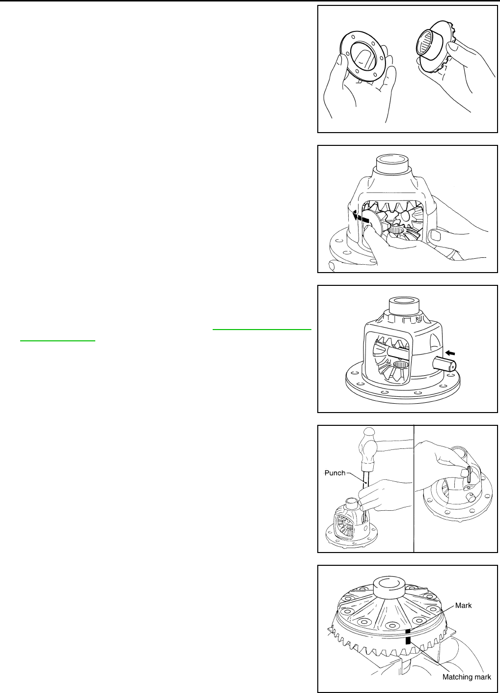
DLN-360
< DISASSEMBLY AND ASSEMBLY > [FRONT FINAL DRIVE: R180A]
FRONT FINAL DRIVE
1. Install side gear thrust washers with the same thickness as the
ones installed prior to disassembly, or reinstall the old ones on
the side gears.
2. Install the side gears and side gear thrust washers into the dif-
ferential case.
3. Install the pinion mate thrust washers to the two pinion mate
gears. Then install the pinion mate gears with the pinion mate
thrust washers by aligning them in diagonally opposite positions
and rotating them into the differential case.
4. Install the pinion mate shaft and align the lock pin hole on the
pinion mate shaft with the lock pin hole on the differential case.
5. Measure the side gear end play. If necessary, select the appro-
priate side gear thrust washers. Refer to DLN-364, "Inspection
and Adjustment".
6. Drive a new lock pin into the pinion mate shaft until it is flush
with the differential case using suitable tool.
CAUTION:
Do not reuse lock pin.
7. Align the matching mark of the differential case with the mark of
the drive gear, then place the drive gear onto the differential
case.
SDIA0193J
SDIA2025E
SDIA0195J
SPD030
SDIA2593E
Revision: October 2008
2009 Pathfinder
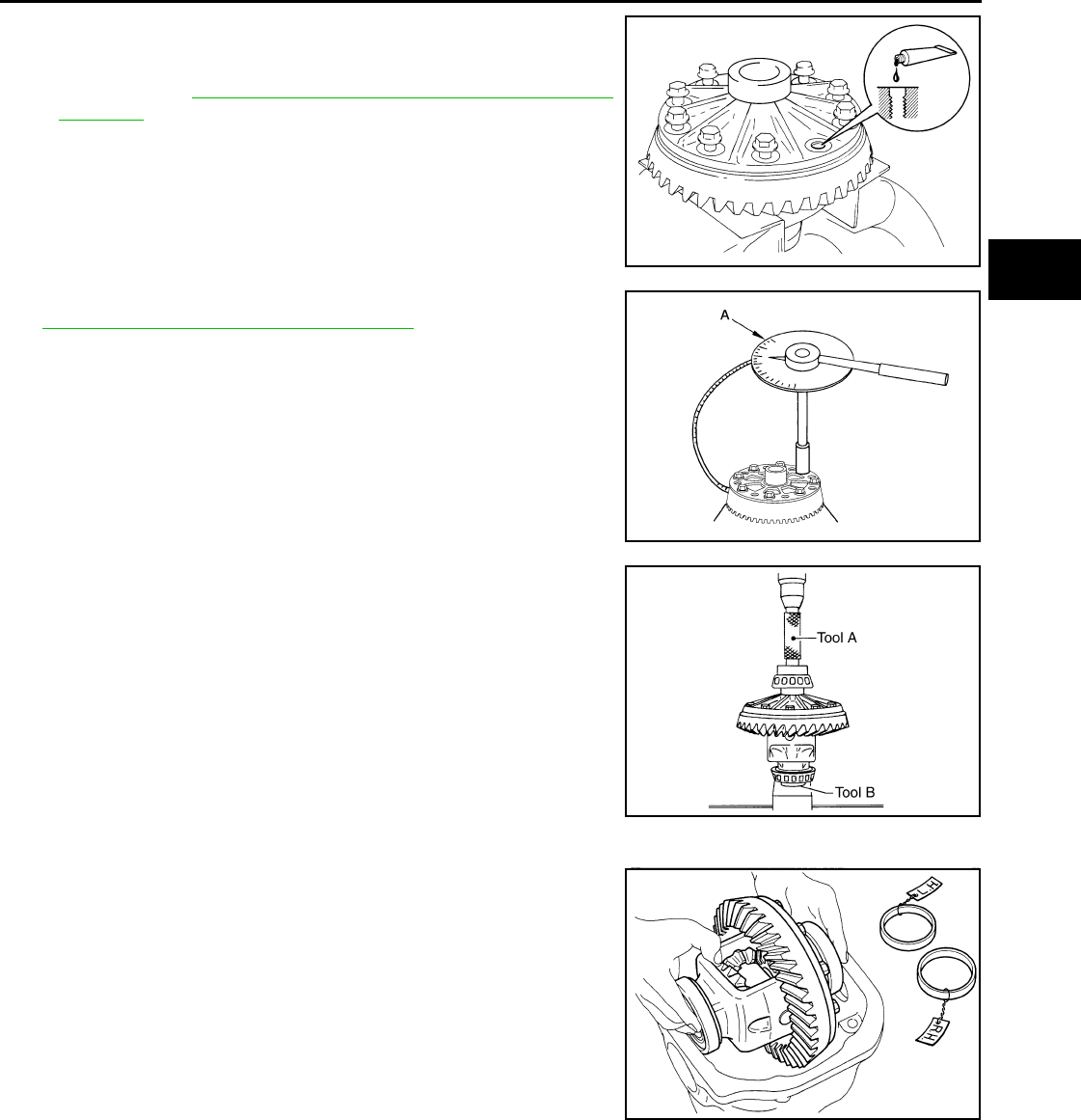
FRONT FINAL DRIVE
DLN-361
< DISASSEMBLY AND ASSEMBLY > [FRONT FINAL DRIVE: R180A]
C
E
F
G
H
I
J
K
L
M
A
B
DLN
N
O
P
8. Apply thread locking sealant into the threaded holes of the drive
gear and install the new drive gear bolts.
• Use Genuine High Strength Thread Locking Sealant or equiv-
alent. Refer to GI-26, "Recommended Chemical Products and
Sealants".
CAUTION:
Make sure the drive gear back and threaded holes are
clean.
9. Tighten the new drive gear bolts to the specified torque. Refer to
DLN-345, "Disassembly and Assembly". After tightening the
new drive gear bolts to the specified torque, tighten an additional
34° to 39° using Tool.
CAUTION:
• Always use Tool. Avoid tightening based on visual check
alone.
• Tighten new drive gear bolts in a crisscross pattern.
10. Press the new side bearing inner races to the differential case
using Tools.
CAUTION:
Do not reuse side bearing inner races.
11. Install housing spacer into gear carrier.
12. Apply differential gear oil to the side bearings, and install the dif-
ferential case assembly with the side bearing outer races into
the gear carrier.
CAUTION:
Do not reuse side bearing outer race when replacing side
bearing inner race (replace as a set).
SDIA2594E
Tool number : KV10112100-A (BT-8653-A)
AWBIA0722Z
Z
Tool number A: ST33230000 (J-35867)
B: ST33061000 (J-8107-2)
SPD353
SPD527
Revision: October 2008
2009 Pathfinder
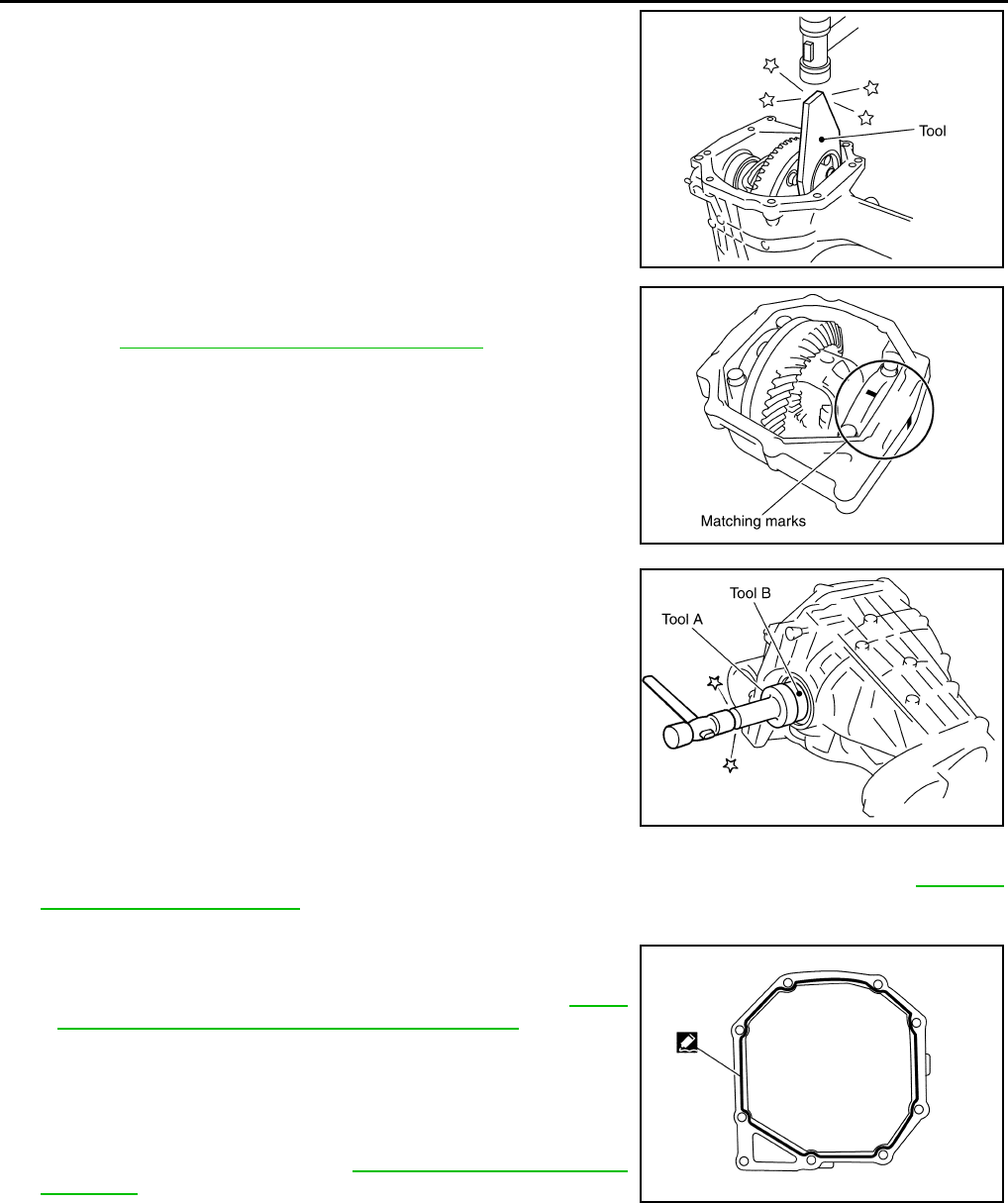
DLN-362
< DISASSEMBLY AND ASSEMBLY > [FRONT FINAL DRIVE: R180A]
FRONT FINAL DRIVE
13. Insert left and right original side bearing adjusting washers in
place between side bearings and gear carrier using Tool.
14. Install the side bearing caps with the matching marks aligned
and tighten the side bearing cap bolts to the specified torque.
Refer to DLN-345, "Disassembly and Assembly".
15. Apply multi-purpose grease to the lips and differential gear oil to
the circumference of the new side oil seal. Then drive the new
side oil seal in evenly until it becomes flush with the gear carrier
using Tools.
CAUTION:
• Do not reuse side oil seal.
• Do not incline the new side oil seal when installing.
• Apply multi-purpose grease to the lips and differential
gear oil to the circumference of the new side oil seal.
16. Check and adjust tooth contact, backlash, drive gear runout and total preload torque. Refer to DLN-364,
"Inspection and Adjustment".
Recheck above items.
17. Apply a 3 mm (0.12 in) bead of sealant to the mating surface of
the carrier cover as shown.
• Use Genuine Silicone RTV or equivalent. Refer to GI-26,
"Recommended Chemical Products and Sealants".
CAUTION:
Remove any old sealant adhering to the mating surfaces.
Also remove any moisture, oil, or foreign material adhering
to the application and mating surfaces.
18. Install the carrier cover to the gear carrier. Tighten the bolts to
the specified torque. Refer to DLN-345, "Disassembly and
Assembly".
Differential side shaft
Tool number : KV38100600 (J-25267)
PDIA0706E
PDIA0700E
Tool number A: ST30720000 (J-25405)
B: ST27863000 ( — )
PDIA0711E
PDIA0712E
Revision: October 2008
2009 Pathfinder
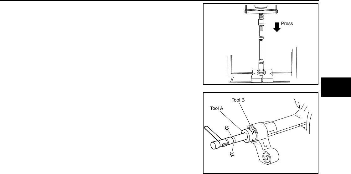
FRONT FINAL DRIVE
DLN-363
< DISASSEMBLY AND ASSEMBLY > [FRONT FINAL DRIVE: R180A]
C
E
F
G
H
I
J
K
L
M
A
B
DLN
N
O
P
1. Press differential side shaft bearing to differential side shaft.
CAUTION:
Do not reuse differential side shaft bearing.
2. Install snap ring (differential side shaft side).
3. Install differential side shaft assembly into gear carrier.
4. Install snap ring (hole side).
5. Apply multi-purpose grease to the lips and differential gear oil to
the circumference of the new side oil seal. Then drive the new
side oil seal in evenly until it becomes flush with the gear carrier
using Tools.
CAUTION:
• Do not reuse side oil seal.
• Do not incline the new side oil seal when installing.
• Apply multi-purpose grease to the lips and differential
gear oil to the circumference of the new side oil seal.
PDIA0719E
Tool number A: ST30720000 (J-25405)
B: ST27863000 ( — )
PDIA0828E
Revision: October 2008
2009 Pathfinder

DLN-364
< SERVICE DATA AND SPECIFICATIONS (SDS) [FRONT FINAL DRIVE: R180A]
SERVICE DATA AND SPECIFICATIONS (SDS)
SERVICE DATA AND SPECIFICATIONS (SDS)
SERVICE DATA AND SPECIFICATIONS (SDS)
General Specification INFOID:0000000003937436
Inspection and Adjustment INFOID:0000000003937437
DRIVE GEAR RUNOUT
Unit: mm (in)
SIDE GEAR CLEARANCE
Unit: mm (in)
PRELOAD TORQUE
Unit: N·m (kg-m, in-lb)
BACKLASH
Unit: mm (in)
COMPANION FLANGE RUNOUT
Unit: mm (in)
SELECTIVE PARTS
Drive Pinion Height Adjusting Washer
Applied model VQ40DE
Final drive model R180A
Gear ratio 3.357
Number of teeth (Drive gear/Drive pinion) 47/14
Differential gear oil capacity (Approx.) 0.85 (1-3/4 US pt, 1-1/2 lmp pt)
Number of pinion gears 2
Drive pinion adjustment spacer type Collapsible
Item Runout limit
Drive gear back face 0.08 (0.0031) or less
Item Specification
Side gear back clearance (Clearance between side gear and differ-
ential case for adjusting side gear backlash)
0.1 (0.004) or less
(Each gear should rotate smoothly without excessive resistance
during differential motion.)
Item Specification
Drive pinion bearing preload torque 1.08 - 1.66 (0.11 - 0.16, 10 - 14)
Side bearing preload torque 0.59 - 1.08 (0.06 - 0.11, 6 - 9)
Total preload torque
(Total preload torque = drive pinion bearing preload torque + side
bearing preload torque).
1.67 - 2.74 (0.17 - 0.27, 15 - 24)
Item Specification
Drive gear to drive pinion backlash 0.10 - 0.15 (0.0039 - 0.0059)
Item Runout limit
Companion flange face 0.1 (0.004) or less
Companion flange inner side 0.1 (0.004) or less
Revision: October 2008
2009 Pathfinder

SERVICE DATA AND SPECIFICATIONS (SDS)
DLN-365
< SERVICE DATA AND SPECIFICATIONS (SDS) [FRONT FINAL DRIVE: R180A]
C
E
F
G
H
I
J
K
L
M
A
B
DLN
N
O
P
Unit: mm (in)
*: Always check with the Parts Department for the latest parts information.
Side Gear Thrust Washer
Unit: mm (in)
*: Always check with the Parts Department for the latest parts information.
Side Bearing Adjusting Washer
Unit: mm (in)
*: Always check with the Parts Department for the latest parts information.
Thickness Part number* Thickness Part number*
3.09 (0.1217)
3.12 (0.1228)
3.15 (0.1240)
3.18 (0.1252)
3.21 (0.1264)
3.24 (0.1276)
3.27 (0.1287)
3.30 (0.1299)
3.33 (0.1311)
3.36 (0.1323)
38154 EA000
38154 EA001
38154 EA002
38154 EA003
38154 EA004
38154 EA005
38154 EA006
38154 EA007
38154 EA008
38154 EA009
3.39 (0.1335)
3.42 (0.1346)
3.45 (0.1358)
3.48 (0.1370)
3.51 (0.1382)
3.54 (0.1394)
3.57 (0.1406)
3.60 (0.1417)
3.63 (0.1429)
3.66 (0.1441)
38154 EA010
38154 EA011
38154 EA012
38154 EA013
38154 EA014
38154 EA015
38154 EA016
38154 EA017
38154 EA018
38154 EA019
Thickness Part number* Thickness Part number*
0.75 (0.0295)
0.78 (0.0307)
0.81 (0.0319)
0.84 (0.0331)
38424 W2010
38424 W2011
38424 W2012
38424 W2013
0.87 (0.0343)
0.90 (0.0354)
0.93 (0.0366)
0.96 (0.0378)
38424 W2014
38424 W2015
38424 W2016
38424 W2017
Thickness Part number* Thickness Part number*
1.95 (0.0768)
2.00 (0.0787)
2.05 (0.0807)
2.10 (0.0827)
2.15 (0.0846)
2.20 (0.0866)
2.25 (0.0886)
2.30 (0.0906)
38453 EA000
38453 EA001
38453 EA002
38453 EA003
38453 EA004
38453 EA005
38453 EA006
38453 EA007
2.35 (0.0925)
2.40 (0.0945)
2.45 (0.0965)
2.50 (0.0984)
2.55 (0.1004)
2.60 (0.1024)
2.65 (0.1043)
38453 EA008
38453 EA009
38453 EA010
38453 EA011
38453 EA012
38453 EA013
38453 EA014
Revision: October 2008
2009 Pathfinder

DLN-366
< PRECAUTION > [FRONT FINAL DRIVE: M205]
PRECAUTIONS
PRECAUTION
PRECAUTIONS
Precaution for Servicing Front Final Drive INFOID:0000000003937438
• Before starting diagnosis of the vehicle, understand the symptoms well. Perform correct and systematic
operations.
• Check for the correct installation status prior to removal or disassembly. When matching marks are required,
be certain they do not interfere with the function of the parts they are applied to.
• Overhaul should be done in a clean work area, a dust proof area is recommended.
• Before disassembly, completely remove sand and mud from the exterior of the unit, preventing them from
entering into the unit during disassembly or assembly.
• Always use shop paper for cleaning the inside of components.
• Avoid using cotton gloves or a shop cloth to prevent the entering of lint.
• Check appearance of the disassembled parts for damage, deformation, and abnormal wear. Replace them
with new ones if necessary.
• Gaskets, seals and O-rings should be replaced any time the unit is disassembled.
• Clean and flush the parts sufficiently and blow them dry.
• Be careful not to damage sliding surfaces and mating surfaces.
• When applying sealant, remove the old sealant from the mating surface; then remove any moisture, oil, and
foreign materials from the application and mating surfaces.
• In principle, tighten nuts or bolts gradually in several steps working diagonally from inside to outside. If a
tightening sequence is specified, observe it.
• During assembly, observe the specified tightening torque.
• Add new differential gear oil, petroleum jelly, or multi-purpose grease, as specified.
Revision: October 2008
2009 Pathfinder
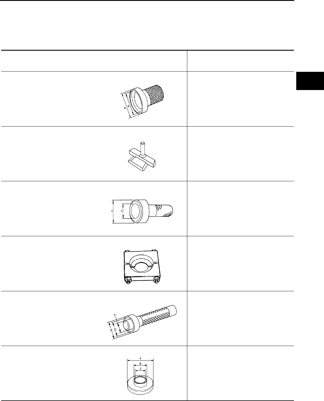
PREPARATION
DLN-367
< PREPARATION > [FRONT FINAL DRIVE: M205]
C
E
F
G
H
I
J
K
L
M
A
B
DLN
N
O
P
PREPARATION
PREPARATION
Special Service Tool INFOID:0000000003937439
The actual shapes of Kent-Moore tools may differ from those of special service tools illustrated here.
Tool number
(Kent-Moore No.)
Tool name
Description
ST35271000
(—)
Drift
Installing drive pinion front bearing outer
race.
a: 72 mm (2.83 in) dia.
b: 36 mm (1.42 in) dia.
KV10111100
(J-37228)
Seal cutter
Removing carrier cover
KV38100500
(J-25273)
Drift
Installing front oil seal.
a: 80 mm (3.15 in) dia.
b: 60 mm (2.36 in) dia.
ST30021000
(—)
Puller
• Removing side bearing inner race.
• Removing drive pinion rear bearing inner
race.
KV38100300
(J-25523)
Drift
Installing side bearing inner race.
a: 54 mm (2.13 in) dia.
b: 46 mm (1.81 in) dia.
c: 32 mm (1.26 in) dia.
ST30901000
(—)
Drift
Installing drive pinion rear bearing outer race.
A: 79 mm (3.11 in) dia.
B: 45 mm (1.77 in) dia.
C: 35.2 mm (1.39 in) dia.
ZZA0702D
NT046
ZZA0811D
ZZA0700D
ZZA1046D
SDIA0217J
Revision: October 2008
2009 Pathfinder
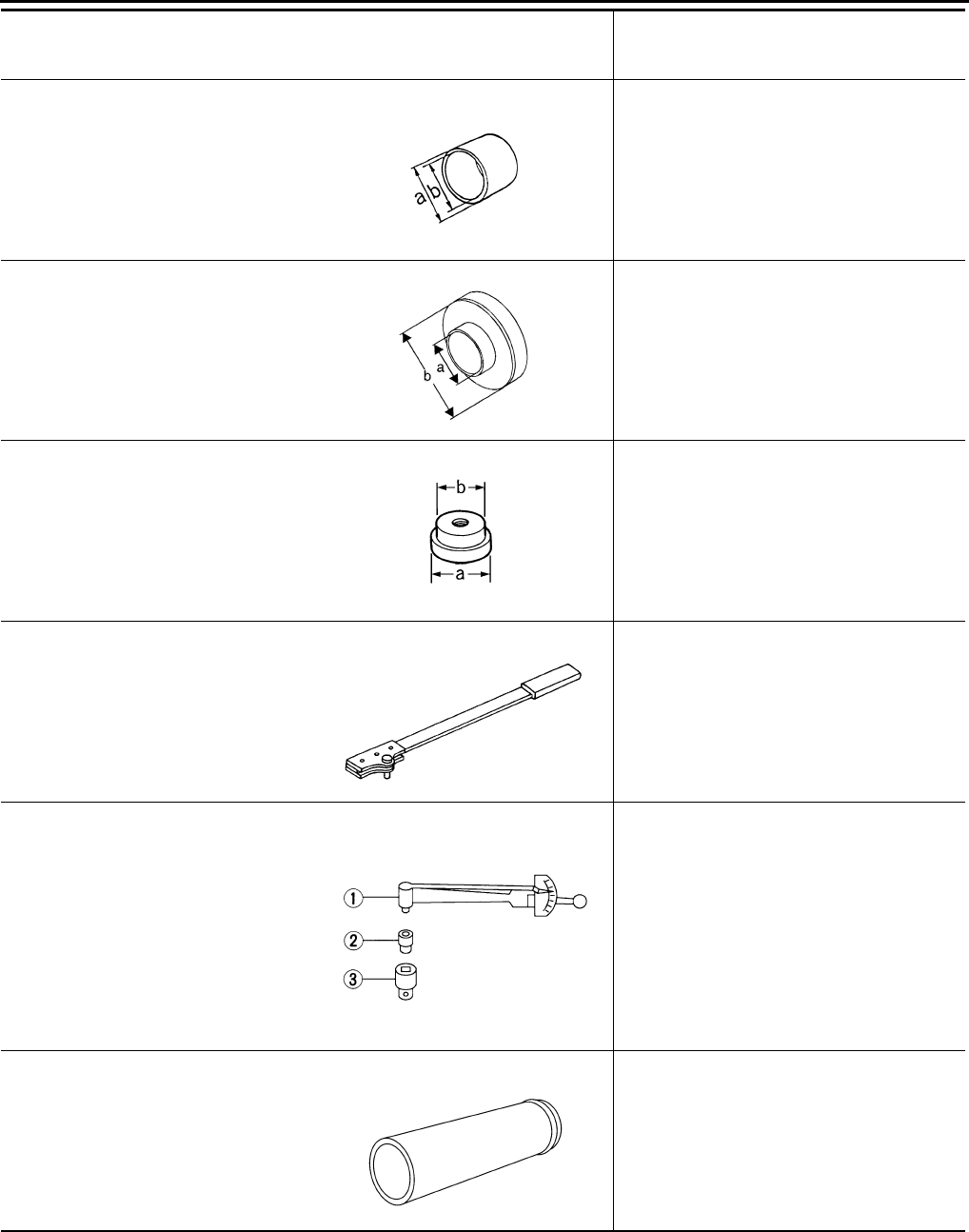
DLN-368
< PREPARATION > [FRONT FINAL DRIVE: M205]
PREPARATION
KV40104810
(—)
Drift
Installing drive pinion front bearing outer
race.
a: 68 mm (2.68 in) dia.
b: 55 mm (2.17 in) dia.
KV38102200
(—)
Drift
Installing front oil seal.
a: 90 mm (3.54 in) dia.
b: 55.3 mm (2.18 in) dia.
ST33081000
(—)
Adapter
Removing and installing side bearing inner
race.
a: 43 mm (1.69 in) dia.
b: 33.5 mm (1.32 in) dia.
KV38108300
(J-44195)
Companion flange wrench
Removing and installing drive pinion nut.
ST3127S000
(J-25765-A)
Preload gauge
1. GG91030000
(J-25765)
Torque wrench
2. HT62940000
( — )
Socket adapter (1/2″)
3. HT62900000
( — )
Socket adapter (3/8″)
Inspecting drive pinion bearing preload and
total preload
—
(C-4040)
Installer
Installing drive pinion rear bearing inner race.
Tool number
(Kent-Moore No.)
Tool name
Description
ZZA1003D
NT660
ZZA1000D
NT771
NT124
SDIA2607E
Revision: October 2008
2009 Pathfinder
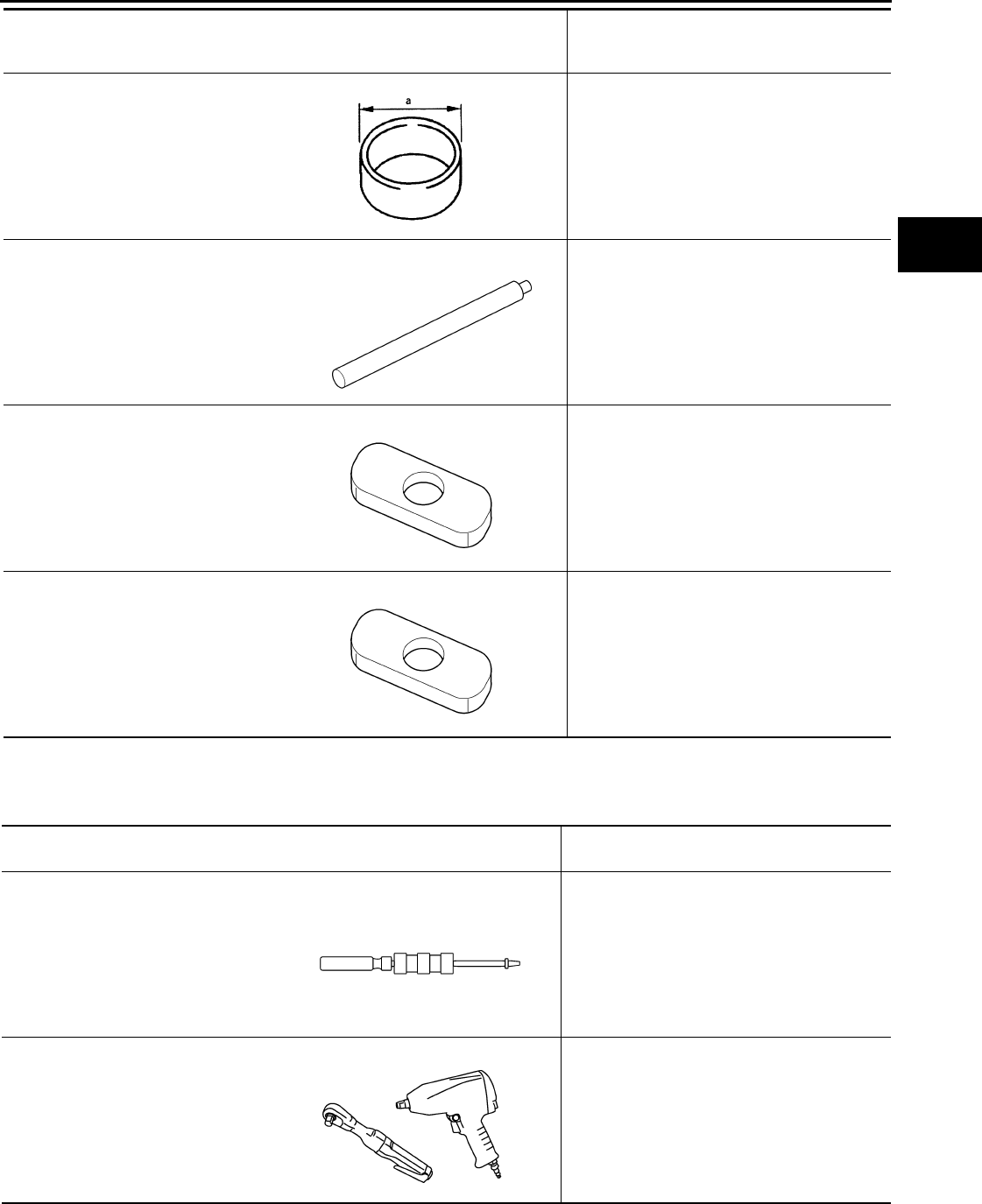
PREPARATION
DLN-369
< PREPARATION > [FRONT FINAL DRIVE: M205]
C
E
F
G
H
I
J
K
L
M
A
B
DLN
N
O
P
Commercial Service Tool INFOID:0000000003937440
KV40105230
(—)
Drift
Installing drive pinion rear bearing outer race.
a: 92 mm (3.62 in) dia.
—
(C-4171)
Handle
• Removing drive pinion front bearing outer
race
• Removing drive pinion rear bearing outer
race
—
(D-103)
Remover
Removing drive pinion front bearing outer
race
—
(C-4307)
Remover
Removing drive pinion rear bearing outer
race
Tool number
(Kent-Moore No.)
Tool name
Description
ZZA0898D
LDIA0134E
LDIA0135E
LDIA0135E
(Kent-Moore No.)
Tool name Description
(SP8P)
Slide hammer • Removing front oil seal
• Removing side oil seal
Power tool Loosening bolts and nuts
LDIA0133E
PBIC0190E
Revision: October 2008
2009 Pathfinder
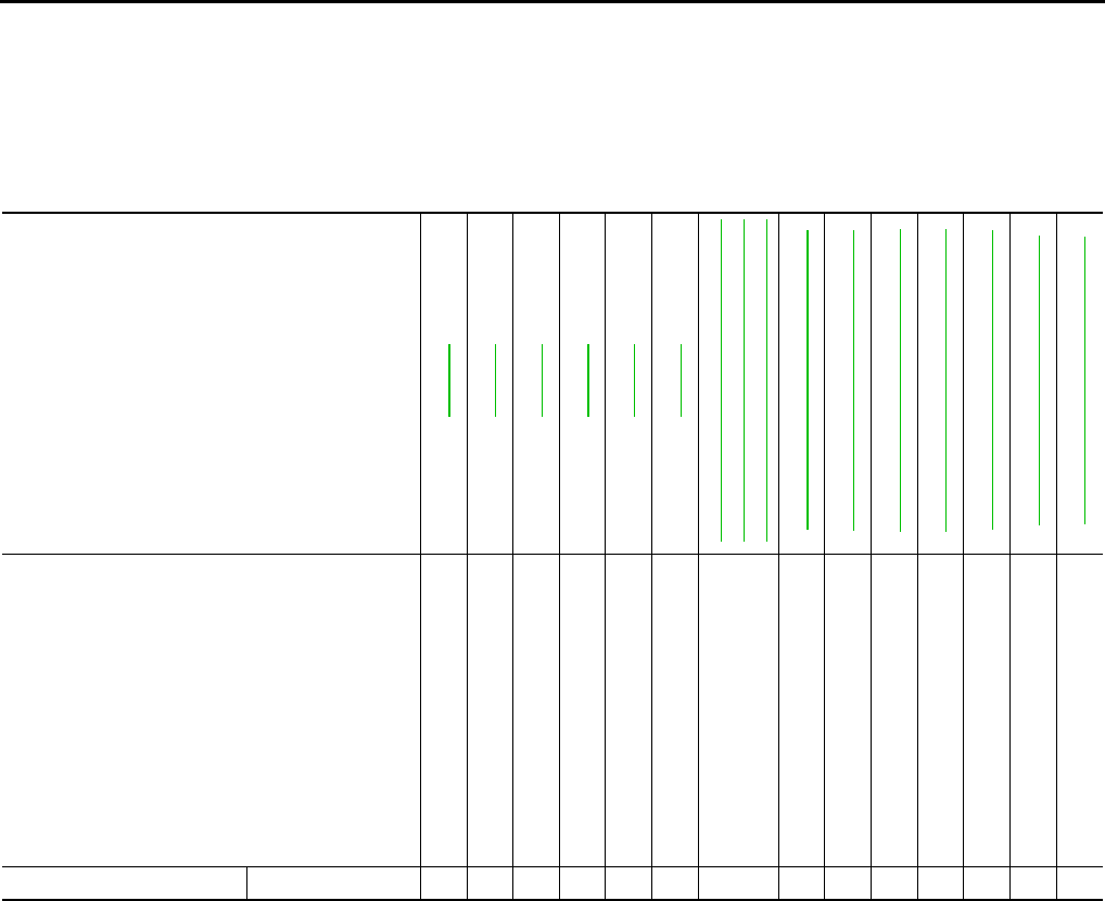
DLN-370
< FUNCTION DIAGNOSIS > [FRONT FINAL DRIVE: M205]
NOISE, VIBRATION AND HARSHNESS (NVH) TROUBLESHOOTING
FUNCTION DIAGNOSIS
NOISE, VIBRATION AND HARSHNESS (NVH) TROUBLESHOOTING
NVH Troubleshooting Chart INFOID:0000000003937441
Use the chart below to help you find the cause of the symptom. If necessary, repair or replace these parts.
×: Applicable
Reference page
DLN-378
DLN-378
DLN-378
DLN-378
DLN-378
DLN-371
DLN-307, "NVH Troubleshooting Chart"
DLN-315, "NVH Troubleshooting Chart"
DLN-324, "NVH Troubleshooting Chart"
FAX-4, "NVH Troubleshooting Chart"
FSU-5, "NVH Troubleshooting Chart"
WT-45, "NVH Troubleshooting Chart"
WT-45, "NVH Troubleshooting Chart"
FAX-4, "NVH Troubleshooting Chart"
BR-6, "NVH Troubleshooting Chart"
ST-9, "NVH Troubleshooting Chart"
Possible cause and SUSPECTED PARTS
Gear tooth rough
Gear contact improper
Tooth surfaces worn
Incorrect backlash
Companion flange excessive runout
Gear oil improper
PROPELLER SHAFT
FRONT AXLE
FRONT SUSPENSION
TIRES
ROAD WHEEL
DRIVE SHAFT
BRAKES
STEERING
Symptom Noise ×××××× × ×××××××
Revision: October 2008
2009 Pathfinder
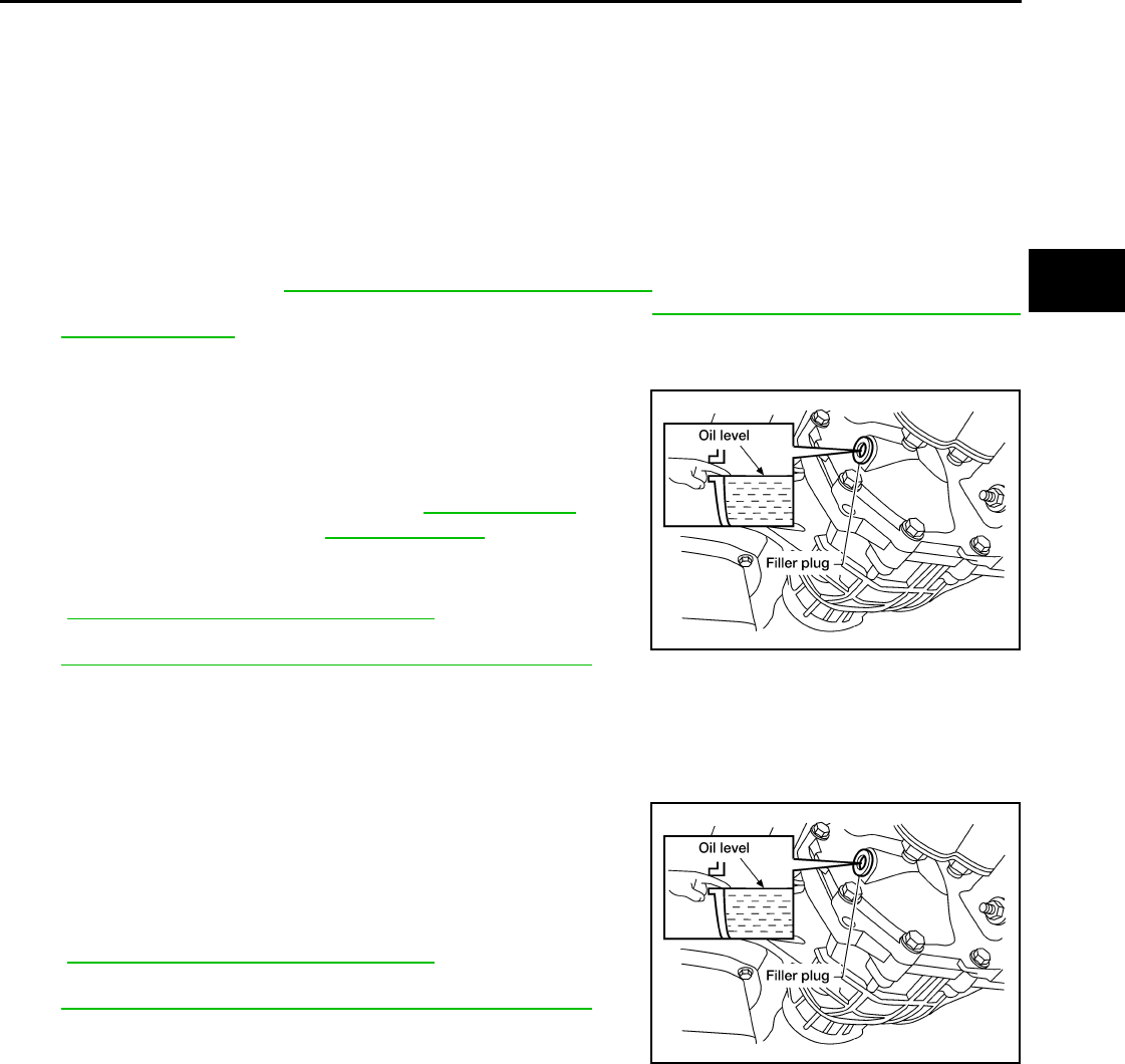
DIFFERENTIAL GEAR OIL
DLN-371
< ON-VEHICLE MAINTENANCE > [FRONT FINAL DRIVE: M205]
C
E
F
G
H
I
J
K
L
M
A
B
DLN
N
O
P
ON-VEHICLE MAINTENANCE
DIFFERENTIAL GEAR OIL
Changing Differential Gear Oil INFOID:0000000003937442
DRAINING
1. Stop the engine.
2. Remove the drain plug from the front final drive assembly to drain the differential gear oil.
3. Install the drain plug with sealant applied on the threads to the front final drive assembly. Tighten to the
specified torque. Refer to DLN-378, "Disassembly and Assembly".
• Use High Performance Thread Sealant or equivalent. Refer to GI-26, "Recommended Chemical Prod-
ucts and Sealants".
FILLING
1. Remove the filler plug from the front final drive assembly.
2. Fill the front final drive assembly with new differential gear oil
until the level reaches the specified level near the filler plug hole.
3. Install the filler plug with sealant applied on the threads to the
front final drive assembly. Tighten to the specified torque. Refer
to DLN-378, "Disassembly and Assembly".
• Use High Performance Thread Sealant or equivalent. Refer to
GI-26, "Recommended Chemical Products and Sealants".
Checking Differential Gear Oil INFOID:0000000003937443
DIFFERENTIAL GEAR OIL LEAKAGE AND LEVEL
1. Make sure that differential gear oil is not leaking from the front final drive assembly or around it.
2. Check the differential gear oil level from the filler plug hole as
shown.
CAUTION:
Do not start engine while checking differential gear oil level.
3. Install the filler plug with sealant applied on the threads to the
front final drive assembly. Tighten to the specified torque. Refer
to DLN-378, "Disassembly and Assembly".
• Use High Performance Thread Sealant or equivalent. Refer to
GI-26, "Recommended Chemical Products and Sealants".
Differential gear oil
grade and capacity : Refer to MA-12, "Fluids
and Lubricants".
LDIA0176E
LDIA0176E
Revision: October 2008
2009 Pathfinder
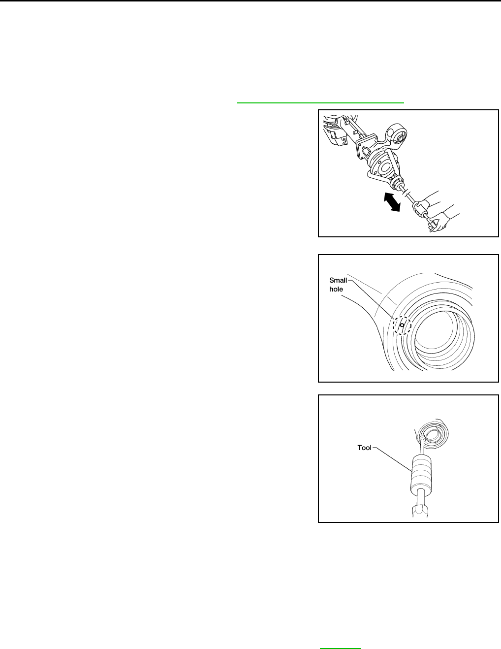
DLN-372
< ON-VEHICLE REPAIR > [FRONT FINAL DRIVE: M205]
SIDE OIL SEAL
ON-VEHICLE REPAIR
SIDE OIL SEAL
Removal and Installation INFOID:0000000003937444
REMOVAL
1. Remove the front final drive assembly. Refer to DLN-376, "Removal and Installation".
2. Remove the differential side shaft and differential side flange
using suitable tool.
3. Place a small hole in the side oil seal case using suitable tool.
4. Remove the side oil seal using Tool as shown.
INSTALLATION
1. Apply multi-purpose grease to the lips of the new side oil seal. Then drive the new side oil seal in evenly to
the gear carrier using suitable tool.
CAUTION:
• Do not reuse side oil seal.
• Do not incline the new side oil seal when installing.
• Apply multi-purpose grease to the lips of the new side oil seal.
2. Installation of the remaining components is in the reverse order of removal.
CAUTION:
Check the differential gear oil level after installation. Refer to DLN-371.
BDIA0006E
LDIA0129E
Tool number : SP8P
LDIA0130E
Revision: October 2008
2009 Pathfinder
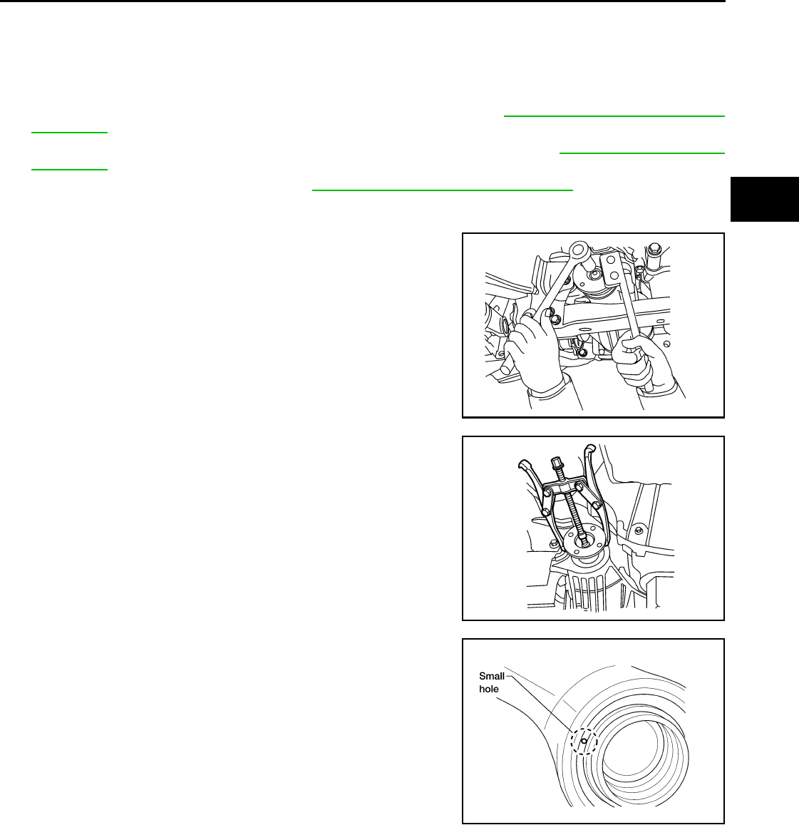
FRONT OIL SEAL
DLN-373
< ON-VEHICLE REPAIR > [FRONT FINAL DRIVE: M205]
C
E
F
G
H
I
J
K
L
M
A
B
DLN
N
O
P
FRONT OIL SEAL
Removal and Installation INFOID:0000000003937445
REMOVAL
1. Remove the drive shafts from the front final drive assembly. Refer to FAX-6, "VQ40DE : Removal and
Installation".
2. Remove the front propeller shaft from the front final drive assembly. Refer to DLN-309, "Removal and
Installation".
3. Measure the total preload torque. Refer to DLN-378, "Disassembly and Assembly".
NOTE:
Record the total preload torque measurement.
4. Remove the drive pinion lock nut using Tool.
5. Put matching marks on the companion flange and drive pinion
using paint.
CAUTION:
Use paint to make the matching marks. Do not damage the
companion flange or drive pinion.
6. Remove companion flange using suitable tool.
7. Place a small hole in the front oil seal case using suitable tool.
Tool number : KV38108300 (J-44195)
BDIA0001E
LDIA0171E
LDIA0129E
Revision: October 2008
2009 Pathfinder
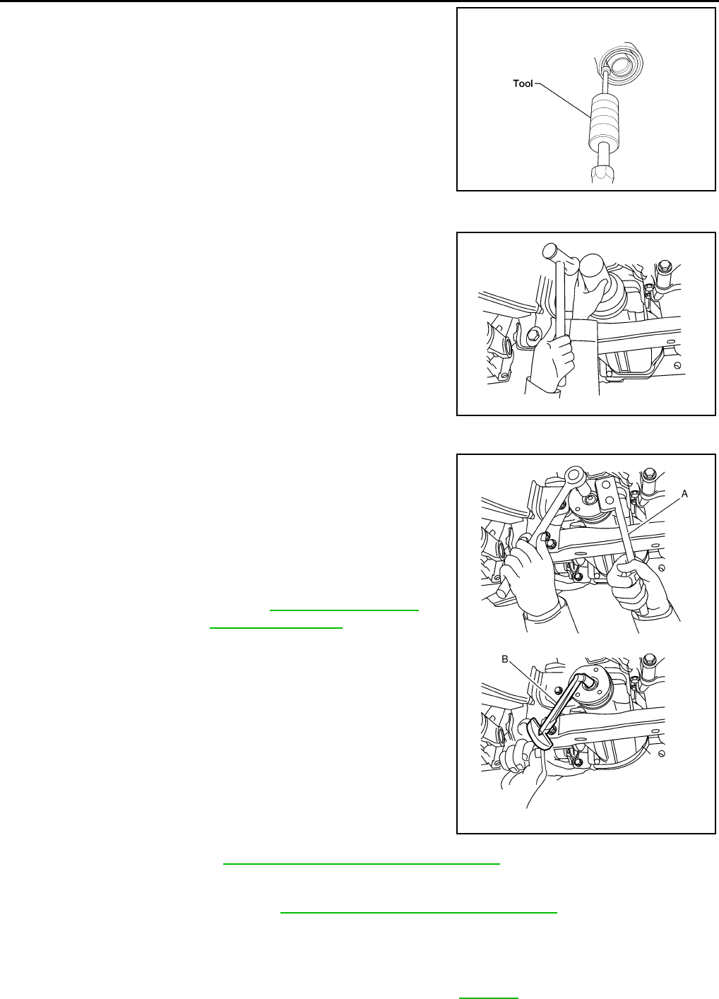
DLN-374
< ON-VEHICLE REPAIR > [FRONT FINAL DRIVE: M205]
FRONT OIL SEAL
8. Remove the front oil seal using Tool as shown.
INSTALLATION
1. Apply multi-purpose grease to the lips of the new front oil seal.
Then drive the new front oil seal in evenly to the gear carrier
using Tool.
CAUTION:
• Do not reuse front oil seal.
• Do not incline the new front oil seal when installing.
• Apply multi-purpose grease to the lips of the new front oil
seal.
2. Install the companion flange to the drive pinion while aligning the matching marks.
3. Apply anti-corrosive oil to the threads of the drive pinion and the
seating surface of the new drive pinion lock nut. Then adjust the
drive pinion lock nut tightening torque using Tool A, and check
the total preload torque using Tool B.
• The total preload torque should be within the total preload
torque specification. When not replacing the collapsible
spacer, it should also be equal to the measurement taken dur-
ing removal plus an additional 0.56 N·m (0.06 Kg-m, 5 in-lb).
• If the total preload torque is low, tighten the drive pinion lock
nut in 6.8 N·m (0.69 Kg-m, 5ft-lb) increments until the total pre-
load torque is met.
CAUTION:
• Do not reuse drive pinion lock nut.
• Apply anti-corrosive oil to the threads of the drive pinion
and the seating surface of the new drive pinion lock nut.
• Adjust the drive pinion lock nut tightening torque to the
lower limit first. Do not exceed the drive pinion lock nut
specified torque. Refer to DLN-378, "Disassembly and Assembly".
• Do not loosen drive pinion lock nut to adjust the total preload torque. If the drive pinion lock nut
torque or the total preload torque exceeds the specifications, replace the collapsible spacer and
tighten it again to adjust. Refer to DLN-378, "Disassembly and Assembly".
• After adjustment, rotate drive pinion back and forth 2 to 3 times to check for unusual noise, rota-
tion malfunction, and other malfunctions.
4. Installation of the remaining components is in the reverse order of removal.
CAUTION:
Check the differential gear oil level after installation. Refer to DLN-371.
Tool number : SP8P
LDIA0130E
Tool number : KV38100500 (J-25273)
BDIA0003E
Tool number A: KV38108300 (J-44195)
B: ST3127S000 (J-25765-A)
Total preload torque: Refer to DLN-378, "Disassem-
bly and Assembly".
WDIA0381E
Revision: October 2008
2009 Pathfinder
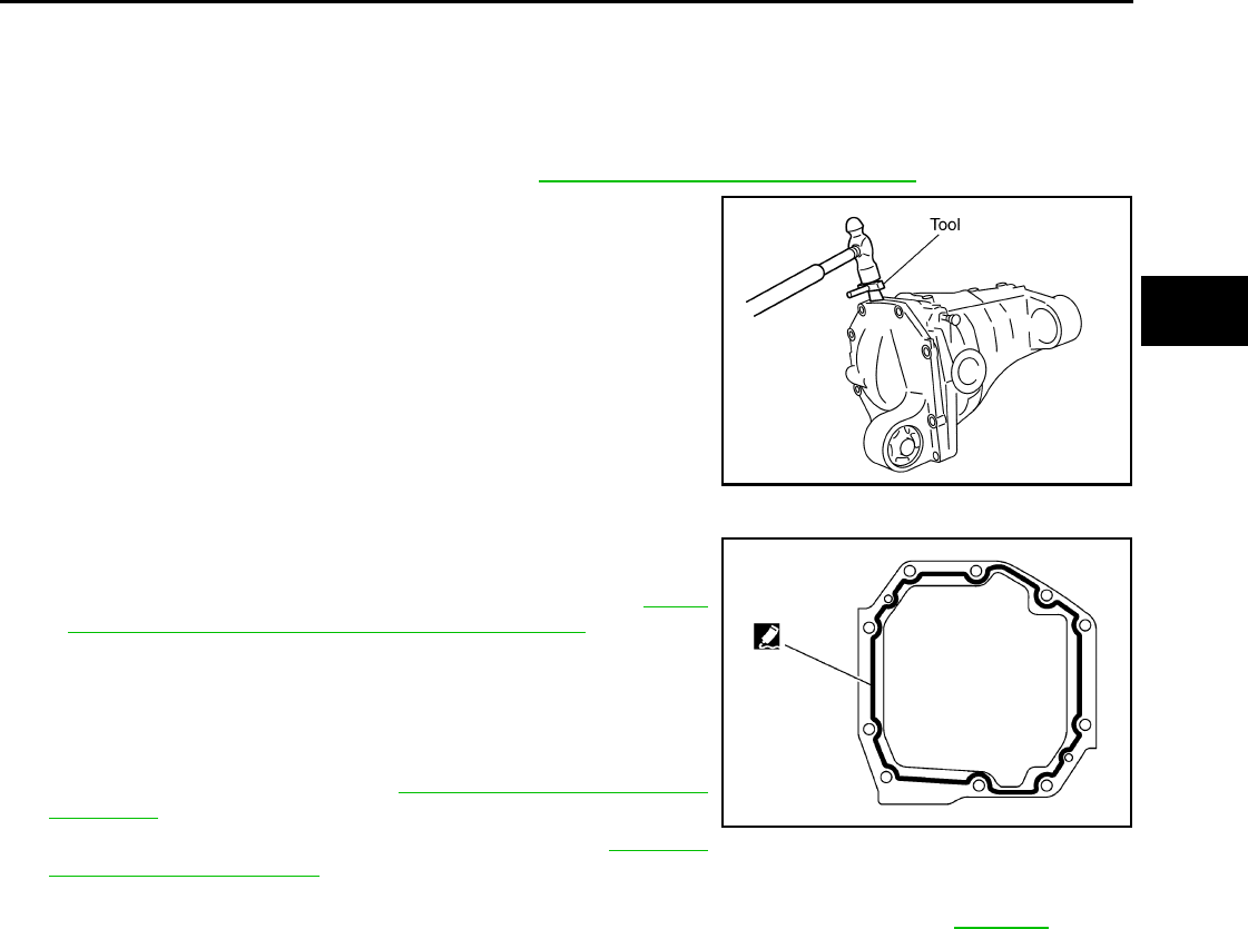
CARRIER COVER
DLN-375
< ON-VEHICLE REPAIR > [FRONT FINAL DRIVE: M205]
C
E
F
G
H
I
J
K
L
M
A
B
DLN
N
O
P
CARRIER COVER
Removal and Installation INFOID:0000000003937446
REMOVAL
1. Remove the front final drive assembly. Refer to DLN-376, "Removal and Installation".
2. Remove the carrier cover bolts and separate the carrier cover
from the gear carrier using Tool.
CAUTION:
• Do not damage the mating surface.
• Do not insert flat-bladed screwdriver, this will damage the
mating surface.
INSTALLATION
1. Apply 3 mm (0.12 in) bead of sealant to the mating surface of
the carrier cover as shown.
• Use Genuine Silicone RTV or equivalent. Refer to GI-26,
"Recommended Chemical Products and Sealants".
CAUTION:
Remove any old sealant adhering to the mating surfaces.
Also remove any moisture, oil, or foreign material adhering
to the application and mating surfaces.
2. Install the carrier cover to the gear carrier. Tighten the bolts to
the specified torque. Refer to DLN-378, "Disassembly and
Assembly".
3. Install the front final drive assembly. Refer to DLN-376,
"Removal and Installation".
CAUTION:
Fill the front final drive assembly with recommended differential gear oil. Refer to DLN-371.
Tool number : KV10111100 (J-37228)
PDIA0699E
SDIA3204E
Revision: October 2008
2009 Pathfinder
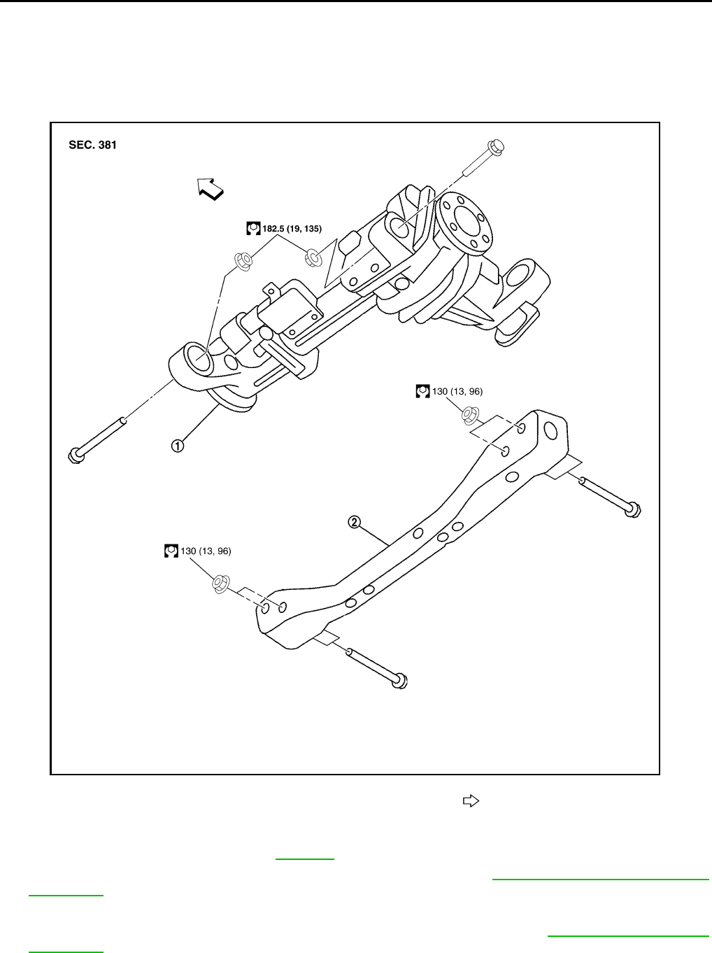
DLN-376
< REMOVAL AND INSTALLATION > [FRONT FINAL DRIVE: M205]
FRONT FINAL DRIVE
REMOVAL AND INSTALLATION
FRONT FINAL DRIVE
Removal and Installation INFOID:0000000003937447
REMOVAL
1. Drain the differential gear oil. Refer to DLN-371.
2. Remove the drive shafts from the front final drive assembly. Refer to FAX-6, "VQ40DE : Removal and
Installation".
3. Remove the front cross member.
4. Remove the front propeller shaft from the front final drive assembly. Refer to DLN-309, "Removal and
Installation".
5. Disconnect the vent hose from the front final drive assembly.
6. Support the front final drive assembly using a suitable jack.
1. Front final drive assembly 2. Front cross member Front
AWDIA0019G
B
Revision: October 2008
2009 Pathfinder
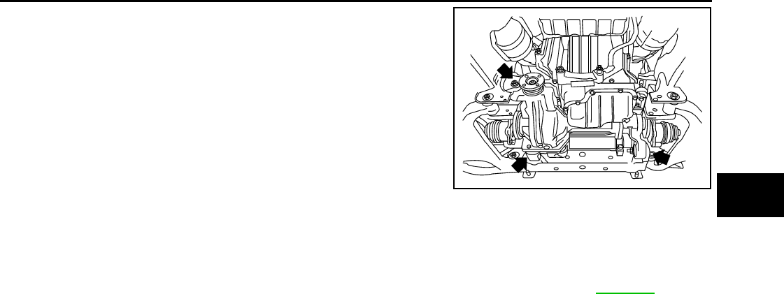
FRONT FINAL DRIVE
DLN-377
< REMOVAL AND INSTALLATION > [FRONT FINAL DRIVE: M205]
C
E
F
G
H
I
J
K
L
M
A
B
DLN
N
O
P
7. Remove the front final drive assembly bolts, then remove the
front final drive assembly.
CAUTION:
Support the front final drive assembly while removing using
a suitable jack.
INSTALLATION
Installation is in the reverse order of removal.
CAUTION:
• Make sure there are no pinched or restricted areas on the breather hose caused by folding or bend-
ing when installing it.
• Fill the front final drive assembly with differential gear oil after installation. Refer to DLN-371.
BDIA0008E
Revision: October 2008
2009 Pathfinder
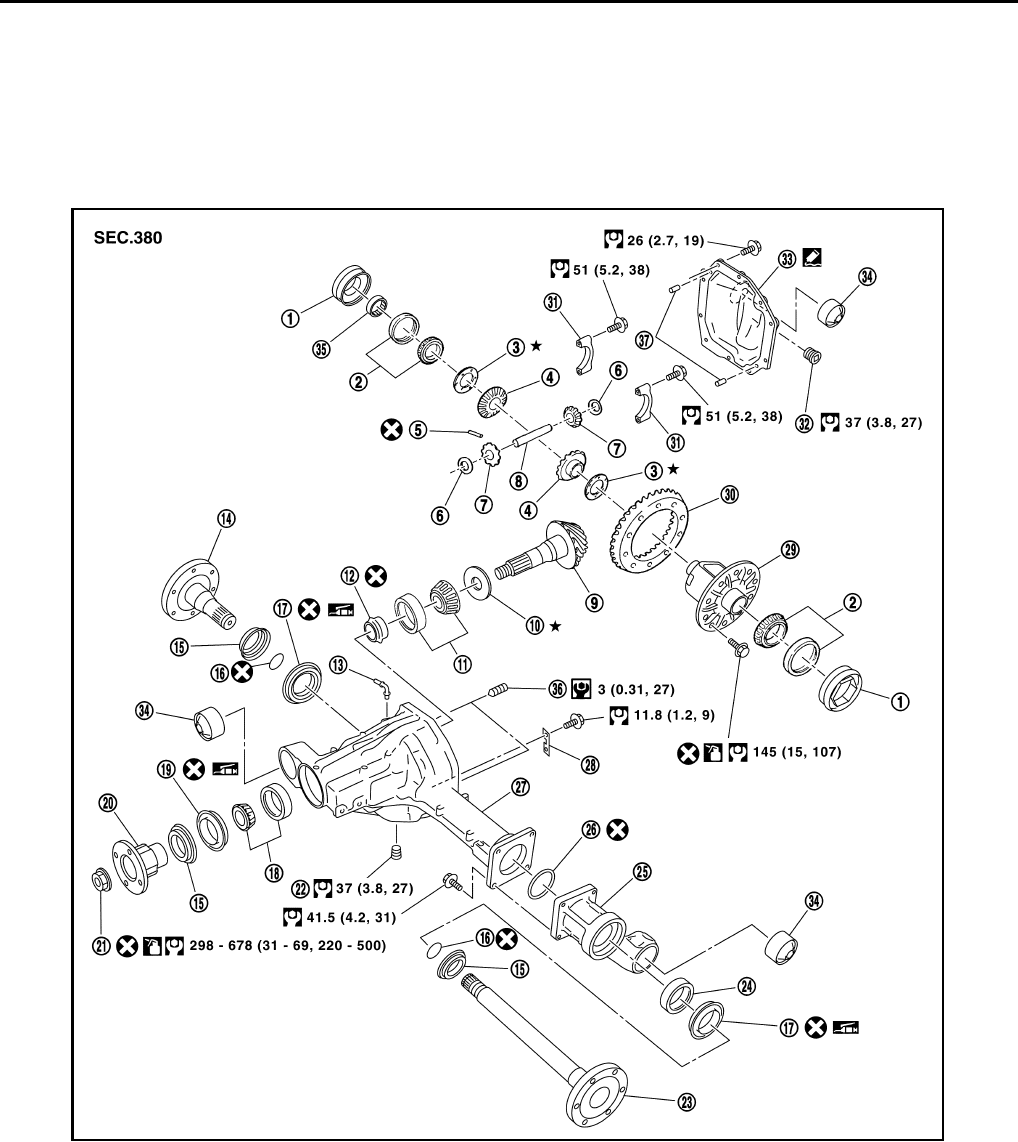
DLN-378
< DISASSEMBLY AND ASSEMBLY > [FRONT FINAL DRIVE: M205]
FRONT FINAL DRIVE
DISASSEMBLY AND ASSEMBLY
FRONT FINAL DRIVE
Disassembly and Assembly INFOID:0000000003937448
COMPONENTS
1. Side bearing adjuster 2. Side bearing 3. Side gear thrust washer
4. Side gear 5. Lock pin 6. Pinion mate thrust washer
7. Pinion mate gear 8. Pinion mate shaft 9. Drive pinion
10. Drive pinion height adjusting
washer
11. Drive pinion rear bearing 12. Collapsible spacer
13. Breather tube 14. Differential side flange 15. Dust shield
16. Circular clip 17. Side oil seal 18. Drive pinion front bearing
19. Front oil seal 20. Companion flange 21. Drive pinion lock nut
22. Drain plug 23. Differential side shaft 24. Differential side shaft bearing
25. Extension tube 26. O-ring 27. Gear carrier
AWDIA0020G
B
Revision: October 2008
2009 Pathfinder
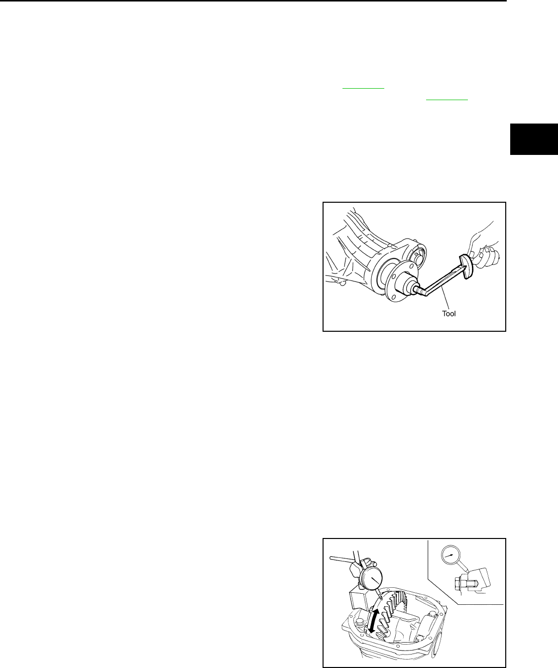
FRONT FINAL DRIVE
DLN-379
< DISASSEMBLY AND ASSEMBLY > [FRONT FINAL DRIVE: M205]
C
E
F
G
H
I
J
K
L
M
A
B
DLN
N
O
P
ASSEMBLY INSPECTION AND ADJUSTMENT
• Drain the differential gear oil before inspection and adjustment. Refer to DLN-371.
• Remove and install the carrier cover as necessary for inspection and adjustment. Refer to DLN-375.
Total Preload Torque
1. Install the differential side shaft and differential side flange if necessary.
CAUTION:
The differential side shaft and differential side flange must be installed in order to measure total
preload torque.
2. Rotate the drive pinion back and forth 2 to 3 times to check for unusual noise and rotation malfunction.
3. Rotate the drive pinion at least 20 times to check for smooth operation of the bearings.
4. Measure total preload torque using Tool.
NOTE:
Total preload torque = Drive pinion bearing preload torque +
Side bearing preload torque
• If the measured value is out of the specification, check and adjust each part. Adjust the drive pinion
bearing preload torque first, then adjust the side bearing preload torque.
Drive Gear Runout
1. Fit a dial indicator to the drive gear back face.
2. Rotate the drive gear to measure runout.
• If the runout is outside of the limit, check the condition of the drive
gear assembly. Foreign material may be caught between the drive
gear and differential case, or the differential case or drive gear may
be deformed.
CAUTION:
Replace drive gear and drive pinion as a set.
Tooth Contact
28. Plate 29. Differential case 30. Drive gear
31. Side bearing cap 32. Filler plug 33. Carrier cover
34. Bushing 35. Bearing 36 Screw
37 Dowel pin
Tool number : ST3127S000 (J-25765-A)
Total preload torque:
2.98 - 4.76 N·m (0.31 - 0.48 kg-m, 27 - 42 in-lb)
PDIA0697E
If the total preload torque is greater than specification
On drive pinion bearings: Replace the collapsible spacer.
On side bearings: Loosen the side bearing adjuster by the same amount on each
side.
If the total preload torque is less than specification
On drive pinion bearings: Tighten the drive pinion lock nut.
On side bearings: Tighten the side bearing adjuster by the same amount on each
side.
Runout limit: 0.08 mm (0.0031 in) or less
SPD886
Revision: October 2008
2009 Pathfinder
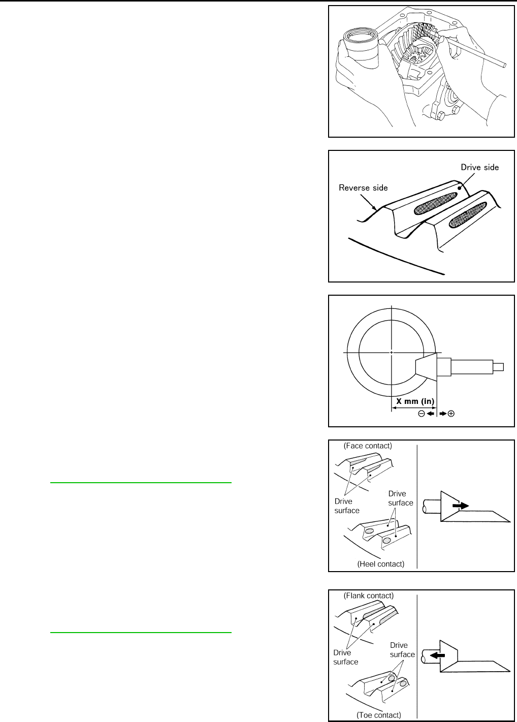
DLN-380
< DISASSEMBLY AND ASSEMBLY > [FRONT FINAL DRIVE: M205]
FRONT FINAL DRIVE
1. Apply red lead to the drive gear.
NOTE:
Apply red lead to both faces of three to four gears, at four loca-
tions evenly spaced on the drive gear.
2. Rotate the drive gear back and forth several times. Then check
for correct drive pinion to drive gear tooth contact as shown.
CAUTION:
Check tooth contact on drive side and reverse side.
3. If the tooth contact is improperly adjusted, follow the procedure
below to adjust the drive pinion height (dimension X).
• If the tooth contact is near the face (face contact), or near the heel
(heel contact), use a thicker drive pinion height adjusting washer to
move drive pinion closer to the drive gear.
Refer to DLN-395, "Inspection and Adjustment".
• If the tooth contact is near the flank (flank contact), or near the toe
(toe contact), use a thinner drive pinion height adjusting washer to
move the drive pinion farther from the drive gear.
Refer to DLN-395, "Inspection and Adjustment".
SPD357
SDIA0570E
SDIA0517E
PDIA0440E
PDIA0441E
Revision: October 2008
2009 Pathfinder
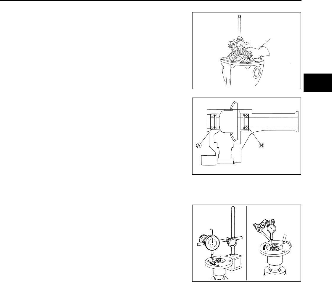
FRONT FINAL DRIVE
DLN-381
< DISASSEMBLY AND ASSEMBLY > [FRONT FINAL DRIVE: M205]
C
E
F
G
H
I
J
K
L
M
A
B
DLN
N
O
P
Backlash
1. Fit a dial indicator to the drive gear face to measure the back-
lash.
• If the backlash is outside of the specification, adjust each side
bearing adjuster.
CAUTION:
Do not change the side bearing adjusters by different
amounts as it will change the side bearing preload torque.
Companion Flange Runout
1. Rotate companion flange and check for runout on the compan-
ion flange face (inner side of the bolt holes) and companion
flange inner side (socket diameter) using suitable tool.
2. If the runout is outside the runout limit, follow the procedure
below to adjust.
a. Rotate the companion flange on the drive pinion by 90°, 180°
and 270° while checking for the position where the runout is minimum.
b. If the runout is still outside of the runout limit after the companion flange has been rotated on the drive pin-
ion, possible cause could be an assembly malfunction of drive pinion and drive pinion bearing or a mal-
functioning drive pinion bearing.
c. If the runout is still outside of the runout limit after repair of the assembly of drive pinion and drive pinion
bearing or drive pinion bearing, replace the companion flange.
DISASSEMBLY
Differential Assembly
1. Drain the differential gear oil if necessary.
Backlash: 0.13 - 0.18 mm (0.0051 - 0.0071 in)
SPD513
If the backlash is greater than specification:
Loosen side bearing adjuster A and tighten side bear-
ing adjuster B by the same amount.
If the backlash is less than specification:
Loosen side bearing adjuster B and tighten side bear-
ing adjuster A by the same amount.
SDIA2262E
Runout limit
Companion flange face: 0.10 mm (0.0039 in)
Companion flange inner side: 0.13 mm (0.0051 in)
SDIA2078E
Revision: October 2008
2009 Pathfinder
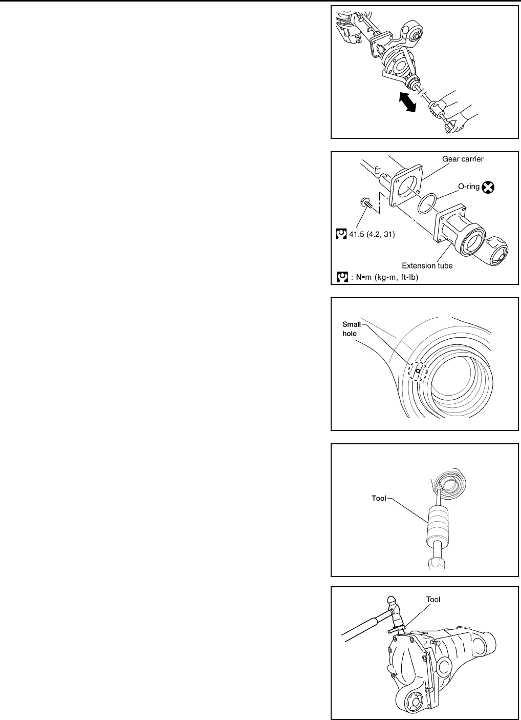
DLN-382
< DISASSEMBLY AND ASSEMBLY > [FRONT FINAL DRIVE: M205]
FRONT FINAL DRIVE
2. Remove the differential side shaft and differential side flange
using suitable tool.
3. Remove the extension tube and O-ring from the gear carrier.
4. Place a small hole in the side oil seal case using suitable tool.
5. Remove the side oil seal using Tool as shown.
6. Remove the carrier cover bolts and separate the carrier cover
from the gear carrier using Tool.
CAUTION:
• Do not damage the mating surface.
• Do not insert flat-bladed screwdriver, this will damage the
mating surface.
BDIA0006E
SDIA3205E
LDIA0129E
Tool number : — SP8P
LDIA0130E
Tool number : KV10111100 (J-37228)
PDIA0699E
Revision: October 2008
2009 Pathfinder
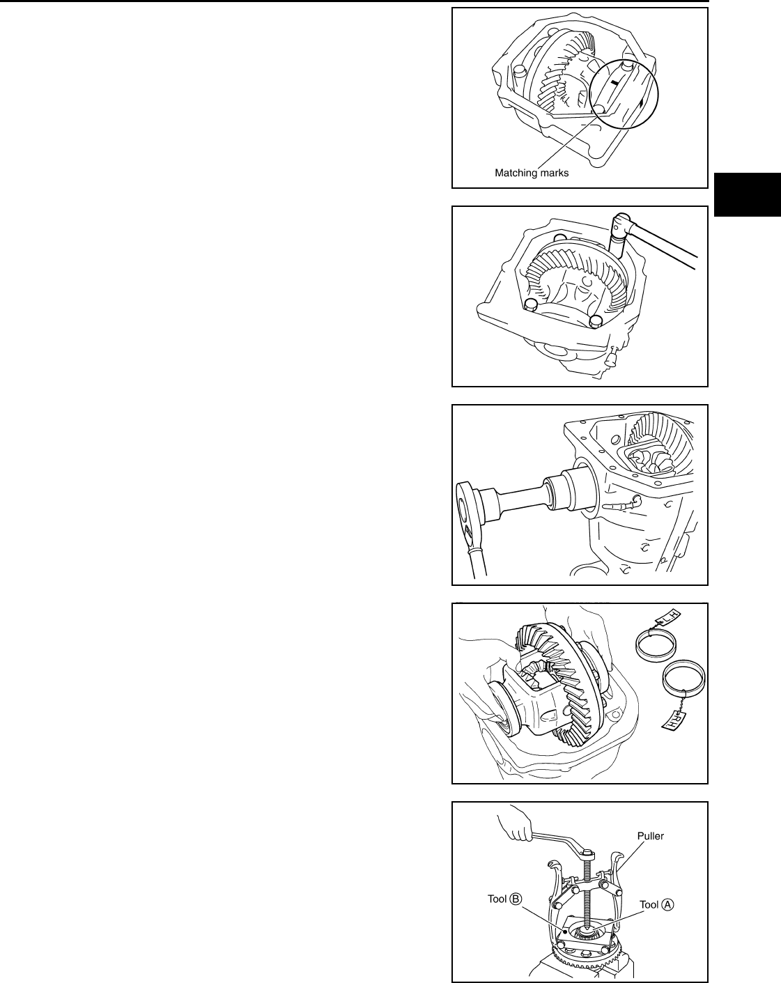
FRONT FINAL DRIVE
DLN-383
< DISASSEMBLY AND ASSEMBLY > [FRONT FINAL DRIVE: M205]
C
E
F
G
H
I
J
K
L
M
A
B
DLN
N
O
P
7. For proper reinstallation, paint matching marks on one side of
the side bearing cap and gear carrier.
CAUTION:
• For matching marks, use paint. Do not damage side bear-
ing cap or gear carrier.
• Side bearing caps are line-board during manufacture. The
matching marks are used to reinstall them in their original
positions.
8. Remove the side bearing caps.
9. Remove the side bearing adjuster.
10. Lift the differential case assembly out of the gear carrier.
CAUTION:
Keep side bearing outer races together with side bearing
inner races. Do not mix them up.
11. Remove side bearing inner race using Tools as shown.
CAUTION:
• Do not remove side bearing inner race unless it is being
replaced.
• Place copper plates between the vise and the side bearing
inner race and drive gear to prevent damage.
• Engage puller jaws in groove to prevent damage to bear-
ing.
PDIA0700E
PDIA0701E
SDIA2230E
SPD527
Tool number A: ST33081000 ( — )
B: ST30021000 ( — )
SDIA2237E
Revision: October 2008
2009 Pathfinder
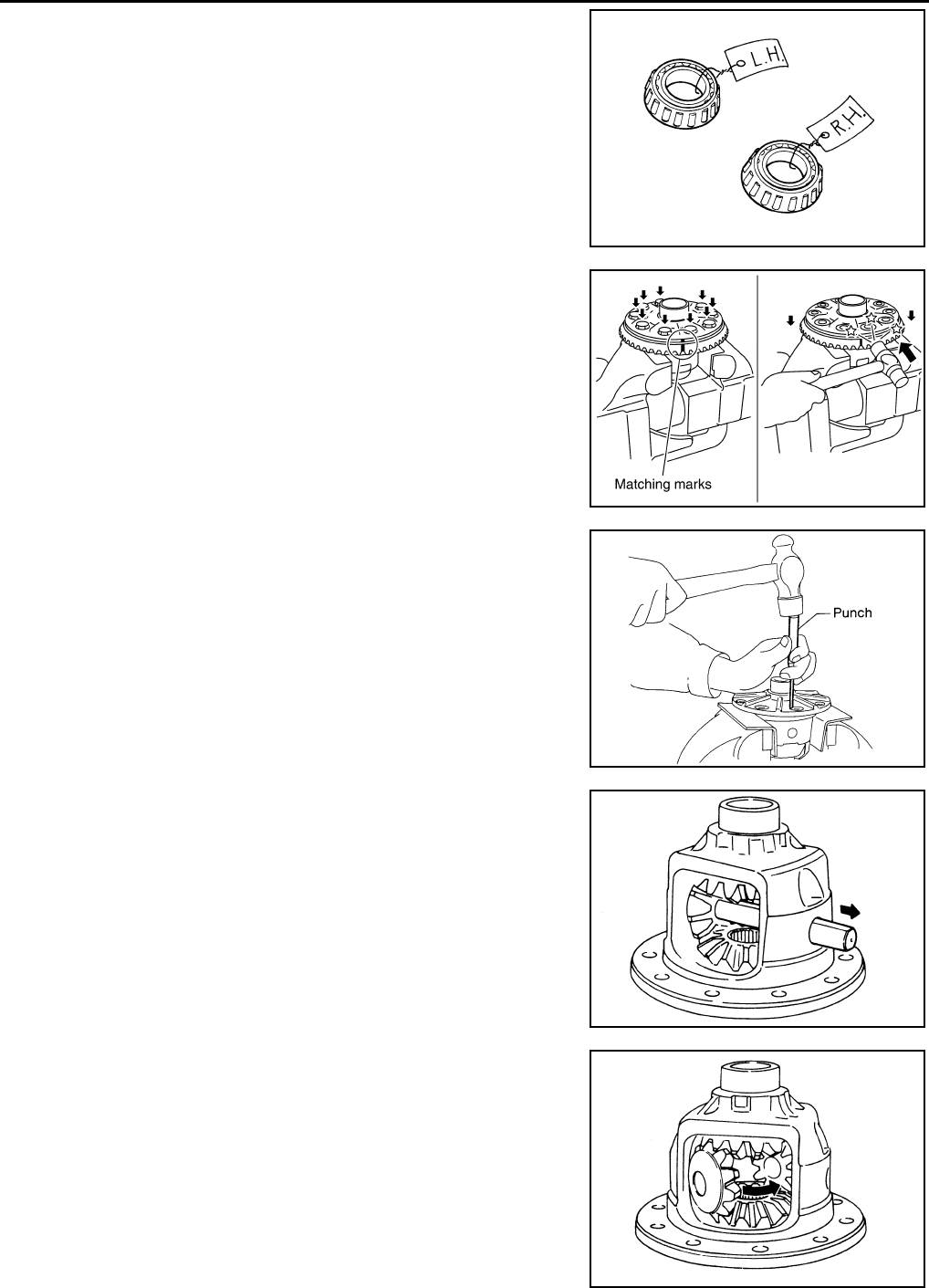
DLN-384
< DISASSEMBLY AND ASSEMBLY > [FRONT FINAL DRIVE: M205]
FRONT FINAL DRIVE
• Keep side bearing outer races together with side bearing
inner races. Do not mix them up.
12. For proper reinstallation, paint matching marks on the differential
case and drive gear.
CAUTION:
Use paint for matching marks. Do not damage differential
case or drive gear.
13. Remove the drive gear bolts.
14. Tap the drive gear off the differential case using suitable tool.
CAUTION:
Tap evenly all around to keep drive gear from bending.
15. Remove the lock pin of the pinion mate shaft from the drive gear
side using suitable tool.
16. Remove the pinion mate shaft.
17. Turn the pinion mate gear, then remove the pinion mate gear,
pinion mate thrust washer, side gear and side gear thrust
washer from the differential case.
SPD022
PDIA0496E
SPD025
SDIA0031J
SDIA0032J
Revision: October 2008
2009 Pathfinder
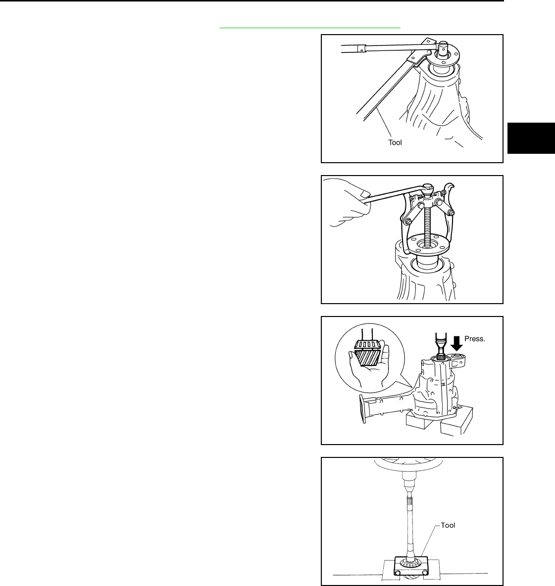
FRONT FINAL DRIVE
DLN-385
< DISASSEMBLY AND ASSEMBLY > [FRONT FINAL DRIVE: M205]
C
E
F
G
H
I
J
K
L
M
A
B
DLN
N
O
P
Drive Pinion Assembly
1. Remove the differential assembly. Refer to DLN-345, "Disassembly and Assembly".
2. Remove the drive pinion lock nut using Tool.
3. Put matching marks on the companion flange and drive pinion
using paint.
CAUTION:
Use paint to make the matching marks. Do not damage the
companion flange or drive pinion.
4. Remove the companion flange using suitable tool.
5. Press the drive pinion assembly (with rear inner bearing race
and collapsible spacer) out of the gear carrier.
CAUTION:
Do not drop drive pinion assembly.
6. Remove the drive pinion rear bearing inner race and drive pinion
height adjusting washer using Tool.
Tool number : KV38108300 (J-44195)
PDIA0702E
PDIA0703E
SDIA2234E
Tool number : ST30021000 ( — )
S-PD179
Revision: October 2008
2009 Pathfinder
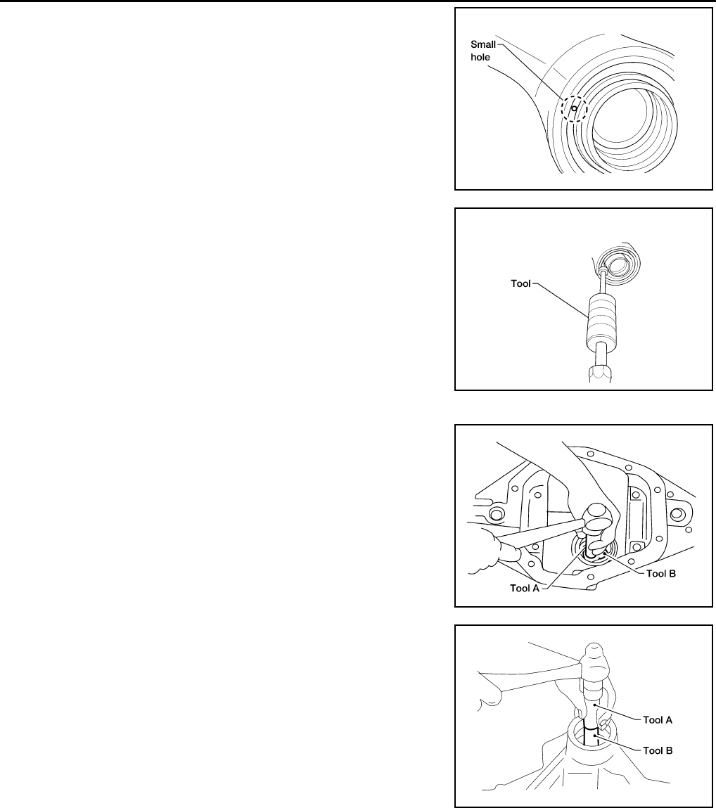
DLN-386
< DISASSEMBLY AND ASSEMBLY > [FRONT FINAL DRIVE: M205]
FRONT FINAL DRIVE
7. Place a small hole in the front oil seal case using suitable tool.
8. Remove the front oil seal using Tool as shown.
9. Remove the drive pinion front bearing inner race.
10. Remove the drive pinion front bearing outer race using Tool as
shown. Locate the driver on the back edge of the drive pinion
front bearing outer race, then drive the drive pinion front bearing
outer race out.
CAUTION:
Do not damage gear carrier.
11. Remove the drive pinion rear bearing outer race using Tool as
shown. Locate the driver on the back edge of the drive pinion
rear bearing outer race, then drive the drive pinion rear bearing
outer race out.
CAUTION:
Do not damage gear carrier.
INSPECTION AFTER DISASSEMBLY
Clean the disassembled parts. Then inspect the parts for wear or damage. If wear or damage are found, follow
the measures below.
Drive Pinion and Drive Gear
• If the drive pinion and drive gear teeth do not mesh or line-up correctly, determine the cause and adjust,
repair, or replace as necessary.
• If the drive pinion or drive gear are worn, cracked, damaged, pitted or chipped (by friction) noticeably,
replace with new drive pinion and drive gear.
LDIA0129E
Tool number : — SP8P
LDIA0130E
Tool number A: — C-4171
B: — D-103
LDIA0131E
Tool number A: — C-4171
B: — C-4307
LDIA0132E
Revision: October 2008
2009 Pathfinder
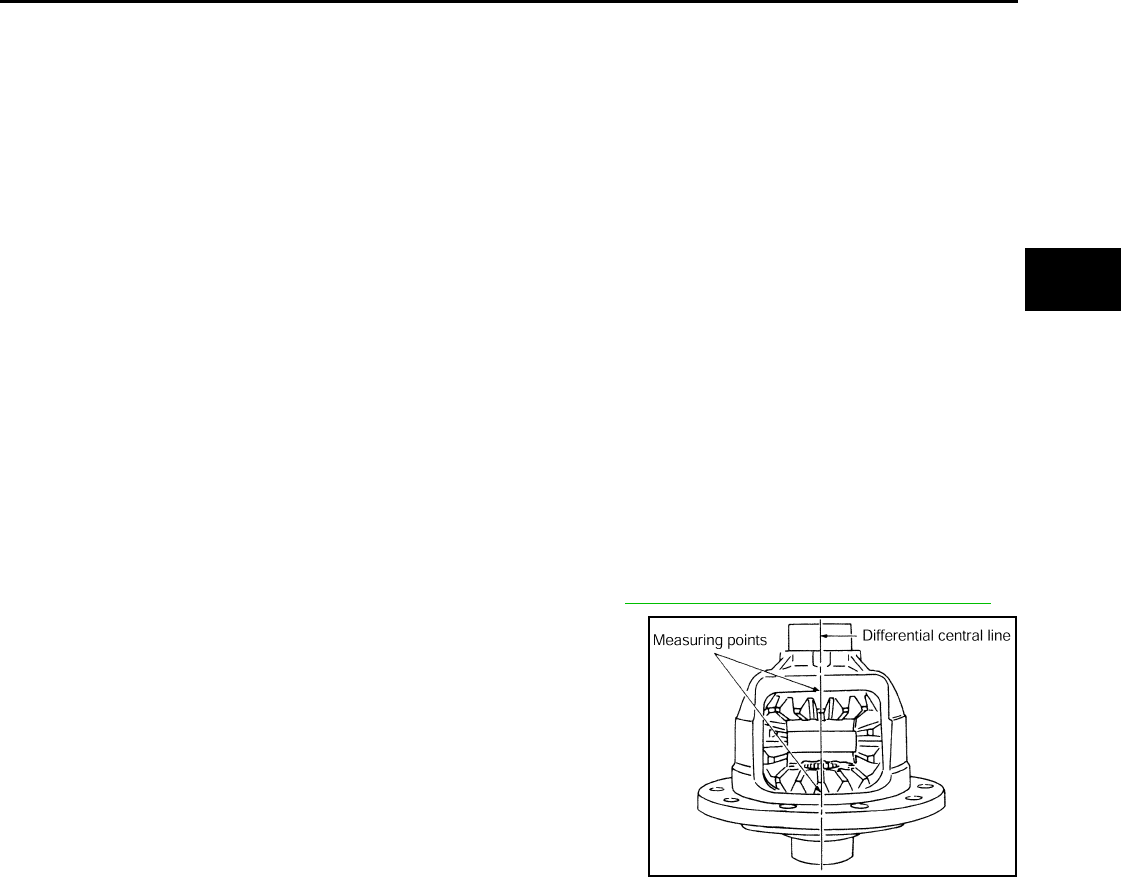
FRONT FINAL DRIVE
DLN-387
< DISASSEMBLY AND ASSEMBLY > [FRONT FINAL DRIVE: M205]
C
E
F
G
H
I
J
K
L
M
A
B
DLN
N
O
P
• Drive pinion and drive gear are supplied in matched sets only. Matching numbers on both drive pinion and
drive gear are etched for verification. If a new drive pinion and drive gear set are being used, verify the num-
bers of each drive pinion and drive gear before proceeding with assembly.
Bearing
• If bearings are chipped (by friction), pitted, worn, rusted, scratched, or unusual noise is coming from bearing,
replace with new bearing assembly (as a new set).
• Bearing must be replaced with a new one whenever disassembled.
Side Gear and Pinion Mate Gear
• If any cracks or damage are found on the surface of the teeth, replace with new one.
• If any worn or chipped marks are found on the side of the side gear and pinion mate gear which contact the
thrust washer, replace with new one.
• Replace both side gear and pinion mate gear as a set when replacing side gear or pinion mate gear.
Side Gear Thrust Washer and Pinion Mate Thrust Washer
• If any chips (by friction), damage, or unusual wear are found, replace with new one.
Gear Carrier
• If any wear or cracks are found on the contact sides of gear carrier, replace with new one.
Companion Flange
• If any chips (about 0.1mm, 0.004 in) or other damage on the companion flange surface which contacts the
front oil seal lips are found, replace with new one.
ADJUSTING AND SELECTING WASHERS
Side Gear Back Clearance
• Assemble the differential parts if they are disassembled. Refer to DLN-345, "Disassembly and Assembly"
1. Place the differential case straight up so that the side gear to be
measured is upward.
PDIA0460E
Revision: October 2008
2009 Pathfinder
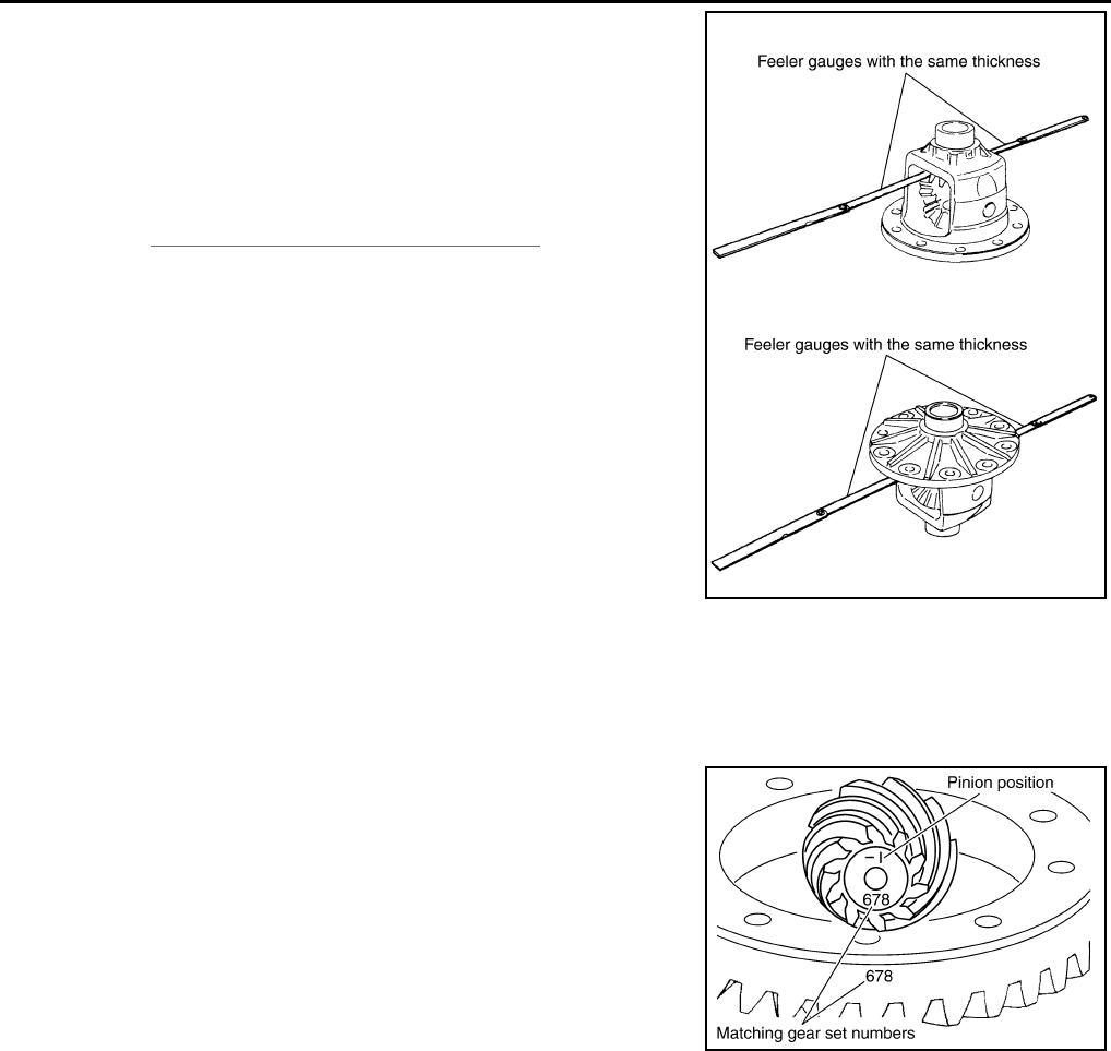
DLN-388
< DISASSEMBLY AND ASSEMBLY > [FRONT FINAL DRIVE: M205]
FRONT FINAL DRIVE
2. Using feeler gauges, measure the clearance between the side
gear back and differential case at three different points, while
rotating the side gear. Average the three readings to calculate
the clearance. (Measure the clearance of the other side as well.)
• If the side gear back clearance is outside of the specification,
use a thicker or thinner side gear thrust washer to adjust.
Refer to DLN-395, "Inspection and Adjustment".
CAUTION:
• Insert feeler gauges with the same thickness on both
sides to prevent side gear from tilting.
• Each gear should rotate smoothly without excessive
resistance during differential motion.
• Select a side gear thrust washer for right and left individu-
ally.
NOTE:
Side gear back clearance is clearance between side gear and differential case for adjusting side gear
backlash.
Drive Pinion Height
• Drive gear and drive pinion are supplied in matched sets only.
Matching numbers on both drive pinion and drive gear are etched
for verification. If a new gear set is being used, verify the numbers
of each drive pinion and drive gear before proceeding with assem-
bly.
• The mounting distance from the centerline of the drive gear to the back face of the drive pinion for the M205
final drive assembly is 103.5 mm (4.0748 inches).
On the button end of each drive pinion, there is etched a plus (+) number, a minus (-) number, or a zero (0),
which indicates the best running position for each particular gear set. This dimension is controlled by a
selective drive pinion height adjusting washer between the drive pinion rear bearing inner race and drive pin-
ion.
For example: If a drive pinion is etched m+8 (+3), it would require 0.08 mm (0.003 inch) less drive pinion
height adjusting washer than a drive pinion etched “0”. This means decreasing drive pinion height adjusting
washer thickness; increases the mounting distance of the drive pinion to 103.6 mm (4.0778 inches). If a
drive pinion is etched m-8 (-3), it would require adding 0.08mm (0.003 inch) more to the drive pinion height
adjusting washer than would be required if the drive pinion were etched “0”. By adding 0.08 mm (0.003 inch),
the mounting distance of the drive pinion was decreased to 103.4 mm (4.0718 inches) which is just what a
m-8 (-3) etching indicated.
• To change the drive pinion height, use different drive pinion height adjusting washers which come in different
thickness.
• Use the following tables as a guide for selecting the correct drive pinion height adjusting washer thickness to
add or subtract from the old drive pinion height adjusting washer.
Side gear back clearance: 0.20 mm (0.0079 in) or less
If the side gear back clearance is greater than
specification:
Use a thicker side gear thrust washer.
If the side gear back clearance is less than spec-
ification:
Use a thinner side gear thrust washer.
PDIA0576E
SDIA2241E
Revision: October 2008
2009 Pathfinder
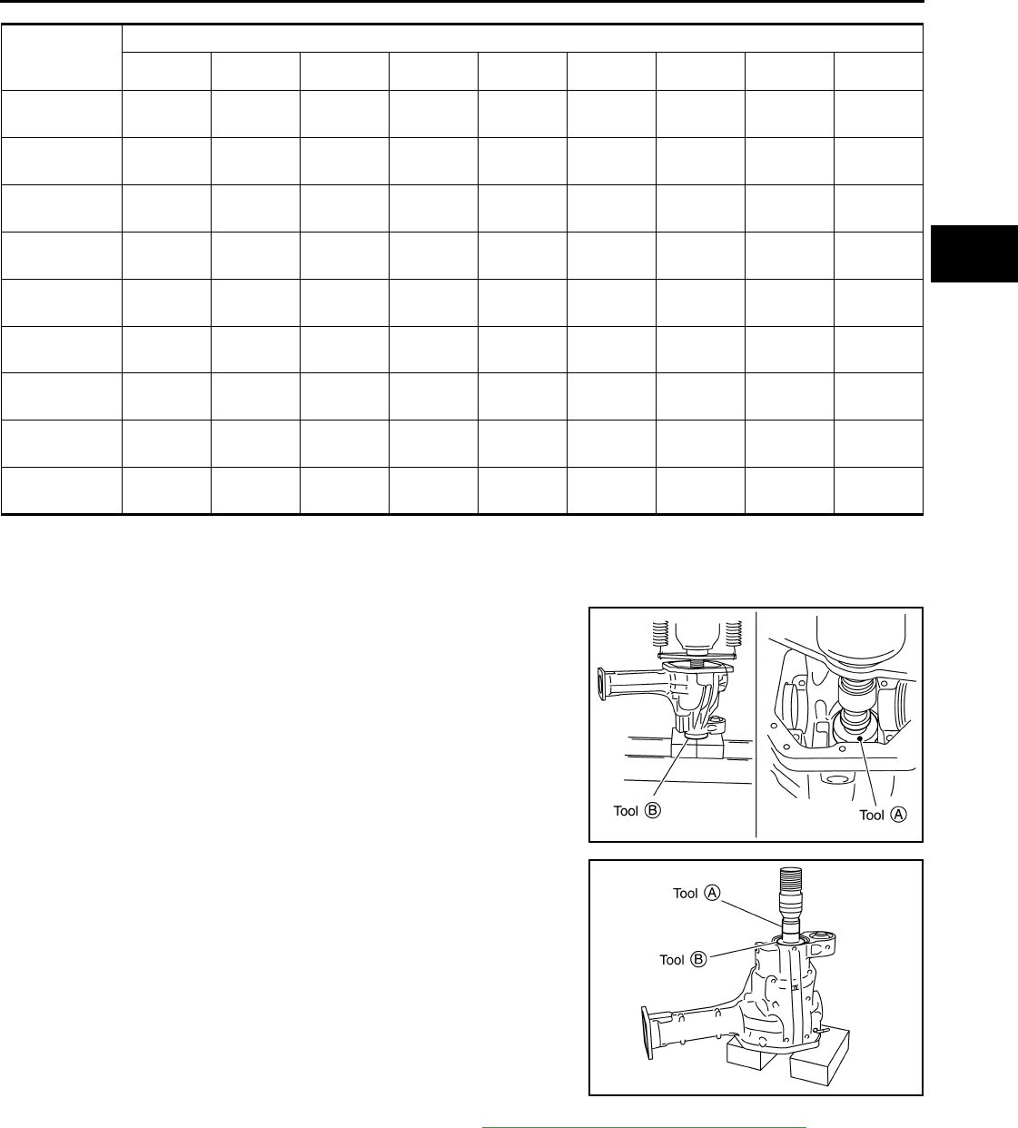
FRONT FINAL DRIVE
DLN-389
< DISASSEMBLY AND ASSEMBLY > [FRONT FINAL DRIVE: M205]
C
E
F
G
H
I
J
K
L
M
A
B
DLN
N
O
P
ASSEMBLY
Drive Pinion Assembly
1. Install drive pinion rear bearing outer race using Tools.
2. Install drive pinion front bearing outer race using Tools.
3. Select drive pinion height adjusting washer. Refer to DLN-364, "Inspection and Adjustment".
OLD DRIVE
PINION
MARKING
NEW DRIVE PINION MARKING mm (in)
-10 (-4) -8 (-3) -5 (-2) -3 (-1) 0 (0) +3 (+1) +5 (+2) +8 (+3) +10 (+4)
+10 (+4) +0.20
(+0.008)
+0.18
(+0.007)
+0.15
(+0.006)
+0.13
(+0.005)
+0.10
(+0.004)
+0.08
(+0.003)
+0.05
(+0.002)
+0.02
(+0.001)
0
(0)
+8 (+3) +0.18
(+0.007)
+0.15
(+0.006)
+0.13
(+0.005)
+0.10
(+0.004)
+0.08
(+0.003)
+0.05
(+0.002)
+0.02
(+0.001)
0
(0)
-0.02
(-0.001)
+5 (+2) +0.15
(+0.006) +0.13
(+0.005) +0.10
(+0.004) +0.08
(+0.003) +0.05
(+0.002) +0.02
(+0.001) 0
(0) -0.02
(-0.001) -0.05
(-0.002)
+3 (+1) +0.13
(+0.005)
+0.10
(+0.004)
+0.08
(+0.003)
+0.05
(+0.002)
+0.02
(+0.001)
0
(0)
-0.02
(-0.001)
-0.05
(-0.002)
-0.08
(-0.003)
0 (0) +0.10
(+0.004)
+0.08
(+0.003)
+0.05
(+0.002)
+0.02
(+0.001)
0
(0)
-0.02
(-0.001)
-0.05
(-0.002)
-0.08
(-0.003)
-0.10
(-0.004)
-3 (-1) +0.08
(+0.003) +0.05
(+0.002) +0.02
(+0.001) 0
(0) -0.02
(-0.001) -0.05
(-0.002) -0.08
(-0.003) -0.10
(-0.004) -0.13
(-0.005)
-5 (-2) +0.05
(+0.002)
+0.02
(+0.001)
0
(0)
-0.02
(-0.001)
-0.05
(-0.002)
-0.08
(-0.003)
-0.10
(-0.004)
-0.13
(-0.005)
-0.15
(-0.006)
-8 (-3) +0.02
(+0.001)
0
(0)
-0.02
(-0.001)
-0.05
(-0.002)
-0.08
(-0.003)
-0.10
(-0.004)
-0.13
(-0.005)
-0.15
(-0.006)
-0.18
(-0.007)
-10 (-4) 0
(0) -0.02
(-0.001) -0.05
(-0.002) -0.08
(-0.003) -0.10
(-0.004) -0.13
(-0.005) -0.15
(-0.006) -0.18
(-0.007) -0.20
(-0.008)
Tool number A: ST30901000 ( — )
B: KV40105230 ( — )
SDIA2251E
Tool number A: ST35271000 ( — )
B: KV40104810 ( — )
SDIA2252E
Revision: October 2008
2009 Pathfinder
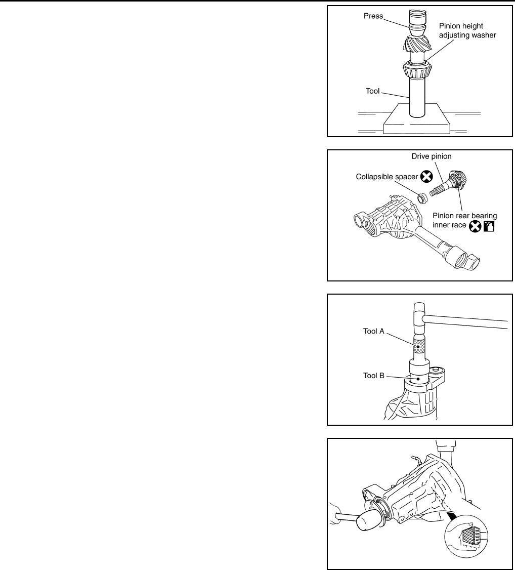
DLN-390
< DISASSEMBLY AND ASSEMBLY > [FRONT FINAL DRIVE: M205]
FRONT FINAL DRIVE
4. Install the selected drive pinion height adjusting washer to the
drive pinion. Press the drive pinion rear bearing inner race to it
using Tool.
CAUTION:
Do not reuse drive pinion rear bearing inner race.
5. Install the collapsible spacer to the drive pinion.
CAUTION:
Do not reuse collapsible spacer.
6. Apply differential gear oil to the drive pinion rear bearing, and
install the drive pinion assembly to the gear carrier.
7. Apply differential gear oil to the drive pinion front bearing, and
install the drive pinion front bearing inner race to the drive pinion
assembly.
CAUTION:
Do not reuse drive pinion front bearing inner race.
8. Apply multi-purpose grease to the lips of the new front oil seal.
Then drive the new front oil seal in evenly using Tools.
CAUTION:
• Do not reuse front oil seal.
• Do not incline the new front oil seal when installing.
• Apply multi-purpose grease to the lips of the new front oil
seal.
9. Install the companion flange to the drive pinion while aligning the
matching marks. Tap the companion flange until fully seated
using suitable tool.
Tool number : — C-4040
SDIA2253E
PDIA0708E
Tool number A: KV38100500 (J-25273)
B: KV38102200 ( — )
PDIA0717E
SDIA2266E
Revision: October 2008
2009 Pathfinder
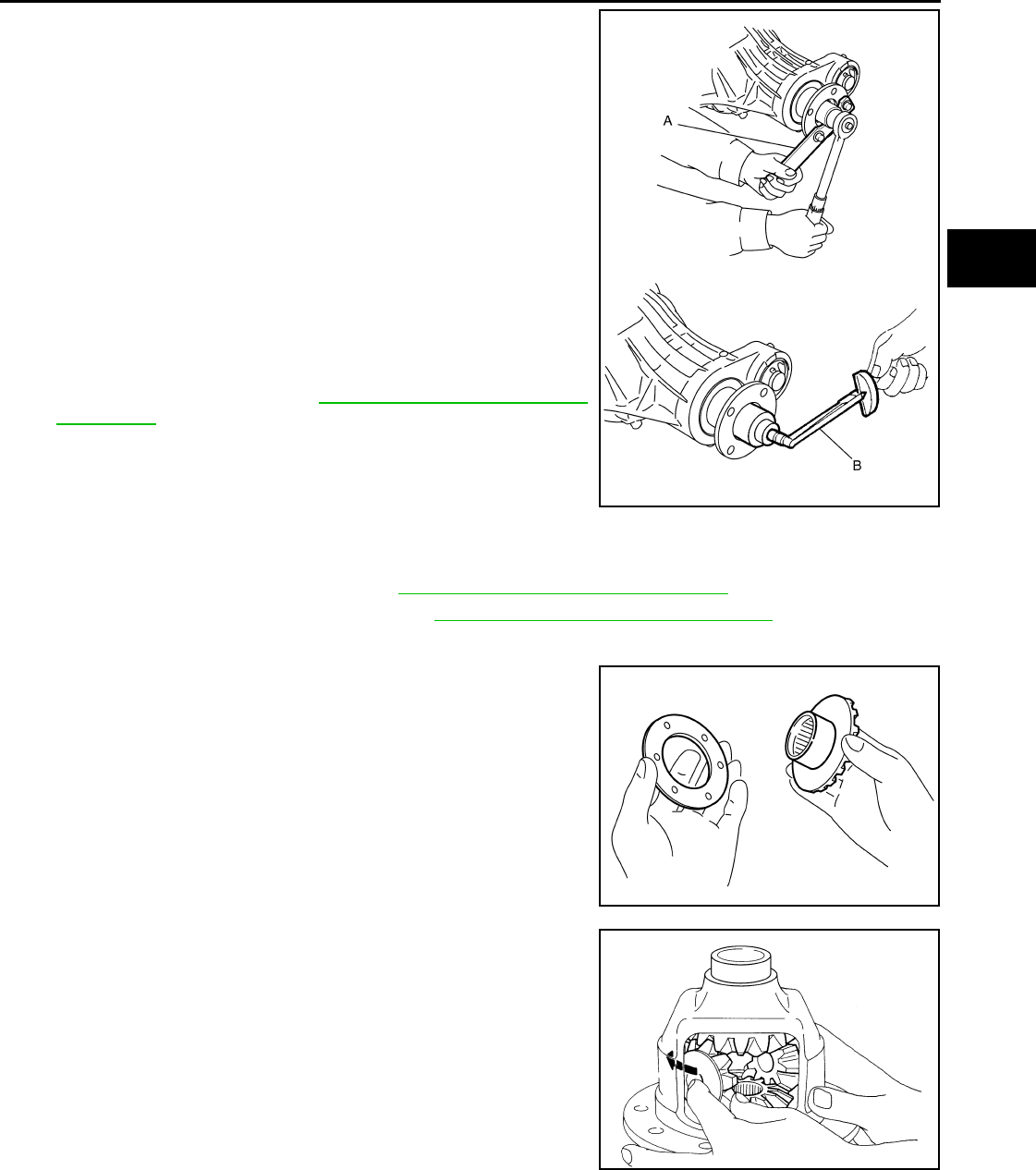
FRONT FINAL DRIVE
DLN-391
< DISASSEMBLY AND ASSEMBLY > [FRONT FINAL DRIVE: M205]
C
E
F
G
H
I
J
K
L
M
A
B
DLN
N
O
P
10. Apply anti-corrosive oil to the threads of the drive pinion and the
seating surface of the new drive pinion lock nut. Then adjust the
drive pinion lock nut tightening torque using Tool A, and check
the drive pinion bearing preload torque using Tool B.
CAUTION:
• Do not reuse drive pinion lock nut.
• Apply anti-corrosive oil to the threads of the drive pinion
and the seating surface of the new drive pinion lock nut.
• Adjust the drive pinion lock nut tightening torque to the
lower limit first. Do not exceed the drive pinion lock nut
specified torque. Refer to DLN-345, "Disassembly and
Assembly".
• If the drive pinion bearing preload torque exceeds the
specified value, replace collapsible spacer and tighten it
again to adjust. Do not loosen drive pinion lock nut to
adjust the drive pinion bearing preload torque.
• After adjustment, rotate drive pinion back and forth 2 to 3
times to check for unusual noise, rotation malfunction, and other malfunctions.
11. Check companion flange runout. Refer to DLN-364, "Inspection and Adjustment".
12. Install the differential case assembly. Refer to DLN-345, "Disassembly and Assembly".
Differential Assembly
1. Install side gear thrust washers with the same thickness as the
ones installed prior to disassembly, or reinstall the old ones on
the side gears.
2. Install the side gears and side gear thrust washers into the dif-
ferential case.
3. Install the pinion mate thrust washers to the two pinion mate
gears. Then install the pinion mate gears with the pinion mate
thrust washers by aligning them in diagonally opposite positions
and rotating them into the differential case.
Tool number A: KV38108300 (J-44195)
B: ST3127S000 (J-25765-A)
Drive pinion bearing preload torque:
2.3 - 3.4 N·m (24 - 34 kg-cm, 21 - 30 in-lb)
WDIA0382E
SDIA0193J
SDIA2025E
Revision: October 2008
2009 Pathfinder
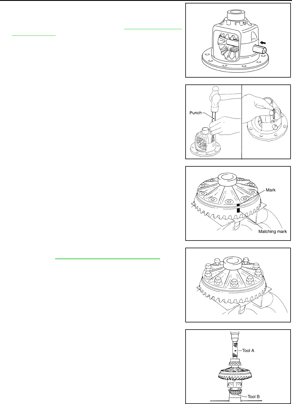
DLN-392
< DISASSEMBLY AND ASSEMBLY > [FRONT FINAL DRIVE: M205]
FRONT FINAL DRIVE
4. Install the pinion mate shaft and align the lock pin hole on the
pinion mate shaft with the lock pin hole on the differential case.
5. Measure the side gear end play. If necessary, select the appro-
priate side gear thrust washers. Refer to DLN-364, "Inspection
and Adjustment".
6. Drive a new lock pin into the pinion mate shaft until it is flush
with the differential case using suitable tool.
CAUTION:
Do not reuse lock pin.
7. Align the matching mark of the differential case with the mark of
the drive gear, then place the drive gear onto the differential
case.
8. Install and tighten the new drive gear bolts to the specified
torque. Refer to DLN-345, "Disassembly and Assembly".
CAUTION:
• Make sure the drive gear back and threaded holes are
clean.
• Do not reuse drive gear bolts.
• Tighten new drive gear bolts in a crisscross pattern.
9. Press the new side bearing inner races to the differential case
using Tools.
CAUTION:
Do not reuse side bearing inner races.
SDIA0195J
SPD030
SDIA2593E
SDIA2239E
Tool number A: KV38100300 (J-25523)
B: ST33081000 ( — )
SPD353
Revision: October 2008
2009 Pathfinder
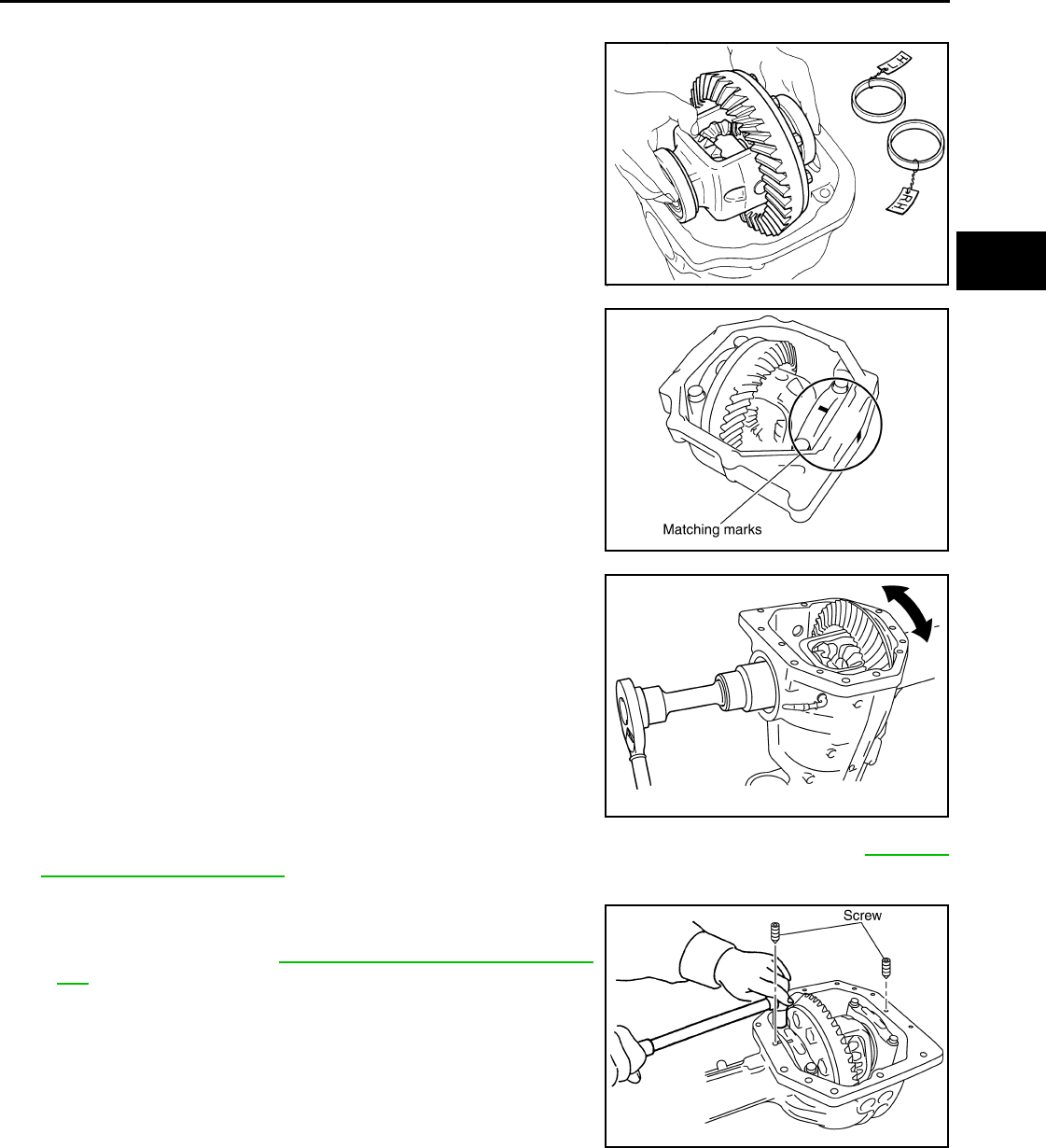
FRONT FINAL DRIVE
DLN-393
< DISASSEMBLY AND ASSEMBLY > [FRONT FINAL DRIVE: M205]
C
E
F
G
H
I
J
K
L
M
A
B
DLN
N
O
P
10. Install side bearing adjusters into gear carrier.
11. Apply differential gear oil to the side bearings, and install the dif-
ferential case assembly with the side bearing outer races into
the gear carrier.
CAUTION:
Do not reuse side bearing outer race when replacing side
bearing inner race (replace as a set).
12. Install the side bearing caps with the matching marks aligned.
NOTE:
Do not tighten at this step. This allows further tightening of side
bearing adjusters.
13. Tighten each side bearing adjuster alternately turning drive gear.
14. Check and adjust tooth contact, backlash, drive gear runout and total preload torque. Refer to DLN-364,
"Inspection and Adjustment".
Recheck above items.
• After adjusting tooth contact and backlash secure side bearing
adjuster with screws and tighten side bearing cap bolt to the
specified torque. Refer to DLN-345, "Disassembly and Assem-
bly".
15. Apply multi-purpose grease to the lips of the new side oil seal. Then drive the new side oil seal in evenly to
the gear carrier using suitable tool.
CAUTION:
• Do not reuse side oil seal.
• Do not incline the new side oil seal when installing.
• Apply multi-purpose grease to the lips of the new side oil seal.
SPD527
PDIA0700E
SDIA2265E
SDIA2263E
Revision: October 2008
2009 Pathfinder
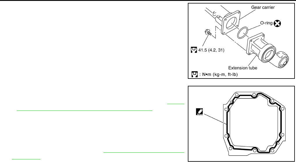
DLN-394
< DISASSEMBLY AND ASSEMBLY > [FRONT FINAL DRIVE: M205]
FRONT FINAL DRIVE
16. Install the extension tube with a new O-ring.
CAUTION:
• Do not reuse O-ring.
• If the extension tube is being replaced, install a new axle
shaft bearing.
17. Apply 3 mm (0.12 in) bead of sealant to the mating surface of
the carrier cover as shown.
• Use Genuine Silicone RTV or equivalent. Refer to GI-26,
"Recommended Chemical Products and Sealants".
CAUTION:
Remove any old sealant adhering to the mating surfaces.
Also remove any moisture, oil, or foreign material adhering
to the application and mating surfaces.
18. Install the carrier cover to the gear carrier. Tighten the bolts to
the specified torque. Refer to DLN-345, "Disassembly and
Assembly".
19. Install side shaft and side flange.
SDIA3205E
SDIA3204E
Revision: October 2008
2009 Pathfinder
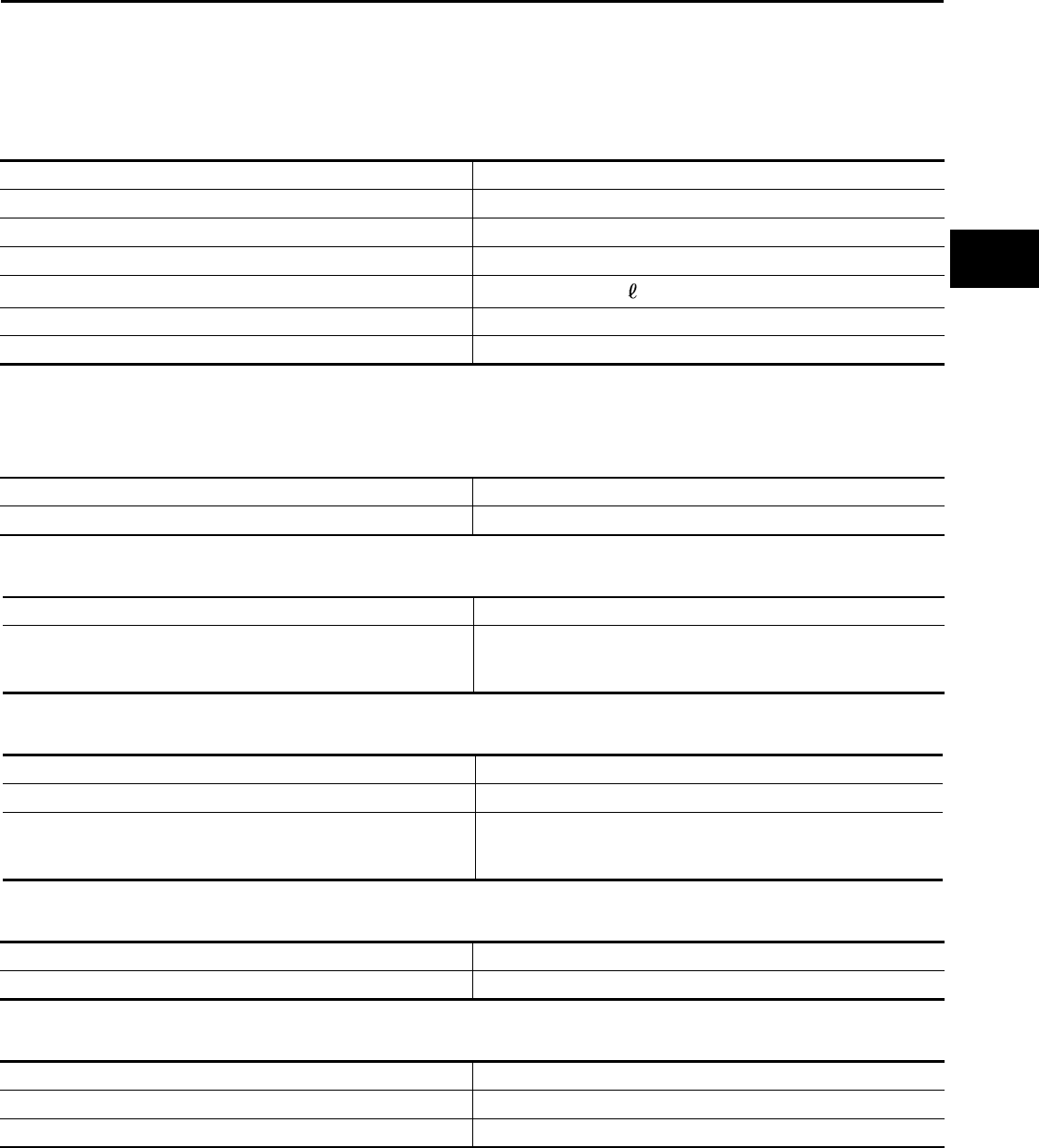
SERVICE DATA AND SPECIFICATIONS (SDS)
DLN-395
< SERVICE DATA AND SPECIFICATIONS (SDS) [FRONT FINAL DRIVE: M205]
C
E
F
G
H
I
J
K
L
M
A
B
DLN
N
O
P
SERVICE DATA AND SPECIFICATIONS (SDS)
SERVICE DATA AND SPECIFICATIONS (SDS)
General Specification INFOID:0000000003937449
Inspection and Adjustment INFOID:0000000003937450
DRIVE GEAR RUNOUT
Unit: mm (in)
SIDE GEAR CLEARANCE
Unit: mm (in)
PRELOAD TORQUE
Unit: N·m (kg-m, in-lb)
BACKLASH
Unit: mm (in)
COMPANION FLANGE RUNOUT
Unit: mm (in)
SELECTIVE PARTS
Drive Pinion Height Adjusting Washer
Applied model VK56DE
Final drive model M205
Gear ratio 2.937
Number of teeth (Drive gear/Drive pinion) 47/16
Differential gear oil capacity (Approx.) 1.6 (3 3/8 US pt, 2 7/8 Imp pt)
Number of pinion gears 2
Drive pinion adjustment spacer type Collapsible
Item Runout limit
Drive gear back face 0.08 (0.0031) or less
Item Specification
Side gear back clearance (Clearance between side gear and dif-
ferential case for adjusting side gear backlash)
0.20 (0.0079) or less
(Each gear should rotate smoothly without excessive resistance
during differential motion.)
Item Specification
Drive pinion bearing preload torque 2.3 - 3.4 (0.23 - 0.35, 21 - 31)
Total preload torque
(Total preload torque = drive pinion bearing preload torque + side
bearing preload torque).
2.98 - 4.76 (0.31 - 0.48, 27 - 42)
Item Specification
Drive gear to drive pinion backlash 0.13 - 0.18 (0.0051 - 0.0071)
Item Runout limit
Companion flange face 0.10 (0.0039) or less
Companion flange inner side 0.13 (0.0051) or less
Revision: October 2008
2009 Pathfinder

DLN-396
< SERVICE DATA AND SPECIFICATIONS (SDS) [FRONT FINAL DRIVE: M205]
SERVICE DATA AND SPECIFICATIONS (SDS)
Unit: mm (in)
*Always check with the Parts Department for the latest parts information.
Side Gear Thrust Washer
Unit: mm (in)
*: Always check with the Parts Department for the latest parts information.
Thickness Package part number*
1.22 (0.048)
1.24 (0.049)
1.27 (0.050)
1.30 (0.051)
1.32 (0.052)
38154 8S111
1.35 (0.053)
1.37 (0.054)
1.40 (0.055)
1.42 (0.056)
1.45 (0.057)
38154 8S112
1.47 (0.058)
1.50 (0.059)
1.52 (0.060)
1.55 (0.061)
1.57 (0.062)
38154 8S113
1.60 (0.063)
1.63 (0.064)
1.65 (0.065)
1.68 (0.066)
1.70 (0.067)
38154 8S114
1.73 (0.068)
1.75 (0.069)
1.78 (0.070)
1.80 (0.071)
1.83 (0.072)
38154 8S115
Thickness Package part number*
0.76 (0.030)
0.79 (0.031)
0.81 (0.032)
0.84 (0.033)
0.87 (0.034)
38424 8S111
0.89 (0.035)
0.91 (0.036)
0.94 (0.037)
0.97 (0.038)
0.99 (0.039)
38424 8S112
Revision: October 2008
2009 Pathfinder

PRECAUTIONS
DLN-397
< PRECAUTION > [REAR FINAL DRIVE: R200]
C
E
F
G
H
I
J
K
L
M
A
B
DLN
N
O
P
PRECAUTION
PRECAUTIONS
Precaution for Servicing Rear Final Drive INFOID:0000000003937451
• Before starting diagnosis of the vehicle, understand the symptoms well. Perform correct and systematic
operations.
• Check for the correct installation status prior to removal or disassembly. When matching marks are required,
be certain they do not interfere with the function of the parts they are applied to.
• Overhaul should be done in a clean work area, a dust proof area is recommended.
• Before disassembly, completely remove sand and mud from the exterior of the unit, preventing them from
entering into the unit during disassembly or assembly.
• Always use shop paper for cleaning the inside of components.
• Avoid using cotton gloves or a shop cloth to prevent the entering of lint.
• Check appearance of the disassembled parts for damage, deformation, and abnormal wear. Replace them
with new ones if necessary.
• Gaskets, seals and O-rings should be replaced any time the unit is disassembled.
• Clean and flush the parts sufficiently and blow them dry.
• Be careful not to damage sliding surfaces and mating surfaces.
• When applying sealant, remove the old sealant from the mating surface; then remove any moisture, oil, and
foreign materials from the application and mating surfaces.
• In principle, tighten nuts or bolts gradually in several steps working diagonally from inside to outside. If a
tightening sequence is specified, observe it.
• During assembly, observe the specified tightening torque.
• Add new differential gear oil, petroleum jelly, or multi-purpose grease, as specified.
Revision: October 2008
2009 Pathfinder
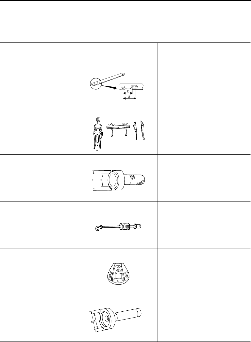
DLN-398
< PREPARATION > [REAR FINAL DRIVE: R200]
PREPARATION
PREPARATION
PREPARATION
Special Service Tool INFOID:0000000003937452
The actual shapes of Kent-Moore tools may differ from those of special service tools illustrated here.
Tool number
(Kent-Moore No.)
Tool name
Description
KV40104000
(—)
Flange wrench
Removing and installing drive pinion lock nut
a: 85 mm (3.35 in) dia.
b: 65 mm (2.56 in) dia.
KV381054S0
(J-34286)
Puller
Removing front oil seal
ST30720000
(J-25405)
Drift
• Installing front oil seal
• Installing drive pinion rear bearing outer
race
a: 77 mm (3.03 in) dia.
b: 55.5 mm (2.185 in) dia.
ST36230000
(J-25840-A)
Sliding hammer
Removing side flange
KV40104100
(—)
Attachment
Removing side flange
KV38100200
(J-26233)
Drift
Installing side oil seal
a: 65 mm (2.56 in) dia.
b: 49 mm (1.93 in) dia.
NT659
ZZA0601D
ZZA0811D
ZZA0803D
ZZA0804D
ZZA1143D
Revision: October 2008
2009 Pathfinder
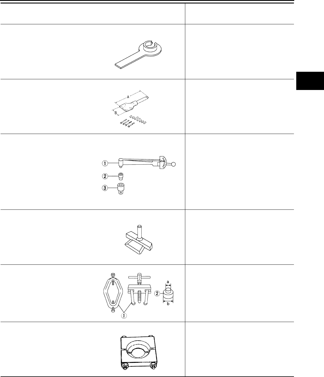
PREPARATION
DLN-399
< PREPARATION > [REAR FINAL DRIVE: R200]
C
E
F
G
H
I
J
K
L
M
A
B
DLN
N
O
P
KV38107900
(J-39352)
Protector
Installing side flange
KV38100800
(J-25604-01)
Attachment
Securing unit assembly
a: 541 mm (21.30 in)
b: 200 mm (7.87 in)
ST3127S000
(J-25765-A)
Preload gauge
1: GG91030000
(J-25765)
Torque wrench
2: HT62940000
(—)
Socket adapter (1/2″)
3: HT62900000
(—)
Socket adapter (3/8″)
Measuring drive pinion bearing preload torque
and total preload torque
KV10111100
(J-37228)
Seal cutter
Removing carrier cover
ST3306S001
(—)
Differential side bearing puller set
1: ST33051001
(J-22888-20)
Puller
2: ST33061000
(J-8107-2)
Base
Removing and installing side bearing inner
race
a: 28.5 mm (1.122 in) dia.
b: 38 mm (1.50 in) dia.
ST30031000
(J-22912-01)
Puller
Removing drive pinion rear bearing inner race
Tool number
(Kent-Moore No.)
Tool name
Description
S-NT129
SDIA0267E
NT124
S-NT046
NT072
ZZA0700D
Revision: October 2008
2009 Pathfinder
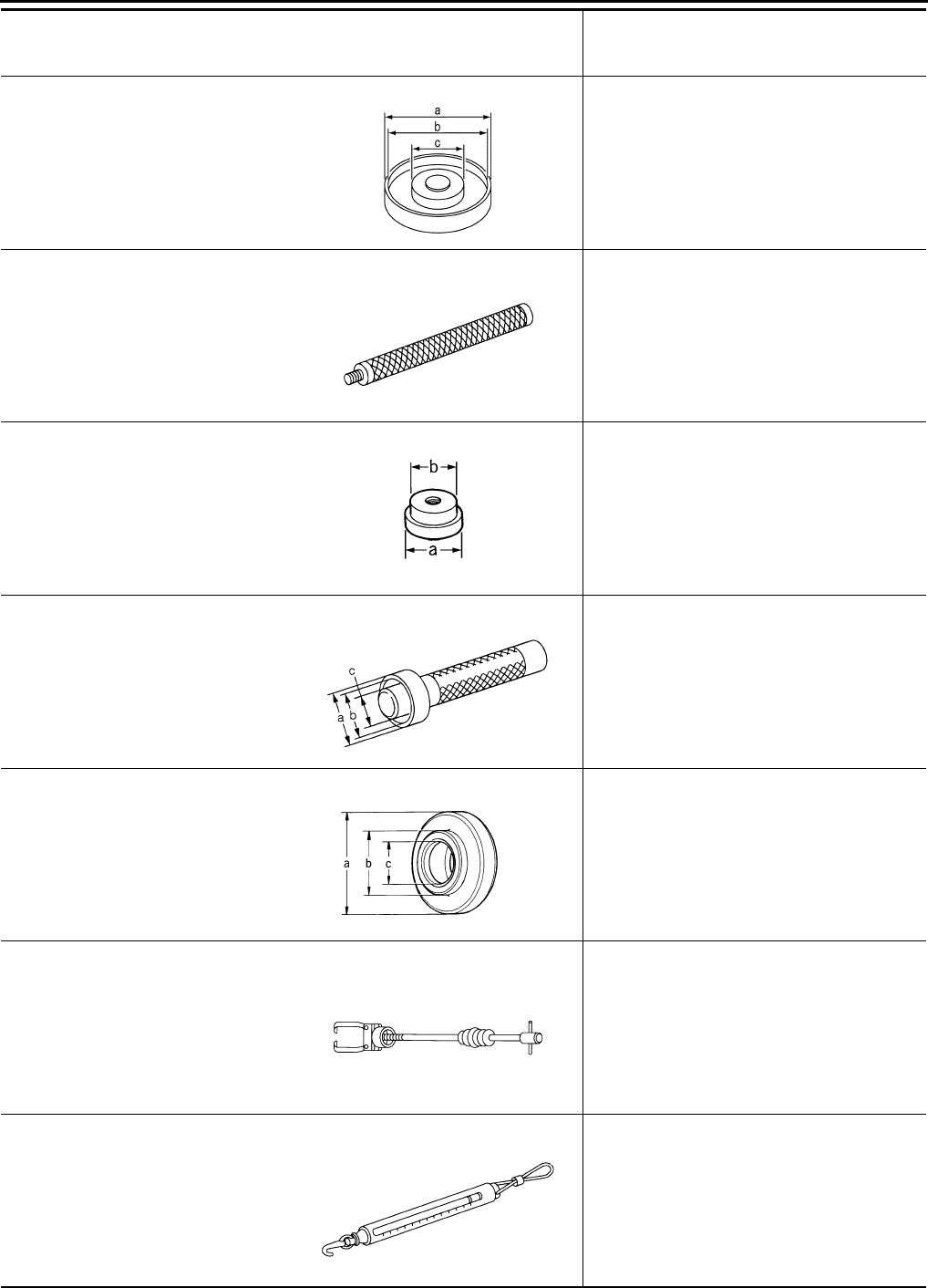
DLN-400
< PREPARATION > [REAR FINAL DRIVE: R200]
PREPARATION
KV40105230
(—)
Drift
Installing drive pinion rear bearing outer race
a: 92 mm (3.62 in) dia.
b: 86 mm (3.39 in) dia.
c: 45 mm (1.77 in) dia.
ST30611000
(J-25742-1)
Drift bar
Installing drive pinion front bearing outer race
(Use with ST30613000)
ST30613000
(J-25742-3)
Drift
Installing drive pinion front bearing outer race
a: 72 mm (2.83 in) dia.
b: 48 mm (1.89 in) dia.
KV38100300
(J-25523)
Drift
Installing side bearing inner race
a: 54 mm (2.13 in) dia.
b: 46 mm (1.81 in) dia.
c: 32 mm (1.26 in) dia.
ST30901000
(J-26010-01)
Drift
Installing drive pinion rear bearing inner race
a: 79 mm (3.11 in) dia.
b: 45 mm (1.77 in) dia.
c: 35.2 mm (1.386 in) dia.
HT72400000
(—)
Slide hammer
Removing differential case assembly
—
(J-8129)
Spring gauge
Measuring turning torque
Tool number
(Kent-Moore No.)
Tool name
Description
PDIA0591E
S-NT090
ZZA1000D
ZZA1046D
ZZA0978D
S-NT125
NT127
Revision: October 2008
2009 Pathfinder
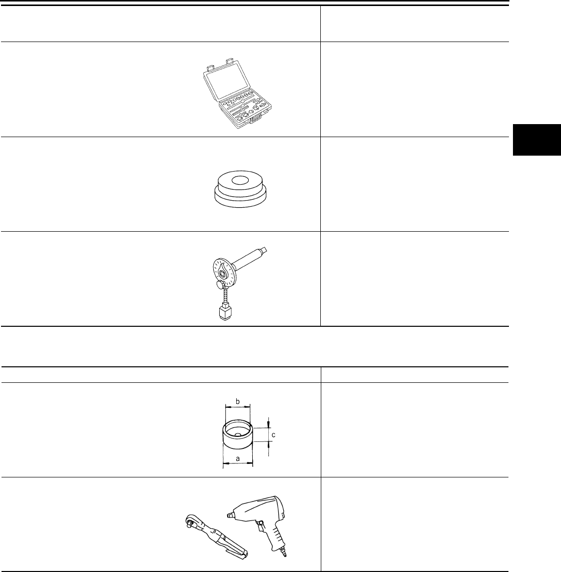
PREPARATION
DLN-401
< PREPARATION > [REAR FINAL DRIVE: R200]
C
E
F
G
H
I
J
K
L
M
A
B
DLN
N
O
P
Commercial Service Tool INFOID:0000000003937453
—
(J-34309)
Differential shim selector tool
Adjusting drive pinion bearing preload and
drive pinion height
—
(J-25269-4)
Side bearing disc (2 Req'd)
Selecting drive pinion height adjusting washer
KV10112100
(BT-8653-A)
Angle wrench
Tightening bolts for drive gear
Tool number
(Kent-Moore No.)
Tool name
Description
NT134
NT136
NT014
Tool name Description
Spacer Installing drive pinion front bearing inner race
a: 60 mm (2.36 in) dia.
b: 36 mm (1.42 in) dia.
c: 30 mm (1.18 in)
Power tool Loosening nuts and bolts
ZZA1133D
PBIC0190E
Revision: October 2008
2009 Pathfinder
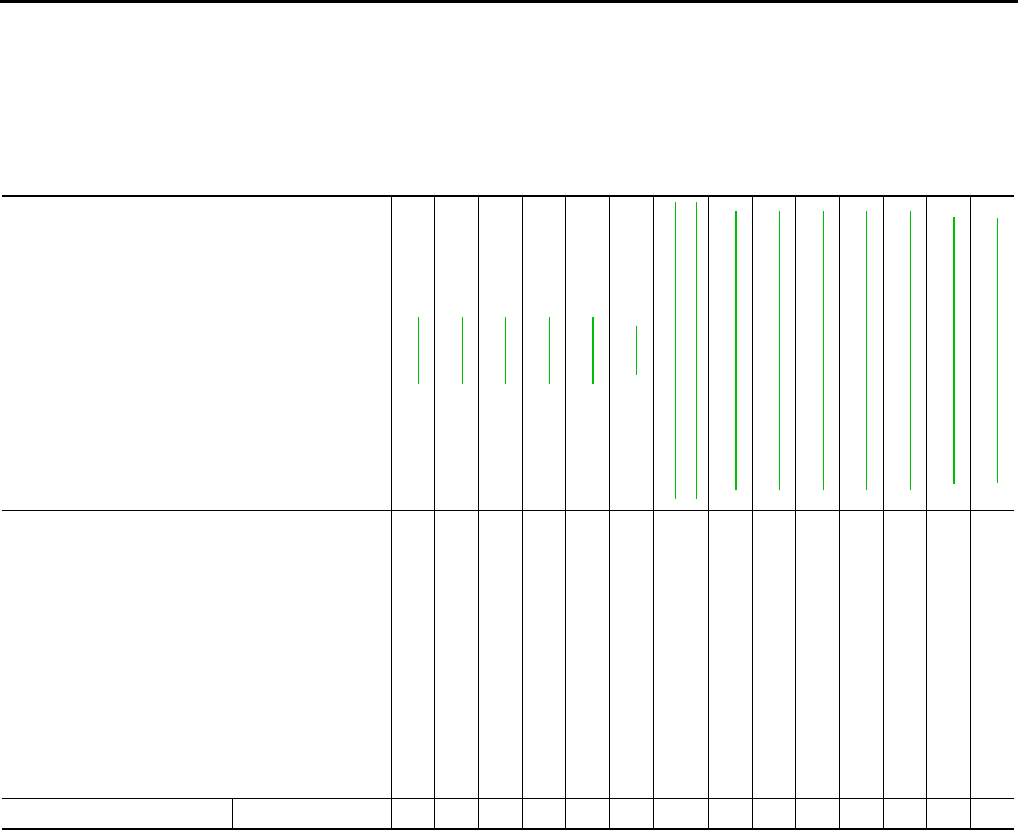
DLN-402
< FUNCTION DIAGNOSIS > [REAR FINAL DRIVE: R200]
NOISE, VIBRATION AND HARSHNESS (NVH) TROUBLESHOOTING
FUNCTION DIAGNOSIS
NOISE, VIBRATION AND HARSHNESS (NVH) TROUBLESHOOTING
NVH Troubleshooting Chart INFOID:0000000003937454
Use the chart below to help you find the cause of the symptom. If necessary, repair or replace these parts.
×: Applicable
Reference page
DLN-413
DLN-413
DLN-413
DLN-413
DLN-432
MA-12
DLN-315, "NVH Troubleshooting Chart"
DLN-324, "NVH Troubleshooting Chart"
RAX-4, "NVH Troubleshooting Chart"
RSU-5, "NVH Troubleshooting Chart"
WT-45, "NVH Troubleshooting Chart"
WT-45, "NVH Troubleshooting Chart"
RAX-4, "NVH Troubleshooting Chart"
BR-6, "NVH Troubleshooting Chart"
ST-9, "NVH Troubleshooting Chart"
Possible cause and SUSPECTED PARTS
Gear tooth rough
Gear contact improper
Tooth surfaces worn
Backlash incorrect
Companion flange excessive runout
Gear oil improper
PROPELLER SHAFT
REAR AXLE
REAR SUSPENSION
TIRES
ROAD WHEEL
DRIVE SHAFT
BRAKES
STEERING
Symptom Noise ×××××× × ××××××
Revision: October 2008
2009 Pathfinder
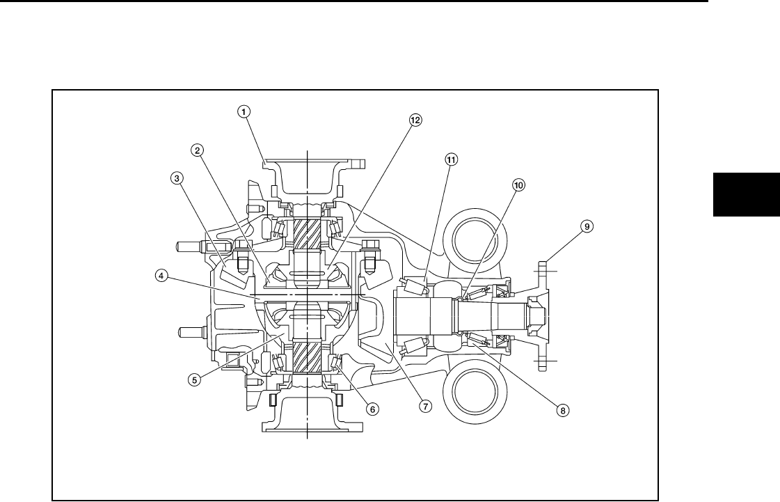
DESCRIPTION
DLN-403
< FUNCTION DIAGNOSIS > [REAR FINAL DRIVE: R200]
C
E
F
G
H
I
J
K
L
M
A
B
DLN
N
O
P
DESCRIPTION
Cross-Sectional View INFOID:0000000003937455
1. Side flange 2. Pinion mate gear 3. Drive gear
4. Pinion mate shaft 5. Differential case 6. Side bearing
7. Drive pinion 8. Drive pinion front bearing 9. Companion flange
10. Collapsible spacer 11. Drive pinion rear bearing 12. Side gear
WDIA0119E
Revision: October 2008
2009 Pathfinder
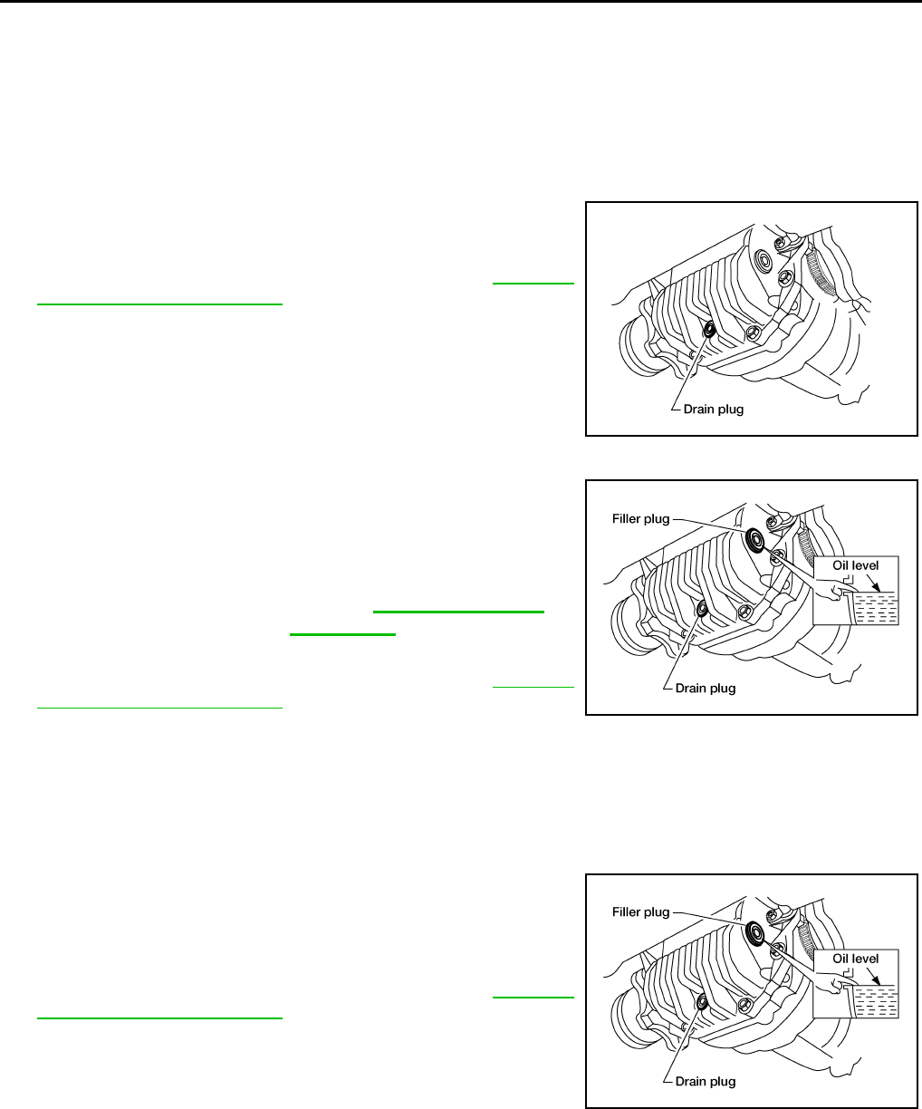
DLN-404
< ON-VEHICLE MAINTENANCE > [REAR FINAL DRIVE: R200]
DIFFERENTIAL GEAR OIL
ON-VEHICLE MAINTENANCE
DIFFERENTIAL GEAR OIL
Changing Differential Gear Oil INFOID:0000000003937456
DRAINING
1. Stop the engine.
2. Remove the drain plug and gasket from the rear final drive
assembly to drain the differential gear oil.
3. Install the drain plug with a new gasket to the rear final drive
assembly. Tighten to the specified torque. Refer to DLN-413,
"Disassembly and Assembly".
CAUTION:
Do not reuse gasket.
FILLING
1. Remove the filler plug and gasket from the rear final drive ass-
mebly.
2. Fill the rear final drive assembly with new differential gear oil
until the level reaches the specified level near the filler plug hole.
3. Install the filler plug with a new gasket on it to the rear final drive
assembly. Tighten to the specified torque. Refer to DLN-413,
"Disassembly and Assembly".
CAUTION:
Do not reuse gasket.
Checking Differential Gear Oil INFOID:0000000003937457
OIL LEAKAGE AND OIL LEVEL
1. Make sure that differential gear oil is not leaking from the rear final drive assembly or around it.
2. Check the differential gear oil level from the filler plug hole as
shown.
CAUTION:
Do not start engine while checking differential gear oil level.
3. Install the filler plug with a new gasket on it to the rear final drive
assembly. Tighten to the specified torque. Refer to DLN-413,
"Disassembly and Assembly".
CAUTION:
Do not reuse gasket.
LDIA0162E
Differential gear oil
grade and capacity : Refer to MA-12, "Fluids and
Lubricants".
LDIA0163E
LDIA0163E
Revision: October 2008
2009 Pathfinder
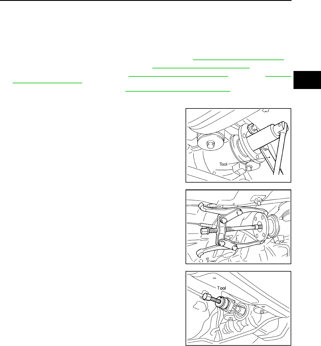
FRONT OIL SEAL
DLN-405
< ON-VEHICLE REPAIR > [REAR FINAL DRIVE: R200]
C
E
F
G
H
I
J
K
L
M
A
B
DLN
N
O
P
ON-VEHICLE REPAIR
FRONT OIL SEAL
Removal and Installation INFOID:0000000003937458
REMOVAL
1. Remove the drive shafts from the rear final drive assembly. Refer to RAX-9, "Removal and Installation".
2. Remove the side flanges and side oil seals. Refer to DLN-407, "Removal and Installation".
3. Remove the rear propeller shaft. Refer to DLN-317, "Removal and Installation" (2S1330) or DLN-326,
"Removal and Installation" (2S1350).
4. Measure the total preload torque. Refer to DLN-413, "Disassembly and Assembly".
NOTE:
Record the total preload torque measurement.
5. Remove the drive pinion lock nut using Tool.
6. Put matching marks on the companion flange and drive pinion
using paint.
CAUTION:
Use paint to make the matching marks. Do not damage the
companion flange or drive pinion.
7. Remove the companion flange using suitable tool.
8. Remove the front oil seal using Tool.
INSTALLATION
Tool number : KV40104000 ( — )
SDIA1142E
SDIA1054E
Tool number : KV381054S0 (J-34286)
SDIA0485E
Revision: October 2008
2009 Pathfinder
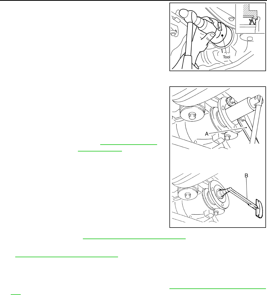
DLN-406
< ON-VEHICLE REPAIR > [REAR FINAL DRIVE: R200]
FRONT OIL SEAL
1. Apply multi-purpose grease to the lips and differential gear oil to
the circumference of the new front oil seal. Then drive the new
front oil seal in evenly until it becomes flush with the gear carrier
using Tool.
CAUTION:
• Do not reuse front oil seal.
• Do not incline the new front oil seal when installing.
• Apply multi-purpose grease to the lips and differential
gear oil to the circumference of the new front oil seal.
2. Install the companion flange to the drive pinion while aligning the matching marks.
3. Apply anti-corrosive oil to the threads of the drive pinion and the
seating surface of the new drive pinion lock nut. Then adjust the
drive pinion lock nut tightening torque using Tool A, and check
the total preload torque using Tool B.
• The total preload torque should be within the total preload
torque specification. When not replacing the collapsible
spacer, it should also be equal to the measurement taken dur-
ing removal plus an additional 0.56 N·m (0.06 Kg-m, 5 in-lb).
• If the total preload torque is low, tighten the drive pinion lock
nut in 6.8 N·m (0.69 Kg-m, 5ft-lb) increments until the total pre-
load torque is met.
CAUTION:
• Do not reuse drive pinion lock nut.
• Apply anti-corrosive oil to the threads of the drive pinion
and the seating surface of the new drive pinion lock nut.
• Adjust the drive pinion lock nut tightening torque to the
lower limit first. Do not exceed the drive pinion lock nut
specified torque. Refer to DLN-413, "Disassembly and Assembly".
• Do not loosen drive pinion lock nut to adjust the total preload torque. If the total preload torque
exceeds the specifications, replace the collapsible spacer and tighten it again to adjust. Refer to
DLN-413, "Disassembly and Assembly".
• After adjustment, rotate drive pinion back and forth 2 to 3 times to check for unusual noise, rota-
tion malfunction, and other malfunctions.
4. Installation of the remaining components is in the reverse order of removal.
CAUTION:
Check the differential gear oil level after installation. Refer to DLN-404, "Checking Differential Gear
Oil".
Tool number : ST30720000 (J-25405)
PDIA0565E
Tool number A: KV40104000 ( — )
B: ST3127S000 (J-25765-A)
Total preload torque: Refer to DLN-432, "Inspection
and Adjustment".
WDIA0380E
Revision: October 2008
2009 Pathfinder
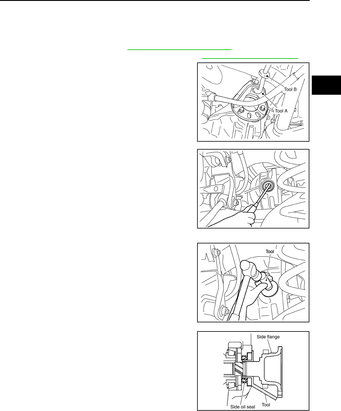
SIDE OIL SEAL
DLN-407
< ON-VEHICLE REPAIR > [REAR FINAL DRIVE: R200]
C
E
F
G
H
I
J
K
L
M
A
B
DLN
N
O
P
SIDE OIL SEAL
Removal and Installation INFOID:0000000003937459
REMOVAL
1. Remove the rear wheel sensor. Refer to BRC-129, "Removal and Installation".
2. Remove the drive shaft from the rear final drive assembly. Refer to RAX-9, "Removal and Installation".
3. Remove the side flange using Tools.
NOTE:
Circular clip installation position: Rear final drive side
4. Remove the side oil seal using suitable tool.
CAUTION:
Do not to damage gear carrier.
INSTALLATION
1. Apply multi-purpose grease to the lips and differential gear oil to
the circumference of the new side oil seal. Then drive the new
side oil seal in evenly until it becomes flush with the gear carrier
using Tool.
CAUTION:
• Do not reuse side oil seal.
• Do not incline the new side oil seal when installing.
• Apply multi-purpose grease to the lips and differential
gear oil to the circumference of the new side oil seal.
2. Install the side flange using Tool.
a. Install the Tool to the side oil seal as shown.
b. Insert the side flange until the serrated part of the side flange
has engaged the serrated part of the side gear and remove the
Tool.
c. Drive in the side flange using suitable tool.
NOTE:
Installation is completed when the driving sound of the side
flange turns into a sound which seems to affect the whole rear
final drive assembly.
3. Installation of the remaining components is in the reverse order of removal.
Tool numbers A: KV40104100 ( — )
B: ST36230000 (J-25840-A)
WDIA0115E
SDIA0495E
Tool number : KV38100200 (J-26233)
SDIA0496E
Tool number : KV38107900 (J-39352)
SDIA0822E
Revision: October 2008
2009 Pathfinder

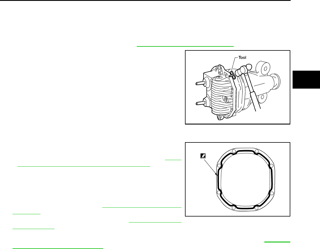
CARRIER COVER
DLN-409
< ON-VEHICLE REPAIR > [REAR FINAL DRIVE: R200]
C
E
F
G
H
I
J
K
L
M
A
B
DLN
N
O
P
CARRIER COVER
Removal and Installation INFOID:0000000003937460
REMOVAL
1. Remove the rear final drive assembly. Refer to DLN-410, "Removal and Installation".
2. Remove the carrier cover bolts and separate the carrier cover
from the gear carrier using Tool.
CAUTION:
• Do not damage the mating surface.
• Do not insert flat-bladed screwdriver, this will damage the
mating surface.
INSTALLATION
1. Apply a 3 mm (0.12 in) bead of sealant to the mating surface of
the carrier cover as shown.
• Use Genuine Silicone RTV or equivalent. Refer to GI-26,
"Recommended Chemical Products and Sealants".
CAUTION:
Remove any old sealant adhering to the mating surfaces.
Also remove any moisture, oil, or foreign material adhering
to the application and mating surfaces.
2. Install the carrier cover to the gear carrier. Tighten the bolts to
the specified torque. Refer to DLN-413, "Disassembly and
Assembly".
3. Install the rear final drive assembly. Refer to DLN-410, "Removal
and Installation".
CAUTION:
Fill the rear final drive assembly with recommended differential gear oil. Refer to DLN-404,
"Changing Differential Gear Oil".
Tool number : KV10111100 (J-37228)
WDIA0123E
WDIA0282E
Revision: October 2008
2009 Pathfinder
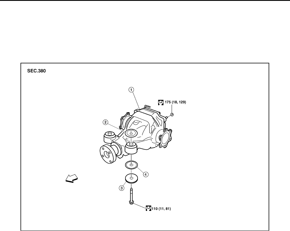
DLN-410
< REMOVAL AND INSTALLATION > [REAR FINAL DRIVE: R200]
REAR FINAL DRIVE
REMOVAL AND INSTALLATION
REAR FINAL DRIVE
Removal and Installation INFOID:0000000003937461
COMPONENTS
Rear Final Drive
WDIA0383E
1. Rear final drive assembly 2. Upper stopper 3. Washer
4. Lower stopper ⇐:Front
Revision: October 2008
2009 Pathfinder
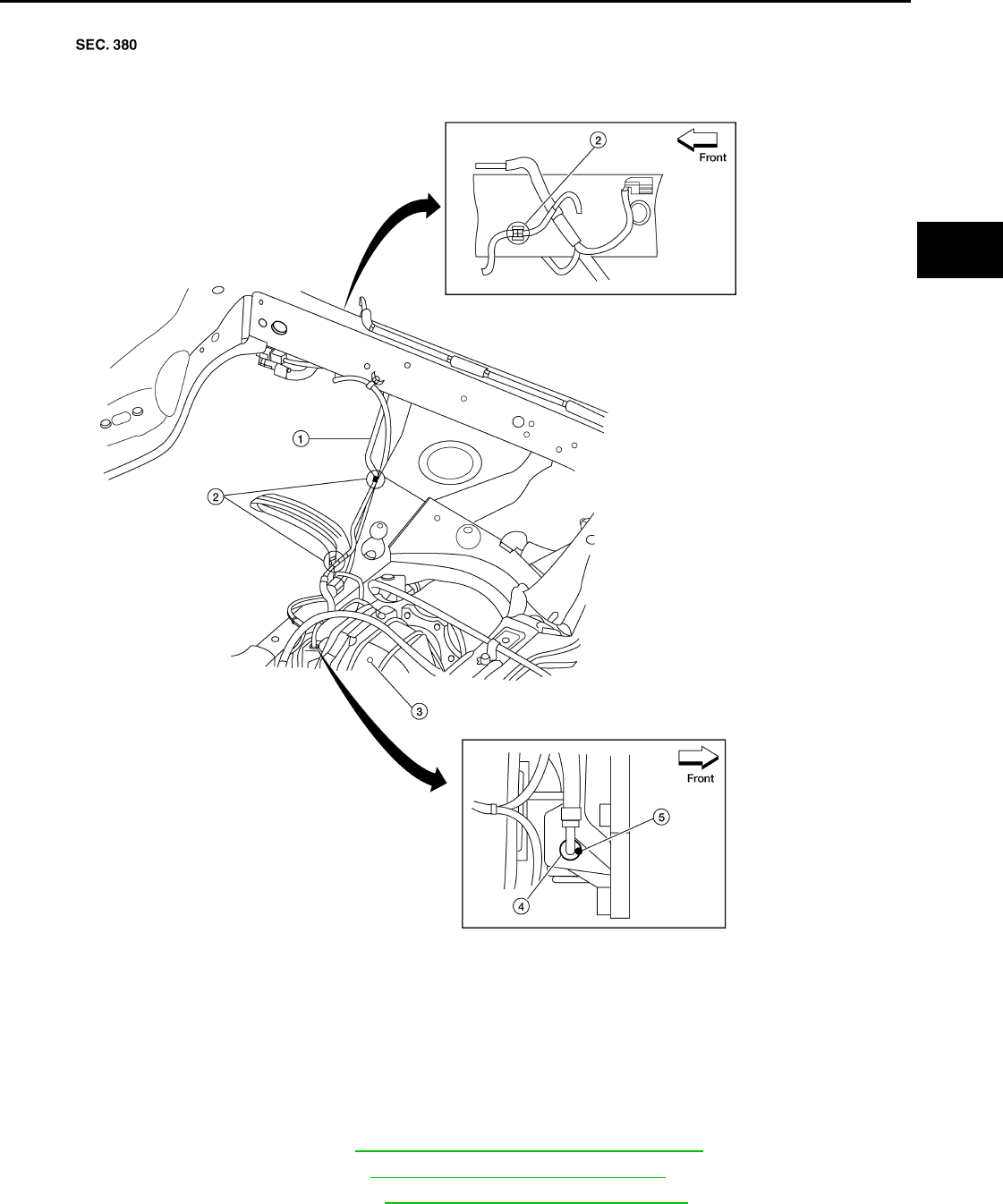
REAR FINAL DRIVE
DLN-411
< REMOVAL AND INSTALLATION > [REAR FINAL DRIVE: R200]
C
E
F
G
H
I
J
K
L
M
A
B
DLN
N
O
P
Rear Final Drive Breather Hose
REMOVAL
1. Remove the spare tire.
2. Drain the differential gear oil. Refer to DLN-404, "Changing Differential Gear Oil".
3. Remove the rear stabilizer bar. Refer to RSU-22, "Removal and Installation".
4. Remove the rear propeller shaft. Refer to DLN-317, "Removal and Installation".
LDIA0166E
1. Breather hose 2. Plastic connectors 3. Rear final drive assembly
4. Metal connector 5. Paint mark
Revision: October 2008
2009 Pathfinder
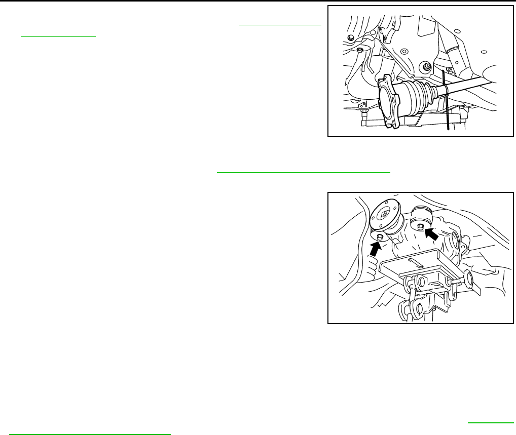
DLN-412
< REMOVAL AND INSTALLATION > [REAR FINAL DRIVE: R200]
REAR FINAL DRIVE
5. Remove the rear drive shafts from the rear final drive assembly
and support them using suitable wire. Refer to RAX-9, "Removal
and Installation".
6. Disconnect the breather hose from the rear final drive assembly.
7. Remove the rear wheel sensors. Refer to BRC-129, "Removal and Installation".
8. Place a suitable jack under the rear final drive assembly.
CAUTION:
Do not place the jack on the carrier cover.
9. Remove the nuts and bolts and remove the rear final drive
assembly.
CAUTION:
Secure rear final drive assembly to the jack while removing
it.
INSTALLATION
Installation is in the reverse order of removal.
CAUTION:
• When installing the breather hose make sure the painted marking on the metal end of breather hose
is to the front of the vehicle and there are no pinched or restricted areas on the breather hose
caused by folding or bending when installing it.
• Make sure the breather hose plastic connectors are in the appropriate holes.
• Fill the front final drive assembly with differential gear oil after installation. Refer to DLN-404,
"Changing Differential Gear Oil".
LDIA0164E
WDIA0117E
Revision: October 2008
2009 Pathfinder
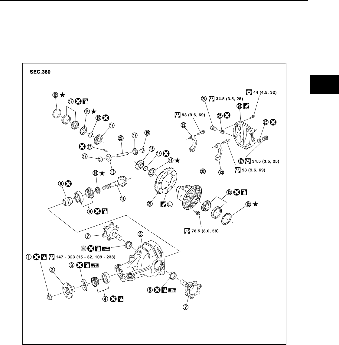
REAR FINAL DRIVE
DLN-413
< DISASSEMBLY AND ASSEMBLY > [REAR FINAL DRIVE: R200]
C
E
F
G
H
I
J
K
L
M
A
B
DLN
N
O
P
DISASSEMBLY AND ASSEMBLY
REAR FINAL DRIVE
Disassembly and Assembly INFOID:0000000003937462
COMPONENTS
1. Drive pinion lock nut 2. Companion flange 3. Front oil seal
4. Drive pinion front bearing 5. Gear carrier 6. Side oil seal
7. Side flange 8. Collapsible spacer 9. Drive pinion rear bearing
10. Drive pinion height adjusting
washer
11. Drive pinion 12. Side bearing adjusting washer
13. Side bearing 14. Side gear thrust washer 15. Circular clip
16. Side gear 17. Lock pin 18. Pinion mate gear
19. Pinion mate thrust washer 20. Pinion mate shaft 21. Drive gear
22. Differential case 23. Side bearing cap 24. Filler plug
25. Gasket 26. Carrier cover 27. Drain plug
WDIA0295E
Revision: October 2008
2009 Pathfinder
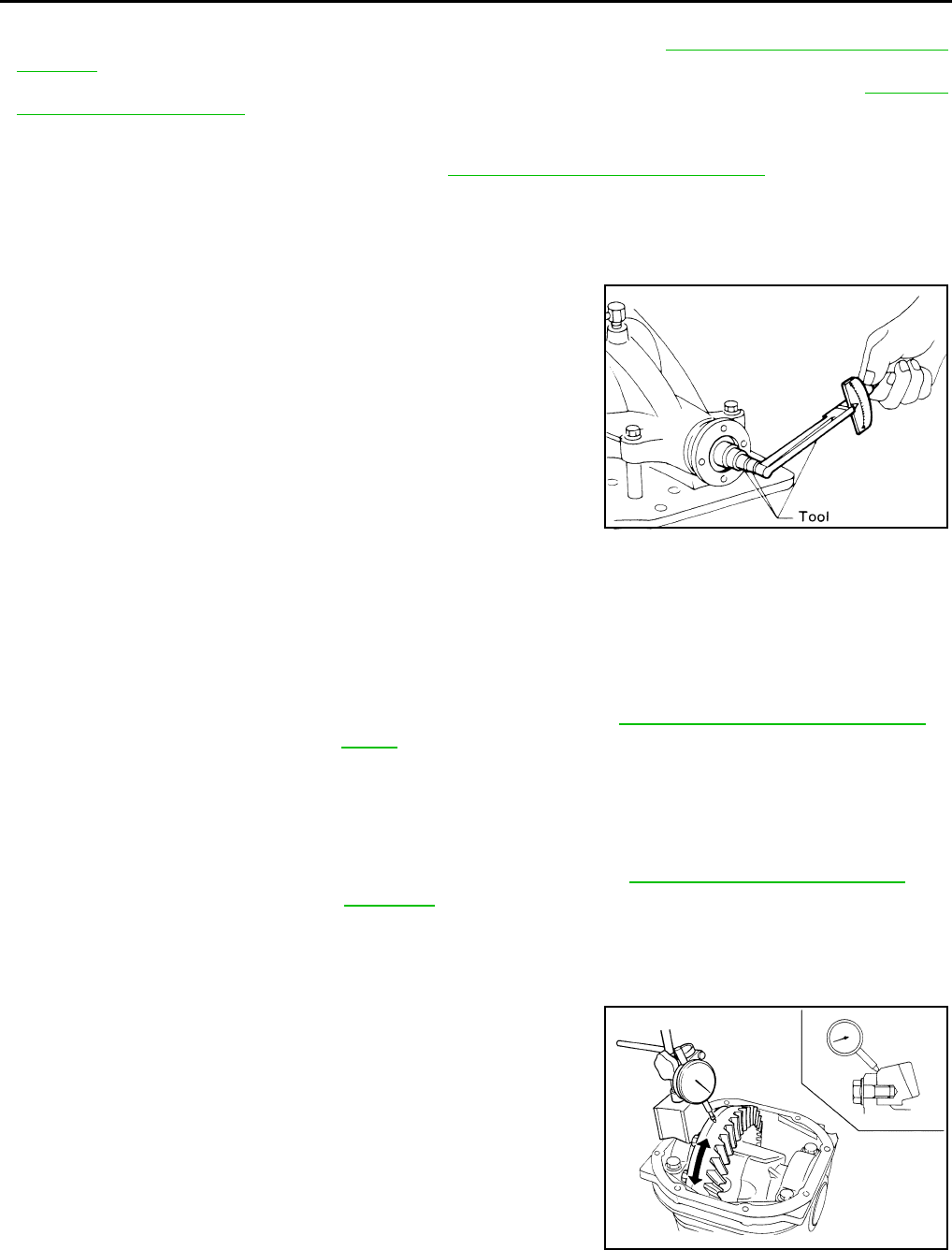
DLN-414
< DISASSEMBLY AND ASSEMBLY > [REAR FINAL DRIVE: R200]
REAR FINAL DRIVE
ASSEMBLY INSPECTION AND ADJUSTMENT
• Drain the differential gear oil before inspection and adjustment. Refer to DLN-404, "Changing Differential
Gear Oil".
• Remove and install the carrier cover as necessary for inspection and adjustment. Refer to DLN-409,
"Removal and Installation".
Total Preload Torque
1. Remove the side flanges if necessary. Refer to DLN-407, "Removal and Installation".
CAUTION:
The side flanges shaft must removed in order to measure total preload torque.
2. Rotate the drive pinion back and forth 2 to 3 times to check for unusual noise and rotation malfunction.
3. Rotate the drive pinion at least 20 times to check for smooth operation of the bearings.
4. Measure total preload torque using Tool.
NOTE:
Total preload torque = Drive pinion bearing preload torque +
Side bearing preload torque
• If the measured value is out of the specification, check and adjust each part. Adjust the drive pinion
bearing preload torque first, then adjust the side bearing preload torque.
CAUTION:
Select a side bearing adjusting washer for right and left individually.
Drive Gear Runout
1. Fit a dial indicator to the drive gear back face.
2. Rotate the drive gear to measure runout.
• If the runout is outside of the limit, check the condition of the drive
gear assembly. Foreign material may be caught between the drive
gear and differential case, or the differential case or drive gear may
be deformed.
CAUTION:
Replace drive gear and drive pinion as a set.
Tooth Contact
Tool number : ST3127S000 (J-25765-A)
Total preload torque:
2.84 - 3.75 N·m (0.29 - 0.38 kg-m, 26 - 33 in-lb)
SPD884
If the total preload torque is greater than specification
On drive pinion bearings: Replace the collapsible spacer.
On side bearings: Use thinner side bearing adjusting washers by the same
amount on each side. Refer to DLN-432, "Inspection and Adjust-
ment".
If the total preload torque is less than specification
On drive pinion bearings: Tighten the drive pinion lock nut.
On side bearings: Use thicker side bearing adjusting washers by the same
amount on each side. Refer to DLN-432, "Inspection and Ad-
justment".
Runout limit : 0.05 mm (0.0020 in) or less
SPD886
Revision: October 2008
2009 Pathfinder
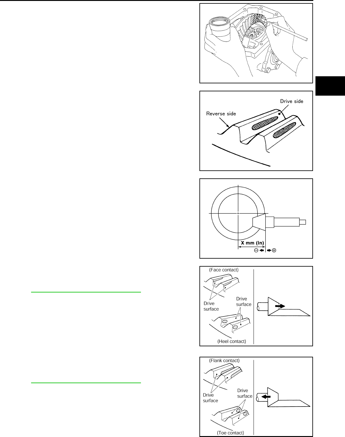
REAR FINAL DRIVE
DLN-415
< DISASSEMBLY AND ASSEMBLY > [REAR FINAL DRIVE: R200]
C
E
F
G
H
I
J
K
L
M
A
B
DLN
N
O
P
1. Apply red lead to the drive gear.
NOTE:
Apply red lead to both faces of three to four gears, at four loca-
tions evenly spaced on the drive gear.
2. Rotate the drive gear back and forth several times. Then check
for correct drive pinion to drive gear tooth contact as shown.
CAUTION:
Check tooth contact on drive side and reverse side.
3. If the tooth contact is improperly adjusted, follow the procedure
below to adjust the pinion height (dimension X).
• If the tooth contact is near the face (face contact), or near the heel
(heel contact), use a thicker drive pinion height adjusting washers
to move the drive pinion closer to the drive gear.
Refer to DLN-432, "Inspection and Adjustment".
• If the tooth contact is near the flank (flank contact), or near the toe
(toe contact), use a thinner drive pinion height adjusting washers to
move the drive pinion farther from the drive gear.
Refer to DLN-432, "Inspection and Adjustment".
SPD357
SDIA0570E
SDIA0517E
PDIA0440E
PDIA0441E
Revision: October 2008
2009 Pathfinder
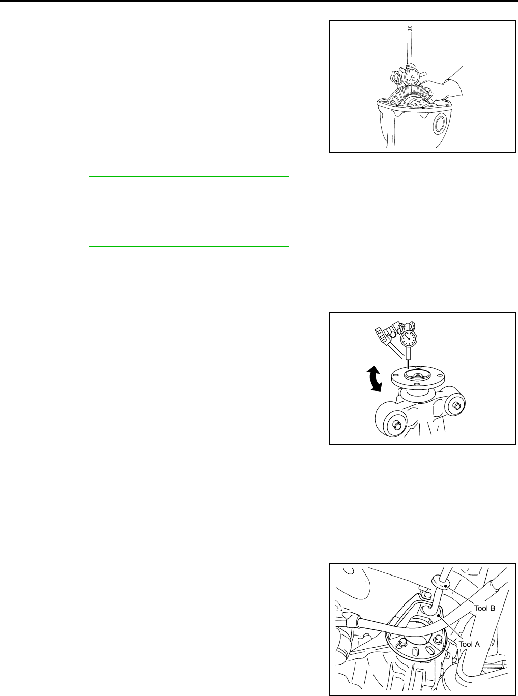
DLN-416
< DISASSEMBLY AND ASSEMBLY > [REAR FINAL DRIVE: R200]
REAR FINAL DRIVE
Backlash
1. Fit a dial indicator to the drive gear face to measure the back-
lash.
• If the backlash is outside of the specification, change the thickness
of the side bearing adjusting washers.
CAUTION:
Do not change the total thickness of side bearing adjusting washers as it will change the side bearing
preload torque.
Companion Flange Runout
1. Rotate companion flange and check for runout on the outer face
of the companion flange using suitable tool.
2. If the runout is outside of the runout limit, follow the procedure
below to adjust.
a. Rotate the companion flange on the drive pinion by 90°, 180°
and 270° while checking for the position where the runout is
minimum.
b. If the runout is still outside of the runout limit after the companion
flange has been rotated on the drive pinion, possible cause
could be an assembly malfunction of drive pinion and drive pinion bearing or a malfunctioning drive pinion
bearing.
c. If the runout is still outside of the runout limit after repair of the assembly of drive pinion and drive pinion
bearing or drive pinion bearing, replace the companion flange.
DISASSEMBLY
Side Flange
1. Drain the differential gear oil if necessary.
2. Remove the side flange using Tools.
NOTE:
Circular clip installation position: Rear final drive side
Backlash: 0.10 - 0.15 mm (0.0039 - 0.0059 in)
If the backlash is greater than specification:
Make side bearing adjusting washer thicker on drive
gear back side, and side bearing adjusting washer
thinner on drive gear tooth side by the same amount.
Refer to DLN-413, "Disassembly and Assembly".
If the backlash is less than specification:
Make side bearing adjusting washer thinner on drive
gear back side, and side bearing adjusting washer
thicker on drive gear tooth side by the same amount.
Refer to DLN-413, "Disassembly and Assembly".
SPD513
Runout limit : 0.08 mm (0.0031 in) or less
WDIA0231E
Tool numbers A: KV40104100 ( — )
B: ST36230000 (J-25840-A)
WDIA0115E
Revision: October 2008
2009 Pathfinder
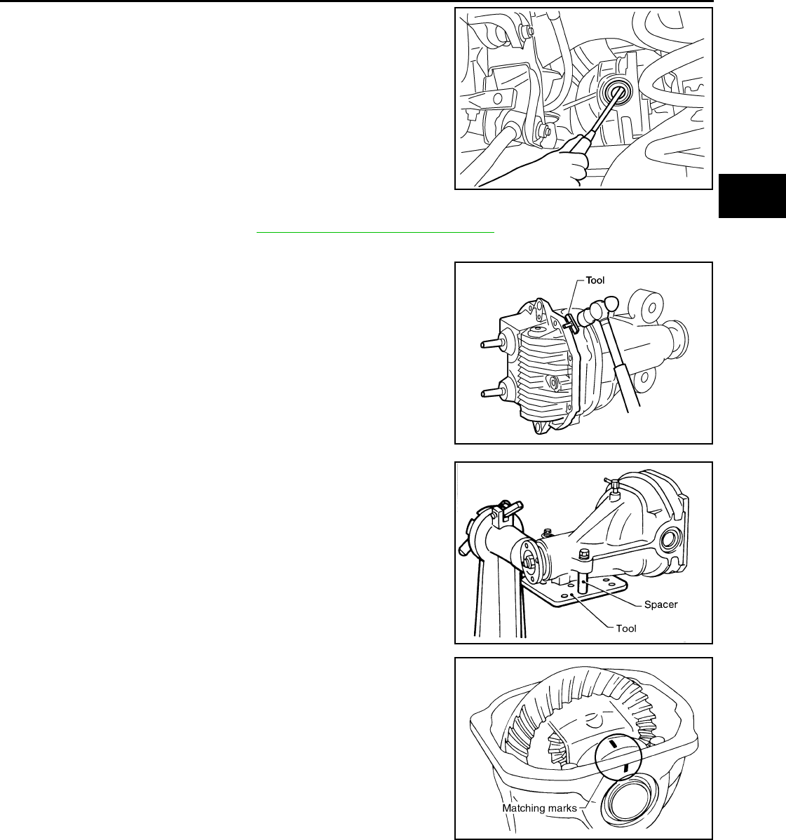
REAR FINAL DRIVE
DLN-417
< DISASSEMBLY AND ASSEMBLY > [REAR FINAL DRIVE: R200]
C
E
F
G
H
I
J
K
L
M
A
B
DLN
N
O
P
3. Remove the side oil seal using suitable tool.
CAUTION:
Do not to damage gear carrier.
Differential Assembly
1. Remove the side flanges. Refer to DLN-407, "Removal and Installation".
2. Remove the carrier cover bolts.
3. Remove the carrier cover bolts and separate the carrier cover
from the gear carrier using Tool.
CAUTION:
• Do not damage the mating surface.
• Do not insert flat-bladed screwdriver, this will damage the
mating surface.
4. Mount the carrier on the Tool using two 45 mm (1.77 in) spacers.
5. For proper reinstallation, paint matching marks on one side of
the side bearing cap and gear carrier.
CAUTION:
• For matching marks, use paint. Do not damage side bear-
ing cap or gear carrier.
• Side bearing caps are line-board during manufacture. The
matching marks are used to reinstall them in their original
positions.
SDIA0495E
Tool number : KV10111100 (J-37228)
WDIA0123E
Tool number : KV38100800 (J-25604-01)
SPD888
SDIA1795E
Revision: October 2008
2009 Pathfinder
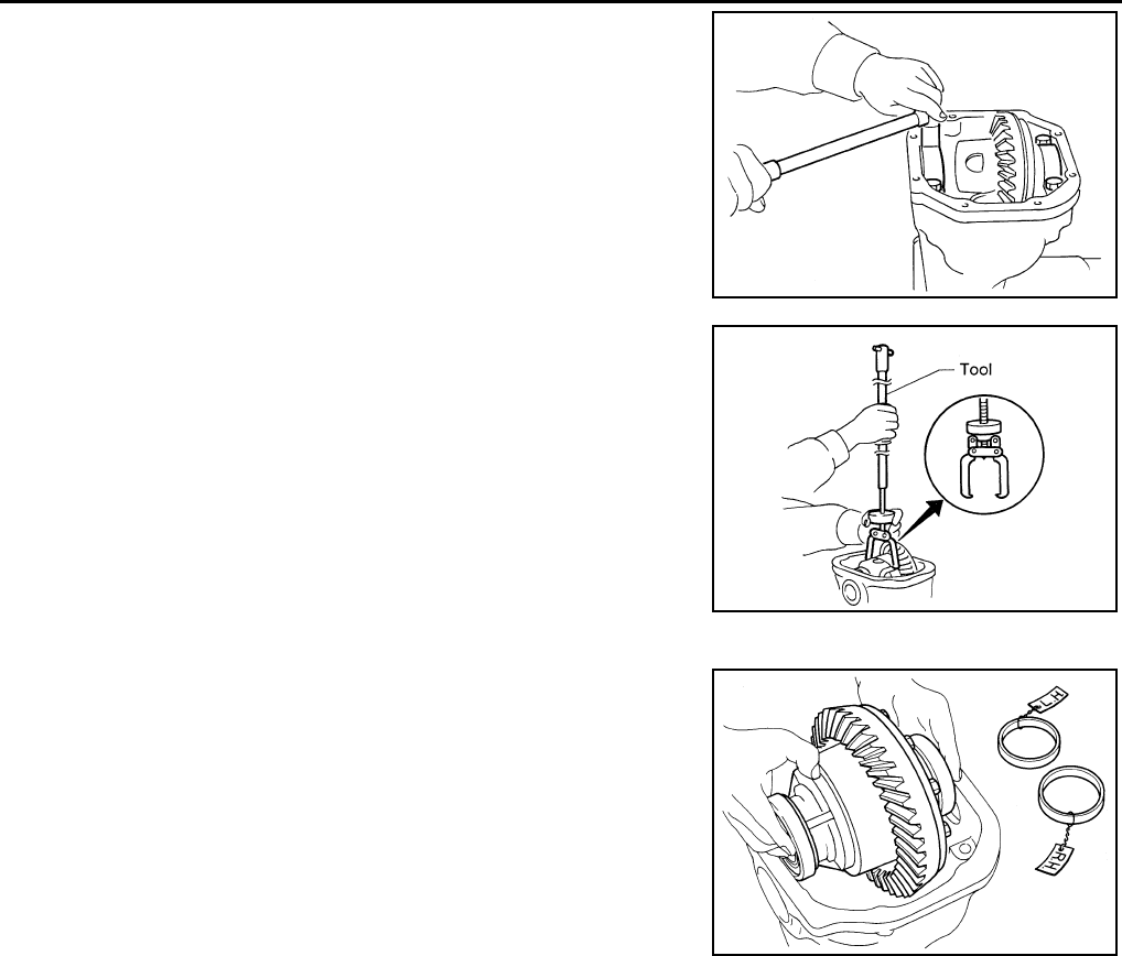
DLN-418
< DISASSEMBLY AND ASSEMBLY > [REAR FINAL DRIVE: R200]
REAR FINAL DRIVE
6. Remove the side bearing caps.
7. Lift the differential case assembly out using Tool.
CAUTION:
• Keep side bearing outer races together with inner race.
Do not mix them up.
• Keep side bearing adjusting washers together with side
bearings.
S-PD343
Tool number : HT72400000 ( — )
S-PD344
SPD919
Revision: October 2008
2009 Pathfinder
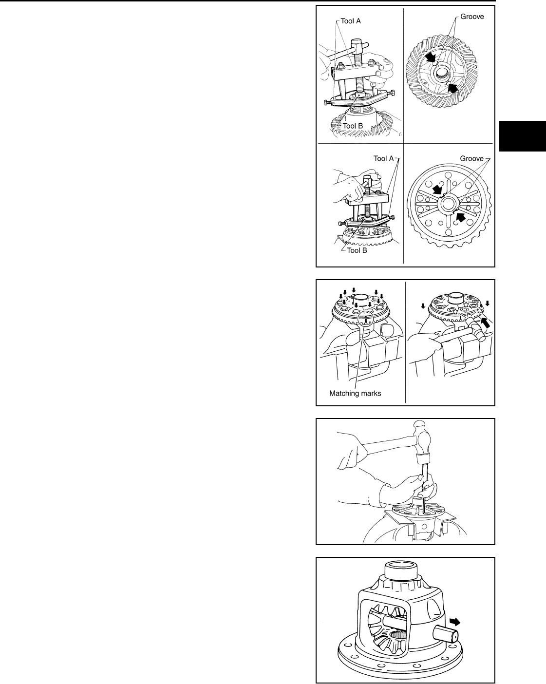
REAR FINAL DRIVE
DLN-419
< DISASSEMBLY AND ASSEMBLY > [REAR FINAL DRIVE: R200]
C
E
F
G
H
I
J
K
L
M
A
B
DLN
N
O
P
8. Remove the side bearing inner races using Tools.
CAUTION:
• Engage Tool jaws in bearing groove to prevent damage.
• Place copper plates between the side bearing and drive
gear and the vise to prevent damage.
• Do not remove side bearing inner race unless it is being
replaced.
9. For proper reinstallation, paint matching marks on the differential
case and drive gear.
CAUTION:
Use paint for matching marks. Do not damage differential
case or drive gear.
10. Remove the drive gear bolts.
11. Tap the drive gear off the differential case using suitable tool.
CAUTION:
Tap evenly all around to keep drive gear from bending.
12. Remove the lock pin of the pinion mate shaft from the drive gear
side using suitable tool.
13. Remove the pinion mate shaft.
Tool number A: ST33051001 (J-22888-20)
B: ST33061000 (J-8107-2)
SPD920
PDIA0496E
WDIA0132E
SDIA0031J
Revision: October 2008
2009 Pathfinder
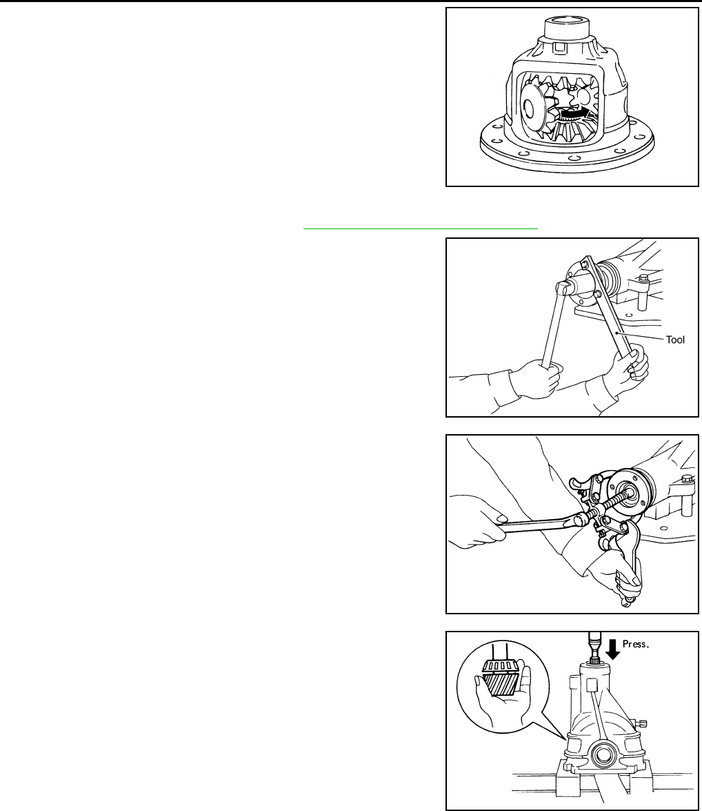
DLN-420
< DISASSEMBLY AND ASSEMBLY > [REAR FINAL DRIVE: R200]
REAR FINAL DRIVE
14. Turn the pinion mate gear, then remove the pinion mate gear,
pinion mate thrust washer, side gear and side gear thrust
washer from the differential case.
Drive Pinion Assembly
1. Remove the differential assembly. Refer to DLN-410, "Removal and Installation".
2. Remove the drive pinion lock nut using Tool.
3. Put matching marks on the companion flange and drive pinion
using paint.
CAUTION:
Use paint to make the matching marks. Do not damage the
companion flange or drive pinion.
4. Remove the companion flange using suitable tool.
5. Press the drive pinion assembly (with rear inner bearing race
and collapsible spacer) out of the gear carrier.
CAUTION:
Do not drop drive pinion assembly.
6. Remove the front oil seal.
CAUTION:
Do not damage gear carrier.
7. Remove the drive pinion front bearing inner race.
SDIA0032J
Tool number : KV40104000 ( — )
SDIA1144E
SDIA1132E
SPD892
Revision: October 2008
2009 Pathfinder
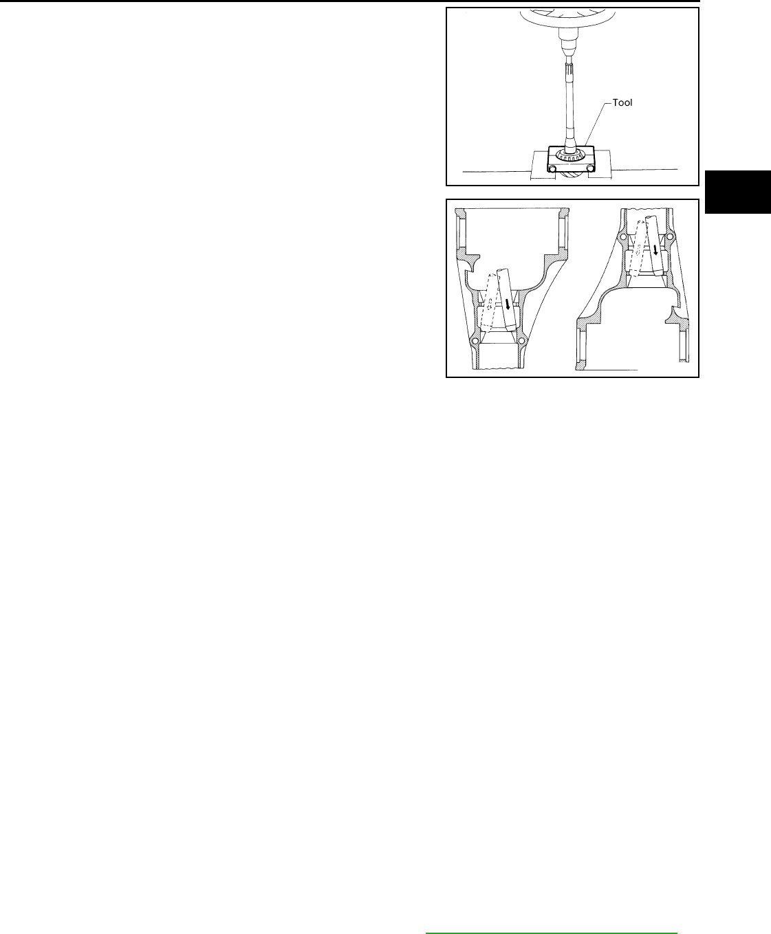
REAR FINAL DRIVE
DLN-421
< DISASSEMBLY AND ASSEMBLY > [REAR FINAL DRIVE: R200]
C
E
F
G
H
I
J
K
L
M
A
B
DLN
N
O
P
8. Remove the drive pinion rear bearing inner race and drive pinion
height adjusting washer using Tool.
9. Remove the drive pinion front and rear bearing outer races by
tapping them uniformly using suitable tool.
CAUTION:
Do not damage gear carrier.
INSPECTION AFTER DISASSEMBLY
Clean the disassembled parts. Then inspect the parts for wear or damage. If wear or damage are found, follow
the measures below.
Drive Pinion and Drive Gear
• If the drive pinion and drive gear teeth do not mesh or line-up correctly, determine the cause and adjust,
repair, or replace as necessary.
• If the drive pinion or drive gear are worn, cracked, damaged, pitted or chipped (by friction) noticeably,
replace with new drive pinion and drive gear.
• Drive pinion and drive gear are supplied in matched sets only. Matching numbers on both drive pinion and
drive gear are etched for verification. If a new drive pinion and drive gear set are being used, verify the num-
bers of each drive pinion and drive gear before proceeding with assembly.
Bearing
• If bearings are chipped (by friction), pitted, worn, rusted, scratched, or unusual noise is coming from bearing,
replace with new bearing assembly (as a new set).
• Bearing must be replaced with a new one whenever disassembled.
Side Gear and Pinion Mate Gear
• If any cracks or damage are found on the surface of the teeth, replace with new one.
• If any worn or chipped marks are found on the side of the side gear and pinion mate gear which contact the
thrust washer, replace with new one.
• Replace both side gear and pinion mate gear as a set when replacing side gear or pinion mate gear.
Side Gear Thrust Washer and Pinion Mate Thrust Washer
• If any chips (by friction), damage, or unusual wear are found, replace with new one.
Gear Carrier
• If any wear or cracks are found on the contact sides of gear carrier, replace with new one.
Companion Flange
• If any chips (about 0.1mm, 0.004 in) or other damage on the companion flange surface which contacts the
front oil seal lips are found, replace with new one.
ADJUSTING AND SELECTING WASHERS
Side Gear Back Clearance
• Assemble the differential parts if they are disassembled. Refer toDLN-413, "Disassembly and Assembly"".
Tool number : ST30031000 (J-22912-01)
S-PD179
SDIA0817E
Revision: October 2008
2009 Pathfinder
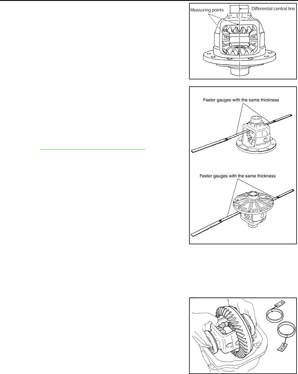
DLN-422
< DISASSEMBLY AND ASSEMBLY > [REAR FINAL DRIVE: R200]
REAR FINAL DRIVE
1. Place the differential case straight up so that the side gear to be
measured is upward.
2. Using feeler gauges, measure the clearance between the side
gear back and differential case at three different points, while
rotating the side gear. Average the three readings to calculate
the clearance. (Measure the clearance of the other side as well.)
• If the side gear back clearance is outside of the specification,
use a thicker or thinner side gear thrust washer to adjust.
Refer to DLN-432, "Inspection and Adjustment".
CAUTION:
• Insert feeler gauges with the same thickness on both
sides to prevent side gear from tilting.
• Each gear should rotate smoothly without excessive
resistance during differential motion.
• Select a side gear thrust washer for right and left individu-
ally.
NOTE:
Side gear back clearance is clearance between side gear and differential case for adjusting side gear
backlash.
Side Bearing Preload Torque
• A selection of side bearing adjusting washers is required for successful completion of this procedure.
1. Apply differential gear oil to the side bearings, and install the dif-
ferential case assembly with the side bearing outer races into
the gear carrier.
CAUTION:
Do not reuse side bearing outer race when replacing side
bearing inner race (replace as a set).
PDIA0460E
Side gear back clearance: 0.2 mm (0.008 in) or less.
If the side gear back clearance is greater than
specification:
Use a thicker side gear thrust washer.
If the side gear back clearance is less than spec-
ification:
Use a thinner side gear thrust washer.
PDIA0576E
SPD527
Revision: October 2008
2009 Pathfinder
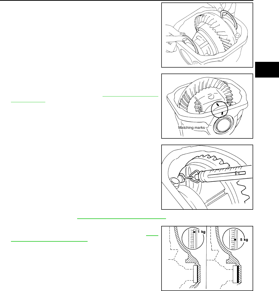
REAR FINAL DRIVE
DLN-423
< DISASSEMBLY AND ASSEMBLY > [REAR FINAL DRIVE: R200]
C
E
F
G
H
I
J
K
L
M
A
B
DLN
N
O
P
2. Insert the left and right original side bearing adjusting washers in
place between side bearings and gear carrier.
3. Align the matching mark on the side bearing cap with the match-
ing mark on the gear carrier.
4. Install the side bearing caps and tighten the side bearing cap
bolts to the specified torque. Refer to DLN-413, "Disassembly
and Assembly".
5. Turn the differential assembly several times to seat the side
bearings.
6. To determine side bearing preload torque, measure the pulling
force of the differential assembly at the drive gear bolt using
Tool.
NOTE:
If pulling force of the differential assembly at the drive gear bolt
is within specification, side bearing preload torque will also be
within specification. Refer to DLN-432, "Inspection and Adjustment".
7. If the pulling force is outside the specification, use a thicker or
thinner side bearing adjusting washer to adjust. Refer to DLN-
432, "Inspection and Adjustment".
CAUTION:
Select a side bearing adjusting washer for right and left
individually.
8. Record the total amount of washer thickness required for the correct side bearing preload torque.
Drive Pinion Height
SPD924
SDIA1795E
Tool number : — (J-8129)
Specification : 34.2 - 39.2 N (3.5 - 4.0 kg, 7.7 - 8.8 lb)
of pulling force at the drive gear bolt
SPD194A
If the pulling force is less than the specification:
Use a thicker side bearing adjusting washer.
If the pulling force is greater than the specification:
Use a thinner side bearing adjusting washer.
SPD772
Revision: October 2008
2009 Pathfinder
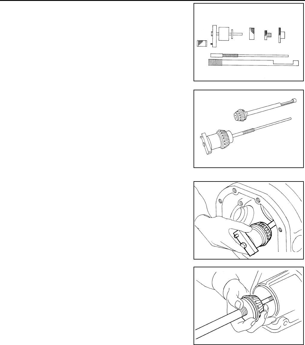
DLN-424
< DISASSEMBLY AND ASSEMBLY > [REAR FINAL DRIVE: R200]
REAR FINAL DRIVE
1. Make sure all parts are clean and that the bearings are well
lubricated.
2. Assemble the drive pinion bearings onto the Tool.
•Drive pinion front bearing; make sure the J-34309-3 drive
pinion front bearing seat is secured tightly against the J-
34309-2 gauge anvil. Then turn the J-34309-5 drive pinion
front bearing pilot to secure the drive pinion bearing in its
proper position.
•Drive pinion rear bearing; the J-34309-8 drive pinion rear
bearing pilot is used to center the drive pinion rear bearing
only. The J-34309-4 drive pinion rear bearing locking seat is
used to lock the drive pinion rear bearing to the assembly.
•Installation of J-34309-9 and J-34309-16; place a suitable
2.5 mm (0.098 in) thick plain washer between J-34309-9 and
J-34309-16. Both surfaces of J-34309-9 and J-34309-16 must
be parallel with a clearance of 2.5 mm (0.098 in).
3. Install the drive pinion rear bearing inner race into the gear car-
rier. Then insert the drive pinion height adjusting washer selec-
tor tool, J-34309-1, gauge screw assembly.
4. Assemble the drive pinion front bearing inner race and the J-
34309-2 gauge anvil. Assemble them together with the J-34309-
1 gauge screw in the gear carrier. Make sure that the drive pin-
ion height gauge plate, J-34309-16, will turn a full 360°. Tighten
the two sections together by hand.
Tool number : — (J-34309)
SPD769
SPD197A
SPD893
SPD199A
Revision: October 2008
2009 Pathfinder
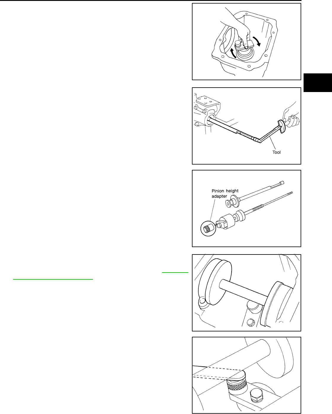
REAR FINAL DRIVE
DLN-425
< DISASSEMBLY AND ASSEMBLY > [REAR FINAL DRIVE: R200]
C
E
F
G
H
I
J
K
L
M
A
B
DLN
N
O
P
5. Turn the assembly several times to seat the drive pinion bear-
ings.
6. Measure the turning torque at the end of the J-34309-2 gauge
anvil using Tool.
7. Place the J-34309-11 “R200A” drive pinion height adapter onto
the gauge plate and tighten it by hand.
CAUTION:
Make sure all machined surfaces are clean.
8. Position the side bearing discs, Tool, and arbor firmly into the
side bearing bores. Install the side bearing caps and tighten the
side bearing cap bolts to the specified torque. Refer to DLN-413,
"Disassembly and Assembly".
9. Select the correct standard drive pinion height adjusting washer
thickness. Select by using a standard gauge of 3 mm (0.12 in)
and your J-34309-101 feeler gauge. Measure the distance
between the J-34309-11 drive pinion height adapter, including
the standard gauge and the arbor.
SPD770
Tool number : ST3127S000 (J-25765- A)
Turning torque: 1.0 - 1.3 N·m (0.11 - 0.13 kg-m,
9 - 11 in-lb)
PDIA0566E
SPD208A
Tool number : — (J-25269-4)
SPD211A
SPD204A
Revision: October 2008
2009 Pathfinder
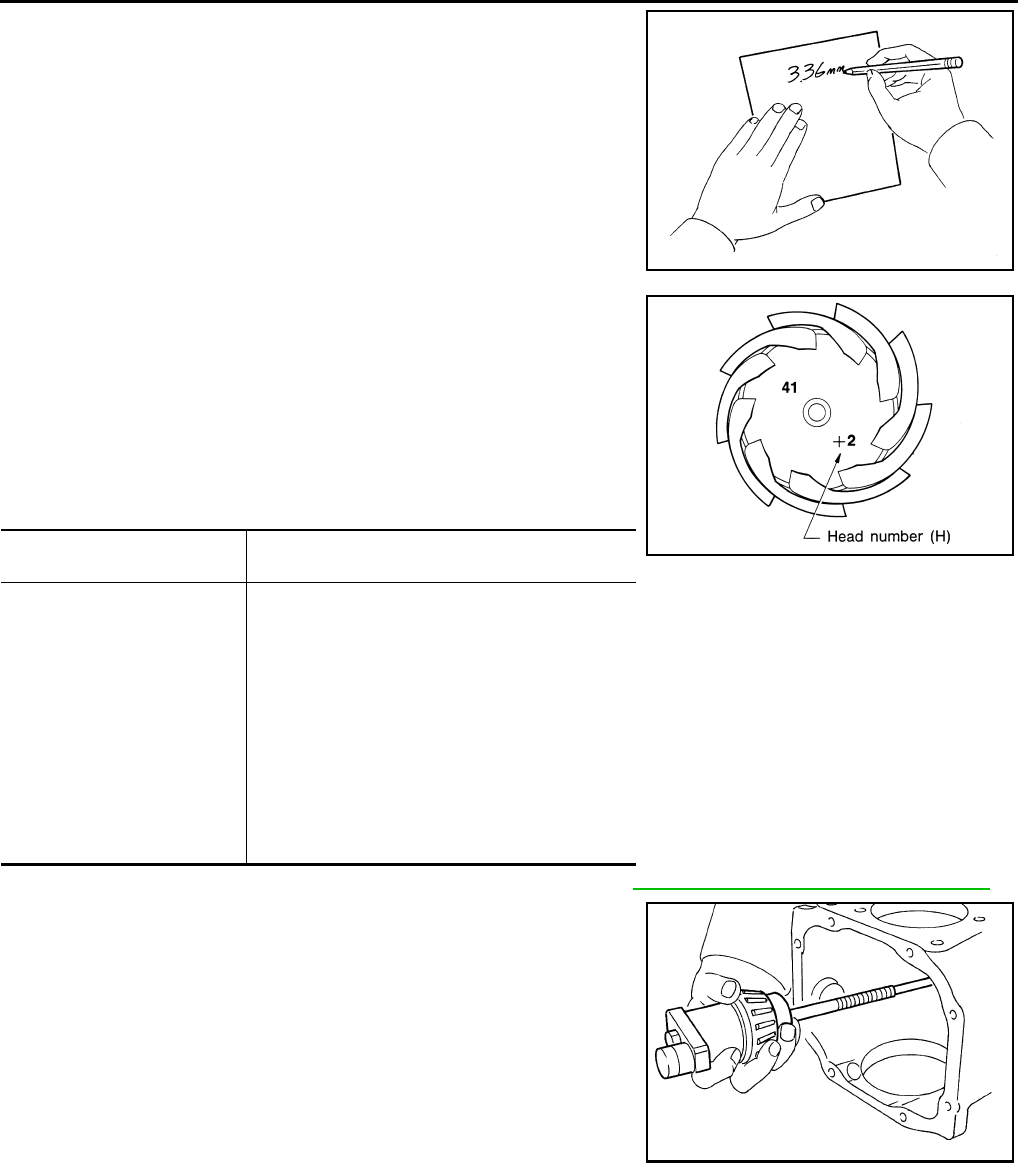
DLN-426
< DISASSEMBLY AND ASSEMBLY > [REAR FINAL DRIVE: R200]
REAR FINAL DRIVE
10. Write down the exact measurement (the value of feeler gauge).
11. Correct the drive pinion height adjusting washer size by referring
to the drive pinion “head number”.
There are two numbers painted on the drive pinion. The first
one refers to the drive pinion and drive gear as a matched
set. This number should be the same as the number on the
drive gear. The second number is the drive pinion “head
number”. It refers to the ideal drive pinion height from stan-
dard for quietest operation. Use the following chart to
determine the correct drive pinion height adjusting washer.
12. Select the correct drive pinion height adjusting washer. Refer to DLN-432, "Inspection and Adjustment".
13. Remove the Tool from the gear carrier and disassemble to
retrieve the drive pinion bearings.
ASSEMBLY
Drive Pinion Assembly
SPD775
Head number Add or remove from the standard drive pinion
height adjusting washer thickness measurement
- 6
- 5
- 4
- 3
- 2
- 1
0
+1
+2
+3
+4
+5
+6
Add 0.06 mm (0.0024 in)
Add 0.05 mm (0.0020 in)
Add 0.04 mm (0.0016 in)
Add 0.03 mm (0.0012 in)
Add 0.02 mm (0.0008 in)
Add 0.01 mm (0.0004 in)
Use the selected washer thickness
Subtract 0.01 mm (0.0004 in)
Subtract 0.02 mm (0.0008 in)
Subtract 0.03 mm (0.0012 in)
Subtract 0.04 mm (0.0016 in)
Subtract 0.05 mm (0.0020 in)
Subtract 0.06 mm (0.0024 in)
Tool number : — (J-34309)
SPD542
SPD205A
Revision: October 2008
2009 Pathfinder
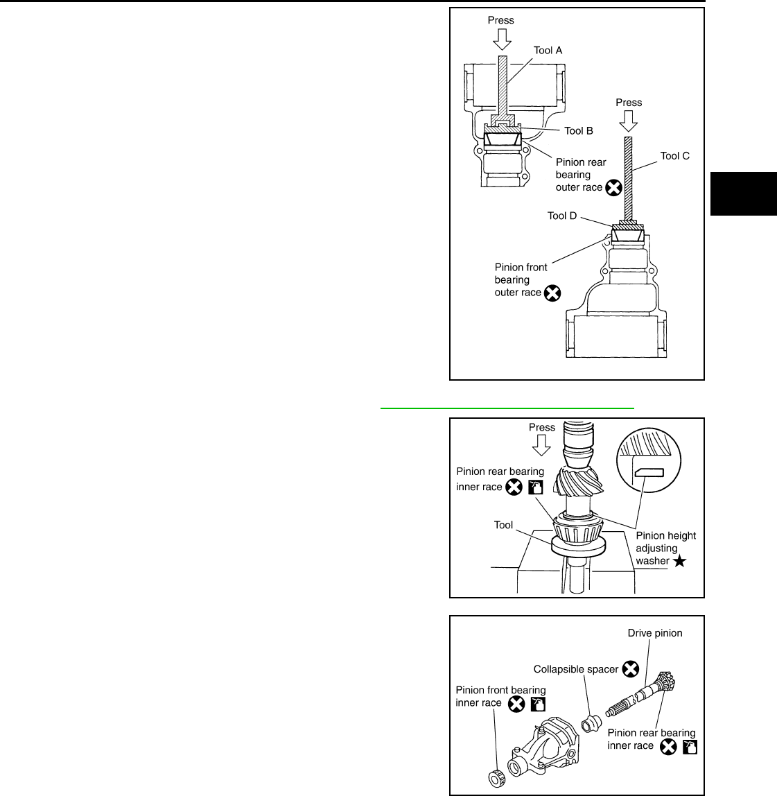
REAR FINAL DRIVE
DLN-427
< DISASSEMBLY AND ASSEMBLY > [REAR FINAL DRIVE: R200]
C
E
F
G
H
I
J
K
L
M
A
B
DLN
N
O
P
1. Install the drive pinion front and rear bearing outer races using
Tools.
CAUTION:
• First tap the drive pinion bearing outer race until it
becomes flush with the gear carrier.
• Do not reuse drive pinion front and rear bearing outer
race.
2. Select a drive pinion height adjusting washer. Refer to DLN-413, "Disassembly and Assembly".
3. Install the selected drive pinion height adjusting washer to the
drive pinion. Press the drive pinion rear bearing inner race to it
using Tool.
CAUTION:
• Install the drive pinion height adjusting washer in the
proper direction as shown.
• Do not reuse drive pinion rear bearing inner race.
4. Assemble the collapsible spacer to the drive pinion.
CAUTION:
Do not reuse collapsible spacer.
5. Apply differential gear oil to the drive pinion rear bearing, and
install the drive pinion assembly to the gear carrier.
6. Apply differential gear oil to the drive pinion front bearing, and
install the drive pinion front bearing inner race to the drive pinion
assembly.
CAUTION:
Do not reuse drive pinion front bearing inner race.
Tool number A: ST30720000 (J-25405)
B: KV40105230 ( — )
C: ST30611000 (J-25742-1)
D: ST30613000 (J-25742-3)
PDIA0562E
Tool number : ST30901000 (J-26010-01)
SDIA0048E
PDIA0492E
Revision: October 2008
2009 Pathfinder
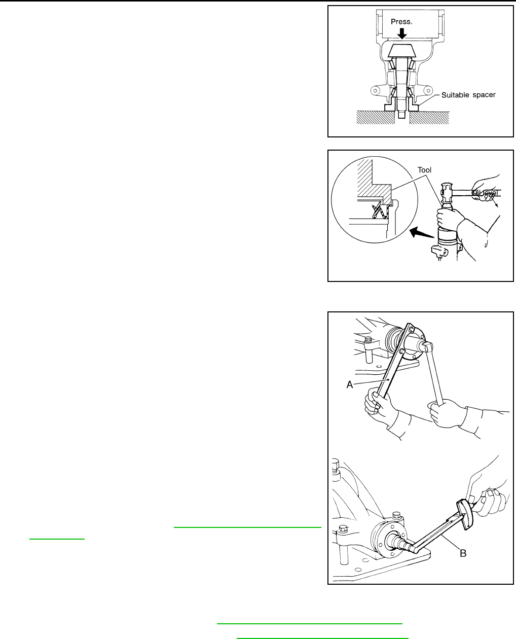
DLN-428
< DISASSEMBLY AND ASSEMBLY > [REAR FINAL DRIVE: R200]
REAR FINAL DRIVE
7. Press the drive pinion front bearing inner race to the drive pinion
as far as drive pinion lock nut can be tightened using suitable
spacer.
8. Apply multi-purpose grease to the lips and differential gear oil to
the circumference of the new front oil seal. Then drive the new
front oil seal in evenly until it becomes flush with the gear carrier
using Tool.
CAUTION:
• Do not reuse front oil seal.
• Do not incline the new front oil seal when installing.
• Apply multi-purpose grease to the lips and differential
gear oil to the circumference of the new front oil seal.
9. Install the companion flange to the drive pinion while aligning the matching marks.
10. Apply anti-corrosive oil to the threads of the drive pinion and the
seating surface of the new drive pinion lock nut. Then adjust the
drive pinion lock nut tightening torque using Tool A, and check
the drive pinion bearing preload torque using Tool B.
CAUTION:
• Do not reuse drive pinion lock nut.
• Apply anti-corrosive oil to the threads of the drive pinion
and the seating surface of the new drive pinion lock nut.
• Adjust the drive pinion lock nut tightening torque to the
lower limit first. Do not exceed the drive pinion lock nut
specified torque. Refer to DLN-413, "Disassembly and
Assembly".
• If the drive pinion bearing preload torque exceeds the
specified value, replace collapsible spacer and tighten it
again to adjust. Do not loosen drive pinion lock nut to
adjust the drive pinion bearing preload torque.
• After adjustment, rotate drive pinion back and forth 2 to 3
times to check for unusual noise, rotation malfunction, and other malfunctions.
11. Check companion flange runout. Refer to DLN-413, "Disassembly and Assembly".
12. Install the differential case assembly. Refer to DLN-410, "Removal and Installation".
Differential Assembly
SPD896
Tool number : ST30720000 (J-25405)
PDIA0563E
Tool number A: KV40104000 ( — )
B: ST3127S000 (J-25765-A)
Drive pinion bearing preload torque:
2.65 - 3.23 N·m (0.27 - 0.32 kg-m, 24 - 28 in-lb)
WDIA0379E
Revision: October 2008
2009 Pathfinder
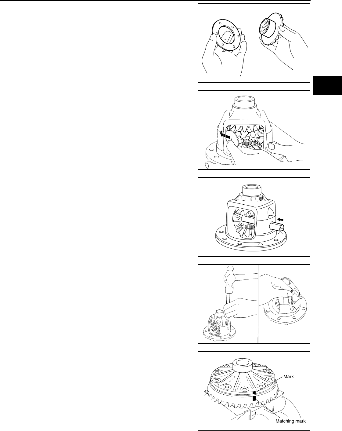
REAR FINAL DRIVE
DLN-429
< DISASSEMBLY AND ASSEMBLY > [REAR FINAL DRIVE: R200]
C
E
F
G
H
I
J
K
L
M
A
B
DLN
N
O
P
1. Install side gear thrust washers with the same thickness as the
ones installed prior to disassembly, or reinstall the old ones on
the side gears.
2. Install the side gears and side gear thrust washers into the dif-
ferential case.
CAUTION:
Make sure that the circular clip is installed to side gears.
3. Install the pinion mate thrust washers to the two pinion mate
gears. Then install the pinion mate gears with the pinion mate
thrust washers by aligning them in diagonally opposite positions
and rotating them into the differential case.
4. Align the lock pin hole on the differential case with the lock pin
hole on the pinion mate shaft, and install the pinion mate shaft.
5. Measure the side gear end play. If necessary, select the appro-
priate side gear thrust washers. Refer to DLN-432, "Inspection
and Adjustment".
6. Drive a new lock pin into the pinion mate shaft until it is flush
with the differential case using suitable tool.
CAUTION:
Do not reuse lock pin.
7. Align the matching mark of the differential case with the mark of
the drive gear, then place the drive gear onto the differential
case.
SDIA0193J
SDIA2025E
SDIA0195J
WDIA0131E
SDIA2593E
Revision: October 2008
2009 Pathfinder
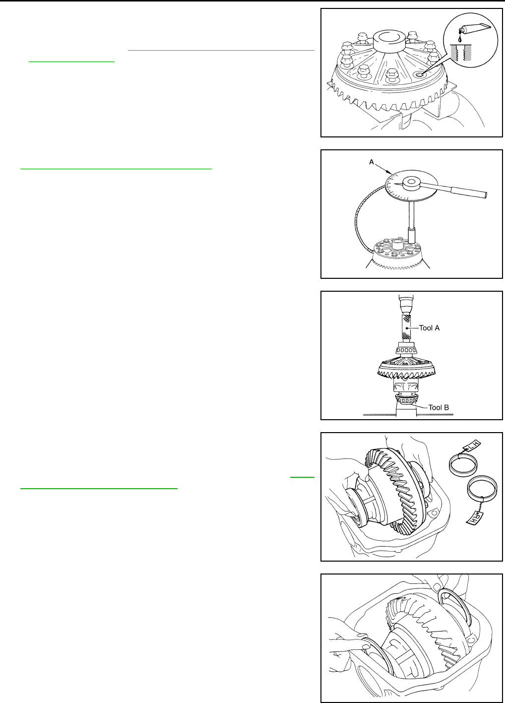
DLN-430
< DISASSEMBLY AND ASSEMBLY > [REAR FINAL DRIVE: R200]
REAR FINAL DRIVE
8. Apply thread locking sealant into the threaded holes of the drive
gear and install the bolts.
• Use Genuine Medium Strength Thread Locking Sealant or
equivalent. Refer to GI-26, "Recommended Chemical Prod-
ucts and Sealants".
CAUTION:
Make sure the drive gear back and threaded holes are
clean.
9. Tighten the drive gear bolts to the specified torque. Refer to
DLN-413, "Disassembly and Assembly". After tightening the
drive gear bolts to the specified torque, tighten an additional 31°
to 36° using Tool.
CAUTION:
• Always use Tool. Avoid tightening based on visual check
alone.
• Tighten drive gear bolts in a crisscross pattern.
10. Press the side bearing inner races into the differential case
using Tools.
CAUTION:
Do not reuse side bearing inner race.
11. Install the differential case assembly with the side bearing outer
races into the gear carrier.
12. Measure the side bearing preload torque. If necessary, select
the appropriate side bearing adjusting washers. Refer to DLN-
413, "Disassembly and Assembly".
13. Insert the selected left and right side bearing adjusting washers
in place between the side bearings and gear carrier.
SDIA2594E
Tool number : KV10112100-A (BT-8653-A)
AWBIA0722Z
Z
Tool number A: KV38100300 (J-25523)
B: ST33061000 (J-8107-2)
SPD353
SPD919
SPD924
Revision: October 2008
2009 Pathfinder
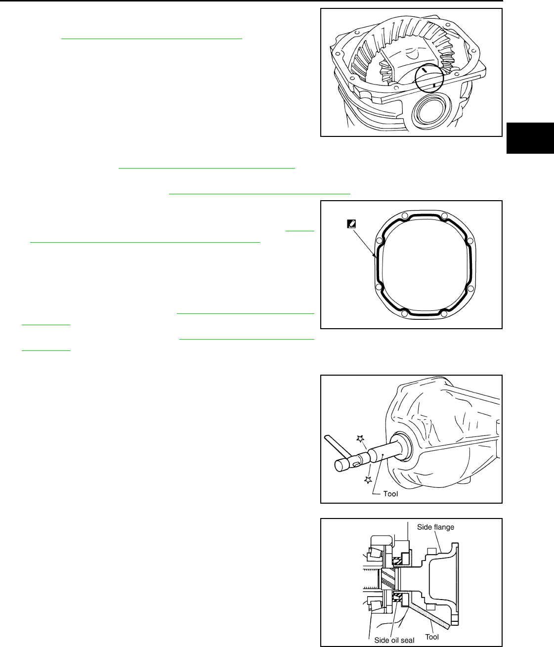
REAR FINAL DRIVE
DLN-431
< DISASSEMBLY AND ASSEMBLY > [REAR FINAL DRIVE: R200]
C
E
F
G
H
I
J
K
L
M
A
B
DLN
N
O
P
14. Install the side bearing caps with the matching marks aligned
and tighten the side bearing cap bolts to the specified torque.
Refer to DLN-413, "Disassembly and Assembly".
15. Check and adjust the drive gear runout, tooth contact, drive gear to drive pinion backlash, and total pre-
load torque. Refer to DLN-432, "Inspection and Adjustment"
Recheck the above items.
16. Install the side flanges. Refer to DLN-413, "Disassembly and Assembly".
17. Apply a 3.2mm (0.126 in) bead of sealant to the mating surface
of the carrier cover.
• Use Genuine Silicone RTV or equivalent. Refer to GI-26,
"Recommended Chemical Products and Sealants".
CAUTION:
Remove any old sealant adhering to the mating surfaces.
Also remove any moisture, oil, or foreign material adhering
to the application and mating surfaces.
18. Install the carrier cover to the gear carrier. Tighten the bolts to
the specified torque. Refer to DLN-413, "Disassembly and
Assembly".
19. Install the side flange. Refer to DLN-413, "Disassembly and
Assembly".
Side Flange
1. Apply multi-purpose grease to the lips and differential gear oil to
the circumference of the new side oil seal. Then drive the new
side oil seal in evenly until it becomes flush with the gear carrier
using Tool.
CAUTION:
• Do not reuse side oil seal.
• Do not incline the new side oil seal when installing.
• Apply multi-purpose grease to the lips and differential
gear oil to the circumference of the new side oil seal.
2. Install the side flange using Tool.
a. Install the Tool to the side oil seal as shown.
b. Insert the side flange until the serrated part of the side flange
has engaged the serrated part of the side gear and remove the
Tool.
c. Drive in the side flange using suitable tool.
NOTE:
Installation is completed when the driving sound of the side
flange turns into a sound which seems to affect the whole rear
final drive assembly.
SPD889
WDIA0282E
Tool number : KV38100200 (J-26233)
SPD560
Tool number : KV38107900 (J-39352)
SDIA0822E
Revision: October 2008
2009 Pathfinder

DLN-432
< SERVICE DATA AND SPECIFICATIONS (SDS) [REAR FINAL DRIVE: R200]
SERVICE DATA AND SPECIFICATIONS (SDS)
SERVICE DATA AND SPECIFICATIONS (SDS)
SERVICE DATA AND SPECIFICATIONS (SDS)
General Specification INFOID:0000000003937463
Inspection and Adjustment INFOID:0000000003937464
DRIVE GEAR RUNOUT
Unit: mm (in)
SIDE GEAR CLEARANCE
Unit: mm (in)
PRELOAD TORQUE
BACKLASH
Unit: mm (in)
COMPANION FLANGE RUNOUT
Unit: mm (in)
SELECTIVE PARTS
Side Gear Thrust Washer
Applied model VQ40DE
2WD 4WD
Final drive model R200
Gear ratio 3.133 3.357
Number of teeth (Drive gear/Drive pinion) 47/15 47/14
Oil capacity (Approx.) 1.4 (3 US pt, 2-1/2 lmp pt)
Number of pinion gears 2
Drive pinion adjustment spacer type Collapsible
Item Runout limit
Drive gear back face 0.05 (0.0020) or less
Item Specification
Side gear back clearance
(Clearance between side gear and differential case for adjusting
side gear backlash)
0.2 (0.008) or less
(Each gear should rotate smoothly without excessive resistance
during differential motion.)
Item Specification
Drive pinion bearing preload torque 2.65 - 3.23 N·m (0.27 - 0.32 kg−m, 24 - 28 in-lb)
Side bearing preload torque (reference value determined by drive
gear bolt pulling force) 0.20 - 0.52 N·m (0.02 - 0.05 kg−m, 2 - 4 in-lb)
Drive gear bolt pulling force (by spring gauge) 34.2 − 39.2 N (3.5 − 4 kg, 7.7 − 8.8 lb)
Total preload torque
(Total preload torque = drive pinion bearing preload torque + Side
bearing preload torque)
2.84 - 3.75 N·m (0.29 - 0.38 kg−m, 26 - 33 in-lb)
Item Specification
Drive gear to drive pinion gear 0.10 - 0.15 (0.0039 - 0.0059)
Item Runout limit
Outer side of the companion flange 0.08 (0.0031) or less
Revision: October 2008
2009 Pathfinder

SERVICE DATA AND SPECIFICATIONS (SDS)
DLN-433
< SERVICE DATA AND SPECIFICATIONS (SDS) [REAR FINAL DRIVE: R200]
C
E
F
G
H
I
J
K
L
M
A
B
DLN
N
O
P
Unit: mm (in)
*: Always check with the Parts Department for the latest parts information.
Drive Pinion Height Adjusting Washer
Unit: mm (in)
*: Always check with the Parts Department for the latest parts information.
Side Bearing Adjusting Washer
Unit: mm (in)
*: Always check with the Parts Department for the latest parts information.
Thickness Part number* Thickness Part number*
0.75 (0.0295)
0.78 (0.0307)
0.81 (0.0319)
0.84 (0.0331)
38424 0C000
38424 0C001
38424 0C002
38424 0C003
0.87 (0.0343)
0.90 (0.0350)
0.93 (0.0366)
38424 0C004
38424 0C005
38424 0C006
Thickness Part number* Thickness Part number*
3.05 (0.1201)
3.08 (0.1213)
3.11 (0.1224)
3.14 (0.1236)
38154 0C000
38154 0C001
38154 0C002
38154 0C003
3.17 (0.1248)
3.20 (0.1260)
3.23 (0.1272)
3.26 (0.1283)
38154 0C004
38154 0C005
38154 0C006
38154 0C007
Thickness Part number* Thickness Part number*
2.00 (0.0787)
2.05 (0.0807)
2.10 (0.0827)
2.15 (0.0846)
2.20 (0.0866)
2.25 (0.0886)
2.30 (0.0906)
38453 N3100
38453 N3101
38453 N3102
38453 N3103
38453 N3104
38453 N3105
38453 N3106
2.35 (0.0925)
2.40 (0.0945)
2.45 (0.0965)
2.50 (0.0984)
2.55 (0.1004)
2.60 (0.1024)
2.65 (0.1043)
38453 N3107
38453 N3108
38453 N3109
38453 N3110
38453 N3111
38453 N3112
38453 N3113
Revision: October 2008
2009 Pathfinder

DLN-434
< PRECAUTION > [REAR FINAL DRIVE: R230 (4WD)]
PRECAUTIONS
PRECAUTION
PRECAUTIONS
Precaution for Servicing Rear Final Drive INFOID:0000000003937465
• Before starting diagnosis of the vehicle, understand the symptoms well. Perform correct and systematic
operations.
• Check for the correct installation status prior to removal or disassembly. When matching marks are required,
be certain they do not interfere with the function of the parts they are applied to.
• Overhaul should be done in a clean work area, a dust proof area is recommended.
• Before disassembly, completely remove sand and mud from the exterior of the unit, preventing them from
entering into the unit during disassembly or assembly.
• Always use shop paper for cleaning the inside of components.
• Avoid using cotton gloves or a shop cloth to prevent the entering of lint.
• Check appearance of the disassembled parts for damage, deformation, and abnormal wear. Replace them
with new ones if necessary.
• Gaskets, seals and O-rings should be replaced any time the unit is disassembled.
• Clean and flush the parts sufficiently and blow them dry.
• Be careful not to damage sliding surfaces and mating surfaces.
• When applying sealant, remove the old sealant from the mating surface; then remove any moisture, oil, and
foreign materials from the application and mating surfaces.
• In principle, tighten nuts or bolts gradually in several steps working diagonally from inside to outside. If a
tightening sequence is specified, observe it.
• During assembly, observe the specified tightening torque.
• Add new differential gear oil, petroleum jelly, or multi-purpose grease, as specified.
Revision: October 2008
2009 Pathfinder
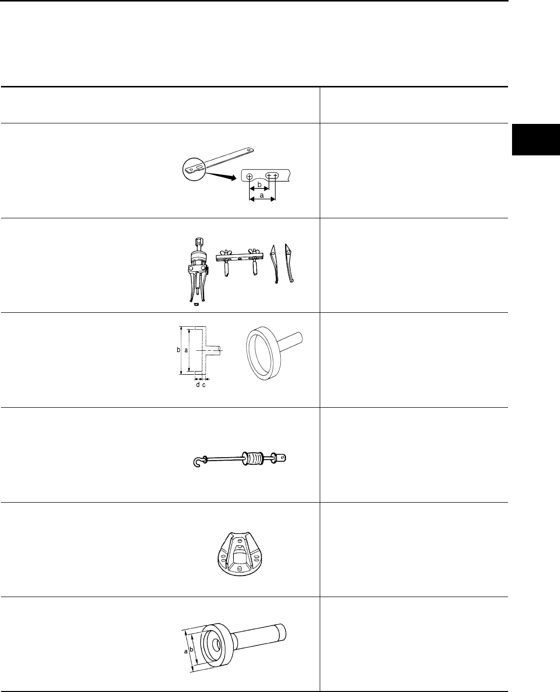
PREPARATION
DLN-435
< PREPARATION > [REAR FINAL DRIVE: R230 (4WD)]
C
E
F
G
H
I
J
K
L
M
A
B
DLN
N
O
P
PREPARATION
PREPARATION
Special Service Tool INFOID:0000000003937466
The actual shapes of Kent-Moore tools may differ from those of special service tools illustrated here.
Tool number
(Kent-Moore No.)
Tool name
Description
KV40104000
(—)
Flange wrench
Removing and installing drive pinion lock nut
a: 85 mm (3.35 in) dia.
b: 65 mm (2.56 in) dia.
KV381054S0
(J-34286)
Puller
Removing front oil seal
ST15310000
(J-25640-B)
Drift
Installing oil seal
a: 84 mm (3.31 in) dia.
b: 96 mm (3.78 in) dia.
c: 8 mm (0.31 in) dia.
d: 20 mm (0.79 in)
ST36230000
(J-25840-A)
Sliding hammer
Removing side flange
KV40104100
(—)
Attachment
Removing side flange
KV38100200
(J-26233)
Drift
Installing side oil seal
a: 65 mm (2.56 in) dia.
b: 49 mm (1.93 in) dia.
NT659
ZZA0601D
NT607
ZZA0803D
ZZA0804D
ZZA1143D
Revision: October 2008
2009 Pathfinder
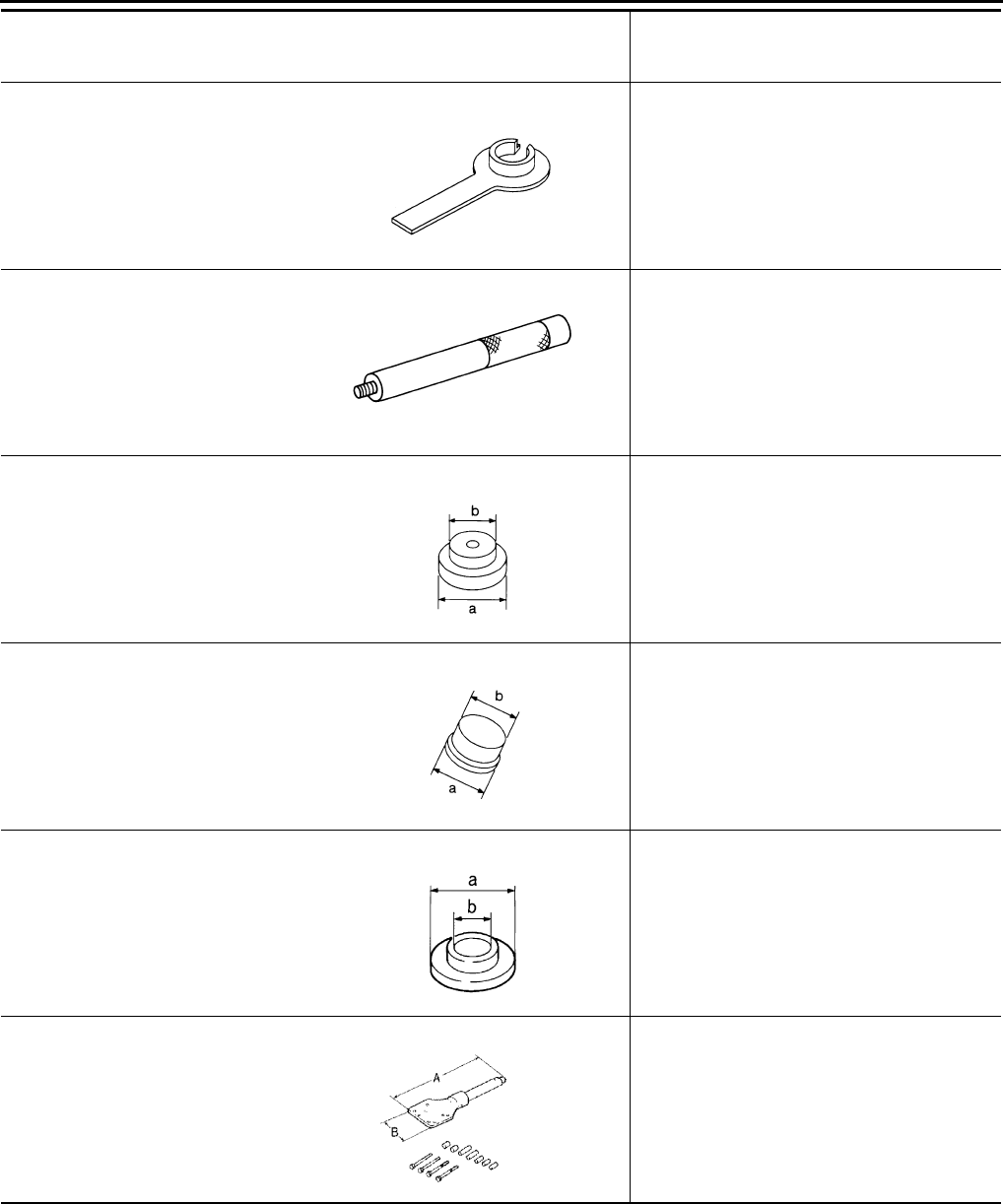
DLN-436
< PREPARATION > [REAR FINAL DRIVE: R230 (4WD)]
PREPARATION
KV38107900
(J-39352)
Protector
Installing side flange
ST35325000
(—)
Drift bar
Installing drive pinion outer race
ST30621000
(J-25742-5)
Drift
Installing drive pinion outer race
a: 79 mm (3.11 in) dia.
b: 59 mm (2.32 in) dia.
SR33081000
(—)
Adapter
Installing side bearing race
a: 43 mm (1.69 in) dia.
b: 33.5 mm (1.319 in) dia.
ST30022000
(—)
Inserter
Installing drive pinion inner race
a: 110 mm (4.33 in) dia.
b: 46 mm (1.81 in) dia.
KV38100800
(J-25604-01)
Attachment
Securing unit assembly
a: 541 mm (21.30 in)
b: 200 mm (7.87 in)
Tool number
(Kent-Moore No.)
Tool name
Description
S-NT129
ZZA1140D
NT073
NT431
ZZA0920D
SDIA0267E
Revision: October 2008
2009 Pathfinder
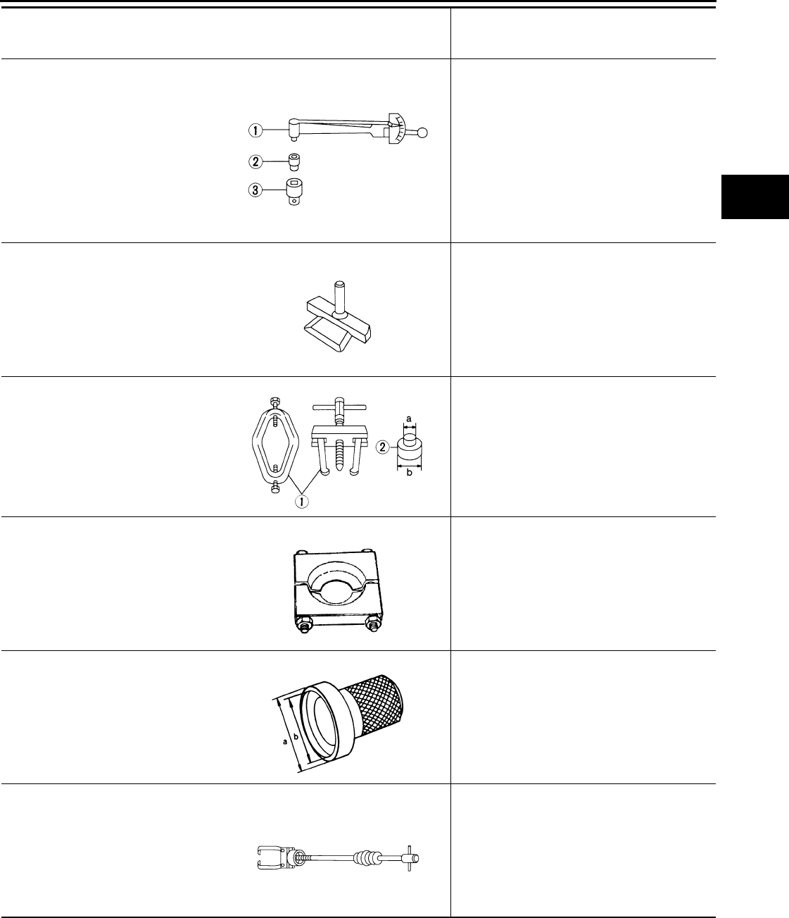
PREPARATION
DLN-437
< PREPARATION > [REAR FINAL DRIVE: R230 (4WD)]
C
E
F
G
H
I
J
K
L
M
A
B
DLN
N
O
P
ST3127S000
(J-25765-A)
Preload gauge
1: GG91030000
(J-25765)
Torque wrench
2: HT62940000
(—)
Socket adapter (1/2″)
3: HT62900000
(—)
Socket adapter (3/8″)
Measuring drive pinion bearing preload torque
and total preload torque
KV10111100
(J-37228)
Seal cutter
Removing carrier cover
ST3306S001
(—)
Differential side bearing puller set
1: ST33051001
(J-22888-20)
Puller
2: ST33061000
(J-8107-2)
Base
Removing and installing side bearing inner
race
a: 28.5 mm (1.122 in) dia.
b: 38 mm (1.50 in) dia.
ST30031000
(J-22912-01)
Puller
Removing drive pinion rear bearing inner race
ST35271000
(—)
Drift
Installing oil seal
a: 72 mm (2.83 in) dia.
b: 63 mm (2.48 in) dia.
HT72400000
(—)
Slide hammer
Removing differential case assembly
Tool number
(Kent-Moore No.)
Tool name
Description
NT124
S-NT046
NT072
ZZA0700D
ZZA0837D
S-NT125
Revision: October 2008
2009 Pathfinder
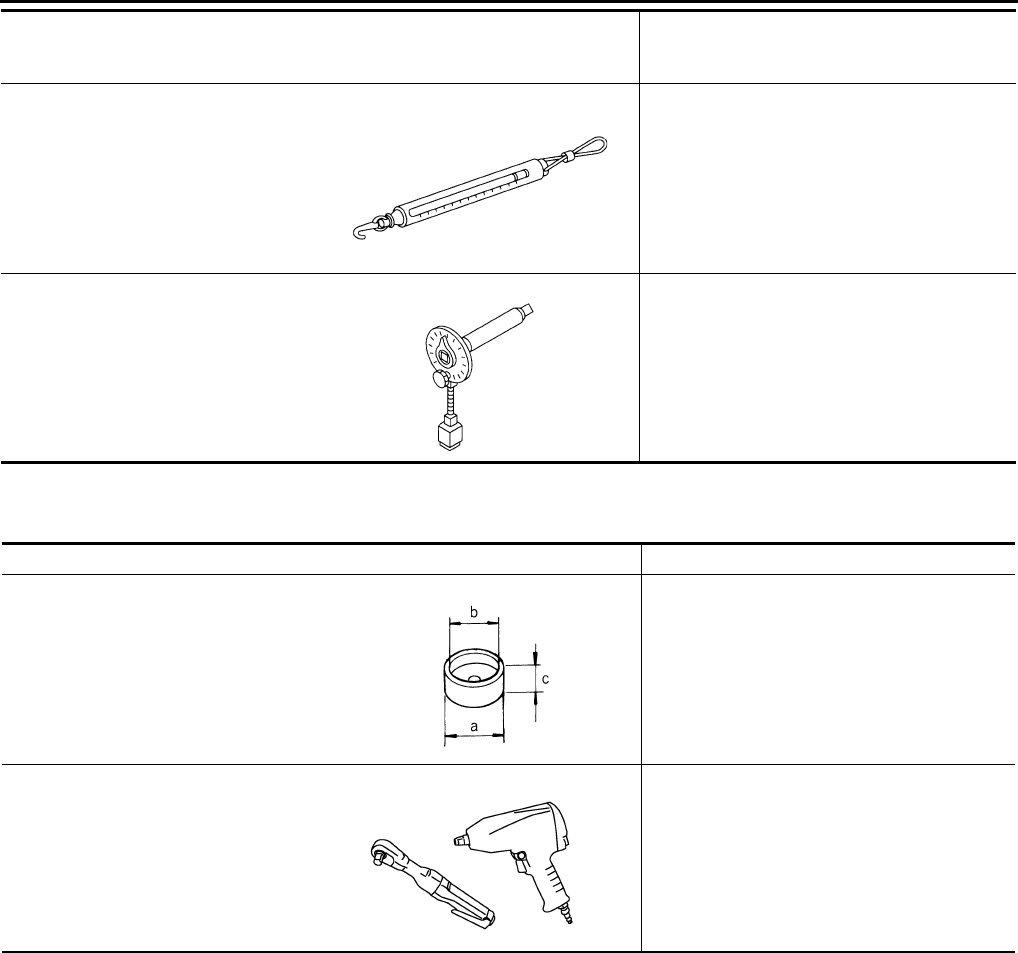
DLN-438
< PREPARATION > [REAR FINAL DRIVE: R230 (4WD)]
PREPARATION
Commercial Service Tool INFOID:0000000003937467
—
(J-8129)
Spring gauge
Measuring turning torque
KV10112100
(BT-8653-A)
Angle wrench
Tightening bolts for drive gear
Tool number
(Kent-Moore No.)
Tool name
Description
NT127
NT014
Tool name Description
Spacer Installing drive pinion front bearing inner race
a: 60 mm (2.36 in) dia.
b: 36 mm (1.42 in) dia.
c: 30 mm (1.18 in)
Power tool Loosening nuts and bolts
ZZA1133D
PBIC0190E
Revision: October 2008
2009 Pathfinder
NOISE, VIBRATION AND HARSHNESS (NVH) TROUBLESHOOTING
DLN-439
< FUNCTION DIAGNOSIS > [REAR FINAL DRIVE: R230 (4WD)]
C
E
F
G
H
I
J
K
L
M
A
B
DLN
N
O
P
FUNCTION DIAGNOSIS
NOISE, VIBRATION AND HARSHNESS (NVH) TROUBLESHOOTING
NVH Troubleshooting Chart INFOID:0000000003937468
Use the chart below to help you find the cause of the symptom. If necessary, repair or replace these parts.
×: Applicable
Reference page
DLN-450
DLN-450
DLN-450
DLN-450
DLN-467
MA-12, "Fluids and Lubricants"
DLN-315, "NVH Troubleshooting Chart"
DLN-324, "NVH Troubleshooting Chart"
RAX-4, "NVH Troubleshooting Chart"
RSU-5, "NVH Troubleshooting Chart"
WT-45, "NVH Troubleshooting Chart"
WT-45, "NVH Troubleshooting Chart"
RAX-4, "NVH Troubleshooting Chart"
BR-6, "NVH Troubleshooting Chart"
ST-9, "NVH Troubleshooting Chart"
Possible cause and SUSPECTED PARTS
Gear tooth rough
Gear contact improper
Tooth surfaces worn
Backlash incorrect
Companion flange excessive runout
Gear oil improper
PROPELLER SHAFT
REAR AXLE
REAR SUSPENSION
TIRES
ROAD WHEEL
DRIVE SHAFT
BRAKES
STEERING
Symptom Noise ×××××× × ××××××
Revision: October 2008
2009 Pathfinder
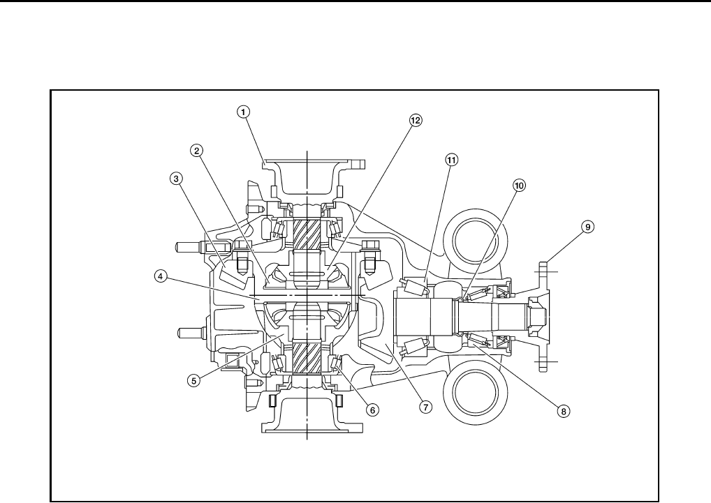
DLN-440
< FUNCTION DIAGNOSIS > [REAR FINAL DRIVE: R230 (4WD)]
DESCRIPTION
DESCRIPTION
Cross-Sectional View INFOID:0000000003937469
1. Side flange 2. Pinion mate gear 3. Drive gear
4. Pinion mate shaft 5. Differential case 6. Side bearing
7. Drive pinion 8. Drive pinion front bearing 9. Companion flange
10. Collapsible spacer 11. Drive pinion rear bearing 12. Side gear
WDIA0119E
Revision: October 2008
2009 Pathfinder
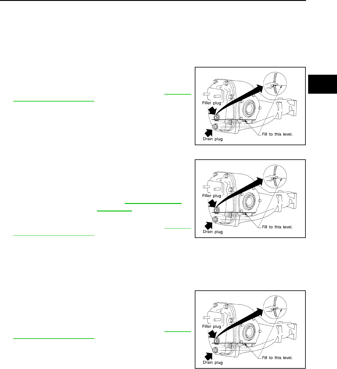
DIFFERENTIAL GEAR OIL
DLN-441
< ON-VEHICLE MAINTENANCE > [REAR FINAL DRIVE: R230 (4WD)]
C
E
F
G
H
I
J
K
L
M
A
B
DLN
N
O
P
ON-VEHICLE MAINTENANCE
DIFFERENTIAL GEAR OIL
Changing Differential Gear Oil INFOID:0000000003937470
DRAINING
1. Stop the engine.
2. Remove the drain plug and gasket from the rear final drive
assembly to drain the differential gear oil.
3. Install the drain plug with a new gasket to the rear final drive
assembly. Tighten to the specified torque. Refer to DLN-450,
"Disassembly and Assembly".
CAUTION:
Do not reuse gasket.
FILLING
1. Remove the filler plug and gasket from the rear final drive
assembly.
2. Fill the rear final drive assembly with new differential gear oil
until the level reaches the specified level near the filler plug hole.
3. Install the filler plug with a new gasket on it to the rear final drive
assembly. Tighten to the specified torque. Refer to DLN-450,
"Disassembly and Assembly".
CAUTION:
Do not reuse gasket.
Checking Differential Gear Oil INFOID:0000000003937471
OIL LEAKAGE AND OIL LEVEL
1. Make sure that differential gear oil is not leaking from the rear final drive assembly or around it.
2. Check the differential gear oil level from the filler plug hole as
shown.
CAUTION:
Do not start engine while checking differential gear oil level.
3. Install the filler plug with a new gasket on it to the rear final drive
assembly. Tighten to the specified torque. Refer to DLN-450,
"Disassembly and Assembly".
CAUTION:
Do not reuse gasket.
LLIA0068E
Differential gear oil
grade and capacity : Refer to MA-12, "Fluids and
Lubricants".
LLIA0068E
LLIA0068E
Revision: October 2008
2009 Pathfinder
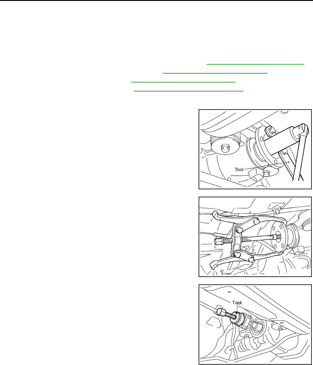
DLN-442
< ON-VEHICLE REPAIR > [REAR FINAL DRIVE: R230 (4WD)]
FRONT OIL SEAL
ON-VEHICLE REPAIR
FRONT OIL SEAL
Removal and Installation INFOID:0000000003937472
REMOVAL
1. Remove the drive shafts from the rear final drive assembly. Refer to RAX-9, "Removal and Installation".
2. Remove the side flanges and side oil seals. Refer to DLN-444, "Removal and Installation".
3. Remove the rear propeller shaft. Refer to DLN-326, "Removal and Installation".
4. Measure the total preload torque. Refer to DLN-467, "Inspection and Adjustment".
NOTE:
Record the total preload torque measurement.
5. Remove the drive pinion lock nut using Tool.
6. Put matching marks on the companion flange and drive pinion
using paint.
CAUTION:
Use paint to make the matching marks. Do not damage the
companion flange or drive pinion.
7. Remove the companion flange using suitable tool.
8. Remove the front oil seal using Tool.
INSTALLATION
Tool number : KV40104000 ( — )
SDIA1142E
SDIA1054E
Tool number : KV381054S0 (J-34286)
SDIA0485E
Revision: October 2008
2009 Pathfinder
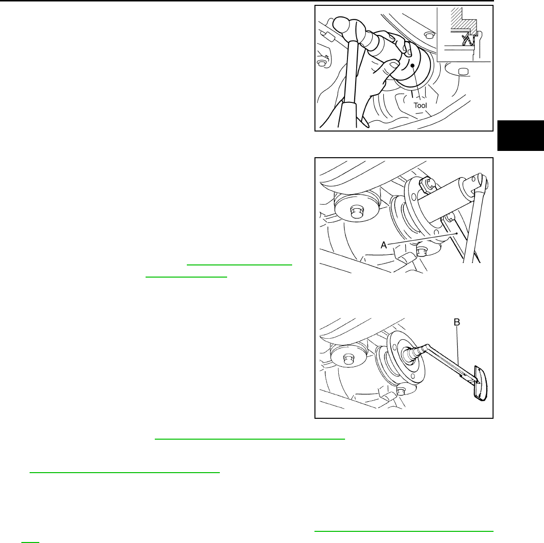
FRONT OIL SEAL
DLN-443
< ON-VEHICLE REPAIR > [REAR FINAL DRIVE: R230 (4WD)]
C
E
F
G
H
I
J
K
L
M
A
B
DLN
N
O
P
1. Apply multi-purpose grease to the lips of the new front oil seal.
Then drive the new front oil seal in evenly until it becomes flush
with the gear carrier using Tool.
CAUTION:
• Do not reuse front oil seal.
• Do not incline the new front oil seal when installing.
• Apply multi-purpose grease to the lips of the new front oil
seal.
2. Install the companion flange to the drive pinion while aligning the matching marks.
3. Apply anti-corrosive oil to the threads of the drive pinion and the
seating surface of the new drive pinion lock nut. Then adjust the
drive pinion lock nut tightening torque using Tool A, and check
the total preload torque using Tool B.
• The total preload torque should be within the total preload
torque specification. When not replacing the collapsible
spacer, it should also be equal to the measurement taken dur-
ing removal plus an additional 0.56 N·m (0.06 Kg-m, 5 in-lb).
• If the total preload torque is low, tighten the drive pinion lock
nut in 6.8 N·m (0.69 Kg-m, 5ft-lb) increments until the total pre-
load torque is met.
CAUTION:
• Do not reuse drive pinion lock nut.
• Apply anti-corrosive oil to the threads of the drive pinion
and the seating surface of the new drive pinion lock nut.
• Adjust the drive pinion lock nut tightening torque to the
lower limit first. Do not exceed the drive pinion lock nut
specified torque. Refer to DLN-450, "Disassembly and Assembly".
• Do not loosen drive pinion lock nut to adjust the total preload torque. If the total preload torque
exceeds the specifications, replace the collapsible spacer and tighten it again to adjust. Refer to
DLN-450, "Disassembly and Assembly".
• After adjustment, rotate drive pinion back and forth 2 to 3 times to check for unusual noise, rota-
tion malfunction, and other malfunctions.
4. Installation of the remaining components is in the reverse order of removal.
CAUTION:
Check the differential gear oil level after installation. Refer to DLN-441, "Checking Differential Gear
Oil".
Tool number : ST15310000 ( — )
PDIA0565E
Tool number A: KV40104000 ( — )
B: ST3127S000 (J-25765-A)
Total preload torque: Refer to DLN-467, "Inspection
and Adjustment".
WDIA0380E
Revision: October 2008
2009 Pathfinder
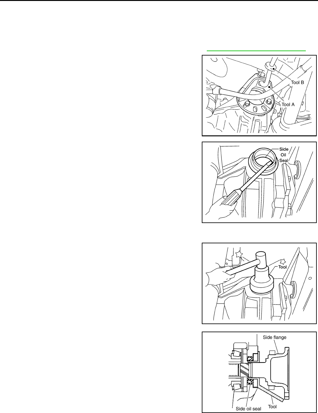
DLN-444
< ON-VEHICLE REPAIR > [REAR FINAL DRIVE: R230 (4WD)]
SIDE OIL SEAL
SIDE OIL SEAL
Removal and Installation INFOID:0000000003937473
REMOVAL
1. Remove the drive shaft from the rear final drive assembly. Refer to RAX-9, "Removal and Installation".
2. Remove the side flange using Tools.
3. Remove the side oil seal using suitable tool.
CAUTION:
Do not to damage gear carrier.
INSTALLATION
1. Apply multi-purpose grease to the lips of the new side oil seal.
Then drive the new side oil seal in evenly until it becomes flush
with the gear carrier using Tool.
CAUTION:
• Do not reuse side oil seal.
• Do not incline the new side oil seal when installing.
• Apply multi-purpose grease to the lips of the new side oil
seal.
2. Install the side flange using Tool.
a. Install the Tool to the side oil seal as shown.
b. Insert the side flange until the serrated part of the side flange
has engaged the serrated part of the side gear and remove the
Tool.
c. Drive in the side flange using suitable tool.
NOTE:
Installation is completed when the driving sound of the side
flange turns into a sound which seems to affect the whole rear
final drive assembly.
3. Installation of the remaining components is in the reverse order of removal.
CAUTION:
Tool numbers A: KV40104100 ( — )
B: ST36230000 (J-25840-A)
WDIA0115E
LDIA0109E
Tool number : ST35271000 (J-26091)
LDIA0111E
Tool number : KV38107900 (J-39352)
SDIA0822E
Revision: October 2008
2009 Pathfinder

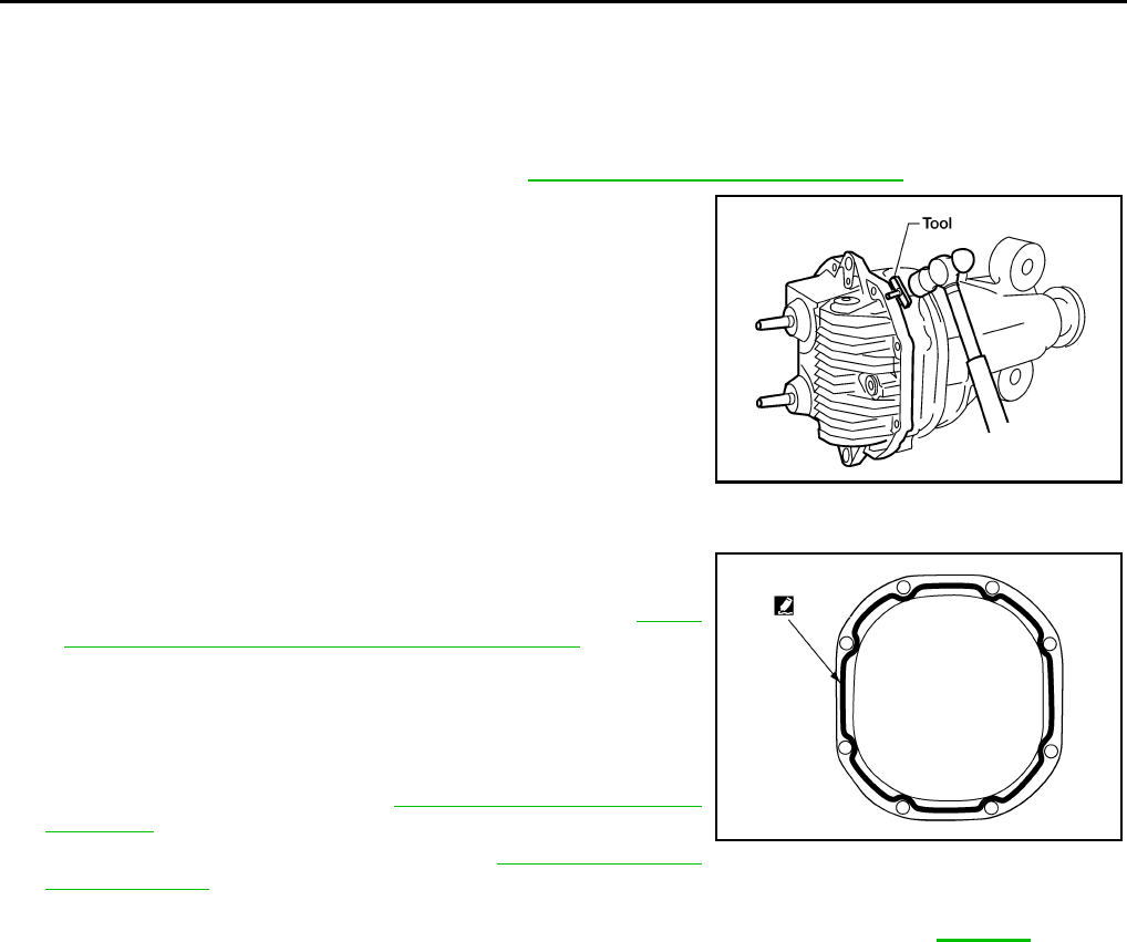
DLN-446
< ON-VEHICLE REPAIR > [REAR FINAL DRIVE: R230 (4WD)]
CARRIER COVER
CARRIER COVER
Removal and Installation INFOID:0000000003937474
REMOVAL
1. Remove the rear final drive assembly. Refer to DLN-447, "Removal and Installation".
2. Remove the carrier cover bolts and separate the carrier cover
from the gear carrier using Tool.
CAUTION:
• Do not damage the mating surface.
• Do not insert flat-bladed screwdriver, this will damage the
mating surface.
INSTALLATION
1. Apply a 3 mm (0.12 in) bead of sealant to the mating surface of
the carrier cover as shown.
• Use Genuine Silicone RTV or equivalent. Refer to GI-26,
"Recommended Chemical Products and Sealants".
CAUTION:
Remove any old sealant adhering to the mating surfaces.
Also remove any moisture, oil, or foreign material adhering
to the application and mating surfaces.
2. Install the carrier cover to the gear carrier. Tighten the bolts to
the specified torque. Refer to DLN-450, "Disassembly and
Assembly".
3. Install the rear final drive assembly. Refer to DLN-447, "Removal
and Installation".
CAUTION:
Fill the rear final drive assembly with recommended differential gear oil. Refer to DLN-441.
Tool number : KV10111100 (J-37228)
WDIA0123E
WDIA0282E
Revision: October 2008
2009 Pathfinder
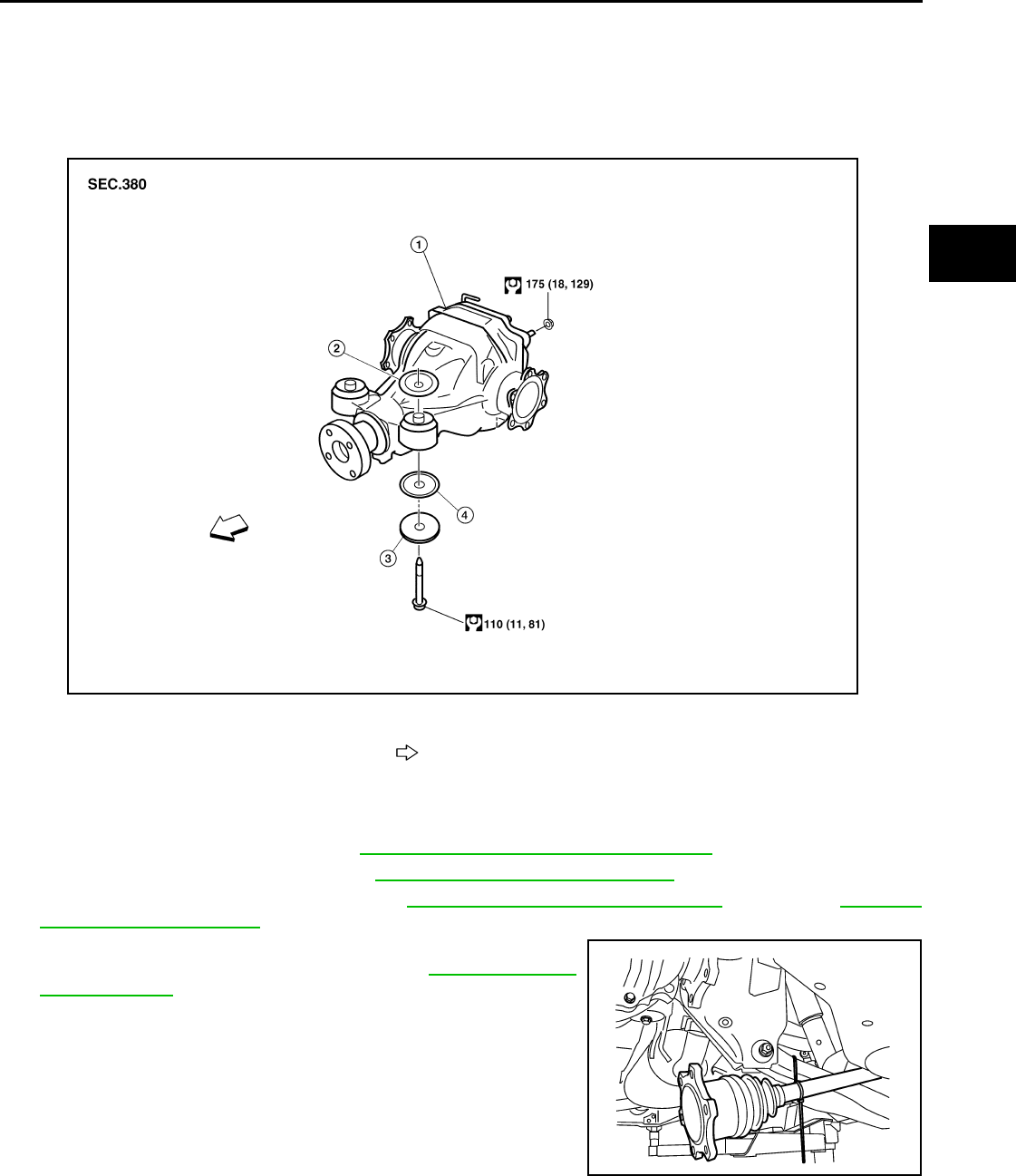
REAR FINAL DRIVE
DLN-447
< REMOVAL AND INSTALLATION > [REAR FINAL DRIVE: R230 (4WD)]
C
E
F
G
H
I
J
K
L
M
A
B
DLN
N
O
P
REMOVAL AND INSTALLATION
REAR FINAL DRIVE
Removal and Installation INFOID:0000000003937475
REMOVAL
1. Remove the spare tire.
2. Drain the differential gear oil. Refer to DLN-441, "Changing Differential Gear Oil".
3. Remove the rear stabilizer bar. Refer to RSU-22, "Removal and Installation".
4. Remove the rear propeller shaft. Refer to DLN-317, "Removal and Installation" (2S1330) or DLN-326,
"Removal and Installation" (2S1350).
5. Remove the rear drive shafts from the rear final drive assembly
and support them using suitable wire. Refer to RAX-9, "Removal
and Installation".
6. Disconnect the breather hose from the rear final drive assembly.
1. Rear final drive assembly 2. Upper stopper 3. Washer
4. Lower stopper Vehicle front
WDIA0383E
LDIA0164E
Revision: October 2008
2009 Pathfinder
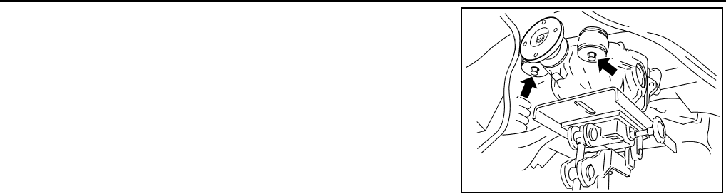
DLN-448
< REMOVAL AND INSTALLATION > [REAR FINAL DRIVE: R230 (4WD)]
REAR FINAL DRIVE
7. Place a suitable jack under the rear final drive assembly.
CAUTION:
Do not place the jack on the carrier cover.
8. Remove the nuts and bolts and remove the rear final drive
assembly.
CAUTION:
Secure rear final drive assembly to the jack while removing
it.
INSTALLATION
Installation is in the reverse order of removal.
CAUTION:
• When installing the breather hose make sure the painted marking on the metal end of breather hose
is to the front of the vehicle and there are no pinched or restricted areas on the breather hose
caused by folding or bending when installing it.
• When installing the breather hose insert the plastic end of the breather hose into the hole in the sus-
pension member.
WDIA0117E
Revision: October 2008
2009 Pathfinder
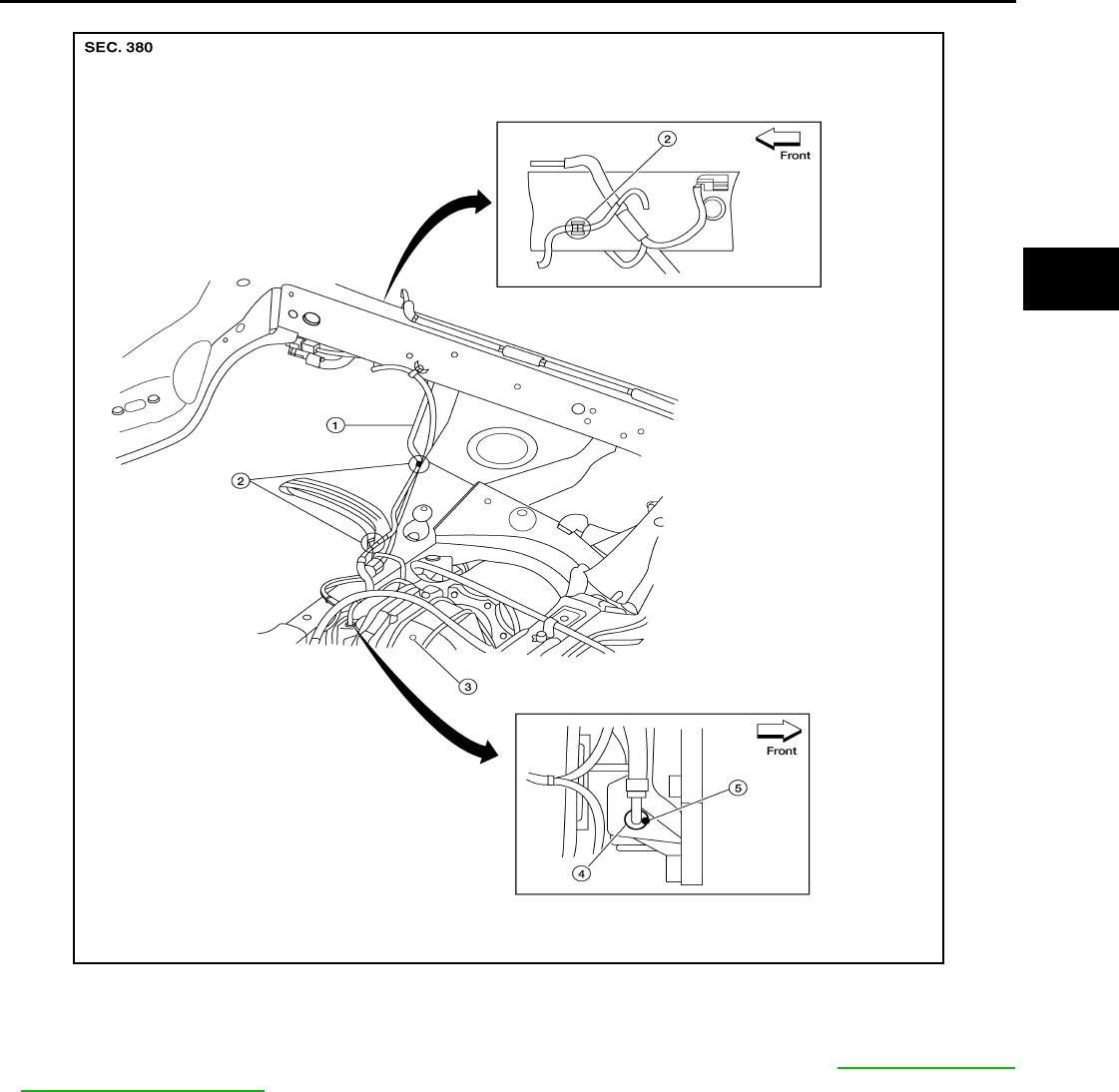
REAR FINAL DRIVE
DLN-449
< REMOVAL AND INSTALLATION > [REAR FINAL DRIVE: R230 (4WD)]
C
E
F
G
H
I
J
K
L
M
A
B
DLN
N
O
P
REAR FINAL DRIVE BREATHER
• Fill the rear final drive assembly with differential gear oil after installation. Refer to DLN-441, "Chang-
ing Differential Gear Oil".
LDIA0166E
1. Breather hose 2. Plastic connector 3. Rear final drive assembly
4. Metal connector 5. Paint mark
Revision: October 2008
2009 Pathfinder
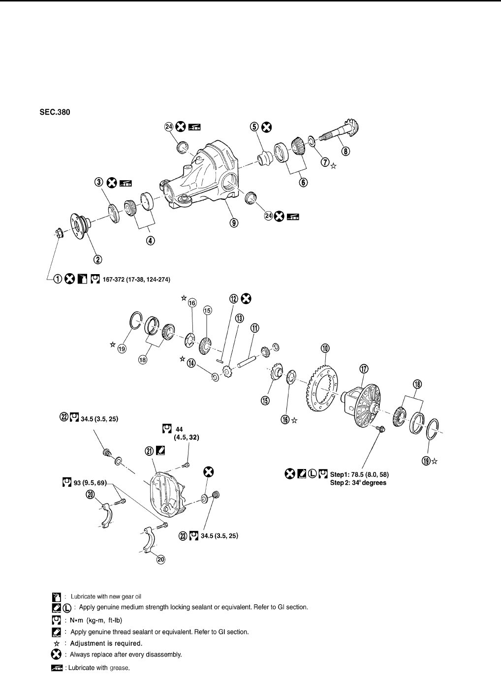
DLN-450
< DISASSEMBLY AND ASSEMBLY > [REAR FINAL DRIVE: R230 (4WD)]
REAR FINAL DRIVE
DISASSEMBLY AND ASSEMBLY
REAR FINAL DRIVE
Disassembly and Assembly INFOID:0000000003937476
COMPONENTS
WDIA0191E
Revision: October 2008
2009 Pathfinder
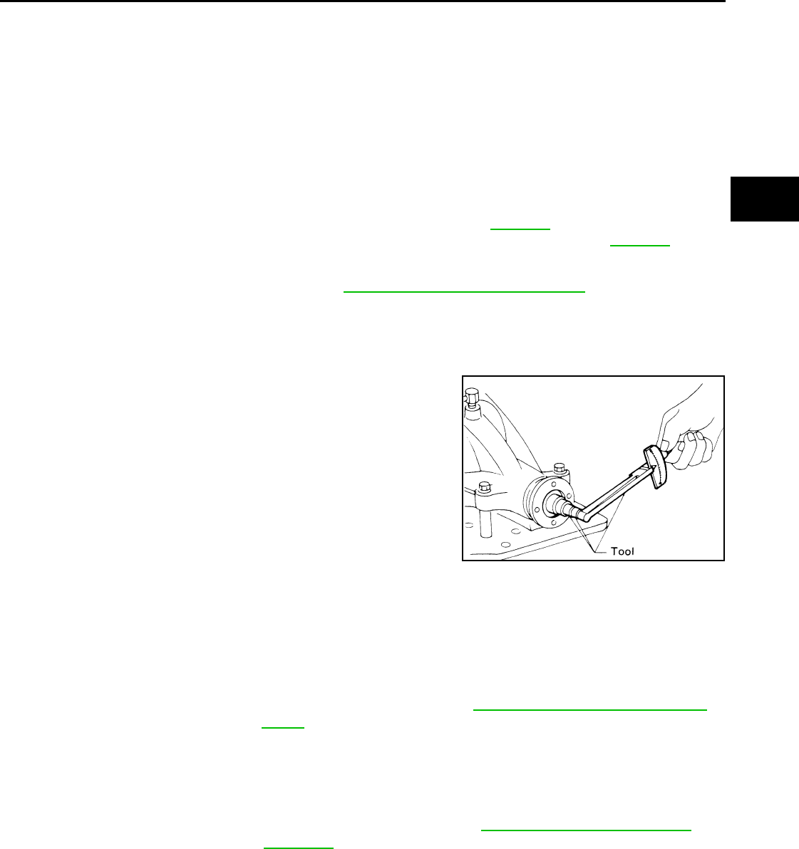
REAR FINAL DRIVE
DLN-451
< DISASSEMBLY AND ASSEMBLY > [REAR FINAL DRIVE: R230 (4WD)]
C
E
F
G
H
I
J
K
L
M
A
B
DLN
N
O
P
ASSEMBLY INSPECTION AND ADJUSTMENT
• Drain the differential gear oil before inspection and adjustment. Refer to DLN-441.
• Remove and install the carrier cover as necessary for inspection and adjustment. Refer to DLN-446.
Total Preload Torque
1. Remove the side flanges if necessary. Refer to DLN-444, "Removal and Installation".
CAUTION:
The side flanges shaft must removed in order to measure total preload torque.
2. Rotate the drive pinion back and forth 2 to 3 times to check for unusual noise and rotation malfunction.
3. Rotate the drive pinion at least 20 times to check for smooth operation of the bearings.
4. Measure the total preload torque using Tool.
NOTE:
Total preload torque = Drive pinion bearing preload torque +
Side bearing preload torque
• If the measured value is out of the specification, check and adjust each part. Adjust the drive pinion
bearing preload torque first, then adjust the side bearing preload torque.
CAUTION:
Select a side bearing adjusting washer for right and left individually.
Drive Gear Runout
1. Drive pinion lock nut 2. Companion flange 3. Front oil seal
4. Drive pinion front bearing 5. Collapsible spacer 6. Drive pinion rear bearing
7. Drive pinion height adjusting
washer 8. Drive pinion 9. Gear carrier
10. Drive gear 11. Pinion mate shaft 12. Lock pin
13. Pinion mate gear 14. Pinion mate thrust washer 15. Side gear
16. Side gear thrust washer 17. Differential case 18. Side bearing
19. Side bearing adjusting washer 20. Bearing cap 21. Carrier cover
22. Filler plug 23. Drain plug 24. Side oil seal
Tool number : ST3127S000 (J-25765-A)
Total preload torque:
2.05 - 4.11 N·m (0.21 - 0.42 kg-m, 19 - 36 in-lb)
SPD884
If the total preload torque is greater than specification
On drive pinion bearings: Replace the collapsible spacer.
On side bearings: Use thinner side bearing adjusting washers by the same
amount on each side. Refer to DLN-467, "Inspection and Adjust-
ment".
If the total preload torque is less than specification
On drive pinion bearings: Tighten the drive pinion lock nut.
On side bearings: Use thicker side bearing adjusting washers by the same
amount on each side. Refer to DLN-467, "Inspection and Ad-
justment".
Revision: October 2008
2009 Pathfinder
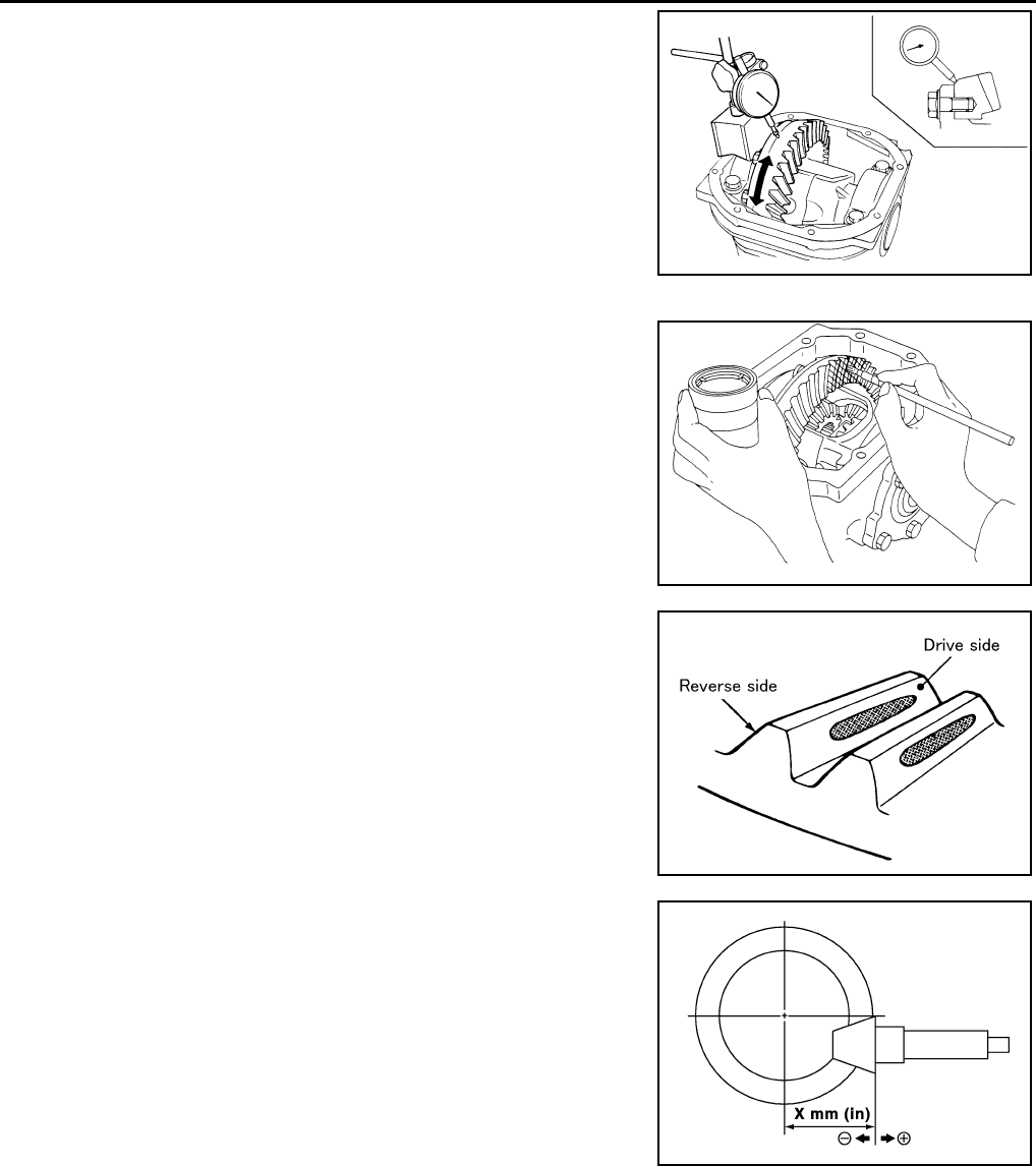
DLN-452
< DISASSEMBLY AND ASSEMBLY > [REAR FINAL DRIVE: R230 (4WD)]
REAR FINAL DRIVE
1. Fit a dial indicator to the drive gear back face.
2. Rotate the drive gear to measure runout.
• If the runout is outside of the limit, check the condition of the drive
gear assembly. Foreign material may be caught between the drive
gear and differential case, or the differential case or drive gear may
be deformed.
CAUTION:
Replace drive gear and drive pinion as a set.
Tooth Contact
1. Apply red lead to the drive gear.
NOTE:
Apply red lead to both faces of three to four gears, at four loca-
tions evenly spaced on the drive gear.
2. Rotate the drive gear back and forth several times. Then check
for correct drive pinion to drive gear tooth contact as shown.
CAUTION:
Check tooth contact on drive side and reverse side.
3. If the tooth contact is improperly adjusted, follow the procedure
below to adjust the pinion height (dimension X).
Runout limit : 0.05 mm (0.0020 in) or less
SPD886
SPD357
SDIA0570E
SDIA0517E
Revision: October 2008
2009 Pathfinder
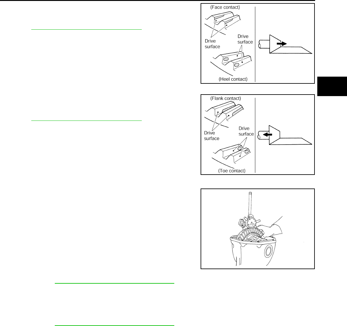
REAR FINAL DRIVE
DLN-453
< DISASSEMBLY AND ASSEMBLY > [REAR FINAL DRIVE: R230 (4WD)]
C
E
F
G
H
I
J
K
L
M
A
B
DLN
N
O
P
• If the tooth contact is near the face (face contact), or near the heel
(heel contact), use a thicker drive pinion height adjusting washers
to move the drive pinion closer to the drive gear.
Refer to DLN-467, "Inspection and Adjustment".
• If the tooth contact is near the flank (flank contact), or near the toe
(toe contact), use a thinner drive pinion height adjusting washers to
move the drive pinion farther from the drive gear.
Refer to DLN-467, "Inspection and Adjustment".
Backlash
1. Fit a dial indicator to the drive gear face to measure the back-
lash.
• If the backlash is outside of the specification, change the thickness
of the side bearing adjusting washers.
CAUTION:
Do not change the total thickness of side bearing adjusting washers as it will change the side bearing
preload torque.
Companion Flange Runout
PDIA0440E
PDIA0441E
Backlash : 0.13 - 0.18 mm (0.0051 - 0.0070 in)
If the backlash is greater than specification:
Make side bearing adjusting washer thicker on drive
gear back side, and side bearing adjusting washer
thinner on drive gear tooth side by the same amount.
Refer to DLN-467, "Inspection and Adjustment".
If the backlash is less than specification:
Make side bearing adjusting washer thinner on drive
gear back side, and side bearing adjusting washer
thicker on drive gear tooth side by the same amount.
Refer to DLN-467, "Inspection and Adjustment".
SPD513
Revision: October 2008
2009 Pathfinder
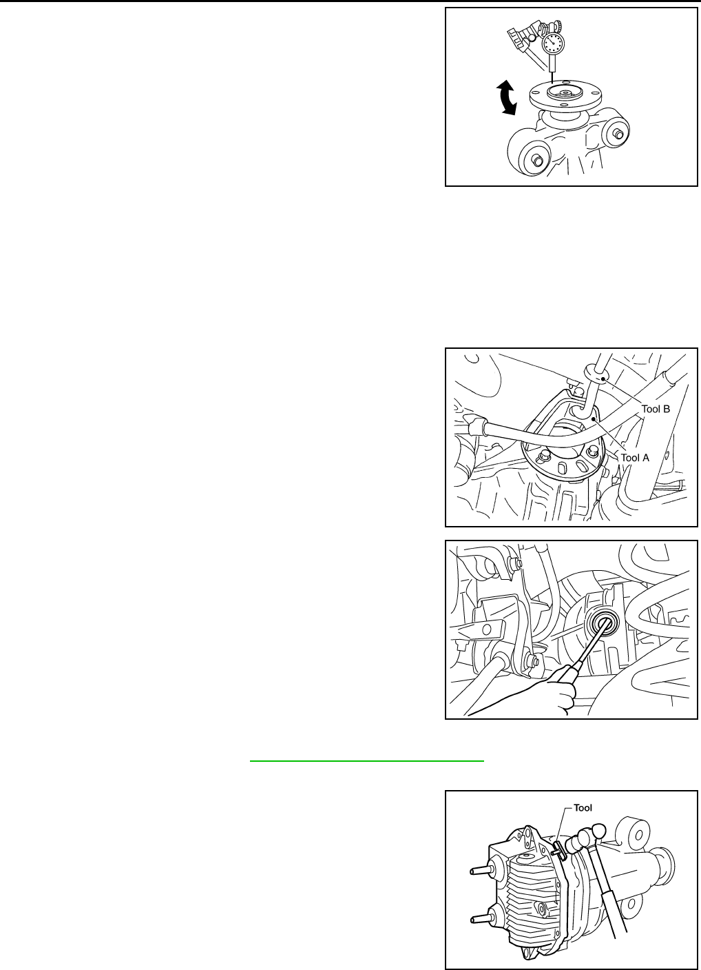
DLN-454
< DISASSEMBLY AND ASSEMBLY > [REAR FINAL DRIVE: R230 (4WD)]
REAR FINAL DRIVE
1. Rotate companion flange and check for runout on the outer face
of the companion flange using suitable tool.
2. If the runout is outside of the runout limit, follow the procedure
below to adjust.
a. Rotate the companion flange on the drive pinion by 90°, 180°
and 270° while checking for the position where the runout is
minimum.
b. If the runout is still outside of the runout limit after the companion
flange has been rotated on the drive pinion, possible cause
could be an assembly malfunction of drive pinion and drive pinion bearing or a malfunctioning drive pinion
bearing.
c. If the runout is still outside of the runout limit after repair of the assembly of drive pinion and drive pinion
bearing or drive pinion bearing, replace the companion flange.
DISASSEMBLY
Side Flange
1. Drain the differential gear oil if necessary.
2. Remove the side flange using Tools.
3. Remove the side oil seal using suitable tool.
CAUTION:
Do not to damage gear carrier.
Differential Assembly
1. Remove the side flanges. Refer to DLN-444, "Removal and Installation".
2. Remove the carrier cover bolts.
3. Remove the carrier cover bolts and separate the carrier cover
from the gear carrier using Tool.
CAUTION:
• Do not damage the mating surface.
• Do not insert flat-bladed screwdriver, this will damage the
mating surface.
Runout limit : 0.08 mm (0.0031 in) or less
WDIA0231E
Tool numbers A: KV40104100 ( — )
B: ST36230000 (J-25840-A)
WDIA0115E
SDIA0495E
Tool number : KV10111100 (J-37228)
WDIA0123E
Revision: October 2008
2009 Pathfinder
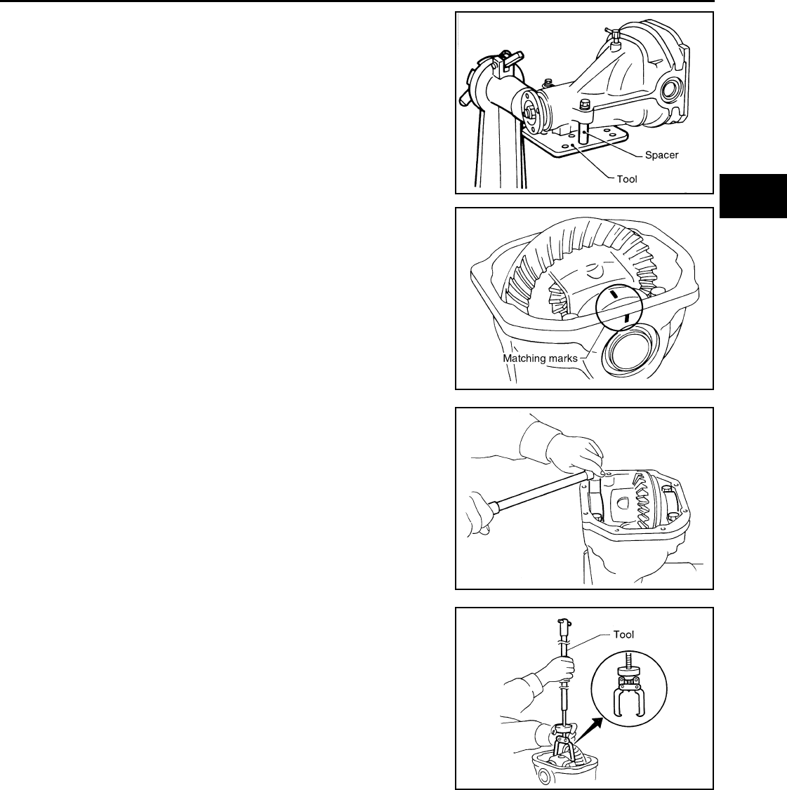
REAR FINAL DRIVE
DLN-455
< DISASSEMBLY AND ASSEMBLY > [REAR FINAL DRIVE: R230 (4WD)]
C
E
F
G
H
I
J
K
L
M
A
B
DLN
N
O
P
4. Mount the carrier on the Tool using two 45 mm (1.77 in) spacers.
5. For proper reinstallation, paint matching marks on one side of
the side bearing cap and gear carrier.
CAUTION:
• For matching marks, use paint. Do not damage side bear-
ing cap or gear carrier.
• Side bearing caps are line-board during manufacture. The
matching marks are used to reinstall them in their original
positions.
6. Remove the side bearing caps.
7. Lift the differential case assembly out using Tool.
CAUTION:
Tool number : KV38100800 (J-25604-01)
SPD888
SDIA1795E
S-PD343
Tool number : HT72400000 ( — )
S-PD344
Revision: October 2008
2009 Pathfinder
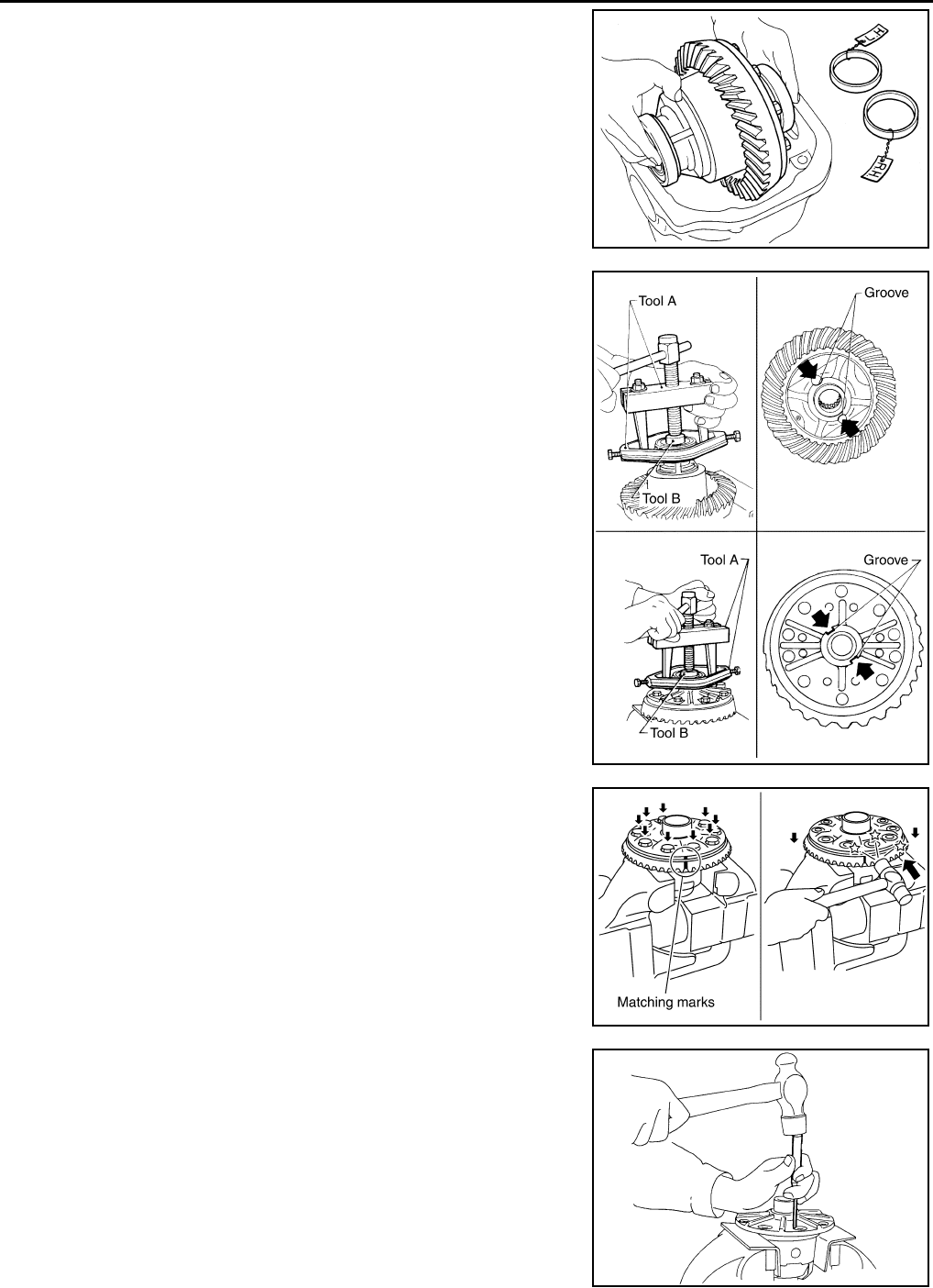
DLN-456
< DISASSEMBLY AND ASSEMBLY > [REAR FINAL DRIVE: R230 (4WD)]
REAR FINAL DRIVE
• Keep side bearing outer races together with inner race.
Do not mix them up.
• Keep side bearing adjusting washers together with side
bearings.
8. Remove the side bearing inner races using Tools.
CAUTION:
• Engage Tool jaws in bearing groove to prevent damage.
• Place copper plates between the side bearing and drive
gear and the vise to prevent damage.
• Do not remove side bearing inner race unless it is being
replaced.
9. For proper reinstallation, paint matching marks on the differential
case and drive gear.
CAUTION:
Use paint for matching marks. Do not damage differential
case or drive gear.
10. Remove the drive gear bolts.
11. Tap the drive gear off the differential case using suitable tool.
CAUTION:
Tap evenly all around to keep drive gear from bending.
12. Remove the lock pin of the pinion mate shaft from the drive gear
side using suitable tool.
SPD919
Tool number A: ST3306S001 ( — )
B: ST33061000 (J-8107-2)
SPD920
PDIA0496E
WDIA0132E
Revision: October 2008
2009 Pathfinder
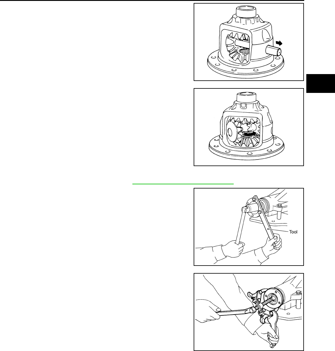
REAR FINAL DRIVE
DLN-457
< DISASSEMBLY AND ASSEMBLY > [REAR FINAL DRIVE: R230 (4WD)]
C
E
F
G
H
I
J
K
L
M
A
B
DLN
N
O
P
13. Remove the pinion mate shaft.
14. Turn the pinion mate gear, then remove the pinion mate gear,
pinion mate thrust washer, side gear and side gear thrust
washer from the differential case.
Drive Pinion Assembly
1. Remove the differential assembly. Refer to DLN-447, "Removal and Installation".
2. Remove the drive pinion lock nut using Tool.
3. Put matching marks on the companion flange and drive pinion
using paint.
CAUTION:
Use paint to make the matching marks. Do not damage the
companion flange or drive pinion.
4. Remove the companion flange using suitable tool.
SDIA0031J
SDIA0032J
Tool number : KV40104000 ( — )
SDIA1144E
SDIA1132E
Revision: October 2008
2009 Pathfinder
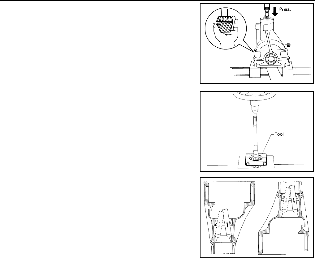
DLN-458
< DISASSEMBLY AND ASSEMBLY > [REAR FINAL DRIVE: R230 (4WD)]
REAR FINAL DRIVE
5. Press the drive pinion assembly (with rear inner bearing race
and collapsible spacer) out of the gear carrier.
CAUTION:
Do not drop drive pinion assembly.
6. Remove the front oil seal.
CAUTION:
Do not damage gear carrier.
7. Remove the drive pinion front bearing inner race.
8. Remove the drive pinion rear bearing inner race and drive pinion
height adjusting washer using Tool.
9. Remove the drive pinion front and rear bearing outer races by
tapping them uniformly using suitable tool.
CAUTION:
Do not damage gear carrier.
INSPECTION AFTER DISASSEMBLY
Clean the disassembled parts. Then inspect the parts for wear or damage. If wear or damage are found, follow
the measures below.
Drive Pinion and Drive Gear
• If the drive pinion and drive gear teeth do not mesh or line-up correctly, determine the cause and adjust,
repair, or replace as necessary.
• If the drive pinion or drive gear are worn, cracked, damaged, pitted or chipped (by friction) noticeably,
replace with new drive pinion and drive gear.
• Drive pinion and drive gear are supplied in matched sets only. Matching numbers on both drive pinion and
drive gear are etched for verification. If a new drive pinion and drive gear set are being used, verify the num-
bers of each drive pinion and drive gear before proceeding with assembly.
Bearing
• If bearings are chipped (by friction), pitted, worn, rusted, scratched, or unusual noise is coming from bearing,
replace with new bearing assembly (as a new set).
• Bearing must be replaced with a new one whenever disassembled.
Side Gear and Pinion Mate Gear
• If any cracks or damage are found on the surface of the teeth, replace with new one.
• If any worn or chipped marks are found on the side of the side gear and pinion mate gear which contact the
thrust washer, replace with new one.
• Replace both side gear and pinion mate gear as a set when replacing side gear or pinion mate gear.
Side Gear Thrust Washer and Pinion Mate Thrust Washer
• If any chips (by friction), damage, or unusual wear are found, replace with new one.
SPD892
Tool number: : ST30031000 (J-22912-01)
S-PD179
SDIA0817E
Revision: October 2008
2009 Pathfinder
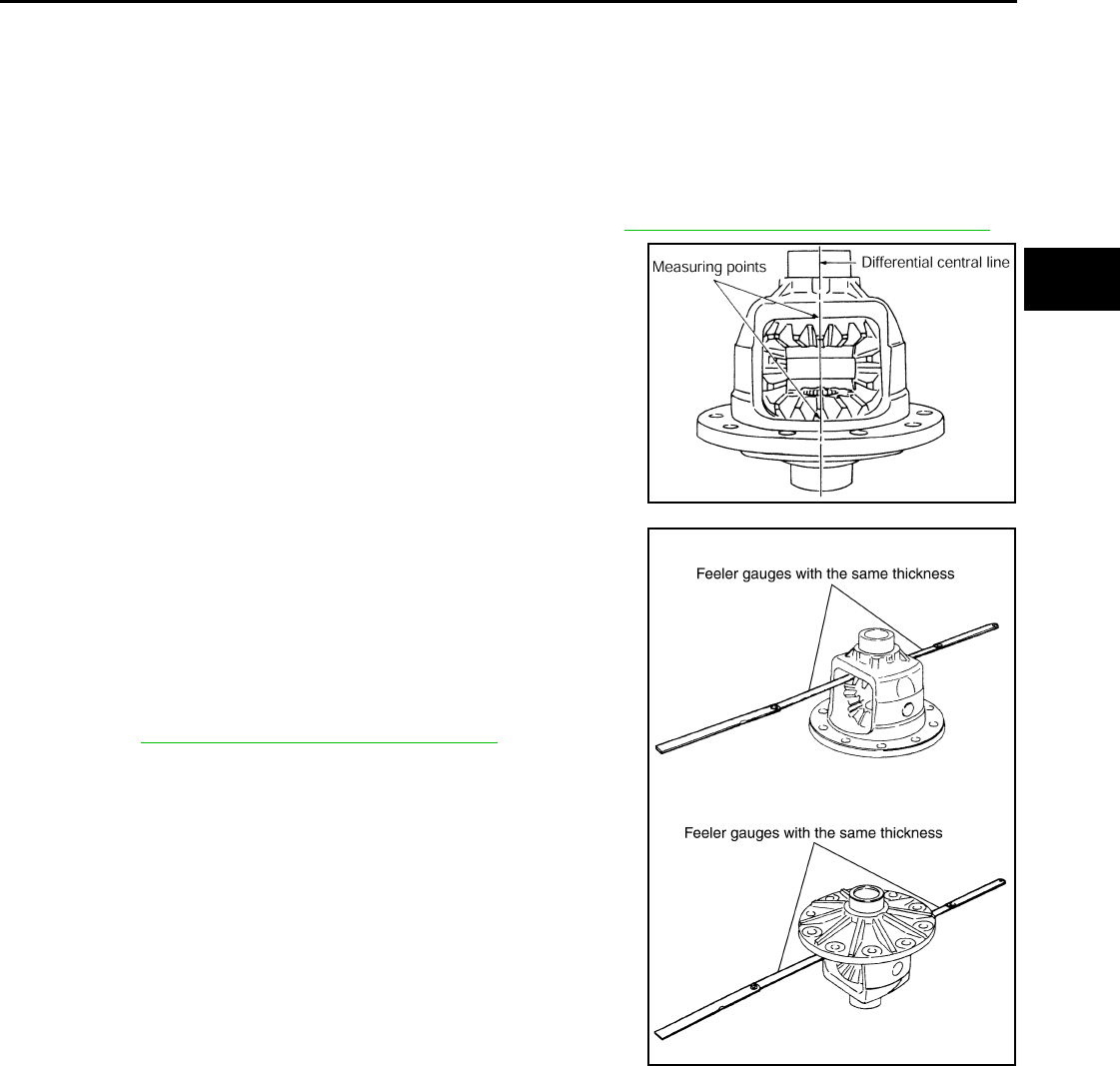
REAR FINAL DRIVE
DLN-459
< DISASSEMBLY AND ASSEMBLY > [REAR FINAL DRIVE: R230 (4WD)]
C
E
F
G
H
I
J
K
L
M
A
B
DLN
N
O
P
Gear Carrier
• If any wear or cracks are found on the contact sides of gear carrier, replace with new one.
Companion Flange
• If any chips (about 0.1mm, 0.004 in) or other damage on the companion flange surface which contacts the
front oil seal lips are found, replace with new one.
ADJUSTING AND SELECTING WASHERS
Side Gear Back Clearance
• Assemble the differential parts if they are disassembled. Refer to DLN-450, "Disassembly and Assembly".
1. Place the differential case straight up so that the side gear to be
measured is upward.
2. Using feeler gauges, measure the clearance between the side
gear back and differential case at three different points, while
rotating the side gear. Average the three readings to calculate
the clearance. (Measure the clearance of the other side as well.)
• If the side gear back clearance is outside of the specification,
use a thicker or thinner side gear thrust washer to adjust.
Refer to DLN-467, "Inspection and Adjustment".
CAUTION:
• Insert feeler gauges with the same thickness on both
sides to prevent side gear from tilting.
• Each gear should rotate smoothly without excessive
resistance during differential motion.
• Select a side gear thrust washer for right and left individu-
ally.
NOTE:
Side gear back clearance is clearance between side gear and differential case for adjusting side gear
backlash.
Side Bearing Preload Torque
• A selection of side bearing adjusting washers is required for successful completion of this procedure.
PDIA0460E
Side gear back clearance: 0.20 mm (0.0079 in) or less.
If the side gear back clearance is greater than
specification:
Use a thicker side gear thrust washer.
If the side gear back clearance is less than spec-
ification:
Use a thinner side gear thrust washer.
PDIA0576E
Revision: October 2008
2009 Pathfinder
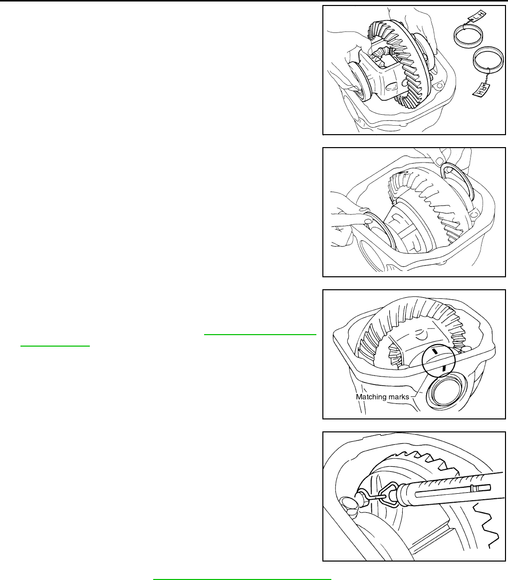
DLN-460
< DISASSEMBLY AND ASSEMBLY > [REAR FINAL DRIVE: R230 (4WD)]
REAR FINAL DRIVE
1. Apply differential gear oil to the side bearings, and install the dif-
ferential case assembly with the side bearing outer races into
the gear carrier.
CAUTION:
Do not reuse side bearing outer race when replacing side
bearing inner race (replace as a set).
2. Insert the left and right original side bearing adjusting washers in
place between side bearings and gear carrier.
3. Align the matching mark on the side bearing cap with the match-
ing mark on the gear carrier.
4. Install the side bearing caps and tighten the side bearing cap
bolts to the specified torque. Refer to DLN-450, "Disassembly
and Assembly".
5. Turn the differential assembly several times to seat the side
bearings.
6. To determine side bearing preload torque, measure the pulling
force of the differential assembly at the drive gear bolt using
Tool.
NOTE:
If pulling force of the differential assembly at the drive gear bolt
is within specification, side bearing preload torque will also be
within specification. Refer to DLN-467, "Inspection and Adjustment".
SPD527
SPD924
SDIA1795E
Tool number : — (J-8129)
Specification : 34.2 - 39.2 N (3.5 - 4.0 kg, 7.7 - 8.8 lb)
of pulling force at the drive gear bolt
SPD194A
Revision: October 2008
2009 Pathfinder
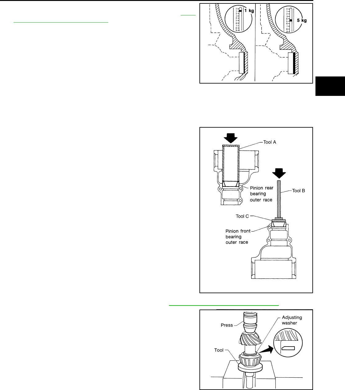
REAR FINAL DRIVE
DLN-461
< DISASSEMBLY AND ASSEMBLY > [REAR FINAL DRIVE: R230 (4WD)]
C
E
F
G
H
I
J
K
L
M
A
B
DLN
N
O
P
7. If the pulling force is outside the specification, use a thicker or
thinner side bearing adjusting washer to adjust. Refer to DLN-
467, "Inspection and Adjustment".
CAUTION:
Select a side bearing adjusting washer for right and left
individually.
8. Record the total amount of washer thickness required for the correct side bearing preload torque.
ASSEMBLY
Drive Pinion Assembly
1. Install the drive pinion front and rear bearing outer races using
Tools.
CAUTION:
Do not reuse drive pinion front and rear bearing outer race.
2. Select a drive pinion height adjusting washer. Refer to DLN-467, "Inspection and Adjustment".
3. Install the selected drive pinion height adjusting washer to the
drive pinion. Press the drive pinion rear bearing inner race to it
using Tool.
CAUTION:
• Install the drive pinion height adjusting washer in the
proper direction as shown.
• Do not reuse drive pinion rear bearing inner race.
If the pulling force is less than the specification:
Use a thicker side bearing adjusting washer.
If the pulling force is greater than the specification:
Use a thinner side bearing adjusting washer.
SPD772
Tool number A: ST15310000 ( — )
B: ST35325000 ( — )
C: ST30621000 (J-25742-5)
SPD992
Tool number : ST30022000 ( — )
SPD377
Revision: October 2008
2009 Pathfinder
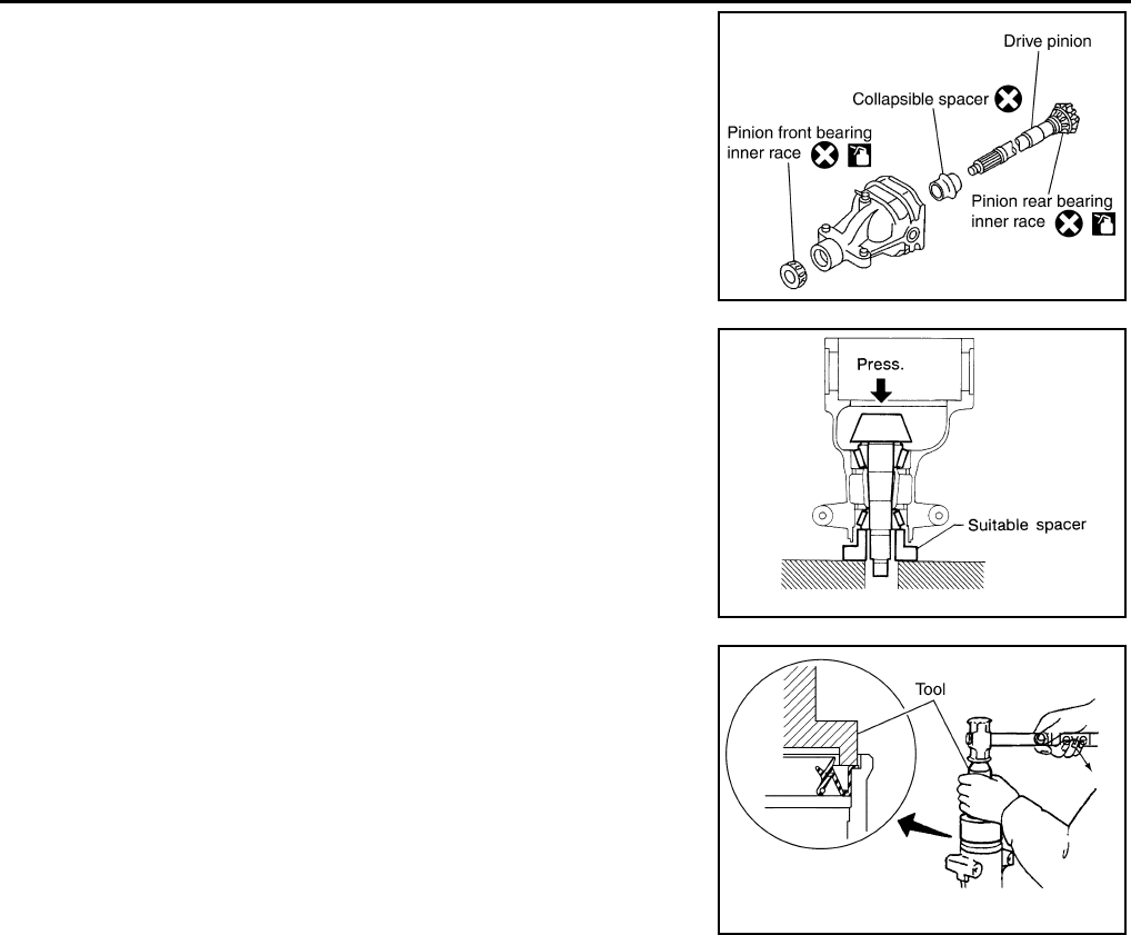
DLN-462
< DISASSEMBLY AND ASSEMBLY > [REAR FINAL DRIVE: R230 (4WD)]
REAR FINAL DRIVE
4. Assemble the collapsible spacer to the drive pinion.
CAUTION:
Do not reuse collapsible spacer.
5. Apply differential gear oil to the drive pinion rear bearing, and
install the drive pinion assembly to the gear carrier.
6. Apply differential gear oil to the drive pinion front bearing, and
install the drive pinion front bearing inner race to the drive pinion
assembly.
CAUTION:
Do not reuse drive pinion front bearing inner race.
7. Press the drive pinion front bearing inner race to the drive pinion
as far as drive pinion lock nut can be tightened using suitable
spacer.
8. Apply multi-purpose grease to the lips of the new front oil seal.
Then drive the new front oil seal in evenly until it becomes flush
with the gear carrier using Tool.
CAUTION:
• Do not reuse front oil seal.
• Do not incline the new front oil seal when installing.
• Apply multi-purpose grease to the lips of the new front oil
seal.
9. Install the companion flange to the drive pinion while aligning the matching marks.
PDIA0492E
SPD896
Tool number : ST15310000 ( — )
PDIA0563E
Revision: October 2008
2009 Pathfinder
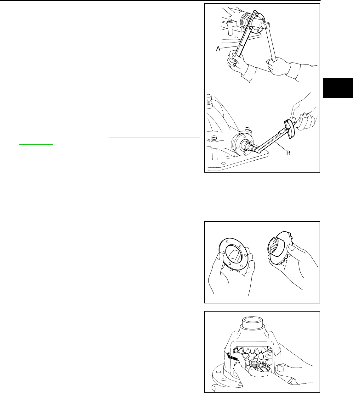
REAR FINAL DRIVE
DLN-463
< DISASSEMBLY AND ASSEMBLY > [REAR FINAL DRIVE: R230 (4WD)]
C
E
F
G
H
I
J
K
L
M
A
B
DLN
N
O
P
10. Apply anti-corrosive oil to the threads of the drive pinion and the
seating surface of the new drive pinion lock nut. Then adjust the
drive pinion lock nut tightening torque using Tool A, and check
the drive pinion bearing preload torque using Tool B.
CAUTION:
• Do not reuse drive pinion lock nut.
• Apply anti-corrosive oil to the threads of the drive pinion
and the seating surface of the new drive pinion lock nut.
• Adjust the drive pinion lock nut tightening torque to the
lower limit first. Do not exceed the drive pinion lock nut
specified torque. Refer to DLN-450, "Disassembly and
Assembly".
• If the drive pinion bearing preload torque exceeds the
specified value, replace collapsible spacer and tighten it
again to adjust. Do not loosen drive pinion lock nut to
adjust the drive pinion bearing preload torque.
• After adjustment, rotate drive pinion back and forth 2 to 3
times to check for unusual noise, rotation malfunction, and other malfunctions.
11. Check companion flange runout. Refer to DLN-467, "Inspection and Adjustment".
12. Install the differential case assembly. Refer to DLN-450, "Disassembly and Assembly".
Differential Assembly
1. Install side gear thrust washers with the same thickness as the
ones installed prior to disassembly, or reinstall the old ones on
the side gears.
2. Install the side gears and side gear thrust washers into the dif-
ferential case.
CAUTION:
Make sure that the circular clip is installed to side gears.
3. Install the pinion mate thrust washers to the two pinion mate
gears. Then install the pinion mate gears with the pinion mate
thrust washers by aligning them in diagonally opposite positions
and rotating them into the differential case.
Tool number A: KV40104000 ( — )
B: ST3127S000 (J-25765-A)
Drive pinion bearing preload torque:
1.77 - 2.64 N·m (0.18 - 0.26 kg-m, 16 - 23 in-lb)
WDIA0379E
SDIA0193J
SDIA2025E
Revision: October 2008
2009 Pathfinder
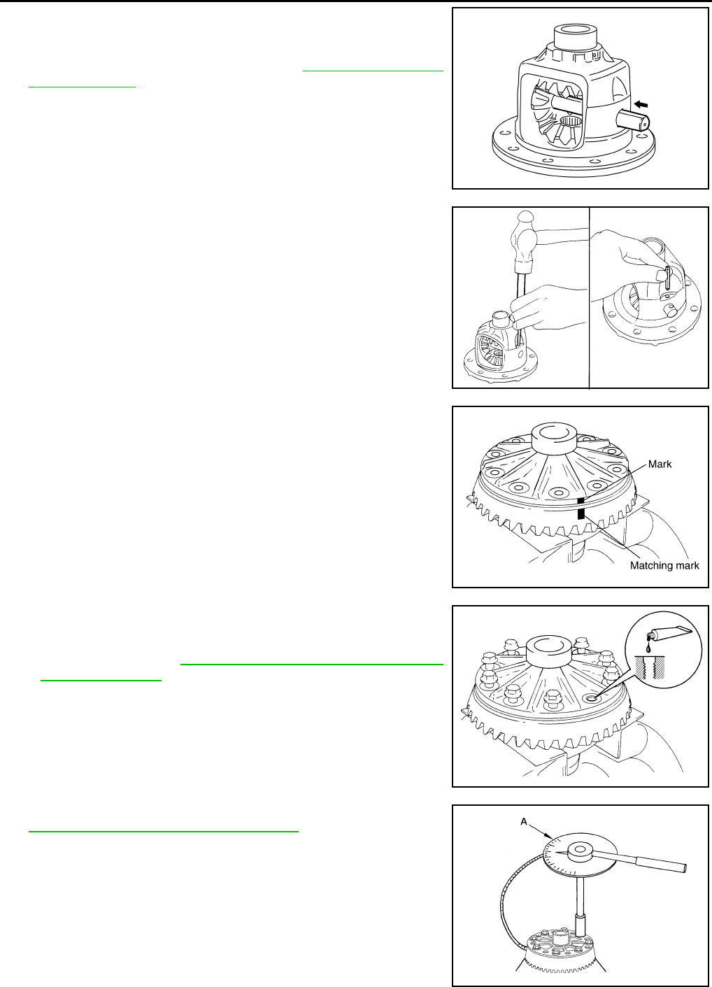
DLN-464
< DISASSEMBLY AND ASSEMBLY > [REAR FINAL DRIVE: R230 (4WD)]
REAR FINAL DRIVE
4. Align the lock pin hole on the differential case with the lock pin
hole on the pinion mate shaft, and install the pinion mate shaft.
5. Measure the side gear end play. If necessary, select the appro-
priate side gear thrust washers. Refer to DLN-467, "Inspection
and Adjustment".
6. Drive a new lock pin into the pinion mate shaft until it is flush
with the differential case using suitable tool.
CAUTION:
Do not reuse lock pin.
7. Align the matching mark of the differential case with the mark of
the drive gear, then place the drive gear onto the differential
case.
8. Apply thread locking sealant into the threaded holes of the drive
gear and install the bolts.
• Use Genuine Medium Strength Thread Locking Sealant or
equivalent. Refer to GI-26, "Recommended Chemical Prod-
ucts and Sealants".
CAUTION:
Make sure the drive gear back and threaded holes are
clean.
9. Tighten the drive gear bolts to the specified torque. Refer to
DLN-450, "Disassembly and Assembly". After tightening the
drive gear bolts to the specified torque, tighten an additional 34°
using Tool.
CAUTION:
• Always use Tool. Avoid tightening based on visual check
alone.
• Tighten drive gear bolts in a crisscross pattern.
SDIA0195J
WDIA0131E
SDIA2593E
SDIA2594E
Tool number : KV10112100-A (BT-8653-A)
AWBIA0722Z
Z
Revision: October 2008
2009 Pathfinder
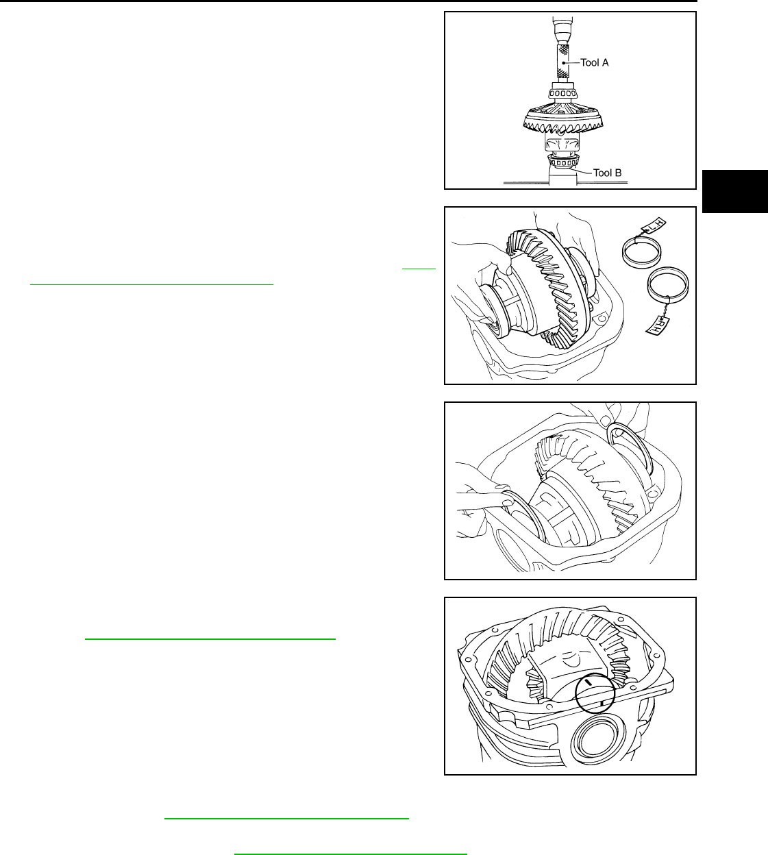
REAR FINAL DRIVE
DLN-465
< DISASSEMBLY AND ASSEMBLY > [REAR FINAL DRIVE: R230 (4WD)]
C
E
F
G
H
I
J
K
L
M
A
B
DLN
N
O
P
10. Press the side bearing inner races into the differential case
using Tools.
CAUTION:
Do not reuse side bearing inner race.
11. Install the differential case assembly with the side bearing outer
races into the gear carrier.
12. Measure the side bearing preload torque. If necessary, select
the appropriate side bearing adjusting washers. Refer to DLN-
467, "Inspection and Adjustment""Side Bearing Preload
Torque".
13. Insert the selected left and right side bearing adjusting washers
in place between the side bearings and gear carrier.
14. Install the side bearing caps with the matching marks aligned
and tighten the side bearing cap bolts to the specified torque.
Refer to DLN-450, "Disassembly and Assembly".
15. Check and adjust the drive gear runout, tooth contact, drive gear to drive pinion backlash, and total pre-
load torque. Refer to DLN-467, "Inspection and Adjustment".
Recheck the above items.
16. Install the side flanges. Refer to DLN-444, "Removal and Installation".
Tool number A: KV38100200 (J-26233)
B: ST33081000 ( — )
SPD353
SPD919
SPD924
SPD889
Revision: October 2008
2009 Pathfinder
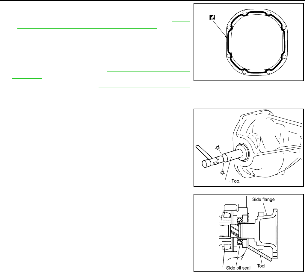
DLN-466
< DISASSEMBLY AND ASSEMBLY > [REAR FINAL DRIVE: R230 (4WD)]
REAR FINAL DRIVE
17. Apply a 3.2mm (0.126 in) bead of sealant to the mating surface
of the carrier cover.
• Use Genuine Silicone RTV or equivalent. Refer to GI-26,
"Recommended Chemical Products and Sealants".
CAUTION:
Remove any old sealant adhering to the mating surfaces.
Also remove any moisture, oil, or foreign material adhering
to the application and mating surfaces.
18. Install the carrier cover to the gear carrier. Tighten the bolts to
the specified torque. Refer to DLN-450, "Disassembly and
Assembly".
19. Install the side flange. Refer to DLN-444, "Removal and Installa-
tion"
Side Flange
1. Apply multi-purpose grease to the lips of the new side oil seal.
Then drive the new side oil seal in evenly until it becomes flush
with the gear carrier using Tool.
CAUTION:
• Do not reuse side oil seal.
• Do not incline the new side oil seal when installing.
• Apply multi-purpose grease to the lips of the new side oil
seal.
2. Install the side flange using Tool.
a. Install the Tool to the side oil seal as shown.
b. Insert the side flange until the serrated part of the side flange
has engaged the serrated part of the side gear and remove the
Tool.
c. Drive in the side flange using suitable tool.
NOTE:
Installation is completed when the driving sound of the side
flange turns into a sound which seems to affect the whole rear
final drive assembly.
WDIA0282E
Tool number : ST35271000 ( — )
SPD560
Tool number : KV38107900 (J-39352)
SDIA0822E
Revision: October 2008
2009 Pathfinder

SERVICE DATA AND SPECIFICATIONS (SDS)
DLN-467
< SERVICE DATA AND SPECIFICATIONS (SDS) [REAR FINAL DRIVE: R230 (4WD)]
C
E
F
G
H
I
J
K
L
M
A
B
DLN
N
O
P
SERVICE DATA AND SPECIFICATIONS (SDS)
SERVICE DATA AND SPECIFICATIONS (SDS)
General Specification INFOID:0000000003937477
Inspection and Adjustment INFOID:0000000003937478
DRIVE GEAR RUNOUT
Unit: mm (in)
SIDE GEAR CLEARANCE
Unit: mm (in)
PRELOAD TORQUE
Unit: N·m (kg-m, in-lb)
BACKLASH
Unit: mm (in)
COMPANION FLANGE RUNOUT
Unit: mm (in)
SELECTIVE PARTS
Side Gear Thrust Washer
Applied model VK56DE
Final drive model R230
Gear ratio 2.937
Number of teeth (Drive gear/Drive pinion) 47 / 16
Oil capacity (Approx.) 1.75 (3 3/4 US pt, 3 1/8 Imp pt)
Number of pinion gears 2
Drive pinion adjustment spacer type Collapsible
Item Runout limit
Drive gear back face 0.05 (0.0020) or less
Item Specification
Side gear back clearance
(Clearance limit between side gear and differential case for adjusting
side gear backlash)
0.20 (0.0079) or less
(Each gear should rotate smoothly without excessive resis-
tance during differential motion.)
Item Specification
Drive pinion bearing preload torque 1.77 − 2.64 N·m (0.18 − 0.26 kg−m, 16 − 23 in-lb)
Side bearing preload torque (reference value determined by drive
gear bolt pulling force) 0.20 − 0.52 N·m (0.02 − 0.05 kg−m, 2 − 4 in-lb)
Drive gear bolt pulling force (by spring gauge) 34.2 − 39.2 N (3.5 − 4 kg, 7.7 − 8.8 lb)
Total preload torque
(Total preload torque = drive pinion bearing preload torque + Side
bearing preload torque) 2.05 − 4.11 N·m (0.21 − 0.42 kg−m, 19 − 36 in-lb)
Item Specification
Drive gear to drive pinion gear 0.13 − 0.18 (0.0051 − 0.0070)
Item Runout limit
Outer side of the companion flange 0.08 (0.0031) or less
Revision: October 2008
2009 Pathfinder

DLN-468
< SERVICE DATA AND SPECIFICATIONS (SDS) [REAR FINAL DRIVE: R230 (4WD)]
SERVICE DATA AND SPECIFICATIONS (SDS)
Unit: mm (in)
*: Always check with the Parts Department for the latest parts information.
Drive Pinion Height Adjusting Washer
Unit: mm (in)
*: Always check with the Parts Department for the latest parts information.
Side Bearing Adjusting Washer
Unit: mm (in)
*: Always check with the Parts Department for the latest parts information.
Thickness Part number*
1.75 (0.0688)
1.80 (0.0708)
1.85 (0.0728)
38424 7S000
38424 7S001
38424 7S002
Thickness Part number* Thickness Part number*
2.59 (0.1020)
2.61 (0.1028)
2.63 (0.1035)
2.65 (0.1043)
2.67 (0.1051)
2.69 (0.1059)
2.71 (0.1067)
2.73 (0.1075)
2.75 (0.1083)
2.77 (0.1091)
38154 40P00
38154 40P01
38154 40P02
38154 40P03
38154 40P04
38154 40P05
38154 40P06
38154 40P07
38154 40P08
38154 40P09
2.79 (0.1098)
2.81 (0.1106)
2.83 (0.1114)
2.85 (0.1122)
2.87 (0.1130)
2.89 (0.1138)
2.91 (0.1146)
2.93 (0.1154)
2.95 (0.1161)
2.97 (0.1169)
38154 40P10
38154 40P11
38154 40P12
38154 40P13
38154 40P14
38154 40P15
38154 40P16
38154 40P17
38154 40P18
38154 40P19
Thickness Part number* Thickness Part number*
2.00 (0.0787)
2.05 (0.0807)
2.10 (0.0827)
2.15 (0.0846)
2.20 (0.0866)
2.25 (0.0886)
2.30 (0.0906)
38453 40P00
38453 40P01
38453 40P02
38453 40P03
38453 40P04
38453 40P05
38453 40P06
2.35 (0.0925)
2.40 (0.0945)
2.45 (0.0965)
2.50 (0.0984)
2.55 (0.1004)
2.60 (0.1024)
38453 40P07
38453 40P08
38453 40P09
38453 40P10
38453 40P11
38453 40P12
Revision: October 2008
2009 Pathfinder
