DWM1001 Firmware User Guide Ver11
User Manual:
Open the PDF directly: View PDF ![]() .
.
Page Count: 30
- DISCLAIMER
- 1 Introduction
- 2 Firmware Overview
- 3 Firmware tool chain
- 4 User Application Examples
- 5 References
- 6 Document History
- 7 Change Log
- 8 About Decawave

DWM1001 Firmware User Guide
© Decawave 2017
SW-DWM1001-Firmware-User-Guide-1.1
DWM1001 Firmware User
Guide
Based on DWM1001-DEV board
Version 1.1
This document is subject to change without
notice

DWM1001 Firmware User Guide
© Decawave 2017
SW-DWM1001-Firmware-User-Guide-1.1
Page 2
TABLE OF CONTENTS
DISCLAIMER ............................................................................................................................ 5
1 INTRODUCTION ..................................................................................................................... 8
1.1 OVERVIEW ................................................................................................................................... 8
1.2 WHAT’S INCLUDED IN THE FIRMWARE RELEASE................................................................................... 8
2 FIRMWARE OVERVIEW .......................................................................................................... 9
2.1 HIGH-LEVEL ARCHITECTURE ............................................................................................................ 9
2.2 OVERVIEW OF THE PANS LIBRARY ................................................................................................. 10
2.3 COMPONENTS AND OPERATIONS OF THE PANS LIBRARY.................................................................... 10
2.3.1 SoftDevice and BLE driver ................................................................................................ 11
2.3.2 eCos RTOS and BSP .......................................................................................................... 11
2.3.3 DW1000 driver ................................................................................................................ 11
2.3.4 Stationary indication ....................................................................................................... 11
2.3.5 DRTLS Network operation ............................................................................................... 11
2.3.6 Commissioning ................................................................................................................ 11
2.3.7 RTLS Management .......................................................................................................... 11
2.3.8 TWR solver / Location Engine .......................................................................................... 12
3 FIRMWARE TOOL CHAIN ...................................................................................................... 13
3.1 TOOL CHAIN OVERVIEW ............................................................................................................... 13
3.2 CONTENT IN THE TOOL CHAIN ........................................................................................................ 13
3.2.1 Hardware part of toolchain ............................................................................................. 14
3.2.2 Software part of toolchain .............................................................................................. 14
3.2.3 Example application package for DWM1001 .................................................................. 14
3.3 GUIDES TO FLASH THE DWM1001 WITH FACTORY IMAGE ................................................................. 14
3.3.1 Using J-Flash Light ........................................................................................................... 14
3.3.2 Using the provided VM tools ........................................................................................... 15
4 USER APPLICATION EXAMPLES ............................................................................................ 18
4.1 OVERVIEW ................................................................................................................................. 18
4.2 “C CODE API” APPLICATION EXAMPLE ............................................................................................ 18
4.2.1 Firmware image partitioning .......................................................................................... 18
4.2.2 Compiling/debugging user application in the firmware ................................................. 19
4.3 UART APPLICATIONS EXAMPLE ...................................................................................................... 21
4.3.1 UART connection ............................................................................................................. 21
4.3.2 UART examples ................................................................................................................ 23
4.4 SPI APPLICATIONS EXAMPLE .......................................................................................................... 25
4.4.1 SPI connection ................................................................................................................. 25
4.4.2 SPI example ..................................................................................................................... 25
5 REFERENCES ........................................................................................................................ 27
6 DOCUMENT HISTORY .......................................................................................................... 28
6.1 REVISION HISTORY ...................................................................................................................... 28
7 CHANGE LOG ....................................................................................................................... 29
8 ABOUT DECAWAVE ............................................................................................................. 30
LIST OF TABLES

DWM1001 Firmware User Guide
© Decawave 2017
SW-DWM1001-Firmware-User-Guide-1.1
Page 3
TABLE 1 UART PIN CONNECTIONS ................................................................................................................ 22
TABLE 2 SPI PIN CONNECTIONS .................................................................................................................... 25
TABLE 3: DOCUMENT HISTORY .................................................................................................................... 28
LIST OF FIGURES
FIGURE 1 HIGH-LEVEL ARCHITECTURE OF DWM1001 FIRMWARE VS. USER SOFTWARE ......................................... 9
FIGURE 2 DWM1001 FIRMWARE LIBRARYCOMPONENTS ............................................................................... 10
FIGURE 3 TOOL CHAIN AND SOURCE COMPONENTS IN DWM1001 FIRMWARE DEVELOPMENT ............................... 13
FIGURE 4 DWM1001 DEV BOARD – MICRO USB CONNECTION ....................................................................... 15
FIGURE 5 TRANSFER DWM1001 FROM WINDOWS TO VIRTUALBOX ................................................................. 17
FIGURE 6 DWM1001 FLASH ADDRESS MAP ................................................................................................. 18
FIGURE 7 J-LINK DEVICE IN WINDOWS .......................................................................................................... 22
FIGURE 8 DWM1001 DEVICE COM PORT OVER J-LINK .................................................................................. 22
FIGURE 9 CONNECTING DWM1001 TO RASPBERRY PI 3 OVER HEADER PINS ...................................................... 23
FIGURE 10 CONNECT TO DWM1001 DEVICE THROUGH UART SHELL ............................................................... 24
FIGURE 11 RUN SIMPLE UART EXAMPLE ON RASPBERRY PI 3 ........................................................................... 25
FIGURE 12 RUN SIMPLE SPI EXAMPLE ON RASPBERRY PI 3 ............................................................................... 26
DWM1001 Firmware User Guide
© Decawave 2017
SW-DWM1001-Firmware-User-Guide-1.1
Page 4
DOCUMENT INFORMATION
Disclaimer
Decawave reserves the right to change product specifications without notice. As far as possible changes to
functionality and specifications will be issued in product specific errata sheets or in new versions of this
document. Customers are advised to check the Decawave website for the most recent updates on this
product
Copyright © 2017 Decawave Ltd
LIFE SUPPORT POLICY
Decawave products are not authorized for use in safety-critical applications (such as life support) where a
failure of the Decawave product would reasonably be expected to cause severe personal injury or death.
Decawave customers using or selling Decawave products in such a manner do so entirely at their own risk
and agree to fully indemnify Decawave and its representatives against any damages arising out of the use of
Decawave products in such safety-critical applications.
Caution! ESD sensitive device.
Precaution should be used when handling the device in order to prevent permanent damage

DWM1001 Firmware User Guide
© Decawave 2017
SW-DWM1001-Firmware-User-Guide-1.1
Page 5
DISCLAIMER
(1) This Disclaimer applies to the software provided by Decawave Ltd. (“Decawave”) in
support of its DWM1001 module product (“Module”) all as set out at clause 3 herein
(“Decawave Software”).
(2) Decawave Software is provided in two ways as follows: -
(a) pre-loaded onto the Module at time of manufacture by Decawave (“Firmware”);
(b) supplied separately by Decawave (“Software Bundle”).
(3) Decawave Software consists of the following components (a) to (d) inclusive:
(a) The Decawave Positioning and Networking Stack (“PANS”), available as a
library accompanied by source code that allows a level of user customisation.
The PANS software is pre-installed and runs on the Module as supplied, and
enables mobile “tags”, fixed “anchors” and “gateways” that together deliver the
DWM1001 Two-Way-Ranging Real Time Location System (“DRTLS”)
Network.
(b) The Decawave DRTLS Manager which is an Android™ application for
configuration of DRTLS nodes (nodes based on the Module) over Bluetooth™.
(c) The Decawave DRTLS Gateway Application which supplies a gateway
function (on a Raspberry Pi ®) routing DRTLS location and sensor data traffic
onto an IP based network (e.g. LAN), and consists of the following components:
DRTLS Gateway Linux Kernel Module
DRTLS Gateway Daemon
DRTLS Gateway MQTT Broker
DRTLS Gateway Web Manager
(d) Example Host API functions, also designed to run on a Raspberry Pi, which
show how to drive the Module from an external host microprocessor.
(4) The following third party components are used by Decawave Software and are
incorporated in the Firmware or included in the Software Bundle as the case may be: -
(a) The PANS software incorporates the Nordic SoftDevice S132-SD-v3 version
3.0.0 (production) which is included in the Firmware and is also included in the
Software Bundle;
(b) The PANS software uses the eCos RTOS which is included in the Software
Bundle. The eCos RTOS is provided under the terms of an open source licence
which may be found at: http://ecos.sourceware.org/license-overview.html;
(c) The PANS software uses an open source CRC-32 function from FreeBSD which
is included in the Software Bundle. This CRC-32 function is provided under the
terms of the BSD licence which may be found at:
https://github.com/freebsd/freebsd/blob/386ddae58459341ec56760470780581
4a2128a57/COPYRIGHT;
DWM1001 Firmware User Guide
© Decawave 2017
SW-DWM1001-Firmware-User-Guide-1.1
Page 6
(d) The Decawave DRTLS Manager application uses open source software which
is provided as source code in the Software Bundle. This open source software
is provided under the terms of the Apache Licence v2.0 which may be found at
http://www.apache.org/licenses/LICENSE-2.0;
(e) The Decawave DRTLS Gateway Application uses the following third party
components: -
(i) The Linux Kernel which is provided as source code in the Software
Bundle. The Linux Kernel is provided under the terms of the GPLv2
licence which may be found at: https://www.gnu.org/licenses/old-
licenses/gpl-2.0.en.html and as such the DWM1001 driver component
of the DRTLS Gateway Application is provided under the same license
terms;
(ii) The three.js JavaScript library, the downloadable version of which is
available here https://threejs.org/, is provided under the terms of the MIT
Licence which may be found at https://opensource.org/licenses/MIT.
Items (a), (b), (c), (d) and (e) in this section 4 are collectively referred to as the “Third
Party Software”
(5) Decawave Software incorporates source code licensed to Decawave by Leaps s.r.o., a
supplier to Decawave, which is included in the Firmware and the Software Bundle in
binary and/or source code forms as the case may be, under the terms of a license
agreement entered into between Decawave and Leaps s.r.o.
(6) Decawave hereby grants you a free, non-exclusive, non-transferable, worldwide license
without the right to sub-license to design, make, have made, market, sell, have sold or
otherwise dispose of products incorporating Decawave Software, to modify Decawave
Software or incorporate Decawave Software in other software and to design, make,
have made, market, sell, have sold or otherwise dispose of products incorporating such
modified or incorporated software PROVIDED ALWAYS that the use by you of Third
Party Software as supplied by Decawave is subject to the terms and conditions of the
respective license agreements as set out at clause 4 herein AND PROVIDED ALWAYS
that Decawave Software is used only in systems and products based on Decawave
semiconductor products. NO OTHER LICENSE, EXPRESS OR IMPLIED, BY
ESTOPPEL OR OTHERWISE TO ANY OTHER DECAWAVE INTELLECTUAL
PROPERTY RIGHT, AND NO LICENSE TO ANY THIRD PARTY TECHNOLOGY
OR INTELLECTUAL PROPERTY RIGHT, IS GRANTED HEREIN, including but
not limited to any patent right, copyright, mask work right, or other intellectual property
right relating to any combination, machine, or process in which Decawave
semiconductor products or Decawave Software are used.
(7) Downloading, accepting delivery of or using Decawave Software indicates your
agreement to the terms of (i) the license grated at clause 6 herein, (ii) the terms of this
Disclaimer and (iii) the terms attaching to the Third Party Software. If you do not agree
with all of these terms do not download, accept delivery of or use Decawave Software.
(8) Decawave Software is solely intended to assist you in developing systems that
incorporate Decawave semiconductor products. You understand and agree that you
remain responsible for using your independent analysis, evaluation and judgment in
designing your systems and products. THE DECISION TO USE DECAWAVE

DWM1001 Firmware User Guide
© Decawave 2017
SW-DWM1001-Firmware-User-Guide-1.1
Page 7
SOFTWARE IN WHOLE OR IN PART IN YOUR SYSTEMS AND PRODUCTS
RESTS ENTIRELY WITH YOU AND DECAWAVE ACCEPTS NO LIABILTY
WHATSOEVER FOR SUCH DECISION.
(9) DECAWAVE SOFTWARE IS PROVIDED "AS IS". DECAWAVE MAKES NO
WARRANTIES OR REPRESENTATIONS WITH REGARD TO DECAWAVE
SOFTWARE OR USE OF DECAWAVE SOFTWARE, EXPRESS, IMPLIED OR
STATUTORY, INCLUDING ACCURACY OR COMPLETENESS. DECAWAVE
DISCLAIMS ANY WARRANTY OF TITLE AND ANY IMPLIED WARRANTIES
OF MERCHANTABILITY, FITNESS FOR A PARTICULAR PURPOSE AND NON-
INFRINGEMENT OF ANY THIRD PARTY INTELLECTUAL PROPERTY
RIGHTS WITH REGARD TO DECAWAVE SOFTWARE OR THE USE THEREOF.
(10) DECAWAVE SHALL NOT BE LIABLE FOR AND SHALL NOT DEFEND OR
INDEMNIFY YOU AGAINST ANY THIRD PARTY INFRINGEMENT CLAIM
THAT RELATES TO OR IS BASED ON DECAWAVE SOFTWARE OR THE USE
OF DECAWAVE SOFTWARE. IN NO EVENT SHALL DECAWAVE BE LIABLE
FOR ANY ACTUAL, SPECIAL, INCIDENTAL, CONSEQUENTIAL OR
INDIRECT DAMAGES, HOWEVER CAUSED, INCLUDING WITHOUT
LIMITATION TO THE GENERALITY OF THE FOREGOING, LOSS OF
ANTICIPATED PROFITS, GOODWILL, REPUTATION, BUSINESS RECEIPTS
OR CONTRACTS, COSTS OF PROCUREMENT OF SUBSTITUTE GOODS OR
SERVICES; LOSS OF USE, DATA, OR PROFITS; OR BUSINESS
INTERRUPTION), LOSSES OR EXPENSES RESULTING FROM THIRD PARTY
CLAIMS. THESE LIMITATIONS WILL APPLY REGARDLESS OF THE FORM
OF ACTION, WHETHER UNDER STATUTE, IN CONTRACT OR TORT
INCLUDING NEGLIGENCE OR ANY OTHER FORM OF ACTION AND
WHETHER OR NOT DECAWAVE HAS BEEN ADVISED OF THE POSSIBILITY
OF SUCH DAMAGES, ARISING IN ANY WAY OUT OF DECAWAVE
SOFTWARE OR THE USE OF DECAWAVE SOFTWARE.
(11) You acknowledge and agree that you are solely responsible for compliance with all
legal, regulatory and safety-related requirements concerning your products, and any use
of Decawave Software in your applications, notwithstanding any applications-related
information or support that may be provided by Decawave.
(12) Decawave reserves the right to make corrections, enhancements, improvements and
other changes to its software, including Decawave Software, at any time.
Mailing address: Decawave Ltd.,
Adelaide Chambers,
Peter Street,
Dublin D08 T6YA
IRELAND.
Copyright (c) 15 November 2017 by Decawave Limited. All rights reserved. All trademarks
are the property of their respective owners

DWM1001 Firmware User Guide
© Decawave 2017
SW-DWM1001-Firmware-User-Guide-1.1
Page 8
1 INTRODUCTION
1.1 Overview
The development of real-time positioning network using UWB technology is not a trivial
project. The intention of DWM1001 is to simplify the development of UWB RTLS by
providing a complete solution in a single module.
The DWM1001 module comes pre-loaded with embedded firmware which provides two-way
ranging (TWR) real time location system (RTLS) functionality and networking. The module
can be configured and controlled via its API, which can be accessed through a number of
different interfaces allowing flexibility to the product designer. The details of the API is
described in document [2]. Additionally, Decawave also provide the module firmware in form
of libraries and source code along with a build environment so that user can customise the
operation and/or add their own functions.
This document describes what is included in the DWM1001 firmware and how these various
elements cooperate together, and explains how users can add their own customisations.
The aim of this user guide is to help the users with their development based on the
DWM1001-DEV board. After reading this guide developers should be able to compile, build
and run the DWM1001 firmware, including custom modifications.
1.2 What’s included in the firmware release
Each DWM1001 firmware release includes:
1) The pre-compiled DWM1001 Firmware, including the firmware Positioning and
Networking stack (PANS) library for on-board development, is provided in the
DWM1001 on-board package. The firmware and library architecture and its basic
partitioning are described in Section 2.
2) Firmware tool chain, described in Section 3. The detailed steps to prepare the
necessary tool chain, download the firmware user application package, and
compile/build/flash their own application are introduced.
3) Simple examples demonstrating how to use the DWM1001 APIs. These are
described in Section 4.
DWM1001 Firmware User Guide
© Decawave 2017
SW-DWM1001-Firmware-User-Guide-1.1
Page 9
2 FIRMWARE OVERVIEW
2.1 High-Level Architecture
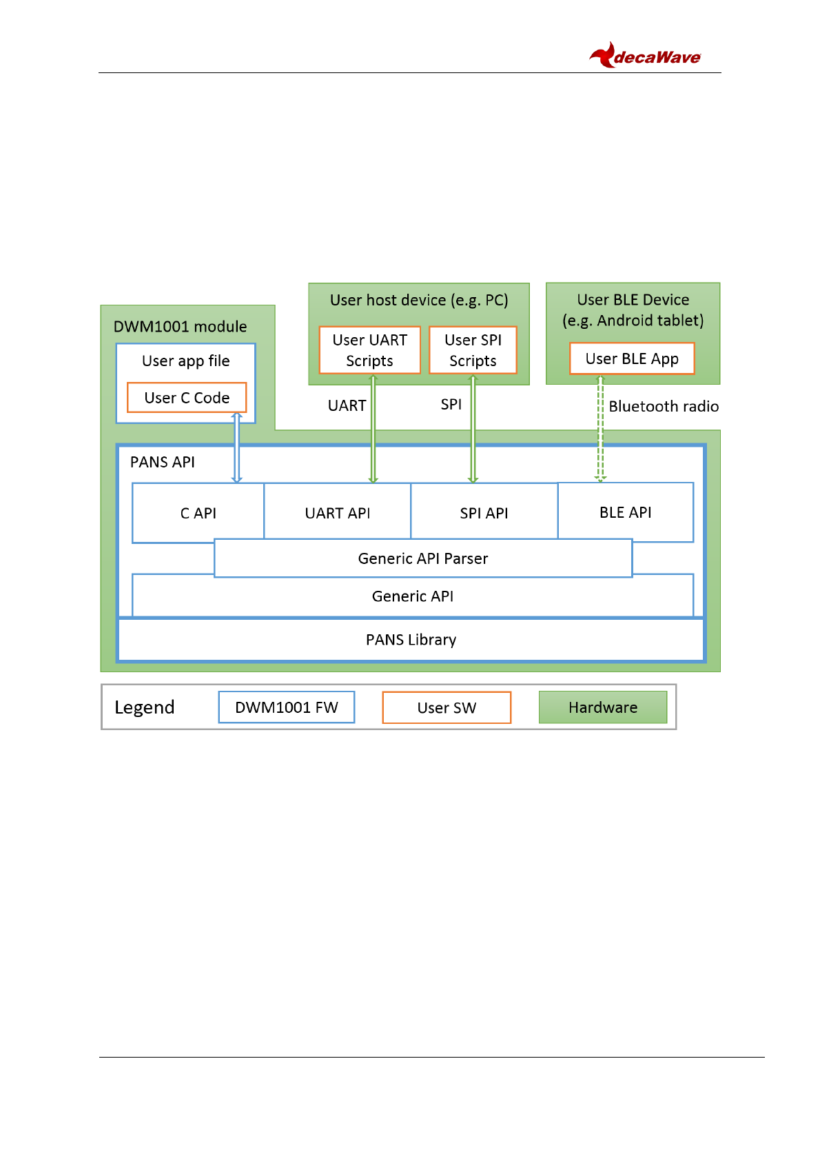
The firmware embedded in the DWM1001 module basically provides two types of functions:
the PANS API and the PANS library which provides lower level functions. The PANS API,
includes the Generic API, (these include different API sets for different interfaces and the
corresponding parser, which acts as the translator between the user APIs (C, UART, SPI
and BLE) and the PANS library). Figure 1 shows the architecture and components of the
DWM1001 firmware.
Figure 1 High-Level Architecture of DWM1001 Firmware vs. User Software
As can be seen in Figure 1, apart from using the DWM1001 module itself, the DWM1001
module can be physically connected to external controlling hardware, either wired or
wirelessly over Bluetooth radio. The PANS API provides the users with four sets of API to
call the PANS library functions through different interfaces:
User C code: an on-board user space, allowing to include an application-specific
code in the user application file provided in the DWM1001 firmware, using the
firmware development tool chain provided by Decawave, see Section 4.2.
SPI: using a host device (e.g. PC) to communicate with the DWM1001 module using
TLV (Type-Length-Value format, detailed in [2]) format requests and responses
through SPI bus, for configuration and data transmission.
UART: using a host device (e.g. PC) to communicate the DWM1001 module through
UART bus, for configuration and data transmission. Two modes of communications
DWM1001 Firmware User Guide
© Decawave 2017
SW-DWM1001-Firmware-User-Guide-1.1
Page 10
are provided over the UART interface: UART Generic mode using TLV format
requests and responses; and UART Shell mode using terminal prompt commands.
BLE: using a Bluetooth Low Energy (BLE) device (e.g. Android tablet) to control and
configure through Bluetooth radio.
All these API sets provide the same set of generic functions calls, namely the Generic API.
The Generic API Parser acts as the translator between the four API sets and the Generic
API. When an API command is called from any of the above API Interfaces, the command
goes through the Generic API Parser which translates the API command into Generic API
function calls. If the API command needs a return message, the DWM1001 responds
through the same interface.
The use of C code, UART and SPI APIs are detailed with simple examples in Section 4.
More detailed information is provided in the API document [2].
Note1: The external interfaces, including the UART, the SPI and the BLE, are used by the
external APIs in the PANS library for Host connection. The on-board user application
through C code API cannot make use of the external interfaces due to compatibility reasons.
Note2: Decawave do not provide the library source code, or support any use of the PANS
library except through the PANS API which is described in the API Document [2]
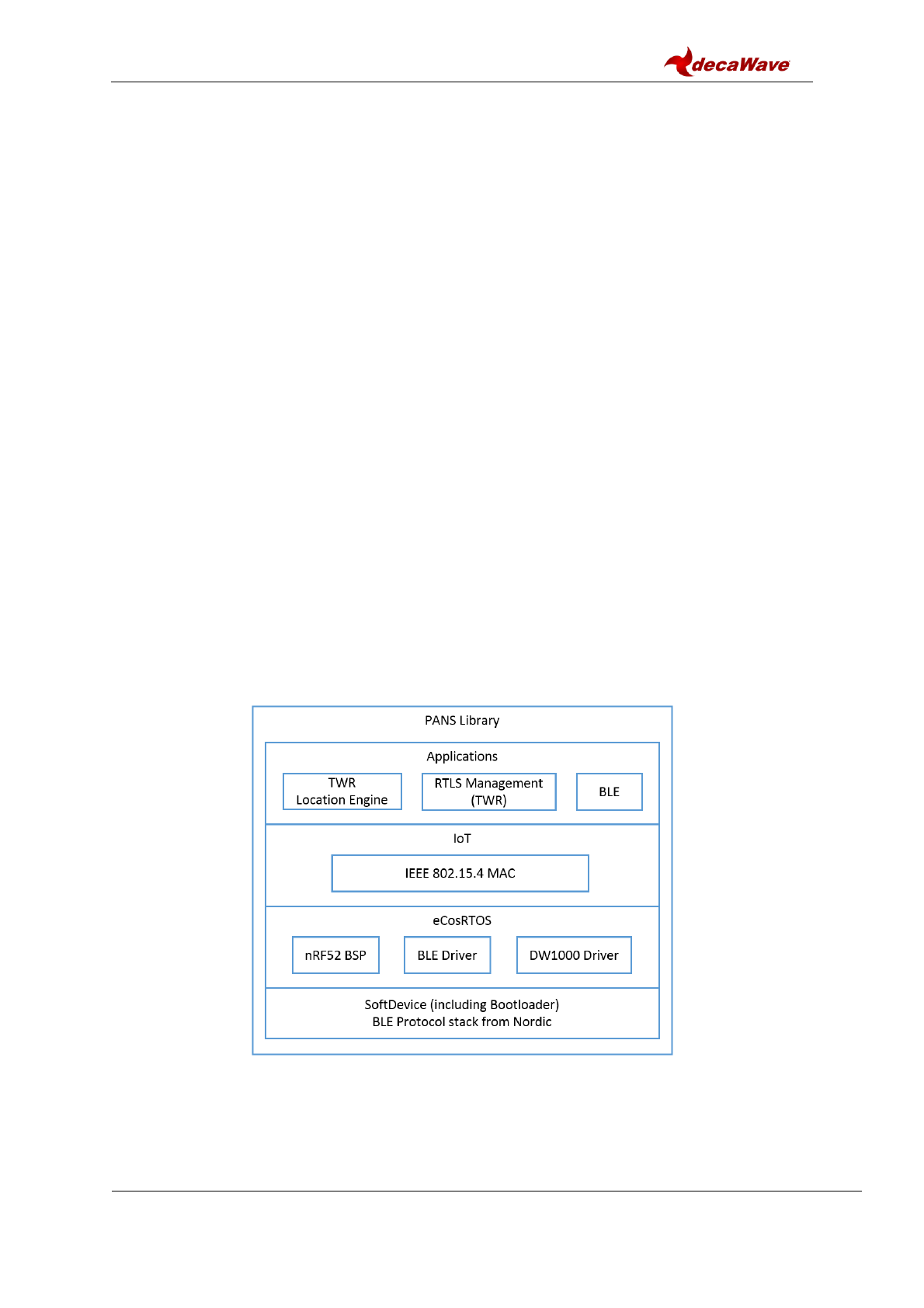
2.2 Overview of the PANS Library
Figure 2 illustrates the architecture of the PANS Library in detail. From bottom up there are
the SoftDevice and the BLE Protocol stack from Nordic Semiconductor, eCos RTOS system
with embedded drivers of the components, IoT layer protocols and the applications layer.
Section 2.3 gives a brief introduction to each of the components in the library and the
operations on the application layer.
Figure 2 DWM1001 Firmware LibraryComponents
2.3 Components and operations of the PANS Library
The PANS library includes a few firmware components to drive the DWM1001 module.

DWM1001 Firmware User Guide
© Decawave 2017
SW-DWM1001-Firmware-User-Guide-1.1
Page 11
Some operations are implemented based on these components to perform the positioning
and networking function.
2.3.1 SoftDevice and BLE driver
SoftDevice is a Nordic Semiconductor feature-rich library for BLE. The SoftDevice employed
on the DWM1001 is the S132, a concurrent multi-link SoftDevice for Central, Peripheral,
Broadcaster and Observer roles in BLE applications. The BLE driver / library is included in
the S132 SoftDevice, providing the DWM001 with BLE features to create complex network
topologies, communication and firmware update over-the-air [1].
2.3.2 eCos RTOS and BSP
eCos RTOS is a free open source real-time operating system. The eCos system provides
very good run-time performance and the board support package (BSP) for the DWM1001
hardware platform. It includes all the necessary drivers for the module components (i.e.
accelerometer, BLE & DW1000).
2.3.3 DW1000 driver
Decawave’s DW1000 API driver. For details please see DW1000 Software API Guide [2].
2.3.4 Stationary indication
An accelerometer component LIS2DH12TR of slave address 0x19 as an I2C peripheral
device is implemented on the DWM1001 module, i.e. the read and write address are 0x33
and 0x32 respectively. This accelerometer provides a simple “stationary” indication function.
The DWM1001-based tag can be configured to use Responsive or Low-Power mode. It will
be in Low-Power mode when stationary, and will enter Responsive mode when moving. The
real-time accelerometer data is accessible through provided Shell API command and I2C
functions in the C code API, see [2] for detailed information.
2.3.5 DRTLS Network operation
The DWM1001 TWR Real Time Location System (DRTLS) networking stack, allows
discovery, joining and leaving. The UWB frames are sent according to 802.15.4 standard
frame formats. The MAC layer functionality implemented on the DWM1001 module, as
described in DWM1001 System Overview document [3], controls the mechanism for joining,
leaving, installation, commissioning of nodes and associated two-way ranging protocol and
data transfer. A number of different use cases e.g. follow-me, large-scale asset-tracking,
navigation, home network are supported.
2.3.6 Commissioning
DRTLS can be commissioned with Decawave RTLS Manager Android application.
After power on, new nodes will advertise over Bluetooth. Decawave RTLS Manager
application is used to connect to the node and configure it (e.g. its role as anchor or tag; its
x,y,z coordinates if it is an anchor and other attributes).
2.3.7 RTLS Management
The RTLS Management application supports configuration of DWM1001 modules as tags
and anchors which will participate in TWR. The tags will range to nearby anchors and use
internal location engine to calculate position. The full implementation is detailed in the
DWM1001 System Overview document [3].
DWM1001 Firmware User Guide
© Decawave 2017
SW-DWM1001-Firmware-User-Guide-1.1
Page 12
2.3.8 TWR solver / Location Engine
The TWR solver / Location Engine in the tags calculates tag’s x, y and z, coordinates is
implemented on the DWM1001 module. TWR results between the tag and the relative
anchors are sent to the solver for the calculation of tag’s position. The TWR results are
accessible through the APIs. The internal location engine can be disable and user
customised location calculation performed instead, e.g. adding extra filtering of change
LE/solver algorithms.
DWM1001 Firmware User Guide
© Decawave 2017
SW-DWM1001-Firmware-User-Guide-1.1
Page 13
3 FIRMWARE TOOL CHAIN
3.1 Tool Chain Overview
The Decawave firmware tool chain includes the following parts:
Virtual Box image with necessary tools pre-installed;
DWM1001 on-board package.
These can be used for developing of a new application with added new functionality which
will reside in the DWM1001 module and will run on top of the PANS library and the main
module functionality.
3.2 Content in the tool chain
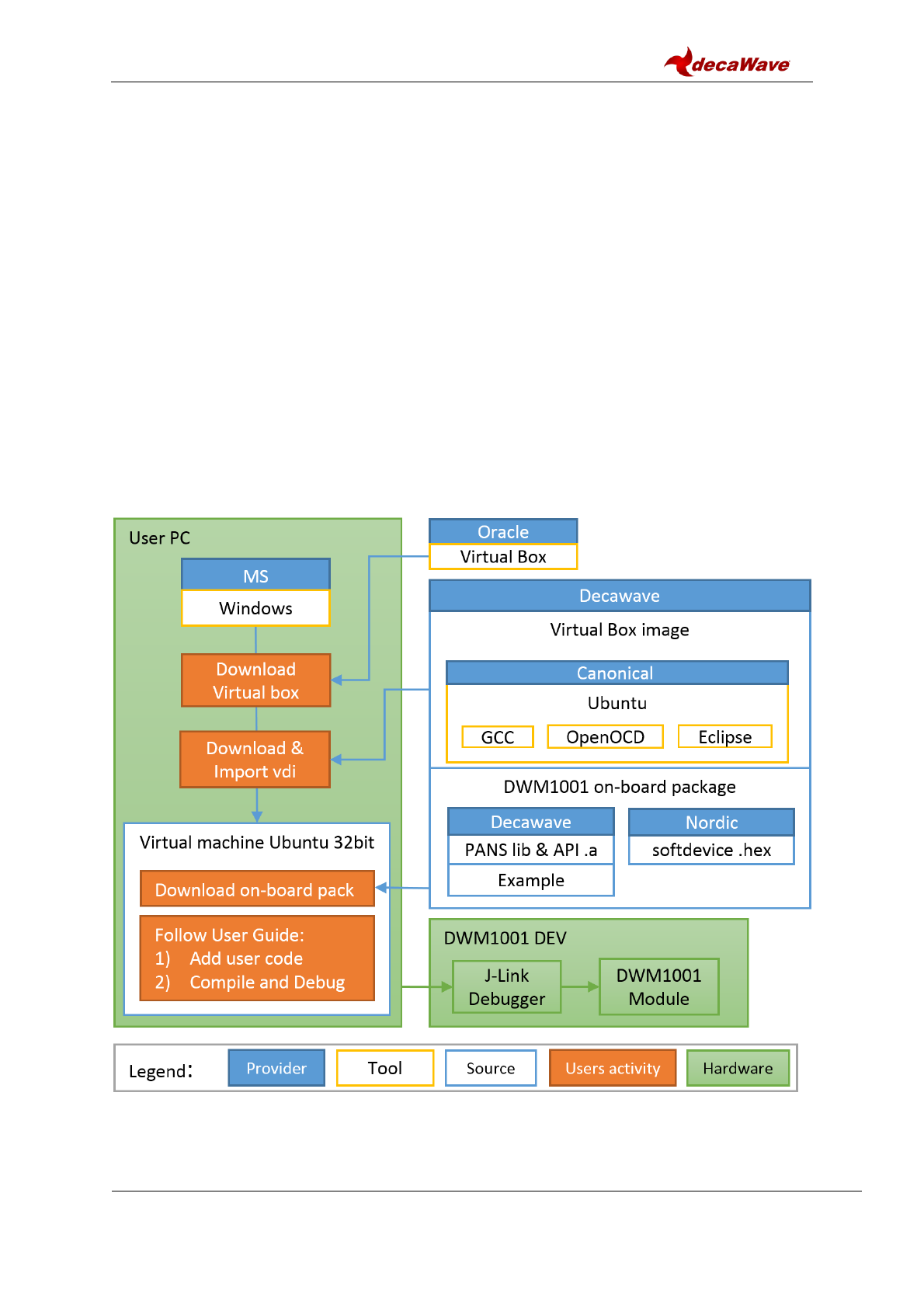
The Figure 3 below shows the tool chain used in the DWM1001 firmware development.
In the DWM1001 product, the whole firmware development is under Linux (Ubuntu) virtual
machine (VM). Apart from the Linux system itself, the VM includes the tools for development:
GCC (arm-none-eabi-gcc version 5.4.1), OpenOCD (version 0.10.0) and Eclipse (version
Oxygen Release 4.7.0). The distributed DWM1001 on-board package contains the user app
source files and the libraries needed to compile and build the DWM1001 user firmware.
Figure 3 Tool chain and source components in DWM1001 firmware development
DWM1001 Firmware User Guide
© Decawave 2017
SW-DWM1001-Firmware-User-Guide-1.1
Page 14
3.2.1 Hardware part of toolchain
As illustrated in green color in Figure 3, a PC with Microsoft Windows OS and a DWM1001-
DEV board are required as the hardware. The DWM1001-DEV board provides the
DWM1001 module as the target and a J-Link debugger.
3.2.2 Software part of toolchain
In the DWM1001 firmware development, two types of tools are used:
1) Microsoft Windows tools – which need to be downloaded by the users;
2) Linux tools – which Decawave have prepared in the Linux VM image.
On the Windows PC, the Virtual Box provided by Oracle needs to be installed. The 32-bit
Linux image provided by Decawave needs to be downloaded and imported into the Virtual
Box as a VM as introduced in Section 3.3.2.
On the Linux VM, Decawave have prepared the required tools to compile, debug and
download the firmware onto the DWM1001 module, including GCC, J-Link and eclipse tools.
Decawave would recommend using the pre-installed software tools, since using different
versions of the above tools may cause unexpected errors. Decawave do NOT provide any
guidance on the installation of the software tools under Linux environment.
3.2.3 Example application package for DWM1001
The DWM1001 on-board package is provided for download on Decawave website [7].
The on-board package includes the DWM1001 PANS library, the Nordic Semiconductor
softdevice binary image and the on-board user application example files.
In DWM1001 firmware, the eCos library and other third party software constitute the PANS
library as introduced in Section 2.2. These source files are not provided in the on-board
package. Folder dwm\examples\dwm-simple is the provided on-board user application folder
for adding user customized functions through the C code APIs.
3.3 Guides to flash the DWM1001 with factory image
DWM1001 comes with pre-flashed factory image of firmware. This image is provided in the
DWM1001 on-board package: /dwm/recovery/dwm1001-flash.hex. Here the guide to flash
the factory image through the DWM1001 DEV board is provided.
3.3.1 Using J-Flash Light
The J-Flash Light tool can be used to flash the factory image through the DWM1001 DEV
over a few different platforms.
1) Prepare j-link tool
a. Download J-Link software from https://www.segger.com/
b. Install J-Link software.
DWM1001 Firmware User Guide
© Decawave 2017
SW-DWM1001-Firmware-User-Guide-1.1
Page 15
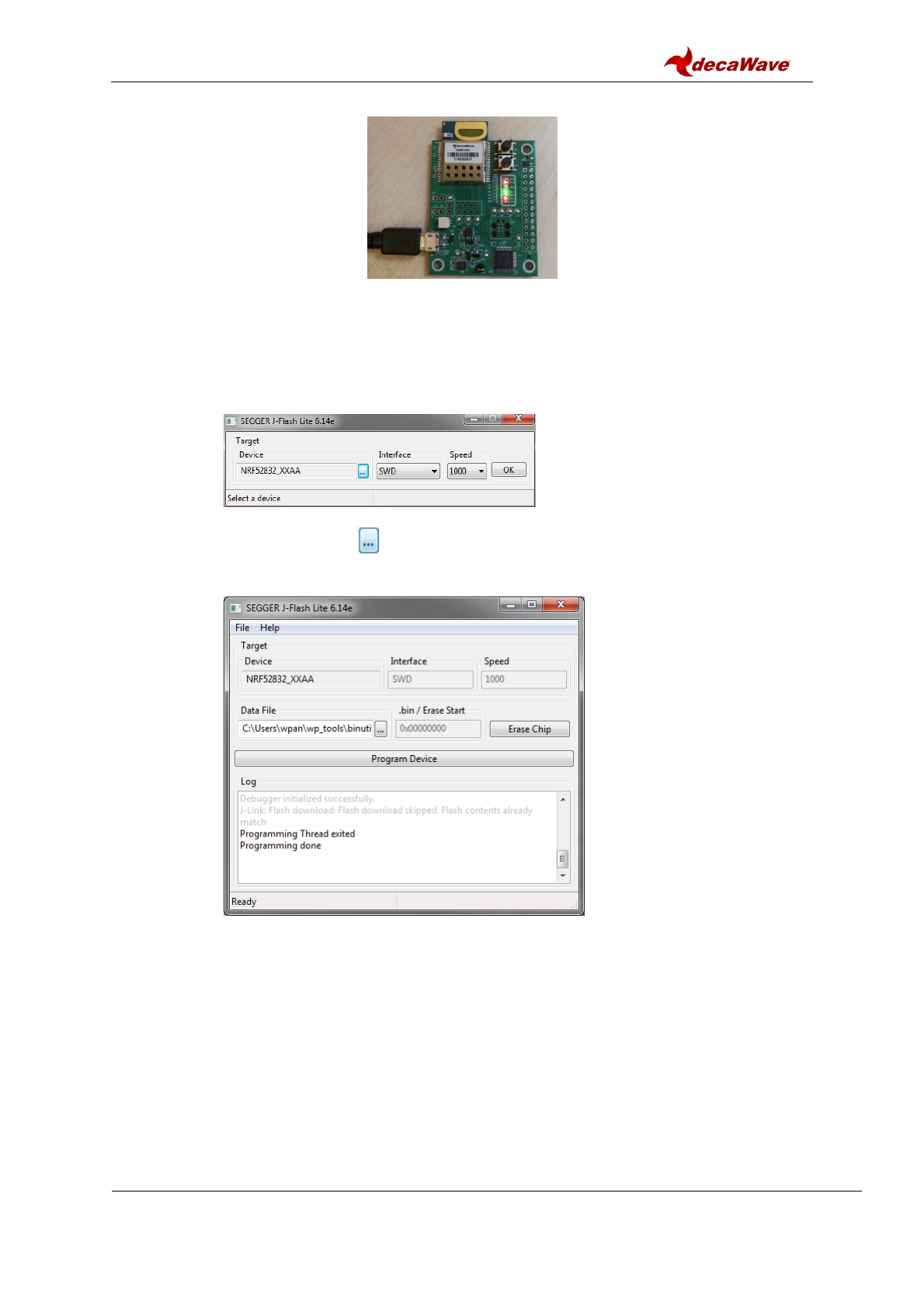
2) Connect the module with a micro USB data cable, shown in Figure 4.
Figure 4 DWM1001 DEV board – micro USB connection
3) Flash the image DWM1001 module
a. Open J-Flash Lite (default path is similar to in C:\Program Files
(x86)\SEGGER\JLink)
b. Choose nrf52832_XXAA as Device and SWD as interface, use default speed
1000. Click “OK”.
c. Click “Erase Chip” to do a full chip erase.
d. In Data File, click and browse to the hex file provided in the DWM1001 on-
board package (/dwm/recovery/dwm1001-flash.hex) to flash, click “Program
Device”.
The LEDs on the boards should be active once the flash update completes.
3.3.2 Using the provided VM tools
The provided VM tools can be used to flash the factory image onto a DWM1001 module.
The necessary steps are listed here.
1) Install Oracle VM VirtualBox [5].
2) Download the DWM1001 VM image package [6] and extract.
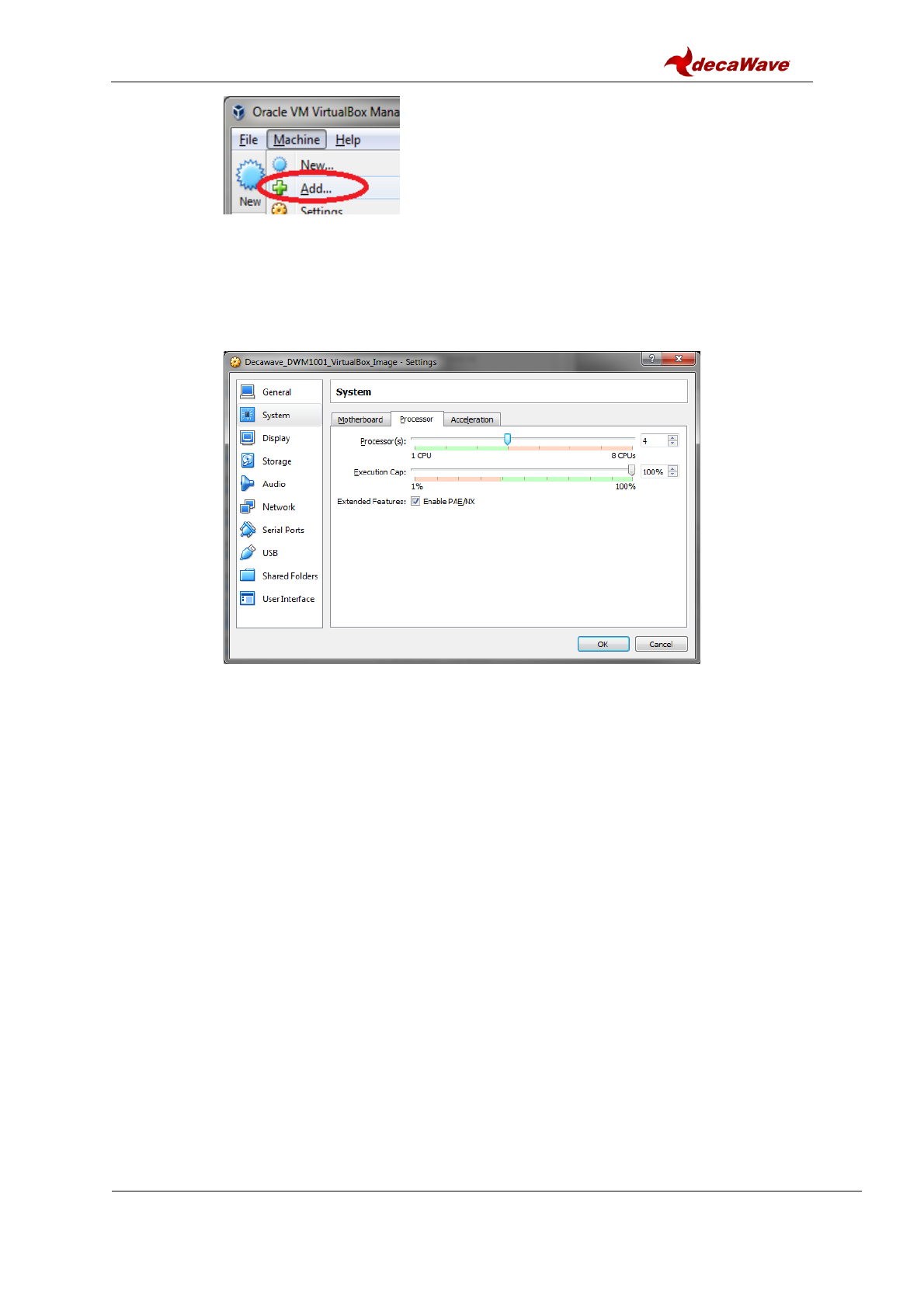
3) Mount the image in VirtualBox Manager. Note that the VM running performance can
be improved by increasing the number of processors, RAM and Disk etc.
a. Go to the menu bar Machine Add…
DWM1001 Firmware User Guide
© Decawave 2017
SW-DWM1001-Firmware-User-Guide-1.1
Page 16
b. Find Decawave_DWM1001_VirtualBox_Image.vbox file extracted from the
package, and click “Open”.
c. If a faster speed of the VM is desired, select the created virtual machine
“Decawave_DWM1001_VirtualBox_Image”, click “Settings” on the menu bar
System. In Tabs Motherboard and Tab Processor, adjust the suitable
amount of memory and processors assigned to the VM. Click “OK” when this
is done.
d. Click “Start” on the menu bar and the virtual machine will start.
e. Use password “dw” to login the virtual machine.
4) Download the DWM1001 on-board package into ~/Documents. To do this, either
downloading directly in the Linux virtual machine or using a shared folder to transmit
from the host system (Windows) can work.
a. In the Linux virtual machine, download the DWM1001 on-board package from
[7] into ~/Documents folder using wget command and unzip command.
cd ~/Documents
wget web/link/to/dwm1001_on-board_package_v1p0.tar
tar xf dwm1001_on-board_package_v1p0.tar
b. Alternatively setup a shared folder to transmit files between the host Windows
system and the Linux virtual machine:
i. In Windows, create folder with name “share_folder”, download the
DWM1001 on-board package and extract it into this folder.
ii. In Virtual box settings, create shared folder using the “share_folder” in
Windows. Use auto mount and permanent.
iii. Restart the Linux virtual machine, the shared folder will show up in
/media/sf_share_folder .
iv. In Linux virtual machine, copy the files from /media/sf_share_folder
into ~/Documents.
Note: by doing either way above, make sure that the extracted on-board package
path looks like ~/Documents/dwm/ .
5) Connect the module with a micro USB data cable, see Figure 4 in Section 3.3.1.
DWM1001 Firmware User Guide
© Decawave 2017
SW-DWM1001-Firmware-User-Guide-1.1
Page 17
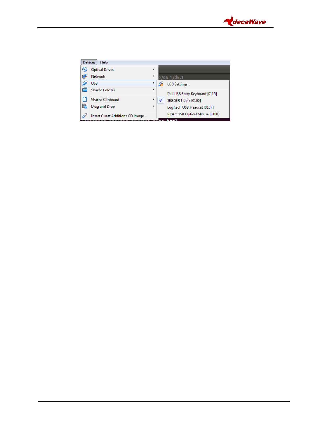
6) Go to VirtualBox Menu bar Device USB Click SEGGER J-Link
Make sure there is a √ before SEGGER J-Link, the device used in DWM1001 DEV
board. Having a √ in front means the device control is now on the VirtualBox side
rather than on the Windows side. See Figure 5.
Figure 5 Transfer DWM1001 from Windows to VirtualBox
7) Run the script to fully erase the DWM1001 module and flash the module with factory
image:
cd ~/Documents/dwm/examples/dwm-simple
make recover
The LEDs on the boards should be active once the flash update completes.
DWM1001 Firmware User Guide
© Decawave 2017
SW-DWM1001-Firmware-User-Guide-1.1
Page 18
4 USER APPLICATION EXAMPLES
4.1 Overview
As illustrated in Figure 1, DWM1001 provides many ways to use its API functions. Examples
that show the use of the APIs are listed in this section. In C code, UART Shell, UART
Generic, and SPI, examples of getting the location of the node through the API are
presented. The API document [2] provides more detailed information.
A tool to open serial port between host device and the DWM1001 module over UART is
needed in the firmware development. In Windows, PuTTY can be used; in Linux, minicom
can be used. The UART baud rate on the DWM1001 module is 115200 bps.
4.2 “C code API” application example
The VM image [6] in the DWM1001 tool chain has pre-installed Eclipse IDE which will be
used for debugging the example below. “C code API” example is an application, which is
running as part of the on-board firmware, utilizing a system resources of built-in to the
module Cortex M4F microcontroller. The application is running as a thread application in
multi-thread environment, driving by included to the PANS library eCos real-time operation
system.
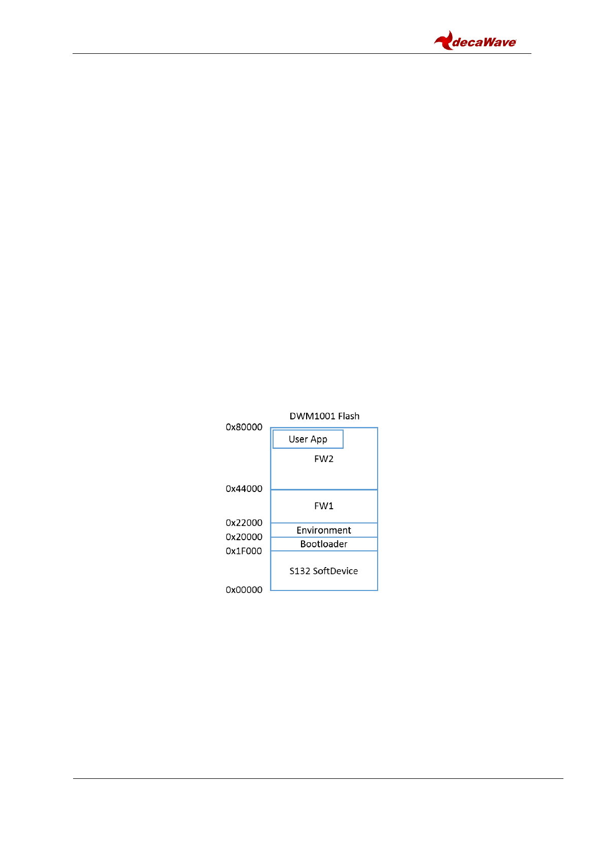
4.2.1 Firmware image partitioning
The flash size of the MCU (nRF52832) used on the DWM1001 module is 512KB from
address 0 to 0x80000. The partitioning of the flash is illustrated as in Figure 6.
Figure 6 DWM1001 Flash Address Map
The DWM1001 firmware includes the following parts: Nordic S132 Softdevice, Bootloader,
Environment, FW1 and FW2:
Softdevice, of size 124KB starting from address 0, provides Bluetooth low energy
central and peripheral protocol stack solution.
Bootloader, of size 4KB start from address 0x1F000, is a firmware manager
controlling the choice of FW1 and FW2 during booting/reseting.
Environment, of size 8KB start from address 0x20000, is a flash section reserved for
the firmware to store user configuration information. Doing power off/on, reset or
DWM1001 Firmware User Guide
© Decawave 2017
SW-DWM1001-Firmware-User-Guide-1.1
Page 19
firmware re-flash will not clear the Environment section in the flash. To clear the
environment section, a full-erase operation introduced in Section 3.3 is needed. Or
alternatively, a shell command “frst” introduced in the PANS API [2] can be used.
FW1, of size 136KB starting from address 0x22000, is a piece of firmware for the
over-the-air (OTA) firmware update.
FW2, size of up to 240KB starting from address 0x44000, is the firmware image that
includes the full PANS library and the c code user application, where the user
application is acting as an independent thread in the firmware and can occupy up to
3KB RAM and 60KB Flash. When rebuilding/reflashing the user application firmware,
the whole FW2 is being operated.
4.2.2 Compiling/debugging user application in the firmware
To add user customized features, the user customized code needs to be added to the
application files and the whole project needs to be re-built. A simple example of making a C
code user application is given in example/dwm-simple/dwm-simple.c. The detailed steps of
setting up the building and compiling with the provided tool chain is listed here.
1) Install the VM tools and download the DWM1001 on-board package as introduced in
Section 3.3.2.
2) Open Eclipse
a. In the VM, double click Eclipse IDE label on the Desktop
b. Alternatively, Eclipse IDE can be found in /data/tools/eclipse folder.
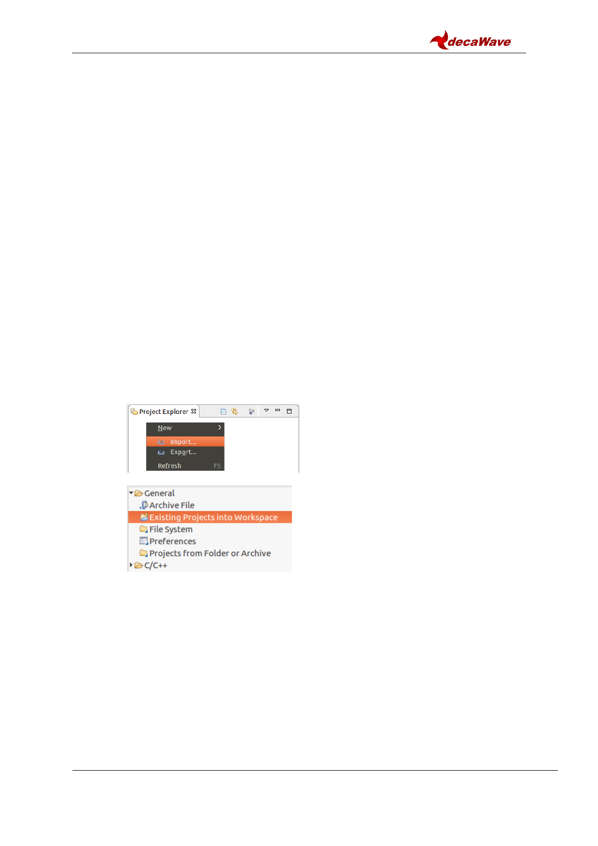
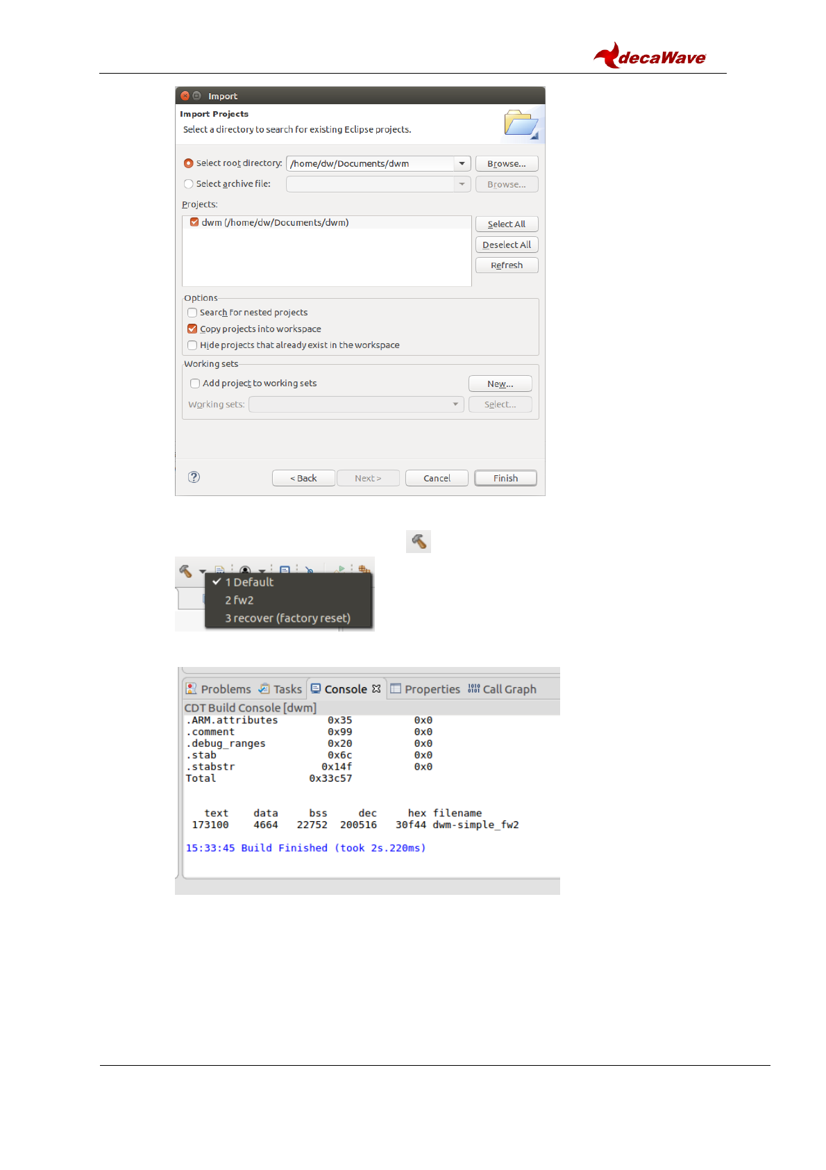
3) Import the dwm project:
a. In Project Explorer view Right click Import…
b. General Existing Project into Workspace Next
c. Select root directory Browse… find /home/dw/Documents/dwm OK.
Note: project path may vary according to users’ local setup.
d. Tick the “copy projects into workspace” option so a copy of such project will be
created in ~/workspace folder.
DWM1001 Firmware User Guide
© Decawave 2017
SW-DWM1001-Firmware-User-Guide-1.1
Page 20
e. Click “Finish”.
4) Build.
a. Click the dropdown list beside the button. There are 3 options on the list.
b. Click option “2 fw2” to build the project.
c. The build information is shown in Console view as on the figure below.
d. If the dwm1001 module needs to be flashed with the factory image. Click option
“3 recover (factory reset)”. To do this, ensure the device is connected, see step 6)
in Section 3.3.2 for more detail.
Note: by doing this, the whole flash including the user configurations will be
erased and reset.
5) Add user code.
User customized code can be added in the application project: here an example of
using the dwm_pos_get API call is given:
DWM1001 Firmware User Guide
© Decawave 2017
SW-DWM1001-Firmware-User-Guide-1.1
Page 21
In Project Explorer view, expand project dwm, find dwm-simple.c in
dwm/examples/dwm-simple/
a. Find function app_thread_entry, add in the local variable area:
dwm_pos_t pos;
b. Find while(1) in function app_thread_entry and add in the brace:
dwm_pos_get(&pos);
printf("x=%ld, y=%ld, z=%ld, qf=%u \n", pos.x, pos.y, pos.z, pos.qf);
printf("\t\t time=%lu \n", dwm_systime_us_get());
Note: printf will send the message to through UART interface when Shell mode is
enabled.
c. Save.
d. Build the project and eliminate errors.
This change intends to read the position information in the device and print the
message on the terminal. A system timer is added in the end of the message to
indicate the message time.
The source file dwm/examples/dwm-simple/dwm-simple.c can be changed to
add/modify functionalities. All available C code API functions are listed in header file
dwm/include/dwm.h. More detailed information of the C code API is introduced in the
DWM1001 API Guide [2].
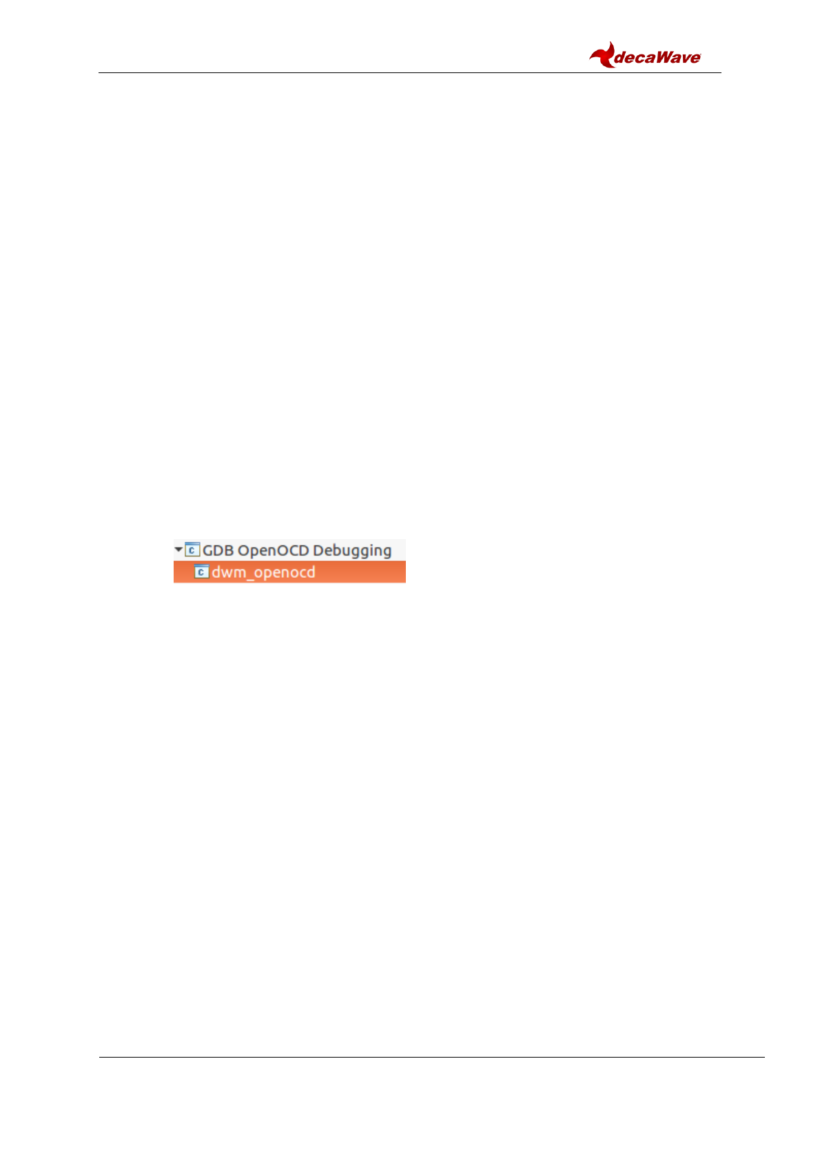
6) Debug
a. Connect the DWM1001 device. See step 6) in Section 3.3.2 for more detail.
b. In Project Explorer view Right click on dwm project Debug As
Debug Configurations…
c. Expand GDB OpenOCD Debugging and choose dwm_openocd.
d. Click “Debug”. This will download the firmware onto the DWM1001 module and
lead to Debug Perspective.
e. Now the project can be debugged in Eclipse.
Note1: A few compilation options are provided in the dwm_user_start() function, with
function names of dwm_XXXX_compile(), where XXXX is the component name.
Disabling these functions can disable the corresponding components in the DWM1001
firmware.
Note2: It is possible to use breakpoints to debug the firmware. However the user has to
be very carefull because the nRF52 softdevice interrupts are of highest priority, and if
there is BLE activity its interrupts will conflict with user interrupt, thus the BLE should
either be disabled or its interrupts masked. Disabling function dwm_ble_compile() can
disable the BLE compilation so as to void BLE operations during debugging. The
function can be re-enabled after debugging.
Note3: SWO debug printf is not supported on the DWM1001 DEV board.
4.3 UART applications example
The PANS library provides API functions through UART interface. The connection and
simple examples are introduced here.
4.3.1 UART connection
The DWM1001 DEV board provides UART access through both the USB connector and the
pins on the external connector. Both accesses are introduced here.
DWM1001 Firmware User Guide
© Decawave 2017
SW-DWM1001-Firmware-User-Guide-1.1
Page 22
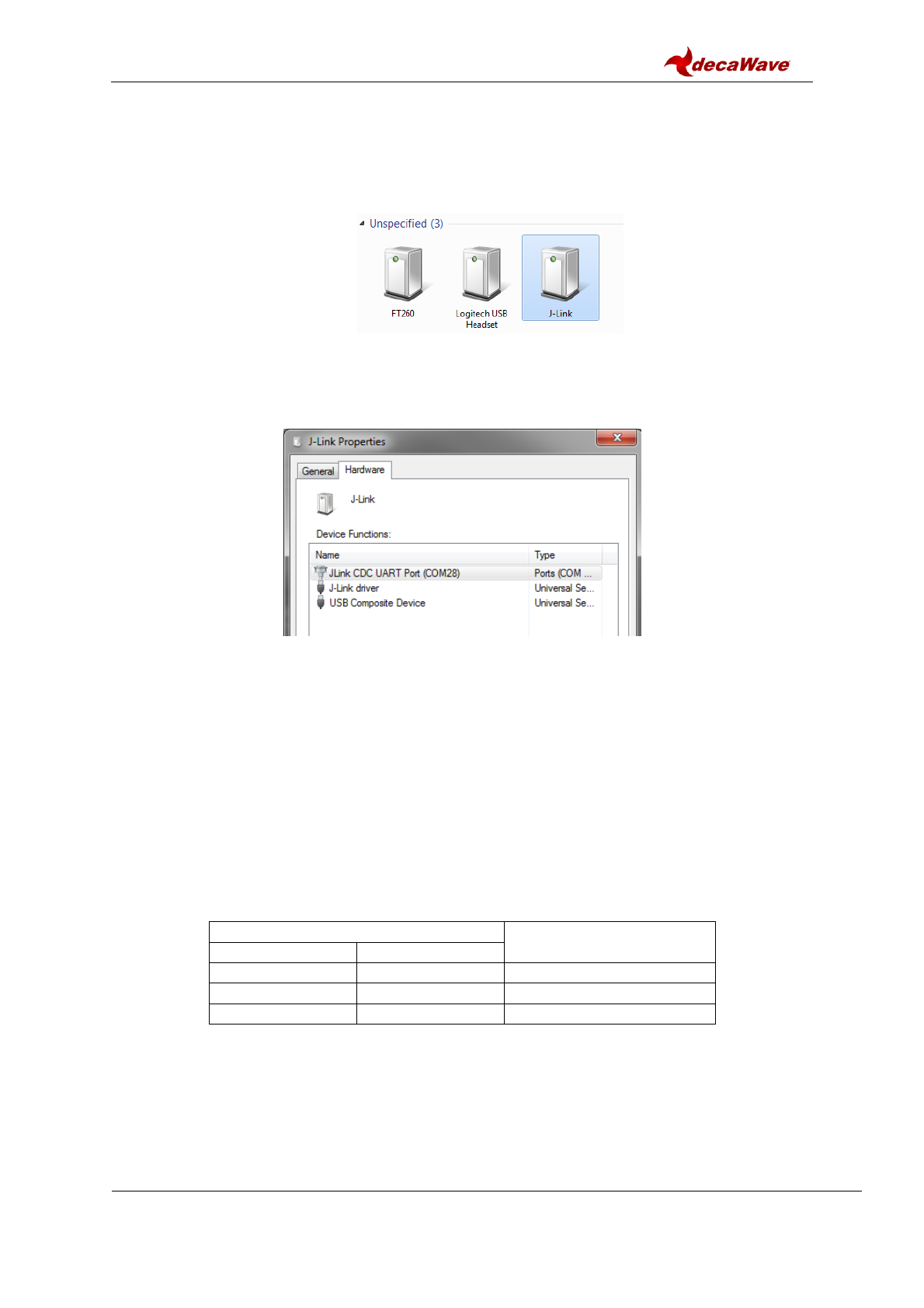
4.3.1.1 UART connection through COM port over USB
The UART connection can be setup simply through a USB data cable as shown in Figure 7.
To find the device name of the DWM1001 DEV board in the Windows system:
1) Open Device and Printers,
2) Find the device J-Link:
Figure 7 J-Link Device in Windows
3) Double click the J-Link icon, go to Hardware tab and find the COM port with number
as the device name (e.g. in Figure 8 below J-Link is device name is COM28).
Figure 8 DWM1001 Device COM port over J-Link
In different Linux systems, the UART devices may show different names. In Linux VM, with
connection shown in Figure 4 with the control of the device passed to Linux side as
introduced in Figure 5, the device name is /dev/ttyACM0.
4.3.1.2 UART connection through external connector Tx and Rx pins
Other than using USB cable to connect, the external header pins provided on J10 of the
DWM1001 DEV board also provides the UART interface. Table 1 shows the pins needed in
the UART connection.
Table 1 UART pin connections
Pin to use in DWM1001 DEV
Pin to be connected to
Connector J10
Function
Pin 6
GND
GND
Pin 8
RXD
TXD
Pin 10
TXD
RXD
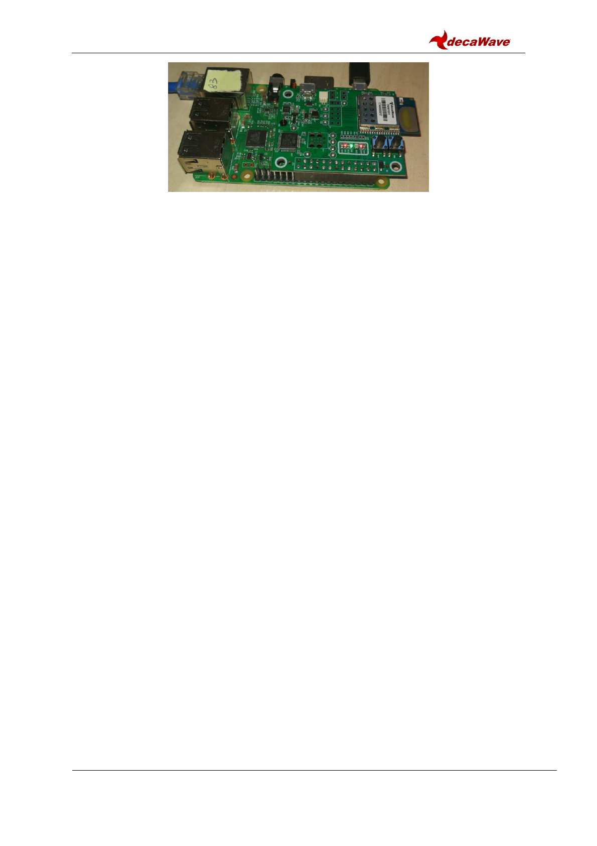
For Raspberry Pi 3 using header pins connection, the device name is /dev/serial0.
The connection between the DWM1001 DEV board and a Raspberry Pi 3 (model B) is
shown in Figure 9.
DWM1001 Firmware User Guide
© Decawave 2017
SW-DWM1001-Firmware-User-Guide-1.1
Page 23
Figure 9 Connecting DWM1001 to Raspberry Pi 3 over header pins
Note: Pins on J10 of the DWM1001 DEV board are compatible with Raspberry Pi 3
connector J8 header pins 1-26.
4.3.2 UART examples
UART interface is accessible through two mode, the Shell mode and the Generic mode.
Both Generic mode and Shell mode can be used to communicate with the DWM1001
module through the UART connection. The default mode of the DWM1001 UART is Generic
mode. The two modes are transferrable:
Generic mode to Shell mode: presses “Enter” twice within one second, or input two bytes
[0x0D, 0x0D] within one second.
Shell mode to Generic mode: input “quit” command.
For more information of the two UART API modes, please refer to DWM1001 API Guide [2].
4.3.2.1 UART Shell mode example
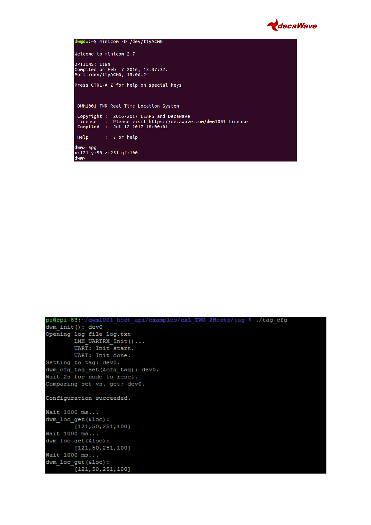
With the connection introduced in Figure 4, in VM Linux terminal, open the UART serial port:
minicom -D /dev/ttyACM0
When seeing “Device or resource busy”, try multiple times until it works.
When seeing “No such file or directory”, check Section 3.3.1 step 6) and Figure 5.
If the connection over UART is successful, “Welcome to minicom” message will show on the
terminal. Now hit “Enter” key twice within one second to enter UART shell mode. “dwm>”
should present in the terminal when this is all done.
To run the UART Shell command for dwm_pos_get, type “apg” followed by “Enter” key. The
position of the module in the whole DRTLS will be printed out, see Figure 10. Type “?”
followed by “Enter” key to get help information in UART Shell mode. More information of the
UART Shell commands is introduce in the DWM1001 API Guide [2].
DWM1001 Firmware User Guide
© Decawave 2017
SW-DWM1001-Firmware-User-Guide-1.1
Page 24
Figure 10 Connect to DWM1001 device through UART shell
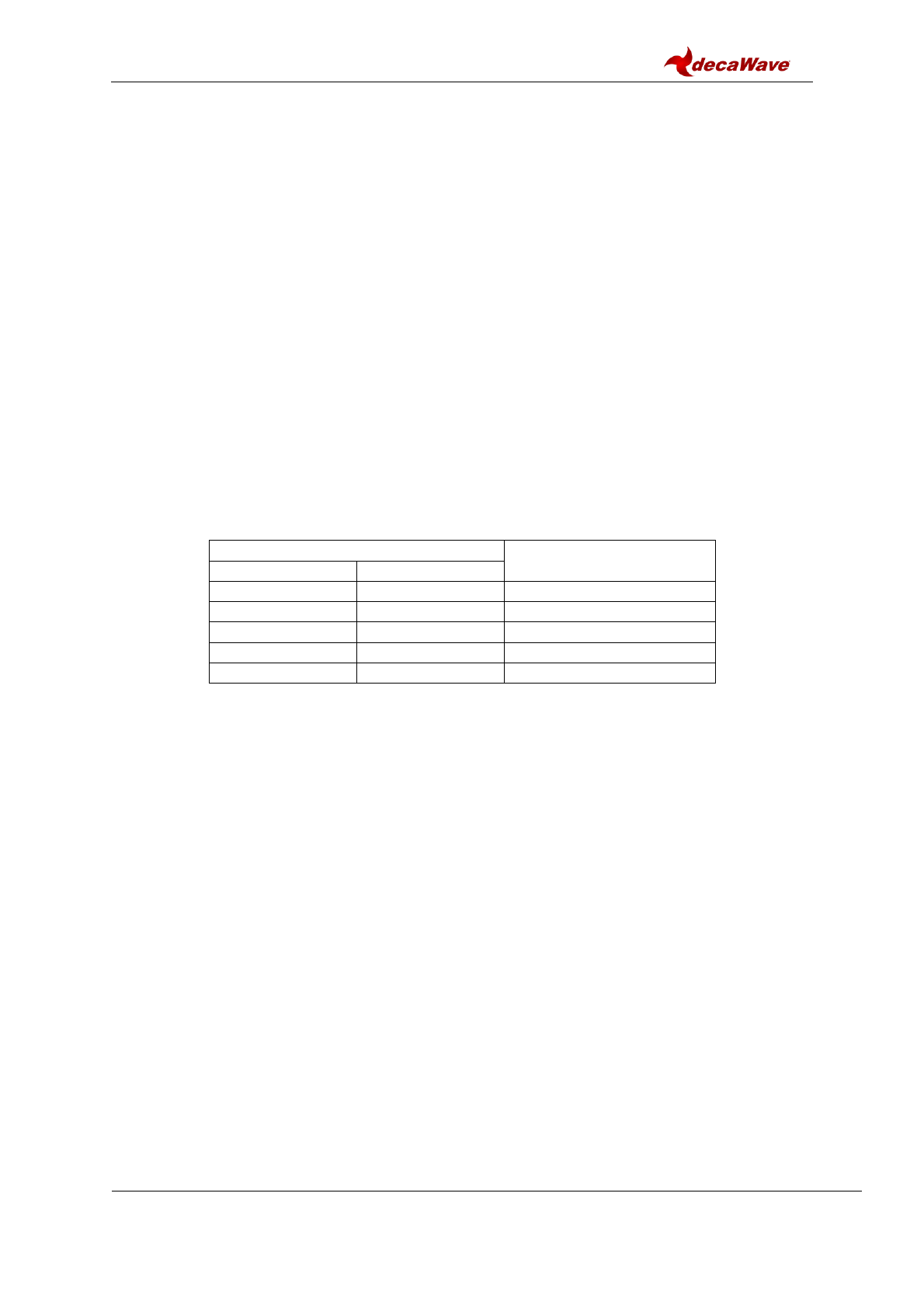
4.3.2.2 UART Generic mode example
A simple example to make use of the UART Generic API is given in the DWM1001 Host Api
package [4]. The example runs on the Raspberry Pi platform:
1) Download the dwm1001_host_api package onto the Raspberry Pi 3 device.
Navigate to folder examples/ex1_TWR_2Hosts/tag/
2) Use nano editor to edit Makefile:
nano Makefile
3) Change the configuration parameter USE_INTERFACE to use UART interface:
USE_INTERFACE = 0
4) Press “Ctrl + o” and “Enter” to save. Press “Ctrl + x” to exit nano editor.
5) Use “make” command to build the example:
make
6) Run the executable:
./tag_cfg
7) Check log.txt file for the detail of UART data transmission.
DWM1001 Firmware User Guide
© Decawave 2017
SW-DWM1001-Firmware-User-Guide-1.1
Page 25
Figure 11 Run simple UART example on Raspberry Pi 3
The simple UART Generic mode example project is designed specifically for Raspberry Pi
platform. The source file examples/ex1_TWR_2Hosts/tag/tag_cfg.c can be changed to
add/modify functionalities. All available UART API functions are listed in header file
include\dwm_api.h. More detailed information of the UART Generic mode is introduced in
the DWM1001 API Guide [2].
The code/makefile needs to be changed, to suit other platforms than Raspberry PI.
4.4 SPI applications example
The DWM1001 module provides APIs over the SPI interface. The connection and a simple
example are introduced here.
4.4.1 SPI connection
To connect to the DWM1001 module over SPI, the SPI pins on external connector J10 on
the DWM1001 DEV board can be used. Table 2 shows the pins needed in the SPI
connection.
Table 2 SPI pin connections
Pin to use
Pin to be connected to
Pin number
Function
Pin 19
MOSI
MOSI
Pin 21
MISO
MISO
Pin 23
SCLK
SCLK
Pin 25
GND
GND
Pin 24
CSN
CSN
The connection with Raspberry Pi 3 (model B) is shown in Figure 9.
Note: the connector J10 on the DWM1001 DEV board is compatible with Raspberry Pi 3
connector J8 header pins 1-26. Pin 4 from J10 provides 5V power from Raspberry Pi to the
DWM1001 DEV board.
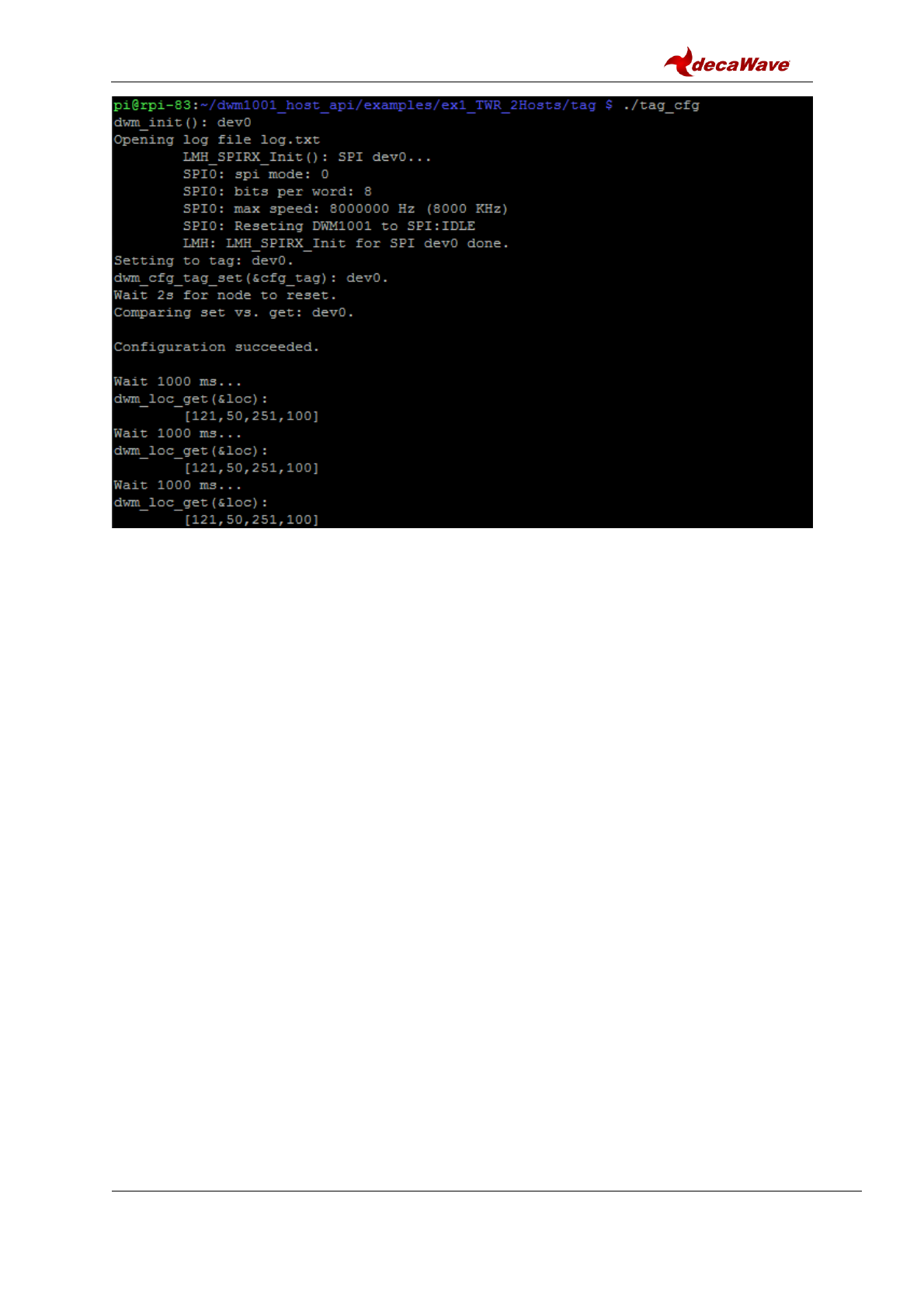
4.4.2 SPI example
A simple example to make use of the SPI API is given in the DWM1001 Host API package
[4]. The example can run on the Raspberry Pi platform:
1) Download the dwm1001_host_api package onto the Raspberry Pi 3 device.
Navigate to folder examples/ex1_TWR_2Hosts/tag/
2) Use nano editor to edit Makefile:
nano Makefile
3) Change the configuration parameter USE_INTERFACE to use SPI interface:
USE_INTERFACE = 1
4) Press “Ctrl + o” and “Enter” to save. Press “Ctrl + x” to exit nano editor.
5) Use “make” command to build the example:
make
6) Run the executable:
./tag_cfg
7) Check log.txt file for the detail of SPI data transmission.
DWM1001 Firmware User Guide
© Decawave 2017
SW-DWM1001-Firmware-User-Guide-1.1
Page 26
Figure 12 Run simple SPI example on Raspberry Pi 3
The simple SPI example project is designed specifically for Raspberry Pi platform. The
source file examples/ex1_TWR_2Hosts/tag/tag_cfg.c can be changed to add/modify
functionalities. All available SPI API functions are listed in header file include\dwm_api.h.
More detailed information of the SPI API is introduced in the DWM1001 API Guide [2].
The code/makefile needs to be changed to suit other platforms than Raspberry PI.
DWM1001 Firmware User Guide
© Decawave 2017
SW-DWM1001-Firmware-User-Guide-1.1
Page 27
5 REFERENCES
This document refers to the documents listed below. Note that References’ format can be as
the author chooses.
1. Nordic nRF52 series Softdevice introduction, available from www.nordicsemi.com
2. DW1000 Software API Guide, available from www.decawave.com
3. DWM1001 System Overview, available from www.decawave.com
4. DWM1001 Host API source code package available from www.decawave.com
5. Oracle VM VirtualBox, available from www.virtualbox.org
6. DWM1001 VM image, available from www.decawave.com
7. DWM1001 on-board source code package, available from www.decawave.com
8. DWM1001 Android application source package, available from www.decawave.com
DWM1001 Firmware User Guide
© Decawave 2017
SW-DWM1001-Firmware-User-Guide-1.1
Page 28
6 DOCUMENT HISTORY
6.1 Revision History
Table 3: Document History
Revision
Date
Description
1.0
18-Dec-2017
Initial version.
1.1
11-Jan-2018
Editorial changes
DWM1001 Firmware User Guide
© Decawave 2017
SW-DWM1001-Firmware-User-Guide-1.1
Page 29
7 CHANGE LOG
Revision 1.1
Page
Change Description
27
Remove unreleased documents from references
27
Repair url links for 2 references
10
Remove paragraph related to fig 2
10
Renumber references

DWM1001 Firmware User Guide
© Decawave 2017
SW-DWM1001-Firmware-User-Guide-1.1
Page 30
8 ABOUT DECAWAVE
Decawave is a pioneering fabless semiconductor company whose flagship product, the
DW1000, is a complete, single chip CMOS Ultra-Wideband IC based on the IEEE 802.15.4-
2011 UWB standard. This device is the first in a family of parts that will operate at data rates
of 110 kbps, 850 kbps and 6.8 Mbps.
The resulting silicon has a wide range of standards-based applications for both Real Time
Location Systems (RTLS) and Ultra Low Power Wireless Transceivers in areas as diverse
as manufacturing, healthcare, lighting, security, transport, inventory & supply chain
management.
Further Information
For further information on this or any other Decawave product contact a sales representative
as follows: -
Decawave Ltd
Adelaide Chambers
Peter Street
Dublin 8
D08 T6YA
t: +353 1 6975030
e: sales@decawave.com
w: www.decawave.com
