Design Guide 2
User Manual:
Open the PDF directly: View PDF ![]() .
.
Page Count: 8

Guidance for vertical resistance
This guide is the second in a series of three giving guidance on the design of
masonry structures to Eurocode 61. The first guide, Introduction to Eurocode 62
gives an introduction to design and assessment of actions using Eurocode 6 and
also covers the specification and execution (workmanship) of masonry. This guide
explains how to design for vertical actions and determine vertical resistance. The
third guide in the series3 covers the design of laterally loaded masonry panels.
Throughout this guide the Nationally Determined Parameters (NDPs) from the UK
National Annexes (NAs) have been used. These enable Eurocode 6 to be applied in
the UK.
Design procedure
This guide explains how to determine the design resistance for a vertically loaded
wall. The first guide in the series, Introduction to Eurocode 6, should be referred to
so that the design load can be determined. In essence, when using the Eurocodes
the designer should check that the resistance is greater than or equal to the
effect of the actions. A flow chart for the design of masonry walls to resist vertical
actions is shown as Figure 1.
Compressive strength
Eurocode 6 introduces some new concepts when dealing with the design of
masonry for vertical loads. The first of these relates to the way the compressive
strength of the masonry units is expressed. For design purposes the normalized
compressive strength, fb, of the masonry units is used. This is the compressive
strength of the units converted to the air-dried compressive strength of an
equivalent 100 mm wide by 100 mm high masonry unit. The detail is contained
in Part 1 of BS EN 772, Methods of test for masonry units4. The advantage to the
designer is that the normalized strength is independent of the size and shape of
the units used in the final construction.
Grouping of masonry units
The second change relates to the way in which masonry units are classified. This is
dealt with by grouping masonry into one of four groups as shown in Table 3.1 of
Eurocode 6. The group designation will normally be declared by the manufacturer.
The designation depends upon the volume and direction of holes in the unit and
the thickness of webs and shells. Historically only Group 1 and Group 2 units have
been used in the UK, so only values for these groups are given in the UK NAs.
How to design masonry structures using Eurocode 6
2. Vertical resistance
Eur Ing, Prof. J J Roberts BSc(Eng), PhD, CEng, FIStructE, FICE, FIMS, FCMI, MICT O Brooker BEng, CEng, MICE, MIStructE
Introduction
This publication is part of a series of three
guides entitled How to design masonry structures
using Eurocode 6. The aim is to make the use of
Eurocode 6, Design of masonry structures as easy
as possible by drawing together in one place key
information and commentary required for the
design of typical masonry elements.
The Concrete Centre (and, originally, The Modern
Masonry Alliance) recognised that effective
guidance was required to ensure that the UK
design profession was able to use Eurocode 6
quickly, effectively, efficiently and with confidence.
Therefore a steering group, with members from
across the masonry industry (see back cover for a
list of members), was established to oversee the
development and publication of the original guides.
This second revision addresses the publication of
PD6697 in 2010 and revised National Annex to
BS EN 1996-1-1 in 2013. It was overseen by a
reconstituted steering group from industry (see
back cover).
Revision 2
How to design masonry structures using Eurocode 6
2
For blocks laid flat, Table 8 of the National Annex to Eurocode 6,
Part 1–1 contains a specific value for K to be used in Equation (3.1)
of Eurocode 6, Part 1–1.
The following limitations are placed on Equation (3.1):
¢The masonry is detailed and constructed in accordance with the
requirements of BS EN 1996–1–1, section 8.
¢fb is taken to be not greater than 110 N/mm2 when units are laid
in general purpose mortar and 50 N/mm2 when laid in thin layer
mortar (fb is determined in the normal direction of loading).
¢fm is taken to be not greater than fb nor greater than 12 N/mm2
when units are laid in general purpose mortar or 10 N/mm2 when
units are laid in lightweight mortar.
¢The coefficient of variation of the strength of the masonry unit is
not more than 25%.
For masonry made with general purpose mortar, adjustments are
made to the value of K as shown in Figure 2.
In addition the following points should be noted:
¢For masonry made of general purpose mortar where Group 2
and Group 3 aggregate concrete units are used with the vertical
cavities filled completely with concrete, the value of fb should
be obtained by considering the units to be Group 1 having a
compressive strength corresponding to the compressive strength of
the units or of the concrete infill, whichever is the lesser.
The characteristic
compressive strength of
masonry
The characteristic compressive strength of masonry (other than
shell bedded masonry) is determined from the results of tests in
accordance with BS EN 1052–15. The tests are carried out on small
wallette specimens rather than the storey-height panels used in the past.
The designer has the option of either testing the units intended to be
used in a project or using the values determined from a database. Values
from a large database are provided in the UK NA to Eurocode 6, Part 1–1
in the form of the constants to be used in the following equation:
fk = K fba fmb [Equation (3.1) of Eurocode 6, Part 1–1]
where
fk = characteristic compressive strength of the masonry, in N/mm2
K = constant – see Table 1 and Figure 2
a, b = constants – see Table 2
fb = normalized mean compressive strength of the units, in the
direction of the applied action effect, in N/mm2
fm = compressive strength of the mortar, in N/mm2
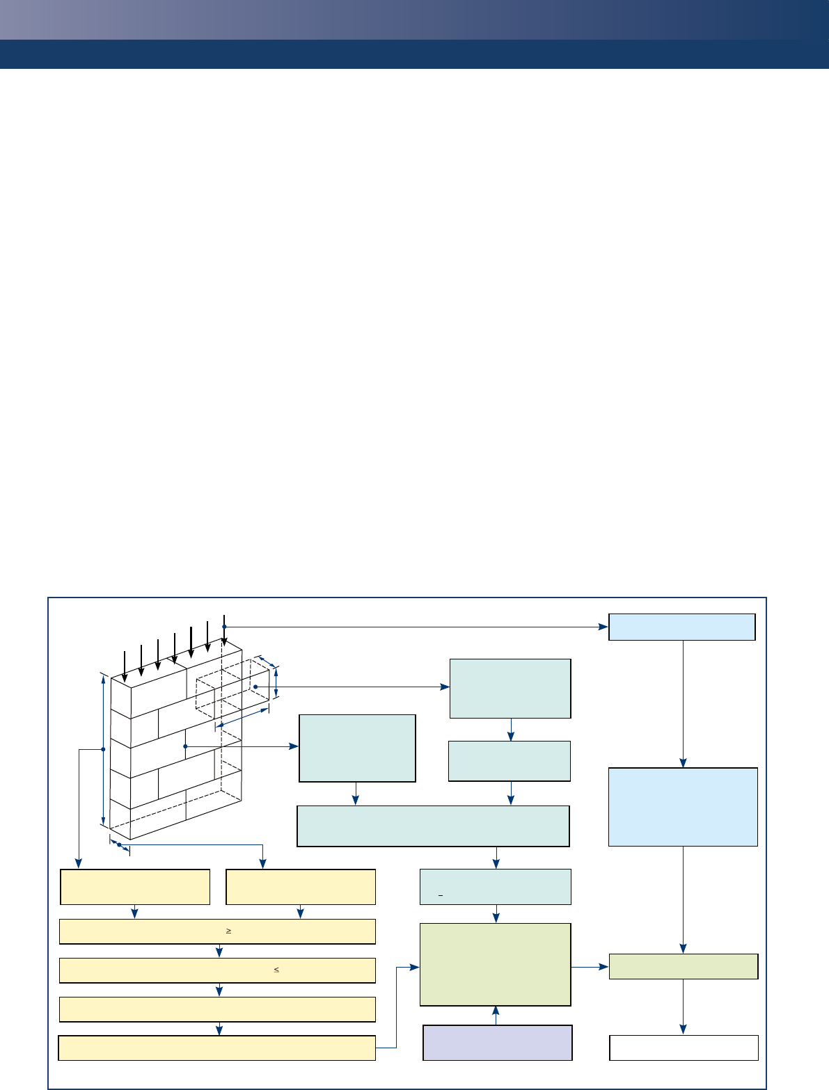
Figure 1
Flow chart for the design of masonry walls to resist vertical actions
.
Obtain gM from table 1 of
Introduction to Eurocode 6
Determine requirements
for mortar strength and
durability. See tables 5
& 6 of Introduction to
Eurocode 6
Determine effective height, hef,
of the wall (see page 4)
Check slenderness ratio h
ef
/t
ef
≤ 27
Check area ≥ 0.04 m
2
Determine eccentricity (see page 5)
Determine capacity reduction factors, F
m
and F
i
from (see page 6)
Determine normalized
compressive strength, fb.
Characteristic vertical actions
Check Ed ≤ NRd
Check complete
Calculate design resistance
(per unit length) from least
favourable of:
NRd = Fm t fk / gM
and
NRd = Fi t fk / gM
Where cross-sectional area,
A < 0.1 m2, factor fk by (0.7 + 3A)
Determine design value of
vertical actions (per unit
length), Ed, using Expression
(6.10), (6.10a) or (6.10b) of
Eurocode (see Introduction to
Eurocode 6)
Masonry unit properties
• Type and group
• Dimensions
• Strength
Determine characteristic compressive strength of masonry,
fk, from Equation (3.1) of Eurocode 6 and Tables 1 & 2
Determine effective thickness, tef,
of the wall (see page 4)
How to design masonry structures using Eurocode 6
2. Vertical resistance
3
¢For collar jointed aggregate concrete masonry made with general
purpose mortar, with or without the collar filled with mortar, the unit
shape factor correction to obtain the normalized strength should use the
width of the wall as the unit width and the height of the masonry units.
¢Where action effects are parallel to the direction of the bed joints, the
characteristic compressive strength may be determined from
Equation (3.1) with fb derived from BS EN 772–1, where the direction
of application of the load to the test specimens is in the same
direction as the direction of the action effect in the masonry, but with
the shape factor, d, as given in BS EN 772–1 taken to be no greater
than 1.0. For Group 2 and 3 units, K should then be multiplied by 0.5.
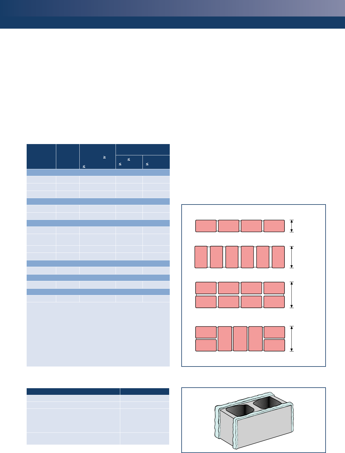
Table 1
Values of K to be used with equation (3.1)
Masonry
unit General
purpose
mortar
Thin layer
mortar
(bed joint ≥
0.5 mm and
≤ 3 mm)
Lightweight mortar
of density (kg/m3)
600 ≤ rd
≤ 800 800 < rd
≤ 1300
Clay
Group 1 0.50 0.75 0.30 0.40
Group 2 0.40 0.70 0.25 0.30
Group 3 and 4 – a– a– a– a
Calcium silicate
Group 1 0.50 0.80 – b– b
Group 2 0.40 0.70 – b– b
Aggregate concrete
Group 1 0.75 0.90 0.45 0.45
Group 1c
(units laid flat) 0.50d0.70d0.40d0.40d
Group 2 0.70 0.76 0.45 0.45
Group 3 and 4 – a– a– a– a
Autoclaved aerated concrete
Group 1 0.75 0.90 0.45 0.45
Manufactured stone
Group 1 0.75 0.90 – b– b
Dimensioned natural stone
Group 1 0.45 – b– b– b
Key
a Group 3 and 4 units have not traditionally been used in the UK, so no values are available.
b These masonry unit and mortar combinations have not traditionally been used in
the UK, so no values are available.
c If Group 1 aggregate concrete units contain formed vertical voids in the normal direction,
multiply K by (100 – n) /100, where n is the percentage of voids, maximum 25%.
d When aggregate concrete masonry units are to be used laid flat the normalised strength
of the unit should be calculated using the width and height of the unit in the upright
position along with the compressive strength of the unit tested in the upright position.
Note
Where a mortar joint is parallel to the face of the wall K should be modified (see Figure 2)
Table 2
Values to be used in Equation (3.1)
Type of mortar Values to be used
General purpose mortar a = 0.7 and b = 0.3
Lightweight mortar a = 0.7 and b = 0.3
Thin layer mortar in bed joints of thickness 0.5
to 3 mm (using clay units of Group 1, calcium
silicate units, aggregate concrete units and
autoclaved aerated concrete units)
a = 0.85 and b = 0
Thin layer mortar in bed joints of thickness 0.5 to
3 mm (using clay units of Group 2)
a = 0.7and b = 0
¢When the perpendicular joints are unfilled, Equation (3.1) may be
used, with consideration of any horizontal actions that might be
applied to, or be transmitted by, the masonry. (See also CI. 3.6.2(4)
of BS EN 1996–1–1.)
The characteristic
compressive strength of
shell bedded masonry
Shell bedding provides two strips of mortar rather than a full mortar bed.
It serves to improve rain penetration resistance but reduces the strength
of the masonry. A typical shell bedded unit is shown in Figure 3.
For Group 1 and Group 4 units the procedure above may be used to
obtain the characteristic compressive strength of the masonry.
Figure 2
Modifications to K for units laid with general purpose mortar
Plan sections of bonded masonry
a) K from Table 1
b) K from Table 1
c) K from Table 1 multiplied by 0.8
d) K from Table 1 multi
p
lied b
y
0.8
Masonry
thickness
Masonry
thickness
Masonry
thickness
Masonry
thickness
Figure 3
Shell bedding
How to design masonry structures using Eurocode 6
4
provided that:
¢The width of each strip of mortar is at least 30 mm.
¢The thickness of the masonry wall is equal to the width or length
of the masonry units so that there is no longitudinal mortar joint
through all or part of the length of the wall.
¢The ratio g/t is not less than 0.4
where
g = total width of the mortar strips
t = the thickness of the wall.
¢K is taken as above when g/t = 1.0 or half this value when g/t = 0.4.
Linear interpolation may be used for intermediate values.
Groups 2 and 3 may be designed as non-shell bedded masonry
provided that the normalized mean compressive strength of the units
used in Equation (3.1) is obtained from tests carried out in accordance
with BS EN 772–14 for shell bedded units.
Effective height
The effective height of a masonry wall is obtained by applying a factor
to the clear height of the wall such that:
hef = rn h
where
hef = effective height of the wall
h = clear storey height of the wall
rn = reduction factor, where n = 2, 3 or 4, depending upon the
edge restraint or stiffening of the wall
The reduction factor to be applied depends upon the restraint offered
by adjoining elements. Masonry walls may be stiffened by a number
of rigid structural elements such as floors, roofs and other walls.
Stiffening walls should have a length of at least 1/5 of the clear height
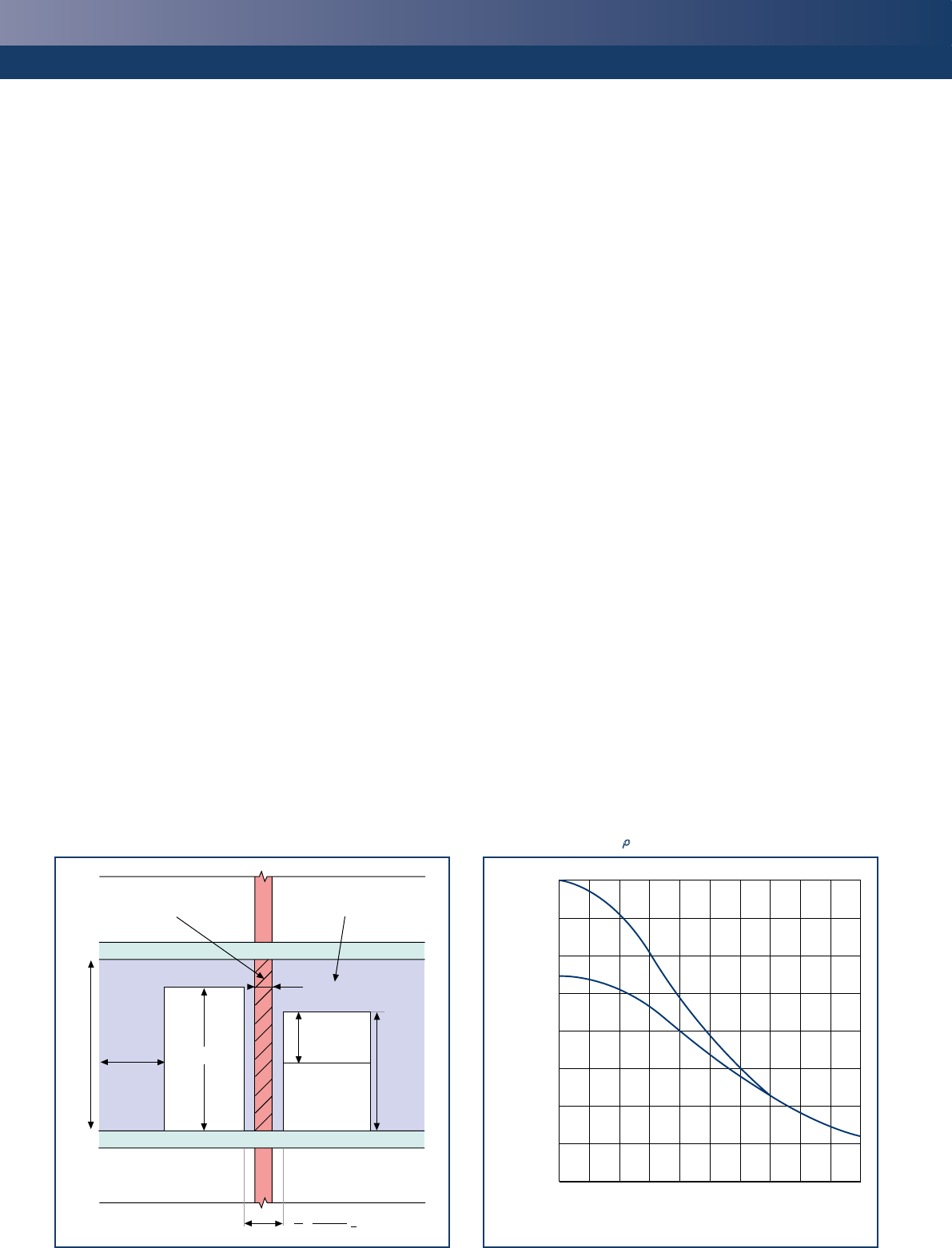
Figure 4
Minimum length of stiffening wall with openings
h2 (window)
h2(door)
h
Stiffened wall Stiffening wall
>h/5 h1
t
1 (h1+ h2)
5 2
> t
and have a thickness of at least 0.3 times the effective thickness of
the wall to be stiffened. When the stiffening wall contains openings,
the minimum length of wall should be as shown in Figure 4 and the
stiffening wall should extend a distance of at least 1/5 of the storey
height beyond each opening.
Where a wall is restrained at the top and bottom by reinforced
concrete floors or roofs spanning from both sides at the same level or
by a reinforced concrete floor spanning from one side only and having
a bearing of at least 2/3 of the thickness of the wall then:
r2 = 0.75
unless the eccentricity of the load at the top of the wall is greater
than 0.25 times the thickness of the wall, in which case r2 = 1.0.
Where the wall is restrained by timber floors or roofs spanning from
both sides at the same level or by a timber floor spanning from one
side having a bearing of at least 2/3 the thickness of the wall but not
less than 85 mm, then:
r2 = 1.0.
For walls restrained at the top and bottom and stiffened on one
vertical edge, use rn = the value r3 from Figure 5 and where both
vertical edges are stiffened, use rn = the value r4 from Figure 6. Note
that Equations (5.6), (5.7) and (5.8) in Eurocode 6, Part 1–1 may be
used as an alternative to the use of the graphs.
Effective thickness
For a single-leaf wall, a double-leaf wall (with ties at a density of
2.5 per m2 or greater), a faced wall, a shell bedded wall and a grouted
cavity wall, the effective thickness, tef, is taken as the actual thickness
Figure 5
Graph showing values of r3
1.0
0.9
0.8
0.7
0.6
0.5
0.4
0.3
0.2
0 1 2 3 4 5
Ratio hef /tef
Reduction factor, r3
r2 = 1.0
r2 = 0.75
How to design masonry structures using Eurocode 6
2. Vertical resistance
5
of the wall (t), provided this is greater than the minimum thickness,
tmin. The value of tmin for a loadbearing wall should be taken as 90 mm
for a single-leaf wall and 75 mm for the leaves of a cavity wall.
For a cavity wall the effective thickness is determined using the
following equation:
tef = 3
R
t1
3 + t2
3 ≥ t2
where
t1 = actual thickness of the outer or unloaded leaf
t2 = actual thickness of the inner or loaded leaf
Note that the effective thickness of the unloaded leaf should not be
taken to be greater than the thickness of the loaded leaf and that ties
should be provided at a density of 2.5 per m2 or greater.
When a wall is stiffened by piers the effective thickness is enhanced by
using the following equation:
tef = rtt
where
tef = effective thickness
rt = coefficient obtained from Table 3
t = thickness of the wall
Slenderness ratio
The slenderness ratio of the wall is obtained by dividing the effective
height by the effective thickness and should not be greater than 27 for
walls subjected to mainly vertical loading. Note also that the effects of
creep may be ignored in walls with a slenderness ratio up to 27.
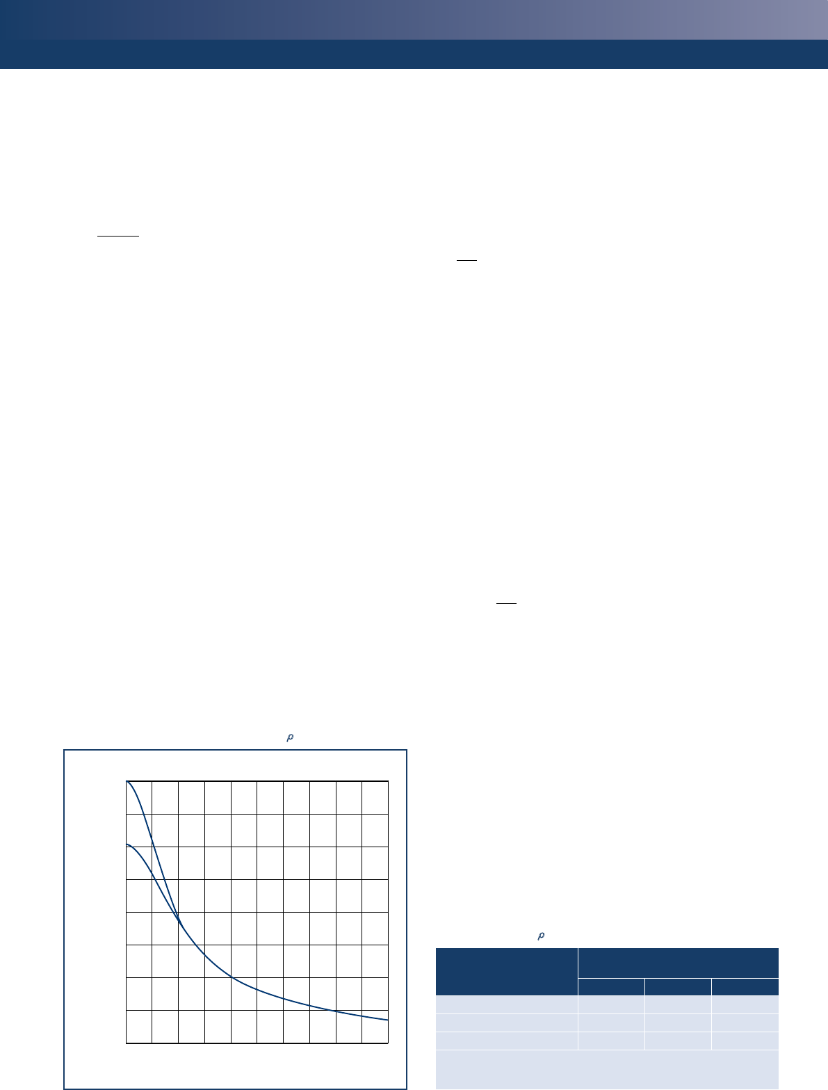
Figure 6
Graph showing values of the reduction factor, r4
1.0
0.9
0.8
0.7
0.6
0.5
0.4
0.3
0.2
0 1 2 3 4 5
Ratio h/l
Reduction factor, r4
r2 = 0.75
r2 = 1.0
Assessment of eccentricity
When a wall is subjected to actions that result in an eccentricity at
right angles to the wall, Eurocode 6 requires the resistance of the wall
to be checked at the top, mid-height and bottom. The eccentricity at
top or bottom of the wall is:
Mid
ei = + ehe + einit ≥ 0.05t
Nid
where
M
id = design value of the bending moment at the top or the
bottom of the wall resulting from eccentricity of the floor
load at the support
N
id = design value of the vertical load at the top or the bottom of
the wall
e
he = the eccentricity at the top or bottom of the wall resulting
from the horizontal loads
e
init = initial eccentricity for construction imperfections, which
may be taken as hef/450, with a sign that increases the
absolute value of ei and em as appropriate
t = thickness of the wall
The mid-height eccentricity, emk, is:
emk = em + ek ≥ 0.05t
where
Mmd
e
m = + ehm + einit
Nmd
ek = 0, when the slenderness ratio ≤ 27 (ie. ignoring creep)
M
md = design value of the greatest moment at the mid-height
of the wall resulting from the moments at the top
and bottom of the wall, including any load applied
eccentrically to the face of the wall (see Figure 7)
N
md = design value of the vertical load at the mid-height of the
wall, including any load applied eccentrically to the face
of the wall
ehm = the eccentricity at mid-height resulting from horizontal loads
A sub-frame analysis may be used as a simplified method for
obtaining the moments at the top and bottom of vertically loaded
walls, as given in Annex C in Part 1–1 of Eurocode 6.
Table 3
Stiffness coefficient, rt, for walls stiffened by piers
Ratio of pier spacing
(centre to centre) to pier
width
Ratio of pier thickness to actual
thickness of wall to which it is bonded
123
61.0 1.4 2.0
10 1.0 1.2 1.4
20 1.0 1.0 1.0
Note
Linear interpolation is permitted in this Table.
How to design masonry structures using Eurocode 6
6
Capacity reduction factors
At the top or bottom of the wall, the reduction factor for slenderness
and eccentricity is given by:
ei
Fi = 1 – 2
t
where
Fi = reduction factor at the top or bottom of the wall
e
i = eccentricity at the top or bottom of the wall
t = thickness of the wall
A method for calculating a capacity reduction factor at the mid-height
of the wall, Fm, is given in Annex G of Eurocode 6, Part 1–1, which
simplifies the principles given in Cl. 6.1.1. This is shown graphically in
Figure 8, which shows the corresponding capacity reduction factors for
different values of slenderness and eccentricity for an elastic modulus
1000 fk, which is the value recommended in the UK NA.
The least favourable value of Fi and Fm should be used to calculate NRd.
Vertical load resistance of
solid walls and columns
The design resistance of a single-leaf wall per unit length, NRd, is given
by the following:
NRd = Ftfd
where
F = capacity reduction factor allowing for the effects of
slenderness and eccentricity of loading
Figure 7
Moments from calculation of eccentricities
N1d
M1d
(at underside
of floor)
Mmd
(at mid-height
of wall)
M2d
(at top of floor)
Nmd
N2d
h
h2
h2
a) Section b) Bending moment diagram
t = thickness of the wall
fd = design compressive strength of the masonry ( fk/gM)
For sections of small plan area, less than 0.1 m2, fd should be
multiplied by (0.7 + 3A)
where
A = loadbearing horizontal cross-sectional area of the wall in m2
In the case of a faced wall, the wall may be designed as a single-leaf
wall constructed entirely of the weaker material with a longitudinal
joint between leaves.
A double-leaf (collar-jointed) wall may also be designed as for a
single-leaf wall provided that the leaves are tied together adequately
and both leaves carry similar loads and the cavity does not exceed
25 mm, or it may be designed as a cavity wall with one leaf loaded.
In the case of cavity walls, check each leaf separately using a
slenderness ratio based on the effective thickness of the wall.
Concentrated loads
For a Group 1 unit (not shell bedded) the vertical load resistance is:
NRdc = bAbfd
where a1 Ab
b = 1 + 0.3 1.5 – 1.1
hc Aef
= enhancement factor for load that should not be less
than 1.0 nor taken to be greater than:
1.25 + a1
or 1.5, whichever is the lesser
2hc
Figure 8
Capacity reduction factor, Fm at the mid-height of the wall
1.0
0.9
0.8
0.7
0.6
0.5
0.4
0.3
0.2
0.1
0.0
0 5 10 15 20 25 30
Ratio, hef /ltef
Capacity reduction factor,
Fm
Eccentricity =
0.05t
0.10t
0.15t
0.20t
0.25t
0.30t
0.35t
0.40t
Values of Fm at the mid-height of the wall against slenderness ratio for different
eccentricities, based on E =1000 fk
How to design masonry structures using Eurocode 6
2. Vertical resistance
7
a1 = distance from the end of the wall to the nearer edge of
the loaded area
hc = height of the wall to the level of the load
Ab = loaded area
Aef = effective area of the bearing, lefm t
lefm = effective length of the bearing as determined at the
mid-height of the wall or pier
t = thickness of the wall, taking into account the depth of
recesses in joints greater than 5 mm wide
Ab/Aef ≤ 0.45
The enhancement factor, b, is shown graphically in Figure 9.
For walls built with Groups 2, 3 and 4 masonry units and when shell
bedding is used, it is necessary to check that, locally under the bearing
of a concentrated load, the design compressive stress does not exceed
the design compressive strength of the masonry, fd (i.e. b is taken to
be 1.0).
In any case, the eccentricity of the load from the centre line of the
wall should not be greater than t/4 as shown in Figure 10.
In all cases where a concentrated load is applied, the requirements
for vertical load design should be met at the mid-height of the wall
below the bearings. Account should be taken of the effects of any
other superimposed vertical loading, particularly where concentrated
loads are sufficiently close together for their effective lengths
to overlap.
The concentrated load needs to bear on a Group 1 unit or other solid
material. The length of this unit or bearing should equal the required
bearing length plus a length on each side of the bearing based on
a 60° spread of load to the base of the solid material. For an end
bearing the extra length is required on one side only.
Figure 9
Enhancement factor, b, concentrated load under bearings
1.6
1.5
1.4
1.3
1.2
1.1
1.0
0 0.1 0.2 0.3 0.4 0.45 0.5
Ratio, Ab / Aef
Enhancement factor, b
a1 = 0
2a1 = 1
hc
The concentrated load may be applied through a spreader beam of
adequate strength and stiffness that has a width the same as the wall
thickness, a height greater than 200 mm and a length greater than
three times the bearing length of the load. In this case the design value
of compressive strength beneath the concentrated load should not
exceed 1.5fd.
Walls subject to shear forces
The design value of shear resistance is given by:
VRd = fvdtlc
where
VRd = the design value of shear resistance of the wall
fvd = the design value of the shear strength of the masonry (the
characteristic shear strength divided by the partial factor
for masonry, gM) based on the average vertical stresses over
the compressed part of the wall that is providing the shear
resistance
t = the thickness of the wall resisting the shear
lc = the length of the compressed part of the wall, ignoring any
part of the wall that is in tension
In calculating lc assume a linear distribution of the compressive stress,
take into account openings, etc. and do not include any area of the
wall subjected to vertical tensile stresses.
Effect of chases
Eurocode 6 recognises that chases and recesses should not impair
the stability of a wall and provides appropriate guidance. Further
explanation is given in the third guide in this series, Lateral resistance3.
Figure 10
Walls subjected to concentrated load
hc/2
NEdc
NEdc
a1
60o60o
60o
NEdc
+
+
++
lefm
lefm
lefm
lefm
a1
h
hc
NEdc
NEdc
t
≤ t / 4
t
Ab
60o
c) Plan d) Sectionb) Section
a) Elevation
8
Ref: TCC/03/36. ISBN 978-1-904818-57-1
First published December 2007
(in partnership with the Modern Masonry Alliance)
revised January 2009 and June 2013
Price Group M
© MPA The Concrete Centre™
References
1 BRITISH STANDARDS INSTITUTION. BS EN 1996: Eurocode 6 – Design of masonry structures. BSI (4 parts). Including their NAs.
2 ROBERTS, JJ & BROOKER, O. How to design masonry structures to Eurocode 6: Introduction to Eurocode 6. The Concrete Centre, 2013.
3 ROBERTS, JJ & BROOKER, O. How to design masonry structures to Eurocode 6: Lateral resistance. The Concrete Centre. 2013.
4 BRITISH STANDARDS INSTITUTION. BS EN 772–1: Methods of test for masonry units – Determination of compressive strength. BSI, 2011.
5 BRITISH STANDARDS INSTITUTION. BS EN 1052–1: Methods of test for masonry – Determination of compressive strength. BSI, 1999.
Selected symbols
Symbol Definition
A Loadbearing horizontal cross-sectional area of the wall in m2
a1 Distance from the end of the wall to the nearer edge of the loaded area
Ab Loaded area
Aef Effective area of the bearing
ehe Eccentricity of the top or bottom of the wall resulting from horizontal
loads
ehm Eccentricity at the middle of a wall, resulting from horizontal loads
ei Eccentricity of the wall
einit Initial eccentricity
em Load eccentricity
emk Eccentricity at the mid-height of the wall
fb Normalized mean compressive strength of a masonry unit
fd Design compressive strength of the masonry in the direction being
considered
fm Compressive strength of the mortar
fk Characteristic compressive strength of the masonry, in N/mm2
fvk Characteristic shear strength of masonry
fvd Design value of the shear strength of the masonry
g Total of the widths of the mortar strips
h Clear storey height of the wall
hc Height of the wall to the level of the load
hef Effective height of the wall
htot Total height of the structure
K Constant to be used with Equation (3.1) of Eurocode 6, Part 1–1
lc Length of the compressed part of the wall, ignoring any part of the
wall that is in tension.
Symbol Definition
lefm Effective length of the bearing as determined at the mid-height of the
wall or pier
Mid Design value of the bending moment at the top or the bottom of the
wall resulting from eccentricity of the floor load at the support
Mmd Design value of the greatest moment at the mid-height of the wall
resulting from the moments at the top and bottom of the wall,
including any load applied eccentrically to the face of the wall
Nid Design value of the vertical load at the top or the bottom of the wall
Nmd Design value of the vertical load at the mid-height of the wall,
including any load applied eccentrically to the face of the wall.
NRd Design resistance of a single-leaf wall per unit length
NRdc Design vertical load resistance to a concentrated load
t Thickness of the wall
t1 Effective thickness of the outer or unloaded leaf
t2 Effective thickness of the of the inner or loaded leaf
tef Effective thickness
tmin Minimum thickness of loadbearing wall
VRd Design value of shear resistance of the wall
v Notional inclination angle to the vertical
a and b Constants to be used with Equation (3.1) of Eurocode 6, Part 1–1
b An enhancement factor for concentrated load
F Capacity reduction factor allowing for the effects of slenderness and
eccentricity of loading
gM Partial factor for a material property
rn Reduction factor (depending upon the edge restraint or stiffening of
the wall, h/l and floor restraint)
rt Stiffness coefficient
2. Vertical resistance
For more information on Eurocode 6 and other questions
relating to the design, use and performance of concrete units,
visit www.eurocode6.org
Published by The Concrete Centre
Gillingham House, 38-44 Gillingham Street, London, SW1V 1HU
Tel: +44 (0)207 963 8000 | www.concretecentre.com
Members of the steering group
Ali Arasteh, Brick Development Association; Owen Brooker, The
Concrete Centre; Ken Fisher, International Masonry Society; Cliff Fudge,
Aircrete Products Association; Charles Goodchild, The Concrete Centre;
Gerry Pettit, Concrete Block Association; John Roberts, Consultant.
Members of the steering group for 2nd revision
Cliff Fudge, Aircrete Products Association; Charles Goodchild, The
Concrete Centre; Simon Hay, Brick Development Association; Andy
Littler, Concrete Block Association; John Roberts, Consultant; Guy
Thompson, The Concrete Centre.
Acknowledgements
This publication was jointly sponsored by the following organisations:
¢Aircrete Products Association - www.aircrete.co.uk
¢Brick Development Association - www.brick.org.uk
¢Concrete Block Association - www.cba-blocks.org.uk
¢MPA - Mortar Industry Association - www.mortar.org.uk
¢MPA - The Concrete Centre - www.concretecentre.com
All advice or information from MPA The Concrete Centre (TCC) et al is intended only for use in the UK by those who will evaluate the
significance and limitations of its contents and take responsibility for its use and application. No liability (including that for negligence) for
any loss resulting from such advice or information is accepted by TCC or their subcontractors, suppliers or advisors. Readers should note that
the publications from TCC et al are subject to revision from time to time and should therefore ensure that they are in possession of the
latest version.
