Digital_Computer_Newsletter_V16N01_Oct62 Jan64 Digital Computer Newsletter V16N01 Oct62
Digital_Computer_Newsletter_V16N01_Oct62-Jan64 Digital_Computer_Newsletter_V16N01_Oct62-Jan64
User Manual: Digital_Computer_Newsletter_V16N01_Oct62-Jan64
Open the PDF directly: View PDF ![]() .
.
Page Count: 34
DIGITAL COMPUTER
NEWSLETTER
OFFICE
OF
NAVAL
RESEARCH
MATHEMATICAL
SCIENCES
DIVISION
Vol. 16,
No.1
(Includes
Vol. 14
No.4
and
Vol.
15
Nos.
1-4)
Gordon
D.
Goldstein,
Editor
January
1964
(Period
of
October
1962
thru
January
1964)
CONTENTS
Page
No.
EDITORIAL
POLICY
NOTICES
1.
Current
Publication
Plan
1
2.
Editorial
1
3.
Contributions
1
4.
Circulation
1
COMPUTING
CENTERS
1.
National
Bureau
of
Standards,
National
Standard
Reference
Data
SysteIl1,
Washington
25,
D.
C.
2
2.
National
Bureau
of
Standards,
OIl1nitab,
Washington
25,
D.
C.
4
3.
U.S.
Navy
Aviation
Supply
Office,
Inventory
Control
Advances,
Philadelphia
II,
Penl"!-sylvania
6
4.
U.S.
Navy
Finance
Center,
IBM
1401/1404/7070
SysteIl1s
Application,
Cleveland
14,
Ohio
7
5.
U.S.
Navy
Finance
Center,
IBM
1401/1404
Satellite
COIl1puter
SysteIl1
Uses
Modified
IBM
Multiple
Duty
PrograIl1,
Cleveland
14,-
Ohio
9
6.
U.S.
Weather
Bureau,
General
Circulation
Research
Laboratory,
Washington
25,
D.
C.
10
COMPUTERS
AND
CENTERS,
OVERSEAS
1.
The
English
Electric
COIl1pany
Ltd.,
Process
Control
COIl1puter
SysteIl1,
London,
W.C.2.,
England
13
2.
Ferranti
Ltd.,
Atlas
2
COIl1puter,
London
WI,
England
13
3.
General
Post
Office,
LEO
326
and
LEO
III
COIl1puters,
London
E.C.1,
England
16
4.
Institute
of
Technology,
COIl1puting
Center,
Karlsruhe,
GerIl1any
17
5.
LEO
COIl1puters
Ltd.,
LEO
IlIF,
London
W2,
England
17
6.
Instytut
Maszyn
MateIl1atycznych,
ZAM
2,
Warsaw,
Poland
21
7.
Shape
Air
Defence
Technical
Centre,
COIl1puting
Center,
The
Hague,
Netherlands
23
8.
Standard
Elektrik
Lorenz
A.G.,
DT
12
Data
TransIl1ission
SysteIl1,
Stuttgart,
GerIl1any
23
MISCELLANEOUS
1.
COIl1puting
Devices
of
Canada
Ltd.,
Tact~cal
Moving
Map
Display,
Ottawa
4,
Canada
27
2.
National
Bureau
of
Standards,
Projects
FIST
and
SAFARI,
Washington
25,
D.
C.
29
3.
National
Bureau
of
Standards,
Foreign-Currency
Scientific
PrograIl1,
Washington
25,
D.
C.
31
4.
National
Bureau
of
Standards,
Real
Printing,
Washington
25,
D.
C.
31
Approved
by
The
Under
Secretary
of
the
Navy
25
September
1961 NAVEXOS· P - 645

Editorial Policy Notices
CURRENT PUBLICATION PLAN
Because
of staffing
problems
the
Digital
Computer
Newsletter
was
not published
in
Oc-
tober
1962 and during 1963. Commencing with
this
issue,
however, the
normal
quarterly
sched-
ule
is
being
resumed.
To
assist
our
readers
in
maintaining
con-
tinuity
in
the
state
of the
art,
this
issue
is
de-
voted
entirely
to
material
scheduled
for
previ-
ous
issues.
The
April
1964
issue
will
be
largely
current
contributions,
but
there
will
still
be
some
earlier
submissions
which could not be
included
in
this
issue.
EDITORIAL
The Digital Computer
Newsletter,
although
a
Department
of
the
Navy publication,
is
not
restricted
to
the
publication of Navy
-originated
material.
The Office of Naval
Research
wel-
comes
contributions
to
the
Newsletter
from
any
source.
The
Newsletter
is
subjected
to
certain
limitations
in
size
which
prevent
pub-
lishing
all
the
material
received.
However,
items
which
are
not
printed
are
kept
on
file
and
are
made
available
to
interested
personnel
within
the
Government.
DCN
is
published
quarterly
(January,
April;
July,
and
October).
Material
for
specific
issues
must
be
received
by
the
editor
at
least
three
months
in
advance.
It
is
to
be noted
that
the
publication of
in-
formation
pertaining
to
commercial
products
does
not,
in
any way, imply Navy
approval
of
those
products,
nor
does
it
mean
that
Navy
vouches
for
the
accuracy
of
the
statements
made
by
the
various
contributors.
The
infor-
mation
contained
herein
is
to be
considered
only
as
being
representative
of
the
state-of-
the-art
and not
as
the
sole
product
or
technique
available.
CONTRIBUTIONS
The Office of Naval
Research
welcomes
contributions
to
the
Newsletter
from
any
source.
1
Your
contributions
will
provide
assistance
in
improving
the
contents
of
the
publication,
there-
by making
it
an
even
better
medium
for
the
ex-
change of
information
between
government
laboratories,
academic
institutions, and
in-
dustry.
It
is
hoped
that
the
readers
will
partic-
ipate
to
an
even
greater
extent
than
in
the
past
in
transmitting
technical
material
and
suggestions
to
the
editor
for
future
issues.
Ma-
terial
for
specific
issues
must
be
received
by
the
editor
at
least
three
months
in
advance.
It
is
often
impossible
for
the
editor,
because
of
limited
time
and
personnel,
to acknowledge
individually
all
material
received.
CmCULATION
The
Newsletter
is
distributed,
without
charge,
to
interested
military
and
government
agencies,
to
contractors
for
the
Federal
Gov-
ernment,
and to
contributors
of
material
for
publication.
For
many
years,
in
addition
to
the
ONR
initial
distribution,
the
Newsletter
was
re-
printed
by
the
Association
for
Computing
Ma-
chinery
as
a
supplement
to
their
Journal
and,
more
recently,
as
a supplement to
their
Communications. The
Association
decided
that
their
Communications could
better
serve
its
members
by
concentrating
on
ACM
editorial
material.
Accordingly, effective
with
the
combined
January-April
1961
issue,
the
Newsletter
became
available
only by
direct
distribution
from
the
Office of Naval
Research.
Requests
to
receive
the
Newsletter
regu-
larly
should be
submitted
to
the
editor.
Con-
tractors
of the
Federal
Government should
ref-
erence
applicable
contracts
in
their
requests.
All
communications
pertaining
to
the
News-
letter
should be
addressed
to:
GORDON D. GOLDSTEIN,
Editor
Digital
Computer
Newsletter
Informations
Systems
Branch
Office of Naval
Research
Washington, D.
C.
20360
Computing
Centers
National'
Standard
Reference
Data
System
National Bureau
of
Standards
Washington,
D.
C.
20234
The National
Bureau
of
Standards
has
been
given
responsibility
for
administering
the
Na-
tional
Standard
Reference
Data
System
recently
established
by
the
Federal
Council
for
Science
and Technology. The
System
will
provide
criti-
cally
evaluated
data
in
the
physical
sciences
on
a national
basis,
centralizing
a
large
part
of
the
present
data;.compiling
activities
of a
number
of Government
agencies.
The National
Standard
Reference
Data
Sys-
tem
represents
an
attempt
to
solve
an
impor-
tant
part
of
the
general
problem
of
communi-
cating
scientific
information
to
users.
Its
aim
is
to develop a
storehouse
of
standard
refer-
ence
data
to
assist
in
the
advancement
of
sci-
ence, technology, and
the
national economy.
This
result
is
to be
achieved
through
a
broad-
based,
comprehensive
effort
by
scientists
both
in
and
outside
government.
.
"Standard
reference
data"
is
defined to
mean
critically
evaluated
data
on
the
physical
and
chemical
properties
of
materials,
authori-
tatively
documented
as
to
reliability,
accuracy,
and
source.
Tabulations of
such
data
are
of
great
value
to
the
scientist
or
engineer
who
is
designing
an
experiment
or
equipment,
for
the
individual
worker
is
thus
relieved,
in
part,
of
the
necessity
of
searching
the
literature
and
at-
tempting
to evaluate
data
in
fields
in
which
he
.
is
not
expert.
Also,
through
study and
analysis
of
standard
reference
data,
areas
of
science
in
which additional
work
is
needed
become
more
clearly
defined, and
relationships
not
previ-
ously
apparent
are
recognized.
Umortunately
it
is
often difficult
or
impos-
sible
to
locate
the
data
that
are
needed
for
a
specific
use.
In a
recent
study
by
the
American
Institute
of
Chemical
Engineers,l
three
com-
monly
used
sources
2 of
standard
reference
data
were
analyzed
in
terms
of the ava.ilability of
lR.
A.
Peterson,
W.
M.
Carlson,
N.
E.
Dahl,
and
R.
H.
McBride,
"Roadmap.to
Physical
Property
Correlations,"
Am.
lnst.
of
Chem-
ical
Eng.
National
Meeting,
Cleveland,
Ohio,
May
7,
1961.
2
data
on 16
important
properties
(such
as
spe-
cific
heat,
viscosity,
thermal
conductivity, and
vapor
pressure)
for
13,150 compounds. The
average
percentage
of compounds
for
which
data
were
available
covering
any
property
was
5
percent,.
and
for
only one
property
were
as
many
as
11
percent
of
the
compounds
covered.
Undoubtedly many additional
data
on
these
com-
pounds
exist
in
the
literature,
but
until
they have
been
evaluated and
compiled
they·
are
of
little
value
to
scientists
and
engineers
as
a whole.
The National
Bureau
of
Standards,
as
well
as
other
organizations
in
this
country
and
abroad,
has
been
active
in
the
compilation
of
standard
reference
data
for
many
years.
How-
ever,
in
view of the
great
accumulation
of
un-
evaluated
data
over
the
past
few
years,
the
present
accelerated
production
of new data, and
the
urgent
needs
of
American
science
and
in-
dustry,
it
has
become
apparent
that
a substan-:
tially
greater
effort,
planned and
coordinated
on
a national
basis,
is· needed.
The National
Standard
Reference
Data
Sys-
tem
(NSRDS)
will
consist
of a National
Standard
Reference
Data
Center
at
NBS,
and
various
other
Standard
Reference
Data
Centers
in
other
Gov-
ernment
agencies
and
at
universities,
research
institutes,
and
other
non-Goverriment
organiza-
tions.
In
order
for
such
centers
to
be a
part
of
the
NSRDS,
they will be
required
to
meet
quality
standards
established
by NBS. However, the
in-
dependent and
operational
status
of
existing
critical
data
projects
will be
encouraged.
The
initial
emphasis
for
establishing
new
standard
data
compilation
projects
will be
in
subject-matter
areas
where
no
effort
-is now
being applied
or
where
the
existing
effort
falls
far
short
of
meeting
important
needs
of
govern-
ment,
science,
or
industry.
2Chemical
Engineering
Handbook,
,edited
by
J.
Perry
(McGraw-Hill,
1950);
Handbook
of
Chem-
istry
and
Physics,
41st
ed.
(Chemical
Rubber
Publishing
Co.,
1959-60);
and
International
Critical
Tables
(McGraw-Hill,
1927-29).
An Advisory
Board
will review and
recom-
mend policy
relative
to
the
operation
of
the
NSRDS.
It
will include, among
others,
repre-
sentation
from
the
National Academy of
Sci-
ences,
National Science Foundation, and
Fed-
eral
agencies
engaged
in
research
and
development.
The
NSRDS
will be conducted
as
a
decen-
tralized
operation
across
the
country, with
cen-
tral
coordination
by
the
National
Bureau
of
Standards.
As
presently
planned,
the
program
will
consist
of
three
parts:
an
input
from
sci-
entists
in
many
different
locations,
a
central
source
of
the
evaluated
data
at
NBS,
and
an
out-
put sy
stem
geared
to the
needs
of
the
nation's
scientists
and
engineers.
Input
The input will
come
from
scientists
who
are
comprehensively
reviewing
the
literature
in
their
fields
of
specialization
and
critically
evaluating
the
data
for
ultimate
inclusion
in
the
storehouse
of
standard
reference
data.
These
scientists
may be
in
universities
or
in
indus-
trial
or
Government
laboratories;
some
will
be
at
NBS. They
will
work
singly
or
in
small
groups
oriented
to
the
traditional
scientific
dis-
ciplines.
At
the
same
time
other
scientists,
Similarly
located,
will
be engaged
in
experi-
mentally
determining
the
standard
reference
data
that
do
not
exist
in
the
literature.
Clearly,
the
interplay
between
the
two
groups
must
be
close
and continuous.
Central
Core
The
central
core
will
consist
of
the
Stand-
ard
Reference
Data
Center
at
NBS,
where
the
evaluated
data
will be
located,
in
punched
cards,
on
magnetic
tape,
in
notebooks,
in
many
other
forms,
all
mechanized
for
storage
and
retrieval.
A
review
and
control
office will
label
the
in-
coming
data
as
to
relative
quality and
reliabil-
ity. The
SRD
Center
will
classify
the
data
into
as
many
major
and
minor
categories
as
are
re-
quired
by
the
needs
of
the
data
users.
Output
The
output will
take
the
form
of a
series
of
services
aimed
at
different
technical
levels
and
tailored
to
the
needs
of
various
segments
of
in-
dustry.
In
general,
it,
will be
oriented
toward
the
application
of the data,
rather
than
toward
a
field of
science.
According to
present
plans,
3
the
output
services
will
be provided
by
the
SRD
Center
and
will
eventually include:
1.
Periodical
Service
designed to
keep
the
user
up
to
date
on new
data
acquisitions
in
the
SRD
Center.
It
will
provide
information
on
the
data
available
in
the
Center
(but
will
not
provide
the
data
themselves)
by
means
of
a monthly
newsletter
and by annual and
semiannual
re-
views of
data
acquisitions.
2.
Subscription
Service
in
which
the
user
pays
to
receive
all
available
data
on a speCific
subject
on
a continuing
basis.
These
data
pack-
ages
will be designed to
meet
the
needs
of
spe-
cific
industries,
industry
groups,
or
Govern-
ment
research
and development
programs.
3.
Referral
Service
which will handle
nar-
row,
one-time
requests
for
data
by
referral
to
the
files
of
the
SRD
Center.
In
general,
this
service
will
take
care
of
needs
that
are
not
met
by
the
other
output
services.
4.
Correlation
and
Prediction
Service
for
computing
values
wherever
possible
in
areas
where
some
data
exist,
but
where
requests
come
in
for
specific
information
not
contain~d
in
the
SRD
Center.
Values
will be computed by
making
use
of
correlations
based
on
molecular
structure
and
the
properties
of
related
com-
pounds.
5.
Mathematical
and
Statistical
Service
which will
offer
mathematical
and
computer
techniques
to
customers
for
evaluating new
data
for
subsequent
inclusion
in
the
files
of the SRD
Center
or
for
individual
use.
This
service
will
also
provide
techniques
to
assist
in
the
Predic-
tion
and
Correlation
service.
'
6.
Aperiodical
Products
including
tabula-
tions,
review
monographs, review
papers,
com-
puter
card
decks,
and
computer
tapes.
These
will
constitute
the
formal
end
products
of the
SRD
Center.
7.
Summary
Reviews to
provide
a
rapid
assessment
of
the
state-of-the-art
in
fields
where
there
are
few
data
but which
must
sud-
denly be
explored
because
of
scientific
break-
throughs
or
crash
programs.
In
planning
the
details
of the
program,
the
needs
of
American
industry,
academic
scien-
tists,
and
Government
laboratories
must
all
be
ascertained
and
taken
into account. Undoubtedly
limitations
in
funds and manpower will
require
establishment
of a
priority
system
of
some
kind.
In choosing
work
to be
undertaken
from
such
a
vast
field, the
Bureau
will be
assisted
by
the
Advisory
Board,
interagency
panels,
expert
consultants
in
the
subject-matter
areas,
and
working
committees
of
the
scientific
and
engi-
neering
societies,
and
industry
associations
that
are
active
in
the
field of
critical
data.
It
is
expected
that
ultimately
a
large
frac-
tion
of
the
senior
scientists
at
the
Bureau
will
participate
in
the
work.
In
addition,
the
Bureau
plans
to
invite
distinguished
scientists
to spend
some
months
at
the
Bureau,
using
its
technical,
administrative,
and
information
retrieval
serv-
ices
for
the
purpose
of producing
critical
re-
views and
compilations.
OMNITAB
National Bureau
of
Standards
Washington,
D.
C.
20234
OMNITAB, a
computer
prpgram
that
per-
mits
scientists
and
others
unfamiliar
with
pro-
gramming
to
communicate
with a 7090
computer
using
simply
written
sentence
commands,
has
been developed by
the
National
Bureau
of
Stand-
ards'
U.S.
Department
of
Commerce.
OMNITAB,
the
work
of
Joseph
Hilsenrath,
Philip
J.
Walsh,
and Guy G.
Ziegler
of
the
Bureau
staff,
is
used
for
the
calculation
of
tables
of functions,
for
solutions of
non-linear
equations,
for
curve
fit-
ting, and
for
statistical
and
numerical
analysis
of
tabular
data.
The
ease
with which OMNITAB
provides
access
to
the
computer
makes
it
a tool
that
will pave
the
way to
more
rapid
computa-
tion
of
routine
laboratory
problems.
Most
computers
require
that
a
program
(or
code) be
prepared
before
even a
relatively
sim-
ple
problem
can
be
run.
These
are
usually
for-
mulated
by a
speCialist.
The
necessity
to
learn
a
programming
language
forms
a bottleneck
in
the
man-machine
system.
This
is
especially
true
for
university
students
and
for
the
average
experimental
or
theoretical
scientist
or
engi-
neer.
OMNITAB
removes
this
bottleneck
by
al-
lowing
the
user
to
communicate
with
the
ma-
chine
directly
through
simple
sentences
made
up of
numbers
and
familiar
English
words.
OMNITAB
was
designed and
written
pri-
marily
for
those
persons
whose
problems
are
normally
performed
on
desk
calculators.
An
underlying
motive
for
its
creation
was
to
re-
lieve
these
people
from
routine
day-to-day
hand
computing. OMNITAB gives
them,a
means
of
direct
man-to-computer
communication
in
a
language they
best
understand.
OMNITAB, how-
ever,
is
by no
means
restricted
to
this
special
group of
personnel-it
can
also
be a valuable
aid
to
professional
programmers.
With OMNITAB,
various
sec·tions of
problem
analysis
can
be
checked independently
in
order
to
determine
proper
programming
procedures,
data
can
be
4
checked
for
validity, and
one-shot
jobs
can
be
done with a working
program.
OMNITAB,
by
allowing the
user
to
prepare
his
own
data
for
processing,
has
accomplished
several
useful
ends:
1. The
computer
is
now
as
readily
availa-
ble
as
a
desk
calculator,
because
of the
.ease
with which
problems
can
be
formulated
for
solu-
tion.
2.
Problems
that,
in
the
past,
may
have
been withheld
from
the
computer
because
of the
need
for
programming,
can
now be solved
in
greater
detail
and
in
less
time
than
formerly.
3. The
responsibility
for
the data, both
its
accuracy
before
going into
the
computer
and the
types
of
operations
to be
performed
on
it,
now
rests
solely
with
the
person
who
is
most
famil-
iar
with
the
problem-the
scientist.
4.
Programmers
who
formerly
spent
con-
siderable
time
devising
routines
for
relatively
straight-forward
problems
will now be
free
to
handle
more
important
tasks.
A wide
variety
of
mathematical
and
manip-
ulative
procedures
are
available
in
the
OMNITAB
routine.
In addition to the
basic
arithmetical
operations,
there
are
provisions
for
raiSing
to
powers,
use
of
logarithms
to
base
10 and
base
~,
elementary
and
special
functions,
curve
fit-
ting,
integration,
differentiation,
interpolation,
and many
others.
The
program
has
a capaCity
of 7200
results,
arranged
in
36
columns
of 200
rows
each.
A
"statistical
analysis"
package, which
computes
the
average
of a
set
of
numbers
(200
maximum) and
30
statistical
measures
related
to
the
average,
disperSion,
randomness,
and
other
properties
of
the
distributions,
has
been
incorporated
in
the
program.
This
analysis,
which
takes
only a
fraction
,of
a
minute
on
the
machine,
should
have a
beneficial
standardizing
influence
on
the
statistical
analysis
of
labora-
tory
data.
The
instructions
to
the
computer,
as
well
as
the
data
to
be
manipulated,
are
prepared
for
entry
to
the
machine
on
punched
cards.
Simple
sentences
are
used
to
indicate
the
allowed
op-
erations.
For
example,
one
instruction
in
a
series
might
read
MULTIPLY COLUMN 3
BY
COLUMN 4,
STORE IN COLUMN 5,
or,
in
abbreviated
form
MULTIPLY 3
BY
4, STORE IN 5,
or
even
shorter
still
as
MULTIPLY 3, 4,
5.
The
figures
in
a
column
can
be
operated
on
by
those
in
another
column
or
by
constants.
The
presence
of a
period
after
a
number
indi-
cates
that
the
number
is
to
be
read
as
itself,
whereas
the
absence
of a
period
indicates
a
column
of
numbers.
Thus
the
two
sentences
ADD
2. TO 3, STORE IN 4; and,
ADD
2
TO
3, STORE IN 4
have
different
meanings.
In
each
instruction,
the
last
figure
indicates
a
column
in
which
the
results
are
stored.
Each
sentence
gives
a
unique
command
for
a
specific
type
of
operation,
a
series
of
commands
being
necessary
for
the
computation
of a
problem
(see
attached
exam-
ple).
The
result
of
an
operation
can
be
stored
in
a
column
or
added
to
the
data
already
in
a
column.
Differentiation
of
these
two
procedures
is
accomplished
by
the
inclusion
of
an
extra
"MULTIPLY"
term
to
provide
cumulative
mul-
tiplication.
For
example,
MULTIPLY COL 2
BY
COL
3,
STORE IN
COL 4
will
result
in
the
product
of
this
operation
being
cut
in
column
4 by
clearing
that
location
prior
to
storage.
MULTIPLY COL 2
BY
COL 3,
MULTIPLY
BY
1.,
ADD
TO COL 4
5
instructs
the
computer
to
add
the
product
to
data
already
in
column
4.
Function
generation
is
achieved
by
such
sentences
as:
LOGE
OF
COL 4, MULT COL 2,
ADD
TO
COL
7;
ERROR FUNCTION
OF
COL 1, MULT
BY
1.8735, STORE IN COL
5;
and
.
TAN OF
1.8
RADIANS, MULT
BY
COL 3,
ADD
TO COL 7.
Other
mathematical
operations
are
obtained
by
such
sentences
as:
STATISTICAL ANALYSIS OF COL
3,
WEIGHTS IN COL 2;
DERIVATIVES OF COL 2, USE 5 POINTS,
H =
1.,
STORE IN COLS
3,
4,
5;
FIT
COL 2, WEIGHTS IN COL
3,
VECTORS
IN COLS 1, 4,
5,
6;
POL
YFIT
COL 2 WEIGHTS IN COL 3, USE
5TH DEGREE POLYNOMIAL;
PLOT
COLS 2,
3,
4,
5,
6, AGAINST COL 1;
and
DIFFERENCE
COL 3.
Additional
features
of
the
program
include
a
variety
of
manipulative
operations,
flexible
input
and
output
formats,
and
options
to
punch
cards,
plot
graphs,
abridge
tables,
and
the
like.
Finally,
a
built-in
dictionary
permits
OMNITAB
to
accept
instructions
not only
in
English
but
in
French,
German,
and
Japanese
as
well.
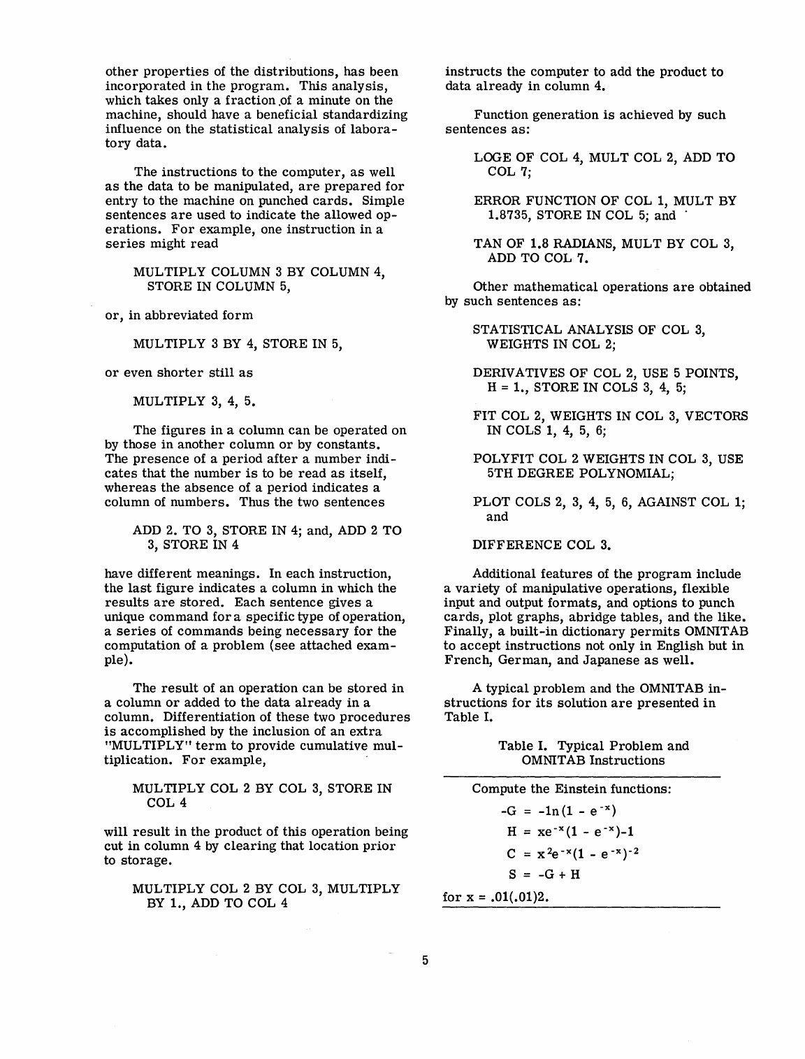
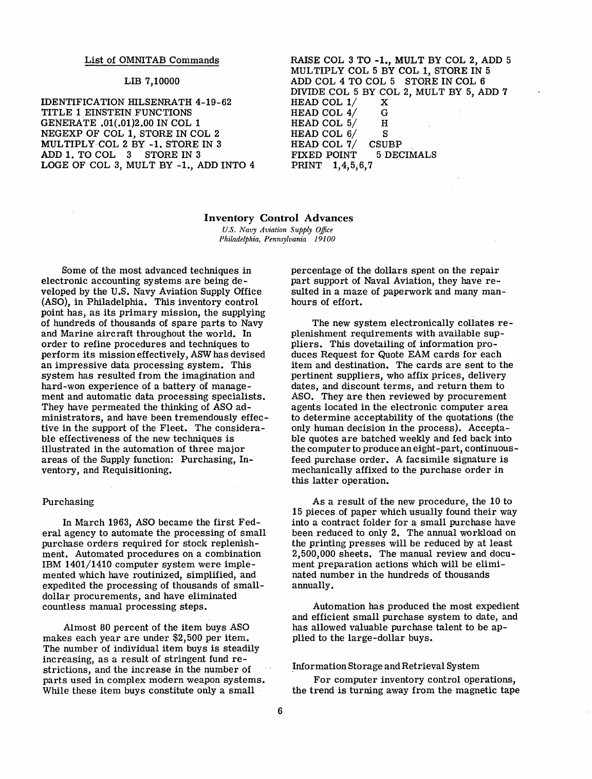
A
typical
problem
and
the
OMNITAB
in-
structions
for
its
solution
are
presented
in
Table
I.
Table
I.
Typical
Problem
and
OMNITAB
Instructions
Compute
the
Einstein
functions:
-G
=
-In(l
-
e-
X)
H =
xe
-x
(1
- e -x )-1
C = x2
e-
X
(1
_
e-
x)-2
S =
-G
+ H
for
x = .01(.01)2.
List
of OMNITAB
Commands
LIB 7,10000
IDENTIFICATION IDLSENRATH
4-19-62
TITLE
1 EINSTEIN FUNCTIONS
GENERATE .01(.01)2.00 IN COL 1
NEGEXP OF COL 1, STORE IN COL 2
MULTIPLY· COL 2
BY
-1.
STORE IN 3
ADD
1.
TO COL 3 STORE IN 3
LOGE OF COL 3, MULT
BY
-1.,
ADD
INTO 4
RAISE COL 3 TO
-1.,
MULT BY COL 2,
ADD
5
MULTIPLY COL 5
BY
COL 1, STORE IN 5
ADD
COL 4 TO COL 5 STORE IN COL 6
DIVIDE COL 5
BY
COL 2, MULT
BY
5,
ADD
7
HEAD COL
1/
X
HEAD COL
4/
G
HEAD COL
5/
H
HEAD COL
6/
S
HEAD COL
7/
CSUBP
FIXED POINT 5 DECIMALS
PRINT
1,4,5,6,7
Inventory
Control
Advances
u.s.
Navy Aviation Supply
Office
Philadelphia, Pennsylvania 19100
Some of
the
most
advanced
techniques
in
electronic
accounting
systems
are
being
de-
veloped by
the
U.S. Navy Aviation Supply Office
(ASO),
in
Philadelphia.
This
inventory
control
point
has,
as
its
primary
mission,
the
supplying
of
hundreds
of
thousands
of
spare
parts
to Navy
and
Marine
aircraft
throughout
the
world.
In
order
to
refine
procedures
and
techniques
to
perform
its
mission
effectively,
ASW
has
devised
an
impressive
data
processing
system~
This
system
has
resulted
from
the
imagination
and
hard-won
experience
of a
battery
of
manage-
ment
and
automatic
data
processing
specialists.
They have
permeated
the
thinking of
ASO
ad-
ministrators,
and
have been
tremendously
effec-
tive
in
the
support
of
the
Fleet.
The
considera-
ble
effectiveness
of
the
new
techniques
is
illustrated
in
the
automation
of
three
maj
or
areas
of
the
Supply function:
Purchasing,
In-
ventory,
and Requisitioning.
Purchasing
In
March
1963,
ASO
became
the
first
Fed-
eral
agency
to
automate
the
processing
of
small
purchase
orders
required
for
stock
replenish-
ment.
Automated
procedures
on a
combination
IBM 1401/1410
computer
system
were
imple-
mented
which have
routinized,
simplified,
and
expedited
the
processing
of
thousands
of
small-
dolla~
procurements,
and have
eliminated
countless
manual
processing
steps.
Almost
80
percent
of
the
item
buys
ASO
makes
each
year
are
under
$2,500
per
item.
The
number
of individual
item
buys
is
steadily
increasing,
as
a
result
of
stringent
fund
re-
strictions,
and
the
increase
in
the
number
of
parts
used
in
complex
modern
weapon'systems.
While
these
item
buys
constitute
only a
small
6
percentage
of
the
dollars
spent
on
the
repair
part
support
of Naval Aviation,
they
have
re-
sulted
in
a
maze
of
paperwork
and
many
man-
hours
of
effort.
The
new
system
electronically
collates
re-
plenishment
requirements
with
available
sup-
pliers.
This
dovetailing of
information
pro-
duces
Request
for
Quote EAM
cards
for
each
item
and
destination.
The
cards
are
sent
to
the
pertinent
suppliers,
who affix
prices,
delivery
dates,
and
discount
terms,
and
return
them
to
ASO. They
are
then
reviewed
by
procurement
agents
located
in
the
electronic
computer
area
to
determine
acceptability
of
the
quotations (the
only human
decision
in
the
process).
Accepta-
ble
quotes
are
batched weekly and fed
back
into
the
computer
to
produce
an
eight-part,
continuous-
feed
purchase
order.
A
facsimile
signature
is
mechanically
affixed to
the
purchase
order
in
this
latter
operation.
As
a
result
of
the
new
procedure,
the
10 to
15
pieces
of
paper
which
usually
found
their
way
into a
contract
folder
for
a
small
purchase
have
been
reduced
to only 2. The annual
workload
on
the
printing
presses
will
be
reduced
by
at
least
2,500,000
sheets.
The
manual
review
and
docu-
mentpreparation
actions
which will be
elimi-
nated
number
in
the
hundreds
of
thousands
annually.
Automation
has
produced
the
most
expedient
and
efficient
small
purchase
system
to
date,
and
has
allowed
valuable
purchase
talent
to
be
ap-
plied
to
the
large-dollar
buys.
.Information
Storage
and
Retrieval
System
For
computer
inventory
control.
operations,
the
trend
is
turning
away
from
the
magnetic
tape
as
the
principal
data
storage
medium and
to-
wards
the magnetic disc
or
drum,
because
of
the
almost
instantaneous
accessibility
of
the
latter,
provided the number location
or
address
is
known. The random
access
capability
is
es-
sential
in
the
processing
of daily
transactions,
which
arrive
in
no
ordered
sequence,
or
in
the
rapid
compilation of a
list
of
associated
items
which
are
scattered
throughout
the
files.
ASO
has pioneered the
latest
techniques
by
participating
in
the pilot
operation
of a
real-
time
data
storage
and
retrieval
system
devel-
oped
at
the
University of
Pennsylvania's
Moore
School of
Electrical
Engineering,
under
con-
tract
to the Navy's
Bureau
of Supplies and
Ac-
counts and the Office of Naval
Research.
This
system,
known
as
the
Multi-List,
solves
the
problem
of
addressing
individual
stock
items.
It
also
provides, through
address
linkage,
lists
of
stock
items
associated
by
a common
charac-
teristic
but physically
scattered
through the
file.
Applying
this
theory to the
capabilities
of
the IBM 1405 Disc Storage Unit
attached
to a
medium
scale
1401 computer,
ASO
programmed
a
data
retrieval
system,
during the
latter
part
of 1962 which
provides
instant
access
to any
stock
item
in
the file through
the
Federal
Item
Identification Number,
the
Manufacturer's
Part
Number,
or
other
keys.
It
gives
immediate
re-
sponse to a
request
for inventory
stock
status
or
a
request
for
technical
information
on
such
matters
as
engineering, units
per
application,
production
lead
time,
and
similar
areas
of
sup-
ply and
technical
data.
It
produces
the
answer
on the console
typewriter,
or
it
can
display
it
on one of many
small
television-type
screens
located
at
various
distances
from
the
computer.
It
responds
to a
request
for
any
desired
weap-
ons
list
breakdown with a
listing
on the
printer,
containing the
stock
numbers
of
all
component
assemblies
with
pertinent
technical
data, along
with
up-to-date
stock
status
information.
An
almost
human quality of the
system
is
its
ability
/ to make decisions
as
to the
relative
importance
of a group of
queries,
and
its
capacity to deflect
less
important
items
in
favor· of
those
with
higher
priority.
The
system
can
receive,
and
store
for
future action, up to
34
requests,
while
answering
higher
priority
queries.
Automatic
Interim
Requisitioning
The
success
of the random
retrieval
exper-
iment
has
started
an
accelerated
program
of
advanced automated techniques to
harness
the
speed
of the new
system
to
other
supply
proce-
dures.
Using a much
larger
IBM 1301 Disc
Storage Unit attached to an IBM
large
scale
1410 computer,
it
has provided automatic
proc-
essing
in
a
certain
range
of
the
interim
consum-
able
parts
requirements
(approximately 350,000
items
in
number) without manual intervention.
As
each
field
requisition
is
fed into
the
computer
system
from
the
transceiver
network,
it
searches
out
activities
which
are
storing
supply
material
not
required
for
local needs, and
based
on a
geographical proximity table,
it
automatically
prepares
the shipping
directive
to have
the
ma-
terial
sent
to
the
requiring
activity. This
direc-
tive
is
transmitted
by
way
of
transceiver
network
to both the shipping and
receiving
activities.
Some
30
to
40
percent
of
current
interim
requests
are
now
being automatically
processed,
but proposed
alterations
to the
system
will widen
the
range
and
increase
the
rate
to
60
percent,
allowing supply
managers
to
concentrate
more
effectively on
the
more
troublesome
items.
Even when
these
are
passed
along by the
com-
puter
for
personal
attention, automation helps
by
supplying
price
and
other
information,
thereby
reducing
the
quantity of manual
screen-
ing
required.
Moreover, in the
near
future
supply
managers
will have
remote
inquiry
sta-
tions
to
tap
the
computer
storage
for
up-to-the-
minute inventory and file information. The
answers
to
their
requests
for
specific
data
will
be displayed instantaneously on
the
screens,
or
printed
on
hard
copy
printers.
These
automatic
procedures
are
also
used
on the
periodic
Consolidated Stock Status
Re-
porting
(CSSR)
redistribution.
Each
week a
seg-
ment of the consumable parts- inventory
is
ana-
lyzed
for
redistribution
purposes
by
item
and
by
activity •
This
results
in
a
report
that
shows
for
each
stock
item
which
activities
have
ex-
cesses
and which have net
requirements.
When
this
information
is
fed into the automatic
proc-
essing
procedures,
shipment
requests
are
pro-
duced
that
will supply
50
to
60
percent
of the
activities
in
short
supply, and
this
is
done within
a
matter
of
hours
instead
of
the
20
days
allowed
under
manual
processing
schedules.
IBM
1401/1404/7070
Systems
Application
u:s.
-Navy Fznance- Center
Cleveland, Ohio
44100
Systems
Application
The addition of an IBM 1401/1404
computer
configuration
as
a
satellite
to
the
U.S. Navy
Fi-
7
nance
Center's
IBM 7070
system
is
unique
in
that
for
$2,000
less
total
monthly
computer
rental,
the new
system
will
perform
all
the
old
functions with
greater
flexibility and
in
less
elapsed
time,
freeing
computer
hours
for
other
applications.
Within 6 months
after
it
installed
its
IBM
7070
computer
(in
September
1960),
the
Cleveland-based
Finance
Center
had two of
its
major
applications,
military
allotments
of pay
and
military
pay
record
processing,
on
the
ma-
chine.
And
in
less
than
1
year
the
third
appli-
cation,
monthly
payments
to
all
U.S. Navy
Re-
tired
and
Fleet
Reserve
personnel,
was
added
to
make
the
system
100-percent
operational.
The
allotment
master
tape
file
has
one
million
accounts
and
disbursements
of $116
million
are
made
monthly. The
retired
pay
master
file
has
128,000
accounts
and
disbursements
of $23
million
a month.
Each
year
1,600,000
military
pay
records
are
reviewed
by
the
computer.
The
Finance
Center's
conversion
from
a
combina-
tion
Addressograph
plate,
IBM
stencil,
and
EAM
system
to
the
7070
was
highly
successful
and
for
the
past
year
the
Center
has
been
processing
100,000 input
documents
a month
and
issuing
600,000
card
checks
and bonds a month
at
an
annual
savings
of
more
than
$150,000-and
with
greater
efficiency and
accuracy.
The
initial
7070
system,
with two
input-
output
channels
and a
5000-word
memory
ca-
pacity:
had
peripheral
equipment
on-line
con-
sisting
of eight
tape
drives,
a
card
reader,
two
card
punch
machines,
and
three
IBM 408
printers
with
bill-feed
attachments.
This
con-
figuration
was
unique
in
that
relatively
slow-
speed
printers
(IBM
408's
-150
lpm)
were
con-
nected
directly
to
the
computer.
This,
however,
was
necessary
since
high-speed
printers
for
printing
card
checks
were
not
then
available.
The
immediate
solution
was
to
use
three
408
printers
on
line,
printing
two
checks
per
printer
and
using
the
priority
features
of
the
7070
equip-
ment
to
achieve
a
rated
print
speed
of 900
lines
per
minute.
In
July
1961, a study
was
made
to
deter-
mine
the
benefits
which could be
realized
with
a
satellite
computer
to
perform
the
input-output
operations
(card-to-tape
and
tape-to-printer
or
punch). At about
the
same
time,
information
was
received
that
the
IBM 1403
printer
(600
lines
per
min)
was
being modified
to
print
card
checks
for
the
Treasury
Department.
Investi-
gation
of
this
new equipment
for
handling
card
checks
at
the
Finance
Center
revealed
that
the
voluminous
check
print
and
print
operations
as
8
well
as
other
input-output
operations
could be
performed
on a 1401/1404
configuration
at
a
reduced
production
cost.
The study
also
re-
vealed
that
a
savings
of.
about $2,000
per
month
could be
realized
through
reduced
rental
of
equipment
and
number
of
operating
personnel
required.
A
recommendation
was
made
to
re-
place
the
7070
peripheral
unit-record
equip-
ment
with
an
IBM 1401
computer
system
having
a 1402
card
reader/punch
and a 1404
printer,
capable
of
printing
either
on EAM
cards
or
con-
tinuous
form
paper.
The
Department
of
Defense
approved
the
recommendation
for
the
1401
satellite
com-
puter
on
February
21, 1962 and appointed the
Navy Management Office to conduct a
Readi-
ness
Review, which
was
held
at
the
Navy
Fi-
nance
Center
on May 1
and
2, 1962. In
Septem-
ber
1962
the
computer
was
installed
and
placed
into
operation
immediately
following a
system
test
to
assure
that
programs
previously
tested
functioned
satisfactorily
on
the
new
configuration.
In addition of a 1401
computer
results
in
a
tape-oriented
7070
system
with a
console
card
reader
and eight
tape
drives
on
line.
Initially,
the
1401
will
be
used
primarily
as
a
"slave"
to
prepare
tapes
for
use
on
the
7070, and
to
punch
or
print
output
requirements.
Except
for
writ-
ing
programs
for
punching and
printing
checks,
the
Navy
Finance
Center
plans
on
using
a
multi-
ple
duty
program,
furnished
by IBM
for
most
of
its
requirements.
The.
multiple
duty
program
has
the
facility
to
perform
card-to-tape,
tape-
to-punch
or
tape-to-printer
operations,
individ-
ually,
in
any
combination
desired,
or
all
three
operations
simultaneously.
With
this
program,
the
card
read
time
or
print
time
can
be
over-
lapped
with
punch
time,
resulting
in
completion
of two
or
more
operations
in
less
time
than
it
would
take
to
do
them
separately.
In addition
to
the
$2,000
per
month
savings,
the
addition
of
the
1401/1404
has
greatly
in-
creased
the
flexibility
of
the
NFC
data
process-
ing
system
and
released
considerable
prime
shift
time
on
the
7070
for
processing
new
ap-
proved
applications
generated
within
the
Center
or
by
other
Government
agencies.
The
first
of
the
outside
jobs
was
put on
the
computer
during
August 1962.
It
consists
of a
management
re-
porting
systemfor
the
Office of Naval
Material
in
Washington.
IBM
1401/1404
Satellite
Computer
System
Uses
Modified
IBM
Multiple
Duty
Program
u.s.
Navy Finance Center
Cleveland, Ohio
44lO0
Multiple Duty
Program
When
the
U.S. Navy
Finance
Center,
Cleve-
land, Ohio,
installed
an
IBM 1401/1404
computer
system
as
a
satellite
to
its
present
IBM 7070
system,
it
employed a modified IBM 1401
multi-
ple
duty
program
to
achieve
maximum
usage
and
optimum
operating
speeds.
The
program,
#1401-UT-039,
permits
card-
to-tape,
tape-to-card,
and
tape-to-printer
oper-
ations
to
run
simultaneously
in
any combination
and
to
start
or
conclude any
operation
while
others
continue. The
program
is
made
up of
six
independent, but
inter-connected
routines
of
binary
coded
decimal
(BCD)
card-to-tape,
BCD
tape-to-card,
tape-to-printer,
pure
binary
card-to-tape,
pure
binary
tape-to-card,
and a
rapid
card-to-tape
or
tape-to-printer
routine.
The Navy
Finance
Center
has
modified
the
program
to
provide
for
tape
labels
and
permit
modifications
for
speCialized
routines
while
re-
taining
the
option to
perform
more
than
one
op-
eration.
The
program
was
modified
as
follows:
1.
Card-to-Tape
a.
Increase
blocking
factor
from
one
to
five
b.
Provide
operator
option to
write
or
not
write
tape
header
and
trailer
records
(labels)
2.
Tape-to-Card
a.
Accept
labeled
or
unlabeled
tape
3.
Tape-to-Printer
a.
Accept
labeled
or
unlabeled
tape
b. Allow
printer
skip
and
space
codes
for
both
before
and
after
print
rather
than
just
before
print.
c.
Read
pre-punched
savings
bond
card
stock
from
the
1404 bill feed
printer
and
com-
pare
with
tape
record
data.
4.
Provide
typewriter
input and output
5.
Binary
routines
a.
Remove
both
card-to-tape
and
tape-
to-card
binary
routines.
9
Basic
program
material
consists
of a
con-
densed
program
card
deck,
system
listing,
op-
erating
instructions,
and flow
charts.
A
source
symbolic
program
deck
is
available
from
IBM,
as
optional
program
material,
upon
request.
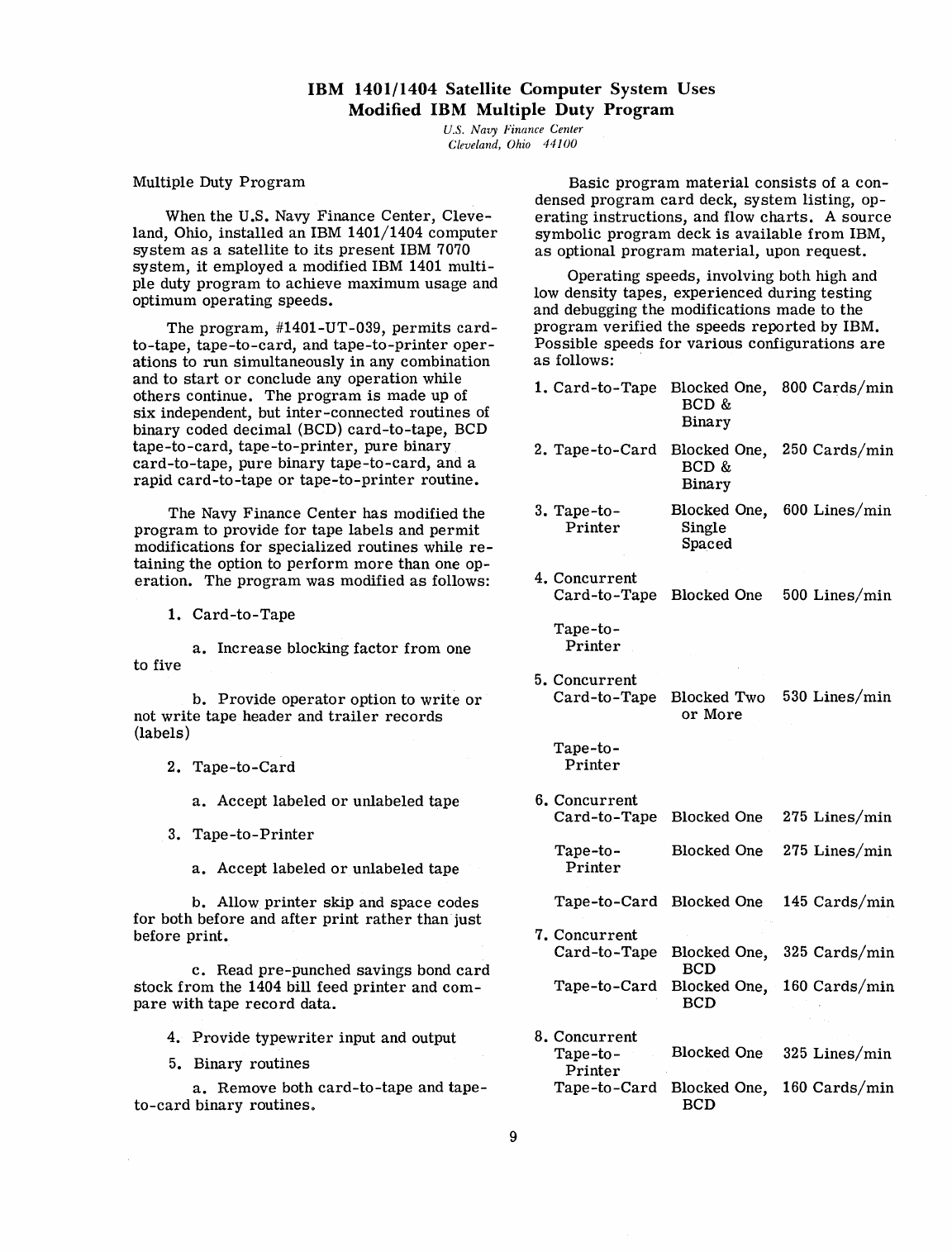
Operating
speeds,
involving both high and
low
density
tapes,
experienced
during
testing
and debugging
the
modifications
made
to
the
program
verified
the
speeds
reported
by IBM.
Possible
speeds
for
various
configurations
are
as
follows:
1.
Card-to-Tape
Blocked One, 800
Cards/min
BCD &
Binary
2.
Tape-to-Card
Blocked One, 250
Cards/min
BCD &
3.
Tape-to-
Printer
4.
Concurrent
Binary
Blocked One, 600
Lines/min
Single
Spaced
Card-to-Tape
Blocked One 500
Lines/min
Tape-to-
Printer
5.
Concurrent
Card-to-Tape
Blocked Two 530
Lines/min
or
More
Tape-to-
Printer
6.
Concurrent
Card-to-Tape
Tape-to-
Printer
Tape-to-Card
7.
Concurrent
Card-to-Tape
Tape-to-Card
8.
Concurrent
Tape-to-
Printer
Tape-to-Card
Blocked One 275
Lines/min
Blocked One 275
Lines/min
Blocked One 145
Cards/min
Blocked One, 325
Cards/min
BCD
Blocked One, 160
Cards/min
BCD
Blocked One 325
Lines/min
Blocked One, 160
Cards/min
BCD
The
program
may be
interrupted
at
any
time
to
introduce
another
operation
by
pushing
the
interrupt
button on
the'1401.
At
that
point,
the
effective
speeds
for
the
applicable
configu-
ration
listed
in
4
through
8 above would
prevail.
As
soon
as
one of
these
operations
is
com-
pleted,
speeds
will
automatically
increase
to
that
of
the
configuration
remaining.
The
versatility
of IBM
multiple
duty
pro-
gram
#1401-UT-039
is
such
that
NFC
is
able
to load
this
basic
program
in
their
satellite
computer
at
the
start
of a day and
perform
a
variety
of
operations
throughout the day without
having to change
programs.
General
Circulation
Research
Laboratory
u.s.
Weather Bureau
Washington,
D.
C.
20235
The goal of
the
General
Circulation
Re-
search
Laboratory
is
to expand
man's
basic
knowledge of
the
atmosphere.
Specifically,
its
purpose
is
to
express
accurately
the
physical
laws
that
govern
atmospheric
behavior.
In the
Laboratory,
Weather
Bureau
scien-
tists
are
seeking
the
answers
to many
questions.
Why
does
the
atmosphere
respond
in
the way
it
does
to
energy
from
the
sun?
How
and why
does
the
atmosphere
transform
this
energy
from
the
sun
through
various
stages
before
it
is
ulti-
mately
dissipated?
Of
all
the
possible
motions
that
one
can
imagine
in
a fluid
such
as
the
at-
mosphere,
why do we
observe
only a few? What
is
the
relationship
between
the
circulation
in
the
Northern
and Southern
Hemispheres?
How
are
the
stratosphere
and
lower
atmosphere
coupled?
To what
extent
do
variations
of
the
earth's
surface
determine
our
climate?
Are
variations
of
the
sun's
radiation
a
significant
factor
in
the
weather
we
experience?
If
man
is
to
modify the
weather
or
even
to
forecast
it
for
long
periods
in
advance,
these
questions
and
many
others
must
be
answered.
The
atmosphere
is
a fluid
so
vast
that
there
are
two
million
tons
of
it
for
each
person
on
earth.
Yet
99
percent
of
the
atmosphere
-or
five billion
million
tons-lies
within
19
miles
of
the
earth's
surface,
encasing
the
globe
like
a
thin
skin.
This
ocean
of
air
is
always
in
mo-
tion,
driven
by
energy
from
the
sun. Heated
more
at
the
equator
and
less
at
the
poles,
the
atmosphere
constantly
tries
to
equalize
its
temperature
and
in
the
effort
creates
wind and
weather.
The winds and
the
weather
are
steered
by
the
earth's
rotation
and,
as
they move
around
the
earth,
they
are
also
affected
by the
topography-mountains,
plains,
and
oceans.
The
result
is
an
amazing
complexity of
weather
events-events
that
never
repeat
themselves
exactly.
10
Developing Techniques
For
Studying the
Atmosphere
Since
the
meteorologist
obviously cannot
study and
observe
the
entire
atmosphere,
he
brings
into
his
laboratory
a hypothetical
at-
mosphere
in
the
form
of
differential
equations
expressing
the
basic
physical
laws.
The
meth-
ods
used
by
the
General
Circulation
Research
Laboratory
trace
their
origin
back
to
Isaac
Newton who
formulated
the
fundamental laws of
particle
dynamics.
Later
theorists
extended
these
laws
to
cover
fluid motion and applied
them
to
studies
of
the
atmosphere.
At
the
beginning of
this
century,
V.
Bjerknes
of Norway
foresaw
the
possibility
of
using
laws
of fluid motion
for
weather
forecasting.
In
1922,
Lewis
Fry
Richardson,
an
English
mathema-
tiCian,
suggested
speCific
means
for
accomplish-
ing
this,
but he
estimated
that
64,000 people
would be needed to
analyze
weather
observations
and
prepare
forecasts
by
this
method, which
is
now
called
numerical
weather
prediction.
In
Richardson'S
day
there
were
no
electronic
com-
puters
and,
in
any
case,
the
structure
of
the
at-
mosphere
was
not
yet
known
well
enough
to
use
his
method
successfully.
In
the
late
1930's
and
early
1940's,
more
sophisticated
theories
applicable
to
numerical
forecasting
were
formulated
by a
number
of
outstanding
scientists.
Carl-Gustaf
Rossby, a
noted
Swedish-American
meteorologist,
de-
veloped a
formula
for
predicting
the
speed
of
westerly
waves high
in
the
atmosphere.
Simply
stated,
the
speed
of a wave depends on the wind
speed,
the
size
of the wave, and
its
latitude.
During
the
same
period,
other
scientists
were
constructing
the
first
high-speed
digital
computers.
With
the
development of
the
com-
puter
and
the
theory
of
westerly
waves,
numer-
ical
weather
forecasting
became
a
practical
possibility.
The
actual
teclmiques
were
devel-
oped
at
the
Institute
for
Advanced Study
in
Princeton,
New
Jersey,
under
the
direction
of
Dr.
J.
von
Neumann
and
Dr.
Jule
Charney.
These
techniques,
developed
for
the
purpose
of
short-range
weather
prediction,
sooJl showed
their
potential
for
the
study of
longer
period
evolutions of
the
earth's
atmosphere.
At
the
Institute
for
Advanced Study,
Dr.
Norman
A.
Phillips
undertook
the
first
"numerical"
study
of
the
atmosphere's
general
circulation,
using
hydrodynamical
equations
to
represent
atmos-
pheric
motion and employing
an
electronic.
computer
to
carry
out
the
calculations.
In 1954,
Dr.
von Neumann
urged
the
Weather
Bureau
to
begin
theoretical
studies
of
the
general
Circulation, and
the
General
Circu-
lation
Research
Section
was
established
by
the
Bureau
in
October
1955. (The
name
was
later
changed
to
General
Circulation
Research
Labo-
ratory.)
Its
aim
was
to
develop a
theoretical
framework
capable
of
reproducing
and
explain-
ing
the
response
of
the
atmosphere
to
the
energy
received
from
the
sun.
Creating
a Model
Atmosphere
In
constructing
a hypothetical
atmosphere
or
mathematical
model,
scientists
must
first
select
a
system
of
physical
laws
that
are
as-
sumed
to be
most
important
in
determining
at-
mospheric
movements
and
evolutions.
The
physical
laws
are
next
expressed
in
differential
equations, which
are
analyzed
numerically
and
programed
as
instructions
for
the
computer.
The complexity of
the
model
is
limited
by
the
capacity
of
the
computer
to be
used.
The
early
models
described
the
motions
of
the
atmosphere
as
simply
as
possible
and
still
stretched
to
the
limit
the
capacity
of
the
computers
then
in
use.
The
computer
solves
the
mathematical
formulas
and
calculates
the
movements
of
the
atmosphere
over
a
series
of
time
intervals
or
"time
steps."
That
is,
upon obtaining
the
fore-
cast
over
the
first
time
interval,
this
result
then
is
used
to
proceed
to
the
next, and
so
on.
For
purposes
of
calculation,
the
earth
is
divided
into
rectangular
grids,
and
the
equations
must
be
solved
at
every
point
on
the
grid
for
every
time
step.
The hypothetical model of
the
atmosphere
is
not
considered
to
be
correct
unless
it
realis-
tically
simulates
possible
atmospheric
behavior
over
extended
periods
of
time.
The
testing
of a model
can
take
several
years,
depending on
its
complexity.
If
it
produces
11
impossible
results-weather
that
has
never
been
observed-the
scientists
must
painstakingly
search
for
the
errors
in
their
calculations
or
in
their
theory.
The
Laboratory's
Models
The
models
of
the
atmosphere
devised
by
the
General
Circulation
Research
Laboratory
have
been
designed
to
simulate
the
characteris-
tics
of
an
atmosphere
in
increasing
degrees
of
reality.
The
six
models
have
been
designated
Mark
I
through
VI.
The
first
model,
Mark
I,
was
limited
to
the
motions of
the
atmosphere
between
the
equator
and 64° N.
latitude,
using
only two
atmospheric
levels
and only 1300
grid
points
in
each
level.
The
vertical
structure
of
this
model
atmosphere
was
described
as
simply
as
possible
while
still
permitting
the
development of
storms.
The
model
ignored
the
effects
of cloud
formations
and preCipitation on
the
evolutions of
the
atmos-
phere'
and highly
simplified
the
way
that
solar
energy
is
made
available
to
the
atmosphere.
Mark
I
has
successfully
accounted
for
some
of
the
most
important
gross
properties
of
the
at-
mosphere's
wind
systems,
the
large-scale
characteristics
of
middle
latitude
storms,
and \
the
role
that
they play
in
maintaining
the
heat
balance
of
the
atmosphere
against
the
sun's
radiant
energy.
All of
the
Laboratory's
later
models,
the
ones
being
worked
on
currently,
are
global
in
scope.
Mark
VI,
with
10,000
grid
points
in
each
of 10
levels
including
the
earth's
surface,
per-
mits
more
detailed
descriptions
of
what
is
hap-
pening
in
the
atmosphere
than
earlier
models.
It
allows
a
close
approximation
of
the
solar
energy
absorbed
and
reemitted
by
the
earth
and
the
atmosphere.
Also,
it
takes
into
account
the
surface
features,
evaporation,
snow
cover,
cloud
formation,
and
precipitation,
so
that
the
atmospheric
evolutions should be
calculated
more
precisely
than
with
earlier
models.
Additional
Research
The
Laboratory's
scientists
sometimes
find
that
in
order
to
add
the
correct
elements
to
their
mathematical
models
they
must
have a
better
understanding
of
certain
atmospheric
processes.
They have
therefore
undertaken
additional
research
to
learn
how
the
atmosphere
absorbs
and
transmits
radiant
energy,
how
the
clouds
and
precipitation
of
large
storms
are
formed,
why and how
the
cumulus
clouds
of
thunderstorms
are
formed,
the
effects
of
large
mountain
masses
and of
the
irregular
distribu-
tion
of land and
water
over
the
globe, and how
the
oceans
exchange
energy
with the
atmosphere.
Studies Benefit
Forecasting
The
research
of
the
General
Circulation
Research
Laboratory
has
produced
by-products
that
are
useful
in
solving
forecasting
problems.
The
first
numerical
method of
forecasting
pre-
cipitation
amounts
was
developed
in
the
Labora-
tory.
The
Laboratory
was
the
first
to
solve
a
system
of
weather
forecasting
equations
that
more
exactly
fit
actual
weather
conditions
than
earlier
methods.
Potential
Results
of
the
Laboratory's
Work
In
the
future,
more
refined
and
realistic
mathematical
models
will
demonstrate
how
ac-
curately
the
behavior
of the
atmosphere
can
be
predicted
over
various
long
periods
of
time.
With
better
models,
scientists
hope to
solve
the
mysteries
of
climatic
change.
These
models
may one day be
used
to
make
the
actual
long-
range
weather
predictions.
When
theoretical
models
are
able
to
repro-
duce
natural
phenomena faithfully enough to be
useful
in
prediction,
the
next
logical
step
is
to
investigate
weather
modification,
inadvertent
as
well
as
intentional.
Where, and how
is
the
at-
mosphere
sensitive
to
external
influences?
12
Could
its
behavior
be
altered
with
the
relatively
small
sources
of
energy
available
to
man?
Through
simulation
in
the
theoretical
models,
the
scientists
will
learn
what would happen to
world
weather
and
climate
if,
for
'example,
artificial
clouds could be
created
to
reflect
more
sunlight away
from
the
earth;
if
more
carbon
dioxide
were
released
to the
atmos-
phere;
if
more
forests
were
converted
to
agri-
cultural
land
or
cities;
or
if
artificial
black
ground
cover
could be
introduced
over
large
areas
such
as
the
Arctic
ice
pack.
Laboratory
Staff and
Facilities
Organizationally,
the
General
Circulation
Research
Laboratory
is
part
of
the
Weather
Bureau's
Office of
Meteorological
Research.
Dr.
Joseph
Smagorinsky
has
directed
the
Bureau's
general
circulation
research
since
the
establishment
of
the
Laboratory
in
October
1955. Since 1955,
the
Laboratory's
staff
has
grown
from
2 to
36
and now
includes
meteorol-
ogists,
physicists,
oceanographers,
mathema-
ticians,
programers,
and
computer
operators.
For
nearly
7
years,
the
Laboratory
was
located
in
the
Weather
Bureau's
facilities
at
Suitland,
Maryland.
From
1955 to 1957,
an
IBM-701
computer
was
used
for
studies
of
the
general
circulation.
This
computer
was
re-
placed
by
an
IBM-704
in
1957, and
then
by
an
IBM-7090
in
1960.
During
the
summer
of 1962,
the
Laboratory
moved
to
the building
at
615
Pennsylvania
Avenue, N.W., Washington, D. C.,
that
houses
the
IBM STRETCH
computer.
Computers
and
Centers,
Overseas
Process
Control
Computer
System
The English Electric Company Ltd.
London W.C.2., England
An
on-line
process
control
computer
sys-
tem
has
been
ordered
from
the
Metal
Industries
Division of
English
Electric,
Stafford,
by
the
Shelton
Iron
and Steel Company
as
part
of the
new
universal
beam
and
section
mill
project
at
their
Etruria
works,
Stoke-on-Trent.
The
sys-
tem
will
be
based
upon
the
KDN2
computer
and
will be
manufactured
by
English
Electric-Leo
Computers
Limited
at
their
Kidsgrove
works
not
far
from
Etruria.
It
will
minimise
the
waste
from
cutting
beams
and
sections
into
the
lengths
ordered
by
customers
by
optimising
control
of
the
two hot
saws.
This
is
the
first
digital
computer
system
in
the
United Kingdom to be
used
on-line
for
direct
control
of
cut
length
at
a hot
saw.
As
a
small
percentage
increase
in
yield
from
this
type of
mill
will
give
substantial
returns;
it
is
esti-
mated
that
the
system
will
regain
the
capital
outlay
in
about
12
months.
With a
beam
and
section
mill
several
dif-
ferent
lengths
are
usually
cut
from
each
finished
beam,
but the
length
of
beam
rolled
is
not
ac-
curately
known
until
it
reaches
the
hot
saw.
It
is
therefore
not
possible
to
schedule
the
cutting
process
in
advance.
Under manual
control
the
sawman
only
has
time
to
carry
out
an
approxi-
mate
calculation,
which often
results
in
short
unsaleable
lengths
being
left
at
the
tail
of
some
beams.
The high
operating
speed
of
the
KDN2
sys-
tem
makes
possible
the
investigation
of many
different
combinations
of
order
lengths
in
a
matter
of
seconds.
The
computer
then
selects
the
solution
giving the
best
yield,
displays
the
lengths
to be
cut
in
sequence
to
the
operator
and
automatically
sets
the
hot saw bench and
stops
for
each
cut.
In addition to
the
control
of
the
two
saws,
the
computer
tracks
each
bloom
that
is
loaded
into
the
reheat
furances
through
the
mill
and on
to
the
cooling
beds,
so
that
each
cut
length
can
be
identified.
At
the
cooling
beds
a
digital
dis-
play
provides
the
cast
number,
and two
tele-
printers
the
order
details.
Six
other
systems
using
English
Electric-
Leo
KDN2
computers
are
installed
or
on
order
for
the
U.K.
steel
industry.
Atlas
2
Computer
Ferranti Ltd.
London
TV
1, England
Atlas
2
is
a new,
smaller
version
of
Atlas
(see
DCN
October
1960 and
October
1961),
av-
eraging
half
its
size
but with a wide
choice
of
both
size
and
speed.
The
computer
offers
up to
131,072
words
of
core
store
and
can
complete
nearly
half a
million
instructions
per
second.
It
provides
comprehensive
time
sharing
with
complete
program
protection.
The
system
can
handle a
large
number
and
variety
of
peripheral
equipments,
with
multiple
operating
consoles.
Special
purpose
on-line
devices
present
no
problem.
The
machine
is
fully
asynchronous.
Thus
future
improvements
in
machine
perform-
ance
are
not blockp.d
by
a fixed
cycle
time.
13
Atlas
2 and
Atlas
1 (hitherto
called
Atlas)
have
an
identical
instruction
code;
programs
may be
written
to
run
on
either
machine.
Atlas
2
bene-
fits
extensively
from
both
hardware
and
software
designed
for
Atlas,
and
therefore
represents
the
cumulative
experience
of
Manchester
Uni-
versity,
Cambridge
University,
and
Ferranti
in
computer
design.
Storage
Systems
B-Store
(Access
0-35
microseconds,
128
halfwords)-This
store
holds
indices
(modifiers)
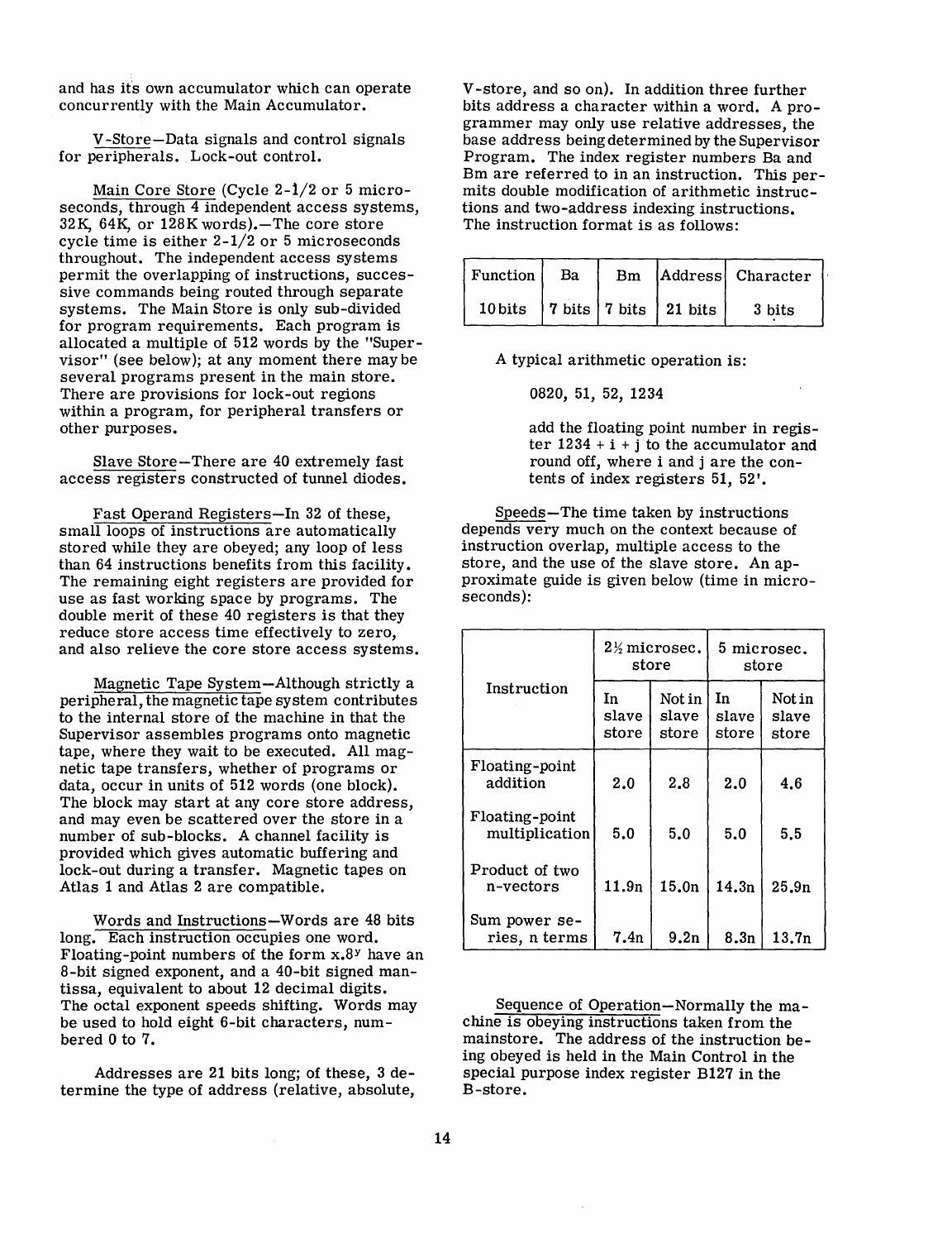
and
has
it's own
accumulator
which
can
operate
concurrently
with
the
Main
Accumulator.
V
-Store-Data
signals
and
control
signals
for
peripherals.
Lock-out
control.
Main
Core
Store
(Cycle
2-1/2
or
5
micro-
seconds,
through
4 independent
access
systems,
32K, 64K,
or
128K
words).-The
core
store
cycle
time
is
either
2-1/2
or
5
microseconds
throughout. The independent
access
systems
permit
the
overlapping
of
instructions,
succes-
sive
commands
being
routed
through
separate
systems.
The Main
Store
is
only
sub-divided
for
program
requirements.
Each
program
is
allocated
a
multiple
of 512
words
by
the
"Super-
visor"
(see
below);
at
any
moment
there
may
be
several
programs
present
in
the
main
store.
There
are
provisions
for
lock-out
regions
within a
program,
for
peripheral
transfers
or
other
purposes.
Slave
Store-There
are
40
extremely
fast
access
registers
constructed
of tunnel
diodes.
Fast
Operand
Registers-In
32
of
these,
small
loops of
instructions
are
automatically
stored
while they
are
obeyed; any loop of
less
than
64
instructions
benefits
from
this
facility.
The
remaining
eight
registers
are
provided
for
use
as
fast
working
space
by
programs.
The
double
merit
of
these
40
registers
is
that
they
reduce
store
access
time
effectively
to
zero,
and
also
relieve
the
core
store
access
systems.
Magnetic
Tape
System-Although
strictly
a
peripheral,
the
magnetic
tape
system
contributes
to
the
internal
store
of
the
machine
in
that
the
Supervisor
assembles
programs
onto
magnetic
tape,
where
they
wait
to be
executed.
All
mag-
netic
tape
transfers,
whether
of
programs
or
data,
occur
in
units
of 512
words
(one block).
The block may
start
at
any
core
store
address,
and may
even
be
scattered
over
the
store
in
a
number
of
sub-blocks.
A channel
facility
is
provided
which
gives
automatic
buffering
and
lock-out
during
a
transfer.
Magnetic
tapes
on
Atlas
1 and
Atlas
2
are
compatible.
Words
and
Instructions
-Words
are
48
bits
long.
Each
instruction
occupies
one
word.
Floating-point
numbers
of
the
form
x.8Y have
an
8-bit
signed
exponent, and a
40-bit
signed
man-
tissa,
equivalent to about 12
decimal
digits.
The
octal
exponent
speeds
shifting.
Words
may
be
used
to hold eight
6-bit
characters,
num-
bered
0 to 7.
Addresses
are
21
bits
long; of
these,
3
de-
termine
the type of
address
(relative,
absolute,
14
V
-store,
and
so
on). In
addition
three
further
bits
address
a
character
within a
word.
A
pro-
grammer
may only
use
relative
addresses,
the
base
address
being
determined
by
the
Supervisor
Program.
The
index
register
numbers
Ba and
Bm
are
referred
to
in
an
instruction.
This
per-
mits
double modification of
arithmetic
instruc-
tions
and
two-address
indexing
instructions.
The
instruction
format
is
as
follows:
Function
Ba Bm
Address
Character
10
bits
7
bits
7
bits
21
bits
3
bits
A
typical
arithmetic
operation
is:
0820, 51, 52, 1234
add
the
floating point
number
in
regis-
ter
1234 + i + j to
the
accumulator
and
round off,
where
i and j
are
the
con-
tents
of
index
registers
51,
52'.
Speeds-The
time
taken
by
instructions
depends
very
much
on
the
context
because
of
instruction
overlap,
multiple
access
to
the
store,
and
the
use
of the
slave
store.
An
ap-
proximate
guide
is
given below
(time
in
micro-
seconds):
2
~
micro
sec.
5
microsec.
store store
Instruction
In Not
in
In
Notin
slave
slave slave
slave
store store
store
store
Floating-
point
addition
2.0 2.8 2.0 4.6
Floating-point
multiplication
5.0 5.0 5.0 5.5
Product
of two
n-vectors
11.9n 15.0n 14.3n 25.9n
Sum
power
se-
ries,
n
terms
7.4n 9.2n 8.3n 13.7n
Sequence of
Operation-Normally
the
ma-
chine
is
obeying
instructions
taken
from
the
mainstore.
The
address
of
the
instruction
be-
ing obeyed
is
held
in
the Main
Control
in
the
special
purpose
index
register
B127
in
the
B-store.
If,
however, a
complicated
instruction
re-
quiring,
for
example,
the
formation
of
the
logarithm
of
the
number
in
the
accumulator
is
required,
the
function
digits
corresponding
to
the
function
logarithm
are
copied
into
the
Ex-
tracode
Control
Register
(B126
in
the
B-store),
and
the
logarithm
is
computed
by
the
extracode
routine,
which
starts
at
an
address
within the
Supervisor
corresponding
to
the
address
in
B126. When
the
extracode
routine
is
com-
pleted,
control
reverts
to
the
Main
Control
in
B127.
The
extracode
facility
allows
the
basic
in-
struction
code of
the
machine
to
be
augmented
to include about 250 additional
codes
for
ele-
mentary
functions, input and output
conversion
and
mixed
radix
conversion.
In
short,
all
the
facilities
normally
thought of
as
part
of a
sub-
routine
library
are
available
in
Atlas
2
as
extracode
functions.
If
a
peripheral
transfer
terminates
or
if
any
peripheral
device
requires
access
to
the
computer
while
either
main
or
extracode
instructions
are
being obeyed,
con-
trol
is
transferred
to a
third
control
register
stored
in
index
register
B125, known
as
Inter-
rupt
Control.
All
peripheral
transfers
are
ini-
tiated
by
extracode
functions.
Interrupt
control
is
called
in
automatically
whenever
an
informa-
tion
transfer
(usually of one
character,
column
or
line)
is
required
to
enable
the
device
to
con-
tinue
at
full
speed.
The
transfer
is
organised
by
a
part
of
the
Supervisor,
whichpasses
con-
trol
back
to
the
interrupted
program
when
the
unit of
information
concerned
has
been
trans-
ferred.
In
the
case
of magnetic·
tape
transfers
the
initiation
of
the
transfer
is
handled
by
an
interrupt
routine,
but
thereafter
the
transfer
and a
program
proceed
concurrently,
the
trans-
fer
causing
the
program
to
hesitate
when
ac-
cess
to a
word
in
the
core
store
is
required
by
the
transfer.
The
Supervisor
Program-Permanently
present
in
the
machine
is
the
Supervisor,
whose function
is
the
control
of autonomous
in-
put
and
output on
paper
tape,
cards
and
line
printers,
control
of autonomous
magnetic
tape
transfers,
execution of
extracodes,
program
scheduling
and
the
Time-Sharing
of
the
various
parts
of
the
machine
between any
number
of
programs
currently
held
in
the
core
store.
The
hardware
and
Supervisor
together
ensure
that
an
error
in
one
program
cannot
interfere
with
any
other.
The
Supervisor
reviews
the
priori-
ties
accorded
to
programs
from
time
to
time
in
the
light
of
the
current
situation
and
the
opera-
tor's
instructions,
and
will
occasionally
move a
program
from
one
part
of
the
store
to
another
to
allow
space
for
a
large
program
which
has
been
assembled
on magnetic
tape.
The
effect
of
15
these
activities
is
to
ensure
maximum
usage
of
the
system
as
a whole. The
Supervisor
also
provides
monitoring
information;
it
has
two-way
communication
with
the
operator.
Automatic
Programming-It
is
planned to
provide
compilers
for
Algol,
Fortran,
and
Cobol.
The
Peripheral
System-The
minimum
peripheral
and
magnetic
tape
coordinators
al-
low
for
equipment
as
shown
in
the
following
list.
Double
the
number
may be
attached
with
extra
hardware.
Minimum
Equipment
Provision
Character
Input
Devices
(tape
readers,
keyboard
inputs)
.••..
6
Character
Output
Devices
(tape
punches,
teleprinters,
flexowriters)
. . • • • . • • • • . • . . 6
Card
Readers
• . • . . . • • • • • • . • . 2
Card
Punches
• • • . • . • . • . • . . • . 1
Line
Printers
. . . . . . . . . . • • . • . 2
Spare
24-bit
channels
and
12-bit
channels
(for
special
purpose
on-
line
devices)
. • • . . • . . • . . •
••
8
each
Magnetic
Tape
Units
The
basic
installation
will
comprise:
1
Operators'
input-output device
3
Paper
Tape
Readers
3
Paper
Tape
Punches
3
Off-line
Flexowriters
2 ICT
Card
Readers
(600
cards/minute)
1 ICT
Card
Punch
(100
cards/minute)
1
AnelexLine
Printer
(1000
lines/minute}
8 Ampex TM2 Magnetic
Tape
Units
(90,000
chars/second)
1
Creed
75
Teleprinter
on-line
for
Mag-
netic
Tape
System
1
Engineers
Console,
consisting
of
1
Paper
Tape
Reader
1
Creed
75
Teleprinter
for
output
Displays
and
operators
keys/switches.
Further
peripheral
devices
may be
attached
to
Atlas
2;
for
example,
IBM
compatible
mag-
netic
tape
units,
mass
stores,
graphical
display
units,
and
the
like.
-LEO
326
and
LEO
III
Computers
General Post
Office
London E.C.1., England
The
Order
The
G.P
.0.
have
announced
that
they
have
placed
an
order
with
English
Electric
-
LEO
Computers
Ltd.
for
two
LEO
326
computers.
The
value
of
the
order
is
over
£ 1
million.
It
is
the
largest
single
order
for
commercial
com-
puting
equipment
ever
placed
in
the
United
Kingdom.
The
LEO
326
computers
will
be
de-
livered
in
1965.
The
Choice
of
Equipment
The
G.P
.0.
chose
LEO
326
after
a
strin-
gently
planned
comparative
survey
designed
to
insure
that
the
equipment
chosen
had
the
best
performance
in
terms
of
data
processed
per
unit
of
cost,
both
as
regards
capital
cost
and
running
costs.
In
arriving
at
their
decision
the
G.P.O.
considered
proposals
made
by
manufac-
turers
of
all
large
scale
data
processing
equip-
ment
both
in
the
United Kingdom
and
also
in
the
United
States
and
Europe.
In
all,
nearly
20
large
scale
computers
were
studied
by a
team
including
G.P
.0.
mechanisation
experts
and
Post
Office
engineers.
Application
Plans
are
being
made
for
the
computers
to
take
in
work
from
a
number
of
different
Post
Office
sources
including
initially
work
connected
with
repayment
of National Savings
Certificates,
dividend
payments
in
respect
of
Government
stock
and
bonds on
the
Post
Office
Register,
the
operations
of
the
Post
Office
Supplies
Depart-
ment,
and
Premium
Savings
Bonds.
It
is
not
intended
to
alter
the
present
arrangements
for
the
generation
of
numbers
for
the
monthly
Pre-
mium
Savings
Bond
draws,
which
will
continue
to
be
done by
"Ernie."
Support
Services
As
well
as
subjecting
the
computer
system
speCification
to
close
study
the
G.P
.0.
assured
themselves
that
support
of
the
highest
quality
in
regard
to
systems
planI?1ng,
programming,
op-
erational
assistance
and
maintenance
could
be
provided
by
the
chosen
manufacturer.
16
The
Buildup
As
indicated
by
theG.P
.0.
the
two
LEO
326
computers
will
be
preceded
by two
LEO
Ill's
(see
DCN,
July
1962)
which
they
will
replace.
The
LEO
Ill's
which
are
fully
compatible
with
the
LEO
326
will
be
used
for
building
up
the
load
of
work
prior
to
the
arrival
of
the
more
powerful
computers.
Before
even
the
LEO
Ill's
are
delivered,
work
to
prove
programmes
and
to
prepare
for
full
scale
running
will
be
carried
out on
LEO
Service
Bureau
Computers.
The
LEO
m
The
LEO
Ills
that
will· be
initially
used
are
fast
transistorised
computers
that
have
been
well
received
by
industrial
organisations,
local
government
authorities,
and
government
de-
partments.
Over
20
LEO
III
computers
have
been
ordered,
7 of
which
have
been
delivered
and
are
in
operation.
A
large
LEO
m
will
be
installed
at
Southend
at
the
beginning of
July
for
H.M.
Customs
and
Excise.
It
will
carry
out
a
variety
of
work
on
import-export
statistics.
A
major
factor
in
the
choice
of
LEO
III
for
this
application
was
the
proven
ability
to
work
on
several
quite
different
jobs
at
the
same
time.
Later
this
summer
the
Board
of
Trade
will
in-
stall
a
LEO
III
in
the
Census
Office
at
Easto-
cote,
Middlesex,
where
the
main
job
is
related
to
the
Census
of
Production.
other
work
in-
cludes
the
census
of
retail
distribution
and
the
calculation
of
retail
and
wholesale
price
.
indices.
The
LEO
326
The
LEO
326
is
an
advanced
version
of
LEO
III,
and
in
the
form
ordered
by
the
G.P
.0.
will
be
nearly
10
times
faster.
It
will
be
able
to
have
access
to
its
fast
memory
of
up
to
320,000
characters
in
approximately
one
mil-
lionth
of a
second.
It
can
multiply
two
10-digit
numbers
together
in
53
microseconds.
It
can
take
logical
decisions
as
to
which
alternative
paths
to
follow
in
three
millionths
of a
second.
Among
the
features
of
LEO
326,
as
of
LEO
III,
is
its
ability
to
work
directly
in
£
.s.d.
as
well
as
decimal
or
any
other
notation.
Magnetic
Tapes
Each
LEO III and LEO 326
will
be equipped
with
a bank of
magnetic
tape
decks
which
will
hold
the
millions
of
records
with
which
the
G.P.O.
has
to
deal.
The
G.P.O.
LEO 326
will
be equipped to
take
information
from
magnetic
tape
at
the
effective
rate
of
nearly
250,000
al-
phanumerical
characters
per
second.
A
special
facility
is
being added to
the
G.P.O.
computer
by
means
of
the
LEO
microprogramme
facili-
ties
to
enable
the
magnetic
tape
records
to
be
inspected
in
the
minimum
of
time
to
see
whether
information
refers
to
a
particular
rec-
0rd.
It
will
take
20
microseconds
to know
whether
a
particular
transaction
refers
to
the
next
record
on
the
magnetic
tape
file.
A high
density
magnetic
tape
system,
in
the
development
of which LEO
designers
have
played
a
leading
part,
will
be
used.
In
the
sys-
tem,
information
will
be
recorded
on
1/2-inch
magnetic
tape
at
a
density
of
750
characters
to
the
inch.
Printers
The
G.P
.0.
work
will
call
for
a heavy
load
of
printing.
The
printers
employed
will
be
able
to
print
lines
of 160
characters
at
the
rate
of
1000
lines
per
minute.
The LEO
Computers
supplied
to
the
G.P.O.
will be
able
to
operate
two of
these
printers
simultaneously
and
on
quite
different
tasks
if
required.
Computing
Center
Institute
of
Technology
Karlsruhe, Germany
In
1962 a
Standard
Elektrik
ER
56
computer
was
installed
at
the
Institute
of Technology
in
Karlsruhe,
Germany.
The
purchase
was
spon-
sored
by
the
German
Federal
Research
Associa-
tion.
The
machine
will be devoted
mainly
to the
training
of
students
and
to
the
needs
of
all
de-
partments
of the
Institute.
The ER
56
(see
DCN,
April
1960)
is
a
se-
rial,
decimal,
medium
Size,
and
medium
speed
computer.
Fixed
point
addition
time
ranges
from
0.3
to
0.9
milliseconds
and
floating point
multiplication
from
1.1
to
2.6
milliseconds.
The
structural
center
of the
computer
is
an
electronic
cross
bar
switch,
the
rows
of which
are
attached
to subblocks (200
or
1000
words
each)
of
the
mainstore,
whilst
the
columns
are
connected
with
the
arithmetic
unit,
the
control
unit,
auxiliary
storage
units,
and
the
input-
output
devices.
Simultaneous
information
flow
from
all
sub-blocks
of
the
mainstore
to
anyone
of
the
"Column-units"
is
possible.
The
Karlsruhe
installation
consists
of 6000
words
of
core
memory,
12000
words
of
drum
memory
(excess
time
10
ms),
400
characters
per
second
paper
tape
reader,
and
50
charac-
ters
per
second
paper
tape
punch. Additional
equipment may be added
in
the
future.
A
computer
word
has
a
length
of 7
decimal
digits,
which
constitute
an
instruction,
a
six-digit
fixed-point
number
plus
sign,
or
a
string
of
three
alphabetic
characters
plus
special
mark.
Two
successive
locations
can
be
processed
to-
gether
and
are
considered
a floating point
num-
ber
or
a fixed-point
number
of double length.
Fixed-point
arithmetic
assumes
the
decimal
point to
the
left
of
the
most
significant
digit.
The
instruction
set
comprises
some
160
different
instructions
which give a
very
power-
ful and flexible tool
for
programming.
The
flexibility
is
enhanced
by
the
possibility
of
us-
ing nine
index
registers
and
various
one-bit
and
two-bit
sense
registers.
LEO
IIIF
Leo
Computers Ltd.
London W2, England
The
Place
of LEO IDF
in
the
LEO III Range
LEO
TIl
(see
DCN,
July
1962)
is
a
general
purpose
computer,
designed
on
the
modular
17
principle
which
enables
installations
to
be
tailored
to
the
requirements
of
the
individual
user.
Additional
storage
or
peripheral
equip-
ments
can
be added subsequently, should
the
work
load
expand.
The
standard
features
of LEO III
are
buffered
input and output and
the
running of
several
programs
concurrently
to
make
the
best
useof
calculating
power
and
peripheral
speed.
The
name
LEO IIIF
designates
a
system
with
faster
storage
and
arithmetic
than
LEO III.
It
is
compatible
in
all
ways
with LEO III
particu-
larly
in
instruction
code and
peripheral
equip-
ment.
As
in
LEO III
it
can
perform
arithmetical
calculations
in
binary,
decimal,
sterling,
or
any
other
radix.
Floating
point
arithmetic
which
is
optional
on LEO III
is
standard
on LEO IIIF.
It
extends
the
already
considerable
range
of LEO
III to include
the
most
demanding
commercial,
scientific,
and
industrial
applications.
Special
Facilities
The
essential
features
of LEO IIIF
are
the
ability
to
carry
out
more
calculation
work
in
a
given
time,
and
to
handle
data
at
a
greater
rate
than
LEO III.
This
calculating
power
can
be
needed when
large
files
have to be
processed
at
--high
sp~d
and many
calculations
performed
on
each
item.
Alternatively
a LEO IIIF
may
be
specified
in
order
to
obtain
the
maximum
efficiency
from
a
time-sharing
installation
where
a heavy
load-
ing
is
expected,
or
to give a
considerably
en-
hanced
performance
on a
mathematical
calcula-
tion
involving floating point working.
Compatibility
In
general,
jobs
can
be exchanged quite
freely
between LEO III and IIIF
installations,
provided
they
are
equipped with
similar
peri-
pheral
equipment.
No
re-programming
is
re-
quired
unless
the
user
has
added a
custom-
built
microprogram
(computer
code action)
in
order
to
meet
some
special
requirement.
Various
features
which
are
optional on
LEO
III
are
standard
on LEO IIIF.
These
in-
clude floating point,
merge
and
condense
in-
structions,
and
lockouts
and
reservations
to
guard
time-shared
programs
from
interference
with
each
other.
The 90K Magnetic
Tape
System
(90,000
characters
per
second) which
is
available
both
on LEO III and IIIF
systems
can
read
tapes
written
by
the
less
powerful
systems
and
can
be
set
to
write
at
the
lower
density
required
by
the
28K and 45K
decks,
thus
giving two-way
com-
patibility.
All
standard
peripheral
devices
with
their
standard
assemblers
can
be
connected
to LEO
18
IIIF, which
has
eight
input-output
channels,
to
each
of which
several
peripheral
units
can
be
connected
via
the
same
assemblers
used
on
LEO III.
In
consequence
programs
can
be
tested
on
LEO III and fully
proved,
before
being
run
on
LEO
IIIF.
The LEO IIIF
Storage
Two
speeds
of
store
are
available
with
cycle
times
of 6 and 2
microseconds.
Storage
is
supplied
in
multiples
of 4096
words
(one
divi-
sion).' A Block of
storage
on LEO IIIF
is
a
com-
bination of one
or
more
divisions
of
the
same
speed
operating
as
a
single
unit.
Blocks
are
ex-
pandable on
site.
A Block
can
be
either
one
to
four
divisions
of
6-
Jlsec
storage
(4096
to
16,384
words),
or
one to
four
divisions
of
2-
Jlsec
stor-
age
(4096
or
16,384
words).
LEO IIIF
can
have one
or
two blocks of
storage.
Both blocks of
store
are
directly
ad':'
dressable
and may be
used
for
holding
data
and
program.
The
programmer
treats
the
two
blocks
as
comprising
a
single
homogeneous
store
in
every
respect
but
speed
of
operation.
Where
there
are
two blocks
they
need
not
be of
the
same
cycle
time
or
size.
By
using
a
single
division
of
2-microsecond
store
in
com-
bination
with
a block of
6-microsecond
store
a
substantial
part
of
the
arithmetic
advantages
of
the
faster
access
time
may be gained
for
the
installation
as
a whole
(see
Fig.
1).
This
results
from
the
arrangement
whereby
the
two
storage
blocks
operate
inde-
pendently and may be
accessed
concurrently.
Thus, when one block
is
handling
transfers
of
data,
access
to
the
other
block
is
not
delayed
at
all.
There
need
not, of
course,
be two blocks of
storage.
A LEO IIIF
installation
is
functionally
complete
with a
single
division
of
store.
High Speed
Channels-Provision
is
made
for
fitting
up
to
three
90K
magnetic
tape
chan-
nels
on a LEO IIIF with
6-microsecond
store
(or
four
channels
by
special
arrangement).
Five
90K
channels
are
allowed with
2-micro-
second
store.
Provision
is
made
for
the
conversion
of a
number
of
channels
to
work
at
ultra
high
speed
where
more
powerful
peripheral
equipments
such
as
disc
files
may
require
this
feature.
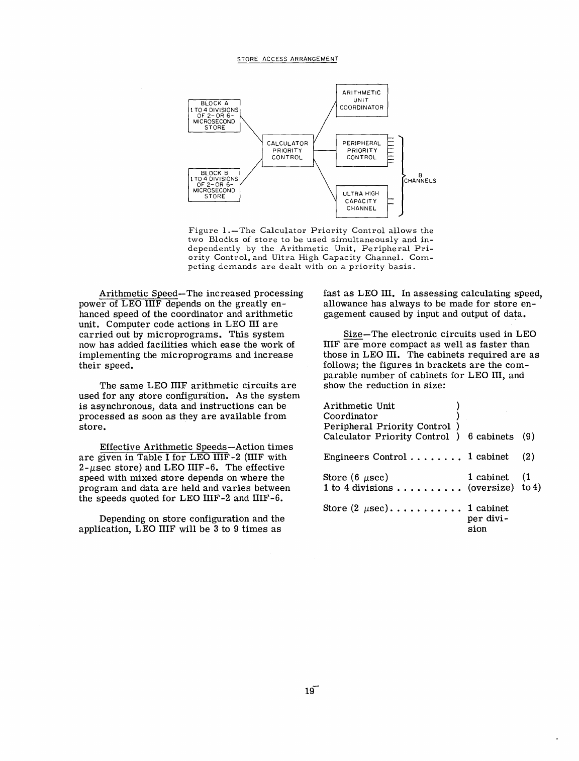
STORE
ACCESS
ARRANGEMENT
BLOCK
A
1
TO
4 DIVISIONS
OF2-0R6-
MICROSECOND
STORE
BLOCK B
1
TO
4 DIVISIONS
OF
2-0R
6-
MICROSECOND
STORE
ARITHMETIC
UNIT
COORDINATOR
PERIPHERAL
PRIORITY
CONTROL
ULTRA
HIGH
CAPACITY
CHANNEL
8
CHANNELS
Figure
1.
-
The
Calculator
Priority
Cont
rol
allows
the
two
Blocks
of
store
to
be
used
simultaneously
and
in-
dependently
by
the
Arithmetic
Unit,
Peripheral
Pri-
ority
Control,
and
Ultra
High
Capacity
Channel.
Com-
peting
demands
are
dealt
with
on
a
priority
basis.
Arithmetic
Speed-The
increased
processing
power
of LEO IIIF depends on
the
greatly
en-
hanced
speed
of
the
coordinator
and
arithmetic
unit.
Computer
code
actions
in
LEO III
are
carried
out
by
microprograms.
This
system
now
has
added
facilities
which
ease
the
work
of
implementing
the
microprograms
and
increase
their
speed.
The
same
LEO IIIF
arithmetic
circuits
are
used
for
any
store
configuration.
As
the
system
is
asynchronous,
data
and
instructions
can
be
processed
as
soon
as
they
are
available
from
store.
Effective
Arithmetic
Speeds-Action
times
are
given
in
Table
I
for
LEO
IIIF-2
(IIIF
with
2-llsec
store)
and LEO
IIIF-6.
The
effective
speed
with
mixed
store
depends on
where
the
program
and
data
are
held
and
varies
between
the
speeds
quoted
for
LEO
IIIF-2
and
IIIF-6.
Depending
on
store
configuration
and
the
application,
LEO IIIF
will
be
3 to 9
times
as
fast
as
LEO III. In
assessing
calculating
speed,
allowance
has
always
to be
made
for
store
en-
gagement
caused
by
input and output of
data.
Size-The
electronic
circuits
used
in
LEO
IIIF
are
more
compact
as
well
as
faster
than
those
in
LEO
III. The
cabinets
required
are
as
follows;
the
figures
in
brackets
are
the
com-
parable
number
of
cabinets
for
LEO III, and
show
the
reduction
in
size:
Arithmetic
Unit
Coordinator
Peripheral
Priority
Control
Calculator
Priority
Control
Engineers
Control
0 •
6
cabinets
1
cabinet
(9)
(2)
Store
(6 Ilsec)
1 to 4
divisions
.•
1
cabinet
(1
(oversize)
to
4)
Store
(2
Ilsec).
. • • • • • • •
•.
1
cabinet
per
divi-
sion
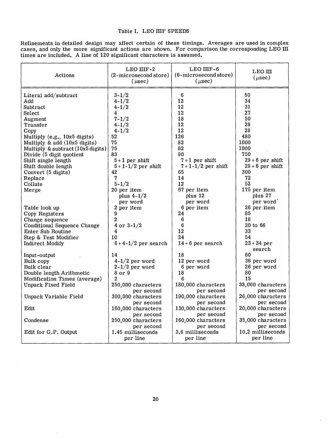
Table
I.
LEO
IDF
SPEEDS
Refinemen:ts
in
detailed
design
may
affect
certain
of
these
timings.
A"erages
are
used
in
complex
cases,
and
only
the
more
significant
actions
are
shown.
For
comparison
the
corresponding
LEO
III
times
are
included.
A
line
of 120
significant
characters
is
assumed.
LEO
IIIF-2
LEO
IIIF-6
LEO
III
Actions
(2-microsecond
store)
(6-microsecond
store)
( j1.sec)
(
j1.sec)
( j1.sec)
Literal
add/subtract
3-1/2
6 50
Add
4-1/2
12 34
Subtract
4-1/2
12
31
Select
4 12 27
Augment
7-1/2
18 50
Transfer
4-1/2
12 28
Copy
4-1/2
12 28
Multiply
(e.g.,
10x5
digits)
52
126 480
Multiply
&
add
(1
Ox5
digits)
75 82 1000
Multiply
&
subtract
(10x5
digits)
75 82 1000
Divide
(5
digit
quotient
83 90 750
Shift
single
length
5 + 1
per
shift
7 + 1
per
shift
29 + 6
per
shift
Shift double
length
5 +
1-1/2
per
shift
7 +
1-1/2
per
shift
29
+ 6
per
shift
Convert
(5
digits)
42
65 300
Replace
7 14 72
Collate
5-1/2
12
52
Merge
20
per
item
67
per
item
175
per
item
plus
4-1/2
plus
12
plus
27
per
word
per
word
per
word'
Table
look
up
2
per
item
6
per
item
26
per
item
Copy
Registers
9 24 85
Change
sequence
2 6 18
Conditional
Sequence
Change 4
or
3-1/2
6 20
to
66
Enter
Sub
Routine
4 12 33
Step
&
Test
Modifier
10 24 54
Indirect
Modify 6 +
4-1/2
per
search
14 + 6
per
search
23 + 34
per
search
Input-output
14 18 80
Bulk
copy
4-1/2
per
word
12
per
word
36
per
word
Bulk
clear
2
-1/2
per
word
6
per
word
26
per
word
Double
length
Arithmetic
8
or
9 18 80
Modification
Times
(average)
2 6 15
Unpack
Fixed
Field
250,000
characters
180,000
characters
33,000
characters
per
second
per
second
per
second
Unpack
Variable
Field
300,000
characters
190,000
characters
26,000
characters
per
second
per
second
per
second
Edit
160,000
characters
130,000
characters
20,000
characters
per
second
per
second
per
second
Condense
250,000
characters
160,000
characters
35,000
characters
per
second
per
second
per
second
Edit
for
G.P.
Output 1.45
milliseconds
3.6
milliseconds
10.2
milliseconds
per
line
per
line
per
line
20
ZAM 2
Instytut Maszyn A1atematycznych
Warsaw, Poland
The
ZAM-2
Computer
is
a
small-size
elec-
tronic
digital
computer
designed
for
solving
numerical,
statistical,
and
some
data
processing
computation
problems
in
science,
industry,
business,
and
commerce.
When
designing
this
computer,
high
relia-
bility
as
well
as
flexibility
of
applications
and
extremely
simple
programming
(SAKP-
autocode)
were
taken
into
account.
Due
to
these
advantages,
the
ZAM-2
Computer
is
able
to
save
time
and
money
solving
the
wide
range
of
problems
in
different
fields
such
as
Structural
Analysis,
Linear
Programming,
Transportation
Problems,
Aircraft
Construction,
Ship
Construc-
tion,
Geodesic
Calculations,
Chemical
Engi-
neering,
Electrical
Engineering,
Aero
and
Hy-
drodynamics'
Nuclear
Physics,
Optics,
and
the
like.
The
ZAM-2
Computer
is
constructed
of
exchangeable
plug-in-units.
It
contains
about
850
electronic
valves,
6000
germanium
diodes,
and
500
transistors.
Only
long-life
electronic
valves
(10,000
hours
guaranteed)
are
used.
Internal
Structure
Serial
computer
Synchronous
operation
Binary
fixed-point
arithmetic
Single-address
instruction
modification
by
means
of one
18-bit
B-register
Programming
Symbolic
Address
System
(SAS)
SAKO-autocode
Library
of
subroutines
(including
linear
programming
algorithms
and
floating-
subroutines)
Word
Length
36
bits
(so
called
"long
word")
or
18
bits
("short
word");
each
long
word
may
com-
prise
two
instructions
21
Working
Storage
Magnetostrictive
nickel
delay
lines
1024
short
words
Average
access
time:
0.36
milliseconds
maximum
Maximum
access
time:
0.72
milliseconds
Auxiliary
Storage
Magnetic
drum
16,384
long
words
1500
rpm
Maximum
of two
drums
may
be
connected
Clock
Rate
405
kc
Basic
Computer
Cycle
90
/lsec
Fixed-Point
Operations
Addition: 90
/lsec
Subtraction:
90
/lsec
Multiplication:
3240
/lsec
Division:
3240
/lsec
Average
Operating
Speed
(Fixed-Point)
Addition
and
subtraction:
100
op/
sec
Multiplication
and
division:
260
op/
sec
Data
Input
High-speed
tape
reader,
using
five
channels
300
characters
per
second
maximum
Maximum
of two
readers
may
be
connected
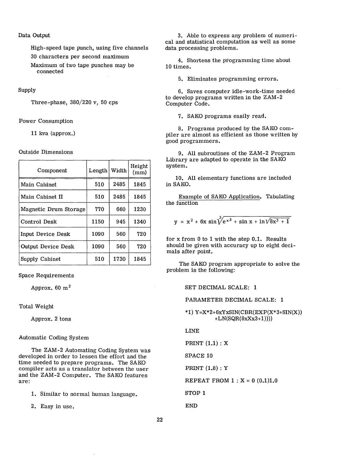
Data
Output
High-speed
tape
punch,
using
five
channels
30
characters
per
second
maximum
Maximum
of two
tape
punches
may
be
connected
Supply
Three-phase,
380/220
v, 50
cps
Power
Consumption
11
kva
(approx.)
Outside
Dimensions
Component
Length
Width
Height
(mm)
Main
Cabinet
510 2485 1845
Main
Cabinet
II
510 2485 1845
Magnetic
Drum
Storage
770 660 1230
Control
Desk
1150 945 1340
Input
Device
Desk
1090 560 720
Output
Device
Desk
1090 560 720
Supply
Cabinet
510 1730 1845
Space
Requirements
Approx.
60
m 2
Total
Weight
Approx.
2 "tons
Automatic
Coding
System
The
ZAM-2
Automating
Coding
System
was
developed
in
order
to
lessen
the
effort
and
the
time
needed
to
prepare
programs.
The
SAKO
compiler
acts
as
a
translator
between
the
user
and
the
ZAM-2
Computer.
The
SAKO
features
are:
1.
Similar
to
normal
human
language.
2.
Easy
in
use.
22
3.
Able
to
express
any
problem
of
numeri-
cal
and
statistical
computation
as
well
as
some
data
processing
problems.
4.
Shortens
the
programming
time
about
10
times.
5.
Eliminates
programming
errors.
6.
Saves
computer
idle-work-time
needed
to
develop
programs
written
in
the
ZAM-2
Computer
Code.
7.
SAKO
programs
easily
read.
8.
Programs
produced
by
the
SAKO
com-
piler
are
almost
as
efficient
as
those
written
by
good
programmers.
9.
All
subroutines
of
the
ZAM-2
Program
Library
are
adapted
to
operate
in
the
SAKO
system.
10.
All
elementary
functions
are
included
in
SAKO.
Example
of SAKO
Application.
Tabulating
the
function
for
x
from
0
to
1
with
the
step
0.1.
Results
should
be
given
with
accuracy
up
to
eight
deci-
mals
after
point.
The
SAKO
program
appropriate
to
solve
the
problem
is
the
following:
SET
DECIMAL SCALE: 1
PARAMETER
DECIMAL SCALE: 1
*1) Y=X*2+6xYxSIN(CBR(EXP(X*3+SIN(X))
+LN(SQR(8xXx3+1))))
LINE
PRINT
(1.1) : X
SPACE
10
PRINT
(1.8) : Y
REPEAT
FROM 1 : X = 0
(0.1)1.0
STOP
1
END
Some
details
of
the
ari~hmetic
formula
must
be explained, namely
x * 2
denotes
X2,
CBR
denotes
cubic
root
operation,
and
SQR
denotes
square
root
operation.
The
same
program
written
in
the
ZAM-2
Com-
puter
Code
consists
of two
or
three
hundred
in-
structions.
An
experienced
programmer
would
need
at
least
4
hours
to
prepare
it.
After
the
SAKO
program
is
recorded
on
five-level
paper
tape,
the
tape
is
read
into
the
ZAM-2
Computer.
The
SAKO
compiler
inter-
prets
it
and PRODUCES A PROGRAM IN ZAM-2
COMPUTER CODE READY TO BE RUN IN
ANY
ZAM-2. The
program
may be
taken
from
the
Computer
either
in
the ZAM-2 Symbolic Code
or
in
the
Internal
Binary
Form.
Details
are
available
in
refs.
1 and 2.
1
L.
LU
ZASZEWICZ,
"SAKO
-
An
Automatic
Coding
System,"
Ann.
Rev.
in
Autom.
Progr.
22,
1961.
A.
MAZURKIEWICZ,
"Arithmetic
Formulae
and
the
Use
of
Subroutines
in
SAKO,"
Ann.
Rev.
in
Autom.
Progr.
2,
1961.
Computing
Center
Shape
Air
Defence Technical Centre
The Hague, Netherlands
The SHAPE
Air
Defense
Technical
Centre
in
The Hague
installed
a
32
K IBM 704 (with
seven
tapes)
and
a 4 K
tape
1401
in
February
1962. The Royal McBee
LGP-30
has
been
re-
tained.
A Chronolog Digital
Clock
was
attached
to
the
704
in
August 1962 and
the
Floating
Point
Trap
Feature
in
September.
Current
areas
of
application
of
the
system
include:
1.
Systems
simulation,
such
as
tracking
studies,
technical
and
operational
studies
of
ground
environment
systems,
and
air
defense
weapons coordination;
2.
Information
requirement
and
decision
models
for
study of
electronic
data
processing
in
integrated
command
and
control;
3. Reduction of
radar
flight
test
data.
Available
software
includes
FORTRAN,
IPL
5,
and
NELIAC.
DT
12
Data
Transmission
System
Standard Elektrik Lorenz A.G.
Stuttgart, Germany
Data
Transmission
over
Long
Distances
with
DT
12-Smooth
operation
of
present-day
industry
and
public
administration
is
to
a
large
extent
dependent on
the
speeds
at
which
urgent
information
can
be
transmitted
and
processed.
This
information
may
consist
of
data,
for
ex-
ample
the
accounting
records
collected
during
a
business
day
by
distant
branch
offices
of
an
enterprise,
which have to be
transmitted
to
the
central
office
for
processing
as
soon
as
possi-
ble.
These
data
are
in
most
cases
obtained
by
machine
methods
and
are
evaluated
by
computers.
The
problem
faced
was
to develop a
trans-
mission
system
providing
high-speed,
error-free,
23
and
economical
transmission
of
such
data
over
existing
communication
lines,
e.g.,
telephone
circuits.
The
data
transmission
system
DT
12
solves
this
problem
because
it
features:
High Speed
Operation-The
transmission
speed
is
600
or
1200 bauds,
in
compliance
with
recommendations
of
the
German
Post
Office
and CCITT;
therewith
it
meets
requirements
for
international
communications.
For
com-
parison:
Telex
messages
are
transmitted
at
a
speed
of 50
to
75
bauds.
Error
Free
Operation-Transmission
errors
due
to
noisy
lines
are
automatically
detected,
and
automatically
corrected
by
reiterative
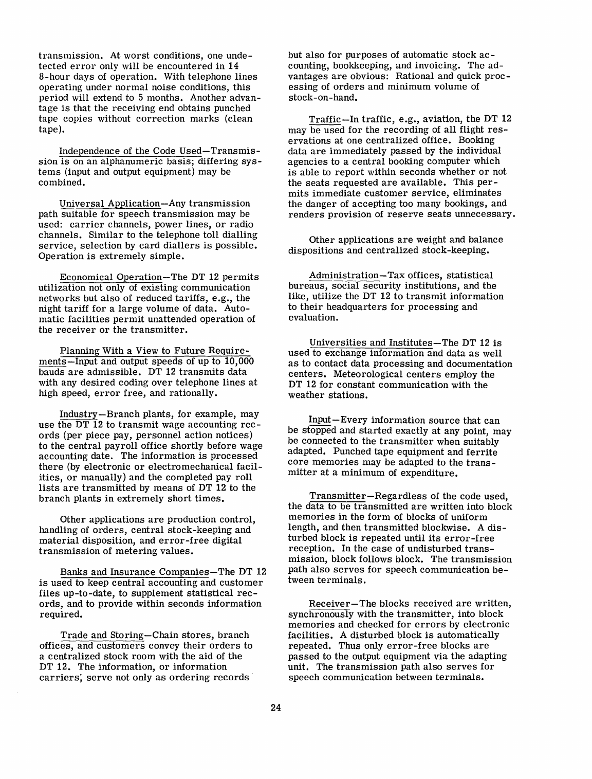
transmission.
At
worst
conditions, one
unde-
tected
error
only will be
encountered
in
14
8-hour
days
of
operation.
With telephone
lines
operating
under
normal
noise
conditions,
this
period
will extend to 5
months.
Another
advan-
tage
is
that
the
receiving
end obtains punched
tape
copies
without
correction
marks
(clean
tape).
Independence of
the
Code
Used-Transmis-
sion
is
on
an
alphanumeric
basis;
differing
sys-
tems
(input and output equipment) may be
combined.
Universal
Application-Any
transmission
path
suitable
for
speech
transmission
may be
used:
carrier
channels,
power
lines,
or
radio
channels.
Similar
to
the
telephone
toll
dialling
service,
selection
by
card
diallers
is
possible.
Operation
is
extremely
simple.
Economical
Operation-The
DT
12
permits
utilization
not only of
existing
communication
networks
but
also
of
reduced
tariffs,
e.g.,
the
night
tariff
for
a
large
volume of
data.
Auto-
matic
facilities
permit
unattended
operation
of
the
receiver
or
the
transmitter.
Planning
With a View to
Future
Require-
ments-Input
and output
speeds
of up to 10,000
bauds
are
admissible.
DT
12
transmits
data
with any
desired
coding
over
telephone
lines
at
high
speed,
error
free,
and
rationally.
Industry-Branch
plants,
for
example,
may
use
the
DT
12
to
transmit
wage accounting
rec-
ords
(per
piece
pay,
personnel
action
notices)
to
the
central
payroll
office
shortly
before
wage
accounting
date.
The
information
is
processed
there
(by
electronic
or
electromechanical
facil-
ities,
or
manually) and
the
completed
pay
roll
lists
are
transmitted
by
means
of DT
12
to
the
branch
plants
in
extremely
short
times.
Other
applications
are
production
control,
handling of
orders,
central
stock-keeping
and
material
disposition,
and
error-free
digital
transmission
of
metering
values.
Banks and
Insurance
Companies-The
DT
12
is
used
to
keep
central
accounting
and
customer
files
up-to-date,
to
supplement
statistical
rec-
ords,
and to
provide
within
seconds
information
required.
Trade
and
Storing-Chain
stores,
branch
offices, and
customers
convey
their
orders
to
a
centralized
stock
room
with
the
aid
of
the
DT 12. The
information,
or
information
carriers;
serve
not only
as
ordering
records
24
but
also
for
purposes
of
automatic
stock
ac-
counting, bookkeeping, and invoicing.
The
ad-
vantages
are
obvious:
Rational
and quick
proc-
essing
of
orders
and
minimum
volume of
stock
-on
-hand.
Traffic-In
traffic,
e.g.,
aviation,
the
DT
12
may be
used
for
the
recording
of
all
flight
res-
ervations
at
one
centralized
office. Booking
data
are
immediately
passed
by
the individual
agencies
to a
central
booking
computer
which
is
able
to
report
within
seconds
whether
or
not
the
seats
requested
are
available.
This
per-
mits
immediate
customer
service,
eliminates
the
danger
of
accepting
too many bookings, and
renders
provision
of
reserve
seats
unnecessary.
Other
applications
are
weight and
balance
dispositions
and
centralized
stock-keeping.
Administration-Tax
offices,
statistical
bureaus,
social
security
institutions,
and
the
like,
utilize
the
DT 12
to
transmit
information
to
their
headquarters
for
processing
and
evaluation.
Universities
and
Institutes-The
DT
12
is
used
to exchange
information
and
data
as
well
as
to
contact
data
processing
and documentation
centers.
Meteorological
centers
employ
the
DT
12
for
constant
communication
with
the
weather
stations.
Input-Every
information
source
that
can
be stopped and
started
exactly
at
any point,
may
be connected to
the
transmitter
when
suitably
adapted.
Punched
tape
equipment
and
ferrite
core
memories
may be
adapted
to
the
trans-
mitter
at
a
minimum
of
expenditure.
Transmitter-Regardless
of
the
code
used,
the
data
to be
transmitted
are
written
into block
memories
in
the
form
of blocks of
uniform
length, and
then
transmitted
blockwise. A
dis-
turbed
block
is
repeated
until
its
error-free
reception.
In
the
case
of
undisturbed
trans-
misSion, block follows block. The
transmission
path
also
serves
for
speech
communication
be-
tween
terminals.
Receiver-The
blocks
received
are
written,
synchronously
with
the
transmitter,
into block
memories
and
checked
for
errors
by
electronic
facilities.
A
disturbed
block
is
automatically
repeated.
Thus only
error-free
blocks
are
passed
to
the
output
equipment
via
the
adapting
unit.
The
transmission
path
also
serves
for
speech
communication
between
terminals.
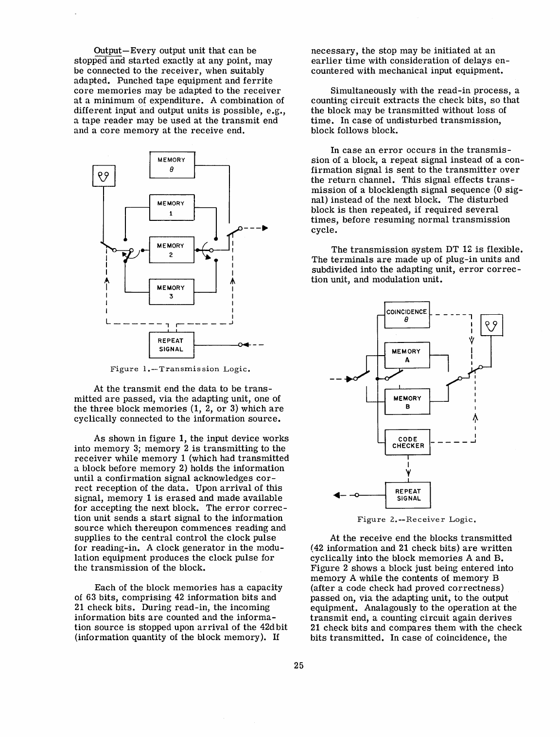
Output-Every
output
unit
that
can
be
stopped and
started
exactly
at
any point, may
be
connected
to
the
receiver,
when
suitably
adapted.
Punched
tape
equipment
and
ferrite
core
memories
may be
adapted
to
the
receiver
at
a
minimum
of
expenditure.
A combination of
different
input
and output
units
is
possible,
e.g.,
a
tape
reader
may be
used
at
the
transmit
end
and a
core
memory
at
the
receive
end.
r:
MEMORY
1
~
ME;ORY
#n_~
I
I
~
I
I
I
I I
I
L - - - - -
-,
r-
--
- - -
..J
I
RE~E~T
04---
_
SIGNAL
Figure
l.---Transrnis
sion
Logic.
At
the
transmit
end
the
data
to be
trans-
mitted
are
passed,
via
the
adapting
unit, one of
the
three
block
memories
(1, 2,
or
3) which
are
cyclically
connected to
the
information
source.
As
shown
in
figure
1,
the
input device
works
into
memory
3;
memory
2
is
transmitting
to
the
receiver
while
memory
1 (which had
transmitted
a block
before
memory
2)
holds
the
information
until
a
confirmation
signal
acknowledges
cor-
rect
reception
of
the
data.
Upon
arrival
of
this
signal,
memory
1
is
erased
and
made
available
for
accepting
the next block. The
error
correc-
tion
unit
sends
a
start
signal
to
the
information
source
which
thereupon
commences
reading
and
supplies
to
the
central
control
the
clock
pulse
for
reading-in.
A
clock
generator
in
the
modu-
lation
equipment
produces
the
clock
pulse
for
the
transmission
of
the
block.
Each
of
the
block
memories
has
a
capacity
of
63
bits,
comprising
42
information
bits
and
21
check
bits.
During
read-in,
the
incoming
information
bits
are
counted and
the
informa-
tion
source
is
stopped upon
arrival
of
the
42d
bit
(information
quantity
of
the block
memory).
If
25
necessary,
the
stop
may be
initiated
at
an
earlier
time
with
consideration
of
delays
en-
countered
with
mechanical
input equipment.
Simultaneously with the
read-in
process,
a
counting
circuit
extracts
the
check
bits,
so
that
the
block
may
be
transmitted
without
loss
of
time.
In
case
of
undisturbed
transmission,
block follows block.
In
case
an
error
occurs
in
the
transmis-
sion
of a block, a
repeat
signal
instead
of a
con-
firmation
signal
is
sent
to
the
transmitter
over
the
return
channel.
This
signal
effects
trans-
mission
of a blockiength
signal
sequence
(0
sig-
nal)
instead
of
the
next block. The
disturbed
block
is
then
repeated,
if
required
several
times,
before
resuming
normal
transmission
cycle.
The
transmission
system
DT
1~
is
flexible.
The
terminals
are
made
up of
plug-in
units
and
subdivided into
the
adapting unit,
error
correc-
tion
unit, and modulation
unit.
~-
-Q---i
I
'f
Figure
2.--Receiver
Logic.
At
the
receive
end
the
blocks
transmitted
(42
information
and
21
check
bits)
are
written
cyclically
into
the block
memories
A and B.
Figure
2 shows a block
just
being
entered
into
memory
A while
the
contents
of
memory
B
(after
a code
check
had
proved
correctness)
passed
on,
via
the
adapting unit,
to
the
output
equipment. Analagously to
the
operation
at
the
transmit
end, a counting
circuit
again
derives
21
check
bits
and
compares
them
with
the
check
bits
transmitted.
In
case
of coincidence,
the

error
correction
unit
delivers
a
start
signal
to
the
information
output,
the
information
output
equipment
commences
receiving
and
supplies
the
clock
pulse
for
the
read-out
of
the
error-
free
block.
During
read
-out,
the
information
bits
are
counted and
the
output equipment
is
stopped
at
the
42d
bit.
With
consideration
of
the
delays
en-
countered
with
mechanical
equipment,
the
stop
may
be
initiated
at
an
earlier
time.
In
case
the
code
check
revealed
an
error,
the
output
equip-
ment
does
not
receive
a
start
signal.
The
dis-
turbed
information
block
as
well
as
the
follow-
ing block
are
erased,
instead.
The
receiver
26
transmits
a
repeat
signal
instead
of
the
con-
firmation
signal
over
the
return
channel.
The
o block,
the
transmission
of which
is
initiated
thereby,
announces a
repetition
of
the
disturbed
block. Only upon
error-free
reception
of
this
block
is
the
normal
reception
cycle
re-
established.
Synchronism
of
transmission
is
achieved
again
even
after
disturbances
of any
length.
The
transmission
system
DT
12
does
not
require
any
specific
signal
code.
Counting of
bits
during
input and output
permits
reading
of
various
codes
into
the
block
memories.
Posi-
tions
unused
can
be
filled
in
with
zeros.
Miscellaneous
Tactical
Moving
Map
Display
Computing Devices
of
Canada Ltd.
Ottawa 4, Canada
The inadequacy of
the
counter-type
display
for
the
indication
of
present
position
to
the
pilots
of
low-level,
high-speed,
tactical
aircraft
has
long
been
recognized.
In
order
for
a
pilot
to be
effective
on a
low-level
mission,
he
must
be
continuously
aware
of
the
relation
between
his
current
flight
path
and
the
surrounding
and
ap-
proaching
terrain.
To
meet
this
need
the
Tacti-
cal
Moving Map Display,
recently
introduced
by
Computing
Devices,
provides
for
the
pilot a
dis-
play of a
brightly
lit
topographic
map,
the
centre
of
which
will
at
all
times
represent
his
position
and
with a
radial
vector
marking
his
track.
In
addition,
to
overcome
cockpit
space
limitations,
the
versatility
of
the
instrument
can
be
increased
by
including optional
features
which
display
track
error,
desired
course,
and
range
to
destination.
These
features
can
be added without
in-
creasing
the
size
of
the
basic
instrument.
The
design
of
the
instrument
has
been
strongly
in-
fluenced
by
considerations
of
the
operational
stresses
imposed
on
the
tactical
pilot.
The
re-
sult
is
a
semi-automatic
navigation
instrument
which
requires
a
minimum
of
manipulative
ac-
tions
on
the
part
of
the
pilot.
Anyone
of a wide
range
of
sensors
and navigation
computers
in-
cluding Computing
Devices
Position
& Homing
Indicator
(PHI)
or
Global Lightweight
Airborne
Navigation
computer
Equipment (GLANCE)
can
furnish
the
necessary
inputs.
Present
Position
Indication
The
display
consists
of a
5-inch
diameter
screen
upon which a
correctly
oriented
colour
image
of
the
map
is
projected.
Present
posi-
tion
is
indicated
by
a
small
fixed
circle
in
the
middle
of
the
screen.
As
the
aircraft
moves
over
the
terrain
the
map
image
moves
corre-
spondingly along the
track
line
and
past
the
present
position
circle.
Steering
Indications
The
unit
also
presents
an
integrated
dis-
play of
other
information
required
by
the
pilot
27
for
effective
aircraft
navigation.
Track,
course,
and
range-to-destination
are
presented
on
counters.
Track
error
is
indicated
by
a
triangular
shaped
pointer
which
moves
around
the
circumference
of
the
map
display
area.
To
make
good a
track
to a
destination
requires
only
that
the
aircraft
be
steered
so
that
the
track
error
indicator
and
the
aircraft
track
line
are
made
coincident.
The
pilot
is
continuously
free
to
deviate
from
his
flight
plan
anywhere
within
the
map
coverage
area
of 1800 x 1800
nautical
miles.
Map Display
The
maps
used
for
the
display
are
standard
1:500,000
air
navigation
charts
reproduced
on
a
single
strip
of
35-mm
colour
film.
This
strip
provides
continuous
coverage
of
an
area
1800 x
1800
nautical
miles.
A
map
drive
unit
within·
the
instrument
orients
the
film
strip
and
moves
it
automatically
and
continuously
in
accordance
with
the
path
of
the
aircraft.
The
pilot
is
not
required
to
make
any
adjustments
to
the
display
other
than
correcting
the
position
when
neces-
sary.
The map
image
is
presented
in
full
colour
and
is
clearly
visible
over
a wide
range
of
am-
bient
light
conditions.
The high
image
resolu-
tion
of
the
system
permits
easy
recognition
of
symbols
and
lettering
as
small
as
1/32
inch.
Map
filmstrips
of
operational
areas
can
be
prepared
by
Computing
Devices
of Canada
or
by
any
other
suitably
equipped
facility.
Look-Ahead,
Destination
Insertion
and
Position
Up-Dating
Facilities
In
the
AHEAD mode,
the
pilot
may
select
any
direction
and manually
slew
the
map
to
dis-
play any
area.
In
this
mode
the
range
and
course
counters
will
display
the
range
and
bear-
ing of the ground
feature
located
in
the·
present
position
indicator
relative
to
the
aircraft's
ac-
tual
position.
Manually
controlled
map
move-
ment
is
achieved
by
the
use
of
the
course
and
range
control
knobs
on
the
unit
face.
The
map
display,
at
command,
automatically
returns
to
present
position
after
the
look-ahead
operation.
When
the
mode
switch
is
in
the
LEG
position
the
pilot
may
insert
the
range
and
course
of
his
next
destination.
When
the
display
is
returned
to
the
TRAC K mode
the
range
counter
will count
down
the
distance
to
go
and
the
course
.counter
will show
the
bearing
to fly. An
alternate
method
of
destination
insertion
is
by
means
of
the
PHI-
type
station
selector.
If
an
"on-top"
position
fix
indicates
the
displayed
position
to
be
incor-
rect,
it
is
possible
to
up-date
the
display
by
setting
the
mode
switch
to
the
FIX
position
and
adjusting
the
range
and
course
controls.
When
the
display
is
not
in
the
TRAC K mode a
limited
memory
storage
facility
ensures
that
no
posi-
tion
information
is
lost.
Display
Controls
On
the
pilot's
instrument,
map
orientation
is
slaved
to
the
aircraft
track.
It
is
possible
however,
to
orient
the
map
to
North
at
12
o'clock
by
depressing
the
spring-loaded
course
knob.
Heading
orientation
can
be
provided
in
lieu
of
track
orientation
if
desired.
In both
operating
modes
the
current
track
of the
aircraft
is
shown
by
a
radial
line
from
the
centre
of
the
display.
A map'
scale
control
enables
two
map
scale
factors,
1:500,000 and 1:1,000,000 to be
se-
lected.
The 1:500,000
scale
is
provided
to
en-
able
the
pilot
to
distinguish
detail
of topographic
features
for
low
altitude
work
and
provides
a
viewing
radius
of 17
nautical
miles
from
pres-
ent
position.
The 1:1,000,000
scale
provides
a
viewing
radius
of 34
nautical
miles.
The
AHEAD
feature
extends
this
viewing
radius
to
any
range
the
pilot
may
desire,
within the
limits
of
the
equipment. Additional
controls
on
the
in-
strument
enable
the
pilot
to
set
the
brightness
level
of
the
map
image.
An optional
automatic
brightness
level
of
the
map
image.
An optional
automatic
brightness
feature
can
be
provided
to
maintain
the
brightness
level,
relative
to
am-
bient light,
at
any
desired
setting.
Alternate
Display
Capability
Supplementary
flight
information
other
than
topographic
map
detail
can
be
incorporated
on
the
film
strip
for
display
at
will.
Typical
of
these
alternate
displays
are
target
or
airport
approach
data,
emergency
operating
procedures
and
air
traffic
control
procedures.
'
28
Input
Information
Sources
The
map
display
unit
is
operated
in
conjunc-
tion
with a
coupler
unit
which
transforms
infor-
mation
from
different
types
of
sensors
and
navi-
gation
computers
into a
form
suitable
for
the
map
display
unit.
An optional
feature
for
the
computation
and
display
of
range
and
bearing
to
destination
can
be
furnished
if
the
navigation
computer
does
not
provide
these
as
outputs.
Specifications
Operational
Limits:
Range
Counter
1000
nautical
miles
Course
Counter
Track
Counter
Area
of
Coverage
1800 X 1800
nautical
miles
(approx)
Maximum Speed 2000
knots
Power
Requirements:
Weight:
Display
Unit
114 v, 400
cps,
55
VI
26
v, 400
cps,
35
w
28
v dc, 185 w
10 lb (approx)
Computer
Coupler
12
lb
(approx)
Dimensions:
Display
Unit 6 x 6 x
11-1/4
inches
Computer
Coupler
3-9/16
x
19
x 7
-5/8
inches
(3/8
ATR long)
Accuracy
Limits:
Environmental
Performance:
Display
Unit
1
mile
+ 1/2%
dis-
tance
flown
MIL-E-5400E
Class
1
Computer
Coupler
MIL-E-5400E
Class
2
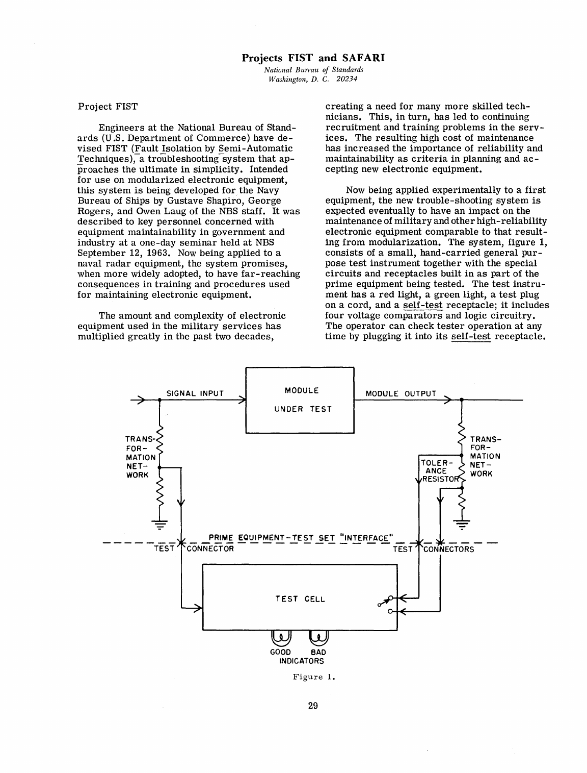
Projects
FIST
and
SAFARI
National Bureau
of
Standards
Washington,
D.
C.
20234
Project
FIST
Engineers
at
the
National
Bureau
of
Stand-
ards
(U.S.
Department
of
Commerce)
have
de-
vised
FIST
(Fault
Isolation
by
Semi-Automatic
Techniques),-
a
troubleshooting-system
that
ap-
proaches
the
ultimate
in
simplicity.
Intended
for
use
on
modularized
electronic
equipment,
this
system
is
being developed
for
the
Navy
Bureau
of Ships
by
Gustave Shapiro,
George
Rogers,
and Owen Laug of
the
NBS
staff.
It
was
described
to
key
personnel
concerned
with
equipment
maintainability
in
government
and
industry
at
a
one-day
seminar
held
at
NBS
September
12, 1963.
Now
being
applied
to
a
naval
radar
equipment,
the
system
promises,
when
more
widely adopted, to have
far-reaching
consequences
in
training
and
procedures
used
for
maintaining
electronic
equipment.
The
amount
and
complexity of
electronic
equipment
used
in
the
military
services
has
multiplied
greatly
in
the
past
two
decades,
SIGNAL
INPUT
MODULE
creating
a
need
for
many
more
skilled
tech-
nicians.
This,
in
turn,
has
led
to continuing
recruitment
and
training
problems
in
the
serv-
ices.
The
resulting
high
cost
of
maintenance
has
increased
the
importance
of
reliability
and
maintainability
as
criteria
in
planning and
ac-
cepting
new
electronic
equipment.
Now
being
applied
experimentally
to
a
first
equipment,
the
new
trouble-shooting
system
is
expected
eventually
to
have
an
impact
on
the
maintenance
of
military
and
other
high-reliability
electronic
equipment
comparable
to
that
result-
ing
from
modularization.
The
system,
figure
1,
consists
of a
small,
hand-carried
general
pur-
pose
test
instrument
together
with
the
special
circuits
and
receptacles
built
in
as
part
of
the
prime
equipment being
tested.
The
test
instru-
ment
has
a
red
light, a
green
light, a
test
plug
on
a
cord,
and a
self-test
receptacle;
it
includes
four
voltage
comparators
and logic
circuitry.
The
operator
can
check
tester
operation
at
any
time
by
plugging
it
into
its
self-test
receptacle.
MODULE OUTPUT
UNDER
TEST
_
~!!!M.f
EQ~MENT-..!.E~T
~E.!.
~NTERFACE"_
CONNECTOR TEST
TEST
CELL
GOOD
BAD
INDICATORS
Figure
1.
29
TRANS-
FOR-
MATION
NET-
WORK
CONNECTORS
In
use,
the
test
set,
which
occupies
only a
fifth of a cubic foot,
gives
a
green
(good)
or
a
red
(bad)
indication
when plugged into
each
test
receptacle
at
which a
test
is
possible.
The
module
is
within
tolerance
if a good
indication
is
obtained.
If
neither
indicator
lights-the
no-
test
response-this
indicates
that
all
needed
in-
puts
are
not
present
at
the
module. The
opera-
tor
can
test
the
modules
in
any
order
with a
uniform
simple
procedure
for
all
types
of
tests.
He
can
save
time,
however, by
first
plugging
into
each
group
test
receptacle
to
localize
the
area
of
failure,
and
then
into
the
constituent
module
receptacles
to
find
the
defective module.
Circuits
needed
by
the
system
to
adapt
module
operational
parameters
for
good-bad
indication
by
the
test
instrument
are
in
the
prime
equipment. They
are
being
designed
with
subminiature
components
on
printed
cir-
cuit
boards,
so
they
can
be mounted on the
backs
of
the
module
test
receptacles.
All of
these
transformation
networks
are
passive,
permitting
the
measurement
of
properties
such
as
ac
and
dc
voltages,
frequency,
amplification,
voltage
waveforms,
impedance,
frequency
response,
and
a
variety
of
other
electronic
and
physical
meas-
urements.
Each
transformation
network
oper-
ates
to
permit
each
desired
operational
and
cir-
cuit
parameter
to be
sensed
as
small
voltages.
The
test
set
operates
by
comparing
two
voltages
for
each
test,
such
as
the
input to
an
amplifier
module and
its
output. The
design
of
the
transformation
network
is
such
that
it
con-
verts
the
amplifier
input
and
output
signals
into
voltages
of
comparable
magnitude
provided
that
the
amplification
is
within
design
tolerances.
The
test
set
comparator
determines
whether
or
not
these
voltages
have
comparable
magnitudes.
The output
signal
is
actually
obtained
alter-
nately
at
opposite
ends
of one of
the
resistors
in
the
attenuation
network,
the
components of
which
have
such
values
that
the
normal
attenuated
voltage
is
obtained
at
the
high end of
the
toler-
ance
resistor
for
a module of the
lowest
accept-
able
gain and
at
the
low end
for
the
highest-gain
module
acceptable.
Any module of
this
type
having a gain between
the
acceptable
limits
must
produce
an
output
signal
that
is
greater
than
the
ideal
level
when
sampled
at
one
end
of
the
tolerance
resistor
and
less
than
the
ideal
at
the
other
end.
The
comparator
input
is
switched
alter-
nately between
the
ends
of
the
tolerance
regis-
ter,
so
that
its
output
changes
polarity
in
testing
a module
characteristic
within
the
specified
limits.
This
makes
for
simplification
of
the
30
circuitry
and
the
indication.
The
comparator
drives
a
zero-crossing
detector
circuit
which
operates
the
green
(good)
indicator
light
if
the
comparator
output
changes
polarity
and
crosses
zero.
Failure
of
the
comparator
output to
re-
verse
polarity
(indicating a module
character-
istic
exceeding
either
limit)
causes
the
detector
to
energize
the
red
(bad)
indicator.
A
simple
one
cell
test
set
would
consist
of
two input
amplifiers,
identical
except
for
one
having a
switch
selecting
its
input
from
either
end
of
the
tolerance
resistor;
two
peak-to-peak
detectors
to
rectify
the
signals;
a
differential
dc
amplifier
to
compare
them;
a
zero-crossing
detector;
and logic
circuits.
Four
such
cells
in
each
test
set
permit
the
simultaneous
measure-
ment
of
interacting
module
parameters.
The
test
set
operator
needs
no
skill
or
training
to
identify and
replace
the
failed
module; he need
know no
more
about
electronics
or
the
equip-
ment
being
tested
than
the
maintenance
man
who
replaced
the
electric
light
bulbs. The
technicians
are
called
in
only if
the
"bulb
charger"
is
unable
to
find
the
malfunction,
as
in
the
case
of
faults
in
cabling
or
connector
wiring.
Project
SAFARI
FIST
design
techniques
not only
carryon
the
maintenance
revolution
already
started
by
modularization,
but have
already
sired
a
project
promising
an
even mo
re
radical
change
in
maintenance.
This
is
Project
SAFARI (Semi-
Automatic
Failure
Anticipation
Recording
Instrumentation),
a-system
of
measuring
and
recording
equipment
performance.
SAFARI
consists
of a
tester,
much
like
the
FIST
tester
except
that
it
presents
performance
figures
in
a
graphical
form
using
a
device
for
recording
and viewing module
performance
as
a function
of
time.
Project
SAFARI
uses
equipment
perform-
ance
measurements
obtained
from
a
test
device
similar
to
that
of FIST, but which
in
addition
graphically
plots
successive
measurements
for
comparison
with
an
established
rejection
level.
The
rate
at
which
the
performance
approaches
this
level
can
be
easily
monitored
and
the
module
replaced
before
the
rejection
level
is
reached.
This
procedure
could add a new
order
of
reliability
to
electronic
equipment
that
is
used
where
reliability
is
the
greatest
consideration.
The
greatest
impact
of
the
FIST
trouble-
shooting
system
is
expected
to
be
in
alleviating
the
shortage
of
capable
electronic
technicians,
by
enabling
unskilled
personnel
to
do many
of
the
required
tasks.
Secondary
effects
will be a
higher
level
of dependable
operation
due
to
better
maintenance,
reduced
numbers
of
tech-
nicians
to be
trained
and
the
accompanying
pos-
sibility
of
creating
a
small
elite
corps
of
tech-
nicians,
trained
in
greater
depth. While not
all
equipment
failures
can
be
troubleshot
by
means
of FIST,
repaired
by
module
replacement,
or
anticipated
by
SAFARI,
the
number
of
failures
that
respond
to
these
techniques
is
expected
to
be
sufficient
to
greatly
reduce
the
burden
of
troubleshooting
and
repair
now
performed
by
technicians.
Foreign-Currency
Scientific
Program
National Bureau
of
Standards
Washington,
D.
C. 20234
Scientific
groups
iIi
underdeveloped
coun-
tries
working
under
NBS
contracts
have shown
that
they
can
extend
the
research
capabilities
of
the
National
Bureau
of
Standards
(U
.S.
De-
partment
of
Commerce)
and
American
indus-
trial
and
scientific
interests
in
addition
to
raising
technological
levels
abroad.
This
fact
is
one of
the
first
conclusions
to
emerge
from
the
Bureau's
new
Foreign
Currency
Program.
In
the
year
and
one-half
since
the
program
was
instituted,
NBS
has
awarded
27
grants
and
contracts
to
support
technical
proj-
ects
in
India,
Israel,
and
Pakistan.
According
to
Dr.
Franz
L.
Alt,
coordinator
of
the
pro-
gram,
each
grant
or
contract
promises
to
con-
tribute
to one
or
more
of
the
Bureau's
basic
needs,
such
as
more
accurate
standards
of
measurement;
compilation
and
measurement
of
critical
data
or
standard
reference
data
on
physical
constants
and
properties
of
materials;
or
improved
methods
for
high
precision
measurement.
Most
of
the
projects
were
developed by
scientists
in
the
three
foreign
countries
with
the
cooperation
of
their
Bureau
counterparts.
Each
proposal
was
accepted
on
the
basis
of
its
contribution
to
the
Bureau's
mission,
its
gen-
eral
scientific
merit,
and
its
cost
in
relation
to
the
funds
presently
available.
Salaries
for
scientists
and
assistants,
equipment,
travel,
and
other
costs
of
research
can
be
provided
by
the
grants.
Funds
for
the
program-a
total
of $1,500,000
thus
far-were
appropriated
under
a
special
section
of
the
Agricultural
Trade
Development and
Assistance
Act of 1954.
It
is
expected
that
grants
and
con-
tracts
will
continue
to
be
awarded
as
relevant
proposals
are
received.
The
opportunity
to
participate
in
this
pro-
gram
arises
from
the
Agriculture
Trade
and
Development Act of 1954,
which
enabled
many
foreign
countries
to buy
surplus
U.S.
agricul-
tural
products
and
pay
for
them
in
local
cur-
rency
rather
than
in
dollars.
As
these
foreign
currencies
accumulate,
the
United
States
can
use
them
for
a
variety
of
purposes,
but only
in
the
country
in
which
they
originated.
When
these
funds
exceed
the
normal
needs
of
the
U.S.
Government,
as
has
happened
in
a few
countries,
the
Congress
may
authorize
the
use
of
some
of
the
surplus
for
scientific
purposes.
This
is
why
NBS
has
been
limited
to
three
countries,
although
the
program
may,
in
the
future,
be
extended
to
a few
others.
This
program
complements
the
work
nor-
mally
conducted by
the
Bureau
although
most
of
the
projects
would not have
top
priority
at
this
time.
All
of
the
studies,
however,
represent
work
that
NBS
should be doing and would
ulti-
mately
have to do
and
pay
for
in
dollars
if
foreign
currencies
were
not
available.
Since
this
research
can
be
conducted now,
the
Bureau
gets
the
advantage of top
level
scientific
re.;..
search
which
meets
timely
and
definite
needs.
Real
Printing
National Bureau
of
Standards
Washington,
D.
C.
20234
With the
cooperation
of
the
Mergenthaler
Linotype Company,
the
National
Bureau
of
Standards
has
prepared
a
volume,
entitled
31
"Experimental
Transition
Probabilities
for
Spectral
Lines
of Seventy
Elements,"
using
an
IBM 7090
computer
and
the
¥ergenthaler
Linofilm
System
of photographic type
setting
equipment.
The
tables
in
this
book
were
composed
by
a
photographic
composition
machine
controlled
by
the output of
the
digital
computer.
The
computer
generated
a
magnetic
tape
containing
all
of
the
printed
material,
including
column
headings,
decimal
tabular
material
and page
numbers.
In
addition
the
tape
contained
the
necessary
print-
ing
instructions
for
font
selection
and
page
lay-
out.
This
output
magnetic
tape
then
became
the
input to
the
photo-composition
machine
which
produced
auto-positive
films.
These
in
turn
32
were
used
to
produce
direct
offset
printing
plates
from
which
the
book
was
prepared.
In
the
future
the
output
magnetic
tape
will
be
run
through
a
converter
which will
produce
15-channel
paper
tape
which
in
turn
will
be-
come
the
input
to
the
commercially
available
photo
composition
machine.
The
fact
that
it
is
possible
to
use
many
different
fonts,
to
adjust
point
size,
to
use
su-
perscripts
and
subscripts,
and
so
on,
in
fact
to
do anything
that
is
done
by
the
present
hot
lead
techniques,
suggests
that
this
technique will
have wide
application.
