E220GEM Manual Ver 9.1
User Manual:
Open the PDF directly: View PDF ![]() .
.
Page Count: 318 [warning: Documents this large are best viewed by clicking the View PDF Link!]

1.0 Introduction
E220/E500 HP, EHP, & EHPi
MEDUIM CURRENT
ION IMPLANTER
GEM MANUAL
Revision 9.1
Varian Semiconductor Equipment Associates, Inc.
35 Dory Road
Gloucester, MA 01930-2297

WARNING
General Equipment Warning
Only persons trained in the operation and maintenance of Varian ion implanters should
attempt to perform these procedures.
Varian Semiconductor Equipment Associates Ion Implanters are complex systems that
contain high current, high voltage power supplies, gases under high pressure, hot
surfaces, toxic materials, ionizing and non- ionizing radiation and mechanical assemblies
that are in motion or which can move rapidly and powerfully in response to a command,
a component failure, or noise on a command line which is interpreted as a command.
These can represent significant hazards with the potential to cause the death of or
serious injury to any personnel not specifically trained in the operation and maintenance
of these machines. It is the “machine specific” knowledge gained in this training, which
makes the personnel aware of the nature and locations of the potential hazards and how
to avoid exposure to them while servicing the machines.
-------------------------------------------------------------------
This information in this document is proprietary to Varian Semiconductor Equipment
Associates and is intended solely for application to Varian equipment by Varian trained
personnel. It is not to be copied or disclosed to others without written permission from
Varian.
1.0 General Information
This document contains the following documentation, arranged in three parts, in accordance with SEMI GEM standard
E30-95, section 8:
General Information .
Manufacturer and product number
General description of equipment function
Function of the GEM interface
Software revision code
Changes from previous versions
Message Summary .
The message summary contains two lists of all messages understood and all messages sent by the
equipment in terms of their stream and function codes. All messages not listed on the received side are
implied to cause an error message to the host. All messages not listed on the sent side are assumed never to
be sent from the equipment.
Message Detail
The message detail contains the details for every message listed in the message summary. Messages that
appear on both the sent and received sides shall be detailed separately.
1.1 Manufacturer And Product Number
The purpose of this manual is to describe the GEM implementation for the E220HP / E500HP Ion Implanters.
1.2 General Description Of Equipment Function
The Varian E220HP / E500HP is a Medium Current Ion Implanter which processes one or two cassettes of wafers as
a batch, a single wafer at a time. A LOT ID (Material ID) can be specified for each cassette.
1.2.1 GEM Messages Defined
The following sections define the messages that are required for the GEM sub-system. Information in these sections
follow the SEMI documentation standard as defined in SEMI E5-95 section 8.
1.2.2 Messages From The E220
The following GEM SECS II transactions shall be implemented in GEM:

H --> E H <--E
S1F0 ABORT TRANSACTION S1
S1F1 A RE Y OU THERE REQUEST
S1F2 ON-LINE DATA
S1F13 ESTA BLISH COMMUNICA TIONS REQUEST
S1F14 ESTA BLISH COMMUNICATIONS ACKNOWLEDGE
S2F17 DATE AND TIME REQUEST
S2F18 DATE AND TIME DATA
S5F1 ALA RM REPORT SEND
S5F2 ALARM REPORT ACKNOWLEDGE
S6F1 TRACE DATA SEND
S6F2 TRACE DATA ACKNOWLEDGE
S6F5 MULTI-BLOCK DATA SEND INQUIRE
S6F6 MULTI-BLOCK GRANT
S6F11 EVENT REPORT SEND
S6F12 EVENT REPORT A CKNOWLEDGE
S7F1 PROCESS PROGRAM LOAD INQUIRE
S7F2 PROCESS PROGRAM LOAD GRANT
S7F3 PROCESS PROGRAM SEND
S7F4 PROCESS PROGRAM ACKNOWLEDGE
S7F5 PROCESS PROGRAM REQUEST
S7F6 PROCESS PROGRA M DA TA
S7F23 FORMATTED PROCESS PROGRAM SEND
S7F24 FORMATTED PROCESS PROGRAM ACKNOWLEDGE
S7F25 FORMATTED PROCESS PROGRAM REQUEST
S7F26 FORMATTED PROCESS PROGRAM DATA
S7F27 PROCESS PROGRAM VERIFICATION SEND
S7F28 PROCESS PROGRAM VERIFICATION ACKNOWLEDGE
S7F29 PROCESS PROGRAM VERIFICATION INQUIRE
S7F30 PROCESS PROGRAM VERIFICATION GRANT
S9F1 UNRECOGNIZED DEVICE ID
S9F3 UNRECOGNIZED STREAM TY PE
S9F5 UNRECOGNIZED FUNCTION TY PE
S9F7 ILLEGAL DATA
S9F9 TRANSACTION TIMER TIMEOUT
S9F11 DATA TOO LONG
S10F1 TERMINAL REQUEST
S10F2 TERMINAL REQUEST ACKNOWLEDGE
S10F7 MULTI-BLOCK NOT ALLOWED
1.2.3 Messages To The E220
The following GEM SECS II transactions shall be implemented in GEM:

H --> E H <--E
S1F0 ABORT TRANSA CTION S1
S1F1 ARE YOU THERE
S1F2 ON-LINE DATA
S1F3 SELECTED EQUIPMENT STA TUS REQUEST
S1F4 SELECTED EQUIPMENT STA TUS DA TA
S1F11 STATUS VARIABLE NAMELIST REQUEST
S1F12 STATUS VARIABLE NAMELIST REPLY
S1F13 ESTA BLISH COMMUNICATIONS REQUEST
S1F14 ESTA BLISH COMMUNICA TIONS REQUEST A CKNOWLEDGE
S2F13 EQUIPMENT CONSTA NT REQUEST
S2F14 EQUIPMENT CONSTANT DA TA
S2F15 NEW EQUIPMENT CONSTANT SEND
S2F16 NEW EQUIPMENT CONSTA NT ACKNOWLEDGE
S2F17 DATE AND TIME REQUEST
S2F18 DATE A ND TIME DATA
S2F23 TRA CE INITIA LIZ E SEND
S2F24 TRACE INITIALIZE ACKNOWLEDGE
S2F29 EQUIPMENT CONSTA NT NA MELIST REQUEST
S2F30 EQUIPMENT CONSTANT NA MELIST
S2F31 DATE A ND TIME SET REQUEST
S2F32 DATE A ND TIME SET ACKNOWLEDGE
S2F33 DEFINE REPORT
S2F34 ACKNOWLEDGE
S2F35 LINK EV ENT REPORT
S2F36 ACKNOWLEDGE
S2F37 ENA BLE/DISA BLE EV ENT REPORT
S2F38 ACKNOWLEDGE
S2F39 MULTI-BLOCK INQUIRE
S2F40 MULTI-BLOCK GRANT
S2F41 HOST COMMAND SEND
S2F42 HOST COMMAND A CKNOWLEDGE
S2F43 RESET SPOOLING STREAMS A ND FUNCTIONS
S2F44 RESET SPOOLING ACKNOWLEDGE
S2F45 DEFINE V A RIABLE LIMIT ATTRIBUTES
S2F46 VARIABLE LIMIT ATTRIBUTE ACKNOWLEDGE
S2F47 VARIABLE LIMIT ATTRIBUTE REQUEST
S2F48 VARIABLE LIMIT ATTRIBUTE SEND
S2F49 ENHANCED REMOTE COMMAND
S2F50 ENHANCED REMOTE COMMA ND A CKNOWLEDGE
S2F71 Initiate Processing Request ( Factory Automation Only)
S2F72 Initiate Processing Acknow ledge
S5F3 ENABLE/DISABLE ALARM SEND
S5F4 ACKNOWLEDGE
S5F5 LIST ALARMS
S5F6 ACKNOWLEDGE
S615 EVENT REPORT REQUEST
S6F16 EVENT REPORT DA TA
S6F19 INDIV IDUA L REPORT REQUEST
S6F20 INDIV IDUAL REPORT DA TA
S6F23 REQUEST SPOOLED DATA
S6F24 REQUEST SPOOLED DATA ACKNOWLEDGE
S7F1 PROCESS PROGRAM LOAD INQUIRE
S7F2 PROCESS PROGRAM LOAD GRANT
S7F3 PROCESS PROGRAM SEND
S7F4 PROCESS PROGRAM ACKNOWLEDGE
S7F5 PROCESS PROGRAM REQUEST
S7F6 PROCESS PROGRAM DATA
S7F17 DELETE PROCESS PROGRAM SEND
S7F18 DELETE PROCESS PROGRAM ACKNOWLEDGE
S7F19 CURRENT EPPD REQUEST
S7F20 CURRENT EPPD DATA
S7F23 FORMATTED PROCESS PROGRAM SEND
S7F24 FORMATTED PROCESS PROGRAM ACKNOWLEDGE
S7F25 FORMATTED PROCESS PROGRAM REQUEST
S7F26 FORMATTED PROCESS PROGRAM DATA

1.3 Function Of The GEM Interface
The GEM sub-system is composed of hardware and software. The hardware component is a SECS interface board, SIB-
311. The software has five components:
FORTH based GEM interface software which is integrated into the E220HP / E500HP control program.
A multi-tasking operating system to provide data sharing and intertask communication for the E220HP / E500HP
application and the GEM functions.
The GEM task, ‘C’ code to initialize the link between the E220HP / E500HP application and integrate the GWGEM
function library.
GWGEM, a ‘C’ function library, a product from GW Associates.
SDR, driver interfacing the SIB-311 to DOS and the E220HP / E500HP application
Protocol Parameter Parameter Description Units Standard Default Value
T1 Inter Character Timeout Sec. 0.5
T2 Protocol Timeout Sec. 10
T3 Reply Timeout Sec. 45
T4 Inter Block Timeout Sec. 45
T5
Connect Separation
Timeout (HSMS only) Sec. 10
T6
Control Transaction
Timeout (HSMS only) Sec. 5
T7
NOT SELECTED
TIMEOUT (HSMS only) Sec. 10
T8
Netw ork Intercharacter
Timeout (HSMS only) Sec. 5
Baud Baud Rate Bits/Sec. 9600
Retry Retry Limit No. of 3
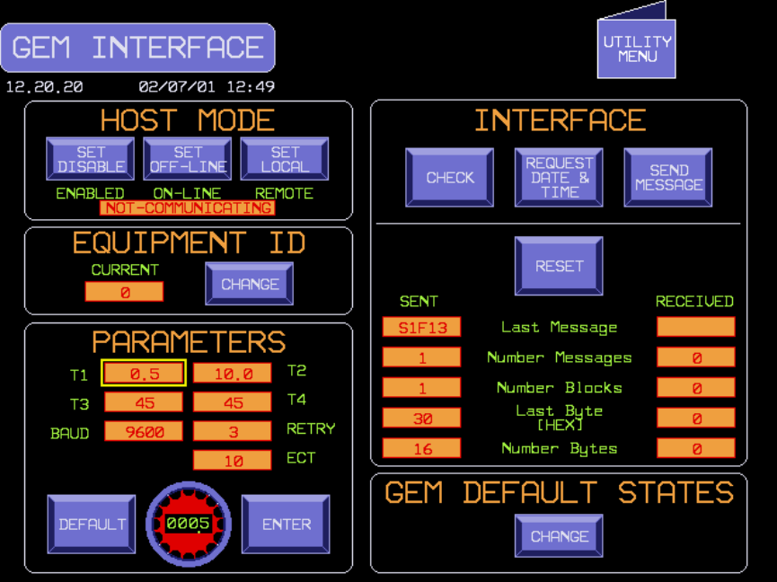
Figure 1 – SCREEN 1, HOST INTERFACE
The Host Mode section has two button icons that contain the present control state of the communications: ON-LINE or
OFF-LINE, REMOTE or LOCAL. Touching the icon causes the control state to switch to the alternative state i.e.:
REMOTE -> LOCAL, LOCAL -> REMOTE; ON-LINE -> OFF-LINE, OFF-LINE -> ON-LINE.
The MODE MENU screen, shown below in Screen 2, displays the HOST CONTROL button when the GEM option is
active. Entry into the HOST CONTROL screen will be allowed if the equipment and Host have established
communications. Upon entry into the HOST CONTROL screen the GEM control state will be set to on-line and remote.
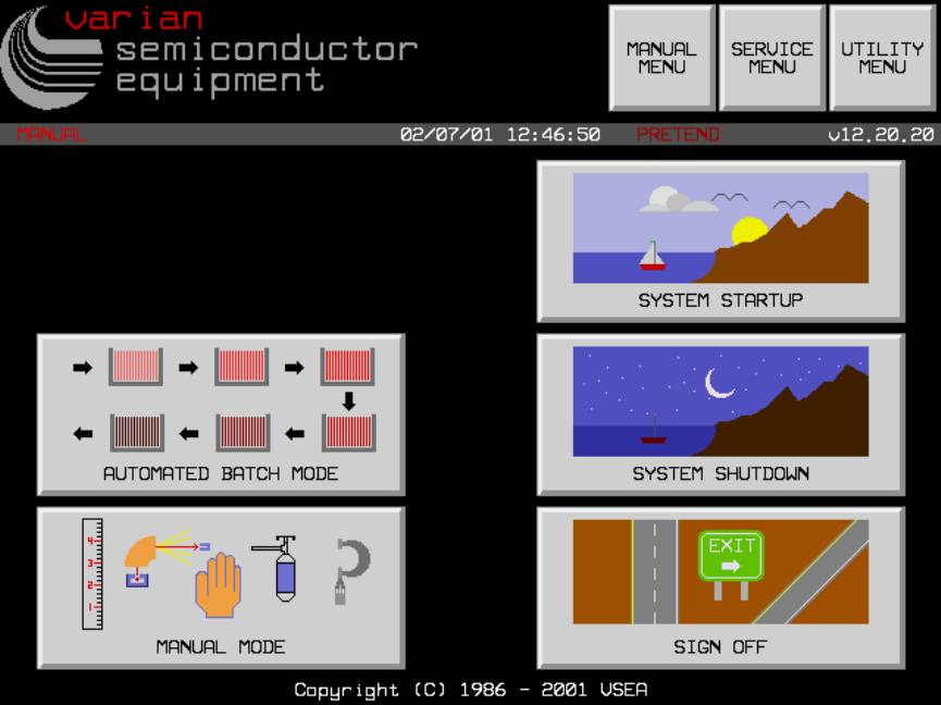
VERSION INTRODUCED: 12.20
Figure 2 - SCREEN 2, MODE MENU
1.3.1 Hardware Component
The hardware is a SECS interface board, SIB-311. The SIB-311 is a single printed circuit board occupying one expansion
slot on the ISA bus of the PC. The SIB-311 provides the following hardware: on-board CPU, RAM, I/O ports, interrupt
request signal, RS 232C interface with a DB37F connector. The SECS interface board contains its own microprocessor,
memory, and performs the entire SECS I, independently of the Intel 486. The SIB-311 interface includes addressing of
the memory and I/O port.
The customer host must be connected to port #1 of the SIB board connector located at the back of the PC.
Ports #2 and #3 are serial connections to the SMIF interface box. Port #2 provides the left SMIF serial connection while
port #3 provides serial communication to the right SMIF.
When option 125 (HSMS Host) is selected, the hardware used is 3COM ethernet card PCI-bus type. This configuration
requires the faster AMD 400 type control computer.
1.3.2 Software Component
The software components of GEM are a sub-system within the E220HP / E500HP application, see figure below.
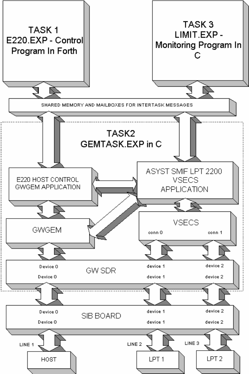
Figure 3 – SMIF Level 1 System Architecture

In E220/E500 software versions previous to Version 10, the main control computer was based on the IBM DOS (MS-
DOS) operating system and the FORTH programming language. The SECS software was written completely in FORTH.
This software handled the SECS I, SECS II and high level communications. Since it was interleaved with the other
FORTH control software, the SECS I communications program and the control program of the implanter interfered with
each other.
In Version 10, DOS has been replaced by a DOS compatible, preemtive multitasking operating system called TSX-32.
This operating system was selected because of its ability to run 32 bit protected mode DOS programs (polyFORTH and
the GEM tasks), its preemptive multitasking, intertask communications, shared memory support and built in realtime
operating system features.
With this new architecture, the SIB board handles all of the SECS I protocol and timing. the GEM task (task 2 above) is a
separate program written in the ‘C’ programming language which handles most of the SECS II message interpretation and
creation. This allows the FORTH software (task 1) to independently control the implanter.
In Version 11.00.22, a multi-threader with an interface similar to PSOS, the VSECS component, and the Asyst SMIF LPT
2200 VSECS application was added to the TSX GEM task (task 2 above). This provides support for two Asyst SMIF LPT
2200 VSECS.
Acronym Description
Control Program in FORTH
This is a modification of the most recent release of the E220HP / E500HP
system software. It controls the implanter.
SECS
The FORTH SECS softw are has been modified to use the SECS and GEM
functions provided by GWGEM and SDR. All FORTH calls to the SECS
softw are by other E220HP / E500HP softw are modules (objects) w ill remain,
but their processing has been moved to functions w ithin GWGEM, SDR or the
SIB-311
Multi-task OS
A third party task schedule, intertask communications, and resource sharing
program. The functions provided by the operating system allow the two tasks
to interact through shared memory and intertask message passing
GEMTASK
A task w ritten in 'C' code to manage the link betw een the E220HP/E500HP
application and GWGEM and SDR functions. This includes function location,
variables, alarms, and process programs.
GWGEM A 'C' function library w ritten by GW Associates, providing GEM compatibility.
Host Control Application A GWGEM application that provides host control for the E220
SDR
An application interfacing the SIB-311 to the E220HP / E500HP application by a
set of ‘C’ library functions.
LIMITS
This is a separate C program w hich executes the limits monitoring functions
required by GEM.
VSECS
A "C" function component utilizing a PSOS style multi-threading component
that provides similar GWGEM functionality for addition SDR ports
SMIF VSECS Application
An application that provides support for tw o Asyst SMIF LPT 2200 cassette
handling robots.
These components linked together with the E220HP / E500HP application and additional hardware comprise the entire
E220HP / E500HP Ion Implanter system with GEM compatibility as specified within this document.
1.3.3 Definitions, Acronyms, and Abbreviations

Acronym Definition
ACH Automatic Cassette Handler - Support for the Daihen buffer (ACH).
C Compiled computer language used in the E220HP / E500HP control system
EPPD Equipment Process Program Directory
Equipment
intelligent system that communicates with the host, in this document it is
synonymous w ith the E220HP / E500HP
function specific message of a stream (see stream in this section)
GEM
Generic Model for Communications and Control of SEMI Equipment (GEM) SEMI
standard E30-95
GWGEM ‘C’ language library of functions producing GEM compatibility
Host the intelligent system that communicates with the Equipment
operator individual using the user interface of the Equipment
FORTH
threaded interpretative programming language, used in the E220 HP / E500HP
control system.
SECS Semiconductor Equipment Communications Standard
SECS I
the description of the physical connector, signal levels, data rate, and logical
protocols required to exchange messages betw een the host and Equipment
over a serial point to point data path
SECS II
the description that gives form and meaning to messages exchanged betw een
Equipment and host using a message transfer protocol
SECSIM
SECS simulator w ith language that can produce SECS formatted messages,
product of GW Associates
SEMI Semiconductor Equipment Manufacturers International, standards organization
SIB SECS Interface Board, product of GW Associates
SMIF
Standard Mechanical Interface - Asyst, Ergospeed II, and Jenoptic, and fixed
Jenoptic SMIF units are supported w ith the E220 application.
stream category of activity defined by SECS II
VILL
Vacuum Independent Loadlocks (ECO 90). An ECO that enables the equipment
to load/unload a loadlock w hile the opposite loadlock’s w afers are being
implanted. (Feature available in V11.01)
VDLL
Vacuum Dependent Loadlocks. Wafers cannot be implanted w hile any
loadlocks are loading or unloading. This operation is only operation available for
V10.00.00 through V11.00.XX
1.3.4 References
Name Date Vers / Rev Originator
E30-95: Generic Model for Communications and
Control of SEMI Equipment (GEM) 1995 E30-95 SEMI
E4-91: SEMI Equipment Communications Standard;
Message Transfer (SECS-I) 1991 E4-91 SEMI
E5-95: SEMI Equipment Communications Standard 2
Message Content (SECS-II) 1995 E5-95 SEMI
EXTRION 220/500 Medium Current Ion Implanter SECS
Communication Manual Feb-93 Rev. 2 Varian
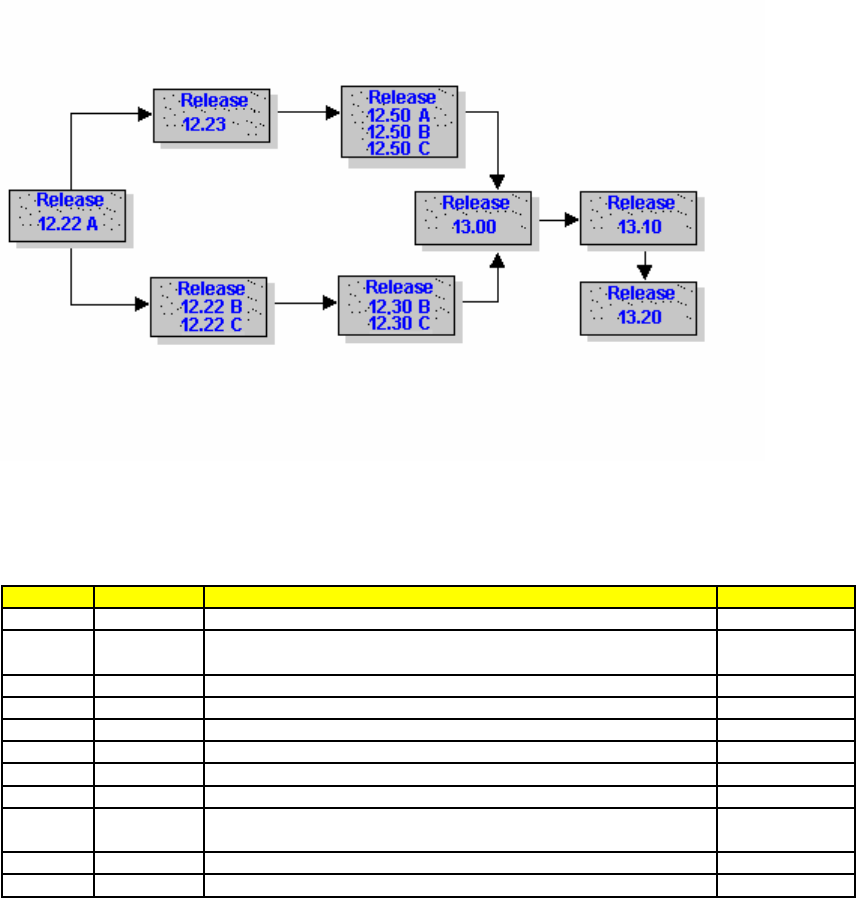
1.4 Software Revision Code
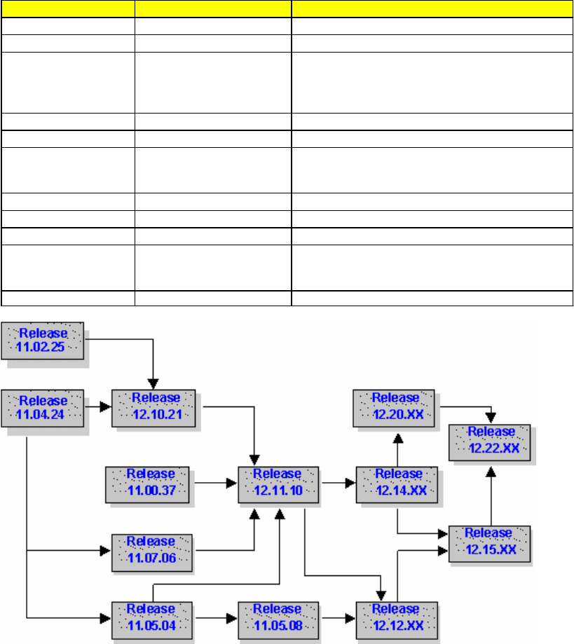
All major threads of the E220/E500 operating system incorporate added features to the GEM interface. This manual
documents which revision certain features were added. To assist with a proper migration path, both a table and migration
flowchart have been provided for reference. The table established the software version where major features which
significantly impact the GEM interface were added. The flowchart provides a migration path to version 12 (and later)
features.
Name Version Introduced Description
GEM V10.00.00 Added the GEM interface.
SMIF1 V11.22.00 Added support for Asyst SMIF LPT 2200
MID1 V11.00.37
Added controller to coordinate factory automation,
Material Identification (MID) readers, and E220 basic
implanter. This softw are component is also
ref erred to as MID Module.
VILL V11.01.00 Vacuum Independent Load Locks.
Y2K V11.00.37 Y2K support.
MID Update V11.05.08
Updated GW Associates library introduced different
buffers for host messages and complex variables
linked to events.
HSMS V12.12.00 Support for HSMS.
ERGOSMIF V11.07.06 Support for Ergospeed SMIF
BCR V12.12.00 Support for Bar Code Reader
LINEUP JOB QUEUE V 12.23 revA
User Interface for the Lineup Job Queue w as
introduced in V12.20 revA, and the
host interface w as introduced in V12.23 revA.
Productivity Plus V12.50 Support for the Dual-Arm Hardw are Upgrade.
1.5 Changes from Previous Versions
Revision Date Reason for Change Author
1 1/16/1995 Original, created from Requirements Document Rev 7 Nick Parisi
2 4/3/1995 Moved events 55 thru 55 to 66 thru 69 to avoid conflicts with SECS2. Jim Hamilton
3 5/20/1996 Update the change from Requirement Document Rev 9 Q. Wei
4 8/30/1997 Added Asyst Automation R. Naugle
5 4/2/1998 Added flouroTrak Cassete ID reader R. Naugle
6 11/16/1999 Finalized Revision R. Cruz
7 3/1/2001 Updated manual and converted to on-line help format K. Zeh
8 2/1/2002 Updated manual for V12.15 Rev B,C and D R. Cruz
8.1 3/26/2002
Updates for V12.15 RevD Custom Software.
Deleted unimplemented or obsolete DVIDs R. Cruz
9 10/12/2004 Updated manual for V12.20 up to V13.10 R. Cruz
9.1 2/15/2005 Added General Equipment Warning Section R. Cruz
2.0 Data Item Directory
2.0 Data Item Directory
This section defines the data items used in the SECS II messages described in the Message Detail section. Each data
item is defined by the following:
1. an unique mnemonic name
2. allowable item format code as complying to SEMI SECS-II E5-95 Section 6.2, Item Format Codes
3. a description of the specific values, and
4. the messages in which the data item is used.
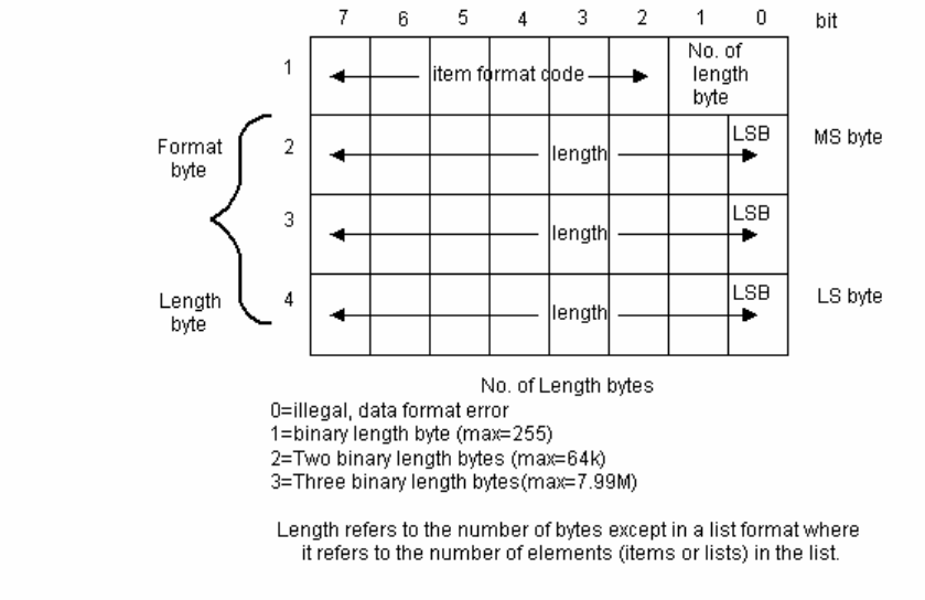
An item is an information packet which has a length and format defined by the first 2, 3, or 4 bytes of the item. These
first bytes are called the item header (IH). The item header consists of the format byte and the length byte(s) as shown
in Figure 2. Bits one and two of the item header tell how many of the following bytes refer to the length of the item.
This feature allows for long items without requiring the byte overhead for shorter items. The item length refers to the
number of bytes following the item header, called the item body (IB), which is the actual data of the item. The item
length refers only to the item body not including the item header, so the actual number of bytes in the message for one
item is the item length plus 2, 3, or 4 bytes for the item header. All bytes in the item body are in the format specified in
the format byte.
Item and List Header
A zero length in the format byte is illegal and produces an error. A zero length in the item length bytes has a special
meaning as defined in the detailed message definitions.
Bits 3 through 8 of the format byte of the item header define the format of the data which follows. Of the 64 possible
formats, fifteen are defined as shown in Table 1. Format code 0 is called a list and is defined in E5 6.3. The remaining 14
item formats define unspecified binary, code 10 (octal); Boolean, code 11 (octal); ASCII character strings, code 20 (octal);
JIS-8 character strings, code 21 (octal) signed integer, codes 30, 31, 32, 34 (octal); floating point, codes 40, 44 (octal);
and unsigned integer, codes 50, 51, 52, 54 (octal). These formats are used for groups of data which have the same
representation in order to save repeated item headers. Signed integers will be two's complement values. Floating point
numbers will conform to the IEEE standard 754. Boolean values will be byte quantities, with zero being equivalent to false,
and non-zero being equivalent to true.
2.0.1 Item Format Codes

MEA NING
Binary
765432 Octal 0-LB
Symbol
0-LB
Hex
n-LB
Symbol
1-LB
Hex
2-LB
Hex
3-LB
Hex
The data after the heading
has the follow ing form
000000 00 L 0 L+n 1 2 3 LIST (length in elements)
001000 10 B1 20 B8+n 21 22 23 Binary
001001 11 BOOL 24 B2+n 25 26 27 Boolean
010000 20 A1 40 A1+n 41 42 43 ASCII 1
010001 21 J1 44 J1+n 45 46 47 JIS-8
100000 40 F8 80 F8+n 81 82 83 8-byte floating point 3
100100 44 F4 90 F4+n 91 92 93 4-byte floating point 3
101000 50 U8 A0 U8+n A1 A2 A3 8-byte integer (unsigned) 2
101001 51 U1 A4 U1+n A5 A6 A7 1-byte integer (unsigned)
101010 52 U2 A8 U2+n A9 AA AB 2-byte integer (unsigned) 2
101100 54 U4 B0 U4+n B1 B2 B3 4-byte integer (unsigned) 2
FORMA
T
1 Non-printing characters are equipment specific.
2 Most significant byte sent first.
3 IEEE 754. The byte containing the sign bit is sent first.
ABS -- Any binary string Format: 10
Where Used: S2F25, S2F26
ACHA -- ACH Acknowledge code Format: 10
0 = acknowledge, ok
1 = can not perform now
2 = requested recipe(PPID) not found
7 = Port is not enabled
10 = bad parameter in S2F71 left side list
11 = bad parameter in S2F71 right side list
12 = error in S2F71 message
13 = process parameter error
14 = cassette not loaded
15 = enqueue failed
16 = FA option or S2F71 queue disabled
Where Used: S2F72
ACKC5 -- Acknowledge code Format: 10
0 = accepted
>0 = error, not accepted
1-63 = reserved
Where Used: S5F2, S5F4
ACKC6 -- Acknowledge code Format: 10
0 = accepted

>0 = error, not accepted
1-63 = reserved
64 = Bad PPID
Where Used: S6F12, S6F14
ACKC7 -- Acknowledge code Format: 10
0 = Accepted
1 = Permission not granted
2 = Length error
3 = Matrix overflow
4 = PPID not found
6 = Recipe with same name exists and can not overwrite (S7F4).
6-63 = reserved
Where Used: S7F4, S7F18
ACKC7A Format: 31, 51
0 = Accepted
1 = MDLN is inconsistent
2 = SOFTREV is inconsistent
3 = Invalid CCODE
4 = Invalid PPARM value
5 = Other error (described by ERRW7)
6-63 = reserved
Where Used: S7F27
ACKC10 -- Acknowledge Code Format: 10
0 = Accepted for display
1 = Message will not be displayed
2 = Terminal not available
3-63 reserved
64
Where Used: S10F2 , S10F4 , S10F6
ALCD -- Alarm code byte Format: 10
bit 7 = 1 means alarm set
bit 7 = 0 means alarm cleared
bit 6-0 = alarm category
0 = not used
1 = Personal safety
2 = Equipment safety
3 = Parameter control warning
4 = Parameter control error
5 = Irrecoverable error

6 = Equipment status warning
7 = Attention flags
8 = Data integrity
>8 = other categories
9-63 = reserved
Where Used: S5F2, S5F6
ALED-- Alarm enable/disable code, 1 byte Format: 10
bit 7 = 1 means enable alarm
bit 7 = 0 means disable alarm
Where Used: S5F3
ALID – Alarm identification Format: 5( )
All alarm identifications can be found in Appendix B of this document.
Note: The format of ALID is 54 in S5F1
Where Used: S5F1, S5F3, S5F5, S5F6
ALTX -- Alarm text limited to 40 characters Format: 20
All alarm text can be found in Appendix B of this document. Only the first 40 characters of the text is sent to the Host.
Where Used: S5F1
CCODE -- Command Code Format: 32, 52
Each command code corresponds to a unique process operation the machine is capable of performing.

Process OperationCommand
Command Code
(CCODE) Desc ription
DOPANT 1 Ion Name
PARAMETRIC MODE 2 Parametrics Operation
MULTIPLE 3 Number of Doses (Max. 12)
MASS 4 Ion Weight
CHARGE 5 Charge
SOURCE MODE 6 Gas/Vaporizer
ENERGY 7 Energy
EXT_V 8 Ex trac tion V olts
ACL/DCL 9 Accel/Decel
# SCANS 10 Minimum Scans
X SIGMA 11 Xsigma
ES VAC 12 Es Vacuum
CHECK 13 Check Interval
PURITY 14 Purity (E500 only)
W TYPE 15 Wafer Type
eFLOOD 16 Electron Flood
COOLING 17 Gas Cooling
MIRROR V 18 Mirror V olts
FLOOD MA 19 eFlood Current
ROTATIONS 20 Rotate 1
TILT 21 Tilt 1
TWIST 22 Tw ist 1
DOSE MANTISSA 23 Mantissa
DOSE EXPONENT 24 Exponent
25 Recipe Name
26 Softw are Revision
27 Recipe Version
28 Edit Date
29 Edit Time
30 Operator ID
31 Learn Date
32 EHP Option
33 Vaporizer Option
34 Recipe Status
35 Beam Slit
36 Interval Units
37 Dose Calibration
38 Arc Voltage
39 Arc Current
40 Filament Voltage
41 Filament Current
42 Extraction Current
43 Suppression Voltage
44 Suppression Current
45 Source Magnet Current
46 Source Magnet Voltage
47 Gas Pressure
48 Source Pressure
49 Pvaporizer Temperature
50 Vaporizer Temperature
51 X-Axis
52 Y-Axis
53 Z-Axis
54 Setup Beam Current
55 Setup Bias
56 Analyzer Current
57 Amu Tune Speed
58 Analyzer Pressure
59 Mirror Current
60 Mirror shunt Current
61 Quad1 Current
62 Quad1 Voltage
63 Quad2 Current
64 Quad2 Voltage
65 Deflector Voltage
66 Lens Current

68 BeamLine Pressure
69 FocusBeam Current
70 Source Type
71 Target Cup Bias
72 E Filament Voltage
73 E Filament Current
74 E Ripple Voltage
75 E Extraction Voltage
76 E Extraction Current
77 E Target Current
78 E Bias Voltage
79 E Bias Current
80 E Suppression Voltage
81 E Secondary Current
82 A Line
83 Beam Width
84 Target Beam Mantissa
85 Target Beam Exponent
86 Range Arc
87 X-Tune Speed
88 Y-Tune Speed
89 Noise
90 Ripple
91 Q1 Tune Speed
92 Q2 Tune Speed
93 Deflector Tune Speed
94 Beam Line Tune Speed
95 Calculated Scans
96 Gas String
97 Source Magnet Type
98 Num Pass
99 Num Fail
100 Last SetupDate
101 Last Setup Time
102 Spare 1
103 Spare 2
104 Spare 3
105 Spare 4
106 Spare 5
107 Spare 6
Where Used: S7F23, S7F26
CEED -- Collection event enable/disable code, 1 byte Format: 11
FALSE = Disable
TRUE = Enable
Where Used: S2F37
CEID -- Collected event ID Format: : 5( )
Identifies the event and report that is being sent. The format of CEID is 54 in S6F11. Supported Event ID's are:
CEID Description
1 Start up started
2 Start up complete
3 Shut down started
4 Shut down complete
5 Source setup started
6 Source setup complete
7 Beamline setup started
8 Beamline setup complete
9 Beamscan setup or check started
10 Beamscan setup or check complete
11 Batch started (GEM Compliant Process Started Started)
12 Batch complete (GEM Compliant Process Started completed)
13 Wafer started
14 Wafer complete
15 Alarm generated (GEM Compliant Alarmn Detected)
16 Alarm silence button pressed (GEM Compliant Alarmn Cleared)
17 Implant Held (GEM Compliant Processing Stopped)
18 Implant Continued
19 Abort started
20 Abort complete
21 Elevator vent started
22 Elevator vent complete
23 Door open started
24 Door open complete
25 Door close started
26 Door close complete
27 Elevator pump started
28 Elevator pump completed
29 Entering host control mode
30 Entering host monitor mode (SECS-II only)
31 High voltage enabled
32 High voltage disabled
33 Entering host ignore mode (SECS-II only)
34 Unload Sequence Started Version available 12.20
35 Pivot Retract Started Version available 12.20
36 Pivot Retract Complete Version available 12.20
37 Setup Only Complete
38 Wafer mapping started
39 Wafer mapping completed
40 Processing started
41 Cassette(s) removed
42 Ready to Process
43 Ready to Implant
44 Port Availability change at ACH or Eqpt
45 Cassette status change at ACH
46 Cassette status change at equipment port
47 Entering Factory Automation Off mode
48 Entering Factory Automation Manual mode
49 Entering Factory Automation Semi Auto mode
50 Entering Factory Automation Full Auto mode
51 Load/Unload ACH port Request
52 Load/Unload ACH port Request Complete
53 System Backup Started
54 System Backup Complete
55 Unused
56 Unused
57 Uniformity Precheck
58 Unused
59 Move Into ACH Port Request
60 Move Out of ACH Port Request
61 Move Into ACH Port Request Complete
62 Move Out of ACH Port Request Complete
63 Go Displayed
64 Go or Cont Button Pressed or remote command START received
from host
65 Pivot Extend Complete
66 Control State OFF-LINE
67 Control State ON-LINE, Local
68 Control State ON-LINE, Remote
69 Unused
70 Spool Activated
71 Spool Deactivated
72 Spool Transmit Failure
73 Operator Command Issued
74 Operator Command Complete
75 Processing State Change
76 Operator Changed Equipment Constant
77 Upper Trace Limit Exceeded
78 Lower Trace Limit Exceeded
79 Process Program Change
80 Process Program Selected
81 Message Recognition
82 Operator Log On
83 Operator Log Off
84 Ready to Receive Material
85 Material Sensed at Port
86 Host Command (Remote) Issued
87 Host Command (Remote) Complete
88 Job Created (Applicable to Process Job Queue)
Version available 12.20
89 Job Deleted (Applicable to Process Job Queue)
90 Job Completed (Applicable to Process Job Queue)
91 Queue Availability Changed (Applicable to Process Job Queue)
92 Job Processing Started (Applicable to Process Job Queue)
93 Job Processing Complete (Applicable to Process Job Queue)
94 Job Chain Modified (Applicable to Process Job Queue)
95 Timed Beam Run Started (Applicable to Process Job Queue)
96 Timed Beam Run Complete (Applicable to Process Job Queue)
97 Job Promoted (Applicable to Process Job Queue)
98 Job Preempt Successful (Applicable to Process Job Queue)
99 Job Preempt Unsuccessful (Applicable to Process Job Queue)
100 SMIF LPT Manual Control Mode
101 SMIF LPT Semi-Auto Control Mode
102 SMIF LPT Full-Auto Control Mode
103 SMIF LPT POD Placed
104 SMIF LPT POD Removed
105 SMIF LPT Load Ready
106 SMIF LPT Load Start
107 SMIF LPT Load Complete
108 SMIF LPT Unload Ready
109 SMIF LPT Unload Start
110 SMIF LPT Unload Complete
111 SMIF LPT Port Locked
112 SMIF LPT Port Unlocked
113 SMIF LPT Switched to Manual

114 SMIF LPT Switched to Auto
115 SMIF LPT Powered Up
116 SMIF LPT Load Aborted
117 SMIF LPT Unload Aborted
118 SMIF LPT init Started
119 SMIF LPT init Complete
120 SMIF LPT init aborted
121 SMIF LPT Cassette Placed on Equipment
122 SMIF LPT Port lock/unlock failed
123 Actual Smif Slot Map Available
124 EMID Actual Cassette ID Available Version available 12.15
125 EMID Actual Cassette ID Update Aborted Version available 12.15
126 Discard Job Version available 12.15
127 Actual SMIF Slot Map Validation Failed
128 Actual Cassette ID Validation Failed Version available 12.15
129 Actual Wafer ID Available
130 Actual Wafer ID Update Abort
131 Actual Wafer ID Validation Failed
132 Actual Equipment Slot Map Validation Failed
133 Actual Equipment Slot Map Update Aborted
134 Reject Pod
135 Actual Equipment Slot Map Validation Passed
136 Actual Smif Slot Map Validation Passed
137 EMID Validation Passed Version available 12.15
138 Actual Wafer ID Validation Passed
139 Actual Equipment Slot Map Validation Passed
140 Job Done Version available 11.05.04
141 Job Started Version available 11.05.04
142 Equipment Count Validation Failed Version available 11.05.04
143 Equipment Count Validation Passed Version available 11.05.04
144 SMIF Count Available Version available 11.05.04
145 SMIF Count Abort Version available 11.05.04
146 Smif Count Validation Failed Version available 11.05.04
147 SMIF Count Validation Passed Version available 11.05.04
160 SMART Tag Data Lot-id Available
161 SMART Tag File Data Available
162 SMART Tag Status Available
200 200+ Used for Limits Zone Transition for Analogs
2000 2000+ Used for Alarm On / Off
In addition, each alarm ID, ALID , has two CEIDs associated with it, one for alarm clear and one for alarm set. The alarm
IDs are calculated at initialization time based on the contents of the MESSAGES.USA file. The formulas for calculating
the alarm IDs are as follow:
Alarm Off CEID = (Alarm ID *2) + 300
Alarm On CEID = Alarm Off CEID + 1
VARIAN RESERVES THE RIGHT TO ADD ADDITIONAL EVENT CEIDs
The Varian GEM uses the CEID number for the SFCD and accesses the reports associated with the CEID.
Where Used: S2F35, S2F37, S6F11, S6F13
CEPACK -- Command Enhanced Parameter Acknowledge, 1 byte Format: 10, 51
0 = no error
1 = Parameter Name (CPNAME) does not exist
2 = Illegal Value specified for CEPVAL
3 = Illegal Format specified for CEPVAL
4 = Parameter name (CPNAME) not valid as used
5-63 = reserved

Where Used: S2F49
CEPVAL -- Command Enhanced Parameter Value Format: 0, 10, 11, 20, 21, 3( ), 4( ), 5( )
A specific application of CEPVAL shall always be identified with a specific value of CPNAME. A CEPVAL has the
following forms: a single (non-list) value (eg. CPVAL), a list of single items of identical format and type, or a list of items of
the form:
L,2
1. CPNAME
2. CEPVAL
Where Used: S2F49
COMMACK -- Establish Communications Acknowledge Code, 1 byte Format: 10
0 = Accepted
1 = Denied, Try Again
2-63 = Reserved
Where Used: S1F13, S1F14
CPACK -- Command Parameter Acknowledge Code, 1 byte Format: 10
1 = Parameter Name (CPNAME) does not exist
2 = Illegal Value specified for CPVAL
3 = Illegal Format specified for CPVAL
>3 = Other equipment=specific error
4-63 = reserved
64 = Discrepancy detected between WaferID and SlotMap parameters
Where Used: S2F42
CPNAME -- Command Parameter Name Format: 20
These are used in the remote command to designate the parameter being sent with the command. See the RCMD
section for CPNAME applicable to each remote command.
Where Used: S2F41
CPVAL -- Command Parameter Value Format: 10, 11, 20, 21, 3( ), 5( )
These are used in the remote command to set parameter values. See the RCMD section for CPVAL applicable to each
remote command.
Where Used: S2F41
DATAID -- Data ID Format: 5()
The data id is used to connect a multi- block request/grant message transaction with the actual multi- block message

transaction. In messages which originate from the Equipment, which include DATAID but are not multi- block, the
DATAID is undefined. In messages which originate from the Host and which are not multi- block but do contain
DATAID, DATAID will be ignored.
Note: The format of DATAID is 54 in S6F11
Where Used: S2F33, S235, S239, S6F5, S6F11, S6F13
DATALENGTH -- Total bytes to be sent Format: 3( ),5( )
Where Used: S2F39, S6F5
DRACK -- Define Report Acknowledge Code, 1 byte Format: 10
0 = Accept
1 = Denied. Insufficient space
2 = Denied. Invalid format
3 = Denied. At least one RPTID already defined
4 = Denied, At least VID does not exist
>4 = Other errors
5-63 = reserved
Where Used: S2F34
DSPER -- Data sample period Format: 20
hhmmss, 6 bytes
Where Used: S2F23
DVID Format: 5( )
The data variables may also be access with a VID of equivalent value using the functions appropriate for VID. See VID for
table showing relationship between data variables identifcation (DVID), equipment constant identifications(ECID), and
status variable identifications( SVID) . The data variable IDs are as follows:
DVID DVNAME DVID DVNAME
Implant And Machine Status Variables Recipe Data Process Program Variables
100 A(LLOT) 200 PPID
101 A(RLOT) 201 ION- NAME
102 LWAF# 202 ION- AMU
103 RWAF# 203 DOSE- MANTISSA
104 OP- NAME 204 DOSE- EXPONENT
105 OPERATOR- ID 205 ENERGY
106 WAFER- NUMBER 206 SCANS
107 WAFER- START- TIME 207 COOLING
108 WAFER- END- TIME 208 FLOOD
109 BATCH- START- TIME 209 <TILT
110 BATCH- END- TIME 210 <TWIST
111 aXSIGMA 211 ION- CHARGE
112 cSCANS 212 EST- VAC
113 aDOSE 213 X- SIGMA
114 aSCANS 214 Y- SIGMA
115 aYSIGMA 215 CHK- INT
116 216 Q- SOURCE
117 STATUS 217 W- TYPE
118 WAFER- HOLDS 218 F-LEARNED
119 BATCH- HOLDS 219 #MULTIPLE
120 LOT 220 GAS/VAPOR
121 #WAFERS 221 EXTRACTION
122 REMOTE- CONTROL 222 ACCEL/DECEL
123 TARGET- I 223 PURITY
124 BEAM- WIDTH 224 MIR-V
125 HOST- CONTROL 225 FLOOD-CURRENT
126 FAUTO 226 ROTATE
127 ACH-STATUS 227 LEFT-PPID
128 BPTN 228 RIGHT-PPID
129 CSTATUS
130 LPORT
131 RPORT
132 PORT-STATUS
133 WFR_CYC_TOT_LEFT
134 WFR_CYC_TOT_RIGHT
135 WFR_CYC_TOT_L/R
136 WFR_CYC_PM_LEFT
137 WFR_CYC_PM_RIGHT
138 WFR_CYC_PM_L/R
139 WAFERS_IMPLANTED
140 NUMBER_OF_SCANS
141 GAS1_TOTAL
142 GAS2_TOTAL
143 GAS3_TOTAL
144 GAS4_TOTAL
145 GAS1_4_TOTAL
146 GAS1_PM
147 GAS2_PM
148 GAS3_PM
149 GAS4_PM
150 GAS1_4_PM
151 PORT-ID
152 LPORT-STATUS
153 RPORT-STATUS
154 LMATERIAL-STATUS
155 RMATERIAL-STATUS
156 EXPECTED-SLOT-MAP(LLOT)
157 EXPECTED-SLOT-MAP(RLOT)
158 EXPECTED-WID(LLOT)
159 EXPECTED-WID(RLOT)
160 ACTUAL-MID(LLOT)
161 ACTUAL-MID(RLOT)
166 CURRENT-WAFER-ID
167 ID-VALIDATION(LLOT)
168 ID-VALIDATION(RLOT)
171 QUEUE-FULL
172 LEFT_WAFERS_IMPLANTED
173 RIGHT_WAFERS_IMPLANTED
174 BATCH_WAFERS_IMPLANTED
175 DI-WATER-FLOW
176 WHEREIS(LLOT)
177 WHEREIS(RLOT)
188 DOSE_CALIBRATION_FACTOR
193 JOB_ID_LIST
194 ECLAMP-I
195 JOB_ID
196 QUEUE_FREE_SLOTS
197 TAG-FILEDATA
198 LTAG-BATSTAT
199 RTAG-BATSTAT
GEM Compliant Data Variables GEM System Data Variables
300 PPChangeStatus 502 ALARMID
301 PPChangeName 503 DATAID
302 ProcessState 504 PREVIOUSCEID
303 PreviousProcessState 509 SPOOLSTARTTIME
304 PPExecName 510 SPOOLFULLTIME
305 Clock 511 SPOOLCOUNTACTUAL
306 EventsEnabled 512 SPOOLCOUNTTOTAL
307 AlarmsEnabled 513 GemSpoolState
308 AlarmsSet 514 GemSpoolFull
309
ControlState 515 GemSpoolLoadSubstate
310 PreviousControlState 516 GemSpoolUnloadSubstate
311 EventLimit
312 LimitVariable
313 TransitionType
Pump Status Variables Implanter and Processing Data
600 a1ESTurboCommStatus[0] 800 TARGET-FARADAY-DAC
601 a1ESTurboState[0] 801 LEFT-ELEV-SERVO-DAC
602 a1ESTurboCommStatus[1] 802 RIGHT-ELEV-SERVO-DAC
603 a1ESTurboState[1] 803 LEFT-ORIENTER-DAC
604 1OnBoardCommStatus 804 RIGHT-ORIENTER-DAC
605 a1OnBoardPumpStatus[0] 805 LEFT-HANDLER-DAC
606 a1OnBoardRegenStatus[0] 806 RIGHT-HANDLER-DAC
607 a1OnBoardPurgeValveStatus[0] 807 PLATEN-TILT-DAC
608 a1OnBoardRoughValveStatus[0] 808 LEFT-ORIENTER-LIFTER-DAC
609 a1OnBoardDelayStart[0] 809 RIGHT-ORIENTER-LIFTER-DAC
610 a1OnBoardDelayRestart[0] 810 ROTATING-PLATEN-DAC
611 a1OnBoardFastRoughTest[0] 811 ROPINS-MOTOR-DAC
612 a1OnBoardExtendedPurge[0] 812 ROTATION#
613 a1OnBoardRepurgeTime[0] 813 LINE#
614 a1OnBoardRepurgeCycles[0] 814 IMPLANT-STEP-PROCESS-TIME
615 a1OnBoardRORLimit[0] 815 SHUFFLE-MODE
616 a1OnBoardRORCycles[0] 816 LEFT-UPPER-ARM
617 a1OnBoardPowerFailRecoveryTemp[0] 817 RIGHT-UPPER-ARM
618 a1OnBoardFirstStageTempSetpoint[0] 818 PLATEN-ROTATION-SENSOR-COUNT
619 a1OnBoardSecondStageTempSetpoint[0] 819 EXTR-HV-TIME
620 a1OnBoardPumpStatus[1] 820 SOURCE-TIME
621 a1OnBoardRegenStatus[1] 821 ECO_SETTINGS
622 a1OnBoardPurgeValveStatus[1] 822 OPTION_SETTINGS
623 a1OnBoardRoughValveStatus[1]
624 a1OnBoardDelayStart[1]
625 a1OnBoardDelayRestart[1]
626 a1OnBoardFastRoughTest[1]
627 a1OnBoardExtendedPurge[1]
628 a1OnBoardRepurgeTime[1]
629 a1OnBoardRepurgeCycles[1]
630 a1OnBoardRORLimit[1]
631 a1OnBoardRORCycles[1]
632 a1OnBoardPowerFailRecoveryTemp[1]
633 a1OnBoardFirstStageTempSetpoint[1]
634 a1OnBoardSecondStageTempSetpoint[1]
635 a1OnBoardPumpStatus[2]
636 a1OnBoardRegenStatus[2]
637 a1OnBoardPurgeValveStatus[2]
638 a1OnBoardRoughValveStatus[2]
639 a1OnBoardDelayStart[2]
640 a1OnBoardDelayRestart[2]
641 a1OnBoardFastRoughTest[2]
642 a1OnBoardExtendedPurge[2]
643 a1OnBoardRepurgeTime[2]
644 a1OnBoardRepurgeCycles[2]
645 a1OnBoardRORLimit[2]
646 a1OnBoardRORCycles[2]
647 a1OnBoardPowerFailRecoveryTemp[2]
648 a1OnBoardFirstStageTempSetpoint[2]
649 a1OnBoardSecondStageTempSetpoint[2]
iQDP Pump Status Variables
650 lIqdpEndTask
651 lIqdpEnabled
652 alIqdpCommunicationsStatus[0]
653 alIqdpPumpStatus[0]
654 alIqdpPumpTemperature[0]
655 alIqdpPumpPower[0]
656 alIqdpPumpCurrent[0]
657 alIqdpExhaustPressure[0]
658 alIqdpWaterFlow[0]
659 alIqdpRunningTime[0]
660 alIqdpOilLevel[0]
661 alIqdpBlowerStatus[0]
662 alIqdpBlowerOilLevel[0]
663 alIqdpBlowerMotorTemperature[0]
664 alIqdpBlowerPower[0]
665 alIqdpBlowerPhaseCurrent[0]
666 alIqdpCommunicationsStatus[1]
667 alIqdpPumpStatus[1]
668 alIqdpPumpTemperature[1]
669 alIqdpPumpPower[1]
670 alIqdpPumpCurrent[1]
671 alIqdpExhaustPressure[1]
672 alIqdpWaterFlow[1]
673 alIqdpRunningTime[1]
674 alIqdpOilLevel[1]
675 alIqdpBlowerStatus[1]
676 alIqdpBlowerOilLevel[1]
677 alIqdpBlowerMotorTemperature[1]
678 alIqdpBlowerPower[1]
679 alIqdpBlowerPhaseCurrent[1]
680 alIqdpCommunicationsStatus[2]
681 alIqdpPumpStatus[2]
682 alIqdpPumpTemperature[2]
683 alIqdpPumpPower[2]
684 alIqdpPumpCurrent[2]
685 alIqdpExhaustPressure[2]
686 alIqdpWaterFlow[2]

687 alIqdpRunningTime[2]
688 alIqdpOilLevel[2]
689 alIqdpBlowerStatus[2]
690 alIqdpBlowerOilLevel[2]
691 alIqdpBlowerMotorTemperature[2]
692 alIqdpBlowerPower[2]
693 alIqdpBlowerPhaseCurrent[2]
Left Ergospeed II SMIF Variables Right Ergospeed II SMIF Variables
8300 Not Used 8400 Not Used
8301 Left ErgoSMIF Last Function 8401 Right ErgoSMIF Last Function
8302 Left ErgoSMIF RCMD Compl State 8402 Right ErgoSMIF RCMD Compl State
8303 Left ErgoSMIF Elevator State 8403 Right ErgoSMIF Elevator State
8304 Left ErgoSMIF Pod Placed 8404 Right ErgoSMIF Pod Placed
8305 Left ErgoSMIF Lock State 8405 Right ErgoSMIF Lock State
8306 Left ErgoSMIF Home State 8406 Right ErgoSMIF Home State
8307 Left ErgoSMIF Pneumatic Stroke State 8407 Right ErgoSMIF Pneumatic Stroke State
8308 Left ErgoSMIF Gripper State 8408 Right ErgoSMIF Gripper State
8309 Left ErgoSMIF Cassette in Gripper 8409 Right ErgoSMIF Cassette in Gripper
8310 Left ErgoSMIF Low Load 8410 Right ErgoSMIF Low Load
8311 Left ErgoSMIF Port Door State 8411 Right ErgoSMIF Port Door State
8312 Left ErgoSMIF Pressure State 8412 Right ErgoSMIF Pressure State
8313 Left ErgoSMIF FFU State 8413 Right ErgoSMIF FFU State
Where Used: S1F3, S1F11, S1F12, S2F23, S2F33, S2F45, S2F46, S2F47, S2F48; S6F13, S6F18, S6F22
DVNAME -- Data value name Format: 3( ),20,5( )
Where Used: S1F12
DVVAL -- Data value Format: 0, 10, 11, 20, 21, 3( ), 4( ), 5( )
Where Used:
EAC -- Equipment acknowledge code, 1 byte Format: 10
0 = Acknowledge
1 = Denied, At least one constant does not exist
2 = Denied, Busy
3 = Denied, At least one constant out of range
>3 = Other equipment-specific error
4-63 = reserved
Where Used: S2F16
ECDEF -- Equipment constant default value Format: 20, 5( )
Where Used: S2F30E5_S2F30_Equipment_Constant_Namelist

ECID -- Equipment Constant ID Format: 5( )
The equipment constants may also be access with a VID of equivalent value using the functions appropriate for VID. See
VID for table showing relationship between data variables identification (DVID), equipment constant identifications(ECID),
and status variable identifications(SVID). The Equipment constant IDs are as follows:
ECID ECNAME ECID ECNAME
250 T1 290 Not Used
251 T2 291 EQUIPMENT IP ADR
252 T3 292 CONNECT MODE
253 RTY 293 PASSIVE IP ADDRESS
254 T4 294 PASSIVE TCP PORT
255 Obsolete (always set to 0) 295 T5
256 FORMAT 296 T6
257 MODES 297 T7
258 Mirror-mode 298 T8
259 Accel-mode 299 BCR Mode
260 Extraction-volts 350 Connection Establishment
261 TYPE-RCP 351 Circuit Assurance
262 Establish-Comm-Timeout 352 TimeoutGrace
263 FACTAUTO 353 MemoryStall
264 PPTF 354 WriteStall
265 GemInitCommState 355 Submask
266 GemInitControlState 356 Router
267 Baud-Rate 357 MidVersion (Not Supported)
268 Equipment-ID
269 DEVICENAME
270 RPTYPE
271 CONFIGALARMS
272 CONFIGCONNECT
273 CONFIGEVENTS
274 WBITS5
275 WBITS6
276 WBITS10
277 HEARTBEAT
278 EQPORT_ENABLE
279 ACHPORT_ENABLE
280 GemConfigSpool
281 GemMaxSpoolFileSize
282 GemMaxSpoolTransmit
283 GemOverWriteSpool
284 GemSpoolFileName
285 GemMsgInterLv
286 MID-MODE
287 SMIF-MODE
288 GEMTASK LOG SIZE
289 EC TIMEFORMAT
Constants 258, 259 and 260 are used for recipe conversion and should be treated as a set. They are only used when
PPBODY1 recipes are used on version 9 software. These conversion numbers are ignored when using PPBODY2.
VARIAN RESERVES THE RIGHT TO ADD MORE EQUIPMENT
CONSTANTS
Where Used: S1F3, S1F11, S1F12, S2F23, S2F13, S2F15, S2F29, S2F30, S2F33, S2F45, S2F46, S2F47, S2F48;
S6F13, S6F18, S6F22

ECMAX -- Equipment constant maximum value Format: 5( )
Where Used: S2F30
ECMIN -- Equipment constant minimum value Format: 5( )
Where Used: S2F30
ECNAME -- Equipment constant name Format: 20
See ECID for list of equipment constant names.
Where Used: S2F30
ECV -- Equipment Constant Value Format: 20, 5( )
See variable dictionary for a list for individual ECV format.
Where Used: S2F15
EDID -- Expected data Identification Format: 10, 20, 3( ), 5( )
Three possible responses.
MEXP EDID EDID
S02F03, <SPID> A[6]
S03Fl3, <PTN> B[1]
S07F03, <PPID> A[16], B[16]
Where Used: S9F13
ERACK -- Enable/Disable Event Report Format: 10
Acknowledge Code, 1 byte
0 = Accepted
1 = Denied. At least one CEID does not exist
<1 = Other Errors
2-63 = reserved
Where Used: S2F38
ERRW7 Format: 20

Text string describing error found in process program
Where Used: S7F27
ESID - Equipment Port Number Format: 10
ESID designates the stage location of the Equipment Port Number
1 = Left
2 = Right
Note: Factory Automation Only
Where Used: S2F71
FCNID -- Function Identification Format: 51
Where Used: S2F43, S2F44
GRANT -- Grant code, 1 byte Format: 10
0 = Permission Granted
1 = Busy, Try Again
2 = No Space Available
3 = Duplicate DATAID
>3 = Equipment Specific Error Code
4-63 = reserved
Where Used: S2F40
GRANT6 -- Permission to send, 1 byte Format: 10
0 = Permission granted
1 = Busy, try again
2 = Not interested
>2 = Other errors
3-63 = reserved
Where Used: S6F6
HCACK -- Host Command Parameter Acknowledge Code, 1 byte Format: 10
0 = Acknowledge, command has been performed
1 = Command does not exist
2 = Cannot perform now
3 = At least one parameter is invalid
4 = Acknowledge, command will be performed with completion signaled later by an event

5 = Rejected, Already in Desired Condition
6 = Object does not exist
7-63 = reserved
64= Double Implant not allowed
65-127 = Left and right SMIF LPT (LPT must be present to occur)
LSB
7 6 5 4 3 2 1 0
0 1 LPT1 LPT1 LPT1 LPT2 LPT2 LPT2
MSB
Bit 6 1
bits 5-3 LPT HCACK code for the left LPT1
bits 2-0 LPT HCACK code for the right LPT2
LPT HCACK code
0h: LPT Completed command
1h: LPT in manual mode
2h: No Pod in place
3h: Host not ready
4h: Limit not reached
5h: LPT already in desired state
6h: LPT does not understand command
7h: LPT cannot perform command or E220 cannot send command to LPT
Where Used: S2F42
LENGTH Format: 5( )
Length of the service program or process program in bytes
Where Used: S7F1
LIMITACK Format: 10
Acknowledgment code for variable limit attribute set, 1 byte.
1 = LIMITID does not exist
2 = UPPERDB > LIMITMAX
3 = LOWERDB < LIMITMIN
4 = UPPERDB < LOWERDB
5 = Illegal format specified for UPPERDB or LOWERDB
6 = ASCII value cannot be translated to numeric
7 = Duplicate limit definition for this variable
>7 = Other equipment-specific error
8-63 = reserved
Where Used: S2F46
LIMITID Format: 10
The identifier of a specific limit in the set of limits (as defined by UPPERDB and LOWERDB) for a variable to which the
corresponding limit attributes refer, 1 byte. The range of allowable Ids is 0 - 6.
Where used: S2F45, S2F46, S2F48

LIMITMAX Format: 20
Presently the highest possible value for the SV’s value (99.9, 9, 9.99999)
Where used: S2F48
LIMITMIN Format: 20
Presently the lowest possible value for the SV’s value (0 or 0.0000099)
Where used: S2F48
LOTID - Material ID 16 bytes maximum Format: 20
This is the lot number for 1 cassette of wafers to be processed.
Note: Factory Automation only
Where used: S2F71
LOWERDB Format: 20
A variable limit attribute which defines the lower boundary of the deadband of a limit. The value applies to a single limit
(LIMITID) for a specified VID. Thus, UPPERDB and LOWERDB as a pair define a limit.
Where used: S2F45, S2F48
LRACK - Link Report Acknowledge Code, 1 byte Format: 10
0 = Accepted
1 = Denied. Insufficient space
2 = Denied. Invalid format
3 = Denied. At least one CEID link already defined
4 = Denied. At least one CEID does not exist
5 = Denied. At least one RPTID does not exist
>5 = Other errors
6-63 = reserved
Where Used: S2F36
LVACK Format: 10
Variable limit definition acknowledge code, 1 byte. Defines the error with the limit attributes for the referenced VID.
1 = Variable does not exist
2 = Variable has no limits capability
3 = Variable repeated in message
4 = Limit value error as described in LIMITACK

5-63 = reserved
Where Used: S2F46
MDLN -- Equipment Model Type, 6 bytes max Format: 20
The Equipment model type of the E220 is a 4 character string and will be "E220"
Where Used: S1F2; S1F13 , S1F14
MEXP Format: 20
Message expected in the form SxxFyy where x is stream and y is function.
Where Used: S9F13
MHEAD Format: 10
SECS message block header associated with message block in error
Where Used: S9F1, S9F3, S9F5, S9F7, S9F11
MID 16 Characters maximum Format: 20
This is the lot name for one cassette of wafers to be processed.
Where Used: S2F41, S2F71
OFLACK Format: 10
Acknowledge code for OFF-LINE request.
0 = OFF-LINE Acknowledge
1-63 Reserved
Where Used: S1F16
ONLACK -- Acknowledge code for ON-LINE request. Format: 10
0 = ON-LINE Accepted
1 = ON-LINE Not Allowed
2 = Equipment Already ON-LINE
3-63 = Reserved
Where Used: S1F18
PPARM -- Process Parameter Format: 11, 20, 3( ), 4( ), 5( )

Numeric or Boolean SECS data item, single or multiple value, or text string which provides information required to
complete the process command to which the parameter refers.
PPID used by the PPselect remote command.
Where Used: S7F23, S7F26
PPBODY -- Process program body Format: 10
The process program describes to the equipment, in its own language, the actions to be taken in processing the material it
receives. . Four process program formats are supported. They are supported for the sake of compatibility with former
models and software revisions of the equipment.
The equipment can receive any format and convert it to the most recent format for operator editing and equipment use.
Parameters not available in older formats are set to default values.
The equipment will transmit the format set by the TYPE-RCP equipment constant.
Where Used: S7F3, S7F6, S7F18
PPBODY1 -- Process program body (Version 8) Format: 10
This process program is made up of 24 fields for each pass. All fields are two bytes long. If a field should not change
from one pass to the next, it must be given a value of 32768. All items in the body are 2 byte integers (format: 32) except
for Ion Name which consists of 2 ASCII characters. Each 2 byte field should be given in reverse order, that is, LSB first,
MSB second. In the case of the Ion Name, the two letters should be in reverse order.
The Fields are:
Ion Name
Ion Weight
Dose Mantissa
Dose Exponent
Energy
Minimum Scans
Gas Cooling
Flood
Tilt
Twist
Charge
ES Vacuum
X-Sigma
Y-Sigma if value = 0 then Accel Mode; if -1 the Decel Mode
Check Interval
Quality if value > 5 it will be stored as Mirror.
Wafer type
Unused1
Unused2
Unused3
Unused4
Unused5
Unused6
Unused7
The Unused space is reserved for future additions and should be space filled. Each process will be a multiple of 48 bytes
long.

Where Used: S7F3, S7F6, S7F18
PPBODY2 Format: 10
All quantities are 16 bit format.
Byte Field name Description
1 Ion Name ASCII 2 characters
2 Learned 0 or 1 (Reset (0) after a Dow nload)
3 #multilines 1-12 If equipped w ith rotating platen
4 Ion Weight
5 Charge 1, 2, or 3
6 Gas/Vapor
0 - Gas
1 - Vaporizer
7 Energy 1 - 750
8 Extraction Volts
Unit 0.1 0 - 400 E220
0 - 700 E500
9 Accel/Decel
0 - Accel
1 - Decel
10 Minimum scans
11 Xsigma Unit 0.01
12 Es Vacuum Unit 10-7 torr
13 Check interval Unit 1 minute
14 Purity E500 only
15 Wafer Type 0 - 5
16 Electron Flood
0 - Disabled
1 - Enabled
17 Gas Cooling
0 - Disabled
1 - Enabled
18 Mirror volts Units 0.1 0 - 300
19 Eflood Current Unit 0.1 mA
20 Unused
21 Unused
22 Unused
23 Unused
24 Unused
25 Unused
26 Rotate 1 0, 1 no rotation 0 - 30
27 Tilt 1 0 - 90
28 Tw ist 1 0 - 359
29 Mantissa 3 digits
30 Exponent Machine Specific Range
31 Unused
32 Unused
33 Unused
Where Used: S7F3, S7F6, S7F18
PPBODY2 LONG Format: 10
Contains the data from a PPBODY2 SHORT in addition to the following:

Byte Name Byte Name Byte Name
34 Rotate 2 42 Rotate 3 50 Rotate 4
35 Tilt 2 43 Tilt 3 51 Tilt 4
36Twist 244Twist 352Twist 4
37 Mantissa 45 Mantissa 53 Mantissa
38 Exponent 46 Exponent 54 Exponent
39 Unused 47 Unused 55 Unused
40 Unused 48 Unused 56 Unused
41 Unused 49 Unused 57 Unused
58 Rotate 5 66 Rotate 6 74 Rotate 7
59 Tilt 5 67 Tilt 6 75 Tilt 7
60Twist 568Twist 676Twist 7
61 Mantissa 69 Mantissa 77 Mantissa
62 Exponent 70 Exponent 78 Exponent
63 Unused 71 Unused 79 Unused
64 Unused 72 Unused 80 Unused
65 Unused 73 Unused 81 Unused
82 Rotate 8 90 Rotate 9 98 Rotate 10
83 Tilt 8 91 Tilt 9 99 Tilt 10
84 Tw ist 8 92 Tw ist 9 100 Tw ist 10
85 Mantissa 93 Mantissa 101 Mantissa
86 Exponent 94 Exponent 102 Exponent
87 Unused 95 Unused 103 Unused
88 Unused 96 Unused 104 Unused
89 Unused 97 Unused 105 Unused
106 Rotate 11 114 Rotate 12
107 Tilt 11 115 Tilt 12
108 Tw ist 11 116 Tw ist 12
109 Mantissa 117 Mantissa
110 Exponent 118 Exponent
111 Unused 119 Unused
112 Unused 120 Unused
113 Unused 121 Unused
Where Used: S7F3, S7F6, S7F18
PPBODY3 - High Performance Recipe Format: 10
PPBODY2 formatting contains all data from the PPBODY2 LONG format with the addition of learned parameters,
maximum/minimum ranges for each parameter, and the type of interlock when a processing parameter exceeds the
specified range. PPBODY3 is the recommended formatting for the E220/E500 medium current ion implanter
PPBODY3 has a total length of 1518 bytes. This lays out the length and possible values of each data item as it appears
in SECS messages downloaded from or uploaded to the host. The possible data types used are:
Type Description
ASCII Plain text
Short Signed 2-byte integer
Ushort Unsigned 2-byte integer
Tgt_lim
8-byte structure consisting of:
2 bytes ushort Low Limit
2 bytes ushort Target
2 bytes ushort HiLimit
2 bytes ushort Interlock
The possible values for Interlock are:
0 = Ignore
1 = Warning

2 = Critical
Scaler is also included in the Remarks column. This number is applied to the raw value to get the final value as displayed
in the E220/500 recipe screen. For example, a raw value of 2000 with a scaler of 2 will be displayed as 20.00. For data
items with the Tgt_lim type, scalar is only applied to the LowLimit, Target and HiLimit.
Data items with format marked as "(learned)" are filled in by the E220/500 after the recipe has been learned in
parametric setup.
Header Parameters
Parameter Ccode Bytes Type Offset Raw Values Remarks Units
PPID Name 25 16 ASCII 0 16 Char
Softw are Rev 26 8 ASCII 16 xx.xx.xx 8 Char
Recipe Version 27 2 Ushort 24
Incremented after
each edit #NAME?
Edit Date 28 10 ASCII 26 mm/dd/yy 2 Trailing blanks
mm/dd/yy
10 Char
Edit Time 29 10 ASCII 36 hh:mm 5 Trailing blanks hh:mm, 10 Char
Operator ID 30 8 ASCII 46 8 Char
Learn Status 2 2 Ushort 54
1=Learned
0=NotLearned Y/N Short
Learn Date 31 10 ASCII 56 mm/dd/yy 2 Trailing blanks
mm/dd/yy
10 Char
Setup Difficulty 32 2 Ushort 66
99=Ehp
0= Not Ehp Short
Vaporizer Option 33 2 Ushort 68
1=standard
59=dual
vaporizer
59 valid only if
option 59 is
enabled Short
Recipe Status 34 2 Ushort 70 0 - 300
ro/rw /appr
Short
#Multilines 3 2 Ushort 72 12-Jan Short
Last Setup Date 100 10 ASCII 74 mm/dd/yy 2 Trailing blanks 10 Char
Last Setup time 101 10 ASCII 84 hh:mm 5 Trailing blanks 10 Char
Dopant 1 2 ASCII 94 2 Char
Gas String 96 6 ASCII 96 (learned) Gas Identifier 6 Char
Charge 5 2 Ushort 102
1 if DECEL
1,2,3 if ACCEL 1+/2+/3+, Short
Accel/Decel 9 2 Short 104 #NAME? A/D, Short
Gas/Vapo Flag 6 2 Short 106 #NAME?
If option 1 or
option 59 is set,
vaporizer can be
on or off, else
must be vaporizer G/V, Short
EFlood 16 2 Short 108 #NAME?
Must match Eflood
option ON/OFF, Short
Cooling 17 2 Short 110
-1 = On/ 0 or
any other value
= Off Wafer cooling ON/OFF, Short
Beam Slit 35 2 Ushort 112
If option 75 is
set, 0,1,2 else,
0,1
0 = off
1 = narrow
2 = w ide
OUT/NA R/WIDE,
Short
Interval Units 36 2 Ushort 114
0 = w afers
1 = minutes min/w af, Short
Check Interval 13 2 Ushort 116 0 - 60 Short
Beam Purity 14 2 Ushort 118 0 - 2000
Unit = %
scaler = 2 %, Short
Dose Calibration 37 2 Ushort 120 0 - 20000
Unit = %
scaler = 2 %, Short
Wafer Type 15 2 Ushort 122 0 - 20 #, Short
XSigma 11 2 Ushort 124 0 - 1000 Scaler = 2 #, Short

Source Parameters
Parameter Units
Default
Min / Max
Spec.
Min / Max
Default
Inter loc k
Arc V V 5% 0/300 w arning
Arc I
amps
(range dependent) 5% 0/999 w arning
Arc Range
Filament V V 20% 0/7.5 ignore
Filament I V 20% 0/200 ignore
Extraction V kV 1% 0/40.0 critical
Extraction I mA 1% 0/25.0 ignore
Suppression V kV 1% 0/2.00 critical
Suppression I mA 1% 0/50.0 ignore
Src Magnet I A 5% 0/50.0 w arning
Src Magnet V V 5% 0/20.0 ignore
Gas Press PSI 5% 0/9.99 w arning
Source Pressure TORR 5% 0 ignore
Vap Temp *C 5% 0/999 w arning
Heater Temp *C 5% 0/999 w arning
X Axis mm 5% 0/999. w arning
Y Axis mm 5% 0/999. w arning
Z Axis mm 5% 0/999. w arning
X Tune Speed
Y Tune Speed
Set Up Beam I
amps
(range dependent) --- 0/999 not monitored
Set Up Bias V 5% w arning
Spare 1
Spare 2
Spare 3
Noise
Ripple

Parameter Ccode Bytes Type Offset Raw Values Remarks
Arc V 38 8 Tgt_lim 126 0 – 300 Unit = V, scaler = 0
Arc I 39 8 Tgt_lim 134
0 – 9999 for Non-EHP
0 – 15000 for EHP
Unit = Arc Range
dependent (see item
below ), scaler = 0
Arc Range 86 2 Ushort 142 0 - 4
0 = A, 4 = uA, other
value = mA
Filament V 40 8 Tgt_lim 144 0 - 750 Unit = V, scaler = 2
Filament I 41 8 Tgt_lim 152 0 - 200 Unit = A, scaler = 0
Extraction V 8 8 Tgt_lim 160 0 - 720 Unit = kV, scaler = 1
Extraction I 42 8 Tgt_lim 168 0 - 250 Unit = mA, scaler = 1
Suppression V 43 8 Tgt_lim 176 0 - 200 Unit = KV, scaler = 2
Suppression I 44 8 Tgt_lim 184 0 - 5000 Unit = mA, scaler = 2
Src Magnet I 45 8 Tgt_lim 192 0 - 500 Unit = A, scaler = 1
Src Magnet V 46 8 Tgt_lim 200 0 -200 Unit = V, scaler = 1
Gas Press 47 8 Tgt_lim 208 0 - 999 Unit = PSI, scaler = 2
Source Pressure 48 8 Tgt_lim 216 0 - 4000 Unit = uT, scaler = 2
PVap Temp 49 8 Tgt_lim 224 0 - 999
Unit =
(prog lamp temperature)
Vap Temp 50 8 Tgt_lim 232 0 - 999 Unit =
X Axis 51 8 Tgt_lim 240 0 - 999 Unit = mm, scaler = 0
Y Axis 52 8 Tgt_lim 248 0 - 999 Unit = mm, scaler = 0
Z Axis 53 8 Tgt_lim 256 0 - 999 Unit = mm, scaler = 0
X Tune Speed 87 2 Ushort 264 (learned)
Y Tune Speed 88 2 Ushort 266 (learned)
Set Up Beam I 54 2 Ushort 268 (learned)
Unit = A (range
dependent)
Set Up Bias 55 2 Ushort 270 (learned) Unit = V
Spare 1 102 2 Ushort 272 Unused
Spare 2 103 2 Ushort 274 Unused
Spare 3 104 2 Ushort 276 Unused
Noise 89 2 Ushort 278 (learned)
Ripple 90 2 Ushort 280 (learned)
Beamline Parameters

Parameter Units
Default
Min / Max
Spec.
Min / Max
Default
Inter loc k
Analyzer I A 0.20% 0/150 w arning
Analyzer AMU AMU 0.5 AMU 0/200 critical
AMU tune speed # --- --- not monitored
Analyzer
Pressure TORR 5% 0 ignore
Mirror V kV 5% 0/30.0
0/60.0 critical
Mirror I mA 5% 0/2.50 ignore
Mirror Shunt I mA 5% 0/2.50 ignore
Q1 I A 5% 0/50.0 w arning
Q1 V V 5% 0/20.0 ignore
Q2 I A 5% 0/50.0 w arning
Q2 V V 5% 0/20.0 ignore
Deflector V kV 5% 0/20.0 w arning
Spare 4
Spare 5
Spare 6
Q1 Tune Speed
Q2 Tune Speed
Deflector Tune
Speed
Bmln Y Tune
Speed
Lens I mA 5% 0/150.0 w arning
Lens V V 5% 0/40.0 ignore
Bmln Pressure
Scans # 10% 4000 w arning
Calculated Scans # --- 0/4000 not monitored
Focus Cup Beam
I
amps
(range dependent) --- 0/999 not monitored
Src Type
Src Mag Type
Calculated Scans # --- 0/4000 not monitored
Num Pass
Num Fail
Target Cup Beam
I
amps
(range dependent) --- 0/999 not monitored
Target Beam I
Exponent

Parameter Ccode Bytes Type Offset Raw Values Remarks
Analyzer I 56 8 Tgt_lim 282
0 – 1500 for non-EHP
0 – 1200 for EHP
Unit = A
Scaler = 1 for non-EHP
Scaler = 2 for EHP
Analyzer AMU 4 8 Tgt_lim 290
0 – 1500 for non-EHP
0 – 1200 for EHP
Unit = A MU
scaler = 1 for non-EHP
Unit = Gauss
scaler = 2 for EHP
AMU tune speed 57 2 Ushort 298 (learned)
Analyzer
Pressure 58 8 Tgt_lim 300 0 - 4000
Unit = uT, scaler = 2,
option = Analyzer CCIG
Mirror V 18 8 Tgt_lim 308 0 – 600
Unit = kV, scaler = 1
Option = 60kV Mirror
Mirror I 59 8 Tgt_lim 316 0 - 120 Unit = mA, scaler = 2
Mirror Shunt I 60 8 Tgt_lim 324 0 - 250 Unit = mA, scaler = 2
Q1 I 61 8 Tgt_lim 332 0 - 500 Unit = A, scaler = 1
Q1 V 62 8 Tgt_lim 340 0 - 200 Unit = V, scaler = 1
Q2 I 63 8 Tgt_lim 348 0 - 500 Unit = A, scaler = 1
Q2 V 64 8 Tgt_lim 356 0 - 200 Unit = V, scaler = 1
Deflector V 65 2 Ushort 364 (learned) Unit = kV, scaler = 1
Spare 4 105 2 Ushort 366 Unused
Spare 5 106 2 Ushort 368 Unused
Spare 6 107 2 Ushort 370 Unused
Q1 Tune Speed 91 2 Ushort 372 (learned)
Q2 Tune Speed 92 2 Ushort 374 (learned)
Deflector Tune
Speed 93 2 Ushort 376 (learned)
Bmln Y Tune
Speed 94 2 Ushort 378 (learned)
Lens I 66 8 Tgt_lim 380 0 - 1500 Unit = mA, scaler = 1
Lens V 67 8 Tgt_lim 388 0 - 4000 Unit = V, scaler = 2
Bmln Pressure 68 8 Tgt_lim 396 0 - 4000 Unit = uT, scaler = 2
Scans 10 8 Tgt_lim 404 1-4000 Unit = #, scaler = 0
Calculated Scans 95 2 Ushort 412 (learned) Unit = #
Focus Cup Beam
I 69 2 Ushort 414 (learned)
Unit = A (range
dependent)
Src Type 70 2 Ushort 416 (learned)
Src Mag Type 97 2 Ushort 418 (learned)
Num Pass 98 2 Ushort 420 (learned)
Num Fail 99 2 Ushort 422 (learned)
TargetCup Beam
I 84 2 Ushort 424 (learned)
Unit = A (range
dependent)
Target Beam I
Exponent 85 2 Short 426 (learned)
End Station Parameters

Parameter Units
Default
Min / Max
Spec.
Min / Max
Def ault
Inter loc k
ES Vac Pressure TORR 1% 0 w arning
Target Cup Bias V V 5% 0/250 w arning
Beam Width
eFilament V Volts 5% 0/20.0 ignore
eFilament I Amps 5% 0/13.0 ignore
eRipple Volts Volts 5% 0/50.0 ignore
eExtraction V Volts 5% 0/350 ignore
eExtraction I Amps 5% 0/99.9 ignore
eTarget I mA 5% 0/99.9 ignore
eBias V Volts 5% 0/25.0 ignore
eBias I mA 5% 0/10.0 ignore
eSuppression V Volts 5% 0/999 ignore
eSecondary I mA 5% 0/10.0 ignore
Parameter Ccode Bytes Type Offset Raw Values Remarks
ES Vac Pressure 12 8 Tgt_lim 428 0 -5000 Unit = uT, scaler = 2
Target Cup Bias V 71 8 Tgt_lim 436
0 – 250 for non-flood
gun
0 – 999 for flood gun Unit = V, scaler = 0
Beam Width 83 2 Ushort 444 (learned)
eFilament V 72 8 Tgt_lim 446 0 - 200
Unit = V, scaler=
1,option= eflood
eFilament I 73 8 Tgt_lim 454 0 - 130
Unit = A, scaler=
1,option= eflood
eRipple Volts 74 8 Tgt_lim 462 0 - 500
Unit = V, scaler=
1,option= eflood
eExtraction V 75 8 Tgt_lim 470 0 - 350
Unit = V, scaler=
0,option= eflood
eExtraction I 76 8 Tgt_lim 478 0 - 999
Unit = A, scaler=
1,option= eflood
eTarget I 77 8 Tgt_lim 486 0 - 999
Unit = mA, scaler=
1,option= eflood
eBias V 78 8 Tgt_lim 494 0 - 250
Unit = V, scaler= 1,
option= eflood
eBias I 79 8 Tgt_lim 502 0 - 100
Unit= mA, scaler= 1,
option= eflood
eSuppression V 80 8 Tgt_lim 510 0 - 999
Unit = V, scaler = 0,
option = eflood
eSecondary I 81 8 Tgt_lim 518 0 - 100
Unit= mA, scaler=
1,option = eflood
AnalyzerG 109 8 Tgt_lim 526 0 - 1200 Unit= G, scaler= 2
Spares 192 Uchar 534
Multi-line Parameters
Note: There are 12 recipe lines, each consisting of data with the structure shown below.
CCODE 82 is the whole multi-line section, consisting of the parameters below.
CCODE 108 is one line.

Parameter Units
Default
Min / Max
Spec.
Min / Max
Def ault
Inter loc k
Dose (mant+expo) ions/cm² ---- 1.00E+20 ----
Dose Exponent
Rotations # ---- 0 /16 critical
Tilt DEG ---- 0/90 critical
Tw ist DEG ---- 0/359 critical
Energy keV 1% 1/400 w arning
Accel V kV 1% /200. ignore
Accel I mA 1% 5 ignore
Decel V V 1% 30 ignore
Decel I mA 1% 2.5 ignore
Accel Suppression V V 5% 5 ignore
Accel Suppression I mA 5% 5 ignore
Parameter Ccode Bytes Type Offset Raw Values Remarks
Dose Mantissa 2 Ushort 726 1000 - 9999
Unit= ions/cm², scaler
= 3
Dose Exponent 2 Ushort 728 17-Sep
Rotations 2 Ushort 730 0 - 30 Unit = #
Tilt 2 Ushort 732 0 -90 Unit = DEG
Tw ist 2 Ushort 734 0 - 359 Unit = DEG
Energy 8 Tgt_lim 736 0 - 750 Unit = keV, scaler = 0
Accel V 8 Tgt_lim 744 0 - 1950 Unit = kV, scaler = 1
Accel I 8 Tgt_lim 752 0 - 8000 Unit = mA, scaler = 3
Decel V 8 Tgt_lim 760 0 - 300 Unit = V, scaler = 1
Decel I 8 Tgt_lim 768 0 - 250 Unit = mA, scaler = 2
Accel Suppr V 8 Tgt_lim 776 0 - 500 Unit = V, scaler = 2
Accel Suppr I 8 Tgt_lim 784 0 - 500 Unit = mA, scaler = 2
Multiline 2 offset = 792
Multiline 3 offset = 858
Multiline 4 offset = 924
Multiline 5 offset = 990
Multiline 6 offset = 1056
Multiline 7 offset = 1122
Multiline 8 offset = 1188
Multiline 9 offset = 1254
Multiline 10 offset = 1320
Multiline 11 offset = 1386
Multiline 12 offset = 1452
End of recipe offset = 1518
Where Used: S7F3, S7F6, S7F18
PPGNT -- Process program grant status, 1 byte Format: 10
0 = OK
1 = already have
2 = no space
3 = invalid PPID
4 = busy, try later
5 = will not accept
>5 = other error
6-63 = reserved
Where Used: S7F2

PPID -- Process program ID. Format: 20
The recipe name as it appears in the process screens of the E220. Maximum of 16 characters. Trailing spaces are
ignored
Where Used: S7F1, S7F3, S7F5, S7F6, S7F17, S7F20
RCMD Format: 20
Code Name Action commanded Screens
(See note on screens
below)
1 START-UP Pump vacuum system, initialize handler Host Control
Batch Status
2 SHUT-DOWN Turn off ion source, idle vacuum system Host Control
Batch Status
3 STOP Cease setting up or processing wafers Host Control
Batch Status
Implant
Auto Source
Auto Scan
Manual Beam
4 START Start processing wafers or continue setting
up Host Control
Batch Status
Implant
Auto Source
Auto Scan
Manual Beam
5 ABORT Abort current operation and return wafers if
aborting during implant Host Control
Batch Status
Implant
Auto Source
Auto Scan
Manual Beam
6 VENT-ONLY Vent elevators (Doors not opened) Host Control
Batch Status
7 PUMP-ONLY Pump elevators Host Control
Batch Status
8 OPEN-ONLY Open elevator doors Host Control
Batch Status
9 CLOSE-ONLY Close elevator doors Host Control
Batch Status
10 CLOSE&PUMP Close elevator doors, pump elevators and
maps wafers Host Control
Batch Status
11 VENT&OPEN Vent elevators and open elevator doors Host Control
Batch Status
12 CYCLE-TEST Map and cycle all wafers present Host Control
Not available in V11.01 and newer software Batch Status
13 RR-PROCEED Proceed, Response to E220 Operator
Message Any Screen after message
appears
14 RR-NOT- Do Not Proceed, Response to E220
PROCEED Operator Message
15 FACTORY-
AUTO Factory Automation Equipment lot
scheduling start Any Screen after message
appears
16 PPSELECT Choose Process Program for Batch Host Control
Batch Status
Parameter Name CPNAME = PPID
Parameter Value CPVAL (Format A) = 16-
character PPID name
CPNAME = LOC
CPVAL (Format B) =
1 - Left
2 – Right
3 - Both
CPNAME = MID1
CPVAL (Format A) = 16- character Left Lot
Name
CPNAME = MID2
CPVAL (Format A) = 16-character Right Lot
Name
CPNAME = START-WAF1
CPVAL (Format B) = starting slot to process
on the left
CPNAME = WAF-COUNT1
CPVAL (Format B) = number of wafers to
process on the left
CPNAME = START-WAF2
CPVAL (Format B) = starting slot to process
on the right
CPNAME = WAF-COUNT2
CPVAL (Format B) = number of wafers to
process on the left
CPNAME = JOB-TIME
CPVAL (Format U2) = number of minutes to
wait after a SETUP-ONLY job. 0 to 120
minutes. Applicable only if Process Job
Queue is enabled.
CPNAME = WAFER-RANGE-CHECK
CPVAL (Format BOOLEAN)
If true, the number of wafers to be
processed as specified by START-WAF and
WAF-COUNT are checked against the
number of wafers mapped. If there is a
conflict, an error message is displayed.
CPNAME = SHUFFLE-MODE
CPVAL (Format BOOLEAN)
If true, a shuffle mode will be performed.
Note: This command will be rejected if ECO
37 (Wafer Shuffle Mode) is not selected.
CPNAME = JOB-ID
CPVAL (Format A) = 16-character Host-
assigned job-id. If the host specifies a JOB-
ID that has a duplicate, the equipment
replies with S2F42, HCACK=3, invalid JOB-
ID.
CPNAME = PPID-LIST
CPVAL (Format L) = list of 16-character
PPID names that the job’s materials will be
process with. (chained implant).
S2F49 message should be used with this
parameter.
CPNAME = WaferID1
CPVAL (Format L) = list of 48-character
WaferIDs on the left side that will be used to
identify the wafer being processed. If the
slot is empty, a blank WaferID should be
used. Applicable only if MID Module is
enabled.
CPNAME = SlotMap1
CPVAL (Format L) = list of Format- B flags
to specify that the wafer in a slot exists on
the left.
0x00 – no wafer in the slot
0x01 – wafer exists in the slot
Applicable only if MID Module is enabled.
CPNAME = WaferID2
CPVAL (Format L) = list of 48-character
WaferIDs on the right side that will be used
to identify the wafer being processed. If the
slot is empty, a blank WaferID should be
used. Applicable only if MID Module is
enabled.
CPNAME = SlotMap2
CPVAL (Format L) = list of Format- B flags
to specify that the wafer in a slot exists on
the right.
0x00 – no wafer in the slot
0x01 – wafer exists in the slot
Applicable only if MID Module is enabled.
17 PPCLEAR-LEFT Clears the selected process program and lot
id for the left loadlock. Not applicable in FA
semi or full-auto mode.
Any screen
18 PPCLEAR-
RIGHT Clears the selected process program and lot
id for the right loadlock. Not applicable in
FA semi or full-auto mode.
Any screen
19 SETUP-ONLY Starts source, beamline and beamscan
setups even if the loadlocks are not closed
and pumped.
Any screen
20 START-
PROCESS Start the job at the top of the Process Job
queue (V12.20 Feature).
21 LEFT-VENT Vent Left Loadlock Host Control, Batch Status
22 LEFT-PUMP Pump Left Loadlock Host Control, Batch Status
23 LEFT-OPEN Open Left Loadlock Host Control, Batch Status
24 LEFT-CLOSE Close Left Loadlock Host Control, Batch Status
25 LEFT-CLOSE-
PUMP Close and pump Left Loadlock, and map
wafers Host Control, Batch Status
26 LEFT-VENT-
OPEN Vent and Open Left Loadlock Host Control, Batch Status
27 START-DUAL Applicable for both VILL and non-VILL
processing. Starts set up on both sides if
recipes are identical. If recipes are not
identical, starts sequential processing
Host Control, Batch Status
28 START-LEFT Starts set up on left side Host Control, Batch Status
29 START-RIGHT Starts set up on right side Host Control, Batch Status
30 START-
IMPLANT Starts implanting wafers after setup Host Control, Batch Status
31 RIGHT-VENT Vent Right Loadlock Host Control, Batch Status
32 RIGHT-PUMP Pump Right Loadlock Host Control, Batch Status
33 RIGHT-OPEN Open Right Loadlock Host Control, Batch Status
34 RIGHT-CLOSE Close Right Loadlock Host Control, Batch Status
35 RIGHT-CLOSE-
PUMP Close and pump Right Loadlock, and map
wafers Host Control, Batch Status
36 RIGHT-VENT-
OPEN Vent and Open Right Loadlock Host Control, Batch Status
37 PPCLEAR-
LINEUP-QUEUE Removes all entries in the Process Job
Queue except those that are already active.
V12.20 Feature
41 GO-LOCAL Switches host control mode to LOCAL in
GEM or MONITOR in SECS. Any screen
42 GO-REMOTE Switches host control mode to REMOTE in
GEM or CONTROL in SECS. Any screen
43 BUZZER-ON Turns audible alarm on Any screen
44 BUZZER-OFF Turns audible alarm off. Note that this
remote command will be rejected if it is sent
while an alarm is unacknowledged. The
audible alarm will be turned off by alarm
acknowledgement through an operator or
host
Any screen
45 BLUE-OFF Signal tower BLUE light turns OFF Any screen
46 BLUE-FLASH Signal tower BLUE light FLASHES Any screen
47 BLUE-ON Signal tower BLUE light turns ON Any screen
48 GREEN-OFF Signal tower GREEN light turns OFF Any screen
49 GREEN-FLASH Signal tower GREEN light FLASHES Any screen
50 GREEN-ON Signal tower GREEN light turns ON Any screen
51 YELLOW-OFF Signal tower YELLOW light turns OFF Any screen
52 YELLOW-FLASH Signal tower YELLOW light FLASHES Any screen
53 YELLOW-ON Signal tower YELLOW light turns ON Any screen
54 RED-OFF Signal tower RED light turns OFF Any screen
55 RED-FLASH Signal tower RED light FLASHES Any screen
56 RED-ON Signal tower RED light turns ON Any screen
57 (unnamed) Sets run parameters LCASSETTE,
RCASSETTE, HOST-OPERATOR-ID and
OPERATION
Any screen
CPNAME = LCASSETTE
CPVAL (Format A) = 16-character
Cassette name
CPNAME = RCASSETTE
CPVAL (Format A) = 16-character Cassette
name
CPNAME = HOST-OPERATOR-ID
CPVAL (Format A) = operator id
CPNAME = OPERATION
CPVAL (Format A) = operation
58 SET-
LIGHTTOWER Set signal tower lights with one remote
command. Any screen
CPNAME = RED
CPVAL (Format U1) =
0 – Off
1 – On
2 – Flashing
CPNAME = YELLOW
CPVAL same as parameter value for RED
CPNAME = GREEN
CPVAL same as parameter value for RED
CPNAME = BLUE
CPVAL same as parameter value for RED
NOTE: Setting for BLUE is ignored when a
3 light tower is used.
60 PPQ Specifies parameters PTN, PPID, and MID
CPNAME = PTN
CPVAL (Format B) =
CPNAME = PPID
CPVAL (Format A) = 16-character PPID
name
CPNAME = MID
CPVAL (Format A) = 16-character Material
ID name
62 DELETE-JOB Deletes the specified job from the Process
Job Queue. Any screen
CPNAME = JOB-ID
CPVAL (Format A) = 16-character Host-
assigned job-id. Applicable only if Process
Job Queue is enabled.
63 PROMOTE-JOB Sets the specified job to be the next one to
be processed in the Process Job Queue. Any screen
CPNAME = JOB-ID
CPVAL (Format A) = 16-character Host-
assigned job-id. Applicable only if Process
Job Queue is enabled.
200 SMIF-Control-
Mode Perform a Load Cycle
201
202 CPNAME = MODE
CPVAL (Format U1) =
1 - Manual Mode
2 - Semi-auto Mode (Asyst smif only)
3 - Full-auto Mode
203 SMIF-Load Perform a Load Cycle Any screen
204
205 CPNAME (Format A) = SMIF
CPVAL (Format U1) =
1 - Left SMIF 1
2 - Right SMIF 2
3 - Both
206 SMIF-Unload Perform a Unload Cycle Any screen
207
208 CPNAME (Format A) = SMIF
CPVAL (Format U1) =
1 - Left SMIF 1
2 - Right SMIF 2
3 - Both
209 SMIF-PortLock Lock the POD Any screen
210
211 CPNAME (Format A) = SMIF
CPVAL (Format U1) =
1 - Left SMIF 1
2 - Right SMIF 2
3 - Both
212 SMIF-Port-
UNlock Unlock the POD Any screen
213
214 CPNAME (Format A) = SMIF
CPVAL (Format U1) =
1 - Left SMIF 1
2 - Right SMIF 2
3 - Both
215 Blink-POD-in-
LED Blink LED labled POD IN PLACE Any screen
216
217 CPNAME (Format A) = SMIF
CPVAL (Format U1) =
1 - Left SMIF 1
2 - Right SMIF 2
3 - Both
218 Emergency-Stop Unconditionally Stop Any screen
219
220 CPNAME (Format A) = SMIF
CPVAL (Format U1) =
1 - Left SMIF 1
2 - Right SMIF 2
3 - Both
221 SMIF-Home Perform a Home Cycle Any screen
222
223 CPNAME (Format A) = SMIF
CPVAL (Format U1) =
1 - Left SMIF 1
2 - Right SMIF 2
3 - Both
224 SMIF-Home- Perform a Level 2 Home Cycle Any screen
Level2 (Ergospeed 2 Only)
225
226
CPNAME (Format A) = SMIF
CPVAL (Format U1) =
1 - Left SMIF 1
2 - Right SMIF 2
3 - Both
227 SMIF-Home-
Level3 Perform a Level 3 Home Cycle
(Ergospeed 2 Only)
Any screen
228
229
CPNAME (Format A) = SMIF
CPVAL (Format U1) =
1 - Left SMIF 1
2 - Right SMIF 2
3 - Both
230 Stop-Blink Stop Blinking of LED labled POD IN
PLACE (Ergospeed 2 Only) Any screen
231
232 CPNAME (Format A) = SMIF
CPVAL (Format U1) =
1 - Left SMIF 1
2 - Right SMIF 2
3 - Both
Notes:
1) The list of remote commands (RCMD) is supported by the E220 GEM application. The maximum length of the RCMD is
20 printable characters. No spaces are allowed.
2) All RCMD names are case-sensitive.
3) CPNAMEs have ‘A’ format.
3) Codes 200-220 were added in V11.00.22. They are used to command dual SMIF LPTs. The dual SMIF LPTs must be
present, selected, and communications established between the E220 and the SMIF LPTs before the E220 will accept
these commands.
Codes 221-232 were added in V11.07.06. They are used to command Ergospeed SMIFs
4) In software versions before V11.01, remote commands are not always available for execution due to the state of the
E220. This is most notable by the displayed screen. The column labeled Screens denotes when a command will be
executed. Users must make sure the E220 is displaying the proper screen before leaving the machine. If a command
cannot be executed the message will be NAKed. In software version V11.01 and later, remote commands can be
executed independently from the screen.
5)
Examples of PPSELECT Remote Command Messages:
The structure for a dual sided PPSELECT will be as follows:
S2F41 W
<L [2]
<A ‘PPSELECT’>
<L [4]
<L [2]
<A ‘PPID’>
<A ‘PP01’>
>
<L [2]
<A ‘LOC’>
<B 03>
>
<L [2]
<A ‘MID1’>
<A ‘LEFT LOT ID’>
>
<L [2]
<A ‘MID2’>
<A ‘RIGHT LOT ID’>
>
>
>
The structure for a left single sided PPSELECT will be as follows:
S2F41 W
<L [2]
<A ‘PPSELECT’>
<L [4]
<L [2]
<A ‘PPID’>
<A ‘PP01’>
>
<L [2]
<A ‘LOC’>
<B 01>
>
<L [2]
<A ‘MID1’>
<A ‘LEFT LOT ID’>
>
<L [2]
<A ‘MID2’>
<A ‘ ’>
>
>
>
The structure for a dual sided PPSELECT with slotmap will be as follows (only wafers 1
and 2 have been specified):
S2F41 W
<L [2]
<A ‘PPSELECT’>
<L [6]
<L [2]
<A ‘PPID’>
<A ‘PP01’>
>
<L [2]
<A ‘LOC’>
<B 03>
>
<L [2]
<A ‘MID1’>
<A ‘LEFT LOT ID’>
>
<L [2]
<A ‘MID2’>
<A ‘RIGHT LOT ID’>
>
<L [2]
<A[8/1] "SlotMap1">
<B[25/1] 0x01 0x01 0x00 0x00 0x00 0x00 0x00 0x00 0x00 0x00 0x00
0x00 0x00 0x00 0x00 0x00 0x00 0x00 0x00 0x00 0x00 0x00
0x00 0x00 0x00>
>
<L [2]
<A[8/1] "SlotMap2">
<B[25/1] 0x01 0x01 0x00 0x00 0x00 0x00 0x00 0x00 0x00 0x00 0x00
0x00 0x00 0x00 0x00 0x00 0x00 0x00 0x00 0x00 0x00 0x00
0x00 0x00 0x00>
>
>
>
The structure for a left sided PPSELECT with slotmap will be as follows (only wafers 1
and 2 have been specified):
S2F41 W
<L [2]
<A ‘PPSELECT’>
<L [6]
<L [2]
<A ‘PPID’>
<A ‘PP01’>
>
<L [2]
<A ‘LOC’>
<B 01>
>
<L [2]
<A ‘MID1’>
<A ‘LEFT LOT ID’>
>
<L [2]
<A ‘MID2’>
<A ‘ ’>
>
<L [2]
<A[8/1] "SlotMap1">
<B[25/1] 0x01 0x01 0x00 0x00 0x00 0x00 0x00 0x00 0x00 0x00 0x00
0x00 0x00 0x00 0x00 0x00 0x00 0x00 0x00 0x00 0x00 0x00
0x00 0x00 0x00>
>
>
>
The structure for a dual sided PPSELECT with wafer ID map will be as follows (only
wafers 1 and 2 have been specified):
S2F41 W
<L [2]
<A ‘PPSELECT’>
<L [6]
<L [2]
<A ‘PPID’>
<A ‘PP01’>
>
<L [2]
<A ‘LOC’>
<B 03>
>
<L [2]
<A ‘MID1’>
<A ‘LEFT LOT ID’>
>
<L [2]
<A ‘MID2’>
<A ‘RIGHT LOT ID’>
>
<L [2]
<A[8/1] "WaferID1">
<L[25/1]
<A[6/1] "Wafer1">
<A[6/1] "Wafer2">
<A[0/1]>
<A[0/1]>
<A[0/1]>
<A[0/1]>
<A[0/1]>
<A[0/1]>
<A[0/1]>
<A[0/1]>
<A[0/1]>
<A[0/1]>
<A[0/1]>
<A[0/1]>
<A[0/1]>
<A[0/1]>
<A[0/1]>
<A[0/1]>
<A[0/1]>
<A[0/1]>
<A[0/1]>
<A[0/1]>
<A[0/1]>
<A[0/1]>
<A[0/1]>
>
>
<L [2]
<A[8/1] "WaferID2">
<L[25/1]
<A[6/1] "Wafer1">
<A[6/1] "Wafer2">
<A[0/1]>
<A[0/1]>
<A[0/1]>
<A[0/1]>
<A[0/1]>
<A[0/1]>
<A[0/1]>
<A[0/1]>
<A[0/1]>
<A[0/1]>
<A[0/1]>
<A[0/1]>
<A[0/1]>
<A[0/1]>
<A[0/1]>
<A[0/1]>
<A[0/1]>
<A[0/1]>
<A[0/1]>
<A[0/1]>
<A[0/1]>
<A[0/1]>
<A[0/1]>
>
>
>
>
The structure for a left sided PPSELECT with Wafer ID map will be as follows (only
wafers 1 and 2 have been specified):
S2F41 W
<L [2]
<A ‘PPSELECT’>
<L [6]
<L [2]
<A ‘PPID’>
<A ‘PP01’>
>
<L [2]
<A ‘LOC’>
<B 01>
>
<L [2]
<A ‘MID1’>
<A ‘LEFT LOT ID’>
>
<L [2]
<A ‘MID2’>
<A ‘ ’>
>
<L [2]
<A[8/1] "WaferID1">
<L[25/1]
<A[6/1] "Wafer1">
<A[6/1] "Wafer2">
<A[0/1]>
<A[0/1]>
<A[0/1]>
<A[0/1]>
<A[0/1]>
<A[0/1]>
<A[0/1]>
<A[0/1]>
<A[0/1]>
<A[0/1]>
<A[0/1]>
<A[0/1]>
<A[0/1]>
<A[0/1]>
<A[0/1]>
<A[0/1]>
<A[0/1]>
<A[0/1]>
<A[0/1]>
<A[0/1]>
<A[0/1]>
<A[0/1]>
<A[0/1]>
>
>
>
>
The structure for a left single sided PPSELECT with cassette slot and wafer ID map will
be as follows (MID-MODE ECID 286 WCC bit must be set. Slot and wafer map comparison is
made at the SMIF and not tool):
<S2F41 W
<L[2/1]
<A[8/1] "PPSELECT">
<L[6/1]
<L[2/1]
<A[4/1] "PPID">
<A[15/1] "PP01">
>
<L[2/1]
<A[3/1] "LOC">
<B[1/1] 0x01>
>
<L[2/1]
<A[4/1] "MID1">
<A[11/1] "LEFT LOT ID">
>
<L[2/1]
<A[4/1] "MID2">
<A[1/1] " ">
>
<L[2/1]
<A[8/1] "WaferID1">
<L[25/1]
<A[6/1] "Wafer1">
<A[6/1] "Wafer2">
<A[0/1]>
<A[0/1]>
<A[0/1]>
<A[0/1]>
<A[0/1]>
<A[0/1]>
<A[0/1]>
<A[0/1]>
<A[0/1]>
<A[0/1]>
<A[0/1]>
<A[0/1]>
<A[0/1]>
<A[0/1]>
<A[0/1]>
<A[0/1]>
<A[0/1]>
<A[0/1]>
<A[0/1]>
<A[0/1]>
<A[0/1]>
<A[0/1]>
<A[0/1]>
>
>
<L[2/1]
<A[8/1] "SlotMap1">
<B[25/1] 0x01 0x01 0x00 0x00 0x00 0x00 0x00 0x00 0x00 0x00 0x00
0x00 0x00 0x00 0x00 0x00 0x00 0x00 0x00 0x00 0x00 0x00
0x00 0x00 0x00>
>
>
>
>
The structure for a dual sided PPSELECT with cassette slot and wafer ID map will be as
follows (MID-MODE ECID 286 WCC bit must be set. Slot and wafer map comparison is made at
the SMIF and not tool):
<S2F41 W
<L[2/1]
<A[8/1] "PPSELECT">
<L[8/1]
<L[2/1]
<A[4/1] "PPID">
<A[15/1] "PP01">
>
<L[2/1]
<A[3/1] "LOC">
<B[1/1] 0x03>
>
<L[2/1]
<A[4/1] "MID1">
<A[11/1] "LEFT LOT ID">
>
<L[2/1]
<A[4/1] "MID2">
<A[12/1] "Right LOT ID">
>
<L[2/1]
<A[8/1] "WaferID1">
<L[25/1]
<A[6/1] "Wafer1">
<A[6/1] "Wafer2">
<A[0/1]>
<A[0/1]>
<A[0/1]>
<A[0/1]>
<A[0/1]>
<A[0/1]>
<A[0/1]>
<A[0/1]>
<A[0/1]>
<A[0/1]>
<A[0/1]>
<A[0/1]>
<A[0/1]>
<A[0/1]>
<A[0/1]>
<A[0/1]>
<A[0/1]>
<A[0/1]>
<A[0/1]>
<A[0/1]>
<A[0/1]>
<A[0/1]>
<A[0/1]>
>
>
<L[2/1]
<A[8/1] "WaferID2">
<L[25/1]
<A[6/1] "Wafer1">
<A[6/1] "Wafer2">
<A[0/1]>
<A[0/1]>
<A[0/1]>
<A[0/1]>
<A[0/1]>
<A[0/1]>
<A[0/1]>
<A[0/1]>
<A[0/1]>
<A[0/1]>
<A[0/1]>
<A[0/1]>
<A[0/1]>
<A[0/1]>
<A[0/1]>
<A[0/1]>
<A[0/1]>
<A[0/1]>
<A[0/1]>
<A[0/1]>
<A[0/1]>
<A[0/1]>
<A[0/1]>
>
>
<L[2/1]
<A[8/1] "SlotMap1">
<B[25/1] 0x01 0x01 0x00 0x00 0x00 0x00 0x00 0x00 0x00 0x00 0x00
0x00 0x00 0x00 0x00 0x00 0x00 0x00 0x00 0x00 0x00
0x00 0x00 0x00 0x00>
>
>
<L[2/1]
<A[8/1] "SlotMap2">
<B[25/1] 0x01 0x01 0x00 0x00 0x00 0x00 0x00 0x00 0x00 0x00 0x00
0x00 0x00 0x00 0x00 0x00 0x00 0x00 0x00 0x00 0x00
0x00 0x00 0x00 0x00>
>
>
>
>
The structure for a dual-sided PPSELECT specifying a 3-recipe chained implant and wafer
ranges will be as follows:
S2F49 W
<L
<U4 0>
<A " ">
<A "PPSELECT">
<L
<L
<A ‘PPID-LIST’>
<L
<A ‘PP01’>
<A ‘PP02’>
<A ‘PP03’>
>
>
<L
<A ‘LOC’>
<B 0x03>
>
<L
<A ‘MID1’>
<A ‘LEFTLOTID’>
>
<L
<A ‘START-WAF1’>
<B 1>
>
<L
<A ‘WAF-COUNT1’>
<B 2>
>
<L
<A ‘MID2’>
<A ‘RIGHTLOTID’>
>
<L
<A ‘START-WAF2’>
<B 1>
>
<L
<A ‘WAF-COUNT2’>

<B 3>
>
>
>.
Where Used: S2F41
REPGSZ -- Reporting group size Format: 5( )
Where Used: S2F23
RPTID -- Report ID Format: 5( )
Identifier of a defined report. Either a default report or a report defined with S2F33 /S2F34 .
Where Used: S2F33, S2F35; S6F11, S6F13
RSACK -- Ready to Send Acknowledge code, 1 byte Format: 10
0 = acknowledge, OK (note that 'OK' differs from 'ready')
1 = invalid port number
2 = port is already occupied
3 = busy, unable to move material at this time. Try again
4 = receiver does not have permission to perform this operation
5-63 = reserved
Where Used:
RSDA -- Request Spool Data Acknowledge Format: 10
0 = OK
1 = Denied, busy try later
2 = Denied, spooled data does not exist
3-63 = Reserved
Where Used: S6F24
RSDC -- Request Spool Data Code Format: 51
0 = Transmit Spooled Messages
1 = Purge Spooled Messages
2-63 = Reserved
Where Used: S6F23

SEQNUM -- Command Number Format: 52
Value which identifies a unique process program command by its position in the list of commands relative to the first. For
the first command of the process program, SEQNUM is l.
Where Used: S7F27
SFCD -- Status form code, 1 byte Format: 10
Where Used:
SHEAD -- Stored header related to the transaction timer Format: 10
Where Used: S9F9
SMPLN -- Sample number Format: 5( )
Where Used: S6F1
SOFTREV -- Software revision code 8 bytes maximum Format: 20
The software revision code for the E220 is a 4 to 8 character string of the form "10.00.00".
Where Used: S1F2, S1F13, S1F14
STIME -- Sample time, 12 bytes Format: 20
yymmddhhmmss
Where Used: S6F1
STRACK -- Spool Stream Acknowledge Format: 10
1 = Spooling not allowed for stream (i.e., Stream 1)
2 = Stream unknown
3 = Unknown function specified for this stream
4 = Secondary function specified for this stream
Where Used: S2F44
STRID -- Stream Identification Format: 51

Where Used: S2F43, S2F44
SV -- Status variable value Format: 20, 5( )
Where Used: S1F4, S6F1
SVID -- Status variable ID Format: 5( )
The status variables may also be access with a VID of equivalent value using the functions appropriate for VID. See VID
for table showing relationship between data variables identifcation (DVID), equipment constant identifications(ECID), and
status variable identifications( SVID) ). The status variable IDs are as follows:
SVID SVNAME SVID SVNAME
Analog Readback Variables Pump Analog Readback Variables
1 TERMINAL- MEGOHMS 400 a1ESTurboSpeed[0]
2 GROUND- MEGOHMS 401 a1ESTurboNormalizedSpeed[0]
3 TERMINAL- WATER- TEMP 402 a1ESTurboCurrent[0]
4 GROUND- WATER- TEMP 403 a1ESTurboVoltage[0]
5 CITY- WATER- TEMP 404 a1ESTurboTempC[0]
6 SOURCE- PRESSURE 405 a1ESTurboLifeHR[0]
7 SCANNER- PRESSURE 406 a1ESTurboCycles[0]
8 CHAMBER- PRESSURE 407 a1ESTurboCycleTimeMIN[0]
9 SOURCE- TURBO- SPEED 408 a1ESTurboSpeed[1]
10 SCANNER- TURBO- SPEED 409 a1ESTurboNormalizedSpeed[1]
11 LEFT- CRYO- TEMP 410 a1ESTurboCurrent[1]
12 CHAMBER- CRYO- TEMP 411 a1ESTurboVoltage[1]
13 RIGHT- CRYO- TEMP 412 a1ESTurboTempC[1]
14 LEFT- ELEVATOR- TC 413 a1ESTurboLifeHR[1]
15 CHAMBER- CRYO- TC 414 a1ESTurboCycles[1]
16 RIGHT- ELEVATOR- TC 415 a1ESTurboCycleTimeMIN[1]
17 GAS 416 a1OnBoardRegenStep[0]
18 G1- PRES 417 a1OnBoardFirstStageTemp[0]
19 G2- PRES 418 a1OnBoardSecondStageTemp[0]
20 G3- PRES 419 a1OnBoardTcGaugePress[0]
21 G4- PRES 420 a1OnBoardTotalOperatingTime[0]
22 FIL- I 421 a1OnBoardTempSinceLastFullRegen[0]
23 FIL- VOLTS 422 a1OnBoardTempSinceLastFastRegen[0]
24 ARC- I 423 a1OnBoardBasePressure[0]
25 RANGE- ARC 424 a1OnBoardRegenStep[1]
26 ARC- VOLTS 425 a1OnBoardFirstStageTemp[1]
27 MAG- I 426 a1OnBoardSecondStageTemp[1]
28 EXT- VOLTS 427 a1OnBoardTcGaugePress[1]
29 EXT- I 428 a1OnBoardTotalOperatingTime[1]
30 SUP- VOLTS 429 a1OnBoardTempSinceLastFullRegen[1]
31 SUP- I 430 a1OnBoardTempSinceLastFastRegen[1]
32 X- AXIS 431 a1OnBoardBasePressure[1]
33 Y- AXIS 432 a1OnBoardRegenStep[2]
34 Z- AXIS 433 a1OnBoardFirstStageTemp[2]
35 AMU- I 434 a1OnBoardSecondStageTemp[2]
36 AMU 435 a1OnBoardTcGaugePress[2]
37 BIAS 436 a1OnBoardTotalOperatingTime[2]
38 BEAM 437 a1OnBoardTempSinceLastFullRegen[2]
39 BEAM- I- RANGE 438 a1OnBoardTempSinceLastFastRegen[2]
40 MIR- VOLTS 439 a1OnBoardBasePressure[2]
41 MIR- I
42 MIR- SHUNT- I
43 Q1- I
44 Q2- I
45 DEFLECTOR
46 LENS- I
47 ACCEL- VOLTS GEM System Data Variables
48 ACCEL- I 506 TIME
49 DEC- VOLTS 507 MDLN
50 DEC- I 508 SOFTREV
51 ENERGY-PROBE 517 ALARMSTATE
52 TARGET- BIAS
53 VAP- TEMP
54 COOLING
55 eFIL- VOLTS
56 eFIL- I
57 eRPL- VOLTS
58 eEXT- VOLTS
59 eEXT- I
60 eTARGET- I
61 eBIAS- VOLTS
62 eBIAS- I
63 eSUP- VOLTS
64 ANALYZER- PRESSURE
65 DRY- PUMP- TC
66 Not Used
67 MAG-VOLTS
68 Q1-VOLTS
69 Q2-VOLTS
70 LENS-VOLTS
71 eSECOND-I
72 HTR-TEMP
73 DECEL-VOLTS
74 DECEL-I
75 AMU-G
76 HELIUM-PRESSURE
77 TERM-DI-RETURN-TEMP
78 ES-DIFFER-TC
79 DI-WATER-DELTA-TEMP
80 ANALYZER-TC
81 BEAMLINE-TC
82 DECEL-SUPPRESSION-VOLTS
Low Analog Readback On Last Wafer Highest Analog Readback On Last Wafer
1001 lwTERMINAL- MEGOHMS 2001 hwTERMINAL- MEGOHMS
1002 lwGROUND- MEGOHMS 2002 hwGROUND- MEGOHMS
1003 lwTERMINAL- WATER- TEMP 2003 hwTERMINAL- WATER- TEMP
1004 lwGROUND- WATER- TEMP 2004 hwGROUND- WATER- TEMP
1005 lwCITY- WATER- TEMP 2005 hwCITY- WATER- TEMP
1006 lwSOURCE- PRESSURE 2006 hwSOURCE- PRESSURE
1007 lwSCANNER- PRESSURE 2007 hwSCANNER- PRESSURE
1008 lwCHAMBER- PRESSURE 2008 hwCHAMBER- PRESSURE
1009 lwSOURCE- TURBO- SPEED 2009 hwSOURCE- TURBO- SPEED
1010 lwSCANNER- TURBO- SPEED 2010 hwSCANNER- TURBO- SPEED
1011 lwLEFT- CRYO- TEMP 2011 hwLEFT- CRYO- TEMP
1012 lwCHAMBER- CRYO- TEMP 2012 hwCHAMBER- CRYO- TEMP
1013 lwRIGHT- CRYO- TEMP 2013 hwRIGHT- CRYO- TEMP
1014 lwLEFT- ELEVATOR- TC 2014 hwLEFT- ELEVATOR- TC
1015 lwCHAMBER- CRYO- TC 2015 hwCHAMBER- CRYO- TC
1016 lwRIGHT- ELEVATOR- TC 2016 hwRIGHT- ELEVATOR- TC
1017 lwGAS 2017 hwGAS
1018 lwG1- PRES 2018 hwG1- PRES
1019 lwG2- PRES 2019 hwG2- PRES
1020 lwG3- PRES 2020 hwG3- PRES
1021 lwG4- PRES 2021 hwG4- PRES
1022 lwFIL- I 2022 hwFIL- I
1023 lwFIL- VOLTS 2023 hwFIL- VOLTS
1024 lwARC- I 2024 hwARC- I
1025 lwRANGE- ARC 2025 hwRANGE- ARC
1026 lwARC- VOLTS 2026 hwARC- VOLTS
1027 lwMAG- I 2027 hwMAG- I
1028 lwEXT- VOLTS 2028 hwEXT- VOLTS
1029 lwEXT- I 2029 hwEXT- I
1030 lwSUP- VOLTS 2030 hwSUP- VOLTS
1031 lwSUP- I 2031 hwSUP- I
1032 lwX- AXIS 2032 hwX- AXIS
1033 lwY- AXIS 2033 hwY- AXIS
1034 lwZ- AXIS 2034 hwZ- AXIS
1035 lwAMU- I 2035 hwAMU- I
1036 lwAMU 2036 hwAMU
1037 lwBIAS 2037 hwBIAS
1038 lwBEAM 2038 hwBEAM
1039 lwBEAM- I- RANGE 2039 hwBEAM- I- RANGE
1040 lwMIR- VOLTS 2040 hwMIR- VOLTS
1041 lwMIR- I 2041 hwMIR- I
1042 lwMIR- SHUNT- I 2042 hwMIR- SHUNT- I
1043 lwQ1- I 2043 hwQ1- I
1044 lwQ2- I 2044 hwQ2- I
1045 lwDEFLECTOR 2045 hwDEFLECTOR
1046 lwLENS- I 2046 hwLENS- I
1047 lwACCEL- VOLTS 2047 hwACCEL- VOLTS
1048 lwACCEL- I 2048 hwACCEL- I
1049 lwDEC- VOLTS 2049 hwDEC- VOLTS
1050 lwDEC- I 2050 hwDEC- I
1051 lwENERGY-PROBE 2051 hwENERGY-PROBE
1052 lwTARGET- BIAS 2052 hwTARGET- BIAS
1053 lwVAP- TEMP 2053 hwVAP- TEMP
1054 lwCOOLING 2054 hwCOOLING
1055 lweFIL- VOLTS 2055 hweFIL- VOLTS
1056 lweFIL- I 2056 hweFIL- I
1057 lweRPL- VOLTS 2057 hweRPL- VOLTS
1058 lweEXT- VOLTS 2058 hweEXT- VOLTS
1059 lweEXT- I 2059 hweEXT- I
1060 lweTARGET- I 2060 hweTARGET- I
1061 lweBIAS- VOLTS 2061 hweBIAS- VOLTS
1062 lweBIAS- I 2062 hweBIAS- I
1063 lweSUP- VOLTS 2063 hweSUP- VOLTS
1064 lwANALYZER- PRESSURE 2064 hwANALYZER- PRESSURE
1065 lwDRY- PUMP- TC 2065 hwDRY- PUMP- TC
1066 Not Used 2066 Not Used
1067 lwMAG-VOLTS 2067 hwMAG-VOLTS
1068 lwQ1-VOLTS 2068 hwQ1-VOLTS
1069 lwQ2-VOLTS 2069 hwQ2-VOLTS
1070 lwLENS-VOLTS 2070 hwLENS-VOLTS
1071 lweSECOND-I 2071 hweSECOND-I
1072 lwHTR-TEMP 2072 hwHTR-TEMP
1073 lwDECEL-VOLTS 2073 hwDECEL-VOLTS
1074 lwDECEL-I 2074 hwDECEL-I
1075 lwAMU-G 2075 hwAMU-G
1076 lwHELIUM-PRESSURE 2076 hwHELIUM-PRESSURE
1077 lwTERM-DI-RETURN-TEMP 2077 hwTERM-DI-RETURN-TEMP
1078 lwES-DIFFER-TC 2078 hwES-DIFFER-TC
1079 lwDI-WATER-DELTA-TEMP 2079 hwDI-WATER-DELTA-TEMP
1080 lwANALYZER-TC 2080 hwANALYZER-TC
1081 lwBEMLINE-TC 2081 hwBEMLINE-TC
Ave. Analog Readback On Last Wafer Lowest Analog Readback On Last Batch
3001 awTERMINAL- MEGOHMS 4001 lbTERMINAL- MEGOHMS
3002 awGROUND- MEGOHMS 4002 lbGROUND- MEGOHMS
3003 awTERMINAL- WATER- TEMP 4003 lbTERMINAL- WATER- TEMP
3004 awGROUND- WATER- TEMP 4004 lbGROUND- WATER- TEMP
3005 awCITY- WATER- TEMP 4005 lbCITY- WATER- TEMP
3006 awSOURCE- PRESSURE 4006 lbSOURCE- PRESSURE
3007 awSCANNER- PRESSURE 4007 lbSCANNER- PRESSURE
3008 awCHAMBER- PRESSURE 4008 lbCHAMBER- PRESSURE
3009 awSOURCE- TURBO- SPEED 4009 lbSOURCE- TURBO- SPEED
3010 awSCANNER- TURBO- SPEED 4010 lbSCANNER- TURBO- SPEED
3011 awLEFT- CRYO- TEMP 4011 lbLEFT- CRYO- TEMP
3012 awCHAMBER- CRYO- TEMP 4012 lbCHAMBER- CRYO- TEMP
3013 awRIGHT- CRYO- TEMP 4013 lbRIGHT- CRYO- TEMP
3014 awLEFT- ELEVATOR- TC 4014 lbLEFT- ELEVATOR- TC
3015 awCHAMBER- CRYO- TC 4015 lbCHAMBER- CRYO- TC
3016 awRIGHT- ELEVATOR- TC 4016 lbRIGHT- ELEVATOR- TC
3017 awGAS 4017 lbGAS
3018 awG1- PRES 4018 lbG1- PRES
3019 awG2- PRES 4019 lbG2- PRES
3020 awG3- PRES 4020 lbG3- PRES
3021 awG4- PRES 4021 lbG4- PRES
3022 awFIL- I 4022 lbFIL- I
3023 awFIL- VOLTS 4023 lbFIL- VOLTS
3024 awARC- I 4024 lbARC- I
3025 awRANGE- ARC 4025 lbRANGE- ARC
3026 awARC- VOLTS 4026 lbARC- VOLTS
3027 awMAG- I 4027 lbMAG- I
3028 awEXT- VOLTS 4028 lbEXT- VOLTS
3029 awEXT- I 4029 lbEXT- I
3030 awSUP- VOLTS 4030 lbSUP- VOLTS
3031 awSUP- I 4031 lbSUP- I
3032 awX- AXIS 4032 lbX- AXIS
3033 awY- AXIS 4033 lbY- AXIS
3034 awZ- AXIS 4034 lbZ- AXIS
3035 awAMU- I 4035 lbAMU- I
3036 awAMU 4036 lbAMU
3037 awBIAS 4037 lbBIAS
3038 awBEAM 4038 lbBEAM
3039 awBEAM- I- RANGE 4039 lbBEAM- I- RANGE
3040 awMIR- VOLTS 4040 lbMIR- VOLTS
3041 awMIR- I 4041 lbMIR- I
3042 awMIR- SHUNT- I 4042 lbMIR- SHUNT- I
3043 awQ1- I 4043 lbQ1- I
3044 awQ2- I 4044 lbQ2- I
3045 awDEFLECTOR 4045 lbDEFLECTOR
3046 awLENS- I 4046 lbLENS- I
3047 awACCEL- VOLTS 4047 lbACCEL- VOLTS
3048 awACCEL- I 4048 lbACCEL- I
3049 awDEC- VOLTS 4049 lbDEC- VOLTS
3050 awDEC- I 4050 lbDEC- I
3051 awENERGY-PROBE 4051 lbENERGY-PROBE
3052 awTARGET- BIAS 4052 lbTARGET- BIAS
3053 awVAP- TEMP 4053 lbVAP- TEMP
3054 awCOOLING 4054 lbCOOLING
3055 aweFIL- VOLTS 4055 lbeFIL- VOLTS
3056 aweFIL- I 4056 lbeFIL- I
3057 aweRPL- VOLTS 4057 lbeRPL- VOLTS
3058 aweEXT- VOLTS 4058 lbeEXT- VOLTS
3059 aweEXT- I 4059 lbeEXT- I
3060 aweTARGET- I 4060 lbeTARGET- I
3061 aweBIAS- VOLTS 4061 lbeBIAS- VOLTS
3062 aweBIAS- I 4062 lbeBIAS- I
3063 aweSUP- VOLTS 4063 lbeSUP- VOLTS
3064 awANALYZER- PRESSURE 4064 lbANALYZER- PRESSURE
3065 awDRY- PUMP- TC 4065 lbDRY- PUMP- TC
3066 Not Used 4066 Not Used
3067 awMAG-VOLTS 4067 lbMAG-VOLTS
3068 awQ1-VOLTS 4068 lbQ1-VOLTS
3069 awQ2-VOLTS 4069 lbQ2-VOLTS
3070 awLENS-VOLTS 4070 lbLENS-VOLTS
3071 aweSECOND-I 4071 lbeSECOND-I
3072 awHTR-TEMP 4072 lbHTR-TEMP
3073 awDECEL-VOLTS 4073 lbDECEL-VOLTS
3074 awDECEL-I 4074 lbDECEL-I
3075 awAMU-G 4075 lbAMU-G
3076 awHELIUM-PRESSURE 4076 lbHELIUM-PRESSURE
3077 awTERM-DI-RETURN-TEMP 4077 lbTERM-DI-RETURN-TEMP
3078 awES-DIFFER-TC 4078 lbES-DIFFER-TC
3079 awDI-WATER-DELTA-TEMP 4079 lbDI-WATER-DELTA-TEMP
3080 awANALYZER-TC 4080 lbANALYZER-TC
3081 awBEMLINE-TC 4081 lbBEMLINE-TC
High Analog Readback On Last Batch Average Analog Readback On Last Batch
5001 hbTERMINAL- MEGOHMS 6001 abTERMINAL- MEGOHMS
5002 hbGROUND- MEGOHMS 6002 abGROUND- MEGOHMS
5003 hbTERMINAL- WATER- TEMP 6003 abTERMINAL- WATER- TEMP
5004 hbGROUND- WATER- TEMP 6004 abGROUND- WATER- TEMP
5005 hbCITY- WATER- TEMP 6005 abCITY- WATER- TEMP
5006 hbSOURCE- PRESSURE 6006 abSOURCE- PRESSURE
5007 hbSCANNER- PRESSURE 6007 abSCANNER- PRESSURE
5008 hbCHAMBER- PRESSURE 6008 abCHAMBER- PRESSURE
5009 hbSOURCE- TURBO- SPEED 6009 abSOURCE- TURBO- SPEED
5010 hbSCANNER- TURBO- SPEED 6010 abSCANNER- TURBO- SPEED
5011 hbLEFT- CRYO- TEMP 6011 abLEFT- CRYO- TEMP
5012 hbCHAMBER- CRYO- TEMP 6012 abCHAMBER- CRYO- TEMP
5013 hbRIGHT- CRYO- TEMP 6013 abRIGHT- CRYO- TEMP
5014 hbLEFT- ELEVATOR- TC 6014 abLEFT- ELEVATOR- TC
5015 hbCHAMBER- CRYO- TC 6015 abCHAMBER- CRYO- TC
5016 hbRIGHT- ELEVATOR- TC 6016 abRIGHT- ELEVATOR- TC
5017 hbGAS 6017 abGAS
5018 hbG1- PRES 6018 abG1- PRES
5019 hbG2- PRES 6019 abG2- PRES
5020 hbG3- PRES 6020 abG3- PRES
5021 hbG4- PRES 6021 abG4- PRES
5022 hbFIL- I 6022 abFIL- I
5023 hbFIL- VOLTS 6023 abFIL- VOLTS
5024 hbARC- I 6024 abARC- I
5025 hbRANGE- ARC 6025 abRANGE- ARC
5026 hbARC- VOLTS 6026 abARC- VOLTS
5027 hbMAG- I 6027 abMAG- I
5028 hbEXT- VOLTS 6028 abEXT- VOLTS
5029 hbEXT- I 6029 abEXT- I
5030 hbSUP- VOLTS 6030 abSUP- VOLTS
5031 hbSUP- I 6031 abSUP- I
5032 hbX- AXIS 6032 abX- AXIS
5033 hbY- AXIS 6033 abY- AXIS
5034 hbZ- AXIS 6034 abZ- AXIS
5035 hbAMU- I 6035 abAMU- I
5036 hbAMU 6036 abAMU
5037 hbBIAS 6037 abBIAS
5038 hbBEAM 6038 abBEAM
5039 hbBEAM- I- RANGE 6039 abBEAM- I- RANGE
5040 hbMIR- VOLTS 6040 abMIR- VOLTS
5041 hbMIR- I 6041 abMIR- I
5042 hbMIR- SHUNT- I 6042 abMIR- SHUNT- I
5043 hbQ1- I 6043 abQ1- I
5044 hbQ2- I 6044 abQ2- I
5045 hbDEFLECTOR 6045 abDEFLECTOR
5046 hbLENS- I 6046 abLENS- I
5047 hbACCEL- VOLTS 6047 abACCEL- VOLTS
5048 hbACCEL- I 6048 abACCEL- I
5049 hbDEC- VOLTS 6049 abDEC- VOLTS
5050 hbDEC- I 6050 abDEC- I
5051 hbENERGY-PROBE 6051 abENERGY-PROBE
5052 hbTARGET- BIAS 6052 abTARGET- BIAS
5053 hbVAP- TEMP 6053 abVAP- TEMP
5054 hbCOOLING 6054 abCOOLING
5055 hbeFIL- VOLTS 6055 abeFIL- VOLTS
5056 hbeFIL- I 6056 abeFIL- I
5057 hbeRPL- VOLTS 6057 abeRPL- VOLTS
5058 hbeEXT- VOLTS 6058 abeEXT- VOLTS
5059 hbeEXT- I 6059 abeEXT- I
5060 hbeTARGET- I 6060 abeTARGET- I
5061 hbeBIAS- VOLTS 6061 abeBIAS- VOLTS
5062 hbeBIAS- I 6062 abeBIAS- I
5063 hbeSUP- VOLTS 6063 abeSUP- VOLTS
5064 hbANALYZER- PRESSURE 6064 abANALYZER- PRESSURE
5065 hbDRY- PUMP- TC 6065 abDRY- PUMP- TC
5066 Not Used 6066 Not Used
5067 hbMAG-VOLTS 6067 abMAG-VOLTS
5068 hbQ1-VOLTS 6068 abQ1-VOLTS
5069 hbQ2-VOLTS 6069 abQ2-VOLTS
5070 hbLENS-VOLTS 6070 abLENS-VOLTS
5071 hbeSECOND-I 6071 abeSECOND-I
5072 hbHTR-TEMP 6072 abHTR-TEMP
5073 hbDECEL-VOLTS 6073 abDECEL-VOLTS
5074 hbDECEL-I 6074 abDECEL-I
5075 hbAMU-G 6075 abAMU-G
5076 hbHELIUM-PRESSURE 6076 abHELIUM-PRESSURE
5077 hbTERM-DI-RETURN-TEMP 6077 abTERM-DI-RETURN-TEMP
5078 hbES-DIFFER-TC 6078 abES-DIFFER-TC
5079 hbDI-WATER-DELTA-TEMP 6079 abDI-WATER-DELTA-TEMP
5080 hbANALYZER-TC 6080 abANALYZER-TC
5081 hbBEMLINE-TC 6081 abBEMLINE-TC
Analog Readback Non-ACSII Format Asyst and Ergospeed II SMIF Common Variables
7001 TERMINAL- MEGOHMS 8000 SMIF Port Id
7002 GROUND- MEGOHMS 8001 SMIF1 Controls
7003 TERMINAL- WATER- TEMP 8002 SMIF Tool
7004 GROUND- WATER- TEMP
7005 CITY- WATER- TEMP
7006 SOURCE- PRESSURE
7007 SCANNER- PRESSURE
7008 CHAMBER- PRESSURE
7009 SOURCE- TURBO- SPEED
7010 SCANNER- TURBO- SPEED
7011 LEFT- CRYO- TEMP
7012 CHAMBER- CRYO- TEMP
7013 RIGHT- CRYO- TEMP
7014 LEFT- ELEVATOR- TC
7015 CHAMBER- CRYO- TC
7016 RIGHT- ELEVATOR- TC
7017 GAS
7018 G1- PRES
7019 G2- PRES
7020 G3- PRES
7021 G4- PRES
7022 FIL- I
7023 FIL- VOLTS
7024 ARC- I
7025 RANGE- ARC
7026 ARC- VOLTS
7027 MAG- I
7028 EXT- VOLTS
7029 EXT- I
7030 SUP- VOLTS
7031 SUP- I
7032 X- AXIS
7033 Y- AXIS
7034 Z- AXIS
7035 AMU- I
7036 AMU
7037 BIAS
7038 BEAM
7039 BEAM- I- RANGE
7040 MIR- VOLTS
7041 MIR- I
7042 MIR- SHUNT- I
7043 Q1- I
7044 Q2- I
7045 DEFLECTOR
7046 LENS- I
7047 ACCEL- VOLTS
7048 ACCEL- I
7049 DEC- VOLTS
7050 DEC- I
7051 ENERGY-PROBE
7052 TARGET- BIAS
7053 VAP- TEMP
7054 COOLING
7055 eFIL- VOLTS
7056 eFIL- I
7057 eRPL- VOLTS
7058 eEXT- VOLTS
7059 eEXT- I
7060 eTARGET- I
7061 eBIAS- VOLTS
7062 eBIAS- I
7063 eSUP- VOLTS
7064 ANALYZER- PRESSURE
7065 DRY- PUMP- TC
7066 Not Used
7067 MAG-VOLTS
7068 Q1-VOLTS
7069 Q2-VOLTS
7070 LENS-VOLTS
7071 eSECOND-I
7072 HTR-TEMP
7073 DECEL-VOLTS
7074 DECEL-I
7075 AMU-G
7076 HELIUM-PRESSURE
7077 TERM-DI-RETURN-TEMP
7078 ES-DIFFER-TC
7079 DI-WATER-DELTA-TEMP
7080 ANALYZER-TC
7081 BEMLINE-TC
Left Asyst SMIF Variables Right Asyst SMIF Variables
8100 Left SMIF1 Full Status 8200 Right SMIF2 Full Status
8101 Left SMIF1 Ctl Status 8201 Right SMIF2 Ctl Status
8102 Left SMIF1 ARMTYPE 8202 Right SMIF2 ARMTYPE
8103 Left SMIF1 ARM_SW 8203 Right SMIF2 ARM_SW
8104 Left SMIF1 COLST 8204 Right SMIF2 COLST
8105 Left SMIF1 COUNT 8205 Right SMIF2 COUNT
8106 Left SMIF1 DIPSW 8206 Right SMIF2 DIPSW
8107 Left SMIF1 ELDN 8207 Right SMIF2 ELDN
8108 Left SMIF1 ELPOS 8208 Right SMIF2 ELPOS
8109 Left SMIF1 ELUP 8209 Right SMIF2 ELUP
8110 Left SMIF1 FUNC 8210 Right SMIF2 FUNC
8111 Left SMIF1 GPST 8211 Right SMIF2 GPST
8112 Left SMIF1 HOMEST 8212 Right SMIF2 HOMEST
8113 Left SMIF1 LFUNC 8213 Right SMIF2 LFUNC
8114 Left SMIF1 MARMDN 8214 Right SMIF2 MARMDN
8115 Left SMIF1 MARMPOS 8215 Right SMIF2 MARMPOS
8116 Left SMIF1 MARMUP 8216 Right SMIF2 MARMUP
8117 Left SMIF1 SWITCH MODE 8217 Right SMIF2 SWITCH MODE
8118 Left SMIF1 MOT 8218 Right SMIF2 MOT
8119 Left SMIF1 MVSTAT 8219 Right SMIF2 MVSTAT
8120 Left SMIF1 PIO_LOCK 8220 Right SMIF2 PIO_LOCK
8121 Left SMIF1 PIO_LRDY 8221 Right SMIF2 PIO_LRDY
8122 Left SMIF1 PIO_LU 8222 Right SMIF2 PIO_LU
8123 Left SMIF1 PIO_URDY 8223 Right SMIF2 PIO_URDY
8124 Left SMIF1 PIP 8224 Right SMIF2 PIP

8125 Left SMIF1 PLDN 8225 Right SMIF2 PLDN
8126 Left SMIF1 PLPOS 8226 Right SMIF2 PLPOS
8127 Left SMIF1 PRTST 8227 Right SMIF2 PRTST
8128 Left SMIF1 RDYST 8228 Right SMIF2 RDYST
8129 Left SMIF1 SWPOS 8229 Right SMIF2 SWPOS
8130 Left SMIF1 TLTDN 8230 Right SMIF2 TLTDN
8131 Left SMIF1 TLTPOS 8231 Right SMIF2 TLTPOS
8132 Left SMIF1 TLTUP 8232 Right SMIF2 TLTUP
8133 Left SMIF1 XPOS 8233 Right SMIF2 XPOS
8134 Left SMIF1 YPOS 8234 Right SMIF2 YPOS
8135 Left SMIF1 Position 8235 Right SMIF2 Position
8136 Left SMIF1 PIO Status 8236 Right SMIF2 PIO Status
8137 Left SMIF1 Wafer Map 8237 Right SMIF2 Wafer Map
8138 Left SMIF1 Wafer Count 8238 Right SMIF2 Wafer Count
8139 Left SMIF1 PLUP 8239 Right SMIF2 PLUP
8140 Left SMIF1 ECV 8240 Right SMIF2 ECV
8141 Left SMIF1 ALED 8241 Right SMIF2 ALED
Left Ergospeed II SMIF Variables Right Ergospeed II SMIF Variables
8314 Left ErgoSMIF MDLN 8414 Right ErgoSMIF MDLN
8315 Left ErgoSMIF SoftRev 8415 Right ErgoSMIF SoftRev
8316 Left ErgoSMIF Control State 8416 Right ErgoSMIF Control State
8317 Left ErgoSMIF Process State 8417 Right ErgoSMIF Process State
8318 Left ErgoSMIF PIO State 8418 Right ErgoSMIF PIO State
Where Used: S1F3, S1F11, S1F12, S2F23, S2F33, S2F45, S2F46, S2F47, S2F48; S6F13, S6F18, S6F22
SVNAME -- Status Variable Name Format: 20
Defined in the SVID table above.
Where Used: S1F12
TEXT -- A single line of characters. Format: 20
Where Used: S10F1, S10F3, S10E5
TIAACK -- Equipment acknowledgement code, 1 byte Format: 10
0 = everything correct
1 = too many SVIDs
2 = no more traces allowed
3 = invalid period
>3 = equipment specified error
4-63 reserved
Where Used: S2F24
TIACK -- Time Acknowledge Code, 1 byte Format: 10

0 = OK
1 = Error, not done
2-63 = reserved
Where Used: S2F32
TID -- Terminal number, 1 byte Format: 10
0 = single or main terminal
>0 = additional terminals at the same equipment
Where Used: S10F1, S10F3, S10F5, S10F7
TIME -- Time of day Format: 20
FOR the Y2K feature
IF EC 289 (TIMEFORMAT ) = 0,
TIME is 12 bytes: yymmddhhmmss
ELSE IF EC 289 (TIMEFORMAT ) = 1,
TIME is 16 bytes: yyyymmddhhmmsscc
OTHERWISE:
TIME is 12 bytes: yymmddhhmmss
Where Used: S2F18
TOTSMP -- Total samples to be made Format: 20, 3( ), 5( )
Where Used: S2F23
TRID -- Trace Request ID Format: 20,.3( ), 5( )
Where Used: S2F23, S6F1
TSID - Material Port Number (ACH) Format: 20
It designates the stage location of the automatic cassette handler. The stage is numbered from left to right facing the
equipment, 1 to 4.
Note: For Factory Automation Only
Where Used: S2F71 S2F71
UNITS -- Units Identifier Format: 20

As allowed by E5 Section 9
Where Used: S1F12, S2F30, S2F48
UPPERDB - Upper Dead Band Format: 20
A variable limit attribute which defines the upper boundary of the deadband of a limit. The value applies to a single limit
(LIMITID) for a specified VID. Thus, UPPERDB and LOWERDB as a pair define a limit.
Where used: S2F45, S2F48
V -- Variable data Format: 20
Where Used: S6F11, S6F13
VLAACK -- Variable Limit Attribute Acknowledge Code, 1 byte Format: 10
0 = Acknowledge, command will be performed
1 = Limit attribute definition error
2 = Cannot perform now
>2 = Other equipment-specific error
3-63 = Reserved
Where Used: S2F46
VID -- Variable ID Format: 20, 3( ), 5( )
The variable id will be the identification of one of the three classes of identifications: data variable identification (DVID),
equipment constant identification (ECID), or status variable identification (SVID).
VID Description Class
1 – 99 Analog readback variables
(available for tracing)
SVID
100 - 199 Data variables (Implant and Machine Status)
(not available for tracing)
DVID
200 - 249 Data process program variables (Recipe)
(not available for tracing)
DVID
250 - 299 Equipment Constants ECID
300 - 349 GEM compliant data variables DVID
350 - 399 Equipment Constants ECID
400 - 499 Status Variables (Pump Analog Readback) SVID
500 - 599 GEM System data variables DVID/ SVID
600 - 699 Data Variables (IQDP Status) DVID
1001-1099 lowest analog readback SV value on last wafer SVID
2001-2099 highest analog readback SV value on last wafer SVID
3001-3099 average analog readback SV value on last wafer SVID
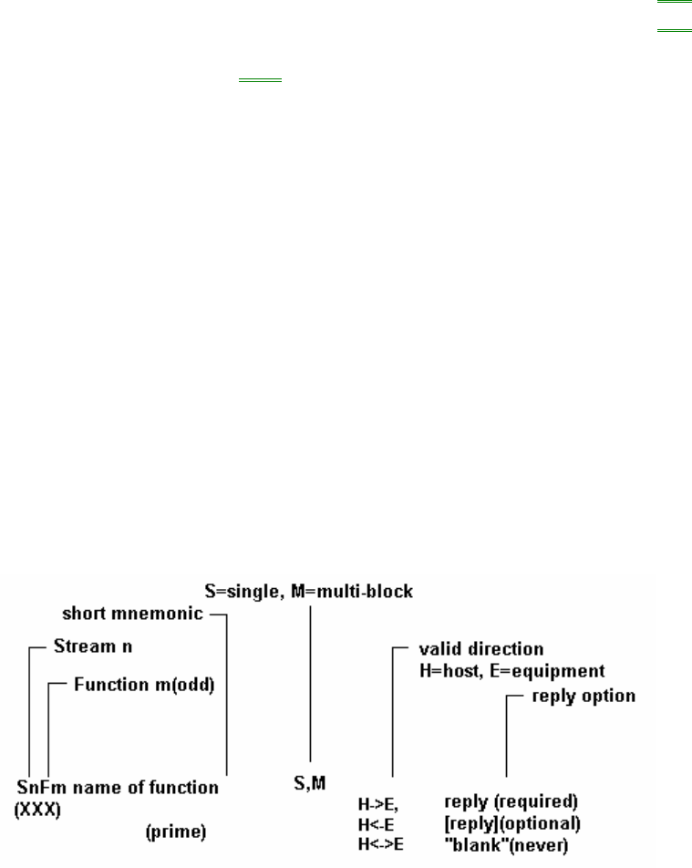
4001-4099 lowest analog readback SV value on last batch SVID
5001-5099 highest analog readback SV value on last batch SVID
6001-6099 average analog readback SV value on last batch SVID
7000-7099 Analog readback variables in a non-ASCII format.
(available for tracing)
SVID
8000-8099 Asyst and Ergospeed common SMIF Variables SVID
8100-8199 Left Asyst SMIF Variables SVID
8200-8299 Right Asyst SMIF Variables SVID
8300-8399 Left Ergospeed SMIF Variables SVID /DVID
8400-8499 Right Ergospeed SMIF Variables SVID /DVID
Where Used: S1F3, S1F11, S1F12, S2F23, S2F33, S2F45, S2F46, S2F47, S2F48; S6F13, S6F18, S6F22
VNAME -- Variable Name Format: 20
Variable names are defined in the VID table above. The name will be the name of one of the three classes of variables:
data variable name (DVNAME), equipment constant name (ECNAME), or status variable name (SVNAME).
Where Used: S1F3, S1F11, S1F12, S2F23
3.0 Message Detail
3.0 Message Detail
This section defines a number of specific functions in different streams to be used as the basis for the GEM
communications between Equipment and Host. The functions are defined in the form of transaction message pairs.
The transactions are described in a standard form, as defined by SEMI E5-95 section 7, which involves specification of
the number, name, single or multiple block, direction of communication, nature of reply required, description, variable
definition, and the detailed structure of the message in terms of lists and items. Double lines separate streams and single
lines separate transactions to aid in readability.
The functions are described in a standard form which involves specification of the number, name, single or multiple block,
direction of communication, nature of reply required, description, variable definition, and the detailed structure of the
message in terms of lists and items. Double lines separate streams, and single lines separate transactions to aid
readability.
The abbreviations used in each transaction are as follows:
Description: A description of the action generated by the function.

Structure: Detailed structure showing lists and defined items. Lists are denoted by a capital L followed by the length
separated by a comma. The individual elements in the list are numbered on separate lines. Nested lists are indented to
emphasize the structure. The detailed form of the items is given in the define section at the beginning of the transaction.
The symbols "<" and ">" are used to enclose each item in the structure data and imply that there is an item header. A
detailed description of each data item as well as a list of the allowable data formats can be found in the Data Item
Dictionary.
Exception: Special cases in the structure that have a different meaning.
SnFm+1 Name of function (same structure as above
(secondary) except never with reply)
Stream 1 Equipment Status
This stream provides a means for exchanging information about the status of the equipment, including its current mode,
depletion of various consumable items, and the status of transfer operations.
S1F0 Abort Transaction (S1F0) S,H<->E
Description:
Used in lieu of an expected reply to abort a transaction. Function 0 is defined in every stream and has the same meaning
in every stream.
Structure:
Header Only.
S1F1 Are You There Request (R) S,H<->E,reply
Description:
Establishes if the equipment is on-line. A function 0 response to this message means the communication is inoperative. In
the equipment, a function 0 is equivalent to a timeout on the receive timer after issuing S1F1 to the host.
Structure:
Header only
S1F2 On Line Data (D) S,H<->E
Description:
Data signifying that the equipment is alive.
Structure:
[1] <L,2
[1][1] <MDLN>
[1][2] <SOFTREV>
>
Exception:
This will not change the ON-LINE/OFF-LINE state of the Equipment. The Host sends a zero length list

to the Equipment.
S1F3 Selected Equipment Status Request (SSR) S,H->E,reply
Description:
A request to the equipment to report selected values of its status.
Structure:
The following structure is approved for all item formats and should be used by all new implementations:
[1] <L,n
[1][1] <VID1>
. .
. .
[1][n] <VIDn>
>
The following structure is included for compatibility with previous implementations and may only be used for items of
format 3 ( ) and 5 ( ):
[1] <Ux,n VID1 … VIDn> or <Ix,n VID1 … VIDn>
Exception:
A zero-length for list item [1] or item [1][x] means report all VIDs.
S1F4 Selected Equipment Status Data (SSD) M,H<-E
Description:
The equipment reports the value of each SVID requested in the order requested. The host remembers the names of
values requested.
Structure:
[1] <L,n
[1][1] <SV1>
. .
. .
[1][n] <SVn>
>
Exceptions:
A zero length for item [1] means no response can be made. A zero-length for item [1][x], SVx, means that SVIDx does not
exist.
S1F11 Status Variable Namelist Request (SVNR) S,H->E,reply
Description:
A request to the equipment to identify certain status variables.
Structure:
[1] <L,n
[1][1] <VID1>
. .
. .
[1][n] <VIDn>
>
Exception:
A zero length for item [1] means report all VIDs.
S1F12 Status Variable Namelist Reply (SVNRR) M,H<-E
Description:
The equipment reports to the host the name and units of the requested SV s.
Structure:
[1] <L,n
[1][1] <L,3
[1][1][1] <VID1>
[1][1][2] <VNAME1>
[1][1][3] <UNITS1>
>
. .
. .
[1][n] <L,3
[1][n][1] <VIDn>
[1][n][2] <VNAMEn>
[1][n][3] <UNITSn>
>
>
S1F13 Establish Communications Request (CR) S,H<->E,reply
Description:
The purpose of this message is to provide a formal means of initializing communications at a logical application level both
on power-up and following a break in commuications. It should be the first message sent following any period where host
and Equipment SECS applications are unable to communicate. An attempt to send an Establish Communications
Request (S1F13) should be repeated at programmable intervals until an Establish Communications Acknowledge (S1F14)
is received within the transaction timeout period with an acknowledgement code accepting the establishment.
Structure:
[1] <L,2
[1][1] <MDLN>
[1][2] <SOFTREV>
>
Exception:
The host sends a zero-length list for item [1] to the equipment.
S1F14 Establish Communications Request Acknowledge (CRA) S,H<->E
Description:
Accept or deny Establish Communications Request (S1F13). MDLN and SOFTREV are on-line data and are valid only if
COMMACK = 0.
Structure:
[1] <L,2
[1][1] <COMMACK>
[1][2] < L,2
[1][2][1] <MDLN>
[1][2][2] <SOFTREV>
>
>
Exception:
The host sends a zero-length for list item [1][2] to the equipment
S1F15 Request OFF-LINE (ROFL) S,H->E,reply
Description:
The host requests that the equipment transition to the OFF-LINE state.
Structure:
Header only.
S1F16 OFF-LINE Acknowledge (OFLA) S,H<-E
Description:
Acknowledge or error.
Structure:
[1] <OFLACK>
S1F17 Request ON-LINE (RONL) S,H->E,reply
Description:
The host requests that the equipment transition to the ON-LINE state.
Structure:
Header only
S1F18 ON-LINE Acknowledge (ONLA) S,H<-E
Description:
Acknowledge or error.
Structure:
[1] <ONLACK>
Stream 2 Equipment Control and Diagnostics
Messages which deal with control of the equipment from the host. This includes all remote operations and equipment self-
diagnostics and calibration but specifically excludes the control operations which are associated with material transfer
(see stream 4 ), loading of executive and boot programs (stream 8 ), and all file and operating system calls (stream 10
and stream 13 ).
S2F0 Abort Transaction S,H<->E
Description:
Same form as S1F0
S2F13 Equipment Constant Request (ECR) S,H->E,reply
Description:
Constants such as for calibration, servo gain, alarm limits, data collection mode and other values that are changed
infrequently can be obtained using this message.
Structure:
[1] < L,n
[1][1] <ECID1>
. .
. .
[1][n] <ECIDn>
>
The following structure is included for compatibility with previous implementations and may only be used for items of
format 3 ( ) and 5 ( ) :
[1] <Ux,n ECID1 ... ECIDn > or <Ix,n ECID1 ... ECIDn >
Exceptions:
A zero-length for list item [1] or item [1][x] means report all ECV 's according to a predefined order.
S2F14 Equipment Constant Data (ECD) M,H<-E
Description:
Data Response to S2F13 in the order requested.
Structure:
[1] <L,n
[1][1] <ECV1>

[1][2] <ECV2>
. .
. .
[1][n] <ECVn>
>
Exceptions:
A zero-length for list item [1] means no response exists. A zero-length for list item [1][x], ECVx , means that ECIDx does
not exist.
S2F15 New Equipment Constant Send (ECS) S,H->E,reply
Description:
Change one or more equipment constants.
Structure:
[1] <L,n
[1][1] <L,2
[1][1][1] <ECID1>
[1][1][2] <ECV1>
>
[1][2] <L,2
[1][2][1] <ECID2>
[1][2][2] <ECV2>
>
. .
. .
. .
[1][n] <L,2
[1][n][1] <ECIDn>
[1][n][2] <ECVn>
>
>
S2F16 New Equipment Constant Acknowledge (ECA) S,H<-E
Description:
Acknowledge or error. If EAC contains a non-zero error code, the equipment should not change any of the ECIDs
specified in S2F15.
Structure:
[1] <EAC>
Note:
Equipment constants cannot be changed if the E220 is displaying either the GEM SETUP or ECO & OPTION,
and only can be changed when E220 is in the idle state. This is done to prevent conflict between operator and
Host attempting to modify the same equipment constant and prevent a change during implanting.
S2F17 Date and Time Request (DTR) S,H<->E,reply

Description:
Useful to check equipment time base or for equipment to synchronize with the host time base.
Structure:
Header only.
S2F18 Data and Time Data (DTD) S,H<->E
Description
Actual time data.
Structure:
[1] <TIME>
Exceptions:
A zero-length item [1] means no time exists.
S2F23 Trace Initialize Send (TIS) S,H->E,reply
Description:
Status variables exist at all times. This function provides a way to sample a subset of those status variables as a function
of time. The trace data is returned on S6F1 and is related to the original request by the TRID. Multiple trace requests may
be made to that equipment allowing it. If equipment receives S2F23 with the same TRID as a trace function that is
currently in progress, the equipment should terminate the old trace and then initiate the new trace. A trace function
currently in progress may be terminated by S2F23 with TRID of that trace and TOTSMP=0.
Structure:
The following structure is approved for all item formats and should be used by all new implementations.
[1] <L,5
[1][1] <TRID>
[1][2] <DSPER>
[1][3] <TOTSMP>
[1][4] <REPGSZ>
[1][5] <L,n
[1][5][1] <SVID1>
. .
. .
[1][5][n] <SVIDn>
>
>
The following structure is included for compatibility with previous implementations and may only be used for items whose
SVID is format 3 ( ) and 5 ( ):
[1] <L,5
[1][1] <TRID>
[1][2] <DSPER>
[1][3] <TOTSMP>

[1][4] <REPGSZ>
[1][5] <U,n SVID1,..., SVIDn> or <I,n SVID1,..., SVIDn>
>
S2F24 Trace Initialize Acknowledge (TIA) S,H<-E
Description:
Acknowledge or error.
Structure:
[1] <TIAACK>
S2F25 Loopback Diagnostic Request (LDR) S,H<->E,reply
Description:
A diagnostic message for checkout of protocol and communication circuits. The binary string sent is echoed back.
Structure:
[1] <ABS>
S2F26 Loopback Diagnostic Data (LDD) S,H<->E
Description:
The echoed binary string.
Structure:
[1] <ABS >
S2F29 Equipment Constant Namelist Request (ECNR) S,H->E,reply
Description:
This function allows the host to retrieve basic information about what equipment constants are available in the equipment.
Structure:
[1] <L,n
[1][1] <ECID1>
. .
. .
[1][n] <ECIDn>
Exception:
A zero-length list item [1] means send information for all ECIDs.
S2F30 Equipment Constant Namelist (ECN) M,H<-E
Description:
Data Response.
Structure:
[1] <L,n (number of equipment constants)
[1][1] <L,6
[1][1][1] <ECID1>
[1][1][2] <ECNAME1>
[1][1][3] <ECMIN1>
[1][1][4] <ECMAX1>
[1][1][5] <ECDEF1>
[1][1][6] <UNITS1>
>
. .
. .
[1][n] <L,6
[1][n][1] <ECIDn>
[1][n][2] <ECNAMEn>
[1][n][3] <ECMINn>
[1][n][4] <ECMAXn>
[1][n][5] <ECDEFn>
[1][n][6] <UNITSn>
>
>
S2F31 Date and Time Set Request (DTS) S,H->E,reply
Description:
Useful to synchronize the equipment time with the host time base.
Structure:
[1] <TIME>
S2F32 Date and Time Set Acknowledge (DTA) S,H<-E
Description:
Acknowledge the receipt of time and date.
Structure:
[1] <TIACK>
S2F33 Define Report (DR) M,H->E,reply
Description:

The purpose of this message is for the host to define a group of reports for the equipment.
The type of report to be transmitted is designated by a Boolean "Equipment Constant." An "Equipment Constant Value" of
"False" means that an "Event Report" (S6F11) will be sent, and a value of "True" means that an "Annoted event Report"
(S6F13) will be sent.
If S2F33 is Multi-block, it must be preceded by the S2F39/S2F40 Inquire/Grant transaction.
Structure:
[1] <L,2
[1][1] <DATAID>
[1][2] <L,n // n reports
[1][2][1] <L,2 // report 1
[1][2][1][1] <RPTID1>
[1][2][1][2] <L,m // m VIDs this report
[1][2][1][2][1] <VID1>
. .
. .
. .
[1][2][1][2][m] <VIDm>
>
>
. .
. .
. .
[1][2][n] <L,2 // report n
[1][2][n][1] <RPTID1>
[1][2][n][2] <L,k // k VIDs this report
[1][2][n][2][1] <VID1>
. .
. .
. .
[1][2][n][2][k] <VIDk>
>
>
>
>
Exceptions:
1. A zero-length list item [1][2] following <DATAID> [1][1] item deletes all report definitions and associated links. See
S2F35 (Link Event/Report).
2. A zero-length list item [1][2][x][2] following <RPTIDx> [1][2][x][1] item deletes report type RPTID. All CEIDs linked to
this RPTID are also deleted.
S2F34 Define Report Acknowledge (DRA) S,H<-E
Description:
Acknowledge or error. If an error condition is detected the entire message is rejected, i.e., partial changes are not allowed.
Structure:
[1] <DRACK>
S2F35 Link Event Report (LER) M,H->E,reply
Description:
The purpose of this message is for the host to link n reports to an event (CEID ). These linked event reports will default to
'disabled' upon linking. That is, the occurrence of an event would not cause the report to be sent until enabled. See S2F37
for enabling reports.
If S2F35 is Multi-block, it must be preceded by the S2F39/S2F40 Inquire/Grant transaction.
Structure:
[1] <L,2
[1][1] <DATAID>
[1][2] <L,n // n events
[1][2][1] <L,2 // event 1
[1][2][1][1] <CEID1>
[1][2][1][2] <L,m // m reports
[1][2][1][2][1] <RPTID1>
. .
. .
. .
[1][2][1][2][m] <RPTIDm>
>
>
. .
. .
. .
[1][2][n] <L,2 // event n
[1][2][n][1] <CEID1>
[1][2][n][2] <L,k // k reports
[1][2][n][2][1] <RPTID1>
. .
. .
. .
[1][2][n][2][k] <RPTIDk>
>
>
>
>
Exceptions:
A zero length list item [1][2][x][2] following <CEIDx > [1][2][x][1] deletes all report links to that event.
S2F36 Link Event Report Acknowledge (LERA) S,H<-E
Description:
Acknowledge or error. If an error condition is detected the entire message is rejected, i.e., partial changes are not allowed.
Structure:
[1] <LRACK>
S2F37 Enable/Disable Event Report (EDER) S,H->E,reply
Description:
The purpose of this message is for the host to enable or disable reporting for a group of events (CEIDs).
Structure:
[1] <L,2
[1][1] <CEED> enable/disable
[1][2] <L,n #CEIDs
[1][2][1] <CEID1>
. .
. .
. .
[1][2][n] <CEIDn>
Exceptions:
A zero length list item [1][2] following <CEED> item [1][] means all CEID s.
S2F38 Enable/Disable Event Report Acknowledge (EERA) S,H<-E
Description
Acknowledge or error. If an error condition is detected the entire message is rejected, i.e., partial changes are not allowed.
Structure:
[1] <ERACK>
S2F39 Multi-block Inquire (DMBI) S,H->E,reply
Description:
If a S2F33, S2F35, or S2F45message is more than one block, this transaction must precede the message.
Structure:
[1] <L,2
[1][1] <DATAID>
[1][2] <DATALENGTH>
>
S2F40 Multi-block Grant (DMBG) S,H<-E
Description:
Grant permission to send multi-block message.
Structure:
[1] <GRANT>
S2F41 Host Command Send (HCS)

S,H->E,reply
Description:
The Host requests the Equipment to perform the specified remote command with the associated parameters.
Structure:
[1] <L,2
[1][1] <RCMD>
[1][2] <L,n // # of parameters
[1][2][1] <L,2
[1][2][1][1] <CPNAME1> // parameter 1 name
[1][2][1][2] <CPVAL1> // parameter 1 value
>
. .
. .
[1][2][n] <L,2
[1][2][n][1] <CPNAMEn> // parameter n name
[1][2][n][2] <CPVALn> // parameter n value
>
>
>
S2F42 Host Command Acknowledge (HCA) S,H<-E
Description:
Acknowledge Host command or error. If command is not accepted due to one or more invalid parameters. (i.e.,
HCACK=3), then a list of invalid parameters will be returned containing the parameter name and reason for being invalid.
Structure:
[1] <L,2
[1][1] <HCACK>
[1][2] <L,n // # of parameters
[1][2][1] <L,2
[1][2][1][1] <CPNAME1> // parameter 1 name
[1][2][1][2] <CPACK1> // parameter 1 reason
>
. .
. .
[1][2][n] <L,2
[1][2][n][1] <CPNAMEn> // parameter n name
[1][2][n][2] <CPACKn> // parameter n reason
>
>
>
Exception:
If there are no invalid parameters, then a list of zero-length will be sent for list item [1][2].
Note:
Remote commands will not be executed unless the machine is in the proper state denoted by the screen being displayed.
Examples of all the screens can be found in the E220 Operator’s or Maintenance Manuals. See RCMD in the Data Item
Dictionary section for further explanation
S2F43 Reset Spooling Streams and Functions (RSSF) S,H->E,reply
Description:
This message allows the host to select specific streams and functions to be spooled whenever spooling is active.
Structure:
[1] <L,m
[1][1] <L,2
[1][1][1] <STRID1>
[1][1][2] <L,n
[1][1][2][1] <FCNID1>
. .
. .
[1][1][2][n] <FCNIDn>
>
>
. .
. .
[1][n] <L,2
[1][n][1] <STRIDn>
[1][n][2] <L,k
[1][n][2][1] <FCNID1>
. .
. .
[1][n][2][k] <FCNIDk>
>
>
>
>
Exceptions:
1. A zero-length for list item[1], m=0, turns off spooling for all streams and functions.
2. A zero-length list item [1][x][2] after item [1][x][1], <STRIDx>, turns on spooling for all functions for the associated
stream <STRIDx>.
Notes:
1. Turning off spooling for all functions for a specific stream is achieved by omitting reference to the stream from
this message.
2. Spooling for Stream 1 is not allowed.
3. Equipment must allow host to spool all primary messages for a stream (except Stream 1 ).
4. A defined list of functions for a stream in this message will replace any previously selected functions.
S2F44 Reset Spooling Acknowledge (RSA) M,H<-E
Description:
Acknowledge or error.
Structure:
[1] <L,2
[1][1] <RSACK> // accept or reject

[1][2] <L,m // m=number of streams with errors
[1][2][1] <L,3
[1][2][1][1] <STRID1>
[1][2][1][2] <STRACK1> // error in stream
[1][2][1][3] <L,n // n = functions in error
[1][2][1][3][1] <FCNID1>
. .
. .
[1][2][1][3][n] <FCNIDn>
>
>
. .
. .
[1][2][m] <L,3
[1][2][m][1] <STRIDm>
[1][2][m][2] <STRACKm> // error in stream
[1][2][m][3] <L,k // k = functions in error
[1][2][m][3][1] <FCNID1>
. .
. .
[1][2][m][3][k] <FCNIDk>
>
>
>
>
Exceptions:
1. If item [1][1], RSACK, =0, list item [1][2] is always zero-length, m=0, indicating no streams or functions in
error.
2. If zero-length list item [1][2][x][3] is zero-length, there are no functions in error for stream <STRIDx>
S2F45 Define Variable Limit Attributes (DVLA) M,H->E,reply
Structure:
[1] <L,2
[1][1] <DATAID>
[1][2] <L,m // # of variables
[1][2][1] <L,2
[1][2][1][1] <VID1>
[1][2][1][2] <L,n // # of limits
[1][2][1][2][1] <L,2
[1][2][1][2][1][1] <LIMITID1>
[1][2][1][2][1][2] <L,p // p=0 or 2
[1][2][1][2][1][2][1] <UPPERDB1>
[1][2][1][2][1][2][2] <LOWERDB1>
>
>
. .
. .
[1][2][1][2][n] <L,2
[1][2][1][2][n][1] <LIMITIDn>
[1][2][1][2][n][2] <L,q // q=0 or 2
[1][2][1][2][n][2][1] <UPPERDBn>
[1][2][1][2][n][2][2] <LOWERDBn>

>
>
>
>
. .
. .
[1][2][m] <L,2
[1][2][m][1] <VIDm>
[1][2][m][2] <L,k // # of limits
[1][2][m][2][1] <L,2
[1][2][m][2][1][1] <LIMITID1>
[1][2][m][2][1][2] <L,r // r=0 or 2
[1][2][m][2][1][2][1] <UPPERDB1>
[1][2][m][2][1][2][2] <LOWERDB1>
>
>
. .
. .
[1][2][m][2][k] <L,2
[1][2][m][2][k][1] <LIMITIDk>
[1][2][m][2][k][2] <L,s // s=0 or 2
[1][2][m][2][k][2][1] <UPPERDBk>
[1][2][m][2][k][2][2] <LOWERDBk>
>
>
>
>
>
>
Exceptions:
1. Zero-length, m=0, list item [1][2] means all deadband limits, UPPERDB and LOWERDB, for all monitored VIDs are
"undefined."
2. Zero-length list item [1][2][x][2]for VIDx means all deadband limits, UPPERDB and LOWERDB for VIDx are
"undefined."
3. Zero-length deadbands list item [1][2][x][2][y][2] means deadband limits UPPERDBy and LOWERDBy for VIDx
are "undefined."
S2F46 Variable Limit Attribute Acknowledge (VLAA) M,H<-E
Description:
Acknowledge definition of variable limit attributes or report error. If S2F45 is not accepted due to one or more invalid
parameters (e.g., LIMITACK=3), then a list of invalid parameters is returned containing the variable limit attribute and
reason for rejection. If an error condition is detected, the entire message is rejected, i.e., partial changes are not allowed.
Structure:
[1] <L,2
[1][1] <VLAACK>
[1][2] <L,m // m=number of invalid parameters
[1][2][1] <L,3
[1][2][1][1] <VID1> // VID with error
[1][2][1][2] <LVACK1> // reason
[1][2][1][3] <L,p // p=0 or 2
[1][2][1][3][1] <LIMITID1> //limit in error
[1][2][1][3][2] <LIMITACK1> // reason
[1][2][1][3][0] >
[1][2][1][0] >
. .
. .
. .
[1][2][m] <L,3
[1][2][m][1] <VIDm> // VID with error
[1][2][m][2] <LVACKm> // reason
[1][2][m][3] <L,q // q=0 or 2
[1][2][m][3][1] <LIMITIDm> //limit in error
[1][2][m][3][2] <LIMITACKm> // reason
[1][2][m][3] >
[1][2][m] >
[1][2] >
[1] >
Exceptions:
1. Zero-length, m=0, list item [1][2] means no invalid variable limit attributes.
2. Zero-length list item [1][2][x][3] means no invalid limit values for that VIDx.
S2F47 Variable Limit Attribute Request (VLAR) S,H->E,reply
Description:
This message allows the host to query the equipment for current variable limit attribute definitions.
Structure:
[1] <L,m // m=# VIDs this request)
[1][1] <VID1>
. .
. .
[1][m] <VIDm>
>
Exceptions:
A zero-length list item [1], m=0, requests a list of all VID values that can have variable limit attributes.
S2F48 Variable Limit Attributes Send (VLAS) M,H<-E
Description:
Equipment sends values of requested variable limit attribute definitions in the order requested.
Structure:
[1] <L,m (m=# VIDs this request)
[1][1] <L,2
[1][1][1] <VID1>
[1][1][2] <L,p // p=0 or 4
[1][1][2][1] <UNITS1>
[1][1][2][2] <LIMITMIN1>
[1][1][2][3] <LIMITMAX1>
[1][1][2][4] <L,n //n=# limits defined
[1][1][2][4][1] <L,3
[1][1][2][4][1][1] <LIMITID1>
[1][1][2][4][1][2] <UPPERDB1>
[1][1][2][4][1][3] <LOWERDB1>
>
. .
. .
. .
[1][1][2][4][n] <L,3
[1][1][2][4][n][1] <LIMITIDn>
[1][1][2][4][n][2] <UPPERDBn>
[1][1][2][4][n][3] <LOWERDBn>
>
>
>
>
. .
. .
. .
[1][m] <L,2
[1][m][1] <VIDm>
[1][m][2] <L,q // q=0 or 4
[1][m][2][1] <UNITSm>
[1][m][2][2] <LIMITMINm>
[1][m][2][3] <LIMITMAXm>
[1][m][2][4] <L,r //r=# limits defined
[1][m][2][4][1] <L,3
[1][m][2][4][1][1] <LIMITID1>
[1][m][2][4][1][2] <UPPERDB1>
[1][m][2][4][1][3] <LOWERDB1>
>
. .
. .
. .
[1][m][2][4][r] <L,3
[1][m][2][4][r][1] <LIMITIDr>
[1][m][2][4][r][2] <UPPERDBr>
[1][m][2][4][r][3] <LOWERDBr>
>
>
>
>
>
>
Exceptions:
1. A zero-length list item [1][x][2] means that limits are not supported for the VIDx.
2. A zero-length list item [1][x][2][4] means no limits are currently defined for VIDx.
S2F49 Host Enhanced Remote Command
S,H->E,reply
Description:
The Host requests the Equipment to perform the specified remote command with the associated parameters.
Structure:
[1] <L,4

[1][1] <DATAID>
[1][2] <OBJSPEC>
[1][3] <RCMD>
[1][4] <L,n // # of parameters
[1][4][1] <L,2
[1][4][1][1] <CPNAME1> // parameter 1 name
[1][4][1][2] <CEPVAL1> // parameter 1 value
>
. .
. .
[1][4][n] <L,2
[1][4][n][1] <CPNAMEn> // parameter n name
[1][4][n][2] <CEPVALn> // parameter n value
>
>
>
Note: This is essentially the same as S2F41 except parameters in CEPVAL can also be lists. This why RCMD
"PPSELECT" has to be in an S2F49 message only when it contains the "PPID-LIST" parameter. DATAID can be any
number while OBJSPEC may be set to a null string.
S2F50 Enhanced Remote Command Acknowledge S,H<-E
Description:
The equipment acknowledges Enhanced Remote Command or reports any errors. If the command is not accepted due to
one or more invalid parameters, then a list of invalid parameters will be returned containing the parameter name and
reason for being invalid.
Structure:
[1] <L,2
[1][1] <HCACK>
[1][2] <L,n // # of parameters
[1][2][1] <L,2
[1][2][1][1] <CPNAME1> // parameter 1 name
[1][2][1][2] <CEPACK1> // parameter 1 reason
>
. .
. .
[1][2][n] <L,2
[1][2][n][1] <CPNAMEn> // parameter n name
[1][2][n][2] <CEPACKn> // parameter n reason
>
>
>
S2F71- AGV-ACH Automation Initiate Processing Request S,H->E,reply
Description:
Initiate Processsing for AGV-ACH automation.
Structure:
[1] <L, 2
[1][1] <L, 4
[1][1][1] <TSID1>
[1][1][2] <ESID1>
[1][1][3] <PPID1>
[1][1][4] <LOTID1>
>
[1][2] <L, 4
[1][2][1] <TSID2>
[1][2][2] <ESID2>
[1][2][3] <PPID2>
[1][2][4] <LOTID2>
>
>
Notes:
1. PPID1 and PPID2 must be same for one batch
2. The E220 shall queue S2F71 while the equipment is processing wafers. The queuing buffer shall hold up to four
S2F71s.
3. In case that only one cassette is processed during one batch, the structure of S2F71 shall be
[1] <L, 2
[1][1] <L, 4
[1][1][1] <TSID1>
[1][1][2] <ESID1>
[1][1][3] <PPID1>
[1][1][4] <LOTID1>
>
[1][2] <L,4
[1][2][1] <0>
[1][2][2] <0>
[1][2][3] <’ ‘>
[1][2][4] <’ ‘>
>
>
S2F72 - ACH Initiate Processing Acknowledge M,H<-E
Description:
Acknowledge or error.
Structure:
[1] <ACHA >
Stream 3 Material Status
The functions of the material status stream are used to communicate material-in-process, time to completion information,
and extraordinary material occurrences.
S3F0 Abort Transaction (S3F0) S,H<->E
Description:
Same form as S1F0
Stream 4 Material Control
The material control stream contains the original material control protocol and the newer protocol which supports the
SEMI-E32 Material Movement Management Services standard.
S4F0 Abort Transaction (S4F0) S,H<->E
Description:
Same form as S1F0.
Stream 5 Exception Reporting
This stream contains messages regarding binary and analog equipment alarms. The alarms are generated by the
equipment in response to changing conditions detected by the equipment. Alarms are divided into categories as follows:
1. Personal safety -- condition may be dangerous to people.
2. Equipment safety -- condition may harm equipment.
3.Parameter control warning -- parameter variation outside of preset limits -- may harm product.
4. Parameter control error -- parameter variation outside of reasonable control limits -- may indicate an equipment
malfunction.
5.Irrecoverable error -- intervention required before normal use of equipment can resume.
6.Equipment status warning -- an unexpected condition has occurred, but operation can continue.
7.Attention flags -- a signal from a process program indicating that a particular step has been reached.
8.Data integrity -- a condition which may cause loss of data; usually related to Stream 6.
S5F0 Abort Transaction S,H<->E
Description:
Same form as S1F0.
S5F1 Alarm Report Send (ARS) S,H<-E,[reply]
Description:
This message reports a change in or presence of an alarm condition. One message will be issued when the alarm is set
and one message will be issued when the alarm is cleared. Irrevocable errors and attention flags may not have a
corresponding clear message.
Structure:
[1] <L,3
[1][1] <ALCD>
[1][2] <ALID>
[1][3] <ALTX>
>
S5F2 Alarm Report Acknowledge (ARA) S,H->E
Description:
Acknowledge or error.
Structure:
[1] <ACKC5>
S5F3 Enable/Disable Alarm Send (EAS) S,H->E,[reply]
Description:
This message will change the state of the enable bit in the equipment. The enable bit determines if the alarm will be sent
to the host. Alarms which are not controllable in this way are unaffected by this message.
Structure:
[1] <L,2
[1][1] <ALED>
[1][2] <ALID>
>
Exception:
A zero-length item [1][2], ALID, means all alarms.
S5F4 Enable/Disable Alarm Acknowledge (EAA) S,H<-E
Description:
Acknowledge or error.
Structure:
[1] <ACKC5>
S5F5 List Alarms Request (LAR) S,H->E,reply
Description:
This message requests the equipment to send binary and analog alarm information to the host.
Structure:
[1] <ALID1,...,ALIDn>
Exception:
A zero-length item [1] means send all possible alarms regardless of the state of ALED.
S5F6 List Alarm Data (LAD) M,H<-E
Description:
This message contains the alarm data known to the equipment. There are "m" alarms in the list.
Structure:

[1] <L,m
[1][1] <L,3
[1][1][1] <ALCD1>
[1][1][2] <ALID1>
[1][1][3] <ALTX1>
>
. .
. .
[1][m] <L,3
[1][m][1] <ALCDm>
[1][m][2] <ALIDm>
[1][m][3] <ALTXm>
>
Exception:
A zero-length item [1], m=0, means no response can be made.
A zero-length item [1][x][1] ALCDx or item [1][x][2] ALIDx or item [1][x][3] ALTXx means that item does not exist.
S5F7 List Enabled Alarm Request (LEAR) S,H->E,reply
Description:
List alarms which are enabled.
Structure:
Header only.
S5F8 List Enabled Alarm Data (LEAD) M,H<-E
Description:
This message is similar to S5F6 except that it lists only alarms which
are enabled.
Structure:
Same as S5F6 .
Stream 6 Data Collection
This stream is intended to cover the needs of in-process measurements and equipment monitoring.
S6F0 Abort Transaction (S6F0) S,H<->E
Description:
Same form as S1F0.
S6F1 Trace Data Send (TDS) S,H<-E,[reply]

Description:
This function sends samples to the host according to the trace setup done by S2,F23. Trace is a time-driven form of
equipment status.
Structure:
[1] <L,4
[1][1] <TRID>
[1][2] <SMPLN>
[1][3] <STIME>
[1][4] <L,n
[1][4][1] <SV1>
. .
. .
[1][4][n] <SVn>
>
>
Exception:
A zero-length [1][3] STIME item means no value is given and that the time is to be
derived from [1][2] SMPLN item along with knowledge of the request.
S6F2 Trace Data Acknowledge (TDA) S,H->E
Description:
Acknowledge or error.
Structure:
[1] <ACKC6>
S6F5 Multi-block Data Send Inquire (MBI) S,H<-E,reply
Description:
If the discrete data report S6F11 , S6F13, can involve more than one block, this transaction must precede the
transmission.
Structure:
[1] <L,2
[1][1] <DATAID>
[1][2] <DATALENGTH>
>
S6F6 Multi-block Grant (MBG) S,H->E
Description:
Grant permission to send.
Structure:

[1] <GRANT6>
S6F11 Event Report Send (ERS) M,H<-E,reply
Description:
The purpose of this message is for the equipment to send a defined, linked, and enabled group of reports to the host upon
the occurrences of an event (CEID).
If S6F11 is Multi-block, it must be preceded by the S6F5 /S6F6 Inquire/Grant transaction.
Structure:
[1] <L,3
[1][1] <DATAID>
[1][2] <CEID>
[1][3] <L,n
[1][3][1] <L,2
[1][3][1][1] <RPTID1>
[1][3][1][2] <L,p
[1][3][1][2][1] <V1>
. .
. .
[1][3][1][2][p] <Vp>
>
>
. .
. .
[1][3][n] <L,2
[1][3][n][1] <RPTID1>
[1][3][n][2] <L,r
[1][3][n][2][1] <V1>
. .
. .
[1][3][n][2][r] <Vr>
>
>
>
>
Exceptions:
A zero-length list item [1][3] for the number of reports means there are no reports linked
to the given CEID and a 'null' report is assumed.
S6F12 Event Report Acknowledge (ERA) S,H->E
Description:
Acknowledge or error.
Structure:
[1] <ACKC6>

S6F13 Annotated Event Report Send (AERS) M,H<-E,reply
Description:
This message is the same as S6F11 with the exception that VID's are sent with the data.
If S6F13 is Multi-block, it must be preceded by the S6F5 /S6F6 Inquire/Grant transaction.
Structure:
[1] <L,3
[1][1] <DATAID>
[1][2] <CEID>
[1][3] <L,n
[1][3][1] <L,2
[1][3][1][1] <RPTID1>
[1][3][1][2] <L,p
[1][3][1][2][1] <L,2
[1][3][1][2][1][1] <VID1>
[1][3][1][2][1][2] <V1>
>
. .
. .
[1][3][1][2][p] <L,2
[1][3][1][2][p][1] <VIDp>
[1][3][1][2][p][2] <Vp>
>
>
>
. .
. .
[1][3][n] <L,2
[1][3][n][1] <RPTIDn>
[1][3][n][2] <L,q
[1][3][n][2][1] <L,2
[1][3][n][2][1][1] <VID1>
[1][3][n][2][1][2] <V1>
>
. .
. .
[1][3][n][2][q] <L,2
[1][3][n][2][q][1] <VIDq>
[1][3][n][2][q][2] <Vq>
>
>
>
>
>
Exceptions:
A zero-length list item [1][3] for the number of reports means there are no reports linked
to the given CEID and a 'null' report is assumed.
S6F14 Annoted Event Report Acknowledge (AERA) S,H->E
Description
Acknowledge or error.
Structure:

[1] <ACKC6>
S6F15 Event Report Request (ERR) S,H->E,reply
Description:
The purpose of this messge is for the host to demand the report group from the equipment linked to event CEID
Structure:
[1] <CEID>
S6F16 Event Report Data M,H<-E
Description:
Equipment sends reports linked to given CEID to host.
Structure:
Identical to structure of S6F11.
S6F17 Annoted Event Report Request (AERR) S,H->E,reply
Description:
Same as S6F15 , but requests annotated reports.
Structure:
[1] <CEID>
S6F18 Annoted Event Report Data (AERD) M,H<-E
Description:
Equipment sends annotated reports linked to given CEID.
Structure:
Same as S6F13.
S6F19 Individual Report Request (IRR) S,H->E,reply
Description:
The purpose of this message is for the host to request a defined report
from the equipment.

Structure:
[1] <RPTID>
S6F20 Individual Report Data (IRD) M,H<-E
Description:
Equipment sends variable data defined for the given RPTID to the host.
Structure:
[1] <L,n # of variable data items
[1][1] <V1>
. .
. .
[1][n] <Vn>
>
Exceptions:
A zero-length list item [1] means RPTID is not defined.
S6F21 Annoted Individual Report Request (AIRR) S,H->E,reply
Description:
The purpose of this message is for the host to request an annotated defined
report from the equipment.
Structure:
<RPTID>
S6F22 Annoted Individual Report Data (AIRD) M,H<-E
Description:
Equipment sends annotated variable data defined for the given RPTID to the host.
Structure:
[1] <L,n // number of variable data items
[1][1] <L,2
[1][1][1] <VID1>
[1][1][2] <V1>
>
.
.
[1][n] <L,2
[1][n][1] <VIDn>
[1][n][2] <Vn>
>
>
Exceptions:
A zero-length for list item [1], n=0, means RPTID is not defined.
S6F23 Request Spooled Data (RSD) S,H->E,reply
Description:
The purpose of this message is for the host to request transmission or deletion of the messages currently spooled by the
equipment.
Structure:
[1] <RSDC>
S6F24 Request Spooled Data Acknowledgement Send (RSDAS) S,H<-E
Description:
The purpose of this message is to acknowledge the receipt of the Request Spooled Data (S6F23) and to respond with an
appropriate acknowledge code.
Structure:
[1] <RSDA>
Stream 7 Process Program Management
The functions in this stream are used to manage and transfer process programs. Process programs are the equipment-
specific descriptions that determine the procedure to be conducted on the material by a single piece of equipment.
Methods are provided to transfer programs as well as establish the link between the process program and the material to
be processed with that program.
NOTE -- The equipment-to-host transfer of the process program, denoted by the R bit in the header (R=1), provides the
mechanism for the host computer to receive process programs created on the equipment. This allows use of the
equipment without having process program generation capabilities on the host.
NOTE -- M/PM defines the Material/Process Matrix. The Material/Process Matrix is a table which links the material to the
process program to be used in processing the material.
NOTE -- The matrix structure allows the program linkages to be extablished for each MID or the multi-MID production
plans for an extended period of time. The host system makes the choice of operating mode. By continuous updates to the
equipment matrix, automatic system backup is achieved.
S7F0 Abort Transaction (S7F0) S,H<->E
Description:
Same form as S1F0
S7F1 Process Program Load Inquire S,H<->E,reply
Description:
This message is used to initiate the transfer of a process program or to select from stored programs. The message may
be used to initiate the transfer of an unformatted process program (S7F3/S7F4) or a formatted process program
(S7F23/S7F24).
Structure:
[1] <L,2
[1][1] <PPID>
[1][2] <LENGTH>
>
S7F2 Process Program Load Grant (PPG) S,H<->E
Description:
This message gives permission for the process program to be loaded.
Structure:
[1] <PPGNT>
S7F3 Process Program Send (PPS) M,H<->E,reply
Description:
The program is sent. If S7F3 is multi-block, it must be preceded by the S7F1/S7F2 Inquire/Grant transaction.
Structure:
[1] <L,2
[1][1] <PPID>
[1][2] <PPBODY>
>
S7F4 Process Program Acknowledge (PPA) S,H<->E
Description:
Acknowledge or error.
Structure:
[1] <ACKC7>
S7F5 Process Program Request S,H<->E,reply
Description:
This message is used to request the transfer of a process program.
Structure:
[1] <PPID>
S7F6 Process Program Data (PPD) M,H<->E
Description:
This message is used to transfer a process program.
Structure:
[1] <L,2
[1][1] <PPID>
[1][2] <PPBODY1>
>
or
[1] <L,2
[1][1] <PPID>
[1][2] <PPBODY2SHORT>
>
or
[1] <L,2
[1][1] <PPID>
[1][2] <PPBODY2LONG>
>
or
[1] <L,2
[1][1] <PPID>
[1][2] <PPBODY3>
>
S7F17 Delete Process Program Send (DPS) S,H->E,reply
Description:
This message is used by the host to request the equipment to delete process program from equipment storage.
Structure:
[1] <L,n (Number of process programs to be deleted)
[1][1] <PPID1>
. .
. .
[1][n] <PPIDn>
>
S7F18 Delete Process Program Acknowledge (DPA) S,H<-E
Description:
Acknowledge or error.
Structure:
[1] <ACKC7>

S7F19 Current EPPD Request (RER) S,H->E,reply
Description:
This message is used to request the transmission of the current equipment process program directory (EPPD). This is a
list of all the PPID s of the process programs stored in the equipment.
Structure:
Header only
S7F20 Current EPPD Data (RED) M,H<-E
Description:
This message is used to transmit the current EPPD.
Structure:
[1] <L,n (number of process programs in the directory)
[1][1] <PPID1>
. .
. .
[1][n] <PPIDn>
S7F23 Formatted Process Program Send (FPS) M,H<->E,reply
Description:
This message allows movement of formatted process programs between a piece of equipment and its host system. The
values of MDLN and SOFTREV are obtained from the PCD used to generate the process program. If S7F23 is multi-
block, it must be preceded by the S7F1/S7F2 Inquire/Grant transaction.
Structure:
[1] <L,4
[1][1] <PPID>
[1][2] <MDLN>
[1][3] <SOFTREV>
[1][4] <L,n // n=Number of Process Commands)
[1][4][1] <L,2
[1][4][1][1] <CCODE1>
[1][4][1][2] <L,p (p=Number of Parameters)
[1][4][1][2][1] <PPARM1>
. .
. .
[1][4][1][2][p] <PPARMp>
>
>
. .
. .
[1][4][n] <L,2
[1][4][n][1] <CCODEn>
[1][4][n][2] <L,q // q=Number of Parameters)
[1][4][n][2][1] <PPARM1>

. .
. .
[1][4][n][2][q] <PPARMq>
>
>
>
>
S7F24 Formatted Process Program Acknowledge (FPA) S,H<->E
Description:
Acknowledges reception of a formatted process program at its destination and whether the process program was
accepted by the interpreter. A returned status of "accepted" by the interpreter means only that the message is understood.
The validity of the contents of the process program is determined through a separate transaction (S7F27/S728).
Structure:
[1] <ACKC7>
S7F25 Formatted Process Program Request (FPR) S,H<->E,reply
Description:
This message is used by either equipment or host to request a particular process program from the other.
Structure:
<PPID>
S7F26 Formatted Process Program Data (FPD) M,H<->E
Description:
This message transfers a process program in response to a request for the PPID. The values of MDLN and SOFTREV
are obtained from the PCD used to generate the process program.
Structure:
[1] <L,4
[1][1] <PPID>
[1][2] <MDLN>
[1][3] <SOFTREV>
[1][4] <L,n // n=Number of Process Commands)
[1][4][1] <L,2
[1][4][1][1] <CCODE1>
[1][4][1][2] <L,p (p=Number of Parameters)
[1][4][1][2][1] <PPARM1>
. .
. .
[1][4][1][2][p] <PPARMp>
>
>
. .
. .
[1][4][n] <L,2
[1][4][n][1] <CCODEn>

[1][4][n][2] <L,q // q=Number of Parameters)
[1][4][n][2][1] <PPARM1>
. .
. .
[1][4][n][2][q] <PPARMq>
>
>
>
>
Exception:
A zero length for list item [1] means the request was denied.
S7F27 Process Program Verification Send (PVS) S,H<-E,reply
Description:
This message indicates to the host that a process program has been received and checked by the equipment. The result
of the check is specified by the list of errors. An empty error list (list of zero-length) or a one-element list with ACKC7A
having a value of zero (0) indicates no errors were found in the process program. The equipment may report as many
errors as it seems appropriate. The equipment is responsible for sending a single copy of this message to the host after
any reception of a formatted process program (S7F23 or S7F26). If S7F27 is multi-block, it must be preceded by the
S7F29/S7F30 Inquire/Grant Transaction.
Structure:
[1] <L,2
[1][1] <PPID>
[1][2] <L,n // n=number of errors being reported)
[1][2][1] <L,3
[1][2][1][1] <ACKC7A1>
[1][2][1][2] <SEQNUM1>
[1][2][1][3] <ERRW71>
>
[1][2][n] <L,3
[1][2][n][1] <ACKC7An>
[1][2][n][2] <SEQNUMn>
[1][2][n][3] <ERRW7n>
>
>
>
S7F28 Process Program Verification Acknowledge (PVA) S,H->E
Description:
Reply by host to equipment acknowledging reception of Process Program Verification Send (PVS).
Structure:
Header only
S7F29 Process Program Verification Inquire (PVI) S,H<-E,reply
Description:
This message allows a piece of equipment to ask a host for permission to send a multi-block PVS.
Structure:
[1] <LENGTH>
S7F30 Process Program Verification Grant (PVG) S,H->E
Description:
Reply by host to equipment providing response to Process Program Verification Inquire (PVI).
Structure:
[1] <PPGNT>
Stream 8 Control Program Transfer
The purpose of this stream is to provide the method for transmitting the programs used in the equipment to perform the
control function or to execute the transmitted process program.
S8F0 Abort Transaction (S8F0) S,H<->E
Description:
Same form as S1F0.
Stream 9 System Errors
This stream provides a method of informing the host that a message block has been received which cannot be handled or
that a timeout on a transaction (receive) timer has occurred. The messages indicate either a Message Fault or a
Communications Fault has occurred but do not indicate a Communications Failure has occurred.
Communications Failure -- A Communications Failure occurs in a SECS-I environment when, and only when, the RTY
limit is exceeded. Note: In the event of a Communications Failure, no Stream 9 message is sent.
Communications Fault -- A Communications Fault occurs when the equipment does not receive an expected message
(when a transaction timer or a conversation timer has expired).
Message Fault -- A message Fault occurs when the equipment receives a message which it cannot process because of a
fault that arises from the content, context, or length of the message.
S9F0 Abort Transaction S,H<->E
Description:
Same form as S1F0.
S9F1 Unrecognized Device ID S,H<-E
Description:
The device ID in the message block header did not correspond to any known device ID in the node detecting the error.
Structure:
[1] <MHEAD>
S9F2 Not Used
S9F3 Unrecognized Stream Type (USN) S,H<-E
Description:
The equipment does not recognize the stream type in the message block header.
Structure:
[1] <MHEAD>
S9F4 Not Used
S9F5 Unrecognized Function Type (UFN) S,H<-E
Description:
This message indicates that the function in the message ID is not recognized by the receiver.
Structure:
[1] <MHEAD>
S9F6 Not Used
S9F7 Illegal Data (IDN) S,H<-E
Description:
This message indicates that the stream and function were recognized, but the associated data format could not be
interpreted.
Structure:
[1] <MHEAD>
S9F8 Not Used
S9F9 Transaction Timer Timeout (TTN) S,H<-E
Description:
This message indicates that a transaction (receive) timer has timed out and that the corresponding transaction has been
aborted. It is up to the host to respond to this error in an appropriate manner to keep the system operational.
Structure:
[1] <SHEAD>
S9F10 Not Used
S9F11 Data Too Long (DLN) S,H<-E
Description:
This message to the host indicates that the equipment has been sent more data than it can handle.
Structure:
[1] <MHEAD>
S9F12 Not Used
S9F13 Conversation Timeout (CTN) S,H<-E
Description:
Data were expected but none were received within a reasonable length of time. Resources have been cleared.
Structure:
[1] <L,2
[1][1] <MEXP>
[1][2] <EDID>
>
S9F14 Not Used
Stream 10 Terminal Services
The functions of this stream is to pass textual messages between operator terminals attached to processing and/or testing
equipment and the host. The equipment makes no attempt to interpret the text of the message, but merely passes it from
terminal keyboard to the host or from the host to the display of the terminal. Management of human response times to
information displayed on terminals is the responsibility of the host.
S10F0 Abort Transaction S,H<->E
Description:
Same form as S1F0.
S10F1 Terminal Request (TRN) S,H<-E,[reply]
Description:
A terminal text message to the host.
Structure:
[1] <L,2
[1][1] <TID>
[1][2] <TEXT>
>
S10F2 Terminal Request Acknowledge S,H->E
Description:
Acknowledge or error
Structure:
[1] <ACKC10>
S10F3 Terminal Display, Single (VTN) S,H->E, [reply]
Description:
Data to be displayed.
Structure:
[1] <L,2
[1][1] <TID>
[1][2] <TEXT>
>
S10F4 Terminal Display, Single Acknowledge (VTA) S,H<-E
Description:
Acknowledge or error
Structure:
[1] <ACKC10>
S10F5 Terminal Display, Multi-Block (VTN) M,H->E,[reply]
Description:
Data to be displayed on the equipment's terminal.
Structure:
[1] <L,2
[1][1] <TID>
[1][2] <L,n
[1][2][1] <TEXT1>
. .
. .
[1][2][n] <TEXTn>
>
>
S10F6 Terminal Display, Multi-block Acknowledge (VMA) S,H<-E
Description:
Acknowledge or error
Structure:
[1] <ACKC10>
S10F7 Multi-block Not Allowed (MNN) S,H<-E
Description:
An error message from a terminal that cannot handle a multi-block message from S10F5.
Structure:
[1] <TID>
S10F8 Not Used
Stream 11 Deleted
Stream 11 has been deleted and will not appear again in this publication.
It is the consensus of the Communications Committee that Stream 11 is obsolete. Its use is discouraged, and it has been
removed from the 1989 edition of the standard. The reasons for removal are three-fold:
1.The purpose of this stream, as it was originally envisioned, is perceived to be of little use and can best be accomplished
by other means beyond the scope of this standard;
2.The functions in this stream have many technical problems that severely limit their use
There is a noticeable lack of implementations of this standard that utilize Stream11 in its originally intended form.
Note: Applications that need to transfer unformatted data between the host and equipment should use the facilities of
Stream 13 .
Stream 12 Wafer Mapping
Messages which deal with coordinate positions and data associated with those positions. This includes functions such as
wafer mapping with coordinates of die on a wafer and the associated binning information.
S12F0 Abort Transaction S,H<->E
Description:
Same form as S1F0.
Stream 13 Unformatted Data Set Transfers
This stream provides a protocol to transfer data sets between systems. It is not intended to provide a general file access
mechanism.
S13F0 Abort Transaction (S13,F0) S,H<->E
Description:
Same form as S1F0
Stream 14 Object Services
The functions in this stream are used for generic functions concerning objects, including obtaining information about
objects and setting values for an object
S14F0 Abort Transaction (S14F0) S,H<->E
Description:
Same form as S1F0.
4.0 Message Scenarios
4.0 Message Scenarios
The following scenarios demonstrate a possible sequence of messages when the Equipment is in a specific operational
state. They are not the only sequence. A number of undeterministic conditions effect the sequences.
Note: The left margin has been extented to the furthest point to allow use of the entire page for the following scenarios.
Host Attempts to Establish Communications
The Equipment has completed initialization and is idle. The default communications states are ENABLED, OFF-LINE,
and LOCAL.
COMMENT HOST EQUIPMENT
Communications state is Enabled
(any substate)
Establish Communications Request S1,F13-->
Reply COMMACK = Accept and
Communications state =
COMMUNICATING
<--S1,F14
Equipment Attempts to Establish Communications
after Power-On
The Communication state is ENABLED. The Control State is ON-LINE/REMOTE. These setting were set as default.
COMMENT HOST EQUIPMENT
[LOOP]
[LOOP] -- SEND
Establish Communications Request <--S1,F13
Reply COMMACK = Accept and
Communications state =
COMMUNICATING
S1,F14-->
[IF] S1,F14 received without
timeouts
[THEN] exit_loop -- SEND
[ELSE] Delay for interval in
Establish Communications
Timeout
[END_IF]
[END_LOOP] -- SEND
[IF] COMMACK = Accept
[THEN] Communication State =
Communicating exit_loop--
[ELSE] Reset timer for delay, and
delay for interval specified in
Establish Communication
Timeout
[END_IF]
[END_LOOP]
ARE YOU THERE? <--S1,F1
Acknowledge S1,F2-->
[IF ENABLED]
CEID = 68
CONTROL STATE IS REMOTE
<--S6,F11
Acknowledge S6,F12-->
OPERATOR LOG ON SCREEN
APPEARS
EQUIPMENT WAITS FOR
OPERATOR LOG-ON
OPERATOR LOGS-ON
[IF ENABLED]
CEID = 82
OPERATOR LOG ON EVENT
<--S6,F11
Acknowledge S6,F12-->
[IF] PRIVILEGE IS CORRECT
HOST CONTROL HOST
CONTROL SCREEN
[ELSE] LESSER PRIVILEGE
MODE MENU SCREEN
[IF ENABLED] AND LOADLOCK
EMPTY
CEID = 84
READY TO RECEIVE MATERIAL
<--S6,F11
Acknowledge S6,F12-->
Operator Attempts to Establish Communications
Operator switches to the Host Interface screen.
The Communications State is DISABLED. The Control state is ON-LINE. NOT COMMUNICATING is displayed in the
status area of the Host Mode block. Operator touches button icon labeled DISABLE. The label changes from DISABLE to
ENABLE.
COMMENT HOST EQUIPMENT COMMENT
[LOOP]
[LOOP] -- SEND
<--S1,F13 Establish Communications Request
Reply COMMACK = Accept and
Communications state =
COMMUNICATING
S1,F14-->
[IF] S1,F14 received without
timeouts
[THEN] exit_loop -- SEND
[ELSE] Delay for interval in
Establish Communications
Timeout
[END_IF]
[END_LOOP] -- SEND
[IF] COMMACK = Accept
[THEN] Communication State =
Communicating exit_loop--
[ELSE] Reset timer for delay, and
delay for interval specified in
Establish Communication
Timeout
[END_IF]
[END_LOOP]
Status area in the Host Mode Block of the Host Interface Screen displays COMMUNICATING
<--S1,F1 ARE YOU THERE?
Acknowledge S1,F2-->
<--S6,F11 [IF ENABLED]
CEID= 67/68
COMMUNICATIONS STATE IS
REMOTE or LOCAL
Acknowledge S6,F12-->
<--S6,F11
[IF ENABLED] AND LOADLOCK EMPTY
CEID= 84
READY TO RECEIVE MATERIAL
Acknowledge S6,F12-->
Host Attempts to Establish Communications,
Equipment Disabled
Equipment is powered on and the communication state is DISABLE.
COMMENT HOST EQUIPMENT COMMENT
Establish Communications Request S1,F13-->
HOST TIMEOUT
Remote Process Control Scenario (Unformatted Process
Program)
Equipment’s Communications state is ENABLED and COMMUNICATING. The Control state is ON-LINE and REMOTE.
The exchanges shown below may take place in a different sequence because of undeterministic timing between the
various devices of the E220.
SCREEN 2
HOST CONTROL SCREEN
Operator switches to Host Control screen.
COMMENT HOST EQUIPMENT COMMENT
Idle State - Waiting for command from
operator or Host
[IF]Operator gives batch ID to Host,
[THEN] Process Program request from
HOST initiated
[IF] Process Program not present in
EPPD
[THEN]
Process Program Load Inquiry S7,F1-->
<--S7,F2 Process Program Load Grant
Process Program Send S7,F3-->
[ENDIF]
<--S7,F4 Process Program Acknowledge
[ELSE] Operator selects process from
recipe index on E220.
[ENDIF]
Return to Idle State
REMOTE COMMAND with
PPSELECT S2,F41-->
<--S2,F42 Host Command Acknowledge
Event Process Program Selected
[IF] Acknowledge Negative
[THEN] Return to Idle State
[ELSE]Equipment displays PPID on Host
Control screen.
Operator verifies PPID
<--S6,F11
Operator places wafers into loadlocks
[IF ENABLED]
CEID = 85
Material sensed at port
Event Report Acknowledge S6,F12-->
<--S6,F11
[IF] Operator touches GO icon on Host
Control Screen
[THEN]
[IF ENABLED]
CEID = 73
Operator Command Issued
Event Report Acknowledge
S6,F12-->
[ELSE] Wait for command from Host
REMOTE COMMAND START S2,F41-->
<--S2,F42 Host Command Acknowledge
[IF] Acknowledge Negative
[THEN] Return to Idle State
<--S6,F11
[IF ENABLED]
CEID = 86
Host command issued
Event Report Acknowledge
S6,F12-->
<--S6,F11 Equipment begins setup for implanting
wafer
[IF ENABLED]
CEID =75
Process state change
Event Report Acknowledge S6,F12-->
<--S6,F11
[IF ENABLED]
CEID = 27
Elevator pump started
Event Report Acknowledge S6,F12-->
<--S6,F11
[IF ENABLED]
CEID = 25
Door close started
Event Report Acknowledge S6,F12-->
<--S6,F11
[IF ENABLED]
CEID = 26
Door close completed
Event Report Acknowledge S6,F12-->
<--S6,F11
[IF ENABLED]
CEID = 38
Wafer mapping started
Event Report Acknowledge S6,F12-->
<--S6,F11
[IF ENABLED]
CEID = 39
Wafer mapping completed
Event Report Acknowledge S6,F12-->
<--S6,F11
[IF ENABLED]
CEID = 28
Elevator pump completed
Event Report Acknowledge S6,F12-->
<--S6,F11
[IF ENABLED]
CEID =75
Process state change
Event Report Acknowledge S6,F12-->
<--S6,F11
[IF ENABLED]
CEID = 5
Source setup started
Event Report Acknowledge S6,F12-->
<--S6,F11
[IF ENABLED]
CEID = 6
Source setup complete
Event Report Acknowledge S6,F12-->
<--S6,F11
[IF ENABLED]
CEID = 7
Beamline setup started
Event Report Acknowledge S6,F12-->
<--S6,F11
[IF ENABLED]
CEID = 8
Beamline setup complete
Event Report Acknowledge S6,F12-->
<--S6,F11
[IF ENABLED]
CEID = 9
Beamscan setup started
Event Report Acknowledge S6,F12-->
<--S6,F11
[IF ENABLED]
CEID = 10
Beamscan setup complete
Event Report Acknowledge S6,F12-->
<--S6,F11
[IF ENABLED]
CEID = 75
Process state change
Event Report Acknowledge S6,F12-->
Equipment is idle waiting for Start
Command
Host Command START Sent
(RCMD = 4) S2,F41-->
<--S2,F42 Host Command Acknowledge
HCACK = 0 (assumes command can be
performed).
<--S6,F11
[IF ENABLED]
CEID = 86
Host command issued
Event Report Acknowledge S6,F12-->
[IF] 1st Wafer
<--S6,F11
[THEN]
[IF ENABLED]
CEID = 11
Batch started
Event Report Acknowledge S6,F12--> [ENDIF]
[LOOP]
<--S6,F11 CEID = 13
Wafer started
Event Report Acknowledge S6,F12-->
[IF] PAUSE RECEIVED FROM HOST OR
OPERATOR
[THEN] EVENT PAUSE STATE
[WAIT]
[IF] HOST SEND S2,F41 OR OPERATOR
PRESSES CONTINUE
[THEN]
EVENT EXECUTING
<--S6,F11 CEID = 14
Wafer complete
[IF] PROCESS PROGRAM COMMAND IS
SET TO PERIODICALLY CHECK THE
BEAM AND TIMEOUT OCCURS
[THEN] BEAMCHECK IS DONE
[IF] FAILS
[THEN] BEAM SCAN
IS DONE
[IF] Last wafer
[THEN] Exit loop [END_LOOP]
[ENDIF]
Event Report Acknowledge S6,F12-->
<--S6,F11 CEID = 12
Batch complete
Event Report Acknowledge S6,F12-->
<--S6,F11
[IF ENABLED]
CEID = 21
Elevator vent started
Event Report Acknowledge S6,F12-->
<--S6,F11
[IF ENABLED]
CEID = 23
Door open started
Event Report Acknowledge S6,F12-->
<--S6,F11
[IF ENABLED]
CEID = 24
Door open completed
Event Report Acknowledge S6,F12-->
<--S6,F11
[IF ENABLED]
CEID = 22
Elevator vent completed
Event Report Acknowledge S6,F12-->
<--S6,F11
[IF ENABLED]
CEID =65
Pivot extend complete
Event Report Acknowledge
Event Report Acknowledge
S6,F12-->
S6,F12-->
<--S6,F11
[IF ENABLED]
CEID= 75
Process state change
<--S6,F11
[IF ENABLED]
CEID =41
Cassette(s) remved
Event Report Acknowledge
Event Report Acknowledge
S6,F12-->
S6, F12 -->
[IF ENABLED]
CEID =46
Cassette sense status change
<--S6,F11
[IF ENABLED]
CEID = 84
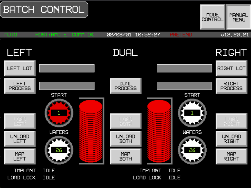
Ready to receive material
Event Report Acknowledge S6,F12-->
Waiting for command from operator or Host
SCREEN CHANGES TO HOST CONTROL
Version Introduced: 12.20
Remote Process Control Scenario (Formatted Process
Program)
Equipment’s Communications state is ENABLED and COMMUNICATING. The Control state is ON-LINE and REMOTE.
The exchanges shown below may take place in a different sequence because of undeterministic timing between the
various devices of the E220.
Operator switches to Host Control screen.
COMMENT HOST EQUIPMENT COMMENT
Idle State - Waiting for command from
operator or Host
[IF]Operator gives batch ID to Host,
[THEN] Process Program request from
HOST initiated
[IF] Process Program not present in
EPPD
[THEN]
[IF] Process Program is multi-block
[THEN]
Process Program Load Inquire S7,F1-->
<--S7,F2 Process Program Load Grant
[END_IF]
Formatted Process Program Send S7,F23-->
<--S7,F24 Formatted Process Program Acknowledge
Verify Process Program
[IF]S7,F27 is multi-block
[THEN]
<--S7,F29 Process Program Verification Inquire
Process Program Verification Grant S7,F30-->
[END_IF]
<--S7,F27 Process Program Verification Send
Process Program Verification
Acknowledge
S7,F28-->
[ELSE] Operator selects process from
recipe index on E220.
[ENDIF]
Return to Idle State
REMOTE COMMAND with
PPSELECT S2,F41-->
<--S2,F42 Host Command Acknowledge
Event Process Program Selected
[IF] Acknowledge Negative
[THEN] Return to Idle State
<--S6,F11
Operator places wafers into loadlocks
[IF ENABLED]
CEID = 85
Material Sensed at Port
Event Report Acknowledge S6,F12-->
<--S6,F11
[IF] Operator touches GO icon on Host
Control Screen
[THEN]
[IF ENABLED]
CEID = 73
Operator Command Issued
Event Report Acknowledge S6,F12-->
[ELSE] Wait for command from Host
REMOTE COMMAND START S2,F41-->
<--S2,F42 Host Command Acknowledge
[IF] Acknowledge Negative
[THEN] Return to Idle State
<--S6,F11
[IF ENABLED]
CEID = 86
HOST COMMAND STARTED
Event Report Acknowledge S6,F12-->
<--S6, F11
Equipment begins setup for implanting
wafer
[IF ENABLED]
CEID = 75
Process state change
Event Report Acknowledge S6, F12-->
<--S6,F11
[IF ENABLED]
CEID = 27
Elevator pump started
Event Report Acknowledge S6,F12-->
<--S6,F11
[IF ENABLED]
CEID = 25
Door close started
Event Report Acknowledge S6,F12-->
<--S6,F11
[IF ENABLED]
CEID = 26
Door close completed
Event Report Acknowledge S6,F12-->
<--S6,F11
[IF ENABLED]
CEID = 38
Wafer mapping started
Event Report Acknowledge S6,F12-->
<--S6,F11
[IF ENABLED]
CEID = 39
Wafer mapping completed
Event Report Acknowledge S6,F12-->
<--S6,F11
[IF ENABLED]
CEID = 28
Elevator pump completed
Event Report Acknowledge
Event Report Acknowledge
S6,F12-->
S6, F12-->
<--S6,F11
[IF ENABLED]
CEID = 75
Process state change
<--S6,F11
[IF ENABLED]
CEID = 5
Source setup started
Event Report Acknowledge S6,F12-->
<--S6,F11
[IF ENABLED]
CEID = 6
Source setup complete
Event Report Acknowledge S6,F12-->
<--S6,F11
[IF ENABLED]
CEID = 7
Beamline setup started
Event Report Acknowledge S6,F12-->
<--S6,F11
[IF ENABLED]
CEID = 8
Beamline setup complete
Event Report Acknowledge S6,F12-->
<--S6,F11
[IF ENABLED]
CEID = 9
Beamscan setup started
Event Report Acknowledge S6,F12-->
<--S6,F11
[IF ENABLED]
CEID = 10
Beamscan setup complete
Event Report Acknowledge S6,F12-->
<--S6,F11
[IF ENABLED]
CEID =75
Process State Change
Event Report Acknowledge S6,F12-->
Equipment is idle waiting for Start
Command
Host Command START Sent
(RCMD = 4) S2,F41-->
<--S2,F42 Host Command Acknowledge
HCACK = 0 (assumes command can be
performed).
<--S6,F11
[IF ENABLED]
CEID = 86
Host command issued
Event Report Acknowledge S6,F12-->
<--S6,F11
[IF ENABLED]
CEID = 75
Process state change
Event Report Acknowledge S6,F12-->
[IF] 1st Wafer
<--S6,F11
[THEN]
[IF ENABLED]
CEID = 11
Batch started
Event Report Acknowledge S6,F12--> [ENDIF]
[LOOP]
<--S6,F11 CEID = 13
Wafer started
Event Report Acknowledge S6,F12-->
[IF] PAUSE RECEIVED FROM HOST OR
OPERATOR
[THEN] EVENT PAUSE STATE
[WAIT]
[IF] HOST SEND S2,F41 OR OPERATOR
PRESSES CONTINUE
[THEN]
EVENT EXECUTING
<--S6,F11 CEID = 14
Wafer complete
[IF] PROCESS PROGRAM COMMAND IS
SET TO PERIODICALLY CHECK THE
BEAM AND TIMEOUT OCCURS
[THEN] BEAMCHECK IS DONE
[IF] FAILS
[THEN] BEAM SCAN
IS DONE
[IF] Last wafer
[THEN] Exit loop [END_LOOP]
[ENDIF]
Event Report Acknowledge S6,F12-->
<--S6,F11 CEID = 12
Batch complete
Event Report Acknowledge S6,F12-->
<--S6,F11
[IF ENABLED]
CEID = 21
Elevator vent started
Event Report Acknowledge S6,F12-->
<--S6,F11
[IF ENABLED]
CEID = 23
Door open started
Event Report Acknowledge S6,F12-->
<--S6,F11
[IF ENABLED]
CEID = 24
Door open completed
Event Report Acknowledge S6,F12-->
<--S6,F11
[IF ENABLED]
CEID = 22
Elevator vent completed
Event Report Acknowledge
Event Report Acknowledge
S6,F12-->
S6,F12-->
<--S6,F11
[IF ENABLED]
CEID = 65
Pivot extend complete
<--S6,F11
[IF ENABLED]
CEID = 75
Process state change
Event Report Acknowledge S6,F12-->
<--S6,F11
[IF ENABLED]
CEID = 41
Cassette removed
Event Report Acknowledge S6,F12-->
<--S6,F11
[IF ENABLED]
CEID = 84
Ready to receive material
Event Report Acknowledge S6,F12-->
Waiting for command from operator or Host
Local Process Control Scenario
Equipment’s Communications state is ENABLE and COMMUNICATING. The Equipment’s Control state is ON-LINE and
LOCAL. The Host shall be prohibited from the use of remote commands that cause physical movement or initiate
processing by operator switching to LOCAL mode. Also, the Host shall not modify Equipment constants that could affect a
process in progress. The exchanges shown below may not take place in the order shown because of timing
considerations between the various devices which are part of the E220.
Operator switches to Batch Status screen.
COMMENT HOST EQUIPMENT COMMENT
Idle State - Waiting for command from
operator
Operator selects PPID from the Recipe Index
screen. Operator switches to Batch status
screen.
<--S6,F11
Operator presses Go button
[IF ENABLED]
CEID = 73
Operator Command Issued
Event Report Acknowledge S6,F12--> Equipment begins setup for implanting wafer
<--S6,F11
[IF ENABLED]
CEID = 75
Process state change
Event Report Acknowledge S6,F12-->
Equipment begins setup for implanting wafer
<--S6,F11
[IF ENABLED]
CEID = 27
Elevator pump started
Event Report Acknowledge S6,F12-->
<--S6,F11
[IF ENABLED]
CEID = 25
Door close started
Event Report Acknowledge S6,F12-->
<--S6,F11
[IF ENABLED]
CEID = 26
Door close completed
Event Report Acknowledge S6,F12-->
<--S6,F11
[IF ENABLED]
CEID = 38
Wafer mapping started
Event Report Acknowledge S6,F12-->
<--S6,F11
[IF ENABLED]
CEID = 39
Wafer mapping completed
Event Report Acknowledge S6,F12-->
<--S6,F11
[IF ENABLED]
CEID = 28
Elevator pump completed
Event Report Acknowledge
Event Report Acknowledge
S6,F12-->
S6, F12-->
<--S6,F11
[IF ENABLED]
CEID = 75
Process state change
<--S6,F11
[IF ENABLED]
CEID = 5
Source setup started
Event Report Acknowledge S6,F12-->
<--S6,F11
[IF ENABLED]
CEID = 6
Source setup complete
Event Report Acknowledge S6,F12-->
<--S6,F11
[IF ENABLED]
CEID = 7
Beamline setup started
Event Report Acknowledge S6,F12-->
<--S6,F11
[IF ENABLED]
CEID = 8
Beamline setup complete
Event Report Acknowledge S6,F12-->
<--S6,F11
[IF ENABLED]
CEID = 9
Beamscan setup started
Event Report Acknowledge S6,F12-->
<--S6,F11
[IF ENABLED]
CEID = 10
Beamscan setup complete
Event Report Acknowledge S6,F12-->
[IF ENABLED]
CEID = 75
Process state change
<--S6,F11
Event Report Acknowledge S6,F12-->
Operator presses Go button
[IF ENABLED]
CEID = 73
Operator command issued
<--S6,F11
[IF ENABLED]
CEID = 75
Process state change
Event Report Acknowledge S6,F12-->
[IF] 1st Wafer
<--S6,F11
[THEN]
[IF ENABLED]
CEID = 11
Batch started
Event Report Acknowledge S6,F12--> [ENDIF]
[LOOP]
<--S6,F11 CEID = 13
Wafer started
Event Report Acknowledge S6,F12-->
[IF] PAUSE RECEIVED FROM HOST OR
OPERATOR
[THEN] EVENT PAUSE STATE
[WAIT]
[IF] HOST SEND S2,F41 OR OPERATOR
PRESSES CONTINUE
[THEN]
EVENT EXECUTING
<--S6,F11 CEID = 14
Wafer complete
[IF] PROCESS PROGRAM COMMAND IS
SET TO PERIODICALLY CHECK THE
BEAM AND TIMEOUT OCCURS
[THEN] BEAMCHECK IS DONE
[IF] FAILS
[THEN] BEAM SCAN
IS DONE
[IF] Last wafer
[THEN] Exit loop [END_LOOP]
[ENDIF]
Event Report Acknowledge S6,F12-->
<--S6,F11 CEID = 12
Batch complete
Event Report Acknowledge
Event Report Acknowledge
S6,F12-->
S6,F12-->
<--S6, F11
[IF ENABLED]
CEID = 75
Process state change
<--S6,F11
[IF ENABLED]
CEID = 21
Elevator vent started
Event Report Acknowledge S6,F12-->
<--S6,F11
[IF ENABLED]
CEID = 23
Door open started
Event Report Acknowledge S6,F12-->
<--S6,F11
[IF ENABLED]
CEID = 24
Door open completed
Event Report Acknowledge S6,F12-->
<--S6,F11
[IF ENABLED]
CEID = 22
Elevator vent completed
Event Report Acknowledge
Event Report Acknowledge
S6,F12-->
S6, F12
<--S6, F11
[IF ENABLED}
CEID = 65
Pivot extend complete
<--S6,F11
[IF ENABLED]
CEID = 75
Process state change
Event Report Acknowledge S6,F12-->
<--S6,F11
[IF ENABLED]
CEID =41
Cassette removed
Event Report Acknowledge S6,F12-->
<--S6,F11
[IF ENABLED]
Event report, CEID = 84
Ready to receive material
Event Report Acknowledge S6,F12-->
Idle State - Waiting for operator command
Off-Line Process Control Scenario
Equipment’s Communications state is DISABLED
COMMENT HOST EQUIPMENT COMMENT
Idle State - Waiting for operator command
Operator enters batch ID
Selects Process Program from Recipe
index screen
Process Program load
Operator presses Go button
Equipment begins setup for implanting
wafer
Elevator pump started
Pivot retract started
Pivot retract completed
Door close started
Door close completed
Wafer mapping started
Wafer mapping completed
Elevator pump completed
Source setup complete
Beamline setup started
Beamline setup complete
Beamscan setup started
Beamscan setup complete
[IF] 1st Wafer
[THEN] Batch started
[ENDIF]
[LOOP]
Wafer started
Wafer complete
[IF] Last wafer
[THEN] Exit loop
[END_LOOP]
Elevator vent started
Door open started
Door open completed
Elevator vent completed
[IF] Last cassette
[THEN] Exit loop
[ELSE IF] 2nd cassette loaded
[THEN] Continue processing
[ELSE] Load 2nd cassette, continue
processing
[ENDIF]
Batch complete
Idle State - Waiting for operator to enter
new batch ID
Host Requests Event Report
The Equipment’s Communication state is ENABLE and COMMUNICATING. The Equipment’s Control state is ON-LINE.
COMMENT HOST EQUIPMENT COMMENT
Host requests an event report S6,F15-->
<--S6,F16 Equipment sends Event Report
Host initiated On-line Identification
The Equipment’s Communications state is ENABLE and COMMUNICATING; the Control state is ON-LINE. This does not
change the label of the LOCAL button or switch modes.
COMMENT HOST EQUIPMENT COMMENT
Are you there? S1,F1-->
<--S1,F2 Equipment replies with MDLN and
SOFTREV.
Message Fault due to Unrecognized Device ID
The Equipment’s Communications state is ENABLE and COMMUNICATING; the Control state is ON-LINE.
COMMENT HOST EQUIPMENT COMMENT
Host sends a message Sx,Fx-->
Equipment detects an unrecognized device
ID within message from the host.
<--S9,F1 Equipment reports to the host that an
"unrecognized device ID" was detected in
the received message
Message Fault due to Unrecognized Stream Type
The Equipment’s Communications state is ENABLE and COMMUNICATING; the Control state is ON-LINE.
COMMENT HOST EQUIPMENT COMMENT
Host sends a message Sx,Fx-->
Equipment detects an unrecognized
stream type within message from the
host.
<--S9,F3 Equipment reports to the host that an
"unrecognized stream type" was
detected in the receive message
Message Fault due to Unrecognized Function type
The Equipment’s Communications state is ENABLE and COMMUNICATING; the Control state is ON-LINE.
COMMENT HOST EQUIPMENT COMMENT
Host sends a message Sx,Fy-->
Equipment detects an unrecognized
function type within message from the host.
<--S9,F5 Equipment reports to the host that an
"unrecognized function type" was detected
in the receive message
Message Fault due to Illegal data format
The Equipment’s Communications state is ENABLE and COMMUNICATING; the Control state is ON-LINE.
COMMENT HOST EQUIPMENT COMMENT
Host sends a message Sx,Fy-->
Equipment detects an illegal data format
within message from the host.
<--S9,F7 Equipment reports to the host that an
"illegal data format" was detected in the
receive message
Message Fault due to Transaction Timer Timeout
The Equipment’s Communications state is ENABLE and COMMUNICATING; the Control state is ON-LINE..
COMMENT HOST EQUIPMENT COMMENT
<--Sx,Fy Equipment sends a message that requires
a reply from the host.
Equipment does not receive an expected
reply message from the host and a
transaction timeout occurs.
<--S9,F9 Equipment reports to the host that a
transaction timer timeout occurred.
Message Fault due to data too long
The Equipment has established communication and is ON-LINE.
COMMENT HOST EQUIPMENT COMMENT
Host sends a message Sx,Fy-->
Equipment detects that the message from
the host contains more data than it can
handle.
<--S9,F11 Equipment reports to the host that "data too
long" was detected in the receive message.
Host Accepts ON-LINE
The Equipment’s Communications state is ENABLE and COMMUNICATING; the Control state is OFF-LINE.
Operator switches to Host Interface screen. Operator touches switch labeled OFF-LINE.
COMMENT HOST EQUIPMENT COMMENT
<--S1,F1 Equipment requests ON-LINE
Host grants ON-LINE S1,F2-->
<--S6,F11 "Control State LOCAL (or REMOTE)"
event, CEID= 67/68
Acknowledge S6,F12-->
Button’s label changes to ON-LINE.
Host denies ON-LINE
The Equipment’s Communications state is ENABLE and COMMUNICATING; the Control state is OFF-LINE.
Operator switches to Host Interface screen. Operator touches switch labeled OFF-LINE.
COMMENT HOST EQUIPMENT COMMENT
<--S1,F1 Equipment requests ON-LINE
Host denies ON-LINE S1,F0-->
Equipment displays message to operator
"HOST DENIES ON-LINE"
Operator Sets OFF-LINE
The Equipment’s Communications state is ENABLE and COMMUNICATING; the Control state is ON-LINE.
Operator switches to Host Interface screen. Operator touches switch labeled OFF-LINE.
COMMENT HOST EQUIPMENT COMMENT
<--S6,F11 Equipment sends Control state change
event, CEID = 66
Acknowledge S6,F12--> An invalid response doesn’t prevent the
Equipment from changing state.
Button’s label changes to OFF-LINE
Operator Sets REMOTE
The Equipment’s Communications state is ENABLE and COMMUNICATING; the Control state is ON-LINE (LOCAL).
Operator switches to Host Interface screen. Operator touches switch labeled REMOTE.
COMMENT HOST EQUIPMENT COMMENT
<--S6,F11 Equipment sends Control state change
event, CEID = 68
Acknowledge S6,F12-->
Button’s label changes to REMOTE.
Operator Sets LOCAL
The Equipment’s Communications state is ENABLE and COMMUNICATING; the Control state is ON-LINE (REMOTE).
Operator switches to Host Interface screen. Operator touches switch labeled REMOTE.
COMMENT HOST EQUIPMENT COMMENT
<--S6,F11 Equipment sends Control state change
event, CEID = 67
Acknowledge S6,F12--> An invalid response doesn’t prevent the
Equipment from changing state.
Button’s label changes to LOCAL
Host Requests Report
The Equipment’s Communications state is ENABLE and COMMUNICATING; the Control state is ON-LINE.
COMMENT HOST EQUIPMENT COMMENT
Host requests data variables
contained in report RPTID S6,F19-->
<--S6,20 Equipment responds with a list if variable
data for the given RPTID
Host Initiates Trace Report
The Equipment’s Communications state is ENABLE and COMMUNICATING; the Control state is ON-LINE.
COMMENT HOST EQUIPMENT COMMENT
Trace Data Initialization requested S2,F23-->
<--S2,F24 Acknowledge, trace initiated
[DO] TOTSMP REPGSZ times
[DO] REPSGZ many times:
collect SVID1....SVIDn data,
delay time by DSPER.
[END_DO]
<--S6,F1 Send SV1....SVn
Acknowledge receipt S6,F2-->
[END_DO]
OPTIONAL:
Request trace termination prior to
completion (TOTSMP = 0) S2,F23-->
<--S2,F24 Acknowledge premature termination
Zone Transition Event occurs in Equipment
The Equipment’s Communications state is ENABLE and COMMUNICATING; the Control state is ON-LINE.
COMMENT HOST EQUIPMENT COMMENT
<--S6,F5 [IF] Event Report is Multi-block
[THEN] send Multi-block inquire
Multi-block Grant S6,F6-->
[ENDIF]
<--S6,F11
[IF ENABLED]
Equipment sends Event Report
Host Acknowledges Event Report S6,F12-->
Host defines Limit Attributes
The Equipment’s Communications state is ENABLE and COMMUNICATING; the Control state is ON-LINE.
COMMENT HOST EQUIPMENT COMMENT
[IF] S2,F45 is Multi-block
[THEN] Send Multi-block inquire
S2,F39-->
<--S2,F40 Multi-block Grant
[ENDIF]
Host defines variable limit attributes. S2,F45-->
<--S2,F46 Equipment acknowledges host request.
Host queries Equipment for current limit
The Equipment’s Communications state is ENABLE and COMMUNICATING; the Control state is ON-LINE.
COMMENT HOST EQUIPMENT COMMENT
Host queries Equipment for current
variable limit attribute definitions. S2,F47-->
<--S2,F48 Equipment returns report containing
requested variable limit attribute values/
Request Equipment Status Report
The Equipment’s Communications state is ENABLE and COMMUNICATING; the Control state is ON-LINE.
COMMENT HOST EQUIPMENT COMMENT
Host requests report of selected
status variable values S1,F3-->
<--S1,F4 Equipment responds with the requested
status variable data.
Request Equipment Status Variable Namelist
The Equipment’s Communications state is ENABLE and COMMUNICATING; the Control state is ON-LINE.
COMMENT HOST EQUIPMENT COMMENT
Host requests Equipment to identify
selected status variables S1,F11-->
<--S1,F12 Equipment responds with the requested
status variable descriptions.
Enable/Disable Alarms
The Equipment’s Communications state is ENABLE and COMMUNICATING; the Control state is ON-LINE.
COMMENT HOST EQUIPMENT COMMENT
Enable/disable Alarm S5,F3-->
Upload Alarm Information
The Equipment’s Communications state is ENABLE and COMMUNICATING; the Control state is ON-LINE.
COMMENT HOST EQUIPMENT COMMENT
Request alarm data/text S5,F5-->
<--S5,F6 Send alarm data/text
Send Alarm Report
The Equipment’s Communications state is ENABLE and COMMUNICATING; the Control state is ON-LINE.
Alarm occurrence is detected by the Equipment
COMMENT HOST EQUIPMENT COMMENT
<--S5,F1
[IF ENABLED]
Send alarm report
Acknowledge S5,F2-->
<--S6,F11
[IF ENABLED]
Send event report.
Acknowledge S6,F12-->
Host sends Remote Command
The Equipment’s Communications state is ENABLE and COMMUNICATING; the Control state is ON-LINE.
COMMENT HOST EQUIPMENT COMMENT
Host Command Send S2,F41-->
<--S2,F42 Host Command Acknowledge
HCACK = 0 (assumes command can be
performed).
[IF ENABLED]
<--S6,F11 Event Report - state change or other
collection event occurrence
Event Report Acknowledge S6,F12-->
Host Sends Equipment Constants
The Equipment’s Communications state is ENABLE and COMMUNICATING; the Control state is ON-LINE. Note: In order
for E220 to accept the change, E220 is in the idle state and touch screen is not in GEM interface.
COMMENT HOST EQUIPMENT COMMENT
Host sends Equipment constants S2,F15-->
Host Equipment Constants Request
The Equipment’s Communications state is ENABLE and COMMUNICATING; the Control state is ON-LINE.
COMMENT HOST EQUIPMENT COMMENT
Host constant request S2,F13-->
<--S2,F14 Equipment constants data
Host Equipment Constant Namelist Request
The Equipment’s Communications state is ENABLE and COMMUNICATING; the Control state is ON-LINE.
COMMENT HOST EQUIPMENT COMMENT
Host constant namelist request S2,F29-->
<--S2,F30 Equipment constant namelist
Operator Changes Equipment Constant
The Equipment’s Communications state is ENABLE and COMMUNICATING; the Control state is ON-LINE.
COMMENT HOST EQUIPMENT COMMENT
Operator changes Equipment constant at
Equipment’s operator console
<--S6,F11
[IF ENABLED]
Equipment reports Equipment constant
change, CEID = 76
Host acknowledges event S6,F12-->
Process Program Created, Edited, or Deleted by
Operator
The Equipment’s Communications state is ENABLE and COMMUNICATING; the Control state is ON-LINE.
COMMENT HOST EQUIPMENT COMMENT
New process program created, edited, or
deleted by operator at Equipment.
PPChangeName = PPID
PPChangeStatus = 1 (Created)
= 2 (Edited)
= 3 (Deleted)
[IF] CEID for Process Program Change
Event enabled
[THEN]
<--S6,F11
[IF ENABLED]
Event report, CEID = 79
Process program change
Event Report Acknowledge S6,F12--> [END_IF]
Process Program Deletion by Host
The Equipment’s Communications state is ENABLE and COMMUNICATING; the Control state is ON-LINE.
COMMENT HOST EQUIPMENT COMMENT
Delete Process Program Send S7,F17-->
<--S7,F18 Delete Process Program Acknowledge.
The process program is removed from
non-volatile storage.
Process Program Directory Request
The Equipment’s Communications state is ENABLE and COMMUNICATING; the Control state is ON-LINE.
COMMENT HOST EQUIPMENT COMMENT
Current EPPD Request S7,F19-->
<--S7,F20 Current EPPD Data
Host-Initiated Process Program Upload - Formatted
The Equipment’s Communications state is ENABLE and COMMUNICATING; the Control state is ON-LINE.
COMMENT HOST EQUIPMENT COMMENT
Formatted Process Program
Request S7,F25-->
<--S7,F26 Formatted Process Program Data
Host-Initiated Process Program Upload - Unformatted
The Equipment’s Communications state is ENABLE and COMMUNICATING; the Control state is ON-LINE. The
Equipment is NOT PROCESSING.
COMMENT HOST EQUIPMENT COMMENT
Process Program Request S7,F5-->
<--S7,F6 Process Program Data (if process
program does not exist zero-length list is
sent).
Operator Initiated Process Program Upload -
Formatted
The Equipment’s Communications state is ENABLE and COMMUNICATING; the Control state is ON-LINE. The
Equipment is idle.
The operator switches to the Recipe Index screen, selects a process program, and presses the button labeled UPLOAD
to HOST.
COMMENT HOST EQUIPMENT COMMENT
[IF] Process program is multi-block
[THEN]
<--S7,F1 Process Program Load Inquire
Process Program Load Grant S7,F2--> [END_IF]
<--S7,F23 Formatted Process Program Send
Formatted Process Program
Acknowledge S7,F24-->
Operator Initiated Process Program Upload -
Unformatted
The Equipment’s Communications state is ENABLE and COMMUNICATING; the Control state is ON-LINE.
The operator switches to the Recipe Index screen(see screen 2), selects a process program, and presses the button
labeled UPLOAD to HOST.
COMMENT HOST EQUIPMENT COMMENT
[IF] Process program is multi-block
[THEN]
<--S7,F1 Process Program Load Inquire
Process Program Load Grant S7,F2--> [END_IF]
<--S7,F3 Process Program Send
Process Program Acknowledge S7,F4-->
Host-Initiated Process Program Download - Formatted
The Equipment’s Communications state is ENABLE and COMMUNICATING; the Control state is ON-LINE.
COMMENT HOST EQUIPMENT COMMENT
[IF] Process Program is multi-block
[THEN]
Process Program Load Inquire S7,F1-->
<--S7,F2 Process Program Load Grant
[END_IF]
Formatted Process Program Send S7,F23-->
<--S7,F24 Formatted Process Program Acknowledge
Verify Process Program
[IF] S7,F27 is multi-block
[THEN]
<--S7,F29 Process Program Verification Inquire
Process Program Verification Grant S7,F30-->
[END_IF]
<--S7,F27 Process Program Verification Send
Process Program Verification
Acknowledge
S7,F28-->
Host initiated Process Program Download -
Unformatted
The Equipment’s Communications state is ENABLE and COMMUNICATING; the Control state is ON-LINE.
COMMENT HOST EQUIPMENT COMMENT
[IF] Process program is multi-block
[THEN]
Process Program Load Inquire S7,F1-->
[END_IF] <--S7,F2 Process Program Load Grant
Process Program Send S7,F3-->
<--S7,F4 Process Program Acknowledge
Operator Initiated Process Program Download -
Formatted
The Equipment’s Communications state is ENABLE and COMMUNICATING; the Control state is ON-LINE.
The operator switches to the Recipe Edit screen, selects a process program, and presses the button labeled DOWNLOAD
from Host.
COMMENT HOST EQUIPMENT COMMENT
<--S7,F25 Formatted Process Program Request
Formatted Process Program Data S7,F26-->
[IF] S7,F27 is multi-block
[THEN]
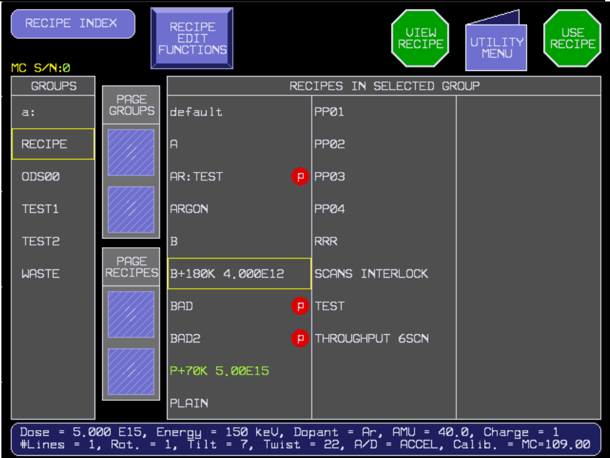
<--S7,F29 Process Program Verification Inquire
Process Program Verification Grant S7,F30-->
[END_IF]
<--S7,F27 Process Program Verification Send
Process Program Verification
Acknowledge S7,F28-->
Operator Initiated Process Program Download -
Unformatted
The Equipment’s Communications state is ENABLE and COMMUNICATING; the Control state is ON-LINE.
The operator switches to the Recipe IEdit screen (see screen 3), enters a process program, and pressesthe button
labeled DOWN from HOST.
COMMENT HOST EQUIPMENT COMMENT
<--S7,F5 Process Program Request
Process Program Send S7,F6-->
Material arrival/departs Equipment
The Equipment’s Communications state is ENABLE and COMMUNICATING; the Control state is ON-LINE.
COMMENT HOST EQUIPMENT COMMENT
Material is sent or received at an
Equipment Loadlock.
<--S6,F11
[IF ENABLED]
CEID = 85
Material sensed at port
Host acknowledges S6,F12-->
Host sends information to an Equipment's display
device
The Equipment’s Communications state is ENABLE and COMMUNICATING; the Control state is ON-LINE.
COMMENT HOST EQUIPMENT COMMENT
Host sends textual information to
Equipment for display to the
operator on terminal x.
S10,F3-->
<--S10,F4 Equipment acknowledges request to
display text. (Equipment sets
unrecognized message indicator.)
Operator indicates message recognition.
(Equipment clears unrecognized message
indicator.)
<--S6,F11
[IF ENABLED]
Event report, CEID = 81
Message recognition event.
Host acknowledges S6,F12-->
Optional:
<--S10,F1 Operator responds with text via terminal x.
Host acknowledges receipt of
operator text. S10, F2
Host sends information to an Equipment's display
device and then overwrites the information before
operator recognizes message
The Equipment’s Communications state is ENABLE and COMMUNICATING; the Control state is ON-LINE.
COMMENT HOST EQUIPMENT COMMENT
Host sends textual information to
Equipment for display to the
operator on terminal x.
S10,F3-->
<--S10,F4 Equipment acknowledges request to
display text. (Equipment sets
unrecognized message indicator.)
Host sends textual information to
Equipment for display to the
operator on terminal x. This
message overwrites the first one
sent by the host since it is still
unrecognized.
S10,F3-->
<--S10,F4 Equipment acknowledges request to
display text. (Equipment sets
unrecognized message indicator.)
Operator indicates message recognition.
(Equipment clears unrecognized message
indicator.)
<--S6,F11
[IF ENABLED]
Event report, CEID=81
Message recognition event.
Host acknowledges S6,F12
Operator sends information to the host
The Equipment’s Communications state is ENABLE and COMMUNICATING; the Control state is ON-LINE.
COMMENT HOST EQUIPMENT COMMENT
<--S10,F1 Operator sends textual information via
Equipment terminal x.
Host acknowledges receipt of
operator initiated message. S10,F2-->
Optional:
Host responds with information for
display to the operator on terminal x.
S10,F3-->
<--S10,F4 Equipment acknowledges receipt of
request to display text. (Equipment sets
unrecognized message indicator.)
Operator indicates message recognition.
[IF ENABLED]
Event report, CEID =81
<--S6,F11 Message recognition event.
Host acknowledges S6,F12
Host sends a multi-block display message
The Equipment’s Communications state is ENABLE and COMMUNICATING; the Control state is ON-LINE.
COMMENT HOST EQUIPMENT COMMENT
Send information S10,F5-->
<--S10,F6 Accepted or denied.
[IF]
Message from host is multi-block and
multi-block is not supported by the
Equipment,
[THEN]
<--S10,F7 Send Multi-block Not Allowed.
[END_IF]
Equipment Requests TIME
The Equipment’s Communications state is ENABLE and COMMUNICATING; the Control state is ON-LINE.
COMMENT HOST EQUIPMENT COMMENT
<--S2,F17 Equipment requests a time value from the
host
Host responds with a time value S2,F18-->
Equipment sets its internal time reference
to the value of TIME received from the
host.
Host Instructs Equipment to Set Time
The Equipment’s Communications state is ENABLE and COMMUNICATING; the Control state is ON-LINE.
COMMENT HOST EQUIPMENT COMMENT
Host instructs Equipment to set its
time S2,F31-->
<--S2F32 Equipment sets its internal time reference
to the value of TIME received from the
host and acknowledges completion.
Host Requests Equipment's Current Time Value
The Equipment’s Communications state is ENABLE and COMMUNICATING; the Control state is ON-LINE.
COMMENT HOST EQUIPMENT COMMENT
Host requests Equipment time. S2,F17-->
<--S2,F18 Equipment returns its internal time
reference value to the host.
VILL Remote Process Control Scenario (Formatted
Process Program)
Vacuum Independent Loadlocks (ECO 90) is selected.
Equipment’s Communications State is ENABLED and COMMUNICATING.
The Control State is ON-LINE and REMOTE.
Note: Because left and right processes are interleaved, completion event sequence will differ. Completion events in the
following scenario are grouped by the side on which they occurred.
Operator switches to Host Control screen.
COMMENT HOST EQUIPMENT COMMENT
Idle State - Waiting for command from
operator or Host
[IF]Operator gives batch ID to Host,
[THEN] Process Program request from
HOST initiated
Download Left Process Program if it
does not exist on the equipment.
[IF] Process Program not present in
EPPD
[THEN]
Process Program Load Inquiry S7,F1-->
<--S7,F2 Process Program Load Grant
Process Program Send S7,F3-->
[ENDIF]
<--S7,F4 Process Program Acknowledge
[ELSE] Operator selects process from
recipe index on E220.
[ENDIF]
Return to Idle State
REMOTE COMMAND with
PPSELECT S2,F41-->
<--S2,F42 Host Command Acknowledge
Event Process Program Selected
[IF] Acknowledge Negative
[THEN] Return to Idle State
[ELSE]Equipment displays PPID on Host
Control screen.
<--S6,F11 [IF ENABLED]
CEID = 80
Process Program Selected
SVID 151 = 1
SVID 228 = LEFT-PPID
Event Report Acknowledge S6,F12-->
<--S6,F11 [IF ENABLED]
CEID = 42
Ready to process
SVID 151 (PORT-ID) =1
Svid 227 (left-ppid) = left PPID
Event Report Acknowledge S6,F12-->
Operator verifies PPID
At this point, another PPSELECT REMOTE
COMMAND with a different PPID on the
right side MAY be issued.
After the PPSELECT, if the Right Go button
is pressed or a START-RIGHT REMOTE
COMMAND is issued, the process will be
queued if another process on the left side
has already been started. The queued
process will start after the left side is done.
If a PPSELECT remote command with the
PPID same as that of the left side is issued,
processing may either be started on the
right side only (by pressing the Right Go
button or issuing a START-RIGHT remote
command) or on both sides (by pressing
the Go button or issuing a START remote
command).
In this scenario, PPSELECT on the right
side will be initiated after the left process is
started.
<--S6,F11
Operator places wafers into left loadlock
[IF ENABLED]
CEID = 85
Material sensed at port
SVID 151 = 1
Event Report Acknowledge S6,F12-->
<--S6,F11
[IF] Operator touches GO icon on Host
Control Screen
[THEN]
[IF ENABLED]
CEID = 73
Operator Command Issued
Event Report Acknowledge
S6,F12-->
<--S6,F11 [IF ENABLED]
CEID = 64
Go button pressed or Host
START command received
Event Report Acknowledge S6,F12-->
[ELSE] Wait for command from Host
REMOTE COMMAND START-LEFT S2,F41-->
<--S2,F42 Host Command Acknowledge
[IF] Acknowledge Negative
[THEN] Return to Idle State
<--S6,F11
[IF ENABLED]
CEID = 86
Host command issued
Event Report Acknowledge
S6,F12-->
<--S6,F11 [IF ENABLED]
CEID = 64
Host START command issued
Event Report Acknowledge S6,F12-->
<--S6,F11 Equipment begins setup for implanting
wafer
[IF ENABLED]
CEID =75
Process state change
Event Report Acknowledge S6,F12-->
<--S6,F11
[IF ENABLED]
CEID = 27
Elevator pump started
SVID 151 = 1
Event Report Acknowledge S6,F12-->
<--S6,F11
[IF ENABLED]
CEID = 25
Door close started
SVID 151 = 1
Event Report Acknowledge S6,F12-->
<--S6,F11
[IF ENABLED]
CEID = 26
Door close completed
SVID 151 = 1
Event Report Acknowledge S6,F12-->
<--S6,F11
[IF ENABLED]
CEID = 38
Wafer mapping started
SVID 151 = 1
Event Report Acknowledge S6,F12-->
<--S6,F11
[IF ENABLED]
CEID = 39
Wafer mapping completed
SVID 151 = 1
Event Report Acknowledge S6,F12-->
<--S6,F11
[IF ENABLED]
CEID = 28
Elevator pump completed
SVID 151 = 1
Event Report Acknowledge S6,F12-->
While the left side is setting up, the
right process may be initiated and
queued.
PPSELECT REMOTE COMMAND
on the right side with Process
Program that may be different from
left side
S2,F41-->
<--S2,F42 Host Command Acknowledge
[IF] Acknowledge is negative
[THEN] Right side returns to Idle state.
[ELSE] Equipment displays right PPID on
HOST Control screen.
<--S6,F11 [IF ENABLED]
CEID = 80
Process Program Selected
SVID 151 = 2
SVID 228 = RIGHT-PPID
Event Report Acknowledge S6,F12-->
<--S6,F11 [IF ENABLED]
CEID = 42
Ready to process
SVID 151 = 2
Event Report Acknowledge S6,F12-->
<--S6,F11 Operator places wafers into right loadlock
[IF ENABLED]
CEID = 85
Material sensed at port
SVID 151 = 2
S6,F12-->
<--S6,F11 [IF] Operator touches RIGHT GO icon on
Host Control Screen
[THEN]
[IF ENABLED]
CEID = 73
Operator Command Issued
Event Report Acknowledge S6,F12-->
<--S6,F11 [IF ENABLED]
CEID = 64
Go button pressed
Event Report Acknowledge S6,F12-->
[ELSE] Wait for command from Host while
continuing to process left side.
REMOTE COMMAND START or
START-RIGHT S2,F41-->
<--S2,F42 Host Command Acknowledge
[IF] Acknowledge is negative
[THEN] Right side returns to Idle State
<--S6,F11 [IF ENABLED]
CEID = 86
Host command issued
Event Report Acknowledge S6,F12-->
<--S6,F11 [IF ENABLED]
CEID = 64
Host START command issued
Event Report Acknowledge S6,F12-->
<--S6,F11 [IF ENABLED]
CEID = 27
Elevator pump started
SVID 151 = 2
Event Report Acknowledge S6,F12-->
<--S6,F11 [IF ENABLED]
CEID = 25
Door close started
SVID 151 = 2
Event Report Acknowledge S6,F12-->
<--S6,F11 [IF ENABLED]
CEID = 26
Door close completed
SVID 151 = 2
Event Report Acknowledge S6,F12-->
<--S6,F11 [IF ENABLED]
CEID = 38
Wafer mapping started
SVID 151 = 2
Event Report Acknowledge S6,F12-->
<--S6,F11 [IF ENABLED]
CEID = 39
Wafer mapping completed
SVID 151 = 2
Event Report Acknowledge S6,F12-->
<--S6,F11 [IF ENABLED]
CEID = 28
Elevator pump completed
SVID 151 = 2
Event Report Acknowledge S6,F12-->
Setup for left process continues
while the right process waits in the
queue.
<--S6,F11
[IF ENABLED]
CEID =75
Process state change
Event Report Acknowledge S6,F12-->
<--S6,F11
[IF ENABLED]
CEID = 5
Source setup started
Event Report Acknowledge S6,F12-->
<--S6,F11
[IF ENABLED]
CEID = 6
Source setup complete
Event Report Acknowledge S6,F12-->
<--S6,F11
[IF ENABLED]
CEID = 7
Beamline setup started
Event Report Acknowledge S6,F12-->
<--S6,F11
[IF ENABLED]
CEID = 8
Beamline setup complete
Event Report Acknowledge S6,F12-->
<--S6,F11
[IF ENABLED]
CEID = 9
Beamscan setup started
Event Report Acknowledge S6,F12-->
<--S6,F11
[IF ENABLED]
CEID = 10
Beamscan setup complete
Event Report Acknowledge S6,F12-->
<--S6,F11
[IF ENABLED]
CEID = 75
Process state change
Event Report Acknowledge S6,F12-->
[IF ECID 257 (MODES) bit S is not set
(non-auto start after beamscan)]
[THEN]
Equipment is idle waiting for Start
Command
[IF ECID 257 (MODES) bit S is not
set]
[THEN]
Host Command
START-IMPLANT (RCMD
= 30) or
S2,F41-->
START (RCMD = 4) sent
<--S2,F42 Host Command Acknowledge
HCACK = 0 (assumes command can be
performed).
<--S6,F11
[IF ENABLED]
CEID = 86
Host command issued
Event Report Acknowledge S6,F12-->
[ENDIF ECID 257 bit S is not set]
[ENDIF ECID 257 bit S is not set]
[IF] 1st Wafer
<--S6,F11
[THEN]
[IF ENABLED]
CEID = 11
Batch started
Event Report Acknowledge S6,F12--> [ENDIF]
[LOOP]
<--S6,F11 CEID = 13
Wafer started
Event Report Acknowledge S6,F12-->
[IF] PAUSE RECEIVED FROM HOST OR
OPERATOR
[THEN] EVENT PAUSE STATE
[WAIT]
[IF] HOST SEND START OR OPERATOR
PRESSES CONTINUE
[THEN]
EVENT EXECUTING
<--S6,F11 CEID = 14
Wafer complete
[IF] PROCESS PROGRAM COMMAND IS
SET TO PERIODICALLY CHECK THE
BEAM AND TIMEOUT OCCURS
[THEN] BEAMCHECK IS DONE
[IF] FAILS
[THEN] BEAM SCAN
IS DONE
[IF] Last wafer
[THEN] Exit loop [END_LOOP]
[ENDIF]
Event Report Acknowledge S6,F12-->
<--S6,F11 CEID = 12
Batch complete
Event Report Acknowledge S6,F12-->
SCREEN CHANGES TO HOST CONTROL
At this point, while the left side starts its
vent sequence, the right side starts setting
up.
Messages from the left and right sides will
be interleaved.
Note: Right side setup, implant and vent
sequences will not be shown here.
IF ECID 257 bit V is set, unloading is
initiated automatically, else, an explicit
LEFT-VENT-OPEN remote command or an
UNLOAD must be issued to start unloading.
[IF ECID 257 bit V is not set]
<--S6,F11 [IF] Operator touches LEFT
UNLOAD button on the
Host Control Screen
[THEN]
[IF ENABLED]
CEID = 73
Operator Command Issued
Event Report Acknowledge S6,F12-->
[ELSE] Wait for command from
Host while continuing to
process right side.
REMOTE COMMAND
LEFT-VENT-OPEN
S2,F41-->
<--S2,F42 Host Command Acknowledge
[IF] Acknowledge is negative
[THEN] Return to Idle State
<--S6,F11 [IF ENABLED]
CEID = 86
Host command issued
Event Report Acknowledge S6,F12-->
[ENDIF ECID 257 bit V is not set]
<--S6,F11
[IF ENABLED]
CEID = 21
Elevator vent started
SVID 151 = 1
Event Report Acknowledge S6,F12-->
<--S6,F11
[IF ENABLED]
CEID = 23
Door open started
SVID 151 = 1
Event Report Acknowledge S6,F12-->
<--S6,F11
[IF ENABLED]
CEID = 24
Door open completed
SVID 151 = 1
Event Report Acknowledge S6,F12-->
<--S6,F11
[IF ENABLED]
CEID = 22
Elevator vent completed
SVID 151 = 1
Event Report Acknowledge S6,F12-->
<--S6,F11
[IF ENABLED]
CEID =65
Pivot extend complete
SVID 151 = 1
Event Report Acknowledge
S6,F12-->
<--S6,F11
[IF ENABLED]
CEID= 75
Event Report Acknowledge
S6,F12-->
Process state change
<--S6,F11
[IF ENABLED]
CEID =41
Cassette(s) removed
SVID 151 = 1
Event Report Acknowledge
Event Report Acknowledge
S6,F12-->
S6, F12 -->
[IF ENABLED]
CEID =46
Cassette sense status change
SVID 151 = 1
<--S6,F11
[IF ENABLED]
CEID = 84
Ready to receive material
SVID 151 = 1
Event Report Acknowledge S6,F12-->
As the left side vents, the right side
continues to setup, implant and
eventually vent.
Note: Right side setup, implant and vent
sequences are the same as that of the
left side and will not be shown here.
.
.
.
Right side sets up, implants and vents
.
.
.
Equipment goes back to idle.
Waiting for command from operator or Host
Effective Throughput Queue Process Control Scenario
This scenario is applicable to software versions that do not support Process Job Queue host interface. If the software
version supports it, see "Process Job Queue Process Control Scenario" instead.
Host scenario with and without SMIF
VILL Remote Process with Process Job Queue Control Scenario (Formatted Process Program)
Process Job Queue (ECO 104) is selected.
Vacuum Independent Loadlocks (ECO 90) is selected.
Clear PPID after Implant (ECO 39) is deselected.
Equipment’s Communications State is ENABLED and COMMUNICATING.
The Control State is ON-LINE and REMOTE.
Note: Because left and right processes are interleaved, completion event sequence will differ.
Operator switches to Host Control screen.
COMMENT HOST EQUIPMENT COMMENT
Idle State - Waiting for command from operator or Host
[IF]Operator gives batch ID to Host,
[THEN] Process Program request from HOST initiated
Download Left Process Program if it
does not exist on the equipment.
[IF] Process Program not present in
EPPD
[THEN]
Process Program Load Inquiry S7,F1-->
<--S7,F2 Process Program Load Grant
Process Program Send S7,F3-->
[ENDIF]
<--S7,F4 Process Program Acknowledge
[ELSE] Operator selects process from recipe index on
E220.
[ENDIF]
Return to Idle State
REMOTE COMMAND with
PPSELECT
dual batch will be used in this
scenario, but may be single batch.
S2,F41-->
<--S2,F42 Host Command Acknowledge
Event Process Program Selected
[IF] Acknowledge Negative
[THEN] Return to Idle State
[ELSE]Equipment displays PPID on Host Control screen.
<--S6,F11 [IF ENABLED]
CEID = 80
Process Program Selected
Event Report Acknowledge S6,F12-->
<--S6,F11 [IF ENABLED]
CEID = 42
Ready to process
Event Report Acknowledge S6,F12-->
Operator verifies PPID
<--S6,F11
Operator places wafers into left loadlock
[IF ENABLED]
CEID = 85
Material sensed at port
SVID 151 = 1
Event Report Acknowledge S6,F12-->
<--S6,F11
Operator places wafers into right loadlock
[IF ENABLED]
CEID = 85
Material sensed at port
SVID 151 = 2
Event Report Acknowledge S6,F12-->
START Remote Command
Trigger
If the Equipment has SMIFs the host
can use events such as ‘SMIF
LOADING COMPLETE’ as trigger in
sending the START remote
command.
If the Equipment is loaded by an
operator, the host can use CEID =
85 as trigger in sending the START
remote command.
If the host sent a PPSELECT with
LOC = 3 (dual-sided), it should wait
for the trigger events for both
loadlocks. For single-sided
PPSELECT, the host should wait for
the trigger event on the processing
side.
(see S6,F11 with CEID = 85 above)
REMOTE COMMAND START S2,F41-->
<--S2,F42 Host Command Acknowledge
[IF] Acknowledge Negative
[THEN] Return to Idle State
<--S6,F11
[IF ENABLED]
CEID = 86
Host command issued
Event Report Acknowledge
S6,F12-->
<--S6,F11 [IF ENABLED]
CEID = 64
Host START command issued
Event Report Acknowledge S6,F12-->
<--S6,F11 Equipment begins setup for implanting wafer
[IF ENABLED]
CEID =75
Process state change
Event Report Acknowledge S6,F12-->
<--S6,F11
[IF ENABLED]
CEID = 27
Elevator pump started
two events for both sides
Event Report Acknowledge S6,F12-->
<--S6,F11
[IF ENABLED]
CEID = 25
Door close started
two events for both sides
Event Report Acknowledge S6,F12-->
<--S6,F11
[IF ENABLED]
CEID = 38
Wafer mapping started
two events for both sides
Event Report Acknowledge S6,F12-->
<--S6,F11
[IF ENABLED]
CEID = 39
Wafer mapping completed
two events for both sides
Event Report Acknowledge S6,F12-->
<--S6,F11
[IF ENABLED]
CEID = 28
Elevator pump completed
two events for both sides
Event Report Acknowledge S6,F12-->
While this batch is setting up, the
next recipe may be queued.
REMOTE COMMAND with S2,F41-->
PPSELECT
<--S2,F42 Host Command Acknowledge
[IF] Acknowledge Negative
[THEN] Lineup queue might already be full. SVID 171 may
be checked to verify this.
[ELSE] Equipment accepts the recipe in the lineup queue
and displays PPID if HOST Control screen is active.
<--S6,F11 [IF ENABLED]
CEID = 80
Process Program Selected
Event Report Acknowledge S6,F12-->
Setup for the first process continues
while the next recipe waits in the
lineup queue.
<--S6,F11
[IF ENABLED]
CEID =75
Process state change
Event Report Acknowledge S6,F12-->
<--S6,F11
[IF ENABLED]
CEID = 5
Source setup started
Event Report Acknowledge S6,F12-->
<--S6,F11
[IF ENABLED]
CEID = 6
Source setup complete
Event Report Acknowledge S6,F12-->
<--S6,F11
[IF ENABLED]
CEID = 7
Beamline setup started
Event Report Acknowledge S6,F12-->
<--S6,F11
[IF ENABLED]
CEID = 8
Beamline setup complete
Event Report Acknowledge S6,F12-->
<--S6,F11
[IF ENABLED]
CEID = 9
Beamscan setup started
Event Report Acknowledge S6,F12-->
<--S6,F11
[IF ENABLED]
CEID = 10
Beamscan setup complete
Event Report Acknowledge S6,F12-->
<--S6,F11
[IF ENABLED]
CEID = 75
Process state change
Event Report Acknowledge S6,F12-->
[IF ECID 257 (MODES) bit S is not set (non-auto start after
beamscan)]
[THEN]
Equipment is idle waiting for Start Command
[IF ECID 257 (MODES) bit S is not
set]
[THEN]
Host Command
START-IMPLANT (RCMD
= 30) or
START (RCMD = 4) sent
S2,F41-->
<--S2,F42 Host Command Acknowledge
HCACK = 0 (assumes command can be performed).
<--S6,F11
[IF ENABLED]
CEID = 86
Host command issued
Event Report Acknowledge S6,F12-->
[ENDIF ECID 257 bit S is not set]
[ENDIF ECID 257 bit S is not set]
[IF] 1st Wafer
<--S6,F11
[THEN]
[IF ENABLED]
CEID = 11
Batch started
Event Report Acknowledge S6,F12--> [ENDIF]
[LOOP]
<--S6,F11 CEID = 13
Wafer started
Event Report Acknowledge S6,F12-->
[IF] PAUSE RECEIVED FROM HOST OR OPERATOR
[THEN] EVENT PAUSE STATE
[WAIT]
[IF] HOST SEND START OR OPERATOR PRESSES
CONTINUE
[THEN]
EVENT EXECUTING
<--S6,F11 CEID = 14
Wafer complete
[IF] PROCESS PROGRAM COMMAND IS SET TO
PERIODICALLY CHECK THE BEAM AND TIMEOUT
OCCURS
[THEN] BEAMCHECK IS DONE
[IF] FAILS
[THEN] BEAM SCAN
IS DONE
[IF] Last wafer
[THEN] Exit loop [END_LOOP]
[ENDIF]
Event Report Acknowledge S6,F12-->
<--S6,F11 CEID = 12
Batch complete
Event Report Acknowledge S6,F12-->
Equipment switches to HOST CONTROL screen.
At this point, while the previous batch starts its vent
sequence, the next recipe in the lineup queue starts
setting up.
<--S6,F11
[IF ENABLED]
CEID =75
Process state change
Event Report Acknowledge S6,F12-->
<--S6,F11
[IF ENABLED]
CEID = 5
Source setup started
Event Report Acknowledge S6,F12-->
Source, Beamline and Beamscan Setup continues…
Setup events are the same as that of the previous
batch and will not be shown here.
Previous batch starts unloading. IF ECID 257 bit V is set,
unloading is initiated automatically, else, an explicit LEFT-
VENT-OPEN remote command or an UNLOAD must be
issued to start unloading.
[IF ECID 257 bit V is not set]
[IF ECID
[ELSE] Wait for command from
Host while continuing to
process right side.
REMOTE COMMAND
LEFT-VENT-OPEN
S2,F41-->
<--S2,F42 Host Command Acknowledge
[IF] Acknowledge is negative
[THEN] Return to Idle State
<--S6,F11 [IF ENABLED]
CEID = 86
Host command issued
Event Report Acknowledge S6,F12-->
[ENDIF ECID 257 bit V is not set]
<--S6,F11
[IF ENABLED]
CEID = 21
Elevator vent started
two events for both sides
Event Report Acknowledge S6,F12-->
<--S6,F11
[IF ENABLED]
CEID = 23
Door open started
two events for both sides
Event Report Acknowledge S6,F12-->
<--S6,F11
[IF ENABLED]
CEID = 24
Door open completed
two events for both sides
Event Report Acknowledge S6,F12-->
<--S6,F11
[IF ENABLED]
CEID = 22
Elevator vent completed
two events for both sides
Event Report Acknowledge S6,F12-->
<--S6,F11
[IF ENABLED]
CEID =65
Pivot extend complete
two events for both sides
Event Report Acknowledge
Event Report Acknowledge
S6,F12-->
S6,F12-->
<--S6,F11
[IF ENABLED]
CEID= 75
Process state change
<--S6,F11
[IF ENABLED]
CEID =41
Cassette(s) removed
two events for both sides
Event Report Acknowledge
Event Report Acknowledge
S6,F12-->
S6, F12 -->
[IF ENABLED]
CEID =46
Cassette sense status change
two events for both sides
<--S6,F11
[IF ENABLED]
CEID = 84
Ready to receive material
two events for both sides
Event Report Acknowledge S6,F12-->
<--S6,F11
Operator places wafers into left loadlock
[IF ENABLED]
CEID = 85
Material sensed at port
SVID 151 = 1
Event Report Acknowledge S6,F12-->
<--S6,F11
Operator places wafers into right loadlock
[IF ENABLED]
CEID = 85
Material sensed at port
SVID 151 = 2
Event Report Acknowledge S6,F12-->
The Host waits for cassette
loading completion as
discussed in ‘START Remote
Command Trigger’.
REMOTE COMMAND START S2,F41-->
<--S2,F42 Host Command Acknowledge
[IF] Acknowledge Negative
[THEN] Return to Idle State
<--S6,F11
[IF ENABLED]
CEID = 86
Host command issued
Event Report Acknowledge
S6,F12-->
<--S6,F11 [IF ENABLED]
CEID = 64
Host START command issued
Event Report Acknowledge S6,F12-->
<--S6,F11 Equipment begins setup for implanting wafer
[IF ENABLED]
CEID =75
Process state change
After the current batch performs source, beamline and
beamscan setup.
The current batch implants and vents.
Equipment goes back to idle.
Waiting for command from operator or Host
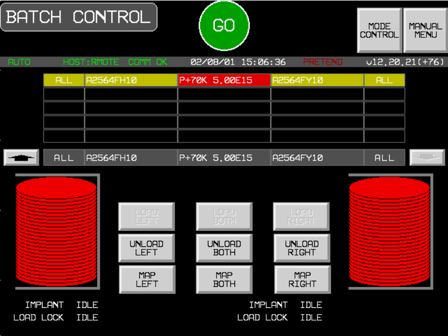
Process Job Queue Process Control Scenario
This scenario is applicable to software versions that support Process Job Queue host interface. If the software version
does not support it, see "Effective Throughput Queue Process Control Scenario" instead.
Process Job Queue (ECO 104) is selected.
Equipment’s Communications State is ENABLED and COMMUNICATING.
The Control State is ON-LINE and REMOTE.
Job Queue is Empty.
Notes:
1. S6F12 replies have been omitted for brevity.
2. Only single-sided jobs are shown, but dual-sided jobs may also be created.
Operator switches to Host Control screen.
COMMENT HOST EQUIPMENT COMMENT
REMOTE COMMAND with
PPSELECT for JOBID1 S2,F41-->
<--S2,F42 Host Command Acknowledge
Event Process Program Selected
Equipment displays Job 1 on Batch Control
screen.
<--S6,F11 CEID = 88 Job Created
SVID 195 = JOBID1
<--S6,F11 CEID = 80 Process Program Selected
SVID 195 = JOBID1
<--S6,F11 CEID = 42
Ready to process
SVID 195 = JOBID1
This event is generated if material for
JOBID1 has arrived.
START-PROCESS REMOTE
COMMAND S2,F41-->
<--S2,F42 Host Command Acknowledge
Equipment starts loading the cassette into
the loadlocks if not already loaded.
<--S6,F11 CEID = 92 Job Processing Started
SVID 195 = JOBID1
<--S6,F11
.
.
.
Beam sets up and implants wafers.
<--S6,F11 CEID = 11 Batch Started
REMOTE COMMAND with
PPSELECT for JOBID2 S2,F41--> Although this scenario shows that a new job
is queued after the first job has started
processing, the host may queue additional
jobs at any time.
<--S2,F42
Equipment adds Job 2 on Batch Control
screen.
<--S6,F11 CEID = 88 Job Created
SVID 195 = JOBID2
<--S6,F11 CEID = 93 Job Processing Completed
SVID 195 = JOBID1
<--S6,F11 CEID = 12 Batch Complete
Material for JOBID1 starts unloading
<--S6,F11 CEID = 80 Process Program Selected
SVID 195 = JOBID2
<--S6,F11 CEID = 42 Ready to process
SVID 195 = JOBID2
This event is generated if material for
JOBID2 has arrived.
START-PROCESS REMOTE
COMMAND S2,F41-->
<--S2,F42 Host Command Acknowledge
Equipment starts loading the cassette for
JOBID2 into the loadlocks if not already
loaded.
<--S6,F11 CEID = 92 Job Processing Started
SVID 195 = JOBID2
<--S6,F11
CEID = 41 Cassette is removed
For JOB1
<--S6,F11 CEID = 90 Job Completed
SVID 195 = JOBID1
<--S6,F11
.
.
.
Beam sets up JOBID2 recipe and
equipment goes into implant.
<--S6,F11 CEID = 11 Batch Started
<--S6,F11 CEID = 93 Job Processing Completed
SVID 195 = JOBID2
<--S6,F11 CEID = 12 Batch Complete
Material for JOBID2 starts unloading
<--S6,F11
CEID = 41 Cassette is removed
For JOBID2
<--S6,F11 CEID = 90 Job Completed
SVID 195 = JOBID2
Chaining with Job Queue Process Control Scenario
Process Job Queue (ECO 104) is selected.
Equipment’s Communications State is ENABLED and COMMUNICATING.
The Control State is ON-LINE and REMOTE.
Job Queue is Empty.
Notes:
1. S6F12 replies have been omitted for brevity.
2. In this example, there are 2 recipes in the PPID-LIST.
Operator switches to Host Control screen.
COMMENT HOST EQUIPMENT COMMENT
REMOTE COMMAND with
PPSELECT and PPID-LIST
parameter for JOBID1
S2,F49-->
<--S2,F42 Host Command Acknowledge
Event Process Program Selected
<--S6,F11 CEID = 88 Job Created
SVID 195 = JOBID1
Equipment displays the first recipe step of
Job 1 on Batch Control screen.
<--S6,F11 CEID = 80 Process Program Selected
SVID 195 = JOBID1
<--S6,F11 CEID = 94 Job Chain Modified
SVID 195 = JOBID1
Equipment displays the second recipe step
of Job 1 on Batch Control screen.
<--S6,F11 CEID = 42
Ready to process
SVID 195 = JOBID1
This event is generated if material for
JOBID1 has arrived.
START-PROCESS REMOTE
COMMAND S2,F41-->
<--S2,F42 Host Command Acknowledge
Equipment starts loading the cassette into
the loadlocks if not already loaded.
<--S6,F11 CEID = 92 Job Processing Started
SVID 195 = JOBID1
<--S6,F11
.
.
.
Beam sets up and implants wafers.
<--S6,F11 CEID = 11 Batch Started
<--S6,F11 CEID = 12 Batch Complete
End of first chained job step
<--S6,F11 CEID = 94 Job Chain Modified
SVID 195 = JOBID1
Equipment removes the first chained job
step of Job 1 on Batch Control screen.
<--S6,F11 CEID = 80 Process Program Selected
Equipment selects the second chained job
step of Job 1 on Batch Control screen.
<--S6,F11
.
.
.
Beam sets up and implants wafers.
<--S6,F11 CEID = 11 Batch Started
<--S6,F11 CEID = 93 Job Processing Completed
SVID 195 = JOBID1
<--S6,F11 CEID = 12 Batch Complete
End of second chained job step
<--S6,F11
CEID = 41 Cassette is removed
For JOBID1
<--S6,F11 CEID = 90 Job Completed
SVID 195 = JOBID1
Appendix A - GEM State Diagrams
Purpose
These state models describe the behavior of equipment from a host perspective in a graphical format. In compliance
to the GEM standard the following diagrams document the operational behavior of the E220. The documentation
includes:
• A state diagram - using Harel notation
• A transition table - listing each transition
• A definition of each state - specifying system behavior when the state is active.
Communication state
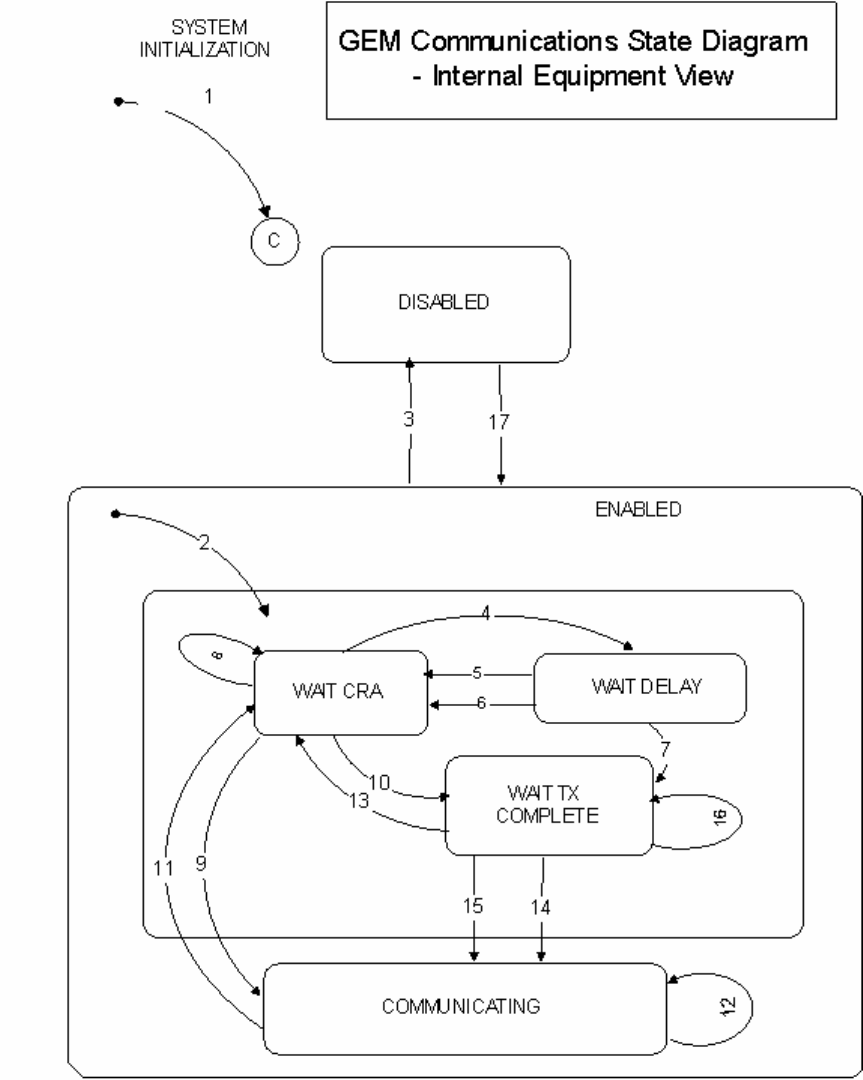
Table 1. Communication State Transitions
Current State Trigger New State Action Comment
(Entry to
Communication) System
Initialization. System Default None
(Entry to Enabled Any entry to
ENABLED state. WAIT CRA Initialize
communications Set
CommDelay timer
"expired" Send
S1,F13.
May enter from
system initialization
to ENABLED or
through operator
touching switch
DISABLED Operator switches WAIT CRA Initialize
from Disabled to
ENABLED. communications Set
CommDelay timer
"expired." Send
S1,F13.
WAIT CRA Connection
transaction failure. WAIT DELAY Initialize CommDelay
timer
Wait for timer to
expire.
WAIT DELAY CommDelay timer
expired WAIT CRA Send S1,F13 Wait for S1,F14. May
receive S1,F13 from
Host
WAIT DELAY Received a
message other
than S1,F13.
WAIT CRA Discard message.
No reply. Set
CommDelay timer
"expired" Send
S1,F13.
Indicates opportunity
to establish
communications
WAIT DELAY Received S1,F13 WAIT TX
COMPLETE Send S1,F14 with
COMMACH = 0. Equipment received
S1,F13 and has no
open S1,F13
transaction.
WAIT CRA Received a
message other
than an S1,F13 or
an expected
S1,F14.
WAIT CRA Discard message no
reply. Continue to wait for
S1,F14.
WAIT CRA Received
expected S1,F14
with COMMACK =
0.
COMMUNICATING None. Communications
established. Normal
Path.
WAIT CRA Received S1,F13. WAIT TX
COMPLETE Send S1,F14 with
COMMACK = 0. Equipment sent
S1,F13 and Host
sends S1,F13
(connect collision)
COMMUNICATING Communications
failure. WAIT CRA Set CommDelay
timer "expired" Send
S1,F13 (connect
collision)
Discard all
messages queued to
send.
COMMUNICATING Receive any
message. COMMUNICATING If S1,F13 received.
send S1,F14 Normal Conditions
WAIT TX
COMPLETE Communications
failure. WAIT CRA Discard all
messages queued to
send. Set timer
"expired." Send
S1,F13.
Equipment attempt
to send S1,F14
failed.
WAIT TX
COMPLETE S1,F14
transmission
completed
successfully.
COMMUNICATING Status of Host
Interface screen
displays
"COMMUNICATING.
"
Normal path to
completion.
Communications
established.
WAIT TX
COMPLETE Received
expected S1,F14
with COMMACK =
0.
COMMUNICATING Status of Host
Interface screen
displays
"COMMUNICATING.
"
WAIT TX
COMPLETE Receive message
other than S1,F14 WAIT TX
COMPLETE Discard message.
No reply.
Control state

Table 2. Control State Transitions
Current State Trigger New State Action Comment
Undefined - System
Initialization Entry into CONTROL
state (System
Initialization)
CONTROL (Substate
conditional on
configuration)
Display of Host
Interface screen
Highlights default
states
Equipment Constant
used at initialization
Undefined Entry into OFF-LINE
state OFF-LINE (Substate
conditional on
configuration:
OFF-LINE DISABLED
= EQUIPMENT OFF-
LINE
ON-LINE DISABLED =
HOST OFF-LINE )
Display of Host
Interface screen
Highlights OFF-LINE
Equipment Constants
used at initialization
EQUIPMENT OFF-
LINE Operator ENABLES
communication and
ON-LINE
ATTEMPT ON-LINE Host interface screen
highlights active
states.
S1,F1 sent to Host.
Default Control state =
OFF-LINE
Default
Communication state
= DISABLE
ATTEMPT ON-LINE S1,F2 Not received or
Receipt of S1,F0 EQUIPMENT OFF-
LINE or HOST OFF-
LINE
Host interface screen
highlights active statesNone
ATTEMPT ON-LINE Equipment receives
expected S1,F2 from
the Host.
ON-LINE Host interface screen
highlights active statesHost is notified of
transition to ON-LINE
at transition 7.
ON-LINE Operator touches
OFF-LINE switch EQUIPMENT OFF-
LINE Host interface screen
highlights active statesEquipment OFF-LINE
event is sent to Host.
Undefined Entry to ON-LINE
state ON-LINE (Substate
conditional on
REMOTE/LOCAL
equipment constant
Host interface screen
highlights active statesControl state LOCAL
or Control state
REMOTE event is to
Host.
LOCAL Operator touches
REMOTE switch REMOTE Host interface screen
highlights active statesControl state
REMOTE event is to
Host
REMOTE Operator touches
LOCAL switch LOCAL Host interface screen
highlights active statesControl state LOCAL
event is to Host
ON-LINE Equipment accepts
OFF-LINE message
from Host
HOST OFF-LINE Host interface screen
highlights active statesEquipment OFF-LINE
event occurs
HOST OFF-LINE Equipment accepts
host request to go
ON-LINE
ON-LINE None Host is notified of
transition to ON-LINE
at transition 7.
HOST OFF-LINE Operator acuates
OFF-LINE switch
EQUIPMENT
OFF-LINE
None Equipment
OFF_LINE event
occurs
Alarm state Model
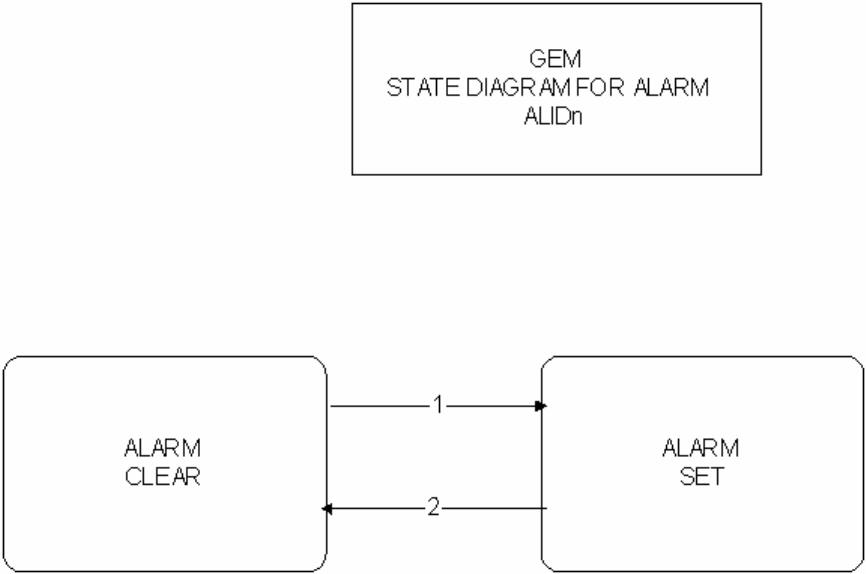
Table 10. Alarm State Transitions
# Current State Trigger New State Actions Comments
1 ALARMn CLEAR Alarmn is detected on the
equipment. ALARMn SET Initiate local actions (if any) to
ensure safety.
Update AlarmsSet and
SLCDn values.
Generate and issue alarm
message if enabled.
Inhibited activities
require operator
or Host
intervention prior
to resuming.
2 ALARMn SET Alarmn is no longer detected on
the equipment ALARMn CLEARUpdate AlarmsSet and
ALCDn values.
Generate and issue alarm
message if enabled.
Inhibited activities
require operator
or Host
intervention prior
ro resuming.
Limit state Model
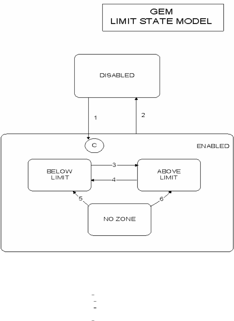
Table 9. Limit State Transitions
# Current State Trigger New State Actions Comments
DISABLED Limit attributes defined x/S2,F45. ENABLED None The substate is determined by the
current value of the monitored
variable.
ENABLED Limit attributes set undefined w/S2,F45. DISABLED None None
BELOW LIMIT Variable Increases to > UPPERDB. ABOVE LIMIT None Zone Transition.
ABOVE LIMIT Variable Decreases to < LOWERDB BELOW LIMIT None Zone Transition
NO ZONE Variable Decreases to < LOWERDB BELOW LIMIT None Zone Transition
NO ZONE Variable Increases to > UPPERDB. ABOVE LIMIT None Zone Transition.
VILL Port State Model
This section describes the Port State Model of the equipment. LPORT refers to the Left Loadlock, which is also called Port
1. RPORT refers to the Right Loadlock, which is also called Port 2.
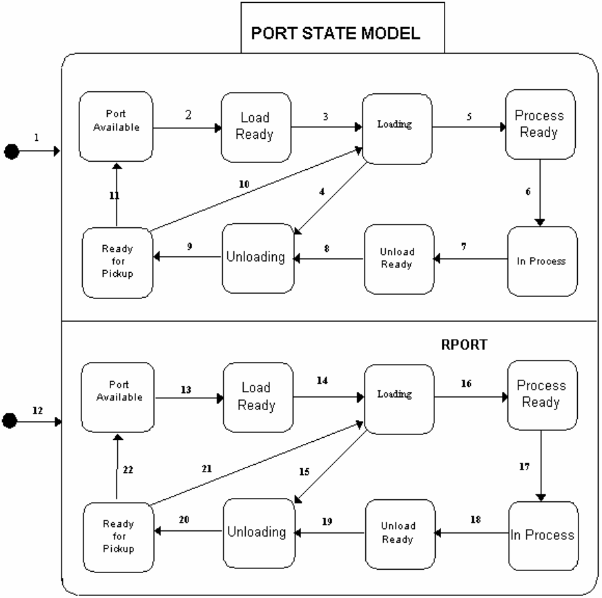
Table 3. VILL Port State Definition
State Definition
PORT AVAILABLE (LPORT) The door of the Left Loadlock is open and there is no material in the Left
Loadlock.
LOAD READY (LPORT) The Left Loadlock door is open and material is present in the Left Loadlock.
LOADING (LPORT) The equipment performs the following:
The Left Loadlock door is closed.
The Left Loadlock is roughed.
The wafers in the Left Loadlock cassette are mapped.
The Left Loadlock is pumped to hi-vac.
PROCESS READY (LPORT) The Left Loadlock has been pumped to hi-vac, but implanting of the batch has
not yet started.
IN PROCESS (LPORT) The wafers in the Left Loadlock are being implanted.
UNLOAD READY (LPORT) The wafers in the Left Loadlock have been implanted, and they are waiting for
the left elevator venting to be started.
UNLOADING (LPORT) The Left Loadlock elevator venting has begun.
READY FOR PICKUP (LPORT) The pivot extend has been completed. The Left Loadlock door is open and the
cassette is ready to be removed.
PORT AVAILABLE (RPORT) The door of the Right Loadlock is open and there is no material in the Right
Loadlock.
LOAD READY (RPORT) The Right Loadlock door is open and material is present in the Right Loadlock.
LOADING (RPORT) The equipment performs the following:
The Right Loadlock door is closed.
The Right Loadlock is roughed.
The wafers in the Right Loadlock cassette are mapped.
The Right Loadlock is pumped to hi-vac.
PROCESS READY (RPORT) The Right Loadlock has been pumped to hi-vac, but implanting of the batch has
not yet started.
IN PROCESS (RPORT) The wafers in the Right Loadlock are being implanted.
UNLOAD READY (RPORT) The wafers in the Right Loadlock have been implanted, and they are waiting for
the right elevator venting to be started.
UNLOADING (RPORT) The Right Loadlock elevator venting has begun.
READY FOR PICKUP (RPORT) The pivot extend has been completed. The Right Loadlock door is open and the
cassette is ready to be removed.
Table 4. VILL Port State Transitions
# Current State Trigger New State Action Comment
1. Undefined The machine has
been started up. LPORT State
Model The Left Loadlock
may be loaded
with a cassette.
"Ready to Receive Material, Port-ID 1"
(CEID 84)
2. LPORT/Port
Available Cassette sensed
at LPORT. LPORT/Load
Ready Operator, AGV, or
SMIF places
cassette in
LPORT.
"Material Sensed at Port, Port-ID 1"
(CEID 85)
3. LPORT/Load
Ready The left LOAD or
GO button is
touched, or an
appropriate RCMD
is received from
the host..
LPORT/Loading Close LPORT
door, rough
LPORT, map
wafers in LPORT
cassette, and hi-
vac LPORT.
"Door Close Started, Port-ID 1"
(CEID 25)
"Door Close Complete, Port-ID 1"
(CEID 26)
"Elevator Pump Started, Port-ID 1"
(CEID27)
"Wafer Mapping Started, Port-ID 1"
(CEID 38)
"Wafer Mapping Complete, Port-ID 1"
(CEID 39)
4. LPORT/Loading The load has
failed. LPORT/Unloading
"Elevator Vent Started, Port-ID 1"
(CEID 21)
"Elevator Vent Complete, Port-ID 1
(CEID 22)
"Door Open Started, Port-ID 1" (CEID 23)
"Door Open Complete, Port ID 1"
(CEID 24)
5. LPORT/Loading The Left Loadlock
has been pumped
to hi-vac.
LPORT/Process
Ready "Elevator Pump Complete, Port-ID 1"
(CEID 28)
6. LPORT/Process
Ready The GO button
has been touched
or a START
command has
been received
from the host.
LPORT/In Process "Batch Started, Port-ID 1" (CEID 11)
"Wafer Started, Port-ID 1" (CEID 13)
"Wafer Complete, Port ID 1" (CEID 14)
7. LPORT/In Process All LPORT wafers
have been
implanted.
LPORT/Unload
Ready All wafers have
been implanted. "Batch Complete, Port-ID 1" (CEID 12)
8. LPORT/Unload
Ready Venting of the left
elevator has
started.
LPORT/Unloading The left elevator is
vented, the door is
opened, and the
pivot starts to
extend.
"Elevator Vent Started, Port-ID 1"
(CEID 21)
"Elevator Vent Complete, Port-ID 1
(CEID 22)
"Door Open Started, Port-ID 1" (CEID 23)
"Door Open Complete, Port ID 1"
(CEID 24)
9. LPORT/Unloading The left pivot is LPORT/Ready for "Pivot Extend Complete, Port-ID 1"
extended. Pickup (CEID 65)
10. LPORT/Ready for
Pickup The LOAD or GO
button has been
touched or an
RCMD has been
received from the
host.
LPORT/Loading A new implant has
been requested.
11. LPORT/Ready for
Pickup The cassette is
not sensed at the
Left Loadlock.
LPORT/Port
Available The left cassette
has been removed
by the operator,
AGV, or SMIF.
"Cassette Removed, Port-ID 1"
(CEID 41)
12. Undefined The machine has
been started up. RPORT State
Model The Right
Loadlock may be
loaded with a
cassette.
"Ready to Receive Material, Port-ID 2"
(CEID 84)
13. RPORT/Port
Available Cassette sensed
at RPORT. RPORT/Load
Ready Operator, AGV, or
SMIF places
cassette in
RPORT.
"Material Sensed at Port, Port-ID 2"
(CEID 85)
14. RPORT/Load
Ready The right LOAD or
GO button is
touched, or an
appropriate RCMD
is received from
the host.
RPORT/Loading Close RPORT
door, rough
RPORT, map
wafers in RPORT
cassette, and hi-
vac RPORT.
"Door Close Started, Port-ID 2"
(CEID 25)
"Door Close Complete, Port-ID 2"
(CEID 26)
"Elevator Pump Started, Port-ID 2"
(CEID27)
"Wafer Mapping Started, Port-ID 2"
(CEID 38)
"Wafer Mapping Complete, Port-ID 2"
(CEID 39)
15. RPORT/Loading The load has
failed. RPORT/Unloading
"Elevator Vent Started, Port-ID 2"
(CEID 21)
"Elevator Vent Complete, Port-ID 2"
(CEID 22)
"Door Open Started, Port-ID 2" (CEID 23)
"Door Open Complete, Port ID 2"
(CEID 24)
16 RPORT/Loading The Right
Loadlock has
been pumped to
hi-vac.
RPORT/Process
Ready "Elevator Pump Complete, Port-ID 2"
(CEID 28)
17. RPORT/Process
Ready The GO button
has been touched
or a START
command has
been received
from the host.
RPORT/In Process "Batch Started, Port-ID 2" (CEID 11)
"Wafer Started, Port-ID 2" (CEID 13)
"Wafer Complete, Port ID 2" (CEID 14)
18. RPORT/In Process All RPORT wafers
have been
implanted.
RPORT/Unload
Ready All wafers have
been implanted. "Batch Complete, Port-ID 2" (CEID 12)
19. RPORT/Unload
Ready Venting of the
right elevator has
started.
RPORT/Unloading The right elevator
is vented, the door
is opened, and the
pivot starts to
extend.
"Elevator Vent Started, Port-ID 2"
(CEID 21)
"Elevator Vent Complete, Port-ID 2"
(CEID 22)
"Door Open Started, Port-ID 2" (CEID 23)
"Door Open Complete, Port ID 2"
(CEID 24)
20. RPORT/Unloading The right pivot is
extended. RPORT/Ready for
Pickup "Pivot Extend Complete, Port-ID 2"
(CEID 65)
21. RPORT/Ready for
Pickup The LOAD or GO
button has been
touched or an
RCMD has been
received from the
RPORT/Loading A new implant has
been requested.
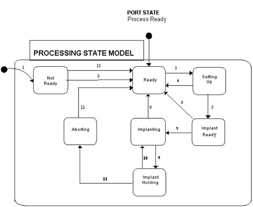
host.
22. RPORT/Ready for
Pickup The cassette is
not sensed at the
Right Loadlock.
RPORT/Port
Available The right cassette
has been removed
by the operator,
AGV, or SMIF.
"Cassette Removed, Port-ID 2"
(CEID 41)
VILL Processing State
Table 5. VILL Processing State Definition
State Definition
NOT READY The machine has been initialized and Start Up has not completed, or Shut
Down has started.
READY Processing is ready to begin. Start Up has completed, a batch has been
completed, or an Abort has been completed.
SETTING UP Source, Beamline, or Beamscan setup is under way, and material is being
readied.
IMPLANT READY Recipe has been set up and material is present. The GO is displayed and
awaiting action.
IMPLANTING Implanting is under way.
IMPLANT HOLDING The Implant has been held.
ABORTING An Abort procedure has been started, but has not yet completed.
Table 6. VILL Processing State Transitions
# Current State Trigger New State Actions Comments
1. Undefined The machine is
initialized. Not Ready Machine performs
software initialization.
2 Not Ready Operator touches
System Startup
button.
Ready The Start Up
procedure has been
completed
successfully.
"Start Up Started" (CEID 1)
"Start Up Complete" (CEID 2)
3. Ready Operator touches GO
on Host Control
screen or RCMD
received from host.
Setting Up Source, Beamline, or
Beamscsn setup is
executed.
"Source Setup Started" (CEID 5)
"Beamline Setup Started" (CEID 7)
"Beamscan Setup or Check Started" (CEID 9)
"Implant Started" (CEID 40)
4. Setting Up Setup fails. Ready
5. Setting Up Completion of
Beamscan Setup or
Check.
Implant Ready "Source Setup Complete" (CEID 6)
"Beamline Setup Complete" (CEID 8)
"Beamscan Setup or Check Complete"
(CEID 10)
"GO Displayed’ (CEID 63)
6. Implant Ready STOP command from
operator or host
RCMD.
Ready
7. Implant Ready The GO button on
Implant Monitor is
touched or RCMD
from host is received.
Implanting Implanting of the
wafers is started. "Batch Started" (CEID 11)
"Wafer Started" (CEID 13)
"Wafer Complete (CEID 14)
8. Implanting The implant for the
batch has been
completed.
Ready "Batch Complete" (CEID 12)
9. Implanting Operator touches
HOLD button on
Implant Monitor
screen.
Implant Holding Implanting of the
wafer is held. "Implant Held" (CEID 17)
10. Implant Holding Operator touches the
CONTINUE button on
the Implant Monitor
screen.
Implanting The held implant has
been resumed. "Implant Continued" (CEID 18)
11. Implant Holding Operator touches
STOP button on the
Implant Monitor
screen and then
chooses Abort at the
prompt, or host sends
Abort RCMD.
Aborting An Abort of the
implant is started. "Abort Started" (CEID 19)
12. Aborting An Abort process has
been completed. Ready "Abort Complete" (CEID 20)
13. Ready Operator touches
System Shut Down
button.
Not Ready A Shutdown from the
Ready is carried out. "Shut Down Started" (CEID 3)
"Shut Down Complete" (CEID 4)
VILL Material State Model
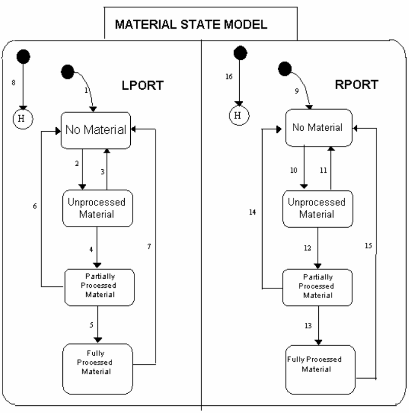
Table 7. VILL Material State Definition
State Definition
LPORT Material State for the Left Loadlock.
LPORT/No Material There is no cassette in the Left Loadlock.
LPORT/Unprocessed Material None of the wafers in the Left Loadlock cassette have been
processed.
LPORT/Partially Processed Material At least one wafer in the Left Loadlock cassette has been
processed.
LPORT/Fully Processed Material All wafers in the Left Loadlock cassette have been
processed.
RPORT Material State for the Right Loadlock.
RPORT/No Material There is no cassette in the Right Loadlock.
RPORT/Unprocessed Material None of the wafers in the Right Loadlock cassette have
been processed.
RPORT/Partially Processed Material At least one wafer in the Right Loadlock cassette has been
processed.
RPORT/Fully Processed Material All wafers in the Right Loadlock cassette have been
processed.
Table 8. VILL Material State Transitions
# Current State Trigger New State Action Comment
1. Undefined Software
initialized. No Material "Ready to Receive Material, Port-ID 1"
(CEID 84)
2. LPORT/No Material Cassette placed
into Left Loadlock
by Operator, AGV,
or SMIF.
Unprocessed
Material "Material Sensed at Port, Port-ID 1"
(CEID 85)
3. LPORT/
Unprocessed
Material
Cassette removed
from Left Loadlock
by Operator, AGV,
or SMIF before
any wafer was
processed.
No Material "Cassette Removed, Port-ID 1" (CEID 41)
"Ready to Receive Material, Port-ID 1"
(CEID 84)
4. LPORT/
Unprocessed
Material
Implant started by
Operator or Host,
and at least one
wafer implanted.
Partially
Processed
Material
"Wafer Started, Port-ID 1" (CEID 13)
"Batch Started, Port-ID 1" (CEID 11)
5. LPORT/Partially
Processed Material Implant
completed. Fully
Processed
Material
"Batch Complete, Port-ID 1" (CEID 12)
6. LPORT/Partially
Processed Material Cassette removed
from Left Loadlock
by Operator, AGV,
or SMIF after
implant is aborted.
No Material "Cassette Removed, Port-ID 1" (CEID 41)
"Ready to Receive Material, Port-ID 1"
(CEID 84)
7. LPORT/Fully
Processed Material Cassette removed
from Left Loadlock
by Operator, AGV,
or SMIF after
implant is
completed.
No Material "Cassette Removed, Port-ID 1" (CEID 41)
"Ready to Receive Material, Port-ID 1"
(CEID 84)
8 LPORT/Undefined One of the
following
situations:
Reset or power
failure.
Previous
LPORT state.
9. Undefined Software
initialized. No Material "Ready to Receive Material, Port-ID 2"
(CEID 84)
10. RPORT/No Material Cassette placed
into Right
Loadlock by
Operator, AGV, or
SMIF.
Unprocessed
Material "Material Sensed at Port, Port-ID 2"
(CEID 85)
11. RPORT/
Unprocessed
Material
Cassette removed
from Right
Loadlock by
Operator, AGV, or
SMIF before any
wafer was
processed.
No Material "Cassette Removed, Port-ID 2" (CEID 41)
"Ready to Receive Material, Port-ID 2"
(CEID 84)
12. RPORT/
Unprocessed
Material
Implant started by
Operator or Host,
and at least one
wafer implanted.
Partially
Processed
Material
"Wafer Started, Port-ID 2" (CEID 13)
"Batch Started, Port-ID 2" (CEID 11)
13. RPORT/Partially
Processed Material Implant
completed. Fully
Processed
Material
"Batch Complete, Port-ID 2" (CEID 12)
14. RPORT/Partially
Processed Material Cassette removed
from Right
Loadlock by
Operator, AGV, or
SMIF after implant
is aborted.
No Material "Cassette Removed, Port-ID 2" (CEID 41)
"Ready to Receive Material, Port-ID 2"
(CEID 84)
15. RPORT/Fully
Processed Material Cassette removed
from Right
Loadlock by
Operator, AGV, or
SMIF after implant
is completed.
No Material "Cassette Removed, Port-ID 2" (CEID 41)
"Ready to Receive Material, Port-ID 2"
(CEID 84)
16 RPORT/Undefined One of the
following
situations:
Reset or power
failure.
Previous
RPORT state.
Appendix B - E220 GEM Alarms
Purpose
The following tables contain the alarm Ids, codes, and text sent within stream 5 messages. Only alarms considered
irrecoverable are sent to the host.
A convention in the text is $ denotes a value filled in before the message is sent.
A ‘|’ character denotes a new line.
Asyst and Ergospeed2 Smif Errors
154302 154303 77001 505 The right smif arm has timed-out during the Ready (T2) timing wait period. Please check the
smif for any problems.
154304 154305 77002 505 The left smif arm has timed-out during the Ready (T2) timing wait period. Please check the
smif for any problems.
154306 154307 77003 505 The right smif arm has timed-out during the Load Complete (T4) timing wait period. Please
check the smif for any problems.
154308 154309 77004 505 The left smif arm has timed-out during the Load Complete (T4) timing wait period. Please
check the smif for any problems.
154310 154311 77005 505 The right smif arm has completed the transfer, but sensors indicate that the transfer was not
successful. Please check for any problems before continuing.
154312 154313 77006 505 The left smif arm has completed the transfer, but sensors indicate that the transfer was not
successful. Please check for any problems before continuing.
154330 154331 77015 515 Unable to set Smif Mode to FULL AUTO because pods were detected on the smif. Please
remove pods and try again.
154500 154501 77100 5 Left LPT1 Load Error. Please get experienced help. $
154502 154503 77101 5 Left LPT1 Unload Error. Please get experienced help. $
154504 154505 77102 5 Left LPT1 Home Error. Please get experienced help. $
154506 154507 77103 5 Left LPT1 Error. Please get experienced help. $
154700 154701 77200 5 Right LPT2 Load Error. Please get experienced help. $
154702 154703 77201 5 Right LPT2 Unload Error. Please get experienced help. $
154704 154705 77202 5 Right LPT2 Home Error. Please get experienced help. $
124302 124303 62001 505 Right smif arm operation timed-out. Please check the smif for any problems.
124304 124305 62002 505 Left smif arm operation timed-out. Please check the smif for any problems.
124314 124315 62007 505 The LOAD CASSETTE command for the right smif arm can not be executed because either
the smif arm or the implanter is not in a ready state.
124316 124317 62008 505 The LOAD CASSETTE command for the left smif arm can not be executed because either
the smif arm or the implanter is not in a ready state.
124318 124319 62009 505 The UNLOAD CASSETTE command for the right smif arm can not be executed because
either the smif arm or the implanter is not in a ready state.
124320 124321 62010 505 The UNLOAD CASSETTE command for the left smif arm can not be executed because
either the smif arm or the implanter is not in a ready state.
124322 124323 62011 505 The INITX2 command for the right smif arm can not be executed because either the smif arm
or the implanter is not in a ready state.
124324 124325 62012 505 The INITX2 command for the left smif arm can not be executed because either the smif arm
or the implanter is not in a ready state.
124326 124327 62013 505 The INITX3 command for the right smif arm can not be executed because either the smif arm
or the implanter is not in a ready state.
124328 124329 62014 505 The INITX3 command for the left smif arm can not be executed because either the smif arm
or the implanter is not in a ready state.
124330 124331 62015 505 Right SMIF Completion Error: $ | Please check the smif for any problems.
124332 124333 62016 505 Left SMIF Completion Error: $ | Please check the smif for any problems.
Most likely Asyst smif errors substituted for messages with $ (77100 to 77202) above:
"Aborted by user, Estop."
"Action time-out."
"Auto correct of error failed."
"Cassette already at tool."
"Collision."
"Gripper close aborted, time-out."
"Gripper finger over-travel."
"Gripper open aborted, time-out."
"Homing calibration aborted, time-out."
"Port action communication failed."
"Port action status indicates failure."
"Port alarm reports fatal error."
"Rotate following error."
"Rotate negative over-travel"
"Rotate positive over-travel"
"Tilt following error."
"Tilt negative over-travel."
"Tilt positive over-travel."
"Vertical following error."
"Vertical negative over-travel."
"Vertical positive over-travel."
Below is a partial list of Asyst smif errors containing messages less likely generated for $ above:
"Aborted by user, Soft-stop."
"ACOMLIBS resources init error."
"LPT action rejected, at Estop."
"LPT action rejected, busy with stop."
"LPT action rejected, busy."
"Axis is busy."
"Brake released."
"Brake set."
"Condition motion abort, time-out."
"Error during io task status init."
"Error of unknown code."
"Estop is reset."
"Estop is clear."
"Estop or soft-stop action time-out."
"Estop requested before completion."
"Face squat is clear."
"Face squat"
"Full squat achieved."
"Gripper finger closed."
"Gripper finger opened."
"Homing calibration completed."
"Invalid/unsupported arm action."
"Invalid/unsupported port action."
"Motion completed."
"Motion time-out."
"Partial squat achieved"
"Port action rejected, at Estop."
"Port action rejected, busy with stop."
"Port action rejected, busy."
"Required cassette condition failed."
"Reserved axis following error."
"Reserved axis negative over-travel."
"Reserved axis positive over-travel."
"Reverse vertical squat."
"Servo disabled."
"Servo enabled."
"Soft stop canceled by Estop."
"Soft-stop requested before completion."
"Unhandled stop request."
"Unrecognized arm event code."
"Y axis position not attainable."
Auto Scan Errors
12302 12303 6001 505 VOLTAGE CALIBRATION FAILED.
12304 12305 6002 505 CAUTION: MIN-SLOPE = 0 | optic link between uniformity controller and scanner
carrying SLOPE and SPOT-MODE may be damaged or disconnected.
12306 12307 6003 505 CAUTION: MIN-SLOPE ($) < 512 | wire inside scanner connecting PROBE signal to
capacitance sense board may be broken.
12308 12309 6004 505 CAUTION: MIN-SLOPE ($) > 2048 | Scanner has inadequate dynamic range to perform
dose correction properly.
12310 12311 6005 505 CAUTION: negative zero offset on dose integrator. | This will result in dose errors during
implant!! Check the dose integrator and preamplifier.
12312 12313 6006 505 CAUTION: input signal to dose integrator exceeded full scale. | This will cause dose
errors during implant!! Check the dose integrator and the preamplifier.
12314 12315 6007 505 CAUTION: DOSE = 0 | optic link carrying INTEGRATE and DOSE between uniformity
controller and dose integrator may be damaged.
12316 12317 6008 505 CAUTION: DOSE = 0 | single optic link carrying SCAN-STATUS from scanner to
uniformity controller may be disconnected or exchanged with ACCEL-OK link.
12318 12319 6009 505 CAUTION: scan ratio ($) > 20 | Scanner performance inadequate for implants. Tubes or
linear optic link may be weak.
12320 12321 6010 505 CAUTION: uniformity poor when scanning at full speed | If there is only a single peak on
the orange plot, set the MIRROR supply to 28 kV, otherwise check the scanner.
12324 12325 6012 507 The center to side ratio is inconsistent.| Press PROCEED to enter the Beamscan screen.
12328 12329 6014 505 FAST SCAN FAILURE| Beam setup was > $.$ times XSIGMA for fast scan test.
12340 12341 6020 505 SCANNER SETUP FAILED| The beam stability may not be adequate.
12344 12345 6022 507 SETUP CALLS FOR TOO MANY SCANS| The computed number of scans is $, which
exceeds the allowed maximum of 16383. It is not possible to implant.
12346 12347 6023 507 COMPUTED NUMBER OF SCANS IS LESS THAN THE NUMBER OF SCANS ASKED
FOR IN THE RECIPE.| DO YOU WISH TO IMPLANT THE WAFERS WITH| $ SCANS ?|
Recipe calls for a mimimum of $ scans.
12400 12401 6050 507 The bearing is not initialized properly. Go to the end station initialization screen to correct
this problem.
12402 12403 6051 507 The head is not initialized properly. Go to the end station initialization screen to correct
this problem.
12404 12405 6052 507 The traveling faraday is not initialized properly. Go to the end station initialization screen
to correct this problem.
12406 12407 6053 507 The traveling faraday cup stopped in the wrong position. Go to the end station
initialization screen to correct this problem.
12408 12409 6054 507 Beam purity check failed.
12414 12415 6057 515 The Dose Integrator must pass a self test before a beamscan SETUP or CHECK can be
run. Run the System Startup sequence, or the Self Test from the Beamscan screen, until
all ranges Pass.
12420 12421 6060 507 The required number of scans ($) differs more than 40% from the recipe value ($).|| Hit
'YES' to continue, 'NO' to abort.
12424 12425 6062 507 The arc current is outside of legal limits.|| (1) Auto setup has to be run to use ECO 26.|
(2) ECO 26 must be turned off to run manually.
12452 12453 6076 507 The 10% scans interlock (ECO 26) is selected and the calculated number of scans falls
outside this range. Options: | 1. Adjust arc and try SETUP again. | 2. Press GO on the
batch screen. | 3. Deselect ECO 26.
12454 12455 6077 505 Dose Integrator Failure!| The Self Test results have indicated a failure that needs to be
corrected prior to running an Implant. Run the Dose Integrator Self Test from the
Beamscan screen to resolve the error.
12462 12463 6081 505 Batch completed, scanner recheck FAILED. | Process Information: | (%) XSIGMA * $ =
$$.$$| Measured (%) XSIGMA = $$.$$| (%) PEAK TO PEAK * $ = $$.$$| Measured (%)
PEAK TO PEAK = $$.$$| Recipe Name: $| Left Lot Number: $| Right Lot Number:
12466 12467 6083 505 Scanner recheck FAILED. | Process check indicates not all wafers in this batch have
been implanted. Please check Implant Log.| Process Information: | (%) XSIGMA * $ =
$$.$$| Measured (%) XSIGMA = $$.$$| (%) PEAK TO PEAK * $ = $$.$$| Measured (%)
PEAK TO PEAK = $$.$$| Recipe Name: $| Left Lot Number: $| Right Lot Number: $|
12470 12471 6085 505 Batch Pre-Implant scanner check FAILED. | Process Information: | (%) XSIGMA * $ =
$$.$$| Measured (%) XSIGMA = $$.$$| (%) PEAK TO PEAK * $ = $$.$$| Measured (%)
PEAK TO PEAK = $$.$$| Recipe Name: $| Left Lot Number: $| Right Lot Number:
12472 12473 6086 505 The Platen is not at the safe position.| Move the Platen to the safe position | before
moving or using the Target Faraday.
12476 12477 6088 505 TARGET FARADAY CUP BIAS VOLTAGE ERROR. READBACK VOLTAGE IS TOO
LOW OR DOES NOT MATCH THE PROGRAM VOLTAGE. CHECK BIAS FEED
CONNECTIONS.
12478 12479 6089 505 Integrated beam found unstable. | The Center to Side measurement exceeds $%.
12480 12481 6090 505 Integrator offset check error! The offset | measurement difference has shown greater
than | 1% between the side and center Faraday positions. | Possible causes are : | 1.
Failure on the current integrator | 2. Excessive noise on the target Faraday | 3.
Excessive impurity, neutral beam or energy | contamination.
12488 12489 6094 505 Dose per Scan Limit Error!| The minimum Dose per Scan $ is greater than the average
Dose per Scan $.| Implant will not be allowed.| Please retry beamscan setup.
12490 12491 6095 505 Dose per Scan Limit Error!| The maximum Dose per Scan $ is less than the average
Dose per Scan plus tolerance $.| Implant will not be allowed.| Please retry beamscan
setup.
Auto-Setup Errors
18300 18301 9000 505 Remote $ does not respond.
18308 18309 9004 505 The extraction supply has been turned off because of overloading.|| Suggestion:| This
failure may be caused by an arc in the source. Turn off the filament power for a few
seconds. Then light the arc again and try to turn on the extraction manually.
18312 18313 9006 505 The source gas control failed to settle.|| Suggestion:| If the gas readback is fluctuating,
the gas control feedback circuit needs to be adjusted or replaced.|| If the gas readback
does not change and is much lower than the setpoint, either the gas control feedback
circuit needs to be adjusted, or the valve is stuck shut.
18314 18315 9007 505 The source magnet power supply failed to settle.|| Suggestion:| Gain access to the
source magnet power supply and check the front panel readings.
18316 18317 9008 505 The Z-axis motor failed to settle.
18318 18319 9009 505 The source extraction power supply failed to settle.
18320 18321 9010 505 The AMU magnet power supply failed to settle.|| Suggestion:| Gain access to the AMU
magnet power supply and check the front panel readings.
18342 18343 9021 505 The arc is glitching too much for automatic source setup to proceed.
18344 18345 9022 505 The source extractor is sparking too much for automatic source setup to proceed.||
Additional possibilities:|| 1.__UNSTABLE SUPPLY:| the extraction power supply may be
unstable.|| 2.__CORONA:| there is corona discharge between part of the source or
source cabinet and other parts of the terminal.
18346 18347 9023 505 The source arc has gone out.|| Suggestion:| Press the SETUP button to try lighting the
source automatically, or set up the source manually.
18348 18349 9024 505 The extraction power supply has lost voltage. The most common cause of this condition
is an arc between a dirty source and the extraction suppressor plate.|| Suggestion:| Turn
off the filament and extractor for a few seconds to extinquish the arc. Move the Z-axis
farther out, re-light the source, and turn on the extractor again. Press "SETUP" to
continue setting up automatically, or set up manually.|| If the extraction supply loses
voltage again, you may need to clean the ion source. Also scrape off any deposits on the
side of the extraction suppressor plate that faces the source.
18354 18355 9027 505 Unable to continue automatic source setup because the mirror supply is shorted.
18364 18365 9032 505 The source cabinet does not respond, even though the door interlocks are made and the
high voltage supplies are armed.|| Suggestion: Open the enclosure and terminal doors,
and check whether the supplies have power.
18400 18401 9050 505 Unable to continue automatic source setup because of unstable beam. Check the arc,
filament, and extraction power supplies.
18402 18403 9051 505 The source arc can't reach the setpoint.|| Suggestion:| This condition may be caused by a
filament voltage limit set too low, an extremely old filament, or inadequate gas flow or
vapor production.
18500 18501 9100 505 The automatic source setup program can't get a low enough beam to achieve the
minimum number of scans specified.|| Do you want to continue anyway?
18502 18503 9101 505 The automatic source setup program can't get a low enough beam to achieve the
minimum number of scans specified in the recipe. Automatic setup halted.
18504 18505 9102 505 Unable to continue automatic source setup because of excessive suppression current.
18506 18507 9103 505 Unable to continue automatic source setup because of excessive suppression current
when tuning Z axis.
18520 18521 9110 505 The mirror supply must be turned on to run multiply-charged ions.
18522 18523 9111 505 The 100-degree magnet current is set outside the calculated AMU window for the
designated species. Implant is not allowed under these conditions.|| Suggestion:| If the
peak is correct, use the SERVICE screen to add an AMU magnet calibration point in the
vicinity.
18524 18525 9112 505 The specified extraction voltage of $ V is not achieved. Please check the extraction
power supply.
18526 18527 9113 505 The target faraday cup is in the wrong position; the head cannot be moved. Go to the
manual BEAMSCAN screen to move it out of the way.
18528 18529 9114 505 The faraday cup suppression supply is too low for accurate beam current measurement.
Check it on the manual BEAMSCAN screen.
18530 18531 9115 505 The requested beam energy of $ keV cannot be achieved with an ion charge of $.
18532 18533 9116 505 The specified beam energy of $ keV is not achieved.|| Suggestion:| Check the extraction
and accel supplies.
18534 18535 9117 505 The Filament Current indicates that the Filament is worn to the point of breakage. It may
burn through during the implant of a wafer, do you wish to continue ?
18536 18537 9118 505 Dipole lens magnet does not match correct setting for desired amu.
18538 18539 9119 505 The flood gun secondary emission current is more than $% different from the value
specified in the recipe.
18540 18541 9120 505 Accel power supply is turned off.
18542 18543 9121 505 Decel power supply is turned off.
18544 18545 9122 505 The Mirror readback does not match the value selected in the RECIPE. |Please adjust
the recipe value to match the readback value.
18546 18547 9123 505 The selected gas bottle label does not match the recipe.| Please select the proper gas.
18548 18549 9124 505 The selected vaporizer label does not match the recipe.| Please select the proper
crucible.
18584 18585 9142 505 PRESSURE OF SDS BOTTLE SELECTED IS BELOW THE EMPTY BOTTLE
DETECTOR SETTING. THE GAS BOX HAS BEEN SHUTDOWN. TO CONTINUE,
REPLACE BOTTLE, TURN OFF EMPTY BOTTLE DETECTOR, OR RESET THE
DETECTOR SETTING.
18960 18961 9330 505 Remove target faraday cup from beam path.
18962 18963 9331 505 Unable to find an initial beam in the focus cup of at least 0.5% of the beam in the setup
cup. Automatic beam setup cannot proceed.
18964 18965 9332 505 The $ power supply is shorted out (either internally or externally.)
18966 18967 9333 505 The $ power supply is at $, and can't reach its setpoint of $.
18968 18969 9334 505 Less than 10 nanoamps of beam in the setup cup: setup cannot continue.
18970 18971 9335 505 The requested energy of $ KeV cannot be achieved on the E-220 with an ion charge of $.
18988 18989 9344 505 The accel voltage is shorted out.|| Possible causes:| 1. The drop bars are down.| 2. The
terminal grounding hook is on.
18990 18991 9345 505 The offset between the deflector programmed voltage and readback exceeds 5%.
Automatic setup cannot continue.
19002 19003 9351 515 Switched over to DECEL mode, but| DECEL static continuity test has failed! Check auto
decel hardware.
19004 19005 9352 515 Switched over to ACCEL mode, but| ACCEL static continuity test has failed! Check auto
decel hardware.
19006 19007 9353 505 BEAM ENERGY PROBE FAILURE,| Check power to energy probe.
19008 19009 9354 505 BEAM ENERGY PROBE FAILURE,| The beam energy varies by more than $.$%. The
beam energy probe reads back $$$.$ KV.
19010 19011 9355 505 BEAM CURRENT TOO HIGH,| This will cause too much power in end station resulting in
focus cup over heating.| Please reduce arc current.
19012 19013 9356 505 The requested energy of $ KeV cannot be achieved on the E-500 with an ion charge of $.
19014 19015 9357 505 The requested energy of $ KeV with an ion charge of $ cannot be achieved using the
automatic source setup because it is too low.
19016 19017 9358 505 Automatic source setup cannot be achieved using the requested extraction voltage of $
kV because it exceeds $ kV which is the maximum allowable extraction based on
calculations that use the kamu magnetic constants table.
19018 19019 9359 515 Continuity check on auto accel/decel switching cannot be done because enclosure doors
are open and high voltage cannot be turned on.
19020 19021 9360 515 Continuity check on auto accel/decel switching cannot be done because the high voltage
is not enabled.
19022 19023 9361 515 Enclosure doors are open. Do you still want to switch?| IF YES, ENSURE THAT ALL
PERSONS ARE CLEAR OF AUTO-DECEL BAR BEFORE PROCEEDING.
19026 19027 9363 515 Continuity check on auto accel/decel switching cannot be done because the source or
beamline is vented.
19028 19029 9364 505 BEAM CURRENT TOO HIGH FOR MIRROR SUPPLY OPERATION.| Cannot allow
mirror to be turned on for single charged, accel mode as requested in the recipe.| Either
set the MIRROR parameter in the recipe to 0 kV, or use a lower beam current
specification.
Auto Vacuum Errors
4304 4305 2002 507 To pump down the elevators | - The elevator cryos' temperatures must be | __less than $
degrees K, and the| __elevator cryos are not being regenerated.
4312 4313 2006 507 To pump down the beamline | - The chamber cryo temperature must be| __less than 20
degrees K, and the| __chamber cryo is not being regenerated.
4338 4339 2019 507 System startup cannot perform pump down. Cryopump temperatures indicate that the
cryos are too warm. Please check them.
4342 4343 2021 507 System pump down has been aborted.| Check the following:| - Cryo temperatures must
be less than| __20 degrees K.| - Handlers must be at the safe position.| - Traveling
faraday cup must be at the| __home position.
4344 4345 2022 507 System startup cannot perform pump down. Traveling faraday status indicates that the
faraday is not initialized. Please check it.
4346 4347 2023 507 System startup cannot perform pump down. Handler status indicates that one or both of
the handlers are not initialized Please check them.
4348 4349 2024 507 System startup has failed to attain high| vacuum. Check the following:| - Source and
beamline turbo speeds must be| __greater than 80%| - Source isolation, left isolation, and
| __right isolation valves must be open.
4350 4351 2025 507 System Start Up has failed to achieve high| vacuum before a 60 second timeout.
4532 4533 2116 515 The elevator isolation valve(s) did not close within the allocated time (20seconds).
4536 4537 2118 515 The beamline chamber cannot be pumped down to hi vacuum. The stage pumps and the
beamline pumps have been shut off and the beamline foreline valve has been closed.
Please check the chamber for any leaks.
4540 4541 2120 515 The auto elevator cryo regen procedure has been aborted and the cryo purge valves
have been closed.| The reason is because:| -- both cryo cold heads did not warm up to $
or greater within the allotted time of $ mins as per the current Regen parameters.
4542 4543 2121 515 The auto elevator Aisin cryo regen procedure has been aborted and the cryo purge
valves have been closed. The reason is because,| -- both cryo cold heads did not warm
up to 280K or greater within 90 mins.
4550 4551 2125 505 The Source turbopump(s) failed to spin up.| The stage pumps and the beamline pumps
have been shut off and the vent valve has been opened.| Please check for pump failures
or vacuum leaks.
4620 4621 2160 515 CRYO PUMP REGENERATION FAILURE.| The rate of rise test has exceeded the $
micron rise in one minute criteria even after trying to rough the elevator cryos $ times
according to the current parameters.
4624 4625 2162 515 FAILURE TO PUMP DOWN THE ELEVATOR CRYO CHAMBERS TO $ MICRONS IN
THE ALLOTED TIME OF $ MINUTES. ||Please check the following: |-- The elevator
doors. Ensure that they are properly closed. | -- The pop-off valve on the cryo pump is
sealing properly.
4628 4629 2164 515 FAILURE TO CHILL DOWN THE ELEVATOR CRYO COLD HEADS TO $ KELVIN IN
THE ALLOTTED TIME OF $ MINUTES. |Please check the compressor and the cryo cold
heads for proper operation.
4632 4633 2166 515 FAILURE TO PUMP DOWN BELOW $ MICRONS AFTER PASSING RATE OF RISE
TEST.
4634 4635 2167 515 FAILURE TO WARM UP CHAMBER CRYO COLD HEAD TO 280 KELVIN WITHIN
ALLOTTED TIME OF $ .
4636 4637 2168 515 FAILURE TO PUMP DOWN THE CRYO CHAMBER AFTER TWO PURGE AND PUMP
DOWN RETRIES.
4638 4639 2169 515 CHAMBER CRYO REGENERATION FAILURE.| The rate of rise test has exceeded the $
micron rise in one minute criteria even after trying to rough the main cryo $ times
according to the current parameters.
4642 4643 2171 515 FAILURE TO PUMP DOWN THE CHAMBER CRYO CHAMBER BELOW 50 MICRONS
AFTER PASSING THE RATE OF RISE TEST.
4644 4645 2172 515 FAILURE TO CHILL DOWN THE CHAMBER CRYO COLD HEAD TO $ KELVIN IN THE
ALLOTTED TIME OF $ MINUTES. |Please check the compressor and the cryo cold head
for proper operation.
4646 4647 2173 505 RIGHT ELEVATOR MOVE TO 1CLEAR FAILURE!| One or more of the following errors
have been detected, preventing the safe move of the elevator:|| 1) Servo is not initialized.
2) The handler is not in a safe position. 3) The wafer walkout sensor is tripped.
4648 4649 2174 505 LEFT ELEVATOR MOVE TO 1CLEAR FAILURE!| One or more of the following errors
have been detected, preventing the safe move of the elevator:|| 1) Servo is not initialized.
2) The handler is not in a safe position. 3) The wafer walkout sensor is tripped.
4650 4651 2175 505 AUTO PUMPDOWN/VENT FAILURE!| The SMIF state is not at the "READY", the SMIF
must be in this state prior to any door and/or Cassette Tilter motions can be made.
Batch Status Errors
26320 26321 13010 515 WARNING: Lot $ has been previously implanted.| | Press YES to permit this implant.|
Press NO to cancel.
26322 26323 13011 515 ERROR: Lot $ has been previously implanted.
26324 26325 13012 515 Recipe loading problem.| Please verify recipe by going to the process editor screen.
26326 26327 13013 515 The currently active recipe is not the selected recipe for this process. Processing
cancelled.
26348 26349 13024 505 The Dose Integrator must pass a Self-Test without any range errors prior to running a
batch of wafers. Run the SYSTEM-STARTUP sequence or Self Test from BEAMSCAN
to correct this interlock.
26360 26361 13030 515 LEFT SIDE WAFER MAPPER PROBLEM|| Specified first wafer ($) is not there.
26362 26363 13031 515 RIGHT SIDE WAFER MAPPER PROBLEM|| Specified first wafer ($) is not there.
26364 26365 13032 515 LEFT SIDE WAFER MAPPER PROBLEM|| Wafers specified before start: $ | Wafers
found after start:_____$
26366 26367 13033 515 RIGHT SIDE WAFER MAPPER PROBLEM|| Wafers specified before start: $ | Wafers
found after start:_____$
26368 26369 13034 515 LEFT SIDE WAFER MAPPER PROBLEM|| No wafers found.
26370 26371 13035 515 RIGHT SIDE WAFER MAPPER PROBLEM|| No wafers found.
26372 26373 13036 515 Unload cassette for shuffle mode contains wafers in destination slots.
26374 26375 13037 515 Loading operation did not start.
26376 26377 13038 515 WAFER MAPPER PROBLEM|| Knob(s) set to "MAP" but mapping ECO disabled.
26386 26387 13043 515 LEFT SIDE WAFER MAPPER PROBLEM|| No wafers found in the range starting from
slot $ to ending slot $.
26388 26389 13044 515 RIGHT SIDE WAFER MAPPER PROBLEM|| No wafers found in the range starting from
slot $ to ending slot $.
26390 26391 13045 515 WAFERS ALREADY IMPLANTED:| Some or all of the wafers in the specified slot range
on the $ side have already been processed.| Press YES if you wish to allow processing.|
Press NO to cancel processing.| WARNING! Possible process risk!| Pressing YES could
result in a double implant.
Elevator Errors
36420 36421 18060 505 Left Wafer $ is detected out of safe area| for the Handler.
36422 36423 18061 505 Right Wafer $ is detected out of safe area| for the Handler.
36424 36425 18062 505 Mapping shows irregular wafer presence patterns| Check the parameters in Travel
Calibration or| the receiver alignment.
36426 36427 18063 505 Left Mapping Light is too dim | for proper mapping.
36428 36429 18064 505 Right Mapping Light is too dim | for proper mapping.
36430 36431 18065 505 Left Wafer $ doesn't have the minimum clearance| for the Handler.
36432 36433 18066 505 Right Wafer $ doesn't have the minimum clearance| for the Handler.
36436 36437 18068 505 RIGHT CASSETTE INSERTED INCORRECTLY Alert!| The cassette is not inserted
correctly, and wafers are present indicating incorrect insertion.
36438 36439 18069 505 LEFT CASSETTE INSERTED INCORRECTLY Alert!| The cassette is not inserted
correctly, and wafers are present indicating incorrect insertion.
36440 36441 18070 505 LEFT ELEVATOR MOVE TO PIVOT FAILURE!| One or more of the following errors
have been detected, preventing the safe move of the elevator:|| 1) Servo is not
initialized. 2) The handler is not in a safe position. 3) The wafer walkout sensor is
tripped.
36442 36443 18071 505 RIGHT ELEVATOR MOVE TO PIVOT FAILURE!| One or more of the following errors
have been detected, preventing the safe move of the elevator:|| 1) Servo is not
initialized. 2) The handler is not in a safe position. 3) The wafer walkout sensor is
tripped.
36460 36461 18080 505 WAFER MISSING ALERT!| Wafers from the LEFT cassette slots listed below appear to
have been lost:| $$$$$$$$$$$$$$$$$$$$$$$$$$
36462 36463 18081 505 WAFER MISSING ALERT!| Wafers from the RIGHT cassette slots listed below appear
to have been lost:| $$$$$$$$$$$$$$$$$$$$$$$$$$
36464 36465 18082 505 WAFER FOUND ALERT!| Wafers that were not seen before in the LEFT cassette have
appeared in the slots listed below:| $$$$$$$$$$$$$$$$$$$$$$$$$$
36466 36467 18083 505 WAFER FOUND ALERT!| Wafers that were not seen before in the RIGHT cassette
have appeared in the slots listed below:| $$$$$$$$$$$$$$$$$$$$$$$$$$
End Station Initialization Errors
16716 16717 8208 505 There is a Wafer Walkout Detected.| The RIGHT SIDE cassette has a walkout. The wafer may
be extending into the iso-valve, the Beamline and Elevator may have to be vented manually.
Visually inspect the iso-valve to determine if is safe to close. Vent the system as necessary to
correct the condition using the ES-MANUAL functions.
16718 16719 8209 505 There is a Wafer Walkout Detected.| The LEFT SIDE cassette has a walkout. The wafer may
be extending into the iso-valve, the Beamline and Elevator may have to be vented manually.
Visually inspect the iso-valve to determine if is safe to close. Vent the system as necessary to
correct the condition using the ES-MANUAL functions.
16720 16721 8210 505 The RIGHT HANDLER did not return to the HOME position!| The Handler did not reach the
home position as commanded. Insure the position of the handler, or insure the correct function
of the position sensor.
16722 16723 8211 505 The LEFT HANDLER did not return to the HOME position!| The Handler did not reach the
home position as commanded. Insure the position of the handler, or insure the correct function
of the position sensor.
16724 16725 8212 505 The RIGHT ELEVATOR CAN'T BE INITIALIZED!| The Right Handler has not been initialized.
It is unsafe to move the elevator with the Handler in an unknown location.
16726 16727 8213 505 The LEFT ELEVATOR CAN'T BE INITIALIZED!| The Left Handler has not been initialized. It is
unsafe to move the elevator with the Handler in an unknown location.
16728 16729 8214 505 The RIGHT ELEVATOR CAN'T BE INITIALIZED!| The Right Handler is extended into the
cassette. It is unsafe to move the elevator with the Handler extended.
16730 16731 8215 505 The LEFT ELEVATOR CAN'T BE INITIALIZED!| The Left Handler is extended into the
cassette. It is unsafe to move the elevator with the Handler extended.
16732 16733 8216 505 The RIGHT ELEVATOR CAN'T BE INITIALIZED!| When using SMIF the Ready state must be
set for elevator initialization to proceed. During Init the door and tilter is closed and retracted.
16734 16735 8217 505 The LEFT ELEVATOR CAN'T BE INITIALIZED!| When using SMIF the Ready state must be
set for elevator initialization to proceed. During Init the door and tilter is closed and retracted.
Facilities and UCC Errors
2302 2303 1001 510 Do you want to try downloading UCC program again?|| Press YES to retry| Press NO to
quit to the manual menu.
2304 2305 1002 505 UCC ERROR:| Uniformity Controller powered down or disconnected from link.| Do you
want to bypass downloading the UCC program?| Press YES to bypass.| Press NO and
you will be given the choice to quit or retry.
2306 2307 1003 505 UCC ERROR:| Uniformity Controller data error.| Do you want to bypass downloading the
UCC program?| Press YES to bypass.| Press NO and you will be given the choice to quit
or retry.
2308 2309 1004 505 UCC ERROR:| Uniformity Controller communication timeout.| Do you want to bypass
downloading the UCC program?| Press YES to bypass.| Press NO and you will be given
the choice to quit or retry.
2310 2311 1005 505 Facilities are not ok.| Correct the conditions in red or yellow.| Press YES to ignore errors
and continue with system startup.| Press NO to recheck facilities.
2402 2403 1051 507 Low City Water flow.
2404 2405 1052 507 Low Cryo coolant flow.
2406 2407 1053 507 Low Platen coolant flow.
2408 2409 1054 507 Low Focus Cup coolant flow.
2410 2411 1055 507 Low EFlood coolant flow.
2412 2413 1056 507 Low End Station Pump coolant flow.
2414 2415 1057 507 Low Stage Pump coolant flow.
2416 2417 1058 507 Doors open.
2418 2419 1059 507 Low DI water tank level.
2420 2421 1060 507 Low Valve air pressure.
2422 2423 1061 507 Low Bearing air pressure.
2424 2425 1062 507 Ground facil Error: Motor Generator.
2426 2427 1063 507 City water too hot.
2428 2429 1064 507 Ground water too hot.
2430 2431 1065 507 Bad ground remotes communications.
2450 2451 1075 507 Low Source coolant flow.
2452 2453 1076 507 Low Source magnet coolant flow.
2454 2455 1077 507 Low Vacuum pump coolant flow.
2456 2457 1078 507 Low Analyzer magnet coolant flow.
2458 2459 1079 507 Low Quad magnet coolant flow.
2460 2461 1080 507 Low Lens magnet coolant flow.
2462 2463 1081 507 Analyzer magnet too hot.
2464 2465 1082 507 Quad1 magnet too hot.
2466 2467 1083 507 Quad2 magnet too hot.
2468 2469 1084 507 Lost Purge N2.
2470 2471 1085 507 Lens Magnet too hot.
2472 2473 1086 507 Lost Exhaust air flow.
2474 2475 1087 507 Terminal DI water tank level low.
2476 2477 1088 507 High Voltage not armed.
2478 2479 1089 507 Terminal water too hot.
2480 2481 1090 507 Terminal water resistivity too low.
2482 2483 1091 507 Bad Terminal remote communications.
Factory Automation (ACH) Errors
80302 80303 40001 505 ACH MODE CHANGE ERROR
80304 80305 40002 505 Equipment received out of range data
80320 80321 40010 505 ACH does not respond--Retries exhausted
80322 80323 40011 505 Equipment detects a receive comm. error
80324 80325 40012 505 Equipment detects a send comm. error
80326 80327 40013 505 Equipment detects a comm. interleave
80328 80329 40014 505 Equipment received illegal commands| from ACH
80340 80341 40020 505 Equipment finds no cassette on| the designated ACH port
80342 80343 40021 505 Equipment finds no cassette in| the designated loadlock
80344 80345 40022 505 Recipe and Lot fit not found
80346 80347 40023 505 Cassette not found in equipment| cassette table
80360 80361 40030 505 Equipment Constant FACTAUTO interlock
80498 80499 40099 505 ACH Error Detected.| This message will be automatically cleared| after ACH error recovery.
If the ACH is| unable to recover, press PROCEED and check| ACH states afterwards.
80380 80381 40040 505 Recipe $ is not valid.
80382 80383 40041 505 Recipe $ is missing.
81702 81703 40701 505 ACH does not accept Link command
81710 81711 40705 505 ACH does not accept AGV Enable command
81712 81713 40706 505 ACH does not return cassette status data
81720 81721 40710 505 ACH returns illegal movement status
81730 81731 40715 505 ACH does not return sensor status data
81742 81743 40721 505 ACH does not accept Lamp or Port Use command:| ACH is not linked
81744 81745 40722 505 ACH does not accept Lamp or Port Use command:| Cassette port is not used
81762 81763 40731 505 ACH does not accept Move command:| ACH is not linked
81764 81765 40732 505 ACH does not accept Move command:| ACH is transferring a cassette
81766 81767 40733 505 ACH does not accept Move command:| Cassette is not found at the transfer| origination
81768 81769 40734 505 ACH does not accept Move command:| Cassette is found at the transfer destination
81770 81771 40735 505 AGV is accessing ACH
81772 81773 40736 505 Discrepancy is found in lot information
81774 81775 40737 505 Command is illegal
81776 81777 40738 505 Access to equipment is denied
81778 81779 40739 505 End Station sensor interlock prevents| cassette transfer
81782 81783 40741 505 ACH is not linked
81784 81785 40742 505 ACH is not transferring a cassette
81786 81787 40743 505 ACH is in an error condition
GasBox 3 Errors
74564 74565 37132 515 *** WARNING: CRITICAL ERROR **** | The gas bottle valve is still open or has failed.
Please get immediate and experienced help.
GasBox 4 Errors
76564 76565 38132 515 *** WARNING: CRITICAL ERROR **** | The gas bottle valve V10 is still open or has failed.
Please get immediate and experienced help.
GasBox 5 Errors
138564 138565 69132 515 *** WARNING: CRITICAL ERROR **** | The gas bottle valve is still open or has failed. Please
get immediate and experienced help.
GasBox 7 Errors
136564 136565 68132 515 *** WARNING: CRITICAL ERROR **** | The gas bottle is still open or has failed. Please get
immediate and experienced help.
GasBox 8 Errors
132564 132565 66132 515 *** WARNING: CRITICAL ERROR **** | The gas bottle is still open or has failed. Please get
immediate and experienced help.
GasBox 9 Errors
140564 140565 70132 515 *** WARNING: CRITICAL ERROR **** | The gas bottle valve is still open or has failed. Please
get immediate and experienced help.
GasBox HP Errors
54564 54565 27132 515 *** WARNING: CRITICAL ERROR **** | The gas bottle valve is still open or has failed.
Please get immediate and experienced help.
Gases Errors
6564 6565 3132 515 *** WARNING: CRITICAL ERROR **** | The gas bottle valve is still open or has failed.
Please get immediate and experienced help.
GEM / SECSII Errors
146302 146303 73001 515 Cannot change equipment constants.
146542 146543 73121 515 Insertion of an unrelated job lot into a job chain is prohibited.
146544 146545 73122 515 POTENTIAL CHAINED IMPLANT PROPOSED:| Please verify duplicate processing
of same lot is desired.
146564 146565 73132 505 Left Cassette ID Mismatch.| Expected: $| Actual : $| Please select YES to continue
processing| or NO to abort.
146566 146567 73133 505 Right Cassette ID Mismatch.| Expected: $| Actual : $| Please select YES to
continue processing| or NO to abort.
146568 146569 73134 505 Left Missing Waf:|$|$| Press PROCEED to discard job.
146570 146571 73135 505 Right Missing Waf:|$|$| Press PROCEED to discard job.
146572 146573 73136 505 Left Extra Waf:|$|$| Press PROCEED to discard job.
146574 146575 73137 505 Right Extra Waf:|$|$| Press PROCEED to discard job.
146576 146577 73138 505 Left Cross Slot:|$|$| Please check wafers in the cassette.
146578 146579 73139 505 Right Cross Slot:|$|$| Please check wafers in the cassette.
146584 146585 73142 505 Left Cassette ID Mismatch.| Expected: $| Actual : $| Press PROCEED to discard
job.
146586 146587 73143 505 Right Cassette ID Mismatch.| Expected: $| Actual : $| Press PROCEED to discard
job.
146600 146601 73150 505 Left SMART Tag Status Read Error.| To retry, remove and place the pod.
146602 146603 73151 505 Right SMART Tag Status Read Error.| To retry, remove and place the pod.
146604 146605 73152 505 Left SMART Tag Lotid Write Error.| Please check SMART Tag.
146606 146607 73153 505 Right SMART Tag Lotid Write Error.| Please check SMART Tag.
146608 146609 73154 505 Left SMART Tag Lotid Read Error.| Please check SMART Tag.
146610 146611 73155 505 Right SMART Tag Lotid Read Error.| Please check SMART Tag.
Hardware Errors
90660 90661 45180 505 POST IMPLANT Mapping WAFER MISSING Alert!| The Wafer in slot $ was not returned to the
cassette.
Hazards Errors
114302 114303 57001 507 Cryo temperatures: Chamber = $ Left = $ Right = $.
114304 114305 57002 507 Touch screen communications have been restored.
114360 114361 57030 507 Touch screen failure: initialization not completed.
114362 114363 57031 507 Touch screen failure: no response message.
114364 114365 57032 507 Touch screen failure: response message incomplete.
114366 114367 57033 507 Touch screen failure: expected response not received.
114368 114369 57034 507 Touch screen failure: unexpected response message.
114370 114371 57035 507 Touch screen failure: error in response message.
114502 114503 57101 507 Software has detected that the outer enclosure doors are open and high| voltage is on. The
high voltage power supplies have been shut down.
114504 114505 57102 507 Software has detected that the extraction power supply is on without| sufficient suppression.
The extraction power supply has been shut down.| Extraction suppression must be at least 900
volts to prevent exposure| to X-Ray radiation.
114506 114507 57103 507 Software has detected that the accel power supply is on without| sufficient suppression. The
accel power supply has been shut down.| Accel suppression must meet the following
requirements to prevent exposure to X-Ray radiation:|
Accel > 100 volts (.1kV): Supp = 2.0kV + (Accel * 0.015)|
Accel < or = 100 volts (.1kV): Supp = 0.5kV + (Accel * 0.015)
114508 114509 57104 507 Software has detected that source power is on without the source being| in vacuum. Source
and extraction power have been shut down, the source| vacuum chamber has been isolated.
114510 114511 57105 507 Software has detected that the mirror power supply is on without the| beamline being in
vacuum. The mirror power supply has been shut down.
114512 114513 57106 507 Software has detected that the deflector power supply is on without the| beamline being in
vacuum. The deflector power supply has been shut down.
114514 114515 57107 507 Software has detected that the accel power supply is on without the| beamline being in vacuum.
The accel and accel suppression power| supplies have been shut down.
114516 114517 57108 507 Software has detected that the decel power supply is on with either| the source or beamline not
in vacuum. The decel power supply has been| shut down.
114518 114519 57109 507 Software has detected that there is too much beam power with the| reducer extended. Beam
power is defined as Extraction Voltage times| Extraction Current. The reducer has been
retracted. Either reduce|
the beam power or increase the Max Beam Reducer Power on the|
Miscellaneous Interlocks Edit screen.
114520 114521 57110 507 Software has detected that beam is possibly in the focus cup with no| cooling flow to the focus
cup. The extraction and extraction suppression| power supplies have been shut down, the
setup cup has been extended.
114522 114523 57111 507 Software has detected that beam is possibly on the platen with no| cooling flow to the platen.
The extraction and extraction suppression| power supplies have been shut down, the setup cup
has been extended.
114524 114525 57112 507 Software has detected that high voltage is up, the service cart is| active, and the Isolated
Service Cart (Option 26) is not selected.| High voltage has been shut down.
114526 114527 57113 507 Software has detected that the inlet cooling water is too hot. It is| also possible that the sensor
is disconnected. The following items| have been shutdown:| All high voltage supplies.| All
magnets.| All ion source power supplies.| All vacuum pumps.| The next logged message will
detail the exact nature of the failure.
114528 114529 57114 507 Software has detected that the inlet cooling water is not flowing.| The following items have been
shutdown:| All high voltage supplies.| All magnets.| All ion source power supplies.| All vacuum
pumps.
114530 114531 57115 507 Software has detected that the ground cooling water is too hot. It is| also possible that the
sensor is disconnected. The following items| have been shutdown:| All high voltage supplies.|
All vacuum pumps (if End Station pumps are water cooled).|
All cryo pumps (if cooled by ground water).|
The next logged message will detail the exact nature of the failure.
114532 114533 57116 507 Software has detected that the ground cooling water pump is running| with all the valves shut.
The ground water pump has been shutdown.
114534 114535 57117 507 Software has detected that the ground cooling water pump is running| with the water tank
empty. The ground water pump has been shutdown.
114536 114537 57118 507 Software has detected that the machine.con file is possibly corrupted.| Enter the Magnet
Constants screen and verify that all values are| correct. Contact Product Support for details.
114538 114539 57119 507 Software has detected that the terminal cooling water is too hot. It| is also possible that the
sensor is disconnected. The following items| have been shutdown:| All high voltage supplies.|
All magnets.| All ion source power supplies.| All vacuum pumps, except for the end station
roughing pump.|
The next logged message will detail the exact nature of the failure.
114540 114541 57120 507 Software has detected that the terminal cooling water pump is running| with all the valves shut.
The terminal water pump has been shutdown.
114542 114543 57121 507 Software has detected that the terminal cooling water pump is running| with the water tank
empty. The terminal water pump has been shutdown.
114544 114545 57122 507 Software has detected that the terminal cooling water resistivity is| too low with high voltage on.
All high voltage supplies have been shut| down. Low resistivity is defined as less than 1.99
Megohms per cubic| centimeter.
114546 114547 57123 507 Software has detected that the Electron Flood Gun filament supply is on| with no water flow.
The filament supply has been shut down.
114548 114549 57124 507 Software has detected that the source exhaust tube is excessively| coated and high voltage is
up. The high voltage supplies have been shut| down. In order to restore operation:| The source
exhaust tube must be cleaned or replaced.| The exhaust current leakage monitor must be
cleared.
114550 114551 57125 507 Software has detected that the beamline exhaust tube is excessively| coated and high voltage
is up. The high voltage supplies have been shut| down. In order to restore operation:| The
beamline exhaust tube must be cleaned or replaced.| The exhaust current leakage monitor
must be cleared.
114552 114553 57126 507 Software has detected a loss of exhaust air flow with source power on.| The source has been
shut down. If ECO 30 is not selected (Exhaust Inter-| locks Gas Box Only), the beamline has
also been shut down.
114554 114555 57127 507 Software has detected that the terminal pump exhaust overheated.| The terminal vacuum
system has been shut down.
114556 114557 57128 507 Software has detected that the source turbo speed dropped by more than| 10%. This indicates
a vacuum failure. The source vacuum system has been| shut down.
114558 114559 57129 507 Software has detected that the source turbo has been on for 16 minutes| and has not reached
95% of full speed. This indicates a vacuum failure.| The source vacuum system has been shut
down.
114560 114561 57130 507 Software has detected that the beamline turbo speed dropped by more than| 10%. This
indicates a vacuum failure. The beamline vacuum system has| been shut down.
114562 114563 57131 507 Software has detected that the beamline turbo has been on for 16 minutes| and has not
reached 95% of full speed. This indicates a vacuum failure.| The beamline vacuum system has
been shut down.
114564 114565 57132 507 Software has detected that the analyzer turbo speed dropped by more than| 10% or the pump
status returned false. This indicates a vacuum failure.| The beamline vacuum system has been
shut down.
114566 114567 57133 507 Software has detected that the analyzer turbo has been on for 16 minutes| and has not reached
95% of full speed. This indicates a vacuum failure.| The beamline vacuum system has been
shut down.
114568 114569 57134 507 Software has detected that the terminal turbo pump cooling water is not| flowing and the pumps
are on. The terminal vacuum system has been shut| down.
114570 114571 57135 507 Software has detected that the source turbo purge nitrogen is lost| with the gas box manifold
shut off valve open. The gas box has been| shut down. Purge nitrogen is needed to prevent
corrosion of the turbo| bearings.
114572 114573 57136 507 Software has detected that the terminal dry pumps are too hot and the| pumps are on. The
terminal vacuum system has been shut down.
114574 114575 57137 507 Software has detected that the end station dry pump is too hot and the| pump is on. The end
station pump has been shut down.
114576 114577 57138 507 Software has detected that the end station dry pump has no coolant flow| and the pump is on.
The end station pump has been shut down.
114578 114579 57139 507 Software has detected that the stage dry pumps are too hot and the| pumps are on. The
beamline vacuum system has been shut down.
114580 114581 57140 507 Software has detected that the stage dry pumps have no coolant flow| and the pumps are on.
The beamline vacuum system has been shut down.
114582 114583 57141 507 Software has detected that the cryo compressor has no coolant flow| and the compressor is on.
The cryo pumps have been shut down.
114584 114585 57142 507 Software has detected that the chamber cryo temperature has exceeded the| setpoint. An
automatic cryo regen has been initiated.
114586 114587 57143 507 Software has detected that the left load lock cryo temperature has| exceeded the setpoint. An
automatic cryo regen has been initiated.
114588 114589 57144 507 Software has detected that the right load lock cryo temperature has| exceeded the setpoint. An
automatic cryo regen has been initiated.
114590 114591 57145 507 Software has detected that there is no coolant flow to the ion source.| The source has been
shut down.
114592 114593 57146 507 Software has detected that the filament and extraction power supplies| are on and the source
isolation valve is closed. There is a possibility| the beam is striking the isolation valve. The
extraction power supply| has been shut down.
114594 114595 57147 507 Software has detected that source pressure rose above 2.0E-4 with the| manifold shutoff valve
open. The manifold shutoff valve has been closed.
114596 114597 57148 507 Software has detected that beamline pressure rose above 4.0E-5 with the| manifold shutoff
valve open. The manifold shutoff valve has been closed.
114598 114599 57149 507 Software has detected a loss of communications with the vaporizer. The| source has been shut
down.
114600 114601 57150 507 Software has detected a vaporizer runaway. The vaporizer current| readback exceeds the
program by over 10%. The source has been shut down.
114602 114603 57151 507 Software has detected a vaporizer runaway. The vaporizer heater| temperature readback
exceeds the program by over 25 degrees and the| current readback is greater than 12% of full
scale. The source has been| shut down.
114604 114605 57152 507 Software has detected a broken vaporizer thermocouple. The vaporizer| temperature readback
exceeds 200 degrees and the heater temperature is| less than 50 degrees. The source has
been shut down.
114606 114607 57153 507 Software has detected a loss of touch screen communication. The next| logged message will
detail the exact nature of the failure.
114608 114609 57154 507 Software has detected a particle monitor diagnostics fault on left side.| Please check the
particle monitor.
114610 114611 57155 507 Software has detected that the particle threshold has been exceeded on| the left side.
114612 114613 57156 507 Software has detected a particle monitor diagnostics fault on right| side. Please check the
particle monitor.
114614 114615 57157 507 Software has detected that the particle threshold has been exceeded on| the right side.
114616 114617 57158 507 Software has detected that the source magnet has no coolant flow and the| magnet is on. The
ion source and the source magnet have been shut down.
114618 114619 57159 507 Software has detected that the analyzer magnet has no coolant flow and| the magnet or
extraction is on. The analyzer magnet and extraction| power supply have been shut down.
114620 114621 57160 507 Software has detected that the analyzer magnet is too hot and the| magnet is on. The analyzer
magnet and extraction power supply have| been shut down.
114622 114623 57161 507 Software has detected that the quad magnets have no coolant flow and| the magnets are on.
The quad magnets and extraction power supply have| been shut down.
114624 114625 57162 507 Software has detected that the quad 1 magnet is too hot and the| magnet is on. The quad 1
magnet and extraction power supply have| been shut down.
114626 114627 57163 507 Software has detected that the quad 2 magnet is too hot and the| magnet is on. The quad 2
magnet and extraction power supply have| been shut down.
114628 114629 57164 507 Software has detected that the lens magnet has no coolant flow and| the magnet is on. The
lens magnet and extraction power supply have| been shut down.
114630 114631 57165 507 Software has detected that the lens magnet is too hot and the| magnet is on. The lens magnet
and extraction power supply have| been shut down.
114632 114633 57166 507 Software has detected that the target bias has deviated by more| than 5%. The target bias
supply has been shutdown.
114634 114635 57167 507 Software has detected that the end station dry pump has no coolant flow| and the pump is on.
The end station pump has been shut down.
114636 114637 57168 507 Software has detected that the stage dry pumps have no coolant flow| and the pumps are on.
The beamline vacuum system has been shut down.
114638 114639 57169 507 Software has detected that the linear motor has no coolant flow and it is scanning. The implant
has been placed on hold.
114640 114641 57170 507 Software has detected that there is toxic leak.| The high voltage supplies have been shut down.
IBM Gases Errors
44564 44565 22132 515 *** WARNING: CRITICAL ERROR **** | The gas bottle valve is still open or has failed.
Please get immediate and experienced help.
Implant Errors
134320 134321 67010 505 Filament power supply is turned off.
134322 134323 67011 505 Arc power supply is turned off.
134324 134325 67012 505 Source magnet power supply is turned off.
134326 134327 67013 505 Cup suppressor power supply is turned off.
134328 134329 67014 505 Quad 1 power supply is turned off.
134330 134331 67015 505 Quad 2 power supply is turned off.
134332 134333 67016 505 Amu magnet power supply is turned off.
134334 134335 67017 505 Lens magnet power supply is turned off.
134336 134337 67018 505 Extraction power supply is turned off.
134338 134339 67019 505 Suppression power supply is turned off.
134340 134341 67020 505 Source CCIG or HCIG Power is turned off.
134342 134343 67021 505 Scanner CCIG or HCIG Power is turned off.
134344 134345 67022 505 Chamber CCIG or HCIG Power is turned off.
134346 134347 67023 505 Analyzer CCIG or HCIG Power is turned off.
134348 134349 67024 505 The Dose Integrator must pass a Self-Test without any range errors prior to running a batch
of wafers. Run the SYSTEM-STARTUP sequence or Self Test from BEAMSCAN to correct
this interlock.
134350 134351 67025 505 Manifold shutoff valve is closed or the vaporizer power supply is turned off.
134360 134361 67030 505 Arc current doesn't match setpoint, | the readback value deviates more than $% from the
programmed value
134362 134363 67031 505 Arc voltage doesn't match setpoint, | the readback value deviates more than $% from the
programmed value
134364 134365 67032 505 Gas pressure doesn't match setpoint, | the readback value deviates more than $% from the
programmed value
134366 134367 67033 505 Source magnet current doesn't match setpoint, | the readback value deviates more than $%
from the programmed value
134368 134369 67034 505 Extraction voltage doesn't match setpoint, | the readback value deviates more than $% from
the programmed value
134370 134371 67035 505 Extraction current doesn't match setpoint, | the readback value deviates more than $% from
the programmed value
134372 134373 67036 505 Suppression voltage doesn't match setpoint, | the readback value deviates more than $%
from the programmed value
134374 134375 67037 505 Suppression current doesn't match setpoint, | the readback value deviates more than $%
from the programmed value
134376 134377 67038 505 Mirror voltage doesn't match setpoint, | the readback value deviates more than $% from the
programmed value
134378 134379 67039 505 Target bias voltage doesn't match setpoint, | the readback value deviates more than $% from
the programmed value
134380 134381 67040 505 Quad 1 magnet current doesn't match setpoint, | the readback value deviates more than $%
from the programmed value
134382 134383 67041 505 Quad 2 magnet current doesn't match setpoint, | the readback value deviates more than $%
from the programmed value
134384 134385 67042 505 Amu magnet current doesn't match setpoint, | the readback value deviates more than $%
from the programmed value
134386 134387 67043 505 Lens magnet current doesn't match setpoint, | the readback value deviates more than $%
from the programmed value
134388 134389 67044 505 Accel voltage doesn't match setpoint, | the readback value deviates more than $% from the
programmed value
134390 134391 67045 505 Accel current doesn't match setpoint, | the readback value deviates more than $% from the
programmed value
134392 134393 67046 505 Accel suppression voltage doesn't match setpoint, | the readback value deviates more than
$% from the programmed value
134394 134395 67047 505 Accel suppression current doesn't match setpoint, | the readback value deviates more than
$% from the programmed value
134396 134397 67048 505 Target cup position doesn't match setpoint, | the readback value deviates more than $% from
the programmed value
134398 134399 67049 505 Vaporizer temperature doesn't match setpoint; | the readback value deviates more than $%
from the programmed value.
134400 134401 67050 505 Decel voltage doesn't match setpoint; | the readback value deviates more than $% from the
programmed value.
134402 134403 67051 505 Faraday cup suppression with flood gun option | doesn't match setpoint; | the readback value
deviates more than $% from the programmed value.
134404 134405 67052 505 Electron Flood Gun secondary electron emission current is more than $% different from the
value specified in the recipe.
134406 134407 67053 505 Decel suppression voltage doesn't match setpoint; | the readback value deviates more than
$% from the programmed value.
134408 134409 67054 505 Left Elevator Turbo Pump failure.
134410 134411 67055 505 Communications failure with Right Elevator Turbo Pump.
134412 134413 67056 505 Right Elevator Turbo Pump failure.
134414 134415 67057 505 A communications failure has occurred with the On-Board Network Terminal. Cryopump
status is unknown and all cryo valves have been closed. Check RS-232 connection.
134416 134417 67058 505 Platen Movement Failure!| Expected Sensor Value = $| __Actual Sensor Value = $| Although
the roplat motor encoder reported arriving at the correct
position, the secondary sensor did not detect proper movement. A problem likely exists with
the roplat motor encoder or the secondary movement sensor.
134418 134419 67059 505 Communications failure with Left Elevator Turbo Pump.
134440 134441 67070 505 Arc current unstable, | changed more than $% since last reading
134442 134443 67071 505 Arc voltage unstable, | changed more than $% since last reading
134444 134445 67072 505 Gas pressure unstable, | changed more than $% since last reading
134446 134447 67073 505 Source magnet current unstable, | changed more than $% since last reading
134448 134449 67074 505 Extraction voltage unstable, | changed more than $% since last reading
134450 134451 67075 505 Extraction current unstable, | changed more than $% since last reading
134452 134453 67076 505 Suppression voltage unstable, | changed more than $% since last reading
134454 134455 67077 505 Suppression current unstable, | changed more than $% since last reading
134456 134457 67078 505 Mirror voltage unstable, | changed more than $% since last reading
134458 134459 67079 505 Target bias voltage unstable, | changed more than $% since last reading
134460 134461 67080 505 Quad 1 magnet current unstable, | changed more than $% since last reading
134462 134463 67081 505 Quad 2 magnet current unstable, | changed more than $% since last reading
134464 134465 67082 505 Amu magnet current unstable, | changed more than $% since last reading
134466 134467 67083 505 Lens magnet current unstable, | changed more than $% since last reading
134468 134469 67084 505 Accel voltage unstable, | changed more than $% since last reading
134470 134471 67085 505 Accel current unstable, | changed more than $% since last reading
134472 134473 67086 505 Accel suppression voltage unstable, | changed more than $% since last reading
134474 134475 67087 505 Accel suppression current unstable, | changed more than $% since last reading
134476 134477 67088 505 Target cup position unstable, | changed more than $% since last reading
134478 134479 67089 505 Vaporizer temperature unstable, | changed more than $% since last reading
134480 134481 67090 505 Decel voltage unstable, | changed more than $% since last reading
134482 134483 67091 505 Faraday cup suppression with flood gun option unstable, | changed more than $% since last
reading
134484 134485 67092 505 Electron Flood Gun secondary electron emission current has changed since the last reading.
It is now more than $% different from the value specified in the recipe.
134486 134487 67093 505 Decel suppression voltage unstable, | changed more than $% since last reading
134520 134521 67110 505 Source pressure exceeds ~2.0E-5 2.6E-3~ ~Torr Pa~ or the turbo speed is less than 90%
134522 134523 67111 505 Chamber pressure exceeds recipe setpoint. The turbo speed is less than 90% or the CCIG
may be disconnected.
134524 134525 67112 505 TOTAL BEAM ENERGY MISMATCH WITH RECIPE. |Desired Energy (keV) = $ |Calculated
Energy = $ |Probe Readback = $
134540 134541 67120 505 LEFT STEP #$ TIMED OUT!! || This step took more than 10 seconds to complete. Normally,
all steps finish within 1 second. Most likely something is wrong with a motion controller
readback signal. Go to the end station initialization scr
134542 134543 67121 505 RIGHT STEP #$ TIMED OUT!! || This step took more than 10 seconds to complete.
Normally, all steps finish within 1 second. Most likely something is wrong with a motion
controller readback signal. Go to the end station initialization screen to check the end station.
134544 134545 67122 505 Bearing stopped in wrong position. | The readback position of the Bearing is more than 10
mils away from where it should be. AP= $
134546 134547 67123 505 LEFT STEP #$ TIMED OUT.| The multi-line energy specified in line $ of the recipe was not
achieved in $ seconds.
134548 134549 67124 505 RIGHT STEP #$ TIMED OUT.| The multi-line energy specified in line $ of the recipe was not
achieved in $ seconds.
134550 134551 67125 505 Bearing stopped in wrong position. | The readback position of the Bearing is more than 10
mils away from where it should be. AP= $ ENCODER= $
134552 134553 67126 505 Handler did not extend. | The handler did not reach the extended position.
134560 134561 67130 505 Unknown error code. | Communication error with uniformity controller.
134562 134563 67131 505 Uniformity controller error code #1 || No scans made after the dose was cleared. | The wafer
on the platen is not implanted.
134564 134565 67132 505 Uniformity controller error code #2 || Implant held by operator command.
134566 134567 67133 505 Uniformity controller error code #3 || Implant held due to beam current drift.
134568 134569 67134 505 Uniformity controller error code #4 || Implant held due to beam dropout.
134570 134571 67135 505 Uniformity controller error code #5 || Air bearing position error has been detected or linear
motor air pressure is too low. If air pressure is correct then air bearing problem is likely.
Initialize end station, if error reoccurs possible causes are:|1. Linear motor problem.|2. End of
scan sensor must be repositioned or has failed.|3. UCC problem.
134572 134573 67136 505 Uniformity controller error code #6 || Implant held due to accel voltage drift.
134574 134575 67137 505 Uniformity controller error code #7 || --- Reserved for future error ---
134576 134577 67138 505 Uniformity controller error code #8 || --- Reserved for future error ---
134578 134579 67139 505 Uniformity controller error code #9 || --- Reserved for future error ---
134580 134581 67140 505 Uniformity controller error code #10 || --- Reserved for future error ---
134582 134583 67141 505 Uniformity controller error code #11 || --- Reserved for future error ---
134584 134585 67142 505 Uniformity controller error code #12 || --- Reserved for future error ---
134586 134587 67143 505 Uniformity controller error code #13 || --- Reserved for future error ---
134588 134589 67144 505 Uniformity controller error code #14 || --- Reserved for future error ---
134590 134591 67145 505 Uniformity controller error code #5 || Bearing in lower limit switch.
134592 134593 67146 505 Uniformity controller error code #5 || Bearing in upper limit switch.
134594 134595 67147 505 Uniformity controller error code #5 | Air pressure at the return side of the bearing is low.
134640 134641 67170 505 Target suppression voltage is too low.
134642 134643 67171 505 Beamscan setup failed. Increase X-SIGMA.
134644 134645 67172 505 Beam parameters are incorrect.
134650 134651 67175 505 Aborting implant(s). | Running implant with illegal function code (FC=0).
134660 134661 67180 505 Left side lost a wafer.| Check this side visually for the presence of a wafer. || Do you want to
continue with this batch?
134662 134663 67181 505 Right side lost a wafer.| Check this side visually for the presence of a wafer. || Do you want to
continue with this batch?
134668 134669 67184 505 Left side has the wrong wafer type.| The wafer might be so far off center that the wafer type
can not be verified in one orient try. Orienter Failure Error Code:$| Do you want to orient
again?
134670 134671 67185 505 Right side has the wrong wafer type.| The wafer might be so far off center that the wafer type
can not be verified in one orient try. Orienter Failure Error Code:$| Do you want to orient
again?
134674 134675 67187 505 Orienter light source is fading.
134676 134677 67188 505 Orienter light source is broken.
134680 134681 67190 505 Orienter sensor error.| Not enough data points were acquired from the orienter light sensor to
orient the wafer. This indicates a problem with the A to D conversion hardware or software
because data storage point $ is out of range. | Contact customer service and include this
error number.
134682 134683 67191 505 Software mismatch within multiline parameters. | Contact customer service and include this
error number.
134690 134691 67195 505 Hazardous condition encountered.|| A red screen condition is detected. Before bringing up
the red screen, the implant will be put on hold in a controlled fashion.
134710 134711 67205 505 The gas cooling pressure behind the wafer is too low.
134712 134713 67206 505 The gas cooling pressure behind the wafer is too high.
134714 134715 67207 505 The gas cooling pressure behind the wafer did not reach it's desired setpoint of $ ~mTorr
mPa~.
134716 134717 67208 505 Cooling option not selected, although recipe specifies cooling.
134718 134719 67209 505 The one or both load lock isolation valves are not open.
134720 134721 67210 505 Tilt angle is greater than 13 degrees with the electron flood gun selected.
134722 134723 67211 505 The handlers are in danger of colliding with each other during the exchange of the wafers on
the platen. The handler that was retracting the wafer that was just implanted did not retract
fast enough. Check the encoder of that handler to see if there is a problem.
134724 134725 67212 505 The traveling faraday cup is left in the scan path of the air bearing. It is not safe to start the
implant.
134726 134727 67213 505 The head is not in the implant position that is specified by the current tilt angle. The wafer
can not be implanted correctly.
134728 134729 67214 505 There is no water flow to the platen. It is not safe to start an implant.
134730 134731 67215 505 Orienter light level indicates that a wafer from the left side did not get transferred to the
platen. | Check that platen pins are functioning correctly.
134732 134733 67216 505 The flag on the bearing is not made. This indicates a bearing breakaway condition. The
handler can not be rotary extended to pick up the wafer that was just implanted.
134734 134735 67217 505 Orienter light level indicates that a wafer from the right side did not get transferred to the
platen. | Check that elevator is functioning correctly.
134740 134741 67220 505 The Uniformity Controller is not responding.
134742 134743 67221 505 The number of vertical scans done on the current wafer = $.| This is more than 10% different
from the computed number of scans.
134744 134745 67222 505 The amount of dose (% of total) for the current wafer was more than +/- .5% of the allowable
variation.
134746 134747 67223 505 ELECTROSTATIC CLAMP FAIL, POSSIBLE LOST WAFER:| It is unsafe to continue
because the electrostatic clamp current readback indicates that the wafer on the platen is
unclamped, or the wafer has been lost.
134748 134749 67224 505 ELECTROSTATIC CLAMP WILL NOT TURN OFF:| It is unsafe to continue because the
electrostatic clamp current readback indicates that the wafer on the platen is clamped.
134750 134751 67225 505 ELECTROSTATIC CLAMP FAULT:| The bearing is not allowed to be moved to the load
position because the electrostatic clamp is on.
134752 134753 67226 505 Electro static clamp failed at step# $. ECLAMP-I = $ DAC units.
134756 134757 67228 505 ELECTROSTATIC CLAMP FAILURE:| The $ % window for the electrostatic clamp readback
current was exceeded. To prevent wafer loss, the bearing has been moved to a safe position
and the implant has been held.| The initial value of the eclamp readback current at the start
of the implant was $ DAC units.
134764 134765 67232 505 ANALYZER PRESSURE FAILURE IN PRE-IMPLANT CHECK:| The analyzer pressure is
greater than ~4.0E-5 5.3E-3~ ~Torr Pa~ CCIG, (or ~8.0E-5 1.0E-2~ ~Torr Pa~ HCIG).
Please check the Manual Vacuum Screen.
134766 134767 67233 505 ROPINS UP FAILURE:| After commanding the ropins up, the ropins motor home position
sensor indicates that the ropins are at the home (down) position.
134768 134769 67234 505 ROPINS DOWN FAILURE:| After commanding the ropins down, the ropins motor home
position sensor indicates that the ropins are not at the home (down) position.
134770 134771 67235 505 Cassette is not sensed.
134772 134773 67236 505 PLATEN FLOW FAILURE:| No coolant flow to the platen, implant on HOLD.
134776 134777 67238 505 HANDLER ROTARY EXTEND INTERLOCK VIOLATION:| While attempting to transfer a
wafer from the handler to the platen, wafer clamped sensors indicate that there is already a
wafer on the platen.
134778 134779 67239 505 HANDLER ROTARY EXTEND INTERLOCK VIOLATION:| While attempting to transfer a
wafer from the handler to the platen, wafer tracking indicates that there is already a wafer on
the platen.
134780 134781 67240 505 HANDLER ROTARY EXTEND INTERLOCK VIOLATION:| While attempting to transfer a
wafer from the platen to the handler, wafer tracking indicates that there is already a wafer on
the handler. Extending the handler will cause the wafer to collide with the pins.
134782 134783 67241 505 Centering Clamp sensors are not in Wafer-Receive condition| YES to continue, NO to cancel.
| Sensor1: $ , Sensor2: $ , Sensor3: $ | (Normal : 0 )
134784 134785 67242 505 Wafer is not sensed by Centering Clamp sensors. Sensor1: $ | Sensor2: $ | Sensor3: $
(Normal : -1 )
134786 134787 67243 505 The chamber cryo door is closed:| It is not safe to start an implant.
134788 134789 67244 505 CHAMBER CRYO DOOR CLOSED:| Target Chamber cryo door closed, implant on HOLD.
134800 134801 67250 505 CRITICAL INTERLOCK ENCOUNTERED ON PRE-IMPLANT CHECK.| $ has exceeded its
recipe limits.| Min Limit = $ , Actual = $ , Max Limit = $| The implant will not be not be allowed
to start until this parameter is within its recipe limits.
134802 134803 67251 505 CRITICAL INTERLOCK ENCOUNTERED DURING IMPLANT.| $ has exceeded its recipe
limits.| Min Limit = $ , Actual = $ , Max Limit = $| The implant will not be not be allowed to
continue until this parameter is within its recipe limits.
134804 134805 67252 505 WARNING INTERLOCK ENCOUNTERED ON PRE-IMPLANT CHECK.| $ has exceeded its
recipe limits.| Min Limit = $ , Actual = $ , Max Limit = $| Hold On Warning ECO (72) selected;
the implant will not be not be allowed to start until this parameter is within its recipe limits.
134806 134807 67253 505 WARNING INTERLOCK ENCOUNTERED ON PRE-IMPLANT CHECK.| $ has exceeded its
recipe limits.| Min Limit = $ , Actual = $ , Max Limit = $| Select YES to continue the implant
and ignore this parameter for the remainder of the implant, or NO to remain in the HOLD
state.| Hold On Warning ECO (72) deselected; the implant will be allowed to start only if the
operator chooses to ignore this parameter for the remainder of the implant.
134808 134809 67254 505 WARNING INTERLOCK ENCOUNTERED DURING IMPLANT.| $ has exceeded its recipe
limits.| Min Limit = $ , Actual = $ , Max Limit = $| Hold On Warning ECO (72) selected; the
implant will not be not be allowed to continue until this parameter is within its recipe limits.
The wafer presently on the platen has received its full dose.
134810 134811 67255 505 WARNING INTERLOCK PRESENT AT COMPLETION OF THE BATCH.| One or more
parameter has been found to exceed its recipe limits after the last wafer was implanted.|
Refer to the chrono log for information on the parameter(s).
134812 134813 67256 505 CRITICAL SCANS INTERLOCK.| The actual scans for the wafer in slot $ exceeded the limits
specified in the recipe.| Min Limit = $ , Actual = $ , Max Limit = $.
134814 134815 67257 505 SCANS INTERLOCK WARNING, HOLD ON WARNING SELECTED.| BATCH PUT ON
HOLD. | The actual scans for the wafer in slot $ exceeded the limits specified in the recipe.|
Min Limit = $ , Actual = $ , Max Limit = $|
134816 134817 67258 505 SCANS INTERLOCK WARNING, HOLD ON WARNING NOT SELECTED.| REPORTED AT
END OF BATCH.| The actual scans of a wafer in this batch had exceeded the limits specified
in the recipe.| Refer to the chrono log for information on the wafer(s) in question.
134818 134819 67259 505 The RIGHT LOWER HANDLER did not return to the HOME position!| The Handler did not
reach the home position as commanded. Insure the position of the handler, or insure the
correct function of the position sensor.
134820 134821 67260 505 The LEFT LOWER HANDLER did not return to the HOME position!| The Handler did not
reach the home position as commanded. Insure the position of the handler, or insure the
correct function of the position sensor.
134822 134823 67261 505 There is a WAFER WALKOUT DETECTION!| There is a wafer extending out of the RIGHT
cassette nest. It may be extending into the Iso-valve. The Beamline & Elevator may have to
be vented manually. Visually inspect the Iso-valve opening to determine if it is safe to close.
Vent the necessary systems and correct the condition using the ES-MANUAL functions.
134824 134825 67262 505 There is a WAFER WALKOUT DETECTION!| There is a wafer extending out of the LEFT
cassette nest. It may be extending into the Iso-valve. The Beamline & Elevator may have to
be vented manually. Visually inspect the Iso-valve opening to determine if it is safe to close.
Vent the necessary systems and correct the condition using the ES-MANUAL functions.
134826 134827 67263 505 LEFT HANDLER not empty!| After implanting, the handler attempted to return the wafer to
the cassette. When the handler was retracted awaiting the Elevator move to the next clear
position the Handler is tested for a wafer. The orienter light level indicates a wafer on the
handler. Visually inspect and correct the condition using the ES-MANUAL functions.
134828 134829 67264 505 RIGHT HANDLER not empty!| After implanting, the handler attempted to return the wafer to
the cassette. When the handler was retracted awaiting the Elevator move to the next clear
position the Handler is tested for a wafer. The orienter light level indicates a wafer on the
handler. Visually inspect and correct the condition using the ES-MANUAL functions.
134834 134835 67267 505 The switch to LINEAR has failed!| The Brake actuator sensors for linear mode and rotary
mode NOT, indicate the mode switch did not achieve linear state on the second try.
134836 134837 67268 505 The switch to ROTARY has failed!| The Brake actuator sensors for rotary mode and linear
mode NOT, indicate the mode switch did not achieve rotary state on the second try.
134840 134841 67270 505 Upper Handler Sequencer Left Step #$ Timed OUT!! || This step took more than 10 seconds
to complete. Normally, all steps finish within 1 second. Most likely something is wrong with a
motion controller readback signal. Go to the end station initialization screen to check the end
station. || Remember the step# and retry the implant. See if the implant stops at the same
step again.
134842 134843 67271 505 Upper Handler Sequencer Right Step #$ Timed OUT!! || This step took more than 10
seconds to complete. Normally, all steps finish within 1 second. Most likely something is
wrong with a motion controller readback signal. Go to the end station initialization screen to
check the end station. || Remember the step# and retry the implant. See if the
implant stops at the same step again.
134844 134845 67272 505 Lower Handler Sequencer Left Step #$ Timed OUT!! || This step took more than 10 seconds
to complete. Normally, all steps finish within 1 second. Most likely something is wrong with a
motion controller readback signal. Go to the end station initialization screen to check the end
station. || Remember the step# and retry the implant. See if the implant stops at the same
step again.
134846 134847 67273 505 Lower Handler Sequencer Right Step #$ Timed OUT!! || This step took more than 10
seconds to complete. Normally, all steps finish within 1 second. Most likely something is
wrong with a motion controller readback signal. Go to the end station initialization screen to
check the end station. ||
Remember the step# and retry the implant. See if the implant stops at the same step again.
134848 134849 67274 505 Implant Sequencer Left Step #$ Timed OUT!! || This step took more than 10 seconds to
complete. Normally, all steps finish within 1 second. Most likely something is wrong with a
motion controller readback signal. Go to the end station initialization screen to check the end
station. || Remember the step# and retry the implant. See if the implant stops at the same
step again.
134850 134851 67275 505 Implant Sequencer Right Step #$ Timed OUT!! || This step took more than 10 seconds to
complete. Normally, all steps finish within 1 second. Most likely something is wrong with a
motion controller readback signal. Go to the end station initialization screen to check the end
station. || Remember the step# and retry the implant. See if the implant stops at the same
step again.
134860 134861 67280 505 A previous motor failure has left a motor uninitialized. It is not possible to continue
processing this batch. It is recommended that the implant be aborted from an end station
manual screen, and all motors successfully initialized before the wafers are recovered.|| The
current wafer has completed all of its implant steps.
Logging Errors
48506 48507 24103 515 hard disk full | please archive/delete some logs
48706 48707 24203 515 Hard disk full. Please archive/delete some logs. If you want to continue without logging,
press [YES], Or press [NO] to cancel this process.
Manual Beam Setup Errors
10360 10361 5030 505 Remove target faraday cup from beam path.
10362 10363 5031 505 Unable to find an initial beam in the focus cup of at least 0.5% of the beam in the setup
cup. Automatic beam setup cannot proceed.
10364 10365 5032 505 The $ power supply is shorted out (either internally or externally.)
10366 10367 5033 505 The $ power supply is at $, and can't reach its setpoint of $.
10368 10369 5034 505 Less than 10 nanoamps of beam in the setup cup: setup cannot continue.
10370 10371 5035 505 The requested energy of $ KeV cannot be achieved on the E-220 with an ion charge of
$.
10388 10389 5044 505 The accel voltage is shorted out.|| Possible causes:| 1. The drop bars are down.| 2. The
terminal grounding hook is on.
10390 10391 5045 505 The offset between the deflector programmed voltage and readback exceeds 5%.
Automatic setup cannot continue.
10402 10403 5051 515 Switched over to DECEL mode, but| DECEL static continuity test has failed! Check auto
decel hardware.
10404 10405 5052 515 Switched over to ACCEL mode, but| ACCEL static continuity test has failed! Check auto
decel hardware.
10408 10409 5054 505 BEAM ENERGY PROBE FAILURE,| The beam energy varies by more than $.$%. The
beam energy probe reads back $$$.$ KV.
10412 10413 5056 505 The requested energy of $ KeV cannot be achieved on the E-500 with an ion charge of
$.
10414 10415 5057 505 The requested energy of $ KeV with an ion charge of $ cannot be achieved using the
automatic source setup because it is too low.
10416 10417 5058 505 Automatic source setup cannot be achieved using the requested extraction voltage of $
kV because it exceeds $ kV which is the maximum allowable extraction based on
calculations that use the kamu magnetic constants table.
10418 10419 5059 515 Continuity check on auto accel/decel switching cannot be done because enclosure
doors are open and high voltage cannot be turned on.
10420 10421 5060 515 Continuity check on auto accel/decel switching cannot be done because the high
voltage is not enabled.
10422 10423 5061 515 Enclosure doors are open. Do you still want to switch?| IF YES, ENSURE THAT ALL
PERSONS ARE CLEAR OF AUTO-DECEL BAR BEFORE PROCEEDING.
10426 10427 5063 515 Continuity check on auto accel/decel switching cannot be done because the source or
beamline is vented.
10428 10429 5064 505 BEAM CURRENT TOO HIGH FOR MIRROR SUPPLY OPERATION.| Cannot allow
mirror to be turned on for single charged, accel mode as requested in the recipe.| Either
set the MIRROR parameter in the recipe to 0 kV, or use a lower beam current
specification.
64414 64415 32057 515 The Dose Integrator must pass a self test before a beamscan SETUP or CHECK can be
run. Run the System Startup sequence, or the Self Test from the Beamscan screen,
until all ranges Pass.
Networking Errors
20302 20303 10001 507 The licensing for the TSX operating system on this computer does not include network utilities, so
the FTP server will not run.| | Please contact customer support to obtain revised licensing from
the vendor.
Parametric Beam Setup Errors
110482 110483 55091 505 Unable to detect Setup Cup current. Verify that desired species is peaked and restart;
otherwise check Setup Cup readback connections.
110502 110503 55101 505 AUTO SETUP: SETUP CUP BEAM CURRENT ERROR ! |RECIPE = $uA + $% AND $%
|ACTUAL = $uA
110510 110511 55105 505 AUTO SETUP: UNABLE TO OPEN SOURCE ISOLATION VALVE DUE TO INADEQUATE
SCANNER TURBO SPEED !
110512 110513 55106 505 AUTO SETUP: INTEGRATED BEAM CURRENT ERROR ! |RECIPE = $uA + $% AND $%
|ACTUAL = $uA
110516 110517 55108 505 Arc Current has extinguished !
110524 110525 55112 505 AUTO SETUP: UNABLE TO MEASURE BEAM CURRENT. CHECK FARADAY CUP FOR
FAULTY OPTIC LINK OR BROKEN PICKUP LEAD !
110526 110527 55113 505 Suppression current readback is not responding during tune. Check for open, or
disconnected suppression cable.
110528 110529 55114 505 AUTO SETUP: CANNOT COMMUNICATE WITH GAS BOX, CHECK HIGH VOLTAGE
DISABLE KEYSWITCH !
110532 110533 55116 505 AUTO SETUP: UNABLE TO GENERATE ARC CURRENT. MANUALLY VERIFY THAT
SOURCE CAN GENERATE AND MAINTAIN STABLE ARC !
110540 110541 55120 505 AUTO SETUP: Beam Energy Probe Readback is| Greater than +/- 5 keV of Calculated
Energy.
110542 110543 55121 505 AUTO SETUP: ARC CURRENT LOW LIMIT (3 mA) HAS BEEN REACHED, UNABLE TO
ACHIEVE DESIRED BEAM CURRENT !
110546 110547 55123 505 AUTO SETUP: DESIRED DOPANT GAS IS UNAVAILABLE AT THIS TIME, CHECK
BOTTLE STATUS AND BOTTLE PRESSURE !
110584 110585 55142 505 The pressure of the SDS bottle selected is below the empty bottle detector setting. The gas
box has been shutdown. To continue, replace the bottle, turn off empty bottle detector, or
reset the detector setting.
110614 110615 55157 505 Arc Current has exceeded power supply limit!
110634 110635 55167 505 AUTO SETUP: UNABLE TO MEASURE INTEGRATED BEAM !
110642 110643 55171 505 SCANNER SETUP FAILURE |RECIPE XSIGMA _= $ |MEASURED XSIGMA = $
110644 110645 55172 505 10 PCT SCAN INTERLOCK ERROR! |RECIPE SCANS _= $ +/- $ SCANS |MEASURED
SCANS = $
110646 110647 55173 505 SIX SCAN MIN INTERLOCK ERROR! |RECIPE SCANS _= $ |MEASURED SCANS = $
110648 110649 55174 505 MINIMUM SCAN INTERLOCK ERROR! |RECIPE SCANS _= $ |MEASURED SCANS = $
110652 110653 55176 505 AUTO SETUP CHECK: SUPPRESSION VOLTS DEVIATES MORE THEN 5% FROM THE
LEARNED VALUE.
110654 110655 55177 505 Extraction Current Limit of $ uA has been exceeded !
110658 110659 55179 505 UNABLE TO STRIKE ARC, MKS VALVE IS NOT REGULATING. GAS READBACK DOES
NOT MATCH GAS PROGRAM WITHIN +/- 20 PERCENT !
110660 110661 55180 505 AUTO SETUP CHECK: VAPORIZER OPTION HAS NOT BEEN SELECTED !
110664 110665 55182 505 AUTO SETUP CHECK: VAPORIZER CONTENTS UNKNOWN! CANNOT SETUP !
110666 110667 55183 505 AUTO SETUP CHECK: VAPORIZER CONTENTS DO NOT MATCH DESIRED RECIPE
DOPANT MATERIAL !
110668 110669 55184 505 HOST COMPUTER HALTED AUTOMATIC SETUP. PRESS 'CANCEL' TO ABORT, OR
AWAIT HOST COMMAND TO CONTINUE OR ABORT PROCESSING.
110670 110671 55185 505 DECEL POWER SUPPLY MALFUNCTION DETECTED. POWER SUPPLY READBACK
VOLTAGE DOES NOT EQUAL PROGRAM VOLTAGE !!
110672 110673 55186 505 ACCEL POWER SUPPLY MALFUNCTION DETECTED. POWER SUPPLY READBACK
VOLTAGE DOES NOT EQUAL PROGRAM VOLTAGE !!
110674 110675 55187 505 SCANNER SETUP FAILURE.| Scan curve didn't pass beam saturation test.
110694 110695 55197 505 Manipulator Stalled!| The X manipulator axis has failed to reach its programmed position of $.
The readback was $ after $ seconds and the tolerance is $.| Please check the manipulator.
110696 110697 55198 505 Manipulator Stalled!| The Y manipulator axis has failed to reach its programmed position of $.
The readback was $ after $ seconds and the tolerance is $.| Please check the manipulator.
110698 110699 55199 505 Manipulator Stalled!| The Z manipulator axis has failed to reach its programmed position of $.
The readback was $ after $ seconds and the tolerance is $.| Please check the manipulator.
110700 110701 55200 505 SCANNER POWER SUPPLY MALFUNCTION DETECTED. POWER SUPPLY READBACK
VOLTAGE DOES NOT EQUAL PROGRAM VOLTAGE !!
110704 110705 55202 505 UNABLE TO SWITCH TO DECEL MODE. DECEL LEAKAGE TEST HAS FAILED. VERIFY
THAT AUTO DECEL HARDARE IS INSTALLED AND FUNCTIONAL !
110706 110707 55203 505 UNABLE TO SWITCH TO ACCEL MODE. MIRROR LEAKAGE TEST HAS FAILED. VERIFY
THAT AUTO DECEL HARDARE IS INSTALLED AND FUNCTIONAL !
110718 110719 55209 505 B11 VERSUS B10 ISOTOPE CHECK FAILED.| BEAM IS NOT TUNED TO THE BORON 11
PEAK.
110722 110723 55211 515 Error: EHP option (99) is enabled and recipe is not an EHP parametric recipe.
110724 110725 55212 515 Error: EHP option (99) is disabled and recipe is an EHP parametric recipe.
110740 110741 55220 505 Machine configurable operating temperatures for the dual vaporizer are uninitialized.|1. Enter
a valid reset temperature for each crucible via the Interlocks Edit Screen. |2. Set the
operating temperature by reconfiguring both crucibles. Saving the crucible configuration will
prompt the user to reset the operating temperature for each crucible.
110742 110743 55221 505 Setup Error: Unable to verify +++P31 species selection. Hit proceed to manually verify
desired species selection.
110744 110745 55222 505 Hall Probe Failure Detected. | PLEASE ARM THE MACHINE AND TRY AGAIN.
110746 110747 55223 505 THE HIGH-VOLTAGE IS NOT ARMED! | PLEASE ARM THE MACHINE AND TRY AGAIN.
110756 110757 55228 505 SCANNER SETUP PEAK-TO-PEAK FAILURE! |RECIPE XSIGMA * 5 _= $ |MEASURED
PEAK-TO-PEAK = $
111116 111117 55408 505 During arc current ramping the suppression | current exceeded the allowable limit $.$ mA.|
Therefore, the suppression power supply has| been turned off, and the setup aborted.
Vacuum Errors
34340 34341 17020 515 The Source Vent Safety Check has failed. Possible hazardous gas in the gasbox manifold.
Source region maintenance may release this gas. Are you sure you want to take this action?
34342 34343 17021 515 The Source Vent Safety Check has failed. Possible hazardous gas in the| gasbox manifold. A
warning message was displayed, the user chose to| vent the source.
35200 35201 17450 515 Door open command unsuccessful.| - because the elevator is under vacuum; i.e., door motor
stalled.
35202 35203 17451 507 A timeout occurred while the door was opening;| - i.e., the door motor never stalled.
35204 35205 17452 507 A timeout occurred while the door was closing;| -i.e., the door motor never stalled.
35206 35207 17453 507 A timeout occurred while the tilter was extending;| - i.e., the tilter motor never stalled.
35208 35209 17454 507 A timeout occurred while the tilter was retracting; | -i.e., the tilter motor never stalled.
35210 35211 17455 507 A timeout occurred while the tilter was initializing, -i.e., the tilter motor never stalled.
35212 35213 17456 507 A timeout occurred while the door was initializing;| i.e., the door motor never stalled.
35310 35311 17505 15 To start an auto vent of the elevator - The rough valve or hi-vac valve must be first closed.
35314 35315 17507 15 The requested operation cannot be performed while an elevator pumpdown is in progress.
35320 35321 17510 15 An auto pumpdown of the elevator cannot be performed, because the door or pivot is in an
unknown state. To correct the problem, initialize the elevator from the End-Station Init
screen.
35340 35341 17520 507 One of the elevator isolation valves initialized into an error state, because the iso closed and
iso open flags both were false. The valve has malfunctioned or is partially open. To clear
the error, open or close the valve from the manual vacuum screen.
35342 35343 17521 507 One of the elevator isolation valves initialized into an error state, because the iso closed and
iso open flags both were true. The valve may have malfunctioned. To clear the error, try
opening or closing the valve from the manual vacuum screen.
35344 35345 17522 507 A timeout error occurred while the isolation valve was opening, and the valve is now in an
unknown state. The valve may have malfunctioned. To clear the error, try opening or
closing the valve.
35346 35347 17523 507 A timeout error occurred while the isolation valve was closing, and the valve is now in an
unknown state. The valve may have malfunctioned. To clear the error, try opening or
closing the valve.
35348 35349 17524 507 A pumpdown sequence has been aborted, because the tilter timed out while it was retracting.
35350 35351 17525 507 A pumpdown sequence has been aborted, because the tilter failed while it was retracting.
35352 35353 17526 507 A pumpdown sequence has been aborted, because the wafer handler was extended at the
time the tilter was to be retracted.
35354 35355 17527 507 A pumpdown sequence has been aborted, because the door/tilter state was unknown at the
time the tilter was to be retracted. To proceed, initialize the elevator from the End-Station Init
screen.
35356 35357 17528 507 A pumpdown sequence has been aborted, because a door/tilter interlock was tripped during
the time the tilter was to be retracted. Check door and tilter status.
35358 35359 17529 507 A pumpdown sequence has been aborted, because the door timed out while it was closing.
35360 35361 17530 507 A pumpdown sequence has been aborted, because the door failed to close.
35362 35363 17531 507 A pumpdown sequence has been aborted, because a door/tilter interlock was tripped while
the door was closing. Check door and tilter status.
35364 35365 17532 507 A pumpdown sequence has been aborted, because the end-station rough pump was off at
the time roughing was to begin.
35366 35367 17533 507 A pumpdown sequence has been aborted, because the elevator did not reach rough
pressure in the alloted time (300 sec).
35368 35369 17534 507 A pumpdown sequence has been aborted, because the elevator pressure rose beyond
~2000 266.6~ ~microns Pa~ between the closing of the rough valve and the opening of the
hi-vac valve. The elevator may have a vacuum leak.
35370 35371 17535 507 A pumpdown sequence has been aborted, because the elevator hi-vac pump was not ready.
Check the hi-vac pump status.
35372 35373 17536 507 A pumpdown sequence has been aborted, because the beamline turbopump was off or not
up to speed at the time the isolation valve was to open.
35374 35375 17537 507 A pumpdown sequence has been aborted, because the isolation valve timed out while it was
opening. The isolation valve is now in an unknown state. To clear the error, the valve must
be opened or closed from the Manual Vacuum screen.
35376 35377 17538 507 A vent sequence has been aborted, because the isolation valve timed out while it was
closing. The isolation valve is now in an unknown state. To clear the error, the valve must
be opened or closed from the Manual Vacuum screen.
35378 35379 17539 507 A vent sequence has been aborted, because an door/tilter interlock was tripped while the
door was opening. Check door and tilter status.
35380 35381 17540 507 A vent sequence has been aborted, because the door timed out while it was opening.
35382 35383 17541 507 A vent sequence has been aborted, because a door/tilter error occurred while the door was
opening.
35384 35385 17542 507 A vent sequence has been aborted, because the wafer handler was extended at the time the
tilter was to be extended.
35386 35387 17543 507 A vent sequence has been aborted, because the door/tilter state was unknown at the time
the tilter was to be extended. To proceed, initialize the elevator from the End-Station Init
screen.
35388 35389 17544 507 A vent sequence has been aborted, because a door/tilter interlock was tripped during the
time the tilter was to be extended. Check door and tilter status.
35390 35391 17545 507 A vent sequence has been aborted, because the tilter timed out while it was extending.
35392 35393 17546 507 A vent sequence has been aborted, because the tilter failed while it was extending.
35394 35395 17547 507 A pump sequence has been aborted, because the roughing manifold valve did not close.
35396 35397 17548 507 A pump sequence has been aborted, the elevator pressure is above ~100 13.3~ ~microns
Pa~ at the time the isolation valve was to open.
35700 35701 17700 507 The chamber cryopump regeneration was aborted, because the cryopump did not warm up
to 290 K within $ minutes.
35702 35703 17701 507 The chamber cryopump regeneration was aborted, because the left elevator rough valve
could not be closed. The elevator may be busy in a vacuum sequence operation.
35704 35705 17702 507 The chamber cryopump regeneration was aborted, because the right elevator rough valve
could not be close. The elevator may be busy in a vacuum sequence operation.
35706 35707 17703 507 The chamber cryopump regeneration was aborted, because the roughing manifold valve
could not be opened. The end-station rough pump may be off or in use.
35708 35709 17704 507 The chamber cryopump regeneration was aborted, because the cryopump failed to rough to
$ ~microns Pa~ after $ repurges.
35710 35711 17705 507 The chamber cryopump regeneration was aborted, because the cryopump failed the rate-of-
rise test after $ attempts.
35712 35713 17706 507 The chamber cryopump regeneration was aborted, because the cryopump failed to cooldown
to 20 K within $ minutes.
35714 35715 17707 507 A communications failure has occurred with the CTI On-Board system and all cryo valves
have been closed. Check the RS-232 connection to the On-Board Network Terminal.
35720 35721 17710 507 The elevator cryopump regeneration was aborted, because the left cryovalve could not be
closed. The elevator may be busy in a vacuum sequence.
35722 35723 17711 507 The elevator cryopump regeneration was aborted, because the right cryovalve could not be
closed. The elevator may be busy in a vacuum sequence.
35724 35725 17712 507 The elevator cryopump regeneration was aborted, because the left cryopump did not warm
up to 290 K within $ minutes.
35726 35727 17713 507 The elevator cryopump regeneration was aborted, because the right cryopump did not warm
up to 290 K within $ minutes.
35728 35729 17714 507 The elevator cryopump regeneration was aborted, because the left elevator rough valve
could not be closed. The elevator may be busy in a vacuum sequence operation.
35730 35731 17715 507 The elevator cryopump regeneration was aborted, because the right elevator rough valve
could not be closed. The elevator may be busy in a vacuum sequence operation.
35732 35733 17716 507 The elevator cryopump regeneration was aborted, because the roughing manifold valve
could not be opened. The end-station rough pump may be off or in use.
35734 35735 17717 507 The elevator cryopump regeneration was aborted, because the left cryopump failed to rough
to $ ~microns Pa~ after $ repurges.
35736 35737 17718 507 The elevator cryopump regeneration was aborted, because the right cryopump failed to
rough to $ ~microns Pa~ after $ repurges.
35738 35739 17719 507 The elevator cryopump regeneration was aborted, because the left cryopump failed the rate-
of-rise test after $ attempts.
35740 35741 17720 507 The elevator cryopump regeneration was aborted, because the right cryopump failed the
rate-of-rise test after $ attempts.
35742 35743 17721 507 The elevator cryopump regeneration was aborted, because the left cryopump failed to
cooldown to $ K within $ minutes.
35744 35745 17722 507 The elevator cryopump regeneration was aborted, because the right cryopump failed to
cooldown to $ K within $ minutes.
35820 35821 17760 507 The turbopump sequence could not open the opposite foreline valve. The turbo on sequence
has been aborted.
35822 35823 17761 507 A failure has occurred on the right elevator turbopump. A hard reset of the controller may be
required.
35824 35825 17762 507 A communications failure has occurred with the left elevator turbopump and the hi-vac valve
has been closed. Check the RS-232 connection to the pump controller.
35826 35827 17763 507 A communications failure has occurred with the right elevator turbopump and the hi-vac valve
has been closed. Check the RS-232 connection to the pump controller.
35828 35829 17764 507 The left elevator turbopump failed to reach operating speed in the alloted time. Possible
problems are:| - Foreline pressure is too high.| - Turbopump is in a failure condition.
35830 35831 17765 507 The right elevator turbopump failed to reach operating speed in the alloted time. Possible
problems are:| - Foreline pressure is too high.| - Turbopump is in a failure condition.
35832 35833 17766 507 The left elevator turbopump has failed to turn off in the alloted time. If the turbopump
controller is in a failure mode, reset the turbopump controller.
35834 35835 17767 507 The right elevator turbopump has failed to turn off in the alloted time. If the turbopump
controller is in a failure mode, reset the turbopump controller.
35836 35837 17768 515 The requested operation cannot be completed, because the left elevator turbopump did not
acknowledge a request. Check the turbopump controller for an error condition; the controller
may need to be reset.
35838 35839 17769 515 The requested operation cannot be completed, because the right elevator turbopump did not
acknowledge a request. Check the turbopump controller for an error condition; the controller
may need to be reset.
35840 35841 17770 507 The timer that monitors the opposite rough valve being closed, during the automatic turbo
pump on sequence, has expired. The sequence has been aborted.
35842 35843 17771 507 The elevator turbo pump has failed to reach 95% operating speed in the alloted time. The
turbo pump command has been set to off.
35844 35845 17772 507 The turbopump on sequence could not close the opposite foreline valve. The turbo on
sequence has been aborted.
35846 35847 17773 507 The auto turbo on sequence could not open the manifold valve. The turbo on sequence has
been aborted.
35848 35849 17774 507 A hardware failure of the left elevator turbopump has occurred. The turbopump controller
may need to be reset from its front panel.
35850 35851 17775 507 A hardware failure of the right elevator turbopump has occurred. The turbopump controller
may need to be reset from its front panel.
35852 35853 17776 507 The left elevator turbopump, which was off, has been detected as on. The turbopump state
machine has been reinitialized to correct for this unexpected event.
35854 35855 17777 507 The right elevator turbopump, which was off, has been detected as on. The turbopump state
machine has been reinitialized to correct for this unexpected event.
35856 35857 17778 507 The left elevator turbopump, which was on, has been detected as off. The turbopump state
machine has been reinitialized to correct for this unexpected event.
35858 35859 17779 507 The right elevator turbopump, which was on, has been detected as off. The turbopump state
machine has been reinitialized to correct for this unexpected event.
36060 36061 17880 507 The target chamber cryopump, which was off, has been detected as on. The cryopump state
machine has been reinitialized to correct for this unexpected event.
36062 36063 17881 507 The target chamber cryopump, which was on, has been detected as off. The cryopump state
machine has been reinitialized to correct for this unexpected event.
36064 36065 17882 507 The target chamber cryopump purge valve, which was closed, has been detected as open.
The cryopump state machine has been reinitialized to correct for this unexpected event.
36066 36067 17883 507 The target chamber cryopump purge valve, which was open, has been detected as closed.
The cryopump state machine has been reinitialized to correct for this unexpected event.
36068 36069 17884 507 The target chamber cryopump rough valve, which was closed, has been detected as open.
The cryopump state machine has been reinitialized to correct for this unexpected event.
36070 36071 17885 507 The target chamber cryopump rough valve, which was open, has been detected as closed.
The cryopump state machine has been reinitialized to correct for this unexpected event.
36072 36073 17886 507 The left elevator cryopump, which was off, has been detected as on. The cryopump state
machine has been reinitialized to correct for this unexpected event.
36074 36075 17887 507 The left elevator cryopump, which was on, has been detected as off. The cryopump state
machine has been reinitialized to correct for this unexpected event.
36076 36077 17888 507 The left elevator cryopump purge valve, which was closed, has been detected as open. The
cryopump state machine has been reinitialized to correct for this unexpected event.
36078 36079 17889 507 The left elevator cryopump purge valve, which was open, has been detected as closed. The
cryopump state machine has been reinitialized to correct for this unexpected event.
36080 36081 17890 507 The left elevator cryopump rough valve, which was closed, has been detected as open. The
cryopump state machine has been reinitialized to correct for this unexpected event.
36082 36083 17891 507 The left elevator cryopump rough valve, which was open, has been detected as closed. The
cryopump state machine has been reinitialized to correct for this unexpected event.
36084 36085 17892 507 The right elevator cryopump, which was off, has been detected as on. The cryopump state
machine has been reinitialized to correct for this unexpected event.
36086 36087 17893 507 The right elevator cryopump, which was on, has been detected as off. The cryopump state
machine has been reinitialized to correct for this unexpected event.
36088 36089 17894 507 The right elevator cryopump purge valve, which was closed, has been detected as open.
The cryopump state machine has been reinitialized to correct for this unexpected event.
36090 36091 17895 507 The right elevator cryopump purge valve, which was open, has been detected as closed.
The cryopump state machine has been reinitialized to correct for this unexpected event.
36092 36093 17896 507 The right elevator cryopump rough valve, which was closed, has been detected as open.
The cryopump state machine has been reinitialized to correct for this unexpected event.
36094 36095 17897 507 The right elevator cryopump rough valve, which was open, has been detected as closed.
The cryopump state machine has been reinitialized to correct for this unexpected event.
DVID Variable Dictionary
#MULTIPLE Format: 20
DVNAME Class VID/DVID UNITS Structure Max Characters
#MULTIPLE DV 219 <A “XX”> 2
If a recipe is a multi-line recipe, #MULTIPLE indicates the number of implant iterations. Significant only if it is 2 or larger.
#WAFER Format: 20
DVNAME Class VID/DVID UNITS Structure Max Characters
#WAFER DV 121 # w afers <A “XX”> 2
Number of wafers on the side being reported at the start or end of a batch implant.
<TILT Format: 20
DVNAME Class VID/DVID UNITS Structure Max Characters
<TILT DV 209 degree <A “XX”> 2
Tilt angle of the wafer relative to the ion beam in degrees.
<TWIST Format: 20
DVNAME Class VID/DVID UNITS Structure Max Characters
<TWIST DV 210 degree <A “XXXX”> 4
Angle of rotation of the wafer flat or notch relative to the axis about which it is tilted in degrees.
A(LLOT) Format: 20
DVNAME Class VID/DVID UNITS Structure Max Characters
A(LLOT) DV 100 none <A “X…X”> 16
The MID of the left cassette, or the expected MID.
A(RLOT) Format: 20
DVNAME Class VID/DVID UNITS Structure Max Characters
A(RLOT) DV 101 none <A “X…X”> 16
The MID of the right cassette, or the expected MID.
a1OnBoardPumpStatus[0] Format : 20

DVNAME Class VID/DVID UNITS Structure Max Characters
a1OnBoardPumpStatus[0] DV 605 none <A “XXXX”> 4
The on board target chamber pump status.
a1ESTurboCommStatus[0] Format : 20
DVNAME Class VID/DVID UNITS Structure Max Characters
a1ESTurboCommStatus[0] DV 600 none <A “XXXX”> 4
The left end station turbo communication status.
a1ESTurboState[0] Format : 20
DVNAME Class VID/DVID UNITS Structure Max Characters
a1ESTurboState[0] DV 601 none <A “XXXX”> 4
The left end station turbo state.
a1ESTurboCommStatus[1] Format : 20
DVNAME Class VID/DVID UNITS Structure Max Characters
a1ESTurboCommStatus[1] DV 602 none <A “XXXX”> 4
The right end station turbo communication status.
a1ESTurboState[1] Format : 20
DVNAME Class VID/DVID UNITS Structure Max Characters
a1ESTurboState[1] DV 603 none <A “XXXX”> 4
The right end station turbo state.
1OnBoardCommStatus Format : 20
DVNAME Class VID/DVID UNITS Structure Max Characters
1OnBoardCommStatus DV 604 none <A “XXXX”> 4
The on board communications status.

a1OnBoardDelayRestart[0] Format : 20
DVNAME Class VID/DVID UNITS Structure Max Characters
a1OnBoardDelayRestart[0] DV 610 minutes <A “XXXX”> 4
The on board target chamber pump delay restart in minutes.
a1OnBoardDelayStart[0] Format : 20
DVNAME Class VID/DVID UNITS Structure Max Characters
a1OnBoardDelayStart[0] DV 609 minutes <A “XXXX”> 4
The on board target chamber pump delay start in minutes.
a1OnBoardExtendedPurge[0] Format : 20
DVNAME Class VID/DVID UNITS Structure Max Characters
a1OnBoardExtendedPurge[0] DV 612 minutes <A “XXXX”> 4
The on board target chamber pump extended purge in minutes.
a1OnBoardFastRoughTest[0] Format : 20
DVNAME Class VID/DVID UNITS Structure Max Characters
a1OnBoardFastRoughTest[0] DV 611 seconds <A “XXXX”> 4
The on board target chamber pump fast rough test in seconds.
a1OnBoardFirstStageTempSetpoint[0] Format : 20
DVNAME Class VID/DVID UNITS Structure Max Characters
a1OnBoardFirstStageTempSetpoint[0] DV 618 oK <A “XXXX”> 4
The on board target chamber pump first stage temperature setpoint in Kelvin.
a1OnBoardPowerFailRecoveryTemp[0] Format : 20
DVNAME Class VID/DVID UNITS Structure Max Characters
a1OnBoardPow erFailRecoveryTemp[0] DV 617 oK <A “XXXX”> 4

The on board target chamber pump power fail recovery temperature in Kelvin.
a1OnBoardPurgeValveStatus[0] Format : 20
DVNAME Class VID/DVID UNITS Structure Max Characters
a1OnBoardPurgeValveStatus[0] DV 607 none <A “XXXX”> 4
The on board target chamber pump purge valve status.
a1OnBoardRegenStatus[0] Format : 20
DVNAME Class VID/DVID UNITS Structure Max Characters
a1OnBoardRegenStatus[0] DV 606 none <A “XXXX”> 4
The on board target chamber pump regen status.
a1OnBoardRepurgeCycles[0] Format : 20
DVNAME Class VID/DVID UNITS Structure Max Characters
a1OnBoardRepurgeCycles[0] DV 614 none <A “XXXX”> 4
The on board target chamber pump repurge cycles.
a1OnBoardRepurgeTime[0] Format : 20
DVNAME Class VID/DVID UNITS Structure Max Characters
a1OnBoardRepurgeTime[0] DV 613 minutes <A “XXXX”> 4
The on board target chamber pump repurge time in minutes.
a1OnBoardRORCycles[0] Format : 20
DVNAME Class VID/DVID UNITS Structure Max Characters
a1OnBoardRORCycles[0] DV 616 none <A “XXXX”> 4
The on board target chamber pump ROR cycles.
a1OnBoardRORLimit[0] Format : 20

DVNAME Class VID/DVID UNITS Structure Max Characters
a1OnBoardRORLimit[0] DV 615 microns <A “XXXX”> 4
The on board target chamber pump ROR limit in microns.
a1OnBoardRoughValveStatus[0] Format : 20
DVNAME Class VID/DVID UNITS Structure Max Characters
a1OnBoardRoughValveStatus[0] DV 608 none <A “XXXX”> 4
The on board target chamber pump rough valve status.
a1OnBoardSecondStageTempSetpoint[0] Format : 20
DVNAME Class VID/DVID UNITS Structure Max Characters
a1OnBoardSecondStageTempSetpoint[0] DV 619 oK <A “XXXX”> 4
The on board target chamber pump second stage temperature setpoint in Kelvin.
a1OnBoardPumpStatus[1] Format : 20
DVNAME Class VID/DVID UNITS Structure Max Characters
a1OnBoardPumpStatus[1] DV 620 none <A “XXXX”> 4
The on board left elevator pump status.
a1OnBoardRegenStatus[1] Format : 20
DVNAME Class VID/DVID UNITS Structure Max Characters
a1OnBoardRegenStatus[1] DV 621 none <A “XXXX”> 4
The on board left elevator pump regen status.
a1OnBoardPurgeValveStatus[1] Format : 20
DVNAME Class VID/DVID UNITS Structure Max Characters
a1OnBoardPurgeValveStatus[1] DV 622 none <A “XXXX”> 4
The on board left elevator pump purge valve status.

a1OnBoardRoughValveStatus[1] Format : 20
DVNAME Class VID/DVID UNITS Structure Max Characters
a1OnBoardRoughValveStatus[1] DV 623 none <A “XXXX”> 4
The on board left elevator pump rough valve status.
a1OnBoardDelayStart[1] Format : 20
DVNAME Class VID/DVID UNITS Structure Max Characters
a1OnBoardDelayStart[1] DV 624 minutes <A “XXXX”> 4
The on board left elevator pump delay start in minutes.
a1OnBoardDelayRestart[1] Format : 20
DVNAME Class VID/DVID UNITS Structure Max Characters
a1OnBoardDelayRestart[1] DV 625 minutes <A “XXXX”> 4
The on board left elevator pump delay restart in minutes.
a1OnBoardFastRoughTest[1] Format : 20
DVNAME Class VID/DVID UNITS Structure Max Characters
a1OnBoardFastRoughTest[1] DV 626 seconds <A “XXXX”> 4
The on board left elevator pump fast rough test in seconds.
a1OnBoardExtendedPurge[1] Format : 20
DVNAME Class VID/DVID UNITS Structure Max Characters
a1OnBoardExtendedPurge[1] DV 627 minutes <A “XXXX”> 4
The on board left elevator pump extended purge in minutes.
a1OnBoardRepurgeTime[1] Format : 20
DVNAME Class VID/DVID UNITS Structure Max Characters
a1OnBoardRepurgeTime[1] DV 628 minutes <A “XXXX”> 4

The on board left elevator pump repurge time in minutes.
a1OnBoardRepurgeCycles[1] Format : 20
DVNAME Class VID/DVID UNITS Structure Max Characters
a1OnBoardRepurgeCycles[1] DV 629 none <A “XXXX”> 4
The on board left elevator pump repurge cycles.
a1OnBoardRORLimit[1] Format : 20
DVNAME Class VID/DVID UNITS Structure Max Characters
a1OnBoardRORLimit[1] DV 630 microns <A “XXXX”> 4
The on board left elevator pump ROR limit in microns.
a1OnBoardRORCycles[1] Format : 20
DVNAME Class VID/DVID UNITS Structure Max Characters
a1OnBoardRORCycles[1] DV 631 none <A “XXXX”> 4
The on board left elevator pump ROR cycles.
a1OnBoardPowerFailRecoveryTemp[1] Format : 20
DVNAME Class VID/DVID UNITS Structure Max Characters
a1OnBoardPow erFailRecoveryTemp[1] DV 632 oK <A “XXXX”> 4
The on board left elevator pump power fail recovery temperature in Kelvin.
a1OnBoardFirstStageTempSetpoint[1] Format : 20
DVNAME Class VID/DVID UNITS Structure Max Characters
a1OnBoardFirstStageTempSetpoint[1] DV 633 oK <A “XXXX”> 4
The on board left elevator pump first stage temperature setpoint in Kelvin.
a1OnBoardSecondStageTempSetpoint[1] Format : 20

DVNAME Class VID/DVID UNITS Structure Max Characters
a1OnBoardSecondStageTempSetpoint[1] DV 634 oK <A “XXXX”> 4
The on board left elevator pump second stage temperature setpoint in Kelvin.
a1OnBoardPumpStatus[2] Format : 20
DVNAME Class VID/DVID UNITS Structure Max Characters
a1OnBoardPumpStatus[2] DV 635 none <A “XXXX”> 4
The on board right elevator pump status.
a1OnBoardRegenStatus[2] Format : 20
DVNAME Class VID/DVID UNITS Structure Max Characters
a1OnBoardRegenStatus[2] DV 636 none <A “XXXX”> 4
The on board right elevator pump regen status.
a1OnBoardPurgeValveStatus[2] Format : 20
DVNAME Class VID/DVID UNITS Structure Max Characters
a1OnBoardPurgeValveStatus[2] DV 637 none <A “XXXX”> 4
The on board right elevator pump purge valve status.
a1OnBoardRoughValveStatus[2] Format : 20
DVNAME Class VID/DVID UNITS Structure Max Characters
a1OnBoardRoughValveStatus[2] DV 638 none <A “XXXX”> 4
The on board right elevator pump rough valve status.
a1OnBoardDelayStart[2] Format : 20
DVNAME Class VID/DVID UNITS Structure Max Characters
a1OnBoardDelayStart[2] DV 639 minutes <A “XXXX”> 4
The on board right elevator pump delay start in minutes.

a1OnBoardDelayRestart[2] Format : 20
DVNAME Class VID/DVID UNITS Structure Max Characters
a1OnBoardDelayRestart[2] DV 640 minutes <A “XXXX”> 4
The on board right elevator pump delay restart in minutes.
a1OnBoardFastRoughTest[2] Format : 20
DVNAME Class VID/DVID UNITS Structure Max Characters
a1OnBoardFastRoughTest[2] DV 641 seconds <A “XXXX”> 4
The on board right elevator pump fast rough test in seconds.
a1OnBoardExtendedPurge[2] Format : 20
DVNAME Class VID/DVID UNITS Structure Max Characters
a1OnBoardExtendedPurge[2] DV 642 minutes <A “XXXX”> 4
The on board right elevator pump extended purge in minutes.
a1OnBoardRepurgeTime[2] Format : 20
DVNAME Class VID/DVID UNITS Structure Max Characters
a1OnBoardRepurgeTime[2] DV 643 minutes <A “XXXX”> 4
The on board right elevator pump repurge time in minutes.
a1OnBoardRepurgeCycles[2] Format : 20
DVNAME Class VID/DVID UNITS Structure Max Characters
a1OnBoardRepurgeCycles[2] DV 644 none <A “XXXX”> 4
The on board right elevator pump repurge cycles.
a1OnBoardRORLimit[2] Format : 20
DVNAME Class VID/DVID UNITS Structure Max Characters
a1OnBoardRORLimit[2] DV 645 microns <A “XXXX”> 4

The on board right elevator pump ROR limit in microns.
a1OnBoardRORCycles[2] Format : 20
DVNAME Class VID/DVID UNITS Structure Max Characters
a1OnBoardRORCycles[2] DV 646 none <A “XXXX”> 4
The on board right elevator pump ROR cycles.
a1OnBoardPowerFailRecoveryTemp[2] Format : 20
DVNAME Class VID/DVID UNITS Structure Max Characters
a1OnBoardPow erFailRecoveryTemp[2] DV 647 oK <A “XXXX”> 4
The on board right elevator pump power fail recovery temperature in Kelvin.
a1OnBoardFirstStageTempSetpoint[2] Format : 20
DVNAME Class VID/DVID UNITS Structure Max Characters
a1OnBoardFirstStageTempSetpoint[2]] DV 648 oK <A “XXXX”> 4
The on board right elevator pump first stage temperature setpoint in Kelvin.
a1OnBoardSecondStageTempSetpoint[2] Format : 20
DVNAME Class VID/DVID UNITS Structure Max Characters
a1OnBoardSecondStageTempSetpoint[2] DV 649 oK <A “XXXX”> 4
The on board right elevator pump second stage temperature setpoint in Kelvin.
ACCEL/DECEL Format: 20
DVNAME Class VID/DVID UNITS Structure Max Characters
ACCEL/DECEL DV 222 none <A “X”> 1
Energy mode; Accel if 0, Decel if 1.
ACH-STATUS Format: 20
DVNAME Class VID/DVID UNITS Structure Max Characters
ACH-STATUS DV 127 none <A “X…X”> 5
Complete cassette status of automatic cassette handler(2 bytes)
1212121212121212
stg5 stg6 stg7 stg8stg1 stg2 stg3 stg4
1st byte cassette status 2nd byte equipment status
0 stage available 0 stage available
1 agv to stage transition 1 left port
2 load cassette at stage 2 right port
3 stage to eq transition
4 load cassette at eq
5 eq to stage transition
6 unload cassette at stage
7 stage to agv
8 not in use
Note: 2nd byte data of 2 (middle port) is not applicable to E220/E500. The stages, stg5 to stg8, are not applicable to
E220/E500.
ACTUAL-MID(LLOT) Format : 20
DVNAME Class VID/DVID UNITS Structure Max Characters
ACTUAL-MID(LLOT) DV 160 None <A “X...X”> 16
The actual cassette id read on the left side. In MID module terminology, this is the left EMID.
ACTUAL-MID(RLOT) Format : 20
DVNAME Class VID/DVID UNITS Structure Max Characters
ACTUAL-MID(RLOT) DV 161 None <A “X...X”> 16
The actual cassette id read on the right side. In MID module terminology, this is the right EMID.
aDOSE Format:20
DVNAME Class VID/DVID UNITS Structure Max Characters
aDOSE DV 113 % <A “XXXXXX”> 6
Dose on the last wafer as a percentage of the recipe dose. .
AlarmID Format:3( ), 5( )
DVNAME Class VID/DVID UNITS Structure Max Characters
AlarmID DV 502 None None None
This variable is valid only upon the setting or clearing of an alarm condition and contains the current alarm identification
(ALID ), regardless of whether that alarm is enabled for reporting.
AlarmsEnabled Format: 00
DVNAME Class VID/DVID UNITS Structure Max Characters
AlarmsEnabled DV 307 None
<L,n
<ALID1>…<ALIDn>
>
List of enabled alarms.
Contains the list of alarms (ALIDs) enabled for reporting (via Stream 5 ).
AlarmsSet Format: 00
DVNAME Class VID/DVID UNITS Structure Max Characters
AlarmsSet DV 308 None
<L,n
<ALID1>…<ALIDn>
>
List of alarms set.
Contents of this variable is a list of alarms (ALIDs) currently in the UNSAFE (alarm set) state, regardless whether the
alarms are enabled for reporting.
alIqdpCommunicationsStatus[0] Format : 20
DVNAME Class VID/DVID UNITS Structure Max Characters
alIqdpCommunicationsStatus[0] DV 652 none <A “XXXX”> 4
alIqdpPumpStatus[0] Format : 20
DVNAME Class VID/DVID UNITS Structure Max Characters
alIqdpPumpStatus[0] DV 653 none <A “XXXX”> 4
alIqdpPumpTemperature[0] Format : 20
DVNAME Class VID/DVID UNITS Structure Max Characters
alIqdpPumpTemperature[0] DV 654 oC <A “XXXX”> 4

alIqdpPumpPower[0] Format : 20
DVNAME Class VID/DVID UNITS Structure Max Characters
alIqdpPumpPow er[0] DV 655 kW <A “XXXX”> 4
alIqdpPumpCurrent[0] Format : 20
DVNAME Class VID/DVID UNITS Structure Max Characters
alIqdpPumpCurrent[0] DV 656 A <A “XXXX”> 4
allqdpExhaustPressure[0] Format : 20
DVNAME Class VID/DVID UNITS Structure Max Characters
alIqdpExhaustPressure[0] DV 657 Psi <A “XXXX”> 4
alIqdpWaterFlow[0] Format : 20
DVNAME Class VID/DVID UNITS Structure Max Characters
alIqdpWaterFlow [0] DV 658 none <A “XXXX”> 4
alIqdpRunningTime[0] Format : 20
DVNAME Class VID/DVID UNITS Structure Max Characters
alIqdpRunningTime[0] DV 659 hours <A “XXXX”> 4
alIqdpOilLevel[0] Format : 20
DVNAME Class VID/DVID UNITS Structure Max Characters
alIqdpOilLevel[0] DV 660 none <A “XXXX”> 4
alIqdpBlowerStatus[0] Format : 20
DVNAME Class VID/DVID UNITS Structure Max Characters
alIqdpBlow erStatus[0] DV 661 none <A “XXXX”> 4
alIqdpBlowerOilLevel[0] Format : 20

DVNAME Class VID/DVID UNITS Structure Max Characters
alIqdpBlow erOilLevel[0] DV 662 none <A “XXXX”> 4
alIqdpBlowerMotorTemperature[0] Format : 20
DVNAME Class VID/DVID UNITS Structure Max Characters
alIqdpBlow erMotorTemperature[0] DV 663 oC <A “XXXX”> 4
alIqdpBlowerPower[0] Format : 20
DVNAME Class VID/DVID UNITS Structure Max Characters
alIqdpBlow erPow er[0] DV 664 kW <A “XXXX”> 4
alIqdpBlowerPhaseCurrent[0] Format : 20
DVNAME Class VID/DVID UNITS Structure Max Characters
alIqdpBlow erPhaseCurrent[0] DV 665 A <A “XXXX”> 4
alIqdpCommunicationsStatus[1] Format : 20
DVNAME Class VID/DVID UNITS Structure Max Characters
alIqdpCommunicationsStatus[1] DV 666 none <A “XXXX”> 4
alIqdpPumpStatus[1] Format : 20
DVNAME Class VID/DVID UNITS Structure Max Characters
alIqdpPumpStatus[1] DV 667 none <A “XXXX”> 4
alIqdpPumpTemperature[1] Format : 20
DVNAME Class VID/DVID UNITS Structure Max Characters
alIqdpPumpTemperature[1] DV 668 oC <A “XXXX”> 4
alIqdpPumpPower[1] Format : 20
DVNAME Class VID/DVID UNITS Structure Max Characters
alIqdpPumpPow er[1] DV 669 kW <A “XXXX”> 4

alIqdpPumpCurrent[1] Format : 20
DVNAME Class VID/DVID UNITS Structure Max Characters
alIqdpPumpCurrent[1] DV 670 A <A “XXXX”> 4
alIqdpExhaustPressure[1] Format : 20
DVNAME Class VID/DVID UNITS Structure Max Characters
alIqdpExhaustPressure[1] DV 671 Psi <A “XXXX”> 4
alIqdpWaterFlow[1] Format : 20
DVNAME Class VID/DVID UNITS Structure Max Characters
alIqdpWaterFlow [1] DV 672 none <A “XXXX”> 4
alIqdpRunningTime[1] Format : 20
DVNAME Class VID/DVID UNITS Structure Max Characters
alIqdpRunningTime[1] DV 673 hours <A “XXXX”> 4
alIqdpOilLevel[1] Format : 20
DVNAME Class VID/DVID UNITS Structure Max Characters
alIqdpOilLevel[1] DV 674 none <A “XXXX”> 4
alIqdpBlowerStatus[1] Format : 20
DVNAME Class VID/DVID UNITS Structure Max Characters
alIqdpBlow erStatus[1] DV 675 none <A “XXXX”> 4
alIqdpBlowerOilLevel[1] Format : 20
DVNAME Class VID/DVID UNITS Structure Max Characters
alIqdpBlow erOilLevel[1] DV 676 none <A “XXXX”> 4

alIqdpBlowerMotorTemperature[1] Format : 20
DVNAME Class VID/DVID UNITS Structure Max Characters
alIqdpBlow erMotorTemperature[1] DV 677 oC <A “XXXX”> 4
alIqdpBlowerPower[1] Format : 20
DVNAME Class VID/DVID UNITS Structure Max Characters
alIqdpBlow erPow er[1] DV 678 kW <A “XXXX”> 4
alIqdpBlowerPhaseCurrent[1] Format : 20
DVNAME Class VID/DVID UNITS Structure Max Characters
alIqdpBlow erPhaseCurrent[1] DV 679 A <A “XXXX”> 4
alIqdpCommunicationsStatus[2] Format : 20
DVNAME Class VID/DVID UNITS Structure Max Characters
alIqdpCommunicationsStatus[2] DV 680 none <A “XXXX”> 4
alIqdpPumpStatus[2] Format : 20
DVNAME Class VID/DVID UNITS Structure Max Characters
alIqdpPumpStatus[2] DV 681 none <A “XXXX”> 4
alIqdpPumpTemperature[2] Format : 20
DVNAME Class VID/DVID UNITS Structure Max Characters
alIqdpPumpTemperature[2] DV 682 oC <A “XXXX”> 4
alIqdpPumpPower[2] Format : 20
DVNAME Class VID/DVID UNITS Structure Max Characters
alIqdpPumpPow er[2] DV 683 kW <A “XXXX”> 4
alIqdpPumpCurrent[2] Format : 20

DVNAME Class VID/DVID UNITS Structure Max Characters
alIqdpPumpCurrent[2] DV 684 A <A “XXXX”> 4
alIqdpExhaustPressure[2] Format : 20
DVNAME Class VID/DVID UNITS Structure Max Characters
alIqdpExhaustPressure[2] DV 685 Psi <A “XXXX”> 4
alIqdpWaterFlow[2] Format : 20
DVNAME Class VID/DVID UNITS Structure Max Characters
alIqdpWaterFlow [2] DV 686 none <A “XXXX”> 4
alIqdpRunningTime[2] Format : 20
DVNAME Class VID/DVID UNITS Structure Max Characters
alIqdpRunningTime[2] DV 687 hours <A “XXXX”> 4
alIqdpOilLevel[2] Format : 20
DVNAME Class VID/DVID UNITS Structure Max Characters
alIqdpOilLevel[2] DV 688 none <A “XXXX”> 4
alIqdpBlowerStatus[2] Format : 20
DVNAME Class VID/DVID UNITS Structure Max Characters
alIqdpBlow erStatus[2] DV 689 none <A “XXXX”> 4
alIqdpBlowerOilLevel[2] Format : 20
DVNAME Class VID/DVID UNITS Structure Max Characters
alIqdpBlow erOilLevel[2] DV 690 none <A “XXXX”> 4
alIqdpBlowerMotorTemperature[2] Format : 20
DVNAME Class VID/DVID UNITS Structure Max Characters
alIqdpBlow erMotorTemperature[2] DV 691 oC <A “XXXX”> 4

alIqdpBlowerPower[2] Format : 20
DVNAME Class VID/DVID UNITS Structure Max Characters
alIqdpBlow erPow er[2] DV 692 kW <A “XXXX”> 4
alIqdpBlowerPhaseCurrent[2] Format : 20
DVNAME Class VID/DVID UNITS Structure Max Characters
alIqdpBlow erPhaseCurrent[2] DV 693 A <A “XXXX”> 4
aSCANS Format:20
DVNAME Class VID/DVID UNITS Structure Max Characters
aSCANS DV 114 # scans <A “XXXXX”> 5
Number of mechanical scans used to implant the wafer. .
aXSIGMA Format:20
DVNAME Class VID/DVID UNITS Structure Max Characters
aXSIGMA DV 111 % <A “XX.XX”> 5
The variation in dose across the wafer as measured by the traveling Faraday during beamscan setup.
aYSIGMA Format:20
DVNAME Class VID/DVID UNITS Structure Max Characters
aYSIGMA DV 115 % <A “XX.XX”> 5
The uniformity controller keeps a record of the dose at each scan line position in Y. The line spacing is 0.1 in in normal
mode and 0.05 in in X compressed mode. At the end of an implant or when on hold it calculates the sigma of the array
of doses.
BATCH-END-TIME Format:20
DVNAME Class VID/DVID UNITS Structure Max Characters
BATCH-END-TIME DV 110 None <A “X…X”> 12
Implant end time for one batch in the format yymmddhhmmss.
BATCH-HOLDS Format:20
DVNAME Class VID/DVID UNITS Structure Max Characters
BATCH-HOLDS DV 119 # holds <A “XXX”> 3
Total number of normal hold conditions (retry conditions) during implant of the current batch. The units are the # of
normal holds.
BATCH-START-TIME Format:20
DVNAME Class VID/DVID UNITS Structure Max Characters
BATCH-STA RT-TIME DV 109 <A “X…X”> 12
Implant start time for one batch in the format yymmddhhmmss.
BATCH_WAFERS_IMPLANTED Format : 20
DVNAME Class VID/DVID UNITS Structure Max Characters
BATCH_WAFERS_IMPLANTED DV 174 # w afers <A “XX”> 3
Version Introduced 11.05.08
The number of wafers for the last batch that were completely or partially implanted with the specified recipe. When a
wafer that is partially implanted is on hold, this SVID will not be incremented. However, as soon as the implant is aborted,
these variables will be incremented to reflect the partially implanted wafer.
BEAM-WIDTH Format:20
DVNAME Class VID/DVID UNITS Structure Max Characters
BEAM-WIDTH DV 124 mm <A “XXX”> 3
The width of the beam in the end station in units of millimeters.
BPTN Format:20
DVNAME Class VID/DVID UNITS Structure Max Characters
BPTN DV 128 <A “X”> 1
ACH stage number; ACH stage (port) is designated 1 to 4, left to right facing the equipment. Port information is no longer
supported for DVID 128 with V12 and greater. DVID 151 should be used to send port information instead of DVID 128.
BPTN is no longer supported in V12 since this is actually the port-id for an automatic cassette handler.
CHK-INT Format:20
DVNAME Class VID/DVID UNITS Structure Max Characters
CHK-INT DV 215 minute <A “XX”> 2
Checking interval. The E220 will recheck the uniformity across the wafer periodically to ensure against beam drift when
running long implants. CHK-INT is the time in minutes between checks. If the value is set to zero, checking will be
performed only between batches of wafers.
CLOCK Format: 20
DVNAME Class VID/DVID UNITS Structure Max Characters
CLOCK DV 305 cs <A “X…X”> 16
The value of the equipment's internal clock. This is a format requirement only and does not imply a precision or accuracy.
Format: YYYYMMDDhhmmsscc
YYYY=Year 0000 to 9999
MM=Month 01 to 12
DD=Day 01 to 31
hh=Hour 00 to 23
mm=Minute 00 to 59
ss=Second 00 to 59
cc=Centisecond 00 to 99
ControlState Format: 51
DVNAME Class VID/DVID UNITS Structure Max Characters
ControlState SV 309 None <U1 >
This status variable contains the code which identifies the current control state of the equipment. When reported related to
a control state transition, its value should represent the state current after the transition.
1 = OFF-LINE/EQUIPMENT OFF-LINE
2 = OFF-LINE/ATTEMPT ON-LINE
3 = OFF-LINE/HOST OFF-LINE
4 = ON-LINE/LOCAL
5 = ON-LINE/REMOTE
6-63 Reserved
COOLING Format:20
DVNAME Class VID/DVID UNITS Structure Max Characters
COOLING DV 207 <A “XXX”> 3
Logical value = true if wafer cooling is to be used.
CSTATUS Format: 20
DVNAME Class VID/DVID UNITS Structure Max Characters
CSTA TUS DV 129 <A “X”> 1
Cassette status at ACH stage; identical to the first byte of ACH-STATUS.
DATAID Format : 54
DVNAME Class VID/DVID UNITS Structure Max Characters
DATAID DV 503 None <U4 >
The data ID for the most recent event report.
DI-WATER-FLOW Format : 20
DVNAME Class VID/DVID UNITS Structure Max Characters
DI-WATER-FLOW DV 175 None <A “X”> 1
Version Introduced 12.14
Terminal DI water flow.
Possible values are:
0 - insufficient flow
1 - sufficient flow
DOSE-CALIBRATION-FACTOR Format : 20
DVNAME Class VID/DVID UNITS Structure Max Characters
DOSE-CALIBRATION-FACTOR DV 188 % <A “XXX.XX”> 5
The number is used to adjust the DOSE measurement system so that two ion implants with the same recipe (DOSE) will
result in the same DOSE on the wafer when measured by Prometrix or Thermawave.
DOSE-EXPONENT Format: 20
DVNAME Class VID/DVID UNITS Structure Max Characters
DOSE-EXPONENT DV 204 <A “XX”> 2
Exponent of the desired dose.
DOSE-MANTISSA Format : 20
DVNAME Class VID/DVID UNITS Structure Max Characters
DOSE-EXPONENT DV 203 None <A “XX”> 2

Mantissa of the desired dose.
ECO_SETTINGS Format : 20
DVNAME Class VID/DVID UNITS Structure Max Characters
ECO_SETTINGS SV 821 <Bool0…Bool511>
Array of ECO Settings. The first byte corresponds to ECO 0 which is unused. The equipment screen may only show a
portion of the ECO settings, but there are actually 512 ECO settings slots allocated for future use. Available in V13.20
ENERGY Format : 20
DVNAME Class VID/DVID UNITS Structure Max Characters
ENERGY DV 205 KeV <A “ XXX”> 3
The total ion energy in units of Kev. In the case of doubly charged ions (P ++, etc) this is twice the total voltage used.
ErgoSMIF Cassette in Gripper Format : 51
DVNAME Class VID/DVID UNITS Structure Max Characters
Left ErgoSMIF Cassette in Gripper DV 8309 None <U1 >
Right ErgoSMIF Cassette in Gripper DV 8409 None <U1 >
Version Available : 11.07.06
Gripper Cassette Sensor
0 - no cassette in gripper
1 - cassette in gripper
ErgoSMIF Elevator State Format : 51
DVNAME Class VID/DVID UNITS Structure Max Characters
Left ErgoSMIF Elevator State DV 8303 None <U1 >
Right ErgoSMIF Elevator State DV 8403 None <U1 >
Version Available : 11.07.06
ErgoSpeed Elevator State
0 - not at home position
1 - at home position
ErgoSMIF FFU State Format : 51
DVNAME Class VID/DVID UNITS Structure Max Characters
Left ErgoSMIF FFU State DV 8313 None <U1 >
Right ErgoSMIF FFU State DV 8413 None <U1 >
Version Available : 11.07.06
Fan Filter Unit State (FFU)
0 - FFU not available
1 - FFU available
ErgoSMIF Gripper State Format : 51
DVNAME Class VID/DVID UNITS Structure Max Characters
Left ErgoSMIF Gripper State DV 8308 None <U1 >
Right ErgoSMIF Gripper State DV 8408 None <U1 >
Version Available : 11.07.06
Gripper
0 - undefined
1 - closed
2 - open
ErgoSMIF Home State Format : 51
DVNAME Class VID/DVID UNITS Structure Max Characters
Left ErgoSMIF Home State DV 8306 None <U1 >
Right ErgoSMIF Home State DV 8406 None <U1 >
Version Available : 11.07.06
Pneumatic Arm Position
0 - undefined
1 - at home
2 - at equipment position
ErgoSMIF Last Function Format : 51
DVNAME Class VID/DVID UNITS Structure Max Characters
Left ErgoSMIF Last Function DV 8301 None <U1 >
Right ErgoSMIF Last Function DV 8401 None <U1 >
Version Available : 11.07.06
Last Function Completed. Refer to Infab ErgoSpeed SECS II Interface Specification for possible values.
ErgoSMIF Lock State Format : 51
DVNAME Class VID/DVID UNITS Structure Max Characters
Left ErgoSMIF Lock State DV 8305 None <U1 >
Right ErgoSMIF Lock State DV 8405 None <U1 >
Version Available : 11.07.06
Pod Lock State
0 - undefined
1 - locked
2 - unlocked
ErgoSMIF Low Load Format : 51
DVNAME Class VID/DVID UNITS Structure Max Characters
Left ErgoSMIF Low Load DV 8310 None <U1 >
Right ErgoSMIF Low Load DV 8410 None <U1 >
Version Available : 11.07.06
LowLoad Position
0 - not at load level
1 - at load level
ErgoSMIF Pneumatic Stroke State Format : 51
DVNAME Class VID/DVID UNITS Structure Max Characters
Left ErgoSMIF Pneumatic Stroke State DV 8307 None <U1 >
Right ErgoSMIF Pneumatic Stroke State DV 8407 None <U1 >
Version Available : 11.07.06
Pneumatic Stroke
0 - undefined
1 - raised
2 - lowered
ErgoSMIF Pod Placed Format : 51
DVNAME Class VID/DVID UNITS Structure Max Characters
Left ErgoSMIF Pod Placed DV 8304 None <U1 >
Right ErgoSMIF Pod Placed DV 8404 None <U1 >
Version Available : 11.07.06
Pod Presence
0 - not placed
1 - placed
ErgoSMIF Port Door State Format : 51
DVNAME Class VID/DVID UNITS Structure Max Characters
Left ErgoSMIF Port Door State DV 8311 None <U1 >
Right ErgoSMIF Port Door State DV 8411 None <U1 >
Version Available : 11.07.06
Port Door State
1 - locked
2 - unlocked
ErgoSMIF Pressure State Format : 51
DVNAME Class VID/DVID UNITS Structure Max Characters
Left ErgoSMIF Pressure State DV 8312 None <U1 >
Right ErgoSMIF Pressure State DV 8412 None <U1 >
Version Available : 11.07.06
Pressure State
0 - low pressure
1 - sufficient pressure
ErgoSMIF RCMD Compl State Format : 52
DVNAME Class VID/DVID UNITS Structure Max Characters
Left ErgoSMIF RCMD Compl State DV 8302 None <U2 >
Right ErgoSMIF RCMD Compl State DV 8402 None <U2 >
Version Available : 11.07.06
Return code of last remote command
1 - Success
>1 - Error (return code)
cSCANS Format:20
DVNAME Class VID/DVID UNITS Structure Max Characters
cSCANS DV 112 # scans <A “XXXXX”> 5
The number of mechanical scans that the beam scan setup program expects will be required to implant the wafer. .
ECLAMP-I Format : 20
DVNAME Class VID/DVID UNITS Structure Max Characters
ECLAMP-I DV 194 mA <A “XXXX”> 4
Eclamp current in mA.
EST-VAC Format : 20

DVNAME Class VID/DVID UNITS Structure Max Characters
ENERGY DV 212 Torr <A “ XXXX”> 4
Maximum end station vacuum allowed during an implant as a multiple of 1E-7 Torr. For example, 500 would correspond
to 5E-5 Torr.
EventsEnabled Format: 00
DVNAME Class VID/DVID UNITS Structure Max Characters
EventsEnabled DV 306 None
<L,n
<CEID1… CEIDn>
>
Contains the list of events (CEIDs) enabled for reporting (via Stream 6).
EventLimit Format : U1
DVNAME Class VID/DVID UNITS Structure Max Characters
EventLimit DV 311 none <A “X”> 1
Used with the Limits Monitoring capability, it contains the LIMITID of the limit reached or crossed by LimitVariable. Since
multiple zone transitions for a variable may occur simultaneously (e.g., due to identical limit definitions or a slow data
sampling rate), EventLimit has been defined to allow for a list of LIMITIDs.
EXPECTED-SLOT-MAP(LLOT) Format : 10
DVNAME Class VID/DVID UNITS Structure Max Characters
EXPECTED-SLOT-MAP(LLOT) DV 156 <B [0,25,26] b..b> 26
The MID Module expected slot map for the left side. The first Boolean b is for slot 1, the second for slot 2 … etc. When
there is no expected map, the variable is <B [0]>. For each b,0 = absent, 1 = present.
EXPECTED-SLOT-MAP(RLOT) Format : 10
DVNAME Class VID/DVID UNITS Structure Max Characters
EXPECTED-SLOT-MAP(RLOT) DV 157 <B [0,25,26] b..b> 26
The MID Module expected slot map for the right side. The first Boolean b is for slot 1, the second for slot 2 … etc. When
there is no expected map, the variable is <B [0]>. For each b,0 = absent, 1 = present.
EXPECTED-WID(LLOT) Format : 00

DVNAME Class VID/DVID UNITS Structure Max Characters
EXPECTED-WID(LLOT) DV 158
<L [0,25,26]
<A[0-48]"WafID 1">
…
<A[0-48]"WafID n">
>
The MID Module expected wafer ids for the left side as specified in the WaferIDn parameter of the PPSELECT remote
command.
EXPECTED-WID(RLOT) Format : 00
DVNAME Class VID/DVID UNITS Structure Max Characters
EXPECTED-WID(RLOT) DV 159
<L [0,25,26]
<A[0-48]"WafID 1">
…
<A[0-48]"WafID n">
>
The MID Module expected wafer ids for the right side as specified in the WaferIDn parameter of the PPSELECT remote
command.
CURRENT-WAFER-ID Format : 20
DVNAME Class VID/DVID UNITS Structure Max Characters
CURRENT-WAFER-ID DV 166 <A "X…X"> 48
Wafer id of the wafer that is currently being implanted as specified in the MID module’s WaferIDn parameter of the
PPSELECT remote command.
EXTR-HV-TIME Format : 20
DVNAME Class VID/DVID UNITS Structure Max Characters
EXTR-HV-TIME SV 819 hours <A “XXXXXX.XX"> 9
Accumulated number of hours the extraction power supply is on. The timer can be reset from the maintenance screen.
Available in V13.10
EXTRACTION Format : 20
DVNAME Class VID/DVID UNITS Structure Max Characters
EXTRACTION DV 221 .1 KeV <A “XX.X”> 4
Extraction voltage; unit is 0.1 keV.
F-LEARNED Format : 20

DVNAME Class VID/DVID UNITS Structure Max Characters
F-LEARNED DV 218 .1 KeV <A “X”> 1
Parametric recipe marker. If a recipe is marked as learned in the implanter recipe directory, this field returns 1, otherwise
0.
FAUTO Format : 20
DVNAME Class VID/DVID UNITS Structure Max Characters
FAUTO DV 126 none <A “X”> 1
Factory automation status variable:
VALUE DESCRIPTION
0 factory automation off or not installed, Host is off-line.
1
factory automation in manual mode
Host is on-line
ACH is not linked to E220/500, AGV is not used.
LPORT and RPORT are directly accessed by hand carried cassette or by ACH in Local Manual
Mode.
Cassette Load Complete buttons show n in HOST CONTROL screen. Button activation (pressing)
w ill cause E220 to send S4F69.
2Reserved
3
factory automation in semi auto mode :
Host is on-line
ACH is linked to E220/500, but AGV and parallel i/o are off.
The operator places a cassette on ACH or removes it from ACH.
4
full auto mode
:Host is on-line
both ACH and AGV are linked
AGV performs material handling.
FLOOD Format : 20
DVNAME Class VID/DVID UNITS Structure Max Characters
FLOOD DV 208 degree <A “XXX”> 3
Logical value = true if the electron flood gun is to be used for the implant.
FLOOD-CURRENT Format : 20
DVNAME Class VID/DVID UNITS Structure Max Characters
FLOOD-CURRENT DV 225 0.1 mA <A “XX.X”> 4
Electron flood current; unit is 0.1 mA.
GAS/VAPOR Format : 20

DVNAME Class VID/DVID UNITS Structure Max Characters
GAS/VAPOR DV 220 none <A “X”> 1
Ion source is gas if 0, vaporizer if 1.
GAS1_4_PM Format : 20
DVNAME Class VID/DVID UNITS Structure Max Characters
GAS1_4_PM DV 150 none <A “XXXXXX.XX”> 9
Sum of the total use times of Gasses 1-4 since the last periodic maintenance, expressed in hours and hundredths of
hours.
GAS1_4_TOTAL Format : 20
DVNAME Class VID/DVID UNITS Structure Max Characters
GAS1_4_TOTAL DV 145 none <A “XXXXXX.XX”> 9
Sum of the total use times of Gasses 1-4 expressed in hours and hudredths of hours.
GAS1_PM Format : 20
DVNAME Class VID/DVID UNITS Structure Max Characters
GAS1_PM DV 146 none <A “XXXXXX.XX”> 9
Total use time of Gas 1 since the last periodic maintenance, expressed in hours and hundredths of hours.
GAS1_TOTAL Format : 20
DVNAME Class VID/DVID UNITS Structure Max Characters
GAS1_TOTAL DV 141 none <A “XXXXXX.XX”> 9
Total use time of Gas 1 expressed in hours and hundredths of hours.
GAS2_TOTAL Format : 20
DVNAME Class VID/DVID UNITS Structure Max Characters
GAS2_TOTAL DV 142 none <A “XXXXXX.XX”> 9
Total use time of Gas 2 expressed in hours and hundredths of hours.

GAS2_PM Format : 20
DVNAME Class VID/DVID UNITS Structure Max Characters
GAS2_PM DV 147 none <A “XXXXXX.XX”> 9
Total use time of Gas 2 since the last periodic maintenance, expressed in hours and hundredths of hours.
GAS3_PM Format : 20
DVNAME Class VID/DVID UNITS Structure Max Characters
GAS3_PM DV 148 none <A “XXXXXX.XX”> 9
Total use time of Gas 3 since the last periodic maintenance, expressed in hours and hundredths of hours.
GAS3_TOTAL Format : 20
DVNAME Class VID/DVID UNITS Structure Max Characters
GAS3_TOTAL DV 143 none <A “XXXXXX.XX”> 9
Total use time of Gas 3 expressed in hours and hundredths of hours.
GAS4_PM Format : 20
DVNAME Class VID/DVID UNITS Structure Max Characters
GAS4_PM DV 149 none <A “XXXXXX.XX”> 9
Total use time of Gas 4 since the last periodic maintenance, expressed in hours and hundredths of hours.
GAS4_TOTAL Format : 20
DVNAME Class VID/DVID UNITS Structure Max Characters
GAS4_TOTAL DV 144 none <A “XXXXXX.XX”> 9
Total use time of Gas 4 expressed in hours and hundredths of hours.
GemSpoolFull Format : 51
DVNAME Class VID/DVID UNITS Structure Max Characters
GemSpoolFull DV 514 None <U1 >
If active, the entire spool file has been filled with messages.
GemSpoolLoadSubstate Format : 51
DVNAME Class VID/DVID UNITS Structure Max Characters
GemSpoolLoadSubstate DV 515 None <U1 >
Writes new equipment initiated promary messages to the spool file. The current state is kept in GemSpoolLoad
Substate and is one of the following:
6 – Spool Not Full – In this state, there is space in the spool file for writing new messages.
7 – Spool Full – In this state, the entire spool file has been filled with messages, and GWGEM is taking the appropriate
action.
GemSpoolState Format : 51
DVNAME Class VID/DVID UNITS Structure Max Characters
GemSpoolState DV 513 None <U1 >
Status variable GemSpoolState contains the current state of the spool finite state machine
1 – Spool Inactive
2 – Spool Active
GemSpoolUnloadSubstate Format : 51
DVNAME Class VID/DVID UNITS Structure Max Characters
GemSpoolUnloadSubstate DV 516 None <U1 >
Removes previously spooled equipment-initiated primary messages from the spool file and sends them to the host. The
current state is kept in GemSpoolUnloadSubstate and is one of the following:
5 – No Spool Output – In this state, no messages are being removed from the spool file.
4 – Transmit Spool – In this state, messages are being removed from the spool file and transmitted to the host.
3 – Purge Spool – In this state, the equipment is erasing its spool file and not transmitting the messages to the host.
HOST-CONTROL Format : 20
DVNAME Class VID/DVID UNITS Structure Max Characters
HOST-CONTROL DV 125 <A “X”> 1
V A LUE DESCRIPTION
1 Ignore
2Monitor
3Control
4 Control w ith Implant
ID-VALIDATION(LLOT) Format : 51

DVNAME Class VID/DVID UNITS Structure Max Characters
ID-VALIDATION(LLOT) DV 167 <U1 [33] u…u> 33
MID module validation statuses on the left side are reported in the following format:
<U1[33]
Expected MID
Expected PPID
Expected Slot Map
Expected Wafer ID
EMID(Actual CID)
EquipActualSlotMap
SMIFActualSlotMap
ActualWaferID1 … ActualWaferID26
>
Each status variable validation will have one of the following values:
0 = empty
1 = exist
2 = validation failed
3 = validation pass
ID-VALIDATION(RLOT) Format : 51
DVNAME Class VID/DVID UNITS Structure Max Characters
ID-VALIDATION(RLOT) DV 168 <U1 [33] u…u> 33
MID module validation statuses on the right side. Same as ID-VALIDATION(LLOT).
IMPLANT-STEP-PROCESS-TIME Format : 20
DVNAME Class VID/DVID UNITS Structure Max Characters
IMPLANT-STEP-PROCESS-TIME DV 814 seconds <A “XXXXXXXXXX”
>
10
The time in seconds it took the latest implant step to complete. The last value is preserved and is only reset on software
reset. It reflects beam-on-wafer time and does not count implant-on-hold time.
ION-AMU Format : 20
DVNAME Class VID/DVID UNITS Structure Max Characters
ION-AMU DV 202 AMU <A “XXX”> 3
The atomic weight of the ion or molecule used for the implant.
ION-CHARGE Format : 20
DVNAME Class VID/DVID UNITS Structure Max Characters
ION-CHARGE DV 211 none <A “X”> 1
The charge state of the ion: 1 for singly charged, 2 for doubly charged implants. The E220 will set up for doubly charged
implants if the ENERGY exceeds the 200 KV rating of the implanter regardless of the value in ION-CHARGE.
ION-NAME Format : 20
DVNAME Class VID/DVID UNITS Structure Max Characters
FLOOD-CURRENT DV 201 none <A “XX”> 2
The 2 character name of the ion to be used: Ar, B, As, etc. This name is used to search through the gas bottles and
vaporizer for the one with the correct species.
JOB_ID Format : 20
JOB_ID DV 195 none <A "XXXXX"> 5
A job identifier automatically assigned by the equipment, but can also be assigned by the host. It identifies which job a
job-related event occurred on.
JOB_ID_LIST Format : 20
DVNA ME Class V ID/DV ID UNITS Structure Max Characters
JOB_ID_LIST DV 193 none <L, n
<inactive_job1…
inactive_job5>
>
5
A list of up to 5 jobs in the job queue that are not yet active. This is applicable if ECO 104 (Lineup job queue) is selected.
LEFT_WAFERS_IMPLANTED Format : 20
DVNAME Class VID/DVID UNITS Structure Max Characters
LEFT_WAFERS_IMPLANTED DV 172 # w afers <A “XX”> 3
Version Introduced 11.05.08
The number of wafers in the left loadlock that were completely or partially implanted with the specified recipe in the last
batch. When a wafer that is partially implanted is on hold, this SVID will not be incremented. However, as soon as the
implant is aborted, these variables will be incremented to reflect the partially implanted wafer.
LimitVariable Format : 54
DVNAME Class VID/DVID UNITS Structure Max Characters
LimitVariable DV 312 none <U4 >
This variable contains the VID for the variable whose value changed monitoring zones.
LMATERIAL-STATUS Format : 20
DVNAME Class VID/DVID UNITS Structure Max Characters
LPORT-STATUS DV 154 none <A “XXX”> 3
Side-specific material status for left side. Normal progression 0-1-2-3-0…
V A LUE DESCRIPTION
0 No material
1 Unprocessed material
2 Partially processed material
3 Fully processed material
255 Unknow n material status (lost records)
LOT Format: 20
DVNAME Class VID/DVID UNITS Structure Max Characters
LOT DV 120 lot # <A “X…X”> 16
Lot number of side being reported on start or end batch or wafer reports.
LEFT-PPID Format : U1
DVNAME Class VID/DVID UNITS Structure Max Characters
LEFT-PPID DV 227 KeV <A “X…X”> 16
The 16 character name of the last recipe run on the left side.
lIqdpEnabled Format : 20
DVNAME Class VID/DVID UNITS Structure Max Characters
lIqdpEnabled DV 651 none <A “XXXX”> 4
lIqdpEndTask Format : 20
DVNAME Class VID/DVID UNITS Structure Max Characters
lIqdpEndTask DV 650 none <A “XXXX”> 4
LEFT-ELEV-SERVO-DAC Format : 20
DVNAME Class VID/DVID UNITS Structure Max Characters
LEFT-ELEV-SERVO-DAC DV 801 encoder cnts <A “XXXXXXXX"> 8
Left elevator position in raw encoder counts.
LEFT-HANDLER-DAC Format : 20
DVNAME Class VID/DVID UNITS Structure Max Characters
LEFT-HANDLER-DAC DV 805 encoder cnts <A “XXXXXXXX"> 8
Left handler position in raw encoder counts.
ECO_SETTINGS Format : 20
DVNAME Class VID/DVID UNITS Structure Max Characters
ECO_SETTINGS DV 821
<Boolean ECO-
0…ECO-511> 512
Array of ECO Settings. The first byte corresponds to ECO 0 which is unused. The equipment screen may only show a
portion of the ECO settings, but there are actually 512 ECO settings slots allocated for future use. Available in V13.20
LEFT-ORIENTER-DAC Format : 20
DVNAME Class VID/DVID UNITS Structure Max Characters
LEFT-ORIENTER-DAC DV 803 encoder cnts <A “XXXXXXXX"> 8
Left orienter position in raw encoder counts.
LEFT-UPPER-ARM Format : 20
DVNAME Class VID/DVID UNITS Structure Max Characters
LEFT-UPPER-ARM DV 816 encoder cnts <A “XXXXXXXX"> 8
Left upper arm position in raw encoder counts. Applicable only to Productivity Plus equipment and V12.50 and later.
LINE# Format : 20
DVNAME Class VID/DVID UNITS Structure Max Characters
LINE# DV 813 none <A “XX"> 2
The current recipe line number being executed. This variable is reset to 1 on the next wafer.
LPORT Format : 20
DVNAME Class VID/DVID UNITS Structure Max Characters
LPORT DV 130 none <A “X”> 1
Left side port status
0 - cassette not present
1 - cassette present
2 - not in use
Note: When FAUTO is either 1 or 0, 0 indicates the port is ready for load cassette, 1 not ready.
LPORT is valid with the cassette sense option.
LPORT-STATUS Format : 20
DVNAME Class VID/DVID UNITS Structure Max Characters
LPORT-STATUS DV 152 none <A “XXX”> 3
Side-specific port status for left side: Normal progression 0-1-2-3-4-5-6-7-0
V A LUE DESCRIPTION
0 Port available
1 Load ready
2 Loading
3 Process ready
4 In process
5 Unload ready
6 Unloading
7 Ready for pickup
255 Unknow n port status
LTAG-BATSTAT Format : 51
DVNAME Class VID/DVID UNITS Structure Max Characters
LTAG-BATSTAT DV 198 None <U1 >
Version Introduced 12.14
Battery Status of the left Tag.
0 = Battery check pass
255 = Battery check fail
Data is valid only when linked with CEID 162

LWAF# Format : 20
DVNAME Class VID/DVID UNITS Structure Max Characters
LWAF# DV 102 # w afers <A “XX”> 2
The number of wafers on the left side.
MIR-V Format : 20
DVNAME Class VID/DVID UNITS Structure Max Characters
MIR-V DV 224 0.1 keV <A “XX.X”> 4
Mirror voltage; unit is 0.1 keV.
NUMBER_OF_SCANS Format : 20
DVNAME Class VID/DVID UNITS Structure Max Characters
NUMBER_OF_SCANS DV 140 none <A “XXXXXX”> 6
Total number of wafer scans.
OP-NAME Format : 20
DVNAME Class VID/DVID UNITS Structure Max Characters
OP-NAME DV 104 none <A “XXXXXX”> 6
The name of the operator running the implanter.
OPERATOR-ID Format : 20
DVNAME Class VID/DVID UNITS Structure Max Characters
OPERATOR-ID DV 105 none <A “XXXXXX”> 6
The ID code of the operator.
OPTION_SETTINGS Format : 20
DVNAME Class VID/DVID UNITS Structure Max Characters
OPTION_SETTINGS SV 822 <Bool0…Bool511>
Array of OPTION Settings. The first byte corresponds to OPTION 0 which is unused. The equipment screen may only
show a portion of the OPTION settings, but there are actually 512 OPTION settings slots allocated for future use.
Available in V13.20
PLATEN-TILT-DAC Format : 20
DVNAME Class VID/DVID UNITS Structure Max Characters
PLATEN-TILT-DAC DV 807 encoder cnts <A “XXXXXXXX"> 8
Platen tilter position in raw encoder counts.
PLATEN-ROTATION-SENSOR-COUNT Format : 20
DVNAME Class VID/DVID UNITS Structure Max Characters
PLATEN-ROTATION-SENSOR-COUNT DV 818 encoder cnts <A “XXXXXXXX"> 8
Accumulated rotation sensor counts for every rotation on the wafer ONLY while implanting. This means that no rotation
counts is accumulated for rotating platen movements done manually in INITIALIZATION or ES-MANUAL screens.
.Applicable only if OPTION 83 (Platen Movement Sensor) is selected. Available in V13.10
PORT-ID Format: 20
DVNAME Class VID/DVID UNITS Structure Max Characters
PORT-ID DV 151 none <A “X”> 1
Event identification by port number (side). This DVID should be used with V12 and greater for sending port information.
V A LUE DESCRIPTION
0 Event is not side-related
1 Event occurred for left side
2 Event occurred for right side
3 Event occurred for both sides
PORT-STATUS Format: 20
DVNAME Class VID/DVID UNITS Structure Max Characters
PORT-STATUS DV 132 none <A “XXXXX”> 5
PORT-STATUS is in a 2-byte format. Feedback from port sensors. If a sensor is "made" the associated bit in PORT-
STATUS =1. If a sensor is not installed, the associated bit always = 0.
Piv o t
Extended
Piv o t
Retracted
Door
Opened
Door
Closed
Not
Used
Cassette
Present
Not
Used
Not
Used
76543210
Right Load Lock
Piv o t
Extended
Piv o t
Retracted
Door
Opened
Door
Closed
Not
Used
Cassette
Present
Not
Used
Not
Used
15 14 13 12 11 10 9 8
Left Load Lock

PPChangeName Format : 20
DVNAME Class VID/DVID UNITS Structure Max Characters
PPChangeName DV 301 none <A “X...X”> 16
The PPID which was affected upon the event of the creation, editing, or deletion of a Process Program local to the
equipment.
PPChangeStatus Format : 51
DVNAME Class VID/DVID UNITS Structure Max Characters
PPChangeStatus DV 300 none <U1 >
The action taken on the Process Program named in PPChangeName. This variable is valid upon the event of the creation,
editing, or deletion of a Process Program local to the equipment.
1 - Created
2 - Edited
3 - Deleted
4 - Learned
5-63 - Reserved
PPID Format : 20
DVNAME Class VID/DVID UNITS Structure Max Characters
PPID DV 200 none <A “X...X”> 16
The 16 character name of the last recipe run on the machine.
PPExecName Format : 20
DVNAME Class VID/DVID UNITS Structure Max Characters
PPEx ec Na me DV 304 none <A “X…X”> 16
The PPID(s) of the Process Program that is currently set up. Start of the beam setup updates this variable.
PREVIOUSCEID Format : 54
DVNAME Class VID/DVID UNITS Structure Max Characters
PREVIOUSCEID DV 504 None <U4 >
PREVIOUSCEID is the most recent event report.
PreviousControlState Format : 51
DVNAME Class VID/DVID UNITS Structure Max Characters
PreviousControlState DV 310 none <U1 >
1=Off-Line
5=On-Line (Remote)
4=On-Line (Local)
PreviousProcessState Format : 51
DVNAME Class VID/DVID UNITS Structure Max Characters
PreviousProcessState DV 303 none <U1 >
The previous processing state of the equipment, before the most recent process state change. Values are the same as in
ProcessState.
ProcessState Format : 51
DVNAME Class VID/DVID UNITS Structure Max Characters
ProcessState DV 302 none <U1 >
The current processing state of the equipment.
0=Not ready
1=Ready
2=Unused
3=Setting up
4=Implant ready
5=Implanting
6=Implant hold
7=Aborting
255=Unknown state
PURITY Format: 20
DVNAME Class VID/DVID UNITS Structure Max Characters
PURITY DV 223 0.01 <A “X.XX”> 4
For E500 only; unit is 0.01.
Q-SOURCE Format : 20

DVNAME Class VID/DVID UNITS Structure Max Characters
Q-SOURCE DV 216 none <A “X”> 1
Obsolete.
QUEUE_FREE_SLOTS Format : 20
DVNAME Class VID/DVID UNITS Structure Max Characters
QUEUE_FREE_SLOTS DV 196 None <A “XX” > 2
Version Introduced 12.20
Status variable #196 returns the number of job entries allowed from the host. As the lineup queue currently contains a
maximum of 5 entries, a value of 0 to 5 will be returned dependent upon the number of jobs currently contained in the
queue. A check of this ASCII SVID will allow the host to determine the number of jobs that can be sent to the tool.
QUEUE-FULL Format : 20
DVNAME Class VID/DVID UNITS Structure Max Characters
QUEUE-FULL DV 171 None <A “X”> 1
Version Introduced 12.10.21
Status variable #171 returns a value of 1 if the lineup queue is full.
REMOTE-CONTROL Format : 20
DVNAME Class VID/DVID UNITS Structure Max Characters
REMOTE-CONTROL DV 122 none <A “XXX”> 3
True if the E220 is in Host Control and will accept remote commands.
RIGHT-ELEV-SERVO-DAC Format : 20
DVNAME Class VID/DVID UNITS Structure Max Characters
RIGHT-ELEV-SERVO-DAC DV 802 encoder cnts <A “XXXXXXXX"> 8
Right elevator position in raw encoder counts.
RIGHT-HANDLER-DAC Format : 20
DVNAME Class VID/DVID UNITS Structure Max Characters
RIGHT-HANDLER-DAC DV 806 encoder cnts <A “XXXXXXXX"> 8
Right handler position in raw encoder counts.

RIGHT-ORIENTER-DAC Format : 20
DVNAME Class VID/DVID UNITS Structure Max Characters
RIGHT-ORIENTER-DAC DV 804 encoder cnts <A “XXXXXXXX"> 8
Right orienter position in raw encoder counts.
RIGHT-ORIENTER-LIFTER-DAC Format : 20
DVNAME Class VID/DVID UNITS Structure Max Characters
RIGHT-ORIENTER-LIFTER-DAC DV 809 encoder cnts <A “XXXXXXXX"> 8
Right orienter lifter position in raw encoder counts.
RIGHT-PPID Format : 20
DVNAME Class VID/DVID UNITS Structure Max Characters
RIGHT-PPID DV 228 none <A “X…X”> 16
The name of the recipe selected on the right side.
RIGHT-UPPER-ARM Format : 20
DVNAME Class VID/DVID UNITS Structure Max Characters
RIGHT-UPPER-ARM DV 817 encoder cnts <A “XXXXXXXX"> 8
Left upper arm position in raw encoder counts. Applicable only to Productivity Plus equipment and V12.50 and later.
RIGHT_WAFERS_IMPLANTED Format : 20
DVNAME Class VID/DVID UNITS Structure Max Characters
RIGHT_WAFERS_IMPLANTED DV 173 # w afers <A “XX”> 2
Version Introduced 11.05.08
The number of wafers in the right loadlock that were completely or partially implanted with the specified recipe in the last
batch. When a wafer that is partially implanted is on hold, this SVID will not be incremented. However, as soon as the
implant is aborted, these variables will be incremented to reflect the partially implanted wafer.
RMATERIAL-STATUS

DVNAME Class VID/DVID UNITS Structure Max Characters
RMATERIAL-STATUS DV 155 none <A “XXX”> 3
Side-specific material status for right side. Normal progression 0-1-2-3-0… See LMATERIAL-STATUS for values.
ROPINS-MOTOR-DAC Format : 20
DVNAME Class VID/DVID UNITS Structure Max Characters
ROPINS-MOTOR-DAC DV 811 encoder cnts <A “XXXXXXXX"> 8
Ropins position in raw encoder counts.
ROTATING-PLATEN-DAC Format : 20
DVNAME Class VID/DVID UNITS Structure Max Characters
ROTATING-PLATEN-DAC DV 810 encoder cnts <A “XXXXXXXX"> 8
Rotating platen position in raw encoder counts.
ROTATION# Format : 20
DVNAME Class VID/DVID UNITS Structure Max Characters
ROTATION# DV 812 none <A “XX"> 2
The current rotation number being executed. This variable is reset to 1 on the next line of a multi-line recipe or the next
wafer.
RTAG-BATSTAT Format : 51
DVNAME Class VID/DVID UNITS Structure Max Characters
RTAG-BATSTAT DV 199 None <U1 >
Version Introduced 12.14
Battery Status of the right Tag.
0 = Battery check pass
255 = Battery check fail
Data is valid only when linked with CEID 162
ROTATE Format : 20
DVNAME Class VID/DVID UNITS Structure Max Characters
ROTATE DV 226 # rotations <A “XX”> 2
For rotating platen option only, this DVID displays the number of rotations.

RPORT Format : 20
DVNAME Class VID/DVID UNITS Structure Max Characters
RPORT DV 131 none <A “X”> 1
Right side port status
0 - cassette not present
1 - cassette present
2 - not in use
Note: When FAUTO is either 1 or 0, 0 indicates the port is ready for load cassette, 1 is not ready. RPORT is valid with the
cassette sense option.
RPORT-STATUS Format : 20
DVNAME Class VID/DVID UNITS Structure Max Characters
RPORT-STATUS DV 153 none <A “XXX”> 3
Side-specific port status for right side: Normal progression 0-1-2-3-4-5-6-7-0… See LPORT-STATUS for values.
RWAF# Format : 20
DVNAME Class VID/DVID UNITS Structure Max Characters
RWAF# DV 103 # w afers <A “XX”> 2
The number of wafers on the right side.
SCANS Format : 20
DVNAME Class VID/DVID UNITS Structure Max Characters
SCANS DV 206 # scans <A “XXXX”> 4
The minimum number of mechanical scans to be used for the implant.
SHUFFLE-MODE Format : 20
DVNAME Class VID/DVID UNITS Structure Max Characters
SHUFFLE-MODE SV 815 none <A “X”> 1
Indicates the SHUFFLE-MODE the equipment is in.
0 – no shuffling
1 – left to right shuffle
2 – right to left shuffle

SOURCE-TIME Format : 20
DV NA ME Class VID/DV ID UNITS Structure Max Characters
SOURCE-TIME SV 820 hours <A “XXXXXX.XX"> 9
Accumulated number of hours the filament power is on. The timer can be reset from the maintenance screen. Available
in V13.10
SPOOLCOUNT ACTUAL Format : 54
DVNAME Class VID/DVID UNITS Structure Max Characters
SPOOLCOUNTACTUAL DV 511 None <U4 > None
Used to keep a count of the messages actually contained in the equipment's spool area. Multi-block inquire/grant
messages are not spooled and not included in this count. Required for GEM compliance.
SPOOLCOUNTTOTAL Format : 54
DVNAME Class VID/DVID UNITS Structure Max Characters
SPOOLCOUNTTOTAL DV 512 None <U4 > None
Used to keep a count of the total number of primary messages directed to the spool, regardless of whether placed or
retained in the spool. Multi-block inquire/grant messages are not spooled and not included in this count.
SPOOLFULLTIME Format : 20
DVNAME Class VID/DVID UNITS Structure Max Characters
SPOOLFULLTIME DV 510 None None None
Contains the timestamp from the time the spool last became full. If the spool was not filled during the last spooling period,
this will contain a time value prior to the current SpoolStartTime.
Format: YYYYMMDDHHMMSSCC
YYYY=Year 0000 to 9999
MM=Month 01 to 12
DD=Day 01 to 31
HH=Hour 00 to 23
MM=Minute 00 to 59
SS=Second 00 to 59
CC=Centisecond 00 to 99
SPOOLSTARTTIME Format: 0, 10, 11, 20, 21, 3(), 4(), 5()
DVNAME Class VID/DVID UNITS Structure Max Characters
SPOOLSTARTTIME DV 509 None None None
Contains the timestamp from the time spooling last became active.
Format: YYYYMMDDHHMMSSCC
YYYY=Year 0000 to 9999
MM=Month 01 to 12
DD=Day 01 to 31
HH=Hour 00 to 23
MM=Minute 00 to 59
SS=Second 00 to 59
CC=Centisecond 00 to 99
STATUS Format : 20
DVNAME Class VID/DVID UNITS Structure Max Characters
STATUS DV 117 none <A “XX”> 2
V A LUE DESCRIPTION
1 standby
2 loading(pumping or ventng cassette)
3 ready(w aiting for cassette)
4 beam setup
5 implanting
6 on hold
TAG-FILEDATA Format : 20
DVNAME Class VID/DVID UNITS Structure Max Characters
TAG-FILEDATA DV 197 None <A “X…X”> 32757
Version Introduced 12.14
This variable should be linked with CEID 161 to get the file data from the Tag on the side where the event occurred on.
TARGET-FARADAY-DAC Format : 20
DVNAME Class VID/DVID UNITS Structure Max Characters
TARGET-FARADAY-DAC DV 800 encoder cnts <A “XXXXXXXX"> 8
Target faraday position in raw encoder counts.
TARGET-I Format : 20
DVNAME Class VID/DVID UNITS Structure Max Characters
TARGET-I DV 123 amp <A “X.XXXE-X”> 8
The integrated beam current in the end station.

TransitionType Format : 51
DVNAME Class VID/DVID UNITS Structure Max Characters
TransactionType DV 313 none <U1 >
Used with the Limits Monitoring capability, it defines the direction of the zone transition which has occurred.
0 - Transition from lower to upper zone.
1 - Transition from upper to lower zone.
W-TYPE Format : 20
DVNAME Class VID/DVID UNITS Structure Max Characters
W-TYPE DV 217 none <A “X”> 1
Specifies the flat configuration on the wafer to allow the implanter to confirm that the right kind of wafers are being run. In
addition, wafer type 5 is used for semitransparent wafers such as silicon on sapphire or LCD display on glass.
WAFER-END-TIME Format : 20
DVNAME Class VID/DVID UNITS Structure Max Characters
WAFER-END-TIME DV 108 none <A “X…X”> 12
Implant end time for wafer in the format yymmddhhmmss.
WAFER-HOLDS Format : 20
DVNAME Class VID/DVID UNITS Structure Max Characters
WAFER-HOLDS DV 118 # holds <A “XX”> 2
Total number of normal hold conditions (retry conditions) during implant of the current wafer.
WAFER-NUMBER Format : 20
DVNAME Class VID/DVID UNITS Structure Max Characters
WAFER-NUMBER DV 106 # holds <A “XXX”> 3
Current wafer being implanted. For 25-wafer cassettes, wafer numbers 1 to 25 are on the left loadlock and 26 to 50 are
on the right. For 26-wafer cassettes, 1 to 26 are on the left and 27 to 52 are on the right.
If ECID 256 (FORMAT) bit 9 (counting from 0) is set, wafer numbers are sequential from 1 to 25 (or 26) on both sides.
WAFER-START-TIME Format : 20
DVNAME Class VID/DVID UNITS Structure Max Characters
WAFER-START-TIME DV 107 none <A “X…X”> 12
Implant start time for wafer in the format yymmddhhmmss.
WAFERS_IMPLANTED Format : 20
DVNAME Class VID/DVID UNITS Structure Max Characters
WAFERS_IMPLANTED DV 139 none <A “XXXXXX”> 6
Total number of wafers implanted. This count is not reset every batch. This counter may be reset in the wafer/gas
metering screen.
WFR_CYC_PM_L/R Format : 20
DVNAME Class VID/DVID UNITS Structure Max Characters
WFR_CYCL_PM_L/R DV 138 none <A “XXXXXX”> 6
Wafer cycles on the left and right sides since the last periodic maintenance.
WFR_CYC_PM_LEFT Format : 20
DVNAME Class VID/DVID UNITS Structure Max Characters
WFR_CYCL_PM_LEFT DV 136 none <A “XXXXXX”> 6
Wafer cycles on the left side since the last periodic maintenance.
WFR_CYC_PM_RIGHT Format : 20
DVNAME Class VID/DVID UNITS Structure Max Characters
WFR_CYCL_PM_RIGHT DV 137 none <A “XXXXXX”> 6
Wafer cycles on the right side since the last periodic maintenance.
WFR_CYC_TOT_L/R Format : 20
DVNAME Class VID/DVID UNITS Structure Max Characters
WFR_CYCL_TOT_L/R DV 135 none <A “XXXXXX”> 6
Wafer cycles total for the left and right sides.

WFR_CYC_TOT_LEFT Format : 20
DVNAME Class VID/DVID UNITS Structure Max Characters
WFR_CYCL_TOT_LEFT DV 133 none <A “XXXXXX”> 6
Wafer cycles total for the left side.
WFR_CYC_TOT_RIGHT Format : 20
DVNAME Class VID/DVID UNITS Structure Max Characters
WFR_CYCL_TOT_RIGHT DV 134 none <A “XXXXXX”> 6
Wafer cycles total for the right side.
WHEREIS(LLOT) Format : 34
DVNAME Class VID/DVID UNITS Structure Max Characters
WHEREIS(LLOT) DV 176 none <I4 [26] i4…i4>
Current location of each wafer on the left loadlock as tracked by the MID module. Values are as follows:
0 = unknown
1 = located in automation ready for locking
2 = located in automation ready to load to tool
3 = automation loading to tool loadlock
4 = located in the tool loadlock ready for readying
5 = located in the tool loadlock ready for processing
6 = tool processing
7 = tool finished processing
8 = located in the tool loadlock ready for returning
9 = located in the tool loadlock ready for unloading
10 = automation unloading from tool loadlock
11 = located in automation ready for unlocking
12 = located in automation ready for removal
WHEREIS(RLOT) Format : 34
DVNAME Class VID/DVID UNITS Structure Max Characters
WHEREIS(RLOT) DV 177 none <I4 [26] i4…i4>
Current location of each wafer on the right loadlock as tracked by the MID module. Values are the same as in
WHEREIS(LLOT).
X-SIGMA Format : 20

DVNAME Class VID/DVID UNITS Structure Max Characters
X-SIGMA DV 213 0.01% <A “XX.XX”> 5
Maximum non-uniformity allowed across the wafer as measured during the scanner setup. Units are 0.1%.
ECID Variable Dictionary
Accel-mode Format: 51
ECNAME CLASS VID/ECID Min. Value Max. Value Default Value
Accel-mode ECV 259 0 1 0
CEID’s 258, 259 and 260 are used for recipe conversion and should be treated as a set. They are only used when
PPBODY1 recipes are used on version 9 software. These conversion numbers are ignored when using PPBODY2.
Note: Default value is set when performing a HOST_COMM_FACTORY_INIT as described in the software revision
release notes.
ACHPORT_ENABLE Format:54
ECNAME CLASS VID/ECID Min. Value Max. Value Default Value
ACHPORT_ENABLE ECV 279 None None None
LSB
76543210
Port 4 Port 3 Port 2 Port 1
15 14 13 12 11 10 9 8
23 22 21 20 19 18 17 16
MSB
31 30 29 28 27 26 25 24
0: Disabled
1: Enabled
Baud-Rate Format: 54
ECNAME CLASS VID/ECID Min. Value Max. Value Default Value
Baud-Rate ECV 267 150 19200 9600
Default Baud rate of the communications port in bps.
Note: Default value is set when performing a HOST_COMM_FACTORY_INIT as described in the software revision
release notes.
BCR MODE Format: : 54
ECNAME CLASS VID/ECID Min. Value Max. Value Default Value
BCR MODE ECV 299

Set to flag if the BCR is enabled on each side (left and/or right). Aside from being host configurable, the operator shall
be able to configure it in the Barcode Reader screen.
BCR Mode bits shall also be configurable using the GUI and its value shall be stored in permanent storage.
LSB
BCRTR RBCR LBCR
SYM SYM SYM SYM MODEL MODEL MODEL MODEL
MSB
Field Description Value - Description
LBCR Left Barcode Reader 0 – Left BCR disabled
1 – Left BCR enabled
RBCR Right Barcode Reader 0 – Right BCR disabled
1 – Right BCR enabled
BCRTR Barcode Reader Trigger
Specifies how Bar code
reading is triggered by the
operator.
Note: in this document,
barcode reading for the
E500 always refers to
retracting the cassette and
reading the barcode.
0 - BCR read after operator
touches LOAD (BCR Read)
button. (default)
1 - BCR automatically read after
cassette is sensed.
(Note: setting 1 will be
implemented in a future software
release. )
MODEL Barcode Reader Model
The following Barcode hardware
are supported:
0 - Sickoptic CLA430A (default)
SYM Barcode Reader
Symbology 0 – Code 39 (default)
Circuit Assurance Format: : 54
ECNAME CLASS VID/ECID Min. Value Max. Value Default Value
Circuit Assurance ECV 351 1 240 15
This specifies the frequency (in seconds) at which the equipment will initiate the HSMS Linktest control transaction to
verify that the link is still functional. A smaller value means more frequent control messages. The equipment sends
Linktest transactions only during idle periods, when there is no normal Data Message traffic which indicates that the
connection remains functional. If you specify the value 0, the equipment initiates no Linktest transactions, and does
not verify that the link remains active.
CONFIGALARMS Format:54
ECNAME CLASS VID/ECID Min. Value Max. Value Default Value
CONFIGA LA RMS ECV 271 0 2 0
Determines what alarm report is sent.
0: S5F1 (default)
1: S5F71
2: S5F73
Note: Default value is set when performing a HOST_COMM_FACTORY_INIT as described in the software revision
release notes.
CONFIGCONNECT Format:54
ECNAME CLASS VID/ECID Min. Value Max. Value Default Value
CONFIGCONNECT ECV 272 0 2 2
Determines what message will be used to establish communications.
0: S1F1
1: S1F65
2: S1F13 (default).
Note: Default value is set when performing a HOST_COMM_FACTORY_INIT as described in the software revision
release notes.
CONFIGEVENTS Format:54
ECNAME CLASS VID/ECID Min. Value Max. Value Default Value
CONFIGEVENTS ECV 273 0 1 1
Controls whether event reports are sent in S6F11/S6F13 GEM format or S6F3/S6F9 SECS format.
0: S6F3/S6F9 (SECS Format)
1: S6F11 /S6F13 (GEM Format)
Note: Default value is set when performing a
HOST_COMM_FACTORY_INIT as described in the software revision
release notes.
CONNECT MODE Format: : 54
ECNAME CLASS VID/ECID Min. Value Max. Value Default Value
CONNECT MODE ECV 292
Controls whether the equipment is the HSMS Active or Passive Entity .
0: HSMS Passive Entity
non-zero: HSMS Active Entity
CONNECTION ESTABLISHMENT Format: : 54
ECNAME CLASS VID/ECID Min. Value Max. Value Default Value
CONNECTION ESTABLISHMENT ECV 350 1 240 10
For a Port configured as ACTIVE, this parameter specifies the maximum time in seconds the equipment will wait after
issuing a TCP/IP connect command without receiving success or failure status from TCP/IP, before the equipment gives
up and assumes the connect attempt has failed. For certain complex networks with many routers, this can be long.
DEVICENAME Format: 20
ECNAME CLASS VID/ECID Min. Value Max. Value Default Value
DEVICENAME ECV 269 asc_lo asc_hi E220
Note: Default value is set when performing a HOST_COMM_FACTORY_INIT as described in the software revision
release notes.
EC TIMEFORMAT Format : 51
ECNAME CLASS VID/ECID Min. Value Max. Value Default Value
EC TIMEFORMAT ECV 289 None None None
This EC controls the date/time format for all applicable SECS II messages. See also TIME data item. Y2K feature.
0 - date/time format = YYMMDDHHMMSS
1 - date/time format = YYYYMMDDHHMMSSCC (Y2K compliant)
EQPORT_ENABLE Format : 54
ECNAME CLASS VID/ECID Min. Value Max. Value Default Value
EQPORT_ENABLE ECV 278 None None None
1: Right Side Enabled
2: Left Side Enabled
3: Both Sides Enabled
Equipment-ID Format: 54
ECNAME CLASS VID/ECID Min. Value Max. Value Default Value
Equipment-ID ECV 268 0 32000 0
Note: Default value is set when performing a HOST_COMM_FACTORY_INIT as described in the software revision
release notes.
EQUIPMENT IP ADR Format: : A
ECNAME CLASS VID/ECID Min. Value Max. Value Default Value
EQUIPMENT IP A DR ECV 291
The passive IP address which is always set to the equipment internet IP address. This is a requirement for the passive
(server) Connect Mode.
Establish-Comm-Timeout Format : 54
ECNAME CLASS VID/ECID Min. Value Max. Value Default Value
Establish-Comm-Timeout ECV 262 1 36000 10
Establish communications timeout. The length of time in seconds of the interval between attempts to send S1F13 when
establishing communications.
Note: Default value is set when performing a HOST_COMM_FACTORY_INIT as described in the software revision
release notes.
Extraction-volts Format: : 51
ECNAME CLASS VID/ECID Min. Value Max. Value Default Value
Extraction-volts ECV 260 0 71 0
CEID’s 258, 259 and 260 are used for recipe conversion and should be treated as a set. They are only used when
PPBODY1 recipes are used on version 9 software. These conversion numbers are ignored when using PPBODY2.
Note: Default value is set when performing a HOST_COMM_FACTORY_INIT as described in the software revision
release notes.
FACTAUTO Format: : 54
ECNAME CLASS VID/ECID Min. Value Max. Value Default Value
FACTAUTO ECV 263 0 4 1
This equipment constant determines the factory automation configuration as follows:
0: Factory Automation is not installed
1: Host Communication is enabled, but no Cassette Handler or Automatic Guided Vehicle
2: Host Communication and Cassette Handler is enabled, no Automatic Guided Vehicle
3: All components of Factory Automation are enable, Host Commuication, Cassette Handler, and Automatic Guided
Vehicle.
Note: Default value is set when performing a HOST_COMM_FACTORY_INIT as described in the software revision
release notes.
FORMAT Format: : 54
ECNAME CLASS VID/ECID Min. Value Max. Value Default Value
FORMAT ECV 256 0 32 128
Report data format
MSB LSB
10 0
bit 10 bit 9 I H X F E D C B X
H : Set to one if a separate end of batch report is to be sent for each cassette in a batch when two cassettes are
implanted at the same time.

Note: Default value is set when performing a HOST_COMM_FACTORY_INIT as described in the software revision
release notes.
I : When set, ESPressure recipe parameter is in lo/target/hi/interlock format when used in formatted recipe
upload/download. When clear, ESPressure only has a target value.
Bit 9: When set, VID 106 (WAFER-NUMBER) shall be reported as 1 to 25 (26 for 26-wafer cassette) for both sides. The
right side shall NOT be reported as 25 (26 ) to 50 (52).
Bit 10: When set, the following variables shall report "NONE" when the value is blank:
VID 100 A(LLOT)
VID 101 A(RLOT)
VID 120 LOT
VID 200 PPID
VID 227 LEFT-PPID
VID 228 RIGHT-PPID
VID 304 PPExecName
GemConfigSpool Format : 51
ECNAME CLASS VID/ECID Min. Value Max. Value Default Value
GemConfigSpool ECV 280 0 1 None
1: Spooling Enabled
0: Spooling Disabled
GemInitCommState Format: : 51
ECNAME CLASS VID/ECID Min. Value Max. Value Default Value
GemInitCommState ECV 265 0 1 0
Specifies the Equipment’s default communications state after power on.
0 – DISABLED
1 - ENABLED
Note: Default value is set when performing a HOST_COMM_FACTORY_INIT as described in the software revision
release notes.
GemInitControlState Format : 51
ECNAME CLASS VID/ECID Min. Value Max. Value Default Value
GemInitControlState ECV 266 0 2 0
EQUIPMENT DEFAULT CONTROL STATE. Specifies the Equipment’s default control state after a power on.
0 - OFFLINE
1 - LOCAL
2 - REMOTE
Note: Default value is set when performing a HOST_COMM_FACTORY_INIT as described in the software revision
release notes.
GemMaxSpoolFileSize Format : 54
ECNAME CLASS VID/ECID Min. Value Max. Value Default Value
GemMaxSpoolFileSize ECV 281 None None None
Maximum size of the spool file, default is 10000 units. Units depend upon the operating system call to create the file.
GemMaxSpoolTransmit Format: 54
ECNAME CLASS VID/ECID Min. Value Max. Value Default Value
GemMaxSpoolTransmit ECV 282 None None None
The maximum number of messages which the equipment will transmit from the spool in response to an S6F23 "Transmit
Spooled Messages" request. If MaxSpoolTransmit is set to zero, no limit is placed on the messages sent from the spool.
Multi-block inquire/grant messages are not counted in this total.
GemMsgInterLv Format : 51
ECNAME CLASS VID/ECID Min. Value Max. Value Default Value
GemMsgInterLv ECV 285 0 1 None
This EC enables/disables the message interleaving capability.
0: Disabled (default)
1: Enabled
Where Used: S2F15
GemOverWriteSpool Format: : 51
ECNAME CLASS VID/ECID Min. Value Max. Value Default Value
GemOverWriteSpool ECV 283 0 1 None
This Equipment Constant is used to indicate to the equipment either to overwrite data in the spool area or to stop spooling
whenever the spool area limits are exceeded.
TRUE- to overwrite spooled data
FALSE - to stop spooling when limits exceeded
GemSpoolFileName Format: : 20
ECNAME CLASS VID/ECID Min. Value Max. Value Default Value
GemSpoolFileName ECV 284 asc_lo asc_hi SPOOL LOG
This EC specifies which file to be used to hold the spooled data.

HEARTBEAT Format: : 54
ECNAME CLASS VID/ECID Min. Value Max. Value Default Value
HEARTBEAT ECV 277 None None 20
Length of delay in the range of 0 - 99 seconds, between the S1F1 being sent to the Host. Setting to 0 disables heartbeat.
Note: Default value is set when performing a HOST_COMM_FACTORY_INIT as described in the software revision
release notes.
GEMTASK LOG SIZE Format : 54
ECNAME CLASS VID/ECID Min. Value Max. Value Default Value
GEMTAKSK LOG SIZE ECV 288 None None None
Version Introduced: 11.05.05
Logging files such as gemtask.log and forth.log continue to increase in size as the tool is run. The possibility exists that
logging files can increase until virtually all hard disk space is utilized. 11.05.05 will now automatically zip all logs including
machine.con. In order prevent filling the hard disk, only the last eight zipped logs files will be kept. The user is able to
determine the file size at which the zipping process begins through the specification of new equipment constant 288.
Setting EC288 to 4000000 limits gemtask.log and gemtask.old to 400K before compression. Compressed logs will be
kept in the c:\data directory under the file names logs1.zip – logs8.zip. In addition to automatic zipping of all log files,
gemtask.log now contains a time stamp as well as converting the SDR hex bytes to SML. To obtain current zip logs, the
following procedure must be used:
[If running, hit any key, type BYE to shutdown to TSX]
cd \tsxutil
copy gemtest.cmd gemtask.cmd
E220
[run a test that highlights the failure]
[hit any key]
BYE
[IF you go into TSX]
sy
[IF gemtask is running, note its {job-id} say 12 ]
DBSTOP {job-id}
[ENDIF]
ZIPLOGS
[ELSE]
[wait five minutes for the log caches to flush reboot by pushing reset button in back of the computer (e220.cmd
will automatically zip all logs)]
[ENDIF]
cd \tsxutil
copy gemrel.cmd gemtask.cmd
cd \data
[put a blank disk in drive a:]
copy LOGS1.ZIP
[email the factory LOGS1.ZIP]
Note: This ECID was changed from MAX-WAFERS in 11.05.05.
MemoryStall Format: : 54

ECNAME CLASS VID/ECID Min. Value Max. Value Default Value
MemoryStall ECV 353 1 240 10
This limits how long (in seconds) the equipment will tolerate a situation where all equipment buffers are full and the
other end of the link attempts to send more data. If the MEMORY STALL timeout expires, the equipment will terminate
the connection, to avoid clogging the TCP/IP network.
MID-MODE Format: : 54
ECNAME CLASS VID/ECID Min. Value Max. Value Default Value
MID-MODE ECV 286 0 0x1FFFF 0
LSB
76543210
CWID CEM CSM A WI A W A CI A C ESM
15 14 13 12 11 10 9 8
ICEM ICWID ICCID WIZ STRT WCC POD CCID
23 22 21 20 19 18 17 16
CCIDJ ICSM
MSB
31 30 29 28 27 26 25 24

FIELD DESCRIPTION V A LUE
ESM Enable SMIF Map
1 - Enable SMIF slot map reader (User can also independently
enable reader using the GUI).
0 – Disable
AC Allow Operator EMID Input
1 - Allow operator EMID (actual cassette identification) input
w hen reader Fails.
0 - Do not allow operator (EMID) actual cassette input w hen
reader fails.
ACI Allow Operator EMID Ignore
1 - Allow operator to ignore EMID (actual cassette ID) reader
failures.
0 - Do not allow Operator to ignore EMID (actual cassette ID)
reader failures.
AW* Allow Operator Wafer ID Input
1 - Allow Operator w afer ID input w hen reader fails.
0 - Do not allow operator w afer ID input w hen reader fails.
AWI* Allow Operator Wafer ID Ignore
1 - Allow operator to ignore w afer ID reader failures.
0 - Do not allow Operator to ignore w afer ID reader failures.
CSM Validate SMIF Slot Map
1 - Validate SMIF actual slot map against host expected slot
map.
0 - Do not compare actual SMIF Slot Map.
CEM* Validate Equip Slot Map
1 - Validate equipment actual slot map against host expected
slot map.
0 - Do not validate equipment actual slot map.
CWID* Validate Wafer ID
1 - Validate the equipment actual w afer ID against the host
expected w afer ID.
0 - Do not validate equipment actual w afer ID.
CCID Check Material ID
1 - Validate the EMID (actual cassette id) against the MID
(expected cassette id).
0 - Do not validate EMID (actual cassette ID) against the MID
(expected cassette ID).
POD*
1 - The host sends the PPSELECT or SetWaferParameters
message w ith the MID after the cassette arrives at the
equipment. Validate the EMID (actual cassette ID) against the
MID (expected cassette ID) as soon as the MID (expected
cassette ID) is received.
0 - The host sends the PPSELECT or SetWaferParameters
before the cassette arrives at the equipment. Validate the
EMID (actual cassette ID) against the MID (expected cassette
ID) as soon as the EMID is received.
WCC
Validate Host Expected Wafer
Par ameter s
1 - Validate expected slot map against expected w afer.
0 - Both a Wafer ID and Slot Map are invalid if both are
received at the same time.
STRT Auto-Start
1 Send a START command as soon as all the EMID(actual
cassette id) are validated.
0 Do not Auto Start.
Note: If STRT is set, ECID 257 bit Y (smif autoload/unload)
should be cleared and vice versa.
WIZ*
1 - Provide helpful Popups that tell the operator w hich buttons
to touch.
0 - Do not provide helpful Popups.
ICCID
Operator Ignore CID
Comparision
1 - Allow the operator to ignore the EMID (actual cassette id)
validation failure.
0 - Do not allow operator to ignore EMID validation failures.
ICWID*
Operator Ignore WID
Comparison
1 - Allow the operator to ignore the actual w afer id validation
failure.
0 - Do not allow operator to ignore actual w afer id validation
failures.
ICSM*
Operator Ignore Smif Slot Map
Comparison
1 - Allow the operator to ignore the SMIF slot map validation
failure.
0 - Do not allow operator to ignore SMIF slot map validation
failures.
ICEM*
Operator Ignore Equipment Slot
Map Comparison
1 - Allow the operator to ignore the equipment slot map
validation failure.
0 - Do not allow operator to ignore equipment slot map
validation failures.
CCIDJ ID Mismatch Job Action
On MID/EMID mis match:
1 - Discard job on MID/EMID mismatch and let the host issue
another PPSELECT.
0 - Retain job on MID/EMID mismatch so operator can place the

* These fields are reserved. They presently have no effect.
Note: Default value is set when performing a HOST_COMM_FACTORY_INIT as described in the software revision
release notes.
Mirror-mode Format: : 51
ECNAME CLASS VID/ECID Min. Value Max. Value Default Value
Mirror-mode ECV 258 0 3 0
CEID’s 258, 259 and 260 are used for recipe conversion and should be treated as a set. They are only used when
PPBODY1 recipes are used on version 9 software. These conversion numbers are ignored when using PPBODY2.
Note: Default value is set when performing a HOST_COMM_FACTORY_INIT as described in the software revision
release notes.
MODES Format: : 54
ECNAME CLASS VID/ECID Min. Value Max. Value Default Value
MODES ECV 257 0 BIT 20 1
LSB
76543210
CNAERPSV
15 14 13 12 11 10 9 8
ZYGDI FBX
23 22 21 20 19 18 17 16
Bit 20 Bit 19 Bit 18 Bit 17 Bit 16
MSB
31 30 29 28 27 26 25 24
Modes control bits

BIT
Character
BIT
Number DESCRIPTION
V 0 Set to one to vent automatically at the end of the implant.
S 1 Set to one to automatically start implanting after beamscan.
P2
Set to one to skip cassette removal message at the end of the batch
processing.
R 3 Set to one to indicate no operator access to Recipe and Lot fields.
E 4 Set to one to indicate ALID is a 4 byte integer.
A5
Set to one to indicate Equipment Scheduling. Cleared to indicate Host
Scheduling. Not used in GEM.
N6
Set to one to indicate automatic start after S2F27 in Host Scheduling
Mode. Not used in GEM.
C7
Set to one to indicate Event Reports for enabled events 51, 52, 55,
and 56 are sent to the Host.
X 8 Reserved.
B9
Set to one to indicate tw o additional recipe fields, Beam Slit and Dose
Calibration Factor, in PPBODY2 MSB.
F 10 Set to one to set orienter to notch. Cleared to set orienter to flat.
I11
Set to one to allow a message w ith TID > 0 to show on main
screenSet for support of S10F5. Not used in GEM.
D 12 Set to one to suppress the Double Implant w arning message.
G13
Set to one to indicate Chained Implant. If this bit is set, the equipment
w ill not vent automatically even if bit V is set.
Y14
Automatically unload to SMIF LPT after an implant and the door
opens; ignore if there is no SMIF LPT.
Note: When MID module is in use, if bit Y is set, ECID 286 (MIDMode)
bit STRT should be cleared and vice versa.
Z15
If clear, PPSELECT and START remote commands w ill be executed
only if the E500 is in the HOST-CONTROL screen. If set, these
commands w ill be executed in HOST-CONTROL, FULL AUTOMATED
or manual BATCH screens. (Applicable only to V11; not in V12 and
newer software)
Bit 16 16
Set to one if S1F1 and S2F17 are sent only the first time eqpt is
sw itched to CONTROL mode and not everytime the HOST-CONTROL
button is touched in the MODE MENU screen.
Bit 17 17
Set to one to force both sides to report "mapping done" event (ECID
39) simultaneously.
Bit 18 18
Set to one if the S2F71 and S2F72 transaction is verified to be
successful before queueing the process.
Version Introduced: 12.11
Bit 19 19
Set to one to sw itch control modes w ith the remote commands G0-
LOCAL and GO-REMOTE.
Version Introduced: 12.14
Bit 20 20
If ECID=257 (MODES) bit 20 is set, then a new PPSELECT shall be
rejected and the E500 shall NOT overw rite the LOTID and PPID of a
previous PPSELECT w hen the previous one has not started
processing.
If the host has to overw rite the previous PPSELECT, it shall have to
send a PPCLEAR-LEFT and/or PPCLEAR-RIGHT first before sending
the new PPSELECT.
ECID=257 (MODES) bit 20 shall have no effect if ECO 104 (Job
Queue) is enabled.
Version introduced: 12.15
In GEM, the A, N, I bits are ignored (bits 5, 6, and 11).
Note: Default value is set when performing a HOST_COMM_FACTORY_INIT as described in the software revision
release notes.
PASSIVE IP ADDRESS Format: : A
ECNAME CLASS VID/ECID Min. Value Max. Value Default Value
PASSIVE IP ADDRESS ECV 293 N/A N/A N/A
Specifies the IP Address at which the PASSIVE ENTITY waits for connection on this HSMS link. A typical TCP Port
Number is 5000.
PASSIVE TCP PORT Format: : 54
ECNAME CLASS VID/ECID Min. Value Max. Value Default Value
PA SSIV E TCP PORT ECV 294 N/A N/A N/A
Specifies the TCP Port Number at which the PASSIVE ENTITY waits for connection on this HSMS link. A typical TCP
Port Number is 5000. TCP Port 5001 is reserved for the Remote Recipe Editor, a separate option.
PPTF Format: : 51
ECNAME CLASS VID/ECID Min. Value Max. Value Default Value
PPTF ECV 264 0 1 0
Process Program Transfer Format. Determines the type of process program transfer from the Equipment to the Host.
Both types are available from the Host to the Equipment.
0 - Unformatted
1 - Formatted.
Note: Default value is set when performing a HOST_COMM_FACTORY_INIT as described in the software revision
release notes.
Router Format: : A
ECNAME CLASS VID/ECID Min. Value Max. Value Default Value
Router ECV 356 N/A N/A N/A
Used to define a route to access a host that is not directly connected to the equipment. This specifies the internet
address of the computer to which messages addressed to the host or to another intermediate computer on the path are to
be routed.
RPTYPE Format: : 51
ECNAME CLASS VID/ECID Min. Value Max. Value Default Value
RPTYPE ECV 270 None None 0
Controls whether Normal (S6F11) or Annotated (S6F13) event reports are used.
1: Annotated
0: Normal
Note: Default value is set when performing a HOST_COMM_FACTORY_INIT as described in the software revision
release notes.
RTY Format: : 54
ECNAME CLASS VID/ECID Min. Value Max. Value Default Value
RTY ECV 253 0 31 3
SECS retry count
Note: Default value is set when performing a HOST_COMM_FACTORY_INIT as described in the software revision
release notes.
SMIF-MODE Format : 54
ECNAME CLASS VID/ECID Min. Value Max. Value Default Value
SMIF-MODE ECV 287 0 0xFFFF 0
LSB
76543210
DMode2 DMode1 AutoLock
15 14 13 12 11 10 9 8
23 22 21 20 19 18 17 16
MSB
31 30 29 28 27 26 25 24
AutoLock: 1 - Lock Pod as soon as placed on Asyst/ErgospeedII SMIF
0 - Do not Lock Pod when placed on Asyst/ErgospeedII SMIF
On bootup, the Asyst/ErgospeedII SMIFs are configured based on Dmode1 and Dmode2 settings as follows:
Dmode2 Dmode1
0 0
0 1
1 0
1 1
Note: Default value is set when performing a
HOST_COMM_FACTORY_INIT as described in the software revision
release notes. DMode1 and DMode2 bits can be set in the Asyst or
ErgospeedII smif screens.
Submask Format: : A
ECNAME CLASS VID/ECID Min. Value Max. Value Default Value
Submask ECV 355 N/A N/A N/A
Used to define a route to access a host that is not directly connected to the equipment. The value is used to determine
whether a message goes to a computer that is on the same subnet as the computer that sent the message. The standard
netmask for a class C network is 255.255.255.0 - basically the last octet, .0, says 'look here for the machine number, the
rest (255) is network number'.
T1 Format : 54
ECNAME CLASS VID/ECID Min. Value Max. Value Default Value
T1 ECV 250 1 100 5
SECS T1 timer timeout in .1 seconds.
Note: Default value is set when performing a HOST_COMM_FACTORY_INIT as described in the software revision
release notes.
T2 Format: : 54
ECNAME CLASS VID/ECID Min. Value Max. Value Default Value
T2 ECV 251 2 250 100
SECS T2 timer timeout in .1 seconds.
Note: Default value is set when performing a HOST_COMM_FACTORY_INIT as described in the software revision
release notes.
T3 Format : 54
ECNAME CLASS VID/ECID Min. Value Max. Value Default Value
T3 ECV 252 1 120 45
SECS transaction timer timeout in seconds
Note: Default value is set when performing a HOST_COMM_FACTORY_INIT as described in the software revision
release notes.
T4 Format : 54
ECNAME CLASS VID/ECID Min. Value Max. Value Default Value
T4 ECV 254 1 120 45
SECS II conversation timeout in seconds.
Note: Default value is set when performing a HOST_COMM_FACTORY_INIT as described in the software revision
release notes.
T5 Format: : 54
ECNAME CLASS VID/ECID Min. Value Max. Value Default Value
T5 ECV 295 1 240 10
Connect Separation Timeout
Specifies the amount of time in seconds between successive attempts to connect to a given remote entry.
T6 Format: : 54
ECNAME CLASS VID/ECID Min. Value Max. Value Default Value
T6 ECV 296 1 240 90
Control Transaction Timeout
Specifies the time which a control transaction may remain open before it is considered a communications failure.
T7 Format: : 54
ECNAME CLASS VID/ECID Min. Value Max. Value Default Value
T7 ECV 297 1 240 10
NOT SELECTED Timeout
Time which a TCP/IP connection can remain in NOT SELECTED state (i.e., no HSMS activity) before it is considered a
communication failure.
T8 Format: : 54
ECNAME CLASS VID/ECID Min. Value Max. Value Default Value
T8 ECV 298 1 120 5
Network Intercharacter Timeout
Maximum time between successive bytes of a single HSMS message which may expire before it is considered a
communications failure.
TimeoutGrace Format: : 54
ECNAME CLASS VID/ECID Min. Value Max. Value Default Value
TimeoutGrace ECV 352 1 240 10
While the equipment is attempting to establish a connection, this specifies the ‘grace period’ (in seconds) during which
the equipment will accept message send operations and will cause messages to be buffered during connection
establishment. The TimeoutGrace interval ends with a timeout or successful connection establishment. If the
connection is successfully established within the TimeoutGrace interval, the messages will be sent. If a TimeoutGrace
timeout occurs, the buffered message will each be failed.
TYPE-RCP Format : 54
ECNAME CLASS VID/ECID Min. Value Max. Value Default Value
TY PE- RCP ECV 261 1 4 1
Determines the type of the PPBODY to be one of the following:
1: PPBODY1 (48 bytes)
2: PPBODY2 short (66 bytes)
3: PPBODY2 long (242 bytes)
4:PPBODY3 (1518 bytes) The PPBODY returned with S7F6 will have the length specified by TYPE-RCP. If the PPID
requested in S7F5 was PPBODY inappropriate with TYPE-RCP, the zero length list is returned.
Note: Default value is set when performing a HOST_COMM_FACTORY_INIT as described in the software revision
release notes.
WBITS5 Format : 54
ECNAME CLASS VID/ECID Min. Value Max. Value Default Value
WBITS5 ECV 274 0 1 1
Controls whether the alarm report is sent with a W-Bit of "0" or "1".
0 : No ACK
1 : ACK
Note: Default value is set when performing a HOST_COMM_FACTORY_INIT as described in the software revision
release notes.
WBITS6 Format : 54
ECNAME CLASS VID/ECID Min. Value Max. Value Default Value
WBITS6 ECV 275 0 1 1
Controls whether the event report is sent with a W-Bit of "0" or "1".
0 : No ACK
1 : ACK
Note: Default value is set when performing a HOST_COMM_FACTORY_INIT as described in the software revision
release notes.
WBITS10 Format: : 54
ECNAME CLASS VID/ECID Min. Value Max. Value Default Value
WBITS10 ECV 276 0 1 1
Determines whether the W-Bit is set for the S10F1 message from the E220.
0 : No ACK
1 : ACK
Note: Default value is set when performing a HOST_COMM_FACTORY_INIT as described in the software revision
release notes.
WriteStall Format: : 54
ECNAME CLASS VID/ECID Min. Value Max. Value Default Value
WriteStall ECV 354 1 240 10
This limits how long (in seconds) the equipment will wait for TCP/IP to accept data the equipment is passing to TCP/IP.
If a WRITE STALL timeout occurs, TCP/IP has a problem and the equipment terminates the connection.

SVID Variable Dictionary
3.0 Variable Item Dictionary
This section defines variable items available to the Host for data collection.
Name: A unique mnemonic name for this variable data item. This name is provided for reference only.
Class: The variable data (V) type classification (SV , ECV , or DVVAL) of the item. Status values (SV's) always contain valid information,
while data values (DVVAL's) may only be valid upon the occurrence of a particular event. All equipment constants (ECV's)
are settable by the Host.
Format: The allowable item format codes which can be used for this variable data item.
IDThe variable data identification, VID.
Description: A description of the variable data item, with the meanings of specific values. Also, specify validity for item of class DVVAL.
3.1 Min, Max, Average Data Variables and non-ASCII
formatting
Status variables are organized according to the operator control "screen" on which they are displayed. The ASCII name
matches the name of the program variable from which the value is derived whenever possible.
Status variable ID’s from 1 to 99 are reserved for analog readback which the E220 monitors several times a second. The
maximum, minimum and average value of each status variable from 1 to 99 is calculated and stored for each wafer and
batch. The ID’s of these discrete variables is the status variable numeric ID plus a multiple of 1000. The name is the same
as the discrete variable name preceded by two characters. The first character indicates lowest/highest/average and the
second one indicates per-wafer/per-batch.
1000 lw low est SV value on last w afer
2000 hw highest SV value on last w afer
3000 aw average SV value on last w afer
4000 lb low est SV value on last batch
5000 hb highest SV value on last batch
6000 ab average SV value on last batch
For example:
ID A SCII ID Des cription
28 EXT-VOLTS Current Extraction Voltage
1028 lw EXT-VOLTS Low est Extraction Voltage on last w afer implant
2028 hw EXT-VOLTS Highest Extraction Voltage on last w afer implant
3028 aw EXT-VOLTS Average Extraction Voltage on last w afer implant
4028 lbEXT-VOLTS Low est Extraction Voltage on last batch implant
5028 hbEXT-VOLTS Highest Extraction Voltage on last batch implant
6028 abEXT-VOLTS Average Extraction Voltage on last batch implant
The same offset value and two character prefix is used for all of the first 99 status variables. The calculated values should
be included in the end of wafer or end of batch event report. Otherwise they will be overwritten as soon as the next wafer
or batch starts. The variable item dictionary lists all the status variables that are available on the E200 by SVID number
and ASCII value.
Support for non-ASCII formatting is available for releases 11.05.05 and greater. These versions have added non ASCII
formatting for all traceable analog readback values.
70XX Non-ASCII format of Analog readback values
For example:
SV ID A SCII ID Des cription
28 EXT-VOLTS SVID ASCII formatting
7028 EXT-VOLTS SVID non-ASCII formatting
The same offset value and two character prefix (70) is used for all of the first 99 status variables. The variable item
dictionary lists all the status variables that are available on the E200 by SVID number and ASCII value.

a1ESTurboSpeed[0] Format : 20
SV NAME Class VID/SV ID UNITS Struc ture Max Charac ters
a1ESTurboSpeed[0] SV 400 KRPM <A "XXXX"> 4
The left end station turbo speed in KRPM.
a1ESTurboNormalizedSpeed[0] Format : 20
SV NAME Class VID/SV ID UNITS Struc ture Max Charac ters
a1ESTurboNormalizedSpeed[0] SV 401 % <A "XX"> 2
The left end station turbo normalized speed.
a1ESTurboCurrent[0] Format : 20
SV NAME Class VID/SV ID UNITS Struc ture Max Characters
a1ESTurboCurrent[0] SV 402 mA <A "XX.X"> 4
The left end station turbo current in mA.
a1ESTurboVoltage[0] Format : 20
SV NAME Class VID/SV ID UNITS Struc ture Max Characters
a1ESTurboVoltage[0] SV 403 V <A "XXX"> 3
The left end station turbo voltage.
a1ESTurboTempC[0] Format : 20
SV NAME Class VID/SV ID UNITS Struc ture Max Characters
a1ESTurboTempC[0] SV 404 Co<A "XXX"> 3
The left end station turbo temperature in degrees C.
a1ESTurboLifeHR[0] Format : 20
SV NAME Class VID/SV ID UNITS Struc ture Max Characters
a1ESTurboLifeHR[0] SV 405 hours <A "XXXX"> 4
The left end station turbo life in hours.

a1ESTurboCycles[0] Format : 20
SV NAME Class VID/SV ID UNITS Struc ture Max Charac ters
a1ESTurboCycles[0] SV 406 none <A "XXXX"> 4
The left end station turbo cycles.
a1ESTurboCycleTimeMIN[0] Format : 20
SV NAME Class VID/SV ID UNITS Struc ture Max Charac ters
a1ESTurboCycleTimeMIN[0] SV 407 Minutes <A "XXXX"> 4
The left end station turbo cycle time in minutes.
a1ESTurboSpeed[1] Format : 20
SV NAME Class VID/SV ID UNITS Struc ture Max Characters
a1ESTurboSpeed[1] SV 408 KRPM <A "XXXX"> 4
The right end station turbo speed in KRPM.
a1ESTurboNormalizedSpeed[1] Format : 20
SV NAME Class VID/SV ID UNITS Struc ture Max Characters
a1ESTurboNormalizedSpeed[1] SV 409 % <A "XX"> 2
The right end station turbo normalized speed.
a1ESTurboCurrent[1] Format : 20
SV NAME Class VID/SV ID UNITS Struc ture Max Characters
a1ESTurboCurrent[1] SV 410 mA <A "XX.X"> 4
The right end station turbo current in mA.
a1ESTurboVoltage[1] Format : 20
SV NAME Class VID/SV ID UNITS Struc ture Max Characters
a1ESTurboVoltage[1] SV 411 V <A "XXX"> 3
The right end station turbo voltage.

a1ESTurboTempC[1] Format : 20
SV NAME Class VID/SV ID UNITS Struc ture Max Charac ters
a1ESTurboTempC[1] SV 412 Co<A "XXX"> 3
The right end station turbo temperature in degrees C.
a1ESTurboLifeHR[1] Format : 20
SV NAME Class VID/SV ID UNITS Struc ture Max Charac ters
a1ESTurboLifeHR[1] SV 413 Hours <A "XXXX"> 4
The right end station turbo life in hours.
a1ESTurboCycles[1] Format : 20
SV NAME Class VID/SV ID UNITS Struc ture Max Characters
a1ESTurboCycles[1] SV 414 none <A "XXXX"> 4
The right end station turbo cycles.
a1ESTurboCycleTimeMIN[1] Format : 20
SV NAME Class VID/SV ID UNITS Struc ture Max Characters
a1ESTurboCycleTimeMIN[1] SV 415 Minutes <A "XXXX"> 4
The right end station turbo cycle time in minutes.
a1OnBoardRegenStep[0] Format : 20
SV NAME Class VID/SV ID UNITS Struc ture Max Characters
a1OnBoardRegenStep[0] SV 416 none <A "XXXX"> 4
The on board target chamber pump regen step number.
a1OnBoardFirstStageTemp[0] Format : 20
SV NAME Class VID/SV ID UNITS Struc ture Max Characters
a1OnBoardFirstStageTemp[0] SV 417 Ko<A "XXX"> 3
The on board target chamber pump first stage temperature in Kelvin.

a1OnBoardSecondStageTemp[0] Format : 20
SV NAME Class VID/SV ID UNITS Struc ture Max Charac ters
a1OnBoardSecondStageTemp[0] SV 418 Ko<A "XXX"> 3
The on board target chamber pump second stage temperature in Kelvin.
a1OnBoardTcGaugePress[0] Format : 20
SV NAME Class VID/SV ID UNITS Struc ture Max Charac ters
a1OnBoardTcGaugePress[0] SV 419 microns <A "XXXX"> 4
The on board target chamber pump thermocouple gauge pressure in microns.
a1OnBoardTotalOperatingTime[0] Format : 20
SV NAME Class VID/SV ID UNITS Struc ture Max Characters
a1OnBoardTotalOperatingTime[0] SV 420 hours <A "XXXX"> 4
The on board target chamber pump total operating time in hours.
a1OnBoardTempSinceLastFullRegen[0] Format : 20
SV NAME Class VID/SV ID UNITS Struc ture Max Characters
a1OnBoardTempSinceLastFullRegen[0] SV 421 hours <A "XXX"> 3
The on board target chamber pump time since the last full regen in hours.
a1OnBoardTempSinceLastFastRegen[0] Format : 20
SV NAME Class VID/SV ID UNITS Struc ture Max Characters
a1OnBoardTempSinceLastFastRegen[0] SV 422 hours <A "XXXX"> 4
The on board target chamber pump time in hours.
a1OnBoardBasePressure[0] Format : 20
SV NAME Class VID/SV ID UNITS Struc ture Max Characters
a1OnBoardBasePressure[0] SV 423 microns <A "XXXX"> 4
The on board target chamber pump base pressure in microns.

a1OnBoardRegenStep[1] Format : 20
SV NAME Class VID/SV ID UNITS Struc ture Max Charac ters
a1OnBoardRegenStep[1] SV 424 none <A "XXXX"> 4
The on board left elevator pump regen step number.
a1OnBoardFirstStageTemp[1] Format : 20
SV NAME Class VID/SV ID UNITS Struc ture Max Charac ters
a1OnBoardFirstStageTemp[1] SV 425 Ko<A "XXX"> 3
The on board left elevator pump first stage temperature in Kelvin.
a1OnBoardSecondStageTemp[1] Format : 20
SV NAME Class VID/SV ID UNITS Struc ture Max Characters
a1OnBoardSecondStageTemp[1] SV 426 Ko<A "XXX"> 3
The on board left elevator pump second stage temperature in Kelvin.
a1OnBoardTcGaugePress[1] Format : 20
SV NAME Class VID/SV ID UNITS Struc ture Max Characters
a1OnBoardTcGaugePress[1] SV 427 microns <A "XXXX"> 4
The on board left elevator pump thermocouple gauge pressure in microns.
a1OnBoardTotalOperatingTime[1] Format : 20
SV NAME Class VID/SV ID UNITS Struc ture Max Characters
a1OnBoardTotalOperatingTime[1] SV 428 hours <A "XXXX"> 4
The on board left elevator pump total operating time in hours.
a1OnBoardTempSinceLastFullRegen[1] Format : 20
SV NAME Class VID/SV ID UNITS Struc ture Max Characters
a1OnBoardTempSinceLastFullRegen[1] SV 429 hours <A "XXXX"> 4
The onboard left elevator pump total operating time in hours.

a1OnBoardTempSinceLastFastRegen[1] Format : 20
SV NAME Class VID/SV ID UNITS Struc ture Max Charac ters
a1OnBoardTempSinceLastFastRegen[1] SV 430 hours <A "XXXX"> 4
The on board left elevator pump time since the last fast regen in hours.
a1OnBoardBasePressure[1] Format : 20
SV NAME Class VID/SV ID UNITS Struc ture Max Charac ters
a1OnBoardBasePressure[1] SV 431 micron <A "XXXX"> 4
The on board left elevator pump base pressure in microns.
a1OnBoardRegenStep[2] Format : 20
SV NAME Class VID/SV ID UNITS Struc ture Max Characters
a1OnBoardRegenStep[2] SV 432 none <A "XXXX"> 4
The on board right elevator pump regen step.
a1OnBoardFirstStageTemp[2] Format : 20
SV NAME Class VID/SV ID UNITS Struc ture Max Characters
a1OnBoardFirstStageTemp[2] SV 433 Ko<A "XXX"> 3
The on board right elevator pump first stage temperature in Kelvin.
a1OnBoardSecondStageTemp[2] Format : 20
SV NAME Class VID/SV ID UNITS Struc ture Max Characters
a1OnBoardSecondStageTemp[2] SV 434 Ko <A "XXX"> 3
The on board right elevator pump second stage temperature in Kelvin.
a1OnBoardTcGaugePress[2] Format : 20
SV NAME Class VID/SV ID UNITS Struc ture Max Characters
a1OnBoardTcGaugePress[2] SV 435 micron <A "XXXX"> 4
The on board right elevator pump thermocouple gauge pressure in microns.

a1OnBoardTotalOperatingTime[2] Format : 20
SV NAME Class VID/SV ID UNITS Struc ture Max Charac ters
a1OnBoardTotalOperatingTime[2] SV 436 hours <A "XXXX"> 4
The on board right elevator pump total operating time in hours.
a1OnBoardTempSinceLastFullRegen[2] Format : 20
SV NAME Class VID/SV ID UNITS Struc ture Max Charac ters
a1OnBoardTempSinceLastFullRegen[2] SV 437 hours <A "XXXX"> 4
The on board right elevator pump time since the last full regen in hours.
a1OnBoardTempSinceLastFastRegen[2] Format : 20
SV NAME Class VID/SV ID UNITS Struc ture Max Characters
a1OnBoardTempSinceLastFastRegen[2] SV 438 hours <A "XXXX"> 4
The on board right elevator pump time since the last fast regen in hours.
a1OnBoardBasePressure[2] Format : 20
SV NAME Class VID/SV ID UNITS Struc ture Max Characters
a1OnBoardBasePressure[2] SV 439 micron <A "XXXX"> 4
The on board right elevator pump base pressure in microns.
ACCEL-I Format: 20
SVNAME Class VID/SVID UNITS Structure Max Characters
ACCEL-I SV 48 mamp <A “XX.XX”> 5
SVID SVNAME DESCRIPTION
48 ACCEL-I Current Acceleration pow er supply current
1048 lw ACCEL-I Low est Acceleration pow er supply current on last w afer implant
2048 hw ACCEL-I Highest Acceleration pow er supply current on last w afer implant
3048 aw ACCEL-I Average Acceleration pow er supply current on last w afer implant
4048 lbACCEL-I Low est Acceleration pow er supply current on last batch implant
5048 hbACCEL-I Highest Acceleration pow er supply current on last batch implant
6048 abACCEL-I Average Acceleration pow er supply current on last batch implant
7048 ACCEL-I Non-ASCII formatting available w ith V 11.05.05 and above
Acceleration power supply current.
ACCEL-VOLTS Format: 20
SVNAME Class VID/SVID UNITS Structure Max Characters
ACCEL-VOLTS SV 47 Kvolts <A “XXX.X”> 5
SVID SVNAME DESCRIPTION
47 ACCEL-VOLTS Current Acceleration pow er supply voltage
1047 lw ACCEL-VOLTS Low est Acceleration pow er supply voltage on last w afer implant
2047 hw ACCEL-VOLTS Highest Acceleration pow er supply voltage on last w afer implant
3047 aw ACCEL-VOLTS Average Acceleration pow er supply voltage on last w afer implant
4047 lbACCEL-VOLTS Low est Acceleration pow er supply voltage on last batch implant
5047 hbACCEL-VOLTS Highest Acceleration pow er supply voltage on last batch implant
6047 abACCEL-VOLTS Average Acceleration pow er supply voltage on last batch implant
7047 ACCEL-VOLTS Non-ASCII formatting available w ith V 11.05.05 and above
Acceleration power supply voltage in kilovolts.
ALARMSTATE Format : U1
SVNAME Class VID/SVID UNITS Structure Max Characters
ALARMSTATE SV 517 None <A "X"> 1
ALARMSTATE is the GEM compliant format of reporting the alarm state of the most recent alarm ID. The default value of
ALARMSTATE is 0.
AMU Format: 20
SVNAME Class VID/SVID UNITS Structure Max Characters
AMU SV 36 none <A “XXX.X”> 5
SVID SVNAME DESCRIPTION
36 AMU Current AMU
1036 lw AMU Low est AMU on last w afer implant
2036 hw AMU Highest AMU on last w afer implant
3036 aw AMU Average AMU on last w afer implant
4036 lbAMU Low est AMU on last batch implant
5036 hbAMU Highest AMU on last batch implant
6036 abAMU Average AMU on last batch implant
7036 AMU Non-ASCII formatting available w ith V 11.05.05 and above
AMU value calculated from the extraction voltage, analyzer current, ion charge in the recipe and the analyzer magnet
constant table.
AMU-I Format: 20
SVNAME Class VID/SVID UNITS Structure Max Characters
AMU-I SV 35 amp <A “XXX.X”> 5
SVID SVNAME DESCRIPTION
35 AMU-I Current AMU-I
1035 lw AMU-I Low est AMU-I on last w afer implant
2035 hw AMU-I Highest AMU-I on last w afer implant
3035 aw AMU-I Average AMU-I on last w afer implant
4035 lbAMU-I Low est AMU-I on last batch implant
5035 hbAMU-I Highest AMU-I on last batch implant
6035 abAMU-I Average AMU-I on last batch implant
7035 AMU-I Non-ASCII formatting available w ith V 11.05.05 and above
Analyzer magnet current in amperes.
AMU-G Format: 20
SVNAME Class VID/SVID UNITS Structure Max Characters
AMU-G SV 75 kGauss <A “XX.XX”> 5
SVID SVNAME DESCRIPTION
75 AMU-G Current AMU-G
1075 lw AMU-G Low est AMU-G on last w afer implant
2075 hw AMU-G Highest AMU-G on last w afer implant
3075 aw AMU-G Average AMU-G on last w afer implant
4075 lbAMU-G Low est AMU-G on last batch implant
5075 hbAMU-G Highest AMU-G on last batch implant
6075 abAMU-G Average AMU-G on last batch implant
7075 AMU-G Non-ASCII formatting available w ith V 11.05.05 and above
ANALYZER-PRESSURE Format: 20
SVNAME Class VID/SVID UNITS Structure Max Characters
ANALYZER-PRESSURE SV 64 Torr <A “X.XE-X”> 6
SVID SVNAME DESCRIPTION
64 ANALYZER-PRESSURE Current analyzer pressure
1064 lw ANALYZER-PRESSURE Low est analyzer pressure on last w afer implant
2064 hw ANALYZER-PRESSURE Highest analyzer pressure on last w afer implant
3064 aw ANALYZER-PRESSURE Average analyzer pressure on last w afer implant
4064 lbANALYZER-PRESSURE Low est analyzer pressure on last batch implant
5064 hbANALYZER-PRESSURE Highest analyzer pressure on last batch implant
6064 abANALYZER-PRESSURE Average analyzer pressure on last batch implant
7064 ANALYZER-PRESSURE Non-ASCII formatting available w ith V 11.05.05 and above
Read back from the CCIG near the resolving aperture.
ANALYZER-TC Format : 20
SV NAME Class VID/SV ID UNITS Struc ture Max Characters
ANALYZER-TC SV 80 micron <A "XXXX"> 4

SV ID SV NAME DESCRIPTION
80 ANALYZER-TC Current analyzer thermocouple reading
1080 lw ANALYZER-TC Low est analyzer thermocouple reading on last w afer implant
2080 hw ANALYZER-TC Highest analyzer thermocouple reading on last w afer implant
3080 aw ANALYZER-TC Average analyzer thermocouple reading on last w afer implant
4080 lbANALYZER-TC Low est analyzer thermocouple reading on last batch implant
5080 hbANALYZER-TC Highest analyzer thermocouple reading on last batch implant
6080 abANALYZER-TC Average analyzer thermocouple reading on last batch implant
7080 ANALYZER-TC Non-ASCII formatting available w ith V 11.05.05 and above
Analyzer thermocouple reading for the additional thermocouple gauge option.
ARC-I Format: 20
SVNAME Class VID/SVID UNITS Structure Max Characters
ARC-I SV 24 A/mA <A “XXX.X”> 5
SVID SVNAME DESCRIPTION
24 ARC-I Current arc current
1024 lw ARC-I Low est arc current on last w afer implant
2024 hw ARC-I Highest arc current on last w afer implant
3024 aw ARC-I Average arc current on last w afer implant
4024 lbARC-I Low est arc current on last batch implant
5024 hbARC-I Highest arc current on last batch implant
6024 abARC-I Average arc current on last batch implant
7024 ARC-I Non-ASCII formatting available w ith V 11.05.05 and above
Arc current.
ARC-VOLTS Format: 20
SVNAME Class VID/SVID UNITS Structure Max Characters
ARC-VOLTS SV 26 volts <A “XXXX”> 4
SVID SVNAME DESCRIPTION
26 ARC-VOLTS Current arc voltage
1026 lw ARC-VOLTS Low est arc voltage on last w afer implant
2026 hw ARC-VOLTS Highest arc voltage on last w afer implant
3026 aw ARC-VOLTS Average arc voltage on last w afer implant
4026 lbARC-VOLTS Low est arc voltage on last batch implant
5026 hbARC-VOLTS Highest arc voltage on last batch implant
6026 abARC-VOLTS Average arc voltage on last batch implant
7026 ARC-VOLTS Non-ASCII formatting available w ith V 11.05.05 and above
Arc voltage in volts.
BEAM Format: 20
SVNAME Class VID/SVID UNITS Structure Max Characters
BEAM SV 38 amp <A “XXX”> 3

SVID SVNAME DESCRIPTION
38 BEAM Current setup faraday cup current
1038 lw BEAM Low est setup faraday cup current on last w afer implant
2038 hw BEAM Highest setup faraday cup current on last w afer implant
3038 aw BEAM Average setup faraday cup current on last w afer implant
4038 lbBEAM Low est setup faraday cup current on last batch implant
5038 hbBEAM Highest setup faraday cup current on last batch implant
6038 abBEAM Average setup faraday cup current on last batch implant
7038 BEAM Non-ASCII formatting available w ith V 11.05.05 and above
Setup Faraday cup current. See SVID 39 for unit. The Faraday cup is retracted during implant so the reading is only
valid at the end of ion source setup and before beamline setup.
BEAM-I-RANGE Format: 20
SVNAME Class VID/SVID UNITS Structure Max Characters
BEAM-I-RANGE SV 39 none <A “XX”> 1
SVID SVNAME DESCRIPTION
39 BEAM-I-RANGE Current beam current unit
1039 lw BEAM-I-RANGE Low est beam current unit on last w afer implant
2039 hw BEAM-I-RANGE Highest beam current unit on last w afer implant
3039 aw BEAM-I-RANGE Average beam current unit on last w afer implant
4039 lbBEAM-I-RANGE Low est beam current unit on last batch implant
5039 hbBEAM-I-RANGE Highest beam current unit on last batch implant
6039 abBEAM-I-RANGE Average beam current unit on last batch implant
7039 BEAM-I-RANGE Non-ASCII formatting available w ith V 11.05.05 and above
BEAM-I-RANGE Unit
0 Milliamp
1 Microamp
2 Microamp
3 Microamp
4 Nanoamp
5 Nanoamp
Unit for the BEAM current.
BEAMLINE-TC
BEAMLINE-TC Format : 20
SV NAME Class VID/SV ID UNITS Struc ture Max Characters
BEAMLINE-TC SV 81 micron <A "XXXX"> 4
SV ID SV NAME DESCRIPTION
81 BEAMLINE-TC Current beamline thermocouple reading
1081 lw BEAMLINE-TC Low est beamline thermocouple reading on last w afer implant
2081 hw BEAMLINE-TC Highest beamline thermocouple reading on last w afer implant
3081 aw BEAMLINE-TC Average beamline thermocouple reading on last w afer implant
4081 lbBEAMLINE-TC Low est beamline thermocouple reading on last batch implant
5081 hbBEAMLINE-TC Highest beamline thermocouple reading on last batch implant
6081 abBEAMLINE-TC Average beamline thermocouple reading on last batch implant
7081 BEAMLINE-TC Non-ASCII formatting available w ith V 11.05.05 and above

Beamline thermocouple reading for the additional thermocouple gauge option.
BIAS Format: 20
SVNAME Class VID/SVID UNITS Structure Max Characters
BIAS SV 37 volts <A “XXX”> 3
SVID SVNAME DESCRIPTION
37 BIAS Current Faraday setup cup suppression voltage
1037 lw BIAS Low est Faraday setup cup suppression voltage on last w afer implant
2037 hw BIAS Highest Faraday setup cup suppression voltage on last w afer implant
3037 aw BIAS Average Faraday setup cup suppression voltage on last w afer implant
4037 lbBIAS Low est Faraday setup cup suppression voltage on last batch implant
5037 hbBIAS Highest Faraday setup cup suppression voltage on last batch implant
6037 abBIAS Average Faraday setup cup suppression voltage on last batch implant
7037 BIAS Non-ASCII formatting available w ith V 11.05.05 and above
Setup Faraday cup suppression voltage in volts.
CHAMBER-CRYO-TC Format: 20
SVNAME Class VID/SVID UNITS Structure Max Characters
CHAMBER-CRYO-TC SV 15 micron <A “XXXX”> 4
SVID SVNAME DESCRIPTION
15 CHAMBER-CRYO-TC Current chamber cryo pump temperature
1015 lw CHAMBER-CRYO-TC Low est chamber cryo pump temperature on last w afer implant
2015 hw CHAMBER-CRYO-TC Highest chamber cryo pump temperature on last w afer implant
3015 aw CHAMBER-CRYO-TC highest chamber cryo pump temperature on last batch implant
4015 lbCHAMBER-CRYO-TC Low est chamber cryo pump temperature on last batch implant
5015 hbCHAMBER-CRYO-TC Highest chamber cryo pump temperature on last batch implant
6015 abCHAMBER-CRYO-TC Average chamber cryo pump temperature on last batch implant
7015 CHAMBER-CRYO-TC Non-ASCII formatting available w ith V 11.05.05 and above
The pressure inside the chamber cryo pump as measured by its thermocouple gauge.
CHAMBER-CRYO-TEMP Format: 20
SV NAME Class VID/SV ID UNITS Struc ture Max Charac ters
CHA MBER-CRY O-TEMP SV 12 Ko<A “XXX”> 3
SVID SVNAME DESCRIPTION
12 CHAMBER-CRYO-TEMP Current ES cryo pump temperature
1012 lw CHAMBER-CRYO-TEMP Low est ES cryo pump temperature on last w afer implant
2012 hw CHAMBER-CRYO-TEMP Highest ES cryo pump temperature on last w afer implant
3012 aw CHAMBER-CRYO-TEMP Average ES cryo pump temperature on last w afer implant
4012 lbCHAMBER-CRYO-TEMP Low est ES cryo pump temperature on last batch implant
5012 hbCHAMBER-CRYO-TEMP Highest ES cryo pump temperature on last batch implant
6012 abCHAMBER-CRYO-TEMP Average ES cryo pump temperature on last batch implant
7012 CHAMBER-CRYO-TEMP Non-ASCII formatting available w ith V 11.05.05 and above
The temperature of the cryo pump for the main end station chamber.
CHAMBER-PRESSURE Format: 20
SVNAME Class VID/SVID UNITS Structure Max Characters
CHA MBER-PRESSURE SV 8 Tor r <A “ X.XE- X” > 6
SVID SVNAME DESCRIPTION
8 CHA MBER-PRESSURE Current CCIG press ure
1008 lw CHAMBER-PRESSURE Low est CCIG pressure on last w afer implant
2008 hw CHAMBER-PRESSURE Highest CCIG pressure on last w afer implant
3008 aw CHAMBER-PRESSURE Average CCIG pressure on last w afer implant
4008 lbCHAMBER-PRESSURE Low est CCIG pressure on last batch implant
5008 hbCHAMBER-PRESSURE Highest CCIG pressure on last batch implant
6008 abCHAMBER-PRESSURE Average CCIG pressure on last batch implant
7008 CHAMBER-PRESSURE Non-ASCII formatting available w ith V 11.05.05 and above
The readback from the CCIG mounted in the end station.
CITY-WATER-TEMP Format: 20
SV NAME Class VID/SV ID UNITS Struc ture Max Characters
CITY-WATER-TEMP SV 5 deg. C <A “XXX”> 3
SVID SVNAME DESCRIPTION
5 CITY-WATER-TEMP Current cooling w ater temperature
1005 lw CITY-WATER-TEMP Low est cooling w ater temperature on last w afer implant
2005 hw CITY-WATER-TEMP Highest cooling w ater temperature on last w afer implant
3005 aw CITY-WATER-TEMP Average cooling w ater temperature on last w afer implant
4005 lbCITY-WATER-TEMP Low est cooling w ater temperature on last batch implant
5005 hbCITY-WATER-TEMP Highest cooling w ater temperature on last batch implant
6005 abCITY-WATER-TEMP Average cooling w ater temperature on last batch implant
7005 CITY-WATER-TEMP Non-ASCII formatting available w ith V 11.05.05 and above
The temperature of the cooling water supplied to the implanter from facilities.
COOLING Format: 20
SVNAME Class VID/SVID UNITS Structure Max Characters
COOLING SV 54 Torr <A “X.XX”> 4
SVID SVNAME DESCRIPTION
54 COOLING Current gas pressure readback
1054 lw COOLING Low est gas pressure readback on last w afer implant
2054 hw COOLING Highest gas pressure readback on last w afer implant
3054 aw COOLING Average gas pressure readback on last w afer implant
4054 lbCOOLING Low est gas pressure readback on last batch implant
5054 hbCOOLING Highest gas pressure readback on last batch implant
6054 abCOOLING Average gas pressure readback on last batch implant
7054 COOLING Non-ASCII formatting available w ith V 11.05.05 and above
Gas pressure regulator readback in Torr.
DECEL-I Format: 20
SVNAME Class VID/SVID UNITS Structure Max Characters
DECEL-I SV 74 mamp <A “XX.XX”> 5
SVID SVNAME DESCRIPTION
74 DECEL-I Current decel current
1074 lw DECEL-I Low est decel current on last w afer implant
2074 hw DECEL-I Highest decel current on last w afer implant
3074 aw DECEL-I Average decel current on last w afer implant
4074 lbDECEL-I Low est decel current on last batch implant
5074 hbDECEL-I Highest decel current on last batch implant
6074 abDECEL-I Average decel current on last batch implant
7074 DECEL-I Non-ASCII formatting available w ith V 11.05.05 and above
Deceleration power supply current in milliamps.
DECEL-SUPPRESSION-VOLTS Format: 20
SVNAME Class VID/SVID UNITS Structure Max Characters
DECEL-SUPPRESSION-VOLTS SV 82 Kvolts <A “XXX.X”> 5
SVID SVNAME DESCRIPTION
82 DECEL-SUPPRESSION-VOLTS Current decel suppression voltage
1082 lw DECEL-SUPPRESSION-VOLTS Low est decel suppression voltage on last w afer implant
2082 hw DECEL-SUPPRESSION-VOLTS Highest decel suppression voltage on last w afer implant
3082 aw DECEL-SUPPRESSION-VOLTS Average decel suppression voltage on last w afer implant
4082 lbDECEL-SUPPRESSION-VOLTS Low est decel suppression voltage on last batch implant
5082 hbDECEL-SUPPRESSION-VOLTS Highest decel suppression voltage on last batch implant
6082 abDECEL-SUPPRESSION-VOLTS Average decel suppression voltage on last batch implant
7082 DECEL-SUPPRESSION-VOLTS Non-ASCII formatting available w ith V 11.05.05 and above
Deceleration power supply voltage in kilovolts.
DECEL-VOLTS Format: 20
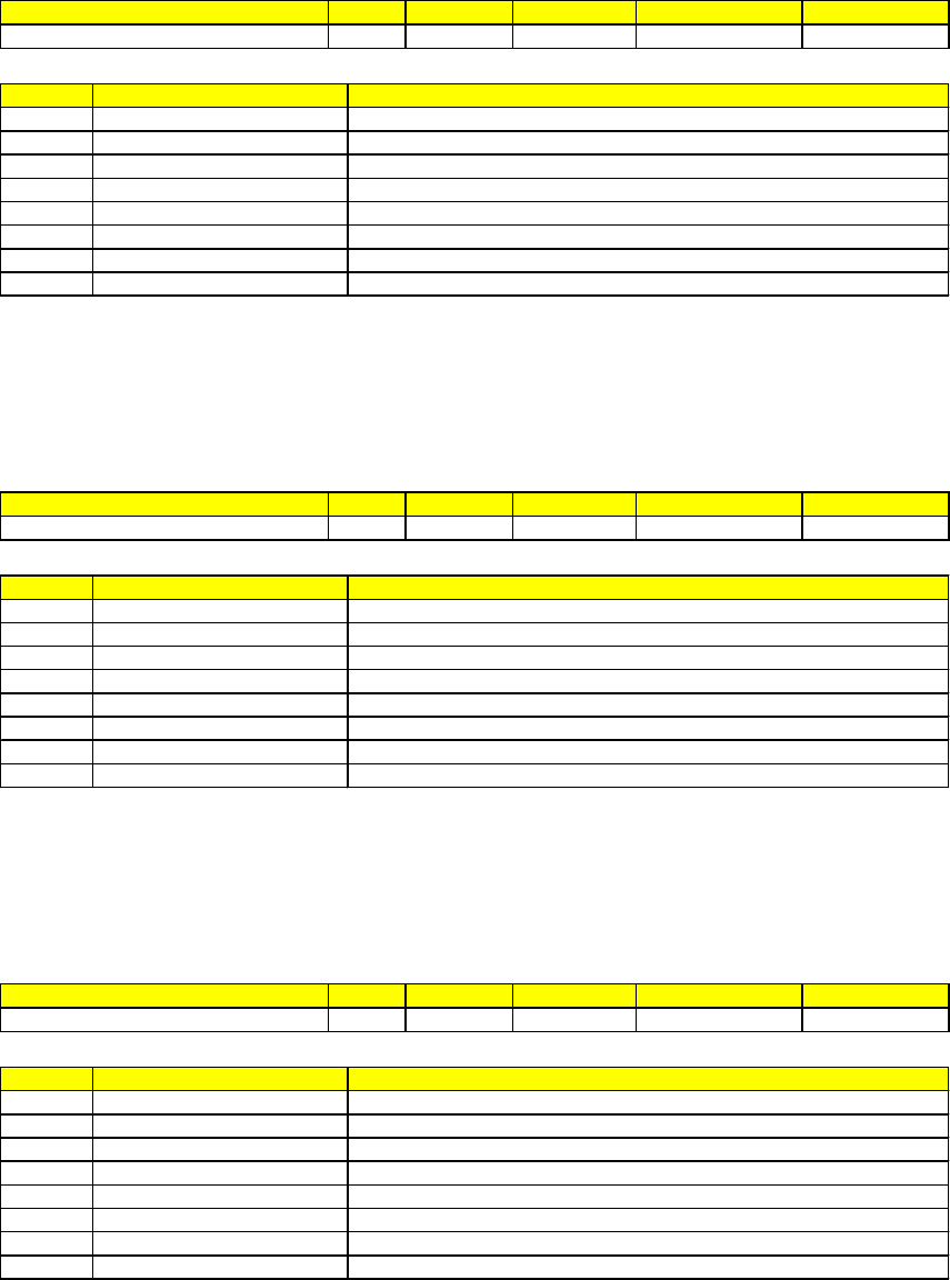
SVNAME Class VID/SVID UNITS Structure Max Characters
DECEL-VOLTS SV 73 Kvolts <A “XXX.X”> 5
SVID SVNAME DESCRIPTION
73 DECEL-VOLTS Current decel voltage
1073 lw DECEL-VOLTS Low est decel voltage on last w afer implant
2073 hw DECEL-VOLTS Highest decel voltage on last w afer implant
3073 aw DECEL-VOLTS Average decel voltage on last w afer implant
4073 lbDECEL-VOLTS Low est decel voltage on last batch implant
5073 hbDECEL-VOLTS Highest decel voltage on last batch implant
6073 abDECEL-VOLTS Average decel voltage on last batch implant
7073 DECEL-VOLTS Non-ASCII formatting available w ith V 11.05.05 and above
Deceleration power supply voltage in kilovolts.
DEC-I Format: 20
SVNAME Class VID/SVID UNITS Structure Max Characters
DEC-I SV 50 mamp <A “XX.XX”> 5
SVID SVNAME DESCRIPTION
50 DEC-I Current suppression supply current
1050 lw DEC-I Low est suppression supply current on last w afer implant
2050 hw DEC-I Highest suppression supply current on last w afer implant
3050 aw DEC-I Average suppression supply current on last w afer implant
4050 lbDEC-I Low est suppression supply current on last batch implant
5050 hbDEC-I Highest suppression supply current on last batch implant
6050 abDEC-I Average suppression supply current on last batch implant
7050 DEC-I Non-ASCII formatting available w ith V 11.05.05 and above
Accel column electron suppression supply current in milliamps.
DEC-VOLTS Format: 20
SVNAME Class VID/SVID UNITS Structure Max Characters
DEC-VOLTS SV 49 kvolts <A “XX.XX”> 5
SVID SVNAME DESCRIPTION
49 DEC-VOLTS Current suppression supply voltage
1049 lw DEC-VOLTS Low est suppression supply voltage on last w afer implant
2049 hw DEC-VOLTS Highest suppression supply voltage on last w afer implant
3049 aw DEC-VOLTS Average suppression supply voltage on last w afer implant
4049 lbDEC-VOLTS Low est suppression supply voltage on last batch implant
5049 hbDEC-VOLTS Highest suppression supply voltage on last batch implant
6049 abDEC-VOLTS Average suppression supply voltage on last batch implant
7049 DEC-VOLTS Non-ASCII formatting available w ith V 11.05.05 and above
Accel column electron suppression supply voltage in kilovolts.

DEFLECTOR Format: 20
SVNAME Class VID/SVID UNITS Structure Max Characters
DEFLECTOR SV 45 kvolts <A “XX.X”> 4
SVID SVNAME DESCRIPTION
45 DEFLECTOR Current deflector voltage
1045 lw DEFLECTOR Low est deflector voltage on last w afer implant
2045 hw DEFLECTOR Highest deflector voltage on last w afer implant
3045 aw DEFLECTOR Average deflector voltage on last w afer implant
4045 lbDEFLECTOR Low est deflector voltage on last batch implant
5045 hbDEFLECTOR Highest deflector voltage on last batch implant
6045 abDEFLECTOR Average deflector voltage on last batch implant
7045 DEFLECTOR Non-ASCII formatting available w ith V 11.05.05 and above
The voltage on the deflector electrode in kilovolts.
DI-WATER-DELTA-TEMP Format : 20
SVNAME Class VID/SVID UNITS Structure Max Characters
DI-WATER-DELTA-TEMP SV 79 Celsius <A "XXX"> 3
SV ID SVNAME DESCRIPTION
79 DI-WATER-DELTA-TEMP Current differential temperature
1079 lw DI-WATER-DELTA-TEMP Low est differential temperature on last w afer implant
2079 hw DI-WATER-DELTA-TEMP Highest differential temperature on last w afer implant
3079 aw DI-WATER-DELTA-TEMP Average differential temperature on last w afer implant
4079 lbDI-WATER-DELTA-TEMP Low est differential temperature on last batch implant
5079 hbDI-WATER-DELTA-TEMP Highest differential temperature on last batch implant
6079 abDI-WATER-DELTA-TEMP Average differential temperature on last batch implant
7079 DI-WATER-DELTA-TEMP Non-ASCII formatting available w ith V 11.05.05 and above
Differential temperature between the terminal and return DI cooling water supply in degrees Celsius.
DRY-PUMP-TC Format : 20
SVNAME Class VID/SVID UNITS Structure Max Characters
DRY-PUMP-TC SV 65 micron <A “XXXX”> 4
SVID SVNAME DESCRIPTION
65 DRY-PUMP-TC Current foreline thermocouple readback
1065 lw DRY-PUMP-TC Low est foreline thermocouple readback on last w afer implant
2065 hw DRY-PUMP-TC Highest foreline thermocouple readback on last w afer implant
3065 aw DRY-PUMP-TC Average foreline thermocouple readback on last w afer implant
4065 lbDRY-PUMP-TC Low est foreline thermocouple readback on last batch implant
5065 hbDRY-PUMP-TC Highest foreline thermocouple readback on last batch implant
6065 abDRY-PUMP-TC Average foreline thermocouple readback on last batch implant
7065 DRY-PUMP-TC Non-ASCII formatting available w ith V 11.05.05 and above
Readback from the thermocouple gauge on the foreline of the source dry pump in units of microns.

eBIAS-I Format : 20
SVNAME Class VID/SVID UNITS Structure Max Characters
eBIAS-I SV 62 mamp <A “XX.X”> 4
SVID SVNAME DESCRIPTION
62 eBIAS-I Current bias current
1062 lw eBIAS-I Low est bias current on last w afer implant
2062 hw eBIAS-I Highest bias current on last w afer implant
3062 aw eBIAS-I Average bias current on last w afer implant
4062 lbeBIAS-I Low est bias current on last batch implant
5062 hbeBIAS-I Highest bias current on last batch implant
6062 abeBIAS-I Average bias current on last batch implant
7062 eBIAS-I Non-ASCII formatting available w ith V 11.05.05 and above
Bias current in milliamps (can be negative).
eBIAS-VOLTS Format : 20
SVNAME Class VID/SVID UNITS Structure Max Characters
eBIAS-VOLTS SV 61 volt <A “XX.X”> 4
SVID SVNAME DESCRIPTION
61 eBIAS-VOLTS Current target bias voltage
1061 lw eBIAS-VOLTS Low est target bias voltage on last w afer implant
2061 hw eBIAS-VOLTS Highest target bias voltage on last w afer implant
3061 aw eBIAS-VOLTS Average target bias voltage on last w afer implant
4061 lbeBIAS-VOLTS Low est target bias voltage on last batch implant
5061 hbeBIAS-VOLTS Highest target bias voltage on last batch implant
6061 abeBIAS-VOLTS Average target bias voltage on last batch implant
7061 eBIAS-VOLTS Non-ASCII formatting available w ith V 11.05.05 and above
Target bias voltage in volts.
eEXT-I Format : 20
SVNAME Class VID/SVID UNITS Structure Max Characters
eEXT-I SV 59 mamp <A “XXX.XX”> 6
SVID SVNAME DESCRIPTION
59 eEXT-I Current extraction current
1059 lw eEXT-I Low est extraction current on last w afer implant
2059 hw eEXT-I Highest extraction current on last w afer implant
3059 aw eEXT-I Average extraction current on last w afer implant
4059 lbeEXT-I Low est extraction current on last batch implant
5059 hbeEXT-I Highest extraction current on last batch implant
6059 abeEXT-I Average extraction current on last batch implant
7059 eEXT-I Non-ASCII formatting available w ith V 11.05.05 and above
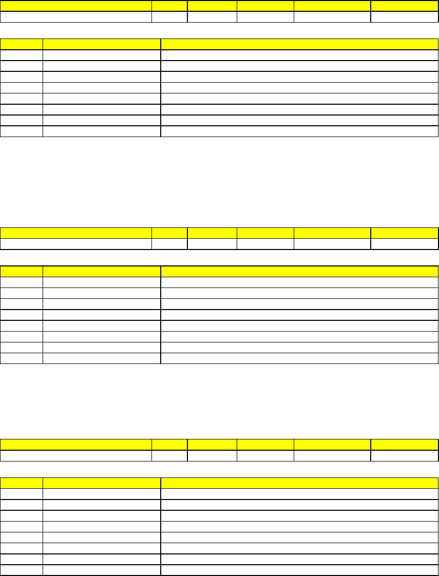
Extraction current in amps.
eFIL-I Format : 20
SVNAME Class VID/SVID UNITS Structure Max Characters
eFIL-I SV 56 amp <A “XX.X”> 4
SVID SVNAME DESCRIPTION
56 eFIL-I Current filament current
1056 lw eFIL-I Low est filament current on last w afer implant
2056 hw eFIL-I Highest filament current on last w afer implant
3056 aw eFIL-I Average filament current on last w afer implant
4056 lbeFIL-I Low est filament current on last batch implant
5056 hbeFIL-I Highest filament current on last batch implant
6056 abeFIL-I Average filament current on last batch implant
7056 eFIL-I Non-ASCII formatting available w ith V 11.05.05 and above
Filament current in amps.
eEXT-VOLTS Format : 20
SVNAME Class VID/SVID UNITS Structure Max Characters
eEXT-VOLTS SV 58 volt <A “XXX”> 3
SVID SVNAME DESCRIPTION
58 eEXT-VOLTS Current extraction voltage
1058 lw eEXT-VOLTS Low est extraction voltage on last w afer implant
2058 hw eEXT-VOLTS Highest extraction voltage on last w afer implant
3058 aw eEXT-VOLTS Averageextraction voltage on last w afer implant
4058 lbeEXT-VOLTS Low est extraction voltage on last batch implant
5058 hbeEXT-VOLTS Highest extraction voltage on last batch implant
6058 abeEXT-VOLTS Average extraction voltage on last batch implant
7058 eEXT-VOLTS Non-ASCII formatting available w ith V 11.05.05 and above
Extraction voltage in volts.
eFIL-VOLTS Format : 20
SVNAME Class VID/SVID UNITS Structure Max Characters
eFIL-VOLTS SV 55 volt <A “XX.X”> 4
SVID SVNAME DESCRIPTION
55 eFIL-VOLTS Current filament voltage
1055 lw eFIL-VOLTS Low est filament voltage on last w afer implant
2055 hw eFIL-VOLTS Highest filament voltage on last w afer implant
3055 aw eFIL-VOLTS Average filament voltage on last w afer implant
4055 lbeFIL-VOLTS Low est filament voltage on last batch implant
5055 hbeFIL-VOLTS Highest filament voltage on last batch implant
6055 abeFIL-VOLTS Average filament voltage on last batch implant
7055 eFIL-VOLTS Non-ASCII formatting available w ith V 11.05.05 and above

Filament voltage in volts.
ENERGY-PROBE Format : 20
SV NAME Class VID/SV ID UNITS Struc ture Max Charac ters
ENERGY-PROBE SV 51 none <A "XXX.X"> 5
SV ID SVNAME DESCRIPTION
51 ENERGY-PROBE Current accel voltage
1051 lw ENERGY-PROBE Low est accel voltage on last w afer implant
2051 hw ENERGY-PROBE Highest accel voltage on last w afer implant
3051 aw ENERGY-PROBE Average accel voltage on last w afer implant
4051 lbENERGY-PROBE Low est accel voltage on last batch implant
5051 hbENERGY-PROBE Highest accel voltage on last batch implant
6051 abENERGY-PROBE Average accel voltage on last batch implant
7051 ENERGY-PROBE Non-ASCII formatting available w ith V 11.05.05 and above
The total voltage used to accelerate the ion beam in kilovolts times the ion charge in the recipe. If the high voltage probe
option is installed, this value comes from the probe. Otherwise, it is calculated from the extraction and accelerating
voltages.
ErgoSMIF MDLN Format : A6
SV NAME Class V ID/SVID UNITS Structure Max Characters
Left ErgoSMIF MDLN SV 8314 none <A "XXXXXX"> 6
Right ErgoSMIF MDLN SV 8414 none <A "XXXXXX"> 6
Version Available : 11.07.06
Equipment Model Type. The default is "ERGO 2"
ErgoSMIF SoftRev Format : A6
SV NAME Class VID/SVID UNITS Structure Max Characters
Left ErgoSMIF SoftRev SV 8315 none <A "XXXXXX"> 6
Right ErgoSMIF SoftRev SV 8415 none <A "XXXXXX"> 6
Version Available : 11.07.06
SMIF software revision V2.00 or higher. The default is "PID200"
ErgoSMIF Control State Format : U1
SV NAME Class VID/SVID UNITS Structure Max Characters
Left ErgoSMIF Control State SV 8316 none <A "X"> 1
Right ErgoSMIF Control State SV 8416 none <A "X"> 1

Version Available : 11.07.06
The current control state of the SMIF. The default is "4" (Local).
4 - local
5 - remote
ErgoSMIF Process State Format : U1
SV NAME Class VID/SVID UNITS Structure Max Characters
Left ErgoSMIF Process State SV 8317 none <A "X"> 1
Right ErgoSMIF P rocess St at e SV 8417 none <A "X"> 1
Version Available : 11.07.06
The process state of the SMIF. The default is "0" (Idle).
0 - idle
1 - loading
2 - unloading
3 - initializing
4 - service running
5 - load paused
6 - unload paused
ErgoSMIF PIO State Format : U2
SV NAME Class VID/SVID UNITS Structure Max Characters
Left ErgoSMIF PIO State SV 8318 none <A "XX"> 2
Right ErgoSMIF PIO State SV 8418 none <A "XX"> 2
Version Available : 11.07.06
The binary PIO State. The default is set as "0".
eRPL-VOLTS Format : 20
SVNAME Class VID/SVID UNITS Structure Max Characters
eRPL-VOLTS SV 57 volt <A “XX.X”> 4
SVID SVNAME DESCRIPTION
57 eRPL-VOLTS Current repeller voltage
1057 lw eRPL-VOLTS Low est repeller voltage on last w afer implant
2057 hw eRPL-VOLTS Highest repeller voltage on last w afer implant
3057 aw eRPL-VOLTS Average repeller voltage on last w afer implant
4057 lbeRPL-VOLTS Low est repeller voltage on last batch implant
5057 hbeRPL-VOLTS Highest repeller voltage on last batch implant
6057 abeRPL-VOLTS Average repeller voltage on last batch implant
7057 eRPL-VOLTS Non-ASCII formatting available w ith V 11.05.05 and above
Repeller voltage in volts.

ES-DIFFER-TC Format : 20
SV NAME Class VID/SV ID UNITS Struc ture Max Charac ters
ES-DIFFER-TC SV 78 micron <A "XXXX"> 4
SV ID SVNAME DESCRIPTION
78 ES-DIFFER-TC Current ES differential pressure
1078 lw ES-DIFFER-TC Low est ES differential pressure on last w afer implant
2078 hw ES-DIFFER-TC Highest ES differential pressure on last w afer implant
3078 aw ES-DIFFER-TC Average ES differential pressure on last w afer implant
4078 lbES-DIFFER-TC Low est ES differential pressure on last batch implant
5078 hbES-DIFFER-TC Highest ES differential pressure on last batch implant
6078 abES-DIFFER-TC Average ES differential pressure on last batch implant
7078 ES-DIFFER-TC Non-ASCII formatting available w ith V 11.05.05 and above
End station differential pressure.
eSECOND-I Format : 20
SVNAME Class VID/SVID UNITS Structure Max Characters
eSECOND-I SV 71 mamp <A “XX.X”> 4
SVID SVNAME DESCRIPTION
71 eSECOND-I Current secondary current sensor readback
1071 lw eSECOND-I Low est secondary current sensor readback on last w afer implant
2071 hw eSECOND-I Highest secondary current sensor readback on last w afer implant
3071 aw eSECOND-I Average secondary current sensor readback on last w afer implant
4071 lbeSECOND-I Low est secondary current sensor readback on last batch implant
5071 hbeSECOND-I Highest secondary current sensor readback on last batch implant
6071 abeSECOND-I Average secondary current sensor readback on last batch implant
7071 eSECOND-I Non-ASCII formatting available w ith V 11.05.05 and above
Secondary current sensor readback in milliamps if ECO Option # 44 is selected.
eSUP-VOLTS Format : 20
SVNAME Class VID/SVID UNITS Structure Max Characters
eSUP-VOLTS SV 63 volt <A “XXX.XX”> 6
SVID SVNAME DESCRIPTION
63 eSUP-VOLTS Current ES Faraday suppression voltage
1063 lw eSUP-VOLTS Low est ES Faraday suppression voltage on last w afer implant
2063 hw eSUP-VOLTS Highest ES Faraday suppression voltage on last w afer implant
3063 aw eSUP-VOLTS Average ES Faraday suppression voltage on last w afer implant
4063 lbeSUP-VOLTS Low est ES Faraday suppression voltage on last batch implant
5063 hbeSUP-VOLTS Highest ES Faraday suppression voltage on last batch implant
6063 abeSUP-VOLTS Average ES Faraday suppression voltage on last batch implant
7063 eSUP-VOLTS Non-ASCII formatting available w ith V 11.05.05 and above
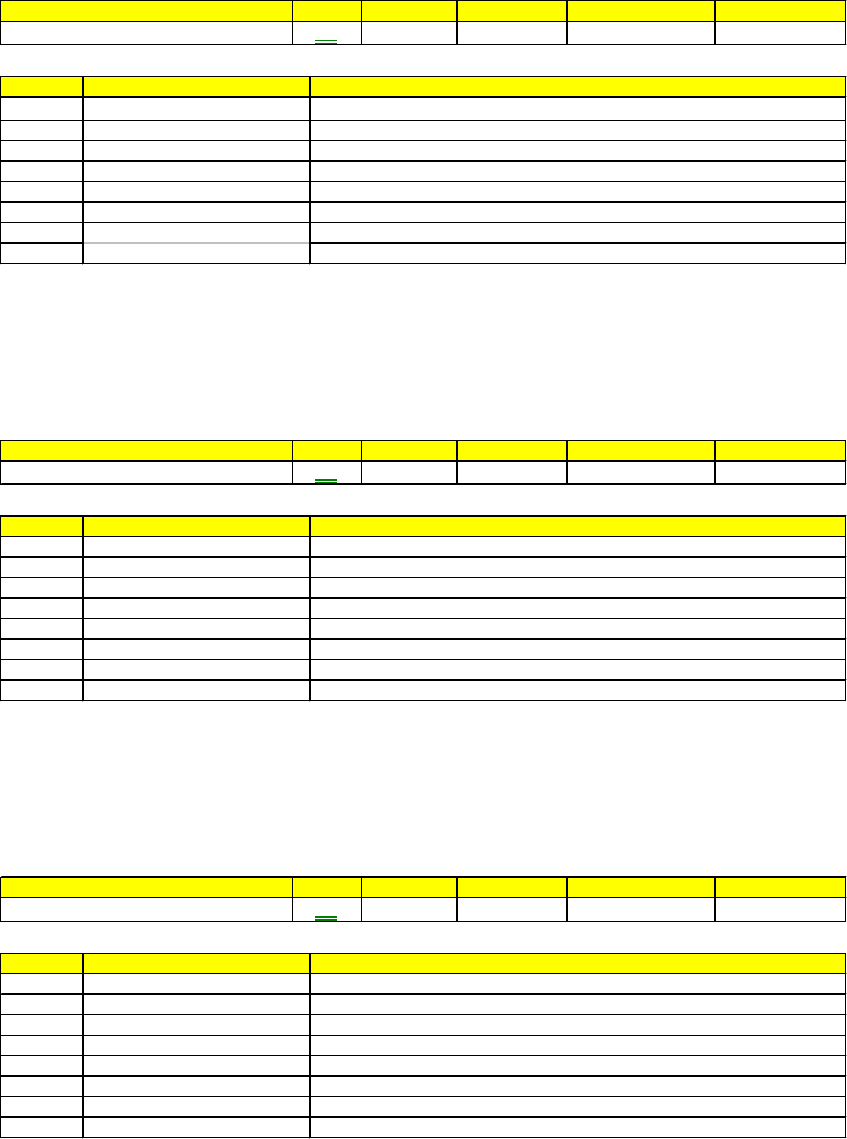
End station Faraday cup suppression voltage in volts.
eTARGET-I Format : 20
SV NAME Class V ID/SV ID UNITS Struc ture Max Characters
eTARGET-I SV 60 mamp <A "XXX.XX"> 6
SV ID SV NA ME DESCRIPTION
60 eTARGET-I Current target current
1060 lw eTARGET-I Low est target current on last w afer implant
2060 hw eTARGET-I Highest target current on last w afer implant
3060 aw eTARGET-I Average target current on last w afer implant
4060 lbeTARGET-I Low est target current on last batch implant
5060 hbeTARGET-I Highest target current on last batch implant
6060 eTARGET-I Average target current on last batch implant
7060 eTARGET-I Non-ASCII formatting available w ith V 11.05.05 and above
Target current in milliamps.
EXT-I Format: 20
SV NAME Class V ID/SV ID UNITS Struc ture Max Characters
EXT-I SV 29 mamp <A "XX.X"> 4
SV ID SV NAME DESCRIPTION
29 EXT-I Current extraction supply current
1029 lw EXT-I Low estextraction supply current on last w afer implant
2029 hw EXT-I Highestextraction supply current on last w afer implant
3029 aw EXT-I Averageextraction supply current on last w afer implant
4029 lbEXT-I Low est extraction supply current on last batch implant
5029 hbEXT-I Highest extraction supply current on last batch implant
6029 abEXT-I Average extraction supply current on last batch implant
7029 EXT-I Non-ASCII formatting available w ith V 11.05.05 and above
Extraction supply current in milliamps.
EXT-VOLTS Format : 20
SV NAME Class V ID/SVID UNITS Structure Max Characters
EXT-VOLTS SV 28 kvolts <A "XX.XX"> 5
SV ID SV NAME DESCRIPTION
28 EXT-VOLTS Current extraction supply voltage
1028 lw EXT-VOLTS Low est extraction supply voltage on last w afer implant
2028 hw EXT-VOLTS Highest extraction supply voltage on last w afer implant
3028 aw EXT-VOLTS Average extraction supply voltage on last w afer implant
4028 lbEXT-VOLTS Low est extraction supply voltage on last batch implant
5028 hbEXT-VOLTS Highest extraction supply voltage on last batch implant
6028 abEXT-VOLTS Averageextraction supply voltage on last batch implant
7028 EXT-VOLTS Non-ASCII formatting available w ith V 11.05.05 and above
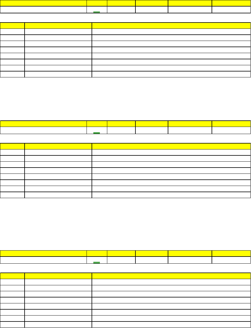
Extraction supply voltage in kilovolts.
FIL-I Format : 20
SV NAME Class V ID/SVID UNITS Structure Max Characters
FIL-I SV 22 amp <A "XXX.X"> 5
SV ID SV NAME DESCRIPTION
22 FIL-I Current filament current
1022 lw FIL-I Low est filament current on last w afer implant
2022 hw FIL-I Highest filament current on last w afer implant
3022 aw FIL-I Average filament current on last w afer implant
4022 lbFIL-I Low est filament current on last batch implant
5022 hbFIL-I Highest filament current on last batch implant
6022 abFIL-I Average filament current on last batch implant
7022 FIL-I Non-ASCII formatting available w ith V 11.05.05 and above
Filament current in amperes.
FIL-VOLTS Format : 20
SV NAME Class V ID/SVID UNITS Structure Max Characters
FIL-VOLTS SV 23 Volts <A "XX.XX"> 5
SV ID SV NAME DESCRIPTION
23 FIL-VOLTS Current filament voltage
1022 lw FIL-VOLTS Low est filament voltage on last w afer implant
2023 hw FIL-VOLTS Highest filament voltage on last w afer implant
3023 aw FIL-VOLTS Average filament voltage on last w afer implant
4023 lbFIL-VOLTS Low est filament voltage on last batch implant
5023 hbFIL-VOLTS Highest filament voltage on last batch implant
6023 abFIL-VOLTS Average filament voltage on last batch implant
7023 FIL-VOLTS Non-ASCII formatting available w ith V 11.05.05 and above
Filament voltage in volts.
G1-PRES Format : 20
SV NAME Class V ID/SVID UNITS Structure Max Characters
G1-PRES SV 18 psi <A "XXXX.X"> 6
SV ID SV NAME DESCRIPTION
18 G1-PRES Current pressure in gas bottle 1
1018 lw G1-PRES Low est pressure in gas bottle 1 on last w afer implant
2018 hw G1-PRES Highest pressure in gas bottle 1 on last w afer implant
3018 aw G1-PRES Averagepressure in gas bottle 1 on last w afer implant
4018 lbG1-PRES Low est pressure in gas bottle 1 on last batch implant
5018 hbG1-PRES Highest pressure in gas bottle 1 on last batch implant
6018 abG1-PRES Average pressure in gas bottle 1 on last batch implant
7018 G1-PRES Non-ASCII formatting available w ith V 11.05.05 and above

Pressure in gas bottle 1. Units are pounds per square inch with a full scale of 3000 psi. The gauge readings should not be
used to determine when a bottle is empty since the pressure in most toxic gas bottles is only 300 psi when full and the
gauges have significant zero offsets.
G2-PRES Format : 20
SV NAME Class V ID/SVID UNITS Structure Max Characters
G2-PRES SV 19 psi <A "XXXX.X"> 6
SV ID SV NAME DESCRIPTION
19 G2-P RES Current pressure in gas bottle 2
1019 lw G2-PRES Low est pressure in gas bottle 2 on last w afer implant
2019 hw G2-PRES Highest pressure in gas bottle 2 on last w afer implant
3019 aw G2-PRES Average pressure in gas bottle 2 on last w afer implant
4019 lbG2-PRES Low est pressure in gas bottle 2 on last batch implant
5019 hbG2-PRES Highest pressure in gas bottle 2 on last batch implant
6019 abG2-PRES Average pressure in gas bottle 2 on last batch implant
7019 G2-PRES Non-ASCII formatting available w ith V 11.05.05 and above
Pressure in gas bottle 2.
G3-PRES Format : 20
SV NAME Class V ID/SVID UNITS Structure Max Characters
G3-PRES SV 20 psi <A "XXXX.X"> 6
SV ID SV NA ME DESCRIPTION
20 G3-PRES Current pressure in gas bottle 3
1020 lw G3-PRES Low est pressure in gas bottle 3 on last w afer implant
2020 hw G3-PRES Highest pressure in gas bottle 3 on last w afer implant
3020 aw G3-PRES Average pressure in gas bottle 3 on last w afer implant
4020 lbG3-PRES Low est pressure in gas bottle 3 on last batch implant
5020 hbG3-PRES Highest pressure in gas bottle 3 on last batch implant
6020 abG3-PRES Average pressure in gas bottle 3 on last batch implant
7020 G3-PRES Non-ASCII formatting available w ith V 11.05.05 and above
Pressure in gas bottle 3.
G4-PRES Format : 20
SV NAME Class V ID/SVID UNITS Structure Max Characters
G4-PRES SV 21 psi <A "XXXX.X"> 6

SV ID SV NAME DESCRIPTION
21 G4-PRES Current pressure in gas bottle 4
1021 lw G4-PRES Low est pressure in gas bottle 4 on last w afer implant
2021 hw G4-PRES Highestpressure in gas bottle 4 on last w afer implant
3021 aw G4-PRES Averagepressure in gas bottle 4 on last w afer implant
4021 lbG4-PRES Low est pressure in gas bottle 4 on last batch implant
5021 hbG4-PRES Highest pressure in gas bottle 4 on last batch implant
6021 abG4-PRES Average pressure in gas bottle 4 on last batch implant
7021 G4-PRES Non-ASCII formatting available w ith V 11.05.05 and above
Pressure in gas bottle 4.
Note: Many special gas box configurations exist and the "bottle pressure" readings cited above may not apply to some
custom configurations.
GAS Format : 20
SV NAME Class V ID/SVID UNITS Structure Max Characters
GA S SV 17 Torr <A "XX.XX"> 5
SV ID SV NAME DESCRIPTION
17 GAS Current readback from manometer
1017 lw GAS Low est readback from manometer on last w afer implant
2017 hw GAS Highest readback from manometer on last w afer implant
3017 aw GAS Average readback from manometer on last w afer implant
4017 lbGAS Low est readback from manometer on last batch implant
5017 hbGAS Highest readback from manometer on last batch implant
6017 abGAS Average readback from manometer on last batch implant
7017 GAS Non-ASCII formatting available w ith V 11.05.05 and above
The readback from the capacitance manometer pressure gauge that is used to control the gas flow to the ion source.
GROUND-MEGOHMS Format : 20
SV NAME Class V ID/SVID UNITS Structure Max Characters
GROUND-MEGOHMS SV 2 Mohm/cm <A "XX.XX"> 5
SV ID SV NAME DESCRIPTION
2 GROUND-MEGOHMS Current resistivity of the cooling w ater
1002 lw GROUND-MEGOHMS Low est resistivity of the cooling w ater on last w afer implant
2002 hw GROUND-MEGOHMS Highest resistivity of the cooling w ater on last w afer implant
3002 aw GROUND-MEGOHMS Average resistivity of the cooling w ater on last w afer implant
4002 lbGROUND-MEGOHMS Low est resistivity of the cooling w ater on last batch implant
5002 hbGROUND-MEGOHMS Highest resistivity of the cooling w ater on last batch implant
6002 abGROUND-MEGOHMS Average resistivity of the cooling w ater on last batch implant
7002 GROUND-MEGOHMS Non-ASCII formatting available w ith V 11.05.05 and above
The resistivity of the cooling water at ground. The production machines do not use deionized cooling water at ground but
this may change to support electrostatic clamping of the water so the variable is provided for future use.
GROUND-WATER-TEMP Format : 20
SV NAME Class V ID/SV ID UNITS Structure Max Characters
GROUND-WATER-TEMP SV 4Co<A "XXX"> 3
SV ID SVNAME DESCRIPTION
4 GROUND-WATER-TEMP Current temperature of the cooling w ater
1004 lw GROUND-WATER-TEMP Low est temperature of the cooling w ater on last w afer implant
2004 hw GROUND-WATER-TEMP Highest temperature of the cooling w ater on last w afer implant
3004 aw GROUND-WATER-TEMP Average temperature of the cooling w ater on last w afer implant
4004 lbGROUND-WATER-TEMP Low est temperature of the cooling w ater on last batch implant
5004 hbGROUND-WATER-TEMP Highest temperature of the cooling w ater on last batch implant
6004 abGROUND-WATER-TEMP Average temperature of the cooling w ater on last batch implant
7004 GROUND-WATER-TEMP Non-ASCII formatting available w ith V 11.05.05 and above
The temperature of the cooling water used to cool the end station.
HELIUM-PRESSURE Format : 20
SVNAME Class VID/SVID UNITS Structure Max Characters
HELIUM-PRESSURE SV 76 Psi <A "XXX.X"> 5
SV ID SV NA ME DESCRIPTION
76 HELIUM-PRESSURE Current Helium pressure
1076 lw HELIUM-PRESSURE Low est Helium pressure on last w afer implant
2076 hw HELIUM-PRESSURE Highest Helium pressure on last w afer implant
3076 aw HELIUM-PRESSURE Average Helium pressure on last w afer implant
4076 lbHELIUM-PRESSURE Low est Helium pressure on last batch implant
5076 hbHELIUM-PRESSURE Highest Helium pressure on last batch implant
6076 abHELIUM-PRESSURE Average Helium pressure on last batch implant
7076 HELIUM-PRESSURE Non-ASCII formatting available w ith V 11.05.05 and above
Cryo compressor helium pressure.
HTR-TEMP Format : 20
SVNAME Class VID/SVID UNITS Structure Max Characters
HTR-TEMP SV 72 Co<A "XXX"> 3
SV ID SV NAME DESCRIPTION
72 HTR-TEMP Current heater temperature
1072 lw HTR-TEMP Low estheater temperature on last w afer implant
2072 hw HTR-TEMP Highest heater temperature on last w afer implant
3072 aw HTR-TEMP Average heater temperature on last w afer implant
4072 lbHTR-TEMP Low est heater temperature on last batch implant
5072 hbHTR-TEMP Highest heater temperature on last batch implant
6072 abHTR-TEMP Average heater temperature on last batch implant
7072 HTR-TEMP Non-ASCII formatting available w ith V 11.05.05 and above
Temperature for the standard heater in degrees centigrade.
LEFT-CYRO-TEMP Format : 20

SVNAME Class VID/SVID UNITS Structure Max Characters
LEFT-CYRO-TEMP SV 11 Ko<A "XXX"> 3
SV ID SV NAME DESCRIPTION
11 LEFT-CYRO-TEMP Current temperature of left cryo
1011 lw LEFT-CYRO-TEMP Low est temperature of left cryo on last w afer implant
2011 hw LEFT-CYRO-TEMP Highest temperature of left cryo on last w afer implant
3011 aw LEFT-CYRO-TEMP Average temperature of left cryo on last w afer implant
4011 lbLEFT-CYRO-TEMP Low est temperature of left cryo on last batch implant
5011 hbLEFT-CYRO-TEMP Highest temperature of left cryo on last batch implant
6011 abLEFT-CYRO-TEMP Averagetemperature of left cryo on last batch implant
7011 LEFT-CYRO-TEMP Non-ASCII formatting available w ith V 11.05.05 and above
The temperature of the left elevator cryo pump in degrees Kelvin. Generally the pump must be colder than 20 degrees
Kelvin to pump effectively.
LEFT-ELEVATOR-TC Format: 20
SV NAME Class VID/SV ID UNITS Struc ture Max Charac ters
LEFT-ELEVATOR-TC SV 14 micron <A "XXXX"> 4
SV ID SV NAME DESCRIPTION
14 LEFT-ELEVATOR-TC Current left elevator pressure
1014 lw LEFT-ELEVATOR-TC Low est left elevator pressure on last w afer implant
2014 hw LEFT-ELEVATOR-TC Highest left elevator pressure on last w afer implant
3014 aw LEFT-ELEVATOR-TC Average left elevator pressure on last w afer implant
4014 lbLEFT-ELEVATOR-TC Low est left elevator pressure on last batch implant
5014 hbLEFT-ELEVATOR-TC Highest left elevator pressure on last batch implant
6014 abLEFT-ELEVATOR-TC Average left elevator pressure on last batch implant
7014 LEFT-ELEVATOR-TC Non-ASCII formatting available w ith V 11.05.05 and above
The left elevator pressure as measured by its thermocouple pressure gauge. Units are microns. Reading above 2000
microns should be considered unreliable because the gauge cannot reliably measure pressures between 2000 microns
and atmosphere.
LEFT-ORIENTER-LIFTER-DAC Format : 20
DVNAME Class VID/DVID UNITS Structure Max Characters
LEFT-ORIENTER-LIFTER-DAC DV 808 encoder cnts <A “XXXXXXXX"> 8
Left orienter lifter position in raw encoder counts.
LENS-I Format: 20
SV NAME Class VID/SV ID UNITS Struc ture Max Charac ters
LENS-I SV 46 amp <A "XXX.X"> 5

SV ID SV NAME DESCRIPTION
46 LENS-I Current lens magnet current
1046 lw LENS-I Low est lens magnet current on last w afer implant
2046 hw LENS-I Highest lens magnet current on last w afer implant
3046 aw LENS-I Average lens magnet current on last w afer implant
4046 lbLENS-I Low est lens magnet current on last batch implant
5046 hbLENS-I Highest lens magnet current on last batch implant
6046 abLENS-I Averagelens magnet current on last batch implant
7046 LENS-I Non-ASCII formatting available w ith V 11.05.05 and above
Current in the lens magnet in amps.
LENS-VOLTS Format: 20
SV NAME Class V ID/SVID UNITS Structure Max Characters
LENS-VOLTS SV 70 Kvolts <A "XXX.X"> 5
SV ID SV NAME DESCRIPTION
70 LENS-VOLTS Current lens magnet voltage
1070 lw LENS-VOLTS Low est lens magnet voltage on last w afer implant
2070 hw LENS-VOLTS Highest lens magnet voltage on last w afer implant
3070 aw LENS-VOLTS Average lens magnet voltage on last w afer implant
4070 lbLENS-VOLTS Low est lens magnet voltage on last batch implant
5070 hbLENS-VOLTS Highest lens magnet voltage on last batch implant
6070 abLENS-VOLTS Average lens magnet voltage on last batch implant
7070 LENS-VOLTS Non-ASCII formatting available w ith V 11.05.05 and above
Lens magnet voltage in kilovolts.
LPT SMIF Ctl Status Format : U1
SV NAME Class V ID/SVID UNITS Structure Max Characters
Left SMIF1 Ctl Status SV 8101 none <A "X…X"> 20
Right SMIF 2 Ctl Status SV 8201 none <A "X…X"> 20
<U1[20]
MODE 8x17,
PIP 8x24,
HOMEST 8x12,
FUNC 8x10,
COLST 8x04,
LFUNC 8x13,
GPST 8x11,
PRTST 8x27,
ELUP 8x09,
PLDN 8x25,
MARMUP 8x16,
MARMDN 8x14,
TILUP 8x32,
ELDN 8x07,
PLUP 8x39,
SWPOS 8x29,
DIPSW 8x06,
ARMTYP 8x02,

ECV 8x40,
ALED 8x41
>
<L[0] > : Not available
LPT SMIF Ctl ARMTYPE Format : U1
SV NAME Class V ID/SVID UNITS Structure Max Characters
Left SMIF1 Ctl ARMTYPE SV 8102 none <A "X"> 1
Right SMIF 2 Ctl ARMTYPE SV 8202 none <A "X"> 1
Value Arm Type
0 Arm 1000 V
1 Arm 1000 H Bar Towards
2 Arm 1000 H Bar Away
3 2000 Outside Move
4 2000 Inside Move
5 Arm 3000 V
6 Arm 3000 H Bar Towards
7 Arm 3000 H Bar Away
8 ALU 2000
9 Other Configuration
10 ALU 2200
11 Arm 2200 Outside V Move
12 Arm 2200 Inside V Move
13 Arm 2200 Outside H Move
14 Arm 2200 Inside H Move
LPT SMIF ARM SW Format : A
SV NAME Class V ID/SVID UNITS Structure Max Characters
Left SMIF1 ARM SW SV 8103 none <A "X…X"> 20
Righ t SMIF 2 ARM SW SV 8203 none <A "X…X"> 20
LPT Arm software part number in 20 byte format.
LPT SMIF COLST Format : U1
SV NAME Class V ID/SVID UNITS Structure Max Characters
Left SMIF1 COLST SV 8104 none <A "X"> 1
Right SMIF 2 COLST SV 8204 none <A "X"> 1
Value Collision Status
1 No Collision
2 Collision
3 Improper squat in cassette pickup during load
4 Improper squat in cassette place during load

5 Improper squat in cassette pickup during unload
6 Improper squat in cassette place during unload
7 Improper wafer seating
LPT SMIF COUNT Format : U2
SV NAME Class V ID/SVID UNITS Structure Max Characters
Left SMIF1 COUNT SV 8105 counts <A "X"> 1
Right SMIF 2 COUNT SV 8205 counts <A "X"> 1
(RESERVED, NOT USED)
The LPT SMIF count for Move Distance (n).
LPT SMIF DIPSW Format : U1
SV NAME Class V ID/SVID UNITS Structure Max Characters
Left SMIF1 DIPSW SV 8106 none <A "X"> 1
Right SMIF 2 DIPSW SV 8206 none <A "X"> 1
Dip switch setting on the arm controller board.
LPT SMIF ELDN Format : U1
SV NAME Class V ID/SVID UNITS Structure Max Characters
Left SMIF1 ELDN SV 8107 none <A "X"> 1
Right SMIF 2 ELDN SV 8207 none <A "X"> 1
Elevator platform flag
0 - Elevator not at down limit
1 - Elevator at down limit
<L[0] > - Not available
LPT SMIF ELPOS Format : U2
SV NAME Class V ID/SVID UNITS Structure Max Characters
Left SMIF1 ELPOS SV 8108 none <A "X"> 1
Right SMIF 2 ELPOS SV 8208 none <A "X"> 1
Elevator position
0 - Elevator at home position
xx - steps away from the home position
<L[0] > - Not available
LPT SMIF ELUP Format : U1
SV NAME Class V ID/SVID UNITS Structure Max Characters
Left SMIF1 ELUP SV 8109 none <A "X"> 1
Right SMIF 2 ELUP SV 8209 none <A "X"> 1
Elevator UP flag
0 - Elevator not at UP limit
1 - Elevator at UP limit
<L[0] > - Not available
LPT SMIF FUNC Format : U1
SV NAME Class V ID/SVID UNITS Structure Max Characters
Left SMIF1 FUNC SV 8110 none <A "X"> 1
Right SMIF 2 FUNC SV 8210 none <A "X"> 1
Function being done by the arm
0 - Idle
1 - Load/Open in progress
2 - Unload/Close in progress
3 - Auto Home in progress
<L[0] > - Not available
LPT SMIF Full Status Format : 0
SV NAME Class V ID/SVID UNITS Structure Max Characters
Left SMIF1 Full Status SV 8100 none <A "X"> 1
Righ t SMIF 2 Full St at us SV 8200 none <A "X"> 1
<L [5]
<U1[20]
MODE 8x17,
PIP 8x24,
HOMEST 8x12,
FUNC 8x10,
COLST 8x04,
LFUNC 8x13,
GPST 8x11,
PRTST 8x27,
ELUP 8x09,
PLDN 8x25,
MARMUP 8x16,
MARMDN 8x14,
TILUP 8x32,
ELDN 8x07,
PLUP 8x39,
SWPOS 8x29,

DIPSW 8x06,
ARMTYP 8x02,
ECV 08x40,
ALED 08x41
>
<U2[4] XPOS 8x33, YPOS 8x34, ELPOS 8x08, TLTPOS 8x31 >
<U1 RDYS 8x28 >
<A [20] ARM_SW 8x03 >
<U1[4] PIO_LU 8x22, PIO_LRDY 8x21, PIO_URDY 8x23, PIO_LOCK 8x20>
>
<L[0] > - Not available
LPT SMIF GPST Format : U1
SV NAME Class V ID/SVID UNITS Structure Max Characters
Left SMIF1 GPST SV 8111 none <A "X"> 1
Righ t SMIF 2 GP ST SV 8211 none <A "X"> 1
Gripper Status
0 - Gripper Open
1 - Gripper Closed with Cassette
2 - Gripper Closed without Cassette
3 - None of the above
<L[0] > - Not available
LPT SMIF HOMEST Format : U1
SV NAME Class V ID/SVID UNITS Structure Max Characters
Left SMIF1 HOMEST SV 8112 none <A "X"> 1
Right SMIF 2 HOMEST SV 8212 none <A "X"> 1
Arm Home Status
0 - Arm not at home
1 - Arm at Home
<L[0] > - Not available
LPT SMIF LFUNC Format : U1
SV NAME Class V ID/SVID UNITS Structure Max Characters
Left SMIF1 LFUNC SV 8113 none <A "X"> 1
Right SMIF 2 LFUNC SV 8213 none <A "X"> 1
Last Function done
0 - Switched to manual/power up with manual
1 - Switched to auto/power up with auto mode
11 - Load/Open
12 - Unload/Close
13 - Auto Home
<L[0] > - Not available

LPT SMIF MARMDN Format : U1
SV NAME Class V ID/SVID UNITS Structure Max Characters
Left SMIF1 MARMDN SV 8114 none <A "X"> 1
Right SMIF 2 MARMDN SV 8214 none <A "X"> 1
Moving arm down flag
0 - Moving arm not at down limit
1 - Moving arm at down limit
<L[0] > - Not available
LPT SMIF MARMPOS Format : U2
SV NAME Class V ID/SVID UNITS Structure Max Characters
Left SMIF1 MARMPOS SV 8115 count <A "X"> 1
Right SMIF 2 MARMPOS SV 8215 count <A "X"> 1
(RESERVED, NOT USED)
Moving arm position
0 - Arm at home position
xx - Steps away from home position
<L[0] > - Not available
LPT SMIF MARMUP Format : U1
SV NAME Class V ID/SVID UNITS Structure Max Characters
Left SMIF1 MARMUP SV 8116 none <A "X"> 1
Right SMIF 2 MARMUP SV 8216 none <A "X"> 1
Moving arm up flag
0 - Moving arm not at UP limit
1 - Moving arm at UP limit
<L[0] > - Not available
LPT SMIF SWITCH MODE Format : U1
SV NAME Class V ID/SVID UNITS Structure Max Characters
Left SMIF1 SWITCH MODE SV 8117 none <A "X"> 1
Righ t SMIF 2 SW IT CH MODE SV 8217 none <A "X"> 1
Switch Position on maintenance control panel
1- Auto mode
2 - Manual mode
<L[0] > - Not available

LPT SMIF MOT Format : U1
SV NAME Class V ID/SVID UNITS Structure Max Characters
Left SMIF1 MOT SV 8118 none <A "X"> 1
Right SMIF 2 MOT SV 8218 none <A "X"> 1
(RESERVED, NOT USED)
Motor id code
1 - Elevator motor
<L[0] > - Not available
LPT SMIF MVSTAT Format : U1
SV NAME Class V ID/SVID UNITS Structure Max Characters
Left SMIF1 MVSTAT SV 8119 none <A "X"> 1
Righ t SMIF 2 M VST AT SV 8219 none <A "X"> 1
(RESERVED, NOT USED)
Motor move status
1 - Move motor
2 - Stop motor
<L[0] > - Not available
LPT SMIF PIO LOCK Format : U1
SV NAME Class V ID/SVID UNITS Structure Max Characters
Left SMIF1 PIO LOCK SV 8120 none <A "X"> 1
Right SMIF 2 PIO LOCK SV 8220 none <A "X"> 1
Parallel Interface Pod lock switch position
0 - Inactive
1 – Active
<L[0] > - Not available
LPT SMIF PIO LRDY Format : U1
SV NAME Class V ID/SVID UNITS Structure Max Characters
Left SMIF1 PIO LRDY SV 8121 none <A "X"> 1
Right SMIF 2 PIO LRDY SV 8221 none <A "X"> 1
Parallel Interface Host Ready to Load Line
0 - Inactive
1 – Active
<L[0] > - Not available

LPT SMIF PIO LU Format : U1
SV NAME Class V ID/SVID UNITS Structure Max Characters
Left SMIF1 PIO LU SV 8122 none <A "X"> 1
Right SMIF 2 PIO LU SV 8222 none <A "X"> 1
Parallel Interface Load / Unload Line
0 - Inactive
1 – Active
<L[0] > - Not available
LPT SMIF PIO URDY Format : U1
SV NAME Class V ID/SVID UNITS Structure Max Characters
Left SMIF1 PIO URDY SV 8123 none <A "X"> 1
Right SMIF 2 PIO URDY SV 8223 none <A "X"> 1
Parallel Interface Host Ready to Unload Line
0 - Inactive
1 – Active
<L[0] > - Not available
LPT SMIF PIP Format : U1
SV NAME Class V ID/SVID UNITS Structure Max Characters
Left SMIF1 PIP SV 8124 none <A "X"> 1
Right SMIF 2 PIP SV 8224 none <A "X"> 1
Pod in place state
0 - No pod present
1 - Pod present
<L[0] > - Not available
LPT SMIF PLDN Format : U1
SV NAME Class V ID/SVID UNITS Structure Max Characters
Left SMIF1 PLDN SV 8125 none <A "X"> 1
Right SMIF 2 PLDN SV 8225 none <A "X"> 1
Arm platform down flag
0 - Platform not at down limit
1 - Platform at down limit
<L[0] > - Not available

LPT SMIF PLPOS Format : U2
SV NAME Class V ID/SVID UNITS Structure Max Characters
Left SMIF1 PLPOS SV 8126 none <A "X"> 1
Right SMIF 2 PLPOS SV 8226 none <A "X"> 1
Arm platform position
0 - Arm platform at home position
xx - steps away from home position
<L[0] > - Not available
LPT SMIF PRTST Format : U1
SV NAME Class V ID/SVID UNITS Structure Max Characters
Left SMIF1 PRTST SV 8127 none <A "X"> 1
Right SMIF 2 PRT ST SV 8227 none <A "X"> 1
SMIF Port Status
0 - port unlock
1 - port locked
2 - none of the above
<L[0] > - Not available
LPT SMIF RDYST Format : U1
SV NAME Class V ID/SVID UNITS Structure Max Characters
Left SMIF1 RDYST SV 8128 none <A "X"> 1
Right SMIF 2 RDYST SV 8228 none <A "X"> 1
Arm Ready status
0 - Arm not ready
1 - Arm ready to load/open
2 - Arm ready to unload/close
3 - Arm ready to load / unload
4 - Arm ready to auto home
<L[0] > - Not available
LPT SMIF SWPOS Format : U1
SV NAME Class V ID/SVID UNITS Structure Max Characters
Left SMIF1 SW P OS SV 8129 none <A "X"> 1
Righ t SMIF 2 SW P OS SV 8229 none <A "X"> 1
Load /unload switch position
0 - All positions
n - Position n
<L[0] > - Not available

LPT SMIF TLTDN Format : U1
SV NAME Class V ID/SVID UNITS Structure Max Characters
Left SMIF1 TLTDN SV 8130 none <A "X"> 1
Right SMIF 2 T LTDN SV 8230 none <A "X"> 1
(RESERVED, NOT USED)
Gripper tilt down flag
0 - Gripper tilt not at down limit
1 - Gripper tilt at down limit
<L[0] > - Not available
LPT SMIF TLTPOS Format : U2
SV NAME Class V ID/SVID UNITS Structure Max Characters
Left SMIF1 TLTPOS SV 8131 count <A "X"> 1
Right SMIF 2 TLTPOS SV 8231 count <A "X"> 1
Gripper tilt position
0 - Tilt at home position
xx - steps away from the home position
<L[0] > - Not available
LPT SMIF TLTUP Format : U1
SV NAME Class V ID/SVID UNITS Structure Max Characters
Left SMIF1 TLTUP SV 8132 none <A "X"> 1
Right SMIF 2 T LTUP SV 8232 none <A "X"> 1
Gripper tilt UP flag
0 - Gripper tilt not at UP limit
1 - Gripper tilt at UP limit
<L[0] > - Not available
LPT SMIF XPOS Format : U2
SV NAME Class V ID/SVID UNITS Structure Max Characters
Left SMIF1 XPOS SV 8133 none <A "X"> 1
Right SMIF 2 XPOS SV 8233 none <A "X"> 1
X Coordinate of gripper
0 - Horizontal position of gripper is at home
nn - gripper is nn mils (1/1000 of in.) away from home
<L[0] > - Not available

LPT SMIF YPOS Format : U2
SV NAME Class V ID/SVID UNITS Structure Max Characters
Left SMIF1 YPOS SV 8134 none <A "X"> 1
Right SMIF 2 YPOS SV 8234 none <A "X"> 1
Y Coordinate of gripper
0 - Horizontal position of gripper is at home
nn - gripper is nn mils(1/1000 of in.) away from home
<L[0] > - Not available
LPT SMIF Position Format : U2
SV NAME Class V ID/SVID UNITS Structure Max Characters
Left SMIF1 Position SV 8135 none <A "XXXX"> 4
Right SMIF 2 Position SV 8235 none <A "XXXX"> 4
<U2 [4] XPOS 8x33 , YPOS 8x34, ELPOS 8x08, TLTPOS 8x31>
<L[0] > - Not available
LPT SMIF PIO Status Format : U1
SV NAME Class V ID/SVID UNITS Structure Max Characters
Left SMIF1 PIO Status SV 8136 none <A "XXXX"> 4
Right SMIF 2 P IO St at us SV 8236 none <A "XXXX"> 4
<U1[4] PIO_LU 8x22, PIO_LRDY 8x21, PIO_URDY 8x23, PIO_LOCK 8x20>
<L[0] > - Not available
LPT SMIF Wafer Map Format : U1
SV NAME Class V ID/SVID UNITS Structure Max Characters
Left SMIF1 Wafer Map SV 8137 none <A "X…X"> 25
Right SMIF 2 Wafer Map SV 8237 none <A "X…X"> 25
<U1 slot1_status ... slot25_status >
<L[0] > - Not available
The slotx_status value may be returned as one of the following values:
0x00 – No wafer detected
0x01 – Wafer detected
0x02 – Cross slot detected

LPT SMIF Wafer Count Format : U1
SV NAME Class V ID/SVID UNITS Structure Max Characters
Left SMIF1 Wafer Count SV 8138 none <A "X"> 1
Right SMIF 2 Wafer Count SV 8238 none <A "X"> 1
n - Wafer Count in Cassette handled by the SMIF LPT.
<L[0] > - Not available
LPT SMIF PLUP Format : U1
SV NAME Class V ID/SVID UNITS Structure Max Characters
Left SMIF1 PLUP SV 8139 none <A "X"> 1
Right SMIF 2 PLUP SV 8239 none <A "X"> 1
Vertical LPT positive over-travel status
0 - Vertical arm not at positive over-travel
1 - Vertical arm at positive over-travel
<L[0] > - Not available
LPT SMIF ECV Format : U1
SV NAME Class V ID/SVID UNITS Structure Max Characters
Left SMIF1 ECV SV 8140 none <A "X"> 1
Right SMIF 2 ECV SV 8240 none <A "X"> 1
ECV EQUIPMENT CONSTANT VALUE
0 - Do not report
1 - Report
<L[0] > - Not available
LPT SMIF ALED Format : U1
SV NAME Class V ID/SVID UNITS Structure Max Characters
Left SMIF1 ALED SV 8141 none <A "X"> 1
Right SMIF 2 ALED SV 8241 none <A "X"> 1
Where used: S1F3, F11, F12, S2F23
ALED Alarm Enable/Disable Code
Bit 8 = 1: Enable Alarm
Bit 8 = 0: Disable Alarm
<L[0] > - Not available
MAG-I Format : 20
SV NAME Class VID/SV ID UNITS Struc ture Max Charac ters
MAG-I SV 27 amp <A "XX.XX"> 5
SV ID SV NAME DESCRIPTION
27 MAG-I Current source magent current
1027 lw MAG-I Low est source magent current on last w afer implant
2027 hw MAG-I Highest source magent current on last w afer implant
3027 aw MAG-I Average source magent current on last w afer implant
4027 lbMAG-I Low est source magent current on last batch implant
5027 hbMAG-I Highest source magent current on last batch implant
6027 abMAG-I Average source magent current on last batch implant
7027 MAG-I Non-ASCII formatting available w ith V 11.05.05 and above
Source magnet current in amperes.
MAG-VOLTS Format : 20
SV NAME Class V ID/SVID UNITS Structure Max Characters
MAG-VOLTS SV 67 Kvolts <A "XX.X"> 4
SV ID SV NAME DESCRIPTION
67 MAG-VOLTS Current source magent voltage
1067 lw MAG-VOLTS Low est source magent voltage on last w afer implant
2067 hw MAG-VOLTS Highest source magent voltage on last w afer implant
3067 aw MAG-VOLTS Average source magent voltage on last w afer implant
4067 lbMAG-VOLTS Low est source magent voltage on last batch implant
5067 hbMAG-VOLTS Highest source magent voltage on last batch implant
6067 abMAG-VOLTS Average source magent voltage on last batch implant
7067 MAG-VOLTS Non-ASCII formatting available w ith V 11.05.05 and above
Source magnet voltage in kilovolts.
MDLN Format : A
SVNAME Class VID/SVID UNITS Structure Max Characters
MDLN SV 507 None <A "XXXX"> 4
GEM compliant equipment constant for the machine. This value is ‘E220’ by default.
MIR-I Format : 20
SV NAME Class VID/SV ID UNITS Struc ture Max Charac ters
MIR-I SV 41 mamp <A "XX.XX"> 5

SV ID SV NAME DESCRIPTION
41 MIR-I Current mirror current
1041 lw MIR-I Low est mirror current on last w afer implant
2041 hw MIR-I Highest mirror current on last w afer implant
3041 aw MIR-I Average mirror current on last w afer implant
4041 lbMIR-I Low est mirror current on last batch implant
5041 hbMIR-I Highest mirror current on last batch implant
6041 abMIR-I Average mirror current on last batch implant
7041 MIR-I Non-ASCII formatting available w ith V 11.05.05 and above
The current output of the mirror supply in milliamps.
MIR-SHUNT-I Format: 20
SV NAME Class V ID/SVID UNITS Structure Max Characters
MIR-SHUNT-I SV 42 mamp <A "XX.XX"> 5
SV ID SV NAME DESCRIPTION
42 MIR-SHUNT-I Current mirror shunt current
1042 lw MIR-SHUNT-I Low est mirror shunt current on last w afer implant
2042 hw MIR-SHUNT-I Highest mirror shunt current on last w afer implant
3042 aw MIR-SHUNT-I Average mirror shunt current on last w afer implant
4042 lbMIR-SHUNT-I Low est mirror shunt current on last batch implant
5042 hbMIR-SHUNT-I Highest mirror shunt current on last batch implant
6042 abMIR-SHUNT-I Average mirror shunt current on last batch implant
7042 MIR-SHUNT-I Non-ASCII formatting available w ith V 11.05.05 and above
The current flowing into the shunt regulator in the mirror supply in milliamps. The net current in the supply is (MIR-I) minus
(MIR-SHUNT-I) and can be negative when running decel mode.
MIR-VOLTS Format : 20
SV NAME Class V ID/SVID UNITS Structure Max Characters
MIR-VOLTS SV 40 volts <A "XX.X"> 4
SV ID SV NAME DESCRIPTION
40 MIR-VOLTS Current mirror voltage
1040 lw MIR-VOLTS Low est mirror voltage on last w afer implant
2040 hw MIR-VOLTS Highest mirror voltage on last w afer implant
3040 aw MIR-VOLTS Average mirror voltage on last w afer implant
4040 lbMIR-VOLTS Low est mirror voltage on last batch implant
5040 hbMIR-VOLTS Highest mirror voltage on last batch implant
6040 abMIR-VOLTS Average mirror voltage on last batch implant
7040 MIR-VOLTS Non-ASCII formatting available w ith V 11.05.05 and above
The voltage on the beam filter electrode(mirror) when running double charged ions. The same supply is connected to the
accel column and used to decelerate the ion beam when running in decel mode.
Q1-I Format : 20

SV NAME Class V ID/SVID UNITS Structure Max Characters
Q1-I SV 43 amp <A "XX.X"> 4
SV ID SV NAME DESCRIPTION
43 Q1-I Current first quadrupole magnet current
1043 lw Q1-I Low est first quadrupole magnet current on last w afer implant
2043 hw Q1-I Highest first quadrupole magnet current on last w afer implant
3043 aw Q1-I Average first quadrupole magnet current on last w afer implant
4043 lbQ1-I Low est first quadrupole magnet current on last batch implant
5043 hbQ1-I Highest first quadrupole magnet current on last batch implant
6043 abQ1-I Average first quadrupole magnet current on last batch implant
7043 Q1-I Non-ASCII formatting available w ith V 11.05.05 and above
The current in the first quadrupole magnet in amps.
Q1-VOLTS Format : 20
SV NAME Class VID/SV ID UNITS Struc ture Max Charac ters
Q1-VOLTS SV 68 Kvolts <A "XX.X"> 4
SV ID SV NAME DESCRIPTION
68 Q1-VOLTS Current first quadrupole magnet voltage
1068 lw Q1-VOLTS Low est first quadrupole magnet voltage on last w afer implant
2068 hw Q1-VOLTS Highest first quadrupole magnet voltage on last w afer implant
3068 aw Q1-VOLTS Average first quadrupole magnet voltage on last w afer implant
4068 lbQ1-VOLTS Low est first quadrupole magnet voltage on last batch implant
5068 hbQ1-VOLTS Highest first quadrupole magnet voltage on last batch implant
6068 abQ1-VOLTS Average first quadrupole magnet voltage on last batch implant
7068 Q1-VOLTS Non-ASCII formatting available w ith V 11.05.05 and above
Quadrupole 1 magnet voltage in kilovolts.
Q2-I Format : 20
SV NAME Class V ID/SVID UNITS Structure Max Characters
Q2-I SV 44 amp <A "XX.X"> 4
SV ID SV NAME DESCRIPTION
44 Q2-I Current second quadrupole magnet current
1044 lw Q2-I Low est second quadrupole magnet current on last w afer implant
2044 hw Q2-I Highest second quadrupole magnet current on last w afer implant
3044 aw Q2-I Average second quadrupole magnet current on last w afer implant
4044 lbQ2-I Low est second quadrupole magnet current on last batch implant
5044 hbQ2-I Highest second quadrupole magnet current on last batch implant
6044 abQ2-I Average second quadrupole magnet current on last batch implant
7044 Q2-I Non-ASCII formatting available w ith V 11.05.05 and above
The current in the second quadrupole magnet in amps.
Q2-VOLTS Format : 20
SV NAME Class VID/SV ID UNITS Struc ture Max Charac ters
Q2-VOLTS SV 69 Kvolts <A "XX.X"> 4
SV ID SV NAME DESCRIPTION
69 Q2-VOLTS Current second quadrupole magnet voltage
1069 lw Q2-VOLTS Low est second quadrupole magnet voltage on last w afer implant
2069 hw Q2-VOLTS Highest second quadrupole magnet voltage on last w afer implant
3069 aw Q2-VOLTS Average second quadrupole magnet voltage on last w afer implant
4069 lbQ2-VOLTS Low est second quadrupole magnet voltage on last batch implant
5069 hbQ2-VOLTS Highest second quadrupole magnet voltage on last batch implant
6069 abQ2-VOLTS Average second quadrupole magnet voltage on last batch implant
7069 Q2-VOLTS Non-ASCII formatting available w ith V 11.05.05 and above
Quadrupole 2 magnet voltage in kilovolts.
RANGE-ARC Format : 20
SV NAME Class V ID/SVID UNITS Structure Max Characters
RANGE-ARC SV 25 none <A "X"> 1
SV ID SV NAME DESCRIPTION
25 RANGE-ARC Current arc range
1025 lw RANGE-ARC Low est arc range on last w afer implant
2025 hw RANGE-ARC Highest arc range on last w afer implant
3025 aw RANGE-ARC Average arc range on last w afer implant
4025 lbRANGE-ARC Low est arc range on last batch implant
5025 hbRANGE-ARC Highest arc range on last batch implant
6025 abRANGE-ARC Average arc range on last batch implant
7025 RANGE-ARC Non-ASCII formatting available w ith V 11.05.05 and above
Arc current unit.
RANGE-ARC Unit
0 Amperes
1 Milliamps
2 Milliamps
3 Milliamps
4 Microamps
RIGHT-CRYO-TEMP Format : 20
SV NAME Class V ID/SVID UNITS Structure Max Characters
RIGHT-CRYO-TEMP SV 13 Ko <A "XXX"> 3

SV ID SV NAME DESCRIPTION
13 RIGHT-CRYO-TEMP Current right cryo temperature
1013 lw RIGHT-CRYO-TEMP Low est right cryo temperature on last w afer implant
2013 hw RIGHT-CRYO-TEMP Highest right cryo temperature on last w afer implant
3013 aw RIGHT-CRYO-TEMP Average right cryo temperature on last w afer implant
4013 lbRIGHT-CRYO-TEMP Low est right cryo temperature on last batch implant
5013 hbRIGHT-CRYO-TEMP Highest right cryo temperature on last batch implant
6013 abRIGHT-CRYO-TEMP Average right cryo temperature on last batch implant
7013 RIGHT-CRYO-TEMP Non-ASCII formatting available w ith V 11.05.05 and above
The temperature of the right elevator cryo pump.
RIGHT-ELEVATOR-TC Format : 20
SV NAME Class V ID/SVID UNITS Structure Max Characters
RIGHT-ELEVATOR-TC SV 16 micron <A "XXXX"> 4
SV ID SV NAME DESCRIPTION
16 RIGHT-ELEVATOR-TC Current pressure inside right elevator
1016 lw RIGHT-ELEVATOR-TC Low est pressure inside right elevator on last w afer implant
2016 hw RIGHT-ELEVATOR-TC Highest pressure inside right elevator on last w afer implant
3016 aw RIGHT-ELEVATOR-TC Average pressure inside right elevator on last w afer implant
4016 lbRIGHT-ELEVATOR-TC Low est pressure inside right elevator on last batch implant
5016 hbRIGHT-ELEVATOR-TC Highest pressure inside right elevator on last batch implant
6016 abRIGHT-ELEVATOR-TC Average pressure inside right elevator on last batch implant
7016 RIGHT-ELEVATOR-TC Non-ASCII formatting available w ith V 11.05.05 and above
The pressure inside the right elevator.
SCANNER-PRESSURE Format : 20
SV NAME Class VID/SV ID UNITS Struc ture Max Charac ters
SCANNER-P RESSURE SV 7 Torr <A "X.XE-X"> 6
SV ID SV NAME DESCRIPTION
7 SCANNER-PRESSURE Current scanner CCIG reading
1007 lw SCANNER-PRESSURE Low est scanner CCIG reading on last w afer implant
2007 hw SCANNER-PRESSURE Highest scanner CCIG reading on last w afer implant
3007 aw SCANNER-PRESSURE Average scanner CCIG reading on last w afer implant
4007 lbSCANNER-PRESSURE Low est scanner CCIG reading on last batch implant
5007 hbSCANNER-PRESSURE Highest scanner CCIG reading on last batch implant
6007 abSCANNER-PRESSURE Average scanner CCIG reading on last batch implant
7007 SCANNER-PRESSURE Non-ASCII formatting available w ith V 11.05.05 and above
The readback from the CCIG mounted in the beamline just past the scan plates.
SCANNER-TURBO-SPEED Format : 20
SV NAME Class V ID/SVID UNITS Structure Max Characters
SCANNER-T URBO-SPEED SV 10 % <A "XX"> 2

SV ID SV NAME DESCRIPTION
10 SCA NNER-TURBO-SPEED Current scanner turbo speed
1010 lw SCANNER-TURBO-SPEED Low est scanner turbo speed on last w afer implant
2010 hw SCANNER-TURBO-SPEED Highest scanner turbo speed on last w afer implant
3010 aw SCANNER-TURBO-SPEED Average scanner turbo speed on last w afer implant
4010 lbSCANNER-TURBO-SPEED Low est scanner turbo speed on last batch implant
5010 hbSCANNER-TURBO-SPEED Highest scanner turbo speed on last batch implant
6010 abSCANNER-TURBO-SPEED Average scanner turbo speed on last batch implant
7010 SCANNER-TURBO-SPEED Non-ASCII formatting available w ith V 11.05.05 and above
The speed of the scanner turbo pump.
SMIF1 Controls Format : U1
SV NAME Class V ID/SVID UNITS Structure Max Characters
SMIF1 Controls SV 8001 none <A "X"> 1
The control mode for LPT units.
1 Manual
2 SEMI-Auto
3 FULL AUTO
SMIF Port ID Format : U1
SV NAME Class V ID/SVID UNITS Structure Max Characters
SMIF Port ID SV 8000 none <A "X"> 1
Defines the SMIF unit port ID. This variable may be linked to SMIF-related CEID event reports to
determine which side the event was generated on.
1 – Left SMIF
2 – Right SMIF
This is also used for the material identification bar code reader. This SVID reports the side where the event occurs.
1 - left
2 - right
SMIF Tool Format : U1
SV NAME Class VID/SV ID UNITS Struc ture Max Charac ters
SMIF Tool SV 8002 none <A "X"> 1
The SMIF tool in use. Use these status variables in reports generated by a SMIF CEID to determine which tool originated
the report.
1 tool 1
2 tool 2

SOFTREV Format : A
SVNAME Class VID/SVID UNITS Structure Max Characters
SP FT REV SV 508 None <A "XXXXXX"> 6
SOFTREV is the GEM compliant software version number. This will display the current software revision installed on the
implanter.
SOURCE-PRESSURE Format : 20
SV NAME Class VID/SV ID UNITS Struc ture Max Charac ters
SOURCE-PRESSURE SV 6 Torr <A "X.XE-X"> 6
SV ID SV NAME DESCRIPTION
0 SOURCE-PRESSURE Current source CCIG reading
1006 lw SOURCE-PRESSURE Low est source CCIG reading on last w afer implant
2006 hw SOURCE-PRESSURE Highest source CCIG reading on last w afer implant
3006 aw SOURCE-PRESSURE Average source CCIG reading on last w afer implant
4006 lbSOURCE-PRESSURE Low est source CCIG reading on last batch implant
5006 hbSOURCE-PRESSURE Highest source CCIG reading on last batch implant
6006 abSOURCE-PRESSURE Average source CCIG reading on last batch implant
7006 SOURCE-PRESSURE Non-ASCII formatting available w ith V 11.05.05 and above
The readback from the source cold cathode ion gauge in units of Torr. The format: is either "X.XE- X" or "OFF" if the ion
gauge is not operating.
SOURCE-TURBO-SPEED Format : 20
SV NAME Class VID/SV ID UNITS Struc ture Max Charac ters
SOURCE-T URBO-SPEED SV 9 % <A "XX"> 2
SV ID SV NAME DESCRIPTION
9 SOURCE-TURBO-SPEED Current source turbo speed
1009 lw SOURCE-TURBO-SPEED Low est source turbo speed on last w afer implant
2009 hw SOURCE-TURBO-SPEED Highest source turbo speed on last w afer implant
3009 aw SOURCE-TURBO-SPEED Average source turbo speed on last w afer implant
4009 lbSOURCE-TURBO-SPEED Low est source turbo speed on last batch implant
5009 hbSOURCE-TURBO-SPEED Highest source turbo speed on last batch implant
6009 abSOURCE-TURBO-SPEED Average source turbo speed on last batch implant
7009 SOURCE-TURBO-SPEED Non-ASCII formatting available w ith V 11.05.05 and above
The speed of the source turbo pump as a percentage of full speed. The turbo speeds are used as an indicator of the
roughing pressure and determine when the CCIG’s will be turned on.
SUP-VOLTS Format : 20
SV NAME Class VID/SV ID UNITS Struc ture Max Charac ters
SUP -VOLT S SV 30 kvolts <A "XX.XX"> 5

SV ID SV NAME DESCRIPTION
30 SUP-VOLTS Current extraction supply voltage
1030 lw SUP-VOLTS Low est extraction supply voltage on last w afer implant
2030 hw SUP-VOLTS Highest extraction supply voltage on last w afer implant
3030 aw SUP-VOLTS Average extraction supply voltage on last w afer implant
4030 lbSUP-VOLTS Low est extraction supply voltage on last batch implant
5030 hbSUP-VOLTS Highest extraction supply voltage on last batch implant
6030 abSUP-VOLTS Average extraction supply voltage on last batch implant
7030 SUP-VOLTS Non-ASCII formatting available w ith V 11.05.05 and above
Extraction electron suppression supply voltage in kilovolts.
SUP-I Format : 20
SV NAME Class V ID/SVID UNITS Structure Max Characters
SUP -I SV 31 mamp <A "XX.X"> 4
SV ID SV NAME DESCRIPTION
31 SUP-I Current extraction suppression current
1031 lw SUP-I Low est extraction suppression current on last w afer implant
2031 hw SUP-I Highest extraction suppression current on last w afer implant
3031 aw SUP-I Average extraction suppression current on last w afer implant
4031 lbSUP-I Low est extraction suppression current on last batch implant
5031 hbSUP-I Highest extraction suppression current on last batch implant
6031 abSUP-I Average extraction suppression current on last batch implant
7031 SUP-I Non-ASCII formatting available w ith V 11.05.05 and above
Extraction electron suppression supply current in milliamps.
TARGET-BIAS Format : 20
SV NAME Class VID/SV ID UNITS Struc ture Max Charac ters
TARGET-BIAS SV 52 volt <A "XXX.X"> 5
SV ID SV NAME DESCRIPTION
52 TARGET-BIAS Current ES faraday electron suppression
1052 lw TARGET-BIAS Low est ES faraday electron suppression on last w afer implant
2052 hw TARGET-BIAS Highest ES faraday electron suppression on last w afer implant
3052 aw TARGET-BIAS Average ES faraday electron suppression on last w afer implant
4052 lbTARGET-BIAS Low est ES faraday electron suppression on last batch implant
5052 hbTARGET-BIAS Highest ES faraday electron suppression on last batch implant
6052 abTARGET-BIAS Average ES faraday electron suppression on last batch implant
7052 TARGET-BIAS Non-ASCII formatting available w ith V 11.05.05 and above
End station Faraday cup electron suppression voltage in volts. (only on machines without an electron flood gun!)
Note: The current readouts from the Faraday cups in the end station are hard to interpret because they are smaller than
the beam and the beam would not ordinarily be pointed at them most of the time so they are not provided as a status
variable.
TERM-DI-RETURN-TEMP Format : 20

SVNAME Class VID/SVID UNITS Structure Max Characters
TERM-DI-RETURN-TEMP SV 77 Celsius <A "XXX"> 3
SV ID SV NAME DESCRIPTION
77 TERM-DI-RETURN-TEMP Current DI return temperature
1077 lw TERM-DI-RETURN-TEMP Low est DI return temperature on last w afer implant
2077 hw TERM-DI-RETURN-TEMP Highest DI return temperature on last w afer implant
3077 aw TERM-DI-RETURN-TEMP Average DI return temperature on last w afer implant
4077 lbTERM-DI-RETURN-TEMP Low est DI return temperature on last batch implant
5077 hbTERM-DI-RETURN-TEMP Highest DI return temperature on last batch implant
6077 abTERM-DI-RETURN-TEMP Average DI return temperature on last batch implant
7077 TERM-DI-RETURN-TEMP Non-ASCII formatting available w ith V 11.05.05 and above
Terminal DI Water Return Temperature.
TERMINAL-MEGOHMS Format : 20
SV NAME Class V ID/SVID UNITS Structure Max Characters
TERMINAL-MEGOHMS SV 1 Mohm/cm <A "XX.XX"> 5
SV ID SV NAME DESCRIPTION
1 TERMINAL-MEGOHMS Current terminal resistivity
1001 lw TERMINAL-MEGOHMS Low est terminal resistivity on last w afer implant
2001 hw TERMINAL-MEGOHMS Highest terminal resistivity on last w afer implant
3001 aw TERMINAL-MEGOHMS Average terminal resistivity on last w afer implant
4001 lbTERMINAL-MEGOHMS Low est terminal resistivity on last batch implant
5001 hbTERMINAL-MEGOHMS Highest terminal resistivity on last batch implant
6001 abTERMINAL-MEGOHMS Average terminal resistivity on last batch implant
7001 TERMINAL-MEGOHMS Non-ASCII formatting available w ith V 11.05.05 and above
The resistivity of the cooling water used to cool the terminal in Mohm-cm. Generally the value must exceed 2.00 Mohm-
cm. The water flows across the 180 KV gap to the terminal so high resistance is necessary to avoid drawing excessive
current from the high voltage supplies. Full scale: 9.99.
TERMINAL-WATER-TEMP Format : 20
SV NAME Class VID/SV ID UNITS Struc ture Max Charac ters
TERMINAL-WATER-TEMP SV 3 Co <A "XXX"> 3
SV ID SV NAME DESCRIPTION
3 TERMINAL-WATER-TEMP Current cooling w ater temperature
1003 lw TERMINAL-WATER-TEMP Low est cooling w ater temperature on last w afer implant
2003 hw TERMINAL-WATER-TEMP Highest cooling w ater temperature on last w afer implant
3003 aw TERMINAL-WATER-TEMP Average cooling w ater temperature on last w afer implant
4003 lbTERMINAL-WATER-TEMP Low est cooling w ater temperature on last batch implant
5003 hbTERMINAL-WATER-TEMP Highest cooling w ater temperature on last batch implant
6003 abTERMINAL-WATER-TEMP Average cooling w ater temperature on last batch implant
7003 TERMINAL-WATER-TEMP Non-ASCII formatting available w ith V 11.05.05 and above
The temperature of the cooling water for the terminal in degrees centigrade. The control computer will shut down the
implanter if this or any other water circuit becomes too hot.

TIME Format : A
SVNAME Class VID/SVID UNITS Structure Max Characters
TIME SV 506 None <A "X...X"> 16
GEM compliant time format. Time will be displayed in the format YYYYMMDDHHMMSSCC.
VAP-TEMP Format : 20
SV NAME Class VID/SV ID UNITS Struc ture Max Charac ters
VAP -T EM P SV 53 Co <A "XXX"> 3
SV ID SV NAME DESCRIPTION
53 VAP-TEMP Current vaporizer temperature
1053 lw VAP-TEMP Low est vaporizer temperature on last w afer implant
2053 hw VAP-TEMP Highest vaporizer temperature on last w afer implant
3053 aw VAP-TEMP Average vaporizer temperature on last w afer implant
4053 lbVAP-TEMP Low est vaporizer temperature on last batch implant
5053 hbVAP-TEMP Highest vaporizer temperature on last batch implant
6053 abVAP-TEMP Average vaporizer temperature on last batch implant
7053 VAP-TEMP Non-ASCII formatting available w ith V 11.05.05 and above
For the vaporizer option. Vaporizer temperature is in degrees centigrade.
X-AXIS Format : 20
SV NAME Class V ID/SVID UNITS Structure Max Characters
X-AXIS SV 32 arb <A "XXX"> 3
SV ID SV NAME DESCRIPTION
32 X-AXIS Current extraction electrode x axis position
1032 lw X-AXIS Low est extraction electrode x axis position on last w afer implant
2032 hw X-AXIS Highest extraction electrode x axis position on last w afer implant
3032 aw X-AXIS Average extraction electrode x axis position on last w afer implant
4032 lbX-AXIS Low est extraction electrode x axis position on last batch implant
5032 hbX-AXIS Highest extraction electrode x axis position on last batch implant
6032 abX-AXIS Average extraction electrode x axis position on last batch implant
7032 X-AXIS Non-ASCII formatting available w ith V 11.05.05 and above
Extraction electrode x axis position. The units are arbitrary and the values run from 0 to 999. The value 500 is the
approximate mechanical center.
Y-AXIS Format : 20
SV NAME Class V ID/SVID UNITS Structure Max Characters
Y-AXIS SV 33 arb <A "XXX"> 3

SV ID SV NAME DESCRIPTION
33 Y-AXIS Current extraction electrode y axis position
1033 lw Y-AXIS Low est extraction electrode y axis position on last w afer implant
2033 hw Y-AXIS Highest extraction electrode y axis position on last w afer implant
3033 aw Y-AXIS Average extraction electrode y axis position on last w afer implant
4033 lbY-AXIS Low est extraction electrode y axis position on last batch implant
5033 hbY-AXIS Highest extraction electrode y axis position on last batch implant
6033 abY-AXIS Average extraction electrode y axis position on last batch implant
7033 Y-AXIS Non-ASCII formatting available w ith V 11.05.05 and above
Extraction electrode y axis position. The units are arbitrary and the values run from 0 to 999. The value 500 is the
approximate mechanical center.
Y-SIGMA Format : 20
SV NAME Class V ID/SVID UNITS Structure Max Characters
Y-SIGMA DV 214 0.01% <A "XX.XX"> 5
Obsolete.
Z-AXIS Format : 20
SV NAME Class V ID/SVID UNITS Structure Max Characters
Z-AXIS SV 34 arb <A "XXX"> 3
SV ID SV NAME DESCRIPTION
34 Z-AXIS Current extraction electrode z axis position
1034 lw Z-AXIS Low est extraction electrode z axis position on last w afer implant
2034 hw Z-AXIS Highest extraction electrode z axis position on last w afer implant
3034 aw Z-AXIS Average extraction electrode z axis position on last w afer implant
4034 lbZ-AXIS Low est extraction electrode z axis position on last batch implant
5034 hbZ-AXIS Highest extraction electrode z axis position on last batch implant
6034 abZ-AXIS Average extraction electrode z axis position on last batch implant
7034 Z-AXIS Non-ASCII formatting available w ith V 11.05.05 and above
Extraction electrode z axis position. The units are arbitrary.
