E1000 E3000 User Manual 2011053001A1
User Manual:
Open the PDF directly: View PDF ![]() .
.
Page Count: 131 [warning: Documents this large are best viewed by clicking the View PDF Link!]

E3000
·A·
CONTENTS
I. Product ………………………………………………………………..
1.1 Product model naming rule…………………………………
1.2 Optional function naming rule…………………………………
1.3 Nameplate……..……………………………………………
1.4 Appearance…………….………………………………………
1.5 Technical Specifications ……………………………………
1.6 Designed Standards for Implementation……………………
1.7 Safe Instructions………………………………………………
1.8 Precautions……………………………………………………
1.9 Examination and Maintenance…………………………..……
II. Keypad panel………………………………………………………..
2.1 Panel Illustrations……………………………………………
2.2 Panel Structure……………………………………………….
2.3 Panel Operating ……………………………………………
2.4 Parameters Setting …………………………………………
2.5 Function Codes Switchover In/Between Code-Groups…..…
2.6 Panel Display ………………………………………………
III. Installation & Connection ………………………………………………
3.1 Installation……………………………………………………
3.2 Connection ……………………………………………………
3.3 Measurement of main circuit…………………………………
3.4 Function of Control Terminals……………………………………
3.5 Wiring Recommended…………………………………………
3.6 Lead Section Area of Protect Conductor(grounding wire) ……
3.7 Overall connection………………………………………………
3.8 Basic methods of suppressing the noise …………………………
IV. Operation and Simple Running ………………………………………
V. Function Parameters ……………………………………………………
1
1
1
2
2
4
5
5
6
7
9
9
10
12
12
12
14
15
15
15
17
19
22
22
23
24
29
38

E3000
·B·
5.1 Basic Parameters………………………………………………
5.2 Operation Control ……………………………………………..
5.3 Multifunctional Input and Output Terminals……………………
5.4 Analog Input and Output………………………………….…
5.5 Pulse input and output………………………………….……
5.6 Multi-stage Speed Control…………………….………………
5.7 Auxiliary Functions………………………………..…….……
5.8 Malfunction and Protection……………………………………
5.9 Parameters of the motor………………………………………
5.10 Communication parameters……………………………………
5.11 PID parameters………………………………………………….
5.13 Torque control parameters…………………………………..
Appendix 1 Trouble Shooting…………………………………..…….
Appendix 2 Reference wiring of water system…………………..…….
Appendix 3 Products and Structure ………………………..…………..
Appendix 4 Selection of Braking Resistance ………………………….….
Appendix 5 Communication Manual………………………………….
Appendix 6 Introduction of PG card……………………………………
Appendix 7 Zoom Table of Function Code ……………………….………
38
46
64
69
74
76
78
81
85
87
88
91
93
94
97
101
102
110
113
E3000
·1·
I. Product
This manual offers a brief introduction of the installation connection for E3000 series
inverters, parameters setting and operations, and should therefore be properly kept. Please
contact manufacturer or dealer in case of any malfunction during application.
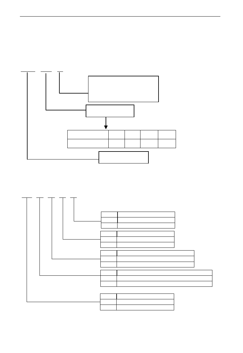
1.1 Product model naming rule
E3000 – 0007 S2
1.2 Optional function naming rule
D Y K B R
None
Built-in EMI filter
Including built-in EMI filter
None
R
Mark
None
Built-in braking unit
Including built-in braking unit
None
B
Mark
Local operation panel without potentiometer
Operation panel with potentiometer
Local operation panel with potentiometer
None
K
Mark
Please purchase operation panel, to be controlled remotely
Operation panel type
Operation panel is removable, to be controlled remotely
None
Y
Mark
Hanging type
Structure code
Cabinet type
None
D
Mark
Mark
0002
0004
0007
……
Motor power (kW)
0.2
0.4
0.75
……
Relation
Input power type:
S2 means single-phase 230VAC
T3 means three-phase 400VAC
Motor power
Product series
E3000
·2·
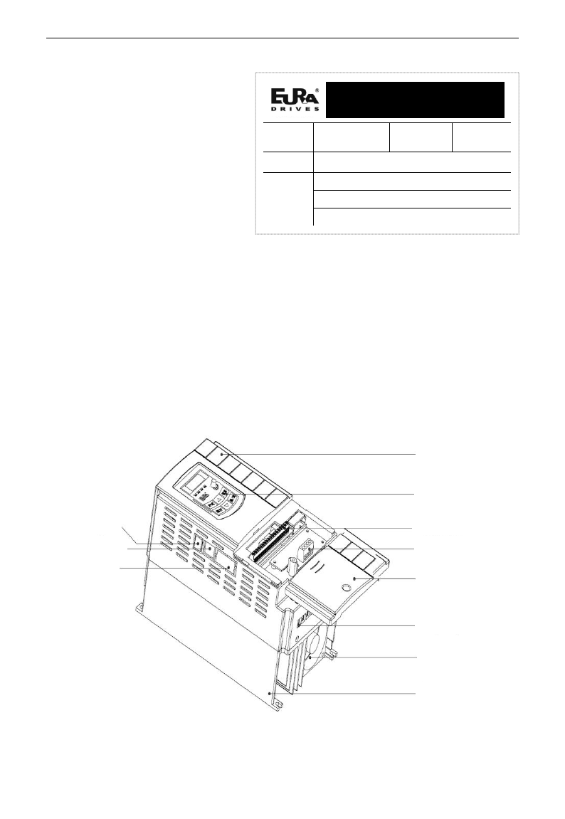
1.3 Nameplate
Taking for instance the E3000
series 1.5kW inverter with 1-phase
input, its nameplate is illustrated
as Fig 1-1.
1Ph: single-phase input; 230V,
50/60Hz: input voltage range and
rated frequency.
3Ph: 3-phase output; 7.0A, 1.5kW:
rated output current and power;
0.50~650.0Hz: output frequency
range.
1.4 Appearance
The external structure of E3000 series inverter is classified into plastic and metal housings.
Wall hanging type and cabinet type are adopted. Good poly-carbon materials are adopted
through die-stamping for plastic housing with nice form, good strength and toughness.
Taking E3000-0037T3 for instance, the external appearance and structure are shown as in
below Fig.
Cover
Keypad
panel
Control
terminal
PG expand
card
MODBUS
port
Remote keypad
port
PROFIBUS port
Radiator
Fan
Power terminal
Wiring cover
EURA DRIVES ELECTRIC CO., LTD
MODEL
E3000-0015S2
Function
Symbol
KBR
INPUT
AC 1PH 230V 50/60Hz
OUTPUT
3PH 1.5KW 7.0A 0~230V
0.50~650.0Hz
BAR CODE
E3000
·3·
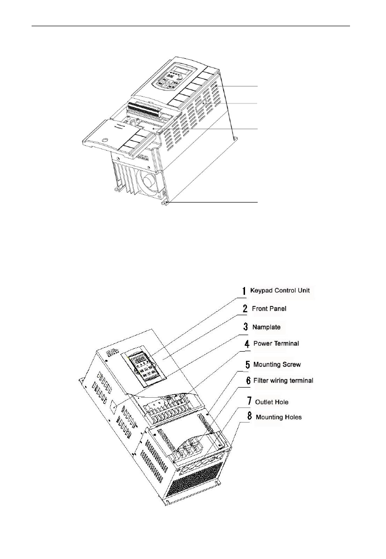
Metal housing uses advanced exterior plastic- spraying and powder-spraying process on the surface with
elegant color and with detachable one-side door hinge structure adopted for front cover,
convenient for wiring and maintenance. Taking E3000-0185T3 for instance, its appearance and
structure are shown as in right Fig.
Vent hole
Expand card
installation location
Mounting hole
Optional expand port

E3000
·4·
1.5 Technical Specifications
Table1-1 Technical Specifications for E3000 Series Inverters
Items
Contents
Input
Rated Voltage Range
3-phase 400V±15%; single-phase 230V±15%
Rated Frequency
50/60Hz
Output
Rated Voltage Range
3-phase 0~400V;3-phase 0~230V
Frequency Range
0.50~650.0Hz (In SVC control mode, the max frequency
should be lower than 150Hz.)
Control
Mode
Carrier Frequency
2000~10000Hz; Fixed carrier-wave and random carrier-wave
can be selected by F159.
Input Frequency Resolution
Digital setting: 0.01Hz, analog setting: max frequency
0.1%
Control Mode
SensorlessVector Control (open-loop vector control), VC control
(closed-loop vector control), VVVF control, vector control 1
Start Torque
0.5 Hz / 150% (SVC), 0.05Hz/180%(VC)
Speed-control Scope
1:100 (SVC), 1:1000 (VC)
Steady Speed Precision
±0.5% (SVC), ±0.02% (VC)
Torque Control Precision
±5% (SVC), ±0.5% (VC)
Overload Capacity
150% rated current, 60 seconds.
Torque Elevating
Auto torque promotion, Manual Torque Promotion
includes 1-16 curves.
VVVF Curve
4 kinds of modes: beeline type, square type, under-defined
VVVF curve and auto torque promotion.
Startup mode
Direct startup, speed track startup (VVVF control)
DC Braking
DC braking frequency: 0.2-5.00 Hz, braking time: 0.00~10.00s
Jogging Control
Jogging frequency range: min frequency~ max frequency,
jogging acceleration/deceleration time: 0.1~3000.0s
Auto Circulating Running and
multi-stage speed running
Auto circulating running or terminals control can realize
15-stage speed running.
Built-in PID adjusting
easy to realize a system for process closed-loop control
Auto current regulation (AVR)
When source voltage changes, the modulation rate can be
adjusted automatically, so that the output voltage is
unchanged.
Operation
Function
Frequency Setting
Potentiometer or external analog signal (0~5V, 0~10V,
-10~10V, 0~20mA); keypad (terminal)▲/▼ keys,
external control logic and automatic circulation setting.
Start/Stop Control
Terminal control, keypad control or communication control.
Running Command Channels
3 kinds of channels from keypad panel, control terminal and
series communication port.
Frequency Source
Frequency sources: given digit, given analog voltage, given
analog current and given series communication port.
Accessorial frequency Source
Flexible implementation of 5 kinds of accessorial frequency
fine adjustments and frequency compound.
Protection
Function
Input phase loss, Output phase loss, input under-voltage, DC over-voltage, over-current, inverter
over-load, motor over-load, current stall, over-heat, external disturbance, under-load, pressure
control, analog line disconnected.
E3000
·5·
Display
LED nixie tube showing present output frequency, present rotate-speed (rpm), present output
current, present output voltage, present linear-velocity, types of faults, and parameters for the
system and operation; LED indicators showing the current working status of inverter.
Environment
Conditions
Equipment Location
In an indoor location, Prevent exposure from direct
sunlight, Free from dust, tangy caustic gases, flammable
gases, steam or the salt-contented, etc.
Environment Temperature
-10℃~+50℃
Environment Humidity
Below 90% (no water-bead coagulation)
Vibration Strength
Below 0.5g (acceleration)
Height above sea level
1000m or below
Protection
level
IP20
Applicable
Motor
0.2~90kW
1.6 Designed Standards for Implementation
- IEC/EN 61800-5-1: 2003 Adjustable speed electrical power drive systems
safety requirements.
- IEC/EN 61800-3: 2004 Adjustable speed electrical power drive systems-Part
3: EMC product standard including specific test methods.
1.7 Safe instructions
- Please check the model in the nameplate of the inverter and the rated value of
the inverter. Please do not use the damaged inverter in transit.
- Installation and application environment should be free of rain, drips, steam,
dust and oily dirt; without corrosive or flammable gases or liquids, metal
particles or metal powder. Environment temperature within the scope of
-10℃~+50℃.
- Please install inverter away from combustibles.
- Do not drop anything into the inverter.
- The reliability of inverters relies heavily on the temperature. The around
temperature increases by 10℃, inverter life will be halved. Because of the
wrong installation or fixing, the temperature of inverter will increase and
inverter will be damaged.
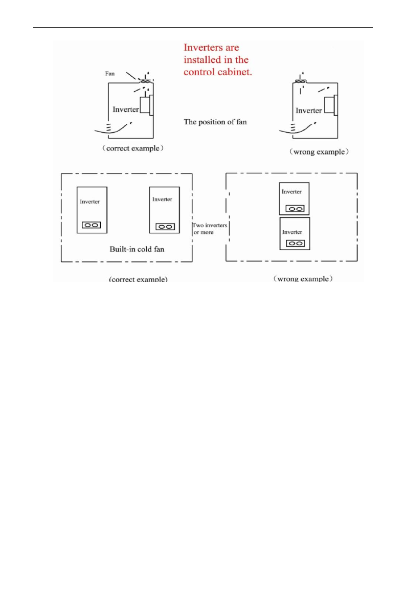
- Inverter is installed in a control cabinet, and smooth ventilation should be
ensured and inverter should be installed vertically. If there are several inverters
in one cabinet, in order to ensure ventilation, please install inverters side by side.
If it is necessary to install several inverters up and down, please add
heat-insulation plate.
E3000
·6·
1.8 Precautions
1.8.1 Instructions for use
- Never touch the internal elements within 15 minutes after power off. Wait till it
is completely discharged.
- Input terminals R, S and T are connected to power supply of 400V while output
terminals U, V and W are connected to motor.
- Proper grounding should be ensured with grounding resistance not exceeding
4Ω; separate grounding is required for motor and inverter. Grounding with
series connection is forbidden.
- There should be separate wiring between control loop and power loop to avoid
any possible interference.
- Signal line should not be too long to avoid any increase with common mode
interference.
- If circuit breaker or contactor needs to be connected between the drive and the
motor, be sure to operate these circuit breakers or contactor when the drive has
no output, to avoid damaging of drive.
- Before using the drive, the insulation of the motors must be checked, especially, if it
is used for the first time or if it has been stored for a long time. This is to reduce the
risk of the drive from being damaged by the poor insulation of the motor.
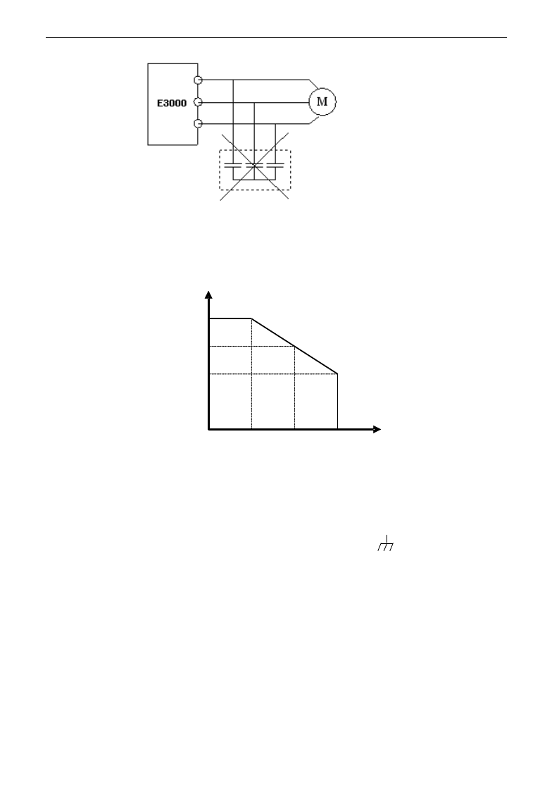
- Do not connect any varistor or capacitor to the output terminals of the drive, because
the drive‟s output voltage waveform is pulse wave, otherwise tripping or damaging
of components may occur; in addition, do not install circuit breaker or contactor at
the output side of the drive as shown in Fig 1-6.
E3000
·7·
Fig 1-6 Capacitors are prohibited to be used.
- Derating must be considered when the drive is installed at high altitude, greater
than 1000m. This is because the cooling effect of drive is deteriorated due to the
thin air, as shown in Fig. 1-7 that indicates the relationship between the
elevation and rated current of the drive.
Fig 1-7 Derating drive‟s output current with altitude
1.8.2 Special Warning!!
- Never touch high-voltage terminals inside the inverter to avoid any electric shock.
- Before inverter is powered on, please be sure that input voltage is correct.
- Please do not connect input power supply onto U,V,W or /PE/E terminals.
- Please do not install inverter directly under sunshine, do not block up the cooling hole.
- All safety covers should be well fixed before inverter is power connected, to
avoid any electric shock.
- Only professional personnel are allowed for any maintenance, checking or
replacement of parts.
- No live-line work is allowed.
1.9 Maintenance
1.9.1 Periodic checking
- Cooling fan and wind channel should be cleaned regularly to check whether it is
normal; remove the dust accumulated in the inverter on a regular basis.
- Check inverter‟s input and output wiring and wiring terminals regularly and
check if wirings are ageing.
Iout
(m)
100%
90%
80%
1000 2000 3000
Fig 1-7 D erating Drive’s output current w ith altitude

E3000
·8·
- Check whether screws on each terminals are fastened.
- Check whether inverter is corrosive.
1.9.2 Replacement of wearing parts
The wearing parts include cooling fan and electrolytic capacitors.
- The life of the fan usually is 2~3 years. Users should change the cooling fan
according to all running time of inverter. Cooling fan could be damaged
because bearing is damaged and fan blades are aging. Users could check fan
blades for cracks or check the abnormal vibration noise when starting. Users
could change fan according to abnormal phenomena.
- The useful life of electrolytic capacitors is 4~5 years. Users should change the
electrolytic capacitors according to all running time of inverter. Filter
capacitors could be damaged because the power supply is unstable, the
environment temperature is high, frequent over-load occurs and electrolyte is
ageing. By checking whether there is leakage of liquid, or the safety valve
bulges out, or the static electricity and insulated resistor is ok, users could
change the capacitor according to these phenomena.
1.9.3 Storage
- Please put the inverter in the packing case of manufacture.
- If inverter is stored for long time, please charge the inverter within half a year
to prevent the electrolytic capacitors damaged. The charging time should be
longer than 5 hours.
1.9.4 Daily Maintenance
Environment temperature, humidity, dust and vibration would decrease the life of inverter.
So daily maintenance is necessary to inverter.
Daily inspecting:
- Inspecting for noise of motor when it is working.
- Inspecting for abnormal vibration of motor when it is working.
- Inspecting for the installing environment of inverter.
- Inspecting for the fan and inverter temperature.
Daily cleaning:
Keep the inverter clean. Clean surface dust of inverter to prevent dust, metal
powder, oily dirt and water from dropping into the inverter.
1.10 Options
Name
Model
Function
Remarks
Modbus bus (internal)
Only one kind of bus
communication can be selected
at the same time.
PROFIBUS-DP bus card
PC01
PROFIBUS-DP bus port
CANopen bus card
PC10
CANopen bus port
PG card
E3PG01
Rotary encoder expand card
Differential PG card
E3PG10
Differential encoder expand card
Remote LED panel
AA-A
Remote keypad panel (small)
Remote LED panel
A6-1-A
Remote keypad panel (big)
Match for 18.5kW and above
18.5kW inverters
Safe relay card
I/O expand card
E3000
·9·
II. Keypad panel
Keypad panel and monitor screen are both fixed on keypad controller. Two kinds of controllers (with and
without potentiometer) are available for E3000 series inverters. Refer to note for Fig2-1.
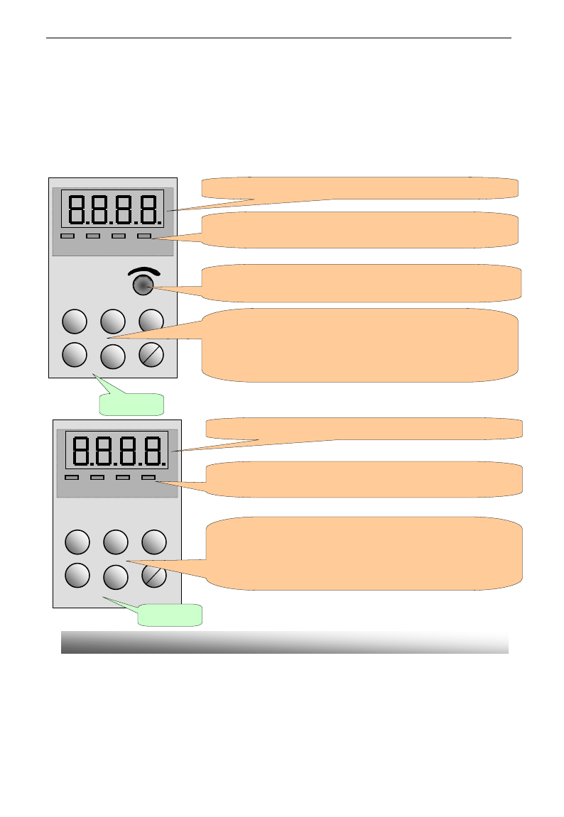
2.1 Panel Illustration
The panel covers three sections: data display section, status indicating section and keypad operating section,
as shown in Fig. 2-1.
Instructions for operation panel:
1. Operation panels of below 15kW can not be pulled out. Please select AA-A or A6-1-A control panel to
realize remote control, which is connected by 8-core net cable.
2. Operation panels A6-1-A of above 18.5kW can be pulled out, which are connected by 8 core net cable.
Operation panel
RUN FWD DGT FRQ
Min Max
Fun
Set
▲
▼
Run
stop
reset
EURA
4 LEDs indicate working status. RUN is lighting while running. FWD is lighting
when working forward and FRQ is lighting when showing frequency.
4个发光二极管指示工作状态。运行时 RUN 亮,正转时FWD 亮,功能
码区间内切换 DGT 亮,FRQ 亮表示显示频率。
LED shows running frequency, flashing target frequency, function code,
parameter value or fault code.
Press “Fun” for function code, and “set” for original parameters.▲
and▼keys can be used to select function codes and parameters.
Press “set” again to confirm. In the mode of keypad control, ▲and
▼keys can also be used for dynamic speed control. “Run” and
“Stop/Reset” keys control start and stop. Press “Stop/Reset” key to
reset inverter in fault status.
Potentiometer can be used for manual speed control in mode of
analog signals control. External potentiometer or external analog
signal can also be used.
Fun
Set
▲
▼
Run
Stop
reset
EURA
RUN FWD DGT FRQ
LED shows running frequency, flashing target frequency, function code,
parameter value or fault code.
4 LEDs indicate working status. RUN is lighting while running. FWD is lighting
when working forward and FRQ is lighting when showing frequency.
Press “Fun” for function code, and “set” for original parameters.▲
and▼keys can be used to select function codes and parameters.
Press “set” again to confirm. In the mode of keypad control, ▲and
▼keys can also be used for dynamic speed control. “Run” and
“Stop/Reset” keys control start and stop. Press “Stop/Reset” key to
reset inverter in fault status.
Operation panel
Fig.2-1 Operation Panels
E3000
·10·
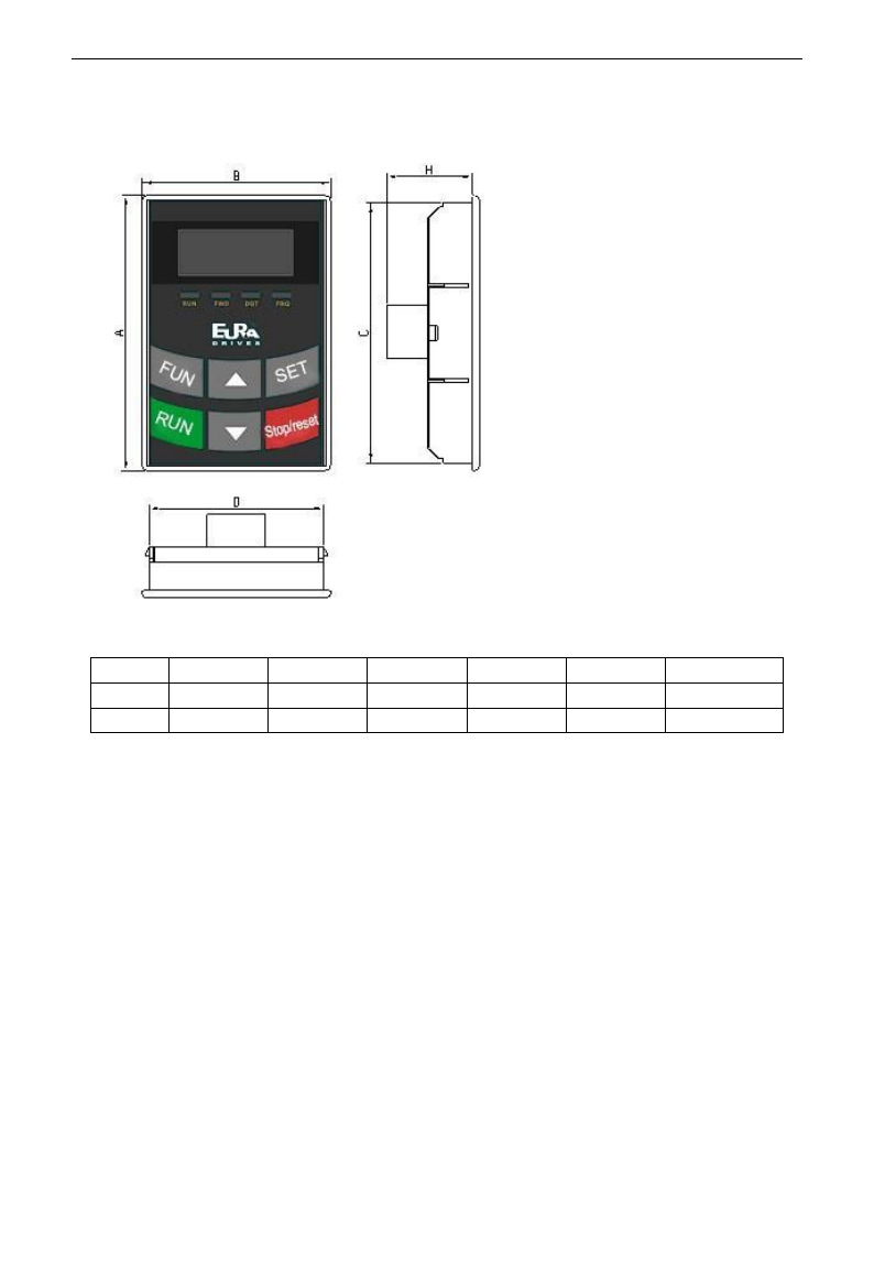
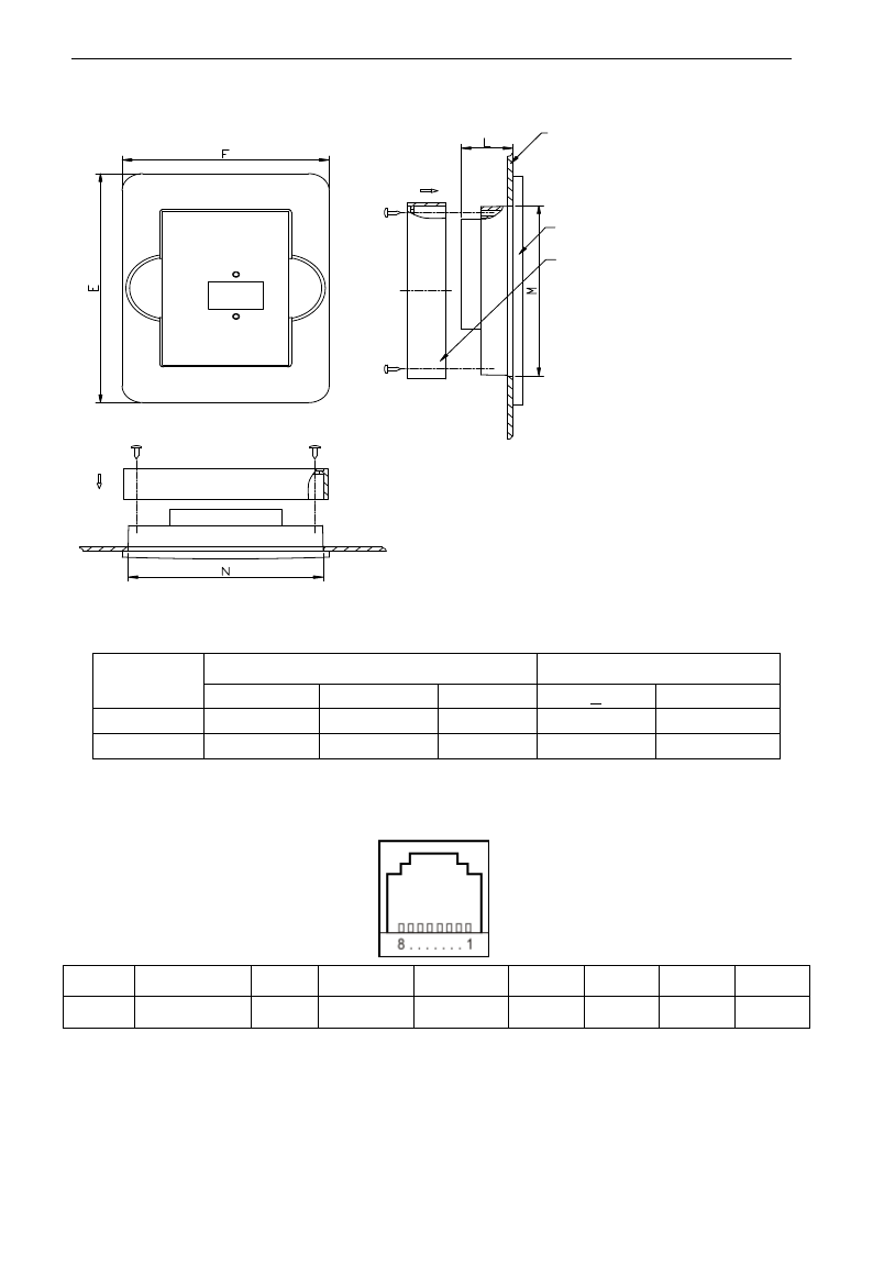
2.2 Panel structure
1. structure diagram
2. Structure size (Unit: mm)
Code
A
B
C
D
H
Opening size
AA
76
52
72
48
24
73*49
A6-1
124
74
120
70
26
121*71
3. Panel mounting structure diagram
E3000
·11·
Mounting panel
Keypad frame
Frame back cover
4. Panel mounting size (Unit: mm)
Code
Keypad panel size
Opening size
E
F
L
N
M
AA
109
80
20
75
81
A6-1
170
110
22
102
142
5. Port of control panel
Pins
1
2
3
4
5
6
7
8
8 core
Potentiometer
5V
Grounding
Grounding
Signal 1
Signal 2
Signal 3
Signal 4
Please pay attention to the sequence of cable port.
6. The default length of remote-control cable is 1m, if users need longer cables more than 3m, please
put a magnetic ring on the cable to avoid the interference.
E3000
·12·
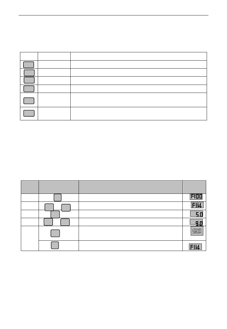
2.3 Panel Operating
All keys on the panel are available for user. Refer to Table 2-1 for their functions.
Table 2-1 Uses of Keys
Keys
按键
Names
Remarks
Fun
To call function code and switch over display mode.
Set
To call and save data.
Up
To increase data (speed control or setting parameters)
Down
To decrease data (speed control or setting parameters)
Run
To start inverter;
Stop or reset
To stop inverter; to reset in fault status; to change function codes in a code
group or between two code groups.
2.4 Parameters Setting
This inverter has numerous function parameters, which the user can modify to effect different modes of
operation control. User needs to realize that if user sets password valid (F107=1), user‟s password must be
entered first if parameters are to be set after power off or protection is effected, i.e., to call F100 as per the
mode in Table 2-2 and enter the correct code. User‟s password is invalid before delivery, and user could set
corresponding parameters without entering password.
Table 2-2 Steps for Parameters Setting
Steps
Keys
Operation
Display
1
Press “Fun” key to display function code
2
Press “Up” or “Down” to select required function code
3
To read data set in the function code
4
To modify data
5
To show corresponding target frequency by flashing
after saving the set data
To display the current function code
The above-mentioned step should be operated when inverter is in stop status.
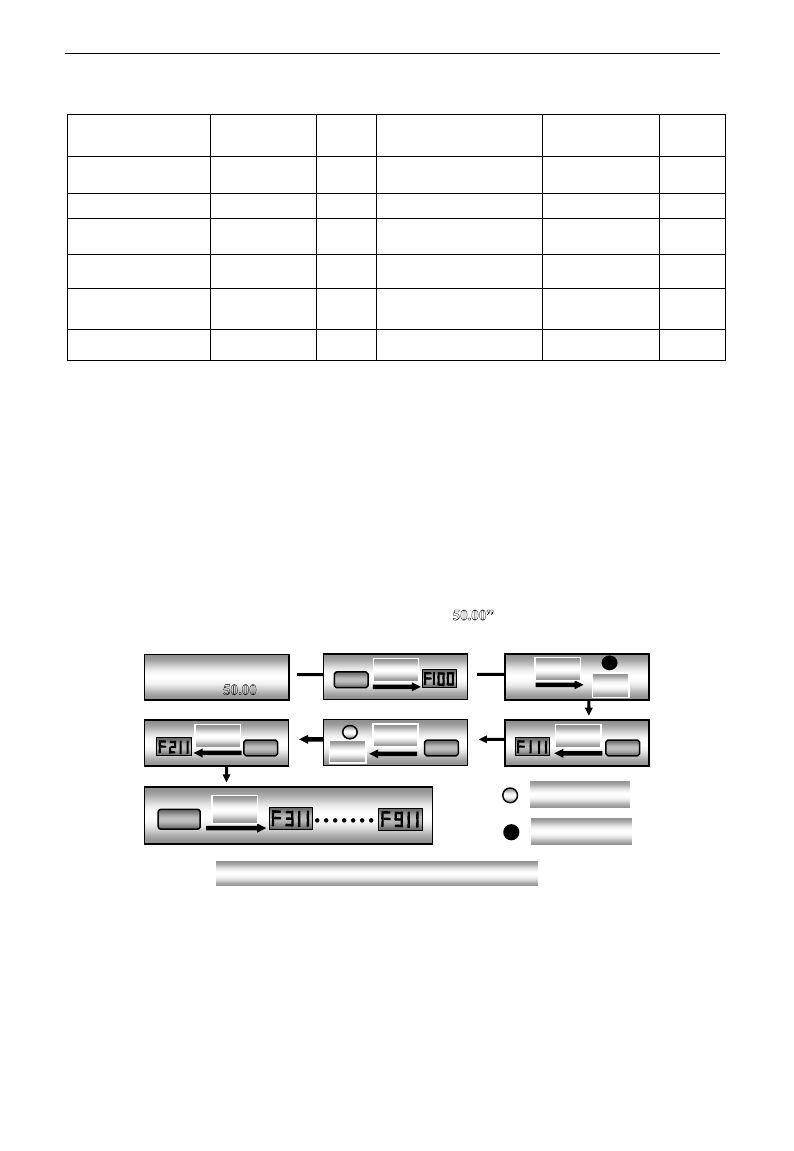
2.5 Function Codes Switchover in/between Code-Groups
It has more than 300 parameters (function codes) available to user, divided into 10 sections as indicated in Table 2-3.
Fun
Set
Run
Stop/reset
▲
▼
Fun
▲
▼
or
Set
Set
Fun
▲
▼
or
F
1
1
4
F
1
1
4
E3000
·13·
Table 2-3 Function Code Partition
Group Name
Function
Code Range
Group
No.
Group Name
Function
Code Range
Group
No.
Basic Parameters
F100~F160
1
Timing control and
protection function
F700~F770
7
Run Control Mode
F200~F280
2
Parameters of the motor
F800~F860
8
Multi-functional
input/output terminal
F300~F330
3
Communication function
F900~F930
9
Analog signals and
pulse of input/output
F400~F480
4
PID parameter setting
FA00~FA80
10
Multi-stage speed
parameters
F500~F580
5
Reserved
FB00~FB80
11
Subsidiary function
F600~F650
6
Torque control function
FC00~FC40
12
As parameters setting costs time due to numerous function codes, such function is specially designed as
“Function Code Switchover in a Code Group or between Two Code-Groups” so that parameters setting
become convenient and simple.
Press “Fun” key so that the keypad controller will display function code. If press “▲” or “▼” key then,
function code will circularly keep increasing or decreasing by degrees within the group; if press the
“stop/reset” key again, function code will change circularly between two code groups when operating the
“▲” or “▼” key.
e.g. when function code shows F111 and DGT indicator is on, press “▲”/ “▼” key, function code will keep
increasing or decreasing by degrees within F100~F160; press “stop/reset” key again, DGT indicator will be
off. When pressing “▲”/ “▼” key, function codes will change circularly among the 10 code-groups, like
F211, F311…FA11, F111…, Refer to Fig 2-2 (The sparkling “ is indicated the corresponding target
frequency values).
Enter correct user‟s
password (currently
showing )
Fun
Display
Display
DGT
Stop/Reset
Display
DGT
▲
Display
▲
Display
▲
Display
DGT Off
DGT On
Fig 2-2 Switch over in a Code Group or between Different Code-Groups

E3000
·14·
2.6 Panel Display
Table 2-4 Items and Remarks Displayed on the Panel
Items
Remarks
HF-0
This Item will be displayed when you press “Fun” in stopping status, which indicates
jogging operation is valid. But HF-0 will be displayed only after you change the
value of F132.
-HF-
It stands for resetting process and will display target frequency after reset.
OC, OC1, OE, OL1,
OL2, OH, LU, PF0,
PF1, GF
Fault code, indicating “over-current OC”, “over-current OC1”, “over-voltage”,
“inverter over-load”, “motor over-load” “over-heat”, “under-voltage for input”,
“phase loss for output”, “phase loss for input” , "Grounding fault" respectively.
AErr, EP, nP, Err5
Analog line disconnected, inverter under-load, pressure control, PID parameters are set
wrong,
OVER, BRK1,
BRK2
(textile industry) yarn full, yarn broken, yarn intertwining.
ESP
During two-line/three line running mode, “stop/reset” key is pressed or external
emergency stop terminal is closed, ESP will be displayed.
F152
Function code (parameter code).
10.00
Indicating inverter‟s current running frequency (or rotate speed) and parameter
setting values, etc.
Sparkling in stopping status to display target frequency.
0.
Holding time when changing the running direction. When “Stop” or “Free Stop”
command is executed, the holding time can be canceled
A100、U100
Output current (100A) and output voltage (100V). Keep one digit of decimal when
current is below 100A.
b*.*
PID feedback value is displayed.
o*.*
PID given value is displayed.
L***
Linear speed is displayed.
H *
Radiator temperature is displayed.
E3000
·15·
III. Installation & Connection
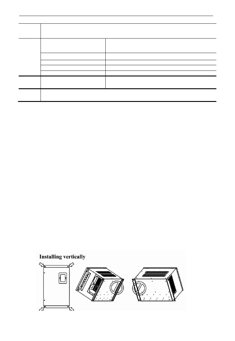
3.1 Installation
Inverter should be installed vertically, as shown in Fig 3-1. Sufficient ventilation space should be ensured in
its surrounding. Clearance dimensions (recommended) are available from Table 3-1 for installing the
inverter.
Table 3-1 Clearance Dimensions
Model
Clearance Dimensions
Hanging (<22kW)
A≥150mm
B≥50mm
Hanging (≥22kW)
A≥200mm
B≥75mm
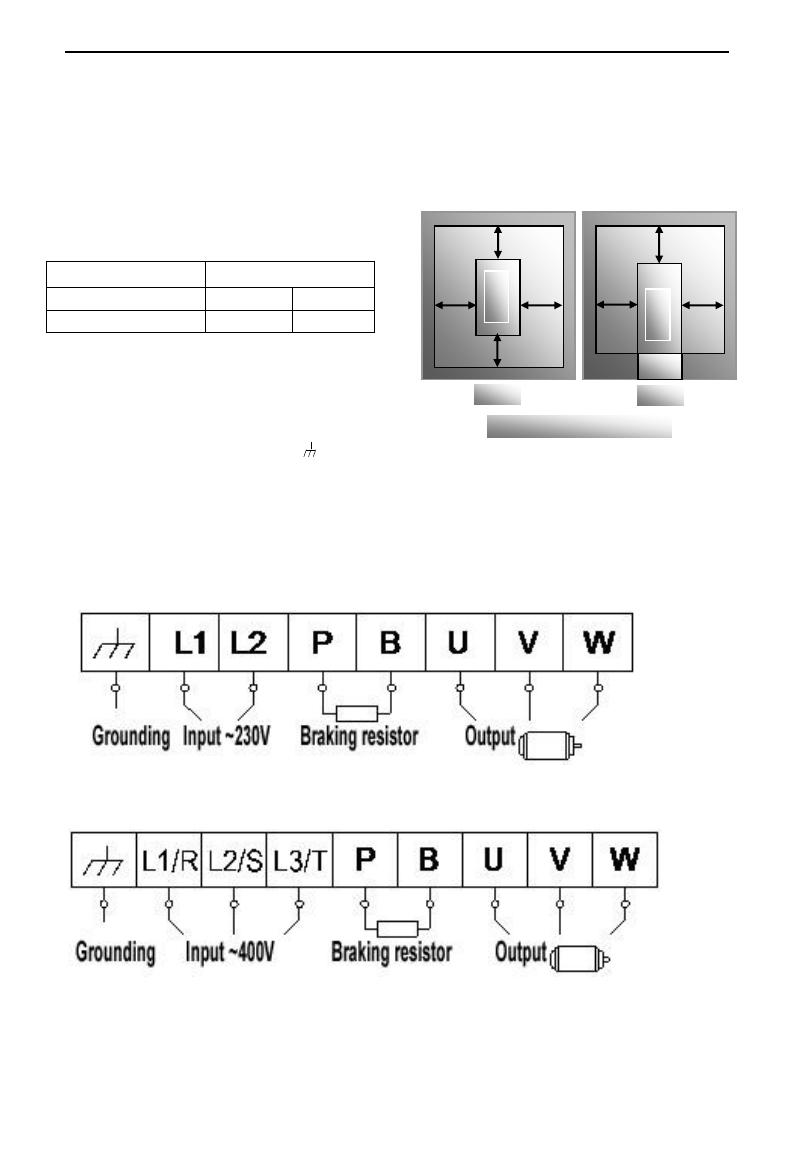
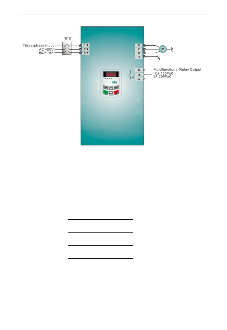
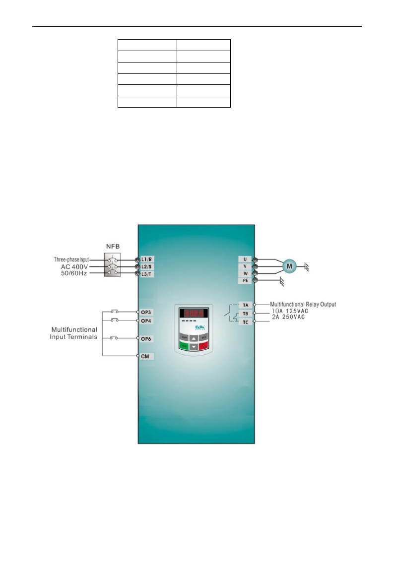
3.2 Connection
- In case of 3-phase input, connect R/L1,
S/L2 and T/L3 terminals (L1/R and L2/S
terminals for single-phase) with power
source from network and /PE/E to
grounding, U, V and W terminals to motor.
- Motor shall have to be ground connected. Or else electrified motor causes interference.
- For inverter power lower than 15kW, braking cell is also built-in. If the load inertia is moderate,
it is Ok to only connect braking resistance.
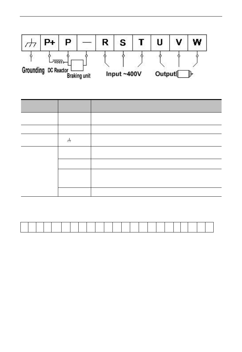
Power terminals sketch of inverter with single-phase 230V 0.2~0.75kW.
Power terminals sketch of inverter with single-phase 230V 1.5~2.2kW and three-phase
400V 0.75kW~15kW.
Note: power terminals L1/R, L2/S of single-phase 230V 1.5kW and 2.2kW are connected
to 230V of power grid; L3/T is not connected.
A
B B
A
Inverter
C
D D
Inverter
Trench
Hanging
Cabinet
Fig 3-1 Installation Sketch
E3000
·16·
Power terminals sketch of inverter with three-phase 400V above 18.5kW
(The figure is only sketch, terminals order of practical products may be different from the above-mentioned
figure.)
Introduction of terminals of power loop
Terminals
Terminal
Marking
Terminal Function Description
Power Input
Terminal
R/L1, S/L2,
T/L3
Input terminals of three-phase 400V AC voltage (R/L1 and S/L2
terminals for single-phase)
Output Terminal
U, V, W
Inverter power output terminal, connected to motor.
Grounding
Terminal
/PE/E
Inverter grounding terminal.
Rest Terminal
P, B
External braking resistor (Note: no Terminals P or B for inverter
without built-in braking unit).
P+、-(N)
DC bus-line output
P、-(N)
Externally connected to braking unit
P connected to input terminal “P” of braking unit, N connected to
input terminal of braking unit “N”.
P, P+
Externally connected to DC reactor
Wiring for control loop as follows:
Note:
1. 15kW and below 15kW inverters have no DO2, OP7, OP8 control terminals, the terminals of A+
and B- are on the side of inverter, which are pullout terminals.
A+
B-
TA
TB
TC
DO1
DO2
24V
CM
OP1
OP2
OP3
OP4
OP5
OP6
OP7
OP8
10V
AI1
AI2
GND
AO1
AO2
E3000
·17·
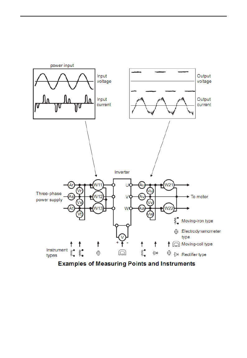
3.3 Measurement of main circuit voltages, currents and powers
Since the voltages and currents on the inverter power supply and output sides include harmonics,
measurement data depends on the instruments used and circuits measured. When instruments for commercial
frequency are used for measurement, measure the following circuits with the recommended instruments.
E3000
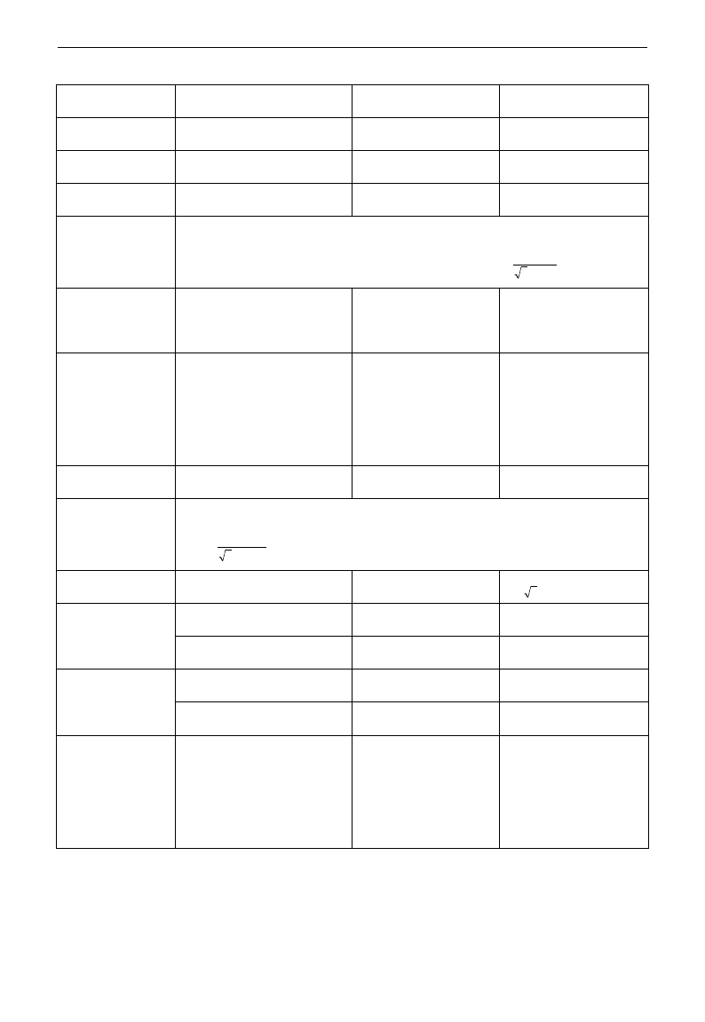
·18·
Item
Measuring Point
Measuring
Instrument
Remarks (Reference
Measurement Value)
Power supply
voltage V1
Across R-S,S-T, T-R
Moving-iron
type AC voltmeter
400V±15%,230V±15%
Power supply side
current I1
R, S, and T line currents
Moving-iron
type AC voltmeter
Power supply side
power P1
At R, S and T, and across
R-S, S-T and T-R
Electrodynamic type
single-phase wattmeter
P1=W11+W12+W13
(3-wattmeter method)
Power supply side
power factor Pf1
Calculate after measuring power supply voltage, power supply side current and
power supply side power.[Three phase power supply]
%100
113
1
1
IV
P
Pf
Output side
voltage V2
Across U-V, V-W and W-U
Rectifier type AC
voltmeter (Moving-iron
type cannot measure)
Difference between the
phases is within ±1% of
the maximum output
voltage.
Output side
current I2
U, V and W line currents
Moving-iron type AC
Ammeter
Current should be equal
to or less than rated
inverter current.
Difference between the
phases is 10% or lower
of the rated inverter
current.
Output side power
P2
U, V, W and U-V, V-W,W-U
Electrodynamic type
single-phase wattmeter
P2 = W21 + W22
2-wattmeter method
Output side power
factor Pf2
Calculate in similar manner to power supply side power factor:
%100
223
2
2
IV
P
Pf
Converter output
Across P+(P)and -(N)
Moving-coil type
(such as multi-meter)
DC voltage, the value is
12 V
Power supply of
control PCB
Across 10V-GND
Moving-coil type
(such as multi-meter)
DC10V±0.2V
Across 24V-CM
Moving-coil type
(such as multi-meter)
DC24V±1.5V
Analog output
AO1
Across AO1-GND
Moving-coil type
(such as multi-meter)
Approx. DC10V at max
frequency.
Across AO2-GND
Moving-coil type
(such as multi-meter)
Approx. DC 4~20mA
at max frequency
Alarm signal
Across TA/TC
Across TB/TC
Moving-coil type
(such as multi-meter)
<Normal> <Abnormal>
Across
TA/TC: Discontinuity
Continuity
Across
TB/TC: Continuity
Discontinuity

E3000
·19·
3.4 Functions of control terminals
The key to operate the inverter is to operate the control terminals correctly and flexibly. Certainly, the control
terminals are not operated separately, and they should match corresponding settings of parameters. This
chapter describes basic functions of the control terminals. The users may operate the control terminals by
combining relevant contents hereafter about “Defined Functions of the Terminals”.
Table 4-3 Functions of Control Terminals
Terminal
Type
Description
Function
DO1
Output
signal
Multifunctional
output terminal 1
When the token function is valid, the value
between this terminal and CM is 0V; when
the inverter is stopped, the value is 24V.
The functions of output
terminals shall be
defined per
manufacturer‟s value.
Their initial state may be
changed through
changing function codes.
DO2Note
Multifunctional
output terminal 2
When the token function is valid, the value
between this terminal and CM is 0V; when
the inverter is stopped, the value is 24V.
TA
Relay contact
TC is a common point, TB-TC are normally
closed contacts, TA-TC are normally open
contacts. The contact capacity of 15kW and
below 15kW inverter is 10A/125VAC、
5A/250VAC、5A/30VDC, contact capacity of
above 15kW is 12A/125VAC、7A/250VAC、
7A/30VDC.
TB
TC
AO1
Voltage / current
display
The token content is output frequency, output current, output voltage.
Please refer to parameters F423~F426.
AO2
Current display
10V
Analog
power
supply
Self contained
power supply
Internal 10V self-contained power supply of the inverter provides power
to the inverter. When used externally, it can only be used as the power
supply for voltage control signal, with current restricted below 20mA.
AI1
Analog
input
Voltage / Current
analog input port
When analog speed control is adopted, the voltage or current signal is
input through this terminal. The range of voltage input is 0~5V or
0~10V, -10~10V (only for AI1 channel) and the current input is 0~
20mA, the input resistor is 500Ohm, and grounding: GND. If the input
is 4~20mA, it can be realized through adjusting parameter F406=2. The
voltage or current signal can be chosen by coding switch. See table 4-2
and table 4-3 for details, the default output of AI1 channel is 0~10V, and
the default output of AI2 is 0~20mA current channel.
AI2
GND
Self-contained
Power
supply Ground
Ground terminal of external control signal (voltage control signal or
current source control signal) is also the ground of 10V power supply of
this inverter.
24V
Power
supply
Control power
supply
Power: 24±1.5V, grounding is CM; current is restricted below 50mA for
external use.
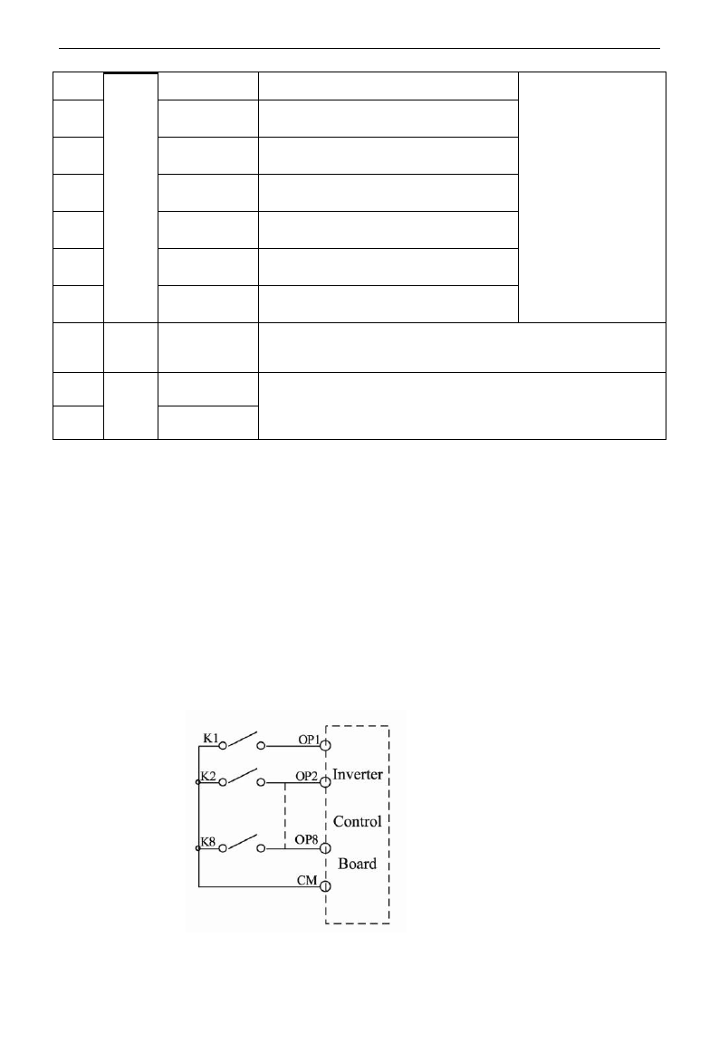
OP1
Digital
input
control
terminal
Jogging terminal
When this terminal is valid, the inverter will
have jogging running. The jogging function
of this terminal is valid under both at stopped
and running status. This terminal can also be
used as high-speed pulse input port. The max
frequency is 50K.
The functions of input
terminals shall be
defined per
manufacturer‟s value.
Other functions can also
be defined by changing
function codes.
OP2
External
When this terminal is valid, “ESP”
E3000
·20·
Emergency Stop
malfunction signal will be displayed.
OP3
“FWD”
Terminal
When this terminal is valid, inverter will run
forward.
OP4
“REV” Terminal
When this terminal is valid, inverter will run
reversely.
OP5
Reset terminal
Make this terminal valid under fault status to
reset the inverter.
OP6
Free-stop
Make this terminal valid during running can
realize free stop.
OP7
Run terminal
When this terminal is in the valid state,
inverter will run by the acceleration time.
OP8
Stop terminal
Make this terminal valid during running can
realize stop by the deceleration time.
CM
Common
port
Grounding of
control power
supply
The grounding of 24V power supply and other control signals.
A+note
485
communic
ation
Positive polarity of
differential signal
Standard: TIA/EIA-485(RS-485)
Communication protocol: Modbus
Communication rate: 1200/2400/4800/9600/19200/38400/57600bps
B-note
Negative polarity of
Differential signal
Note:
1. 15kW and below 15kW inverters have no DO2, OP7, OP8 control terminals. The terminals of A+
and B- are on the side of inverter, which are pullout terminals.
2. AI1 terminal of 15kW and below 15kW inverters can only accept voltage signal.
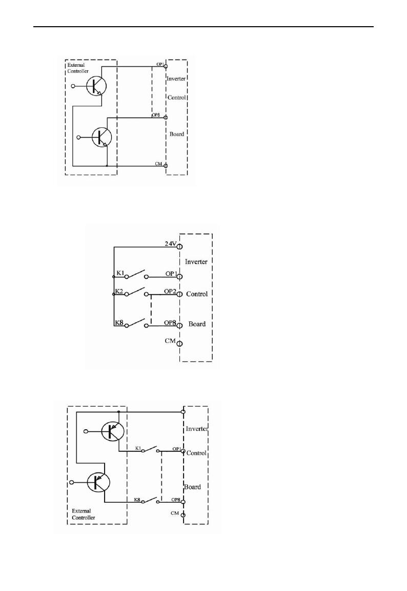
Wiring for digital input terminals:
Generally, shield cable is adopted and wiring distance should be as short as possible. When active
signal is adopted, it is necessary to take filter measures to prevent power supply interference. Mode of
contact control is recommended.
Digital input terminals are only connected by source electrode (NPN mode) or by drain electrode (PNP
mode). If NPN mode is adopted, please turn the toggle switch to the end of “NPN”.
Wiring for control terminals as follows:
1. Wiring for positive source electrode (NPN mode).
E3000
·21·
2. Wiring for active source electrode
If digital input control terminals are connected by drain electrode, please turn the toggle switch to the
end of “PNP”. Wiring for control terminals as follows:
3. Wiring for positive drain electrode (PNP mode)
4. Wiring for active drain electrode (PNP mode)
E3000
·22·
NPN
PNP
Fig 3-2 Toggle Switch J7
Wiring by source electrode is a mode most in use at present. Wiring for control terminal is connected
by source electrode, user should choose wiring mode according to requirement.
Instructions of choosing NPN mode or PNP mode:
1. There is a toggle switch J7 near to control terminals. Please refer to
Fig 3-2.
2. When turning J7 to “NPN”, OP terminal is connected to CM.
When turning J7 to “PNP”, OP terminal is connected to 24V.
3. The switch J7 of single-phase inverters 0.2kW~0.75kW is on the back of
control PCB.
3.4 Wiring Recommended
Inverter Model
Lead Section Area(mm2)
Inverter Model
Lead Section Area(mm2)
E3000-0002S2
1.0
E3000-0055T3
4.0
E3000-0004S2
1.5
E3000-0075T3
4.0
E3000-0007S2
2.5
E3000-0110T3
6.0
E3000-0011S2
2.5
E3000-0150T3
10
E3000-0015S2
2.5
E3000-0185T3
16
E3000-0022S2
4.0
E3000-0220T3
16
E3000-0007T3
1.5
E3000-0300T3
25
E3000-0015T3
2.5
E3000-0370T3
25
E3000-0022T3
2.5
E3000-0450T3
35
E3000-0030T3
2.5
E3000-0550T3
35
E3000-0037T3
2.5
E3000-0750T3
50
E3000-0040T3
2.5
E3000-0900T3
70
3.5 Lead section area of protect conductor (grounding wire)
Lead section area S of U,V,W (mm2)
Minimum lead section area S of E (mm2)
S
16
16<S
35
35<S
S
16
S/2
E3000
·23·
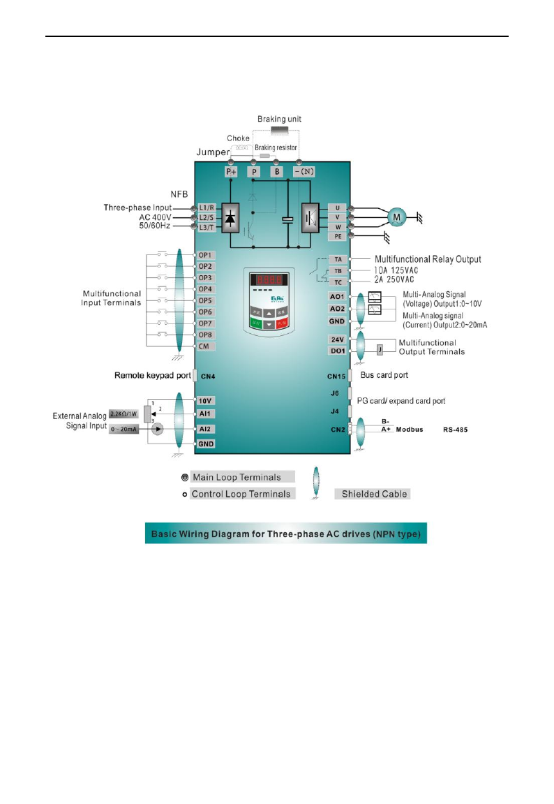
3.6 Overall Connection and “Three- Line” Connection
* Refer to next figure for overall connection sketch for E3000 series inverters. Wiring mode is available
for various terminals whereas not every terminal needs connection when applied.
Note:
1. Please only connect power terminals L1/R and L2/S with power grid for single-phase inverters.
2. If the remote keypad of 15kW and below 15kW inverters is needed, users should purchase it. The 485
communication port is connected to the pullout terminals on the side of inverter.
3. Inverter above 15kW has 8 multifunctional input terminals OP1~OP8, 15kW inverter and below 15kW has 6
multifunctional input terminals OP1~OP6.
4. The contact capacity of 15kW and below 15kW inverter is 10A/125VAC、5A/250VAC、5A/30VDC, contact
capacity of above 15kW is 12A/125VAC、7A/250VAC、7A/30VDC.
E3000
·24·
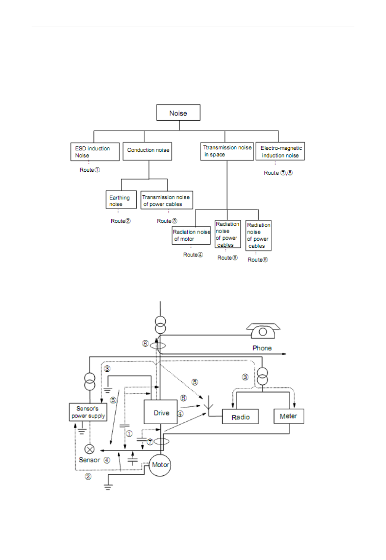
3.8 Basic methods of suppressing the noise
The noise generated by the drive may disturb the equipment nearby. The degree of disturbance is dependent
on the drive system, immunity of the equipment, wiring, installation clearance and grounding methods.
3.8.1 Noise propagation paths and suppressing methods
① Noise categories
② Noise propagation paths
E3000
·25·
③Basic methods of suppressing the noise
Noise emission
paths
Actions to reduce the noise
②
When the external equipment forms a loop with the drive, the equipment may suffer
nuisance tripping due to the drive‟s earth leakage current. The problem can be solved if
the equipment is not grounded.
③
If the external equipment shares the same AC supply with the drive, the drive‟s noise
may be transmitted along its input power supply cables, which may cause nuisance
tripping to other external equipment. Take the following actions to solve this problem:
Install noise filter at the input side of the drive, and use an isolation transformer or line
filter to prevent the noise from disturbing the external equipment.
④⑤⑥
If the signal cables of measuring meters, radio equipment and sensors are installed in a
cabinet together with the drive, these equipment cables will be easily disturbed. Take the
actions below to solve the problem:
(1) The equipment and the signal cables should be as far away as possible from the drive.
The signal cables should be shielded and the shielding layer should be grounded. The
signal cables should be placed inside a metal tube and should be located as far away as
possible from the input/output cables of the drive. If the signal cables must cross over the
power cables, they should be placed at right angle to one another.
(2) Install radio noise filter and linear noise filter (ferrite common-mode choke) at the
input and output of the drive to suppress the emission noise of power lines.
(3) Motor cables should be placed in a tube thicker than 2mm or buried in a cement conduit.
Power cables should be placed inside a metal tube and be grounded by shielding layer
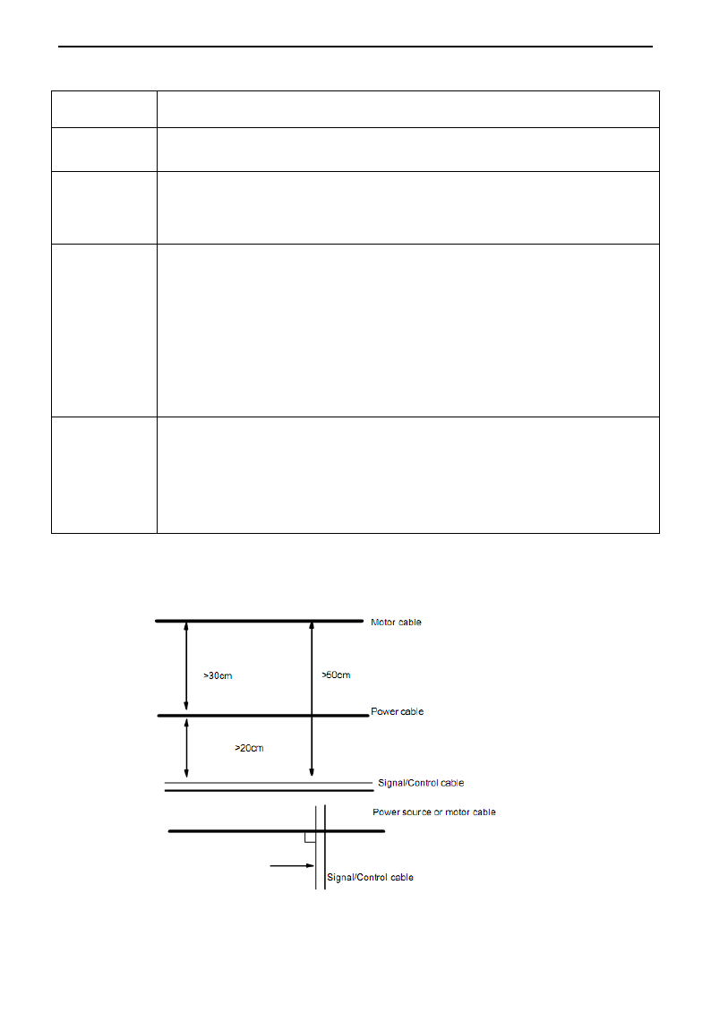
①⑦⑧
Don‟t route the signal cables in parallel with the power cables or bundle these cables
together because the induced electro-magnetic noise and induced ESD noise may disturb
the signal cables. Other equipment should also be located as far away as possible from
the drive. The signal cables should be placed inside a metal tube and should be placed as
far away as possible from the input/output cables of the drive. The signal cables and
power cables should be shielded cables. EMC interference will be further reduced if they
could be placed inside metal tubes. The clearance
between the metal tubes should be at least 20cm.
3.8.2 Field Wire Connections
Control cables, input power cables and motor cables should be installed separately, and enough clearance
should be left among the cables, especially when the cables are laid in parallel and the cable length is big. If
the signal cables must go through the power cables, they should be vertical to each other.
Generally, the control cables should be shielded cables and the shielding metal net must be connected to the
E3000
·26·
metal enclosure of the drive by cable clamps.
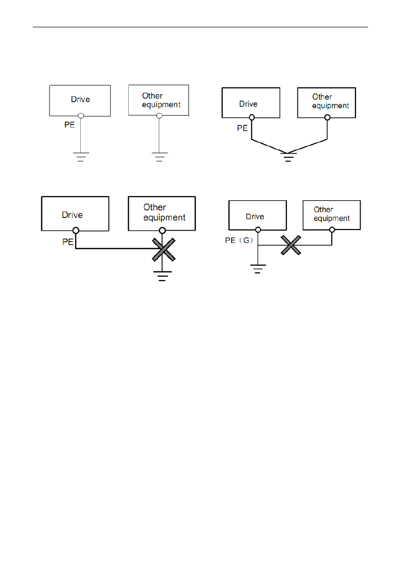
3.8.3 Grounding
Independent grounding poles (best) Shared grounding pole (good)
Shared grounding cable (not good)
Note:
1. In order to reduce the grounding resistance, flat cable should be used because the high frequency
impedance of flat cable is smaller than that of round cable with the same CSA.
2. If the grounding poles of different equipment in one system are connected together, then the leakage
current will be a noise source that may disturb the whole system. Therefore, the drive‟s grounding pole
should be separated with the grounding pole of other equipment such as audio equipment, sensors and PC,
etc.
3. Grounding cables should be as far away from the I/O cables of the equipment that is sensitive to noise, and
also should be as short as possible.
3.8.4 Leakage current
Leakage current may flow through the drive‟s input and output capacitors and the motor‟s capacitor. The
leakage current value is dependent on the distributed capacitance and carrier wave frequency. The leakage
current includes ground leakage current and the leakage current between lines.
Ground leakage current
The ground leakage current can not only flow into the drive system, but also other equipment via grounding
cables. It may cause the leakage current circuit breaker and relays falsely activated. The higher the drive‟s
carrier wave frequency, the bigger the leakage current, also, the longer the motor cable, the greater the
leakage current,
Suppressing methods:
- Reduce the carrier wave frequency, but the motor noise may be louder;
E3000
·27·
- Motor cables should be as short as possible;
- The drive and other equipment should use leakage current circuit breaker designed for protecting the
product against high-order harmonics/surge leakage current;
Leakage current between lines
The line leakage current flowing through the distribution capacitors of the drive out side may cause the
thermal relay falsely activated, especially for the drive whose power is lower than 7.5kW. When the cable is
longer than 50m, the ratio of leakage current to motor rated current may be increased that can cause the
wrong action of external thermal relay very easily.
Suppressing methods:
- Reduce the carrier wave frequency, but the motor noise may become louder;
- Install reactor at the output side of the drive.
In order to protect the motor reliably, it is recommended to use a temperature sensor to detect the motor‟s
temperature, and use the drive‟s over-load protection device (electronic thermal relay) instead of an external
thermal relay.
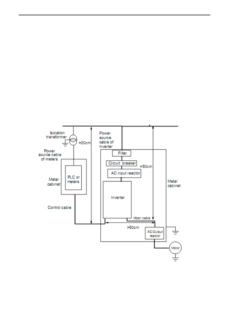
3.8.5 Electrical installation of the drive
Note:
·Motor cable should be earthed at the drive side, if possible, the motor and drive should be earthed
separately;
·Motor cable and control cable should be shielded . The shield must be earthed and avoid entangling at cable
end to improve high frequency noise immunity.

E3000
·28·
·Assure good conductivity among plates, screw and metal case of the drive; use tooth-shape washer and
conductive installation plate;
3.8.6 Application of Power Line Filter
Power source filter should be used in the equipment that may generate strong EMI or the equipment that is
sensitive to the external EMI. The power source filter should be a two-way low pass filter through which
only 50Hz current can flow and high frequency current should be rejected.
Function of power line filter
The power line filter ensures the equipment can satisfy the conducting emission and conducting sensitivity in
EMC standard. It can also suppress the radiation of the equipment.
Common mistakes in using power cable filter
1. Too long power cable
The filter inside the cabinet should be located near to the input power source. The length of the power cables
should be as short as possible.
2. The input and output cables of the AC supply filter are too close
The distance between input and output cables of the filter should be as far apart as possible, otherwise, the
high frequency noise may be coupled between the cables and bypass the filter. Thus, the filter will become
ineffective.
3. Bad grounding of filter
The filter‟s enclosure must be earthed properly to the metal case of the drive. In order to be earthed well,
make use of a special grounding terminal on the filter‟s enclosure. If you use one cable to connect the filter
to the case, the grounding is useless for high frequency interference. When the frequency is high, so is the
impedance of cable, hence there is little bypass effect. The filter should be mounted on the enclosure of
equipment. Ensure to clear away the insulation paint between the filter case and the enclosure for good
grounding contact.

E3000
·29·
IV. Operation and Simple Running
This chapter defines and interprets the terms and nouns describing the control, running and status of the
inverter. Please read it carefully. It will be helpful to your correct operation.
4.1 Basic Introduction
4.1.1 Control mode
E3000 inverter has four control modes: sensorless vector control (F106=0), closed-loop vector control
(F106=1), VVVF control (F106=2) and vector control 1(F106=3).
4.1.2 Mode of torque compensation
Under VVVF control mode, E3000 inverter has four kinds of torque compensation modes: Linear
compensation (F137=0); Square compensation (F137=1); User-defined multipoint compensation (F137=2);
Auto torque compensation (F137=3)
4.1.3 Mode of frequency setting
Please refer to F203~F207 for the method for setting the running frequency of the E3000 inverter.
4.1.4 Mode of controlling for running command
The channel for inverter to receive control commands (including start, stop and jogging, etc) contains three
modes: 1. Keypad (keypad panel) control; 2. External terminal control; 3. Communication control.
The modes of control command can be selected through the function codes F200 and F201.
4.1.5 Operating status of inverter
When the inverter is powered on, it may have four kinds of operating status: stopped status, programming
status, running status, and fault alarm status. They are described in the following:
Stopped status
If re-energize the inverter (if “auto-startup after being powered on” is not set) or decelerate the inverter to
stop, the inverter is at the stopping status until receiving control command. At this moment, the running
status indicator on the keypad goes off, and the display shows the display status before power down.
Programming status
Through keypad panel, the inverter can be switched to the status that can read or change the function
code parameters. Such a status is the programming status.
There are numbers of function parameters in the inverter. By changing these parameters, the user can
realize different control modes.
Running status
The inverter at the stopped status or fault-free status will enter running status after having received
operation command.
The running indicator on keypad panel lights up under normal running status.
Fault alarm status
The status under which the inverter has a fault and the fault code is displayed.
Fault codes mainly include: OC, OE, OL1, OL2, OH, LU, PF1 and PF0 representing “over current”,
“over voltage”, “inverter overload”, “motor overload”, “overheat”, “input undervoltage”, “input phase
loss”, and “output phase loss” respectively.
For trouble shooting, please refer to Appendix I to this manual, “Trouble Shooting”.

E3000
·30·
4.2 Keypad panel and operation method
Keypad panel (keypad) is a standard part for configuration of E3000 inverter. Through keypad panel, the user
may carry out parameter setting, status monitoring and operation control over the inverter. Both keypad panel
and display screen are arranged on the keypad controller, which mainly consists of three sections: data
display section, status indicating section, and keypad operating section. There are two types of keypad
controller (with potentiometer or without potentiometer) for inverter. For details, please refer to Chapter II of
this manual, “Keypad panel”.
It is necessary to know the functions and how to use the keypad panel. Please read this manual carefully
before operation.
4.2.1 Method of operating the keypad panel
(1) Operation process of setting the parameters through keypad panel
A three-level menu structure is adopted for setting the parameters through keypad panel of inverter, which
enables convenient and quick searching and changing of function code parameters.
Three-level menu: Function code group (first-level menu) → Function code (second-level menu) → Set
value of each function code (third-level menu).
(2) Setting the parameters
Setting the parameters correctly is a precondition to give full play of inverter performance. The following
is the introduction on how to set the parameters through keypad panel.
Operating procedures:
① Press the “Fun” key, to enter programming menu.
② Press the key “Stop/Reset”, the DGT lamp goes out. Press ▲ and ▼, the function code will change
within the function code group. The first number behind F displayed on the panel is 1, in other
words, it displays F1××at this moment.
③ Press the key “Stop/Reset” again, the DGT lamp lights up, and the function code will change
within the code group. Press ▲ and ▼ to change the function code to F113; press the “Set” key to
display 50.00; while press ▲ and ▼ to change to the need frequency.
④ Press the “Set” key to complete the change.
4.2.2 Switching and displaying of status parameters
Under stopped status or running status, the LED digitron of inverter can display status parameters of the
inverter. Actual parameters displayed can be selected and set through function codes F131 and F132.
Through the “Fun” key, it can switch over repeatedly and display the parameters of stopped status or running
status. The followings are the description of operation method of displaying the parameters under stopped
status and running status.
(1) Switching of the parameters displayed under stopped status
Under stopped status, inverter has eleven kinds of stopped status, which can be switched over repeatedly
and displayed with the keys “Fun” and “Stop/Reset”. These parameters are displaying: keypad jogging,
target frequency, target rotary speed, PN voltage, PID feedback value, temperature, PID given value and
count values. Please refer to the description of function code F132.
(2) Switching of the parameters displayed under running status
Under running status, 14 kinds of running status can be switched over repeatedly and displayed with the
keys “Fun”. These parameters are displayed: output frequency, output rotary speed, output current, output
voltage, PN voltage, PID feedback value, temperature, count value, linear speed and PID given value.
Please refer to the description of function code F131.
4.2.3 Operation process of measuring motor parameters
The user shall input the parameters accurately as indicated on the nameplate of the motor prior to selecting

E3000
·31·
operation mode of vector control and auto torque compensation (F137=3) of VVVF control mode. Inverter
will match standard motor stator resistance parameters according to these parameters indicated on the
nameplate. To achieve better control performance, the user may start the inverter to measure the motor stator
resistance parameters, so as to obtain accurate parameters of the motor controlled.
The stator resistance parameters of the motor can be measured through function code F800.
For example: If the parameters indicated on the nameplate of the motor controlled are as follows: numbers of
motor poles are 4; rated power is 7.5kW; rated voltage is 400V; rated current is 15.4A; rated frequency is
50.00HZ; and rated rotary speed is 1440rpm, operation process of measuring the parameters shall be done as
described in the following:
In accordance with the above motor parameters, set the values of F801 to F805 correctly: set the value of
F801 = 7.5, F802 = 400, F803 = 15.4, F804 = 4, F805 = 144 and F810 = 50.00 respectively.
2. In order to ensure dynamic control performance of the inverter, set F800=1, i.e. select rotating tuning.
Make sure that the motor is disconnected from the load. Press the “Run” key on the keypad, and the
inverter will display “TEST”, and it will measure the motor„s static parameters of two stages. After that,
the motor will accelerate according to the acceleration time set at F114 and maintain for a certain period.
The speed of motor will then decelerate to 0 according to the time set at F115. After auto-checking is
completed, relevant parameters of the motor will be stored in function codes F806~F809, and F800 will
turn to 0 automatically.
3. If it is impossible to disconnect the motor from the load, select F800=2, i.e. stationary tuning. Press the
“Run” key, the inverter will display “TEST”, and it will measure the motor„s static parameters of two
stages. The motor‟s stator resistance, rotor resistance and leakage inductance will be stored in F806-F808
automatically, and F800 will turn to 0 automatically. The user may also calculate and input the motor‟s
mutual inductance value manually according to actual conditions of the motor.
4.2.4 Operation process of simple running
Table 4-1 Brief Introduction to Inverter Operation Process
Process
Operation
Reference
Installation and
operation environment
Install the inverter at a location meeting the technical
specifications and requirements of the product. Mainly take into
consideration the environment conditions (temperature, humidity,
etc) and heat radiation of the inverter, to check whether they can
satisfy the requirements.
See Chapters I, II,
III.
Wiring of the inverter
Wiring of input and output terminals of the main circuit; wiring
of grounding; wiring of switching value control terminal,
analog terminal and communication interface, etc.
See Chapter III.
Checking before
getting energized
Make sure that the voltage of input power supply is correct; the input
power supply loop is connected with a breaker; the inverter has been
grounded correctly and reliably; the power cable is connected to the
power supply input terminals of inverter correctly (R/L1, S/L2 terminals
for single-phase power grid, and R/L1, S/L2, and T/L3 for three-phase
power grid); the output terminals U, V, and W of the inverter are
connected to the motor correctly; the wiring of control terminals is
correct; all the external switches are preset correctly; and the motor is
under no load (the mechanical load is disconnected from the motor).
See Chapters I~
III

E3000
·32·
Checking immediately
after energized
Check if there is any abnormal sound, fuming or foreign flavor
with the inverter. Make sure that the display of keypad panel is
normal, without any fault alarm message. In case of any
abnormality, switch off the power supply immediately.
See Appendix 1
and Appendix 2.
Inputting the parameters
indicated on the motor‟s
nameplate correctly, and
measuring the motor‟s
parameters.
Make sure to input the parameters indicated on the motor
nameplate correctly, and study the parameters of the motor. The
users shall check carefully, otherwise, serious problems may
arise during running. Before initial running with vector control
mode, carry out tuning of motor parameters, to obtain accurate
electric parameters of the motor controlled. Before carrying out
tuning of the parameters, make sure to disconnect the motor
from mechanical load, to make the motor under entirely no load
status. It is prohibited to measure the parameters when the
motor is at a running status.
See description of
parameter group
F800~F830
Setting running control
parameters
Set the parameters of the inverter and the motor correctly, which
mainly include target frequency, upper and lower frequency limits,
acceleration/deceleration time, and direction control command, etc.
The user can select corresponding running control mode according
to actual applications.
See description of
parameter group.
Checking under
no load
With the motor under no load, start the inverter with the keypad or
control terminal. Check and confirm running status of the drive
system.
Motor‟s status: stable running, normal running, correct rotary
direction, normal acceleration/deceleration process, free from
abnormal vibration, abnormal noise and foreign flavor.
Inverter‟ status: normal display of the data on keypad panel, normal
running of the fan, normal acting sequence of the relay, free from
the abnormalities like vibration or noise.
In case of any abnormality, stop and check the inverter immediately.
See Chapter Ⅳ.
Checking under with
load
After successful test run under no load, connect the load of
drive system properly. Start the inverter with the keypad or
control terminal, and increase the load gradually. When the load
is increased to 50% and 100%, keep the inverter run for a
period respectively, to check if the system is running normally.
Carry out overall inspection over the inverter during running, to
check if there is any abnormality. In case of any abnormality,
stop and check the inverter immediately.
Checking during
running
Check if the motor is running stably, if the rotary direction of
the motor is correct, if there is any abnormal vibration or noise
when the motor is running, if the acceleration/deceleration
process of the motor is stable, if the output status of the inverter
and the display of keypad panel is correct, if the blower fan is
run normally, and if there is any abnormal vibration or noise. In
case of any abnormality, stop the inverter immediately, and
check it after switching off the power supply.
4.3 Illustration of basic operation
Illustration of inverter basic operation: we hereafter show various basic control operation processes by taking
a 7.5kW inverter that drives a 7.5kW three-phase asynchronous AC motor as an example.
E3000
·33·
Figure 4-1 Wiring Diagram 1
The parameters indicated on the nameplate of the motor are as follows: 4 poles; rated power, 7.5kW;
rated voltage, 400V; rated current, 15.4A; rated frequency 50.00HZ; and rated rotary speed, 1440rpm.
4.3.1 Operation process of frequency setting, start, forward running and stop with keypad
panel
(1) Connect the wires in accordance with Figure 4-1. After having checked the wiring successfully,
switch on the air switch, and power on the inverter.
(2) Press the “Fun” key, to enter the programming menu.
(3) Measure the parameters of the motor
Function code
Values
F800
1(2)
F801
7.5
F802
380
F803
15.4
F805
1440
Press the “Run” key, to measure the parameters of the motor. After completion of the tuning, the
motor will stop running, and relevant parameters will be stored in F806~F809. For the details of
tuning of motor parameters, please refer to “Operation process of measuring the motor parameters” in
this manual and Chapter XII of this manual. (Note: F800=1 is rotating tuning, F800=2 is stationary
tuning. In the mode of rotating tuning, make sure to disconnect the motor from the load).
(4) Set functional parameters of the inverter:
E3000
·34·
Function code
Values
F111
50.00
F200
0
F201
0
F202
0
F203
0
(5) Press the “Run” key, to start the inverter;
(6) During running, current frequency of the inverter can be changed by pressing ▲ or ▼;
(7) Press the “Stop/Reset” key once, the motor will decelerate until it stops running;
(8) Switch off the air switch, and power off the inverter.
4.3.2 Operation process of setting the frequency with keypad panel, and starting,
forward and reverse running, and stopping inverter through control terminals
(1) Connect the wires in accordance with Figure 4-2. After having checked the wiring successfully,
switch on the air switch, and power on the inverter;
Figure 4-2 Wiring Diagram 2
(2) Press the “Fun” key, to enter the programming menu.
(3) Study the parameters of the motor: the operation process is the same as that of example 1.
(4) Set functional parameters of the inverter:

E3000
·35·
Function code
Values
F111
50.00
F203
0
F208
1
(5) Close the switch OP3, the inverter starts forward running;
(6) During running, current frequency of the inverter can be changed by pressing ▲ or ▼;
(7) During running, switch off the switch OP3, then close the switch OP4, the running direction of the
motor will be changed (Note: The user should set the dead time of forward and reverse running F120 on
the basis of the load. If it was too short, OC protection of the inverter may occur.)
(8) Switch off the switches OP3 and OP4, the motor will decelerate until it stops running;
(9) Switch off the air switch, and power off the inverter.
4.3.3 Operation process of jogging operation with keypad panel
(1) Connect the wires in accordance with Figure 4-1. After having checked the wiring successfully,
switch on the air switch, and power on the inverter;
(2) Press the “Fun” key, to enter the programming menu.
(3) Study the parameters of the motor: the operation process is the same as that of example 1.
(4) Set functional parameters of the inverter:
Function code
Values
F124
5.00
F125
30
F126
30
F132
1
F202
0
(5) Press and hold the “Run” key until the motor is accelerated to the jogging frequency, and maintain the
status of jogging operation.
(6) Release the “Run” key. The motor will decelerate until jogging operation is stopped;
(7) Switch off the air switch, and power off the inverter.
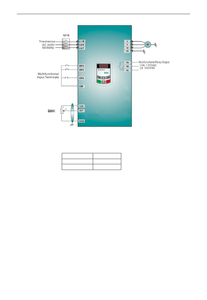
4.3.4 Operation process of setting the frequency with analog terminal and controlling
the operation with control terminals
(1) Connect the wires in accordance with Figure 4-3. After having checked the wiring successfully,
switch on the air switch, and power on the inverter. Note: 2K~5K potentiometer may be adopted for
setting external analog signals. For the cases with higher requirements for precision, please adopt precise
multiturn potentiometer, and adopt shielded wire for the wire connection, with near end of the shielding
layer grounded reliably.
E3000
·36·
Figure 4-3 Wiring Diagram 3
(2) Press the “Fun” key, to enter the programming menu.
(3) Study the parameters of the motor: the operation process is the same as that of example 1.
(4) Set functional parameters of the inverter:
Function code
Values
F203
1
F208
1
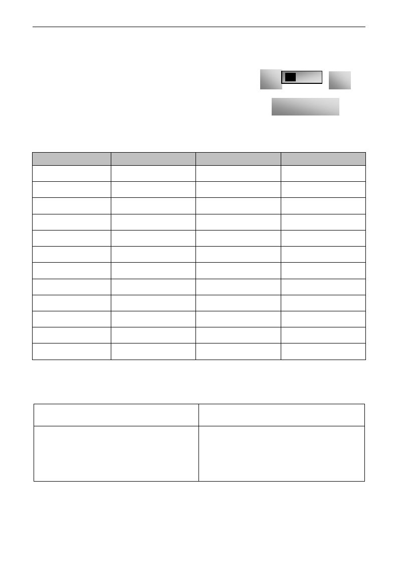
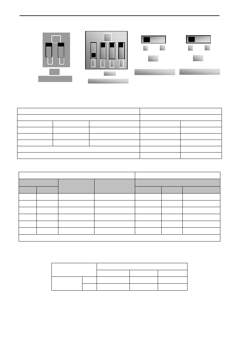
(5) There is a red two-digit coding switch SW1 near the control terminal block of 15 kW inverter and
below 15kW, as shown in Figure 4-4. The function of coding switch is to select the voltage signal (0~
5V/0~10V) or current signal of analog input terminal AI2, current channel is default. In actual application,
select the analog input channel through F203. Turn switches 1 to ON and 2 to ON as illustrated in the
figure, and select 0~20mA current speed control. Another switches states and mode of control speed are as
table 4-2.
(6) There is a red four-digit coding switch SW1 near the control terminal block of above 15 kW inverter, as
shown in Figure 4-5. The function of coding switch is to select the input range (0~5V/0~10V/0~20mA)
of analog input terminal AI1 and AI2. In actual application, select the analog input channel through F203.
AI1 channel default value is 0~10V, AI2 channel default value is 0~20mA. Another switches states and
mode of control speed are as table 4-3.
(7) There is a toggle switch S1 at the side of control terminals, please refer to Fig 4-7. S1 is used to select
the voltage input range of AI1 channel. When turning S1 to “+”, the input range is 0~10V, when turning
S1 to “-”, the input range is -10~10V.
(8) Close the switch OP3, the motor starts forward running;
(9) The potentiometer can be adjusted and set during running, and the current setting frequency of the
inverter can be changed;
(10) During running process, switch off the switch OP3, then, close OP4, the running direction of the motor will be
changed;
(11) Switch off the switches OP3 and OP4, the motor will decelerate until it stops running;
E3000
·37·
+
-
Fig 4-7
S1
V
J
Fig 4-8
J5
(12) Switch off the air switch, and power off the inverter.
Table 4-2
The Setting of Coding Switch and Parameters in the Mode of Analog Speed Control (15kW and below 15kW)
F203=2, channel AI2 is selected
F203=1, channel AI1 is selected
SW1 coding switch
SW1 toggle switch
Coding Switch 1
Coding Switch 2
Mode of Speed Control
+
-
OFF
OFF
0~5V voltage
0~10V voltage
-10~10V voltage
OFF
ON
0~10V voltage
ON
ON
0~20mA current
ON refers to switching the coding switch to the top.
OFF refers to switching the coding switch to the bottom.
Table 4-3
The Setting of Coding Switch and Parameters in the Mode of Analog Speed Control (above 15kW)
(12) Analog output terminal AO2 can only output current signal, AO1 terminal can output voltage and current
signal, the selecting switch is J5, please refer to Fig 4-8, the output relation is shown in table 4-4.
Table 4-4 Relationship between AO1 output and J5
AO1 output
Setting of F423
0
1
2
J5 position
V
0~5V
0~10V
Reserved
I
Reserved
0~20mA
4~20mA
Set F203 to 1, to select channel AI1
Set F203 to 2, to select channel AI2
Coding Switch SW1
Toggle switch S1
Analog signal range
Coding Switch SW1
Switch 1
Switch 3
Switch 2
Switch 4
Analog signal range
OFF
OFF
+
0~5V voltage
OFF
OFF
0~5V voltage
OFF
ON
+
0~10V voltage
OFF
ON
0~10V voltage
ON
ON
+
0~20mA current
ON
ON
0~20mA current
OFF
OFF
-
Reserved
OFF
ON
-
-10~10V voltage
ON
ON
-
Reserved
ON refers to switching the coding switch to the top, OFF refers to switching the coding switch to the bottom
SW1
ON
1
4
2
3
Fig 4-5
Fig 4-4
ON
2
1
SW1

E3000
·38·
V. Function Parameters
5.1 Basic parameters
F100 User‟s Password
Setting range: 0~9999
Mfr‟s value: 8
·When F107=1 with valid password, the user must enter correct user‟s password after power on or fault reset
if you intend to change parameters. Otherwise, parameter setting will not be possible, and a prompt “Err1”
will be displayed.
Relating function code: F107 Password valid or not
F108 Setting user‟s password
F102 Inverter‟s Rated Current (A)
Setting range: 1.0~1000
Mfr‟s value: Subject to inverter model
F103 Inverter Power (kW)
Setting range: 0.2~650.0
Mfr‟s value: Subject to inverter model
· Rated current and rated power can only be checked but cannot be modified.
Software Edition No. can only be checked but cannot be modified.
·0: Sensorless vector control is suitable for the application of high-performance requirement. One inverter can only
drive one motor.
·1: When Closed-loop vector control is selected, encoder must be installed, this control mode is suitable for
the application of high-precision speed control and torque control. One inverter can only drive one motor.
When F106=0 or 1 or 3, max frequency F111 should be lower than 3 times of motor rated frequency.
·2: VVVF control is suitable for common requirement of control precision or one inverter drives several
motors.
·3: Vector control 1 is auto torque promotion, which has the same function of F137=3. While studying motor
parameters, motor does not need to be disconnected with load. One inverter can only drive one motor.
Note:
1. It is necessary to study the parameters of motor before inverter runs in the vector control mode
(F106=0,1,3).
2. Under vector control mode (F106=0,1,3), one inverter can only drive one motor and the power of
motor should be similar to the power of inverter. Otherwise, control performance will be increased or
system can not work properly.
3. The operator may input motor parameters manually according to the motor parameters given by
motor manufactures.
4. Usually, the motor will work normally by inverter‟s default parameters, but the inverter‟s best control
performance will not be acquired. Therefore, in order to get the best control performance, please study
the parameters of motor before inverter runs in the sensorless vector control.
5. When speed track function is adopted, please make sure control mode is VVVF mode. This function
is invalid in SVC control mode.
F105 Software Edition No.
Setting range: 1.00~10.00
Mfr‟s value: Subject to inverter model
F106 Control mode
Setting range:
0:Sensorless vector control (SVC);
1: Closed-loop vector control (VC);
2: VVVF; 3: Vector control 1
Mfr‟s value: 0

E3000
·39·
F107 Password Valid or Not
Setting range: 0: invalid; 1: valid
Mfr‟s value: 0
F108 Setting User‟s Password
Setting range: 0~9999
Mfr‟s value: 8
·When F107 is set to 0, the function codes can be changed without inputting the password. When F107 is set
to 1, the function codes can be changed only after inputting the user‟s password by F100.
·The user can change “User‟s Password”. The operation process is the same as those of changing other
parameters.
· Input the value of F108 into F100, and the user‟s password can be unlocked.
Note: When password protection is valid, and if the user‟s password is not entered, F108 will display 0.
F109 Starting Frequency (Hz)
Setting range: 0.00~10.00
Mfr‟s value: 0.00 Hz
F110 Holding Time of Starting Frequency (S)
Setting range: 0.0~10.0
Mfr‟s value: 0.0
·The inverter begins to run from the starting frequency. If the target frequency is lower than starting
frequency, F109 is invalid.
·The inverter begins to run from the starting frequency. After it keeps running at the starting frequency for the
time as set in F110, it will accelerate to target frequency. The holding time is not included in
acceleration/deceleration time.
·Starting frequency is not limited by the Min frequency set by F112. If the starting frequency set by F109 is
lower than Min frequency set by F112, inverter will start according to the setting parameters set by F109 and
F110. After inverter starts and runs normally, the frequency will be limited by frequency set by F111 and F112.
·Starting frequency should be lower than Max frequency set by F111.
Note: when speed track is adopted, F109 and F110 are invalid.
F111 Max Frequency (Hz)
Setting range: F113~650.0
Mfr‟s value: 50.00Hz
F112 Min Frequency (Hz)
Setting range: 0.00~F113
Mfr‟s value: 0.50Hz
· Max frequency is set by F111. Note: in SVC mode (F106=0), the max frequency should be lower than
150Hz.
· Min frequency is set by F112.
· The setting value of min frequency should be lower than target frequency set by F113.
· The inverter begins to run from the starting frequency. During inverter running, if the given frequency is
lower than min frequency, then inverter will run at min frequency until inverter stops or given frequency is
higher than min frequency.
Max/Min frequency should be set according to the nameplate parameters and running situations of motor. The
motor is forbidden running at low frequency for a long time, or else motor will be damaged because of overheat.
F113 Target Frequency (Hz)
Setting range: F112~F111
Mfr‟s value: 50.00Hz
·It shows the preset frequency. Under keypad speed control or terminal speed control mode, the inverter will
run to this frequency automatically after startup.
F114 First Acceleration Time (S)
Setting range:
0.1~3000S
Mfr‟s value: For 0.2~4.0kW, 5.0S
For 5.5~30kW, 30.0S
For above 37kW, 60.0S
F115 First Deceleration Time (S)
F116 Second Acceleration Time (S)
Mfr‟s value: For 0.2~4.0kW, 8.0S
For 5.5~30kW, 50.0S
For above 37kW, 90.0S
F117 Second Deceleration Time (S)
· The second Acceleration/Deceleration time can be chosen by multifunction digital input terminals F316~F323. Set
the value of function code to 18 and select the second acceleration/Deceleration time by connecting OP terminal with
CM terminal.
When speed track is working, acceleration/deceleration time, min frequency and target frequency are invalid.
After speed track is finished, inverter will run to target frequency according to acceleration/deceleration time.
F118 Turnover Frequency (Hz)
Setting range: 15.00~650.0
Mfr‟s value: 50.00Hz
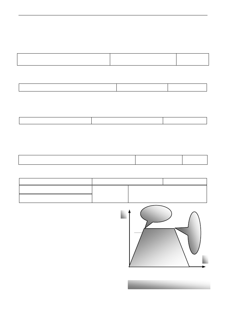
E3000
·40·
· Turnover frequency is the final frequency of VVVF curve, and also is the least frequency according to the
highest output voltage.
·When running frequency is lower than this value, inverter has constant-torque output. When running
frequency exceeds this value, inverter has constant-power output.
Note: during the process of speed track, turnover frequency is invalid. After speed track is finished, this
function code is valid.
F119 The reference of setting accel/decel time
Setting range: 0: 0~50.00Hz
1: 0~max frequency
Mfr‟s value: 0
When F119=0, acceleration/ deceleration time means the time for inverter to accelerate/ decelerate from 0Hz
(50Hz) to 50Hz (0Hz).
When F119=1, acceleration/ deceleration time means the time for inverter to accelerate/ decelerate from 0Hz
(max frequency) to max frequency (0Hz).
F120 Forward / Reverse Switchover dead-Time (S)
Setting range: 0.0~3000
Mfr‟s value: 0.00S
· Within “forward/ reverse switchover dead-time”, this latency time will be cancelled and the inverter will
switch to run in the other direction immediately upon receiving “stop” signal. This function is suitable for all
the speed control modes except automatic cycle operation.
· This function can ease the current impact in the process of direction switchover.
Note: during the process of speed track, F120 is invalid. After speed track is finished, this function code is valid.
F122 Reverse Running Forbidden
Setting range: 0: invalid; 1: valid
Mfr‟s value: 0
When F122=1, inverter will only run forward no matter the state of terminals and the parameters set by F202.
Inverter will not run reverse and forward / reverse switchover is forbidden. If reverse signal is given, inverter will stop.
If reverse running locking is valid (F202=1), whatever speed track is valid or not, inverter has no output.
When F122=1,F613=1,F614≥2 and inverter gets forward running command and motor is sliding reverse, if inverter
can detect the sliding direction and track to motor speed, then inverter will run to 0.0Hz reverse, then run forward
according to the setting value of parameters.
F123 Minus frequency is valid in the mode of combined speed control.
0:Invalid;1:valid
0
·In the mode of combined speed control, if running frequency is minus and F123=0, inverter will run at 0Hz;
if F123=1, inverter will run reverse at this frequency. (This function is controlled by F122.)
·There are two types of jogging: keypad
jogging and terminal jogging. Keypad
jogging is valid only under stopped status
(F132 including of displaying items of
keypad jogging should be set). Terminal
jogging is valid under both running status
and stopped status.
·Carry out jogging operation through the
keypad (under stopped status):
a. Press the “Fun” key, it will display
“HF-0”;
b. Press the “Run” key, the inverter will run
to “jogging frequency” (if pressing “Fun”
key again, “keypad jogging” will be
cancelled).
·Jogging Acceleration Time: the time for inverter to accelerate from 0Hz to 50Hz.
F124 Jogging Frequency (Hz)
Setting range: F112~F111
Mfr‟s value: 5.00Hz
F125 Jogging Acceleration Time (S)
Setting range:
0.1~3000
Mfr‟s value: For 0.2~4.0kW, 5.0S
For 5.5~30kW, 30.0S
For above 37kW. 60.0S
F126 Jogging Deceleration Time (S)
Figure 5-1 Jogging Operation
t
f
Jogging Operation
Receiving jogging
operation
instruction
Removing jogging
operation instruction
F124
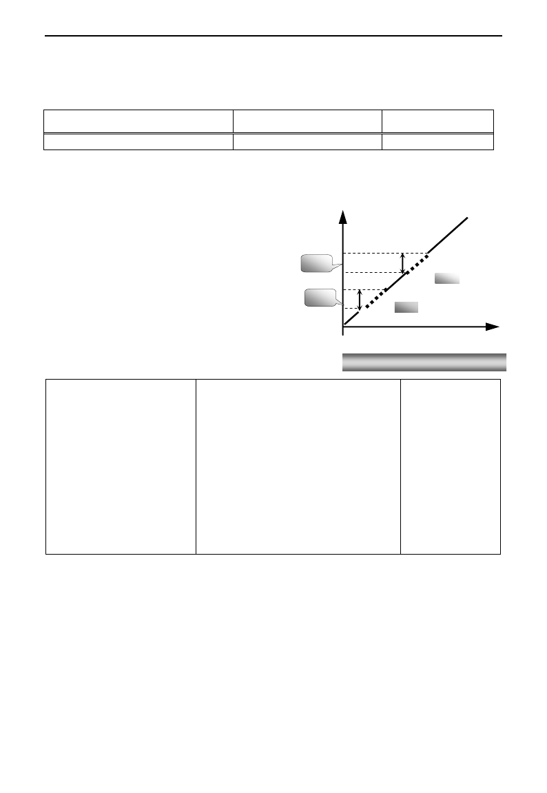
E3000
·41·
·Jogging Deceleration Time: the time for inverter to decelerate from 50Hz to 0Hz.
· In case of terminal jogging, make “jogging” terminal (such as OP1) connected to CM, and inverter will
run to jogging frequency. The rated function codes are from F316 to F323.
Note: when jogging function is valid, speed track function is invalid.
F127/F129 Skip Frequency A,B (Hz)
Setting range: 0.00~650.0
Mfr‟s value:0.00Hz
F128/F130 Skip Width A,B (Hz)
Setting range: ±2.5
Mfr‟s value: 0.0
· Systematic vibration may occur when the motor is running at a certain frequency. This parameter is set to
skip this frequency.
·The inverter will skip the point automatically when output frequency is equal to the set value of this
parameter.
·“Skip Width” is the span from the upper to the lower
limits around Skip Frequency. For example, Skip
Frequency=20Hz, Skip Width=±0.5Hz, inverter will
skip automatically when output is between 19.5~
20.5Hz.
·Inverter will not skip this frequency span during
acceleration/deceleration.
Note: during the process of speed track, skip
frequency function is invalid. After speed track is
finished, this function is valid.
F131 Running Display Items
0-Current output frequency/function-code
1-Output rotary speed
2-Output current
4-Output voltage
8-PN voltage
16-PID feedback value
32-Temperature
64-Count values
128-Linear speed
256-PID given value
512-Yarn length
1024-Center frequency
2048-Reserved
4096- Output torque
Mfr‟s value:
0+1+2+4+8=15
· Single-phase 0.2~0.75kW inverters have no the function of temperature display.
·Selection of one value from 1, 2, 4, 8, 16, 32, 64 and 128 shows that only one specific display item is
selected. Should multiple display items be intended, add the values of the corresponding display items and
take the total values as the set value of F131, e.g., just set F131 to be 19 (1+2+16) if you want to call “current
output rotary speed”, “output current” and “PID feedback value”. The other display items will be covered.
·As F131=511, all display items are visible, of which, “frequency/function-code” will be visible whether or
not it is selected.
·Should you intend to check any display item, just press the “Fun” key for switchover.
·Refer to the following table for each specific value unit and its indication:
·Whatever the value of F131 is set to, corresponding target frequency will flash under stopped status.
Figure 5-2 Skip Frequency
Time (t)
Output
Frequency
(Hz)
F128
F130
F129
F127

E3000
·42·
Target rotary speed is an integral number. If it exceeds 9999, add a decimal point to it.
Current display A *.* Voltage display U*** Count value **** Temperature H***
Linear speed L***. If it exceeds 999, add a decimal point to it. If it exceeds 9999, add two decimal
points to it, and the like.
PID given value o*.* PID feedback value b*.*
Note: when count value is displayed and it exceeds 9999, only 4 digits are displayed and add a
decimal point to it, i.e. 12345 is displayed in the form of 1234. .
F132 Display items of stop
Setting range: 0: Frequency/function-code
1: Keypad jogging
2: Target rotary speed
4: PN voltage 8: PID feedback value
16: Temperature 32: Count values
64: PID given value 128: Yarn length
256: Center frequency 512: Setting torque
Mfr‟s value:
0+2+4=6
F133 Drive ratio of driven system
Setting range: 0.10~200.0
Mfr‟s value: 1.00
F134 Transmission-wheel radius
0.001~1.000 (m)
Mfr‟s value: 0.001
·Calculation of rotary speed and linear speed:
For example, If inverter‟s max frequency F111=50.00Hz, numbers of motor poles F804=4, drive ratio
F133=1.00, transmission-shaft radius R=0.05m, then
Transmission shaft perimeter: 2πr =2×3.14×0.05=0.314 (meter)
Transmission shaft rotary speed: 60× operation frequency/ (numbers of poles pairs × drive ratio)
=60×50/ (2×1.00) =1500rpm
Endmost linear speed: rotary speed × perimeter=1500×0.314=471(meters/second)
F136 Slip compensation
Setting range: 0~10%
Mfr‟s value: 0
· Under VVVF controlling, rotary speed of motor rotor will decrease as load increases. Be assured that rotor
rotate speed is near to synchronization rotary speed while motor with rated load, slip compensation should be
adopted according to the setting value of frequency compensation.
Note: during the process of speed track, slip compensation function is invalid. After speed track is finished,
this function is valid.
F137 Modes of torque compensation
Setting range:
0: Linear compensation;
1: Square compensation;
2: User-defined multipoint compensation
3: Auto torque compensation
Mfr‟s value: 3
F138 Linear compensation
Setting range: 1~16
Mfr‟s value:
0.2-4.0kW: 7
5.5-30kW: 6
37~75kW: 5
90kW: 4
F139 Square compensation
Setting range: 1: 1.5 2: 1.8
3: 1.9 4: 2.0
Mfr‟s value: 1
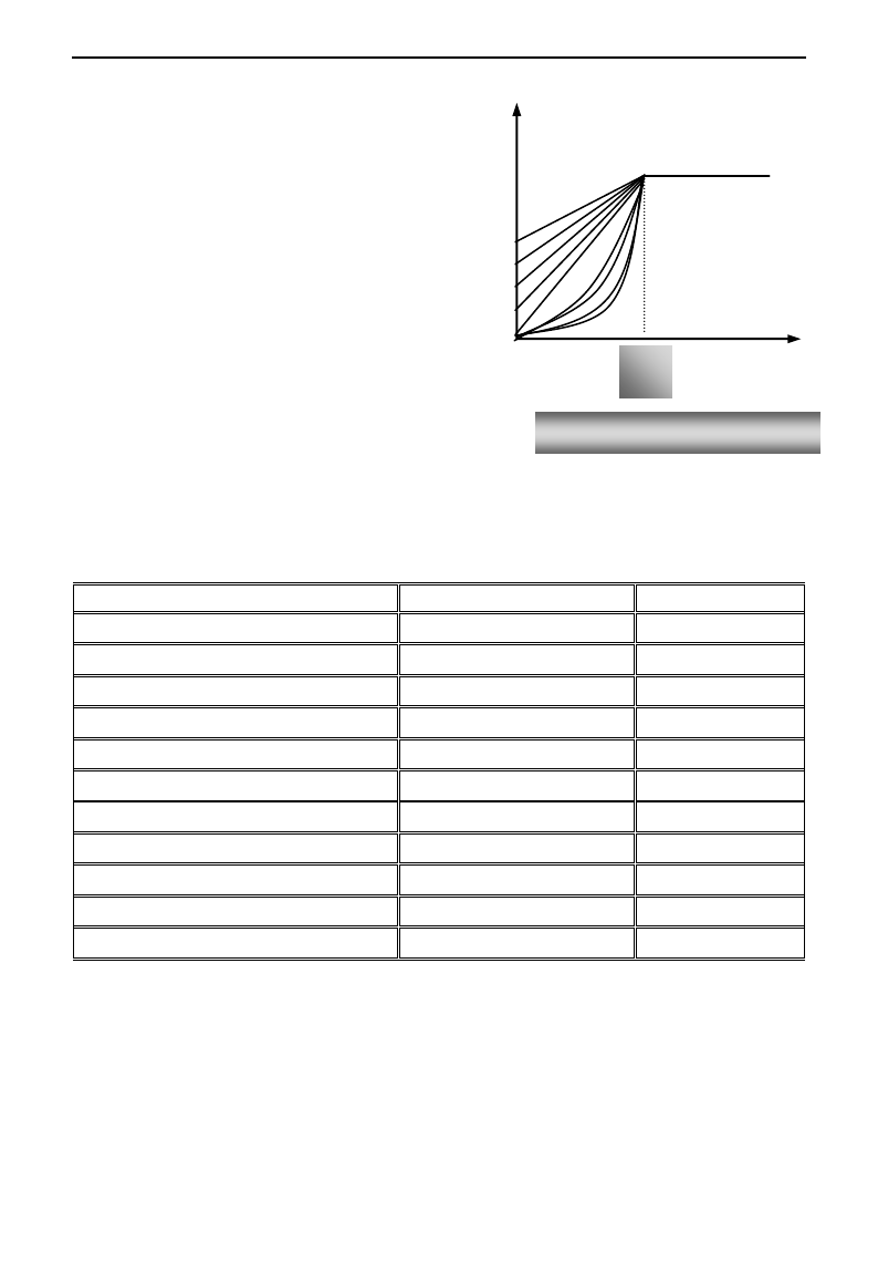
E3000
·43·
To compensate low-frequency torque controlled by
VVVF, output voltage of inverter while
low-frequency should be compensated.
When F137=0, linear compensation is chosen and
it is applied on universal constant-torque load;
When F137=1, square compensation is chose and
it is applied on the loads of fan or water pump;
When F137=2, user-defined multipoint
compensation is chosen and it is applied on the
special loads of spin-drier or centrifuge;
This parameter should be increased when the load
is heavier, and this parameter should be decreased
when the load is lighter.
If the torque is elevated too much, motor is easy to
overheat, and the current of inverter will be too
high. Please check the motor while elevating the torque.
When F137=3, auto torque compensation is chose and it can compensate low-frequency torque automatically,
to diminish motor slip, to make rotor rotary speed close to synchro rotary speed and to restrain motor
vibration. Customers should set correctly motor power, rotary speed, numbers of motor poles, motor rated
current and stator resistance. Please refer to the chapter “Operation process of measuring motor parameters”.
F140 User-defined frequency point F1
Setting range: 0~F142
Mfr‟s value: 1.00
F141 User-defined voltage point V1
Setting range: 0~100%
Mfr‟s value: 4
F142 User-defined frequency point F2
Setting range: F140~F144
Mfr‟s value: 5.00
F143 User-defined voltage point V2
Setting range: 0~100%
Mfr‟s value: 13
F144 User-defined frequency point F3
Setting range: F142~F146
Mfr‟s value: 10.00
F145 User-defined voltage point V3
Setting range: 0~100%
Mfr‟s value: 24
F146 User-defined frequency point F4
Setting range: F144~F148
Mfr‟s value: 20.00
F147 User-defined voltage point V4
Setting range: 0~100%
Mfr‟s value: 45
F148 User-defined frequency point F5
Setting range: F146~F150
Mfr‟s value: 30.00
F149 User-defined voltage point V5
Setting range: 0~100%
Mfr‟s value: 63
F150 User-defined frequency point F6
Setting range: F148~F118
Mfr‟s value: 40.00
F151 User-defined voltage point V6
Setting range: 0~100%
Mfr‟s value: 81
Multi-stage VVVF curves are defined by 12 parameters from F140 to F151.
The setting value of VVVF curve is set by motor load characteristic.
Note: V1<V2<V3<V4<V5<V6,F1<F2<F3<F4<F5<F6.As low-frequency, if the setting voltage is too high, motor
will overheat or be damaged. Inverter will be stalling or occur over-current protection.
16
f
Turnover
frequency
V(%)
Fig 5-3 Torque Promotion
1
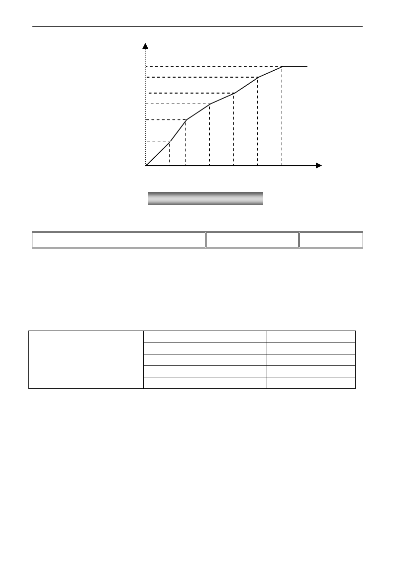
E3000
·44·
Note: during the process of speed track, polygonal-line VVVF curve function is invalid. After speed track is
finished, this function is valid.
F152 Output voltage corresponding to turnover frequency
Setting range: 10~100%
Mfr‟s value: 100
This function can meet the needs of some special loads, for example, when the frequency outputs 300Hz and
corresponding voltage outputs 200V (supposed voltage of inverter power supply is 400V), turnover
frequency F118 should be set to 300Hz and F152 is set to(200÷400)×100=50. And F152 should be equal to
50.
Please pay attention to nameplate parameters of motor. If the working voltage is higher than rated voltage or
the frequency is higher than rated frequency, motor would be damaged.
Note: during the process of speed track, slip compensation function is invalid. After speed track is finished,
this function is valid.
Carrier-wave frequency of inverter is adjusted by setting this code function. Adjusting carrier-wave may
reduce motor noise, avoid point of resonance of mechanical system, decrease leakage current of wire to earth
and the interference of inverter.
When carrier-wave frequency is low, although carrier-wave noise from motor will increase, the current
leaked to the earth will decrease. The wastage of motor and the temperature of motor will increase, but the
temperature of inverter will decrease.
When carrier-wave frequency is high, the situations are opposite, and the interference will rise.
When output frequency of inverter is adjusted to high frequency, the setting value of carrier-wave should be
increased. Performance is influenced by adjusting carrier-wave frequency as below table:
F153 Carrier frequency setting
Setting range:
Mfr‟s value:
0.2~7.5kW:800-10000
4000
11~15kW: 800-10000
3000
18.5kW~45kW: 2000-6000
4000
Above 55kW: 2000-4000
2000
Voltage (%)
V6
V5
V4
V3
V2
V1
F1 F2 F3 F4 F5 F6 Fre(Hz)
Fig 5-4 Polygonal-Line Type VVVF
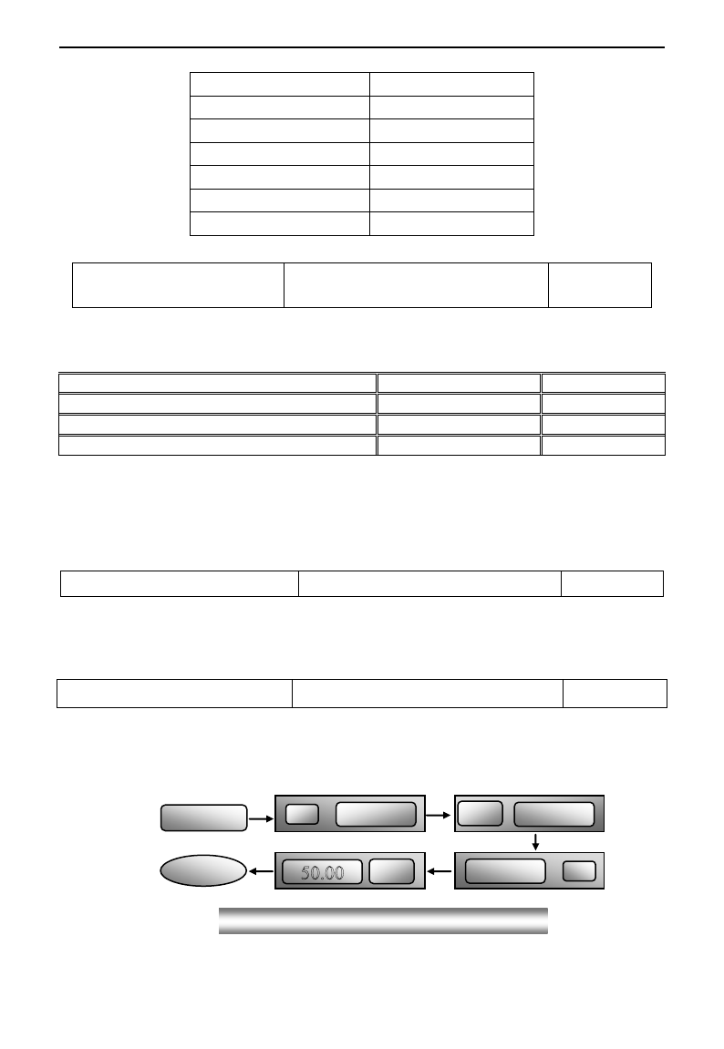
E3000
·45·
Carrier-wave frequency
Low → High
Motor noise
Loud → Low
Waveform of output current
Bad → Good
Motor temperature
High → Low
Inverter temperature
Low → High
Leakage current
Low → High
Interference
Low → High
F154 Automatic voltage rectification
Setting range: 0: Invalid 1: Valid
2:Invalid during deceleration process
Mfr‟s value: 0
This function is enable to keep output voltage constant automatically in the case of fluctuation of input
voltage, but the deceleration time will be affected by internal PI adjustor. If deceleration time is forbidden
being changed, please select F154=2.
F155 Digital accessorial frequency setting
Setting range: 0~F111
Mfr‟s value: 0
F156 Digital accessorial frequency polarity setting
Setting range: 0 or 1
Mfr‟s value: 0
F157 Reading accessorial frequency
F158 Reading accessorial frequency polarity
Under combined speed control mode, when accessorial frequency source is digital setting memory (F204=0), F155 and
F156 are considered as initial set values of accessorial frequency and polarity (direction).
In the mode of combined speed control, F157 and F158 are used for reading the value and direction of accessorial
frequency.
For example, when F203=1, F204=0. F207=1, the given analog frequency is 15Hz, inverter is required to run to 20Hz. In
case of this requirement, user can push “UP” button to raise the frequency from 15Hz to 20Hz. User can also set
F155=5Hz and F160=0 (0 means forward, 1 means reverse). In this way, inverter can be run to 20Hz directly.
F159 Random carrier-wave selection
Setting range: 0: Invalid 1: Valid
Mfr‟s value: 1
When F159=0, inverter will modulate as per the carrier-wave set by F153. When F159=1, inverter will operate in
mode of random carrier-wave modulating.
Note: when random carrier-wave is selected, output torque will increase but noise will be loud. When the
carrier-wave set by F153 is selected, noise will be reduced, but output torque will decrease. Please set the value
according to the situation.
F160 Reverting to manufacturer values
Setting range: 0: Invalid 1: Valid
Mfr‟s value: 0
·When there is disorder with inverter‟s parameters and manufacturer values need to be restored, set F160=1.
After “Reverting to manufacturer values” is done, F160 values will be automatically changed to 0.
· “Reverting to manufacturer values” will not work for the function-codes marked “○”in the “change”
column of the parameters table. These function codes have been adjusted properly before delivery. And it is
recommended not to change them.
Figure 5-3 Reverting to manufacturer values
▲
1
set
0
▼
F 1 6 0
F 1 0 0
OK!
10
set

E3000
·46·
5.2 Operation Control
F200
Source of start
command
Setting range:
0: Keypad command; 1: Terminal command;
2: Keypad+Terminal; 3: Communication;
4: Keypad+Terminal+Communication
Mfr‟s value: 0
F201
Source of stop
command
Setting range:
0: Keypad command; 1: Terminal command;
2: Keypad+Terminal; 3: Communication;
4: Keypad+Terminal+Communication
Mfr‟s value: 0
· F200 and F201 are the resource of selecting inverter control commands.
· Inverter control commands include: starting, stopping, forward running, reverse running, jogging, etc.
·”Keypad command” refers to the start/stop commands given by the “Run” or ”stop/reset” key on the keypad.
·“Terminal command” refers to the start/stop command given by the “Run” terminal defined by F316-F323.
·When F200=3 and F201=3, the running command is given by Communication.
·When F200=2 and F201=2, “keypad command” and “terminal command” are valid at the mean time,
F200=4 and F201=4 are the same.
F202
Mode of direction setting
Setting range:
0: Forward running locking;
1: Reverse running locking;
2: Terminal setting
Mfr‟s value: 0
· The running direction is controlled by this function code together with other speed control mode which can
set the running direction of inverter. When auto-circulation speed is selected by F500=2, this function code
is not valid.
· When speed control mode without controlling direction is selected, the running direction of inverter is
controlled by this function code, for example, keypad controls speed.
. When speed control mode with controlling direction is selected, the running direction of inverter is
controlled by both modes. The way is polarity addition, for example, one forward direction and one
reverse direction make the inverter run reversely, both forward directions make inverter run forward, both
reverse directions which equal to forward direction make inverter run forward.
F203
Main frequency source X
Setting range:
0: Memory of digital given;
1: External analog AI1;
2: External analog AI2;
3: Pulse input given; 4: Stage speed control;
5: No memory of digital given;
6: Keypad potentiometer; 7: Reserved;
8:Reserved; 9: PID adjusting;
10: Communication
Mfr‟s value: 0
· Main frequency source is set by this function code.
·0: Memory of digital given
Its initial value is the value of F113. The frequency can be adjusted through the key “up” or “down”, or

E3000
·47·
through the “up”, “down” terminals.
“Memory of digital given” means after inverter stops, the target frequency is the running frequency before
stop. If the user would like to save target frequency in memory when the power is disconnected, please set
F220=1, i.e. frequency memory after power down is valid.
1: External analog AI1; 2: External analog AI2
The frequency is set by analog input terminal AI1 and AI2. The analog signal may be current signal (0-20mA
or 4-20mA) or voltage signal (0-5V or 0-10V), which can be chosen by switch code. Please adjust the switch
code according to practical situations, refer to fig 4-4 and table 4-2.
When inverters leave the factory, the analog signal of AI1 channel is DC voltage signal, the range of voltage
is 0-10V, and the analog signal of AI2 channel is DC current signal, the range of current is 0-20 mA. If
4-20mA current signal is needed, please set lower limit of analog input F406=2, which input resistor is
500OHM. If some errors exist, please make some adjustments.
3: Pulse input given
When frequency is given by pulse input, the pulse is only inputted by OP1 terminal. The max pulse
frequency is 50K. The related parameters are from F440 to F446.
4: Stage speed control
Multi-stage speed control is selected by setting stage speed terminals F316-F322 and function codes of
multi-stage speed section. The frequency is set by multi-stage terminal or automatic cycling frequency.
5: No memory of digital given
Its initial value is the value of F113. The frequency can be adjusted through the key “up” or “down”, or
through the “up”, “down” terminals.
“No memory of digital given” means that the target frequency will restore to the value of F113 after stop no
matter the state of F220.
6: Keypad Potentiometer AI3
The frequency is set by the analog on the control panel.
9: PID adjusting
When PID adjusting is selected, the running frequency of inverter is the value of frequency adjusted by PID.
Please refer to instructions of PID parameters for PID given resource, PID given numbers, feedback source,
and so on.
10: COMMUNICATION
The main frequency is given by communication.
F204 Accessorial frequency
source Y
Setting range:
0: Memory of digital given; 1: External analog AI1;
2: External analog AI2; 3: Pulse input given;
4: Stage speed control; 5: PID adjusting;
6: Keypad potentiometer AI3
Mfr‟s value: 0
· When accessorial frequency Y is given to channel as independent frequency, it has the same function with main
frequency source X.
· When F204=0, the initial value of accessorial frequency is set by F155. When accessorial frequency controls speed
independently, polarity setting F156 is not valid.
· When F207=1 or 3, and F204=0, the initial value of accessorial frequency is set by F155, the polarity of accessorial
frequency is set by F156, the initial value of accessorial frequency and the polarity of accessorial frequency can be

E3000
·48·
checked by F157 and F158.
· When the accessorial frequency is given by analog input (AI1, AI2), the setting range for the accessorial frequency is set
by F205 and F206.
When the accessorial frequency is given by keypad potentiometer, the main frequency can only select stage speed control
and Communication control (F203=4, 10)
· Note: accessorial frequency source Y and main frequency source X can not use the same frequency given channel.
F205 reference for selecting accessorial
frequency source Y range
Setting range:
0: Relative to max frequency;
1: Relative to main frequency X
Mfr‟s value: 0
F206 Accessorial frequency Y range (%)
Setting range: 0~100
Mfr‟s value: 100
· When combined speed control is adopted for frequency source, F206 is used to confirm the relative object
of the setting range for the accessorial frequency.
F205 is to confirm the reference of the accessorial frequency range. If it is relative to main frequency, the
range will change according to the change of main frequency X.
F207 Frequency source selecting
Setting range:
0: X; 1: X+Y;
2: X or Y (terminal switchover);
3: X or X+Y (terminal switchover);
4: Combination of stage speed and analog
5: X-Y 6: X+Y(F206-50%)*F205
Mfr‟s value: 0
·Select the channel of setting the frequency. The frequency is given by combination of main frequency X and
accessorial frequency Y.
·When F207=0, the frequency is set by main frequency source.
·When F207=1, X+Y, the frequency is set by adding main frequency source to accessorial frequency source.
X or Y can not be given by PID.
·When F207=2, main frequency source and accessorial frequency source can be switched over by frequency
source switching terminal.
·When F207=3, main frequency given and adding frequency given(X+Y) can be switched over by frequency
source switching terminal. X or Y can not be given by PID.
·When F207=4, stage speed setting of main frequency source has priority over analog setting of accessorial
frequency source (only suitable for F203=4 F204=1).
·When F207=5, X-Y, the frequency is set by subtracting accessorial frequency source from main frequency
source. If the frequency is set by main frequency or accessorial frequency, PID speed control can not be
selected.
·When F207=6, X+Y(F206-50%)*F205, the frequency is given by both main frequency source and accessorial
frequency source. X or Y can not be given by PID.
Note:
1. When F203=4 and F204=1, the difference between F207=1 and F207=4 is that when F207=1,
frequency source selecting is the addition of stage speed and analog, when F207=4, frequency source
selecting is stage speed with stage speed and analog given at the same time. If stage speed given is
canceled and analog given still exists, inverter will run by analog given.
2. Frequency given mode can be switched over by selecting F207. For example: switching PID adjusting

E3000
·49·
and normal speed control, switching stage speed and analog given, switching PID adjusting and analog
given, and so on.
3. The acceleration/deceleration time of stage speed is set by function code of corresponding stage speed
time. When combined speed control is adopted for frequency source, the acceleration/deceleration time
is set by F114 and F115.
4. The mode of automatic cycle speed control is unable to combine with other modes.
5. When F207=2 (main frequency source and accessorial frequency source can be switched over by
terminals), if main frequency is not set to be under stage-speed control, accessorial frequency can be set
to be under automatic cycle speed control (F204=5, F500=0). Through the defined switchover terminal,
the control mode (defined by X) and automatic cycle speed control (defined by Y) can be freely
switched.
6. If the settings of main frequency and accessorial frequency are the same, only main frequency will be
valid.
7. When F207=6, F205=0 and F206=100, X+Y(F206-50%)*F205=X+(100%-50%)*F111, and if F207=6,
F205=1 and F206=100, then X+Y(F206-50%)*F205=X+(100%-50%)*X.
F208
Terminal
two-line/three-line
operation control
Setting range:
0: No function;
1: Two-line operation mode 1;
2: Two-line operation mode 2;
3: three-line operation mode 1;
4: three-line operation mode 2;
5: start/stop controlled by direction pulse
Mfr‟s value: 0
· When selecting two-line type or three-line type), F200, F201 and F202 are invalid.
· Five modes are available for terminal operation control.
Note:
In case of stage speed control, set F208 to 0. If F208 ≠0 (when selecting two-line type or three-line type),
F200, F201 and F202 are invalid.
“FWD”, “REV” and “X” are three terminals designated in programming OP1~OP6.
1: Two-line operation mode 1: this mode is the most popularly used two-line mode. The running direction of
mode is controlled by FWD, REV terminals.
For example: “FWD” terminal-----“open”: stop, “closed”: forward running;
“REV” terminal-----“open”: stop, “closed”: reverse running;
“CM” terminal-----common port
K1
K2
Running command
0
0
Stop
1
0
Forward running
0
1
Reverse running
1
1
Stop
1
K
FWD
REV
CM
K2
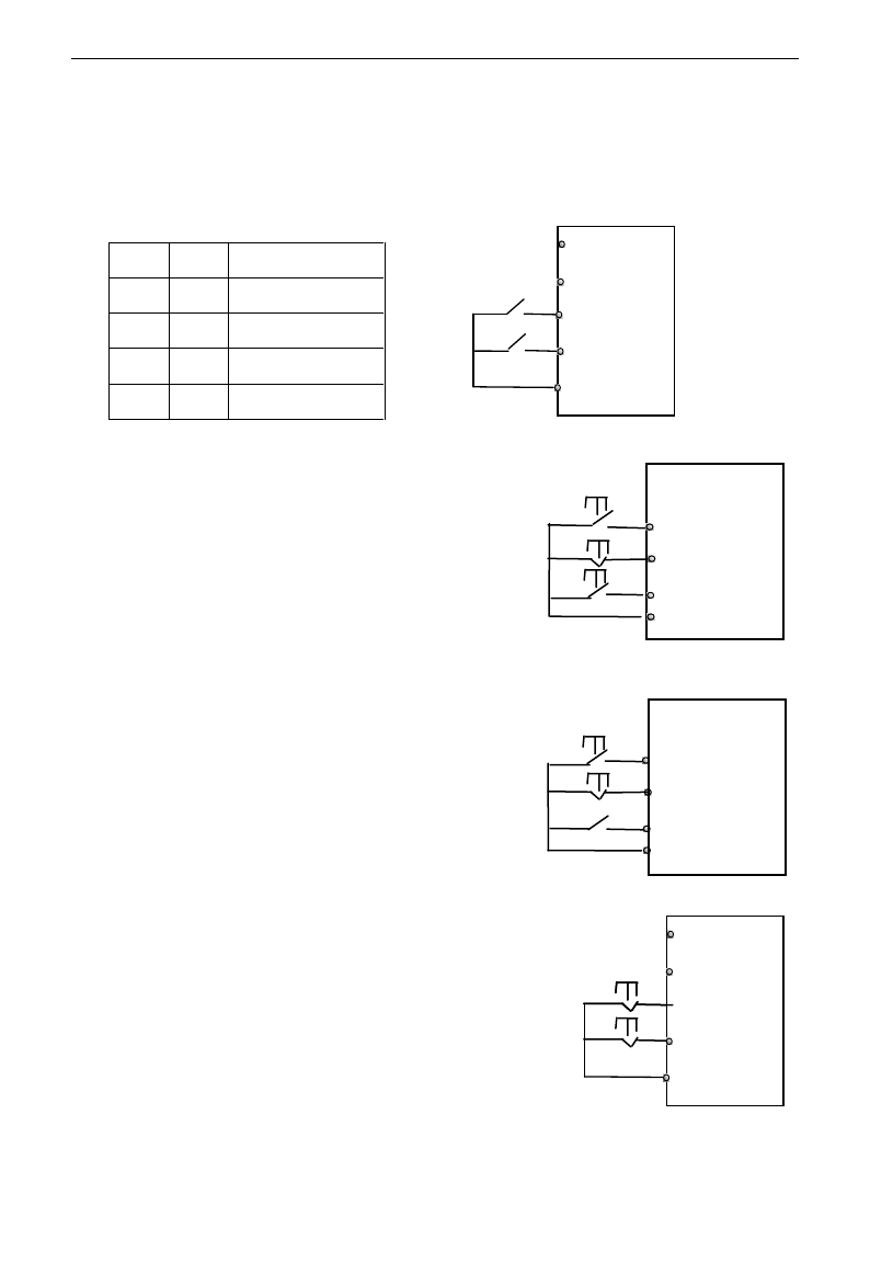
E3000
·50·
2. Two-line operation mode 2: when this mode is used, FWD is enable terminal, the direction is controlled by
REV terminal.
For example: “FWD” terminal-----“open”: stop, “closed”: running;
“REV” terminal-----“open”: forward running, “closed”: reverse running;
“CM” terminal-----common port
3. Three-line operation mode 1:
In this mode, X terminal is enable terminal, the direction is
controlled by FWD terminal and REV terminal. Pulse signal is
valid.
Stopping commands is enabled by opening X terminal.
SB3: Stop button
SB2: Forward button.
SB1: Reverse button.
4. Three-line operation mode 2:
In this mode, X terminal is enable terminal, running command is
controlled by FWD terminal. The running direction is controlled by
REV terminal, and stopping command enable by opening X
terminal.
SB1: Running button
SB2: Stop button
K1: direction switch. Open stands for forward running; close
stands for reverse running.
5. Start/stop controlled by direction pulse:
“FWD” terminal—(impulse signal: forward/stop)
“REV” terminal—(impulse signal: reverse/stop)
“CM” terminal—common port
Note: when pulse of SB1 triggers, inverter will run forward. When the
pulse triggers again, inverter will stop running.
When pulse of SB2 triggers, inverter will run reverse. When the pulse
triggers again, inverter will stop running.
K1
K2
Running command
0
0
Stop
0
1
Stop
1
0
Forward running
1
1
Reverse running
1
K
FWD
REV
CM
K2
REV
SB2
SB1
FWD
REV
SB2
FWD
CM
SB3
SB2
SB1
X
REV
CM
FWD
CM
X
FWD
REV
K1
SB1
SB2

E3000
·51·
F209 Selecting the mode of stopping
the motor
Setting range:
0: stop by deceleration time; 1: free stop
Mfr‟s value: 0
When the stop signal is input, stopping mode is set by this function code:
F209=0: stop by deceleration time
Inverter will decrease output frequency according to setting acceleration/deceleration curve and decelerating
time, after frequency decreases to 0, inverter will stop. This is often common stopping type. During the
process of speed track, this function is invalid. And inverter will be forced to stop during this process.
F209=1: free stop
After stop command is valid, inverter will stop output. Motor will free stop by mechanical inertia.
F210 Frequency display accuracy
Setting range: 0.01~2.00
Mfr‟s value: 0.01
Under keypad speed control or terminal UP/DOWN speed control, frequency display accuracy is set by this
function code and the range is from 0.01 to 2.00. For example, when F210=0.5, UP/DOWN terminal is
pressed at one time, frequency will increase or decrease by 0.5Hz.
This function is valid when inverter is in the running state. When inverter is in the standby state, no matter
what value of this function code is, frequency will increase or decrease by 0.01Hz.
F211 Speed of digital control
Setting range: 0.01~100.0Hz/S
Mfr‟s value: 5.00
When UP/DOWN terminal is pressed, frequency will change at the setting rate. The Mfr‟s value is 5.00Hz/s.
F212 Direction memory
Setting range: 0: Invalid 1: Valid
Mfr‟s value: 0
· This function is valid when three-line operation mode 1(F208=3) is valid.
· When F212=0,after inverter is stopped, resetted and repowered on, the running direction is not memorized.
· When F212=1,after inverter is stopped, resetted and repowered on, if inverter starts running but no
direction signal, inverter will run according the memory direction.
F213 Auto-starting after repowered on
Setting range: 0: invalid; 1: valid
Mfr‟s value: 0
F214 Auto-starting after reset
Setting range: 0: invalid; 1: valid
Mfr‟s value: 0
Whether or not to start automatically after repowered on is set by F213
F213=1, Auto-starting after repowered on is valid. When inverter is power off and then powered on again, it
will run automatically after the time set by F215 and according to the running mode before power-down. If
F220=0 frequency memory after power-down is not valid, inverter will run by the setting value of F113.
F213=0, after repower-on, inverter will not run automatically unless running command is given to inverter.
·Whether or not to start automatically after fault resetting is set by F214
When F214=1, if fault occurs, inverter will reset automatically after delay time for fault reset (F217). After
resetting, inverter will run automatically after the auto-starting delay time (F215).
If frequency memory after power-down (F220) is valid, inverter will run at the speed before power-down.
Otherwise, inverter will run at the speed set by F113.
In case of fault under running status, inverter will reset automatically and auto-start. In case of fault under
stopped status, the inverter will only reset automatically.
When F214=0, after fault occurs, inverter will display fault code, it must be reset by manually.
F215 Auto-starting delay time
Setting range: 0.1~3000.0
Mfr‟s value: 60.0
F215 is the auto-starting delay time for F213 and F214. The range is from 0.1s to 3000.0s.
F216 Times of auto-starting in case of
repeated faults
Setting range: 0~5
Mfr‟s value: 0
F217 Delay time for fault reset
Setting range: 0.0~10.0
Mfr‟s value: 3.0

E3000
·52·
F216 sets the most times of auto-starting in case of repeated faults. If starting times are more than the setting
value of this function code, inverter will not reset or start automatically after fault. Inverter will run after
running command is given to inverter manually.
F217 sets delay time for fault reset. The range is from 0.0 to 10.0S which is time interval from fault to
resetting.
F220 Frequency memory after power-down
Setting range: 0: invalid; 1: valid
Mfr‟s value: 0
F220 sets whether or not frequency memory after power-down is valid.
This function is valid for F213 and F214. Whether or not to memory running state after power-down or
malfunction is set by this function.
·The function of frequency memory after power-down is valid for main frequency and accessorial frequency
that is given by digital. Because the digital given accessorial frequency has positive polarity and negative
polarity, it is saved in the function codes F155 and F156.
F222 count memory selection
Setting range: 0: Invalid 1: Valid
Mfr‟s value:0
·F220 sets whether or not count memory is valid. Whether or not to memory counting values after
power-down or malfunction is set by this function.
Table 5-1 Combination of Speed Control
F204
F203
0. Memory
of digital
setting
1 External
analog AI1
2 External
analog AI2
3 Pulse input
given
4 Terminal
stage speed
control
5 PID
adjusting
6 Keypad
potentiome
ter AI3
0 Memory of
Digital setting
〇
●
●
●
●
●
〇
1External
analog AI1
●
〇
●
●
●
●
〇
2External
analog AI2
●
●
〇
●
●
●
〇
3 Pulse input
given
●
●
●
〇
●
●
〇
4Terminal Stage
speed control
●
●
●
●
〇
●
●
5 Digital setting
〇
●
●
●
●
●
〇
6 Keypad
potentiometer
AI3
●
●
●
●
●
●
〇
9 PID adjusting
●
●
●
●
●
〇
〇
10
Communication
●
●
●
●
●
●
●
●: Inter-combination is allowable.
〇: Combination is not allowable.
The mode of automatic cycle speed control is unable to combine with other modes. If the combination
includes the mode of automatic cycle speed control, only main speed control mode will be valid.
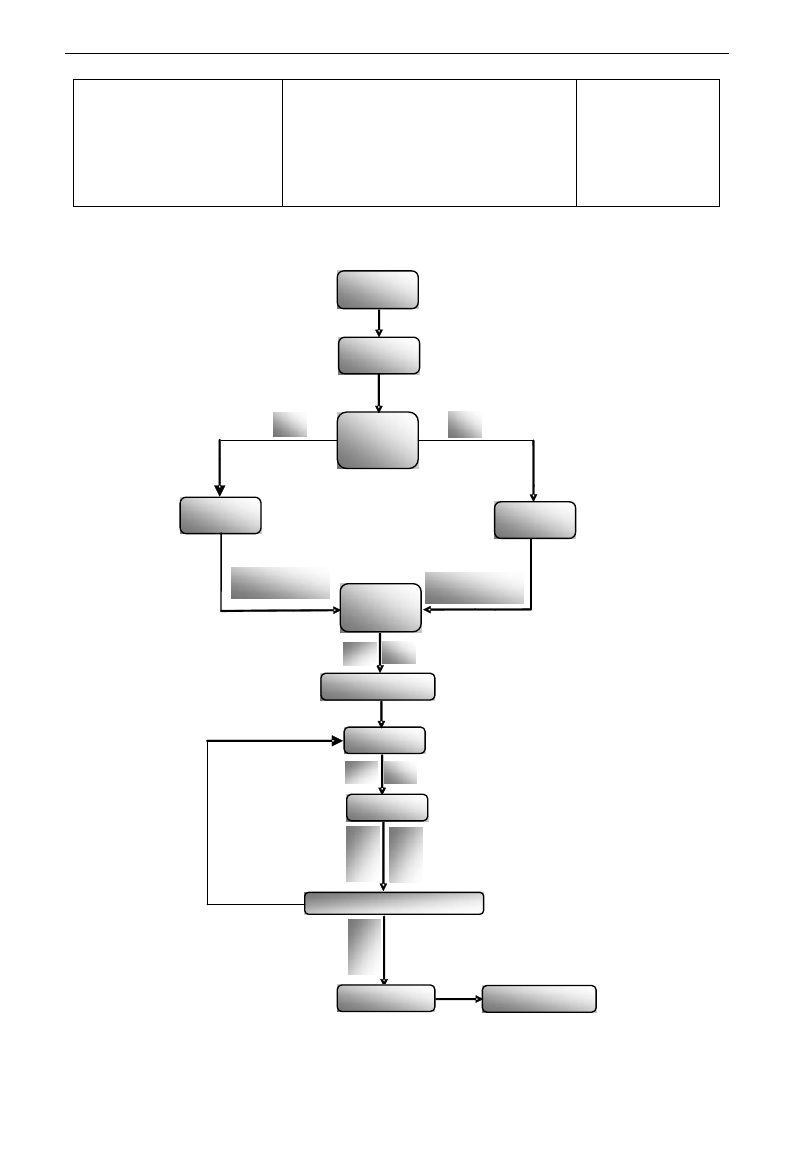
E3000
·53·
F230
Application macro selection
Setting range:
0:Macro of manufacturer
1:PID control macro
2:Torque control macro
3:Multi-stage speed control macro
4:Local/remote control macro
5~8:Reserved
Mfr‟s value: 0
Application macro includes some functions of speed control, and with wiring scheme. User will use inverter
more conveniently. If some function is not included in the macro, user can set them outside of the macro.
Brief process is as below:
▲ ▼
▲ ▼
▲OR▼
F230
Change
or not
NO
YES
Set
Enter guide
mode
Enter need macro
Addressing
inside macro
Set
Set
Modify
macro
Inside
parameter
Enter next function code
Stop/reset
Enter current
macro
Save and quit
Set
Set

E3000
·54·
F231 Reverting to macro
manufacturer values
Setting range:
0: Not reverting to manufacturer
1: Reverting to manufacturer values
Mfr‟s value: 0
·When F231=1, macro is reverted to manufacturer values except communications parameters (nine section).
Brief introduction of macro
0: Macro of manufacturer is the simple keypad control mode, which includes the below function code.
Function code
Function definition
Mfr‟s value
F106
Control mode
0: Sensorless vector control
F113
Target frequency
50.00Hz
F114
First acceleration time
Subject to inverter model
F115
First deceleration time
Subject to inverter model
F122
Reverse running forbidden
0: Invalid
F200
Source of start command
0: Keypad command
F201
Source of stop command
0: Keypad command
F202
Mode of direction setting
0: Forward running locking
F203
Main frequency source X
0: Digital setting memory
F204
Accessorial frequency source Y
0: Digital setting memory
1: PID control macro is suitable for the occasion of process control. For example: controlling changing
process of pressure, liquid levels and flow. The manufacture setting is that digital given value is signal given
source, AI2 is feedback source. Operation mode is two-line 1 mode, and OP3 is set as FWD terminal. PID
control and constant-speed control is switched by OP5 terminal, AI1 is the frequency source of
constant-speed control.
Following function codes are included.
Function code
Function definition
Mfr‟s value
F106
Control mode
2: VVVF
F111
Max frequency
50.00Hz
F112
Min frequency
0.50Hz
F113
Target frequency
50.00Hz
F114
First acceleration time
Subject to inverter model
F115
First deceleration time
Subject to inverter model
F131
Running display items
1+2+4+8+16
F132
Display items of stop
2+4+8+64
F122
Reverse running forbidden
0: Invalid
F137
Modes of torque compensation
0: Linear compensation
F138
Linear compensation
Subject to model
F203
Main frequency source X
9: PID
F204
Accessorial frequency source Y
1: AI1
F207
Frequency source selecting
2: X or Y
F208
Two-line / three-line operation control
1: two-line operation mode 1
F209
Selecting the mode of stop the motor
0: stop by deceleration time
F318
OP3 terminal function setting
15: FWD
F320
OP5 terminal function setting
21: Frequency source switchover terminal
FA00
Water supply mode
0: PID control mode
FA01
PID adjusting target given source
1:AI1
FA02
PID adjusting feedback given source
2:AI2
FA03
Max limit of PID adjusting
100%
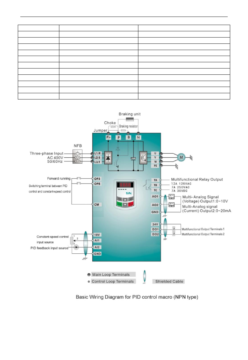
E3000
·55·
FA04
Digital setting value of PID adjusting
50%
FA05
Min limit of PID adjusting
0%
FA06
PID polarity
1:Negative feedback
FA07
Dormancy function selection
1:Invalid
FA09
Min frequency of PID adjusting(S)
5.00Hz
FA10
Dormancy delay time (S)
15
FA11
Wake delay time (S)
3
FA19
Proportion Gain P
0.30
FA20
Integration time I (S)
0.3
FA21
Differential time D (S)
0.0
FA22
PID sampling period (S)
0.1
FA29
PID dead time (%)
2.0
·The wiring is as following:
2. Torque control macro (user must study motor parameter at first). This macro is suitable for the
occasion of constant-torque output. Torque is given by AI1 and forward speed is limited by AI2.
Operation mode is two-line mode 1, and OP3 is set to FWD terminal.

E3000
·56·
Following function codes are included.
Function code
Function definition
Mfr‟s value
F106
Control mode
0
F114
First Acceleration Time
Subject to inverter model
F115
First Deceleration Time
Subject to inverter model
F131
Running Display Items
1+2+4+8+4096
F132
Display items of stop
2+4+512
F208
Terminal two-line/three-line
operation control
1: Two-line operation mode 1
F318
OP3 terminal function setting
15:FWD
F431
AO1 analog output signal selecting
6:torque
F432
AO2 analog output signal selecting
6:torque
FC00
Speed/torque control selection
1:Torque control
FC06
Torque given channel
1:AI1
FC07
Torque given coefficient
3.000
FC08
Reserved
FC09
Torque given command value(%)
100.0
FC14
Offset torque given channel
0:digital given (FC17)
FC15
Offset torque coefficient
0.500
FC16
Offset torque cut-off frequency (%)
10.0
FC17
Offset torque command value (%)
10.0
FC20
Reserved
FC22
Forward speed limited channel
2:AI2
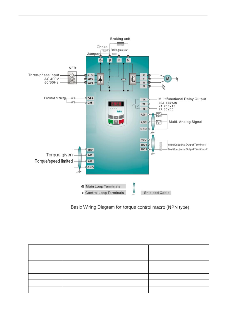
E3000
·57·
·The wiring is as following:
3. Multi-stage speed control macro: 7-stage speed is given by OP1~OP3 terminals, and combination of
stage speed and analog is realized, stage speed has the priority and analog is given by AI1 channel.
Operation control mode is two-line mode 1, OP4 is FWD terminal to control start and stop, OP5 is
REV terminal and OP6 terminal is reset terminal.
Below function codes are include:
Function code
Function definition
Mfr‟s value
F106
Control mode
0:Sensorless vector control
F111
Max Frequency
50.00Hz
F112
Min Frequency
0.50Hz
F114
First Acceleration Time
Subject to inverter model
F115
First Deceleration Time
Subject to inverter model
F122
Reverse Running Forbidden
0: invalid

E3000
·58·
F131
Running Display Items
1+2+4+8
F132
Display items of stop
2+4
F203
Main frequency source
4: Stage speed control
F208
Terminal two-line/three-line operation control
1: Two-line operation mode 1
F209
Selecting the mode of stopping the motor
0: stop by deceleration time
F316
OP1 terminal function setting
3: multi-stage speed terminal 1
F317
OP2 terminal function setting
4: multi-stage speed terminal 2
F318
OP3 terminal function setting
5: multi-stage speed terminal 3
F319
OP4 terminal function setting
15: FWD
F320
OP5 terminal function setting
16: REV
F321
OP6 terminal function setting
7: Reset
F500
Stage speed type
1: 15-stage speed
F504
Frequency setting for stage 1 speed
5Hz
F505
Frequency setting for stage 2 speed
10Hz
F506
Frequency setting for stage 3 speed
15Hz
F507
Frequency setting for stage 4 speed
20Hz
F508
Frequency setting for stage 5 speed
25Hz
F509
Frequency setting for stage 6 speed
30Hz
F510
Frequency setting for stage 7 speed
35Hz
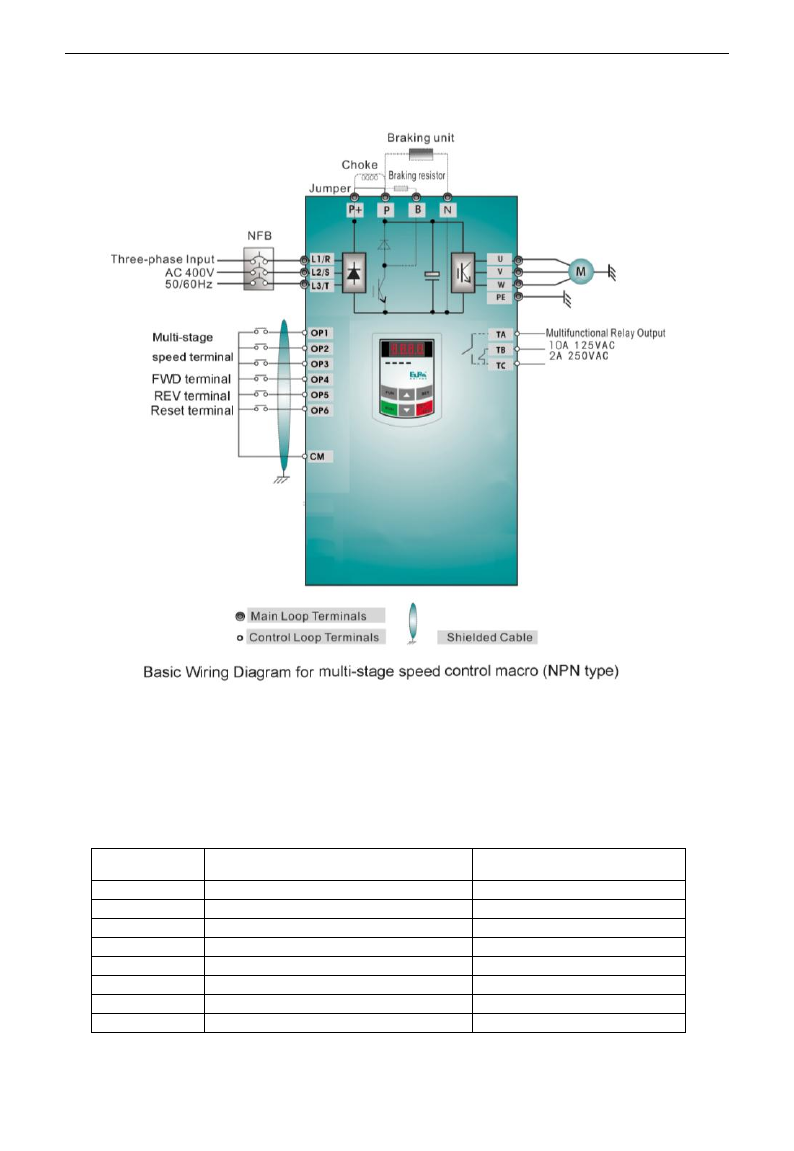
E3000
·59·
The wiring is as following:
4. Local/remote control macro is switched by terminals. Each control mode has frequency given source,
start/stop control and direction given source.
Frequency source switch is between X and Y (F207=2) or X and X+Y (F207=3), start/stop control and
direction switch is valid at the same time.
The control mode of start/stop and direction selecting is set by F200, F201, F202 and F208 (given by panel,
terminal, scene bus). The default control mode is two-line 1 mode, main frequency source X is set by F203
and the default channel is AI1. The accessorial frequency source Y is set by F204 and the default channel is
AI2. Only when F207=2 or 3, frequency source can be switched, the default setting is F207=2.
Function code
Function definition
Mfr‟s value
F106
Control mode
0:SVC
F111
Max Frequency
50.00Hz
F112
Min Frequency
0.50Hz
F113
Target Frequency
50.00Hz
F114
First Acceleration Time
Subject to inverter model
F115
First Deceleration Time
Subject to inverter model
F122
Reverse Running Forbidden
0: invalid
F131
Running Display Items
1+2+4+8
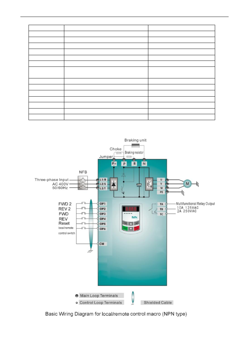
E3000
·60·
F132
Display items of stop
2+4
F200
Source of start command
0: Keypad command
F201
Source of stop command
0: Keypad command
F202
Mode of direction setting
0: Forward running locking
F203
Main frequency source X
1:AI1
F204
Accessorial frequency source Y
2:AI2
F207
Frequency source selecting
2:X or Y
F208
Terminal two-line/three-line operation
control
1: Two-line operation mode 1
F209
Selecting the mode of stopping the motor
0: stop by deceleration time
F316
OP1 terminal function setting
52: FWD2
F317
OP2 terminal function setting
53: REV2
F318
OP3 terminal function setting
15: FWD
F319
OP4 terminal function setting
16: REV
F320
OP5 terminal function setting
7: reset
F321
OP6 terminal function setting
51: control 1/ control 2 selecting
The wiring is as following:
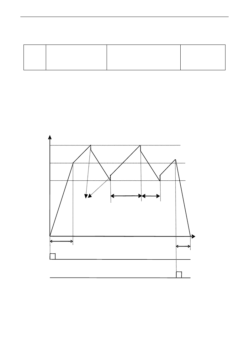
E3000
·61·
Traverse Operating function
Traverse operation is widely used in textile and chemical fiber industry.
F235
Traverse operating mode
0:Invalid
1:Traverse operating mode 1
2:Traverse operating mode 2
3:Traverse operating mode 3
Mfr's value: 0
·F235=0,this function is invalid.
·F235=1,traverse operating mode 1, the central frequency is set by F242, and the working process is shown
in Fig 5-6.
·F235=2,traverse operating mode 2, the central frequency is on the decrease, the working process is shown
in Fig 5-7.
·F235=3,traverse operating mode 3, the central frequency is set by F203. Under this mode, if the central
frequency set by F203 is lower than the lower limit of central frequency, inverter will not stop running. In
the other traverse operating mode, the value of central frequency is controlled by F243.
t
Decelerate
according to
Dec. time
Descending
time
Rising time
Jitter Freq.
Accelerate
according to
Acc. time
Upper limit of Freq.
Hz
Central Freq.
频率
Stop
command
Fig 5-6
Lower limit of Freq.
Run
command
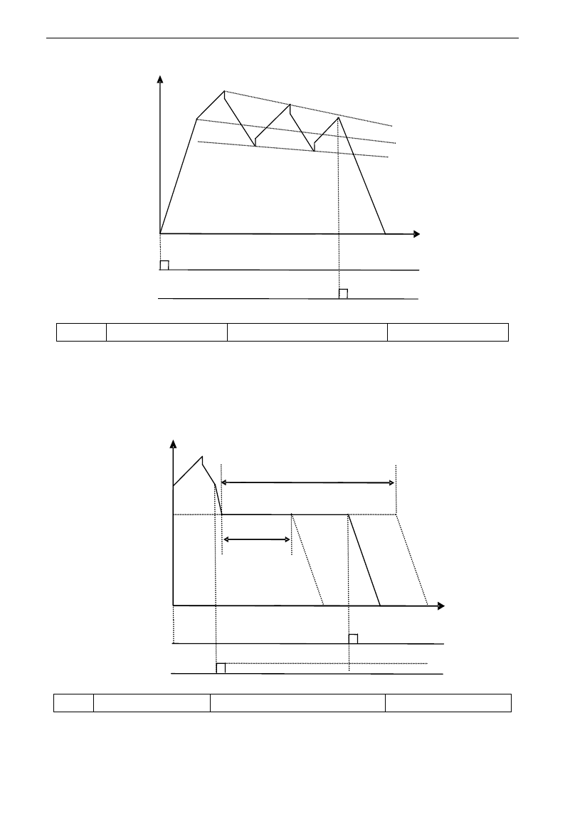
E3000
·62·
Fig 5-7
Hz
t
Run
command
Stop
command
F236
Crawl-positioning
0:Disabled 1:Enabled
Mfr's value: 0
·Crawl-positioning mode: when this mode is enabled, if inverter gets the signal of stop, full of yarn, broken
of yarn, fixed length control, inverter will run to the frequency of crawl-positioning (F252). After the
waiting time of crawl-positioning (F253), if inverter gets a positioning stop signal, inverter will stop (the
positioning stop signal is invalid within crawl-positioning waiting time). If there is no positioning stop
signal, inverter will stop automatically after max time of crawl-positioning time (F524). Note: if F524=0,
inverter will not stop automatically.
Running frequency
of crawl-positioning Waiting time of
crawl-positioning
t
Hz
Positioning
signal
Stop signal of
full of yarn or
broken of yarn Fig 5-8
Max running time of crawl-positioning
F237
Traverse signal source
0:Auto start 1:X terminal start
Mfr's value: 0
·When F237=0 and F235≠0, inverter will run by traverse mode.
·When F237=1 and F235≠0, user should set OPX terminal as traverse start terminal, when this terminal is

E3000
·63·
valid, traverse function is valid.
F238
Stop mode of
length arrival
0:Stop the motor at fixed length
1:Stop the motor at fixed spindle radius
2:Non-stop at fixed length, it indicates full of yarn.
3:Fixed radius arrival, it indicates full of yarn.
Mfr's value: 0
F239
Traverse memory
mode
0:Memory at the status of stop and power off
1:Only memory at the status of stop.
2:Only memory at the status of power off.
3:No memory.
Mfr's value: 0
F238=0 or 1, when fixed length or fixed radius is arrival, inverter will stop.
F238=2 or 3, when fixed length or fixed radius is arrival, multifunction terminals (DO1, DO2 and relay
output terminal) will output signal. Inverter will not stop, and “OVER” will be displayed in the panel.
F240
Preset frequency (Hz)
F112~F111
Mfr's value: 5.00
F241
Running time of preset frequency (S)
0~3000.0
Mfr's value: 0
F240 is used to define the inverter‟s operating frequency before entering traverse mode.
F241 is used to define the time when the inverter operates at pre-traverse frequency.
F242
Central frequency (Hz)
F243~F111
Mfr's value: 25.00
F243
Lower limit of central frequency
(Hz)
F112~F242
Mfr's value: 0.50
F244
Descending rate of central
frequency (Hz / S)
0~65.00
Mfr's value: 0.500
F247
Traverse amplitude setting mode
0:Relative to max frequency
1:Relative to central frequency
Mfr's value: 1
F248
Traverse amplitude
0~100.00%
Mfr's value: 10.00%
F249
Jump frequency
0~50.00%
Mfr's value: 30.00%
F250
Rising time of traverse (S)
1~3000.0
Mfr's value: 10.0
F251
Descending time of traverse (S)
1~3000.0
Mfr's value: 10.0
F252
Crawl-positioning frequency (Hz)
F112~F111
Mfr's value: 3.00
F253
Waiting time of crawl-positioning (S)
0~3000.0
Mfr's value: 5.0
F254
Max time of crawl-positioning (S)
0~3000.0
Mfr's value: 10.0
Please refer to Fig 5-6, 5-7 and 5-8.
If the lower limit frequency of traverse amplitude is lower than min frequency F112, then the lower limit of
frequency of traverse amplitude turns to min frequency of inverter. If the upper limit frequency of traverse
amplitude is higher than the max frequency F111, the frequency of traverse amplitude will turn to max
frequency of inverter.
Jitter frequency is the percent of traverse amplitude, which is set by F249.
F257
Cumulative length (Km)
0~6500
Mfr's value: 0
F258
Actual length (Km)
0~65.00
Mfr's value: 0
F259
Setting length (Km)
0~65.00
Mfr's value: 0
F260
Pulse numbers of length sensor
0~650.0
Mfr's value: 1.00
In fixed length control mode, the function of F257~F260 is valid.
F264
Feedback channel of fixed radius
0:AI1 1:AI2
Mfr's value: 0
F265
Fixed-radius display value
0~10000
Mfr's value: 5000
F266
Output voltage at fixed radius mode (V)
0~10.00
Mfr's value: 5.00

E3000
·64·
F267
Voltage hysteresis when judging full of
yarn signal is clear.
0~10.00
Mfr's value: 0
·F265 is used to set the display value corresponding to analog max value.
·F266 is used to set output voltage of fixed radius sensor when fixed radius is arrival.
· Voltage hysteresis is set by F267. For example: if F266=5.00, F267=0.30, only when the feedback voltage
is lower than 4.70V, inverter will judge full of yarn signal clear.
F272
Delay time of broken yarn and intertwining yarn(S)
0~3000.0
0
·The delay time after judging broken of yarn and intertwining yarn.
·when broken of yarn, BRK1 is displayed. When full of yarn, BRK2 is displayed.
F275
Detect frequency value
F112~F111
25.00
F276
Detect frequency width
0~20.00
0.50
·When inverter runs to diction frequency set by F275,the multifunction terminal will output a signal.
5.3. Multifunctional Input and Output Terminals
5.3.1 Digital multifunctional output terminals
During the process of speed track, the function of F300~F312 is still valid.
F300 Relay token output
Setting range: 0~32
Refer to table 5-2 for detailed instructions.
Mfr‟s value: 1
F301 DO1 token output
Mfr‟s value: 14
F302 DO2 token output
Mfr‟s value: 5
E3000 inverter has one multifunctional relay output terminal. Inverters of 15kW and below 15kW have one
multifunctional digital output terminals (without DO2 terminal), inverters above 15kW have two multifunctional
digital output terminals.
In water supply system, if the fixed mode or timing interchanging mode is selected, the values of from F300 to
F301 can not be set 30-32.
Table 5-2 Instructions for digital multifunctional output terminal
Value
Function
Instructions
0
no function
Output terminal has no functions.
1
inverter fault protection
When inverter works wrong, ON signal is output.
2
over latent frequency 1
Please refer to instructions from F307 to F309.
3
over latent frequency 2
Please refer to instructions from F307 to F309.
4
free stop
Under free stop status, after stop command is given, ON signal is
output until inverter completely stops.
5
In running status 1
Indicating that inverter is running and ON signal is output.
6
DC braking
Indicating that inverter is in the status of DC braking and ON signal is
output.
7
acceleration/deceleration
time switchover
Indicating that inverter is in the status of acceleration/deceleration
time switchover
8
Reaching the Set Count
Value
This terminal will be “action” when inverter carries the external
count instruction and count value reaches the set value of F314.
9
Reaching the Designated
Count Value
This terminal will be “action” when inverter carries the external
count instruction and count value reaches the set value of F315.

E3000
·65·
10
inverter overload
pre-alarm
After inverter overloads, ON signal is output after the half time of
protection timed, ON signal stops outputting after overload stops or
overload protection occurs.
11
motor overload pre-alarm
After motor overloads, ON signal is output after the half time of
protection timed, ON signal stops outputting after overload stops or
overload protection occurs.
12
stalling
During accel/decel process, inverter stops accelerating/decelerating
because inverter is stalling, and ON signal is output.
13
Inverter is ready to run
When inverter is powered on. Protection function is not in action
and inverter is ready to run, then ON signal is output.
14
In running status 2
Indicating that inverter is running and ON signal is output. When inverter is
running at 0HZ, it seems as the running status, and ON signal is output.
15
frequency arrival output
Indicating inverter runs to the setting target frequency, and ON
signal is output. See F312.
16
overheat pre-alarm
When testing temperature reaches 80% of setting value, ON signal
is output. When overheat protection occurs or testing value is lower
than 80%of setting value, ON signal stops outputting.
17
over latent current output
When output current of inverter reaches the setting overlatent
current, ON signal is output. See F310 and F311.
18
Analog line disconnection
protection
Indicating inverter detects analog input lines disconnection, and ON
signal is output. Please refer to F741.
19
Zero current detecting
output
When inverter output current has fallen to zero current detecting
value, and after the setting time of F755, ON signal is output.
Please refer to F754 and F755.
20
Under-load 1 pre-alarm
The threshold is different with under-load protection, please refer to
F754.
21-29
Reserved
30
General pump is running
Indicating some general pumps are running.
31
Converter pump is running
Indicating some converter pumps are running.
32
Over-limit pressure token
Indicating the max limit value when PID adjusting is valid and
negative feedback is selected, and feedback pressure is higher than
max pressure set by F503
35
Stop signal of yarn full,
yarn broken, yarn
intertwining and stop
inverter by manual
Indicating stop signal of yarn full, yarn broken, yarn intertwining and
stop inverter by manual
36
Full yarn signal
Indicating yarn is full.
37
Output signal of traverse
rising
Indicating traverse is rising.
38
Traverse wave form output
Indicating inverter is in the traverse status.
39
Yarn frequency detected
This function is valid when it is higher than yarn frequency, or else
it is invalid.
F303 DO output types selection
Setting range: 0: level output : pulse output
Mfr‟s value: 0
· When level output is selected, all terminal functions in table 5-2 can be defined by F301.
· When pulse output is selected, DO1 can be defined as high-speed pulse output terminal. The max pulse
frequency is 50KHz. The related function codes are F449、F450、F451、F452、F453.
F307 Characteristic frequency 1
Setting range: F112~F111Hz
Mfr‟s value: 10Hz
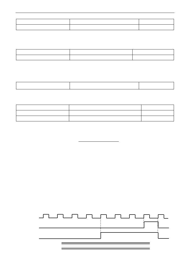
E3000
·66·
F308 Characteristic frequency 2
Mfr‟s value: 50Hz
F309 Characteristic frequency width
Setting range: 0~100%
Mfr‟s value: 50
When F300=2, 3, F301=2, 3 and F302=2, 3 and token characteristic frequency is selected, this group
function codes set characteristic frequency and its width. For example: setting F301=2, F307=10, F309=10,
when frequency is higher than F307, DO1 outputs ON signal. When frequency is lower than (10-10*10%)
=9Hz, DO1 outputs OFF signal.
F310 Characteristic current
Setting range: 0~1000A
Mfr‟s value: Rated current
F311 Characteristic current width
Setting range: 0~100%
Mfr‟s value: 10
When F300=17 and F301=17 and F302=17 and token characteristic current is selected, this group function
codes set characteristic current and its width.
For example: setting F301=17, F310=100, F311=10, when inverter current is higher than F310, DO1 outputs ON
signal. When inverter current is lower than (100-100*10%)=90A, DO1 outputs OFF signal.
F312 Frequency arrival threshold
Setting range: 0.00~5.00Hz
Mfr‟s value: 0.00
When F300=15 and F301=15, threshold range is set by F312.
For example: when F301=15, target frequency is 20HZ and F312=2, the running frequency reaches 18Hz
(20-2), ON signal is output by DO1 until the running frequency reaches target frequency.
·Count frequency divisions refer to the ratio of actual pulse input and inverter‟s count times, i.e.,
Inverter‟s Count Times =
e.g. when F313=3, inverter will count once for every 3 inputs of external pulse.
·Set count values refer to a count width pulse output by the output terminal (DO1 terminal or relay)
programmed with “reaching the set count values” function when a certain number of pulses are input
from OP1. Count will restart after the count value reaches “set times”.
As shown in Fig 5-6: if F313=1, F314=8, F301=8, DO1 will output an instruction signal when OP1
inputs the 8th pulse.
·Designated count values refer to an pulse output by the output terminal (DO1 or RELAY terminal)
programmed with “reaching the set count values” function when a certain number of pulses are input
from OP1, until count value reaches the “set times”.
As shown in Fig 5-6: if F313=1、F314=8,F315=5,F300=9, relay will output an instruction signal
when OP1 inputs the 5th pulse, relay will output an instruction signal until reaching “set count times 8”.
1 2 3 4 5 6 7 8 1
OP1 Input:
DO1:
Relay:
F313 Count frequency divisions
Setting range:1~65000
Mfr‟s value: 1
F314 Set count value
Setting range: F315~65000
Mfr‟s value: 1000
F315 Designated count value
Setting range: 1~F314
Mfr‟s value : 500
Fig 5-6 Set Count times & Designated Count Times
Count Frequency Division
Actual Pulse Input

E3000
·67·
5.3.2 Digital multifunctional input terminals
F316 OP1 terminal function setting
Setting range:
0: no function;
1: running terminal;
2: stop terminal;
3: multi-stage speed terminal 1;
4: multi-stage speed terminal 2;
5: multi-stage speed terminal 3;
6: multi-stage speed terminal 4;
7: reset terminal;
8: free stop terminal;
9: external emergency stop terminal;
10: acceleration/deceleration forbidden terminal;
11: forward run jogging;
12: reverse run jogging;
13: UP frequency increasing terminal;
14: DOWN frequency decreasing terminal;
15: “FWD” terminal;
16: “REV” terminal;
17: three-line type input “X” terminal;
18: acceleration/deceleration time switchover terminal;
19~20: Reserved;
21: frequency source switchover terminal;
22: Count input terminal:
23: Count reset terminal, clear actual yarn length
24: clear traverse status
25: Traverse operating mode is valid.
26: yarn broken 27: intertwining yarn
28: crawl-positioning signal
29: clear actual yarn length and traverse status
30: Water lack signal; 31: Signal of water
32: Fire pressure switchover;
33: Emergency fire control
Mfr‟s value: 11
F317 OP2 terminal function setting
Mfr‟s value: 9
F318 OP3 terminal function setting
Mfr‟s value: 15
F319 OP4 terminal function setting
Mfr‟s value: 16
F320 OP5 terminal function setting
Mfr‟s value: 7
F321 OP6 terminal function setting
Mfr‟s value: 8
F322 OP7 terminal function setting
Mfr‟s value: 1
F323 OP8 terminal function setting
Mfr‟s value: 2
·This parameter is used for setting the corresponding function for multifunctional digital input terminal.
·Both free stop and external emergency stop of the terminal have the highest priority.
·When pulse given is selected, OP1 terminal is set as pulse signal input terminal automatically.
Note: 15kW inverter and below 15kW has 6 multifunctional digital input terminals OP1~OP6.
Table 5-3 Instructions for digital multifunctional input terminal
Value
Function
Instructions
0
No function
Even if signal is input, inverter will not work. This function can be
set by undefined terminal to prevent mistake action.
1
Running terminal
When running command is given by terminal or terminals
combination and this terminal is valid, inverter will run. This
terminal has the same function with “run” key in keypad.
2
Stop terminal
When stop command is given by terminal or terminals combination
and this terminal is valid, inverter will stop. This terminal has the
same function with “stop” key in keypad.
3
Multistage speed terminal 1
15-stage speed is realized by combination of this group of
terminals. See table 5-4.
4
Multistage speed terminal 2
5
Multistage speed terminal 3

E3000
·68·
6
Multistage speed terminal 4
7
Reset terminal
This terminal has the same function with “reset” key in keypad.
Long-distance malfunction reset can be realized by this function.
8
Free stop terminal
Inverter closes off output and motor stop process is not controlled
by inverter. This mode is often used when load has big inertia or
there are no requirements for stop time. This mode has the same
function with free stop of F209.
9
External emergency
stop terminal
When external malfunction signal is given to inverter,
malfunction will occur and inverter will stop.
10
Acceleration/deceleration
forbidden terminal
Inverter will not be controlled by external signal (except for stop
command), and it will run at the current output frequency.
11
forward run jogging
Forward jogging running and reverse jogging running. Refer to
F124, F125 and F126 for jogging running frequency, jogging
acceleration/deceleration time.
12
reverse run jogging
13
UP frequency increasing
terminal
When frequency source is set by digital given, the setting
frequency can be adjusted which rate is set by F211.
14
DOWN frequency
decreasing terminal
15
“FWD” terminal
When start/stop command is given by terminal or terminals
combination, running direction of inverter is controlled by
external terminals.
16
“REV” terminal
17
Three-line input “X”
terminal
“FWD”、“REV”、“CM” terminals realize three-line control. See
F208 for details.
18
acceleration/deceleration
time switchover terminal
When this function is selected, second acceleration/deceleration
time is valid. See F116 and F117 for the second
acceleration/deceleration time.
19
Reserved
Reserved
20
Reserved
Reserved
21
frequency source
switchover terminal
When F207=2, main frequency source and accessorial frequency
source can be switched over by frequency source switching terminal.
When F207=3, X and (X + Y) can be switched over by frequency
source switching terminal.
22
Count input terminal
Built-in count pulse input terminal.
23
Count reset terminal
Reset terminal count value to zero.
24-29
Reserved
Reserved
30
Water lack signal
When PID control is valid and FA26=1, this function is valid.
While lack of water, inverter will be in the protection state.
31
Signal of water
When PID control is valid and FA26=1, this function is valid. If
water is enough, inverter will reset automatically.
32
Fire pressure switchover
When PID control is valid and this terminal is valid, the setting
value of PID switches into fire pressure given (FA58).
33
Emergency fire control
When emergency fire mode (FA59) is valid, inverter will be in
emergency fire mode.
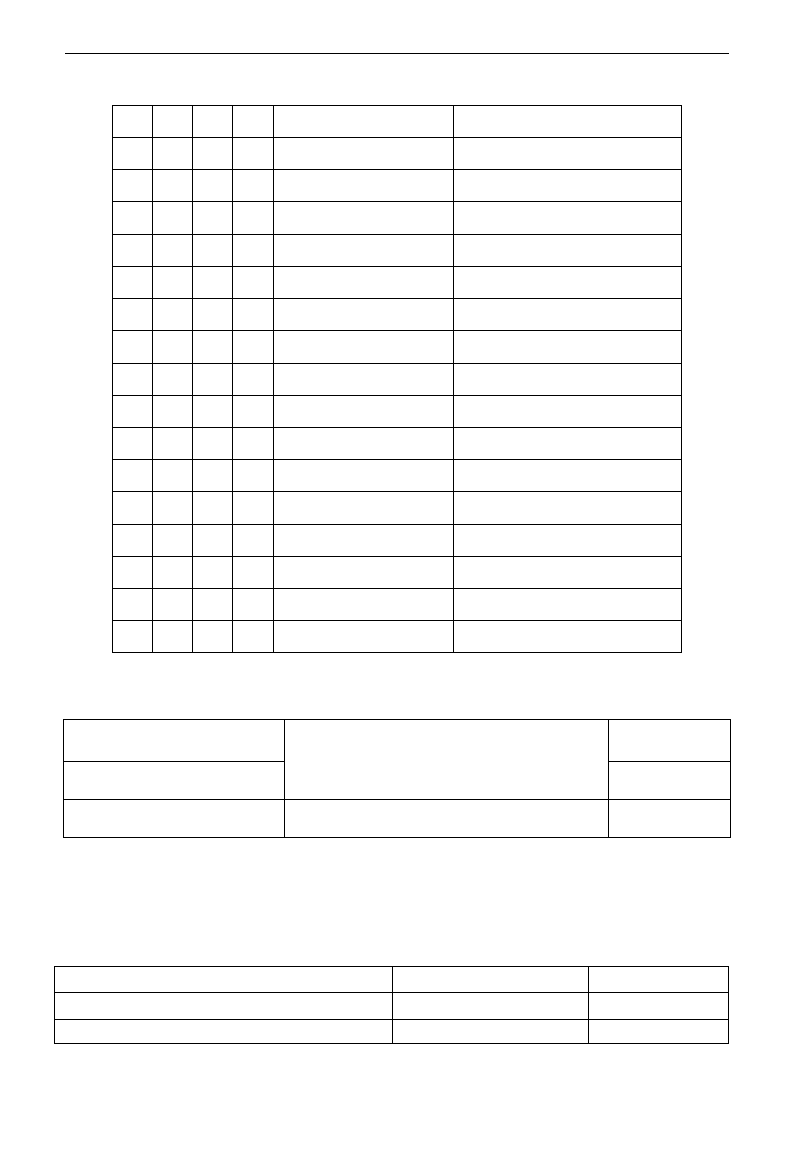
E3000
·69·
Table 5-4 Instructions for multistage speed
Note: 1. K4 is multi-stage speed terminal 4, K3 is multi-stage speed terminal 3, K2 is multi-stage speed
terminal 2, K1 is multi-stage speed terminal 1. And 0 stands for OFF, 1 stands for ON.
2. 0=OFF, 1=ON
F324 Free stop terminal logic
Setting range:
0: positive logic (valid for low level);
1: negative logic (valid for high level)
Mfr‟s value: 0
F325 External emergency stop
terminal logic
Mfr‟s value: 0
F328 Terminal filtering times
Setting range: 1~100
Mfr‟s value: 10
When multi-stage speed terminal is set to free stop terminal (8) and external emergency stop terminal (9),
terminal logic level is set by this group of function codes. When F324=0 and F325=0, positive logic and low
level is valid, when F324=1 and F325=1, negative logic and high level is valid.
5.4 Analog Input and Output
E3000 series inverters have 2 analog input channels and 2 analog output channels. AI3 input channel is
inside input channel for potentiometer on the keypad panel.
F400 Lower limit of AI1 channel input
Setting range: 0.00~F402
Mfr‟s value: 0.01V
F401 Corresponding setting for lower limit of AI1 input
Setting range: 0~F403
Mfr‟s value: 1.00
F402 Upper limit of AI1 channel input
Setting range: F400~10.00V
Mfr‟s value: 10.00V
K4
K3
K2
K1
Frequency setting
Parameters
0
0
0
0
None
None
0
0
0
1
Multi-stage speed 1
F504/F519/F534/F549/F557/F565
0
0
1
0
Multi-stage speed 2
F505/F520/F535/F550/F558/F566
0
0
1
1
Multi-stage speed 3
F506/F521/F536/F551/F559/F567
0
1
0
0
Multi-stage speed 4
F507/F522/F537/F552/F560/F568
0
1
0
1
Multi-stage speed 5
F508/F523/F538/F553/F561/F569
0
1
1
0
Multi-stage speed 6
F509/F524/F539/F554/F562/F570
0
1
1
1
Multi-stage speed 7
F510/F525/F540/F555/F563/F571
1
0
0
0
Multi-stage speed 8
F511/F526/F541/F556/F564/F572
1
0
0
1
Multi-stage speed 9
F512/F527/F542/F573
1
0
1
0
Multi-stage speed 10
F513/F528/F543/F574
1
0
1
1
Multi-stage speed 11
F514/F529/F544/F575
1
1
0
0
Multi-stage speed 12
F515/F530/F545/F576
1
1
0
1
Multi-stage speed 13
F516/F531/F546/F577
1
1
1
0
Multi-stage speed 14
F517/F532/F547/F578
1
1
1
1
Multi-stage speed 15
F518/F533/F548/F579
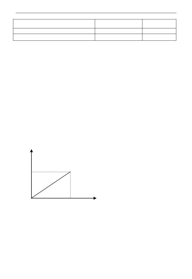
E3000
·70·
F403 Corresponding setting for upper limit of AI1 input
Setting range:
Max (1.00,F401) ~2.00
Mfr‟s value: 2.00
F404 AI1 channel proportional gain K1
Setting range: 0.0~10.0
Mfr‟s value: 1.0
F405 AI1 filtering time constant
Setting range: 0.1~10.0
Mfr‟s value: 0.10
·In the mode of analog speed control, sometimes it requires adjusting coincidence relation among upper limit
and lower limit of input analog, analog changes and output frequency, to achieve a satisfactory speed control
effect.
· Upper and lower limit of analog input are set by F400 and F402.
For example: when F400=1, F402=8, if analog input voltage is lower than 1V, system judges it as 0. If input
voltage is higher than 8V, system judges it as 10V (Suppose analog channel selects 0-10V). If Max
frequency F111 is set to 50Hz, the output frequency corresponding to 1-8V is 0-50Hz.
· The filtering time constant is set by F405.
The greater the filtering time constant is, the more stable for the analog testing. However, the precision may
decrease to a certain extent. It may require appropriate adjustment according to actual application.
· Channel proportional gain is set by F404.
If 1V corresponds to 10Hz and F404=2, then 1V will correspond to 20Hz.
· Corresponding setting for upper / lower limit of analog input are set by F401 and F403.
If Max frequency F111 is 50Hz, analog input voltage 0-10V can correspond to output frequency from -50Hz
to 50Hz by setting this group function codes. Please set F401=0 and F403=2, then 0V corresponds to -50Hz,
5V corresponds to 0Hz and 10V corresponds to 50Hz. The unit of corresponding setting for upper / lower
limit of input is in percentage (%). If the value is greater than 1.00, it is positive; if the value is less than 1.00,
it is negative. (e.g. F401=0.5 represents –50%).
If the running direction is set to forward running by F202, then 0-5V corresponding to the minus frequency
will cause reverse running, or vice versa.
100.0%
0.0%
0V
(0mA)
Corresponding setting
(Frequency)
AI
10V
(20mA)
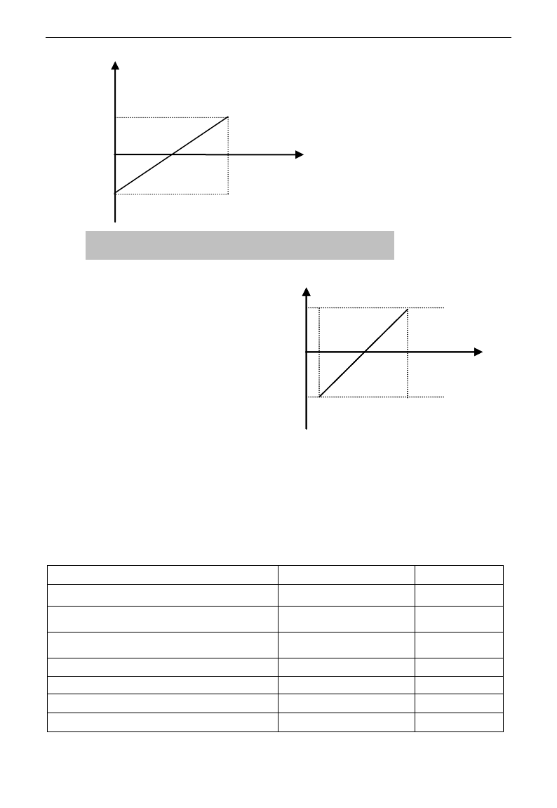
E3000
·71·
The unit of corresponding setting for upper /
lower limit of input is in percentage (%). If the
value is greater than 1.00, it is positive; if the
value is less than 1.00, it is negative. (e.g.
F401=0.5 represents –50%).The corresponding
setting benchmark: in the mode of combined
speed control, analog is the accessorial
frequency and the setting benchmark for range
of accessorial frequency which relatives to main
frequency is “main frequency X”; corresponding
setting benchmark for other cases is the “max
frequency”, as illustrated in the right figure:
A= (F401-1)* setting value
B= (F403-1)* setting value
C= F400
D= F402
F406 Lower limit of AI2 channel input
Setting range: 0.00~F408
Mfr‟s value: 0.01V
F407 Corresponding setting for lower limit of AI2 input
Setting range: 0~F409
Mfr‟s value: 1.00
F408 Upper limit of AI2 channel input
Setting range: F406~10.00V
Mfr‟s value:
10.00V
F409 Corresponding setting for upper limit of AI2 input
Setting range:
Max (1.00,F407) ~2.00
Mfr‟s value: 2.00
F410 AI2 channel proportional gain K2
Setting range: 0.0~10.0
Mfr‟s value: 1.0
F411 AI2 filtering time constant
Setting range: 0.1~50.0
Mfr‟s value: 0.1
F412 Lower limit of AI3 channel input (V)
Setting range: 0.00~F414
Mfr‟s value: 0.05
F413 Corresponding setting for lower limit of AI3 input
Setting range: 0~F415
Mfr‟s value: 1.00
100.0%
-100.0%
0V
(0mA)
AI
Corresponding setting
(Frequency)
10V
(20mA)
Fig 5-6 correspondence of analog input to setting
AI1
B
A
D
C
AI1
B
A
D
C

E3000
·72·
F414 Upper limit of AI3 channel input
Setting range: F412~10.0V
Mfr‟s value: 10.0V
F415 Corresponding setting for upper limit of AI3 input
Setting range:
Max (1.00,F413) ~2.00
Mfr‟s value: 2.00
F416 AI3 channel proportional gain K1
Setting range: 0.0~10.0
Mfr‟s value: 1.0
F417 AI3 filtering time constant
Setting range: 0.1~10.0
Mfr‟s value: 0.10
The function of AI2 and AI3 is the same with AI1.
F418 AI1 channel 0Hz voltage dead zone
Setting range:
0~0.50V (Positive-Negative)
Mfr‟s value: 0.00
F419 AI2 channel 0Hz voltage dead zone
Setting range:
0~0.50V (Positive-Negative)
Mfr‟s value: 0.00
F420 AI3 channel 0Hz voltage dead zone
Setting range:
0~0.50V (Positive-Negative)
Mfr‟s value: 0.00
Analog input voltage 0-5V can correspond to output frequency -50Hz-50Hz (2.5V corresponds to 0Hz) by
setting the function of corresponding setting for upper / lower limit of analog input. The group function codes of
F418, F419 and F420 set the voltage range corresponding to 0Hz. For example, when F418=0.5, F419=0.5 and
F420=0.5, the voltage range from (2.5-0.5=2) to (2.5+0.5=3) corresponds to 0Hz. So if F418=N, F419=N and
F420=N, then 2.5±N should correspond to 0Hz. If the voltage is in this range, inverter will output 0Hz.
0HZ voltage dead zone will be valid when corresponding setting for lower limit of input is less than 1.00.
E3000 series inverters have two analog output channels.
The panel selection and potentiometer selection for 15kW and below 15kW inverters is as following:
·When F421 is set to 0, local keypad panel is working. When F421 is set to 1, remote control keypad panel is
working, and local keypad panel will be invalid for saving energy.
·F422 is used to select potentiometer.
If F421=1, local keypad panel is valid, so even if F422=0, the potentiometer in remote control panel does
not work.
When F160 is set to 1, the values of F421 and F422 can not be reverted to Mfr‟s values.
The remote control panel is connected by 8-cores net cable.
The greater the setting value of F437 is, the steadier the detecting analog is, but the response speed will
decrease. Please set it according to the actual situations.
F460 AI1channel input mode
Setting range: 0: straight line mode
1: folding line mode
Mfr‟s value: 0
F461 AI2 channel input mode
Setting range: 0: straight line mode
1: folding line mode
Mfr‟s value: 0
F462 AI1 insertion point A1 voltage value
Setting range: F400~F464
Mfr‟s value: 2.00V
F463 AI1 insertion point A1 setting value
Setting range: F401~F465
Mfr‟s value: 1.20
F464 AI1 insertion point A2 voltage value
Setting range: F462~F466
Mfr‟s value: 5.00V
F465 AI1 insertion point A2 setting value
Setting range: F463~F467
Mfr‟s value: 1.50
F466 AI1 insertion point A3 voltage value
Setting range: F464~F402
Mfr‟s value: 8.00V
F467 AI1 insertion point A3 setting value
Setting range: F465~F403
Mfr‟s value: 1.80
F421 Panel selection
Setting range: 0: Local keypad panel
1: Remote control keypad panel
Mfr‟s value: 0
F422 Potentiometer selection
Setting range: 0: Potentiometer in local panel
1: Potentiometer in remote control panel
Mfr‟s value: 0
F437 Analog filter width
Setting range: 1~100
Mfr‟s value:10

E3000
·73·
F468 AI2 insertion point B1 voltage value
Setting range: F406~F470
Mfr‟s value: 2.00V
F469 AI2 insertion point B1 setting value
Setting range: F407~F471
Mfr‟s value: 1.20
F470 AI2 insertion point B2 voltage value
Setting range: F468~F472
Mfr‟s value: 5.00V
F471 AI2 insertion point B2 setting value
Setting range: F469~F473
Mfr‟s value: 1.50
F472 AI2 insertion point B3 voltage value
Setting range: F470~F412
Mfr‟s value: 8.00V
F473 AI2 insertion point B3 setting value
Setting range: F471~F413
Mfr‟s value: 1.80
E3000 can supply two analog output channels AO1, AO2.
F423 AO1 output range selecting
Setting range:
0: 0~5V; 1: 0~10V or 0~20mA
2: 4~20mA
Mfr‟s value: 1
F424 AO1 lowest corresponding frequency
Setting range: 0.0~F425
Mfr‟s value: 0.05Hz
F425 AO1 highest corresponding frequency
Setting range: F424~F111
Mfr‟s value: 50.00Hz
F426 AO1 output compensation
Setting range: 0~120%
Mfr‟s value: 100
· AO1 output range is selected by F423. When F423=0, AO1 output range selects 0-5V, and when F423=1,
AO1 output range selects 0-10V or 0-20mA. When F423=2, AO1 output range selects 4-20mA (When AO1
output range selects current signal, please turn the switch J5 to “I” position, below 15kW and 15kW
inverters do not have this function)
· Correspondence of output voltage range (0-5V or 0-10V) to output frequency is set by F424 and F425. For
example, when F423=0, F424=10 and F425=120, analog channel AO1 outputs 0-5V and the output
frequency is 10-120Hz.
· AO1 output compensation is set by F426. Analog excursion can be compensated by setting F426.
F427 AO2 output range
Setting range:
0: 0~20mA; 1: 4~20 mA
Mfr‟s value: 0
F428 AO2 lowest corresponding frequency
Setting range: 0.0~F429
Mfr‟s value: 0.05Hz
F429 AO2 highest corresponding frequency
Setting range: F428~F111
Mfr‟s value: 50.00
F430 AO2 output compensation
Setting range: 0~120%
Mfr‟s value: 100
The function of AO2 is the same as AO1, but AO2 will output current signal, current signal of 0-20mA and
4-20mA could be selected by F427.
F431 AO1 analog output signal selecting
Setting range:
0: Running frequency;
1: Output current;
2: Output voltage;
3~5: Reserved
Mfr‟s value: 0
F432 AO2 analog output signal selecting
Mfr‟s value: 1
· Token contents output by analog channel are selected by F431 and F432. Token contents include running
frequency, output current and output voltage.
· During the process of speed track, the function of F431 and F432 is still valid.
· When output current is selected, analog output signal is from 0 to twofold rated current.
· When output voltage is selected, analog output signal is from 0V to rated output voltage (230V or 400V).
F433 Corresponding current for full range of external voltmeter
Setting range:
0.01~5.00 times of
rated current
Mfr‟s value: 2.00
F434 Corresponding current for full range of external ammeter
Mfr‟s value: 2.00
· In case of F431=1 and AO1 channel for token current, F433 is the ratio of measurement range of external
voltage type ammeter to rated current of the inverter.
· In case of F432=1 and AO2 channel for token current, F434 is the ratio of measurement range of external
current type ammeter to rated current of the inverter.
For example: measurement range of external ammeter is 20A, and rated current of the inverter is 8A, then,
F433=20/8=2.50.
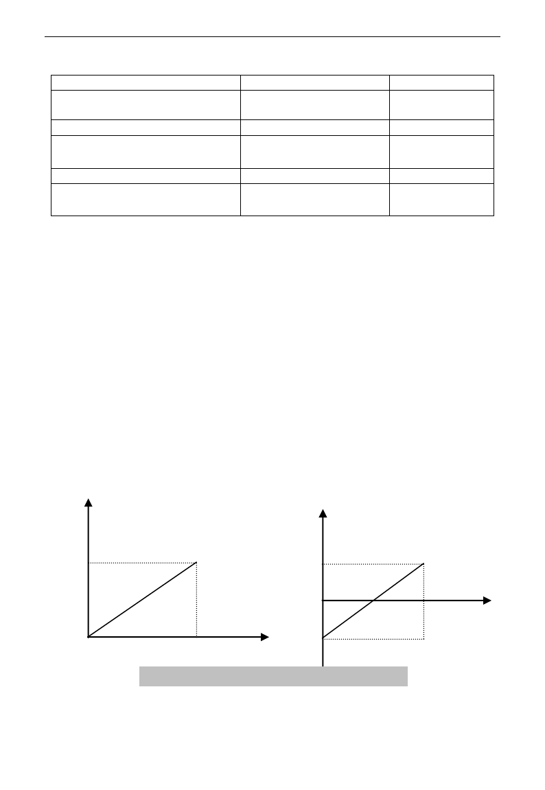
E3000
·74·
5.5 Pulse input/output
F440 Min frequency of input pulse FI
Setting range: 0.00~F442
Mfr‟s value: 0.00K
F441 Corresponding setting of FI min
frequency
Setting range:0.00~2.00
Mfr‟s value: 1.00
F442 Max frequency of input pulse FI
Setting range: F440~50.00K
Mfr‟s value: 10.00K
F443 Corresponding setting of FI max
frequency
Setting range: Max (1.00 ,
F441)~2.00
Mfr‟s value: 2.00
F445 Filtering constant of FI input pulse
Setting range: 0~100
Mfr‟s value: 0
F446 FI channel 0Hz frequency dead zone
Setting range: 0~F442
(Positive-Negative)
Mfr‟s value: 0.00
·Min frequency of input pulse is set by F440 and max frequency of input pulse is set by F442.
For example: when F440=0K and F442=10K, and the max frequency is set to 50Hz, then input pulse
frequency 0-10K corresponds to output frequency 0-50Hz.
·Filtering time constant of input pulse is set by F445.
The greater the filtering time constant is, the more steady pulse measurement, but precision will be lower, so
please adjust it according to the application situation.
·Corresponding setting of min frequency is set by F441 and corresponding setting of max frequency is set by
F443.
When the max frequency is set to 50Hz, pulse input 0-10K can corresponds to output frequency -50Hz-50Hz
by setting this group function codes. Please set F441 to 0 and F443 to 2, then 0K corresponds to -50Hz, 5K
corresponds to 0Hz, and 10K corresponds to 50Hz. The unit of corresponding setting for max/min pulse
frequency is in percentage (%). If the value is greater than 1.00, it is positive; if the value is less than 1.00, it
is negative.
If the running direction is set to forward running by F202, then 0-5K corresponding to the minus frequency
will cause reverse running, or vice versa.
· 0 Hz frequency dead zone is set by F446.
Input pulse 0-10K can correspond to output frequency -50Hz~50Hz (5K corresponds to 0Hz) by setting the
function of corresponding setting for max/min input pulse frequency. The function code F446 sets the input pulse
range corresponding to 0Hz. For example, when F446=0.5, the pulse range from (5K-0.5K=4.5K) to
(5K+0.5K=5.5K) corresponds to 0Hz. So if F446=N, then 5±N should correspond to 0Hz. If the pulse is in this
range, inverter will output 0Hz.
0HZ voltage dead zone will be valid when corresponding setting for min pulse frequency is less than 1.00.
The unit of corresponding setting for max/min input pulse frequency is in percentage (%). If the value is
greater than 1.00, it is positive; if the value is less than 1.00, it is negative. (e.g. F441=0.5 represents
0.0%
100.0%
0K
Corresponding setting
(frequency)
FI
10K
Corresponding setting
(frequency)
100.0%
-100.0%
0K
FI
10K
Fig 5-9 correspondence of pulse input and setting
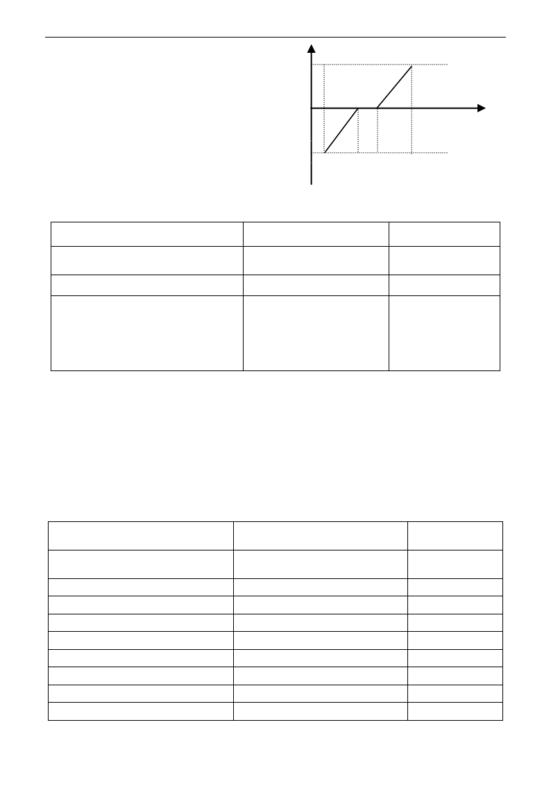
E3000
·75·
–50%).The corresponding setting benchmark: in the
mode of combined speed control, pulse input is the
accessorial frequency and the setting benchmark for
range of accessorial frequency which relatives to main
frequency (F205=1) is “main frequency X”;
corresponding setting benchmark for other cases is the
“max frequency”, as illustrated in the right figure:
A=(F441-1)*setting benchmark
B=(F443-1)*setting benchmark
C= F440
F= F442
(E-D)/2=F446
F449 Max frequency of output pulse FO
Setting range: 0.00~50.00K
Mfr‟s value: 10.00K
F450 Zero bias coefficient of output pulse
frequency
Setting range: 0.0~100.0%
Mfr‟s value: 0.0%
F451 Frequency gain of output pulse
Setting range: 0.00~10.00
Mfr‟s value: 1.00
F453 Output pulse signal
Setting range:
0: Running frequency
1: Output current
2: Output voltage
3~5: reserved
Mfr‟s value: 0
· When DO1 is defined as high-speed pulse output terminal, the max frequency of output pulse is set
byF449.
If “b” stands for zero bias coefficient, “k” stands for gain, “Y” stands for actual output of pulse frequency
and “X” stands for standard output, then Y=Kx+b.
·Standard output X is the token value corresponding to output pulse min/max frequency, which range is from
zero to max value.
·100 percent of zero bias coefficient of output pulse frequency corresponds to the max output pulse
frequency (the set value of F449.)
·Frequency gain of output pulse is set by F451. User can set it to compensate the deviation of output pulse.
·Output pulse token object is set by F453. For example: running frequency, output current and output voltage, etc.
·When output current is displayed, the range of token output is 0-2 times of rated current.
·When output voltage is displayed, the range of token output is from 0-1.2 times of rated output voltage.
F460 AI1channel input mode
Setting range: 0: straight line mode
1: folding line mode
Mfr‟s value: 0
F461 AI2 channel input mode
Setting range: 0: straight line mode
1: folding line mode
Mfr‟s value: 0
F462 AI1 insertion point A1 voltage value
Setting range: F400~F464
Mfr‟s value: 2.00V
F463 AI1 insertion point A1 setting value
Setting range: F401~F465
Mfr‟s value: 1.20
F464 AI1 insertion point A2 voltage value
Setting range: F462~F466
Mfr‟s value: 5.00V
F465 AI1 insertion point A2 setting value
Setting range: F463~F467
Mfr‟s value: 1.50
F466 AI1 insertion point A3 voltage value
Setting range: F464~F402
Mfr‟s value: 8.00V
F467 AI1 insertion point A3 setting value
Setting range: F465~F403
Mfr‟s value: 1.80
F468 AI2 insertion point B1 voltage value
Setting range: F406~F470
Mfr‟s value: 2.00V
F469 AI2 insertion point B1 setting value
Setting range: F407~F471
Mfr‟s value: 1.20
FI
B
A
F
C
D
E
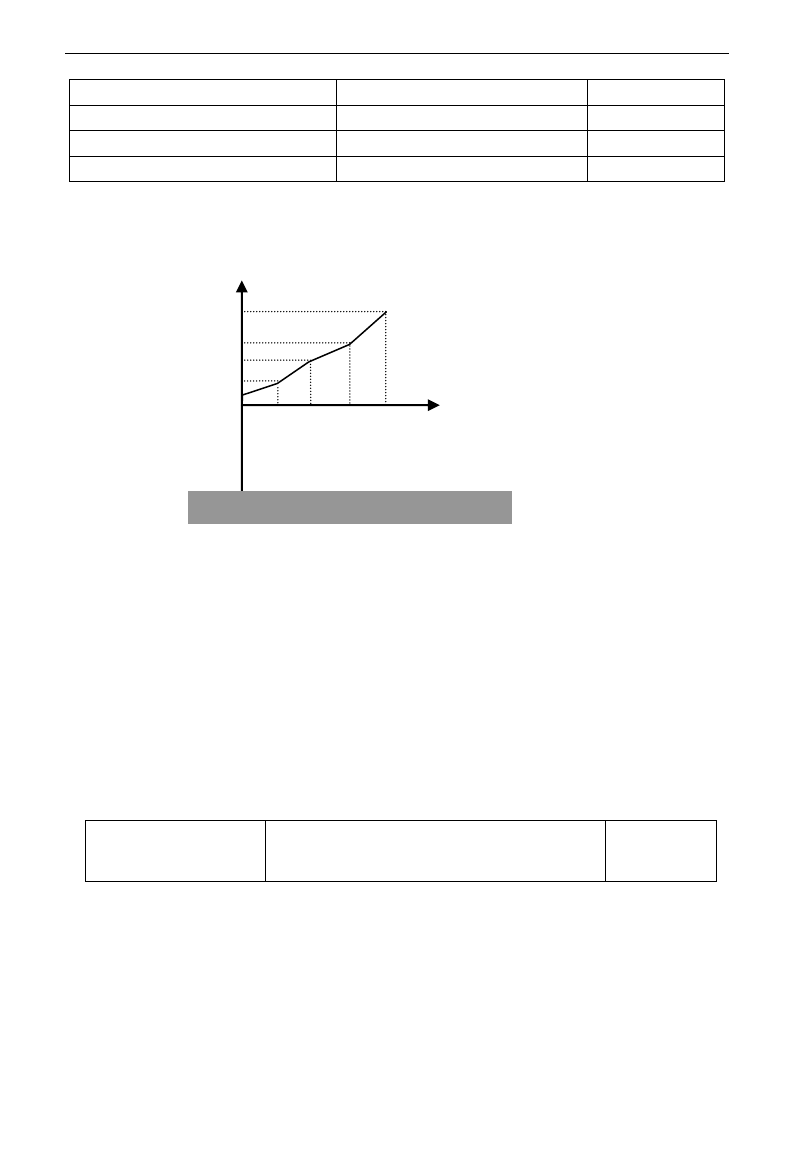
E3000
·76·
F470 AI2 insertion point B2 voltage value
Setting range: F468~F472
Mfr‟s value: 5.00V
F471 AI2 insertion point B2 setting value
Setting range: F469~F473
Mfr‟s value: 1.50
F472 AI2 insertion point B3 voltage value
Setting range: F470~F412
Mfr‟s value: 8.00V
F473 AI2 insertion point B3 setting value
Setting range: F471~F413
Mfr‟s value: 1.80
When analog channel input mode selects straight-line, please set it according to the parameters from F400 to
F429. When folding line mode is selected, three points A1(B1), A2(B2), A3(B3) are inserted into the
straight line, each of which can set the according frequency to input voltage. Please refer to the following
figure:
F400 and F402 are lower/upper limit of analog AI1 input. When F460=1,F462=2.00V, F463=1.4, F111=50,
F203=1, F207=0, then A1 point corresponding frequency is (F463-1)*F111=20Hz, which means 2.00V
corresponding to 20Hz. The other points can be set by the same way.
AI2 channel has the same setting way as AI1.
5.6 Multi-stage Speed Control
The function of multi-stage speed control is equivalent to a built-in PLC in the inverter. This function can set
running time, running direction and running frequency.
E3000 series inverter can realize 15-stage speed control and 8-stage speed auto circulating.
During the process of speed track, multi-stage speed control is invalid. After speed track is finished, inverter
will run to target frequency according to the setting value of parameters.
F500 Stage speed type
Setting range: 0: 3-stage speed;
1: 15-stage speed;
2: Max 8-stage speed auto circulating
Mfr‟s value: 1
·In case of multi-stage speed control (F203=4), the user must select a mode by F500. When F500=0, 3-stage
speed is selected. When F500=1, 15-stage speed is selected. When F500=2, max 8-stage speed auto
circulating is selected. When F500=2, “auto circulating” is classified into “2-stage speed auto circulating”,
“3-stage speed auto circulating”, … “8-stage speed auto circulating”, which is to be set by F501.
100%
A1 A2 A3 F402
F400
AI1
According setting (frequency)
Fig 5-9 Folding analog with setting value
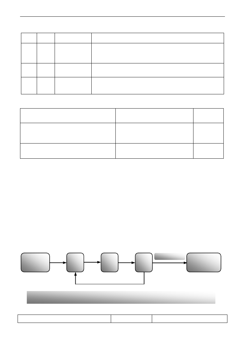
E3000
·77·
Table 5-5 Selection of Stage Speed Running Mode
F203
F500
Mode of Running
Description
4
0
3-stage speed
control
The priority in turn is stage-1 speed, stage-2 speed and stage-3 speed.
It can be combined with analog speed control. If F207=4, “3-stage
speed control” is prior to analog speed control.
4
1
15-stage speed
control
It can be combined with analog speed control. If F207=4, “15-stage
speed control” is prior to analog speed control.
4
2
Max 8-stage speed
auto circulating
Adjusting the running frequency manually is not allowable. “2-stage
speed auto circulating”, “3-stage speed auto circulating”, … “8-stage
speed auto circulating” may be selected through setting the parameters.
F501 Selection of Stage Speed Under
Auto-circulation Speed Control
Setting range: 2~8
Mfr‟s value: 7
F502 Selection of Times of Auto-circulation
Speed Control
Setting range: 0~9999
(when the value is set to 0, the inverter
will carry out infinite circulating)
Mfr‟s value: 0
F503 Status After Auto-circulation
Running Finished.
Setting range:
0: Stop 1: Keep running at last-stage speed
Mfr‟s value: 0
· If running mode is auto-circulation speed control (F203=4 and F500=2), please set the related parameters
by F501~F503.
· That the inverter runs at the preset stage speed one by one under the auto-circulation speed control is called
as “one time”.
· If F502=0, inverter will run at infinite auto circulation, which will be stopped by “stop” signal.
· If F502>0, inverter will run at auto circulation conditionally. When auto circulation of the preset times is
finished continuously (set by F502), inverter will finish auto-circulation running conditionally. When
inverter keeps running and the preset times is not finished, if inverter receives “stop command”, inverter will
stop. If inverter receives “run command” again, inverter will automatically circulate by the setting time of
F502.
· If F503=0, then inverter will stop after auto circulation is finished. If F503=1, then inverter will run at the
speed of the last-stage after auto-circulation is finished as follows:
e.g., F501=3, then inverter will run at auto circulation of 3-stage speed;
F502=100, then inverter will run 100 times of auto circulation;
F503=1, inverter will run at the speed of the last stage after the auto-circulation running is finished.
Then the inverter can be stopped by pressing “stop” or sending “stop” signal through terminal during
auto-circulation running.
F504 Frequency setting for stage 1 speed
Setting range:
Mfr‟s value: 5.00Hz
Start auto
circulating running
Stage-1
speed
Stage-2
speed
Stage-3
speed
After circulating
100 times
Keep running at
Stage-3 speed
Figure 5-11 Auto-circulating Running

E3000
·78·
F505 Frequency setting for stage 2 speed
F112~F111
Mfr‟s value: 10.00Hz
F506 Frequency setting for stage 3 speed
Mfr‟s value: 15.00Hz
F507 Frequency setting for stage 4 speed
Mfr‟s value: 20.00Hz
F508 Frequency setting for stage 5 speed
Mfr‟s value: 25.00Hz
F509 Frequency setting for stage 6 speed
Mfr‟s value: 30.00Hz
F510 Frequency setting for stage 7 speed
Mfr‟s value: 35.00Hz
F511 Frequency setting for stage 8 speed
Mfr‟s value: 40.00Hz
F512 Frequency setting for stage 9 speed
Mfr‟s value: 5.00Hz
F513 Frequency setting for stage 10 speed
Mfr‟s value: 10.00Hz
F514 Frequency setting for stage 11 speed
Mfr‟s value: 15.00Hz
F515 Frequency setting for stage 12 speed
Mfr‟s value: 20.00Hz
F516 Frequency setting for stage 13 speed
Mfr‟s value: 25.00Hz
F517 Frequency setting for stage 14 speed
Mfr‟s value: 30.00Hz
F518 Frequency setting for stage 15 speed
Mfr‟s value: 35.00Hz
F519~F533 Acceleration time setting for the
speeds from Stage 1 to Stage 15
Setting range:
0.1~3000S
Mfr‟s value:
0.2-4.0kW: 5.0S
5.5-30kW: 30.0S
Above 37kW: 60.0S
F534~F548 Deceleration time setting for the
speeds from Stage 1 to Stage 15
Setting range:
0.1~3000S
F549~F556
Running directions of stage speeds from Stage 1
to Stage 8
Setting range:
0: forward running;
1: reverse running
Mfr‟s value: 0
F573~F579
Running directions of stage speeds from stage 9
to stage 15
Setting range:
0: forward running;
1: reverse running
Mfr‟s value: 0
F557~564 Running time of stage speeds
from Stage 1 to Stage 8
Setting range:
0.1~3000S
Mfr‟s value: 1.0S
F565~F572 Stop time after finishing stages
from Stage 1 to Stage 8
Setting range:
0.0~3000S
Mfr‟s value: 0.0S
5.7 Auxiliary Functions
F600 DC Braking Function Selection
Setting range:
0: Invalid;
1: braking before starting;
2: braking during stopping;
3: braking during starting and stopping
Mfr‟s value: 0
F601 Initial Frequency for DC Braking
Setting range: 0.20~5.00
Mfr‟s value: 1.00
F602 DC Braking efficiency before Starting
Setting range: 0~100
Mfr‟s value: 10
F603 DC Braking efficiency During Stop
F604 Braking Lasting Time Before Starting
Setting range: 0.0~10.0
Mfr‟s value: 0.5
F605 Braking Lasting Time During Stopping
F606 DC braking mode selection
0: Braking by voltage
1: Braking by current
2: Auto braking by voltage
Mfr‟s value: 0
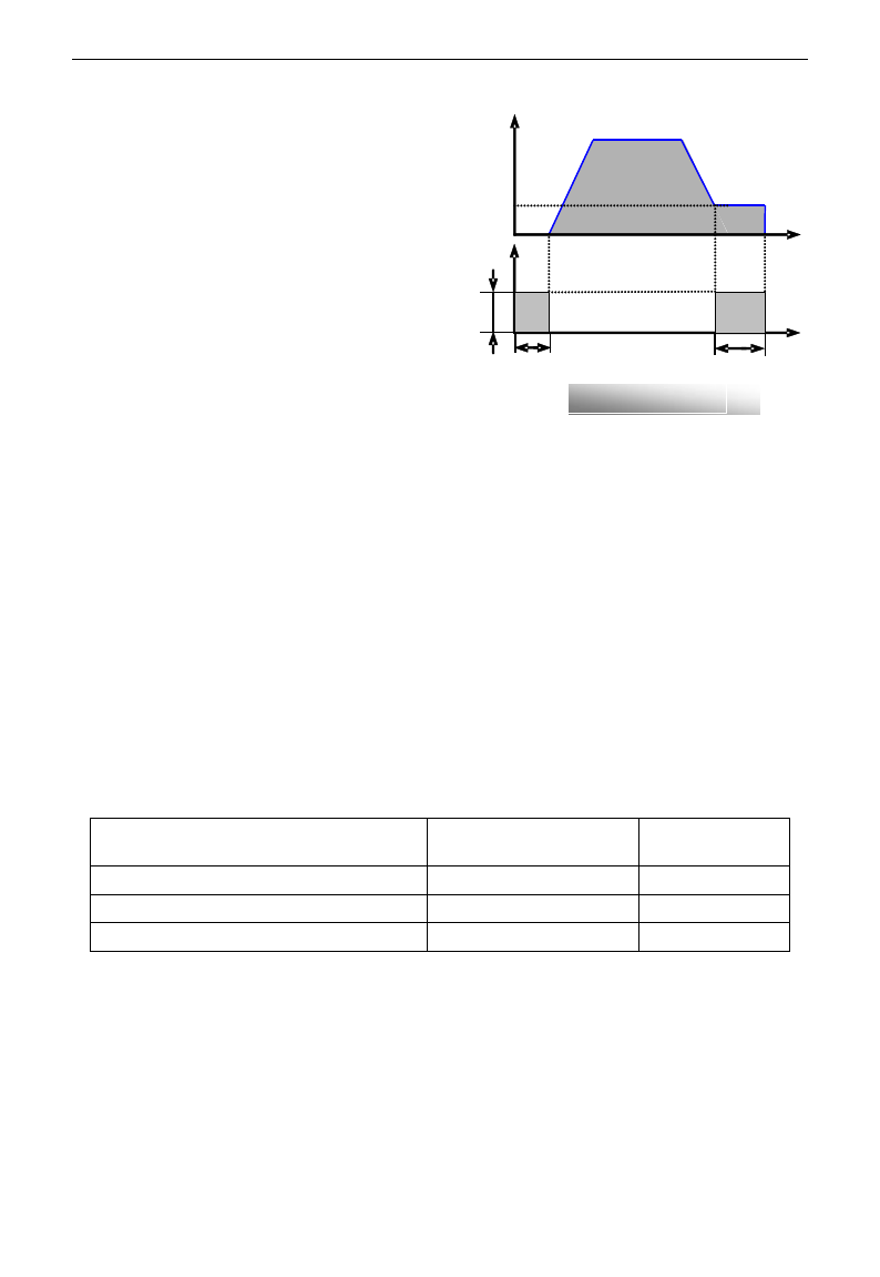
E3000
·79·
· When F600=0, DC braking function is invalid.
· When F600=1, braking before starting is valid.
After the right starting signal is input, inverter
starts DC braking. After braking is finished,
inverter will run from the initial frequency.
In some application occasion, such as fan,
motor is running at a low speed or in a reverse
status, if inverter starts immediately, OC
malfunction will occur. Adopting “braking
before starting” will ensure that the fan stays
in a static state before starting to avoid this
malfunction.
·During braking before starting, if “stop” signal
is given, inverter will stop by deceleration time.
When F600=2, DC braking during stopping is
selected. After output frequency is lower than
the initial frequency for DC braking (F601), DC braking will stop the motor immediately
During the process of braking during stopping, if “start” signal is given, DC braking will be finished and
inverter will start.
If “stop” signal is given during the process of braking during stopping, inverter will have no response and
DC braking during stopping still goes on.
· When jogging function is valid, the function of braking before starting set by F600 is valid, and the
function of speed track is invalid.
· When jogging function is invalid and F613-1, the function of braking before starting is invalid.
· Parameters related to “DC Braking”: F601, F602, F603, F604, F605 and F606, interpreted as follows:
a. F601: Initial frequency of DC-braking. DC braking will start to work as inverter‟s output
frequency is lower than this value.
b. F602/F603: DC braking efficiency (When F606=0, the unit is V. When F606=1, the unit is the
percentage of rated current). The bigger value will result in a quick braking. However, motor
will overheat with too big value.
c. F604: Braking duration before starting. The time lasted for DC braking before inverter starts.
d. F605: Braking duration when stopping. The time lasted for DC braking while inverter stops.
·DC braking, as shown in Figure 5-9
Note: during DC braking, because motor does not have self-cold effect cause by rotating, it is in the state of
easy over-heat. Please do not set DC braking voltage too high and do not set DC braking time to long.
F607 Selection of Stalling Adjusting Function
Setting range:
0: invalid; 1: valid
Mfr‟s value: 0
F608 Stalling Current Adjusting (%)
Setting range: 60~200
Mfr‟s value: 160
F609 Stalling Voltage Adjusting (%)
Setting range: 60~200
Mfr‟s value: 140
F610 Stalling Protection Judging Time
Setting range: 0.1~3000.0
Mfr‟s value: 5.0
Initial value of stalling current adjusting is set by F608, when the present current is higher than rated current
*F608, stalling current adjusting function is valid.
During the process of deceleration, stalling current function is invalid.
During the process of acceleration, if output current is higher than initial value of stalling current adjusting
and F607=1, then stalling adjusting function is valid. Inverter will not accelerate until the output current is
lower than initial value of stalling current adjusting.
In case of stalling during stable speed running, the frequency will drop. If the current returns to normal
during dropping, the frequency will return to rise. Otherwise, the frequency will keep dropping to the
minimum frequency and the protection OL1 will occur after it lasts for the time as set in F610.
Figure 5-12 DC braking
t
V/A
F604
F602
F605
t
Hz
F601

E3000
·80·
Initial value of stalling voltage adjusting is set by F609, when the present voltage is higher than rated
voltage *F609, stalling voltage adjusting function is valid.
Stalling voltage adjusting is valid during the process of deceleration, including the deceleration process
caused by stalling current.
Over-voltage means the DC bus voltage is too high and it is usually caused by decelerating. During the
process of deceleration, DC bus voltage will increase because of energy feedback. When DC bus voltage is
higher than the initial value of stalling voltage and F607=1, then stalling adjusting function is valid. Inverter
will temporarily stop decelerating and keep output frequency constant, then inverter stops energy feedback.
Inverter will not decelerate until DC bus voltage is lower than the initial value of stalling voltage.
Stalling protection judging time is set by F610. When inverter starts stalling adjusting function and
continues the setting time of F610, inverter will stop running and OL1 protection occurs.
F611 Dynamic Braking threshold
Setting range: 200~1000
Mfr‟s value: Three-phase 700V
Single-phase 380V
F612 Dynamic braking duty ratio (%)
Setting range: 0~100%
Mfr‟s value: 80
Initial voltage of dynamic braking threshold is set by F611, which of unit is V. When DC bus voltage is
higher than the setting value of this function, dynamic braking starts, braking unit starts working. After DC
bus voltage is lower than the setting value, braking unit stops working.
Dynamic braking duty ratio is set by F612, the range is 0~100%. The value is higher, the braking effect is
better, but the braking resistor will get hot.
When F613=0, the function of speed track is invalid.
When F613=1, the function of speed track is valid.
After inverter tracks motor speed and rotating direction, inverter will begin running according to the tracked
frequency, to start the rotating motor smoothly. This function is suitable for the situation of auto-starting
after re-powered on, auto-starting after reset, auto-starting when running command valid but direction signal
lost and auto-starting when running command invalid.
When F613=2, the function is valid at the first time after inverter is re-powered on.
Note: When F106=0, speed track function is invalid.
F614 Speed track mode
Setting range:
0: Speed track from frequency memory
1: Speed track from max frequency
2: Speed track from frequency memory and direction memory
3: Speed track from max frequency and direction memory
Mfr‟s value: 0
When F614 is set to 0 or 1, if memory frequency or max frequency is lower than 10.00Hz, inverter will track
speed from 10.00Hz.
If inverter is powered down, inverter will remember valid target frequency. For the other situations (inverter
has no output before stop), inverter will remember instant frequency before it stops.
This parameter is used for starting and stopping a motor with high inertia. A motor with high inertia will
take a long time to stop completely. By setting this parameter, the user does not need to wait for the motor to
come to a complete stop before restarting the AC motor drive.
F615 Speed track rate
Setting range: 1~100
Mfr‟s value: 20
It is used to select the rotation velocity speed track when the rotation tracking restart mode is adopted. The
larger the parameter is, the faster the speed track is. But if this parameter is too large, it likely results in
unreliable tracking,
F613 Speed track
Setting range: 0: invalid 1: valid
2: valid at the first time
Mfr‟s value: 0

E3000
·81·
When F622=0, fixed duty ratio is valid. When bus-line voltage reaches energy consumption brake point set
by F611, braking module will start dynamic braking according to F612.
When F622=1, auto duty ratio is valid. When bul-line voltage reaches dynamic braking threshold set by
F611, braking module will start dynamic braking according to duty ratio which is adjusted by the bus-line
voltage. The higher bus-line voltage is, the greater duty ratio is, and the better braking effect is. But
braking resistor will get hotter.
F623 dynamic braking frequency is the work frequency of braking module. F623 is valid only when F622=1.
When F622=0, braking module works at default frequency.
5.8. Malfunction and Protection
F700 Selection of terminal free stop mode
Setting range:
0: free stop immediately;
1: delayed free stop
Mfr‟s value: 0
F701 Delay time for free stop and programmable terminal action
Setting range: 0.0~60.0S
Mfr‟s value: 0.0
· “Selection of free stop mode” can be used only for the mode of “free stop” controlled by the terminal. The
related parameters setting is F201=1, 2, 4 and F209=1.
When “free stop immediately” is selected, delay time (F701) will be invalid and inverter will free stop
immediately.
· “Delayed free stop” means that upon receiving “free stop” signal, the inverter will execute “free stop”
command after waiting some time instead of stopping immediately. Delay time is set by F701. During the
process of speed track, the function of delayed free stop is invalid.
F702 Fan control mode
0: controlled by temperature
1: Running when inverter is powered on.
2: controlled by running status
Mfr‟s value: 2
When F702=0, fan will run if radiator‟s temperature is up to setting temperature 35℃.
When F702=2, fan will run when inverter begins running. When inverter stops, fan will stop until
radiator‟s temperature is lower than 40℃.
Single-phase 0.2~0.75kW inverters do not have this function, when inverter is powered on, fan will run.
F704 Inverter Overloading pre-alarm Coefficient (%)
Setting range: 50~100
Mfr‟s value: 80
F705 Motor Overloading pre-alarm Coefficient (%)
Setting range: 50~100
Mfr‟s value: 80
F706 Inverter Overloading Coefficient (%)
Setting range: 120~190
Mfr‟s value: 150
F707 Motor Overloading Coefficient (%)
Setting range: 20~100
Mfr‟s value: 100
· Inverter overloading coefficient: the ratio of overload-protection current and rated current, whose value
shall be subject to actual load.
· Motor overloading coefficient (F707): when inverter drives lower power motor, please set the value of
F707 by below formula in order to protect motor
Motor Overloading Coefficient= ×100%。
F622 Dynamic braking mode
Setting range: 0: Fixed duty ratio
1: Auto duty ratio
Mfr‟s value: 0
F623 Dynamic braking frequency (Hz)
Setting range: 100~10000
Mfr‟s value: 500
Actual motor power
Matching motor power
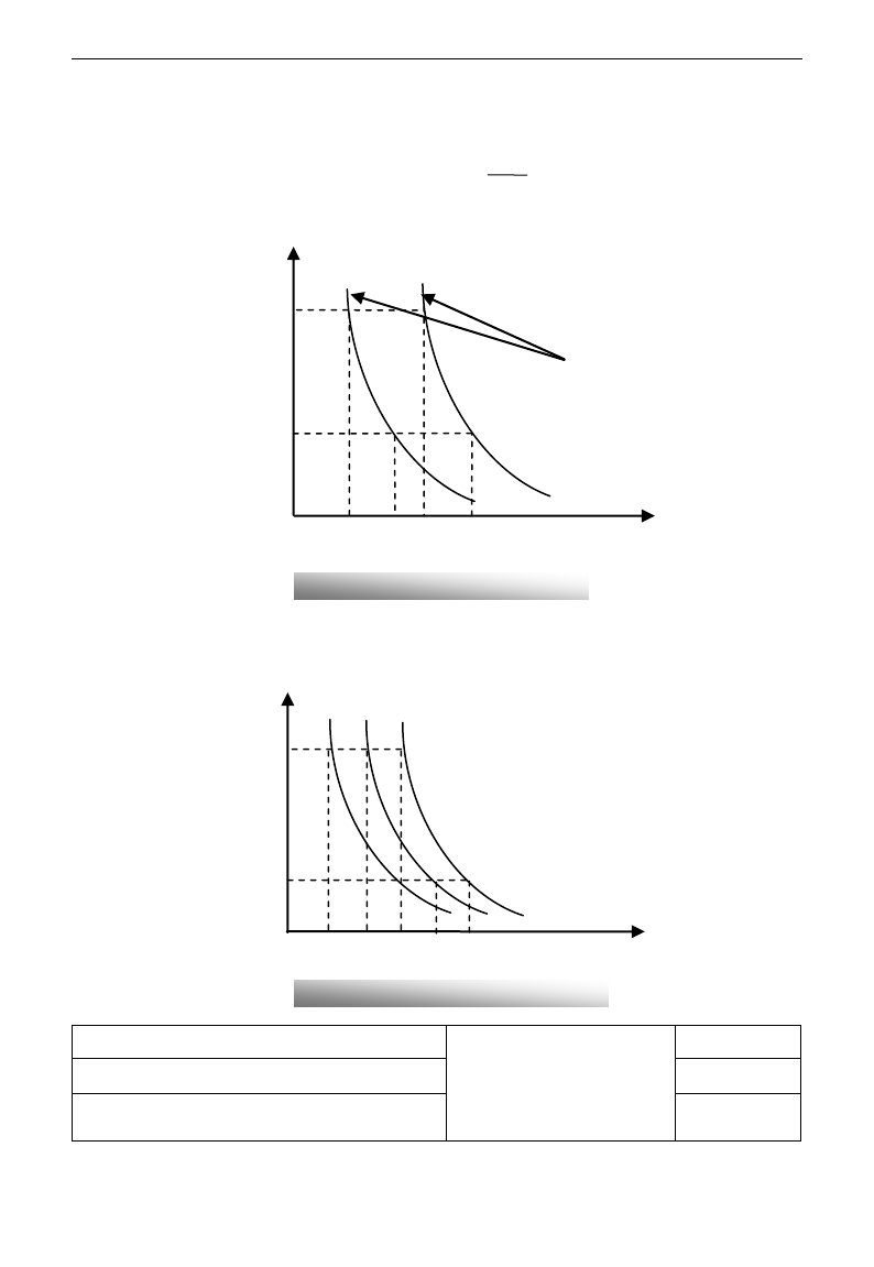
E3000
·82·
Please set F707 according to actual situation. The lower the setting value of F707 is, the faster the overload
protection speed. Please refer to Fig 5-14.
For example: 7.5kW inverter drives 5.5kW motor, F707= ×100%≈70%. When the actual current
of motor reaches 140% of inverter rated current, inverter overload protection will display after 1 minute.
When the output frequency is lower than 10Hz, the heat dissipation effect of common motor will be worse.
So when running frequency is lower than 10Hz, the threshold of motor overload value will be reduced.
Please refer to Fig 5-15 (F707=100%):
F708 Record of The Latest Malfunction Type
Setting range:
2: over current (OC)
3: over voltage (OE)
4: input phase loss (PF1)
5: inverter overload (OL1)
F709 Record of Malfunction Type for Last but One
F710 Record of Malfunction Type for Last but Two
Fig 5-14 Motor overload coefficient
Fig 5-11 Motor overload protection value
200%
70%
100%
Motor overload coefficient
时间
Current
10
160%
1
140%
110%
Time (minutes)
140%
180%
<5Hz
5~10Hz
1
Current
>10Hz
200%
10
160%
120%
Time (minutes)
5.5
7.5

E3000
·83·
6: under voltage (LU)
7: overheat (OH)
8: motor overload (OL2)
11: external malfunction (ESP)
13. studying parameters without
motor (Err2)
16: over current 1 (OC1)
17: output phase loss (PF0)
18: Aerr analog disconnected
20: EP/EP2/EP3 under-load
22: Np pressure control
23: Err5 PID parameters are set
wrong
F711 Fault Frequency of The Latest Malfunction
F712 Fault Current of The Latest Malfunction
F713 Fault PN Voltage of The Latest Malfunction
F714 Fault Frequency of Last Malfunction but One
F715 Fault Current of Last Malfunction but One
F716 Fault PN Voltage of Last Malfunction but One
F717 Fault Frequency of Last Malfunction but Two
F718 Fault Current of Last Malfunction but Two
F719 Fault PN Voltage of Last Malfunction but Two
F720 Record of overcurrent protection fault times
F721 Record of overvoltage protection fault times
F722 Record of overheat protection fault times
F723 Record of overload protection fault times
F724 Input phase loss
Setting range:
0: invalid; 1: valid
Mfr‟s value: 1
F725 Undervoltage
Setting range:
0: invalid; 1: valid
Mfr‟s value: 1
F726 Overheat
Setting range:
0: invalid; 1: valid
Mfr‟s value: 1
F727 Output phase loss
Setting range:
0: invalid; 1: valid
Mfr‟s value: 0
F728 Input phase loss filtering constant
Setting range: 0.1~60.0
Mfr‟s value: 0.5
F729 Undervoltage filtering constant
Setting range: 0.1~60.0
Mfr‟s value: 5.0
F730 Overheat protection filtering constant
Setting range: 0.1~60.0
Mfr‟s value: 5.0
F732 Voltage threshold of undervoltage protection
Setting range: 0~450
Mfr‟s value:
Single-phase: 215
Three-phase: 400
·“Undervoltage” refers to too low voltage at AC input side.
“Input phase loss” refers to phase loss of three-phase power supply, 4.0kW and below 4.0kW inverters have no this
function.
“Output phase loss” refers to phase loss of inverter three-phase wirings or motor wirings.

E3000
·84·
·“Undervoltage” / “phase loss” signal filtering constant is used for the purpose of eliminating disturbance to avoid
mis-protection. The greater the set value is, the longer the filtering time constant is and the better for the filtering effect.
F737 Over-current 1 protection
Setting range: 0:Invalid 1: Valid
Mfr‟s value: 0
F738 Over-current 1 protection coefficient
Setting range: 0.50~3.00
Mfr‟s value: 2.0
F739 Over-current 1 protection record
· F738=Software OC value/inverter rated current
· In running status, F738 is not allowed to modify. When over-current occurs, OC1 is displayed
F741 Analog disconnected protection
Setting range:
0: Invalid
1: Stop and AErr displays.
2: Stop and AErr is not displayed.
3: Inverter runs at the min frequency.
4: Reserved.
Mfr‟s value: 0
F742 Threshold of analog disconnected
protection (%)
Setting range: 1~100
Mfr‟s value: 50
When the values of F400 and F406 are lower than 0.01V, analog disconnected protection is invalid. Analog
channel AI3 has no disconnected protection.
When F741 is set to 1, 2 or 3, the values of F400 and F406 should be set to 1V-2V, to avoid the error
protection by interference.
Analog disconnected protection voltage=analog channel input lower limit * F742. Take the AI1 channel for
the example, if F400=1.00, F742=50, then disconnection protection will occur when the AI1 channel
voltage is lower than 0.5V.
F745 Threshold of pre-alarm overheat (%)
Setting range: 0~100
Mfr‟s value: 80
F747 Carrier frequency auto-adjusting
Setting range: 0: Invalid 1: Valid
Mfr‟s value: 1
When the temperature of radiator reaches the value of 95℃ X F745 and multi-function output terminal is set to
16 (Please refer to F300~F302), it indicates inverter is in the status of overheat.
When F747=1, the temperature of radiator reaches 86℃, inverter carrier frequency will adjust automatically,
to decrease the temperature of inverter. This function can avoid overheat malfunction.
When F159=1, random carrier frequency is selected, F747 is invalid.
F745 Zero-current threshold (%)
Setting range: 0~200
Mfr‟s value: 5
F755 Duration time of zero-current
Setting range: 0~60
Mfr‟s value: 0.5
When the output current is fallen to zero-current threshold, and after the duration time of zero-current, ON signal is
output.
F760 Grounding fault
Setting range: 0~3
Mfr‟s value: 0
·Grounding fault: when U, V, W or motor wiring is short-connected, or the grounding current is higher than
50% times of rated current, GF is displayed.
·Note: the other power terminals of inverter are connected to the ground, grounding fault function is invalid.
·When F760=0, this function is invalid.
·When F760=1,it is grounding fault 1, this function is valid. But this function is invalid when inverter is
powered on.
·F760=2,it is grounding fault 2, this function is valid. And this function is valid when inverter is powered on.
·F760=3,reserved.

E3000
·85·
5.9. Parameters of the Motor
F800 Motor‟s parameters selection
Setting range:
0: Invalid;
1: Rotating tuning;
2: Stationary tuning.
Mfr‟s value: 0
F801 Rated power
Setting range: 0.2~1000kW
F802 Rated voltage
Setting range: 1~440V
F803 Rated current
Setting range: 0.1~6500A
F804 Number of motor poles
Setting range: 2~100
4
F805 Rated rotary speed
Setting range: 1~30000
F810 Motor rated frequency
Setting range: 1.0~300.0Hz
50.00
·Please set the parameters in accordance with those indicated on the nameplate of the motor.
·Excellent control performance of vector control requires accurate parameters of the motor. Accurate
parameter tuning requires correct setting of rated parameters of the motor.
·In order to get the excellent control performance, please configurate the motor in accordance with
adaptable motor of the inverter. In case of too large difference between the actual power of the motor
and that of adaptable motor for inverter, the inverter‟s control performance will decrease remarkably.
·F800=0, no parameter tuning. But it is still necessary to set the parameters F801~F803,F805 and F810
correctly according to those indicated on the nameplate of the motor.
After being powered on, it will use default parameters of the motor (see the values of F806-F809)
according to the motor power set in F801. This value is only a reference value in view of Y series 4-pole
asynchronous motor.
·F800=1, rotating tuning.
In order to ensure dynamic control performance of the inverter, select “rotating tuning” after ensuring
that the motor is disconnected from the load. Please set F801-805 and F810 correctly prior to running
testing.
Operation process of rotating tuning: Press the “Run” key on the keypad to display “TEST”, and it will
tune the motor„s parameter of two stages. After that, the motor will accelerate according to acceleration
time set at F114 and maintain it for a certain period. The motor will then decelerate to 0 according to the
time set at F115. After auto-checking is completed, relevant parameters of the motor will be stored in
function codes F806~F809, and F800 will turn to 0 automatically.
·F800=2, stationary tuning.
It is suitable for the cases where it is impossible to disconnect the motor from the load.
Press the “Run” key, and the inverter will display “TEST”, and it will tune the motor„s parameter of two
stages. The motor‟s stator resistance, rotor resistance and leakage inductance will be stored in F806-F809
automatically (the motor‟s mutual inductance uses default value generated according to the power), and
F800 will turn to 0 automatically. The user may also calculate and input the motor‟s mutual inductance
value manually according to actual conditions of the motor. With regard to calculation formula and
method, please call us for consultation.
When tuning the motor‟s parameter, motor is not running but it is powered on. Please do not touch motor
during this process.
*Note:
1. No matter which tuning method of motor parameter is adopted, please set the information of the motor
(F801-F805) correctly according to the nameplate of the motor. If the operator is quite familiar with the
motor, the operator may input all the parameters (F806-F809) of the motor manually.
2. Parameter F804 can only be checked, not be modified.
3. Incorrect parameters of the motor may result in unstable running of the motor or even failure of normal
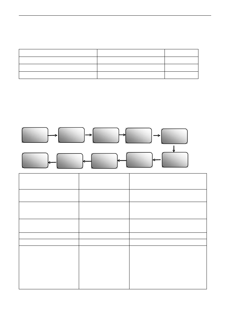
E3000
·86·
running. Correct tuning of the parameters is a fundamental guarantee of vector control performance.
Each time when F801 rated power of the motor is changed, the parameters of the motor (F806-F809) will be
refreshed to default settings automatically. Therefore, please be careful while amending this parameter.
The motor‟s parameters may change when the motor heats up after running for a long time. If the load can
be disconnected, we recommend auto-checking before each running.
F806 Stator resistance
Setting range: 0.001~65.00Ω
F807 Rotor resistance
Setting range: 0.001~65.00Ω
F808 Leakage inductance
Setting range: 0.01~650.0mH
F809 Mutual inductance
Setting range: 0.1~6500mH
·The set values of F806~F809 will be updated automatically after normal completion of parameter tuning
of the motor.
·The inverter will restore the parameter values of F806~F809 automatically to default standard parameters
of the motor each time after changing F801 rated power of the motor;
·If it is impossible to measure the motor at the site, input the parameters manually by referring to the known
parameters of a similar motor.
Take a 3.7kW inverter for the example: all data are 3.7kW, 400V, 8.8A, 1440rmp/min, 50Hz, and the load is
disconnected. When F800=1, the operation steps are as following:
F813 Rotary speed loop KP1
0.01~20.00(Below 22kW)
0.01~50.00(Above 30kW)
0.2-2.2kW: 2.00 3.7-7.5kW: 4.00
11-30kW: 8.00 37-75kW: 15.00
Over 90kW: 20.00
F814 Rotary speed loop KI1
0.01~2.00(Below 22kW)
0.01~3.00(Above 30kW)
1.00
F815 Rotary speed loop KP2
0.01~20.00(Below 22kW)
0.01~50.00(Above 30kW)
0.2-7.5kW: 2.00 11-22kW: 6.00
30KW: 8.00 37-75kW: 15.00
Over 90kW: 25.00
F816 Rotary speed loop KI2
0.01~2.00(Below 22kW)
0.01~3.00(Above 30kW)
1.00
F817 PI switching frequency 1
Setting range: 0~F111
5.00
F818 PI switching frequency 2
Setting range: F817~F111
50.00
F819 Rotary speed loop KP3
0.01~20.00(Below 22kW)
0.01~30.00(Above 30kW)
Single phase:
≤0.2kW: 0.10 0.2~0.4kW: 0.20
≥0.5kW: 0.40
Three phase:
0.2~2.2kW: 0.40 3.7~7.5kW: 0.50
11~15kW: 2.00 15~30kW: 1.00
37~75kW: 8.00 >75kW: 10.00
F801=3.7 F802=
400
F803=8.8 F805=
1440
F810=
50
F800=1
Press
“Run”key
TEST is
displayed
Target
frequency is
blinking
Ok
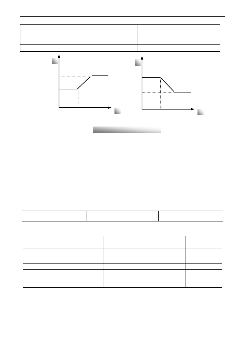
E3000
·87·
F820 Rotary speed loop KI3
0.01~2.00(Below 22kW)
0.01~10.00(Above 30kW)
Single phase: 0.40
Three phase:
≤15kW: 1.00 >15kW: 0.2
F821 PI switching frequency 3
(Hz)
F818~F111
100.0
Dynamic response of vector control speed can be adjusted through adjusting proportional and storage gains
of speed loop. Increasing KP and KI can speed up dynamic response of speed loop. However, if proportional
gain or storage gain is too large, it may give rise to oscillation.
Recommended adjusting procedures:
Make fine adjustment of the value on the basis of manufacturer value if the manufacturer setting value can
not meet the needs of practical application. Be cautious that amplitude of adjustment each time should not
be too large.
In the event of weak loading capacity or slow rising of rotary speed, please increase the value of KP first
under the precondition of ensuring no oscillation. If it is stable, please increase the value of KI properly to
speed up response.
In the event of oscillation of current or rotary speed, decrease KP and KI properly.
Note: Improper setting of KP and KI may result in violent oscillation of the system, or even failure of
normal operation. Please set them carefully.
F851 Encoder resolution
1~9999
1000
Note: when F106=1, PG card must be installed, and set encoder resolution correctly.
5.10. Communication Parameter
F900 Communication Address
1~255: single inverter address
0: broadcast address
1
F901 Communication Mode
1: ASCII 2: RTU
3: Reserved 4:PROFIBUS_DP
5: CANOPEN
1
F903 Parity Check
0: Invalid 1: Odd 2: Even
0
F904 Baud Rate
Setting range:
0: 1200; 1: 2400; 2: 4800;
3: 9600; 4: 19200 5: 38400 6: 57600
3
Please set F901 to 3 to select remote controlling keypad, the keypad of inverter will automatically close
for saving energy.
If the keypad of inverter and remote controlling keypad need work at the same time, please connect OP5
terminal to CM terminal. When inverter works steadily, please disconnect OP5 with CM in case
malfunction.
F904=9600 is recommended for baud rate, which makes run steady. Communication parameters refer to
Appendix 4.
f
KP
p
F815
F813
F817
F818
F818
F817
F816
F814
f
KI
p
Fig 8-2 PI parameter

E3000
·88·
5.11 PID Parameters
5.11.1. Internal PID adjusting and constant pressure water supply
Internal PID adjusting control is used for single pump or double pump automatic constant-pressure water
supply, or used for simple close-loop system with convenient operation.
The usage of pressure meter:
As FAO2=1: channel AI1
“10V” connect with the power supply of pressure meter, if the power supply of pressure meter is 5V, please
supply a 5V power.
“AI1” connect with the pressure signal port of pressure meter
“GND” connect with the grounding of pressure meter
As FAO2=2: channel AI2
“10V” connect with the power supply of pressure meter, if the power supply of pressure meter is 5V, please
supply a 5V power.
“AI2” connect with the pressure signal port of pressure meter
“GND” connect with the grounding of pressure meter
For current type sensor, two-line 4-20mA signal inputs to inverter, please connect CM to GND, and 24V is
connected to power supply of sensor.
5.11.2. Parameters
FA00 Water supply mode
Setting range:
0: Single pump (PID control mode)
1: Fixed mode
2: Timing interchanging
Mfr‟s value: 0
When FA00=0 and single pump mode is selected, the inverter only controls one pump. The control mode
can be used in the closed-loop control system, for example, pressure, flow.
When FA00=1, one motor is connected with converter pump or general pump all the time.
When FA00=2, two pumps are interchanging to connect with inverter for a fixed period of time, this
function should be selected. The duration time is set by FA25.
FA01 PID adjusting target given source
Setting range:
0: FA04 1: AI1 2: AI2
3: AI3 (Potentiometer on the keypad)
4: FI (pulse frequency input)
Mfr‟s value: 0
When FA01=0, PID adjusting target is given by FA04 or by Communication.
When FA01=1, PID adjusting target is given by external analog AI1.
When FA01=2, PID adjusting target is given by external analog AI2.
When FA01=3, PID adjusting target is given by the AI3 potentiometer on the keypad.
When FA01=4, PID adjusting target is given by FI pulse frequency (OP1 terminal).
FA02 PID adjusting feedback given source
Setting range:
1: AI1 2: AI2
3: FI (pulse frequency input)
Mfr‟s value: 1
When FA02=1, PID adjusting feedback signal is given by external analog AI1.
When FA02=2, PID adjusting feedback signal is given by external analog AI2.
When FA03=3, PID adjusting feedback signal is given by FI pulse frequency input.
FA03
Max limit of PID adjusting (%)
0.0~100.0
Mfr‟s value:100.0
FA04
Digital setting value of PID adjusting (%)
0.0~100.0
Mfr‟s value:50.0
FA05
Min limit of PID adjusting (%)
0.0~100.0
Mfr‟s value:0.0
When negative feedback adjusting is valid, if pressure is higher than max limit of PID adjusting, pressure
protection will occur. If inverter is running, it will free stop, and “nP” is displayed. When positive feedback
adjusting is valid, if pressure is higher than Max limit, it indicates that feedback pressure is too low, inverter
should accelerate or a linefrequency should be added to increase the displacement.
When FA01=0, the value set by FA04 is digital setting reference value of PID adjusting.
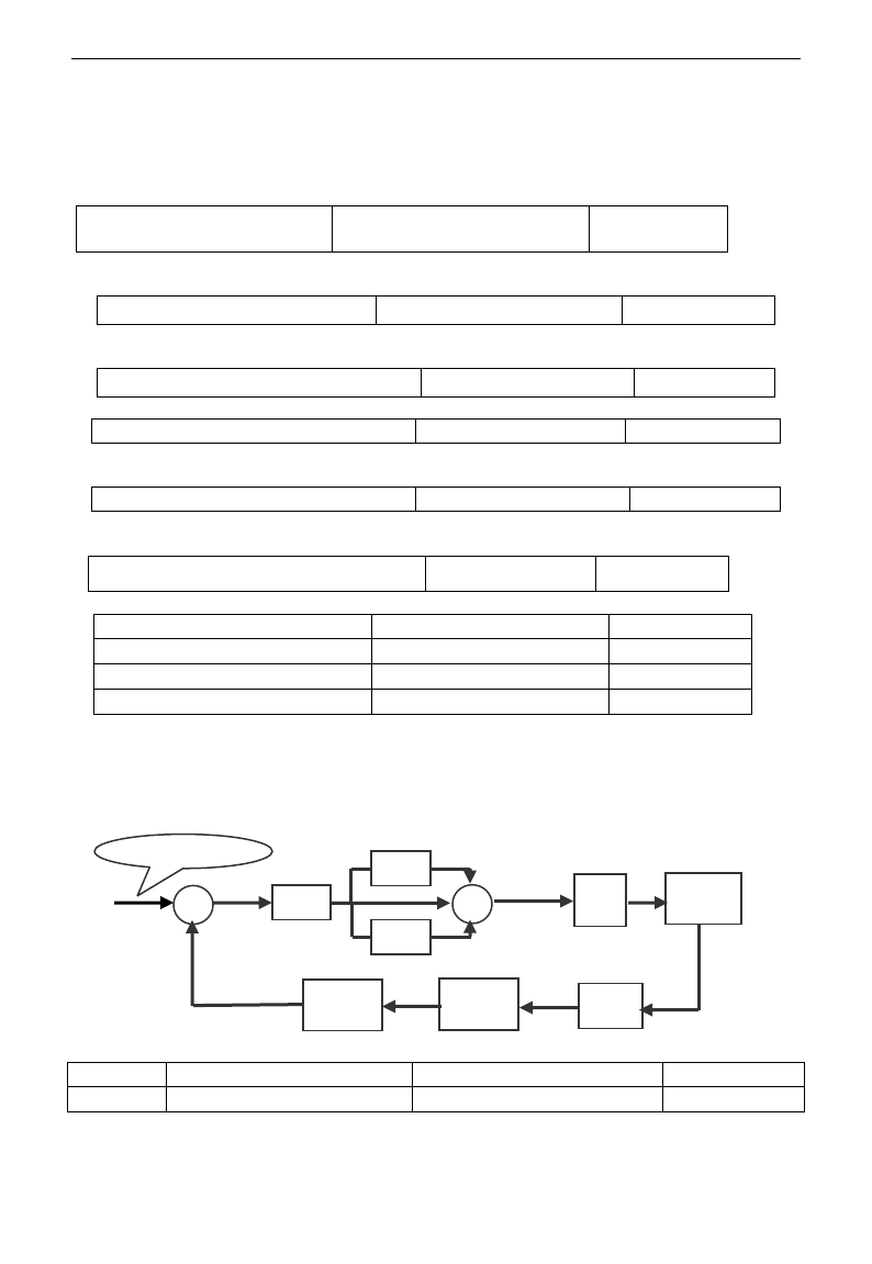
E3000
·89·
When positive feedback adjusting is valid, if pressure is higher than min limit of PID adjusting, pressure
protection will occur. If inverter is running, it will free stop, and “nP” is displayed. When negative feedback
adjusting, if pressure is higher than min limit, it indicates that feedback pressure is too low, inverter should
accelerate or a linefrequency should be added to increase the displacement.
For example: if the range of pressure meter is 0-1.6MPa, then setting pressure is 1.6*70%=1.12MPa, and the
max limit pressure is 1.6*90%=1.44MPa, and the min limit pressure is 1.6*5%=0.08MPa.
FA06 PID polarity
0: Positive feedback
1: Negative feedback
Mfr‟s value:1
When FA06=0, the higher feedback value is, the higher the motor speed is. This is positive feedback.
When FA06=1, the lower the feedback value is, the higher the motor speed is. This is negative feedback.
FA07 Dormancy function selection
Setting range: 0: Valid 1: Invalid
Mfr‟s value: 0
When FA07=0, if inverter runs at the min frequency FA09 for a period time set by FA10, inverter will stop.
When FA07=1, the dormancy function is invalid.
FA09 Min frequency of PID adjusting (Hz)
Setting range: F112~F111
Mfr‟s value: 5.00
The min frequency is set by FA09 when PID adjusting is valid.
FA10 Dormancy delay time (S)
Setting range: 0~500.0
Mfr‟s value: 15.0
When FA07=0, inverter runs at min frequency FA09 for a period time set by FA10, inverter will free stop
and enter into the dormancy status, “nP” is displayed.
FA11 Wake delay time (S)
Setting range: 0.0~3000
Mfr‟s value: 3.0
After the wake delay time, if the pressure is lower than min limit pressure (Negative feedback), inverter
will begin running immediately, or else, inverter will be in the dormancy status.
FA18 Whether PID adjusting target is changed
0: Invalid 1: Valid
Mfr‟s value: 1
When FA18=0, PID adjusting target can not be changed.
FA19 Proportion Gain P
Setting range: 0.00~10.00
Mfr‟s value: 0.3
FA20 Integration time I (S)
Setting range: 0.1~100.0S
Mfr‟s value: 0.3
FA21 Differential time D (S)
Setting range: 0.00~10.00
Mfr‟s value: 0.0
FA22 PID sampling period (S)
Setting range: 0.1~10.0s
Mfr‟s value: 0.1
Increasing proportion gain, decreasing integration time and increasing differential time can increase the
dynamic response of PID closed-loop system. But if P is too high, I is too low or D is too high, system will
not be steady.
PID adjusting period is set by FA22. It affects PID adjusting speed.
The following is PID adjusting arithmetic.
FA24
Switching Timing unit setting
Setting range: 0: hour 1: minute
Mfr‟s value: 0
FA25
Switching Timing Setting
1~9999
Mfr‟s value: 100
Switching time is set by F525. The unit is set by F524.
P
I
D
Drive
limit
+
+
+
Control
Object
Sensor
Feedback
Gain
Feedback
Filter
Target -
Value
Negative feedback
+

E3000
·90·
FA26 Under-load protection mode
Setting Range
0: No protection
1: Protection by contactor
2: Protection by PID
3: Protection by current
Mfr‟s value: 0
FA27 Current threshold of under-load protection
(%)
Setting range: 10~150
Mfr‟s value: 80
FA66 Duration time of under-load protection (S)
Setting range: 0~60
Mfr‟s value: 2
Under-load protection is used to save energy. For some pumps device, when the output power is too low, the
efficiency will get worse, so we suggest that the pumps should be closed.
During the running process, if the load decreases to zero suddenly, it means the mechanical part is broken.
For example, belt is broken or water pump is dried up. Under-load protection must occur.
When FA26=1, water signal and lack water signal is controlled by two input terminals. When the lack water
terminal is valid, inverter will enter into the protection status, and EP1 is displayed. When the water terminal
is valid, inverter will deactivate EP1 fault automatically.
When FA26=2, PID adjusting frequency runs to max frequency, if inverter current is lower than the product
FA27 and rated current, inverter will enter PID under-load protection status immediately, and EP2 is
displayed.
When FA26=3, if inverter current is lower than the product of FA27 and rated current, after duration time of
FA66, inverter will enter under-load protection, and EP3 is displayed.
FA28 Waking time after protection (min)
0.0~3000
Mfr‟s value: 60
After the duration time of FA28, inverter will judge that whether the under-load protection signal disappears.
If malfunction is reset, inverter will run again. Or else inverter will wait until malfunction is reset. User can
reset the inverter by pressing “stop/reset”, inverter will stop.
FA29 PID dead time (%)
0.0~10.0
Mfr‟s value: 2.0
FA30 Running Interval of restarting converter pump (S)
2.0~999.9s
Mfr‟s value: 20.0
FA31 Delay time of starting general pumps (S)
0.1~999.9s
Mfr‟s value: 30.0
FA32 Delay time of stopping general pumps (S)
0.1~999.9s
Mfr‟s value: 30.0
FA29, PID dead time has two functions. First, setting dead time can restrain PID adjustor oscillation. The
greater this value is, the lighter PID adjustor oscillation is. But if the value of FA29 is too high, PID
adjusting precision will decrease. For example: when FA29=2.0% and FA04=70, PID adjusting will not
invalid during the feedback value from 68 to 72.
Second, FA29 is set to PID dead time when starting and stopping general pumps by PID adjusting. When
negative feedback adjusting is valid, if feedback value is lower than value FA04-FA29 (which equal to set
value MINUS dead-time value), inverter will delay the set time of FA31, and then start the general pump. If
feedback value is higher than value FA04+FA29 (which equal to set value PLUS dead-time value), inverter
will delay the set time of FA32, then stop the general pump.
· When starting general pump or interchange time is over, inverter will free stop. After starting general pump,
inverter will delay the set time of FA30, and restart converter pump.
· When inverter drives two pumps and negative feedback adjusting, if the frequency already reach the max value
and after the delay time (FA31), the pressure value is still lower than the value, then the inverter will stop output
immediately and motor will freely stop. At the same time, the general pump will be started. After the general
pump is fully run, if the present pressure is higher than the set value, inverter will low down the output to the
min frequency. After delaying the set time (FA32), inverter will stop the general pump and start converter pump.
· When inverter drives two pumps and positive feedback adjusting, if the frequency already reach the max value
and after the delay time (FA31), the pressure value still higher than the value, then the inverter will stop output
immediately and motor will freely stop. At the same time the general pump will be started. After the general
pump runs, if the present pressure is lower than the set value, inverter will low down the output to the min
frequency. After delaying the set time (FA32), inverter will stop the general pump and start converter pump.
FA36
Whether No.1 relay is started
0: Stopped 1: Started
Mfr‟s value: 0
FA37
Whether No.2 relay is started
0: Stopped 1: Started
Mfr‟s value: 0

E3000
·91·
No 1 relay corresponds to the terminal DO1 in the control PCB, No 2 relay corresponds to the terminal TA/TC
FA47
The sequence of starting No 1 relay
1~20
Mfr‟s value: 20
FA48
The sequence of starting No 2 relay
1~20
Mfr‟s value: 20
The sequence of starting relays is set by FA47~FA48. The setting value of FA47 and FA48 must be different
with each other, or else “Err5” is displayed in the keypad.
FA58 Fire pressure given value (%)
Setting range: 0.0~100.0
Mfr‟s value: 80.0
FA58 is also called second pressure, when the fire control terminal is valid, pressure target value will switch into
second pressure value.
FA59 Emergency fire mode
Setting range:
0: Invalid 1: Emergency fire mode 1
2: Emergency fire mode 2
Mfr‟s value: 0
When emergency fire mode is valid and emergency fire terminal is valid, inverter will be forbidden
operating and protecting (When OC and OE protection occur, inverter will reset automatically and start
running). And inverter will run at the frequency of FA60 or target frequency until inverter is broken.
Emergency fire mode 1: when the terminal is valid, inverter will run at target frequency.
Emergency fire mode 2: when the terminal is valid, inverter will run at the frequency of FA60.
FA60 Running frequency of emergency fire
Setting range: F112~F111
Mfr‟s value: 50.0
When the emergency fire mode 2 is valid and the fire terminal is valid, inverter will run at the frequency set by
FA60.
5.13 Torque control parameters
FC00 Speed/torque control
selection
0:Speed control 1:Torque control 2:Terminal switchover
0
0: speed control. Inverter will run by setting frequency, and output torque will automatically match with the
torque of load, and output torque is limited by max torque (set by manufacture.)
1: Torque control. Inverter will run by setting torque, and output speed will automatically match with the
speed of load, and output speed is limited by max speed (set by FC23 and FC25). Please set the proper
torque and speed limited.
2:Terminal switchover. User can set OPX terminal as torque/speed switchover terminal to realize
switchover between torque and speed. When the terminal is valid, torque control is valid. When the terminal
is invalid, speed control is valid.
FC01
Delay time of torque/speed control switchover(S)
0.0~1.0
0.1
This function is valid while terminal switchover.
FC02
Torque accel/decel time (S)
0.1~100.0
1
The time is for inverter to run from 0% to 100% of motor rated torque.
FC06
Torque given channel
0: Digital given (FC09)
1: Analog input AI1
2: Analog input AI2
3: Analog input AI3
4: Pulse input channel FI
5: Reserved
0
When FC06=4, only OP1 terminal can be selected because only OP1 terminal has the pulse input function.
FC07
Torque given coefficient
0~3.000
3.000
FC09
Torque given command value (%)
0~300.0
100.0
FC07: when input given torque reaches max value, FC07 is the ratio of inverter output torque and motor
rated torque. For example, if FC06=1, F402=10.00, FC07=3.00, when AI1 channel output 10V, the output
torque of inverter is 3 times of motor rated torque.

E3000
·92·
FC14
Offset torque given channel
0: Digital given (FC17)
1: Analog input AI1
2: Analog input AI2
3: Analog input AI3
4: Pulse input channel FI
5: Reserved
0
FC15
Offset torque coefficient
0~0.500
0.500
FC16
Offset torque cut-off frequency (%)
0~100.0
10.00
FC17
Offset torque command value (%)
0~50.0
10.00
· Offset torque is used to output larger start torque which equals to setting torque and offset torque when
motor drives big inertia load. When actual speed is lower than the setting frequency by FC16, offset torque
is given by FC14. When actual speed is higher than the setting frequency by FC16, offset torque is 0.
· When FC14≠0, and offset torque reaches max value, FC15 is the ratio of offset torque and motor rated
torque. For example: if FC14=1, F402=10.00 and FC15=0.500, when AI1 channel outputs 10V, offset torque
is 50% of motor rated torque.
FC22
Forward speed limited channel
0: Digital given (FC23)
1: Analog input AI1
2: Analog input AI2
3: Analog input AI3
4: Pulse input channel FI
5: Reserved
0
FC23
Forward speed limited (%)
0~100.0
10.00
FC24
Reverse speed limited channel
0: Digital given (FC25)
1: Analog input AI1
2: Analog input AI2
3: Analog input AI3
0
FC25
Reverse speed limited (%)
0~100.0
10.00
·Speed limited FC23/FC25: if given speed reaches max value, they are used to set percent of inverter output
frequency and max frequency F111.
FC28
Electric torque limit channel
0: Digital given (FC30)
1: Analog input AI1
2: Analog input AI2
3: Analog input AI3
4: Pulse input channel FI
5: Reserved
0
FC29
Electric torque limit coefficient
0~3.000
3.000
FC30
Electric torque limit (%)
0~300.0
200.0
FC31
Braking torque limit channel
0: Digital given (FC35)
1: Analog input AI1
2: Analog input AI2
3: Analog input AI3
4: Pulse input channel FI
5: Reserved
0
FC34
Braking torque limit coefficient
0~3.000
3.000
FC35
Braking torque limit (%)
0~300.0
200.00
·When motor is in the electric status, output torque limit channel is set by FC28, and limit torque is set by
FC29.
·When motor is in the Braking status, Braking torque limit channel is set by FC31, and limit torque is set by
FC34.

E3000
·93·
Appendix 1 Trouble Shooting
When malfunction occurs to inverter, don‟t run by resetting immediately. Check any
causes and get it removed if there is any.
Take counter measures by referring to this manual in case of any malfunctions on inverter.
Should it still be unsolved, contact the manufacturer. Never attempt any repairing without
due authorization.
Table 1-1 Inverter‟s Common Cases of Malfunctions
Fault
Description
Causes
Countermeasures
O.C.
Overcurrent
* too short acceleration time
* short circuit at output side
* locked rotor with motor
* parameter tuning is not correct.
*prolong acceleration time;
*whether motor cable is broken;
*check if motor overloads;
*reduce VVVF compensation value
* measure parameter correctly.
OC1
Overcurrent 1
O.L1
Inverter
Overload
* load too heavy
*reduce load; *check drive ratio;
*increase inverter‟s capacity
O.L2
Motor
Overload
* load too heavy
*reduce load; *check drive ratio;
*increase motor‟s capacity
O.E.
DC
Over-Voltage
*supply voltage too high;
*load inertia too big
*deceleration time too short;
*motor inertia rise again
*parameter of rotary speed loop PID is
set abnormally.
*check if rated voltage is input;
*add braking resistance(optional);
*increase deceleration time
*set the parameter of rotary speed loop
PID correctly.
P.F1.
Input Phase
loss
*phase loss with input power
*check if power input is normal;
*check if parameter setting is correct.
PF0
Output
Phase loss
* Motor is broken
* Motor wire is loose.
* Inverter is broken
* check if wire of motor is loose.
* check if motor is broken.
L.U.
Under-Voltage
Protection
*input voltage on the low side
*check if supply voltage is normal
*check if parameter setting is correct.
O.H.
Radiator
Overheat
*environment temperature too high;
*radiator too dirty
*install place not good for ventilation;
*fan damaged
* Carrier wave frequency or
compensation curve is too high.
*improve ventilation;
*clean air inlet and outlet and radiator;
*install as required;
*change fan
* Decrease carrier wave frequency or
compensation curve.
AErr
Line
disconnected
* Analog signal line disconnected
* Signal source is broken.
* Change the signal line.
* Change the signal source.
EP/EP2/E
P3
Inverter
under-load
* Water pump dries up.
* Belt is broken.
* Equipment is broken.
* Supply water for pump
* Change the belt.
* Repair the equipment.
nP
Pressure
control
* Pressure is too high when negative
feedback.
* Pressure is too low when positive
feedback.
* Inverter enters into the dormancy
status.
* Decrease the min frequency of PID.
* Reset inverter to normal status.

E3000
·94·
ERR1
Password is
wrong
*When password function is valid,
password is set wrong.
*please set password correctly.
ERR2
Parameters
tuning wrong
* Do not connect motor when tuning
parameters
*please connect motor correctly.
ERR3
Current
malfunction
before running
*Current alarm signal exists before
running.
*check if control board is connected
with power board well.
*ask for help from manufacture.
ERR4
Current zero
excursion
malfunction
*Flat cable is loosened.
*Current detector is broken.
*check the flat cable.
*ask for help from manufacture.
ERR5
PID
parameters are
set wrong,
* PID parameters are set wrong.
* Set the parameters correctly.
GF
Grounding
fault
* Motor line is damaged.
* Motor is damaged.
* Check motor line.
* Check motor.
- No P.F1. protection for single-phase inverter.
Table 1-2 Motor Malfunction and Counter Measures
Malfunction
Items to Be Checked
Counter Measures
Motor not Running
Wiring correct? Setting correct? Too big with
load? Motor is damaged? Malfunction
protection occurs?
Get connected with power; Check
wiring; Checking malfunction; Reduce
load; Check against Table 1-1
Wrong Direction of
Motor Running
U, V, W wiring correct?
Parameters setting correct?
To correct wiring
Setting the parameters correctly.
Motor Turning but
Speed Change not
Possible
Wiring correct for lines with given frequency?
Correct setting of running mode?
Too big with load?
To correct wiring;
To correct setting; Reduce load
Motor Speed Too
High or Too Low
Motor‟s rated value correct? Drive ratio
correct? Inverter parameters are set
incorrectly? Check if inverter output voltage is
abnormal?
Check motor nameplate data; Check
the setting of drive ratio; Check
parameters setting; Check VVVF
Characteristic value
Motor Running
Unstable
Too big load? Too big with load change?
Phase loss? Motor malfunction.
Reduce load; reduce load change,
increase capacity;
Correct wiring.
Power Trip
Wiring current is too high?
Check input wring; Selecting
matching air switch; Reduce load;
checking inverter malfunction.
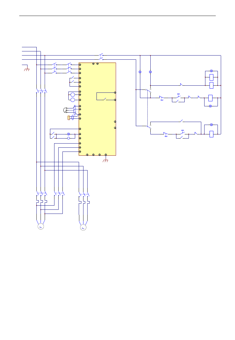
E3000
·95·
Appendix 2 Reference wiring of water system
1. Fixed mode of 1 inverter driving 2 pumps
Instructions of wiring:
1. Please connect the wiring according to above wiring, after checking the wiring and close MCCB3.
2. Please set F208=1, F203=9, FA00=1, FA36=1, FA37=1, FA47=1, FA48=2, FA04=pressure percentage,
FA03=channel limit pressure, and FA05.
3. In manual status, please close power-frequency switch MCCB2. When pressing S1, pump M1 starts working.
When pressing S2, M1 stops working. When pressing S3, M2 starts working. When pressing S4, M2 stops
working.
4. In automatic status, please close converter-frequency switch MCCB1 and power-frequency switch MCCB2.
- When inverter is powered on, inverter will run forward by short-connecting OP3 terminal (or run
reverse by short-connecting OP4 terminal), M1 will work at power frequency status.
- If the pressure is not high enough, inverter will accelerate to max frequency. If the pressure is still not
high enough after duration time FA31, inverter will free stop and pump M2 will start working at
power frequency status. After the duration time of FA30, inverter will start working and M1 works at
M C C B1
Freuency-conversion switc h
R
S
T
N
PE
M
M 1
U
V
WP N PE
T
S
MC1
OP6
R
OP1
CM
10V
AI1
GND
TC
TA
AO2
AO1
GND
AI2
F
A
S2
DO1
DO2
B-A+
24V
B
M C C B2
Linefrequency sw itch
MC2
FR1
Com munication Interface
MC1
S1
Pow er Switch
M C CB 3
HL1
MC1
HL0
FR1-NC
Ru nning m anually
S5
L2L1
Running autom atically
FR2
FR1L 3
BZ
Pressure sensor
Freq u en cy giv en
CM
M
M 2
MC3
FR2
24V
MC1MC2
S4
MC3
S3 HL3
MC3
FR2-NC
Ru nning m anually
S5
Runn ing au tom atically
MC0
MC0
MC2
KA1
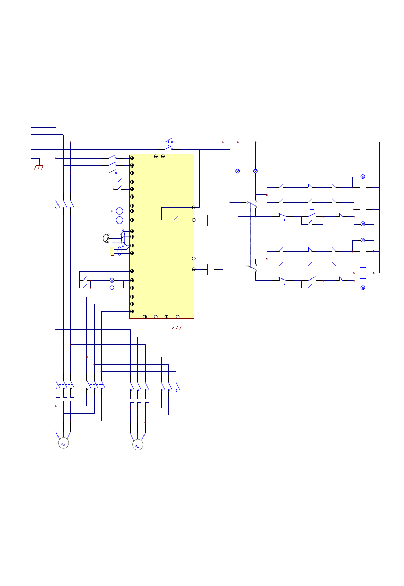
E3000
·96·
converter frequency status.
- When two pumps work at the same time, if pressure is too high, inverter will decelerate to min
frequency. If the pressure is still too high after the duration time FA32, M2 will stop working.
- If one pump M1 works at converter frequency status and inverter works at the min frequency, inverter
will free stop after the duration time FA10, inverter will enter into dormancy status and np is
displayed.
2. Rotating mode of 1 inverter driving 2 pumps
Instructions of wiring:
1. Please connect the wiring according to above wiring, after checking the wiring and close MCCB3.
2. Please set F208=1, F203=9, FA00=2, FA36=1, FA37=1, FA47=1, FA48=2, FA04=pressure percentage,
FA03=channel limit pressure, and FA05
3. In manual status, please close power-frequency switch MCCB2. When pressing S1, pump M1 starts
working. When pressing S2, M1 stops working. When pressing S3, M2 starts working. When pressing
M C CB 1
Fre q u e n cy-conversio n sw itc h
R
S
T
N
PE
M
M 1
U
V
WP N PE
T
S
MC1
OP6
R
OP1
CM
10V
AI1
GND
TC
TA
AO2
AO1
GND
AI2
F
A
S2
DO1
DO2
B-A+
24V
B
M C CB 2
Lin e freq uency switch
MC2
FR1
Com munication interface
MC1
S1
Pow e r sw itch
M C CB 3
HL1
MC1
HL2
FR1-NC
Run m an u a lly
S3
L2L1
MC3
Run a u tom atically
FR2
FR1L3
BZ
Pre ssure sensor
Fre q u e n cy given
CM
M
M 2
MC3MC4
FR2
+24V
MC1
KA1
MC2
MC4KA1
MC4
KA2
KA1S4 MC3
S3
HL3
MC3
HL4
FR2-NC
Run m an u a lly
S5
MC1
Run a u tom atically MC2
KA2
MC4
MC3KA2
MC2

E3000
·97·
S4, M2 stops working.
4. In automatic status, please close converter-frequency switch MCCB1 and power-frequency switch
MCCB2.
- When inverter is powered on, KA1 is “action”, and inverter will run forward by short-connecting OP3
terminal, KA2 makes M1 start working at converter frequency status. If the pressure is not high
enough, inverter will accelerate to max frequency. If the pressure is still not high enough after
duration time FA31, inverter will free stop and pump M2 will start working at power frequency
status. After the duration time of FA30, inverter will start working and M1 works at converter
frequency status.
- After the duration time FA25, all pumps will free stop, then KA2 is “action”, M2 is converter pump. If
the pressure is not high enough, inverter will accelerate to max frequency. If the pressure is still not
high enough after duration time FA31, inverter will free stop and KA1 makes M1 start working at
power frequency status. After the duration time of FA30, inverter will start working and M2 works at
converter frequency status.
- When two pumps work at the same time, if pressure is too high, inverter will decelerate to min
frequency. If the pressure is still too high after the duration time FA32, general pump will stop
working.
- If one pump works at converter frequency status and inverter works at the min frequency, inverter will
free stop after the duration time FA10, inverter will enter into dormancy status and np is displayed.
Appendix 3 Products & Structures
E3000 series inverter has its power range between 0.2~90kW. Refer to Tables 2-1 and 2-2 for main data.
There may be two (or more than two) kinds of structures for certain products. Please make a clear indication
when placing your order.
Inverter should operate under the rated output current, with overload permitted for a short time. However,
it shall not exceed the allowable values at working time.
Table 3-1 Product List of E3000
Model
Applicable
Motor (kW)
Rated
Current
Output
Remote keypad
panel
Structure
Code
Cooling Mode
Remarks
E3000-0002S2
0.2
1.5
AA-A or A6-1-A
E2
Self-Cooling
Single-Phase
Plastic Hanging
E3000-0004S2
0.4
2.5
AA-A or A6-1-A
E2
Air-Cooling
E3000-0007S2
0.75
4.5
AA-A or A6-1-A
E2
Air-Cooling
E3000-0011S2
1.1
5
AA-A or A6-1-A
E2
Air-Cooling
E3000-0015S2
1.5
7
AA-A or A6-1-A
E2
Air- Cooling
E3000-0022S2
2.2
10
AA-A or A6-1-A
E3
Air-Cooling
E3000-0007T3
0.75
2
AA-A or A6-1-A
E2
Air-Cooling
Three-Phase Plastic
Hanging
E3000-0015T3
1.5
4
AA-A or A6-1-A
E2
Air- Cooling
E3000-0022T3
2.2
6.5
AA-A or A6-1-A
E2
Air- Cooling
E3000-0030T3
3.0
7
AA-A or A6-1-A
E4
Air-Cooling
E3000-0037T3
3.7
8
AA-A or A6-1-A
E4
Air- Cooling
E3000-0040T3
4.0
9
AA-A or A6-1-A
E4
Air- Cooling
E3000-0055T3
5.5
12
AA-A or A6-1-A
E5
Air- Cooling
E3000-0075T3
7.5
17
AA-A or A6-1-A
E5
Air- Cooling
E3000-0110T3
11
23
AA-A or A6-1-A
E6
Air- Cooling
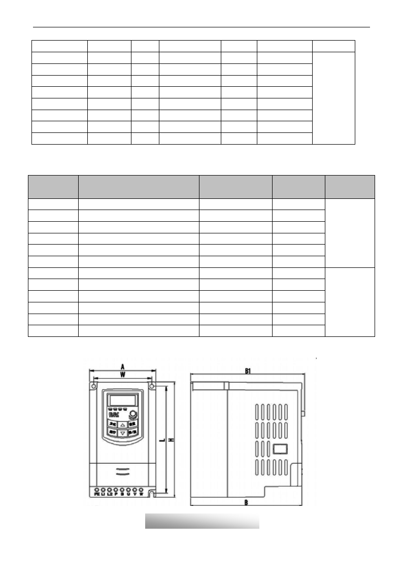
E3000
·98·
E3000-0150T3
15
32
AA-A or A6-1-A
E6
Air- Cooling
E3000-0185T3
18.5
38
AA-A or A6-1-A
C3
Air-Cooling
Three-phase Metal
hanging
E3000-0220T3
22
44
AA-A or A6-1-A
C3
Air- Cooling
E3000-0300T3
30
60
AA-A or A6-1-A
C3
Air- Cooling
E3000-0370T3
37
75
AA-A or A6-1-A
C5
Air- Cooling
E3000-0450T3
45
90
AA-A or A6-1-A
C5
Air- Cooling
E3000-0550T3
55
110
AA-A or A6-1-A
C5
Air- Cooling
E3000-0750T3
75
150
AA-A or A6-1-A
C6
Air- Cooling
E3000-0900T3
90
180
AA-A or A6-1-A
C6
Air-Cooling
Table 3-2 Structure List
Structure
Code
External Dimension
[A×B(B1)×H]note1
Mounting
Size(W×L)
Mounting
Bolt
Remarks
E1
80×135(142)×138
70×128
M4
Plastic
Housing
E2
106×150(157)×180
正在研发
94×170
M4
E3
106×170(177)×180
94×170
M4
E4
138×152(159)×235
126×225
M5
E5
156×170(177)×265
146×255
M5
E6
205×196 (202) ×340
194×330
M5
E7
271×235×637
235×613
M6
Metal Housing
E8
360×265×901
320×876
M8
E9
420×300×978
370×948
M10
C3
265×235×435
235×412
M6
C5
360×265×555
320×530
M8
C6
410×300×630
370×600
M10
Note 1: the unit is mm.
Plastic Profile
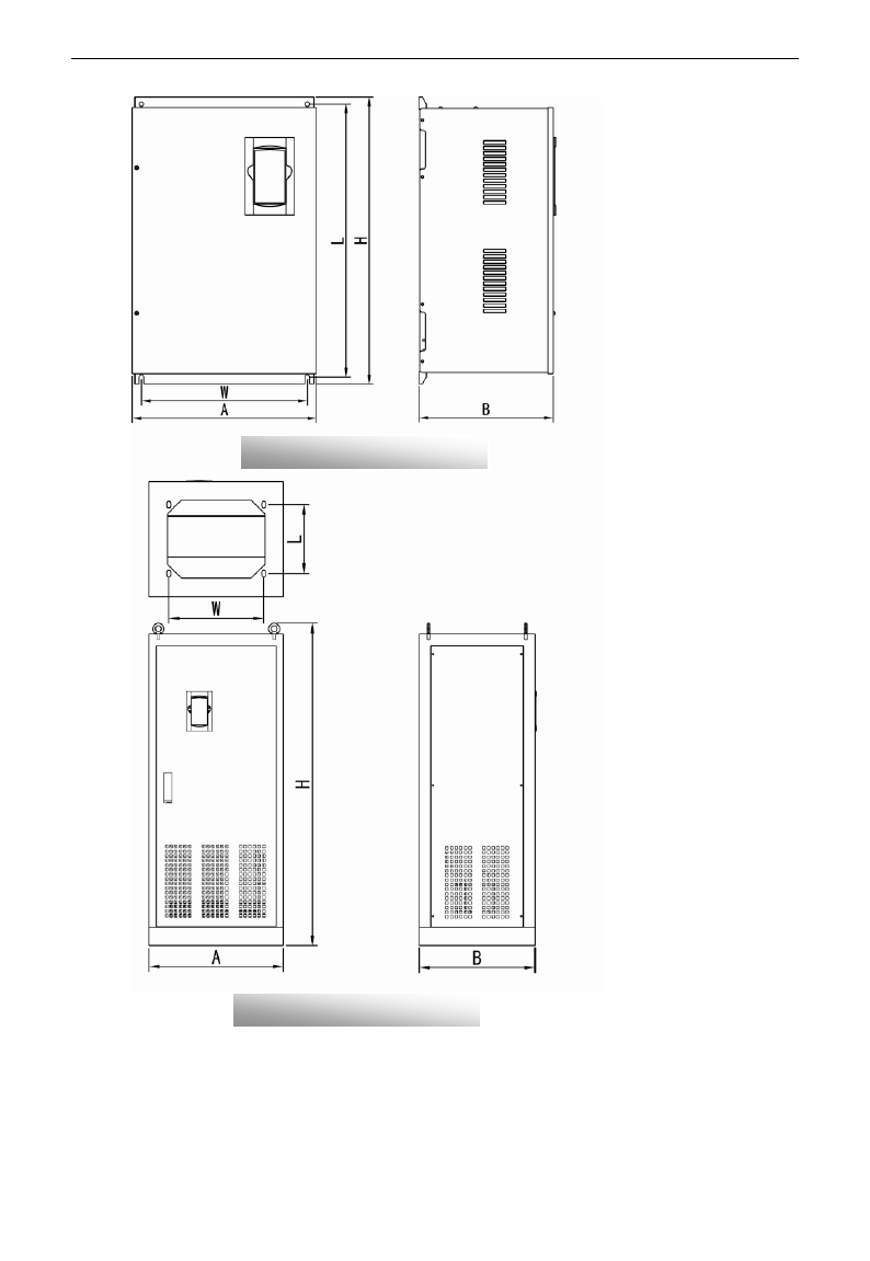
E3000
·99·
Note1: if keypad control unit has potentiometer, the external dimension is B1.
If keypad control unit has no potentiometer, the external dimension is B.
Metal Hanging Profile
Metal Cabinet Profile

E3000
·100·
Appendix 4 Selection of Braking Resistance
Note: please select higher power of resistor on the occasion of big inertia load.
Inverter Models
Applicable Motor
Power(kW)
Applicable Braking Resistance
E3000-0002S2
0.2
150W/60Ω
E3000-0004S2
0.4
E3000-0007S2
0.75
E3000-0011S2
1.1
E3000-0015S2
1.5
E3000-0007T3
0.75
80W/200Ω
E3000-0015T3
1.5
80W/150Ω
E3000-0022T3
2.2
150W/150Ω
E3000-0030T3
3.0
E3000-0037T3
3.7
E3000-0040T3
4.0
E3000-0055T3
5.5
250W/120Ω
E3000-0075T3
7.5
500W/120Ω
E3000-0110T3
11
1kW/90Ω
E3000-0150T3
15
1.5kW/80Ω

E3000
·101·
Appendix 5 Communication Manual
(Version 1.8)
I. General
Modbus is a serial and asynchronous communication protocol. Modbus protocol is a general language
applied to PLC and other controlling units. This protocol has defined an information structure which can be
identified and used by a controlling unit regardless of whatever network they are transmitted.
You can read reference books or ask for the details of MODBUS from manufactures.
Modbus protocol does not require a special interface while a typical physical interface is RS485.
II. Modbus Protocol
2.1 Transmission mode
2.1.1 Format
1) ASCII mode
Start
Address
Function
Data
LRC check
End
:
(0X3A)
Inverter
Address
Function
Code
Data
Length
Data
1
…
…
Data
N
High-order
byte of LRC
Low-order
byte of
LRC
Return
(0X0D)
Line Feed
(0X0A)
2)RTU mode
Start
Address
Function
Data
CRC check
End
T1-T2-T3-T4
Inverter
Address
Function
Code
N data
Low-order byte
of CRC
High-order byte
of CRC
T1-T2-T3-T4
2.1.2 ASCII Mode
In ASCII mode, one Byte (hexadecimal format) is expressed by two ASCII characters.
For example, 31H (hexadecimal data) includes two ASCII characters‟3(33H)‟,‟1(31H)‟.
Common characters, ASCII characters are shown in the following table:
Characters
„0‟
„1‟
„2‟
„3‟
„4‟
„5‟
„6‟
„7‟
ASCII Code
30H
31H
32H
33H
34H
35H
36H
37H
Characters
„8‟
„9‟
„A‟
„B‟
„C‟
„D‟
„E‟
„F‟
ASCII Code
38H
39H
41H
42H
43H
44H
45H
46H
2.1.3 RTU Mode
In RTU mode, one Byte is expressed by hexadecimal format. For example, 31H is delivered to data packet.
2.2 Baud rate
Setting range: 1200, 2400, 4800, 9600, 19200, 38400, 57600
2.3 Frame structure:
ASCII mode

E3000
·102·
Byte
Function
1
7
0/1
1/2
Start Bit (Low Level)
Data Bit
Parity Check Bit (None for this bit in case of no checking. Otherwise 1 bit)
Stop Bit (1 bit in case of checking, otherwise 2 bits)
2) RTU mode
Byte
Function
1
8
0/1
1/2
Start Bit (Low Level)
Data Bit
Parity Check Bit (None for this bit in case of no checking. Otherwise 1 bit)
Stop Bit (1 bit in case of checking, otherwise 2 bits)
2.4 Error Check
2.4.1 ASCII mode
Longitudinal Redundancy Check (LRC): It is performed on the ASCII message field contents excluding
the „colon‟ character that begins the message, and excluding the CRLF pair at the end of the message.
The LRC is calculated by adding together successive 8–bit bytes of the message, discarding any carries, and
then two‟s complementing the result.
A procedure for generating an LRC is:
1. Add all bytes in the message, excluding the starting „colon‟ and ending CRLF. Add them into an 8–bit
field, so that carries will be discarded.
2. Subtract the final field value from FF hex (all 1‟s), to produce the ones–complement.
3. Add 1 to produce the twos–complement.
2.4.2 RTU Mode
Cyclical Redundancy Check (CRC): The CRC field is two bytes, containing a 16–bit binary value.
The CRC is started by first preloading a 16–bit register to all 1‟s. Then a process begins of applying
successive 8–bit bytes of the message to the current contents of the register. Only the eight bits of data in
each character are used for generating the CRC. Start and stop bits, and the parity bit, do not apply to the
CRC.
A procedure for generating a CRC-16 is:
1. Load a 16–bit register with FFFF hex (all 1‟s). Call this the CRC register.
2. Exclusive OR the first 8–bit byte of the message with the high–order byte of the 16–bit CRC register,
putting the result in the CRC register.
3. Shift the CRC register one bit to the right (toward the LSB), zero–filling the MSB. Extract and examine
the LSB.
4. (If the LSB was 0): Repeat Step 3 (another shift).
(If the LSB was 1): Exclusive OR the CRC register with the polynomial value A001 hex (1010 0000 0000
0001).
5. Repeat Steps 3 and 4 until 8 shifts have been performed. When this is done, a complete 8–bit byte will
have been processed.
When the CRC is appended to the message, the low-order byte is appended first, followed by the
high-order byte.
2.4.3 Protocol Converter
It is easy to turn a RTU command into an ASCII command followed by the lists:

E3000
·103·
1) Use the LRC replacing the CRC.
2) Transform each byte in RTU command into a corresponding two byte ASCII. For example: transform
0x03 into 0x30, 0x33 (ASCII code for 0 and ASCII code for 3).
3) Add a „colon‟ ( : ) character (ASCII 3A hex) at the beginning of the message.
4) End with a „carriage return – line feed‟ (CRLF) pair (ASCII 0D and 0A hex).
So we will introduce RTU Mode in followed part. If you use ASCII mode, you can use the up lists to
convert.
2.5 Command Type & Format
2.5.1 The listing below shows the function codes.
code
name
description
03
Read Holding Registers
Read the binary contents of holding registers in the slave.
(Less than 10 registers once time )
06
Preset Single Register
Preset a value into holding register
2.5.2 Address and meaning
The part introduces inverter running, inverter status and related parameters setting.
Description of rules of function codes parameters address:
1) Use the function code as parameter address
General Series:
High-order byte: 01~0A (hexadecimal)
Low-order byte: 00~50 (max range) (hexadecimal) Function code range of each partition is not
the same. The specific range refers to manual.
For example: parameter address of F114 is 010E (hexadecimal).
parameter address of F201 is 0201 (hexadecimal).
Note: in this situation, it allows to read six function codes and write only one function code.
Some function codes can only be checked but cannot be modified; some function codes can
neither be checked nor be modified; some function codes can not be modified in run state;
some function codes can not be modified both in stop and run state.
In case parameters of all function codes are changed, the effective range, unit and related
instructions shall refer to user manual of related series of inverters. Otherwise, unexpected
results may occur.
2) Use different parameters as parameter address
(The above address and parameters descriptions are in hexadecimal format, for example, the decimal
digit 4096 is represented by hexadecimal 1000).
1. Running status parameters
Parameters Address
Parameter Description(read only)
1000
Output frequency
1001
Output voltage
1002
Output current
1003
Pole numbers/ control mode, high-order byte is pole numbers, low-order byte
is control mode.

E3000
·104·
1004
Bus-line voltage
1005
----E3000
Drive ratio/inverter status
High-order byte is drive ratio, low-order byte is inverter status
Inverter status:
0X00: Standby mode 0X01: Forward running
0X02: Reverse running 0X04: Over-current (OC)
0X05: DC over-current (OE) 0X06: Input Phase loss (PF1)
0X07: Frequency Over-load (OL1) 0X08: Under-voltage (LU)
0X09: Overheat (OH) 0X0A: Motor overload (OL2)
0X0B: Interference (ERR) 0X0C: LL
0X0D: External Malfunction (ESP) 0X0E: ERR3 0X0F: Err2
0X11: Err4 0X14: Analog disconnected protection (AErr)
0X16:Under-load protection (EP) 0X18: Pressure control protection (nP)
0X19: PID parameters are set incorrectly (Err5)
0X1A: Invalid user-define macro (UERO)
0X1B: macro terminal switchover conflict (UER2)
0X1C: Grounding protection (GF) 0X1D: PG card mistake (PG)
1006
Reserved
1007
Inverter radiator temperature
1008
PID given value
1009
PID feedback value
2. Control commands
Parameters Address
Parameters Description(write only)
2000
Command meaning:
0001:Forward running (no parameters)
0002:Reverse running(no parameters)
0003:Deceleration stop
0004:Free stop
0005:Forward jogging start
0006:Forward jogging stop
0007:Reserved
0008:Run(no directions)
0009:Fault reset
000A: Forward jogging stop
000B: Reverse jogging stop
2001
Lock parameters
0001:Relieve system locked (remote control locked)
0002:Lock remote control (any remote control commands are no valid
before unlocking)
.

E3000
·105·
2. Illegal Response When Reading Parameters
Command Description
Function
Data
Slave parameters response
The highest-order byte changes into 1.
Command meaning:
0001: Illegal function code
0002: Illegal address
0003: Illegal data
0004: Slave fault note 2
Note 2: Illegal response 0004 appears below two cases:
4. Do not reset inverter when inverter is in the malfunction state.
5. Do not unlock inverter when inverter is in the locked state.
2.5.3 Additional Remarks
Expressions during communication process:
Parameter Values of Frequency=actual value X 100 (General Series)
Parameter Values of Frequency=actual value X 10 (Medium Frequency Series)
Parameter Values of Time=actual value X 10
Parameter Values of Current=actual value X 10
Parameter Values of Voltage=actual value X 1
Parameter Values of Power=actual value X 100
Parameter Values of Drive Ratio=actual value X 100
Parameter Values of Version No. =actual value X 100
Instruction: Parameter value is the value sent in the data package. Actual value is the actual value of
inverter. After PC/PLC receives the parameter value, it will divide the corresponding coefficient to get
the actual value.
NOTE: Take no account of radix point of the data in the data package when PC/PLC transmits command to
inverter. The valid value is range from 0 to 65535.
Ⅲ Function Codes Related to Communication
Function Code
Function Definition
Setting Rang
Mfr‟s Value
F200
Source of start command
0: Keypad command;
1: Terminal command;
2: Keypad+Terminal;
3:Communication;
4: Keypad+Terminal+Communication
0
F201
Source of stop command
0: Keypad command;
1: Terminal command;
2: Keypad+Terminal;
3: Communication;
4: Keypad+Terminal+Communication
0
F203
Main frequency source X
0: Digital setting memory;
1: External analog AI1;
2: External analog AI2;
3: Pulse input given;
4: Stage speed control;
5: No memory by digital setting;
6:Keypad potentiometer;
7~8: Reserved; 9: PID adjusting
10: Communication
0
F900
Inverter Address
1~255
1
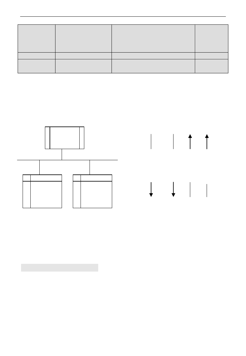
E3000
·106·
F901
Modbus Mode Selection
1: ASCII mode
2: RTU mode
3: Reserved 4:PROFIBUS_DP
5: CANOPEN
1
F903
Parity Check
0: Invalid 1: Odd 2: Even
0
F904
Baud Rate
0: 1200 1: 2400 2: 4800 3: 9600
4: 19200 5: 38400 6: 57600
3
Please set functions code related to communication consonant with the PLC/PC communication parameters,
when inverter communicates with PLC/PC.
Ⅳ Physical Interface
4.1 Interface instruction
Communication interface of RS485 is located on the most left of control terminals, marked underneath with
A+ and B-
4.2 Structure of Field Bus
Connecting Diagram of Field Bus
RS485 Half-duplex communication mode is adopted for E3000 series inverter. Daisy chain structure is
adopted by 485 Bus-line. Do not use 'spur' lines or a star configuration. Reflect signals which are produced
by spur lines or star configuration will interfere in 485 communications.
Please note that for the same time in half-duplex connection, only one inverter can have communication
with PC/PLC. Should two or more than two inverters upload data at the same time, then bus competition
will occur, which will not only lead to communication failure, but higher current to certain elements as well.
3. Grounding and Terminal
Terminal resistance of 120
will be adopted for terminal of RS485 network, to diminish the reflection of
signals. Terminal resistance shall not be used for intermediate network.
Inverter
Inverter
Control
Comman
d
Given
Value
Status
Info
Actual
Value
PLC/PC
Field Bus
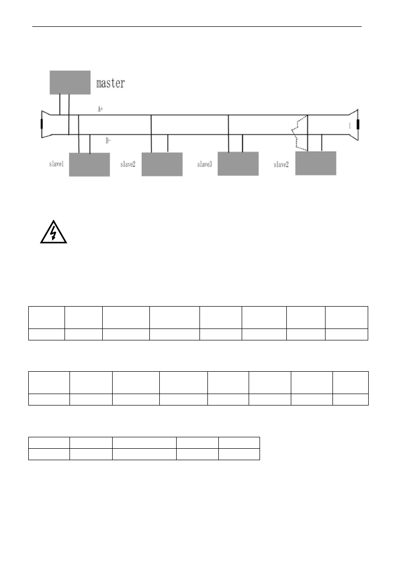
E3000
·107·
No direct grounding shall be allowed for any point of RS485 network. All the equipment in the network
shall be well grounded via their own grounding terminal. Please note that grounding wires will not form
closed loop in any case.
Connecting Diagram of Terminal Resistance
Please think over the drive capacity of PC/PLC and the distance between PC/PLC and inverter when wiring.
Add a repeaters if drive capacity is not enough.
All wiring connections for installation shall have to be made when the inverter is
disconnected from power supply.
V. Examples
Eg1: In RTU mode, change acc time (F114) to 10.0s in NO.01 inverter.
Query
Address
Function
Register
Address Hi
Register
Address Lo
Preset
Data Hi
Preset
Data Lo
CRC Lo
CRC Hi
01
06
01
0E
00
64
E8
1E
Function code F114 Value: 10.0S
Normal Response
Address
Function
Register
Address Hi
Register
Address Lo
Response
Data Hi
Response
Data Lo
CRC Lo
CRC Hi
01
06
01
0E
00
64
E8
1E
Function code F114 Normal Response
Abnormal Response
Address
Function
Abnormal code
CRC Lo
CRC Hi
01
86
04
43
A3
The max value of function code is 1. Slave fault
Eg 2:Read output frequency, output voltage, output current and current rotate speed from N0.2 inverter.
Host Query
Terminal
Resistor
The distance should
be less than 0.5M.
Terminal
Resistor

E3000
·108·
Address
Function
First Register
Address Hi
First Register
Address Lo
Register
count Hi
Register
count L0
CRC
Lo
CRC
Hi
02
03
10
00
00
04
40
FA
Communication Parameters Address 1000H
Slave Response:
Address
Function
Byte
Count
Data Hi
Data Lo
Data Hi
Data Lo
Data Hi
Data Lo
Data Hi
Data
Lo
Crc Lo
Crc
Hi
02
03
08
13
88
01
90
00
3C
02
00
82
F6
Output Frequency Output Voltage Output Current Numbers of Pole Pairs Control Mode
NO.2 Inverter‟s output frequency is 50.00Hz, output voltage is 400V, output current is 6.0A, numbers of pole pairs
are 2 and control mode keypad control.
Eg 3: NO.1 Inverter runs forwardly.
Host Query:
Address
Function
Register
Hi
Register
Lo
Write
status Hi
Write
status Lo
CRC Lo
CRC Hi
01
06
20
00
00
01
43
CA
Communication parameters address 2000H Forward running
Slave Normal Response:
Address
Function
Register
Hi
Register
Lo
Write
status Hi
Write
status Lo
CRC Lo
CRC Hi
01
06
20
00
00
01
43
CA
Normal Response
Slave Abnormal Response:
Address
Function
Abnormal Code
CRC Lo
CRC Hi
01
86
01
83
A0
The max value of function code is 1. Illegal function code (assumption)
Eg4: Read the value of F113, F114 from NO.2 inverter
Host Query:
Address
Function
Register
Address Hi
Register
Address Lo
Register
Count Hi
Register
Count L0
CRC
Lo
CRC
Hi
02
03
01
0D
00
02
54
07
Communication Parameter Address F10DH Numbers of Read Registers
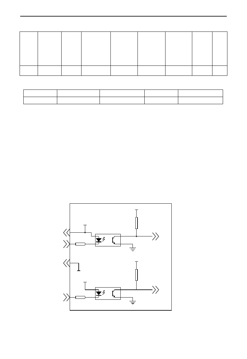
E3000
·109·
Slave Normal Response:
Address
Function
Byte
count
The first
parameters
status Hi
The first
parameters
status Lo
The second
parameters
status Hi
The second
parameters
status Lo
CRC
Lo
CRC
Hi
02
03
04
03
E8
00
78
49
61
The actual value is 10.00. The actual value is 12.00.
Slave Abnormal Response:
Address
Function Code
Abnormal Code
CRC Lo
CRC Hi
02
83
08
B0
F6
The max value of function code is 1. Parity check fault
Appendix 6 Introduction of PG card
1. Introduction
1.1 When F106=1, close-loop vector control mode is selected, PG expand card should be selected. User
should connect encoder line correctly. PGA and PGB terminals can receive two-way orthogonal encoder
signal (only NPN type encoder can be connected), the power supply of encoder is +12V.
User should select shielding wire and one end of it should be connected to the grounding, the length of wire
should be shorter than 30m.
1.2
+12V
+3.3V
+12V
+3.3V
CM
Encoder port diagram
A
B
+12V
PG A
CM
PG B
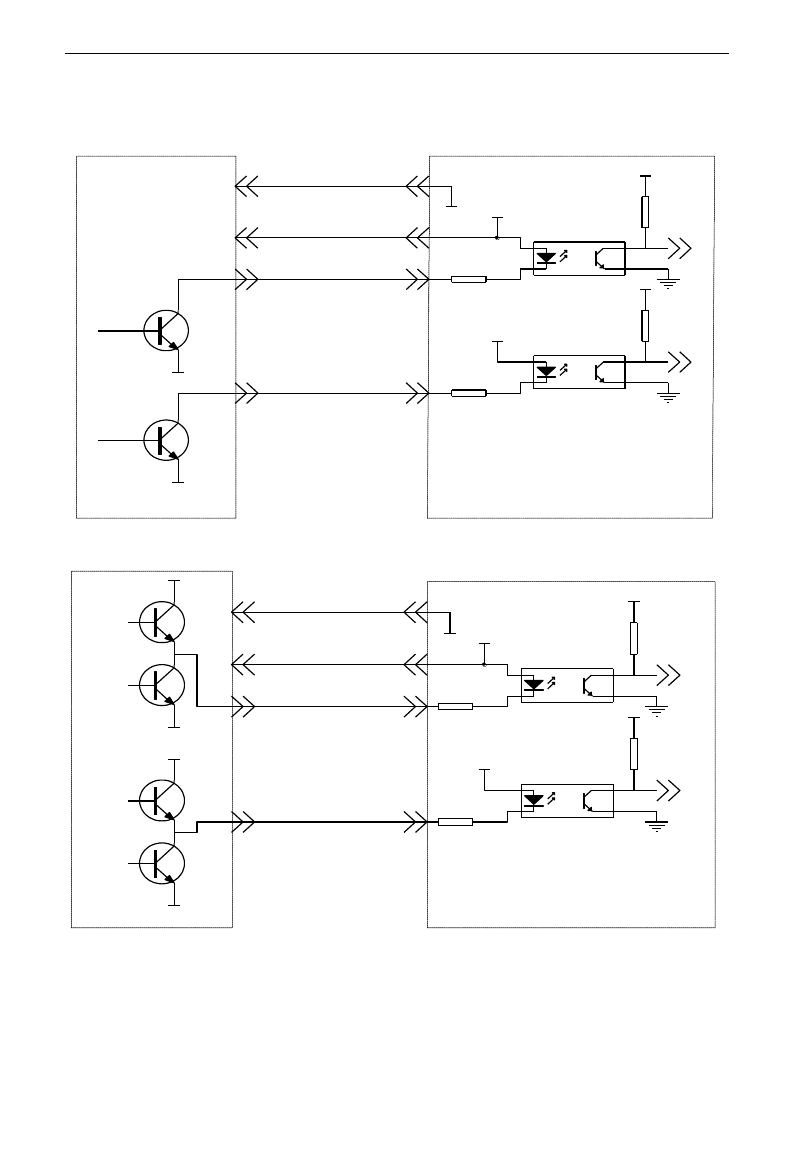
E3000
·110·
1.3 Application
1.3.1 Open-collector output encoder
1.3.2 Push-Pull output encoder
B
A
VC C
GND
CM
CM
+12V
+3.3V
+12V
+3.3V
PG A
PG B
+12V
PG CA RD
A
B
0V
0V
B
A
CM
CM
+12V
+3.3V
+12V
+3.3V
PG A
PG B
+12V
PG card
VC C
VC C
0V
VC C
A
B
0V
0V
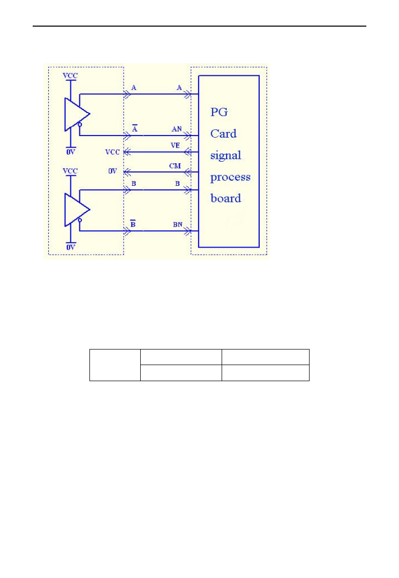
E3000
·111·
1.3.3 Differential encoder
Note: VCC=5V, please pay attention.
1.4 Installation
For 3.7kW and above 3.7kW inverter, PG card is installed inside of inverter by 3*5 tapping screw. User can
connect J4 of PG card to J6 or J4 of control board by 20-core wire. For 2.2kW and below 2.2kW inverter,
PG card is installed outside of inverter, the length of wire should be shorter than 30cm, please refer to
following table:
PG CARD
External size (mm)
Installation size (mm)
86*35
76*25
2. Note
1. The signal wire of encoder should be far away from power wire.
2. Please select shielding wire as the encoder signal wire, and one end of it should be connected to grounding.
3. The length of shielding wire should be shorter than 30m, if user needs the wire longer than 30m, please
indicate it.
4. The given direction of inverter, the rotation direction of motor (from output axis of motor) and the
rotation direction of encoder should be the same.

E3000
·112·
Appendix 7 Zoom Table of Function Code
Basic parameters F100~F160
Function
Code
Function
Definition
Setting Range
Mfr‟s Value
Change
F100
User‟s Password
0~9999
8
√
F102
Inverter‟s Rated Current (A)
1.0~1000
Subject to inverter model
*
F103
Inverter Power (kW)
0.20~650.00
Subject to inverter model
*
F104
Inverter Power Code
100~400
Subject to inverter model
*
F105
Software Edition No.
1.00~10.00
Subject to inverter model
*
F106
Control mode
Setting range:
0:Sensorless vector
control (SVC);
1: Closed-loop vector
control (VC);
2: VVVF
3: Vector control 1
0
╳
F107
Password Valid or Not
0: invalid; 1: valid
0
√
F108
Setting User‟s Password
0~9999
8
√
F109
Starting Frequency (Hz)
0.0~10.00Hz
0.00Hz
√
F110
Holding Time of Starting Frequency
(S)
0.0~10.0S
0.0
√
F111
Max Frequency (Hz)v
F113~650.0Hz
50.00Hz
√
F112
Min Frequency (Hz)
0.00Hz~F113
0.50Hz
√
F113
Target Frequency (Hz)
F111~F112
50.00Hz
√
F114
1stAcceleration Time
0.1~3000S
5.0S for 0.2~4.0 kW
30.0S for 5.5~30kW
60.0S for above 37kW.
√
F115
1stDeceleration Time
0.1~3000S
√
F116
2ndAcceleration Time
0.1~3000S
8.0S for 0.2~4.0 kW
50.0S for 5.5~30kW
90.0S for above 37kW.
√
F117
2nd Deceleration Time
0.1~3000S
√
F118
Turnover Frequency
15.00~650.0Hz
50.00
╳
F119
Reference of setting
accel/decel time
0: 0~50.00Hz
1: 0~max frequency
0
╳
F120
Forward/Reverse Switchover
dead-Time
0.0~3000S
0.0S
√
F121
Reserved
F122
Reverse running forbidden
0: invalid; 1: valid
0
╳
F123
Minus frequency is valid in the
mode of combined speed control.
0:Invalid;1:valid
0
╳
F124
Jogging Frequency
F112~F111
5.00Hz
√
F125
Jogging Acceleration Time
0.1~3000S
0.2~4.0kW: 5.0S
5.5~30kW: 30.0S
Above37kW: 60.0S
√
F126
Jogging Deceleration Time
0.1~3000S
√

E3000
·113·
F127
Skip Frequency A
0.00~650.0Hz
0.00Hz
√
F128
Skip Width A
±2.50Hz
0.00
√
F129
Skip Frequency B
0.00~650.0Hz
0.00Hz
√
F130
Skip Width B
±2.50Hz
0.00
√
F131
Running Display Items
0-Present output
frequency / function code
1-Current output rotary speed
2-Output current
4-Output voltage
8-PN voltage
16-PID feedback value
32-Temperature
64-Count values
128-Linear speed
256-PID given value
512-Yarn length
1024: Center frequency
2048: Reserved
4096: Output torque
0+1+2+4+8=15
√
F132
Display items of stop
0: frequency / function code
1: Keypad jogging
2: Target rotary speed
4: PN voltage
8: PID feedback value
16: Temperature
32: Count values
64: PID given value
128: Yarn length
256: Center frequency
512: Setting torque
2+4=6
√
F133
Drive Ratio of Driven System
0.10~200.0
1.0
√
F134
Transmission-wheel radius
0.001~1.000(m)
0.001
√
F135
Reserved
F136
Slip compensation
0~10%
0
╳
F137
Modes of torque compensation
0: Linear compensation;
1: Square compensation;
2: User-defined multipoint
compensation
3: Auto torque compensation
3
╳
F138
Linear compensation
1~16
0.2-4.0: 5
5.5-30: 4
Above 37: 3
╳
F139
Square compensation
1:1.5; 2:1.8;
3:1.9; 4:2.0
1
╳
F140
User-defined frequency point 1
0~F142
1.00
╳
F141
User-defined voltage point 1
0~100%
4
╳
F142
User-defined frequency point 2
F140~F144
5.00
╳
F143
User-defined voltage point 2
0~100%
13
╳
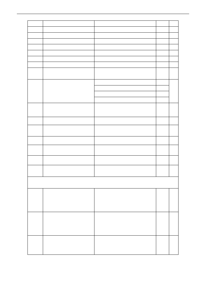
E3000
·114·
F144
User-defined frequency point 3
F142~F146
10.00
╳
F145
User-defined voltage point 3
0~100%
24
╳
F146
User-defined frequency point 4
F144~F148
20.00
╳
F147
User-defined voltage point 4
0~100%
45
╳
F148
User-defined frequency point 5
F146~F150
30.00
╳
F149
User-defined voltage point 5
0~100%
63
╳
F150
User-defined frequency point 6
F148~F118
40.00
╳
F151
User-defined voltage point 6
0~100%
81
╳
F152
Output voltage corresponding to
turnover frequency
10~100%
100
╳
F153
Carrier frequency setting
0.2~7.5kW: 800~10000
4000
╳
11~15kW: 800~10000
3000
18.5kW~45kW: 800~6000
4000
Above 55kW: 800~4000
2000
F154
Automatic voltage rectification
Setting range:
0: Invalid 1: Valid
2:Invalid during deceleration process
0
╳
F155
Digital accessorial frequency setting
0~F111
0
╳
F156
Digital accessorial frequency polarity
setting
0 or 1
0
╳
F157
Reading accessorial frequency
△
F158
Reading accessorial frequency
polarity
△
F159
Random carrier-wave frequency
selection
0: Control speed normally;
1: Random carrier-wave frequency
F160
Reverting to manufacturer values
0: Not reverting to manufacturer values;
1: Reverting to manufacturer values
0
╳
Running control mode F200~F230:
F200
Source of start command
0: Keypad command;
1: Terminal command;
2: Keypad+Terminal;
3: Communication;
4: Keypad+Terminal+Communication
0
╳
F201
Source of stop command
0: Keypad command;
1: Terminal command;
2: Keypad+Terminal;
3: Communication;
4: Keypad+Terminal+Communication
0
╳
F202
Mode of direction setting
0: Forward running locking;
1: Reverse running locking;
2: Terminal setting
0
╳

E3000
·115·
F203
Main frequency source X
0: Digital setting memory;
1: External analog AI1;
2: External analog AI2;
3: Pulse input given;
4: Stage speed control;
5: No memory by digital setting;
6:Keypad potentiometer AI3;
7: Reserved;
8: Reserved;
9: PID adjusting; 10: Communication
0
╳
F204
Accessorial frequency
source Y
0: Digital setting memory;
1: External analog AI1;
2: External analog AI2;
3: Pulse input given;
4: Stage speed control;
5: PID adjusting;
6: Keypad potentiometer AI3;
0
╳
F205
Reference for selecting
accessorial frequency source Y
range
0: Relative to max frequency;
1: Relative to main frequency X
0
╳
F206
Accessorial frequency Y range
0~100%
100
╳
F207
Frequency source selecting
0: X; 1: X+Y;
2: X or Y (terminal switchover);
3: X or X+Y (terminal switchover);
4: Combination of stage speed and analog
5: X-Y 6: X+(Y-50%)
0
╳
F208
Terminal
two-line/three-line
operation control
0: No function;
1: Two-line operation mode 1;
2: Two-line operation mode 2;
3: three-line operation mode 1;
4: three-line operation mode 2;
5: start/stop controlled by direction
pulse
0
╳
F209
Selecting the mode of
stopping the motor
0: stop by deceleration time;
1: free stop
0
╳
F210
Frequency display accuracy
0.01~2.00
0.01
√
F211
Speed of digital control
0.01~100.00Hz/S
5.00
Hz/S
√
F212
Reserved
F213
Auto-starting after repowered
on
0: invalid; 1: valid
0
√
F214
Auto-starting after reset
0: invalid; 1: valid
0
√
F215
Auto-starting delay time
0.1~3000.0
60.0
√
F216
Times of auto-starting in case of
repeated faults
0~5
0
√
F217
Delay time for fault reset
0.0~10.0
3.0
√
F218~
F219
Reserved
F220
Frequency memory after
power-down
0: invalid; 1: valid
0
√
F221
Reserved
F222
count memory selection
Setting range: 0: Invalid 1: Valid
0
√

E3000
·116·
F223~
F229
Reserved
F230
Application macro
selection
0~8
0
×
F231
Reverting to macro
manufacturer values
0: Not reverting to manufacturer
1: Reverting to manufacturer values
0
×
F232~F2
34
Reserved
Traverse Operating function
F235
Traverse operating mode
0:Invalid
1:Traverse operating mode 1
2:Traverse operating mode 2
3:Traverse operating mode 3
0
×
F236
Crawl-positioning
0:Disabled 1:Enabled
0
√
F237
Traverse signal source
0:Auto start 1:X terminal start
0
F238
Stop mode of length arrival
0:Stop the motor at fixed length
1:Stop the motor at fixed spindle
radius
2:Non-stop at fixed length, it
indicates full of yarn.
3:Fixed radius arrival, it indicates
full of yarn.
0
×
F239
Traverse memory mode
0: Memory at the status of stop and
power off
1: Only memory at the status of stop.
2: Only memory at the status of
power off.
3:No memory.
0
√
F240
Preset frequency (Hz)
F112~F111
5.00
√
F241
Running time of preset frequency
(S)
0~3000.0
0
√
F242
Central frequency (Hz)
F243~F111
25.00
√
F243
Lower limit of central frequency
(Hz)
F112~F242
0.50
√
F244
Descending rate of central
frequency (Hz / S)
0~65.00
0.500
√
F245~F246
Reserved
F247
Traverse amplitude setting mode
0:Relative to max frequency
1:Relative to central frequency
1
×
F248
Traverse amplitude
0~100.00%
10.00%
√
F249
Jump frequency
0~50.00%
30.00%
√
F250
Rising time of traverse (S)
1~3000.0
10.0
√
F251
Descending time of traverse (S)
1~3000.0
10.0
√
F252
Crawl-positioning frequency (Hz)
F112~F111
3.00
√
F253
Waiting time of crawl-positioning
(S)
0~3000.0
5.0
√
F254
Max time of crawl-positioning (S)
0~3000.0
10.0
√
F255~F256
Reserved

E3000
·117·
F257
Cumulative length (Km)
0~6500
0
√
F258
Actual length (Km)
0~65.00
0
√
F259
Setting length (Km)
0~65.00
0
√
F260
Pulse numbers of length sensor
0~650.0
1.00
√
F261~F263
Reserved
F264
Feedback channel of fixed radius
0:AI1
1:AI2
0
√
F265
Fixed-radius display value
0~10000
5000
√
F266
Output voltage at fixed radius
mode (V)
0~10.00
5.00
√
F267
Voltage hysteresis when judging
full of yarn signal is clear.
0~10.00
0
√
F268~F271
Reserved
F272
Delay time of yarn broken and
yarn intertwining(S)
0~3000.0
0
√
F273~F274
Reserved
F275
Detect frequency value
F112~F111
25.00
√
F276
Detect frequency width
0~20.00
0.50
√
Multifunctional Input and Output Terminals: F300~F330
Function
Code
Function
Definition
Setting Range
Mfr‟s Value
Change
F300
Relay token output
0: no function;
1: inverter fault protection;
2: over latent frequency 1;
3: over latent frequency 2;
4: free stop;
5: in running status 1;
6: DC braking;
7: acceleration/deceleration time
switchover;
8: Reaching the Set Count Value;
9: Reaching the Designated Count
Value;
10: inverter overload pre-alarm;
11: motor overload pre-alarm;
12: stalling;
13: Inverter is ready to run
14: in running status 2;
15: frequency arrival output;
16: overheat pre-alarm;
17: over latent current output
18: Analog line disconnection
protection
19: Under-load protection output
20: Zero current detecting output
30: General pump is running
31: Converter pump is running
32: Over-limit pressure token
35: Stop signal of yarn full, yarn
broken, yarn intertwining and stop
inverter by manual
36: Full yarn signal
1
√
F301
DO1 token output
14
√
F302
DO2 token output
5

E3000
·118·
37: Output signal of traverse rising
38: Traverse wave form output
39: Yarn frequency detected
F303~
F306
Reserved
F307
Characteristic frequency 1
F112~F111
10.00Hz
√
F308
Characteristic frequency 2
F112~F111
50.00Hz
√
F309
Characteristic frequency
width
0~100%
50%
√
F310
Characteristic current
0~1000A
Rated current
√
F311
Characteristic current width
0~100%
10%
√
F312
Frequency arrival threshold
0.00~5.00Hz
0.00
√
F313
Count frequency divisions
1~65000
1
√
F314
Set count value
F315~65000
1000
√
F315
Designated count value
1~F314
500
√
F316
OP1 terminal function
setting
0: no function;
1: running terminal;
2: stop terminal;
3: multi-stage speed terminal 1;
4: multi-stage speed terminal 2;
5: multi-stage speed terminal 3;
6: multi-stage speed terminal 4;
7: reset terminal;
8: free stop terminal;
9: external emergency stop terminal;
10: acceleration/deceleration
forbidden terminal;
11: forward run jogging;
12: reverse run jogging;
13: UP frequency increasing terminal;
14: DOWN frequency decreasing terminal;
15: “FWD” terminal;
16: “REV” terminal;
17: three-line type input “X” terminal;
18: acceleration/deceleration time
switchover terminal;
19-20: Reserved;
21: frequency source switchover terminal;
22: Count input terminal:
23: Count reset terminal
24~29: reserved
30: Water lack signal;
31: Signal of water
32: Fire pressure switchover;
33: Emergency fire control
11
√
F317
OP2 terminal function
setting
9
√
F318
OP3 terminal function
setting
15
√
F319
OP4 terminal function
setting
16
√
F320
OP5 terminal function
setting
7
√
F321
OP6 terminal function
setting
8
√
F322
OP7 terminal function
setting
1
√
F323
OP8 terminal function
setting
2
√
F322~F32
3
Reserved
F324
Free stop terminal logic
0: positive logic (valid for low level);
1: negative logic (valid for high level)
0
╳
F325
External emergency stop
terminal logic
0
╳
F328
Terminal filter times
1~100
10
√
F329~F330
Reserved

E3000
·119·
Analog Input and Output: F400~F473
Function
Code
Function Definition
Setting Range
Mfr‟s
Value
F400
Lower limit of AI1 channel input
0.00~F402
0.01V
√
F401
Corresponding setting for lower limit of AI1
input
0~F403
1.00
√
F402
Upper limit of AI1 channel input
F400~10.00V
10.00V
√
F403
Corresponding setting for upper limit of AI1
input
Max(1.00,F401)~2.00
2.00
√
F404
AI1 channel proportional gain K1
0.0~10.0
1.0
√
F405
AI1 filtering time constant
0.1~10.0
0.1
√
F406
Lower limit of AI2 channel input
0.00~F408
0.01V
√
F407
Corresponding setting for lower limit of AI2
input
0~F409
1.00
√
F408
Upper limit of AI2 channel input
F406~10.00V
10.00V
√
F409
Corresponding setting for upper limit of AI2
input
Max(1.00,F407)~2.00
2.00
√
F410
AI2 channel proportional gain K2
0.0~10.0
1.0
√
F411
AI2 filtering time constant
0.1~10.0
0.1
√
F412
Lower limit of AI3 channel input
0.00~F414
0.01V
√
F413
Corresponding setting for lower limit of AI3
input
0~F415
1.00
√
F414
Upper limit of AI3 channel input
F412~10.0V
10.0V
√
F415
Corresponding setting for upper limit of AI3
input
Max(1.00,F413)~2.00
2.00
√
F416
AI3 channel proportional gain K1
0.0~10.0
1.0
√
F417
AI3 filtering time constant
0.1~10.0
0.1
√
F418
AI1 channel 0Hz voltage dead zone
0~0.50V (Positive-Negative)
0.00
√
F419
AI2 channel 0Hz voltage dead zone
0~0.50V (Positive-Negative)
0.00
√
F420
AI3 channel 0Hz voltage dead zone
0~0.50V (Positive-Negative)
0.00
√
F421
Panel selection
0: Local keypad panel
1: Remote control keypad panel
0
√
F422
Potentiometer selection
0: Potentiometer in local panel
1: Potentiometer in remote
control panel
0
√
F423
AO1 output range selecting
0: 0~5V 1:0~10V or 0-20mA
2: 4-20mA
1
√
F424
AO1 lowest corresponding frequency
0.0~F425
0.05Hz
√
F425
AO1 highest corresponding frequency
F424~F111
50.00Hz
√
F426
AO1 output compensation
0~120%
100
√
F427
AO2 output range
0:0~20mA;1:4~20mA
0
√
F428
AO2 lowest corresponding frequency
0.0~F429
0.05Hz
√
F429
AO2 highest corresponding frequency
F428~F111
50.00Hz
√
F430
AO2 output compensation
0~120%
100
√
F431
AO1 analog output signal selecting
0: Running frequency;
1: Output current;
0
√

E3000
·120·
F432
AO2 analog output signal selecting
2: Output voltage;
3~5: Reserved
1
√
F433
Corresponding current for full range of external
voltmeter
0.01~5.00 times of rated current
2
╳
F434
Corresponding current for full range of external
ammeter
2
╳
F435~
F436
Reserved
F437
Analog filter width
1~100
10
*
F438~
F439
Reserved
F440
Min frequency of input pulse FI
0.00~F442
0.00K
√
F441
Corresponding setting of FI min
frequency
0.00~F443
1.00
√
F442
Max frequency of input pulse FI
F440~50.00K
10.00K
√
F443
Corresponding setting of FI max
frequency
Max(1.00,F441)~2.00
2.00
√
F444
Reserved
F445
Filtering constant of FI input pulse
0~100
0
√
F446
FI channel 0Hz frequency dead zone
0~F442Hz (Positive-Negative)
0.00
√
F447~
F448
Reserved
F449
Max frequency of output pulse FO
0.00~50.00K
10.00K
√
F450
Zero bias coefficient of output pulse
frequency
0.0~100.0%
0.0%
√
F451
Frequency gain of output pulse
0.00~10.00
1.00
√
F452
Reserved
F453
Output pulse signal
0: Running frequency
1: Output current
2: Output voltage
3~5: reserved
0
√
F460
AI1channel input mode
0: straight line mode
1: folding line mode
0
╳
F461
AI2 channel input mode
0: straight line mode
1: folding line mode
0
╳
F462
AI1 insertion point A1 voltage value
F400~F464
2.00V
╳
F463
AI1 insertion point A1 setting value
F401~F465
1.20
╳
F464
AI1 insertion point A2 voltage value
F462~F466
5.00V
╳
F465
AI1 insertion point A2 setting value
F463~F467
1.50
╳
F466
AI1 insertion point A3 voltage value
F464~F402
8.00V
╳
F467
AI1 insertion point A3 setting value
F465~F403
1.80
╳
F468
AI2 insertion point B1 voltage value
F406~F470
2.00V
╳
F469
AI2 insertion point B1 setting value
F407~F471
1.20
╳
F470
AI2 insertion point B2 voltage value
F468~F472
5.00V
╳
F471
AI2 insertion point B2 setting value
F469~F473
1.50
╳
F472
AI2 insertion point B3 voltage value
F470~F412
8.00V
╳
F473
AI2 insertion point B3 setting value
F471~F413
1.80
╳

E3000
·121·
Multi-stage Speed Control: F500~F580
Function
Code
Function Definition
Setting Range
Mfr‟s Value
F500
Stage speed type
0: 3-stage speed;
1: 15-stage speed;
2: Max 8-stage speed auto
circulating
1
╳
F501
Selection of Stage Speed Under
Auto-circulation Speed Control
2~8
7
√
F502
Selection of Times of Auto- Circulation
Speed Control
0~9999(when the
value is set to 0, the
inverter will carry out
infinite circulating)
0
√
F503
Status after auto circulation running
Finished
0: Stop
1: Keep running at last
stage speed
0
√
F504
Frequency setting for stage 1 speed
F112~F111
5.00Hz
√
F505
Frequency setting for stage 2 speed
F112~F111
10.00Hz
√
F506
Frequency setting for stage 3 speed
F112~F111
15.00Hz
√
F507
Frequency setting for stage 4 speed
F112~F111
20.00Hz
√
F508
Frequency setting for stage 5 speed
F112~F111
25.00Hz
√
F509
Frequency setting for stage 6 speed
F112~F111
30.00Hz
√
F510
Frequency setting for stage 7 speed
F112~F111
35.00Hz
√
F511
Frequency setting for stage 8 speed
F112~F111
40.00Hz
√
F512
Frequency setting for stage 9 speed
F112~F111
5.00Hz
√
F513
Frequency setting for stage 10 speed
F112~F111
10.00Hz
√
F514
Frequency setting for stage 11 speed
F112~F111
15.00Hz
√
F515
Frequency setting for stage 12 speed
F112~F111
20.00Hz
√
F516
Frequency setting for stage 13 speed
F112~F111
25.00Hz
√
F517
Frequency setting for stage 14 speed
F112~F111
30.00Hz
√
F518
Frequency setting for stage 15 speed
F112~F111
35.00Hz
√
F519~
F533
Acceleration time setting for the speeds from
Stage 1 to stage 15
0.1~3000S
0.2-4.0kW:5.0S
5.5-30kW:30.0S
Above 37kW:
60.0S
√
F534~
F548
Deceleration time setting for the speeds from
Stage 1 to stage 15
0.1~3000S
0.2-4.0kW:5.0S;
5.5-30kW:30.0S
Above 37kW:
60.0S
√
F549~
F556
Running directions of stage speeds from
Stage 1 to stage 8
0: forward running;
1: reverse running
0
√
F557~F5
64
Running time of stage speeds from Stage 1
to stage 8
0.1~3000S
1.0S
√
F565~
F572
Stop time after finishing stages from Stage
1 to stage 8.
0.0~3000S
0.0S
√
F573~
Running directions of stage speeds from
0: forward running;
0
√

E3000
·122·
F579
Stage 9 to stage 15.
1: reverse running
F580
Reserved
Auxiliary Functions: F600~F650
Function
Code
Function Definition
Setting Range
Mfr‟s Value
F600
DC Braking Function Selection
0: not allowed;
1: braking before starting;
2: braking during stopping;
3: braking during starting and stopping
0
√
F601
Initial Frequency for DC Braking
0.2~5.00
1.00
√
F602
DC Braking efficiency before Starting
0~100
10
√
F603
DC Braking efficiency During Stop
0~100
10
√
F604
Braking Lasting Time Before Starting
0.0~10.0
0.5
√
F605
Braking Lasting Time During Stopping
0.0~10.0
0.5
√
F606
DC braking mode selection
0: Braking by voltage
1: Braking by current
2: Auto braking by voltage
0
F607
Selection of Stalling Adjusting Function
0: invalid; 1: valid
0
√
F608
Stalling Current Adjusting (%)
60~200
160
√
F609
Stalling Voltage Adjusting (%)
60~200
140
√
F610
Stalling Protection Judging Time
0.1~3000.0
5.0
√
F611
Dynamic Braking threshold
200~1000
Single
phase :380V
Three phase:
700V
△
F612
Dynamic braking duty ratio (%)
0~100%
80
╳
F613
Speed track
0: invalid 1: valid
2: valid at the first time
0
╳
F614
Speed track mode
0: Speed track from frequency
memory
1: Speed track from max frequency
2: Speed track from frequency
memory and direction memory
3: Speed track from max frequency
and direction memory
0
╳
F615
Speed track rate
1~100
20
╳
F616~
F621
Reserved
F622
Dynamic braking mode
0: Fixed duty ratio
1: Auto duty ratio
0
√
F623
Dynamic braking frequency (Hz)
100~10000
500
√
F624-
F630
Reserved

E3000
·123·
Timing Control and Protection: F700~F760
Functio
n Code
Function Definition
Setting Range
Mfr‟s Value
F700
Selection of terminal free
stop mode
0: free stop immediately;
1: delayed free stop
0
√
F701
Delay time for free stop and
programmable terminal action
0.0~60.0s
0.0
√
F702
Fan control mode
0:controlled by temperature
1: Running when inverter is powered on
2: Controlled by running status
0.2~90kW: 0
Above 110kW:
2
╳
F703
Setting fan control temperature
0~100℃
45℃
╳
F704
Inverter Overloading pre-alarm
Coefficient (%)
50~100
80
╳
F705
Motor Overloading pre-alarm
Coefficient (%)
50~100
80
╳
F706
Inverter Overloading Coefficient %
120~190
150
╳
F707
Motor Overloading
Coefficient %
20~100
100
╳
F708
Record of The Latest
Malfunction Type
Setting range:
2: over current (OC)
3: over voltage (OE)
4: input phase loss (PF1)
5: inverter overload (OL1)
6: under voltage (LU)
7: overheat (OH)
8: motor overload (OL2)
11: external malfunction (ESP)
13. studying parameters without motor
(Err2)
16: over current 1 (OC1)
17: output phase loss (PF0)
18: Aerr analog disconnected
20: EP/EP2/EP3 under-load
22: Np pressure control
23: Err5 PID parameters are set wrong
△
F709
Record of Malfunction Type for
Last but One
△
F710
Record of Malfunction Type for
Last but Two
△
F711
Fault Frequency of The Latest
Malfunction
△
F712
Fault Current of The Latest
Malfunction
△
F713
Fault PN Voltage of The Latest
Malfunction
△
F714
Fault Frequency of Last
Malfunction but One
△
F715
Fault Current of Last
Malfunction but One
△
F716
Fault PN Voltage of Last
Malfunction but One
△
F717
Fault Frequency of Last
Malfunction but Two
△

E3000
·124·
F718
Fault Current of Last
Malfunction but Two
△
F719
Fault PN Voltage of Last
Malfunction but Two
△
F720
Record of overcurrent
protection fault times
△
F721
Record of overvoltage
protection fault times
△
F722
Record of overheat protection
fault times
△
F723
Record of overload protection
fault times
△
F724
Input phase loss
0: invalid; 1: valid
1
╳
F725
Undervoltage
0: invalid; 1: valid
1
╳
F726
Overheat
0: invalid; 1: valid
1
╳
F727
Output phase loss
0: invalid; 1: valid
0
╳
F728
Input phase loss filtering
constant
0.1~60.0
0.5
√
F729
Undervoltage filtering
constant
0.1~60.0
5.0
√
F730
Overheat protection filtering
constant
0.1~60.0
5.0
√
F732
Voltage threshold of
undervoltage protection
0~450
Single-phase: 215
Three-phase: 400
○
F737
Over-current 1 protection
0: Invalid 1:Valid
0
F738
Over-current 1 protection
coefficient
0.50~3.00
2.0
F739
Over-current 1 protection
record
△
F741
Analog disconnected
protection
0: Invalid
1: Stop and AErr displays.
2: Stop and AErr is not displayed.
3: Inverter runs at the min frequency.
4: Reserved.
0
√
F742
Threshold of analog
disconnected protection (%)
1~100
50
○
F745
Threshold of pre-alarm
overheat (%)
0~100
80
○
F747
Carrier frequency
auto-adjusting
0: Invalid 1: Valid
1
√
F745
Zero-current threshold (%)
0~200
5
╳
F755
Duration time of zero-current
0~60
0.5
√
F756~
F759
Reserved
F760
Grounding fault
0: Invalid 1: Grounding fault 1
2: Grounding fault 2 3: Reserved
0
√
F761~
F770
Reserved

E3000
·125·
Motor parameters: F800~F860
Functio
n Code
Function Definition
Setting Range
Mfr‟s Value
F800
Motor‟s parameters
tuning
Setting range:
0: Invalid;
1: Rotating tuning.;
2: Stationary tuning;
0
╳
F801
Rated power
0.2~1000kW
╳
F802
Rated voltage
1~440V
╳
F803
Rated current
0.1~6500A
╳
F804
Number of motor poles
2~100
4
╳
F805
Rated rotary speed
1~30000
╳
F806
Stator resistance
0.001~65.00Ω
╳
F807
Rotor resistance
0.001~65.00Ω
╳
F808
Leakage inductance
0.01~650.0mH
╳
F809
Mutual inductance
0.1~6500mH
╳
F810
Motor rated power
1.00~300.0Hz
50.00
╳
F813
Rotary speed loop KP1
0.01~20.00(Below 22kW)
0.01~50.00(Above 30kW)
0.2-2.2kW: 2.00
3.7-7.5kW: 4.00
11-30kW: 8.00
37-75kW: 15.00
Over 90kW: 20.00
√
F814
Rotary speed loop KI1
0.01~2.00(Below 22kW)
0.01~3.00(Above 30kW)
1.00
√
F815
Rotary speed loop KP2
0.01~20.00(Below 22kW)
0.01~50.00(Above 30kW)
0.2-7.5kW: 2.00
11-22kW: 6.00
30kW: 8.00
37-75kW: 15.00
Over 90kW: 25.00
√
F816
Rotary speed loop KI2
0.01~2.00(Below 22kW)
0.01~3.00(Above 30kW)
1.00
√
F817
PID switching frequency 1
0~F111
5.00
√
F818
PID switching frequency 2
F817~F111
50.00
√
F819
Rotary speed loop KP3
0.01~20.00(Below 22kW)
0.01~30.00(Above 30kW)
Single phase:
≤0.2kW: 0.10 0.2-0.4kW: 0.20
≥0.75kW: 0.40
Three phase:
0.2-2.2kW: 0.40 3.7-7.5kW: 0.50
11-15kW: 2.00 15-30kW: 1.00
37-75kW: 8.00 >75kW: 10.00
√
F820
Rotary speed loop KI3
0.01~2.00(Below 22kW)
0.01~10.00(Above 30kW)
Single phase: 0.40
Three phase:
≤15kW: 1.00 >15kW: 0.2
√
F821
PI switching frequency 3
F818~F111
100.0
F827~
F830
Reserved
F851
Encoder resolution
1~9999
1000
╳
F852~
F860
Reserved

E3000
·126·
Communication Parameter: F900~F930
Function
Code
Function Definition
Setting Range
Mfr‟s Value
F900
Communication Address
1~255: single inverter address
0: broadcast address
1
√
F901
Communication Mode
1: ASCII 2: RTU
3: Reserved 4:PROFIBUS_DP
5: CANOPEN
1
√
F902
Reserved
F903
Parity Check
0: Invalid 1: Odd 2: Even
0
√
F904
Baud Rate
0: 1200; 1: 2400; 2: 4800;
3: 9600 ; 4: 19200 5: 38400
6: 57600
3
√
F905~F930
Reserved
PID Parameters: FA00~FA80
Function
Code
Function Definition
Setting Range
Mfr‟s
Value
FA00
Water supply mode
0: Single pump (PID control mode)
1: Fixed mode
2: Timing interchanging
0
╳
FA01
PID adjusting target given source
0: FA04 1: AI1 2: AI2
3: AI3 (Potentiometer on the keypad)
4: FI (pulse frequency input)
0
╳
FA02
PID adjusting feedback given
source
1: AI1 2: AI2
3: FI (pulse frequency input)
1
√
FA03
Max limit of PID adjusting (%)
0.0~100.0
10.00
√
FA04
Digital setting value of PID
adjusting (%)
0.0~100.0
50.0
√
FA05
Min limit of PID adjusting (%)
0.0~100.0
0.0
√
FA06
PID polarity
0: Positive feedback
1: Negative feedback
1
╳
FA07
Dormancy function selection
0: Valid 1: Invalid
0
╳
FA08
Reserved
FA09
Min frequency of PID adjusting
(Hz)
F112~F111
5.00
√
FA10
Dormancy delay time (S)
0~500.0
15.0
√
FA11
Wake delay time (S)
0.0~3000
3.0
√
FA12~
FA17
Reserved
FA18
Whether PID adjusting target is
changed
0: Invalid 1: Valid
1
╳
FA19
Proportion Gain P
0.00~10.00
0.3
√
FA20
Integration time I (S)
0.0~100.0S
0.3
√
FA21
Differential time D (S)
0.00~10.00
0.0
√

E3000
·127·
FA22
PID sampling period (S)
0.1~10.0s
0.1
√
FA24
Switching Timing unit setting
0: hour 1: minute
0
╳
FA25
Switching Timing Setting
1~9999
100
╳
FA26
Under-load protection mode
0: No protection
1: Protection by contactor
2: Protection by PID
3: Protection by current
0
╳
FA27
Current threshold of under-load
protection (%)
10~150
80
√
FA28
Waking time after protection
(min)
0.0~3000
60
√
FA29
PID dead time (%)
0.0~10.0
2.0
√
FA30
Running Interval of restarting
converter pump (S)
2.0~999.9s
20.0
√
FA31
Delay time of starting general
pumps (S)
0.1~999.9s
30.0
√
FA32
Delay time of stopping general
pumps (S)
0.1~999.9s
30.0
√
FA36
Whether No.1 relay is started
0: Stopped 1: Started
0
╳
FA37
Whether No.2 relay is started
0: Stopped 1: Started
0
╳
FA47
The sequence of starting No 1
relay
1~20
20
╳
FA48
The sequence of starting No 2
relay
1~20
20
╳
FA58
Fire pressure given value (%)
0.0~100.0
80.0
√
FA59
Emergency fire mode
0: Invalid
1: Emergency fire mode 1
2: Emergency fire mode 2
0
√
FA60
Running frequency of
emergency fire
F112~F111
50.0
√
FA66
Duration time of under-load
protection (S)
0~60
2
√
FA67~
FA80
Reserved

E3000
·128·
Torque control parameters: FC00~FC40
Function
Code
Function Definition
Setting Range
Mfr‟s
Value
FC00
Speed/torque control selection
0:Speed control
1:Torque control
2:Terminal switchover
0
√
FC01
Delay time of torque/speed control
switchover(S)
0.0~1.0
0.1
╳
FC02
Torque accel/decel time (S)
0.1~100.0
1
√
FC03 ~
FC05
Reserved
FC06
Torque given channel
0: Digital given (FC09)
1: Analog input AI1
2: Analog input AI2
3: Analog input AI3
4: Pulse input channel FI
5: Reserved
0
╳
FC07
Torque given coefficient
0~3.000
3.000
╳
FC08
Torque given command value (%)
0~300.0
100.0
√
FC09
FC10 ~
FC13
Reserved
FC14
Offset torque given channel
0: Digital given (FC17)
1: Analog input AI1
2: Analog input AI2
3: Analog input AI3
4: Pulse input channel FI
5: Reserved
0
FC15
Offset torque coefficient
0~0.500
0.500
FC16
Offset torque cut-off frequency (%)
0~100.0
10.00
FC17
Offset torque command value (%)
0~50.0
10.00
FC18~
FC21
Reserved
FC22
Forward speed limited channel
0: Digital given (FC23)
1: Analog input AI1
2: Analog input AI2
3: Analog input AI3
4: Pulse input channel FI
5: Reserved
0
FC23
Forward speed limited (%)
0~100.0
10.00
FC24
Reverse speed limited channel
0: Digital given (FC25)
1: Analog input AI1
2: Analog input AI2
3: Analog input AI3
0
FC25
Reverse speed limited (%)
0~100.0
10.00
FC26~
FC27
Reserved

E3000
·129·
FC28
Electric torque limited channel
0: Digital given (FC30)
1: Analog input AI1
2: Analog input AI2
3: Analog input AI3
4: Pulse input channel FI
5: Reserved
0
FC29
Electric torque limited coefficient
0~3.000
3.000
FC30
Electric torque limited (%)
0~300.0
200.0
FC31
Braking torque limited channel
0: Digital given (FC35)
1: Analog input AI1
2: Analog input AI2
3: Analog input AI3
4: Pulse input channel FI
5: Reserved
0
FC34
Braking torque limited coefficient
0~3.000
3.000
FC35
Braking torque limited (%)
0~300.0
200.00
FC36~
FC40
Reserved
Note: × indicating that function code can only be modified in stop state.
√ indicating that function code can be modified both in stop and run state.
△ indicating that function code can only be checked in stop or run state but
cannot be modified.
○ indicating that function code cannot be initialized as inverter restores
manufacturer‟s value but can only be modified manually.
2011053001A1
