ERA 1101 F06 Communication Between_Dec50 Between Dec50
ERA-1101-f06-CommunicationBetween_Dec50 ERA-1101-f06-CommunicationBetween_Dec50
User Manual: ERA-1101-f06-CommunicationBetween_Dec50
Open the PDF directly: View PDF ![]() .
.
Page Count: 12
..
~
"
Em
INEERINJ
RESEARCH
ASSOCIATES,
INC.
OPERATIONS
DIVISION
TM-
15
Date
12 December 1950
,
TECHnICAL
}.{SMORANDUM
COVER
SHEET
Title
of
l!emorandum -Communication Between
Electronic
Circuitry
and Mechanical
or
Electro-Mechanical
Devices
Developed
by
-Task
13
Personnel
Memorandum
prepared
by
-
F.
C. Mullaney
Work
Done
Under -3020 -Task
13
Classification
of
Memorandum
-
None
Drawing
Number
of
Memorandum
-XAl9142
Date
of
Memorandum
-
12
December 1950 .
Description
A
discussion
of
the
means
of
communication
used
in
the
Task 13 machine
between
the
electronic
equipment and
mechanical
or
electro-mechanical
devices.
Distribution:
~
St.
Paul
Arli~ton
BuSh
ips
(855)
J.
E.
Parker
w.
Aamoth
T. D.
Rowan
H.
T. Engstrom
US
NCk'L
W.
C.
Norris
w.
P.
Burrell
C. Rowland
R.
c.
Bryant
Knight
Pryor
v.
A.
Gill
R.
F. Thews
L.
R.
Steinhardt
J.
M.
Coombs
D.
I.
Hinz
T.
D.
Thomas
R.
E.
Kilham
J.
H.
Boekhoff
K.
E.
Johnson
J.
E. Thornton
R.
K.
Patterson
D.
C.
Johnston
F. E
•.
Tidball
'-
"'~l
• F. Winget
R.
A.
Madvig E.
Tomash
R.
H.
Sorensen
E.
A.
Nelson
D.
H.
Toth
Project
Super'(isors
'vV.
Ogden
D.
M.
Weidenbach
Project
Engineers
L. C.
Pollock
E.
B.
Zimmer
ERA
Library
D.
H.
Raudenbush
Technical
Writers
Unclassified
or
Restricted
techrUcal.
memorandum
may
be
ordered
directly
from
the
Ozalid
Room
by
a
print
requisition
countersigned
by
a
project
engineer
or
a
supervisor.
A
file
of
unclassified
technical
memorandums
will
be
maintained
in
the
ERA
Library
for
general
use.
Technical
memorandums
of
a
classification
higher
than
Rest~icted
will
not
be
issued
with. a
cover
sheet,
but
may
be
ordered
by
authorized
personnel
directly
from
the
Ozalid
Room
on a
classified
print
requi-
sition.
These
prints
are
subject
to
all
security
regulations
including
a
Quarterly
Inventory
and must
be
returned
in
the
event
of
employee
termination.
;j
,_~_,r..o-"c,\c<
•••
'\
12
December 1950
TECHNICAL
MEMORANDUM
NO.
15
COM~CATION
BETWEEN
ELECTRONIC
CIRCUITRY
AND
MECHANICAL
OR
ELECTRO-MECHANICAL
DEVICES
In
the
design
of
electronic
computing equipment
it
is
necessar.y
to
provide
means
of
communication
between
the
electronic
equipment and
mechanical
or
eleotro-mechanical
.devices.
In
the
Task
13
equipment,
such
communication
includes
the
followings
1.
Vanua!
Start.
\
2.
Operation
of
relays
as
a
result
or
pulse
occurrence.
3.
Producing
relay
contact
pulses
88
a
result
of
a
very
short
pulse
(O.lusec).
4. Communioating
with
the
output
system.
5.
Generation
.of
system
clock
pulses
tor
use
on
single
step
or
"inch"
9peration
•
•
The above
problems
will
be
t~en
up
in
order.
It
is
recognized
that
there
are
m~
methods'
of
accomplishing
these
results.
The
ones
discussed
have
proved
to
be
very
reliable.
The
standard
pulses
in
the
arithmetic
and
control
systems
vary
between
0.1
and'O.2
US8C
in
width
and
from
20
to
35
volts
in
amplitude.
Pulse
widths
up
to
0.,
usec
may
be
tolerated
with
the
standard
circuitry.
__
~j1e
o~_~.~!tis
fact
W88
taken
in
the
development
ot
thE!
circuits
dis-
cusse
elow.
\
Page 1
ot
11

'.
"':-..:.;..:~;.~-;.:-
..
-
1.
Manual
start
This
a.pplication
calls
for
the
generation
of
a
single
pulse
as
a
result
of
a
mechanical
contact
closure.
This
pulse
must
be
coincident
with
a
standard
clock
pulse.
,
This
is
accomplished
in
two
steps.
The
first
is
the
productio~
of
a
single
sharp
pulse
initiated
by
a
contact
closure.
The
second
is
the
synchronizing
ot
this
signal
with
the
standard
clock
pUlses.
For
the
first
step,
a
self-extinguishing
thyratron
circuit
was
chosen
because
an
output
pulse
of
V'ery
short
rise
time
may
be
easily
obtained.
Adjustment
of
circuit
time
constants
eliminates
spurious
pulses
due
to
contact
bounce.
This
circuit'
is
shown
in
Fi~e
1.
PUSH
BUTTON
OR
RELAY
CONTACT
-Jl-
.
CI
.05
RI
12K
-10
R2
33K
+ 210
Figure
1 -
Pulse-former
C3
.003
R5
470
OlJ'T
The
thyratron
is
norma.l.ly
held
off
by
the
-10
volt
bias.
Capacitor
C3
is
charged
to
+210
volts.
.
Capacitor
C1
serves
the
dual
purpose
of
preventing
firing
due
to
cross-talk
and
elimi~at1ng
DlUoh
of
the
oontact
bounce
signal.
Capacitor
C2
is
initially
disoharged
(-10
both
sides).
Closing
the
contact
oauses
the
grid
to
momentarily come
to
ground
potential.
The
tube
fires,.
producing
a
negative
output
at@.
Firing
or
the
tube
discharges
C).
The
tube
will
go
out
when'
~he
plate
reaches
the
extinction
potential
as
C,3
discharges.
The
tube
cannot
fire
again
until
C3
charges
through
1\
to
the
tiring
potential.
By
this
time,
however,
the
grid
has
regained
its
negative
bi..
and
the
tube
remains
ott.
,.
Page 2
ot
II
,.
The
output
pulse
is
several
microseconds
wide
so
must
be
shaped
into
a
usable
pulse.
For
this
purpose
the
circuit
of
Figure
2 was
used.
+80
'/2
6AL5
6.8
K
®
~.7USE~.
470
Figure
2 -
Pulse
Shaper
-The
"6AN5
is
normally
conduoting.-
'ffirtJtffii-,"rl'fli'tfl~~IIt:r:TOn
circu.1t
cuts
orf
the
tube
'thereby'
interrupting
the
flow
of
current
through
the
inductance.
The
potential
at
®
wil.l
rise
sharply,
its
limit
being
proportional
to.
L~~.
The
circuit
will
attElll1pt
to
oscillate,
but
i&
pre-
vented
from
doing
so
by
the
damping
diode.
The
output
is
essentially
a
hal.1'
-sine
wave
of
about
40
v
amplitude
and
0.7
usee
duration.
Page 3
of
II
'-
,-
One
more
stage
is
necessary
to
produce a
pulse
approximating
the
standard
characteristics.
Figure
3 shows
the
pulse
amplifier
used
through-
out
the
equipment.
+80
+210
,
®
270
o I
100
K .
-15
F~ure
3 -
Pulse
Amplifier
When
the
~ignal
from ® ot
Figure
2
is
applied
to
the
input
of
Figure
3,
an
output
will
appear
across
C.
Either
polar!
ty
may
be
used.
'!'he
cireui
t
will.
deliver
about a
35
;~
...
pul8e
into
a loo.n..
load.
When
used
with
Figure
2,
the
width
is
about
O~l{usec.
Since
these
three
circuits
will
be used throughout
the
discussion,
it
is
convenient
to
assign
names
and eymbols
for
them.
(See
Figure
4).
The
symbols from
left
to
right
represent
the
circuits
of
Figures
1,>
2,
and 3
respectively.,
'
-t::l....
·1
F I 1
p 1
t--
~t
0 0 p S P A
THYRATRON
PULSE
.,
-,~
----
r.:r irt-n -
Rft5~
--
PULSE
FORMER
SHAPER
A MPLIFIE R
Figure
4 - Uanually
Initiated
Pulse
Former
Page 4
of
11
•
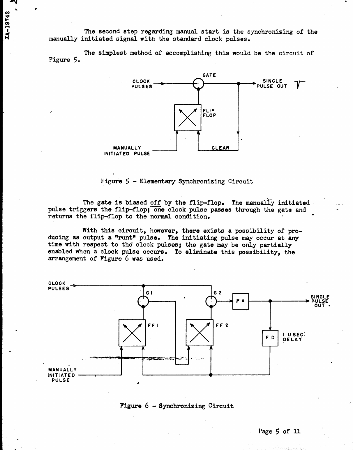
The
second
step
regarding
manual
start
is
the
synchronizing
of
the
manually
initiated
signal
with
the
standard
clock
pulses.
The
simplest
method
of
accomplishing
this
would
be
the
circuit
of
Figure
5.
CLOCK
PULS£S
MANUALLY
INITIATED
PULSE
...
I'
GATE
L"\..
~~
X
FLIP
FLOP
~
CLEAR
Figure
5 - Elementar,y
Synchronizing
Circuit
SINGLE
r
PULSE
OUT
The
gate
is
biased
off
by
the
flip-flop.
The
manually
initiated,
pulse
triggers
the
flip-floPJ-on.
clock
pulse
passes
through
the
gate
and
returns
the
flip-flop
to
the
normal.
condition.
With
this
circuit,
however,
'there
exists
a
possibility
of
pro-
ducing
as
output
a
"runt"
pulse.
The
initiating
pulse
may
occur
at
any
time
with
respect
to
the
clock
pulsesJ
the
gate
may
be
only
partially
enabled
when a
clock
pulse
occurs.
To
eliminate
this
possibility,
the
arrangement
of
Figure
6 was
used.
CLOCK
PULSES
•
SINGLE
~-
.......
----.
P,ULSE
MANUALLY
INITIATED
--~----'
PULSE
x
FFI
x
FF
2
Figure
6 -
Synchronizing
Circuit
OUT
•
I U SEC:
DELAY
Page 5
of
11
,
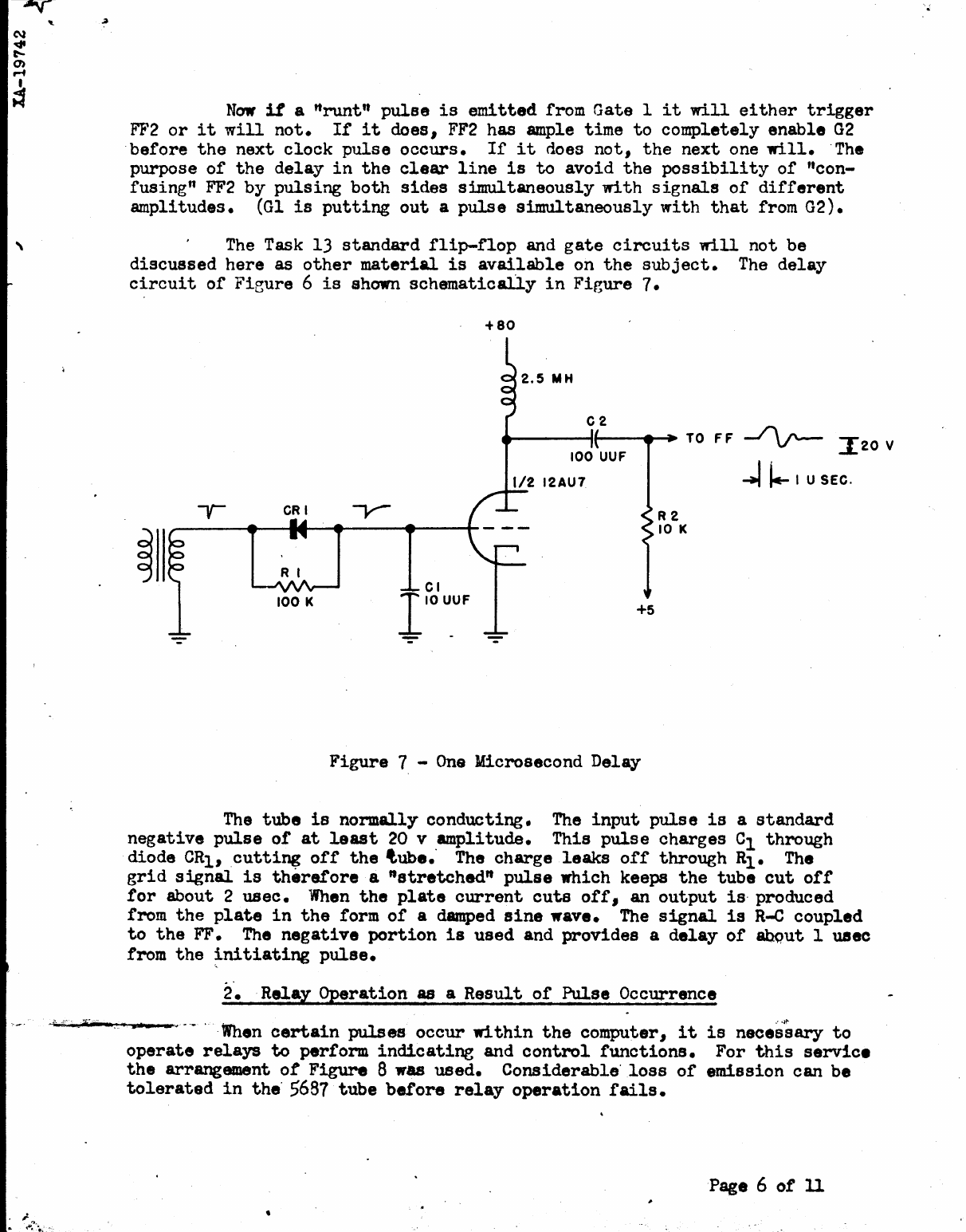
Now
it
a ttruntft
pulse
is
emitted
from
Gate
1
it
will
either
trigger
FF2
or
it
will
not.
If
it
does,
FF2
has
ample
time
to
completely
enable
G2
·before
the
next
clock
pulse
occurs.
If
it
does
not,
the
next
one
will.
The
purpose
of
the
delay
in
the
cleat"
line
is
to
avoid
the
possibility
of
"con-
fusing"
FF2
by
pulsing
both
sides
simultaneously
with
signals
of
different
amplitudes.
(Gl
is
putting
out
a
pulse
simultaneously
with
that
from
G2).
The
Task
13
standard
flip-flop
and
gate
circuits
will
not
be
discussed
here
as
other
material
is
available
on
the
subject.
The
delay
circuit
of
Fieure
6
is
shown
schematically
in
Figure
7.
RI
100 K
+80
.-----ft·----t~
TO
F F --/\!'--
I20
V
+5
Figure
1 -
Ona
Microsecond
Delay
R2
10
K
~
t.-
I U SEC.
The
tube
is
normally
conducting.
The
input
puls
e
is
a
standard
negative
pulse
of
at
least
20 v
amplitude.
This
pulse
charges
01
through
diode
CRl,
cutting
off
the
tube."
The
charge
leaks
off
through
Rl.
The
grid
signal.
is
there.fore
a
"stretched"
pulse
which
keeps
the
tube
cut
off
tor
about
2
usec.
When
the
plate
current
cuts
otf,
an
output
is"
produced
from
the
plate
in
the
form
of
a damped
sine
wave.
The
signal
is
R-C
coupled
to
the
FF. The
negative
portion
is
used
and
provides
a
delay
of
abQut 1 usee
from
the
~nitiating
pulse.
2".
.
Relay
Operation
as
a
Result
of
Pulse
Occurrence
"."~
When
certain
pulses
occur
within
the
computer,
it
is
necessar.y
to
operate
relays
to
perform
indicating
and
control
functions.
For
this
service
the
arrangement
ot
Figure
8
was
used.
Considerable'
loss
of
emission
can
be
tolerated
in
the"
5681
tube
before
relay
operation
fails.
Page 6
of
11
•
,..
.
-.
•
,INITIATING
__
---'
PULSE
220
K
150 K
CLEAR
-60
Figure
8 -
Flip-flop
and Relay
Puller
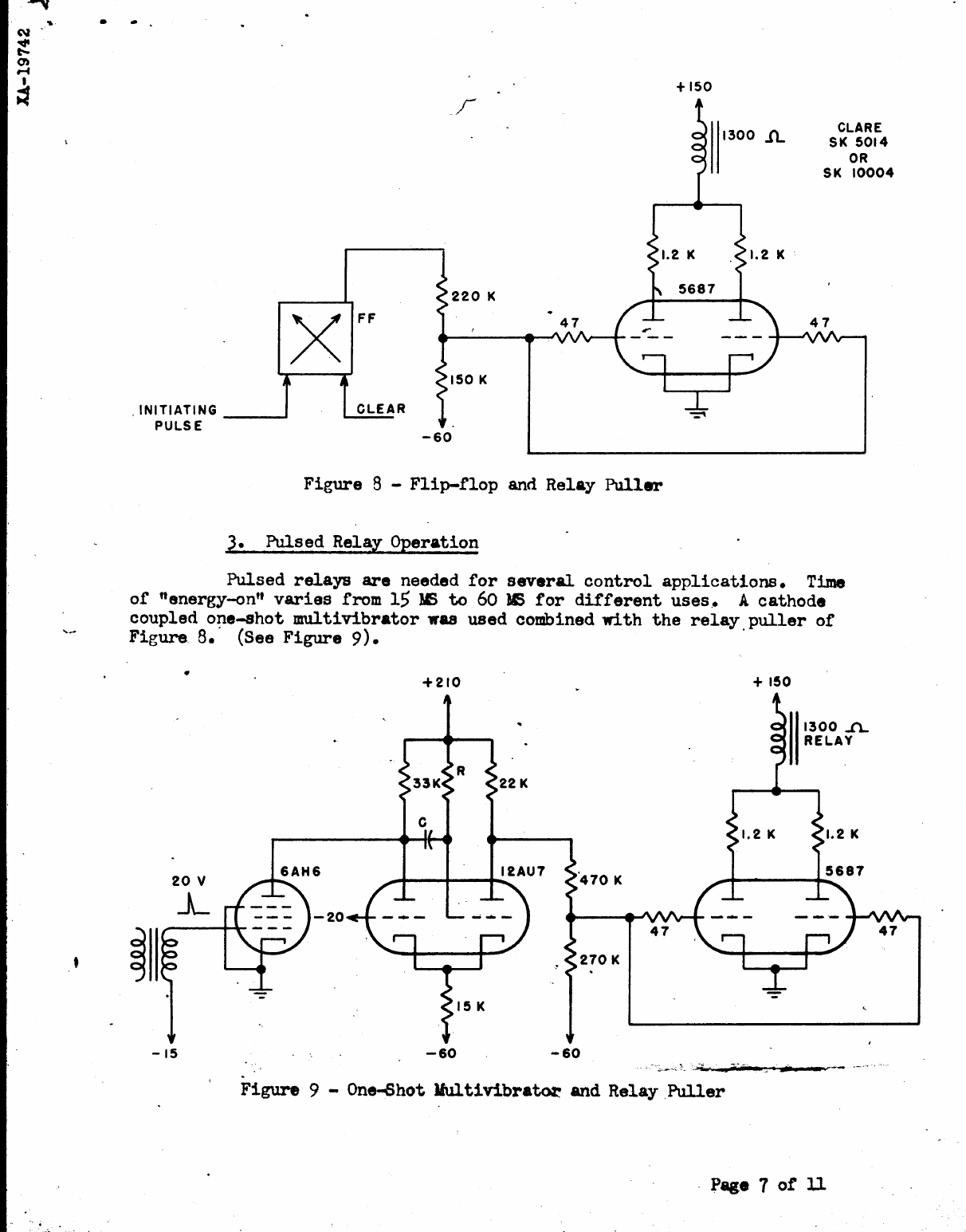
3.
Pulsed Relay Operation
+150
1300
1L
CLARE
SK
5014
OR
SK
10004
Pulsed
relays
are
needed
for
several
control
applications.
Time
of
nenergy-on"
varies
from
15
MS
to
60
IE
for
different
uses.. A cathode
coupled
one-shot
multivibrator
was
used combined
with
the
relay
puller
of
Figure.
8.'
(See
Figure
9).
.
•
-15
-20
+210
R
22
K
ItAU7
.--I1----4~-
.........
-60
+150
-60
1300..n...
RELAY
~
.....
__
.'0"'
Figure
9 - One-Shot Mllltivibrator and Relay
Puller
Page 7
of
11
".
The
pulse
duration
is
equal
to
kRC;
for
this
circuit
k =
.28
within
the
range
used.
4.
Providing
Information
to
the
Output
System
It
was
required
to
print
out
a
character
corresponding
t\a
six-
digit
binary
number.
The
information
was
read
out
of
storage
to
a
hyratron-
relay
registor.
These
relays
energize
the
relay
translator
which
selects
the
proper
typewriter
solenoid.
Each
element
of
the
register
has
theAcircuit
of
Figure
10.
•
NEON
INDICATORS
IND.
ON
I MEG.
TO + 150
THRU
CONTROL
CONTACTS
33
K
READ TO
____
....--~+-JL---------~~--+-
PPR
used.
-20
ENABLE
FROM
READING
AMPLIFIER
Figure
10
-
Print-Punch
Register
Element
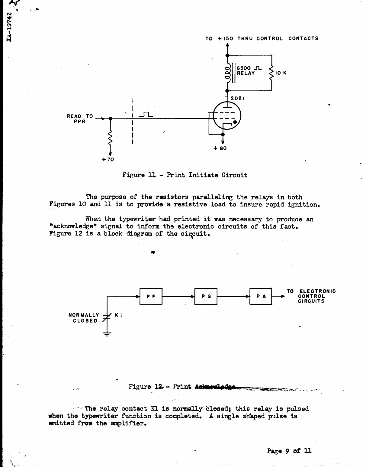
To
initiate"
the
print
cycle
I
the
circui
t
of
Figure
11 was
•
Page
8
or
11
.~
N
~
0)
r-<f
I
~
TO +
150
THRU
CONTROL
CONTACTS
10 K
READ TO
~--..~_.......:..._.sL
________
-++-
PPR
+
80
+70
Figure
11
-
Print
Initiate
Circuit
The
purpose
of
the
resistors
paralleling
the
relays
in
both
Figures
10
and
11
is
to
~vid.
a
resistive
load
to
insure
rapid
ignition.
When
the
typewriter
had
printed
it
was
necessary
to
produce
an
"acknowledge"
signal
to
inform
the
electronic
circuits
of
this
fact.
Figure
12
is
a
block
diagram
of
the
cir\cuit.
NORMALLY
CLOSED
K I
"
TO
ELECTRONIC
CONTROL
CIRCUITS
~~,
The
relay
contact
n
is
normally
blosed}
this
relay
is
pulsed
when
the
typewriter
function
is
completed. A
single
sHkped
pulse
1s
emitted
from
the
amplifier.
Page
9 M 11
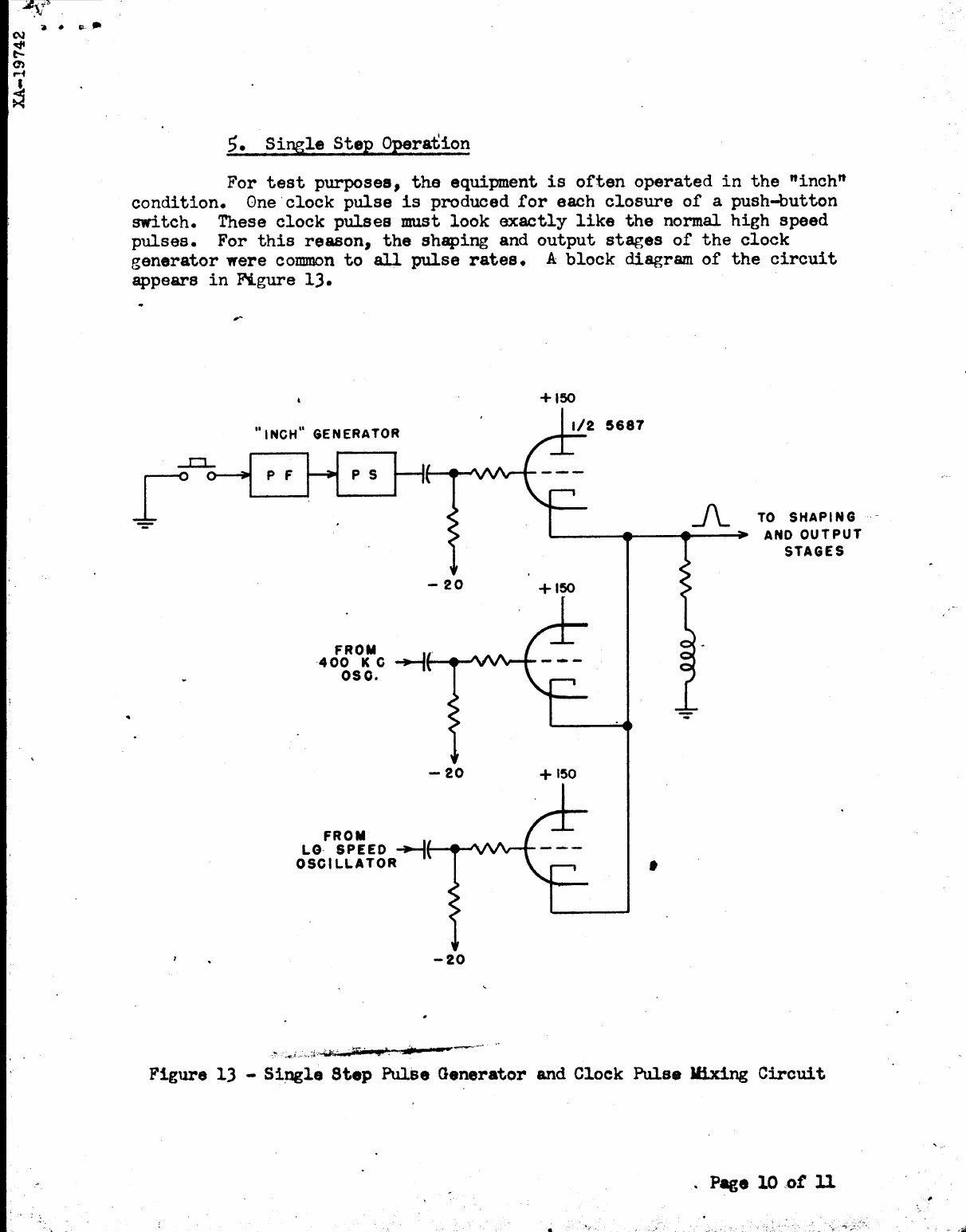
5.
Single
Step
Operation
For
test
purposes,
the
equipment
is
often
operated
in
the
"inch"
condition.
One·
clock
pulse
is
produced
for
each
closure
of
a
push-button
switch.
These
clock
pulses
must
look
exactly
like
the
normal
high
speed
pulses.
For
this
reason,
the
shaping
and
output
stages
of
the
clock
generator
were
common
to
all
pulse
rates.
A
block
diagram
of
the
circuit
appears
in
Figure
13.
+150
"INCH"
GENERATOR
1/2
5687
A TO
SHAPING
-
L...-
__
....
__
....
_~
AND
OUTPUT
STAGES
-
20
+150
FROM
-----1.
400
K C
--,'--
.......
"'~."
..........
050.
FROM
LO-
SPEED
-+-I
OSCILLATOR
-20
-20
+150
,
Figure
13 -
Single
Step
PulSe
Generator
and Cloek
Pulse
Ifix1ng
Circui
t
. Page
10
~ot
U
SUMMARY,
,
For
producing
sharp
pulses
from
contact
closures,
a
6e1£-
extinguishing
thyratron
circuit
is
used
in
combination
with
a
pulse
shaper
and
pulse
amplifier.
The
input
circuit
has
an
RC
filter
to
avoid
spurious
pulses
due
to
contact
bounce.
To
ope~ate
relays
as
a
result
of
a'
pulse
occurrence,
either
a
flip-flop
or
a
one-ehot
multivibrator
is
used
in
conjunction
with
a
hard
tube
amplifier
termed'a
"rel~
puller".
To
transrer
intelligence
to
th,
output
system,
a
thyratron-
relay
register
is
used.
Te.
9.h.,~~A~
4_
F.
c.
Mill;~
•
Rererence,
For
a
discussion
oL
Task
13
standard
circuits
see
Instruction
I Book
exm
e9.ui~e~~
(C9nfidential)
Section
3.
"Detailed
Theory" •
•
",.!!'PII;4a&n,
Q'JI!I~",
_.:tII.»_,
=-wuC!';:~,_\~
.....
:ac:3C.==
......
~~,
....
:Iio;---"'<~
Z'~<
•
Page
11
of
11
,.
,
J
