ETABS RC Slab Design
User Manual: ETABS RC Slab Design
Open the PDF directly: View PDF ![]() .
.
Page Count: 397 [warning: Documents this large are best viewed by clicking the View PDF Link!]
- Title
- Copyright
- Disclaimer
- Contents
- Chapter 01 Introduction
- Chapter 02 Design for ACI 318-14
- Chapter 03 Design for ACI 318-11
- Chapter 04 Design for ACI-318-08
- Chapter 05 Design for AS 3600-09
- 5.1 Notations
- 5.2 Design Load Combinations
- 5.3 Limits on Material Strength
- 5.4 Strength Reduction Factors
- 5.5 Slab Design
- 5.5.1 Design Flexural Reinforcement
- 5.5.1.1 Determine Factored Moments
- 5.5.1.2 Determine Required Flexural Reinforcement
- 5.5.1.3 Design of uniform thickness slab
- 5.5.1.4 Design of nonuniform thickness slab
- 5.5.1.5 Flanged Slab Section Under Negative Moment
- 5.5.1.6 Flanged Slab Section Under Positive Moment
- 5.5.1.7 Minimum and Maximum Reinforcement
- 5.5.2 Design Slab Shear Reinforcement
- 5.5.3 Check for Punching Shear
- 5.5.4 Design Punching Shear Reinforcement
- 5.5.1 Design Flexural Reinforcement
- Chapter 06 Design for AS 3600-01
- 6.1 Notations
- 6.2 Design Load Combinations
- 6.3 Limits on Material Strength
- 6.4 Strength Reduction Factors
- 6.5 Slab Design
- 6.5.1 Design Flexural Reinforcement
- 6.5.2 Design Slab Shear Reinforcement
- 6.5.3 Check for Punching Shear
- 6.5.4 Design Punching Shear Reinforcement
- Chapter 07 Design for BS 8100-97
- Chapter 08 Design for CSA A23.3-14
- Chapter 09 Design for CSA A23.3-04
- Chapter 10 Design for Eurocode 2-2004
- 10.1 Notations
- 10.2 Design Load Combinations
- 10.3 Limits on Material Strength
- 10.4 Partial Safety Factors
- 10.5 Slab Design
- 10.6 Nationally Determined Parameters (NDPs)
- Chapter 11 Design for Hong Kong CP-2013
- Chapter 12 Design for Hong Kong CP-04
- Chapter 13 Design for IS 456-2000
- Chapter 14 Design for Italian NTC 2008
- Chapter 15 Design for NZS 3101-06
- Chapter 16 Design for Singapore CP 65-99
- Chapter 17 Design for TS 500-2000
- References
- ETABS RC Slab Design_1.pdf
- Title
- Copyright
- Disclaimer
- Contents
- Chapter 1 Introduction
- Chapter 2 Design Prerequisites
- Chapter 3 Design Process
- 3.1 Notation
- 3.2 Design Load Combinations
- 3.3 Limits on Material Strength
- 3.4 Column Design
- 3.5 Beam Design
- 3.6 Joint Design
- 3.7 Summary of Special Considerations for Seismic Design
- Appendices
- References

Reinforced Slab Design Manual

Reinforced Concrete Slab Design
Manual
For ETABS® 2016
ISO ETA122815M62 Rev.0
Proudly developed in the United States of America
July 2016

Copyright
Copyright Computers & Structures, Inc., 1978-2016
All rights reserved.
The CSI Logo®, SAP2000®, ETABS®, and SAFE® are registered trademarks of
Computers & Structures, Inc. Watch & LearnTM is a trademark of Computers &
Structures, Inc.
The computer programs SAP2000® and ETABS® and all associated documentation are
proprietary and copyrighted products. Worldwide rights of ownership rest with Computers
& Structures, Inc. Unlicensed use of these programs or reproduction of documentation in
any form, without prior written authorization from Computers & Structures, Inc., is
explicitly prohibited.
No part of this publication may be reproduced or distributed in any form or by any means,
or stored in a database or retrieval system, without the prior explicit written permission of
the publisher.
Further information and copies of this documentation may be obtained from:
Computers & Structures, Inc.
http://www.csiamerica.com/
info@csiamerica.com (for general information)
support@csiamerica.com (for technical support)
DISCLAIMER
CONSIDERABLE TIME, EFFORT AND EXPENSE HAVE GONE INTO THE
DEVELOPMENT AND TESTING OF THIS SOFTWARE. HOWEVER, THE USER
ACCEPTS AND UNDERSTANDS THAT NO WARRANTY IS EXPRESSED OR
IMPLIED BY THE DEVELOPERS OR THE DISTRIBUTORS ON THE ACCURACY
OR THE RELIABILITY OF THIS PRODUCT.
THIS PRODUCT IS A PRACTICAL AND POWERFUL TOOL FOR STRUCTURAL
DESIGN. HOWEVER, THE USER MUST EXPLICITLY UNDERSTAND THE BASIC
ASSUMPTIONS OF THE SOFTWARE MODELING, ANALYSIS, AND DESIGN
ALGORITHMS AND COMPENSATE FOR THE ASPECTS THAT ARE NOT
ADDRESSED.
THE INFORMATION PRODUCED BY THE SOFTWARE MUST BE CHECKED BY
A QUALIFIED AND EXPERIENCED ENGINEER. THE ENGINEER MUST
INDEPENDENTLY VERIFY THE RESULTS AND TAKE PROFESSIONAL
RESPONSIBILITY FOR THE INFORMATION THAT IS USED.

Contents
1 Introduction
1.1 Slab Design 1-1
1.2 Design Strips 1-2
1.3 Integration of Moments – Wood-Armer 1-2
1.4 Required Reinforcement – Strip Based 1-3
1.5 Required Reinforcement – FEM Based 1-3
1.6 Slab Punching Shear Check 1-3
2 Design for ACI 318-14
2.1 Notations 2-1
2.2 Design Load Combinations 2-4
2.3 Limits on Material Strength 2-5
2.4 Strength Reduction Factors 2-5
2.5 Slab Design 2-5
2.5.1 Design Flexure reinforcement 2-6
2.5.2 Design Slab Shear Reinforcement 2-15
2.5.3 Check for Punching Shear 2-16
i

ETABS Reinforced Concrete Slab Design
2.5.4 Design Punching Shear
Reinforcement 2-22
3 Design for ACI 318-11
3.1 Notations 3-1
3.2 Design Load Combinations 3-4
3.3 Limits on Material Strength 3-5
3.4 Strength Reduction Factors 3-5
3.5 Slab Design 3-5
3.5.1 Design Flexure reinforcement 3-6
3.5.2 Design Slab Shear Reinforcement 3-15
3.5.3 Check for Punching Shear 3-16
3.5.4 Design Punching Shear
Reinforcement 3-23
4 Design for ACI 318-08
4.1 Notations 4-1
4.2 Design Load Combinations 4-4
4.3 Limits on Material Strength 4-5
4.4 Strength Reduction Factors 4-5
4.5 Slab Design 4-5
4.5.1 Design Flexure reinforcement 4-6
4.5.2 Design Slab Shear Reinforcement 4-15
4.5.3 Check for Punching Shear 4-17
4.5.4 Design Punching Shear
Reinforcement 4-23
5 Design for AS 3600-09
5.1 Notations 5-1
5.2 Design Load Combinations 5-4
5.3 Limits on Material Strength 5-5
5.4 Strength Reduction Factors 5-5
ii

Contents
5.5 Slab Design 5-5
5.5.1 Design Flexure reinforcement 5-6
5.5.2 Design Slab Shear Reinforcement 5-14
5.5.3 Check for Punching Shear 5-17
5.5.4 Design Punching Shear
Reinforcement 5-19
6 Design for AS 3600-01
6.1 Notations 6-1
6.2 Design Load Combinations 6-4
6.3 Limits on Material Strength 6-5
6.4 Strength Reduction Factors 6-5
6.5 Slab Design 6-5
6.5.1 Design Flexure reinforcement 6-6
6.5.2 Design Slab Shear Reinforcement 6-13
6.5.3 Check for Punching Shear 6-16
6.5.4 Design Punching Shear
Reinforcement 6-18
7 Design for BS 8110-97
7.1 Notations 7-1
7.2 Design Load Combinations 7-4
7.3 Limits on Material Strength 7-5
7.4 Partial Safety Factors 7-5
7.5 Slab Design 7-5
7.5.1 Design Flexure reinforcement 7-5
7.5.2 Design Slab Shear Reinforcement 7-13
7.5.3 Check for Punching Shear 7-16
7.5.4 Design Punching Shear
Reinforcement 7-19
8 Design for CSA A23.3-14
8.1 Notations 8-1
iii

ETABS Reinforced Concrete Slab Design
8.2 Design Load Combinations 8-4
8.3 Limits on Material Strength 8-5
8.4 Strength Reduction Factors 8-5
8.5 Slab Design 8-6
8.5.1 Design Flexure reinforcement 8-6
8.5.2 Design Slab Shear Reinforcement 8-14
8.5.3 Check for Punching Shear 8-20
8.5.4 Design Punching Shear
Reinforcement 8-26
9 Design for CSA A23.3-04
9.1 Notations 9-1
9.2 Design Load Combinations 9-4
9.3 Limits on Material Strength 9-5
9.4 Strength Reduction Factors 9-5
9.5 Slab Design 9-6
9.5.1 Design Flexure reinforcement 9-6
9.5.2 Design Slab Shear Reinforcement 9-14
9.5.3 Check for Punching Shear 9-20
9.5.4 Design Punching Shear
Reinforcement 9-25
10 Design for Eurocode 2-2004
10.1 Notations 10-2
10.2 Design Load Combinations 10-4
10.3 Limits on Material Strength 10-7
10.4 Partial Safety Factors 10-7
10.5 Slab Design 10-8
10.5.1 Design Flexure reinforcement 10-8
10.5.2 Design Slab Shear Reinforcement 10-17
10.5.3 Check for Punching Shear 10-20
10.5.4 Design Punching Shear
Reinforcement 10-22
iv

Contents
10.7 Nationally Determined Parameters (NDPs) 10-24
11 Design for Hong Kong CP-2013
11.1 Notations 11-1
11.2 Design Load Combinations 11-3
11.3 Limits on Material Strength 11-4
11.4 Partial Safety Factors 11-4
11.5 Slab Design 11-5
11.5.1 Design Flexure reinforcement 11-5
11.5.2 Design Slab Shear Reinforcement 11-13
11.5.3 Check for Punching Shear 11-16
11.5.4 Design Punching Shear
Reinforcement 11-19
12 Design for Hong Kong CP-04
12.1 Notations 12-1
12.2 Design Load Combinations 12-3
12.3 Limits on Material Strength 12-4
12.4 Partial Safety Factors 12-4
12.5 Slab Design 12-5
12.5.1 Design Flexure reinforcement 12-5
12.5.2 Design Slab Shear Reinforcement 12-13
12.5.3 Check for Punching Shear 12-16
12.5.4 Design Punching Shear
Reinforcement 12-19
13 Design for IS 456-2000
13.1 Notations 13-1
13.2 Design Load Combinations 13-4
13.3 Partial Safety Factors 13-5
13.4 Slab Design 13-5
13.4.1 Design Flexure reinforcement 13-6
13.4.2 Design Slab Shear Reinforcement 13-14
v

ETABS Reinforced Concrete Slab Design
13.5.3 Check for Punching Shear 13-16
13.5.4 Design Punching Shear
Reinforcement 13-21
14 Design for Italian NTC 2008
14.1 Notations 14-1
14.2 Design Load Combinations 14-4
14.3 Limits on Material Strength 14-5
14.4 Partial Safety Factors 14-6
14.5 Slab Design 14-7
14.5.1 Design Flexure reinforcement 14-7
14.5.2 Design Slab Shear Reinforcement 14-16
14.5.3 Check for Punching Shear 14-19
14.5.4 Design Punching Shear
Reinforcement 14-22
15 Design for NZS 3101-06
15.1 Notations 15-1
15.2 Design Load Combinations 15-4
15.3 Limits on Material Strength 15-5
15.4 Strength Reduction Factors 15-5
15.5 Slab Design 15-6
15.5.1 Design Flexure reinforcement 15-6
15.5.2 Design Slab Shear Reinforcement 15-14
15.5.3 Check for Punching Shear 15-17
15.5.4 Design Punching Shear
Reinforcement 15-23
16 Design for Singapore CP 65-99
16.1 Notations 16-1
16.2 Design Load Combinations 16-4
16.3 Limits on Material Strength 16-4
16.4 Partial Safety Factors 16-5
vi

Contents
16.5 Slab Design 16-5
16.6.1 Design Flexure reinforcement 16-6
16.6.2 Design Slab Shear Reinforcement 16-14
16.6.3 Check for Punching Shear 16-16
16.6.4 Design Punching Shear
Reinforcement 16-19
17 Design for TS 500-2000
17.1 Notations 17-1
17.2 Design Load Combinations 17-4
17.3 Limits on Material Strength 17-5
17.4 Design Strength 17-5
17.5 Slab Design 17-5
17.5.1 Design Flexure reinforcement 17-6
17.5.2 Design Slab Shear Reinforcement 17-13
17.5.3 Check for Punching Shear 17-16
17.5.4 Design Punching Shear
Reinforcement 17-18
References
vii

Chapter 1
Introduction
ETABS automates several slab and mat design tasks. Specifically, it integrates
slab design moments across design strips and designs the required reinforce-
ment; it checks slab punching shear around column supports and concentrated
loads; and it designs shear link and shear stud if needed. The actual design algo-
rithms vary based on the specific design code chosen by the user. This manual
describes the algorithms used for the various codes.
It should be noted that the design of reinforced concrete slabs is a complex sub-
ject and the design codes cover many aspects of this process. ETABS is a tool to
help the user in this process. Only the aspects of design documented in this man-
ual are automated by ETABS design capabilities. The user must check the results
produced and address other aspects not covered by ETABS.
1.1 Slab Design
ETABS slab design procedure involves defining sets of strips in two mutually
perpendicular directions. The locations of the strips are usually governed by the
locations of the slab supports. The axial force, moments and shears for a partic-
ular strip are recovered from the analysis (on the basis of the Wood-Armer tech-
nique), and a flexural design is carried out based on the ultimate strength design
method. As an alternative to this strip based method, ETABS also offers a FEM
1 - 1

Welcome to ETABS
based design, which is useful for irregular slabs where strip based techniques
may not be appropriate.
1.2 Design Strips
ETABS provides two principal strip layers used for design, namely Layer A de-
sign strips and Layer B design strips. The strips are defined as polylines with
associated widths that can vary along the length of the strip.
The strips need not be mutually perpendicular. The extent of the design strips is
defined by the edges of the area objects defining the slab, and strips can overlap
if needed. The location of the design strips is usually governed by the support or
grid locations. Design strips may be defined as either Column Strips or Middle
Strips – models with post-tensioning typically have column strips only.
1.3 Integration of Moments – Wood-Armer
Use of the Wood-Armer method for the integration of design moments results in
the following steps:
For a particular combination or load case, for each finite element within the de-
sign strip, ETABS calculates the design moments per unit width using the inter-
nal forces. Internal forces are converted to design moments per unit width in the
following manner:
bB B AB
mmm= +
bA A AB
mmm= +
tB B AB
mmm= +
tB A AB
mmm= +
where mA, mB, and mAB are internal moments per unit width, and mbA and mbB are
design moments per unit width for the bottom of the slab in the A and B direc-
tions, respectively, and mtA and mtB are the design moments for the top of the slab
in the A and B directions, respectively. Design moments may be factored com-
binations for strength design, or unfactored moments for service load checks
1- 2

Required Reinforcement – Strip Based
when post-tensioning is present. The design moments calculated using the
Wood-Armer integration will most likely not completely satisfy equilibrium of
the applied loads, but for a mesh that accurately captures the overall behavior of
the slab, this integration scheme provides a good design. This is the case because
the Wood-Armer integration scheme effectively calculates design moments
when cracking occurs diagonally to the design strip directions.
1.4 Required Reinforcement – Strip Based
The design of the mild reinforcement for slabs is carried out for a particular strip
at each transverse mesh line location along the length of the strip. The moments
are integrated across all elements of like property in the strip to determine the
factored design moments. The required reinforcement for slabs is computed for
each set of elements with the same property type, and then summed to give the
total required reinforcement for the strip. The maximum required top and bottom
strip reinforcement for a particular mesh line is obtained, along with the corre-
sponding controlling combinations.
As an option, minimum reinforcement requirements may be enforced in accord-
ance with the selected design code.
1.5 Required Reinforcement – FEM Based
The FEM Based design determines the required reinforcement on an element-
by-element basis and is therefore independent of design strips. Several options
are available for refining the display of the required reinforcement, including
averaging, which will flatten peaks and provide an averaged required reinforce-
ment over a particular area of the slab.
1.6 Slab Punching Shear Check
The distribution of stresses close to concentrated loads or reaction points in re-
inforced and prestressed concrete slabs is quite complex. Punching shear is one
particular failure mode recognized by design codes for which an elastic plate
bending analysis may not provide adequate stress distribution. Most codes use
empirical methods based on experimental verification to check against punching
shear failures. ETABS automates this check for common geometries. If the
Required Reinforcement – Strip Based 1- 3

Welcome to ETABS
check results in a punching shear ratio greater than unity (i.e., punching failure),
ETABS will design punching shear reinforcement. The ETABS procedure for
the punching shear check carried out for each column, for each design combina-
tion is as follows:
Locate the critical section around the column or point load. ETABS reports
whether it assumed the column to be an interior, edge, or corner column. This
determination is based on whether the slab is present within 10 times the slab
thickness along the column edges. A column is classified as a corner column
when two slab edges are found within 10 times the slab thickness. A column
with only one slab edge within 10 times the slab thickness is classified as an edge
column, and a column is classified as interior when no slab edges are found
within 10 times the slab thickness. For single footings, this determination is
based on the minimum area of the critical section.
Check that each slab element in the area enclosed between the face of the column
and the critical section for punching shear has the same slab property label. If
this is not the case, the minimum slab thickness within the punching shear pe-
rimeter is used.
Use the net shear to check punching shear if a point load or column (call it
load/column A) is within the critical section for punching shear for another point
load or column (call it load/column B).
Calculate punching shear based on net forces in the slab when line objects
(beams, walls, or releases) frame into a column.
Calculate the reactive force and moments at the column for the combination. The
shear and moment values used in the punching shear check are reduced by the
load (or reaction) that is included within the boundaries of the punching shear
critical section.
Calculate the distribution of shear stress around the critical section.
Obtain the shear capacity of the critical section.
Compare the shear stress distribution with the shear capacity. The comparison
is reported as a ratio for the worst combination. A value above 1.0 indicates fail-
ure.
1- 4
ETABS designs rebar ties or stud rails when such options are activated in the
punching shear design overwrites. The details of rebar ties or stud rails are doc-
umented in the Reinforced Concrete Design Manual and the Post-Tensioned
Concrete Design Manual.
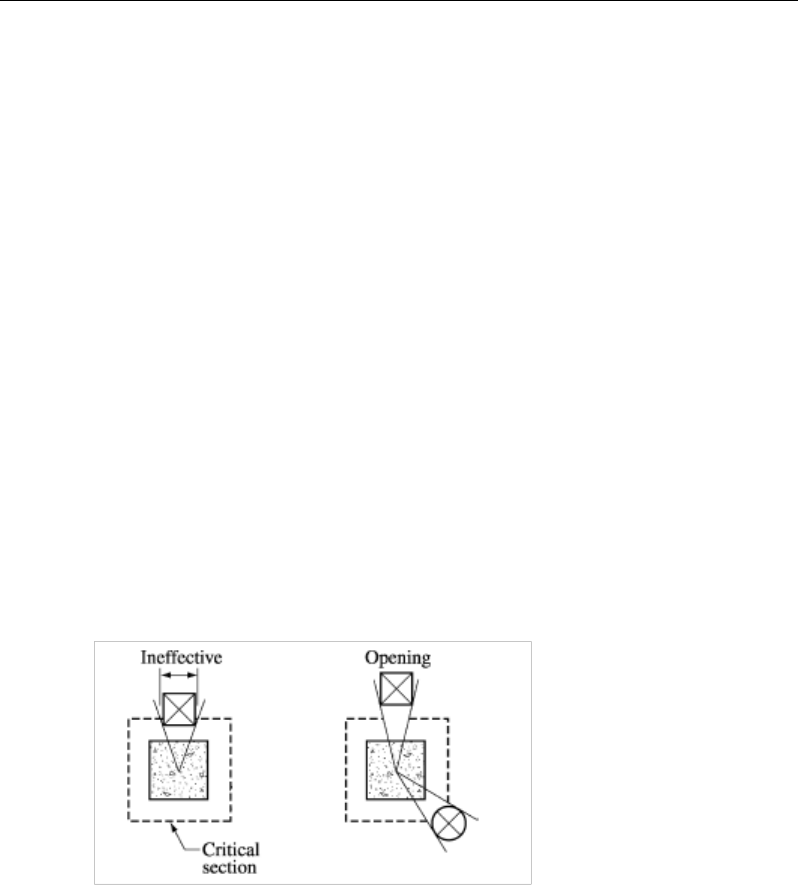
Design overwrites are available to modify the location type, punching shear pe-
rimeter, openings in the slab, and reinforcement pattern, when the punching
shear parameters computed need to be changed.
For computing the punching parameters, the following assumptions are used:
Punching shear is calculated for columns punching through a slab or a drop
panel. ETABS also checks the drop panel punching through a slab. The effect of
column capitals is included in the punching shear calculation.
ETABS uses the effective depth for computing the punching shear. The concrete
cover to rebar is taken from the design preferences unless a design strip is pre-
sent. In that case, the rebar cover is taken from the design strip.
Openings within 10 times the slab thickness are automatically included in the
punching shear calculations. The slab edge within the punching zone radius is
subtracted from the punching shear perimeter.
1- 5

Chapter 2
Design for ACI 318-14
This chapter describes in detail the various aspects of the concrete slab design
procedure that is used by ETABS when the American code ACI 318-14 [ACI
2014] is selected. Various notations used in this chapter are listed in Table 2-1.
For referencing to the pertinent sections or equations of the ACI code in this
chapter, a prefix “ACI” followed by the section or equation number is used
herein.
The design is based on user-specified load combinations. The program provides
a set of default load combinations that should satisfy the requirements for the
design of most building type structures.
English as well as SI and MKS metric units can be used for input. The code is
based on inch-pound-second units. For simplicity, all equations and descriptions
presented in this chapter correspond to inch-pound-second units unless otherwise
noted.
2.1 Notations
Table 2-1 List of Symbols Used in the ACI 318-14 Code
A
cp
Area enclosed by the outside perimeter of the section, sq-in
A
g
Gross area of concrete, sq-in
Notations 2 - 1

ETABS Reinforced Concrete Slab Design
Table 2-1 List of Symbols Used in the ACI 318-14 Code
A
l
Area of longitudinal reinforcement for torsion, sq-in
A
o
Area enclosed by the shear flow path, sq-in
A
oh
Area enclosed by the centerline of the outermost closed transverse
torsional reinforcement, sq-in
A
s
Area of tension reinforcement, sq-in
A'
s
Area of compression reinforcement, sq-in
A
t
/s
Area of closed shear reinforcement per unit length of member for
torsion, sq-in/in
A
v
Area of shear reinforcement, sq-in
A
v
/s
Area of shear reinforcement per unit length, sq-in/in
a
Depth of compression block, in
a
max
Maximum allowed depth of compression block, in
b
Width of section, in
b
f
Effective width of flange (flanged section), in
b
o
Perimeter of the punching shear critical section, in
b
w
Width of web (flanged section), in
b
1
Width of the punching shear critical section in the direction of
bending, in
b
2
Width of the punching shear critical section perpendicular to the di-
rection of bending, in
c
Depth to neutral axis, in
d
Distance from compression face to tension reinforcement, in
d'
Distance from compression face to compression reinforcement, in
E
c
Modulus of elasticity of concrete, psi
E
s
Modulus of elasticity of reinforcement, psi
f'
c
Specified compressive strength of concrete, psi
2 - 2 Notations

Chapter 2 - Design for ACI 318-14
Table 2-1 List of Symbols Used in the ACI 318-14 Code
f'
s
Stress in the compression reinforcement, psi
f
y
Specified yield strength of flexural reinforcement, psi
f
yt
Specified yield strength of shear reinforcement, psi
h
Overall depth of a section, in
h
f
Height of the flange, in
M
u
Factored moment at a section, lb-in
N
u
Factored axial load at a section occurring simultaneously with V
u
or
Tu, lb
P
u
Factored axial load at a section, lb
p
cp
Outside perimeter of concrete cross-section, in
p
h
Perimeter of centerline of outermost closed transverse torsional
reinforcement, in
s
Spacing of shear reinforcement along the strip, in
T
cr
Critical torsion capacity, lb-in
T
u
Factored torsional moment at a section, lb-in
V
c
Shear force resisted by concrete, lb
V
max
Maximum permitted total factored shear force at a section, lb
V
s
Shear force resisted by transverse reinforcement, lb
V
u
Factored shear force at a section, lb
α
s
Punching shear scale factor based on column location
β
c
Ratio of the maximum to the minimum dimensions of the punching
shear critical section
β
1
Factor for obtaining depth of the concrete compression block
ε
c
Strain in the concrete
ε
c max
Maximum usable compression strain allowed in the extreme
concrete fiber, (0.003 in/in)
Notations 2 - 3

ETABS Reinforced Concrete Slab Design
Table 2-1 List of Symbols Used in the ACI 318-14 Code
ε
s
Strain in the reinforcement
ε
s,min
Minimum tensile strain allowed in the reinforcement at nominal
strength for tension controlled behavior (0.005 in/in)
φ
Strength reduction factor
γ
f
Fraction of unbalanced moment transferred by flexure
γ
v
Fraction of unbalanced moment transferred by eccentricity of shear
λ
Shear strength reduction factor for light-weight concrete
θ
Angle of compression diagonals, degrees
2.2 Design Load Combinations
The design load combinations are the various combinations of the load cases for
which the structure needs to be designed. For ACI 318-14, if a structure is sub-
jected to dead (D), live (L), pattern live (PL), snow (S), wind (W), and earth-
quake (E) loads, and considering that wind and earthquake forces are reversible,
the following load combinations may need to be considered (ACI 5.3.1):
1.4D
(ACI Eqn. 5.3.1a)
1.2D + 1.6L + 0.5L
r
(ACI Eqn.5.3.1b)
1.2D + 1.0L + 1.6L
r
(ACI Eqn.5.3.1c)
1.2D + 1.6(0.75 PL) + 0.5Lr
(ACI Eqn.5.3.1b, 6.4)
1.2D + 1.6L + 0.5S
(ACI Eqn.5.3.1b)
1.2D + 1.0L + 1.6S
(ACI Eqn.5.3.1c)
0.9D ± 1.0W
(ACI Eqn.5.3.1f)
1.2D + 1.0L + 0.5Lr ± 1.0W
(ACI Eqn.5.3.1d)
1.2D + 1.6L
r
± 0.5W
(ACI Eqn.5.3.1c)
1.2D + 1.6S ± 0.5W
(ACI Eqn.5.3.1c)
1.2D + 1.0L + 0.5S ± 1.0W
(ACI Eqn.5.3.1d)
2 - 4 Design Load Combinations

Chapter 2 - Design for ACI 318-14
0.9D
± 1.0E
1.2D + 1.0L +
0.2S ± 1.0E
(ACI Eqn.5.3.1g
)
(ACI Eqn.5.3.1e
)
These are the default design load combinations in ETABS whenever the ACI
318-14 code is used. The user should use other appropriate load combinations if
roof live load is treated separately, or if other types of loads are present.
2.3 Limits on Material Strength
The concrete compressive strength,
,
′
c
f
should not be less than 2,500 psi (ACI
19.2.1, Table 19.2.1.1). The upper limit of the reinforcement yield strength, fy, is
taken as 80 ksi (ACI 20.2.2.4a, Table 20.2.2.4a) and the upper limit of the rein-
forcement shear strength, fyt, is taken as 60 ksi (ACI 21.2.2.4a, Table 21.2.2.4a).
If the input
′
c
f
is less than 2,500 psi, ETABS continues to design the members
based on the input
′
c
f
and does not warn the user about the violation of the code.
The user is responsible for ensuring that the minimum strength is satisfied.
2.4 Strength Reduction Factors
The strength reduction factors,
φ
, are applied to the specified strength to obtain
the design strength provided by a member. The
φ
factors for flexure, shear, and
torsion are as follows:
φ
= 0.90 for flexure (tension controlled) (ACI 21.2.1, Table 21.2.1)
φ
= 0.75 for shear and torsion (ACI 21.2.1, Table 21.2.1)
These values can be overwritten; however, caution is advised.
2.5 Slab Design
ETABS slab design procedure involves defining sets of strips in two mutually
perpendicular directions. The locations of the strips are usually governed by the
locations of the slab supports. The axial force, moments and shears for a partic-
Limits on Material Strength 2 - 5

ETABS Reinforced Concrete Slab Design
ular strip are recovered from the analysis (on the basis of the Wood-Armer tech-
nique), and a flexural design is carried out based on the ultimate strength design
method.
The slab design procedure involves the following steps:
Design flexural reinforcement
Design shear reinforcement
Punching check
2.5.1 Design Flexural Reinforcement
For slabs, ETABS uses either design strips or the finite element based design to
calculate the slab flexural reinforcement in accordance with the selected design
code. For simplicity, only strip-by-strip design is document in the proceeding
sections.
The design of the slab reinforcement for a particular strip is carried out at specific
locations along the length of the strip. These locations correspond to the element
boundaries. Controlling reinforcement is computed on either side of those ele-
ment boundaries. The slab flexural design procedure for each load combination
involves the following:
Determine factored axial loads and moments for each slab strip.
Design flexural reinforcement for the strip.
These two steps, described in the text that follows, are repeated for every load
combination. The maximum reinforcement calculated for the top and bottom of
the slab within each design strip, along with the corresponding controlling load
combination, is obtained and reported.
2.5.1.1 Determine Factored Moments
In the design of flexural reinforcement of concrete slab, the factored moments
for each load combination at a particular design strip are obtained by factoring
the corresponding moments for different load cases, with the corresponding load
factors.
2 - 6 Slab Design

Chapter 2 - Design for ACI 318-14
The slab is then designed for the maximum positive and maximum negative fac-
tored moments obtained from all of the load combinations. Calculation of bottom
reinforcement is based on positive design strip moments. In such cases, the slab
may be designed as a rectangular or flanged slab section. Calculation of top re-
inforcement is based on negative design strip moments. In such cases, the slab
may be designed as a rectangular or inverted flanged slab section.
2.5.1.2 Determine Required Flexural Reinforcement
In the flexural reinforcement design process, the program calculates both the
tension and compression reinforcement. Compression reinforcement is added
when the applied design moment exceeds the maximum moment capacity of a
singly reinforced section. The user has the option of avoiding compression
reinforcement by increasing the effective depth, the width, or the strength of the
concrete. Note that the flexural reinforcement strength, fy , is limited to 80 ksi
(ACI 20.2.2.4a), even if the material property is defined using a higher value.
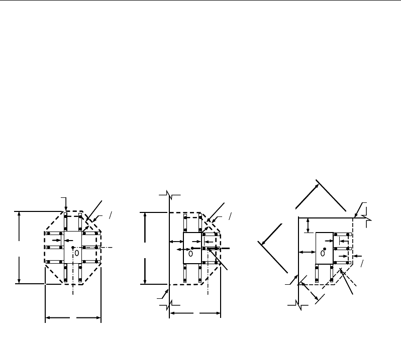
The design procedure is based on the simplified rectangular stress block, as
shown in Figure 2-1 (ACI 22.2.2). Furthermore, it is assumed that the net tensile
strain in the reinforcement shall not be less than 0.005 (tension controlled) (ACI
21.2.2, Table 21.2.2) when the concrete in compression reaches its assumed
strain limit of 0.003. When the applied moment exceeds the moment capacity at
this design condition, the area of compression reinforcement is calculated as-
suming that the additional moment will be carried by compression reinforcement
and additional tension reinforcement.
The design procedure used by ETABS, for both rectangular and flanged sections
(L- and T-shaped sections), is summarized in the text that follows. For reinforced
concrete design where design ultimate axial compression load does not ex-
ceed
()
cg
fA0.1 ′
(ACI 9.5.2.1), axial force is ignored; hence, all slab are de-
signed for major direction flexure, shear, and punching check only. Axial com-
pression greater than
( )
cg
fA0.1 ′
and axial tensions are always included in flex-
ural and shear design.
Slab Design 2 - 7
ETABS Reinforced Concrete Slab Design
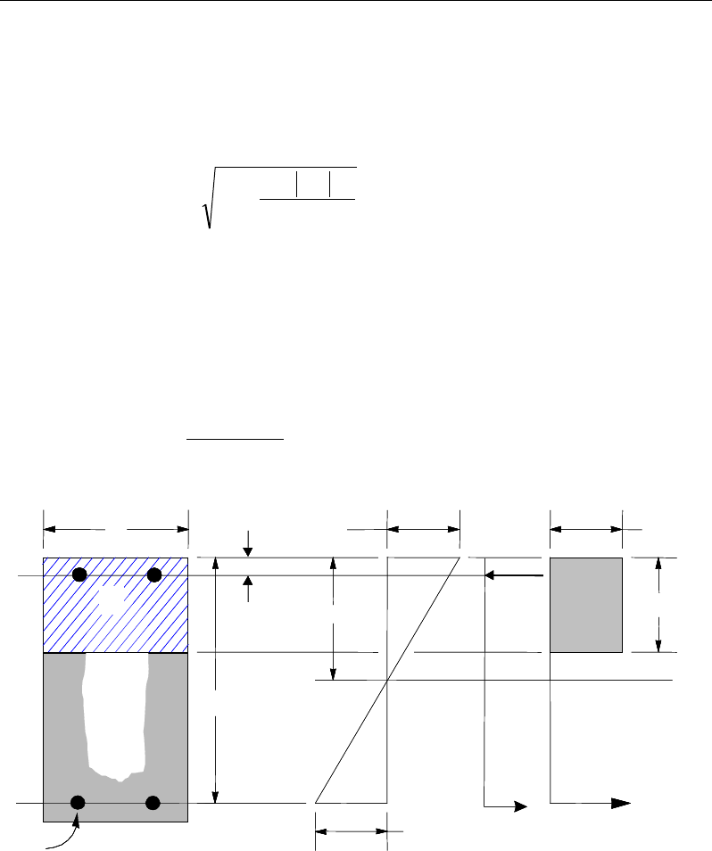
2.5.1.2.1 Design of uniform thickness slab
In designing for a factored negative or positive moment, Mu (i.e., designing top
or bottom reinforcement), the depth of the compression block is given by a (see
Figure 2-1), where,
bf
M
dda
c
u
φ
'85.0
2
2
−−=
(ACI 22.2.2)
and the value of
φ
is taken as that for a tension-controlled section, which by
default is 0.90 (ACI 9.3.2.1) in the preceding and the following equations.
The maximum depth of the compression zone, cmax, is calculated based on the
limitation that the tension reinforcement strain shall not be less than
ε
smin, which
is equal to 0.005 for tension controlled behavior (ACI 21.2.2, Table 21.2.2):
max
max max min
c
cs
cd
ε
εε
=+
(ACI 22.2.1.2)
Figure 2-1 Uniform Thickness Slab Design
(I) BEAM
SECTION (II) STRAIN
DIAGRAM (III) STRESS
DIAGRAM
0.003
ε
=c
0.85 f ′
1
ac
β
=
cs
T
s
T
s
ε
cs
C
d′
d
b
s
A
s
A′
(I) BEAM
SECTION (II) STRAIN
DIAGRAM (III) STRESS
DIAGRAM
0.003
ε
=c
0.85 f ′
1
ac
β
=
cs
T
s
T
s
ε
cs
C
d′
d
b
s
A
s
A′
2 - 8 Slab Design

Chapter 2 - Design for ACI 318-14
where,
ε
cmax = 0.003 (ACI 21.2.2, Fig R21.2)
ε
smin = 0.005 (ACI 21.2.2, Fig R21.2.26)
The maximum allowable depth of the rectangular compression block, amax, is
given by:
amax =
β
1cmax (ACI 22.2.2.4.1)
where
β
1 is calculated as:
c
f
1
4000
0.85 0.05 ,
1000
β
′−
= −
0.65 ≤
β
1 ≤ 0.85 (ACI 22.2.2.4.3)
If a ≤ amax (ACI 10.3.4), the area of tension reinforcement is then given by:
−
=
2
a
df
M
A
y
u
s
φ
This reinforcement is to be placed at the bottom if Mu is positive, or at the top
if Mu is negative.
If a > amax, compression reinforcement is required (ACI 9.3.3.1, 21.2.2, Fig
21.2.26, 22.2.2.4.1) and is calculated as follows:
− The compressive force developed in the concrete alone is given by:
max
'85.0 bafC c
=
(ACI 22.2.2.4.1)
and the moment resisted by concrete compression and tension reinforcement
is:
max
2
uc
a
M Cd
φ
= −
− Therefore the moment required to be resisted by compression reinforcement
and tension reinforcement is:
Slab Design 2 - 9

ETABS Reinforced Concrete Slab Design
Mus = Mu − Muc
− The required compression reinforcement is given by:
( )( )
'' 0.85 ' '
us
s
sc
M
Af f dd
φ
=−−
, where
yc
ss
f
c
d
c
E
f≤
−
=
max
max
max
'
'
ε
(ACI 9.2.1.2, 9.5.2.1, 20.2.2,
22.2.1.2)
− The required tension reinforcement for balancing the compression in the
concrete is:
1max
2
uc
s
y
M
Aa
fd
φ
=
−
and the tension reinforcement for balancing the compression reinforcement
is given by:
()
2
'
us
s
y
M
Afdd
φ
=−
Therefore, the total tension reinforcement is As = As1 + As2, and the total com-
pression reinforcement is A's. As is to be placed at the bottom and A's is to be
placed at the top if Mu is positive, and vice versa if Mu is negative.
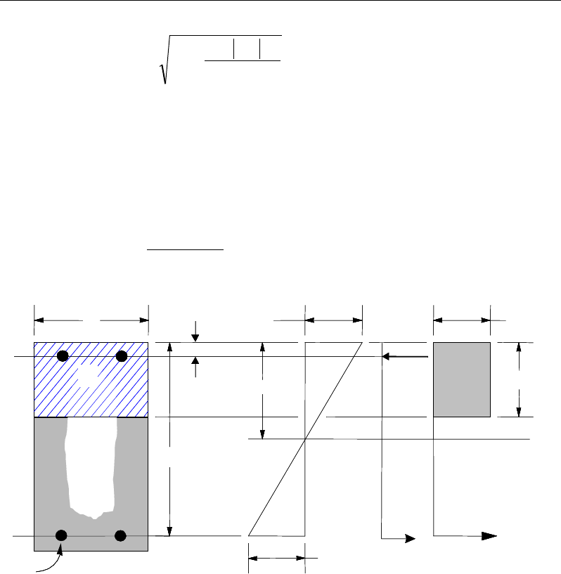
2.5.1.2.2 Design of nonuniform thickness slab
In designing a nonuniform thickness slab, a simplified stress block, as shown in
Figure 2-2, is assumed if the flange is under compression, i.e., if the moment is
positive. If the moment is negative, the flange comes under tension, and the
flange is ignored. In that case, a simplified stress block similar to that shown in
Figure 2-1 is assumed on the compression side.
2 - 10 Slab Design

Chapter 2 - Design for ACI 318-14
Figure 2-2 Nonuniform Thickness Slab Design
2.5.1.2.2.1 Flanged Slab Section Under Negative Moment
In designing for a factored negative moment, Mu (i.e., designing top reinforce-
ment), the calculation of the reinforcement area is exactly the same as described
previously, i.e., no flanged data is used.
2.5.1.2.2.2 Flanged Slab Section Under Positive Moment
If Mu > 0, the depth of the compression block is given by:
fc
u
bf
M
dda
φ
'85.0
2
2−−=
(ACI 22.2)
where, the value of
φ
is taken as that for a tension-controlled section, which by
default is 0.90 (ACI 21.2.1, 21.2.2, Table 21.2.1, Table 21.2.2) in the preceding
and the following equations.
The maximum depth of the compression zone, cmax, is calculated based on the
limitation that the tension reinforcement strain shall not be less than
ε
smin, which
is equal to 0.005 for tension controlled behavior (ACI 9.3.3.1, 21.2.2, Fig
21.2.26):
(I) BEAM
SECTION
s
A
(II) STRAIN
DIAGRAM
(III) STRESS
DIAGRAM
s
A′
w
b
f
b
d
d′
s
f′
0.003
ε
=
c
0.85 f ′
w
T
s
T
s
ε
c
0.85 f ′
f
T
f
C
w
C
s
C
f
h
c
(I) BEAM
SECTION
s
A
(II) STRAIN
DIAGRAM
(III) STRESS
DIAGRAM
s
A′
w
b
f
b
d
d′
s
f′
0.003
ε
=
c
0.85 f ′
w
T
s
T
s
ε
c
0.85 f ′
f
T
f
C
w
C
s
C
f
h
c
Slab Design 2 - 11

ETABS Reinforced Concrete Slab Design
dc
sc
c
minmax
max
max
εε
ε
+
=
(ACI 22.2.1.2)
where,
ε
cmax = 0.003 (ACI 21.2.2, Fig 21.2.26)
ε
smin = 0.005 (ACI 21.2.2, Fig 21.2.26)
The maximum allowable depth of the rectangular compression block, amax, is
given by:
max1max
ca
β
=
(ACI 22.2.2.4.11)
where
β
1 is calculated as:
c
f
1' 4000
0.85 0.05 ,
1000
β
−
= −
0.65 ≤
β
1 ≤ 0.85 (ACI 22.2.2.4.3)
If a ≤ hf, the subsequent calculations for As are exactly the same as previously
defined for the rectangular uniform slab design. However, in this case, the
width of the slab is taken as bf. Compression reinforcement is required if a >
amax.
If a > hf, the calculation for As has two parts. The first part is for balancing the
compressive force from the flange, Cf, and the second part is for balancing the
compressive force from the web, Cw, as shown in Figure 2-2. Cf is given by:
() ( )
max
,
min'85.0 ah
b
bfC
fwf
cf −=
(ACI 22.2.2.4.1)
Therefore,
y
f
s
f
C
A=
1
and the portion of Mu that is resisted by the flange is
given by:
( )
max
min ,
2
f
uf f
ha
M Cd
φ
= −
Again, the value for
φ
is 0.90 by default. Therefore, the balance of the moment,
Mu , to be carried by the web is:
2 - 12 Slab Design

Chapter 2 - Design for ACI 318-14
Muw = Mu − Muf
The web is a rectangular section with dimensions bw and d, for which the de-
sign depth of the compression block is recalculated as:
w
c
uw
b
f
M
d
d
a
φ
'
85
.
0
2
2
1
−−
=
(ACI 22.2)
If a1 ≤ amax (ACI 9.3.3.1, 21.2.2), the area of tension reinforcement is then
given by:
−
=
2
1
2
a
df
M
A
y
uw
s
φ
, and
As = As1 + As2
This reinforcement is to be placed at the bottom of the flanged slab section.
If a1 > amax, compression reinforcement is required (ACI 9.3.3.1, 21.2.2, Fig
21.2.2b, 22.2.2.4.1) and is calculated as follows:
− The compressive force in the web concrete alone is given by:
max
0.85 '
w cw
C f ba=
(ACI 22.2.2.4.1)
Therefore the moment resisted by the concrete web and tension reinforce-
ment is:
φ
= −
max
2
uc w a
M Cd
and the moment resisted by compression and tension reinforcement is:
Mus = Muw − Muc
Therefore, the compression reinforcement is computed as:
( )( )
us
ssc
M
Af f dd ,
0.85
φ
′=′ ′′
−−
where
Slab Design 2 - 13
ETABS Reinforced Concrete Slab Design
s sc y
cd
fE f
c
max
max max
ε
′
−
′= ≤
(ACI 9.2.1.2, 9.5.2.1, 20.2.2, 22.2.1.2)
The tension reinforcement for balancing compression in the web concrete is:
2max
2
uc
s
y
M
Aa
fd
φ
=
−
and the tension reinforcement for balancing the compression reinforcement
is:
()
φ
'
3
ddf
M
A
y
us
s
−
=
The total tension reinforcement is As = As1 + As2 + As3, and the total compres-
sion reinforcement is A's. As is to be placed at the bottom and A's is to be
placed at the top.
2.5.1.3 Minimum and Maximum Slab Reinforcement
The minimum flexural tension reinforcement required for each direction of a
slab is given by the following limits (ACI 7.6.1.1, 8.6.1.1):
As,min = 0.0020 bh for fy < 60 ksi (ACI Table 7.6.1.1, Table 8.6.1.1)
As,min = 0.0018 bh for fy = 60 ksi (ACI Table 7.6.1.1, Table 8.6.1.1)
As,min =
bh
fy
600000018.
0×
for fy > 60 ksi(ACI Table 7.6.1.1, Table
8.6.1.1)
In addition, an upper limit on both the tension reinforcement and compression
reinforcement has been imposed to be 0.04 times the gross cross-sectional area.
2.5.2 Design Slab Shear Reinforcement
The shear reinforcement is designed for each load combination at each station
along the design strip. In designing the shear reinforcement for a particular strip,
2 - 14 Slab Design

Chapter 2 - Design for ACI 318-14
for a particular load combination, at a particular station due to the slab major
shear, the following steps are involved:
Determine the factored shear force, Vu.
Determine the shear force, Vc, that can be resisted by the concrete.
Determine the shear reinforcement required to carry the balance.
The following three sections describe in detail the algorithms associated with
these steps.
2.5.2.1 Determine Factored Shear Force
In the design of the slab shear reinforcement, the shear forces for each load com-
bination at a particular design strip station are obtained by factoring the corre-
sponding shear forces for different load cases, with the corresponding load com-
bination factors.
2.5.2.2 Determine Concrete Shear Capacity
The shear force carried by the concrete, Vc, is calculated as:
dbfV
wcc
'2
λ
=
(ACI 22.5.5.1)
A limit is imposed on the value of
c
f'
as
'
c
f
≤ 100 (ACI 22.5.3.1)
The value of λ should be specified in the material property definition.
2.5.2.3 Determine Required Shear Reinforcement
The shear force is limited to a maximum of:
( )
max c cw
V V 8 f' b d= +
(ACI 22.5.1.2)
Given Vu, Vc, and Vmax, the required shear reinforcement is calculated as follows
where,
φ
, the strength reduction factor, is 0.75 (ACI 9.3.2.3). The flexural rein-
forcement strength, fyt, is limited to 60 ksi (ACI 11.5.2) even if the material prop-
erty is defined with a higher value.
Slab Design 2 - 15
ETABS Reinforced Concrete Slab Design
If
,
uc
VV
φ
≤
s
A
v
= 0 (ACI 9.6.3.1)
If
max
,
cu
VV V
φφ
<≤
( )
df
VV
s
A
yt
cuv
φ
φ
−
=
(ACI 22.5.1.1, 22.5.10.1, 20.5.10.5.3)
If Vu >
φ
Vmax, a failure condition is declared. (ACI 22.5.1.2)
If Vu exceeds the maximum permitted value of
φ
Vmax, the concrete section should
be increased in size (ACI 22.5.1.2).
The minimum shear reinforcement given by ACI 9.6.3.3.
0.75 ' 50
max ,
c
vw
w
yt yt
f
Ab
b
s ff
≥
(ACI 9.6.3.3, Table 9.6.3.3)
The maximum of all of the calculated Av
/s values obtained from each load com-
bination is reported along with the controlling shear force and associated load
combination.
The slab shear reinforcement requirements considered by the program are based
purely on shear strength considerations. Any minimum stirrup requirements to
satisfy spacing and volumetric considerations must be investigated
independently of the program by the user.
2.5.3 Check for Punching Shear
The algorithm for checking punching shear is detailed in the section entitled
“Slab Punching Shear Check” in the Chapter 1. Only the code-specific items are
described in the following sections.
2.5.3.1 Critical Section for Punching Shear
The punching shear is checked on a critical section at a distance of d / 2 from the
face of the support (ACI 22.6.4.2). For rectangular columns and concentrated
2 - 16 Slab Design
Chapter 2 - Design for ACI 318-14
loads, the critical area is taken as a rectangular area with the sides parallel to the
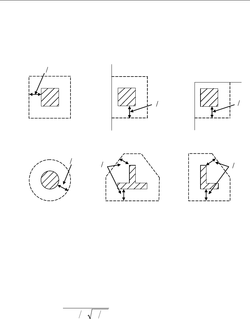
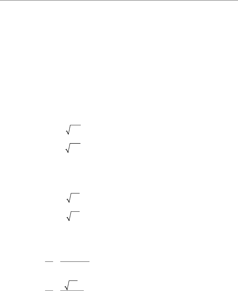
sides of the columns or the point loads (ACI 22.6.4.3). Figure 2-3 shows the auto
punching perimeters considered by ETABS for the various column shapes. The
column location (i.e., interior, edge or corner) and the punching
perimeter may be overwritten using the Punching Check Overwrites.
Figure 2-3 Punching Shear Perimeters
2.5.3.2 Transfer of Unbalanced Moment
The fraction of unbalanced moment transferred by flexure is taken to be
γ
f Msc
and the fraction of unbalanced moment transferred by eccentricity of shear is
taken to be
γ
v Msc.
( )
21
321
1
bb
f+
=
γ
(ACI 8.4.2.3)
γ
v = 1 −
γ
f (ACI 8.4.4.2.2)
d2
Interior Column
Circular Column
d2 d2
d2
T-Shape Column
Edge Column Edge Column
L-Shape Column
d2
d2
d2
Interior Column
Circular Column
d2 d2
d2
T-Shape Column
Edge Column Edge Column
L-Shape Column
d2
d2
Slab Design 2 - 17
ETABS Reinforced Concrete Slab Design
For reinforced concrete slabs,
γ
f is permitted to increase to the maximum mod-
ified values provided in ACI Table 8.4.2.3.4 provided that the limitations on vug
and εt given in ACI Table 8.4.2.3.4 are satisfied .
Column
Location
Span
Direc-
tion
v
ug
ε
t
Maximum modified
γ
f
Corner
column
Either
direction
≤0.5ϕv
c
≥0.004
1.0
Edge
column
Perpen-
dicular
to the
edge
≤0.75ϕv
c
≥0.004
1.0
Parallel
to
the edge
≤0.4ϕv
c
≥0.010
( )
12
1.25 1.0
1 23
f
bb
γ
= ≤
+
Interior
column
Either
direction
≤0.4ϕv
c
≥0.010
( )
12
1.25 1.0
1 23
f
bb
γ
= ≤
+
where b1 is the width of the critical section measured in the direction of the span
and b2 is the width of the critical section measured in the direction perpendicular
to the span.
2.5.3.3 Determine Concrete Capacity
The concrete punching shear stress capacity is taken as the minimum of the fol-
lowing three limits:
4
2
min 2
4
c
c
s
cc
o
c
f
d
vf
b
f
λ
β
αλ
λ
′
+
′
= +
′
(ACI 22.6.5.2)
2 - 18 Slab Design
Chapter 2 - Design for ACI 318-14
where,
β
c is the ratio of the maximum to the minimum dimensions of the critical
section, bo is the perimeter of the critical section, and
α
s is a scale factor based
on the location of the critical section.
s
40 for interior columns,
30 for edge columns, and
20 for corner columns.
α
=
(ACI 22.6.65.3)
A limit is imposed on the value of
c
f'
as:
c
f'
≤ 100 (ACI 22.5.3.1)
2.5.3.4 Computation of Maximum Shear Stress
Given the punching shear force and the fractions of moments transferred by ec-
centricity of shear about the two axes, the shear stress is computed assuming
linear variation along the perimeter of the critical section.
22 3 1 33 4 3 23 4 3
2
022 33 23
33 3 1 22 4 3 23 4 3
2
22 33 23
[ ( )][ ( ) ( )]
[ ( )][ ( ) ( )]
γ
γ
− − −− −
=+−
−
− − −− −
−
VUU
U
U
VUU
M Vy y I y y I x x
V
vbd I I I
M VxxIxx Iyy
II I
Eq. 1
22 22
1
,
=
=∑
n
sides
II
where "sides" refers to the sides of the critical section
for punching shear Eq. 2
33 33
1
,
=
=∑
n
sides
II
where "sides" refers to the sides of the critical section
for punching shear Eq. 3
23 23
1
,
=
=∑
n
sides
II
where "sides" refers to the sides of the critical section
for punching shear Eq. 4
Slab Design 2 - 19

ETABS Reinforced Concrete Slab Design
The equations for
22 33 23
, , andII I
are different depending on whether the
side of the critical section for punching shear being considered is parallel to
the 2-axis or parallel to the 3-axis. Refer to Figure 2-4.
2
22 2 3
( ),= −I Ld y y
for the side of the critical section parallel
to the 2-axis Eq. 5a
33 2
22 2 3
( ),
12 12
= ++ −
Ld dL
I Ld y y
for the side of the critical section
parallel to the 3-axis Eq. 5b
33 2
33 2 3
( ),
12 12
= ++ −
Ld dL
I Ld x x
for the side of the critical section
parallel to the 2-axis Eq. 6a
2
33 2 3
( ),= −I Ld x x
for the side of the critical section parallel
to the 3-axis Eq. 6b
23 2 3 2 3
( )( ),=−−I Ld x x y y
for side of critical section parallel
to 2-axis or 3-axis Eq. 7
NOTE:
23
I
is explicitly set to zero for corner condition.
2 - 20 Slab Design
Chapter 2 - Design for ACI 318-14
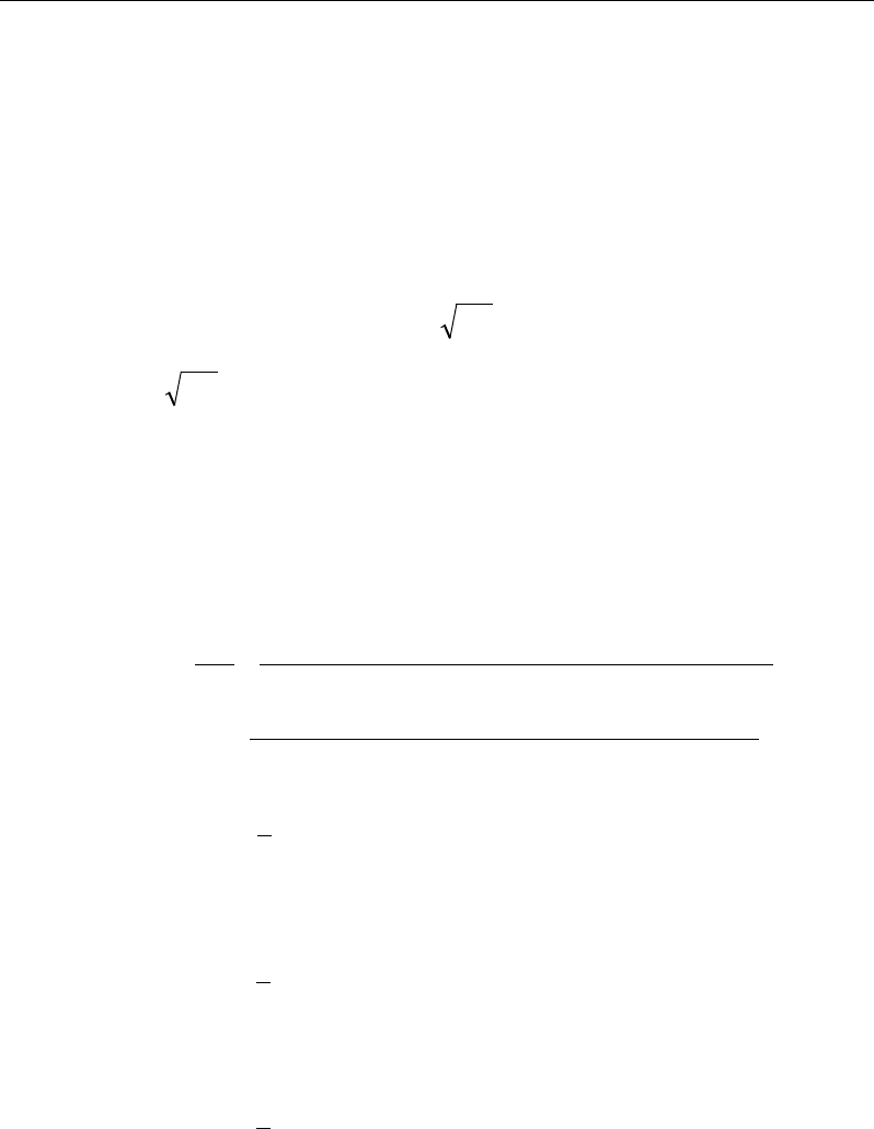
Figure 2-4 Shear Stress Calculations at Critical Sections
where,
b0 = Perimeter of the critical section for punching shear
d = Effective depth at the critical section for punching shear based on the
average of d for 2 direction and d for 3 direction
I22 = Moment of inertia of the critical section for punching shear about an axis
that is parallel to the local 2-axis
I33 = Moment of inertia of the critical section for punching shear about an axis
that is parallel to the local 3-axis
I23 = Product of the inertia of the critical section for punching shear with re-
spect to the 2 and 3 planes
Plan View For Side of Critical Section Parallel to 3-Axis
y
2
- y
3
L
Critical section for
punching shear
shown by heavy line
2
3
Side of critical section
being considered
shown solid
Center of side of critical
section being considered.
Coordinates are (x
2
,y
2
).
Work This Sketch With Equations 5b, 6b and
7
Centroid
of entire
critical section for
punching shear.
Coordinates are (x
3
,y
3
).
x
2
- x
3
y
2
- y
3
L
Critical section for
punching shear shown
by heavy line. Side of
critical section being
considered shown solid
2
3
Center of side of critical
section being considered.
Coordinates are (x
2
,y
2
).
Plan View For Side of Critical Section Parallel to 2-Axis
Work This Sketch With Equations 5a, 6a and
7
Centroid
of entire
critical section for
punching shear.
Coordinates are (x
3
,y
3
).
x
2
- x
3
Slab Design 2 - 21

ETABS Reinforced Concrete Slab Design
L = Length of the side of the critical section for punching shear currently
being considered
MU2 = Moment about the line parallel to the 2-axis at the center of the column
(positive in accordance with the right-hand rule)
MU3 = Moment about the line parallel to the 3-axis at the center of the column
(positive in accordance with the right-hand rule)
vU = Punching shear stress
VU = Shear at the center of the column (positive upward)
x1, y1 = Coordinates of the column centroid
x2, y2 = Coordinates of the center of one side of the critical section for punching
shear
x3, y3 = Coordinates of the centroid of the critical section for punching shear
x4, y4 = Coordinates of the location where stress is being calculated
γ
V2 = Percent of MU2 resisted by shear
γ
V3 = Percent of MU3 resisted by shear
2.5.3.5 Determine Capacity Ratio
Given the punching shear force and the fractions of moments transferred by ec-
centricity of shear about the two axes, the shear stress is computed assuming
linear variation along the perimeter of the critical section. The ratio of the max-
imum shear stress and the concrete punching shear stress capacity is reported as
the punching shear capacity ratio by ETABS. If this ratio exceeds 1.0, punching
shear reinforcement is designed as described in the following section.
2.5.4 Design Punching Shear Reinforcement
The use of shear studs as shear reinforcement in slabs is permitted, provided that
the effective depth of the slab is greater than or equal to 6 inches, and not less
than 16 times the shear reinforcement bar diameter (ACI 22.6.7.1). If the slab
2 - 22 Slab Design
Chapter 2 - Design for ACI 318-14
thickness does not meet these requirements, the punching shear reinforcement is
not designed and the slab thickness should be increased by the user.
The algorithm for designing the required punching shear reinforcement is used
when the punching shear capacity ratio exceeds unity. The Critical Section for
Punching Shear and Transfer of Unbalanced Moment as described in the earlier
sections remain unchanged. The design of punching shear reinforcement is de-
scribed in the subsections that follow.
2.5.4.1 Determine Concrete Shear Capacity
The concrete punching shear stress capacity of a section with punching shear
reinforcement is limited to:
2'
cc
vf
λ
≤
for shear links (ACI 22.6.6.1)
3'
cc
vf
λ
≤
for shear studs (ACI 22.6.6.1)
2.5.4.2 Determine Required Shear Reinforcement
The shear force is limited to a maximum of:
Vmax = 6
′
c
f
bod for shear links (ACI 22.6.6.2)
Vmax = 8
′
c
f
bod for shear studs (ACI 22.6.6.2)
Given Vu, Vc, and Vmax, the required shear reinforcement is calculated as follows,
where,
φ
, the strength reduction factor, is 0.75 (ACI 9.3.2.3).
()
uc
v
ys
VV
A
s fd
φ
φ
−
=
(ACI 22.5.1.1, 22.5.10.1, 20.5.10.5.3)
2′
≥co
v
y
fb
A
sf
for shear studs
If Vu >
φ
Vmax, a failure condition is declared. (ACI 22.5.1.2)
Slab Design 2 - 23
ETABS Reinforced Concrete Slab Design
If Vu exceeds the maximum permitted value of
φ
Vmax, the concrete section
should be increased in size.
2.5.4.3 Determine Reinforcement Arrangement
Punching shear reinforcement in the vicinity of rectangular columns should be
arranged on peripheral lines, i.e., lines running parallel to and at constant dis-
tances from the sides of the column. Figure 2-5 shows a typical arrangement of
shear reinforcement in the vicinity of a rectangular interior, edge, and corner
column.
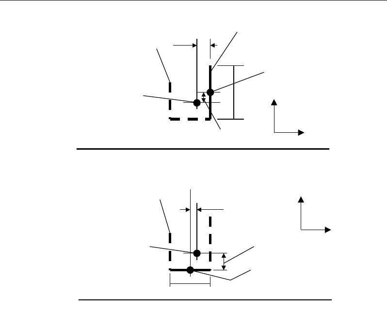
Figure 2-5 Typical arrangement of shear studs
and critical sections outside shear-reinforced zone
The distance between the column face and the first line of shear reinforcement
shall not exceed d / 2(ACI 8.7.6.3, Table 8.7.6.3) and the spacing between shear
reinforcement shall not exceed d / 2(ACI 8.7.6.3, Table 8.7.6.3). The spacing be-
tween adjacent shear reinforcement in the first line (perimeter) of shear rein-
forcement shall not exceed 2d measured in a direction parallel to the column face
(ACI 8.7.6.3, Table 8.7.6.3).
Punching shear reinforcement is most effective near column corners where there
are concentrations of shear stress. Therefore, the minimum number of lines of
shear reinforcement is 4, 6, and 8, for corner, edge, and interior columns respec-
tively.
Iy
Typical Studrail
(only first and last
studs shown)
Outermost
peripheral line
of studs
Interior Column Edge Column Corner Column
Critical section
centroid
Free
edge
Free
edge
Critical
section
centroid
Free edge
Outermost
peripheral line
of studs
Iy
Iy
yx
d2 d2
d2
x
I
x
I
x
g
y
g
x
g
0
s
0
s
0
s
x
I
y
xx
Iy
Typical Studrail
(only first and last
studs shown)
Outermost
peripheral line
of studs
Interior Column Edge Column Corner Column
Critical section
centroid
Free
edge
Free
edge
Critical
section
centroid
Free edge
Outermost
peripheral line
of studs
Iy
Iy
yx
d2 d2
d2
x
I
x
I
x
g
y
g
x
g
0
s
0
s
0
s
x
I
y
xx
2 - 24 Slab Design

Chapter 2 - Design for ACI 318-14
2.5.4.4 Determine Reinforcement Diameter, Height, and Spacing
The punching shear reinforcement is most effective when the anchorage is close
to the top and bottom surfaces of the slab. The cover of anchors should not be
less than the minimum cover specified in 20.6.1.3 plus half of the
diameter of the flexural reinforcement.
Punching shear reinforcement in the form of shear studs is generally available in
3/8-, 1/2-, 5/8-, and 3/4-inch diameters.
When specifying shear studs, the distance, so, between the column face and the
first peripheral line of shear studs should not be smaller than 0.5d. The spacing
between adjacent shear studs, g, at the first peripheral line of studs shall not
exceed 2d, and in the case of studs in a radial pattern, the angle between adjacent
stud rails shall not exceed 60 degrees. The limits of so and the spacing, s, between
the peripheral lines are specified as:
so ≤ 0.5d (ACI 8.7.7.1.2)
0 75 for 6
0 50 for 6
uc
uc
.d v f
s.d v f
φ
φ
′
≤
≤′
>
(ACI 8.7.7.1.2)
g ≤ 2d (ACI 8.7.7.1.2)
The limits of so and the spacing, s, between for the links are specified as:
so ≤ 0.5d (ACI 8.7.6.3)
0 50≤s .d
(ACI 8.7.6.3)
Slab Design 2 - 25

Chapter 03
Design for ACI 318-11
This chapter describes in detail the various aspects of the concrete design proce-
dure that is used by ETABS when the American code ACI 318-11 [ACI 2011]
is selected. Various notations used in this chapter are listed in Table 3-1. For
referencing to the pertinent sections or equations of the ACI code in this chapter,
a prefix “ACI” followed by the section or equation number is used herein.
The design is based on user-specified load combinations. The program provides
a set of default load combinations that should satisfy the requirements for the
design of most building type structures.
English as well as SI and MKS metric units can be used for input. The code is
based on inch-pound-second units. For simplicity, all equations and descriptions
presented in this chapter correspond to inch-pound-second units unless otherwise
noted.
3.1 Notations
Table 3-1 List of Symbols Used in the ACI 318-11 Code
A
cp
Area enclosed by the outside perimeter of the section, sq-in
A
g
Gross area of concrete, sq-in
Notations 3 - 1

ETABS Reinforced Concrete Design
Table 3-1 List of Symbols Used in the ACI 318-11 Code
A
l
Area of longitudinal reinforcement for torsion, sq-in
A
o
Area enclosed by the shear flow path, sq-in
A
oh
Area enclosed by the centerline of the outermost closed transverse
torsional reinforcement, sq-in
A
s
Area of tension reinforcement, sq-in
A'
s
Area of compression reinforcement, sq-in
A
t
/s
Area of closed shear reinforcement per unit length of member for
torsion, sq-in/in
A
v
Area of shear reinforcement, sq-in
A
v
/s
Area of shear reinforcement per unit length, sq-in/in
a
Depth of compression block, in
a
max
Maximum allowed depth of compression block, in
b
Width of section, in
b
f
Effective width of flange (flanged section), in
b
o
Perimeter of the punching shear critical section, in
b
w
Width of web (flanged section), in
b
1
Width of the punching shear critical section in the direction of
bending, in
b
2
Width of the punching shear critical section perpendicular to the di-
rection of bending, in
c
Depth to neutral axis, in
d
Distance from compression face to tension reinforcement, in
d'
Distance from compression face to compression reinforcement, in
E
c
Modulus of elasticity of concrete, psi
E
s
Modulus of elasticity of reinforcement, psi
f'
c
Specified compressive strength of concrete, psi
3 - 2 Notations

Chapter 03 - Design for ACI 318-11
Table 3-1 List of Symbols Used in the ACI 318-11 Code
f'
s
Stress in the compression reinforcement, psi
f
y
Specified yield strength of flexural reinforcement, psi
f
yt
Specified yield strength of shear reinforcement, psi
h
Overall depth of a section, in
h
f
Height of the flange, in
M
u
Factored moment at a section, lb-in
N
u
Factored axial load at a section occurring simultaneously with V
u
or
Tu, lb
P
u
Factored axial load at a section, lb
p
cp
Outside perimeter of concrete cross-section, in
p
h
Perimeter of centerline of outermost closed transverse torsional
reinforcement, in
s
Spacing of shear reinforcement along the strip, in
T
cr
Critical torsion capacity, lb-in
T
u
Factored torsional moment at a section, lb-in
V
c
Shear force resisted by concrete, lb
V
max
Maximum permitted total factored shear force at a section, lb
V
s
Shear force resisted by transverse reinforcement, lb
V
u
Factored shear force at a section, lb
α
s
Punching shear scale factor based on column location
β
c
Ratio of the maximum to the minimum dimensions of the punching
shear critical section
β
1
Factor for obtaining depth of the concrete compression block
ε
c
Strain in the concrete
ε
c max
Maximum usable compression strain allowed in the extreme
concrete fiber, (0.003 in/in)
Notations 3 - 3

ETABS Reinforced Concrete Design
Table 3-1 List of Symbols Used in the ACI 318-11 Code
ε
s
Strain in the reinforcement
ε
s,min
Minimum tensile strain allowed in the reinforcement at nominal
strength for tension controlled behavior (0.005 in/in)
φ
Strength reduction factor
γ
f
Fraction of unbalanced moment transferred by flexure
γ
v
Fraction of unbalanced moment transferred by eccentricity of shear
λ
Shear strength reduction factor for light-weight concrete
θ
Angle of compression diagonals, degrees
3.2 Design Load Combinations
The design load combinations are the various combinations of the load cases for
which the structure needs to be designed. For ACI 318-11, if a structure is sub-
jected to dead (D), live (L), pattern live (PL), snow (S), wind (W), and earth-
quake (E) loads, and considering that wind and earthquake forces are reversible,
the following load combinations may need to be considered (ACI 9.2.1):
1.4D
(ACI 9-1)
1.2D + 1.6L
(ACI 9-2)
1.2D + 1.6 (0.75 PL)
(ACI 13.7.6.3, 9-2)
0.9D ± 1.0W
1.2D + 1.0L ± 1.0W (ACI 9-6
)
(ACI 9-
4)
0.9D ± 1.0E
1.2D + 1.0L ± 1.0E (ACI 9-7
)
(ACI 9-
5)
1.2D + 1.6L + 0.5S
1.2D + 1.0L + 1.6S
1.2D + 1.6S ± 0.5W
1.2D + 1.0L + 0.5S ± 1.0W
1.2D + 1.0L + 0.2S ± 1.0E
(ACI 9-2)
(ACI 9-3
)
(ACI 9-3
)
(ACI 9-4
)
(ACI 9-5)
3 - 4 Design Load Combinations

Chapter 03 - Design for ACI 318-11
These are the default design load combinations in ETABS whenever the ACI
318-11 code is used. The user should use other appropriate load combinations if
roof live load is treated separately, or if other types of loads are present.
3.3 Limits on Material Strength
The concrete compressive strength,
,
′
c
f
should not be less than 2,500 psi (ACI
5.1.1). The upper limit of the reinforcement yield strength, fy, is taken as 80 ksi
(ACI 9.4) and the upper limit of the reinforcement shear strength, fyt, is taken as
60 ksi (ACI 11.4.2).
If the input
′
c
f
is less than 2,500 psi, ETABS continues to design the members
based on the input
′
c
f
and does not warn the user about the violation of the code.
The user is responsible for ensuring that the minimum strength is satisfied.
3.4 Strength Reduction Factors
The strength reduction factors,
φ
, are applied to the specified strength to obtain
the design strength provided by a member. The
φ
factors for flexure, shear, and
torsion are as follows:
φ
= 0.90 for flexure (tension controlled) (ACI 9.3.2.1)
φ
= 0.75 for shear and torsion (ACI 9.3.2.3)
These values can be overwritten; however, caution is advised.
3.5 Slab Design
ETABS slab design procedure involves defining sets of strips in two mutually
perpendicular directions. The locations of the strips are usually governed by the
locations of the slab supports. The axial force, moments and shears for a partic-
ular strip are recovered from the analysis (on the basis of the Wood-Armer tech-
nique), and a flexural design is carried out based on the ultimate strength design
method.
The slab design procedure involves the following steps:
Limits on Material Strength 3 - 5

ETABS Reinforced Concrete Design
Design flexural reinforcement
Design shear reinforcement
Punching check
3.5.1 Design Flexural Reinforcement
For slabs, ETABS uses either design strips or the finite element based design to
calculate the slab flexural reinforcement in accordance with the selected design
code. For simplicity, only strip-by-strip design is document in the proceeding
sections.
The design of the slab reinforcement for a particular strip is carried out at specific
locations along the length of the strip. These locations correspond to the element
boundaries. Controlling reinforcement is computed on either side of those ele-
ment boundaries. The slab flexural design procedure for each load combination
involves the following:
Determine factored axial loads and moments for each slab strip.
Design flexural reinforcement for the strip.
These two steps, described in the text that follows, are repeated for every load
combination. The maximum reinforcement calculated for the top and bottom of
the slab within each design strip, along with the corresponding controlling load
combination, is obtained and reported.
3.5.1.1 Determine Factored Moments
In the design of flexural reinforcement of concrete slab, the factored moments
for each load combination at a particular design strip are obtained by factoring
the corresponding moments for different load cases, with the corresponding load
factors.
The slab is then designed for the maximum positive and maximum negative fac-
tored moments obtained from all of the load combinations. Calculation of bottom
reinforcement is based on positive design strip moments. In such cases, the slab
3 - 6 Slab Design

Chapter 03 - Design for ACI 318-11
may be designed as a rectangular or flanged slab section. Calculation of top re-
inforcement is based on negative design strip moments. In such cases, the slab
may be designed as a rectangular or inverted flanged slab section.
3.5.1.2 Determine Required Flexural Reinforcement
In the flexural reinforcement design process, the program calculates both the
tension and compression reinforcement. Compression reinforcement is added
when the applied design moment exceeds the maximum moment capacity of a
singly reinforced section. The user has the option of avoiding compression
reinforcement by increasing the effective depth, the width, or the strength of the
concrete. Note that the flexural reinforcement strength, fy , is limited to 80 ksi
(ACI 9.4), even if the material property is defined using a higher value.
The design procedure is based on the simplified rectangular stress block, as
shown in Figure 3-1 (ACI 10.2). Furthermore, it is assumed that the net tensile
strain in the reinforcement shall not be less than 0.005 (tension controlled) (ACI
10.3.4) when the concrete in compression reaches its assumed strain limit of
0.003. When the applied moment exceeds the moment capacity at this design
condition, the area of compression reinforcement is calculated assuming that the
additional moment will be carried by compression reinforcement and additional
tension reinforcement.
The design procedure used by ETABS, for both rectangular and flanged sections
(L- and T-shaped sections), is summarized in the text that follows. For reinforced
concrete design where design ultimate axial compression load does not ex-
ceed
( )
cg
fA0.1 ′
(ACI 10.3.5), axial force is ignored; hence, all slabs are de-
signed for major direction flexure, shear, and torsion only. Axial compression
greater than
()
cg
fA
0.1 ′
and axial tensions are always included in flexural and
shear design.
3.5.1.2.1 Design of uniform thickness slab
In designing for a factored negative or positive moment, Mu (i.e., designing top
or bottom reinforcement), the depth of the compression block is given by a (see
Figure 3-1), where,
Slab Design 3 - 7
ETABS Reinforced Concrete Design
b
f
M
d
da
c
u
φ
'
85.
0
2
2−−=
(ACI 10.2)
and the value of
φ
is taken as that for a tension-controlled section, which by
default is 0.90 (ACI 9.3.2.1) in the preceding and the following equations.
The maximum depth of the compression zone, cmax, is calculated based on the
limitation that the tension reinforcement strain shall not be less than
ε
smin, which
is equal to 0.005 for tension controlled behavior (ACI 10.3.4):
max
max max min
c
cs
cd
ε
εε
=+
(ACI 10.2.2)
Figure 3-1 Uniform Thickness Slab Design
where,
ε
cmax = 0.003 (ACI 10.2.3)
ε
smin = 0.005 (ACI 10.3.4)
(I) BEAM
SECTION (II) STRAIN
DIAGRAM (III) STRESS
DIAGRAM
0.003
ε
=c
0.85 f ′
1
ac
β
=
cs
T
s
T
s
ε
cs
C
d′
d
b
s
A
s
A′
(I) BEAM
SECTION (II) STRAIN
DIAGRAM (III) STRESS
DIAGRAM
0.003
ε
=c
0.85 f ′
1
ac
β
=
cs
T
s
T
s
ε
cs
C
d′
d
b
s
A
s
A′
3 - 8 Slab Design

Chapter 03 - Design for ACI 318-11
The maximum allowable depth of the rectangular compression block, amax, is
given by:
amax =
β
1cmax (ACI 10.2.7.1)
where
β
1 is calculated as:
c
f
1
4000
0.85 0.05 ,
1000
β
′−
= −
0.65 ≤
β
1 ≤ 0.85 (ACI 10.2.7.3)
If a ≤ amax (ACI 10.3.4), the area of tension reinforcement is then given by:
−
=
2
a
df
M
A
y
u
s
φ
This reinforcement is to be placed at the bottom if Mu is positive, or at the top
if Mu is negative.
If a > amax, compression reinforcement is required (ACI 10.3.5.1) and is cal-
culated as follows:
− The compressive force developed in the concrete alone is given by:
max
'85.0 bafC c
=
(ACI 10.2.7.1)
and the moment resisted by concrete compression and tension reinforcement
is:
max
2
uc
a
M Cd
φ
= −
(ACI 9.3.2.1)
− Therefore the moment required to be resisted by compression reinforcement
and tension reinforcement is:
Mus = Mu − Muc
− The required compression reinforcement is given by:
Slab Design 3 - 9

ETABS Reinforced Concrete Design
( )( )
'' 0.85 ' '
us
s
sc
M
Af f dd
φ
=−−
, where
ycss
f
c
dc
Ef ≤
−
=
max
max
max
'
'
ε
(ACI 10.2.2, 10.2.3, 10.2.4)
− The required tension reinforcement for balancing the compression in the
concrete is:
1max
2
uc
s
y
M
Aa
fd
φ
=
−
and the tension reinforcement for balancing the compression reinforcement
is given by:
( )
2'
us
s
y
M
Afdd
φ
=−
Therefore, the total tension reinforcement is As = As1 + As2, and the total com-
pression reinforcement is A's. As is to be placed at the bottom and A's is to be
placed at the top if Mu is positive, and vice versa if Mu is negative.
3.5.1.2.2 Design of nonuniform thickness slab
In designing a nonuniform thickness slab, a simplified stress block, as shown in
Figure 3-2, is assumed if the flange is under compression, i.e., if the moment is
positive. If the moment is negative, the flange comes under tension, and the
flange is ignored. In that case, a simplified stress block similar to that shown in
Figure 3-1 is assumed on the compression side.
3 - 10 Slab Design
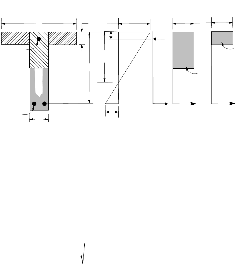
Chapter 03 - Design for ACI 318-11
Figure 3-2 Nonuniform Thickness Slab Design
3.5.1.2.2.1 Flanged Slab Under Negative Moment
In designing for a factored negative moment, Mu (i.e., designing top reinforce-
ment), the calculation of the reinforcement area is exactly the same as described
previously, i.e., no flanged data is used.
3.5.1.2.2.2 Flanged Slab Under Positive Moment
If Mu > 0, the depth of the compression block is given by:
fc
u
bf
M
dda
φ
'85.0
2
2
−−=
(ACI 10.2)
where, the value of
φ
is taken as that for a tension-controlled section, which by
default is 0.90 (ACI 9.3.2.1) in the preceding and the following equations.
The maximum depth of the compression zone, cmax, is calculated based on the
limitation that the tension reinforcement strain shall not be less than
ε
smin, which
is equal to 0.005 for tension controlled behavior (ACI 10.3.4):
(I) BEAM
SECTION
s
A
(II) STRAIN
DIAGRAM
(III) STRESS
DIAGRAM
s
A′
w
b
f
b
d
d′
s
f′
0.003
ε
=
c
0.85 f ′
w
T
s
T
s
ε
c
0.85 f ′
f
T
f
C
w
C
s
C
f
h
c
(I) BEAM
SECTION
s
A
(II) STRAIN
DIAGRAM
(III) STRESS
DIAGRAM
s
A′
w
b
f
b
d
d′
s
f′
0.003
ε
=
c
0.85 f ′
w
T
s
T
s
ε
c
0.85 f ′
f
T
f
C
w
C
s
C
f
h
c
Slab Design 3 - 11

ETABS Reinforced Concrete Design
dc
sc
c
minmax
max
max
εε
ε
+
=
(ACI 10.2.2)
where,
ε
cmax = 0.003 (ACI 10.2.3)
ε
smin = 0.005 (ACI 10.3.4)
The maximum allowable depth of the rectangular compression block, amax, is
given by:
max1max ca
β
=
(ACI 10.2.7.1)
where
β
1 is calculated as:
c
f
1' 4000
0.85 0.05 ,
1000
β
−
= −
0.65 ≤
β
1 ≤ 0.85 (ACI 10.2.7.3)
If a ≤ hf, the subsequent calculations for As are exactly the same as previously
defined for the rectangular slabdesign. However, in this case, the width of the
slab is taken as bf. Compression reinforcement is required if a > amax.
If a > hf, the calculation for As has two parts. The first part is for balancing the
compressive force from the flange, Cf, and the second part is for balancing the
compressive force from the web, Cw, as shown in Figure 3-2. Cf is given by:
( ) ()
max
,min'85.0 a
hbbf
C
fwf
cf
−=
(ACI 10.2.7.1)
Therefore,
y
f
s
f
C
A=
1
and the portion of Mu that is resisted by the flange is
given by:
( )
max
min ,
2
f
uf f
ha
M Cd
φ
= −
(ACI 9.3.2.1)
Again, the value for
φ
is 0.90 by default. Therefore, the balance of the moment,
Mu , to be carried by the web is:
3 - 12 Slab Design

Chapter 03 - Design for ACI 318-11
Muw = Mu − Muf
The web is a rectangular section with dimensions bw and d, for which the de-
sign depth of the compression block is recalculated as:
wc
uw
bf
M
dda
φ
'85.0
2
2
1−−=
(ACI 10.2)
If a1 ≤ amax (ACI 10.3.4), the area of tension reinforcement is then given by:
−
=
2
1
2
a
df
M
A
y
uw
s
φ
, and
As = As1 + As2
This reinforcement is to be placed at the bottom of the flanged slab.
If a1 > amax, compression reinforcement is required (ACI 10.3.5.1) and is cal-
culated as follows:
− The compressive force in the web concrete alone is given by:
max
0.85 '
w cw
C f ba=
(ACI 10.2.7.1)
Therefore the moment resisted by the concrete web and tension reinforce-
ment is:
φ
= −
max
2
uc w a
M Cd
and the moment resisted by compression and tension reinforcement is:
Mus = Muw − Muc
Therefore, the compression reinforcement is computed as:
( )( )
us
ssc
M
Af f dd ,
0.85
φ
′=′ ′′
−−
where
Slab Design 3 - 13

ETABS Reinforced Concrete Design
s sc y
cd
fE f
c
max
max max
ε
′
−
′= ≤
(ACI 10.2.2, 10.2.3, 10.2.4)
The tension reinforcement for balancing compression in the web concrete is:
2max
2
uc
s
y
M
Aa
fd
φ
=
−
and the tension reinforcement for balancing the compression reinforcement
is:
()
φ
'
3
ddf
M
A
y
us
s
−
=
The total tension reinforcement is As = As1 + As2 + As3, and the total compres-
sion reinforcement is A's. As is to be placed at the bottom and A's is to be
placed at the top.
3.5.1.1 Minimum and Maximum Slab Reinforcement
The minimum flexural tension reinforcement required for each direction of a
slab is given by the following limits (ACI 7.12.2, 13.3.1):
As,min = 0.0020 bh for fy = 40 ksi or 50 ksi (ACI 7.12.2.1(a))
As,min = 0.0018 bh for fy = 60 ksi (ACI 7.12.2.1(b))
As,min =
bh
fy
600000018
.0 ×
for fy > 60 ksi (ACI 7.12.2.1(c))
In addition, an upper limit on both the tension reinforcement and compression
reinforcement has been imposed to be 0.04 times the gross cross-sectional area.
3.5.2 Design Slab Shear Reinforcement
The shear reinforcement is designed for each load combination at each station
along the design strip. In designing the shear reinforcement for a particular strip,
3 - 14 Slab Design

Chapter 03 - Design for ACI 318-11
for a particular load combination, at a particular station due to the slab major
shear, the following steps are involved:
Determine the factored shear force, Vu.
Determine the shear force, Vc, that can be resisted by the concrete.
Determine the shear reinforcement required to carry the balance.
The following three sections describe in detail the algorithms associated with
these steps.
3.5.2.1 Determine Factored Shear Force
In the design of the slab shear reinforcement, the shear forces for each load com-
bination at a particular design strip station are obtained by factoring the corre-
sponding shear forces for different load cases, with the corresponding load com-
bination factors.
3.5.2.2 Determine Concrete Shear Capacity
The shear force carried by the concrete, Vc, is calculated as:
dbfV wcc '2
λ
=
(ACI 11.2.1.2)
A limit is imposed on the value of
c
f'
as
'
c
f
≤ 100 (ACI 11.1.2)
The value of λ should be specified in the material property definition.
3.5.2.3 Determine Required Shear Reinforcement
The shear force is limited to a maximum of:
( )
max c cw
V V 8 f' b d= +
(ACI 11.4.7.9)
Given Vu, Vc, and Vmax, the required shear reinforcement is calculated as follows
where,
φ
, the strength reduction factor, is 0.75 (ACI 9.3.2.3). The flexural rein-
forcement strength, fyt, is limited to 60 ksi (ACI 11.5.2) even if the material prop-
erty is defined with a higher value.
Slab Design 3 - 15
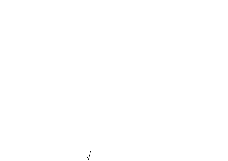
ETABS Reinforced Concrete Design
If
,
uc
VV
φ
≤
s
Av
= 0 (ACI 11.4.6.1)
If
max ,
cu
VV V
φφ
<≤
( )
df
VV
s
A
yt
cuv
φ
φ
−
=
(ACI 11.4.7.1, 11.4.7.2)
If Vu >
φ
Vmax, a failure condition is declared. (ACI 11.4.7.9)
If Vu exceeds the maximum permitted value of
φ
Vmax, the concrete section should
be increased in size (ACI 11.4.7.9).
The minimum shear reinforcement given by ACI 11.4.6.3 is not enforced (ACI
11.4.6.1).
0.75 ' 50
max ,
c
vw
w
yt yt
f
Ab
b
s ff
≥
(ACI 11.4.6.3)
The maximum of all of the calculated Av
/s values obtained from each load com-
bination is reported along with the controlling shear force and associated load
combination.
The slab shear reinforcement requirements considered by the program are based
purely on shear strength considerations. Any minimum stirrup requirements to
satisfy spacing and volumetric considerations must be investigated
independently of the program by the user.
3.5.3 Check for Punching Shear
The algorithm for checking punching shear is detailed in the section entitled
“Slab Punching Shear Check” in the Chapter 1. Only the code-specific items are
described in the following sections.
3 - 16 Slab Design

Chapter 03 - Design for ACI 318-11
3.5.3.1 Critical Section for Punching Shear
The punching shear is checked on a critical section at a distance of d / 2 from the
face of the support (ACI 11.11.1.2). For rectangular columns and concentrated
loads, the critical area is taken as a rectangular area with the sides parallel to the
sides of the columns or the point loads (ACI 11.11.1.3). Figure 3-3 shows the
auto punching perimeters considered by ETABS for the various column shapes.
The column location (i.e., interior, edge, corner) and the punching
perimeter may be overwritten using the Punching Check Overwrites.
Figure 3-3 Punching Shear Perimeters
3.5.3.2 Transfer of Unbalanced Moment
The fraction of unbalanced moment transferred by flexure is taken to be
γ
f Mu
and the fraction of unbalanced moment transferred by eccentricity of shear is
taken to be
γ
v Mu.
( )
21
321
1
bb
f+
=
γ
(ACI 13.5.3.2)
d2
Interior Column
Circular Column
d2 d2
d2
T-Shape Column
Edge Column Edge Column
L-Shape Column
d2
d2
d2
Interior Column
Circular Column
d2 d2
d2
T-Shape Column
Edge Column Edge Column
L-Shape Column
d2
d2
Slab Design 3 - 17

ETABS Reinforced Concrete Design
γ
v = 1 −
γ
f (ACI 13.5.3.1)
For flat plates,
γ
v is determined from the following equations taken from ACI
421.2R-07 Seismic Design of Punching Shear Reinforcement in Flat Plates [ACI
2007].
For interior columns,
( )
1
11 23
vx
yx
ll
γ
= − +
(ACI 421.2 C-11)
( )
1
11 23
vy
xy
ll
γ
= − +
(ACI 421.2 C-12)
For edge columns,
γ
vx = same as for interior columns (ACI 421.2 C-13)
()
2.0321
1
1−+
−
=
yx
vy l
l
γ
(ACI 421.2 C-14)
γ
vy = 0 when
xy
ll 0.2≤
For corner columns,
γ
vx = 0.4 (ACI 421.2 C-15)
γ
vy = same as for edge columns (ACI 421.2 C-16)
NOTE: Program uses ACI 421.2-12 and ACI 421.2-15 equations in lieu of ACI
421.2 C-14 and ACI 421.2 C-16 which are currently NOT enforced.
where b1 is the width of the critical section measured in the direction of the span
and b2 is the width of the critical section measured in the direction perpendicular
to the span. The values lx and ly are the projections of the shear-critical section
onto its principal axes, x and y, respectively.
3 - 18 Slab Design
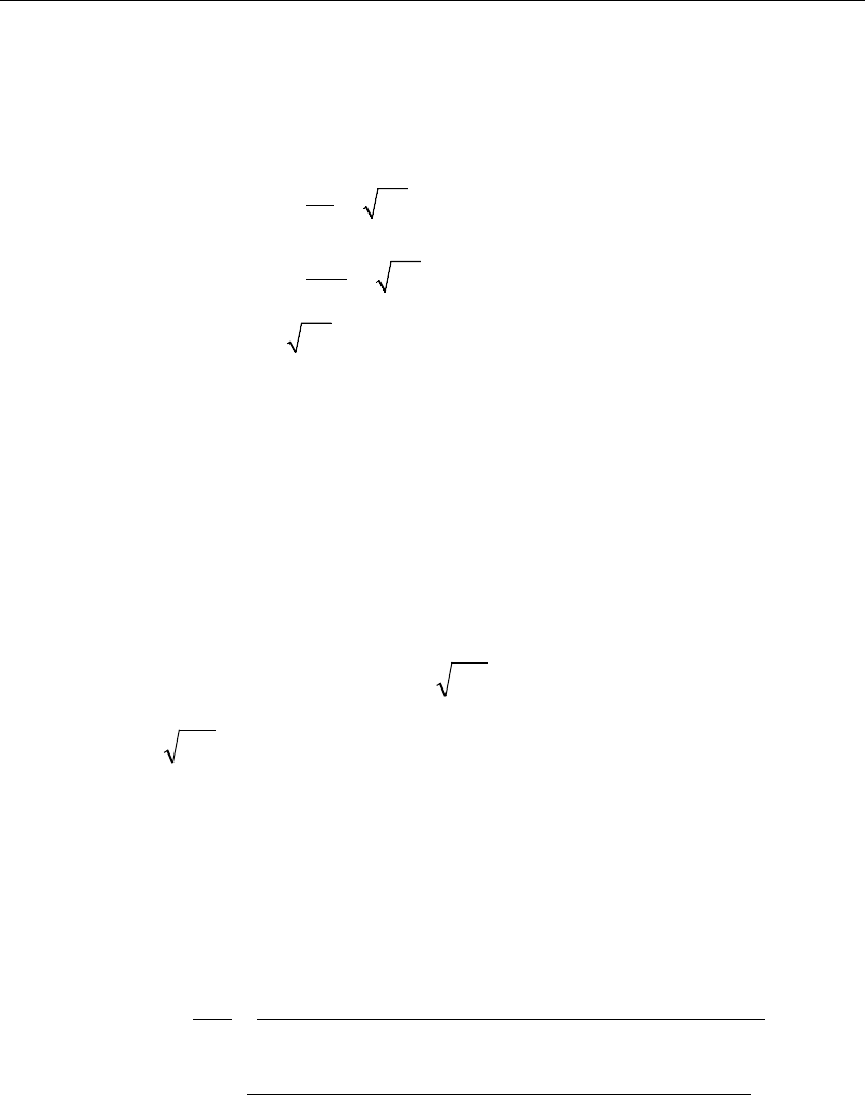
Chapter 03 - Design for ACI 318-11
3.5.3.3 Determine Concrete Capacity
The concrete punching shear stress capacity is taken as the minimum of the fol-
lowing three limits:
4
2
min 2
4
c
c
s
cc
o
c
f
d
vf
b
f
λ
β
αλ
λ
′
+
′
= +
′
(ACI 11.11.2.1)
where,
β
c is the ratio of the maximum to the minimum dimensions of the critical
section, bo is the perimeter of the critical section, and
α
s is a scale factor based
on the location of the critical section.
s
40 for interior columns,
30 for edge columns, and
20 for corner columns.
α
=
(ACI 11.11.2.1)
A limit is imposed on the value of
c
f'
as:
c
f'
≤ 100 (ACI 11.1.2)
3.5.3.4 Computation of Maximum Shear Stress
Given the punching shear force and the fractions of moments transferred by ec-
centricity of shear about the two axes, the shear stress is computed assuming
linear variation along the perimeter of the critical section.
22 3 1 33 4 3 23 4 3
2
022 33 23
33 3 1 22 4 3 23 4 3
2
22 33 23
[ ( )][ ( ) ( )]
[ ( )][ ( ) ( )]
γ
γ
− − −− −
=+−
−
− − −− −
−
VUU
U
U
VUU
M Vy y I y y I x x
V
vbd I I I
M VxxIxx Iyy
II I
Eq. 1
Slab Design 3 - 19

ETABS Reinforced Concrete Design
22 22
1
,
=
=∑
n
sides
II
where "sides" refers to the sides of the critical section
for punching shear Eq. 2
33 33
1
,
=
=∑
n
sides
II
where "sides" refers to the sides of the critical section
for punching shear Eq. 3
23 23
1
,
=
=∑
n
sides
II
where "sides" refers to the sides of the critical section
for punching shear Eq. 4
The equations for
22 33 23
, , andII I
are different depending on whether the
side of the critical section for punching shear being considered is parallel to
the 2-axis or parallel to the 3-axis. Refer to Figure 3-4.
2
22 2 3
( ),= −I Ld y y
for the side of the critical section parallel
to the 2-axis Eq. 5a
33 2
22 2 3
( ),
12 12
= ++ −
Ld dL
I Ld y y
for the side of the critical section
parallel to the 3-axis Eq. 5b
33 2
33 2 3
( ),
12 12
= ++ −
Ld dL
I Ld x x
for the side of the critical section
parallel to the 2-axis Eq. 6a
2
33 2 3
( ),
= −I Ld x x
for the side of the critical section parallel
to the 3-axis Eq. 6b
3 - 20 Slab Design
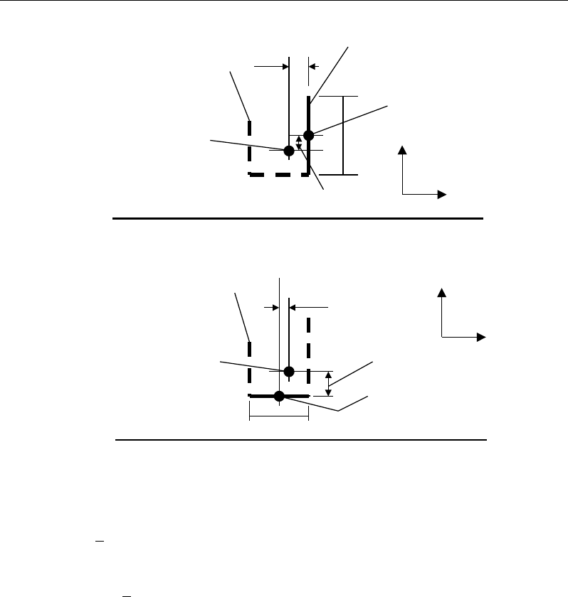
Chapter 03 - Design for ACI 318-11
Figure 3-4 Shear Stress Calculations at Critical Sections
23 2 3 2 3
( )( ),
=−−I Ld x x y y
for side of critical section parallel
to 2-axis or 3-axis Eq. 7
NOTE:
23
I
is explicitly set to zero for corner condition.
where,
b0 = Perimeter of the critical section for punching shear
d = Effective depth at the critical section for punching shear based on the
average of d for 2 direction and d for 3 direction
I22 = Moment of inertia of the critical section for punching shear about an axis
that is parallel to the local 2-axis
Plan View For Side of Critical Section Parallel to 3-Axis
y
2
- y
3
L
Critical section for
punching shear
shown by heavy line
2
3
Side of critical section
being considered
shown solid
Center of side of critical
section being considered.
Coordinates are (x
2
,y
2
).
Work This Sketch With Equations 5b, 6b and
7
Centroid
of entire
critical section for
punching shear.
Coordinates are (x
3
,y
3
).
x
2
- x
3
y
2
- y
3
L
Critical section for
punching shear shown
by heavy line. Side of
critical section being
considered shown solid
2
3
Center of side of critical
section being considered.
Coordinates are (x
2
,y
2
).
Plan View For Side of Critical Section Parallel to 2-Axis
Work This Sketch With Equations 5a, 6a and
7
Centroid
of entire
critical section for
punching shear.
Coordinates are (x
3
,y
3
).
x
2
- x
3
Slab Design 3 - 21

ETABS Reinforced Concrete Design
I33 = Moment of inertia of the critical section for punching shear about an axis
that is parallel to the local 3-axis
I23 = Product of the inertia of the critical section for punching shear with re-
spect to the 2 and 3 planes
L = Length of the side of the critical section for punching shear currently
being considered
MU2 = Moment about the line parallel to the 2-axis at the center of the column
(positive in accordance with the right-hand rule)
MU3 = Moment about the line parallel to the 3-axis at the center of the column
(positive in accordance with the right-hand rule)
vU = Punching shear stress
VU = Shear at the center of the column (positive upward)
x1, y1 = Coordinates of the column centroid
x2, y2 = Coordinates of the center of one side of the critical section for punching
shear
x3, y3 = Coordinates of the centroid of the critical section for punching shear
x4, y4 = Coordinates of the location where stress is being calculated
γ
V2 = Percent of MU2 resisted by shear
γ
V3 = Percent of MU3 resisted by shear
3.5.3.5 Determine Capacity Ratio
Given the punching shear force and the fractions of moments transferred by ec-
centricity of shear about the two axes, the shear stress is computed assuming
linear variation along the perimeter of the critical section. The ratio of the max-
imum shear stress and the concrete punching shear stress capacity is reported as
the punching shear capacity ratio by ETABS. If this ratio exceeds 1.0, punching
shear reinforcement is designed as described in the following section.
3 - 22 Slab Design

Chapter 03 - Design for ACI 318-11
3.5.4 Design Punching Shear Reinforcement
The use of shear studs as shear reinforcement in slabs is permitted, provided that
the effective depth of the slab is greater than or equal to 6 inches, and not less
than 16 times the shear reinforcement bar diameter (ACI 11.11.3). If the slab
thickness does not meet these requirements, the punching shear reinforcement is
not designed and the slab thickness should be increased by the user.
The algorithm for designing the required punching shear reinforcement is used
when the punching shear capacity ratio exceeds unity. The Critical Section for
Punching Shear and Transfer of Unbalanced Moment as described in the earlier
sections remain unchanged. The design of punching shear reinforcement is de-
scribed in the subsections that follow.
3.5.4.1 Determine Concrete Shear Capacity
The concrete punching shear stress capacity of a section with punching shear
reinforcement is limited to:
2'
cc
vf
λ
≤
for shear links (ACI 11.11.3.1)
3'
cc
vf
λ
≤
for shear studs (ACI 11.11.5.1)
3.5.4.2 Determine Required Shear Reinforcement
The shear force is limited to a maximum of:
Vmax = 6
′
c
f
bod for shear links (ACI 11.11.3.2)
Vmax = 8
′
c
f
bod for shear studs (ACI 11.11.5.1)
Given Vu, Vc, and Vmax, the required shear reinforcement is calculated as follows,
where,
φ
, the strength reduction factor, is 0.75 (ACI 9.3.2.3).
( )
uc
v
ys
VV
A
s fd
φ
φ
−
=
(ACI 11.4.7.1, 11.4.7.2)
Slab Design 3 - 23

ETABS Reinforced Concrete Design
2′
≥co
v
y
fb
A
sf
for shear studs (ACI 11.11.5.1)
If Vu >
φ
Vmax, a failure condition is declared. (ACI 11.11.3.2)
If Vu exceeds the maximum permitted value of
φ
Vmax, the concrete section
should be increased in size.
3.5.4.3 Determine Reinforcement Arrangement
Punching shear reinforcement in the vicinity of rectangular columns should be
arranged on peripheral lines, i.e., lines running parallel to and at constant dis-
tances from the sides of the column. Figure 3-6 shows a typical arrangement of
shear reinforcement in the vicinity of a rectangular interior, edge, and corner
column.
Figure 3-6 Typical arrangement of shear studs
and critical sections outside shear-reinforced zone
The distance between the column face and the first line of shear reinforcement
shall not exceed d / 2(ACI R11.11.3.3, 11.11.5.2. The spacing between adjacent
shear reinforcement in the first line (perimeter) of shear reinforcement shall not
exceed 2d measured in a direction parallel to the column face (ACI 11.11.3.3).
Punching shear reinforcement is most effective near column corners where there
are concentrations of shear stress. Therefore, the minimum number of lines of
Iy
Typical Studrail
(only first and last
studs shown)
Outermost
peripheral line
of studs
Interior Column Edge Column Corner Column
Critical section
centroid
Free
edge
Free
edge
Critical
section
centroid
Free edge
Outermost
peripheral line
of studs
Iy
Iy
yx
d2 d2
d2
x
I
x
I
x
g
y
g
x
g
0
s
0
s
0
s
x
I
y
xx
Iy
Typical Studrail
(only first and last
studs shown)
Outermost
peripheral line
of studs
Interior Column Edge Column Corner Column
Critical section
centroid
Free
edge
Free
edge
Critical
section
centroid
Free edge
Outermost
peripheral line
of studs
Iy
Iy
yx
d2 d2
d2
x
I
x
I
x
g
y
g
x
g
0
s
0
s
0
s
x
I
y
xx
3 - 24 Slab Design

Chapter 03 - Design for ACI 318-11
shear reinforcement is 4, 6, and 8, for corner, edge, and interior columns respec-
tively.
3.5.4.4 Determine Reinforcement Diameter, Height, and Spacing
The punching shear reinforcement is most effective when the anchorage is close
to the top and bottom surfaces of the slab. The cover of anchors should not be
less than the minimum cover specified in ACI 7.7 plus half of the
diameter of the flexural reinforcement.
Punching shear reinforcement in the form of shear studs is generally available in
3/8-, 1/2-, 5/8-, and 3/4-inch diameters.
When specifying shear studs, the distance, so, between the column face and the
first peripheral line of shear studs should not be smaller than 0.5d. The spacing
between adjacent shear studs, g, at the first peripheral line of studs shall not
exceed 2d, and in the case of studs in a radial pattern, the angle between adjacent
stud rails shall not exceed 60 degrees. The limits of so and the spacing, s, between
the peripheral lines are specified as:
so ≤ 0.5d (ACI 11.11.5.2)
0 75 for 6
0 50 for 6
uc
uc
.d v f
s.d v f
φ
φ
′
≤
≤′
>
(ACI 11.11.5.2)
g ≤ 2d (ACI 11.11.5.3)
The limits of so and the spacing, s, between for the links are specified as:
so ≤ 0.5d (ACI 11.11.3)
0 50≤s .d
(ACI 11.11.3)
Slab Design 3 - 25

Chapter 4
Design for ACI 318-08
This chapter describes in detail the various aspects of the concrete design proce-
dure that is used by ETABS when the American code ACI 318-08 [ACI 2008]
is selected. Various notations used in this chapter are listed in Table 4-1. For
referencing to the pertinent sections or equations of the ACI code in this chapter,
a prefix “ACI” followed by the section or equation number is used herein.
The design is based on user-specified load combinations. The program provides
a set of default load combinations that should satisfy the requirements for the
design of most building type structures.
English as well as SI and MKS metric units can be used for input. The code is
based on inch-pound-second units. For simplicity, all equations and descriptions
presented in this chapter correspond to inch-pound-second units unless otherwise
noted.
4.1 Notations
Table 4-1 List of Symbols Used in the ACI 318-08 Code
A
cp
Area enclosed by the outside perimeter of the section, sq-in
A
g
Gross area of concrete, sq-in
Notations 4 - 1

ETABS Reinforced Concrete Design
Table 4-1 List of Symbols Used in the ACI 318-08 Code
A
l
Area of longitudinal reinforcement for torsion, sq-in
A
o
Area enclosed by the shear flow path, sq-in
A
oh
Area enclosed by the centerline of the outermost closed transverse
torsional reinforcement, sq-in
A
s
Area of tension reinforcement, sq-in
A'
s
Area of compression reinforcement, sq-in
A
t
/s
Area of closed shear reinforcement per unit length of member for
torsion, sq-in/in
A
v
Area of shear reinforcement, sq-in
A
v
/s
Area of shear reinforcement per unit length, sq-in/in
a
Depth of compression block, in
a
max
Maximum allowed depth of compression block, in
b
Width of section, in
b
f
Effective width of flange (flanged section), in
b
o
Perimeter of the punching shear critical section, in
b
w
Width of web (flanged section), in
b
1
Width of the punching shear critical section in the direction of
bending, in
b
2
Width of the punching shear critical section perpendicular to the di-
rection of bending, in
c
Depth to neutral axis, in
d
Distance from compression face to tension reinforcement, in
d'
Distance from compression face to compression reinforcement, in
E
c
Modulus of elasticity of concrete, psi
E
s
Modulus of elasticity of reinforcement, psi
f'
c
Specified compressive strength of concrete, psi
4 - 2 Notations

Chapter 4 - Design for ACI 318-08
Table 4-1 List of Symbols Used in the ACI 318-08 Code
f'
s
Stress in the compression reinforcement, psi
f
y
Specified yield strength of flexural reinforcement, psi
f
yt
Specified yield strength of shear reinforcement, psi
h
Overall depth of a section, in
h
f
Height of the flange, in
M
u
Factored moment at a section, lb-in
N
u
Factored axial load at a section occurring simultaneously with V
u
or
Tu, lb
P
u
Factored axial load at a section, lb
p
cp
Outside perimeter of concrete cross-section, in
p
h
Perimeter of centerline of outermost closed transverse torsional
reinforcement, in
s
Spacing of shear reinforcement along the strip, in
T
cr
Critical torsion capacity, lb-in
T
u
Factored torsional moment at a section, lb-in
V
c
Shear force resisted by concrete, lb
V
max
Maximum permitted total factored shear force at a section, lb
V
s
Shear force resisted by transverse reinforcement, lb
V
u
Factored shear force at a section, lb
α
s
Punching shear scale factor based on column location
β
c
Ratio of the maximum to the minimum dimensions of the punching
shear critical section
β
1
Factor for obtaining depth of the concrete compression block
ε
c
Strain in the concrete
ε
c max
Maximum usable compression strain allowed in the extreme
concrete fiber, (0.003 in/in)
Notations 4 - 3

ETABS Reinforced Concrete Design
Table 4-1 List of Symbols Used in the ACI 318-08 Code
ε
s
Strain in the reinforcement
ε
s,min
Minimum tensile strain allowed in the reinforcement at nominal
strength for tension controlled behavior (0.005 in/in)
φ
Strength reduction factor
γ
f
Fraction of unbalanced moment transferred by flexure
γ
v
Fraction of unbalanced moment transferred by eccentricity of shear
λ
Shear strength reduction factor for light-weight concrete
θ
Angle of compression diagonals, degrees
4.2 Design Load Combinations
The design load combinations are the various combinations of the load cases for
which the structure needs to be designed. For ACI 318-08, if a structure is sub-
jected to dead (D), live (L), pattern live (PL), snow (S), wind (W), and earth-
quake (E) loads, and considering that wind and earthquake forces are reversible,
the following load combinations may need to be considered (ACI 9.2.1):
1.4D
(ACI 9-1)
1.2D + 1.6L
(ACI 9-2)
1.2D + 1.6 (0.75 PL)
(ACI 13.7.6.3, 9-2)
0.9D ± 1.6W
1.2D + 1.0L ± 1.6W (ACI 9-6
)
(ACI 9-
4)
0.9D ± 1.0E
1.2D + 1.0L ± 1.0E (ACI 9-7
)
(ACI 9-
5)
1.2D + 1.6L + 0.5S
1.2D + 1.0L + 1.6S
1.2D + 1.6S ± 0.8W
1.2D + 1.0L + 0.5S ± 1.6W
1.2D + 1.0L + 0.2S ± 1.0E
(ACI 9-2)
(ACI 9-3
)
(ACI 9-3
)
(ACI 9-4
)
(ACI 9-5)
4 - 4 Design Load Combinations

Chapter 4 - Design for ACI 318-08
These are the default design load combinations in ETABS whenever the ACI
318-08 code is used. The user should use other appropriate load combinations if
roof live load is treated separately, or if other types of loads are present.
4.3 Limits on Material Strength
The concrete compressive strength,
,
′
c
f
should not be less than 2,500 psi (ACI
5.1.1). If the input
′
c
f
is less than 2,500 psi, ETABS continues to design the
members based on the input
′
c
f
and does not warn the user about the violation
of the code. The user is responsible for ensuring that the minimum strength is
satisfied.
4.4 Strength Reduction Factors
The strength reduction factors,
φ
, are applied to the specified strength to obtain
the design strength provided by a member. The
φ
factors for flexure, shear, and
torsion are as follows:
φ
= 0.90 for flexure (tension controlled) (ACI 9.3.2.1)
φ
= 0.75 for shear and torsion (ACI 9.3.2.3)
These values can be overwritten; however, caution is advised.
4.5 Slab Design
ETABS slab design procedure involves defining sets of strips in two mutually
perpendicular directions. The locations of the strips are usually governed by the
locations of the slab supports. The axial force, moments and shears for a partic-
ular strip are recovered from the analysis (on the basis of the Wood-Armer tech-
nique), and a flexural design is carried out based on the ultimate strength design
method.
The slab design procedure involves the following steps:
Design flexural reinforcement
Limits on Material Strength 4 - 5

ETABS Reinforced Concrete Design
Design shear reinforcement
Punching check
4.5.1 Design Flexural Reinforcement
For slabs, ETABS uses either design strips or the finite element based design to
calculate the slab flexural reinforcement in accordance with the selected design
code. For simplicity, only strip-by-strip design is document in the proceeding
sections.
The design of the slab reinforcement for a particular strip is carried out at specific
locations along the length of the strip. These locations correspond to the element
boundaries. Controlling reinforcement is computed on either side of those ele-
ment boundaries. The slab flexural design procedure for each load combination
involves the following:
Determine factored axial loads and moments for each slab strip.
Design flexural reinforcement for the strip.
These two steps, described in the text that follows, are repeated for every load
combination. The maximum reinforcement calculated for the top and bottom
of the slab within each design strip, along with the corresponding controlling
load combination, is obtained and reported.
4.5.1.1 Determine Factored Moments
In the design of flexural reinforcement of concrete slab, the factored moments
for each load combination at a particular design strip are obtained by factoring
the corresponding moments for different load cases, with the corresponding load
factors.
The slab is then designed for the maximum positive and maximum negative fac-
tored moments obtained from all of the load combinations. Calculation of bottom
reinforcement is based on positive design strip moments. In such cases, the slab
may be designed as a rectangular or flanged slab section. Calculation of top re-
inforcement is based on negative design strip moments. In such cases, the slab
may be designed as a rectangular or inverted flanged slab section.
4 - 6 Slab Design
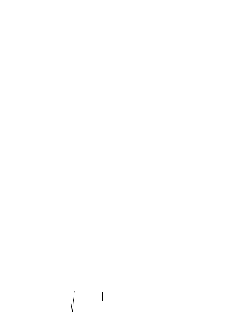
Chapter 4 - Design for ACI 318-08
4.5.1.2 Determine Required Flexural Reinforcement
In the flexural reinforcement design process, the program calculates both the
tension and compression reinforcement. Compression reinforcement is added
when the applied design moment exceeds the maximum moment capacity of a
singly reinforced section. The user has the option of avoiding compression
reinforcement by increasing the effective depth, the width, or the strength of the
concrete. Note that the flexural reinforcement strength, fy , is limited to 80 ksi
(ACI 9.4), even if the material property is defined using a higher value.
The design procedure is based on the simplified rectangular stress block, as
shown in Figure 4-1 (ACI 10.2). Furthermore, it is assumed that the net tensile
strain in the reinforcement shall not be less than 0.005 (tension controlled) (ACI
10.3.4) when the concrete in compression reaches its assumed strain limit of
0.003. When the applied moment exceeds the moment capacity at this design
condition, the area of compression reinforcement is calculated assuming that the
additional moment will be carried by compression reinforcement and additional
tension reinforcement.
The design procedure used by ETABS, for both rectangular and flanged sections
(L- and T- shaped sections), is summarized in the text that follows. For rein-
forced concrete design where design ultimate axial compression load does not
exceed
( )
cg
fA0.1 ′
(ACI 10.3.5), axial force is ignored; hence, all slabs are de-
signed for major direction flexure and shear only. Axial compression greater
than
( )
cg
fA0.1 ′
and axial tensions are always included in flexural and shear de-
sign.
4.5.1.2.1 Design of uniform thickness slab
In designing for a factored negative or positive moment, Mu (i.e., designing top
or bottom reinforcement), the depth of the compression block is given by a (see
Figure 4-1), where,
b
f
M
dd
a
c
u
φ
'85.
0
2
2
−
−=
(ACI 10.2)
and the value of
φ
is taken as that for a tension-controlled section, which by
default is 0.90 (ACI 9.3.2.1) in the preceding and the following equations.
Slab Design 4 - 7
ETABS Reinforced Concrete Design
The maximum depth of the compression zone, cmax, is calculated based on the
limitation that the tension reinforcement strain shall not be less than
ε
smin, which
is equal to 0.005 for tension controlled behavior (ACI 10.3.4):
max
max max min
c
cs
cd
ε
εε
=+
(ACI 10.2.2)
Figure 4-1 Uniform Thickness Slab Design
where,
ε
cmax = 0.003 (ACI 10.2.3)
ε
smin = 0.005 (ACI 10.3.4)
The maximum allowable depth of the rectangular compression block, amax, is
given by:
amax =
β
1cmax (ACI 10.2.7.1)
where
β
1 is calculated as:
(I) BEAM
SECTION (II) STRAIN
DIAGRAM (III) STRESS
DIAGRAM
0.003
ε
=c
0.85 f ′
1
ac
β
=
cs
T
s
T
s
ε
cs
C
d′
d
b
s
A
s
A′
(I) BEAM
SECTION (II) STRAIN
DIAGRAM (III) STRESS
DIAGRAM
0.003
ε
=c
0.85 f ′
1
ac
β
=
cs
T
s
T
s
ε
cs
C
d′
d
b
s
A
s
A′
4 - 8 Slab Design

Chapter 4 - Design for ACI 318-08
c
f
1
4000
0.85 0.05 ,
1000
β
′−
= −
0.65 ≤
β
1 ≤ 0.85 (ACI 10.2.7.3)
If a ≤ amax (ACI 10.3.4), the area of tension reinforcement is then given by:
−
=
2
a
df
M
A
y
u
s
φ
This reinforcement is to be placed at the bottom if Mu is positive, or at the top
if Mu is negative.
If a > amax, compression reinforcement is required (ACI 10.3.5.1) and is cal-
culated as follows:
− The compressive force developed in the concrete alone is given by:
max
'85.0 bafC c
=
(ACI 10.2.7.1)
and the moment resisted by concrete compression and tension reinforcement
is:
max
2
uc
a
M Cd
φ
= −
(ACI 9.3.2.1)
− Therefore the moment required to be resisted by compression reinforcement
and tension reinforcement is:
Mus = Mu − Muc
− The required compression reinforcement is given by:
( )( )
'' 0.85 ' '
us
s
sc
M
Af f dd
φ
=−−
, where
yc
ss
f
c
dc
Ef ≤
−
=
max
max
max
'
'
ε
(ACI 10.2.2, 10.2.3, 10.2.4)
Slab Design 4 - 9

ETABS Reinforced Concrete Design
− The required tension reinforcement for balancing the compression in the
concrete is:
1max
2
uc
s
y
M
Aa
fd
φ
=
−
and the tension reinforcement for balancing the compression reinforcement
is given by:
( )
2
'
us
s
y
M
Afdd
φ
=−
Therefore, the total tension reinforcement is As = As1 + As2, and the total com-
pression reinforcement is A's. As is to be placed at the bottom and A's is to be
placed at the top if Mu is positive, and vice versa if Mu is negative.
4.5.1.2.2 Design of nonuniform thickness slab
In designing a nonuniform thickness slab, a simplified stress block, as shown in
Figure 4-2, is assumed if the flange is under compression, i.e., if the moment is
positive. If the moment is negative, the flange comes under tension, and the
flange is ignored. In that case, a simplified stress block similar to that shown in
Figure 4-1 is assumed on the compression side.
4 - 10 Slab Design

Chapter 4 - Design for ACI 318-08
Figure 4-2 Nonuniform Thickness Slab Design
4.5.1.2.2.1 Flanged Slab Section Under Negative Moment
In designing for a factored negative moment, Mu (i.e., designing top reinforce-
ment), the calculation of the reinforcement area is exactly the same as described
previously, i.e., no flanged data is used.
4.5.1.2.2.2 Flanged Slab Section Under Positive Moment
If Mu > 0, the depth of the compression block is given by:
fc
u
bf
M
dda
φ
'85.0
2
2−−=
(ACI 10.2)
where, the value of
φ
is taken as that for a tension-controlled section, which by
default is 0.90 (ACI 9.3.2.1) in the preceding and the following equations.
The maximum depth of the compression zone, cmax, is calculated based on the
limitation that the tension reinforcement strain shall not be less than
ε
smin, which
is equal to 0.005 for tension controlled behavior (ACI 10.3.4):
(I) BEAM
SECTION
s
A
(II) STRAIN
DIAGRAM
(III) STRESS
DIAGRAM
s
A′
w
b
f
b
d
d′
s
f′
0.003
ε
=
c
0.85 f ′
w
T
s
T
s
ε
c
0.85 f ′
f
T
f
C
w
C
s
C
f
h
c
(I) BEAM
SECTION
s
A
(II) STRAIN
DIAGRAM
(III) STRESS
DIAGRAM
s
A′
w
b
f
b
d
d′
s
f′
0.003
ε
=
c
0.85 f ′
w
T
s
T
s
ε
c
0.85 f ′
f
T
f
C
w
C
s
C
f
h
c
Slab Design 4 - 11

ETABS Reinforced Concrete Design
dc
sc
c
minmax
max
max
εε
ε
+
=
(ACI 10.2.2)
where,
ε
cmax = 0.003 (ACI 10.2.3)
ε
smin = 0.005 (ACI 10.3.4)
The maximum allowable depth of the rectangular compression block, amax, is
given by:
max1max
ca
β
=
(ACI 10.2.7.1)
where
β
1 is calculated as:
c
f
1' 4000
0.85 0.05 ,
1000
β
−
= −
0.65 ≤
β
1 ≤ 0.85 (ACI 10.2.7.3)
If a ≤ hf, the subsequent calculations for As are exactly the same as previously
defined for the uniform thickness slab design. However, in this case, the width
of the slab is taken as bf. Compression reinforcement is required if a > amax.
If a > hf, the calculation for As has two parts. The first part is for balancing the
compressive force from the flange, Cf, and the second part is for balancing the
compressive force from the web, Cw, as shown in Figure 4-2. Cf is given by:
( ) ( )
max
,min'85.0 ahbbfC fwfcf −=
(ACI 10.2.7.1)
Therefore,
y
f
s
f
C
A=
1
and the portion of Mu that is resisted by the flange is
given by:
( )
max
min ,
2
f
uf f
ha
M Cd
φ
= −
(ACI 9.3.2.1)
Again, the value for
φ
is 0.90 by default. Therefore, the balance of the moment,
Mu , to be carried by the web is:
4 - 12 Slab Design

Chapter 4 - Design for ACI 318-08
Muw = Mu − Muf
The web is a rectangular section with dimensions bw and d, for which the de-
sign depth of the compression block is recalculated as:
w
c
uw
b
f
M
d
d
a
φ
'
85
.
0
2
2
1
−−
=
(ACI 10.2)
If a1 ≤ amax (ACI 10.3.4), the area of tension reinforcement is then given by:
−
=
2
1
2
a
df
M
A
y
uw
s
φ
, and
As = As1 + As2
This reinforcement is to be placed at the bottom of the flanged slab.
If a1 > amax, compression reinforcement is required (ACI 10.3.5.1) and is cal-
culated as follows:
− The compressive force in the web concrete alone is given by:
max
0.85 '
w cw
C f ba=
(ACI 10.2.7.1)
Therefore the moment resisted by the concrete web and tension reinforce-
ment is:
φ
= −
max
2
uc w a
M Cd
and the moment resisted by compression and tension reinforcement is:
Mus = Muw − Muc
Therefore, the compression reinforcement is computed as:
()( )
us
ssc
M
Af f dd ,
0.85
φ
′=′ ′′
−−
where
Slab Design 4 - 13

ETABS Reinforced Concrete Design
s sc y
cd
fE f
c
max
max max
ε
′
−
′= ≤
(ACI 10.2.2, 10.2.3, 10.2.4)
The tension reinforcement for balancing compression in the web concrete is:
2max
2
uc
s
y
M
Aa
fd
φ
=
−
and the tension reinforcement for balancing the compression reinforcement
is:
()
φ
'
3
ddf
M
A
y
us
s
−
=
The total tension reinforcement is As = As1 + As2 + As3, and the total compres-
sion reinforcement is A's. As is to be placed at the bottom and A's is to be
placed at the top.
4.5.1.2.3 Minimum and Maximum Reinforcement
The minimum flexural tension reinforcement required for each direction of a
slab is given by the following limits (ACI 7.12.2):
As,min = 0.0020 bh for fy = 40 ksi or 50 ksi (ACI 7.12.2.1(a))
As,min = 0.0018 bh for fy = 60 ksi (ACI 7.12.2.1(b))
As,min =
bh
fy
600000018.
0×
for fy > 60 ksi (ACI 7.12.2.1(c))
In addition, an upper limit on both the tension reinforcement and compression
reinforcement has been imposed to be 0.04 times the gross cross-sectional area.
4.5.2 Design Slab Shear Reinforcement
The shear reinforcement is designed for each load combination at each station
along the design strip. In designing the shear reinforcement for a particular strip,
4 - 14 Slab Design
Chapter 4 - Design for ACI 318-08
for a particular load combination, at a particular station due to the slab major
shear, the following steps are involved:
Determine the factored shear force, Vu.
Determine the shear force, Vc, that can be resisted by the concrete.
Determine the shear reinforcement required to carry the balance.
The following three sections describe in detail the algorithms associated with
these steps.
4.5.2.1 Determine Factored Shear Force
In the design of the slab shear reinforcement, the shear forces for each load com-
bination at a particular design strip station are obtained by factoring the corre-
sponding shear forces for different load cases, with the corresponding load com-
bination factors.
4.5.2.2 Determine Concrete Shear Capacity
The shear force carried by the concrete, Vc, is calculated as:
dbfV
wcc
'2
λ
=
(ACI 11.2.1.2, 11.2.1.2, 11.2.2.3)
A limit is imposed on the value of
c
f'
as
'
c
f
≤ 100 (ACI 11.1.2)
The value of λ should be specified in the material property definition.
4.5.2.3 Determine Required Shear Reinforcement
The shear force is limited to a maximum of:
( )
max c cw
V V 8 f' b d= +
(ACI 11.4.7.9)
Given Vu, Vc, and Vmax, the required shear reinforcement is calculated as follows
where,
φ
, the strength reduction factor, is 0.75 (ACI 9.3.2.3). The flexural rein-
forcement strength, fyt, is limited to 60 ksi (ACI 11.5.2) even if the material prop-
erty is defined with a higher value.
Slab Design 4 - 15
ETABS Reinforced Concrete Design
If
,
uc
VV
φ
≤
s
A
v
= 0 (ACI 11.5.6.1)
If
max
,
cu
VV V
φφ
<≤
( )
df
VV
s
A
yt
cuv
φ
φ
−
=
(ACI 11.4.7.1, 11.4.7.2)
If Vu >
φ
Vmax, a failure condition is declared. (ACI 11.4.7.9)
If Vu exceeds the maximum permitted value of
φ
Vmax, the concrete section should
be increased in size (ACI 11.4.7.9).
The minimum shear reinforcement given by ACI 11.4.6.3 is not enforced (ACI
11.4.6.1).
≥
yt
w
w
yt
c
v
f
b
b
f
f
s
A50
,
'75
.0
max
λ
(ACI 11.4.6.3)
The maximum of all of the calculated Av
/s values obtained from each load com-
bination is reported along with the controlling shear force and associated load
combination.
The slab shear reinforcement requirements considered by the program are
based purely on shear strength considerations. Any minimum stirrup require-
ments to satisfy spacing and volumetric considerations must be investigated
independently of the program by the user.
4.5.3 Check for Punching Shear
The algorithm for checking punching shear is detailed in the section entitled
“Slab Punching Shear Check” in the Chapter 1. Only the code-specific items are
described in the following sections.
4 - 16 Slab Design
Chapter 4 - Design for ACI 318-08
4.5.3.1 Critical Section for Punching Shear
The punching shear is checked on a critical section at a distance of d / 2 from the
face of the support (ACI 11.11.1.2). For rectangular columns and concentrated
loads, the critical area is taken as a rectangular area with the sides parallel to the
sides of the columns or the point loads (ACI 11.11.1.3). Figure 4-3 shows the
auto punching perimeters considered by ETABS for the various column shapes.
The column location (i.e., interior, edge, corner) and the punching
perimeter may be overwritten using the Punching Check Overwrites.
Figure 4-3 Punching Shear Perimeters
4.5.3.2 Transfer of Unbalanced Moment
The fraction of unbalanced moment transferred by flexure is taken to be
γ
f Mu
and the fraction of unbalanced moment transferred by eccentricity of shear is
taken to be
γ
v Mu.
( )
21
321
1
bb
f+
=
γ
(ACI 13.5.3.2)
d2
Interior Column
Circular Column
d2 d2
d2
T-Shape Column
Edge Column Edge Column
L-Shape Column
d2
d2
d2
Interior Column
Circular Column
d2 d2
d2
T-Shape Column
Edge Column Edge Column
L-Shape Column
d2
d2
Slab Design 4 - 17
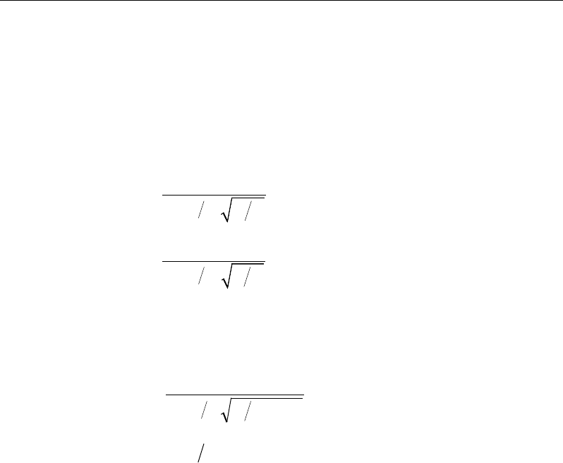
ETABS Reinforced Concrete Design
γ
v = 1 −
γ
f (ACI 13.5.3.1)
For flat plates,
γ
v is determined from the following equations taken from ACI
421.2R-07 Seismic Design of Punching Shear Reinforcement in Flat Plates [ACI
2007].
For interior columns,
( )
1
11 23
vx
yx
ll
γ
= − +
(ACI 421.2 C-11)
( )
1
11 23
vy
xy
ll
γ
= − +
(ACI 421.2 C-12)
For edge columns,
γ
vx = same as for interior columns (ACI 421.2 C-13)
( )
2.0321
1
1−+
−=
yx
vy
ll
γ
(ACI 421.2 C-14)
γ
vy = 0 when
xy
ll 0.2≤
For corner columns,
γ
vx = 0.4 (ACI 421.2 C-15)
γ
vy = same as for edge columns (ACI 421.2 C-16)
NOTE: Program uses ACI 421.4-12 and ACI 421.4-15 equations in lieu of ACI
421.2 C-14 and ACI 421.2 C-16 which are currently NOT enforced.
where b1 is the width of the critical section measured in the direction of the span
and b2 is the width of the critical section measured in the direction perpendicular
to the span. The values lx and ly are the projections of the shear-critical section
onto its principal axes, x and y, respectively.
4 - 18 Slab Design
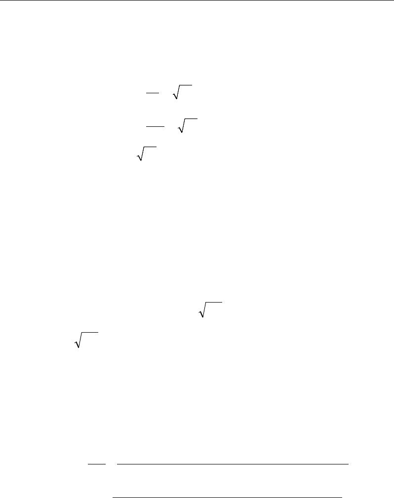
Chapter 4 - Design for ACI 318-08
4.5.3.3 Determine Concrete Capacity
The concrete punching shear stress capacity is taken as the minimum of the fol-
lowing three limits:
c
c
s
cc
o
c
f
d
vf
b
f
4
2
min 2
4
φλ
β
α
φλ
φλ
′
+
′
= +
′
(ACI 11.11.2.1)
where,
β
c is the ratio of the maximum to the minimum dimensions of the critical
section, bo is the perimeter of the critical section, and
α
s is a scale factor based
on the location of the critical section.
s
40 for interior columns,
30 for edge columns, and
20 for corner columns.
α
=
(ACI 11.11.2.1)
A limit is imposed on the value of
c
f'
as:
c
f'
≤ 100 (ACI 11.1.2)
4.5.3.4 Computation of Maximum Shear Stress
Given the punching shear force and the fractions of moments transferred by ec-
centricity of shear about the two axes, the shear stress is computed assuming
linear variation along the perimeter of the critical section.
22 3 1 33 4 3 23 4 3
2
022 33 23
33 3 1 22 4 3 23 4 3
2
22 33 23
[ ( )][ ( ) ( )]
[ ( )][ ( ) ( )]
γ
γ
− − −− −
=+−
−
− − −− −
−
VUU
U
U
VUU
M Vy y I y y I x x
V
vbd I I I
M VxxIxx Iyy
II I
Eq. 1
Slab Design 4 - 19

ETABS Reinforced Concrete Design
22 22
1
,
=
=∑
n
sides
II
where "sides" refers to the sides of the critical section
for punching shear Eq. 2
33 33
1
,
=
=∑
n
sides
II
where "sides" refers to the sides of the critical section
for punching shear Eq. 3
23 23
1
,
=
=∑
n
sides
II
where "sides" refers to the sides of the critical section
for punching shear Eq. 4
The equations for
22 33 23
, , andII I
are different depending on whether the
side of the critical section for punching shear being considered is parallel to
the 4-axis or parallel to the 3-axis. Refer to Figure 4-4.
2
22 2 3
( ),= −I Ld y y
for the side of the critical section parallel
to the 4-axis Eq. 5a
33 2
22 2 3
( ),
12 12
= ++ −
Ld dL
I Ld y y
for the side of the critical section
parallel to the 3-axis Eq. 5b
33 2
33 2 3
( ),
12 12
= ++ −
Ld dL
I Ld x x
for the side of the critical section
parallel to the 4-axis Eq. 6a
2
33 2 3
( ),= −I Ld x x
for the side of the critical section parallel
to the 3-axis Eq. 6b
4 - 20 Slab Design

Chapter 4 - Design for ACI 318-08
Figure 4-4 Shear Stress Calculations at Critical Sections
23 2 3 2 3
( )( ),
=−−I Ld x x y y
for side of critical section parallel
to 4-axis or 3-axis Eq. 7
NOTE:
23
I
is explicitly set to zero for corner condition.
where,
b0 = Perimeter of the critical section for punching shear
d = Effective depth at the critical section for punching shear based on the
average of d for 2 direction and d for 3 direction
I22 = Moment of inertia of the critical section for punching shear about an axis
that is parallel to the local 4-axis
Plan View For Side of Critical Section Parallel to 3-Axis
y
2
- y
3
L
Critical section for
punching shear
shown by heavy line
2
3
Side of critical section
being considered
shown solid
Center of side of critical
section being considered.
Coordinates are (x
2
,y
2
).
Work This Sketch With Equations 5b, 6b and
7
Centroid
of entire
critical section for
punching shear.
Coordinates are (x
3
,y
3
).
x
2
- x
3
y
2
- y
3
L
Critical section for
punching shear shown
by heavy line. Side of
critical section being
considered shown solid
2
3
Center of side of critical
section being considered.
Coordinates are (x
2
,y
2
).
Plan View For Side of Critical Section Parallel to 2-Axis
Work This Sketch With Equations 5a, 6a and
7
Centroid
of entire
critical section for
punching shear.
Coordinates are (x
3
,y
3
).
x
2
- x
3
Slab Design 4 - 21

ETABS Reinforced Concrete Design
I33 = Moment of inertia of the critical section for punching shear about an axis
that is parallel to the local 3-axis
I23 = Product of the inertia of the critical section for punching shear with re-
spect to the 2 and 3 planes
L = Length of the side of the critical section for punching shear currently
being considered
MU2 = Moment about the line parallel to the 4-axis at the center of the column
(positive in accordance with the right-hand rule)
MU3 = Moment about the line parallel to the 3-axis at the center of the column
(positive in accordance with the right-hand rule)
vU = Punching shear stress
VU = Shear at the center of the column (positive upward)
x1, y1 = Coordinates of the column centroid
x2, y2 = Coordinates of the center of one side of the critical section for punching
shear
x3, y3 = Coordinates of the centroid of the critical section for punching shear
x4, y4 = Coordinates of the location where stress is being calculated
γ
V2 = Percent of MU2 resisted by shear
γ
V3 = Percent of MU3 resisted by shear
4.5.3.5 Determine Capacity Ratio
Given the punching shear force and the fractions of moments transferred by ec-
centricity of shear about the two axes, the shear stress is computed assuming
linear variation along the perimeter of the critical section. The ratio of the max-
imum shear stress and the concrete punching shear stress capacity is reported as
the punching shear capacity ratio by ETABS. If this ratio exceeds 1.0, punching
shear reinforcement is designed as described in the following section.
4 - 22 Slab Design
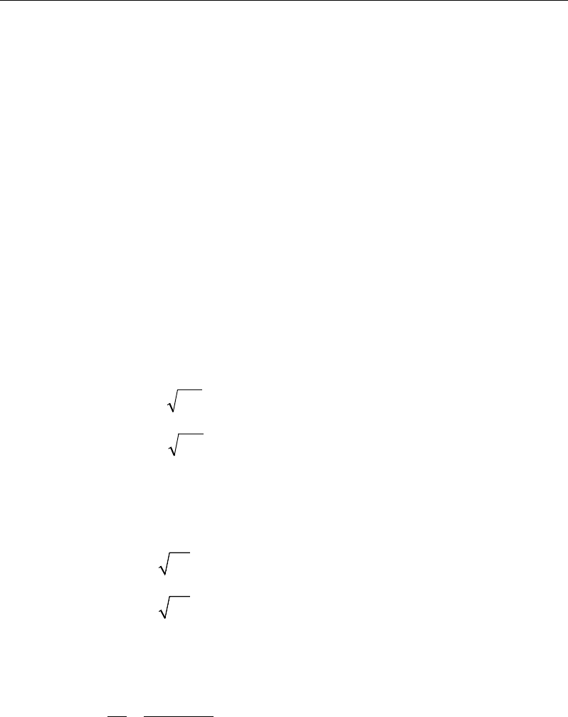
Chapter 4 - Design for ACI 318-08
4.5.4 Design Punching Shear Reinforcement
The use of shear studs as shear reinforcement in slabs is permitted, provided that
the effective depth of the slab is greater than or equal to 6 inches, and not less
than 16 times the shear reinforcement bar diameter (ACI 11.11.3). If the slab
thickness does not meet these requirements, the punching shear reinforcement is
not designed and the slab thickness should be increased by the user.
The algorithm for designing the required punching shear reinforcement is used
when the punching shear capacity ratio exceeds unity. The Critical Section for
Punching Shear and Transfer of Unbalanced Moment as described in the earlier
sections remain unchanged. The design of punching shear reinforcement is de-
scribed in the subsections that follow.
4.5.4.1 Determine Concrete Shear Capacity
The concrete punching shear stress capacity of a section with punching shear
reinforcement is limited to:
cc
fv '2
λφ
≤
for shear links (ACI 11.11.3.1)
cc
fv '3
λφ
≤
for shear studs (ACI 11.11.5.1)
4.5.4.2 Determine Required Shear Reinforcement
The shear force is limited to a maximum of:
Vmax = 6
′
c
f
bod for shear links (ACI 11.11.3.2)
Vmax = 8
′
c
f
bod for shear studs (ACI 11.11.5.1)
Given Vu, Vc, and Vmax, the required shear reinforcement is calculated as follows,
where,
φ
, the strength reduction factor, is 0.75 (ACI 9.3.2.3).
( )
uc
v
ys
VV
A
s fd
φ
φ
−
=
(ACI 11.4.7.1, 11.4.7.2)
Slab Design 4 - 23
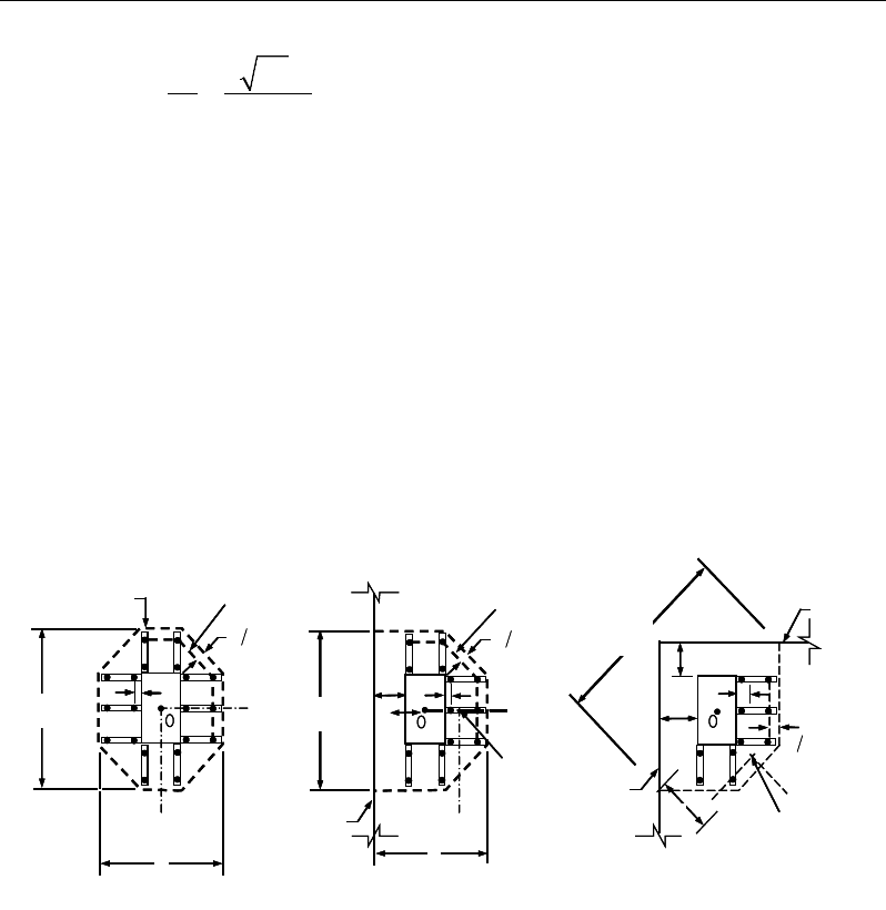
ETABS Reinforced Concrete Design
2′
≥co
v
y
fb
A
sf
for shear studs (ACI 11.11.5.1)
If Vu >
φ
Vmax, a failure condition is declared. (ACI 11.11.3.2)
If Vu exceeds the maximum permitted value of
φ
Vmax, the concrete section
should be increased in size.
4.5.4.3 Determine Reinforcement Arrangement
Punching shear reinforcement in the vicinity of rectangular columns should be
arranged on peripheral lines, i.e., lines running parallel to and at constant dis-
tances from the sides of the column. Figure 4-6 shows a typical arrangement of
shear reinforcement in the vicinity of a rectangular interior, edge, and corner
column.
Figure 4-6 Typical arrangement of shear studs
and critical sections outside shear-reinforced zone
The distance between the column face and the first line of shear reinforcement
shall not exceed d / 2(ACI R11.3.3, 11.11.5.2. The spacing between adjacent
shear reinforcement in the first line (perimeter) of shear reinforcement shall not
exceed 2d measured in a direction parallel to the column face (ACI 11.11.3.3).
Punching shear reinforcement is most effective near column corners where there
are concentrations of shear stress. Therefore, the minimum number of lines of
Iy
Typical Studrail
(only first and last
studs shown)
Outermost
peripheral line
of studs
Interior Column Edge Column Corner Column
Critical section
centroid
Free
edge
Free
edge
Critical
section
centroid
Free edge
Outermost
peripheral line
of studs
Iy
Iy
yx
d2 d2
d2
x
I
x
I
x
g
y
g
x
g
0
s
0
s
0
s
x
I
y
xx
Iy
Typical Studrail
(only first and last
studs shown)
Outermost
peripheral line
of studs
Interior Column Edge Column Corner Column
Critical section
centroid
Free
edge
Free
edge
Critical
section
centroid
Free edge
Outermost
peripheral line
of studs
Iy
Iy
yx
d2 d2
d2
x
I
x
I
x
g
y
g
x
g
0
s
0
s
0
s
x
I
y
xx
4 - 24 Slab Design
Chapter 4 - Design for ACI 318-08
shear reinforcement is 4, 6, and 8, for corner, edge, and interior columns respec-
tively.
4.5.4.4 Determine Reinforcement Diameter, Height, and Spacing
The punching shear reinforcement is most effective when the anchorage is close
to the top and bottom surfaces of the slab. The cover of anchors should not be
less than the minimum cover specified in ACI 7.7 plus half of the
diameter of the flexural reinforcement.
Punching shear reinforcement in the form of shear studs is generally available in
3/8-, 1/4-, 5/8-, and 3/4-inch diameters.
When specifying shear studs, the distance, so, between the column face and the
first peripheral line of shear studs should not be smaller than 0.5d. The spacing
between adjacent shear studs, g, at the first peripheral line of studs shall not
exceed 2d, and in the case of studs in a radial pattern, the angle between adjacent
stud rails shall not exceed 60 degrees. The limits of so and the spacing, s, between
the peripheral lines are specified as:
so ≤ 0.5d (ACI 11.11.5.2)
0 75 for 6
0 50 for 6
uc
uc
.d v f
s.d v f
φλ
φλ
′
≤
≤′
>
(ACI 11.11.5.2)
g ≤ 2d (ACI 11.11.5.3)
The limits of so and the spacing, s, between for the links are specified as:
so ≤ 0.5d (ACI 11.11.3)
0 50≤s .d
(ACI 11.11.3)
Slab Design 4 - 25

Chapter 05
Design for AS 3600-09
This chapter describes in detail the various aspects of the concrete design proce-
dure that is used by ETABS when the Australian code AS 3600-2009 [AS 2009]
is selected. Various notations used in this chapter are listed in Table 5-1. For
referencing to the pertinent sections of the AS code in this chapter, a prefix “AS”
followed by the section number is used.
The design is based on user-specified load combinations. The program provides
a set of default load combinations that should satisfy the requirements for the
design of most building type structures.
English as well as SI and MKS metric units can be used for input. The code is
based on Newton-millimeter-second units. For simplicity, all equations and de-
scriptions presented in this chapter correspond to Newton-millimeter-second
units unless otherwise noted.
5.1 Notations
Table 5-1 List of Symbols Used in the AS 3600-2009 Code
A
g
Gross area of concrete, mm2
A
l
Area of longitudinal reinforcement for torsion, mm2
A
sc
Area of compression reinforcement, mm2
Notations 5 - 1

ETABS Reinforced Concrete Design
Table 5-1 List of Symbols Used in the AS 3600-2009 Code
A
st
Area of tension reinforcement, mm2
A
st(re-
quired)
Area of required tension reinforcement, mm2
A
sv
Area of shear reinforcement, mm2
A
sv,min
Minimum area of shear reinforcement, mm2
A
sv
/s
Area of shear reinforcement per unit length, mm2 /mm
A
sw
/s
Area of shear reinforcement per unit length consisting of closed
ties, mm2/mm
A
t
Area of a polygon with vertices at the center of longitudinal bars at
the corners of a section, mm2
a
Depth of compression block, mm
a
b
Depth of compression block at balanced condition, mm
a
max
Maximum allowed depth of compression block, mm
b
Width of member, mm
b
ef
Effective width of flange (flanged section), mm
b
w
Width of web (flanged section), mm
c
Depth to neutral axis, mm
d
Distance from compression face to tension reinforcement, mm
d'
Concrete cover to compression reinforcement, mm
d
o
Distance from the extreme compression fiber to the centroid of the
outermost tension reinforcement, mm
d
om
Mean value of d
o
, averaged around the critical shear perimeter,
mm
D
Overall depth of a section, mm
D
s
Thickness of slab (flanged section), mm
E
c
Modulus of elasticity of concrete, MPa
E
s
Modulus of elasticity of reinforcement, MPa
f '
c
Specified compressive strength of concrete, MPa
f '
cf
Characteristic flexural tensile strength of concrete, MPa
5 - 2 Notations

Chapter 05 - Design for AS 3600-09
Table 5-1 List of Symbols Used in the AS 3600-2009 Code
f
cv
Concrete shear strength, MPa
f
sy
Specified yield strength of flexural reinforcement, MPa
f
sy,f
Specified yield strength of shear reinforcement, MPa
f '
s
Stress in the compression reinforcement, MPa
J
t
Torsional modulus, mm3
k
u
Ratio of the depth to the neutral axis from the compression face, to
the effective depth, d
M
ud
Reduced ultimate strength in bending without axial force, N-mm
M*
Factored moment at section, N-mm
N*
Factored axial load at section, N
s
Spacing of shear reinforcement along the strip, mm
T
uc
Torsional strength of section without torsional reinforcement, N-
mm
T
u.max
Maximum permitted total factored torsion at a section, N-mm
T
us
Torsion strength of section with torsion reinforcement, N-mm
T*
Factored torsional moment at a section, N-mm
u
t
Perimeter of the polygon defined by A
t
, mm
V*
Factored shear force at a section, N
V
u.max
Maximum permitted total factored shear force at a section, N
V
u.min
Shear strength provided by minimum shear reinforcement, N
V
uc
Shear force resisted by concrete, N
V
us
Shear force resisted by reinforcement, N
γ
1
Factor for obtaining depth of compression block in concrete
β
h
Ratio of the maximum to the minimum dimensions of the punch-
ing critical section
ε
c
Strain in concrete
ε
c, max
Maximum usable compression strain allowed in extreme concrete
fiber, (0.003 mm/mm)
Notations 5 - 3

ETABS Reinforced Concrete Design
Table 5-1 List of Symbols Used in the AS 3600-2009 Code
ε
s
Strain in reinforcement
φ
Strength reduction factor
θ
t
Angle of compression strut for torsion, degrees
θ
v
Angle of compression strut for shear, degrees
5.2 Design Load Combinations
The design load combinations are the various combinations of the load cases for
which the structure needs to be designed. For AS 3600-09, if a structure is sub-
jected to dead (D), live (L), pattern live (PL), snow (S), wind (W), and earth-
quake (E) loads, and considering that wind and earthquake forces are reversible,
the following load combinations may need to be defined (AS 2.4.2):
1.35D
(AS/NZS 1170.0-02, 4.2.2(a))
1.2D + 1.5L
(AS/NZS 1170.0-02, 4.2.2(b))
1.2D + 1.5(0.75 PL)
(AS/NZS 1170.0-02, 4.2.2(b))
1.2D + 0.4L + 1.0S
(AS/NZS 1170.0-02, 4.2.2(g))
0.9D ± 1.0W
1.2D
± 1.0W
1.2D + 0.4L
± 1.0W
(AS/NZS 1170.0-02, 4.2.2(e))
(AS/NZS 1170.0-
02, 4.2.2(d))
(AS/NZS 1170.0-02, 4.2.2(d
))
1.0D ± 1.0E
1.0D
+ 0.4L ± 1.0E
(AS/NZS 1170.0-02, 4.2.2(f))
(AS/NZS 1170.0-
02, 4.2.2(f))
Note that the 0.4 factor on the live load in three of the combinations is not valid
for live load representing storage areas. These are also the default design load
combinations in ETABS whenever the AS 3600-2009 code is used. If roof live
load is treated separately or other types of loads are present, other appropriate
load combinations should be used.
5 - 4 Design Load Combinations

Chapter 05 - Design for AS 3600-09
5.3 Limits on Material Strength
The upper and lower limits of f'c are 100 MPa and 20 MPa, respectively, for all
framing types (AS 3.1.1.1(b)).
' 100MPa
c
f≤
(AS 3.1.1.1)
' 20MPa
c
f≥
(AS 3.1.1.1)
The upper limit of fsy is 500 MPa for all frames (AS 3.2.1, Table 3.2.1).
The code allows use of f'c and fsy beyond the given limits, provided special care
is taken regarding the detailing and ductility (AS 3.1.1, 3.2.1, 17.2.1.1).
ETABS enforces the upper material strength limits for flexure and shear design
o slabs. The input material strengths are taken as the upper limits if they are
defined in the material properties as being greater than the limits. The user is
responsible for ensuring that the minimum strength is satisfied.
5.4 Strength Reduction Factors
The strength reduction factor,
φ
, is defined as given in AS 2.2.2(ii), Table 2.2.2:
For members with Class N reinforcement only
φ
= 0.80 for flexure (tension controlled) (Table 2.2.2(b))
φ
= 0.60 for flexure (compression controlled) (Table 2.2.2(b))
For members with Class L reinforcement
φ
= 0.64 for flexure (tension controlled) (Table 2.2.2(b))
φ
= 0.60 for flexure (compression controlled) (Table 2.2.2(b))
φ
= 0.70 for shear and torsion (Table 2.2.2(b))
These values can be overwritten; however, caution is advised.
Limits on Material Strength 5 - 5

ETABS Reinforced Concrete Design
5.5 Slab Design
ETABS slab design procedure involves defining sets of strips in two mutually
perpendicular directions. The locations of the strips are usually governed by the
locations of the slab supports. The axial force, moments and shears for a partic-
ular strip are recovered from the analysis (on the basis of the Wood-Armer tech-
nique), and a flexural design is carried out based on the ultimate strength design
method.
The slab design procedure involves the following steps:
Design flexural reinforcement
Design shear reinforcement
Punching check
5.5.1 Design Flexural Reinforcement
For slabs, ETABS uses either design strips or the finite element based design to
calculate the slab flexural reinforcement in accordance with the selected design
code. For simplicity, only strip-by-strip design is document in the proceeding
sections.
The design of the slab reinforcement for a particular strip is carried out at specific
locations along the length of the strip. These locations correspond to the element
boundaries. Controlling reinforcement is computed on either side of those ele-
ment boundaries. The slab flexural design procedure for each load combination
involves the following:
Determine factored axial loads and moments for each slab strip.
Design flexural reinforcement for the strip.
These two steps, described in the text that follows, are repeated for every load
combination. The maximum reinforcement calculated for the top and bottom
of the slab within each design strip, along with the corresponding controlling
load combination, is obtained and reported.
5 - 6 Slab Design

Chapter 05 - Design for AS 3600-09
5.5.1.1 Determine Factored Moments
In the design of flexural reinforcement of concrete slab, the factored moments
for each load combination at a particular design strip are obtained by factoring
the corresponding moments for different load cases, with the corresponding load
factors.
The slab is then designed for the maximum positive and maximum negative fac-
tored moments obtained from all of the load combinations. Calculation of bottom
reinforcement is based on positive design strip moments. In such cases, the slab
may be designed as a rectangular or flanged slab section. Calculation of top re-
inforcement is based on negative design strip moments. In such cases, the slab
may be designed as a rectangular or inverted flanged slab section.
5.5.1.2 Determine Required Flexural Reinforcement
In the flexural reinforcement design process, the program calculates both the
tension and compression reinforcement. Compression reinforcement is added
when the applied design moment exceeds the maximum moment capacity of a
singly reinforced section. The user has the option of avoiding compression rein-
forcement by increasing the effective depth, the width, or the strength of the
concrete. Note that the flexural reinforcement strength, fy , is limited to 500MPa
(AS 3.2.1), even if the material property is defined using a higher value.
The design procedure is based on the simplified rectangular stress block, as
shown in Figure 5-1 (AS 8.1.2).
The following assumptions apply to the stress block used to compute the flexural
bending capacity of rectangular sections (AS 8.1.2).
The maximum strain in the extreme compression fiber is taken as 0.003 (AS
8.1.3(a)).
A uniform compressive stress of α2 f'c acts on an area (AS 8.1.3(b)) bounded
by:
– The edges of the cross-sections.
– A line parallel to the neutral axis at the strength limit under the loading con-
cerned, and located at a distance
γ
kud from the extreme compression
fiber.
Slab Design 5 - 7
ETABS Reinforced Concrete Design
The maximum allowable depth of the rectangular compression block, amax, is
given by
max u
a kd
γ
=
where, (AS 8.1.3(b))
21.0 0.003 'c
f
α
= −
where,
2
0.67 0.85≤α ≤
(AS 8.1.3(1))
1.05 0.007 'c
fγ= −
where,
0.67 0.85≤γ≤
(AS 8.1.3(2))
ku = 0.36 (AS 8.1.5)
The design procedure used by ETABS for both rectangular and flanged sections
(L- and T-shaped sections) is summarized in the following subsections. It is as-
sumed that the design ultimate axial force does not exceed (Ascfsy > 0.15N*) (AS
10.7.1a); hence, all slabs are designed for major direction flexure, shear, and
torsion only.
5.5.1.3 Design of uniform thickness slab
In designing for a factored negative or positive moment, M*(i.e., designing top
or bottom reinforcement), the depth of the compression block is given by a (see
Figure 5-1), where,
*
2
2
2
'
c
M
ad d fb
αϕ
=−−
(AS 8.1.3)
5 - 8 Slab Design
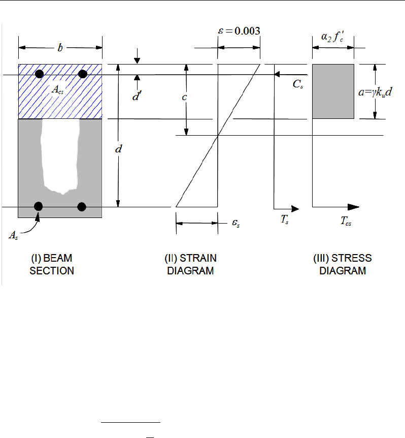
Chapter 05 - Design for AS 3600-09
Figure 5-1 Uniform Thickness Slab Design
where, the value of
φ
is taken as that for a tension controlled section (ku ≤ 0.36),
which by default is 0.80 (AS 2.2.2) in the preceding and following equations.
The selection of Reinforcement Class can be made using the Design Preferences.
If a ≤ amax, the area of tension reinforcement is then given by:
*
2
st
sy
M
Aa
fd
ϕ
=
−
This reinforcement is to be placed at the bottom if M* is positive, or at the top
if M* is negative.
If a > amax, i.e., ku > 0.36, compression reinforcement is required (AS 8.1.5)
and is calculated as follows:
The compressive force developed in the concrete alone is given by:
Slab Design 5 - 9

ETABS Reinforced Concrete Design
2 max
'
c
C f ba
α
=
(AS 8.1.3)
and the moment resisted by concrete compression and tension reinforcement
is:
φ
−= 2
max
a
dCM
uc
Therefore, the moment required to be resisted by compression reinforcement
and tension reinforcement is:
uc
us
M
MM −=
*
The required compression reinforcement is given by:
()( )
2
''
us
sc sc
M
Af f dd
αφ
=′
−−
, where
0.003
s s sy
cd
fE f
c
′
−
′= ≤
(AS 8.1.2.1, 3.2.2)
The required tension reinforcement for balancing the compression in the con-
crete is:
φ
−
=
2
max
1
a
df
M
A
sy
uc
s
and the tension reinforcement for balancing the compression reinforcement is
given by:
( )
2us
ssy
M
Af dd
φ
=′
−
Therefore, the total tension reinforcement is Ast = As1 + As2, and the total com-
pression reinforcement is Asc. Ast is to be placed at the bottom and Asc is to be
placed at the top if M* is positive, and vice versa if M* is negative.
5 - 10 Slab Design
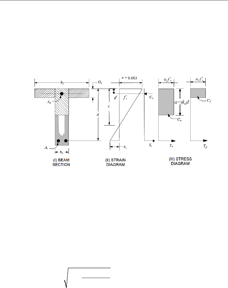
Chapter 05 - Design for AS 3600-09
5.5.1.4 Design of nonuniform thickness slab
In designing a nonuniform thickness slab, a simplified stress block, as shown in
Figure 5-2, is assumed if the flange is under compression, i.e., if the moment is
positive. If the moment is negative, the flange comes under tension, and the
flange is ignored. In that case, a simplified stress block similar to that shown in
Figure 5-1 is assumed on the compression side (AS 8.1.5).
Figure 5-2 T- Nonuniform Thickness Slab Design
5.5.1.5 Flanged Slab Section Under Negative Moment
In designing for a factored negative moment, M* (i.e., designing top reinforce-
ment), the calculation of the reinforcement is exactly the same as above, i.e., no
flanged data is used.
5.5.1.6 Flanged Slab Section Under Positive Moment
If M* > 0, the depth of the compression block is given by:
*
2
2
2
'
cf
M
ad d fb
αϕ
=−−
where, the value of
φ
is taken as that for ku ≤ 0.36, which is 0.80 by default (AS
2.2.2) in the preceding and the following equations.
Slab Design 5 - 11

ETABS Reinforced Concrete Design
The maximum allowable depth of the rectangular compression block, amax, is
given by:
d
ka
u
γ
=
max
where, ku = 0.36 (AS 8.1.5)
If a ≤ Ds, the subsequent calculations for Ast are exactly the same as previously
defined for the uniform thickness slab design. However, in that case, the width
of the slkab is taken as bf. Compression reinforcement is required when a >
amax.
If a > Ds, the calculation for Ast has two parts. The first part is for balancing
the compressive force from the flange, Cf, and the second part is for balancing
the compressive force from the web, Cw, as shown in Figure 5-2. Cf is given
by:
( )
( )
2 max
' min ,
f c ef w s
C f b b Da
α
= −×
(AS 8.1.3(b))
Therefore,
1=f
s
sy
C
Af
and the portion of M* that is resisted by the flange is
given by:
( )
max
min ,
2
s
uf f
Da
M Cd
ϕ
= −
Therefore, the balance of the moment M* to be carried by the web is:
*
uw uf
M MM= −
The web is a rectangular section of dimensions bw and d, for which the design
depth of the compression block is recalculated as:
2
1
2
2
uw
cw
M
ad d fb
αφ
=−−′
If a1 ≤ amax, the area of tension reinforcement is then given by:
5 - 12 Slab Design

Chapter 05 - Design for AS 3600-09
21
2
φ
=
−
uw
s
sy
M
Aa
fd
, and
21 ssst AAA +=
This reinforcement is to be placed at the bottom of the flanged slab.
If a1 > amax, compression reinforcement is required and is calculated as follows:
The compression force in the web concrete alone is given by:
2 max
'
w cw
C f ba
α
=
(AS 8.1.3)
Therefore the moment resisted by the concrete web and tension reinforcement
is:
φ
−= 2
max
a
dC
Mwuc
and the moment resisted by compression and tension reinforcement is:
ucuwus
MMM −=
Therefore, the compression reinforcement is computed as:
( )( )
2
,
us
sc sc
M
Af f dd
αφ
=′′ ′
−−
where
max
max
0.003
s s sy
cd
fE f
c
′
−
′= ≤
(AS 8.1.2.1,
3.2.2)
The tension reinforcement for balancing compression in the web concrete is:
2max
2
φ
=
−
uc
s
sy
M
Aa
fd
Slab Design 5 - 13

ETABS Reinforced Concrete Design
and the tension reinforcement for balancing the compression reinforcement is:
( )
3
φ
=′
−
us
s
sy
M
Af dd
The total tensile reinforcement is Ast = As1 + As2 + As3, and the total compression
reinforcement is Asc. Ast is to be placed at the bottom and Asc is to be placed at
the top.
5.5.1.7 Minimum and Maximum Reinforcement
The minimum flexural tensile reinforcement required for each direction of a slab
is given by the following limits (AS 9.1.1):
2',
,
0.24
ct f
s
sy f
f
h
A bh
df
=
for flat slabs (AS 9.1.1(a))
2',
,
0.19
ct f
s
sy f
f
h
A bh
df
=
for slabs supported by beams/walls and slab footings. (AS 9.1.1(b))
In addition, an upper limit on both the tension reinforcement and compression
reinforcement has been imposed to be 0.04 times the gross cross-sectional area.
5.5.2 Design Slab Shear Reinforcement
The shear reinforcement is designed for each load combination at each station
along the design strip. In designing the shear reinforcement for a particular strip,
for a particular load combination, at a particular station due to the slab major
shear, the following steps are involved:
Determine the factored shear force, V*.
Determine the shear force, Vuc, that can be resisted by the concrete.
Determine the shear reinforcement required to carry the balance.
5 - 14 Slab Design
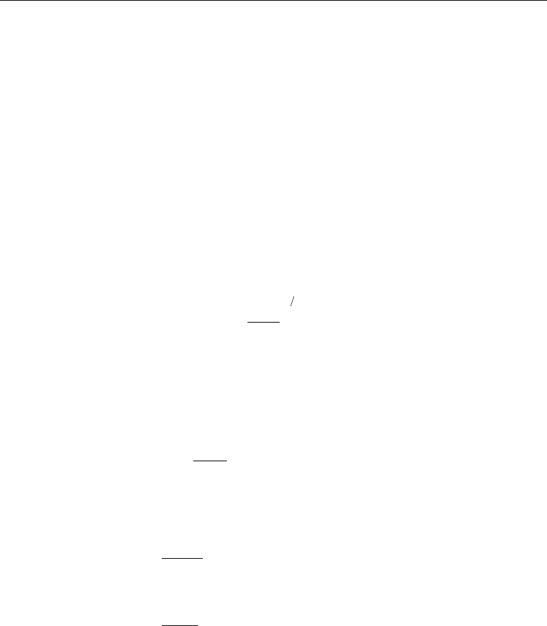
Chapter 05 - Design for AS 3600-09
The following three sections describe in detail the algorithms associated with
these steps.
5.5.2.1 Determine Shear Force
In the design of the slab shear reinforcement, the shear forces for each load com-
bination at a particular design strip station are obtained by factoring the corre-
sponding shear forces for different load cases, with the corresponding load com-
bination factors.
5.5.2.2 Determine Concrete Shear Capacity
The shear force carried by the concrete, Vuc, is calculated as:
13
123
'
st
uc w o cv
wo
A
V bd f bd
βββ
=
(AS 8.2.7.1)
where,
( )
1/3
' ' 4MPa
cv c
ff= ≤
(AS 8.2.7.1)
1.1
1000
6.11.1
1≥
−= o
d
β
(AS 8.2.7.1)
β2 = 1, or (AS 8.2.7.1)
=
0
5.3
1
*
≥
−
g
A
N
for members subject to significant axial tension, or
=
+
g
A
N
14
1*
for members subject to significant axial compression.
β3 = 1
5.5.2.3 Determine Required Shear Reinforcement
The shear force is limited to:
Slab Design 5 - 15

ETABS Reinforced Concrete Design
ovucu dbVV 6.0
min.+=
(AS 8.2.9)
ocu bdfV '2.0
max.=
(AS 8.2.6)
Given V*, Vuc, and Vu.max, the required shear reinforcement is calculated as fol-
lows, where,
φ
, the strength reduction factor, is 0.75 by default (AS 2.2.2).
If
*
/2,
uc
VV
φ
≤
0
sv
A,
s=
if D ≤ 750 mm; otherwise Asv.min shall be provided. (AS 8.2.5).
If
( )
*.min
/2 ,
uc u
V VV
φφ
<≤
0,
sv
A
s=
if D < bw /2 or 250 mm, whichever is greater (AS 8.2.5(c)(i));
otherwise Asv.min shall be provided.
If
*
.min .max ,
uu
V VV
φφ
<≤
( )
*
.
,
cot
uc
sv
sy f o v
VV
A
s fd
φ
φθ
−
=
(AS 8.2.10)
and greater than Asv.min, defined as:
=
fsy
wsv
f
b
s
A
.
min.
35.
0
(AS 8.2.8)
θ
v = the angle between the axis of the concrete compression strut and the lon-
gitudinal axis of the member, which varies linearly from 30 degrees when
V*=
φ
Vu.min to 45 degrees when V*=
φ
Vu,max.
If
*max ,
VV
φ
>
a failure condition is declared. (AS 8.2.6)
If V* exceeds its maximum permitted value
φ
Vmax, the concrete section size
should be increased (AS 8.2.6).
5 - 16 Slab Design

Chapter 05 - Design for AS 3600-09
Note that if torsion design is considered and torsion reinforcement is required,
the calculated shear reinforcement is ignored. Closed stirrups are designed for
combined shear and torsion according to AS 8.3.4(b).
The maximum of all of the calculated Asv
/s values obtained from each load com-
bination is reported along with the controlling shear force and associated load
combination.
The slab shear reinforcement requirements considered by the program are based
purely on shear strength considerations. Any minimum stirrup requirements to
satisfy spacing and volumetric considerations must be investigated inde-
pendently of the program by the user.
5.5.3 Check for Punching Shear
The algorithm for checking punching shear is detailed in the section entitled
“Slab Punching Shear Check” in the Chapter 1. Only the code-specific items are
described in the following sections.
5.5.3.1 Critical Section for Punching Shear
The punching shear is checked on a critical section at a distance of dom /2 from
the face of the support (AS 9.2.1.1). For rectangular columns and concentrated
loads, the critical area is taken as a rectangular area with the sides parallel to the
sides of the columns or the point loads (AS 9.2.1.3). Figure 5-3 shows the auto
punching perimeters considered by ETABS for the various column shapes. The
column location (i.e., interior, edge, corner) and the punching perimeter may be
overwritten using the Punching Check Overwrites.
Slab Design 5 - 17
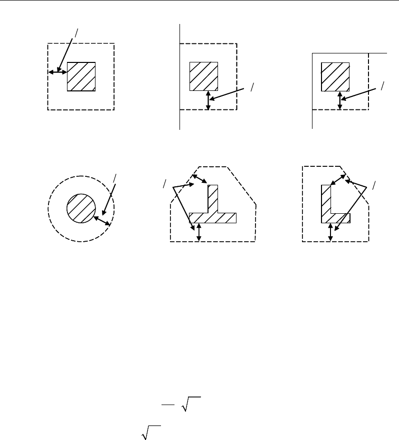
ETABS Reinforced Concrete Design
Figure 5-3 Punching Shear Perimeters
5.5.3.2 Determine Concrete Capacity
The shear capacity,
cv
f,
is calculated based on the minimum of the two expres-
sions from AS 9.2.3, as shown, with the dom and u terms removed to convert
force to stress.
2
0 17 1
min
0 34
c
h
cv
c
.f
f
.f
β
′
+
=
′
(AS 9.2.3(a))
where,
β
h is the ratio of the longest dimension to the shortest dimension of the
critical section.
5.5.3.3 Determine Maximum Shear Stress
The maximum design shear stress is computed along the major and minor axis
of column separately using the following equation:
d2
Interior Column
Circular Column
d2 d2
d2
T-Shape Column
Edge Column Edge Column
L-Shape Column
d2
d2
d2
Interior Column
Circular Column
d2 d2
d2
T-Shape Column
Edge Column Edge Column
L-Shape Column
d2
d2
5 - 18 Slab Design

Chapter 05 - Design for AS 3600-09
*
max *
mm
1.0 8
= +
v
oo
uM
V
vud V ad
(AS 9.2.4(a))
5.5.3.4 Determine Capacity Ratio
The ratio of the maximum shear stress and the concrete punching shear stress
capacity is reported as the punching shear capacity ratio by ETABS. If this ratio
exceeds 1.0, punching shear reinforcement is designed as described in the fol-
lowing section.
5.5.4 Design Punching Shear Reinforcement
The design guidelines for shear links or shear studs are not available in AS 3600-
2009. ETABS uses the NZS 3101-06 guidelines to design shear studs or shear
links.
The use of shear studs as shear reinforcement in slabs is permitted, provided that
the effective depth of the slab is greater than or equal to 150 mm, and not less
than 16 times the shear reinforcement bar diameter (NZS 12.7.4.1). If the slab
thickness does not meet these requirements, the punching shear reinforcement is
not designed and the slab thickness should be increased by the user.
The algorithm for designing the required punching shear reinforcement is used
when the punching shear capacity ratio exceeds unity. The Critical Section for
Punching Shear and Transfer of Unbalanced Moment as described in the earlier
sections remain unchanged. The design of punching shear reinforcement is car-
ried out as described in the subsections that follow.
5.5.4.1 Determine Concrete Shear Capacity
The concrete punching shear stress capacity of a section with punching shear
reinforcement is as previously determined for the punching check.
5.5.4.2 Determine Required Shear Reinforcement
The shear force is limited to a maximum of:
Vmax = 3 Vu,min = 3*Vu (AS 9.2.4(a), (d))
Slab Design 5 - 19
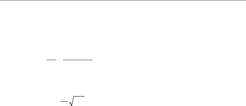
ETABS Reinforced Concrete Design
where Vu is computed from AS 9.2.3 or 9.2.4. Given V*, Vu, and Vu,max, the
required shear reinforcement is calculated as follows, where,
φ
is the strength
reduction factor.
( )
*
m
,
u
sv
sy o
VV
A
s fd
φ
−
=
(AS 8.2.10)
Minimum punching shear reinforcement should be provided such that:
m
1'
16
≥
s co
V f ud
(NZS 12.7.4.3)
If V* >
φ
Vmax, a failure condition is declared. (NZS 12.7.3.4)
If V* exceeds the maximum permitted value of
φ
Vmax, the concrete section
should be increased in size.
5.5.4.3 Determine Reinforcement Arrangement
Punching shear reinforcement in the vicinity of rectangular columns should be
arranged on peripheral lines, i.e., lines running parallel to and at constant dis-
tances from the sides of the column. Figure 5-4 shows a typical arrangement of
shear reinforcement in the vicinity of a rectangular interior, edge, and corner
column.
The distance between the column face and the first line of shear reinforcement
shall not exceed d/2. The spacing between adjacent shear reinforcement in the
first line (perimeter) of shear reinforcement shall not exceed 2d measured in a
direction parallel to the column face (NZS 12.7.4.4).
Punching shear reinforcement is most effective near column corners where there
are concentrations of shear stress. Therefore, the minimum number of lines of
shear reinforcement is 4, 6, and 8, for corner, edge, and interior columns respec-
tively.
5 - 20 Slab Design
Chapter 05 - Design for AS 3600-09
Figure 5-4 Typical arrangement of shear studs
and critical sections outside shear-reinforced zone
5.5.4.4 Determine Reinforcement Diameter, Height, and Spacing
The punching shear reinforcement is most effective when the anchorage is close
to the top and bottom surfaces of the slab. The cover of anchors should not be
less than the minimum cover specified in NZS 3.11 plus one-half of the
diameter of the flexural reinforcement.
When specifying shear studs, the distance, so, between the column face and the
first peripheral line of shear studs should not be smaller than 0.5d. The spacing
between adjacent shear studs, g, at the first peripheral line of studs shall not ex-
ceed 2d and in the case of studs in a radial pattern, the angle between adjacent
stud rails shall not exceed 60 degrees. The limits of so and the spacing, s, between
the peripheral lines are specified as:
so ≤ 0.5d (NZS 12.7.4.4)
s ≤ 0.5d (NZS 12.7.4.4)
g ≤ 2d (NZS 12.7.4.4)
I
y
Typical Studrail
(only first and last
studs shown)
Outermost
peripheral line
of studs
Interior Column Edge Column Corner Column
Critical section
centroid
Free
edge
Free
edge
Critical
section
centroid
Free edge
Outermost
peripheral line
of studs
I
y
I
y
yx
d2 d2
d2
x
I
x
I
x
g
y
g
x
g
0
s0
s
0
s
x
I
y
x
x
I
y
Typical Studrail
(only first and last
studs shown)
Outermost
peripheral line
of studs
Interior Column Edge Column Corner Column
Critical section
centroid
Free
edge
Free
edge
Critical
section
centroid
Free edge
Outermost
peripheral line
of studs
I
y
I
y
yx
d2 d2
d2
x
I
x
I
x
g
y
g
x
g
0
s0
s
0
s
x
I
y
x
x
Slab Design 5 - 21

Chapter 6
Design for AS 3600-01
This chapter describes in detail the various aspects of the concrete design proce-
dure that is used by ETABS when the Australian code AS 3600-2001 [AS 2001]
is selected. Various notations used in this chapter are listed in Table 6-1. For
referencing to the pertinent sections of the AS code in this chapter, a prefix “AS”
followed by the section number is used.
The design is based on user-specified load combinations. The program provides
a set of default load combinations that should satisfy the requirements for the
design of most building type structures.
English as well as SI and MKS metric units can be used for input. The code is
based on Newton-millimeter-second units. For simplicity, all equations and de-
scriptions presented in this chapter correspond to Newton-millimeter-second
units unless otherwise noted.
6.1 Notations
Table 6-1 List of Symbols Used in the AS 3600-2001 Code
A
g
Gross area of concrete, mm2
A
l
Area of longitudinal reinforcement for torsion, mm2
A
s
Area of tension reinforcement, mm2
Notations 6 - 1

ETABS Reinforced Concrete Design
Table 6-1 List of Symbols Used in the AS 3600-2001 Code
A
sc
Area of compression reinforcement, mm2
A
st
Area of tension reinforcement, mm2
A
s(required)
Area of required tension reinforcement, mm2
A
sv
Area of shear reinforcement, mm2
A
sv,min
Minimum area of shear reinforcement, mm2
A
sv
/s
Area of shear reinforcement per unit length, mm2 /mm
A
sw
/s
Area of shear reinforcement per unit length consisting of closed
ties, mm2/mm
A
t
Area of a polygon with vertices at the center of longitudinal bars at
the corners of a section, mm2
a
Depth of compression block, mm
a
b
Depth of compression block at balanced condition, mm
a
max
Maximum allowed depth of compression block, mm
b
Width of member, mm
b
ef
Effective width of flange (flanged section), mm
b
w
Width of web (flanged section), mm
c
Depth to neutral axis, mm
d
Distance from compression face to tension reinforcement, mm
d'
Concrete cover to compression reinforcement, mm
d
o
Distance from the extreme compression fiber to the centroid of the
outermost tension reinforcement, mm
d
om
Mean value of d
o
, averaged around the critical shear perimeter,
mm
D
Overall depth of a section, mm
D
s
Thickness of slab (flanged section), mm
E
c
Modulus of elasticity of concrete, MPa
E
s
Modulus of elasticity of reinforcement, MPa
f '
c
Specified compressive strength of concrete, MPa
f '
cf
Characteristic flexural tensile strength of concrete, MPa
6 - 2 Notations

Chapter 6 - Design for AS 3600-01
Table 6-1 List of Symbols Used in the AS 3600-2001 Code
f
cv
Concrete shear strength, MPa
f
sy
Specified yield strength of flexural reinforcement, MPa
f
sy,f
Specified yield strength of shear reinforcement, MPa
f '
s
Stress in the compression reinforcement, MPa
J
t
Torsional modulus, mm3
k
u
Ratio of the depth to the neutral axis from the compression face, to
the effective depth, d
M
ud
Reduced ultimate strength in bending without axial force, N-mm
M*
Factored moment at section, N-mm
N*
Factored axial load at section, N
s
Spacing of shear reinforcement along the strip, mm
T
uc
Torsional strength of section without torsional reinforcement, N-
mm
T
u.max
Maximum permitted total factored torsion at a section, N-mm
T
us
Torsion strength of section with torsion reinforcement, N-mm
T*
Factored torsional moment at a section, N-mm
u
t
Perimeter of the polygon defined by A
t
, mm
V*
Factored shear force at a section, N
V
u.max
Maximum permitted total factored shear force at a section, N
V
u.min
Shear strength provided by minimum shear reinforcement, N
V
uc
Shear force resisted by concrete, N
V
us
Shear force resisted by reinforcement, N
γ
1
Factor for obtaining depth of compression block in concrete
β
h
Ratio of the maximum to the minimum dimensions of the punch-
ing critical section
ε
c
Strain in concrete
ε
c, max
Maximum usable compression strain allowed in extreme concrete
fiber, (0.003 mm/mm)
Notations 6 - 3

ETABS Reinforced Concrete Design
Table 6-1 List of Symbols Used in the AS 3600-2001 Code
ε
s
Strain in reinforcement
φ
Strength reduction factor
θ
t
Angle of compression strut for torsion, degrees
θ
v
Angle of compression strut for shear, degrees
6.2 Design Load Combinations
The design load combinations are the various combinations of the load cases for
which the structure needs to be designed. For AS 3600-01, if a structure is sub-
jected to dead (D), live (L), pattern live (PL), snow (S), wind (W), and earth-
quake (E) loads, and considering that wind and earthquake forces are reversible,
the following load combinations may need to be defined (AS 3.3.1):
1.35D
(AS/NZS 1170.0-02, 4.2.2(a))
1.2D + 1.5L
(AS/NZS 1170.0-02, 4.2.2(b))
1.2D + 1.5(0.75 PL)
(AS/NZS 1170.0-02, 4.2.2(b))
1.2D + 0.4L + 1.0S
(AS/NZS 1170.0-02, 4.2.2(g))
0.9D ± 1.0W
1.2D
± 1.0W
1.2D + 0.4L
± 1.0W
(AS/NZS 1170.0-02, 4.2.2(e))
(AS/NZS 1170.0-
02, 4.2.2(d))
(AS/NZS 1170.0-02,
4.2.2(d))
1.0D ± 1.0E
1.0D
+ 0.4L ± 1.0E
(AS/NZS 1170.0-02, 4.2.2(f))
(AS/NZS 1170.0-
02, 4.2.2(f))
Note that the 0.4 factor on the live load in three of the combinations is not valid
for live load representing storage areas. These are also the default design load
combinations in ETABS whenever the AS 3600-2001 code is used. If roof live
load is treated separately or other types of loads are present, other appropriate
load combinations should be used.
6 - 4 Design Load Combinations

Chapter 6 - Design for AS 3600-01
6.3 Limits on Material Strength
The upper and lower limits of f'c are 65 MPa and 20 MPa, respectively, for all
framing types (AS 6.1.1.1(b)).
' 65MPa≤
c
f
(AS 6.1.1.1)
' 20MPa
c
f≥
(AS 6.1.1.1)
The upper limit of fsy is 500 MPa for all frames (AS 6.2.1, Table 6.2.1).
The code allows use of f'c and fsy beyond the given limits, provided special care
is taken regarding the detailing and ductility (AS 6.1.1, 6.2.1, 19.2.1.1).
ETABS enforces the upper material strength limits for flexure and shear design
of slabs. The input material strengths are taken as the upper limits if they are
defined in the material properties as being greater than the limits. The user is
responsible for ensuring that the minimum strength is satisfied.
6.4 Strength Reduction Factors
The strength reduction factor,
φ
, is defined as given in AS 2.3(c), Table 2.3:
φ
= 0.80 for flexure (tension controlled) (AS 2.3(c))
φ
= 0.70 for shear and torsion (AS 2.3(c))
These values can be overwritten; however, caution is advised.
6.5 Slab Design
ETABS slab design procedure involves defining sets of strips in two mutually
perpendicular directions. The locations of the strips are usually governed by the
locations of the slab supports. The axial force, moments and shears for a partic-
ular strip are recovered from the analysis (on the basis of the Wood-Armer tech-
nique), and a flexural design is carried out based on the ultimate strength design
method.
Limits on Material Strength 6 - 5

ETABS Reinforced Concrete Design
The slab design procedure involves the following steps:
Design flexural reinforcement
Design shear reinforcement
Punching check
6.5.1 Design Flexural Reinforcement
For slabs, ETABS uses either design strips or the finite element based design to
calculate the slab flexural reinforcement in accordance with the selected design
code. For simplicity, only strip-by-strip design is document in the proceeding
sections.
The design of the slab reinforcement for a particular strip is carried out at specific
locations along the length of the strip. These locations correspond to the element
boundaries. Controlling reinforcement is computed on either side of those ele-
ment boundaries. The slab flexural design procedure for each load combination
involves the following:
Determine factored axial loads and moments for each slab strip.
Design flexural reinforcement for the strip.
These two steps, described in the text that follows, are repeated for every load
combination. The maximum reinforcement calculated for the top and bottom
of the slab within each design strip, along with the corresponding controlling
load combination, is obtained and reported.
6.5.1.1 Determine Factored Moments
In the design of flexural reinforcement of concrete slab, the factored moments
for each load combination at a particular design strip are obtained by factoring
the corresponding moments for different load cases, with the corresponding load
factors.
The slab is then designed for the maximum positive and maximum negative fac-
tored moments obtained from all of the load combinations. Calculation of bottom
reinforcement is based on positive design strip moments. In such cases, the slab
6 - 6 Slab Design

Chapter 6 - Design for AS 3600-01
may be designed as a rectangular or flanged slab section. Calculation of top re-
inforcement is based on negative design strip moments. In such cases, the slab
may be designed as a rectangular or inverted flanged slab section.
6.5.1.2 Determine Required Flexural Reinforcement
In the flexural reinforcement design process, the program calculates both the
tension and compression reinforcement. Compression reinforcement is added
when the applied design moment exceeds the maximum moment capacity of a
singly reinforced section. The user has the option of avoiding compression rein-
forcement by increasing the effective depth, the width, or the strength of the
concrete. Note that the flexural reinforcement strength, fy , is limited to 500MPa
(AS 6.2.1), even if the material property is defined using a higher value.
The design procedure is based on the simplified rectangular stress block, as
shown in Figure 6-1 (AS 8.1.2.2).
The following assumptions are used for the stress block used to compute the
flexural bending capacity of rectangular sections (AS 8.1.2.2).
The maximum strain in the extreme compression fiber is taken as 0.003.
A uniform compressive stress of 0.85f'c acts on an area bounded by:
– The edges of the cross-sections.
– A line parallel to the neutral axis at the strength limit under the loading con-
cerned, and located at a distance
γ
kud from the extreme compression
fiber.
The maximum allowable depth of the rectangular compression block, amax, is
given by
dka
u
γ
=
max
where, (AS 8.1.3)
( )
[ ]
28'007.085.0 −
−=
c
f
γ
0.65 0.85≤γ≤
(AS 8.1.2.2)
ku = 0.4
Slab Design 6 - 7
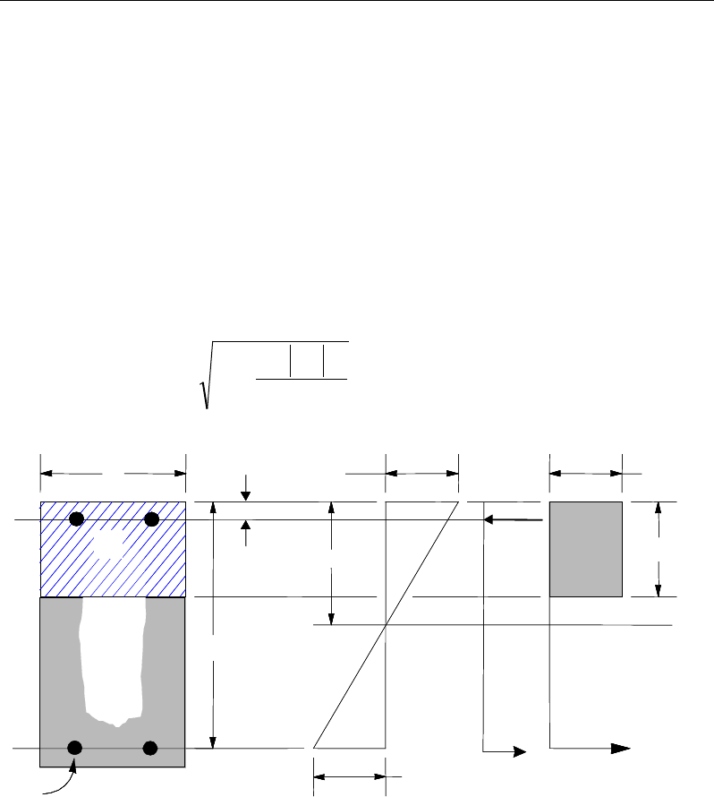
ETABS Reinforced Concrete Design
The design procedure used by ETABS for both rectangular and flanged sections
(L- and T-shaped sections) is summarized in the following subsections. It is as-
sumed that the design ultimate axial force does not exceed (Ascfsy > 0.15N*) (AS
10.7.1a); hence, all slabs are designed for major direction flexure, shear, and
torsion only.
6.5.1.3 Design of uniform thickness slab
In designing for a factored negative or positive moment, M*(i.e., designing top
or bottom reinforcement), the depth of the compression block is given by a (see
Figure 6-1), where,
bf
M
dd
a
c
φ
'85
.0
2
*
2
−
−=
(AS 8.1.2.2)
Figure 6-1 Uniform Thickness Slab Design
where, the value of
φ
is taken as that for a tension controlled section (ku ≤ 0.4),
which by default is 0.80 (AS 2.3) in the preceding and following equations.
(I) BEAM
SECTION (II) STRAIN
DIAGRAM (III) STRESS
DIAGRAM
0.003
ε
=c
0.85 f ′
u
a kd
γ
=
cs
T
s
T
s
ε
cs
C
d′
d
b
s
A
cs
A
(I) BEAM
SECTION (II) STRAIN
DIAGRAM (III) STRESS
DIAGRAM
0.003
ε
=c
0.85 f ′
u
a kd
γ
=
cs
T
s
T
s
ε
cs
C
d′
d
b
s
A
cs
A
6 - 8 Slab Design

Chapter 6 - Design for AS 3600-01
If a ≤ amax, the area of tension reinforcement is then given by:
−
=
2
*
a
df
M
A
sy
st
φ
This reinforcement is to be placed at the bottom if M* is positive, or at the top
if M* is negative.
If a > amax, i.e., ku > 0.4, compression reinforcement is required (AS 8.1.3) and
is calculated as follows:
The compressive force developed in the concrete alone is given by:
max
'85.0 bafC c
=
(AS 8.1.2.2)
and the moment resisted by concrete compression and tension reinforcement
is:
φ
−= 2
max
a
d
CMuc
Therefore, the moment required to be resisted by compression reinforcement
and tension reinforcement is:
ucus
MM
M−=
*
The required compression reinforcement is given by:
( )( )
' 0.85 '
us
sc sc
M
Af f dd
φ
=′
−−
, where
0.003
s s sy
cd
fE f
c
′
−
′= ≤
(AS 8.1.2.1, 6.2.2)
The required tension reinforcement for balancing the compression in the con-
crete is:
Slab Design 6 - 9
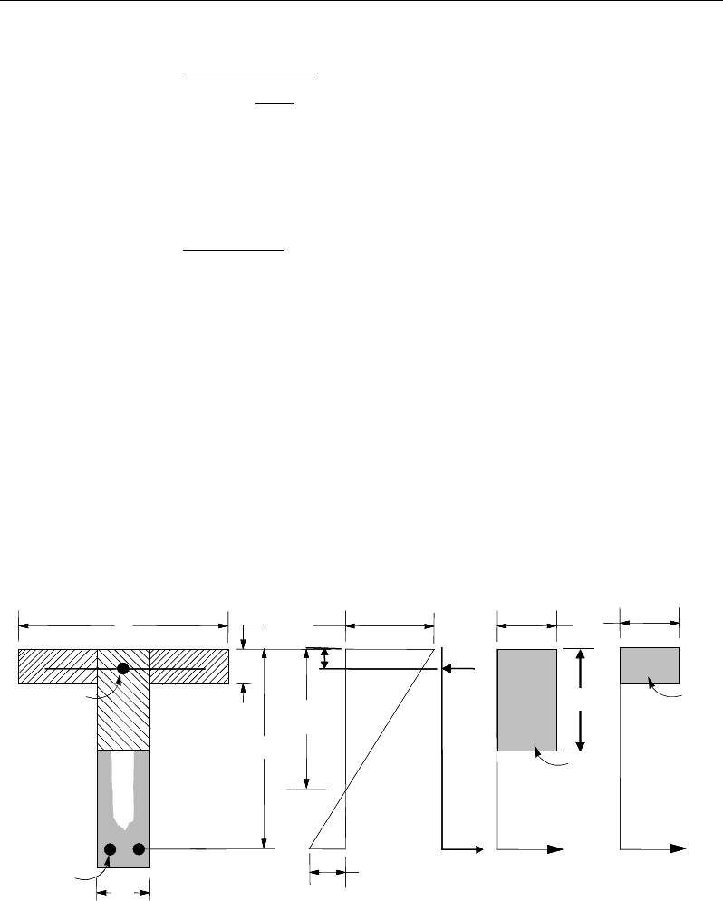
ETABS Reinforced Concrete Design
φ
−
=
2
max
1
a
df
M
A
sy
uc
s
and the tension reinforcement for balancing the compression reinforcement is
given by:
( )
2us
ssy
M
Af dd
φ
=′
−
Therefore, the total tension reinforcement is Ast = As1 + As2, and the total com-
pression reinforcement is Asc. Ast is to be placed at the bottom and Asc is to be
placed at the top if M* is positive, and vice versa if M* is negative.
6.5.1.4 Design of nonuniform thickness slab
In designing a flanged shaped section, a simplified stress block, as shown in
Figure 6-2, is assumed if the flange is under compression, i.e., if the moment is
positive. If the moment is negative, the flange comes under tension, and the
flange is ignored. In that case, a simplified stress block similar to that shown in
Figure 6-1 is assumed on the compression side (AS 8.1.3).
Figure 6-2 T- Nonuniform Thickness Slab Design
(I) BEAM
SECTION
s
A
(II) STRAIN
DIAGRAM
(III) STRESS
DIAGRAM
sc
A
w
b
f
b
d
d′s
f′
0.003
ε
=c
0.85 f ′
w
T
s
T
s
ε
c
0.85 f ′
f
T
f
C
w
C
s
C
s
D
cu
a kd
γ
=
(I) BEAM
SECTION
s
A
(II) STRAIN
DIAGRAM
(III) STRESS
DIAGRAM
sc
A
w
b
f
b
d
d′s
f′
0.003
ε
=c
0.85 f ′
w
T
s
T
s
ε
c
0.85 f ′
f
T
f
C
w
C
s
C
s
D
cu
a kd
γ
=
6 - 10 Slab Design
Chapter 6 - Design for AS 3600-01
6.5.1.4.1.1 Flanged Slab Section Under Negative Moment
In designing for a factored negative moment, M* (i.e., designing top reinforce-
ment), the calculation of the reinforcement is exactly the same as above, i.e., no
flanged data is used.
6.5.1.4.1.2 Flanged Slab Section Under Positive Moment
If M* > 0, the depth of the compression block is given by:
fc
bf
M
dda
φ
'85.0
2
*
2
−−=
where, the value of
φ
is taken as that for ku ≤ 0.4, which is 0.80 by default (AS
2.3) in the preceding and the following equations.
The maximum allowable depth of the rectangular compression block, amax, is
given by:
dka
u
γ
=
max
where, ku = 0.4 (AS 8.1.3)
If a ≤ Ds, the subsequent calculations for Ast are exactly the same as previously
defined for the uniform thickness slab design. However, in that case, the width
of the slkab is taken as bf. Compression reinforcement is required when a >
amax.
If a > Ds, the calculation for Ast has two parts. The first part is for balancing
the compressive force from the flange, Cf, and the second part is for balancing
the compressive force from the web, Cw, as shown in Figure 6-2. Cf is given
by:
( )
( )
max
,min'85.0 aDbbfC
swefcf
×−=
(AS 8.1.2.2)
Therefore,
1
=
f
s
sy
C
Af
and the portion of M* that is resisted by the flange is
given by:
()
−= 2
,
min max
aD
dCM s
fuf
φ
Therefore, the balance of the moment, M* to be carried by the web is:
Slab Design 6 - 11

ETABS Reinforced Concrete Design
*
uw uf
M MM= −
The web is a rectangular section of dimensions bw and d, for which the design
depth of the compression block is recalculated as:
2
1
2
0.85
φ
=−− ′
uw
cw
M
ad d fb
If a1 ≤ amax, the area of tension reinforcement is then given by:
21
2
φ
=
−
uw
s
sy
M
Aa
fd
, and
21 ssst AAA +=
This reinforcement is to be placed at the bottom of the flanged slab.
If a1 > amax, compression reinforcement is required and is calculated as follows:
The compression force in the web concrete alone is given by:
max
'85.0 abfC
wcw
=
(AS 8.1.2.2)
Therefore the moment resisted by the concrete web and tension reinforcement
is:
φ
−= 2
max
a
dCM
wuc
and the moment resisted by compression and tension reinforcement is:
ucuwus
MMM −=
Therefore, the compression reinforcement is computed as:
( )( )
,
0.85
us
sc sc
M
Af f dd
φ
=′ ′′
−−
where
6 - 12 Slab Design

Chapter 6 - Design for AS 3600-01
max
max
0.003
s s sy
cd
fE f
c
′
−
′= ≤
(AS 8.1.2.1,
6.2.2)
The tension reinforcement for balancing compression in the web concrete is:
2max
2
φ
=
−
uc
s
sy
M
Aa
fd
and the tension reinforcement for balancing the compression reinforcement is:
()
3
φ
=′
−
us
s
sy
M
Af dd
The total tensile reinforcement is Ast = As1 + As2 + As3, and the total compression
reinforcement is Asc. Ast is to be placed at the bottom and Asc is to be placed at
the top.
6.5.1.5 Minimum and Maximum Reinforcement
The minimum flexural tensile reinforcement required for each direction of a slab
is given by the following limits (AS 9.1.1):
As ≥ 0.0025 bh for flat slabs (AS 9.1.1(a))
As ≥ 0.0020 bh for slabs supported by beams/walls and slab footings
(AS 9.1.1(b))
In addition, an upper limit on both the tension reinforcement and compression
reinforcement has been imposed to be 0.04 times the gross cross-sectional area.
6.5.2 Design Slab Shear Reinforcement
The shear reinforcement is designed for each load combination at each station
along the design strip. In designing the shear reinforcement for a particular strip,
for a particular load combination, at a particular station due to the slab major
shear, the following steps are involved:
Slab Design 6 - 13

ETABS Reinforced Concrete Design
Determine the factored shear force, V*.
Determine the shear force, Vuc, that can be resisted by the concrete.
Determine the shear reinforcement required to carry the balance.
The following three sections describe in detail the algorithms associated with
these steps.
6.5.2.1 Determine Shear Force
In the design of the slab shear reinforcement, the shear forces for each load com-
bination at a particular design strip station are obtained by factoring the corre-
sponding shear forces for different load cases, with the corresponding load com-
bination factors.
6.5.2.2 Determine Concrete Shear Capacity
The shear force carried by the concrete, Vuc, is calculated as:
31
321
'
=
ow
cst
owuc
db
fA
dbV
βββ
(AS 8.2.7.1)
where,
1.1
1000
6.11.1
1
≥
−=
o
d
β
(AS 8.2.7.1)
β2 = 1, or (AS 8.2.7.1)
=
0
5.3
1
*
≥
−
g
A
N
for members subject to significant axial tension, or
=
+
g
A
N
14
1*
for members subject to significant axial compression.
β3 = 1
6 - 14 Slab Design

Chapter 6 - Design for AS 3600-01
6.5.2.3 Determine Required Shear Reinforcement
The shear force is limited to:
ovucu dbVV 6.0
min.+=
(AS 8.2.9)
ocu bdfV '2.0
max.=
(AS 8.2.6)
Given V*, Vuc, and Vu.max, the required shear reinforcement is calculated as fol-
lows, where,
φ
, the strength reduction factor, is 0.6 by default (AS 2.3).
If
*
/2,
uc
VV
φ
≤
0
sv
A,
s=
if D ≤ 750 mm; otherwise Asv.min shall be provided. (AS 8.2.5).
If
( )
*.min
/2 ,
uc u
V VV
φφ
<≤
0,
sv
A
s=
if D < bw /2 or 250 mm, whichever is greater (AS 8.2.5(c)(i));
otherwise Asv.min shall be provided.
If
*
.min .max ,
uu
V VV
φφ
<≤
( )
*
.
,
cot
uc
sv
sy f o v
VV
A
s fd
φ
φθ
−
=
(AS 8.2.10)
and greater than Asv.min, defined as:
=
fsy
wsv
f
b
s
A
.
min.
35.0
(AS 8.2.8)
θ
v = the angle between the axis of the concrete compression strut and the lon-
gitudinal axis of the member, which varies linearly from 30 degrees when
V*=
φ
Vu.min to 45 degrees when V*=
φ
Vu,max.
If
*max ,VV
φ
>
a failure condition is declared. (AS 8.2.6)
Slab Design 6 - 15

ETABS Reinforced Concrete Design
If V* exceeds its maximum permitted value
φ
Vmax, the concrete section size
should be increased (AS 8.2.6).
Note that if torsion design is considered and torsion reinforcement is required,
the calculated shear reinforcement is ignored. Closed stirrups are designed for
combined shear and torsion according to AS 8.3.4(b).
The maximum of all of the calculated Asv
/s values obtained from each load com-
bination is reported along with the controlling shear force and associated load
combination.
The slab shear reinforcement requirements considered by the program are based
purely on shear strength considerations. Any minimum stirrup requirements to
satisfy spacing and volumetric considerations must be investigated inde-
pendently of the program by the user.
6.5.3 Check for Punching Shear
The algorithm for checking punching shear is detailed in the section entitled
“Slab Punching Shear Check” in the Chapter 1. Only the code-specific items are
described in the following sections.
6.5.3.1 Critical Section for Punching Shear
The punching shear is checked on a critical section at a distance of dom /2 from
the face of the support (AS 9.2.1.1). For rectangular columns and concentrated
loads, the critical area is taken as a rectangular area with the sides parallel to the
sides of the columns or the point loads (AS 9.2.1.3). Figure 6-3 shows the auto
punching perimeters considered by ETABS for the various column shapes. The
column location (i.e., interior, edge, corner) and the punching perimeter may be
overwritten using the Punching Check Overwrites.
6 - 16 Slab Design
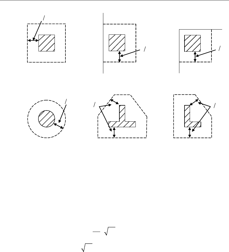
Chapter 6 - Design for AS 3600-01
Figure 6-3Punching Shear Perimeters
6.5.3.2 Determine Concrete Capacity
The shear capacity,
cv
f,
is calculated based on the minimum of the two expres-
sions from AS 3600-01 equation 11-35, as shown, with the dom and u terms re-
moved to convert force to stress.
2
0 17 1
min
0 34
c
h
cv
c
.f
f
.f
β
′
+
=
′
(AS 9.2.3(a))
where,
β
h is the ratio of the longest dimension to the shortest dimension of the
critical section.
6.5.3.3 Determine Maximum Shear Stress
The maximum design shear stress is computed along the major and minor axis
of column separately using the following equation:
d2
Interior Column
Circular Column
d2 d2
d2
T-Shape Column
Edge Column Edge Column
L-Shape Column
d2
d2
d2
Interior Column
Circular Column
d2 d2
d2
T-Shape Column
Edge Column Edge Column
L-Shape Column
d2
d2
Slab Design 6 - 17

ETABS Reinforced Concrete Design
*
max *
mm
1.0 8
= +
v
oo
uM
V
vud V ad
(AS 9.2.4(a))
6.5.3.4 Determine Capacity Ratio
The ratio of the maximum shear stress and the concrete punching shear stress
capacity is reported as the punching shear capacity ratio by ETABS. If this ratio
exceeds 1.0, punching shear reinforcement is designed as described in the fol-
lowing section.
6.5.4 Design Punching Shear Reinforcement
The design guidelines for shear links or shear studs are not available in AS 3600-
2001. ETABS uses the NZS 3101-06 guidelines to design shear studs or shear
links.
The use of shear studs as shear reinforcement in slabs is permitted, provided that
the effective depth of the slab is greater than or equal to 150 mm, and not less
than 16 times the shear reinforcement bar diameter (NZS 12.7.4.1). If the slab
thickness does not meet these requirements, the punching shear reinforcement is
not designed and the slab thickness should be increased by the user.
The algorithm for designing the required punching shear reinforcement is used
when the punching shear capacity ratio exceeds unity. The Critical Section for
Punching Shear and Transfer of Unbalanced Moment as described in the earlier
sections remain unchanged. The design of punching shear reinforcement is car-
ried out as described in the subsections that follow.
6.5.4.1 Determine Concrete Shear Capacity
The concrete punching shear stress capacity of a section with punching shear
reinforcement is as previously determined for the punching check.
6.5.4.2 Determine Required Shear Reinforcement
The shear force is limited to a maximum of:
Vmax = 3 Vu,min = 3*Vu (AS 92.2.4(a), (d))
6 - 18 Slab Design
Chapter 6 - Design for AS 3600-01
where Vu is computed from AS 9.2.3 or 9.2.4. Given V*, Vu, and Vu,max, the
required shear reinforcement is calculated as follows, where,
φ
is the strength
reduction factor.
( )
*
m
,
u
sv
sy o
VV
A
s fd
φ
−
=
(AS 8.2.10)
Minimum punching shear reinforcement should be provided such that:
m
1'
16
≥
s co
V f ud
(NZS 12.7.4.3)
If V* >
φ
Vmax, a failure condition is declared. (NZS 12.7.3.4)
If V* exceeds the maximum permitted value of
φ
Vmax, the concrete section
should be increased in size.
6.5.4.3 Determine Reinforcement Arrangement
Punching shear reinforcement in the vicinity of rectangular columns should be
arranged on peripheral lines, i.e., lines running parallel to and at constant dis-
tances from the sides of the column. Figure 6-4 shows a typical arrangement of
shear reinforcement in the vicinity of a rectangular interior, edge, and corner
column.
The distance between the column face and the first line of shear reinforcement
shall not exceed d/2. The spacing between adjacent shear reinforcement in the
first line (perimeter) of shear reinforcement shall not exceed 2d measured in a
direction parallel to the column face (NZS 12.7.4.4).
Punching shear reinforcement is most effective near column corners where there
are concentrations of shear stress. Therefore, the minimum number of lines of
shear reinforcement is 4, 6, and 8, for corner, edge, and interior columns respec-
tively.
Slab Design 6 - 19

ETABS Reinforced Concrete Design
Figure 6-4 Typical arrangement of shear studs
and critical sections outside shear-reinforced zone
6.5.4.4 Determine Reinforcement Diameter, Height, and Spacing
The punching shear reinforcement is most effective when the anchorage is close
to the top and bottom surfaces of the slab. The cover of anchors should not be
less than the minimum cover specified in NZS 3.11 plus half of the
diameter of the flexural reinforcement.
When specifying shear studs, the distance, so, between the column face and the
first peripheral line of shear studs should not be smaller than 0.5d. The spacing
between adjacent shear studs, g, at the first peripheral line of studs shall not ex-
ceed 2d and in the case of studs in a radial pattern, the angle between adjacent
stud rails shall not exceed 60 degrees. The limits of so and the spacing, s, between
the peripheral lines are specified as:
so ≤ 0.5d (NZS 12.7.4.4)
s ≤ 0.5d (NZS 12.7.4.4)
g ≤ 2d (NZS 12.7.4.4)
I
y
Typical Studrail
(only first and last
studs shown)
Outermost
peripheral line
of studs
Interior Column Edge Column Corner Column
Critical section
centroid
Free
edge
Free
edge
Critical
section
centroid
Free edge
Outermost
peripheral line
of studs
I
y
I
y
yx
d2 d2
d2
x
I
x
I
x
g
y
g
x
g
0
s0
s
0
s
x
I
y
x
x
I
y
Typical Studrail
(only first and last
studs shown)
Outermost
peripheral line
of studs
Interior Column Edge Column Corner Column
Critical section
centroid
Free
edge
Free
edge
Critical
section
centroid
Free edge
Outermost
peripheral line
of studs
I
y
I
y
yx
d2 d2
d2
x
I
x
I
x
g
y
g
x
g
0
s0
s
0
s
x
I
y
x
x
6 - 20 Slab Design

Chapter 7
Design for BS 8110-97
This chapter describes in detail the various aspects of the concrete design proce-
dure that is used by ETABS when the British code BS 8110-1997 [BSI 1997] is
selected. For light-weight concrete and torsion, reference is made to BS 8110-
2:1985 [BSI 1985]. Various notations used in this chapter are listed in Table 7-
1. For referencing to the pertinent sections of the British code BS 8110-1997 in
this chapter, a prefix “BS” followed by the section number is used.
The design is based on user-specified loading combinations. The program pro-
vides a set of default load combinations that should satisfy the requirements for
the design of most building type structures.
English as well as SI and MKS metric units can be used for input. The code is
based on Newton-millimeter-second units. For simplicity, all equations and de-
scriptions presented in this chapter correspond to Newton-millimeter-second
units unless otherwise noted.
7.1 Notations
Table 7-1 List of Symbols Used in the BS 8110-1997 Code
A
g
Gross area of cross-section, mm2
Notations 7- 1

ETABS Reinforced Concrete Design
Table 7-1 List of Symbols Used in the BS 8110-1997 Code
A
l
Area of longitudinal reinforcement for torsion, mm2
A
s
Area of tension reinforcement, mm2
A'
s
Area of compression reinforcement, mm2
A
sv
Total cross-sectional area of links at the neutral axis, mm2
A
sv,t
Total cross-sectional area of closed links for torsion, mm2
A
sv
/ s
v
Area of shear reinforcement per unit length, mm2/mm
a
Depth of compression block, mm
b
Width or effective width of the section in the compression zone,
mm
bf
Width or effective width of flange, mm
bw
Average web width of a flanged section, mm
C
Torsional constant, mm
4
d
Effective depth of tension reinforcement, mm
d'
Depth to center of compression reinforcement, mm
Ec
Modulus of elasticity of concrete, MPa
Es
Modulus of elasticity of reinforcement, assumed as 200,000 MPa
f
Punching shear factor considering column location
fcu
Characteristic cube strength at 28 days, MPa
f's
Stress in the compression reinforcement, MPa
fy
Characteristic strength of reinforcement, MPa
fyv
Characteristic strength of shear reinforcement, MPa
h
Overall depth of a section in the plane of bending, mm
7 - 2 Notations
Chapter 7 - Design for BS 8110-97
Table 7-1 List of Symbols Used in the BS 8110-1997 Code
h
f
Flange thickness, mm
h
min
Smaller dimension of a rectangular section, mm
h
max
Larger dimension of a rectangular section, mm
K
Normalized design moment,
2u
cu
M
bd f
K' Maximum
2u
cu
M
bd f
for a singly reinforced concrete section, taken
as 0.156 by assuming that moment redistribution is limited to
10%.
k
1
Shear strength enhancement factor for support compression
k2 Concrete shear strength factor,
[]
3
1
25
cu
f
k
3
Shear strength reduction factor for light-weight concrete
M
Design moment at a section, N-mm
M
single
Limiting moment capacity as singly reinforced slab, N-mm
s
v
Spacing of the links along the length of the strip, mm
T
Design torsion at ultimate design load, N-mm
u
Perimeter of the punching critical section, mm
V
Design shear force at ultimate design load, N
v
Design shear stress at a slab cross-section or at a punching critical
section, MPa
v
c
Design concrete shear stress capacity, MPa
v
max
Maximum permitted design factored shear stress, MPa
Notations 7 - 3

ETABS Reinforced Concrete Design
Table 7-1 List of Symbols Used in the BS 8110-1997 Code
v
t
Torsional shear stress, MPa
x
Neutral axis depth, mm
x
bal
Depth of neutral axis in a balanced section, mm
z
Lever arm, mm
β
Torsional stiffness constant
β
b
Moment redistribution factor in a member
γ
f
Partial safety factor for load
γ
m
Partial safety factor for material strength
ε
c
Maximum concrete strain, 0.0035
ε
s
Strain in tension reinforcement
ε
'
s
Strain in compression reinforcement
7.2 Design Load Combinations
The design load combinations are the various combinations of the load cases for
which the structure needs to be designed. The design load combinations are ob-
tained by multiplying the characteristic loads by appropriate partial factors of
safety,
γ
f (BS 2.4.1.3). For BS 8110-1997, if a structure is subjected to dead (D),
live (L), pattern live (PL), snow (S), and wind (W) loads, and considering that
wind forces are reversible, the following load combinations may need to be con-
sidered (BS 2.4.3).
1.4D
1.
4D + 1.6L (BS 2.4.3
)
1.
4D + 1.6(0.75PL)
(BS 2.4.3)
1.0D ± 1.4W
1.4D
± 1.4W
1.2D + 1.
2L ± 1.2W (BS 2.4.3
)
7 - 4 Design Load Combinations
Chapter 7 - Design for BS 8110-97
1.4D + 1.6L + 1.6S
1.2D + 1.
2S ± 1.2W
1.2D + 1.
2L + 1.2S ± 1.2W
(BS 2.4.3)
These are also the default design load combinations in ETABS whenever the BS
8110-1997 code is used. If roof live load is treated separately or other types of
loads are present, other appropriate load combinations should be used. Note that
the automatic combination, including pattern live load, is assumed and should
be reviewed before using for design.
7.3 Limits on Material Strength
The concrete compressive strength, fcu, should not be less than 25 MPa (BS
3.1.7.2). ETABS does not enforce this limit for flexure and shear design of slabs.
The input material strengths are used for design even if they are outside of the
limits. It is the user's responsibility to use the proper strength values while de-
fining the materials.
7.4 Partial Safety Factors
The design strengths for concrete and reinforcement are obtained by dividing the
characteristic strength of the material by a partial safety factor,
γ
m. The values of
γ
m used in the program are listed in the following table, as taken from BS Table
2.2 (BS 2.4.4.1):
Values of
γ
m for the Ultimate Limit State
Reinforcement 1.15
Concrete in flexure and axial load 1.50
Concrete shear strength without shear reinforcement 1.25
These factors are already incorporated into the design equations and tables in the
code. Note that for reinforcement, the default factor of 1.15 is for Grade 500
reinforcement. If other grades are used, this value should be overwritten as nec-
essary. Changes to the partial safety factors are carried through the design equa-
tions where necessary, typically affecting the material strength portions of the
equations.
Limits on Material Strength 7 - 5

ETABS Reinforced Concrete Design
7.5 Slab Design
ETABS slab design procedure involves defining sets of strips in two mutually
perpendicular directions. The locations of the strips are usually governed by the
locations of the slab supports. The axial force, moments and shears for a partic-
ular strip are recovered from the analysis (on the basis of the Wood-Armer tech-
nique), and a flexural design is carried out based on the ultimate strength design
method.
The slab design procedure involves the following steps:
Design flexural reinforcement
Design shear reinforcement
Punching check
7.5.1 Design Flexural Reinforcement
For slabs, ETABS uses either design strips or the finite element based design to
calculate the slab flexural reinforcement in accordance with the selected design
code. For simplicity, only strip-by-strip design is document in the proceeding
sections.
The design of the slab reinforcement for a particular strip is carried out at specific
locations along the length of the strip. These locations correspond to the element
boundaries. Controlling reinforcement is computed on either side of those ele-
ment boundaries. The slab flexural design procedure for each load combination
involves the following:
Determine factored axial loads and moments for each slab strip.
Design flexural reinforcement for the strip.
These two steps, described in the text that follows, are repeated for every load
combination. The maximum reinforcement calculated for the top and bottom
of the slab within each design strip, along with the corresponding controlling
load combination, is obtained and reported.
7 - 6 Slab Design

Chapter 7 - Design for BS 8110-97
7.5.1.1 Determine Factored Moments
In the design of flexural reinforcement of concrete slab, the factored moments
for each load combination at a particular design strip are obtained by factoring
the corresponding moments for different load cases, with the corresponding load
factors.
The slab is then designed for the maximum positive and maximum negative fac-
tored moments obtained from all of the load combinations. Calculation of bottom
reinforcement is based on positive design strip moments. In such cases, the slab
may be designed as a rectangular or flanged slab section. Calculation of top re-
inforcement is based on negative design strip moments. In such cases, the slab
may be designed as a rectangular or inverted flanged slab section.
7.5.1.2 Determine Required Flexural Reinforcement
In the flexural reinforcement design process, the program calculates both the
tension and compression reinforcement. Compression reinforcement is added
when the applied design moment exceeds the maximum moment capacity of a
singly reinforced section. The user has the option of avoiding the compression
reinforcement by increasing the effective depth, the width, or the strength of the
concrete.
The design procedure is based on the simplified rectangular stress block shown
in Figure 7-1 (BS 3.4.4.4). Furthermore, it is assumed that moment redistribution
in the member does not exceed 10% (i.e., βb ≥ 0.9; BS 3.4.4.4). The code also
places a limitation on the neutral axis depth, x/d ≤ 0.5, to safeguard against non-
ductile failures (BS 3.4.4.4). In addition, the area of compression reinforcement
is calculated assuming that the neutral axis depth remains at the maximum per-
mitted value.
The design procedure used by ETABS, for both rectangular and flanged sections
(L- and T-shaped section) is summarized in the subsections that follow. It is as-
sumed that the design ultimate axial force does not exceed (0.1fcu Ag) (BS
3.4.4.1); hence, all slabs are designed for major direction flexure, shear, and tor-
sion only.
Slab Design 7 - 7
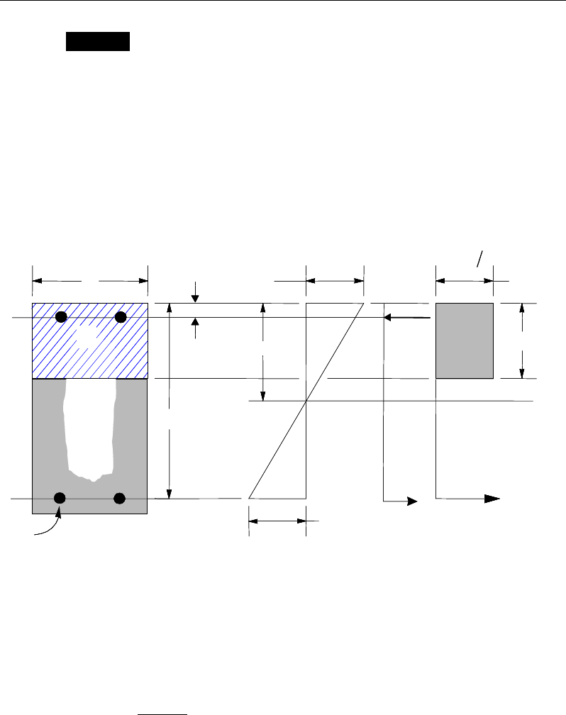
ETABS Reinforced Concrete Design
Design of uniform thickness slab
For uniform thickness slab, the limiting moment capacity as a singly reinforced
slab, Msingle, is first calculated for a section. The reinforcement is determined
based on M being greater than, less than, or equal to Msingle. See Figure 7-1.
Calculate the ultimate limiting moment of resistance of the section as singly
reinforced.
Msingle = K'fcu bd2, where (BS 3.4.4.4)
K' = 0.156
Figure 7-1 Uniform Thickness Slab Design
If M ≤ Msingle, the area of tension reinforcement, As, is given by:
0 87
sy
M
A,
. fz
=
, where (BS 3.4.4.4)
(I) BEAM
SECTION (II) STRAIN
DIAGRAM (III) STRESS
DIAGRAM
ε
=0.0035
γ
0 67 cu m
.f
=09a .x
cs
T
s
T
s
ε
xs
C
d′
d
b
s
A
s
A′′
s
f
(I) BEAM
SECTION (II) STRAIN
DIAGRAM (III) STRESS
DIAGRAM
ε
=0.0035
γ
0 67 cu m
.f
=09
a .x
cs
T
s
T
s
ε
xs
C
d′
d
b
s
A
s
A′′
s
f
7 - 8 Slab Design
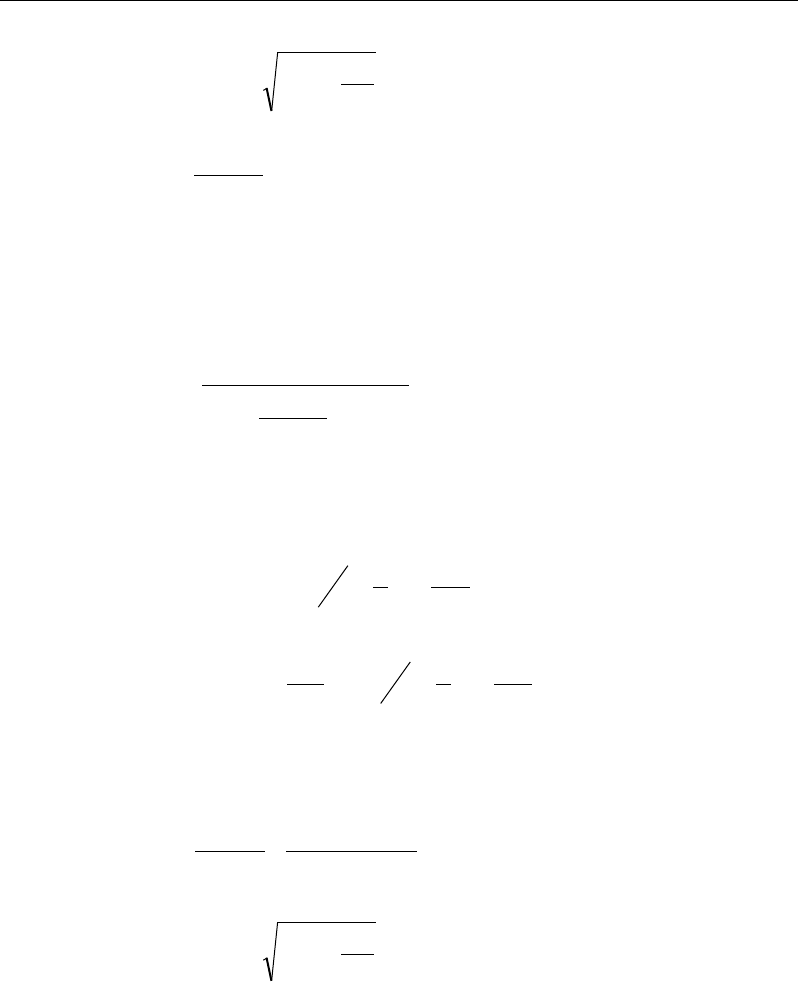
Chapter 7 - Design for BS 8110-97
d
K
dz 95.0
9.0
25.05.0 ≤
−+=
(BS 3.4.4.4)
2
bdf
M
K
cu
=
(BS 3.4.4.4)
This reinforcement is to be placed at the bottom if M is positive, or at the top
if M is negative.
If M > Msingle, compression reinforcement is required and calculated as follows:
( )
single
'
'0.67
'
s
cu
sc
MM
Af
f dd
γ
−
=
−−
(BS 3.4.4.4)
where d' is the depth of the compression reinforcement from the concrete com-
pression face, and
ys
ff 87.0' =
if
'
11
2 800
y
f
dd
≤−
(BS 3.4.4.1, 2.5.3, Fig 2.2)
−
=d
d
Ef
c
s
s
'
2
1
'
ε
if
'
11
2 800
>−
y
f
dd
(BS 3.4.4.1, 2.5.3, Fig 2.2)
The tension reinforcement required for balancing the compression in the con-
crete and the compression reinforcement is calculated as:
( )
single single
',
0.87 0.87
syy
M MM
Afz fdd
−
= + −
where (BS 3.4.4.4)
d
K
dz 777.0
9.0
'
25.05.0 =
−+=
(BS 3.4.4.4)
Slab Design 7 - 9
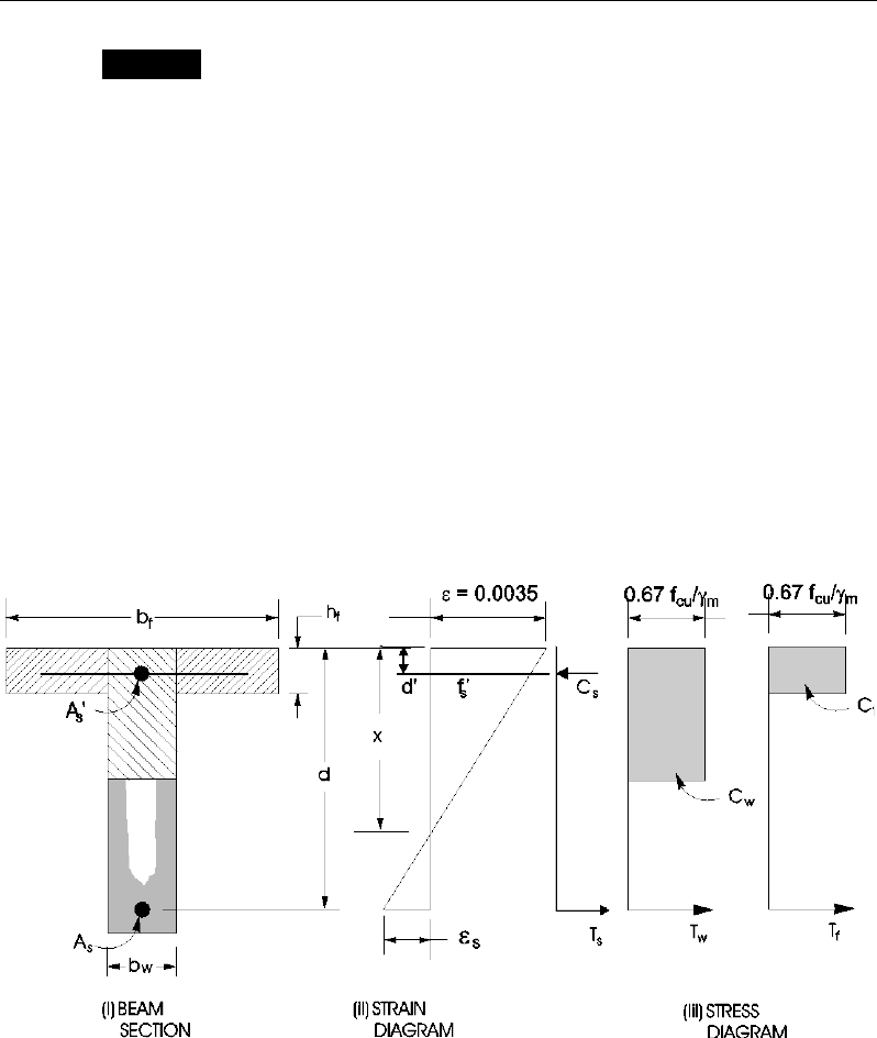
ETABS Reinforced Concrete Design
Design of nonuniform thickness slab
7.5.1.2.2.1 Flanged Slab Section Under Negative Moment
In designing for a factored negative moment, M (i.e., designing top reinforce-
ment), the calculation of the reinforcement area is exactly the same as described
previously, i.e., no flanged data is used.
7.5.1.2.2.2 Flanged Slab Section Under Positive Moment
With the flange in compression, the program analyzes the section by considering
alternative locations of the neutral axis. Initially the neutral axis is assumed to
be located in the flange. Based on this assumption, the program calculates the
exact depth of the neutral axis. If the stress block does not extend beyond the
flange thickness, the section is designed as a uniform thickness slab of width bf.
If the stress block extends beyond the flange depth, the contribution of the web
to the flexural strength of the slab is taken into account. See Figure 7-2.
Figure 7-2 Nonuniform Thickness Slab Design
Assuming the neutral axis to lie in the flange, the normalized moment is given
by:
7 - 10 Slab Design
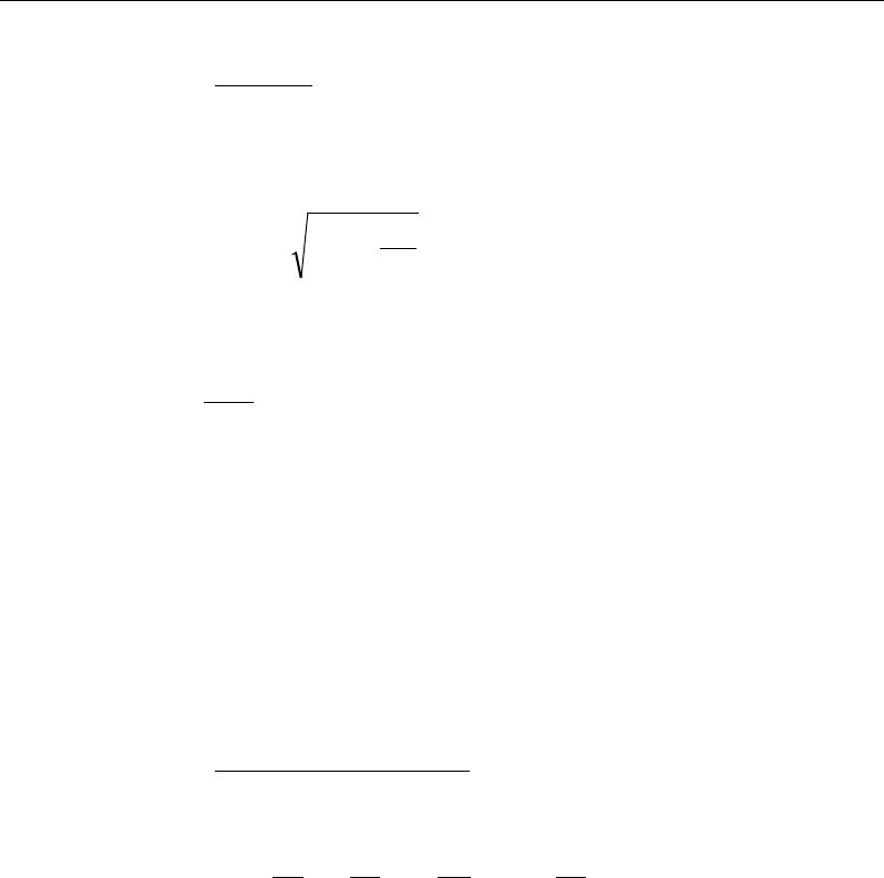
Chapter 7 - Design for BS 8110-97
K =
2
dbf
M
fcu
(BS 3.4.4.4)
Then the moment arm is computed as:
z = d
−
+9
.0
25
.0
5.
0K
≤ 0.95d (BS 3.4.4.4)
the depth of the neutral axis is computed as:
x =
45.0
1
(d − z) (BS 3.4.4.4)
and the depth of the compression block is given by:
a = 0.9x (BS 3.4.4.4)
If a ≤ hf, the subsequent calculations for As are exactly the same as previously
defined for the uniform thickness slab design. However, in that case, the width
of the slab is taken as bf. Compression reinforcement is required when K > K'.
If a > hf, when M ≤
β
ffcubd2 and hf ≤ 0.45d, then
( )
( )
01 045
087 05
cu f
s
yf
M . f bd . d h
A,
. f d .h
+−
=−
where (BS 3.4.4.5)
b
b
d
h
b
b
d
h
w
f
w
f
f
15.0
2
1145
.
0+
−
−=
β
(BS 3.4.4.5)
Otherwise the calculation for As has two parts. The first part is for balancing
the compressive force from the flange, Cf, and the second part is for balancing
the compressive force from the web, Cw, as shown in Figure 7-2.
In that case, the ultimate resistance moment of the flange is given by:
( ) ( )
0.45 0.5
f cu f w f f
M f b bhd h= −−
(BS 3.4.4.5)
The moment taken by the web is computed as:
Slab Design 7 - 11
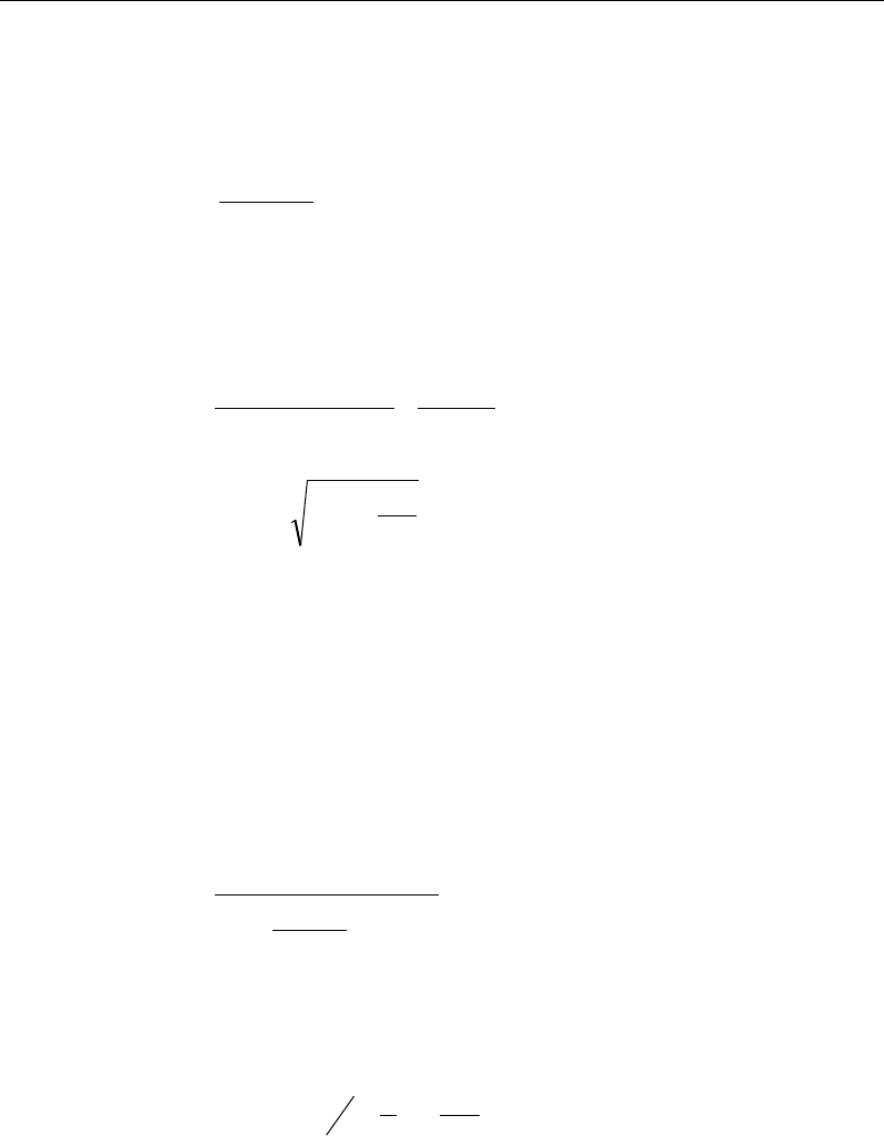
ETABS Reinforced Concrete Design
fw
MMM −=
and the normalized moment resisted by the web is given by:
Kw =
2
w
cu w
M
f bd
(BS 3.4.4.4)
If Kw ≤ 0.156 (BS 3.4.4.4), the slab is designed as a singly reinforced concrete
slab. The reinforcement is calculated as the sum of two parts, one to balance
compression in the flange and one to balance compression in the web.
( )
0 87
087 05
fw
sy
yf
MM
A,
. fz
. f d .h
= +
−
where
d
K
dz w95
.0
9.0
25.
0
5.
0≤
−
+=
If Kw > K' (BS 3.4.4.4), compression reinforcement is required and is calcu-
lated as follows:
The ultimate moment of resistance of the web only is given by:
2
'dbfKM
wcuuw
=
(BS 3.4.4.4)
The compression reinforcement is required to resist a moment of magnitude
Mw − Muw. The compression reinforcement is computed as:
()
0 67
w uw
s
cu
sc
MM
A.f
f d d'
γ
−
′=
′−−
(BS 3.4.4.4)
where, d’ is the depth of the compression reinforcement from the concrete
compression face, and
0 87
sy
f' . f=
if
11
2 800
′≤−
y
f
dd
(BS 3.4.4.1, 2.5.3, Fig 2.2)
7 - 12 Slab Design

Chapter 7 - Design for BS 8110-97
2
1
s sc d
f' E d
ε
′
= −
if
11
2 800
′>−
y
f
dd
(BS 3.4.4.1, 2.5.3, Fig 2.2)
The area of tension reinforcement is obtained from equilibrium as:
( )
( ) ( )
0 87 0 777 0 87
087 05
fuw w uw
sfy
yf
MM MM
A. f . d . fdd
. f d .h
−
= ++
′
−
−
7.5.1.3 Minimum and Maximum Slab Reinforcement
The minimum flexural tension reinforcement required for each direction of a
slab is given by the following limits (BS 3.12.5.3, BS Table 3.25) with interpo-
lation for reinforcement of intermediate strength:
0 0024 if 250MPa
0 0013 f 500MPa
y
sy
. bh f
A. bh i f
=
≥=
(BS 3.12.5.3)
In addition, an upper limit on both the tension reinforcement and compression
reinforcement has been imposed to be 0.04 times the gross cross-sectional area
(BS 3.12.6.1).
7.5.2 Design Slab Shear Reinforcement
The shear reinforcement is designed for each load combination at each station
along the design strip. In designing the shear reinforcement for a particular strip,
for a particular load combination, at a particular station due to the slab major
shear, the following steps are involved:
Determine the shear stress, v.
Determine the shear stress, vc, that can be resisted by the concrete.
Determine the shear reinforcement required to carry the balance.
The following three sections describe in detail the algorithms associated with
these steps.
Slab Design 7 - 13
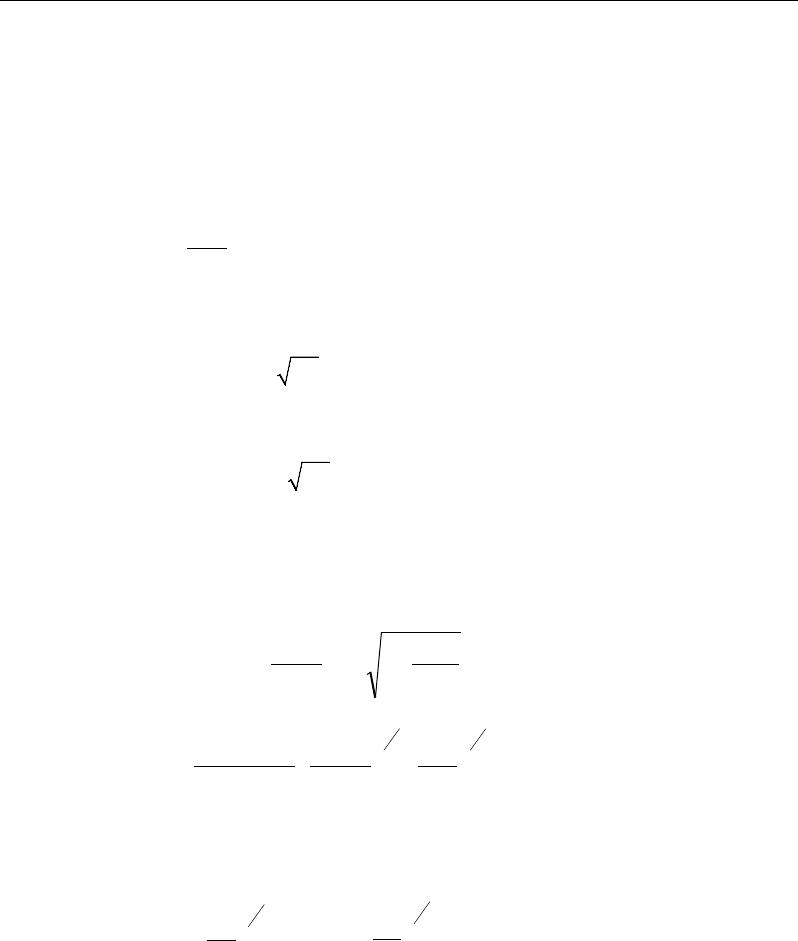
ETABS Reinforced Concrete Design
7.5.2.1 Determine Shear Stress
In the design of the slab shear reinforcement, the shear forces for each load com-
bination at a particular strip station are obtained by factoring the corresponding
shear forces for different load cases with the corresponding load combination
factors. The shear stress is then calculated as:
db
V
v
w
=
(BS 3.4.5.2)
The maximum allowable shear stress, vmax is defined as:
vmax = min(0.8
cu
f,
5 MPa) (BS 3.4.5.2)
For light-weight concrete, vmax is defined as:
vmax = min(0.63
cu
f,
4 MPa) (BS 8110-2:1985 5.4)
7.5.2.2 Determine Concrete Shear Capacity
The shear stress carried by the concrete, vc, is calculated as:
cc
c
c
cc
vA
N
v
MA
NVh
vv +≤+= 16.0'
(BS 3.4.5.12)
11
34
123
0.79 100 400
s
c
m
kkk A
vbd d
γ
=
(BS 3.4.5.4, Table 3.8)
k1 is the enhancement factor for support compression,
and is conservatively taken as 1 (BS 3.4.5.8)
k2 =
13
25
cu
f,
1 ≤ k2 ≤
3
1
25
40
(BS 3.4.5.4, Table 3.8)
γ
m = 1.25 (BS 2.4.4.1)
However, the following limits also apply:
7 - 14 Slab Design
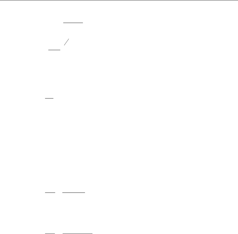
Chapter 7 - Design for BS 8110-97
0.15 ≤
bd
A
s
100
≤ 3 (BS 3.4.5.4, Table 3.8)
4
1
400
d
≥ 0.67 (unreinforced) or ≥ 1 (reinforced)(BS 3.4.5.4, Table
3.8)
fcu ≤ 40 MPa (for calculation purposes only) (BS 3.4.5.4)
1
≤
M
Vh
(BS 3.4.5.12)
As is the area of tension reinforcement.
7.5.2.3 Determine Required Shear Reinforcement
Given v, vc, and vmax, the required shear reinforcement is calculated as follows
(BS Table 3.8, BS 3.4.5.3):
If v ≤ (v’c + 0.4),
yv
w
v
sv
f
b
s
A
87.0
4.0
=
(BS 3.4.5.3, Table 3.7)
If (v′c + 0.4) < v ≤ vmax,
( )
yv
wc
v
sv
f
bv
v
s
A
87.0
'−
=
(BS 3.4.5.3, Table 3.7)
If v > vmax, a failure condition is declared. (BS 3.4.5.2)
In the preceding expressions, a limit is imposed on fyv as:
fyv ≤ 500 MPa. (BS 3.4.5.1)
The maximum of all of the calculated Asv /sv values, obtained from each load
combination, is reported along with the controlling shear force and associated
load combination.
Slab Design 7 - 15

ETABS Reinforced Concrete Design
The slab shear reinforcement requirements considered by the program are based
purely on shear strength considerations. Any minimum stirrup requirements to
satisfy spacing and volumetric considerations must be investigated
independently of the program by the user.
7.5.3 Check for Punching Shear
The algorithm for checking punching shear is detailed in the section entitled
“Slab Punching Shear Check” in the Chapter 1. Only the code-specific items are
described in the following sections.
7.5.3.1 Critical Section for Punching Shear
The punching shear is checked at the face of the column (BS 3.7.6.4) and at a
critical section at a distance of 1.5d from the face of the support (BS 3.7.7.6).
For rectangular columns and concentrated loads, the critical area is taken as a
rectangular area with the sides parallel to the sides of the columns or the point
loads (BS 3.7.7.1). Figure 7-3 shows the auto punching perimeters considered
by ETABS for the various column shapes. The column location (i.e., interior,
edge, corner) and the punching perimeter may be overwritten using the Punching
Check Overwrites.
7 - 16 Slab Design
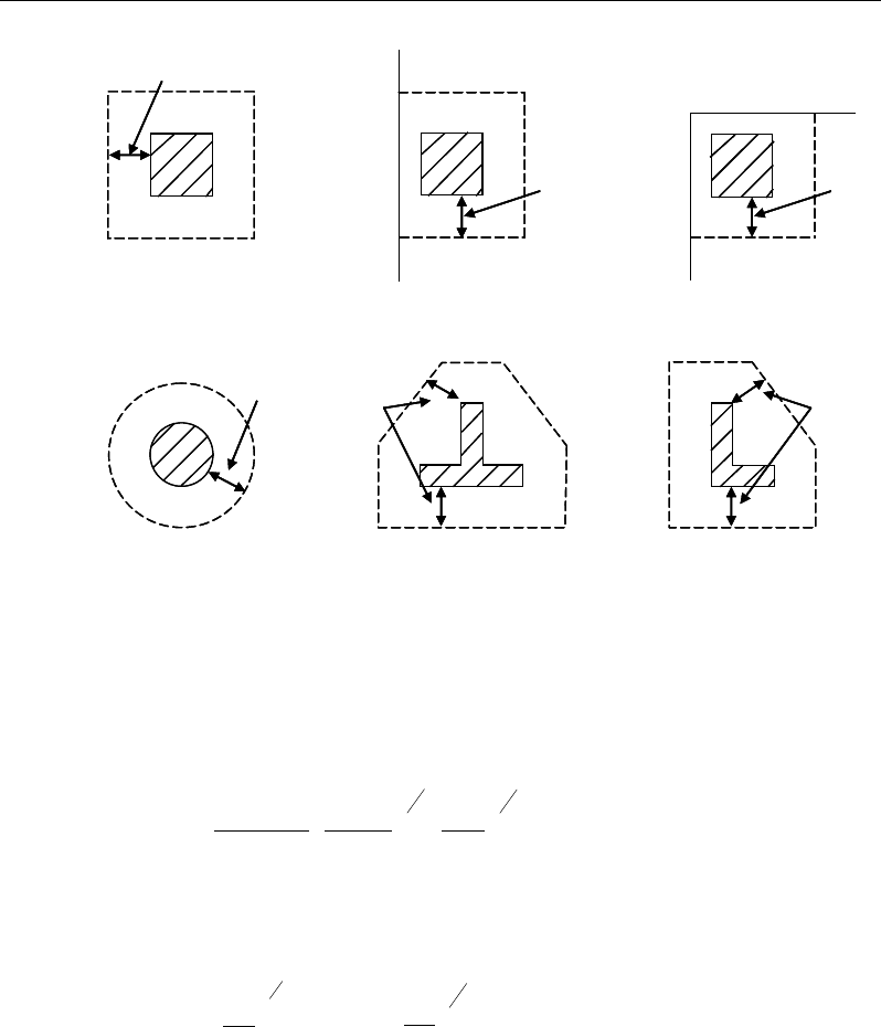
Chapter 7 - Design for BS 8110-97
Figure 7-3 Punching Shear Perimeters
7.5.3.2 Determine Concrete Capacity
The concrete punching shear factored strength is taken as (BS 3.7.7.4, 3.7.7.6):
4
1
3
1
21 400
100
79.0
=dbd
A
kk
vs
m
c
γ
(BS 3.4.5.4, Table 3.8)
k1 is the enhancement factor for support compression,
and is conservatively taken as 1 (BS 3.4.5.8)
k2 =
13
25
cu
f,
1 ≤ k2 ≤
3
1
25
40
(BS 3.4.5.4, Table 3.8)
γm = 1.25 (BS 3.4.5.2)
However, the following limitations also apply:
1.5d
Interior Column
Circular Column T-Shape Column
Edge Column Corner Column
L-Shape Column
1.5d 1.5d
1.5d
1.5d
1.5d
1.5d
Interior Column
Circular Column T-Shape Column
Edge Column Corner Column
L-Shape Column
1.5d 1.5d
1.5d
1.5d
1.5d
Slab Design 7 - 17
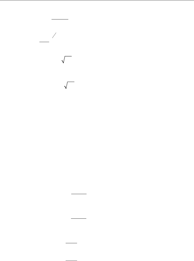
ETABS Reinforced Concrete Design
0.15 ≤
bd
A
s
100
≤ 3 (BS 3.4.5.4, Table 3.8)
4
1
400
d
≥ 0.67 (unreinforced) or ≥ 1 (reinforced) (BS 3.4.5.4)
v ≤ min(0.8
cu
f,
5MPa) (BS 3.7.6.4)
For light-weight concrete, vmax is defined as:
v ≤ min(0.63
cu
f,
4 MPa) (BS 8110-2:1985 5.4)
fcu ≤ 40 MPa (for calculation purpose only) (BS 3.4.5.4)
As = area of tension reinforcement, which is taken as the average tension
reinforcement of design strips in Layer A and layer B where Layer
A and Layer design strips are in orthogonal directions. When design
strips are not present in both orthogonal directions then tension rein-
forcement is taken as zero in the current implementation.
7.5.3.3 Determine Maximum Shear Stress
Given the punching shear force and the fractions of moments transferred by ec-
centricity of shear about the bending axis, the nominal design shear stress, vmax,
is calculated as:
= +
1.5
,
Mx
V Vf
eff x Vy
(BS 3.7.6.2, 3.7.6.3)
= +
1.5
,
My
V Vf
eff y Vx
(BS 3.7.6.2, 3.7.6.3)
,
max
,
max
eff x
eff y
V
ud
vV
ud
=
(BS 3.7.7.3)
7 - 18 Slab Design

Chapter 7 - Design for BS 8110-97
where,
u is the perimeter of the critical section
x and y are the lengths of the sides of the critical section parallel to the
axis of bending
Mx and My are the design moments transmitted from the slab to the
column at the connection
V is the total punching shear force
f is a factor to consider the eccentricity of punching shear force and is
taken as:
1.00 for interior columns
1.25 for edge columns
1.25 for corner columns
f
=
(BS 3.7.6.2, 3.7.6.3)
7.5.3.4 Determine Capacity Ratio
The ratio of the maximum shear stress and the concrete punching shear stress
capacity is reported as the punching shear capacity ratio by ETABS. If this ratio
exceeds 1.0, punching shear reinforcement is designed as described in the fol-
lowing section.
7.5.4 Design Punching Shear Reinforcement
The use of shear studs as shear reinforcement in slabs is permitted, provided that
the effective depth of the slab is greater than or equal to 200 mm (BS 3.7.7.5). If
the slab thickness does not meet these requirements, the punching shear rein-
forcement is not designed and the slab thickness should be increased by the user.
The algorithm for designing the required punching shear reinforcement is used
when the punching shear capacity ratio exceeds unity. The Critical Section for
Punching Shear and Transfer of Unbalanced Moment as described in the earlier
sections remain unchanged. The design of punching shear reinforcement is car-
ried out as explained in the subsections that follow.
Slab Design 7 - 19

ETABS Reinforced Concrete Design
7.5.4.1 Determine Concrete Shear Capacity
The concrete punching shear stress capacity of a section with punching shear
reinforcement is as previously determined for the punching check.
7.5.4.2 Determine Required Shear Reinforcement
The shear stress is limited to a maximum of:
vmax = 2vc (BS 3.7.7.5)
Given v, vc, and vmax, the required shear reinforcement is calculated as follows
(BS 3.7.7.5).
If v ≤ 1.6vc,
s
A
v
=
( )
0.4
0.87 0.87
≥
c
yv yv
v -v ud ud
ff
,
(BS 3.7.7.5)
If 1.6vc ≤ v < 2.0vc,
s
A
v
=
( )
5 0.7 0.4
0.87 0.87
≥
c
yv yv
v -v ud ud
ff
, (BS 3.7.7.5)
If v > vmax, a failure condition is declared. (BS 3.7.7.5)
If v exceeds the maximum permitted value of vmax, the concrete section should
be increased in size.
7.5.4.3 Determine Reinforcement Arrangement
Punching shear reinforcement in the vicinity of rectangular columns should be
arranged on peripheral lines, i.e., lines running parallel to and at constant dis-
tances from the sides of the column. Figure 7-4 shows a typical arrangement of
shear reinforcement in the vicinity of a rectangular interior, edge, and corner
column.
The distance between the column face and the first line of shear reinforcement
shall not exceed d/2. The spacing between adjacent shear reinforcement in the
first line (perimeter) of shear reinforcement shall not exceed 1.5d measured in a
direction parallel to the column face (BS 3.7.7.6).
7 - 20 Slab Design
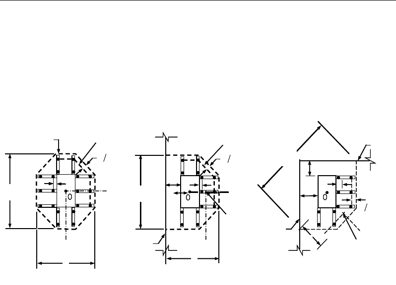
Chapter 7 - Design for BS 8110-97
Punching shear reinforcement is most effective near column corners where there
are concentrations of shear stress. Therefore, the minimum number of lines of
shear reinforcement is 4, 6, and 8, for corner, edge, and interior columns respec-
tively.
Figure 7-4 Typical arrangement of shear studs and
critical sections outside shear-reinforced zone
7.5.4.4 Determine Reinforcement Diameter, Height, and Spacing
The punching shear reinforcement is most effective when the anchorage is close
to the top and bottom surfaces of the slab. The cover of anchors should not be
less than the minimum cover specified in BS 3.3 plus half of the diameter of the
flexural reinforcement.
Punching shear reinforcement in the form of shear studs is generally available in
10-, 12-, 17-, 16-, and 20-millimeter diameters.
When specifying shear studs, the distance, so, between the column face and the
first peripheral line of shear studs should not be smaller than 0.5d. The spacing
between adjacent shear studs, g, at the first peripheral line of studs shall not ex-
ceed 1.5d. The limits of so and the spacing, s, between the peripheral lines are
specified as:
so ≤ 0.5d (BS 3.7.7.6)
I
y
Typical Studrail
(only first and last
studs shown)
Outermost
peripheral line
of studs
Interior Column Edge Column Corner Column
Critical section
centroid
Free
edge
Free
edge
Critical
section
centroid
Free edge
Outermost
peripheral line
of studs
I
y
I
y
yx
d2 d2
d2
x
I
x
I
x
g
y
g
x
g
0
s
0
s
0
s
x
I
y
xx
Iy
Typical Studrail
(only first and last
studs shown)
Outermost
peripheral line
of studs
Interior Column Edge Column Corner Column
Critical section
centroid
Free
edge
Free
edge
Critical
section
centroid
Free edge
Outermost
peripheral line
of studs
I
y
I
y
yx
d2 d2
d2
x
I
x
I
x
g
y
g
x
g
0
s
0
s
0
s
x
I
y
xx
Slab Design 7 - 21

ETABS Reinforced Concrete Design
s ≤ 0.75d (BS 3.7.7.6)
g ≤ 1.5d (BS 3.7.7.6)
7 - 22 Slab Design

Chapter 8
Design for CSA A23.3-14
This chapter describes in detail the various aspects of the concrete design proce-
dure that is used by ETABS when the Canadian code CSA A23.3-14 [CSA 14]
is selected. Various notations used in this chapter are listed in Table 5-1. For
referencing to the pertinent sections of the Canadian code in this chapter, a prefix
“CSA” followed by the section number is used.
The design is based on user-specified load combinations. The program provides
a set of default load combinations that should satisfy the requirements for the
design of most building type structures.
English as well as SI and MKS metric units can be used for input. The code is
based on Newton-millimeter-second units. For simplicity, all equations and de-
scriptions presented in this chapter correspond to Newton-millimeter-second
units unless otherwise noted.
8.1 Notations
Table 8-1 List of Symbols Used in the CSA A23.3-14 Code
A
c
Area enclosed by outside perimeter of concrete cross-section, sq-
mm
A
ct
Area of concrete on flexural tension side, sq-mm
Notations 8 - 1

ETABS Reinforced Concrete Design
Table 8-1 List of Symbols Used in the CSA A23.3-14 Code
A
l
Area of longitudinal reinforcement for torsion, sq-mm
A
o
Gross area enclosed by shear flow path, sq-mm
A
oh
Area enclosed by centerline of outermost closed transverse tor-
sional reinforcement, sq-mm
A
s
Area of tension reinforcement, sq-mm
A'
s
Area of compression reinforcement, sq-mm
A
s(required)
Area of steel required for tension reinforcement, sq-mm
A
t
/s
Area of closed shear reinforcement for torsion per unit length, sq-
mm/mm
A
v
Area of shear reinforcement, sq-mm
A
v
/s
Area of shear reinforcement per unit length, sq-mm/mm
a
Depth of compression block, mm
a
b
Depth of compression block at balanced condition, mm
b
Width of member, mm
b
f
Effective width of flange (flanged section), mm
b
w
Width of web (flanged section), mm
b
0
Perimeter of the punching critical section, mm
b
1
Width of the punching critical section in the direction of bending,
mm
b
2
Width of the punching critical section perpendicular to the direc-
tion of bending, mm
c
Depth to neutral axis, mm
c
b
Depth to neutral axis at balanced conditions, mm
d
Distance from compression face to tension reinforcement, mm
d
v
Effective shear depth, mm
d'
Distance from compression face to compression reinforcement,
mm
h
s
Thickness of slab (flanged section), mm
E
c
Modulus of elasticity of concrete, MPa
8 - 2 Notations

Chapter 8 - Design for CSA A23.3-14
Table 8-1 List of Symbols Used in the CSA A23.3-14 Code
E
s
Modulus of elasticity of reinforcement, assumed as 200,000 MPa
f '
c
Specified compressive strength of concrete, MPa
f '
s
Stress in the compression reinforcement, psi
f
y
Specified yield strength of flexural reinforcement, MPa
f
yt
Specified yield strength of shear reinforcement, MPa
h
Overall depth of a section, mm
I
g
Moment of inertia of gross concrete section about centroidal axis,
neglecting reinforcement.
M
f
Factored moment at section, N-mm
N
f
Factored axial force at section, N
p
c
Outside perimeter of concrete cross-section, mm
p
h
Perimeter of area A
oh
, mm
s
Spacing of the shear reinforcement along the strip, mm
s
z
Crack spacing parameter
T
f
Factored torsion at section, N-mm
V
c
Shear resisted by concrete, N
V
r,max
Maximum permitted total factored shear force at a section, N
V
f
Factored shear force at a section, N
V
s
Shear force at a section resisted by steel, N
α
1
Ratio of average stress in rectangular stress block to the specified
concrete strength
β
Factor accounting for shear resistance of cracked concrete
β
1
Factor for obtaining depth of compression block in concrete
β
c
Ratio of the maximum to the minimum dimensions of the punch-
ing critical section
ε
c
Strain in concrete
ε
s
Strain in reinforcing steel
ε
x
Longitudinal strain at mid-depth of the section
Notations 8 - 3

ETABS Reinforced Concrete Design
Table 8-1 List of Symbols Used in the CSA A23.3-14 Code
φ
c
Strength reduction factor for concrete
φ
s
Strength reduction factor for steel
φ
m
Strength reduction factor for member
γ
f
Fraction of unbalanced moment transferred by flexure
γ
v
Fraction of unbalanced moment transferred by eccentricity of
shear
θ
Angle of diagonal compressive stresses, degrees
λ
Shear strength factor
8.2 Design Load Combinations
The design load combinations are the various combinations of the load cases for
which the structure needs to be designed. For CSA A23.3-14, if a structure is
subjected to dead (D), live (L), pattern live (PL), snow (S), wind (W), and earth-
quake (E) loads, and considering that wind and earthquake forces are reversible,
the following load combinations may need to be considered (CSA 8.3.2, Table
C.1a)
1.4D
(CSA 8.3.2, Table C.1a Case 1)
1.25D + 1.5L
1.25D + 1.5L +
1.0S
1.25D + 1.5L
± 0.4W
0.9
D + 1.5L
0.9D + 1.5L + 1.0
S
0.9D + 1.5L
± 0.4W
(CSA 8.3.2, Table C.1a Case 2
)
1.25D + 1.5(0.75 PL)
(CSA 13.8.4.3)
1.25D + 1.5S
1.2
5D + 1.5S + 0.5L
1.25D + 1.5S
± 0.4W
0.9D + 1.5S
0.9
D + 1.5S + 0.5L
0.9D + 1.5S
± 0.4W
(CSA 8.3.2, Table C.1a Case 3
)
8 - 4 Design Load Combinations

Chapter 8 - Design for CSA A23.3-14
1.25D ± 1.4W
1.2
5D + 0.5L ± 1.4W
1.25D + 0.5S
± 1.4W
0.9D
± 1.4W
0.9
D + 0.5L ± 1.4W
0.9D + 0.5S
± 1.4W
(CSA 8.3.2, Table C.1a Case 4
)
1.0D ± 1.0E
1.0D + 0.5L
± 1.0E
1.0D + 0.
25S ± 1.0E
1.0D + 0.5L + 0.
25S ± 1.0E
(CSA 8.3.2, Table C.1a Case 5
)
These are also the default design load combinations in ETABS whenever the
CSA A23.3-14 code is used. If roof live load is treated separately or other types
of loads are present, other appropriate load combinations should be used.
8.3 Limits on Material Strength
The upper and lower limits of f'c are 80 MPa and 20 MPa, respectively, for all
framing types (CSA 8.6.1.1).
20 MPa ≤ f'c ≤ 80 MPa (CSA 8.6.1.1)
The upper limit of fy is 500 MPa for all frames (CSA 8.5.1).
fy ≤ 500 MPa (CSA 8.5.1)
ETABS enforces the upper material strength limits for flexure and shear design
of slabs. The input material strengths are taken as the upper limits if they are
defined in the material properties as being greater than the limits. The user is
responsible for ensuring that the minimum strength is satisfied.
8.4 Strength Reduction Factors
The strength reduction factors,
φ
, are material dependent and defined as:
φ
c = 0.65 for concrete (CSA 8.4.2)
φ
s = 0.85 for reinforcement (CSA 8.4.3a)
Limits on Material Strength 8 - 5

ETABS Reinforced Concrete Design
These values can be overwritten; however, caution is advised.
8.5 Slab Design
ETABS slab design procedure involves defining sets of strips in two mutually
perpendicular directions. The locations of the strips are usually governed by the
locations of the slab supports. The axial force, moments and shears for a partic-
ular strip are recovered from the analysis (on the basis of the Wood-Armer tech-
nique), and a flexural design is carried out based on the ultimate strength design
method.
The slab design procedure involves the following steps:
Design flexural reinforcement
Design shear reinforcement
Punching check
8.5.1 Design Flexural Reinforcement
For slabs, ETABS uses either design strips or the finite element based design to
calculate the slab flexural reinforcement in accordance with the selected design
code. For simplicity, only strip-by-strip design is document in the proceeding
sections.
The design of the slab reinforcement for a particular strip is carried out at specific
locations along the length of the strip. These locations correspond to the element
boundaries. Controlling reinforcement is computed on either side of those ele-
ment boundaries. The slab flexural design procedure for each load combination
involves the following:
Determine factored axial loads and moments for each slab strip.
Design flexural reinforcement for the strip.
These two steps, described in the text that follows, are repeated for every load
combination. The maximum reinforcement calculated for the top and bottom
of the slab within each design strip, along with the corresponding controlling
load combination, is obtained and reported.
8 - 6 Slab Design

Chapter 8 - Design for CSA A23.3-14
8.5.1.1 Determine Factored Moments
In the design of flexural reinforcement of concrete slab, the factored moments
for each load combination at a particular design strip are obtained by factoring
the corresponding moments for different load cases, with the corresponding load
factors.
The slab is then designed for the maximum positive and maximum negative fac-
tored moments obtained from all of the load combinations. Calculation of bottom
reinforcement is based on positive design strip moments. In such cases, the slab
may be designed as a rectangular or flanged slab section. Calculation of top re-
inforcement is based on negative design strip moments. In such cases, the slab
may be designed as a rectangular or inverted flanged slab section.
8.5.1.2 Determine Required Flexural Reinforcement
In the flexural reinforcement design process, the program calculates both the
tension and compression reinforcement. Compression reinforcement is added
when the applied design moment exceeds the maximum moment capacity of a
singly reinforced section. The user has the option of avoiding compression rein-
forcement by increasing the effective depth, the width, or the strength of the
concrete.
The design procedure is based on the simplified rectangular stress block shown
in Figure 8-1 (CSA 10.1.7). Furthermore, it is assumed that the compression car-
ried by the concrete is less than or equal to that which can be carried at the bal-
anced condition (CSA 10.1.4). When the applied moment exceeds the moment
capacity at the balanced condition, the area of compression reinforcement is cal-
culated assuming that the additional moment will be carried by compression and
additional tension reinforcement.
The design procedure used by ETABS, for both rectangular and flanged sections
(L- and T-shaped sections), is summarized in the text that follows. For reinforced
concrete design where design ultimate axial compression load does not ex-
ceed (0.1 f'c Ag), axial force is ignored; hence, all slabs are designed for major
direction flexure, shear, and punching shear only. Axial compression greater
than 0.1f'c Ag and axial tensions are always included in flexural and shear design.
Slab Design 8 - 7
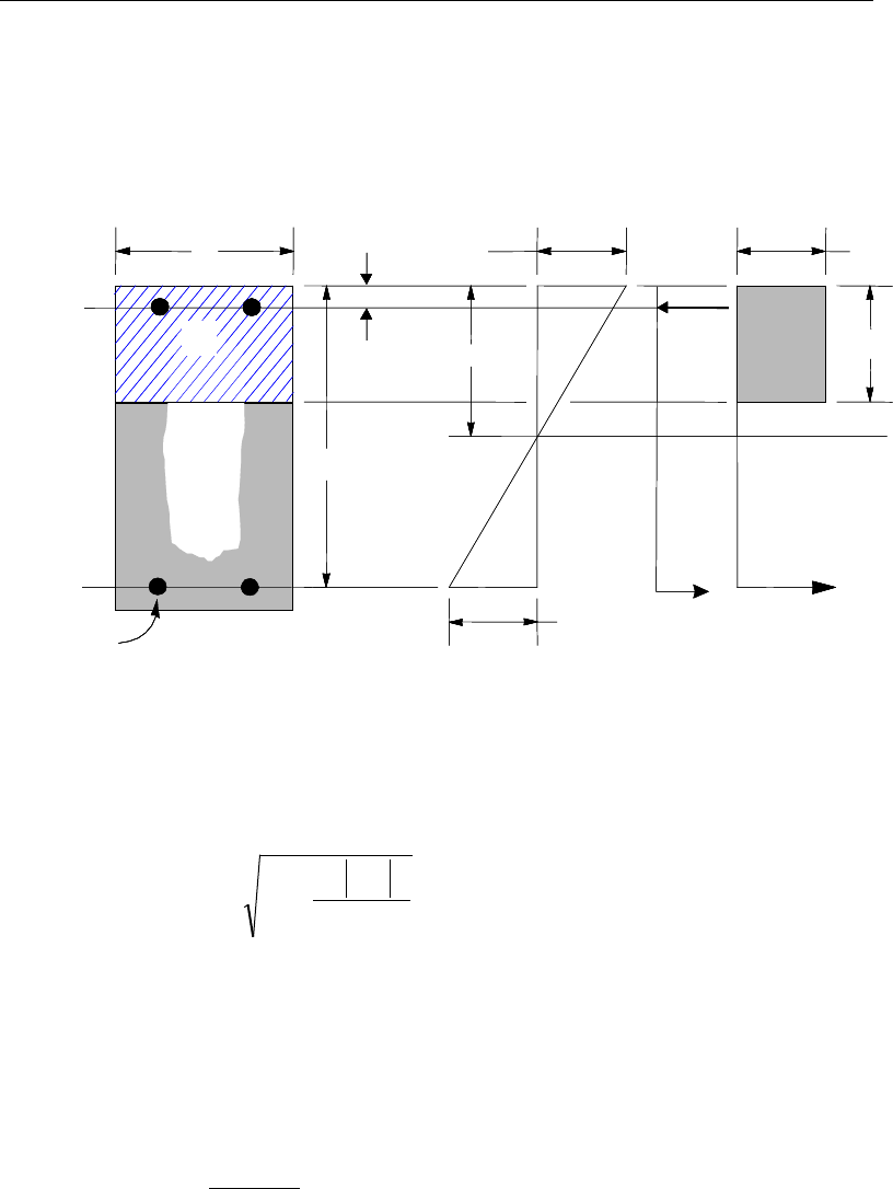
ETABS Reinforced Concrete Design
8.5.1.2.1 Design of uniform thickness slab
In designing for a factored negative or positive moment, Mf (i.e., designing top
or bottom reinforcement), the depth of the compression block is given by a (see
Figure 8-1), where,
Figure 8-1 Uniform Thickness Slab Design
bf
M
dda
cc
f
φα
'
2
1
2−−=
(CSA 10.1)
where the value of
φ
c is 0.65 (CSA 8.4.2) in the preceding and the following
equations. The parameters
α
1,
β
1, and cb are calculated as:
α1 = 0.85 – 0.0015f′c ≥ 0.67, (CSA 10.1.7)
β1 = 0.97 – 0.0025f′c ≥ 0.67, (CSA 10.1.7)
cb =
y
f+700
700
d (CSA 10.5.2)
BEAM
SECTION STRAIN
DIAGRAM STRESS
DIAGRAM
0.0035
ε
=1 cc
f
αφ
′
1
ac
β
=
cs
T
s
T
s
ε
cs
C
d′
d
b
s
A
cs
A
BEAM
SECTION STRAIN
DIAGRAM STRESS
DIAGRAM
0.0035
ε
=1 cc
f
αφ
′
1
ac
β
=
cs
T
s
T
s
ε
cs
C
d′
d
b
s
A
cs
A
8 - 8 Slab Design

Chapter 8 - Design for CSA A23.3-14
The balanced depth of the compression block is given by:
ab =
β
1cb (CSA 10.1.7)
If a ≤ ab (CSA 10.5.2), the area of tension reinforcement is given by:
−
=
2
a
df
M
A
ys
f
s
φ
This reinforcement is to be placed at the bottom if Mf is positive, or at the top
if Mf is negative.
If a > ab (CSA 10.5.2), compression reinforcement is required and is calculated
as follows:
The factored compressive force developed in the concrete alone is given by:
bcc
bafC '
1
αφ
=
(CSA 10.1.7)
and the factored moment resisted by concrete compression and tension rein-
forcement is:
Mfc = C
−2
b
a
d
Therefore, the moment required to be resisted by compression reinforcement
and tension reinforcement is:
Mfs = Mf − Mfc
The required compression reinforcement is given by:
( )( )
1
,
fs
sss c c
M
Af f dd
φ φα
′=′ ′′
−−
where
s
f′
= 0.0035 Es
−
c
dc '
≤ fy (CSA 10.1.2, 10.1.3)
Slab Design 8 - 9
ETABS Reinforced Concrete Design
The required tension reinforcement for balancing the compression in the con-
crete is:
s
b
y
fc
sa
df
M
A
φ
−
=
2
1
and the tension reinforcement for balancing the compression reinforcement is
given by:
( )
2
fs
s
ys
M
Afdd
φ
=′
−
Therefore, the total tension reinforcement, As = As1 + As2, and the total com-
pression reinforcement is A's. As is to be placed at the bottom and A's is to be
placed at the top if Mf is positive, and vice versa if Mf is negative.
8.5.1.2.2 Design of nonuniform thickness slab
8.5.1.2.2.1 Flanged Slab Section Under Negative Moment
In designing for a factored negative moment, Mf (i.e., designing top reinforce-
ment), the calculation of the reinforcement area is exactly the same as described
previously, i.e., no flanged data is used.
8.5.1.2.2.2 Flanged Slab Section Under Positive Moment
If Mf > 0, the depth of the compression block is given by:
2
1
2f
cc f
M
ad d fb
αφ
=−−
′
(CSA 10.1)
where, the value of
φ
c is 0.65 (CSA 8.4.2) in the preceding and the following
equations. The parameters
α
1,
β
1, and cb are calculated as:
α1 = 0.85 – 0.0015 f'c ≥ 0.67, (CSA 10.1.7)
β1 = 0.97 – 0.0025 f'c ≥ 0.67, (CSA 10.1.7)
8 - 10 Slab Design
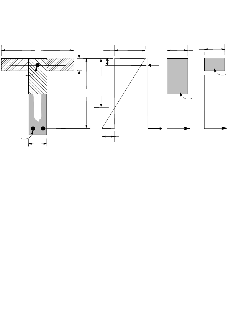
Chapter 8 - Design for CSA A23.3-14
cb =
y
f+700
700
d (CSA 10.5.2)
Figure 8-2 Nonuniform Thickness Slab Design
The balanced depth of the compression block is given by:
ab =
β
1cb (CSA 10.1.4,10.1.7)
If a ≤ hs, the subsequent calculations for As are exactly the same as previously
defined for the uniform thickness slab design. However, in this case the width
of the slab is taken as bf. Compression reinforcement is required when a > ab.
If a > hs, calculation for As has two parts. The first part is for balancing the
compressive force from the flange, Cf, and the second part is for balancing the
compressive force from the web, Cw as shown in Figure 8-2. Cf is given by:
( )
( )
1
min ,
f c f w sb
C f b b ha
α
′
= −
(CSA 10.1.7)
Therefore,
sy
cf
sf
C
A
φ
φ
=
1
and the portion of Mf that is resisted by the flange is
given by:
(I) BEAM
SECTION
s
A
(II) STRAIN
DIAGRAM
(III) STRESS
DIAGRAM
s
A′
w
b
f
b
d
d′
s
f′
0.0035
ε
=
1 cc
f
αφ
′
w
T
s
T
s
ε
f
T
f
C
w
C
s
C
s
h
c
1 cc
f
αφ
′
(I) BEAM
SECTION
s
A
(II) STRAIN
DIAGRAM
(III) STRESS
DIAGRAM
s
A′
w
b
f
b
d
d′
s
f′
0.0035
ε
=
1 cc
f
αφ
′
w
T
s
T
s
ε
f
T
f
C
w
C
s
C
s
h
c
1 cc
f
αφ
′
Slab Design 8 - 11

ETABS Reinforced Concrete Design
( )
c
bs
fff
ah
dCM
φ
−= 2
,min
Therefore, the balance of the moment, Mf to be carried by the web is:
Mfw = Mf − Mff
The web is a rectangular section with dimensions bw and d, for which the de-
sign depth of the compression block is recalculated as:
wcc
fw
bf
M
dda
φα
'
2
1
2
1
−−=
(CSA 10.1)
If a1 ≤ ab (CSA 10.5.2), the area of tension reinforcement is then given by:
21
2
fw
s
sy
M
A,
a
fd
φ
=
−
and
As = As1 + As2
This reinforcement is to be placed at the bottom of the flanged slab.
If a1 > ab (CSA 10.5.2), compression reinforcement is required and is calcu-
lated as follows:
The compressive force in the web concrete alone is given by:
bwc
cabfC '
1
αφ
=
(CSA 10.1.7)
Therefore the moment resisted by the concrete web and tension reinforcement
is:
Mfc = C
−2
b
a
d
and the moment resisted by compression and tension reinforcement is:
Mfs = Mfw − Mfc
8 - 12 Slab Design

Chapter 8 - Design for CSA A23.3-14
Therefore, the compression reinforcement is computed as:
( )
( )
'
1
,
''
fs
s
sc c c
M
Af f dd
φ φα
′=−−
where
s
f′
=
ε
cEs
cd
c
′
−
≤ fy (CSA 10.1.2, 10.1.3)
The tension reinforcement for balancing compression in the web concrete is:
s
b
y
fc
sa
df
M
A
φ
−
=
2
2
and the tension reinforcement for balancing the compression reinforcement is:
( )
3fs
sys
M
Afdd
φ
=′
−
The total tension reinforcement is As = As1 + As2 + As3, and the total compres-
sion reinforcement is A's. As is to be placed at the bottom and A's is to be placed
at the top.
8.5.1.3 Minimum and Maximum Reinforcement
The minimum flexural tensile reinforcement required for each direction of a slab
is given by the following limit (CSA 13.10.1):
As ≥ 0.002 bh (CSA 7.8.1)
In addition, an upper limit on both the tension reinforcement and compres-
sion reinforcement has been imposed to be 0.04 times the gross cross-sec-
tional area.
8.5.2 Design Slab Shear Reinforcement
The shear reinforcement is designed for each load combination at each station
along the design strip. In designing the shear reinforcement for a particular strip,
Slab Design 8 - 13
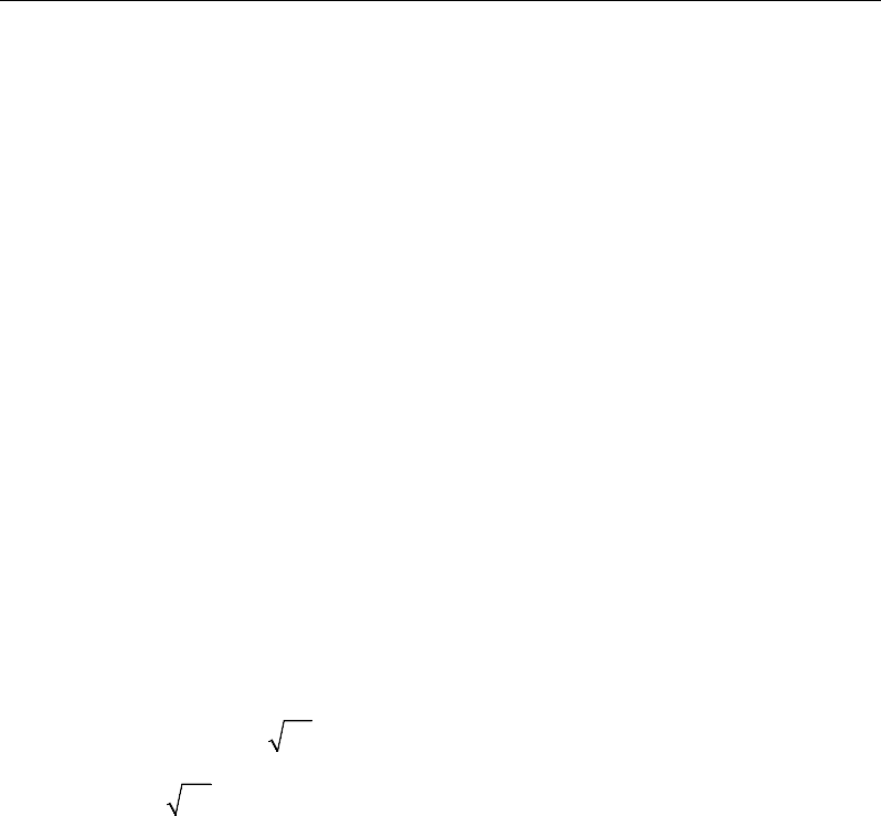
ETABS Reinforced Concrete Design
for a particular load combination, at a particular station due to the slab major
shear, the following steps are involved:
Determine the factored shear force, Vf.
Determine the shear force, Vc, that can be resisted by the concrete.
Determine the shear reinforcement required to carry the balance.
The following three subsections describe in detail the algorithms associated with
these steps.
8.5.2.1 Determine Factored Shear Force
In the design of the slab shear reinforcement, the shear forces for each load com-
bination at a particular design strip station are obtained by factoring the corre-
sponding shear forces for different load cases, with the corresponding load com-
bination factors.
8.5.2.2 Determine Concrete Shear Capacity
The shear force carried by the concrete, Vc, is calculated as:
c c cwv
V f bd
φ λβ
′
=
(CSA 11.3.4)
′
c
f
≤
8 MPa (CSA 11.3.4)
φ
c is the resistance factor for concrete. By default it is taken as 0.65 (CSA
8.4.2).
λ
is the strength reduction factor to account for low density concrete (CSA
2.2). For normal density concrete, its value is 1 (CSA 8.6.5), which is taken
by the program as the default value. For concrete using lower density aggre-
gate, the user can change the value of
λ
in the material property data. The
recommended value for
λ
is as follows (CSA 8.6.5):
8 - 14 Slab Design

Chapter 8 - Design for CSA A23.3-14
λ
=
1.00, for normal density concrete,
0.85, for semi-low-density concrete
in which all of the fine aggregate is natural sand,
0.75, for semi-low-density concrete
in which none of the fine aggregate is natural
sand.
(CSA 8.6.5)
β
is the factor for accounting for the shear resistance of cracked concrete
(CSA 2.2) and should be greater or equal to 0.05. Its value is normally be-
tween 0.1 and 0.4. It is determined according to CSA 11.3.6, and described
further in the following sections.
w
b
is the effective web width. For uniform thickness slab, it is the width of the
slab. For flanged-shaped slab, it is the width of the web of the slab.
v
d
is the effective shear depth. It is taken as the greater of 0.9d or 0.72h(CSA
2.3), where d is the distance from the extreme compression fiber to the cen-
troid of the tension reinforcement, and h is the overall depth of the cross-
section in the direction of the shear force (CSA 2.3).
The value of
β
is preferably taken as the special value (CSA 11.3.6.2) or it is
determined using the simplified method (CSA 11.3.6.3), if applicable. When the
conditions of the special value or simplified method do not apply, the general
method is used (CSA 11.3.6.4).
If the overall slab depth, h, is less than 250 mm or if the depth of a flanged below
the slab is not greater than one-half of the width of the web or 350 mm,
β
is taken
as 0.21 (CSA 11.3.6.2).
When the specified yield strength of the longitudinal reinforcing fy does not ex-
ceed 400 MPa, the specified concrete strength f'c does not exceed 60 MPa, and
the tensile force is negligible,
β
is determined in accordance with the simplified
method, as follows (CSA 11.3.6.3):
When the section contains at least the minimum transverse reinforcement,
β
is
taken as 0.18 (CSA 11.6.3.3a).
β
= 0.18 (CSA 11.3.6.3(a))
Slab Design 8 - 15

ETABS Reinforced Concrete Design
When the section contains no transverse reinforcement,
β
is determined based
on the specified maximum nominal size of coarse aggregate, ag.
For a maximum size of coarse aggregate not less than 20 mm,
β
is taken as:
230
1000
β
=+v
d
(CSA 11.3.6.3(b))
where dv is the effective shear depth expressed in millimeters.
For a maximum size of coarse aggregate less than 20 mm,
β
is taken as:
230
1000
β
=+
ze
s
(CSA 11.3.6.3 c)
where,
z
g
z
ze s
a
s
s85.0
15
35 ≥
+
=
(CSA 11.3.6.3.c)
In the preceding expression, the crack spacing parameter, sze, shall be taken as
the minimum of dv and the maximum distance between layers of distributed lon-
gitudinal reinforcement. However, sze is conservatively taken as equal to dv.
In summary, for simplified cases,
β
can be expressed as follows:
0.18, if minimum transverse reinforcement is provided,
230 , if no transverse reinforcement is provided, and 20mm,
1000
230 , if no transverse reinforcement is provided, and 20mm.
1000
g
v
g
ze
a
d
a
S
β
= ≥
+
<
+
When the specified yield strength of the longitudinal reinforcing fy is greater
than 400 MPa, the specified concrete strength f'c is greater than 60 MPa, or
tension is not negligible,
β
is determined in accordance with the general
method as follows (CSA 11.3.6.1, 11.3.6.4):
( ) ( )
0.40 1300
1 1500 1000
βε
= •
++
x ze
S
(CSA 11.3.6.4)
8 - 16 Slab Design

Chapter 8 - Design for CSA A23.3-14
In the preceding expression, the equivalent crack spacing parameter, sze is taken
equal to 300 mm if minimum transverse reinforcement is provided (CSA
11.3.6.4). Otherwise it is determined as stated in the simplified method.
300 if minimum transverse reinforcement is provided,
35 0.85 otherwise.
15
ze zz
g
SSS
a
=≥
+
(CSA 11.3.6.3, 11.3.6.4)
The value of ag in the preceding equations is taken as the maximum aggregate
size for f'c of 60 MPa, is taken as zero for f'c of 70 MPa, and linearly interpolated
between these values (CSA 11.3.6.4).
The longitudinal strain,
ε
x at mid-depth of the cross-section is computed from
the following equation:
( )
ss
ffvf
xAE
NVdM
2
5.0++
=
ε
(CSA 11.3.6.4)
In evaluating
ε
x the following conditions apply:
ε
x is positive for tensile action.
Vf and Mf are taken as positive quantities. (CSA 11.3.6.4(a))
Mf is taken as a minimum of Vfdv. (CSA 11.3.6.4(a))
Nf is taken as positive for tension. (CSA 2.3)
As is taken as the total area of longitudinal reinforcement in the slab. It is taken
as the envelope of the reinforcement required for all design load combinations.
The actual provided reinforcement might be slightly higher than this quantity.
The reinforcement should be developed to achieve full strength (CSA
11.3.6.3(b)).
If the value of
ε
x is negative, it is recalculated with the following equation, in
which Act is the area of concrete in the flexural tensile side of the slab, taken as
half of the total area.
Slab Design 8 - 17

ETABS Reinforced Concrete Design
()
ct
cs
s
f
fv
f
x
AE
A
E
NV
d
M
+
++
=2
5
.0
ε
(CSA 11.3.6.4(c))
200,000
s
E=
MPa (CSA 8.5.4.1)
'
4500
cc
Ef=
MPa (CSA 8.6.2.3)
If the axial tension is large enough to induce tensile stress in the section, the
value of
ε
x is doubled (CSA 11.3.6.4(e)).
For sections closer than dv from the face of the support,
ε
x is calculated based on
Mf and Vf at a section at a distance dv from the face of the support (CSA
11.3.6.4(d)). This condition currently is not checked by ETABS.
An upper limit on
ε
x is imposed as:
003.0≤
x
ε
(CSA 11.3.6.4(f))
In both the simplified and general methods, the shear strength of the section due
to concrete, vc depends on whether the minimum transverse reinforcement is pro-
vided. To check this condition, the program performs the design in two passes.
In the first pass, it assumes that no transverse shear reinforcement is needed.
When the program determines that shear reinforcement is required, the program
performs the second pass assuming that at least minimum shear reinforcement is
provided.
8.5.2.3 Determine Required Shear Reinforcement
The shear force is limited to
,maxr
V
where:
d
bfV wccr '25.0
max,
φ
=
(CSA 11.3.3)
Given Vf, Vc, and Vr,max, the required shear reinforcement is calculated as follows:
If
,≤
fc
VV
0=
v
A
s
(CSA 11.3.5.1)
8 - 18 Slab Design
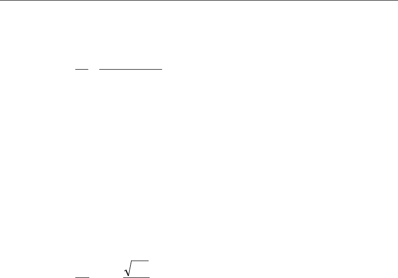
Chapter 8 - Design for CSA A23.3-14
If
,max
,<≤
cfr
VVV
( )
tan
fc
v
s yt v
VV
A
s fd
θ
φ
−
=
(CSA 11.3.3, 11.3.5.1)
If
,max ,>
fr
VV
a failure condition is declared. (CSA 11.3.3)
A minimum area of shear reinforcement is provided in the following regions
(CSA 11.2.8.1):
(a) in regions of flexural members where the factored shear force Vf exceeds
Vc
(b) in regions of slab with an overall depth greater than 750 mm.
Where the minimum shear reinforcement is required by CSA 11.2.8.1, or by cal-
culation, the minimum area of shear reinforcement per unit spacing is taken as:
w
yt
c
v
b
f
f
s
A'
06.0≥
(CSA 11.2.8.2)
In the preceding equations, the term
θ
is used, where
θ
is the angle of inclination
of the diagonal compressive stresses with respect to the longitudinal axis of the
member (CSA 2.3). The
θ
value is normally between 22 and 44 degrees. It is
determined according to CSA 11.3.6.
Similar to the
β
factor, which was described previously, the value of
θ
is prefer-
ably taken as the special value (CSA 11.3.6.2), or it is determined using the sim-
plified method (CSA 11.3.6.3), whenever applicable. The program uses the gen-
eral method when conditions for the simplified method are not satisfied (CSA
11.3.6.4).
If the overall slab depth, h, is less than 250 mm or if the depth of the
flanged slab below the slab is not greater than one-half of the width of the web
or 350 mm,
θ
is taken as 42 degrees (CSA 11.3.6.2).
If the specified yield strength of the longitudinal reinforcing fy does not exceed
400 MPa, or the specified concrete strength f'c does not exceed 60 MPa,
θ
is
taken to be 35 degree (CSA 11.3.6.3).
Slab Design 8 - 19

ETABS Reinforced Concrete Design
o
35
θ
=
for
0≤
f
P
or
400≤
y
f
MPa or f'c ≤ 60 MPa (CSA11.3.6.3)
If the axial force is tensile, the specified yield strength of the longitudinal re-
inforcing fy > 400 MPa, and the specified concrete strength f'c > 60 MPa,
θ
is
determined using the general method as follows (CSA 11.3.6.4),
29 7000
θε
= + x
for
0,<
f
P
>
y
f
400 MPa, f'c ≤ 60 MPa (CSA11.3.6.4)
where
ε
x is the longitudinal strain at the mid-depth of the cross-section for the
factored load. The calculation procedure is described in preceding sections.
The maximum of all of the calculated Av
/s values obtained from each load com-
bination is reported along with the controlling shear force and associated load
combination.
The slab shear reinforcement requirements considered by the program are based
purely on shear strength considerations. Any minimum stirrup requirements to
satisfy spacing and volumetric considerations must be investigated inde-
pendently of the program by the user.
8.5.3 Check for Punching Shear
The algorithm for checking punching shear is detailed in the section entitled
“Slab Punching Shear Check” in the Chapter 1. Only the code-specific items are
described in the following sections.
8.5.3.1 Critical Section for Punching Shear
The punching shear is checked on a critical section at a distance of d/2 from the
face of the support (CSA 13.3.3.1 and CSA 13.3.3.2). For rectangular columns
and concentrated loads, the critical area is taken as a rectangular area with the
sides parallel to the sides of the columns or the point loads (CSA 13.3.3.3). Fig-
ure 8-3 shows the auto punching perimeters considered by ETABS for the vari-
ous column shapes. The column location (i.e., interior, edge, corner) and the
punching perimeter may be overwritten using the Punching Check Overwrites.
8 - 20 Slab Design
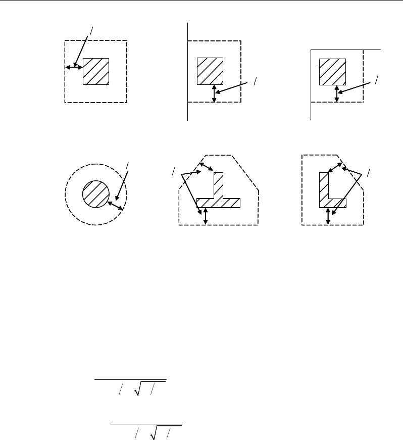
Chapter 8 - Design for CSA A23.3-14
Figure 8-3 Punching Shear Perimeters
8.5.3.2 Transfer of Unbalanced Moment
The fraction of unbalanced moment transferred by flexure is taken to be γf Mu
and the fraction of unbalanced moment transferred by eccentricity of shear is
taken to be γv Mu, where
γf =
( )
12
1,
1 23 bb+
and (CSA 13.10.2)
γv = 1−
( )
12
1,
1 23 bb+
(CSA 13.3.5.3)
where b1 is the width of the critical section measured in the direction of the span,
and b2 is the width of the critical section measured in the direction perpendicular
to the span.
8.5.3.3 Determination of Concrete Capacity
The concrete punching shear factored strength is taken as the minimum of the
following three limits:
d2
Interior Column
Circular Column
d2 d2
d2
T-Shape Column
Edge Column Corner Column
L-Shape Column
d2
d2
d2
Interior Column
Circular Column
d2 d2
d2
T-Shape Column
Edge Column Corner Column
L-Shape Column
d2
d2
Slab Design 8 - 21
ETABS Reinforced Concrete Design
0
2
1 0 19
min 0 19
0 38
cc
c
s
vc c
cc
.f
d
v.f
b
.f
φλ
β
α
φλ
φλ
′
+
′
= +
′
(CSA 13.3.4.1)
where,
β
c is the ratio of the minimum to the maximum dimensions of the critical
section, b0 is the perimeter of the critical section, and αs is a scale factor based
on the location of the critical section.
α
=
4, for interior columns
3, for edge colums, and
2, for corner columns.
s
(CSA 13.3.4.1(b))
The value of
c
f'
is limited to 8 MPa for the calculation of the concrete shear
capacity (CSA 13.3.4.2).
If the effective depth, d, exceeds 300 mm, the value of vc is reduced by a factor
equal to 1300/(1000 + d) (CSA 13.3.4.3).
8.5.3.4 Determine Maximum Shear Stress
Given the punching shear force and the fractions of moments transferred by ec-
centricity of shear about the two axes, the shear stress is computed assuming
linear variation along the perimeter of the critical section.
22 3 1 33 4 3 23 4 3
2
022 33 23
33 3 1 22 4 3 23 4 3
2
22 33 23
[ ( )][ ( ) ( )]
[ ( )][ ( ) ( )]
γ
γ
− − −− −
=+−
−
− − −− −
−
V
f ff
f
Vff
V M Vy y I y y I x x
vbd I I I
M VxxIxx Iyy
II I
Eq. 1
22 22
1
,
=
=∑
n
sides
II
where "sides" refers to the sides of the critical
section for punching shear Eq. 2
8 - 22 Slab Design
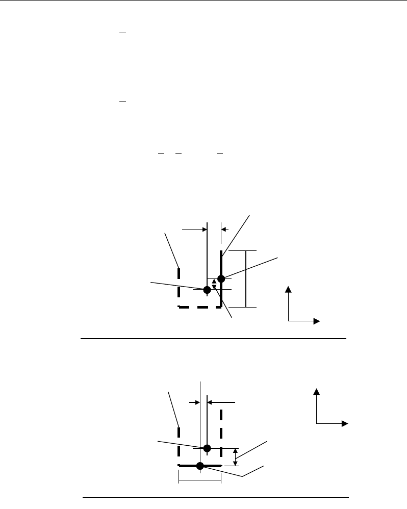
Chapter 8 - Design for CSA A23.3-14
33 33
1
,
=
=∑
n
sides
II
where "sides" refers to the sides of the critical
section for punching shear Eq. 3
23 23
1
,
=
=∑
n
sides
II
where "sides" refers to the sides of the critical
section for punching shear Eq. 4
The equations for
22 33
,,II
and
23
I
are different depending on whether the
side of the critical section for punching shear being considered is parallel
to the 2-axis or parallel to the 3-axis. Refer to Figures 8-4.
Figure 8-4 Shear Stress Calculations at Critical Sections
Plan View For Side of Critical Section Parallel to 3-Axis
y
2
- y
3
L
Critical section for
punching shear
shown by heavy line
2
3
Side of critical section
being considered
shown solid
Center of side of critical
section being considered.
Coordinates are (x
2
,y
2
).
Work This Sketch With Equations 5b, 6b and
7
Centroid
of entire
critical section for
punching shear.
Coordinates are (x
3
,y
3
).
x
2
- x
3
y
2
- y
3
L
Critical section for
punching shear shown
by heavy line. Side of
critical section being
considered shown solid
2
3
Center of side of critical
section being considered.
Coordinates are (x
2
,y
2
).
Plan View For Side of Critical Section Parallel to 2-Axis
Work This Sketch With Equations 5a, 6a and
7
Centroid
of entire
critical section for
punching shear.
Coordinates are (x
3
,y
3
).
x
2
- x
3
Slab Design 8 - 23

ETABS Reinforced Concrete Design
2
22 2 3
( ),= −I Ld y y
for side of critical section parallel to 2-axis Eq. 5a
33 2
22 2 3
( ),
12 12
= ++ −
Ld dL
I Ld y y
for side of critical section
parallel to 3-axis Eq. 5b
33 2
33 2 3
( ),
12 12
= ++ −
Ld dL
I Ld x x
for side of critical section
parallel to 2-axis Eq. 6a
2
33 2 3
( ),
= −I Ld x x
for side of critical section parallel to 3-axis Eq. 6b
23 2 3 2 3
( )( ),=−−
I Ld x x y y
for side of critical section parallel
to 2-axis or 3-axis Eq. 7
NOTE:
23
I
is explicitly set to zero for corner condition.
where,
b0 = Perimeter of the critical section for punching shear
d = Effective depth at the critical section for punching shear based on the
average of d for 2 direction and d for 3 direction
I22 = Moment of inertia of the critical section for punching shear about an axis
that is parallel to the local 2-axis
I33 = Moment of inertia of the critical section for punching shear about an axis
that is parallel to the local 3-axis
I23 = Product of inertia of the critical section for punching shear with respect
to the 2 and 3 planes
L = Length of the side of the critical section for punching shear currently
being considered
Mf2 = Moment about the line parallel to the 2-axis at the center of the column
(positive in accordance with the right-hand rule)
8 - 24 Slab Design

Chapter 8 - Design for CSA A23.3-14
Mf3 = Moment about the line parallel to the 3-axis at the center of the column
(positive in accordance with the right-hand rule)
Vf = Punching shear stress
Vf = Shear at the center of the column (positive upward)
x1, y1 = Coordinates of the column centroid
x2, y2 = Coordinates of the center of one side of the critical section for punching
shear
x3, y3 = Coordinates of the centroid of the critical section for punching shear
x4, y4 = Coordinates of the location where stress is being calculated
γ
V2 = Percent of Mf2 resisted by shear
γ
V3 = Percent of Mf3 resisted by shear
8.5.3.5 Determine Capacity Ratio
The ratio of the maximum shear stress and the concrete punching shear stress
capacity is reported as the punching shear capacity ratio by ETABS. If this ratio
exceeds 1.0, punching shear reinforcement is designed as described in the fol-
lowing section.
8.5.4 Design Punching Shear Reinforcement
The use of shear studs as shear reinforcement in slabs is permitted, provided that
the effective depth of the slab is greater than or equal to 200 mm (CSA 13.2.1).
If the slab thickness does not meet these requirements, the punching shear rein-
forcement is not designed, and the slab thickness should be increased by the user.
The algorithm for designing the required punching shear reinforcement is used
when the punching shear capacity ratio exceeds unity. The Critical Section for
Punching Shear and Transfer of Unbalanced Moment as described in the earlier
sections remain unchanged. The design of punching shear reinforcement is per-
formed as explained in the subsections that follow.
Slab Design 8 - 25
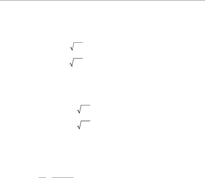
ETABS Reinforced Concrete Design
8.5.4.1 Determine Concrete Shear Capacity
The concrete punching shear stress capacity of a section with punching shear
reinforcement is taken as:
ccc
fv '28.0
λφ
=
for shear studs (CSA 13.3.8.3)
0.19 '
c cc
vf
λφ
=
for shear stirrups (CSA 13.3.9.3)
8.5.4.2 Determine Required Shear Reinforcement
The shear force is limited to a maximum of
,max ,
r
v
where
,max 0.75 '
r cc
vf
λφ
=
for shear studs (CSA 13.3.8.2)
,max 0.55 '
r cc
vf
λφ
=
for shear stirrups (CSA 13.3.9.2)
Given vf, vc, and vf,,max, the required shear reinforcement is calculated as follows,
where,
φ
s, is the strength reduction factor.
If vf > vr,max,
( )
fc
vo
s yv
vv
Ab
sf
φ
−
=
(CSA 13.3.8.5, 13.3.9.4)
If vf > vr,max, a failure condition is declared. (CSA 13.3.8.2)
If vf exceeds the maximum permitted value of vrmax, the concrete section should
be increased in size.
8.5.4.3 Determine Reinforcement Arrangement
Punching shear reinforcement in the vicinity of rectangular columns should be
arranged on peripheral lines, i.e., lines running parallel to and at constant dis-
tances from the sides of the column. Figure 8-5 shows a typical arrangement of
shear reinforcement in the vicinity of a rectangular interior, edge, and corner
column.
8 - 26 Slab Design

Chapter 8 - Design for CSA A23.3-14
Figure 8-5 Typical arrangement of shear studs
and critical sections outside shear-reinforced zone
The distance between the column face and the first line of shear reinforcement
shall not exceed
0.4d for shear studs (CSA 13.3.8.6)
0.25d for shear stirrups (CSA 13.3.8.6)
Punching shear reinforcement is most effective near column corners where there
are concentrations of shear stress. Therefore, the minimum number of lines of
shear reinforcement is 4, 6, and 8, for corner, edge, and interior columns respec-
tively.
8.5.4.4 Determine Reinforcement Diameter, Height, and Spacing
The punching shear reinforcement is most effective when the anchorage is close
to the top and bottom surfaces of the slab. The cover of anchors should not be
less than the minimum cover specified in CSA 7.9 plus half of the diameter of
the flexural reinforcement.
When specifying shear studs, the distance, so, between the column face and the
first peripheral line of shear studs should not be smaller than 0.45d to 0.4d. The
limits of so and the spacing, s, between the peripheral lines are specified as:
0.4
o
sd≤
(CSA 13.3.8.6)
I
y
Typical Studrail
(only first and last
studs shown)
Outermost
peripheral line
of studs
Interior Column Edge Column Corner Column
Critical section
centroid
Free
edge
Free
edge
Critical
section
centroid
Free edge
Outermost
peripheral line
of studs
I
y
I
y
yx
d2 d2
d2
x
I
x
I
x
g
y
g
x
g
0
s0
s
0
s
x
I
y
x
x
I
y
Typical Studrail
(only first and last
studs shown)
Outermost
peripheral line
of studs
Interior Column Edge Column Corner Column
Critical section
centroid
Free
edge
Free
edge
Critical
section
centroid
Free edge
Outermost
peripheral line
of studs
I
y
I
y
yx
d2 d2
d2
x
I
x
I
x
g
y
g
x
g
0
s0
s
0
s
x
I
y
x
x
Slab Design 8 - 27

ETABS Reinforced Concrete Design
0.75 0.56 '
0.50 0.56 '
f cc
f cc
dv f
sdv f
λφ
λφ
≤
≤>
(CSA 13.3.8.6)
For shear stirrups,
≤0.25
o
sd
(CSA 13.3.9.5)
≤0.25sd
(CSA 13.3.9.5)
The minimum depth for reinforcement should be limited to 300 mm (CSA
13.3.9.1).
8 - 28 Slab Design

Chapter 9
Design for CSA A23.3-04
This chapter describes in detail the various aspects of the concrete design proce-
dure that is used by ETABS when the Canadian code CSA A23.3-04 [CSA 04]
is selected. Various notations used in this chapter are listed in Table 9-1. For
referencing to the pertinent sections of the Canadian code in this chapter, a prefix
“CSA” followed by the section number is used.
The design is based on user-specified load combinations. The program provides
a set of default load combinations that should satisfy the requirements for the
design of most building type structures.
English as well as SI and MKS metric units can be used for input. The code is
based on Newton-millimeter-second units. For simplicity, all equations and de-
scriptions presented in this chapter correspond to Newton-millimeter-second
units unless otherwise noted.
9.1 Notations
Table 9-1 List of Symbols Used in the CSA A23.3-04 Code
A
c
Area enclosed by outside perimeter of concrete cross-section, sq-
mm
A
ct
Area of concrete on flexural tension side, sq-mm
Notations 9 - 1

ETABS Reinforced Concrete Design
Table 9-1 List of Symbols Used in the CSA A23.3-04 Code
A
l
Area of longitudinal reinforcement for torsion, sq-mm
A
o
Gross area enclosed by shear flow path, sq-mm
A
oh
Area enclosed by centerline of outermost closed transverse tor-
sional reinforcement, sq-mm
A
s
Area of tension reinforcement, sq-mm
A'
s
Area of compression reinforcement, sq-mm
A
s(required)
Area of steel required for tension reinforcement, sq-mm
A
t
/s
Area of closed shear reinforcement for torsion per unit length, sq-
mm/mm
A
v
Area of shear reinforcement, sq-mm
A
v
/s
Area of shear reinforcement per unit length, sq-mm/mm
a
Depth of compression block, mm
a
b
Depth of compression block at balanced condition, mm
b
Width of member, mm
b
f
Effective width of flange (flanged section), mm
b
w
Width of web (flanged section), mm
b
0
Perimeter of the punching critical section, mm
b
1
Width of the punching critical section in the direction of bending,
mm
b
2
Width of the punching critical section perpendicular to the direc-
tion of bending, mm
c
Depth to neutral axis, mm
c
b
Depth to neutral axis at balanced conditions, mm
d
Distance from compression face to tension reinforcement, mm
d
v
Effective shear depth, mm
d'
Distance from compression face to compression reinforcement,
mm
h
s
Thickness of slab (flanged section), mm
E
c
Modulus of elasticity of concrete, MPa
9 - 2 Notations

Chapter 9 - Design for CSA A23.3-04
Table 9-1 List of Symbols Used in the CSA A23.3-04 Code
E
s
Modulus of elasticity of reinforcement, assumed as 200,000 MPa
f '
c
Specified compressive strength of concrete, MPa
f '
s
Stress in the compression reinforcement, psi
f
y
Specified yield strength of flexural reinforcement, MPa
f
yt
Specified yield strength of shear reinforcement, MPa
h
Overall depth of a section, mm
I
g
Moment of inertia of gross concrete section about centroidal axis,
neglecting reinforcement.
M
f
Factored moment at section, N-mm
N
f
Factored axial force at section, N
p
c
Outside perimeter of concrete cross-section, mm
p
h
Perimeter of area A
oh
, mm
s
Spacing of the shear reinforcement along the strip, mm
s
z
Crack spacing parameter
T
f
Factored torsion at section, N-mm
V
c
Shear resisted by concrete, N
V
r,max
Maximum permitted total factored shear force at a section, N
V
f
Factored shear force at a section, N
V
s
Shear force at a section resisted by steel, N
α
1
Ratio of average stress in rectangular stress block to the specified
concrete strength
β
Factor accounting for shear resistance of cracked concrete
β
1
Factor for obtaining depth of compression block in concrete
β
c
Ratio of the maximum to the minimum dimensions of the punch-
ing critical section
ε
c
Strain in concrete
ε
s
Strain in reinforcing steel
ε
x
Longitudinal strain at mid-depth of the section
Notations 9 - 3

ETABS Reinforced Concrete Design
Table 9-1 List of Symbols Used in the CSA A23.3-04 Code
φ
c
Strength reduction factor for concrete
φ
s
Strength reduction factor for steel
φ
m
Strength reduction factor for member
γ
f
Fraction of unbalanced moment transferred by flexure
γ
v
Fraction of unbalanced moment transferred by eccentricity of
shear
θ
Angle of diagonal compressive stresses, degrees
λ
Shear strength factor
9.2 Design Load Combinations
The design load combinations are the various combinations of the load cases for
which the structure needs to be designed. For CSA A23.3-04, if a structure is
subjected to dead (D), live (L), pattern live (PL), snow (S), wind (W), and earth-
quake (E) loads, and considering that wind and earthquake forces are reversible,
the following load combinations may need to be considered (CSA 8.3.2, Table
C.1)
1.4D
(CSA 8.3.2, Table C.1 Case 1)
1.25D + 1.5L
1.25D + 1.5L + 0.5S
1.25D + 1.5L
± 0.4W
0.9
D + 1.5L
0.9D + 1.5L + 0.5S
0.9D + 1.5L
± 0.4W
(CSA 8.3.2, Table C.1 Case 2
)
1.25D + 1.5(0.75 PL)
(CSA 13.8.4.3)
1.25D + 1.5S
1.2
5D + 1.5S + 0.5L
1.25D + 1.5S
± 0.4W
0.9D + 1.5S
0.9
D + 1.5S + 0.5L
0.9D + 1.5S
± 0.4W
(CSA 8.3.2, Table C.1 Case 3
)
9 - 4 Design Load Combinations

Chapter 9 - Design for CSA A23.3-04
1.25D ± 1.4W
1.2
5D + 0.5L ± 1.4W
1.25D + 0.5S
± 1.4W
0.9D
± 1.4W
0.9
D + 0.5L ± 1.4W
0.9D + 0.5S
± 1.4W
(CSA 8.3.2, Table C.1 Case 4
)
1.0D ± 1.0E
1.0D + 0.5L
± 1.0E
1.0D + 0.
25S ± 1.0E
1.0D + 0.5L + 0.
25S ± 1.0E
(CSA 8.3.2, Table C.1 Case 5
)
These are also the default design load combinations in ETABS whenever the
CSA A23.3-04 code is used. If roof live load is treated separately or other types
of loads are present, other appropriate load combinations should be used.
9.3 Limits on Material Strength
The upper and lower limits of f'c are 80 MPa and 20 MPa, respectively, for all
framing types (CSA 8.6.1.1).
20 MPa ≤ f'c ≤ 80 MPa (CSA 8.6.1.1)
The upper limit of fy is 500 MPa for all frames (CSA 8.5.1).
fy ≤ 500 MPa (CSA 8.5.1)
ETABS enforces the upper material strength limits for flexure and shear design
slabs. The input material strengths are taken as the upper limits if they are de-
fined in the material properties as being greater than the limits. The user is re-
sponsible for ensuring that the minimum strength is satisfied.
9.4 Strength Reduction Factors
The strength reduction factors,
φ
, are material dependent and defined as:
φ
c = 0.65 for concrete (CSA 8.4.2)
φ
s = 0.85 for reinforcement (CSA 8.4.3a)
Limits on Material Strength 9 - 5

ETABS Reinforced Concrete Design
These values can be overwritten; however, caution is advised.
9.5 Slab Design
ETABS slab design procedure involves defining sets of strips in two mutually
perpendicular directions. The locations of the strips are usually governed by the
locations of the slab supports. The axial force, moments and shears for a partic-
ular strip are recovered from the analysis (on the basis of the Wood-Armer tech-
nique), and a flexural design is carried out based on the ultimate strength design
method.
The slab design procedure involves the following steps:
Design flexural reinforcement
Design shear reinforcement
Punching check
9.5.1 Design Flexural Reinforcement
For slabs, ETABS uses either design strips or the finite element based design to
calculate the slab flexural reinforcement in accordance with the selected design
code. For simplicity, only strip-by-strip design is document in the proceeding
sections.
The design of the slab reinforcement for a particular strip is carried out at specific
locations along the length of the strip. These locations correspond to the element
boundaries. Controlling reinforcement is computed on either side of those ele-
ment boundaries. The slab flexural design procedure for each load combination
involves the following:
Determine factored axial loads and moments for each slab strip.
Design flexural reinforcement for the strip.
These two steps, described in the text that follows, are repeated for every load
combination. The maximum reinforcement calculated for the top and bottom
of the slab within each design strip, along with the corresponding controlling
load combination, is obtained and reported.
9 - 6 Slab Design

Chapter 9 - Design for CSA A23.3-04
9.5.1.1 Determine Factored Moments
In the design of flexural reinforcement of concrete slab, the factored moments
for each load combination at a particular design strip are obtained by factoring
the corresponding moments for different load cases, with the corresponding load
factors.
The slab is then designed for the maximum positive and maximum negative fac-
tored moments obtained from all of the load combinations. Calculation of bottom
reinforcement is based on positive design strip moments. In such cases, the slab
may be designed as a rectangular or flanged slab section. Calculation of top re-
inforcement is based on negative design strip moments. In such cases, the slab
may be designed as a rectangular or inverted flanged slab section.
9.5.1.2 Determine Required Flexural Reinforcement
In the flexural reinforcement design process, the program calculates both the
tension and compression reinforcement. Compression reinforcement is added
when the applied design moment exceeds the maximum moment capacity of a
singly reinforced section. The user has the option of avoiding compression rein-
forcement by increasing the effective depth, the width, or the strength of the
concrete.
The design procedure is based on the simplified rectangular stress block shown
in Figure 9-1 (CSA 10.1.7). Furthermore, it is assumed that the compression car-
ried by the concrete is less than or equal to that which can be carried at the bal-
anced condition (CSA 10.1.4). When the applied moment exceeds the moment
capacity at the balanced condition, the area of compression reinforcement is cal-
culated assuming that the additional moment will be carried by compression and
additional tension reinforcement.
The design procedure used by ETABS, for both rectangular and flanged sections
(L- and T-shaped sections), is summarized in the text that follows. For reinforced
concrete design where design ultimate axial compression load does not ex-
ceed (0.1 f'c Ag), axial force is ignored; hence, all slabs are designed for major
direction flexure, shear, and torsion only. Axial compression greater than 0.1 f'c
Ag and axial tensions are always included in flexural and shear design.
Slab Design 9 - 7

ETABS Reinforced Concrete Design
9.5.1.2.1 Design of uniform thickness slab
In designing for a factored negative or positive moment, Mf (i.e., designing top
or bottom reinforcement), the depth of the compression block is given by a (see
Figure 9-1), where,
Figure 9-1 Uniform Thickness Slab Design
bf
M
dda
cc
f
φα
'
2
1
2−−=
(CSA 10.1)
where the value of
φ
c is 0.65 (CSA 8.4.2) in the preceding and the following
equations. The parameters
α
1,
β
1, and cb are calculated as:
α1 = 0.85 – 0.0015f′c ≥ 0.67, (CSA 10.1.7)
β1 = 0.97 – 0.0025f′c ≥ 0.67, (CSA 10.1.7)
cb =
y
f+700
700
d (CSA 10.5.2)
BEAM
SECTION STRAIN
DIAGRAM STRESS
DIAGRAM
0.0035
ε
=1 cc
f
αφ
′
1
ac
β
=
cs
T
s
T
s
ε
cs
C
d′
d
b
s
A
cs
A
BEAM
SECTION STRAIN
DIAGRAM STRESS
DIAGRAM
0.0035
ε
=1 cc
f
αφ
′
1
ac
β
=
cs
T
s
T
s
ε
cs
C
d′
d
b
s
A
cs
A
9 - 8 Slab Design

Chapter 9 - Design for CSA A23.3-04
The balanced depth of the compression block is given by:
ab =
β
1cb (CSA 10.1.7)
If a ≤ ab (CSA 10.5.2), the area of tension reinforcement is given by:
−
=
2
a
df
M
A
ys
f
s
φ
This reinforcement is to be placed at the bottom if Mf is positive, or at the top
if Mf is negative.
If a > ab (CSA 10.5.2), compression reinforcement is required and is calculated
as follows:
The factored compressive force developed in the concrete alone is given by:
bcc
bafC '
1
αφ
=
(CSA 10.1.7)
and the factored moment resisted by concrete compression and tension rein-
forcement is:
Mfc = C
−2
b
a
d
Therefore, the moment required to be resisted by compression reinforcement
and tension reinforcement is:
Mfs = Mf − Mfc
The required compression reinforcement is given by:
( )( )
1
,
fs
sss c c
M
Af f dd
φ φα
′=′ ′′
−−
where
s
f′
= 0.0035 Es
−
c
dc '
≤ fy (CSA 10.1.2, 10.1.3)
Slab Design 9 - 9

ETABS Reinforced Concrete Design
The required tension reinforcement for balancing the compression in the con-
crete is:
s
b
y
fc
sa
df
M
A
φ
−
=
2
1
and the tension reinforcement for balancing the compression reinforcement is
given by:
( )
2
fs
s
ys
M
Afdd
φ
=′
−
Therefore, the total tension reinforcement, As = As1 + As2, and the total com-
pression reinforcement is A's. As is to be placed at the bottom and A's is to be
placed at the top if Mf is positive, and vice versa if Mf is negative.
9.5.1.2.2 Design of nonuniform thickness slab
9.5.1.2.2.1 Flanged Slab Section Under Negative Moment
In designing for a factored negative moment, Mf (i.e., designing top reinforce-
ment), the calculation of the reinforcement area is exactly the same as described
previously, i.e., no flanged data is used.
9.5.1.2.2.2 Flanged Slab Section Under Positive Moment
If Mf > 0, the depth of the compression block is given by:
2
1
2f
cc f
M
ad d fb
αφ
=−−
′
(CSA 10.1)
where, the value of
φ
c is 0.65 (CSA 8.4.2) in the preceding and the following
equations. The parameters
α
1,
β
1, and cb are calculated as:
α1 = 0.85 – 0.0015 f'c ≥ 0.67, (CSA 10.1.7)
β1 = 0.97 – 0.0025 f'c ≥ 0.67, (CSA 10.1.7)
9 - 10 Slab Design

Chapter 9 - Design for CSA A23.3-04
cb =
y
f+700
700
d (CSA 10.5.2)
Figure 9-2 Nonuniform Thickness Slab Design
The balanced depth of the compression block is given by:
ab =
β
1cb (CSA 10.1.4,10.1.7)
If a ≤ hs, the subsequent calculations for As are exactly the same as previously
defined for the uniform thickness slab design. However, in this case the width
of the slab is taken as bf. Compression reinforcement is required when a > ab.
If a > hs, calculation for As has two parts. The first part is for balancing the
compressive force from the flange, Cf, and the second part is for balancing the
compressive force from the web, Cw as shown in Figure 9-2. Cf is given by:
( )
( )
1
min ,
f c f w sb
C f b b ha
α
′
= −
(CSA 10.1.7)
Therefore,
sy
cf
sf
C
A
φ
φ
=
1
and the portion of Mf that is resisted by the flange is
given by:
(I) BEAM
SECTION
s
A
(II) STRAIN
DIAGRAM
(III) STRESS
DIAGRAM
s
A′
w
b
f
b
d
d′
s
f′
0.0035
ε
=
1 cc
f
αφ
′
w
T
s
T
s
ε
f
T
f
C
w
C
s
C
s
h
c
1 cc
f
αφ
′
(I) BEAM
SECTION
s
A
(II) STRAIN
DIAGRAM
(III) STRESS
DIAGRAM
s
A′
w
b
f
b
d
d′
s
f′
0.0035
ε
=
1 cc
f
αφ
′
w
T
s
T
s
ε
f
T
f
C
w
C
s
C
s
h
c
1 cc
f
αφ
′
Slab Design 9 - 11
ETABS Reinforced Concrete Design
( )
c
bs
fff
ah
dCM
φ
−= 2
,min
Therefore, the balance of the moment, Mf to be carried by the web is:
Mfw = Mf − Mff
The web is a rectangular section with dimensions bw and d, for which the de-
sign depth of the compression block is recalculated as:
wcc
fw
bf
M
dda
φα
'
2
1
2
1
−−=
(CSA 10.1)
If a1 ≤ ab (CSA 10.5.2), the area of tension reinforcement is then given by:
21
2
fw
s
sy
M
A,
a
fd
φ
=
−
and
As = As1 + As2
This reinforcement is to be placed at the bottom of the flanged slab.
If a1 > ab (CSA 10.5.2), compression reinforcement is required and is calcu-
lated as follows:
The compressive force in the web concrete alone is given by:
bwc
cabfC '
1
αφ
=
(CSA 10.1.7)
Therefore the moment resisted by the concrete web and tension reinforcement
is:
Mfc = C
−2
b
a
d
and the moment resisted by compression and tension reinforcement is:
Mfs = Mfw − Mfc
9 - 12 Slab Design

Chapter 9 - Design for CSA A23.3-04
Therefore, the compression reinforcement is computed as:
( )
( )
'
1
,
''
fs
s
sc c c
M
Af f dd
φ φα
′=−−
where
s
f′
=
ε
cEs
cd
c
′
−
≤ fy (CSA 10.1.2, 10.1.3)
The tension reinforcement for balancing compression in the web concrete is:
s
b
y
fc
sa
df
M
A
φ
−
=
2
2
and the tension reinforcement for balancing the compression reinforcement is:
( )
3fs
sys
M
Afdd
φ
=′
−
The total tension reinforcement is As = As1 + As2 + As3, and the total compres-
sion reinforcement is A's. As is to be placed at the bottom and A's is to be placed
at the top.
9.5.1.3 Minimum and Maximum Reinforcement
The minimum flexural tensile reinforcement required for each direction of a slab
is given by the following limit (CSA 13.10.1):
As ≥ 0.002 bh (CSA 7.8.1)
In addition, an upper limit on both the tension reinforcement and compression
reinforcement has been imposed to be 0.04 times the gross cross-sectional
area.
9.5.2 Design Slab Shear Reinforcement
The shear reinforcement is designed for each load combination at each station
along the design strip. In designing the shear reinforcement for a particular strip,
Slab Design 9 - 13
ETABS Reinforced Concrete Design
for a particular load combination, at a particular station due to the slab major
shear, the following steps are involved:
Determine the factored shear force, Vf.
Determine the shear force, Vc, that can be resisted by the concrete.
Determine the shear reinforcement required to carry the balance.
The following three subsections describe in detail the algorithms associated with
these steps.
9.5.2.1 Determine Concrete Shear Capacity
The shear force carried by the concrete, Vc, is calculated as:
c c cwv
V f bd
φ λβ
′
=
(CSA 11.3.4)
′
c
f
≤
8 MPa (CSA 11.3.4)
φ
c is the resistance factor for concrete. By default it is taken as 0.65 (CSA
8.4.2).
λ
is the strength reduction factor to account for low density concrete (CSA
2.2). For normal density concrete, its value is 1 (CSA 8.6.5), which is taken
by the program as the default value. For concrete using lower density aggre-
gate, the user can change the value of
λ
in the material property data. The
recommended value for
λ
is as follows (CSA 8.6.5):
λ
=
1.00, for normal density concrete,
0.85, for semi-low-density concrete
in which all of the fine aggregate is natural sand,
0.75, for semi-low-density concrete
in which none of the fine aggregate is natural
sand.
(CSA 8.6.5)
β
is the factor for accounting for the shear resistance of cracked concrete
(CSA 2.2). Its value is normally between 0.1 and 0.4. It is determined
according to CSA 11.3.6, and described further in the following sections.
9 - 14 Slab Design

Chapter 9 - Design for CSA A23.3-04
w
b
is the effective web width. For uniform thickness slab, it is the width of the
slab. For flanged-shaped slab, it is the width of the web of the slab.
v
d
is the effective shear depth. It is taken as the greater of 0.9d or 0.72h(CSA
2.3), where d is the distance from the extreme compression fiber to the cen-
troid of the tension reinforcement, and h is the overall depth of the cross-
section in the direction of the shear force (CSA 2.3).
The value of
β
is preferably taken as the special value (CSA 11.3.6.2) or it is
determined using the simplified method (CSA 11.3.6.3), if applicable. When the
conditions of the special value or simplified method do not apply, the general
method is used (CSA 11.3.6.4).
If the overall slab depth, h, is less than 250 mm or if the depth of a flanged below
the slab is not greater than one-half of the width of the web or 350 mm,
β
is taken
as 0.21 (CSA 11.3.6.2).
When the specified yield strength of the longitudinal reinforcing fy does not ex-
ceed 400 MPa, the specified concrete strength f'c does not exceed 60 MPa, and
the tensile force is negligible,
β
is determined in accordance with the simplified
method, as follows (CSA 11.3.6.3):
When the section contains at least the minimum transverse reinforcement,
β
is
taken as 0.18 (CSA 11.6.3.3a).
β
= 0.18 (CSA 11.3.6.3(a))
When the section contains no transverse reinforcement,
β
is determined based
on the specified maximum nominal size of coarse aggregate, ag.
For a maximum size of coarse aggregate not less than 20 mm,
β
is taken as:
230
1000
β
=+
v
d
(CSA 11.3.6.3(b))
where dv is the effective shear depth expressed in millimeters.
For a maximum size of coarse aggregate less than 20 mm,
β
is taken as:
230
1000
β
=+ze
s
(CSA 11.3.6.3 c)
Slab Design 9 - 15

ETABS Reinforced Concrete Design
where,
z
g
z
ze
s
a
s
s85.0
15
35 ≥
+
=
(CSA 11.3.6.3.c)
In the preceding expression, the crack spacing parameter, sze, shall be taken as
the minimum of dv and the maximum distance between layers of distributed lon-
gitudinal reinforcement. However, sze is conservatively taken as equal to dv.
In summary, for simplified cases,
β
can be expressed as follows:
0.18, if minimum transverse reinforcement is provided,
230 , if no transverse reinforcement is provided, and 20mm,
1000
230 , if no transverse reinforcement is provided, and 20mm.
1000
g
v
g
ze
a
d
a
S
β
= ≥
+
<
+
When the specified yield strength of the longitudinal reinforcing fy is greater
than 400 MPa, the specified concrete strength f'c is greater than 60 MPa, or
tension is not negligible,
β
is determined in accordance with the general
method as follows (CSA 11.3.6.1, 11.3.6.4):
( ) ( )
0.40 1300
1 1500 1000
βε
= •
++
x ze
S
(CSA 11.3.6.4)
In the preceding expression, the equivalent crack spacing parameter, sze is taken
equal to 300 mm if minimum transverse reinforcement is provided (CSA
11.3.6.4). Otherwise it is determined as stated in the simplified method.
300 if minimum transverse reinforcement is provided,
35 0.85 otherwise.
15
ze zz
g
SSS
a
=≥
+
(CSA 11.3.6.3, 11.3.6.4)
The value of ag in the preceding equations is taken as the maximum aggregate
size for f'c of 60 MPa, is taken as zero for f'c of 70 MPa, and linearly interpolated
between these values (CSA 11.3.6.4).
9 - 16 Slab Design
Chapter 9 - Design for CSA A23.3-04
The longitudinal strain,
ε
x at mid-depth of the cross-section is computed from
the following equation:
( )
ss
ff
v
f
xAE
NV
d
M
2
5.
0+
+
=
ε
(CSA 11.3.6.4)
In evaluating
ε
x the following conditions apply:
ε
x is positive for tensile action.
Vf and Mf are taken as positive quantities. (CSA 11.3.6.4(a))
Mf is taken as a minimum of Vfdv. (CSA 11.3.6.4(a))
Nf is taken as positive for tension. (CSA 2.3)
As is taken as the total area of longitudinal reinforcement in the slab. It is taken
as the envelope of the reinforcement required for all design load combinations.
The actual provided reinforcement might be slightly higher than this quantity.
The reinforcement should be developed to achieve full strength (CSA
11.3.6.3(b)).
If the value of
ε
x is negative, it is recalculated with the following equation, in
which Act is the area of concrete in the flexural tensile side of the slab, taken as
half of the total area.
( )
ctcss
ffvf
x
AEAE
NVdM
+
++
=2
5.0
ε
(CSA 11.3.6.4(c))
200,000
s
E=
MPa (CSA 8.5.4.1)
'
4500
cc
Ef=
MPa (CSA 8.6.2.3)
If the axial tension is large enough to induce tensile stress in the section, the
value of
ε
x is doubled (CSA 11.3.6.4(e)).
For sections closer than dv from the face of the support,
ε
x is calculated based on
Mf and Vf at a section at a distance dv from the face of the support (CSA
11.3.6.4(d)). This condition currently is not checked by ETABS.
Slab Design 9 - 17

ETABS Reinforced Concrete Design
An upper limit on
ε
x is imposed as:
003.0≤
x
ε
(CSA 11.3.6.4(f))
In both the simplified and general methods, the shear strength of the section due
to concrete, vc depends on whether the minimum transverse reinforcement is pro-
vided. To check this condition, the program performs the design in two passes.
In the first pass, it assumes that no transverse shear reinforcement is needed.
When the program determines that shear reinforcement is required, the program
performs the second pass assuming that at least minimum shear reinforcement is
provided.
9.5.2.2 Determine Required Shear Reinforcement
The shear force is limited to
,maxr
V
where:
d
bfV wcc
r'25.
0
max,
φ
=
(CSA 11.3.3)
Given Vf, Vc, and Vr,max, the required shear reinforcement is calculated as follows:
If
,≤
fc
VV
0=
v
A
s
(CSA 11.3.5.1)
If
,max
,<≤
cfr
VVV
( )
tan
fc
v
s yt v
VV
A
s fd
θ
φ
−
=
(CSA 11.3.3, 11.3.5.1)
If
,max ,>
fr
VV
a failure condition is declared. (CSA 11.3.3)
A minimum area of shear reinforcement is provided in the following regions
(CSA 11.2.8.1):
(a) in regions of flexural members where the factored shear force Vf exceeds
Vc
(b) in regions of slab with an overall depth greater than 750 mm.
9 - 18 Slab Design

Chapter 9 - Design for CSA A23.3-04
Where the minimum shear reinforcement is required by CSA 11.2.8.1, or by cal-
culation, the minimum area of shear reinforcement per unit spacing is taken as:
w
yt
c
v
b
f
f
s
A'
06.0≥
(CSA 11.2.8.2)
In the preceding equations, the term
θ
is used, where
θ
is the angle of inclination
of the diagonal compressive stresses with respect to the longitudinal axis of the
member (CSA 2.3). The
θ
value is normally between 22 and 44 degrees. It is
determined according to CSA 11.3.6.
Similar to the
β
factor, which was described previously, the value of
θ
is prefer-
ably taken as the special value (CSA 11.3.6.2), or it is determined using the sim-
plified method (CSA 11.3.6.3), whenever applicable. The program uses the gen-
eral method when conditions for the simplified method are not satisfied (CSA
11.3.6.4).
If the overall slab depth, h, is less than 250 mm or if the depth of the
flanged slab below the slab is not greater than one-half of the width of the web
or 350 mm,
θ
is taken as 42 degrees (CSA 11.3.6.2).
If the specified yield strength of the longitudinal reinforcing fy does not exceed
400 MPa, or the specified concrete strength f'c does not exceed 60 MPa,
θ
is
taken to be 35 degree (CSA 11.3.6.3).
o
35
θ
=
for
0≤
f
P
or
400≤
y
f
MPa or f'c ≤ 60 MPa (CSA11.3.6.3)
If the axial force is tensile, the specified yield strength of the longitudinal re-
inforcing fy > 400 MPa, and the specified concrete strength f'c > 60 MPa,
θ
is
determined using the general method as follows (CSA 11.3.6.4),
29 7000
θε
= + x
for
0,<
f
P
>
y
f
400 MPa, f'c ≤ 60 MPa (CSA11.3.6.4)
where
ε
x is the longitudinal strain at the mid-depth of the cross-section for the
factored load. The calculation procedure is described in preceding sections.
The maximum of all of the calculated Av
/s values obtained from each load com-
bination is reported along with the controlling shear force and associated load
combination.
Slab Design 9 - 19
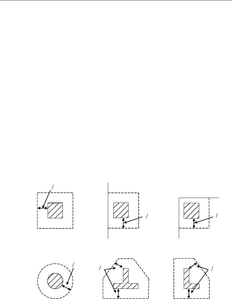
ETABS Reinforced Concrete Design
The slab shear reinforcement requirements considered by the program are based
purely on shear strength considerations. Any minimum stirrup requirements to
satisfy spacing and volumetric considerations must be investigated inde-
pendently of the program by the user.
9.5.3 Check for Punching Shear
The algorithm for checking punching shear is detailed in the section entitled
“Slab Punching Shear Check” in the Chapter 1. Only the code-specific items are
described in the following sections.
9.5.3.1 Critical Section for Punching Shear
The punching shear is checked on a critical section at a distance of d/2 from the
face of the support (CSA 13.3.3.1 and CSA 13.3.3.2). For rectangular columns
and concentrated loads, the critical area is taken as a rectangular area with the
sides parallel to the sides of the columns or the point loads (CSA 13.3.3.3). Fig-
ure 9-3 shows the auto punching perimeters considered by ETABS for the vari-
ous column shapes. The column location (i.e., interior, edge, corner) and the
punching perimeter may be overwritten using the Punching Check Overwrites.
Figure 9-3 Punching Shear Perimeters
d2
Interior Column
Circular Column
d2 d2
d2
T-Shape Column
Edge Column Corner Column
L-Shape Column
d2
d2
d2
Interior Column
Circular Column
d2 d2
d2
T-Shape Column
Edge Column Corner Column
L-Shape Column
d2
d2
9 - 20 Slab Design
Chapter 9 - Design for CSA A23.3-04
9.5.3.2 Transfer of Unbalanced Moment
The fraction of unbalanced moment transferred by flexure is taken to be γf Mu
and the fraction of unbalanced moment transferred by eccentricity of shear is
taken to be γv Mu, where
γf =
( )
12
1,
1 23 bb+
and (CSA 13.10.2)
γv = 1−
( )
12
1,
1 23 bb+
(CSA 13.3.5.3)
where b1 is the width of the critical section measured in the direction of the span,
and b2 is the width of the critical section measured in the direction perpendicular
to the span.
9.5.3.3 Determination of Concrete Capacity
The concrete punching shear factored strength is taken as the minimum of the
following three limits:
0
2
1 0 19
min 0 19
0 38
cc
c
s
vc c
cc
.f
d
v.f
b
.f
φλ
β
α
φλ
φλ
′
+
′
= +
′
(CSA 13.3.4.1)
where,
β
c is the ratio of the minimum to the maximum dimensions of the critical
section, b0 is the perimeter of the critical section, and αs is a scale factor based
on the location of the critical section.
α
=
4, for interior columns
3, for edge colums, and
2, for corner columns.
s
(CSA 13.3.4.1(b))
Slab Design 9 - 21
ETABS Reinforced Concrete Design
The value of
c
f'
is limited to 8 MPa for the calculation of the concrete shear
capacity (CSA 13.3.4.2).
If the effective depth, d, exceeds 300 mm, the value of vc is reduced by a factor
equal to 1300/(1000 + d) (CSA 13.3.4.3).
9.5.3.4 Determine Maximum Shear Stress
Given the punching shear force and the fractions of moments transferred by ec-
centricity of shear about the two axes, the shear stress is computed assuming
linear variation along the perimeter of the critical section.
22 3 1 33 4 3 23 4 3
2
022 33 23
33 3 1 22 4 3 23 4 3
2
22 33 23
[ ( )][ ( ) ( )]
[ ( )][ ( ) ( )]
γ
γ
− − −− −
=+−
−
− − −− −
−
V
f ff
f
Vff
V M Vy y I y y I x x
vbd I I I
M VxxIxx Iyy
II I
Eq. 1
22 22
1
,
=
=∑
n
sides
II
where "sides" refers to the sides of the critical
section for punching shear Eq. 2
33 33
1
,
=
=∑
n
sides
II
where "sides" refers to the sides of the critical
section for punching shear Eq. 3
23 23
1
,
=
=∑
n
sides
II
where "sides" refers to the sides of the critical
section for punching shear Eq. 4
The equations for
22 33
,,II
and
23
I
are different depending on whether the
side of the critical section for punching shear being considered is parallel
to the 2-axis or parallel to the 3-axis. Refer to Figures 9-4.
9 - 22 Slab Design
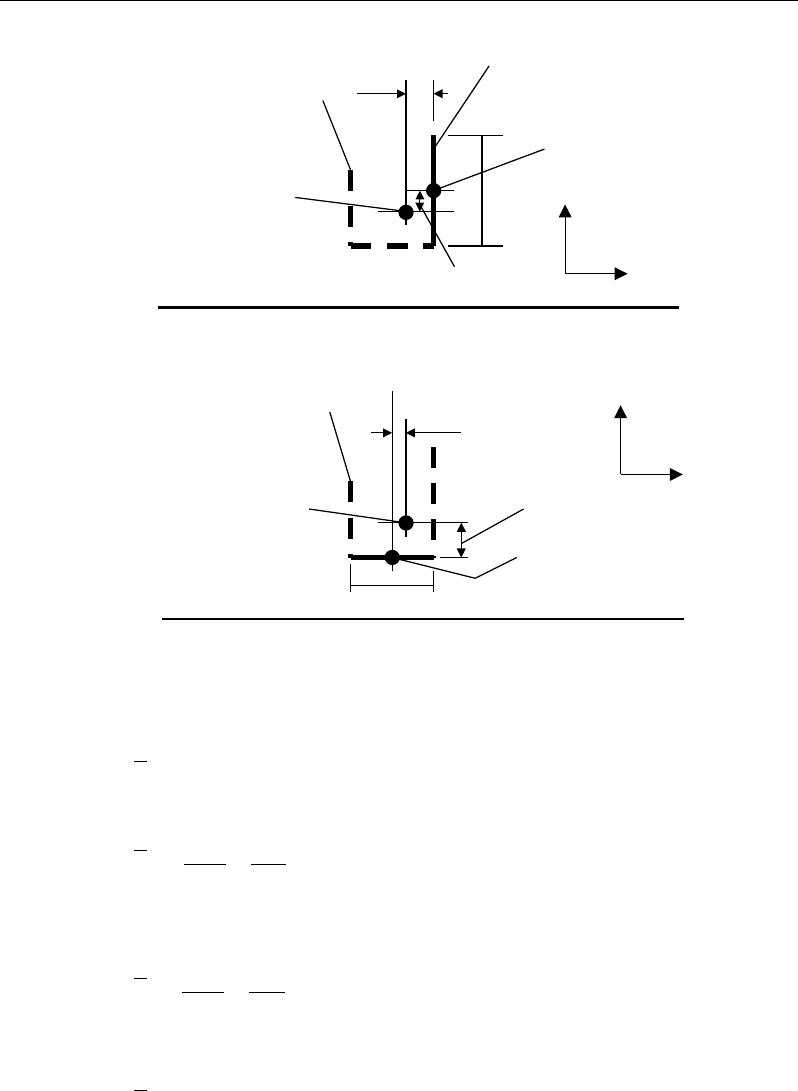
Chapter 9 - Design for CSA A23.3-04
Figure 9-4 Shear Stress Calculations at Critical Sections
2
22 2 3
( ),
= −I Ld y y
for side of critical section parallel to 2-axis Eq. 5a
33 2
22 2 3
( ),
12 12
= ++ −
Ld dL
I Ld y y
for side of critical section
parallel to 3-axis Eq. 5b
33 2
33 2 3
( ),
12 12
= ++ −
Ld dL
I Ld x x
for side of critical section
parallel to 2-axis Eq. 6a
2
33 2 3
( ),= −I Ld x x
for side of critical section parallel to 3-axis Eq. 6b
Plan View For Side of Critical Section Parallel to 3-Axis
y
2
- y
3
L
Critical section for
punching shear
shown by heavy line
2
3
Side of critical section
being considered
shown solid
Center of side of critical
section being considered.
Coordinates are (x
2
,y
2
).
Work This Sketch With Equations 5b, 6b and
7
Centroid
of entire
critical section for
punching shear.
Coordinates are (x
3
,y
3
).
x
2
- x
3
y
2
- y
3
L
Critical section for
punching shear shown
by heavy line. Side of
critical section being
considered shown solid
2
3
Center of side of critical
section being considered.
Coordinates are (x
2
,y
2
).
Plan View For Side of Critical Section Parallel to 2-Axis
Work This Sketch With Equations 5a, 6a and
7
Centroid
of entire
critical section for
punching shear.
Coordinates are (x
3
,y
3
).
x
2
- x
3
Slab Design 9 - 23

ETABS Reinforced Concrete Design
23 2 3 2 3
( )( ),=−−I Ld x x y y
for side of critical section parallel
to 2-axis or 3-axis Eq. 7
NOTE:
23
I
is explicitly set to zero for corner condition.
where,
b0 = Perimeter of the critical section for punching shear
d = Effective depth at the critical section for punching shear based on the
average of d for 2 direction and d for 3 direction
I22 = Moment of inertia of the critical section for punching shear about an axis
that is parallel to the local 2-axis
I33 = Moment of inertia of the critical section for punching shear about an axis
that is parallel to the local 3-axis
I23 = Product of inertia of the critical section for punching shear with respect
to the 2 and 3 planes
L = Length of the side of the critical section for punching shear currently
being considered
Mf2 = Moment about the line parallel to the 2-axis at the center of the column
(positive in accordance with the right-hand rule)
Mf3 = Moment about the line parallel to the 3-axis at the center of the column
(positive in accordance with the right-hand rule)
Vf = Punching shear stress
Vf = Shear at the center of the column (positive upward)
x1, y1 = Coordinates of the column centroid
x2, y2 = Coordinates of the center of one side of the critical section for punching
shear
x3, y3 = Coordinates of the centroid of the critical section for punching shear
x4, y4 = Coordinates of the location where stress is being calculated
9 - 24 Slab Design

Chapter 9 - Design for CSA A23.3-04
γ
V2 = Percent of Mf2 resisted by shear
γ
V3 = Percent of Mf3 resisted by shear
9.5.3.5 Determine Capacity Ratio
The ratio of the maximum shear stress and the concrete punching shear stress
capacity is reported as the punching shear capacity ratio by ETABS. If this ratio
exceeds 1.0, punching shear reinforcement is designed as described in the fol-
lowing section.
9.5.4 Design Punching Shear Reinforcement
The use of shear studs as shear reinforcement in slabs is permitted, provided that
the effective depth of the slab is greater than or equal to 200 mm (CSA 13.2.1).
If the slab thickness does not meet these requirements, the punching shear rein-
forcement is not designed, and the slab thickness should be increased by the user.
The algorithm for designing the required punching shear reinforcement is used
when the punching shear capacity ratio exceeds unity. The Critical Section for
Punching Shear and Transfer of Unbalanced Moment as described in the earlier
sections remain unchanged. The design of punching shear reinforcement is per-
formed as explained in the subsections that follow.
9.5.4.1 Determine Concrete Shear Capacity
The concrete punching shear stress capacity of a section with punching shear
reinforcement is taken as:
ccc fv '28
.0
λφ
=
for shear studs (CSA 13.3.8.3)
0.19 '
c cc
vf
λφ
=
for shear stirrups (CSA 13.3.9.3)
9.5.4.2 Determine Required Shear Reinforcement
The shear force is limited to a maximum of
,max
,
r
v
where
,max 0.75 '
r cc
vf
λφ
=
for shear studs (CSA 13.3.8.2)
Slab Design 9 - 25
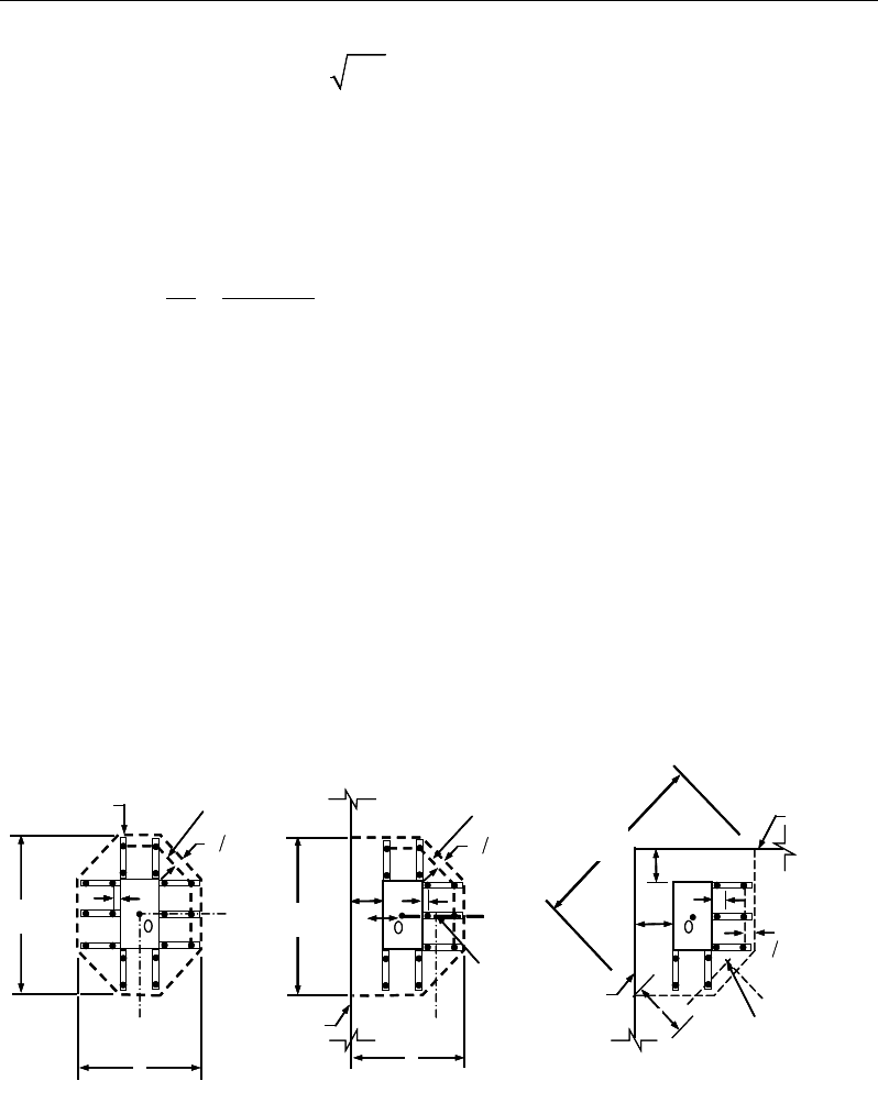
ETABS Reinforced Concrete Design
,max 0.55 '
r cc
vf
λφ
=
for shear stirrups (CSA 13.3.9.2)
Given vf, vc, and vf,,max, the required shear reinforcement is calculated as follows,
where,
φ
s, is the strength reduction factor.
If vf > vr,max,
( )
fc
vo
s yv
vv
Ab
sf
φ
−
=
(CSA 13.3.8.5, 13.3.9.4)
If vf > vr,max, a failure condition is declared. (CSA 13.3.8.2)
If vf exceeds the maximum permitted value of vrmax, the concrete section should
be increased in size.
9.5.4.3 Determine Reinforcement Arrangement
Punching shear reinforcement in the vicinity of rectangular columns should be
arranged on peripheral lines, i.e., lines running parallel to and at constant dis-
tances from the sides of the column. Figure 9-5 shows a typical arrangement of
shear reinforcement in the vicinity of a rectangular interior, edge, and corner
column.
Figure 9-5 Typical arrangement of shear studs
and critical sections outside shear-reinforced zone
I
y
Typical Studrail
(only first and last
studs shown)
Outermost
peripheral line
of studs
Interior Column Edge Column Corner Column
Critical section
centroid
Free
edge
Free
edge
Critical
section
centroid
Free edge
Outermost
peripheral line
of studs
I
y
I
y
yx
d2 d2
d2
x
I
x
I
x
g
y
g
x
g
0
s0
s
0
s
x
I
y
x
x
I
y
Typical Studrail
(only first and last
studs shown)
Outermost
peripheral line
of studs
Interior Column Edge Column Corner Column
Critical section
centroid
Free
edge
Free
edge
Critical
section
centroid
Free edge
Outermost
peripheral line
of studs
I
y
I
y
yx
d2 d2
d2
x
I
x
I
x
g
y
g
x
g
0
s0
s
0
s
x
I
y
x
x
9 - 26 Slab Design
Chapter 9 - Design for CSA A23.3-04
The distance between the column face and the first line of shear reinforcement
shall not exceed
0.4d for shear studs (CSA 13.3.8.6)
0.25d for shear stirrups (CSA 13.3.8.6)
Punching shear reinforcement is most effective near column corners where there
are concentrations of shear stress. Therefore, the minimum number of lines of
shear reinforcement is 4, 6, and 8, for corner, edge, and interior columns respec-
tively.
9.5.4.4 Determine Reinforcement Diameter, Height, and Spacing
The punching shear reinforcement is most effective when the anchorage is close
to the top and bottom surfaces of the slab. The cover of anchors should not be
less than the minimum cover specified in CSA 7.9 plus half of the diameter of
the flexural reinforcement.
When specifying shear studs, the distance, so, between the column face and the
first peripheral line of shear studs should not be smaller than 0.4d. The limits of
so and the spacing, s, between the peripheral lines are specified as:
0.4
o
sd≤
(CSA 13.3.8.6)
0.75 0.56 '
0.50 0.56 '
f cc
f cc
dv f
sdv f
λφ
λφ
≤
≤>
(CSA 13.3.8.6)
For shear stirrups,
≤0.25
o
sd
(CSA 13.3.9.5)
≤0.25sd
(CSA 13.3.9.5)
The minimum depth for reinforcement should be limited to 300 mm (CSA
13.3.9.1).
Slab Design 9 - 27

Chapter 10
Design for Eurocode 2-2004
This chapter describes in detail the various aspects of the concrete design
procedure that is used by ETABS when the European code Eurocode 2-2004
[EN 1992-1-1:2004] is selected. For the load combinations, reference is also
made to Eurocode 0 [EN 1990], which is identified with the prefix “EC0.” Var-
ious notations used in this chapter are listed in Table 10-1. For referencing to the
pertinent sections of the Eurocode in this chapter, a prefix “EC2” followed by
the section number is used. It also should be noted that this section describes the
implementation of the CEN Default version of Eurocode 2-2004, without a coun-
try specific National Annex. Where Nationally Determined Parameters [NDPs]
are to be considered, this is highlighted in the respective section by the notation
[NDP].
The design is based on user-specified loading combinations. However, the pro-
gram provides a set of default load combinations that should satisfy requirements
for the design of most building type structures.
English as well as SI and MKS metric units can be used for input. The code is
based on Newton-millimeter-second units. For simplicity, all equations and
descriptions presented in this chapter correspond to Newton-millimeter-second
units unless otherwise noted.
Notations 10- 1

ETABS Reinforced Concrete Design
10.1 Notations
Table 10-1 List of Symbols Used in the Eurocode 2-2004
A
c
Area of concrete section, mm2
A
s
Area of tension reinforcement, mm2
A'
s
Area of compression reinforcement, mm2
A
sl
Area of longitudinal reinforcement for torsion, mm2
A
sw
Total cross-sectional area of links at the neutral axis, mm2
A
sw
/s
v
Area of shear reinforcement per unit length, mm2/mm
A
t
/s
Area of transverse reinforcement per unit length for torsion,
mm2/mm
a
Depth of compression block, mm
b
Width or effective width of the section in the compression zone,
mm
b
f
Width or effective width of flange, mm
b
w
Average web width of a flanged slab section, mm
d
Effective depth of tension reinforcement, mm
d'
Effective depth of compression reinforcement, mm
E
c
Modulus of elasticity of concrete, MPa
E
s
Modulus of elasticity of reinforcement
f
cd
Design concrete strength = α
cc
f
ck
/ γ
c
, MPa
f
ck
Characteristic compressive concrete cylinder strength at 28 days,
MPa
f
ctm
Mean value of concrete axial tensile strength, MPa
f
cwd
Design concrete compressive strength for shear design = α
cc
cwk
c
f
γ
, MPa
f
cwk
Characteristic compressive cylinder strength for shear design,
MPa
f'
s
Compressive stress in compression reinforcement, MPa
f
yd
Design yield strength of reinforcement = f
yk
/γ
s
, MPa
10 - 2 Notations

Chapter 10 - Design for Eurocode 2-2004
Table 10-1 List of Symbols Used in the Eurocode 2-2004
f
yk
Characteristic strength of shear reinforcement, MPa
f
ywd
Design strength of shear reinforcement = f
ywk
/γ
s
, MPa
f
ywk
Characteristic strength of shear reinforcement, MPa
h
Overall depth of section, mm
h
f
Flange thickness, mm
M
Ed
Design moment at a section, N-mm
m
Normalized design moment, M/bd2ηf
cd
m
lim
Limiting normalized moment capacity as a singly reinforced slab
s
v
Spacing of the shear reinforcement, mm
T
Ed
Torsion at ultimate design load, N-mm
T
Rdc
Torsional cracking moment, N-mm
T
Rd,max
Design torsional resistance moment, N-mm
u
Perimeter of the punch critical section, mm
V
Rdc
Design shear resistance from concrete alone, N
V
Rd,max
Design limiting shear resistance of a cross-section, N
V
Ed
Shear force at ultimate design load, N
x
Depth of neutral axis, mm
x
lim
Limiting depth of neutral axis, mm
z
Lever arm, mm
α
cc
Coefficient accounting for long-term effects on the concrete com-
pressive strength
α
cw
Coefficient accounting for the state of stress in the compression
chord
δ
Redistribution factor
ε
c
Concrete strain
ε
s
Strain in tension reinforcement
ε
’
s
Strain in compression steel
γ
c
Partial safety factor for concrete strength
Notations 10 - 3

ETABS Reinforced Concrete Design
Table 10-1 List of Symbols Used in the Eurocode 2-2004
γ
s
Partial safety factor for reinforcement strength
λ
Factor defining the effective depth of the compression zone
ν
Effectiveness factor for shear resistance without concrete crush-
ing
η
Concrete strength reduction factor for sustained loading and stress
block
ρ
l
Tension reinforcement ratio
σ
cp
Axial stress in the concrete, MPa
θ
Angle of the concrete compression strut
ω
Normalized tension reinforcement ratio
ω
'
Normalized compression reinforcement ratio
ω
lim
Normalized limiting tension reinforcement ratio
10.2 Design Load Combinations
The design load combinations are the various combinations of the load cases for
which the structure needs to be checked. Eurocode 0-2002 allows load combina-
tions to be defined based on EC0 Equation 6.10 or the less favorable of EC0
Equations 6.10a and 6.10b [NDP].
∑ ∑
≥ >
+
++
1 1 ,,0,1,1
,,,
j i ikiiQkQPjkjG Q
QPG
ψγγγγ
(EC0 Eq. 6.10)
∑ ∑
≥ >
+
++
1 1 ,,0
,1,1,01,,,
j i ikii
QkQPjk
jG
QQPG
ψγψ
γγγ
(EC0 Eq. 6.10a)
∑ ∑
≥ >
+
++
1 1 ,,
0,1
,1
,,,
jiik
ii
Qk
QPj
kj
Gj QQ
PG
ψ
γγ
γγ
ξ
(EC0 Eq. 6.10b)
Load combinations considering seismic loading are automatically generated
based on EC0 Equation 6.12b.
∑ ∑
≥ >
+
++
1 1 ,,
2,
j i ikiEd
jk QA
PG
ψ
(EC0 Eq. 6.12b)
10 - 4 Design Load Combinations

Chapter 10 - Design for Eurocode 2-2004
For this code, if a structure is subjected to dead (D), live (L), pattern live (PL),
snow (S), wind (W), and earthquake (E) loads, and considering that wind and
earthquake forces are reversible, the following load combinations need to be
considered if equation 6.10 is specified for generation of the load combinations
(EC0 6.4.3):
γ
Gj,sup
D
(EC0 Eq. 6.10)
γ
Gj,sup
D + γ
Q,1
L
(EC0 Eq. 6.10)
γ
Gj,sup
D + (0.75)γ
Q,1
PL
(EC0 Eq. 6.10)
γ
Gj,inf
D ± γ
Q,1
W
γ
Gj,sup D ± γQ,1 W
(EC0 Eq. 6.10)
γ
Gj,sup
D + γ
Q,1
L ± γ
Q,i
ψ
0,i
W
γ
Gj,sup D + γQ,1 L + γQ,i ψ0,i S
γ
Gj,sup D ± γQ,1 W + γQ,i ψ0,i L
γ
Gj,sup D ± γQ,1 W + γQ,i ψ0,i S
γ
Gj,sup D + γQ,1 S ± γQ,i ψ0,i W
γ
Gj,sup D + γQ,1 S + γQ,i ψ0,i L
(EC0 Eq. 6.10)
γ
Gj,sup
D + γ
Q,1
L + γ
Q,i
ψ
0,i
S ± γ
Q,i
ψ
0,i
W
γ
Gj,sup D ± γQ,1 W + γQ,i ψ0,i L + γQ,i ψ0,i S
γ
Gj,sup D + γQ,1 S ± γQ,i ψ0,i W + γQ,i ψ0,i L
(EC0 Eq. 6.10)
D ± 1.0E
D
± 1.0E + ψ2,i L
D
± 1.0E + ψ2,i L + ψ2,i S (EC0 Eq. 6.12b
)
If the load combinations are specified to be generated from the max of EC0
Equations 6.10a and 6.10b, the following load combinations from both equations
are considered in the program.
γ
Gj,sup
D
ξ γ
Gj,sup D
(EC0 Eq. 6.10a)
(EC0 Eq. 6.10b)
γ
Gj,sup
D + γ
Q,1
ψ
0,1
L
ξ
γGj,supD + γQ,1 L
(EC0 Eq. 6.10a)
(EC0 Eq. 6.10b)
Design Load Combinations 10 - 5

ETABS Reinforced Concrete Design
γ
Gj,sup
D + (0.75)γ
Q,1
ψ
0,1
PL
ξ
γGj,supD + (0.75)γQ,1 PL
(EC0 Eq. 6.10a)
(EC0 Eq. 6.10b)
γ
Gj,inf
D ± γ
Q,1
ψ
0,1
W
γ
Gj,sup D ± γQ,1 ψ0,1 W
γ
Gj,inf D ± γQ,1 W
ξ
γGj,sup D ± γQ,1 W
(EC0 Eq. 6.10a)
(EC0 Eq. 6.10a)
(EC0 Eq. 6.10b)
(EC0 Eq. 6.10b)
γ
Gj,sup
D + γ
Q,1
ψ
0,1
L ± γ
Q,i
ψ
0,i
W
γ
Gj,sup D + γQ,1 ψ0,1 L + γQ,i ψ0,i S
γ
Gj,sup D ± γQ,1 ψ0,1 W + γQ,i ψ0,i L
γ
Gj,sup D ± γQ,1 ψ0,1 W + γQ,i ψ0,i S
γ
Gj,sup D + γQ,1 ψ0,1 S + γQ,i ψ0,i L
γ
Gj,sup D + γQ,1 ψ0,1 S ± γQ,i ψ0,i W
(EC0 Eq. 6.10a)
ξ γ
Gj,sup
D + γ
Q,1
L ± γ
Q,i
ψ
0,i
W
ξ
γGj,sup D + γQ,1 L + γQ,i ψ0,i S
ξ
γGj,sup D + γQ,1 S ± γQ,i ψ0,i W
ξ
γGj,sup D + γQ,1 S + γQ,i ψ0,i L
γ
Gj,inf D ± γQ,1 W + γQ,i ψ0,i L
γ
Gj,inf D ± γQ,1 W + γQ,i ψ0,i S
(EC0 Eq. 6.10b)
D ± 1.0E
D
± 1.0E + ψ2,i L
D
± 1.0E + ψ2,i L + ψ2,i S
(EC0 Eq. 6.12b)
For both sets of load combinations, the variable values for the CEN Default ver-
sion of the load combinations are defined in the list that follows [NDP].
γGj,sup = 1.35 (EC0 Table A1.2(B))
γGj,inf = 1.00 (EC0 Table A1.2(B))
γQ,1 = 1.5 (EC0 Table A1.2(B))
γQ,i = 1.5 (EC0 Table A1.2(B))
ψ0,i = 0.7 (live load, assumed not to be storage) (EC0 Table A1.1)
ψ0,i = 0.6 (wind load) (EC0 Table A1.1)
ψ0,i = 0.5 (snow load, assumed H ≤ 1,000 m) (EC0 Table A1.1)
10 - 6 Design Load Combinations

Chapter 10 - Design for Eurocode 2-2004
ξ = 0.85 (EC0 Table A1.2(B))
ψ2,i = 0.3 (live, assumed office/residential space) (EC0 Table A1.1)
ψ2,i = 0 (snow, assumed H ≤ 1,000 m) (EC0 Table A1.1)
These are also the default design load combinations in ETABS whenever the
Eurocode 2-2004 code is used. If roof live load is treated separately or other
types of loads are present, other appropriate load combinations should be used.
10.3 Limits on Material Strength
The concrete compressive strength, fck, should not be greater than 90 MPa (EC2
3.1.2(2)). The lower and upper limits of the reinforcement yield strength, fyk,
should be 400 and 600 MPa, respectively (EC2 3.2.2(3)).
ETABS enforces the upper material strength limits for flexure and shear design
of slabs. The input material strengths are taken as the upper limits if they are
defined in the material properties as being greater than the limits. It is the user's
responsibility to ensure that the minimum strength is satisfied.
10.4 Partial Safety Factors
The design strengths for concrete and steel are obtained by dividing the charac-
teristic strengths of the materials by the partial safety factors, γs and γc as shown
here [NDP].
/
cd cc ck c
ff=αγ
(EC2 3.1.6(1))
/
yd yk s
ff= γ
(EC2 3.2.7(2))
/
ywd ywk s
ff= γ
(EC2 3.2.7(2))
αcc is the coefficient taking account of long term effects on the compressive
strength. αcc is taken as 1.0 by default and can be overwritten by the user (EC2
3.1.6(1)).
Limits on Material Strength 10 - 7

ETABS Reinforced Concrete Design
The partial safety factors for the materials and the design strengths of concrete
and reinforcement are given in the text that follows (EC2 2.4.2.4(1), Table 2.1N):
Partial safety factor for reinforcement, γs = 1.15
Partial safety factor for concrete, γc = 1.5
These values are recommended by the code to give an acceptable level of safety
for normal structures under regular design situations (EC2 2.4.2.4). For acci-
dental and earthquake situations, the recommended values are less than the tab-
ulated values. The user should consider those separately.
These values can be overwritten; however, caution is advised.
10.5 Slab Design
ETABS slab design procedure involves defining sets of strips in two mutually
perpendicular directions. The locations of the strips are usually governed by the
locations of the slab supports. The axial force, moments and shears for a partic-
ular strip are recovered from the analysis (on the basis of the Wood-Armer tech-
nique), and a flexural design is carried out based on the ultimate strength design
method.
The slab design procedure involves the following steps:
Design flexural reinforcement
Design shear reinforcement
Punching check
10.5.1 Design Flexural Reinforcement
For slabs, ETABS uses either design strips or the finite element based design to
calculate the slab flexural reinforcement in accordance with the selected design
code. For simplicity, only strip-by-strip design is document in the proceeding
sections.
The design of the slab reinforcement for a particular strip is carried out at specific
locations along the length of the strip. These locations correspond to the element
10 - 8 Slab Design

Chapter 10 - Design for Eurocode 2-2004
boundaries. Controlling reinforcement is computed on either side of those ele-
ment boundaries. The slab flexural design procedure for each load combination
involves the following:
Determine factored axial loads and moments for each slab strip.
Design flexural reinforcement for the strip.
These two steps, described in the text that follows, are repeated for every load
combination. The maximum reinforcement calculated for the top and bottom
of the slab within each design strip, along with the corresponding controlling
load combination, is obtained and reported.
10.5.1.1 Determine Factored Moments
In the design of flexural reinforcement of concrete slab, the factored moments
for each load combination at a particular design strip are obtained by factoring
the corresponding moments for different load cases, with the corresponding load
factors.
The slab is then designed for the maximum positive and maximum negative fac-
tored moments obtained from all of the load combinations. Calculation of bottom
reinforcement is based on positive design strip moments. In such cases, the slab
may be designed as a rectangular or flanged slab section. Calculation of top re-
inforcement is based on negative design strip moments. In such cases, the slab
may be designed as a rectangular or inverted flanged slab section.
10.5.1.2 Determine Required Flexural Reinforcement
In the flexural reinforcement design process, the program calculates both the
tension and compression reinforcement. Compression reinforcement is added
when the applied design moment exceeds the maximum moment capacity of a
singly reinforced section. The user has the option of avoiding compression rein-
forcement by increasing the effective depth, the width, or the strength of the
concrete.
The design procedure is based on the simplified rectangular stress block shown
in Figure 10-1 (EC2 3.1.7(3)). The area of the stress block and the depth of the
compressive block is taken as:
Slab Design 10 - 9

ETABS Reinforced Concrete Design
ab
fF
cdc
η
=
(EC2 3.1.7(3), Fig 3.5)
a =
λ
x (EC2 3.1.7(3), Fig 3.5)
where x is the depth of the neutral axis. The factor
λ
defining the effective height
of the compression zone and the factor
η
defining the effective strength are given
as:
8
.0
=
λ
for fck ≤ 50 MPa (EC2 3.1.7(3))
−
=400
50
8.0 ck
f
λ
for 50 < fck ≤ 90 MPa (EC2 3.1.7(3))
0.1=
η
for fck ≤ 50 MPa (EC2 3.1.7(3))
−
−
=200
50
0.
1
ck
f
η
for 50 < fck ≤ 90 MPa (EC2 3.1.7(3))
Furthermore, it is assumed that moment redistribution in the member does not
exceed the code-specified limiting value. The code also places a limitation on
the neutral axis depth, to safeguard against non-ductile failures (EC2 5.5(4)).
When the applied moment exceeds the limiting moment capacity as a singly
reinforced slab, the area of compression reinforcement is calculated assuming
that the neutral axis depth remains at the maximum permitted value.
The limiting value of the ratio of the neutral axis depth at the ultimate limit state
to the effective depth,
( )
lim ,xd
is expressed as a function of the ratio of the
redistributed moment to the moment before redistribution,
δ
, as follows:
2
1
lim
k
k
d
x−
=
δ
for fck ≤ 50 MPa (EC2 5.5(4))
4
3
lim
k
k
d
x−
=
δ
for fck > 50 MPa (EC2 5.5(4))
For reinforcement with fyk ≤ 500 MPa, the following values are used:
k1 = 0.44 [NDP] (EC 5.5(4))
10 - 10 Slab Design
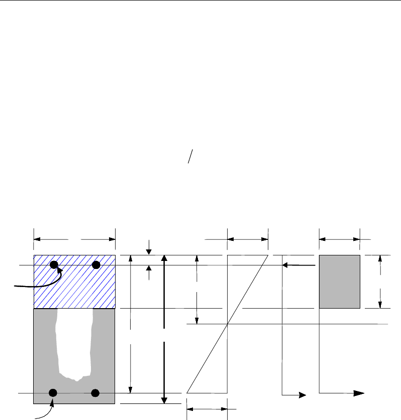
Chapter 10 - Design for Eurocode 2-2004
k2 = k4 = 1.25(0.6 + 0.0014/εcu2) [NDP] (EC 5.5(4))
k3 = 0.54 [NDP] (EC 5.5(4))
δ
is assumed to be 1
where the ultimate strain,
ε
cu2 [NDP], is determined from EC2 Table 3.1 as:
ε
cu2 = 0.0035 for fck < 50 MPa (EC2 Table 3.1)
ε
cu2 = 2.6 + 35
( )
4
90 100
ck
f
−
for fck ≥ 50 MPa (EC2 Table 3.1)
The design procedure used by ETABS, for both rectangular and flanged sections
(L- and T-shaped sections), is summarized in the subsections that follow.
Figure 10-1 Uniform Thickness Slab Design
BEAM
SECTION STRAIN
DIAGRAM STRESS
DIAGRAM
cu3
ε
cd
f
η
ax
λ
=
cs
T
s
T
s
ε
x
s
C
d′
d
b
s
A
s
A′
c
f′
h
BEAM
SECTION STRAIN
DIAGRAM STRESS
DIAGRAM
cu3
ε
cd
f
η
ax
λ
=
cs
T
s
T
s
ε
x
s
C
d′
d
b
s
A
s
A′
c
f′
h
Slab Design 10 - 11
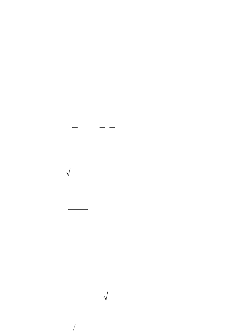
ETABS Reinforced Concrete Design
10.5.1.2.1 Design of uniform thickness slab
For uniform thinness slab, the normalized moment, m, and the normalized sec-
tion capacity as a singly reinforce slab, mlim, are obtained first. The reinforcement
area is determined based on whether m is greater than, less than, or equal to mlim.
The normalized design moment, m, is calculated as:
cd
f
bd
M
m
η
2
=
The normalized concrete moment capacity as a singly reinforced slab, mlim, is
calculated as:
−
=
limlim
lim
2
1d
x
d
x
m
λ
λ
If m ≤ mlim, a singly reinforced slab is designed. The normalized reinforcement
ratio is calculated as:
m211 −−=
ω
The area of tension reinforcement, As, is then given by:
=
yd
cd
sf
bdf
A
η
ω
This reinforcement is to be placed at the bottom if MEd is positive, or at the top
if MEd is negative.
If m > mlim, both tension and compression reinforcement is designed as fol-
lows:
The normalized steel ratios
ω
',
ω
lim, and
ω
are calculated as:
lim
lim
lim 211 m
d
x−−=
=
λω
lim
'1
mm
dd
ω
−
=′
−
10 - 12 Slab Design

Chapter 10 - Design for Eurocode 2-2004
'
lim
ωωω
+=
where, d' is the depth to the compression reinforcement from the concrete com-
pression face.
The area of compression and tension reinforcement, A's and As, are given by:
cd
ss cd
f bd
Aff
η
ωη
′′
=
′−
=
yd
cd
s
f
bd
f
A
η
ω
where, f's is the stress in the compression reinforcement, and is given by:
ε
′
′= −≤
3lim
1
s s cu yd
d
fE f
x
(EC2 6.1, 3.2.7(4), Fig 3.8)
10.5.1.2.2 Design of nonuniform thickness slab
10.5.1.2.2.1 Flanged Slab Section Under Negative Moment
In designing for a factored negative moment, MEd (i.e., designing top reinforce-
ment), the calculation of the reinforcement area is exactly the same as described
previously, i.e., no flanged data is used.
10.5.1.2.2.2 Flanged Slab Section Under Positive Moment
With the flange in compression, the program analyzes the section by considering
alternative locations of the neutral axis. Initially, the neutral axis is assumed to
be located within the flange. Based on this assumption, the program calculates
the depth of the neutral axis. If the stress block does not extend beyond the flange
thickness, the section is designed as a uniform thickness slab of width bf. If the
stress block extends beyond the flange, additional calculation is required. See
Figure 10-2.
The normalized design moment, m, is calculated as:
Slab Design 10 - 13
ETABS Reinforced Concrete Design
(EC2 6.1, 3.1.7(3))
The limiting values are calculated as:
(EC2 5.5(4), 3.1.7(3))
amax =
ω
limd
The values
ω
and a are calculated as:
ω
= 1
a = ωd
Figure 10-2 Nonuniform Thickness Slab Design
If a ≤ hf, the subsequent calculations for As are exactly the same as previously
defined for the uniform thickness slab design. However, in that case, the width
of the slab is taken as bf. Compression reinforcement is required when m >
mlim.
10 - 14 Slab Design
Chapter 10 - Design for Eurocode 2-2004
If a > hf, the calculation for As has two parts. The first part is for balancing the
compressive force from the flange, and the second part is for balancing the
compressive force from the web, as shown in Figure 10-2. The reinforcement
area required for balancing the flange compression, As2 is given as:
( )
2
f w f cd
syd
b bhf
Af
η
−
=
and the corresponding resistive moment is given by
−= 2
22
f
yds
h
dfAM
The reinforcement required for balancing the compressive force from the web,
considering a rectangular section of width bw to resist the moment,
M1 = M − M2, is determined as follows:
cdw
fdb
M
m
η
21
1
=
If m1 ≤ mlim,
11 211 m−−=
ω
=
yd
wcd
s
f
dbf
A
η
ω
11
If m1 > mlim,
ω' =
1 lim
1
mm
dd
−
′
−
lim
lim
=d
x
λω
1 lim
ωω ω
′
= +
Slab Design 10 - 15
ETABS Reinforced Concrete Design
''
cd
ss cd
f bd
Aff
η
ωη
′=
−
=
yd
wcd
s
f
db
f
A
η
ω
11
where, f's is given by:
ε
′
′= −≤
3lim
1
s s cu yd
d
fE f
x
(EC2 6.1, 3.2.7(4), Fig 3.8)
The total tension reinforcement is As = As1 + As2, and the total compression rein-
forcement is A's. As is to be placed at the bottom and A's is to be placed at the top.
10.5.1.3 Minimum and Maximum Reinforcement
The minimum flexural tension reinforcement required for each direction of a
slab is given by the following limits (EC2 9.3.1.1) [NDP]:
bd
f
f
A
yk
ctm
s
26.0
min,
=
(EC2 9.2.1.1(1))
bdA
s
0013.0
min,
=
(EC2 9.2.1.1(1))
where fctm is the mean value of axial tensile strength of the concrete and is com-
puted as:
( )
32
30.0 ckctm ff =
for fck ≤ 50 MPa (EC2 Table 3.1)
( )
2.12 1 10
ctm cm
f ln f= +
for fck > 50 MPa (EC2 Table 3.1)
8 MPa
cm ck
ff= +
(EC2 Table 3.1)
The minimum flexural tension reinforcement required for control of cracking
should be investigated independently by the user.
An upper limit on the tension reinforcement and compression reinforcement has
been imposed to be 0.04 times the gross cross-sectional area (EC 9.2.1.1(3)).
10 - 16 Slab Design

Chapter 10 - Design for Eurocode 2-2004
10.5.2 Design Slab Shear Reinforcement
The shear reinforcement is designed for each load combination at each station
along the design strip. In designing the shear reinforcement for a particular strip,
for a particular load combination, at a particular station due to the slab major
shear, the following steps are involved (EC2 6.2):
Determine the factored shear force, VEd.
Determine the shear force, VRd,c, that can be resisted by the concrete.
Determine the shear reinforcement required.
The following three sections describe in detail the algorithms associated with
these steps.
10.5.2.1 Determine Factored Shear Force
In the design of the slab shear reinforcement, the shear forces for each load com-
bination at a particular design strip station are obtained by factoring the corre-
sponding shear forces for different load cases, with the corresponding load com-
bination factors.
10.5.2.2 Determine Concrete Shear Capacity
The shear force carried by the concrete, VRd,c, is calculated as:
( )
13
,,1 1
100
Rd c Rd c ck cp w
V C k f k bd
ρσ
= +
(EC2 6.2.2(1))
with a minimum of:
( )
, min 1Rd c cp w
V v k bd
σ
= +
(EC2 6.2.2(1))
where
fck is in MPa
200
1 2.0kd
=+≤
with d in mm (EC2 6.2.2(1))
Slab Design 10 - 17

ETABS Reinforced Concrete Design
ρ
1 = tension reinforcement ratio =
db
A
w
s1
≤ 0.02 (EC2 6.2.2(1))
As1 = area of tension reinforcement (EC2 6.2.2(1))
/ 0.2
cp Ed c cd
NA fσ= <
MPa (EC2 6.2.2(1))
The value of CRd,c, vmin and k1 for use in a country may be found in its National
Annex. The program default values for CRd,c [NDP], vmin [NDP], and k1 [NDP]
are given as follows (EC2 6.2.2(1)):
CRd,c= 0.18/γc (EC2 6.2.2(1))
vmin = 0.035 k3/2 fck1/2 (EC2 6.2.2(1))
k1 = 0.15. (EC2 6.2.2(1))
For light-weight concrete:
CRd,c= 0.18/ γc (EC2 11.6.1(1))
vmin = 0.03 k3/2 fck1/2 (EC2 11.6.1(1))
k1 = 0.15. (EC2 11.6.1(1))
10.5.2.3 Determine Required Shear Reinforcement
The shear force is limited to a maximum of:
1
,max ,
cot tan
cw w cd
Rd bz f
V
αν
θθ
=+
where (EC2 6.2.3(3))
αcw [NDP] is conservatively taken as 1. (EC2 6.2.3(3))
The strength reduction factor for concrete cracked in shear, v1 [NDP], is
defined as:
−= 250
16.0
1ck
f
ν
(EC2 6.2.2(6))
z = 0.9d (EC2 6.2.3(1))
10 - 18 Slab Design
Chapter 10 - Design for Eurocode 2-2004
θ is optimized by the program and is set to 45° for combinations including
seismic loading (EC2 6.2.3(2)).
Given VEd, VRdc, and VRd,max, the required shear reinforcement is calculated as
follows:
If VEd ≤ VRdc,
v
sw
s
A
=
s
A
sw min,
If VR,dc < VEd ≤ VRd,max
s
A
zf
V
s
A
sw
ywd
Edsw min,
cot ≥=
θ
(EC2 6.2.3(3))
If VEd > VRd,max, a failure condition is declared. (EC2 6.2.3(3))
The minimum shear reinforcement is defined as:
w
yk
ck
sw b
f
f
s
A08.0
min,=
(EC2 9.2.2(5))
The maximum of all of the calculated Asw /sv values obtained from each load
combination is reported along with the controlling shear force and associated
load combination.
The slab shear reinforcement requirements considered by the program are
based purely on shear strength considerations. Any minimum stirrup require-
ments to satisfy spacing and volumetric considerations must be investigated
independently of the program by the user.
10.5.3 Check for Punching Shear
The algorithm for checking punching shear is detailed in the section entitled
“Slab Punching Shear Check” in the Key Features and Terminology manual.
Only the code-specific items are described in the following subsections.
Slab Design 10 - 19
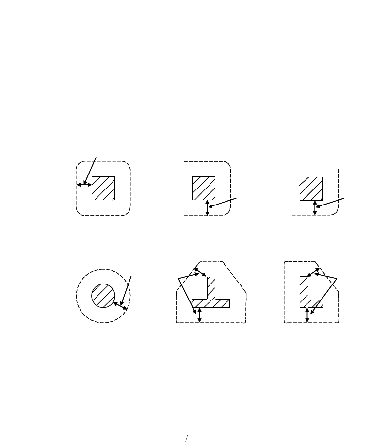
ETABS Reinforced Concrete Design
10.5.3.1 Critical Section for Punching Shear
The punching shear is checked at the face of the column (EC2 6.4.1(4)) and at a
critical section at a distance of 2.0d from the face of the support (EC2 6.4.2(1)).
The perimeter of the critical section should be constructed such that its length is
minimized. Figure 10-3 shows the auto punching perimeters considered by
ETABS for the various column shapes. The column location (i.e., interior, edge,
corner) and the punching perimeter may be overwritten using the Punching
Check Overwrites.
Figure 10-3 Punching Shear Perimeters
10.5.3.2 Determination of Concrete Capacity
The concrete punching shear stress capacity is taken as:
( )
13
,,1 1
100
Rd c Rd c ck cp
V Ck f k
ρσ
= +
(EC2 6.4.4(1))
with a minimum of:
( )
cpcRd
kvV
σ
1min,
+=
(EC2 6.4.4(1))
where fck is in MPa and
2d
Interior Column
Circular Column T-Shape Column
Edge Column Corner Column
L-Shape Column
2d 2d
2d
2d
2d
2d
Interior Column
Circular Column T-Shape Column
Edge Column Corner Column
L-Shape Column
2d 2d
2d
2d
2d
10 - 20 Slab Design
Chapter 10 - Design for Eurocode 2-2004
200
1 2.0kd
=+≤
with d in mm (EC2 6.4.4(1))
ρ
1 =
y
x1
1
ρ
ρ
≤ 0.02 (EC2 6.4.4(1))
where
ρ
1x and
ρ
1y are the reinforcement ratios in the x and y directions respec-
tively, which is taken as the average tension reinforcement ratios of design strips
in Layer A and layer B where Layer A and Layer design strips are in orthogonal
directions. When design strips are not present in both orthogonal directions then
tension reinforcement ratio is taken as zero in the current implementation, and
σcp = (σcx + σcy)/2 (EC2 6.4.4(1))
where σcx and σcy are the normal concrete stresses in the critical section in the x
and y directions respectively, conservatively taken as zeros.
ccRd
C
γ
18.0
,=
[NDP] (EC2 6.4.4(1))
21
23
min 035.0 ck
fk=
ν
[NDP] (EC2 6.4.4(1))
k1 = 0.15 [NDP]. (EC2 6.4.4(1))
10.5.3.3 Determine Maximum Shear Stress
Given the punching shear force and the fractions of moments transferred by ec-
centricity of shear, the nominal design shear stress, vEd, is calculated as:
,2 1 ,3 1
1,2 1,3
1,
=++
Ed Ed
Ed
Ed
Ed Ed
Mu Mu
V
v kk
ud VW VW
where (EC2 6.4.4(2))
k
is the function of the aspect ratio of the loaded area in Table 6.1 of
EN 1992-1-1
u1 is the effective perimeter of the critical section
d is the mean effective depth of the slab
MEd is the design moment transmitted from the slab to the column at the
connection along bending axis 2 and 3
Slab Design 10 - 21

ETABS Reinforced Concrete Design
VEd is the total punching shear force
W1 accounts for the distribution of shear based on the control perimeter
along bending axis 2 and 3.
10.5.3.4 Determine Capacity Ratio
The ratio of the maximum shear stress and the concrete punching shear stress
capacity is reported as the punching shear capacity ratio by ETABS. If this ratio
exceeds 1.0, punching shear reinforcement is designed as described in the fol-
lowing section.
10.5.4 Design Punching Shear Reinforcement
The use of shear studs as shear reinforcement in slabs is permitted, provided that
the effective depth of the slab is greater than or equal to 200 mm.
The algorithm for designing the required punching shear reinforcement is used
when the punching shear capacity ratio exceeds unity. The Critical Section for
Punching Shear and Transfer of Unbalanced Moment as described in the earlier
sections remain unchanged. The design of punching shear reinforcement is per-
formed as described in the subsections that follow.
10.5.4.1 Determine Concrete Shear Capacity
The concrete punching shear stress capacity of a section with punching shear
reinforcement is as previously determined for the punching check.
10.5.4.2 Determine Required Shear Reinforcement
The shear is limited to a maximum of VRd,max calculated in the same manner as
explained previously for slabs.
Given vEd, vRd,c, and vRd,max, the required shear reinforcement is calculated as fol-
lows (EC2 6.4.5).
If vR,dc < vEd ≤ vRd,max
10 - 22 Slab Design
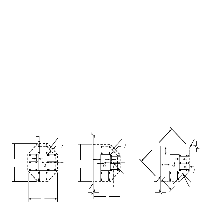
Chapter 10 - Design for Eurocode 2-2004
( )
( )
,
1
,
0.75
1.5
Ed Rd c
sw r
ywd ef
vv
A ud s
f
−
=
(EC2 6.4.5)
If vEd > vRd,max, a failure condition is declared. (EC2 6.2.3(3))
If vEd exceeds the maximum permitted value of VRd,max, the concrete section
should be increased in size.
10.5.4.3 Determine Reinforcement Arrangement
Punching shear reinforcement in the vicinity of rectangular columns should be
arranged on peripheral lines, i.e., lines running parallel to and at constant dis-
tances from the sides of the column. Figure 10-4 shows a typical arrangement of
shear reinforcement in the vicinity of a rectangular interior, edge, and corner
column.
Figure 10-4 Typical arrangement of shear studs and
critical sections outside shear-reinforced zone
The distance between the column face and the first line of shear reinforcement
shall not exceed 2d. The spacing between adjacent shear reinforcement in the
first line (perimeter) of shear reinforcement shall not exceed 1.5d measured in a
direction parallel to the column face (EC2 9.4.3(1)).
Punching shear reinforcement is most effective near column corners where there
are concentrations of shear stress. Therefore, the minimum number of lines of
I
y
Typical Studrail
(only first and last
studs shown)
Outermost
peripheral line
of studs
Interior Column Edge Column Corner Column
Critical section
centroid
Free
edge
Free
edge
Critical
section
centroid
Free edge
Outermost
peripheral line
of studs
I
y
I
y
yx
d2 d2
d2
x
I
x
I
x
g
y
g
x
g
0
s
0
s
0
s
x
I
y
x
x
I
y
Typical Studrail
(only first and last
studs shown)
Outermost
peripheral line
of studs
Interior Column Edge Column Corner Column
Critical section
centroid
Free
edge
Free
edge
Critical
section
centroid
Free edge
Outermost
peripheral line
of studs
I
y
I
y
yx
d2 d2
d2
x
I
x
I
x
g
y
g
x
g
0
s
0
s
0
s
x
I
y
x
x
Slab Design 10 - 23

ETABS Reinforced Concrete Design
shear reinforcement is 4, 6, and 8, for corner, edge, and interior columns respec-
tively.
10.5.4.4 Determine Reinforcement Diameter, Height, and Spacing
The punching shear reinforcement is most effective when the anchorage is close
to the top and bottom surfaces of the slab. The cover of anchors should not be
less than the minimum cover specified in EC2 4.4.1 plus half of the diameter of
the flexural reinforcement.
Punching shear reinforcement in the form of shear studs is generally available in
10-, 12-, 14-, 110-, and 20-millimeter diameters.
When specifying shear studs, the distance, so, between the column face and the
first peripheral line of shear studs should not be smaller than 0.3d. The spacing
between adjacent shear studs, g, at the first peripheral line of studs shall not ex-
ceed 1.5d and should not exceed 2d at additional perimeters. The limits of so and
the spacing, s, between the peripheral lines are specified as:
0.3d ≤ so ≤ 2d (EC2 9.4.3(1))
s ≤ 0.75d (EC2 9.4.3(1))
g ≤ 1.5d (first perimeter) (EC2 9.4.3(1))
g ≤ 2d (additional perimeters) (EC2 9.4.3(1))
10.6 Nationally Determined Parameters (NDPs)
The Comité Européen de Normalisation (CEN) version of Eurocode 2-2004
specifies a set of clauses in the design code, for which Nationally Determined
Parameters [NDPs] are permitted to be adjusted by each member country within
their National Annex. Variations in these parameters between countries are con-
sidered in the program by choosing the desired country from the Options menu
> Preferences > Concrete Frame Design command. This appendix lists the
NDPs as adopted in the program for the CEN Default version of the design code.
Additional tables are provided that list the NDPs that differ from the CEN De-
fault values for each country supported in the program.
10 - 24 Nationally Determined Parameters (NDPs)

Chapter 10 - Design for Eurocode 2-2004
Table
10-2 CEN Default NDPs
NDP Clause Value
γ
c 2.4.2.4(1) 1.5
γ
s 2.4.2.4(1) 1.15
α
cc 3.1.6(1) 1.0
α
ct 3.1.6(2) 1.0
max fyk 3.2.2(3) 600MPa
Load Combinations 5.1.3(1) Combinations from Eq. 6.10
θ
0 5.2(5) 0.005
k1 5.5(4) 0.44
k2 5.5(4) 1.25(0.6 + 0.0014/
ε
cu2)
k3 5.5(4) 0.54
k4 5.5(4) 1.25(0.6 + 0.0014/
ε
cu2)
λ
lim 5.8.3.1(1)
20 /ABC n⋅⋅⋅
CRd,c 6.2.2(1) 0.18/
γ
c
vmin 6.2.2(1) 0.035k3/2fck1/2
k1 6.2.2(1) 0.15
θ
6.2.3(2) 45 degrees
ν
1 6.2.3(3)
0.6 1 250
ck
f
−
α
cw 6.2.3(3) 1.0
Nationally Determined Parameters (NDPs) 10 - 25

ETABS Reinforced Concrete Design
Table
10-2 CEN Default NDPs
NDP Clause Value
Beam As,min 9.2.1.1(1)
0.26 0.0013
ctm tt
yk
fbd bd
f≥
Beam As,max 9.2.1.1(3) 0.04Ac
Beam
ρ
w,min 9.2.2(5)
( )
0.08 /
ck yk
ff
α
lcc 11.3.5(1) 0.85
α
lct 11.3.5(2) 0.85
ClRd,c 11.6.1(1) 0.15/
γ
c
vl,min 11.6.1(1) 0.30k3/2flck1/2
k1 11.6.1(1) 0.15
ν1 11.6.2(1) 0.5
η
1(1 – flck/250)
Table 10-3 Denmark NDPs
NDP Clause Value
γc 2.4.2.4(1) 1.45
γs 2.4.2.4(1) 1.20
Max fyk 3.2.2(3) 650MPa
Load Combinations 5.1.3(1) Combinations from Eq. 6.10a/b
λ
lim 5.8.3.1(1)
20
c cd
Ed
Af
N
⋅
10 - 26 Nationally Determined Parameters (NDPs)

Chapter 10 - Design for Eurocode 2-2004
Table 10-3 Denmark NDPs
NDP Clause Value
Beam
ρ
w,min 9.2.2(5)
( )
0.063 /
ck yk
ff
α
lcc 11.3.5(1) 1.0
α
lct 11.3.5(2) 1.0
vl,min 11.6.1(1) 0.03k2/3flck1/2
Table 10-4 Finland NDPs
NDP Clause Value
αcc 3.1.6(1) 0.85
Max fyk 3.2.2(3) 700MPa
Load Combinations 5.1.3(1) Combinations from Eq. 6.10a/b
k2 5.5(4) 1.10
Beam As,max 9.2.1.1(3) Unlimited
Table 10-5 Norway NDPs
NDP Clause Value
α
cc 3.1.6(1) 0.85
α
ct 3.1.6(2) 0.85
λ
lim 5.8.3.1(1) 13(2 − rm)Af
Nationally Determined Parameters (NDPs) 10 - 27

ETABS Reinforced Concrete Design
Table 10-5 Norway NDPs
NDP Clause Value
k1 6.2.2(1) 0.15 for compression
0.3 for tension
vmin 6.2.2(1) 0.035k3/2fck1/2
Beam
ρ
w,min 9.2.2(5)
( )
01
ck yk
. f /f
vl,min 11.6.1(1) 0.03k2/3flck1/2
k1 11.6.1(1) 0.15 for compression
0.3 for tension
ν1 11.6.2(1) 0.5(1 – flck/250)
Table 10-6 Singapore NDPs
NDP Clause Value
αcc 3.1.6(1) 0.85
k1 5.5(4) 0.4
k2 5.5(4) 0.6 + 0.0014/
ε
cu2
k3 5.5(4) 0.54
k4 5.5(4) 0.6 + 0.0014/
ε
cu2
vlim 5.8.3.1(1) 0.30k3/2flck1/2
Table 10-7 Slovenia NDPs
10 - 28 Nationally Determined Parameters (NDPs)

Chapter 10 - Design for Eurocode 2-2004
NDP Clause Value
Same As CEN Default
Table 10-8 Sweden NDPs
NDP Clause Value
Beam As,max 9.2.1.1(3) Unlimited
α
lcc 11.3.5(1) 1.0
α
lct 11.3.5(2) 1.0
Table 10-9 United Kingdom NDPs
NDP Clause Value
ψ
0,i (wind load) EC0 Combos 0.5
α
cc 3.1.6(1) 0.85
k1 5.5(4) 0.4
k2 5.5(4) 0.6 + 0.0014/
ε
cu2
k3 5.5(4) 0.4
k4 5.5(4) 0.6 + 0.0014/εcu2
vl,min 11.6.1(1) 0.30k3/2flck1/2
Nationally Determined Parameters (NDPs) 10 - 29

Chapter 11
Design for Hong Kong CP-2013
This chapter describes in detail the various aspects of the concrete design proce-
dure that is used by ETABS when the Hong Kong limit state code CP-2013 [CP
2013] is selected. The various notations used in this chapter are listed in Table
11-1. For referencing to the pertinent sections of the Hong Kong code in this
chapter, a prefix “CP” followed by the section number is used.
The design is based on user-specified load combinations. The program provides
a set of default load combinations that should satisfy the requirements for the
design of most building type structures.
English as well as SI and MKS metric units can be used for input. The code is
based on Newton-millimeter-second units. For simplicity, all equations and de-
scriptions presented in this chapter correspond to Newton-millimeter-second
units unless otherwise noted.
11.1 Notations
Table 11-1 List of Symbols Used in the CP-2013 Code
A
g
Gross area of cross-section, mm2
A
l
Area of longitudinal reinforcement for torsion, mm2
A
s
Area of tension reinforcement, mm2
Notations 11 - 1

ETABS Reinforced Concrete Design
Table 11-1 List of Symbols Used in the CP-2013 Code
A'
s
Area of compression reinforcement, mm2
A
sv
Total cross-sectional area of links at the neutral axis, mm2
A
sv,t
Total cross-sectional area of closed links for torsion, mm2
A
sv
/s
v
Area of shear reinforcement per unit length, mm2/mm
a
Depth of compression block, mm
b
Width or effective width of the section in the compression zone,
mm
b
f
Width or effective width of flange, mm
b
w
Average web width of a flanged shaped section, mm
C
Torsional constant, mm4
d
Effective depth of tension reinforcement, mm
d'
Depth to center of compression reinforcement, mm
E
c
Modulus of elasticity of concrete, N/mm2
E
s
Modulus of elasticity of reinforcement, assumed as 200,000 N/mm2
f
Punching shear factor considering column location
f
cu
Characteristic cube strength, N/mm2
f'
s
Stress in the compression reinforcement, N/mm2
f
y
Characteristic strength of reinforcement, N/mm2
f
yv
Characteristic strength of shear reinforcement, N/mm2
h
Overall depth of a section in the plane of bending, mm
h
f
Flange thickness, mm
h
min
Smaller dimension of a rectangular section, mm
h
max
Larger dimension of a rectangular section, mm
K
Normalized design moment,
2u
cu
M
bd f
K' Maximum
2u
cu
M
bd f
for a singly reinforced concrete section
k
1
Shear strength enhancement factor for support compression
11 - 2 Notations
Chapter 11 - Design for Hong Kong CP-2013
Table 11-1 List of Symbols Used in the CP-2013 Code
k2 Concrete shear strength factor,
[ ]
3
1
25
cu
f
M
Design moment at a section, N-mm
M
single
Limiting moment capacity as singly reinforced slab section, N-mm
s
v
Spacing of the links along the strip, mm
T
Design torsion at ultimate design load, N-mm
u
Perimeter of the punch critical section, mm
V
Design shear force at ultimate design load, N
v
Design shear stress at a slab cross-section or at a punching critical
section, N/mm2
v
c
Design concrete shear stress capacity, N/mm2
v
max
Maximum permitted design factored shear stress, N/mm2
v
t
Torsional shear stress, N/mm2
x
Neutral axis depth, mm
x
bal
Depth of neutral axis in a balanced section, mm
z
Lever arm, mm
β
Torsional stiffness constant
β
b
Moment redistribution factor in a member
γ
f
Partial safety factor for load
γ
m
Partial safety factor for material strength
ε
c
Maximum concrete strain
ε
s
Strain in tension reinforcement
ε
'
s
Strain in compression reinforcement
11.2 Design Load Combinations
The design load combinations are the various combinations of the load cases for
which the structure needs to be designed. The design load combinations are ob-
tained by multiplying the characteristic loads by appropriate partial factors of
safety, γf (CP 2.3.1.3). For CP-2013, if a structure is subjected to dead (G), live
Design Load Combinations 11 - 3

ETABS Reinforced Concrete Design
(Q), pattern live (PQ), and wind (W) loads, and considering that wind forces are
reversible, the following load combinations may need to be considered. (CP
2.3.2.1, Table 2.1).
1.4G
1.
4G + 1.6Q
(CP 2.3.2)
1.4G + 1.6(0.75PQ)
(CP 2.3.2)
1.0G ± 1.4W
1.4
G ± 1.4W
1.2
G + 1.2Q ± 1.2W (CP 2.3.2
)
These are also the default design load combinations in ETABS whenever the
CP-2013 code is used. If roof live load is separately treated or other types of
loads are present, other appropriate load combinations should be used. Note that
the automatic combination, including pattern live load, is assumed and should
be reviewed before using for design.
11.3 Limits on Material Strength
The concrete compressive strength, fcu, should not be less than 20 N/mm2 (CP
3.1.3). The program does not enforce this limit for flexure and shear design of
slabs. The input material strengths are used for design even if they are outside of
the limits. It is the user's responsible to use the proper strength values while de-
fining the materials.
11.4 Partial Safety Factors
The design strengths for concrete and reinforcement are obtained by dividing the
characteristic strength of the material by a partial safety factor,
γ
m. The values of
γ
m used in the program are listed in the following table, as taken from CP Table
2.2 (CP 2.4.3.2):
11 - 4 Limits on Material Strength
Chapter 11 - Design for Hong Kong CP-2013
Values of
γ
m for the Ultimate Limit State
Reinforcement 1.15
Concrete in flexure and axial load 1.50
Concrete shear strength without shear reinforcement 1.25
These factors are incorporated into the design equations and tables in the code,
but can be overwritten.
11.5 Slab Design
ETABS slab design procedure involves defining sets of strips in two mutually
perpendicular directions. The locations of the strips are usually governed by the
locations of the slab supports. The axial force, moments and shears for a partic-
ular strip are recovered from the analysis (on the basis of the Wood-Armer tech-
nique), and a flexural design is carried out based on the ultimate strength design
method.
The slab design procedure involves the following steps:
Design flexural reinforcement
Design shear reinforcement
Punching check
11.5.1 Design Flexural Reinforcement
For slabs, ETABS uses either design strips or the finite element based design to
calculate the slab flexural reinforcement in accordance with the selected design
code. For simplicity, only strip-by-strip design is document in the proceeding
sections.
The design of the slab reinforcement for a particular strip is carried out at specific
locations along the length of the strip. These locations correspond to the element
boundaries. Controlling reinforcement is computed on either side of those ele-
ment boundaries. The slab flexural design procedure for each load combination
involves the following:
Slab Design 11 - 5

ETABS Reinforced Concrete Design
Determine factored axial loads and moments for each slab strip.
Design flexural reinforcement for the strip.
These two steps, described in the text that follows, are repeated for every load
combination. The maximum reinforcement calculated for the top and bottom
of the slab within each design strip, along with the corresponding controlling
load combination, is obtained and reported.
11.5.1.1 Determine Factored Moments
In the design of flexural reinforcement of concrete slab, the factored moments
for each load combination at a particular design strip are obtained by factoring
the corresponding moments for different load cases, with the corresponding load
factors.
The slab is then designed for the maximum positive and maximum negative fac-
tored moments obtained from all of the load combinations. Calculation of bottom
reinforcement is based on positive design strip moments. In such cases, the slab
may be designed as a rectangular or flanged slab section. Calculation of top re-
inforcement is based on negative design strip moments. In such cases, the slab
may be designed as a rectangular or inverted flanged slab section.
11.5.1.2 Determine Required Flexural Reinforcement
In the flexural reinforcement design process, the program calculates both the
tension and compression reinforcement. Compression reinforcement is added
when the applied design moment exceeds the maximum moment capacity of a
singly reinforced section. The user has the option of avoiding the compression
reinforcement by increasing the effective depth, the width, or the strength of the
concrete.
The design procedure is based on the simplified rectangular stress block shown
in Figure 11-1 (CP 6.1.2.4(a)), where
ε
c,max is defined as:
( )
2
max 12
2
0 0035 if 60N/mm
0 0035 0 00006 60 if 60N/mm
cu
c,
cu cu
.f
. .f f
ε
≤
=−− >
11 - 6 Slab Design

Chapter 11 - Design for Hong Kong CP-2013
Furthermore, it is assumed that moment redistribution in the member does not
exceed 10% (i.e.,
β
b ≥ 0.9; CP 6.1.2.4(b)). The code also places a limitation on
the neutral axis depth,
2
2
2
0.5 for 45 N/mm
0.4 for 45 70 N/mm
0.33 for 70 100N/mm
cu
cu
cu
f
xf
df
≤
≤ <≤
<≤
(CP 6.1.2.4(b))
to safeguard against non-ductile failures (CP 6.1.2.4(b)). In addition, the area of
compression reinforcement is calculated assuming that the neutral axis depth re-
mains at the maximum permitted value.
The depth of the compression block is given by:
2
2
2
0.9 for 45 N/mm
0.8 for 45 < 70 N/mm
0.72 for 70 < 100 N/mm
a
≤
= ≤
≤
cu
cu
cu
xf
xf
xf
(CP 6.1.2.4(a), Fig 6.1)
The design procedure used by ETABS, for both rectangular and flanged sections
(L- and T-shaped sections), is summarized in the text that follows. For reinforced
concrete design where design ultimate axial compression load does not ex-
ceed (0.1fcuAg) (CP 6.1.2.4(a)), axial force is ignored; hence, all slabs are de-
signed for major direction flexure and shear only. Axial compression greater
than 0.1fcuAg and axial tensions are always included in flexural and shear design.
11.5.1.2.1 Design of uniform thickness slab
For uniform thickness slab, the limiting moment capacity as a singly reinforced
slab, Msingle, is obtained first for a section. The reinforcing is determined based
on whether M is greater than, less than, or equal to Msingle. See Figure 11-1
Calculate the ultimate limiting moment of resistance of the section as singly re-
inforced.
Msingle = K'fcu bd2, where (CP 6.1.2.4(c), Eqn. 6.8)
Slab Design 11 - 7
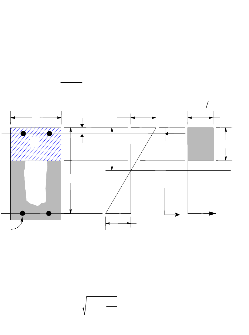
ETABS Reinforced Concrete Design
2
2
2
0.156 for 45N/mm
' 0.120 for 45 70N/mm
0.094 for 70 100N/mm
≤
= <≤
<≤
cu
cu
cu
f
Kf
f
If M ≤ Msingle, the area of tension reinforcement, As, is obtained from:
,
0.87
sy
M
Afz
=
where (CP 6.1.2.4(c), Eqn. 6.12)
Figure 11-1 Uniform Thickness Slab Design
d
K
dz 95.0
9.0
25.05.0 ≤
−+=
(CP 6.1.2.4(c), Eqn. 6.10)
2
bdf
M
K
cu
=
(CP 6.1.2.4(c) , Eqn. 6.7)
BEAM
SECTION STRAIN
DIAGRAM STRESS
DIAGRAM
c
εγ
0 67
cu m
.f
a
cs
T
s
T
s
ε
x
s
C
d′
d
b
s
A
s
A′′
s
f
BEAM
SECTION STRAIN
DIAGRAM STRESS
DIAGRAM
c
εγ
0 67
cu m
.f
a
cs
T
s
T
s
ε
x
s
C
d′
d
b
s
A
s
A′′
s
f
11 - 8 Slab Design
Chapter 11 - Design for Hong Kong CP-2013
This reinforcement is to be placed at the bottom if M is positive, or at the top
if M is negative.
If M > Msingle, compression reinforcement is required and calculated as fol-
lows:
( )
sin
0.67
gle
s
cu
sc
MM
Af
f dd
γ
−
′=
′′
−−
(CP 6.1.2.4(c), , Eqn. 6.15)
where d′ is the depth of the compression reinforcement from the concrete com-
pression face, and
1 0.87 ,
s sc y
d
fE f
x
ε
′
′= −≤
(CP 6.1.2.4(c), 3.2.6, Fig.
3.9)
2
2
2
, for 45N/mm
0.45
, for 45 70 N/mm
0.40
, for 70 100 N/mm
0.36
cu
cu
cu
dz f
dz
xf
dz f
−
≤
−
= <≤
−<≤
(CP 6.1.2.4(a), Fig 6.1, Eqn.
6.11)
'
0.5 0.25 0.9
K
zd
=+−
≤ 0.95d (CP 6.1.2.4(c))
The tension reinforcement required for balancing the compression in the con-
crete and the compression reinforcement is calculated as:
( )
single single
0.87 0.87
syy
M MM
Afz f d d
−
= + ′
−
(CP
6.1.2.4(c))
Slab Design 11 - 9
ETABS Reinforced Concrete Design
11.5.1.2.2 Design of nonuniform thickness slab
11.5.1.2.2.1 Flanged Slab Section Under Negative Moment
In designing for a factored negative moment, M (i.e., designing top reinforce-
ment), the calculation of the reinforcement area is exactly the same as described
previously, i.e., no flanged data is used.
11.5.1.2.2.2 Flanged Slab Section Under Positive Moment
With the flange in compression, the program analyzes the section by considering
alternative locations of the neutral axis. Initially, the neutral axis is assumed to
be located in the flange. On the basis of this assumption, the program calculates
the exact depth of the neutral axis. If the stress block does not extend beyond the
flange thickness, the section is designed as a uniform thickness slab of width bf.
If the stress block extends beyond the flange depth, the contribution of the web
to the flexural strength of the slab is taken into account. See Figure 11-2.
Assuming the neutral axis to lie in the flange, the normalized moment is given
by:
2
.
cu f
M
Kf bd
=
(CP 6.1.2.4(c) , Eqn. 6.7)
Then the moment arm is computed as:
z = d
0.5 0.25 0.9
K
+−
≤ 0.95d, (CP 6.1.2.4(c), , Eqn. 6.10)
the depth of the neutral axis is computed as:
2
2
2
, for 45N/mm
0.45
, for 45 70N/mm
0.40
, for 70 100N/mm
0.36
cu
cu
cu
dz f
dz
xf
dz f
−
≤
−
= <≤
−<≤
(CP 6.1.2.4(c), Fig 6.1, , Eqn.
6.11)
11 - 10 Slab Design
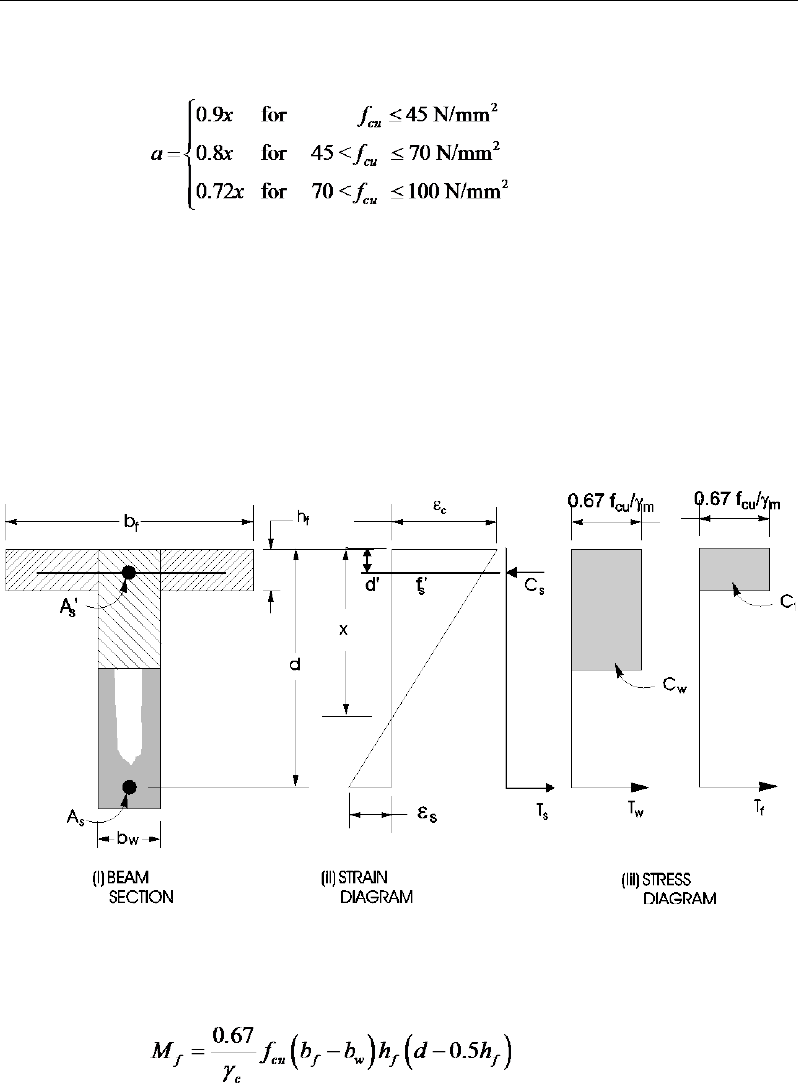
Chapter 11 - Design for Hong Kong CP-2013
and the depth of the compression block is given by:
(CP 6.1.2.4(a), Fig 6.1)
If a ≤ hf, the subsequent calculations for As are exactly the same as previously
defined for the uniform thickness slab design. However, in that case, the width
of the slab is taken as bf. Compression reinforcement is required when K > K'.
If a > hf , the calculation for As has two parts. The first part is for balancing the
compressive force from the flange, Cf, and the second part is for balancing the
compressive force from the web, Cw, as shown in Figure 11-2.
Figure 11-2 Nonuniform Thickness Slab Design
In that case, the ultimate resistance moment of the flange is given by:
Slab Design 11 - 11
ETABS Reinforced Concrete Design
The moment taken by the web is computed as:
f
w
M
M
M−
=
and the normalized moment resisted by the web is given by:
Kw =
2
w
cu w
M
f bd
If Kw ≤ K′ (CP 6.1.2.4(c)), the slab is designed as a singly reinforced concrete
section. The reinforcement is calculated as the sum of two parts, one to balance
compression in the flange and one to balance compression in the web.
( )
,
0.87
0.87 0.5
fw
sy
yf
MM
Afz
fd h
= +
−
where
d
K
dz w95
.
0
9.0
25
.0
5.0 ≤
−
+=
If Kw > K′, compression reinforcement is required and is calculated as follows:
The ultimate moment of resistance of the web only is given by:
2
uw cu w
M Kf b d=
The compression reinforcement is required to resist a moment of magnitude
Mw − Muw. The compression reinforcement is computed as:
( )
0.67
w uw
s
cu
sc
MM
Af
f dd
γ
−
′=
′′
−−
where, d′ is the depth of the compression reinforcement from the concrete
compression face, and
1 0.87
s sc y
d
fE f
x
ε
= −≤
(CP 6.1.2.4(c), 3.2.6, Fig 3.9)
The area of tension reinforcement is obtained from equilibrium as:
11 - 12 Slab Design

Chapter 11 - Design for Hong Kong CP-2013
1
0.87 0.5 '
fuw w uw
s
yf
MM MM
Af d h z dd
−
= ++
−−
0.5 0.25 0.95
0.9
K
zd d
′
= + −≤
11.5.1.2.2.3 Minimum and Maximum Reinforcement
The minimum flexural tension reinforcement required in each direction of a slab
is given by the following limits (CP 9.3.1.1), with interpolation for reinforcement
of intermediate strength:
0 0024 if 250 MPa
0 0013 if 460 MPa
y
s
y
. bh f
A. bh f
≤
≥≥
(CP 9.3.1.1(a))
In addition, an upper limit on both the tension reinforcement and compres-
sion reinforcement has been imposed to be 0.04 times the gross cross-sec-
tional area (CP 9.2.1.3).
11.5.2 Design Slab Shear Reinforcement
The shear reinforcement is designed for each load combination at each station
along the design strip. In designing the shear reinforcement for a particular strip,
for a particular load combination, at a particular station due to the slab major
shear, the following steps are involved (CP 6.1.2.5):
Determine the shear stress, v.
Determine the shear stress, vc, that can be resisted by the concrete.
Determine the shear reinforcement required to carry the balance.
The following three sections describe in detail the algorithms associated with
these steps.
Slab Design 11 - 13

ETABS Reinforced Concrete Design
11.5.2.1 Determine Shear Stress
In the design of the slab shear reinforcement, the shear stresses for each load
combination at a particular design strip station are obtained by factoring the cor-
responding shear forces for different load cases, with the corresponding load
combination factors:
bd
V
v=
(CP 6.1.2.5(a))
The maximum allowable shear stress, vmax is defined as:
vmax = min(0.8
cu
f,
7 MPa) (CP 6.1.2.5(a))
11.5.2.2 Determine Concrete Shear Capacity
The shear stress carried by the concrete, vc, is calculated as:
cc
c
c
cc
vA
N
v
MA
NVh
vv +≤+= 16.0'
(CP 6.1.2.5(k) , Eqn. 6.22)
4
1
3
1
2
1400
100
79.0
=d
bd
A
kk
vs
m
c
γ
(CP 6.1.2.5(c), Table 6.3)
1
k
is the enhancement factor for support compression,
and is conservatively taken as 1 (CP 6.1.2.5(g))
k2 =
13
25
cu
f,
1 ≤ k2 ≤
3
1
25
80
(CP 6.1.2.5(c), Table 6.3)
1.25
m
γ
=
(CP 6.1.2.5(c), Table 6.3)
However, the following limitations also apply:
100
0.15 3,
s
A
bd
≤≤
(CP 6.1.2.5(c), Table 6.3)
11 - 14 Slab Design

Chapter 11 - Design for Hong Kong CP-2013
≥
140 67 Members without shear reinforcement
400
1 00 Members with shear reinforcement
.,
.,
d
(CP 6.1.2.5(c), Table 6.3)
1≤
M
Vh
(CP 6.1.2.5(k))
11.5.2.3 Determine Required Shear Reinforcement
Given v, vc, and vmax, the required shear reinforcement is calculated as follows
(CP Table 6.2, CP 6.1.2.5(b)):
Calculate the design average shear stress that can be carried by minimum shear
reinforcement, vr, as:
( )
2
23
2
23
2
Nmm
Nmm
Nmm
0.4 if 40
0.4 if 40 80
40
80
0.4 if 80
40
≤
= <≤
>
cu
cu
r cu
cu
f
f
vf
f
(CP 6.1.2.5(b), Table 6.2)
If v ≤ v’c + vr, minimum reinforcement is required:
,
0.87
sr
v yv
Avb
sf
=
(CP 6.1.2.5(b))
If v > v’c + vr,
( )
0 87
c
sv
v yv
v v' b
A
s .f
−
=
(CP 6.1.2.5(b))
If v > vmax, a failure condition is declared. (CP 6.1.2.5(b))
The maximum of all the calculated Asv /sv values obtained from each load com-
bination is reported along with the controlling shear force and associated load
combination.
Slab Design 11 - 15
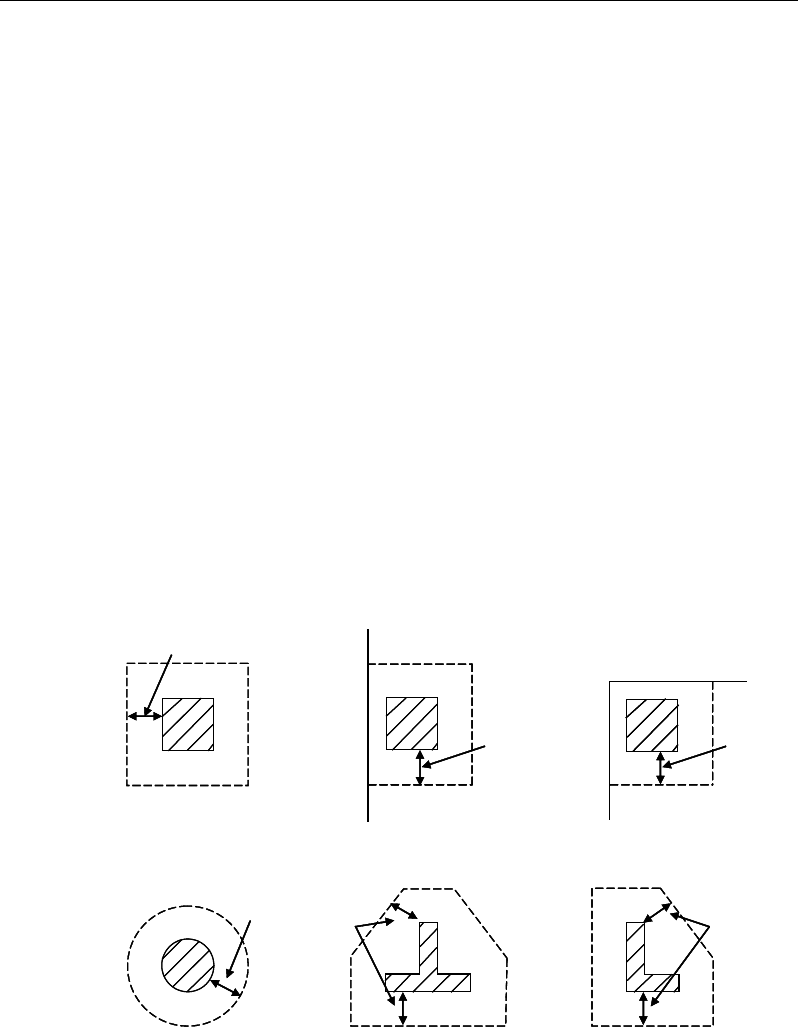
ETABS Reinforced Concrete Design
The slab shear reinforcement requirements considered by the program are
based purely on shear strength considerations. Any minimum stirrup require-
ments to satisfy spacing and volumetric considerations must be investigated
independently of the program by the user.
11.5.3 Check for Punching Shear
The algorithm for checking punching shear is detailed in the section entitled
“Slab Punching Shear Check” in the Chapter 1. Only the code-specific items are
described in the following sections.
11.5.3.1 Critical Section for Punching Shear
The punching shear is checked on a critical section at a distance of 1.5d from the
face of the support (CP 6.1.5.7(d)). For rectangular columns and concentrated
loads, the critical area is taken as a rectangular area with the sides parallel to the
sides of the columns or the point loads (CP 6.1.5.7). Figure 11-3 shows the auto
punching perimeters considered by ETABS for the various column shapes. The
column location (i.e., interior, edge, corner) and the punching perimeter may be
overwritten using the Punching Check Overwrites.
Figure 11-3 Punching Shear Perimeters
1.5d
Interior Column
Circular Column T-Shape Column
Edge Column Corner Column
L-Shape Column
1.5d 1.5d
1.5d
1.5d
1.5d
1.5d
Interior Column
Circular Column T-Shape Column
Edge Column Corner Column
L-Shape Column
1.5d 1.5d
1.5d
1.5d
1.5d
11 - 16 Slab Design
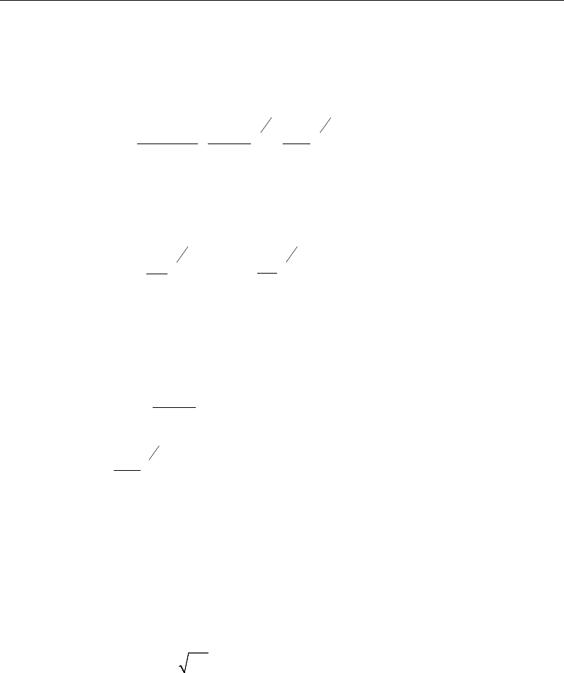
Chapter 11 - Design for Hong Kong CP-2013
11.5.3.2 Determine Concrete Capacity
The concrete punching shear factored strength is taken as (CP 6.1.5.7(d), Table
6.3):
4
1
3
1
2
1400
100
79.
0
=d
bd
A
k
k
vs
m
c
γ
(CP 6.1.2.5(d), Table 6.3)
1
k
is the enhancement factor for support compression,
and is conservatively taken as 1 (CP 6.1.2.5(g), 6.1.5.7(d))
k2 =
3
1
25
cu
f
1 ≤ k2 ≤ 3
1
25
80
(CP 6.1.2.5(c), Table 6.3)
1.25
m
γ
=
(CP 2.4.3.2, Table 2.2)
However, the following limitations also apply:
100
0.15 3,
s
A
bd
≤≤
(CP 6.1.2.5(c), Table 6.3)
≥
14
0 67 Members without shear reinforcement
400
1 00 Members with shear reinforcement
.,
.,
d
(CP 6.1.2.5(c), Table 6.3)
As = area of tension reinforcement, which is taken as the average tension
reinforcement of design strips in Layer A and layer B where Layer
A and Layer design strips are in orthogonal directions. When design
strips are not present in both orthogonal directions then tension rein-
forcement is taken as zero in the current implementation.
v ≤ min(0.8
cu
f,
7 MPa) (CP 6.1.5.7(b))
fcu ≤ 80 MPa (for calculation purpose only) (CP Table 6.3)
Slab Design 11 - 17

ETABS Reinforced Concrete Design
11.5.3.3 Determine Maximum Shear Stress
Given the punching shear force and the fractions of moments transferred by ec-
centricity of shear about the bending axis, the nominal design shear stress, vmax,
is calculated as:
,
1.5
eff x
Mx
V Vf Vy
= +
(CP 6.1.5.6(b), 6.1.5.6(c))
.
1.5
eff y
My
V Vf Vx
= +
(CP 6.1.5.6(b), 6.1.5.6(c))
,
max
,
max
eff x
eff y
V
ud
vV
ud
=
(CP 6.1.5.7)
where,
u is the perimeter of the critical section,
x and y are the lengths of the sides of the critical section parallel to the axis
of bending,
Mx and My are the design moments transmitted from the slab to the column
at the connection,
V is the total punching shear force, and
f is a factor to consider the eccentricity of punching shear force and is
taken as
1 00 for interior columns
1 25 for edge columns
1 25 for corner columns
.
f.
.
=
(CP 6.1.5.6(b), 6.1.5.6(c))
11 - 18 Slab Design

Chapter 11 - Design for Hong Kong CP-2013
11.5.3.4 Determine Capacity Ratio
The ratio of the maximum shear stress and the concrete punching shear stress
capacity is reported as the punching shear capacity ratio by ETABS. If this ratio
exceeds 1.0, punching shear reinforcement is designed as described in the fol-
lowing section.
11.5.4 Design Punching Shear Reinforcement
The use of shear links as shear reinforcement in slabs is permitted, provided that
the effective depth of the slab is greater than or equal to 200 mm (CP 6.1.5.7(e)).
The use of shear studs is not covered in Hong Kong CP 2013. However, program
uses the identical clauses for shear studs when CP 20013 code is selected. If the
slab thickness does not meet these requirements, the punching shear reinforce-
ment is not designed and the slab thickness should be increased by the user.
The algorithm for designing the required punching shear reinforcement is used
when the punching shear capacity ratio exceeds unity. The Critical Section for
Punching Shear and Transfer of Unbalanced Moment as described in the earlier
sections remain unchanged. The design of punching shear reinforcement is car-
ried out as described in the subsections that follow.
11.5.4.1 Determine Concrete Shear Capacity
The concrete punching shear stress capacity of a section with punching shear
reinforcement is as previously determined for the punching check.
11.5.4.2 Determine Required Shear Reinforcement
The shear stress is limited to a maximum of:
vmax = 2vc (CP 6.1.5.7(e))
Given v, vc, and vmax, the required shear reinforcement is calculated as follows
(CP 6.1.5.7(e)).
If v ≤ 1.6vc,
Slab Design 11 - 19

ETABS Reinforced Concrete Design
s
Av
=
( )
0.87 0.87
−≥
cr
yv yv
v v ud v ud
ff
,
(CP 6.1.5.7(e))
If 1.6vc ≤ v < 2.0vc,
s
Av
=
( )
5 0.7 ,
0.87 0.87
c
yv yv
v v ud ud
ff
−≥r
v
(CP 6.1.5.7(e))
0.4
0.4 40
rcu
v= f
2/3
N/mm2 (CP 6.1.5.7, Table 6.2)
If v > 2.0vc, a failure condition is declared. (CP 6.1.5.7(e))
If v exceeds the maximum permitted value of vmax, the concrete section should
be increased in size.
11.5.4.3 Determine Reinforcement Arrangement
Punching shear reinforcement in the vicinity of rectangular columns should be
arranged on peripheral lines, i.e., lines running parallel to and at constant dis-
tances from the sides of the column. Figure 11-4 shows a typical arrangement of
shear reinforcement in the vicinity of a rectangular interior, edge, and corner
column.
The distance between the column face and the first line of shear reinforcement
shall not exceed d/2. The spacing between adjacent shear reinforcement in the
first line (perimeter) of shear reinforcement shall not exceed 1.5d measured in a
direction parallel to the column face (CP 6.1.5.7(f)).
Punching shear reinforcement is most effective near column corners where there
are concentrations of shear stress. Therefore, the minimum number of lines of
shear reinforcement is 4, 6, and 8, for corner, edge, and interior columns respec-
tively.
11 - 20 Slab Design

Chapter 11 - Design for Hong Kong CP-2013
Figure 11-4 Typical arrangement of shear studs
and critical sections outside shear-reinforced zone
11.5.4.4 Determine Reinforcement Diameter, Height, and Spacing
The punching shear reinforcement is most effective when the anchorage is close
to the top and bottom surfaces of the slab. The cover of anchors should not be
less than the minimum cover specified in CP 4.2.4 plus half of the
diameter of the flexural reinforcement.
Punching shear reinforcement in the form of shear studs is generally available in
10-, 12-, 14-, 16-, and 20-millimeter diameters.
When specifying shear studs, the distance, so, between the column face and the
first peripheral line of shear studs should not be smaller than 0.5d. The spacing
between adjacent shear studs, g, at the first peripheral line of studs shall not ex-
ceed 1.5d. The limits of so and the spacing, s, between the peripheral lines are
specified as:
so ≤ 0.5d (CP 6.1.5.7(f))
s ≤ 0.75d (CP 6.1.5.7(f))
g ≤ 1.5d (CP 6.1.5.7(f))
Stirrups are only permitted when slab thickness is greater than 200 mm (CP
6.1.5.7(e)).
I
y
Typical Studrail
(only first and last
studs shown)
Outermost
peripheral line
of studs
Interior Column Edge Column Corner Column
Critical section
centroid
Free
edge
Free
edge
Critical
section
centroid
Free edge
Outermost
peripheral line
of studs
I
y
I
y
yx
d2 d2
d2
x
I
x
I
x
g
y
g
x
g
0
s
0
s
0
s
x
I
y
x
x
I
y
Typical Studrail
(only first and last
studs shown)
Outermost
peripheral line
of studs
Interior Column Edge Column Corner Column
Critical section
centroid
Free
edge
Free
edge
Critical
section
centroid
Free edge
Outermost
peripheral line
of studs
I
y
I
y
yx
d2 d2
d2
x
I
x
I
x
g
y
g
x
g
0
s
0
s
0
s
x
I
y
x
x
Slab Design 11 - 21

Chapter 12
Design for Hong Kong CP-04
This chapter describes in detail the various aspects of the concrete design proce-
dure that is used by ETABS when the Hong Kong limit state code CP-04 [CP
04], which also incorporates Amendment 1 published in June 2007, is selected.
The various notations used in this chapter are listed in Table 12-1. For referenc-
ing to the pertinent sections of the Hong Kong code in this chapter, a prefix “CP”
followed by the section number is used.
The design is based on user-specified load combinations. The program provides
a set of default load combinations that should satisfy the requirements for the
design of most building type structures.
English as well as SI and MKS metric units can be used for input. The code is
based on Newton-millimeter-second units. For simplicity, all equations and de-
scriptions presented in this chapter correspond to Newton-millimeter-second
units unless otherwise noted.
12.1 Notations
Table 12-1 List of Symbols Used in the CP-04 Code
A
g
Gross area of cross-section, mm2
A
l
Area of longitudinal reinforcement for torsion, mm2
Notations 12 - 1

ETABS Reinforced Concrete Design
Table 12-1 List of Symbols Used in the CP-04 Code
A
s
Area of tension reinforcement, mm2
A'
s
Area of compression reinforcement, mm2
A
sv
Total cross-sectional area of links at the neutral axis, mm2
A
sv,t
Total cross-sectional area of closed links for torsion, mm2
A
sv
/s
v
Area of shear reinforcement per unit length, mm2/mm
a
Depth of compression block, mm
b
Width or effective width of the section in the compression zone,
mm
b
f
Width or effective width of flange, mm
b
w
Average web width of a flanged shaped section, mm
C
Torsional constant, mm4
d
Effective depth of tension reinforcement, mm
d'
Depth to center of compression reinforcement, mm
E
c
Modulus of elasticity of concrete, N/mm2
E
s
Modulus of elasticity of reinforcement, assumed as 200,000 N/mm2
f
Punching shear factor considering column location
f
cu
Characteristic cube strength, N/mm2
f'
s
Stress in the compression reinforcement, N/mm2
f
y
Characteristic strength of reinforcement, N/mm2
f
yv
Characteristic strength of shear reinforcement, N/mm2
h
Overall depth of a section in the plane of bending, mm
h
f
Flange thickness, mm
h
min
Smaller dimension of a rectangular section, mm
h
max
Larger dimension of a rectangular section, mm
K
Normalized design moment,
2u
cu
M
bd f
K' Maximum
2u
cu
M
bd f
for a singly reinforced concrete section
12 - 2 Notations

Chapter 12 - Design for Hong Kong CP-04
Table 12-1 List of Symbols Used in the CP-04 Code
k
1
Shear strength enhancement factor for support compression
k2 Concrete shear strength factor,
[ ]
3
1
25
cu
f
M
Design moment at a section, N-mm
M
single
Limiting moment capacity as singly reinforced section, N-mm
s
v
Spacing of the links along the strip, mm
T
Design torsion at ultimate design load, N-mm
u
Perimeter of the punch critical section, mm
V
Design shear force at ultimate design load, N
v
Design shear stress at a slab cross-section or at a punching critical
section, N/mm2
v
c
Design concrete shear stress capacity, N/mm2
v
max
Maximum permitted design factored shear stress, N/mm2
v
t
Torsional shear stress, N/mm2
x
Neutral axis depth, mm
x
bal
Depth of neutral axis in a balanced section, mm
z
Lever arm, mm
β
Torsional stiffness constant
β
b
Moment redistribution factor in a member
γ
f
Partial safety factor for load
γ
m
Partial safety factor for material strength
ε
c
Maximum concrete strain
ε
s
Strain in tension reinforcement
ε
'
s
Strain in compression reinforcement
12.2 Design Load Combinations
The design load combinations are the various combinations of the load cases for
which the structure needs to be designed. The design load combinations are ob-
tained by multiplying the characteristic loads by appropriate partial factors of
Design Load Combinations 12 - 3

ETABS Reinforced Concrete Design
safety, γf (CP 2.3.1.3). For CP-04, if a structure is subjected to dead (D), live (L),
pattern live (PL), and wind (W) loads, and considering that wind forces are re-
versible, the following load combinations may need to be considered. (CP
2.3.2.1, Table 2.1).
1.4D
1.
4D + 1.6L
(CP 2.3.2)
1.4D + 1.6(0.75PL)
(CP 2.3.2)
1.0D ± 1.4W
1.4D
± 1.4W
1.2D + 1.
2L ± 1.2W (CP 2.3.2
)
These are also the default design load combinations in ETABS whenever the
CP-04 code is used. If roof live load is separately treated or other types of loads
are present, other appropriate load combinations should be used. Note that the
automatic combination, including pattern live load, is assumed and should be
reviewed before using for design.
12.3 Limits on Material Strength
The concrete compressive strength, fcu, should not be less than 20 N/mm2 (CP
3.1.3). The program does not enforce this limit for flexure and shear design of
slabs. The input material strengths are used for design even if they are outside of
the limits. It is the user's responsible to use the proper strength values while de-
fining the materials.
12.4 Partial Safety Factors
The design strengths for concrete and reinforcement are obtained by dividing the
characteristic strength of the material by a partial safety factor,
γ
m. The values of
γ
m used in the program are listed in the following table, as taken from CP Table
2.2 (CP 2.4.3.2):
12 - 4 Limits on Material Strength

Chapter 12 - Design for Hong Kong CP-04
Values of
γ
m for the Ultimate Limit State
Reinforcement 1.15
Concrete in flexure and axial load 1.50
Concrete shear strength without shear reinforcement 1.25
These factors are incorporated into the design equations and tables in the code,
but can be overwritten.
12.5 Slab Design
ETABS slab design procedure involves defining sets of strips in two mutually
perpendicular directions. The locations of the strips are usually governed by the
locations of the slab supports. The axial force, moments and shears for a partic-
ular strip are recovered from the analysis (on the basis of the Wood-Armer tech-
nique), and a flexural design is carried out based on the ultimate strength design
method.
The slab design procedure involves the following steps:
Design flexural reinforcement
Design shear reinforcement
Punching check
12.5.1 Design Flexural Reinforcement
For slabs, ETABS uses either design strips or the finite element based design to
calculate the slab flexural reinforcement in accordance with the selected design
code. For simplicity, only strip-by-strip design is document in the proceeding
sections.
The design of the slab reinforcement for a particular strip is carried out at specific
locations along the length of the strip. These locations correspond to the element
boundaries. Controlling reinforcement is computed on either side of those ele-
ment boundaries. The slab flexural design procedure for each load combination
involves the following:
Slab Design 12 - 5

ETABS Reinforced Concrete Design
Determine factored axial loads and moments for each slab strip.
Design flexural reinforcement for the strip.
These two steps, described in the text that follows, are repeated for every load
combination. The maximum reinforcement calculated for the top and bottom
of the slab within each design strip, along with the corresponding controlling
load combination, is obtained and reported.
12.5.1.1 Determine Factored Moments
In the design of flexural reinforcement of concrete slab, the factored moments
for each load combination at a particular design strip are obtained by factoring
the corresponding moments for different load cases, with the corresponding load
factors.
The slab is then designed for the maximum positive and maximum negative fac-
tored moments obtained from all of the load combinations. Calculation of bottom
reinforcement is based on positive design strip moments. In such cases, the slab
may be designed as a rectangular or flanged slab section. Calculation of top re-
inforcement is based on negative design strip moments. In such cases, the slab
may be designed as a rectangular or inverted flanged slab section.
12.5.1.2 Determine Required Flexural Reinforcement
In the flexural reinforcement design process, the program calculates both the
tension and compression reinforcement. Compression reinforcement is added
when the applied design moment exceeds the maximum moment capacity of a
singly reinforced section. The user has the option of avoiding the compression
reinforcement by increasing the effective depth, the width, or the strength of the
concrete.
The design procedure is based on the simplified rectangular stress block shown
in Figure 12-1 (CP 6.1.2.4(a)), where
ε
c,max is defined as:
( )
2
max 12
2
0 0035 if 60N/mm
0 0035 0 00006 60 if 60N/mm
cu
c,
cu cu
.f
. .f f
ε
≤
=−− >
12 - 6 Slab Design

Chapter 12 - Design for Hong Kong CP-04
Furthermore, it is assumed that moment redistribution in the member does not
exceed 10% (i.e.,
β
b ≥ 0.9; CP 6.1.2.4(b)). The code also places a limitation on
the neutral axis depth,
2
2
2
0.5 for 45 N/mm
0.4 for 45 70 N/mm
0.33 for 70 100N/mm
cu
cu
cu
f
xf
df
≤
≤ <≤
<≤
(CP 6.1.2.4(b))
to safeguard against non-ductile failures (CP 6.1.2.4(b)). In addition, the area of
compression reinforcement is calculated assuming that the neutral axis depth re-
mains at the maximum permitted value.
The depth of the compression block is given by:
2
2
2
0.9 for 45 N/mm
0.8 for 45 < 70 N/mm
0.72 for 70 < 100 N/mm
a
≤
= ≤
≤
cu
cu
cu
xf
xf
xf
(CP 6.1.2.4(a), Fig 6.1)
The design procedure used by ETABS, for both rectangular and flanged sections
(L- and T-shaped sections), is summarized in the text that follows. For reinforced
concrete design where design ultimate axial compression load does not ex-
ceed (0.1fcuAg) (CP 6.1.2.4(a)), axial force is ignored; hence, all slabs are de-
signed for major direction flexure and shear only. Axial compression greater
than 0.1fcuAg and axial tensions are always included in flexural and shear design.
12.5.1.2.1 Design of uniform thickness slab
For uniform thickness slab, the limiting moment capacity as a singly reinforced
section, Msingle, is obtained first for a section. The reinforcing is determined based
on whether M is greater than, less than, or equal to Msingle. See Figure 12-1
Calculate the ultimate limiting moment of resistance of the section as singly re-
inforced.
Msingle = K'fcu bd2, where (CP 6.1.2.4(c))
Slab Design 12 - 7

ETABS Reinforced Concrete Design
2
2
2
0.156 for 45N/mm
' 0.120 for 45 70N/mm
0.094 for 70 100N/mm
≤
= <≤
<≤
cu
cu
cu
f
Kf
f
If M ≤ Msingle, the area of tension reinforcement, As, is obtained from:
,
0.87
sy
M
Afz
=
where (CP 6.1.2.4(c))
Figure 12-1 Uniform Thickness Slab Design
d
K
dz 95.0
9.0
25.05.0 ≤
−+=
(CP 6.1.2.4(c))
2
bdf
M
K
cu
=
(CP 6.1.2.4(c))
BEAM
SECTION STRAIN
DIAGRAM STRESS
DIAGRAM
c
εγ
0 67
cu m
.f
a
cs
T
s
T
s
ε
x
s
C
d′
d
b
s
A
s
A′′
s
f
BEAM
SECTION STRAIN
DIAGRAM STRESS
DIAGRAM
c
εγ
0 67
cu m
.f
a
cs
T
s
T
s
ε
x
s
C
d′
d
b
s
A
s
A′′
s
f
12 - 8 Slab Design
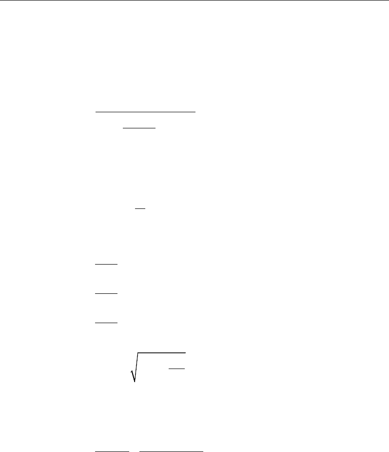
Chapter 12 - Design for Hong Kong CP-04
This reinforcement is to be placed at the bottom if M is positive, or at the top
if M is negative.
If M > Msingle, compression reinforcement is required and calculated as fol-
lows:
( )
sin
0.67
gle
s
cu
sc
MM
Af
f dd
γ
−
′=
′′
−−
(CP 6.1.2.4(c))
where d′ is the depth of the compression reinforcement from the concrete com-
pression face, and
1 0.87 ,
s sc y
d
fE f
x
ε
′
′= −≤
(CP 6.1.2.4(c), 3.2.6, Fig.
3.9)
2
2
2
, for 45N/mm
0.45
, for 45 70 N/mm
0.40
, for 70 100 N/mm
0.36
cu
cu
cu
dz f
dz
xf
dz f
−
≤
−
= <≤
−<≤
(CP 6.1.2.4(a), Fig 6.1)
'
0.5 0.25 0.9
K
zd
=+−
≤ 0.95d (CP 6.1.2.4(c))
The tension reinforcement required for balancing the compression in the con-
crete and the compression reinforcement is calculated as:
( )
single single
0.87 0.87
syy
M MM
Afz f d d
−
= + ′
−
(CP
6.1.2.4(c))
Slab Design 12 - 9

ETABS Reinforced Concrete Design
12.5.1.2.2 Design of nonuniform thickness slab
12.5.1.2.2.1 Flanged Slab Section Under Negative Moment
In designing for a factored negative moment, M (i.e., designing top reinforce-
ment), the calculation of the reinforcement area is exactly the same as described
previously, i.e., no flanged data is used.
12.5.1.2.2.2 Flanged Slab Section Under Positive Moment
With the flange in compression, the program analyzes the section by considering
alternative locations of the neutral axis. Initially, the neutral axis is assumed to
be located in the flange. On the basis of this assumption, the program calculates
the exact depth of the neutral axis. If the stress block does not extend beyond the
flange thickness, the section is designed as a uniform thickness slab of width bf.
If the stress block extends beyond the flange depth, the contribution of the web
to the flexural strength of the section is taken into account. See Figure 12-2.
Assuming the neutral axis to lie in the flange, the normalized moment is given
by:
2
.
cu f
M
Kf bd
=
(CP 6.1.2.4(c))
Then the moment arm is computed as:
z = d
0.5 0.25 0.9
K
+−
≤ 0.95d, (CP 6.1.2.4(c))
the depth of the neutral axis is computed as:
2
2
2
, for 45N/mm
0.45
, for 45 70N/mm
0.40
, for 70 100N/mm
0.36
cu
cu
cu
dz f
dz
xf
dz f
−
≤
−
= <≤
−<≤
(CP 6.1.2.4(c), Fig 6.1)
and the depth of the compression block is given by:
12 - 10 Slab Design
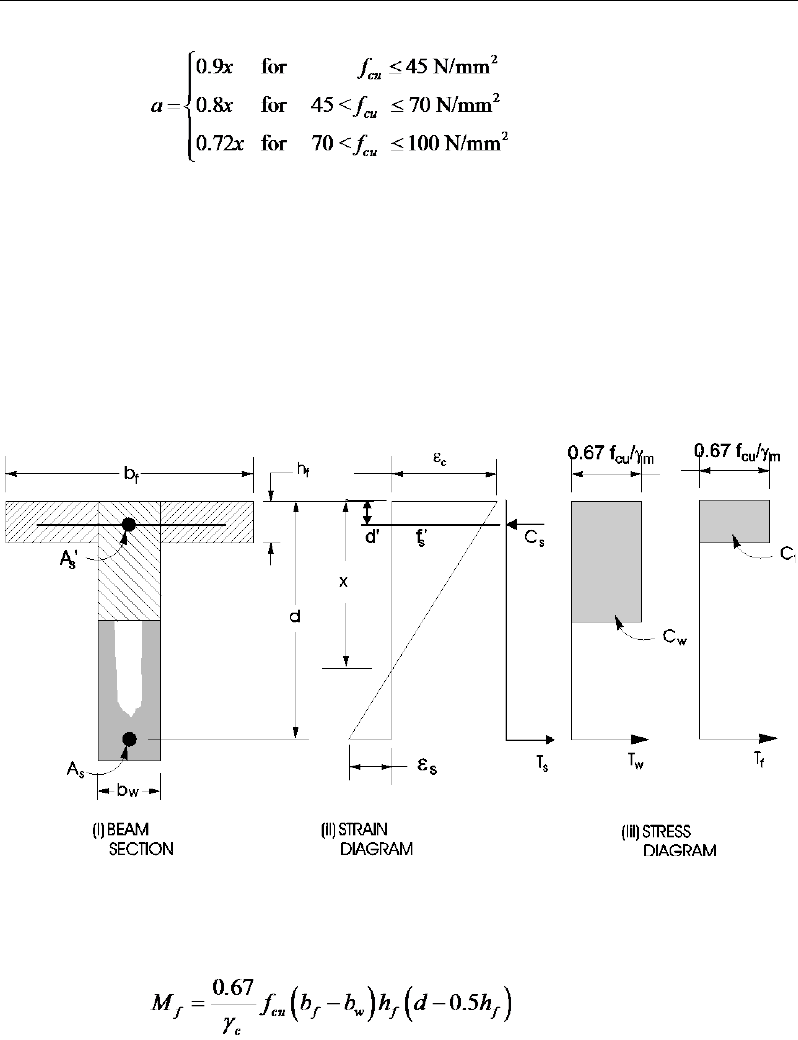
Chapter 12 - Design for Hong Kong CP-04
(CP 6.1.2.4(a), Fig 6.1)
If a ≤ hf, the subsequent calculations for As are exactly the same as previously
defined for the uniform thickness slab design. However, in that case, the width
of the slab is taken as bf. Compression reinforcement is required when K > K'.
If a > hf , the calculation for As has two parts. The first part is for balancing the
compressive force from the flange, Cf, and the second part is for balancing the
compressive force from the web, Cw, as shown in Figure 12-2.
Figure 12-2 Nonuniform Thickness Slab Design
In that case, the ultimate resistance moment of the flange is given by:
The moment taken by the web is computed as:
Slab Design 12 - 11
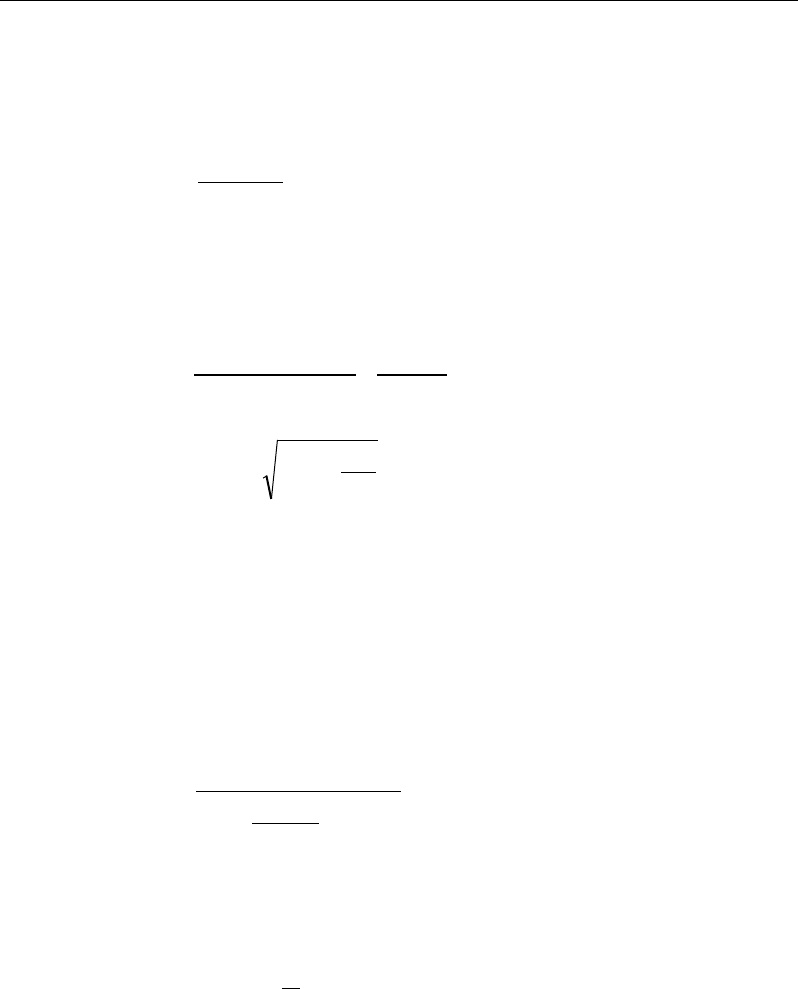
ETABS Reinforced Concrete Design
fw
MMM −=
and the normalized moment resisted by the web is given by:
Kw =
2
w
cu w
M
f bd
If Kw ≤ K′ (CP 6.1.2.4(c)), the slab is designed as a singly reinforced concrete
slab. The reinforcement is calculated as the sum of two parts, one to balance
compression in the flange and one to balance compression in the web.
( )
,
0.87
0.87 0.5
fw
sy
yf
MM
Afz
fd h
= +
−
where
d
K
d
zw95
.0
9
.0
25.
05.
0≤
−
+=
If Kw > K′, compression reinforcement is required and is calculated as follows:
The ultimate moment of resistance of the web only is given by:
2
uw cu w
M Kf b d=
The compression reinforcement is required to resist a moment of magnitude
Mw − Muw. The compression reinforcement is computed as:
( )
0.67
w uw
s
cu
sc
MM
Af
f dd
γ
−
′=
′′
−−
where, d′ is the depth of the compression reinforcement from the concrete
compression face, and
1 0.87
s sc y
d
fE f
x
ε
= −≤
(CP 6.1.2.4(c), 3.2.6, Fig 3.9)
The area of tension reinforcement is obtained from equilibrium as:
12 - 12 Slab Design

Chapter 12 - Design for Hong Kong CP-04
1
0.87 0.5 '
fuw w uw
s
yf
MM MM
Af d h z dd
−
= ++
−−
0.5 0.25 0.95
0.9
K
zd d
′
= + −≤
12.5.1.2.2.3 Minimum and Maximum Reinforcement
The minimum flexural tension reinforcement required in each direction of a slab
is given by the following limits (CP 9.3.1.1), with interpolation for reinforcement
of intermediate strength:
0 0024 if 250 MPa
0 0013 if 460 MPa
y
s
y
. bh f
A. bh f
≤
≥≥
(CP 9.3.1.1(a))
In addition, an upper limit on both the tension reinforcement and compres-
sion reinforcement has been imposed to be 0.04 times the gross cross-sec-
tional area (CP 9.2.1.3).
12.5.2 Design Slab Shear Reinforcement
The shear reinforcement is designed for each load combination at each station
along the design strip. In designing the shear reinforcement for a particular strip,
for a particular load combination, at a particular station due to the slab major
shear, the following steps are involved (CP 6.1.2.5):
Determine the shear stress, v.
Determine the shear stress, vc, that can be resisted by the concrete.
Determine the shear reinforcement required to carry the balance.
The following three sections describe in detail the algorithms associated with
these steps.
Slab Design 12 - 13
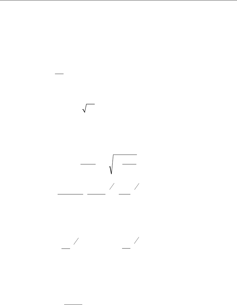
ETABS Reinforced Concrete Design
12.5.2.1 Determine Shear Stress
In the design of the slab shear reinforcement, the shear stresses for each load
combination at a particular design strip station are obtained by factoring the cor-
responding shear forces for different load cases, with the corresponding load
combination factors:
bd
V
v=
(CP 6.1.2.5(a))
The maximum allowable shear stress, vmax is defined as:
vmax = min(0.8
cu
f,
7 MPa) (CP 6.1.2.5(a))
12.5.2.2 Determine Concrete Shear Capacity
The shear stress carried by the concrete, vc, is calculated as:
cc
c
c
cc
vA
N
v
MA
NVh
vv +≤+= 16.0'
(CP 6.1.2.5(k))
4
1
3
1
2
1400
100
79.0
=d
bd
A
kk
vs
m
c
γ
(CP 6.1.2.5(c), Table 6.3)
1
k
is the enhancement factor for support compression,
and is conservatively taken as 1 (CP 6.1.2.5(g))
k2 =
13
25
cu
f,
1 ≤ k2 ≤
3
1
25
80
(CP 6.1.2.5(c), Table 6.3)
1.25
m
γ
=
(CP 6.1.2.5(c), Table 6.3)
However, the following limitations also apply:
100
0.15 3,
s
A
bd
≤≤
(CP 6.1.2.5(c), Table 6.3)
12 - 14 Slab Design
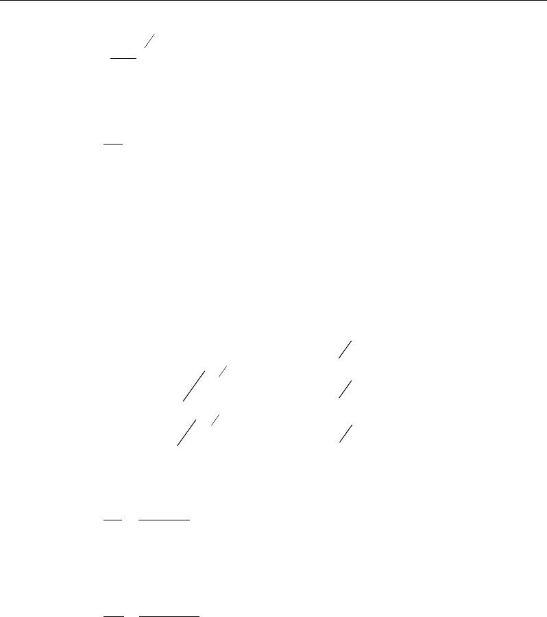
Chapter 12 - Design for Hong Kong CP-04
≥
140 67 Members without shear reinforcement
400
1 00 Members with shear reinforcement
.,
.,
d
(CP 6.1.2.5(c), Table 6.3)
1≤
M
Vh
(CP 6.1.2.5(k))
12.5.2.3 Determine Required Shear Reinforcement
Given v, vc, and vmax, the required shear reinforcement is calculated as follows
(CP Table 6.2, CP 6.1.2.5(b)):
Calculate the design average shear stress that can be carried by minimum shear
reinforcement, vr, as:
( )
2
23
2
23
2
Nmm
Nmm
Nmm
0.4 if 40
0.4 if 40 80
40
80
0.4 if 80
40
≤
= <≤
>
cu
cu
r cu
cu
f
f
vf
f
(CP 6.1.2.5(b), Table 6.2)
If v ≤ v’c + vr, minimum reinforcement is required:
,
0.87
sr
v yv
Avb
sf
=
(CP 6.1.2.5(b))
If v > v’c + vr,
( )
0 87
c
sv
v yv
v v' b
A
s .f
−
=
(CP 6.1.2.5(b))
If v > vmax, a failure condition is declared. (CP 6.1.2.5(b))
The maximum of all the calculated Asv /sv values obtained from each load com-
bination is reported along with the controlling shear force and associated load
combination.
Slab Design 12 - 15
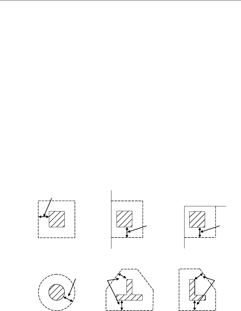
ETABS Reinforced Concrete Design
The slab shear reinforcement requirements considered by the program are based
purely on shear strength considerations. Any minimum stirrup requirements to
satisfy spacing and volumetric considerations must be investigated
independently of the program by the user.
12.5.3 Check for Punching Shear
The algorithm for checking punching shear is detailed in the section entitled
“Slab Punching Shear Check” in the Key Features and Terminology manual.
Only the code-specific items are described in the following subsections.
12.5.3.1 Critical Section for Punching Shear
The punching shear is checked on a critical section at a distance of 1.5d from the
face of the support (CP 6.1.5.7(d)). For rectangular columns and concentrated
loads, the critical area is taken as a rectangular area with the sides parallel to the
sides of the columns or the point loads (CP 6.1.5.7). Figure 12-3 shows the auto
punching perimeters considered by ETABS for the various column shapes. The
column location (i.e., interior, edge, corner) and the punching perimeter may be
overwritten using the Punching Check Overwrites.
Figure 12-3 Punching Shear Perimeters
1.5d
Interior Column
Circular Column T-Shape Column
Edge Column Corner Column
L-Shape Column
1.5d 1.5d
1.5d
1.5d
1.5d
1.5d
Interior Column
Circular Column T-Shape Column
Edge Column Corner Column
L-Shape Column
1.5d 1.5d
1.5d
1.5d
1.5d
12 - 16 Slab Design

Chapter 12 - Design for Hong Kong CP-04
12.5.3.2 Determine Concrete Capacity
The concrete punching shear factored strength is taken as (CP 6.1.5.7(d), Table
6.3):
4
1
3
1
2
1400
100
79.
0
=d
bd
A
k
k
vs
m
c
γ
(CP 6.1.2.5(d), Table 6.3)
1
k
is the enhancement factor for support compression,
and is conservatively taken as 1 (CP 6.1.2.5(g), 6.1.5.7(d))
k2 =
3
1
25
cu
f
1 ≤ k2 ≤ 3
1
25
80
(CP 6.1.2.5(c), Table 6.3)
1.25
m
γ
=
(CP 2.4.3.2, Table 2.2)
However, the following limitations also apply:
100
0.15 3,
s
A
bd
≤≤
(CP 6.1.2.5(c), Table 6.3)
≥
14
0 67 Members without shear reinforcement
400
1 00 Members with shear reinforcement
.,
.,
d
(CP 6.1.2.5(c), Table 6.3)
As = area of tension reinforcement, which is taken as the average tension
reinforcement of design strips in Layer A and layer B where Layer
A and Layer design strips are in orthogonal directions. When design
strips are not present in both orthogonal directions then tension rein-
forcement is taken as zero in the current implementation.
v ≤ min(0.8
cu
f,
7 MPa) (CP 6.1.5.7(b))
fcu ≤ 80 MPa (for calculation purpose only) (CP Table 6.3)
Slab Design 12 - 17

ETABS Reinforced Concrete Design
12.5.3.3 Determine Maximum Shear Stress
Given the punching shear force and the fractions of moments transferred by ec-
centricity of shear about the bending axis, the nominal design shear stress, vmax,
is calculated as:
,
1.5
eff x
Mx
V Vf Vy
= +
(CP 6.1.5.6(b), 6.1.5.6(c))
.
1.5
eff y
My
V Vf Vx
= +
(CP 6.1.5.6(b), 6.1.5.6(c))
,
max
,
max
eff x
eff y
V
ud
vV
ud
=
(CP 6.1.5.7)
where,
u is the perimeter of the critical section,
x and y are the lengths of the sides of the critical section parallel to the axis
of bending,
Mx and My are the design moments transmitted from the slab to the column
at the connection,
V is the total punching shear force, and
f is a factor to consider the eccentricity of punching shear force and is
taken as
1 00 for interior columns
1 25 for edge columns
1 25 for corner columns
.
f.
.
=
(CP 6.1.5.6(b), 6.1.5.6(c))
12 - 18 Slab Design

Chapter 12 - Design for Hong Kong CP-04
12.5.3.4 Determine Capacity Ratio
The ratio of the maximum shear stress and the concrete punching shear stress
capacity is reported as the punching shear capacity ratio by ETABS. If this ratio
exceeds 1.0, punching shear reinforcement is designed as described in the fol-
lowing section.
12.5.4 Design Punching Shear Reinforcement
The use of shear studs as shear reinforcement in slabs is permitted, provided that
the effective depth of the slab is greater than or equal to 200 mm (CP 6.1.5.7(e)).
If the slab thickness does not meet these requirements, the punching shear rein-
forcement is not designed and the slab thickness should be increased by the user.
The algorithm for designing the required punching shear reinforcement is used
when the punching shear capacity ratio exceeds unity. The Critical Section for
Punching Shear and Transfer of Unbalanced Moment as described in the earlier
sections remain unchanged. The design of punching shear reinforcement is car-
ried out as described in the subsections that follow.
12.5.4.1 Determine Concrete Shear Capacity
The concrete punching shear stress capacity of a section with punching shear
reinforcement is as previously determined for the punching check.
12.5.4.2 Determine Required Shear Reinforcement
The shear stress is limited to a maximum of:
vmax = 2vc (CP 6.1.5.7(e))
Given v, vc, and vmax, the required shear reinforcement is calculated as follows
(CP 6.1.5.7(e)).
If v ≤ 1.6vc,
s
A
v
=
( )
0.87 0.87
−≥
cr
yv yv
v v ud v ud
ff
,
(CP 6.1.5.7(e))
If 1.6vc ≤ v < 2.0vc,
Slab Design 12 - 19

ETABS Reinforced Concrete Design
s
A
v
=
( )
5 0.7 ,
0.87 0.87
c
yv yv
v v ud ud
ff
−≥r
v
(CP 6.1.5.7(e))
0.4
0.4 40
rcu
v= f
2/3
N/mm2 (CP 6.1.5.7, Table 6.2)
If v > 2.0vc, a failure condition is declared. (CP 6.1.5.7(e))
If v exceeds the maximum permitted value of vmax, the concrete section should
be increased in size.
12.5.4.3 Determine Reinforcement Arrangement
Punching shear reinforcement in the vicinity of rectangular columns should be
arranged on peripheral lines, i.e., lines running parallel to and at constant dis-
tances from the sides of the column. Figure 12-4 shows a typical arrangement of
shear reinforcement in the vicinity of a rectangular interior, edge, and corner
column.
The distance between the column face and the first line of shear reinforcement
shall not exceed d/2. The spacing between adjacent shear reinforcement in the
first line (perimeter) of shear reinforcement shall not exceed 1.5d measured in a
direction parallel to the column face (CP 6.1.5.7(f)).
Punching shear reinforcement is most effective near column corners where there
are concentrations of shear stress. Therefore, the minimum number of lines of
shear reinforcement is 4, 6, and 8, for corner, edge, and interior columns respec-
tively.
12 - 20 Slab Design

Chapter 12 - Design for Hong Kong CP-04
Figure 12-4 Typical arrangement of shear studs
and critical sections outside shear-reinforced zone
12.5.4.4 Determine Reinforcement Diameter, Height, and Spacing
The punching shear reinforcement is most effective when the anchorage is close
to the top and bottom surfaces of the slab. The cover of anchors should not be
less than the minimum cover specified in CP 4.2.4 plus half of the
diameter of the flexural reinforcement.
Punching shear reinforcement in the form of shear studs is generally available in
10-, 12-, 14-, 16-, and 20-millimeter diameters.
When specifying shear studs, the distance, so, between the column face and the
first peripheral line of shear studs should not be smaller than 0.5d. The spacing
between adjacent shear studs, g, at the first peripheral line of studs shall not ex-
ceed 1.5d. The limits of so and the spacing, s, between the peripheral lines are
specified as:
so ≤ 0.5d (CP 6.1.5.7(f))
s ≤ 0.75d (CP 6.1.5.7(f))
g ≤ 1.5d (CP 6.1.5.7(f))
Stirrups are only permitted when slab thickness is greater than 200 mm (CP
6.1.5.7(e)).
I
y
Typical Studrail
(only first and last
studs shown)
Outermost
peripheral line
of studs
Interior Column Edge Column Corner Column
Critical section
centroid
Free
edge
Free
edge
Critical
section
centroid
Free edge
Outermost
peripheral line
of studs
I
y
I
y
yx
d2 d2
d2
x
I
x
I
x
g
y
g
x
g
0
s
0
s
0
s
x
I
y
x
x
I
y
Typical Studrail
(only first and last
studs shown)
Outermost
peripheral line
of studs
Interior Column Edge Column Corner Column
Critical section
centroid
Free
edge
Free
edge
Critical
section
centroid
Free edge
Outermost
peripheral line
of studs
I
y
I
y
yx
d2 d2
d2
x
I
x
I
x
g
y
g
x
g
0
s
0
s
0
s
x
I
y
x
x
Slab Design 12 - 21

Chapter 13
Design for IS 456-2000
This chapter describes in detail the various aspects of the concrete design proce-
dure that is used by ETABS when the Indian Code IS 456-2000 [IS 2000] is
selected. Various notations used in this chapter are listed in Table 13-1. For ref-
erencing to the pertinent sections of the Indian code in this chapter, a prefix “IS”
followed by the section number is used.
The design is based on user-specified load combinations. The program provides
a set of default load combinations that should satisfy the requirements for the
design of most building type structures.
English as well as SI and MKS metric units can be used for input. The code is
based on Newton-millimeter-second units. For simplicity, all equations and de-
scriptions presented in this chapter correspond to Newton-millimeter-second
units unless otherwise noted.
13.1 Notations
Table 13-1 List of Symbols Used in the IS 456-2000 Code
A
c
Area of concrete, mm2
A
cv
Area of section for shear resistance, mm2
A
g
Gross cross-sectional area of a frame member, mm2
Notations 13 - 1

ETABS Reinforced Concrete Design
Table 13-1 List of Symbols Used in the IS 456-2000 Code
A
s
Area of tension reinforcement, mm2
A'
s
Area of compression reinforcement, mm2
A
sv
Total cross-sectional area of links at the neutral axis, mm2
A
sv
/s
v
Area of shear reinforcement per unit length, mm2/mm
a
Depth to the center of the compression block, mm
a
1
Width of the punching critical section in the direction of bending,
mm
a
2
Width of the punching critical section perpendicular to the direc-
tion of bending, mm
b
Width or effective width of the section in the compression zone,
mm
b
f
Width or effective width of flange, mm
b
w
Average web width of a flanged section, mm
d
Effective depth of tension reinforcement, mm
d'
Effective depth of compression reinforcement, mm
D
Overall depth of a slab, mm
D
f
Flange thickness in a flanged shaped-section, mm
E
c
Modulus of elasticity of concrete, MPa
E
s
Modulus of elasticity of reinforcement, assumed as 200,000 MPa
f
cd
Design concrete strength = f
ck
/
γ
c
, MPa
f
ck
Characteristic compressive strength of concrete, MPa
f
sc
Compressive stress in compression steel, MPa
f
yd
Design yield strength of reinforcement = f
y
/
γ
s
, MPa
f
y
Characteristic strength of reinforcement, MPa
f
ys
Characteristic strength of shear reinforcement, MPa
k
Enhancement factor of shear strength for depth of the slab
M
single
Design moment resistance of a section as a singly reinforced sec-
tion, N-mm
M
u
Ultimate factored design moment at a section, N-mm
13 - 2 Notations

Chapter 13 - Design for IS 456-2000
Table 13-1 List of Symbols Used in the IS 456-2000 Code
M
t
Equivalent factored bending moment due to torsion at a section,
N-mm
M
e1
Equivalent factored moment including moment and torsion ef-
fects (Me1 = Mu+Mt) at a section, N-mm
M
e2
Residual factored moment when M
t
> M
u
at a section applied in
the opposite sense of Me1 at a section, N-mm
m
Normalized design moment, M/bd2
α
f
ck
s
v
Spacing of the shear reinforcement along the strip, mm
T
u
Factored torsional moment at a section, N-mm
V
u
Factored shear force at a section, N
V
e
Equivalent factored shear force including torsion effects, N
v
c
Allowable shear stress in punching shear mode, N
x
u
Depth of neutral axis, mm
x
u,max
Maximum permitted depth of neutral axis, mm
z
Lever arm, mm
α
Concrete strength reduction factor for sustained loading, as well
as reinforcement over strength factor for computing capacity mo-
ment at a section
β
Factor for the depth of compressive force resultant of the concrete
stress block
β
c
Ratio of the minimum to maximum dimensions of the punching
critical section
γ
c
Partial safety factor for concrete strength
γ
f
Partial safety factor for load, and fraction of unbalanced moment
transferred by flexure
γ
m
Partial safety factor for material strength
γ
s
Partial safety factor for reinforcement strength
δ
Enhancement factor of shear strength for compression
ε
c,max
Maximum concrete strain in the slab (= 0.0035)
Notations 13 - 3

ETABS Reinforced Concrete Design
Table 13-1 List of Symbols Used in the IS 456-2000 Code
ε
s
Strain in tension steel
ε
s
'
Strain in compression steel
τ
v
Average design shear stress resisted by concrete, MPa
τ
c
Basic design shear stress resisted by concrete, MPa
τ
c,max
Maximum possible design shear stress permitted at a section,
MPa
τ
cd
Design shear stress resisted by concrete, MPa
13.2 Design Load Combinations
The design load combinations are the various combinations of the load cases for
which the structure needs to be designed. For IS 456-2000, if a structure is sub-
jected to dead (D), live (L), pattern live (PL), snow (S), wind (W), and earth-
quake (E) loads, and considering that wind and earthquake forces are reversible,
the following load combinations may need to be considered (IS 36.4, Table 18):
1.5D
(IS 36.4.1)
1.5D + 1.5L
1.5D + 1.5S
(IS 36.4.1
)
1.5D + 1.5(0.75 PL)
(IS 31.5.2.3)
1.5D ± 1.5W
0.9D
± 1.5W
1.2D + 1.2L
± 1.2W
1.5D + 1.5L
± 1.0W
(IS 36.4.1
)
1.5D ± 1.5E
0.9D
± 1.5E
1.2D + 1.2L
± 1.2E
1.5D + 1.5L
± 1.0E
(IS 36.4.1
)
13 - 4 Design Load Combinations

Chapter 13 - Design for IS 456-2000
1.5D + 1.5L + 1.5S
1.2D + 1.
2S ± 1.2W
1.2D + 1.
2L + 1.2S ± 1.2W
1.2D + 1.2S
± 1.2E
1.2D + 1.
2L + 1.2S ± 1.2E
(IS 36.4.1
)
These are also the default design load combinations in ETABS whenever the IS
456-2000 code is used. If roof live load is treated separately or other types of
loads are present, other appropriate load combinations should be used.
13.3 Partial Safety Factors
The design strength for concrete and reinforcement is obtained by dividing the
characteristic strength of the material by a partial safety factor,
γ
m. The values of
γ
m used in the program are as follows:
Partial safety factor for reinforcement,
γ
s = 1.15 (IS 36.4.2.1)
Partial safety factor for concrete,
γ
c = 1.5 (IS 36.4.2.1)
These factors are already incorporated into the design equations and tables in the
code. These values can be overwritten; however, caution is advised.
13.4 Slab Design
ETABS slab design procedure involves defining sets of strips in two mutually
perpendicular directions. The locations of the strips are usually governed by the
locations of the slab supports. The axial force, moments and shears for a partic-
ular strip are recovered from the analysis (on the basis of the Wood-Armer tech-
nique), and a flexural design is carried out based on the ultimate strength design
method.
The slab design procedure involves the following steps:
Design flexural reinforcement
Design shear reinforcement
Punching check
Partial Safety Factors 13 - 5

ETABS Reinforced Concrete Design
13.4.1 Design Flexural Reinforcement
For slabs, ETABS uses either design strips or the finite element based design to
calculate the slab flexural reinforcement in accordance with the selected design
code. For simplicity, only strip-by-strip design is document in the proceeding
sections.
The design of the slab reinforcement for a particular strip is carried out at specific
locations along the length of the strip. These locations correspond to the element
boundaries. Controlling reinforcement is computed on either side of those ele-
ment boundaries. The slab flexural design procedure for each load combination
involves the following:
Determine factored axial loads and moments for each slab strip.
Design flexural reinforcement for the strip.
These two steps, described in the text that follows, are repeated for every load
combination. The maximum reinforcement calculated for the top and bottom
of the slab within each design strip, along with the corresponding controlling
load combination, is obtained and reported.
13.4.1.1 Determine Factored Moments
In the design of flexural reinforcement of concrete slab, the factored moments
for each load combination at a particular design strip are obtained by factoring
the corresponding moments for different load cases, with the corresponding load
factors.
The slab is then designed for the maximum positive and maximum negative fac-
tored moments obtained from all of the load combinations. Calculation of bottom
reinforcement is based on positive design strip moments. In such cases, the slab
may be designed as a rectangular or flanged slab section. Calculation of top re-
inforcement is based on negative design strip moments. In such cases, the slab
may be designed as a rectangular or inverted flanged slab section.
13.4.1.2 Determine Required Flexural Reinforcement
In the flexural reinforcement design process, the program calculates both the
tension and compression reinforcement. Compression reinforcement is added
when the applied design moment exceeds the maximum moment capacity of a
singly reinforced section. The user has the option of avoiding compression
13 - 6 Slab Design
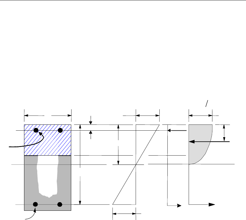
Chapter 13 - Design for IS 456-2000
reinforcement by increasing the effective depth, the width, or the strength of the
concrete.
The design procedure is based on the simplified parabolic stress block shown in
Figure 13-1 (IS 38.1). The area of the stress block, c, and the depth of the center
of the compressive force from the extreme compression fiber, a, are taken as
c =
α
fck xu (IS 38.1)
a =
β
xu (IS 38.1)
Figure 13-1 Uniform Thickness Slab Design
where xu is the depth of the neutral axis, and
α
and
β
are taken as:
α
= 0.36 (IS 38.1)
β
= 0.42 (IS 38.1)
where
α
is the reduction factor to account for sustained compression and the
partial safety factor for concrete and is generally taken to be 0.36 for the assumed
parabolic stress block (IS 38.1). The
β
factor considers the depth to the center of
the compressive force.
BEAM
SECTION STRAIN
DIAGRAM STRESS
DIAGRAM
0.0035
ε
=
γ
0 67
cu m
.f
0 42
u
.x
cs
T
s
T
s
ε
u
x
s
C
d′
d
b
s
A
s
A′
′
s
f
C
BEAM
SECTION STRAIN
DIAGRAM STRESS
DIAGRAM
0.0035
ε
=
γ
0 67
cu m
.f
0 42
u
.x
cs
T
s
T
s
ε
u
x
s
C
d′
d
b
s
A
s
A′
′
s
f
C
Slab Design 13 - 7
ETABS Reinforced Concrete Design
Furthermore, it is assumed that moment redistribution in the member does not
exceed the code-specified limiting value. The code also places a limitation on
the neutral axis depth, as shown in the following table, to safeguard against non-
ductile failures (IS 38.1). ETABS uses interpolation between these three values.
fy (MPa) xu,max /d
250
0.53
415
0.48
500
0.46
When the applied moment exceeds the moment capacity of the slab as a singly
reinforced section, the area of compression reinforcement is calculated assuming
that the neutral axis depth remains at the maximum permitted value. The maxi-
mum fiber compression is taken as:
ε
c,max = 0.0035 (IS 38.1)
The design procedure used by ETABS, for both rectangular and flanged sections
(L- and T-shaped sections), is summarized in the subsections that follow. It is
assumed that the design ultimate axial force can be neglected; hence all slabs are
designed for major direction flexure and shear only.
13.4.1.3 Design of uniform thickness slab
For uniform thickness slab, the limiting depth of the neutral axis, xu,max, and the
moment capacity as a singly reinforced section, Msingle, are obtained first. The
reinforcement area is determined based on whether Mu is greater than, less than,
or equal to Msingle.
Calculate the limiting depth of the neutral axis.
max
0 53 if 250 MPa
250
0 53 0 05 if 250 415 MPa
165
415
0 48 0 02 if 415 500 MPa
85
0 46 if 500 MPa
y
yy
u,
yy
y
.f
f
.. f
x
f
d.. f
.f
≤
−
− <≤
=−
− <≤
≥
(IS 38.1)
Calculate the limiting ultimate moment of resistance as a
singly reinforced section.
13 - 8 Slab Design
Chapter 13 - Design for IS 456-2000
,max ,max 2
single
1
uu
ck
xx
M bd f
dd
αβ
= −
(IS G-1.1)
Calculate the depth of the neutral axis as:
1 14
2
um
x
d
β
β
−−
=
where the normalized design moment, m, is given by
ck
u
fbd
M
m
α
2
=
− If Mu ≤ Msingle the area of tension reinforcement, As, is obtained from
( )
,
/
u
s
ys
M
Afz
γ
=
where (IS G-1.1)
1.
u
x
zd d
β
= −
(IS 38.1)
This reinforcement is to be placed at the bottom if Mu is positive, or at the
top if Mu is negative.
− If Mu > Msingle, the area of compression reinforcement, A's, is given by:
()
single
0.67 '
u
s
ck
sc m
MM
Af
f dd
γ
−
′=
−−
(IS G-1.2)
where d' is the depth of the compression reinforcement from the concrete
compression face, and
s
y
u
scsc
f
x
d
Ef
γ
ε
≤
−=
max,
max
,'
1
(IS G-1.2)
The required tension reinforcement is calculated as:
Slab Design 13 - 9

ETABS Reinforced Concrete Design
( ) ()
( )
single single ,
'
u
s
ys ys
M MM
Af z f dd
γγ
−
= + −
where (IS G-1.2)
,max
1
u
x
zd d
β
= −
(IS 38.1)
As is to be placed at the bottom and A′s is to be placed at the top if Mu is positive,
and vice versa if Mu is negative.
13.4.1.4 Design of nonuniform thickness slab
13.4.1.4.1 Flanged Slab Section Under Negative Moment
In designing for a factored negative moment, Mu (i.e., designing top reinforce-
ment), the calculation of the reinforcement area is exactly the same as described
previously, i.e., no flanged data is used.
13.4.1.4.2 Flanged Slab Section Under Positive Moment
With the flange in compression, the program analyzes the section by considering
alternative locations of the neutral axis. Initially the neutral axis is assumed to
be located within the flange. On the basis of this assumption, the program calcu-
lates the depth of the neutral axis. If the stress block does not extend beyond the
flange thickness, the section is designed as a uniform thickness slab of width bf..
If the stress block extends beyond the flange depth, the contribution of the web
to the flexural strength of the slab is taken into account. See Figure 13-2.
13 - 10 Slab Design
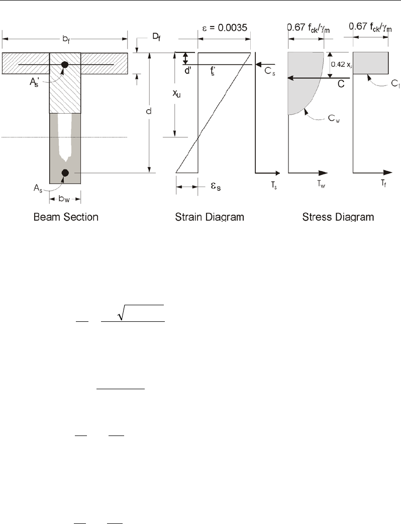
Chapter 13 - Design for IS 456-2000
Figure 13-2 Nonuniform Thickness Slab Design
Assuming the neutral axis lies in the flange, the depth of the neutral axis is cal-
culated as:
β
β
2
411 m
d
x
u
−−
=
where the normalized design moment, m, is given by
ckf
u
fdb
M
m
α
2
=
If
f
u
D
x,
dd
≤
the neutral axis lies within the flange and the subsequent
calculations for As are exactly the same as previously defined for the uniform
thickness slab design (IS G-2.1). However, in this case, the width of the slab
is taken as bf. Compression reinforcement is required when Mu > Msingle.
If
f
uD
x,
dd
>
the neutral axis lies below the flange and the calculation for
As has two parts. The first part is for balancing the compressive force from the
Slab Design 13 - 11
ETABS Reinforced Concrete Design
flange, Cf, and the second part is for balancing the compressive force from the
web, Cw, as shown in Figure 13-2.
− Calculate the ultimate resistance moment of the flange as:
( )
−−= 2
45.0 f
fwfckfdbbfM
γ
γ
(IS G-2.2)
where
γ
f is taken as:
if 0 2
015 065 if 02
ff
f
u ff
D D .d
. x . D D .d
γ
≤
=+>
(IS G-2.2)
− Calculate the moment taken by the web as
Mw = Mu − Mf.
− Calculate the limiting ultimate moment of resistance of the web for tension
reinforcement as:
Mw,single = αfckbwd2
−d
x
d
x
uu max,max,
1
β
where (IS G-1.1)
max
0 53 if 250 MPa
250
0 53 0 05 if 250 415 MPa
165
415
0 48 0 02 if 415 500 MPa
85
0 46 if 500 MPa
y
yy
u,
yy
y
.f
f
.. f
x
f
d.. f
.f
≤
−
− <≤
=−
− <≤
≥
(IS 38.1)
If Mw ≤ Mw,single, the slab is designed as a singly reinforced concrete slab. The
area of reinforcement is calculated as the sum of two parts, one to balance
compression in the flange and one to balance compression in the web.
( )( ) ( )
05
fw
s
ys f ys
MM
A,
f d .y f z
γγ
= +
−
where
13 - 12 Slab Design
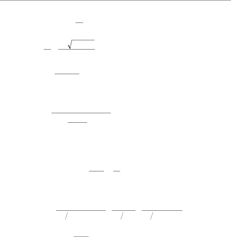
Chapter 13 - Design for IS 456-2000
−= d
x
dz
u
β
1
β
β
2
411 m
d
x
u
−−
=
2w
w ck
M
mbd f
α
=
If Mw > Mw,single, the area of compression reinforcement, A's, is given by:
( )
,single
0.67 '
ww
s
ck
sm
MM
Af
f dd
γ
−
′=
′−−
where d' is the depth of the compression reinforcement from the concrete
compression face, and
,max ,max
'
1y
sc c s us
f
d
fE
x
εγ
= −≤
(IS G-1.2)
The required tension reinforcement is calculated as:
( )( ) ( ) ( )
( )
single single
0.5
f w, w w,
s
ys f ys ys
M M MM
Af d f z f dd
γ γγ γ
−
= ++ ′
−−
where
,max
1u
x
zd d
β
= −
13.4.1.5 Minimum and Maximum Reinforcement
The minimum flexural tension reinforcement required for each direction of a
slab is given by the following limits (IS 26.5.2):
0 0015 if 415 MPa
0 0012 if 415 MPa
y
s
y
. bD f
A. bD f
<
≤≥
(IS 26.5.2.1)
Slab Design 13 - 13

ETABS Reinforced Concrete Design
In addition, an upper limit on both the tension reinforcement and compression
reinforcement has been imposed to be 0.04 times the gross cross-sectional area
(IS 26.5.1.1).
13.4.2 Design Slab Shear Reinforcement
The shear reinforcement is designed for each load combination at each station
along the design strip. In designing the shear reinforcement for a particular strip,
for a particular load combination, at a particular station due to the slab major
shear, the following steps are involved (IS 40.1):
Determine the design shear stress
Determine the shear stress that can be resisted by the concrete
Determine the shear reinforcement required to carry the balance
Determine the design nominal shear stress as follows.
For prismatic sections
τ
v =
bd
Vu
(IS 40.1)
For non-prismatic sections (slab with varying depth)
τ
v =
u
u
M
V tan
d,
bd
β
±
where (IS 40.1.1)
β = angle between the top and bottom edges of the slab
Mu is the moment at the section, and the negative sign is considered when
the numerical value of the moment increases in the same direction as
the depth, d, and the positive sign is considered when the numerical
value of the moment decreases in the same direction as the depth in-
creases.
τ
v ≤
τ
c,max (IS 40.2.3, Table 20)
The maximum nominal shear stress,
τ
c,max is given in IS Table 20 as follows:
13 - 14 Slab Design
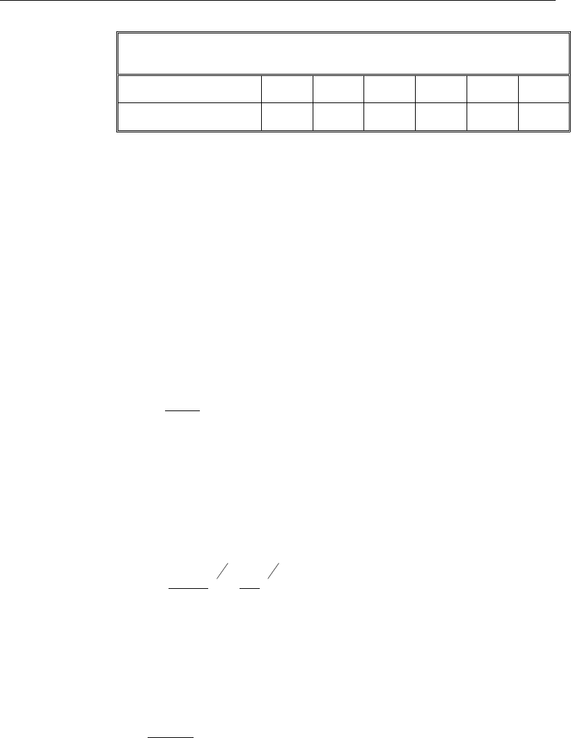
Chapter 13 - Design for IS 456-2000
Maximum Shear Stress,
τ
c,max
(MPa)
(IS 40.2.3, IS Table 20)
Concrete Grade M15 M20 M25 M30 M35 M40
τ
c,max (MPa) 2.5 2.8 3.1 3.5 3.7 4.0
The maximum nominal shear stress,
τ
c,max, is computed using linear interpolation
for concrete grades between those indicated in IS Table 20.
Determine the design shear stress that can be carried by the concrete, as:
τ
cd = k
δλτ
c, (IS 40.2)
where k is the enhancement factor for the depth of the section, taken as 1.0 for
slabs, and is computed as follows for other slabs:
k = 1 (IS 40.2.1.1)
δ is the enhancement factor for compression and is given as:
1 3 1 5 if 0 Under Compression
1 if 0 Under Tension
uu
g ck
u
P. P,
Af
P,
δ
+≤ >
=
≤
(IS 40.2.2)
δ is always taken as 1
λ is the factor for light-weight concrete, and
τ
c is the basic design shear strength for concrete, which is given by:
11
34
100
0 64 25
s ck
c
Af
.bd
τ
=
(IS 40.2.1)
The preceding expression approximates IS Table 19. It should be noted that the
value of
γ
c has already been incorporated in IS Table 19 (see note in IS 36.4.2.1).
The following limitations are enforced in the determination of the design shear
strength as is the case in the Table.
0.15 ≤
bd
A
s
100
≤ 3 (IS 40.2.1, Table 19)
Slab Design 13 - 15

ETABS Reinforced Concrete Design
fck ≤ 40 MPa (for calculation purpose only) (IS 40.2.1, Table 19)
Determine required shear reinforcement:
If
τ
v ≤
τ
cd + 0.4,
0.4
0.87
sv
vy
Ab
sf
=
(IS 40.3, 26.5.1.6)
If
τ
cd + 0.4 <
τ
v ≤
τ
c,max,
( )
0.87
v cd
sv
vy
b
A
sf
ττ
−
=
(IS 40.4(a))
0.4
0.87
sv
vy
Ab
sf
≥
(IS 40.4(a))
If
τ
v >
τ
c,max, a failure condition is declared. (IS 40.2.3)
In calculating the shear reinforcement, a limit is imposed on the fy as:
fy ≤ 415 MPa (IS 40.4)
The maximum of all of the calculated Asv /sv values, obtained from each load
combination, is reported along with the controlling shear force and associated
load combination.
The slab shear reinforcement requirements considered by the program are
based purely on shear strength considerations. Any minimum stirrup require-
ments to satisfy spacing and volumetric considerations must be investigated
independently of the program by the user.
13.4.3 Check for Punching Shear
The algorithm for checking punching shear is detailed in the section entitled
“Slab Punching Shear Check” in the Chapter 1. Only the code-specific items are
described in the following sections.
13 - 16 Slab Design
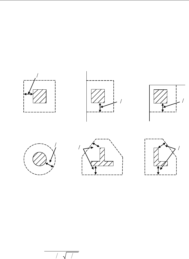
Chapter 13 - Design for IS 456-2000
13.4.3.1 Critical Section for Punching Shear
The punching shear is checked on a critical section at a distance of d/2 from the
face of the support (IS 31.6.1). For rectangular columns and concentrated loads,
the critical area is taken as a rectangular area with the sides parallel to the sides
of the columns or the point loads (IS 31.6.1). Figure 13-3 shows the auto punch-
ing perimeters considered by ETABS for the various column shapes. The column
location (i.e., interior, edge, corner), and the punching perimeter may be over-
written using the Punching Check Overwrites.
Figure 13-3 Punching Shear Perimeters
13.4.3.2 Transfer of Unbalanced Moment
The fraction of unbalanced moment transferred by flexure is taken to be αMu
and the fraction of unbalanced moment transferred by eccentricity of shear is
taken to be (1 − α) Mu (IS 31.6.2.2), where:
( )
12
1
1 23 aa
α
=+
(IS 31.3.3)
d2
Interior Column
Circular Column
d2 d2
d2
T-Shape Column
Edge Column Corner Column
L-Shape Column
d2
d2
d2
Interior Column
Circular Column
d2 d2
d2
T-Shape Column
Edge Column Corner Column
L-Shape Column
d2
d2
Slab Design 13 - 17
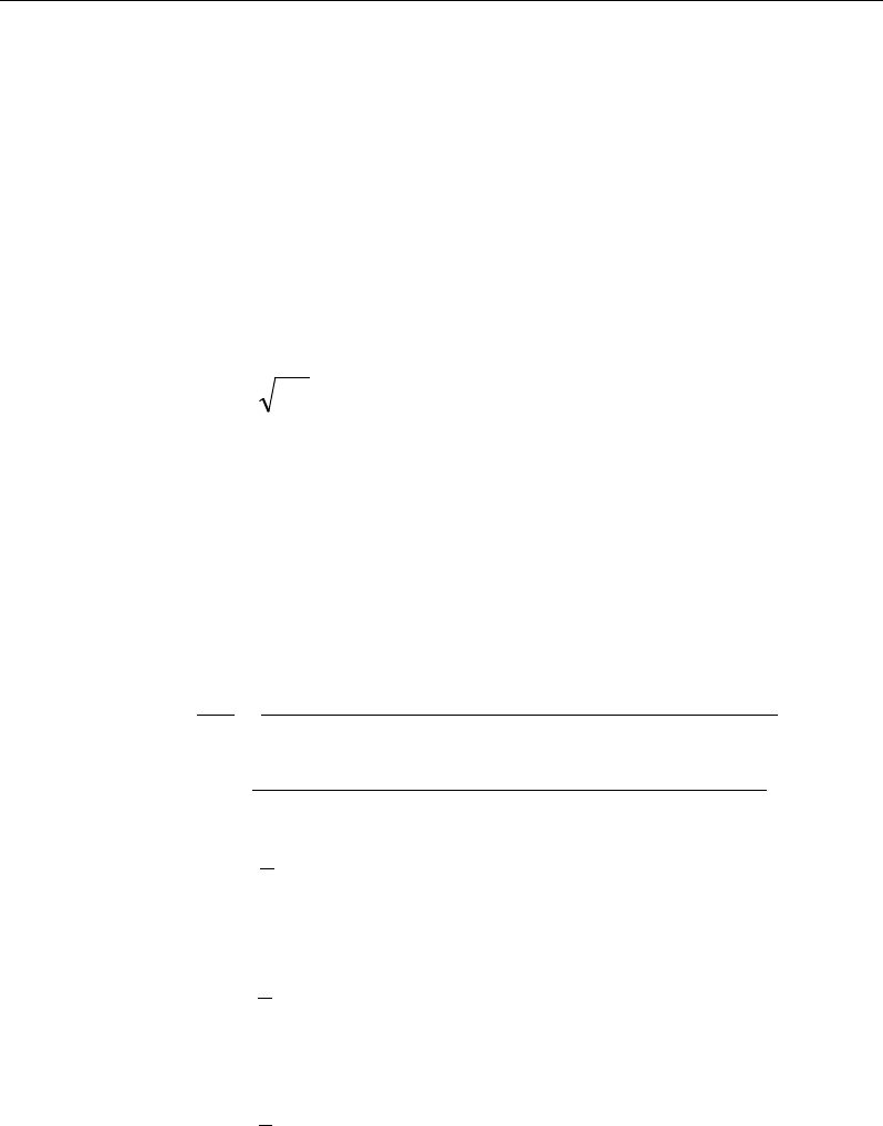
ETABS Reinforced Concrete Design
and a1 is the width of the critical section measured in the direction of the span
and a2 is the width of the critical section measured in the direction perpendicular
to the span.
13.4.3.3 Determine Concrete Capacity
The concrete punching shear factored strength is taken as:
vc = ks
τ
c (IS 31.6.3.1)
ks = 0.5 +
β
c ≤ 1.0 (IS 31.6.3.1)
τ
c = 0.25
ck
f
(IS 31.6.3.1)
β
c = ratio of the minimum to the maximum dimensions of the support sec-
tion.
13.4.3.4 Determine Maximum Shear Stress
Given the punching shear force and the fractions of moments transferred by ec-
centricity of shear about the two axes, the shear stress is computed assuming
linear variation along the perimeter of the critical section.
22 3 1 33 4 3 23 4 3
2
0 22 33 23
33 3 1 22 4 3 23 4 3
2
22 33 23
[ ( )][ ( ) ( )]
[ ( )][ ( ) ( )]
γ
γ
− − −− −
=+−
−
− − −− −
−
VUU
U
U
VUU
M Vy y I y y I x x
V
vbd I I I
M VxxIxx Iyy
II I
Eq. 1
22 22
1=
=
∑
n
sides
II
, where "sides" refers to the sides of the critical
section for punching shear Eq. 2
33 33
1=
=
∑
n
sides
II
, where "sides" refers to the sides of the critical
section for punching shear Eq. 3
23 23
1=
=
∑
n
sides
II
, where "sides" refers to the sides of the critical
section for punching shear Eq. 4
13 - 18 Slab Design
Chapter 13 - Design for IS 456-2000
Figure 13-4 Shear Stress Calculations at Critical Sections
The equations for
22 33 23
, andII I
are different depending on whether the
side of the critical section for punching shear being considered is parallel to
the 2-axis or parallel to the 3-axis. Refer to Figures 13-4.
2
22 2 3
()= −I Ld y y
, for side of critical section parallel to 2-axis Eq. 5a
33 2
22 2 3
()
12 12
= ++ −
Ld dL
I Ld y y
, for side of critical section
parallel to 3-axis Eq. 5b
33 2
33 2 3
()
12 12
= ++ −
Ld dL
I Ld x x
, for side of critical section
parallel to 2-axis Eq. 6a
Plan View For Side of Critical Section Parallel to 3-Axis
y
2
- y
3
L
Critical section for
punching shear
shown by heavy line
2
3
Side of critical section
being considered
shown solid
Center of side of critical
section being considered.
Coordinates are (x
2
,y
2
).
Work This Sketch With Equations 5b, 6b and
7
Centroid
of entire
critical section for
punching shear.
Coordinates are (x
3
,y
3
).
x
2
- x
3
y
2
- y
3
L
Critical section for
punching shear shown
by heavy line. Side of
critical section being
considered shown solid
2
3
Center of side of critical
section being considered.
Coordinates are (x
2
,y
2
).
Plan View For Side of Critical Section Parallel to 2-Axis
Work This Sketch With Equations 5a, 6a and
7
Centroid
of entire
critical section for
punching shear.
Coordinates are (x
3
,y
3
).
x
2
- x
3
Slab Design 13 - 19

ETABS Reinforced Concrete Design
2
33 2 3
()= −I Ld x x
, for side of critical section parallel to 3-axis Eq. 6b
23 2 3 2 3
( )( )=−−I Ld x x y y
, for side of critical section
parallel to 2-axis or 3-axis Eq. 7
NOTE:
23
I
is explicitly set to zero for corner condition.
where,
b0 = Perimeter of critical section for punching shear
d = Effective depth at critical section for punching shear based on the aver-
age of d for the 2 direction and d for the 3 direction
I22 = Moment of inertia of critical section for punching shear about an axis
that is parallel to the local 2-axis
I33 = Moment of inertia of critical section for punching shear about an axis
that is parallel to the local 3-axis
I23 = Product of inertia of critical section for punching shear with respect to
the 2 and 3 planes
L = Length of side of critical section for punching shear currently being con-
sidered
MU2 = Moment about line parallel to 2-axis at center of column (positive in
accordance with the right-hand rule)
MU3 = Moment about line parallel to 3-axis at center of column (positive in
accordance with the right-hand rule)
vU = Punching shear stress
VU = Shear at center of column (positive upward)
x1, y1 = Coordinates of column centroid
x2, y2 = Coordinates of center of one side of critical section for punching shear
x3, y3 = Coordinates of centroid of critical section for punching shear
13 - 20 Slab Design

Chapter 13 - Design for IS 456-2000
x4, y4 = Coordinates of location where you are calculating stress
γ
V2 = Percent of MU2 resisted by shear
γV3 = Percent of MU3 resisted by shear
13.4.3.5 Determine Capacity Ratio
The ratio of the maximum shear stress and the concrete punching shear stress
capacity is reported as the punching shear capacity ratio by ETABS. If this ratio
exceeds 1.0, punching shear reinforcement is designed as described in the fol-
lowing section.
13.4.4 Design Punching Shear Reinforcement
The use of shear studs as shear reinforcement in slabs is permitted.
The algorithm for designing the required punching shear reinforcement is used
when the punching shear capacity ratio exceeds unity. The Critical Section for
Punching Shear and Transfer of Unbalanced Moment as described in the earlier
sections remain unchanged. The design of punching shear reinforcement is com-
pleted as described in the subsections that follow.
13.4.4.1 Determine Concrete Shear Capacity
The concrete punching shear stress capacity of a section with punching shear
reinforcement is as previously determined, but limited to:
cc
v
τ
5.1≤
(IS 31.6.3.2)
13.4.4.2 Determine Required Shear Reinforcement
The shear force is limited to a maximum of:
Vmax = 0.5
c
τ
bod (IS 31.6.3.2)
Given Vu, Vc, and Vmax, the required shear reinforcement is calculated as follows
(IS 31.6.3.2).
( )
0.5
0.87
uc
v
y
V VS
Afd
−
=
(IS 31.6.3.2, 40.4(a))
Slab Design 13 - 21
ETABS Reinforced Concrete Design
If Vu > Vmax, a failure condition is declared. (IS 31.6.3.2)
If Vu exceeds the maximum permitted value of Vmax, the concrete section
should be increased in size.
13.4.4.3 Determine Reinforcement Arrangement
Punching shear reinforcement in the vicinity of rectangular columns should be
arranged on peripheral lines, i.e., lines running parallel to and at constant dis-
tances from the sides of the column. Figure 13-5 shows a typical arrangement of
shear reinforcement in the vicinity of a rectangular interior, edge, and corner
column.
Figure 13-6 Typical arrangement of shear studs
and critical sections outside shear-reinforced zone
The distance between the column face and the first line of shear reinforcement
shall not exceed d/2. The spacing between adjacent shear reinforcement in the
first line (perimeter) of shear reinforcement shall not exceed 2d measured in a
direction parallel to the column face.
Punching shear reinforcement is most effective near column corners where there
are concentrations of shear stress. Therefore, the minimum number of lines of
shear reinforcement is 4, 6, and 8, for corner, edge, and interior columns respec-
tively.
I
y
Typical Studrail
(only first and last
studs shown)
Outermost
peripheral line
of studs
Interior Column Edge Column Corner Column
Critical section
centroid
Free
edge
Free
edge
Critical
section
centroid
Free edge
Outermost
peripheral line
of studs
I
y
I
y
yx
d2 d2
d2
x
I
x
I
x
g
y
g
x
g
0
s0
s
0
s
x
I
y
x
x
I
y
Typical Studrail
(only first and last
studs shown)
Outermost
peripheral line
of studs
Interior Column Edge Column Corner Column
Critical section
centroid
Free
edge
Free
edge
Critical
section
centroid
Free edge
Outermost
peripheral line
of studs
I
y
I
y
yx
d2 d2
d2
x
I
x
I
x
g
y
g
x
g
0
s0
s
0
s
x
I
y
x
x
13 - 22 Slab Design

Chapter 13 - Design for IS 456-2000
13.4.4.4 Determine Reinforcement Diameter, Height, and Spacing
The punching shear reinforcement is most effective when the anchorage is close
to the top and bottom surfaces of the slab. The cover of anchors should not be
less than the minimum cover specified in IS 26.4 plus half of the diameter of the
flexural reinforcement.
When specifying shear studs, the distance, so, between the column face and the
first peripheral line of shear studs should not be smaller than 0.5d. The spacing
between adjacent shear studs, g, at the first peripheral line of studs shall not ex-
ceed 2d. The limits of so and the spacing, s, between the peripheral lines are
specified as:
so ≤ 0. 5d
s ≤ 0.5d
g ≤ 2d
Slab Design 13 - 23

Chapter 14
Design for Italian NTC 2008
This chapter describes in detail the various aspects of the concrete design
procedure that is used by ETABS when the Italian code NTC2008 [D.M.
14/01/2008] is selected. For the load combinations, reference is also made to
NTC2008. Various notations used in this chapter are listed in Table 14-1.
The design is based on user-specified loading combinations. However, the pro-
gram provides a set of default load combinations that should satisfy requirements
for the design of most building type structures.
English as well as SI and MKS metric units can be used for input. The code is
based on Newton-millimeter-second units. For simplicity, all equations and
descriptions presented in this chapter correspond to Newton-millimeter-second
units unless otherwise noted.
14.1 Notations
Table 14-1 List of Symbols Used in the NTC2008
A
c
Area of concrete section, mm2
A
s
Area of tension reinforcement, mm2
A'
s
Area of compression reinforcement, mm2
Notations 14 - 1

ETABS Reinforced Concrete Design
Table 14-1 List of Symbols Used in the NTC2008
A
sl
Area of longitudinal reinforcement for torsion, mm2
A
sw
Total cross-sectional area of links at the neutral axis, mm2
A
sw
/s
v
Area of shear reinforcement per unit length, mm2/mm
A
t
/s
Area of transverse reinforcement per unit length for torsion,
mm2/mm
a
Depth of compression block, mm
b
Width or effective width of the section in the compression zone,
mm
b
f
Width or effective width of flange, mm
b
w
Average web width of a flanged shaped-section, mm
d
Effective depth of tension reinforcement, mm
d'
Effective depth of compression reinforcement, mm
E
c
Modulus of elasticity of concrete, MPa
E
s
Modulus of elasticity of reinforcement
f
cd
Design concrete strength = α
cc
f
ck
/ γ
c
, MPa
f
ck
Characteristic compressive concrete cylinder strength at 28 days,
MPa
f
ctm
Mean value of concrete axial tensile strength, MPa
f
cwd
Design concrete compressive strength for shear design = α
cc
cwk
c
f
γ
, MPa
f
cwk
Characteristic compressive cylinder strength for shear design,
MPa
f'
s
Compressive stress in compression reinforcement, MPa
f
yd
Design yield strength of reinforcement = f
yk
/γ
s
, MPa
f
yk
Characteristic strength of shear reinforcement, MPa
f
ywd
Design strength of shear reinforcement = f
ywk
/γ
s
, MPa
f
ywk
Characteristic strength of shear reinforcement, MPa
h
Overall depth of section, mm
14 - 2 Notations

Chapter 14 - Design for Italian NTC 2008
Table 14-1 List of Symbols Used in the NTC2008
h
f
Flange thickness, mm
M
Ed
Design moment at a section, N-mm
m
Normalized design moment, M/bd2ηf
cd
m
lim
Limiting normalized moment capacity as a singly reinforced sec-
tion
s
v
Spacing of the shear reinforcement, mm
T
Ed
Torsion at ultimate design load, N-mm
T
Rdc
Torsional cracking moment, N-mm
T
Rd,max
Design torsional resistance moment, N-mm
u
Perimeter of the punch critical section, mm
V
Rdc
Design shear resistance from concrete alone, N
V
Rd,max
Design limiting shear resistance of a cross-section, N
V
Ed
Shear force at ultimate design load, N
x
Depth of neutral axis, mm
x
lim
Limiting depth of neutral axis, mm
z
Lever arm, mm
α
cc
Coefficient accounting for long-term effects on the concrete com-
pressive strength
α
cw
Coefficient accounting for the state of stress in the compression
chord
δ
Redistribution factor
ε
c
Concrete strain
ε
s
Strain in tension reinforcement
ε
’
s
Strain in compression steel
γ
c
Partial safety factor for concrete strength
γ
s
Partial safety factor for reinforcement strength
λ
Factor defining the effective depth of the compression zone
Notations 14 - 3

ETABS Reinforced Concrete Design
Table 14-1 List of Symbols Used in the NTC2008
ν
Effectiveness factor for shear resistance without concrete crush-
ing
η
Concrete strength reduction factor for sustained loading and stress
block
ρ
l
Tension reinforcement ratio
σ
cp
Axial stress in the concrete, MPa
θ
Angle of the concrete compression strut
ω
Normalized tension reinforcement ratio
ω
'
Normalized compression reinforcement ratio
ω
lim
Normalized limiting tension reinforcement ratio
14.2 Design Load Combinations
The design load combinations are the various combinations of the load cases for
which the structure needs to be checked. NTC2008 allows load combinations to
be defined based on NTC2008 Equation 2.5.1.
1, 1 , 2 , 2 , ,1 ,1 , 0, ,
11 1
G j kj G kl kl Q k Qi i ki
jl i
G GP Q Qγ γ γ γψ
≥≥ >
+ ++ +
∑∑ ∑
(Eq. 2.5.1)
Load combinations considering seismic loading are automatically generated
based on NTC2008 Equation 2.5.5.
1 , 2 , 2, ,
11 1
kj kl i ki
jl i
G G PE Qψ
≥≥ >
+ +++
∑∑ ∑
(Eq. 2.5.5)
For both sets of load combinations, the variable values are defined in the list that
follows.
γG1,sup = 1.30 (NTC2008 Table 2.6.I)
γG1,inf = 1.00 (NTC2008 Table 2.6.I)
γG2,sup = 1.50 (NTC2008 Table 2.6.I)
γG2,inf = 0.00 (NTC2008 Table 2.6.I)
14 - 4 Design Load Combinations
Chapter 14 - Design for Italian NTC 2008
γQ,1,sup = 1.5 (NTC2008 Table 2.6.I)
γQ,1,inf = 0.0 (NTC2008 Table 2.6.I)
γQ,I,sup = 1.5 (NTC2008 Table 2.6.I)
γQ,I,inf = 0.0 (NTC2008 Table 2.6.I)
ψ0,i = 0.7 (live load, assumed not to be storage) (Table 2.5.I)
ψ0,i = 0.6 (wind load) (Table 2.5.I)
ψ0,i = 0.5 (snow load, assumed H ≤ 1,000 m) (Table 2.5.I)
ψ2,i = 0.3 (live, assumed office/residential space) (Table 2.5.I)
ψ2,i = 0 (snow, assumed H ≤ 1,000 m) (Table 2.5.I)
If roof live load is treated separately or other types of loads are present, other
appropriate load combinations should be used.
14.3 Limits on Material Strength
The concrete compressive strength, fck, should not be greater than 90 MPa
(NTC2008 Tab. 4.1.I). The reinforcement material should be B450C or B450A
(NTC2008 §11.3.2).
NTC Table 11.3.Ia:
fy,nom
450 N/mm
2
ft,nom
540 N/mm2
NTC Table 11.3.Ib: Material TYPE B450C Properties
Properties
Prerequisite
Fracture %
Characteristic yield stress, f
yk
≥ f
y,nom
5.0
Characteristic rupture stress, f
tk
≥ f
y,nom
5.0
Limits on Material Strength 14 - 5

ETABS Reinforced Concrete Design
(f
t/
f
y
)
k
≥ 1.15
< 1.35
10.0
Elongation at rupture
(fy/ fy,nom)k
(Agt)k
< 1.25
≥ 7.5 %
10.0
10.0
NTC Table 11.3.Ic: Material TYPE B450A Properties
Properties
Prerequisite
Fracture %
Characteristic yield stress, f
yk
≥ f
y,nom
5.0
Characteristic rupture stress, f
tk
≥ f
y,nom
5.0
(f
t/
f
y
)
k
≥ 1.05
< 1.25
10.0
Elongation at rupture
(fy/ fy,nom)k
(Agt)k
< 1.25
≥ 2.5 %
10.0
10.0
14.4 Partial Safety Factors
The design strengths for concrete and steel are obtained by dividing the charac-
teristic strengths of the materials by the partial safety factors, γs and γc as shown
here.
/
cd cc ck c
ff=αγ
(NTC Eq. 4.1.4)
/
yd yk s
ff= γ
(NTC Eq. 4.1.6)
/
ywd ywk s
ff
= γ
(NTC Eq. 4.1.6)
αcc is the coefficient taking account of long term effects on the compressive
strength. αcc is taken as 0.85 (NTC2008 4.1.2.1.1.1) by default and can be over-
written by the user.
14 - 6 Partial Safety Factors

Chapter 14 - Design for Italian NTC 2008
The partial safety factors for the materials and the design strengths of concrete
and reinforcement are given in the text that follows (NTC2008 4.1.2.1.1.1-3):
Partial safety factor for reinforcement, γs = 1.15
Partial safety factor for concrete, γc = 1.5
These values can be overwritten; however, caution is advised.
14.5 Slab Design
ETABS slab design procedure involves defining sets of strips in two mutually
perpendicular directions. The locations of the strips are usually governed by the
locations of the slab supports. The axial force, moments and shears for a partic-
ular strip are recovered from the analysis (on the basis of the Wood-Armer tech-
nique), and a flexural design is carried out based on the ultimate strength design
method.
The slab design procedure involves the following steps:
Design flexural reinforcement
Design shear reinforcement
Punching check
14.5.1 Design Flexural Reinforcement
For slabs, ETABS uses either design strips or the finite element based design to
calculate the slab flexural reinforcement in accordance with the selected design
code. For simplicity, only strip-by-strip design is document in the proceeding
sections.
The design of the slab reinforcement for a particular strip is carried out at specific
locations along the length of the strip. These locations correspond to the element
boundaries. Controlling reinforcement is computed on either side of those ele-
ment boundaries. The slab flexural design procedure for each load combination
involves the following:
Determine factored axial loads and moments for each slab strip.
Slab Design 14 - 7

ETABS Reinforced Concrete Design
Design flexural reinforcement for the strip.
These two steps, described in the text that follows, are repeated for every load
combination. The maximum reinforcement calculated for the top and bottom
of the slab within each design strip, along with the corresponding controlling
load combination, is obtained and reported.
14.5.1.1 Determine Factored Moments
In the design of flexural reinforcement of concrete slab, the factored moments
for each load combination at a particular design strip are obtained by factoring
the corresponding moments for different load cases, with the corresponding load
factors.
The slab is then designed for the maximum positive and maximum negative fac-
tored moments obtained from all of the load combinations. Calculation of bottom
reinforcement is based on positive design strip moments. In such cases, the slab
may be designed as a rectangular or flanged slab section. Calculation of top re-
inforcement is based on negative design strip moments. In such cases, the slab
may be designed as a rectangular or inverted flanged slab section.
14.5.1.2 Determine Required Flexural Reinforcement
In the flexural reinforcement design process, the program calculates both the
tension and compression reinforcement. Compression reinforcement is added
when the applied design moment exceeds the maximum moment capacity of a
singly reinforced section. The user can avoid the need for compression reinforce-
ment by increasing the effective depth, the width, or the grade of concrete.
The design procedure is based on a simplified rectangular stress block, as shown
in Figure 14-1 (NTC Fig. 4.1.3). When the applied moment exceeds the moment
capacity, the area of compression reinforcement is calculated on the assumption
that the additional moment will be carried by compression and additional tension
reinforcement.
The design procedure used by the program for both rectangular and flanged sec-
tions (T-shaped section) is summarized in the following subsections. . For rein-
forced concrete design where design ultimate axial compression load does not
14 - 8 Slab Design
Chapter 14 - Design for Italian NTC 2008
exceed
( )
0.1
cd g
fA
, axial force is ignored; hence, all slabs are designed for ma-
jor direction flexure, shear, and torsion only. Axial compression greater than
( )
0.1
cd g
fA
and axial tensions are always included in flexural and shear design.
Figure 14-1 Uniform Thickness Slab Design
In designing for a factored negative or positive moment, MEd (i.e., designing top
or bottom steel), the effective strength and depth of the compression block are
given by αccfcd and βx (see Figure 14-1) respectively, where:
β
= 0.8 (NTC § 4.1.2.1.2.2)
αcc = 0.85 (NTC § 4.1.2.1.2.2)
ck
cd cc
c
f
f= α γ
if
2
50 /
ck
f N mm≤
0.85
cc
α=
1.5
c
γ=
if
2
50 /
ck
f N mm>
NTC 2008 refer to Eurocode 2:
Beam Section Strain Diagram Stress Diagram
d'
dh
x
b
s
ε
3cu
ε
s
A′
s
A
s
T
s
f′s
C
ax
λ
=
cd
f
η
c
T
Beam Section Strain Diagram Stress Diagram
d'
dh
x
b
s
ε
3cu
ε
s
A′
s
A
s
T
s
f′s
C
ax
λ
=
cd
f
η
c
T
x0=βx
Slab Design 14 - 9
ETABS Reinforced Concrete Design
ck
cd cc
c
f
f=αη
γ
η
= 1.0 – (fck – 50)/200 for 50 < fck ≤ 90 MPa (EC2 Eq. 3.22)
For the design of the slab, a ductility criterion, suggested in Eurocode 2 § 5.5, is
followed.
The limiting value of the ratio of the neutral axis depth at the ultimate limit state
to the effective depth, (x/d)lim, is expressed as a function of the ratio of the redis-
tributed moment to the moment before redistribution,
δ
, as follows:
( ) ( )
12
lim
xd k k= −
δ
for fck ≤ 50 MPa (EC2 Eq. 5.10a)
( )
( )
34
lim
xd k k= −
δ
for fck > 50 MPa (EC2 Eq. 5.10b)
No redistribution is assumed, such that
δ
is assumed to be 1. The four factors, k1,
k2, k3, and k4 are defined as:
k1 = 0.44 (EC2 5.5(4))
( )
2
1.25 0.6 0.0014
cu
k
ε
= +
(EC2 5.5(4))
k3 = 0.54 (EC2 5.5(4))
( )
4
1.25 0.6 0.0014
cu
k
ε
= +
(EC2 5.5(4))
where the ultimate strain,
ε
cu2, is determined from EC2 Table 3.1 as:
ε
cu2 = 0.0035 for fck < 50 MPa (NTC § 4.1.2.1.2.2)
ε
cu2 = 2.6 + 35
( )
4
90 100
ck
f
−
for fck ≥ 50 MPa (NTC § 4.1.2.1.2.2)
14.5.1.2.1 Uniform Thickness Slab Flexural Reinforcement
For uniform thickness slab, the normalized moment, m, and the normalized sec-
tion capacity as a singly reinforced section, mlim, are determined as:
2cd
M
mbd f
=
14 - 10 Slab Design
Chapter 14 - Design for Italian NTC 2008
β
β
= −
lim
lim lim
12
xx
mdd
The reinforcing steel area is determined based on whether m is greater than, less
than, or equal to mlim.
If m
≤
mlim, a singly reinforced slab will be adequate. Calculate the normalized
steel ratio,
ω
, and the required area of tension reinforcement, As, as:
ω = 1−
m21−
As = ω
cd
yd
f bd
f
This area of reinforcing steel is to be placed at the bottom if MEd is positive, or
at the top if MEd is negative.
If m > mlim, compression reinforcement is required. Calculate the normalized
steel ratios, ω', ωlim, and ω, as:
ω
lim =
β
lim
x
d
= 1 −
−
lim
12
m
ω' =
−
′
−
mm
dd
lim
1
ω = ωlim + ω'
where d' is the depth to the compression steel, measured from the concrete
compression face.
Calculate the required area of compression and tension reinforcement, As' and
As, as:
As' = ω'
cd
s
f bd
f
′
Slab Design 14 - 11

ETABS Reinforced Concrete Design
As = ω
cd
yd
f bd
f
where
,
s
f′
the stress in the compression steel, is calculated as:
′
s
f
= Es εc
′
−
lim
d
x
1
≤ fyd
As is to be placed at the bottom and As' is to be placed at the top if MEd is
positive, and As' is to be placed at the bottom and As is to be placed at the top
if MEd is negative.
14.5.1.2.2 Nonuniform Thickness Slab Flexural Reinforcement
In designing a T-shaped slab section, a simplified stress block, as shown in
Figure14-2, as assumed if the flange is in compression, i.e., if the moment is
positive. If the moment is negative, the flange is in tension, and therefore ig-
nored. In that case, a simplified stress block, similar to that shown in Figure
14-2, is assumed on the compression side.
14.5.1.2.2.1 Flanged Slab Section Under Negative Moment
In designing for a factored negative moment, MEd (i.e., designing top steel), the
calculation of the reinforcing steel area is exactly the same as described for a
uniform thickness slab, i.e., no specific flanged data is used.
14.5.1.2.2.2 Flanged Slab Section Under Positive Moment
In designing for a factored positive moment, MEd, the program analyzes the sec-
tion by considering the depth of the stress block. If the depth of the stress block
is less than or equal to the flange thickness, the section is designed as a uniform
thickness with a width bf. If the stress block extends into the web, additional
calculation is required.
For flanged-shaped section, the normalized moment, m, and the normalized sec-
tion capacity as a singly reinforced section, mlim, are calculated as:
14 - 12 Slab Design
Chapter 14 - Design for Italian NTC 2008
2
f cd
M
mbd f
=
β
β
= −
lim
lim lim
12
xx
mdd
Calculate the normalized steel ratios ωlim and ω, as:
ω
lim =β
lim
x
d
ω
= 1 −
m21−
Calculate the maximum depth of the concrete compression block, xmax, and the
effective depth of the compression block, x, as:
xmax = ωlim d
x = ωd
The reinforcing steel area is determined based on whether m is greater than, less
than, or equal to mlim.
If x ≤ hf , the subsequent calculations for As are exactly the same as previ-
ously defined for uniform thickness slab design. However, in this case, the
width of the slab is taken as bf , as shown in Figure 14-2. Compression rein-
forcement is required if m>mlim .
If x > hf , the calculation for As has two parts. The first part is for balancing
the compressive force from the flange, and the second part is for balancing
the compressive force from the web, as shown in Figure 14-2.
The required reinforcing steel area, As2, and corresponding resistive moment,
M2, for equilibrating compression in the flange outstands are calculated as:
( )
2
f w f cd
s
yd
b b hf
Af
−
=
Slab Design 14 - 13
ETABS Reinforced Concrete Design
−= 2
22
f
yds
h
dfAM
Figure 14-2 Nonuniform Thickness Slab Design
Now calculate the required reinforcing steel area As1 for the rectangular sec-
tion of width bw to resist the remaining moment M1 = MEd – M2. The normal-
ized moment, m1 is calculated as:
1
12
w cd
M
mbd f
=
The reinforcing steel area is determined based on whether m1 is greater than,
less than, or equal to mlim.
If m1
≤
mlim, a singly reinforced section will be adequate. Calculate the
normalized steel ratio,
ω1
, and the required area of tension reinforce-
ment, As1, as:
ω
1 = 1−
m21−
As1 = ω1
cd
yd
f bd
f
d's
C
ax
λ
=
cd
f
η
cd
f
η
w
c
f
C
d
x
s
f′
s
ε
s
Tw
T
f
T
3
cu
ε
s
A′
s
A
Beam Section Strain Diagram Stress Diagram
w
b
f
h
f
b
d's
C
ax
λ
=
cd
f
η
cd
f
η
w
c
f
C
d
x
s
f′
s
ε
s
Tw
T
f
T
3
cu
ε
s
A′
s
A
Beam Section Strain Diagram Stress Diagram
w
b
f
h
f
b
x
0
=β
14 - 14 Slab Design
Chapter 14 - Design for Italian NTC 2008
If m1 > mlim, compression reinforcement is required. Calculate the nor-
malized steel ratios, ω', ωlim, and ω, as:
ωlim = β
lim
d
x
ω′ =
−
′
−
mm
dd
lim
1
ω1 = ωlim + ω′
where d' is the depth to the compression steel, measured from the
concrete compression face.
Calculate the required area of compression and tension reinforcement,
As′ and As, as:
As′ = ω'
cd
s
f bd
f
′
As1 = ω1
cd
yd
f bd
f
where fs′, the stress in the compression steel, is calculated as:
′
s
f
= Esεc
lim
1d
x
′
−
≤ fyd
The total tensile reinforcement is As = As1 + As2, and the total compression
reinforcement is As′. As is to be placed at the bottom and As′ is to be placed
at the top of the section.
14.5.1.3 Minimum and Maximum Tensile Reinforcement
The minimum flexural tension reinforcement required for each direction of a
slab is given by the following limits:
Slab Design 14 - 15

ETABS Reinforced Concrete Design
bd
f
f
A
yk
ctm
s26.0
min,=
(NTC Eq. 4.1.43)
bdA
s
0013.0
min,
=
(NTC Eq. 4.1.43)
where fctm is the mean value of axial tensile strength of the concrete and is com-
puted as:
( )
32
30.0 ckctm ff =
for fck ≤ 50 MPa (NTC Eq. 11.2.3a)
()
2.12 1 10
ctm cm
f ln f
= +
for fck > 50 MPa (NTC Eq. 11.2.3b)
8 MPa
cm ck
ff= +
(NTC Eq. 11.2.2)
The minimum flexural tension reinforcement required for control of cracking
should be investigated independently by the user.
An upper limit on the tension reinforcement and compression reinforcement has
been imposed to be 0.04 times the gross cross-sectional area (NTC § 4.1.6.1.1).
14.5.2 Design Slab Shear Reinforcement
The shear reinforcement is designed for each load combination at each station
along the design strip. In designing the shear reinforcement for a particular strip,
for a particular load combination, at a particular station due to the slab major
shear, the following steps are involved.
Determine the design forces acting on the section, NEd and VEd. Note that NEd
is needed for the calculation of VRcd.
Determine the maximum design shear force that can be carried without
crushing of the notional concrete compressive struts, VRcd.
Determine the required shear reinforcement as area per unit length,
sw
A s.
The following three sections describe in detail the algorithms associated with
this process.
14 - 16 Slab Design
Chapter 14 - Design for Italian NTC 2008
14.5.2.1 Determine Design Shear Force
In the design of the slab shear reinforcement, the shear forces and moments for
a particular design load combination at a particular strip are obtained by factor-
ing the associated shear forces and moments with the corresponding design load
combination factors.
14.5.2.2 Determine Concrete Shear Capacity
The shear force carried by the concrete, VRd,c, is calculated as:
( )
13
,,1 1
100
Rd c Rd c ck cp w
V C k f k bd
ρσ
= +
(EC2 6.2.2(1))
with a minimum of:
( )
, min 1Rd c cp w
V v k bd
σ
= +
(EC2 6.2.2(1))
where
fck is in MPa
200
1 2.0kd
=+≤
with d in mm (EC2 6.2.2(1))
ρ
1 = tension reinforcement ratio =
db
A
w
s1
≤ 0.02 (EC2 6.2.2(1))
As1 = area of tension reinforcement (EC2 6.2.2(1))
/ 0.2
cp Ed c cd
NA fσ= <
MPa (EC2 6.2.2(1))
The value of CRd,c, vmin and k1 for use in a country may be found in its National
Annex. The program default values for CRd,c , vmin, and k1 are given as follows
(EC2 6.2.2(1)):
CRd,c= 0.18/γc (EC2 6.2.2(1))
vmin = 0.035 k3/2 fck1/2 (EC2 6.2.2(1))
k1 = 0.15. (EC2 6.2.2(1))
Slab Design 14 - 17

ETABS Reinforced Concrete Design
For light-weight concrete:
CRd,c= 0.18/ γc (EC2 11.6.1(1))
vmin = 0.03 k3/2 fck1/2 (EC2 11.6.1(1))
k1 = 0.15. (EC2 11.6.1(1))
14.5.2.3 Determine Maximum Design Shear Force
To prevent crushing of the concrete compression struts, the design shear force
VEd is limited by the maximum sustainable design shear force, VRcd. If the design
shear force exceeds this limit, a failure condition occurs. The maximum sustain-
able shear force is defined as:
'
2
cot cot
0.9 1 cot
Rcd w c cd
V db f
αϑ
αϑ
+
= ⋅⋅ ⋅ ⋅ +
(NTC Eq. 4.1.19)
c
α
= 1 for members not subjected to axial compression
1
cp
cd
f
σ
= +
for
0 0.25
cp cd
f
σ
≤≤
1.25=
for
0.25 0.5
cd cp cd
ff
σ
≤≤
2.5 1 cp
cd
f
σ
= +
for
0.5 cd cp cd
ff
σ
≤≤
'0.5
cd cd
ff=
α
angle between the shear reinforcement and the column axis. In the case of
vertical stirrups
90
α
=
degrees
θ
angle between the concrete compression struts and the column axis. NTC
2008 allows
θ
to be taken between 21.8 and 45 degrees.
14.5.2.4 Determine Required Shear Reinforcement
If VEd is less than VRcd, the required shear reinforcement in the form of stirrups
or ties per unit spacing,
sw
A s,
is calculated as:
14 - 18 Slab Design

Chapter 14 - Design for Italian NTC 2008
( )
α θα
= ⋅
⋅+
1
0.9 cot cot sin
sw Ed
ywd
AV
s df
(NTC Eq. 4.1.18)
with
90
α
=
degrees and ϑ given in the previous section.
The maximum of all of the calculated
sw
As
values, obtained from each design
load combination, is reported for the major direction of the slab, along with the
controlling combination name.
The calculated shear reinforcement must be greater than the minimum reinforce-
ment:
= ⋅
,min 1.5
sw
Ab
with b in millimeters and Asw, min in mm2/mm.
The slab shear reinforcement requirements reported by the program are based
purely on shear strength consideration. Any minimum stirrup requirements to
satisfy spacing considerations or transverse reinforcement volumetric consider-
ations must be investigated independently by the user.
14.5.3 Check for Punching Shear
The algorithm for checking punching shear is detailed in the section entitled
“Slab Punching Shear Check” in the Chapter 1. Only the code-specific items are
described in the following sections.
NTC2008 for the punching shear check refers to Eurocode2-2004.
14.5.3.1 Critical Section for Punching Shear
The punching shear is checked at the face of the column (EC2 6.4.1(4)) and at a
critical section at a distance of 2.0d from the face of the support (EC2 6.4.2(1)).
The perimeter of the critical section should be constructed such that its length is
minimized. Figure 6-3 shows the auto punching perimeters considered by
ETABS for the various column shapes. The column location (i.e., interior, edge,
corner) and the punching perimeter may be overwritten using the Punching
Check Overwrites.
Slab Design 14 - 19
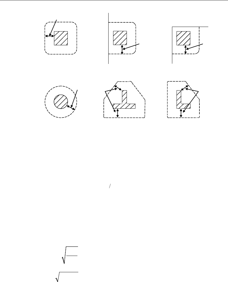
ETABS Reinforced Concrete Design
Figure 6-3 Punching Shear Perimeters
14.5.3.2 Determination of Concrete Capacity
The concrete punching shear stress capacity is taken as:
( )
13
,,1 1
100
Rd c Rd c ck cp
V Ck f k
ρσ
= +
(EC2 6.4.4(1))
with a minimum of:
( )
cp
cRd kvV
σ
1min,+
=
(EC2 6.4.4(1))
where fck is in MPa and
200
1 2.0
kd
=+≤
with d in mm (EC2 6.4.4(1))
ρ
1 =
yx 11
ρρ
≤ 0.02 (EC2 6.4.4(1))
where
ρ
1x and
ρ
1y are the reinforcement ratios in the x and y directions respec-
tively, conservatively taken as zeros, and
σcp = (σcx + σcy)/2 (EC2 6.4.4(1))
2d
Interior Column
Circular Column T-Shape Column
Edge Column Corner Column
L-Shape Column
2d 2d
2d
2d
2d
2d
Interior Column
Circular Column T-Shape Column
Edge Column Corner Column
L-Shape Column
2d 2d
2d
2d
2d
14 - 20 Slab Design

Chapter 14 - Design for Italian NTC 2008
where σcx and σcy are the normal concrete stresses in the critical section in the x
and y directions respectively, conservatively taken as zeros.
ccRd
C
γ
18.0
,=
(EC2 6.4.4(1))
21
23
min 035.0 ck
fk=
ν
(EC2 6.4.4(1))
k1 = 0.15 (EC2 6.4.4(1))
14.5.3.3 Determine Maximum Shear Stress
Given the punching shear force and the fractions of moments transferred by ec-
centricity of shear, the nominal design shear stress, vEd, is calculated as:
,2 1 ,3 1
1,2 1,3
1,
=++
Ed Ed
Ed
Ed
Ed Ed
Mu Mu
V
v kk
ud VW VW
where (EC2 6.4.4(2))
k
is the function of the aspect ratio of the loaded area in Table 14.1 of
EN 1992-1-1
u1 is the effective perimeter of the critical section
d is the mean effective depth of the slab
MEd is the design moment transmitted from the slab to the column at the
connection along bending axis 2 and 3
VEd is the total punching shear force
W1 accounts for the distribution of shear based on the control perimeter
along bending axis 2 and 3.
14.5.3.4 Determine Capacity Ratio
The ratio of the maximum shear stress and the concrete punching shear stress
capacity is reported as the punching shear capacity ratio by ETABS. If this ratio
exceeds 1.0, punching shear reinforcement is designed as described in the fol-
lowing section.
Slab Design 14 - 21

ETABS Reinforced Concrete Design
14.5.4 Design Punching Shear Reinforcement
The use of shear studs as shear reinforcement in slabs is permitted, provided that
the effective depth of the slab is greater than or equal to 200 mm.
The algorithm for designing the required punching shear reinforcement is used
when the punching shear capacity ratio exceeds unity. The Critical Section for
Punching Shear and Transfer of Unbalanced Moment as described in the earlier
sections remain unchanged. The design of punching shear reinforcement is per-
formed as described in the subsections that follow.
14.5.4.1 Determine Concrete Shear Capacity
The concrete punching shear stress capacity of a section with punching shear
reinforcement is as previously determined for the punching check.
14.5.4.2 Determine Required Shear Reinforcement
The shear is limited to a maximum of VRcd calculated in the same manner as
explained previously for slabs.
Given vEd, vRd,c, and vRcd , the required shear reinforcement is calculated as fol-
lows (EC2 6.4.5).
If vR,dc < vEd ≤ vRcd
( )
( )
,
1
,
0.75
1.5
Ed Rd c
sw r
ywd ef
vv
A ud s
f
−
=
(EC2 6.4.5)
If vEd > vRcd, a failure condition is declared. (EC2 6.2.3(3))
If vEd exceeds the maximum permitted value of VRcd the concrete section
should be increased in size.
14.5.4.3 Determine Reinforcement Arrangement
Punching shear reinforcement in the vicinity of rectangular columns should be
arranged on peripheral lines, i.e., lines running parallel to and at constant dis-
tances from the sides of the column. Figure 6-4 shows a typical arrangement of
shear reinforcement in the vicinity of a rectangular interior, edge, and corner
column.
14 - 22 Slab Design
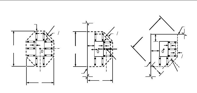
Chapter 14 - Design for Italian NTC 2008
Figure 6-4 Typical arrangement of shear studs and
critical sections outside shear-reinforced zone
The distance between the column face and the first line of shear reinforcement
shall not exceed 2d. The spacing between adjacent shear reinforcement in the
first line (perimeter) of shear reinforcement shall not exceed 1.5d measured in a
direction parallel to the column face (EC2 9.4.3(1)).
Punching shear reinforcement is most effective near column corners where there
are concentrations of shear stress. Therefore, the minimum number of lines of
shear reinforcement is 4, 6, and 8, for corner, edge, and interior columns respec-
tively.
14.5.4.4 Determine Reinforcement Diameter, Height, and Spacing
The punching shear reinforcement is most effective when the anchorage is close
to the top and bottom surfaces of the slab. The cover of anchors should not be
less than the minimum cover specified in EC2 4.4.1 plus half of the diameter of
the flexural reinforcement.
Punching shear reinforcement in the form of shear studs is generally available in
10-, 12-, 14-, 16-, and 20-millimeter diameters.
When specifying shear studs, the distance, so, between the column face and the
first peripheral line of shear studs should not be smaller than 0.3d. The spacing
I
y
Typical Studrail
(only first and last
studs shown)
Outermost
peripheral line
of studs
Interior Column Edge Column Corner Column
Critical section
centroid
Free
edge
Free
edge
Critical
section
centroid
Free edge
Outermost
peripheral line
of studs
I
y
I
y
yx
d2 d2
d2
x
I
x
I
x
g
y
g
x
g
0
s
0
s
0
s
x
I
y
x
x
I
y
Typical Studrail
(only first and last
studs shown)
Outermost
peripheral line
of studs
Interior Column Edge Column Corner Column
Critical section
centroid
Free
edge
Free
edge
Critical
section
centroid
Free edge
Outermost
peripheral line
of studs
I
y
I
y
yx
d2 d2
d2
x
I
x
I
x
g
y
g
x
g
0
s
0
s
0
s
x
I
y
x
x
Slab Design 14 - 23

ETABS Reinforced Concrete Design
between adjacent shear studs, g, at the first peripheral line of studs shall not ex-
ceed 1.5d and should not exceed 2d at additional perimeters. The limits of so and
the spacing, s, between the peripheral lines are specified as:
0.3d ≤ so ≤ 2d (EC2 9.4.3(1))
s ≤ 0.75d (EC2 9.4.3(1))
g ≤ 1.5d (first perimeter) (EC2 9.4.3(1))
g ≤ 2d (additional perimeters) (EC2 9.4.3(1))
14 - 24 Slab Design

Chapter 15
Design for NZS 3101-06
This chapter describes in detail the various aspects of the concrete design proce-
dure that is used by ETABS when the New Zealand code NZS 3101-06 [NZS
06] is selected. Various notations used in this chapter are listed in Table 15-1.
For referencing to the pertinent sections of the New Zealand code in this chapter,
a prefix “NZS” followed by the section number is used.
The design is based on user-specified load combinations. The program provides
a set of default load combinations that should satisfy the requirements for the
design of most building type structures.
English as well as SI and MKS metric units can be used for input. The code is
based on Newton-millimeter-second units. For simplicity, all equations and de-
scriptions presented in this chapter correspond to Newton-millimeter-second
units unless otherwise noted.
15.1 Notations
Table 15-1 List of Symbols Used in the NZS 3101-06 Code
A
co
Area enclosed by perimeter of the section, sq-mm
A
cv
Area of concrete used to determine shear stress, sq-mm
A
g
Gross area of concrete, sq-mm
Notations 15 - 1

ETABS Reinforced Concrete Design
Table 15-1 List of Symbols Used in the NZS 3101-06 Code
A
l
Area of longitudinal reinforcement for torsion, sq-mm
A
o
Gross area enclosed by shear flow path, sq-mm
A
s
Area of tension reinforcement, sq-mm
A'
s
Area of compression reinforcement, sq-mm
A
s(required)
Area of steel required for tension reinforcement, sq-mm
A
t
/s
Area of closed shear reinforcement per unit length for torsion, sq-
mm/mm
A
v
Area of shear reinforcement, sq-mm
A
v
/s
Area of shear reinforcement per unit length, sq-mm/mm
a
Depth of compression block, mm
a
b
Depth of compression block at balanced condition, mm
a
max
Maximum allowed depth of compression block, mm
b
Width of member, mm
b
f
Effective width of flange (flanged section), mm
b
w
Width of web (flanged section), mm
b
0
Perimeter of the punching critical section, mm
b
1
Width of the punching critical section in the direction of bending,
mm
b
2
Width of the punching critical section perpendicular to the direc-
tion of bending, mm
c
Distance from extreme compression fiber to the neutral axis, mm
c
b
Distance from extreme compression fiber to neutral axis at bal-
anced condition, mm
d
Distance from extreme compression fiber to tension reinforce-
ment, mm
d'
Distance from extreme compression fiber to compression rein-
forcement, mm
E
c
Modulus of elasticity of concrete, MPa
E
s
Modulus of elasticity of reinforcement, assumed as 200,000 MPa
15 - 2 Notations

Chapter 15 - Design for NZS 3101-06
Table 15-1 List of Symbols Used in the NZS 3101-06 Code
f'
c
Specified compressive strength of concrete, MPa
f'
s
Stress in the compression reinforcement, psi
f
y
Specified yield strength of flexural reinforcement, MPa
f
yt
Specified yield strength of shear reinforcement, MPa
h
Overall depth of sections, mm
h
f
Thickness of slab or flange, mm
k
a
Factor accounting for influence of aggregate size on shear
strength
k
d
Factor accounting for influence of member depth on shear
strength
M*
Factored design moment at a section, N-mm
p
c
Outside perimeter of concrete section, mm
p
o
Perimeter of area A
o
, mm
s
Spacing of shear reinforcement along the strip, mm
T*
Factored design torsion at a section, N-mm
t
c
Assumed wall thickness of an equivalent tube for the gross
section, mm
t
o
Assumed wall thickness of an equivalent tube for the area
enclosed by the shear flow path, mm
V
c
Shear force resisted by concrete, N
V*
Factored shear force at a section, N
v*
Average design shear stress at a section, MPa
v
c
Design shear stress resisted by concrete, MPa
v
max
Maximum design shear stress permitted at a section, MPa
v
tn
Shear stress due to torsion, MPa
α
s
Punching shear factor accounting for column location
α
1
Concrete strength factor to account for sustained loading and
equivalent stress block
β
1
Factor for obtaining depth of compression block in concrete
Notations 15 - 3

ETABS Reinforced Concrete Design
Table 15-1 List of Symbols Used in the NZS 3101-06 Code
β
c
Ratio of the maximum to the minimum dimensions of the punch-
ing critical section
ε
c
Strain in concrete
ε
c,max
Maximum usable compression strain allowed in the extreme
concrete fiber, (0.003 in/in)
ε
s
Strain in reinforcement
φ
b
Strength reduction factor for bending
φ
s
Strength reduction factor for shear and torsion
γ
f
Fraction of unbalanced moment transferred by flexure
γ
v
Fraction of unbalanced moment transferred by eccentricity of
shear
15.2 Design Load Combinations
The design load combinations are the various combinations of the load cases for
which the structure needs to be designed. For NZS 3101-06, if a structure is sub-
jected to dead (D), live (L), pattern live (PL), snow (S), wind (W), and earth-
quake (E) loads, and considering that wind and earthquake forces are reversible,
the following load combinations may need to be considered (AS/NZS 1170.0,
4.2.2):
1.35D
(AS/NZS 1170.0, 4.2.2(a))
1.2D + 1.5L
(AS/NZS 1170.0, 4.2.2(b))
1.2D + 1.5(0.75 PL)
(AS/NZS 1170.0, 4.2.2(b))
1.2D + 0.4L + 1.0S
(AS/NZS 1170.0, 4.2.2(g))
1.2D ± 1.0W
0.9D
± 1.0W
1.2D + 0.4L
± 1.0W
(AS/NZS 1170.0, 4.2.2(d))
(AS/NZS 1170.0, 4.2.2(e))
(AS/NZS 1170.0, 4.2.2(d))
1.0D ± 1.0E
1.0D + 0.4L
± 1.0E
(AS/NZS 1170.0, 4.2.2(f))
(AS/NZS 1170.0, 4.2.2(f))
15 - 4 Design Load Combinations

Chapter 15 - Design for NZS 3101-06
Note that the 0.4 factor on the live load in three of the combinations is not valid
for live load representing storage areas. These are also the default design load
combinations in ETABS whenever the NZS 3101-06 code is used. If roof live
load is treated separately or if other types of loads are present, other appropriate
load combinations should be used.
15.3 Limits on Material Strength
The upper and lower limits of f'c shall be as follows:
25 ' 100MPa≤≤
c
f
(NZS 5.2.1)
The lower characteristic yield strength of longitudinal reinforcement, fy, should
be equal to or less than 500 MPa for all frames (NZS 5.3.3). The lower charac-
teristic yield strength of transverse (stirrup) reinforcement, fyt, should not be
greater than 500 MPa for shear or 800 MPa for confinement (NZS 5.3.3).
The code allows use of f'c and fy beyond the given limits, provided special study
is conducted (NZS 5.2.1).
ETABS enforces the upper material strength limits for flexure and shear design
of slabs. The input material strengths are taken as the upper limits if they are
defined in the material properties as being greater than the limits. The user is
responsible for ensuring that the minimum strength is satisfied.
15.4 Strength Reduction Factors
The strength reduction factors,
φ
, are applied to the specified strength to obtain
the design strength provided by a member. The
φ
factors for flexure, shear, and
torsion are as follows:
φ
b = 0.85 for flexure (NZS 2.3.2.2)
φ
s = 0.75 for shear and torsion (NZS 2.3.2.2)
These values can be overwritten; however, caution is advised.
Limits on Material Strength 15 - 5

ETABS Reinforced Concrete Design
15.5 Slab Design
ETABS slab design procedure involves defining sets of strips in two mutually
perpendicular directions. The locations of the strips are usually governed by the
locations of the slab supports. The axial force, moments and shears for a partic-
ular strip are recovered from the analysis (on the basis of the Wood-Armer tech-
nique), and a flexural design is carried out based on the ultimate strength design
method.
The slab design procedure involves the following steps:
Design flexural reinforcement
Design shear reinforcement
Punching check
15.5.1 Design Flexural Reinforcement
For slabs, ETABS uses either design strips or the finite element based design to
calculate the slab flexural reinforcement in accordance with the selected design
code. For simplicity, only strip-by-strip design is document in the proceeding
sections.
The design of the slab reinforcement for a particular strip is carried out at specific
locations along the length of the strip. These locations correspond to the element
boundaries. Controlling reinforcement is computed on either side of those ele-
ment boundaries. The slab flexural design procedure for each load combination
involves the following:
Determine factored axial loads and moments for each slab strip.
Design flexural reinforcement for the strip.
These two steps, described in the text that follows, are repeated for every load
combination. The maximum reinforcement calculated for the top and bottom
of the slab within each design strip, along with the corresponding controlling
load combination, is obtained and reported.
15 - 6 Slab Design

Chapter 15 - Design for NZS 3101-06
15.5.1.1 Determine Factored Moments
In the design of flexural reinforcement of concrete slab, the factored moments
for each load combination at a particular design strip are obtained by factoring
the corresponding moments for different load cases, with the corresponding load
factors.
The slab is then designed for the maximum positive and maximum negative fac-
tored moments obtained from all of the load combinations. Calculation of bottom
reinforcement is based on positive design strip moments. In such cases, the slab
may be designed as a rectangular or flanged slab section. Calculation of top re-
inforcement is based on negative design strip moments. In such cases, the slab
may be designed as a rectangular or inverted flanged slab section.
15.5.3.2 Determine Required Flexural Reinforcement
In the flexural reinforcement design process, the program calculates both the
tension and compression reinforcement. Compression reinforcement is added
when the applied design moment exceeds the maximum moment capacity of a
singly reinforced section. The user has the option of avoiding the compression
reinforcement by increasing the effective depth, the width, or the strength of the
concrete.
The design procedure is based on the simplified rectangular stress block shown
in Figure 15-1 (NZS 7.4.2.7). Furthermore, it is assumed that the compression
carried by the concrete is 0.75 times that which can be carried at the balanced
condition (NZS 9.3.8.1). When the applied moment exceeds the moment capac-
ity at the balanced condition, the area of compression reinforcement is calculated
assuming that the additional moment will be carried by compression reinforce-
ment and additional tension reinforcement.
Slab Design 15 - 7
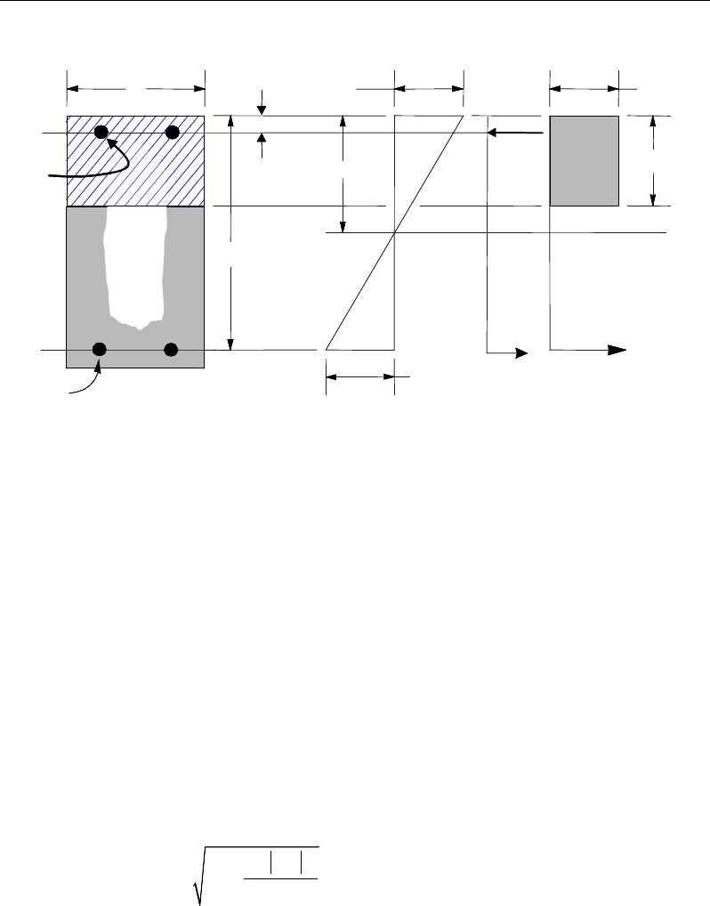
ETABS Reinforced Concrete Design
Figure 15-1 Uniform Thickness Slab Design
The design procedure used by ETABS, for both rectangular and flanged sections
(L- and T-shaped sections), is summarized in the text that follows. For reinforced
concrete design where design ultimate axial compression load does not ex-
ceed (0.1 f'c Ag), axial force is ignored; hence, all slabs are designed for major
direction flexure, shear, and torsion only. Axial compression greater than 0.1 f'c
Ag and axial tensions are always included in flexural and shear design.
15.5.1.2.1 Design of uniform thickness slab
In designing for a factored negative or positive M* (i.e., designing top or bottom
reinforcement), the depth of the compression block is given by a (see Figure 15-
1), where,
*
2
1
2
cb
M
ad d fb
αφ
=−−
′
(NZS 7.4.2)
where the default value of
φ
b is 0.85 (NZS 2.3.2.2) in the preceding and follow-
ing equations. The factor α1 is calculated as follows (NZS 7.4.2.7):
BEAM
SECTION STRAIN
DIAGRAM STRESS
DIAGRAM
0 003.
ε
=1c
f
α
′
1
ac
β
=
cs
T
s
T
s
ε
cs
C
d′
d
b
s
A
s
A′
BEAM
SECTION STRAIN
DIAGRAM STRESS
DIAGRAM
0 003.
ε
=1c
f
α
′
1
ac
β
=
cs
T
s
T
s
ε
cs
C
d′
d
b
s
A
s
A′
15 - 8 Slab Design
Chapter 15 - Design for NZS 3101-06
α
′
= ≤
1
0.85 for 55MPa
c
f
11
0.85 0.004( 55) for 55MPa, 0.75 0.85
cc
ff
αα
′′
= − − ≥ ≤≤
The value
β
1 and cb are calculated as follows:
10.85 for 30,
c
f
β
′
= ≤
(NZS 7.4.2.7)
11
0.85 0.008( 30), 0.65 0.85
c
f
ββ
′
= − − ≤≤
(NZS 7.4.2.7)
c
bc ys
cd
fE
ε
ε
=+
(NZS 7.4.2.8)
The maximum allowed depth of the rectangular compression bloack, amax, is
given by:
amax = 0.75
β
1cb (NZS 7.4.2.7, 9.3.8.1)
If a ≤ amax (NZS 9.3.8.1), the area of tension reinforcement is given by:
*
2
s
by
M
Aa
fd
φ
=
−
The reinforcement is to be placed at the bottom if M* is positive, or at the top
if M* is negative.
If a > amax (NZS 9.3.8.1), compression reinforcement is required (NZS 7.4.2.9)
and is calculated as follows:
The compressive force developed in the concrete alone is given by:
C = α1
c
f′
bamax (NZS 7.4.2.7)
and the moment resisted by concrete compression and tension reinforcement
is:
M*c = C
−2
max
a
d
φ
b
Slab Design 15 - 9

ETABS Reinforced Concrete Design
Therefore the moment required to be resisted by compression reinforcement
and tension reinforcement is:
M*s = M* − M*c
The required compression reinforcement is given by:
( )( )
1
*
s
ssc b
M
Af f d d'
αφ
′=′′
−−
, where
s c,max s y
c d'
fE f
c
ε
−
′= ≤
(NZS 7.4.2.2, 7.4.2.4)
The required tension reinforcement for balancing the compression in the con-
crete is:
As1 =
by
c
a
df
M
φ
−2
*
max
and the tension reinforcement for balancing the compression reinforcement is
given by:
As2 =
(
)
b
y
s
dd
f
M
φ
'
*
−
Therefore, the total tension reinforcement, As = As1 + As2, and the total compres-
sion reinforcement is A's. A s is to be placed at the bottom and A's is to be placed
at the top if M* is positive, and vice versa if M* is negative.
15.5.1.2.2 Design of nonuniform thickness slab
15.5.1.2.2.1 Flanged Slab Section Under Negative Moment
In designing for a factored negative moment, M* (i.e., designing top reinforce-
ment), the calculation of the reinforcement area is exactly the same as described
previously, i.e., no flanged data is used.
15 - 10 Slab Design
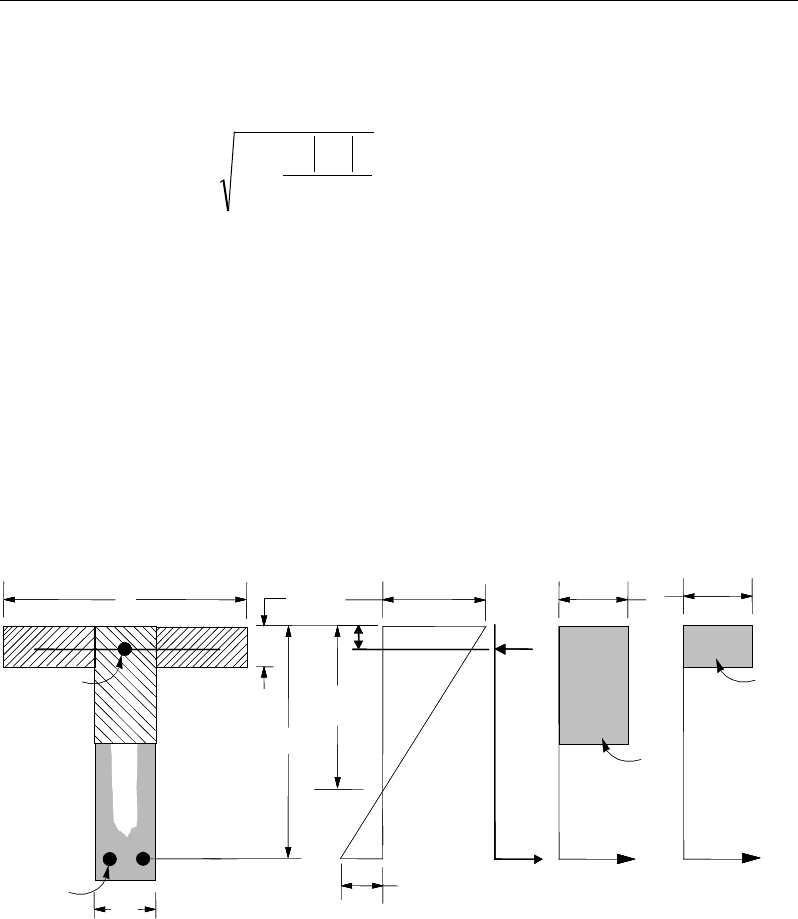
Chapter 15 - Design for NZS 3101-06
15.5.1.2.2.2 Flanged Slab Section Under Positive Moment
If M* > 0, the depth of the compression block is given by:
a = d −
fbc bf
M
d
φα
'
1
*
22
−
(NZS 7.4.2)
The maximum allowable depth of the rectangular compression block, amax, is
given by:
amax = 0.75
β
1cb (NZS 7.4.2.7, 9.3.8.1)
If a ≤ hf, the subsequent calculations for As are exactly the same as previously defined for
the uniform thickness slab design. However, in this case the width of the sl;ab is taken as
bf. Compression reinforcement is required when a > amax.
If a > hf, calculation for As has two parts. The first part is for balancing the compressive
force from the flange, Cf, and the second part is for balancing the compressive force from
the web, Cw, as shown in Figure 15-2.
Figure 15-2 Nonuniform Thickness Slab Design
Cf is given by:
(I) BEAM
SECTION
s
A
(II) STRAIN
DIAGRAM
(III) STRESS
DIAGRAM
s
A′
w
b
f
b
d
d′s
f′
0.003
ε
=1c
f
α
′
w
T
s
T
s
ε
f
T
f
C
w
C
s
C
f
h
c
1c
f
α
′
(I) BEAM
SECTION
s
A
(II) STRAIN
DIAGRAM
(III) STRESS
DIAGRAM
s
A′
w
b
f
b
d
d′s
f′
0.003
ε
=1c
f
α
′
w
T
s
T
s
ε
f
T
f
C
w
C
s
C
f
h
c
1c
f
α
′
Slab Design 15 - 11
ETABS Reinforced Concrete Design
( )
1f cf wf
C fb bh
α
′
= −
(NZS 7.4.2.7)
Therefore, As1 =
y
f
f
C
and the portion of M* that is resisted by the flange is
given by:
b
s
ff
d
dCM
φ
−= 2
*
Therefore, the balance of the moment, M*, to be carried by the web is:
M*w = M* − M*f
The web is a rectangular section with dimensions bw and d, for which the depth
of the compression block is recalculated as:
2
11
2
*
w
cbw
M
ad d fb
αφ
=−−
′
(NZS 7.4.2 )
If a1 ≤ amax (NZS 9.3.8.1), the area of tension reinforcement is then given by:
As2 =
−2
1
*
a
df
M
yb
w
φ
, and
As = As1 + As2
This reinforcement is to be placed at the bottom of the flanged section.
If a1 > amax (NZS 9.3.8.1), compression reinforcement is required and is cal-
culated as follows:
The compressive force in the web concrete alone is given by:
1 maxw cw
C fba
α
′
=
(NZS 7.4.2.7)
and the moment resisted by the concrete web and tension reinforcement is:
15 - 12 Slab Design

Chapter 15 - Design for NZS 3101-06
max
2
*
cw b
a
M Cd
φ
= −
The moment resisted by compression and tension reinforcement is:
M*s = M*w − M*c
Therefore, the compression reinforcement is computed as:
( )( )
1
*
s
ssc b
M
Af f d d'
αφ
′=′′
−−
, where
maxs c, s y
c d'
fE f
c
ε
−
′= ≤
(NZS 7.4.2.2, 7.4.2.4)
The tension reinforcement for balancing compression in the web concrete is:
As2 =
max
2
*
c
yb
M
a
fd
φ
−
and the tension reinforcement for balancing the compression reinforcement is:
As3 =
( )
b
y
s
dd
f
M
φ
'
*
−
Total tension reinforcement is As = As1 + As2 + As3, and the total compression
reinforcement is A's. As is to be placed at the bottom, and A's is to be placed at the
top.
15.5.3.2 Minimum and Maximum Reinforcement
The minimum flexural tension reinforcement required for each direction of a
slab is given by the following limit (NZS 12.5.6.2, 8.8, 2.4.4):
07 500 MPa
0 0014 500 MPa
y
y
s
y
.bh f
f
A
. bh f
<
≥
≥
(NZS 12.5.6.2, 8.8.1)
Slab Design 15 - 13

ETABS Reinforced Concrete Design
In addition, an upper limit on both the tension reinforcement and compression
reinforcement has been imposed to be 0.04 times the gross cross-sectional area.
The slab reinforcement requirements reported by the program do not con-
sider crack control. Any minimum requirements to satisfy crack limita-
tions must be investigated independently of the program by the user.
15.5.2 Design Slab Shear Reinforcement
The shear reinforcement is designed for each load combination at each station
along the design strip. In designing the shear reinforcement for a particular strip,
for a particular load combination, at a particular station due to the slab major
shear, the following steps are involved:
Determine the factored shear force, V*.
Determine the shear force, Vc, that can be resisted by the concrete.
Determine the shear reinforcement required to carry the balance.
The following three sections describe in detail the algorithms associated with
these steps.
15.5.3.2 Determine Shear Force and Moment
In the design of the slab shear reinforcement, the shear forces for each load com-
bination at a particular slab section are obtained by factoring the corresponding
shear forces for different load cases with the corresponding load combination
factors.
15.5.3.2 Determine Concrete Shear Capacity
The shear force carried by the concrete, Vc, is calculated as:
Vc = vc Acv (NZS 9.3.9.3.4)
The allowable shear stress capacity is given by:
ν
c = kd ka kn νb (NZS 9.3.9.3.4)
The basic shear strength for a rectangular section is computed as,
15 - 14 Slab Design
Chapter 15 - Design for NZS 3101-06
ν
b =
+db
A
w
s
1007.0
λ
′
c
f
, where (NZS 9.3.9.3.4)
c
f′
≤ 50 MPa, and (NZS 9.3.9.3.4)
0.08
λ
′
c
f
≤
ν
b ≤ 0.2
λ
′
c
f
(NZS 9.3.9.3.4)
where
1 0 normal concrete
0 85 sandlight-weight concrete
0 75 alllight-weight concrete
.,
.,
.,
λ
=
(NZS 9.3.9.3.5)
The factor ka allows for the influence of maximum aggregate size on shear
strength. For concrete with a maximum aggregate size of 20 mm or more, ka shall
be taken as 1.0. For concrete where the maximum aggregate size is 10 mm or
less, the value of ka shall be taken as 0.85. Interpolation is used between these
limits. The program default for ka is 1.0.
0 85 10mm
10
0 85 0 15 20mm
20
1 00 20mm
g
g
ag
g
., a
a
k . . ,a
., a
≤
−
=+<
≥
(NZS 9.3.9.3.4)
The factor kd allows for the influence of member depth on strength and it shall
be calculated from the following conditions:
For members with shear reinforcement equal to or greater than the nomi-
nal shear reinforcement given in NZS 9.3.9.4.15, kd = 1.0
For members with an effective depth equal to or smaller than 400 mm,
kd = 1.0 (NZS 9.3.9.3.4)
For members with an effective depth greater than 400,
( )
0.25
400/
d
kd=
where d is in mm (NZS 9.3.9.3.4)
The factor kn allows for the influence of axial loading (NZS 10.3.10.3.1).
Slab Design 15 - 15
ETABS Reinforced Concrete Design
= +
+
*
*
*
1 N =0
1 3 N >0
1 12 N < 0
*
n'
gc
*
'
gc
,
N
k,
Af
N,
Af
(NZS 10.3.10.3.1)
15.5.3.2 Determine Required Shear Reinforcement
The average shear stress is computed for rectangular and flanged sections as:
ν
* =
db
V
w
*
(NZS 7.5.1)
The average shear stress is limited to a maximum of,
vmax = min
{ }
0.2 , 8 MPa
′
c
f
(NZS 7.5.2, 9.3.9.3.3)
The shear reinforcement is computed as follows:
If
ν
* ≤
φ
s
( )
2
c
v
or h ≤ max(300 mm, 0.5bw),
s
Av
= 0 (NZS 9.3.9.4.13)
If
φ
s
( )
2
c
v
<
ν
* ≤
φ
s
ν
c,
s
Av
=
1
16 ′w
c
yt
b
ff
(NZS 7.5.10, 9.3.9.4.15)
If
φ
s
ν
c <
ν
* ≤
φ
s
ν
max, (NZS 9.3.9.4.2)
( )
df
vv
s
A
yts
csv
φ
φ
−
=
*
If
ν
* >
ν
max, a failure condition is declared. (NZS 7.5.2, 9.3.9.3.3)
15 - 16 Slab Design

Chapter 15 - Design for NZS 3101-06
If the slab depth h is less than the minimum of 300 mm and 0.5bw, no shear
reinforcement is required (NZS 9.3.9.4.13).
The maximum of all of the calculated Av/s values, obtained from each load com-
bination, is reported along with the controlling shear force and associated load
combination.
The slab shear reinforcement requirements considered by the program are based
purely on shear strength considerations. Any minimum stirrup requirements to
satisfy spacing and volumetric considerations must be investigated inde-
pendently of the program by the user.
15.5.3 Check for Punching Shear
The algorithm for checking punching shear is detailed in the section entitled
“Slab Punching Shear Check” in the Key Features and Terminology manual.
Only the code-specific items are described in the following.
15.5.3.1 Critical Section for Punching Shear
The punching shear is checked on a critical section at a distance of d/2 from the
face of the support (NZS 12.7.1(b)). For rectangular columns and concentrated
loads, the critical area is taken as a rectangular area with the sides parallel to the
sides of the columns or the point loads (NZS 12.7.1(b)). Figure 15-3 shows the
auto punching perimeters considered by ETABS for the various column shapes.
The column location (i.e., interior, edge, corner) and the punching perimeter may
be overwritten using the Punching Check Overwrites.
Slab Design 15 - 17
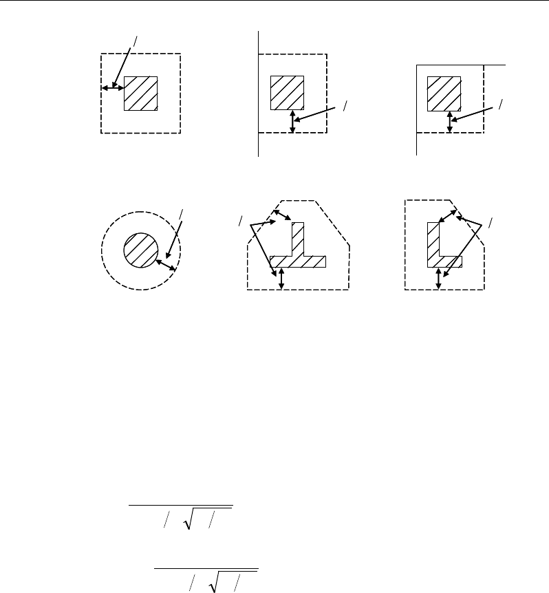
ETABS Reinforced Concrete Design
Figure 15-3 Punching Shear Perimeters
15.5.3.2 Transfer of Unbalanced Moment
The fraction of unbalanced moment transferred by flexure is taken to be γf M*
and the fraction of unbalanced moment transferred by eccentricity of shear is
taken to be γv M*, where
γf =
( )
21
321
1
bb+
(NZS 12.7.7.2 )
γv = 1 −
( )
21
321
1
bb+
(NZS 12.7.7.1)
where b1 is the width of the critical section measured in the direction of the span
and b2 is the width of the critical section measured in the direction perpendicular
to the span.
15.5.3.3 Determination of Concrete Capacity
The concrete punching shear factored strength is taken as the minimum of the
following three limits:
d2
Interior Column
Circular Column
d2 d2
d2
T-Shape Column
Edge Column Corner Column
L-Shape Column
d2
d2
d2
Interior Column
Circular Column
d2 d2
d2
T-Shape Column
Edge Column Corner Column
L-Shape Column
d2
d2
15 - 18 Slab Design
Chapter 15 - Design for NZS 3101-06
β
α
′
+
′
= +
′
0
12
1
6
1
min 1
6
1
3
c
c
s
cc
c
f
d
vf
b
f
(NZS 12.7.3.2)
where,
β
c is the ratio of the maximum to the minimum dimension of the critical
section (NZS 12.1, 12.7.3.2(a)), b0 is the perimeter of the critical section, and
α
s
is a scale factor based on the location of the critical section.
α
=
20 for interior columns,
15 for edge columns,
10 for corner columns.
s
(NZS 12.7.3.2(b))
A limit is imposed on the value of
c
f′
as follows:
λ
′
c
f
≤
100
(NZS 9.3.9.3.5(6))
15.5.3.4 Determine Maximum Shear Stress
Given the punching shear force and the fractions of moments transferred by ec-
centricity of shear about the two axes, the shear stress is computed
assuming linear variation along the perimeter of the critical section.
*
**
*22 3 1 33 4 3 23 4 3
2
022 33 23
**
33 3 1 22 4 3 23 4 3
2
22 33 23
[ ( )][ ( ) ( )]
[ ( )][ ( ) ( )]
γ
γ
− − −− −
=+−
−
− − −− −
−
V
V
M Vy y I y y I x x
V
vbd I I I
M Vx x I x x I y y
II I
Eq. 1
22 22
1=
=
∑
n
sides
II
, where "sides" refers to the sides of the critical
section for punching shear Eq. 2
Slab Design 15 - 19

ETABS Reinforced Concrete Design
33 33
1=
=
∑
n
sides
II
, where "sides" refers to the sides of the critical
section for punching shear Eq. 3
23 23
1=
=∑
n
sides
II
, where "sides" refers to the sides of the critical
section for punching shear Eq. 4
The equations for
22 33, 23
, and II I
are different depending on whether the side
of the critical section for punching shear being considered is parallel to the 2-
axis or parallel to the 3-axis. Refer to Figures 15-4.
2
22 2 3
()
= −I Ld y y
, for side of critical section parallel to 2-axis Eq. 5a
33 2
22 2 3
()
12 12
= ++ −
Ld dL
I Ld y y
, for the side of the critical section
parallel to the 3-axis Eq. 5b
15 - 20 Slab Design
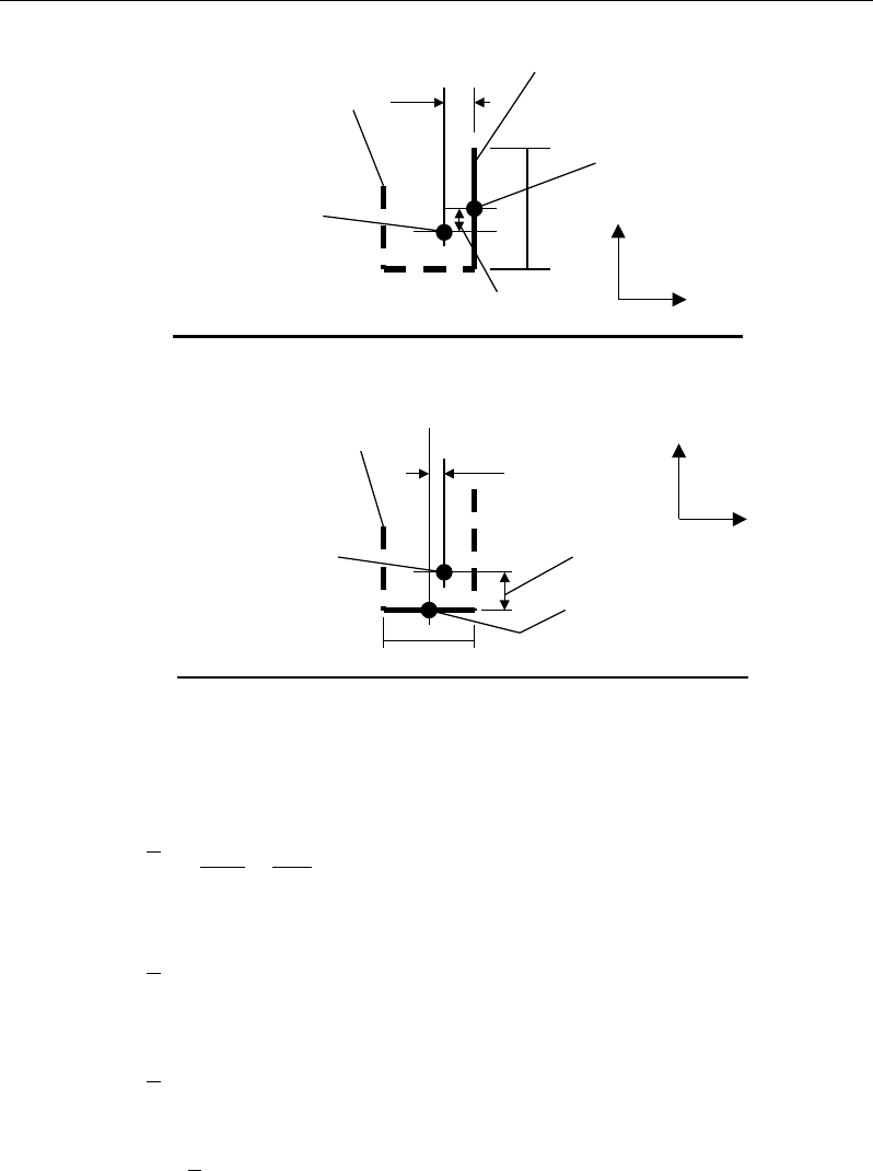
Chapter 15 - Design for NZS 3101-06
Figure 15-4 Shear Stress Calculations at Critical Sections
33 2
33 2 3
()
12 12
= ++ −
Ld dL
I Ld x y
, for the side of the critical section
parallel to the 2-axis Eq. 6
2
33 2 3
()= −I Ld x x
, for the side of the critical section
parallel to the 3-axis Eq. 6b
23 2 3 2 3
()()=−−I Ld x x y y
, for the side of the critical section
parallel to the 2-axis or 3-axis Eq. 7
NOTE:
23
I
is explicitly set to zero for corner condition.
Plan View For Side of Critical Section Parallel to 3-Axis
y
2
- y
3
L
Critical section for
punching shear
shown by heavy line
2
3
Side of critical section
being considered
shown solid
Center of side of critical
section being considered.
Coordinates are (x
2
,y
2
).
Work This Sketch With Equations 5b, 6b and
7
Centroid
of entire
critical section for
punching shear.
Coordinates are (x
3
,y
3
).
x
2
- x
3
y
2
- y
3
L
Critical section for
punching shear shown
by heavy line. Side of
critical section being
considered shown solid
2
3
Center of side of critical
section being considered.
Coordinates are (x
2
,y
2
).
Plan View For Side of Critical Section Parallel to 2-Axis
Work This Sketch With Equations 5a, 6a and
7
Centroid
of entire
critical section for
punching shear.
Coordinates are (x
3
,y
3
).
x
2
- x
3
Slab Design 15 - 21

ETABS Reinforced Concrete Design
where,
b0 = Perimeter of critical section for punching shear
d = Effective depth at critical section for punching shear based on average
of d for 2 direction and d for 3 direction
I22 = Moment of inertia of critical section for punching shear about an axis
that is parallel to the local 2-axis
I33 = Moment of inertia of critical section for punching shear about an axis
that is parallel to the local 3-axis
I23 = Product of inertia of critical section for punching shear with respect to
the 2 and 3 planes
L = Length of the side of the critical section for punching shear currently
being considered
*
2
M
= Moment about line parallel to 2-axis at center of column (positive per
right-hand rule)
*
3
M
= Moment about line parallel to 3-axis at center of column (positive per
right-hand rule)
V* = Punching shear stress
V* = Shear at center of column (positive upward)
x1, y1 = Coordinates of column centroid
x2, y2 = Coordinates of center of one side of critical section for punching shear
x3, y3 = Coordinates of centroid of critical section for punching shear
x4, y4 = Coordinates of location where you are calculating stress
γ
V2 = Percent of MU2 resisted by shear
γ
V3 = Percent of MU3 resisted by shear
15 - 22 Slab Design

Chapter 15 - Design for NZS 3101-06
15.5.3.5 Determine Capacity Ratio
The ratio of the maximum shear stress and the concrete punching shear stress
capacity is reported as the punching shear capacity ratio by ETABS. If this ratio
exceeds 1.0, punching shear reinforcement is designed as described in the fol-
lowing section.
15.5.4 Design Punching Shear Reinforcement
The use of shear studs as shear reinforcement in slabs is permitted, provided that
the effective depth of the slab is greater than or equal to 150 mm, and not less
than 16 times the shear reinforcement bar diameter (NZS 12.7.4.1). If the slab
thickness does not meet these requirements, the punching shear reinforcement is
not designed and the slab thickness should be increased by the user.
The algorithm for designing the required punching shear reinforcement is used
when the punching shear capacity ratio exceeds unity. The Critical Section for
Punching Shear and Transfer of Unbalanced Moment as described in the earlier
sections remain unchanged. The design of punching shear reinforcement is per-
formed as described in the subsections that follow.
15.5.4.1 Determine Concrete Shear Capacity
The concrete punching shear stress capacity of a section with punching shear
reinforcement is determined as:
cc
fv '
6
1
=
(NZS 12.7.3.5)
15.5.4.2 Determine Required Shear Reinforcement
The shear force is limited to a maximum of:
vmax = 0.5
c
f′
(NZS 12.7.3.4)
Given v*, vc, and vmax, the required shear reinforcement is calculated as follows,
where,
φ
, is the strength reduction factor.
Slab Design 15 - 23
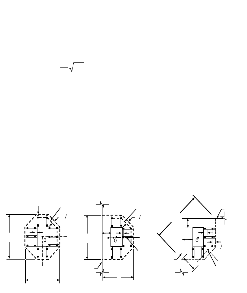
ETABS Reinforced Concrete Design
( )
nc
v
yv
vv
A
s fd
φ
−
=
(NZS 12.7.4.2(a))
Minimum punching shear reinforcement should be provided such that:
dbfV oc
s'
16
1
≥
(NZS 12.7.4.3)
If vn >
φ
vmax, a failure condition is declared. (NZS 12.7.3.4)
If vn exceeds the maximum permitted value of
φ
vmax, the concrete section
should be increased in size.
15.5.4.3 Determine Reinforcement Arrangement
Punching shear reinforcement in the vicinity of rectangular columns should be
arranged on peripheral lines, i.e., lines running parallel to and at constant dis-
tances from the sides of the column. Figure 15-5 shows a typical arrangement of
shear reinforcement in the vicinity of a rectangular interior, edge, and corner
column.
Figure 15-5 Typical arrangement of shear studs
and critical sections outside shear-reinforced zone
The distance between the column face and the first line of shear reinforcement
shall not exceed d/2. The spacing between adjacent shear reinforcement in the
I
y
Typical Studrail
(only first and last
studs shown)
Outermost
peripheral line
of studs
Interior Column Edge Column Corner Column
Critical section
centroid
Free
edge
Free
edge
Critical
section
centroid
Free edge
Outermost
peripheral line
of studs
I
y
I
y
yx
d2 d2
d2
x
I
x
I
x
g
y
g
x
g
0
s0
s
0
s
x
I
y
x
x
I
y
Typical Studrail
(only first and last
studs shown)
Outermost
peripheral line
of studs
Interior Column Edge Column Corner Column
Critical section
centroid
Free
edge
Free
edge
Critical
section
centroid
Free edge
Outermost
peripheral line
of studs
I
y
I
y
yx
d2 d2
d2
x
I
x
I
x
g
y
g
x
g
0
s0
s
0
s
x
I
y
x
x
15 - 24 Slab Design

Chapter 15 - Design for NZS 3101-06
first line (perimeter) of shear reinforcement shall not exceed 2d measured in a
direction parallel to the column face (NZS 12.7.4.4).
Punching shear reinforcement is most effective near column corners where there
are concentrations of shear stress. Therefore, the minimum number of lines of
shear reinforcement is 4, 6, and 8, for corner, edge, and interior columns respec-
tively.
15.5.4.4 Determine Reinforcement Diameter, Height, and Spacing
The punching shear reinforcement is most effective when the anchorage is close
to the top and bottom surfaces of the slab. The cover of anchors should not be
less than the minimum cover specified in NZS 3.11 plus half of the
diameter of the flexural reinforcement.
When specifying shear studs, the distance, so, between the column face and the
first peripheral line of shear studs should not be smaller than 0.5d. The spacing
between adjacent shear studs, g, at the first peripheral line of studs shall not ex-
ceed 2d and in the case of studs in a radial pattern, the angle between adjacent
stud rails shall not exceed 60 degrees. The limits of so and the spacing, s, between
the peripheral lines are specified as:
so ≤ 0.5d (NZS 12.7.4.4)
s ≤ 0.5d (NZS 12.7.4.4)
g ≤ 2d (NZS 12.7.4.4)
Slab Design 15 - 25

Chapter 16
Design for Singapore CP 65-99
This chapter describes in detail the various aspects of the concrete design
procedure that is used by ETABS when the Singapore standard, Structural Use
of Concrete code CP 65-99 [CP 99], is selected. The program also includes the
recommendations of BC 2:2008 Design Guide of High Strength Concrete to Sin-
gapore Standard CP65 [BC 2008]. Various notations used in this chapter are
listed in Table 16-1. For referencing to the pertinent sections of the Singapore
code in this chapter, a prefix “CP” followed by the section number is used.
The design is based on user-specified load combinations. The program
provides a set of default load combinations that should satisfy the requirements
for the design of most building type structures.
English as well as SI and MKS metric units can be used for input. The code is
based on Newton-millimeter-second units. For simplicity, all equations and
descriptions presented in this chapter correspond to Newton-millimeter-second
units unless otherwise noted.
16.1 Notations
Table 16-1 List of Symbols Used in the CP 65-99 Code
A
g
Gross area of cross-section, mm2
Notations 16 - 1

ETABS Reinforced Concrete Design
Table 16-1 List of Symbols Used in the CP 65-99 Code
A
l
Area of longitudinal reinforcement for torsion, mm2
A
s
Area of tension reinforcement, mm2
A'
s
Area of compression reinforcement, mm2
A
sv
Total cross-sectional area of links at the neutral axis, mm2
A
sv
/s
v
Area of shear reinforcement per unit length of the member,
mm2/mm
a
Depth of compression block, mm
b
Width or effective width of the section in the compression zone,
mm
b
f
Width or effective width of flange, mm
b
w
Average web width of a flanged section, mm
C
Torsional constant, mm4
d
Effective depth of tension reinforcement, mm
d'
Depth to center of compression reinforcement, mm
E
c
Modulus of elasticity of concrete, MPa
E
s
Modulus of elasticity of reinforcement, assumed as 200,000 MPa
f
Punching shear factor considering column location
f
cu
Characteristic cube strength, MPa
f
′
s
Stress in the compression reinforcement, MPa
f
y
Characteristic strength of reinforcement, MPa
f
yv
Characteristic strength of shear reinforcement, MPa (< 460 MPa)
h
Overall depth of a section in the plane of bending, mm
h
f
Flange thickness, mm
h
min
Smaller dimension of a rectangular section, mm
h
max
Larger dimension of a rectangular section, mm
K
Normalized design moment, M
u
/bd2f
cu
K' Maximum
2u
cu
M
bd f
for a singly reinforced concrete section
16 - 2 Notations

Chapter 16 - Design for Singapore CP 65-99
Table 16-1 List of Symbols Used in the CP 65-99 Code
k
1
Shear strength enhancement factor for support compression
k2 Concrete shear strength factor,
[ ]
13
30
cu
f
M
Design moment at a section, N-mm
M
single
Limiting moment capacity as singly reinforced section, N-mm
s
v
Spacing of the links along the strip, mm
T
Design torsion at ultimate design load, N-mm
u
Perimeter of the punching critical section, mm
V
Design shear force at ultimate design load, N
v
Design shear stress at a slab cross-section or at a punching critical
section, MPa
v
c
Design concrete shear stress capacity, MPa
v
max
Maximum permitted design factored shear stress, MPa
v
t
Torsional shear stress, MPa
x
Neutral axis depth, mm
x
bal
Depth of neutral axis in a balanced section, mm
z
Lever arm, mm
β
Torsional stiffness constant
β
b
Moment redistribution factor in a member
γ
f
Partial safety factor for load
γ
m
Partial safety factor for material strength
ε
c
Maximum concrete strain
ε
s
Strain in tension reinforcement
ε
'
s
Strain in compression reinforcement
Notations 16 - 3

ETABS Reinforced Concrete Design
16.2 Design Load Combinations
The design load combinations are the various combinations of the load cases for
which the structure needs to be designed. The design load combinations are ob-
tained by multiplying the characteristic loads by appropriate partial factors of
safety, γf (CP 2.4.1.3). If a structures is subjected to dead (D), live (L), pattern
live (PL), and wind (W) loads, and considering that wind forces are reversible,
the following load combinations may need to be considered (CP 2.4.3).
1.4D
1.
4D + 1.6L (CP 2.4.3
)
1.4D + 1.6(0.75PL)
(CP 2.4.3)
1.0D ± 1.4W
1.4D
± 1.4W
1.2D + 1.
2L ± 1.2W (CP 2.4.3
)
These are also the default design load combinations in ETABS whenever the CP
65-99 code is used. If roof live load is treated separately or other types of loads
are present, other appropriate load combinations should be used. Note that the
automatic combination, including pattern live load, is assumed and should be
reviewed before using for design.
16.3 Limits on Material Strength
The concrete compressive strength, fcu, should not be less than 30 MPa (CP
3.1.7.2).
The program does not enforce this limit for flexure and shear design of slabs.
The input material strengths are used for design even if they are outside of the
limits. It is the user's responsible to use the proper strength values while defining
the materials.
16.4 Partial Safety Factors
The design strengths for concrete and reinforcement are obtained by dividing the
characteristic strength of the material by a partial safety factor,
γ
m. The
16 - 4 Design Load Combinations
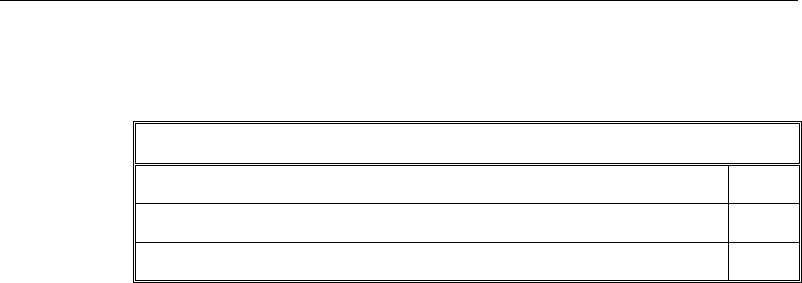
Chapter 16 - Design for Singapore CP 65-99
values of
γ
m used in the program are listed in the table that follows and are taken
from CP Table 2.2 (CP 2.4.4.1):
Values of
γ
m for the Ultimate Limit State
Reinforcement 1.15
Concrete in flexure and axial load 1.50
Concrete shear strength without shear reinforcement 1.25
These factors are incorporated into the design equations and tables in the code,
but can be overwritten.
16.5 Slab Design
ETABS slab design procedure involves defining sets of strips in two mutually
perpendicular directions. The locations of the strips are usually governed by the
locations of the slab supports. The axial force, moments and shears for a partic-
ular strip are recovered from the analysis (on the basis of the Wood-Armer tech-
nique), and a flexural design is carried out based on the ultimate strength design
method.
The slab design procedure involves the following steps:
Design flexural reinforcement
Design shear reinforcement
Punching check
16.5.1 Design Flexural Reinforcement
For slabs, ETABS uses either design strips or the finite element based design to
calculate the slab flexural reinforcement in accordance with the selected design
code. For simplicity, only strip-by-strip design is document in the proceeding
sections.
The design of the slab reinforcement for a particular strip is carried out at specific
locations along the length of the strip. These locations correspond to the element
Slab Design 16 - 5

ETABS Reinforced Concrete Design
boundaries. Controlling reinforcement is computed on either side of those ele-
ment boundaries. The slab flexural design procedure for each load combination
involves the following:
Determine factored axial loads and moments for each slab strip.
Design flexural reinforcement for the strip.
These two steps, described in the text that follows, are repeated for every load
combination. The maximum reinforcement calculated for the top and bottom
of the slab within each design strip, along with the corresponding controlling
load combination, is obtained and reported.
16.5.1.1 Determine Factored Moments
In the design of flexural reinforcement of concrete slab, the factored moments
for each load combination at a particular design strip are obtained by factoring
the corresponding moments for different load cases, with the corresponding load
factors.
The slab is then designed for the maximum positive and maximum negative fac-
tored moments obtained from all of the load combinations. Calculation of bottom
reinforcement is based on positive design strip moments. In such cases, the slab
may be designed as a rectangular or flanged slab section. Calculation of top re-
inforcement is based on negative design strip moments. In such cases, the slab
may be designed as a rectangular or inverted flanged slab section.
16.5.1.2 Determine Required Flexural Reinforcement
In the flexural reinforcement design process, the program calculates both the
tension and compression reinforcement. Compression reinforcement is added
when the applied design moment exceeds the maximum moment capacity of a
singly reinforced section. The user has the option of avoiding the compression
reinforcement by increasing the effective depth, the width, or the strength of the
concrete.
The design procedure is based on the simplified rectangular stress block shown
in Figure 16-1 (CP 3.4.4.4), where
ε
c is defined as:
16 - 6 Slab Design

Chapter 16 - Design for Singapore CP 65-99
( )
0 0035 if 60MPa
60
0 0035 if 60MPa
50000
cu
ccu cu
.f
f
.f
ε
≤
=−
−>
(CP 2.5.3, BC 2.2)
Furthermore, it is assumed that moment redistribution in the member does not
exceed 10% (i.e.,
β
b ≥ 0.9; CP 3.4.4.4). The code also places a limitation on the
neutral axis depth,
2
2
2
0.5 for 60N/mm
0.4 for 60 75N/mm
0.33 for 75 105N/mm
cu
cu
cu
f
xf
df
≤
≤ <≤
<≤
(CP 3.4.4.4, BC 2.2)
to safeguard against non-ductile failures (CP 3.4.4.4). In addition, the area of
compression reinforcement is calculated assuming that the neutral axis depth re-
mains at the maximum permitted value.
The depth of the compression block is given by:
cu
cu
cu
xf
xf
xf
≤
= ≤
≤
2
2
2
0.9 for 60 N/mm
0.8 for 60 < 75 N/mm
0.72 for 75 < 105 N/mm
a
(CP 3.4.4.4, BC 2.2)
The design procedure used by ETABS, for both rectangular and flanged sections
(L- and T-shaped sections), is summarized in the text that follows. For reinforced
concrete design where design ultimate axial compression load does not ex-
ceed (0.1fcuAg) (CP 3.4.4.1), axial force is ignored; hence, all slabs are designed
for major direction flexure and shear only. Axial compression greater than
0.1fcuAg g and axial tensions are always included in flexural and shear design.
16.5.1.2.1 Design of uniform thickness slab
For uniform thickness slab, the limiting moment capacity as a singly reinforced
slab, Msingle, is first calculated for a section. The reinforcement is determined
based on whether M is greater than, less than, or equal to Msingle. See Figure
16-1.
Slab Design 16 - 7
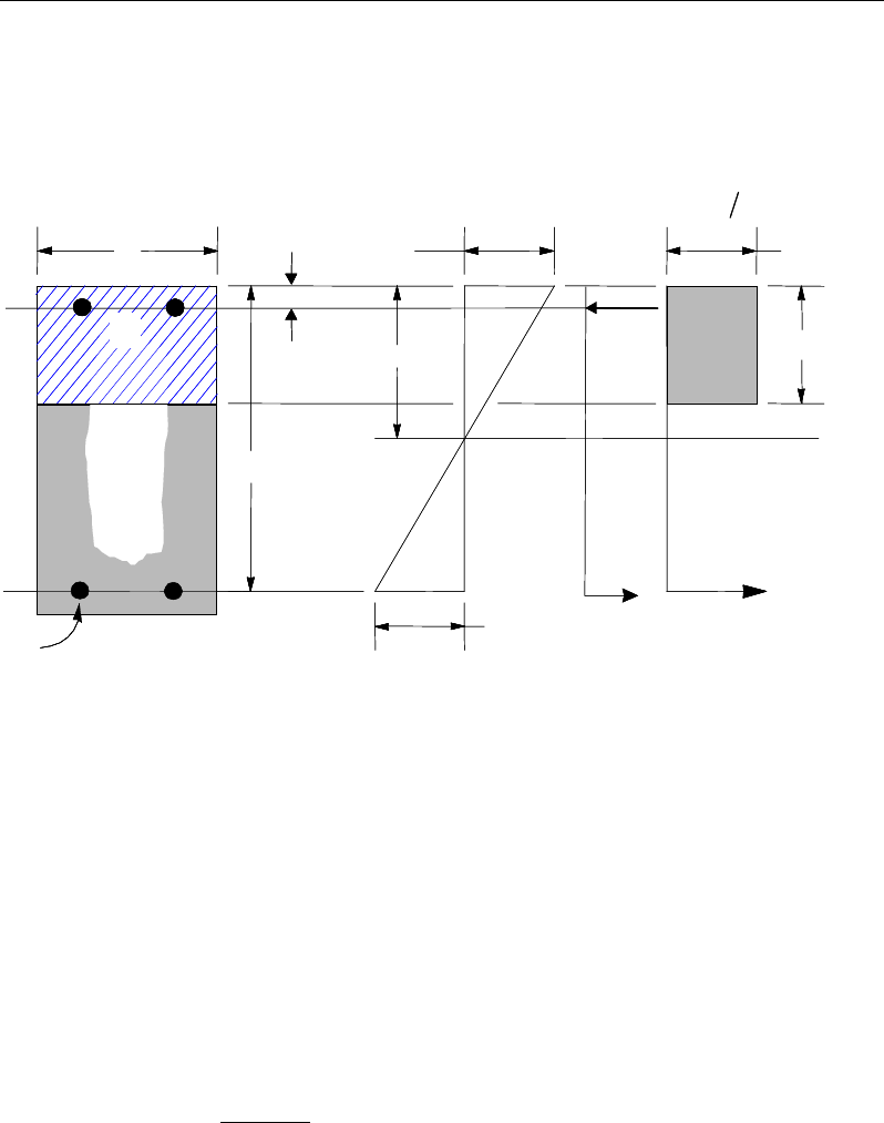
ETABS Reinforced Concrete Design
Calculate the ultimate limiting moment of resistance of the section as singly re-
inforced.
Msingle = K'fcu bd2, where (CP 3.4.4.4)
Figure 16-1 Uniform Thickness Slab Design
2
2
2
0.156 for 60N/mm
' 0.120 for 60 75N/mm
0.094 for 75 105N/mm and no moment redistribution.
≤
= <≤
<≤
cu
cu
cu
f
Kf
f
If M ≤ Msingle, the area of tension reinforcement, As, is given by:
zf
M
A
y
s
87.0
=
, where (CP 3.4.4.4)
BEAM
SECTION STRAIN
DIAGRAM STRESS
DIAGRAM
c
ε
0 67
cu m
.f
γ
a
cs
T
s
T
s
ε
x
s
C
d′
d
b
s
A
s
A′
s
f′
BEAM
SECTION STRAIN
DIAGRAM STRESS
DIAGRAM
c
ε
0 67
cu m
.f
γ
a
cs
T
s
T
s
ε
x
s
C
d′
d
b
s
A
s
A′
s
f′
16 - 8 Slab Design
Chapter 16 - Design for Singapore CP 65-99
d
K
dz 95.0
9.0
25.05.0 ≤
−+=
(CP 3.4.4.4)
2
bdf
M
K
cu
=
(CP 3.4.4.4)
This reinforcement is to be placed at the bottom if M is positive, or at the top
if M is negative.
If M > Msingle, compression reinforcement is required and calculated as follows:
( )
single
0 67
s
cu
sm
MM
A' .f
f' d d
γ
−
=
′
−−
(CP 3.4.4.4)
where d' is the depth of the compression reinforcement from the concrete com-
pression face, and
s
f′
= 0.87 fy if
11
2 800
′≤−
y
f
dd
(CP 3.4.4.1, 2.5.3, Fig 2.2)
css Ef
ε
='
2
1′
−
d
d
if
11
2 800
′>−
y
f
dd
(CP 3.4.4.4, 2.5.3, Fig 2.2)
The tension reinforcement required for balancing the compression in the con-
crete and the compression reinforcement is calculated as:
( )
single single
0 87 0 87
syy
M MM
A.fz .fdd
−
= + ′
−
, where (CP 3.4.4.4)
d
K
d
z95.
0
9
.0
'
25.0
5.0 ≤
−+=
(CP 3.4.4.4)
Slab Design 16 - 9
ETABS Reinforced Concrete Design
16.5.1.2.2 Design of nonuniform thickness slab
16.5.1.2.2.1 Flanged Slab Section Under Negative Moment
In designing for a factored negative moment, M (i.e., designing top reinforce-
ment), the calculation of the reinforcement area is exactly the same as described
previously, i.e., no flanged data is used.
16.5.1.2.2.2 Flanged Slab Section Under Positive Moment
With the flange in compression, the program analyzes the section by considering
alternative locations of the neutral axis. Initially the neutral axis is assumed to
be located in the flange. On the basis of this assumption, the program calculates
the exact depth of the neutral axis. If the stress block does not extend beyond the
flange thickness, the section is designed as a uniform thickness slab of width bf.
If the stress block extends beyond the flange width, the contribution of the web
to the flexural strength of the slab is taken into account. See Figure 16-2.
Figure 16-2 Nonuniform Thickness Slab Design
Assuming the neutral axis to lie in the flange, the normalized moment is given
by:
BEAM
SECTION
s
A
STRAIN
DIAGRAM
STRESS
DIAGRAM
s
A′
w
b
f
b
d
d′s
f′
c
ε
w
T
s
T
s
ε
0 67 cu m
.f
γ
f
T
f
C
w
C
s
C
f
h
x
0 67 cu m
.f
γ
BEAM
SECTION
s
A
STRAIN
DIAGRAM
STRESS
DIAGRAM
s
A′
w
b
f
b
d
d′s
f′
c
ε
w
T
s
T
s
ε
0 67 cu m
.f
γ
f
T
f
C
w
C
s
C
f
h
x
0 67 cu m
.f
γ
16 - 10 Slab Design
Chapter 16 - Design for Singapore CP 65-99
K =
2
d
bf
M
fcu
(CP 3.4.4.4)
Then the moment arm is computed as:
z = d
−
+9
.0
25
.0
5.
0K
≤ 0.95d (CP 3.4.4.4)
the depth of neutral axis is computed as:
2
2
2
, for 60N/mm
0.45
, for 60 75N/mm
0.40
, for 75 105N/mm
0.36
cu
cu
cu
dz f
dz
xf
dz f
−
≤
−
= <≤
−<≤
(CP 3.4.4.4, BC 2.2, Fig 2.3)
and the depth of the compression block is given by:
cu
cu
cu
xf
xf
xf
≤
= ≤
≤
2
2
2
0.9 for 60 N/mm
0.8 for 60 < 75 N/mm
0.72 for 75 < 105 N/mm
a
(CP 3.4.4.4, BC 2.2, Fig 2.3)
If a ≤ hf, the subsequent calculations for As are exactly the same as previously
defined for the uniform thickness slab design. However, in this case the width
of the slab is taken as bf. Compression reinforcement is required when K > K'.
If a > hf,
If M ≤
β
ffcubd2 and hf ≤ 0.45d then,
( )
( )
fy
f
cu
s
hdf
hd
bdfM
A5.087.0
45.01.0
−
−+
=
, where (BS 3.4.4.5)
b
b
d
h
b
b
d
h
w
f
w
f
f
15.0
2
1145
.0 +
−
−=
β
(BS 3.4.4.5)
Slab Design 16 - 11
ETABS Reinforced Concrete Design
Otherwise the calculation for As has two parts. The first part is for balancing
the compressive force from the flange, Cf, and the second part is for balancing
the compressive force from the web, Cw, as shown in Figure 16-2.
In that case, the ultimate resistance moment of the flange is given by:
( ) ( )
0.45 0.5
f cu f w f f
M f b bhd h= −−
(CP 3.4.4.5)
The moment taken by the web is computed as:
fw
MMM −=
and the normalized moment resisted by the web is given by:
Kw =
2
w
cu w
M
f bd
(CP 3.4.4.4)
If Kw ≤ 0.156 (CP 3.4.4.4), the slab is designed as a singly reinforced concrete
slab. The reinforcement is calculated as the sum of two parts, one to balance
compression in the flange and one to balance compression in the web.
( )
zf
M
hdf
M
A
y
w
fy
f
s87.05.087.0 +
−
=
, where
d
K
dz w95.
0
9.0
25
.0
5.0 ≤
−
+=
If Kw > K' (CP 3.4.4.4), compression reinforcement is required and is calcu-
lated as follows:
The ultimate moment of resistance of the web only is given by:
Muw = K' fcu bw d2 (CP 3.4.4.4)
The compression reinforcement is required to resist a moment of magnitude
Mw − Muw. The compression reinforcement is computed as:
16 - 12 Slab Design
Chapter 16 - Design for Singapore CP 65-99
( )
0 67
w uw
s
cu
sm
MM
A.f
f d d'
γ
−
′=
′−−
where, d' is the depth of the compression reinforcement from the concrete com-
pression face, and
ys
ff 87.0' =
if
11
2 800
′≤−
y
f
dd
(CP 3.4.4.4, 2.5.3, Fig 2.2)
−= d
d
Ef
c
ss
'2
1'
ε
if
11
2 800
′>−
y
f
dd
(CP 3.4.4.4, 2.5.3, Fig 2.2)
The area of tension reinforcement is obtained from equilibrium as:
1
0.87 0.5 '
fuw w uw
s
yf
MM MM
Af d h z dd
−
= ++
−−
0.5 0.25 0.95
0.9
K
zd d
′
= + −≤
16.5.1.3 Minimum and Maximum Reinforcement
The minimum flexural tension reinforcement required for each direction of a
slab is given by the following limit (CP 3.12.5.3, CP Table 3.25) with interpola-
tion for reinforcement of intermediate strength:
0 0024 if 250 MPa
0 0013 if 460 MPa
y
s
y
. bh f
A. bh f
=
≥=
(CP 3.12.5.3)
For fcu > 40 N/mm2, the preceding minimum reinforcement shall be multiplied
by (fcu/40)2/3.
In addition, an upper limit on both the tension reinforcement and compression
reinforcement has been imposed to be 0.04 times the gross cross-sectional area
(CP 3.12.6.1).
Slab Design 16 - 13
ETABS Reinforced Concrete Design
16.5.2 Design Slab Shear Reinforcement
The shear reinforcement is designed for each load combination at each station
along the design strip. In designing the shear reinforcement for a particular strip,
for a particular load combination, at a particular station due to the slab major
shear, the following steps are involved (CP 3.4.5):
Determine the shear stress, v.
Determine the shear stress, vc, that can be resisted by the concrete.
Determine the shear reinforcement required to carry the balance.
The following three sections describe in detail the algorithms associated with
these steps.
16.5.2.1 Determine Shear Stress
In the design of the slab shear reinforcement, the shear forces for each load com-
bination at a particular strip station are obtained by factoring the corresponding
shear forces for different load cases with the corresponding load combination
factors. The shear stress is then calculated as:
d
b
V
v
w
=
(CP 3.4.5.2)
The maximum allowable shear stress, vmax is defined as:
vmax = min (0.8
cu
f
, 7 MPa). (CP 3.4.5.2)
For light-weight concrete, vmax is defined as:
vmax = min(0.63
cu
f
, 4 MPa) (CP Part 2 5.4)
16.5.2.2 Determine Concrete Shear Capacity
The shear stress carried by the concrete, vc, is calculated as:
16 - 14 Slab Design
Chapter 16 - Design for Singapore CP 65-99
cc
c
c
cc
vA
N
v
MA
NVh
vv +≤+= 16.0'
(CP 3.4.5.12)
4
1
3
1
21 400
100
84.0
=dbd
A
kk
vs
m
c
γ
(CP 3.4.5.4, Table 3.9)
k1 is the enhancement factor for support compression,
and is conservatively taken as 1 (CP 3.4.5.8)
k2 =
13
30
cu
f
, 1 ≤ k2 ≤
1
3
80
30
(CP 3.4.5.4)
γm = 1.25 (CP 2.4.4.1)
However, the following limitations also apply:
0.15 ≤
bd
A
s
100
≤ 3 (CP 3.4.5.4, Table 3.9)
4
1
400
d
≥ 0.67 (unreinforced) or ≥ 1 (reinforced)(CP 3.4.5.4, Table
3.9)
fcu ≤ 80 MPa (for calculation purpose only) (CP 3.4.5.4, Table 3.9)
1≤
M
Vh
(CP 3.4.5.12)
As is the area of tension reinforcement
16.5.2.3 Determine Required Shear Reinforcement
Given v, v’c, and vmax, the required shear reinforcement is calculated as follows
(CP Table 3.8, CP 3.4.5.3):
Calculate the design average shear stress that can be carried by minimum shear
reinforcement, vr, as:
Slab Design 16 - 15

ETABS Reinforced Concrete Design
•
23
2
2
0.4 if 40N/mm
0.4 if 40 80N/mm
40
≤
= <≤
cu
rcu cu
f
vff
(CP 3.4.5.3, Table 3.8)
2
80N/mm≤
cu
f
(for calculation purpose only) (CP 3.4.5.3, Table 3.8)
If v ≤ v′c + vr,
,
0.87
sr
v yv
Avb
sf
=
(CP 3.4.5.3, Table 3.8)
If v > v′c + vr,
( )
'
0.87
c
sv
v yv
vv b
A
sf
−
=
(CP 3.4.5.3, Table 3.8)
If v > vmax, a failure condition is declared. (CP 3.4.5.2)
In the preceding expressions, a limit is imposed on the fyv as
fyv ≤ 460 MPa (CP 3.4.5.1)
The maximum of all of the calculated Asv /sv values, obtained from each load
combination, is reported along with the controlling shear force and associated
load combination.
The slab shear reinforcement requirements considered by the program are
based purely on shear strength considerations. Any minimum stirrup require-
ments to satisfy spacing and volumetric considerations must be investigated
independently of the program by the user.
16.5.3 Check for Punching Shear
The algorithm for checking punching shear is detailed in the section entitled
“Slab Punching Shear Check” in the Chapter 1. Only the code-specific items are
described in the following sections.
16 - 16 Slab Design
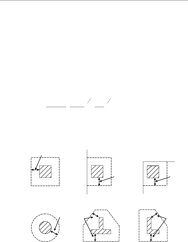
Chapter 16 - Design for Singapore CP 65-99
16.5.3.1 Critical Section for Punching Shear
The punching shear is checked on a critical section at a distance of 1.5d from the
face of the support (CP 3.7.7.4, 3.7.7.6). For rectangular columns and concen-
trated loads, the critical area is taken as a rectangular area with the sides parallel
to the sides of the columns or the point loads (CP 3.7.7.1). Figure 16-3 shows
the auto punching perimeters considered by ETABS for the various column
shapes. The column location (i.e., interior, edge, corner) and the punching pe-
rimeter may be overwritten using the Punching Check Overwrites.
16.5.3.2 Determination of Concrete Capacity
The concrete punching shear factored strength is taken as (CP 3.7.7.4, 3.7.7.6):
4
1
3
1
21 400
100
84.0
=dbd
A
kk
vs
m
c
γ
(CP 3.4.5.4, Table 3.9)
k1 is the enhancement factor for support compression,
and is conservatively taken as 1 (CP 3.4.5.8)
Figure 16-3 Punching Shear Perimeters
1.5d
Interior Column
Circular Column T-Shape Column
Edge Column Corner Column
L-Shape Column
1.5d 1.5d
1.5d
1.5d
1.5d
1.5d
Interior Column
Circular Column T-Shape Column
Edge Column Corner Column
L-Shape Column
1.5d 1.5d
1.5d
1.5d
1.5d
Slab Design 16 - 17
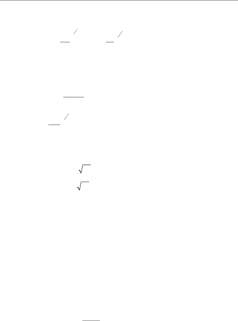
ETABS Reinforced Concrete Design
k2 =
13
30
cu
f
1 ≤ k2 ≤
3
1
30
80
(CP 3.4.5.4, Table 3.9)
γm = 1.25 (CP 3.4.5.2)
However, the following limitations also apply:
0.15 ≤
bd
A
s
100
≤ 3 (CP 3.4.5.4, Table 3.9)
4
1
400
d
≥ 0.67 (unreinforced) or ≥ 1 (reinforced)(CP 3.4.5.4, Table
3.9)
For light-weight concrete, vmax is defined as:
v ≤ min(0.63
,
cu
f
4 MPa) (CP Part 2 5.4)
v ≤ min (0.8
,
cu
f
7 MPa) (CP 3.4.5.2, Table 3.9)
fcu ≤ 80 MPa (for calculation purpose only) (CP 3.4.5.4, Table 3.9)
As = area of tension reinforcement, which is taken as the average tension
reinforcement of design strips in Layer A and layer B where Layer A
and Layer design strips are in orthogonal directions. When design
strips are not present in both orthogonal directions then tension rein-
forcement is taken as zero in the current implementation.
16.5.3.3 Determine Maximum Shear Stress
Given the punching shear force and the fractions of moments transferred by ec-
centricity of shear about the two axes, the nominal design shear stress, v, is cal-
culated as:
,1.5 x
eff x y
M
V Vf V
= +
(CP 3.7.6.2, 3.7.6.3)
16 - 18 Slab Design

Chapter 16 - Design for Singapore CP 65-99
,
1.5
y
eff y x
M
V Vf V
= +
(CP 3.7.6.2, 3.7.6.3)
,
max
,
max
eff x
eff y
V
ud
vV
ud
=
(CP 3.7.7.3)
where,
u is the perimeter of the critical section,
x and y are the lengths of the sides of the critical section parallel to the axis
of bending
Mx and My are the design moments transmitted from the slab to the column
at the connection
V is the total punching shear force
f is a factor to consider the eccentricity of punching shear force and is
taken as:
1 00 for interior columns,
1 25 for edge columns, and
1 25 for corner columns.
.
f.
.
=
(CP 3.7.6.2, 3.7.6.3)
16.5.3.4 Determine Capacity Ratio
The ratio of the maximum shear stress and the concrete punching shear stress
capacity is reported as the punching shear capacity ratio by ETABS. If this ratio
exceeds 1.0, punching shear reinforcement is designed as described in the fol-
lowing section.
16.5.4 Design Punching Shear Reinforcement
The use of shear links as shear reinforcement in slabs is permitted, provided that
the effective depth of the slab is greater than or equal to 200 mm (CP 3.7.7.5). If
Slab Design 16 - 19

ETABS Reinforced Concrete Design
the slab thickness does not meet this requirement, the punching shear reinforce-
ment is not designed and the slab thickness should be increased by the user.
The algorithm for designing the required punching shear reinforcement is used
when the punching shear capacity ratio exceeds unity. The Critical Section for
Punching Shear and Transfer of Unbalanced Moment as described in the earlier
sections remain unchanged. The design of punching shear reinforcement is com-
pleted as described in the following subsections.
16.5.4.1 Determine Concrete Shear Capacity
The concrete punching shear stress capacity of a section with punching shear
reinforcement is as previously determined for the punching check.
16.5.4.2 Determine Required Shear Reinforcement
The shear stress is limited to a maximum of:
vmax = 2vc (CP 3.7.7.5)
Given v, vc, and vmax, the required shear reinforcement is calculated as follows
(CP 3.7.7.5).
If v ≤ 1.6vc,
s
A
v
=
( )
0.4
0.87 0.87
−≥
c
yv yv
v v ud ud
ff
, (CP 3.7.7.5)
If 1.6vc ≤ v < 2.0vc,
s
A
v
=
( )
5 0.7 0.4
0.87 0.87
−≥
c
yv yv
v v ud ud
ff
, (CP 3.7.7.5)
If v > vmax, a failure condition is declared. (CP 3.7.7.5)
If v exceeds the maximum permitted value of vmax, the concrete section should
be increased in size.
16 - 20 Slab Design
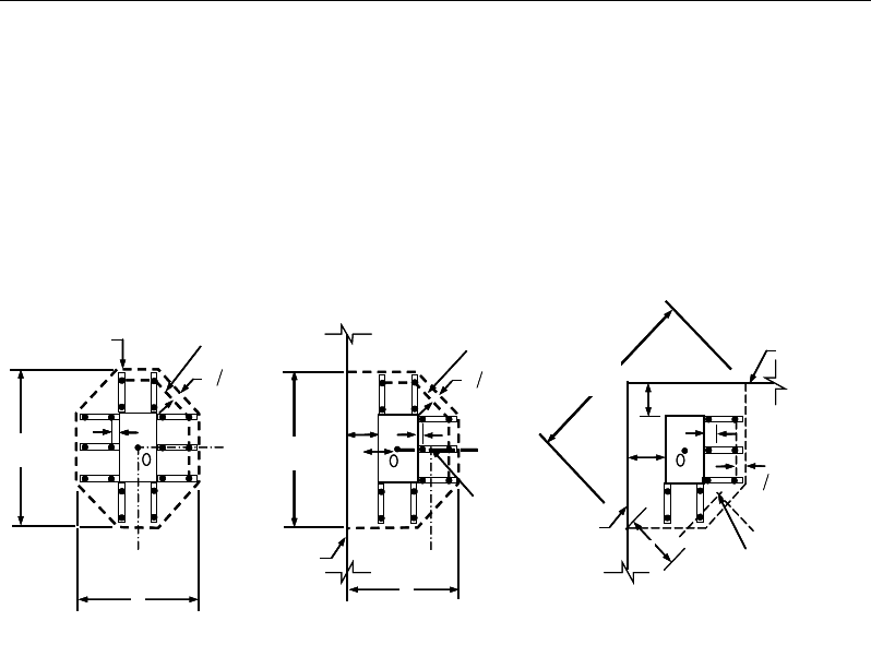
Chapter 16 - Design for Singapore CP 65-99
16.5.4.3 Determine Reinforcement Arrangement
Punching shear reinforcement in the vicinity of rectangular columns should be
arranged on peripheral lines, i.e., lines running parallel to and at constant dis-
tances from the sides of the column. Figure 16-4 shows a typical arrangement of
shear reinforcement in the vicinity of a rectangular interior, edge, and corner
column.
Figure 16-4 Typical arrangement of shear studs
and critical sections outside shear-reinforced zone
The distance between the column face and the first line of shear reinforcement
shall not exceed d/2. The spacing between adjacent shear reinforcement in the
first line (perimeter) of shear reinforcement shall not exceed 1.5d measured in a
direction parallel to the column face (CP 3.7.7.6).
Punching shear reinforcement is most effective near column corners where there
are concentrations of shear stress. Therefore, the minimum number of lines of
shear reinforcement is 4, 6, and 8, for corner, edge, and interior columns respec-
tively.
16.5.4.4 Determine Reinforcement Diameter, Height, and Spacing
The punching shear reinforcement is most effective when the anchorage is close
to the top and bottom surfaces of the slab. The cover of anchors should not be
less than the minimum cover specified in CP 3.3 plus half of the diameter of the
flexural reinforcement.
I
y
Typical Studrail
(only first and last
studs shown)
Outermost
peripheral line
of studs
Interior Column Edge Column Corner Column
Critical section
centroid
Free
edge
Free
edge
Critical
section
centroid
Free edge
Outermost
peripheral line
of studs
I
y
I
y
yx
d2 d2
d2
x
I
x
I
x
g
y
g
x
g
0
s
0
s
0
s
x
I
y
x
x
I
y
Typical Studrail
(only first and last
studs shown)
Outermost
peripheral line
of studs
Interior Column Edge Column Corner Column
Critical section
centroid
Free
edge
Free
edge
Critical
section
centroid
Free edge
Outermost
peripheral line
of studs
I
y
I
y
yx
d2 d2
d2
x
I
x
I
x
g
y
g
x
g
0
s
0
s
0
s
x
I
y
x
x
Slab Design 16 - 21

ETABS Reinforced Concrete Design
Punching shear reinforcement in the form of shear studs is generally available in
16-, 12-, 14-, 16-, and 20-millimeter diameters.
When specifying shear studs, the distance, so, between the column face and the
first peripheral line of shear studs should not be smaller than 0.5d. The spacing
between adjacent shear studs, g, at the first peripheral line of studs shall not ex-
ceed 1.5d. The limits of so and the spacing, s, between the peripheral lines are
specified as:
so ≤ 0.5d (CP 3.7.7.6)
s ≤ 0.75d (CP 3.7.7.6)
g ≤ 1.5d (CP 3.7.7.6)
16 - 22 Slab Design

Chapter 17
Design for TS 500-2000
This chapter describes in detail the various aspects of the concrete design proce-
dure that is used by ETABS when the American code TS 500-2000 [TS 500] is
selected. Various notations used in this chapter are listed in Table 17-1. For ref-
erencing to the pertinent sections or equations of the TS code in this chapter, a
prefix “TS” followed by the section or equation number is used herein.
The design is based on user-specified load combinations. The program provides
a set of default load combinations that should satisfy the requirements for the
design of most building type structures.
English as well as SI and MKS metric units can be used for input. The code is
based on Newton-millimeter-second units. For simplicity, all equations and de-
scriptions presented in this chapter correspond to Newton-millimeter-second
units unless otherwise noted.
17.1 Notations
Table 17-1 List of Symbols Used in the TS 500-2000 Code
A
cp
Area enclosed by the outside perimeter of the section, mm2
A
g
Gross area of concrete, mm2
Notations 17 - 1

ETABS Reinforced Concrete Design
Table 17-1 List of Symbols Used in the TS 500-2000 Code
A
l
Area of longitudinal reinforcement for torsion, mm2
A
o
Area enclosed by the shear flow path, mm2
A
oh
Area enclosed by the centerline of the outermost closed transverse
torsional reinforcement, mm2
A
s
Area of tension reinforcement, mm2
A'
s
Area of compression reinforcement, mm2
A
ot
/s
Area of transverse torsion reinforcement (closed stirrups) per unit
length of the member, mm2/mm
A
ov
/s
Area of transverse shear reinforcement per unit length of the mem-
ber, mm2/mm
a
Depth of compression block, mm
A
sw
Area of shear reinforcement, mm2
A
sw
/s
Area of shear reinforcement per unit length of the member, mm
2
/mm
a
max
Maximum allowed depth of compression block, mm
b
Width of section, mm
b
f
Effective width of flange (flanged section), mm
b
o
Perimeter of the punching shear critical section, mm
b
w
Width of web (flanged section), mm
b
1
Width of the punching shear critical section in the direction of
bending, mm
b
2
Width of the punching shear critical section perpendicular to the di-
rection of bending, mm
c
Depth to neutral axis, mm
d
Distance from compression face to tension reinforcement, mm
d'
Distance from compression face to compression reinforcement, in
E
c
Modulus of elasticity of concrete, N/mm2
17 - 2 Notations

Chapter 17 - Design for TS 500-2000
Table 17-1 List of Symbols Used in the TS 500-2000 Code
E
s
Modulus of elasticity of reinforcement, N/mm2
f
cd
Designed compressive strength of concrete, N/mm2
f
ck
Characteristic compressive strength of concrete, N/mm2
f
ctk
Characteristic tensile strength of concrete, N/mm2
f
yd
Designed yield stress of flexural reinforcement, N/mm2.
f
yk
Characteristic yield stress of flexural reinforcement, N/mm2.
f
ywd
Designed yield stress of transverse reinforcement, N/mm2.
h
Overall depth of a section, mm
h
f
Height of the flange, mm
M
d
Design moment at a section, N/mm
N
d
Design axial load at a section, N
p
cp
Outside perimeter of concrete cross-section, mm
p
h
Perimeter of centerline of outermost closed transverse torsional
reinforcement, mm
s
Spacing of shear reinforcement along the strip, mm
T
cr
Critical torsion capacity, N/mm
T
d
Design torsional moment at a section, N/mm
V
c
Shear force resisted by concrete, N
V
max
Maximum permitted total factored shear force at a section, N
V
s
Shear force resisted by transverse reinforcement, N
V
d
Design shear force at a section, N
α
s
Punching shear scale factor based on column location
β
c
Ratio of the maximum to the minimum dimensions of the punching
shear critical section
k
1
Factor for obtaining depth of the concrete compression block
Notations 17 - 3

ETABS Reinforced Concrete Design
Table 17-1 List of Symbols Used in the TS 500-2000 Code
ε
c
Strain in the concrete
ε
c max
Maximum usable compression strain allowed in the extreme
concrete fiber, (0.003 mm / mm)
ε
s
Strain in the reinforcement
ε
cu,
Maximum usable compression strain allowed in extreme concrete fi-
ber (0.003 mm/mm)
ε
s
Strain in reinforcing steel
γ
m
Material factor
γmc
Material factor for concrete
λ
Shear strength reduction factor for light-weight concrete
17.2 Design Load Combinations
The design load combinations are the various combinations of the load cases for
which the structure needs to be designed. For TS 500-2000, if a structure is sub-
jected to dead (G), live (Q), wind (W), and earthquake (E) loads, and considering
that wind and earthquake forces are reversible, the following load combinations
may need to be considered (TS 6.2.6):
1.4G + 1.6Q
(TS Eqn. 6.3)
0.9G ± 1.3W
1.0G + 1.3Q ± 1.3W (TS Eqn. 6.6
)
(TS Eqn. 6.5
)
0.9G ± 1.0E
1.0G + 1.0Q ± 1.0E (TS Eqn. 6.8
)
(TS Eqn. 6.7
)
These are the default design load combinations in ETABS whenever the TS 500-
2000 code is used. The user should use other appropriate load combinations if
roof live load is treated separately, or if other types of loads are present.
17 - 4 Design Load Combinations

Chapter 17 - Design for TS 500-2000
17.3 Limits on Material Strength
The characteristic compressive strength of concrete, fck, should not be less than
16 N/mm2. The upper limit of the reinforcement yield stress, fy, is taken as 420
N/mm2 and the upper limit of the reinforcement shear strength, fyk is taken as 420
N/mm2.
The program enforces the upper material strength limits for flexure and shear
design of slab. The input material strengths are taken as the upper limits if they
are defined in the material properties as being greater than the limits. The user is
responsible for ensuring that the minimum strength is satisfied.
17.4 Design Strength
The design strength for concrete and steel is obtained by dividing the character-
istic strength of the material by a partial factor of safety, γmc and γms. The values
used in the program are as follows:
Partial safety factor for steel, γms = 1.15, and (TS 6.2.5)
Partial safety factor for concrete, γmc = 1.5. (TS 6.2.5)
These factors are already incorporated in the design equations and tables in the
code. Although not recommended, the program allows them to be overwritten.
If they are overwritten, the program uses them consistently by modifying the
code-mandated equations in every relevant place.
17.5 Slab Design
ETABS slab design procedure involves defining sets of strips in two mutually
perpendicular directions. The locations of the strips are usually governed by the
locations of the slab supports. The axial force, moments and shears for a partic-
ular strip are recovered from the analysis (on the basis of the Wood-Armer tech-
nique), and a flexural design is carried out based on the ultimate strength design
method.
The slab design procedure involves the following steps:
Design flexural reinforcement
Limits on Material Strength 17 - 5

ETABS Reinforced Concrete Design
Design shear reinforcement
Punching check
17.5.1 Design Flexural Reinforcement
For slabs, ETABS uses either design strips or the finite element based design to
calculate the slab flexural reinforcement in accordance with the selected design
code. For simplicity, only strip-by-strip design is document in the proceeding
sections.
The design of the slab reinforcement for a particular strip is carried out at specific
locations along the length of the strip. These locations correspond to the element
boundaries. Controlling reinforcement is computed on either side of those ele-
ment boundaries. The slab flexural design procedure for each load combination
involves the following:
Determine factored axial loads and moments for each slab strip.
Design flexural reinforcement for the strip.
These two steps, described in the text that follows, are repeated for every load
combination. The maximum reinforcement calculated for the top and bottom
of the slab within each design strip, along with the corresponding controlling
load combination, is obtained and reported.
17.5.1.1 Determine Factored Moments
In the design of flexural reinforcement of concrete slab, the factored moments
for each load combination at a particular design strip are obtained by factoring
the corresponding moments for different load cases, with the corresponding load
factors.
The slab is then designed for the maximum positive and maximum negative fac-
tored moments obtained from all of the load combinations. Calculation of bottom
reinforcement is based on positive design strip moments. In such cases, the slab
may be designed as a rectangular or flanged slab section. Calculation of top re-
inforcement is based on negative design strip moments. In such cases, the slab
may be designed as a rectangular or inverted flanged slab section.
17 - 6 Slab Design
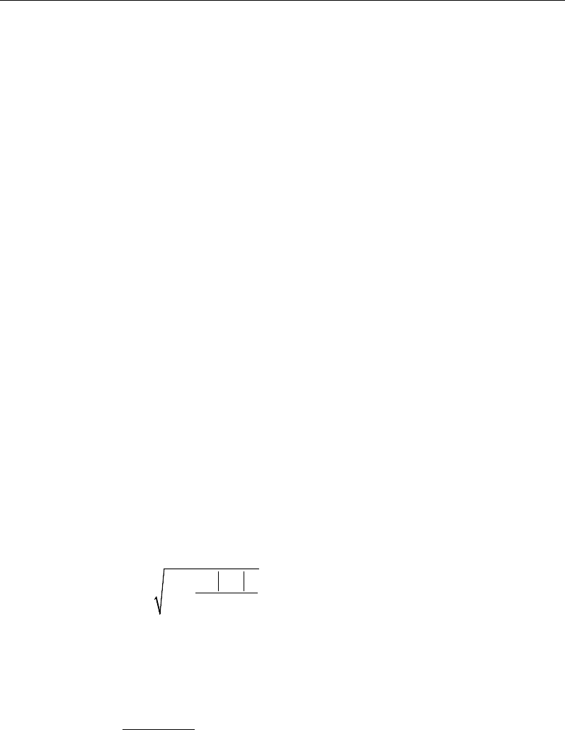
Chapter 17 - Design for TS 500-2000
17.5.1.2 Determine Required Flexural Reinforcement
In the flexural reinforcement design process, the program calculates both the
tension and compression reinforcement. Compression reinforcement is added
when the applied design moment exceeds the maximum moment capacity of a
singly reinforced section. The user has the option of avoiding the compression
reinforcement by increasing the effective depth, the width, or the grade of con-
crete.
The design procedure is based on the simplified rectangular stress block, as
shown in Figure 17-1 (TS 7.1). When the applied moment exceeds the moment
capacity at this design condition, the area of compression reinforcement is cal-
culated on the assumption that the additional moment will be carried by com-
pression and additional tension reinforcement.
The design procedure used by the program for both rectangular and flanged sec-
tions is summarized in the following subsections. It is assumed that the design
ultimate axial force does not exceed
( )
0.1 ck g
fA
(TS 7.3, Eqn. 7.2); hence, all of
the slabs are designed ignoring axial force; hence, all slabs are designed for ma-
jor direction flexure and shear only. Axial compression greater than
( )
0.1 ck g
fA
and axial tensions are always included in flexural and shear design..
17.5.1.2.1 Design of uniform thickness slab
In designing for a factored negative or positive moment, Md (i.e., designing top
or bottom reinforcement), the depth of the compression block is given by a (see
Figure 17-1), where,
22,
0.85
d
cd
M
ad d fb
=−−
(TS 7.1)
The maximum depth of the compression zone, cb, is calculated based on the com-
pressive strength of the concrete and the tensile steel tension using the following
equation (TS 7.1):
cu s
bcu s yd
E
cd
Ef
ε
ε
=+
(TS 7.1)
Slab Design 17 - 7
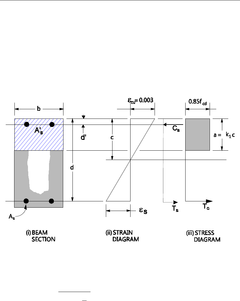
ETABS Reinforced Concrete Design
The maximum allowable depth of the rectangular compression block, amax, is
given by
max 1
0.85 b
a kc=
(TS 7.11, 7.3, Eqn. 7.4)
where k1 is calculated as follows:
k1 = 0.85 − 0.006
( )
25
ck
f−
, 0.70 ≤ k1 ≤ 0.85. (TS 7.1, Table 7.1)
Figure 17-1 Uniform Thickness Slab Design
If a ≤ amax, the area of tension reinforcement is then given by:
2
d
s
yd
M
Aa
fd
=
−
This reinforcement is to be placed at the bottom if Md is positive, or at the top
if Md is negative.
17 - 8 Slab Design

Chapter 17 - Design for TS 500-2000
If a > amax, compression reinforcement is required (TS 7.1) and is calculated
as follows:
− The compressive force developed in the concrete alone is given by:
max
0.85 ,
cd
C f ba=
(TS 7.1)
and the moment resisted by concrete compression and tension reinforcement
is:
max
.
2
dc
a
M Cd
= −
− Therefore the moment required to be resisted by compression reinforcement
and tension reinforcement is:
.
ds d dc
M MM= −
− The required compression reinforcement is given by:
( )
( )
',
0.85
ds
s
s cd
M
Af dd
σ
′=′
−−
where
'max
max
.
s s cu yd
cd
Ef
c
σε
′
−
= ≤
(TS 7.1)
− The required tension reinforcement for balancing the compression in the
concrete is:
1max
,
2
ds
s
yd
M
Aa
fd
=
−
and the tension reinforcement for balancing the compression reinforcement
is given by:
( )
2ds
syd
M
Af dd
=′
−
Slab Design 17 - 9
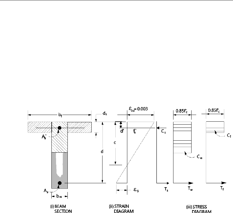
ETABS Reinforced Concrete Design
Therefore, the total tension reinforcement is As = As1 + As2, and the total com-
pression reinforcement is A's. As is to be placed at the bottom and A's is to be
placed at the top if Md is positive, and vice versa if Md is negative.
17.5.1.2.2 Design of nonuniform thickness slab
In designing a flanged-shaped section, a simplified stress block, as shown in Fig-
ure 17-2, is assumed if the flange is under compression, i.e., if the moment is
positive. If the moment is negative, the flange comes under tension, and the
flange is ignored. In that case, a simplified stress block similar to that shown in
Figure 17-1 is assumed on the compression side.
Figure 17-2 Nonuniform Thickness Slab Design
17.5.1.2.2.1 Flanged Slab Section Under Negative Moment
In designing for a factored negative moment, Md (i.e., designing top reinforce-
ment), the calculation of the reinforcement area is exactly the same as described
previously, i.e., no flanged data is used.
17.5.1.2.2.2 Flanged Slab Section Under Positive Moment
If Md > 0, the depth of the compression block is given by:
17 - 10 Slab Design
Chapter 17 - Design for TS 500-2000
22
0.85
d
cd f
M
ad d fb
=−−
The maximum depth of the compression zone, cb, is calculated based on the com-
pressive strength of the concrete and the tensile steel tension using the following
equation (TS 7.1):
cs
bcu s yd
E
cd
Ef
ε
ε
=+
(TS 7.1)
The maximum allowable depth of the rectangular compression block, amax, is
given by
max 1
0.85 b
a kc=
(TS 7.11, 7.3, Eqn. 7.4)
where k1 is calculated as follows:
k1 = 0.85 − 0.006
( )
25
ck
f−
, 0.70 ≤ k1 ≤ 0.85. (TS 7.1, Table 7.1)
If a ≤ ds, the subsequent calculations for As are exactly the same as previ-
ously defined for the uniform thickness slab section design. However, in
that case, the width of the slab is taken as bf, as shown in Figure 17-2.
Compression reinforcement is required if a > amax.
If a > ds, the calculation for As has two parts. The first part is for balancing
the compressive force from the flange, Cf , and the second part is for
balancing the compressive force from the web, Cw, as shown in Figure 17-
2. Cf is given by:
( )
( )
max
0.85 min ,
f cd f w s
C f b b da= −×
(TS 7.1)
Therefore,
1
f
s
yd
C
Af
=
and the portion of Md that is resisted by the flange is
given by:
( )
max
min ,
2
s
df f
da
M Cd
= −
Slab Design 17 - 11
ETABS Reinforced Concrete Design
Therefore, the balance of the moment, Md, to be carried by the web is given
by:
dw d df
M MM= −
The web is a rectangular section of dimensions bw and d, for which the design
depth of the compression block is recalculated as:
2
12
0.85
dw
cd w
M
ad d fb
=−−
(TS 7.1)
If a1 ≤ amax (TS 7.1), the area of tensile steel reinforcement is then given by:
21
2
dw
s
yd
M
Aa
fd
=
−
, and
12ss s
AA A= +
This steel is to be placed at the bottom of the T-shaped section.
If a1 > amax, compression reinforcement is required and is calculated as follows:
The compression force in the web concrete alone is given by:
max
0.85 cd w
C f ba=
(TS 7.1)
Therefore the moment resisted by the concrete:
max
,
2
dc
a
M Cd
= −
The tensile steel for balancing compression in the web concrete is:
2max
2
dc
s
yd
M
Aa
fd
=
−
,
The moment resisted by compression steel and tensile steel is:
17 - 12 Slab Design

Chapter 17 - Design for TS 500-2000
ds dw dc
MMM= −
Therefore, the compression steel is computed as:
( )
( )
'0.85
ds
s
s cd
M
Af dd
σ
′=′
−−
, where
'max
max
s s cu yd
cd
Ef
c
σε
′
−
= ≤
, and (TS 7.1)
the tensile steel for balancing the compression steel is:
( )
3ds
syd
M
Af dd
=′
−
The total tensile reinforcement is
123
,
ss s s
AA A A=++
and the total compres-
sion reinforcement is
s
A.
′
As is to be placed at the bottom and
s
A′
is to be
placed at the top.
17.5.1.2.3 Minimum and Maximum Tensile Reinforcement
The minimum flexural tension reinforcement required for each direction of a
slab is given by the following limits (TS 11.4.5):
As,min = 0.0020 bh for steel grade S220 (TS 11.4.5)
As,min = 0.00175 bh for steel grade S420 and S500 (TS 11.4.5)
In addition, an upper limit on both the tension reinforcement and compres-
sion reinforcement has been imposed to be 0.04 times the gross cross-sec-
tional area.
17.5.2 Design Slab Shear Reinforcement
The shear reinforcement is designed for each load combination at each station
along the design strip. In designing the shear reinforcement for a particular strip,
for a particular load combination, at a particular station due to the slab major
shear, the following steps are involved:
Slab Design 17 - 13

ETABS Reinforced Concrete Design
Determine the factored shear force, Vd.
Determine the shear force, Vc, that can be resisted by the concrete.
Determine the shear reinforcement required to carry the balance.
The following three sections describe in detail the algorithms associated with
these steps.
17.5.2.1 Determine Factored Shear Force
In the design of the slab shear reinforcement, the shear forces for each load com-
bination at a particular design strip station are obtained by factoring the corre-
sponding shear forces for different load cases, with the corresponding load com-
bination factors.
17.5.2.2 Determine Concrete Shear Capacity
Given the design force set Nd and Vd, the shear force carried by the concrete, Vc,
is calculated as follows:
If the slab is subjected to axial loading, Nd is positive in this equation regardless
of whether it is a compressive or tensile force,
0.65 1 d
cr ctd w
g
N
V f bd A
γ
= +
, (TS 8.1.3, Eqn. 8.1)
where,
0.07foraxialcompression
-0.3foraxialtension
0when tensile stress < 0.5 MPa
γ
=
0.8
c cr
VV
=
, (TS 8.1.4, Eqn. 8.4)
17.5.2.3 Determine Required Shear Reinforcement
Given Vd and Vc, the required shear reinforcement in the form of stirrups or ties
within a spacing, s, is given for rectangular and circular columns by the follow-
ing:
17 - 14 Slab Design

Chapter 17 - Design for TS 500-2000
The shear force is limited to a maximum of
max
0.22
cd w
V fA=
(TS 8.1.5b)
The required shear reinforcement per unit spacing, Av /s, is calculated as
follows:
If
,
d cr
VV≤
0.3 ,
sw ctd w
ywd
Af
b
sf
=
(TS 8.1.5, Eqn. 8.6)
else if
max
,
cr d
V VV
<≤
( )
dc
sw
ywd
VV
A
s fd
−
=
, (TS 8.1.4, Eqn. 8.5)
0.3
sw ctd w
ywd
Af
b
sf
≥
(TS 8.1.5, Eqn. 8.6)
else if
max ,
d
VV
>
a failure condition is declared. (TS 8.1.5b)
If Vd exceeds its maximum permitted value Vmax, the concrete section size should
be increased (TS 8.1.5b).
The maximum of all of the calculated Asw/s values, obtained from each design
load combination, is reported along with the controlling shear force and associ-
ated design load combination name.
The slab shear reinforcement requirements considered by the program are based
purely on shear strength considerations. Any minimum stirrup requirements to
satisfy spacing and volumetric considerations must be investigated
independently of the program by the user.
Slab Design 17 - 15
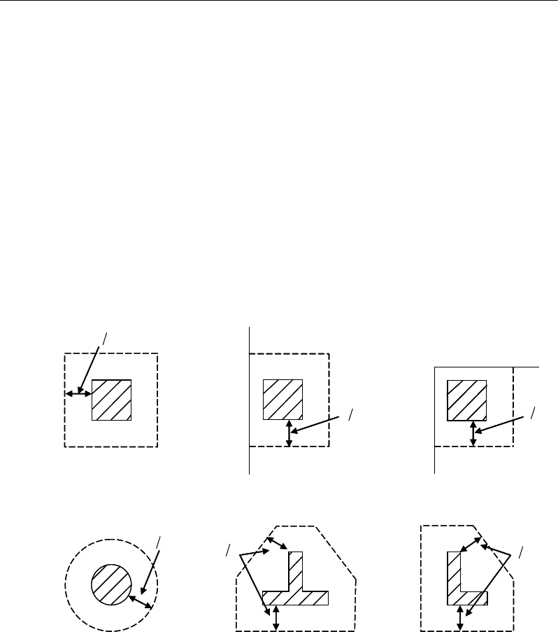
ETABS Reinforced Concrete Design
17.5.3 Check for Punching Shear
The algorithm for checking punching shear is detailed in the section entitled
“Slab Punching Shear Check” in the Chapter 1. Only the code-specific items are
described in the following sections.
17.5.3.1 Critical Section for Punching Shear
The punching shear is checked on a critical section at a distance of d / 2 from the
face of the support (TS 8.3.1). For rectangular columns and concentrated loads,
the critical area is taken as a rectangular area with the sides parallel to the sides
of the columns or the point loads (TS 8.3.1). Figure 17-3 shows the auto punch-
ing perimeters considered by ETABS for the various column shapes. The column
location (i.e., interior, edge, corner) and the punching
perimeter may be overwritten using the Punching Check Overwrites.
Figure 17-3 Punching Shear Perimeters
d2
Interior Column
Circular Column
d2 d2
d2
T-Shape Column
Edge Column Edge Column
L-Shape Column
d2
d2
d2
Interior Column
Circular Column
d2 d2
d2
T-Shape Column
Edge Column Edge Column
L-Shape Column
d2
d2
17 - 16 Slab Design
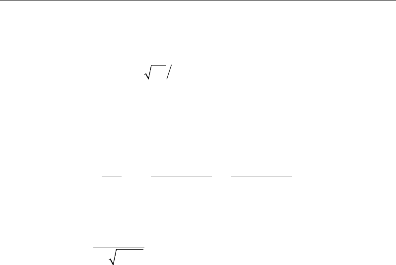
Chapter 17 - Design for TS 500-2000
17.5.3.2 Determine Concrete Capacity
The concrete punching shear stress capacity is taken as the following limit:
0.35
pr ctd ck c
vf f
γ
= =
(TS 8.3.1)
17.5.3.3 Computation of Maximum Shear Stress
Given the punching shear force and the fractions of moments transferred by ec-
centricity of shear, the nominal design shear stress, vpd, is calculated as:
,2 ,3
,2 ,3
0.4 0.4
1,
pd pd p pd p
pd
p pd m pd m
V M ud M ud
vud VW VW
ηη
=++
where (TS 8.3.1)
η
factor to be used in punching shear check
21
1
1/bb
η
=+
where
21
0.7bb≥
When the aspect ratio of loaded area is greater than 3, the critical primeter
is limited assuming
3hb=
up is the effective perimeter of the critical section
d is the mean effective depth of the slab
Mpd is the design moment transmitted from the slab to the column at the
connection along bending axis 2 and 3
Vpd is the total punching shear force
Wm section modulus of area within critical punching perimeter (up) along
bending axis 2 and 3.
17.5.3.4 Determine Capacity Ratio
Given the punching shear force and the fractions of moments transferred by ec-
centricity of shear about the two axes, the shear stress is computed assuming
linear variation along the perimeter of the critical section. The ratio of the max-
imum shear stress and the concrete punching shear stress capacity is reported as
Slab Design 17 - 17

ETABS Reinforced Concrete Design
the punching shear capacity ratio by ETABS. If this ratio exceeds 1.0, punching
shear reinforcement is designed as described in the following section.
17.5.4 Design Punching Shear Reinforcement
The use of shear studs as shear reinforcement in slabs is permitted, provided that
the slab thickness is greater than or equal to 250 mm, a (TS 8.3.2). If the slab
thickness does not meet these requirements, the punching shear reinforcement is
not designed and the slab thickness should be increased by the user.
The algorithm for designing the required punching shear reinforcement is used
when the punching shear capacity ratio exceeds unity. The Critical Section for
Punching Shear and Transfer of Unbalanced Moment as described in the earlier
sections remain unchanged. The design of punching shear reinforcement is de-
scribed in the subsections that follow.
17.5.4.1 Determine Concrete Shear Capacity
The concrete punching shear stress capacity of a section with punching shear
reinforcement is limited to:
0.35
pr ctd ck c
vf f
γ
= =
(TS 8.3.1)
17.5.4.2 Determine Required Shear Reinforcement
The shear force is limited to a maximum of:
,max
1.5 0.525
pr ctd ck c
vf f
γ γγ
= =
for shear links/shear studs (TS 8.3.1)
Given Vpd, Vpr, and Vpr,max, the required shear reinforcement is calculated as fol-
lows,
( )
pd pr
v
yd
VV
A
s fd
−
=
(TS8.1.4 )
If Vpd > Vpr,max, a failure condition is declared. (TS 8.3.1)
If Vpd exceeds the maximum permitted value of Vpr,max, the concrete section
should be increased in size.
17 - 18 Slab Design
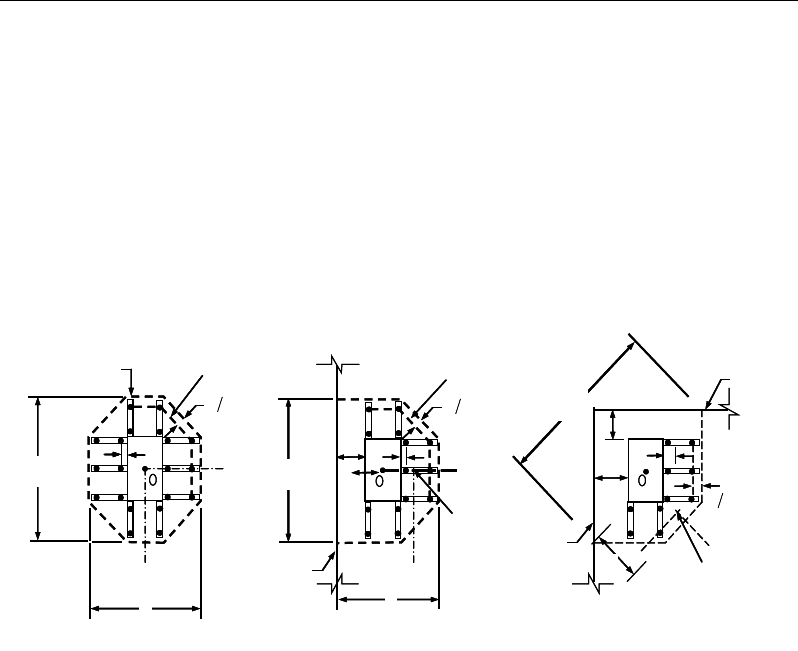
Chapter 17 - Design for TS 500-2000
17.5.4.3 Determine Reinforcement Arrangement
Punching shear reinforcement in the vicinity of rectangular columns should be
arranged on peripheral lines, i.e., lines running parallel to and at constant dis-
tances from the sides of the column. Figure 17-4 shows a typical arrangement of
shear reinforcement in the vicinity of a rectangular interior, edge, and corner
column.
NOTE: Shear Stud and shear links requirements are computed based on ACI
318-08 code as Turkish TS 500-2000 refers to special literature on this topic.
Figure 17-4 Typical arrangement of shear studs
and critical sections outside shear-reinforced zone
The distance between the column face and the first line of shear reinforcement
shall not exceed d / 2(ACI R11.3.3, 11.11.5.2. The spacing between adjacent
shear reinforcement in the first line (perimeter) of shear reinforcement shall not
exceed 2d measured in a direction parallel to the column face (ACI 11.11.3.3).
Punching shear reinforcement is most effective near column corners where there
are concentrations of shear stress. Therefore, the minimum number of lines of
shear reinforcement is 4, 6, and 8, for corner, edge, and interior columns respec-
tively.
Iy
Typical Studrail
(only first and last
studs shown)
Outermost
peripheral line
of studs
Interior Column Edge Column Corner Column
Critical section
centroid
Free
edge
Free
edge
Critical
section
centroid
Free edge
Outermost
peripheral line
of studs
Iy
Iy
yx
d2 d2
d2
x
I
x
I
x
g
y
g
x
g
0
s
0
s
0
s
x
I
y
xx
Iy
Typical Studrail
(only first and last
studs shown)
Outermost
peripheral line
of studs
Interior Column Edge Column Corner Column
Critical section
centroid
Free
edge
Free
edge
Critical
section
centroid
Free edge
Outermost
peripheral line
of studs
Iy
Iy
yx
d2 d2
d2
x
I
x
I
x
g
y
g
x
g
0
s
0
s
0
s
x
I
y
xx
Slab Design 17 - 19

ETABS Reinforced Concrete Design
17.5.4.4 Determine Reinforcement Diameter, Height, and Spacing
The punching shear reinforcement is most effective when the anchorage is close
to the top and bottom surfaces of the slab. The cover of anchors should not be
less than the minimum cover specified in ACI 7.7 plus half of the
diameter of the flexural reinforcement.
Punching shear reinforcement in the form of shear studs is generally available in
10-, 12-, 14-, 16-, and 20-millimeter diameters.
When specifying shear studs, the distance, so, between the column face and the
first peripheral line of shear studs should not be smaller than 0.5d. The spacing
between adjacent shear studs, g, at the first peripheral line of studs shall not
exceed 2d, and in the case of studs in a radial pattern, the angle between adjacent
stud rails shall not exceed 60 degrees. The limits of so and the spacing, s, between
the peripheral lines are specified as:
so ≤ 0.5d (ACI 11.11.5.2)
0 75 for 6
0 50 for 6
uc
uc
.d v f
s.d v f
φλ
φλ
′
≤
≤′
>
(ACI 11.11.5.2)
g ≤ 2d (ACI 11.11.5.3)
The limits of so and the spacing, s, between for the links are specified as:
so ≤ 0.5d (ACI 11.11.3)
0 50≤s .d
(ACI 11.11.3)
17 - 20 Slab Design

References
ACI, 2007. Seismic Design of Punching Shear Reinforcement in Flat
Plates (ACI 421.2R-07), American Concrete Institute, 38800
Country Club Drive, Farmington Hills, Michigan.
ACI, 2008. Building Code Requirements for Structural Concrete (ACI
318-08) and Commentary (ACI 318R-08), American Concrete In-
stitute, P.O. Box 9094, Farmington Hills, Michigan.
ACI, 2011. Building Code Requirements for Structural Concrete (ACI
318-11) and Commentary (ACI 318R-11), American Concrete In-
stitute, P.O. Box 9094, Farmington Hills, Michigan.
AS, 2001. Australian StandardTM for Concrete Structure (AS 3600-2001)
incorporating Amendment No.1 and Amendment No. 2, Standards
Australia International Ltd, GPO Box 5420, Sydney, NSW 2001,
Australia.
AS, 2009. Australian Standard® for Concrete Structure (AS 3600-2009),
Standards Australia International Ltd, GPO Box 476, Sydney,
NSW 2001, Australia.
BC, 2008. BC 2:2008, Design Guide of High Strength Concrete to Singa-
pore Standard CP65, February 2008, Building and Construction
Authority, Singapore.
R - 1

ETABS Reinforced Concrete Design
BSI, 1997. BS 8110-1:1997 Incorporating Amendments Nos. 1, 2, and 3,
Structural Use of Concrete, Part 1, Code of Practice for Design
and Construction, British Standards Institution, London, UK,
2005.
BSI, 1985. BS 8110-2:1985 Reprinted, incorporating Amendments Nos.
1, 2, and 3, Structural Use of Concrete, Part 2, Code of Practice
for Special Circumstances, British Standards Institution, London,
UK, 2005.
CP, 1999. CP 65:Part 1:1999, Code of Practice for Structural Use of Con-
crete Part 1: Design and Construction Incorporating Erratum No.
1, September 2000, Singapore Productivity and Standards Board,
Singapore.
EN 1992-1-1, 2004. Eurocode 2: Design of Concrete Structures, Part 1-1,
General Rules and Rules for Buildings, European Committee for
Standardization, Brussels, Belgium.
EN 1990:2002. Eurocode: Basis of Structural Design (includes Amend-
ment A1:2005), European Committee for Standardization, Brus-
sels, Belgium.
CSA, 2004. A23.3-04, Design of Concrete Structures, Canadian Standards
Association, Rexdale, Ontario, Canada.
HK CP, 2013. Code of Practice for Structural Use of Concrete 2013,
Buildings Department, 12/F-18/F Pioneer Centre, 750 Nathan
Road, Mongkok, Kowloon, Hong Kong.
HK CP, 2004. Code of Practice for Structural Use of Concrete 2004,
Buildings Department, 12/F-18/F Pioneer Centre, 750 Nathan
Road, Mongkok, Kowloon, Hong Kong.
Italian NTC, 2008. Design and Calculations of Reinforced and Prestressed
Concrete Structure, Ministerial Decree of January 14, 2008 and pub-
lished in the Offical Gazette No. 29 of February 4, 2008.
R - 2

References
IS, 2000. Code of Practice for Plain and Reinforced Concrete, Third Edi-
tion, Twentieth Reprint, March 2000, Bureau of Indian Standards,
Manak Bhavan, 9 Bahadur Shah Zafar Marg, New Delhi 110002,
India.
NZS, 2006. Concrete Structures Standard, Part 1 – Design of Concrete
Structures, Standards New Zealand, Private Bag 2439, Welling-
ton, New Zealand.
TS 500-2000. Requirements for Design and Construction of Reinforced
Concrete Structures. Turkish Standard Institute. Necatibey Street No.
112, Bakanliklar, Ankara.
TS 3233-1979. Building Code Requirements for Presstressed Concrete.
Turkish Standard Institute. Necatibey Street No. 112, Bakanliklar, An-
kara.
R- 3
